Eastern Municipal Water District
72
December 14, 2021 EASTERN MUNICIPAL WATER DISTRICT POTABLE WATER HYDRO-PNEUMATIC BOOSTER STATION SUBMITTAL AND DESIGN GUIDELINES EASTERN MUNICIPAL WATER DISTRICT 2270 TRUMBLE ROAD PERRIS, CALIFORNIA 92570 (951) 928-3777 Prepared by KRIEGER & STEWART, INCORPORATED 3602 UNIVERSITY AVENUE RIVERSIDE, CALIFORNIA 92501 (951) 684-6900
-
Upload
khangminh22 -
Category
Documents
-
view
1 -
download
0
Transcript of Eastern Municipal Water District

December 14, 2021
EASTERN MUNICIPAL WATER DISTRICT POTABLE WATER HYDRO-PNEUMATIC BOOSTER STATION
SUBMITTAL AND DESIGN GUIDELINES
EASTERN MUNICIPAL WATER DISTRICT 2270 TRUMBLE ROAD
PERRIS, CALIFORNIA 92570 (951) 928-3777
Prepared by
KRIEGER & STEWART, INCORPORATED
3602 UNIVERSITY AVENUE RIVERSIDE, CALIFORNIA 92501
(951) 684-6900

December 14, 2021
TABLE OF CONTENTS

December 14, 2021
TABLE OF CONTENTS
CHAPTER PAGE I. Introduction I-1
II. Submittal Procedures II-1
III. Design Requirements III-1
A. General III-1
B. Site Selection III-2
C. Property Acquisition III-3
D. Booster Station Capacity and Hydro-Pneumatic Tank Sizing III-4
E. Pumping Unit Selection III-6
F. Leadership in Energy and Environmental Design III-8
IV. Civil Design IV-1
A. Site Layout IV-1
B. Site Plans IV-1
C. Access Road/Driveway IV-2
D. Site Grading IV-3
E. Site Paving IV-4
F. Site Fencing IV-4
G. Site Lighting IV-4
H. Landscaping IV-5
V. Mechanical Design V-1
A. General V-1
B. Mechanical Layout V-2
C. Pumping Units and Pump Suction Cans V-7
D. Hydro-Pneumatic Tank and Compressed Air System V-10
E. Piping, Valves, and Appurtenances V-12
F. Building Mechanical V-16
G. Emergency Standby Power Generator V-18

December 14, 2021
VI. Structural/Architectural Design VI-1
A. Equipment Building VI-1
VII. Electrical Design VII-1
A. General VII-1
B. Normal Power VII-1
C. Emergency Power VII-2
D. Transient Voltage Surge Suppressor (TVSS) VII-3
E. Motor Control Center (MCC) VII-3
F. Motors VII-7
G. Conduit and Conductors VII-8
H. Grounding VII-9
I. Controls, Security, and Telemetry VII-9
Appendix A - Typical Hydro-Pneumatic Booster Station Construction Drawing Index
Appendix B - Typical Hydro-Pneumatic Booster Station Mechanical Plan and Mechanical Sections
Appendix C - Hydro-Pneumatic Tank Control Points

December 14, 2021
UPDATE LOG Date Item(s) Changed Page #
12/14/21 Clarified design Risk Category. Updated control strategy requirements.
III-2, VI-1 II-6
11/04/21 Revised various electrical provisions throughout. Deleted skylight provisions throughout.
08/12/21 Revised minimum capacity under Section V.G. Revised DPF system requirements under Section V.G.7. Revised minimum capacity under Section V.G.14. Added article 16 under Section V.G.
V-18 V-19 V-21 V-21
09/27/16 Entire section revised 03/01/10 Original

December 14, 2021
POTABLE WATER HYDRO-PNEUMATIC BOOSTER STATION SUBMITTAL AND DESIGN GUIDELINES

December 14, 2021
I-1
CHAPTER I INTRODUCTION
This document in conjunction with the District's Water System Planning and Design Guidelines provides guidance to Developers and their Engineers through the process of planning and designing potable water hydro-pneumatic booster stations. District's existing domestic water distribution system consists of transmission pipelines, booster stations, and storage tanks. Distribution system pressures are based on pressure zones established by the elevation of the water storage tanks. Domestic water system facilities for new developments shall be consistent with the District's existing water distribution system and master planned facilities. Domestic water systems for new developments shall utilize storage tanks open to the atmosphere (reservoirs) to provide the required capacity to serve the pressure zone, or combination of pressure zones. Closed pressurized water distribution systems are not consistent with the District's standards and are undesirable for a variety of reasons, including operational difficulties, greater incidence of water quality problems, increased reliability problems, and higher maintenance costs. Closed distribution systems using booster stations with hydro-pneumatic tanks are prohibited unless the Developer demonstrates to the District's satisfaction that construction of a distribution system using elevated storage tanks is either physically impossible, or economically infeasible. Hydro-pneumatic booster stations, if allowed by the District, will be limited to residential developments with no more than 200 dwelling units. Hydro-pneumatic booster stations, if allowed by the District, are a temporary solution to providing water service. It is the District's goal to ultimately replace hydro-pneumatic pressure systems with gravity pressure systems using water storage reservoirs. Consequently, hydro-pneumatic booster stations shall be located so that the booster stations may supply water to future reservoirs. Wherever possible, the pressure zone established by the hydro-pneumatic system shall match an existing District pressure zone. Hydro-pneumatic booster stations may not be used to supply higher pressure zones above the booster station discharge pressure zone. Each hydro-pneumatic booster station shall be reviewed and approved by the District from concept through design, construction, and start-up. Preparation of engineering analyses, design calculations, and construction drawings and specifications shall be performed by engineers licensed in the State of California with experience in water system and hydro-pneumatic booster station design. Developer is responsible for the design and construction of all water system facilities within and adjacent to their development which are necessary to serve their development, including extensions of lines to properties that may be served in the future. The District reserves the right to modify and supplement these guidelines and to require additional facilities, depending upon the specific project location, limitations, and changes in government regulations and standards.

December 14, 2021
II-1
CHAPTER II SUBMITTAL PROCEDURES
Procedures required for District approval of a potable water hydro-pneumatic booster station are as follows: A. The Developer and the Developer's Engineer (Engineer) shall acquire and review
the latest revision of the Potable Water System Evaluation and Facilities Planning Criteria, as well as these guidelines.
B. All required submittals shall be prepared in accordance with the District's published
design criteria and guidelines, and as directed by District staff. Incomplete or unorganized submittals shall be returned to the Developer or Developer's Engineer without review. All submittal documents, including, but not limited to reports, evaluations, drawings, and specifications, shall be provided in an appropriate electronic format (i.e., searchable pdf, MS Word, CAD, GIS, jpg, tif).
C. The Developer shall pay all District costs for the following:
• Review and approval of the Plan of Service for the proposed development. • Plan checking of hydro-pneumatic booster station construction drawings
and specifications, including all associated engineering submittals required herein.
• Inspection and construction engineering costs associated with the construction of hydro-pneumatic booster stations.
Planning, plan checking, and inspection/construction engineering fees shall be determined by the District.
The Developer is advised to review these guidelines, including the typical
construction drawing index provided in Appendix A herein, to understand the full scope of the submittal and review process for hydro-pneumatic booster stations. The Developer is also advised to consult with the District's New Business Development Department to obtain an estimate of the planning, plan checking, and inspection/construction engineering deposits and fees for the proposed booster station. The Developer's actual fees for these services will be dependent upon the competence and diligence of the Developer's Engineer and Contractor.
The Developer will be required to deposit funds for Plan of Service review and
approval, prior to District Staff commencing any effort on the project. The Developer will be required to deposit funds for plan check services prior to District Staff, or District's representative commencing review of any engineering or construction drawing submittals required herein. Prior to District approval of the hydro-pneumatic booster station construction drawings, Developer shall pay all remaining plan check fees. Likewise, the Developer will be required to deposit

December 14, 2021
II-2
funds for inspection/construction engineering services prior to scheduling the preconstruction conference and initiating any construction activities. Prior to District acceptance of the completed hydro-pneumatic booster station, Developer shall pay all remaining inspection/construction engineering fees.
D. Following District approval of the Plan of Service for the proposed development,
the Engineer shall request a preliminary planning/concept meeting with District staff to discuss the design of the required potable water conveyance facilities. At least two (2) weeks prior to the meeting, the Engineer shall submit four (4) copies of the following:
1. Development information, including preliminary tentative tract map(s),
dwelling unit densities, demand quantities (average, maximum, and peak hour demands, and fire flow), conceptual sizing and layout of in-tract water system, conceptual sizing and alignment of any transmission pipelines, and point(s) of connection to the District's existing system.
2. District's existing and master planned facilities in the vicinity of the
development. 3. Source(s) of water supply for the proposed development, including suction
zone high water level (HWL) and low water level (LWL) elevation, and available system pressure during all ranges of operation at the proposed connection points to the existing system. If possible, two sources of water supply shall be provided to the proposed hydro-pneumatic booster station. If necessary, District staff will utilize the existing distribution system network computer model to determine the system pressures at connection points to the existing system under various operating conditions.
4. Identifying concepts for serving the proposed development and adjacent
areas (if applicable) using elevated water storage tanks (reservoirs). Identify minimum and maximum reservoir elevations required to meet District static pressure requirements per EMWD Reservoir and Reservoir Site Submittal and Design Guidelines. Compare reservoir elevations to existing District pressure zones in the vicinity of the development and establish a preliminary pressure zone elevation conforming to the District's Water Facilities Master Plan (WFMP).
5. Identify concepts for reservoir site(s). 6. Identify concepts for hydro-pneumatic booster station site(s). At the preliminary planning/concept meeting, the Engineer shall present the above information to District staff. District staff and Engineer shall jointly establish the water system alternatives to be further evaluated by the Engineer. If necessary, a second concept meeting will be scheduled to refine the water system alternatives.

December 14, 2021
II-3
E. Engineer shall evaluate the water system alternatives established during the
concept meeting(s). At a minimum, the evaluation process shall consist of the following preliminary engineering:
1. Provide a land use study, delineating the geographic extent of the proposed
pressure zone necessitated by the project. The land use study shall also include the water demand for future development in this area, which will require future infrastructure.
2. Determine the demands within the pressure zone (initial and ultimate). 3. Determine the booster station and reservoir capacities necessary to serve
the proposed development. Determine HWL and LWL for the reservoir. 4. Determine the hydro-pneumatic booster station capacity necessary to serve
the proposed development, including peak hour demand and fire flow. Determine minimum and maximum operating pressures for the hydro-pneumatic system. Provide preliminary pump selection (number and size) based on rough estimate of system head loss.
5. Determine the capital cost per dwelling unit for the hydro-pneumatic and
gravity water distribution systems to demonstrate the financial feasibility of implementing a hydro-pneumatic system versus a pump/reservoir system.
6. Identify the booster station and reservoir capacities necessary to serve the
ultimate pressure zone per District's WFMP. 7. Prepare preliminary scaled map(s) showing existing roads, dwellings,
ground surface topography, existing and proposed water system facilities (pipelines, booster stations, and reservoirs), and pressure zone boundary.
Engineer shall document the evaluation results in a preliminary design report
(PDR), and shall submit the PDR to the District for review and comment. In addition to the above evaluation requirements, the PDR shall contain the following:
• Tentative tract map(s) for the proposed development. • Conceptual service plan • Sub-area master plan • Project site map showing proposed water system facilities • All other maps or drawings as may be required by the District

December 14, 2021
II-4
F. Following the District's review and approval of the PDR, the District will either accept or reject the Developer's request to allow a hydro-pneumatic booster station for the proposed development. If the request is rejected, the Engineer shall proceed with the design of a permanent booster station and reservoir in accordance with the District's published guidelines for these facilities. If the request is accepted, the Engineer shall proceed with the design of a temporary hydro-pneumatic booster station in accordance with these guidelines.
Prior to commencing detailed design, a Preliminary Hydro-Pneumatic Booster Station Site Plan shall be submitted that includes the following:
1. Proposed property to be deeded to the District. This shall include all
fee/easement requirements for Items 2 through 7 of this section. 2. Location of booster station facilities, including equipment building, pumping
units, chemical conditioning equipment and appurtenances (chemicals, if any, to be determined by the District), electrical panels, standby generator, and hydro-pneumatic tank.
3. Location of future facilities, including additional pumping units, associated
suction and discharge piping, electrical panels, standby generator, and equipment building expansion (if necessary).
4. Access road and/or driveway. 5. Location of site fencing or walls and access gates. 6. Site drainage facilities, including discharge to offsite improvements and/or
drainage courses. 7. Location of any cut or fill slopes adjacent to the booster station site.
Note: The Preliminary Hydro-Pneumatic Booster Station Site Plan shall clearly demonstrate the intent and method to control/contain discharge of storm water runoff to eliminate or mitigate any downstream impacts to public or private property.
G. Submit design calculations, construction drawings, and specifications for District
approval as follows: 1. Preliminary design (30% complete construction drawings) including booster
station capacity calculations, system hydraulics, pump selection, drainage hydrology and hydraulic calculations, slope stability calculations, hydro-pneumatic tank sizing calculations including pressure/level setpoints, standby generator sizing calculations, building HVAC calculations, noise study, geotechnical report, preliminary site layout and grading plan,

December 14, 2021
II-5
preliminary equipment building mechanical layout, and a list of selected equipment and materials. Preliminary site layout and grading plan shall depict all property requirements identified in Section E above. Depending upon the site location, the District will determine whether the site will need special considerations and improvements such as masonry block perimeter walls in lieu of chain link fence, concrete paving in lieu of asphalt pavement, additional site lighting, additional access points, etc. District will provide specialty technical specifications to be utilized if necessary and available.
2. Submit 60% complete booster station construction drawings and
specifications. Construction drawings shall incorporate District review comments from the 30% submittal. Submit legal description and plat for all identified booster station property. Property requirements, title reports and related title documents shall be submitted with the legal description and plat. Construction drawings shall include references to all associated property and easement documents, including, but not limited to, the following: title reports, legal descriptions/plats, parcel maps, records of survey, and easements. In addition, submit plans for associated street improvements, water pipelines, storm drains, and access roads.
3. Submit 90% complete booster station construction drawings, specifications,
and final engineering design calculations. Construction drawings and specifications shall incorporate District review comments from the 60% submittal.
4. Submit final design calculations and 100% complete construction drawings
and specifications. Construction drawing set shall include general, civil, mechanical, architectural, structural, and electrical drawings showing all schedules, plans, sections, and details necessary for construction of the booster station facilities. A typical booster station construction drawing index is provided in Appendix A, herein. The title sheet shall include a summary of project specific requirements and data, such as booster station capacity, number of pumping units (duty and standby), and required pumping unit performance including minimum shut-off head, minimum motor size, discharge capacity, maximum net positive suction head required, total dynamic head and efficiency for at least three conditions with one being the design condition.
H. Submit Original Construction Drawings for Signature
After all plan checks are completed and the booster station construction drawings and specifications are acceptable to the District, the original drawings shall be submitted to the District for signature. Prior to the District approval of the booster station construction drawings, final legal descriptions and plats shall have been received, reviewed by the District for conformance with the approved plans, and

December 14, 2021
II-6
approved for use in property conveyance documents. In addition, Developer shall pay all remaining plan checking fees.
I. Provide the District with Drawings and Specifications
When the drawings have been fully approved by all agencies, the Developer shall provide the District with a clean set of photo mylars, three sets of full-size prints, three sets of half-size prints, one loose master Specification, and computer CD/DVD containing the drawing files in AutoCAD/Microstation and pdf formats, and Specification files in MS Word and smart (searchable) pdf formats. All files shall be compatible with the District's latest software versions.
J. Prepare and Present the Control Strategy At the completion of the design phase and prior to facility commissioning during
the construction phase, the Engineer shall prepare a presentation (PowerPoint) and review workshop to discuss the proposed operational strategy. The strategy shall address the following key aspects at a minimum:
• Purpose of workshop and presentation • Facility and system overview • Project features and components • Anticipated operating conditions • Initial set point recommendations • Energy saving initiatives and District energy use optimization • Other items of interest • Programming and SCADA coordination during construction and startup • Meeting and presentation at end of design and prior to startup with District's
Operations and Maintenance staff to review procedure and schedule Engineer shall summarize the results of the workshop into a technical manual (detailed PowerPoint) and submit eight (8) copies for District review. District comments on the Draft manual shall be incorporated into a Final manual for future reference. The Engineer may submit to the District eight (8) copies of the Final manual, including an electronic copy (smart pdf) and original files.

December 14, 2021
III-1
CHAPTER III DESIGN REQUIREMENTS
A. General 1. Guidelines, Standards, Codes and Regulations
a. Potable water hydro-pneumatic booster stations shall be designed and constructed in accordance with the District guidelines contained herein and other District published standards (drawings and specifications).
b. Where not specifically addressed or modified by the District
guidelines and standards, the most current edition of the following codes and regulations shall be complied with: Riverside County Department of Environmental Health and California Department of Public Health, District Detailed Provisions, Standard Specifications for Public Works Construction, California Building Code, National Electric Code, Uniform Fire Code, American Water Works Association, and all other applicable government codes and regulations.
2. Construction Drawings
a. Hydro-pneumatic booster station construction drawings shall be prepared by an engineer licensed in the State of California experienced in the design of similar facilities.
b. Drawings shall be clear, concise, and meet all District guidelines and
standards contained herein. c. Drawings shall be drawn in ink on D size mylar sheets (24" x 36")
with an Eastern Municipal Water District approved title block. d. The Drawings shall be professional quality drawings specifically
prepared as Hydro-Pneumatic Booster Station Construction Drawings for the proposed project.
e. Work shall be of standard engineering practice and shall be legible
and present the proposed construction without confusion. 3. Construction Specifications
a. The project Construction Specifications shall include the District's General Requirements, Detailed Provisions, District Standard

December 14, 2021
III-2
Drawings, District Approved Materials List, and Geotechnical Report for the booster station site.
b. District's Detailed Provisions shall be utilized wherever applicable.
District's Detailed Provisions do not cover all equipment and material required for booster station construction. Engineer shall provide Detailed Provisions for all equipment and material not addressed by District's Detailed Provisions.
4. Geotechnical Investigation
a. A Geotechnical Investigation shall be performed for the selected
booster station site and a report shall be prepared presenting the findings and design recommendations for the proposed booster station facilities.
b. As a minimum, the geotechnical report shall contain site preparation
requirements, allowable soil bearing loads, lateral soil loads for below grade or soil retaining structures, seismic design parameters, soil corrosion potential, pipe backfill recommendations, foundation design recommendations, and pavement design recommendations. All recommendations contained therein shall be adhered to during design and construction of booster station facilities. Seismic design parameters shall conform to Risk Category IV for “essential facilities” in accordance with Chapter VI.
B. Site Selection
A number of factors shall be considered when selecting the booster station site, including, but not limited to: 1. Conformance with all state and local subdivision and zoning regulations. 2. Proximity to existing distribution system transmission lines for the pressure
zone supplying the station. 3. Providing the required elevation to receive water from the supplying
transmission lines. 4. Adequate property for the proposed booster station facilities, including
adequate space around the facilities to accommodate maintenance, service, and safety vehicles, such as crane trucks and fire trucks.
Minimum lot size shall be 200' by 200'.

December 14, 2021
III-3
5. Adequate property for future booster station facilities (as determined by the District) adjacent to the proposed facilities, such as future pumping units, pipelines, and associated components.
6. Access from public roads. 7. Minimizing noise and visual impacts on the surrounding neighborhoods. 8. Proximity to existing drainage facilities that can accommodate site
discharge flows due to storm runoff. The booster station site and associated access road and/or driveways shall be located a minimum of 2' above the 100-year floodplain. The booster station shall be located outside of any areas designated as wetlands or critical habitat for endangered species. In addition, locations vulnerable to overland drainage and erosion shall be avoided. The booster station site shall be located such that existing or proposed offsite drainage facilities are available whenever possible; however, should offsite facilities not be available or construction of same is impracticable, downstream impact shall be evaluated and if necessary, facilities to mitigate same shall be designed and constructed. A separate access road/driveway shall be provided to the booster station site. The access road/driveway may not serve as a multi-purpose access, such as being coupled with access to facilities of other public agencies or with a private driveway. The access road/driveway shall commence at a public road and terminate at the booster station site. The Engineer shall design the proposed booster station facilities to comply with all applicable city or county noise ordinances. To ensure that the facilities to be constructed will comply with said ordinances, the District may require the Engineer to perform a sound study that provides the theoretical sound levels from the proposed equipment as measured at the booster station property lines and at adjacent property (if applicable). The construction drawings and specifications shall include all sound attenuating measures necessary to comply with the applicable noise ordinances.
C. Property Acquisition The property required for the booster station shall be owned by the District in fee title. Booster station access roads/driveways, suction and discharge pipelines, and storm drains shall be constructed on District property, District right-of-way, or within public right-of-way whenever possible. Easements for access roads/driveways and pipelines will only be considered under special conditions.

December 14, 2021
III-4
Submit legal descriptions, plats, and current title reports for the proposed booster station property, and easements (if applicable) for the proposed access roads/driveways, and pipelines. Legal descriptions and plats shall conform to District Standards. Contact District's Rights-of-Way Department for details. Note, final plans will not be signed until all legal descriptions, plats, title reports, and easements have been received and reviewed for conformance with the approved site plan. Before construction can commence, all property Grant Deeds and easement deeds shall be conveyed to the District and recorded by the County of Riverside. A street address for the booster station site shall be obtained from the City or County.
D. Booster Station Capacity and Hydro-Pneumatic Tank Sizing
1. Booster Station Capacity
The minimum required hydro-pneumatic booster station capacity shall be the "peak hour demand" of the distribution system supplied by the station. Depending on the size of the development, the District may require that a "peak instantaneous demand" be established that is greater than the "peak hour demand". In this case, the minimum required hydro-pneumatic booster station capacity shall be the "peak instantaneous demand" of the distribution system supplied by the station. The "peak hour demand" or "peak instantaneous demand" (if applicable) shall be supplied by the booster station's duty pump(s). The hydro-pneumatic tank shall not be used to provide equalization storage for meeting "peak hour demands" or be considered for fire protection purposes. The hydro-pneumatic tank shall be sized to provide a withdrawal capacity sufficient to limit cycling of the largest duty pump. Distribution system demands shall be determined in accordance with the District's Water System Planning and Design Guidelines. These guidelines provide criteria for determining "Average Day Demand", "Maximum Day Demand", and "Peak Hour Demand". In addition to supplying the peak hour demand of the distribution system, the booster station shall be provided with a high flow pump capable of supplying the fire flow requirements for the system.
2. Booster Station Pressure Criteria
The following table provides the District's static and dynamic water pressure conditions in distribution systems served by hydro-pneumatic booster

December 14, 2021
III-5
stations:
Condition Water Service Pressure
Maximum Static Pressure 110 psi Minimum Dynamic Pressure (a) @ Peak hour demand
40 psi
Maximum Dynamic Pressure 125 psi Minimum Dynamic Pressure @ Maximum Day Demand plus Fire Flow
20 psi
PRV Blow-Off Pressure for Fire Pump 125 psi
Notes: (a) The dynamic pressure is defined as the pressure in the system
with demand occurring in the distribution system. Booster station pumping units may or may not be operating depending upon the demand quantity.
The ideal pressure throughout the distribution system would range between 60 to 80 psi.
3. Hydro-Pneumatic Tank Sizing
The hydro-pneumatic tank shall be sized and controlled to maintain distribution system pressures within the limits prescribed in the table above. Sizing criteria and control setpoints are summarized on Figure 1 provided in Appendix C herein. Active storage volume of the tank shall be sufficient to limit cycling of the largest duty pump to no more than 6 starts per hour, or as recommended by the pump manufacturer if less than 6 starts per hour. Maximum cycling frequency shall be determined when the system demand is one-half the pumping rate of the largest duty pump. The minimum operating pressure in the hydro-pneumatic tank for the duty pump (lead pump) shall be the pressure required to deliver the peak hour demand with at least 40 psi at the highest service connection in the pressure zone. The active storage volume shall be established based on a 20-psi differential between the minimum operating pressure in the hydro-pneumatic tank for the duty pump and the shut-off pressure for the duty pump. The standby pump (lag pump) shall start and stop at 5 psi below the duty pump (lead pump) start and stop pressures.

December 14, 2021
III-6
The minimum operating pressure in the hydro-pneumatic tank for the high flow pump shall be the pressure required to deliver the maximum day demand plus fire flow with at least 20 psi at the highest fire hydrant in the pressure zone. The high flow pump shall start at its minimum operating pressure and stop at a pressure that is below the stop pressure for the standby pump. To avoid excessive cycling of the high flow pump (since the hydro-pneumatic tank is sized for the duty and standby pumps), controls shall be provided to operate the high flow pump for a preset (adjustable) minimum time period, even if the stop high flow pump pressure setpoint is reached. During this time, discharge from the high flow pump will recirculate through the pressure relief valve. Reduction of required tank volume for systems using alternating pump controls will not be allowed. The maximum operating pressure in the hydro-pneumatic tank shall be the pressure that, during static conditions, produces the maximum allowable system pressure at the lowest service connection in the pressure zone. The pressure relief valve (PRV) provided between the discharge and suction piping and shall be set to relieve discharge pressure that corresponds to a maximum of 125 psi at the lowest service connection in the distribution system. The low water level in the hydro-pneumatic tank shall correspond to at least 10% of the tank volume. Engineer shall submit calculations for determination of hydro-pneumatic tank size and all control setpoints as shown on Figure 1. Construction plans shall include a schematic diagram showing the hydro-pneumatic tank and all control setpoints.
E. Pumping Unit Selection
Pumping units shall be selected to supply the booster station ultimate design flow rate to the distribution system for both domestic demands and fire flow.
1. Pumping Unit Type
Pumps for use in potable water hydro-pneumatic booster stations shall generally be vertical turbine type with enclosed impellers, electric motor driven, and constant speed. Only in specific cases, as approved by the District, may alternate types of pumps be used.

December 14, 2021
III-7
2. Number of Pumping Units
At least three (3) pumping units shall be provided, consisting of: one duty pump, one standby pump, and one high flow pump. Where multiple duty pumps are provided, the combined capacity of the duty pumps shall be sufficient to meet the peak hour demand of the distribution system. The standby pump shall be the same size as the largest duty pump. The number of duty pumps will be dependent upon the booster station design flow rate(s). Unless special conditions dictate otherwise, multiple duty pumps shall be the same size. The following table is a general guide for determining the required number of pumping units:
Booster Station Design Flow Rate
(gpm)
No. of Duty Pumps
No. of Standby Pumps
Below 500 1 1 500 - 1,000 2 1
3. Hydraulic Design Criteria
A complete hydraulic analysis of the piping network on the supply and discharge side of the booster station shall be made to determine system curves for maximum, minimum, and average operating conditions. Systems curves shall be developed based on the Hazen-Williams formula for C-factors of 120 and 150, and shall include minor losses for fittings, valves, etc. Computer modeling software, such as Infowater, H2ONet, Haested Methods, EPANet, or KYPIPE may be utilized to develop the system curves. As a minimum, system curves shall be provided for the following operating conditions:
a. High Head Condition - No demand on the discharge side of the
booster station (i.e., maximum operating pressure in the hydro-pneumatic tank), and lowest hydraulic gradient on suction side (suction side reservoirs at low water level).
b. Low Head Condition - Maximum demand on discharge side of
booster station (peak hour demand with 50 psi at highest service connection, or maximum day demand plus fire flow with 20 psi at the highest fire hydrant), highest hydraulic gradient on suction side (suction reservoirs at high water level), and lowest hydraulic gradient on discharge side (hydro-pneumatic tank at minimum operating pressure).
c. Average Head Condition (Normal Operation Condition) - Peak hour
demand on discharge side of booster station (PID), and average

December 14, 2021
III-8
hydraulic gradient on suction and discharge sides (suction side reservoirs at 50% level and hydro-pneumatic tank pressure at average of minimum and maximum operating pressures).
Pump curves (including TDH, flow rate, NPSHR, and efficiency) from each of the selected manufacturers shall be plotted on the system curves. The manufacturer's published limits of continuous pump operation shall be delineated on the pump curves. Combined pump head/capacity curves shall be plotted for each pump combination. The point of intersection of the combined pump curve for all duty pumps operating with the system curve for the average head condition and C=120 shall match the booster station design capacity. Wherever possible, the pump design point shall correspond to the peak pump efficiency. Under every design condition, the selected pumping unit(s) shall operate within their normal operating range as established by the manufacturer. The net positive suction head required (NPSHR) for the selected pumping unit(s) shall be less than the net positive suction head available from the lowest suction pressure condition with a minimum safety factor of 10 feet.
F. Leadership in Energy and Environmental Design
Engineer shall evaluate green design initiatives for the proposed hydro-pneumatic booster station in accordance with the U.S. Green Building Council's Leadership in Energy and Environmental Design (LEED) program. The LEED evaluation shall include site development, storm water system, site lighting, landscaping, energy usage, material supply, building materials, building ventilation, and building lighting. Implementation of LEED initiatives shall be at the discretion of the District. The equipment building design shall, at a minimum, incorporate a roof-mounted tubular daylighting system and/or integrated translucent wall paneling system in order to transmit sufficient natural light to the building interior so as to not require use of building lighting during daytime hours.
December 14, 2021
IV-1
CHAPTER IV CIVIL DESIGN
The following design criteria shall be utilized in preparing construction drawings for the proposed booster station site. A. Site Layout
The site shall be designed to accommodate the proposed booster station, as well as other facilities as directed by the District. The site shall be designed to accommodate maintenance, service, and safety vehicles, such as truck cranes, chemical delivery trucks, and fire trucks. Adequate space shall be provided around the booster station facilities for vehicle ingress/egress and access to related facilities. A vehicle turn movement analysis is required. As a minimum, space and turning radius requirements for truck cranes shall be according to the State of California Department of Transportation, Highway Design Manual for California Legal Design Vehicle with 50' radius per Figure 404.5D. Space and turning radius requirements for fire trucks shall be according to the local agency having jurisdiction over the proposed site. Site layouts requiring vehicles to exit the site by backing out into street right-of-way will not be acceptable. The site shall be designed to accommodate all booster station ancillary facilities, including vehicle access to said facilities. The height of the hydro-pneumatic tank shall be minimized. Masonry block walls and landscaping may be required to conceal the tank from view. A minimum 100' setback from booster station equipment to residential dwelling units is preferred in order to minimize noise, visual, and lighting impacts. The site setback from public road right-of-way shall be sufficient to provide a minimum of 30' between the roadway sidewalk and the front of the site.
B. Site Plans
The booster station site plans (e.g., general site plan, site plan, site grading plan, site piping plan, and site electrical plan) shall be drawn at a scale of not greater than 1" = 10' and shall show all proposed above and below grade facilities. Existing improvements/features shall be shown up to 30' (minimum) beyond the booster station site. The site plan shall clearly show the location of all proposed facilities with sufficient information to perform construction staking for same. As a minimum, the following components shall be located on the Site Plan(s):
• Hydro-pneumatic tank • Site piping and appurtenances • Equipment building • Electrical Utility Provider electrical service transformer

December 14, 2021
IV-2
• Fencing and/or masonry block walls • Access road/driveway • Site drainage improvements
The Electrical Utility Provider service transformer and panel (meter and main circuit breaker) shall be located in a separate fenced enclosure at the front of the site and adjacent to the street right-of-way. The Electrical Utility Provider area shall be provided with a separate driveway, completely independent of the hydro-pneumatic booster station driveway(s). Development of the Electrical Utility Provider Service Plan shall be coordinated with the hydro-pneumatic booster station site plan. Horizontal and vertical survey control information shall be provided on the title sheet, including "Basis of Bearings" and "Benchmark". The "Benchmark" shall be based on the North American Datum of 1983 (NAD 83).
C. Access Road/Driveway Each site shall be provided with a paved access road and/or driveway from a public
road to the booster station site. A minimum of one (1) driveway, of at least 30' length, shall be provided between the public road sidewalk (existing or future) and the front of the site for vehicle staging prior to site entry.
1. The access road between public road right-of-way and booster station
driveway(s) shall adhere to the following design criteria:
a. Minimum Width: 20' (curb face to curb face) b. Maximum Slope: 15% c. Minimum Cross Slope: 2% d. Maximum Cross Slope: 5% e. Minimum Radius: 100' (to centerline of road) f. The access road shall be paved with a minimum of 4" of asphalt
concrete (A.C.) pavement over 6" of Class II base, or as recommended in the geotechnical report (if greater).
g. A 6" high concrete curb with an 18" wide gutter shall be constructed
along both edges of the booster station access road. h. At approximately 200' intervals, openings shall be provided in the
concrete curb to convey storm flows off of the access road. Concrete swales shall be constructed down the fill slopes to protect the slopes

December 14, 2021
IV-3
from erosion damage. Concrete swales shall terminate into flow energy dissipaters.
i. At natural drainage course crossings, culverts with headwalls shall
be constructed to convey storm flows under the access road. j. If required by the District, an access road barrier shall be provided
approximately 30' from the beginning of the access road to keep unauthorized vehicles from using the road.
2. Booster station driveway(s) shall adhere to the following design criteria:
a. A minimum of one (1) driveway, of at least 30' length, shall be
provided between the public road sidewalk (existing or future) and the front of the site for vehicle staging prior to site entry.
b. Minimum Width: 20' c. Maximum Slope: 8% d. Maximum Cross Slope: 2% e. The driveway(s) shall be paved with minimum of 6" of reinforced
concrete over 6" of Class II base, or as recommended in the geotechnical report (if greater).
D. Site Grading
The booster station site grading plan shall be drawn at a scale of not greater than 1" = 10' and shall show all proposed above grade facilities. Existing contours and improvements/features shall be shown up to 30' (minimum) beyond the booster station site. The site grading plan shall show existing and proposed ground surface contours at 1' contour intervals. Grades for paved areas within the booster station site shall be designed to prevent local ponding, and to provide positive drainage away from structures and facilities. Pavement slope within the booster station site shall be 1.5% minimum and 5% maximum. The maximum step height from asphalt paving to concrete slabs shall be 8". Grading of land outside the booster station fence shall have a maximum slope of 3:1. Retaining walls adjacent to the booster station shall be avoided. Drainage facilities (above or below grade) shall be provided to convey surface runoff from the booster station site to offsite drainage courses and improvements. Drainage facilities shall be adequately sized to convey runoff from a 100-year storm event and shall be designed to require minimal maintenance.

December 14, 2021
IV-4
E. Site Paving
The entire booster station site shall be paved with a minimum of 4" of A.C. pavement over 6" of Class II base, or as recommended in the geotechnical report (if greater). The Class II base and 12" of subgrade beneath the base shall be compacted to 95% relative compaction, minimum. A.C. pavement shall be furnished and installed in two lifts in accordance with District Standards and Detailed Provisions.
F. Site Fencing
As a minimum, the entire booster station site shall be secured by a commercial grade 6' high chainlink fence with 3-strand barbed wire or a 6' high masonry block wall. Access gates shall include a minimum 20' wide double gate for District vehicles and a 4’ wide single gate for District personnel. The Electrical Utility Provider service transformer and electrical service panel shall be located in a separate fenced enclosure at the front of the site and adjacent to the street right-of-way. A minimum 16' wide double gate shall be provided for Electrical Utility Provider vehicles and a 4' wide single gate shall be provided for District personnel at the rear of the Electrical Utility Provider fenced enclosure. Chainlink fencing and gates shall be provided in accordance with District Detailed Provisions and District Standard Drawing D-672. Where masonry block walls are selected for site security, construction plans shall show the top of wall elevation and top of concrete footing elevation for each wall segment. Walls shall be constructed level. Walls shall step as required to provide a minimum of 6'-0" height from outside finished grade. Drawings shall include masonry block wall and concrete footing construction details showing all dimensions, reinforcing steel, block type, and grouting requirements. If site fence or masonry block wall is not located along the property line, 2' high permanent markers shall be placed at property corners and along property lines at maximum 200' intervals. Marker type shall be approved by District prior to installation. Conduit shall be installed between each access gate and the RTU for future installation of gate switches by District staff. Conduit shall be stubbed up adjacent to each gate post. Conduit shall be provided with end caps and pull ropes.
G. Site Lighting
Booster station site shall be provided with a lighting system designed to minimize offsite impacts while maintaining functionality for maintenance personnel working on outdoor booster station components. As a minimum, each site shall be provided with a pole mounted exterior work light and area light. The work light

December 14, 2021
IV-5
shall be one LED outdoor fixture mounted on top of a 4" square aluminum pole. The area light shall be one LED outdoor fixture with built-in photocell mounted 5' below the work light and 180° apart. Unless directed otherwise by District, work light shall be 20'± above finished grade. Concrete support foundation for light pole shall extend 3' above grade to protect pole from vehicles. A 120V duplex receptacle with ground fault interrupter and weatherproof gasketed cover shall be provided at the bottom of the light pole. The receptacle opening shall be integrated in the pole construction, external boxes are not allowed. The work light shall be activated by a standard light switch located inside the equipment building.
H. Landscaping
In general, site fencing shall be constructed along the property lines for the booster station site. Landscaping beyond the booster station site fencing, including design, construction, and maintenance of same, shall be the responsibility of the Developer, Homeowner's Association, or a public entity other than the District (e.g., City or County Special District). Prior to District acceptance of booster station facilities and placement of same into operation, the Responsible Party shall provide District with a copy of the executed agreement with the entity responsible for maintenance of landscaping adjacent to the booster station site. In specific cases where the District requests landscaping within the limits of the booster station property, the following requirements shall apply: 1. All areas to receive landscaping shall be located outside the booster station
site fencing or block wall. Landscaping areas shall be a minimum of 5' wide and shall be bordered by continuous 2" x 6" (all heart) redwood headers per District Standard Drawing.
2. Landscaping shall consist of shrubs and/or trees. The use of vines or vine-
like plants is prohibited. Plants shall not be supported by or climb booster station fencing.
3. Landscaping plants shall be California-friendly plant only. Plants shall be
aesthetically pleasing and require minimal maintenance (fertilizing, trimming, etc.)
4. Plants shall be selected and located to provide a year-round screen around
the booster station site. 5. Plants shall require minimal watering. Plants and irrigation system shall
comply with the District's Water Conservation Ordinances. 6. Recycled water shall be utilized for landscape irrigation where available.
Recycled water irrigation system design shall comply with the District's "Procedural Guide and General Design Requirements for Construction of

December 14, 2021
IV-6
Recycled Water Facilities". Where recycled water is not available, potable water shall be utilized for landscape irrigation. The connection for irrigation supply shall be from the discharge side of the booster station. A reduced pressure backflow assembly per District Standards shall be provided prior to any irrigation facilities.
7. Landscape planting plans shall be prepared showing the planting
arrangement of the shrubs and trees, identifying each type of plant by both genetic and common names, specifying plant size, and providing installation details.
8. Landscape irrigation plans shall be prepared showing type, size, and
location of all irrigation piping, valves, heads, controllers, and appurtenances. Plans shall show water flow rates and pressures for each irrigation zone. Drip or other water conserving heads are recommended wherever appropriate. Irrigation system shall be automatic and shall be furnished with a programmable controller.

December 14, 2021
V-1
CHAPTER V MECHANICAL DESIGN
The following design criteria shall be utilized in preparing construction drawings and specifications for booster station equipment, piping, valves, and appurtenances. A. General
Booster station facilities shall be designed with the following capabilities and features:
1. Deliver potable water to the distribution system at the required flow rates
and pressures. 2. Provided with the necessary redundant equipment to maintain reliable
station operation. 3. Equipment and materials selected to provide long-term trouble-free
operation. 4. Equipment selected to provide required performance and minimize energy
consumption. 5. All equipment and systems shall be capable of continuous operation. 6. All equipment and systems shall be capable of manual and automatic
operation. 7. Provided with control and monitoring safeguards to protect equipment and
facilities from damage. 8. Provided with adequate access and space for maintenance. 9. Provided with unobstructed access to all equipment. 10. Provided with protective features to maintain personnel safety. 11. Provided with equipment and materials to minimize noise impacts to
operations personnel and adjacent property. 12. Secure from trespass and vandalism. Packaged or pre-manufactured hydro-pneumatic systems or booster stations are not acceptable. The Engineer shall be responsible for the design of the

December 14, 2021
V-2
hydro-pneumatic system and pumping units, including all appurtenances, controls, and instrumentation. All equipment, piping, materials, and appurtenances that can come into contact with water intended for use in the District's domestic water supply shall meet the applicable NSF International/American National Standards Institute (ANSI) standards for drinking water additives and shall be compatible with chlorine concentrations up to 5 mg/l. District's primary method of maintaining chlorine residual throughout the distribution system is via chloramination.
B. Mechanical Layout
All mechanical and electrical equipment shall be located within a masonry block building (as described hereinafter), except for the hydro-pneumatic tank and Electrical Utility Provider meter panel. The layout of hydro-pneumatic booster station mechanical facilities shall take into account: access space for maintenance, ease of removal/replacement, personnel safety, and noise control. Confined spaces shall be avoided. Facilities requiring access shall be located above grade. For reference, drawings showing a mechanical plan and mechanical sections for a typical booster station are provided in Appendix B, herein. 1. Equipment
Equipment arrangements and layouts shall satisfy the requirements of applicable local, state, and national codes, including state and federal OSHA requirements. Equipment layouts shall comply with the following requirements: a. Equipment shall be located to provide easy access for service,
repair, removal, and replacement. b. Crane truck access shall be provided opposite of the above grade
discharge piping and valves. c. Electrical panels (including main control panel) shall face the
pumping units unless electrical panels are located in a separate Electrical Room.
d. Equipment components requiring routine maintenance shall be
located at a convenient height above the floor slab or be provided with a permanent platform for access. Maintenance access requirements will be assessed by the District on a case-by-case basis.
e. Equipment shall be located so that access for repair does not require
removal or disassembly of adjacent equipment.

December 14, 2021
V-3
f. A minimum of 36" of clearance shall be provided between pump
foundations, and 60" minimum distance between pump centerlines, whichever is greater.
g. A minimum of 36" of clearance shall be provided adjacent to
mechanical and electrical components that need periodic adjustment or service (e.g., pump seals, valves, instrumentation, grease fittings, and oil reservoirs).
h. Walking areas shall be free of tripping hazards and overhead
obstructions to a minimum height of 7'. i. For future pumping units, the following facilities shall be installed
during initial construction:
1) Pump suction cans 2) Suction piping and isolation valve between the suction header
and suction can 3) Discharge piping from the discharge header to above grade
and terminated with a blind flange.
j. A minimum of 48" clearance shall be provided in front of all electrical equipment.
2. Piping and Valves
Piping and valves shall be located to provide easy access for service, repair, removal, and replacement. Piping and valve layouts shall comply with the following requirements: a. Piping shall be provided with strategically placed break-out joints,
such as flexible couplings or Victualic couplings, to permit the easy removal of pumps, valves, meters, etc.
b. Below grade suction and discharge piping shall be designed to
minimize high points where air may accumulate. Air release valves shall be provided at high points.
c. All suction piping shall be below grade. d. Suction header shall be located outside the equipment building.

December 14, 2021
V-4
e. Branch connection from header to pump suction piping shall be a horizontal tee or wye fitting. Each branch connection to the header shall be equipped with a below grade isolation valve (see Chapter VI, Section D.3.a for valve requirements).
f. Minimum cover over below grade piping shall be 36". g. A minimum of 24" clearance shall be provided between the bottom
of the building footing and top of suction piping to pump cans. h. Discharge piping from each pumping unit shall be a minimum of 30"
and a maximum of 36" above the equipment building floor slab (distance from top of slab to centerline of piping).
i. Centerline of pumping unit discharge head shall match centerline of
discharge piping. j. Discharge header shall be below grade and shall be located outside
the equipment building. k. Discharge and suction headers shall be provided with bypass
connections that allow the entire booster station to be bypassed with portable pumping unit(s). Bypass connections shall be extended above grade and shall be equipped with isolations valves and blind flanges. Bypass connections shall be placed in a convenient location for staging portable pump(s) and shall not interfere with vehicle access to station facilities.
l. Discharge piping from each pumping unit shall be equipped with a
flow meter, combination air valve, pressure gauge, check valve, and isolation valve (see Chapter VI, Sections D.3 and D.4 for valve and appurtenance requirements).
m. Each flow meter shall be provided with the appropriate length of
straight piping on the upstream and downstream sides of the meter. As a minimum, provide 5 pipe diameters of straight piping upstream and 2 pipe diameters downstream of each flow meter.
n. Provide one spare pipe spool with the same end connections,
diameter, and length as the flow meter for use as a replacement when the meter is removed for repair.
o. Provide two (2) 1" corp stops in the pipe spool upstream of the flow
meter tube, approximately 6" from the tube. One corp stop shall be located at the top of the piping with the other corp stop located 45° above the pipe springline.

December 14, 2021
V-5
p. Provide one (1) 1" corp stop at the top of the pump discharge piping
just prior to the downturn to the discharge header. q. An above grade hydraulic operated pressure relief valve (PRV) shall
be provided between the booster station discharge header and suction header. Isolation valves and short pipe spools equipped with combination air valves shall be provided on each side of the PRV. One pipe spool shall be provided with a Victualic coupling located to facilitate PRV removal/replacement.
r. A combination air release and vacuum valve, along with a pressure
transmitter, shall be provided on each pump suction can. s. Pressure transmitters shall be provided on both suction and
discharge header piping. Minimum 3/4" pressure sensing lines shall be provided from the suction and discharge pipe headers to adjacent to inside the equipment building for connection to suction and discharge pressure transmitters. Pressure sensing line shall be constructed of Schedule 40 red brass or Type K copper.
Each pressure transmitter shall be equipped with an isolation ball
valve, pressure gauge, and manual bleed valve. t. Provide a minimum 1 1/2" connection to the discharge header for
supplying water to booster station hose bibs and restroom facilities (if required). Provide a 1 1/2" reduced pressure backflow assembly per District Standards prior to any water using fixtures.
u. Provide conveniently located hose bibs adjacent to areas or
equipment requiring wash down, such as the pump room, air cooling units, and hydro-pneumatic tank.
v. Pipe supports shall be located to eliminate transfer of pipe loads to
equipment, to minimize piping removal when removing connected valves and appurtenances, and to minimize pipe stresses.
w. Each pumping unit shall be provided with a 2" drainpipe directly
adjacent to the pump foundation. A seal water drain line shall be provided between the pump discharge head drain connection and the 2" drainpipe.
x. A minimum 3/4" water quality sample line shall be provided on the
suction piping. In addition, a minimum 3/4" water quality sample line shall be provided from the discharge header.

December 14, 2021
V-6
Sample lines shall be connected to smooth-nosed, chrome plated water sampling taps located above grade adjacent to the pressure transmitters. Each sample tap shall be provided with a nameplate designating the location of the sample point.
3. Building
An equipment building designed to house booster station equipment, systems, and components shall be provided, unless the Engineer demonstrates, to the satisfaction of the District, that certain equipment items may be located outdoors. As a minimum, an equipment building shall be provided to house the pumping units, electrical panels, emergency standby generator, and hydro-pneumatic tank air compressor/receiver. The following layout requirements pertain to an equipment building housing all potential equipment systems, including pumping units, electrical panels, standby generator, and hydro-pneumatic tank air system. Therefore, certain requirements will not apply to booster stations containing only some of these equipment systems. a. A separate room shall be provided to house the pumping units (initial
and ultimate), pumping unit flow meters, pressure relief valve, and electrical panels (except Electrical Utility Provider service panel).
A roof hatch shall be provided over each pumping unit for pump
removal/replacement by a crane truck parked outside the building. Roof hatches shall be sized for the ultimate pumping units with a minimum of 12" of clearance on all sides.
The pump/electrical room shall be provided with a double door or roll-up door, 6' wide by 8' high, minimum.
The pump/electrical room shall be provided with evaporative cooling.
Wall mounted louvers shall exhaust air from the room. Air supply diffusers and exhaust louvers shall be located to maximize air flow across the pumping units and electrical panels.
b. A separate room shall be provided to house the electrical panels if
variable frequency drives are required. The electrical room shall be located next to the pump room.
The electrical room shall be air conditioned if it will contain variable
frequency drives (VFDs). The air conditioner shall be located on the roof with bottom entry supply and return ductwork into the electrical

December 14, 2021
V-7
room. If the electrical room will not contain VFDs, it shall be forced air ventilated. Outside air to the room shall be through wall mounted louvers. Roof mounted fans shall exhaust air from the room. Air supply louvers and exhaust fans shall be located to maximize air flow across the electrical panels.
The electrical room shall be provided with a double door, 6' wide by
8' high minimum. A single door, 3' wide by 7' high (minimum) shall be provided between the electrical room and the pump room.
c. A separate room shall be provided to house the emergency standby
generator and hydro-pneumatic tank air compressor/receiver.
The generator room shall be provided with a double door or roll-up door, sized to allow removal/replacement of the generator unit. Allow a minimum of 6" for placement of rollers beneath the generator unit skid.
The generator room shall be provided with forced air ventilation. Outside air supply to the room shall be through wall mounted louvers. Roof mounted fan(s) shall exhaust air from the room. The air supply louvers shall be sized for the roof exhaust fans and the generator unit radiator fan. The radiator fan shall exhaust through a wall mounted louver. A sheet metal shroud and flex connector shall be provided between the radiator housing and the wall exhaust louver. For noise control, the exhaust louver shall face away from adjacent property with existing or potential future residential or commercial buildings.
d. Each equipment building room shall be provided with a floor drain for
wash down. Additional drains are required adjacent to the following: each pumping unit to convey seal water drainage, the hydro-pneumatic tank compressed air receiver to convey receiver tank condensate, air release and vacuum valves to convey nuisance water, and the water sampling station to convey sample waste.
C. Pumping Units and Pump Suction Cans
1. Pumping Unit Construction Pumping units shall be provided in accordance with the District's Detailed
Provisions Section 11936, Vertical Turbine Pumps. Pumping units shall be vertical turbine, close coupled open line shaft type with above ground flanged discharge. Approved pump manufacturers consist of Fairbanks Morse, Goulds, Weir Floway, and Peerless. Pumping units from alternate manufacturers are not acceptable.

December 14, 2021
V-8
Pumping units shall comply with the following requirements.
a. Pump Speed - Speed shall not exceed 1,800 RPM. b. Pump Bowls - Bowls shall be lined with vitreous porcelain enamel or
fusion bonded epoxy. c. Pump Impellers - Impellers shall be enclosed type. Impellers in multi-
stage pumps shall all have the same diameter and trim. d. Suction Bell Assembly - A suction bell of the same material and
diameter as the bowl assembly shall be provided at the pump inlet. The suction bell shall be equipped with a stainless steel strainer with cross vanes designed for vortex suppression. The strainer shall have a net inlet area of at least four times the column pipe area.
e. Flow Vanes - Pumping units with capacities greater than 3,000 gpm
shall be equipped with two vertical flow vanes attached to the pump bowls and column. Since larger pumps may be installed in the future, vertical vanes attached to the inside of the suction can are not acceptable.
f. Discharge Head - Pump discharge head shall be constructed of
fabricated steel with AWWA Class E base and discharge flanges. Discharge flange size shall match discharge piping. Base flange shall be provided with at least one 1" diameter threaded tap for suction can air release. Discharge head shall be provided with a mechanical seal assembly. Discharge head shall accommodate a two (2) piece top shaft with coupling. The discharge head assembly shall be capable of withstanding 1-1/2 times the pump shut-off head pressure (zero discharge) or the discharge piping hydrostatic test pressure, whichever is greater.
g. Line Shaft - Pump line shaft shall be open type (water lubricated).
Pump line shaft sections shall not exceed 10' in length. Top shaft shall be two (2) piece with coupling within discharge head.
h. Motor - Motor horsepower shall be selected such that no point on the
pump performance curve exceeds the motor nameplate horsepower. i. Safety Guards - Pump discharge head shall be provided with
removable safety guards around the pump shaft.

December 14, 2021
V-9
2. Pump Suction Cans Pump suction cans shall be designed and constructed for the ultimate
pumping units. Pump suction cans shall comply with the following:
a. Designed to withstand 1-1/2 times the maximum suction side operating pressure or the suction piping hydrostatic test pressure, whichever is greater.
b. Constructed of minimum 1/4" thick steel. c. Provided with 10 mil thick (minimum) holiday free epoxy lining. Steel
shall receive a near-white sandblast prior to application of the epoxy coating.
d. Provided with AWWA Class E top flange drilled and tapped to mate
with pump discharge head. e. Encased in reinforced concrete, minimum 6" thick. Encasement
shall extend up to the bottom of the pump can top flange. Set elevation of pump can top flange such that pump discharge head outlet flange shall be 30" to 36" above the floor slab (distance from center of flange to floor).
f. Can shall be of sufficient length to provide column piping of 4'
minimum length, and a minimum clearance of 12" or the suction bell diameter (whichever is greater) between the bottom of the pump suction bell/strainer assembly and bottom of can.
g. Minimum distance between the bottom of pump suction bell and the
centerline of the suction piping inlet shall be 200% of the pump can diameter. Suction piping inlet shall be located to provide 36" minimum cover over piping. Provide a minimum of 24" clearance between bottom of pump slab and top of pump can suction piping.
h. The net inside diameter (including lining thickness) shall be sized so
that the velocity of water passing between the can and the largest cross-sectional area of the pump/column assembly, including suction bell, is no greater than 2 fps at the maximum flow rate for the ultimate pumping unit. The maximum flow rate shall be determined from the low head condition system curve with C=150 and one pump operating.

December 14, 2021
V-10
D. Hydro-Pneumatic Tank and Compressed Air System 1. Hydro-Pneumatic Tank
Hydro-pneumatic tank shall be constructed of steel. Tank shall be designed and constructed in accordance with the ASME Boiler and Pressure Vessel Code, Section VIII, Division 1, be ASME and National Board stamped and approved, and be OSHA certified. The tank design working pressure shall be the maximum expected distribution system working pressure plus 30%. The minimum tank design working pressure shall be 150 psi. Metal thickness shall include at least 1/8-inch corrosion allowance. Hydro-pneumatic tank shall not contain a rubber bladder. Tanks with volumes of 500 gallons or less may be horizontal or vertical vessels. Tanks with volumes greater than 500 gallons shall be horizontal vessels. Tanks shall be located above the site ground surface. All tank connections 3" diameter and larger shall be flanged. All tank connections smaller than 3" diameter shall be threaded 3,000 lb. full or half couplings. Tanks shall be provided with the following minimum appurtenances: a. One (1) inlet/outlet nozzle, 150 lb. flanged, at bottom of tank. b. One (1) air inlet connection, threaded, top mounted. c. One (1) pressure relief valve connection, threaded, top mounted. d. Two (2) manways (one elliptical 14" x 18" minimum, side mounted,
and one round 24" diameter minimum, hinged, end mounted) e. One (1) 4" diameter drain outlet, 150 lb. flanged, at bottom of tank. f. One (1) air release valve and silencer connection, 150 lb. flanged,
top mounted. g. Two (1) stilling well connections, threaded, end mounted. h. One (1) 8" diameter (minimum) external stilling well for mounting
level monitoring probes and a sight glass. i. One (1) sight glass with stainless steel upper and lower isolation
valves and four guard rods. j. One (1) pressure gauge connection, threaded, end mounted near
stilling well.

December 14, 2021
V-11
k. Two (2) lifting lugs on top. The tank air release valve and silencer connection shall consist of a blind flanged nozzle with a 2" (minimum) threaded coupling welded through the center of the blind flange. The threaded coupling shall be equipped with a 2" (minimum) air release valve and silencer on top and a 2" (minimum) threaded pipe on bottom that extends to the LWL inside the tank. If the water level in the tank falls to the LWL, the air release valve shall open to release excess air and prevent the water level from falling below the LWL. A tank mounted pressure relief valve shall be provided in accordance with ASME and OSHA requirements. Isolation valves shall be provided for the following appurtenances: air inlet connection, drain outlet, pressure gauge connection, and stilling well connections. The stilling well and sight glass shall be provided with valves to allow independent drainage of each. In addition, tank inlet/outlet connection shall be provided with an isolation valve to allow operation of the pumping units without the tank. Level monitoring probes shall be conductance type or capacitance type. Adequate clearance shall be provided around the stilling well for access to the level monitoring probes for removal and installation, including space for ladders and portable platform lifts.
2. Compressed Air System
The compressed air system shall be designed to maintain the hydro-pneumatic tank air volume. The compressed air system shall be provided with all necessary appurtenances to provide clean, oil free air to the hydro-pneumatic tank. Compressed air system shall consist of one air compressor, an air receiver, control panel, and appurtenances. The air compressor shall be air cooled, two stage, reciprocating type. Oil shall be suitable for use in a drinking water system. The compressor shall be equipped with an air filter suitable for removing 99.9% of 5-micron particles and oil aerosols and shall be sized for the compressor rate with a maximum pressure drop of 4 psig over the element life. The filter shall be piped into the system with bypass piping for changing the filter element without shutting the air system down. As a minimum, the compressor shall be capable of delivering 1.0 cfm per 1,000 gallons of hydropneumatic tank capacity at the design pressure of the tank. The air receiver shall be a minimum of 60 gallons. The air receiver shall be ASME and National Board stamped and approved and shall be OSHA certified. The receiver shall be equipped with a pressure gauge, pressure relief safety valve before the first isolation valve, and a solenoid type automatic drain trap. The air compressor shall be mounted on the receiver tank. The receiver tank shall be provided with vibration isolators.

December 14, 2021
V-12
All controls necessary to start and stop the compressor at the appropriate air pressures shall be provided in a unit mounted control panel. The unit mounted control panel shall consist of a combination starter for the compressor motor, HOA switch, elapsed time meter, low air pressure switch, control voltage transformer, and a NEMA 12 enclosure with hinged door and padlocking hasp.
E. Piping, Valves, and Appurtenances
Piping, valves, and appurtenances shall be provided in accordance with the District's Detailed Provisions, and shall comply with the following requirements: 1. Design Criteria
a. Flow Rate - Below grade suction and discharge piping shall be sized for ultimate design flow rates. Above grade discharge piping shall be sized for the initial flow rates, unless requested otherwise by the District.
b. Velocity - Maximum velocity in suction piping shall be 3 ft/sec.
Maximum velocity in discharge piping shall be 6 ft/sec. c. Pressure - Suction piping and valves shall be capable of withstanding
1 1/2 times the maximum suction operating pressure or the suction piping hydrostatic test pressure, whichever is greater. Discharge piping and valves shall be capable of withstanding 1 1/2 times the pump shut-off head pressure (zero discharge) or the discharge piping hydrostatic test pressure, whichever is greater. In no case shall the station piping or valves be rated for less than 150 psi working pressure.
2. Piping Materials
All piping materials shall be provided in accordance with the District's Detailed Provisions and shall comply with the following requirements. Pipe and fitting pressure class and thickness specified herein are minimum requirements. These requirements shall be increased as necessary for working pressures and test pressures that exceed these minimum ratings.
a. Suction Piping
All suction piping shall be buried. Suction piping shall be constructed of schedule steel pipe, or fabricated steel pipe. Suction piping beneath the equipment building shall be schedule steel pipe with minimum thickness of 3/8” and shall be concrete encased (6" min.

December 14, 2021
V-13
thickness). All suction piping shall be constructed with restrained joints. Acceptable restrained joints consist of welded joints, flanged joints, mechanical joints with restraining glands, and flexible couplings with restraining harnesses. Victaulic couplings are not acceptable since they are not desired in below grade applications.
b. Discharge Piping
Above grade discharge piping shall be constructed of schedule steel pipe with smooth bend fittings. Mitered fabricated steel fittings are not acceptable above grade. Above grade piping shall be constructed with restrained joints. Acceptable above grade restrained joints consist of welded joints, flanged joints, Victaulic couplings, and flexible coupling with restraining harnesses. Below grade discharge piping shall be constructed of schedule steel pipe, or fabricated steel pipe. Below grade discharge piping shall be constructed with restrained joints. Acceptable below grade restrained joints consist of welded joints, flanged joints, mechanical joints with restraining glands, and flexible coupling with restraining harnesses. Victaulic couplings are not acceptable since they are not desired in below grade applications.
c. Schedule Steel Pipe
Schedule steel pipe shall be ASTM A53 or A105, electric – resistance welded or seamless, and Grade B (35,000 psi minimum yield strength). Pipe dimensions and wall thickness shall be standard weight (minimum) per ASME B36.10. Pipe fittings shall be ASTM A234, Grade B with dimensions conforming to ASME B16.9 and shall be standard weight (minimum). Pipe joints for piping 4" and larger shall be welded, flanged, Victaulic (above grade only), or flexible couplings with restraining harnesses. Pipe joints for piping smaller than 4" shall be welded or coupled. Flanged pipe and fittings shall be provided with fully welded slip-on or weld-neck flanges conforming to ASTM A105 and ANSI B16.5. Plain end pipe with flanged adaptors is not acceptable. All schedule steel pipe and fittings shall be cement mortar lined per Detailed Provision Section 15061. Below grade pipe and fittings shall be cement mortar coated per Detailed Provision Section 15061.

December 14, 2021
V-14
d. Fabricated Steel Pipe (Below grade Only)
Fabricated steel pipe and fittings shall be Class 150 (minimum) and shall be provided in accordance with District Detailed Provision Section 15061, Steel Cylinder Water Pipe. The inside diameter of fabricated steel pipe shall match the inside diameter of associated fittings. Pipe joints shall be welded, flanged, or flexible couplings with restraining harnesses. All fabricated steel piping and fittings shall be cement mortar lined and coated per Detailed Provision Section 15061.
3. Valves
Valves shall be provided in accordance with the District's Detailed Provisions and Approved Materials List and shall comply with the following requirements. Engineer shall obtain current copies of the District's Detailed Provisions and Approved Materials List from the District's website (http://www.emwd.org/). Engineer shall consult with District staff for confirmation of the applicable Detailed Provision sections. All valves shall be rated for a working pressure of not less than 150 psi. Valves rated for higher working pressures shall be provided where system working pressures may exceed 150 psi. In addition, the pressure rating of valves connected to station discharge piping shall exceed the maximum pump shut-off head pressure (zero discharge). a. Isolation Valves
Below grade isolation valves shall be flanged resilient seated gate valves per AWWA C509 with non-rising stems, and 2" square nut. Above grade isolation valves 12" and smaller shall be flanged resilient seated gate valves. Above grade isolation valves greater than 12" shall be flanged butterfly valves. Resilient seated gate valves shall conform to AWWA C509 with non-rising stem, and 2" square nut. Butterfly valves shall conform to AWWA C504 with rubber seats, worm gear operators, and 2" square nuts. Electric valve actuators shall be 120V and Modbus-capable.
b. Check Valves
Valves shall be flanged single disc, swing type, check valves per AWWA C508, with outside lever and spring. Check valves shall be

December 14, 2021
V-15
"clear waterway" type, where the disc in the full-open position swings clear of the waterway.
c. Pressure Relief Valves
Valves shall be flanged diaphragm type globe valves as manufactured Cla-Val Company; no substitutes. Pressure relief valves shall be provided with stainless steel trim and shall be equipped with a limit switch which activates when the valve opens.
d. Air Valves
All air release valves shall be combination air/vacuum and air release type valves.
Each air valve assembly shall include an isolation ball valve, pressure gauge, and manual bleed valve. Pipe and fittings for the air valve assembly shall be Schedule 40 red brass, NPT. Pipe outlets for air valves shall be 3000 lb welded half couplings.
4. Appurtenances
Booster station appurtenances shall be provided in accordance with the District's Detailed Provisions and Approved Materials List and shall comply with the following requirements. Appurtenances shall be located to provide easy access for service, repair, removal, and replacement.
a. Flow Meters
Flow meters shall be propeller type or magnetic type as determined by the District for each specific project. Propeller type flow meters shall be manufactured by McCrometer for uniformity with existing District equipment. Flow meter tubes shall be constructed of carbon steel with Victaulic end connections and be suitable for a working pressure of 150 psi (minimum). Each flow meter shall be equipped with a direct mounted register and 4-20 ma signal transmitter. The meter register shall display the flow rate in "gpm" and total flow in "acre feet". Magnetic type flow meters shall be manufactured by Endress+Hauser, ABB or Siemens;no substitutes. Flow meter tubes shall be constructed of carbon steel with flanged end connections and be suitable for a working pressure of 150 psi (minimum). Each flow meter shall be equipped with a local readout/totalizer and a remote signal transmitter (4-20 ma). The meter shall be Modbus-

December 14, 2021
V-16
capable. The meter shall display the flow rate in "gpm" and total flow in "acre feet".
b. Pressure Gauges
Pressure gauges shall be liquid filled, weatherproof, and provided with 4-1/2" dials, 1/4" threaded connections, epoxy coated aluminum cases with safety glass windows, and 316 stainless steel needle valves. Pressure gauge range shall be selected such that the normal operating pressure is near the middle of the range. Pressure gauge accuracy shall be ±1%.
c. Pressure Transmitters
Pressure transmitters shall be electronic two wire devices with adjustable span, integral display scaled in engineering units, solid state circuitry, and HART communication. Process connection shall be 1/2" NPT and shall be provided with a 316 stainless steel isolation ball valve. Transmitter housing shall be epoxy coated low copper aluminum alloy and rated NEMA 4X. Pressure transmitters shall be as manufactured by Foxboro; no substitutes.
d. Pipe Supports
All piping and valves shall be adequately supported. Pipe supports shall consist of cast iron or fabricated steel saddles with adjustable stanchions and fully welded floor mounting plates. Pipe supports shall be provided with hot-dipped galvanized coating.
F. Building Mechanical
Booster station mechanical equipment shall comply with the following requirements.
1. Heating, Ventilation, and Air Conditioning (HVAC)
HVAC system design shall be in accordance with the guidelines and standards of the American Society of Heating, Refrigerating and Air Conditioning Engineers (ASHRAE) and the Air Movement Control Association (AMCA). HVAC system components, including louvers, ductwork, registers, ventilators, and air conditioners shall be sized and selected to provide the required performance and minimize room noise levels. Noise generated by HVAC system components shall not exceed levels recommended for light industrial/commercial occupancy. HVAC ductwork shall not be routed over electrical equipment unless an

December 14, 2021
V-17
appropriate pan and drain system is provided per ASHRAE guidelines and standards. a. Wall Louvers
Louvers shall be supply or exhaust with a blade width of 4" and sized to fit the wall opening. Louvers shall be fixed, adjustable, automatic gravity, or acoustical type depending upon the application. Louvers shall be constructed of heavy gauge galvanized steel and shall be provided with 1/4" galvanized mesh insect screens.
b. Roof Mounted Exhaust Ventilators
Roof exhaust ventilators shall be sized to remove heat generated by the housed equipment operating at full capacity. A maximum temperature differential of 10 degrees-F above the outdoor ambient temperature shall be used when determining the required air flow for the ventilators. Air flow determined for heat removal shall not be less than that required to provide 12 room volume air changes per hour.
Roof exhaust ventilators shall be low profile, centrifugal, belt-driven or direct drive type, with aluminum hoods. A single stage (or two stage if two speed ventilator) cooling thermostat shall be provided for automatic operation.
c. Roof Mounted or Ground Mounted Air Conditioning Unit
Air conditioners shall be sized to remove heat generated by the housed equipment operating at full capacity plus radiated heat from an outdoor ambient temperature of 110°F, minimum. The air conditioning unit shall be capable of maintaining an indoor temperature of 72°F.
Air conditioners shall be packaged units with easily replaceable air filter elements and roof curb or concrete slab on grade for unit support. A weatherproof power disconnect with convenience receptacle shall be provided adjacent to each air conditioning unit.
2. Roof Hatches
a. Pump Hatches Pump hatches shall be constructed of aluminum with single or double
door leafs. Door leafs shall be provided with automatic hold open arms, padlockable latch, and compression springs sized for easy opening and to retard downward motion when closing.

December 14, 2021
V-18
b. Roof Access Hatches Roof access hatches shall be constructed of galvanized steel with
single door leaf. Door leaf shall be provided with automatic hold open arm, padlockable latch, and compression springs sized for easy opening and to retard downward motion when closing.
G. Emergency Standby Power Generator
The emergency standby power generator shall be provided with sufficient capacity to start and operate all booster station motor loads and low voltage transformer loads (except the standby pumping unit) for a minimum of 24 hours during a Electrical Utility Provider power outage. In addition, the standby generator shall be sized to accommodate future equipment and ultimate equipment loads. Large equipment loads may be step started under emergency power, provided the appropriate time delays are incorporated into the station controls. The emergency standby power generator (generator set) shall comply with the following requirements. 1. The generator set shall be as manufactured by Caterpillar, Generac, Penn
Power Systems, or Katolight; no substitutes. 2. The maximum allowable instantaneous voltage dip shall be 20%. 3. The generator set shall be rated 277/480 (reconnectable), 3-phase, 4 wire,
60 hz. 4. The engine shall be naturally aspirated or turbocharged and after-cooled
diesel, 4 cycle, 1800 RPM (maximum), and water cooled. Two cycle engines are not acceptable. The engine shall be manufactured by Caterpillar, Cummins, John Deere, Detroit Diesel, or Perkins; no substitutes.
5. Generator set components shall be mounted to a heavy-duty steel base
(skid) to maintain alignment between components. 6. The generator set shall be equipped with an engine-driven radiator with
blower fan and all accessories. The cooling system shall be sized to operate at full rated load and 110 degrees F ambient air entering the generator room or outdoor enclosure.
7. Generator sets shall be “pre-certified”/”pre-approved” by South Coast Air
Quality Management District (SCAQMD) for emergency standby power service and shall be equipped with all necessary components to meet

December 14, 2021
V-19
current SCAQMD air emission regulations for the operation of a diesel emergency standby generator. Generator sets shall have the highest available Tier certification. If equipped with a diesel particulate filter (DPF) to meet the requirements of SCAQMD Rule 1470, the Engineer shall evaluate site-specific operational parameters and electrical loading characteristics in order to specify one of the following ancillary equipment alternatives:
• Passive DPF System; or • Passive DPF System + Permanent Load Bank
For a passive DPF system to be specified without a permanent load bank, site electrical loads must be sufficient during all routine testing and standby operations scenarios to provide adequate engine exhaust gas temperatures and ensure passive DPF regeneration.
When a passive DPF system is specified with a permanent load bank, the load bank must include an integral ‘active control’ panel that can sense the facility loads and automatically regulate the load applied to the generator by the load bank.
Engineer shall submit all DPF technical data and supporting calculations for District’s review and acceptance.
8. The generator shall be a single bearing, self-ventilated, drip-proof design in
accordance with NEMA MG1. Insulation material shall meet NEMA standards for Class H insulation. Temperature rise of the rotor and stator shall not exceed NEMA Class F (130°C rise by resistance over 40°C ambient at unit full load rating). Excitation power shall be via a permanent magnetic generator (PMG). An automatic voltage regulator shall be provided to maintain output voltage with 1% for any constant load between no load and full load. Generator shall be provided with a 120-volt space heater to prevent condensation when the unit is not operating.
9. A generator set mounted control panel shall be provided for complete
control and monitoring of the engine and generator functions. Alarm and status indicating lamps for protection and diagnostics shall be provided in accordance with NFPA 110, Level 1.
10. An engine mounted, thermostatically controlled, UL listed, circulation type
water jacket heater shall be provided to maintain jacket water temperature at 90 degrees F. Power to the jacket water heater shall be supplied by a dedicated GFI-type circuit breaker. Circuit breaker shall be 110v for heater wattages up to 3,000W. For heater wattages of 3,000W or greater, circuit breaker shall be 220/240v, single phase.

December 14, 2021
V-20
11. Engine shall be provided with a critical or hospital grade silencer which shall be constructed of stainless steel. Engine exhaust piping and fittings shall be constructed of 316 stainless steel. Engine exhaust system inside the generator room or outdoor enclosure shall be insulated with removable silica/glass mat insulation and silicone coated silica fabric.
12. Heavy-duty diesel starting type lead-acid batteries shall be provided. A UL
listed, current limiting battery charger shall be furnished to automatically recharge the batteries.
13. Generator set shall be provided with a main circuit breaker equipped with a
thermal magnetic trip unit and DC shunt trip. Circuit breaker shall be housed in a NEMA 1 enclosure mounted on the generator set and shall be provided with a dead front panel and a padlockable handle with an extension arm for the breaker.
14. Generator sets located outdoors shall be provided with weather resistant,
sound attenuated enclosures. The enclosure shall attenuate generator set sound levels to 75 dBA at a horizontal distance of 23' with the generator set running at full load.
15. Unless a remote fuel storage tank is required, the generator set shall be
provided with a UL listed double walled, sub-base fuel storage tank, constructed of corrosion resistant aluminized steel. The sub-base tank shall be provided with over-fill protection and tank rupture and low fuel level alarms. Fuel tank shall have sufficient capacity to allow continuous operation of the generator set for a minimum of 24 hours at 100% rated load.
16. Adequate and safe clearance shall be provided around the generator set
for access such as ladders and portable platform lifts. Generator set isolated foundation and sub-base anchorage shall be designed to provide appropriate clearance free of tripping hazards or stepped surfaces.

December 14, 2021
VI-1
CHAPTER VI STRUCTURAL/ARCHITECTURAL DESIGN
The following design criteria shall be utilized in preparing construction drawings and specifications for the booster station equipment building.
A. Equipment Building
The equipment building shall be designed to house booster station equipment, systems, and components. Layout requirements for the equipment building are addressed in Chapter V. The equipment building shall comply with the following structural and architectural requirements. 1. Building shall be designed in accordance with the California Building Code
(CBC), latest edition. Seismic design parameters shall be established by the geotechnical investigation for the booster station site. Risk Category IV (CBC Table 1604.5 “essential facilities”) shall be used for the design of buildings and other structures, and for the design of equipment and other nonstructural components, and their supports and attachments.
2. Building shall be constructed of masonry block, solid grouted. Masonry
block type and color shall match landscaping features and walls within the Development or surrounding area.
3. Building shall be designed to be vandal-resistant. Under no circumstances
shall exterior windows be provided. All doors shall be constructed of steel and shall be equipped with panic bars. Vandal-resistant door hardware in accordance with the District's Detailed Provisions shall be used, including heavy duty locksets with deadbolts and tamper-proof door hinges with non-removable pins. Roof access ladders shall be located inside the building.
4. Building shall be provided with a roof parapet. Roof parapet shall be of
adequate height to conceal the roof mounted equipment including engine exhaust silencers, roof hatches, ventilation fans, and air conditioners.
5. Building shall be provided with metal roof decking covered by built-up
roofing. The built-up roof system shall be warrantied for 20 years, minimum (full value, non-prorated, no dollar limit guarantee). Metal roof decking shall be supported by structural steel roof framing. Steel roof framing shall be supported by the masonry walls. No interior columns will be allowed. Bottom of roof framing shall be at least 24" above the top of any electrical or mechanical equipment, including MCC and pumping units.

December 14, 2021
VI-2
6. A roof hatch shall be provided over each pumping unit for pump removal/replacement. Each roof hatch shall be provided with a retractable safety net beneath the hatch for fall protection when the hatch door(s) is open. The safety net shall comply with Cal/OSHA, General Industry Safety Orders, Section 3212 for roof opening covers.
7. An interior wall mounted ladder and roof hatch shall be provided for access
to roof equipment. The ladder shall be provided with a safety climb assembly, RailBloc Model AC101A or DBI Sala 1 Lad - Safe Flexible Cable Ladder Safety System Model 6116502. When ladders are used to ascend to heights exceeding 20', landing platforms shall be provided. Each ladder section shall be offset from adjacent ladder sections at each landing.
8. Building roof shall drain to wall mounted roof scuppers or to roof drains.
Parapet shall be provided with roof overflow openings near the scuppers or roof drains.
9. Floors shall be constructed of reinforced concrete, 6" minimum thickness,
with a light broom finish to provide a slip-resistant surface. Floors shall be sloped a minimum of 1% to floor drains. Floor drains shall be cast iron with 8" diameter (minimum) bronze strainers and p-traps, or channel drains with cast iron channel grates and p-traps, where appropriate.
10. Roof and floor drains shall be provided with clean-outs. Below grade drain
piping shall be constructed of Schedule 40 CPVC. The building drain system shall be connected to the District's sewer system or drywell seepage pit if no sewer connection is available.
11. Pump foundations shall be of adequate mass and rigidity to absorb vibration
from the pumping units as recommended by the Hydraulic Institute Standards.
12. Building rooms shall be well lighted by 4' or 8' long energy efficient LED
fixtures. Lighting fixtures shall be suitable for damp locations, and shall be fully gasketed, totally enclosed and provided with acrylic diffusers attached with pivot latches. Light fixtures shall be located for easy access by ladder for changing bulbs.
13. A wall mounted LED exterior light fixture with integral photocell shall be
provided on each side of the building. The exterior lights shall be activated by photocell or by a wall mounted light switch located inside the building.
14. Convenience receptacles shall be provided on at least two (2) walls in every
room. All convenience receptacles shall be GFI type and waterproofed.

December 14, 2021
VII-1
CHAPTER VII ELECTRICAL DESIGN
A. General
Electrical design and components shall be in strict accordance with all applicable national, state, and local codes (e.g., NEC, NEMA, IEEE) and Electrical Utility Provider requirements, or the latest revision of the District’s electrical standards and details. Wherever practical, electrical equipment and components shall be sized for the ultimate conditions and loads. These items may include panels, bussing, short circuit protective devices, motor starters, motor control center (MCC) buckets, transformers, lighting panels, conduit, and conductors. As a minimum, panel/bucket sizes and conduit sizes shall be selected for ultimate conditions and loads.
Electrical equipment specifications shall include requirements for performance of an Arc Flash Hazard Study to determine potential arc flash incident energies, arc flash boundaries, shock hazard boundaries and required personal protective equipment (PPE) for all energized electrical equipment, and arc flash and shock hazard warning labels. The study shall include all electrical equipment from the normal power source or sources to and including all electrical panels with voltage greater than 24 volts. Electrical equipment shall be provided with warning labels in accordance with study recommendations. The Arc Flash Hazard Study and equipment labeling shall be performed in accordance with the District's latest Detailed Provisions for same. The study shall be completed utilizing SKM software and submitted to the District. A Protective Device Coordination Study shall also be completed in accordance with the District’s latest Detailed Provisions to determine proper settings of protective devices to assure that the protective devices operate as an integrated system.
B. Normal Power
Three-phase, 480-volt, 60 hertz power is required from Electrical Utility Provider. The Engineer shall contact Electrical Utility Provider to confirm the availability of 480-volt power and establish requirements for providing 480-volt power to the booster station site. The Engineer is responsible for preparation of all Electrical Utility Provider applications, furnishing all pertinent drawings and data, obtaining all Electrical Utility Provider design requirements for the booster station electrical service, and obtaining the Electrical Utility Provider Electrical Service Plan. The Electrical Utility Provider Electrical Service Plan shall be incorporated into the Specifications. The booster station electrical plans shall include all Electrical Utility Provider related facilities required to be constructed by the applicant (Developer), such as conduit and pull boxes for primary and secondary conductors, transformer pad, electrical service panel, grounding system(s), and protective guard posts. All
December 14, 2021
VII-2
electrical service equipment, materials and components shall conform to Electrical Utility Provider requirements, including the Electrical Service Plan document, and comply with the following: 1. The Electrical Utility Provider service transformer and electrical service
panel (pull section, metering section, and main disconnect) shall be located in a separate fenced enclosure at the front of the site and adjacent to the street right-of-way.
2. The electrical service panel shall face north or east. 3. Pedestal type electrical service panel rated for 200A (minimum) on 480 volt,
3-phase power shall be provided for booster stations with total connected loads of 200A or less. The electrical service pedestal shall be UL listed with a short circuit current rating of 42 KAIC (minimum) and be provided with a NEMA 3R enclosure. Pedestal shall include a separate, barriered-off, utility metering compartment with sealable door and padlock hasp as approved by Electrical Utility Provider. Electrical service pedestals shall be as manufactured by Milbank Manufacturing Co., or Cooper B-Line; no substitutes.
4. Booster station total connected load shall be 25 KVA or greater. Connected
loads less than 25 KVA will not qualify for 3-phase, 480-volt service from Electrical Utility Provider.
5. Full height (90" high), 480 volt, 3-phase, electrical service panel with current
rating higher than the booster station total connected load, or 400A (whichever is greater) shall be provided for loads in excess of 200A. The electrical service panel shall have a short circuit current rating of 65 KAIC (minimum) and be provided in a NEMA 1 enclosure with a NEMA 3R wrapper and padlockable door handles. Panel shall include a separate, barriered-off, utility metering compartment with hinged sealable door as approved by Electrical Utility Provider.
6. Main disconnect shall be a molded case circuit breaker with inverse time
and instantaneous tripping characteristics, and ground fault protection system. Main circuit breaker shall have a minimum interrupting capacity matching the service panel rating. Circuit breaker shall be provided with adjustable continuous current and thermal-magnetic trip units, an Arc Flash reduction mode switch with blue indicator light, and a padlockable door mounted operator mechanism.
C. Emergency Power
If required by the District, emergency standby power facilities shall be incorporated into the booster station design. These facilities shall be capable of automatically

December 14, 2021
VII-3
providing power for full booster station operating capacity during a Electrical Utility Provider power outage. Emergency power facilities shall consist of an emergency standby power generator (reference Chapter V for requirements) and an automatic transfer switch (ATS). The ATS shall automatically transfer electrical current from multiple sources to the load. The ATS shall be capable of the following operations:
1. Supply normal (Electrical Utility Provider) power to the MCC when normal
power is available. Supply standby power from the emergency standby power generator set to the MCC when normal power fails or is disconnected.
2. Detect the sustained loss of normal power (power failure), signal the
emergency standby generator to start and run when normal power fails, and when standby power from the generator is within proper limits of voltage and frequency, transfer to supply standby power to the MCC.
3. Detect the sustained restoration of normal power within proper limits of
voltage and frequency, and then retransfer to supply normal power to the MCC.
The ATS shall be mounted in the MCC. The ATS and accessories shall be UL listed, labeled, and tested per UL Standard 1008 and comply with applicable NEMA and NFPA standards. The ATS shall be rated for continuous duty and shall be "open" transition type. The ATS continuous and short circuit current ratings shall match the electrical service panel ratings. The ATS shall be as manufactured by ASCO, Olympian, Russelectric, or equal.
D. Transient Voltage Surge Suppressor (TVSS)
A TVSS shall be provided on the load side of the ATS (or load side of the main circuit breaker if emergency power is not required) and shall be mounted in the MCC. The TVSS shall be provided with an integral disconnect switch which has been tested to the surge current rating of the TVSS. The TVSS shall be UL tested and labeled as a complete system to a symmetrical fault current rating of 200 KA, minimum. The TVSS shall provide protection for L-L and L-G modes, and each mode shall be fused and incorporate a thermal cutout device. The minimum surge current capability of the TVSS shall be 150 KA per mode and 300 KA per phase. The TVSS shall be provided with status indicating lights, surge counter, and dry contacts for remote monitoring.
E. Motor Control Center (MCC)
All electrical switchgear and controls for pumping units, and ancillary equipment such as building ventilation equipment and hydro-pneumatic tank air compressor, shall be housed in an MCC. MCC shall be rated for 600 volts and shall be suitable for operation on a 3-phase, 60 hertz system. MCC shall be sized based on ultimate

December 14, 2021
VII-4
equipment requirements and shall include all sections and compartments required for any future equipment; however, internal switchgear and components for future equipment is not necessary. MCCs shall be as manufactured by Eaton, Allen-Bradley, General Electric, or Square D; no substitutes.
The MCC line-up shall include a full height section to house the District furnished remote telemetry unit (RTU). The RTU section shall be a minimum of 24" deep and 36" wide by 30” high. The RTU section shall not be bussed and shall be provided with a full height back panel. The RTU door shall be equipped with filtered and louvered openings at the top and bottom, and a 120V thermostatically controlled supply air fan at the bottom.
1. Construction
MCC structures shall be totally enclosed dead front, free-standing assemblies, 90± inches high and minimum 21± inches deep. Each section shall be minimum 20± inches wide, and wider where required for housing specified components. Each structure shall contain a main horizontal copper tin plated or copper silver plated bus with a minimum ampacity rating of 400A or matching the electrical service panel rating (whichever is greater). All MCC disconnect switches, circuit breakers, and motor circuit protectors shall be provided with external padlockable "on/off" handles. MCC enclosures shall be suitable for the proposed location. As a minimum, MCC enclosures shall be rated NEMA 1 and shall be fully gasketed. MCCs installed outdoors shall be provided with NEMA 3R wrappers. As a minimum, each outdoor MCC enclosure section shall be furnished with a convenience receptacle, overhead fluorescent light in wrapper vestibule, inside mounted light switch, and padlockable door handles. Outdoor MCCs shall be positioned on the site to face north or east.
2. Motor Controllers (Motor Starters)
Equipment with motor horsepower ratings of 100 or less shall be provided with full voltage combination starters. Equipment with motor horsepower ratings greater than 100 shall be provided with solid-state reduced voltage starters. Motor controllers shall be sized for the motor horsepower of the initial equipment; however, MCC controller bucket space shall be sized for the ultimate equipment motor starter. Each pumping unit shall be provided with a power monitor.

December 14, 2021
VII-5
a. Combination Starters
Combination starters shall consist of motor circuit protectors and motor starters with overload relays. Combination starter units shall be full voltage, non-reversing, rated for 42 KAIC (minimum). Current overload protection shall consist of thermal bimetallic ambient compensated type overloads. Overloads shall be sized based on characteristics of the actual furnished motors. Combination starters shall be provided with phase loss protection, which shall consist of a DLM series phase loss relay as manufactured by SSAC; no substitutes.
b. Solid-State Reduced Voltage (SSRV) Starters
SSRV starters shall consist of input circuit breaker and solid-state motor controller (SSMC). SSMC units shall be integrated, solid state systems, designed to energize electric motor drivers. SSMC units shall provide a smooth and stepless acceleration ramp on startup and a deceleration ramp on shutdown to reduce inrush current and hydraulic surges. Power semiconductor assemblies shall contain MOVs and resistor capacitors to protect the semiconductors from line voltage transients. Each SSMC shall be provided with current overload protection, power unit overtemperature protection, input line fuses, and phase loss and undervoltage protection. Each SSMC unit shall be equipped with internal shunting contactors, which shall engage when the motor reaches full speed. SSRV starters shall be in accordance with District Detailed Provision Section 16480. SSRV starters shall be capable of Modbus RTU communication.
c. Controls
Each starter shall be equipped with control relays, timers, selector switches, indicating lights, elapsed time meter, and auxiliary contacts as required to provide manual and automatic equipment operation. As a minimum, each starter shall be provided with a Hand-Off-Auto switch, elapsed time meter, and the following status and alarm lights. Status lights shall be provided for "Control Power On" and "Run". Three lights shall be provided. Power on (white), Running (green), and Fail (red). Alarm conditions shall open the respective motor starter and activate a corresponding alarm light, which shall be latched "on". Alarm conditions shall require a manual reset to clear. Warning lights shall be latched "on" and require a manual reset to deactivate the light but shall not open the motor starter. All status and alarm lights shall be push-to-test type LED and shall be heavy duty, oil tight (NEMA 13). All control power shall be 120-volt, single phase.

December 14, 2021
VII-6
d. Variable Frequency Drives (VFDs)
VFDs, where required, shall be front end active drive type and shall be equipped with Modbus RTU communications. VFDs shall be in accordance with District Detailed Provision Section 16160.
3. Lighting Panel
The MCC shall include a step-down transformer and lighting panel for low voltage single phase loads such as lights, controls, convenience receptacles, and miscellaneous small equipment. The transformer shall be dry type 480-volt/120 to 240-volt and shall be adequately sized for ultimate loads and future equipment. Circuit breakers shall be provided for future equipment. As a minimum, six (6) spare 20A, 120-volt circuit breakers shall be provided.
4. Ventilation and Heating
Ventilation and heating shall be as designed by the MCC manufacturer and shall comply with the following requirements.
a. All electrical equipment and components shall be capable of
operation under any combination of the following conditions without mechanical or electrical damage.
Ambient Temperature: 15°F to 120°F Relative Humidity: 10% to 90% b. Ventilation openings (if necessary), including fan openings, shall be
provided with washable aluminum mesh air filters. c. Forced air ventilation (if necessary) shall be provided by supply air
fans with cooling thermostats. d. Each MCC section (except section with low voltage lighting panel
transformer) shall be provided with thermostatically controlled space heaters to prevent condensation.
e. Power for forced air ventilation and space heaters shall be provided
from dedicated circuit breakers in the lighting panel.

December 14, 2021
VII-7
F. Motors
All electric motors shall be high efficiency and shall be provided with a minimum service factor of 1.15. Motor horsepower, not including motor service factor, shall equal or exceed the horsepower requirements of the driven equipment over its full range of operation. Pumping unit electric motors shall be provided in accordance with the District's Detailed Provisions and comply with the following requirements. 1. Motors shall be vertical hollow shaft type and shall be Design B, high thrust,
squirrel cage with NEMA weather protected Type I enclosures. 2. Motors shall be nameplate rated, 3 phase, 60 hertz, 460 volts. 3. Motors shall have a no-load speed of 1800 rpm or less. 4. Motors shall be rated premium efficiency. 5. Motors shall be equipped with anti-friction type thrust and guide bearings.
Bearings shall be of sufficient capacity to carry all static and dynamic up and down thrust loads, both momentary and continuous, imposed by the pump. Bearings shall provide a minimum 5-year B10 life (40,000 hours) based on continuous design thrust load or minimum 1-year B10 life (8770 hours) based on pump shut-off thrust load, whichever is greater. Bearings shall also provide for minimum momentary upthrust equal to 30% of rated downthrust. Motor thrust bearings shall be oil lubricated; however, motor guide bearings shall be grease lubricated.
6. Motors greater than 50 hp shall be equipped with 120-volt thermal sensors,
one for each phase, affixed to or embedded in the motor windings, set to open the motor control circuit at 135 degrees C. Thermal sensor leads shall terminate in the motor terminal box.
7. Motors greater than 25 hp shall be equipped with 120-volt single phase belt
type space heaters capable of raising motor temperature 10 degrees C above ambient temperature to prevent condensation. Space heater leads shall terminate in the motor terminal box.
8. Motors shall be equipped with non-reverse mechanisms which shall limit
reversal to within 10 degrees of rotation. 9. Motors shall be equipped with extra large heavy duty split type conduit
boxes. Motor terminal boxes shall be located 90 degrees from the pump discharge.

December 14, 2021
VII-8
G. Conduit and Conductors
Conduit shall be of adequate size to carry conductors required for ultimate electrical loads. Conduit without conductors shall be provided from the MCC to all future equipment locations. Spare conduit shall be provided to all locations requested by the District. Pull ropes shall be installed in all future or spare conduits. 1. Conduit
a. Exposed conduit shall be minimum 3/4". Below grade conduit shall be minimum 1".
b. Below grade conduit shall be PVC, Schedule 40, UL listed, and
sunlight resistant. c. Above grade conduit shall be Schedule 40 rigid steel, finished inside
and out by hot-dip galvanizing (HDG), and shall be UL listed. d. Below grade conduit shall be installed with a minimum of 24" cover.
Below grade conduit shall be encased in red colored concrete per District Detailed Provisions.
e. Transition from below grade PVC conduit to above grade HDG
conduit shall be made at the horizontal leg of the below grade conduit bend. Conduit bend and riser shall be PVC-coated rigid HDG to 3” above finished floor.
f. HDG rigid steel conduit in direct contact with the ground or concrete
shall be PVC-coated. g. Above grade conduit shall be run exposed. h. Exposed conduit in the Chemical Room shall be PVC coated rigid
steel conduit as manufactured by Ocal, Robroy, or equal. i. Connection from junction box or conduit to motor or equipment
terminal box shall be with PVC coated liquid-tight flexible metallic conduit.
2. Conductors
a. All conductors below grade shall be stranded copper with 75 degrees
C XHHW-2 insulation from the source to the device.

December 14, 2021
VII-9
b. Minimum power conductor size shall be #12 AWG. Minimum control conductor size shall be #14 AWG.
c. Provide three (3) conductor #16 AWG shielded Belden cable for all
4-20 ma analog signals unless special cable is required by the instrument manufacturer.
H. Grounding
All grounding shall be in accordance with the National Electrical Code, latest edition. Under no circumstances shall electrical grounding systems utilize booster station piping.
I. Controls, Security, and Telemetry 1. General
Controls for manual and automatic equipment operation shall be located in the MCC compartment containing switchgear for the respective equipment and the Main Control Panel (MCP). The MCP shall contain the automatic pressure and volume control system for the hydro-pneumatic tank. The MCP shall be located in an individual, full height section of the MCC. The MCP shall provide the start/stop signals to the pumping unit controls (located in MCC buckets) when the respective pump H-O-A switch is in the "auto" position. Minimum control requirements for the individual pumping units are described herein under the section entitled "Motor Control Center (MCC)". The District will furnish the telemetry equipment for the booster station, including internal components for the remote telemetry unit (RTU). However, the enclosure for the RTU shall be furnished and installed by the contractor. The RTU will transmit alarm and status signals from the booster station to the existing Telemetry System and provide the control signals for pumping unit operation based on discharge pressure. All booster station alarm, status, and control signals shall be terminated on a terminal block within the RTU panel. The RTU section of the MCC and terminal block shall be furnished and installed by the contractor. The RTU internal components shall be mounted by the District on the MCC back panel supplied by the contractor. If the RTU fails, the only mode of pump operation will be manual via the pump H-O-A switch.

December 14, 2021
VII-10
2. Security
Each hydro-pneumatic booster station shall be provided with a security system, which shall be connected to the RTU for alarming District security personnel via the District's Telemetry System. Specific security system components will be determined by the District depending upon facility location. For hydro-pneumatic booster stations with equipment buildings, the minimum security system components shall include site access gate limit switches and building motion sensors. As described above, Construction Drawings shall show conduit from the RTU to the hinge side of each access gate and corresponding junction boxes. In addition, conduit shall be shown between the RTU and each building door. Conduit shall terminate at an LB condulet over each door leaf or along the side of each roll-up door. Additional security system components may include outdoor security cameras and motion detectors, card readers for automatic rolling access gates, card readers for equipment building doors, and motion detectors inside the equipment building. Where any of these components are required by the District, Construction Drawings shall show conduit and junction boxes between the RTU and/or security system cabinet (if applicable) and the respective device.
3. Hydro-Pneumatic Tank Automatic Pressure and Volume Control The hydro-pneumatic tank shall be equipped with conductance or capacitance type level monitoring system. The level monitoring system shall be furnished with sufficient probes to provide the level setpoints specified herein. The level monitoring system shall control the addition of air into the hydro-pneumatic tank independent of the RTU and provide hydro-pneumatic tank level alarms as specified below. The Engineer shall determine the level for each setpoint and provide supporting calculations for same. The MCP shall be equipped with an automatic pressure and volume control system for the hydro-pneumatic tank. The control system shall include all relays, timers, switches, push-buttons, terminal strips, etc. to provide the control functions specified herein. The RTU shall control the operation of the pumps based on pressure signal from the station discharge pressure transmitter. The RTU shall send start/stop signals to the duty pump(s), standby pump, and high flow pump. The duty pump(s) will operate in the "lead" position (one duty pump) or the "lead" and "lag 1" positions (two duty pumps). The standby pump will only

December 14, 2021
VII-11
operate if a duty pump fails. Motor starters shall be electrically interlocked to prevent the duty pump(s) and standby pumps from operating simultaneously. The high flow pump will operate in the "lag 1" or "lag 2" position depending upon whether there are one or two duty pumps. To avoid excessive cycling of the high flow pump (since the hydro-pneumatic tank is sized for the duty and standby pumps), controls shall be provided to operate the high flow pump for a preset (adjustable) minimum time period, even if the stop high flow pump pressure setpoint is reached. During this time, discharge from the high flow pump will recirculate through the pressure relief valve. For booster stations with one (1) duty pump, the hydro-pneumatic tank automatic pressure and volume control system shall perform the following functions: a. If the water pressure in the tank falls to the predetermined "start lead
pump" pressure in the tank, the RTU will send a closed "dry contact" signal ("call to start" signal) to start the lead pump and provide an inflow of water into the tank.
b. If the water pressure in the tank continues to fall and reaches the
predetermined "start lag 1 pump" pressure in the tank, the RTU will send a second "call to start" signal to start the lag 1 pump.
c. If the water level in the tank reaches the predetermined "low water
level" (LWL), close a relay circuit to activate a LWL alarm light on the MCP and send a closed "dry contact" signal to the RTU.
d. If the water pressure in the tank rises to the predetermined "stop lag
1 pump" pressure in the tank and the run timer for the lag 1 pump times out, the RTU will open the "call to start" signal contact to stop the lag 1 pump. If the water pressure in the tank rises to the predetermined "stop lag 1 pump" pressure in the tank, but the run timer for the lag 1 pump has not timed out, the lag 1 pump shall continue to operate.
e. If the water pressure in the tank continues to rise and reaches the
predetermined "stop lead pump" pressure in the tank, the RTU will open the "call to start" signal contact to stop the lead pump.
f. If the water level in the tank reaches the predetermined "high water
level" (HWL), close a relay circuit to activate a HWL alarm light on the MCP and send a closed "dry contact" signal to the RTU.
g. If the water level in the tank is above the predetermined "start add air
level" when the "stop lead pump" level has been reached, close a

December 14, 2021
VII-12
relay circuit to open the solenoid valve in the compressed air supply line connected to the tank to begin adding pressurized air to the tank. When the water level in the tank reaches the predetermined "stop add air level", open the relay circuit to close the solenoid valve to stop adding air to the tank.
For booster stations with two (2) duty pumps, the hydro-pneumatic tank automatic pressure and volume control system shall perform the following functions: a. If the water pressure in the tank falls to the predetermined "start lead
pump" pressure in the tank, the RTU will send a closed "dry contact" signal ("call to start" signal) to start the lead pump and provide an inflow of water into the tank.
b. If the water pressure in the tank continues to fall and reaches the
predetermined "start lag 1 pump" pressure in the tank, the RTU will send a second "call to start" signal to start the lag 1 pump.
c. If the water pressure in the tank continues to fall and reaches the
predetermined "start lag 2 pump" pressure in the tank, the RTU will send a third "call to start" signal to start the lag 2 pump.
d. If the water level in the tank reaches the predetermined "low water
level" (LWL), close a relay circuit to activate a LWL alarm light on the MCP and send a closed "dry contact" signal to the RTU.
e. If the water pressure in the tank rises to the predetermined "stop lag
2 pump" pressure in the tank and the run timer for the lag 2 pump times out, the RTU will open the "call to start" signal contact to stop the lag 2 pump. If the water pressure in the tank rises to the predetermined "stop lag 2 pump" pressure in the tank, but the run timer for the lag 2 pump has not timed out, the lag 2 pump shall continue to operate.
f. If the water pressure in the tank continues to rise and reaches the
predetermined "stop lag 1 pump" pressure in the tank, the RTU will open the "call to start" signal contact to stop the lag 1 pump.
g. If the water pressure in the tank continues to rise and reaches the
predetermined "stop lead pump" pressure in the tank, the RTU will open the "call to start" signal contact to stop the lead pump.
h. If the water level in the tank reaches the predetermined "high water
level" (HWL), close a relay circuit to activate a HWL alarm light on the MCP and send a closed "dry contact" signal to the RTU.

December 14, 2021
VII-13
i. If the water level in the tank is above the predetermined "start add air
level" when the "stop lead pump" level has been reached, close a relay circuit to open the solenoid valve in the compressed air supply line connected to the tank to begin adding pressurized air to the tank. When the water level in the tank reaches the predetermined "stop add air level", open the relay circuit to close the solenoid valve to stop adding air to the tank.
Schematic diagrams showing the control points for the hydro-pneumatic tank are provided in Appendix C, herein. Figure 1 shows the control points for one duty pump and the high flow pump. Figure 2 shows the control points for two duty pumps and the high flow pump. The control system shall be provided with adjustable timers for each control setpoint. The prescribed level related function shall take place when the respective level probe remains activated for the preset (adjustable) time duration. The Engineer shall determine the initial settings for each timer.
3. Remote Telemetry Unit (RTU)
The District furnished RTU will contain a programmable logic controller. The programmable logic controller (PLC) will receive all booster station alarm and status signals, and all analog signals from field instrumentation. In addition, the PLC will provide output signals to the MCP which will start/ stop pumping units and cause pumping unit shutdown under various alarm conditions (e.g., low flow rate, high discharge pressure, low discharge pressure, and low suction pressure). All input/output signals to the RTU shall be connected to a common RTU terminal strip located in the MCP. The contractor will be required to provide the interconnection wiring between the MCP terminal strip and the RTU. As a minimum, the following alarm, status and control signals shall be provided:
Discrete Input to RTU Pump in Auto mode Pump in Hand mode Pump Running Pump Fail (motor overload, or phase loss) Pump Warning (motor high temp) High Water Level in Hydro-Tank Low Water Level in Hydro-Tank Add Air Solenoid Valve Opened Low Compressor Air PRV Opened Generator Run

December 14, 2021
VII-14
Generator Fail Gate Intrusion Alarm Building Door Intrusion Alarm or RTU Door Intrusion Alarm (if no
equipment building) Discrete Output from RTU Start/Stop Lead Pump Start/Stop Lag 1 Pump Start/Stop Lag 2 Pump Stop Lead Pump on Low Flow Rate Stop Lag 1 Pump on Low Flow Rate Stop Lag 2 Pump on Low Flow Rate Stop All Pumps on Low Suction Pressure Stop All Pumps on Low Discharge Pressure Stop All Pumps on High Discharge Pressure Analog Input to RTU Suction Header Pressure Discharge Header Pressure
Lead Pump Flow Rate Lag 1 Pump Flow Rate
Lag 2 Pump Flow Rate

APPENDIX A TYPICAL HYDRO-PNEUMATIC BOOSTER STATION
CONSTRUCTION DRAWING INDEX

TABLE 1
EASTERN MUNICIPAL WATER DISTRICT POTABLE WATER HYDRO-PNEUMATIC BOOSTER STATION SUBMITTAL AND DESIGN GUIDELINES
TYPICAL HYDRO-PNEUMATIC BOOSTER STATION CONSTRUCTION DRAWING INDEX
NO. SHT. NO. SHEET TITLE 1 G-1 TITLE SHEET 2 G-2 CONSTRUCTION NOTES 3 G-3 LEGENDS, SYMBOLS, AND ABBREVIATIONS 4 G-4 SCHEDULES AND PIPE DUTY DESIGNATIONS 5 C-1 GENERAL SITE PLAN 6 C-2 SITE GRADING PLAN 7 C-3 SITE PIPING AND ELECTRICAL PLAN 8 C-4 CIVIL SECTIONS AND DETAILS 9 M-1 EQUIPMENT BUILDING MECHANICAL PLAN 10 M-2 EQUIPMENT BUILDING MECHANICAL SECTIONS 11 M-3 EQUIPMENT BUILDING MECHANICAL SECTION AND DETAILS 12 M-4 HYDRO-PNEUMATIC TANK SECTION, AND MISCELLANEOUS DETAILS 13 M-5 MISCELLANEOUS DETAILS 14 A-1 EQUIPMENT BUILDING FLOOR PLAN 15 A-2 EQUIPMENT BUILDING ELEVATIONS AND FINISH SCHEDULE 16 A-3 EQUIPMENT BUILDING ROOF PLAN 17 A-4 EQUIPMENT BUILDING SECTION AND DETAILS 18 S-1 STANDARD STRUCTURAL DETAILS 19 S-2 EQUIPMENT BUILDING FOUNDATION AND FLOOR PLAN

TABLE 1
EASTERN MUNICIPAL WATER DISTRICT POTABLE WATER HYDRO-PNEUMATIC BOOSTER STATION SUBMITTAL AND DESIGN GUIDELINES
TYPICAL HYDRO-PNEUMATIC BOOSTER STATION CONSTRUCTION DRAWING INDEX
NO. SHT. NO. SHEET TITLE 20 S-3 EQUIPMENT BUILDING ROOF FRAMING AND ROOF DRAINAGE PLANS 21 S-4 EQUIPMENT BUILDING SECTIONS 22 S-5 EQUIPMENT BUILDING STRUCTURAL DETAILS 23 E-1 ELECTRICAL NOTES, SYMBOLS, AND ABBREVIATIONS
24 E-2 ELECTRICAL SINGLE LINE DIAGRAM, CONDUIT SCHEDULE, AND PANEL ELEVATIONS
25 E-3 EQUIPMENT BUILDING ELECTRICAL POWER PLAN AND LIGHTING PLAN 26 E-4 ELECTRICAL CONTROL DIAGRAMS 27 E-5 ELECTRICAL CONTROL DIAGRAMS AND RTU INTERCONNECT DIAGRAMS

APPENDIX B TYPICAL HYDRO-PNEUMATIC BOOSTER STATION MECHANICAL PLAN AND MECHANICAL SECTIONS

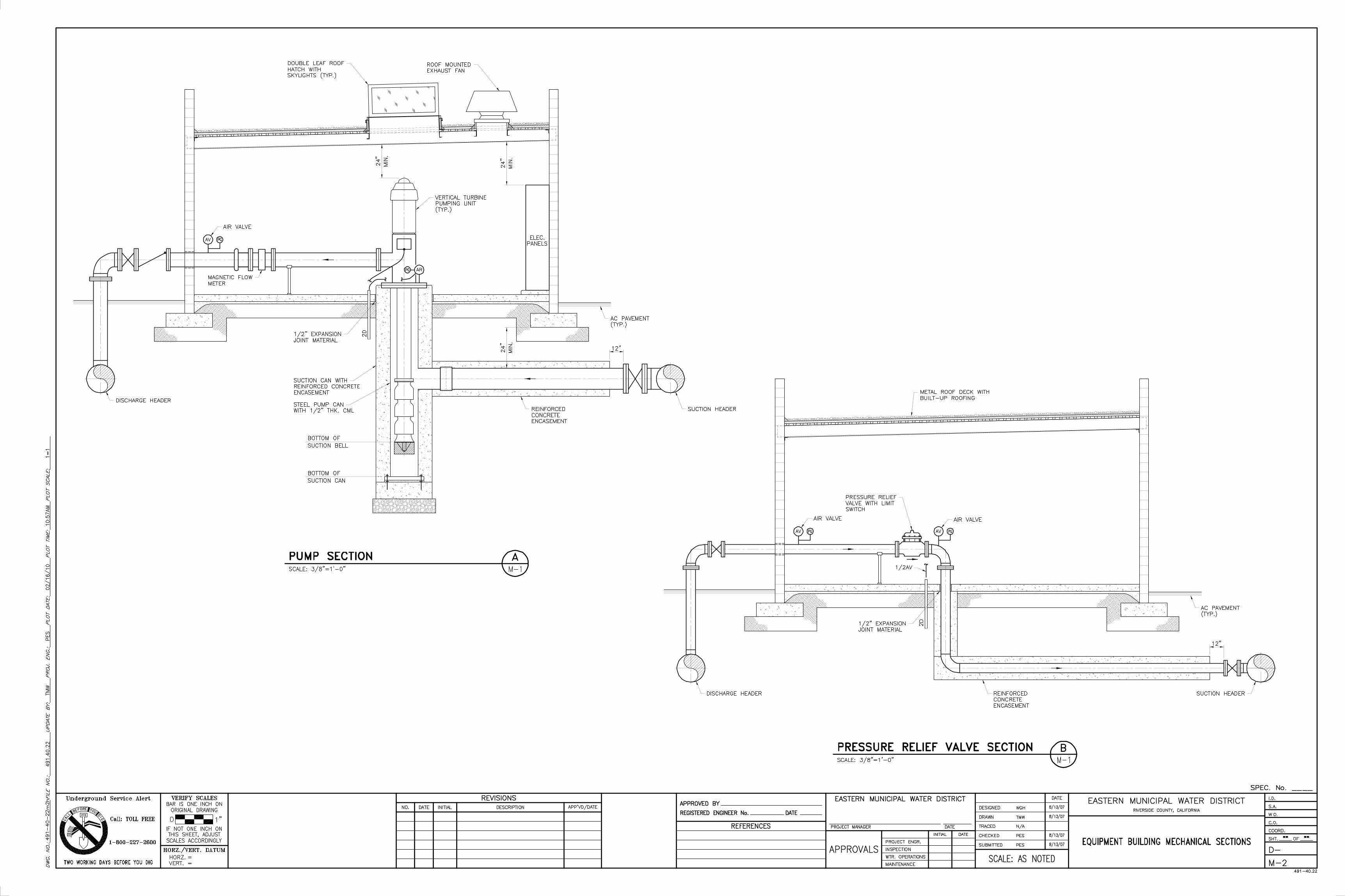

APPENDIX C HYDRO-PNEUMATIC TANK CONTROL POINTS