Attachment Q - Eastern Municipal Water District
1173
INVITATION TO PREQUALIFY PREQUALIFICATION PACKAGE PAGE 51 Attachment Q Wells 206-209 90% Specification and Construction Drawings
-
Upload
khangminh22 -
Category
Documents
-
view
0 -
download
0
Transcript of Attachment Q - Eastern Municipal Water District

INVITATION TO PREQUALIFY
PREQUALIFICATION PACKAGE PAGE 51
Attachment Q
Wells 206-209 90% Specification and Construction Drawings

[PAGE LEFT INTENTIONALLY BLANK]

Riverside County Perris, California
SPECIFICATION NO.
Wells 206, 207, 208, and 209 Equipping and Treatment Facility
Work Order #
A PUBLIC WORKS PROJECT
Contents: Specifications | Notice Inviting Bids | Bidding Requirements | Bid Forms | Contract Forms |
Conditions of Contract
Joe Mouawad, P.E. ‐ General Manager
Safety is of paramount and overriding importance to Eastern Municipal Water District
Visit our website at www.emwd.org to view currently advertised projects Navigate to Construction Construction Bid Opportunities
90% Submittal

00010‐1 Table of Contents
Bidding Requirements & General Conditions
Note: Documents in black font are required.
If applicable, use/include documents in blue font
TABLE OF CONTENTS
BIDDING REQUIREMENTS PAGE
00000 Title Page
00010 Table of Contents
00012 Notice Inviting Bids NIB‐1 thru NIB‐5
00014 Bid Opening Map
00016 Bid Walk‐thru map/directions 1 thru 2
00018 Instructions to Bidders B‐1 thru ‐6
00020 Bidding Sheets & Equipment & Material List (submit with bid) BS‐1 thru ‐19
00024 Proposal (7 day) (submit with bid) C3‐1 thru ‐2
00027 Bidder’s Experience Record & Resumes (submit with bid) BR‐1 thru ‐2
00028 Designation of Subcontractors (submit with bid) C5a thru e
00030 Contractor's Licensing Statement (submit with bid) C6‐1 thru ‐2
00032 Non‐Collusion Declaration (submit with bid) C7‐1 thru ‐2
00034 Agreement C8a thru d
00036 Performance Bond C9‐1 thru ‐4
00038 Payment Bond C10‐1 thru ‐4
00040 Bid Bond (submit with bid) BB‐1
00042 Worker’s Compensation Insurance Certificate C11‐1 thru ‐2
00044 Certificate of Insurance Sample C12
00046 Iran Contracting Act Certification (submit with bid if over $1million) C13‐1 thru ‐4
00048 Maintenance Bond (by Contractor) ‐ Pumping Equipment C14‐1 thru ‐2
00049 Maintenance Bond (by Supplier) ‐ Pumping Equipment C14.1 thru ‐2
00050 Cal‐OSHA form 300A (submit with bid) C16‐1 thru ‐2
00052 Contractor’s Cal Osha Compliance History
and SIC Code (submit with bid) C17‐1 thru ‐2
00054 Pipe Zone Density Chart C18
00056 Employee Safety & Health Training Records C19‐1 thru ‐2
00057 Contractor Registration Extract(s) (submit with bid) C22‐1 thru ‐2
00058 Contractor’s Proof of Insurance Certificate (submit with bid) C23‐1 thru ‐2
GENERAL CONDITIONS
00062 Section E, Inspection & Tests E‐1 thru E‐2
00064 Section F, Labor & Construction F‐1 thru F‐60
Includes Exhibit A – Escrow Agreement
00066 Section H, Permits H‐1 thru H‐1
90% Submittal

00010‐2 Table of Contents
SPECIAL CONDITIONS
00100 Special Conditions SC‐1 thru SC‐13
00110 Supplemental Special Conditions SSC‐1 thru SSC‐7
CONTRACT DRAWINGS
00200 Section P Standard & Construction Drawings (list) P‐1 thru P‐9
EMWD Detailed Provisions can be viewed on our website. Remove the detailed provisions from the Table
of Contents that are not applicable to this project.
EMWD DETAILED PROVISIONS
01000 General Safety Requirements 1 thru 10
01026 Schedule of Values 1 thru 10
01100 Work Restrictions and Constraints (Custom) 1 thru 5
01250 Substitution Procedures (Custom) 1 thru 3
01310 Project Control Schedule – Large Job 1 thru 14
01330 Submittal Procedures (Custom) 1 thru 11
01381 Pre‐Const. Audio Video Taping Above Ground Facilities
01400 Quality Requirements (Custom) 1 thru 10
01420 References (Custom) 1 thru 8
01430 Maintenance Manual Requirements 1 thru 10
01500 Temporary Facilities Controls
01600 Product Requirements (Custom) 1 thru 7
01730 Execution (Custom) 1 thru 12
01741 Construction Waste Management and Disposal (Custom) 1 thru 8
01770 Closeout Procedures (Custom) 1 thru 6
01783 Project Record Documents (Custom) 1 thru 4
01790 Demonstration and Training (Custom) 1 thru 6
01882 Seismic Performance Requirements (Custom) 1 thru 6
01883 Wind Performance Requirements (Custom) 1 thru 3
01910 General Commissioning Requirements (Custom) 1 thru 17
01911 Exterior Enclosure Commissioning (Custom) 1 thru 4
02201 Construction Methods and Earthwork 1 thru 26
02205 Tank Site Preparation and Base Ring Construction 1 thru 8
02210 Site Grading 1 thru 8
02221 Trenching, Backfilling, and Compacting 1 thru 10
02253 Controlled Low Strength Material 1 thru 6
02433 Drainage Pipe 1 thru 4
02444 Chain Link Fencing 1 thru 6
02505 Roadway Base Course 1 thru 4
02513 Asphalt Concrete Paving 1 thru 4
02718 Installation of Water Pipeline 1 thru 22
02762 Furnish and Install Plastic Sewer Pipe System 1 thru 14
02810 Irrigation System 1 thru 8
90% Submittal

00010‐3 Table of Contents
02813 Irrigation (Custom) 1 thru 19
02900 Landscape (Custom) 1 thru 15
02950 Trees, Plants and Ground Covers 1 thru 6
03150 Formwork for Cast‐in‐Place Concrete 1 thru 6
03200 Reinforcing 1 thru 6
03300 Cast‐in‐Place Concrete 1 thru 38
04220 Concrete Unit Masonry 1 thru 12
05100 Structural Metals 1 thru 6
05210 Steel Joist Framing (Custom) 1 thru 6
05310 Steel Decking (Custom) 1 thru 6
05502 Metal Fabrications (Custom) 1 thru 14
05519 Post‐Installed Anchors and Reinforcing Bars (Custom) 1 thru 9
05600 Standards for Aluminum Work 1 thru 8
06100 Carpentry Work 1 thru 8
06741 Fiberglass Reinforced Plastic Components (Custom) 1 thru 8
07190 Water Repellents (Custom) 1 thru 5
07210 Thermal Insulation (Custom) 1 thru 4
07412 Standing‐Seam Metal Roof Panels (Custom) 1 thru 13
07429 Soffit Panels (Custom) 1 thru 9
07710 Roof Specialties (Custom) 1 thru 11
07720 Roof Accessories (Custom) 1 thru 8
07841 Penetration Firestopping (Custom) 1 thru 7
07920 Sealants and Caulking 1 thru 6
08113 Hollow Metal Doors and Frames (Custom) 1 thru 9
08365 Rolling Service Doors 1 thru 4
08511 Aluminum Windows (Custom) 1 thru 7
08625 Tabular Daylighting Devices (Custom) 1 thru 6
08800 Glazing (Custom) 1 thru 12
08919 Fixed Louvers (Custom) 1 thru 8
08711 Locksets and Hardware 1 thru 2
09811 Chemical Resistant Coatings 1 thru 2
09871 Coating System for Water Pumping Plants 1 thru 10
09900 Painting and Protective Coatings 1 thru 48
09973 Factory Coating for Bolted Steel Tanks (Custom) 1 thru 3
10280 Toilet, Bath and Laundry Accessories (Custom) 1 thru 6
10442 Fire Extinguishers (Custom) 1 thru 3
11005 General Mechanical and Equipment Provisions 1 thru 18
11214 Hydro‐Pneumatic Surge Arrestor System (Custom) 1 thru 14
11222 Peristaltic Metering Pumps (Custom) 1 thru 20
11247 Portable Tank Mixers (Custom) 1 thru 6
11250 Granular Activated Carbon (GAC) System (Custom) 1 thru 11
11251 Granular Activated Carbon (GAC) Media (Custom) 1 thru 5
11325 Rotary‐Screw Compressors (Custom) 1 thru 12
11364 Pressure Filters (Custom) 1 thru 19
90% Submittal
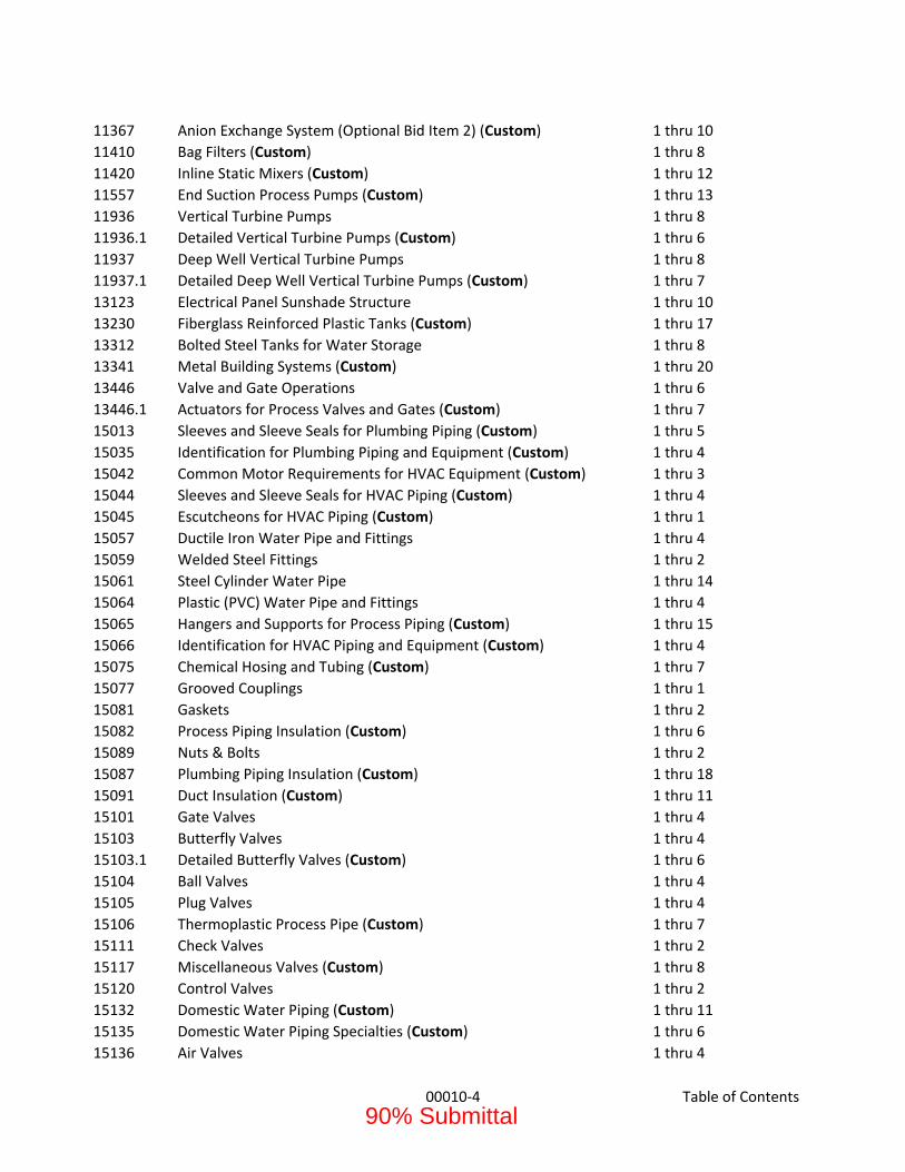
00010‐4 Table of Contents
11367 Anion Exchange System (Optional Bid Item 2) (Custom) 1 thru 10
11410 Bag Filters (Custom) 1 thru 8
11420 Inline Static Mixers (Custom) 1 thru 12
11557 End Suction Process Pumps (Custom) 1 thru 13
11936 Vertical Turbine Pumps 1 thru 8
11936.1 Detailed Vertical Turbine Pumps (Custom) 1 thru 6
11937 Deep Well Vertical Turbine Pumps 1 thru 8
11937.1 Detailed Deep Well Vertical Turbine Pumps (Custom) 1 thru 7
13123 Electrical Panel Sunshade Structure 1 thru 10
13230 Fiberglass Reinforced Plastic Tanks (Custom) 1 thru 17
13312 Bolted Steel Tanks for Water Storage 1 thru 8
13341 Metal Building Systems (Custom) 1 thru 20
13446 Valve and Gate Operations 1 thru 6
13446.1 Actuators for Process Valves and Gates (Custom) 1 thru 7
15013 Sleeves and Sleeve Seals for Plumbing Piping (Custom) 1 thru 5
15035 Identification for Plumbing Piping and Equipment (Custom) 1 thru 4
15042 Common Motor Requirements for HVAC Equipment (Custom) 1 thru 3
15044 Sleeves and Sleeve Seals for HVAC Piping (Custom) 1 thru 4
15045 Escutcheons for HVAC Piping (Custom) 1 thru 1
15057 Ductile Iron Water Pipe and Fittings 1 thru 4
15059 Welded Steel Fittings 1 thru 2
15061 Steel Cylinder Water Pipe 1 thru 14
15064 Plastic (PVC) Water Pipe and Fittings 1 thru 4
15065 Hangers and Supports for Process Piping (Custom) 1 thru 15
15066 Identification for HVAC Piping and Equipment (Custom) 1 thru 4
15075 Chemical Hosing and Tubing (Custom) 1 thru 7
15077 Grooved Couplings 1 thru 1
15081 Gaskets 1 thru 2
15082 Process Piping Insulation (Custom) 1 thru 6
15089 Nuts & Bolts 1 thru 2
15087 Plumbing Piping Insulation (Custom) 1 thru 18
15091 Duct Insulation (Custom) 1 thru 11
15101 Gate Valves 1 thru 4
15103 Butterfly Valves 1 thru 4
15103.1 Detailed Butterfly Valves (Custom) 1 thru 6
15104 Ball Valves 1 thru 4
15105 Plug Valves 1 thru 4
15106 Thermoplastic Process Pipe (Custom) 1 thru 7
15111 Check Valves 1 thru 2
15117 Miscellaneous Valves (Custom) 1 thru 8
15120 Control Valves 1 thru 2
15132 Domestic Water Piping (Custom) 1 thru 11
15135 Domestic Water Piping Specialties (Custom) 1 thru 6
15136 Air Valves 1 thru 4
90% Submittal

00010‐5 Table of Contents
15140 Hangers and Supports for Plumbing Piping and Equipment (Custom) 1 thru 10
15153 Sanitary Waste and Vent Piping (Custom) 1 thru 11
15154 Sanitary Waste Piping Specialties (Custom) 1 thru 6
15155 Sanitary Drains (Custom) 1 thru 4
15241 Facility Fuel‐Oil Piping (Custom) 1 thru 21
15273 Facility Above‐Ground Fuel‐Oil Storage Tanks (Custom) 1 thru 9
15340 Manholes and Fittings 1 thru 2
15430 Emergency Eyewash/Shower Units 1 thru 4
15421 Commercial Water Closets (Custom) 1 thru 5
15422 Commercial Urinals (Custom) 1 thru 4
15423 Commercial Lavatories (Custom) 1 thru 6
15476 Electric, Domestic‐Water Heaters (Custom) 1 thru 6
15505 Refrigerant Piping (Custom) 1 thru 6
15712 Metal Ducts (Custom) 1 thru 15
15715 Air Duct Accessories (Custom) 1 thru 8
15724 HVAC Power Ventilators (Custom) 1 thru 5
15806 Packaged Terminal A/C, Outdoor, Wall Mounted Units (Custom) 1 thru 5
15816 Split‐System Air‐Conditioners (Custom) 1 thru 5
15905 Testing, Adjusting, and Balancing for HVAC (Custom) 1 thru 11
16010 General Electrical Requirements 1 thru 28
16040 Short Circuit/Coordination Study and Arc Flash Hazard Study 1 thru 26
16050 Basic Electrical Materials and Methods 1 thru 60
16055 Control‐Voltage Electrical Power Cables (Custom) 1 thru 9
16057 Hangers and Supports for Electrical Systems (Custom) 1 thru 6
16064 Sleeves and Sleeve Seals for Electrical Raceway and Cabling (Custom) 1 thru 4
16092 Lighting Control Devices (Custom) 1 thru 10
16150 Induction Motors 1 thru 22
16151 Vertical Hollowshaft Electric Motors 1 thru 14
16160 A.C. Variable Frequency Drives 1 thru 30
16191 Low‐Voltage Transformers (Custom) 1 thru 5
16225 Low‐Voltage Transformers for Load Centers (Custom) 1 thru 3
16230 Low Voltage Switchgear (Custom) 1 thru 31
16250 Automatic Transfer Switch 1 thru 14
16273 Electrical Cabinets and Enclosures (Custom) 1 thru 3
16283 Fuses (Custom) 1 thru 4
16322 Diesel Emergency Engine Generators (Custom) 1 thru 22
16480 Motor Control Centers, Switchboards, and Panelboards 1 thru 62
16513 LED Interior Lighting (Custom) 1 thru 6
16522 Emergency and Exit Lighting (Custom) 1 thru 8
16551 Lighting Poles and Standards (Custom) 1 thru 7
16553 LED Exterior Lighting (Custom) 1 thru 8
16640 Corrosion Monitoring System for Underground Piping 1 thru 4
16600 Underground Ducts and Raceways for Electrical Systems (Custom) 1 thru 9
16890 Fiber Optic Cabling and Components 1 thru 22
90% Submittal

00010‐6 Table of Contents
16950 Custom Control Panels (Custom) 1 thru 5
16990 Commissioning of Electrical Systems (Custom) 1 thru 7
17005 General Instrumentation and Control Components 1 thru 32
17005.1 Detailed Field Instrument Schedule (Custom) 1 thru 6
17006 Configuration of HMI Software (Custom) 1 thru 10
17020 Process Control System Input‐Output List and Schedule(Custom) 1 thru 11
17030 Switches and Routers (Custom) 1 thru 7
17035 Device Network Equipment (Custom) 1 thru 5
17040 Process Control Description (Custom) 1 thru 95
17210 Magnetic Flowmeters 1 thru 10
17210.1 Detailed Magnetic Flowmeters (Custom) 1 thru 3
17220 Variable Area Flow Meters (Custom) 1 thru 4
17230 Flow Switches (Custom) 1 thru 5
17240 Multi‐Parameter Analyzer Transmitter (Custom) 1 thru 5
17250 Single Parameter Analyzer Transmitter (Custom) 1 thru 5
17260 Nitrate Analyzers (Custom) 1 thru 5
17270 pH/ORP Analyzers (Custom) 1 thru 6
17280 Chlorine Analyzers (Custom) 1 thru 5
17290 Monochloramines Analyzers (Custom) 1 thru 5
17300 Pressure and Differential Pressure Type Level Meters (Custom) 1 thru 5
17310 Site Access System 1 thru 14
APPENDICES
Appendix A Approved Materials List 1 thru 50
90% Submittal
Notice Inviting Bid
00012-1
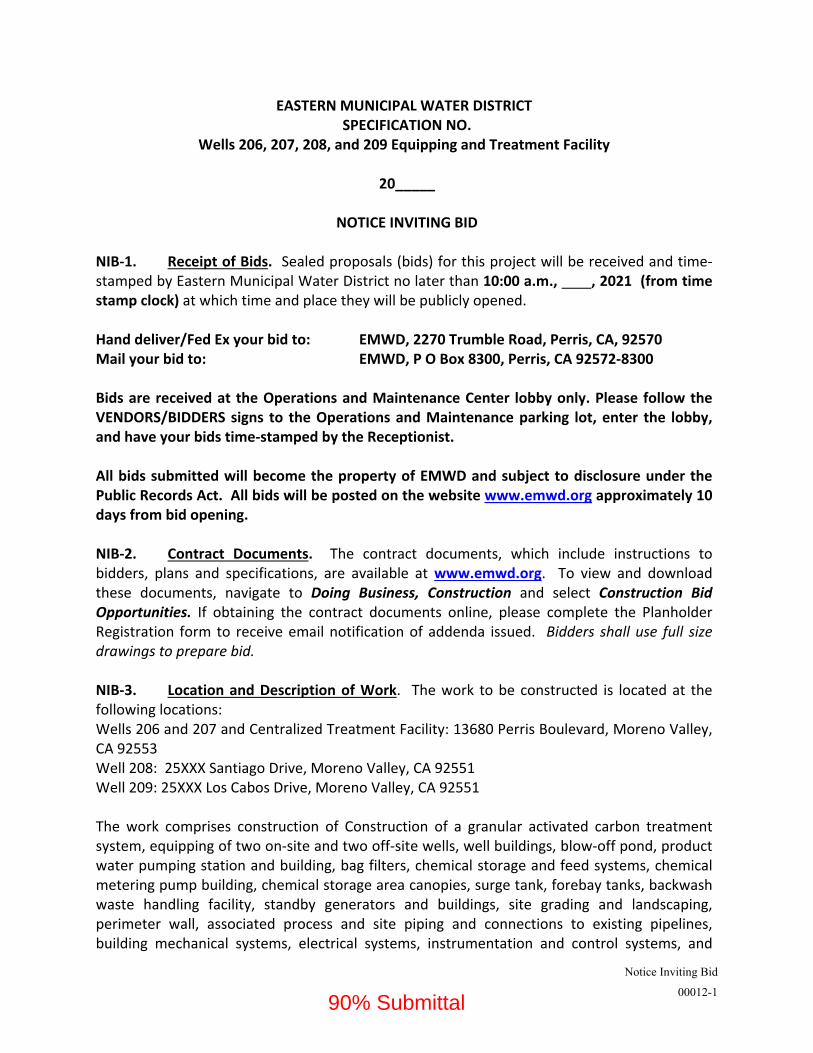
EASTERN MUNICIPAL WATER DISTRICT SPECIFICATION NO.
Wells 206, 207, 208, and 209 Equipping and Treatment Facility 20_____ NOTICE INVITING BID NIB‐1. Receipt of Bids. Sealed proposals (bids) for this project will be received and time‐stamped by Eastern Municipal Water District no later than 10:00 a.m., , 2021 (from time stamp clock) at which time and place they will be publicly opened. Hand deliver/Fed Ex your bid to: EMWD, 2270 Trumble Road, Perris, CA, 92570 Mail your bid to: EMWD, P O Box 8300, Perris, CA 92572‐8300 Bids are received at the Operations and Maintenance Center lobby only. Please follow the VENDORS/BIDDERS signs to the Operations and Maintenance parking lot, enter the lobby, and have your bids time‐stamped by the Receptionist. All bids submitted will become the property of EMWD and subject to disclosure under the Public Records Act. All bids will be posted on the website www.emwd.org approximately 10 days from bid opening. NIB‐2. Contract Documents. The contract documents, which include instructions to bidders, plans and specifications, are available at www.emwd.org. To view and download these documents, navigate to Doing Business, Construction and select Construction Bid Opportunities. If obtaining the contract documents online, please complete the Planholder Registration form to receive email notification of addenda issued. Bidders shall use full size drawings to prepare bid. NIB‐3. Location and Description of Work. The work to be constructed is located at the following locations: Wells 206 and 207 and Centralized Treatment Facility: 13680 Perris Boulevard, Moreno Valley, CA 92553 Well 208: 25XXX Santiago Drive, Moreno Valley, CA 92551 Well 209: 25XXX Los Cabos Drive, Moreno Valley, CA 92551 The work comprises construction of Construction of a granular activated carbon treatment system, equipping of two on‐site and two off‐site wells, well buildings, blow‐off pond, product water pumping station and building, bag filters, chemical storage and feed systems, chemical metering pump building, chemical storage area canopies, surge tank, forebay tanks, backwash waste handling facility, standby generators and buildings, site grading and landscaping, perimeter wall, associated process and site piping and connections to existing pipelines, building mechanical systems, electrical systems, instrumentation and control systems, and
90% Submittal

Notice Inviting Bid
00012-2
other Work indicated in the Contract Documents. NIB‐4. Mandatory Pre‐Bid Walk‐Through will be conducted by EMWD on , 2021 at 9:00 a.m., meeting at 13680 Perris Boulevard, Moreno Valley, CA 92553. Please arrive promptly! All bidders must have an employee of their firm sign‐in and attend the mandatory pre‐bid walk‐through meeting. Failure to do so shall deem your bid non‐responsive. Personal Protective Equipment (PPE). For your safety, attendees shall bring and wear face masks, hard hats, safety vests, and close‐toed shoes. QUESTIONS: All questions must be submitted in writing by 5:00 p.m. on _________ to Mr. Greg Kolwalski c/o CAR name here; EMAIL: [email protected] & [email protected]. Questions received after this time may not be responded to. NIB‐5. Contract Bonds. All bonds shall be executed by admitted surety insurers, as defined in Code of Civil Procedure section 995.120. Each proposal must be accompanied by a certified check or satisfactory surety bond (by utilizing the District’s Bid Bond form BB‐1) for not less than 10% of the bidder's total contract price as a guarantee that the bidder shall, within seven (7) days after the mailing of a notice of acceptance of bid by the District to the bidder, enter into the written contract supplied by the District. The District shall return the bid bond, upon request. The Contractor shall furnish a faithful performance bond in an amount equal to 100% of the amount of the contract and a labor payment bond in an amount equal to 100% of the contract amount. Pursuant to Section 995.660(a) of the Code of Civil Procedure, the Contractor shall submit the following documents with the performance and payment bonds:
(1) The original, or a certified copy, of the unrevoked appointment, power of attorney, bylaws, or other instrument entitling or authorizing the person who executed the bond to do so;
(2) A certified copy of the certificate of authority of the insurer issued by the State of California’s Insurance Commissioner; and
(3) Copies of the insurer's most recent annual and quarterly statements filed with the Department of Insurance.
NO PAYMENT SHALL BE MADE UNTIL THE BONDS ARE APPROVED BY THE DISTRICT NIB‐6. Safety. Safety of all activities in connection with the work is of paramount and overriding importance to the District. The District is recognized by the California Occupational Safety and Health Administration (Cal OSHA) as an active participant in the California Voluntary Protection Program (Cal VPP). The District is designated a Cal STAR site due to our high‐level
90% Submittal
Notice Inviting Bid
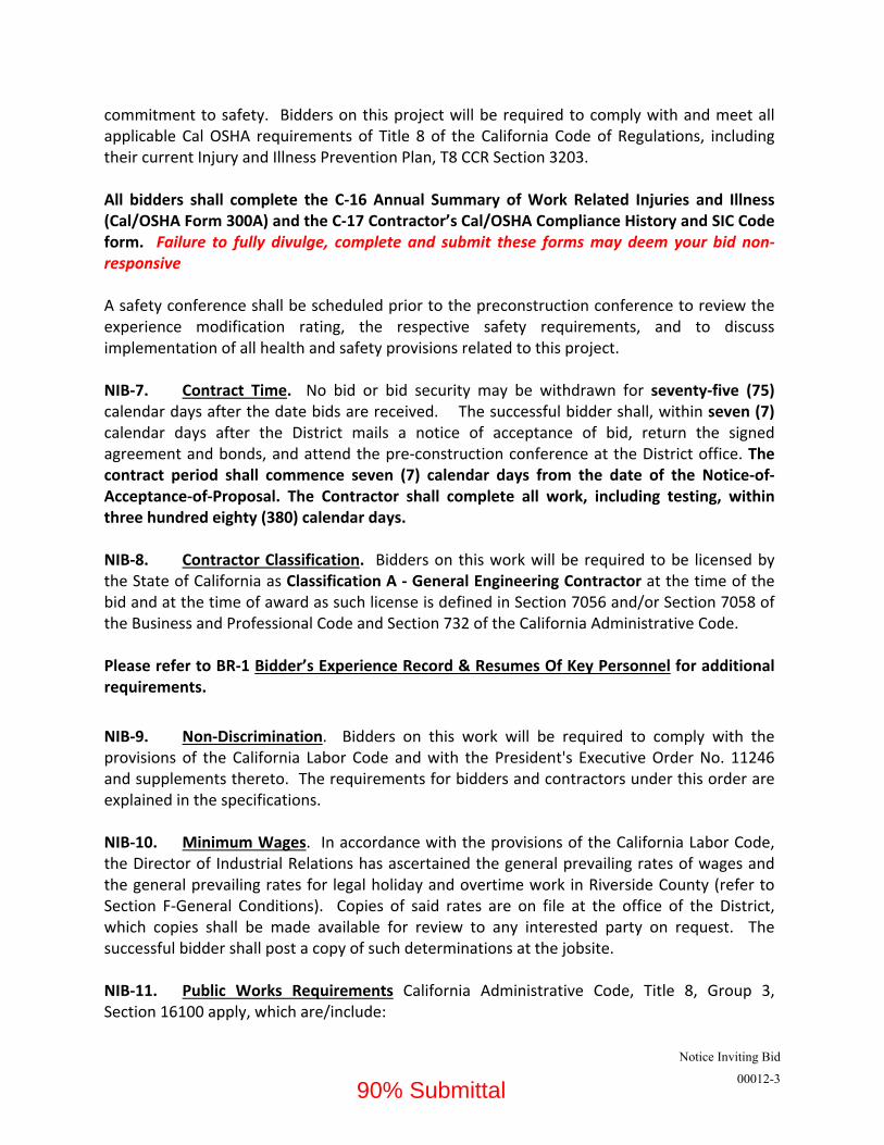
00012-3
commitment to safety. Bidders on this project will be required to comply with and meet all applicable Cal OSHA requirements of Title 8 of the California Code of Regulations, including their current Injury and Illness Prevention Plan, T8 CCR Section 3203. All bidders shall complete the C‐16 Annual Summary of Work Related Injuries and Illness (Cal/OSHA Form 300A) and the C‐17 Contractor’s Cal/OSHA Compliance History and SIC Code form. Failure to fully divulge, complete and submit these forms may deem your bid non‐responsive A safety conference shall be scheduled prior to the preconstruction conference to review the experience modification rating, the respective safety requirements, and to discuss implementation of all health and safety provisions related to this project. NIB‐7. Contract Time. No bid or bid security may be withdrawn for seventy‐five (75) calendar days after the date bids are received. The successful bidder shall, within seven (7) calendar days after the District mails a notice of acceptance of bid, return the signed agreement and bonds, and attend the pre‐construction conference at the District office. The contract period shall commence seven (7) calendar days from the date of the Notice‐of‐Acceptance‐of‐Proposal. The Contractor shall complete all work, including testing, within three hundred eighty (380) calendar days.
NIB‐8. Contractor Classification. Bidders on this work will be required to be licensed by the State of California as Classification A ‐ General Engineering Contractor at the time of the bid and at the time of award as such license is defined in Section 7056 and/or Section 7058 of the Business and Professional Code and Section 732 of the California Administrative Code.
Please refer to BR‐1 Bidder’s Experience Record & Resumes Of Key Personnel for additional requirements.
NIB‐9. Non‐Discrimination. Bidders on this work will be required to comply with the provisions of the California Labor Code and with the President's Executive Order No. 11246 and supplements thereto. The requirements for bidders and contractors under this order are explained in the specifications. NIB‐10. Minimum Wages. In accordance with the provisions of the California Labor Code, the Director of Industrial Relations has ascertained the general prevailing rates of wages and the general prevailing rates for legal holiday and overtime work in Riverside County (refer to Section F‐General Conditions). Copies of said rates are on file at the office of the District, which copies shall be made available for review to any interested party on request. The successful bidder shall post a copy of such determinations at the jobsite. NIB‐11. Public Works Requirements California Administrative Code, Title 8, Group 3, Section 16100 apply, which are/include:
90% Submittal

Notice Inviting Bid
00012-4
A. all applicable requirements of sections 1771, 1774 ‐ 1776, 1813, and 1815.
B. the appropriate number of apprentices are on the job site, as set forth in Labor Code Section 1777.5.
C. workers' compensation coverage, set forth in Labor Code Sections 1860 and 1861.
D. to keep accurate records of the work performed on the public works project, as set forth in Labor Code Section 1812.
E. inspection of payroll records pursuant to Labor Code Section 1776, and as set forth in Section 16400 (e) of these regulations.
F. and other requirements imposed by law.
NIB‐12. Public Works Contractor and Subcontractor Registration. This project is subject to compliance monitoring and enforcement by the Department of Industrial Relations.
No contractor or subcontractor may be listed on a bid proposal or be awarded a contract for a public works project unless registered with the Department of Industrial Relations pursuant to Labor Code section 1725.5 [with limited exceptions from this requirement for bid purposes only under Labor Code section 1771.1(a)].
BIDDERS AND THEIR SUBCONTRACTORS (listed on the Designation of Subcontractors List C‐05) are to provide an extract (pdf or excel) at time of bid showing active registration from the Public Works Contractor Registration online registration at: https://cadir.secure.force.com/ContractorSearch
All contractors and subcontractors, including soils, survey and inspection services must furnish electronic certified payroll records directly to the Labor Commissioner (aka Division of Labor Standards Enforcement). Additionally, the awarded Contractor shall submit certified payroll records to the District. In addition, awarded Contractor must post jobsite notices prescribed by regulations. NIB‐13. Ineligibility of Contractor or Subcontractor. Pursuant to Section 1777.1 and 1777.7 of the Labor Code, any contractor or subcontractor who is found by the Labor Commissioner to be in violation of certain provisions of law and is debarred for a specific period of time, is ineligible to bid or work on, or be awarded, a public works contract. NIB‐14. Substitution of Securities. Substitution of securities shall be permitted for any monies withheld to ensure contract performance, in accordance with the provisions of law and Section F‐General Conditions of the contract specifications. NIB‐15. No Equal Clause. The application of California Public Contract Code Section 3400 (b) applies. The District’s Board of Directors has authorized the General Manager to approve
90% Submittal

Notice Inviting Bid
00012-5
purchase and installation of certain equipment, material and services which has been designated sole‐sourced and as no‐equal in order to match other equipment and services already completed or in the course of construction. NIB‐16. Covid‐19 Special Notice. By submitting a Bid for this work, Bidder agrees to proceed with the work as proposed and to execute the contract in the form provided. Any conditions, caveats, or force majeure notices submitted with a bid will not be accepted and may result in a determination that the bid is non‐responsive. Any such conditions, caveats, or notices submitted after award may result in the forfeiture of Bidder’s bid security and award to the next lowest bidder. Bidders shall comply with all governmental requirements for safety during the COVID‐19 pandemic, including but not limited to orders and guidance of the California Department of Public Health, orders and guidelines of Cal/OSHA, and orders of the public health officer of the County of Riverside. The costs of adhering to and complying with such COVID‐19 safety measures shall be the responsibility of the bidders and shall be included and incorporated into their respective bid amounts. NIB‐17. Funding Program. This project is subject to requirements funded under the State Water Resources Control Board (SWRCB) Proposition 1 Groundwater Grant Program. Bidders shall follow the guidelines included in the Appendix A.
NIB‐18. Debarment and Suspension (2 CFR Part 1400). The Department of the Interior regulations at 2 CFR Part 1400—Nonprocurement Debarment and Suspension (Non‐procurement), which adopt the common rule for the government‐wide system of debarment and suspension for non‐procurement activities, are hereby incorporated by reference and made a part of this Agreement. By entering into this Agreement with the District, Contractor hereby certifies that they are not presently debarred, suspended, proposed for debarment, declared ineligible, or voluntarily excluded from covered transitions by any federal department or agency. (C‐08 Agreement to include this provision) Also include: Davis‐Bacon, Contract Provisions, DBE Good Faith Efforts, if applicable per the funding agreement.
Eastern Municipal Water District
Joe E. Mouawad, P.E. General Manager
Official Bid Publication: EMWD Website (www.emwd.org) Posted date:
90% Submittal
Pre-Bid Walk-thru Map and Directions
00016-1
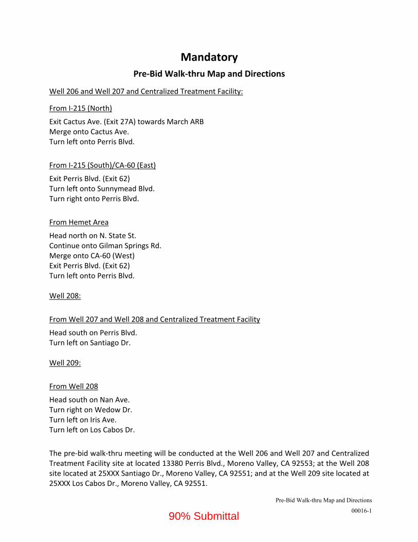
Mandatory
Pre‐Bid Walk‐thru Map and Directions
Well 206 and Well 207 and Centralized Treatment Facility:
From I‐215 (North)
Exit Cactus Ave. (Exit 27A) towards March ARB Merge onto Cactus Ave. Turn left onto Perris Blvd.
From I‐215 (South)/CA‐60 (East)
Exit Perris Blvd. (Exit 62) Turn left onto Sunnymead Blvd. Turn right onto Perris Blvd.
From Hemet Area
Head north on N. State St. Continue onto Gilman Springs Rd. Merge onto CA‐60 (West) Exit Perris Blvd. (Exit 62) Turn left onto Perris Blvd. Well 208:
From Well 207 and Well 208 and Centralized Treatment Facility
Head south on Perris Blvd. Turn left on Santiago Dr. Well 209:
From Well 208
Head south on Nan Ave. Turn right on Wedow Dr. Turn left on Iris Ave. Turn left on Los Cabos Dr.
The pre‐bid walk‐thru meeting will be conducted at the Well 206 and Well 207 and Centralized Treatment Facility site at located 13380 Perris Blvd., Moreno Valley, CA 92553; at the Well 208 site located at 25XXX Santiago Dr., Moreno Valley, CA 92551; and at the Well 209 site located at 25XXX Los Cabos Dr., Moreno Valley, CA 92551.
90% Submittal

Pre
-Bid
Wal
k-th
ru M
ap a
nd D
irec
tion
s
0001
6-2
90%
Sub
mitt
al

Bidding Sheets & Equipment & Material List
00020-1
EASTERN MUNICIPAL WATER DISTRICT SPECIFICATION NO. XXX
WELLS 206, 207, 208, AND 209 EQUIPPING AND TREATMENT FACILITY BIDDING SHEETS The Contractor shall construct the project under these Specifications all in conformance with the Contract Drawings listed in Section P and these Specifications. The District reserves the right to:
A. Accept or reject any or all bids on this specification; B. Award Contract to the lowest qualified bidder, based on the total bid price: C. Waive any defects and informalities.
The District shall be the final authority with regard to whether a bid is responsive to the call for bids and to whether a bidder is a responsible bidder under the conditions of his bid, or for any reason. The total contract price shall include all work, materials and equipment needed to complete the project as defined in the General Conditions, Section F. The bidder shall include costs for such other items in the most appropriate category (bid item).
90% Submittal

EASTERN MUNICIPAL WATER DISTRICT SPECIFICATION NO.
WELLS 206, 207, 208, AND 209 EQUIPPING AND TREATMENT FACILITY
BIDDING SHEETS
Bidding Sheets & Equipment & Material List
00020-2
Bid Item Qty Units
Description (Unit Prices Written in Words)
Unit Price (Figures)
Total Amount (Figures)
1 1 LS Mobilization and Approved: Bonds, Insurance, and Schedule of Values (see Section 01026) and Preliminary Project Schedule (PPS) (see section 01310)
5% of Engineer’s Estimate In Words $
PRESET
$
5% amt here
(words) 2 1 LS Centralized Treatment Facility Site Work:
Furnish and install: Gravel base cover, concrete pads, below‐grade piping (up to connection with process piping), product water forebay tank overflow piping, backwash holding tank overflow piping, product water forebay inlet and outlet piping, backwash holding tank inlet and outlet piping, valves and appurtenances, shoring, excavation, bedding, backfill, pavement removal, pavement replacement, perimeter wall, perimeter fencing, access gates, landscaping, disinfection of piping, trench and pipeline dewatering, connections to existing piping, painting and coating; electrical work, site and exterior lighting, conduit, wiring and connections; all labor, materials and equipment, as shown on the Contract Drawings and Specifications complete and in place.
$
Lump Sum $
(words) 3 1 LS Well 208 Site Work:
Furnish and install: Gravel base cover, concrete pads, below‐grade piping (up to connection with process piping), shoring, excavation, bedding,
90% Submittal

EASTERN MUNICIPAL WATER DISTRICT SPECIFICATION NO.
WELLS 206, 207, 208, AND 209 EQUIPPING AND TREATMENT FACILITY
BIDDING SHEETS
Bidding Sheets & Equipment & Material List
00020-3
Bid Item Qty Units
Description (Unit Prices Written in Words)
Unit Price (Figures)
Total Amount (Figures)
backfill, paving, perimeter wall, perimeter fencing, access gates, landscaping, disinfection of piping, trench and pipeline dewatering, connections to existing piping, painting and coating; electrical work, site and exterior lighting, conduit, wiring and connections; all labor, materials and equipment, as shown on the Contract Drawings and Specifications complete and in place.
$
Lump Sum $
(words) 4 1 LS Well 209 Site Work:
Furnish and install: Gravel base cover, concrete pads, concrete walkway, below‐grade piping (up to connection with process piping), shoring, excavation, bedding, backfill, landscape restoration, disinfection of piping, trench and pipeline dewatering, connections to existing piping, painting and coating; electrical work, exterior lighting, conduit, wiring and connections; all labor, materials and equipment, as shown on the Contract Drawings and Specifications complete and in place.
$
Lump Sum $
(words) 5 1 LS GAC Vessels:
Receive, unload, and install: Three (3) separate trains of two (2) vessels and all associated piping within or on the vessels and vessel valve trees (valve manifolds), instruments, appurtenances, motorized flow control valves, backwash supply
90% Submittal

EASTERN MUNICIPAL WATER DISTRICT SPECIFICATION NO.
WELLS 206, 207, 208, AND 209 EQUIPPING AND TREATMENT FACILITY
BIDDING SHEETS
Bidding Sheets & Equipment & Material List
00020-4
Bid Item Qty Units
Description (Unit Prices Written in Words)
Unit Price (Figures)
Total Amount (Figures)
system including piping, valves, pressure reducing valve, motorized valve, and flow meter; electrical work, painting and coating, disinfection, testing and startup, all labor, materials, and equipment; as shown on the Contract Drawings and Specifications complete and in place.
$
Lump Sum
$
(words) 6 1 LS Product Water Forebay and Backwash Holding
Tanks: Furnish and install: Bolted steel tanks, all associated valves and appurtenance, access ladders and fall protection, platforms and railing, forebay tank mixers, instruments, electrical work, painting and coating, disinfection, testing, all labor, materials, and equipment; as shown on the Contract Drawings and Specifications complete and in place.
$
Lump Sum $
(words) 7 1 LS Backwash Handling System:
Furnish and install: Piping, valves and appurtenances, two (2) bag filters, two (2) end suction process pumps, electrical work, variable frequency drives, painting and coating, startup and testing, all labor, materials, and equipment; as shown on the Contract Drawings and Specifications complete and in place.
90% Submittal
EASTERN MUNICIPAL WATER DISTRICT SPECIFICATION NO.
WELLS 206, 207, 208, AND 209 EQUIPPING AND TREATMENT FACILITY
BIDDING SHEETS
Bidding Sheets & Equipment & Material List
00020-5
Bid Item Qty Units
Description (Unit Prices Written in Words)
Unit Price (Figures)
Total Amount (Figures)
$
Lump Sum $
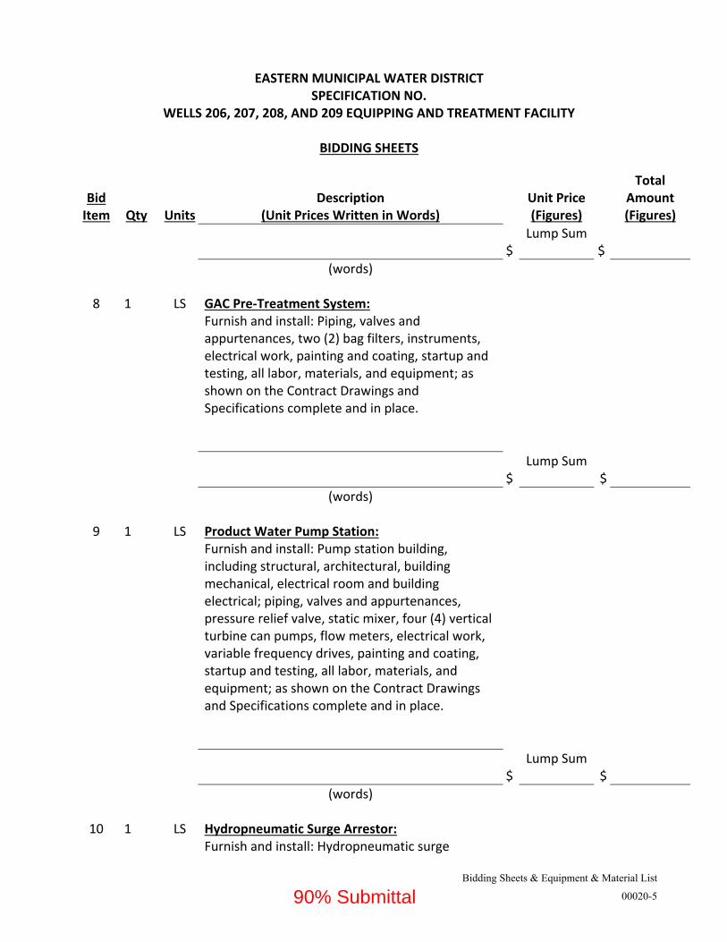
(words) 8 1 LS GAC Pre‐Treatment System:
Furnish and install: Piping, valves and appurtenances, two (2) bag filters, instruments, electrical work, painting and coating, startup and testing, all labor, materials, and equipment; as shown on the Contract Drawings and Specifications complete and in place.
$
Lump Sum $
(words) 9 1 LS Product Water Pump Station:
Furnish and install: Pump station building, including structural, architectural, building mechanical, electrical room and building electrical; piping, valves and appurtenances, pressure relief valve, static mixer, four (4) vertical turbine can pumps, flow meters, electrical work, variable frequency drives, painting and coating, startup and testing, all labor, materials, and equipment; as shown on the Contract Drawings and Specifications complete and in place.
$
Lump Sum $
(words)
10 1 LS Hydropneumatic Surge Arrestor: Furnish and install: Hydropneumatic surge
90% Submittal

EASTERN MUNICIPAL WATER DISTRICT SPECIFICATION NO.
WELLS 206, 207, 208, AND 209 EQUIPPING AND TREATMENT FACILITY
BIDDING SHEETS
Bidding Sheets & Equipment & Material List
00020-6
Bid Item Qty Units
Description (Unit Prices Written in Words)
Unit Price (Figures)
Total Amount (Figures)
arrestor tank and appurtenances, piping, valves and appurtenances, instruments, two (2) air compressors and motors, one (1) air receiver, air treatment equipment and appurtenances, electrical work, painting and coating, startup and testing, all labor, materials, and equipment; as shown on the Contract Drawings and Specifications complete and in place.
$
Lump Sum $
(words)
11 1 LS Chemical Storage and Feed: Furnish and install: Chemical canopy and facility building including structural, architectural, building mechanical, mechanical room, restroom, and building electrical; water heater, plumbing fixtures, plumbing piping, valves, and appurtenances; chemical containment area and canopy, chemical storage tanks and appurtenances, peristaltic metering pumps and appurtenances, piping, valves, and appurtenances, instruments, electrical work, painting and coating, startup and testing, all labor, materials, and equipment; as shown on the Contract Drawings and Specifications complete and in place.
$
Lump Sum $
(words)
12 1 LS Inline Blending Station:
90% Submittal
EASTERN MUNICIPAL WATER DISTRICT SPECIFICATION NO.
WELLS 206, 207, 208, AND 209 EQUIPPING AND TREATMENT FACILITY
BIDDING SHEETS
Bidding Sheets & Equipment & Material List
00020-7
Bid Item Qty Units
Description (Unit Prices Written in Words)
Unit Price (Figures)
Total Amount (Figures)
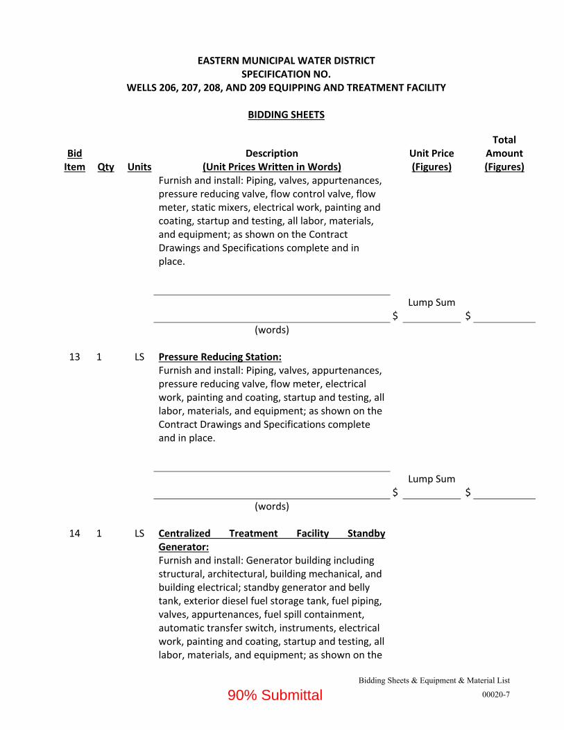
Furnish and install: Piping, valves, appurtenances, pressure reducing valve, flow control valve, flow meter, static mixers, electrical work, painting and coating, startup and testing, all labor, materials, and equipment; as shown on the Contract Drawings and Specifications complete and in place.
$
Lump Sum $
(words)
13 1 LS Pressure Reducing Station: Furnish and install: Piping, valves, appurtenances, pressure reducing valve, flow meter, electrical work, painting and coating, startup and testing, all labor, materials, and equipment; as shown on the Contract Drawings and Specifications complete and in place.
$
Lump Sum $
(words)
14 1 LS Centralized Treatment Facility Standby Generator: Furnish and install: Generator building including structural, architectural, building mechanical, and building electrical; standby generator and belly tank, exterior diesel fuel storage tank, fuel piping, valves, appurtenances, fuel spill containment, automatic transfer switch, instruments, electrical work, painting and coating, startup and testing, all labor, materials, and equipment; as shown on the
90% Submittal

EASTERN MUNICIPAL WATER DISTRICT SPECIFICATION NO.
WELLS 206, 207, 208, AND 209 EQUIPPING AND TREATMENT FACILITY
BIDDING SHEETS
Bidding Sheets & Equipment & Material List
00020-8
Bid Item Qty Units
Description (Unit Prices Written in Words)
Unit Price (Figures)
Total Amount (Figures)
Contract Drawings and Specifications complete and in place.
$
Lump Sum $
(words)
15 1 LS Well 206 Equipping: Furnish and install: Well pump building including structural, architectural, building mechanical, and building electrical; piping, valves, appurtenances, motorized valves, flow meter, deep well vertical turbine pump, variable frequency drive, electrical work, painting and coating, startup and testing, all labor, materials, and equipment; as shown on the Contract Drawings and Specifications complete and in place.
$
Lump Sum $
(words)
16 1 LS Well 207 Equipping: Furnish and install: Well pump building including structural, architectural, building mechanical, electrical room, and building electrical; piping, valves, appurtenances, motorized valves, flow meter, deep well vertical turbine pump, variable frequency drive, electrical work, painting and coating, startup and testing, all labor, materials, and equipment; as shown on the Contract Drawings and Specifications complete and in place.
90% Submittal

EASTERN MUNICIPAL WATER DISTRICT SPECIFICATION NO.
WELLS 206, 207, 208, AND 209 EQUIPPING AND TREATMENT FACILITY
BIDDING SHEETS
Bidding Sheets & Equipment & Material List
00020-9
Bid Item Qty Units
Description (Unit Prices Written in Words)
Unit Price (Figures)
Total Amount (Figures)
$
Lump Sum $
(words)
17 1 LS Well 208 Equipping: Furnish and install: Well pump building including structural, architectural, building mechanical, standby generator room, electrical room, and building electrical; piping, valves, appurtenances, motorized valves, flow meter, deep well vertical turbine pump, variable frequency drive, standby generator with belly tank, exterior fuel tank, fuel piping and valves, fuel spill containment, automatic transfer switch, electrical work, painting and coating, startup and testing, all labor, materials, and equipment; as shown on the Contract Drawings and Specifications complete and in place.
$
Lump Sum $
(words)
18 1 LS Well 209 Equipping: Furnish and install: Well pump building including structural, architectural, mechanical room, building mechanical, electrical room, electrical closet, and building electrical; piping, valves, appurtenances, motorized valves, flow meter, deep well vertical turbine pump, variable frequency drive, electrical work, painting and coating, startup and testing, all labor, materials, and equipment; as shown on the Contract Drawings and Specifications complete and in
90% Submittal

EASTERN MUNICIPAL WATER DISTRICT SPECIFICATION NO.
WELLS 206, 207, 208, AND 209 EQUIPPING AND TREATMENT FACILITY
BIDDING SHEETS
Bidding Sheets & Equipment & Material List
00020-10
Bid Item Qty Units
Description (Unit Prices Written in Words)
Unit Price (Figures)
Total Amount (Figures)
place.
$
Lump Sum $
(words)
19 1 LS Instrumentation and Controls: Furnish and install: Instrumentation (not provided with a vendor package), programmable logic controllers (PLCs), input/output (I/O), human machine interfaces, networking switches and equipment, communications equipment, wiring and cabling, control panel and PLC enclosures, uninterruptible power supplies, electrical work, startup and testing, all labor, materials, and equipment; as shown on the Contract Drawings and Specifications complete and in place.
$
Lump Sum $
(words)
20 1 LS ADDITION OR DEDUCTION Circle one (If applicable):
Addition (+)
Deduction(‐)
$
(words)
TOTAL BASE BID (Basis of award)
$________________________
90% Submittal
EASTERN MUNICIPAL WATER DISTRICT SPECIFICATION NO.
WELLS 206, 207, 208, AND 209 EQUIPPING AND TREATMENT FACILITY
BIDDING SHEETS
Bidding Sheets & Equipment & Material List
00020-11
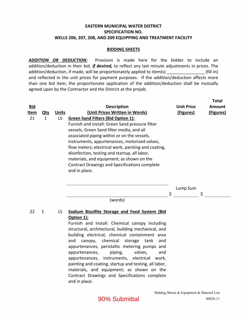
ADDITION OR DEDUCTION: Provision is made here for the bidder to include an addition/deduction in their bid, if desired, to reflect any last minute adjustments in prices. The addition/deduction, if made, will be proportionately applied to item(s) (fill in) and reflected in the unit prices for payment purposes. If the addition/deduction affects more than one bid item, the proportionate application of the addition/deduction shall be mutually agreed upon by the Contractor and the District at the prejob.
Bid Item Qty Units
Description (Unit Prices Written in Words)
Unit Price (Figures)
Total Amount (Figures)
21 1 LS Green Sand Filters (Bid Option 1): Furnish and install: Green Sand pressure filter vessels, Green Sand filter media, and all associated piping within or on the vessels, instruments, appurtenances, motorized valves, flow meters; electrical work, painting and coating, disinfection, testing and startup, all labor, materials, and equipment; as shown on the Contract Drawings and Specifications complete and in place.
$
Lump Sum $
(words)
22 1 LS Sodium Bisulfite Storage and Feed System (Bid Option 1): Furnish and install: Chemical canopy including structural, architectural, building mechanical, and building electrical; chemical containment area and canopy, chemical storage tank and appurtenances, peristaltic metering pumps and appurtenances, piping, valves, and appurtenances, instruments, electrical work, painting and coating, startup and testing, all labor, materials, and equipment; as shown on the Contract Drawings and Specifications complete and in place.
90% Submittal

EASTERN MUNICIPAL WATER DISTRICT SPECIFICATION NO.
WELLS 206, 207, 208, AND 209 EQUIPPING AND TREATMENT FACILITY
BIDDING SHEETS
Bidding Sheets & Equipment & Material List
00020-12
$
Lump Sum
$
(words)
23 1 LS Sodium Hypochlorite Feed System (Bid Option 1): Furnish and install: Peristaltic metering pumps and appurtenances, piping, valves, and appurtenances, instruments, electrical work, painting and coating, startup and testing, all labor, materials, and equipment; as shown on the Contract Drawings and Specifications complete and in place.
$
Lump Sum
$
(words)
24 1 LS ADDITION OR DEDUCTION Circle one (If applicable):
Addition (+)
Deduction(‐)
$
(words)
TOTAL BID OPTION 1
$________________________
Bid Item Qty Units
Description (Unit Prices Written in Words)
Unit Price (Figures)
Total Amount (Figures)
25 1 LS Non‐Regenerable Ion Exchange Vessels (Bid Option 2): Receive, unload, and install: Two (2) separate
90% Submittal
EASTERN MUNICIPAL WATER DISTRICT SPECIFICATION NO.
WELLS 206, 207, 208, AND 209 EQUIPPING AND TREATMENT FACILITY
BIDDING SHEETS
Bidding Sheets & Equipment & Material List
00020-13
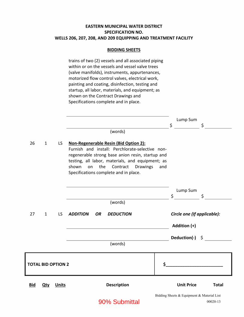
trains of two (2) vessels and all associated piping within or on the vessels and vessel valve trees (valve manifolds), instruments, appurtenances, motorized flow control valves, electrical work, painting and coating, disinfection, testing and startup, all labor, materials, and equipment; as shown on the Contract Drawings and Specifications complete and in place.
$
Lump Sum $
(words)
26 1 LS Non‐Regenerable Resin (Bid Option 2): Furnish and install: Perchlorate‐selective non‐regenerable strong base anion resin, startup and testing, all labor, materials, and equipment; as shown on the Contract Drawings and Specifications complete and in place.
$
Lump Sum $
(words)
27 1 LS ADDITION OR DEDUCTION Circle one (If applicable):
Addition (+)
Deduction(‐)
$
(words)
TOTAL BID OPTION 2
$________________________
Bid Qty Units Description Unit Price Total
90% Submittal

EASTERN MUNICIPAL WATER DISTRICT SPECIFICATION NO.
WELLS 206, 207, 208, AND 209 EQUIPPING AND TREATMENT FACILITY
BIDDING SHEETS
Bidding Sheets & Equipment & Material List
00020-14
Item (Unit Prices Written in Words) (Figures) Amount (Figures)
28 1 LS Regenerable Ion Treatment System (Bid Option 3): Receive, unload, and install: Staggered bed ion exchange system and all associated piping, instruments, appurtenances, motorized valves, electrical work, painting and coating, disinfection, testing and startup, all labor, materials, and equipment; as shown on the Contract Drawings and Specifications complete and in place.
$
Lump Sum $
(words)
29 1 LS Ion Exchange Treatment Building (Bid Option 3): Furnish and install: Ion exchange treatment building, including structural, architectural, building mechanical, electrical room and building electrical, painting and coating, testing, all labor, materials, and equipment; as shown on the Contract Drawings and Specifications complete and in place.
$
Lump Sum $
(words)
30 1 LS Regenerable Ion Exchange Process Tanks and Pumps (Bid Option 3): Furnish and install: FRP tank(s), brine pumps, backwash/displacement pumps, rinse pumps, piping, valves, instruments, appurtenances, electrical work, painting and coating, startup and testing, all labor, materials, and equipment; as shown on the Contract Drawings and Specifications complete and in place.
90% Submittal

EASTERN MUNICIPAL WATER DISTRICT SPECIFICATION NO.
WELLS 206, 207, 208, AND 209 EQUIPPING AND TREATMENT FACILITY
BIDDING SHEETS
Bidding Sheets & Equipment & Material List
00020-15
$
Lump Sum $
(words)
31 1 LS Ion Exchange Regeneration System (Bid Option 3): Furnish and install: FRP brine making tanks, piping, valves, instruments, appurtenances, electrical work, painting and coating, startup and testing, all labor, materials, and equipment; as shown on the Contract Drawings and Specifications complete and in place.
$
Lump Sum $
(words)
32 1 LS Regenerable Ion Exchange Brine Waste System (Bid Option 3): Furnish and install: FRP tanks, FRP end suction pumps, piping, valves, instruments, appurtenances, electrical work, painting and coating, startup and testing, all labor, materials, and equipment; as shown on the Contract Drawings and Specifications complete and in place.
$
Lump Sum $
(words)
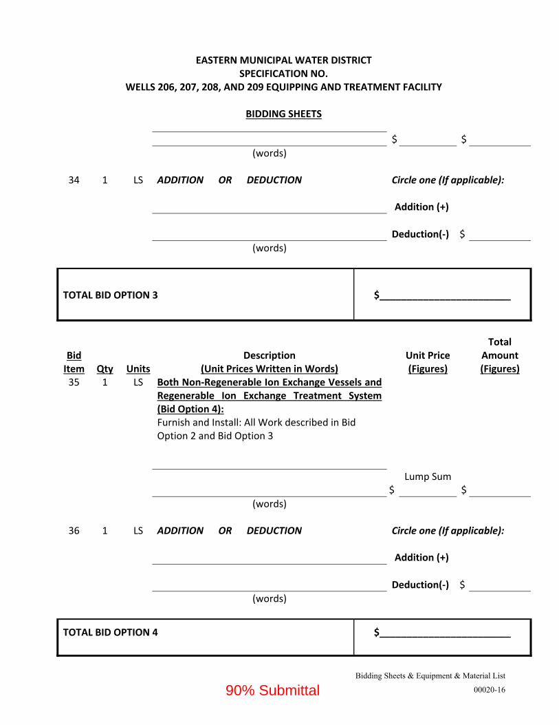
33 1 LS Regenerable Ion Exchange Resin (Bid Option 3): Furnish and install: Strong base anion exchange resin, startup and testing, all labor, materials, and equipment; as shown on the Contract Drawings and Specifications complete and in place.
Lump Sum
90% Submittal
EASTERN MUNICIPAL WATER DISTRICT SPECIFICATION NO.
WELLS 206, 207, 208, AND 209 EQUIPPING AND TREATMENT FACILITY
BIDDING SHEETS
Bidding Sheets & Equipment & Material List
00020-16
$ $
(words)
34 1 LS ADDITION OR DEDUCTION Circle one (If applicable):
Addition (+)
Deduction(‐)
$
(words)
TOTAL BID OPTION 3
$________________________
Bid Item Qty Units
Description (Unit Prices Written in Words)
Unit Price (Figures)
Total Amount (Figures)
35 1 LS Both Non‐Regenerable Ion Exchange Vessels and Regenerable Ion Exchange Treatment System (Bid Option 4): Furnish and Install: All Work described in Bid Option 2 and Bid Option 3
$
Lump Sum $
(words)
36 1 LS ADDITION OR DEDUCTION Circle one (If applicable):
Addition (+)
Deduction(‐)
$
(words)
TOTAL BID OPTION 4
$________________________
90% Submittal

EASTERN MUNICIPAL WATER DISTRICT SPECIFICATION NO.
WELLS 206, 207, 208, AND 209 EQUIPPING AND TREATMENT FACILITY
BIDDING SHEETS
Bidding Sheets & Equipment & Material List
00020-17
Addenda and/or Letter of Clarification By submitting a bid, Bidder certifies that any addenda and letters of clarification issued to these specifications, whether acknowledged or not below, shall be made a part of the contract. Bidder further agrees to perform all labor and services and furnish all materials, tools and appliances necessary for completing the work called out in the addenda or letter of clarification.
Addenda received: Letter of Clarification received:
Person who inspected site of the proposed work as an employee of your firm: (Representative must have inspected the jobsite and be an employee on the company’s payroll to be considered a responsive bidder) (Name) (Date of Inspection)
90% Submittal
Bidding Sheets & Equipment & Material List
00020-18
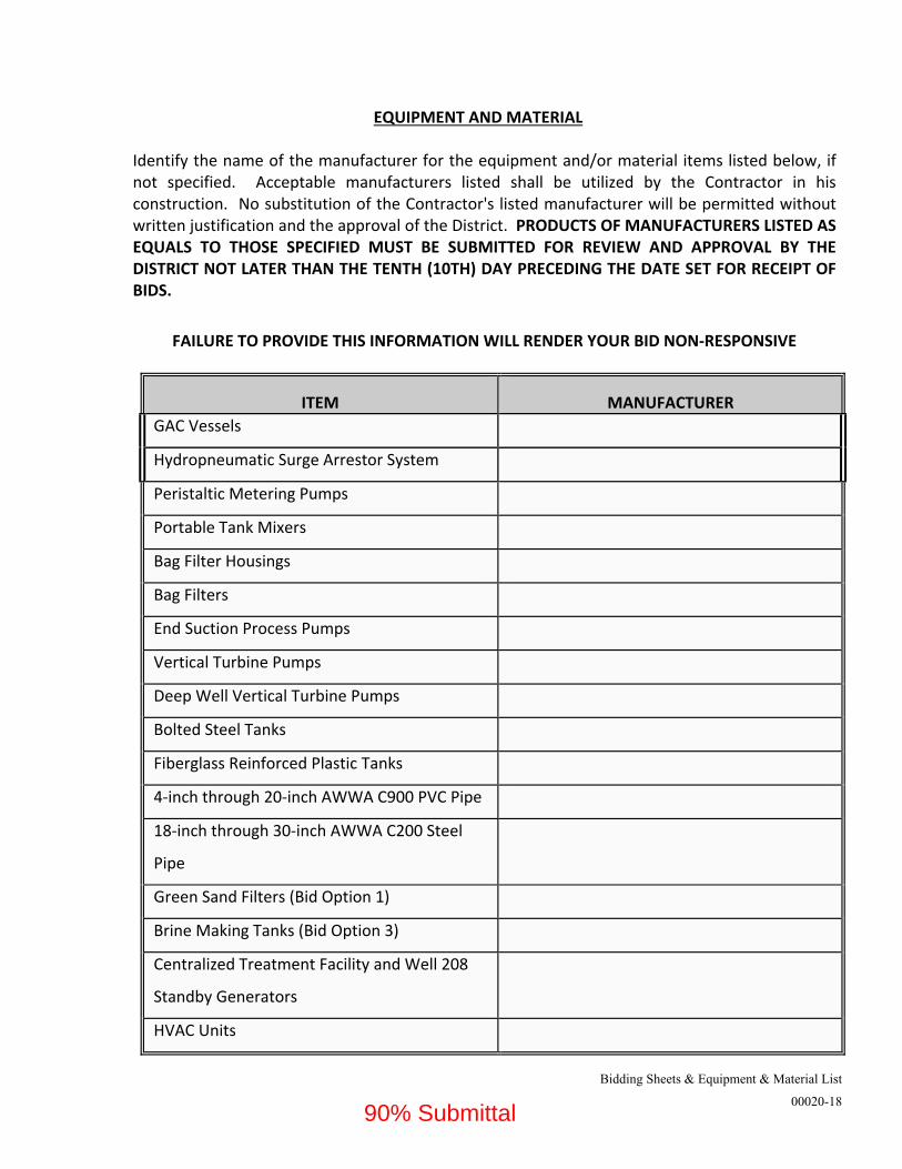
EQUIPMENT AND MATERIAL Identify the name of the manufacturer for the equipment and/or material items listed below, if not specified. Acceptable manufacturers listed shall be utilized by the Contractor in his construction. No substitution of the Contractor's listed manufacturer will be permitted without written justification and the approval of the District. PRODUCTS OF MANUFACTURERS LISTED AS EQUALS TO THOSE SPECIFIED MUST BE SUBMITTED FOR REVIEW AND APPROVAL BY THE DISTRICT NOT LATER THAN THE TENTH (10TH) DAY PRECEDING THE DATE SET FOR RECEIPT OF BIDS.
FAILURE TO PROVIDE THIS INFORMATION WILL RENDER YOUR BID NON‐RESPONSIVE
ITEM
MANUFACTURER
GAC Vessels
Hydropneumatic Surge Arrestor System
Peristaltic Metering Pumps
Portable Tank Mixers
Bag Filter Housings
Bag Filters
End Suction Process Pumps
Vertical Turbine Pumps
Deep Well Vertical Turbine Pumps
Bolted Steel Tanks
Fiberglass Reinforced Plastic Tanks
4‐inch through 20‐inch AWWA C900 PVC Pipe
18‐inch through 30‐inch AWWA C200 Steel
Pipe
Green Sand Filters (Bid Option 1)
Brine Making Tanks (Bid Option 3)
Centralized Treatment Facility and Well 208
Standby Generators
HVAC Units
90% Submittal

Bidding Sheets & Equipment & Material List
00020-19
NOTE
Please refer to Special Conditions SC‐13 for Specified Equipment with No Equal Substitution.
90% Submittal
Section H, Permits
00066-1
EASTERN MUNICIPAL WATER DISTRICT SPECIFICATION NO. XXXX
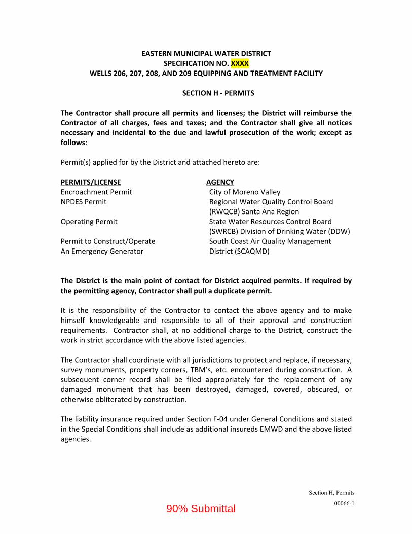
WELLS 206, 207, 208, AND 209 EQUIPPING AND TREATMENT FACILITY SECTION H ‐ PERMITS The Contractor shall procure all permits and licenses; the District will reimburse the Contractor of all charges, fees and taxes; and the Contractor shall give all notices necessary and incidental to the due and lawful prosecution of the work; except as follows: Permit(s) applied for by the District and attached hereto are: PERMITS/LICENSE AGENCY
Encroachment Permit City of Moreno Valley NPDES Permit Regional Water Quality Control Board (RWQCB) Santa Ana Region Operating Permit State Water Resources Control Board (SWRCB) Division of Drinking Water (DDW) Permit to Construct/Operate South Coast Air Quality Management An Emergency Generator District (SCAQMD) The District is the main point of contact for District acquired permits. If required by the permitting agency, Contractor shall pull a duplicate permit. It is the responsibility of the Contractor to contact the above agency and to make himself knowledgeable and responsible to all of their approval and construction requirements. Contractor shall, at no additional charge to the District, construct the work in strict accordance with the above listed agencies. The Contractor shall coordinate with all jurisdictions to protect and replace, if necessary, survey monuments, property corners, TBM’s, etc. encountered during construction. A subsequent corner record shall be filed appropriately for the replacement of any damaged monument that has been destroyed, damaged, covered, obscured, or otherwise obliterated by construction. The liability insurance required under Section F‐04 under General Conditions and stated in the Special Conditions shall include as additional insureds EMWD and the above listed agencies.
90% Submittal

Special Conditions
00100-1
EASTERN MUNICIPAL WATER DISTRICT SPECIFICATION NO. XXX
Final Design of Cactus Corridor Facilities
SECTION SC ‐ SPECIAL CONDITIONS SPECIAL PROVISIONS
SC‐01. Safety. Safety of all activities in connection with the work is of paramount and overriding importance. See Section 01000 ‐ General Safety Requirements for details. A preconstruction safety conference shall be scheduled prior to the preconstruction conference to review the respective safety requirements and to discuss implementation of all health and safety provisions related to this project. The Contractor and District representatives shall be present. Please note that the District reserves the right to suspend the work wholly or in part, for any time period as the District representative deems necessary, due to unresolved safety disputes. See Section 01000 ‐ 1.04. No additional compensation or contract time will be allowed for the period the work is wholly or in part suspended. Should the contractor continue with the disputed work after having received a written notice of suspension, any work performed by the Contractor during the suspension shall be considered as having been done by the Contractor at the Contractor's own risk as a volunteer, and shall not entitle the Contractor to compensation or any other rights under the contract. The Contractor shall submit an Injury and Illness Prevention Program and a Project Specific Safety Plan to the District at the pre‐construction conference. The Contractor shall not begin work until the above referenced documents have been accepted by the District. The Contractor shall conform to all applicable occupational safety and health standards, rules, regulations and orders established by local agencies, State of California, and California Division of Occupational Safety and Health Construction Safety Regulations (Cal Osha), including obtaining permits required by California Code of Regulations, Title 8, Sections 341 and 341 (a).
90% Submittal

Special Conditions
00100-2
The Contractor’s on‐site superintendent shall be responsible for keeping a daily log, updated continuously, of the workers on‐site each day and posting the log in a location acceptable to the Plant Managers. The log shall clearly identify check‐in and check‐out times for each person employed by the Contractor, his sub‐contractors, and/or suppliers. SC‐02. Scope of Work. Under these Specifications the Contractor shall perform all well equipping and construction of the treatment equipment and facilities in accordance with these specifications and the contract drawings. SC‐03. Construction Period and Requirements. The contract time is set forth in the Notice Inviting Bids. The following documents shall be accepted by the District prior to any construction: A. Insurance Certificate(s) and all required endorsements B. Injury and Illness Prevention Program C. EN‐84: Specific Operating Safety Procedure (see section 01000) D. SWPPP: For the SWPPP, Submittal of the SWPPP and proof of filing of the
NOI/LCAN must be completed prior to the commencement of any construction activities.
E. Project Sign. F. Preliminary Project Schedule (PPS) (see section 01310) Before any work of any subcontractor is started, the Contractor shall submit, at the preconstruction conference, a Subcontractors List and Worker Classification form giving the name, business, license number, email address, and worker classification for each subcontractor who will perform work on the project. Contractor shall update and resubmit the Subcontractors List and Worker Classification as required. (see Section F‐General Conditions, F‐17, Subcontracts, c. Contract Provisions). EN‐29 or Schedule of Values. The Contractor shall be responsible to submit and receive District approval of the EN‐29, Breakdown of Contract Price or Schedule of Values (see Section 01026) by the tenth (10th) of the month for processing of the monthly pay estimate. Submittal and approval of the EN‐29 or Schedule of Values beyond the 10th of the month will result in the pay estimate processed the following month (pay period ends on the 20th of each month). SC‐04. Performance and Payment Bonds. Pursuant to Section 995.660(a) of the Code of Civil Procedure, the Contractor shall submit the following documents with the performance and payment bonds: (1) The original, or a certified copy, of the unrevoked appointment, power of
attorney, bylaws, or other instrument entitling or authorizing the person who executed the bond to do so;
90% Submittal

Special Conditions
00100-3
(2) A certified copy of the certificate of authority of the insurer issued by the State of
California’s Insurance Commissioner; and (3) Copies of the insurer's most recent annual and quarterly statements filed with the
Department of Insurance. NO PAYMENT SHALL BE MADE UNTIL THE BONDS ARE APPROVED SC‐05. Location of Contract Work Site. The contract work sites are located at: Well 206, Well 207, and Treatment Facility – 13680 Perris Boulevard, Moreno Valley, CA 92553. Well 208 – 25XXX Santiago Drive, Moreno Valley, CA 92551 Well 209 – 25XXX Los Cabos Drive, Moreno Valley, CA 92551 See pre‐bid walk‐through map and directions herein. SC‐06. Liquidated Damages. The fixed liquidated damages amount for each calendar day of unauthorized delay in completion of the work is hereby established at One Thousand Dollars ($1,000) per calendar day. Administrative Delay Liquidated Damages. Liquidated damages may also be applied to compensate the District for undue delays in the completion of punch list items, site clean‐up, demobilization, and miscellaneous contract obligations after a notice of Substantial Completion has been filed. The cost to the District for administration, inspection, mileage, and other similar items would be extremely difficult to determine. For that reason, additional liquidated damages, known as Administrative Delay Liquidated Damages shall be imposed in the amount of $500 per day, effective 30 days after the Substantial Completion date is filed or the Revised Completion date is reached, whichever is later. Charges will be assessed until the Final Completion date is issued by the Inspector. SC‐07. Construction Water. For work under this specification, the Contractor can obtain water, free of charge, upon proper arrangements for metering its use from the District’s Resident Inspector at Cactus II Feeder piping. Contractor shall provide all necessary piping and appurtenances, including pumps, to convey water to the work site. Arrangements for water from sources other than EMWD shall be the sole responsibility of the Contractor, and no additional compensation will be allowed. INSURANCE LIMITS TO BE DETERMINED BY EMWD SC‐08. Insurance. At all times during the life of this contract, Contractor and his subcontractors shall procure and maintain Commercial Liability, Automobile Liability,
90% Submittal

Special Conditions
00100-4
Workers Compensation, Equipment Floater and Installation Floater per Section F – General Conditions, F‐04. Contractor’s and Subcontractor's Insurance. Refer to Section F‐04 for complete details, including required insurance limits, deductibles, and endorsements. Note: An Aggregate limit (cap), Professional Employer Organization (PEO), or Self Insurance Plan is not acceptable. In addition to the requirements noted above and found in Section F‐04, the following shall apply to this project: Additional Insureds. The liability insurance required under Section F‐04 under General Conditions shall include EMWD, City of Moreno Valley, RWQCB and all agencies listed in Section H‐Permits as additional insured. Refer to Section F‐04 for additional requirements pertaining to this section Pollution Liability Coverage. The Contractor shall procure Pollution Liability Coverage in amounts not less than the following: $2,000,000 per each occurrence Builders Risk, including Flood Insurance. The Contractor and his subcontractors shall maintain or cause to be maintained at all times during the life of this contract, builders' risk "All Risk" completed value insurance, to include, at the option of the District, loss or damage caused by fire, FLOOD, insuring completed work, work in progress, material, supplies and equipment of the work site, in storage or in transit, in an amount equal to the full replacement cost thereof. Such insurance shall include the interests of the District, Contractor, all tiers of subcontractors, suppliers and materialmen, with deductible amounts, if any, for the sole account of and payable by Contractor. Loss under such insurance shall be adjusted with and payable to the District for the interest of all parties. The amount of property insurance shall be sufficient to protect against such loss or damage in full until the work is accepted by the District. EMWD must be named as “loss payee” on the certificate for Builder’s Risk policy.
Builder’s “All Risk” insurance policy shall contain a deductible not higher than $1,000 unless otherwise approved by the District. Flood Insurance policy shall contain a deductible not higher than $100,000.00 unless otherwise approved by the District. SC‐09. Compliance with Storm Water Regulations (NPDES) in Accordance with the General Permit for Storm Water Discharges Associated with Construction Activity Order No. 2009‐0009 DWQ (NPDES General Permit No. CAS000002). Contractor, as EMWD’s authorized representative, shall comply with the regulatory requirements of the State Water Resources Control Board’s (SWRCB) Order No. 2009‐0009 DWQ, National Pollutant Discharge Elimination System (NPDES) General Permit No. CAS000002 for
90% Submittal

Special Conditions
00100-5
Discharges of Storm Water Runoff Associated with Construction Activity, copies of which are available on SWRCB website at http://www.swrcb.ca.gov/stormwtr/construction.html. The Contractor shall submit a project specific Storm Water Pollution and Prevention Plan prepared by a Qualified SWPPP Developer (QSD) and certified by the Contractor as EMWD’s authorized representative in accordance with Order No. 2009‐0009 DWQ, NPDES General Permit No. CAS000002. The Contractor shall submit 1 hard copy and 2 electronic copies (Flash Drives in Smart pdf format) of the SWPPP to the District within two weeks of the contract start date. The District, upon approval of the SWPPP, shall electronically file Permit Registration Documents (PRDs) using the Stormwater Multi Application Reporting & Tracking System (SMARTS) and shall mail the Notice of Intent (NOI) Fee Statement with appropriate Application Fee to the State Water Resources Control Board. SWRCB will process the PRDs and a Waste Discharge Identification Number (WDID) will be assigned to the project. EMWD will forward the completed NOI including the WDID to the Contractor upon receipt. The Contractor, as EMWD’s authorized representative, shall then maintain a copy of the SWPPP on the job site at all times for review and inspection by the Regional Water Quality Control Board. Documents that shall be available on site include but are not limited to the SWPPP that is monitored as needed for current conditions; construction site monitoring plan (CSMP); weekly and extended rain event inspection checklists; pre and post‐rain event reports; quarterly non‐stormwater monitoring reports; and Rain Event Action Plans (Risk Level 2 and 3 projects only). All on‐site reports shall be revised and updated as necessary by noon every Monday. If a District observed holiday falls on Monday, all on‐site reports shall be revised and updated by noon the next day. The Contractor, as EMWD’s authorized representative, shall have a Qualified SWPPP Practitioner (QSP) to implement the SWPPP in compliance with Order No. 2009‐0009 DWQ including but not limited to training/certification requirements for key personnel implementing the SWPPP/BMPs etc.; performance of weekly inspection reports; performance of all required monitoring and reporting including monitoring data/records and visual monitoring records; and maintaining records of corrective actions taken and not taken. Submittal of weekly inspections and monthly reports to EMWD in compliance with the permit is required by the end of each month. The Contractor’s QSP must be registered in SMARTS so EMWD may link the QSP to the project in SMARTS as a Data Person. The District, at its discretion, may withhold payment and/or return pay requests if the contractor fails to submit monthly reports by the last working day of the month, properly maintain records, or otherwise comply with the permit requirements. The Contractor shall include all costs for preparation of the SWPPP, record keeping, implementation, and reporting requirements of the permit. No additional compensation
90% Submittal

Special Conditions
00100-6
will be allowed. SC‐10. Percentage of Work by Contractor, per Section F‐ General Conditions. The first paragraph under F‐14. Obligations of Contractor is revised to read as follows: Contractor shall perform, with his own organization, contract work amounting to at least 50 percent of the contract except that any designated “Specialty Items” may be performed by subcontractor and the amount of any such “Specialty Items” may be deducted from the Contract Price before computing the amount required to be performed by the Contractor with it’s own organization. Specialty Items are defined as follows: GAC Vessels and Bolted Steel Tanks. When an entire item is subcontracted, the value of work subcontracted will be based on the contract unit price. When a portion of an item is subcontracted, the value of work subcontracted will be based on the estimated percentage of the contract unit price. This will be determined from information submitted by the Contractor and subject to approval by the District. SC‐11. Preconstruction Conference. A Pre‐job conference shall be scheduled prior to the start of the project. District representatives, Permit agencies, and the Contractor shall be present. SC‐12. Preconstruction Audio Video Recording (DVD). The Contractor shall make arrangements with a professional photographer, approved by the District, to prepare a full color pre‐construction audio video recording on DVD of the project site with the Inspector present prior to mobilizing (refer to Section 01381) and provide the District with a copy. SC‐13. Or Equal Substitutions. Products of manufacturers listed as equals to those specified must be submitted for review and approval by the District not later than the tenth (10th) day preceding the date for receipt of bids. If project includes sole‐source items, list below:
Specified Equipment with No Equal Substitution. For the purposes of standardization within the DISTRICT, the following table of specification sections lists approved manufacturers and no equals. Manufacturers not named in these listed specifications will not be considered or approved. See Technical Specification Section for additional details.
Section Application Manufacturer
SC‐14. Submission of Documents In Electronic Media Format. Unless otherwise specified by the District, Contractor shall submit all documents (ie: RFIs, Contract Documents, Design Submittals, and Materials and Equipment Submittals) electronically
90% Submittal

Special Conditions
00100-7
via CIPO. The Contractor shall be prepared to submit the following:
1. Correspondence and Proposed Change Order Requests:
2. Request for Information (RFI’s): Refer to Section F, F‐30 Changes in Work and Extras.
3. Shop Drawing Submittals: Refer to Section F, F‐29 Equipment and Material Items. SC‐15. Potential COVID‐19 Exposure. There is no higher priority than the safety and well‐being of our employees, our Contractors/Suppliers, and customers. Throughout the pandemic and beyond, the District will continue to assess our safety protocols and take actions to maintain our operations and provide safe and reliable water, wastewater and recycle water service. The District has implemented a new reporting mechanism specifically for Contactors/Suppliers to inform EMWD of potential COVID‐19 exposures of their employees. Please forward an e‐mail to [email protected] to report potential exposure. Please abstain from notifying multiple District contacts as this results in duplicated efforts. An e‐mail should be forwarded each time any of your employees have been informed by a medical provider that they are suspected of having COVID‐19 and they are asked to isolate from others or anytime an employee has tested positive for COVID‐19. Along with this information the following should be provided:
What District sites has the employee visited?
When was the last date and time that they were on‐site?
Specifically what District employees were they in contact with?
Did they practice social distancing at all times while on‐site?
Were they wearing a face covering while on‐site? The information provided will then be used to determine which EMWD personnel need to be notified of the potential exposure, to request that they self‐monitor for symptoms and/or seek medical attention, and to determine what areas may require disinfection and sanitization. If you use subcontractors/suppliers, please forward this communication on to them as well. As always, please continue to inform your Construction Administrator and Inspector of any questions regarding this protocol.
90% Submittal

Special Conditions
00100-8
SC‐16. Control Density Fill (CDF): The Contractor will be required to use CDF, in accordance with Section 02252 as backfill in areas under and around existing mainline utilities, and all utility crossings of the proposed underground piping and appurtenances. CDF shall be placed from the bottom of the excavation to the center grade of the utility, and shall extend five feet each side of the existing facility. All costs associated with furnishing and placing CDF shall be included in the respective bid item. SC‐17. Project Sign. Prior to the start of construction, the Contractor shall place a project sign at a prominent location on each project site, as directed by the District. The Contractor shall submit a prototype of the construction sign to the District for review and approval before posting the sign at the construction site. A construction project sign template and logo guidelines will be provided to the awarded contractor. The sign shall be prepared in a professional manner, be at least four feet tall by eight feet wide, made of 3/4‐inch thick exterior grade plywood or other approved material. At a minimum, the following shall be included on the project sign:
Project Title Purpose of Project Estimated Construction Duration Project Cost (if provided) Public Affairs contact: (Contact name & ext to be provided at Prejob) EMWD’s color logo EMWD’s Mission Statement
90% Submittal

Special Conditions
00100-9
In addition to the above, the sign shall include other agencies logos, disclosure statements, or additional information as requested by the District, so long as the above requirements are equally prominent. The Contractor shall be responsible to maintain the sign in good condition for the duration of the project. Sample:
Building For Your Future
Project Title
PURPOSE:
ESTIMATED PROJECT COMPLETION:
PROJECT COST/FUNDING:
EMWD CONTACT:
The Mission of Eastern Municipal Water District is to deliver value to our diverse customers and the communities we serve by providing safe, reliable, economical and
environmentally sustainable water, wastewater and recycled water services.
SC‐18. Notification. Public outreach may be required, as determined by EMWD Public & Governmental Affairs staff. That outreach may include attendance at community presentations, distribution of door hangers, distribution of letters or other like forms of community engagement. Any printed materials will be provided by EMWD Public & Governmental Affairs staff. If the District receives complaints from individuals or agencies affected by the project; the Contractor shall take immediate action to correct the situation as directed by the District. If Contractor receives complaints directly, Contractor shall forward complaint directly to PGA Staff at (951) 928‐3777 ext. 3430 and immediately notify the District Inspector. Thereafter, Contractor shall take immediate action to correct the situation as directed by the District.
SC‐19. Markups for Negotiated Change Order Work.
Other Logo if applicable
Contractor’s Logo
90% Submittal
Special Conditions
00100-10
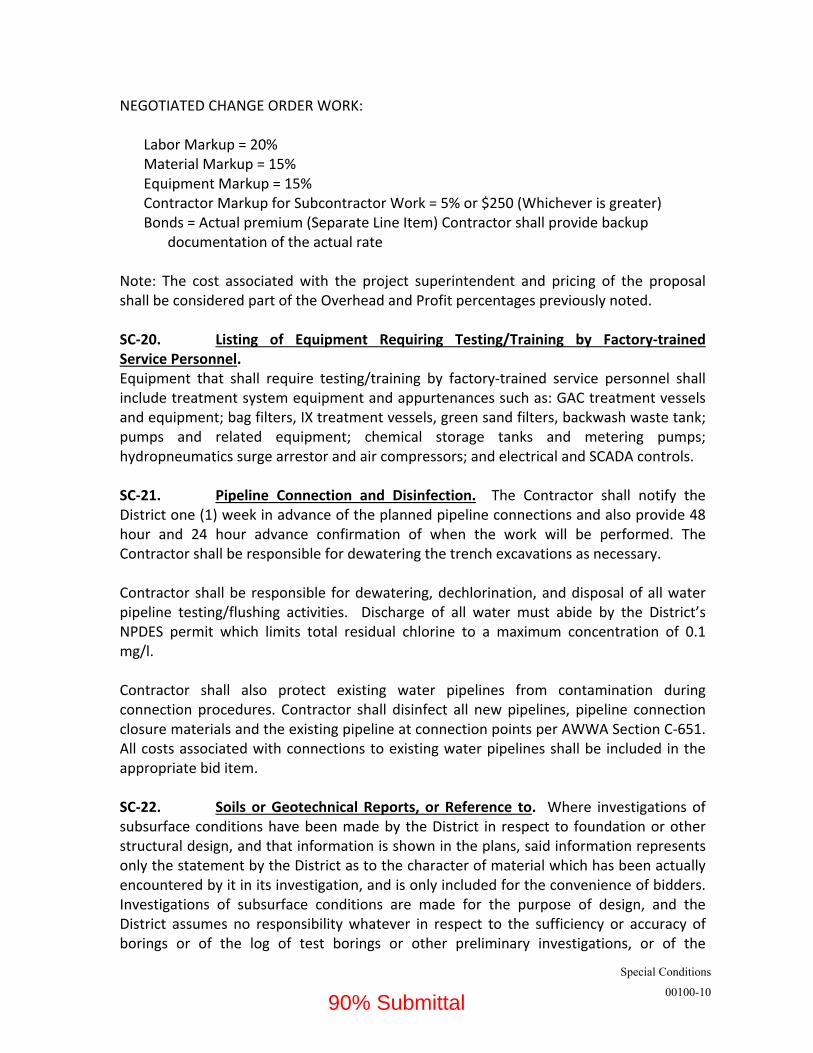
NEGOTIATED CHANGE ORDER WORK:
Labor Markup = 20% Material Markup = 15% Equipment Markup = 15% Contractor Markup for Subcontractor Work = 5% or $250 (Whichever is greater) Bonds = Actual premium (Separate Line Item) Contractor shall provide backup
documentation of the actual rate Note: The cost associated with the project superintendent and pricing of the proposal shall be considered part of the Overhead and Profit percentages previously noted. SC‐20. Listing of Equipment Requiring Testing/Training by Factory‐trained Service Personnel. Equipment that shall require testing/training by factory‐trained service personnel shall include treatment system equipment and appurtenances such as: GAC treatment vessels and equipment; bag filters, IX treatment vessels, green sand filters, backwash waste tank; pumps and related equipment; chemical storage tanks and metering pumps; hydropneumatics surge arrestor and air compressors; and electrical and SCADA controls. SC‐21. Pipeline Connection and Disinfection. The Contractor shall notify the District one (1) week in advance of the planned pipeline connections and also provide 48 hour and 24 hour advance confirmation of when the work will be performed. The Contractor shall be responsible for dewatering the trench excavations as necessary. Contractor shall be responsible for dewatering, dechlorination, and disposal of all water pipeline testing/flushing activities. Discharge of all water must abide by the District’s NPDES permit which limits total residual chlorine to a maximum concentration of 0.1 mg/l. Contractor shall also protect existing water pipelines from contamination during connection procedures. Contractor shall disinfect all new pipelines, pipeline connection closure materials and the existing pipeline at connection points per AWWA Section C‐651. All costs associated with connections to existing water pipelines shall be included in the appropriate bid item. SC‐22. Soils or Geotechnical Reports, or Reference to. Where investigations of subsurface conditions have been made by the District in respect to foundation or other structural design, and that information is shown in the plans, said information represents only the statement by the District as to the character of material which has been actually encountered by it in its investigation, and is only included for the convenience of bidders. Investigations of subsurface conditions are made for the purpose of design, and the District assumes no responsibility whatever in respect to the sufficiency or accuracy of borings or of the log of test borings or other preliminary investigations, or of the
90% Submittal

Special Conditions
00100-11
interpretation thereof, and there is no guaranty either expressed or implied, that the conditions indicated are representative of those existing throughout the work, or any part of it, or that unlooked for developments may not occur. Making such information available to bidders is not be construed in any way as waiver of the provisions of the first part of this article and bidders must satisfy themselves through their own investigations as to conditions to be encountered. SC‐23. Reference to District’s Standard Drawings and Detailed Provisions. Any and all referenced Standard Drawings and Detailed Provisions shall be considered part of the contract drawings and specifications. All referenced Standard Drawings and Detailed Provisions of the District are available from the District upon request. The Contractor shall not be entitled to any compensation due to referenced documents not included in the Specifications and Contract Drawings. SC‐24. Storage of Materials and Equipment and Security. Contractor may utilize available land at the Work site, within the limits of construction, for storage of materials and equipment. Contractor shall coordinate the location of material and equipment storage with the District Inspector. Contractor has the option to secure their own storage yard for materials and equipment. However, if private or public property is used, the Contractor must obtain written permission from affected property owners and/or agencies in advance of moving said material or equipment onto offsite property. A copy of the letter from the private owner granting permission shall be submitted to the District prior to use of the site. The District will not approve the use of any property unless it can be considered “previously disturbed” in accordance with CEQA guidelines. The Contractor shall be responsible for providing all security measures necessary to secure the stored materials or equipment and to protect the construction area regardless of whether it is stored on District property or Contractor acquired property. The District is not responsible for items lost, damaged or stolen from the secured site or for injuries to the public due to unsafe or unsecured conditions. SC‐25. Shutdown Requirements, Work Restrictions and Operations Coordination. Contractor shall coordinate the shutdown operation of existing systems with the District, to include the Inspector and Operations and Maintenance personnel per the Shutdown schedule attached (see Appendix XX). No work shall be performed without 2 week prior notice followed by forty‐eight (48) hour prior and twenty‐four (24) hour confirmation notices to the District. No work shall be done without a District representative present. SC‐26. Construction Survey and Soils Tests. Upon Contractor's request, District will provide construction survey and soil/compaction testing for the project. However, any cost of re‐staking or re‐compaction due to the Contractor's negligence will be at the
90% Submittal

Special Conditions
00100-12
Contractor's expense. A 48‐hour notice is required for survey and soil services. SC‐27. Tracer Wire. Tracer wire is to be placed over any and all pipelines regardless of product and electrical duct banks to be installed on this project. After all trench backfill operations are complete, the District shall pay for and conduct the locatability test to confirm that the wire is continuous. The Contractor shall be responsible for all costs to confirm, locate and repair any breaks in the tracer wire identified in the locatability test. In addition, the Contractor shall reimburse the District for all costs to retest repaired sections of the wire. The Contractor is advised to use care in the installation and backfilling operations to prevent damage to the wire. Tracer wire shall be a #14 AWG (0.0641” diameter) fully annealed, high carbon 1055 grade steel, high strength solid copper clad steel conductor (HS‐CCS), insulated with a 30 mil, high‐density, high molecular weight polyethylene (HDPE) insulation and rated for direct burial use at 30 volts. HS‐CCS conductor must be at 21% conductivity for locating purposes. Break load of 282 pounds. Insulation color shall meet the APWA color code standard for identification of buried utilities. Manufacturers supplying copper clad steel tracer wire must have available detailed performance data including 5 years of underground testing in terms of durability related to damage of protective insulation and effects of potential corrosion of the specific copper clad steel used. Origin of copper clad steel manufacturer is required and steel core must be manufactured in the United States. If manufacturer has not completed 5 year corrosion testing, a 5‐year warranty must be provided. Where utility marking tape is also required for the installation, only “NON‐DETECTABLE” marking tape will be allowed. SC‐28. Maintenance Bond for Pumping Equipment. The contractor or his supplier shall provide a maintenance bond (EMWD standard form C‐14 or C‐14.1) from a bonding company acceptable to the District equal to 100% of the pumping equipment value (including motors, pumps and pump assemblies) for a two (2) year term starting when the District has accepted the contracted work. Equipment and/or components failing within this period due to deficiency in design, workmanship or material shall be removed, replaced, and reinstalled at no cost to the District, and said replacement shall be guaranteed for two years continuous service. The maintenance bond shall be submitted to the District prior to the performance test of the pump(s). Warranty. All pumping equipment shall carry an extended warranty for a two year period from the date of installation. All warranties shall be turned into the District prior to project completion. SC‐29. Specification Section 16480; Main Switchboard and Motor Control Center. Power Monitor shall be installed on all motor control centers unless specifically
90% Submittal
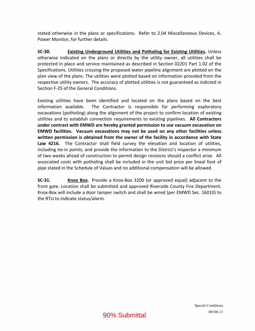
Special Conditions
00100-13
stated otherwise in the plans or specifications. Refer to 2.04 Miscellaneous Devices, A. Power Monitor, for further details. SC‐30. Existing Underground Utilities and Potholing for Existing Utilities. Unless otherwise indicated on the plans or directly by the utility owner, all utilities shall be protected in place and service maintained as described in Section 02201 Part 1.02 of the Specifications. Utilities crossing the proposed water pipeline alignment are plotted on the plan view of the plans. The utilities were plotted based on information provided from the respective utility owners. The accuracy of plotted utilities is not guaranteed as indicted in Section F‐25 of the General Conditions. Existing utilities have been identified and located on the plans based on the best information available. The Contractor is responsible for performing exploratory excavations (potholing) along the alignment of the project to confirm location of existing utilities and to establish connection requirements to existing pipelines. All Contractors under contract with EMWD are hereby granted permission to use vacuum excavation on EMWD facilities. Vacuum excavations may not be used on any other facilities unless written permission is obtained from the owner of the facility in accordance with State Law 4216. The Contractor shall field survey the elevation and location of utilities, including tie‐in points, and provide the information to the District’s inspector a minimum of two weeks ahead of construction to permit design revisions should a conflict arise. All associated costs with potholing shall be included in the unit bid price per lineal foot of pipe stated in the Schedule of Values and no additional compensation will be allowed. SC‐31. Knox Box. Provide a Knox‐Box 3200 (or approved equal) adjacent to the front gate. Location shall be submitted and approved Riverside County Fire Department. Knox‐Box will include a door tamper switch and shall be wired (per EMWD Sec. 16010) to the RTU to indicate status/alarm.
90% Submittal

Supplemental Special Conditions
00110-1
EASTERN MUNICIPAL WATER DISTRICT SPECIFICATION NO. X
Wells 206, 207, 208, and 209 Equipping and Treatment Facility
SECTION SSC – SUPPLEMENTAL SPECIAL CONDITIONS
SSC‐1. SECTION 03150 – FORMWORK FOR CAST‐IN‐PLACE CONCRETE. Contractor shall
recognize the following changes:
Section 1.02 B, Revise from “ACI 347R‐88” to “ACI 347R‐14” and revise from “ACI 117‐90” to “ACI 117‐10.”
SSC‐2. SECTION 03200 – REINFORCING. Contractor shall recognize the following changes:
Revise the governing code, Section 1.02‐A from “Chapter 26 of the Uniform Building Code” to “the California Building Code.”
Revise steel type, Section 2.01, Delete “Type “S” .”
Revise document approval organization, Section 2.04 from “I.C.B.O. Research Recommendation Approval” to “International Code Council Evaluation Services (ICC‐ES) approval.”
Revise splice type, Section 3.01‐D from “(Class A)(Class C)” to “Class B.”
Revise Dowels, Section 3.01‐H from “use non‐shrink epoxy type grout” to “use adhesive dowels with valid ICC‐ES reports that are approved for use in cracked concrete.” Revise “Holes for epoxy doweling in place in existing concrete shall provide ½” minimum clearance on all sides of dowel bar” to “Install epoxy dowels in accordance with manufacturer’s requirements.
SSC‐3. SECTION 03300 – CAST‐IN‐PLACE CONCRETE. Contractor shall recognize the following
changes:
Revise the governing code, Section 1.03‐A from “Chapter 26 of the Uniform Building Code” to “the California Building Code.”
Revise concrete strength requirement for Class “AA”” concrete, Section 1.04‐A.1.a from “4000 psi” to “4500 psi.”
Revise admixture requirements, Section 2.01.C.2 from “hydroxylated carboxylic acid type admixture” to “Water‐Reducing Admixture conforming to the requirements of ASTM C494 Type A.”
Revise air entrainment requirements, Section 2.01.C.3 from “Table 4.2.1” to Table “19.3.3.1” and from “Table 4.2.2.4” to “Table 4.2.2.7.b.1.”
“Waterstops Section 2.01.G
Update joint sealants
90% Submittal

Supplemental Special Conditions
00110-2
Revise Non‐Shrink grout to use pre‐packaged system. Sections 2.01‐M from “Non‐Shrink Grout shall be made…sack of cement” to “Non‐shrink grout shall be a pre‐packaged grout confirming to ASTM C1107. Non‐Shrink Grout shall be SikaGrout 212 by SikaCorp; Set Grout by BASF Building Systems, or equal. Florable non‐shrink grout shall be Masterflow 928 by BASF Building Systems, SikaGrout 212 by Sika Corp, or equal.”
Update approved epoxies, Section 2.01‐P from “Adhesive Engineering Company” to “Master Builders”. Section 2.01‐P.2 delete “and for grouting metal anchors”; revise from “Sikadur Hi‐Mod LV” to “Sikadur 35 Hi‐Mod LV” “Adhesive Engineering Company’s Concresive 1001‐LPL “ to “Master Builders MasterEmaco ADH 326.”
Revise curing compound, Section 2.01‐Q from “Use “TLF” or “Clear 225 TU” by Hunt Process Company, Burke “Rez‐X”, or equal conforming to ASTM C309” to “Use a liquid curing compound conforming to ASTM C309.”
Revise listed approved products, revise paragraph to: “Concrete Expansion Anchors. Except as otherwise specified, where expansion anchors are called for on the Drawings, Simpson Strong‐Bolt 2 by Simpson Strong‐Tie, Hilti Kwik Bolt TZ by Hilti Inc, or approved equal. Approved equal shall have equivalent tensile and shear capacity, have a current ICC‐ES report and be approved for use in cracked concrete in accordance with ACI 318 Chapter 17. See Section 05502 for additional requirements”
Add requirement to end of parapgrapgh for mix designs, Section 2.02‐C: “Provide Class 560‐C 3250 concrete mix for water containing structures and secondary chemical containment area.”
Revise added water requirements, Section 3.04‐A.3, add “Water shall only be added to the full batch prior to discharge.”
Reference ACI documents for hot and cold weather concreting. Section 3.04‐B, add “All concrete placement shall meet the requirements of ACI 301. Provide a cold weather concreting plan per ACI 306.1 and ACI 306R. Provide a hot weather concreting plan per ACI 305R.
Concrete pumping requirements Section 3.04‐D.3, replace “ACI 304.2R‐96” with ACI 304.2.R‐17
Restriction, Section 3.11‐B, following “water‐bearing structures” add “, including secondary chemical containment areas,”
Watertightness of Concrete Structures, Section 3.17. Add subsection E “See ACI 350.1‐10 for additional requirements.”
Alterations and Rework, Section 3.18 Replace “Sikastix Adhesive” with “Sikadur‐32 Hi‐Mod.” Replace “Hunt Process Company’s HB Series Epoxy Mortar” with “Master Builder’s MasterEmaco P124”
Bonding Agent’s, Section 3.19‐C, Replace “Hunt Process Company’s HB Series Epoxy Mortar” with “Master Builder’s MasterEmaco P124”
SSC‐4. SECTION 4220 – CONCRETE MASONRY UNITS. Contractor shall recognize the following
changes:
90% Submittal

Supplemental Special Conditions
00110-3
Quality assurance Section 1.02 replace “Uniform Building Code” with “California Building Code.”
Masonry units, Section 2.01‐A, replace “Grade N‐1, natural” with “Normal Weight of color as specified in the architectural drawings.” Add “Masonry units shall have a minimum compressive strength of 2000psi.”
Pea gravel aggregates, Section 2.01‐E, Replace “3/4 inch sieve” with “3/8 inch sieve.”
Shrinkage Reducing Admixture, Section 2.01‐F, Delete paragraph.
Waterproofing, Section 2.01‐J, replace “MFW SubSeal 40” with “MFM SubSeal 40.”
Mortar Mix, “Section 2.02‐A” replace entire paragraph with. “Mortar shall be Type S per TMS‐402/602 with a minimum compressive strength of 2000 psi.”
Grout Mix, Section 2.02‐B, replace entire paragraph with “Grout shall be ready mix masonry grout conforming to the requirements of ASTM C‐476, have a 0.6 minimum water‐cement ratio, and have a minimum compressive strength of 2000 psi at 28 days.”
Water, Section 2.02‐D, replace “9‐10 inches” with “8‐11 inches.” Replace “seven (7) sacks of cement” with “five (5) sacks of cement”
Removal of Units, Section 3.03‐G, replace “reset in fresh water” with “reset in fresh mortar.”
Grouting, Section 3.04‐C.4 replace “Pout grout” with “Pour grout.” Delete “rod or“ SSC‐5. SECTION 06100 – CARPENTRY WORK. Contractor shall recognize the following changes:
Revise the governing code, Section 1.02 A from “Chapter 23 of the UBC, Latest Edition” to "Chapter 23 of the 2019 California Building Code”.
SSC‐6. SECTION 07920 – SEALANTS AND CAULKING. Contractor shall recognize the following changes:
Revise Section 2.01 C (4) from “Mamenco International No. 45” to "Tremco Vulkem 45”.
SSC‐7. SECTION 08365 – ROLLING SERVICE DOORS – CHAIN OPERATED. Contractor shall
recognize the following changes:
Revise Section 1.03 A (1) from “Chapter 23 of the UBC, Latest Edition” to "Chapter 23 of the 2019 California Building Code”.
Revise the acceptable manufacturers 1 & 2 in Section 2.01 A to the following manufacturers, 1. Wayne Dalton Model 800C Thermotite, and 2. Overhead Door Company Model Stormtite 627.
90% Submittal

Supplemental Special Conditions
00110-4
SSC‐8. SECTION 09900 – Painting and Protective Coatings. The Contractor shall recognize the following changes:
Section 1.01 C (2), add to the end of the sentence “and for UV protection.”
Section 2.08 A, add to the end of the first sentence “and for UV protection.” SSC‐9. SECTION 13312 – Bolted Steel Tanks for Water Storage. The Contractor shall recognize
the following changes:
Section 1.01 – Add the following for the loading criteria:
Design Requirements: Materials, design, fabrication and erection per AWWA D103, latest edition, and also:
Roof live load:
a. Outside guardrails: 25 lb/ft2.
b. Platform and ladder areas of the tank roof around access hatches enclosed in guardrails: 50 lb/ft2.
c. Handrails, guardrails, and stair rails: 20 plf @ top rails.
d. Ladder loads: 500 lb. on each vertical section of the ladder.
Wind load:
Basic Wind Speed: V = 105 mph (Ultimate)
V = 89 (Allowable)
Exposure: C Seismic design: IBC Section 1613; ASCE 7, Section 15.7.7.1; AWWA
D103, Section 14. Refer to the coefficients and factors below: Seismic Use Group: III Seismic Importance Factor (Table 24) : IE = 1.25 Site Class (Table 25): D Design Earthquake Spectral Response Acceleration, 0.2 sec: SDS = 1.104 Design Earthquake Spectral Response Acceleration, 1.0 sec: SD1 = 0.731
a. The design earthquake ground motion in this specification is
based on a maximum considered earthquake ground motion, defined as a motion caused by an event with a 2 percent probability of exceedance within a 50‐year period (recurrence interval of approximately 2,500 years).
b. When information has been provided for determination of the design earthquake ground motion using either the general procedure of AWWA D103 or the site‐specific procedure, both
90% Submittal
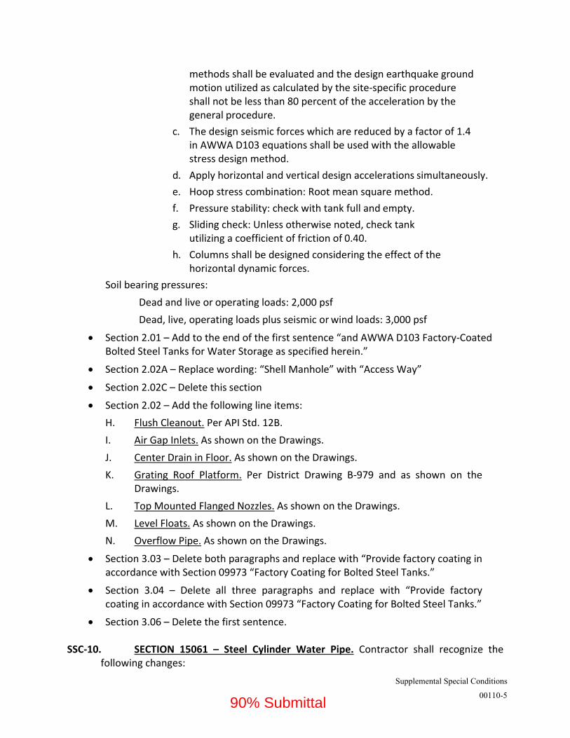
Supplemental Special Conditions
00110-5
methods shall be evaluated and the design earthquake ground motion utilized as calculated by the site‐specific procedure shall not be less than 80 percent of the acceleration by the general procedure.
c. The design seismic forces which are reduced by a factor of 1.4 in AWWA D103 equations shall be used with the allowable stress design method.
d. Apply horizontal and vertical design accelerations simultaneously.
e. Hoop stress combination: Root mean square method.
f. Pressure stability: check with tank full and empty.
g. Sliding check: Unless otherwise noted, check tank utilizing a coefficient of friction of 0.40.
h. Columns shall be designed considering the effect of the horizontal dynamic forces.
Soil bearing pressures:
Dead and live or operating loads: 2,000 psf
Dead, live, operating loads plus seismic or wind loads: 3,000 psf
Section 2.01 – Add to the end of the first sentence “and AWWA D103 Factory‐Coated Bolted Steel Tanks for Water Storage as specified herein.”
Section 2.02A – Replace wording: “Shell Manhole” with “Access Way”
Section 2.02C – Delete this section
Section 2.02 – Add the following line items:
H. Flush Cleanout. Per API Std. 12B.
I. Air Gap Inlets. As shown on the Drawings.
J. Center Drain in Floor. As shown on the Drawings.
K. Grating Roof Platform. Per District Drawing B‐979 and as shown on the Drawings.
L. Top Mounted Flanged Nozzles. As shown on the Drawings.
M. Level Floats. As shown on the Drawings.
N. Overflow Pipe. As shown on the Drawings.
Section 3.03 – Delete both paragraphs and replace with “Provide factory coating in accordance with Section 09973 “Factory Coating for Bolted Steel Tanks.”
Section 3.04 – Delete all three paragraphs and replace with “Provide factory coating in accordance with Section 09973 “Factory Coating for Bolted Steel Tanks.”
Section 3.06 – Delete the first sentence. SSC‐10. SECTION 15061 – Steel Cylinder Water Pipe. Contractor shall recognize the
following changes:
90% Submittal

Supplemental Special Conditions
00110-6
Section 1.01.A – Add the following line item: “5. Cement mortar lined and
polyurethane coated steel pipe.”
Section 1.02 – Add the following line item: “L. AWWA C222. Polyurethane Linings
and Coatings for Steel Water Pipe and Fittings.
Section 2.03.C – Add the following line item:
“4. Painted Coatings shall be applied in accordance with Section 09900.”
Section 2.03.D.1 (Joints) – Replace with:
1. All pipes shall have welded lap joints unless otherwise shown.
Section 2.03.D.1(b) – Delete “,or by rolling” SSC‐11. SECTION 15136 – Air Valves. Contractor shall recognize the following changes:
Revise Section 2.02.B to include the following additional text “Valves shall have an intake orifice area equal to nominal size of valve. Discharge of pressurized air shall be controlled by seating and unseating of a small orifice needle on the control float. Venting of large quantities of air during pipeline filling shall be accomplished through a large orifice at top of valve. The valve shall be designed to seat at low pressures (less than 2 psi) where indicated on the Drawings. Vacuum relief shall be accomplished through the large orifice when the control float falls due to negative pressure in the pipeline. Valve design shall incorporate an over pressure safety feature that will fail without an explosive effect, such as is normally the case when highly compressed air is released suddenly. Feature shall consist of easily replaceable gaskets”.
Revise Section 2.02.C to include the following additional text “Small orifice assembly air release valves shall automatically release air accumulations from pipe while under positive pressure. When valve body fills with air, float mechanism shall fall to open small orifice and exhaust air to atmosphere. When air has been exhausted, float mechanism shall be buoyed up and shall tightly close small orifice. The valve shall be designed to seat at low pressures (less than 2 psi) where indicated on the Drawings.”
Revise Section 2.02.D to include the following additional text “The valve shall be designed to seat at low pressures (less than 2 psi) where indicated on the Drawings.”
Revise Section 2.02 to include an additional sub‐section E labelled Deep Well Vacuum Breaker/ Air Release Valves. Section shall read “Shall be dual body air valves. The large valve shall be a vacuum breaker valve and shall have an intake orifice equal to the nominal size of the pipe and designed to draw large amounts of air into the pipeline under vacuum, but will not allow air discharge from the pipeline. The cracking pressure of the vacuum breaker valve shall be 0.25 psi
90% Submittal

Supplemental Special Conditions
00110-7
vacuum and fully open at 2 psi vacuum. The small valve shall be an air‐release valve with a maximum air release orifice of 0.13‐inch.”
Replace “Air Release & Vacuum Valves” in Section 2.03 with “Combination Air‐Vacuum and Air Release Valves.”
Revise Section 2.03 to include an additional list of approved manufacturers for “Vacuum Breaker/ Air Release Valves.” Include in this list:
Apco 1502TC 2” Valmatic 1802AVB/38” 2”
Revise Part 2 to include an additional Section 2.05 titled “Reference Standards”. Section 2.05 to read “Valves to comply with AWWA C512. Valves shall be NSF 61 and 372 certified”.
90% Submittal
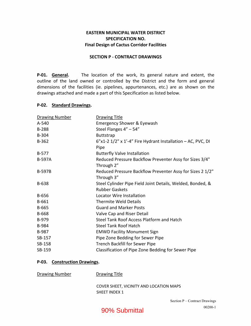
Section P – Contract Drawings
00200-1
EASTERN MUNICIPAL WATER DISTRICT SPECIFICATION NO.
Final Design of Cactus Corridor Facilities
SECTION P ‐ CONTRACT DRAWINGS P‐01. General. The location of the work, its general nature and extent, the outline of the land owned or controlled by the District and the form and general dimensions of the facilities (ie. pipelines, appurtenances, etc.) are as shown on the drawings attached and made a part of this Specification as listed below. P‐02. Standard Drawings. Drawing Number Drawing Title A‐540 Emergency Shower & Eyewash B‐288 Steel Flanges 4” – 54” B‐304 Buttstrap B‐362 6”x1‐2 1/2" x 1’‐4” Fire Hydrant Installation – AC, PVC, DI Pipe B‐577 Butterfly Valve Installation B‐597A Reduced Pressure Backflow Preventer Assy for Sizes 3/4" Through 2” B‐597B Reduced Pressure Backflow Preventer Assy for Sizes 2 1/2" Through 3” B‐638 Steel Cylinder Pipe Field Joint Details, Welded, Bonded, & Rubber Gaskets B‐656 Locator Wire Installation B‐661 Thermite Weld Details B‐665 Guard and Marker Posts B‐668 Valve Cap and Riser Detail B‐979 Steel Tank Roof Access Platform and Hatch B‐984 Steel Tank Roof Hatch B‐987 EMWD Facility Monument Sign SB‐157 Pipe Zone Bedding for Sewer Pipe SB‐158 Trench Backfill for Sewer Pipe SB‐159 Classification of Pipe Zone Bedding for Sewer Pipe P‐03. Construction Drawings. Drawing Number Drawing Title
COVER SHEET, VICINITY AND LOCATION MAPS
SHEET INDEX 1
90% Submittal

Section P – Contract Drawings
00200-2
SHEET INDEX 2
GENERAL NOTES AND LEGENDS
ABBREVIATIONS
CENTRALIZED TREATMENT FACILITY OVERALL SITE PLAN
WELLS 208 AND 209 OVERALL SITE PLANS
PROCESS FLOW DIAGRAM 1
PROCESS FLOW DIAGRAM 2
CENTRALIZED TREATMENT HYDRAULIC PROFILE
WELLS 208 AND 209 HYDRAULIC PROFILE
DESIGN CRITERIA 1
DESIGN CRITERIA 2
CENTRALIZED TREATMENT FACILITY SITE MOBILIZATION PLAN
WELLS 208 AND 209 SITE MOBILIZATION PLAN
CIVIL LEGEND AND GENERAL NOTES
WELLS 206 AND 207 AND CENTRALIZED TREATMENT FACILITIES EXISTING SITE, DEMOLITION, AND SURVEY CONTROL PLAN
CENTRALIZED TREATMENT FACILITY SITE PLAN
CENTRALIZED TREATMENT FACILITY ENLARGED GRADING PLAN 1
CENTRALIZED TREATMENT FACILITY ENLARGED GRADING PLAN 2
CENTRALIZED TREATMENT FACILITY YARD PIPING PLAN CENTRALIZED TREATMENT FACILITIES ENLARGED YARD PIPING PLAN 1
CENTRALIZED TREATMENT FACILITIES ENLARGED YARD PIPING PLAN 2
WELL 208 SURVEY CONTROL PLAN
WELL 208 SITE LAYOUT AND GRADING PLAN
WELL 208 YARD PIPING PLAN
WELL 209 SITE SURVEY CONTROL PLAN
WELL 209 SITE LAYOUT AND GRADING PLAN
WELL 209 YARD PIPING PLAN
PIPELINE PROFILE A AND B
PIPELINE PROFILE C AND D
PIPELINE PROFILE E AND F
PIPELINE PROFILE G AND H
PERIMETER WALL ELEVATIONS
CIVIL DETAILS 1
CIVIL DETAILS 2
CIVIL DETAILS 3
CIVIL DETAILS 4
CIVIL DETAILS 5
CATHODIC MONITORING SYSTEM DETAILS
CATHODIC MONITORING SYSTEM DETAILS
CATHODIC MONITORING SYSTEM DETAILS
CENTRALIZED TREATMENT FACILITY LANDSCAPE ‐ IRRIGATION PLAN
90% Submittal

Section P – Contract Drawings
00200-3
CENTRALIZED TREATMENT FACILITY LANDSCAPE ‐ PLANTING PLAN
WELL 208 LANDSCAPE ‐ IRRIGATION & PLANTING PLANS
WELL 209 LANDSCAPE ‐ IRRIGATION & PLANTING PLANS
LANDSCAPE NOTES, DETAILS
LANDSCAPE DETAILS
ARCHITECTURAL LEGENDS, ABBREVIATIONS & GENERAL NOTES
CODE SUMMARY & LIFE SAFETY PLANS I
CODE SUMMARY & LIFE SAFETY PLANS II
CODE SUMMARY & LIFE SAFETY PLANS III
CODE SUMMARY & LIFE SAFETY PLANS IV
CODE SUMMARY & LIFE SAFETY PLANS V
CODE SUMMARY & LIFE SAFETY PLANS VI
WELL 206 BUILDING FLOOR PLAN AND ROOF PLAN
WELL 206 BUILDING ELEVATIONS AND SECTIONS
WELL 206 BUILDING ISOMETRIC VIEWS
WELL 207 BUILDING FLOOR PLAN AND ROOF PLAN
WELL 207 BUILDING ELEVATIONS AND SECTIONS
WELL 207 BUILDING ISOMETRIC VIEWS
CHEMICAL FACILITY BUILDING FLOOR PLAN AND ROOF PLAN
CHEMICAL FACILITY BUILDING ELEVATIONS AND SECTIONS
CHEMICAL STORAGE CANOPY FLOOR PLAN AND ROOF PLAN
CHEMICAL STORAGE CANOPY ELEVATIONS
CHEMICAL FACILITY ISOMETRIC VIEW
PRODUCT WATER PUMP STATION BUILDING FLOOR PLAN AND ROOF PLAN
PRODUCT WATER PUMP STATION BUILDING ELEVATIONS AND SECTIONS
PRODUCT WATER PUMP STATION BUILDING ISOMETRIC VIEW
GENERATOR BUILDING FLOOR PLAN AND ROOF PLAN
GENERATOR BUILDING ELEVATIONS AND SECTIONS
GENERATOR BUILDING ISOMETRIC VIEWS
WELL 208 BUILDING FLOOR PLAN AND ROOF PLAN
WELL 208 BUILDING ELEVATIONS AND SECTIONS
WELL 208 BUILDING ISOMETRIC VIEWS
WELL 209 BUILDING FLOOR PLAN AND ROOF PLAN
WELL 209 BUILDING ELEVATIONS AND SECTIONS
WELL 209 BUILDING ISOMETRIC VIEWS
IX TREATMENT BUILDING FLOOR PLAN
IX TREATMENT BUILDING ROOF PLAN
IX TREATMENT BUILDING ELEVATIONS I
IX TREATMENT BUILDING ELEVATIONS II
IX TREATMENT BUILDING SECTIONS
IX TREATMENT BUILDING ISOMETRIC VIEW
ARCHITECTURAL SCHEDULES I
90% Submittal

Section P – Contract Drawings
00200-4
ARCHITECUTRAL SCHEDULES II
ARCHITECTURAL DETAILS I
ARCHITECTURAL DETAILS II
ARCHITECTURAL DETAILS III
ARCHITECTURAL DETAILS IV
STRUCTURAL GENERAL NOTES 1
STRUCTURAL GENERAL NOTES 2
WELL 206 BUILDING FOUNDATION AND ROOF PLANS AND SECTION
WELL 207 BUILDING FOUNDATION AND ROOF PLANS
WELL 207 BUILDING SECTIONS
GAC TREATMENT AND GAC BAG FILTERS FOUNDATION PLAN
PRODUCT WATER FOREBAY NOS. 1 & 2 FOUNDATION PLANS AND SECTION
CHEMICAL FACILITY BUILDING PLANS
CHEMICAL FACILITY BUILDING SECTION
CHEMICAL METERING AND STORAGE FACILITY FOUNDATION PLAN, SECTIONS AND DETAILS
PRODUCT WATER PUMP STATION BUILDING FOUNDATION AND ROOF PLANS
PRODUCT WATER PUMP STATION BUILDING SECTIONS
GENERATOR BUILDING FOUNDATION AND ROOF PLANS
GENERATOR BUILDING SECTIONS
SURGE TANK AND BLENDING STATION FOUNDATION PLAN
GAC BACKWASH WASTE SYSTEM FOUNDATION PLAN
WELL 208 BUILDING FOUNDATION AND ROOF PLANS
WELL 208 BUILDING SECTIONS
WELL 209 BUILDING FOUNDATION AND ROOF PLANS
WELL 209 BUILDING SECTIONS
GREEN SAND FILTERS FOUNDATION PLAN
IX TREATMENT BUILDING FOUNDATION PLAN
IX TREATMENT BUILDING ROOF PLAN
IX TREATMENT BUILDING SECTIONS
IX REGEN FOUNDATION PLAN
IX BRINE WASTE FOUNDATION PLAN
IX PERCHLORATE TREATMENT SYSTEM FOUNDATION PLAN
STRUCTURAL STANDARD DETAILS I
STRUCTURAL STANDARD DETAILS II
STRUCTURAL STANDARD DETAILS III
STRUCTURAL STANDARD DETAILS IV
STRUCTURAL STANDARD DETAILS V
STRUCTURAL STANDARD DETAILS VI
JOIST LOAD DIAGRAMS
SITE WALL DETAILS
MECHANICAL SYMBOLS, LEGENDS, ABBREVIATIONS & GENERAL
90% Submittal

Section P – Contract Drawings
00200-5
NOTES
WELL 206 BUILDING PLAN
WELL 206 BUILDING SECTIONS
WELL 206 BUILDING ISOMETRICS
WELL 207 BUILDING PLAN
WELL 207 BUILDING SECTIONS
WELL 207 BUILDING ISOMETRICS
BAG FILTERS PLAN AND SECTIONS
BAG FILTERS ISOMETRICS
GAC TREATMENT PLAN
GAC TREATMENT SECTIONS
GAC TREATMENT ISOMETRICS
BLENDING STATION PLAN AND SECTIONS
PRODUCT WATER FOREBAY NOS. 1 AND 2 PLANS
PRODUCT WATER FOREBAY NO. 1 SECTIONS
PRODUCT WATER FOREBAY NO. 2 SECTIONS
PRODUCT WATER FOREBAY ISOMETRICS
CHEMICAL METERING AND STORAGE FACILITY PLAN I
CHEMICAL METERING AND STORAGE FACILITY PLAN II
CHEMICAL METERING AND STORAGE FACILITY SECTIONS I
CHEMICAL METERING AND STORAGE FACILITY SECTIONS II
PRODUCT WATER PUMP STATION BUILDING PLAN
PRODUCT WATER PUMP STATION BUILDING SECTIONS
PRODUCT WATER PUMP STATION BUILDING ISOMETRICS
STATIC MIXER, SURGE TANK, AND PRESSURE REDUCING STATION PLANS
STATIC MIXER, SURGE TANK, AND PRESSURE REDUCING STATION SECTIONS
SURGE TANK ISOMETRICS
BACKWASH WASTE SYSTEM PLAN
BACKWASH WASTE SYSTEM SECTIONS
BACKWASH WASTE SYSTEM ISOMETRICS
WELL 208 BUILDING PLAN
WELL 208 BUILDING SECTIONS
WELL 208 BUILDING ISOMETRICS
WELL 209 BUILDING PLAN
WELL 209 BUILDING SECTIONS
WELL 209 BUILDING ISOMETRICS
GREEN SAND FILTERS PLAN
GREEN SAND FILTERS SECTIONS
GREEN SAND FILTERS ISOMETRICS
IX TREATMENT BUILDING PLAN (ENVIROGEN)
IX TREATMENT BUILDING PLAN (CALGON)
IX TREATMENT BUILDING SECTIONS
IX TREATMENT BUILDING ISOMETRIC
90% Submittal

Section P – Contract Drawings
00200-6
IX REGEN PLAN AND SECTION
IX REGEN SYSTEM SECTIONS AND DETAIL
IX REGEN SYSTEM ISOMETRICS
IX BRINE WASTE PLAN AND SECTION
IX BRINE WASTE SECTIONS
IX BRINE WASTE ISOMETRICS
IX PERCHLORATE TREATMENT SYSTEM PLAN
IX PERCHLORATE TREATMENT SYSTEM SECTIONS
IX PERCHLORATE TREATMENT SYSTEM ISOMETRICS
WELL 208 SODIUM HYPOCHLORITE PLAN AND SECTIONS
CHEMICAL TANK NOZZLES SCHEDULES
FOREBAY TANKS AND BWW TANK NOZZLE SCHEDULE
MECHANICAL DETAILS 1
MECHANICAL DETAILS 2
MECHANICAL DETAILS 3
MECHANICAL DETAILS 4
MECHANICAL DETAILS 5
BELOW GRADE PIPING SCHEDULE
ABOVE GRADE PIPING SCHEDULE
HVAC SYMBOLS, LEGENDS AND ABBREVIATIONS
WELL 206 BUILDING HVAC PLAN
WELL 207 BUILDING HVAC PLAN
CHEMICAL METERING AND STORAGE FACILITY HVAC PLAN
PRODUCT WATER PUMP STATION BUILDING HVAC PLAN
GENERATOR BUILDING HVAC PLAN
WELL 208 BUILDING HVAC PLAN
WELL 209 BUILDING HVAC PLAN
IX BUILDING HVAC PLAN
HVAC DETAILS
HVAC SCHEDULES I
HVAC SCHEDULES II
HVAC FLOW DIAGRAMS
PLUMBING SYMBOLS, LEGENDS AND ABBREVIATIONS
WELL 206 BUILDING PLUMBING PLAN
WELL 207 BUILDING PLUMBING PLAN
CHEMICAL METERING AND STORAGE FACILITY PLUMBING PLAN
PRODUCT WATER PUMP STATION BUILDING PLUMBING PLAN
WELL 208 BUILDING PLUMBING PLAN
WELL 209 BUILDING PLUMBING PLAN
IX BUILDING PLUMBING PLAN
PLUMBING DETAILS I
PLUMBING DETAILS II
PLUMBING SCHEDULES
PLUMBING DIAGRAMS
ELECTRICAL LEGEND I
90% Submittal

Section P – Contract Drawings
00200-7
ELECTRICAL LEGEND II
ELECTRICAL GENERAL NOTES
CENTRALIZED TREATMENT FACILITY ELECTRICAL SITE PLAN
CENTRAL TREATMENT FACILITY ELECTRICAL SITE LIGHTING
CENTRALIZED TREATMENT FACILITIES DUCTBANK SECTIONS I
CENTRALIZED TREATMENT FACILITIES DUCTBANK SECTIONS II
CENTRALIZED TREATMENT FACILITIES SWITCHBOARD SWBD‐1 AND SWITCHGEAR SWGR‐1 ONE LINE DIAGRAM & ELEVATIONS
PWPS BUILDING (WELL 206) MOTOR CONTROL CENTER MCC‐PWPS ONE LINE DIAGRAM & ELEVATIONS
WELL 207 MOTOR CONTROL CENTER MCC‐WELL 207 ONE LINE DIAGRAM & ELEVATION
CENTRALIZED TREATMENT FACILITY PANELBOARD SCHEDULES I
CENTRALIZED TREATMENT FACILITY PANELBOARD SCHEDULES II
WELL 206 BUILDING POWER AND GROUNDING PLAN
WELL 206 BUILDING LIGHTING AND RECEPTACLE PLAN
WELL 207 BUILDING POWER AND GROUNDING PLAN
WELL 207 BUILDING LIGHTING AND RECEPTACLE PLAN
BAG FILTERS POWER PLAN
GAC TREATMENT POWER PLAN
BLENDING STATION POWER PLAN CHEMICAL METERING BUILDING AND STORAGE FACILITY POWER AND GROUNDING PLAN I
CHEMICAL METERING BUILDING AND STORAGE FACILITY POWER AND GROUNDING PLAN II
CHEMICAL METERING BUILDING AND STORAGE FACILITY LIGHTING AND RECEPTACLE PLAN
PRODUCT WATER FOREBAYS NOS. 1 AND 2 POWER PLAN
PRODUCT WATER PUMP STATION BUILDING POWER AND GROUNDING PLAN
PRODUCT WATER PUMP STATION BUILDING LIGHTING AND RECEPTACLE PLAN
SURGE TANK POWER PLAN
GENERATOR BUILDING PLAN
GAC BACKWASH WASTE SYSTEM POWER PLAN
CACTUS II FEEDER PHASE 1 TURNOUT 2 MODIFICATION PLAN
CENTRALIZED TREATMENT FACILITIES RISER DIAGRAM I
CENTRALIZED TREATMENT FACILITIES RISER DIAGRAM II
CENTRALIZED TREATMENT FACILITIES RISER DIAGRAM III
CENTRALIZED TREATMENT FACILITIES RISER DIAGRAM IV
WELL 208 ELECTRICAL SITE PLAN
WELL 208 MOTOR CONTROL CENTER MCC‐WELL 208 ONE LINE DIAGRAM & ELEVATIONS
WELL 208 PANELBOARD SCHEDULES I
WELL 208 BUILDING POWER AND GROUNDING PLAN
WELL 208 BUILDING LIGHTING AMD RECEPTACLE PLAN
90% Submittal

Section P – Contract Drawings
00200-8
WELL 208 BUILDING RISER DIAGRAM
WELL 209 ELECTRICAL SITE PLAN
WELL 209 MOTOR CONTROL CENTER MCC‐WELL 209 ONE LINE DIAGRAM & ELEVATIONS
WELL 209 PANELBOARD SCHEDULES I
WELL 209 BUILDING POWER AND GROUNDING PLAN
WELL 209 BUILDING LIGHTING AND RECEPTACLE PLAN
WELL 209 BUILDING RISER DIAGRAM
IX MOTOR CONTROL CENTER MCC‐IX ONE LINE DIAGRAM & ELEVATION
IX PANELBOARD SCHEDULES I
GREEN SAND FILTERS POWER PLAN
IX TREATMENT BUILDING POWER AND GROUNDING PLAN
IX TREATMENT LIGHTING AND RECEPTACLE PLAN
IX REGEN SYSTEM POWER AND GROUDING PLAN
IX BRINE WASTE POWER AND GROUNDING PLAN
IX PERCHLORATE TREATMENT SYSTEM POWER AND GROUNDING PLAN
IX RISER DIAGRAM I
IX RISER DIAGRAM II
LIGHTING FIXTURE SCHEDULE
SCHEMATIC I
SCHEMATIC II
SCHEMATIC III
SCHEMATIC IV
ELECTRICAL DETAILS I
ELECTRICAL DETAILS II
ELECTRICAL DETAILS III
ELECTRICAL DETAILS IV
PROCESS AND INSTRUMENTATON LEGEND I
PROCESS AND INSTRUMENTATON LEGEND II
PROCESS AND INSTRUMENTATION SYSTEM ARCHITECTURE
PROCESS AND INSTRUMENTATION ‐ STANDBY GENERATOR & MISCELLANEOUS
PROCESS AND INSTRUMENTATION ‐ RAW WATER AND GREEN SAND FILTERS (OPTION 1)
PROCESS AND INSTRUMENTATION ‐ WELL 208
PROCESS AND INSTRUMENTATION ‐ WELL 209
PROCESS AND INSTRUMENTATION ‐ WELL 206
PROCESS AND INSTRUMENTATION ‐ WELL 207
PROCESS AND INSTRUMENTATION ‐ GAC BAG FILTERS
PROCESS AND INSTRUMENTATION ‐ GAC TREATMENT
PROCESS AND INSTRUMENTATION ‐ TYPICAL GAC VESSEL TRAIN
PROCESS AND INSTRUMENTATION ‐ BACKWASH WASTE HANDLING
90% Submittal

Section P – Contract Drawings
00200-9
PROCESS AND INSTRUMENTATION ‐ BLENDING STATION
PROCESS AND INSTRUMENTATION ‐ PRODUCT WATER FOREBAY TANKS
PROCESS AND INSTRUMENTATION ‐ PRODUCT WATER PUMP STATION
PROCESS AND INSTRUMENTATION ‐ SURGE TANK & PRESSURE REDUCING STATION
PROCESS AND INSTRUMENTATION ‐ SODIUM HYPOCHLORITE STORAGE AND FEED
PROCESS AND INSTRUMENTATION ‐ LIQUID AMMONIUM SULFATE STORAGE AND FEED
PROCESS AND INSTRUMENTATION ‐ SODIUM BISULFITE STORAGE AND FEED (OPTION 1)
PROCESS AND INSTRUMENTATION ‐ IX NITRATE TREATMENT (OPTION 3)
PROCESS AND INSTRUMENTATION ‐ IX REGEN SYSTEM (OPTION 3)
PROCESS AND INSTRUMENTATION ‐ IX CHEMICALS (OPTION 3)
PROCESS AND INSTRUMENTATION ‐ IX BRINE WASTE (OPTION 3)
PROCESS AND INSTRUMENTATION ‐ IX PERCHLORATE TREATMENT SYSTEM (OPTION 2) PROCESS AND INSTRUMENTATION ‐ TYPICAL IX PERCHLORATE VESSEL TRAIN (OPTION 2) PROCESS AND INSTRUMENTATION ‐ WELL 208 SODIUM HYPOCHLORITE STORAGE AND FEED
PROCESS AND INSTRUMENTATION INSTALLATION DETAILS I
PROCESS AND INSTRUMENTATION INSTALLATION DETAILS II
PROCESS AND INSTRUMENTATION INSTALLATION DETAILS III
90% Submittal

Rev:10/12/20
SPECIFICATIONS ‐ DETAILED PROVISIONS
Section 01026 ‐ Schedule of Values
TABLE OF C O N T E N T S
PART 1 ‐ GENERAL ............................................................................................................................... 1 1.01 SUMMARY ............................................................................................................................... 1 1.02 PREPARATION ......................................................................................................................... 1 1.03 SUBMITTAL .............................................................................................................................. 1
PART 2 ‐ EXECUTION ........................................................................................................................... 1 2.01 SAMPLE SCHEDULE OF VALUES ............................................................................................... 1
90% Submittal

Schedule of Values 01026‐1
SECTION 01026
SCHEDULE OF VALUES
PART 1 ‐ GENERAL
1.01 SUMMARY
A. Section Includes: Preparation, format, and submittal of Schedule of Values.
B. The Schedule of Values will establish unit prices for individual items of work.
C. The Schedule of Values will be the basis for payment of contract work and will be used to establish payment for any “extra work” i.e., work requested which is beyond the scope of the original contract.
1.02 PREPARATION
A. Prepare satisfactory Schedule of Values identifying costs of items of work shown in sample included at the end of the Section.
B. Assign unit prices to items of work and calculate total prices, which aggregate the Contract Price. Base unit prices on costs associated with scheduled activities for each item of work. For any bid item broken down into unit prices, Contractor shall verify that the unit cost of the items are rounded to the nearest dollar.
1.03 SUBMITTAL
A. Submit preliminary Schedule of Values at the preconstruction meeting to the District for review and approval. DO NOT SUBMIT THE SCHEDULE OF VALUES WITH YOUR BID PACKAGE.
B. Submit corrected Schedule of Values within ten (10) days upon receipt of reviewed or rejected Schedule of Values for approval by the District.
C. Upon request, support prices with data which will substantiate their correctness.
PART 2 ‐ EXECUTION
2.01 SAMPLE SCHEDULE OF VALUES
90% Submittal

Schedule of Values 01026‐2
The following is a sample and acceptable form for Schedule of Values. The District may request additional detail as necessary to adequately represent the Scope of Work. The contractor may provide an additional breakdown of any of the items listed below. THE CONTRACTOR SHALL VERIFY ALL QUANTITIES AND ITEMS OF WORK PRIOR TO SUBMITTAL.
SCHEDULE OF VALUES
Item No.
Qty Unit Description Unit Cost Total Cost
1.00 1 LS Mobilization and Approved: Bonds, Insurance, and Schedule of Values
1.01 1 LS Permits
2.01 1 LS Shoring
2.02 1 LS Excavation
2.03 1 LS Bedding
2.04 1 LS Backfill
2.05 1 LS Pavement Removal
2.06 1 LS Pavement Replacement and Restoration
2.07 1 LS Traffic Control
2.08 1 LS Gravel Base Cover
2.09 1 LS Concrete Pads
2.10 1 LS Asphalt Paving
2.11 1 LS GAC Influent/Effluent Piping
2.12 1 LS Backwash Waste Tank Overflow Piping
2.13 1 LS Backwash Waste Tank Air Gap Piping
2.14 1 LS Backwash Supply Piping
90% Submittal

Schedule of Values 01026‐3
Item No.
Qty Unit Description Unit Cost Total Cost
2.15 1 LS Miscellaneous Valves and Appurtenances
2.16 1 LS Flow Control Valves
2.17 1 LS Pressure Reducing Valves
2.18 1 LS Product Water Forebay Tank Overflow Piping
2.19 1 LS Blending Station Piping
2.20 1 LS Product Water Forebay Tank Piping
2.21 1 LS Product Water Pump Station Piping
2.22 1 LS Surge Tank Piping
2.23 1 LS Compressed Air Piping
2.24 1 LS Pressure Reducing Station Piping
2.25 1 LS Anti‐Siphon Loop Piping
2.26 1 LS Fuel Piping
2.27 1 LS Backflow Assembly
2.28 1 LS Sodium Hypochlorite Injection Lines
2.29 1 LS Liquid Ammonium Sulfate Injection Lines
2.30 1 LS Sample Lines
2.31 1 LS Pressure Testing and Disinfection
2.32 1 LS Painting and Coating
3.01 1 LS Shoring
3.02 1 LS Excavation
3.03 1 LS Bedding
3.04 1 LS Backfill
90% Submittal
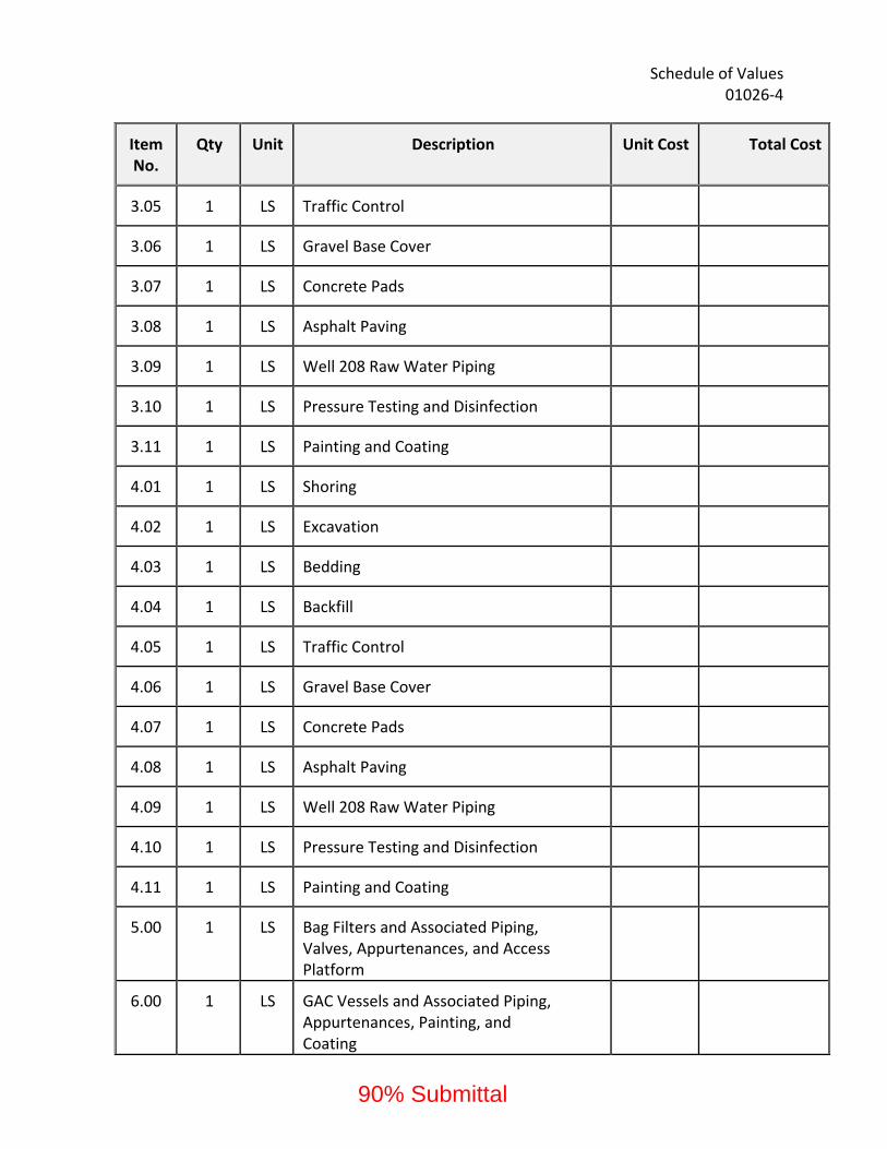
Schedule of Values 01026‐4
Item No.
Qty Unit Description Unit Cost Total Cost
3.05 1 LS Traffic Control
3.06 1 LS Gravel Base Cover
3.07 1 LS Concrete Pads
3.08 1 LS Asphalt Paving
3.09 1 LS Well 208 Raw Water Piping
3.10 1 LS Pressure Testing and Disinfection
3.11 1 LS Painting and Coating
4.01 1 LS Shoring
4.02 1 LS Excavation
4.03 1 LS Bedding
4.04 1 LS Backfill
4.05 1 LS Traffic Control
4.06 1 LS Gravel Base Cover
4.07 1 LS Concrete Pads
4.08 1 LS Asphalt Paving
4.09 1 LS Well 208 Raw Water Piping
4.10 1 LS Pressure Testing and Disinfection
4.11 1 LS Painting and Coating
5.00 1 LS Bag Filters and Associated Piping, Valves, Appurtenances, and Access Platform
6.00 1 LS GAC Vessels and Associated Piping, Appurtenances, Painting, and Coating
90% Submittal
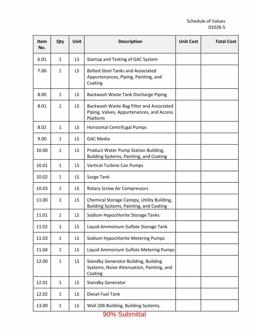
Schedule of Values 01026‐5
Item No.
Qty Unit Description Unit Cost Total Cost
6.01 1 LS Startup and Testing of GAC System
7.00 1 LS Bolted Steel Tanks and Associated Appurtenances, Piping, Painting, and Coating
8.00 1 LS Backwash Waste Tank Discharge Piping
8.01 1 LS Backwash Waste Bag Filter and Associated Piping, Valves, Appurtenances, and Access Platform
8.02 1 LS Horizontal Centrifugal Pumps
9.00 1 LS GAC Media
10.00 1 LS Product Water Pump Station Building, Building Systems, Painting, and Coating
10.01 1 LS Vertical Turbine Can Pumps
10.02 1 LS Surge Tank
10.03 1 LS Rotary Screw Air Compressors
11.00 1 LS Chemical Storage Canopy, Utility Building, Building Systems, Painting, and Coating
11.01 1 LS Sodium Hypochlorite Storage Tanks
11.02 1 LS Liquid Ammonium Sulfate Storage Tank
11.03 1 LS Sodium Hypochlorite Metering Pumps
11.04 1 LS Liquid Ammonium Sulfate Metering Pumps
12.00 1 LS Standby Generator Building, Building Systems, Noise Attenuation, Painting, and Coating
12.01 1 LS Standby Generator
12.02 1 LS Diesel Fuel Tank
13.00 1 LS Well 206 Building, Building Systems,
90% Submittal

Schedule of Values 01026‐6
Item No.
Qty Unit Description Unit Cost Total Cost
Painting, and Coating
13.01 1 LS Well 206 Deep Well Vertical Turbine Pump
14.00 1 LS Well 207 Building, Building Systems, Painting, and Coating
14.01 1 LS Well 207 Deep Well Vertical Turbine Pump
15.00 1 LS Well 208 Building, Building Systems, Painting, and Coating
15.01 1 LS Well 208 Deep Well Vertical Turbine Pump
15.02 1 LS Well 208 Sodium Hypochlorite Storage Tank
15.03 1 LS Well 208 Sodium Hypochlorite Metering Pumps
16.00 1 LS Well 209 Building, Building Systems, Painting, and Coating
16.01 1 LS Well 208 Deep Well Vertical Turbine Pump
17.00 1 LS Security Systems
18.00 1 LS Shoring (Bid Option 1)
18.01 1 LS Excavation (Bid Option 1)
18.02 1 LS Bedding (Bid Option 1)
18.03 1 LS Backfill (Bid Option 1)
18.04 1 LS Gravel Base Cover (Bid Option 1)
18.05 1 LS Concrete Pads (Bid Option 1)
18.06 1 LS Shoring (Bid Option 2)
18.07 1 LS Excavation (Bid Option 2)
18.08 1 LS Bedding (Bid Option 2)
90% Submittal

Schedule of Values 01026‐7
Item No.
Qty Unit Description Unit Cost Total Cost
18.09 1 LS Backfill (Bid Option 2)
18.10 1 LS Gravel Base Cover (Bid Option 2)
18.11 1 LS Concrete Pads (Bid Option 2)
18.12 1 LS Shoring (Bid Option 3)
18.13 1 LS Excavation (Bid Option 3)
18.14 1 LS Bedding (Bid Option 3)
18.15 1 LS Backfill (Bid Option 3)
18.16 1 LS Gravel Base Cover (Bid Option 3)
18.17 1 LS Concrete Pads (Bid Option 3)
18.18 1 LS Green Sand Filter Piping (Bid Option 1)
18.19 1 LS Non‐Regenerable Ion Exchange Influent/Effluent Piping (Bid Option 2)
18.20 1 LS Regenerable Ion Exchange Influent/Effluent Piping (Bid Option 3)
18.21 1 LS Brine Piping (Bid Option 3)
18.22 1 LS Waste Brine Piping (Bid Option 3)
18.23 1 LS Sodium Hypochlorite Injection Lines (Bid Option 1)
18.24 1 LS Sodium Bisulfite Injection Lines (Bid Option 1)
18.25 1 LS Hydrochloric Acid Injection Lines (Bid Option 3)
18.26 1 LS Sample Piping (Bid Option 1)
18.27 1 LS Sample Piping (Bid Option 3)
18.28 1 LS Miscellaneous Valves and Appurtenances (Bid Option 1)
90% Submittal

Schedule of Values 01026‐8
Item No.
Qty Unit Description Unit Cost Total Cost
18.29 1 LS Miscellaneous Valves and Appurtenances (Bid Option 2)
18.30 1 LS Miscellaneous Valves and Appurtenances (Bid Option 3)
18.31 1 LS Pressure Testing and Disinfection (Bid Option 1)
18.32 1 LS Pressure Testing and Disinfection (Bid Option 2)
18.33 1 LS Pressure Testing and Disinfection (Bid Option 3)
19.00 1 LS Green Sand Filters and Associated Piping, Appurtenances, Painting, and Coating (Bid Option 1)
19.01 1 LS Green Sand Filter Media (Bid Option 1)
19.02 1 LS Startup and Testing of Green Sand Filters (Bid Option 1)
20.00 1 LS Non‐Regenerable Ion Exchange Treatment System and Associated Piping, Appurtenances, Painting, and Coating (Bid Option 2)
20.01 1 LS Non‐Regenerable Ion Exchange Resin (Bid Option 2)
20.02 1 LS Startup and Testing of Non‐Regenerable Ion Exchange System (Bid Option 2)
21.00 1 LS Ion Exchange Treatment Building, Building Systems, Painting, and Coating (Bid Option 3)
21.01 1 LS Regenerable Ion Exchange Treatment System, Process Pumps, and Process Tanks (Bid Option 3)
21.02 1 LS Regenerable Ion Exchange Resin (Bid Option 3)
21.03 1 LS Brine Making Tanks, Piping, and Appurtenances (Bid Option 3)
90% Submittal
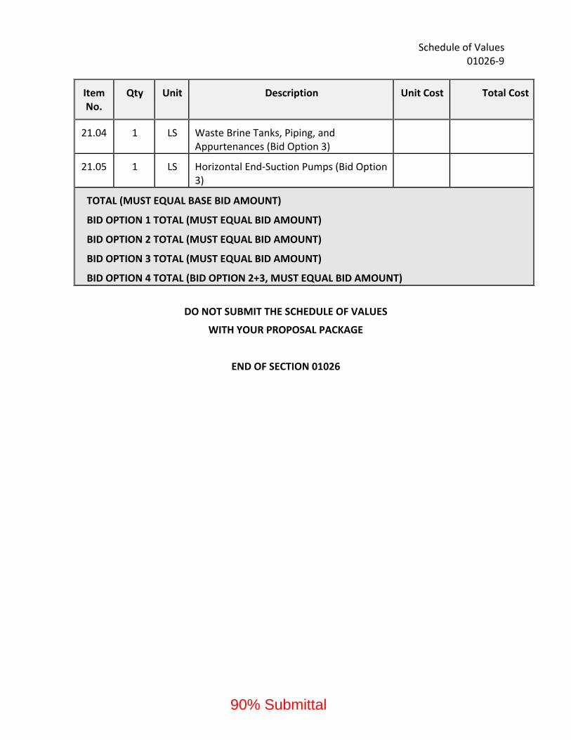
Schedule of Values 01026‐9
Item No.
Qty Unit Description Unit Cost Total Cost
21.04 1 LS Waste Brine Tanks, Piping, and Appurtenances (Bid Option 3)
21.05 1 LS Horizontal End‐Suction Pumps (Bid Option 3)
TOTAL (MUST EQUAL BASE BID AMOUNT)
BID OPTION 1 TOTAL (MUST EQUAL BID AMOUNT)
BID OPTION 2 TOTAL (MUST EQUAL BID AMOUNT)
BID OPTION 3 TOTAL (MUST EQUAL BID AMOUNT)
BID OPTION 4 TOTAL (BID OPTION 2+3, MUST EQUAL BID AMOUNT)
DO NOT SUBMIT THE SCHEDULE OF VALUES
WITH YOUR PROPOSAL PACKAGE
END OF SECTION 01026
90% Submittal
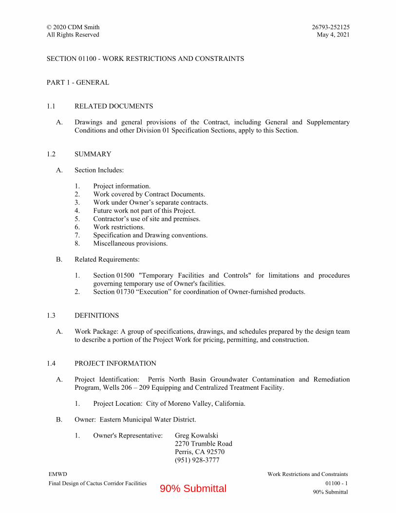
© 2020 CDM Smith 26793-252125 All Rights Reserved May 4, 2021
EMWD Work Restrictions and Constraints Final Design of Cactus Corridor Facilities 01100 - 1
90% Submittal
SECTION 01100 - WORK RESTRICTIONS AND CONSTRAINTS
PART 1 - GENERAL
1.1 RELATED DOCUMENTS
A. Drawings and general provisions of the Contract, including General and Supplementary Conditions and other Division 01 Specification Sections, apply to this Section.
1.2 SUMMARY
A. Section Includes:
1. Project information. 2. Work covered by Contract Documents. 3. Work under Owner’s separate contracts. 4. Future work not part of this Project. 5. Contractor’s use of site and premises. 6. Work restrictions. 7. Specification and Drawing conventions. 8. Miscellaneous provisions.
B. Related Requirements:
1. Section 01500 "Temporary Facilities and Controls" for limitations and procedures governing temporary use of Owner's facilities.
2. Section 01730 “Execution” for coordination of Owner-furnished products.
1.3 DEFINITIONS
A. Work Package: A group of specifications, drawings, and schedules prepared by the design team to describe a portion of the Project Work for pricing, permitting, and construction.
1.4 PROJECT INFORMATION
A. Project Identification: Perris North Basin Groundwater Contamination and Remediation Program, Wells 206 – 209 Equipping and Centralized Treatment Facility.
1. Project Location: City of Moreno Valley, California.
B. Owner: Eastern Municipal Water District.
1. Owner's Representative: Greg Kowalski 2270 Trumble Road Perris, CA 92570 (951) 928-3777
90% Submittal
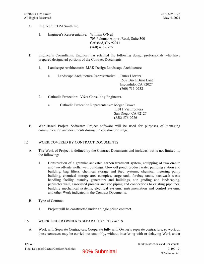
© 2020 CDM Smith 26793-252125 All Rights Reserved May 4, 2021
EMWD Work Restrictions and Constraints Final Design of Cactus Corridor Facilities 01100 - 2
90% Submittal
C. Engineer: CDM Smith Inc.
1. Engineer's Representative: William O’Neil 703 Palomar Airport Road, Suite 300 Carlsbad, CA 92011 (760) 438-7755
D. Engineer's Consultants: Engineer has retained the following design professionals who have prepared designated portions of the Contract Documents:
1. Landscape Architecture: MAK Design Landscape Architecture.
a. Landscape Architecture Representative: James Lievers 1537 Birch Briar Lane Escondido, CA 92027 (760) 715-0732
2. Cathodic Protection: V&A Consulting Engineers.
a. Cathodic Protection Representative: Megan Brown 11011 Via Frontera San Diego, CA 92127 (858) 576-0226
E. Web-Based Project Software: Project software will be used for purposes of managing communication and documents during the construction stage.
1.5 WORK COVERED BY CONTRACT DOCUMENTS
A. The Work of Project is defined by the Contract Documents and includes, but is not limited to, the following:
1. Construction of a granular activated carbon treatment system, equipping of two on-site and two off-site wells, well buildings, blow-off pond, product water pumping station and building, bag filters, chemical storage and feed systems, chemical metering pump building, chemical storage area canopies, surge tank, forebay tanks, backwash waste handling facility, standby generators and buildings, site grading and landscaping, perimeter wall, associated process and site piping and connections to existing pipelines, building mechanical systems, electrical systems, instrumentation and control systems, and other Work indicated in the Contract Documents.
B. Type of Contract:
1. Project will be constructed under a single prime contract.
1.6 WORK UNDER OWNER’S SEPARATE CONTRACTS
A. Work with Separate Contractors: Cooperate fully with Owner’s separate contractors, so work on those contracts may be carried out smoothly, without interfering with or delaying Work under
90% Submittal

© 2020 CDM Smith 26793-252125 All Rights Reserved May 4, 2021
EMWD Work Restrictions and Constraints Final Design of Cactus Corridor Facilities 01100 - 3
90% Submittal
this Contract or other contracts. Coordinate the Work of this Contract with work performed under Owner’s separate contracts.
B. Preceding Work: Owner will award separate contract(s) for the following construction operations at Project site. Those operations are scheduled to be substantially complete before Work under this Contract begins or may be partially conducted simultaneously with Work under this Contract.
1. Well Drilling: To drill and develop the four wells that will be equipped under this Contract.
2. Cactus II Feeder: To construct a turnout facility on the project site. Connections to piping associated with the turnout will be made under this Contract.
C. Future Work Not Part of this Contract: The Contract Documents include requirements that will allow Owner to carry out future work following completion of this Project; provide for the following future work:
1. Construction of additional treatment processes.
1.7 CONTRACTOR’S USE OF SITE AND PREMISES
A. Unrestricted Use of Site: Contractor shall have full use of Project site for construction operations during construction period. Contractor's use of Project site is limited only by Owner's right to perform work or to retain other contractors on portions of Project.
B. Limits on Use of Site: Limit use of Project site to areas within the Contract limits indicated. Do not disturb portions of Project site beyond areas in which the Work is indicated.
1. Driveways, Walkways and Entrances: Keep driveways and entrances serving premises clear and available to Owner, Owner's employees, and emergency vehicles at all times. Do not use these areas for parking or for storage of materials.
a. Schedule deliveries to minimize use of driveways and entrances by construction operations.
b. Schedule deliveries to minimize space and time requirements for storage of materials and equipment on-site.
1.8 WORK RESTRICTIONS
A. Comply with restrictions on construction operations.
1. Comply with limitations on use of public streets, work on public streets, rights of way, and other requirements of authorities having jurisdiction.
B. On-Site Work Hours: Limit work to between 8:00 a.m. to 5:00 p.m., Monday through Friday, unless otherwise indicated. Work hours may be modified to meet Project requirements if approved by Owner and authorities having jurisdiction.
1. Weekend Hours: Not permitted without authorization from the District. 2. Early Morning Hours: Not permitted without authorization from the District.
90% Submittal

© 2020 CDM Smith 26793-252125 All Rights Reserved May 4, 2021
EMWD Work Restrictions and Constraints Final Design of Cactus Corridor Facilities 01100 - 4
90% Submittal
3. Hours for Utility Shutdowns: As approved by the District, maximum shutdown duration is 4 hours.
C. On-Site Work Day restrictions: Do not perform work resulting in utility shutdowns or resulting in noisy activity on-site during work black-out days.
D. Existing Utility Interruptions: Do not interrupt utilities serving facilities occupied by Owner or others unless permitted under the following conditions and then only after arranging for temporary utility services according to requirements indicated:
1. Notify Engineer not less than two days in advance of proposed utility interruptions. 2. Obtain Engineer's written permission before proceeding with utility interruptions.
E. Noise, Vibration, Dust, and Odors: Coordinate operations that may result in high levels of noise and vibration, dust, odors, or other disruption to Owner occupancy with Owner.
1. Notify Engineer not less than two days in advance of proposed disruptive operations. 2. Obtain Engineer's written permission before proceeding with disruptive operations.
F. Smoking and Controlled Substance Restrictions: Use of tobacco products, alcoholic beverages, and other controlled substances on Project site is not permitted.
G. Employee Identification: Provide identification tags for Contractor personnel working on Project site. Require personnel to use identification tags at all times.
H. Employee Screening: Comply with Owner's requirements for drug and background screening of Contractor personnel working on Project site.
1. Maintain list of approved screened personnel with Owner's representative.
1.9 SPECIFICATION AND DRAWING CONVENTIONS
A. Specification Content: The Specifications use certain conventions for the style of language and the intended meaning of certain terms, words, and phrases when used in particular situations. These conventions are as follows:
1. Imperative mood and streamlined language are generally used in the Specifications. The words "shall," "shall be," or "shall comply with," depending on the context, are implied where a colon (:) is used within a sentence or phrase.
2. Text Color: Text used in the Specifications, including units of measure, manufacturer and product names, and other text may appear in multiple colors or underlined as part of a hyperlink; no emphasis is implied by text with these characteristics.
3. Hypertext: Text used in the Specifications may contain hyperlinks. Hyperlinks may allow for access to linked information that is not residing in the Specifications. Unless otherwise indicated, linked information is not part of the Contract Documents.
4. Specification requirements are to be performed by Contractor unless specifically stated otherwise.
B. Division 0 Contracting Requirements: General provisions of the Contract, including General and Supplementary Conditions, apply to all Sections of the Specifications.
90% Submittal
© 2020 CDM Smith 26793-252125 All Rights Reserved May 4, 2021
EMWD Work Restrictions and Constraints Final Design of Cactus Corridor Facilities 01100 - 5
90% Submittal
C. Division 1 General Requirements: Requirements of Sections in Division 1 apply to the Work of all Sections in the Specifications.
D. Drawing Coordination: Requirements for materials and products identified on Drawings are described in detail in the Specifications. One or more of the following are used on Drawings to identify materials and products:
1. Terminology: Materials and products are identified by the typical generic terms used in the individual Specifications Sections.
2. Abbreviations: Materials and products are identified by abbreviations scheduled on Drawings and published as part of the U.S. National CAD Standard.
3. Keynoting: Materials and products are identified by reference keynotes referencing Specification Section numbers found in this Project Manual.
PART 2 - PRODUCTS (NOT USED)
PART 3 - EXECUTION (NOT USED)
END OF SECTION 01100
90% Submittal

© 2020 CDM Smith 26793-252125
All Rights Reserved May 4, 2021
EMWD Substitution Procedures
Final Design of Cactus Corridor Facilities 01250 - 1
90% Submittal
SECTION 01250 - SUBSTITUTION PROCEDURES
PART 1 - GENERAL
1.1 RELATED DOCUMENTS
A. Drawings and general provisions of the Contract, including General and Supplementary
Conditions and other Division 01 Specification Sections, apply to this Section.
1.2 SUMMARY
A. Section includes administrative and procedural requirements for substitutions.
B. Related Requirements:
1. Section 01600 "Product Requirements" for requirements for submitting comparable
product submittals for products by listed manufacturers.
1.3 DEFINITIONS
A. Substitutions: Changes in products, materials, equipment, and methods of construction from
those required by the Contract Documents.
1. Substitutions for Cause: Changes proposed by Contractor that are required due to
changed Project conditions, such as unavailability of product, regulatory changes, or
unavailability of required warranty terms.
2. Substitutions for Convenience: Changes proposed by Contractor or Owner that are not
required to meet other Project requirements but may offer advantage to Contractor or
Owner.
1.4 ACTION SUBMITTALS
A. Substitution Requests: Submit documentation identifying product or fabrication or installation
method to be replaced. Include Specification Section number and title and Drawing numbers
and titles.
1. Substitution Request Form: Use form acceptable to Engineer.
2. Documentation: Show compliance with requirements for substitutions and the following,
as applicable:
a. Statement indicating why specified product or fabrication or installation method
cannot be provided, if applicable.
b. Coordination of information, including a list of changes or revisions needed to
other parts of the Work and to construction performed by Owner and separate
contractors that will be necessary to accommodate proposed substitution.
90% Submittal

© 2020 CDM Smith 26793-252125
All Rights Reserved May 4, 2021
EMWD Substitution Procedures
Final Design of Cactus Corridor Facilities 01250 - 2
90% Submittal
c. Detailed comparison of significant qualities of proposed substitutions with those of
the Work specified. Include annotated copy of applicable Specification Section.
Significant qualities may include attributes, such as performance, weight, size,
durability, visual effect, sustainable design characteristics, warranties, and specific
features and requirements indicated. Indicate deviations, if any, from the Work
specified.
d. Product Data, including drawings and descriptions of products and fabrication and
installation procedures.
e. Samples, where applicable or requested.
f. Certificates and qualification data, where applicable or requested.
g. List of similar installations for completed projects, with project names and
addresses as well as names and addresses of Engineers and owners.
h. Material test reports from a qualified testing agency, indicating and interpreting
test results for compliance with requirements indicated.
i. Detailed comparison of Contractor's construction schedule using proposed
substitutions with products specified for the Work, including effect on the overall
Contract Time. If specified product or method of construction cannot be provided
within the Contract Time, include letter from manufacturer, on manufacturer's
letterhead, stating date of receipt of purchase order, lack of availability, or delays
in delivery.
j. Cost information, including a proposal of change, if any, in the Contract Sum.
k. Contractor's certification that proposed substitution complies with requirements in
the Contract Documents, except as indicated in substitution request, is compatible
with related materials and is appropriate for applications indicated.
l. Contractor's waiver of rights to additional payment or time that may subsequently
become necessary because of failure of proposed substitution to produce indicated
results.
3. Engineer's Action: If necessary, Engineer will request additional information or
documentation for evaluation within seven days of receipt of a request for substitution.
Engineer will notify Contractor of acceptance or rejection of proposed substitution within
15 days of receipt of request, or seven days of receipt of additional information or
documentation, whichever is later.
a. Forms of Acceptance: Change Order, Construction Change Directive, or
Engineer's Supplemental Instructions for minor changes in the Work.
b. Use product specified if Engineer does not issue a decision on use of a proposed
substitution within time allocated.
1.5 QUALITY ASSURANCE
A. Compatibility of Substitutions: Investigate and document compatibility of proposed substitution
with related products and materials. Engage a qualified testing agency to perform compatibility
tests recommended by manufacturers.
1.6 PROCEDURES
A. Coordination: Revise or adjust affected work as necessary to integrate work of the approved
substitutions.
90% Submittal

© 2020 CDM Smith 26793-252125
All Rights Reserved May 4, 2021
EMWD Substitution Procedures
Final Design of Cactus Corridor Facilities 01250 - 3
90% Submittal
1.7 SUBSTITUTIONS
A. Substitutions for Cause: Submit requests for substitution immediately on discovery of need for
change, but not later than 15 days prior to time required for preparation and review of related
submittals.
1. Conditions: Engineer will consider Contractor's request for substitution when the
following conditions are satisfied. If the following conditions are not satisfied, Engineer
will return requests without action, except to record noncompliance with these
requirements:
a. Requested substitution is consistent with the Contract Documents and will produce
indicated results.
b. Substitution request is fully documented and properly submitted.
c. Requested substitution will not adversely affect Contractor's construction schedule.
d. Requested substitution has received necessary approvals of authorities having
jurisdiction.
e. Requested substitution is compatible with other portions of the Work.
f. Requested substitution has been coordinated with other portions of the Work.
g. Requested substitution provides specified warranty.
h. If requested substitution involves more than one contractor, requested substitution
has been coordinated with other portions of the Work, is uniform and consistent, is
compatible with other products, and is acceptable to all contractors involved.
B. Substitutions for Convenience: Not allowed.
PART 2 - PRODUCTS (NOT USED)
PART 3 - EXECUTION (NOT USED)
END OF SECTION 01250
90% Submittal

© 2020 CDM Smith 26793-252125
All Rights Reserved May 4, 2021
EMWD Submittal Procedures
Final Design of Cactus Corridor Facilities 01330 - 1
90% Submittal
SECTION 01330 - SUBMITTAL PROCEDURES
PART 1 - GENERAL
1.1 RELATED DOCUMENTS
A. Drawings and general provisions of the Contract, including General and Supplementary
Conditions and other Division 1 Specification Sections, apply to this Section.
1.2 SUMMARY
A. Section Includes:
1. Submittal schedule requirements.
2. Administrative and procedural requirements for submittals.
B. Related Requirements:
1. Section 01400 "Quality Requirements" for submitting test and inspection reports, and
schedule of tests and inspections.
2. Section 01770 "Closeout Procedures" for submitting closeout submittals and maintenance
material submittals.
3. Section 01430 "Maintenance Manual Requirements" for submitting operation and
maintenance manuals.
4. Section 01783 "Project Record Documents" for submitting record Drawings, record
Specifications, and record Product Data.
5. Section 01790 "Demonstration and Training" for submitting video recordings of
demonstration of equipment and training of Owner's personnel.
1.3 DEFINITIONS
A. Action Submittals: Written and graphic information and physical samples that require
Engineer's responsive action. Action submittals are those submittals indicated in individual
Specification Sections as "action submittals."
B. Informational Submittals: Written and graphic information and physical samples that do not
require Engineer's responsive action. Submittals may be rejected for not complying with
requirements. Informational submittals are those submittals indicated in individual Specification
Sections as "informational submittals."
C. Mass Submittals: Six or more submittals or items in one day or 15 or more submittals or items
in one week.
90% Submittal

© 2020 CDM Smith 26793-252125
All Rights Reserved May 4, 2021
EMWD Submittal Procedures
Final Design of Cactus Corridor Facilities 01330 - 2
90% Submittal
1.4 SUBMITTAL SCHEDULE
A. Submittal Schedule: Submit, as an action submittal, a list of submittals, arranged in
chronological order by dates required by construction schedule. Include time required for
review, ordering, manufacturing, fabrication, and delivery when establishing dates. Include
additional time required for making corrections or revisions to submittals noted by Engineer and
additional time for handling and reviewing submittals required by those corrections.
1. Coordinate submittal schedule with list of subcontracts, the schedule of values, and
Contractor's construction schedule.
2. Initial Submittal Schedule: Submit concurrently with startup construction schedule.
Include submittals required during the first 60 days of construction. List those submittals
required to maintain orderly progress of the Work and those required early because of
long lead time for manufacture or fabrication.
3. Final Submittal Schedule: Submit concurrently with the first complete submittal of
Contractor's construction schedule.
a. Submit revised submittal schedule as required to reflect changes in current status
and timing for submittals.
4. Format: Arrange the following information in a tabular format:
a. Scheduled date for first submittal.
b. Specification Section number and title.
c. Submittal Category: Action; informational.
d. Name of subcontractor.
e. Description of the Work covered.
f. Scheduled date for Engineer's final release or approval.
g. Scheduled dates for purchasing.
h. Scheduled date of fabrication.
i. Scheduled dates for installation.
j. Activity or event number.
1.5 SUBMITTAL FORMATS
A. Numbering System: Utilize the following example submittal identification numbering system to
identify submittals and as file names for PDF submissions:
1. First Identifier - Alphabet Character: D, S, M or I which represents Shop Drawing
(including working drawings and product data), Sample, Manual (Operating &
Maintenance) or Informational, respectively.
2. Second Identifier - Next 6 or 8 Digits: Applicable Specification Section Number. Do not
mix submittals from different specification sections into a single submittal.
3. Third Identifier - Next Three Digits: Sequential number of each separate item or drawing
submitted under each Specification Section, in chronological order submitted, starting at
001.
4. Fourth Identifier - Last Alphabet Character: A to Z, indicating the submission (or
resubmission) of the same submittal, i.e., "A" = 1st submission, "B" = 2nd submission,
"C" = 3rd submission, etc.
5. EXAMPLE: D-03300A-008-B.
90% Submittal

© 2020 CDM Smith 26793-252125
All Rights Reserved May 4, 2021
EMWD Submittal Procedures
Final Design of Cactus Corridor Facilities 01330 - 3
90% Submittal
a. D = Shop Drawing.
b. 03300.13 = Section; use only 5 digits for sections that do not include 7 digits.
c. 008 = the eighth different submittal under this Section.
d. B = the second submission (first resubmission) of that particular shop drawing.
B. Submittal Information: Include the following information in each submittal:
1. Project name.
2. Date.
3. Name of Engineer.
4. Name of Construction Manager.
5. Name of Contractor.
6. Name of firm or entity that prepared submittal.
7. Names of subcontractor, manufacturer, and supplier.
8. Unique submittal number, including revision identifier. Include Specification Section
number with sequential alphanumeric identifier and alphanumeric suffix for resubmittals.
9. Category and type of submittal.
10. Submittal purpose and description.
11. Number and title of Specification Section, with paragraph number and generic name for
each of multiple items.
12. Drawing number and detail references, as appropriate.
13. Indication of full or partial submittal.
14. Location(s) where product is to be installed, as appropriate.
15. Other necessary identification.
16. Remarks.
17. Signature of transmitter.
C. Options: Identify options requiring selection by Engineer.
D. Deviations and Additional Information: On each submittal, clearly indicate deviations from
requirements in the Contract Documents, including minor variations and limitations; include
relevant additional information and revisions, other than those requested by Engineer on
previous submittals. Indicate by highlighting on each submittal or noting on attached separate
sheet.
E. Electronic Submittals: Prepare submittals as PDF package, incorporating complete information
into each PDF file. Name PDF file with submittal number.
F. Submittals Utilizing Web-Based Project Software: Prepare submittals as PDF files or other
format indicated by Project management software.
1.6 SUBMITTAL PROCEDURES
A. Prepare and submit submittals required by individual Specification Sections. Types of
submittals are indicated in individual Specification Sections.
1. Email: Prepare submittals as PDF package and transmit to Engineer by sending via email.
Include PDF transmittal form. Include information in email subject line as requested by
Engineer.
90% Submittal
© 2020 CDM Smith 26793-252125
All Rights Reserved May 4, 2021
EMWD Submittal Procedures
Final Design of Cactus Corridor Facilities 01330 - 4
90% Submittal
a. Engineer will return annotated file. Annotate and retain one copy of file as a digital
Project Record Document file.
2. Web-Based Project Management Software: Prepare submittals in PDF form, and upload
to web-based Project management software website. Enter required data in web-based
software site to fully identify submittal.
B. Coordination: Coordinate preparation and processing of submittals with performance of
construction activities.
1. Coordinate each submittal with fabrication, purchasing, testing, delivery, other
submittals, and related activities that require sequential activity.
2. Submit all submittal items required for each Specification Section concurrently unless
partial submittals for portions of the Work are indicated on approved submittal schedule.
3. Submit action submittals and informational submittals required by the same Specification
Section as separate packages under separate transmittals.
4. Coordinate transmittal of submittals for related parts of the Work specified in different
Sections, so processing will not be delayed because of need to review submittals
concurrently for coordination.
a. Engineer reserves the right to withhold action on a submittal requiring
coordination with other submittals until related submittals are received.
C. Processing Time: Allow time for submittal review, including time for resubmittals, as follows.
Time for review shall commence on Engineer's receipt of submittal. No extension of the
Contract Time will be authorized because of failure to transmit submittals enough in advance of
the Work to permit processing, including resubmittals.
1. Initial Review: Allow 30 days for initial review of each submittal (and 45 days for multi-
discipline reviews). Allow additional time if coordination with subsequent submittals is
required. Engineer will advise Contractor when a submittal being processed must be
delayed for coordination.
2. Intermediate Review: If intermediate submittal is necessary, process it in same manner as
initial submittal.
3. Resubmittal Review: Allow 15 days for review of each resubmittal.
4. Sequential Review: Where sequential review of submittals by Engineer's consultants,
Owner, or other parties is indicated, allow 21 days for initial review of each submittal.
5. Concurrent Consultant Review: Where the Contract Documents indicate that submittals
may be transmitted simultaneously to Engineer and to Engineer's consultants, allow 30
days for review of each submittal. Submittal will be returned to Engineer before being
returned to Contractor.
D. Resubmittals: Make resubmittals in same form and number of copies as initial submittal.
1. Note date and content of previous submittal.
2. Note date and content of revision in label or title block and clearly indicate extent of
revision.
3. Resubmit submittals until they are marked with approval notation from Engineer's action
stamp.
4. Repetitive Reviews: Shop drawings, O&M manuals, and other submittals will be
reviewed no more than twice at the Owner's expense. All subsequent reviews will be
90% Submittal

© 2020 CDM Smith 26793-252125
All Rights Reserved May 4, 2021
EMWD Submittal Procedures
Final Design of Cactus Corridor Facilities 01330 - 5
90% Submittal
performed at the Contractor's expense. Reimburse the Owner for all costs invoiced by
Engineer for the third and subsequent reviews.
E. Distribution: Furnish copies of final submittals to manufacturers, subcontractors, suppliers,
fabricators, installers, authorities having jurisdiction, and others as necessary for performance of
construction activities. Show distribution on transmittal forms.
F. Use for Construction: Retain complete copies of submittals on Project site. Use only final action
submittals that are marked with approval notation from Engineer's action stamp.
1.7 SUBMITTAL REQUIREMENTS
A. Product Data: Collect information into a single submittal for each element of construction and
type of product or equipment.
1. If information must be specially prepared for submittal because standard published data
are unsuitable for use, submit as Shop Drawings, not as Product Data.
2. Mark each copy of each submittal to show which products and options are applicable.
3. Include the following information, as applicable:
a. Manufacturer's catalog cuts.
b. Manufacturer's product specifications.
c. Standard color charts.
d. Statement of compliance with specified referenced standards.
e. Testing by recognized testing agency.
f. Application of testing agency labels and seals.
g. Notation of coordination requirements.
h. Availability and delivery time information.
4. For equipment, include the following in addition to the above, as applicable:
a. Wiring diagrams that show factory-installed wiring.
b. Printed performance curves.
c. Operational range diagrams.
d. Clearances required to other construction, if not indicated on accompanying Shop
Drawings.
5. Submit Product Data before Shop Drawings, and before or concurrently with Samples.
B. Shop Drawings: Prepare Project-specific information, drawn accurately to scale. Do not base
Shop Drawings on reproductions of the Contract Documents or standard printed data unless
submittal based on Engineer's digital data drawing files is otherwise permitted.
1. Preparation: Fully illustrate requirements in the Contract Documents. Include the
following information, as applicable:
a. Identification of products.
b. Schedules.
c. Compliance with specified standards.
d. Notation of coordination requirements.
90% Submittal

© 2020 CDM Smith 26793-252125
All Rights Reserved May 4, 2021
EMWD Submittal Procedures
Final Design of Cactus Corridor Facilities 01330 - 6
90% Submittal
e. Notation of dimensions established by field measurement.
f. Relationship and attachment to adjoining construction clearly indicated.
g. Seal and signature of professional engineer if specified.
2. Paper Sheet Size: Except for templates, patterns, and similar full-size Drawings, submit
Shop Drawings on sheets at least 8-1/2 by 11 inches, but no larger than 30 by 42 inches.
C. Samples: Submit Samples for review of type, color, pattern, and texture for a check of these
characteristics with other materials.
1. Transmit Samples that contain multiple, related components such as accessories together
in one submittal package.
2. Identification: Permanently attach label on unexposed side of Samples that includes the
following:
a. Project name and submittal number.
b. Generic description of Sample.
c. Product name and name of manufacturer.
d. Sample source.
e. Number and title of applicable Specification Section.
f. Specification paragraph number and generic name of each item.
3. Email Transmittal: Provide PDF transmittal. Include digital image file illustrating Sample
characteristics and identification information for record.
4. Web-Based Project Management Software: Prepare submittals in PDF form, and upload
to web-based Project software website. Enter required data in web-based software site to
fully identify submittal.
5. Paper Transmittal: Include paper transmittal, including complete submittal information
indicated.
6. Disposition: Maintain sets of approved Samples at Project site, available for quality-
control comparisons throughout the course of construction activity. Sample sets may be
used to determine final acceptance of construction associated with each set.
a. Samples that may be incorporated into the Work are indicated in individual
Specification Sections. Such Samples must be in an undamaged condition at time
of use.
b. Samples not incorporated into the Work, or otherwise designated as Owner's
property, are the property of Contractor.
7. Samples for Initial Selection: Submit manufacturer's color charts consisting of units or
sections of units, showing the full range of colors, textures, and patterns available.
a. Number of Samples: Submit one full set(s) of available choices where color,
pattern, texture, or similar characteristics are required to be selected from
manufacturer's product line. Engineer will return submittal with options selected.
8. Samples for Verification: Submit full-size units or Samples of size indicated, prepared
from same material to be used for the Work, cured and finished in manner specified, and
physically identical with material or product proposed for use, and that show full range of
color and texture variations expected. Samples include, but are not limited to, the
following: partial sections of manufactured or fabricated components; small cuts or
90% Submittal
© 2020 CDM Smith 26793-252125
All Rights Reserved May 4, 2021
EMWD Submittal Procedures
Final Design of Cactus Corridor Facilities 01330 - 7
90% Submittal
containers of materials; complete units of repetitively used materials; swatches showing
color, texture, and pattern; color range sets; and components used for independent testing
and inspection.
a. Number of Samples: Submit three sets of Samples. Engineer will retain two
Sample sets; remainder will be returned. Mark up and retain one returned Sample
set as a project record Sample.
1) Submit a single Sample where assembly details, workmanship, fabrication
techniques, connections, operation, and other similar characteristics are to
be demonstrated.
2) If variation in color, pattern, texture, or other characteristic is inherent in
material or product represented by a Sample, submit at least three sets of
paired units that show approximate limits of variations.
D. Product Schedule: As required in individual Specification Sections, prepare a written summary
indicating types of products required for the Work and their intended location. Include the
following information in tabular form:
1. Type of product. Include unique identifier for each product indicated in the Contract
Documents or assigned by Contractor if none is indicated.
2. Manufacturer and product name, and model number if applicable.
3. Number and name of room or space.
4. Location within room or space.
E. Qualification Data: Prepare written information that demonstrates capabilities and experience of
firm or person. Include lists of completed projects with project names and addresses, contact
information of architects and owners, and other information specified.
F. Design Data: Prepare and submit written and graphic information indicating compliance with
indicated performance and design criteria in individual Specification Sections. Include list of
assumptions and summary of loads. Include load diagrams if applicable. Provide name and
version of software, if any, used for calculations. Number each page of submittal.
G. Certificates:
1. Certificates and Certifications Submittals: Submit a statement that includes signature of
entity responsible for preparing certification. Certificates and certifications shall be
signed by an officer or other individual authorized to sign documents on behalf of that
entity. Provide a notarized signature where indicated.
2. Insert definition of Contractor certificates here if required by individual Specification
Sections. See the Evaluations.
3. Contractor’s Certification: Each shop drawing, working drawing, product data, and
sample shall have affixed to it the following Certification Statement:
a. "Certification Statement: by this submittal, I hereby represent that I have
determined and verified all field measurements, field construction criteria,
materials, dimensions, catalog numbers and similar data and I have checked and
coordinated each item with other applicable approved shop drawings and all
Contract requirements. "
90% Submittal
© 2020 CDM Smith 26793-252125
All Rights Reserved May 4, 2021
EMWD Submittal Procedures
Final Design of Cactus Corridor Facilities 01330 - 8
90% Submittal
4. Installer Certificates: Submit written statements on manufacturer's letterhead, certifying
that Installer complies with requirements in the Contract Documents and, where required,
is authorized by manufacturer for this specific Project.
5. Manufacturer Certificates: Submit written statements on manufacturer's letterhead,
certifying that manufacturer complies with requirements in the Contract Documents.
Include evidence of manufacturing experience where required.
6. Material Certificates: Submit written statements on manufacturer's letterhead certifying
that material complies with requirements in the Contract Documents.
7. Product Certificates: Submit written statements on manufacturer's letterhead certifying
that product complies with requirements in the Contract Documents.
8. Welding Certificates: Prepare written certification that welding procedures and personnel
comply with requirements in the Contract Documents. Submit record of AWS
B2.1/B2.1M on AWS forms. Include names of firms and personnel certified.
H. Test and Research Reports:
1. Compatibility Test Reports: Submit reports written by a qualified testing agency, on
testing agency's standard form, indicating and interpreting results of compatibility tests
performed before installation of product. Include written recommendations for substrate
preparation and primers required.
2. Field Test Reports: Submit written reports indicating and interpreting results of field tests
performed either during installation of product or after product is installed in its final
location, for compliance with requirements in the Contract Documents.
3. Material Test Reports: Submit reports written by a qualified testing agency, on testing
agency's standard form, indicating and interpreting test results of material for compliance
with requirements in the Contract Documents.
4. Preconstruction Test Reports: Submit reports written by a qualified testing agency, on
testing agency's standard form, indicating and interpreting results of tests performed
before installation of product, for compliance with performance requirements in the
Contract Documents.
5. Product Test Reports: Submit written reports indicating that current product produced by
manufacturer complies with requirements in the Contract Documents. Base reports on
evaluation of tests performed by manufacturer and witnessed by a qualified testing
agency, or on comprehensive tests performed by a qualified testing agency.
6. Research Reports: Submit written evidence, from a model code organization acceptable
to authorities having jurisdiction, that product complies with building code in effect for
Project. Include the following information:
a. Name of evaluation organization.
b. Date of evaluation.
c. Time period when report is in effect.
d. Product and manufacturers' names.
e. Description of product.
f. Test procedures and results.
g. Limitations of use.
90% Submittal

© 2020 CDM Smith 26793-252125
All Rights Reserved May 4, 2021
EMWD Submittal Procedures
Final Design of Cactus Corridor Facilities 01330 - 9
90% Submittal
1.8 DELEGATED-DESIGN SERVICES
A. Performance and Design Criteria: Where professional design services or certifications by a
design professional are specifically required of Contractor by the Contract Documents, provide
products and systems complying with specific performance and design criteria indicated.
1. If criteria indicated are insufficient to perform services or certification required, submit a
written request for additional information to Engineer.
B. Delegated-Design Services Certification: In addition to Shop Drawings, Product Data, and other
required submittals, submit digitally signed PDF file, signed and sealed by the responsible
design professional, for each product and system specifically assigned to Contractor to be
designed or certified by a design professional.
1. Indicate that products and systems comply with performance and design criteria in the
Contract Documents. Include list of codes, loads, and other factors used in performing
these services.
1.9 PROPOSED PRODUCT LIST
A. Within 15days after date of Notice to Proceed, submit list of major products proposed for use,
with name of manufacturer, trade name, and model number of each product.
B. For products specified only by reference standards, indicate manufacturer, trade name, model or
catalog designation, and reference standards.
1.10 CONTRACTOR'S REVIEW
A. Action Submittals and Informational Submittals: Review each submittal and check for
coordination with other Work of the Contract and for compliance with the Contract Documents.
Note corrections and field dimensions. Mark with approval stamp before submitting to
Engineer.
B. Contractor Responsible for:
1. Determination and verification of materials including manufacturer’s catalog numbers.
2. Determination and verification of field measurements and field construction criteria.
3. Checking and coordinating information in submittal with requirements of Work and of
Contract Documents.
4. Determination of accuracy and completeness of dimensions and quantities.
5. Confirmation and coordination of dimensions and field conditions at Site.
6. Construction means, techniques, sequences, and procedures.
7. Safety precautions.
8. Coordination and performance of Work of all trades.
9. Other requirements enumerated in Contract Documents.
C. Contractor's Approval: Indicate Contractor's approval for each submittal with a uniform
approval stamp. Include name of reviewer, date of Contractor's approval, and statement
90% Submittal

© 2020 CDM Smith 26793-252125
All Rights Reserved May 4, 2021
EMWD Submittal Procedures
Final Design of Cactus Corridor Facilities 01330 - 10
90% Submittal
certifying that submittal has been reviewed, checked, and approved for compliance with the
Contract Documents.
1. Engineer will not review submittals received from Contractor that do not have
Contractor's review and approval.
1.11 ENGINEER'S REVIEW
A. Do not make mass submittals to Engineer. If mass submittals are received, Engineer's review
time stated above will be extended as necessary to perform proper review. Engineer will review
mass submittals based on priority determined by Engineer after consultation with Owner and
Contractor.
B. Action Submittals: Engineer will review each submittal, indicate corrections or revisions
required, and return.
C. Informational Submittals: Engineer will review each submittal and will not return it, or will
return it if it does not comply with requirements. Engineer will forward each submittal to
appropriate party.
D. Partial submittals prepared for a portion of the Work will be reviewed when use of partial
submittals has received prior approval from Engineer.
E. Incomplete submittals are unacceptable, will be considered nonresponsive, and will be returned
for resubmittal without review.
F. Engineer will return without review submittals received from sources other than Contractor.
G. Submittals not required by the Contract Documents will be returned by Engineer without action.
H. Shop drawings will be returned to the Contractor with one of the following codes.
1. "APPROVED" - This code is assigned when there are no notations or comments on the
submittal. When returned under this code the Contractor may release the equipment
and/or material for manufacture.
2. "APPROVED AS NOTED" - This code is assigned when a confirmation of the notations
and comments IS NOT required by the Contractor. The Contractor may release the
equipment or material for manufacture; however, all notations and comments must be
incorporated into the final product.
3. "APPROVED AS NOTED/RESUBMIT" - This combination of codes is assigned when
notations and comments are extensive enough to require a resubmittal of the package.
The Contractor may release the equipment or material for manufacture; however, all
notations and comments must be incorporated into the final product. The resubmittal is to
address all comments, omissions and non-conforming items that were noted. An
additional box is checked to indicate whether the resubmission is for the complete
package, or for parts of the package. If no box is checked, a complete resubmittal shall be
provided. Review code may designate if a partial or full submittal is required. If full
submittal is required, a complete resubmittal package addressing all comments shall be
provided. If a partial submittal is designated, resubmittal shall only include information
pertaining to those items noted in review comments requiring clarification and any
90% Submittal

© 2020 CDM Smith 26793-252125
All Rights Reserved May 4, 2021
EMWD Submittal Procedures
Final Design of Cactus Corridor Facilities 01330 - 11
90% Submittal
portions of submittal impacted as a result of the response. Resubmittal is to be received
by the Engineer within 30 calendar days of the date of the Engineer's transmittal
requiring the resubmittal.
4. "REJECTED" - This code is assigned when the submittal does not meet the intent of the
Contract Documents. The Contractor must resubmit the entire package revised to bring
the submittal into conformance. It may be necessary to resubmit using a different
manufacturer/vendor to meet the requirements of the Contract Documents.
5. "RECEIPT ACKNOWLEDGED (Not subject to Engineer's Approval)" - This code is
assigned to acknowledge receipt of a submittal that is not subject to the Engineer's
approval. This code is generally used with submittals involving the Contractor’s means
and methods of construction work plans, and health and safety plans.
1.12 ELECTRONIC CAD FILES OF PROJECT DRAWINGS
A. Electronic CAD Files of Project Drawings: May only be used to expedite production of Shop
Drawings for the Project. Use for other Projects or purposes is not allowed.
B. Electronic CAD Files of Project Drawings: Distributed only under the following conditions:
1. Use of files is solely at receiver's risk. Engineer does not warrant accuracy of files.
Receiving files in electronic form does not relieve receiver of responsibilities for
measurements, dimensions, and quantities set forth in Contract Documents. In the event
of ambiguity, discrepancy, or conflict between information on electronic media and that
in Contract Documents, notify Engineer of discrepancy and use information in hard-copy
Drawings and Specifications.
2. CAD files do not necessarily represent the latest Contract Documents, existing
conditions, and as-built conditions. Receiver is responsible for determining and
complying with these conditions and for incorporating addenda and modifications.
3. User is responsible for removing information not normally provided on Shop Drawings
and removing references to Contract Documents. Shop Drawings submitted with
information associated with other trades or with references to Contract Documents will
not be reviewed and will be immediately returned.
4. Receiver shall not hold Engineer responsible for data or file clean-up required to make
files usable, nor for error or malfunction in translation, interpretation, or use of this
electronic information.
5. Receiver shall understand that even though Engineer has computer virus scanning
software to detect presence of computer viruses, there is no guarantee that computer
viruses are not present in files or in electronic media.
6. Receiver shall not hold Engineer responsible for such viruses or their consequences, and
shall hold Engineer/Engineer harmless against costs, losses, or damage caused by
presence of computer virus in files or media.
PART 2 - PRODUCTS (NOT USED)
PART 3 - EXECUTION (NOT USED)
END OF SECTION 01330
90% Submittal

© 2020 CDM Smith 26793-252125
All Rights Reserved May 4, 2021
EMWD Quality Requirements
Final Design of Cactus Corridor Facilities 01400 - 1
90% Submittal
SECTION 01400 - QUALITY REQUIREMENTS
PART 1 - GENERAL
1.1 RELATED DOCUMENTS
A. Drawings and general provisions of the Contract, including General and Supplementary
Conditions and other Division 01 Specification Sections, apply to this Section.
1.2 SUMMARY
A. Section includes administrative and procedural requirements for quality assurance and quality
control.
B. Testing and inspection services are required to verify compliance with requirements specified or
indicated. These services do not relieve Contractor of responsibility for compliance with the
Contract Document requirements.
1. Specific quality-assurance and quality-control requirements for individual work results
are specified in their respective Specification Sections. Requirements in individual
Sections may also cover production of standard products.
2. Specified tests, inspections, and related actions do not limit Contractor's other quality-
assurance and quality-control procedures that facilitate compliance with the Contract
Document requirements.
3. Requirements for Contractor to provide quality-assurance and quality-control services
required by Engineer, Owner, or authorities having jurisdiction are not limited by
provisions of this Section.
1.3 DEFINITIONS
A. Experienced: When used with an entity or individual, "experienced," unless otherwise further
described, means having successfully completed a minimum of five previous projects similar in
nature, size, and extent to this Project; being familiar with special requirements indicated; and
having complied with requirements of authorities having jurisdiction.
B. Field Quality-Control Tests and Inspections: Tests and inspections that are performed on-site
for installation of the Work and for completed Work.
C. Installer/Applicator/Erector: Contractor or another entity engaged by Contractor as an
employee, subcontractor, or sub-subcontractor, to perform a particular construction operation,
including installation, erection, application, assembly, and similar operations.
1. Use of trade-specific terminology in referring to a Work result does not require that
certain construction activities specified apply exclusively to specific trade(s).
A. Preconstruction Testing: Tests and inspections performed specifically for Project before
products and materials are incorporated into the Work, to verify performance or compliance
90% Submittal

© 2020 CDM Smith 26793-252125
All Rights Reserved May 4, 2021
EMWD Quality Requirements
Final Design of Cactus Corridor Facilities 01400 - 2
90% Submittal
with specified criteria. Unless otherwise indicated, copies of reports of tests or inspections
performed for other than the Project do not meet this definition.
B. Product Tests: Tests and inspections that are performed by a nationally recognized testing
laboratory (NRTL) according to 29 CFR 1910.7, by a testing agency accredited according to
NIST's National Voluntary Laboratory Accreditation Program (NVLAP), or by a testing agency
qualified to conduct product testing and acceptable to authorities having jurisdiction, to
establish product performance and compliance with specified requirements.
C. Source Quality-Control Tests and Inspections: Tests and inspections that are performed at the
source (e.g., plant, mill, factory, or shop).
D. Testing Agency: An entity engaged to perform specific tests, inspections, or both. The term
“testing laboratory” shall have the same meaning as the term “testing agency.”
E. Quality-Assurance Services: Activities, actions, and procedures performed before and during
execution of the Work, to guard against defects and deficiencies and substantiate that proposed
construction will comply with requirements.
F. Quality-Control Services: Tests, inspections, procedures, and related actions during and after
execution of the Work, to evaluate that actual products incorporated into the Work and
completed construction comply with requirements. Contractor's quality-control services do not
include contract administration activities performed by Engineer.
1.4 DELEGATED-DESIGN SERVICES
A. Performance and Design Criteria: Where professional design services or certifications by a
design professional are specifically required of Contractor by the Contract Documents, provide
products and systems complying with specific performance and design criteria indicated.
1. If criteria indicated are not sufficient to perform services or certification required, submit
a written request for additional information to Engineer.
B. Delegated-Design Services Statement: Submit a statement signed and sealed by the responsible
design professional, for each product and system specifically assigned to Contractor to be
designed or certified by a design professional, indicating that the products and systems are in
compliance with performance and design criteria indicated. Include list of codes, loads, and
other factors used in performing these services.
1.5 CONFLICTING REQUIREMENTS
A. Conflicting Standards and Other Requirements: If compliance with two or more standards or
requirements is specified and the standards or requirements establish different or conflicting
requirements for minimum quantities or quality levels, inform the Engineer regarding the
conflict and obtain clarification prior to proceeding with the Work. Refer conflicting
requirements that are different, but apparently equal, to Engineer for clarification before
proceeding.
90% Submittal
© 2020 CDM Smith 26793-252125
All Rights Reserved May 4, 2021
EMWD Quality Requirements
Final Design of Cactus Corridor Facilities 01400 - 3
90% Submittal
B. Minimum Quantity or Quality Levels: The quantity or quality level shown or specified shall be
the minimum provided or performed. The actual installation may comply exactly with the
minimum quantity or quality specified, or it may exceed the minimum within reasonable limits.
To comply with these requirements, indicated numeric values are minimum or maximum, as
appropriate, for the context of requirements. Refer uncertainties to Engineer for a decision
before proceeding.
1.6 INFORMATIONAL SUBMITTALS
A. Contractor's Quality-Control Plan: For quality-assurance and quality-control activities and
responsibilities.
B. Qualification Data: For Contractor's quality-control personnel and Delegated-Designer.
C. Contractor's Statement of Responsibility: When required by authorities having jurisdiction,
submit copy of written statement of responsibility submitted to authorities having jurisdiction
before starting work on the following systems:
1. Seismic-force-resisting system, designated seismic system, or component listed in the
Statement of Special Inspections.
2. Primary wind-force-resisting system or a wind-resisting component listed in the
Statement of Special Inspections.
D. Testing Agency Qualifications: For testing agencies specified in "Quality Assurance" Article to
demonstrate their capabilities and experience. Include proof of qualifications in the form of a
recent report on the inspection of the testing agency by a recognized authority.
E. Schedule of Tests and Inspections: Prepare in tabular form and include the following:
1. Specification Section number and title.
2. Entity responsible for performing tests and inspections.
3. Description of test and inspection.
4. Identification of applicable standards.
5. Identification of test and inspection methods.
6. Number of tests and inspections required.
7. Time schedule or time span for tests and inspections.
8. Requirements for obtaining samples.
9. Unique characteristics of each quality-control service.
F. Reports: Prepare and submit certified written reports and documents as specified.
G. Permits, Licenses, and Certificates: For Owner's record, submit copies of permits, licenses,
certifications, inspection reports, releases, jurisdictional settlements, notices, receipts for fee
payments, judgments, correspondence, records, and similar documents established for
compliance with standards and regulations bearing on performance of the Work.
90% Submittal

© 2020 CDM Smith 26793-252125
All Rights Reserved May 4, 2021
EMWD Quality Requirements
Final Design of Cactus Corridor Facilities 01400 - 4
90% Submittal
1.7 CONTRACTOR'S QUALITY-CONTROL PLAN
A. Quality-Control Plan, General: Submit quality-control plan within 10 days of Notice to Proceed,
and not less than five days prior to preconstruction conference. Submit in format acceptable to
Engineer. Identify personnel, procedures, controls, instructions, tests, records, and forms to be
used to carry out Contractor's quality-assurance and quality-control responsibilities and to
coordinate Owner’s quality-assurance and quality-control activities. Coordinate with
Contractor's Construction Schedule.
B. Quality-Control Personnel Qualifications: Engage qualified personnel trained and experienced
in managing and executing quality-assurance and quality-control procedures similar in nature
and extent to those required for Project.
1. Project quality-control manager shall not have other Project responsibilities.
C. Submittal Procedure: Describe procedures for ensuring compliance with requirements through
review and management of submittal process. Indicate qualifications of personnel responsible
for submittal review.
D. Testing and Inspection: In quality-control plan, include a comprehensive schedule of Work
requiring testing or inspection, including the following:
1. Contractor-performed tests and inspections, including subcontractor-performed tests and
inspections. Include required tests and inspections and Contractor-elected tests and
inspections. Distinguish source quality-control tests and inspections from field quality-
control tests and inspections.
2. Special inspections required by authorities having jurisdiction and indicated on the
Statement of Special Inspections.
3. Owner-performed tests and inspections indicated in the Contract Documents.
E. Continuous Inspection of Workmanship: Describe process for continuous inspection during
construction to identify and correct deficiencies in workmanship in addition to testing and
inspection specified. Indicate types of corrective actions to be required to bring the Work into
compliance with standards of workmanship established by Contract requirements and approved
mockups.
F. Monitoring and Documentation: Maintain testing and inspection reports including log of
approved and rejected results. Include Work Engineer has indicated as nonconforming or
defective. Indicate corrective actions taken to bring nonconforming Work into compliance with
requirements. Comply with requirements of authorities having jurisdiction.
1.8 REPORTS AND DOCUMENTS
A. Test and Inspection Reports: Prepare and submit certified written reports specified in other
Sections. Include the following:
1. Date of issue.
2. Project title and number.
3. Name, address, telephone number, and email address of testing agency.
4. Dates and locations of samples and tests or inspections.
90% Submittal

© 2020 CDM Smith 26793-252125
All Rights Reserved May 4, 2021
EMWD Quality Requirements
Final Design of Cactus Corridor Facilities 01400 - 5
90% Submittal
5. Names of individuals making tests and inspections.
6. Description of the Work and test and inspection method.
7. Identification of product and Specification Section.
8. Complete test or inspection data.
9. Test and inspection results and an interpretation of test results.
10. Record of temperature and weather conditions at time of sample-taking and testing and
inspection.
11. Comments or professional opinion on whether tested or inspected Work complies with
the Contract Document requirements.
12. Name and signature of laboratory inspector.
13. Recommendations on retesting and reinspecting.
B. Manufacturer's Technical Representative's Field Reports: Prepare written information
documenting manufacturer's technical representative's tests and inspections specified in other
Sections. Include the following:
1. Name, address, telephone number, and email address of technical representative making
report.
2. Statement on condition of substrates and their acceptability for installation of product.
3. Statement that products at Project site comply with requirements.
4. Summary of installation procedures being followed, whether they comply with
requirements and, if not, what corrective action was taken.
5. Results of operational and other tests and a statement of whether observed performance
complies with requirements.
6. Statement of whether conditions, products, and installation will affect warranty.
7. Other required items indicated in individual Specification Sections.
C. Factory-Authorized Service Representative's Reports: Prepare written information documenting
manufacturer's factory-authorized service representative's tests and inspections specified in
other Sections. Include the following:
1. Name, address, telephone number, and email address of factory-authorized service
representative making report.
2. Statement that equipment complies with requirements.
3. Results of operational and other tests and a statement of whether observed performance
complies with requirements.
4. Statement of whether conditions, products, and installation will affect warranty.
5. Other required items indicated in individual Specification Sections.
1.9 QUALITY ASSURANCE
A. Qualifications paragraphs in this article establish the minimum qualification levels required;
individual Specification Sections specify additional requirements.
B. Manufacturer Qualifications: A firm experienced in manufacturing products or systems similar
to those indicated for this Project and with a record of successful in-service performance, as
well as sufficient production capacity to produce required units. As applicable, procure products
from manufacturers able to meet qualification requirements, warranty requirements, and
technical or factory-authorized service representative requirements.
90% Submittal

© 2020 CDM Smith 26793-252125
All Rights Reserved May 4, 2021
EMWD Quality Requirements
Final Design of Cactus Corridor Facilities 01400 - 6
90% Submittal
C. Fabricator Qualifications: A firm experienced in producing products similar to those indicated for this Project and with a record of successful in-service performance, as well as sufficient production capacity to produce required units.
D. Installer Qualifications: A firm or individual experienced in installing, erecting, applying, or assembling work similar in material, design, and extent to that indicated for this Project, whose work has resulted in construction with a record of successful in-service performance.
E. Professional Engineer Qualifications: A professional engineer who is legally qualified to practice in jurisdiction where Project is located and who is experienced in providing engineering services of the kind indicated. Engineering services are defined as those performed for installations of the system, assembly, or product that is similar in material, design, and extent to those indicated for this Project.
F. Specialists: Certain Specification Sections require that specific construction activities shall be performed by entities who are recognized experts in those operations. Specialists shall satisfy qualification requirements indicated and shall be engaged in the activities indicated.
1. Requirements of authorities having jurisdiction shall supersede requirements for specialists.
G. Testing and Inspecting Agency Qualifications: An NRTL, an NVLAP, or an independent agency with the experience and capability to conduct testing and inspection indicated, as documented in accordance with ASTM E329, and with additional qualifications specified in individual Sections; and, where required by authorities having jurisdiction, that is acceptable to authorities.
H. Manufacturer's Technical Representative Qualifications: An authorized representative of manufacturer who is trained and approved by manufacturer to observe and inspect, demonstrate, repair and perform service on installations of manufacturer's products that are similar in material, design, and extent to those indicated for this Project.
I. Factory-Authorized Service Representative Qualifications: An authorized representative of manufacturer who is trained and approved by manufacturer to inspect installation of manufacturer's products that are similar in material, design, and extent to those indicated for this Project.
J. Preconstruction Testing: Where testing agency is indicated to perform preconstruction testing for compliance with specified requirements for performance and test methods. Contractor responsibilities include the following:
1. Provide test specimens representative of proposed products and construction.
2. Submit specimens in a timely manner with sufficient time for testing and analyzing results to prevent delaying the Work.
3. Provide sizes and configurations of test assemblies to adequately demonstrate capability of products to comply with performance requirements.
4. Build site-assembled test assemblies using installers who will perform same tasks for Project.
5. When testing is complete, remove test specimens and test assemblies; do not reuse products on Project.
90% Submittal

© 2020 CDM Smith 26793-252125
All Rights Reserved May 4, 2021
EMWD Quality Requirements
Final Design of Cactus Corridor Facilities 01400 - 7
90% Submittal
6. Testing Agency Responsibilities: Submit a certified written report of each test,
inspection, and similar quality-assurance service to Engineer, with copy to Contractor.
Interpret tests and inspections and state in each report whether tested and inspected Work
complies with or deviates from the Contract Documents.
1.10 QUALITY CONTROL
A. Owner Responsibilities: Where quality-control services are indicated as Owner's responsibility,
Owner will engage a qualified testing agency to perform these services.
1. Owner will furnish Contractor with names, addresses, and telephone numbers of testing
agencies engaged and a description of types of testing and inspection they are engaged to
perform.
2. Costs for retesting and reinspecting construction that replaces or is necessitated by Work
that failed to comply with the Contract Documents will be charged to Contractor, and the
Contract Sum will be adjusted by Change Order.
B. Contractor Responsibilities: Tests and inspections not explicitly assigned to Owner are
Contractor's responsibility. Perform additional quality-control activities, whether specified or
not, to verify and document that the Work complies with requirements.
1. Unless otherwise indicated, provide quality-control services specified and those required
by authorities having jurisdiction. Perform quality-control services required of Contractor
by authorities having jurisdiction, whether specified or not.
2. Engage a qualified testing agency to perform quality-control services.
a. Contractor shall not employ same entity engaged by Owner, unless agreed to in
writing by Owner.
3. Notify testing agencies at least 24 hours in advance of time when Work that requires
testing or inspection will be performed.
4. Where quality-control services are indicated as Contractor's responsibility, submit a
certified written report, in duplicate, of each quality-control service.
5. Testing and inspection requested by Contractor and not required by the Contract
Documents are Contractor's responsibility.
6. Submit additional copies of each written report directly to authorities having jurisdiction,
when they so direct.
C. Retesting/Reinspecting: Regardless of whether original tests or inspections were Contractor's
responsibility, provide quality-control services, including retesting and reinspecting, for
construction that replaced Work that failed to comply with the Contract Documents.
D. Testing Agency Responsibilities: Cooperate with Engineer and Contractor in performance of
duties. Provide qualified personnel to perform required tests and inspections.
1. Notify Engineer and Contractor promptly of irregularities or deficiencies observed in the
Work during performance of its services.
2. Determine the locations from which test samples will be taken and in which in-situ tests
are conducted.
90% Submittal

© 2020 CDM Smith 26793-252125
All Rights Reserved May 4, 2021
EMWD Quality Requirements
Final Design of Cactus Corridor Facilities 01400 - 8
90% Submittal
3. Conduct and interpret tests and inspections and state in each report whether tested and
inspected Work complies with or deviates from requirements.
4. Submit a certified written report, in duplicate, of each test, inspection, and similar
quality-control service through Contractor.
5. Do not release, revoke, alter, or increase the Contract Document requirements or approve
or accept any portion of the Work.
6. Do not perform duties of Contractor.
E. Manufacturer's Field Services: Where indicated, engage a factory-authorized service
representative to inspect field-assembled components and equipment installation, including
service connections. Report results in writing as specified in Section 01330 "Submittal
Procedures."
F. Manufacturer's Technical Services: Where indicated, engage a manufacturer's technical
representative to observe and inspect the Work. Manufacturer's technical representative's
services include participation in preinstallation conferences, examination of substrates and
conditions, verification of materials, observation of Installer activities, inspection of completed
portions of the Work, and submittal of written reports.
G. Contractor’s Associated Requirements and Services: Cooperate with agencies and
representatives performing required tests, inspections, and similar quality-control services, and
provide reasonable auxiliary services as requested. Notify agency sufficiently in advance of
operations to permit assignment of personnel. Provide the following:
1. Access to the Work.
2. Incidental labor and facilities necessary to facilitate tests and inspections.
3. Adequate quantities of representative samples of materials that require testing and
inspection. Assist agency in obtaining samples.
4. Facilities for storage and field curing of test samples.
5. Delivery of samples to testing agencies.
6. Preliminary design mix proposed for use for material mixes that require control by testing
agency.
7. Security and protection for samples and for testing and inspection equipment at Project
site.
H. Coordination: Coordinate sequence of activities to accommodate required quality-assurance and
quality-control services with a minimum of delay and to avoid necessity of removing and
replacing construction to accommodate testing and inspection.
1. Schedule times for tests, inspections, obtaining samples, and similar activities.
I. Schedule of Tests and Inspections: Prepare a schedule of tests, inspections, and similar quality-
control services required by the Contract Documents as a component of Contractor's quality-
control plan. Coordinate and submit concurrently with Contractor's Construction Schedule.
Update and submit with each Application for Payments.
1. Schedule Contents: Include tests, inspections, and quality-control services, including
Contractor- and Owner-retained services, commissioning activities, and other Project-
required services paid for by other entities.
2. Distribution: Distribute schedule to Owner, Engineer, testing agencies, and each party
involved in performance of portions of the Work where tests and inspections are required.
90% Submittal

© 2020 CDM Smith 26793-252125
All Rights Reserved May 4, 2021
EMWD Quality Requirements
Final Design of Cactus Corridor Facilities 01400 - 9
90% Submittal
1.11 SPECIAL TESTS AND INSPECTIONS
A. Special Tests and Inspections: Owner will engage a qualified special inspector to conduct
special tests and inspections required by authorities having jurisdiction as the responsibility of
Owner, and as follows:
1. Verifying that manufacturer maintains detailed fabrication and quality-control
procedures, and reviewing the completeness and adequacy of those procedures to perform
the Work.
2. Notifying Engineer and Contractor promptly of irregularities and deficiencies observed in
the Work during performance of its services.
3. Submitting a certified written report of each test, inspection, and similar quality-control
service to Engineer with copy to Contractor and to authorities having jurisdiction.
4. Submitting a final report of special tests and inspections at Substantial Completion,
which includes a list of unresolved deficiencies.
5. Interpreting tests and inspections, and stating in each report whether tested and inspected
Work complies with or deviates from the Contract Documents.
6. Retesting and reinspecting corrected Work.
PART 2 - PRODUCTS (NOT USED)
PART 3 - EXECUTION
3.1 TEST AND INSPECTION LOG
A. Test and Inspection Log: Prepare a record of tests and inspections. Include the following:
1. Date test or inspection was conducted.
2. Description of the Work tested or inspected.
3. Date test or inspection results were transmitted to Engineer.
4. Identification of testing agency or special inspector conducting test or inspection.
B. Maintain log at Project site. Post changes and revisions as they occur. Provide access to test and
inspection log for Engineer's and authorities’ having jurisdiction reference during normal
working hours.
1. Submit log at Project closeout as part of Project Record Documents.
3.2 REPAIR AND PROTECTION
A. General: On completion of testing, inspection, sample taking, and similar services, repair
damaged construction and restore substrates and finishes.
1. Provide materials and comply with installation requirements specified in other
Specification Sections or matching existing substrates and finishes. Restore patched areas
and extend restoration into adjoining areas with durable seams that are as invisible as
90% Submittal

© 2020 CDM Smith 26793-252125
All Rights Reserved May 4, 2021
EMWD Quality Requirements
Final Design of Cactus Corridor Facilities 01400 - 10
90% Submittal
possible. Comply with the Contract Document requirements for cutting and patching in
Section 01730 "Execution."
B. Protect construction exposed by or for quality-control service activities.
C. Repair and protection are Contractor's responsibility, regardless of the assignment of
responsibility for quality-control services.
END OF SECTION 01400
90% Submittal

© 2020 CDM Smith 26793-252125
All Rights Reserved May 4, 2021
EMWD References
Final Design of Cactus Corridor Facilities 01420 - 1
90% Submittal
SECTION 01420 - REFERENCES
PART 1 - GENERAL
1.1 RELATED DOCUMENTS
A. Drawings and general provisions of the Contract, including General and Supplementary
Conditions and other Division 1 Specification Sections, apply to this Section.
1.2 DEFINITIONS
A. General: Basic Contract definitions are included in the Conditions of the Contract.
B. "Approved": When used to convey Engineer's action on Contractor's submittals, applications,
and requests, "approved" is limited to Engineer's duties and responsibilities as stated in the
Conditions of the Contract.
C. "Directed": A command or instruction by Engineer. Other terms including "requested,"
"authorized," "selected," "required," and "permitted" have the same meaning as "directed."
D. "Indicated": Requirements expressed by graphic representations or in written form on
Drawings, in Specifications, and in other Contract Documents. Other terms including "shown,"
"noted," "scheduled," and "specified" have the same meaning as "indicated."
E. "Regulations": Laws, ordinances, statutes, and lawful orders issued by authorities having
jurisdiction, and rules, conventions, and agreements within the construction industry that control
performance of the Work.
F. "Furnish": Supply and deliver to Project site, ready for unloading, unpacking, assembly,
installation, and similar operations.
G. "Install": Unload, temporarily store, unpack, assemble, erect, place, anchor, apply, work to
dimension, finish, cure, protect, clean, and similar operations at Project site.
H. "Provide": Furnish and install, complete and ready for the intended use.
I. "Project Site": Space available for performing construction activities. The extent of Project site
is shown on Drawings and may or may not be identical with the description of the land on
which Project is to be built.
1.3 INDUSTRY STANDARDS
A. Applicability of Standards: Unless the Contract Documents include more stringent
requirements, applicable construction industry standards have the same force and effect as if
bound or copied directly into the Contract Documents to the extent referenced. Such standards
are made a part of the Contract Documents by reference.
90% Submittal

© 2020 CDM Smith 26793-252125
All Rights Reserved May 4, 2021
EMWD References
Final Design of Cactus Corridor Facilities 01420 - 2
90% Submittal
B. Publication Dates: Comply with standards in effect as of date of the Contract Documents unless
otherwise indicated.
C. Copies of Standards: Each entity engaged in construction on Project should be familiar with
industry standards applicable to its construction activity. Copies of applicable standards are not
bound with the Contract Documents.
1. Where copies of standards are needed to perform a required construction activity, obtain
copies directly from publication source.
1.4 ABBREVIATIONS AND ACRONYMS
A. Industry Organizations: Where abbreviations and acronyms are used in Specifications or other
Contract Documents, they shall mean the recognized name of the entities indicated in Gale's
"Encyclopedia of Associations: National Organizations of the U.S." or in Columbia Books'
"National Trade & Professional Associations of the United States."
B. Industry Organizations: Where abbreviations and acronyms are used in Specifications or other
Contract Documents, they shall mean the recognized name of the entities in the following list.
Abbreviations and acronyms not included in this list shall mean the recognized name of the
entities indicated in Gale’s “Encyclopedia of Associations: National Organizations of the U.S.”
or in Columbia Books’ “National Trade & Professional Associations of the United States.” The
information in this list is subject to change and is believed to be accurate as of the date of the
Contract Documents.
1. AABC - Associated Air Balance Council; www.aabc.com.
2. AAMA - American Architectural Manufacturers Association; www.aamanet.org.
3. AAPFCO - Association of American Plant Food Control Officials; www.aapfco.org.
4. AASHTO - American Association of State Highway and Transportation Officials;
www.transportation.org.
5. AATCC - American Association of Textile Chemists and Colorists; www.aatcc.org.
6. ABMA - American Bearing Manufacturers Association; www.americanbearings.org.
7. ABMA - American Boiler Manufacturers Association; www.abma.com.
8. ACI - American Concrete Institute; (Formerly: ACI International); www.concrete.org
9. ACPA - American Concrete Pipe Association; www.concrete-pipe.org.
10. AEIC - Association of Edison Illuminating Companies, Inc. (The); www.aeic.org.
11. AF&PA - American Forest & Paper Association; www.afandpa.org.
12. AGA - American Gas Association; www.aga.org.
13. AHAM - Association of Home Appliance Manufacturers; www.aham.org.
14. AHRI - Air-Conditioning, Heating, and Refrigeration Institute (The); www.ahrinet.org.
15. AI - Asphalt Institute; www.asphaltinstitute.org.
16. AIA - American Institute of Architects (The); www.aia.org.
17. AISC - American Institute of Steel Construction; www.aisc.org.
18. AISI - American Iron and Steel Institute; www.steel.org.
19. AITC - American Institute of Timber Construction; www.aitc-glulam.org.
20. AMCA - Air Movement and Control Association International, Inc.; www.amca.org.
21. ANSI - American National Standards Institute; www.ansi.org.
22. AOSA - Association of Official Seed Analysts, Inc.; www.aosaseed.com.
23. APA - APA - The Engineered Wood Association; www.apawood.org.
24. APA - Architectural Precast Association; www.archprecast.org.
90% Submittal
© 2020 CDM Smith 26793-252125
All Rights Reserved May 4, 2021
EMWD References
Final Design of Cactus Corridor Facilities 01420 - 3
90% Submittal
25. API - American Petroleum Institute; www.api.org.
26. ARI - Air-Conditioning & Refrigeration Institute; (See AHRI).
27. ARI - American Refrigeration Institute; (See AHRI).
28. ARMA - Asphalt Roofing Manufacturers Association; www.asphaltroofing.org.
29. ASCE - American Society of Civil Engineers; www.asce.org.
30. ASCE/SEI - American Society of Civil Engineers/Structural Engineering Institute; (See
ASCE).
31. ASHRAE - American Society of Heating, Refrigerating and Air-Conditioning Engineers;
www.ashrae.org.
32. ASME - ASME International; (American Society of Mechanical Engineers);
www.asme.org.
33. ASSE - American Society of Safety Engineers (The); www.asse.org.
34. ASSE - American Society of Sanitary Engineering; www.asse-plumbing.org.
35. ASTM - ASTM International; www.astm.org.
36. ATIS - Alliance for Telecommunications Industry Solutions; www.atis.org.
37. AWEA - American Wind Energy Association; www.awea.org.
38. AWI - Architectural Woodwork Institute; www.awinet.org.
39. AWMAC - Architectural Woodwork Manufacturers Association of Canada;
www.awmac.com.
40. AWPA - American Wood Protection Association; www.awpa.com.
41. AWS - American Welding Society; www.aws.org.
42. AWWA - American Water Works Association; www.awwa.org.
43. BHMA - Builders Hardware Manufacturers Association; www.buildershardware.com.
44. BIA - Brick Industry Association (The); www.gobrick.com.
45. BICSI - BICSI, Inc.; www.bicsi.org.
46. BIFMA - BIFMA International; (Business and Institutional Furniture Manufacturer's
Association); www.bifma.org.
47. BISSC - Baking Industry Sanitation Standards Committee; www.bissc.org.
48. BWF - Badminton World Federation; (Formerly: International Badminton Federation);
www.bissc.org.
49. CDA - Copper Development Association; www.copper.org.
50. CE - Conformite Europeenne; http://ec.europa.eu/growth/single-market/ce-marking/
51. CEA - Canadian Electricity Association; www.electricity.ca.
52. CEA - Consumer Electronics Association; www.ce.org.
53. CFFA - Chemical Fabrics and Film Association, Inc.; www.chemicalfabricsandfilm.com.
54. CFSEI - Cold-Formed Steel Engineers Institute; www.cfsei.org.
55. CGA - Compressed Gas Association; www.cganet.com.
56. CIMA - Cellulose Insulation Manufacturers Association; www.cellulose.org.
57. CISCA - Ceilings & Interior Systems Construction Association; www.cisca.org.
58. CISPI - Cast Iron Soil Pipe Institute; www.cispi.org.
59. CLFMI - Chain Link Fence Manufacturers Institute; www.chainlinkinfo.org.
60. CPA - Composite Panel Association; www.pbmdf.com.
61. CRI - Carpet and Rug Institute (The); www.carpet-rug.org.
62. CRRC - Cool Roof Rating Council; www.coolroofs.org.
63. CRSI - Concrete Reinforcing Steel Institute; www.crsi.org.
64. CSA - CSA Group; www.csagroup.com.
65. CSA - CSA International; www.csa-international.org.
66. CSI - Construction Specifications Institute (The); www.csinet.org.
67. CSSB - Cedar Shake & Shingle Bureau; www.cedarbureau.org.
68. CTI - Cooling Technology Institute; (Formerly: Cooling Tower Institute); www.cti.org.
69. CWC - Composite Wood Council; (See CPA).
90% Submittal

© 2020 CDM Smith 26793-252125
All Rights Reserved May 4, 2021
EMWD References
Final Design of Cactus Corridor Facilities 01420 - 4
90% Submittal
70. DASMA - Door and Access Systems Manufacturers Association; www.dasma.com.
71. DHI - Door and Hardware Institute; www.dhi.org.
72. ECA - Electronic Components Association; (See ECIA).
73. ECAMA - Electronic Components Assemblies & Materials Association; (See ECIA).
74. ECIA - Electronic Components Industry Association; www.eciaonline.org.
75. EIA - Electronic Industries Alliance; (See TIA).
76. EIMA - EIFS Industry Members Association; www.eima.com.
77. EJMA - Expansion Joint Manufacturers Association, Inc.; www.ejma.org.
78. ESD - ESD Association; (Electrostatic Discharge Association); www.esda.org .
79. ESTA - Entertainment Services and Technology Association; (See PLASA).
80. ETL - Intertek (See Intertek); www.intertek.com.
81. EVO - Efficiency Valuation Organization; www.evo-world.org.
82. FCI - Fluid Controls Institute; www.fluidcontrolsinstitute.org.
83. FIBA - Federation Internationale de Basketball; (The International Basketball
Federation); www.fiba.com.
84. FIVB - Federation Internationale de Volleyball; (The International Volleyball
Federation); www.fivb.org.
85. FM Approvals - FM Approvals LLC; www.fmglobal.com.
86. FM Global - FM Global; (Formerly: FMG - FM Global); www.fmglobal.com.
87. FRSA - Florida Roofing, Sheet Metal & Air Conditioning Contractors Association, Inc.;
www.floridaroof.com.
88. FSA - Fluid Sealing Association; www.fluidsealing.com.
89. FSC - Forest Stewardship Council U.S.; www.fscus.org.
90. GA - Gypsum Association; www.gypsum.org.
91. GANA - Glass Association of North America; www.glasswebsite.com.
92. GS - Green Seal; www.greenseal.org.
93. HI - Hydraulic Institute; www.pumps.org.
94. HI/GAMA - Hydronics Institute/Gas Appliance Manufacturers Association; (See AHRI).
95. HMMA - Hollow Metal Manufacturers Association; (See NAAMM).
96. HPVA - Hardwood Plywood & Veneer Association; www.hpva.org.
97. HPW - H. P. White Laboratory, Inc.; www.hpwhite.com.
98. IAPSC - International Association of Professional Security Consultants; www.iapsc.org.
99. IAS - International Accreditation Service; www.iasonline.org.
100. ICBO - International Conference of Building Officials; (See ICC).
101. ICC - International Code Council; www.iccsafe.org.
102. ICEA - Insulated Cable Engineers Association, Inc.; www.icea.net.
103. ICPA - International Cast Polymer Alliance; www.icpa-hq.org.
104. ICRI - International Concrete Repair Institute, Inc.; www.icri.org.
105. IEC - International Electrotechnical Commission; www.iec.ch.
106. IEEE - Institute of Electrical and Electronics Engineers, Inc. (The); www.ieee.org.
107. IES - Illuminating Engineering Society; (Formerly: Illuminating Engineering Society of
North America); www.ies.org.
108. IESNA - Illuminating Engineering Society of North America; (See IES).
109. IEST - Institute of Environmental Sciences and Technology; www.iest.org.
110. IGMA - Insulating Glass Manufacturers Alliance; www.igmaonline.org.
111. IGSHPA - International Ground Source Heat Pump Association;
www.igshpa.okstate.edu.
112. ILI - Indiana Limestone Institute of America, Inc.; www.iliai.com.
113. Intertek - Intertek Group; (Formerly: ETL SEMCO; Intertek Testing Service NA);
www.intertek.com.
90% Submittal

© 2020 CDM Smith 26793-252125
All Rights Reserved May 4, 2021
EMWD References
Final Design of Cactus Corridor Facilities 01420 - 5
90% Submittal
114. ISA - International Society of Automation (The); (Formerly: Instrumentation, Systems,
and Automation Society); www.isa.org.
115. ISAS - Instrumentation, Systems, and Automation Society (The); (See ISA).
116. ISFA - International Surface Fabricators Association; (Formerly: International Solid
Surface Fabricators Association); www.isfanow.org.
117. ISO - International Organization for Standardization; www.iso.org.
118. ISSFA - International Solid Surface Fabricators Association; (See ISFA).
119. ITU - International Telecommunication Union; www.itu.int/home.
120. KCMA - Kitchen Cabinet Manufacturers Association; www.kcma.org.
121. LMA - Laminating Materials Association; (See CPA).
122. LPI - Lightning Protection Institute; www.lightning.org.
123. MBMA - Metal Building Manufacturers Association; www.mbma.com.
124. MCA - Metal Construction Association; www.metalconstruction.org.
125. MFMA - Maple Flooring Manufacturers Association, Inc.; www.maplefloor.org.
126. MFMA - Metal Framing Manufacturers Association, Inc.; www.metalframingmfg.org.
127. MHIA - Material Handling Industry of America; www.mhia.org.
128. MIA - Marble Institute of America; www.marble-institute.com.
129. MMPA - Moulding & Millwork Producers Association; www.wmmpa.com.
130. MPI - Master Painters Institute; www.paintinfo.com.
131. MSS - Manufacturers Standardization Society of The Valve and Fittings Industry Inc.;
www.mss-hq.org.
132. NAAMM - National Association of Architectural Metal Manufacturers;
www.naamm.org.
133. NACE - NACE International; (National Association of Corrosion Engineers
International); www.nace.org.
134. NADCA - National Air Duct Cleaners Association; www.nadca.com.
135. NAIMA - North American Insulation Manufacturers Association; www.naima.org.
136. NBGQA - National Building Granite Quarries Association, Inc.; www.nbgqa.com.
137. NBI - New Buildings Institute; www.newbuildings.org.
138. NCAA - National Collegiate Athletic Association (The); www.ncaa.org.
139. NCMA - National Concrete Masonry Association; www.ncma.org.
140. NEBB - National Environmental Balancing Bureau; www.nebb.org.
141. NECA - National Electrical Contractors Association; www.necanet.org.
142. NeLMA - Northeastern Lumber Manufacturers Association; www.nelma.org.
143. NEMA - National Electrical Manufacturers Association; www.nema.org.
144. NETA - InterNational Electrical Testing Association; www.netaworld.org.
145. NFHS - National Federation of State High School Associations; www.nfhs.org.
146. NFPA - National Fire Protection Association; www.nfpa.org.
147. NFPA - NFPA International; (See NFPA).
148. NFRC - National Fenestration Rating Council; www.nfrc.org.
149. NHLA - National Hardwood Lumber Association; www.nhla.com.
150. NLGA - National Lumber Grades Authority; www.nlga.org.
151. NOFMA - National Oak Flooring Manufacturers Association; (See NWFA).
152. NOMMA - National Ornamental & Miscellaneous Metals Association; www.nomma.org.
153. NRCA - National Roofing Contractors Association; www.nrca.net.
154. NRMCA - National Ready Mixed Concrete Association; www.nrmca.org.
155. NSF - NSF International; www.nsf.org.
156. NSPE - National Society of Professional Engineers; www.nspe.org.
157. NSSGA - National Stone, Sand & Gravel Association; www.nssga.org.
158. NTMA - National Terrazzo & Mosaic Association, Inc. (The); www.ntma.com.
159. NWFA - National Wood Flooring Association; www.nwfa.org.
90% Submittal

© 2020 CDM Smith 26793-252125
All Rights Reserved May 4, 2021
EMWD References
Final Design of Cactus Corridor Facilities 01420 - 6
90% Submittal
160. PCI - Precast/Prestressed Concrete Institute; www.pci.org.
161. PDI - Plumbing & Drainage Institute; www.pdionline.org.
162. PLASA - PLASA; (Formerly: ESTA - Entertainment Services and Technology
Association); www.plasa.org.
163. RCSC - Research Council on Structural Connections; www.boltcouncil.org.
164. RFCI - Resilient Floor Covering Institute; www.rfci.com.
165. RIS - Redwood Inspection Service; www.redwoodinspection.com.
166. SAE - SAE International; www.sae.org.
167. SCTE - Society of Cable Telecommunications Engineers; www.scte.org.
168. SDI - Steel Deck Institute; www.sdi.org.
169. SDI - Steel Door Institute; www.steeldoor.org.
170. SEFA - Scientific Equipment and Furniture Association (The); www.sefalabs.com.
171. SEI/ASCE - Structural Engineering Institute/American Society of Civil Engineers; (See
ASCE).
172. SIA - Security Industry Association; www.siaonline.org.
173. SJI - Steel Joist Institute; www.steeljoist.org.
174. SMA - Screen Manufacturers Association; www.smainfo.org.
175. SMACNA - Sheet Metal and Air Conditioning Contractors' National Association;
www.smacna.org.
176. SMPTE - Society of Motion Picture and Television Engineers; www.smpte.org.
177. SPFA - Spray Polyurethane Foam Alliance; www.sprayfoam.org.
178. SPIB - Southern Pine Inspection Bureau; www.spib.org.
179. SPRI - Single Ply Roofing Industry; www.spri.org.
180. SRCC - Solar Rating & Certification Corporation; www.solar-rating.org.
181. SSINA - Specialty Steel Industry of North America; www.ssina.com.
182. SSPC - SSPC: The Society for Protective Coatings; www.sspc.org.
183. STI - Steel Tank Institute; www.steeltank.com.
184. SWI - Steel Window Institute; www.steelwindows.com.
185. SWPA - Submersible Wastewater Pump Association; www.swpa.org.
186. TCA - Tilt-Up Concrete Association; www.tilt-up.org.
187. TCNA - Tile Council of North America, Inc.; www.tileusa.com.
188. TEMA - Tubular Exchanger Manufacturers Association, Inc.; www.tema.org.
189. TIA - Telecommunications Industry Association (The); (Formerly: TIA/EIA -
Telecommunications Industry Association/Electronic Industries Alliance);
www.tiaonline.org.
190. TIA/EIA - Telecommunications Industry Association/Electronic Industries Alliance; (See
TIA).
191. TMS - The Masonry Society; www.masonrysociety.org.
192. TPI - Truss Plate Institute; www.tpinst.org.
193. TPI - Turfgrass Producers International; www.turfgrasssod.org.
194. TRI - Tile Roofing Institute; www.tileroofing.org.
195. UL - Underwriters Laboratories Inc.; http://www.ul.com.
196. UNI - Uni-Bell PVC Pipe Association; www.uni-bell.org.
197. USAV - USA Volleyball; www.usavolleyball.org.
198. USGBC - U.S. Green Building Council; www.usgbc.org.
199. USITT - United States Institute for Theatre Technology, Inc.; www.usitt.org.
200. WA - Wallcoverings Association; www.wallcoverings.org
201. WASTEC - Waste Equipment Technology Association; www.wastec.org.
202. WCLIB - West Coast Lumber Inspection Bureau; www.wclib.org.
203. WCMA - Window Covering Manufacturers Association; www.wcmanet.org.
204. WDMA - Window & Door Manufacturers Association; www.wdma.com.
90% Submittal
© 2020 CDM Smith 26793-252125
All Rights Reserved May 4, 2021
EMWD References
Final Design of Cactus Corridor Facilities 01420 - 7
90% Submittal
205. WI - Woodwork Institute; www.wicnet.org.
206. WSRCA - Western States Roofing Contractors Association; www.wsrca.com.
207. WWPA - Western Wood Products Association; www.wwpa.org.
C. Code Agencies: Where abbreviations and acronyms are used in Specifications or other Contract
Documents, they shall mean the recognized name of the entities in the following list. This
information is believed to be accurate as of the date of the Contract Documents.
1. DIN - Deutsches Institut fur Normung e.V.; www.din.de.
2. IAPMO - International Association of Plumbing and Mechanical Officials;
www.iapmo.org.
3. ICC - International Code Council; www.iccsafe.org.
4. ICC-ES - ICC Evaluation Service, LLC; www.icc-es.org.
D. Federal Government Agencies: Where abbreviations and acronyms are used in Specifications or
other Contract Documents, they shall mean the recognized name of the entities in the following
list. Information is subject to change and is up to date as of the date of the Contract Documents.
1. COE - Army Corps of Engineers; www.usace.army.mil.
2. CPSC - Consumer Product Safety Commission; www.cpsc.gov.
3. DOC - Department of Commerce; National Institute of Standards and Technology;
www.nist.gov.
4. DOD - Department of Defense; www.quicksearch.dla.mil.
5. DOE - Department of Energy; www.energy.gov.
6. EPA - Environmental Protection Agency; www.epa.gov.
7. FAA - Federal Aviation Administration; www.faa.gov.
8. FG - Federal Government Publications; www.gpo.gov/fdsys.
9. GSA - General Services Administration; www.gsa.gov.
10. HUD - Department of Housing and Urban Development; www.hud.gov.
11. LBL - Lawrence Berkeley National Laboratory; Environmental Energy Technologies
Division; www.eetd.lbl.gov.
12. OSHA - Occupational Safety & Health Administration; www.osha.gov.
13. SD - Department of State; www.state.gov.
14. TRB - Transportation Research Board; National Cooperative Highway Research
Program; The National Academies; www.trb.org.
15. USDA - Department of Agriculture; Agriculture Research Service; U.S. Salinity
Laboratory; www.ars.usda.gov.
16. USDA - Department of Agriculture; Rural Utilities Service; www.usda.gov.
17. USDOJ - Department of Justice; Office of Justice Programs; National Institute of Justice;
www.ojp.usdoj.gov.
18. USP - U.S. Pharmacopeial Convention; www.usp.org.
19. USPS - United States Postal Service; www.usps.com.
E. Standards and Regulations: Where abbreviations and acronyms are used in Specifications or
other Contract Documents, they shall mean the recognized name of the standards and
regulations in the following list. This information is subject to change and is believed to be
accurate as of the date of the Contract Documents.
1. CFR - Code of Federal Regulations; Available from Government Printing Office;
www.gpo.gov/fdsys.
90% Submittal

© 2020 CDM Smith 26793-252125
All Rights Reserved May 4, 2021
EMWD References
Final Design of Cactus Corridor Facilities 01420 - 8
90% Submittal
2. DOD - Department of Defense; Military Specifications and Standards; Available from
DLA Document Services; www.quicksearch.dla.mil.
3. DSCC - Defense Supply Center Columbus; (See FS).
4. FED-STD - Federal Standard; (See FS).
5. FS - Federal Specification; Available from DLA Document Services;
www.quicksearch.dla.mil.
a. Available from Defense Standardization Program; www.dsp.dla.mil.
b. Available from General Services Administration; www.gsa.gov.
c. Available from National Institute of Building Sciences/Whole Building Design
Guide; www.wbdg.org.
6. MILSPEC - Military Specification and Standards; (See DOD).
7. USAB - United States Access Board; www.access-board.gov.
8. USATBCB - U.S. Architectural & Transportation Barriers Compliance Board; (See
USAB).
F. State Government Agencies: Where abbreviations and acronyms are used in Specifications or
other Contract Documents, they shall mean the recognized name of the entities in the following
list. This information is subject to change and is believed to be accurate as of the date of the
Contract Documents.
1. CBHF; State of California; Department of Consumer Affairs; Bureau of Electronic and
Appliance Repair, Home Furnishings and Thermal Insulation; www.bearhfti.ca.gov.
2. CCR; California Code of Regulations; Office of Administrative Law; California Title 24
Energy Code; www.calregs.com.
3. CDPH; California Department of Public Health; Indoor Air Quality Program; www.cal-
iaq.org.
4. CPUC; California Public Utilities Commission; www.cpuc.ca.gov.
5. DDW; State of California Water Resources Control Board Division of Drinking Water
6. SCAQMD; South Coast Air Quality Management District; www.aqmd.gov.
7. TFS; Texas A&M Forest Service; Sustainable Forestry and Economic Development;
www.txforestservice.tamu.edu.
PART 2 - PRODUCTS (NOT USED)
PART 3 - EXECUTION (NOT USED)
END OF SECTION 01420
90% Submittal
© 2020 CDM Smith 26793-252125
All Rights Reserved May 4, 2021
EMWD Product Requirements
Final Design of Cactus Corridor Facilities 01600 - 1
90% Submittal
SECTION 01600 - PRODUCT REQUIREMENTS
PART 1 - GENERAL
1.1 RELATED DOCUMENTS
A. Drawings and general provisions of the Contract, including General and Supplementary
Conditions and other Division 1 Specification Sections, apply to this Section.
1.2 SUMMARY
A. Section includes administrative and procedural requirements for selection of products for use in
Project; product delivery, storage, and handling; manufacturers' standard warranties on
products; special warranties; and comparable products.
B. Related Requirements:
1. Section 01250 "Substitution Procedures" for requests for substitutions.
2. Section 01420 "References" for applicable industry standards for products specified.
3. Section 01770 “Closeout Procedures” for submitting warranties.
1.3 DEFINITIONS
A. Products: Items obtained for incorporating into the Work, whether purchased for Project or
taken from previously purchased stock. The term "product" includes the terms "material,"
"equipment," "system," and terms of similar intent.
1. Named Products: Items identified by manufacturer's product name, including make or
model number or other designation shown or listed in manufacturer's published product
literature that is current as of date of the Contract Documents.
2. New Products: Items that have not previously been incorporated into another project or
facility. Salvaged items or items reused from other projects are not considered new
products. Items that are manufactured or fabricated to include recycle contract materials
are considered new products, unless indicated otherwise.
3. Comparable Product: Product by named manufacturer that is demonstrated and approved
through the comparable product submittal process described in Part 2 “Comparable
Products” Article, to have the indicated qualities related to type, function, dimension, in-
service performance, physical properties, appearance, and other characteristics that equal
or exceed those of specified product.
B. Basis-of-Design Product Specification: A specification in which a single manufacturer's product
is named and accompanied by the words "basis-of-design product," including make or model
number or other designation. Published attributes and characteristics of basis-of-design product
establish salient characteristics of products.
1. Evaluation of Comparable Products: In addition to the basis-of-design product
description, product attributes and characteristics may be listed to establish the significant
90% Submittal

© 2020 CDM Smith 26793-252125
All Rights Reserved May 4, 2021
EMWD Product Requirements
Final Design of Cactus Corridor Facilities 01600 - 2
90% Submittal
qualities related to type, function, in-service performance and physical properties, weight,
dimension, durability, visual characteristics, and other special features and requirements
for purposes of evaluating comparable products of additional manufacturers named in the
specification. Manufacturer’s published attributes and characteristics of basis-of-design
product also establish salient characteristics of products for purposes of evaluating
comparable products.
C. Subject to Compliance with Requirements: Where the phrase "Subject to compliance with
requirements" introduces a product selection procedure in an individual Specification Section,
provide products qualified under the specified product procedure. In the event that a named
product or product by a named manufacturer does not meet the other requirements of the
specifications, select another named product or product from another named manufacturer that
does meet the requirements of the specifications; submit a comparable product request or
substitution request, if applicable.
D. Comparable Product Request Submittal: An action submittal requesting consideration of a
comparable product, including the following information:
1. Identification of basis-of-design product or fabrication or installation method to be
replaced, including Specification Section number and title and Drawing numbers and
titles.
2. Data indicating compliance with the requirements specified in Part 2 "Comparable
Products" Article.
E. Basis-of-Design Product Specification Submittal: An action submittal complying with
requirements in Section 01330 "Submittal Procedures."
F. Substitution: Refer to Section 01250 “Substitution Procedures” for definition and limitations on
substitutions.
1.4 QUALITY ASSURANCE
A. Compatibility of Options: If Contractor is given option of selecting between two or more
products for use on Project, select product compatible with products previously selected, even if
previously selected products were also options.
1. Resolution of Compatibility Disputes between Multiple Contractors:
a. Contractors are responsible for providing products and construction methods
compatible with products and construction methods of other contractors.
b. If a dispute arises between the multiple contractors over concurrently selectable
but incompatible products, Engineer will determine which products shall be used.
B. Identification of Products: Except for required labels and operating data, do not attach or
imprint manufacturer or product names or trademarks on exposed surfaces of products or
equipment that will be exposed to view in occupied spaces or on the exterior.
1. Labels: Locate required product labels and stamps on a concealed surface, or, where
required for observation following installation, on a visually accessible surface that is not
conspicuous.
90% Submittal

© 2020 CDM Smith 26793-252125
All Rights Reserved May 4, 2021
EMWD Product Requirements
Final Design of Cactus Corridor Facilities 01600 - 3
90% Submittal
2. Equipment Nameplates: Provide a permanent nameplate on each item of service- or
power-operated equipment. Locate on a visually accessible but inconspicuous surface.
Include information essential for operation, including the following:
a. Name of product and manufacturer.
b. Model and serial number.
c. Capacity.
d. Speed.
e. Ratings.
3. See individual identification Sections in Divisions 11, 15, and 16 for additional
equipment identification requirements.
1.5 COORDINATION
A. Modify or adjust affected work as necessary to integrate work of approved comparable products
and approved substitutions.
1.6 PRODUCT DELIVERY, STORAGE, AND HANDLING
A. Deliver, store, and handle products, using means and methods that will prevent damage,
deterioration, and loss, including theft and vandalism. Comply with manufacturer's written
instructions.
B. Delivery and Handling:
1. Schedule delivery to minimize long-term storage at Project site and to prevent
overcrowding of construction spaces.
2. Coordinate delivery with installation time to ensure minimum holding time for items that
are flammable, hazardous, easily damaged, or sensitive to deterioration, theft, and other
losses.
3. Deliver products to Project site in an undamaged condition in manufacturer's original
sealed container or other packaging system, complete with labels and instructions for
handling, storing, unpacking, protecting, and installing.
4. Inspect products on delivery to determine compliance with the Contract Documents and
that products are undamaged and properly protected.
C. Storage:
1. Provide a secure location and enclosure at Project site for storage of materials and
equipment.
2. Store products to allow for inspection and measurement of quantity or counting of units.
3. Store materials in a manner that will not endanger Project structure.
4. Store products that are subject to damage by the elements, under cover in a weathertight
enclosure above ground, with ventilation adequate to prevent condensation and with
adequate protection for wind.
5. Protect foam plastic from exposure to sunlight, except to extent necessary for period of
installation and concealment.
90% Submittal
© 2020 CDM Smith 26793-252125
All Rights Reserved May 4, 2021
EMWD Product Requirements
Final Design of Cactus Corridor Facilities 01600 - 4
90% Submittal
6. Comply with product manufacturer's written instructions for temperature, humidity,
ventilation, and weather-protection requirements for storage.
7. Protect stored products from damage and liquids from freezing.
8. Provide a secure location and enclosure at Project site for storage of materials and
equipment by Owner's construction forces. Coordinate location with Owner.
1.7 PRODUCT WARRANTIES
A. Warranties specified in other Sections shall be in addition to, and run concurrent with, other
warranties required by the Contract Documents. Manufacturer's disclaimers and limitations on
product warranties do not relieve Contractor of obligations under requirements of the Contract
Documents.
1. Manufacturer's Warranty: Written standard warranty form furnished by individual
manufacturer for a particular product and issued in the name of the Owner or endorsed by
manufacturer to Owner.
2. Special Warranty: Written warranty required by the Contract Documents to provide
specific rights for Owner and issued in the name of the Owner or endorsed by
manufacturer to Owner.
B. Special Warranties: Prepare a written document that contains appropriate terms and
identification, ready for execution.
1. Manufacturer's Standard Form: Modified to include Project-specific information and
properly executed.
2. Specified Form: When specified forms are included in the Project Manual, prepare a
written document, using indicated form properly executed.
3. See other Sections for specific content requirements and particular requirements for
submitting special warranties.
C. Submittal Time: Comply with requirements in Section 01770 "Closeout Procedures."
PART 2 - PRODUCTS
2.1 PRODUCT SELECTION PROCEDURES
A. General Product Requirements: Provide products that comply with the Contract Documents, are
undamaged and, unless otherwise indicated, are new at time of installation.
1. Provide products complete with accessories, trim, finish, fasteners, and other items
needed for a complete installation and indicated use and effect.
2. Standard Products: If available, and unless custom products or nonstandard options are
specified, provide standard products of types that have been produced and used
successfully in similar situations on other projects.
3. Owner reserves the right to limit selection to products with warranties meeting
requirements of the Contract Documents.
4. Where products are accompanied by the term "as selected," Engineer will make selection.
90% Submittal

© 2020 CDM Smith 26793-252125
All Rights Reserved May 4, 2021
EMWD Product Requirements
Final Design of Cactus Corridor Facilities 01600 - 5
90% Submittal
5. Descriptive, performance, and reference standard requirements in the Specifications
establish salient characteristics of products.
6. Or Equal: For products specified by name and accompanied by the term "or equal," "or
approved equal," or "or approved," comply with requirements in "Comparable Products"
Article to obtain approval for use of an unnamed product.
a. Submit additional documentation required by Engineer in order to establish
equivalency of proposed products. Unless otherwise indicated, evaluation of "or
equal" product status is by the Engineer, whose determination is final.
B. Product Selection Procedures:
1. Sole Product: Where Specifications name a single manufacturer and product, provide the
named product that complies with requirements. Comparable products or substitutions for
Contractor's convenience will not be considered.
a. Sole product may be indicated by the phrase "Subject to compliance with
requirements, provide the following.”
2. Sole Manufacturer/Source: Where Specifications name a single manufacturer or source,
provide a product by the named manufacturer or source that complies with requirements.
Comparable products or substitutions for Contractor's convenience will not be
considered.
a. Sole manufacturer/source may be indicated by the phrase "Subject to compliance
with requirements, provide products by the following.”
3. Limited List of Products: Where Specifications include a list of names of both
manufacturers and products, provide one of the products listed that complies with
requirements. Comparable products or substitutions for Contractor's convenience will not
be considered.
a. Limited list of products may be indicated by the phrase "Subject to compliance
with requirements, provide one of the following.”
4. Non-Limited List of Products: Where Specifications include a list of names of both
available manufacturers and products, provide one of the products listed, or an unnamed
product that complies with requirements.
a. Non-limited list of products is indicated by the phrase "Subject to compliance with
requirements, available products that may be incorporated in the Work include, but
are not limited to, the following.”
b. Provision of an unnamed product is not considered a substitution, if the product
complies with requirements.
5. Limited List of Manufacturers: Where Specifications include a list of manufacturers'
names, provide a product by one of the manufacturers listed that complies with
requirements. Comparable products or substitutions for Contractor's convenience will not
be considered.
90% Submittal
© 2020 CDM Smith 26793-252125
All Rights Reserved May 4, 2021
EMWD Product Requirements
Final Design of Cactus Corridor Facilities 01600 - 6
90% Submittal
a. Limited list of manufacturers is indicated by the phrase "Subject to compliance
with requirements, provide products by one of the following.”
6. Non-Limited List of Manufacturers: Where Specifications include a list of available
manufacturers, provide a product by one of the manufacturers listed, or a product by an
unnamed manufacturer that complies with requirements.
a. Non-limited list of manufacturers is indicated by the phrase "Subject to compliance
with requirements, available manufacturers whose products may be incorporated in
the Work include, but are not limited to, the following.”
b. Provision of products of an unnamed manufacturer is not considered a substitution,
if the product complies with requirements.
7. Basis-of-Design Product: Where Specifications name a product, or refer to a product
indicated on Drawings, and include a list of manufacturers, provide the specified or
indicated product or a comparable product by one of the other named manufacturers.
Drawings and Specifications may additionally indicate sizes, profiles, dimensions, and
other characteristics that are based on the product named. Comply with requirements in
"Comparable Products" Article for consideration of an unnamed product by one of the
other named manufacturers.
a. For approval of products by unnamed manufacturers, comply with requirements in
Section 01250 "Substitution Procedures" for substitutions for convenience.
C. Visual Matching Specification: Where Specifications require the phrase "match Engineer's
sample," provide a product that complies with requirements and matches Engineer's sample.
Engineer's decision will be final on whether a proposed product matches.
1. If no product available within specified category matches and complies with other
specified requirements, comply with requirements in Section 01250 "Substitution
Procedures" for proposal of product.
D. Visual Selection Specification: Where Specifications include the phrase "as selected by
Engineer from manufacturer's full range" or a similar phrase, select a product that complies with
requirements. Engineer will select color, gloss, pattern, density, or texture from manufacturer's
product line that includes both standard and premium items.
2.2 COMPARABLE PRODUCTS
A. Conditions for Consideration of Comparable Products: Engineer will consider Contractor's
request for comparable product when the following conditions are satisfied. If the following
conditions are not satisfied, Engineer may return requests without action, except to record
noncompliance the following requirements:
1. Evidence that proposed product does not require revisions to the Contract Documents, is
consistent with the Contract Documents, will produce the indicated results, and is
compatible with other portions of the Work.
2. Detailed comparison of significant qualities of proposed product with those of the named
basis-of-design product. Significant product qualities include attributes, such as type,
90% Submittal

© 2020 CDM Smith 26793-252125
All Rights Reserved May 4, 2021
EMWD Product Requirements
Final Design of Cactus Corridor Facilities 01600 - 7
90% Submittal
function, in-service performance and physical properties, weight, dimension, durability,
visual characteristics, and other specific features and requirements.
3. Evidence that proposed product provides specified warranty.
4. List of similar installations for completed projects, with project names and addresses and
names and addresses of Engineers and owners, if requested.
5. Samples, if requested.
B. Engineer’s Action on Comparable Products Submittal: If necessary, Engineer will request
additional information or documentation for evaluation, as specified in Section 01330
“Submittal Procedures.”
1. Form of Approval of Submittal: As specified in Section 01330 “Submittal Procedures.”
2. Use product specified if Engineer does not issue a decision on use of a comparable
product request within time allocated.
C. Submittal Requirements, Two-Step Process: Approval by the Engineer of Contractor's request
for use of comparable product is not intended to satisfy other submittal requirements. Comply
with specified submittal requirements.
D. Submittal Requirements, Single-Step Process: When acceptable to Engineer, incorporate
specified submittal requirements of individual Specification Section in combined submittal for
comparable products. Approval by the Engineer of Contractor’ request for use of comparable
product and of individual submittal requirements will also satisfy other submittal requirements.
PART 3 - EXECUTION (NOT USED)
END OF SECTION 01600
90% Submittal

© 2020 CDM Smith 26793-252125
All Rights Reserved May 4, 2021
EMWD Execution
Final Design of Cactus Corridor Facilities 01730 - 1
90% Submittal
SECTION 01730 - EXECUTION
PART 1 - GENERAL
1.1 RELATED DOCUMENTS
A. Drawings and general provisions of the Contract, including General and Supplementary
Conditions and other Division 1 Specification Sections, apply to this Section.
1.2 SUMMARY
A. Section includes general administrative and procedural requirements governing execution of the
Work, including, but not limited to, the following:
1. Construction layout.
2. Field engineering and surveying.
3. Installation of the Work.
4. Cutting and patching.
5. Coordination of Owner’s portion of the Work.
6. Coordination of Owner-installed products.
7. Progress cleaning.
8. Starting and adjusting.
9. Protection of installed construction.
B. Related Requirements:
1. Section 011000 "Summary" for coordination of, Owner’s separate contracts, and limits
on use of Project site.
2. Section 01330 "Submittal Procedures" for submitting surveys.
3. Section 01770 "Closeout Procedures" for submitting final property survey with Project
Record Documents, recording of Owner-accepted deviations from indicated lines and
levels, replacing defective work, and final cleaning.
4. Section 07841 "Penetration Firestopping" for patching penetrations in fire-rated
construction.
1.3 DEFINITIONS
A. Cutting: Removal of in-place construction necessary to permit installation or performance of
subsequent work.
B. Patching: Fitting and repair work required to restore construction to original conditions after
installation of subsequent work.
1.4 PREINSTALLATION MEETINGS
A. Cutting and Patching Conference: Conduct conference at Project site.
90% Submittal

© 2020 CDM Smith 26793-252125
All Rights Reserved May 4, 2021
EMWD Execution
Final Design of Cactus Corridor Facilities 01730 - 2
90% Submittal
1. Prior to commencing work requiring cutting and patching, review extent of cutting and
patching anticipated and examine procedures for ensuring satisfactory result from cutting
and patching work. Inform Engineer of scheduled meeting. Require representatives of
each entity directly concerned with cutting and patching to attend, including the
following:
a. Contractor's superintendent.
b. Trade supervisor responsible for cutting operations.
c. Trade supervisor(s) responsible for patching of each type of substrate.
d. Mechanical, electrical, and utilities subcontractors' supervisors, to the extent each
trade is affected by cutting and patching operations.
2. Review areas of potential interference and conflict. Coordinate procedures and resolve
potential conflicts before proceeding.
B. Layout Conference: Conduct conference at Project site.
1. Prior to establishing layout of new perimeter and structural column grid(s), review
building location requirements. Review benchmark, control point, and layout and
dimension requirements. Inform Architect of scheduled meeting. Require representatives
of each entity directly concerned with Project layout to attend, including the following:
a. Contractor's superintendent.
b. Professional surveyor responsible for performing Project surveying and layout.
c. Professional surveyor responsible for performing site survey serving as basis for
Project design.
2. Review meanings and intent of dimensions, notes, terms, graphic symbols, and other
layout information indicated on the Drawings.
3. Review requirements for including layouts on Shop Drawings and other submittals.
4. Review areas of potential interference and conflict. Coordinate procedures and resolve
potential conflicts before proceeding.
1.5 INFORMATIONAL SUBMITTALS
A. Qualification Data: For land surveyor.
B. Certified Surveys: Submit two copies signed by land surveyor.
C. Certificates: Submit certificate signed by land surveyor, certifying that location and elevation of
improvements comply with requirements.
D. Cutting and Patching Plan: Submit plan describing procedures at least 10 days prior to the time
cutting and patching will be performed. Include the following information:
1. Extent: Describe reason for and extent of each occurrence of cutting and patching.
2. Changes to In-Place Construction: Describe anticipated results. Include changes to
structural elements and operating components as well as changes in building appearance
and other significant visual elements.
90% Submittal

© 2020 CDM Smith 26793-252125
All Rights Reserved May 4, 2021
EMWD Execution
Final Design of Cactus Corridor Facilities 01730 - 3
90% Submittal
3. Products: List products to be used for patching and firms or entities that will perform
patching work.
4. Dates: Indicate when cutting and patching will be performed.
5. Utilities and Mechanical and Electrical Systems: List services and systems that cutting
and patching procedures will disturb or affect. List services and systems that will be
relocated and those that will be temporarily out of service. Indicate length of time
permanent services and systems will be disrupted.
a. Include description of provisions for temporary services and systems during
interruption of permanent services and systems.
E. Landfill Receipts: Submit copy of receipts issued by a landfill facility, licensed to accept
hazardous materials, for hazardous waste disposal.
1.6 CLOSEOUT SUBMITTALS
A. Final Property Survey: Submit 10 copies showing the Work performed and record survey data.
1.7 QUALITY ASSURANCE
A. Land Surveyor Qualifications: A professional land surveyor who is legally qualified to practice
in jurisdiction where Project is located and who is experienced in providing land-surveying
services of the kind indicated.
B. Professional Engineer Qualifications: Refer to Section 01400 “Quality Requirements.”
C. Cutting and Patching: Comply with requirements for and limitations on cutting and patching of
construction elements.
1. Structural Elements: When cutting and patching structural elements, or when
encountering the need for cutting and patching of elements, whose structural function is
not known, notify Engineer of locations and details of cutting and await directions from
Engineer before proceeding. Shore, brace, and support structural elements during cutting
and patching. Do not cut and patch structural elements in a manner that could change
their load-carrying capacity or increase deflection.
2. Operational Elements: Do not cut and patch operating elements and related components
in a manner that results in reducing their capacity to perform as intended or that results in
increased maintenance or decreased operational life or safety.
3. Other Construction Elements: Do not cut and patch other construction elements or
components in a manner that could change their load-carrying capacity, that results in
reducing their capacity to perform as intended, or that results in increased maintenance or
decreased operational life or safety. Other construction elements include but are not
limited to the following:
a. Water, moisture, or vapor barriers.
b. Membranes and flashings.
c. Exterior curtain-wall construction.
d. Sprayed fire-resistive material.
90% Submittal

© 2020 CDM Smith 26793-252125
All Rights Reserved May 4, 2021
EMWD Execution
Final Design of Cactus Corridor Facilities 01730 - 4
90% Submittal
e. Equipment supports.
f. Piping, ductwork, vessels, and equipment.
g. Noise- and vibration-control elements and systems.
4. Visual Elements: Do not cut and patch construction in a manner that results in visual
evidence of cutting and patching. Do not cut and patch exposed construction in a manner
that would, in Engineer's opinion, reduce the building's aesthetic qualities. Remove and
replace construction that has been cut and patched in a visually unsatisfactory manner.
D. Manufacturer's Installation Instructions: Obtain and maintain on-site manufacturer's written
recommendations and instructions for installation of specified products and equipment.
PART 2 - PRODUCTS
2.1 MATERIALS
A. Comply with requirements specified in other Sections.
1. For projects requiring compliance with sustainable design and construction practices and
procedures, use products for patching that comply with sustainable design requirements.
B. In-Place Materials: Use materials for patching identical to in-place materials. For exposed
surfaces, use materials that visually match in-place adjacent surfaces to the fullest extent
possible.
1. If identical materials are unavailable or cannot be used, use materials that, when installed,
will provide a match acceptable to Engineer for the visual and functional performance of
in-place materials. Use materials that are not considered hazardous.
C. Cleaning Agents: Use cleaning materials and agents recommended by manufacturer or
fabricator of the surface to be cleaned. Do not use cleaning agents that are potentially hazardous
to health or property or that might damage finished surfaces.
1. Use cleaning products that comply with Green Seal's GS-37, or if GS-37 is not
applicable, use products that comply with the California Code of Regulations maximum
allowable VOC levels.
PART 3 - EXECUTION
3.1 EXAMINATION
A. Existing Conditions: The existence and location of underground and other utilities and
construction indicated as existing are not guaranteed. Before beginning sitework, investigate
and verify the existence and location of underground utilities, and other construction affecting
the Work.
90% Submittal

© 2020 CDM Smith 26793-252125
All Rights Reserved May 4, 2021
EMWD Execution
Final Design of Cactus Corridor Facilities 01730 - 5
90% Submittal
1. Before construction, verify the location and invert elevation at points of connection of
sanitary sewer, storm sewer, gas service piping, and water-service piping; underground
electrical services; and other utilities.
2. Furnish location data for work related to Project that must be performed by public
utilities serving Project site.
B. Examination and Acceptance of Conditions: Before proceeding with each component of the
Work, examine substrates, areas, and conditions, with Installer or Applicator present where
indicated, for compliance with requirements for installation tolerances and other conditions
affecting performance. Record observations.
1. Examine roughing-in for mechanical and electrical systems to verify actual locations of
connections before equipment and fixture installation.
2. Examine walls, floors, and roofs for suitable conditions where products and systems are
to be installed.
3. Verify compatibility with and suitability of substrates, including compatibility with
existing finishes or primers.
C. Written Report: Where a written report listing conditions detrimental to performance of the
Work is required by other Sections, include the following:
1. Description of the Work, including Specification Section number and paragraphs, and
Drawing sheet number and detail, where applicable.
2. List of detrimental conditions, including substrates.
3. List of unacceptable installation tolerances.
4. Recommended corrections.
D. Proceed with installation only after unsatisfactory conditions have been corrected. Proceeding
with the Work indicates acceptance of surfaces and conditions.
3.2 PREPARATION
A. Existing Utility Information: Furnish information to local utility that is necessary to adjust,
move, or relocate existing utility structures, utility poles, lines, services, or other utility
appurtenances located in or affected by construction. Coordinate with authorities having
jurisdiction.
B. Field Measurements: Take field measurements as required to fit the Work properly. Recheck
measurements before installing each product. Where portions of the Work are indicated to fit to
other construction, verify dimensions of other construction by field measurements before
fabrication. Coordinate fabrication schedule with construction progress to avoid delaying the
Work.
C. Space Requirements: Verify space requirements and dimensions of items shown
diagrammatically on Drawings.
D. Review of Contract Documents and Field Conditions: Immediately on discovery of the need for
clarification of the Contract Documents, submit a request for information to the Engineer.
90% Submittal

© 2020 CDM Smith 26793-252125
All Rights Reserved May 4, 2021
EMWD Execution
Final Design of Cactus Corridor Facilities 01730 - 6
90% Submittal
3.3 CONSTRUCTION LAYOUT
A. Verification: Before proceeding to lay out the Work, verify layout information shown on
Drawings, in relation to the property survey and existing benchmarks and existing conditions. If
discrepancies are discovered, notify Engineer promptly.
B. Engage a land surveyor experienced in laying out the Work, using the following accepted
surveying practices.
1. Establish benchmarks and control points to set lines and levels at each story of
construction and elsewhere as needed to locate each element of Project.
2. Establish limits on use of Project site.
3. Establish dimensions within tolerances indicated. Do not scale Drawings to obtain
required dimensions.
4. Inform installers of lines and levels to which they must comply.
5. Check the location, level and plumb, of every major element as the Work progresses.
6. Notify Engineer when deviations from required lines and levels exceed allowable
tolerances.
7. Close site surveys with an error of closure equal to or less than the standard established
by authorities having jurisdiction.
C. Site Improvements: Locate and lay out site improvements, including pavements, grading, fill
and topsoil placement, utility slopes, and rim and invert elevations.
D. Building Lines and Levels: Locate and lay out control lines and levels for structures, building
foundations, column grids, and floor levels, including those required for mechanical and
electrical work. Transfer survey markings and elevations for use with control lines and levels.
Level foundations and piers from two or more locations.
E. Record Log: Maintain a log of layout control work. Record deviations from required lines and
levels. Include beginning and ending dates and times of surveys, weather conditions, name and
duty of each survey party member, and types of instruments and tapes used. Make the log
available for reference by Engineer.
3.4 FIELD ENGINEERING
A. Identification: Owner will identify existing benchmarks, control points, and property corners.
B. Reference Points: Locate existing permanent benchmarks, control points, and similar reference
points before beginning the Work. Preserve and protect permanent benchmarks and control
points during construction operations.
1. Do not change or relocate existing benchmarks or control points without prior written
approval of Engineer. Report lost or destroyed permanent benchmarks or control points
promptly. Report the need to relocate permanent benchmarks or control points to
Engineer before proceeding.
2. Replace lost or destroyed permanent benchmarks and control points promptly. Base
replacements on the original survey control points.
90% Submittal

© 2020 CDM Smith 26793-252125
All Rights Reserved May 4, 2021
EMWD Execution
Final Design of Cactus Corridor Facilities 01730 - 7
90% Submittal
C. Benchmarks: Establish and maintain a minimum of two permanent benchmarks on Project site,
referenced to data established by survey control points. Comply with authorities having
jurisdiction for type and size of benchmark.
1. Record benchmark locations, with horizontal and vertical data, on Project Record
Documents.
2. Where the actual location or elevation of layout points cannot be marked, provide
temporary reference points sufficient to locate the Work.
3. Remove temporary reference points when no longer needed. Restore marked construction
to its original condition.
D. Certified Survey: On completion of foundation walls, major site improvements, and other work
requiring field-engineering services, prepare a certified survey showing dimensions, locations,
angles, and elevations of construction and sitework.
E. Final Property Survey: Engage a land surveyor to prepare a final property survey showing
significant features (real property) for Project. Include on the survey a certification, signed by
land surveyor, that principal metes, bounds, lines, and levels of Project are accurately positioned
as shown on the survey.
1. Show boundary lines, monuments, streets, site improvements and utilities, existing
improvements and significant vegetation, adjoining properties, acreage, grade contours,
and the distance and bearing from a site corner to a legal point.
2. Recording: At Substantial Completion, have the final property survey recorded by or with
authorities having jurisdiction as the official "property survey."
3.5 INSTALLATION
A. Locate the Work and components of the Work accurately, in correct alignment and elevation, as
indicated.
1. Make vertical work plumb and make horizontal work level.
2. Where space is limited, install components to maximize space available for maintenance
and ease of removal for replacement.
3. Conceal pipes, ducts, and wiring in finished areas unless otherwise indicated.
4. Maintain minimum headroom clearance of 84 inches, unless otherwise indicated on
Drawings.
B. Comply with manufacturer's written instructions and recommendations for installing products in
applications indicated.
C. Install products at the time and under conditions that will ensure satisfactory results as judged
by Engineer. Maintain conditions required for product performance until Substantial
Completion.
D. Conduct construction operations so no part of the Work is subjected to damaging operations or
loading in excess of that expected during normal conditions of occupancy of type expected for
Project.
90% Submittal

© 2020 CDM Smith 26793-252125
All Rights Reserved May 4, 2021
EMWD Execution
Final Design of Cactus Corridor Facilities 01730 - 8
90% Submittal
E. Sequence the Work and allow adequate clearances to accommodate movement of construction
items onsite and placement in permanent locations.
F. Tools and Equipment: Select tools or equipment that minimize production of excessive noise
levels.
G. Templates: Obtain and distribute to the parties involved templates for Work specified to be
factory prepared and field installed. Check Shop Drawings of other portions of the Work to
confirm that adequate provisions are made for locating and installing products to comply with
indicated requirements.
H. Attachment: Provide blocking and attachment plates and anchors and fasteners of adequate size
and number to securely anchor each component in place, accurately located and aligned with
other portions of the Work. Where size and type of attachments are not indicated, verify size
and type required for load conditions with manufacturer.
1. Mounting Heights: Where mounting heights are not indicated, mount components at
heights directed by Engineer.
2. Allow for building movement, including thermal expansion and contraction.
3. Coordinate installation of anchorages. Furnish setting drawings, templates, and directions
for installing anchorages, including sleeves, concrete inserts, anchor bolts, and items with
integral anchors, that are to be embedded in concrete or masonry. Deliver such items to
Project site in time for installation.
I. Joints: Make joints of uniform width. Where joint locations in exposed Work are not indicated,
arrange joints for the best visual effect, as judged by Engineer. Fit exposed connections together
to form hairline joints.
J. Repair or remove and replace damaged, defective, or nonconforming Work.
1. Comply with Section 01770 "Closeout Procedures" for repairing or removing and
replacing defective Work.
3.6 CUTTING AND PATCHING
A. General: Employ skilled workers to perform cutting and patching. Proceed with cutting and
patching at the earliest feasible time, and complete without delay.
1. Cut in-place construction to provide for installation of other components or performance
of other construction, and subsequently patch as required to restore surfaces to their
original condition.
B. Existing Warranties: Remove, replace, patch, and repair materials and surfaces cut or damaged
during installation or cutting and patching operations, by methods and with materials so as not
to void existing warranties.
C. Temporary Support: Provide temporary support of Work to be cut.
90% Submittal
© 2020 CDM Smith 26793-252125
All Rights Reserved May 4, 2021
EMWD Execution
Final Design of Cactus Corridor Facilities 01730 - 9
90% Submittal
D. Protection: Protect in-place construction during cutting and patching to prevent damage.
Provide protection from adverse weather conditions for portions of Project that might be
exposed during cutting and patching operations.
E. Adjacent Occupied Areas: Where interference with use of adjoining areas or interruption of free
passage to adjoining areas is unavoidable, coordinate cutting and patching in accordance with
requirements in Section 01100 "Summary."
F. Existing Utility Services and Mechanical/Electrical Systems: Where existing services/systems
are required to be removed, relocated, or abandoned, bypass such services/systems before
cutting to minimize interruption to occupied areas.
G. Cutting: Cut in-place construction by sawing, drilling, breaking, chipping, grinding, and similar
operations, including excavation, using methods least likely to damage elements retained or
adjoining construction. If possible, review proposed procedures with original Installer; comply
with original Installer's written recommendations.
1. In general, use hand or small power tools designed for sawing and grinding, not
hammering and chopping. Cut holes and slots neatly to minimum size required, and with
minimum disturbance of adjacent surfaces. Temporarily cover openings when not in use.
2. Finished Surfaces: Cut or drill from the exposed or finished side into concealed surfaces.
3. Concrete: Cut using a cutting machine, such as an abrasive saw or a diamond-core drill.
4. Excavating and Backfilling: Comply with requirements in applicable Sections where
required by cutting and patching operations.
5. Mechanical and Electrical Services: Cut off pipe or conduit in walls or partitions to be
removed. Cap, valve, or plug and seal remaining portion of pipe or conduit to prevent
entrance of moisture or other foreign matter after cutting.
6. Proceed with patching after construction operations requiring cutting are complete.
H. Patching: Patch construction by filling, repairing, refinishing, closing up, and similar operations
following performance of other Work. Patch with durable seams that are as invisible as
practicable, as judged by Engineer. Provide materials and comply with installation requirements
specified in other Sections, where applicable.
1. Inspection: Where feasible, test and inspect patched areas after completion to
demonstrate physical integrity of installation.
2. Exposed Finishes: Restore exposed finishes of patched areas and extend finish restoration
into retained adjoining construction in a manner that will eliminate evidence of patching
and refinishing.
a. Clean piping, conduit, and similar features before applying paint or other finishing
materials.
b. Restore damaged pipe covering to its original condition.
3. Floors and Walls: Where walls or partitions that are removed extend one finished area
into another, patch and repair floor and wall surfaces in the new space. Provide an even
surface of uniform finish, color, texture, and appearance. Remove in-place floor and wall
coverings and replace with new materials, if necessary, to achieve uniform color and
appearance.
90% Submittal

© 2020 CDM Smith 26793-252125
All Rights Reserved May 4, 2021
EMWD Execution
Final Design of Cactus Corridor Facilities 01730 - 10
90% Submittal
a. Where patching occurs in a painted surface, prepare substrate and apply primer and
intermediate paint coats appropriate for substrate over the patch, and apply final
paint coat over entire unbroken surface containing the patch, corner to corner of
wall and edge to edge of ceiling. Provide additional coats until patch blends with
adjacent surfaces.
4. Ceilings: Patch, repair, or rehang in-place ceilings as necessary to provide an even-plane
surface of uniform appearance.
5. Exterior Building Enclosure: Patch components in a manner that restores enclosure to a
weathertight condition and ensures thermal and moisture integrity of building enclosure.
I. Cleaning: Clean areas and spaces where cutting and patching are performed. Remove paint,
mortar, oils, putty, and similar materials from adjacent finished surfaces.
3.7 COORDINATION OF OWNER’S PORTION OF THE WORK
A. Site Access: Provide access to Project site for Owner's construction personnel and Owner’s
separate contractors.
B. Coordination: Coordinate construction and operations of the Work with work performed by
Owner's construction personnel and Owner’s separate contactors.
1. Construction Schedule: Inform Owner of Contractor's preferred construction schedule for
Owner's portion of the Work. Adjust construction schedule based on a mutually agreeable
timetable. Notify Owner if changes to schedule are required due to differences in actual
construction progress.
2. Preinstallation Conferences: Include Owner's construction personnel and Owner’s
separate contractors at preinstallation conferences, covering portions of the Work that are
to receive Owner's work. Attend preinstallation conferences conducted by Owner's
construction personnel if portions of the Work depend on Owner's construction.
3.8 PROGRESS CLEANING
A. Clean Project site and work areas daily, including common areas. Enforce requirements strictly.
Dispose of materials lawfully.
1. Comply with requirements in NFPA 241 for removal of combustible waste materials and
debris.
2. Do not hold waste materials more than seven days during normal weather or three days if
the temperature is expected to rise above 80 deg F.
3. Containerize hazardous and unsanitary waste materials separately from other waste. Mark
containers appropriately and dispose of legally, according to regulations.
a. Use containers intended for holding waste materials of type to be stored.
4. Coordinate progress cleaning for joint-use areas where Contractor and other contractors
are working concurrently.
B. Site: Maintain Project site free of waste materials and debris.
90% Submittal

© 2020 CDM Smith 26793-252125
All Rights Reserved May 4, 2021
EMWD Execution
Final Design of Cactus Corridor Facilities 01730 - 11
90% Submittal
C. Work Areas: Clean areas where Work is in progress to the level of cleanliness necessary for
proper execution of the Work.
1. Remove liquid spills promptly.
2. Where dust would impair proper execution of the Work, broom-clean or vacuum the
entire work area, as appropriate.
D. Installed Work: Keep installed work clean. Clean installed surfaces according to written
instructions of manufacturer or fabricator of product installed, using only cleaning materials
specifically recommended. If specific cleaning materials are not recommended, use cleaning
materials that are not hazardous to health or property and that will not damage exposed surfaces.
E. Concealed Spaces: Remove debris from concealed spaces before enclosing the space.
F. Exposed Surfaces: Clean exposed surfaces and protect as necessary to ensure freedom from
damage and deterioration at time of Substantial Completion.
G. Waste Disposal: Do not bury or burn waste materials on-site. Do not wash waste materials
down sewers or into waterways. Comply with waste disposal requirements in Section 01741
"Construction Waste Management and Disposal."
H. During handling and installation, clean and protect construction in progress and adjoining
materials already in place. Apply protective covering where required to ensure protection from
damage or deterioration at Substantial Completion.
I. Clean and provide maintenance on completed construction as frequently as necessary through
the remainder of the construction period. Adjust and lubricate operable components to ensure
operability without damaging effects.
J. Limiting Exposures: Supervise construction operations to ensure that no part of the
construction, completed or in progress, is subject to harmful, dangerous, damaging, or otherwise
deleterious exposure during the construction period.
3.9 STARTING AND ADJUSTING
A. Coordinate startup and adjusting of equipment and operating components with requirements in
Section 01910 "General Commissioning Requirements."
B. Start equipment and operating components to confirm proper operation. Remove
malfunctioning units, replace with new units, and retest.
C. Adjust equipment for proper operation. Adjust operating components for proper operation
without binding.
D. Test each piece of equipment to verify proper operation. Test and adjust controls and safeties.
Replace damaged and malfunctioning controls and equipment.
E. Manufacturer's Field Service: Comply with qualification requirements in Section 01400
"Quality Requirements."
90% Submittal

© 2020 CDM Smith 26793-252125
All Rights Reserved May 4, 2021
EMWD Execution
Final Design of Cactus Corridor Facilities 01730 - 12
90% Submittal
3.10 PROTECTION AND REPAIR OF INSTALLED CONSTRUCTION
A. Provide final protection and maintain conditions that ensure installed Work is without damage
or deterioration at time of Substantial Completion.
B. Repair Work previously completed and subsequently damaged during construction period
Repair to like-new condition.
C. Protection of Existing Items: Provide protection and ensure that existing items to remain
undisturbed by construction are maintained in condition that existed at commencement of the
Work.
D. Comply with manufacturer's written instructions for temperature and relative humidity.
END OF SECTION 01730
90% Submittal
© 2020 CDM Smith 26793-252125 All Rights Reserved May 4, 2021
EMWD Construction Waste Management and Disposal Final Design of Cactus Corridor Facilities 01741 - 1
90% Submittal
SECTION 01741 - CONSTRUCTION WASTE MANAGEMENT AND DISPOSAL
PART 1 - GENERAL
1.1 RELATED DOCUMENTS
A. Drawings and general provisions of the Contract, including General and Supplementary Conditions and other Division 01 Specification Sections, apply to this Section.
1.2 SUMMARY
A. Section includes administrative and procedural requirements for the following:
1. Salvaging nonhazardous demolition and construction waste. 2. Recycling nonhazardous demolition and construction waste. 3. Disposing of nonhazardous demolition and construction waste.
1.3 DEFINITIONS
A. Construction Waste: Building, structure, and site improvement materials and other solid waste resulting from construction, remodeling, renovation, or repair operations. Construction waste includes packaging.
B. Demolition Waste: Building, structure, and site improvement materials resulting from demolition operations.
C. Disposal: Removal of demolition or construction waste and subsequent salvage, sale, recycling, or deposit in landfill, incinerator acceptable to authorities having jurisdiction, or designated spoil areas on Owner’s property.
D. Recycle: Recovery of demolition or construction waste for subsequent processing in preparation for reuse.
E. Salvage: Recovery of demolition or construction waste and subsequent sale or reuse in another facility.
F. Salvage and Reuse: Recovery of demolition or construction waste and subsequent incorporation into the Work.
1.4 MATERIALS OWNERSHIP
A. Unless otherwise indicated, demolition and construction waste becomes property of Contractor.
B. Historic items, relics, antiques, and similar objects including, but not limited to, cornerstones and their contents, commemorative plaques and tablets, and other items of interest or value to Owner that may be uncovered during demolition remain the property of Owner.
90% Submittal

© 2020 CDM Smith 26793-252125 All Rights Reserved May 4, 2021
EMWD Construction Waste Management and Disposal Final Design of Cactus Corridor Facilities 01741 - 2
90% Submittal
1. Carefully salvage in a manner to prevent damage and promptly return to Owner.
1.5 ACTION SUBMITTALS
A. Waste Management Plan: Submit plan within 30 days of date established for the Notice to Proceed.
1.6 INFORMATIONAL SUBMITTALS
A. Waste Reduction Progress Reports: Concurrent with each Application for Payment, submit report. Use Form CWM-7 for construction waste and Form CWM-8 for demolition waste. Include the following information:
1. Material category. 2. Generation point of waste. 3. Total quantity of waste in tons. 4. Quantity of waste salvaged, both estimated and actual in tons. 5. Quantity of waste recycled, both estimated and actual in tons. 6. Total quantity of waste recovered (salvaged plus recycled) in tons. 7. Total quantity of waste recovered (salvaged plus recycled) as a percentage of total waste.
B. Waste Reduction Calculations: Before request for Substantial Completion, submit calculated end-of-Project rates for salvage, recycling, and disposal as a percentage of total waste generated by the Work.
C. Records of Donations: Indicate receipt and acceptance of salvageable waste donated to individuals and organizations. Indicate whether organization is tax exempt.
D. Records of Sales: Indicate receipt and acceptance of salvageable waste sold to individuals and organizations. Indicate whether organization is tax exempt.
E. Recycling and Processing Facility Records: Indicate receipt and acceptance of recyclable waste by recycling and processing facilities licensed to accept them. Include manifests, weight tickets, receipts, and invoices.
F. Landfill and Incinerator Disposal Records: Indicate receipt and acceptance of waste by landfills and incinerator facilities licensed to accept them. Include manifests, weight tickets, receipts, and invoices.
G. Qualification Data: For waste management coordinator.
1.7 QUALITY ASSURANCE
A. Waste Management Coordinator Qualifications: Experienced firm, or individual employed and assigned by General Contractor, with a record of successful waste management coordination of projects with similar requirements. Superintendent may serve as Waste Management Coordinator.
90% Submittal

© 2020 CDM Smith 26793-252125 All Rights Reserved May 4, 2021
EMWD Construction Waste Management and Disposal Final Design of Cactus Corridor Facilities 01741 - 3
90% Submittal
B. Regulatory Requirements: Comply with transportation and disposal regulations of authorities having jurisdiction.
C. Waste Management Conference(s): Conduct conference(s) at Project site. Review methods and procedures related to waste management including, but not limited to, the following:
1. Review and discuss waste management plan including responsibilities of each contractor and waste management coordinator.
2. Review requirements for documenting quantities of each type of waste and its disposition.
3. Review and finalize procedures for materials separation and verify availability of containers and bins needed to avoid delays.
4. Review procedures for periodic waste collection and transportation to recycling and disposal facilities.
5. Review waste management requirements for each trade.
1.8 WASTE MANAGEMENT PLAN
A. General: Develop a waste management plan according to requirements in this Section. Plan shall consist of waste identification, waste reduction work plan, and cost/revenue analysis. Distinguish between demolition and construction waste. Indicate quantities by weight or volume, but use same units of measure throughout waste management plan.
B. Waste Identification: Indicate anticipated types and quantities of demolition, site-clearing and construction waste generated by the Work. Use Form CWM-1 for construction waste and Form CWM-2 for demolition waste. Include estimated quantities and assumptions for estimates.
C. Waste Reduction Work Plan: List each type of waste and whether it will be salvaged, recycled, or disposed of in landfill or incinerator. Use Form CWM-3 for construction waste and Form CWM-4 for demolition waste. Include points of waste generation, total quantity of each type of waste, quantity for each means of recovery, and handling and transportation procedures.
1. Salvaged Materials for Sale: For materials that will be sold to individuals and organizations, include list of their names, addresses, and telephone numbers.
2. Salvaged Materials for Donation: For materials that will be donated to individuals and organizations, include list of their names, addresses, and telephone numbers.
3. Recycled Materials: Include list of local receivers and processors and type of recycled materials each will accept. Include names, addresses, and telephone numbers.
4. Disposed Materials: Indicate how and where materials will be disposed of. Include name, address, and telephone number of each landfill and incinerator facility.
5. Handling and Transportation Procedures: Include method that will be used for separating recyclable waste including sizes of containers, container labeling, and designated location where materials separation will be performed.
D. Cost/Revenue Analysis: Indicate total cost of waste disposal as if there were no waste management plan and net additional cost or net savings resulting from implementing waste management plan. Use Form CWM-5 for construction waste and Form CWM-6 for demolition waste. Include the following:
1. Total quantity of waste.
90% Submittal
© 2020 CDM Smith 26793-252125 All Rights Reserved May 4, 2021
EMWD Construction Waste Management and Disposal Final Design of Cactus Corridor Facilities 01741 - 4
90% Submittal
2. Estimated cost of disposal (cost per unit). Include transportation and tipping fees and cost of collection containers and handling for each type of waste.
3. Total cost of disposal (with no waste management). 4. Revenue from salvaged materials. 5. Revenue from recycled materials. 6. Savings in transportation and tipping fees by donating materials. 7. Savings in transportation and tipping fees that are avoided. 8. Handling and transportation costs. Include cost of collection containers for each type of
waste. 9. Net additional cost or net savings from waste management plan.
PART 2 - PRODUCTS
2.1 RECYCLING RECEIVERS AND PROCESSORS
A. Subject to compliance with requirements, available recycling receivers and processors include, but are not limited to, the following:
1. Greenstone Materials, Inc.: 1420 Nandina Avenue, Perris, CA 92571, (951) 943-1500. 2. Ewles Materials: 26160 Adama Avenue, Murrieta, CA 92562, (951) 304-3274 3. Engelauf Construction Specialists: 5610 Market Street, Riverside, CA 92509, (951) 684-
1332 4. Other recycling receivers and processors can be found on the Riverside County
Department of Water Resources website: https://www.rcwaste.org/Waste-Guide/CandD
2.2 PERFORMANCE REQUIREMENTS
A. General: Achieve end-of-Project rates for salvage/recycling of 50 percent by weight of total nonhazardous solid waste generated by the Work. Practice efficient waste management in the use of materials in the course of the Work. Use all reasonable means to divert construction and demolition waste from landfills and incinerators. Facilitate recycling and salvage of materials.
1. Packaging: Regardless of salvage/recycle goal indicated in "General" Paragraph above, salvage or recycle 100 percent of the following uncontaminated packaging materials:
a. Paper. b. Cardboard. c. Boxes. d. Plastic sheet and film. e. Polystyrene packaging. f. Wood crates. g. Wood pallets. h. Plastic pails.
2. Construction Office Waste: Regardless of salvage/recycle goal indicated in "General" Paragraph above, salvage or recycle 100 percent of the following construction office waste materials:
90% Submittal

© 2020 CDM Smith 26793-252125 All Rights Reserved May 4, 2021
EMWD Construction Waste Management and Disposal Final Design of Cactus Corridor Facilities 01741 - 5
90% Submittal
a. Paper. b. Aluminum cans. c. Glass containers.
PART 3 - EXECUTION
3.1 PLAN IMPLEMENTATION
A. General: Implement approved waste management plan. Provide handling, containers, storage, signage, transportation, and other items as required to implement waste management plan during the entire duration of the Contract.
1. Comply with operation, termination, and removal requirements in Section 01500 "Temporary Facilities and Controls."
B. Waste Management Coordinator: Engage a waste management coordinator to be responsible for implementing, monitoring, and reporting status of waste management work plan.
C. Training: Train workers, subcontractors, and suppliers on proper waste management procedures, as appropriate for the Work.
1. Distribute waste management plan to everyone concerned within three days of submittal return.
2. Distribute waste management plan to entities when they first begin work on-site. Review plan procedures and locations established for salvage, recycling, and disposal.
D. Site Access and Temporary Controls: Conduct waste management operations to ensure minimum interference with roads, streets, walks, walkways, and other adjacent occupied and used facilities.
1. Designate and label specific areas on Project site necessary for separating materials that are to be salvaged and recycled.
2. Comply with Section 01500 "Temporary Facilities and Controls" for controlling dust and dirt, environmental protection, and noise control.
3.2 SALVAGING DEMOLITION WASTE
A. Salvaged Items for Sale and Donation: Not permitted on Project site.
B. Salvaged Items for Owner's Use: Salvage items for Owner's use and handle as follows:
1. Clean salvaged items. 2. Pack or crate items after cleaning. Identify contents of containers with label indicating
elements, date of removal, quantity, and location where removed. 3. Store items in a secure area until delivery to Owner. 4. Transport items to Owner's storage area on-site off-site designated by Owner. 5. Protect items from damage during transport and storage.
90% Submittal

© 2020 CDM Smith 26793-252125 All Rights Reserved May 4, 2021
EMWD Construction Waste Management and Disposal Final Design of Cactus Corridor Facilities 01741 - 6
90% Submittal
3.3 RECYCLING DEMOLITION AND CONSTRUCTION WASTE, GENERAL
A. General: Recycle paper and beverage containers used by on-site workers.
B. Recycling Incentives: Revenues, savings, rebates, tax credits, and other incentives received for recycling waste materials shall be shared equally by Owner and Contractor.
C. Preparation of Waste: Prepare and maintain recyclable waste materials according to recycling or reuse facility requirements. Maintain materials free of dirt, adhesives, solvents, petroleum contamination, and other substances deleterious to the recycling process.
D. Procedures: Separate recyclable waste from other waste materials, trash, and debris. Separate recyclable waste by type at Project site to the maximum extent practical according to approved construction waste management plan.
1. Provide appropriately marked containers or bins for controlling recyclable waste until removed from Project site. Include list of acceptable and unacceptable materials at each container and bin.
a. Inspect containers and bins for contamination and remove contaminated materials if found.
2. Stockpile processed materials on-site without intermixing with other materials. Place, grade, and shape stockpiles to drain surface water. Cover to prevent windblown dust.
3. Stockpile materials away from construction area. Do not store within drip line of remaining trees.
4. Store components off the ground and protect from the weather. 5. Remove recyclable waste from Owner's property and transport to recycling receiver or
processor as often as required to prevent overfilling bins.
3.4 RECYCLING DEMOLITION WASTE
A. Asphalt Paving: Grind asphalt to maximum 1-1/2-inch size.
1. Crush asphaltic concrete paving and screen to comply with requirements in Section 02201 "Construction Methods and Earthwork" for use as general fill.
B. Asphalt Paving: Break up and transport paving to asphalt-recycling facility.
C. Concrete: Remove reinforcement and other metals from concrete and sort with other metals.
1. Pulverize concrete to maximum 1-1/2-inch size. 2. Crush concrete and screen to comply with requirements in Section 02201 "Construction
Methods and Earthwork" for use as satisfactory soil for fill or subbase.
D. Wood Materials: Sort and stack members according to size, type, and length. Separate lumber, engineered wood products, panel products, and treated wood materials.
E. Metals: Separate metals by type.
1. Structural Steel: Stack members according to size, type of member, and length.
90% Submittal
© 2020 CDM Smith 26793-252125 All Rights Reserved May 4, 2021
EMWD Construction Waste Management and Disposal Final Design of Cactus Corridor Facilities 01741 - 7
90% Submittal
2. Remove and dispose of bolts, nuts, washers, and other rough hardware.
F. Asphalt Shingle Roofing: Separate organic and glass-fiber asphalt shingles and felts. Remove and dispose of nails, staples, and accessories.
G. Gypsum Board: Stack large clean pieces on wood pallets or in container and store in a dry location. Remove edge trim and sort with other metals. Remove and dispose of fasteners.
H. Acoustical Ceiling Panels and Tile: Stack large clean pieces on wood pallets and store in a dry location.
I. Metal Suspension System: Separate metal members, including trim and other metals from acoustical panels and tile, and sort with other metals.
J. Piping: Reduce piping to straight lengths and store by material and size. Separate supports, hangers, valves, sprinklers, and other components by material and size.
K. Conduit: Reduce conduit to straight lengths and store by material and size.
L. Lamps: Separate lamps by type and store according to requirements in 40 CFR 273.
3.5 RECYCLING CONSTRUCTION WASTE
A. Packaging:
1. Cardboard and Boxes: Break down packaging into flat sheets. Bundle and store in a dry location.
2. Polystyrene Packaging: Separate and bag materials. 3. Pallets: As much as possible, require deliveries using pallets to remove pallets from
Project site. For pallets that remain on-site, break down pallets into component wood pieces and comply with requirements for recycling wood.
4. Crates: Break down crates into component wood pieces and comply with requirements for recycling wood.
B. Wood Materials:
1. Clean Cut-Offs of Lumber: Grind or chip into small pieces. 2. Clean Sawdust: Bag sawdust that does not contain painted or treated wood.
C. Gypsum Board: Stack large clean pieces on wood pallets or in container and store in a dry location.
1. Clean Gypsum Board: Grind scraps of clean gypsum board using small mobile chipper or hammer mill. Screen out paper after grinding.
D. Paint: Seal containers and store by type.
90% Submittal

© 2020 CDM Smith 26793-252125 All Rights Reserved May 4, 2021
EMWD Construction Waste Management and Disposal Final Design of Cactus Corridor Facilities 01741 - 8
90% Submittal
3.6 DISPOSAL OF WASTE
A. General: Except for items or materials to be salvaged or recycled, remove waste materials from Project site and legally dispose of them in a landfill or incinerator acceptable to authorities having jurisdiction.
1. Except as otherwise specified, do not allow waste materials that are to be disposed of accumulate on-site.
2. Remove and transport debris in a manner that will prevent spillage on adjacent surfaces and areas.
B. General: Except for items or materials to be salvaged or recycled, remove waste materials and legally dispose of at designated spoil areas on Owner’s property.
C. Burning: Do not burn waste materials.
D. Burning: Burning of waste materials is permitted only at designated areas on Owner's property, provided required permits are obtained. Provide full-time monitoring for burning materials until fires are extinguished.
3.7 ATTACHMENTS
A. Form CWM-1 for construction waste identification.
B. Form CWM-2 for demolition waste identification.
C. Form CWM-3 for construction waste reduction work plan.
D. Form CWM-4 for demolition waste reduction work plan.
E. Form CWM-5 for cost/revenue analysis of construction waste reduction work plan.
F. Form CWM-6 for cost/revenue analysis of demolition waste reduction work plan.
G. Form CWM-7 for construction waste reduction progress report.
H. Form CWM-8 for demolition waste reduction progress report.
END OF SECTION 01741
90% Submittal

© 2020 CDM Smith 26793-252125
All Rights Reserved May 4, 2021
EMWD Closeout Procedures
Final Design of Cactus Corridor Facilities 01770 - 1
90% Submittal
SECTION 01770 - CLOSEOUT PROCEDURES
PART 1 - GENERAL
1.1 RELATED DOCUMENTS
A. Drawings and general provisions of the Contract, including General and Supplementary
Conditions and other Division 01 Specification Sections, apply to this Section.
1.2 SUMMARY
A. Section includes administrative and procedural requirements for Contract closeout, including,
but not limited to, the following:
1. Substantial Completion procedures.
2. Final completion procedures.
3. Warranties.
4. Final cleaning.
B. Related Requirements:
1. Construction photographic documentation.
2. Section 01430 "Maintenance Manual Requirements" for additional operation and
maintenance manual requirements.
3. Section 01783 "Project Record Documents" for submitting Record Drawings, Record
Specifications, and Record Product Data.
4. Section 01790 "Demonstration and Training" for requirements to train the Owner's
maintenance personnel to adjust, operate, and maintain products, equipment, and
systems.
1.3 DEFINITIONS
A. List of Incomplete Items: Contractor-prepared list of items to be completed or corrected,
prepared for the Engineer’s use prior to Engineer’s inspection, to determine if the Work is
substantially complete.
1.4 ACTION SUBMITTALS
A. Product Data: For each type of cleaning agent.
B. Contractor's List of Incomplete Items: Initial submittal at Substantial Completion.
C. Certified List of Incomplete Items: Final submittal at Final Completion.
90% Submittal

© 2020 CDM Smith 26793-252125
All Rights Reserved May 4, 2021
EMWD Closeout Procedures
Final Design of Cactus Corridor Facilities 01770 - 2
90% Submittal
1.5 CLOSEOUT SUBMITTALS
A. Certificates of Release: From authorities having jurisdiction.
B. Certificate of Insurance: For continuing coverage.
C. Field Report: For pest-control inspection.
1.6 MAINTENANCE MATERIAL SUBMITTALS
A. Schedule of Maintenance Material Items: For maintenance material submittal items required by
other Sections.
1.7 SUBSTANTIAL COMPLETION PROCEDURES
A. Contractor's List of Incomplete Items: Prepare and submit a list of items to be completed and
corrected (Contractor's “punch list”), indicating the value of each item on the list and reasons
why the Work is incomplete.
B. Submittals Prior to Substantial Completion: Complete the following a minimum of 10 days
prior to requesting inspection for determining date of Substantial Completion. List items below
that are incomplete at time of request.
1. Certificates of Release: Obtain and submit releases from authorities having jurisdiction,
permitting Owner unrestricted use of the Work and access to services and utilities.
Include occupancy permits, operating certificates, and similar releases.
2. Submit closeout submittals specified in other Division 01 Sections, including Project
Record Documents, operation and maintenance manuals, damage or settlement surveys,
property surveys, and similar final record information.
3. Submit closeout submittals specified in individual Sections, including specific warranties,
workmanship bonds, maintenance service agreements, final certifications, and similar
documents.
4. Submit maintenance material submittals specified in individual Sections, including tools,
spare parts, extra materials, and similar items, and deliver to location designated by
Engineer. Label with manufacturer's name and model number.
a. Schedule of Maintenance Material Items: Prepare and submit schedule of
maintenance material submittal items, including name and quantity of each item
and name and number of related Specification Section. Obtain Engineer's signature
for receipt of submittals.
5. Submit testing, adjusting, and balancing records.
6. Submit sustainable design submittals not previously submitted.
7. Submit changeover information related to Owner's occupancy, use, operation, and
maintenance.
C. Procedures Prior to Substantial Completion: Complete the following a minimum of 10 days
prior to requesting inspection for determining date of Substantial Completion. List items below
that are incomplete at time of request.
90% Submittal
© 2020 CDM Smith 26793-252125
All Rights Reserved May 4, 2021
EMWD Closeout Procedures
Final Design of Cactus Corridor Facilities 01770 - 3
90% Submittal
1. Advise Owner of pending insurance changeover requirements.
2. Make final changeover of permanent locks and deliver keys to Owner. Advise Owner's
personnel of changeover in security provisions.
3. Complete startup and testing of systems and equipment.
4. Perform preventive maintenance on equipment used prior to Substantial Completion.
5. Instruct Owner's personnel in operation, adjustment, and maintenance of products,
equipment, and systems. Submit demonstration and training video recordings specified in
Section 01790 "Demonstration and Training."
6. Advise Owner of changeover in utility services.
7. Participate with Owner in conducting inspection and walkthrough with local emergency
responders.
8. Terminate and remove temporary facilities from Project site, along with mockups,
construction tools, and similar elements.
9. Complete final cleaning requirements.
10. Touch up paint and otherwise repair and restore marred exposed finishes to eliminate
visual defects.
D. Inspection: Submit a written request for inspection to determine Substantial Completion a
minimum of 10 days prior to date the Work will be completed and ready for final inspection and
tests. On receipt of request, Engineer will either proceed with inspection or notify Contractor of
unfulfilled requirements. Engineer will prepare the Certificate of Substantial Completion after
inspection or will notify Contractor of items, either on Contractor's list or additional items
identified by Engineer, that must be completed or corrected before certificate will be issued.
1. Request reinspection when the Work identified in previous inspections as incomplete is
completed or corrected.
2. Results of completed inspection will form the basis of requirements for Final
Completion.
1.8 FINAL COMPLETION PROCEDURES
A. Submittals Prior to Final Completion: Before requesting final inspection for determining Final
Completion, complete the following:
1. Submit a final Application for Payment.
2. Certified List of Incomplete Items: Submit certified copy of Engineer's Substantial
Completion inspection list of items to be completed or corrected (punch list), endorsed
and dated by Engineer. Certified copy of the list shall state that each item has been
completed or otherwise resolved for acceptance.
3. Certificate of Insurance: Submit evidence of final, continuing insurance coverage
complying with insurance requirements.
4. Submit pest-control final inspection report.
5. Submit Final Completion photographic documentation.
B. Inspection: Submit a written request for final inspection to determine acceptance a minimum of
10 days prior to date the Work will be completed and ready for final inspection and tests. On
receipt of request, Engineer will either proceed with inspection or notify Contractor of
unfulfilled requirements. Engineer will prepare a final Certificate for Payment after inspection
or will notify Contractor of construction that must be completed or corrected before certificate
will be issued.
90% Submittal

© 2020 CDM Smith 26793-252125
All Rights Reserved May 4, 2021
EMWD Closeout Procedures
Final Design of Cactus Corridor Facilities 01770 - 4
90% Submittal
1. Request reinspection when the Work identified in previous inspections as incomplete is
completed or corrected.
1.9 LIST OF INCOMPLETE ITEMS
A. Organization of List: Include name and identification of each space and area affected by
construction operations for incomplete items and items needing correction including, if
necessary, areas disturbed by Contractor that are outside the limits of construction.
1. Organize list of spaces in sequential order, starting with exterior areas first, listed by
room or space number.
2. Organize items applying to each space by major element, including categories for
ceilings, individual walls, floors, equipment, and building systems.
3. Include the following information at the top of each page:
a. Project name.
b. Date.
c. Name of Engineer.
d. Name of Contractor.
e. Page number.
4. Submit list of incomplete items in the following format:
a. MS Excel Electronic File. Engineer will return annotated file.
b. PDF Electronic File. Engineer will return annotated file.
c. Web-Based Project Management Software Upload: Utilize software feature for
creating and updating list of incomplete items (punch list).
1.10 SUBMITTAL OF PROJECT WARRANTIES
A. Time of Submittal: Submit written warranties on request of Engineer for designated portions of
the Work where warranties are indicated to commence on dates other than date of Substantial
Completion, or when delay in submittal of warranties might limit Owner's rights under
warranty.
B. Partial Occupancy: Submit properly executed warranties within 15 days of completion of
designated portions of the Work that are completed and occupied or used by Owner during
construction period by separate agreement with Contractor.
C. Organize warranty documents into an orderly sequence based on the table of contents of Project
Manual.
D. Warranty Electronic File: Provide warranties and bonds in PDF format. Assemble complete
warranty and bond submittal package into a single electronic PDF file with bookmarks enabling
navigation to each item. Provide bookmarked table of contents at beginning of document.
1. Submit on digital media acceptable to Engineer.
E. Warranties in Paper Form:
90% Submittal

© 2020 CDM Smith 26793-252125
All Rights Reserved May 4, 2021
EMWD Closeout Procedures
Final Design of Cactus Corridor Facilities 01770 - 5
90% Submittal
1. Bind warranties and bonds in heavy-duty, three-ring, vinyl-covered, loose-leaf binders,
thickness as necessary to accommodate contents, and sized to receive 8-1/2-by-11-inch
paper.
2. Provide heavy paper dividers with plastic-covered tabs for each separate warranty. Mark
tab to identify the product or installation. Provide a typed description of the product or
installation, including the name of the product and the name, address, and telephone
number of Installer.
3. Identify each binder on the front and spine with the typed or printed title
"WARRANTIES," Project name, and name of Contractor.
F. Provide additional copies of each warranty to include in operation and maintenance manuals.
PART 2 - PRODUCTS
2.1 MATERIALS
A. Cleaning Agents: Use cleaning materials and agents recommended by manufacturer or
fabricator of the surface to be cleaned. Do not use cleaning agents that are potentially hazardous
to health or property or that might damage finished surfaces.
1. Use cleaning products that comply with Green Seal's GS-37, or if GS-37 is not
applicable, use products that comply with the California Code of Regulations maximum
allowable VOC levels.
PART 3 - EXECUTION
3.1 FINAL CLEANING
A. General: Perform final cleaning. Conduct cleaning and waste-removal operations to comply
with local laws and ordinances and Federal and local environmental and antipollution
regulations.
B. Cleaning: Employ experienced workers or professional cleaners for final cleaning. Clean each
surface or unit to condition expected in an average commercial building cleaning and
maintenance program. Comply with manufacturer's written instructions.
1. Complete the following cleaning operations before requesting inspection for certification
of Substantial Completion for entire Project or for a designated portion of Project:
a. Clean Project site of rubbish, waste material, litter, and other foreign substances.
b. Sweep paved areas broom clean. Remove petrochemical spills, stains, and other
foreign deposits.
c. Rake grounds that are not planted, mulched, or paved to a smooth, even-textured
surface.
d. Remove tools, construction equipment, machinery, and surplus material from
Project site.
e. Remove snow and ice to provide safe access to building.
90% Submittal

© 2020 CDM Smith 26793-252125
All Rights Reserved May 4, 2021
EMWD Closeout Procedures
Final Design of Cactus Corridor Facilities 01770 - 6
90% Submittal
f. Clean exposed exterior and interior hard-surfaced finishes to a dirt-free condition,
free of stains, films, and similar foreign substances. Avoid disturbing natural
weathering of exterior surfaces. Restore reflective surfaces to their original
condition.
g. Remove debris and surface dust from limited access spaces, including roofs,
plenums, shafts, trenches, equipment vaults, manholes, attics, and similar spaces.
h. Clean flooring, removing debris, dirt, and staining: clean according to
manufacturer’s recommendations.
i. Vacuum and mop concrete.
j. Vacuum carpet and similar soft surfaces, removing debris and excess nap; clean
according to manufacturer's recommendations if visible soil or stains remain.
k. Clean transparent materials, including mirrors and glass in doors and windows.
Remove glazing compounds and other noticeable, vision-obscuring materials.
Polish mirrors and glass, taking care not to scratch surfaces.
l. Remove labels that are not permanent.
m. Wipe surfaces of mechanical and electrical equipment and similar equipment.
Remove excess lubrication, paint and mortar droppings, and other foreign
substances.
n. Clean plumbing fixtures to a sanitary condition, free of stains, including stains
resulting from water exposure.
o. Replace disposable air filters and clean permanent air filters. Clean exposed
surfaces of diffusers, registers, and grills.
p. Clean ducts, blowers, and coils if units were operated without filters during
construction or that display contamination with particulate matter on inspection.
1) Clean HVAC system in compliance with NADCA ACR. Provide written
report on completion of cleaning.
q. Clean luminaires, lamps, globes, and reflectors to function with full efficiency.
r. Clean strainers.
s. Leave Project clean and ready for occupancy.
C. Pest Control: Comply with pest control requirements in Section 01500 "Temporary Facilities
and Controls." Prepare written report.
D. Construction Waste Disposal: Comply with waste disposal requirements in Section 01741
"Construction Waste Management and Disposal."
3.2 REPAIR OF THE WORK
A. Complete repair and restoration operations required by Section 01730 “Execution” before
requesting inspection for determination of Substantial Completion.
END OF SECTION 01770
90% Submittal
© 2020 CDM Smith 26793-252125
All Rights Reserved May 4, 2021
EMWD Project Record Documents
Final Design of Cactus Corridor Facilities 01783 - 1
90% Submittal
SECTION 01783 - PROJECT RECORD DOCUMENTS
PART 1 - GENERAL
1.1 RELATED DOCUMENTS
A. Drawings and general provisions of the Contract, including General and Supplementary
Conditions and other Division 1 Specification Sections, apply to this Section.
1.2 SUMMARY
A. Section includes administrative and procedural requirements for Project Record Documents,
including the following:
1. Record Drawings.
2. Record Specifications.
3. Record Product Data.
4. Miscellaneous record submittals.
B. Related Requirements:
1. Section 01730 "Execution" for final property survey.
2. Section 01770 "Closeout Procedures" for general closeout procedures.
3. Section 01430 "Maintenance Manual Requirements" for operation and maintenance
manual requirements.
1.3 CLOSEOUT SUBMITTALS
A. Record Drawings: Comply with the following:
1. Number of Copies: Submit one set(s) of marked-up record prints.
2. Number of Copies: Submit copies of Record Drawings as follows:
a. Initial Submittal:
1) Submit PDF electronic files of scanned record prints and one set(s) of file
prints.
2) Engineer will indicate whether general scope of changes, additional
information recorded, and quality of drafting are acceptable.
b. Final Submittal:
1) Submit PDF electronic files of scanned Record Prints and three set(s) of file
prints.
2) Print each drawing, whether or not changes and additional information were
recorded.
c. Final Submittal:
90% Submittal

© 2020 CDM Smith 26793-252125
All Rights Reserved May 4, 2021
EMWD Project Record Documents
Final Design of Cactus Corridor Facilities 01783 - 2
90% Submittal
1) Submit one paper-copy set of marked-up record prints.
2) Submit Record Digital Data Files and three set(s) of Record Digital Data
File plots.
3) Plot each drawing file, whether or not changes and additional information
were recorded.
B. Record Specifications: Submit annotated PDF electronic files of Project's Specifications,
including addenda and Contract modifications.
C. Record Product Data: Submit annotated PDF electronic files and directories of each submittal.
1. Where record Product Data are required as part of operation and maintenance manuals,
submit duplicate marked-up Product Data as a component of manual.
D. Miscellaneous Record Submittals: See other Specification Sections for miscellaneous record-
keeping requirements and submittals in connection with various construction activities. Submit
annotated PDF electronic files and directories of each submittal.
E. Reports: Submit written report weekly indicating items incorporated into Project Record
Documents concurrent with progress of the Work, including revisions, concealed conditions,
field changes, product selections, and other notations incorporated.
1.4 RECORD DRAWINGS
A. Record Prints: Maintain one set of marked-up paper copies of the Contract Drawings and Shop
Drawings, incorporating new and revised drawings as modifications are issued.
1. Preparation: Mark record prints to show the actual installation, where installation varies
from that shown originally. Require individual or entity who obtained record data,
whether individual or entity is Installer, subcontractor, or similar entity, to provide
information for preparation of corresponding marked-up record prints.
a. Give particular attention to information on concealed elements that would be
difficult to identify or measure and record later.
b. Accurately record information in an acceptable drawing technique.
c. Record data as soon as possible after obtaining it.
d. Record and check the markup before enclosing concealed installations.
e. Cross-reference record prints to corresponding photographic documentation.
2. Content: Types of items requiring marking include, but are not limited to, the following:
a. Dimensional changes to Drawings.
b. Revisions to details shown on Drawings.
c. Depths of foundations.
d. Locations and depths of underground utilities.
e. Revisions to routing of piping and conduits.
f. Revisions to electrical circuitry.
g. Actual equipment locations.
h. Duct size and routing.
i. Locations of concealed internal utilities.
90% Submittal

© 2020 CDM Smith 26793-252125
All Rights Reserved May 4, 2021
EMWD Project Record Documents
Final Design of Cactus Corridor Facilities 01783 - 3
90% Submittal
j. Changes made by Change Order or Work Change Directive.
k. Changes made following Engineer's written orders.
l. Details not on the original Contract Drawings.
m. Field records for variable and concealed conditions.
n. Record information on the Work that is shown only schematically.
3. Mark the Contract Drawings and Shop Drawings completely and accurately. Use
personnel proficient at recording graphic information in production of marked-up record
prints.
4. Mark record prints with erasable, red-colored pencil. Use other colors to distinguish
between changes for different categories of the Work at same location.
5. Mark important additional information that was either shown schematically or omitted
from original Drawings.
6. Note Construction Change Directive numbers, alternate numbers, Change Order
numbers, and similar identification, where applicable.
B. Format: Identify and date each Record Drawing; include the designation "PROJECT RECORD
DRAWING" in a prominent location.
1. Record Prints: Organize record prints into manageable sets. Bind each set with durable
paper cover sheets. Include identification on cover sheets.
2. Format: Annotated PDF electronic file with comment function enabled.
3. Record Digital Data Files: Organize digital data information into separate electronic files
that correspond to each sheet of the Contract Drawings. Name each file with the sheet
identification. Include identification in each digital data file.
4. Identification: As follows:
a. Project name.
b. Date.
c. Designation "PROJECT RECORD DRAWINGS."
d. Name of Engineer.
e. Name of Contractor.
1.5 RECORD SPECIFICATIONS
A. Preparation: Mark Specifications to indicate the actual product installation, where installation
varies from that indicated in Specifications, addenda, and Contract modifications.
1. Give particular attention to information on concealed products and installations that
cannot be readily identified and recorded later.
2. Mark copy with the proprietary name and model number of products, materials, and
equipment furnished, including substitutions and product options selected.
3. Record the name of manufacturer, supplier, Installer, and other information necessary to
provide a record of selections made.
4. For each principal product, indicate whether Record Product Data has been submitted in
operation and maintenance manuals instead of submitted as Record Product Data.
5. Note related Change Orders, Record Product Data, and Record Drawings where
applicable.
B. Format: Submit Record Specifications as annotated PDF electronic file.
90% Submittal

© 2020 CDM Smith 26793-252125
All Rights Reserved May 4, 2021
EMWD Project Record Documents
Final Design of Cactus Corridor Facilities 01783 - 4
90% Submittal
1.6 RECORD PRODUCT DATA
A. Recording: Maintain one copy of each submittal during the construction period for Project
Record Document purposes. Post changes and revisions to Project Record Documents as they
occur; do not wait until end of Project.
B. Preparation: Mark Product Data to indicate the actual product installation where installation
varies substantially from that indicated in Product Data submittal.
1. Give particular attention to information on concealed products and installations that
cannot be readily identified and recorded later.
2. Include significant changes in the product delivered to Project site and changes in
manufacturer's written instructions for installation.
3. Note related Change Orders, Record Specifications, and Record Drawings where
applicable.
C. Format: Submit Record Product Data as annotated PDF electronic file.
1. Include Record Product Data directory organized by Specification Section number and
title, electronically linked to each item of Record Product Data.
1.7 MISCELLANEOUS RECORD SUBMITTALS
A. Assemble miscellaneous records required by other Specification Sections for miscellaneous
record keeping and submittal in connection with actual performance of the Work. Bind or file
miscellaneous records and identify each, ready for continued use and reference.
B. Format: Submit miscellaneous record submittals as PDF electronic file.
1. Include miscellaneous record submittals directory organized by Specification Section
number and title, electronically linked to each item of miscellaneous record submittals.
1.8 MAINTENANCE OF RECORD DOCUMENTS
A. Maintenance of Record Documents: Store Record Documents in the field office apart from the
Contract Documents used for construction. Do not use Project Record Documents for
construction purposes. Maintain Record Documents in good order and in a clean, dry, legible
condition, protected from deterioration and loss. Provide access to Project Record Documents
for Engineer's reference during normal working hours. As a prerequisite for monthly progress
payments, exhibit the updated record documents for review by Owner and Engineer for
accuracy and completeness.
PART 2 - PRODUCTS (NOT USED)
PART 3 - EXECUTION (NOT USED)
END OF SECTION 01783
90% Submittal

© 2020 CDM Smith 26793-252125
All Rights Reserved May 4, 2021
EMWD Demonstration and Training
Final Design of Cactus Corridor Facilities 01790 - 1
90% Submittal
SECTION 01790 - DEMONSTRATION AND TRAINING
PART 1 - GENERAL
1.1 RELATED DOCUMENTS
A. Drawings and general provisions of the Contract, including General and Supplementary
Conditions and other Division 1 Specification Sections, apply to this Section.
1.2 SUMMARY
A. Section includes administrative and procedural requirements for instructing Owner's personnel,
including the following:
1. Instruction in operation and maintenance of systems, subsystems, and equipment.
2. Demonstration and training video recordings.
B. Unit Price for Instruction Time: Length of instruction time will be measured by actual time
spent performing demonstration and training in required location. No payment will be made for
time spent assembling educational materials, setting up, or cleaning up.
1.3 INFORMATIONAL SUBMITTALS
A. Instruction Program: Submit outline of instructional program for demonstration and training,
including a list of training modules and a schedule of proposed dates, times, length of
instruction time, and instructors' names for each training module. Include learning objective and
outline for each training module.
1. Indicate proposed training modules using manufacturer-produced demonstration and
training video recordings for systems, equipment, and products in lieu of video recording
of live instructional module.
B. Qualification Data: For instructor and videographer.
C. Attendance Record: For each training module, submit list of participants and length of
instruction time.
D. Evaluations: For each participant and for each training module, submit results and
documentation of performance-based test.
1.4 CLOSEOUT SUBMITTALS
A. Demonstration and Training Video Recordings: Submit two copies within seven days of end of
each training module.
1. Identification: On each copy, provide an applied label with the following information:
90% Submittal

© 2020 CDM Smith 26793-252125
All Rights Reserved May 4, 2021
EMWD Demonstration and Training
Final Design of Cactus Corridor Facilities 01790 - 2
90% Submittal
a. Name of Project.
b. Name and address of videographer.
c. Name of Engineer.
d. Name of Construction Manager.
e. Name of Contractor.
f. Date of video recording.
2. Transcript: Prepared and bound in format matching operation and maintenance manuals.
Mark appropriate identification on front and spine of each binder. Include a cover sheet
with same label information as the corresponding video recording. Include name of
Project and date of video recording on each page.
3. Transcript: Prepared in PDF electronic format. Include a cover sheet with same label
information as the corresponding video recording and a table of contents with links to
corresponding training components. Include name of Project and date of video recording
on each page.
4. At completion of training, submit complete training manual(s) for Owner's use prepared
in same paper and PDF file format required for operation and maintenance manuals
specified in Section 01430 "Maintenance Manual Requirements."
1.5 QUALITY ASSURANCE
A. Instructor Qualifications: A factory-authorized service representative, complying with
requirements in Section 01400 "Quality Requirements," experienced in operation and
maintenance procedures and training.
B. Videographer Qualifications: A professional videographer who is experienced photographing
demonstration and training events similar to those required.
C. Preinstruction Conference: Conduct conference at Project site. Review methods and procedures
related to demonstration and training including, but not limited to, the following:
1. Inspect and discuss locations and other facilities required for instruction.
2. Review and finalize instruction schedule and verify availability of educational materials,
instructors' personnel, audiovisual equipment, and facilities needed to avoid delays.
3. Review required content of instruction.
4. For instruction that must occur outside, review weather and forecasted weather conditions
and procedures to follow if conditions are unfavorable.
1.6 COORDINATION
A. Coordinate instruction schedule with Owner's operations. Adjust schedule as required to
minimize disrupting Owner's operations and to ensure availability of Owner's personnel.
B. Coordinate instructors, including providing notification of dates, times, length of instruction
time, and course content.
C. Coordinate content of training modules with content of approved emergency, operation, and
maintenance manuals. Do not submit instruction program until operation and maintenance data
have been reviewed and approved by Engineer.
90% Submittal

© 2020 CDM Smith 26793-252125
All Rights Reserved May 4, 2021
EMWD Demonstration and Training
Final Design of Cactus Corridor Facilities 01790 - 3
90% Submittal
1.7 INSTRUCTION PROGRAM
A. Program Structure: Develop an instruction program that includes individual training modules
for each system and for equipment not part of a system, as required by individual Specification
Sections.
B. Training Modules: Develop a learning objective and teaching outline for each module. Include a
description of specific skills and knowledge that participant is expected to master. For each
module, include instruction for the following as applicable to the system, equipment, or
component:
1. Basis of System Design, Operational Requirements, and Criteria: Include the following:
a. System, subsystem, and equipment descriptions.
b. Performance and design criteria if Contractor is delegated design responsibility.
c. Operating standards.
d. Regulatory requirements.
e. Equipment function.
f. Operating characteristics.
g. Limiting conditions.
h. Performance curves.
2. Documentation: Review the following items in detail:
a. Emergency manuals.
b. Systems and equipment operation manuals.
c. Systems and equipment maintenance manuals.
d. Product maintenance manuals.
e. Project Record Documents.
f. Identification systems.
g. Warranties and bonds.
h. Maintenance service agreements and similar continuing commitments.
3. Emergencies: Include the following, as applicable:
a. Instructions on meaning of warnings, trouble indications, and error messages.
b. Instructions on stopping.
c. Shutdown instructions for each type of emergency.
d. Operating instructions for conditions outside of normal operating limits.
e. Sequences for electric or electronic systems.
f. Special operating instructions and procedures.
4. Operations: Include the following, as applicable:
a. Startup procedures.
b. Equipment or system break-in procedures.
c. Routine and normal operating instructions.
d. Regulation and control procedures.
e. Control sequences.
f. Safety procedures.
g. Instructions on stopping.
90% Submittal

© 2020 CDM Smith 26793-252125
All Rights Reserved May 4, 2021
EMWD Demonstration and Training
Final Design of Cactus Corridor Facilities 01790 - 4
90% Submittal
h. Normal shutdown instructions.
i. Operating procedures for emergencies.
j. Operating procedures for system, subsystem, or equipment failure.
k. Seasonal and weekend operating instructions.
l. Required sequences for electric or electronic systems.
m. Special operating instructions and procedures.
5. Adjustments: Include the following:
a. Alignments.
b. Checking adjustments.
c. Noise and vibration adjustments.
d. Economy and efficiency adjustments.
6. Troubleshooting: Include the following:
a. Diagnostic instructions.
b. Test and inspection procedures.
7. Maintenance: Include the following:
a. Inspection procedures.
b. Types of cleaning agents to be used and methods of cleaning.
c. List of cleaning agents and methods of cleaning detrimental to product.
d. Procedures for routine cleaning.
e. Procedures for preventive maintenance.
f. Procedures for routine maintenance.
g. Instruction on use of special tools.
8. Repairs: Include the following:
a. Diagnosis instructions.
b. Repair instructions.
c. Disassembly; component removal, repair, and replacement; and reassembly
instructions.
d. Instructions for identifying parts and components.
e. Review of spare parts needed for operation and maintenance.
1.8 PREPARATION
A. Assemble educational materials necessary for instruction, including documentation and training
module. Assemble training modules into a training manual organized in coordination with
requirements in Section 01430 "Maintenance Manual Requirements."
B. Set up instructional equipment at instruction location.
90% Submittal

© 2020 CDM Smith 26793-252125
All Rights Reserved May 4, 2021
EMWD Demonstration and Training
Final Design of Cactus Corridor Facilities 01790 - 5
90% Submittal
1.9 INSTRUCTION
A. Engage qualified instructors to instruct Owner's personnel to adjust, operate, and maintain
systems, subsystems, and equipment not part of a system.
1. Engineer will furnish an instructor to describe basis of system design, operational
requirements, criteria, and regulatory requirements.
2. Owner will furnish an instructor to describe Owner's operational philosophy.
3. Owner will furnish Contractor with names and positions of participants.
B. Scheduling: Provide instruction at mutually agreed-on times. For equipment that requires
seasonal operation, provide similar instruction at start of each season.
1. Schedule training with Owner with at least seven days' advance notice.
C. Training Location and Reference Material: Conduct training on-site in the completed and fully
operational facility using the actual equipment in-place. Conduct training using final operation
and maintenance data submittals.
D. Evaluation: At conclusion of each training module, assess and document each participant's
mastery of module by use of a written performance-based test.
E. Cleanup: Collect used and leftover educational materials and remove from Project site. Remove
instructional equipment. Restore systems and equipment to condition existing before initial
training use.
1.10 DEMONSTRATION AND TRAINING VIDEO RECORDINGS
A. General: Engage a qualified commercial videographer to record demonstration and training
video recordings. Record each training module separately. Include classroom instructions and
demonstrations, board diagrams, and other visual aids, but not student practice.
1. At beginning of each training module, record each chart containing learning objective
and lesson outline.
B. Digital Video Recordings: Provide high-resolution, digital video in MPEG format, produced by
a digital camera with minimum sensor resolution of 12 megapixels and capable of recording in
full HD mode with vibration reduction technology.
1. Submit video recordings on DVD-ROM or thumb drive.
2. File Hierarchy: Organize folder structure and file locations according to Project Manual
table of contents. Provide complete screen-based menu.
3. File Names: Utilize file names based on name of equipment generally described in video
segment, as identified in Project specifications.
4. Contractor and Installer Contact File: Using appropriate software, create a file for
inclusion on the equipment demonstration and training recording that describes the
following for each Contractor involved on the Project, arranged according to Project
Manual table of contents:
a. Name of Contractor/Installer.
90% Submittal
© 2020 CDM Smith 26793-252125
All Rights Reserved May 4, 2021
EMWD Demonstration and Training
Final Design of Cactus Corridor Facilities 01790 - 6
90% Submittal
b. Business address.
c. Business phone number.
d. Point of contact.
e. Email address.
C. Recording: Mount camera on tripod before starting recording, unless otherwise necessary to
adequately cover area of demonstration and training. Display continuous running time.
1. Film training session(s) in segments not to exceed 15 minutes.
a. Produce segments to present a single significant piece of equipment per segment.
b. Organize segments with multiple pieces of equipment to follow order of Project
Manual table of contents.
c. Where a training session on a particular piece of equipment exceeds 15 minutes,
stop filming and pause training session. Begin training session again upon
commencement of new filming segment.
D. Light Levels: Verify light levels are adequate to properly light equipment. Verify equipment
markings are clearly visible prior to recording.
1. Furnish additional portable lighting as required.
E. Narration: Describe scenes on video recording by audio narration by microphone while video
recording is recorded. Include description of items being viewed.
F. Transcript: Provide a transcript of the narration. Display images and running time captured from
videotape opposite the corresponding narration segment.
G. Preproduced Video Recordings: Provide video recordings used as a component of training
modules in same format as recordings of live training.
PART 2 - PRODUCTS (NOT USED)
PART 3 - EXECUTION (NOT USED)
END OF SECTION 01790
90% Submittal
© 2020 CDM Smith 26793-252125
All Rights Reserved May 4, 2021
EMWD Seismic Performance Requirements
Final Design of Cactus Corridor Facilities 01882 - 1
90% Submittal
SECTION 01882 - SEISMIC PERFORMANCE REQUIREMENTS
PART 1 - GENERAL
1.1 SUMMARY
A. Section Includes:
1. Architectural, fire suppression, plumbing, mechanical, and electrical building
components and systems and non-building structures that are designed and constructed
for seismic demands, unless specifically exempted in ASCE 7.
2. Design and provide complete seismic restraint systems.
B. Related Requirements:
1. Architectural Components: Refer to various Sections in Division 02 through Division 14.
2. Fire Suppression Components: Refer to various Sections in Division 21.l
3. Plumbing Components: Refer to various Sections in Division 22.
4. HVAC Components: Refer to various Sections in Division 23.
5. Electrical Components: Refer to various Sections in Division 26 through Division 28.
1.2 DEFINITIONS AND ABBREVIATIONS
A. Anchorage: Connection to structure typically through the use of welding, bolts, screws, anchor
bolts, post-installed anchors or other fasteners selected to meet the Building Code.
B. Authority Having Jurisdiction (AHJ): The governmental agency or subagency that regulates the
construction process. This may be a local building department, state agency, federal entity or
other body or bodies having statutory authority.
C. California Building Code (CBC).
D. Code or Building Code: Building Code currently in effect where the Project is located.
E. International Accreditation Service, Inc. (IAS).
F. International Building Code (IBC).
G. International Code Council Evaluation Service (ICC-ES).
H. Inspection Agency: Organization or individual accredited to ISO 17020 and regularly engaged
in factory inspection services for seismic restraint or qualification of non-structural components
and equipment.
I. California Office of Statewide Health, Planning and Development (OSHPD).
J. Nonstructural Component: A part or element of an architectural, electrical or mechanical system
permanently attached to a structure including its supports and attachments.
90% Submittal
© 2020 CDM Smith 26793-252125
All Rights Reserved May 4, 2021
EMWD Seismic Performance Requirements
Final Design of Cactus Corridor Facilities 01882 - 2
90% Submittal
K. Restraint/Bracing: Bracing or anchorage used to limit movement under seismic forces. Cables
or rigid elements, i.e., strut, pipe, and angles, used to resist forces by uniaxial tension or
compression. Term "bracing" may also be used to describe design to resist lateral forces through
the use of wall or frame elements.
L. Seismic Deformations: Drifts, deflections and relative displacements determined in accordance
with the applicable seismic requirements of the Building Code.
M. Seismic Demand: Forces and deformations caused by a Code seismic event that must be
resisted or accommodated by a structure, component, or system.
N. Seismic Forces: Forces acting in any direction due to the action of an earthquake as defined in
the Building Code.
O. Special Inspector: An IAS accredited IBC Special Inspection Agency or qualified Professional
Engineer who demonstrates competence, to the satisfaction of the building official (or Authority
Having Jurisdiction AHJ), for inspection of the Designated Seismic System. The Owner is
responsible for all inspections.
P. Support: Elements used to support the weight (gravity load) of an item. Where the support is
located at a seismic brace, the element may also resist tension/compression reactions from the
restraint system.
Q. Vibration Isolation and Seismic Control Manufacturers Association (VISCMA).
1.3 PREINSTALLATION MEETINGS
A. Preinstallation Conference: Conduct conference at Project site.
1. Review requirements related to seismic performance including, but not limited to, the
following:
a. Delegated design requirements, including shop drawings and seismic calculations.
b. Equipment anchoring materials, material application, sequencing, tolerances, and
required clearances.
c. Temperature, humidity & moisture limitations for adhesive anchoring system for
equipment anchorage.
d. Manufacturer’s instructions for installation of expansion anchors and adhesive
anchoring system for equipment anchorage.
e. Inspections required by Professional Engineer responsible for delegated design.
2. Attendees:
a. Owner.
b. Resident Engineer.
c. Contractor.
d. Equipment Manufacturer Representative.
90% Submittal

© 2020 CDM Smith 26793-252125
All Rights Reserved May 4, 2021
EMWD Seismic Performance Requirements
Final Design of Cactus Corridor Facilities 01882 - 3
90% Submittal
1.4 ACTION SUBMITTALS
A. Product Data: For each type of product.
1.5 DELEGATED-DESIGN SUBMITTALS
A. Shop Drawings:
1. Prepare, seal, and sign seismic restraint Shop Drawings and signed by a Professional
Engineer. Indicate restraint details including materials, quantities, anchor bolts, size and
embedment of anchor bolts, base plate setting details and locations, and location,
direction and magnitudes of project related loads transferred to the structure.
2. Include sufficient information regarding the component attachments to verify compliance
with applicable codes and standards.
3. Use of proprietary restraint systems with a Certificate of Compliance verified and listed
by an IAS accredited Inspection Agency is acceptable.
B. Seismic Calculations:
1. Prepare, seal, and sign seismic calculations by a Civil or Structural Professional Engineer
and submit with Shop Drawings.
2. Include sufficient information regarding component attachments to verify a continuous
load path of sufficient strength and stiffness that demonstrates compliance with
applicable codes and standards.
1.6 INFORMATIONAL SUBMITTALS
A. Welding certificates.
B. Product certificates.
C. Material test reports.
D. Product test reports.
E. Research reports.
1.7 QUALITY ASSURANCE
A. Comply with the International Building Code (IBC) latest adopted Edition by the jurisdiction
where the Project is located and applicable local and statewide adopted amendments.
B. Owner will provide inspections for all aspects of the project requiring inspection, all equipment
and non-structural elements as required by Chapter 17 of the IBC.
90% Submittal

© 2020 CDM Smith 26793-252125
All Rights Reserved May 4, 2021
EMWD Seismic Performance Requirements
Final Design of Cactus Corridor Facilities 01882 - 4
90% Submittal
PART 2 - PRODUCTS
2.1 SYSTEM DESCRIPTION
A. Provide seismic restraint of nonstructural components to withstand seismic demands without
displacing or overturning.
B. Provide non-building structures designed and constructed to withstand seismic demands as
specified herein.
2.2 PROJECT SEISMIC DESIGN CRITERIA
A. Seismic Design Category: D.
B. Seismic Design Force: Base calculation of seismic design force on requirements of ASCE 7
including Chapter 11 through Chapter 15 with the following seismic design parameters:
1. SS = 1.656: Mapped Short Period Spectral Response Acceleration Parameter.
2. S1 = 0.645: Mapped 1 s. Spectral Response Acceleration Parameter.
3. SDS = 1.104: Design Short Period Spectral Response Acceleration Parameter.
4. SD1 = 0.731: Design 1 s. Spectral Response Acceleration Parameter.
5. SV = 0.2*SDS: Peak Spectral Response Vertical Acceleration Parameter.
6. Ie = 1.25: Building or Structure Importance Factor.
7. Ip=1.50: For anchorage of tanks and equipment in Chemical area and of fuel tanks
8. IP = 1.0: Component Importance Factor.
C. Seismic Relative Displacement: Design shall accommodate seismic relative displacement of
0.02 times the story height in addition to thermal movement that may be present.
2.3 MATERIALS
A. Anchor Bolts and Post-Installed Anchors:
1. Cast-in Anchor Bolts or Headed Studs: Use whenever possible and design in accordance
with Section 1912 of the IBC and ACI 318 Appendix D. Do not use post-installed
expansion anchors for critical fastening such as vibrating conditions and impact loads.
2. Expansion or Sleeve Anchors: Pre-qualify for use in seismic applications per ASTME
488 and current ICC-ES evaluation reports.
3. Adhesive Anchors: Pre-qualify for use in seismic applications per ASTM E488 and
current ICC-ES evaluation reports.
4. For components weighing over 400 pounds: Minimum 5/8-inch diameter anchor size
with minimum 5-inch embedment.
5. For components weighing more than 100 pounds and less than 400 pounds: Minimum
3/8-inch diameter anchor size with minimum 3-inch embedment.
90% Submittal

© 2020 CDM Smith 26793-252125
All Rights Reserved May 4, 2021
EMWD Seismic Performance Requirements
Final Design of Cactus Corridor Facilities 01882 - 5
90% Submittal
PART 3 - EXECUTION
3.1 COORDINATION
A. Do not fabricate or install seismic restraints or non-building structures until submittals have
been approved by the Engineer.
B. Verify that multiple systems installed in the same vicinity can be installed without conflict.
C. Verify tolerances between installed items to confirm that unbraced components will not come
into contact with restrained equipment or structural members during an earthquake. When
contact is possible, provide seismic restraint or provide justification to Engineer’s satisfaction
that contact will not cause unacceptable damage to the components in contact, their supports,
finishes or other elements that are contacted.
3.2 DESIGN AND GENERAL CONSTRUCTION
A. Attach or anchor components and their supports, non-building structures, and Designated
Seismic Systems to the structure. Provide a continuous load path of sufficient strength and
stiffness between the component and the supporting structure.
B. Design equipment support and bracing to resist seismic design force in any direction.
C. Provide supports, braces, connections, hardware, and anchoring devices to withstand code-
required seismic forces and seismic deformations without shifting or overturning.
D. Bolt, weld, or otherwise positively fastened component attachments in accordance with ASCE 7
Chapter 13 without consideration of frictional resistance produced by the effects of gravity.
E. Where equipment is mounted on vibration isolators and restraints, use isolators and restraints
designed for amplified code forces per ASCE 7 and with demonstrated ability to resist required
forces including gravity, operational, and seismic forces.
F. As an alternate to project-specific design of seismic bracing, use of proprietary restraint systems
with a Certificate of Compliance verified and listed by an accredited Inspection Agency is
acceptable. Use of a certified product does not preclude the requirement for Shop Drawings.
G. Design piping, piping risers, ducts, and duct risers to accommodate interstory drift.
H. Provide flexible connections:
1. Between floor-mounted equipment and suspended piping.
2. Between unbraced piping and restrained suspended items.
3. As required for thermal movement.
4. At building separations and seismic joints.
5. Wherever relative differential movements could damage piping in an earthquake.
I. Where piping is explicitly exempt from seismic bracing requirements, provide flexible
connections between piping and connected equipment, including in-line devices such as VAV
boxes and reheat coils.
90% Submittal

© 2020 CDM Smith 26793-252125
All Rights Reserved May 4, 2021
EMWD Seismic Performance Requirements
Final Design of Cactus Corridor Facilities 01882 - 6
90% Submittal
J. Where piping is explicitly exempt from seismic bracing requirements, install piping such that
swinging of the pipes will not cause damaging impact with adjacent components, finishes or
structural framing. This will be considered satisfied if there is horizontal clear distance of at
least 2/3 the hanger length between subject components. If swinging of exempted piping can
cause damaging contact with adjacent components, finishes or structural framing, add swing
restraints as required to eliminate contact.
K. Ductwork:
1. Provide independent support for in-line devices weighing more than 20 pounds.
2. Provide independent support and bracing for in-line devices weighing more than 75
pounds.
L. Provide unbraced piping attached to braced in-line equipment with adequate flexibility to
accommodate differential displacements.
M. Tanks:
1. Design tank to resist seismic design forces.
2. Design tank anchorage to resist seismic design forces.
3. Design tank legs or supporting structure to resist seismic design forces.
4. Provide flexible connections between tank and interconnected piping.
N. Fire suppression equipment and piping:
1. See requirements for piping.
2. See requirements for equipment.
3. Satisfy requirements of NFPA 13 and the force and displacement requirements of ASCE
7. All components shall be UL listed.
4. Provide end of line restraint as required by NFPA 13.
O. Conduit, cable tray, bus duct, raceways, bundled cabling:
1. Provide gravity support for conduit/cable tray/bus duct/raceway/bundled cabling that is
independent of suspended ceiling framing.
2. Provide seismic bracing of conduit/cable tray/bus duct/raceway/bundled cabling to resist
gravity and seismic design forces.
3. Design conduit/cable tray/bus duct/raceway/bundled cabling to accommodate interstory
drift.
P. As an alternate to project-specific design of seismic bracing, use of proprietary restraint systems
with a Certificate of Compliance verified and listed by an accredited Inspection Agency is
acceptable. Use of a certified product does not preclude the requirement for Shop Drawings.
1. Provide flexible connections wherever relative differential movement could damage
conduit/cable tray/bus duct/raceway/bundled cabling in an earthquake.
END OF SECTION 01882
90% Submittal
© 2020 CDM Smith 26793-252125 All Rights Reserved May 4, 2021
EMWD Wind Performance Requirements Final Design of Cactus Corridor Facilities 01883 - 1
90% Submittal
SECTION 01883 - WIND PERFORMANCE REQUIREMENTS
PART 1 - GENERAL
1.1 SUMMARY
A. Section Includes:
1. Structural design due to the action of wind for project components and systems to be designed by performance specification.
2. Requirements regarding applicable codes, basis-of-design, and load criteria to be used in the detailed design of project components and systems to be designed under other Sections.
3. Apply wind design criteria to the design of following components and systems, and other components and systems specified under other Sections:
a. Pre-engineered metal canopies. b. Steel joists c. Pipes and pipe supports. d. Tanks, platforms, guardrail and stairs. e. Equipment and equipment enclosures. f. Rooftop equipment. g. Signs. h. HVAC equipment i. Radio antennas and towers
B. Related Requirements:
1. Section 01882 "Seismic Performance Requirements" for seismic design requirements. 2. Section 03300 “Cast-In-Place Concrete” for concrete. 3. Section 05502 “Metal Fabrications” for miscellaneous metals. 4. Architectural Components: Refer to various Sections in Division 6 through Division 10. 5. HVAC Components: Refer to various Sections in Division 15. 6. Electrical Components: Refer to various Sections in Division 16. 7. Process Mechanical Components: Refer to various Sections in Division 11, 13 and 15.
1.2 ACTION SUBMITTALS
A. Provide submittal documentation in the related equipment or component submittal.
B. Product Data: For each type of product.
C. Submit calculations for specified loads and load combinations.
D. Shop Drawings:
1. Include plans, elevations, sections, and attachment details.
90% Submittal
© 2020 CDM Smith 26793-252125 All Rights Reserved May 4, 2021
EMWD Wind Performance Requirements Final Design of Cactus Corridor Facilities 01883 - 2
90% Submittal
2. Include details of equipment assemblies. Indicate dimensions, weights, loads, required clearances, method of field assembly, components, and location and size of each field connection.
E. Delegated-Design Submittal:
1. Sign and seal calculations and shop drawings by a professional civil or structural engineer registered in the State of California for project records.
PART 2 - PRODUCTS
2.1 SYSTEM DESCRIPTION
A. Use following basic wind design criteria in project calculations. Determine other factors in accordance with ASCE 7.
1. Basic Wind Speed: VULT = 105 miles per hour. 2. Wind Exposure Category: C. 3. Risk Category: III.
2.2 COMBINATION OF LOADS
A. Use wind loads in combination with all other applicable design loads, including but not limited to: dead loads, live loads, rain loads, snow loads, ice loads, flood loads, earth and ground water pressures, and self-straining in accordance with the load combinations of ASCE 7 and the project building code.
B. Determine most severe distribution, concentration, and combination of design loads and forces and then use in the design conforming with the project building code. Design to meet code requirements and to satisfy all combinations of loads.
1. Some combinations of design loadings may be eliminated based on practical considerations.
2.3 GENERAL
A. Delegated Design: Engage a qualified professional engineer, as defined in Division 01 Section "Quality Requirements," to design elements and anchorage of elements listed in Part 1.
B. Use products meeting the requirements of the project building code.
C. Use anchors in accordance with current ICC Evaluation Service Evaluation Reports.
PART 3 - EXECUTION
3.1 COORDINATION
90% Submittal

© 2020 CDM Smith 26793-252125 All Rights Reserved May 4, 2021
EMWD Wind Performance Requirements Final Design of Cactus Corridor Facilities 01883 - 3
90% Submittal
A. Do not fabricate or install wind restraints until submittals have been reviewed by the Engineer.
B. Use wind design criteria in conjunction with the appropriate load factors and load combinations in accordance with ASCE 7 and the project building code.
3.2 DESIGN AND GENERAL CONSTRUCTION
A. Attach or anchor components and their supports to the structure. Provide a continuous load path of sufficient strength and stiffness between the component and supporting structure.
B. Design equipment support and bracing to resist wind design force in any direction.
C. Provide supports, braces, connections, hardware and anchoring devices to withstand code-required wind forces without shifting or overturning.
END OF SECTION 01883
90% Submittal

© 2020 CDM Smith 26793-252125
All Rights Reserved May 4, 2021
EMWD General Commissioning Requirements
Final Design of Cactus Corridor Facilities 01910 - 1
90% Submittal
SECTION 01910 - GENERAL COMMISSIONING REQUIREMENTS
PART 1 - GENERAL
1.1 RELATED DOCUMENTS
A. Drawings and general provisions of the Contract, including General and Supplementary
Conditions and other Division 1 Specification Sections, apply to this Section.
B. Owner's Project Requirements and Basis-of-Design Document are included by reference for
information only.
1.2 SUMMARY
A. Section Includes:
1. General requirements for coordinating and scheduling commissioning activities.
2. Commissioning meetings.
3. Commissioning reports.
4. Use of commissioning process test equipment, instrumentation, and tools.
5. Construction checklists, including, but not limited to, installation checks, startup,
performance tests, and performance test demonstration.
6. Commissioning tests and commissioning test demonstration.
7. Adjusting, verifying, and documenting identified systems and assemblies.
B. Related Requirements:
1. Section 01330 "Submittal Procedures" for submittal procedure requirements for
commissioning process.
2. Section 01770 "Closeout Procedures" for Certificate of Construction-Phase
Commissioning Process Completion submittal requirements.
3. Section 01430 "Maintenance Manual Requirements" for preliminary operation and
maintenance data submittal requirements.
4. Section 01911 "Exterior Enclosure Commissioning" for technical commissioning
requirements for exterior closure.
1.3 DEFINITIONS
A. Acceptance Criteria: Threshold of acceptable work quality or performance specified for a
commissioning activity, including, but not limited to, construction checklists, performance tests,
performance test demonstrations, commissioning tests, and commissioning test demonstrations.
B. Basis-of-Design Document: A document prepared by Engineer that records concepts,
calculations, decisions, and product selections used to comply with Owner's Project
Requirements and to suit applicable regulatory requirements, standards, and guidelines.
90% Submittal
© 2020 CDM Smith 26793-252125
All Rights Reserved May 4, 2021
EMWD General Commissioning Requirements
Final Design of Cactus Corridor Facilities 01910 - 2
90% Submittal
C. Commissioning Plan: A document, prepared by Contractor, that outlines the organization,
schedule, allocation of resources, and documentation of commissioning requirements.
D. Commissioning: A quality-focused process for verifying and documenting that the facility and
all of its systems and assemblies are planned, designed, installed, and tested to comply with
Owner's Project Requirements. The requirements specified here are limited to the construction
phase commissioning activities.
E. Construction-Phase Commissioning-Process Completion: The stage of completion and
acceptance of commissioning process when resolution of deficient conditions and issues
discovered during commissioning process and retesting until acceptable results are obtained has
been accomplished. Owner will establish in writing the date construction-phase commissioning-
process completion is achieved. See Section 01770 "Closeout Procedures" for Certificate of
Construction-Phase Commissioning Process Completion submittal requirements.
1. Commissioning process is complete when the Work specified of this Section and related
Sections has been completed and accepted, including, but not limited to, the following:
a. Completion of tests and acceptance of test results.
b. Resolution of issues, as verified by retests performed and documented with
acceptance of retest results.
c. Comply with requirements in Section 01790 "Demonstration and Training."
d. Completion and acceptance of submittals and reports.
F. Owner's Project Requirements: A document that details the functional requirements of a project
and the expectations of how it will be used and operated, including Project goals, measurable
performance criteria, cost considerations, benchmarks, success criteria, and supporting
information. This document is prepared either by the Owner or for the Owner by the Engineer.
G. Owner's Witness: Owner's Project Manager, or Engineer-designated witness authorized to
authenticate test demonstration data and to sign completed test data forms.
H. "Systems," "Assemblies," "Subsystems," "Equipment," and "Components": Where these terms
are used together or separately, they shall mean "as-built" systems, assemblies, subsystems,
equipment, and components.
I. Test: Performance tests, performance test demonstrations, commissioning tests, and
commissioning test demonstrations.
1.4 COMPENSATION
A. If Engineer, other Owner's witness, or Owner's staff perform additional services or incur
additional expenses due to actions of Contractor listed below, compensate Owner for such
additional services and expenses.
1. Failure to provide timely notice of commissioning activities schedule changes.
2. Failure to meet acceptance criteria for test demonstrations.
B. Contractor shall compensate Owner for such additional services and expenses at the rate of
$200 per labor hour, plus $224 per round trip for personnel travelling more than 200 miles, plus
90% Submittal
© 2020 CDM Smith 26793-252125
All Rights Reserved May 4, 2021
EMWD General Commissioning Requirements
Final Design of Cactus Corridor Facilities 01910 - 3
90% Submittal
per diem allowances for meals and lodging according to current U.S. General Services
Administration (GSA) Per Diem Rates.
1.5 INFORMATIONAL SUBMITTALS
A. Comply with requirements in Section 01330 "Submittal Procedures" for submittal procedure
general requirements for commissioning process.
B. Commissioning Plan Information:
1. List of Contractor-appointed commissioning team members to include specific personnel
and subcontractors performing the various commissioning requirements.
2. Schedule of commissioning activities, integrated with the Construction Schedule.
Comply with requirements in Section 01320 "Construction Progress Documentation" for
the Construction Schedule general requirements for commissioning process.
3. Contractor personnel and subcontractors participating in each test.
4. List of instrumentation required for each test to include identification of parties that will
provide instrumentation for each test.
C. Commissioning schedule.
D. Two-week look-ahead schedules.
E. List test instrumentation, equipment, and monitoring devices. Include the following
information:
1. Make, model, serial number, and application for each instrument, equipment, and
monitoring device.
2. Brief description of intended use.
3. Calibration record showing the following:
a. Calibration agency, including name and contact information.
b. Last date of calibration.
c. Range of values for which calibration is valid.
d. Certification of accuracy.
e. Certification for calibration equipment traceable to NIST.
f. Due date of the next calibration.
F. Test Reports:
1. Pre-Startup Report: Prior to startup of equipment or a system, submit signed, completed
construction checklists.
2. Test Data Reports: At the end of each day in which tests are conducted, submit test data
for tests performed.
3. Commissioning Issue Reports: Daily, at the end of each day in which tests are conducted,
submit commissioning issue reports for tests for which acceptable results were not
achieved.
4. Weekly Progress Report: Weekly, at the end of each week in which tests are conducted,
submit a progress report.
5. Data Trend Logs: Submit data trend logs at the end of the trend log period.
90% Submittal
© 2020 CDM Smith 26793-252125
All Rights Reserved May 4, 2021
EMWD General Commissioning Requirements
Final Design of Cactus Corridor Facilities 01910 - 4
90% Submittal
6. System Alarm Logs: Daily, at the start of days following a day in which tests were
performed, submit printout of log of alarms that occurred since the last log was printed.
G. Construction Checklists:
1. Material checks.
2. Installation checks.
3. Startup procedures, where required.
1.6 CLOSEOUT SUBMITTALS
A. Commissioning Report:
1. At Construction-Phase Commissioning Completion, include the following:
a. Pre-startup reports.
b. Approved test procedures.
c. Test data forms, completed and signed.
d. Progress reports.
e. Commissioning issue report log.
f. Commissioning issue reports showing resolution of issues.
g. Correspondence or other documents related to resolution of issues.
h. Other reports required by commissioning process.
i. List unresolved issues and reasons they remain unresolved and should be exempted
from the requirements for Construction-Phase Commissioning Completion.
j. Report shall include commissioning work of Contractor.
B. Request for Certificate of Construction-Phase Commissioning Process Completion.
C. Operation and Maintenance Data: For proprietary test equipment, instrumentation, and tools to
include in operation and maintenance manuals.
PART 2 - PRODUCTS
2.1 TEST EQUIPMENT, INSTRUMENTATION, AND TOOLS
A. Test equipment and instrumentation required to perform the commissioning process shall
remain the property of Contractor unless otherwise indicated.
B. Test equipment and instrumentation required to perform commissioning process shall comply
with the following criteria:
1. Be manufactured for the purpose of testing and measuring tests for which they are being
used and have an accuracy to test and measure system performance within the tolerances
required to determine acceptable performance.
2. Calibrated and certified.
a. Calibration performed and documented by a qualified calibration agency according
to national standards applicable to the tools and instrumentation being calibrated.
90% Submittal

© 2020 CDM Smith 26793-252125
All Rights Reserved May 4, 2021
EMWD General Commissioning Requirements
Final Design of Cactus Corridor Facilities 01910 - 5
90% Submittal
Calibration shall be current according to national standards or within test
equipment and instrumentation manufacturer's recommended intervals, whichever
is more frequent, but not less than within six months of initial use on Project.
Calibration tags shall be permanently affixed.
b. Repair and recalibrate test equipment and instrumentation if dismantled, dropped,
or damaged since last calibrated.
3. Maintain test equipment and instrumentation.
4. Use test equipment and instrumentation only for testing or monitoring Work for which
they are designed.
2.2 PROPRIETARY TEST EQUIPMENT, INSTRUMENTATION, AND TOOLS
A. Proprietary test equipment, instrumentation, and tools are those manufactured or prescribed by
tested equipment manufacturer and required for work on its equipment as a condition of
equipment warranty, or as otherwise required to service, repair, adjust, calibrate, or perform
work on its equipment.
1. Identify proprietary test equipment, instrumentation, and tools required in the test
equipment identification list submittal.
2. Proprietary test equipment, instrumentation, and tools shall become the property of
Owner at Substantial Completion.
2.3 REPORT FORMAT AND ORGANIZATION
A. General Format and Organization:
1. Bind report in three-ring binders.
2. Label the front cover and spine of each binder with the report title, volume number,
project name, Contractor's name, and date of report.
3. Record report on compact disk.
4. Electronic Data: Portable document format (PDF); a single file with outline-organized
bookmarks for major and minor tabs and tab contents itemized for specific reports.
B. Commissioning Report:
1. Include a table of contents and an index to each test.
2. Include major tabs for each Specification Section.
3. Include minor tabs for each test.
4. Within each minor tab, include the following:
a. Test specification.
b. Pre-startup reports.
c. Approved test procedures.
d. Test data forms, completed and signed.
e. Commissioning issue reports, showing resolution of issues, and documentation
related to resolution of issues pertaining to a single test. Group data forms,
commissioning issue reports showing resolution of issues, and documentation
90% Submittal

© 2020 CDM Smith 26793-252125
All Rights Reserved May 4, 2021
EMWD General Commissioning Requirements
Final Design of Cactus Corridor Facilities 01910 - 6
90% Submittal
related to resolution of issues for each test repetition together within the minor tab,
in reverse chronological order (most recent on top).
PART 3 - EXECUTION
3.1 PREPARATION
A. Review preliminary construction checklists and preliminary test procedures and data forms.
3.2 CONSTRUCTION CHECKLISTS
A. Construction checklists cannot modify or conflict with the Contract Documents.
B. Create construction checklists based on actual systems and equipment to be included in Project.
C. Material Checks: Compare specified characteristics and approved submittals with materials as
received. Include factory tests and other evaluations, adjustments, and tests performed prior to
shipment if applicable.
1. Service connection requirements, including configuration, size, location, and other
pertinent characteristics.
2. Included optional features.
3. Delivery Receipt Check: Inspect and record physical condition of materials and
equipment on delivery to Project site, including agreement with approved submittals,
cleanliness, and lack of damage.
4. Installation Checks:
a. Location according to Drawings and approved Shop Drawings.
b. Configuration.
c. Compliance with manufacturers' written installation instructions.
d. Attachment to structure.
e. Access clearance to allow for maintenance, service, repair, removal, and
replacement without the need to disassemble or remove other equipment or
building elements. Access coordinated with other building elements and
equipment, including, but not limited to, ceiling and wall access panels, in a
manner consistent with OSHA fall-protection regulations and safe work practices.
f. Utility connections are of the correct characteristics, as applicable.
g. Correct labeling and identification.
h. Startup Checks: Verify readiness of equipment to be energized. Include
manufacturer's standard startup procedures and forms.
D. Startup: Perform and document initial operation of equipment to prove that it is installed
properly and operates as intended according to manufacturer's standard startup procedures, at
minimum.
E. Performance Tests:
90% Submittal
© 2020 CDM Smith 26793-252125
All Rights Reserved May 4, 2021
EMWD General Commissioning Requirements
Final Design of Cactus Corridor Facilities 01910 - 7
90% Submittal
1. Static Tests: As specified elsewhere, including, but not limited to, duct and pipe leakage
tests, insulation-resistance tests, and water-penetration tests.
2. Component Performance Tests: Tests evaluate the performance of an input or output of
components under a full range of operating conditions.
3. Equipment and Assembly Performance Tests: Test and evaluate performance of
equipment and assemblies under a full range of operating conditions and loads.
4. System Performance Tests: Test and evaluate performance of systems under a full range
of operating conditions and loads.
5. Intersystem Performance Tests: Test and evaluate the interface of different systems under
a full range of operating conditions and loads.
F. Deferred Construction Checklists: Obtain Owner approval of proposed deferral of construction
checklists, including proposed schedule of completion of each deferred construction checklist,
before submitting request for Certificate of Construction-Phase Commissioning Process
Completion. When approved, deferred construction checklists may be completed after date of
Construction-Phase Commissioning Completion. Include the following in a request for
Certificate of Construction-Phase Commissioning Process Completion:
1. Identify deferred construction checklists by number and title.
2. Provide a target schedule for completion of deferred construction checklists.
3. Written approval of proposed deferred construction checklists, including approved
schedule of completion of each deferred construction checklist.
G. Delayed Construction Checklists: Obtain Owner approval of proposed delayed construction
checklists, including proposed schedule of completion of each delayed construction checklist,
before submitting request for Certificate of Construction-Phase Commissioning Process
Completion. When approved, delayed construction checklists may be completed after date of
Construction-Phase Commissioning Completion. Include the following in a request for
Certificate of Construction-Phase Commissioning Process Completion:
1. Identify delayed construction checklist by construction checklist number and title.
2. Provide a target schedule for completion of delayed construction checklists.
3. Written approval of proposed delayed construction checklists, including approved
schedule of completion of each delayed construction checklist.
3.3 GENERAL EXECUTION REQUIREMENTS
A. Schedule and coordinate commissioning process with the Construction Schedule.
B. Perform activities identified in construction checklists, including tests, and document results of
actions as construction proceeds.
C. Perform test demonstrations for Owner's witness. Unless otherwise indicated, demonstrate tests
for 100 percent of work to which the test applies. In some instances, demonstration of a random
sample of other than 100 percent of the results of a test is specified.
D. Report test data and commissioning issue resolutions.
E. Schedule personnel to participate in and perform Commissioning-Process Work.
90% Submittal

© 2020 CDM Smith 26793-252125
All Rights Reserved May 4, 2021
EMWD General Commissioning Requirements
Final Design of Cactus Corridor Facilities 01910 - 8
90% Submittal
F. Installing contractors' commissioning responsibilities include, but are not limited to, the
following:
1. Operating the equipment and systems they install during tests.
2. In addition, installing contractors may be required to assist in tests of equipment and
systems with which their work interfaces.
3.4 COMMISSIONING COORDINATOR RESPONSIBILITIES
A. Management and Coordination: Manage, schedule, and coordinate commissioning process,
including, but not limited to, the following:
1. Coordinate with subcontractors on their commissioning responsibilities and activities.
2. Obtain, assemble, and submit commissioning documentation.
3. Conduct periodic on-site commissioning meetings.
4. Develop and maintain the commissioning schedule. Integrate commissioning schedule
into the Construction Schedule. Update Construction Schedule at specified intervals.
5. Review and comment on preliminary test procedures and data forms.
6. Report inconsistencies and issues in system operations.
7. Verify that tests have been completed and results comply with acceptance criteria, and
that equipment and systems are ready before scheduling test demonstrations.
8. Direct and coordinate test demonstrations.
9. Coordinate witnessing of test demonstrations by Owner's witness.
10. Coordinate and manage training. Be present during training sessions to direct video
recording, present training, and direct the training presentations of others. Comply with
requirements in Section 01790 "Demonstration and Training."
11. Prepare and submit specified commissioning reports.
12. Track commissioning issues until resolution and retesting is successfully completed.
13. Retain original records of Commissioning-Process Work, organized as required for the
commissioning report. Provide Owner's representative access to these records on request.
14. Assemble and submit commissioning report.
3.5 COMMISSIONING TESTING
A. Quality Control: Construction checklists, including tests, are quality-control tools designed to
improve the functional quality of Project. Test demonstrations evaluate the effectiveness of
Contractor's quality-control process.
B. Owner's witness will be present to witness commissioning work requiring the signature of an
owner's witness, including, but not limited to, test demonstrations. Owner's project manager will
coordinate attendance by Owner's witness with Contractor's published Commissioning
Schedule. Owner's witness will provide no labor or materials in the commissioning work. The
only function of Owner's witness will be to observe and comment on the progress and results of
commissioning process.
C. Construction Checklists:
1. Complete construction checklists as Work is completed.
2. Distribute construction checklists to installing contractors before they start work.
90% Submittal

© 2020 CDM Smith 26793-252125
All Rights Reserved May 4, 2021
EMWD General Commissioning Requirements
Final Design of Cactus Corridor Facilities 01910 - 9
90% Submittal
3. Installers:
a. Verify installation using approved construction checklists as Work proceeds.
D. Installation Compliance Issues: Record as an installation compliance issue Work found to be
incomplete, inaccessible, at variance with the Contract Documents, nonfunctional, or that does
not comply with construction checklists. Record installation compliance issues on the
construction checklist at the time they are identified. Record corrective action and how future
Work should be modified before signing off the construction checklist.
E. Pre-Startup Audit: Prior to executing startup procedures, review completed installation checks
to determine readiness for startup and operation. Report conditions, which, if left uncorrected,
adversely impact the ability of systems or equipment to operate satisfactorily or to comply with
acceptance criteria. Prepare pre-startup report for each system.
F. Test Procedures and Test Data Forms:
1. Test procedures shall define the step-by-step procedures to be used to execute tests and
test demonstrations.
2. Test procedures shall be specific to the make, model, and application of the equipment
and systems being tested.
3. Completed test data forms are the official records of the test results.
4. Obtain preliminary test procedures and test data forms for performance tests and
commissioning tests from equipment manufacturers/suppliers after approval of Product
Data, Shop Drawings, and preliminary operation and maintenance manual.
5. Review preliminary test procedures and test data forms, and provide comments within 14
days of receipt from manufacturer/supplier. Review shall address the following:
a. Equipment protection and warranty issues, including, but not limited to,
manufacturers' installation and startup recommendations, and operation and
maintenance instructions.
b. Applicability of the procedure to the specific software, equipment, and systems
approved for installation.
6. After Contractor has reviewed and commented on the preliminary test procedures and test
data forms, submit revised test procedures to Engineer for approval.
7. Use only approved test procedures and test data forms to perform and document tests and
test demonstrations.
G. Performance of Tests:
1. The sampling rate for tests is 100 percent. The sampling rate for test demonstrations is
100 percent unless otherwise indicated.
2. Perform and complete each step of the approved test procedures in the order listed.
3. Record data observed during performance of tests on approved data forms at the time of
test performance and when the results are observed.
4. Record test results that are not within the range of acceptable results on commissioning
issue report forms in addition to recording the results on approved test procedures and
data forms according to the "Commissioning Compliance Issues" Paragraph in this
Article.
90% Submittal

© 2020 CDM Smith 26793-252125
All Rights Reserved May 4, 2021
EMWD General Commissioning Requirements
Final Design of Cactus Corridor Facilities 01910 - 10
90% Submittal
5. On completion of a test, sign the completed test procedure and data form. Tests for which
test procedures and data forms are incomplete, not signed, or which indicate performance
that does not comply with acceptance criteria will be rejected. Tests for which test
procedures and data forms are rejected shall be repeated and results resubmitted.
H. Performance of Test Demonstration:
1. Perform test demonstrations on a sample of tests after test data submittals are approved.
The sampling rate for test demonstrations shall be 100 percent unless otherwise indicated
in the individual test specification.
2. Notify Owner's witness at least three days in advance of each test demonstration.
3. Perform and complete each step of the approved test procedures in the order listed.
4. Record data observed during performance of test demonstrations on approved data forms
at the time of demonstration and when the results are observed.
5. Provide full access to Owner's witness to directly observe the performance of all aspects
of system response during the test demonstration. On completion of a test demonstration,
sign the completed data form and obtain signature of Owner's witness at the time of the
test to authenticate the reported results.
6. Test demonstration data forms not signed by Contractor and Owner's witness at the time
of the completion of the procedure will be rejected. Test demonstrations for which data
forms are rejected shall be repeated and results shall be resubmitted.
a. Exception for Failure of Owner's Witness to Attend: Failure of Owner's witness to
be present for agreed-on schedule of test demonstration shall not delay Contractor.
If Owner's witness fails to attend a scheduled test, Contractor shall proceed with
the scheduled test. On completion, Contractor shall sign the data form for
Contractor and for Owner's witness, and shall note the absence of Owner's witness
at the scheduled time and place.
7. False load test requirements are specified in related sections.
a. Where false load testing is specified, provide temporary equipment, power,
controls, wiring, piping, valves, and other necessary equipment and connections
required to apply the specified load to the system. False load system shall be
capable of steady-state operation and modulation at the level of load specified.
Equipment and systems permanently installed in this work shall not be used to
create the false load without Engineer's written approval.
I. Deferred Tests:
1. Deferred Test List: Identify, in the request for Certificate of Construction-Phase
Commissioning Process Completion, proposed deferred tests or other tests approved for
deferral until specified seasonal or other conditions are available. When approved,
deferred tests may be completed after the date of Construction-Phase Commissioning
Completion. Identify proposed deferred tests in the request for Certificate of
Construction-Phase Commissioning Process Completion as follows:
a. Identify deferred tests by number and title.
b. Provide a target schedule for completion of deferred tests.
90% Submittal

© 2020 CDM Smith 26793-252125
All Rights Reserved May 4, 2021
EMWD General Commissioning Requirements
Final Design of Cactus Corridor Facilities 01910 - 11
90% Submittal
2. Schedule and coordinate deferred tests. Schedule deferred tests when specified conditions
are available. Notify Engineer at least three working days (minimum) in advance of tests.
3. Where deferred tests are specified, coordinate participation of necessary personnel and of
Engineer, and Owner's witness. Schedule deferred tests to minimize occupant and facility
impact. Obtain Engineer's approval of the proposed schedule.
J. Delayed Tests:
1. Delayed Test List: Identify, in the request for Certificate of Construction-Phase
Commissioning Process Completion, proposed delayed tests. Obtain Owner approval of
proposed delayed tests, including proposed schedule of completion of each delayed test,
before submitting request for Certificate of Construction-Phase Commissioning Process
Completion. Include the following in the request for Certificate of Construction-Phase
Commissioning Process Completion:
a. Identify delayed tests by test number and title.
b. Written approval of proposed delayed tests, including approved schedule of
completion of delayed tests.
2. Schedule and coordinate delayed tests. Schedule delayed tests when conditions that
caused the delay have been rectified. Notify Engineer at least three working days
(minimum) in advance of tests.
3. Where delayed tests are approved, coordinate participation of necessary personnel and of
Engineer, and Owner's witness. Schedule delayed tests to minimize occupant and facility
impact. Obtain Engineer's approval of the proposed schedule.
K. Commissioning Compliance Issues:
1. Test results that are not within the range of acceptable results are commissioning
compliance issues.
2. Track and report commissioning compliance issues until resolution and retesting are
successfully completed.
3. If a test demonstration fails, determine the cause of failure. Direct timely resolution of
issue and then repeat the demonstration. If a test demonstration must be repeated due to
failure caused by Contractor work or materials, reimburse Owner for billed costs for the
participation in the repeated demonstration.
4. Test Results: If a test demonstration fails to meet the acceptance criteria, perform the
following:
a. Complete a commissioning compliance issue report form promptly on discovery of
test results that do not comply with acceptance criteria.
b. Submit commissioning compliance issue report form within 24 hours of the test.
c. Determine the cause of the failure.
d. Establish responsibility for corrective action if the failure is due to conditions
found to be Contractor's responsibility.
5. Commissioning Compliance Issue Report: Provide a commissioning compliance issue
report for each issue. Do not report multiple issues on the same commissioning
compliance issue report.
90% Submittal

© 2020 CDM Smith 26793-252125
All Rights Reserved May 4, 2021
EMWD General Commissioning Requirements
Final Design of Cactus Corridor Facilities 01910 - 12
90% Submittal
a. Exception: If an entire class of devices is determined to exhibit the identical issue,
they may be reported on a single commissioning compliance issue report. (For
example, if all return-air damper actuators that are specified to fail to the open
position are found to fail to the closed position, they may be reported on a single
commissioning issue report. If a single commissioning issue report is used for
multiple commissioning compliance issues, each device shall be identified in the
report, and the total number of devices at issue shall be identified.
b. Complete and submit Part 1 of the commissioning compliance issue report
immediately when the condition is observed.
c. Record the commissioning compliance issue report number and describe the
deficient condition on the data form.
d. Resolve commissioning compliance issues promptly. Complete and submit Part 2
of the commissioning compliance issue report when issues are resolved.
6. Diagnose and correct failed test demonstrations as follows:
a. Perform diagnostic tests and activities required to determine the fundamental cause
of issues observed.
b. Record each step of the diagnostic procedure prior to performing the procedure.
Update written procedure as changes become necessary.
c. Record the results of each step of the diagnostic procedure.
d. Record the conclusion of the diagnostic procedure on the fundamental cause of the
issue.
e. Determine and record corrective measures.
f. Include diagnosis of fundamental cause of issues in commissioning compliance
issue report.
7. Retest:
a. Schedule and repeat the complete test procedure for each test demonstration for
which acceptable results are not achieved. Obtain signature of Owner's witness on
retest data forms. Repeat test demonstration until acceptable results are achieved.
Except for issues that are determined to result from design errors or omissions, or
other conditions beyond Contractor's responsibility, compensate Owner for direct
costs incurred as the result of repeated test demonstrations to achieve acceptable
results.
b. For each repeated test demonstration, submit a new test data form, marked
"Retest."
8. Do not correct commissioning compliance issues during test demonstrations.
a. Exceptions will be allowed if the cause of the issue is obvious and resolution can
be completed in less than five minutes. If corrections are made under this
exception, note the deficient conditions on the test data form and issue a
commissioning compliance issue report. A new test data form, marked "Retest,"
shall be initiated after the resolution has been completed.
3.6 COMMISSIONING MEETINGS
A. Schedule and conduct commissioning meetings.
90% Submittal

© 2020 CDM Smith 26793-252125
All Rights Reserved May 4, 2021
EMWD General Commissioning Requirements
Final Design of Cactus Corridor Facilities 01910 - 13
90% Submittal
3.7 SEQUENCING
A. Sequencing of Commissioning Verification Activities: For a particular material, item of
equipment, assembly, or system, perform the following in the order listed unless otherwise
indicated:
1. Construction Checklists:
a. Material checks.
b. Installation checks.
c. Startup, as appropriate. Some startup may depend on component performance.
Such startup may follow component performance tests on which the startup
depends.
d. Performance Tests:
1) Static tests, as appropriate.
2) Component performance tests. Some component performance tests may
depend on completion of startup. Such component performance tests may
follow startup.
3) Equipment and assembly performance tests.
4) System performance tests.
5) Intersystem performance tests.
2. Commissioning tests.
B. Before performing commissioning tests, verify that materials, equipment, assemblies, and
systems are delivered, installed, started, and adjusted to perform according to construction
checklists.
C. Verify readiness of materials, equipment, assemblies, and systems by performing tests prior to
performing test demonstrations. Notify Engineer if acceptable results cannot be achieved due to
conditions beyond Contractor's control or responsibility.
D. Commence tests as soon as installation checks for materials, equipment, assemblies, or systems
are satisfactorily completed. Tests of a particular system may proceed prior to completion of
other systems, provided the incomplete work does not interfere with successful execution of
test.
3.8 SCHEDULING
A. Commence commissioning process as early in the construction period as possible.
B. Commissioning Schedule: Integrate commissioning activities into Construction Schedule.
1. Include detailed commissioning activities in monthly updated Construction Schedule and
short-interval schedule submittals.
2. Schedule the start date and duration for the following commissioning activities:
a. Submittals.
b. Preliminary operation and maintenance manual submittals.
90% Submittal

© 2020 CDM Smith 26793-252125
All Rights Reserved May 4, 2021
EMWD General Commissioning Requirements
Final Design of Cactus Corridor Facilities 01910 - 14
90% Submittal
c. Installation checks.
d. Startup, where required.
e. Performance tests.
f. Performance test demonstrations.
g. Commissioning tests.
h. Commissioning test demonstrations.
3. Schedule shall include a line item for each installation check, startup, and test activity
specific to the equipment or systems involved.
4. Determine milestones and prerequisites for commissioning process. Show commissioning
milestones, prerequisites, and dependencies in monthly updated critical-path-method
construction schedule and short-interval schedule submittals.
C. Two-Week Look-Ahead Commissioning Schedule:
1. Two weeks prior to the beginning of tests, submit a detailed two-week look-ahead
schedule. Thereafter, submit updated two-week look-ahead schedules weekly for the
duration of commissioning process.
2. Two-week look-ahead schedules shall identify the date, time, beginning location,
Contractor personnel required, and anticipated duration for each startup or test activity.
3. Use two-week look-ahead schedules to notify and coordinate participation of Owner's
witnesses.
D. Owner's Witness Coordination:
1. Coordinate Owner's witness participation via Engineer.
2. Notify Engineer of commissioning schedule changes at least two work days in advance
for activities requiring the participation of Owner's witness.
3.9 COMMISSIONING REPORTS
A. Test Reports:
1. Pre-startup reports include observations of the conditions of installation, organized into
the following sections:
a. Equipment Model Verification: Compare contract requirements, approved
submittals, and provided equipment. Note inconsistencies.
b. Preinstallation Physical Condition Checks: Observe physical condition of
equipment prior to installation. Note conditions including, but not limited to,
physical damage, corrosion, water damage, or other contamination or dirt.
c. Preinstallation Component Verification Checks: Verify components supplied with
the equipment, preinstalled or field installed, are correctly installed and functional.
Verify external components required for proper operation of equipment correctly
installed and functional. Note missing, improperly configured, improperly
installed, or nonfunctional components.
d. Summary of Installation Compliance Issues and Corrective Actions: Identify
installation compliance issues and the corrective actions for each. Verify that
issues noted have been corrected.
90% Submittal
© 2020 CDM Smith 26793-252125
All Rights Reserved May 4, 2021
EMWD General Commissioning Requirements
Final Design of Cactus Corridor Facilities 01910 - 15
90% Submittal
e. Evaluation of System Readiness for Startup: For each item of equipment for each
system for which startup is anticipated, document in summary form acceptable to
Owner completion of equipment model verification, preinstallation physical
condition checks, preinstallation component verification checks, and completion of
corrective actions for installation compliance issues.
2. Test data reports include the following:
a. "As-tested" system configuration. Complete record of conditions under which the
test was performed, including, but not limited to, the status of equipment, systems,
and assemblies; temporary adjustments and settings; and ambient conditions.
b. Data and observations, including, but not limited to, data trend logs, recorded
during the tests.
c. Signatures of individuals performing and witnessing tests.
d. Data trend logs accumulated overnight from the previous day of testing.
3. Commissioning Compliance Issue Reports: Report as commissioning compliance issues
results of tests and test demonstrations that do not comply with acceptance criteria.
Report only one issue per commissioning compliance issue report. Use sequentially
numbered facsimiles of commissioning compliance issue report form included in this
Section, or other form approved by Owner. Distribute commissioning compliance issue
reports to parties responsible for taking corrective action. Identify the following:
a. Commissioning compliance issue report number. Assign unique, sequential
numbers to individual commissioning compliance issue reports when they are
created, to be used for tracking.
b. Action distribution list.
c. Report date.
d. Test number and description.
e. Equipment identification and location.
f. Briefly describe observations about the performance associated with failure to
achieve acceptable results. Identify the cause of failure if apparent.
g. Diagnostic procedure or plan to determine the cause (include in initial submittal)
h. Diagnosis of fundamental cause of issues as specified below (include in
resubmittal).
i. Fundamental cause of unacceptable performance as determined by diagnostic tests
and activities.
j. When issues have been resolved, update and resubmit the commissioning issue
report forms by completing Part 2. Identify resolution taken and the dates and
initials of the persons making the entries.
k. Schedule for retesting.
4. Weekly progress reports include information for tests conducted since the preceding
report and the following:
a. Completed data forms.
b. Equipment or system tested, including test number, system or equipment tag
number and location, and notation about the apparent acceptability of results.
c. Activities scheduled but not conducted per schedule.
d. Commissioning compliance issue report log.
e. Schedule changes for remaining Commissioning-Process Work, if any.
90% Submittal
© 2020 CDM Smith 26793-252125
All Rights Reserved May 4, 2021
EMWD General Commissioning Requirements
Final Design of Cactus Corridor Facilities 01910 - 16
90% Submittal
5. Data trend logs shall be initiated and running prior to the time scheduled for the test
demonstration.
a. Trend log data format shall be multiple data series graphs. Where multiple data
series are trend logged concurrently, present the data on a common horizontal time
axis. Individual data series may be presented on a segmented vertical axis to avoid
interference of one data series with another, and to accommodate different axis
scale values. Graphs shall be sufficiently clear to interpret data within the accuracy
required by the acceptance criteria.
b. Attach to the data form printed trend log data collected during the test or test
demonstration.
c. Record, print out, and attach to the data form operator activity during the time the
trend log is running. During the time the trend log is running, operator intervention
not directed by the test procedure invalidates the test results.
6. System Alarm Logs: Record and print out a log of alarms that occurred since the last log
was printed. Evaluate alarms to determine if the previous day's work resulted in any
conditions that are not considered "normal operation."
a. Conditions that are not considered "normal operation" shall be reported on a
commissioning issue report attached to the alarm log. Resolve as necessary. The
intent of this requirement is to discover control system points or sequences left in
manual or disabled conditions, equipment left disconnected, set points left with
abnormal values, or similar conditions that may have resulted from failure to fully
restore systems to normal, automatic control after test completion.
3.10 CERTIFICATE OF CONSTRUCTION-PHASE COMMISSIONING PROCESS
COMPLETION
A. When Contractor considers that construction-phase commissioning process, or a portion thereof
which Owner agrees to accept separately, is complete, Contractor shall prepare and submit to
Owner through Engineer a comprehensive list of items to be completed or corrected. Failure to
include an item on such list does not alter Contractor's responsibility to compete commissioning
process.
B. On receipt of Contractor's list, Engineer will make an inspection to determine whether the
construction-phase commissioning process or designated portion thereof is complete. If
Engineer's inspection discloses items, whether included on Contractor's list, which is not
sufficiently complete as defined in "Construction-Phase Commissioning Process Completion"
Paragraph in the "Definitions" Article, Contractor shall, before issuance of the Certificate of
Construction-Phase Commissioning Process Completion, complete or correct such items on
notification by Engineer. In such case, Contractor shall then submit a request for another
inspection by Engineer to determine construction-phase commissioning process completion.
C. Contractor shall promptly correct deficient conditions and issues discovered during
commissioning process. Costs of correcting such deficient conditions and issues, including
additional testing and inspections, the cost of uncovering and replacement, and compensation
for Engineer's services and expenses made necessary thereby, shall be at Contractor's expense.
90% Submittal

© 2020 CDM Smith 26793-252125
All Rights Reserved May 4, 2021
EMWD General Commissioning Requirements
Final Design of Cactus Corridor Facilities 01910 - 17
90% Submittal
D. When construction-phase commissioning process or designated portion is complete, Engineer
will prepare a Certificate of Construction-Phase Commissioning Process Completion that shall
establish the date of completion of construction-phase commissioning process. Certificate of
Construction-Phase Commissioning Process Completion shall be submitted prior to requesting
inspection for determining date of Substantial Completion.
END OF SECTION 01910
90% Submittal

© 2020 CDM Smith 26793-252125
All Rights Reserved May 4, 2021
EMWD Exterior Enclosure Commissioning
Final Design of Cactus Corridor Facilities 01911 - 1
90% Submittal
SECTION 01911 - EXTERIOR ENCLOSURE COMMISSIONING
PART 1 - GENERAL
1.1 RELATED DOCUMENTS
A. Drawings and general provisions of the Contract, including General and Supplementary
Conditions and other Division 1 Specification Sections, apply to this Section.
1.2 SUMMARY
A. Section includes building enclosure commisioning process requirements for the above- and
below-grade systems and assemblies:
1. Horizontal and vertical waterproofing.
2. Opaque walls.
3. Roofs.
4. Openings.
5. Interfaces.
B. Related Requirements:
1. Section 01910 "General Commissioning Requirements" for general requirements for
commissioning processes including definitions, commissioning team membership,
Owner's responsibilities, Contractor's responsibilities, and Commissioning Coordinator's
responsibilities.
1.3 DEFINITIONS
A. Building Enclosure: Materials, components, systems, and assemblies intended to provide shelter
and environmental separation between interior and exterior, or between two or more
environmentally distinct interior spaces in a building or structure. The building enclosure
includes, but is not limited to, exterior walls, above and below grade, and roof assemblies.
B. Cx: Commissioning, as defined in Section 01910 "General Commissioning Requirements."
C. "Systems," "Assemblies," "Subsystems," "Equipment," and "Components": Where these terms
are used together or separately, they shall mean "as-built" systems, assemblies, subsystems,
equipment, and components.
D. Water Penetration: Visible evidence of uncontrolled water penetration on or adjacent to the test
specimen in a location not intended to collect and drain water to the building exterior.
1.4 INFORMATIONAL SUBMITTALS
A. Qualification Data: For testing agency.
90% Submittal
© 2020 CDM Smith 26793-252125
All Rights Reserved May 4, 2021
EMWD Exterior Enclosure Commissioning
Final Design of Cactus Corridor Facilities 01911 - 2
90% Submittal
B. Construction Checklists: Draft Construction Checklists will be created by Contractor .
C. Construction Checklists: Include the following and comply with requirements in Section 01910
"General Commissioning Requirements" for Construction Checklists:
1. Delivery and Storage Checklists.
a. Document delivery of equipment and materials to the site
b. Verify equipment is consistent with approved shop drawings
c. Equipment and materials are properly handled and stored
2. Installation and Startup Checklists.
a. Check components
b. Check systems
D. Cx Process Submittals:
1. Testing Program: Developed specifically for Project.
2. Test Reports: Prepared by a qualified testing agency for each test.
3. Record Drawings: As-built drawings of mockups showing changes made during testing.
E. Field quality-control reports.
1.5 CLOSEOUT SUBMITTALS
A. Operation and Maintenance Data: For building envelope systems and components to include in
operation and maintenance manuals.
1.6 QUALITY ASSURANCE
A. Testing Agency Qualifications: Qualified according to ASTM E 699 for testing indicated.
PART 2 - PRODUCTS (NOT USED)
PART 3 - EXECUTION
3.1 CONSTRUCTION CHECKLISTS
A. Prepare detailed Construction Checklists for exterior enclosure Cx systems, subsystems,
equipment, and components. Complete and submit Construction Checklists.
3.2 CONSTRUCTION CHECKLIST REVIEW
A. Owner will review and provide written comments on draft Construction Checklists.
90% Submittal
© 2020 CDM Smith 26793-252125
All Rights Reserved May 4, 2021
EMWD Exterior Enclosure Commissioning
Final Design of Cactus Corridor Facilities 01911 - 3
90% Submittal
B. Draft Construction Checklist review comments will be returned within 10 days of receipt.
C. When review comments have been resolved, Owner will provide final Construction Checklists,
marked "Approved for Use, (date)."
D. Use only Construction Checklists, marked "Approved for Use, (date)."
3.3 GENERAL TESTING REQUIREMENTS
A. If tests cannot be completed because of a deficiency outside the scope of the building enclosure
systems, document the deficiency and report it to Owner. After deficiencies are resolved,
reschedule tests.
B. If seasonal testing is specified, complete appropriate initial performance tests and
documentation and schedule seasonal tests.
C. Coordinate schedule with and perform Cx activities at the direction of the Contractor’s
Commissioning Coordinator.
3.4 BUILDING ENCLOSURE TESTING
A. Building Enclosure Testing: Perform testing before installation of interior finishes unless
otherwise indicated.
B. Testing Agency: Engage a qualified testing agency to perform tests and inspections.
C. Building Enclosure Testing: Perform the following tests in the following order:
1. Smoke Testing: ASTM E 1186 at a static-air-pressure differential of 1.57 lbf/sq. ft..
2. Opaque Wall Air Infiltration: ASTM E 783 at a static-air-pressure differential of 1.57
lbf/sq. ft..
a. Maximum air leakage of 0.004 cfm/sq. ft..
3. Window Air Infiltration: ASTM E 783 at a static-air-pressure differential of 1.57 lbf/sq.
ft..
a. Maximum air leakage of 0.05 cfm/sq. ft..
b. Perform a minimum of two tests.
4. Air Leakage Site Detection: ASTM E 1186.
a. Maximum air leakage of 0.003 cfm/sq. ft..
5. Water Penetration under Static Pressure: ASTM E 1105 with minimum uniform static-
air-pressure differential of 6.24 lbf/sq. ft..
a. No evidence of water penetration.
90% Submittal

© 2020 CDM Smith 26793-252125
All Rights Reserved May 4, 2021
EMWD Exterior Enclosure Commissioning
Final Design of Cactus Corridor Facilities 01911 - 4
90% Submittal
6. Water Penetration under Dynamic Pressure: AAMA 501.1 at a minimum air-pressure
differential of 6.24 lbf/sq. ft..
a. No evidence of water penetration.
7. Water-Spray Test: AAMA 501.2.
a. No evidence of water penetration.
8. Flood Testing of Horizontal Waterproofing: ASTM D 5957 on all exterior horizontal
surfaces.
a. No evidence of water penetration.
9. Location of Wet Insulation in Roofing Systems: ASTM C 1153.
a. No wet insulation.
10. Pull-off Strength of Adhered Air Barriers: ASTM D 4541 as modified by ABAA.
a. Minimum 16 lbf/sq. in. adhesion to substrate.
11. Anchor Pull-Out: ASTM E 488/488M.
a. F = 800 psi x π x 1.4142 x H²
Where:
F = pull out force (lbs)
π = 3.1415
H = embedment depth (in)
12. Pull Test for EIFS: ASTM E 2359.
a. Per manufacturer.
13. Sealant Durability: ASTM C 794.
a. 20 lbs.
b. Perform a minimum of three tests.
END OF SECTION 01911
90% Submittal

26793-252125 May 4, 2021
EMWD Irrigation Final Design of Cactus Corridor Facilities 02813 - 1
90% Submittal
SECTION 02813 - IRRIGATION PART 1 - GENERAL 1.1 SCOPE OF WORK
A. The work includes all labor, materials, appliances, tools, equipment, facilities, transportation and services necessary for and incidental to performing all operations in connection with furnishing, delivery, and installation of "irrigation," complete as shown on the drawings and as specified herein.
1.2 QUALITY ASSURANCE
A. It is the intention of this specification to accomplish the work of installing an automatic irrigation system, which will operate in an efficient and satisfactory manner according to the workmanlike standards established for landscape installation and sprinkler irrigation operation as set forth by the California Landscape Contractors Association. The specification can only indicate the intent of the work to be performed rather than a detailed description of the performance of the work. It shall be the responsibility of the Contractor to install said materials and equipment in such a manner that they shall operate efficiently and evenly and support optimum plant growth and health.
1.3 INTENT OF CONSTRUCTION DRAWINGS
A. Irrigation piping and related equipment are drawn diagrammatically. Scaled dimensions are approximate only. Before proceeding with work, carefully check and verify dimensions and immediately notify the District of discrepancies between the drawings or specifications and the actual conditions. Although sizes and locations of plants and of irrigation equipment are drawn to scale wherever possible, it is not within the scope of the drawings to show all necessary offsets, obstructions, or site conditions. The Contractor shall be responsible to install his work in such a manner that it will be in conformance to site conditions, complete, and in good working order.
B. Piping and equipment is to be located within the designated planting areas wherever possible
unless specifically defined or dimensioned otherwise. 1.4 SUBMITTALS
A. Prior to installation of any irrigation work, the Contractor shall submit for approval, by the District, a list of all materials and equipment proposed for use. Submit catalog cuts for the following materials for approval: 1. Main line and lateral pipe 2. Gate valves 3. Service saddles 4. Air relief valves 5. Valve boxes 6. Controllers, controller cabinets and electrical GFI etc. 7. Anti-drain valves
90% Submittal

26793-252125 May 4, 2021
EMWD Irrigation Final Design of Cactus Corridor Facilities 02813 - 2
90% Submittal
8. Swing joints 9. Waterproof splices 10. Solvent cement 11. Backflow preventer & enclosure cage 12. Sprinkler heads (for each type) 13. Flush valves (for each type) 14. Pressure reducing valves (for each type) 15. Paint products 16. Drip irrigation components 17. Remote control and master valves 18. Flow and rain sensors 19. Solar power components
B. Upon 15 days after the Contractor has received the District's notice to proceed, the Contractor
shall submit to the District three (3) typewritten lists of all materials proposed, along with the manufacturer, model number, cut sheets and source, manufacturer’s specifications and other data needed to prove compliance with the specified requirements and manufacturer’s recommended installation procedures which, when approved by the District, will become the basis for accepting or rejecting actual installation procedures used on the work.
1.5 GUARANTEE
A. Contractor guarantees all equipment, materials, and labor furnished or performed under the contract (unless furnished by the District) against defects in design, materials and workmanship for a period of one year, unless otherwise specified, from the date of final acceptance of work.
B. Neither the final certificate for payment nor any provision in the contract documents shall relieve
the Contractor of responsibility for faulty materials or workmanship, and he shall remedy any defects due thereto and pay for any damage to other work resulting therefrom which may appear within a period of one year from the date of final acceptance of work.
1.6 PROTECTION OF WORK AND PROPERTY
A. All materials and equipment shall be stored properly and protected as required by the Contractor. The Contractor shall be entirely responsible for damages or loss by weather or other cause to work under the contract. Materials shall be furnished in ample quantities and at such times as to ensure uninterrupted progress of the work.
B. The Contractor shall continuously maintain adequate protection of all his work from damage,
destruction, or loss, and shall protect the District's property from damage arising in connection with this contract. Contractor shall make good any such damage, destruction, loss or injury. Contractor shall adequately protect adjacent property as provided by law and the contract documents.
C. Prior to excavation for irrigation piping or equipment, Contractor shall locate underground utility
lines and take proper precautions to avoid damage to such improvements. In the event of a conflict between such lines and irrigation piping or equipment locations, Contractor shall notify the District's representative and arrangements will be made for relocation as necessary. The
90% Submittal
26793-252125 May 4, 2021
EMWD Irrigation Final Design of Cactus Corridor Facilities 02813 - 3
90% Submittal
Contractor assumes responsibility for making repairs for damages resulting from work as herein specified.
1.7 POINTS OF CONNECTION
A. The Contractor shall verify with the District the most appropriate location and source for the water and electrical points of connection.
B. The electrical point of connection shall be made by a licensed electrical Contractor per governing
codes. 1.8 TEMPORARY UTILITIES
A. All temporary piping, wiring, meters, panels and other related appurtenances required between source of supply and point of use shall be provided by the Contractor and coordinated with the District's representative. Existing utilities may be used with the written permission of the District.
1.9 CUTTING, PATCHING, TRENCHING AND DIGGINGS
A. The Contractor shall do all cutting, fitting, trenching or patching of his work that may be required to make its several parts come together properly and fit them to receive or be received by work of other Contractors shown upon, or reasonably implied by, the drawings and specifications for the completed project. Contractor shall do all that is necessary to accomplish the joining of said several parts in a neat and workman-like manner to the satisfaction of the District's representative.
B. Trenching shall be performed only during the period when beneficial and optimum results may be
obtained. If the moisture content of the soil should reach a level that working it would destroy the soil structure, digging and trenching operations shall be suspended until the moisture level is increased or reduced to acceptable levels and the desired results are likely to be obtained.
C. The Contractor shall not endanger any work by cutting, digging or otherwise, and shall not cut or
alter the work of any other Contractor without the consent of the District's representative. 1.10 TRANSPLANTED TREES
A. All transplanted trees shall be installed prior to the location of the irrigation system. The layout of the irrigation system shall be adjusted to accommodate all transplanted trees with the approval of the District's representative.
1.11 USE OF PREMISES
A. The Contractor shall confine his apparatus, the storage of materials and the operations of his workmen to limits indicated by the law, ordinances, or permits and shall not unreasonably encumber the premises with his materials.
1.12 APPLICABLE CODES AND STANDARDS
90% Submittal
26793-252125 May 4, 2021
EMWD Irrigation Final Design of Cactus Corridor Facilities 02813 - 4
90% Submittal
A. Wherever references are made in the contract to standards or codes in accordance with which work is to be performed or tested, the edition or revision of the standards and codes current on the effective date of this contract shall apply, unless otherwise expressly set forth. Unless otherwise specified, reference to such standards or codes is solely for implementation of the technical portions of such standards and codes.
B. In case of conflict among any referenced standards or codes or between any referenced standards
and codes and the specifications, the District shall determine which shall govern. 1.13 CONTROLLER CHARTS
A. Provide one controller chart for each automatic controller installed. Controller chart shall be blackline print of actual "as-built" drawing showing the area covered by that controller and reduced to fit in the controller cabinet. Keep reduction to maximum size possible to retain full legibility.
B. Identify the area of coverage of each remote control valve, using a distinctly different pastel
color, drawn over the entire piping system of area of coverage.
C. Following approval of charts by consultant hermetically seal chart between two layers of 20 mil. thick plastic sheet.
D. Charts must be completed and approved prior to final walk-through of irrigation system.
E. The charts shall be affixed to the inside of the controller cabinet doors using an approved mastic or fastening system and in the maintenance room area, if any.
1.14 SITE OBSERVATIONS
A. Site observations herein specified shall be made by the District during office working hours on each of the steps or conditions listed below. The Contractor or his authorized representative shall be on the site at the time of each observation. The Contractor will not be permitted to initiate the succeeding step of work until he has received approval to proceed by the District. The Contractor shall notify the District of a site observation at least 3 days in advance of an observation.
B. All changes and deviations to the plans and specifications by the District to the Contractor shall
be confirmed in writing.
C. The Contractor shall have sufficient work personnel available during normal working hours to correct deficiencies immediately upon request of the District. Such repair or re-work services are to be performed without interference of regular project schedule.
D. Site observations will be required for the following parts of the work:
1. LANDSCAPE AND IRRIGATION PRE-CONSTRUCTION MEETING: Immediately
prior to the commencement of work of this section, the District, landscape architect, and Contractor shall meet for approval of the materials specified, equipment, schedule of work and the method of installation.
90% Submittal

26793-252125 May 4, 2021
EMWD Irrigation Final Design of Cactus Corridor Facilities 02813 - 5
90% Submittal
2. TRENCHING AND SLEEVING REVIEW: completion and installation of all trenching and sleeving.
3. PRESSURE MAIN LINE TEST: Completion of installation and testing, prior to backfilling.
4. LATERAL LINE TEST: completion and testing, prior to backfilling.
5. ADJUSTMENT AND COVERAGE TEST: Adjust and test all installed irrigation systems prior to commencement of planting operations with the exception of specimen tree planting.
6. PRE-MAINTENANCE OBSERVATION: Entire system shall be completely installed and operational. This observation shall be coordinated with the pre-maintenance observation of the planting installation. A written "punch" list indicating all items to be corrected and the beginning date of the maintenance period will be sent to the Contractor. This is not final acceptance and does not relieve the Contractor from any of the responsibilities in the contract documents.
7. FINAL SITE OBSERVATION AND ACCEPTANCE: At the conclusion of the maintenance period a final site observation will be made. The Contractor shall show evidence that the District has received all charts, records, drawings, and extra equipment as required before final acceptance. The Contractor shall show all corrections made from "punch" list. Any items deemed not acceptable shall be reworked and the maintenance period will be extended. The Contractor will be notified in writing that the contract work and maintenance period has been accepted or that the maintenance period has been extended to correct any deficiencies remaining. Final acceptance shall establish the beginning date for the guarantee period.
E. Site observation of the work shall not relieve the Contractor of the obligation to fulfill all
conditions of the contract. 1.15 DELIVERY, STORAGE AND HANDLING
A. Deliver products to the job site in the manufacturer’s original container or packing, with labels intact and legible. Maintain materials in original packing until time of use. Protect from damage and weathering. Promptly remove any damaged material and unsuitable items from the job site and replace with the approved required materials, at no cost to the Owner.
PART 2 - PRODUCTS 2.1 MATERIALS
A. All materials shall be of standard, approved and first grade quality and shall be new and in perfect condition when installed and accepted.
B. The use of a manufacturer's name and model or catalog number is for the purpose of establishing
the standard of quality and configuration desired only. Other manufacturer's equipment may be submitted for approval with written approval by the District. Only upon submittal and
90% Submittal

26793-252125 May 4, 2021
EMWD Irrigation Final Design of Cactus Corridor Facilities 02813 - 6
90% Submittal
subsequent written approval of the material list shall these items be permitted. Changes to hydraulics brought about by the use of other equipment than that specified shall be recalculated by the Contractor and submitted to the District for written approval. Such work shall not be installed prior to receipt by the Contractor of the written approval.
C. Whenever such terms as "in accordance with manufacturer's specifications" is used, it shall mean
in strict accordance with the manufacturer's printed directions. If those directions conflict with this specification, the matter shall be brought to the attention of the District for clarification prior to proceeding with work.
D. Approval of any items or substitutions indicates only that the product(s) apparently meet the
requirements of the drawings and specifications on the basis of the information or samples submitted. The Contractor shall be responsible for the performance of substituted items. If the substitution proves to be unsatisfactory, the Contractor shall replace said items with the originally specified items, including all necessary work and modifications to replace the items, at no cost to the District.
2.2 PIPING MATERIAL
A. Individual types of pipe and fittings supplied are to be of compatible manufacturer unless otherwise approved. Pipe sizes shown are nominal inside diameter unless otherwise noted.
B. Brass pipe and fittings. Brass pipe shall be 85% red brass, American National Standard Institute
(ANSI), schedule 40-screwed pipe. Fittings shall be medium brass, screwed 125-pound class.
C. Copper pipe and fittings. Copper pipe shall be type k, hard tempered in accordance with ASTM b 88. Fittings shall be solder type wrought copper for 2-1/2 inch and smaller pipe. Cast brass fittings shall be used for pipe over 2-1/2 inch.
D. Plastic pipe and fittings.
1. All pipe shall be free of blisters, internal striations, cracks, or any other defects or
imperfections. The pipe shall be continuously and permanently marked with the following information: manufacturer’s name or trade mark, size, class and type of pipe pressure rating, quality control identifications and date of extrusion.
2. Pressure mainline for piping upstream of remote control valve:
a. 4" diameter pipe and larger: Use AWWA C-900 alertline PVC.
b. 3" diameter and smaller: Use schedule 40 PVC, CL-315 PVC or CL-200 PVC, marked
1120-2200, and bearing the seal of the National Sanitation Foundation for potable systems.
3. Non-pressure lateral line for piping downstream of remote control valves: plastic pipe for use with solvent weld or threaded fittings. Shall be manufactured rigid virgin polyvinyl chloride PVC 1220 (type 1, grade 2) conforming to ASTM d 1785, class 200, SDR 21. (all 1/2" diameter pipe class 315).
90% Submittal

26793-252125 May 4, 2021
EMWD Irrigation Final Design of Cactus Corridor Facilities 02813 - 7
90% Submittal
4. Fittings and connections:
a. Fittings for 4" diameter pipe and larger: the fitting shall be an integral part of the pipe barrel. It shall consist of a thickened section, which has an expanded bell with groove to retain a rubber-sealing ring of uniform cross section.
b. Fittings for 3" diameter pipe and smaller shall be plastic manufactured rigid virgin polyvinyl chloride PVC 1220, (type ii, grade 1), conforming to ASTM d 2464 or d 2466, SCH. 40, high impact molded suitable for either solvent weld or threaded connections as required.
2.3 PIPE CONNECTION MATERIALS
A. Threaded connections - Teflon tape or approved equivalent, UL listed.
B. Solvent weld connections - primer and adhesive solvent shall be type as recommended by manufacturer of pipe and fittings:
1. All cans of solvents and primers shall have labels intact and shall be stamped with the date
and manufacturer. No cans dated over two years old will be permitted. 2. No thinning of solvent or primer in any manner will be permitted.
C. Nipples and risers:
1. Metallic: red brass, standard pipe size, schedule 40, ASTM b43. Composition: nominal
copper content to be 85 percent (min. 83%, max. 86%), nominal zinc content to be 15 percent. Maximum allowable lead and iron content to be 0.05 percent each.
2. Plastic: plastic nipples and risers shall be manufactured rigid virgin polyvinyl chloride
PVC, (type i, grade i), conforming to ASTM d 1784 or d 2464, SCH. 80 with molded threads.
2.4 BACKFLOW PREVENTION DEVICES
A. All sprinkler irrigation systems that are using water from potable water systems shall require backflow prevention. All backflow prevention devices shall be installed in accordance with requirements set forth by local codes, the health department and E.M.W.D. standards.
B. Backflow preventer device shall be brass and bronze with all bronze or stainless steel trim and all
moving parts of non-corrosive materials. All parts shall be removable or replaceable without removal of the unit from the line.
C. Reduced pressure principle type shall be integrally fitted with a ball valve at both the inlet and
outlet points.
D. See irrigation legend for manufacturer and model type.
90% Submittal

26793-252125 May 4, 2021
EMWD Irrigation Final Design of Cactus Corridor Facilities 02813 - 8
90% Submittal
E. Backflow preventer assembly is to be housed within expanded metal backflow preventer cage. Color to be painted green. Size as required to allow 12" minimum clearance around assembly.
2.5 PRESSURE REGULATOR
A. Pressure regulator shall be a bronze body with threaded fittings and y strainer equipped with sillcock. See irrigation legend for manufacturer and model type.
2.6 BALL VALVES
A. Ball valves for 3/4" through 2-1/2" shall be of PVC, block, tru-union design with HDPE seals and o-ring.
B. Ball valves for 3" and larger shall be gate design and shall be iron body, brass or bronze mounted
AWWA gate valves, and shall have a clear waterway equal to the full nominal diameter of the valve, and shall be rubber gasket, flanged or mechanical joint only, and shall be able to withstand a continuous working pressure of 150 psi. Valve shall be equipped with a square-operating nut.
C. All ball valves located in a valve manifold shall be the same size as the mainline (1-1/2” size
minimum). Provide pipe-reducing adapters down stream of valves, as required. All ball valves in line shall be the same size as the pipe.
D. See irrigation legend for manufacturer and model type.
2.7 CHECK VALVES
A. Swing check valves 2" and smaller shall be 200 lbs., W.O.G., bronze construction with replaceable composition, neoprene or rubber disc and shall meet or exceed federal specification WW-V- 5ld, class a, type iv.
B. Anti-drain valves shall be of heavy-duty virgin PVC construction with f.i.p. thread inlet and
outlet. Internal parts shall be stainless steel and neoprene. Anti-drain valves shall be field adjustable against draw out from 5 to 40 feet of head shall be Hunter “hcv” or approved equal.
2.8 REMOTE CONTROL VALVES
A. Remote control valves shall be electrically operated, single seat, normally closed configuration, equipped with flow control adjustment and capability for manual operation.
B. Valves shall be actuated by a normally closed low wattage solenoid using 24 volts, 50/60 cycle
solenoid power requirement. Solenoid shall be epoxy encased. A union shall be installed on the discharge end.
C. See irrigation legend for manufacturer and model type. Valves shall be wired to controller in
same numerical sequence as indicated on plans. 2.9 SPRINKLER HEADS
A. All sprinkler heads shall be as indicated on the irrigation legend.
90% Submittal

26793-252125 May 4, 2021
EMWD Irrigation Final Design of Cactus Corridor Facilities 02813 - 9
90% Submittal
B. Riser nipples for all sprinkler heads shall be the same size as the riser opening in the sprinkler
body and fabricated in accordance with the details shown on the plans. 2.10 AUTOMATIC CONTROLLER
A. Automatic controller shall be electric or solar powered (as noted on plans), self-contained outdoor type, wall or pedestal mounted, 120 volt, 60 cycle controller, shall be completely automatic and also be able to operate manually. Independent stations shall be adjustable from 2 to 60 minutes and the programming shall be capable of at least two (2) independent programs with at least three starts per day. Controller shall have a master switch, which shall be possible to operate each valve manually, independent of the clock, or any other valve. Automatic irrigation controller shall utilize either evapotranspiration or soil moisture sensor data and non-volatile memory shall be required for irrigation system scheduling.
2.11 ELECTRICAL CONTROL WIRING
A. Low voltage
1. The electrical control wire shall be direct burial type UF, no. 12 AWG, solid, single conductor, copper wire UL. approved or larger, if required to operate system as designed.
2. Color code wires to each valve. Common wire shall be white. All master valve or fill
valve wires to be blue. All spare wires to be solid red.
3. If multiple controllers are being utilized, and wire paths of different controllers cross each other, both common and control wires from each controller to be of different colors.
4. Control wire connections and splices shall be made with Rainbird Pentite connectors, or
similar dry splice method. Control wire splices: allowed only on runs of more than 300 feet.
B. High voltage
1. Shall be of type as required by local codes and ordinances.
2. Shall be of proper size to accommodate needs of equipment it is to serve.
C. Wire markers: white, self-laminating, vinyl-impregnated cloth with printed letters and numerals.
Legend color: black. Background color: white. Minimum dimension of complete marker: 3/4" by 1-1/2". Markers shall be insta-code pcm series as manufactured by Panduit Corp. or equal.
D. Tracer wires: shall be no. 14 direct burial plastic coated copper wires. Wire shall be of color not
used to wire valves. 2.12 VALVE BOXES AND MATERIALS
A. Valve boxes: valve boxes shall be constructed of ABS (acrylonitrile butadiene styrene) plastic, green in color, with rigid base and sides and shall be supplied with bolt lock cover secured with
90% Submittal

26793-252125 May 4, 2021
EMWD Irrigation Final Design of Cactus Corridor Facilities 02813 - 10
90% Submittal
stainless steel bolts. Cover shall be identified as shown on plans. Provide box extensions as required.
B. For gate valves and wire stub boxes use 12” diameter box. For control valves 3/4" to 2", use
Carson #1419 - 13b box. For drip assemblies use #1419 - 13b. Install per details. 2.13 CONCRETE THRUST BLOCKS
A. Size for average safe soil-bearing load of 700-lbs./sq. Ft. 2.14 EQUIPMENT TO BE FURNISHED TO DISTRICT
A. As a part of the contract, the Contractor shall supply the following extra equipment at the conclusion of the maintenance period. A signed receipt by the District will be required at the time of final acceptance.
1. Two (2) sets of keys for each automatic controller. 2. Three (3) sets of special tools required for removing, disassembling and adjusting each type
of bubbler and valve supplied on this project.
3. Four (4) bubblers of each type used. 2.15 INCIDENTAL MATERIALS AND EQUIPMENT
A. Furnish all materials and equipment not specified above which are necessary for completion of the work as intended.
2.16 MAINLINE BEDDING SAND
A. Sand shall consist of natural or manufactured granular material, free of organic material, mica, loam, clay or other substances not suitable for the intended purpose.
PART 3 - EXECUTION 3.1 PREPARATION AND SITE REVIEW
A. Contractor shall consult all other relevant specification sections to determine the extent and character of work specified elsewhere but related to the irrigation system.
B. Contractor shall be responsible for scheduling and coordinating to facilitate the most expeditious
completion of the project in a workmanlike manner, including all required irrigation utility connections with other project trades.
C. Contractor shall obtain all information pertaining to locations of all existing and proposed
utilities, lines, and appurtenances prior to irrigation installation. Section 4216/4217 of the government code requires a dig-alert identification number be issued before a “permit to excavate” will be valid. For your dig-alert i.d. number call underground service alert toll free 811 two working DAYS BEFORE YOU DIG.
90% Submittal
26793-252125 May 4, 2021
EMWD Irrigation Final Design of Cactus Corridor Facilities 02813 - 11
90% Submittal
D. Unsatisfactory Surface Conditions. Examine the areas and conditions under which work of this
Section will be performed. Correct conditions detrimental to timely and proper completion of the work. Do not proceed until unsatisfactory conditions are corrected and approved.
3.2 LAYOUT AND VERIFICATION
A. Locations and drawings are diagrammatic and approximate only. Actual work shall be changed and adjusted as necessary and as directed to meet existing conditions and obtain complete water coverage.
B. Contractor shall stake out locations of all pipe, valves, equipment and irrigation heads and
emitters using an approved staking method and maintain the staking of the approved layout in accordance with the drawings. Verify all horizontal and vertical site dimensions prior to staking of heads. Do not exceed spacing shown on drawings for any given area. If such modified spacing demand additional or less material than shown on the drawings, notify the District before beginning any work in the adjacent area.
C. Minor changes in locations of the above from locations shown shall be made as necessary to
avoid existing specimen and relocated tree plantings or proposed piping, utilities, structures, etc. at the Contractor's expense or when directed by the District.
D. The Contractor shall be held responsible for relocation of any items without first obtaining the
District's approval. The Contractor shall remove and relocate such items at his expense if so directed by the District.
E. Before starting work on irrigation system, carefully check all grades to determine that work may
safely proceed, keeping within the specified material depths. The Contractor shall be aware of the fact that the drawings are based on horizontal dimensions. Actual measurements taken along the slope of a bank will differ from those shown on the drawings. Mow curbs and specimen trees shall be in place before installation of irrigation system.
F. No fittings shall be installed on pipe underneath pavement or walls. If such a need should occur,
the Contractor shall notify the District before beginning any work.
G. All changes shall be recorded on the redline "as-built" blueprint on Friday of every week. 3.3 TRENCHING
A. Perform all trenching and excavations as required for the installation of the work included under this section, including shoring of earth banks to prevent cave-ins. Trench, backfill, and compact in accordance with provisions of section 02221.
B. Make trenches for mains, laterals and control wiring straight and true to grade and free of
protruding stones, roots or other material which would prevent proper bedding of pipe or wire.
C. Excavate trenches wide enough to allow a minimum of 4" between parallel pipe lines and 8" from lines of other trades. Do not install irrigation lines directly parallel or vertically over one another.
90% Submittal

26793-252125 May 4, 2021
EMWD Irrigation Final Design of Cactus Corridor Facilities 02813 - 12
90% Submittal
Maintain 3" vertical clearance between irrigation lines. Minimum transverse angle is 45 degrees. All pipes shall be serviced or replaced without disturbing the other pipes.
D. Trenches for pipelines shall be made of sufficient depth to provide the minimum cover from
finished grade as follows:
1. Pressure main line: 18" below finish grade and 24" below paved areas in SCH. 40 PVC sleeves, 3” dia. or smaller; 36” below finish grade, 4” dia. or larger.
2. Lateral lines: 12" below finish grade and 18" below paved areas in SCH. 40 PVC sleeves. 3. Control wiring: to the side of pressure mainline and 24" below paved areas in SCH. 40
PVC sleeves.
E. Trenching within "drip line" of existing trees shall only be by written approval of the District prior to start of trenching operations.
F. When trenching through areas where imported soil has been spread, deposit imported soils on one side of trench and subsoil on opposite side. Replace imported soil at the top when backfilling trench.
G. Trenches through paved areas shall be resurfaced with same material of same quality as existing material as part of contract. Piping may be installed under existing pavement by jacking, boring, or hydraulic driving except, no hydraulic driving will be permitted under asphalt concrete pavement. Where cutting or breaking of existing pavement is necessary, secure permission from the owner before cutting or breaking pavement, and then make necessary repairs and replacements to the approval of the owner.
3.4 PIPING ASSEMBLY
A. General
1. Install assemblies and pipe to conform to respective details and where shown diagrammatically on drawings, using first class workmanship and best standard practices as approved. All fittings that are necessary for proper connections such as swing joints, offsets, and reducing bushings that are not shown on details shall be installed as necessary and directed as part of the work.
2. Do not install multiple assemblies on plastic lines. Provide each assembly with its own
outlet. 3. Dielectric bushings shall be used in any connections of dissimilar metals. 4. Carefully inspect pipe and fittings before installation, removing all foreign materials as
necessary. Install pipe with markings up for visual inspection.
B. Brass pipe
90% Submittal

26793-252125 May 4, 2021
EMWD Irrigation Final Design of Cactus Corridor Facilities 02813 - 13
90% Submittal
1. Cut brass piping by power hacksaw, circular cutting machine using an abrasive wheel or hand hacksaw. Cut no piping with metallic wheel cutter of any description. Ream and remove rough edges of burrs so smooth and unobstructed flow is obtained.
2. Carefully and smoothly place on male thread only. Tighten screwed joints with tongs or
wrenches, caulking is not permitted.
C. Copper pipe
1. Copper pipe shall be made with sweated solder joints. Before jointing, the end of the pipe (to the depth of the fitting) and the interior of the fitting shall be buffed to a bright finish and coated with solder flux. A continuous solder bead shall show around the joint circumference after soldering. Copper pipe shall be joined to steel galvanized pipe with a dielectric union.
D. Galvanized steel pipe
1. Cut galvanized steel iron pipe by power hacksaw, circular cutting machine using an
abrasive wheel, or hand hacksaw. Ream and remove rough edges or burrs so smooth and unobstructed flow is obtained.
2. Carefully and smoothly place on male thread only. Tighten screwed joints with tongs or
wrenches. All threaded pipe connections shall be made using Teflon tape applied to male threads only.
3. Metal to non-metallic connection shall be couplings of the same material as the metallic
item or as shown on detail.
E. Plastic pipe
1. Gasketed plastic pipe: pipe to pipe joints or pipe to fittings shall be made in accordance with manufacturer's specifications.
2. Solvent weld or threaded plastic pipe:
a. Installation of all pipe and fittings shall be in strict accordance with manufacturer's specifications.
b. Because of the nature of plastic pipe and fittings, exercise caution in handling,
loading and storing, to avoid damage. All pipe and fittings shall be stored under cover until used. Transport only on a vehicle with a bed long enough to allow pipe to lay flat to avoid undue bending and concentrated external load. Any pipe that has been dented or damaged shall be discarded until damaged section is cut out and rejoined with coupling.
c. Pipe shall be cut using approved PVC pipe cutters only. Sawed joints are
disallowed. All field cuts shall be beveled to remove burrs and excess before gluing.
90% Submittal

26793-252125 May 4, 2021
EMWD Irrigation Final Design of Cactus Corridor Facilities 02813 - 14
90% Submittal
d. Pipe ends and fittings shall be lightly sanded & wiped clean before welding solvent is applied. Welded joints shall be given a minimum of 15 minutes to set before moving or handling. Excess solvent on the exterior of the joint shall be wiped clean immediately after assembly.
e. Plastic to metal connections shall be made with plastic adapters and if necessary,
short (not close) brass threaded-nipples. Work the metal connection first. Connection shall be made with four (4) wraps of Teflon tape or non-hardening pipe dope and hand tightened plus one turn with a strap wrench.
f. Pipe shall be assembled and welded on the surface. Cure all joints per
manufacturer's recommendations before placing into trench. All joints must cure at least 24 hours before permitting water through pipe.
g. Snake pipe horizontally in trench to allow one (1) foot of expansion and contraction
per 100 feet of straight run. h. Threaded pipe joints shall be made using Teflon tape. Solvent shall not be used
with threaded joints. Pipe shall be protected from tool damage during assembly. All damaged pipe shall be removed and replaced. Take up threaded joints with light wrench pressure.
i. No close nipples or risers are allowed. Cross connections in piping is disallowed. j. Center load pipe with small amount of backfill to prevent arching and slipping under
pressure. Other than this preliminary backfill, all pipe joints, fittings and connections are to remain uncovered until successful completion of hydrostatic testing and written approval.
3.5 FLUSHING AND TESTING
A. Do not allow or cause any of the work of this Section be covered up or enclosed until it is inspected, tested and approved.
B. Flushing
1. Openings in piping system during installation are to be capped or plugged to prevent dirt
and debris from entering pipe and equipment. Remove plugs when necessary to flush or complete system.
2. After completion and prior to the installation of any terminal fittings, the entire pipe line
system shall be thoroughly flushed to remove dirt, debris or other material.
C. Testing
1. After flushing, the following tests shall be conducted in the sequence listed below. The Contractor shall furnish all equipment; materials and labor necessary to perform the tests and all tests shall be conducted in the presence of District's representative.
90% Submittal

26793-252125 May 4, 2021
EMWD Irrigation Final Design of Cactus Corridor Facilities 02813 - 15
90% Submittal
2. Water pressure tests shall be performed on all pressure mainlines and lateral lines before any couplings, fittings, valves and the like are concealed.
3. Immediately prior to testing, all irrigation lines shall be purged of all entrapped air or debris by adjusting control valves and installing temporary caps forcing water and debris to be discharged from a single outlet.
4. Test all pressure mainline at 150 psi. For a minimum of four (4) hours with an allowable
loss of 5 psi. Pressure and gauges shall be read in psi. And calibrated such that accurate determination of potential pressure loss can be ascertained.
5. Test all non-pressure pipes at 100 psi. For a minimum of two (2) hours with an allowable
loss of 5 psi. 6. Re-test as required until the system meets the requirements. Any leaks, which occur during
test period, will be repaired immediately following the test. All pipe shall be re-tested until final written acceptance.
7. All materials and installation procedure used for making corrections are to be the same as
specified herein. 3.6 PIPE BACKFILLING AND COMPACTING
A. Irrigation trenches shall be carefully backfilled with material approved for backfilling and free of rocks and debris one (1) inch in diameter and larger.
B. Under no circumstance is pipe to rest on concrete, rock, wood blocks or similar items.
C. Backfill shall be compacted with approved equipment to 90% maximum density. Finish grade of
all trenches shall conform to adjacent grades without clips or other irregularities. Dispose of excess soil or debris off site at Contractor's expense.
D. Restore all surfaces and repair existing underground installations damaged or cut as a result of the
excavation to their original condition, satisfactory to the District's representative.
E. Any settling of backfill material during the maintenance or warranty period shall be repaired at the Contractor's expense, including any replacement or repair of soil, lawn, and plant material or paving surface. Surface drainage flows shall be maintained by design.
3.7 INSTALLATION OF EQUIPMENT
A. Backflow preventer
1. Install per details at location designated on the plans and with approval of District’s representative.
2. All tests and certificates required for operation shall be performed by the Contractor at his
cost.
90% Submittal

26793-252125 May 4, 2021
EMWD Irrigation Final Design of Cactus Corridor Facilities 02813 - 16
90% Submittal
3. Pressure regulator: Install as shown on detail at locations designated on drawings. Set regulator for required psi per manufacturer's specifications.
4. Gate valves: Install as required at locations designated on drawings in a valve box. 5. Check valves: Install as shown on detail at locations necessary to prevent low head run off.
B. Remote control valves
1. Install as shown on detail at locations designated on plans and house each valve in an
individual box. Group valves together where practical and locate in shrub areas. 2. Valve manifolds and hose bibbs shall be separate allowing use of a quick coupler with all
remote control valves shut off. 3. Review all valve box locations with District's representative prior to installation of valves.
Install boxes no farther than 12" from edge of paving and perpendicular to edge of paving and parallel to each other. Allow 6" clearance between adjacent boxes.
C. Bubbler heads
1. All mainlines and lateral lines, including risers, shall be flushed and pressure tested before
installing bubbler heads, after which a water coverage test shall be performed. 2. Install specified bubbler heads as shown in details at locations shown on the plans. Adjust
layout of bubblers as necessary to ensure adequate access of rootball to water.
D. Irrigation controllers
1. Install as per manufacturer's instructions and/or detail, where indicated on the plans. District's representative shall approve location before installation.
2. Remote control valves shall be connected to controller in numerical sequence as shown on
the plans. 3. Controller shall be tested with complete electrical connections. The Contractor shall be
responsible for temporary power to the controller for operation and testing purposes. 4. Connections to control wiring shall be made within the pedestal of the controller. All wire
shall follow the pressure main insofar as possible. 5. Electrical wiring shall be in a rigid PVC plastic conduit from controller to electrical outlet.
The electrical Contractor shall be responsible for installing all wiring to the controller, in order to complete this installation. A disconnect switch shall be included.
6. Inside the controller cabinet, the letter of the controller as designated on the plans, shall be
painted on with black or white oil base enamel paint.
E. Wiring
90% Submittal

26793-252125 May 4, 2021
EMWD Irrigation Final Design of Cactus Corridor Facilities 02813 - 17
90% Submittal
1. Low voltage
a. Control wiring between controller and electrical valves shall be installed in the same trench as the mainline where practical. The wire shall be bundled and secured to the lower quadrant of the trench at 10-foot intervals with plastic electrical tape.
b. When the control wiring cannot be installed in same mainline trench it shall be
installed a minimum of 18 inches below finish grade and a bright colored plastic ribbon with suitable markings shall be installed in the trench 6 inches below grade directly over the wire.
c. An expansion loop shall be provided every 500 feet in a box and inside each valve
box. Expansion loop shall be formed by wrapping wire at least eight (8) times around a ¾" pipe and withdrawing pipe.
d. Provide one control wire to service each valve in system. e. Provide one common wire per controller. f. Run two (2) spare #14-1 wires from controller along entire mainline to last electric
remote control valve on each and every leg of mainline. Label spare wires at controller and wire stub to be located in a box.
g. All control wire splices not occurring at control valve shall be installed in a separate
splice valve box. h. Wire markers (sealed, 1” to 3” square) are to identify control wires at valves and at
terminal strips of controller. At the terminal strip mark each wire clearly indicting valve circuit number.
2. High voltage wiring for automatic controller
a. All electrical work shall conform to local codes, ordinances and any authorities having jurisdiction. All high voltage electrical work to be performed by licensed electrician.
b. The Contractor shall provide 120-volt power connection to the automatic controller
unless noted otherwise on plans.
F. Valve boxes
1. Install one valve box for each type of valve installed as per the details. 2. Gravel sump shall be installed after compaction of all trenches. Final portion of gravel
shall be placed inside valve box after valve is backfilled and compacted. 3. Heat-brand valve number and controller letter on top of valve box lid.
G. Tracer wire
90% Submittal
26793-252125 May 4, 2021
EMWD Irrigation Final Design of Cactus Corridor Facilities 02813 - 18
90% Submittal
1. Tracer wire shall be installed with non-metallic plastic irrigation mainlines and lateral lines. 2. The tracer wire shall be placed 6” above mainline and lateral piping with spliced joints
soldered and covered with insulation type tape.
3. Tracer wire shall be of a color not used for valve wiring. Terminate wire in a valve box. Provide enough length of wire to make a loop and attach wire marker with the designation "tracer wire".
3.8 ADJUSTMENT AND COVERAGE TEST
A. Adjustment
1. The Contractor shall flush and adjust all bubblers and all other equipment to ascertain that they function according to the manufacturer's data.
B. Coverage/Fill test
1. The Contractor shall perform the coverage and fill tests for the District's representative after
all bubblers have been installed, flushed and adjusted. Each section is tested to provide uniform and adequate coverage of the areas serviced.
2. Any systems that require adjustments for full and even coverage shall be done by the
Contractor prior to final acceptance at the direction of the landscape District’s representative at no additional cost. Adjustments may also include realignment of pipes, addition of extra heads, and changes in nozzle type or size.
3. The Contractor at no additional cost shall immediately correct all unauthorized changes or
poor installation practices. 4. The entire system shall be operating properly with written approval prior to any planting
operations. 3.9 FINAL INSPECTION
A. Clean, adjust and balance all systems. Verify:
1. Remote control valves are properly balanced.
2. Heads are properly adjusted for radius and arc of coverage.
3. The installed system is workable, clean and efficient. 3.10 CLEAN-UP
A. Clean up shall be a continuous operation throughout the duration of the work. Contractor shall be responsible for disposing of, off site, at no additional expense, any trash or debris generated by the installation of the work.
90% Submittal

26793-252125 May 4, 2021
EMWD Irrigation Final Design of Cactus Corridor Facilities 02813 - 19
90% Submittal
3.11 GENERAL MAINTENANCE AND THE MAINTENANCE PERIOD
A. General maintenance shall begin immediately after installation of irrigation system. The general maintenance and the maintenance period shall include the following:
1. On a weekly basis the Contractor shall keep the irrigation system in good running order and
make inspections on the entire system for proper operation and coverage. Repair and cleaning shall be done to keep the system in full operation.
2. Records of all timing changes to control valves from initial installation to time of final
acceptance shall be kept and turned over to the District at the time of final acceptance. 3. During the last week of the maintenance period, provide equipment familiarization and
instruction on the total operations of the system to the personnel who will assume responsibility for running the irrigation system.
4. At the end of the maintenance period, turn over all operations logs, manuals, instructions,
schedules, keys and any other equipment necessary for operation of the irrigation system to the representative of the District who will assume responsibility for the operations and maintenance of the irrigation system.
5. The maintenance period for the irrigation system shall coincide with the (360) day
maintenance period for the landscape plant materials.
END OF SECTION 02813
90% Submittal
26793-252125 May 4, 2021
EMWD Landscape Final Design of Cactus Corridor Facilities 02900 - 1
90% Submittal
SECTION 02900 - LANDSCAPE PART 1 - GENERAL 1.1 SCOPE OF WORK
A. The work includes all labor, materials, appliances, tools, equipment, facilities, transportation and services necessary for, and incidental to performing all operations in connection with furnishing, delivery, and installation of "landscaping," complete as shown on the drawings and as specified herein.
1.2 DEFINITIONS OF TERMS
A. “Planting area" shall mean all areas to be planted with trees, shrubs, and/or groundcovers.
B. “Soil test” shall be submitted by a qualified laboratory that complies with the California soil testing procedures program inaugurated by the California Fertilizer Association in compliance with approved methods of analysis of the University of California and the United States Department of Agriculture Handbook Publication No. 60. The District shall appoint a representative to oversee soil sampling that may be required. Time, depth, location and number of samples to be as per the District's instructions. All samples taken shall be split into two samples, one half will go to a qualified laboratory by the Contractor (at his expense) and the other half will be retained by the District's representative. All samples shall be at least one pint in volume. All samples shall be analyzed for:
1. Alkaline earth carbonates 2. Percolation rate 3. Saturation % of soil 4. Boron (ppm) 5. pH 6. Saturation extract conductivity (c.c. x 10') 7. Total soluble salts: meg/l 8. Soluble calcium + magnesium: meg/l 9. Soluble sodium: meg/l 10. Sodium absorption ratio (sar) 11. Exchangeable sodium percentage (esp) 12. Estimated cation exchange capacity (c.e.c.) of soil, estimated: meg/l 13. Sodium in soil: meg/loo g 14. Sodium to be removed: meg/loo g
C. Each soil analysis shall include recommended soil treatments/amendments based upon test
results. These recommendations shall include:
1. Volume of soil amendment per 1000 sq.ft.or cu.yd. of backfill mix. 2. Pounds of gypsum per 1000 sq.ft. or cu.yd. of backfill mix. 3. Pounds of soil sulfur per 1000 sq.ft. or cu.yd. of backfill mix. 4. Pounds of iron sulfate per 1000 sq.ft. or cu.yd. of backfill mix. 5. Pounds of pre-plant fertilizer per 1000 sq.ft. or cu.yd. of backfill mix. 6. Pounds of soil polymers per 1000 sq.ft. 7. Recommendation for soil leaching.
90% Submittal
26793-252125 May 4, 2021
EMWD Landscape Final Design of Cactus Corridor Facilities 02900 - 2
90% Submittal
8. Recommendation for tree drain installation. 9. Pounds of maintenance fertilizer per 1000 sq. Ft. and analysis. 10. Recommendation for soil wetting agent and application rate. 11. Percent of site soil to soil amendment in backfill mix.
D. If any of the above listed items are not recommended, the recommendation shall call for zero
volume or poundage per 1000 square feet. All soil test costs will be the responsibility of the Contractor.
1.3 VERIFICATION OF EXISTING CONDITIONS
A. All scaled dimensions on the drawings are approximate. Before proceeding with any work, the Contractor shall carefully check and verify all dimensions, quantities, and grade elevations, and shall immediately inform the District's representative of any discrepancies.
B. Prior to the excavation for planting or placing of plant materials, the Contractor shall verify the
location of all underground utility lines and other improvements, and take proper precautions to avoid damage to such improvements. In the event of conflict between such improvements and plant locations, the Contractor shall notify the District's representative, and arrangements will be made for relocation as necessary. Failure to follow this procedure places upon the Contractor the responsibility for making any and all repairs for damage resulting from work as herein specified at his own expense.
C. The specified soil amendments and their rates of application are for bidding purpose only. The
Contractor shall verify the soil conditions through soil testing. See Part 3 for execution of soil amendments.
1.4 SUBMITTALS AND SUBSTITUTIONS
A. Upon 15 days after the Contractor has received the District's notice to proceed, the Contractor shall submit to the District three (3) typewritten lists of all materials proposed with quantities, size, quality and source.
B. Actual samples of the soil amendments shall be submitted to the District along with the product
specifications, if requested by the District at submittal time.
C. Substitutions for the indicated materials will only be permitted provided the substitute materials are approved in writing, in advance, by the District. All substitute materials shall conform to the requirements of these specifications. If accepted substitute materials are of less value than those indicated or specified, the contract price will be adjusted in accordance with the provisions of the contract.
1.5 PLANT MATERIAL QUANTITY
A. Quantities for plant materials are shown per plan for convenience only and not guaranteed. Contractor shall make his own plant count and notify District at the time of bidding of any discrepancies.
1.6 GUARANTEES AND REPLACEMENTS
A. All plant material 24” box size and larger shall be guaranteed to live and grow in healthy
90% Submittal

26793-252125 May 4, 2021
EMWD Landscape Final Design of Cactus Corridor Facilities 02900 - 3
90% Submittal
condition during the contract period, maintenance period and for 1 year from the date of final acceptance. The Contractor shall not be held responsible for failure due to neglect by District, vandalism, etc. during the guarantee period. Report such conditions to the District's representative in writing.
B. All plant material smaller than 24” box size shall be guaranteed to live and grow in vigorous,
healthy, and upright condition for a minimum of 90 days after final acceptance of work (excluding seasonal color).
C. Replacement: All plants not healthy and in a vigorous growing condition as determined by the
District's representative shall be replaced immediately. Plants used for replacement shall be the same kind and size as specified in the plant list. They shall be furnished, planted and fertilized as originally specified at no cost to District.
1.7 PROTECTION OF EXISTING IMPROVEMENTS
A. During the construction and maintenance period, the Contractor shall take every precaution to protect and avoid damage to sprinkler heads, irrigation lines, drainage lines, existing underground facilities, paving, structures, fixtures, and existing plantings. The Contractor shall be held responsible for any and all damage to such improvements and shall completely repair or replace the same at no cost to the District.
1.8 DELIVERING AND INVOICING OF MATERIALS
A. The Contractor shall notify the District in advance when material is scheduled for each delivery, in order to ensure satisfactory coordination of delivery and to expedite the required inspection at the point of delivery. The delivery of the material shall include invoices certifying that subject material has been inspected as required by the State Agricultural Code prior to acceptance or installation. Particular care, using approved equipment, shall be exercised to ensure safe loading, unloading, shipping and handling for all material from source to in place locations indicated on the drawings.
B. The Contractor shall furnish the District with three (3) copies of signed, legible certificates and/or
invoices stating the quality and quantity of all items herein specified at time of delivery. The District maintains the authority to stop work progress until certificates are received and reviewed by the District.
C. Upon delivery of materials and/or completion of all soil amending and with the heretofore
specified signed copies of required certificates, trip slips and invoices for soil preparation materials the District shall invoice such material, comparing the total quantities of each material furnished against the total area of each operation. If the minimum rates of application have not been met, the District will require the distribution of additional quantities of these materials to fulfill the minimum application requirements specified.
D. After installation of plant materials, but prior to the pre-maintenance site observation, the District,
with the heretofore specified signed copies of the required certificates and related items, shall invoice such material, comparing the total area and/or the amounts specified. If the minimum amounts have not been furnished, the District will require the installation of additional materials to fulfill the minimum requirements specified.
1.9 SITE OBSERVATIONS
90% Submittal

26793-252125 May 4, 2021
EMWD Landscape Final Design of Cactus Corridor Facilities 02900 - 4
90% Submittal
A. Site observations herein specified shall be made by the District during office hours. The
Contractor or his authorized representative shall be on the site at the time of each observation. The Contractor will not be permitted to initiate the succeeding step of work until he has received approval to proceed by the District. The Contractor shall notify the District of a site observation at least three (3) days in advance of an observation.
B. All changes to and deviations from the plans and specifications by the District to the Contractor
shall be confirmed in writing.
C. The Contractor shall have sufficient work personnel available during normal working hours to correct deficiencies immediately upon request of the District. Such repair or re-work services are to be performed without interference of regular project schedule.
D. Site observations will be required for the following parts of work:
1. Landscape & Irrigation Pre-construction meeting: Immediately prior to the commencement
of work of this section, the District and Contractor shall meet for the approval of the materials specified, equipment, schedule of work and the method of installation.
2. Layout of specimen trees: when trees are spotted in place for planting, but before planting
holes are excavated. 3. Incorporation of soil amendments: Specified soil amendments are for bidding purposes
only. A final soil test performed by a licensed laboratory shall be submitted and paid for by the Contractor for agricultural suitability recommendations and approved by the District before planting proceeds.
4. Layout of plant materials: When material is spotted in place for planting, but prior to
excavation of planting holes. 5. Pre-maintenance observation: When planting and all specified work has been installed and
completed. The District will prepare a written "punch" list indicating all items to be corrected. These items must be completed prior to initiating the beginning date of the maintenance period. The District will inform the Contractor of the actual date of the start of the maintenance period in writing. This observation is not the final acceptance and does not relieve the Contractor from any of the responsibilities in the contract documents.
6. Final site observation and acceptance: At the conclusion of the maintenance period a final
site observation will be made. The Contractor shall show all corrections made from "punch" list. Any items deemed not acceptable shall be reworked and the maintenance period will be extended. The Contractor will be notified in writing that the contract work and maintenance period has been accepted or that the maintenance period has been extended to correct any deficiencies remaining. Final acceptance shall establish the beginning date for the guarantee period.
E. Site observations of the work shall not relieve the Contractor of the obligation to fulfill all
conditions of the contract. 1.10 SUSPENSION OF WORK
90% Submittal

26793-252125 May 4, 2021
EMWD Landscape Final Design of Cactus Corridor Facilities 02900 - 5
90% Submittal
A. The District’s representative shall recommend to the District any necessity to suspend the work wholly, or in part, for such period or periods as he may deem necessary due to unsuitable weather, or such other conditions as are considered unfavorable for the reasonable performance of the work, or for such time as is necessary due to the failure on the part of the Contractor to carry out orders given or to perform any or all provisions of the contract.
B. If it should become necessary to stop work for an indefinite period, the Contractor shall store all
materials in such a manner that they will not become an obstruction nor become damaged in any way, and he shall take every precaution to prevent damage or deterioration of the work performed. The Contractor shall cover all open excavations and shall provide suitable drainage by opening ditches, planting pits, etc., and erect temporary structures where necessary.
C. Grading, soil preparation, and planting work shall be performed only during periods when
beneficial and optimum results may be obtained. If the moisture content of the soil should reach a level that working it would destroy the soil structure, spreading, grading and tilling operations shall be suspended until the moisture content reaches acceptable levels and the desired results are attainable.
PART 2 - PRODUCTS 2.1 QUALITY
A. All materials shall be of standard, approved, and first grade quality and shall be in prime condition when installed and accepted. All commercially processed and/or packaged materials shall be delivered to the site in the original unopened containers bearing the manufacturer's guaranteed analysis.
2.2 SOIL AMENDMENT AND FERTILIZER
A. Soil amendment shall be a product that aids the structure of the soil consisting of rapidly decaying, slowly decaying and non-decaying material. The rate of decomposition of this amendment is very important.
1. Wt./cu.yd. + 560#-820#. 2. Nitrogen (organic) 0.5% 3. pH (less than) 6.8. 4. Salinity (ec x 10' at 25' c) = 2.5. 5. Ash content not to exceed 10%. 6. Iron (Fe) expressed as metallic, 0.08%. 7. Organic matter, 85%. 8. A non-ionic wetting agent should be used. 9. Properties: Screen analysis (% retained on stacked screens):
a. 1 mesh + 0. 2%; 8-mesh + 25.7%; 32-mesh + 5.9%; 10-mesh + 36.6%; 12-mesh +
30.7%; remainder 0.9%.
B. The commercial grade product used shall be Loamex, Gro-power, or approved equal.
C. Agricultural grade gypsum - shall be a (CaSO - H2O) calcium sulfate product - 94.3%. 90% shall pass a 50-mesh screen. Control of dust during application is mandatory. The commercial grade product used shall be U.S. Gypsum, Sof’n’soil, or Dolmar, or approved equal.
90% Submittal

26793-252125 May 4, 2021
EMWD Landscape Final Design of Cactus Corridor Facilities 02900 - 6
90% Submittal
D. Sulfur (soil) - shall be elemental sulfur (99.5%) commercially manufactured so that a pure sulfur
product is used. Sulfur is a constituent of three amino acids (cystine, methionne and cysteine) and is essential for protein synthesis. The sulfur used shall be 99.5% elemental. Sizing on stacked screen shall be approximately: 8-mesh 4.3 %; 20-mesh 7.8 %; 50-mesh 46.9 %; I00-mesh 39.3 %; 200-mesh 1.7%. The commercial grade product used shall be Wil-Gro; Union Chemicals or Baker Industries.
E. Iron sulfate - iron shall be expressed as metallic-derived from sulfate-deep green (FeSO,H,O) a
minimum analysis of 20.0% and 98.3% read on a 10-mesh screen. The commercial grade product used shall be Wil-Gro, Bandini, or Wilson & Geo. Meyer. If none of these products are available, then an equal may be used.
F. Chelated granular iron sulfate shall be iron (expressed as elemental) 10.0%. The source of iron
shall be from a metal salt, which is complexed with polyflavonoid. Elemental sulfur is converted into sulfite and sulfate forms before combining into the polyflavonoid complex. Product shall contain 4% organic nitrogen; 10% sulfur and 10% iron. The commercial grade product used shall be Ruffin-Tuff chelated granular iron; Rigo chelated granular iron or Black Leaf chelated granular iron.
G. Pre-plant starter fertilizer (1-0-10) analysis shall be a commercial grade flowable fertilizer with a
1% nitrogen analysis; and 10% potassium sulfate. No potassium chloride is to be used. Organic nitrogen shall be from cottonseed meal and urea. Phosphorous from superphosphate and cottonseed meal. Potassium (potash) from sulfate of potash and cottonseed meal. Screen analysis 74% to be retained on a 20 mesh screen. 0% to pass a 4-mesh screen, and 2 % to pass a 48 mesh screen. The commercial grade product used shall be Wil-Gro, Gro- Power, Bandini or Kellogg.
H. Prilled post fertilizer (14-0-3) for maintenance - all areas. A maintenance fertilizer shall be used
that is granular and homogeneous. Iron and zinc shall be in chelated form and sizing of granules during manufacture is very important. A regular maintenance program using this product for at least the first year is recommended. The homogeneous fertilizer granules used shall contain a fertilizer analysis of 14% nitrogen. Remainder of nitrogen shall be 8.75% water soluble and 1.25% water insoluble. Potassium oxide shall be 3.0%. Minor elements shall be chelated 25% by volume consisting of iron 2.0%; zinc 0.15% and manganese 0.15%. By-product calcium shall be 2.0%. Organic nitrogen is derived from urea and cottonseed meal. Phosphate from superphosphate and cottonseed meal. Potash from sulfate of potash and cottonseed meal. No potassium chloride is to be used. Sulfur from sulfate of ammonia. Calcium from superphosphate, iron from ferrous sulfate and mixed sulfides. Zinc and manganese are expressed as metallic and in their elemental form. Screen analysis (% retained) approximately: 4-mesh 1.3%; 8 mesh = 24.2%; 20-mesh = 74.0%; and 48-mesh = 0.05%. The commercial grade product used shall be Wil-Gro Fairway, Gro-Power, Bandini or Kellogg.
I. Planting tablets shall be tightly compressed chip type commercial grade planting tablets, of
varying sizes with the following available percentages by weight of plant food:
1. Nitrogen 20.0 % min. 2. Phosphoric acid 10.0% min. 3. Potash 5.0 % min.
J. The commercial grade product used shall be Agriform, Gro-power, or approved equal.
90% Submittal
26793-252125 May 4, 2021
EMWD Landscape Final Design of Cactus Corridor Facilities 02900 - 7
90% Submittal
2.3 PLANTING BACKFILL FOR TREES AND SHRUBS
A. Planting backfill shall be a thoroughly blended mixture of site soil and soil amendments at the following mixtures:
1. soil amendments 1/2 cu.yd. 2. stock-piled site soil 1/2 cu.yd. 3. gypsum 10lbs. per cu.yd. of mix. 4. iron sulfate 5lbs. per cu.yd. of mix. 5. pre-plant (1-10-10) 5lbs. per cu.yd. of mix.
2.4 IMPORTED SOIL – IF USED FOR THIS PROJECT
A. Definition
1. Imported soil shall be from a source outside the limits of the project selected by the Contractor and in compliance with the requirements specified herein. The District’s representative may make such inspections and perform such tests as deemed necessary to determine that the material meets the requirements.
2. At least 15 days before scheduled use, the proposed source of imported soil must be
submitted to the District for approval. The Contractor shall submit a written request for approval, which shall be accompanied by a written report of a testing agency registered by the state for agricultural soil evaluation, which states that the proposed source complies with these specifications. The imported soil shall be screened, fertile, friable soil from well drained aerated land, and free from nutgrass, refuse, roots, heavy clay, noxious weeds, stones larger than 1-inch (25 mm) in greatest dimensions or any material toxic to plant growth. It shall not be infested with nematodes or other undesirable insects and plant disease organisms. The imported soil shall meet the following requirements:
a. Gradation limits. Sand, 50-80 percent, clay 20 percent maximum, and silt, 30
percent maximum. The sand, clay and silt gradation limits shall be as defined in ASTM D 422.
b. Permeability rate. Not less than 0.5 inches (13 mm)-per hour nor more than 2
inches (50 mm) per hour when tested in accordance with astm d 2434 or other approved methods.
c. Agricultural suitability. The soil shall be suitable to sustain the growth of the
plants specified as per USDA specs.
d. Supply imported soil in the following proportions:
1) For all trees and shrubs, imported soil for backfill mixes shall be supplied and mixed with soil amendments at the specified mixture shown in section “planting backfill for trees and shrubs."
2.5 PLANT MATERIALS
A. Nomenclature: Scientific and common names of plants herein specified shall conform with the approved names given in “U.C. Berkeley/Jepson Herbaria”, https://ucjeps.berkeley.edu/.
90% Submittal

26793-252125 May 4, 2021
EMWD Landscape Final Design of Cactus Corridor Facilities 02900 - 8
90% Submittal
B. Pruning: At no time shall the plant materials be pruned, trimmed or topped prior to delivery, and
any alteration on the site of their shape shall be conducted only with the approval and in the presence of the District.
C. Inspection of plant materials: Plants shall be subject to inspection at the project site at any time
before or during progress of work for condition and injuries.
D. Protection: All plants at all times shall be handled and stored so that they are adequately protected from drying out, from wind burn, and from all other injury. All plants determined by the District's representative to be wilted, burned, or dried out, may be rejected at any time, whether in the ground or not. All plants shall be handled solely by their containers and all plants that have been handled by the stem or trunk shall be rejected, and removed from the site. The Contractor's on-site plant storage area shall be approved by the District's representative prior to the delivery of any plant materials
2.6 STAKING MATERIAL
A. Tree stakes shall be sound, straight, pressure treated, lodge pole pine stakes of two (2) inch minimum diameter height per detail. Tree ties shall be cinch tie or approved equal.
2.7 PRE-EMERGENT HERBICIDE
A. Pre-emergent herbicide shall be as determined by the landscape Contractor. The purpose of the pre-emergence herbicide is to control the growth of weeds within planter areas below firbark mulch or decomposed granite.
2.8 WEED CONTACT HERBICIDE
A. Weed contact herbicide shall be as determined by the landscape Contractor. 2.9 TURF PLANTINGS
A. SEED: For turf areas being planted solely from seed, use the following seed mix:
Proportion Turf Seed Mix by weight Purity Germination Perennial Rye 60% 95% 90% (50% 'Caliente Fine', 50% 'Prelude') PJ Bluegrass (50% 'Rugby' 50% 'Parade') 10% 98% 80% Un-Hulled Bermuda 30% 98% 85% (Certified Arizona Common)* Seeding rate: Shall be as noted on the approved plans, but in no case less than a minimum of 218 pounds per acre (5 LBS/1,000 SF) *Note: For applications in May through September, use Hulled Bermuda.
B. SOD: Turf sod shall be of the type noted on the Plans. All sod shall be new, fresh, viable sod delivered in full pallets ready for installation.
90% Submittal
26793-252125 May 4, 2021
EMWD Landscape Final Design of Cactus Corridor Facilities 02900 - 9
90% Submittal
PART 3 - EXECUTION 3.1 SITE REVIEW
A. Examine proposed planting areas and conditions of installation. Do not start planting work until unsatisfactory conditions are corrected.
3.2 PREPARATION
A. GENERAL: The areas to receive trees, shrubs, ground-cover and seed planting and their respective requirements for imported soil, fertilizing, soil amendments, and other treatment shall be as defined on the drawings. Equipment necessary for preparation of the ground surface and for handling and placing all required material shall be on hand in good working condition. Work shall be performed only during periods when beneficial results can be obtained.
B. CLEARING AND GRUBBING: Prior to ripping and tillage operations, all vegetation in the area
to be planted shall be grubbed, raked, and cleared from the site. The ground surface shall be cleared of all material which has accumulated during construction and all material which might hinder proper grading, tillage, planting, and subsequent maintenance operations. All grubbed materials and debris shall be lawfully disposed of off the site by the Contractor at his cost.
C. Obstruction below ground: All subsurface rocks over 2" in diameter and other underground
obstructions shall be removed to the depth necessary to permit proper fine grading, tilling, or planting according to plans and specifications. All abandoned utility lines uncovered or severed shall be cut below grade and capped or plugged with concrete. Explosives shall not be used for removal. When the location of utility lines is shown on the plans or has been made known to the Contractor, all damage to these lines shall be repaired by the Contractor in a manner approved by the District's representative and affected utility.
3.3 SOIL AMENDMENTS, FERTILIZING, AND ROTOTILLING
A. Specified soil amendments are for bidding purposes only. At the time of rough grade, the Contractor shall meet with the District's representative to determine quantity and locations of soil samples to be taken. The soil tests are the responsibility of the Contractor. The Contractor shall submit the results to the District for interpretation and recommendations. If the test's results reduce or increase the quantities specified the District's representative shall be notified.
B. After the areas have been deep ripped, the following rates of soil amendment materials shall be
evenly spread over all planting areas and shall be thoroughly scarified to an average depth of eight (8) inches by rototilling a minimum of two alternating passes. Amendment must be intimately blended with soil.
1. soil amendment: 3 cu.yd 1,000 sq. Ft. 2. gypsum: 40 lbs. Per 1,000 sq. Ft. 3. soil sulfur: 2 lbs. Per 1,000 sq. Ft. 4. iron sulfate: 3 lbs. Per 1,000 sq. Ft.
C. A commercial grade fertilizer shall be applied at the rate of 2 pounds per thousand square feet and
scarified into the top two inches of finish grade. Fertilizer shall be applied prior to leaching operation.
90% Submittal
26793-252125 May 4, 2021
EMWD Landscape Final Design of Cactus Corridor Facilities 02900 - 10
90% Submittal
D. The wetting agent shall be sprayed on the soil amendments and soil prior to rototilling the
amendments into the soil. The rate of application shall be as specified by the manufacturer.
E. The thoroughness and completeness of the rototilling and incorporation of the soil amendments shall be acceptable to the District's representative. Omit soil amendments on all slopes 2:1 and steeper or as indicated on the drawings.
F. Deep Water Leaching And Soil Testing:
1. After rototilling in soil amendments, the area shall be deep water leached a minimum of three (3) times. Apply 1/2" of water evenly to all landscape areas and then allow the soil to dry out between applications. Soil type (sand, silt or clay) will determine the amount of time required for the soil to dry out. Do not apply more water if the soil saturation exceeds 50% between applications. Treat and/or remove weeds that germinate.
2. One day after final application of water, the soil shall be tested for content of soluble salts
(electrical conductivity e.c.). District's representative and Contractor shall take several soil samples and deliver the samples to a laboratory for testing of soluble salts. E. C. Test reading shall not be above 3.0.
3. If soil test reading for a particular area tested is above 3.0, the soil amending, tilling and
deep watering procedure shall be repeated until test readings are not above 3.0. 4. Care shall be taken that the rate of application of water does not cause erosion, sloughing of
soils, damage to hardscape or structures. Contractor assumes all responsibility for monitoring of all areas during leaching period.
5. All depressions, voids, erosion scars and settled trenches generated by the deep watering
shall be filled with amended soil and brought to finish grade. 3.4 IMPORTED SOIL – IF USED FOR THIS PROJECT
A. Subgrades. of all planting areas (as noted on the plans to receive imported soil), shall be established at below finish grade in order to accommodate imported soil.
B. Scarify. the subgrade shall be scarified before placement of the imported soil.
C. Placement. of the imported soil shall be smooth and even in all planting areas. Finish grades in
lawn areas shall be 1 inch below adjacent finished paving surfaces and 2 inches in shrub areas without abrupt changes in gradient, not only in the surface of the soil but also where soil meets walks, curbs, pavement or other features, unless otherwise indicated on the drawings.
3.5 SOIL PREPARATION AND FINISH GRADING
A. Rough Grade: Site to be received by landscape Contractor to within 1/10th of a foot plus or minus by others based on civil engineer's drawing.
B. Finish Grade: Finish grading to consist of grading, raking, watering in, mechanically compacting
and settling to achieve desired contour and flow line patterns resulting in evenly finished surface.
90% Submittal

26793-252125 May 4, 2021
EMWD Landscape Final Design of Cactus Corridor Facilities 02900 - 11
90% Submittal
C. All undulations and irregularities in the planting surfaces resulting from tillage, rototilling and all other operations shall be leveled and floated out before planting operations are initiated.
D. The Contractor shall take every precaution to protect and avoid damage to sprinkler heads,
irrigation lines, and other underground utilities during soil amending and fertilizing operations.
E. Finish grades shall insure positive drainage of the site with all surface drainage away from buildings, walls, over sidewalks, and toward roadways, drains and catch basins. Planting surfaces shall be graded with no less than 2 percent surface slope for positive drainage.
F. All rock and debris shall be removed from planting areas and then from the site in accordance
with the following criteria: 1” dia. in lawn areas; 2" dia. in shrub areas.
G. Final finish grade shall be 2" below sidewalk finish surfaces. Final grades shall be acceptable to the District's representative before planting operations will be allowed to begin.
3.6 PLANTING INSTALLATION
A. Timing: Actual planting shall be performed during those periods when weather and soil conditions are suitable and in accordance with locally acceptable practice.
B. Layout of trees: All trees shall be placed in the landscape per the direction of the District prior to
installation of irrigation system. The trees shall then be moved so that planting holes can be excavated and amended. The trees shall then be installed in their respective holes and positioned in the holes per direction of the District.
C. Layout of planting: Locations shall be approved by the District. All plant locations shall be
checked for possible interference with existing underground utility lines.
D. Backfill for trees and Shrubs: shall be as specified in part 11. If artificial drainage is requested, then drains shall be installed first, then backfilled with soil.
E. Disposal of excess soil and debris: all excess excavated subsoil, rocks and debris shall be legally
disposed off the site by the Contractor at his cost or utilized on the site as directed by and at the option of the District's representative.
3.7 PLANTING TREES
A. Soil moisture level prior to planting shall be no less than horticulturally acceptable. The Contractor shall request approval of moisture, and if found to be insufficient for planting, the planting pits shall be filled with water and allowed to drain before starting any planting operations.
B. All excavated holes shall have vertical sides with roughened surfaces and shall be of the
minimum sizes indicated on drawings. Holes shall be in all cases large enough to permit handling and planting without injury or breakage of root balls or roots.
C. Excavation shall include the stripping and stacking of all acceptable soil encountered within the
areas to be excavated for plant pits and planting beds. Protect all areas that are to be trucked over and upon which soil is to be temporarily stacked pending its re-use for the filling of holes, pits and beds.
90% Submittal

26793-252125 May 4, 2021
EMWD Landscape Final Design of Cactus Corridor Facilities 02900 - 12
90% Submittal
D. Plants shall be removed from containers in such a manner that the ball of earth surrounding the
roots is not broken, and they shall be planted and watered immediately after the removal from the containers.
E. The plants shall be planted at approved locations with the heretofore specified amendments and
soil planting backfill.
F. Backfill shall be placed at the bottom of each hole and thoroughly watered and compacted to a height so that when a plant is placed in the hole, its roots crown is slightly above the established final grade unless otherwise noted on the detail.
G. Planting tablets shall be placed in each planting hole at the following rates and per the
manufacturer's recommendations:
1. 1-5 gram tablet per individual liner and flat size plant. 2. 1-21 gram tablet per gallon container. 3. 3-21 gram tablets per 5 gallon container. 4. 4-21 gram tablets per 15 gallon container. 5. 1-21 gram tablet per each 4 inch of box size.
H. Random testing to verify planting tablet installation shall be conducted by the District's
representative.
I. All plants shall be thoroughly watered to the full depth of each planting hole immediately after planting.
J. Staking: All trees and any other plants indicated on the plans shall be staked per detail. Stakes shall be driven into the ground of the windward side of the tree. The stakes shall be driven in plumb and secured. Special care shall be taken that the driving in of the stake does not damage the tree bark, tree roots or root ball.
K. Guying: All trees and any other plants indicated on the plans shall be guyed as detailed.
L. The Contractor shall be responsible for all surface and subsurface drainage required which may affect his guarantee of the trees, shrubs and vines.
M. All trees shall be spotted and planted with a crane. 3.8 TURF PLANTING
A. Turf planting shall be performed by either hydroseeding or sodding as indicated on the Plans, or, if not noted, as suitable for the species of turf specified and as acceptable to the District:
1. Pre-moistening: All areas to be planted shall be moistened to a depth of six inches just prior to
application. 2. Hydroseeding:
a. Mixing of hydroseed slurry:
1) Mixing shall be performed in a tank, with a built-in continuous agitation and
90% Submittal
26793-252125 May 4, 2021
EMWD Landscape Final Design of Cactus Corridor Facilities 02900 - 13
90% Submittal
recirculation system of sufficient operating capacity to produce a homogeneous slurry of fiber, M-Binder, seed, fertilizer and water in the following designated unit proportions:
Fiber-Mulch: 1,500 lbs./acre Fertilizers: CRF 870 lbs./acre (20#/1000 SF) Triple superphosphate 200 lb./acre (4 #/1000 SF) Seed: as specified above. Binding Agent: 100 lbs./acre (use on all slopes 5:1 and steeper) Water: 3,000 gal./acre (maximum) Agricultural Grade Gypsum: 500 lb./acre
2) With agitation system operating at part speed, water shall be added to the tank, good recirculation shall be established. Materials shall be added in such a manner that they are uniformly blended into the mixture in the following sequence (assumes a nominal 1500 gallon tank):
3) When tank is 1/3 filled with water: Add binding agent - acre requirement. Add 5 - 50 pound bales of fiber-mulch. Add seed - acre requirement. Add fertilizer - acre requirement.
4) Agitate mixture at full speed when the tank is half-filled with water. 5) Add remainder fiber-mulch requirement, 10 bales, before tank is 3/4 full. 6) Add remainder fertilizers, seed and gypsum. Slurry distribution should begin
immediately.
b. Application: Hydroseed slurry shall be applied under high pressure evenly and result in a uniform coat on all areas to be treated. Care shall be exercised to assure that plants in place are not subjected to the direct force of the application. Slurry shall be immediately removed from walks, structures, plants, etc., that are inadvertently sprayed.
c. Clean-up: The slurry shall not be sprayed on non-designated areas. Any slurry spilled or sprayed into areas other than those designated to receive spray shall be cleaned up at Contractor's expense to the satisfaction of the District Inspector.
3. Sodding: All areas to receive sod shall be finish graded prior to commencement of sodding.
Immediately prior to laying sod, all areas shall be irrigated to moisten the soil as specified above. Rooting agent shall be applied per the written recommendations of the sod grower. Contractor shall provide a copy of such recommendations to the city Inspector prior to installation of the sod. Lay sod in parallel rows with a running bond pattern using uniformly sized strips of sod. Use whole pieces wherever possible. Lay sod smooth, with tight joints, no gaps greater than 1/8" in size. All irrigation heads shall be marked with flags for ease of location. Cut sod neatly trimming it away from around each irrigation head a maximum of 1/8" all around to allow for proper spray pattern and smooth pop-up and retract operation. Immediately following completion of sodding operations, irrigate as necessary.
4. Replanting: At the point that the turf is generally showing signs of establishment, all bare spots
shall be replanted within 10 days by Contractor, either with seed or sod as designated by the District. Contractor shall be responsible for all replanted turf areas for as long after replanting as is necessary until acceptable germination/rooting and establishment is realized and
90% Submittal

26793-252125 May 4, 2021
EMWD Landscape Final Design of Cactus Corridor Facilities 02900 - 14
90% Submittal
approved by the District Inspector. 3.8 PRE-EMERGENT HERBICIDE
A. Pre-emergent herbicide shall be applied to all shrub and groundcover areas only and in accordance with manufacturer's specifications. The herbicide shall not be applied to sod or seeded areas (lawn seed or hydroseed areas). The District's representative shall be notified and present at the time of application.
3.9 WEED CONTACT
A. Weed contact shall be applied to all areas as recommended by manufacturer's specifications. 3.10 TREE DRAIN
A. Install as per construction detail and on all trees within 4’ of walkways, walls or buildings. 3.11 CLEAN-UP
A. As project progresses, Contractor shall maintain all areas in a neat manner and remove unsightly debris as necessary. After completion of project each day, Contractor shall remove all debris and containers used in accomplishing work. He shall sweep and clean all sidewalks, asphalt, and concrete areas adjacent to plantings.
3.12 GENERAL MAINTENANCE AND THE MAINTENANCE PERIOD
A. General maintenance operations shall begin immediately after each plant is planted. The general maintenance and maintenance period shall include the following:
1. Keeping the plants in a healthy, growing condition by watering, fertilizing, pruning,
spraying, weeding and all other necessary operations of maintenance. All paving and walks shall be kept clear, clean and washed down.
2. Protection: The Contractor shall be responsible for providing adequate protection of all
planting areas against traffic or other use by erecting fencing or other acceptable means immediately after the planting is completed. Warning signs and barricades shall be placed in various high traffic areas. Damaged areas shall be repaired immediately by the Contractor.
3. Weeding and cultivating: All tree, shrub, groundcover and hydroseeded areas shall be kept
free of weeds, noxious grasses, rocks over 1" in diameter, clods, trash and debris on a weekly basis. Groundcover and shrub areas shall be cultivated at intervals of not more than fourteen (14) days minimum.
4. Replacement: During the maintenance period, plants which die or which are in an
unhealthy or badly impaired condition shall be replaced by the Contractor within fourteen (14) days after unsatisfactory condition is evident. No replacement of plantings shall be made in any season definitely unfavorable for planting. At the conclusion of the maintenance period, the District will make an inspection of the work to determine the condition of all plants. All unhealthy plants shall be removed from the site and replaced with plants of the same kinds and sizes as originally specified. Such replacement shall be
90% Submittal

26793-252125 May 4, 2021
EMWD Landscape Final Design of Cactus Corridor Facilities 02900 - 15
90% Submittal
made in the same manner as specified for the original planting and at no extra cost to the District.
5. Fertilization:
1) Trees - post fertilization shall occur at 100 day intervals after planting. Bore holes around dripline (various depths) and apply fertilizer at the rate of 1-lb. per 1" caliper in holes. Fertilizer shall be 14-7- 3 or approved equal.
B. Maintenance period: The maintenance period shall begin on the first day after the pre-
maintenance observation acceptance and shall continue thereafter for no less than 360 continuous calendar days.
C. Extended maintenance: When, in the opinion of the District, there is improper maintenance, poor
or unhealthy condition of plant materials, the Contractor shall be responsible for additional maintenance of the work at no additional cost to the contract until all work is acceptable.
END OF SECTION 02900
90% Submittal

© 2020 CDM Smith 26793-252125
All Rights Reserved May 4, 2021
EMWD Steel Joist Framing
Final Design of Cactus Corridor Facilities 05210 - 1
90% Submittal
SECTION 05210 - STEEL JOIST FRAMING
PART 1 - GENERAL
1.1 RELATED DOCUMENTS
A. Drawings and general provisions of the Contract, including General and Supplementary
Conditions and Division 01 Specification Sections, apply to this Section.
1.2 SUMMARY
A. Section Includes:
1. LH- and DLH-series long-span steel joists.
2. Joist accessories.
B. Related Requirements:
1. Section 03300 "Cast-in-Place Concrete" for installing bearing plates in concrete.
2. Section 04220 "Concrete Unit Masonry" for installing bearing plates in unit masonry.
3. Section 05100 “Structural Metals” for structural metal items to be installed as part of the
steel joist framing work.
4. Section 05310 “Steel Decking” for steel decking installed on steel joist framing.
5. Section 05502 "Metal Fabrications” for miscellaneous metal items installed as part of the
steel joist framing work.
1.3 DEFINITIONS
A. SJI's "Specifications": Steel Joist Institute's "Standard Specifications, Load Tables and Weight
Tables for Steel Joists and Joist Girders."
B. Special Joists: Steel joists or joist girders requiring modification by manufacturer to support
nonuniform, unequal, or special loading conditions that invalidate load tables in SJI's
"Specifications."
1.4 SEQUENCING
A. Furnish steel bearing plates to be built into masonry construction.
1.5 ACTION SUBMITTALS
A. Product Data: For each type of joist, accessory, and product.
B. Design calculations: For all joists.
90% Submittal

© 2020 CDM Smith 26793-252125
All Rights Reserved May 4, 2021
EMWD Steel Joist Framing
Final Design of Cactus Corridor Facilities 05210 - 2
90% Submittal
C. Shop Drawings:
1. Include layout, designation, number, type, location, and spacing of joists.
2. Include joining and anchorage details; bracing, bridging, and joist accessories; splice and
connection locations and details; and attachments to other construction.
3. Indicate locations and details of bearing plates to be embedded in other construction.
4. Materials and details of construction of all members, including camber.
5. Erection marks. Mark each field piece to correspond to the shop drawings.
6. Size and length of all field welds to supports.
7. Uniform, concentrated and varying loads used to design the special joists indicated on the
Drawings.
1.6 INFORMATIONAL SUBMITTALS
A. Qualification Data: For manufacturer and professional engineer.
B. Welding certificates.
C. Manufacturer certificates.
D. Mill Certificates: For each type of bolt.
E. Comprehensive engineering analysis of special joists signed and sealed by the qualified
professional engineer, registered in the state where the project will be constructed, responsible
for its preparation.
F. Field quality-control reports.
G. Certification from the Steel Joist Institute showing that the manufacturer's products conform to
the Institute's standards and load tables for the type of member provided.
H. Electrode manufacturer's data for actual electrodes proposed. Data shall include manufacturer's
recommended welding parameters for each electrode to be used.
1.7 QUALITY ASSURANCE
A. Manufacturer Qualifications: A manufacturer certified by SJI to manufacture joists complying
with applicable standard specifications and load tables in SJI's "Specifications.
1. Manufacturer's responsibilities include providing professional engineering services for
designing special joists to comply with performance requirements.
B. Welding Qualifications: Qualify field-welding procedures and personnel according to
AWS D1.1/D1.1M, "Structural Welding Code - Steel."
1.8 DELIVERY, STORAGE, AND HANDLING
A. Deliver, store, and handle joists as recommended in SJI's "Specifications.
90% Submittal

© 2020 CDM Smith 26793-252125
All Rights Reserved May 4, 2021
EMWD Steel Joist Framing
Final Design of Cactus Corridor Facilities 05210 - 3
90% Submittal
B. Protect joists from corrosion, deformation, and other damage during delivery, storage, and
handling.
1.9 FIELD CONDITIONS
A. Verify, at the site, both the dimensions and work of other trades adjoining the work of this
Section before installation of the items specified.
B. Coordinate locations of openings and weight of equipment mounted on steel joists.
C. Provide steel framing around openings and miscellaneous steel to erect the joists.
D. Provide additional web members at all concentrated loads not occurring at panel points.
E. The Drawings indicate loads applied to special joists. Locations and loads indicated on the
Drawings for equipment and appurtenances supported by special joists are approximate.
Coordinate with the manufacturer(s) of the approved equipment and appurtenances to obtain the
actual locations and operating loads for the design of special joists. Design joists using load
combinations prescribed in the design code indicated on the Drawings.
PART 2 - PRODUCTS
2.1 MANUFACTURERS
A. Manufacturers: Subject to compliance with requirements, provide products by one of the
following:
1. New Millennium Building Systems, LLC.
2. Structures of U.S.A., Inc.
3. Vulcraft; Nucor Corporation, Verco Group.
2.2 PERFORMANCE REQUIREMENTS
A. Structural Performance: Provide special joists and connections capable of withstanding design
loads indicated on the drawings.
1. Use LRFD; data are given at factored-load level.
2. Design special joists to withstand design loads with live-load deflections no greater than
the following:
a. Roof Joists: Vertical deflection of 1/360 of the span.
3. Design special joists to withstand design loads with total load deflections no greater than
the following:
a. Roof Joists: Vertical deflection of 1/240 of the span.
90% Submittal
© 2020 CDM Smith 26793-252125
All Rights Reserved May 4, 2021
EMWD Steel Joist Framing
Final Design of Cactus Corridor Facilities 05210 - 4
90% Submittal
2.3 LONG-SPAN STEEL JOISTS
A. Manufacture steel joists according to "Standard Specification for Longspan Steel Joists, LH-
Series and Deep Longspan Steel Joists, DLH-Series" in SJI's "Specifications," with steel-angle
top- and bottom-chord members; of joist type and end and top-chord arrangements as follows:
1. Joist Type: LH-series steel joists.
2. End Arrangement: Underslung unless shown otherwise on the drawings.
3. Top-Chord Arrangement: Pitched 4 inches per 12 inches, two ways, unless shown
otherwise on the drawings.
B. Provide holes in chord members for connecting and securing other construction to joists.
C. Camber long-span steel joists according to SJI's "Specifications."
D. Equip bearing ends of joists with manufacturer's standard beveled ends or sloped shoes if joist
slope exceeds 1/4 inch per 12 inches.
E. Top-Chord Extensions: Extend top chords of joists with SJI's Type S top-chord extensions
where indicated, complying with SJI's "Specifications."
F. Provide additional accessories where indicated on Drawings:
2.4 PRIMERS
A. Primer: SSPC-Paint 15, or manufacturer's standard shop primer complying with performance
requirements in SSPC-Paint 15.
B. Primer: Provide shop primer that complies with Section 09900 “Painting and Protective
Coatings”.
2.5 JOIST ACCESSORIES
A. Bridging: Provide bridging to brace bottom chords against lateral movement under the net wind
uplift pressure indicated on the Drawings. Connect all bridging to end walls unless otherwise
shown on the Drawings.
B. Bridging: Fabricate as indicated and according to SJI's "Specifications. Furnish additional
erection bridging if required for stability.
C. Fabricate steel bearing plates from ASTM A36/A36M steel with integral anchorages of sizes
and thicknesses indicated. Shop prime paint.
D. Steel bearing plates with integral anchorages are specified in Section 05502 "Metal
Fabrications."
E. High strength steel bolts shall conform to ASTM F3125 Type A325 and shall be mechanically
galvanized in accordance with ASTM B695, Class 50, Type II.
1. Finish: Plain.
90% Submittal
© 2020 CDM Smith 26793-252125
All Rights Reserved May 4, 2021
EMWD Steel Joist Framing
Final Design of Cactus Corridor Facilities 05210 - 5
90% Submittal
F. Welding Electrodes: E70XX. Comply with AWS standards.
G. Furnish miscellaneous accessories including splice plates and bolts required by joist
manufacturer to complete joist assembly.
2.6 CLEANING AND SHOP PAINTING
A. Clean and remove loose scale, heavy rust, and other foreign materials from fabricated joists and
accessories
B. Do not prime paint joists and accessories to receive sprayed fire-resistive materials.
C. Apply one coat of shop primer to joists and joist accessories to be primed to provide a
continuous, dry paint film not less than 1 mil thick.
D. Shop priming of joists and joist accessories is specified in Section 09900 "Painting and
Performance Coatings."
PART 3 - EXECUTION
3.1 EXAMINATION
A. Examine supporting substrates, embedded bearing plates, and abutting structural framing for
compliance with requirements for installation tolerances and other conditions affecting
performance of the Work.
B. Proceed with installation only after unsatisfactory conditions have been corrected.
3.2 INSTALLATION
A. Do not install joists until supporting construction is in place and secured.
B. Install joists and accessories plumb, square, and true to line; securely fasten to supporting
construction according to SJI's "Specifications," as indicated by the joist manufacturer's written
instructions, and requirements in this Section.
1. Before installation, splice joists delivered to Project site in more than one piece.
2. Space, adjust, and align joists accurately in location before permanently fastening.
3. Install temporary bracing and erection bridging, connections, and anchors to ensure that
joists are stabilized during construction.
4. Delay rigidly connecting bottom-chord extensions to columns or supports until dead
loads are applied.
C. Field weld joists to supporting steel bearing plates. Coordinate welding sequence and procedure
with placement of joists. Comply with AWS requirements and procedures for welding,
appearance and quality of welds, and methods used in correcting welding work.
90% Submittal

© 2020 CDM Smith 26793-252125
All Rights Reserved May 4, 2021
EMWD Steel Joist Framing
Final Design of Cactus Corridor Facilities 05210 - 6
90% Submittal
D. Weld or bolt bridging to joists and structural steel as shown on the Drawings. Bridging and
bridging anchors shall be completely installed before construction loads are placed on the steel
joists
E. Install and connect bridging concurrently with joist erection, before construction loads are
applied. Anchor ends of bridging lines at top and bottom chords if terminating at walls or
beams.
F. Do not attach supports or braces for equipment, piping, conduits, ductwork, or other utilities to
steel joists, bridging, or accessories unless the steel joists have been designed and fabricated to
support all loads due to the equipment, piping, conduits, ductwork, or other utilities.
3.3 FIELD QUALITY CONTROL
A. Testing Agency: Owner or owner’s representative will perform tests and inspections.
B. Visually inspect field welds according to AWS D1.1/D1.1M.
1. In addition to visual inspection, test field welds according to AWS D1.1/D1.1M and the
following procedures, at testing agency's option:
a. Liquid Penetrant Inspection: ASTM E165/E165M.
b. Magnetic Particle Inspection: ASTM E709.
c. Ultrasonic Testing: ASTM E164.
d. Radiographic Testing: ASTM E94.
C. Visually inspect bolted connections.
D. Prepare test and inspection reports.
3.4 PROTECTION
A. Repair damaged galvanized coatings on galvanized items with galvanized repair paint according
to ASTM A780/A780M and manufacturer's written instructions.
B. Touchup Painting: After installation, promptly clean, prepare, and prime or reprime field
connections, rust spots, and abraded surfaces of prime-painted joists bearing plates abutting
structural steel and accessories.
1. Clean and prepare surfaces by hand-tool cleaning according to SSPC-SP 2 or power-tool
cleaning according to SSPC-SP 3.
2. Apply a compatible primer of same type as primer used on adjacent surfaces.
C. Touchup Painting: Cleaning and touchup painting are specified in Section 09900 "Painting and
Performance Coatings."
END OF SECTION 05210
90% Submittal

© 2020 CDM Smith 26793-252125
All Rights Reserved May 4, 2021
EMWD Steel Decking
Final Design of Cactus Corridor Facilities 05310 - 1
90% Submittal
SECTION 05310 - STEEL DECKING
PART 1 - GENERAL
1.1 RELATED DOCUMENTS
A. Drawings and general provisions of the Contract, including General and Supplementary
Conditions and Division 01 Specification Sections, apply to this Section.
1.2 SUMMARY
A. Section Includes:
1. Roof deck.
B. Related Requirements:
1. Section 03300 "Cast-in-Place Concrete" for normal-weight and lightweight structural
concrete fill over steel deck.
2. Section 05120 "Structural Steel Framing" for shop- and field-welded shear connectors.
3. Section 05210 “Steel Joist Framing” for steel joists
4. Section 05502 "Metal Fabrications" for framing deck openings with miscellaneous steel
shapes.
5. Various Sections in Division 07 for insulation and roofing systems applied over steel
decking.
6. Section 09900 " Painting and Performance Coatings" for repair painting of primed deck
and finish painting of deck.
1.3 ACTION SUBMITTALS
A. Product Data: For each type of deck, accessory, and product indicated.
B. Shop Drawings:
1. Include layout and types of deck panels, anchorage details such as fastener types and
sizes, weld types and sizes, and layout patterns, reinforcing channels, pans, cut deck
openings, special jointing, closures, and ridge plates, cant strips, cover plates accessories,
and attachments to other construction.
1.4 INFORMATIONAL SUBMITTALS
A. Manufacturer's load table including design thickness in inches and section properties, gravity
load carrying capability at the span used, and diaphragm shear capacity.
B. Welding certificates.
90% Submittal

© 2020 CDM Smith 26793-252125
All Rights Reserved May 4, 2021
EMWD Steel Decking
Final Design of Cactus Corridor Facilities 05310 - 2
90% Submittal
C. Product Certificates: For each type of steel deck.
D. Product Test Reports: For tests performed by a qualified testing agency, indicating that each of
the following complies with requirements:
1. Power-actuated mechanical fasteners.
2. Acoustical roof deck.
E. Evaluation Reports: For steel deck, from ICC-ES.
F. Field quality-control reports.
1.5 QUALITY ASSURANCE
A. Testing Agency Qualifications: Qualified according to ASTM E329 for testing indicated.
B. Welding Qualifications: Qualify procedures and personnel according to AWS D1.3/D1.3M,
"Structural Welding Code - Sheet Steel."
1. Perform by certified welders and in accordance with AISI SG-673 standard.
C. Electrode manufacturer's data for actual electrodes proposed. Data shall include manufacturer's
recommended welding parameters for each electrode to be used.
D. Electrical Raceway Units: Provide UL-labeled cellular floor-deck units complying with UL 209
and listed in UL's "Electrical Construction Equipment Directory" for use with standard header
ducts and outlets for electrical distribution systems.
E. FM Global Listing: Provide steel roof deck evaluated by FM Global and listed in its "Approval
Guide, Building Materials" for Class 1 fire rating and Class 1-90 windstorm ratings.
F. Certification from the Steel Deck Institute (SDI) that the steel roof deck is designed in
accordance with the SDI.
G. Conform to requirements of SDI Standard Specifications for steel roof deck.
1.6 DELIVERY, STORAGE, AND HANDLING
A. Protect steel deck from corrosion, deformation, and other damage during delivery, storage, and
handling.
B. Stack steel deck on platforms or pallets and slope to provide drainage. Protect with a waterproof
covering and ventilate to avoid condensation.
1. Protect and ventilate acoustical cellular roof deck with factory-installed insulation to
maintain insulation free of moisture.
90% Submittal

© 2020 CDM Smith 26793-252125
All Rights Reserved May 4, 2021
EMWD Steel Decking
Final Design of Cactus Corridor Facilities 05310 - 3
90% Submittal
PART 2 - PRODUCTS
2.1 PERFORMANCE REQUIREMENTS
A. AISI Specifications: Comply with calculated structural characteristics of steel deck according to
AISI's "North American Specification for the Design of Cold-Formed Steel Structural
Members."
B. Fire-Resistance Ratings: Comply with ASTM E119; testing by a qualified testing agency.
Identify products with appropriate markings of applicable testing agency.
1. Indicate design designations from UL's "Fire Resistance Directory" or from the listings of
another qualified testing agency.
2.2 ROOF DECK
A. Manufacturers: Subject to compliance with requirements, provide products by one of the
following:
1. New Millennium Building Systems, LLC.
2. Nucor Corporation.
3. Roof Deck, Inc.
B. Roof Deck: Fabricate panels, without top-flange stiffening grooves, to comply with "SDI
Specifications and Commentary for Steel Roof Deck," in SDI Publication No. 31, AISI, and
‘North American Specification for the Design of Cold-Formed Steel Structural Members’, and
with the following:
1. Galvanized-Steel Sheet: ASTM A 653/A 653M, Structural Steel (SS), Grade 40, G90
zinc coating.
2. Deck Profile: Type B
3. Profile Depth: As indicated.
4. Design Uncoated-Steel Thickness: As indicated.
5. Span Condition: Double span or more.
6. Side Laps: Overlapped.
2.3 ACCESSORIES
A. General: Provide manufacturer's standard accessory materials for deck that comply with
requirements indicated.
B. Mechanical Fasteners: Corrosion-resistant, low-velocity, power-actuated or pneumatically
driven carbon-steel fasteners; or self-drilling, self-threading screws, No. 10 minimum diameter.
C. Side-Lap Fasteners: Corrosion-resistant, hexagonal washer head; self-drilling, carbon-steel
screws, No. 10 minimum diameter.
D. Flexible Closure Strips: Vulcanized, closed-cell, synthetic rubber.
90% Submittal

© 2020 CDM Smith 26793-252125
All Rights Reserved May 4, 2021
EMWD Steel Decking
Final Design of Cactus Corridor Facilities 05310 - 4
90% Submittal
E. Miscellaneous Sheet Metal Deck Accessories: Steel sheet, minimum yield strength of 33,000
psi, not less than 0.0359-inch design uncoated thickness, of same material and finish as deck; of
profile indicated or required for application.
F. Closures, Ridge Plates, Cover Plates and Cant Strips: Steel sheet, of same material, finish, and
thickness as deck, unless otherwise indicated.
G. Column Closures, End Closures, Z-Closures, and Cover Plates: Steel sheet, of same material,
finish, and thickness as deck unless otherwise indicated.
H. Piercing Hanger Tabs: Piercing steel sheet hanger attachment devices for use with floor deck.
I. Weld Washers: Uncoated steel sheet, shaped to fit deck rib, 0.0747 inch thick, with factory-
punched hole of 3/8-inch minimum diameter.
J. Galvanizing Repair Paint: ASTM A780/A780M.
PART 3 - EXECUTION
3.1 EXAMINATION
A. Examine supporting frame and field conditions for compliance with requirements for
installation tolerances and other conditions affecting performance of the Work.
B. Proceed with installation only after unsatisfactory conditions have been corrected.
3.2 INSTALLATION, GENERAL
A. Install deck panels and accessories according to applicable specifications and commentary in
SDI Publication No. 31, manufacturer's written instructions, and requirements in this Section.
B. Install temporary shoring before placing deck panels if required to meet deflection limitations.
C. Locate deck bundles to prevent overloading of supporting members.
D. Place deck panels on supporting frame and adjust to final position with ends accurately aligned
and bearing on supporting frame before being permanently fastened. Do not stretch or contract
side-lap interlocks.
E. Place deck panels flat and square and fasten to supporting frame without warp or deflection.
F. Cut and neatly fit deck panels and accessories around openings and other work projecting
through or adjacent to deck.
G. Provide additional reinforcement and closure pieces at openings as required for strength,
continuity of deck, and support of other work.
H. Comply with AWS requirements and procedures for manual shielded metal arc welding,
appearance and quality of welds, and methods used for correcting welding work.
90% Submittal

© 2020 CDM Smith 26793-252125
All Rights Reserved May 4, 2021
EMWD Steel Decking
Final Design of Cactus Corridor Facilities 05310 - 5
90% Submittal
3.3 ROOF-DECK INSTALLATION
A. Fasten roof-deck panels to steel supporting members by arc spot (puddle) welds of the surface
diameter indicated or arc seam welds with an equal perimeter that is not less than 1-1/2 inches
long, and as follows:
1. Weld Diameter: 3/4 inch, nominal.
2. Weld Spacing: Weld edge and interior ribs of deck units with a minimum of two welds
per deck unit at each support. Space welds as indicated on Drawings.
3. Weld Washers: Install weld washers at each weld location.
B. Side-Lap and Perimeter Edge Fastening: Fasten side laps and perimeter edges of panels between
supports, at intervals not exceeding the lesser of one-half of the span or 18 inches, and as
follows:
1. Mechanically fasten with self-drilling, No. 10 diameter or larger, carbon-steel screws.
2. Mechanically clinch or button punch.
3. Fasten with a minimum of 1-1/2-inch- long welds.
C. End Bearing: Install deck ends over supporting frame with a minimum end bearing of 2 inches,
with end joints as follows:
1. End Joints: Lapped 2 inches minimum.
D. Miscellaneous Roof-Deck Accessories: Install ridge and valley plates, finish strips, end
closures, cover plates, cant strips and reinforcing channels according to deck manufacturer's
written instructions. Weld to substrate to provide a complete deck installation.
1. Weld cover plates at changes in direction of roof-deck panels unless otherwise indicated.
E. Flexible Closure Strips: Install flexible closure strips over partitions, walls, and where indicated.
Install with adhesive according to manufacturer's written instructions to ensure complete
closure.
F. Sound-Absorbing Insulation: Installation into topside ribs of deck as specified in Division 07.
3.4 FIELD QUALITY CONTROL
A. Testing: Owner will perform tests and inspections.
B. Field welds will be subject to inspection.
C. Prepare test and inspection reports.
3.5 PROTECTION
A. Galvanizing Repairs: Prepare and repair damaged galvanized coatings on both surfaces of deck
with galvanized repair paint according to ASTM A780/A780M and manufacturer's written
instructions.
90% Submittal

© 2020 CDM Smith 26793-252125
All Rights Reserved May 4, 2021
EMWD Steel Decking
Final Design of Cactus Corridor Facilities 05310 - 6
90% Submittal
B. Repair Painting: Wire brush and clean rust spots, welds, and abraded areas on both surfaces of
prime-painted deck immediately after installation and apply repair paint.
1. Apply repair paint, of same color as adjacent shop-primed deck, to bottom surfaces of
deck exposed to view.
2. Wire brushing, cleaning, and repair painting of bottom deck surfaces are included in
Section 09900 "Painting and Performance Coatings."
C. Repair Painting: Wire brushing, cleaning, and repair painting of rust spots, welds, and abraded
areas of both deck surfaces are included in Section 09900 "Painting and Performance Coatings."
END OF SECTION 05310
90% Submittal

© 2020 CDM Smith 26793-252125 All Rights Reserved May 4, 2021
EMWD Metal Fabrications Final Design of Cactus Corridor Facilities 05502 - 1
90% Submittal
SECTION 05502 - METAL FABRICATIONS
PART 1 - GENERAL
1.1 RELATED DOCUMENTS
A. Drawings and general provisions of the Contract, including General and Supplementary Conditions and Division 01 Specification Sections, apply to this Section.
1.2 SUMMARY
A. Section Includes:
1. Steel framing and supports for mechanical and electrical equipment. 2. Steel framing and supports for applications where framing and supports are not specified
in other Sections. 3. Slotted channel framing. 4. Metal ladders. 5. Structural-steel door frames. 6. Miscellaneous steel trim. 7. Metal bollards. 8. Vehicular barrier cable systems. 9. Downspout guards. 10. Cast-iron wheel guards. 11. Metal downspout boots. 12. Loose bearing and leveling plates for applications where they are not specified in other
Sections.
B. Products furnished, but not installed, under this Section include the following:
1. Loose steel lintels. 2. Anchor bolts, steel pipe sleeves, slotted-channel inserts, and wedge-type inserts indicated
to be cast into concrete or built into unit masonry. 3. Steel weld plates and angles for casting into concrete for applications where they are not
specified in other Sections.
C. Related Requirements:
1. Section 04220 "Concrete Masonry Units" for installing loose lintels, anchor bolts, and other items built into unit masonry.
2. Section 05100 "Structural Metals" for steel framing, supports, door frames, and other steel items attached to the structural-steel framing.
90% Submittal

© 2020 CDM Smith 26793-252125 All Rights Reserved May 4, 2021
EMWD Metal Fabrications Final Design of Cactus Corridor Facilities 05502 - 2
90% Submittal
1.3 COORDINATION
A. Coordinate selection of shop primers with topcoats to be applied over them. Comply with paint and coating manufacturers' written instructions to ensure that shop primers and topcoats are compatible with one another.
B. Coordinate installation of metal fabrications that are anchored to or that receive other work. Furnish setting drawings, templates, and directions for installing anchorages, including sleeves, concrete inserts, anchor bolts, and items with integral anchors, that are to be embedded in concrete or masonry. Deliver such items to Project site in time for installation.
1.4 ACTION SUBMITTALS
A. Product Data: For the following:
1. Fasteners. 2. Shop primers. 3. Slotted channel framing. 4. Manufactured metal ladders. 5. Metal bollards. 6. Vehicular barrier cable systems. 7. and Downspout guards. 8. Cast-iron wheel guards. 9. Metal downspout boots.
B. Shop Drawings: Show fabrication and installation details. Include plans, elevations, sections, and details of metal fabrications and their connections. Show anchorage and accessory items. Provide Shop Drawings for the following:
1. Steel framing and supports for mechanical and electrical equipment. 2. Steel framing and supports for applications where framing and supports are not specified
in other Sections. 3. Metal ladders. 4. Structural-steel door frames. 5. Miscellaneous steel trim. 6. Metal bollards. 7. Loose steel lintels. 8. Vehicular barrier cable systems.
1.5 DELEGATED-DESIGN SUBMITTAL
A. For ladders platforms, including analysis data signed and sealed by the qualified professional engineer responsible for their preparation.
90% Submittal

© 2020 CDM Smith 26793-252125 All Rights Reserved May 4, 2021
EMWD Metal Fabrications Final Design of Cactus Corridor Facilities 05502 - 3
90% Submittal
1.6 INFORMATIONAL SUBMITTALS
A. Qualification Data: For professional engineer's experience with providing delegated-design engineering services of the kind indicated, including documentation that engineer is licensed in the jurisdiction in which Project is located.
B. Mill Certificates: Signed by stainless steel manufacturers, certifying that products furnished comply with requirements.
C. Welding certificates.
D. Paint Compatibility Certificates: From manufacturers of topcoats applied over shop primers, certifying that shop primers are compatible with topcoats.
E. Research Reports: For post-installed anchors.
1.7 QUALITY ASSURANCE
A. Welding Qualifications: Qualify procedures and personnel in accordance with the following:
1. AWS D1.1/D1.1M, "Structural Welding Code - Steel." 2. AWS D1.2/D1.2M, "Structural Welding Code - Aluminum." 3. AWS D1.6/D1.6M, "Structural Welding Code - Stainless Steel."
1.8 FIELD CONDITIONS
A. Field Measurements: Verify actual locations of walls, floor slabs, decks, and other construction contiguous with metal fabrications by field measurements before fabrication.
PART 2 - PRODUCTS
2.1 PERFORMANCE REQUIREMENTS
A. Delegated Design: Engage a qualified professional engineer, as defined in Section 01400 "Quality Requirements," to design ladders.
B. Structural Performance of Aluminum Ladders: Ladders, including landings, shall withstand the effects of loads and stresses within limits and under conditions specified in ANSI A14.3.
C. Structural Performance of Aluminum Platforms: Aluminum Platforms including stairs to platforms, shall withstand the effects of gravity loads, seismic loads, wind loads and the following loads and stresses within limits and under conditions indicated:
1. Uniform Load: 100 lbf/sq. ft.. 2. Concentrated Load: 300 lbf applied on an area of 4 sq. in.. 3. Uniform and concentrated loads need not be assumed to act concurrently. 4. Aluminum Platform Framing: Capable of withstanding stresses resulting from railing
loads in addition to loads specified above.
90% Submittal

© 2020 CDM Smith 26793-252125 All Rights Reserved May 4, 2021
EMWD Metal Fabrications Final Design of Cactus Corridor Facilities 05502 - 4
90% Submittal
5. Structural Performance of Railings: Railings shall withstand the effects of gravity loads and the following loads and stresses within limits and under conditions indicated.
a. Handrails and Top Rails of Guards: b. Uniform load of 50 lbf/ ft. applied in any direction. c. Concentrated load of 200 lbf applied in any direction. d. Uniform and concentrated loads need not be assumed to act concurrently.
6. Infill of Guards:
a. Concentrated load of 50 lbf applied horizontally on an area of 1 sq. ft. b. Infill load and other loads need not be assumed to act concurrently.
D. Thermal Movements: Allow for thermal movements from ambient and surface temperature changes acting on exterior metal fabrications by preventing buckling, opening of joints, overstressing of components, failure of connections, and other detrimental effects.
1. Temperature Change: 120 deg F, ambient; 180 deg F, material surfaces.
2.2 METALS
A. Metal Surfaces, General: Provide materials with smooth, flat surfaces unless otherwise indicated. For metal fabrications exposed to view in the completed Work, provide materials without seam marks, roller marks, rolled trade names, or blemishes.
B. Steel Plates, Shapes, and Bars: ASTM A36/A36M.
C. Stainless Steel Sheet, Strip, and Plate: ASTM A240/A240M or ASTM A666, Type 316L.
D. Stainless Steel Bars and Shapes: ASTM A276/A276M, Type 316L.
E. Rolled-Steel Floor Plate: ASTM A786/A786M, rolled from plate complying with ASTM A36/A36M or ASTM A283/A283M, Grade C or D.
F. Rolled-Stainless Steel Floor Plate: ASTM A793.
G. Abrasive-Surface Floor Plate: Steel plate with abrasive granules rolled into surface.
1. Source Limitations: Obtain floor plate from single source from single manufacturer.
H. Steel Tubing: ASTM A500/A500M, cold-formed steel tubing.
I. Steel Pipe: ASTM A53/A53M, Standard Weight (Schedule 40) unless otherwise indicated.
J. Zinc-Coated Steel Wire Rope: ASTM A741.
1. Wire Rope Fittings: Hot-dip galvanized-steel connectors with capability to sustain, without failure, a load equal to minimum breaking strength of wire rope with which they are used.
K. Slotted Channel Framing: Cold-formed metal box channels (struts) complying with MFMA-4.
90% Submittal
© 2020 CDM Smith 26793-252125 All Rights Reserved May 4, 2021
EMWD Metal Fabrications Final Design of Cactus Corridor Facilities 05502 - 5
90% Submittal
1. Size of Channels: 1-5/8 by 1-5/8 inches. 2. Material: Galvanized steel, ASTM A653/A653M, structural steel, Grade 33, with G90
coating; 0.108-inch nominal thickness. 3. Material: Cold-rolled steel, ASTM A1008/A1008M, structural steel, Grade 33; 0.0966-
inch minimum thickness; hot-dip galvanized after fabrication.
L. Cast Iron: Either gray iron, ASTM A48/A48M, or malleable iron, ASTM A47/A47M, unless otherwise indicated.
M. Aluminum Plate and Sheet: ASTM B209, Alloy 6061-T6.
N. Aluminum Extrusions: ASTM B221, Alloy 6063-T6.
O. Aluminum-Alloy Rolled Tread Plate: ASTM B632/B632M, Alloy 6061-T6.
P. Aluminum Grating: ASTM B632/B632M, Alloy 6061-T6.
Q. Aluminum Castings: ASTM B26/B26M, Alloy 443.0-F.
2.3 FASTENERS
A. General: Unless otherwise indicated, provide Type 316 stainless steel fasteners for exterior use and zinc-plated fasteners with coating complying with ASTM B633 or ASTM F1941/F1941M, Class Fe/Zn 5, at exterior walls. Select fasteners for type, grade, and class required.
1. Provide stainless steel fasteners for fastening aluminum stainless steel. 2. Provide bronze fasteners for fastening bronze.
B. Steel Bolts and Nuts: Regular hexagon-head bolts, ASTM A307, Grade A; with hex nuts, ASTM A563; and, where indicated, flat washers.
C. High-Strength Bolts, Nuts, and Washers: ASTM F3125/F3125M, Grade A325, Type 3, heavy-hex steel structural bolts; ASTM A563, Grade DH3, heavy-hex carbon-steel nuts; and where indicated, flat washers.
D. Stainless Steel Bolts and Nuts: Regular hexagon-head annealed stainless steel bolts, ASTM F593; with hex nuts, ASTM F594; and, where indicated, flat washers; Alloy Group 2.
E. Anchor Bolts: ASTM F1554, Grade 36, of dimensions indicated; with nuts, ASTM A563; and, where indicated, flat washers.
1. Hot-dip galvanize or provide mechanically deposited, zinc coating where item being fastened is indicated to be galvanized.
F. Anchors, General: Capable of sustaining, without failure, a load equal to six times the load imposed when installed in unit masonry and four times the load imposed when installed in concrete, as determined by testing in accordance with ASTM E488/E488M, conducted by a qualified independent testing agency.
G. Cast-in-Place Anchors in Concrete and grouted masonry: Either threaded or wedge type unless otherwise indicated; galvanized ferrous castings, either ASTM A47/A47M malleable iron or
90% Submittal
© 2020 CDM Smith 26793-252125 All Rights Reserved May 4, 2021
EMWD Metal Fabrications Final Design of Cactus Corridor Facilities 05502 - 6
90% Submittal
ASTM A27/A27M cast steel. Provide bolts, washers, and shims as needed, all hot-dip galvanized per ASTM F2329/F2329M.
H. Post-Installed Anchors: Torque-controlled expansion anchorsorchemical anchors.
1. Material for Interior Locations: Carbon-steel components zinc plated to comply with ASTM B633 or ASTM F1941/F1941M, Class Fe/Zn 5, unless otherwise indicated.
2. Material for Exterior Locations and Where Stainless Steel Is Indicated: Alloy Group 2 stainless steel bolts, ASTM F593, and nuts, ASTM F594.
3. See Section 04
I. Slotted-Channel Inserts: Cold-formed, hot-dip galvanized-steel box channels (struts) complying with MFMA-4, 1-5/8 by 7/8 inches by length indicated with anchor straps or studs not less than 3 inches long at not more than 8 inches o.c. Provide with temporary filler and tee-head bolts, complete with washers and nuts, all zinc-plated to comply with ASTM B633, Class Fe/Zn 5, as needed for fastening to inserts.
2.4 MISCELLANEOUS MATERIALS
A. Shop Primers: Provide primers that comply with Section 09900 "Painting and Protective Coatings."
B. Universal Shop Primer: Fast-curing, lead- and chromate-free, universal modified-alkyd primer complying with MPI#79 and compatible with topcoat.
1. Use primer containing pigments that make it easily distinguishable from zinc-rich primer.
C. Water-Based Primer: Emulsion type, anticorrosive primer for mildly corrosive environments that is resistant to flash rusting when applied to cleaned steel, complying with MPI#107 and compatible with topcoat.
D. Epoxy Zinc-Rich Primer: Complying with MPI#20 and compatible with topcoat.
E. Shop Primer for Galvanized Steel: Primer formulated for exterior use over zinc-coated metal and compatible with finish paint systems indicated.
F. Galvanizing Repair Paint: High-zinc-dust-content paint complying with SSPC-Paint 20 and compatible with paints specified to be used over it.
G. Bituminous Paint: Cold-applied asphalt emulsion complying with ASTM D1187/D1187M.
H. Concrete: Comply with requirements in Section 03300 "Cast-in-Place Concrete."
2.5 FABRICATION, GENERAL
A. Shop Assembly: Preassemble items in the shop to greatest extent possible. Disassemble units only as necessary for shipping and handling limitations. Use connections that maintain structural value of joined pieces. Clearly mark units for reassembly and coordinated installation.
90% Submittal
© 2020 CDM Smith 26793-252125 All Rights Reserved May 4, 2021
EMWD Metal Fabrications Final Design of Cactus Corridor Facilities 05502 - 7
90% Submittal
B. Cut, drill, and punch metals cleanly and accurately. Remove burrs and ease edges to a radius of approximately 1/32 inch unless otherwise indicated. Remove sharp or rough areas on exposed surfaces.
C. Form bent-metal corners to smallest radius possible without causing grain separation or otherwise impairing work.
D. Form exposed work with accurate angles and surfaces and straight edges.
E. Weld corners and seams continuously to comply with the following:
1. Use materials and methods that minimize distortion and develop strength and corrosion resistance of base metals.
2. Obtain fusion without undercut or overlap. 3. Remove welding flux immediately. 4. At exposed connections, finish exposed welds and surfaces smooth and blended so no
roughness shows after finishing and contour of welded surface matches that of adjacent surface.
F. Form exposed connections with hairline joints, flush and smooth, using concealed fasteners or welds where possible. Where exposed fasteners are required, use Phillips flat-head (countersunk) fasteners unless otherwise indicated. Locate joints where least conspicuous.
G. Fabricate seams and other connections that are exposed to weather in a manner to exclude water. Provide weep holes where water may accumulate.
H. Cut, reinforce, drill, and tap metal fabrications as indicated to receive finish hardware, screws, and similar items.
I. Provide for anchorage of type indicated; coordinate with supporting structure. Space anchoring devices to secure metal fabrications rigidly in place and to support indicated loads.
J. Where units are indicated to be cast into concrete or built into masonry, equip with integrally welded steel strap anchors, 1/8 by 1-1/2 inches, with a minimum 6-inch embedment and 2-inch hook, not less than 8 inches from ends and corners of units and 24 inches o.c., unless otherwise indicated.
2.6 MISCELLANEOUS FRAMING AND SUPPORTS
A. General: Provide steel framing and supports not specified in other Sections as needed to complete the Work.
B. Fabricate units from steel shapes, plates, and bars of welded construction unless otherwise indicated. Fabricate to sizes, shapes, and profiles indicated and as necessary to receive adjacent construction.
1. Fabricate units from slotted channel framing where indicated. 2. Furnish inserts for units installed after concrete is placed.
C. Galvanize miscellaneous framing and supports where indicated.
90% Submittal
© 2020 CDM Smith 26793-252125 All Rights Reserved May 4, 2021
EMWD Metal Fabrications Final Design of Cactus Corridor Facilities 05502 - 8
90% Submittal
D. Prime miscellaneous framing and supports with primer specified in Section 09900 "Painting and Performance Coatings" where indicated.
2.7 METAL LADDERS
A. General:
1. Comply with ANSI A14.3.
B. Aluminum Ladders:
1. Manufacturers: Subject to compliance with requirements, available manufacturers offering products that may be incorporated into the Work include, but are not limited to the following:
a. Fixfast USA. b. Halliday Products. c. Precision Ladders, LLC.
2. Source Limitations: Obtain aluminum ladders from single manufacturer. 3. Space siderails 18 inches apart unless otherwise indicated. 4. Siderails: Continuous extruded-aluminum channels or tubes, not less than 2-1/2 inches
deep, 3/4 inch wide, and 1/8 inch thick. 5. Rungs: Extruded-aluminum tubes, not less than 3/4 inch deep and not less than 1/8 inch
thick, with ribbed tread surfaces. 6. Fit rungs in centerline of siderails; fasten by welding or with stainless steel fasteners or
brackets and aluminum rivets. 7. Provide platforms as indicated fabricated from pressure-locked aluminum bar grating or
extruded-aluminum plank grating, supported by extruded-aluminum framing. Limit openings in gratings to no more than 3/4 inch in least dimension.
8. Support each ladder at top and bottom and not more than 60 inches o.c. with welded or bolted aluminum brackets.
9. Provide minimum 72-inch- high, hinged security door with padlock hasp at foot of ladder to prevent unauthorized ladder use.
2.8 ALUMINUM PLATFORMS
A. General: Comply with applicable requirements of ASCE 7 and California Building Code. Assemble by welding or with stainless steel fasteners.
B. Aluminum Platforms: Fabricate aluminum platforms with all-aluminum construction, using extruded or cast aluminum shapes.
C. Platform surface and stair treads: Rectangular aluminum bar grating, with 3/16” thick bearing bars, with minimum bar depth of 1”. All grating panels shall be banded with a bar the same size as the bearing bars.
90% Submittal

© 2020 CDM Smith 26793-252125 All Rights Reserved May 4, 2021
EMWD Metal Fabrications Final Design of Cactus Corridor Facilities 05502 - 9
90% Submittal
1. The grating shall produce a deflection of 1/4 inch, 1/180 of the span, or less under a uniform live load of the adjacent floor or 100 lbs/sq ft, whichever is greater, on the maximum span.
2. The grating shall produce a deflection of 1/4 inch, 1/180 of the span, or less under a concentrated live load of 300 lbs applied at the mid-point of the maximum span
3. Portions of platform designated as removable on the drawings shall be constructed of pieces not to exceed 50-lbs.
D. Railing: Mechanically fastened or welded aluminum tube railing, comply with OSHA and California Building Code.
2.9 STRUCTURAL-STEEL DOOR FRAMES
A. Fabricate structural-steel door frames from steel shapes, plates, and bars of size and to dimensions indicated, fully welded together, with 5/8-by-1-1/2-inch steel channel stops, unless otherwise indicated. Plug-weld built-up members and continuously weld exposed joints. Secure removable stops to frame with countersunk machine screws, uniformly spaced at not more than 10 inches o.c. Reinforce frames and drill and tap as necessary to accept finish hardware.
1. Provide with integrally welded steel strap anchors for securing door frames into adjoining concrete or masonry.
B. Extend bottom of frames to floor elevation indicated with steel angle clips welded to frames for anchoring frame to floor with expansion shields and bolts.
C. Galvanize and primesteel frames.
D. Primesteel frames with zinc-rich primer.
2.10 MISCELLANEOUS STEEL TRIM
A. Unless otherwise indicated, fabricate units from steel shapes, plates, and bars of profiles shown with continuously welded joints and smooth exposed edges. Miter corners and use concealed field splices where possible.
B. Provide cutouts, fittings, and anchorages as needed to coordinate assembly and installation with other work.
1. Provide with integrally welded steel strap anchors for embedding in concrete or masonry construction.
C. Galvanize and prime exterior miscellaneous steel trim.
D. Prime exterior miscellaneous steel trim with zinc-rich primer.
2.11 METAL BOLLARDS
A. Fabricate metal bollards from Schedule 40 steel pipe.
90% Submittal
© 2020 CDM Smith 26793-252125 All Rights Reserved May 4, 2021
EMWD Metal Fabrications Final Design of Cactus Corridor Facilities 05502 - 10
90% Submittal
1. Cap bollards with 1/4-inch- thick, steel plate with domed top. 2. Where bollards are indicated to receive controls for door operators, provide cutouts for
controls and holes for wire. 3. Where bollards are indicated to receive light fixtures, provide cutouts for fixtures and
holes for wire.
B. Fabricate internal sleeves for removable bollards from Schedule 80 steel pipe or 1/4-inch wall-thickness steel tubing with an OD approximately 1/16 inch less than ID of bollards. Match drill sleeve and bollard for 3/4-inch stainless steel machine bolt.
C. Prime steel bollards with zinc-rich primer.
2.12 DOWNSPOUT GUARDS
A. Fabricate downspout guards from 3/8-inch- thick by 12-inch- wide, steel plate, bent to fit flat against the wall or column at both ends and to fit around pipe with 2-inch clearance between pipe and pipe guard. Drill each end for two 3/4-inch anchor bolts.
B. Galvanize and prime steel downspout guards.
C. Prime steel downspout guards with zinc-rich primer.
2.13 CAST-IRON WHEEL GUARDS
A. Provide wheel guards made from cast-iron, 3/4-inch- thick, hollow-core construction, of size and shape indicated. Provide holes for countersunk anchor bolts and grouting.
B. Prime cast-iron wheel guards with zinc-rich primer.
2.14 METAL DOWNSPOUT BOOTS
A. Source Limitations: Obtain downspout boots from single source from single manufacturer.
B. Provide downspout boots made from cast iron in heights indicated with inlets of size and shape to suit downspouts. Provide units with flanges and holes for countersunk anchor bolts.
1. Outlet: At 35 degrees from horizontal, to discharge onto splash block or pavement.
C. Prime cast-iron downspout boots with zinc-rich primer.
2.15 LOOSE BEARING AND LEVELING PLATES
A. Provide loose bearing and leveling plates for steel items bearing on masonry or concrete construction. Drill plates to receive anchor bolts and for grouting.
B. Galvanize bearing and leveling plates.
C. Prime plates with zinc-rich primer.
90% Submittal

© 2020 CDM Smith 26793-252125 All Rights Reserved May 4, 2021
EMWD Metal Fabrications Final Design of Cactus Corridor Facilities 05502 - 11
90% Submittal
D. For Joist supports, see Section 05210.
2.16 LOOSE STEEL LINTELS
A. Fabricate loose steel lintels from steel angles and shapes of size indicated for openings and recesses in masonry walls and partitions at locations indicated. Fabricate in single lengths for each opening unless otherwise indicated. Weld adjoining members together to form a single unit where indicated.
B. Size loose lintels to provide bearing length at each side of openings equal to 1/12 of clear span, but not less than 8 inches unless otherwise indicated.
C. Galvanize and prime loose steel lintels located in exterior walls.
D. Prime loose steel lintels located in exterior walls with zinc-rich primer.
2.17 STEEL WELD PLATES AND ANGLES
A. Provide steel weld plates and angles not specified in other Sections, for items supported from concrete construction as needed to complete the Work. Provide each unit with no fewer than two integrally welded steel strap anchors for embedding in concrete.
2.18 GENERAL FINISH REQUIREMENTS
A. Finish metal fabrications after assembly.
B. Finish exposed surfaces to remove tool and die marks and stretch lines, and to blend into surrounding surface.
2.19 STEEL AND IRON FINISHES
A. Galvanizing: Hot-dip galvanize items as indicated to comply with ASTM A153/A153M for steel and iron hardware and with ASTM A123/A123M for other steel and iron products.
1. Do not quench or apply post galvanizing treatments that might interfere with paint adhesion.
B. Preparation for Shop Priming Galvanized Items: After galvanizing, thoroughly clean galvanized surfaces of grease, dirt, oil, flux, and other foreign matter, and treat with metallic phosphate process.
C. Shop prime iron and steel items unless they are to be embedded in concrete, sprayed-on fireproofing, or masonry, or unless otherwise indicated.
1. Shop prime with universal shop primer unless zinc-rich primer is indicated.
D. Preparation for Shop Priming: Prepare surfaces to comply with
90% Submittal

© 2020 CDM Smith 26793-252125 All Rights Reserved May 4, 2021
EMWD Metal Fabrications Final Design of Cactus Corridor Facilities 05502 - 12
90% Submittal
1. Exterior Items: SSPC-SP 6/NACE No. 3, "Commercial Blast Cleaning." 2. Items Indicated to Receive Zinc-Rich Primer: SSPC-SP 6/NACE No. 3, "Commercial
Blast Cleaning." 3. Items Indicated to Receive Primers Specified in Section 09960 "High-Performance
Coatings": SSPC-SP 6/NACE No. 3, "Commercial Blast Cleaning." 4. Other Steel Items: SSPC-SP 3, "Power Tool Cleaning." 5. Galvanized-Steel Items: SSPC-SP 16, "Brush-off Blast Cleaning of Coated and Uncoated
Galvanized Steel, Stainless Steels, and Non-Ferrous Metals."
E. Shop Priming: Apply shop primer to comply with SSPC-PA 1, "Paint Application Specification No. 1: Shop, Field, and Maintenance Painting of Steel," for shop painting.
1. Stripe paint corners, crevices, bolts, welds, and sharp edges.
2.20 ALUMINUM FINISHES
A. As-Fabricated Finish: AA-M12.
B. Clear Anodic Finish: AAMA 611, Class I, AA-M12C22A41.
PART 3 - EXECUTION
3.1 INSTALLATION, GENERAL
A. Cutting, Fitting, and Placement: Perform cutting, drilling, and fitting required for installing metal fabrications. Set metal fabrications accurately in location, alignment, and elevation; with edges and surfaces level, plumb, true, and free of rack; and measured from established lines and levels.
B. Fit exposed connections accurately together to form hairline joints. Weld connections that are not to be left as exposed joints but cannot be shop welded because of shipping size limitations. Do not weld, cut, or abrade surfaces of exterior units that have been hot-dip galvanized after fabrication and are for bolted or screwed field connections.
C. Field Welding: Comply with the following requirements:
1. Use materials and methods that minimize distortion and develop strength and corrosion resistance of base metals.
2. Obtain fusion without undercut or overlap. 3. Remove welding flux immediately. 4. At exposed connections, finish exposed welds and surfaces smooth and blended so no
roughness shows after finishing and contour of welded surface matches that of adjacent surface.
D. Fastening to In-Place Construction: Provide anchorage devices and fasteners where metal fabrications are required to be fastened to in-place construction. Provide threaded fasteners for use with concrete and masonry inserts, toggle bolts, through bolts, lag screws, wood screws, and other connectors.
90% Submittal
© 2020 CDM Smith 26793-252125 All Rights Reserved May 4, 2021
EMWD Metal Fabrications Final Design of Cactus Corridor Facilities 05502 - 13
90% Submittal
E. Provide temporary bracing or anchors in formwork for items that are to be built into concrete, masonry, or similar construction.
F. Corrosion Protection: Coat concealed surfaces of aluminum that come into contact with grout, concrete, masonry, wood, or dissimilar metals with the following:
1. Cast Aluminum: Heavy coat of bituminous paint. 2. Extruded Aluminum: Two coats of clear lacquer.
3.2 INSTALLATION OF MISCELLANEOUS FRAMING AND SUPPORTS
A. General: Install framing and supports to comply with requirements of items being supported, including manufacturers' written instructions and requirements indicated on Shop Drawings.
B. Anchor supports for overhead doors securely to, and rigidly brace from, building structure.
C. Support steel girders on solid grouted masonry, concrete, or steel pipe columns. Secure girders with anchor bolts embedded in grouted masonry or concrete or with bolts through top plates of pipe columns.
1. Where grout space under bearing plates is indicated for girders supported on concrete or masonry, install as specified in "Installing Bearing and Leveling Plates" Article.
D. Install pipe columns on concrete footings with grouted baseplates. Position and grout column baseplates as specified in "Installation of Bearing and Leveling Plates" Article.
1. Grout baseplates of columns supporting steel girders after girders are installed and leveled.
3.3 INSTALLATION OF METAL BOLLARDS
A. Fill metal-capped bollards solidly with concrete and allow concrete to cure seven days before installing.
1. Do not fill removable bollards with concrete.
B. Anchor bollards in concrete in formed or core-drilled holes not less than 42 inches deep and 3/4 inch larger than OD of bollard. Fill annular space around bollard solidly with shrinkage-resistant grout; mixed and placed to comply with grout manufacturer's written instructions. Slope grout up approximately 1/8 inch toward bollard.
C. Anchor bollards in place with concrete footings. Center and align bollards in holes 3 inches above bottom of excavation. Place concrete and vibrate or tamp for consolidation. Support and brace bollards in position until concrete has cured.
D. Anchor internal sleeves for removable bollards in concrete by inserting in pipe sleeves preset into concrete. Fill annular space around internal sleeves solidly with shrinkage-resistant grout; mixed and placed to comply with grout manufacturer's written instructions. Slope grout up approximately 1/8 inch toward internal sleeve.
90% Submittal

© 2020 CDM Smith 26793-252125 All Rights Reserved May 4, 2021
EMWD Metal Fabrications Final Design of Cactus Corridor Facilities 05502 - 14
90% Submittal
E. Anchor internal sleeves for removable bollards in place with concrete footings. Center and align sleeves in holes 3 inches above bottom of excavation. Place concrete and vibrate or tamp for consolidation. Support and brace sleeves in position until concrete has cured.
F. Place removable bollards over internal sleeves and secure with 3/4-inch machine bolts and nuts. After tightening nuts, drill holes in bolts for inserting padlocks. Owner furnishes padlocks.
G. Fill bollards solidly with concrete, mounding top surface to shed water.
1. Do not fill removable bollards with concrete.
3.4 INSTALLATION OF VEHICULAR BARRIER CABLE SYSTEMS
A. Install vehicular barrier cable systems at locations indicated, mounted at heights indicated on Drawings above the parking surface. Anchor wire ropes to structural columns and walls and tension to withstand vehicle loading as specified in "Performance Requirements" Article with no cable tensioned less than 3000 lbf. Do not displace supporting components.
3.5 INSTALLATION OF CAST-IRON WHEEL GUARDS
A. Anchor wheel guards to concrete or masonry construction to comply with manufacturer's written instructions. Fill cores solidly with concrete.
3.6 INSTALLATION OF BEARING AND LEVELING PLATES
A. Clean concrete and masonry bearing surfaces of bond-reducing materials, and roughen to improve bond to surfaces. Clean bottom surface of plates.
B. Set bearing and leveling plates on wedges, shims, or leveling nuts. After bearing members have been positioned and plumbed, tighten anchor bolts. Do not remove wedges or shims but, if protruding, cut off flush with edge of bearing plate before packing with shrinkage-resistant grout. Pack grout solidly between bearing surfaces and plates to ensure that no voids remain.
3.7 REPAIRS
A. Touchup Painting:
1. Immediately after erection, clean field welds, bolted connections, and abraded areas. Paint uncoated and abraded areas with same material as used for shop painting to comply with SSPC-PA 1 for touching up shop-painted surfaces.
a. Apply by brush or spray to provide a minimum 2.0-mil dry film thickness.
B. Galvanized Surfaces: Clean field welds, bolted connections, and abraded areas and repair galvanizing to comply with ASTM A780/A780M.
END OF SECTION 05502
90% Submittal

© 2020 CDM Smith 26793-252125 All Rights Reserved May 4, 2021
EMWD Post-Installed Anchors and Reinforcing Bars Final Design of Cactus Corridor Facilities 05519 - 1
90% Submittal
SECTION 05519 - POST-INSTALLED ANCHORS AND REINFORCING BARS
PART 1 - GENERAL
1.1 RELATED DOCUMENTS
A. Drawings and general provisions of the Contract, including General and Supplementary Conditions and Division 01 Specification Sections, apply to this Section.
1.2 SUMMARY
A. Section Includes:
1. Post-installed adhesive and expansion anchors for concrete and concrete masonry unit substrates.
2. Post-installed reinforcing bar dowels using adhesive anchoring system. 3. Proof testing of post-installed adhesive anchoring system for anchors.
B. Related Requirements:
1. Section 03300 “Cast-In-Place Concrete” and related Sections for concrete, reinforcement, and accessories.
2. Section 04220 “Concrete Unit Masonry” for concrete masonry units and accessories. 3. Various Sections in Division 05 related to metals. 4. Section 06741 “Fiberglass Reinforced Gratings”. 5. Various Sections in Divisions 21, 22, 23, 25, 26, 27, and 28 related to facility utilities. 6. Various Sections in Divisions 40, 41, 43, 44, and 46 related to process mechanical
equipment.
1.3 PREINSTALLATION MEETINGS
A. Preinstallation Conference: Conduct conference at Project site.
1. Review methods and procedures related to post-installed anchors including, but not limited to, the following:
a. Verify specialist's personnel, equipment, and facilities needed to make progress and avoid delays.
b. Materials, material application, sequencing, tolerances, and required clearances. c. Temperature, humidity & moisture limitations for adhesive anchoring system. d. Manufacturer’s instructions for installation of expansion anchors and adhesive
anchoring system. e. Quality-control program. f. Coordination with building occupants.
2. Attendees:
90% Submittal

© 2020 CDM Smith 26793-252125 All Rights Reserved May 4, 2021
EMWD Post-Installed Anchors and Reinforcing Bars Final Design of Cactus Corridor Facilities 05519 - 2
90% Submittal
a. Owner. b. Resident Engineer. c. Contractor. d. Manufacturer Representative.
1.4 ACTION SUBMITTALS
A. Submit in accordance with Section 01330 “Submittal Procedures”.
B. Post-Installed Expansion Anchors:
1. Design Data: Submit manufacturer’s specifications and data including recommended design values and physical characteristics for expansion anchors.
2. Product Data: Include construction details, material descriptions, dimensions of individual components and profiles, materials and finishes for post-installed expansion anchors installed into cracked concrete or masonry, as appropriate.
3. Installation Procedures: Submit procedures stating product proposed for use, and complete installation method.
C. Post-Installed Adhesive Anchoring System:
1. Design Data: Submit manufacturer’s specifications and data including recommended design values and physical characteristics, including temperature, humidity, and moisture limitations for adhesive anchoring system.
2. Product Data: Include construction details, material descriptions, dimensions of individual components and profiles, materials and finishes for post-installed adhesive anchoring system installed into cracked concrete or masonry, as appropriate.
3. Installation Procedures: Submit procedures stating method of drilling, product proposed for use, and complete installation method.
D. Post-Installed Adhesive Anchoring System Testing:
1. Equipment Data: Manufacturer's information for equipment to be used to conduct proof tests on adhesive anchoring system. Submit diagrams showing geometry of performance and proof test equipment relative to the anchors and reinforcing bar dowels to be tested and calibration data for system of jacks and gauges, including:
a. Calibration: Conducted by a certified testing laboratory, of the complete proof test assembly, together as a unit. Conduct assembly calibration within one month prior to conducting first test and present in the form of a plot of gauge pressure versus actual jack force.
b. Project Specific Diagram: Laboratory's proposed test equipment setups for monitoring elongation of anchors reinforcing bar dowels during proof tests. Meet the requirements of ASTM E488. Have proposed test equipment completely independent of the jack and include a micrometer dial gauge capable of measuring anchor extension to nearest 0.001 inch having 3 inches of travel and be mounted on an adjustable tripod or other device with flexible extension arms or a goose neck to permit rapid alignment of the dial gauge axis with the axis of the anchor.
90% Submittal

© 2020 CDM Smith 26793-252125 All Rights Reserved May 4, 2021
EMWD Post-Installed Anchors and Reinforcing Bars Final Design of Cactus Corridor Facilities 05519 - 3
90% Submittal
1.5 INFORMATIONAL SUBMITTALS
A. Installation procedure: Submit installation procedure for post-installed adhesive anchoring system; including method of drilling.
B. Certificates:
1. Installer Qualifications for Adhesive Anchoring System: Submit installer and testing agency qualifications as stated in following Paragraph of this Article.
2. Submit current International Code Council (ICC) Evaluation Service Reports (ESR) for expansion anchors and adhesive anchoring system, for installation into cracked concrete or masonry, as applicable, indicating conformance with current ICC Evaluation Service (ICC-ES) Acceptance Criteria.
3. Seismic Qualification Certificates for Post-installed Concrete Anchors. Indicate whether certification is based on actual test of assembled components or on calculations.
C. Qualification Data:
1. Installer: Indicate manufacturer’s training date and a list of personnel trained on installation of adhesive anchoring system.
2. Testing Agency:
a. Laboratory: Meet requirements of ASTM E329. Prior to testing, submit qualifications of proposed testing laboratory for approval that includes:
1) Name and address. 2) Names and positions of principal officers and name, position, and
qualifications of responsible registered professional engineer in charge. 3) List technical services provided, indicating external technical services to be
provided by other organizations. 4) Names and qualifications of the supervising laboratory technicians. 5) Provide report prepared by laboratory evaluations authority when requested
by The Engineer. 6) Submit as required above for other organizations that will provide external
technical services.
b. Include in submittal a list of five projects in which the laboratory has performed testing in accordance with ASTM E488. Include following information for each project:
1) Project name and location. 2) Project Owner. 3) Owner’s representative including address and phone number. 4) Brief description of work.
3. Submit qualifications of other laboratory or laboratories until approved.
D. Proof Test Reports of Adhesive Anchoring System – Each Procedure: For each diameter of post-installed anchors and reinforcing bar dowels , for tests performed by the Owner or Owner’s Representative. Submit a report stamped and sealed by a Professional Engineer registered in
90% Submittal

© 2020 CDM Smith 26793-252125 All Rights Reserved May 4, 2021
EMWD Post-Installed Anchors and Reinforcing Bars Final Design of Cactus Corridor Facilities 05519 - 4
90% Submittal
State of California for each test procedure, including whether additional tests or design modifications are required. Based on the results of the reports, The Engineer will determine if any additional tests or modifications to the design are required. Prepare each inspection report complying with ASTM E488 and ASTM E575 that includes:
1. Date of issue. 2. Project title and number. 3. Name, address, and telephone number of testing laboratory. 4. Dates and locations of samples and tests or inspections. 5. Names of individuals making the inspection or test. 6. Designation of the work and test method. 7. Complete inspection or test data. 8. Test results and an interpretation of test results. 9. Ambient conditions at time of testing. 10. Comments or professional opinion on whether inspected or tested work complies with
Contract Document requirements. 11. Name and signature of laboratory inspector. 12. Recommendations on retesting. 13. Design data. 14. Test reports. 15. Field reports.
E. Evaluation Reports: From ICC-ES for expansion anchors and adhesive anchoring system, for installation of post-installed anchors into cracked concrete or concrete masonry unit, as applicable, indicating conformance with current ICC ES Acceptance Criteria.
1.6 QUALITY ASSURANCE
A. General: Coordinate with the work of other Sections, field verifying dimensions and work of other trades adjoining items of work before installing items specified in this Section.
B. Representatives of post-installed anchor system manufacturer:
1. Proof Testing: Be on site periodically for assistance during installation and testing/inspection of their respective products system, subsystem, or component. Observe, guide and provide instruction on Contractor’s assembly, erection, installation or application procedures during the drilling, placement, injection and testing. Inspect, check, and make adjustments as required for the product to function as warranted by the manufacturer and as necessary to furnish the Manufacturer’s Certification of Proper Installation.
C. Adhesive Anchoring System:
1. Installer Training: Conduct thorough training by the manufacturer or the manufacturer’s representative. Training shall consist of the complete installation process for post-installed anchors and reinforcing bar dowels, including but not limited to:
a. Tool selection. b. Hole drilling procedure. c. Hole preparation and cleaning techniques.
90% Submittal

© 2020 CDM Smith 26793-252125 All Rights Reserved May 4, 2021
EMWD Post-Installed Anchors and Reinforcing Bars Final Design of Cactus Corridor Facilities 05519 - 5
90% Submittal
d. Adhesive injection technique and dispenser training and maintenance. e. Anchor preparation and installation. f. Reinforcing bar dowels preparation and installation. g. Proof loading and torqueing. h. Temperature, humidity, and moisture limitations. i. Working time limitations. j. Setting time.
2. Include training for anchors and reinforcing bar dowels installed horizontally or upwardly inclined to support sustained tension loads. Install horizontally or upwardly inclined anchors and reinforcing bar dowels by personnel certified by an applicable certification program. Certification shall include written and performance tests in accordance with the ACI/CRSI Adhesive Anchor Installer Certification program, or equivalent.
3. Manufacturer’s Certificate of Proper Installation: Submit upon completion of work, for the post-installed anchors and reinforcing bar dowels, including non-production and production anchors and reinforcing bar dowels.
1.7 DELIVERY, STORAGE AND HANDLING
A. Deliver items to be incorporated into the work of other trades in sufficient time to be checked prior to installation.
B. Handle materials with cranes or derricks. Do not dump material off transportation vehicles or handle in ways that will cause damage.
C. Store materials elevated above grade and block up so they will not become bent or otherwise damaged.
D. Repair items that have become damage or corroded to satisfaction of the Engineer prior to incorporating them into the work.
PART 2 - PRODUCTS
2.1 EXPANSION ANCHORS
A. Fastening to Concrete Substrate: Zinc plated carbon steel wedge type anchors, complete with zinc plated nuts and washers, unless otherwise noted.
B. Submerged or Weather Exposed Substrates: ASTM A276 Type 316 stainless steel wedge type anchors, complete with Type 316 stainless steel nuts and washers, unless otherwise noted.
C. Chemical-Exposed Substrates: ASTM A276 Type 316 stainless steel wedge type anchors, complete with Type 316 stainless steel nuts and washers, unless otherwise noted.
D. Meet ICC ES AC01 or ICC ES AC193.
E. Length: When length or anchor embedment is not indicated, provide length sufficient to place the wedge and expansion cone portion of the anchor at least 1 inch behind concrete reinforcing steel.
90% Submittal

© 2020 CDM Smith 26793-252125 All Rights Reserved May 4, 2021
EMWD Post-Installed Anchors and Reinforcing Bars Final Design of Cactus Corridor Facilities 05519 - 6
90% Submittal
F. Basis-of-Design:
1. Anchorage designs indicated are based on Hilti, Kwik-Bolt TZ, unless otherwise noted. 2. Acceptable Anchors: Hilti Kwik-Bolt TZ; Simpson Strong-Tie Strong Bolt 2 Wedge
Anchor; DeWalt Power-Stud+ SD1, DeWalt Power-Stud+ SD6 for stainless steel; or equal.
2.2 ADHESIVE ANCHORING SYSTEM
A. Fastening to Concrete Substrate: Manufactured system consisting of post installed threaded rods, nuts, washers, other anchoring hardware, and chemical dispenser for installation in hammer drilled holes.
1. Anchors: Meet ICC ES AC308. 2. Injection Adhesive: Two-component epoxy system consisting of a hardener and a resin,
furnished in pre-measured side-by-side cartridges which keep both components separate. 3. Adhesive Cartridge: Side-by-side design to accept a static mixing nozzle which
thoroughly blends both components and allows injection directly into a drilled hole. 4. Anchor:
a. Fastening to Concrete Substrate: Zinc plated carbon steel wedge type anchors, complete with zinc plated nuts and washers, unless otherwise noted.
b. Submerged or Weather Exposed Substrates: ASTM A276 Type 316 stainless steel wedge type anchors, complete with Type 316 stainless steel nuts and washers, unless otherwise noted.
c. Chemical-Exposed Substrates: ASTM A276 Type 316 stainless steel wedge type anchors, complete with Type 316 stainless steel nuts and washers, unless otherwise noted.
5. Basis-of-Design:
a. Anchorage designs indicated are based on Hilti HIT- RE 500 V3, unless otherwise noted.
b. Acceptable Manufacturers: Hilti HIT- RE 500 V3; Simpson Strong Tie SET-3G; DeWalt PE1000+; or equal.
6. Reinforcing Bar Dowels: Reinforcing bar, per Section 03200 “Reinforcing”.
a. Basis-of-Design:
1) Anchorage designs indicated are based on Hilti HIT- RE 500 V3, unless otherwise noted.
2) Acceptable Manufacturers: Hilti HIT- RE 500 V3; Simpson Strong Tie SET-3G; DeWalt PE1000+; or equal.
B. Fastening to Concrete Block, Three-part threaded rod, screen tube, and chemical dispenser anchoring system.
1. Anchors: Meet ICC ES AC58.
90% Submittal
© 2020 CDM Smith 26793-252125 All Rights Reserved May 4, 2021
EMWD Post-Installed Anchors and Reinforcing Bars Final Design of Cactus Corridor Facilities 05519 - 7
90% Submittal
2. Adhesive Cartridges: Contain pre-measured amounts of resin and hardener which are mixed and deposited in a screen tube by a dispenser.
3. Anchor: Zinc plated carbon steel or Type 316 stainless steel as indicated consisting of an all-thread anchor rod with nut and washer, of matching material to anchor rod.
4. Reinforcing Bar Dowel: Reinforcing bar, per Section 03200 “Reinforcing”. 5. Basis-of-Design:
a. Anchorage designs indicated are based on Hilti HIT HY-70 System, unless otherwise noted; or equal.
2.3 PERFORMANCE REQUIREMENTS
A. Performance: design anchors and reinforcing bar dowel anchorage for all anticipated loads and load combinations per ASCE/SEI 7 including omega-naught (Ωo) factors as applicable..
B. Seismic Performance: post-installed concrete anchors shall withstand the effects of earthquake motions determined according to ASCE/SEI 7 and shall be certified for use in cracked concrete in accordance with ICC-ES..
1. Term "withstand" means "the system will remain in place without separation of any parts when subjected to the seismic forces specified and the system will be fully operational after the seismic event."
2. Component Importance Factor is (IP):
a. Component Importance Factor (IP) = 1.5 for tanks storing hazardous chemicals and for emergency generators.
b. Component Importance Factor (IP) = 1.0 for all other components.
PART 3 - EXECUTION
3.1 INSTALLATION
A. General:
1. Install anchoring system in strict compliance with manufacturer's published installation instructions and approved Shop Drawings. Comply with recommended surface preparation, temperature, and moisture of substrate and ambient conditions.
2. Coordinate installation with Owner or Owner’s Representative. 3. Use drill bit of correct diameter and drill to required depth using rotary impact type
hammer drills with carbide-tipped bits. 4. Drill holes perpendicular to concrete surface, unless otherwise indicated. 5. Use oil free compressed air to blast out loose particles and dust from drilled holes.
B. Expansion anchors:
1. Check expansion anchors for tightness a minimum of 24 hours after initial installation. 2. Do not use expansion anchors subject to sustained tension loads.
C. Adhesive anchoring system:
90% Submittal

© 2020 CDM Smith 26793-252125 All Rights Reserved May 4, 2021
EMWD Post-Installed Anchors and Reinforcing Bars Final Design of Cactus Corridor Facilities 05519 - 8
90% Submittal
1. Perform installation only by personnel trained in anchor installation and having certification required in PART 1 - GENERAL.
2. Inject adhesive and install anchors or reinforcing bar dowels that are clean and free of dirt, oil, grease, ice or other deleterious material which would reduce bond.
3.2 TESTING OF ADHESIVE ANCHORING SYSTEM
A. Proof Testing:
1. Perform proof tests in accordance with ASTM E488. 2. During the progress of the work perform periodic proof test of post-installed anchors.
a. Threaded rod sizes: 1/2-inch diameter, and greater. b. Post-installed Anchors: During progress of the work, randomly chose for Proof
Testing 5 percent of each anchor diameter, embedment length, and adhesive bonding material system. Select test anchors at random. Test the anchors for the static tension test only, to the allowable test load of 40 percent of the expected yield strength of the anchor.
NOTE: Test loads are based on Hilti. The Engineer may modify Table values based on approved adhesive anchoring system.
3.3 TEST FAILURE - ADHESIVE ANCHORING SYSTEM
A. Failure Defined: Observance of any one or any combination of failure modes in ASTM E488.
B. Performance Testing: If results show a failure of the adhesive system, not yielding of anchor, the Engineer will require greater embedment, changes in installation technique, or require the use of another adhesive anchoring system, at no additional cost to Owner.
C. Proof Testing of Anchors: If any of the tested anchors failed, perform two additional tests on adjacent untested anchors, one each side. Continue additional tests until no more tests fail, or all anchors installed that day are tested. The Engineer may require greater embedment, changes in installation technique, or require the use of another adhesive anchoring system, at no additional cost to Owner.
D. If installations fail to produce the required strength performance, the Engineer will require additional post-installed anchors[and require modified or enlarged base plates or additional metal connecting pieces to meet the required design strength. Perform this additional work and additional tests to correct deficient installations, at no additional cost to Owner.
3.4 REPAIRS
A. At testing completion, repair damaged concrete, post-installed anchors, and other damaged construction as required to match conditions prior to testing.
B. Repair concrete damaged by testing as directed by the Owner or the Owner’s Representative, including but not limited to:
90% Submittal

© 2020 CDM Smith 26793-252125 All Rights Reserved May 4, 2021
EMWD Post-Installed Anchors and Reinforcing Bars Final Design of Cactus Corridor Facilities 05519 - 9
90% Submittal
1. Saw cutting and removal of damaged, loose, or unsound concrete. 2. Removal of damaged anchors. 3. Cleaning and preparing concrete surface and reinforcing bar dowels. 4. Place new repair material. 5. Install new anchors to replace anchors that are found to be unacceptable or deficient. 6. Perform repairs at no additional cost to Owner.
END OF SECTION 05519
90% Submittal
© 2020 CDM Smith 26793-252125 All Rights Reserved May 4, 2021
EMWD Fiberglass Reinforced Plastic Components Final Design of Cactus Corridor Facilities 06741 - 1
90% Submittal
SECTION 06741 - FIBERGLASS REINFORCED PLASTIC COMPONENTS
PART 1 - GENERAL
1.1 RELATED DOCUMENTS
A. Drawings and general provisions of the Contract, including General and Supplementary Conditions and Division 01 Specification Sections, apply to this Section.
1.2 SUMMARY
A. Section includes FRP gratings, frames, and supports for gratings and guardrails.
1.3 DEFINITIONS
A. FRP: Refers to fiberglass reinforced plastic or glass fiber reinforced plastics.
1.4 COORDINATION
A. Coordinate installation of anchorages for gratings, grating frames, guardrails, and supports.
B. Furnish setting drawings, templates, and directions for installing anchorages, including sleeves, concrete inserts, anchor bolts, and items with integral anchors, that are to be embedded in concrete as specified in Division 03 or masonry as specified in Division 04. Deliver such items to Project site in time for installation.
1.5 ACTION SUBMITTALS
A. Test Data: Certified data based on tests of actual production samples which demonstrate that products conform to specified stress and deflection requirements.
B. Shop Drawings: Include plans, sections, details, and attachments to other work.
C. Samples for Verification: Two sets of samples from plant production that represent construction, workmanship, appearance, and surface finish. Resubmit until accepted.
1. Submit 12-inch by 12-inch samples of grating, illustrating surface finish, color, texture, and jointing details.
2. Submit 12-inch long samples of guardrail.
E. Delegated-Design Submittal: For FRP components, including manufacturer's published load tables and analysis data signed and sealed by qualified professional engineer responsible for their preparation.
90% Submittal

© 2020 CDM Smith 26793-252125 All Rights Reserved May 4, 2021
EMWD Fiberglass Reinforced Plastic Components Final Design of Cactus Corridor Facilities 06741 - 2
90% Submittal
1.6 INFORMATIONAL SUBMITTALS
A. Qualification Data: For professional engineer confirming registration in State of California.
1.7 QUALITY ASSURANCE
A. Manufacturer Qualifications: The manufacturers of fiberglass reinforced plastic components shall be experienced in the manufacture of the items specified. Present proof as required demonstrating successful installations of the specified items under conditions similar to those of this project.
B. Coordinate the work of this Section with the work of other Sections. Verify at the site both the dimensions and work of other trades adjoining items of work in this Section before fabrication and installation of items herein specified.
C. Furnish to the pertinent trades all items included under this Section that are to be built into the work of other sections.
1.8 DELIVERY, STORAGE, AND HANDLING
A. Transport, lift, and handle units with care, avoiding excessive stress and preventing damage; use appropriate equipment.
B. Store in a clean dry area off the ground and protected from weather, moisture and damage; do not stack unless permitted by manufacturer.
C. Handle products to prevent damage from abrasion, cracking, chipping, twisting, deformations, and other types of damage.
1.9 FIELD CONDITIONS
A. Field Measurements: Verify actual locations of walls and other construction contiguous with gratings by field measurements before fabrication.
PART 2 - PRODUCTS
2.1 MANUFACTURERS
A. Manufacturers: Subject to compliance with requirements, provide products by one of the following:
1. Fibergrate Composite Structures Inc. 2. Grating Pacific, Inc.
90% Submittal

© 2020 CDM Smith 26793-252125 All Rights Reserved May 4, 2021
EMWD Fiberglass Reinforced Plastic Components Final Design of Cactus Corridor Facilities 06741 - 3
90% Submittal
2.2 PERFORMANCE REQUIREMENTS
A. Delegated Design: Engage a qualified professional engineer, as defined in Section 01400 "Quality Requirements," to design FRP components.
B. Resin for FRP components in chemical service: Vinyl ester, integrally resistant without applied coatings to: ultra-violet radiation, sodium hypochlorite, liquid ammonium sulfate, sodium bisulfite, and hydrochloric acid. Resin for FRP components in general service: Polyester, integrally resistant without applied coatings to: ultra-violet radiation and weathering .
1. Provide compatible and equally resistant resin as acceptable for shop and field sealing of cut edges.
C. Colors: Integral colors acceptable to the Engineer selected from standard resin colors.
D. Pultruded fiberglass reinforcement shall be a combination of continuous roving, continuous strand mat, and surfacing veil in sufficient quantities as needed by the application and/or physical properties required.
E. Minimum physical properties for pultruded structural FRP shapes and plates:
1. Tensile Strength: According to ASTM D 638.
a. Coupon: 30,000 psi. b. Full Section in Bending: 19,986 psi at 75 degrees F.
2. Modulus of Elasticity: According to ASTM D 790.
a. 32.3 x 10 6 psiat 75 degrees F. b. 1.8 x 10 6 psiat 125 degrees F.
3. Barcol Hardness: 50. 4. Water Absorption: 0.75 percent (by weight), according to ASTM D 349. 5. Specific Gravity: 1.66, according to ASTM D 792.
F. Provide pultruded shapes conforming to the visual quality of ASTM D 4385.
G. Protect pultruded and molded FRP from ultraviolet (UV) degradation with:
1. Integral UV inhibitors in the resin. 2. A synthetic surfacing veil to produce a resin rich surface.
H. Structural Performance: Withstand the effects of gravity loads and the following loads and stresses within limits and under conditions indicated.
1. Floors: Uniform load of 125 lb/sq. ft. or concentrated load of 2000 lb, whichever produces the greater stress.
2. Walkways and Elevated Platforms Other Than Exits: Uniform load of 60 lb/sq. ft.. 3. Walkways and Elevated Platforms Used as Exits: Uniform load of 100 lb/sq. ft.. 4. Limit live load deflection to L/360 or 1/4 inch, whichever is less.
90% Submittal

© 2020 CDM Smith 26793-252125 All Rights Reserved May 4, 2021
EMWD Fiberglass Reinforced Plastic Components Final Design of Cactus Corridor Facilities 06741 - 4
90% Submittal
I. Seismic Performance: Gratings shall withstand the effects of earthquake motions determined according to ASCE/SEI 7. See Section 01882 “Seismic Performance Requirements” for additional seismic design criteria.
1. Component Importance Factor: 1.0.
2.3 GRATING COMPONENTS
A. Molded FRP Gratings: Bar gratings made by placing glass-fiber strands that have been saturated with thermosetting plastic resin in molds in alternating directions to form interlocking bars without voids and with a high resin content.
1. Configuration: 3/4-inch-square mesh (top), 1 1/2-inch square mesh (bottom), thickness as required to comply with structural performance requirements.
2. Resin: Polyester (general service) or Vinylester (chemical service).
a. Flame-Spread Index: 25 or less when tested according to ASTM E 84.
3. Color: Manufacturer's standard. 4. Traffic Surface: Integrally applied grit.
B. Protect grating from ultraviolet (UV) degradation with:
1. Integral UV inhibitors in the resin 2. A synthetic surfacing veil to produce a resin rich surface
C. Securely attach FRP grating to supporting members and angles using either stainless steel or FRP with stainless steel fasteners. Attach each grating panel to supporting members at a minimum of four locations, two at each edge. Provide materials and incidentals required for attaching grating to angle frame and supports under this Section.
D. Coordinate grating panel layouts with work of other Sections to provide openings for approved mechanical equipment, operators, gates, and other items which require penetrations or openings in the grating. Further subdivide grating panels and support to provide maximum panel weight of110 lbs.
2.4 MISCELLANEOUS COMPONENTS
A. Provide structural FRP angle frames, structural support shapes, and grit impregnated plate where required and appurtenances as indicated.
B. Provide angle frames continuous around the opening in order to present an even and flat support for the grating except as otherwise indicated.
C. Provide all finished surfaces of FRP items and fabrications smooth, resin rich, free of voids and without dry spots, cracks, crazes or unreinforced areas. Provide glass fibers well covered with resin to protect against exposure due to wear or weathering.
D. Provide all exposed surfaces smooth and true to form, consistent with ASTM D 4385.
90% Submittal

© 2020 CDM Smith 26793-252125 All Rights Reserved May 4, 2021
EMWD Fiberglass Reinforced Plastic Components Final Design of Cactus Corridor Facilities 06741 - 5
90% Submittal
2.5 GUARDRAIL SYSTEM
A. Design FRP guardrail system, including connections, to meet loading and deflection requirements of OSHA and State Building Code.
1. Basis-of-Design: Safrail Handrail System by Strongwell Corporation; Dynarail Guardrail and Handrail by Fibergrate; or equal.
B. Provide system composed of 2-inch square FRP tubes; solid FRP connector plugs snugly fitting inside dimensions of tubes; solid 0.49-inch diameter FRP connector rods; and flattened corrugated 0.125-inch thick, 4-inch high, FRP kickplates with 0.5-inch deep corrugations and stainless-steel drive rivets for fastening to posts.
C. Provide FRP sleeves for removable connections to concrete and FRP baseplate assemblies with stainless-steel fasteners for wall connections and for slab connections where shown. Provide approved epoxy cement for tube, plug and rod connections and epoxy grout for post connections set in concrete.
D. Fabricate with continuous posts and top rail, and intermediate rails cut between posts. Miter corners and direction changes. Provide for rail expansion with internal plugs cemented one side and square, resin sealed, tube ends. Provide for kickplate expansion as detailed.
2.6 FASTENERS
A. General: Unless otherwise indicated, provide Type 316 stainless-steel fasteners for exterior use and zinc-plated fasteners with coating complying with ASTM B 633 or ASTM F 1941, Class Fe/Zn 5, at exterior walls. Select fasteners for type, grade, and class required.
B. Steel Bolts and Nuts: Regular hexagon-head bolts, ASTM A 307, Grade A; with hex nuts, ASTM A 563; and, where indicated, flat washers.
C. Stainless-Steel Bolts and Nuts: Regular hexagon-head annealed stainless-steel bolts, nuts, and, where indicated, flat washers; ASTM F 593 for bolts and ASTM F 594 for nuts, Alloy Group 2.
D. Anchor Bolts: ASTM F 1554, Grade 36, of dimensions indicated; with nuts, ASTM A 563; and, where indicated, flat washers.
E. Post-Installed Anchors: Adhesive anchors with two component epoxy injection adhesive and 316 stainless steel anchors – Hilti HIT- RE 500 V3; Simpson Strong Tie SET-XP; ITW Ramset Red Head Epcon G5; or equal.
2.7 FABRICATION
A. Shop Assembly: Shop fabricate grating sections to greatest extent possible to minimize field splicing and assembly. Disassemble units only as necessary for shipping and handling limitations. Use connections that maintain structural value of joined pieces. Clearly mark units for reassembly and coordinated installation.
90% Submittal
© 2020 CDM Smith 26793-252125 All Rights Reserved May 4, 2021
EMWD Fiberglass Reinforced Plastic Components Final Design of Cactus Corridor Facilities 06741 - 6
90% Submittal
B. Cut, drill, and punch material cleanly and accurately. Remove burrs and ease edges to a radius of approximately 1/32 inch, unless otherwise indicated. Remove sharp or rough areas on exposed surfaces.
C. Form FRP components from materials of size, thickness, and shapes indicated, but not less than that needed to support indicated loads.
D. Fit exposed connections accurately together to form hairline joints.
E. Provide for anchorage of type indicated; coordinate with supporting structure. Fabricate and space the anchoring devices to secure gratings, frames, and supports rigidly in place and to support indicated loads.
F. Fabricate cutouts in grating sections for penetrations indicated. Arrange cutouts to permit grating removal without disturbing items penetrating gratings.
2.8 FRP FRAMES AND SUPPORTS
A. Frames and Supports for FRP Gratings and Plates: Fabricate from FRP shapes of sizes, shapes, and profiles indicated and as necessary to receive gratings. Miter connections for perimeter angle frames. Cut, drill, and tap units to receive hardware and similar items.
1. Unless otherwise indicated, use shapes made from same resin as gratings. 2. Equip units indicated to be cast into concrete or built into masonry with integral anchors.
PART 3 - EXECUTION
3.1 PREPARATION
A. Coordinate locations and elevations of required supports. Verify that members are properly installed to support components specified in this Section.
B. Coordinate and furnish anchorages, setting drawings, diagrams, templates, instructions and directions for installation of anchorages, including concrete inserts, sleeves, anchor bolts and miscellaneous items having integral anchors that are to be embedded in concrete or masonry construction.
C. Proceed with installation only after unsatisfactory conditions have been corrected.
3.2 INSTALLATION, GENERAL
A. Install assemblies in accordance with manufacturer’s installations instructions. Install products plumb, level, and square, unless otherwise required by the design.
B. Fastening to In-Place Construction: Provide anchorage devices and fasteners where necessary for securing gratings to in-place construction. Include threaded fasteners for concrete and masonry inserts, through-bolts, lag bolts, and other connectors.
90% Submittal

© 2020 CDM Smith 26793-252125 All Rights Reserved May 4, 2021
EMWD Fiberglass Reinforced Plastic Components Final Design of Cactus Corridor Facilities 06741 - 7
90% Submittal
C. Cutting, Fitting, and Placement: Perform cutting, drilling, and fitting required for installing FRP components. Set units accurately in location, alignment, and elevation; measured from established lines and levels and free of rack.
D. Provide temporary bracing or anchors in formwork for items that are to be built into concrete or masonry. Provide additional supports at penetrations through grating in order to meet design criteria.
E. Fit exposed connections accurately together to form hairline joints.
3.3 INSTALLING FRP COMPONENTS
A. Comply with manufacturer's written instructions for installing components. Use manufacturer's standard stainless-steel anchor clips and hold-down devices for grating anchorage.
END OF SECTION 06741
90% Submittal

© 2020 CDM Smith 26793-252125 All Rights Reserved May 4, 2021
EMWD Fiberglass Reinforced Plastic Components Final Design of Cactus Corridor Facilities 06741 - 8
90% Submittal
This page intentionally left blank
90% Submittal

© 2020 CDM Smith 26793-252125
All Rights Reserved May 4, 2021
EMWD Water Repellents
Final Design of Cactus Corridor Facilities 07190 - 1
90% Submittal
SECTION 07190 - WATER REPELLENTS
PART 1 - GENERAL
1.1 RELATED DOCUMENTS
A. Drawings and general provisions of the Contract, including General and Supplementary
Conditions and Division 01 Specification Sections, apply to this Section.
1.2 SUMMARY
A. Section includes penetrating water-repellent treatments for the following vertical and horizontal
surfaces:
1. Cast-in-place concrete.
2. Concrete unit masonry.
3. Portland cement plaster (stucco).
B. Related Requirements:
1. Section 04200 "Unit Masonry" for integral water-repellent admixture for unit masonry
assemblies.
1.3 PREINSTALLATION MEETINGS
A. Preinstallation Conference: Conduct conference at Project site.
1.4 ACTION SUBMITTALS
A. Product Data: For each type of product.
1. Include manufacturer's printed statement of VOC content.
2. Include manufacturer's standard colors.
3. Include manufacturer's recommended number of coats for each type of substrate and
spreading rate for each separate coat.
4. Include printout of current "MPI Approved Products List" for each product category
specified in Part 2 that specifies water repellents approved by MPI, with the proposed
product highlighted.
B. Samples: For each type of water repellent and substrate indicated, 12 by 12 inches in size, with
specified water-repellent treatment applied to half of each Sample.
1.5 INFORMATIONAL SUBMITTALS
A. Qualification Data: For Applicator.
90% Submittal

© 2020 CDM Smith 26793-252125
All Rights Reserved May 4, 2021
EMWD Water Repellents
Final Design of Cactus Corridor Facilities 07190 - 2
90% Submittal
B. Product Certificates: For each type of water repellent.
C. Preconstruction Test Reports: For water-repellent-treated substrates.
D. Field quality-control reports.
E. Sample Warranty: For special warranty.
1.6 QUALITY ASSURANCE
A. Applicator Qualifications: An employer of workers trained and approved by manufacturer.
B. MPI Standards: Comply with MPI standards indicated and provide water repellents listed in its
"MPI Approved Products List."
C. Mockups: Prepare mockups of each required water repellent on each type of substrate required
to demonstrate aesthetic effects, for preconstruction testing, and to set quality standards for
materials and execution.
1. Locate mockups on existing surfaces where directed by Engineer.
a. Size: 10 sq. ft. each.
2. Approval of mockups does not constitute approval of deviations from the Contract
Documents contained in mockups unless Engineer specifically approves such deviations
in writing.
3. Subject to compliance with requirements, approved mockups may become part of the
completed Work if undisturbed at time of Substantial Completion.
1.7 FIELD CONDITIONS
A. Limitations: Proceed with application only when the following existing and forecasted weather and substrate conditions permit water repellents to be applied according to manufacturers' written instructions and warranty requirements:
1. Concrete surfaces and mortar have cured for not less than 28 days.
2. Building has been closed in for not less than 30 days before treating wall assemblies.
3. Ambient temperature is above 40 deg F and below 100 deg F and will remain so for 24 hours.
4. Substrate is not frozen and substrate-surface temperature is above 40 deg F and below 100 deg F.
5. Rain or snow is not predicted within 24 hours.
6. Not less than seven days have passed since surfaces were last wet.
7. Windy conditions do not exist that might cause water repellent to be blown onto vegetation or surfaces not intended to be treated.
90% Submittal
© 2020 CDM Smith 26793-252125
All Rights Reserved May 4, 2021
EMWD Water Repellents
Final Design of Cactus Corridor Facilities 07190 - 3
90% Submittal
1.8 WARRANTY
A. Special Warranty: Manufacturer's standard form in which manufacturer agree(s) to repair or
replace materials that fail to maintain water repellency specified in "Performance
Requirements" Article within specified warranty period.
1. Warranty Period: Two years from date of Substantial Completion.
PART 2 - PRODUCTS
2.1 PERFORMANCE REQUIREMENTS
A. Performance: Water repellents shall meet the following performance requirements as
determined by preconstruction testing on manufacturer's standard substrates representing those
indicated for this Project.
B. Water Absorption: Minimum 80 percent reduction of water absorption after 24 hours for treated
compared to untreated specimens when tested according to the following:
1. Cast-in-Place Concrete: ASTM C642.
2. Concrete Masonry Units: ASTM C140.
3. Portland Cement Plaster (Stucco): ASTM D6532.
C. Water-Vapor Transmission: Comply with one or both of the following:
1. Maximum 10 percent reduction water-vapor transmission of treated compared to
untreated specimens, according to ASTM E96/E96M.
2. Minimum 80 percent water-vapor transmission of treated compared to untreated
specimens, according to ASTM D1653.
D. Water Penetration and Leakage through Masonry: Minimum 90 percent reduction in leakage
rate of treated compared to untreated specimens, according to ASTM E514/E514M.
E. Durability: Maximum 5 percent loss of water-repellent performance after 2500 hours of
weathering according to ASTM G154 compared to water-repellent-treated specimens before
weathering.
F. Chloride-Ion Intrusion in Concrete: NCHRP Report 244, Series II tests.
1. Reduction of Water Absorption: 80 percent.
2. Reduction in Chloride Content: 80 percent.
2.2 PENETRATING WATER REPELLENTS
A. Silane/Siloxane-Blend, Penetrating Water Repellent: Clear, silane and siloxane blend with
400 g/L or less of VOCs.
90% Submittal

© 2020 CDM Smith 26793-252125
All Rights Reserved May 4, 2021
EMWD Water Repellents
Final Design of Cactus Corridor Facilities 07190 - 4
90% Submittal
PART 3 - EXECUTION
3.1 EXAMINATION
A. Examine substrates, areas, and conditions, with Applicator present, for compliance with
requirements and conditions affecting performance of the Work.
1. Verify that surfaces are clean and dry according to water-repellent manufacturer's
requirements. Check moisture content in three representative locations by method
recommended by manufacturer.
2. Verify that there is no efflorescence or other removable residues that would be trapped
beneath the application of water repellent.
3. Verify that required repairs are complete, cured, and dry before applying water repellent.
B. Test pH level according to water-repellent manufacturer's written instructions to ensure
chemical bond to silica-containing or siliceous minerals.
C. Proceed with installation only after unsatisfactory conditions have been corrected.
3.2 PREPARATION
A. New Construction and Repairs: Allow concrete and other cementitious materials to age before
application of water repellent, according to repellent manufacturer's written instructions.
B. Cleaning: Before application of water repellent, clean substrate of substances that could impair
penetration or performance of product according to water-repellent manufacturer's written
instructions.
C. Protect adjoining work, including mortar and sealant bond surfaces, from spillage or blow-over
of water repellent. Cover adjoining and nearby surfaces of aluminum and glass if there is the
possibility of water repellent being deposited on surfaces. Cover live vegetation.
D. Coordination with Mortar Joints: Do not apply water repellent until pointing mortar for joints
adjacent to surfaces receiving water-repellent treatment has been installed and cured.
E. Coordination with Sealant Joints: Do not apply water repellent until sealants for joints adjacent
to surfaces receiving water-repellent treatment have been installed and cured.
1. Water-repellent work may precede sealant application only if sealant adhesion and
compatibility have been tested and verified using substrate, water repellent, and sealant
materials identical to those required.
3.3 APPLICATION
A. Manufacturer's Field Service: Engage a factory-authorized service representative to inspect the
substrate before application of water repellent and to instruct Applicator on the product and
application method to be used.
90% Submittal

© 2020 CDM Smith 26793-252125
All Rights Reserved May 4, 2021
EMWD Water Repellents
Final Design of Cactus Corridor Facilities 07190 - 5
90% Submittal
B. Apply coating of water repellent on surfaces to be treated using 15 psi-pressure spray with a
fan-type spray nozzle roller or brush to the point of saturation. Apply coating in dual passes of
uniform, overlapping strokes. Remove excess material; do not allow material to puddle beyond
saturation. Comply with manufacturer's written instructions for application procedure unless
otherwise indicated.
C. Apply a second saturation coating, repeating first application. Comply with manufacturer's
written instructions for limitations on drying time between coats and after rainstorm wetting of
surfaces between coats. Consult manufacturer's technical representative if written instructions
are not applicable to Project conditions.
3.4 FIELD QUALITY CONTROL
A. Testing of Water-Repellent Material: Owner reserves the right to invoke the following
procedure at any time and as often as Owner deems necessary during the period when water
repellent is being applied:
1. Owner will engage the services of a qualified testing agency to sample water-repellent
material being used. Samples of material delivered to Project site will be taken,
identified, sealed, and certified in presence of Contractor.
2. Testing agency will perform tests for compliance of water-repellent material with product
requirements.
3. Owner may direct Contractor to stop applying water repellents if test results show
material being used does not comply with product requirements. Contractor shall remove
noncomplying material from Project site, pay for testing, and correct deficiency of
surfaces treated with rejected materials, as approved by Engineer..
B. Coverage Test: In the presence of Engineer, hose down a dry, repellent-treated surface to verify
complete and uniform product application. A change in surface color will indicate incomplete
application.
1. Notify Engineer seven days in advance of the dates and times when surfaces will be
tested.
2. Reapply water repellent until coverage test indicates complete coverage.
3.5 CLEANING
A. Immediately clean water repellent from adjoining surfaces and surfaces soiled or damaged by
water-repellent application as work progresses. Correct damage to work of other trades caused
by water-repellent application, as approved by Engineer.
B. Comply with manufacturer's written cleaning instructions.
END OF SECTION 07190
90% Submittal

© 2020 CDM Smith 26793-252125 All Rights Reserved May 4, 2021
EMWD Thermal Insulation Final Design of Cactus Corridor Facilities 07210 - 1
90% Submittal
SECTION 07210 - THERMAL INSULATION
PART 1 - GENERAL
1.1 RELATED DOCUMENTS
A. Drawings and general provisions of the Contract, including General and Supplementary Conditions and Division 01 Specification Sections, apply to this Section.
1.2 SUMMARY
A. Section Includes:
1. Extruded polystyrene foam-plastic board. 2. Polyisocyanurate foam-plastic board. 3. Glass-fiber blanket.
B. Related Requirements:
1. Section 07412 Metal Roof Panel for insulation specified as part of roofing construction.
1.3 ACTION SUBMITTALS
A. Product Data: For each type of product.
1.4 INFORMATIONAL SUBMITTALS
A. Product Test Reports: For each product, for tests performed by a qualified testing agency.
B. Evaluation Reports: For foam-plastic insulation, from ICC-ES.
1.5 DELIVERY, STORAGE, AND HANDLING
A. Protect insulation materials from physical damage and from deterioration due to moisture, soiling, and other sources. Store inside and in a dry location. Comply with manufacturer's written instructions for handling, storing, and protecting during installation.
90% Submittal
© 2020 CDM Smith 26793-252125 All Rights Reserved May 4, 2021
EMWD Thermal Insulation Final Design of Cactus Corridor Facilities 07210 - 2
90% Submittal
PART 2 - PRODUCTS
2.1 EXTRUDED POLYSTYRENE FOAM-PLASTIC BOARD
A. Extruded Polystyrene Board, Type X: ASTM C578, Type X, 15-psi minimum compressive strength; unfaced; maximum flame-spread and smoke-developed indexes of 25 and 450, respectively, per ASTM E84.
1. Fire Propagation Characteristics: Passes NFPA 285 testing as part of an approved assembly.
B. Extruded Polystyrene Board, Type IV: ASTM C578, Type IV, 25-psi minimum compressive strength; unfaced; maximum flame-spread and smoke-developed indexes of 25 and 450, respectively, per ASTM E84.
1. Fire Propagation Characteristics: Passes NFPA 285 testing as part of an approved assembly.
2.2 POLYISOCYANURATE FOAM-PLASTIC BOARD
A. Polyisocyanurate Board, Glass-Fiber-Mat Faced: ASTM C1289, glass-fiber-mat faced, Type II, Class 2.
1. Fire Propagation Characteristics: Passes NFPA 285 testing as part of an approved assembly.
2.3 GLASS-FIBER BLANKET
A. Glass-Fiber Blanket, Unfaced: ASTM C665, Type I; with maximum flame-spread and smoke-developed indexes of 25 and 50, respectively, per ASTM E84; passing ASTM E136 for combustion characteristics.
2.4 INSULATION FASTENERS
A. Weather resistant, ceramic coated self-drilling screws for attaching continuous insulation to heavy gauge steel studs or metal deck.
B. Insulation Plastic Masonry Fasterner. 2 ¼” diameter plastic tapered plate head for mechanically attaching continuous insulation to masonry and concrete substrates. Hammer flush into pre-drilled hole.
C. Insulation-Retaining Washers: Self-locking washers formed from 0.016-inch-thick galvanized-steel sheet, with beveled edge for increased stiffness, sized as required to hold insulation securely in place, but not less than 1-1/2 inches square or in diameter.
90% Submittal

© 2020 CDM Smith 26793-252125 All Rights Reserved May 4, 2021
EMWD Thermal Insulation Final Design of Cactus Corridor Facilities 07210 - 3
90% Submittal
2.5 ACCESSORIES
A. Continuous Insulation Support System:
1. Provide a thermally broken cladding support System such as Armatherm Z-Girt or Advanced Architectural Products SMARTci Greengirt consisting of a composite or copolymer furring system designed for installing rigid insulation with gypsum wall board finish.
PART 3 - EXECUTION
3.1 PREPARATION
A. Clean substrates of substances that are harmful to insulation, including removing projections capable of puncturing insulation or vapor retarders, or that interfere with insulation attachment.
3.2 INSTALLATION, GENERAL
A. Comply with insulation manufacturer's written instructions applicable to products and applications.
B. Install insulation that is undamaged, dry, and unsoiled and that has not been left exposed to ice, rain, or snow at any time.
C. Extend insulation to envelop entire area to be insulated. Fit tightly around obstructions and fill voids with insulation. Remove projections that interfere with placement.
D. Provide sizes to fit applications and selected from manufacturer's standard thicknesses, widths, and lengths. Apply single layer of insulation units unless multiple layers are otherwise shown or required to make up total thickness or to achieve R-value.
3.3 INSTALLATION OF SLAB INSULATION
A. On vertical slab edge and foundation surfaces, set insulation units using manufacturer's recommended adhesive according to manufacturer's written instructions.
1. If not otherwise indicated, extend insulation a minimum of 24 inches below exterior grade line.
B. On horizontal surfaces, loosely lay insulation units according to manufacturer's written instructions. Stagger end joints and tightly abut insulation units.
1. If not otherwise indicated, extend insulation a minimum of 24 inches in from exterior walls.
90% Submittal

© 2020 CDM Smith 26793-252125 All Rights Reserved May 4, 2021
EMWD Thermal Insulation Final Design of Cactus Corridor Facilities 07210 - 4
90% Submittal
3.4 INSTALLATION OF INSULATION IN FRAMED CONSTRUCTION
A. Blanket Insulation: Install in cavities formed by framing members according to the following requirements:
1. Use insulation widths and lengths that fill the cavities formed by framing members. If more than one length is required to fill the cavities, provide lengths that will produce a snug fit between ends.
2. Place insulation in cavities formed by framing members to produce a friction fit between edges of insulation and adjoining framing members.
3. Maintain 3-inch clearance of insulation around recessed lighting fixtures not rated for or protected from contact with insulation.
4. For metal-framed wall cavities where cavity heights exceed 96 inches, support unfaced blankets mechanically and support faced blankets by taping flanges of insulation to flanges of metal studs.
B. Miscellaneous Voids: Install insulation in miscellaneous voids and cavity spaces where required to prevent gaps in insulation using the following materials:
1. Glass-Fiber Insulation: Compact to approximately 40 percent of normal maximum volume equaling a density of approximately 2.5 lb/cu. ft..
2. Spray Polyurethane Insulation: Apply according to manufacturer's written instructions.
C. Loose-Fill Insulation: Apply according to ASTM C1015 and manufacturer's written instructions. Level horizontal applications to uniform thickness as indicated, lightly settle to uniform density, but do not compact excessively.
1. For cellulosic-fiber loose-fill insulation, comply with CIMA's Bulletin #2, "Standard Practice for Installing Cellulose Insulation."
D. Spray-Applied Cellulosic Insulation: Apply spray-applied insulation according to manufacturer's written instructions. Do not apply insulation until installation of pipes, ducts, conduits, wiring, and electrical outlets in walls is completed and windows, electrical boxes, and other items not indicated to receive insulation are masked. After insulation is applied, make flush with face of studs by using method recommended by insulation manufacturer.
3.5 PROTECTION
A. Protect installed insulation from damage due to harmful weather exposures, physical abuse, and other causes. Provide temporary coverings or enclosures where insulation is subject to abuse and cannot be concealed and protected by permanent construction immediately after installation.
END OF SECTION 07210
90% Submittal

© 2020 CDM Smith 26793-252125
All Rights Reserved May 4, 2021
EMWD Standing-Seam Metal Roof Panels
Final Design of Cactus Corridor Facilities 07412 - 1
90% Submittal
SECTION 07412 - STANDING-SEAM METAL ROOF PANELS
PART 1 - GENERAL
1.1 RELATED DOCUMENTS
A. Drawings and general provisions of the Contract, including General and Supplementary
Conditions and Division 01 Specification Sections, apply to this Section.
1.2 SUMMARY
A. Section Includes:
1. Standing-seam metal roof panels.
B. Related Sections:
1. Section 07429 "Soffit Panels" for metal panels used in horizontal soffit applications.
1.3 PREINSTALLATION MEETINGS
A. Preinstallation Conference: Conduct conference at Project site.
1. Meet with Owner, Engineer, Owner's insurer if applicable, metal panel Installer, metal
panel manufacturer's representative, structural-support Installer, and installers whose
work interfaces with or affects metal panels, including installers of roof accessories and
roof-mounted equipment.
2. Review and finalize construction schedule and verify availability of materials, Installer's
personnel, equipment, and facilities needed to make progress and avoid delays.
3. Review methods and procedures related to metal panel installation, including
manufacturer's written instructions.
4. Examine support conditions for compliance with requirements, including alignment
between and attachment to structural members.
5. Review structural loading limitations of deck during and after roofing.
6. Review flashings, special details, drainage, penetrations, equipment curbs, and condition
of other construction that affect metal panels.
7. Review governing regulations and requirements for insurance, certificates, and tests and
inspections if applicable.
8. Review temporary protection requirements for metal panel systems during and after
installation.
9. Review procedures for repair of metal panels damaged after installation.
10. Document proceedings, including corrective measures and actions required, and furnish
copy of record to each participant.
90% Submittal

© 2020 CDM Smith 26793-252125
All Rights Reserved May 4, 2021
EMWD Standing-Seam Metal Roof Panels
Final Design of Cactus Corridor Facilities 07412 - 2
90% Submittal
1.4 ACTION SUBMITTALS
A. Product Data: For each type of product.
1. Include construction details, material descriptions, dimensions of individual components
and profiles, and finishes for each type of panel and accessory.
B. Shop Drawings:
1. Include fabrication and installation layouts of metal panels; details of edge conditions,
joints, panel profiles, corners, anchorages, attachment system, trim, flashings, closures,
and accessories; and special details.
2. Accessories: Include details of the flashing, trim, and anchorage systems, at a scale of not
less than 1-1/2 inches per 12 inches.
C. Samples for Initial Selection: For each type of metal panel indicated with factory-applied color
finishes.
1. Include similar Samples of trim and accessories involving color selection.
D. Samples for Verification: For each type of exposed finish required, prepared on Samples of size
indicated below.
1. Metal Panels: 12 inches long by actual panel width. Include clips, fasteners, closures, and
other metal panel accessories.
1.5 INFORMATIONAL SUBMITTALS
A. Qualification Data: For Installer.
B. Product Test Reports: For each product, for tests performed by a qualified testing agency.
C. Field quality-control reports.
D. Sample Warranties: For special warranties.
1.6 CLOSEOUT SUBMITTALS
A. Maintenance Data: For metal panels to include in maintenance manuals.
1.7 QUALITY ASSURANCE
A. Installer Qualifications: An entity that employs installers and supervisors who are trained and
approved by manufacturer.
B. UL-Certified, Portable Roll-Forming Equipment: UL-certified, portable roll-forming equipment
capable of producing metal panels warranted by manufacturer to be the same as factory-formed
products. Maintain UL certification of portable roll-forming equipment for duration of work.
90% Submittal

© 2020 CDM Smith 26793-252125
All Rights Reserved May 4, 2021
EMWD Standing-Seam Metal Roof Panels
Final Design of Cactus Corridor Facilities 07412 - 3
90% Submittal
C. Mockups: Build mockups to verify selections made under Sample submittals and to demonstrate
aesthetic effects and set quality standards for fabrication and installation.
1. Build mockup of typical roof area and eave, including fascia, and soffit as shown on
Drawings; approximately 48 inches square by full thickness, including attachments and
accessories.
2. Approval of mockups does not constitute approval of deviations from the Contract
Documents contained in mockups unless Engineer specifically approves such deviations
in writing.
3. Approved mockups may become part of the completed Work if undisturbed at time of
Substantial Completion.
1.8 DELIVERY, STORAGE, AND HANDLING
A. Deliver components, metal panels, and other manufactured items so as not to be damaged or
deformed. Package metal panels for protection during transportation and handling.
B. Unload, store, and erect metal panels in a manner to prevent bending, warping, twisting, and
surface damage.
C. Stack metal panels horizontally on platforms or pallets, covered with suitable weathertight and
ventilated covering. Store metal panels to ensure dryness, with positive slope for drainage of
water. Do not store metal panels in contact with other materials that might cause staining,
denting, or other surface damage.
D. Retain strippable protective covering on metal panels during installation.
E. Copper Panels: Wear gloves when handling to prevent fingerprints and soiling of surface.
1.9 FIELD CONDITIONS
A. Weather Limitations: Proceed with installation only when existing and forecasted weather
conditions permit assembly of metal panels to be performed according to manufacturers' written
instructions and warranty requirements.
1.10 COORDINATION
A. Coordinate sizes and locations of roof curbs, equipment supports, and roof penetrations with
actual equipment provided.
B. Coordinate metal panel installation with rain drainage work, flashing, trim, construction of
soffits, and other adjoining work to provide a leakproof, secure, and noncorrosive installation.
90% Submittal
© 2020 CDM Smith 26793-252125
All Rights Reserved May 4, 2021
EMWD Standing-Seam Metal Roof Panels
Final Design of Cactus Corridor Facilities 07412 - 4
90% Submittal
1.11 WARRANTY
A. Special Warranty: Manufacturer's standard form in which manufacturer agrees to repair or
replace components of metal panel systems that fail in materials or workmanship within
specified warranty period.
1. Failures include, but are not limited to, the following:
a. Structural failures including rupturing, cracking, or puncturing.
b. Deterioration of metals and other materials beyond normal weathering.
2. Warranty Period: Two years from date of Substantial Completion.
B. Special Warranty on Panel Finishes: Manufacturer's standard form in which manufacturer
agrees to repair finish or replace metal panels that show evidence of deterioration of factory-
applied finishes within specified warranty period.
1. Exposed Panel Finish: Deterioration includes, but is not limited to, the following:
a. Color fading more than 5 Delta E units when tested according to ASTM D2244.
b. Chalking in excess of a No. 8 rating when tested according to ASTM D4214.
c. Cracking, checking, peeling, or failure of paint to adhere to bare metal.
2. Finish Warranty Period: 20 years from date of Substantial Completion.
C. Special Weathertightness Warranty: Manufacturer's standard form in which manufacturer
agrees to repair or replace standing-seam metal roof panel assemblies that fail to remain
weathertight, including leaks, within specified warranty period.
1. Warranty Period: 20 years from date of Substantial Completion.
PART 2 - PRODUCTS
2.1 PERFORMANCE REQUIREMENTS
A. Energy Performance: Provide roof panels that are listed on the EPA/DOE's ENERGY STAR
"Roof Product List" for-sloped roof products.
B. Energy Performance: Provide roof panels according to one of the following when tested
according to CRRC-1:
1. Three-year, aged solar reflectance of not less than 0.55 and emissivity of not less than
0.75.
2. Three-year, aged Solar Reflectance Index of not less than 64 when calculated according
to ASTM E1980.
C. Structural Performance: Provide metal panel systems capable of withstanding the effects of the
following loads, based on testing according to ASTM E1592:
1. Wind Loads: As indicated on Drawings.
90% Submittal
© 2020 CDM Smith 26793-252125
All Rights Reserved May 4, 2021
EMWD Standing-Seam Metal Roof Panels
Final Design of Cactus Corridor Facilities 07412 - 5
90% Submittal
2. Other Design Loads: As indicated on Drawings.
3. Deflection Limits: For wind loads, no greater than 1/180 of the span.
D. Air Infiltration: Air leakage of not more than 0.06 cfm/sq. ft. when tested according to
ASTM E1680 at the following test-pressure difference:
1. Test-Pressure Difference: 1.57 lbf/sq. ft.
E. Water Penetration under Static Pressure: No water penetration when tested according to
ASTM E1646 or ASTM E331 at the following test-pressure difference:
1. Test-Pressure Difference: 2.86 lbf/sq. ft..
F. Hydrostatic-Head Resistance: No water penetration when tested according to ASTM E2140.
G. Wind-Uplift Resistance: Provide metal roof panel assemblies that comply with UL 580 for
wind-uplift-resistance class indicated.
1. Uplift Rating: UL 90.
H. FM Global Listing: Provide metal roof panels and component materials that comply with
requirements in FM Global 4471 as part of a panel roofing system and that are listed in FM
Global's "Approval Guide" for Class 1 or noncombustible construction, as applicable. Identify
materials with FM Global markings.
1. Fire/Windstorm Classification: Class 1A- 90.
2. Hail Resistance: MH.
I. Thermal Movements: Allow for thermal movements from ambient and surface temperature
changes by preventing buckling, opening of joints, overstressing of components, failure of joint
sealants, failure of connections, and other detrimental effects. Base calculations on surface
temperatures of materials due to both solar heat gain and nighttime-sky heat loss.
1. Temperature Change (Range): 120 deg F, ambient; 180 deg F, material surfaces.
2.2 STANDING-SEAM METAL ROOF PANELS
A. Provide factory-formed metal roof panels designed to be installed by lapping and
interconnecting raised side edges of adjacent panels with joint type indicated and mechanically
attaching panels to supports using concealed clips in side laps. Include clips, cleats, pressure
plates, and accessories required for weathertight installation.
1. Steel Panel Systems: Unless more stringent requirements are indicated, comply with
ASTM E1514.
2. Aluminum Panel Systems: Unless more stringent requirements are indicated, comply
with ASTM E1637.
B. Vertical-Rib, Snap-Joint, Standing-Seam Metal Roof Panels: Formed with vertical ribs at panel
edges and intermediate stiffening ribs symmetrically spaced between ribs; designed for
sequential installation by mechanically attaching panels to supports using concealed clips
90% Submittal

© 2020 CDM Smith 26793-252125
All Rights Reserved May 4, 2021
EMWD Standing-Seam Metal Roof Panels
Final Design of Cactus Corridor Facilities 07412 - 6
90% Submittal
located under one side of panels, engaging opposite edge of adjacent panels, and snapping
panels together.
1. Manufacturers: Subject to compliance with requirements, provide products by one of the
following:
a. ATAS International, Inc.
b. MBCI.
c. Morin - A Kingspan Group Company.
d. Or equal.
2. Metallic-Coated Steel Sheet: Zinc-coated (galvanized) steel sheet complying with
ASTM A653/A653M, G90 coating designation, or aluminum-zinc alloy-coated steel
sheet complying with ASTM A792/A792M, Class AZ50 coating designation; structural
quality. Prepainted by the coil-coating process to comply with ASTM A755/A755M.
a. Nominal Thickness: 0.022 inch.
b. Exterior Finish: Two-coat fluoropolymer or Three-coat fluoropolymer.
c. Color: As selected by Engineer from manufacturer's full range.
C. Integral-Standing-Seam Metal Roof Panels: Formed with integral ribs at panel edges and
intermediate stiffening ribs symmetrically spaced between ribs; designed for sequential
installation by mechanically attaching panels to supports using concealed clips located under
one side of panels and lapping and interconnecting side edges of adjacent panels.
1. Manufacturers: Subject to compliance with requirements, available manufacturers
offering products that may be incorporated into the Work include, but are not limited to,
the following:
a. ATAS International, Inc.
b. Morin - A Kingspan Group Company.
2. Metallic-Coated Steel Sheet: Zinc-coated (galvanized) steel sheet complying with
ASTM A653/A653M, G90 coating designation, or aluminum-zinc alloy-coated steel
sheet complying with ASTM A792/A792M, Class AZ50 coating designation; structural
quality. Prepainted by the coil-coating process to comply with ASTM A755/A755M.
a. Nominal Thickness: 0.022 inch.
b. Exterior Finish: Two-coat fluoropolymer or Three-coat fluoropolymer.
c. Color: As selected by Engineer from manufacturer's full range.
2.3 UNDERLAYMENT MATERIALS
A. Self-Adhering, High-Temperature Underlayment: Provide self-adhering, cold-applied, sheet
underlayment, a minimum of 30 mils thick, consisting of slip-resistant, polyethylene-film top
surface laminated to a layer of butyl or SBS-modified asphalt adhesive, with release-paper
backing. Provide primer when recommended by underlayment manufacturer.
1. Thermal Stability: Stable after testing at 240 deg F; ASTM D1970.
2. Low-Temperature Flexibility: Passes after testing at minus 20 deg F; ASTM D1970.
90% Submittal

© 2020 CDM Smith 26793-252125
All Rights Reserved May 4, 2021
EMWD Standing-Seam Metal Roof Panels
Final Design of Cactus Corridor Facilities 07412 - 7
90% Submittal
B. Felt Underlayment: ASTM D226/D226M, Type II (No. 30), asphalt-saturated organic felts.
C. Slip Sheet: Manufacturer's recommended slip sheet, of type required for application.
2.4 MISCELLANEOUS MATERIALS
A. Miscellaneous Metal Subframing and Furring: ASTM C645; cold-formed, metallic-coated steel
sheet, ASTM A653/A653M, G90 coating designation or ASTM A792/A792M, Class AZ50
coating designation unless otherwise indicated. Provide manufacturer's standard sections as
required for support and alignment of metal panel system.
B. Panel Accessories: Provide components required for a complete, weathertight panel system
including trim, copings, fasciae, mullions, sills, corner units, clips, flashings, sealants, gaskets,
fillers, closure strips, and similar items. Match material and finish of metal panels unless
otherwise indicated.
1. Closures: Provide closures at eaves and ridges, fabricated of same metal as metal panels.
2. Backing Plates: Provide metal backing plates at panel end splices, fabricated from
material recommended by manufacturer.
3. Closure Strips: Closed-cell, expanded, cellular, rubber or crosslinked, polyolefin-foam or
closed-cell laminated polyethylene; minimum 1-inch-thick, flexible closure strips; cut or
premolded to match metal panel profile. Provide closure strips where indicated or
necessary to ensure weathertight construction.
C. Flashing and Trim: Provide flashing and trim formed from same material as metal panels as
required to seal against weather and to provide finished appearance. Locations include, but are
not limited to, eaves, rakes, corners, bases, framed openings, ridges, fasciae, and fillers. Finish
flashing and trim with same finish system as adjacent metal panels.
D. Gutters: Formed from same material as roof panels, complete with end pieces, outlet tubes, and
other special pieces as required. Fabricate in minimum 96-inch-long sections, of size and metal
thickness according to SMACNA's "Architectural Sheet Metal Manual." Furnish gutter supports
spaced a maximum of 36 inches o.c., fabricated from same metal as gutters. Provide wire ball
strainers of compatible metal at outlets. Finish gutters to match metal roof panels.
E. Downspouts: Formed from same material as roof panels. Fabricate in 10-foot-long sections,
complete with formed elbows and offsets, of size and metal thickness according to SMACNA's
"Architectural Sheet Metal Manual." Finish downspouts to match gutters.
F. Roof Curbs: Fabricated from same material as roof panels, 0.048-inch nominal thickness; with
bottom of skirt profiled to match roof panel profiles and with welded top box and integral full-
length cricket. Fabricate curb subframing of 0.060-inch-nominal thickness, angle-, C-, or Z-
shaped steel sheet. Fabricate curb and subframing to withstand indicated loads of size and
height indicated. Finish roof curbs to match metal roof panels.
1. Insulate roof curb with 1-inch-thick, rigid insulation.
G. Panel Fasteners: Self-tapping screws designed to withstand design loads.
90% Submittal
© 2020 CDM Smith 26793-252125
All Rights Reserved May 4, 2021
EMWD Standing-Seam Metal Roof Panels
Final Design of Cactus Corridor Facilities 07412 - 8
90% Submittal
H. Panel Sealants: Provide sealant type recommended by manufacturer that are compatible with
panel materials, are nonstaining, and do not damage panel finish.
1. Sealant Tape: Pressure-sensitive, 100 percent solids, gray polyisobutylene compound
sealant tape with release-paper backing. Provide permanently elastic, nonsag, nontoxic,
nonstaining tape 1/2 inch wide and 1/8 inch thick.
2. Joint Sealant: ASTM C920; elastomeric polyurethane or silicone sealant; of type, grade,
class, and use classifications required to seal joints in metal panels and remain
weathertight; and as recommended in writing by metal panel manufacturer.
3. Butyl-Rubber-Based, Solvent-Release Sealant: ASTM C1311.
2.5 FABRICATION
A. Fabricate and finish metal panels and accessories at the factory, by manufacturer's standard
procedures and processes, as necessary to fulfill indicated performance requirements
demonstrated by laboratory testing. Comply with indicated profiles and with dimensional and
structural requirements.
B. On-Site Fabrication: Subject to compliance with requirements of this Section, metal panels may
be fabricated on-site using UL-certified, portable roll-forming equipment if panels are of same
profile and warranted by manufacturer to be equal to factory-formed panels. Fabricate
according to equipment manufacturer's written instructions and to comply with details shown.
C. Provide panel profile, including major ribs and intermediate stiffening ribs, if any, for full
length of panel.
D. Fabricate metal panel joints with factory-installed captive gaskets or separator strips that
provide a weathertight seal and prevent metal-to-metal contact, and that minimize noise from
movements.
E. Sheet Metal Flashing and Trim: Fabricate flashing and trim to comply with manufacturer's
recommendations and recommendations in SMACNA's "Architectural Sheet Metal Manual"
that apply to design, dimensions, metal, and other characteristics of item indicated.
1. Form exposed sheet metal accessories that are without excessive oil canning, buckling,
and tool marks and that are true to line and levels indicated, with exposed edges folded
back to form hems.
2. Seams for Aluminum: Fabricate nonmoving seams with flat-lock seams. Form seams and
seal with epoxy seam sealer. Rivet joints for additional strength.
3. Seams for Other Than Aluminum: Fabricate nonmoving seams in accessories with flat-
lock seams. Tin edges to be seamed, form seams, and solder.
4. Sealed Joints: Form nonexpansion, but movable, joints in metal to accommodate sealant
and to comply with SMACNA standards.
5. Conceal fasteners and expansion provisions where possible. Exposed fasteners are not
allowed on faces of accessories exposed to view.
6. Fabricate cleats and attachment devices from same material as accessory being anchored
or from compatible, noncorrosive metal recommended in writing by metal panel
manufacturer.
90% Submittal
© 2020 CDM Smith 26793-252125
All Rights Reserved May 4, 2021
EMWD Standing-Seam Metal Roof Panels
Final Design of Cactus Corridor Facilities 07412 - 9
90% Submittal
a. Size: As recommended by SMACNA's "Architectural Sheet Metal Manual" or
metal panel manufacturer for application, but not less than thickness of metal being
secured.
2.6 FINISHES
A. Protect mechanical and painted finishes on exposed surfaces from damage by applying a
strippable, temporary protective covering before shipping.
B. Appearance of Finished Work: Variations in appearance of abutting or adjacent pieces are
acceptable if they are within one-half of the range of approved Samples. Noticeable variations
in same piece are unacceptable. Variations in appearance of other components are acceptable if
they are within the range of approved Samples and are assembled or installed to minimize
contrast.
C. Steel Panels and Accessories:
1. Two-Coat Fluoropolymer: AAMA 621. Fluoropolymer finish containing not less than 70
percent polyvinylidene fluoride (PVDF) resin by weight in color coat. Prepare, pretreat,
and apply coating to exposed metal surfaces to comply with coating and resin
manufacturers' written instructions for seacoast and severe environments.
2. Three-Coat Fluoropolymer: AAMA 621. Fluoropolymer finish containing not less than
70 percent polyvinylidene fluoride (PVDF) resin by weight in both color coat and clear
topcoat. Prepare, pretreat, and apply coating to exposed metal surfaces to comply with
coating and resin manufacturers' written instructions for seacoast and severe
environments.
PART 3 - EXECUTION
3.1 EXAMINATION
A. Examine substrates, areas, and conditions, with Installer present, for compliance with
requirements for installation tolerances, metal panel supports, and other conditions affecting
performance of the Work.
1. Examine primary and secondary roof framing to verify that rafters, purlins, angles,
channels, and other structural panel support members and anchorages have been installed
within alignment tolerances required by metal roof panel manufacturer.
2. Examine solid roof sheathing to verify that sheathing joints are supported by framing or
blocking and that installation is within flatness tolerances required by metal roof panel
manufacturer.
a. Verify that air- or water-resistive barriers have been installed over sheathing or
backing substrate to prevent air infiltration or water penetration.
B. Examine roughing-in for components and systems penetrating metal panels to verify actual
locations of penetrations relative to seam locations of metal panels before installation.
90% Submittal

© 2020 CDM Smith 26793-252125
All Rights Reserved May 4, 2021
EMWD Standing-Seam Metal Roof Panels
Final Design of Cactus Corridor Facilities 07412 - 10
90% Submittal
C. Proceed with installation only after unsatisfactory conditions have been corrected.
3.2 PREPARATION
A. Miscellaneous Supports: Install subframing, furring, and other miscellaneous panel support
members and anchorages according to ASTM C754 and metal panel manufacturer's written
recommendations.
3.3 INSTALLATION OF UNDERLAYMENT
A. Self-Adhering Sheet Underlayment: Apply primer if required by manufacturer. Comply with
temperature restrictions of underlayment manufacturer for installation. Apply at locations
indicated below, wrinkle free, in shingle fashion to shed water, and with end laps of not less
than 6 inches staggered 24 inches between courses. Overlap side edges not less than 3-1/2
inches. Roll laps with roller. Cover underlayment within 14 days.
1. Apply over the entire roof surface.
2. Apply over the roof area indicated below:
a. Roof perimeter for a distance up from eaves of 24 inches beyond interior wall line.
b. Valleys, from lowest point to highest point, for a distance on each side of 18
inches. Overlap ends of sheets not less than 6 inches.
c. Rake edges for a distance of 18 inches.
d. Hips and ridges for a distance on each side of 12 inches.
e. Roof-to-wall intersections for a distance from wall of 18 inches.
f. Around dormers, chimneys, skylights, and other penetrating elements for a
distance from element of 18 inches.
B. Slip Sheet: Apply slip sheet over underlayment before installing metal roof panels.
C. Flashings: Install flashings to cover underlayment to comply with requirements specified in
Section 07620 "Sheet Metal Flashing and Trim."
3.4 INSTALLATION OF STANDING SEAM METAL ROOF PANELS
A. Install metal panels according to manufacturer's written instructions in orientation, sizes, and
locations indicated. Install panels perpendicular to supports unless otherwise indicated. Anchor
metal panels and other components of the Work securely in place, with provisions for thermal
and structural movement.
1. Shim or otherwise plumb substrates receiving metal panels.
2. Flash and seal metal panels at perimeter of all openings. Fasten with self-tapping screws.
Do not begin installation until air- or water-resistive barriers and flashings that will be
concealed by metal panels are installed.
3. Install screw fasteners in predrilled holes.
4. Locate and space fastenings in uniform vertical and horizontal alignment.
5. Install flashing and trim as metal panel work proceeds.
90% Submittal

© 2020 CDM Smith 26793-252125
All Rights Reserved May 4, 2021
EMWD Standing-Seam Metal Roof Panels
Final Design of Cactus Corridor Facilities 07412 - 11
90% Submittal
6. Locate panel splices over, but not attached to, structural supports. Stagger panel splices
and end laps to avoid a four-panel lap splice condition.
7. Align bottoms of metal panels and fasten with blind rivets, bolts, or self-tapping screws.
Fasten flashings and trim around openings and similar elements with self-tapping screws.
8. Provide weathertight escutcheons for pipe- and conduit-penetrating panels.
B. Fasteners:
1. Steel Panels: Use stainless steel fasteners for surfaces exposed to the exterior; use
galvanized-steel fasteners for surfaces exposed to the interior.
2. Aluminum Panels: Use aluminum or stainless steel fasteners for surfaces exposed to the
exterior; use aluminum or galvanized-steel fasteners for surfaces exposed to the interior.
3. Copper Panels: Use copper, stainless steel, or hardware-bronze fasteners.
4. Stainless Steel Panels: Use stainless steel fasteners.
C. Anchor Clips: Anchor metal roof panels and other components of the Work securely in place,
using manufacturer's approved fasteners according to manufacturers' written instructions.
D. Metal Protection: Where dissimilar metals contact each other or corrosive substrates, protect
against galvanic action as recommended in writing by metal panel manufacturer.
E. Standing-Seam Metal Roof Panel Installation: Fasten metal roof panels to supports with
concealed clips at each standing-seam joint at location, spacing, and with fasteners
recommended in writing by manufacturer.
1. Install clips to supports with self-tapping fasteners.
2. Install pressure plates at locations indicated in manufacturer's written installation
instructions.
3. Snap Joint: Nest standing seams and fasten together by interlocking and completely
engaging factory-applied sealant.
4. Seamed Joint: Crimp standing seams with manufacturer-approved, motorized seamer tool
so clip, metal roof panel, and factory-applied sealant are completely engaged.
5. Watertight Installation:
a. Apply a continuous ribbon of sealant or tape to seal joints of metal panels, using
sealant or tape as recommend in writing by manufacturer as needed to make panels
watertight.
b. Provide sealant or tape between panels and protruding equipment, vents, and
accessories.
c. At panel splices, nest panels with minimum 6-inch end lap, sealed with sealant and
fastened together by interlocking clamping plates.
F. Clipless Metal Panel Installation: Fasten metal panels to supports with screw fasteners at each
lapped joint at location and spacing recommended by manufacturer.
G. Accessory Installation: Install accessories with positive anchorage to building and weathertight
mounting, and provide for thermal expansion. Coordinate installation with flashings and other
components.
1. Install components required for a complete metal panel system including trim, copings,
corners, seam covers, flashings, sealants, gaskets, fillers, closure strips, and similar items.
90% Submittal

© 2020 CDM Smith 26793-252125
All Rights Reserved May 4, 2021
EMWD Standing-Seam Metal Roof Panels
Final Design of Cactus Corridor Facilities 07412 - 12
90% Submittal
Provide types indicated by metal roof panel manufacturers; or, if not indicated, types
recommended by metal roof panel manufacturer.
H. Flashing and Trim: Comply with performance requirements, manufacturer's written installation
instructions, and SMACNA's "Architectural Sheet Metal Manual." Provide concealed fasteners
where possible, and set units true to line and level as indicated. Install work with laps, joints,
and seams that will be permanently watertight and weather resistant.
1. Install exposed flashing and trim that is without buckling and tool marks, and that is true
to line and levels indicated, with exposed edges folded back to form hems. Install sheet
metal flashing and trim to fit substrates and achieve waterproof and weather-resistant
performance.
2. Expansion Provisions: Provide for thermal expansion of exposed flashing and trim. Space
movement joints at a maximum of 10 feet with no joints allowed within 24 inches of
corner or intersection. Where lapped expansion provisions cannot be used or would not
be sufficiently weather resistant and waterproof, form expansion joints of intermeshing
hooked flanges, not less than 1 inch deep, filled with mastic sealant (concealed within
joints).
I. Gutters: Join sections with riveted and soldered or lapped and sealed joints. Attach gutters to
eave with gutter hangers spaced not more than 36 inches o.c. using manufacturer's standard
fasteners. Provide end closures and seal watertight with sealant. Provide for thermal expansion.
J. Downspouts: Join sections with telescoping joints. Provide fasteners designed to hold
downspouts securely 1 inch away from walls; locate fasteners at top and bottom and at
approximately 60 inches o.c. in between.
1. Provide elbows at base of downspouts to direct water away from building.
2. Connect downspouts to underground drainage system indicated.
K. Roof Curbs: Install flashing around bases where they meet metal roof panels.
L. Pipe Flashing: Form flashing around pipe penetration and metal roof panels. Fasten and seal to
metal roof panels as recommended by manufacturer.
3.5 ERECTION TOLERANCES
A. Installation Tolerances: Shim and align metal panel units within installed tolerance of 1/4 inch
in 20 feet on slope and location lines as indicated and within 1/8-inch offset of adjoining faces
and of alignment of matching profiles.
3.6 FIELD QUALITY CONTROL
A. Manufacturer's Field Service: Engage a factory-authorized service representative to test and
inspect metal roof panel installation, including accessories. Report results in writing.
B. Remove and replace applications of metal roof panels where tests and inspections indicate that
they do not comply with specified requirements.
90% Submittal

© 2020 CDM Smith 26793-252125
All Rights Reserved May 4, 2021
EMWD Standing-Seam Metal Roof Panels
Final Design of Cactus Corridor Facilities 07412 - 13
90% Submittal
C. Additional tests and inspections, at Contractor's expense, are performed to determine
compliance of replaced or additional work with specified requirements.
D. Prepare test and inspection reports.
3.7 CLEANING AND PROTECTION
A. Remove temporary protective coverings and strippable films, if any, as metal panels are
installed, unless otherwise indicated in manufacturer's written installation instructions. On
completion of metal panel installation, clean finished surfaces as recommended by metal panel
manufacturer. Maintain in a clean condition during construction.
B. Replace metal panels that have been damaged or have deteriorated beyond successful repair by
finish touchup or similar minor repair procedures.
END OF SECTION 07412
90% Submittal

© 2020 CDM Smith 26793-252125
All Rights Reserved May 4, 2021
EMWD Soffit Panels
Final Design of Cactus Corridor Facilities 07429 - 1
90% Submittal
SECTION 07429 - SOFFIT PANELS
PART 1 - GENERAL
1.1 RELATED DOCUMENTS
A. Drawings and general provisions of the Contract, including General and Supplementary
Conditions and Division 01 Specification Sections, apply to this Section.
1.2 SUMMARY
A. Section Includes:
1. Metal soffit panels.
B. Related Sections:
1. Section 07412 "Standing Seam Metal Roof Panels" for lap-seam metal roof panels.
1.3 PREINSTALLATION MEETINGS
A. Preinstallation Conference: Conduct conference at Project site.
1.4 ACTION SUBMITTALS
A. Product Data: For each type of product.
1. Include construction details, material descriptions, dimensions of individual components
and profiles, and finishes for each type of panel and accessory.
B. Shop Drawings:
1. Include fabrication and installation layouts of metal panels; details of edge conditions,
joints, panel profiles, corners, anchorages, attachment system, trim, flashings, closures,
and accessories; and special details.
2. Accessories: Include details of flashing, trim, and anchorage systems, at a scale of not
less than 1-1/2 inches per 12 inches.
C. Samples for Initial Selection: For each type of metal panel indicated with factory-applied color
finishes.
1. Include similar Samples of trim and accessories involving color selection.
D. Samples for Verification: For each type of exposed finish required, prepared on Samples of size
indicated below:
90% Submittal
© 2020 CDM Smith 26793-252125
All Rights Reserved May 4, 2021
EMWD Soffit Panels
Final Design of Cactus Corridor Facilities 07429 - 2
90% Submittal
1. Metal Panels: 12 inches long by actual panel width. Include fasteners, closures, and other
metal panel accessories.
1.5 INFORMATIONAL SUBMITTALS
A. Qualification Data: For Installer.
B. Product Test Reports: For each product, tests performed by a qualified testing agency.
C. Sample Warranties: For special warranties.
1.6 CLOSEOUT SUBMITTALS
A. Maintenance Data: For metal panels to include in maintenance manuals.
1.7 QUALITY ASSURANCE
A. Installer Qualifications: An entity that employs installers and supervisors who are trained and
approved by manufacturer.
B. UL-Certified, Portable Roll-Forming Equipment: UL-certified, portable roll-forming equipment
capable of producing metal panels warranted by manufacturer to be the same as factory-formed
products. Maintain UL certification of portable roll-forming equipment for duration of work.
1.8 DELIVERY, STORAGE, AND HANDLING
A. Deliver components, metal panels, and other manufactured items so as not to be damaged or
deformed. Package metal panels for protection during transportation and handling.
B. Unload, store, and erect metal panels in a manner to prevent bending, warping, twisting, and
surface damage.
C. Stack metal panels horizontally on platforms or pallets, covered with suitable weathertight and
ventilated covering. Store metal panels to ensure dryness, with positive slope for drainage of
water. Do not store metal panels in contact with other materials that might cause staining,
denting, or other surface damage.
D. Retain strippable protective covering on metal panels during installation.
E. Copper Panels: Wear gloves when handling to prevent fingerprints and soiling of surface.
1.9 FIELD CONDITIONS
A. Weather Limitations: Proceed with installation only when existing and forecasted weather
conditions permit assembly of metal panels to be performed according to manufacturers' written
instructions and warranty requirements.
90% Submittal
© 2020 CDM Smith 26793-252125
All Rights Reserved May 4, 2021
EMWD Soffit Panels
Final Design of Cactus Corridor Facilities 07429 - 3
90% Submittal
1.10 COORDINATION
A. Coordinate metal panel installation with rain drainage work, flashing, trim, construction of
walls, and other adjoining work to provide a leakproof, secure, and noncorrosive installation.
1.11 WARRANTY
A. Special Warranty: Manufacturer's standard form in which manufacturer agrees to repair or
replace components of metal panel systems that fail in materials or workmanship within
specified warranty period.
1. Failures include, but are not limited to, the following:
a. Structural failures including rupturing, cracking, or puncturing.
b. Deterioration of metals and other materials beyond normal weathering.
2. Warranty Period: Two years from date of Substantial Completion.
B. Special Warranty on Panel Finishes: Manufacturer's standard form in which manufacturer
agrees to repair finish or replace metal panels that show evidence of deterioration of factory-
applied finishes within specified warranty period.
1. Exposed Panel Finish: Deterioration includes, but is not limited to, the following:
a. Color fading more than 5 Delta E units when tested according to ASTM D2244.
b. Chalking in excess of a No. 8 rating when tested according to ASTM D4214.
c. Cracking, checking, peeling, or failure of paint to adhere to bare metal.
2. Finish Warranty Period: 20 years from date of Substantial Completion.
PART 2 - PRODUCTS
2.1 PERFORMANCE REQUIREMENTS
A. Structural Performance: Provide metal panel systems capable of withstanding the effects of the
following loads, based on testing according to ASTM E1592:
1. Wind Loads: As indicated on Drawings.
2. Other Design Loads: As indicated on Drawings.
3. Deflection Limits: For wind loads, no greater than 1/180 of the span.
B. Air Infiltration: Air leakage of not more than 0.06 cfm/sq. ft. when tested according to
ASTM E283 at the following test-pressure difference:
1. Test-Pressure Difference: 1.57 lbf/sq. ft.
C. Water Penetration under Static Pressure: No water penetration when tested according to
ASTM E331 at the following test-pressure difference:
90% Submittal

© 2020 CDM Smith 26793-252125
All Rights Reserved May 4, 2021
EMWD Soffit Panels
Final Design of Cactus Corridor Facilities 07429 - 4
90% Submittal
1. Test-Pressure Difference: 2.86 lbf/sq. ft.
D. Thermal Movements: Allow for thermal movements from ambient and surface temperature
changes by preventing buckling, opening of joints, overstressing of components, failure of joint
sealants, failure of connections, and other detrimental effects. Base calculations on surface
temperatures of materials due to both solar heat gain and nighttime-sky heat loss.
1. Temperature Change (Range): 120 deg F, ambient; 180 deg F, material surfaces.
2.2 METAL SOFFIT PANELS
A. Provide metal soffit panels designed to be installed by lapping and interconnecting side edges of
adjacent panels and mechanically attaching through panel to supports using concealed fasteners
in side laps. Include accessories required for weathertight installation.
B. Metal Soffit Panels: Match profile and material of metal roof panels.
1. Finish: Match finish and color of metal roof panels.
2. Sealant: Factory applied within interlocking joint.
C. Flush-Profile Metal Soffit Panels: Solid panels formed with vertical panel edges and a flat pan
between panel edges; with flush joint between panels.
1. Material: Same material, finish, and color as metal roof panels.
2. Metallic-Coated Steel Sheet: Zinc-coated (galvanized) steel sheet complying with
ASTM A653/A653M, G90 coating designation, or aluminum-zinc alloy-coated steel
sheet complying with ASTM A792/A792M, Class AZ50 coating designation; structural
quality. Prepainted by the coil-coating process to comply with ASTM A755/A755M.
a. Nominal Thickness: 0.022 inch.
b. Exterior Finish: Two-coat fluoropolymer Three-coat fluoropolymer.
c. Color: As selected by Engineer from manufacturer's full range.
2.3 MISCELLANEOUS MATERIALS
A. Miscellaneous Metal Subframing and Furring: ASTM C645, cold-formed, metallic-coated steel
sheet, ASTM A653/A653M, G90 coating designation or ASTM A792/A792M, Class AZ50
aluminum-zinc-alloy coating designation unless otherwise indicated. Provide manufacturer's
standard sections as required for support and alignment of metal panel system.
B. Panel Accessories: Provide components required for a complete, weathertight panel system
including trim, clips, flashings, sealants, gaskets, fillers, closure strips, and similar items. Match
material and finish of metal panels unless otherwise indicated.
1. Closure Strips: Closed-cell, expanded, cellular, rubber or crosslinked, polyolefin-foam or
closed-cell laminated polyethylene; minimum 1-inch-thick, flexible closure strips; cut or
premolded to match metal panel profile. Provide closure strips where indicated or
necessary to ensure weathertight construction.
90% Submittal

© 2020 CDM Smith 26793-252125
All Rights Reserved May 4, 2021
EMWD Soffit Panels
Final Design of Cactus Corridor Facilities 07429 - 5
90% Submittal
C. Flashing and Trim: Provide flashing and trim formed from same material as metal panels as
required to seal against weather and to provide finished appearance. Finish flashing and trim
with same finish system as adjacent metal panels.
D. Panel Fasteners: Self-tapping screws designed to withstand design loads. Provide exposed
fasteners with heads matching color of metal panels by means of plastic caps or factory-applied
coating. Provide EPDM or PVC sealing washers for exposed fasteners.
E. Panel Sealants: Provide sealant types recommended by manufacturer that are compatible with
panel materials, are nonstaining, and do not damage panel finish.
1. Sealant Tape: Pressure-sensitive, 100 percent solids, gray polyisobutylene compound
sealant tape with release-paper backing. Provide permanently elastic, nonsag, nontoxic,
nonstaining tape 1/2 inch wide and 1/8 inch thick.
2. Joint Sealant: ASTM C920; elastomeric polyurethane or silicone sealant; of type, grade,
class, and use classifications required to seal joints in metal panels and remain
weathertight; and as recommended in writing by metal panel manufacturer.
3. Butyl-Rubber-Based, Solvent-Release Sealant: ASTM C1311.
2.4 FABRICATION
A. Fabricate and finish metal panels and accessories at the factory, by manufacturer's standard
procedures and processes, as necessary to fulfill indicated performance requirements
demonstrated by laboratory testing. Comply with indicated profiles and with dimensional and
structural requirements.
B. On-Site Fabrication: Subject to compliance with requirements of this Section, metal panels may
be fabricated on-site using UL-certified, portable roll-forming equipment if panels are of same
profile and warranted by manufacturer to be equal to factory-formed panels. Fabricate
according to equipment manufacturer's written instructions and to comply with details shown.
C. Provide panel profile, including major ribs and intermediate stiffening ribs, if any, for full
length of panel.
D. Fabricate metal panel joints with factory-installed captive gaskets or separator strips that
provide a weathertight seal and prevent metal-to-metal contact, and that minimize noise from
movements.
E. Sheet Metal Flashing and Trim: Fabricate flashing and trim to comply with manufacturer's
recommendations and recommendations in SMACNA's "Architectural Sheet Metal Manual"
that apply to design, dimensions, metal, and other characteristics of item indicated.
1. Form exposed sheet metal accessories that are without excessive oil canning, buckling,
and tool marks and that are true to line and levels indicated, with exposed edges folded
back to form hems.
2. Seams for Aluminum: Fabricate nonmoving seams with flat-lock seams. Form seams and
seal with epoxy seam sealer. Rivet joints for additional strength.
3. Seams for Other Than Aluminum: Fabricate nonmoving seams in accessories with flat-
lock seams. Tin edges to be seamed, form seams, and solder.
90% Submittal

© 2020 CDM Smith 26793-252125
All Rights Reserved May 4, 2021
EMWD Soffit Panels
Final Design of Cactus Corridor Facilities 07429 - 6
90% Submittal
4. Sealed Joints: Form nonexpansion, but movable, joints in metal to accommodate sealant
and to comply with SMACNA standards.
5. Conceal fasteners and expansion provisions where possible. Exposed fasteners are not
allowed on faces of accessories exposed to view.
6. Fabricate cleats and attachment devices from same material as accessory being anchored
or from compatible, noncorrosive metal recommended in writing by metal panel
manufacturer.
a. Size: As recommended by SMACNA's "Architectural Sheet Metal Manual" or
metal soffit panel manufacturer for application but not less than thickness of metal
being secured.
2.5 FINISHES
A. Protect mechanical and painted finishes on exposed surfaces from damage by applying a
strippable, temporary protective covering before shipping.
B. Appearance of Finished Work: Variations in appearance of abutting or adjacent pieces are
acceptable if they are within one-half of the range of approved Samples. Noticeable variations
in same piece are not acceptable. Variations in appearance of other components are acceptable
if they are within the range of approved Samples and are assembled or installed to minimize
contrast.
C. Steel Panels and Accessories:
1. Two-Coat Fluoropolymer: AAMA 621. Fluoropolymer finish containing not less than 70
percent polyvinylidene fluoride (PVDF) resin by weight in color coat. Prepare, pretreat,
and apply coating to exposed metal surfaces to comply with coating and resin
manufacturers' written instructions for seacoast and severe environments.
2. Three-Coat Fluoropolymer: AAMA 621. Fluoropolymer finish containing not less than
70 percent polyvinylidene fluoride (PVDF) resin by weight in both color coat and clear
topcoat. Prepare, pretreat, and apply coating to exposed metal surfaces to comply with
coating and resin manufacturers' written instructions for seacoast and severe
environments.
PART 3 - EXECUTION
3.1 EXAMINATION
A. Examine substrates, areas, and conditions, with Installer present, for compliance with
requirements for installation tolerances, metal panel supports, and other conditions affecting
performance of the Work.
1. Examine framing to verify that girts, angles, channels, studs, and other structural panel
support members and anchorage have been installed within alignment tolerances required
by metal panel manufacturer.
2. Examine sheathing to verify that sheathing joints are supported by framing or blocking
and that installation is within flatness tolerances required by metal panel manufacturer.
90% Submittal

© 2020 CDM Smith 26793-252125
All Rights Reserved May 4, 2021
EMWD Soffit Panels
Final Design of Cactus Corridor Facilities 07429 - 7
90% Submittal
a. Verify that air- or water-resistive barriers been installed over sheathing or backing
substrate to prevent air infiltration or water penetration.
B. Examine roughing-in for components and systems penetrating metal panels to verify actual
locations of penetrations relative to seam locations of metal panels before installation.
C. Proceed with installation only after unsatisfactory conditions have been corrected.
3.2 PREPARATION
A. Miscellaneous Supports: Install subframing, furring, and other miscellaneous panel support
members and anchorages according to ASTM C754 and metal panel manufacturer's written
recommendations.
3.3 INSTALLATION
A. Install metal panels according to manufacturer's written instructions in orientation, sizes, and
locations indicated. Install panels perpendicular to supports unless otherwise indicated. Anchor
metal panels and other components of the Work securely in place, with provisions for thermal
and structural movement.
1. Shim or otherwise plumb substrates receiving metal panels.
2. Flash and seal metal panels at perimeter of all openings. Fasten with self-tapping screws.
Do not begin installation until air- or water-resistive barriers and flashings that will be
concealed by metal panels are installed.
3. Install screw fasteners in predrilled holes.
4. Locate and space fastenings in uniform vertical and horizontal alignment.
5. Install flashing and trim as metal panel work proceeds.
6. Locate panel splices over, but not attached to, structural supports. Stagger panel splices
and end laps to avoid a four-panel lap splice condition.
7. Provide weathertight escutcheons for pipe- and conduit-penetrating panels.
B. Fasteners:
1. Steel Panels: Use stainless steel fasteners for surfaces exposed to the exterior; use
galvanized-steel fasteners for surfaces exposed to the interior.
2. Aluminum Panels: Use aluminum or stainless steel fasteners for surfaces exposed to the
exterior; use aluminum or galvanized-steel fasteners for surfaces exposed to the interior.
3. Copper Panels: Use copper, stainless steel, or hardware-bronze fasteners.
4. Stainless Steel Panels: Use stainless steel fasteners.
C. Metal Protection: Where dissimilar metals contact each other or corrosive substrates, protect
against galvanic action as recommended in writing by metal panel manufacturer.
D. Lap-Seam Metal Panels: Fasten metal panels to supports with fasteners at each lapped joint at
location and spacing recommended by manufacturer.
1. Apply panels and associated items true to line for neat and weathertight enclosure.
90% Submittal
© 2020 CDM Smith 26793-252125
All Rights Reserved May 4, 2021
EMWD Soffit Panels
Final Design of Cactus Corridor Facilities 07429 - 8
90% Submittal
2. Provide metal-backed washers under heads of exposed fasteners bearing on weather side
of metal panels.
3. Locate and space exposed fasteners in uniform vertical and horizontal alignment. Use
proper tools to obtain controlled uniform compression for positive seal without rupture of
washer.
4. Install screw fasteners with power tools having controlled torque adjusted to compress
washer tightly without damage to washer, screw threads, or panels. Install screws in
predrilled holes.
E. Watertight Installation:
1. Apply a continuous ribbon of sealant or tape to seal lapped joints of metal panels, using
sealant or tape as recommend by manufacturer on side laps of nesting-type panels and
elsewhere as needed to make panels watertight.
2. Provide sealant or tape between panels and protruding equipment, vents, and accessories.
3. At panel splices, nest panels with minimum 6-inch end lap, sealed with sealant and
fastened together by interlocking clamping plates.
F. Accessory Installation: Install accessories with positive anchorage to building and weathertight
mounting, and provide for thermal expansion. Coordinate installation with flashings and other
components.
1. Install components required for a complete metal panel system including trim, corners,
seam covers, flashings, sealants, gaskets, fillers, closure strips, and similar items. Provide
types indicated by metal panel manufacturer; or, if not indicated, provide types
recommended by metal panel manufacturer.
G. Flashing and Trim: Comply with performance requirements, manufacturer's written installation
instructions, and SMACNA's "Architectural Sheet Metal Manual." Provide concealed fasteners
where possible, and set units true to line and level as indicated. Install work with laps, joints,
and seams that are permanently watertight.
1. Install exposed flashing and trim that is without buckling, and tool marks, and that is true
to line and levels indicated, with exposed edges folded back to form hems. Install sheet
metal flashing and trim to fit substrates and to achieve waterproof performance.
2. Expansion Provisions: Provide for thermal expansion of exposed flashing and trim. Space
movement joints at a maximum of 10 feet with no joints allowed within 24 inches of
corner or intersection. Where lapped expansion provisions cannot be used or would not
be waterproof, form expansion joints of intermeshing hooked flanges, not less than 1 inch
deep, filled with mastic sealant (concealed within joints).
3.4 CLEANING AND PROTECTION
A. Remove temporary protective coverings and strippable films, if any, as metal panels are
installed unless otherwise indicated in manufacturer's written installation instructions. On
completion of metal panel installation, clean finished surfaces as recommended by metal panel
manufacturer. Maintain in a clean condition during construction.
B. After metal panel installation, clear weep holes and drainage channels of obstructions, dirt, and
sealant.
90% Submittal

© 2020 CDM Smith 26793-252125
All Rights Reserved May 4, 2021
EMWD Soffit Panels
Final Design of Cactus Corridor Facilities 07429 - 9
90% Submittal
C. Replace metal panels that have been damaged or have deteriorated beyond successful repair by
finish touchup or similar minor repair procedures.
END OF SECTION 07429
90% Submittal

© 2020 CDM Smith 26793-252125
All Rights Reserved May 4, 2021
EMWD Roof Specialties
Final Design of Cactus Corridor Facilities 07710 - 1
90% Submittal
SECTION 07710 - ROOF SPECIALTIES
PART 1 - GENERAL
1.1 RELATED DOCUMENTS
A. Drawings and general provisions of the Contract, including General and Supplementary
Conditions and Division 01 Specification Sections, apply to this Section.
1.2 SUMMARY
A. Section Includes:
1. Copings.
2. Roof-edge specialties.
3. Roof-edge drainage systems.
4. Reglets and counterflashings.
B. Related Requirements:
1. Section 05502 "Metal Fabrications" for downspout guards and downspout boots.
2. Section 07412 "Standing-Seam Metal Roof Panels" for roof-edge drainage-system
components provided by metal-roof-panel manufacturer.
3. Section 07720 "Roof Accessories" for set-on-type curbs, equipment supports, roof
hatches, vents, and other manufactured roof accessory units.
4. Section 07920 "Joint Sealants" for field-applied sealants between roof specialties and
adjacent materials.
C. Preinstallation Conference: Conduct conference at Project site.
1. Meet with Owner, Engineer, Owner's insurer if applicable, roofing-system testing and
inspecting agency representative, roofing Installer, roofing-system manufacturer's
representative, Installer, structural-support Installer, and installers whose work interfaces
with or affects roof specialties, including installers of roofing materials and accessories.
2. Examine substrate conditions for compliance with requirements, including flatness and
attachment to structural members.
3. Review special roof details, roof drainage, and condition of other construction that will
affect roof specialties.
1.3 ACTION SUBMITTALS
A. Product Data: For each type of product.
1. Include construction details, material descriptions, dimensions of individual components
and profiles, and finishes.
B. Shop Drawings: For roof specialties.
90% Submittal

© 2020 CDM Smith 26793-252125
All Rights Reserved May 4, 2021
EMWD Roof Specialties
Final Design of Cactus Corridor Facilities 07710 - 2
90% Submittal
1. Include plans, elevations, expansion-joint locations, keyed details, and attachments to
other work. Distinguish between plant- and field-assembled work.
2. Include details for expansion and contraction; locations of expansion joints, including
direction of expansion and contraction.
3. Indicate profile and pattern of seams and layout of fasteners, cleats, clips, and other
attachments.
4. Detail termination points and assemblies, including fixed points.
5. Include details of special conditions.
C. Samples: For each type of roof specialty and for each color and texture specified.
D. Samples for Initial Selection: For each type of roof specialty indicated with factory-applied
color finishes.
E. Samples for Verification:
1. Include Samples of each type of roof specialty to verify finish and color selection, in
manufacturer's standard sizes.
1.4 INFORMATIONAL SUBMITTALS
A. Qualification Data: For manufacturer.
B. Product Certificates: For each type of roof specialty.
C. Product Test Reports: For copings and roof-edge flashings, for tests performed by a qualified
testing agency.
D. Sample Warranty: For manufacturer's special warranty.
E. Florida Regulatory Approvals: Provide copy of current, valid statewide product approval for
product, material or system as shown on the drawings and as specified in this section, in
accordance with Rule 9N-3. Product approval shall be for the specific manufacturer, product
type, model or style, and the State Approval Number.
1.5 CLOSEOUT SUBMITTALS
A. Maintenance Data: For roofing specialties to include in maintenance manuals.
1.6 QUALITY ASSURANCE
A. Manufacturer Qualifications: A qualified manufacturer offering products meeting requirements
that are FM Approvals listed for specified class.
B. Source Limitations: Obtain roof specialties approved by manufacturer providing roofing-system
warranty specified in Section.
90% Submittal

© 2020 CDM Smith 26793-252125
All Rights Reserved May 4, 2021
EMWD Roof Specialties
Final Design of Cactus Corridor Facilities 07710 - 3
90% Submittal
1.7 DELIVERY, STORAGE, AND HANDLING
A. Do not store roof specialties in contact with other materials that might cause staining, denting,
or other surface damage. Store roof specialties away from uncured concrete and masonry.
B. Protect strippable protective covering on roof specialties from exposure to sunlight and high
humidity, except to extent necessary for the period of roof-specialty installation.
1.8 FIELD CONDITIONS
A. Field Measurements: Verify profiles and tolerances of roof-specialty substrates by field
measurements before fabrication, and indicate measurements on Shop Drawings.
B. Coordination: Coordinate roof specialties with flashing, trim, and construction of parapets, roof
deck, roof and wall panels, and other adjoining work to provide a leakproof, secure, and
noncorrosive installation.
1.9 WARRANTY
A. Roofing-System Warranty: Roof specialties are included in warranty provisions in Section
07412 "Standing Seam Metal Roof Panels."
B. Special Warranty on Painted Finishes: Manufacturer agrees to repair finish or replace roof
specialties that show evidence of deterioration of factory-applied finishes within specified
warranty period.
1. Fluoropolymer Finish: Deterioration includes, but is not limited to, the following:
a. Color fading more than 5 Delta E units when tested according to ASTM D2244.
b. Chalking in excess of a No. 8 rating when tested according to ASTM D4214.
c. Cracking, checking, peeling, or failure of paint to adhere to bare metal.
2. Finish Warranty Period: 20 years from date of Substantial Completion.
PART 2 - PRODUCTS
2.1 PERFORMANCE REQUIREMENTS
A. General Performance: Roof specialties shall withstand exposure to weather and resist thermally
induced movement without failure, rattling, leaking, or fastener disengagement due to defective
manufacture, fabrication, installation, or other defects in construction.
B. FM Approvals' Listing: Manufacture and install copings and roof-edge specialties that are listed
in FM Approvals' "RoofNav" and approved for windstorm classification, Class 1-90. Identify
materials with FM Approvals' markings.
C. Thermal Movements: Allow for thermal movements from ambient and surface temperature
changes to prevent buckling, opening of joints, hole elongation, overstressing of components,
90% Submittal

© 2020 CDM Smith 26793-252125
All Rights Reserved May 4, 2021
EMWD Roof Specialties
Final Design of Cactus Corridor Facilities 07710 - 4
90% Submittal
failure of joint sealants, failure of connections, and other detrimental effects. Provide clips that
resist rotation and avoid shear stress as a result of thermal movements. Base calculations on
surface temperatures of materials due to both solar heat gain and nighttime-sky heat loss.
1. Temperature Change (Range): 120 deg F, ambient; 180 deg F, material surfaces.
2.2 COPINGS
A. Metal Copings: Manufactured coping system consisting of metal coping cap in section lengths
not exceeding 12 feet, concealed anchorage; with corner units, end cap units, and concealed
splice plates with finish matching coping caps.
1. Manufacturers: Subject to compliance with requirements, provide products by one of the
following:
a. Metal-Era, Inc.
b. OMG, Inc.
c. PAC-CLAD; Petersen Aluminum Corporation; a Carlisle company.
2. Metallic-Coated Steel Sheet Coping Caps: Zinc-coated (galvanized) steel, nominal 0.028-
inch thickness.
a. Surface: Smooth, flat finish.
b. Finish: Three-coat fluoropolymer.
c. Color: As selected by Engineer from manufacturer's full range.
3. Formed Aluminum Sheet Coping Caps: Aluminum sheet, 0.040 inch thick.
a. Surface: Smooth, flat finish.
b. Finish: Two-coat fluoropolymer, minimum.
c. Color: As selected by Engineer from manufacturer's full range.
4. Extruded-Aluminum Coping Caps: Extruded aluminum, 0.080 inch thick.
a. Finish: Two-coat fluoropolymer, minimum.
b. Color: As selected by Engineer from manufacturer's full range.
5. Corners: Factory mitered and soldered or continuously welded.
6. Coping-Cap Attachment Method: Snap-on or face leg hooked to continuous cleat with
back leg fastener exposed, fabricated from coping-cap material.
a. Snap-on Coping Anchor Plates: Concealed, galvanized-steel sheet, 12 inches wide,
with integral cleats.
b. Face-Leg Cleats: Concealed, continuous galvanized-steel sheet.
2.3 ROOF-EDGE DRAINAGE SYSTEMS
A. Gutters: Manufactured in uniform section lengths not exceeding 12 feet, with matching corner
units, ends, outlet tubes, and other accessories. Elevate back edge at least 1 inch above front
90% Submittal

© 2020 CDM Smith 26793-252125
All Rights Reserved May 4, 2021
EMWD Roof Specialties
Final Design of Cactus Corridor Facilities 07710 - 5
90% Submittal
edge. Furnish flat-stock gutter straps, gutter brackets, expansion joints, and expansion-joint
covers fabricated from same metal as gutters.
1. Zinc-Coated Steel: Nominal 0.034-inch thickness.
2. Aluminum Sheet: 0.032 inch thick.
3. Gutter Profile: Style B or Style F according to SMACNA's "Architectural Sheet Metal
Manual."
4. Corners: Factory mitered and soldered or continuously welded.
5. Gutter Supports: Manufacturer's standard supports as selected by Engineer with finish
matching the gutters.
B. Downspouts: Plain rectangular complete with mitered or smooth-curve elbows, manufactured
from the following exposed metal. Furnish with metal hangers, from same material as
downspouts, and anchors.
1. Zinc-Coated Steel: Nominal 0.034-inch thickness.
2. Formed Aluminum: 0.032 inch thick.
3. Extruded Aluminum: 0.125 inch thick.
2.4 REGLETS AND COUNTERFLASHINGS
A. Manufacturers: Subject to compliance with requirements, provide products by one of the
following:
1. ATAS International, Inc.
2. Fry Reglet Corporation.
3. Metal-Era, Inc.
4. OMG, Inc.
B. Reglets: Manufactured units formed to provide secure interlocking of separate reglet and
counterflashing pieces, from the following exposed metal:
1. Zinc-Coated Steel: Nominal 0.022-inch thickness.
2. Formed Aluminum: 0.024 inch thick.
3. Masonry Type, Embedded: Provide reglets with offset top flange for embedment in
masonry mortar joint.
4. Multiuse Type, Embedded: For multiuse embedment in masonry mortar joints.
C. Counterflashings: Manufactured units of heights to overlap top edges of base flashings by 4
inches and in lengths not exceeding 12 feet designed to snap into reglets or through-wall-
flashing receiver and compress against base flashings with joints lapped, from the following
exposed metal:
1. Zinc-Coated Steel: Nominal 0.022-inch thickness.
2. Formed Aluminum: 0.024 inch thick.
D. Accessories:
90% Submittal

© 2020 CDM Smith 26793-252125
All Rights Reserved May 4, 2021
EMWD Roof Specialties
Final Design of Cactus Corridor Facilities 07710 - 6
90% Submittal
1. Flexible-Flashing Retainer: Provide resilient plastic or rubber accessory to secure flexible
flashing in reglet where clearance does not permit use of standard metal counterflashing
or where reglet is provided separate from metal counterflashing.
2. Counterflashing Wind-Restraint Clips: Provide clips to be installed before
counterflashing to prevent wind uplift of counterflashing lower edge.
E. Zinc-Coated Steel Finish: Two-coat fluoropolymer, minimum.
1. Color: As selected by Engineer from manufacturer's full range.
F. Aluminum Finish: Two-coat fluoropolymer, minimum.
1. Color: As selected by Engineer from manufacturer's full range.
2.5 MATERIALS
A. Zinc-Coated (Galvanized) Steel Sheet: ASTM A653/A653M, G90 coating designation.
B. Aluminum Sheet: ASTM B209, alloy as standard with manufacturer for finish required, with
temper to suit forming operations and performance required.
C. Aluminum Extrusions: ASTM B221, alloy and temper recommended by manufacturer for type
of use and finish indicated, finished as follows:
D. Stainless Steel Sheet: ASTM A240/A240M or ASTM A666, Type 304.
E. Copper Sheet: ASTM B370, cold-rolled copper sheet, H00 or H01 temper.
2.6 UNDERLAYMENT MATERIALS
A. Self-Adhering, High-Temperature Sheet: Minimum 30 to 40 mils thick, consisting of slip-
resisting polyethylene-film top surface laminated to layer of butyl or SBS-modified asphalt
adhesive, with release-paper backing; cold applied. Provide primer when recommended by
underlayment manufacturer.
1. Thermal Stability: ASTM D1970/D1970M; stable after testing at 240 deg F.
2. Low-Temperature Flexibility: ASTM D1970/D1970M; passes after testing at minus 20
deg F.
B. Felt: ASTM D226/D226M, Type II (No. 30), asphalt-saturated organic felt, nonperforated.
C. Slip Sheet: Rosin-sized building paper, 3-lb/100 sq. ft. minimum.
2.7 MISCELLANEOUS MATERIALS
A. Fasteners: Manufacturer's recommended fasteners, suitable for application and designed to meet
performance requirements. Furnish the following unless otherwise indicated:
90% Submittal

© 2020 CDM Smith 26793-252125
All Rights Reserved May 4, 2021
EMWD Roof Specialties
Final Design of Cactus Corridor Facilities 07710 - 7
90% Submittal
1. Exposed Penetrating Fasteners: Gasketed screws with hex washer heads matching color
of sheet metal.
2. Fasteners for Copper Sheet: Copper, hardware bronze, or passivated Series 300 stainless
steel.
3. Fasteners for Aluminum: Aluminum or Series 300 stainless steel.
4. Fasteners for Stainless Steel Sheet: Series 300 stainless steel.
5. Fasteners for Zinc-Coated (Galvanized) Steel Sheet: Series 300 stainless steel or hot-dip
zinc-coated steel according to ASTM A153/A153M or ASTM F2329.
B. Elastomeric Sealant: ASTM C920, elastomeric polyurethane or silicone polymer sealant of
type, grade, class, and use classifications required by roofing-specialty manufacturer for each
application.
C. Butyl Sealant: ASTM C1311, single-component, solvent-release butyl rubber sealant;
polyisobutylene plasticized; heavy bodied for hooked-type joints with limited movement.
D. Bituminous Coating: Cold-applied asphalt emulsion complying with ASTM D1187/D1187M.
E. Asphalt Roofing Cement: ASTM D4586, asbestos free, of consistency required for application.
2.8 FINISHES
A. Comply with NAAMM's "Metal Finishes Manual for Architectural and Metal Products" for
recommendations for applying and designating finishes.
B. Protect mechanical and painted finishes on exposed surfaces from damage by applying a
strippable, temporary protective covering before shipping.
C. Appearance of Finished Work: Noticeable variations in same piece are unacceptable. Variations
in appearance of adjoining components are acceptable if they are within the range of approved
Samples and are assembled or installed to minimize contrast.
D. Coil-Coated Galvanized-Steel Sheet Finishes:
1. High-Performance Organic Finish: Prepare, pretreat, and apply coating to exposed metal
surfaces to comply with ASTM A755/A755M and coating and resin manufacturers'
written instructions.
a. Two-Coat Fluoropolymer: AAMA 621. Fluoropolymer finish containing not less
than 70 percent polyvinylidene fluoride (PVDF) resin by weight in color coat.
Prepare, pretreat, and apply coating to exposed metal surfaces to comply with
coating and resin manufacturers' written instructions for seacoast and severe
environments.
b. Three-Coat Fluoropolymer: AAMA 621. Fluoropolymer finish containing not less
than 70 percent polyvinylidene fluoride (PVDF) resin by weight in both color coat
and clear topcoat. Prepare, pretreat, and apply coating to exposed metal surfaces to
comply with coating and resin manufacturers' written instructions for seacoast and
severe environments.
90% Submittal

© 2020 CDM Smith 26793-252125
All Rights Reserved May 4, 2021
EMWD Roof Specialties
Final Design of Cactus Corridor Facilities 07710 - 8
90% Submittal
c. Concealed Surface Finish: Apply pretreatment and manufacturer's standard acrylic
or polyester backer finish consisting of prime coat and wash coat with a minimum
total dry film thickness of 0.5 mil.
E. Coil-Coated Aluminum Sheet Finishes:
1. High-Performance Organic Finish: Prepare, pretreat, and apply coating to exposed metal
surfaces to comply with coating and resin manufacturers' written instructions.
a. Two-Coat Fluoropolymer: AAMA 2605. Fluoropolymer finish containing not less
than 70 percent polyvinylidene fluoride (PVDF) resin by weight in color coat.
Prepare, pretreat, and apply coating to exposed metal surfaces to comply with
coating and resin manufacturers' written instructions for seacoast and severe
environments.
b. Three-Coat Fluoropolymer: AAMA 2605. Fluoropolymer finish containing not
less than 70 percent polyvinylidene fluoride (PVDF) resin by weight in both color
coat and clear topcoat. Prepare, pretreat, and apply coating to exposed metal
surfaces to comply with coating and resin manufacturers' written instructions for
seacoast and severe environments.
c. Concealed Surface Finish: Apply pretreatment and manufacturer's standard acrylic
or polyester backer finish consisting of prime coat and wash coat with a minimum
total dry film thickness of 0.5 mil.
F. Aluminum Extrusion Finishes:
1. High-Performance Organic Finish: Prepare, pretreat, and apply coating to exposed metal
surfaces to comply with coating and resin manufacturers' written instructions.
a. Two-Coat Fluoropolymer: AAMA 2605. Fluoropolymer finish containing not less
than 70 percent polyvinylidene fluoride (PVDF) resin by weight in color coat.
Prepare, pretreat, and apply coating to exposed metal surfaces to comply with
coating and resin manufacturers' written instructions.
b. Three-Coat Fluoropolymer: AAMA 2605. Fluoropolymer finish containing not
less than 70 percent polyvinylidene fluoride (PVDF) resin by weight in both color
coat and clear topcoat. Prepare, pretreat, and apply coating to exposed metal
surfaces to comply with coating and resin manufacturers' written instructions.
c. Concealed Surface Finish: Apply pretreatment and manufacturer's standard acrylic
or polyester backer finish consisting of prime coat and wash coat with a minimum
total dry film thickness of 0.5 mil.
PART 3 - EXECUTION
3.1 EXAMINATION
A. Examine substrates, areas, and conditions, with Installer present, to verify actual locations,
dimensions, and other conditions affecting performance of the Work.
B. Examine walls, roof edges, and parapets for suitable conditions for roof specialties.
90% Submittal

© 2020 CDM Smith 26793-252125
All Rights Reserved May 4, 2021
EMWD Roof Specialties
Final Design of Cactus Corridor Facilities 07710 - 9
90% Submittal
C. Verify that substrate is sound, dry, smooth, clean, sloped for drainage where applicable, and
securely anchored.
D. Proceed with installation only after unsatisfactory conditions have been corrected.
3.2 INSTALLATION OF UNDERLAYMENT
A. Self-Adhering Sheet Underlayment: Apply primer if required by manufacturer. Comply with
temperature restrictions of underlayment manufacturer for installation. Apply wrinkle free, in
shingle fashion to shed water, and with end laps of not less than 6 inches staggered 24 inches
between courses. Overlap side edges not less than 3-1/2 inches. Roll laps with roller. Cover
underlayment within 14 days.
1. Coordinate application of self-adhering sheet underlayment under roof specialties with
requirements for continuity with adjacent air barrier materials.
B. Felt Underlayment: Install with adhesive for temporary anchorage to minimize use of
mechanical fasteners under roof specialties. Apply in shingle fashion to shed water, with lapped
joints of not less than 2 inches.
C. Slip Sheet: Install with tape or adhesive for temporary anchorage to minimize use of mechanical
fasteners under roof specialties. Apply in shingle fashion to shed water, with lapped joints of
not less than 2 inches.
3.3 INSTALLATION, GENERAL
A. Install roof specialties according to manufacturer's written instructions. Anchor roof specialties
securely in place, with provisions for thermal and structural movement. Use fasteners, solder,
protective coatings, separators, underlayments, sealants, and other miscellaneous items as
required to complete roof-specialty systems.
1. Install roof specialties level, plumb, true to line and elevation; with limited oil-canning
and without warping, jogs in alignment, buckling, or tool marks.
2. Provide uniform, neat seams with minimum exposure of solder and sealant.
3. Install roof specialties to fit substrates and to result in weathertight performance. Verify
shapes and dimensions of surfaces to be covered before manufacture.
4. Torch cutting of roof specialties is not permitted.
5. Do not use graphite pencils to mark metal surfaces.
B. Metal Protection: Protect metals against galvanic action by separating dissimilar metals from
contact with each other or with corrosive substrates by painting contact surfaces with
bituminous coating or by other permanent separation as recommended by manufacturer.
1. Coat concealed side of uncoated aluminum roof specialties with bituminous coating
where in contact with wood, ferrous metal, or cementitious construction.
2. Bed flanges in thick coat of asphalt roofing cement where required by manufacturers of
roof specialties for waterproof performance.
C. Expansion Provisions: Allow for thermal expansion of exposed roof specialties.
90% Submittal

© 2020 CDM Smith 26793-252125
All Rights Reserved May 4, 2021
EMWD Roof Specialties
Final Design of Cactus Corridor Facilities 07710 - 10
90% Submittal
1. Space movement joints at a maximum of 12 feet with no joints within 18 inches of
corners or intersections unless otherwise indicated on Drawings.
2. When ambient temperature at time of installation is between 40 and 70 deg F, set joint
members for 50 percent movement each way. Adjust setting proportionately for
installation at higher ambient temperatures.
D. Fastener Sizes: Use fasteners of sizes that penetrate substrate not less than recommended by
fastener manufacturer to achieve maximum pull-out resistance.
E. Seal concealed joints with butyl sealant as required by roofing-specialty manufacturer.
F. Seal joints as required for weathertight construction. Place sealant to be completely concealed in
joint. Do not install sealants at temperatures below 40 deg F.
G. Soldered Joints: Clean surfaces to be soldered, removing oils and foreign matter. Pre-tin edges
of sheets to be soldered to a width of 1-1/2 inches; however, reduce pre-tinning where pre-
tinned surface would show in completed Work. Tin edges of uncoated copper sheets using
solder for copper. Do not use torches for soldering. Heat surfaces to receive solder and flow
solder into joint. Fill joint completely. Completely remove flux and spatter from exposed
surfaces.
3.4 INSTALLATION OF COPINGS
A. Install cleats, anchor plates, and other anchoring and attachment accessories and devices with
concealed fasteners.
B. Anchor copings with manufacturer's required devices, fasteners, and fastener spacing to meet
performance requirements.
1. Interlock face and back leg drip edges of snap-on coping cap into cleated anchor plates
anchored to substrate at 30-inch centers or manufacturer's required spacing that meets
performance requirements.
2. Interlock face-leg drip edge into continuous cleat anchored to substrate at 24-inch centers
or manufacturer's required spacing that meets performance requirements. Anchor back
leg of coping with screw fasteners and elastomeric washers at 24-inch centers or
manufacturer's required spacing that meets performance requirements.
3.5 INSTALLATION OF ROOF-EDGE SPECIALITIES
A. Install cleats, cants, and other anchoring and attachment accessories and devices with concealed
fasteners.
B. Anchor roof edgings with manufacturer's required devices, fasteners, and fastener spacing to
meet performance requirements.
90% Submittal

© 2020 CDM Smith 26793-252125
All Rights Reserved May 4, 2021
EMWD Roof Specialties
Final Design of Cactus Corridor Facilities 07710 - 11
90% Submittal
3.6 INSTALLATION OF ROOF-EDGE DRAINAGE-SYSTEM
A. Install components to produce a complete roof-edge drainage system according to
manufacturer's written instructions. Coordinate installation of roof perimeter flashing with
installation of roof-edge drainage system.
B. Gutters: Join and seal gutter lengths. Allow for thermal expansion. Attach gutters to firmly
anchored gutter supports spaced not more than 24 inches apart. Attach ends with rivets and seal
with sealant or solder to make watertight. Slope to downspouts.
C. Downspouts: Join sections with manufacturer's standard telescoping joints. Provide hangers
with fasteners designed to hold downspouts securely to walls and 1 inch away from walls;
locate fasteners at top and bottom and at approximately 60 inches o.c.
1. Provide elbows at base of downspouts at grade to direct water away from building.
2. Connect downspouts to underground drainage system indicated.
3.7 INSTALLATION OF REGLETS AND COUNTERFLASHINGS
A. Coordinate installation of reglets and counterflashings with installation of base flashings.
B. Embedded Reglets: See Section 04200 "Unit Masonry" for installation of reglets.
C. Surface-Mounted Reglets: Install reglets to receive flashings where flashing without embedded
reglets is indicated on Drawings. Install at height so that inserted counterflashings overlap 4
inches over top edge of base flashings.
D. Counterflashings: Insert counterflashings into reglets or other indicated receivers; ensure that
counterflashings overlap 4 inches over top edge of base flashings. Lap counterflashing joints a
minimum of 4 inches and bed with butyl sealant. Fit counterflashings tightly to base flashings.
3.8 CLEANING AND PROTECTION
A. Clean exposed metal surfaces of substances that interfere with uniform oxidation and
weathering.
B. Clean and neutralize flux materials. Clean off excess solder and sealants.
C. Remove temporary protective coverings and strippable films as roof specialties are installed. On
completion of installation, clean finished surfaces, including removing unused fasteners, metal
filings, pop rivet stems, and pieces of flashing. Maintain roof specialties in a clean condition
during construction.
D. Replace roof specialties that have been damaged or that cannot be successfully repaired by
finish touchup or similar minor repair procedures.
END OF SECTION 07710
90% Submittal

© 2020 CDM Smith 26793-252125
All Rights Reserved May 4, 2021
EMWD Roof Accessories
Final Design of Cactus Corridor Facilities 07720 - 1
90% Submittal
SECTION 07720 - ROOF ACCESSORIES
PART 1 - GENERAL
1.1 RELATED DOCUMENTS
A. Drawings and general provisions of the Contract, including General and Supplementary
Conditions and Division 01 Specification Sections, apply to this Section.
1.2 SUMMARY
A. Section Includes:
1. Roof hatches.
2. Preformed flashing sleeves.
B. Related Requirements:
1. Section 05502 "Metal Fabrications" for metal vertical ladders, ships' ladders, and stairs
for access to roof hatches.
2. Section 07710 "Roof Specialties" for manufactured fasciae, copings, gravel stops, gutters
and downspouts, and counterflashing.
1.3 COORDINATION
A. Coordinate layout and installation of roof accessories with roofing membrane and base flashing
and interfacing and adjoining construction to provide a leakproof, weathertight, secure, and
noncorrosive installation.
B. Coordinate dimensions with rough-in information or Shop Drawings of equipment to be
supported.
1.4 ACTION SUBMITTALS
A. Product Data: For each type of roof accessory.
1. Include construction details, material descriptions, dimensions of individual components
and profiles, and finishes.
B. Shop Drawings: For roof accessories.
1. Include plans, elevations, keyed details, and attachments to other work. Indicate
dimensions, loadings, and special conditions. Distinguish between plant- and field-
assembled work.
90% Submittal
© 2020 CDM Smith 26793-252125
All Rights Reserved May 4, 2021
EMWD Roof Accessories
Final Design of Cactus Corridor Facilities 07720 - 2
90% Submittal
C. Samples: For each exposed product and for each color and texture specified, prepared on
Samples of size to adequately show color.
1.5 DELEGATED-DESIGN SUBMITTALS
A. For roof curbs equipment supports and walkways indicated to comply with performance
requirements and design criteria, including analysis data signed and sealed by the qualified
professional engineer responsible for their preparation.
1. Detail mounting, securing, and flashing of roof-mounted items to roof structure. Indicate
coordinating requirements with roof membrane system.
2. Wind-Restraint Details: Detail fabrication and attachment of wind restraints. Show
anchorage details and indicate quantity, diameter, and depth of penetration of anchors.
1.6 INFORMATIONAL SUBMITTALS
A. Coordination Drawings: Roof plans, drawn to scale, and coordinating penetrations and roof-
mounted items. Show the following:
1. Size and location of roof accessories specified in this Section.
2. Method of attaching roof accessories to roof or building structure.
3. Other roof-mounted items including mechanical and electrical equipment, ductwork,
piping, and conduit.
4. Required clearances.
B. Sample Warranties: For manufacturer's special warranties.
1.7 CLOSEOUT SUBMITTALS
A. Operation and Maintenance Data: For roof accessories to include in operation and maintenance
manuals.
1.8 WARRANTY
A. Special Warranty on Painted Finishes: Manufacturer's standard form in which manufacturer
agrees to repair finishes or replace roof accessories that show evidence of deterioration of
factory-applied finishes within specified warranty period.
1. Fluoropolymer Finish: Deterioration includes, but is not limited to, the following:
a. Color fading more than 5 Delta E units when tested according to ASTM D2244.
b. Chalking in excess of a No. 8 rating when tested according to ASTM D4214.
c. Cracking, checking, peeling, or failure of paint to adhere to bare metal.
2. Finish Warranty Period: 20 years from date of Substantial Completion.
90% Submittal
© 2020 CDM Smith 26793-252125
All Rights Reserved May 4, 2021
EMWD Roof Accessories
Final Design of Cactus Corridor Facilities 07720 - 3
90% Submittal
PART 2 - PRODUCTS
2.1 PERFORMANCE REQUIREMENTS
A. General Performance: Roof accessories shall withstand exposure to weather and resist thermally
induced movement without failure, rattling, leaking, or fastener disengagement due to defective
manufacture, fabrication, installation, or other defects in construction.
B. Delegated Design: Engage a qualified professional engineer, as defined in Section 01400
"Quality Requirements," to design roof curbs and equipment supports to comply with wind
performance requirements, including comprehensive engineering analysis by a qualified
professional engineer, using performance requirements and design criteria indicated.
C. Wind-Restraint Performance: As indicated on Drawings.
2.2 ROOF HATCHES
A. Roof Hatches: Metal roof-hatch units with lids and insulated double-walled curbs, welded or
mechanically fastened and sealed corner joints, continuous lid-to-curb counterflashing and
weathertight perimeter gasketing, straight sides, and integrally formed deck-mounting flange at
perimeter bottom.
1. Manufacturers: Subject to compliance with requirements, provide products by one of the
following:
a. Babcock-Davis.
b. BILCO Company (The).
c. Milcor; a division of Hart & Cooley, Inc.
d. Nystrom.
e. Or equal.
B. Type and Size: Double-leaf lid, 60 by 60 inches.
C. Loads: Minimum 40-lbf/sq. ft. external live load and 20-lbf/sq. ft. internal uplift load.
D. Hatch Material: Zinc-coated (galvanized) steel sheet.
1. Thickness: Manufacturer's standard thickness for hatch size indicated.
2. Finish: Two-coat fluoropolymer.
3. Color: As selected by Engineer from manufacturer's full range.
E. Hatch Material: Aluminum sheet.
1. Thickness: Manufacturer's standard thickness for hatch size indicated.
2. Finish: Two-coat fluoropolymer.
3. Color: As selected by Engineer from manufacturer's full range.
F. Construction:
1. Insulation:
90% Submittal

© 2020 CDM Smith 26793-252125
All Rights Reserved May 4, 2021
EMWD Roof Accessories
Final Design of Cactus Corridor Facilities 07720 - 4
90% Submittal
a. R-Value: 2.78 according to ASTM C1363.
2. Nailer: Factory-installed wood nailer continuous around hatch perimeter.
3. Hatch Lid: Opaque, insulated, and double walled, with manufacturer's standard metal
liner of same material and finish as outer metal lid.
4. Curb Liner: Manufacturer's standard, of same material and finish as metal curb.
5. On ribbed or fluted metal roofs, form flange at perimeter bottom to conform to roof
profile.
6. Fabricate curbs to minimum height of 12 inches above roofing surface unless otherwise
indicated.
7. Sloping Roofs: Where slope or roof deck exceeds 1:48, fabricate curb with perimeter
curb height that is tapered to accommodate roof slope so that top surfaces of perimeter
curb are level. Equip hatch with water diverter or cricket on side that obstructs water
flow.
G. Hardware: Spring operators, hold-open arm, stainless steel spring latch with turn handles,
stainless steel butt- or pintle-type hinge system, and padlock hasps inside and outside.
1. Provide two-point latch on lids larger than 84 inches.
2. Provide remote-control operation.
H. Safety Railing System: Roof-hatch manufacturer's standard system including rails, clamps,
fasteners, safety barrier at railing opening, and accessories required for a complete installation;
attached to roof hatch and complying with 29 CFR 1910.23 requirements and authorities having
jurisdiction.
2.3 PREFORMED FLASHING SLEEVES
A. Exhaust Vent Flashing: Double-walled metal flashing sleeve or boot, insulation filled, with
integral deck flange, 12 inches high, with removable metal hood and slotted or perforated metal
collar.
1. Metal: Aluminum sheet, 0.063 inch thick.
2. Diameter: As indicated on Drawings.
3. Finish: Manufacturer's standard.
B. Vent Stack Flashing: Metal flashing sleeve, uninsulated, with integral deck flange.
1. Metal: Aluminum sheet, 0.063 inch thick.
2. Height: 7 inches.
3. Diameter: As indicated on Drawings.
4. Finish: Manufacturer's standard.
2.4 MISCELLANEOUS MATERIALS
A. Provide materials and types of fasteners, protective coatings, sealants, and other miscellaneous
items required by manufacturer for a complete installation.
90% Submittal
© 2020 CDM Smith 26793-252125
All Rights Reserved May 4, 2021
EMWD Roof Accessories
Final Design of Cactus Corridor Facilities 07720 - 5
90% Submittal
B. Acrylic Glazing: ASTM D4802, thermoformable, monolithic sheet, manufacturer's standard,
Type UVA (formulated with UV absorber), Finish 1 (smooth or polished).
C. Polycarbonate Glazing: Thermoformable, monolithic polycarbonate sheets manufactured by
extrusion process, burglar-resistance rated according to UL 972 with an average impact strength
of 12 to 16 ft-lbf/in. of width when tested according to ASTM D256, Method A (Izod).
D. Cellulosic-Fiber Board Insulation: ASTM C208, Type II, Grade 1, thickness as indicated.
E. Glass-Fiber Board Insulation: ASTM C726, nominal density of 3 lb/cu. ft., thermal resistivity of
4.3 deg F x h x sq. ft./Btu x in. at 75 deg F, thickness as indicated.
F. Polyisocyanurate Board Insulation: ASTM C1289, thickness and thermal resistivity as
indicated.
G. Wood Nailers: Softwood lumber, pressure treated with waterborne preservatives for
aboveground use, acceptable to authorities having jurisdiction, and complying with AWPA C2;
not less than 1-1/2 inches thick.
H. Security Grilles: 3/4-inch diameter, ASTM A1011/A1011M steel bars spaced 6 inches o.c. in
one direction and 12 inches o.c. in the other; factory finished as follows:
1. Surface Preparation: Remove mill scale and rust, if any, from uncoated steel, complying
with SSPC-SP 5/NACE No. 1, "White Metal Blast Cleaning," or SSPC-SP 8, "Pickling."
2. Factory Priming for Field-Painted Finish: Apply shop primer specified below
immediately after surface preparation and pretreatment.
3. Shop Primer: Manufacturer's or fabricator's standard, fast-curing, lead- and chromate-
free, universal primer; selected for resistance to normal atmospheric corrosion, for
compatibility with substrate and field-applied finish paint system indicated, and for
capability to provide a sound foundation for field-applied topcoats under prolonged
exposure.
I. Bituminous Coating: Cold-applied asphalt emulsion complying with ASTM D1187/D1187M.
J. Underlayment:
1. Felt: ASTM D226/D226M, Type II (No. 30), asphalt-saturated organic felt,
nonperforated.
2. Polyethylene Sheet: 6-mil-thick polyethylene sheet complying with ASTM D4397.
3. Slip Sheet: Building paper, 3 lb/100 sq. ft. minimum, rosin sized.
4. Self-Adhering, High-Temperature Sheet: Minimum 30 to 40 mils thick, consisting of
slip-resisting polyethylene-film top surface laminated to layer of butyl or SBS-modified
asphalt adhesive, with release-paper backing; cold applied. Provide primer when
recommended by underlayment manufacturer.
K. Fasteners: Roof accessory manufacturer's recommended fasteners suitable for application and
metals being fastened. Match finish of exposed fasteners with finish of material being fastened.
Provide nonremovable fastener heads to exterior exposed fasteners. Furnish the following
unless otherwise indicated:
90% Submittal
© 2020 CDM Smith 26793-252125
All Rights Reserved May 4, 2021
EMWD Roof Accessories
Final Design of Cactus Corridor Facilities 07720 - 6
90% Submittal
1. Fasteners for Zinc-Coated or Aluminum-Zinc Alloy-Coated Steel: Series 300 stainless
steel or hot-dip zinc-coated steel according to ASTM A153/A153M or ASTM F2329.
2. Fasteners for Aluminum Sheet: Aluminum or Series 300 stainless steel.
3. Fasteners for Stainless Steel Sheet: Series 300 stainless steel.
L. Gaskets: Manufacturer's standard tubular or fingered design of neoprene, EPDM, PVC, or
silicone or a flat design of foam rubber, sponge neoprene, or cork.
M. Elastomeric Sealant: ASTM C920, elastomeric polyurethane or silicone polymer sealant as
recommended by roof accessory manufacturer for installation indicated; low modulus; of type,
grade, class, and use classifications required to seal joints and remain watertight.
N. Butyl Sealant: ASTM C1311, single-component, solvent-release butyl rubber sealant;
polyisobutylene plasticized; heavy bodied for expansion joints with limited movement.
O. Asphalt Roofing Cement: ASTM D4586/D4586M, asbestos free, of consistency required for
application.
2.5 GENERAL FINISH REQUIREMENTS
A. Comply with NAAMM's "Metal Finishes Manual for Architectural and Metal Products" for
recommendations for applying and designating finishes.
B. Appearance of Finished Work: Noticeable variations in same piece are not acceptable.
Variations in appearance of adjoining components are acceptable if they are within the range of
approved Samples and are assembled or installed to minimize contrast.
PART 3 - EXECUTION
3.1 EXAMINATION
A. Examine substrates, areas, and conditions, with Installer present, to verify actual locations,
dimensions, and other conditions affecting performance of the Work.
B. Verify that substrate is sound, dry, smooth, clean, sloped for drainage, and securely anchored.
C. Verify dimensions of roof openings for roof accessories.
D. Proceed with installation only after unsatisfactory conditions have been corrected.
3.2 INSTALLATION
A. Install roof accessories according to manufacturer's written instructions.
1. Install roof accessories level; plumb; true to line and elevation; and without warping, jogs
in alignment, buckling, or tool marks.
2. Anchor roof accessories securely in place so they are capable of resisting indicated loads.
90% Submittal

© 2020 CDM Smith 26793-252125
All Rights Reserved May 4, 2021
EMWD Roof Accessories
Final Design of Cactus Corridor Facilities 07720 - 7
90% Submittal
3. Use fasteners, separators, sealants, and other miscellaneous items as required to complete
installation of roof accessories and fit them to substrates.
4. Install roof accessories to resist exposure to weather without failing, rattling, leaking, or
loosening of fasteners and seals.
B. Metal Protection: Protect metals against galvanic action by separating dissimilar metals from
contact with each other or with corrosive substrates by painting contact surfaces with
bituminous coating or by other permanent separation as recommended by manufacturer.
1. Coat concealed side of uncoated aluminum and stainless steel roof accessories with
bituminous coating where in contact with wood, ferrous metal, or cementitious
construction.
2. Underlayment: Where installing roof accessories directly on cementitious or wood
substrates, install a course of underlayment and cover with manufacturer's recommended
slip sheet.
3. Bed flanges in thick coat of asphalt roofing cement where required by manufacturers of
roof accessories for waterproof performance.
C. Roof Curb Installation: Install each roof curb so top surface is level.
D. Equipment Support Installation: Install equipment supports so top surfaces are level with each
other.
E. Roof-Hatch Installation:
1. Verify that roof hatch operates properly. Clean, lubricate, and adjust operating
mechanism and hardware.
2. Attach safety railing system to roof-hatch curb.
3. Attach ladder-assist post according to manufacturer's written instructions.
F. Heat and Smoke Vent Installation:
1. Install heat and smoke vent so top perimeter surfaces are level.
2. Install and test heat and smoke vents and their components for proper operation
according to NFPA 204.
G. Gravity Ventilator Installation: Verify that gravity ventilators operate properly and have
unrestricted airflow. Clean, lubricate, and adjust operating mechanisms.
H. Pipe Support Installation: Comply with MSS SP-58 and MSS SP-89. Install supports and
attachments as required to properly support piping. Arrange for grouping of parallel runs of
horizontal piping, and support together.
1. Pipes of Various Sizes: Space supports for smallest pipe size or install intermediate
supports for smaller diameter pipes as specified for individual pipe hangers.
I. Preformed Flashing-Sleeve Installation: Secure flashing sleeve to roof membrane according to
flashing-sleeve manufacturer's written instructions; flash sleeve flange to surrounding roof
membrane according to roof membrane manufacturer's instructions.
90% Submittal
© 2020 CDM Smith 26793-252125
All Rights Reserved May 4, 2021
EMWD Roof Accessories
Final Design of Cactus Corridor Facilities 07720 - 8
90% Submittal
J. Security Grilles: Weld bar intersections and ends of bars to structural frame or primary curb
walls.
K. Roof Walkway Installation:
1. Verify that locations of access and servicing points for roof-mounted equipment are
served by locations of roof walkways.
2. Remove ballast from top surface of low-slope roofing at locations of contact with roof-
walkway supports.
3. Install roof walkway support pads prior to placement of roof walkway support stands
onto low-slope roofing.
4. Redistribute removed ballast after installation of support pads.
L. Seal joints with elastomeric or butyl sealant as required by roof accessory manufacturer.
3.3 REPAIR AND CLEANING
A. Galvanized Surfaces: Clean field welds, bolted connections, and abraded areas and repair
galvanizing according to ASTM A780/A780M.
B. Touch up factory-primed surfaces with compatible primer ready for field painting according to
Section 09911 "Exterior Painting."
C. Clean exposed surfaces according to manufacturer's written instructions.
D. Clean off excess sealants.
E. Replace roof accessories that have been damaged or that cannot be successfully repaired by
finish touchup or similar minor repair procedures.
END OF SECTION 07720
90% Submittal
© 2020 CDM Smith 26793-252125
All Rights Reserved May 4, 2021
EMWD Penetration Firestopping
Final Design of Cactus Corridor Facilities 07841 - 1
90% Submittal
SECTION 07841 - PENETRATION FIRESTOPPING
PART 1 - GENERAL
1.1 RELATED DOCUMENTS
A. Drawings and general provisions of the Contract, including General and Supplementary
Conditions and Division 01 Specification Sections, apply to this Section.
1.2 SUMMARY
A. Section Includes:
1. Penetration firestopping systems for the following applications:
a. Penetrations in fire-resistance-rated walls.
b. Penetrations in horizontal assemblies.
c. Penetrations in smoke barriers.
B. Related Requirements:
1. Section 07844 "Joint Firestopping" for joints in or between fire-resistance-rated
construction, at exterior curtain-wall/floor intersections, and in smoke barriers.
1.3 PREINSTALLATION MEETINGS
A. Preinstallation Conference: Conduct conference at Project site.
1.4 ACTION SUBMITTALS
A. Product Data: For each type of product.
B. Product Schedule: For each penetration firestopping system. Include location, illustration of
firestopping system, and design designation of qualified testing and inspecting agency.
1. Engineering Judgments: Where Project conditions require modification to a qualified
testing and inspecting agency's illustration for a particular penetration firestopping
system, submit illustration, with modifications marked, approved by penetration
firestopping system manufacturer's fire-protection engineer as an engineering judgment
or equivalent fire-resistance-rated assembly. Obtain approval of authorities having
jurisdiction prior to submittal.
1.5 INFORMATIONAL SUBMITTALS
A. Qualification Data: For Installer.
90% Submittal
© 2020 CDM Smith 26793-252125
All Rights Reserved May 4, 2021
EMWD Penetration Firestopping
Final Design of Cactus Corridor Facilities 07841 - 2
90% Submittal
B. Product Test Reports: For each penetration firestopping system, for tests performed by a
qualified testing agency.
1.6 CLOSEOUT SUBMITTALS
A. Installer Certificates: From Installer indicating that penetration firestopping systems have been
installed in compliance with requirements and manufacturer's written instructions.
1.7 QUALITY ASSURANCE
A. Installer Qualifications: A firm that has been approved by FM Approval according to
FM Approval 4991, "Approval Standard for Firestop Contractors," or been evaluated by UL and
found to comply with its "Qualified Firestop Contractor Program Requirements."
1.8 PROJECT CONDITIONS
A. Environmental Limitations: Do not install penetration firestopping system when ambient or
substrate temperatures are outside limits permitted by penetration firestopping system
manufacturers or when substrates are wet because of rain, frost, condensation, or other causes.
B. Install and cure penetration firestopping materials per manufacturer's written instructions using
natural means of ventilations or, where this is inadequate, forced-air circulation.
1.9 COORDINATION
A. Coordinate construction of openings and penetrating items to ensure that penetration
firestopping systems can be installed according to specified firestopping system design.
B. Coordinate sizing of sleeves, openings, core-drilled holes, or cut openings to accommodate
penetration firestopping systems.
C. Notify testing agency at least seven days in advance of penetration firestopping installations;
confirm dates and times on day preceding each series of installations.
PART 2 - PRODUCTS
2.1 PERFORMANCE REQUIREMENTS
A. Fire-Test-Response Characteristics:
1. Perform penetration firestopping system tests by a qualified testing agency acceptable to
authorities having jurisdiction.
2. Test per testing standards referenced in "Penetration Firestopping Systems" Article.
Provide rated systems complying with the following requirements:
90% Submittal
© 2020 CDM Smith 26793-252125
All Rights Reserved May 4, 2021
EMWD Penetration Firestopping
Final Design of Cactus Corridor Facilities 07841 - 3
90% Submittal
a. Penetration firestopping systems shall bear classification marking of a qualified
testing agency.
1) UL in its "Fire Resistance Directory."
2) Intertek Group in its "Directory of Listed Building Products."
3) FM Approval in its "Approval Guide."
2.2 PENETRATION FIRESTOPPING SYSTEMS
A. Penetration Firestopping Systems: Systems that resist spread of fire, passage of smoke and other
gases, and maintain original fire-resistance rating of construction penetrated. Penetration
firestopping systems shall be compatible with one another, with the substrates forming
openings, and with penetrating items if any.
B. Penetrations in Fire-Resistance-Rated Walls: Penetration firestopping systems with ratings
determined per ASTM E814 or UL 1479, based on testing at a positive pressure differential of
0.01-inch wg.
1. F-Rating: Not less than the fire-resistance rating of constructions penetrated.
C. Penetrations in Horizontal Assemblies: Penetration firestopping systems with ratings
determined per ASTM E814 or UL 1479, based on testing at a positive pressure differential of
0.01-inch wg.
1. F-Rating: At least one hour, but not less than the fire-resistance rating of constructions
penetrated.
2. T-Rating: At least one hour, but not less than the fire-resistance rating of constructions
penetrated except for floor penetrations within the cavity of a wall.
3. W-Rating: Provide penetration firestopping systems showing no evidence of water
leakage when tested according to UL 1479.
D. Penetrations in Smoke Barriers: Penetration firestopping systems with ratings determined per
UL 1479, based on testing at a positive pressure differential of 0.30-inch wg.
1. L-Rating: Not exceeding 5.0 cfm/sq. ft. of penetration opening at and no more than 50-
cfm cumulative total for any 100 sq. ft. at both ambient and elevated temperatures.
E. Exposed Penetration Firestopping Systems: Flame-spread and smoke-developed indexes of less
than 25 and 450, respectively, per ASTM E84.
F. Manufactured Piping Penetration Firestopping System: Penetration firestopping systems with
ratings determined per ASTM E814 or UL 1479, based on testing at a positive pressure
differential of 0.01-inch wg.
1. F-Rating: At least one hour, but not less than the fire-resistance rating of constructions
penetrated.
2. T-Rating: At least one hour, but not less than the fire-resistance rating of constructions
penetrated except for floor penetrations within the cavity of a wall.
3. W-Rating: Provide penetration firestopping systems showing no evidence of water
leakage when tested according to UL 1479.
90% Submittal
© 2020 CDM Smith 26793-252125
All Rights Reserved May 4, 2021
EMWD Penetration Firestopping
Final Design of Cactus Corridor Facilities 07841 - 4
90% Submittal
4. Sleeve: Molded-PVC plastic, of length to match slab thickness and with integral nailing
flange on one end for installation in cast-in-place concrete slabs.
5. Stack Fitting: ASTM A48/A48M, gray-iron, hubless-pattern wye branch with neoprene
O-ring at base and gray-iron plug in thermal-release harness. Include PVC protective cap
for plug.
6. Special Coating: Corrosion resistant on interior of fittings.
G. Accessories: Provide components for each penetration firestopping system that are needed to
install fill materials and to maintain ratings required. Use only those components specified by
penetration firestopping system manufacturer and approved by qualified testing and inspecting
agency for conditions indicated.
1. Permanent forming/damming/backing materials.
2. Substrate primers.
3. Collars.
4. Steel sleeves.
5. Temporary forming materials.
6. Masking Tape: Type recommended by firestopping manufacturer or width required by
project conditions.
2.3 FILL MATERIALS
A. Cast-in-Place Firestop Devices: Factory-assembled devices for use in cast-in-place concrete
floors and consisting of an outer sleeve lined with an intumescent strip, a flange attached to one
end of the sleeve for fastening to concrete formwork, and a neoprene gasket.
B. Latex Sealants: Single-component latex formulations that do not re-emulsify after cure during
exposure to moisture.
C. Firestop Devices: Factory-assembled collars formed from galvanized steel and lined with
intumescent material sized to fit specific diameter of penetrant.
D. Intumescent Composite Sheets: Rigid panels consisting of aluminum-foil-faced intumescent
elastomeric sheet bonded to galvanized-steel sheet.
E. Intumescent Putties: Nonhardening, water-resistant, intumescent putties containing no solvents
or inorganic fibers.
F. Intumescent Wrap Strips: Single-component intumescent elastomeric sheets with aluminum foil
on one side.
G. Mortars: Prepackaged dry mixes consisting of a blend of inorganic binders, hydraulic cement,
fillers and lightweight aggregate formulated for mixing with water at Project site to form a
nonshrinking, homogeneous mortar.
H. Pillows/Bags: Reusable heat-expanding pillows/bags consisting of glass-fiber cloth cases filled
with a combination of mineral-fiber, water-insoluble expansion agents, and fire-retardant
additives. Where exposed, cover openings with steel-reinforcing wire mesh to protect
pillows/bags from being easily removed.
90% Submittal
© 2020 CDM Smith 26793-252125
All Rights Reserved May 4, 2021
EMWD Penetration Firestopping
Final Design of Cactus Corridor Facilities 07841 - 5
90% Submittal
I. Silicone Foams: Multicomponent, silicone-based liquid elastomers that, when mixed, expand
and cure in place to produce a flexible, nonshrinking foam.
J. Silicone Sealants: Single-component, silicone-based, neutral-curing elastomeric sealants.
2.4 MIXING
A. Penetration Firestopping Materials: For those products requiring mixing before application,
comply with penetration firestopping system manufacturer's written instructions for accurate
proportioning of materials, water (if required), type of mixing equipment, selection of mixer
speeds, mixing containers, mixing time, and other items or procedures needed to produce
products of uniform quality with optimum performance characteristics for application indicated.
PART 3 - EXECUTION
3.1 EXAMINATION
A. Examine substrates and conditions, with Installer present, for compliance with requirements for
opening configurations, penetrating items, substrates, and other conditions affecting
performance of the Work.
B. Proceed with installation only after unsatisfactory conditions have been corrected.
3.2 PREPARATION
A. Surface Cleaning: Before installing penetration firestopping systems, clean out openings
immediately to comply with manufacturer's written instructions and with the following
requirements:
1. Remove from surfaces of opening substrates and from penetrating items foreign materials
that could interfere with adhesion of penetration firestopping materials.
2. Clean opening substrates and penetrating items to produce clean, sound surfaces capable
of developing optimum bond with penetration firestopping materials. Remove loose
particles remaining from cleaning operation.
3. Remove laitance and form-release agents from concrete.
B. Prime substrates where recommended in writing by manufacturer using that manufacturer's
recommended products and methods. Confine primers to areas of bond; do not allow spillage
and migration onto exposed surfaces.
C. Masking Tape: Use masking tape to prevent penetration firestopping from contacting adjoining
surfaces that will remain exposed on completion of the Work and that would otherwise be
permanently stained or damaged by such contact or by cleaning methods used to remove stains.
Remove tape as soon as possible without disturbing firestopping's seal with substrates.
90% Submittal
© 2020 CDM Smith 26793-252125
All Rights Reserved May 4, 2021
EMWD Penetration Firestopping
Final Design of Cactus Corridor Facilities 07841 - 6
90% Submittal
3.3 INSTALLATION
A. General: Install penetration firestopping systems to comply with manufacturer's written
installation instructions and published drawings for products and applications.
B. Install forming materials and other accessories of types required to support fill materials during
their application and in the position needed to produce cross-sectional shapes and depths
required to achieve fire ratings.
1. After installing fill materials and allowing them to fully cure, remove combustible
forming materials and other accessories not forming permanent components of
firestopping.
C. Install fill materials by proven techniques to produce the following results:
1. Fill voids and cavities formed by openings, forming materials, accessories and
penetrating items to achieve required fire-resistance ratings.
2. Apply materials so they contact and adhere to substrates formed by openings and
penetrating items.
3. For fill materials that will remain exposed after completing the Work, finish to produce
smooth, uniform surfaces that are flush with adjoining finishes.
3.4 IDENTIFICATION
A. Wall Identification: Permanently label walls containing penetration firestopping systems with
the words "FIRE AND/OR SMOKE BARRIER - PROTECT ALL OPENINGS," using lettering
not less than 3 inches high and with minimum 0.375-inch strokes.
1. Locate in accessible concealed floor, floor-ceiling, or attic space at 15 feet from end of
wall and at intervals not exceeding 30 feet.
B. Penetration Identification: Identify each penetration firestopping system with legible metal or
plastic labels. Attach labels permanently to surfaces adjacent to and within 6 inches of
penetration firestopping system edge so labels are visible to anyone seeking to remove
penetrating items or firestopping systems. Use mechanical fasteners or self-adhering-type labels
with adhesives capable of permanently bonding labels to surfaces on which labels are placed.
Include the following information on labels:
1. The words "Warning - Penetration Firestopping - Do Not Disturb. Notify Building
Management of Any Damage."
2. Contractor's name, address, and phone number.
3. Designation of applicable testing and inspecting agency.
4. Date of installation.
5. Manufacturer's name.
6. Installer's name.
90% Submittal

© 2020 CDM Smith 26793-252125
All Rights Reserved May 4, 2021
EMWD Penetration Firestopping
Final Design of Cactus Corridor Facilities 07841 - 7
90% Submittal
3.5 FIELD QUALITY CONTROL
A. Owner will engage a qualified testing agency to perform tests and inspections according to
ASTM E2174.
B. Where deficiencies are found or penetration firestopping system is damaged or removed
because of testing, repair or replace penetration firestopping system to comply with
requirements.
C. Proceed with enclosing penetration firestopping systems with other construction only after
inspection reports are issued and installations comply with requirements.
3.6 CLEANING AND PROTECTION
A. Clean off excess fill materials adjacent to openings as the Work progresses by methods and with
cleaning materials that are approved in writing by penetration firestopping system
manufacturers and that do not damage materials in which openings occur.
B. Provide final protection and maintain conditions during and after installation that ensure that
penetration firestopping systems are without damage or deterioration at time of Substantial
Completion. If, despite such protection, damage or deterioration occurs, immediately cut out
and remove damaged or deteriorated penetration firestopping material and install new materials
to produce systems complying with specified requirements.
END OF SECTION 07841
90% Submittal

© 2020 CDM Smith 26793-252125
All Rights Reserved May 4, 2021
EMWD Hollow Metal Doors and Frames
Final Design of Cactus Corridor Facilities 08113 - 1
90% Submittal
SECTION 08113 - HOLLOW METAL DOORS AND FRAMES
PART 1 - GENERAL
1.1 RELATED DOCUMENTS
A. Drawings and general provisions of the Contract, including General and Supplementary
Conditions and Division 01 Specification Sections, apply to this Section.
1.2 SUMMARY
A. Section includes:
1. Interior standard steel doors and frames.
2. Exterior standard steel doors and frames.
B. Related Requirements:
1. Section 08119 "Stainless-Steel Doors and Frames" for hollow-metal doors and frames
2. Section 08710 "Door Hardware" for door hardware for hollow-metal doors.
1.3 DEFINITIONS
A. Minimum Thickness: Minimum thickness of base metal without coatings according to
NAAMM-HMMA 803 or ANSI/SDI A250.8.
1.4 COORDINATION
A. Coordinate anchorage installation for hollow-metal frames. Furnish setting drawings, templates,
and directions for installing anchorages, including sleeves, concrete inserts, anchor bolts, and
items with integral anchors. Deliver such items to Project site in time for installation.
B. Coordinate requirements for installation of door hardware, electrified door hardware, and access
control and security systems.
1.5 PREINSTALLATION MEETINGS
A. Preinstallation Conference: Conduct conference at Project site.
1.6 ACTION SUBMITTALS
A. Product Data: For each type of product.
90% Submittal

© 2020 CDM Smith 26793-252125
All Rights Reserved May 4, 2021
EMWD Hollow Metal Doors and Frames
Final Design of Cactus Corridor Facilities 08113 - 2
90% Submittal
1. Include construction details, material descriptions, core descriptions, fire-resistance
ratings, and finishes.
B. Shop Drawings: Include the following:
1. Elevations of each door type.
2. Details of doors, including vertical- and horizontal-edge details and metal thicknesses.
3. Frame details for each frame type, including dimensioned profiles and metal thicknesses.
4. Locations of reinforcement and preparations for hardware.
5. Details of each different wall opening condition.
6. Details of electrical raceway and preparation for electrified hardware, access control
systems, and security systems.
7. Details of anchorages, joints, field splices, and connections.
8. Details of accessories.
9. Details of moldings, removable stops, and glazing.
C. Samples for Initial Selection: For hollow-metal doors and frames with factory-applied color
finishes.
D. Samples for Verification:
1. Finishes: For each type of exposed finish required, prepared on Samples of not less than 3
by 5 inches.
E. Product Schedule: For hollow-metal doors and frames, prepared by or under the supervision of
supplier, using same reference numbers for details and openings as those on Drawings.
Coordinate with final door hardware schedule.
1.7 INFORMATIONAL SUBMITTALS
A. Qualification Data: For door inspector.
1. Fire-Rated Door Inspector: Submit documentation of compliance with NFPA 80,
Section 5.2.3.1.
2. Egress Door Inspector: Submit documentation of compliance with NFPA 101,
Section 7.2.1.15.4.
3. Submit copy of DHI Fire and Egress Door Assembly Inspector (FDAI) certificate.
B. Product Test Reports: For each type of fire-rated hollow-metal door and frame assembly for
tests performed by a qualified testing agency indicating compliance with performance
requirements.
C. Oversize Construction Certification: For assemblies required to be fire-rated and exceeding
limitations of labeled assemblies.
D. Field quality control reports.
90% Submittal
© 2020 CDM Smith 26793-252125
All Rights Reserved May 4, 2021
EMWD Hollow Metal Doors and Frames
Final Design of Cactus Corridor Facilities 08113 - 3
90% Submittal
1.8 CLOSEOUT SUBMITTALS
A. Record Documents: For fire-rated doors, list of door numbers and applicable room name and
number to which door accesses.
1.9 QUALITY ASSURANCE
A. Fire-Rated Door Inspector Qualifications: Inspector for field quality control inspections of fire-
rated door assemblies shall meet the qualifications set forth in NFPA 80, section 5.2.3.1 and the
following:
1. Door and Hardware Institute Fire and Egress Door Assembly Inspector (FDAI)
certification.
B. Egress Door Inspector Qualifications: Inspector for field quality control inspections of egress
door assemblies shall meet the qualifications set forth in NFPA 101, Section 7.2.1.15.4 and the
following:
1. Door and Hardware Institute Fire and Egress Door Assembly Inspector (FDAI)
certification.
1.10 DELIVERY, STORAGE, AND HANDLING
A. Deliver hollow-metal doors and frames palletized, packaged, or crated to provide protection
during transit and Project-site storage. Do not use nonvented plastic.
1. Provide additional protection to prevent damage to factory-finished units.
B. Deliver welded frames with two removable spreader bars across bottom of frames, tack welded
to jambs and mullions.
C. Store hollow-metal doors and frames vertically under cover at Project site with head up. Place
on minimum 4-inch-high wood blocking. Provide minimum 1/4-inch space between each
stacked door to permit air circulation.
PART 2 - PRODUCTS
2.1 MANUFACTURERS
A. Manufacturers: Subject to compliance with requirements, available manufacturers offering
products that may be incorporated into the Work include, but are not limited to, the following:
1. Ceco Door; ASSA ABLOY.
2. Curries Company; ASSA ABLOY.
3. Republic Doors and Frames.
4. Steelcraft; an Allegion brand.
5. Or equal.
90% Submittal
© 2020 CDM Smith 26793-252125
All Rights Reserved May 4, 2021
EMWD Hollow Metal Doors and Frames
Final Design of Cactus Corridor Facilities 08113 - 4
90% Submittal
2.2 PERFORMANCE REQUIREMENTS
A. Fire-Rated Door Assemblies: Assemblies complying with NFPA 80 that are listed and labeled
by a qualified testing agency acceptable to authorities having jurisdiction for fire-protection
ratings indicated on Drawings, based on testing at positive pressure according to NFPA 252 or
UL 10C.
1. Smoke- and Draft-Control Door Assemblies: Listed and labeled for smoke and draft
control by a qualified testing agency acceptable to authorities having jurisdiction, based
on testing according to UL 1784 and installed in compliance with NFPA 105.
2. Oversize Fire-Rated Door Assemblies: For units exceeding sizes of tested assemblies,
provide certification by a qualified testing agency that doors comply with standard
construction requirements for tested and labeled fire-rated door assemblies except for
size.
2.3 EXTERIOR STANDARD STEEL DOORS AND FRAMES
A. Construct hollow-metal doors and frames to comply with standards indicated for materials,
fabrication, hardware locations, hardware reinforcement, tolerances, and clearances, and as
specified.
B. Extra-Heavy-Duty Doors and Frames: ANSI/SDI A250.8, Level 3; ANSI/SDI A250.4, Level A.
At locations indicated in the Door and Frame Schedule.
1. Doors:
a. Type: As indicated in the Door and Frame Schedule.
b. Thickness: 1-3/4 inches.
c. Face: Metallic-coated steel sheet, minimum thickness of 0.053 inch, with
minimum A60coating.
d. Edge Construction: Model 2, Seamless.
e. Edge Bevel: Provide manufacturer's standard beveled or square edges.
f. Top Edge Closures: Close top edges of doors with flush closures of same material
as face sheets. Seal joints against water penetration.
g. Bottom Edges: Close bottom edges of doors with end closures or channels of same
material as face sheets. Provide weep-hole openings in bottoms of exterior doors to
permit moisture to escape.
h. Core: Manufacturer's standard.
i. Fire-Rated Core: Manufacturer's standard core for fire-rated doors.
2. Frames:
a. Materials: Metallic-coated steel sheet, minimum thickness of 0.053 inch, with
minimum A60coating.
b. Construction: Full profile welded.
3. Exposed Finish: Factory.
90% Submittal
© 2020 CDM Smith 26793-252125
All Rights Reserved May 4, 2021
EMWD Hollow Metal Doors and Frames
Final Design of Cactus Corridor Facilities 08113 - 5
90% Submittal
2.4 HOLLOW-METAL PANELS
A. Provide hollow-metal panels of same materials, construction, and finish as adjacent door
assemblies.
2.5 FRAME ANCHORS
A. Jamb Anchors:
1. Type: Anchors of minimum size and type required by applicable door and frame
standard, and suitable for performance level indicated.
2. Quantity: Minimum of three anchors per jamb, with one additional anchor for frames
with no floor anchor. Provide one additional anchor for each 24 inches of frame height
above 7 feet.
3. Postinstalled Expansion Anchor: Minimum 3/8-inch-diameter bolts with expansion
shields or inserts, with manufacturer's standard pipe spacer.
B. Floor Anchors: Provide floor anchors for each jamb and mullion that extends to floor.
C. Floor Anchors for Concrete Slabs with Underlayment: Adjustable-type anchors with extension
clips, allowing not less than 2-inch height adjustment. Terminate bottom of frames at top of
underlayment.
D. Material: ASTM A879/A879M, Commercial Steel (CS), 04Z coating designation; mill
phosphatized.
1. For anchors built into exterior walls, steel sheet complying with ASTM A1008/A1008M
or ASTM A1011/A1011M; hot-dip galvanized according to ASTM A153/A153M,
Class B.
2.6 MATERIALS
A. Cold-Rolled Steel Sheet: ASTM A1008/A1008M, Commercial Steel (CS), Type B; suitable for
exposed applications.
B. Hot-Rolled Steel Sheet: ASTM A1011/A1011M, Commercial Steel (CS), Type B; free of scale,
pitting, or surface defects; pickled and oiled.
C. Metallic-Coated Steel Sheet: ASTM A653/A653M, Commercial Steel (CS), Type B.
D. Inserts, Bolts, and Fasteners: Hot-dip galvanized according to ASTM A153/A153M.
E. Power-Actuated Fasteners in Concrete: Fastener system of type suitable for application
indicated, fabricated from corrosion-resistant materials, with clips or other accessory devices for
attaching hollow-metal frames of type indicated.
F. Mineral-Fiber Insulation: ASTM C665, Type I (blankets without membrane facing); consisting
of fibers manufactured from slag or rock wool; with maximum flame-spread and smoke-
developed indexes of 25 and 50, respectively; passing ASTM E136 for combustion
characteristics.
90% Submittal

© 2020 CDM Smith 26793-252125
All Rights Reserved May 4, 2021
EMWD Hollow Metal Doors and Frames
Final Design of Cactus Corridor Facilities 08113 - 6
90% Submittal
G. Glazing: Comply with requirements in Section 08800 "Glazing."
2.7 FABRICATION
A. Door Astragals: Provide overlapping astragal on one leaf of pairs of doors where required by
NFPA 80 for fire-performance rating or where indicated. Extend minimum 3/4 inch beyond
edge of door on which astragal is mounted or as required to comply with published listing of
qualified testing agency.
B. Hollow-Metal Frames: Fabricate in one piece except where handling and shipping limitations
require multiple sections. Where frames are fabricated in sections, provide alignment plates or
angles at each joint, fabricated of metal of same or greater thickness as frames.
1. Transom Bar Frames: Provide closed tubular members with no visible face seams or
joints, fabricated from same material as door frame. Fasten members at crossings and to
jambs by welding, or by rigid mechanical anchors.
2. Provide countersunk, flat- or oval-head exposed screws and bolts for exposed fasteners
unless otherwise indicated.
3. Door Silencers: Except on weather-stripped frames, drill stops to receive door silencers
as follows. Keep holes clear during construction.
a. Single-Door Frames: Drill stop in strike jamb to receive three door silencers.
b. Double-Door Frames: Drill stop in head jamb to receive two door silencers.
4. Terminated Stops (Hospital Stops): Terminate stops 6 inches above finish floor with a
45-degree angle cut, and close open end of stop with steel sheet closure. Cover opening
in extension of frame with welded-steel filler plate, with welds ground smooth and flush
with frame.
C. Hardware Preparation: Factory prepare hollow-metal doors and frames to receive templated
mortised hardware, and electrical wiring; include cutouts, reinforcement, mortising, drilling,
and tapping according to ANSI/SDI A250.6, the Door Hardware Schedule, and templates.
1. Reinforce doors and frames to receive nontemplated, mortised, and surface-mounted door
hardware.
2. Comply with BHMA A156.115 for preparing hollow-metal doors and frames for
hardware.
2.8 STEEL FINISHES
A. Prime Finish: Clean, pretreat, and apply manufacturer's standard primer.
1. Shop Primer: Manufacturer's standard, fast-curing, lead- and chromate-free primer
complying with ANSI/SDI A250.10; recommended by primer manufacturer for substrate;
compatible with substrate and field-applied coatings despite prolonged exposure.
B. Factory Finish: Clean, pretreat, and apply manufacturer's standard two-coat, baked-on finish
consisting of prime coat and thermosetting topcoat, complying with ANSI/SDI A250.3.
90% Submittal

© 2020 CDM Smith 26793-252125
All Rights Reserved May 4, 2021
EMWD Hollow Metal Doors and Frames
Final Design of Cactus Corridor Facilities 08113 - 7
90% Submittal
1. Color and Gloss: As selected by Engineer from manufacturer's full range.
2.9 LOUVERS
A. Provide louvers for interior doors, where indicated, which comply with SDI 111, with blades or
baffles formed of 0.020-inch-thick, cold-rolled steel sheet set into 0.032-inch-thick steel frame.
1. Sightproof Louver: Stationary louvers constructed with inverted-V or inverted-Y blades.
2. Lightproof Louver: Stationary louvers constructed with baffles to prevent light from
passing from one side to the other.
3. Fire-Rated Automatic Louvers: Louvers constructed with movable blades closed by
actuating fusible link, and listed and labeled for use in fire-rated door assemblies of type
and fire-resistance rating indicated by same qualified testing and inspecting agency that
established fire-resistance rating of door assembly.
B. Form corners of moldings with hairline joints. Provide fixed frame moldings on outside of
exterior and on secure side of interior doors and frames.
PART 3 - EXECUTION
3.1 PREPARATION
A. Remove welded-in shipping spreaders installed at factory. Restore exposed finish by grinding,
filling, and dressing, as required to make repaired area smooth, flush, and invisible on exposed
faces. Touch up factory-applied finishes where spreaders are removed.
B. Drill and tap doors and frames to receive nontemplated, mortised, and surface-mounted door
hardware.
3.2 INSTALLATION
A. Install hollow-metal doors and frames plumb, rigid, properly aligned, and securely fastened in
place. Comply with approved Shop Drawings and with manufacturer's written instructions.
B. Hollow-Metal Frames: Comply with ANSI/SDI A250.11 NAAMM-HMMA 840.
1. Set frames accurately in position; plumbed, aligned, and braced securely until permanent
anchors are set. After wall construction is complete, remove temporary braces without
damage to completed Work.
a. Where frames are fabricated in sections, field splice at approved locations by
welding face joint continuously; grind, fill, dress, and make splice smooth, flush,
and invisible on exposed faces. Touch-up finishes.
b. Install frames with removable stops located on secure side of opening.
2. Fire-Rated Openings: Install frames according to NFPA 80.
3. Floor Anchors: Secure with postinstalled expansion anchors.
90% Submittal
© 2020 CDM Smith 26793-252125
All Rights Reserved May 4, 2021
EMWD Hollow Metal Doors and Frames
Final Design of Cactus Corridor Facilities 08113 - 8
90% Submittal
a. Floor anchors may be set with power-actuated fasteners instead of postinstalled
expansion anchors if so indicated and approved on Shop Drawings.
4. Solidly pack mineral-fiber insulation inside frames.
5. Masonry Walls: Coordinate installation of frames to allow for solidly filling space
between frames and masonry with grout or mortar.
6. Installation Tolerances: Adjust hollow-metal frames to the following tolerances:
a. Squareness: Plus or minus 1/16 inch, measured at door rabbet on a line 90 degrees
from jamb perpendicular to frame head.
b. Alignment: Plus or minus 1/16 inch, measured at jambs on a horizontal line
parallel to plane of wall.
c. Twist: Plus or minus 1/16 inch, measured at opposite face corners of jambs on
parallel lines, and perpendicular to plane of wall.
d. Plumbness: Plus or minus 1/16 inch, measured at jambs at floor.
C. Hollow-Metal Doors: Fit and adjust hollow-metal doors accurately in frames, within clearances
specified below.
1. Non-Fire-Rated Steel Doors: Comply with ANSI/SDI A250.8 NAAMM-HMMA 841 and
NAAMM-HMMA guide specification indicated.
2. Fire-Rated Doors: Install doors with clearances according to NFPA 80.
3. Smoke-Control Doors: Install doors according to NFPA 105.
D. Glazing: Comply with installation requirements in Section 08800 "Glazing" and with hollow-
metal manufacturer's written instructions.
3.3 FIELD QUALITY CONTROL
A. Inspection Agency: Engage a qualified inspector to perform inspections and to furnish reports
to Engineer.
B. Inspections:
1. Fire-Rated Door Inspections: Inspect each fire-rated door according to NFPA 80,
Section 5.2.
2. Egress Door Inspections: Inspect each door equipped with panic hardware, each door
equipped with fire exit hardware, each door located in an exit enclosure, each electrically
controlled egress door, and each door equipped with special locking arrangements
according to NFPA 101, Section 7.2.1.15.
C. Repair or remove and replace installations where inspections indicate that they do not comply
with specified requirements.
D. Reinspect repaired or replaced installations to determine if replaced or repaired door assembly
installations comply with specified requirements.
E. Prepare and submit separate inspection report for each fire-rated door assembly indicating
compliance with each item listed in NFPA 80.
90% Submittal

© 2020 CDM Smith 26793-252125
All Rights Reserved May 4, 2021
EMWD Hollow Metal Doors and Frames
Final Design of Cactus Corridor Facilities 08113 - 9
90% Submittal
3.4 REPAIR
A. Prime-Coat Touchup: Immediately after erection, sand smooth rusted or damaged areas of
prime coat and apply touchup of compatible air-drying, rust-inhibitive primer.
B. Metallic-Coated Surface Touchup: Clean abraded areas and repair with galvanizing repair paint
according to manufacturer's written instructions.
C. Factory-Finish Touchup: Clean abraded areas and repair with same material used for factory
finish according to manufacturer's written instructions.
D. Touchup Painting: Cleaning and touchup painting of abraded areas of paint are specified in
painting Sections.
END OF SECTION 08113
90% Submittal

© 2020 CDM Smith 26793-252125 All Rights Reserved May 4, 2021
EMWD Aluminum Windows Final Design of Cactus Corridor Facilities 08511 - 1
90% Submittal
SECTION 08511 - ALUMINUM WINDOWS
PART 1 - GENERAL
1.1 RELATED DOCUMENTS
A. Drawings and general provisions of the Contract, including General and Supplementary Conditions and Division 01 Specification Sections, apply to this Section.
1.2 SUMMARY
A. Section includes aluminum windows for exterior locations.
1.3 PREINSTALLATION MEETINGS
A. Preinstallation Conference: Conduct conference at Project site.
1. Review and finalize construction schedule and verify availability of materials, Installer's personnel, equipment, and facilities needed to make progress and avoid delays.
2. Review and discuss the finishing of aluminum windows that is required to be coordinated with the finishing of other aluminum work for color and finish matching.
3. Review, discuss, and coordinate the interrelationship of aluminum windows with other exterior wall components. Include provisions for anchoring, flashing, weeping, sealing perimeters, and protecting finishes.
4. Review and discuss the sequence of work required to construct a watertight and weathertight exterior building envelope.
5. Inspect and discuss the condition of substrate and other preparatory work performed by other trades.
1.4 ACTION SUBMITTALS
A. Product Data: For each type of product.
1. Include construction details, material descriptions, glazing and fabrication methods, dimensions of individual components and profiles, hardware, and finishes for aluminum windows.
B. Shop Drawings: For aluminum windows.
1. Include plans, elevations, sections, hardware, accessories, insect screens, operational clearances, and details of installation, including anchor, flashing, and sealant installation.
C. Samples: For each exposed product and for each color specified, 2 by 4 inches in size.
D. Samples for Initial Selection: For units with factory-applied finishes.
90% Submittal

© 2020 CDM Smith 26793-252125 All Rights Reserved May 4, 2021
EMWD Aluminum Windows Final Design of Cactus Corridor Facilities 08511 - 2
90% Submittal
1. Include Samples of hardware and accessories involving color selection.
E. Samples for Verification: For aluminum windows and components required, showing full range of color variations for finishes, and prepared on Samples of size indicated below:
1. Exposed Finishes: 2 by 4 inches. 2. Exposed Hardware: Full-size units.
F. Product Schedule: For aluminum windows. Use same designations indicated on Drawings.
1.5 INFORMATIONAL SUBMITTALS
A. Qualification Data: For manufacturer and Installer.
B. Product Test Reports: For each type of aluminum window, for tests performed by a qualified testing agency.
C. Field quality-control reports.
D. Sample Warranties: For manufacturer's warranties.
E. Florida Regulatory Approvals: Provide copy of current, valid statewide product approval for product, material or system as shown on the drawings and as specified in this section, in accordance with Rule 9N-3. Product approval shall be for the specific manufacturer, product type, model or style, and the State Approval Number.
1.6 QUALITY ASSURANCE
A. Manufacturer Qualifications: A manufacturer capable of fabricating aluminum windows that meet or exceed performance requirements indicated and of documenting this performance by test reports and calculations.
B. Installer Qualifications: An installer acceptable to aluminum window manufacturer for installation of units required for this Project.
1.7 WARRANTY
A. Manufacturer's Warranty: Manufacturer agrees to repair or replace aluminum windows that fail in materials or workmanship within specified warranty period.
1. Failures include, but are not limited to, the following:
a. Failure to meet performance requirements. b. Structural failures including excessive deflection, water leakage, condensation, and
air infiltration. c. Faulty operation of movable sash and hardware. d. Deterioration of materials and finishes beyond normal weathering. e. Failure of insulating glass.
90% Submittal
© 2020 CDM Smith 26793-252125 All Rights Reserved May 4, 2021
EMWD Aluminum Windows Final Design of Cactus Corridor Facilities 08511 - 3
90% Submittal
2. Warranty Period:
a. Window: 10 years from date of Substantial Completion. b. Glazing Units: Five years from date of Substantial Completion. c. Aluminum Finish: 10 years from date of Substantial Completion.
PART 2 - PRODUCTS
2.1 MANUFACTURERS
A. Source Limitations: Obtain aluminum windows from single source from single manufacturer.
2.2 WINDOW PERFORMANCE REQUIREMENTS
A. Product Standard: Comply with AAMA/WDMA/CSA 101/I.S.2/A440 for definitions and minimum standards of performance, materials, components, accessories, and fabrication unless more stringent requirements are indicated.
1. Window Certification: AAMA certified with label attached to each window.
B. Performance Class and Grade: AAMA/WDMA/CSA 101/I.S.2/A440 as follows:
1. Minimum Performance Class: CW. 2. Minimum Performance Grade: 40.
C. Thermal Transmittance: NFRC 100 maximum whole-window U-factor of 0.35 Btu/sq. ft. x h x deg F.
D. Solar Heat-Gain Coefficient (SHGC): NFRC 200 maximum whole-window SHGC of 0.40.
E. Condensation-Resistance Factor (CRF): Provide aluminum windows tested for thermal performance according to AAMA 1503, showing a CRF of 45.
F. Thermal Movements: Provide aluminum windows, including anchorage, that allow for thermal movements resulting from the following maximum change (range) in ambient and surface temperatures by preventing buckling, opening of joints, overstressing of components, failure of joint sealants, failure of connections, and other detrimental effects. Base engineering calculation on surface temperatures of materials due to both solar heat gain and nighttime-sky heat loss.
1. Temperature Change: 120 deg F ambient; 180 deg F material surfaces.
G. Sound Transmission Class (STC): Rated for not less than 26 STC when tested for laboratory sound transmission loss according to ASTM E90 and determined by ASTM E413.
H. Outside-Inside Transmission Class (OITC): Rated for not less than 26 OITC when tested for laboratory sound transmission loss according to ASTM E90 and determined by ASTM E1332.
90% Submittal

© 2020 CDM Smith 26793-252125 All Rights Reserved May 4, 2021
EMWD Aluminum Windows Final Design of Cactus Corridor Facilities 08511 - 4
90% Submittal
2.3 ALUMINUM WINDOWS
A. Types: Provide the following types in locations indicated on Drawings: 1. Fixed.
B. Frames and Sashes: Aluminum extrusions complying with AAMA/WDMA/CSA 101/I.S.2/A440.
1. Thermally Improved Construction: Fabricate frames, sashes, and muntins with an integral, concealed, low-conductance thermal barrier located between exterior materials and window members exposed on interior side in a manner that eliminates direct metal-to-metal contact.
C. Glass: Clear annealed glass, ASTM C1036, Type 1, Class 1, q3.
1. Kind: Fully tempered where indicated on Drawings.
D. Glazing System: Manufacturer's standard factory-glazing system that produces weathertight seal.
E. Fasteners: Noncorrosive and compatible with window members, trim, hardware, anchors, and other components.
1. Exposed Fasteners: Do not use exposed fasteners to greatest extent possible. For application of hardware, use fasteners that match finish hardware being fastened.
2.4 FABRICATION
A. Fabricate aluminum windows in sizes indicated. Include a complete system for assembling components and anchoring windows.
B. Glaze aluminum windows in the factory.
C. Weather strip each operable sash to provide weathertight installation.
D. Weep Holes: Provide weep holes and internal passages to conduct infiltrating water to exterior.
E. Provide water-shed members above side-hinged sashes and similar lines of natural water penetration.
F. Mullions: Provide mullions and cover plates, matching window units, complete with anchors for support to structure and installation of window units. Allow for erection tolerances and provide for movement of window units due to thermal expansion and building deflections. Provide mullions and cover plates capable of withstanding design wind loads of window units.
G. Complete fabrication, assembly, finishing, hardware application, and other work in the factory to greatest extent possible. Disassemble components only as necessary for shipment and installation.
90% Submittal

© 2020 CDM Smith 26793-252125 All Rights Reserved May 4, 2021
EMWD Aluminum Windows Final Design of Cactus Corridor Facilities 08511 - 5
90% Submittal
2.5 GENERAL FINISH REQUIREMENTS
A. Comply with NAAMM's "Metal Finishes Manual" for recommendations for applying and designating finishes.
B. Protect mechanical finishes on exposed surfaces from damage by applying a strippable, temporary protective covering before shipping.
C. Appearance of Finished Work: Noticeable variations in same piece are not acceptable. Variations in appearance of adjoining components are acceptable if they are within the range of approved Samples and are assembled or installed to minimize contrast.
2.6 ALUMINUM FINISHES
A. Finish designations prefixed by AA comply with the system established by the Aluminum Association for designating aluminum finishes.
B. High-Performance Organic Finish (Two-Coat Fluoropolymer): AA-C12C40R1x (Chemical Finish: cleaned with inhibited chemicals; Chemical Finish: conversion coating; Organic Coating: manufacturer's standard two-coat, thermocured system consisting of specially formulated inhibitive primer and fluoropolymer color topcoat containing not less than 70 percent polyvinylidene fluoride resin by weight). Prepare, pretreat, and apply coating to exposed metal surfaces to comply with AAMA 2605 and with coating and resin manufacturers' written instructions.
1. Color and Gloss: As selected by Engineer from full range of industry colors and color densities.
C. High-Performance Organic Finish (Three-Coat Fluoropolymer): AA-C12C40R1x (Chemical Finish: cleaned with inhibited chemicals; Chemical Finish: conversion coatings; Organic Coating: manufacturer's standard three-coat, thermocured system consisting of specially formulated inhibitive primer, fluoropolymer color coat, and clear fluoropolymer topcoat, with both color coat and clear topcoat containing not less than 70 percent polyvinylidene fluoride resin by weight). Prepare, pretreat, and apply coating to exposed metal surfaces to comply with AAMA 2605 and with coating and resin manufacturers' written instructions.
1. Color and Gloss: As selected by Engineer from full range of industry colors and color densities.
PART 3 - EXECUTION
3.1 EXAMINATION
A. Examine openings, substrates, structural support, anchorage, and conditions, with Installer present, for compliance with requirements for installation tolerances and other conditions affecting performance of the Work.
B. Verify rough opening dimensions, levelness of sill plate, and operational clearances.
90% Submittal

© 2020 CDM Smith 26793-252125 All Rights Reserved May 4, 2021
EMWD Aluminum Windows Final Design of Cactus Corridor Facilities 08511 - 6
90% Submittal
C. Examine wall flashings, vapor retarders, water and weather barriers, and other built-in components to ensure weathertight window installation.
D. Proceed with installation only after unsatisfactory conditions have been corrected.
3.2 INSTALLATION
A. Comply with manufacturer's written instructions for installing windows, hardware, accessories, and other components. For installation procedures and requirements not addressed in manufacturer's written instructions, comply with installation requirements in ASTM E2112.
B. Install windows level, plumb, square, true to line, without distortion or impeding thermal movement, anchored securely in place to structural support, and in proper relation to wall flashing and other adjacent construction to produce weathertight construction.
C. Install windows and components to drain condensation, water penetrating joints, and moisture migrating within windows to the exterior.
D. Separate aluminum and other corrodible surfaces from sources of corrosion or electrolytic action at points of contact with other materials.
3.3 FIELD QUALITY CONTROL
A. Testing Agency: Engage a qualified testing agency to perform tests and inspections.
1. Testing and inspecting agency will interpret tests and state in each report whether tested work complies with or deviates from requirements.
B. Testing Services: Testing and inspecting of installed windows shall take place as follows:
1. Testing Methodology: Testing of windows for air infiltration and water resistance shall be performed according to AAMA 502.
2. Air-Infiltration Testing:
a. Test Pressure: That required to determine compliance with AAMA/WDMA/CSA 101/I.S.2/A440 performance class indicated.
b. Allowable Air-Leakage Rate: 1.5 times the applicable AAMA/WDMA/CSA 101/I.S.2/A440 rate for product type and performance class rounded down to one decimal place.
3. Water-Resistance Testing:
a. Test Pressure: Two-thirds times test pressure required to determine compliance with AAMA/WDMA/CSA 101/I.S.2/A440 performance grade indicated.
b. Allowable Water Infiltration: No water penetration.
4. Testing Extent: Three windows of each type as selected by Engineer and a qualified independent testing and inspecting agency. Windows shall be tested after perimeter sealants have cured.
5. Test Reports: Prepared according to AAMA 502.
90% Submittal

© 2020 CDM Smith 26793-252125 All Rights Reserved May 4, 2021
EMWD Aluminum Windows Final Design of Cactus Corridor Facilities 08511 - 7
90% Submittal
C. Windows will be considered defective if they do not pass tests and inspections.
D. Prepare test and inspection reports.
3.4 ADJUSTING, CLEANING, AND PROTECTION
A. Adjust operating sashes and hardware for a tight fit at contact points and weather stripping for smooth operation and weathertight closure.
B. Clean exposed surfaces immediately after installing windows. Avoid damaging protective coatings and finishes. Remove excess sealants, glazing materials, dirt, and other substances.
1. Keep protective films and coverings in place until final cleaning.
C. Remove and replace glass that has been broken, chipped, cracked, abraded, or damaged during construction period.
D. Protect window surfaces from contact with contaminating substances resulting from construction operations. If contaminating substances do contact window surfaces, remove contaminants immediately according to manufacturer's written instructions.
END OF SECTION 08511
90% Submittal

© 2020 CDM Smith 26793-252125 All Rights Reserved May 4, 2021
EMWD Tabular Daylighting Devices Final Design of Cactus Corridor Facilities 08625 - 1
90% Submittal
SECTION 08625 - TUBULAR DAYLIGHTING DEVICES
PART 1 - GENERAL
1.1 RELATED DOCUMENTS
A. Drawings and general provisions of the Contract, including General and Supplementary Conditions and Division 01 Specification Sections, apply to this Section.
1.2 SUMMARY
A. Section Includes:
1. Tubular Daylighting Devices and Accessories.
B. Related Requirements:
1. Section 07412 "Standing Seam Metal Roof Panels" for roofing assembly.
1.3 PREINSTALLATION MEETINGS
A. Preinstallation Conference: Conduct conference at Project site.
1.4 ACTION SUBMITTALS
A. Product Data: Manufacturer's data sheets on each product to be used, including:
1. Preparation instructions and recommendations. 2. Storage and handling requirements and recommendations. 3. Data sheets showing roof dome assembly, flashing base, reflective tubes, diffuser
assembly, and accessories. 4. Installation requirements.
B. Shop Drawings. Submit shop drawings showing layout, profiles and product components, including rough opening and framing dimensions, anchorage, roof flashings and accessories.
C. Verification Samples: As requested by Architect.
D. Test Reports: Independent testing agency or evaluation service reports verifying compliance with specified performance requirements.
E. Provide manufacturer's standard catalog pages and data sheets including detailed information on luminaire construction, dimensions, ratings, finishes, mounting requirements, listings, service
90% Submittal

© 2020 CDM Smith 26793-252125 All Rights Reserved May 4, 2021
EMWD Tabular Daylighting Devices Final Design of Cactus Corridor Facilities 08625 - 2
90% Submittal
conditions, photometric performance, installed accessories, and ceiling compatibility; include model number nomenclature clearly marked.
1.5 INFORMATIONAL SUBMITTALS
A. Qualification Data: For qualified Installer and manufacturer.
B. Product Test Reports: For each type and size of unit skylight, for tests performed within the last four years by a qualified testing agency. Test results based on testing of smaller unit skylights than specified will not be accepted.
C. Field quality-control reports.
D. Sample Warranty: For special warranty.
1.6 CLOSEOUT SUBMITTALS
A. Maintenance Data: For tubular daylighting devices to include in maintenance manuals.
1.7 QUALITY ASSURANCE
A. Manufacturer Qualifications: A manufacturer capable of fabricating tubular daylighting devices that meet or exceed performance requirements indicated and of documenting this performance by inclusion in lists and by labels, test reports, and calculations.
B. Installer Qualifications: An installer acceptable to tubular daylighting device manufacturer for installation of units required for this Project.
1.8 WARRANTY
A. Special Warranty: Manufacturer agrees to repair or replace components of tubular daylighting devices that fail in materials or workmanship within specified warranty period.
1. Failures include, but are not limited to, the following:
a. Uncontrolled water leakage. b. Deterioration of metals, metal finishes, and other materials beyond normal
weathering. c. Yellowing of acrylic glazing. d. Breakage of polycarbonate glazing. e. Deterioration of insulating-glass hermetic seal.
2. Warranty Period: Five years from date of Substantial Completion.
1.9 REGULATORY REQUIREMENTS
90% Submittal

© 2020 CDM Smith 26793-252125 All Rights Reserved May 4, 2021
EMWD Tabular Daylighting Devices Final Design of Cactus Corridor Facilities 08625 - 3
90% Submittal
A. Skylights shall conform with authorities having jurisdiction and be designed to meet design criteria of the project location and the following:
1. Provide skylights certified by NFRC. 2. Provide skylights tested and labeled in accordance with AAMA/WDMA/CSA
101/I.S.2/A440. 3. Provide skylights with Factory Mutual (FM) Approval Class Number 4431. 4. Meet or exceed OSHA 200 pound (90 kg) Drop Tests expressed in 29 CFR 1910.23(e)(8) 5. Provide skylights with minimum 69 psf (3.30 kPa) design load.
PART 2 - PRODUCTS
2.1 MANUFACTURERS
A. Manufacturers: Subject to compliance with requirements, available manufacturers offering products that may be incorporated into the Work include, but are not limited to, the following:
1. Solatube International, Inc 2. Velux 3. Or equal.
2.2 PERFORMANCE REQUIREMENTS
A. Unit Skylight Standard: Comply with AAMA/WDMA/CSA 101/I.S.2/A440 for definitions and minimum standards of performance, materials, components, accessories, and fabrication unless more stringent requirements are indicated.
B. Air Infiltration Test:
1. Air infiltration will not exceed 0.30 cfm/sf aperture with a pressure delta of 1.57 psf across the tube when tested in accordance with ASTM E 283.
C. Water Resistance Test:
1. Passes water resistance; no uncontrolled water leakage with a pressure differential of 10.7 psf (512 Pa) or 15 percent of the design load (whichever is greater) and a water spray rate of 5 gallons/hour/sf for 24 minutes when tested in accordance with ICC-ES AC-16, ASTM E 547 and ASTM E 331.
D. Uniform Load Test: All units tested with a safety factor of (3) for positive pressure and (2) for negative pressure, acting normal to plane of roof in accordance with ASTM E 330.
1. No breakage, permanent damage to fasteners, hardware parts, or damage to make daylighting system inoperable or cause excessive permanent deflection of any section when tested at a Positive Load of 150 psf (7.18 kPa) or Negative Load of 70 psf (3.35 kPa).
90% Submittal

© 2020 CDM Smith 26793-252125 All Rights Reserved May 4, 2021
EMWD Tabular Daylighting Devices Final Design of Cactus Corridor Facilities 08625 - 4
90% Submittal
2.3 TUBULAR DAYLIGHTING DEVICES
A. Tubular Daylighting Devices General: Transparent roof-mounted skylight dome and self-flashing curb, reflective tube, and ceiling level diffuser assembly, transferring sunlight to interior spaces; complying with ICC AC-16.
B. Roof Dome Assembly: Transparent, UV and impact resistant dome with flashing base supporting dome and top of tube.
1. Dome Glazing: Type DA, 0.143 inch (3.7 mm) minimum thickness injection molded acrylic classified as CC2 material; UV inhibiting (100 percent UV C, 100 percent UV B and 98.5 percent UV A), impact modified acrylic blend.
2. Dome Glazing: Type DP, 0.115 inch (3 mm) minimum thickness polycarbonate classified as CC1 material.
3. Tube Ring: Attached to top of base section; 0.090 inch (2.3 mm) nominal thickness injection molded high impact PVC; to prevent thermal bridging between base flashing and tubing and channel condensed moisture out of tubing. Attached to the base of the dome ring using butyl glazing rope 0.24 inch (6 mm) diameter; to minimize air infiltration.
4. Dome Seal: Adhesive backed weatherstrip, 0.63 inch (16 mm) tall by 0.28 inch (7 mm) wide.
5. LightTracker Reflector, made of aluminum sheet, thickness 0.015 inch (0.4 mm) with Spectralight Infinity. Positioned in the dome to capture low angle sunlight.
C. Flashings:
1. Roof Flashing Base:
a. One Piece: One piece, seamless, leak-proof flashing functioning as base support for dome and top of tube. Sheet steel, corrosion resistant conforming to ASTM A 653/A 653M or ASTM A 463/A 463M or ASTM A792/A 792M, 0.028 inch (0.7 mm) plus or minus .006 inch (.015 mm) thick.
D. Curbs: Metal Insulated Roof Curb: Corrosion resistant 18 Gauge hot-dipped galvanized steel conforming to ASTM A 653 G90 with continuous welded seams, integrated base plate for water tightness and extra strength.
E. Extension Tubes: Aluminum sheet, thickness 0.018 inch (0.5 mm).
1. Reflective Tubes:
a. Reflective extension tube, Type EXX and Type EL with total length of run as indicated on the Drawings.
b. Interior Finish: Spectralight Infinity with INFRAREDuction Technology combining ultra-high Visible Light reflectance with Ultra-low Infrared (IR) reflectance.
F. Diffuser Assemblies for Tubes Not Penetrating Ceilings (Open Ceiling): diffuser attached directly to bottom of tube.
90% Submittal

© 2020 CDM Smith 26793-252125 All Rights Reserved May 4, 2021
EMWD Tabular Daylighting Devices Final Design of Cactus Corridor Facilities 08625 - 5
90% Submittal
1. Lens: Fresnel lens design to maximize light output and diffusion. Visible Light Transmission shall be greater than 90 percent at 0.022 inch (0.6 mm) thick. Classified as CC2.
2. Diffuser Seal: Open cell foam, acrylic adhesive backed, 0.75 inch (19 mm) wide by 0.125 inch (3.2 mm) thick to minimize condensation and bug, dirt and air infiltration per ASTM E 283.
3. Diffuser Trim Ring: Injection molded acrylic. Nominal wall thickness 0.172 inches (4.4 mm).
G. Diffuser Assemblies for Tubes Penetrating Ceilings: Ceiling mounted box transitioning from round tube to square ceiling assembly, supporting light transmitting surface at bottom termination of tube 23.8 inches by 23.8 inches (605 mm by 605 mm) square frame to fit standard suspended ceiling grids or hard ceilings.
2.4 ACCESSORY MATERIALS
A. Fasteners: Same material as metals being fastened, non-magnetic steel, non-corrosive metal of type recommended by manufacturer, or injection molded nylon.
B. Suspension Wire: Steel, annealed, galvanized finish, size and type for application and ceiling system requirement.
C. Sealant: Polyurethane or copolymer based elastomeric sealant as provided or recommended by manufacturer.
PART 3 - EXECUTION
3.1 EXAMINATION
A. Examine openings, substrates, structural support, anchorage, and conditions, with Installer present, for compliance with requirements for installation tolerances and other conditions affecting performance of the Work.
B. Proceed with installation only after unsatisfactory conditions have been corrected.
3.2 INSTALLATION
A. Install in accordance with manufacturer's printed instructions.
B. Coordinate installation with substrates, air and vapor retarders, roof insulation, roofing membrane, and flashing to ensure that each element of the Work performs properly and that finished installation is weather tight.
1. Install flashing to produce weatherproof seal with curb and overlap with roofing system termination at top of curb.
2. Provide thermal isolation when components penetrate or disrupt building insulation. Pack fibrous insulation in rough opening to maintain continuity of thermal barriers.
3. Coordinate attachment and seal of perimeter air and vapor barrier material.
90% Submittal

© 2020 CDM Smith 26793-252125 All Rights Reserved May 4, 2021
EMWD Tabular Daylighting Devices Final Design of Cactus Corridor Facilities 08625 - 6
90% Submittal
C. Where metal surfaces of tubular unit skylights will contact incompatible metal or corrosive substrates, including preservative-treated wood, provide permanent separation as recommended by manufacturer
D. Align device free of warp or twist, maintain dimensional tolerances.
E. After installation of first unit, field test to determine adequacy of installation. Conduct water test in presence of Owner, Architect, or Contractor, or their designated representative. Correct if needed before proceeding with installation of subsequent units.
F. Inspect installation to verify secure and proper mounting. Test each fixture to verify operation, control functions, and performance. Correct deficiencies.
3.3 CLEANING
A. Clean exposed unit skylight surfaces according to manufacturer's written instructions. Touch up damaged metal coatings and finishes.
B. Remove excess sealants, glazing materials, dirt, and other substances.
C. Remove and replace glazing that has been broken, chipped, cracked, abraded, or damaged during construction period.
D. Protect unit skylight surfaces from contact with contaminating substances resulting from construction operations.
E. Unit Skylight Operating System: Clean and lubricate joints and hardware. Adjust for proper operation.
END OF SECTION 08625
90% Submittal
© 2020 CDM Smith 26793-252125 All Rights Reserved May 4, 2021
EMWD Glazing Final Design of Cactus Corridor Facilities 08800 - 1
90% Submittal
SECTION 08800 – GLAZING
PART 1 - GENERAL
1.1 RELATED DOCUMENTS
A. Drawings and general provisions of the Contract, including General and Supplementary Conditions and Division 01 Specification Sections, apply to this Section.
1.2 SUMMARY
A. Section Includes:
1. Glass products. 2. Laminated glass. 3. Insulating glass. 4. Glazing sealants. 5. Glazing tapes. 6. Miscellaneous glazing materials.
B. Related Requirements:
1. Section 08113 "Hollow Metal Doors and Frames." 2. Section 08511 "Aluminum Windows."
1.3 DEFINITIONS
A. Glass Manufacturers: Firms that produce primary glass, fabricated glass, or both, as defined in referenced glazing publications.
B. Glass Thicknesses: Indicated by thickness designations in millimeters in accordance with ASTM C1036.
C. IBC: International Building Code.
D. Interspace: Space between lites of an insulating-glass unit.
1.4 COORDINATION
A. Coordinate glazing channel dimensions to provide necessary bite on glass, minimum edge and face clearances, and adequate sealant thicknesses, with reasonable tolerances to achieve proper safety margins for glazing retention under each design load case, load case combination, and service condition.
90% Submittal
© 2020 CDM Smith 26793-252125 All Rights Reserved May 4, 2021
EMWD Glazing Final Design of Cactus Corridor Facilities 08800 - 2
90% Submittal
1.5 PREINSTALLATION MEETINGS
A. Preinstallation Conference: Conduct conference at Project site.
1. Review and finalize construction schedule and verify availability of materials, Installer's personnel, equipment, and facilities needed to make progress and avoid delays.
2. Review temporary protection requirements for glazing during and after installation.
1.6 ACTION SUBMITTALS
A. Product Data: For each type of product.
B. Glass Samples: For each type of the following products; 12 inches square.
1. Laminated glass. 2. Insulating glass.
C. Glazing Accessory Samples: For sealants and colored spacers, in 12-inch lengths. Install sealant Samples between two strips of material representative in color of adjoining framing system.
D. Glazing Schedule: List glass types and thicknesses for each size opening and location. Use same designations indicated on Drawings.
1.7 INFORMATIONAL SUBMITTALS
A. Qualification Data: For Installer manufacturers of fabricated glass units.
B. Product Certificates: For glass.
C. Product Test Reports: For [fabricated glass and glazing sealants, for tests performed by a qualified testing agency.
1. For glazing sealants, provide test reports based on testing current sealant formulations within previous 36-month period.
D. Preconstruction adhesion and compatibility test report.
E. Sample Warranties: For special warranties.
1.8 QUALITY ASSURANCE
A. Fabricated-Glass Manufacturer Qualifications: A qualified manufacturer of fabricated glass units who is approved and certified by primary glass manufacturer.
B. Installer Qualifications: A qualified glazing contractor for this Project who is certified under the North American Contractor Certification Program (NACC) for Architectural Glass & Metal (AG&M) contractors.
90% Submittal

© 2020 CDM Smith 26793-252125 All Rights Reserved May 4, 2021
EMWD Glazing Final Design of Cactus Corridor Facilities 08800 - 3
90% Submittal
C. Glass Testing Agency Qualifications: A qualified independent testing agency accredited according to the NFRC CAP 1 Certification Agency Program.
D. Sealant Testing Agency Qualifications: An independent testing agency qualified according to ASTM C1021 to conduct the testing indicated.
1.9 PRECONSTRUCTION TESTING
A. Preconstruction Adhesion and Compatibility Testing: Test each glass product, tape sealant, gasket, glazing accessory, and glass-framing member for adhesion to and compatibility with elastomeric glazing sealants.
1. Testing is not required if data are submitted based on previous testing of current sealant products and glazing materials matching those submitted.
2. Use ASTM C1087 to determine whether priming and other specific joint-preparation techniques are required to obtain rapid, optimum adhesion of glazing sealants to glass, tape sealants, gaskets, and glazing channel substrates.
3. Test no fewer than eight Samples of each type of material, including joint substrates, shims, sealant backings, secondary seals, and miscellaneous materials.
4. Schedule enough time for testing and analyzing results to prevent delaying the Work. 5. For materials failing tests, submit sealant manufacturer's written instructions for
corrective measures including use of specially formulated primers.
1.10 DELIVERY, STORAGE, AND HANDLING
A. Protect glazing materials in accordance with manufacturer's written instructions. Prevent damage to glass and glazing materials from condensation, temperature changes, direct exposure to sun, or other causes.
B. Comply with insulating-glass manufacturer's written instructions for venting and sealing units to avoid hermetic seal ruptures due to altitude change.
1.11 FIELD CONDITIONS
A. Environmental Limitations: Do not proceed with glazing when ambient and substrate temperature conditions are outside limits permitted by glazing material manufacturers and when glazing channel substrates are wet from rain, frost, condensation, or other causes.
1. Do not install glazing sealants when ambient and substrate temperature conditions are outside limits permitted by sealant manufacturer or are below 40 deg F.
1.12 WARRANTY
A. Manufacturer's Special Warranty for Coated-Glass Products: Manufacturer agrees to replace coated-glass units that deteriorate within specified warranty period. Deterioration of coated glass is defined as defects developed from normal use that are not attributed to glass breakage or to maintaining and cleaning coated glass contrary to manufacturer's written instructions. Defects include peeling, cracking, and other indications of deterioration in coating.
90% Submittal

© 2020 CDM Smith 26793-252125 All Rights Reserved May 4, 2021
EMWD Glazing Final Design of Cactus Corridor Facilities 08800 - 4
90% Submittal
1. Warranty Period: 10 years from date of Substantial Completion.
B. Manufacturer's Special Warranty for Laminated Glass: Manufacturer agrees to replace laminated-glass units that deteriorate within specified warranty period. Deterioration of laminated glass is defined as defects developed from normal use that are not attributed to glass breakage or to maintaining and cleaning laminated glass contrary to manufacturer's written instructions. Defects include edge separation, delamination materially obstructing vision through glass, and blemishes exceeding those allowed by referenced laminated-glass standard.
1. Warranty Period: Five years from date of Substantial Completion.
C. Manufacturer's Special Warranty for Insulating Glass: Manufacturer agrees to replace insulating-glass units that deteriorate within specified warranty period. Deterioration of insulating glass is defined as failure of hermetic seal under normal use that is not attributed to glass breakage or to maintaining and cleaning insulating glass contrary to manufacturer's written instructions. Evidence of failure is obstruction of vision by dust, moisture, or film on interior surfaces of glass.
1. Warranty Period: 10 years from date of Substantial Completion.
D. Manufacturer's Special Warranty for Heat-Soaked Tempered Glass: Manufacturer agrees to replace heat-soaked tempered glass units that spontaneously break due to nickel sulfide (NiS) inclusions at a rate exceeding 0.3 percent (3/1000) within specified warranty period. Coverage for any other cause is excluded.
1. Warranty Period: Five years from date of Substantial Completion.
PART 2 - PRODUCTS
2.1 MANUFACTURERS
A. Source Limitations for Glass: Obtain tinted and coated glass from single source from single manufacturer.
B. Source Limitations for Glazing Accessories: For each product and installation method, obtain from single source from single manufacturer.
2.2 PERFORMANCE REQUIREMENTS
A. General: Installed glazing systems shall withstand normal thermal movement and wind and impact loads (where applicable) without failure, including loss or glass breakage attributable to defective manufacture, fabrication, or installation; failure of sealants or gaskets to remain watertight and airtight; deterioration of glazing materials; or other defects in construction.
B. Delegated Design: Engage a qualified professional engineer, as defined in Section 014000 "Quality Requirements," to design glazing.
C. Structural Performance: Glazing shall withstand the following design loads within limits and under conditions indicated determined in accordance with the IBC and ASTM E1300:
90% Submittal
© 2020 CDM Smith 26793-252125 All Rights Reserved May 4, 2021
EMWD Glazing Final Design of Cactus Corridor Facilities 08800 - 5
90% Submittal
1. Design Wind Pressures: As indicated on Drawings.
a. Wind Design Data: As indicated on Drawings. b. Basic Wind Speed: As indicated on Drawings. c. Importance Factor: 1.0. d. Exposure Category: As indicated on Drawings.
2. Design Snow Loads: As indicated on Drawings. 3. Probability of Breakage for Sloped Glazing: For glass sloped more than 15 degrees from
vertical, design glass for a probability of breakage not greater than 0.001. 4. Maximum Lateral Deflection: For glass supported on all four edges, limit center-of-glass
deflection at design wind pressure to not more than 1/50 times the short-side length or 1 inch, whichever is less.
5. Thermal Loads: Design glazing to resist thermal stress breakage induced by differential temperature conditions and limited air circulation within individual glass lites and insulated glazing units.
D. Safety Glazing: Where safety glazing is indicated, provide glazing that complies with 16 CFR 1201, Category II.
E. Thermal and Optical Performance Properties: Provide glass with performance properties specified, as indicated in manufacturer's published test data, based on procedures indicated below:
1. For monolithic-glass lites, properties are based on units with lites 6 mm thick. 2. For laminated-glass lites, properties are based on products of construction indicated. 3. For insulating-glass units, properties are based on units of thickness indicated for overall
unit and for each lite. 4. U-Factors: Center-of-glazing values, in accordance with NFRC 100 and based on most
current non-beta version of LBL's WINDOW computer program, expressed as Btu/sq. ft. x h x deg F.
5. SHGC and Visible Transmittance: Center-of-glazing values, in accordance with NFRC 200 and based on most current non-beta version of LBL's WINDOW computer program.
6. Visible Reflectance: Center-of-glazing values, in accordance with NFRC 300.
2.3 GLASS PRODUCTS, GENERAL
A. Glazing Publications: Comply with published recommendations of glass product manufacturers and organizations below unless more stringent requirements are indicated. See these publications for glazing terms not otherwise defined in this Section or in referenced standards.
1. NGA Publications: "Laminated Glazing Reference Manual" and "Glazing Manual." 2. AAMA Publications: AAMA GDSG-1, "Glass Design for Sloped Glazing," and
AAMA TIR A7, "Sloped Glazing Guidelines." 3. IGMA Publication for Sloped Glazing: IGMA TB-3001, "Guidelines for Sloped
Glazing." 4. IGMA Publication for Insulating Glass: SIGMA TM-3000, "North American Glazing
Guidelines for Sealed Insulating Glass Units for Commercial and Residential Use."
90% Submittal

© 2020 CDM Smith 26793-252125 All Rights Reserved May 4, 2021
EMWD Glazing Final Design of Cactus Corridor Facilities 08800 - 6
90% Submittal
B. Safety Glazing Labeling: Where safety glazing is indicated, permanently mark glazing with certification label of the SGCC or another certification agency acceptable to authorities having jurisdiction. Label shall indicate manufacturer's name, type of glass, thickness, and safety glazing standard with which glass complies.
C. Insulating-Glass Certification Program: Permanently marked either on spacers or on at least one component lite of units with appropriate certification label of the IGCC.
D. Thickness: Where glass thickness is indicated, it is a minimum. Provide glass that complies with performance requirements and is not less than thickness indicated.
1. Minimum Glass Thickness for Exterior Lites: 6 mm. 2. Thickness of Tinted Glass: Provide same thickness for each tint color indicated
throughout Project.
E. Strength: Where annealed float glass is indicated, provide annealed float glass, heat-strengthened float glass, or fully tempered float glass as needed to comply with "Performance Requirements" Article. Where heat-strengthened float glass is indicated, provide heat-strengthened float glass or fully tempered float glass as needed to comply with "Performance Requirements" Article. Where fully tempered float glass is indicated, provide fully tempered float glass.
2.4 GLASS PRODUCTS
A. Clear Annealed Float Glass: ASTM C1036, Type I, Class 1 (clear), Quality-Q3.
B. Fully Tempered Float Glass: ASTM C1048, Kind FT (fully tempered), Condition A (uncoated) unless otherwise indicated, Type I, Class 1 (clear) or Class 2 (tinted) as indicated, Quality-Q3.
1. Fabrication Process: By horizontal (roller-hearth) process with roll-wave distortion parallel to bottom edge of glass as installed unless otherwise indicated.
C. Heat-Strengthened Float Glass: ASTM C1048, Kind HS (heat strengthened), Type I, Condition A (uncoated) unless otherwise indicated, Type I, Class 1 (clear) or Class 2 (tinted) as indicated, Quality-Q3.
1. Fabrication Process: By horizontal (roller-hearth) process with roll-wave distortion parallel to bottom edge of glass as installed unless otherwise indicated.
D. Reflective- and Low-E-Coated Vision Glass: ASTM C1376.
2.5 LAMINATED GLASS
A. Laminated Glass: ASTM C1172. Use materials that have a proven record of no tendency to bubble, discolor, or lose physical and mechanical properties after fabrication and installation.
1. Construction: Laminate glass with polyvinyl butyral interlayer to comply with interlayer manufacturer's written instructions.
2. Interlayer Thickness: Provide thickness not less than that indicated and as needed to comply with requirements.
90% Submittal
© 2020 CDM Smith 26793-252125 All Rights Reserved May 4, 2021
EMWD Glazing Final Design of Cactus Corridor Facilities 08800 - 7
90% Submittal
3. Interlayer Color: Clear unless otherwise indicated.
2.6 INSULATING GLASS
A. Insulating-Glass Units: Factory-assembled units consisting of sealed lites of glass separated by a dehydrated interspace, qualified in accordance with ASTM E2190.
1. Sealing System: Dual seal, with manufacturer's standard primary and secondary sealants. 2. Perimeter Spacer: Manufacturer's standard spacer material and construction. 3. Desiccant: Molecular sieve or silica gel, or a blend of both.
2.7 GLAZING SEALANTS
A. General:
1. Compatibility: Compatible with one another and with other materials they contact, including glass products, seals of insulating-glass units, and glazing channel substrates, under conditions of service and application, as demonstrated by sealant manufacturer based on testing and field experience.
2. Suitability: Comply with sealant and glass manufacturers' written instructions for selecting glazing sealants suitable for applications indicated and for conditions existing at time of installation.
3. Colors of Exposed Glazing Sealants: As selected by Engineer from manufacturer's full range of industry colors.
B. Neutral-Curing Silicone Glazing Sealant, Class 100/50: Complying with ASTM C920, Type S, Grade NS, Use NT.
2.8 GLAZING TAPES
A. Back-Bedding Mastic Glazing Tapes: Preformed, butyl-based, 100 percent solids elastomeric tape; nonstaining and nonmigrating in contact with nonporous surfaces; with or without spacer rod as recommended in writing by tape and glass manufacturers for application indicated; and complying with ASTM C1281 and AAMA 800 for products indicated below:
1. AAMA 806.3 tape, for glazing applications in which tape is subject to continuous pressure.
B. Expanded Cellular Glazing Tapes: Closed-cell, PVC foam tapes; factory coated with adhesive on both surfaces; and complying with AAMA 800 for the following types:
1. AAMA 810.1, Type 1, for glazing applications in which tape acts as primary sealant. 2. AAMA 810.1, Type 2, for glazing applications in which tape is used in combination with
a full bead of liquid sealant.
90% Submittal
© 2020 CDM Smith 26793-252125 All Rights Reserved May 4, 2021
EMWD Glazing Final Design of Cactus Corridor Facilities 08800 - 8
90% Submittal
2.9 MISCELLANEOUS GLAZING MATERIALS
A. General: Provide products of material, size, and shape complying with referenced glazing standard, recommended in writing by manufacturers of glass and other glazing materials for application indicated, and with a proven record of compatibility with surfaces contacted in installation.
B. Cleaners, Primers, and Sealers: Types recommended by sealant or gasket manufacturer.
C. Setting Blocks:
1. EPDM with Shore A durometer hardness of 85, plus or minus 5. 2. Type recommended in writing by sealant or glass manufacturer.
D. Spacers:
1. Neoprene blocks or continuous extrusions of hardness required by glass manufacturer to maintain glass lites in place for installation indicated.
2. Type recommended in writing by sealant or glass manufacturer.
E. Edge Blocks:
1. EPDM with Shore A durometer hardness per manufacturer's written instructions. 2. Type recommended in writing by sealant or glass manufacturer.
F. Cylindrical Glazing Sealant Backing: ASTM C1330, Type O (open-cell material), of size and density to control glazing sealant depth and otherwise produce optimum glazing sealant performance.
2.10 FABRICATION OF GLAZING UNITS
A. Fabricate glazing units in sizes required to fit openings indicated for Project, with edge and face clearances, edge and surface conditions, and bite complying with written instructions of product manufacturer and referenced glazing publications, to comply with system performance requirements.
1. Allow for thermal movements from ambient and surface temperature changes acting on glass framing members and glazing components.
a. Temperature Change: 120 deg F, ambient; 180 deg F, material surfaces.
B. Clean-cut or flat-grind vertical edges of butt-glazed monolithic lites to produce square edges with slight chamfers at junctions of edges and faces.
C. Grind smooth and polish exposed glass edges and corners.
90% Submittal
© 2020 CDM Smith 26793-252125 All Rights Reserved May 4, 2021
EMWD Glazing Final Design of Cactus Corridor Facilities 08800 - 9
90% Submittal
PART 3 - EXECUTION
3.1 EXAMINATION
A. Examine framing, glazing channels, and stops, with Installer present, for compliance with the following:
1. Manufacturing and installation tolerances, including those for size, squareness, and offsets at corners.
2. Presence and functioning of weep systems. 3. Minimum required face and edge clearances. 4. Effective sealing between joints of glass-framing members.
B. Proceed with installation only after unsatisfactory conditions have been corrected.
3.2 PREPARATION
A. Clean glazing channels and other framing members receiving glass immediately before glazing. Remove coatings not firmly bonded to substrates.
B. Examine glazing units to locate exterior and interior surfaces. Label or mark units as needed so that exterior and interior surfaces are readily identifiable. Do not use materials that leave visible marks in the completed Work.
3.3 GLAZING, GENERAL
A. Comply with combined written instructions of manufacturers of glass, sealants, gaskets, and other glazing materials, unless more stringent requirements are indicated, including those in referenced glazing publications.
B. Protect glass edges from damage during handling and installation. Remove damaged glass from Project site and legally dispose of off Project site. Damaged glass includes glass with edge damage or other imperfections that, when installed, could weaken glass, impair performance, or impair appearance.
C. Apply primers to joint surfaces where required for adhesion of sealants, as determined by preconstruction testing.
D. Install setting blocks in sill rabbets, sized and located to comply with referenced glazing publications, unless otherwise required by glass manufacturer. Set blocks in thin course of compatible sealant suitable for heel bead.
E. Do not exceed edge pressures stipulated by glass manufacturers for installing glass lites.
F. Provide spacers for glass lites where length plus width is larger than 50 inches.
1. Locate spacers directly opposite each other on both inside and outside faces of glass. Install correct size and spacing to preserve required face clearances, unless gaskets and
90% Submittal

© 2020 CDM Smith 26793-252125 All Rights Reserved May 4, 2021
EMWD Glazing Final Design of Cactus Corridor Facilities 08800 - 10
90% Submittal
glazing tapes are used that have demonstrated ability to maintain required face clearances and to comply with system performance requirements.
2. Provide 1/8-inch-minimum bite of spacers on glass and use thickness equal to sealant width. With glazing tape, use thickness slightly less than final compressed thickness of tape.
G. Provide edge blocking where indicated or needed to prevent glass lites from moving sideways in glazing channel, as recommended in writing by glass manufacturer and in accordance with requirements in referenced glazing publications.
H. Set glass lites in each series with uniform pattern, draw, bow, and similar characteristics.
I. Set glass lites with proper orientation so that coatings face exterior or interior as specified.
J. Where wedge-shaped gaskets are driven into one side of channel to pressurize sealant or gasket on opposite side, provide adequate anchorage so gasket cannot walk out when installation is subjected to movement.
K. Square cut wedge-shaped gaskets at corners and install gaskets in a manner recommended by gasket manufacturer to prevent corners from pulling away; seal corner joints and butt joints with sealant recommended in writing by gasket manufacturer.
3.4 TAPE GLAZING
A. Position tapes on fixed stops so that, when compressed by glass, their exposed edges are flush with or protrude slightly above sightline of stops.
B. Install tapes continuously, but not necessarily in one continuous length. Do not stretch tapes to make them fit opening.
C. Cover vertical framing joints by applying tapes to heads and sills first, then to jambs. Cover horizontal framing joints by applying tapes to jambs, then to heads and sills.
D. Place joints in tapes at corners of opening with adjoining lengths butted together, not lapped. Seal joints in tapes with compatible sealant approved by tape manufacturer.
E. Do not remove release paper from tape until right before each glazing unit is installed.
F. Apply heel bead of elastomeric sealant.
G. Center glass lites in openings on setting blocks, and press firmly against tape by inserting dense compression gaskets formed and installed to lock in place against faces of removable stops. Start gasket applications at corners and work toward centers of openings.
H. Apply cap bead of elastomeric sealant over exposed edge of tape.
3.5 GASKET GLAZING (DRY)
A. Cut compression gaskets to lengths recommended by gasket manufacturer to fit openings exactly, with allowance for stretch during installation.
90% Submittal

© 2020 CDM Smith 26793-252125 All Rights Reserved May 4, 2021
EMWD Glazing Final Design of Cactus Corridor Facilities 08800 - 11
90% Submittal
B. Insert soft compression gasket between glass and frame or fixed stop so it is securely in place with joints miter cut and bonded together at corners.
C. Installation with Drive-in Wedge Gaskets: Center glass lites in openings on setting blocks, and press firmly against soft compression gasket by inserting dense compression gaskets formed and installed to lock in place against faces of removable stops. Start gasket applications at corners and work toward centers of openings. Compress gaskets to produce a weathertight seal without developing bending stresses in glass. Seal gasket joints with sealant recommended in writing by gasket manufacturer.
D. Installation with Pressure-Glazing Stops: Center glass lites in openings on setting blocks, and press firmly against soft compression gasket. Install dense compression gaskets and pressure-glazing stops, applying pressure uniformly to compression gaskets. Compress gaskets to produce a weathertight seal without developing bending stresses in glass. Seal gasket joints with sealant recommended in writing by gasket manufacturer.
E. Install gaskets so they protrude past face of glazing stops.
3.6 SEALANT GLAZING (WET)
A. Install continuous spacers, or spacers combined with cylindrical sealant backing, between glass lites and glazing stops to maintain glass face clearances and to prevent sealant from extruding into glass channel and blocking weep systems until sealants cure. Secure spacers or spacers and backings in place and in position to control depth of installed sealant relative to edge clearance for optimum sealant performance.
B. Force sealants into glazing channels to eliminate voids and to ensure complete wetting or bond of sealant to glass and channel surfaces.
C. Tool exposed surfaces of sealants to provide a substantial wash away from glass.
3.7 CLEANING AND PROTECTION
A. Immediately after installation, remove nonpermanent labels and clean surfaces.
B. Protect glass from contact with contaminating substances resulting from construction operations. Examine glass surfaces adjacent to or below exterior concrete and other masonry surfaces at frequent intervals during construction, but not less than once a month, for buildup of dirt, scum, alkaline deposits, or stains.
1. If, despite such protection, contaminating substances do contact with glass, remove substances immediately as recommended in writing by glass manufacturer. Remove and replace glass that cannot be cleaned without damage to coatings.
C. Remove and replace glass that is damaged during construction period.
D. Wash glass on both exposed surfaces not more than four days before date scheduled for inspections that establish date of Substantial Completion. Wash glass as recommended in writing by glass manufacturer.
90% Submittal
© 2020 CDM Smith 26793-252125 All Rights Reserved May 4, 2021
EMWD Glazing Final Design of Cactus Corridor Facilities 08800 - 12
90% Submittal
3.8 MONOLITHIC GLASS SCHEDULE
A. Clear Glass Type (MG): Fully tempered float glass.
1. Minimum Thickness: 6 mm. 2. Safety glazing required.
3.9 LAMINATED GLASS SCHEDULE
A. Clear Laminated Glass Type (LG): Two plies of heat-strengthened float glass.
1. Minimum Thickness of Each Glass Ply: 3 mm. 2. Interlayer Thickness: 0.060 inch. 3. Safety glazing required.
3.10 INSULATING GLASS SCHEDULE
A. Low-E-Coated, Clear Insulating Glass Type (IG):
1. Overall Unit Thickness: 1 inch. 2. Minimum Thickness of Each Glass Lite: 6 mm. 3. Outdoor Lite: Fully tempered float glass. 4. Interspace Content: Air or Argon. 5. Indoor Lite: Fully tempered float glass. 6. Low-E Coating: Pyrolytic or sputtered on second or third surface. 7. Winter Nighttime U-Factor: 0.31 maximum. 8. Summer Daytime U-Factor: 0.30 maximum. 9. Visible Light Transmittance: 68 percent minimum. 10. SGHC: 0.61 maximum. 11. Safety glazing required.
END OF SECTION 08800
90% Submittal

© 2020 CDM Smith 26793-252125
All Rights Reserved May 4, 2021
EMWD Fixed Louvers
Final Design of Cactus Corridor Facilities 08919 - 1
90% Submittal
SECTION 08919 - FIXED LOUVERS
PART 1 - GENERAL
1.1 RELATED DOCUMENTS
A. Drawings and general provisions of the Contract, including General and Supplementary
Conditions and Division 01 Specification Sections, apply to this Section.
1.2 SUMMARY
A. Section Includes:
1. Fixed extruded-aluminum louvers.
2. Fixed formed-metal acoustical louvers.
B. Related Requirements:
1. Section 08113 "Hollow Metal Doors and Frames" for louvers in hollow-metal doors.
1.3 DEFINITIONS
A. Louver Terminology: Definitions of terms for metal louvers contained in AMCA 501 apply to
this Section unless otherwise defined in this Section or in referenced standards.
B. Horizontal Louver: Louver with horizontal blades (i.e., the axis of the blades are horizontal).
C. Vertical Louver: Louver with vertical blades (i.e., the axis of the blades are vertical).
D. Drainable-Blade Louver: Louver with blades having gutters that collect water and drain it to
channels in jambs and mullions, which carry it to bottom of unit and away from opening.
E. Wind-Driven-Rain-Resistant Louver: Louver that provides specified wind-driven-rain
performance, as determined by testing according to AMCA 500-L.
F. Windborne-Debris-Impact-Resistant Louver: Louver that provides specified windborne-debris-
impact resistance, as determined by testing according to AMCA 540.
1.4 ACTION SUBMITTALS
A. Product Data: For each type of product.
1. For louvers specified to bear AMCA seal, include printed catalog pages showing
specified models with appropriate AMCA Certified Ratings Seals.
90% Submittal

© 2020 CDM Smith 26793-252125
All Rights Reserved May 4, 2021
EMWD Fixed Louvers
Final Design of Cactus Corridor Facilities 08919 - 2
90% Submittal
B. Shop Drawings: For louvers and accessories. Include plans, elevations, sections, details, and
attachments to other work. Show frame profiles and blade profiles, angles, and spacing.
1. Show weep paths, gaskets, flashings, sealants, and other means of preventing water
intrusion.
2. Show mullion profiles and locations.
C. Samples: For each type of metal finish required.
1.5 DELEGATED-DESIGN SUBMITTALS
A. For louvers indicated to comply with structural and seismic performance requirements and
design criteria, including analysis data signed and sealed by the qualified professional engineer
responsible for their preparation.
1.6 INFORMATIONAL SUBMITTALS
A. Product Test Reports: Based on evaluation of comprehensive tests performed according to
AMCA 500-L by a qualified testing agency or by manufacturer and witnessed by a qualified
testing agency, for each type of louver and showing compliance with performance requirements
specified.
B. Windborne-debris-impact-resistance test reports.
C. Sample Warranties: For manufacturer's special warranties.
1.7 QUALITY ASSURANCE
A. Welding Qualifications: Qualify procedures and personnel according to the following:
1. AWS D1.2/D1.2M, "Structural Welding Code - Aluminum."
2. AWS D1.3/D1.3M, "Structural Welding Code - Sheet Steel."
3. AWS D1.6/D1.6M, "Structural Welding Code - Stainless Steel."
1.8 FIELD CONDITIONS
A. Field Measurements: Verify actual dimensions of openings by field measurements before
fabrication.
1.9 WARRANTY
A. Special Finish Warranty: Manufacturer agrees to repair or replace components on which
finishes fail in materials or workmanship within specified warranty period.
1. Deterioration includes, but is not limited to, the following:
a. Color fading more than 5 Hunter units when tested according to ASTM D2244.
90% Submittal

© 2020 CDM Smith 26793-252125
All Rights Reserved May 4, 2021
EMWD Fixed Louvers
Final Design of Cactus Corridor Facilities 08919 - 3
90% Submittal
b. Chalking in excess of a No. 8 rating when tested according to ASTM D4214.
c. Cracking, checking, peeling, or failure of paint to adhere to bare metal.
2. Warranty Period: 10 years from date of Substantial Completion.
PART 2 - PRODUCTS
2.1 MANUFACTURERS
A. Source Limitations: Obtain fixed louvers from single source from a single manufacturer where
indicated to be of same type, design, or factory-applied color finish.
2.2 PERFORMANCE REQUIREMENTS
A. Delegated Design: Design louvers, including comprehensive engineering analysis by a qualified
professional engineer, using structural and seismic performance requirements and design
criteria indicated.
B. Structural Performance: Louvers shall withstand the effects of gravity loads and the following
loads and stresses within limits and under conditions indicated without permanent deformation
of louver components, noise or metal fatigue caused by louver-blade rattle or flutter, or
permanent damage to fasteners and anchors. Wind pressures shall be considered to act normal
to the face of the building.
1. Wind Loads: Determine loads based on pressures as indicated on Drawings.
2. Wind Loads: Determine loads based on a uniform pressure of 20 lbf/sq. ft., acting inward
or outward.
C. Seismic Performance: As indicated on drawings.
D. Seismic Performance: Louvers, including attachments to other construction, shall withstand the
effects of earthquake motions determined according to ASCE/SEI 7.
E. Louver Performance Ratings: Provide louvers complying with requirements specified, as
demonstrated by testing manufacturer's stock units identical to those provided, except for length
and width according to AMCA 500-L.
F. Thermal Movements: Allow for thermal movements from ambient and surface temperature
changes.
1. Temperature Change (Range): 120 deg F, ambient; 180 deg F, material surfaces.
G. SMACNA Standard: Comply with recommendations in SMACNA's "Architectural Sheet Metal
Manual" for fabrication, construction details, and installation procedures.
2.3 FIXED EXTRUDED-ALUMINUM LOUVERS
A. Horizontal Drainable-Blade Louver:
90% Submittal

© 2020 CDM Smith 26793-252125
All Rights Reserved May 4, 2021
EMWD Fixed Louvers
Final Design of Cactus Corridor Facilities 08919 - 4
90% Submittal
1. Manufacturers: Subject to compliance with requirements, available manufacturers
offering products that may be incorporated into the Work include, but are not limited to,
the following:
a. Airolite Company, LLC (The).
b. Greenheck Fan Corporation.
c. Ruskin Company.
d. Or equal.
2. Louver Depth: See Louver Schedule on HVAC drawings.
3. Frame and Blade Nominal Thickness: Not less than 0.080 inch.
4. Mullion Type: Recessed.
5. Louver Performance Ratings: See Louver Schedule on HVAC drawings.
6. AMCA Seal: Mark units with AMCA Certified Ratings Seal.
2.4 FIXED ACOUSTICAL LOUVERS
A. Acoustic Performance: Provide acoustical louvers complying with ratings specified, as
demonstrated by testing manufacturer's stock units identical to those specified, except for length
and width for airborne sound-transmission loss according to ASTM E90.
B. Fixed, Formed-Metal, Acoustical Louver: Louver with formed-metal blades filled on interior
with mineral-fiber, rigid-board, acoustical insulation retained by perforated metal sheet of same
material and finish as blade.
1. Louver Depth: 24-inches (600 mm).
2. Frame Material: Extruded aluminum or aluminum sheet, not less than 0.080-inch nominal
thickness.
3. Blade Material: Aluminum sheet, not less than 0.063-inch nominal thickness.
4. Blade Shape: Airfoil.
5. Blade Angle: 45 degrees unless otherwise indicated.
6. Free Area: Not less than 4 sq. ft. for 48-inch-wide by 48-inch-high louver.
7. Airborne Sound-Transmission Loss: According to ASTM E413, determined by testing
according to ASTM E90. See Louver Schedule on HVAC drawings for sound
transmission loss data.
2.5 LOUVER SCREENS
A. General: Provide screen at each exterior louver.
1. Screen Location for Fixed Louvers: Interior face.
2. Screening Type: Bird screening.
B. Secure screen frames to louver frames with stainless-steel machine screws or machine screws
with heads finished to match louver, spaced a maximum of 6 inches from each corner and at 12
inches o.c.
C. Louver Screen Frames: Fabricate with mitered corners to louver sizes indicated.
25% Free area exceedsspecs in Louver Schedule.
90% Submittal

© 2020 CDM Smith 26793-252125
All Rights Reserved May 4, 2021
EMWD Fixed Louvers
Final Design of Cactus Corridor Facilities 08919 - 5
90% Submittal
1. Metal: Same type and form of metal as indicated for louver to which screens are
attached. Reinforce extruded-aluminum screen frames at corners with clips.
2. Finish: Same finish as louver frames to which louver screens are attached.
3. Type: Non-rewirable, U-shaped frames.
D. Louver Screening for Aluminum Louvers:
1. Bird Screening: Aluminum, 3/4-inch- (19-mm-) square mesh, 0.051-inch (1.30-mm)
wire.
2.6 MATERIALS
A. Aluminum Extrusions: ASTM B221, Alloy 6063-T5, T-52, or T6.
B. Aluminum Sheet: ASTM B209, Alloy 3003 or 5005, with temper as required for forming, or as
otherwise recommended by metal producer for required finish.
C. Fasteners: Use types and sizes to suit unit installation conditions.
1. For fastening aluminum, use aluminum or 300 series stainless-steel fasteners.
2. For fastening stainless steel, use 300 series stainless-steel fasteners.
3. For color-finished louvers, use fasteners with heads that match color of louvers.
D. Postinstalled Fasteners for Concrete and Masonry: Torque-controlled expansion anchors,
fabricated from stainless-steel components, with allowable load or strength design capacities
calculated according to ICC-ES AC193 and ACI 318 greater than or equal to the design load, as
determined by testing according to ASTM E488/E488M conducted by a qualified testing
agency.
E. Bituminous Paint: Cold-applied asphalt emulsion complying with ASTM D1187/D1187M.
2.7 FABRICATION
A. Factory assemble louvers to minimize field splicing and assembly. Disassemble units as
necessary for shipping and handling limitations. Clearly mark units for reassembly and
coordinated installation.
B. Vertical Assemblies: Where height of louver units exceeds fabrication and handling limitations,
fabricate units to permit field-bolted assembly with close-fitting joints in jambs and mullions,
reinforced with splice plates.
C. Maintain equal louver blade spacing, including separation between blades and frames at head
and sill, to produce uniform appearance.
D. Fabricate frames, including integral sills, to fit in openings of sizes indicated, with allowances
made for fabrication and installation tolerances, adjoining material tolerances, and perimeter
sealant joints.
1. Frame Type: Channel unless otherwise indicated.
90% Submittal

© 2020 CDM Smith 26793-252125
All Rights Reserved May 4, 2021
EMWD Fixed Louvers
Final Design of Cactus Corridor Facilities 08919 - 6
90% Submittal
E. Include supports, anchorages, and accessories required for complete assembly.
F. Provide vertical mullions of type and at spacings indicated, but not more than is recommended
by manufacturer, or 72 inches o.c., whichever is less.
1. Fully Recessed Mullions: Where indicated, provide mullions fully recessed behind louver
blades. Where length of louver exceeds fabrication and handling limitations, fabricate
with close-fitting blade splices designed to permit expansion and contraction.
2. Semirecessed Mullions: Where indicated, provide mullions partly recessed behind louver
blades, so louver blades appear continuous. Where length of louver exceeds fabrication
and handling limitations, fabricate with interlocking split mullions and close-fitting blade
splices designed to permit expansion and contraction.
3. Exposed Mullions: Where indicated, provide units with exposed mullions of same width
and depth as louver frame. Where length of louver exceeds fabrication and handling
limitations, provide interlocking split mullions designed to permit expansion and
contraction.
G. Provide subsills made of same material as louvers or extended sills for recessed louvers.
H. Join frame members to each other and to fixed louver blades with fillet welds concealed from
view, threaded fasteners, or both, as standard with louver manufacturer unless otherwise
indicated or size of louver assembly makes bolted connections between frame members
necessary.
2.8 ALUMINUM FINISHES
A. Finish louvers after assembly.
B. Baked-Enamel or Powder-Coat Finish: AAMA 2603 except with a minimum dry film thickness
of 1.5 mils. Comply with coating manufacturer's written instructions for cleaning, conversion
coating, and applying and baking finish.
1. Color and Gloss: As selected by Engineer from manufacturer's full range.
C. High-Performance Organic Finish: Two-coat fluoropolymer finish, minimum, complying with
AAMA 2605 and containing not less than 50 percent PVDF resin by weight in color coat.
Prepare, pretreat, and apply coating to exposed metal surfaces to comply with coating and resin
manufacturers' written instructions.
1. Color and Gloss: As selected by Engineer from manufacturer's full range.
PART 3 - EXECUTION
3.1 EXAMINATION
A. Examine substrates and openings, with Installer present, for compliance with requirements for
installation tolerances and other conditions affecting performance of the Work.
B. Proceed with installation only after unsatisfactory conditions have been corrected.
90% Submittal

© 2020 CDM Smith 26793-252125
All Rights Reserved May 4, 2021
EMWD Fixed Louvers
Final Design of Cactus Corridor Facilities 08919 - 7
90% Submittal
3.2 PREPARATION
A. Coordinate setting drawings, diagrams, templates, instructions, and directions for installation of
anchorages that are to be embedded in concrete or masonry construction. Coordinate delivery of
such items to Project site.
3.3 INSTALLATION
A. Locate and place louvers level, plumb, and at indicated alignment with adjacent work.
B. Use concealed anchorages where possible. Provide brass or lead washers fitted to screws where
required to protect metal surfaces and to make a weathertight connection.
C. Form closely fitted joints with exposed connections accurately located and secured.
D. Provide perimeter reveals and openings of uniform width for sealants and joint fillers, as
indicated.
E. Protect unpainted galvanized- and nonferrous-metal surfaces that are in contact with concrete,
masonry, or dissimilar metals from corrosion and galvanic action by applying a heavy coating
of bituminous paint or by separating surfaces with waterproof gaskets or nonmetallic flashing.
F. Install concealed gaskets, flashings, joint fillers, and insulation as louver installation progresses,
where weathertight louver joints are required. Comply with Section 07920 "Joint Sealants" for
sealants applied during louver installation.
3.4 ADJUSTING AND CLEANING
A. Clean exposed louver surfaces that are not protected by temporary covering, to remove
fingerprints and soil during construction period. Do not let soil accumulate during construction
period.
B. Before final inspection, clean exposed surfaces with water and a mild soap or detergent not
harmful to finishes. Thoroughly rinse surfaces and dry.
C. Restore louvers damaged during installation and construction, so no evidence remains of
corrective work. If results of restoration are unsuccessful, as determined by Engineer, remove
damaged units and replace with new units.
1. Touch up minor abrasions in finishes with air-dried coating that matches color and gloss
of, and is compatible with, factory-applied finish coating.
END OF SECTION 08919
90% Submittal

© 2020 CDM Smith 26793-252125
All Rights Reserved May 4, 2021
EMWD Fixed Louvers
Final Design of Cactus Corridor Facilities 08919 - 8
90% Submittal
This page intentionally left blank
90% Submittal

© 2020 CDM Smith 26793-252125 All Rights Reserved May 4, 2021
EMWD Factory Coating for Bolted Steel Tanks Final Design of Cactus Corridor Facilities 09973 - 1
90% Submittal
SECTION 09973 – FACTORY COATING FOR BOLTED STEEL TANKS
PART 1 - GENERAL
1.1 RELATED DOCUMENTS
A. Drawings and general provisions of the Contract, including General and Supplementary Conditions and Division 1 Specification Sections apply to this Section.
1.2 SUMMARY
A. Section includes surface preparation and application of high-performance factory-applied fusion bonded epoxy coating systems on exterior and interior steel surfaces.
B. Related Requirements:
1. Section 09900 "Painting and Protective Coatings" for general field painting. 2. Section 13312 “Bolted Steel Tanks for Water Storage.”
1.3 DEFINITIONS
A. MPI Gloss Levels: Following define gloss levels according to ASTM D523:
1. MPI Gloss Level 1 - Traditional Matte or Flat Finish: Maximum five units at 60 degrees and 10 units at 85 degrees.
2. MPI Gloss Level 2 - Velvet-Like Finish: Maximum 10 units at 60 degrees and 10 to 35 units at 85 degrees.
3. MPI Gloss Level 3 - Traditional Eggshell-Like Finish: 10 to 25 units at 60 degrees and 10 to 35 units at 85 degrees.
4. MPI Gloss Level 4 - Satin-Like Finish: 20 to 35 units at 60 degrees and minimum 35 units at 85 degrees.
5. MPI Gloss Level 5 - Traditional Semi-Gloss Finish: 35 to 70 units at 60 degrees. 6. MPI Gloss Level 6 - Traditional Gloss: 70 to 85 units at 60 degrees. 7. MPI Gloss Level 7 - High Gloss: Minimum 85 units at 60 degrees.
1.4 ACTION SUBMITTALS
A. Product Data: For each type of product. Include preparation requirements and application instructions.
B. Samples for Verification: For each type of coating system and each color and gloss of topcoat indicated.
1. Submit Samples on actual substrate material to be coated, 8 inches square. 2. Label each Sample for location and application area.
90% Submittal

© 2020 CDM Smith 26793-252125 All Rights Reserved May 4, 2021
EMWD Factory Coating for Bolted Steel Tanks Final Design of Cactus Corridor Facilities 09973 - 2
90% Submittal
1.5 INFORMATIONAL SUBMITTALS
A. Source quality-control reports.
1.6 MAINTENANCE MATERIAL SUBMITTALS
A. Furnish extra materials that are suitable for field touch-up and repair and that are packaged with protective covering for storage and identified with labels describing contents.
1. Coatings: 5 percent, but not less than 1 gal. of each material and color applied.
1.7 QUALITY ASSURANCE
A. Manufacturer Qualifications: Specializing in construction of bolted, epoxy coated steel tanks and completed at least ten comparable or larger tanks that are now in service.
1.8 DELIVERY, STORAGE, AND HANDLING
A. Package parts for shipment in a manner that prevents abrasion or scratching of finished coating system. Place heavy paper or plastic foam sheets between each panel to eliminate sheet-to-sheet abrasion.
B. Deliver materials to job site and marked for proper installation as close to time of erection as possible.
C. Wrap individual stacks of panels in heavy black plastic and steel band to special wood pallets built to roll radius of tank panels. Ship tank components from factory to job site by truck. Ensure truck carrying tank components hauls tank components exclusively.
PART 2 - PRODUCTS
2.1 MATERIALS
A. Provide factory applied coating that is certified for potable water contact in accordance with NSF 61.
B. Steel Sheets: Steel grit blasted on both sides to equivalent of SSPC SP-10. Do not use sand blasting and chemical pickling of steel sheets.
C. Tank Coating System: Section 12.6 of AWWA D103. Inspect sheets for traces of foreign matter or rust. Clean sheets found with defects or grit blast to an acceptable level of quality.
D. Within 30 minutes of blast cleaning, dry-powder coat interior and exterior surfaces by electrostatic application with a powder coating.
E. Oven-cure coating in accordance with coating manufacturers requirements.
90% Submittal

© 2020 CDM Smith 26793-252125 All Rights Reserved May 4, 2021
EMWD Factory Coating for Bolted Steel Tanks Final Design of Cactus Corridor Facilities 09973 - 3
90% Submittal
F. Colors: Provide final topcoat that is EMWD tan, with MPI Gloss Level 5.
2.2 SOURCE QUALITY CONTROL
A. After curing, test panels to identify any holidays, inclusions, or areas with less than the minimum coating thickness. Correct defects before topcoat application.
B. Inspect coated sheets for mil thickness (Mikrotest or equal). Check sheets for color uniformity by an electronic colorimeter.
C. Perform holiday testing per AWWA D103 in factory on inside surface after fabrication of sheet.
PART 3 - EXECUTION
3.1 FIELD QUALITY CONTROL
A. For the interior coating, the manufacturer shall perform mil thickness test (Mikrotest or equal) and a holiday detection test, per AWWA D103, of the coating following tank erection. Repair electrical leak points found on inside surface in accordance with manufacturer's recommendations.
B. For exterior coating, the manufacturer shall perform a visual inspection to detect defects/ holidays. These shall be repaired in accordance with the manufacturer's recommendations.
C. Submit report summarizing results of tests.
D. Tank manufacturer shall make a visual inspection of tank interior coating and appurtenances, tank exterior coating and appurtenances, and immediate area surrounding tank. Submit written report prepared by tank manufacturer, certifying work was inspected in accordance with Section 11 of AWWA D103. Ensure report meets requirements of Section 11 and also covers leak testing per Section 13312 “Bolted Steel Tanks for Water Storage”.
END OF SECTION 09973
90% Submittal

© 2020 CDM Smith 26793-252125
All Rights Reserved May 4, 2021
EMWD Toilet, Bath, and Laundry Accessories
Final Design of Cactus Corridor Facilities 10280 - 1
90% Submittal
SECTION 10280 - TOILET, BATH, AND LAUNDRY ACCESSORIES
PART 1 - GENERAL
1.1 RELATED DOCUMENTS
A. Drawings and general provisions of the Contract, including General and Supplementary
Conditions and Division 01 Specification Sections, apply to this Section.
1.2 SUMMARY
A. Section Includes:
1. Public-use washroom accessories.
2. Underlavatory guards.
3. Custodial accessories.
1.3 COORDINATION
A. Coordinate accessory locations with other work to prevent interference with clearances required
for access by people with disabilities, and for proper installation, adjustment, operation,
cleaning, and servicing of accessories.
B. Deliver inserts and anchoring devices set into concrete or masonry as required to prevent
delaying the Work.
1.4 ACTION SUBMITTALS
A. Product Data: For each type of product.
1. Include construction details, material descriptions, dimensions of individual components
and profiles, and finishes.
2. Include anchoring and mounting requirements, including requirements for cutouts in
other work and substrate preparation.
B. Product Schedule: Indicating types, quantities, sizes, and installation locations by room of each
accessory required.
1. Identify locations using room designations indicated.
2. Identify accessories using designations indicated.
1.5 INFORMATIONAL SUBMITTALS
A. Sample Warranty: For manufacturer's special warranties.
90% Submittal
© 2020 CDM Smith 26793-252125
All Rights Reserved May 4, 2021
EMWD Toilet, Bath, and Laundry Accessories
Final Design of Cactus Corridor Facilities 10280 - 2
90% Submittal
1.6 CLOSEOUT SUBMITTALS
A. Maintenance Data: For accessories to include in maintenance manuals.
1.7 WARRANTY
A. Manufacturer's Special Warranty for Mirrors: Manufacturer agrees to repair or replace mirrors
that fail in materials or workmanship within specified warranty period.
1. Failures include, but are not limited to, visible silver spoilage defects.
2. Warranty Period: 10 years from date of Substantial Completion.
PART 2 - PRODUCTS
2.1 PERFORMANCE REQUIREMENTS
A. Structural Performance: Design accessories and fasteners to comply with the following
requirements:
1. Grab Bars: Installed units are able to resist 250 lbf concentrated load applied in any
direction and at any point.
2.2 PUBLIC-USE WASHROOM ACCESSORIES
A. Source Limitations: Obtain public-use washroom accessories from single source from single
manufacturer.
B. Toilet Tissue (Roll) Dispenser:
1. Description: Double-roll dispenser with shelf.
2. Mounting: Surface mounted.
3. Operation: Noncontrol delivery with standard spindle.
4. Capacity: Designed for 4-1/2- or 5-inch-diameter tissue rolls.
5. Material and Finish: Stainless steel, ASTM A480/A480M No. 4 finish (satin).
C. Paper Towel (Folded) Dispenser:
1. Mounting: Surface mounted.
2. Minimum Capacity: 400 C-fold or 525 multifold towels.
3. Material and Finish: Stainless steel, ASTM A480/A480M No. 4 finish (satin).
4. Lockset: Tumbler type.
5. Refill Indicator: Pierced slots at sides or front.
D. Combination Towel (Folded) Dispenser/Waste Receptacle:
1. Description: Combination unit for dispensing C-fold or multifold towels, with removable
waste receptacle.
2. Mounting: Surface mounted.
90% Submittal
© 2020 CDM Smith 26793-252125
All Rights Reserved May 4, 2021
EMWD Toilet, Bath, and Laundry Accessories
Final Design of Cactus Corridor Facilities 10280 - 3
90% Submittal
3. Minimum Towel-Dispenser Capacity: 600 C-fold or 800 multifold paper towels.
4. Minimum Waste-Receptacle Capacity: 12 gal..
5. Material and Finish: Stainless steel, ASTM A480/A480M No. 4 finish (satin).
6. Liner: Reusable, vinyl waste-receptacle liner.
7. Lockset: Tumbler type for towel-dispenser compartment and waste receptacle.
E. Soap Dispenser:
1. Description: Designed for manual operation and dispensing soap in liquid or lotion form.
2. Mounting: Horizontally oriented, surface mounted or Vertically oriented, surface
mounted.
3. Capacity: 40oz.
4. Materials: Stainless Steel.
5. Lockset: Tumbler type.
6. Refill Indicator: Window type.
F. Grab Bar:
1. Mounting: Flanges with concealed fasteners.
2. Material: Stainless steel, 0.05 inch thick.
a. Finish: Smooth, ASTM A480/A480M No. 4 finish (satin) on ends and slip-
resistant texture in grip area.
3. Outside Diameter: 1-1/2 inches.
4. Configuration and Length: As indicated on Drawings.
G. Seat-Cover Dispenser:
1. Mounting: Surface mounted.
2. Minimum Capacity: 250 seat covers.
3. Exposed Material and Finish: Stainless steel, ASTM A480/A480M No. 4 finish (satin).
4. Lockset: Tumbler type.
H. Mirror Unit:
1. Frame: Stainless steel angle, 0.05 inch thick Stainless steel channel.
a. Corners: Welded and ground smooth.
2. Size: As indicated on Drawings.
3. Shelf:
a. Type: Integral, welded Concealed mounting.
b. Depth: 5 inches.
4. Hangers: Manufacturer's standard rigid, tamper and theft resistant.
90% Submittal

© 2020 CDM Smith 26793-252125
All Rights Reserved May 4, 2021
EMWD Toilet, Bath, and Laundry Accessories
Final Design of Cactus Corridor Facilities 10280 - 4
90% Submittal
2.3 MATERIALS
A. Stainless Steel: ASTM A240/A240M or ASTM A666, Type 304, 0.031-inch-minimum nominal
thickness unless otherwise indicated.
B. Steel Sheet: ASTM A1008/A1008M, Designation CS (cold rolled, commercial steel), 0.036-
inch-minimum nominal thickness.
C. Galvanized-Steel Sheet: ASTM A653/A653M, with G60 hot-dip zinc coating.
D. Galvanized-Steel Mounting Devices: ASTM A153/A153M, hot-dip galvanized after fabrication.
E. Fasteners: Screws, bolts, and other devices of same material as accessory unit, unless otherwise
recommended by manufacturer or specified in this Section, and tamper and theft resistant where
exposed, and of stainless or galvanized steel where concealed.
F. Chrome Plating: ASTM B456, Service Condition Number SC 2 (moderate service).
G. Mirrors: ASTM C1503, Mirror Glazing Quality, clear-glass mirrors, nominal 6.0 mm thick.
2.4 FABRICATION
A. General: Fabricate units with tight seams and joints, and exposed edges rolled. Hang doors and
access panels with full-length, continuous hinges. Equip units for concealed anchorage and with
corrosion-resistant backing plates.
B. Keys: Provide universal keys for internal access to accessories for servicing and resupplying.
Provide minimum of six keys to Owner's representative.
PART 3 - EXECUTION
3.1 INSTALLATION
A. Install accessories according to manufacturers' written instructions, using fasteners appropriate
to substrate indicated and recommended by unit manufacturer. Install units level, plumb, and
firmly anchored in locations and at heights indicated.
1. Remove temporary labels and protective coatings.
B. Grab Bars: Install to comply with specified structural-performance requirements.
C. Shower Seats: Install to comply with specified structural-performance requirements.
3.2 ADJUSTING AND CLEANING
A. Adjust accessories for unencumbered, smooth operation. Replace damaged or defective items.
B. Clean and polish exposed surfaces according to manufacturer's written instructions.
90% Submittal

© 2020 CDM Smith 26793-252125
All Rights Reserved May 4, 2021
EMWD Toilet, Bath, and Laundry Accessories
Final Design of Cactus Corridor Facilities 10280 - 5
90% Submittal
END OF SECTION 10280
90% Submittal

© 2020 CDM Smith 26793-252125
All Rights Reserved May 4, 2021
EMWD Toilet, Bath, and Laundry Accessories
Final Design of Cactus Corridor Facilities 10280 - 6
90% Submittal
This page intentionally left blank
90% Submittal

© 2020 CDM Smith 26793-252125
All Rights Reserved May 4, 2021
EMWD Fire Extinguishers
Final Design of Cactus Corridor Facilities 10442 - 1
90% Submittal
SECTION 10442 - FIRE EXTINGUISHERS
PART 1 - GENERAL
1.1 RELATED DOCUMENTS
A. Drawings and general provisions of the Contract, including General and Supplementary
Conditions and Division 01 Specification Sections, apply to this Section.
1.2 SUMMARY
A. Section includes portable, hand-carried fire extinguishers and mounting brackets for fire
extinguishers.
1.3 PREINSTALLATION MEETINGS
A. Preinstallation Conference: Conduct conference at Project site.
1. Review methods and procedures related to fire extinguishers including, but not limited to,
the following:
a. Schedules and coordination requirements.
1.4 ACTION SUBMITTALS
A. Product Data: For each type of product. Include rating and classification, material descriptions,
dimensions of individual components and profiles, and finishes for fire extinguisher.
1.5 INFORMATIONAL SUBMITTALS
A. Warranty: Sample of special warranty.
1.6 CLOSEOUT SUBMITTALS
A. Operation and Maintenance Data: For fire extinguishers to include in maintenance manuals.
1.7 COORDINATION
A. Coordinate type and capacity of fire extinguishers with fire-protection cabinets to ensure fit and
function.
90% Submittal
© 2020 CDM Smith 26793-252125
All Rights Reserved May 4, 2021
EMWD Fire Extinguishers
Final Design of Cactus Corridor Facilities 10442 - 2
90% Submittal
1.8 WARRANTY
A. Special Warranty: Manufacturer's standard form in which manufacturer agrees to repair or
replace fire extinguishers that fail in materials or workmanship within specified warranty
period.
1. Failures include, but are not limited to, the following:
a. Failure of hydrostatic test according to NFPA 10 when testing interval required by
NFPA 10 is within the warranty period.
b. Faulty operation of valves or release levers.
2. Warranty Period: Six years from date of Substantial Completion.
PART 2 - PRODUCTS
2.1 PERFORMANCE REQUIREMENTS
A. NFPA Compliance: Fabricate and label fire extinguishers to comply with NFPA 10, "Portable
Fire Extinguishers."
B. Fire Extinguishers: Listed and labeled for type, rating, and classification by an independent
testing agency acceptable to authorities having jurisdiction.
1. Provide fire extinguishers approved, listed, and labeled by FM Global.
2.2 PORTABLE, HAND-CARRIED FIRE EXTINGUISHERS
A. Fire Extinguishers: Type, size, and capacity for each and mounting bracket indicated.
1. Manufacturers: Subject to compliance with requirements, provide products by one of the
following:
a. Amerex Corporation.
b. Badger Fire Protection.
c. Guardian Fire Equipment, Inc.
d. Kidde Residential and Commercial Division.
e. Or equal.
2. Source Limitations: Obtain fire extinguishers, fire-protection cabinets, and accessories,
from single source from single manufacturer.
3. Valves: Manufacturer's standard.
4. Handles and Levers: Manufacturer's standard.
5. Instruction Labels: Include pictorial marking system complying with NFPA 10,
Appendix B.
B. Multipurpose Dry-Chemical Type in Steel Container: UL-rated 4-A:60-B:C, 10-lb nominal
capacity, with monoammonium phosphate-based dry chemical in enameled-steel container.
90% Submittal

© 2020 CDM Smith 26793-252125
All Rights Reserved May 4, 2021
EMWD Fire Extinguishers
Final Design of Cactus Corridor Facilities 10442 - 3
90% Submittal
2.3 MOUNTING BRACKETS
A. Mounting Brackets: Manufacturer's standard galvanized steel, designed to secure fire
extinguisher to wall or structure, of sizes required for types and capacities of fire extinguishers
indicated, with plated or red baked-enamel finish.
1. Source Limitations: Obtain mounting brackets and fire extinguishers from single source
from single manufacturer.
B. Identification: Lettering complying with authorities having jurisdiction for letter style, size,
spacing, and location. Locate as indicated by Engineer.
1. Identify bracket-mounted fire extinguishers with the words "FIRE EXTINGUISHER" in
red letter decals applied to mounting surface.
a. Orientation: Vertical.
PART 3 - EXECUTION
3.1 EXAMINATION
A. Examine fire extinguishers for proper charging and tagging.
1. Remove and replace damaged, defective, or undercharged fire extinguishers.
B. Proceed with installation only after unsatisfactory conditions have been corrected.
3.2 INSTALLATION
A. General: Install fire extinguishers and mounting brackets in locations indicated and in
compliance with requirements of authorities having jurisdiction.
1. Mounting Brackets: Top of fire extinguisher to be at 42 inches above finished floor.
B. Mounting Brackets: Fasten mounting brackets to surfaces, square and plumb, at locations
indicated.
3.3 FIELD QUALITY CONTROL
A. Verify that each fire extinguisher is present at Substantial Completion.
END OF SECTION 10442
90% Submittal
© 2020 CDM Smith 26793-252125 All Rights Reserved May 4, 2021
EMWD Hydro-Pneumatic Surge Arrestor System Final Design of Cactus Corridor Facilities 11214 - 1
90% Submittal
SECTION 11214 - HYDRO-PNEUMATIC SURGE ARRESTOR SYSTEM
PART 1 - GENERAL
1.1 RELATED DOCUMENTS
A. Drawings and general provisions of the Contract, including General and Supplementary Conditions and Division 01 Specification Sections, apply to this Section.
1.2 SUMMARY
A. Section includes a hydro-pneumatic surge arrestor system, including level control system and air compressors at the Product Water Pump Station.
B. Related Requirements:
1. Vertical Turbine Pumps are included in Division 11. 2. Valves and appurtenances are included in Division 15. 3. Rotary screw compressor is specified in Section 11325. 4. Piping is included in Division 15. 5. Electrical work is specified in Division 16. 6. Instrumentation and controls, other than those specified herein, are specified under their
respective Sections of Division 17.
1.3 ACTION SUBMITTALS
A. Product Data: For each type of product.
1. Include construction details, material descriptions, dimensions of individual components and profiles, and finishes for hydro-pneumatic surge arrestor system.
2. Include rated capacities, operating characteristics, and furnished specialties and accessories. Include complete motor data in accordance with Division 16. Include complete drawings, wiring diagrams, component list, and schematics of the control panel and all connected motors and associated devices.
B. Shop Drawings: Include details of materials, fabrication and installation details, and the following:
1. Detailed surge arrestor (tank) fabrication drawings. Drawings shall clearly show materials, plate thicknesses, welding details, weights, etc.
2. Equipment base drawings indicating size and location of anchor bolt holes for anchorage, details of anchorage of the equipment to the foundation including anchor bolt type, size, material, embedment depth and minimum edge distance.
3. Air compressor and receiver tank drawings showing all critical dimensions, points of connection, and weights. Include any required sound attenuation equipment or enclosures.
90% Submittal
© 2020 CDM Smith 26793-252125 All Rights Reserved May 4, 2021
EMWD Hydro-Pneumatic Surge Arrestor System Final Design of Cactus Corridor Facilities 11214 - 2
90% Submittal
4. System assembly and installation drawings, with solenoid valves, check valves, silencer, wall mounting, and all interconnecting piping
1.4 INFORMATIONAL SUBMITTALS
A. Provide copies of certifications and certified factory testing prior to shipment.
B. Copies of all certification statements and certificates as required and specified herein, including a copy of ASME Pressure Vessel Code Form U-1A
C. Provide calculations of pressure vessel design in accordance with ASME pressure vessel code Section VIII Division 1 requirements including a minimum corrosion allowance of 3/16-inch.
D. Copies of all hydrostatic test reports and test procedures for all factory tests as required and specified herein.
E. Prior to approval, the manufacturer shall review the surge evaluation prepared by the Engineer and confirm that the equipment being provided is consistent with the surge mitigation requirements. The manufacturers review shall include additional surge modeling by the manufacturer if determined to be necessary to judge suitability of the equipment. The evaluation shall be documented in a Surge Analysis Report that includes the following:
1. Provide the calculated transient surge pressures (with the surge arrestor installed) at the pump station over a sufficient duration to show minimum and maximum pressures following:
a. Total pump station power failure of all pumps simultaneously. b. Total pump station shut down of all pumps as described below in paragraph 2.3
and sequential normal pump start up at maximum flow conditions of all pumps as described in Part 2 “System Description” article.
2. Provide calculations showing surge arrestor air volumes and water levels during maximum flow and no flow conditions.
3. Identify any component resistance, such as an energy dissipater, if used. 4. Surge analysis report from the surge arrestor manufacturer to account for the final pump
manufacturer selected and to account for the final pipeline alignment and profile of the Distribution System. The surge analysis report must show a representative pipeline profile (including the high points), initial flow rate, initial and maximum expanded air volume and envelope of maximum and minimum line pressure throughout the pipeline.
F. Qualification Data: For Installer, manufacturer, and factory-authorized service representative.
G. Field quality-control reports. Startup and Field Test Report: Submit a field test report as specified in “PART 3,” including Manufacturer's certification of proper installation.
1.5 CLOSEOUT SUBMITTALS
A. Operation and Maintenance Data: For the surge arrestor system, level control system and air compressors
90% Submittal
© 2020 CDM Smith 26793-252125 All Rights Reserved May 4, 2021
EMWD Hydro-Pneumatic Surge Arrestor System Final Design of Cactus Corridor Facilities 11214 - 3
90% Submittal
1. Copies of all certification statements and certificates as required and specified herein, including a copy of ASME Pressure Vessel Code Form U-1A
2. Copies of all test reports and test procedures for all field and factory tests as required and specified herein including manufacturers certification of proper installation
3. Provide separate chapters in the O&M manuals for the hydro-pneumatic tanks and air compressors.
1.6 MAINTENANCE MATERIAL SUBMITTALS
A. Provide operation and maintenance instructions including information for ordering spare parts.
B. Furnish the following standard spare parts for each surge arrestor tank:
1. Two solenoid valves. 2. One manway gasket. 3. One glass for sight gauge. 4. One set of packing for sight gauge valves. 5. If a magnetic level gauge is supplied in lieu of a sight glass, provide manufactures
recommended spare parts.
1.7 QUALITY ASSURANCE
A. General: The equipment specified herein is intended to be standard hydro-pneumatic surge arrestor equipment, in regular production and designed for the intended service.
B. Manufacturer Qualifications: Provide the hydro-pneumatic surge arrestor system by a manufacturer who is fully experienced, reputable and qualified in the design and manufacture of the equipment and has successfully completed a minimum of six operating surge control systems of similar or larger capacity and complexity within the last five years.
1. Submit a written description of the manufacturer's design and equipment fabrication ability and a list of completed installations which are similar to this project in size and service.
C. Manufacturer's Field Representative Qualifications: A representative or representatives of the manufacturer that has complete knowledge and experience in the installation, operation and maintenance of the equipment.
1. Duties of the Manufacturer’s Field Representative include the following:
a. Supervise the installation, adjustment and testing of the equipment. b. Instruct representatives of the Owner and the Engineer on the proper operation and
maintenance of the equipment. c. Other duties specified.
D. Single Source Design Responsibility: To assure unity of responsibility, the surge arrestor manufacturer is required to coordinate the design of the surge arrestor system with the compressor and motor/receiver, and all accessories. The Manufacturer shall also confirm the size of all air supply piping.
90% Submittal

© 2020 CDM Smith 26793-252125 All Rights Reserved May 4, 2021
EMWD Hydro-Pneumatic Surge Arrestor System Final Design of Cactus Corridor Facilities 11214 - 4
90% Submittal
E. The Contractor is responsible for the satisfactory installation and operation of the entire systems including surge arrestor, motors, instrumentation and controls, piping and corrosion control.
1.8 DELIVERY, STORAGE, AND HANDLING
A. Inspection: Accept materials on Site in manufacturer's original packaging and inspect for damage.
B. Store materials according to manufacturer instructions.
C. Protection:
1. Protect materials from moisture and dust by storing in clean, dry location remote from construction operations areas.
2. Furnish temporary end caps and closures on piping and fittings and maintain in place until installation.
3. Provide additional protection according to manufacturer instructions.
1.9 FIELD CONDITIONS
A. Field Measurements:
1. Verify field measurements prior to fabrication. 2. Indicate field measurements on Shop Drawings.
1.10 WARRANTY
A. Warranty: Manufacturer and Installer agree to repair or replace components of the surge arrestor system that fail(s) in materials or workmanship within specified warranty period.
1. Warranty Period: one year from date of Substantial Completion or eighteen months from delivery whichever comes first.
PART 2 - PRODUCTS
2.1 MANUFACTURERS
A. Basis-of-Design: Provide equipment manufactured by:
1. PULSCO, Incorporated 1813 E Dyer Road, Santa Ana, California 92705. 2. Or equal.
2.2 GENERAL
A. Surge Arrestor: Horizontal aligned cylindrical configuration as indicated on the Drawings and constructed from carbon steel in accordance with ASME Section VIII Pressure Vessel Code.
90% Submittal

© 2020 CDM Smith 26793-252125 All Rights Reserved May 4, 2021
EMWD Hydro-Pneumatic Surge Arrestor System Final Design of Cactus Corridor Facilities 11214 - 5
90% Submittal
1. Design pressure shall be 150 psig. 2. Conform to jurisdictional authorities and local regulations.
B. Accessories: Furnish with the equipment
1. Hydro-Pneumatic Surge Arrestor:
a. Access Manhole: 24-inch diameter. b. Air Charge Coupling: 3/4-inch. c. Bottom Drain: 4-inch. d. Check valve for air line. e. Safety Pressure Release Valve: 3/4-inch; setpoint shall be set to maximum
allowable working pressure of the surge tank. f. Lifting Lugs. g. Flanged connection rating as indicated on the drawings for connecting pipe. h. Integral mounting base and sight glass to indicate water level, unless an optional
Water Level Control Panel is provided.
1) The sight glass and connecting valves shall be equal to Penberthy Model N7B 3/4-inch.
2) Connections to the sight glass shall be 2-inchand ball valves shall be provided on the 2-inchconnections.
3) The top and bottom elevations of the sight glass for the surge arrestor installed to allow reading of the static level (no flow condition) and the level associated with the maximum and minimum head.
4) Sight Glass and the Control levels Elevations: Determined by the surge arrestor manufacturer.
5) Provide a water level control system with a differential pressure transmitter (DPT) with a 4-20 mA signal to actuate an air supply solenoid valve upon the high-level signal and a gas venting solenoid valve upon the low-level signal. Locate the electrodes within a stilling well.
6) A magnetic level gauge may be supplied in lieu of the sight glass.
i. A ladder shall be mounted to surge arrestor for viewing the sight glass.
C. Incorporate a one to fifteen-minute adjustable time delay device into the venting solenoid valve and the air supply solenoid valve to prevent activation of these valves during a water hammer event. Provide probe support and high-level and low-level control relays. Provide interfacing with instrumentation to control room panel at the pumping station for high- and low-level alarms shall be provided. Provide a time delay for the Low- and high-level alarms.
D. Provide dual air compressors with a common air receiver tank. Size the air compressor and air receiver tank for the surge arrestors as recommended by the manufacturer to provide make-up air to the surge arrestor. Include all required air valves and accessories, water level control panel and feed pipe supplied by the manufacturer as part of the system.
1. Air compressors in compliance with Section 11325. 2. Compressor: Minimum of 10 HP base-mounted compressors with a standalone 120
gallon air receiver
90% Submittal

© 2020 CDM Smith 26793-252125 All Rights Reserved May 4, 2021
EMWD Hydro-Pneumatic Surge Arrestor System Final Design of Cactus Corridor Facilities 11214 - 6
90% Submittal
3. Drive Motors: 230/460 Volt, 3 Phase, TEFC copper wound, Class F insulation with Class B temperature rise, 1.15 service factor. Provide muffler/sound attenuation on compressor motors.
E. Water Level Control Panel
1. Provide a NEMA 4X 304 stainless steel control panel with a power On/Off switch with an input line fuse furnished for the system to house all the water level control system components time delay relays. Provide a 115 Volt strip heater in the panel.
a. Door mounted devises: NEMA 4X. b. Location: Mounted in an elevated location near the surge arrestor approved by the
Engineer so that the panel is visible.
2. Provide the control panel with two alarm-indicator lights and a reset pushbutton mounted on the door to indicate high- and low-level alarm conditions.
3. Provide the control with a Common Alarm relay (dry contact) for connection to the Plant SCADA system.
4. A 120Volt, single phase, 60 Hz circuit for the Water Level Control Panel will be furnished.
5. As an option in lieu of the above specified level control panel, at no additional cost to the Owner, the manufacturer may submit for review a NEMA 4X PLC/HMI based Vendor Control Panel (Skypark 750 Surge Control Panel by Pulsco or equal) which receives a 4-20 ma signal from either a DPT (such as manufactured by Rosemount or Foxboro), or a multi-point single capacitance probe (as manufactured by Magnetrol (Kotron Model 82CE RF Level Transmitter,) or equal. The DPT or capacitance probe shall be provided by the surge arrestor manufacturer The Vendor Control Panel shall be supplied pre-programmed ready to provide full communication to the Owner’s control system. Wiring to the Owner’s control system is by the Contractor. The panel enclosure shall be NEMA 4X 304 stainless steel and operate on 120 Volt, 60 Hz single phase circuit. All components shall be listed by Underwriters Laboratories and the controller shall be UL508A listed.
6. The complete control panel assembly shall be UL certified or carry a UL listing for "Industrial Control Panels".
F. Air Compressor Control Panel:
1. Install all electrical controls required for the operation and control of the system in one system control panel. Factory install, wire and test all devices.
2. Panel Construction: NEMA 4X 304 stainless steel.
a. Door Mounted Devices: NEMA 4X. b. Electrical Equipment: In compliance with Division 16.
1) Panels shall meet all applicable requirements of NEMA, the NEC as well as local requirements.
3. Design the panel for operation on a single 480 Volt, 3 Phase, 60 Hz power supply.
a. Relays, Switches, etc.: Rated 10 Amps at 230 Volts.
90% Submittal

© 2020 CDM Smith 26793-252125 All Rights Reserved May 4, 2021
EMWD Hydro-Pneumatic Surge Arrestor System Final Design of Cactus Corridor Facilities 11214 - 7
90% Submittal
b. Terminal Blocks: Provided and tagged as required for power and motor leads, sensors, protective device leads and other control circuits.
c. Auxiliary Contacts for Remote Monitoring: Provide SPDT, dry type. d. Furnish the panel with a 480/120 Volt transformer for powering control devices.
4. Control Panel Assembly: UL certified or carry a UL listing for "Industrial Control Panels".
5. Furnish a circuit breaker power disconnect switch for each compressor and mount on the control panel.
a. Disconnect Switch Handles: Accessible from the outside of the panel. b. Switches: NEMA 4X with horsepower and voltage rating as required.
6. Provide control panel containing all motor starters, pressure switches, alarm indicator lights as later specified herein, alternators, timers, selector switches, indicating lights and other equipment as required for a complete and operational package.
7. Motor Starters: Magnetic type with overload relays selected based on actual motor current.
a. Overload Relays Provide auxiliary contacts for motor overload alarm. Provide each starter with a mechanical linkage type reset pushbutton mounted on the control panel door which will reset the overload relays when operated.
1) Minimum Starter Size: NEMA 1.
8. Provide an alarm system consisting of an alarm reset pushbutton and push-to-test type indicator lights for the following conditions:
a. Compressor No. 1 - Motor overload. b. Compressor No. 2 - Motor overload. c. Compressor System – Oil Low – (switch shall not reset without adding oil). d. Failure of lead compressor to start. e. Air system - Pressure Low - (to be set at less than minimum static pressure in the
surge arrestor). f. Air system - Pressure High - (to be set at less than safety valve activation pressure
but greater than maximum pressure in the surge arrestor). g. A single, normally open dry contact that closes when any one of the above alarm
conditions exists shall be provided for remote transmission of a common alarm.
9. Control each compressor by a hand-off-auto switch.
a. Provide a separate run time meter for each compressor.
1) The Auto Stop/Start pressure switch on the air receiver shall start the lead compressor as determined by the automatic alternator. If the lead compressor fails to start or the low-pressure alarm is activated, the lag compressor shall start within 30 seconds. The alternator shall automatically change the lead compressor after each start.
10. Furnish the compressed air system with all pressure switches, pneumatic control piping, fittings and appurtenances required for the control of compressor operation.
90% Submittal
© 2020 CDM Smith 26793-252125 All Rights Reserved May 4, 2021
EMWD Hydro-Pneumatic Surge Arrestor System Final Design of Cactus Corridor Facilities 11214 - 8
90% Submittal
11. Pressure Switches: NEMA 4; by Allen-Bradley; United Electric Controls or equal, externally mounted on the side or bottom of the control panel.
G. Stainless Steel Air Supply Piping:
1. High-Pressure Stainless-Steel Piping Between Compressors and Other Elements: Rated for the peak operating pressures, with anchoring to rigid surfaces or installation within conduit as required.
a. Design of all piping system will be performed by the Contractor in coordination with the surge arrestor system equipment supplier and submitted for approval.
b. Piping: Minimum O.D. tubing minimum I.D. hose or larger as indicated on the plans and required by the surge arrestor manufacturer, whichever is larger.
c. Fittings and Connections: Flared 37-degree, O-ring style construction. d. Include in the design of the piping system the collection and handling of
condensate at all low points. e. Provide Isolation valves suitable for the intended pressure and service.
2. Seamless Annealed Stainless-Steel Alloy Tube: Use for all permanently anchored surfaces where directly exposed except as indicated on the Drawing where flexible steel hose is required.
a. Tubing: Seamless annealed stainless- steel alloy tube, 1/4 to 1/2-inch ASTM A269, Type 304 and 304L (ASME P-8) (L – low alloy for welded fabrication) Austenitic, ID and OD bright annealed to a No. 2BA finish and mechanically polished to a No. 4 finish, at a minimum, for all applications.
b. Piping Used for Direct Burial Applications Outside Building Interiors: Type 316L, unless otherwise indicated on the Drawings.
3. Flared 37-Degree Tube Fittings and Adapters:
a. 1/4 to 1/2-inchdiameter: Used on stainless pipe tube fittings. b. Flared Fittings and Adapters: Dimensional in accordance with SAE J514 with
threads in accordance with ASME B1.20.1. c. Flared 37-degree Fittings and Adapters: Meet the following material standards.
ASTM A182, Grade F304/F304L (ASME P-8) (L – low alloy for welded fabrication) Austenitic for tubes manufactured from ASTM A269, Type 304/304L.
d. For Direct Bury Applications Outside of Buildings: Type 316L.
H. Braided Stainless Steel Hose
1. Braided stainless steel hose: 1/4 to 2 inches diameter.
a. Hose: Suitable for potable water and compressed air and have an annular Type 316L stainless interior with a double 304 series exterior braid.
b. Working Pressure Rating: At least the MAWP of surge arrestor with a 4:1 safety factor.
c. Hose Manufacturer: Provide products by one of the following:
1) US Hose Corporation UFBX2, Hosecraft USA type SB3. 2) Or equal.
90% Submittal

© 2020 CDM Smith 26793-252125 All Rights Reserved May 4, 2021
EMWD Hydro-Pneumatic Surge Arrestor System Final Design of Cactus Corridor Facilities 11214 - 9
90% Submittal
2. Connect hose shall to the tank and steel instrument piping by ASME Class 150 B16.5 flanges or other suitable adapter fittings with pressure ratings suitable for test pressure or greater. Install the hose per the manufacturer's recommendations including no torqueing or out-of-plane bending of the hose.
2.3 SYSTEM DESCRIPTION
A. General Description: The product water pump station will include 4 (3 duty one standby) 200 hp vertical turbine pumps. The hydro-pneumatic surge arrestor system is required to prevent negative pressures in the distribution system as well as attenuate upsurge pressures caused by power failures (pump stops) and pump starts. The pipe connection between the pump station discharge pipeline and its respective hydro-pneumatic surge arrestor permits flow in either direction.
B. Hydro-Pneumatic Surge Arrestor System: a pressurized tank partially filled with water. The air shall be maintained at a pre-set volume, regulated by an automatic water level control system consisting of an electrode sensor which actuates an air admittance solenoid valve and an air venting solenoid valve. The automatic level control system shall provide a high and low water level alarm signal to be made available for display on the control panel. A local alarm display light shall also be provided. The required surge arrestor air volume and initial set point air volume shall be determined by the surge arrestor manufacturer. The air to lower the interface level shall be supplied by duplex 10 hp 175 psig air compressors with a receiver tank, to be supplied by the surge arrestor manufacturer as part of the surge arrestor system. The air receiver shall be designed and certified per the ASME Pressure Vessel Code and shall have all required safety relief and drain valves. The air compressor receiver shall include an automatic solenoid valve for draining condensate at timed intervals. To raise the interface level, air shall be exhausted to atmospheric drains complete with the necessary muffler/silencing apparatus. Note that surge arrestor systems consisting of a bladder style design configuration that would receive a pre-charge of air and not require ancillary compressor systems, will not be allowed for this project.
C. Surge Arrestor: Designed for use on a pipeline carrying potable water.
D. Surge Arrestor System: Guaranteed to control the hydraulic surges after power failure, during pump stops and during pump starts to the following limits:
1. The Maximum Hydraulic Gradeline Elevation (Total Working Plus Transient Pressure) In The Distribution System During Upsurge Caused By Power Failure of all Pumps, Pump Stops and Pump Starts: No greater than 115 psi based on a reference elevations of the surge arrestors and pipelines as indicated on the Drawings.
2. The Minimum Pressure Along the Distribution System During Down surge: No less than -10 psi.
E. The surge arrestor volume shall be selected to allow at least 15 percent water to remain in the arrestor during the downsurge cycle to prevent air from entering the pipeline.
F. The water level control panel common alarm will be connected to the Plant SCADA system using a discrete input in the RTU panel as shown on the Drawings.
90% Submittal

© 2020 CDM Smith 26793-252125 All Rights Reserved May 4, 2021
EMWD Hydro-Pneumatic Surge Arrestor System Final Design of Cactus Corridor Facilities 11214 - 10
90% Submittal
G. The Design Parameters for The Water Hammer Analyses by The Surge Arrestor Manufacturer: As follows:
1. The Maximum Flow Through the Distribution System Prior to Power Failure will be Supplied by: Three duty pumps discharging a flow of 10.2 million gallons per day (mgd). Transient event will be a sudden power outage of the pump station.
2. Pump Station start-up transient will be as follows: From zero pumps on, the first pump will ramp up over 30 seconds. 60 seconds after the first pump reaches full speed, the second pump will be ramp up over 30 seconds. 60 seconds after the second pump reaches full speed, the third pump will be ramp up over 30 seconds.
3. The normal stop sequence will be in reverse of pump start up. 4. Calculate the head loss by the Hazen-Williams equation, C=130 for maximum head
conditions and C=140 for minimum head conditions 5. The Head Loss Associated with The Pump Station Piping: Based on 3.4 mgd per pump
(total flow of 10.2 mgd). 6. Wave speed: As shown in the following table:
Diameter (inch) Material Wave Speed (ft/sec)
30 CS (carbon steel) 3,600
Other pipelines in the distribution system Unspecified 3,600
7. Pipeline diameters and layout of the pump station are indicated on the Drawings. Pipeline
diameters and configuration of the distribution system are in the InfoWater distribution system model.
8. The Location of The Surge Arrestor Connection to The Pipeline: As indicated on the Drawings.
9. Supply the pump characteristic curve and moment of inertia of the pump and motor that are needed to adequately size the surge arrestor to the surge arrestor system supplier by the Engineer. If needed, perform the surge analysis using specific information from the selected pump Supplier related to the startup speed, stopping speed and four-quadrant inertial performance parameters.
10. The product water pumps are supplied from the ground storage tanks. The operating levels of the ground storage tanks supplying the pumping station are as follows at maximum flow:
FROM MINIMUM
ELEVATION (ft)
MAXIMUM
ELEVATION (ft)
Product Water Forebay Tank 1,586 1,605
11. The Product Water Pump Station discharge connection point to the potable water system is at the intersection of Perris Blvd and Cottonwood Ave, is as shown on the Drawings. The hydraulic grade line (HGL) elevations at the connection point are as follows at maximum flow:
90% Submittal
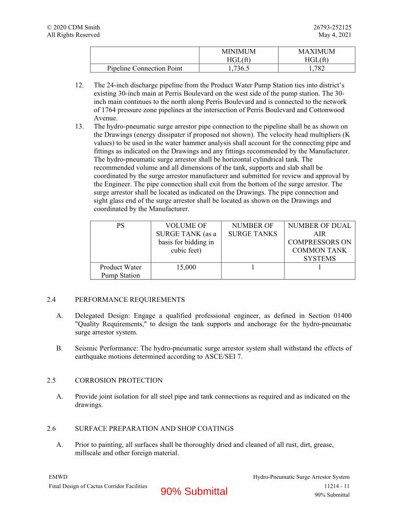
© 2020 CDM Smith 26793-252125 All Rights Reserved May 4, 2021
EMWD Hydro-Pneumatic Surge Arrestor System Final Design of Cactus Corridor Facilities 11214 - 11
90% Submittal
MINIMUM
HGL(ft) MAXIMUM
HGL(ft) Pipeline Connection Point 1,736.5 1,782
12. The 24-inch discharge pipeline from the Product Water Pump Station ties into district’s
existing 30-inch main at Perris Boulevard on the west side of the pump station. The 30-inch main continues to the north along Perris Boulevard and is connected to the network of 1764 pressure zone pipelines at the intersection of Perris Boulevard and Cottonwood Avenue.
13. The hydro-pneumatic surge arrestor pipe connection to the pipeline shall be as shown on the Drawings (energy dissipater if proposed not shown). The velocity head multipliers (K values) to be used in the water hammer analysis shall account for the connecting pipe and fittings as indicated on the Drawings and any fittings recommended by the Manufacturer. The hydro-pneumatic surge arrestor shall be horizontal cylindrical tank. The recommended volume and all dimensions of the tank, supports and slab shall be coordinated by the surge arrestor manufacturer and submitted for review and approval by the Engineer. The pipe connection shall exit from the bottom of the surge arrestor. The surge arrestor shall be located as indicated on the Drawings. The pipe connection and sight glass end of the surge arrestor shall be located as shown on the Drawings and coordinated by the Manufacturer.
PS VOLUME OF
SURGE TANK (as a basis for bidding in
cubic feet)
NUMBER OF SURGE TANKS
NUMBER OF DUAL AIR
COMPRESSORS ON COMMON TANK
SYSTEMS Product Water Pump Station
15,000 1 1
2.4 PERFORMANCE REQUIREMENTS
A. Delegated Design: Engage a qualified professional engineer, as defined in Section 01400 "Quality Requirements," to design the tank supports and anchorage for the hydro-pneumatic surge arrestor system.
B. Seismic Performance: The hydro-pneumatic surge arrestor system shall withstand the effects of earthquake motions determined according to ASCE/SEI 7.
2.5 CORROSION PROTECTION
A. Provide joint isolation for all steel pipe and tank connections as required and as indicated on the drawings.
2.6 SURFACE PREPARATION AND SHOP COATINGS
A. Prior to painting, all surfaces shall be thoroughly dried and cleaned of all rust, dirt, grease, millscale and other foreign material.
90% Submittal
© 2020 CDM Smith 26793-252125 All Rights Reserved May 4, 2021
EMWD Hydro-Pneumatic Surge Arrestor System Final Design of Cactus Corridor Facilities 11214 - 12
90% Submittal
B. The internal surface of the surge arrestor shall be sandblasted to SSPC-SP-10.
C. Internal preservation shall be a 10 to 12 mil coating of an NSF Standard 61 approved epoxy coating.
1. Products: Provide one of the following:
a. Tnemec N140. b. Sherwin Williams 646-PW. c. Or equal.
2. Coating shall be applied in accordance with coating manufacturer’s instructions.
D. The external surface of the surge arrestor shall be sandblasted to SSPC-SP-6 and coated with a poly-urethane coating system with a zinc-rich primer.
E. Final topcoat color shall be in accordance with 09900 “Painting and Protective Coatings”. Coating shall be applied in accordance with coating manufacturer’s instructions.
PART 3 - EXECUTION
3.1 INSTALLATION
A. Install hydro-pneumatic surge arrestor system in accordance with the manufacturer's recommended procedures. The unit shall be fully constructed by the manufacturer prior to shipping, and installed under the direct supervision of the manufacturer and with the approval of the ENGINEER.
3.2 CLEANING, DISINFECTIONAND TESTING
A. Furnish all necessary equipment and labor for cleaning and, testing and chlorination of the surge arrestor tank prior to the inside of the tank coming in contact with the potable water distribution system
B. Thoroughly clean the surge tank by flushing with water to remove all dirt and material which may have entered during the construction period.
C. Chlorinate the interior of the surge tank in accordance with AWWA C651.
D. After treatment, flush the surge tank with potable water.
E. Perform bacteriological tests. Repeat disinfection as necessary to produce satisfactory bacteriological samples in compliance with California requirements.
3.3 FIELD QUALITY CONTROL
A. The surge arrestor shall not be shipped prior to approval by the Engineer.
90% Submittal

© 2020 CDM Smith 26793-252125 All Rights Reserved May 4, 2021
EMWD Hydro-Pneumatic Surge Arrestor System Final Design of Cactus Corridor Facilities 11214 - 13
90% Submittal
B. Prior to field testing, the Contractor shall fully demonstrate the operation readiness of air compressors, surge arrestor, calibration of the level sensors, and control panels in accordance with Division 17. Check alarms by forcing or simulating alarm conditions in accordance with Division 16. Check the solenoid valves for proper operation in accordance with Division 15. After approval of the installation by the Engineer and the manufacturer's representative in writing, the hydro-pneumatic surge arrestor system shall be hydrostatically field tested and field tested under actual operating conditions in the presence of the Engineer and manufacturer's representative. Prior to field operational testing of the hydro-pneumatic surge arrestor, conduct a hydrostatic pressure test of 150 psi of the surge arrestor and all new piping connections as specified in the presence of the Engineer. Following successful hydrostatic pressure test results, the operational field test conditions shall be selected to determine the ability of the hydro-pneumatic surge arrestor system to perform as specified but shall include at a minimum an uncontrolled shut-down of one pump and the controlled start-up of two pumps. If the arrestor performance does not meet the specified requirements, corrective measures shall be taken under the direction of the manufacturer. The hydro-pneumatic surge arrestor system shall comply fully with this Section prior to acceptance.
C. A report shall be submitted by the Contractor, prepared in conjunction with the surge arrestor system Manufacturer, documenting the performance of the surge arrestor systems following the field test. The report shall include plots of the pump station header pressure and surge arrestor volume at each station following each event of the field test for a time sufficient to re-establish steady state conditions. The report shall document any additional field testing or startup testing and data collection performed by the Contractor and surge arrestor manufacturer on the surge arrestor system as described in “Startup Service.”
D. Manufacturer's Field Service: Engage a factory-authorized service representative to test and inspect components, assemblies, and equipment installations, including connections.
1. The hydro pneumatic surge arrestor system Manufacturer shall provide field startup and training services per specification Section 01790. A Manufacturer's factory representative who has complete knowledge of proper operation and maintenance shall be provided as specified below. The listed service requirements below are minimums exclusive of travel time and shall not limit or relieve the CONTRACTOR of the obligation to provide sufficient service necessary to place the equipment in satisfactory and functioning condition.
E. Prepare test and inspection reports.
3.4 STARTUP SERVICE
A. Engage a factory-authorized service representative to perform startup service.
1. Complete installation and startup checks according to manufacturer's written instructions. 2. Start-Up: Provide written certification that the installation is complete and operable in all
respects, and that no conditions exist which may affect the warranty. Field testing as described in Part 3 “Field Quality Control” article. Provide a written report, summarizing test procedures, tested and measured variables (flows, pressures, etc.).
3. One 8-hour day minimum Field and classroom instruction on operation and maintenance of the equipment, including start-up, shut-down troubleshooting, lubrication, maintenance and safety.
90% Submittal

© 2020 CDM Smith 26793-252125 All Rights Reserved May 4, 2021
EMWD Hydro-Pneumatic Surge Arrestor System Final Design of Cactus Corridor Facilities 11214 - 14
90% Submittal
a. One 8-hour day, minimum.
4. The CONTRACTOR alone shall be responsible for requesting the services of the hydro pneumatic surge arrestor system manufacturer's representative and shall coordinate these requests with all other relevant trades, to assure the effectiveness of the Manufacturer's service. In the event that the lack of coordination by the Contractor results in the need to recall the service representative, the lost time shall not be counted against the above days.
END OF SECTION 11214
90% Submittal

© 2020 CDM Smith 26793-252125 All Rights Reserved May 4, 2021
EMWD Peristaltic Metering Pumps Final Design of Cactus Corridor Facilities 11222 - 1
90% Submittal
SECTION 11222 - PERISTALTIC METERING PUMPS
PART 1 - GENERAL
1.1 RELATED DOCUMENTS
A. Drawings and general provisions of the Contract, including General and Supplementary Conditions and Division 1 Specification Sections, apply to this Section.
1.2 SUMMARY
A. Section Includes:
1. Peristaltic-Type Metering Pumps and Drivers:
a. Integral controller and motor enclosure type with local operator interface.
2. Custom control panels. 3. Valves and accessories. 4. Field instruments. 5. Pump shelves/stands. 6. Factory fabricated and tested complete piped and wired skid systems.
B. Related Requirements:
1. Electrical work, except as specified in this Section is included in Division 16. 2. Piping and valves, other than those specified in this section, are included in Division 15. 3. Section 13230 “Fiberglass Reinforced Plastic Tanks.” 4. Section 17040 “Process Control Descriptions.” 5. Section 16273 “Electrical Cabinets and Enclosures.” 6. Section 16950 “Custom Control Panels.”
1.3 DEFINITIONS
A. AESS – Applications Engineering System Supplier. See Section 17006 “Configuration of HMI Software” for definition.
B. LCP – Local Control Panel.
C. I/O – Input/Output signals.
D. PCSS – Process Control System Supplier. See Section 17006 “Configuration of HMI Software” for definition.
E. P&ID – Process and Instrumentation Diagrams.
90% Submittal

© 2020 CDM Smith 26793-252125 All Rights Reserved May 4, 2021
EMWD Peristaltic Metering Pumps Final Design of Cactus Corridor Facilities 11222 - 2
90% Submittal
F. Failsafe – Normally closed contacts that open on alarm condition.
G. NPIP – Net Positive Inlet Pressure
1.4 COORDINATION
A. Section 01330 “Submittal Procedures” for submittals requirements.
B. Section 01770 “Closeout Procedures.”
1.5 ACTION SUBMITTALS
A. Furnish a tabbed Table of Contents at beginning of submittal package, indicating equipment, materials, and services included by supplier/manufacturer.
1. Listing of equipment, materials, and services provided by Manufacturer and/or supplier. 2. Specified scope items excluded from submittal, and reasons for exclusion. 3. Exceptions to Scope items and reasons for exception. 4. Clarifications to Scope items.
B. Product Data:
1. Catalog Data Sheets including model numbers, capacity range, dimensions, connection sizes, materials of construction, and finishes.
2. Guaranteed Performance Curves: Showing pump speed (rpm or percent), volumetric output (gph or gpm), and operating head (psi) for specified design conditions.
3. Integral Pump/Motor Controllers Data: Enclosure, insulation, temperature limits, features, wiring diagram, and electrical connection requirements.
4. Wetted Materials Compatibility: Manufacturers chemical compatibility references with respective service chemicals at concentrations and temperature specified.
5. Complete Manufacturers Spare Parts List for pumps, motors, integral controllers and pump mounted accessories with current itemized pricing.
6. Valve, piping, tubing, fitting, anchor and accessory catalog data sheets indicating size, manufacturing standards and materials of construction.
7. Complete Lubricant List including type and grade and current itemized pricing. 8. List of Spare Parts and Lubricants included with Scope of Supply. 9. Manufacturer’s warranty, compliant with this Specification. 10. Variable frequency drive data sheets with wiring diagrams and sizing calculations
showing compatibility with submitted motor. 11. Control panel component and device data sheets indicating conformance with Division
16. 12. Instrumentation catalog data sheets indicating ranges, specific features/options identified
and electrical characteristics/power requirements. 13. Complete Manufacturers Spare Parts List for controllers and panel components, with
current itemized pricing.
C. Shop Drawings:
90% Submittal
© 2020 CDM Smith 26793-252125 All Rights Reserved May 4, 2021
EMWD Peristaltic Metering Pumps Final Design of Cactus Corridor Facilities 11222 - 3
90% Submittal
1. Manufacturer’s fully dimensioned shop drawings of pump, motor and baseplate showing materials of construction, total weight, and anchorage.
2. Manufacturer’s fully dimensioned shop drawings with minimum three views of pump skid(s) showing proposed arrangement of skid mounted components, materials of construction, total weight, and anchorage. Reference components to a materials table identifying component, quantity, equipment/part number or other pertinent information.
3. Unit Responsibility form or letter, signed by authorized representative and consistent with the submitted Scope of Supply.
4. Manufacturer’s fully dimensioned shop drawings of pump, motor, reducer, baseplate and anchorage locations. Indicate materials of construction, total weight, and anchorage. Reference components to a materials table identifying component, quantity, equipment/part number or other pertinent information.
5. Range and settings for indicators, instruments, pressure regulating valves, back pressure valves, timers and other related devices.
6. Complete, dimensionally correct control panel drawings showing components, door mounted and internal, with complete wiring diagrams showing signals and adherence to failsafe wiring requirements specific for this project indicated on Electrical and Instrumentation Drawings. Reference panel components to a materials table identifying component, quantity, equipment/part number or other pertinent information.
7. Complete listing of I/O signals to/from plant control system. 8. Network interface/communication protocol used to communicate with plant control
system.
D. Provide complete description of surface preparation, shop prime painting and finish painting.
E. Operation and Maintenance Data:
1. Submit manufacturers Installation Operation and Maintenance literature for each product furnished. Label with manufacturer's name and model number.
2. Compile data in an Operating and Maintenance Instruction Manual for equipment and accessories supplied specifically for this project. Include tables, drawings, graphics, equipment lists, descriptions, wiring diagrams, panel diagrams (as applicable).
F. Field Quality Control Submittals:
1. Proposed Testing and Training Plan identifying testing methods for factory testing and for field start-up testing and training to demonstrate compliance with contract requirements. Identify Standard Methods or other industry best practices to be used, duration of performance tests, and detailed test procedures. Provide procedure for testing of functions/signals/communication/ integration with associated systems identified on P&IDs and control narratives in the Contract Documents.
2. Qualifications of Factory service representative who will perform installation inspection and operator training.
3. Qualifications of Factory service representative who will perform start-up and testing. 4. Certificate of Installation, signed by Manufacturer’s authorized representative stating that
equipment has been installed according to manufacturer's instructions. 5. Signed performance test report including field pump curves, notes, corrections made. 6. Training services agenda and training materials no less than 30 days prior to proposed
training date. 7. Certificate of Owner Personnel Training signed by instructor and Owners representative.
90% Submittal

© 2020 CDM Smith 26793-252125 All Rights Reserved May 4, 2021
EMWD Peristaltic Metering Pumps Final Design of Cactus Corridor Facilities 11222 - 4
90% Submittal
8. Documentation of controls revisions performed in the field during commissioning by manufacturer’s representative.
1.6 CLOSEOUT SUBMITTALS
A. Project Record Documents: Record actual locations and final orientation of equipment and accessories.
B. Testing Affidavits: Signed on supplier’s letterhead by Authorized Factory Service Representative and Owner’s witness including testing of signals to the plant control system in the presence of the control system programmer.
C. Software Documentation: Network configuration of pump, sign-off sheets confirming logic and communication has been tested and integrated with plant control system programmer, and copies of programs.
D. Warranties per Section 01770 “Closeout Procedures.”
1.7 MAINTENANCE MATERIAL SUBMITTALS
A. Spare Parts: Furnish the following:
1. For Each Pair of Pumps:
a. Four replacement hoses. b. Four refills of hose lubricant. c. One complete set of gasket, O-rings, etc. d. One set of bearings.
B. Tools: Furnish one sets of special tools and other devices required for Owner to maintain and calibrate equipment. Label tools as to their use.
1.8 QUALITY ASSURANCE
A. Materials in contact with potable water or in contact with chemicals added to potable water: Certified according to NSF 61 and NSF 372.
B. Equipment of Same Type: Products of a single manufacturer.
C. Equipment Manufacturer Experience Under Same Name: Minimum 10 years.
D. System Supplier/Fabricator in Business Performing Similar Work: Minimum 10 years.
1.9 DELIVERY, STORAGE, AND HANDLING
A. Inspection: Accept pumps and associated equipment on-Site in manufacturer’s original packaging. Inspect for damage.
90% Submittal
© 2020 CDM Smith 26793-252125 All Rights Reserved May 4, 2021
EMWD Peristaltic Metering Pumps Final Design of Cactus Corridor Facilities 11222 - 5
90% Submittal
B. Store products in areas protected from weather, moisture, or possible damage.
1. Do not store products directly on ground. 2. Handle products to prevent damage to interior or exterior surfaces. 3. Protect parts from damage or deterioration during a prolonged delay from time of
shipment until installation completion and made ready for operation. 4. Do not dismantle factory assembled parts and components for shipment unless
permission is received in writing from Engineer. 5. Protect finished surfaces of exposed flanges by wooden blind flanges, strongly built and
securely bolted thereto. 6. Protect unfinished and machined finished ferrous surfaces to prevent rust and corrosion. 7. Do not ship until approved by Engineer in writing.
1.10 UNIT RESPONSIBILITY
A. Furnish pumping systems specified under this Section by a single supplier (System Supplier). System Supplier bears sole responsibility for submittal preparation, equipment acquisition, fabrication, manufacturing, assembly, testing, documentation, shipping, delivery, inspection, training, installation and start up assistance, tuning and calibration, repair and warranty of equipment, controls, components, and appurtenances specified.
1.11 WARRANTY
A. Refer to Section 01770 “Closeout Procedures” for warranties.
PART 2 - PRODUCTS
2.1 SYSTEM DESCRIPTION:
A. Factory assembled, wired and tested pump skid systems including control panels, motor controllers, piping, pressure gauges, pressure switches, flow switches, calibration columns, wye strainers, isolation valves, back pressure valves, pressure relief valves, check valves, and splash protection shield as indicated on the Contract Drawings and as specified herein.
B. Pumps and pump bases.
C. Pump stands.
D. Control panels, instrumentation, valves and accessories indicated under this Specification Section.
E. Application Schedule:
1. Supply peristaltic metering pumps for the following applications:
a. Pump Tag No: PMP-7110, PMP-7120, PMP-7130, and PMP-7140 (Base Bid), and PMP-7150 and PMP-7160 (Bid Option 1):
90% Submittal

© 2020 CDM Smith 26793-252125 All Rights Reserved May 4, 2021
EMWD Peristaltic Metering Pumps Final Design of Cactus Corridor Facilities 11222 - 6
90% Submittal
1) Chemical: Sodium Hypochlorite. 2) Formulation: NaOCl. 3) Solution Strength Weight %: 12.5 percent. 4) Solution pH: 13. 5) Specific Gravity @ 25 degree C: 1.19. 6) Viscosity, cp@ 25 degree C: 2.
b. Pump Tag No: PMP-8110, PMP-8120, PMP-8130, and PMP-8140 (Base Bid):
1) Chemical: Liquid Ammonium Sulfate. 2) Formulation: (NH4)2SO4. 3) Solution Strength Weight %: 40 percent. 4) Solution pH: 2.7. 5) Specific Gravity @ 25 degree C: 1.23. 6) Viscosity, cp@ 25 degree C: N/A.
c. Pump Tag No: PMP-8510 and PMP-8520 (Bid Option 1):
1) Chemical: Sodium Bisulfite. 2) Formulation: NaHSO3. 3) Solution Strength Weight %: 38 percent. 4) Solution pH: 3.5 – 5.3. 5) Specific Gravity @ 25 degree C: 1.33. 6) Viscosity, cp@ 25 degree C: N/A.
d. Pump Tag No: PMP-3610 and PMP-3620 (If required for Bid Options 3 and 4):
1) Chemical: Hydrochloric Acid. 2) Formulation: HCl. 3) Solution Strength Weight %: 31 percent. 4) Solution pH: <1. 5) Specific Gravity @ 25 degree C: 1.16. 6) Viscosity, cp@ 25 degree C: N/A.
F. Metering Pump Schedule
1. Pump Tag: PMP-7110 and PMP-7120 (Base Bid):
a. Pump Type: DC motor with integral controller type. b. Operation Range, gph: 3.1 (min) to 7.4 (max). c. Max Operating Discharge Pressure, psi: 60. d. Calculated NPIPa, psi: 13. e. NPIPr, psi: 3. f. Pump Discharge Capacity, gph: 9.3. g. Pump Pressure Capacity, psi: 100. h. Max RPM: 125. i. Rated Motor Power: 190 VA. j. P&ID Reference No.: I-18.
2. Pump Tag: PMP-7130 and PMP-7140 (Base Bid):
90% Submittal

© 2020 CDM Smith 26793-252125 All Rights Reserved May 4, 2021
EMWD Peristaltic Metering Pumps Final Design of Cactus Corridor Facilities 11222 - 7
90% Submittal
a. Pump Type: DC motor with integral controller type. b. Operation Range, gph: 0.7 (min) to 4.1 (max). c. Max Operating Discharge Pressure, psi: 60. d. Calculated NPIPa, psi: 13. e. NPIPr, psi: 3. f. Pump Discharge Capacity, gph: 5.1. g. Pump Pressure Capacity, psi: 100. h. Max RPM: 125. i. Rated Motor Power: 190 VA. j. P&ID Reference No.: I-18.
3. Pump Tag: PMP-7150 and PMP-7160 (Bid Option 1):
a. Pump Type: DC motor with integral controller type. b. Operation Range, gph: 0.25 (min) to 3.7 (max). c. Max Operating Discharge Pressure, psi: 100. d. Calculated NPIPa, psi: 13. e. NPIPr, psi: 3. f. Pump Discharge Capacity, gph: 4.6. g. Pump Pressure Capacity, psi: 100. h. Max RPM: 125. i. Rated Motor Power: 190 VA. j. P&ID Reference No.: I-18.
4. Pump Tag: PMP-8110 and PMP-8120 (Base Bid):
a. Pump Type: DC motor with integral controller type. b. Operation Range, gph: 0.77 (min) to 1.83 (max). c. Max Operating Discharge Pressure, psi: 60. d. Calculated NPIPa, psi: 13. e. NPIPr, psi: 3. f. Pump Discharge Capacity, gph: 2.3. g. Pump Pressure Capacity, psi: 100. h. Max RPM: 125. i. Rated Motor Power: 190 VA. j. P&ID Reference No.: I-19.
5. Pump Tag: PMP-8130 and PMP-8140 (Base Bid):
a. Pump Type: DC motor with integral controller type. b. Operation Range, gph: 0.17 (min) to 1.01 (max). c. Max Operating Discharge Pressure, psi: 60. d. Calculated NPIPa, psi: 13. e. NPIPr, psi: 3. f. Pump Discharge Capacity, gph: 1.3. g. Pump Pressure Capacity, psi: 100. h. Max RPM: 125. i. Rated Motor Power: 190 VA. j. P&ID Reference No.: I-19.
6. Pump Tag: PMP-8510 and PMP-8520 (Bid Option 1):
90% Submittal

© 2020 CDM Smith 26793-252125 All Rights Reserved May 4, 2021
EMWD Peristaltic Metering Pumps Final Design of Cactus Corridor Facilities 11222 - 8
90% Submittal
a. Pump Type: DC motor with integral controller type. b. Operation Range, gph: 0.1 (min) to 1.5 (max). c. Max Operating Discharge Pressure, psi: 60. d. Calculated NPIPa, psi: 13. e. NPIPr, psi: 3. f. Pump Discharge Capacity, gph: 1.9. g. Pump Pressure Capacity, psi: 100. h. Max RPM: 125. i. Rated Motor Power: 190 VA. j. P&ID Reference No.: I-20.
7. Pump Tag: PMP-3610 and PMP-3620 (If required for Bid Option 3 and 4):
a. Pump Type: DC motor with integral controller type. b. Operation Range, gph: TBD (min) to TBD (max). c. Max Operating Discharge Pressure, psi: TBD. d. Calculated NPIPa, psi: 13. e. NPIPr, psi: 3. f. Pump Discharge Capacity, gph: TBD. g. Pump Pressure Capacity, psi: TBD. h. Max RPM: 125. i. Rated Motor Power: 190 VA. j. P&ID Reference No.: I-23.
2.2 PERISTALTIC METERING PUMPS
A. Manufacturers:
1. Watson-Marlow. 2. Blue-White. 3. Verder. 4. Substitutions: Not permitted.
B. Metering Pumps: Pump, drive unit, base, and appurtenances to provide a complete pumping system for specific process fluids and design characteristics as specified.
1. Positive displacement, peristaltic type utilizing a flexible tube and roller or track located in pump head.
2. Suitable for metering service with variable speed control.
a. Dosage Control: within one percent variation from pump setting.
3. Integral tube failure detection system. 4. Roller revolution counter with user adjustable set-point. 5. Dry self-priming. Capable of running dry without damaging effects to pump or tube. 6. Suction Lift Capability: 30 feet vertical water column. 7. No valves, diaphragms, springs, or dynamic seals in fluid path. 8. Process Fluids: Contact thee pump tubing assembly and connection fittings only. 9. Flow: Direction of rotor rotation, and proportional to rotor speed. Rotor rotation is to be
reversible.
90% Submittal

© 2020 CDM Smith 26793-252125 All Rights Reserved May 4, 2021
EMWD Peristaltic Metering Pumps Final Design of Cactus Corridor Facilities 11222 - 9
90% Submittal
10. Pump Head: Single piece of molded thermoplastic or cast and machined metal with clear removable cover.
11. Tube Failure Detection Sensors: Located in pump head. Process fluid waste ports or leak drains not needed.
C. Squeeze Rollers: Encapsulated ball bearings directly coupled to a one-piece thermo-plastic rotor.
1. Squeeze rollers for tube compression located 180 degrees apart.
a. Roller Diameters and Occlusion Gap: Factory set providing optimum tubing compression.
b. Field Adjustment: Not required.
D. Install rotor assembly on a D-shaped, chrome plated motor shaft and make removable without special tools.
E. Materials of Construction: .
1. Enclosure: 30 percent Glass filled PPO/PS. 2. Pump head cover: 30% Glass filled PPE/PS with an integral ball bearing fitted to support
overhung load on motor shaft. 3. Pump Head: Polypropylene. 4. Pump Head Rotor: Polypropylene. 5. Roller Assembly:
a. Rollers: Nylon 6 30% glass bead (PA6 GB30). b. Roller Bearings: Stainless-Steel Ball Bearings.
6. O-rings: Nitrile. 7. Track: Noryl FE1630PW 30% glass filled (PPE+PS GF30). 8. Drive: Noryl FE1630PW 30% glass filled (PPE+PS GF30). 9. Motor Shaft: Stainless steel 440C. 10. TFD System Sensor Pins: Hastelloy C-276. 11. Mounting Hardware: Type 316 stainless steel. 12. Cover Screws: Mounting Hardware: Type 316 stainless steel. 13. Tubing: As specified in tubing/hose schedule below.
a. Pump Tag No.: PMP-7110, PMP-7120, PMP-7130, and PMP-7140 (Base Bid) and PMP-7150 and PMP-7160 (Bid Option 1):
1) Process Fluid Chemical: Sodium Hypochlorite. 2) Tube/Hose Material: Styrene ethylene butylene styrene (SEBS). 3) Pressure Rating, psi: 100. 4) Suction and Discharge Connective Piping Diameter, inches:
a) Suction: 1/2. b) Discharge: 1/2.
b. Pump Tag No.: PMP-8110, PMP-8120, PMP-8130, and PMP-8140 (Base Bid):
90% Submittal
© 2020 CDM Smith 26793-252125 All Rights Reserved May 4, 2021
EMWD Peristaltic Metering Pumps Final Design of Cactus Corridor Facilities 11222 - 10
90% Submittal
1) Process Fluid Chemical: Liquid Ammonium Sulfate. 2) Tube/Hose Material: Santoprene or SEBS. 3) Pressure Rating, psi: 100. 4) Suction and Discharge Connective Piping Diameter, inches:
a) Suction: 1/2. b) Discharge: 1/2.
c. Pump Tag No.: PMP-8510 and PMP-8520 (Bid Option 1):
1) Process Fluid Chemical: Sodium Bisulfite. 2) Tube/Hose Material: Santoprene or SEBS. 3) Pressure Rating, psi: 100. 4) Suction and Discharge Connective Piping Diameter, inches:
a) Suction: 1/2. b) Discharge: 1/2.
d. Pump Tag No.: PMP-3610 and PMP-3620 (If required for Bid Option 3 and 4):
1) Process Fluid Chemical: Hydrochloric Acid. 2) Tube/Hose Material: Santoprene or SEBS. 3) Pressure Rating, psi: 100. 4) Suction and Discharge Connective Piping Diameter, inches:
a) Suction: 1/2. b) Discharge: 1/2.
e. Pump Tube: Assembled to connection fittings of PVDF material. Connection fittings: Permanently clamped to tubing with stainless-steel clamps.
f. Fittings: Insert into keyed slots located in pump head. Secured in place by pump head cover.
g. Four (4) tube elements of specified size per pump. h. One (1) meter of reinforced transparent PVC flexible hose for connection of pump
to suction and discharge process lines for each pump supplied. F. Controls:
1. Description:
a. Sodium hypochlorite (SHC) is dosed to the GAC effluent (or IX Nitrate Treatment effluent under Bid Option 3 and 4) to provide 4-log virus inactivation. After the required contact time, liquid ammonia sulfate (LAS) is dosed to the chlorinated effluent to form chloramines. Secondary SHC and LAS dosing points are provided to adjust the chloramine residual prior to entering the distribution system. The primary SHC feed is flow paced with chlorine residual trim. The primary LAS feed is flow paced with free ammonia and monochloramine residual trim. The secondary SHC feed is flow paced. The secondary LAS feed is flow paced with free ammonia and monochloramine residual trim.
b. Bid Option 1: SHC is dosed to the raw water to provide oxidation and removal of iron and manganese in the Green Sand Filters. SBS is dosed downstream of the Green Sand Filters to quench any chlorine residual. SHC is flow based with
90% Submittal

© 2020 CDM Smith 26793-252125 All Rights Reserved May 4, 2021
EMWD Peristaltic Metering Pumps Final Design of Cactus Corridor Facilities 11222 - 11
90% Submittal
chlorine residual trim. SBS is dosed based on chlorine residual and paced on flow with ORP trim.
c. Bid Option 3 and 4: If required, HCl is dosed into the IX rinse water to reduce scale formation on the IX resin. HCl is flow paced.
d. Refer to Control Logic per Section 17040 “Process Control Descriptions” for coordination with plant control system.
2. Control Circuitry: Integral to pump.
a. Pump Motor Speed Adjustment: 1,000:1 turndown ratio. b. Pump Output:
1) Manually Controlled: Front panel user touchpad controls. 2) Remote Controlled: 4-20mA analog input.
c. Automatically calculate pump motor speed required to achieve a part per million dosing output proportional to a fixed system flow rate.
1) User Input:
a) Dispensing chemical percentage concentration from 1 to 100.0 percent in 0.1 percent increments.
b) Dispensing chemical specific gravity from 0.5 to 2.0 in 0.01 increments.
d. Front Panel User Touchpad Control:
1) Stop and start. 2) Configuration menu access and navigation. 3) Operating mode selection. 4) Auto priming. 5) Display options selection. 6) Tube life data. 7) Reverse direction.
e. LCD Display for Menu Driven Configuration Settings:
1) Pump output value. 2) Service alerts. 3) Tube failure detection system. 4) Flow verification system. 5) Alarms status. 6) Remote input signal values. 7) Tubing life timer value.
f. Remote Stop/Start Pump: 6 to 30 VDC powered loop or non-powered contact closure loop.
g. User Selectable Output Signal: 4-20mA and 0-1000Hz, scalable and proportional to pump output volume.
h. Four Contact Closure Alarm Outputs: Each alarm output assignable to monitor up to 20 separate pump parameters.
90% Submittal

© 2020 CDM Smith 26793-252125 All Rights Reserved May 4, 2021
EMWD Peristaltic Metering Pumps Final Design of Cactus Corridor Facilities 11222 - 12
90% Submittal
1) Three Rated: 1A-115VAC, 0.8A-30VDC. 2) One Rated: 6A-250VAC, 5A-30VDC.
i. Roller Revolution Counter Display: Tube life indicator. User programmable alarm set-point from 1 to 999,999,999 revolutions. Can be assigned to any one of 4 contact closure alarm outputs.
j. User Programmable RPM (revolutions per minute): Set-point value from 0.1 to 100.0 RPM in 0.1 increments.
k. User Adjustable Response Delay Time: 0 to 999.9 seconds for remote start/stop input and four contact closure alarm outputs to facilitate closed-loop applications.
l. Power Interruption Pump Restart Option: User programmable to either automatically restart or require a user re-start if AC mains power is interrupted.
m. Discrete and Analog Signal Interface Points: As shown on the P&IDs.
n. Personal Identification Number (PIN) protected configuration menu. o. SCADA Control:
1) NEMA 4X rating on control and handheld keypad enclosures; Type 316 stainless steel.
2) Display Output: GPH. 3) ON/OFF switch. 4) LED lights for pump running status and alarm conditions. 5) Variable frequency drive. 6) Skid mounted and wired to pump motors.
p. Remote Signals to PLC:
1) Isolated 4 to 20 mA speed (%). 2) Running Status. 3) Pump Alarm. 4) Remote/Ready Status.
q. Remote Signals from PLC:
1) Isolated 4 to 20 mA speed command (%). 2) Remote Start Command.
r. Full local control at pump and Local/Remote signal. s. Control Panel Functions:
1) Communicate to plant PLC via hardwired connection.
a) Display variables and setpoints. b) Pumps are duty/standby, when duty pump fails, then standby pump is
brought online. c) Receives setpoint from PLC and controls pump output to setpoint
value (GPH). d) Generates alarms and transmits failure signal to PLC. e) Provides local power disconnect for pumps per NEC.
90% Submittal
© 2020 CDM Smith 26793-252125 All Rights Reserved May 4, 2021
EMWD Peristaltic Metering Pumps Final Design of Cactus Corridor Facilities 11222 - 13
90% Submittal
G. Motor/Drive Requirements:
1. Reversible, brushless DC gear motor rated for continuous duty. 2. Overload protection. 3. Gear Motor RPM: 125 RPM maximum. 4. Drive System: Each metering pump to be provided with the following:
a. Factory installed totally enclosed in NEMA 4X, (IP66) wash-down enclosure. b. Operating Power Supply: 110 VAC, 60 Hz single phase supply without user
configuration or selection switches. c. Integral variable speed drive. d. Dedicated controller. e. Local disconnect and drive interface panel in a NEMA 4X enclosure. f. Tube Failure Detection (TFD) System and Leak Sensing System: Provide local and
remote alarms.
g. Cables: 10-foot pump connecting cable with plug and 10-foot signal input cable. h. Disconnect Switch: Factory mounted in control panel. i. Enclosure: Pressure cast aluminum with acidic liquid iron phosphate three-stage
clean and coat pretreatment and exterior grade corrosion resistant polyester polyurethane powder coat.
1) Rated NEMA 4X (IP66). 2) Floor and Shelf Level Mounting Brackets and Hardware: Type 316
stainless steel. 3) Wiring compartment for connection of input/output signal wires and alarm
output loads to un-pluggable type terminal block connectors.
a) Terminal board positively secured to rear of pump housing by two polymeric screws and fully enclosed by wiring compartment cover.
b) Not disturbed by removal of wiring compartment cover. c) Do not use ribbon cables in wiring compartment. d) Size conduit hubs, liquid-tight connectors, connector through holes
and tapped holes in U.S. inches.
j. Pump Head Cover: Include an imbedded magnetic safety interlock which will limit motor rotation speed to 6 RPM when removed.
2.3 PUMP MOUNTING SYSTEMS
A. Furnish factory assembled skids, housing two pumps each, suction valves, discharge valves, piping, and appurtenances described in this section and as indicated in the Contract Drawings.
B. Skid: Polyethylene or FRP floor-mounted pump skid suitable to mount two pumps per skid.
1. Integral spill containment and splash proof protective housing. 2. Secure mounted piping and tubing to skid per requirements specified in Division 15. 3. Mounting Hardware: Designed by skid manufacturer and furnished with skid. 4. Acceptable Manufacturers:
90% Submittal

© 2020 CDM Smith 26793-252125 All Rights Reserved May 4, 2021
EMWD Peristaltic Metering Pumps Final Design of Cactus Corridor Facilities 11222 - 14
90% Submittal
a. TMG Services Inc., Peabody Engineering (Corona, CA). b. Coastal Technical Sales. c. Engineer approved equivalent.
C. Furnish foundation bolts, nuts and washers of titanium to accommodate sodium hypochlorite pumps.
D. Furnish foundation bolts, nuts and washers of type 316 stainless steel to accommodate liquid ammonium sulfate, sodium bisulfite, and hydrochloric acid pumps.
2.4 ACCESSORIES
A. Pressure Gauge and Switch Assemblies:
1. Furnished on discharge side of pumps indicating pump discharge pressure. 2. Shuts down pump in event of excessive discharge pressure. 3. Transmits alarm signals to variable frequency drives. 4. Rated: 10 amp SPDT at 120 VAC.
a. Adjustable deadband and trip setpoint. b. Repeatability of 1 percent of actual pressure. c. UL/CSA rated and housed in a NEMA 4X enclosure. d. Automatically trips on pressure rise. e. Manual reset required after pressure fall.
5. Pressure Gauge: Furnish as part of complete factory assembly, including gauge, snubber, diaphragm seal with flush/vent valve, liquid fill, isolation valve and interconnecting piping.
a. Casing: phenolic, 4-1/2-inch diameter with a stainless steel Bourdon tube and a stainless steel movement.
b. Dial Face: White background with black markings, sealed to prevent entrance of moist air.
c. Liquid filled with glycerin with a filler/breather cap. d. Socket: Type 316 stainless steel with bottom connection.
6. Equipped with an isolation valve and diaphragm seals to protect gauge and switch from contact with fluid in pipeline.
7. Isolation Valve: Ball valve. 8. Valves and diaphragm seal housing constructed of same material as applicable chemical
piping system and have either socket weld, socket fuse or flanged process connection.
a. Diaphragm: Teflon.
9. Furnish mineral oil fill with unit for use between diaphragm seal and gauge and seal and switch.
B. Calibration Chambers: Furnished with pumps for measuring pump output. Rigidly installed and not supported from piping system. Arrange pump suction and discharge piping so as not to interfere with location and use of calibration chambers.
90% Submittal

© 2020 CDM Smith 26793-252125 All Rights Reserved May 4, 2021
EMWD Peristaltic Metering Pumps Final Design of Cactus Corridor Facilities 11222 - 15
90% Submittal
1. Materials: Compatible with intended chemical use (e.g., Pyrex, plexiglass, acrylic, butyrate or clear PVC).
2. Flanged connection to suction piping. 3. End Cap: Fitted with ball valve for air venting, as indicated on Drawings. 4. Permanently calibrated and marked in milliliters. 5. Height and Diameter: Sized such that measurable capacity of chamber is 2 minutes of
discharge of each pump at 50 percent maximum pumping capacity.
C. Backpressure/Anti-Siphon Valves: Installed in discharge line of each pump as indicated on the Drawings ensuring seating of ball check valves and preventing anti-siphoning.
1. Valve Material: PVC, suitable for intended chemical use with Teflon®PTFE diaphragm and EPDM or Viton O-rings and seals.
2. Working Pressure: 150 psig 3. Field adjustable with initial setting set at factory.
D. Pressure Relief Valves: Installed in discharge line of each pump, upstream of back-pressure valve as indicated on the Drawings.
1. Valve Material: PVC, suitable for intended chemical use with Teflon diaphragm and EPDM or Viton O-rings and seals.
2. Sized to pass maximum pump capacity when set at 10 psig above back-pressure valve setting.
3. Working Pressure: 150 psig. 4. Field adjustable with initial setting set at factory.
E. Inlet Strainers: Suction line wye strainer on suction line as indicated on the Drawings.
1. Wye Strainers: 1/32 inch perforations. One size larger than suction line in which they are installed.
2. Strainer Materials: Clear PVC body, solvent ends, PVC screen, and EPDM or Viton O-rings.
3. Manufacturer:
a. ASAHI. b. George Fischer. c. Engineer approved equivalent.
2.5 SURFACE PREPARATION AND SHOP PRIME PAINTING
A. As specified in Section 09900 “Painting and Protective Coatings”.
1. Submit paint system with shop submittals for Engineer approval. 2. Do not paint stainless-steel and thermoplastic pump components.
90% Submittal

© 2020 CDM Smith 26793-252125 All Rights Reserved May 4, 2021
EMWD Peristaltic Metering Pumps Final Design of Cactus Corridor Facilities 11222 - 16
90% Submittal
PART 3 - EXECUTION
3.1 INSTALLATION
A. Installation: In strict accordance with manufacturer's instructions and recommendations in locations indicated on Drawings.
1. Anchor Bolts: Set per manufacturer's recommendations and setting plans.
B. Certificate of Installation: Obtain from equipment manufacturer stating installation of equipment is satisfactory, ready for operation, and operating personnel have been suitably instructed in operation, lubrication and maintenance of each unit.
C. Mount pump skid to equipment pad with stainless-steel expansion bolts as indicated on Drawings and manufacturer’s instructions.
D. Fasten pump to mounting skid with titanium bolts for sodium hypochlorite service. Fasten using stainless steel bolts for all other services.
E. Install power and control and wiring as specified under Division 16.
F. Flush tubing with fluid or gas compatible with chemical piping prior to connecting equipment.
3.2 FIELD QUALITY CONTROL
A. Section 01730 “Execution” for testing, adjusting, and balancing requirements.
B. System Manufacturer Quality Control Procedures: Adequate to ensure fabrications comply with these Specifications.
1. Final Inspection and Testing of System: By manufacturer prior to shipment; documented in writing and submitted as a record of completion.
C. Manufacturer Services: Manufacturer's representative experienced in installation of equipment and systems furnished per this Section for not less than two days on-site for installation, inspection, and field testing of supplied equipment and system package.
D. Certificate of Installation: Signed by equipment manufacturer's authorized representative, attesting equipment is properly installed and ready for startup and testing.
E. Water: Dispose of testing water to sewer.
F. Start-up Testing
1. Execute testing per approved Testing and Training Plan submittal. Be responsible for resolving any and integration issues at no additional cost to Owner.
2. Preoperational Check: Prior to operating system or components.
a. System Functional Check: Per Division 17 requirements. Confirm power and control wiring is correct.
90% Submittal

© 2020 CDM Smith 26793-252125 All Rights Reserved May 4, 2021
EMWD Peristaltic Metering Pumps Final Design of Cactus Corridor Facilities 11222 - 17
90% Submittal
b. Vent air from system. c. Sufficiently sized reservoir of potable water for clean water testing.
3. Functional Testing: During commissioning of instrumentation and control system ensuring pumps respond as required to remote input.
4. Clean Water Testing:
a. Preliminary System Potable Water Test: After completion of installation, in presence of Engineer and a qualified system supplier representative.
1) Verify functioning of component parts. 2) Approval does not constitute final approval or acceptance of system and
equipment.
b. Include if a day tank is included. Use proper name of supply reservoir, e.g., Day Tank T-1001.
c. Supply Tank: Filled with water and checked for leaks one hour after filling.
1) Supply Tank Connection to Secondary Containment Tank (on-skid): Test confirming no existing leaks. Submit written record of testing as record of completion.
d. Metering Pump Flow Rate: Test by measuring drawdown rate on suction side leaving discharge undisturbed in its normal, steady-state operating condition.
1) Compute capacities by measuring time to fill or by draining calibration column with potable water.
e. Chemical Feed Systems: Operate on clean water for continuous period of four hours, under supervision of manufacturer's representative.
f. System Piping: Hydrostatically test for leaks at tubing’s rated pressure. g. Document all issues and observations. h. Component Performance Failure: Adjust, repair, modify, and replace components
of system failing to perform.
1) Repeat clean water tests.
i. System and Component Adjustments: Under direction of manufacturer's representative.
j. Test Rejection and Failure: The following are sufficient cause to reject test. Successfully complete functional testing in five tries; otherwise, construction manager will reject System.
1) Mechanical or electrical breakdowns. 2) Unusual vibrations. 3) Control sequencing problems.
k. System Rejection: Inability to complete functional testing in five attempts will be sufficient cause for Engineer to reject System.
l. Post Test System Preparation: Purge water with high pressure dry air for systems designed for chemicals incompatible or reactive with water.
90% Submittal

© 2020 CDM Smith 26793-252125 All Rights Reserved May 4, 2021
EMWD Peristaltic Metering Pumps Final Design of Cactus Corridor Facilities 11222 - 18
90% Submittal
5. Performance Testing: Conduct after installation is complete and ready for testing as demonstrated by successful completion of clean water (or dry) testing.
a. Performed under direction of system supplier representative, and in presence of Engineer and as specified.
b. Incidental Costs: Be responsible for costs other than labor provided by System Supplier, including calibrated testing and measurement instruments and waste disposal. Costs include water and power requirements.
c. Test Chemicals: Provided by Owner in quantities to facilitate full-scale performance testing.
d. Chemical Metering Pumps Field Calibration: In presence of Engineer.
1) Calibrate each pump at maximum flow rate limit using the onboard flow calibration mode.
e. Demonstrate pumps conform to service requirements and design conditions specified.
1) Continuous uninterrupted 24-hour operation of pumps will be required before acceptance.
2) Pump does not meet performance requirements: Take corrective measures or replace pumps and retest until performance requirements are met.
f. Test Capacity: Data monitored at point of discharge at selected strokes and speeds to confirm repeatability of settlings. Record the following at 15-minute intervals during testing period:
1) Metering pump output flow rate. 2) Metering pump pressure. 3) Power draw at minimum, maximum and average operating design points. 4) Operate at maximum design condition for one continuous hour.
g. Failure to Perform as Specified: Adjust, repair, modify, and replace components and repeat testing.
1) Adjust equipment under direction of manufacturer's representative.
h. System Performance and Functionality Evaluation: For modes of operation controlled by components provided by Package Supplier (e.g., control station, control panel) as required per Contract Documents.
1) Control functions. 2) Alarms. 3) Monitoring status.
6. Signatures on Completed Field Testing Forms:
a. Manufacturer’s representative. b. Engineer. c. Owner’s witness.
90% Submittal

© 2020 CDM Smith 26793-252125 All Rights Reserved May 4, 2021
EMWD Peristaltic Metering Pumps Final Design of Cactus Corridor Facilities 11222 - 19
90% Submittal
7. Complete calculations and document performance within Contract requirements. 8. Signed Field Testing Report: Submit to Owner for approval.
3.3 TESTING SAFETY REQUIREMENTS
A. Provide services of a manufacturer’s certified factory trained service engineer, specifically trained on type and size of specified equipment. The listed man-day requirements are on-site hours, exclusive of travel or office preparation time.
1. Installation Inspection and Start-up: Four 8-hour days, non-consecutive. Services include:
a. Inspect installation of pumps and accessories. b. Inspect controller and instrument installation. c. Inspect instrument setpoints. d. Indicate deficiencies, assist Contractor in correcting. e. Operate pumps, make necessary adjustments. f. Perform, or direct and witness field tests. g. Prepare certified field performance curves. h. Provide Manufacturer’s Certification of Proper Installation.
B. Testing involving use of chemicals requires careful safety and handling procedures. Be responsible to be familiar with safety protocols and proper chemical handling procedures for chemicals listed herein.
C. Successfully complete functional testing and clean water testing and fully commission eye wash/shower associated with this system to satisfaction of Owner, prior to initiating work with chemicals.
D. Use of personal protective equipment (PPE) is necessary during full-scale testing and start-up. Prior to receiving dry sodium fluoride and initiating full-scale testing:
1. Confirm in advance the names of attendees who will conduct or witness system testing involving this chemical, and necessary sizes for required PPE.
2. Furnish appropriate PPE for each and every person conducting and witnessing system testing, including Owner’s staff as specified in Part 1 herein.
E. Conduct a briefing regarding chemical and system hazards to persons conducting and witnessing system testing.
F. Verify that parties are wearing appropriate clothing, footwear, and PPE.
G. Furnish appropriate spill clean-up materials.
3.4 DEMONSTRATION AND TRAINING
A. Section 01790 “Demonstration and Training” for demonstration and training requirements.
90% Submittal

© 2020 CDM Smith 26793-252125 All Rights Reserved May 4, 2021
EMWD Peristaltic Metering Pumps Final Design of Cactus Corridor Facilities 11222 - 20
90% Submittal
B. Manufacturer Services: Furnish services of manufacturer's representative experienced in installation of products in this Section for not less than 8 hours on-Site for training of Owner's personnel in operations and maintenance of pumps and associated system package.
1. Demonstrate system performance and functionality including equipment startup, shutdown, routine maintenance, emergency repair procedures, control functions, alarms, and monitoring status for all modes of operation (e.g., local, remote, manual, auto, etc.) as required in the Contract Documents.
2. Operation and Maintenance Training: One 8-hour day. Services include:
a. Execute per approved testing and training plan submittals. b. Prepare and submit training materials and training plan. c. Coordinate training schedule with Contractor and Owner. d. Use approved training materials and follow training plan in training sessions. e. Deliver training sessions. f. Deliver specified quantity training materials to Owner.
g. Videotape training sessions. h. Obtain and submit Training Acknowledgement Certificate with signatures from
trainees indicating session attendance.
3.5 IDENTIFICATION AND MARKING
A. Prior to Substantial Completion: As required by applicable jurisdictional building codes, statues, standards, regulations, and laws; Mark and identify chemical pumping systems and applicable components for health, flammability, and reactivity of hazardous materials.
END OF SECTION 11222
90% Submittal

© 2020 CDM Smith 26793-252125 All Rights Reserved May 4, 2021
EMWD Portable Tank Mixers Final Design of Cactus Corridor Facilities 11247 - 1
90% Submittal
SECTION 11247 - PORTABLE TANK MIXERS
PART 1 - GENERAL
1.1 RELATED DOCUMENTS
A. Drawings and general provisions of the Contract, including General and Supplementary Conditions and Division 1 Specification Sections, apply to this Section.
1.2 SUMMARY
A. Section Includes: Portable tank mixers and accessories for the Product Water Forebay Tanks.
B. Related Requirements:
1. Section 03300 “Cast-in-Place Concrete” for equipment foundation pads. 2. Section 05502 “Metal Fabrications” for miscellaneous metalwork and fasteners as
required by this Section. 3. Section 09900 “Painting and Protective Coatings” for painting as specified by this
Section. 4. Section 16150 “Induction Motors” for basic requirements for motors as required under
this Section. 5. Section 13312 “Bolted Steel Tanks for Water Storage” for tankage receiving Work
described in this Section
1.3 ACTION SUBMITTALS
A. See Section 01330 “Submittal Procedures” for submittals requirements.
B. Product Data:
1. Submit manufacturer information for drive assemblies, mixer components, panels, and other system components.
2. Submit schematics and ladder diagrams.
C. Shop Drawings:
1. Indicate assembly, installation, and connection details. 2. Indicate critical dimensions, sizes, and support locations. 3. Mixer modelling output demonstrating compliance with the requirements of this
specification.
1.4 INFORMATIONAL SUBMITTALS
A. Manufacturer's Certificate: Certify that products meet or exceed specified requirements.
90% Submittal

© 2020 CDM Smith 26793-252125 All Rights Reserved May 4, 2021
EMWD Portable Tank Mixers Final Design of Cactus Corridor Facilities 11247 - 2
90% Submittal
B. Manufacturer Instructions: Submit special procedures and assembly of components. Include disinfection procedures for equipment, materials, and personnel entering the tank.
C. Source Quality-Control Submittals: Indicate results of factory tests and inspections.
D. Field Quality-Control Submittals: Indicate results of Contractor-furnished tests and inspections.
E. Qualifications Statement:
1. Submit qualifications for manufacturer.
1.5 MAINTENANCE MATERIAL SUBMITTALS
A. See Section 01771 “Closeout Procedures” for maintenance materials requirements.
B. Extra Stock Materials: Furnish one impeller for each type and size of mixer specified.
C. Tools: Furnish special tools and other devices required for Owner to maintain equipment.
1.6 QUALITY ASSURANCE
A. Materials in Contact with Potable Water: Certified to NSF 61 and NSF 372.
1.7 QUALIFICATIONS
A. Manufacturer: Company specializing in manufacturing products specified in this Section with minimum five years' experience.
1.8 DELIVERY, STORAGE, AND HANDLING
A. See Section 01600 “Product Requirements” for transporting, handling, storing, and protecting products requirements.
B. Inspection: Accept materials on Site in manufacturer's original packaging and inspect for damage.
C. Store materials according to manufacturer instructions.
D. Protection:
1. Protect materials from moisture and dust by storing in clean, dry location remote from construction operations areas.
2. Provide additional protection according to manufacturer instructions.
1.9 WARRANTY
A. See Section 01770 “Closeout Procedures” for warranties requirements.
90% Submittal
© 2020 CDM Smith 26793-252125 All Rights Reserved May 4, 2021
EMWD Portable Tank Mixers Final Design of Cactus Corridor Facilities 11247 - 3
90% Submittal
PART 2 - PRODUCTS
2.1 MIXERS
A. Manufacturers:
1. Pax Water Technologies 2. Substitutions: As specified in Section 01600 “Product Requirements.”
B. Description:
1. Portable, motorized, vertical jet mixer as indicated on Drawings. 2. Drive: Direct. 3. Bearings: Permanently lubricated. 4. Seals: Chloramine-resistant NBR. 5. NSF-61 certified.
C. Materials:
1. 316 stainless steel 2. Chloramine-resistant EPDM foot.
D. Performance and Design Criteria:
1. Corrosion Resistance: Furnish materials resistant to corrosive attacks from chloraminated potable water.
2. Maximum Working Temperature: 90 degrees F. 3. Performance:
a. Provide water temperatures within any part of the tank that converge within 0.5°C within 24 hours of activating the mixer. During operation, all temperatures must converge within 0.5°C at least once every 24 hours.
b. Provide disinfectant residual within the top five feet of the tank and the bottom five feet of the tank that converge to within 0.2 mg/L 24 hours after activating the mixer. During operation, disinfectant residuals must converge within 0.2 mg/L at least once every 24 hours.
E. Operation:
1. Electrical Characteristics:
a. Power Capacity: 1/3 hp. b. Input Voltage: 120 V, single phase, 60 Hz. c. Maximum: 20 A circuit. d. Minimum Power Factor: 1.15 at rated load.
2. Control Panel: NEMA 250 Type 4. 3. Motors: Submersible.
F. Materials:
1. Shaft and Impeller:
90% Submittal

© 2020 CDM Smith 26793-252125 All Rights Reserved May 4, 2021
EMWD Portable Tank Mixers Final Design of Cactus Corridor Facilities 11247 - 4
90% Submittal
a. Type 316 stainless steel.
2. Fasteners: ASTM F593, Type 316 Stainless Steel.
G. Accessories:
1. SCADA Controller:
a. Provide a 4-20mA output for motor current allowing for monitoring proper operation.
b. Provide a 24VDC relay to allow for remote on and off control of the mixer. c. Provide a local On/Off switch to control power to the mixer. d. Provide an automatic-activated motor shut off if water level drops below motor
height in tank. e. SCADA outputs:
1) Digital Output signal indicating motor running 2) Digital Output signal indicating fault 3) Digital Input/output signal allowing remote motor on/off 4) RS-485 or Dry Contact connections.
H. Finishes:
1. Machine Finish: Comply with ASME B46.1. 2. Coat equipment according to manufacturer's recommended coating for service
conditions.
2.2 SOURCE QUALITY CONTROL
A. See Section 01400 “Quality Requirements” for testing, inspection, and analysis requirements.
B. Provide shop inspection and testing of completed assembly.
PART 3 - EXECUTION
3.1 EXAMINATION
A. See Section 01730 “Execution” for installation examination requirements.
B. Verify that designated areas, clearances, structural requirements, utility connections, and electronic signals are ready to receive equipment.
3.2 INSTALLATION
A. According to manufacturer instructions.
90% Submittal
© 2020 CDM Smith 26793-252125 All Rights Reserved May 4, 2021
EMWD Portable Tank Mixers Final Design of Cactus Corridor Facilities 11247 - 5
90% Submittal
3.3 FIELD QUALITY CONTROL
A. See Section 01400 “Quality Requirements” for inspecting and testing requirements.
B. Inspect for proper alignment.
C. Testing:
1. Demonstrate operation without undue noise, vibration, or overheating. 2. Engineer will witness field testing.
D. Equipment Acceptance: Adjust, repair, modify, or replace components failing to perform as specified and rerun tests.
3.4 DEMONSTRATION
A. See Section 01790 “Demonstration and Training” for demonstration and training requirements.
B. Demonstrate equipment startup, shutdown, routine maintenance, and emergency repair procedures to District's personnel.
3.5 ATTACHMENTS
A. Portable Tank Mixer Schedule:
1. MXR-6111:
a. Location: Product Water Forebay Tank No. 1. b. Manufacturer: Pax Water Technologies. c. Model: PWM50. d. Liquid viscosity: 1 cP. e. Tank dimensions: 33-ft dia x 24.42-ft liquid depth (156,200 gal). f. Motor:
1) Hp: 1/3. 2) Speed: 2,100 rpm. 3) Voltage/Phase: 120/1.
2. MXR-6121:
a. Location: Product Water Forebay Tank No. 2. b. Manufacturer: Pax Water Technologies. c. Model: PWM50. d. Liquid viscosity: 1 cP. e. Tank dimensions: 33-ft dia x 24.42-ft liquid depth (156,200 gal). f. Motor:
1) Hp: 1/3 hp. 2) Speed: 2,100. 3) Voltage/Phase: 120/1.
90% Submittal

© 2020 CDM Smith 26793-252125 All Rights Reserved May 4, 2021
EMWD Portable Tank Mixers Final Design of Cactus Corridor Facilities 11247 - 6
90% Submittal
END OF SECTION 11247
90% Submittal
© 2020 CDM Smith 26793-252125 All Rights Reserved May 4, 2021
EMWD Granular Activated Carbon (GAC) System Final Design of Cactus Corridor Facilities 11250 - 1
90% Submittal
SECTION 11250 - GRANULAR ACTIVATED CARBON (GAC) SYSTEM
PART 1 - GENERAL
1.1 RELATED DOCUMENTS
A. Drawings and general provisions of the Contract, including General and Supplementary Conditions and Division 1 Specification Sections, apply to this Section.
1.2 SUMMARY
A. Section includes GAC system, to be supplied by the GAC System Supplier and installed by the Contractor, complete with all equipment and necessary parts, and incidentals required for successful operation. Installation shall conform with this Section and the instructions and recommendations of the equipment manufacturer. Notify the Engineer in the event of conflicts.
B. Mechanical Drawings and Instrumentation Drawings depict a generalized view of a GAC system to represent the scale and general orientation of the GAC system. Contractor’s shop drawings and manufacturer CAD files and models shall be used to demonstrate the GAC system will fit within the physical envelope indicated on the Drawings, placement of under-slab piping, the scissor lift height adequacy, and the clearance beneath building ceiling and roof members. Contractor’s shop drawings shall also include P&IDs that serve to demonstrate conformance to the functionality required in this Section and to refine the Instrumentation Drawings.
C. Related Requirements:
1. Division 16 “Electrical work”. 2. Division 17 “Instrumentation and Control work”. 3. Section 11251 “Granular Activated Carbon (GAC) Media”.
1.3 ACTION SUBMITTALS
A. Submit, in accordance with Section 01330 “Submittal Procedures”, to the following:
1. Literature and shop drawings describing the equipment in sufficient detail, including parts lists, materials, dimensional drawings and details of construction to indicate full compliance with this Section.
2. Weight of each of the vessels: empty, fully loaded with GAC, and with water in vessel. 3. Process flow diagram. The process flow diagram shall indicate boundary limits of vendor-
supplied equipment. 4. Detailed piping and instrumentation (P&I) diagram for the groundwater treatment system. 5. Piping sizes, arrangements, and connection points including proposed equipment layout
drawing in plan and sectional views. 6. AutoCAD drawing files to enable presentation as three-dimensional models in final record
drawings. 7. A list of previous installations similar to this system.
90% Submittal
© 2020 CDM Smith 26793-252125 All Rights Reserved May 4, 2021
EMWD Granular Activated Carbon (GAC) System Final Design of Cactus Corridor Facilities 11250 - 2
90% Submittal
8. Pressure drop curve based upon flow rate, from 150 gpm to 1,000 gpm per vessel. Curve shall include all losses from inlet to vessel, through GAC media and underdrains, to outlet of vessel. Clearly indicate graphically where the beginning and end of pressure drop calculations are made. Pressure drop values shall be provided for both series (lead-lag) and parallel operations.
9. Tabulation of empty bed contact time, in minutes, from 150 gpm to 1,000 gpm per vessel. Tabulations shall be provided for both series (lead-lag) and parallel operations.
10. All electrical equipment and controls to indicate full compliance with Division 16 and 17 specifications.
11. Anchor Bolts:
a. Submit anchor bolt details including locations, quantity, type, material, diameter, projection, minimum edge distance, and depth of embedment
b. Submit manufacturer’s specifications and data including recommended design values and physical characteristics for adhesive anchors, if used.
c. Submit current International Code Council (ICC) ES Evaluation Reports for adhesive anchoring systems, if used, for installation in cracked concrete, indicating conformance with current ICC ES Acceptance Criteria.
d. All submittals detailing anchorage of vessels shall be sealed, signed and dated by a California-registered professional engineer.
12. Piping, vessel, and manifold assembly instructions. 13. Special Shipping/Handling Information/Requirements. 14. Special Installation Requirements. 15. Disinfection Plan. 16. Field Testing Plan and Schedule.
a. Proposed collection, testing and disposal procedures for all waste streams generated by the GAC system.
17. Startup Plan and Schedule. 18. Scope of GAC System Supplier Construction Phase Services.
1.4 INFORMATIONAL SUBMITTALS
A. Coordination Drawings: Will be required to be provided by the contractor, drawn to scale, and coordinated with each other, using input from installers of the items involved.
B. Seismic Qualification Certificates: For GAC vessels, accessories, and components, from manufacturer.
C. Welding certificates.
D. Product certificates.
E. Material test reports.
F. Product test reports.
G. Research reports.
90% Submittal

© 2020 CDM Smith 26793-252125 All Rights Reserved May 4, 2021
EMWD Granular Activated Carbon (GAC) System Final Design of Cactus Corridor Facilities 11250 - 3
90% Submittal
H. Source quality-control reports.
I. Field quality-control reports.
1. Hydrostatic testing reports: Copies of all hydrostatic test reports and test procedures for all factory tests as required and specified herein.
2. Pressure/leakage testing reports. 3. Bacteriological testing reports. 4. Performance testing reports. 5. Startup and Field Test Report: Submit a field test report as specified in “PART 3,”
including Manufacturer's certification of proper installation.
J. Sample warranty.
1.5 CLOSEOUT SUBMITTALS
A. Operation and Maintenance Data
1. Submit Operations and Maintenance Manuals per Section 01430 “Maintenance Manual Requirements”.
1.6 QUALITY ASSURANCE
A. Equipment described under this Section shall be the standard products of manufacturers who regularly engage in the production of this type of equipment and who are fully experienced, reputable and qualified in the manufacture of the equipment to be furnished. The equipment shall be designed, constructed, delivered and installed in accordance with the best trade standards. Each component furnished under this Section shall be new and unused and the product of a manufacturer having a successful record of operation, manufacturing and servicing the equipment for a minimum for 5 years.
B. Pipe and Pressure-Vessel Welding Qualifications: Qualify procedures and operators according to ASME Boiler and Pressure Vessel Code.
1.7 DELIVERY, STORAGE AND HANDLING
A. The equipment shall be shipped with suitable in-transit protection and shall be outfitted with lifting lugs, cleats or other suitable means for unloading and erecting. Nozzles, manholes or other fittings shall not be used for lifting equipment. Refer to 01600 “Product Requirements” for additional requirements.
B. Finished surfaces which may be damaged during erection shall be protected by removable tape or suitable alternate. Finished surfaces of flanges shall be protected by wooden blind flanges. Hex-head plugs shall be placed on all threaded female connections.
C. After hydrostatic or other factory tests, all entrapped water shall be drained and care taken to prevent the entrance of water or dirt during shipment, storage and handling.
90% Submittal

© 2020 CDM Smith 26793-252125 All Rights Reserved May 4, 2021
EMWD Granular Activated Carbon (GAC) System Final Design of Cactus Corridor Facilities 11250 - 4
90% Submittal
1.8 JOB CONDITIONS
A. Protect all equipment and systems from unauthorized operation during the life of the project. At job completion, clean all equipment by approved decontamination procedures.
1.9 WARRANTY
A. Manufacturer's Warranty: Manufacturer agrees to repair or replace components of the GAC system that fail(s) in materials or workmanship within specified warranty period.
1. Warranty Period: eighteen (18) months(s) from date of Substantial Completion.
PART 2 - PRODUCTS
2.1 PRE-SELECTED GAC SYSTEMS
A. Refer to Section 11200 – “Granular Activated Carbon and Ion Exchange Pressure Vessel System” in EMWD Specification No. 1427W.
PART 3 - EXECUTION
3.1 EXAMINATION
A. Examine areas and conditions for compliance with requirements for installation tolerances and other conditions affecting performance of the Work.
B. Examine roughing-in for piping to verify actual locations of piping connections before equipment installation.
C. Proceed with installation only after unsatisfactory conditions have been corrected.
3.2 PREPARATION
A. Take all necessary measurements in the field to determine the exact dimensions for all work and the required sizes of all equipment.
B. Verify all pertinent data and dimensions.
C. System Manufacturer Quality Control Procedures: Adequate to ensure fabrications comply with these Specifications.
1. Final Inspection and Testing of System: By manufacturer prior to shipment; documented in writing and submitted as a record of completion.
3.3 INSTALLATION
90% Submittal

© 2020 CDM Smith 26793-252125 All Rights Reserved May 4, 2021
EMWD Granular Activated Carbon (GAC) System Final Design of Cactus Corridor Facilities 11250 - 5
90% Submittal
A. To the extent possible, all component equipment shall be furnished pre-piped and pre-wired ready for hookup on transportable structural steel skids.
B. The GAC system supplier will be responsible for delivering the GAC System from its production facility to the project site located in the City of Moreno Valley, California. The Contractor will be responsible for offloading the vessels, valve manifolds, piping, and appurtenances, as well as storing and protecting them at the project site as required until installation. The Contractor will be responsible for coordinating delivery schedule with the GAC System Supplier to ensure optimal delivery time to the project site so as to minimize storing equipment at the project site for an extended period of time
C. The installation of the system equipment shall be in accordance with the manufacturer's technical data and printed instructions.
D. Anchor bolts designed by the GAC system supplier (and furnished by the Contractor) to prevent overturning or movement of the vessels.
E. Disinfect all system components (excluding the GAC media itself) in accordance with AWWA C653 prior to GAC media installation.
1. Before starting any disinfection work, submit to the Engineer a detailed outline of the procedures proposed, the coordination and sequence of operation, and the manner of filling and flushing the reservoir. All procedures shall be acceptable to the Engineer.
2. Corrections, when required, shall be in accordance with the requirements of this Section. 3. Furnish all labor, materials, equipment and incidentals necessary for the cleaning and
disinfecting operations. 4. Dechlorinate all water used in cleaning and disinfecting prior to disposal to the
Stormwater Management Area or disposal in a manner acceptable to the Owner and in accordance with all local regulatory requirements.
5. Employ the services of a testing firm to take samples and test for bacteriological quality after the system has been filled and disinfected. If the samples fail the test, drain the system and repeat the disinfection and testing processes at no additional cost to the Owner.
6. Acceptable forms of chlorine for disinfection: Sodium hypochlorite as specified in AWWA C653.
3.4 FIELD QUALITY CONTROL
A. Certificate of Proper Installation: Signed by equipment manufacturer's authorized representative, attesting equipment is properly installed and ready for startup and testing.
B. Submit field test report summarizing results of all field testing. Required testing is specified in this section under “Testing”.
3.5 TESTING
A. Field Testing
1. Testing and startup responsibilities
90% Submittal

© 2020 CDM Smith 26793-252125 All Rights Reserved May 4, 2021
EMWD Granular Activated Carbon (GAC) System Final Design of Cactus Corridor Facilities 11250 - 6
90% Submittal
a. Supervise and assist equipment functional and performance tests specified herein. b. Complete all Work associated with the GAC System and related processes before
testing, including related manufacturer's representative services. c. Provide all related operating and maintenance manuals, and spare parts and special
tools as specified before testing any unit or system. d. Furnish qualified manufacturer's representatives when required to assist in testing. e. Furnish qualified on-site personnel to test the GAC system and assist the
programmer in order to achieve project objectives. f. Utilize an approved Manufacturer's Certificate of Proper Installation Form,
supplemented as necessary, to document all functional and performance procedures, results, problems, and conclusions.
g. Furnish, Calibrate, Program, and test all instruments, transmitters and analyzers provided by the GAC System Supplier.
h. Coordinate the electrical controls (analog and discrete) PLC and HMI interface for devices provided by others but which are controlled or communicate with the GAC System Supplier’s system.
i. Schedule and attend pretest (functional and performance) meetings related to test schedule, plan of test, materials, chemicals, and liquids required, facilities' operations interface, District and Contractor involvement.
2. Functional Testing:
a. General: Conduct an initial functional test on installed components of the GAC System to demonstrate their proper installation and operation. Submit report documenting each test in a format acceptable to the District.
b. Piping and Valves:
1) Conduct hydrostatic pressure and leakage tests on all piping. 2) Water shall be used for the hydrostatic test fluid. 3) The District will monitor the tests. Test pressure shall be as specified in the
individual piping sections. 4) Examine all joints and connections for leaks. 5) The piping system shall show no visual evidence of weeping or leaking. 6) Any visible leakage shall be corrected and the line re-tested. 7) Instrumentation and Control System: Conduct an operational readiness test
for the control system prior to initiating system performance tests.
3. 48-Hour Performance Testing
a. General
1) Prior to complete system startup, components of the GAC system shall undergo individual functional tests to demonstrate and confirm that the equipment and/or sub-system meets requirements specified herein.
2) Include a compliance report documenting each test in a format acceptable to the District in the startup file for each item of equipment.
b. Coordinate performance testing of the GAC system with the GAC System Supplier and District.
c. Performance testing of the system shall be Coordinated between the Contractor and GAC System Supplier with assistance from the District’s operating personnel.
90% Submittal

© 2020 CDM Smith 26793-252125 All Rights Reserved May 4, 2021
EMWD Granular Activated Carbon (GAC) System Final Design of Cactus Corridor Facilities 11250 - 7
90% Submittal
d. Following successful completion of the initial tests prior to the 48-hour performance test for the GAC System, and after piping in the system has been disinfected and flushed, the GAC System Supplier will be allowed to load GAC into the unit in preparation for the GAC system 48-hour performance test, as specified herein.
e. Minimum prerequisites prior to initiation of GAC System performance testing include the following:
1) Completion of final control systems check out and demonstration activities. 2) Completion of functional testing of individual components, as specified
herein. 3) Completion of temporary facilities and subsystems required for distribution
of GAC waste streams generated during testing.
f. 48-hour performance testing shall be completed with the entire system operating, which may include Green Sand Filters, GAC, Single Use IX, Staggered Bed Regenerable IX and Product Water Pump Station.
g. Testing shall be conducted on the System for a period of up to 48-hours of cumulative operation, during which the regenerable IX system will be operated, and adjustments made to demonstrate that the equipment and controls operate as intended.
h. The major acceptance criteria for the 48-hour performance tests shall be that the System, along with associated feed delivery, product transfer, and other ancillary systems operate as intended without major mechanical or electrical problems and with minimal operator attention.
i. Observed deficiencies in operation of any component shall be corrected to the satisfaction of the District.
j. During the testing, the Contractor shall furnish temporary piping assemblies and components necessary to dispose of untreated and/or treated water generated during the testing to an appropriate disposal location designated by the District.
B. Operational Testing
1. General
a. Complete 48-hour performance tests on the GAC System as specified herein prior to initiation of the test.
b. Conduct a GAC System 7-day performance test on the complete system to demonstrate its competent operation in accordance with the intent of these Contract Documents.
c. After the plant is operating, but prior to initiation of the GAC System 7-Day performance test, complete the testing of those items of equipment, systems, and subsystems which could not be, or were not, adequately or successfully tested prior to plant startup.
d. Successful checkout of the GAC System and performance testing of related ancillary systems shall constitute grounds for Substantial Completion of the GAC System and allow it to proceed to the 7-day test.
2. 7-Day Performance Testing
90% Submittal
© 2020 CDM Smith 26793-252125 All Rights Reserved May 4, 2021
EMWD Granular Activated Carbon (GAC) System Final Design of Cactus Corridor Facilities 11250 - 8
90% Submittal
a. The test shall be considered complete when, in the opinion of the District, the complete treatment system has operated within the limits of design process parameters and in the manner intended at plant design capacity for 7 continuous days without significant interruption. This period is in addition to any training, functional, or performance test periods specified elsewhere. A significant interruption will require the test then in progress to be stopped and restarted after corrections are made.
b. Significant Interruption: May include any of the following events, as may be determined by the District:
1) Failure of GAC System Supplier to maintain qualified onsite startup personnel as scheduled.
2) Failure of any equipment item or treatment subsystem furnished by the GAC System Supplier to meet specified performance requirements for more than 2 consecutive hours.
3) Failure of any critical equipment unit, system, or subsystem that is not satisfactorily corrected within 5 hours after failure.
4) Failure of a non-critical unit, system, or subsystem that is not satisfactorily corrected within 8 hours after failure.
5) The following events will not be considered cause for significant interruption:
a) Loss of feedwater delivered to the GAC System for reasons beyond the control of the GAC System Supplier.
b) Loss of power to the plant for reasons beyond the control of the GAC System Supplier.
c) Inability of the finished water distribution system to accept water produced by the GAC system.
c. GAC System 7-day performance testing shall be completed with the entire system operating, which may include Green Sand Filters, GAC, Single Use IX, and Staggered Bed Regenerable IX and going to the distribution system, or diverted as designated by the District.
d. Minimum prerequisites prior to initiation of the 7-Day performance test include the following:
1) Successful completion of 48-hour performance tests for the GAC System. 2) Completion of GAC media loading. 3) Completion of initial startup operations, including successful completion of
performance testing on remaining equipment items as specified herein.
e. Report: At the end of the 7-day test, the GAC System Supplier shall prepare a test report which shall include a log of daily operating activities and normalized performance data for each day of the test and submit to the District for approval.
3.6 MANUFACTURER’S FIELD SERVICES
A. Services of Manufacturer's Representative:
90% Submittal
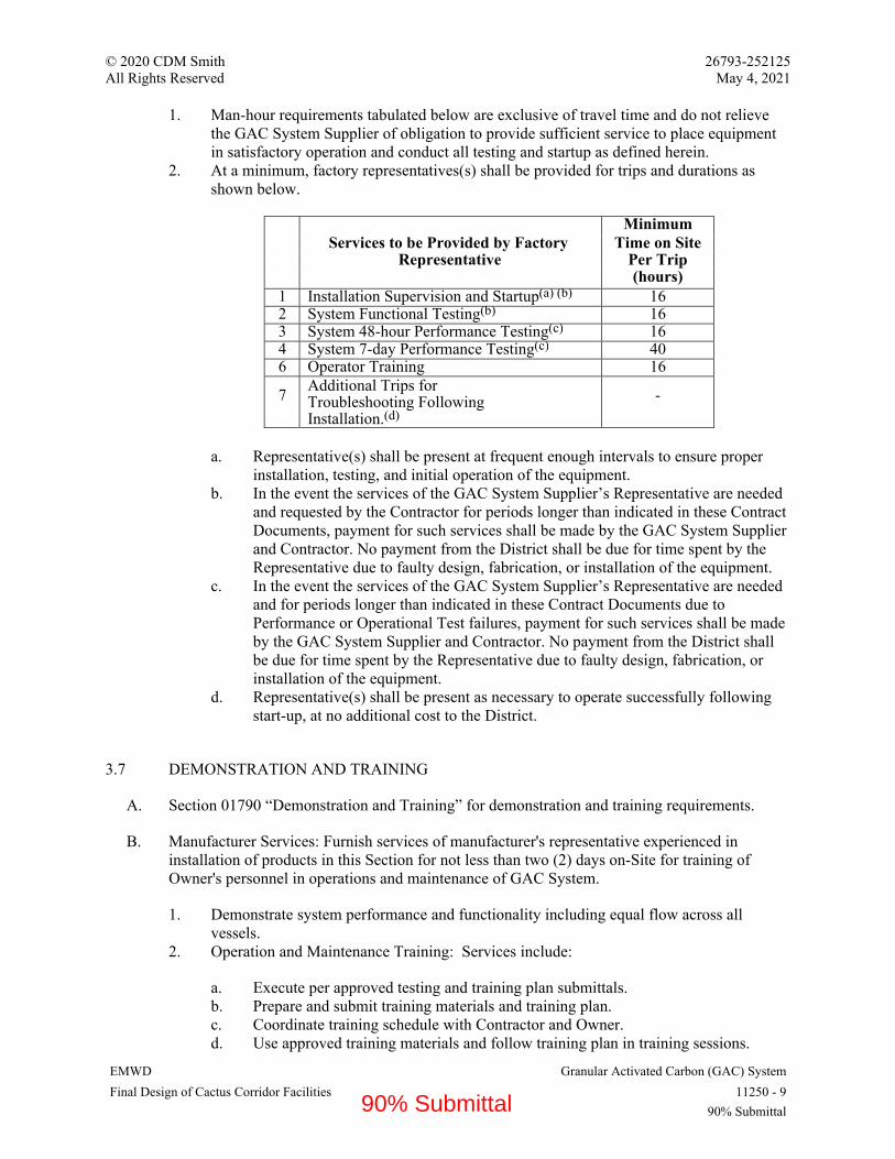
© 2020 CDM Smith 26793-252125 All Rights Reserved May 4, 2021
EMWD Granular Activated Carbon (GAC) System Final Design of Cactus Corridor Facilities 11250 - 9
90% Submittal
1. Man-hour requirements tabulated below are exclusive of travel time and do not relieve the GAC System Supplier of obligation to provide sufficient service to place equipment in satisfactory operation and conduct all testing and startup as defined herein.
2. At a minimum, factory representatives(s) shall be provided for trips and durations as shown below.
Minimum
Services to be Provided by Factory Time on Site Representative Per Trip
(hours) 1 Installation Supervision and Startup(a) (b) 16 2 System Functional Testing(b) 16 3 System 48-hour Performance Testing(c) 16 4 System 7-day Performance Testing(c) 40 6 Operator Training 16
7 Additional Trips for Troubleshooting Following Installation.(d)
-
a. Representative(s) shall be present at frequent enough intervals to ensure proper
installation, testing, and initial operation of the equipment. b. In the event the services of the GAC System Supplier’s Representative are needed
and requested by the Contractor for periods longer than indicated in these Contract Documents, payment for such services shall be made by the GAC System Supplier and Contractor. No payment from the District shall be due for time spent by the Representative due to faulty design, fabrication, or installation of the equipment.
c. In the event the services of the GAC System Supplier’s Representative are needed and for periods longer than indicated in these Contract Documents due to Performance or Operational Test failures, payment for such services shall be made by the GAC System Supplier and Contractor. No payment from the District shall be due for time spent by the Representative due to faulty design, fabrication, or installation of the equipment.
d. Representative(s) shall be present as necessary to operate successfully following start-up, at no additional cost to the District.
3.7 DEMONSTRATION AND TRAINING
A. Section 01790 “Demonstration and Training” for demonstration and training requirements.
B. Manufacturer Services: Furnish services of manufacturer's representative experienced in installation of products in this Section for not less than two (2) days on-Site for training of Owner's personnel in operations and maintenance of GAC System.
1. Demonstrate system performance and functionality including equal flow across all vessels.
2. Operation and Maintenance Training: Services include:
a. Execute per approved testing and training plan submittals. b. Prepare and submit training materials and training plan. c. Coordinate training schedule with Contractor and Owner. d. Use approved training materials and follow training plan in training sessions.
90% Submittal

© 2020 CDM Smith 26793-252125 All Rights Reserved May 4, 2021
EMWD Granular Activated Carbon (GAC) System Final Design of Cactus Corridor Facilities 11250 - 10
90% Submittal
e. Deliver training sessions. f. Deliver specified quantity training materials to Owner. g. Videotape training sessions. h. Obtain and submit Training Acknowledgement Certificate with signatures from
trainees indicating session attendance.
90% Submittal
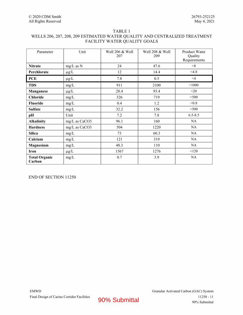
© 2020 CDM Smith 26793-252125 All Rights Reserved May 4, 2021
EMWD Granular Activated Carbon (GAC) System Final Design of Cactus Corridor Facilities 11250 - 11
90% Submittal
TABLE 1 WELLS 206, 207, 208, 209 ESTIMATED WATER QUALITY AND CENTRALIZED TREATMENT
FACILITY WATER QUALITY GOALS
Parameter Unit Well 206 & Well 207
Well 208 & Well 209
Product Water Quality
Requirements
Nitrate mg/L as N 24 47.6 <8
Perchlorate µg/L 12 14.4 <4.8
PCE µg/L 7.8 0.5 <4
TDS mg/L 911 2100 <1000
Manganese µg/L 28.4 93.4 <20
Chloride mg/L 326 719 <500
Fluoride mg/L 0.4 1.2 <0.8
Sulfate mg/L 32.2 156 <500
pH Unit 7.2 7.8 6.5-8.5
Alkalinity mg/L as CaCO3 96.1 160 NA
Hardness mg/L as CaCO3 504 1220 NA
Silica mg/L 73 60.3 NA
Calcium mg/L 121 319 NA
Magnesium mg/L 48.3 110 NA
Iron µg/L 1567 1276 <120
Total Organic Carbon
mg/L 0.7 3.9 NA
END OF SECTION 11250
90% Submittal

© 2020 CDM Smith 26793-252125 All Rights Reserved May 4, 2021
EMWD Granular Activated Carbon (GAC) Media Final Design of Cactus Corridor Facilities 11251 - 1
90% Submittal
SECTION 11251 - GRANULAR ACTIVATED CARBON (GAC) MEDIA
PART 1 - GENERAL
1.1 RELATED DOCUMENTS
A. Drawings and general provisions of the Contract, including General and Supplementary Conditions and Division 01 Specification Sections, apply to this Section.
1.2 SUMMARY
A. Section includes:
1. Provide, ready for operation, aqueous phase granular activated carbon (GAC) media for six (6) GAC vessels as shown on the Drawings and as specified herein.
2. Media volume shall be 27,000 dry pounds per vessel.
B. Related Requirements:
1. Section 11250 “Granular Activated Carbon (GAC) System”.
1.3 ACTION SUBMITTALS
A. Shop Drawings:
1. GAC Media data sheets indicating material, material source, unit weight, effective size, uniformity coefficient and other pertinent data specified or required to evaluate media quality.
2. Complete installation and placement procedures. 3. An Affidavit of Compliance in accordance with AWWA B100, NSF No. 61 and AWWA
B604 for activated carbon. 4. Test Results performed by the independent testing laboratory as required by “Quality
Assurance” Article in Part 1. 5. Evidence of Manufacturing Experience as required by “Quality Assurance” Article in
Part 1. 6. Certification of Quality Control Program.
1.4 QUALITY ASSURANCE
A. Proper operation of the GAC vessels requires very careful selection of relative sizes of the various media. No material shall be shipped to the site of the work until such material is approved by the Engineer in writing.
B. All the media of each type specified under this Section shall be furnished by a single supplier. The supplier shall submit a list of at least 10 operating facilities having media similar to that
90% Submittal

© 2020 CDM Smith 26793-252125 All Rights Reserved May 4, 2021
EMWD Granular Activated Carbon (GAC) Media Final Design of Cactus Corridor Facilities 11251 - 2
90% Submittal
specified herein. Any “or equal” to the named suppliers shall be products of a supplier having at least 10 years of current and continuous experience in the production of such media.
C. Quality Control and Testing:
1. Provide the services of a qualified testing laboratory experienced in testing GAC media materials to perform the tests specified.
2. Testing laboratory shall be approved by the Engineer/Owner. 3. The costs for testing shall be included. Owner may perform additional testing at Owner's
expense and Contractor shall permit and assist sampling as required. 4. The following tests are to be reported:
a. Particle Size Distribution, ASTM D2862. b. Average Apparent Density, ASTM D2854. c. Effective Size and Uniformity Coefficient, ASTM D2862. d. Abrasion (coal) or Hardness (coconut). e. Iodine Number, ASTM D4607. f. Moisture Content
5. Pre-Shipment Tests:
a. Sampling and testing to be performed in accordance with AWWA B604, prior to shipment of materials.
b. Perform tests on samples obtained directly by the approved testing laboratory in accordance with above-listed ASTM and AWWA B604 methods.
c. Provide certified copies of all tests performed by laboratory.
6. Receipt Tests:
a. Sampling and testing to be performed in accordance with AWWA B604, on material delivered to the site by the independent laboratory personnel of the Engineer.
b. Perform tests on samples obtained directly by the approved testing laboratory in accordance with above-listed ASTM and AWWA B604 methods.
c. If the results of the Receipt Tests do not comply with this Section, the materials must be replaced to comply with this Section at no additional cost to the Owner.
1.5 DELIVERY, STORAGE AND HANDLING
A. Delivery, storage and handling shall be in accordance with Section 01600.
B. All media shall be properly protected against damage and deterioration during prolonged storage at the site.
C. Furnish extra stock of GAC as necessary to account for all losses during backwashing as required for the installation procedures specified in Part 3 of this Section. In addition, supply two spare waterproof bags (50 lbs maximum size) which are stamped with the media type and size. Inventory media shall be stacked neatly for storage where directed by the Engineer.
90% Submittal
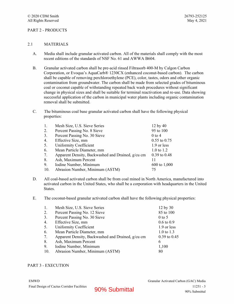
© 2020 CDM Smith 26793-252125 All Rights Reserved May 4, 2021
EMWD Granular Activated Carbon (GAC) Media Final Design of Cactus Corridor Facilities 11251 - 3
90% Submittal
PART 2 - PRODUCTS
2.1 MATERIALS
A. Media shall include granular activated carbon. All of the materials shall comply with the most recent editions of the standards of NSF No. 61 and AWWA B604.
B. Granular activated carbon shall be pre-acid rinsed Filtrasorb 400-M by Calgon Carbon Corporation, or Evoqua’s AquaCarb® 1230CX (enhanced coconut-based carbon). The carbon shall be capable of removing perchloroethylene (PCE), color, tastes, odors and other organic contamination from groundwater. The carbon shall be made from selected grades of bituminous coal or coconut capable of withstanding repeated back wash procedures without significant change in physical sizes and shall be suitable for terminal reactivation and re-use. Data showing successful application of the carbon in municipal water plants including organic contamination removal shall be submitted.
C. The bituminous coal base granular activated carbon shall have the following physical properties:
1. Mesh Size, U.S. Sieve Series 12 by 40 2. Percent Passing No. 8 Sieve 95 to 100 3. Percent Passing No. 30 Sieve 0 to 4 4. Effective Size, mm 0.55 to 0.75 5. Uniformity Coefficient 1.9 or less 6. Mean Particle Diameter, mm 1.0 to 1.2 7. Apparent Density, Backwashed and Drained, g/cu cm 0.39 to 0.48 8. Ash, Maximum Percent 11 9. Iodine Number, Minimum 600 to 1,000 10. Abrasion Number, Minimum (ASTM) 75
D. All coal-based activated carbon shall be from coal mined in North America, manufactured into activated carbon in the United States, who shall be a corporation with headquarters in the United States.
E. The coconut-based granular activated carbon shall have the following physical properties:
1. Mesh Size, U.S. Sieve Series 12 by 30 2. Percent Passing No. 12 Sieve 85 to 100 3. Percent Passing No. 30 Sieve 0 to 5 4. Effective Size, mm 0.6 to 0.9 5. Uniformity Coefficient 1.9 or less 6. Mean Particle Diameter, mm 1.0 to 1.3 7. Apparent Density, Backwashed and Drained, g/cu cm 0.39 to 0.45 8. Ash, Maximum Percent 6 9. Iodine Number, Minimum 1,100 10. Abrasion Number, Minimum (ASTM) 80
PART 3 - EXECUTION
90% Submittal

© 2020 CDM Smith 26793-252125 All Rights Reserved May 4, 2021
EMWD Granular Activated Carbon (GAC) Media Final Design of Cactus Corridor Facilities 11251 - 4
90% Submittal
3.1 INSTALLATION
A. Granular activated carbon shall be transported, delivered and placed in a careful manner to exclude all dust, dirt, or deleterious material and to prevent physical damage to the particles.
B. After delivery to the site, but before placing the media, take samples of each material as approved by the Engineer and in accordance with AWWA B604 and have the receipt tests performed as specified in Part 1 “Quality Assurance” article. Failure of the samples to meet the specified requirements shall be cause for rejection and the Contractor shall remove such media from the site and provide media meeting the requirements specified herein at no additional cost to the Owner. No plus tolerance will be allowed on any uniformity coefficients. The media supplier shall provide suitable shipment and/or make allowance for any degradation or segregation during shipping, so the delivered material meets these specifications for effective size and uniformity coefficient.
C. Each GAC vessel shall be thoroughly cleaned before any media is placed and shall be kept clean throughout the placement operation.
D. Following the installation of the GAC media, the GAC adsorbers shall be slowly filled in an up-flow orientation to push air from the GAC beds. Water shall be added to the GAC vessel very gradually (at a rate indicated by GAC supplier), particularly with new media, as the air trapped in the bed can be very disruptive to the media. After filling, the media will be soaked for a period of twenty-four (24) hours to allow the media to degas.
E. After the initial soaking, the GAC bed shall be backwashed for a total period of at least 30 minutes in order to stratify the bed and remove fines. This will require slowly ramping up to a flow necessary to achieve a bed expansion of 30 percent followed by a slow ramp-down of flow. Adequate backwashing shall be evidenced by a visibly clear backwash water with minimal fines, as judged by the Engineer. Contractor is responsible for replacing any media lost during testing and start-up beyond the skimming allowance at no additional cost to the Owner.
F. Some GAC products have been shown to increase pH and release arsenic during initial operation. Coordinate with GAC media supplier to develop a media conditioning plan, such that the pH and arsenic concentrations in the GAC effluent water are approximately the same as the influent water prior to delivering GAC effluent to the blending system.
3.2 WATER FOR BACKWASHING
A. Chloraminated water for backwashing shall be supplied by the District.
B. If backwash water is obtained from the Owner, coordinate time and usage with the Owner so as not to interfere with Owner's operations.
3.3 SPENT BACKWASH HOLDING TANK
A. Spent backwash water will be sent to one 79,000 gallon holding tanks. The backwash waste will be pumped through bag filters and on to the sewer. Contractor should anticipate up to 16,200 gallons of water per each individual vessel, given Engineer’s initial estimates of 1,350 gallon
90% Submittal

© 2020 CDM Smith 26793-252125 All Rights Reserved May 4, 2021
EMWD Granular Activated Carbon (GAC) Media Final Design of Cactus Corridor Facilities 11251 - 5
90% Submittal
per minute wash for up to 12 minutes on each of the individual vessels. The estimated wash rate of 1,350 gallons per minute shall be refined by the GAC supplier.
3.4 MEDIA CONDITIONING WATER DISCHARGE
A. Until the water quality requirements for pH, arsenic, and PCE are achieved, water discharged during the initial startup of the GAC treatment vessels shall be discharged to the Backwash Waste Holding Tank. Compliant GAC effluent shall be characterized as:
1. PCE: Non-detect 2. Arsenic: GAC effluent arsenic concentration shall be equal to, or less than, the GAC
influent arsenic concentration. 3. pH: GAC effluent pH should be within 0.2 pH units of the GAC influent pH.
END OF SECTION 11251
90% Submittal

© 2020 CDM Smith 26793-252125
All Rights Reserved May 4, 2021
EMWD Rotary-Screw Compressors
Final Design of Cactus Corridor Facilities 11325 - 1
90% Submittal
SECTION 11325 - ROTARY-SCREW COMPRESSORS
PART 1 - GENERAL
1.1 RELATED DOCUMENTS
A. Drawings and general provisions of the Contract, including General and Supplementary
Conditions and Division 01 Specification Sections, apply to this Section.
1.2 SUMMARY
A. Section Includes:
1. Rotary-screw air compressors.
2. Air receivers.
B. Related Requirements:
1. Section 05502, “Metal Fabrications” for fasteners, brackets, and other miscellaneous
metal fabrications as required by this Section.
2. Section 09900, “Painting and Protective Coating” for product and execution requirements
for painting as required by this Section.
3. Section 16150, “Induction Motors” for electric motors and their accessories normally
supplied as part of equipment assemblies.
1.3 COORDINATION
A. Coordinate Work of this Section with Work of other Sections.
1.4 PREINSTALLATION MEETINGS
A. Convene minimum one week prior to commencing Work of this Section.
1.5 ACTION SUBMITTALS
A. Section 01330 “Submittal Procedures” for submittals requirements.
B. Qualifications Statements:
1. Submit qualifications for manufacturer and installer.
2. Submit manufacturer's approval of installer.
C. Shop Drawings:
1. Certified shop and erection drawing showing details of construction and dimensions.
90% Submittal

© 2020 CDM Smith 26793-252125
All Rights Reserved May 4, 2021
EMWD Rotary-Screw Compressors
Final Design of Cactus Corridor Facilities 11325 - 2
90% Submittal
2. Equipment base drawing indicating size and location of bolt holes for anchorage, details
of anchorage of the equipment to the foundation including anchor bolt type, size,
materials, embedment depth, and minimum edge distance.
3. Certified performance data based on actual tests of similar units, showing specified
requirements for discharge pressure, volume, and brake horsepower.
4. Total equipment weight and weight of largest component.
5. A total bill of materials for all equipment.
6. Parts arrangement drawing including materials of construction.
7. Descriptive literature, bulletins, and/or catalogs of the equipment.
8. Data for electric motors. reference Section 16150.
9. Description of the performance and rating of the gear reducer.
10. Description of painting and protective coatings.
11. Noise Data.
D. Submit the Following Data:
1. Compressor:
a. Manufacturer.
b. Model.
c. Speed.
d. Capacity (scfm).
e. Pressure (psi).
f. Power (hp)
2. V-Belt Drive
a. Manufacturer.
b. Number of Size of V-Belt.
c. Rated Capacity (HP) of V-Belt Drive.
3. Air Receiver
a. Manufacturer.
b. Volume/Dimensions.
c. Pressure Rating (psi).
d. Compressor Mounting.
4. Air Filters:
a. Manufacturer.
b. Materials of construction.
c. Pressure rating.
d. Capacity.
e. Filter element data.
1.6 INFORMATIONAL SUBMITTALS
A. Manufacturer's Certificate: Products meet or exceed specified requirements.
B. Manufacturer's Instructions: Detailed instructions on installation requirements, including
storage and handling procedures.
90% Submittal

© 2020 CDM Smith 26793-252125
All Rights Reserved May 4, 2021
EMWD Rotary-Screw Compressors
Final Design of Cactus Corridor Facilities 11325 - 3
90% Submittal
C. Source Quality-Control Submittals: Results of factory tests and inspections.
D. Field Quality-Control Submittals: Results of Contractor-furnished tests and inspections.
E. Manufacturer Reports: Equipment has been installed according to manufacturer's instructions.
1.7 CLOSEOUT SUBMITTALS
A. Section 01770 “Closeout Procedures” for closeout procedures requirements.
B. Project Record Documents: Record actual locations of compressors and components.
C. Operation and Maintenance Data: Instructions for lubrication, motor and drive replacement,
spare parts list, and wiring diagrams.
1.8 MAINTENANCE MATERIAL SUBMITTALS
A. Section 01770 “Closeout Procedures” for maintenance materials requirements.
B. Spare Parts: Furnish one set of manufacturer's recommended spare parts. At a minimum,
provide the following:
1. Suction air filter
2. Oil filter
3. Separator cartridge
4. Belt
C. Tools: Furnish special wrenches and other devices required for Owner to maintain and calibrate.
1.9 QUALIFICATIONS
A. Manufacturer: Company specializing in manufacturing products specified in this Section with
minimum three years' experience.
B. Installer: Company specializing in performing Work of this Section with minimum three years'
experience.
1.10 WARRANTY
A. Section 01770 “Closeout Procedures” for warranties requirements.
PART 2 - PRODUCTS
2.1 ROTARY-SCREW AIR COMPRESSORS
A. Manufacturers:
1. Gardner Denver
90% Submittal

© 2020 CDM Smith 26793-252125
All Rights Reserved May 4, 2021
EMWD Rotary-Screw Compressors
Final Design of Cactus Corridor Facilities 11325 - 4
90% Submittal
2. Ingersoll-Rand
3. Quincy Compressor
4. Substitutions: Section 01600, “Product Requirements.”
B. Oil lubricated rotary screw compressor: One-stage, belt driven oil flooded twin rotary screw
compressor.
1. Electric motor.
2. Air cooled air aftercooler and air/oil separator (two stage coalescent type with return line,
strainer, sight glass, automatic blow down valve and a minimum pressure valve).
3. Air cooled oil cooler.
4. Oil filter.
5. Shaft driven oil pump.
6. Inlet filter/silencer with maintenance indicator.
7. Power saving modulating air volume control for 0 to 100 percent capacity control and no-
load starting and stopping.
8. Discharge pressure sensor and high and low discharge pressure switches and shut-down
device.
9. Discharge temperature sensor and high temperature switch and shut-down device.
10. Oil temperature and pressure sensors, high/low switches, and shut-down devices.
11. Full enclosure with vibration absorbers.
C. Description:
1. Number of Units: 2 (1 duty, 1 standby).
2. Mounting: Base.
3. Seals: Manufacturer’s standard.
4. Bearings: Manufacturer’s standard.
5. Compressor Base: Welded steel or cast iron to support all weight and operating loads of
compressor. Provision to adjust belt tension. Anchor to concrete foundation to conform to
Section 05502 “Metal Fabrications.”
6. Designed for continuous unattended service.
7. Air pressure actuated intake volumetric control valve: For modulating control of intake
air maintaining discharge pressure at varying air flow demands from 0 to 100 percent
capacity.
8. Discharge Air Connection: Threaded.
D. Performance and Design Criteria:
1. Nominal Speed: Per manufacturer.
2. Inlet Size: Per manufacturer.
3. Discharge Size: Per manufacturer.
4. Number of Stages: One.
5. Capacity: Per Hydropneumatic Surge Arrestor manufacturer.
6. Performance Base: 1,584 feet above mean sea level conditions.
7. Maximum Discharge Pressure: 150 .
8. Maximum Sound Level: 70 dBA, 3 feet from compressor unit.
9. Static and Dynamic Balance: Eliminate vibration or noise transmission to occupied areas.
E. Materials:
1. Oil Reservoir: Stainless steel.
90% Submittal

© 2020 CDM Smith 26793-252125
All Rights Reserved May 4, 2021
EMWD Rotary-Screw Compressors
Final Design of Cactus Corridor Facilities 11325 - 5
90% Submittal
2. Seals: Carbon.
F. Motors:
1. As specified in Section 16150, “Induction Motors.”
2. Horizontal, base mounted, belt drive.
3. Premium efficiency.
4. Enclosure: Open drip proof.
5. Power factor correction capacitor.
G. Control Panels:
1. Factory mounted.
2. NEMA 250 Type 4.
3. Built to UL – 508
4. Single-point power connection and grounding lug. for a 480 VAC, 3 phase, 60 Hz power
supply
5. Disconnect Switch: Factory-mounted disconnect switch in control panel.
6. Fuse protected control power transformer sized for control functions.
7. Motor Starters: Magnetic, full voltage, non-reversing.
8. Microprocessor controller with integral display and programming functions.
H. Controls:
1. Hand-Off-Automatic selector switch
2. Automatic Start/Stop with alternator.
3. Display:
a. Power on.
b. Discharge air temperature.
c. Discharge pressure.
d. Oil temperature.
e. Oil pressure.
f. Maintenance interval.
g. Run time.
h. Machine status.
4. Programming features:
a. Load and unload set points.
b. Lead/lag control.
c. Restart after power failure.
d. Input for remote start/stop.
e. Continuous or automatic start/stop.
5. Dry contact outputs rated 10 Amp at 120 VAC single pole, double throw dry alarm
contacts for remote status indication of the following:
a. Compressor Running.
b. Maintenance Required.
6. RS485 port for PC connection and to transmit discrete remote alarms
7. Alarms (with shut-down, visual, with acknowledge/silencer/reset/test
90% Submittal

© 2020 CDM Smith 26793-252125
All Rights Reserved May 4, 2021
EMWD Rotary-Screw Compressors
Final Design of Cactus Corridor Facilities 11325 - 6
90% Submittal
a. Compressor No. 1 High Discharge Temperature.
b. Compressor No. 1 High Discharge Pressure.
c. Compressor No. 1 High Discharge Pressure Shutdown.
d. Compressor No. 1 Low Discharge Pressure.
e. Compressor No. 1 Low Discharge Pressure Shutdown.
f. Compressor No. 1 Low Oil Pressure.
g. Compressor No. 1 Motor Overload
h. Compressor No. 2 High Discharge Temperature.
i. Compressor No. 2 High Discharge Pressure.
j. Compressor No. 2 High Discharge Pressure Shutdown.
k. Compressor No. 2 Low Discharge Pressure.
l. Compressor No. 2 Low Discharge Pressure Shutdown.
m. Compressor No. 2 Low Oil Pressure.
n. Compressor No. 2 Motor Overload
I. Belt Drive (If required by equipment design):
1. Multi V-Belt drive with 1.5 service factor based upon motor horsepower rating.
2. Sheaves keyed and locked to their respective shafts.
3. OSHA compliant fabricated steel or expanded metal belt guard, galvanized after
fabrication.
J. Accessories:
1. Safety Relief Valve: ASME approved.
2. Start and Stop Pressure Switch:
a. Diaphragm actuated, snap action.
b. Range: 0 to 150 psi .
c. Repeatability: 1.0 percent of full scale
d. Adjustable setting, adjustable dead band.
e. Automatic reset.
f. Contacts: Single pole, double throw, 10 Amperes, 120 Volts AC.
g. Enclosure: NEMA 4X.
h. Isolation valve and snubber.
3. Compressor high/low discharge pressure and oil pressure alarm/shut-down pressure
switch (same details as above).
4. Compressor high discharge temperature and high oil temperature alarm/shut-down
temperature switch:
a. Bulb and capillary type, snap action
b. Scale range: Up to 300 degrees F .
c. Adjustable Setting Range 100 to 250 degrees F .
d. Adjustable or fixed dead-band.
e. Repeatability: 1.0 percent of full scale.
f. Automatic reset.
g. Contacts: Single pole, double throw, 10 Amperes, 120 Volts AC.
h. Enclosure: NEMA 4X.
i. Thermowell: Type 316 stainless steel or bronze.
5. Oil pressure gage.
90% Submittal

© 2020 CDM Smith 26793-252125
All Rights Reserved May 4, 2021
EMWD Rotary-Screw Compressors
Final Design of Cactus Corridor Facilities 11325 - 7
90% Submittal
6. Oil sight glass.
7. Oil filters.
K. Sound Attenuating Enclosure:
1. Provide for each compressor.
2. Design for easy inspection and maintenance of all blower package components using
quick release panels or hinged doors if panels weigh more than 50 pounds
3. Mount enclosure and compressor package on single skid with vibration isolation and oil
drip pan. Provide grounding strap from compressor to skid and grounding lugs on skid.
4. Fabricate internal and external panels of powder coated galvanized steel sheet.
5. Sound enclosure acoustic material, as a minimum, to comply with UL 94 - HF1 for fire-
retardant, self-extinguishing, non-dripping materials. Materials with a lesser rating are
not acceptable. If used, non-flammable packing materials such as compressed mineral
fibers are acceptable only if lined with retaining mat and supported by galvanized
perforated sheet.
a. Minimum Ambient Temperature: 50 degrees F .
b. Maximum Ambient Temperature: 90 degrees F .
6. Provide a shaft driven or high efficiency electric motor driven fan for ventilation and
cooling of sound enclosure. Electric motor driven ventilation fan to be factory installed
and prewired including motor driven fan, motor starter, wiring, and NEMA 4X stainless
steel fan control panel. Fan to operate on compressor power supply. Fan control panel to
allow compressor motor to run only after ventilation fan operation is confirmed.
Mounting of electrical components, instrumentation and instrument connections to avoid
interference with moving panels of enclosure.
L. Noise Limitation
1. Design air compressor system for a free field sound pressure level not to exceed 70
decibels over a frequency range of 37.8 to 9600 cycles per second at a distance of 3-ft
from any portion of the equipment, under any load condition, when tested using standard
equipment and methods. Noise level to include the noise from the motor. Utilize
mufflers, baffles, or sound attenuating enclosure to reduce noise. Submit data on noise
levels.
2.2 AIR RECEIVERS
A. Manufacturers:
1. Supplied by air compressor manufacturer.
2. Substitutions: Section 01600 “Product Requirements.”
B. Description: Vertical.
1. Pipe Connections: Screwed.
C. Performance and Design Criteria:
1. Build to ASME BPVC Section VIII regulations.
2. Working Pressure: 150 psig.
90% Submittal

© 2020 CDM Smith 26793-252125
All Rights Reserved May 4, 2021
EMWD Rotary-Screw Compressors
Final Design of Cactus Corridor Facilities 11325 - 8
90% Submittal
3. National Board Certificate.
4. Diameter: Per air compressor manufacturer.
5. Length: Per air compressor manufacturer.
6. Capacity: Per air compressor manufacturer.
D. Tappings:
1. One 1.5- inch inlet.
2. One 1.5- inch outlet.
3. One 0.75-inch drain.
4. One 0.5- inch pressure switch.
5. One 0.75-inch pressure relief valve.
6. One 0.25-inch pressure gauge.
E. Accessories:
1. Adjustable outlet pressure regulator.
2. Safety Relief Valve: ASME certified and labeled.
a. Body: Bronze.
b. Seat: PTFE.
c. Stem and Springs: Stainless steel.
d. Automatic, direct-pressure actuated.
3. Pressure Gage.
a. Bourdon tube actuated.
b. Accuracy: Plus or minus 1.0 percent of scale.
c. Pressure Range: As required to place normal operating pressure at mid-scale.
d. Surface or stem mount.
e. Casing: Shock resistant phenolic or Type 316 stainless steel.
f. Mountiing: Surface or stem.
g. Liquid filled.
h. Diameter: 4 inch.
i. Gage petcock and snubber.
4. Drain valve Electric.
5. Automatic float-actuated condensate trap and drain.
6. Tank Outlet Valve: ASME approved.
7. Pressure Transmitter:
a. Microprocessor based, two-wire, loop powered.
b. Diaphragm actuated.
c. Accuracy: plus or minus 0.1 percent.
d. Output: 4 to 20 ma dc.
e. Range: 0 to 150 psi.
f. Enclosure: NEMA 4X.
8. Air temperature gauge.
F. Tank Finish: Shop primed.
90% Submittal
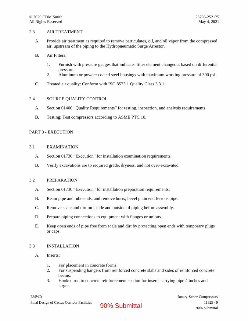
© 2020 CDM Smith 26793-252125
All Rights Reserved May 4, 2021
EMWD Rotary-Screw Compressors
Final Design of Cactus Corridor Facilities 11325 - 9
90% Submittal
2.3 AIR TREATMENT
A. Provide air treatment as required to remove particulates, oil, and oil vapor from the compressed
air, upstream of the piping to the Hydropneumatic Surge Arrestor.
B. Air Filters:
1. Furnish with pressure gauges that indicates filter element changeout based on differential
pressure.
2. Aluminum or powder coated steel housings with maximum working pressure of 300 psi.
C. Treated air quality: Conform with ISO 8573.1 Quality Class 3.3.1.
2.4 SOURCE QUALITY CONTROL
A. Section 01400 “Quality Requirements” for testing, inspection, and analysis requirements.
B. Testing: Test compressors according to ASME PTC 10.
PART 3 - EXECUTION
3.1 EXAMINATION
A. Section 01730 “Execution” for installation examination requirements.
B. Verify excavations are to required grade, dryness, and not over-excavated.
3.2 PREPARATION
A. Section 01730 “Execution” for installation preparation requirements.
B. Ream pipe and tube ends, and remove burrs; bevel plain end ferrous pipe.
C. Remove scale and dirt on inside and outside of piping before assembly.
D. Prepare piping connections to equipment with flanges or unions.
E. Keep open ends of pipe free from scale and dirt by protecting open ends with temporary plugs
or caps.
3.3 INSTALLATION
A. Inserts:
1. For placement in concrete forms.
2. For suspending hangers from reinforced concrete slabs and sides of reinforced concrete
beams.
3. Hooked rod to concrete reinforcement section for inserts carrying pipe 4 inches and
larger.
90% Submittal
© 2020 CDM Smith 26793-252125
All Rights Reserved May 4, 2021
EMWD Rotary-Screw Compressors
Final Design of Cactus Corridor Facilities 11325 - 10
90% Submittal
4. Where concrete slabs form finished ceiling, locate inserts flush with slab surface.
5. Where inserts are omitted, drill through concrete slab from below and provide through
bolt with recessed square steel plate and nut recessed into and grouted flush with slab.
B. Hangers and Supports: Install hangers and supports according to ASME 31.3.
C. Buried Piping Systems:
1. Establish elevations of buried piping with minimum 3 feet of cover.
2. Establish minimum separation of 10 feet from sanitary sewer piping according toTitle 22
requirements.
3. Excavate pipe trench as specified in Section 02221 “Trenching, Backfilling, and
Compacting.”
4. Install pipe to elevation as indicated on Drawings.
5. Place bedding material at trench bottom. Provide uniform bedding for piping, and level
bedding materials in one continuous layer not exceeding 4 inches compacted depth;
compact to 95 percent maximum density.
6. Install pipe on prepared bedding.
7. Route pipe in straight line.
8. Install pipe to allow for expansion and contraction without stressing pipe or joints.
9. Coordinate provision of utility warning and identification tape with backfill operation;
install above buried piping at depth of 8 to 12 inches below finish grade.
10. Backfill trench as specified in Section 02221, “Trenching, Backfilling, and Compaction”
11. Maintain optimum moisture content of fill material to attain required compaction density.
12. After pressure testing, evenly backfill entire trench width by hand, placing backfill
material and hand tamping in 4 inch compacted layers to12 inch minimum cover over top
of pipe; compact to 95 percent maximum density.
13. Evenly and continuously backfill remaining trench depth in uniform layers with backfill
material.
14. Do not use wheeled or tracked vehicles for tamping.
D. Aboveground Piping Systems:
1. Install drip connections with valves at low points of piping system.
2. Install takeoff to outlets from top of main, with shutoff valve after takeoff; slope takeoff
piping to outlets.
3. Install compressed-air couplings, female quick connectors, and pressure gages as
indicated on Drawings.
4. Install tees instead of elbows at changes in direction of piping; fit open end of each tee
with plug.
5. Cut pipe and tubing accurately and install without springing or forcing.
6. Slope piping in direction of flow.
7. Stainless-Steel Pipe with Press-Type Joints:
a. Square-cut ends to plus or minus 0.030 inch tolerance.
b. Remove burrs and clean ends.
c. Fully insert tubing into fitting, and mark pipe ends to ensure full insertion into
coupling or fitting during assembly.
d. Press joint using manufacturer's tool with proper-sized jaw.
8. Copper Pipe with Press-Type Joints:
90% Submittal
© 2020 CDM Smith 26793-252125
All Rights Reserved May 4, 2021
EMWD Rotary-Screw Compressors
Final Design of Cactus Corridor Facilities 11325 - 11
90% Submittal
a. Remove burrs and clean ends.
b. Fully insert tubing into fitting, and mark pipe ends to ensure full insertion into
coupling or fitting.
c. Check alignment against mark to assure tubing is fully inserted.
d. Press joint using manufacturer's tool.
9. Install pipe sleeves where pipes and tubing pass through walls, floors, roofs, and
partitions, as specified in Section 400513, “Common Work Results for Process Piping.”
10. Install firestopping at fire-rated construction perimeters and openings containing
penetrating sleeves and piping.
11. Except where indicated, install manual shutoff valves with stem vertical and accessible
for operation and maintenance.
12. Install strainers on inlet side of pressure-reducing valves; install pressure-reducing valves
with bypasses and isolation valves to allow maintenance without interruption of service.
13. Install strainers on inlet side of pressure regulators.
E. Equipment:
1. Install air compressor on concrete housekeeping pad, minimum 3-1/2 inches high and 6
inches larger than compressor base on each side, as specified in Section 03300, “Cast-In-
Place Concrete.”
2. Install air compressor unit on vibration isolators; level and bolt in place.
3. Install air valve and drain connection on horizontal casing.
4. Install line-sized shutoff valve and check valve on compressor discharge.
5. Install replaceable cartridge-type filter-silencer for each compressor.
6. Install condensate drain piping to nearest floor drain.
7. Provide bypass with valves around receivers.
3.4 FIELD QUALITY CONTROL
A. Section 01400 “Quality Requirements” for inspecting and testing requirements.
B. Compressed-Air Piping Leak Test: Prior to initial operation, clean and test compressed-air
piping according to ASME B31.3.
C. Verify for atmospheric pressure in piping systems, other than system under test.
D. Test system with dry compressed air or dry nitrogen with test pressure in piping system at 50
psig.
E. Manufacturer Services: Furnish services of manufacturer's representative experienced in
installation of products furnished under this Section for not less than one day on-Site for
installation, inspection, field testing, and instructing Owner's personnel in maintenance of
equipment.
F. Equipment Acceptance:
1. Adjust, repair, modify, or replace components failing to perform as specified, and rerun
tests.
2. Make final adjustments to equipment under direction of manufacturer's representative.
90% Submittal

© 2020 CDM Smith 26793-252125
All Rights Reserved May 4, 2021
EMWD Rotary-Screw Compressors
Final Design of Cactus Corridor Facilities 11325 - 12
90% Submittal
G. Furnish installation certificate from equipment manufacturer's representative attesting
equipment has been properly installed and is ready for startup and testing.
3.5 ADJUSTING
A. Section 01730 “Execution” for starting and adjusting requirements.
B. Check control functions and adjust as required.
3.6 CLEANING
A. Sections 01730 “Execution” and 01770 “Closeout Procedures” for cleaning requirements.
B. Blow systems clear of free moisture and foreign matter.
3.7 DEMONSTRATION
A. Section 01790 “Demonstration and Training” for demonstration and training requirements.
B. Demonstrate equipment startup, shutdown, routine maintenance, and emergency repair
procedures to Owner's personnel.
END OF SECTION 11325
90% Submittal

© 2020 CDM Smith 26793-252125 All Rights Reserved May 4, 2021
EMWD Pressure Filters Final Design of Cactus Corridor Facilities 11364 - 1
90% Submittal
SECTION 11364 - PRESSURE FILTERS
PART 1 - GENERAL
1.1 RELATED DOCUMENTS
A. Drawings and general provisions of the Contract, including General and Supplementary Conditions and Division 01 Specification Sections, apply to this Section.
1.2 SUMMARY
A. Section Includes: Pressure filters and accessories.
B. Related Requirements:
1. Section 01882 "Seismic Performance Requirements”. 2. Section 09900 "Painting and Protective Coatings" for coating requirements for equipment
specified in this Section. 3. Section 03300 “Cast-in-place Concrete.” 4. Section 02201 “Construction Methods and Earthwork.” 5. Section 15065 “Hangers and Supports for Process Piping.” 6. Section 15061 "Steel Cylinder Water Pipe" for piping materials and installation as
required for this Section. 7. Section 17005 “General Instrumentation and Control Components.” 8. Section 17006 “Configuration of HMI Software.” 9. Section 17010 “Programmable Logic Controller.” 10. Sections 17210 and 17210.1 for “Magnetic Flowmeters.” 11. Section 11005 “General Mechanical and Equipment Provisions" for nameplates for
equipment specified in this Section. 12. Division 16 for electrical work.
1.3 SUBMITTALS
A. Section 01330 "Submittal Procedures" for requirements for submittals.
B. Product Data: Submit manufacturer's Product Data for system materials and component equipment.
1. Certified shop and erection Vendor Drawings showing model number, dimension, services sizes, materials of construction, finishes, and all details of construction including anchor bolt locations.
2. Descriptive literature, bulletins and/or catalogs of the equipment, in sufficient detail, including parts to indicate full conformance with this Section:
a. Manufacturer's data, order sheet, or equivalent for each individual piece of equipment, component, instrument, or device being supplied. The information shall
90% Submittal

© 2020 CDM Smith 26793-252125 All Rights Reserved May 4, 2021
EMWD Pressure Filters Final Design of Cactus Corridor Facilities 11364 - 2
90% Submittal
include but not be limited to model number, exact chart, scale or calibration range, type of enclosure and mounting, input/output and power data, and the instrument tag number (or loop number for auxiliary equipment). Sales literature will not be accepted.
b. Manufacturer's outline and mounting dimensions for all field mounted devices, including the pressure filters, valves, flow meters, and instrumentation and controls, including control panel(s).
c. Manufacturer's dimensions and field fabrication details for all mechanical equipment including pressure filter equipment, valves, control panels and instruments. Data shall include color selection with color samples for control panels and scaled layout Vendor Drawings for control panels.
d. One set of digital and reproducible Vendor Drawings shall be bound with each copy of the submittal:
1) Complete detailed layouts of all control panels. 2) Complete details of tank interior and exterior arrangement and construction
with associated appurtenances. 3) Media configuration showing depths, volume, and type being provided to
include uniformity coefficient (UC), size, material, product name and number as well as how it is shipped and any extra amount of filter material provided (i.e. 5%).
4) Complete master wiring diagrams, elementary, panel, or control schematics, including coordination with all electrical control devices operating in conjunction with the filter control panel and showing internal wiring schematics and field connections. Standard preprinted sheets or Vendor Drawings showing other than the actual arrangement to be furnished will not be acceptable. Control devices specified in Division 16 and 17 shall be coordinated and indicated in these submitted documents.
e. Sample warranty.
3. Complete description of all accessory equipment, piping, etc.
a. Description of operation and control of equipment. This shall include a complete written description of the control system.
4. Shop drawings required in other sections for equipment provided, such as for valves, and actuators.
5. A complete total bill of materials for all components furnished. 6. A list of the manufacturer's recommended spare parts.
C. Shop Drawing submittals shall include a list of items that may deviate from items specified and the reasons for deviation. Failure to do this will be grounds for rejection of the submittal or for back charges for resulting construction delays or charges. All equipment to be provided under this Section must be approved prior to any equipment being released for manufacturing. The following must be approved by the Engineer before release for manufacturing:
1. Plant finished water quality written guarantee by Pressure Filter System Supplier. 2. Pressure filter equipment, piping, control panel(s), etc., required for the entire pressure
filtration system.
90% Submittal

© 2020 CDM Smith 26793-252125 All Rights Reserved May 4, 2021
EMWD Pressure Filters Final Design of Cactus Corridor Facilities 11364 - 3
90% Submittal
3. Pressure Filter System Supplier shall provide hydraulic calculations of design pressure loss for clean filter bed and backwash conditions, and uniformity of flow for influent distributor/backwash collector and underdrain piping. Calculations shall be based on actual pipe sizes and configuration, orifice sizes, filter media support bed and appurtenant piping.
4. Calculations for backwash expansion for verification of ample filter height. 5. Vessel shall be constructed in accordance with Section VIII of the ASME Boiler and
Pressure Vessel (BPVC) for unfired pressure vessels and shall be code stamped for the operating conditions provided in Part 2. Minimum thicknesses shall be furnished in accordance with ASME code requirements. Verification of ASME code design to include calculated head and shell thicknesses.
6. Preliminary point to point wiring diagrams with instruments and valves pre-wired to termination panels that are skid mounted.
7. Written sequence of operations, and programming sequence. 8. Instrument and Control Panel electrical voltage, amperes and short circuit requirements. 9. PLC programming sequence, OIT graphic screens and PLC point to point wiring
diagrams for the complete system:
a. The following information is required in a submittal no later than 30 days prior to the scheduled shipment of the vendor equipment to the site.
b. The PLC program shall allow for remote monitoring and control of the system from the plant SCADA system.
c. The Pressure Filter System Supplier is responsible for providing the correct Ethernet protocol communication card to talk to with the plant’s SCADA system.
d. The Pressure Filter System Supplier PLC programmer shall provide a SCADA Memory Map Interface List for all inputs and outputs between the vendor PLC and plant PLC. The Memory Map List provided by Pressure Filter System Supplier PLC programmer shall map all applicable data (I/O registers and bits) that are defined in the Contract Documents into contiguous registers such that the plant-wide SCADA system supplier can monitor and control the filter system and receive data from the filter PLC by simply interfacing with these mapped points.
e. One set of registers shall be provided for writing discrete-type information, and one set shall be provided for reading discrete-type information.
f. One set of registers shall be provided for writing floating-point information, and one set shall be provided for reading floating point information.
g. The Pressure Filter System Supplier PLC programmer shall submit this memory map of PLC registers. Vendor shall contact and coordinate with the SCADA Application Engineer System Supplier (AESS) programmer (see Section 17006 for additional information) to ensure compatible configuration of the filter system PLC with the plants SCADA system network. The Pressure Filter System Supplier PLC programmer shall configure the network addresses in their equipment to match the addresses determined by the AESS
D. The following must be approved by the Engineer prior to installation:
1. Media and gravel data including sieve analysis, gradation curve and certification stating that the filter gravel has been tested in accordance with AWWA B100 and meets each and all physical and chemical requirements of the standard and the specifications herein.
2. Certification that the filter media and gravel meets ANSI/NSF Standard 61. 3. The total weight of each component of the equipment, both shipping weight and
operating weight.
90% Submittal

© 2020 CDM Smith 26793-252125 All Rights Reserved May 4, 2021
EMWD Pressure Filters Final Design of Cactus Corridor Facilities 11364 - 4
90% Submittal
4. The tank manufacturer shall submit written certification prepared, sealed, and signed by a professional mechanical engineer licensed in the state of California, indicating the design pressure rating of the filter vessels and conformance with the specified ASME pressure vessel code. Submit certification of fabricating shop and welders to manufacture ASME pressure vessels. Vessels shall be fabricated in a facility holding a current ASME U-stamp. Facilities holding an ASME R (“repair”) or other certification shall not be considered acceptable for vessel fabrication.
E. The following must be approved by the Engineer prior to final acceptance:
1. A plan for the chlorinating method for disinfection of equipment shall be submitted with the calculation for the amount of chlorine to be added to the tank.
2. A plan for commissioning of the filters. The plan shall be updated for equipment-specific procedures by the Pressure Filter System Supplier and submitted to the Engineer for review.
3. Contractor’s certificate stating the media and gravel was installed in accordance with the specifications and is approved by the Pressure Filter System Supplier.
4. Final point to point wiring diagrams to all panels being provided by the vendor 5. Final written sequence of operations and programming sequence
F. Operation and Maintenance Data:
1. Furnish complete operating and maintenance instructions for all equipment included under this section. The maintenance instructions shall include trouble shooting data, preventive maintenance schedules and complete spare parts lists with ordering information.
G. Shop Drawings:
1. Indicate system materials and component equipment. 2. Submit installation and anchoring requirements, fasteners, and other details.
H. Manufacturer's Certificate: Certify that filters meet or exceed specified requirements.
I. Manufacturer's Instructions: Submit detailed instructions on installation requirements, including storage and handling procedures.
J. Source Quality-Control Submittals: Indicate results of factory tests and inspections.
K. Field Quality-Control Submittals: Indicate results of Contractor-furnished tests and inspections.
L. Manufacturer Reports: Indicate that equipment has been installed according to manufacturer's instructions.
M. Qualifications Statements:
1. Submit qualifications for manufacturer and installer. 2. Submit manufacturer's approval of installer.
90% Submittal

© 2020 CDM Smith 26793-252125 All Rights Reserved May 4, 2021
EMWD Pressure Filters Final Design of Cactus Corridor Facilities 11364 - 5
90% Submittal
1.4 CLOSEOUT SUBMITTALS
A. Section 01770 "Closeout Procedures" for requirements for closeout procedures.
B. Project Record Documents: Record actual locations of installed pressure filters.
C. Operation and Maintenance Data: Submit maintenance instructions for equipment and accessories.
1.5 MAINTENANCE MATERIAL SUBMITTALS
A. Section 01770 "Closeout Procedures" for requirements for maintenance materials.
B. Spare Parts:
1. Furnish one set of manufacturer's recommended spare parts including manway gaskets for each filter.
C. Tools: Furnish all special tools and other devices required to service the equipment specified herein.
1.6 QUALITY ASSURANCE
A. Materials in Contact with Potable Water: Comply with NSF Standard 61 and NSF Standard 372.
1.7 QUALIFICATIONS
A. Manufacturer: Company specializing in manufacturing products specified in this Section with minimum five years' documented experience.
B. Installer: Company specializing in performing Work of this Section with minimum three years' documented experience and approved by manufacturer.
1.8 DELIVERY, STORAGE, AND HANDLING
A. Deliver materials in manufacturer's packaging including application instructions. Refer to 01600 “Product Requirements” for additional requirements.
B. Inspection: Accept materials on Site in original packaging and inspect for damage.
C. Store materials according to manufacturer's instructions.
1.9 UNIT RESPONSIBILITY
A. All the equipment, labor, and materials manufactured and supplied as specified under this Section shall be furnished by a single supplier (Package Supplier). The Package Supplier shall
90% Submittal
© 2020 CDM Smith 26793-252125 All Rights Reserved May 4, 2021
EMWD Pressure Filters Final Design of Cactus Corridor Facilities 11364 - 6
90% Submittal
have the sole responsibility for the proper manufacturing, shipping, delivery, assembly, testing, and shall assume proper functioning of all equipment, controls, components, and appurtenances specified.
1.10 EXISTING CONDITIONS
A. Field Measurements:
1. Verify field measurements prior to fabrication. 2. Indicate field measurements on Shop Drawings.
1.11 WARRANTY
A. Section 01770 "Closeout Procedures" for requirements for warranties.
B. Furnish five-year manufacturer's warranty for pressure filters and accessories.
PART 2 - PRODUCTS
2.1 PRESSURE FILTERS
A. Manufacturers:
1. Hungerford & Terry 2. Loprest 3. WesTech Engineering 4. Roberts Filter Group 5. Substitutions: Section 01600 “Product Requirements.”
B. Design Requirements
1. Number of filters: 3 (2 duty, 1 redundant) 2. Number of cells per filter: 3 3. Design rate of flow per filter: 1,033 gpm (3 filters online), 1,550 gpm (two filters online). 4. Filtration rate shall not exceed a surface loading rate of 5 gpm/sq. ft with one filter unit
offline. 5. The filters shall be capable of supporting a minimum backwash flow rate of 12 gpm/sq. ft
or greater to achieve a minimum bed expansion during backwash equal to 30% with water temperature equal to 80 deg F.
6. Design Pressures:
a. Design total pressure: 100 psi.
b. Tank design shall ensure full vacuum conditions are prevented from occurring.
c. The maximum pressure loss across a filter shall not exceed 15 psi at normal service flow at the end of each service run.
90% Submittal
© 2020 CDM Smith 26793-252125 All Rights Reserved May 4, 2021
EMWD Pressure Filters Final Design of Cactus Corridor Facilities 11364 - 7
90% Submittal
d. The clean bed pressure drop through the system shall not exceed 2 psi during normal operation
7. The pressure filter equipment shall be designed for all applicable seismic loads set forth in Section 01882.
8. Continuous Regeneration – sodium hypochlorite system. 9. Influent water quality - The filter shall meet the performance guarantee with the
following influent water quality:
Parameter Concentration pH 7.0 – 8.0 Alkalinity (mg/L as CaCO3) 85 – 160 Turbidity (NTU) < 1 Maximum Total Iron (mg Fe/L) 1.6 Maximum Total Manganese (mg Mn/L) 0.093 Total organic carbon [mg C/L] 0.5 – 3.9 Total Silica, (mg Si/L) 40 – 73
Hardness (mg/L as CaCO3) Temperature (deg. F)
410 – 1,220 70 – 80
10. Pressure Filter System Guarantee - The pressure filter shall produce filtered water having concentrations equal to or less than the concentrations noted below in 95% of the samples taken and shall not exceed the United States Environmental Protection Agency’s secondary maximum contaminant limits of 0.30 mg Fe/L and 0.050 mg Mn/L respectively:
Parameter Concentration Total Iron (mg/L) Less than or equal to 0.24 Total Manganese (mg/L) Less than or equal to 0.02
C. Tank:
1. Diameter: 10 feet. 2. Orientation: Horizontal. 3. Shell Length: 30 feet 4. Number of cells per tank: 3 5. Construction:
a. Carbon steel, SA-516 Grade 70. b. Maximum Hydrostatic Pressure: 100 psig. c. Comply with ASME BPVC and stamp as certified. d. Provide supports, connections, and the like, as indicated on Drawings.
6. Coating: As specified in Section 09910 “Painting.” 7. The horizontal vessel shall be supported on two (or more) structural steel saddles or a
common support skid assembly, which support the bottom of the vessel. 8. Each tank will be provided with lifting lugs for tank placement and removal. In addition
to lifting lugs, tiedowns will be provided at appropriately spaced intervals to facilitate inspection of the filter media in each filter cell via the access manways.
90% Submittal
© 2020 CDM Smith 26793-252125 All Rights Reserved May 4, 2021
EMWD Pressure Filters Final Design of Cactus Corridor Facilities 11364 - 8
90% Submittal
9. Each filter vessel or filter cell shall include tappings for the following:
a. One flanged Class 125/150 12-in inlet (back wash discharge). b. One flanged Class 125/150 12-in outlet (backwash inlet). c. One NPT threaded air-vacuum release valve tap sized per vendor’s calculations. d. Three 1-in NPT threaded sample taps. The taps shall be located:
1) At the interface of the anthracite media and catalytic or sand media 2) Half-way down the catalytic or sand media and 3) At the bottom of the catalytic or sand media. Each tap shall have a stainless-
steel screen or plastic media retention nozzle to prevent loss of media.
10. Access Manway
a. For Horizontal Multicell Pressure Filters: Each filter cell shall be provided with one 18-inch by 24-inch elliptical access manway located at the top side of the tank.
D. Underdrains:
1. Type: 8-in PVC manifold with 3-in PVC laterals and 5-in square stainless steel and monel distributors of the horizontal discharge, expansive port type.
2. Plastic nozzle distributors will not be acceptable. 3. Port openings shall not be less than 1/8-in to avoid clogging of the distributor during
backwashing. 4. The under-drain system shall be concrete encased with the exception of the horizontal
discharge distributors. 5. "Gravelless" type under-drains will not be acceptable.
E. Media:
1. Granular Filter Media: Comply with AWWA B100. 2. Total Depth: 52 inches. 3. As indicated on Drawings. 4. Materials:
a. Anthracite:
1) Depth: 18 inches. 2) Specific Gravity: 1.6. 3) Effective Size range: 0.6 to 0.8 mm 4) Uniformity Coefficient less than: 1.5
b. GreendsandPlus
1) Depth: 18 inches. 2) Specific Gravity: 2.4. 3) Effective Size range: 0.3 to 0.5 mm 4) Uniformity Coefficient less than: 1.6 5) Processed and stabilized for continuous regeneration with hypochlorite.
5. Gravel Support
90% Submittal

© 2020 CDM Smith 26793-252125 All Rights Reserved May 4, 2021
EMWD Pressure Filters Final Design of Cactus Corridor Facilities 11364 - 9
90% Submittal
a. Depth: 16-inches. b. Size: three to five sizes of gravel ranging in size from 3/4 to 1-1/2-inch at the
bottom to 1/16 to 3/32 -inch at the top. c. Gravel shall be clean, carefully graded and free from lime iron, clay, loam, dirt,
calcareous, or and similar contaminants or foreign material and shall consist of round or angular particles being relatively free of flat or elongated particles.
6. Retaining Screen
a. Screen shall be held in place against the flow forces occurring during backwashing. The hold-down system shall be continuous around the interior tank periphery, utilizing a fixed bearing ring surface with clamp plates and stainless-steel bolts or studs and nuts:
1) The gravel retaining screen assembly shall consist of all necessary Type 304 stainless steel angles, Type 304 stainless steel flats, tank clips, Type 304 stainless steel screen, and Type 304 stainless steel welding studs and fasteners.
2) Tank clips shall be a minimum of 1/4 inch thick plate 1.5 inches wide x 3.5 inches long. These clips will act as connecting points for the steel support angles and flats of various lengths.
3) The cross angles will support an 8 mesh Type 304 stainless steel screen with a wire diameter of 0.028 inches with an approximate overlap of 3 inches.
4) The stainless-steel cross flats will hold and secure the screen to the cross angle supports.
5) The filter tank is to include a row of Type 304 stainless steel Nelson pointed end welding studs at the manufacturer recommended spacing around the circumference for screen attachment, and the steel cross angles shall include the welding studs at manufacturer recommended spacing.
F. Distributors/Collectors:
1. Each inlet distributor shall consist of a 12-in schedule 80 PVC inlet manifold with NPT fittings, attached on pipe extensions:
a. The inlet distributor shall be specifically designed to distribute the incoming raw water evenly over the entire filter bed and to evenly collect the backwash water. The distribution shall be designed such that it can be dismantled and reassembled without cutting from inside the tank. Baffle plate distributors are not acceptable.
G. Operation:
1. Filter Control Panel:
a. The filter control system will monitor and control the pressure filters process in manual, automatic, and supervisory mode. In the automatic mode, the filter PLC shall control operations with set point adjustments and operation initiated by the operator at the Filter OIT. In the supervisory mode, the Filter PLC shall control operations with set point adjustments and operation initiated by the SCADA system operator via Ethernet. In the manual mode, the operator shall bypass the PLC
90% Submittal

© 2020 CDM Smith 26793-252125 All Rights Reserved May 4, 2021
EMWD Pressure Filters Final Design of Cactus Corridor Facilities 11364 - 10
90% Submittal
controls and operate the valves and motors manually via the operator interface terminal (OIT). All equipment, instruments and skid mounted control panels shall be wired to the Filter PLC Panel.
b. The Filter system control panel shall be a front accessible only NEMA 4X panel. It shall include a programmable logic controller (PLC) and OIT. The panel shall be shop wired in accordance with local and UL-508 and NEC NFPA 70 so that all internal interconnections are complete. The programmable logic controller shall provide for manual or fully automatic operation of the entire Filter system. The PLC System and OIT shall be as follows:
1) The Filter PLC system shall either be an Allen Bradley ControlLogix or CompactLogix PLC with Ethernet interface or an equivalent from Modicon, GE or Siemens.
2) The OIT shall be a NEMA 4X, twelve (12) inch color interface operator display terminal that shall communicate with the Filter System PLC. The OIT shall have an Ethernet interface.
3) The PLC system shall be equipped with a managed Ethernet switch. The switch shall have shall at least 6 copper RJ45 Ethernet ports and two fiber port uplinks. The switch shall be used to for communication between the PLC and OIT and to the SCADA network. The managed Ethernet switch shall be the same switch used by the SCADA contractor.
a) Layer2 switches Moxa: EDS series, Hirschmann RS20 series or equal as per 17030.
4) The Filter PLC shall adhere to the following for its I/O cards and power supplies. All PLC discrete inputs shall be 120 VAC. All PLC discrete outputs shall be relay output cards rated for 120 VAC. All PLC analog input and output shall be 4-20 mA isolated input and output cards. The I/O communication cards, power supplies shall be from PLC vendor, no third party. The 24 VDC power supply to power the analog circuits shall be redundant.
5) The Filter PLC shall have 20 % spare I/O of each type. All spare I/O shall be wired to terminal blocks.
6) The Filter System panel PLC components and any instruments wired to the PLC shall be powered by UPS power. The Filter vendor shall provide the UPS system. It shall be mounted in the control cabinet The UPS shall be provided with an alarm relay card and its alarm contacts wired to the Filter PLC system. The UPS shall be sized to run on battery power for 15 minutes at full load. Preferred vendors are Eaton Powerware 9 series UPS system, APC smart UPS systems, or equal.
7) Terminal blocks with number tabs shall be provided for connection of all external wiring to the panels, excluding the main power supply connection. Control wiring terminal blocks shall be sized for 12 AWG copper wires, except for grounding terminal blocks, which shall be sized for 14 AWG wires. All instruments and devices shall be separately fused or isolated to protect the equipment. Circuit power from PLC cabinet out to the field devices that are used as discrete inputs to the PLC input cards shall be isolated with an isolating switch terminal block with a flip cover. All PLC discrete outputs to the field shall be isolated with an isolating fuse switch terminal block with a flip cover and a neon blown fuse indicator. Any
90% Submittal

© 2020 CDM Smith 26793-252125 All Rights Reserved May 4, 2021
EMWD Pressure Filters Final Design of Cactus Corridor Facilities 11364 - 11
90% Submittal
additional interposing relays shall be provided. All 120 VAC circuit power to instrument shall have isolating fuse switch terminal block with a flip cover and a neon blown fuse indicator. Refer to specification Section 16950 for control panel internal construction specification.
8) The filter control panel shall have an input voltage of 480 volt, 3 phase, 3 wire.
9) The filter control panel shall have a main circuit breaker, externally operable, to disconnect all power to the panel. The circuit breaker shall have a short circuit interrupting rating of [insert amperage] kA.
10) Provide individual device protection for any 4-20 mA signal and 120VAC power to an instrument or equipment mounted outside of the building or facility housing. Instruments shall be housed in a grounded metallic case. Device surge protectors shall be mounted within the instrument enclosure or a separate junction box coupled to the enclosure. Provide gas tube or metal oxide varisters (MOVs) surge protection.
c. Communication with Plant Control System:
1) The Filter System PLC shall communicate to the with the plant’s SCADA Ethernet network. If the Filter System PLC is different manufacturer from the Plant PLC system, the Filter System vendor shall provide a third party rack mounted interface communication module that will allow the Filter PLC to communicate to the SCADA Ethernet network using the SCADA system Ethernet protocol. At a minimum, the PLC system shall be capable of using Ethernet/IP, Modbus, and OPC as communication protocols to communicate with other PLCs on the network and Plant SCADA or District SCADA, as applicable.
2) The following signals are required to be transmitted between the Filter PLC panel and the plant’s control system as shown on the Contract Drawings. Provide dry contacts rated for 120VAC for all discrete status and alarm signals transmitted to the plant’s control system. Any discrete signals required to be transmitted to the Filter System PLC from the plant’s control system will be dry contacts rated for 120VAC. All analog signals shall be 4-20 ma DC between the Filter PLC and the plant control system.
3) This is a standalone system and there are no communication requirements to external plant control systems.
d. Nameplate Markings and Identification:
1) Provide 2-in by 5-in, nominal, engraved lamicoid master nameplate on the control panel fastened with stainless steel screws or rivets. Nameplate shall be black with white core, 3/8-in high lettering and shall indicate equipment designation as shown on the Contract Drawing.
2) Provide legend plates or 1-in by 3-in engraved nameplates with 1/4-in lettering for identification of door mounted control devices, pilot lights and meters.
3) Provide permanent warning signs as follows:
a) "Danger- High Voltage- Keep Out" on all doors. b) "Warning-Arc Flash Hazard – Disconnect Power Before Opening or
Working on this Unit" on main power disconnect.
90% Submittal

© 2020 CDM Smith 26793-252125 All Rights Reserved May 4, 2021
EMWD Pressure Filters Final Design of Cactus Corridor Facilities 11364 - 12
90% Submittal
e. The touch screen operator interface, at a minimum, shall provide the following screens:
1) Auto Process – To display all equipment run status, timer countdown status, valve status, pressures, flows and levels.
2) Manual Operation – To allow access to manual control and function of individual system components.
3) Settings – Screen showing operator input settings and calculated auto process parameters. Allowing access to factory setting screens.
4) Alarms – Screens to display alarm conditions. The following alarm screens are to be included: emergency stop, power failure, illegal state, system common alarm, tank level and pressure alarms, flow alarms and motor overload condition. All alarms shall be equipped with a time delay. If the alarm condition still exists after the delay has timed out, the alarm will be annunciated. The delay for each alarm condition shall be adjustable.
5) The screens shall include an alarm history page showing status, source, date and time of last 100 alarms and the time and date of acknowledgement.
f. The backwash supply will be prevented from stopping by controls in the instrumentation system whenever a filter is backwashing. The filter control cabinet shall provide a contact closure on initiation of backwashing and another contact closure upon completion of the entire backwashing sequence of all filters.
g. The filter control panel shall be arranged to accept a contact closure signal from the instrumentation system to delay start of a filter backwash if the high water level switch in the backwash holding tank is tripped and to stop backwashing of any filter if the overflow water level alarm switch is tripped. Backwashing may automatically initiate upon automatic reset of the high level switch, but shall require manual reset to reinitiate if the overflow alarm switch is tripped. The OIT shall indicate status of backwash holding tank level switches. A filter in the backwash cycle upon activation of the overflow level switch shall not be automatically returned to service, but shall await manual reset. Upon either high level condition, the contact controlling the backwash flow rate controller shall operate to close the flow rate controller valve.
h. The filter control panel shall incorporate a system to detect failure of any functions within the panel and generate a common alarm to the SCADA system.
i. The backwash and rinse modes shall include a sequence check and alarm.
2. Each respective iron and manganese removal filter shall operate as part of the system as follows and as shown on the Contract Documents:
a. Raw water will be delivered up to a rate of 3,100 gpm to the filtration system in the treatment plant.
b. The raw water will be:
1) Injected with sodium hypochlorite at the influent header as an oxidant. A static mixer will provide mixing of the chemical with raw water.
2) The chemically treated raw water shall flow from the inlet header through the inlet valves and the inlet piping associated with each filter cell.
90% Submittal
© 2020 CDM Smith 26793-252125 All Rights Reserved May 4, 2021
EMWD Pressure Filters Final Design of Cactus Corridor Facilities 11364 - 13
90% Submittal
3) Once in the filter, the raw water shall be distributed evenly over the entire filter bed by an inlet distributor, which shall also serve as a backwash water collector.
4) The raw water shall then be treated by flowing through a layer of anthracite coal. Below the coal, the flow shall pass through a layer of catalytic media supported by a layer of gravel support media.
5) The flow shall ultimately be collected by an under-drain system, located in the bottom of the tank, which shall also serve as the inlet distributor for the backwash system.
6) Filtered water shall discharge to the greensand filter effluent header.
c. Backwash and Rinse-General:
1) In the backwash mode, the respective filter cell inlet valve shall close and the associated filter cell waste valve shall open allowing filtered water to flow upward from the bottom of the filter out the top of the filter to the backwash waste water line. Once the backwash water flow path is confirmed open, the backwash supply isolation valve to the filter shall open and the backwash water introduced at a controlled rate. The remaining filter cells shall backwash in similar fashion, sequentially. Between the backwashing of each filter cell, the backwash supply shall be isolated and the backwash water flow path reset and confirmed open for the filter cell being backwash prior to re-introducing backwash water.
2) After the timed backwash of all three filter cells is complete, the waste outlet valves shall close and the inlet and filter-to-waste valves shall open, allowing a timed rinse of the filter to the Backwash Waste Holding Tank. The length of backwashing and rinsing shall be independently adjustable. After rinsing, the valves shall assume their operating positions for the filtering mode:
a) On the control panel, backwashing shall be initiated manually or automatically by any of the following: filter run time clock setting or filter differential headloss. The control panel shall also allow for an adjustable time delay between successive backwashes in the sequence. The control panel shall include the ability to accept remote signals to initiate a backwash cycle, or to prevent initiation of backwashing.
b) The backwash and rinse rates shall be set in the control panel and managed by a control valve (by others).
c) The backwash and rinse system logic shall activate the rate controller, and initiate High (backwash) and Low (rinse) flow rates.
d) Backwash flow rate shall be based on the media backwash requirements.
e) Upon power failure, if a filter is in the backwash or rinse mode, all valves shall close. Upon restoration of power the filter control shall not reinitiate backwashing until manually initiated at the control panel.
f) The filter system shall be a fully automatic system with continuous filter media regeneration and interlocks between the filters to prevent more than one filter, or filter cell, from backwashing at once. The
90% Submittal

© 2020 CDM Smith 26793-252125 All Rights Reserved May 4, 2021
EMWD Pressure Filters Final Design of Cactus Corridor Facilities 11364 - 14
90% Submittal
control panel shall be supplied and mounted as shown on the Contract Documents by the Pressure Filter Supplier and Contractor.
d. Detailed Water Only Backwash Sequence: The following is a general description of each step of the backwash sequence and general feedback signals.
1) Step 1: Close Filter’s Inlet and Filtered Water Valves. Close the filter’s inlet valves then close the filtered water valve. Wait for signal from all valves indicating valves are closed before proceeding to the next step of the sequence. If filter inlet valves do not go full closed before timer times out, or if the filter filtered water valve fails to go full closed before timer times out, declare a Sequence Failure alarm.
a) Upon initiation of backwash at each filter, the transmitter for the filtered water flow meter on each filter shall be deactivated. The transmitter shall be reactivated when the backwash cycle for their respective filter is completed.
2) Step 2: Open Filter Cell Backwash Waste Valve. Open the backwash waste valve of the filter cell being backwashed and wait for the valve OPEN signal feedback. If the valve does not go full open before the timer times out, declare a Sequence Failure. This step is complete when the valve full open signal is received.
3) Step 3: Open Filter Backwash Supply Valve. Open the filter backwash supply valve and wait for the valve open signal feedback. If the valve does not go desired set point open position before the timer times outs, declare a Sequence Failure.
4) Step 4: Request backwash supply flow from main PLC. Based on flow signal feedback from main PLC, modulate flow request signal to control flow rate from 0 gpm to a preset (operator adjustable) setpoint to control slow refill rate of flow.
5) Step 5: Backwash Flow Control. Modulate flow request signal to control flow rate up to a preset (operator adjustable) flow rate for low rate water wash.
6) Step 6: Backwash Timer. Start the Backwash Timer.
a) Wait for Backwash timer to complete. When the timer is completed, set backwash flow request signal to 0 and wait for flow rate feedback to equal 0 before advancing to the next step.
7) Step 8: Close Filter Backwash Supply Valve. When the backwash timer times out, close the backwash supply valve. If the valve does not go full close before the timer times out, declare a Sequence Failure.
8) Repeat Steps 2 through 8 for each successive filter cell. 9) Step 9: Bed Rest. Close all valves and allow the expanded media a settle step
based on manufacture recommended rest time. 10) Step 10: Open Filter-to-Waste Valve. Open the filter-to-waste valve and
wait for the valve OPEN signal feedback. If the valve does not go full open before the timer times out, declare a Sequence Failure
11) Step 11: Open Filter Inlet Valves. Open the filter inlet valves and wait for the valve OPEN signal feedback. If the valve does not go full open
90% Submittal
© 2020 CDM Smith 26793-252125 All Rights Reserved May 4, 2021
EMWD Pressure Filters Final Design of Cactus Corridor Facilities 11364 - 15
90% Submittal
before the timer times out, declare a Sequence Failure, terminate the backwash, and isolate the filter by closing all the valves associated with the filter.
12) Step 12: Close Filter-to-Waste Valve. After a preset time, open the filtered water valve and wait for the OPEN signal feedback. Close the filter-to-waste valve and wait for the valve CLOSED signal feedback. If the valve does not go full close before the timer times out, declare a Sequence Failure.
a) The transmitter for the filtered water flow meter shall be reactivated.
13) Step 14: Normal Operation. The filter will be back in normal operation upon receipt of the CLOSED signal feedback from the filter-to-waste valve.
H. Accessories:
1. Valves and Actuators:
a. For actuators, refer to Section 13446 and 13446.1 b. For butterfly valves, refer to Section 15103 and 15103.1. c. For combination air valves, refer to Section 15136 “Air Valves” and Section 00110
“Supplemental Special Conditions”. d. For ball valves, refer to Section 15104.
2. Sample Valves and Gauges:
a. Each filter shall be equipped with sample valves located on the three sample taps on the filter vessel plus the two sample taps located on the inlet and treated water tees.
b. Refer to Section 17005 “General Instrumentation and Control Components”.
3. Combination Air Valves:
a. Each filter shall be provided with air release, anti-vacuum valves mounted on a tap on the top head of the tank. Body shall be cast or ductile iron with float, plug and internal parts Type 316L stainless steel. Single body Combination Air Valves per Section 15136 and Section 00110 shall be designed for a pressure of 300 psi or manufacturer’s submitted calculations. Pressure Filter System Supplier shall size and provide connection flanged for accepting valve.
b. Discharge from valves shall be hard piped to an adjacent equipment drain located on the filter support pad with air gap and collection funnel.
4. Magnetic Flowmeter:
a. Refer to Section 17210 and 17210.1
5. Gauge/Differential Pressure Transmitters:
a. Refer to Section 17005 “General Instrumentation and Control Components”.
90% Submittal

© 2020 CDM Smith 26793-252125 All Rights Reserved May 4, 2021
EMWD Pressure Filters Final Design of Cactus Corridor Facilities 11364 - 16
90% Submittal
2.2 SOURCE QUALITY CONTROL
A. Certificate of Compliance: When fabricator is approved by authorities having jurisdiction, submit certificate of compliance indicating Work performed at fabricator's facility conforms to Contract Documents.
PART 3 - EXECUTION
3.1 EXAMINATION
A. Section 01730 "Execution" for requirements for installation examination.
B. Before installing filter media, inspect piping connections and ensure that filter components are in acceptable condition and proper positions.
C. Verify that piping connections are ready to receive pressure filters.
3.2 PREPARATION
A. Section 01730 "Execution" for requirements for installation preparation.
B. Clean filter tank prior to installation of underdrain.
3.3 INSTALLATION
A. Pre-installation meeting(s):
1. Review Drawing layout with Engineer to confirm equipment placement prior to pouring equipment pads or stubbing up electrical equipment.
2. Review pipe routing, support and alignment plans with Engineer. Routing is not always detailed fully on Drawings, coordinate routing and alignment to insure egress and room for equipment maintenance.
3. Meet with electrical installer and Engineer to determine conduit, panel, enclosure and support locations and methodology.
B. Install process piping and electrical equipment so that access to equipment for maintenance is provided.
C. Installation shall be in strict accordance with the manufacturer's instructions and recommendations in the locations shown on the Contract Documents. Installation shall include furnishing the required lubricants for initial operation. The grades of oil and grease shall be in accordance with the manufacturer's recommendations. Anchor bolts shall be set in accordance with the manufacturer's recommendations.
D. Underdrains:
1. Install underdrains as indicated on Shop Drawings.
90% Submittal

© 2020 CDM Smith 26793-252125 All Rights Reserved May 4, 2021
EMWD Pressure Filters Final Design of Cactus Corridor Facilities 11364 - 17
90% Submittal
E. Support Gravel:
1. Place gravel by hand to avoid movement of underdrain system and to ensure free passage of water from underdrain.
2. Complete each gravel layer before succeeding layer is placed. 3. Backwash support gravel after it has been placed, according to AWWA B100.
F. Filter Media:
1. Installed media under supervision of the filter manufacturer's representative. 2. Complete each media layer before succeeding layer is placed. 3. Backwash and clean filter media according to AWWA B100 after placement of each
layer.
3.4 FIELD QUALITY CONTROL
A. Section 01730 "Execution" for requirements for testing, adjusting, and balancing.
B. After installation, inspect and test for proper operation.
1. Hydrostatically test system piping, tanks, etc. for leaks.
C. Manufacturer Services: Furnish services of manufacturer's representative experienced in installation of products furnished under this Section for not less than 16 days on Site for installation, inspection, field testing, and instructing Owner's personnel in maintenance of equipment.
1. This time shall be broken down as follows and shall include at least three separate visits to the treatment plant:
a. A minimum of 1 day shall be furnished to coordinate with the AESS regarding signals and data between the vendor provided PLC and the Plant’s SCADA System.
b. Approximately 10 days of this time shall be devoted to installation supervision/ inspection and start-up of the filtration system.
c. Approximately 2 days shall be devoted to instruction of the operating personnel after all treatment system components are calibrated and fully functioning in both automatic and manual modes, including the filter system, chemical feed and pacing systems, flow meters, the backwash/rinse rate control system, and all other systems which would be required for operation of the filter system as specified. Training shall be furnished by a fully qualified field service engineer of each equipment system being provided and include classroom and field training.
d. At least 1 day of this time shall be devoted to a follow-up visit during the first year of operation, at a time requested by the Engineer or Owner, to inspect the equipment and assist with any necessary adjustments to operation.
e. 2 days of float has been provided to cover additional areas as directed by the Engineer.
D. Equipment Acceptance:
90% Submittal

© 2020 CDM Smith 26793-252125 All Rights Reserved May 4, 2021
EMWD Pressure Filters Final Design of Cactus Corridor Facilities 11364 - 18
90% Submittal
1. Adjust, repair, modify, or replace components failing to perform as specified, and rerun tests.
2. Make final adjustments to equipment under direction of manufacturer's representative.
E. Furnish installation certificate from equipment manufacturer's representative attesting equipment has been properly installed and is ready for startup and testing.
3.5 CLEANING
A. Sections 01730 “Execution” and 01770 “Closeout Procedures” for requirements for cleaning.
B. Following installation, clean and wash underdrain system of loose materials and debris.
3.6 DEMONSTRATION
A. Section 01790 "Demonstration and Training" for requirements for demonstration and training.
B. Demonstrate equipment startup, shutdown, routine maintenance, and emergency repair procedures to Owner's personnel.
1. After the plant is in operation, a full operating test shall be performed in the presence of the Owner and/or Engineer, and a qualified manufacturer's representative. The test shall process well water with chemical adjustment through one complete filtering and backwash cycle with all filters in operation. In addition, at least one filter shall be operated for one full filtering cycle at its maximum design loading rate. Additional filters shall be tested at maximum design loading rate, as directed by the Owner and/or Engineer, if the results of the first test are not satisfactory. The manufacturer's representative shall assist in the adjustment of chemical feed rates to obtain proper filter performance. Furnish all labor, materials and equipment required for such tests and shall correct any deficiencies noted by repairing or replacing the defective component and retesting as required until the equipment meets the specified requirements.
a. Coordinate with and require the manufacturers of equipment to furnish the services of a factory representative who has complete knowledge of the proper operation and maintenance of the equipment to supervise operation of the equipment on the same day as the full operating test of the filter system. The supervision required above shall be in addition to checkout and testing procedures for equipment as specified in other Sections. The purpose is to ensure that qualified personnel are on site to assist in the operation of all equipment which interfaces with the filter system during the operating test.
b. The filter system shall operate in accordance with the guaranteed performance requirements as specified under all normal operating conditions. The Engineer or Owner will take samples of raw and treated water at a frequency specified by the Engineer and perform tests for iron, manganese and other parameters. The results of these tests will be compared to the performance requirements specified above. The cost for these water quality tests shall be bore by the Contractor.
c. All automatic controls of the filter system shall be tested under all normal modes of operation specified herein and as directed by the Engineer.
90% Submittal

© 2020 CDM Smith 26793-252125 All Rights Reserved May 4, 2021
EMWD Pressure Filters Final Design of Cactus Corridor Facilities 11364 - 19
90% Submittal
d. Replacement or repairs of defective equipment shall be made within 30 days with equipment which satisfactorily meets the specified requirements. If, after the 30 day period, the equipment does not meet the specified requirements, the Owner may order the removal of the equipment from the premises at no additional cost to the Owner within 60 days after rejection.
3.7 PROCESS PERFORMANCE GUARANTEE
A. The Pressure Filter System Supplier shall furnish a process performance guarantee for the system supplied under this Contract. The system will be required to meet the water quality and performance standards specified. Following start-up and demonstration of the equipment by the Pressure Filter System Supplier, the Owner shall continuously monitor the parameters described herein before.
B. After acceptance of the equipment by the Owner, the Owner will record effluent water quality on a routine basis, during the first year of operation
C. Routine calibration shall be performed on the continuous monitoring instrumentation for, or by, the Owner. For the purpose of process evaluation, samples will be taken 4 hours after completion of a filter backwash cycle. Iron and manganese analyses will be performed in accordance with US EPA Methods, Standard Methods, or other State approved field test methods
D. After one year of operation, if the system has met the filtered water quality criteria, it will have fulfilled the performance guarantee. If the system is determined not to have fulfilled the performance guarantee, the Pressure Filter System Supplier shall repair the system to enable the system to meet the performance guarantee.
END OF SECTION 11364
90% Submittal

© 2020 CDM Smith 26793-252125 All Rights Reserved May 4, 2021
EMWD Anion Exchange System (Optional Bid Item 2) Final Design of Cactus Corridor Facilities 11367 - 1
90% Submittal
SECTION 11367 - ANION EXCHANGE SYSTEM (OPTIONAL BID ITEM 2)
PART 1 - GENERAL
1.1 RELATED DOCUMENTS
A. Drawings and general provisions of the Contract, including General and Supplementary Conditions and Division 01 Specification Sections, apply to this Section.
B. Appendix B to the Specifications contains Ion Exchange System Supplier’s Proposal to Bidding Contractors.
C. Procurement specifications for the Ion Exchange Systems are included in EMWD Specification No. 1427W.
1.2 SUMMARY
A. Section includes installation of a regenerable ion exchange system for perchlorate removal, a staggered bed ion exchange system, process and utility piping, valves, connections, and miscellaneous appurtenances, and system instruments and controls.
B. Related Requirements:
1. Division 16 for all associated electrical work in this Section. 2. Section 15061 “Steel Cylinder Pipe” for steel pipe specified in this Section. 3. Section 15106 “Thermoplastic Process Pipe” for plastic pipe specified in this Section. 4. Section 15103 “Butterfly Valves” for equipment specified in this Section. 5. Division 17 for process control and instrumentation equipment specified in this section.
1.3 DEFINITIONS
A. IX - Ion Exchange
B. IXSS – Ion Exchange System Supplier
C. P&IDs – Process and Instrumentation Diagrams
1.4 DELIVERY, STORAGE, AND HANDLING
A. The equipment shall be shipped with suitable in-transit protection and shall be outfitted with lifting lugs, cleats or other suitable means for unloading and erecting. Nozzles, manholes or other fittings shall not be used for lifting equipment.
B. Finished surfaces, which may be damaged during erection, shall be protected by removable tape or suitable alternate. Finished surfaces of flanges shall be protected by wooden blind flanges. Hex-head plugs shall be placed on all threaded female connections.
90% Submittal
© 2020 CDM Smith 26793-252125 All Rights Reserved May 4, 2021
EMWD Anion Exchange System (Optional Bid Item 2) Final Design of Cactus Corridor Facilities 11367 - 2
90% Submittal
C. After hydrostatic or other factory tests, all entrapped water shall be drained with care taken toprevent the entrance of water or dirt during shipment, storage and handling.
D. Refer to Section 01600 “Product Requirements” for additional requirements.
PART 2 - PRODUCTS
2.1 PRE-SELECTED IX SYSTEMS
A. For the non-regenerable IX system, refer to Section 11200 – “Granular Activated Carbon andIon Exchange Pressure Vessel System” in EMWD Specification No. 1427W.
B. For the regenerable IX system, refer to Section 11280 – “Staggered Bed Regenerable IonExchange System” in EMWD Specification No. 1427W.
PART 3 - EXECUTION
3.1 INSTALLATION
A. For the non-regenerable IX system, the valve manifold is pre-assembled but the vessels, facepiping, and other valves are shipped loose for installation by the Contractor.
B. For the regenerable IX system, the extent of pre-assembly and pre-wiring depends on thesystem provided.
C. The installation of the system equipment shall be in accordance with the manufacturer'stechnical data and printed instructions.
D. Provide anchor bolts designed for the IX systems to prevent overturning or movement of thevessels.
E. Painting: Field touchup painting shall be performed for any surfaces damaged during shipping.Touchup painting shall blend with factory paint and shall be applied as recommended by theSupplier.
F. Protect all equipment and systems from unauthorized operation during construction. At jobcompletion, clean all equipment by approved decontamination procedures.
3.2 DISINFECTION
A. Prior to the resin installation, all vessels and system piping will be disinfected in accordancewith American Water Works Association (AWWA) and American National Standards Institute(ANSI). These standards include:
1. ANSI / AWWA C653 for Disinfection of Treatment Plants2. ANSI / AWWA C651 for Disinfection of Water Mains3. ANSI / AWWA C653 for Disinfection of Water Storage Facilities
90% Submittal

© 2020 CDM Smith 26793-252125 All Rights Reserved May 4, 2021
EMWD Anion Exchange System (Optional Bid Item 2) Final Design of Cactus Corridor Facilities 11367 - 3
90% Submittal
3.3 FIELD QUALITY CONTROL – NON-REGENERABLE IX
A. IXSS, assisted by the Contractor, shall conduct field tests as described below.
1. Functional Test: Prior to plant startup, all equipment shall be inspected for proper installation and proper connections to exterior piping.
2. Hydrostatically test pressure vessels and related piping.
3.4 SUPPLIER’S SERVICES – NON-REGENERABLE IX
A. Furnish IXSS’s representative for the following services at jobsite or classroom, as designated by the Engineer and/or District. Assume one day of onsite service will be required per each system furnished.
1. Installation assistance and inspection. 2. Functional testing and completion of Supplier's Certificate of Proper Installation. 3. Pre-startup classroom or Site training of plant’s personnel.
B. Furnish startup services and training of District’s personnel at such times as requested by District.
3.5 COMMISSIONING – NON-REGENERABLE IX
A. Provide all materials, instruments, and incidental and expendable equipment required for commissioning of the Ion Exchange systems.
B. Arrange for the IXSS to install the ion exchange resin in all the Ion Exchange system vessels.
C. After ion exchange resin is installed, IXSS will provide instructions and oversee the placement of the units into operation and the performance tests to determine if the units are operating properly.
D. IXSS will oversee testing to confirm:
1. Units, including valves, piping, and instrumentation are properly installed. 2. No water or air leaks in the system. 3. Electrical system is operating correctly. 4. Instrumentation is properly calibrated. 5. Units are fully operational. 6. Units can complete all operating cycle(s) free of problems. 7. Units are free from overloading, vibration, or other operational problems.
E. Coordinate commissioning activities with the IXSS, District, and Engineer. IXSS-furnished commissioning activities may include, but are not limited to:
1. Initial start-up activities
a. Verify unit and piping installation. b. Verify valve tags. c. Verify instrumentation installation and calibration certificates.
90% Submittal
© 2020 CDM Smith 26793-252125 All Rights Reserved May 4, 2021
EMWD Anion Exchange System (Optional Bid Item 2) Final Design of Cactus Corridor Facilities 11367 - 4
90% Submittal
2. Commissioning activities
a. Test modulating valves. b. Test and calibrate process instruments. c. Test miscellaneous equipment.
3. Startup activities
a. Place Ion Exchange systems in operation. b. Verify process flow is stable.
F. Water: Provide water for cleaning, disinfection, and pressure testing by obtaining a temporary meter from the District. Use temporary meter for all connections to the District’s water supply. De-chlorinate the water prior to disposal if the chlorine residual exceeds 0.2 mg/L.
G. Waste Disposal: Dispose of waste water generated during cleaning, disinfecting, pressure testing, start-up, and commissioning. De-chlorinated water may be discharged to the sanitary sewer between the hours of 12:00am and 5:00am at a rate not to exceed 240 gallons per minute.
H. Request Engineer to review the operation of the equipment to confirm that commissioning is complete.
1. Engineer may perform random tests to determine if equipment is operating properly. 2. Make any adjustments or modifications required to correct deficiencies or non-compliant
installation of equipment noted during the Engineer’s review. 3. Upon satisfactory completion of the review, Engineer will issue a Notice of Completed
Commissioning. 4. Once Notice of Completed Commissioning is issued, training of District’s personnel and
acceptance testing may proceed.
90% Submittal

© 2020 CDM Smith 26793-252125 All Rights Reserved May 4, 2021
EMWD Anion Exchange System (Optional Bid Item 2) Final Design of Cactus Corridor Facilities 11367 - 5
90% Submittal
3.6 TRAINING – NON-REGENERABLE IX
A. The IXSS shall provide training for the District’s personnel.
B. The training shall incorporate both classroom and field training components. A minimum of one 2-hour classroom sessions shall be provided along with a minimum of one 4-hour field session. The District reserves the right to video tape all training sessions.
C. Base training on the manufacturer’s O&M manuals and divide into appropriate categories such as:
1. Process overview 2. Process flow diagram 3. Process description and design intent 4. Description of equipment 5. Normal and emergency operation 6. Types of control 7. SCADA monitoring 8. Equipment troubleshooting 9. Process and process control troubleshooting 10. Maintenance requirements and schedules 11. Data collection
D. Conduct training in the field including but not limited to:
1. Startup and shutdown 2. Trace process flows 3. Valve positioning 4. Definition and review of standard operating procedures 5. Field equipment and control troubleshooting 6. Response to alarms
3.7 ACCEPTANCE TESTING – NON-REGENERABLE IX
A. Perform acceptance testing in conjunction with training of District’s personnel on the operation of the Ion Exchange systems.
B. Furnish all materials, instruments, and incidental and expendable equipment required during acceptance testing of the Ion Exchange systems.
C. Duration: 14 consecutive days or longer, if deemed necessary by Engineer until compliance with the Contract requirements has been demonstrated.
D. During acceptance testing, the District’s personnel will operate the Ion Exchange systems.
E. Provide acceptance testing to demonstrate:
1. Ion Exchange systems are ready to be placed into service by the District. 2. Ion Exchange systems comply the service conditions, performance requirements,
specifications, and other requirements of the Contract.
90% Submittal
© 2020 CDM Smith 26793-252125 All Rights Reserved May 4, 2021
EMWD Anion Exchange System (Optional Bid Item 2) Final Design of Cactus Corridor Facilities 11367 - 6
90% Submittal
F. Water: Water for acceptance testing will be provided from the on-site well(s).
G. Waste Disposal: Dispose of waste water generated during acceptance testing. De-chlorinated water may be discharged to the sanitary sewer between the hours of 12:00am and 5:00am at a rate not to exceed 240 gallons per minute.
H. Keep detailed notes during acceptance testing and record all test data.
I. After completion of acceptance testing, submit a written report detailing the results of the acceptance testing, including copies of all field notes and test data.
1. Engineer and District will review the report to determine compliance with the Contract requirements.
2. If the Ion Exchange systems do not perform in accordance with the Contract requirements, make adjustments or modifications as required to correct the deficiencies at the IXSS’s cost.
3. If any items arise or are identified by the IXSS as causing the Ion Exchange system(s) to fail, the District may allow for immediate modifications to the system(s) and a restart of the acceptance testing.
4. If the acceptance test is interrupted at the request of the IXSS or due to non-conformance of IXSS-furnished equipment, the District or Engineer may require that acceptance testing be restarted from the beginning at no additional cost.
5. Interruption of acceptance testing due to circumstances beyond the IXSS’s control will not require the testing to be restarted from the beginning.
J. Upon satisfactory completion of the acceptance testing, Engineer will issue a Notice of Completed Acceptance Testing.
3.8 TRAINING – REGENERABLE IX
A. The IXSS shall provide a comprehensive training program for the operators.
B. The training shall incorporate both classroom and field training components. A minimum of one 4-hour classroom sessions shall be provided along with a minimum of one 8-hour field session. The District reserves the right to video tape all training sessions.
C. The training shall cover all system components and their coordinated operation.
D. The IXSS shall review all system settings and set points, including alarms. The process issues associated with each shall be describe in detail.
E. Describe and demonstrate all operating sequences.
F. Submit proposed training outlines and presentation materials at least 21 days prior to scheduled training sessions for District review and approval.
G. Clearly define and train operators on all data monitoring and recording required to support the regenerable IX system warranty.
H. Conduct training on finished systems using process treatment chemicals.
90% Submittal

© 2020 CDM Smith 26793-252125 All Rights Reserved May 4, 2021
EMWD Anion Exchange System (Optional Bid Item 2) Final Design of Cactus Corridor Facilities 11367 - 7
90% Submittal
3.9 COMMISSIONING – REGENERABLE IX
A. Field Testing:
1. Testing and Startup Responsibilities:
a. Supervise and assist equipment functional and performance tests specified herein. b. Complete all Work associated with the regenerable IX System and related
processes before testing, including related manufacturer's representative services. c. Provide all related operating and maintenance manuals, and spare parts and special
tools as specified before testing any unit or system. d. Furnish qualified manufacturer's representatives when required to assist in testing. e. Furnish qualified on-site personnel to test the regenerable IX system and assist the
programmer in order to achieve project objectives. f. Utilize an approved Manufacturer's Certificate of Proper Installation Form,
supplemented as necessary, to document all functional and performance procedures, results, problems, and conclusions.
g. Furnish, Calibrate, Program, and test all instruments, transmitters and analyzers provided by the IXSS
h. Coordinate the electrical controls (analog and discrete) PLC and HMI interface for devices provided by others but which are controlled or communicate with the IXSS’s system.
i. Schedule and attend pretest (functional and performance) meetings related to test schedule, plan of test, materials, chemicals, and liquids required, facilities' operations interface, District and Contractor involvement.
2. Regenerable IX system Functional Testing:
a. General: Conduct an initial functional test on installed components of the regenerable IX system to demonstrate their proper installation and operation. Submit report documenting each test in a format acceptable to the District.
b. Piping and Valves:
1) Conduct hydrostatic pressure and leakage tests on all piping. 2) Water shall be used for the hydrostatic test fluid. 3) The District will monitor the tests. Test pressure shall be as specified in the
individual piping sections. 4) Examine all joints and connections for leaks. 5) The piping system shall show no visual evidence of weeping or leaking. 6) Any visible leakage shall be corrected and the line re-tested. 7) Instrumentation and Control System: Conduct an operational readiness test
for the control system prior to initiating system performance tests.
3. Regenerable IX system 48-hour Performance Testing:
a. General:
1) Prior to complete system startup, components of the regenerable IX system shall undergo individual functional tests to demonstrate and confirm that the equipment and/or sub-system meets requirements specified herein.
2) Include a compliance report documenting each test in a format acceptable to
90% Submittal
© 2020 CDM Smith 26793-252125 All Rights Reserved May 4, 2021
EMWD Anion Exchange System (Optional Bid Item 2) Final Design of Cactus Corridor Facilities 11367 - 8
90% Submittal
the District in the startup file for each item of equipment.
4. Regenerable IX system 48-hour Performance Testing:
a. Coordinate performance testing of the regenerable IX system with the IXSS and DISTRICT.
b. Performance testing of the system shall be Coordinated between the CONTRACTOR and IXSS with assistance from the DISTRICT’s operating personnel.
c. Following successful completion of the initial tests prior to the 48-hour performance test for the regenerable IX System, and after piping in the system has been disinfected and flushed, the IXSS will be allowed to nitrate selective resin into the unit in preparation of the regenerable IX system 48-hour performance test, as specified herein.
d. Minimum prerequisites prior to initiation of regenerable IX system performance testing include the following:
1) Completion of final control systems check out and demonstration activities. 2) Completion of functional testing of individual components, as specified
herein. 3) Completion of temporary facilities and subsystems required for distribution
of regenerable IX waste streams generated during testing.
e. 48-hour performance testing shall be completed with the entire system operating, which may include Green Sand Filters, GAC, Single Use IX, Staggered Bed Regenerable IX and Product Water Pump Station.
f. Testing shall be conducted on the System for a period of up to 48-hours of cumulative operation, during which the regenerable IX system will be operated, and adjustments made to demonstrate that the equipment and controls operate as intended.
g. The major acceptance criteria for the 48-hour performance tests shall be that the System, along with associated feed delivery, chemical feed, product transfer, and other ancillary systems operate as intended without major mechanical or electrical problems and with minimal operator attention.
h. Observed deficiencies in operation of any component shall be corrected to the satisfaction of the District.
i. During the testing, the CONTRACTOR shall furnish temporary piping assemblies and components necessary to dispose of untreated and/or treated water generated during the testing to an appropriate disposal location designated by the DISTRICT.
3.10 OPERATIONAL TESTING – REGENERABLE IX
A. General:
1. Complete 48-hour performance tests on the regenerable IX as specified herein prior to initiation of the test.
2. Conduct a regenerable IX system 7-day performance test on the complete system to demonstrate its competent operation in accordance with the intent of these Contract Documents.
3. After the plant is operating, but prior to initiation of the regenerable IX system 7-Day
90% Submittal

© 2020 CDM Smith 26793-252125 All Rights Reserved May 4, 2021
EMWD Anion Exchange System (Optional Bid Item 2) Final Design of Cactus Corridor Facilities 11367 - 9
90% Submittal
performance test, complete the testing of those items of equipment, systems, and subsystems which could not be or were not adequately or successfully tested prior to plant startup.
4. Successful checkout of the regenerable IX System and performance testing of related ancillary systems shall constitute grounds for Substantial Completion of the regenerable IX system and allow it to proceed to the 7-day test.
B. Regenerable IX system 7-day Performance Testing:
1. The test shall be considered complete when, in the opinion of the District, the complete treatment system has operated within the limits of design process parameters and in the manner intended at plant design capacity for 7 continuous days without significant interruption. This period is in addition to any training, functional, or performance test periods specified elsewhere. A significant interruption will require the test then in progress to be stopped and restarted after corrections are made.
2. Significant Interruption: May include any of the following events, as may be determined by the District:
a. Failure of IXSS to maintain qualified onsite startup personnel as scheduled. b. Failure of any equipment item or treatment subsystem furnished by IXSS to meet
specified performance requirements for more than 2 consecutive hours. c. Failure of any critical equipment unit, system, or subsystem that is not
satisfactorily corrected within 5 hours after failure. d. Failure of a non-critical unit, system, or subsystem that is not satisfactorily
corrected within 8 hours after failure. e. The following events will not be considered cause for significant interruption:
1) Loss of feedwater delivered to the regenerable IX System for reasons beyond the control of the IXSS.
2) Loss of power to the plant for reasons beyond the control of the IXSS. 3) Inability of the finished water distribution system to accept water produced
by the regenerable IX system.
3. Regenerable IX system 7-day performance testing shall be completed with the entire system operating Green Sand Filters, GAC, Single Use IX, and Staggered Bed Regenerable IX and going to the distribution system, or diverted as designated by the District.
4. Minimum prerequisites prior to initiation of the 7-Day performance test include the following:
a. Successful completion of 48-hour performance tests for the regenerable IX Unit. b. Completion of slurry IX resin loading. c. Completion of initial startup operations, including successful completion of
performance testing on remaining equipment items as specified herein.
5. Report: At the end of the 7-day test, the IXSS representative shall prepare a test report which shall include a log of daily operating activities and normalized performance data for each day of the test and submit to the District for approval.
C. Regenerable IX subsystem testing shall be performed concurrently with other subsystem testing as necessary and described herein. Regenerable IX subsystem testing may be performed
90% Submittal

© 2020 CDM Smith 26793-252125 All Rights Reserved May 4, 2021
EMWD Anion Exchange System (Optional Bid Item 2) Final Design of Cactus Corridor Facilities 11367 - 10
90% Submittal
concurrently with other subsystem testing that has not been described herein if desired and with the approval the District.
3.11 MANUFACTURER’S FIELD SERVICES – REGENERABLE IX
A. Services of Manufacturer's Representative:
1. Man-hour requirements tabulated below are exclusive of travel time and do not relieve the IXSS of obligation to provide sufficient service to place equipment in satisfactory operation and conduct all testing and startup as defined herein.
2. At a minimum, factory representatives(s) shall be provided for trips and durations as shown below.
Minimum Services to be Provided by Factory Time on Site
Representative Per Trip (hours)
1 Installation Supervision and Startup(a) (b) 16 2 System Functional Testing(b) 16 3 System 48-hour Performance Testing(c) 16 4 System 7-day Performance Testing(c) 40 6 Operator Training 16
7 Additional Trips for Troubleshooting Following Installation.(d)
-
(a) Representative(s) shall be present at frequent enough intervals to ensure proper installation, testing, and initial operation of the equipment.
(b) In the event the services of the IXSS’s Representative are needed and requested by the Contractor for periods longer than indicated in these Contract Documents, payment for such services shall be made by the IXSS and Contractor. No payment from the District shall be due for time spent by the Representative due to faulty design, fabrication, or installation of the equipment.
(c) In the event the services of the IXSS’s Representative are needed and for periods longer than indicated in these Contract Documents due to Performance or Operational Test failures, payment for such services shall be made by the IXSS and Contractor. No payment from the District shall be due for time spent by the Representative due to faulty design, fabrication, or installation of the equipment.
(d) Representative(s) shall be present as necessary to operate successfully following start-up, at no additional cost to the District.
END OF SECTION 11367
90% Submittal
© 2020 CDM Smith 26793-252125
All Rights Reserved May 4, 2021
EMWD Bag Filters
Final Design of Cactus Corridor Facilities 11410 - 1
90% Submittal
SECTION 11410 - BAG FILTERS
PART 1 - GENERAL
1.1 RELATED DOCUMENTS
A. Drawings and general provisions of the Contract, including General and Supplementary
Conditions and Division 01 Specification Sections, apply to this Section.
1.2 SUMMARY
A. Section Includes: Bag filters, filter bags, and accessories.
B. Related Requirements:
1. Section 15061 “Steel Cylinder Water Pipe,” for piping materials and installation as
required for this Section.
2. Section 15103 “Butterfly Valves,” for butterfly valve materials and installation as
required for this Section.
3. Section 15104 “Ball Valves,” for ball valve materials and installation as required for this
Section.
1.3 ACTION SUBMITTALS
A. Section 01330 “Submittal Procedures,” for submittals requirements.
B. Product Data: Manufacturer's product data including sales and technical brochures, product
options and equipment sizing and pressure loss data.
C. Shop Drawings:
1. Dimensional drawings of equipment including bill of materials, equipment component
weights, process connections, product finishes, furnished accessories.
2. Rigging, installation and anchoring requirements, bolting templates, anchor bolts, and
associated details.
1.4 INFORMATIONAL SUBMITTALS
A. Manufacturer's Certificate:
1. Certificate of Authorization from the American Society of Mechanical Engineers
(ASME) to manufacture pressure vessels in accordance with the ASME Boiler and
Pressure Vessel Code.
B. Manufacturer's Instructions: Detailed instructions on installation requirements, including
storage and handling procedures.
90% Submittal

© 2020 CDM Smith 26793-252125
All Rights Reserved May 4, 2021
EMWD Bag Filters
Final Design of Cactus Corridor Facilities 11410 - 2
90% Submittal
C. Source Quality-Control Submittals: Results of shop tests and inspections.
D. Field Quality-Control Submittals: Results of Contractor-furnished tests and inspections.
E. Manufacturer Reports: Equipment has been installed according to manufacturer's instructions.
F. Qualifications Statements: For manufacturer.
1.5 CLOSEOUT SUBMITTALS
A. Section 01770 “Closeout Procedures,” for closeout procedures requirements.
B. Project Record Documents: Record actual locations and process piping alignment of installed
bag filters.
C. Operation and Maintenance Data: Instructions for equipment and accessories.
1.6 MAINTENANCE MATERIAL SUBMITTALS
A. Section 01730 “Execution,” for maintenance materials requirements.
B. Spare Parts:
C. Furnish three sets of manufacturer's recommended spare parts. At a minimum, include:
1. Three sets of replacement filter bags per filter housing.
2. Three cover gaskets per filter housing.
3. One set of cover hardware including eyebolts, nuts, washers, and pins.
D. Tools: Special wrenches and other devices required for Owner to maintain bag filters.
1.7 QUALITY ASSURANCE
A. Filter housings: Comply with NSF Standard 61 and NSF Standard 372 for groundwater
treatment applications (FLT-2210, FLT-2220, FLT-3900A, FLT-3900B).
1.8 QUALIFICATIONS
A. Manufacturer: Company specializing in manufacturing products specified in this Section with
minimum three years' experience.
1.9 DELIVERY, STORAGE, AND HANDLING
A. Section 01600 “Product Requirements,” For transporting, handling, storing, and protecting
products requirements.
B. Delivery:
90% Submittal
© 2020 CDM Smith 26793-252125
All Rights Reserved May 4, 2021
EMWD Bag Filters
Final Design of Cactus Corridor Facilities 11410 - 3
90% Submittal
1. Ship from manufacturer secured on pallets or appropriate blocking, cover all process
openings with protective plugs and flange coverings.
2. Inspection: Accept materials on Site in original packaging. Inspect for damage.
C. Store materials according to manufacturer's instructions.
D. Protect materials from physical damage, moisture and dust by storing in clean, dry location
remote from areas involved in construction operations.
1. Provide additional protection according to manufacturer's instructions.
1.10 EXISTING CONDITIONS
A. Field Measurements: Verify field measurements prior to fabrication. Document field
measurements on Shop Drawings.
1.11 WARRANTY
A. Section 01770 “Closeout Procedures,” for warranties requirements.
PART 2 - PRODUCTS
2.1 PERFORMANCE AND DESIGN CRITERIA
A. Flow Rate: Per Bag Filter Schedule
B. Flow Conditions: Per Bag Filter Schedule.
C. Pressure Conditions: Per Bag Filter Schedule.
D. Initial Differential Pressure at Design Temperature: 2 psi.
E. pH: Per Bag Filter Schedule
F. Design Inlet: Per Bag Filter Schedule
G. Design Effluent:
1. Suspended Solids: <2 mg/L.
2. Particle Size: <10 microns.
H. Capacity: Size each online and standby unit to treat the Design flow capacity independently.
2.2 BAG FILTERS
A. Manufacturers:
90% Submittal
© 2020 CDM Smith 26793-252125
All Rights Reserved May 4, 2021
EMWD Bag Filters
Final Design of Cactus Corridor Facilities 11410 - 4
90% Submittal
1. Fil-Trek Corporation.
2. Rosedale Products.
3. Global Filter.
4. Parker.
5. Shelco Filters.
6. Or equal.
7. Substitutions: Section 01600 “Product Requirements.”
B. Description:
1. Bag Type: Flanged, Single layer felt, sewn construction.
2. Bag Size: 2 (7”D x 32”L)
3. Nominal Rating: 10 microns.
4. Maximum Differential Pressure Rating: 35 psig.
5. NSF-61 certified for groundwater treatment applications (FLT-2210, FLT-2220, FLT-
3900A, FLT-3900B).
C. Materials:
1. Filter: Polypropylene.
2. Flange/Collar: Polyethylene.
2.3 FILTER HOUSINGS
A. Manufacturers:
1. Fil-Trek Corporation.
2. Rosedale Products.
3. Substitutions: Section 01600 “Product Requirements.”
B. Vessel Design Criteria:
1. Certification: UL.
2. Design Standard: ASME Section 8, Division 1, U stamped.
3. Maximum Allowable Working Pressure: 150 psi @ 400 deg. F.
4. Additional Corrosion Allowance: None.
5. Anchor Bolt Design: By manufacturer.
C. Description:
1. Housing Orientation: Vertical, with 4 support legs.
2. Housing Type: Multi-round bag, bottom in, bottom out.
3. Number of Filters: Per Bag Filter Schedule
4. Filter Supports: Size 2 baskets, 1/8-inch perforations on 3/16” centers.
5. Closure type: gasketed, swing bolt closure, eye bolts with hex nuts.
6. Cover Lift: Mechanical davit with handwheel.
7. Process Connections:
a. Inlet/Outlet: Raised face, 150 lb flanged.
b. Top Vent: ½” 3000 lb NPT coupling.
90% Submittal
© 2020 CDM Smith 26793-252125
All Rights Reserved May 4, 2021
EMWD Bag Filters
Final Design of Cactus Corridor Facilities 11410 - 5
90% Submittal
c. Inlet Pressure Port: ½” 3000 lb NPT coupling.
d. Outlet Pressure Port: ½” 3000 lb NPT coupling.
e. Clean Side Drain: 2” 3000 lb NPT coupling.
f. Dirty Side Drain: ½” 3000 lb NPT coupling.
D. Materials:
1. Housing, Cover, Support Legs: Type 304 stainless steel.
2. Process Connections: Type 304 stainless steel.
3. Filter Support Assembly: Type 304 stainless steel.
4. Cover O-Ring: Buna-N.
5. Closure Hardware: Grade 5 carbon steel, zinc plated.
6. Anchor Bolts: Type 304 stainless steel.
E. Finishes:
1. Housing Interior: Glass bead blast, SSPC-SP6.
2. Housing Exterior: Glass bead blast, SSPC-SP6.
3. Piping/Flanges: 2B.
4. Flange Faces: Standard.
F. Accessories:
1. Anchor Bolts.
2. Air Eliminator.
2.4 SOURCE QUALITY CONTROL
A. Section 01400 “Quality Requirements,” for testing, inspection, and analysis requirements.
B. Fabrication QA Testing:
1. Non-Destructive Examination – Spot Weld Radiography.
C. Certificate of Compliance: When fabricator is approved by authorities having jurisdiction,
submit certificate of compliance indicating Work performed at fabricator's facility conforms to
Contract Documents.
PART 3 - EXECUTION
3.1 EXAMINATION
A. Section 01730 “Execution” for installation examination requirements.
B. Verify equipment is installed level and plumb.
C. Verify that piping connections are ready to receive bag filters.
90% Submittal

© 2020 CDM Smith 26793-252125
All Rights Reserved May 4, 2021
EMWD Bag Filters
Final Design of Cactus Corridor Facilities 11410 - 6
90% Submittal
3.2 INSTALLATION
A. Install bag filters according to manufacturer's instructions.
B. Install piping so that it is supported independently from process connections/flanges.
3.3 FIELD QUALITY CONTROL
A. Section 01400 “Quality Requirements” for inspecting and testing requirements.
B. After installation, inspect and test for proper operation.
C. Manufacturer Services: Furnish services of manufacturer's representative experienced in
installation of products furnished under this Section for not less than one days on Site for
installation, inspection, field testing, and instructing Owner's personnel in maintenance of
equipment.
D. Equipment Acceptance: Adjust, repair, modify, or replace components failing to perform as
specified, and rerun tests.
1. Make final adjustments to equipment under direction of manufacturer's representative.
E. Installation Certification: From equipment manufacturer's representative attesting equipment
has been properly installed and is ready for startup and testing.
3.4 DEMONSTRATION
A. Section 01790 “Demonstration and Training” for demonstration and training requirements.
B. Demonstrate equipment operation, routine maintenance, and emergency repair procedures to
Owner's personnel.
3.5 ATTACHMENTS
A. Bag Filter Schedule:
1. FLT-2210, FLT-2220:
a. Type: Vertical ASME pressure vessel.
b. Housing Diameter: 48 inches.
c. Overall Height: 95 inches.
d. Location: Greensand Filter Treatment Area.
e. Process Fluid: Groundwater.
1) Temperature: 70 degrees F.
2) Viscosity: 2.09x10⁻⁵ lbf-s/sq. ft.
3) Suspended Solids: <2 mg/L.
4) Particle Size: 0.5 - 400 microns.
5) pH:
a) Minimum: 6
90% Submittal

© 2020 CDM Smith 26793-252125
All Rights Reserved May 4, 2021
EMWD Bag Filters
Final Design of Cactus Corridor Facilities 11410 - 7
90% Submittal
b) Maximum: 9
f. Material: 304SS.
g. Flow Capacity, each: 2,580 gpm.
h. Design Pressure: 100 psi
i. Number of bags: 26.
j. Flow Conditions: Continuous.
k. Inlet: 14” flanged, ASME B16.5 Class 150.
l. Outlet: 14” flanged, ASME B16.5 Class 150.
m. Configuration: Inline, bottom.
2. FLT-5201, FLT-5202:
a. Type: Vertical ASME pressure vessel.
b. Housing Diameter: 48 inches.
c. Overall Height: 95 inches.
d. Location: GAC BWW Facility.
e. Process Fluid: Settled GAC backwash waste.
1) Temperature: 70 degrees F.
2) Viscosity: 2.09x10⁻⁵ lbf-s/sq. ft.
3) pH:
a) Minimum: 6
b) Maximum: 9
f. Material: Carbon steel.
g. Flow Capacity, each: 500 gpm.
h. Design Pressure: 50 psi.
i. Number of bags: 26.
j. Flow Conditions: Intermittent.
k. Inlet: 14” flanged, ASME B16.5 Class 150.
l. Outlet: 14” flanged, ASME B16.5 Class 150.
m. Configuration: Inline, bottom.
3. FLT-3900A, FLT-3900B:
a. Type: Vertical ASME pressure vessel.
b. Housing Diameter: 48 inches.
c. Overall Height: 95 inches.
d. Location: IX Perchlorate Treatment Area.
e. Process Fluid: Groundwater.
1) Temperature: 70 degrees F.
2) Viscosity: 2.09x10⁻⁵ lbf-s/sq. ft.
3) Suspended Solids: <2 mg/L.
4) Particle Size: 0.5 - 400 microns.
5) pH:
a) Minimum: 6
b) Maximum: 9
f. Material: 304SS.
g. Flow Capacity, each: 2,580 gpm.
h. Design Pressure: 75 psi
i. Number of bags: 26.
j. Flow Conditions: Continuous.
k. Inlet: 14” flanged, ASME B16.5 Class 150.
90% Submittal

© 2020 CDM Smith 26793-252125
All Rights Reserved May 4, 2021
EMWD Bag Filters
Final Design of Cactus Corridor Facilities 11410 - 8
90% Submittal
l. Outlet: 14” flanged, ASME B16.5 Class 150.
m. Configuration: Inline, bottom.
END OF SECTION 11410
90% Submittal
© 2020 CDM Smith 26793-252125
All Rights Reserved May 4, 2021
EMWD Inline Static Mixers
Final Design of Cactus Corridor Facilities 11420 - 1
90% Submittal
SECTION 11420 - INLINE STATIC MIXERS
PART 1 - GENERAL
1.1 RELATED DOCUMENTS
A. Drawings and general provisions of the Contract, including General and Supplementary
Conditions and Division 01 Specification Sections, apply to this Section.
1.2 SUMMARY
A. Section Includes:
1. Helical-style inline static mixers.
B. Related Requirements:
1. Section 05502 “Metal Fabrications” for miscellaneous metalwork and fasteners. as
required by this Section.
2. Section 15061 “Steel Cylinder Water Pipe” for piping connections as specified in this
Section.
1.3 DEFINITIONS
A. CoV: Coefficient of Variation.
B. FRP: Fiberglass-reinforced plastic.
C. PVDF: Polyvinylidene fluoride.
1.4 COORDINATION
A. Coordinate Work of this Section with installation of process piping.
1.5 PREINSTALLATION MEETINGS
A. Convene minimum one week prior to commencing Work of this Section.
1.6 ACTION SUBMITTALS
A. Section 01330 “Submittal Procedures” for requirements for submittals requirements.
B. Product Data: Submit manufacturer information, including system materials, component
equipment, and performance characteristics.
90% Submittal

© 2020 CDM Smith 26793-252125
All Rights Reserved May 4, 2021
EMWD Inline Static Mixers
Final Design of Cactus Corridor Facilities 11420 - 2
90% Submittal
C. Shop Drawings: Submit the following:
1. Descriptive literature, bulletins, catalog cuts and Drawings for the equipment.
2. Dimensional drawings and details.
3. Complete bill of materials for the equipment.
4. Indicate materials of construction.
5. Design calculations and/or other data demonstrating that the equipment process design
requirements are met.
6. Spare parts list.
7. Description of surface preparation and shop prime painting, including certification that
the paint to be used to shop prime the equipment is compatible with the finish coat paint
to be applied to the equipment.
8. The weight of each unit.
9. Certification that materials in contact with Potable Water are compliant with NSF 61 and
372.
1.7 INFORMATIONAL SUBMITTALS
A. Section 01330 “Submittal Procedures” for submittal requirements.
B. Shop Drawings:
1. Indicate installation requirements, including fasteners and other details.
2. Indicate mounting details.
C. Manufacturer's Certificate: Certify that products meet or exceed specified requirements.
D. Manufacturer Instructions: Submit detailed instructions regarding installation requirements,
including storage and handling procedures.
E. Source Quality-Control Submittals: Indicate results of factory tests and inspections.
F. Field Quality-Control Submittals: Indicate results of Contractor-furnished tests and inspections.
G. Manufacturer Reports: Certify that equipment has been installed according to manufacturer
instructions.
H. Qualifications Statements:
1. Submit qualifications for manufacturer and installer.
2. Submit manufacturer's approval of installer.
3. Submit qualifications of Manufacturer’s Representative.
1.8 QUALITY ASSURANCE
A. Materials in Contact with Potable Water: Certified according to NSF 61 and 372.
B. This Section is intended to give a general description of what is required but does not cover all
details which may vary in accordance with the exact requirements of the equipment as offered.
It is, however, intended to cover the furnishing, delivery, installation, field testing and field
90% Submittal

© 2020 CDM Smith 26793-252125
All Rights Reserved May 4, 2021
EMWD Inline Static Mixers
Final Design of Cactus Corridor Facilities 11420 - 3
90% Submittal
calibration of all materials and appurtenances as required. Provide all additional equipment
necessary to meet the design, performance and installation requirements of this specification at
no additional cost to the Owner.
C. Furnish all equipment specified under this Section from a single manufacturer.
D. Services of Manufacturer's Representative
1. Provide services of a manufacturer's representative, as required by Section 01790
“Demonstration and Training,” specifically trained on the type of equipment specified
and furnished. Submit qualifications of service representatives for approval. The number
of required days listed below are exclusive of travel time, and do not relieve the
Contractor of the obligation to provide sufficient service to place the equipment into
satisfactory operation.
a. Operation and maintenance instructions. One eight-hour day.
b. Supervision of Installation and Testing. One eight-hour day.
1.9 QUALIFICATIONS
A. Manufacturer: Company specializing in manufacturing products specified in this Section with
minimum ten years' experience. Submit a list of at least 10 operating facilities having
equipment similar to that specified herein.
B. Installer: Company specializing in performing Work of this Section with minimum three years'
experience.
C. Manufacturer’s Representative: Provide services of a manufacturer's representatives,
specifically trained on the type of equipment specified and furnished. Submit qualifications of
service representatives for approval.
1.10 DELIVERY, STORAGE, AND HANDLING
A. Section 01600 "Product Requirements" for requirements for transporting, handling, storing, and
protecting products.
B. Inspection: Accept materials on Site in manufacturer's original packaging and inspect for
damage.
C. Store materials according to manufacturer instructions.
D. Protection:
1. Protect materials from moisture and dust by storing in clean, dry location remote from
construction operations areas.
2. Provide additional protection according to manufacturer instructions.
90% Submittal
© 2020 CDM Smith 26793-252125
All Rights Reserved May 4, 2021
EMWD Inline Static Mixers
Final Design of Cactus Corridor Facilities 11420 - 4
90% Submittal
1.11 EXISTING CONDITIONS
A. Field Measurements:
1. Verify field measurements prior to fabrication.
2. Indicate field measurements on Shop Drawings.
1.12 WARRANTY
A. Section 01770 "Closeout Procedures" for requirements for warranties.
PART 2 - PRODUCTS
2.1 HELICAL-STYLE INLINE STATIC MIXERS
A. Manufacturers:
1. All of the equipment specified herein to be furnished by a single manufacturer regularly
engaged in the production of static mixing equipment and be by:
a. Statiflo International, Inc.
b. Komax.
c. Cleveland EMI.
d. Chemineer-Kenics.
e. Or approved equal.
2. Substitutions: As specified in Section 01600 “Product Requirements.”
B. Description:
1. Fixed arrangement of stationary baffles enclosed in a pipeline wherein the elemental
geometry divides and rotates the influent flow radially in opposing directions as the flow
moves axially through the mixer, approaching a plug flow condition.
2. Minimum cross-sectional flow area of the static mixer: 98 percent of the open pipe area
to avoid obstruction of flow and plugging.
C. Performance and Design Criteria:
1. Refer to Static Mixer Schedule at the end of this section.
2.2 ACCESSORIES
A. Chemical Injection Ports: Female threaded. Individual ports shall be provided for each chemical
to be injected, plus one spare port fitted with a threaded plug.
B. Chemical injection quills for each chemical addition point. Injection quills shall have built-in
check valves and NPT threads for chemical process connections.
90% Submittal

© 2020 CDM Smith 26793-252125
All Rights Reserved May 4, 2021
EMWD Inline Static Mixers
Final Design of Cactus Corridor Facilities 11420 - 5
90% Submittal
2.3 SOURCE QUALITY CONTROL
A. Section 01400 “Quality Requirements” for requirements for testing, inspection, and analysis.
B. Provide shop inspection and testing of completed assembly.
PART 3 - EXECUTION
3.1 EXAMINATION
A. Section 01700 "Execution" for requirements for installation examination.
B. Verify that field dimensions are as indicated on Shop Drawings.
C. Inspect existing flanges for nonstandard bolt-hole configurations or design and verify that static
mixer and flange mate properly.
3.2 INSTALLATION
A. According to manufacturer instructions.
3.3 FIELD QUALITY CONTROL
A. Section 01400 "Quality Requirements" for requirements for inspecting and testing.
B. Manufacturer Services: Furnish services of manufacturer's representative experienced in
installation of products furnished under this Section for not less than one day on Site for
installation, inspection, startup, field testing, and instructing Owner's personnel in operation and
maintenance of equipment. Equipment Acceptance:
1. Adjust, repair, modify, or replace components failing to perform as specified and rerun
tests.
2. Make final adjustments to equipment under direction of manufacturer's representative.
C. Furnish installation certificate from equipment manufacturer's representative attesting that
equipment has been properly installed and is ready for startup and testing.
3.4 ATTACHMENTS
A. Inline Static Mixer Schedule.
END OF SECTION 11420
90% Submittal

© 2020 CDM Smith 26793-252125
All Rights Reserved May 4, 2021
EMWD Inline Static Mixers
Final Design of Cactus Corridor Facilities 11420 - 6
90% Submittal
Designation SM-2000
Physical Data
Type Helical-Style
Pipe Diameter 16 inches
Number of Units 1
Maximum Allowable Length 72 inches
Maximum Allowable Pressure
Drop
5 psi
Mixing Performance Achieve CoV of 0.01 within 10 pipeline diameters
downstream of the chemical dosing point.
End Connection Flanged
Materials of Construction -
Housing
316 stainless steel
▪ Comply with ASTM A312/A312M
Materials of Construction -
Elements
Titanium
▪ Comply with ASTM B265, Grade 2
Materials of Construction -
Hardware
316 stainless steel
Primary Fluid
Description Chlorinated groundwater
Minimum Design Flow Rate 520 gpm
Maximum Design Flow Rate 3,100 gpm
Specific Gravity 1
Viscosity 1
Temperature Range 50° - 80°F
Pressure Range Up to 100 psi
Chemical to be Added
Description Sodium Hypochlorite
Strength 12.5%
Minimum Flow Rate 0.3 gph
Maximum Flow Rate 2.2 gph
Temperature Range 50° - 80°F
90% Submittal
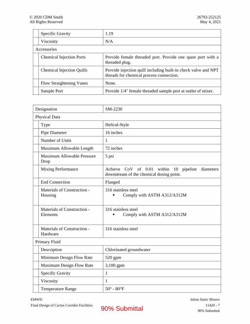
© 2020 CDM Smith 26793-252125
All Rights Reserved May 4, 2021
EMWD Inline Static Mixers
Final Design of Cactus Corridor Facilities 11420 - 7
90% Submittal
Specific Gravity 1.19
Viscosity N/A
Accessories
Chemical Injection Ports Provide female threaded port. Provide one spare port with a
threaded plug.
Chemical Injection Quills Provide injection quill including built-in check valve and NPT
threads for chemical process connection.
Flow Straightening Vanes None.
Sample Port Provide 1/4" female threaded sample port at outlet of mixer.
Designation SM-2230
Physical Data
Type Helical-Style
Pipe Diameter 16 inches
Number of Units 1
Maximum Allowable Length 72 inches
Maximum Allowable Pressure
Drop
5 psi
Mixing Performance Achieve CoV of 0.01 within 10 pipeline diameters
downstream of the chemical dosing point.
End Connection Flanged
Materials of Construction -
Housing
316 stainless steel
▪ Comply with ASTM A312/A312M
Materials of Construction -
Elements
316 stainless steel
▪ Comply with ASTM A312/A312M
Materials of Construction -
Hardware
316 stainless steel
Primary Fluid
Description Chlorinated groundwater
Minimum Design Flow Rate 520 gpm
Maximum Design Flow Rate 3,100 gpm
Specific Gravity 1
Viscosity 1
Temperature Range 50° - 80°F
90% Submittal

© 2020 CDM Smith 26793-252125
All Rights Reserved May 4, 2021
EMWD Inline Static Mixers
Final Design of Cactus Corridor Facilities 11420 - 8
90% Submittal
Pressure Range Up to 100 psi
Chemical to be Added
Description Sodium Bisulfite
Strength 38%
Minimum Flow Rate 0.1 gph
Maximum Flow Rate 1.5 gph
Temperature Range 50° - 80°F
Specific Gravity 1.33
Viscosity N/A
Accessories
Chemical Injection Ports Provide female threaded port. Provide one spare port with a
threaded plug.
Chemical Injection Quills Provide injection quill including built-in check valve and NPT
threads for chemical process connection.
Flow Straightening Vanes None.
Sample Port Provide 1/4" female threaded sample port at outlet of mixer.
Designation SM-6000
Physical Data
Type Helical-Style
Pipe Diameter 16 inches
Number of Units 1
Maximum Allowable Length 72 inches
Maximum Allowable Pressure
Drop
5 psi
Mixing Performance Achieve CoV of 0.01 within 10 pipeline diameters
downstream of the chemical dosing point.
End Connection Flanged
Materials of Construction -
Housing
316 stainless steel
▪ Comply with ASTM A312/A312M
Materials of Construction -
Elements
316 stainless steel
▪ Comply with ASTM A312/A312M
Materials of Construction -
Hardware
316 stainless steel
90% Submittal
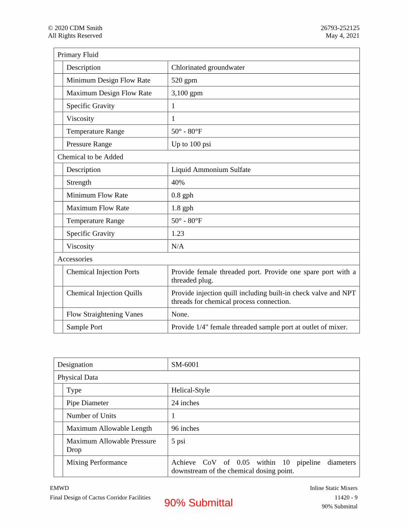
© 2020 CDM Smith 26793-252125
All Rights Reserved May 4, 2021
EMWD Inline Static Mixers
Final Design of Cactus Corridor Facilities 11420 - 9
90% Submittal
Primary Fluid
Description Chlorinated groundwater
Minimum Design Flow Rate 520 gpm
Maximum Design Flow Rate 3,100 gpm
Specific Gravity 1
Viscosity 1
Temperature Range 50° - 80°F
Pressure Range Up to 100 psi
Chemical to be Added
Description Liquid Ammonium Sulfate
Strength 40%
Minimum Flow Rate 0.8 gph
Maximum Flow Rate 1.8 gph
Temperature Range 50° - 80°F
Specific Gravity 1.23
Viscosity N/A
Accessories
Chemical Injection Ports Provide female threaded port. Provide one spare port with a
threaded plug.
Chemical Injection Quills Provide injection quill including built-in check valve and NPT
threads for chemical process connection.
Flow Straightening Vanes None.
Sample Port Provide 1/4" female threaded sample port at outlet of mixer.
Designation SM-6001
Physical Data
Type Helical-Style
Pipe Diameter 24 inches
Number of Units 1
Maximum Allowable Length 96 inches
Maximum Allowable Pressure
Drop
5 psi
Mixing Performance Achieve CoV of 0.05 within 10 pipeline diameters
downstream of the chemical dosing point.
90% Submittal
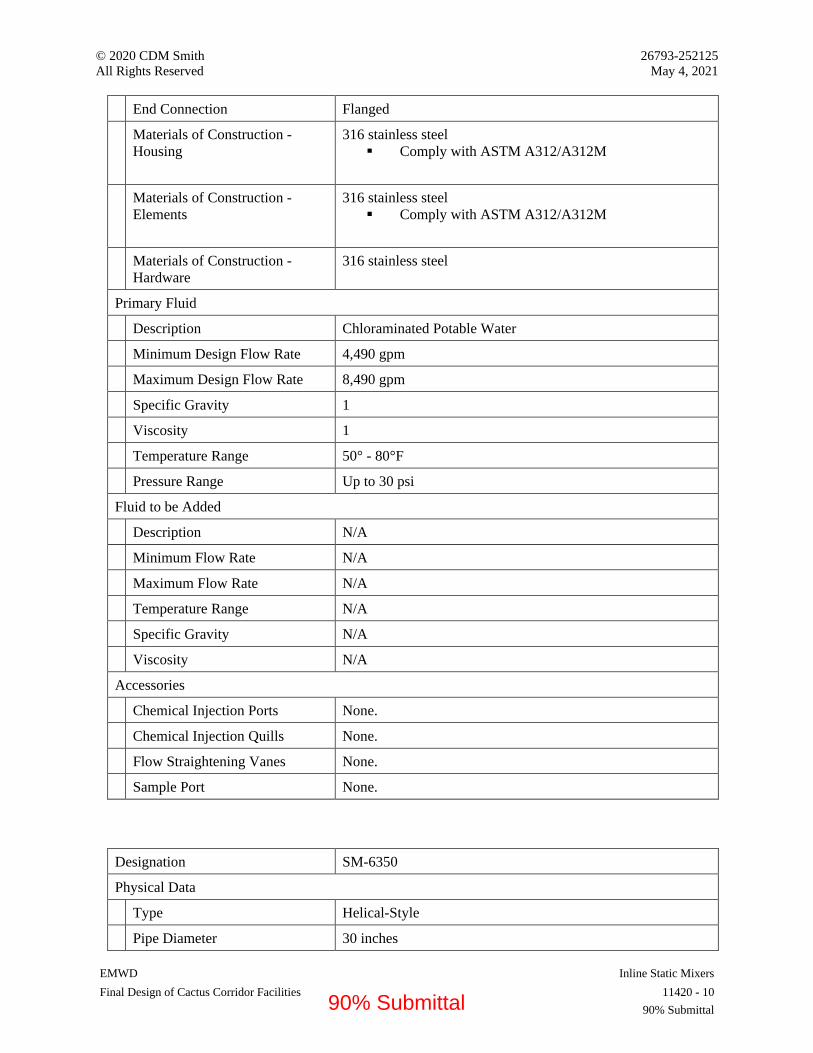
© 2020 CDM Smith 26793-252125
All Rights Reserved May 4, 2021
EMWD Inline Static Mixers
Final Design of Cactus Corridor Facilities 11420 - 10
90% Submittal
End Connection Flanged
Materials of Construction -
Housing
316 stainless steel
▪ Comply with ASTM A312/A312M
Materials of Construction -
Elements
316 stainless steel
▪ Comply with ASTM A312/A312M
Materials of Construction -
Hardware
316 stainless steel
Primary Fluid
Description Chloraminated Potable Water
Minimum Design Flow Rate 4,490 gpm
Maximum Design Flow Rate 8,490 gpm
Specific Gravity 1
Viscosity 1
Temperature Range 50° - 80°F
Pressure Range Up to 30 psi
Fluid to be Added
Description N/A
Minimum Flow Rate N/A
Maximum Flow Rate N/A
Temperature Range N/A
Specific Gravity N/A
Viscosity N/A
Accessories
Chemical Injection Ports None.
Chemical Injection Quills None.
Flow Straightening Vanes None.
Sample Port None.
Designation SM-6350
Physical Data
Type Helical-Style
Pipe Diameter 30 inches
90% Submittal

© 2020 CDM Smith 26793-252125
All Rights Reserved May 4, 2021
EMWD Inline Static Mixers
Final Design of Cactus Corridor Facilities 11420 - 11
90% Submittal
Number of Units 1
Maximum Allowable Length 120 inches
Maximum Allowable Pressure
Drop
5 psi
Mixing Performance Achieve CoV of 0.05 within 10 pipeline diameters
downstream of the chemical dosing point.
End Connection Flanged
Materials of Construction -
Housing
316 stainless steel
▪ Comply with ASTM A312/A312M
Materials of Construction -
Elements
Titanium
▪ Comply with ASTM B265, Grade 2
Materials of Construction -
Hardware
316 stainless steel
Primary Fluid
Description Chloraminated Potable Water
Minimum Design Flow Rate 2,356 gpm
Maximum Design Flow Rate 8,490 gpm
Specific Gravity 1
Viscosity 1
Temperature Range 50° - 80°F
Pressure Range
Chemical #1 to be Added
Description Sodium hypochlorite
Strength 12.5%
Minimum Flow Rate 0.7 gph
Maximum Flow Rate 4.1 gph
Temperature Range 50° - 80°F
Specific Gravity 1.19
Viscosity N/A
Chemical #2 to be Added
Description Liquid Ammonium Sulfate
Strength 40%
Minimum Flow Rate 0.2 gph
90% Submittal

© 2020 CDM Smith 26793-252125
All Rights Reserved May 4, 2021
EMWD Inline Static Mixers
Final Design of Cactus Corridor Facilities 11420 - 12
90% Submittal
Maximum Flow Rate 1.0 gph
Temperature Range 50° - 80°F
Specific Gravity 1.23
Viscosity N/A
Accessories
Chemical Injection Ports Provide female threaded port for each chemical. Provide one
spare port with a threaded plug.
Chemical Injection Quills Provide injection quill for each chemical including built-in
check valves and NPT threads for chemical process
connection.
Flow Straightening Vanes None.
Sample Port Provide 1/4" female threaded sample port at outlet of mixer.
90% Submittal
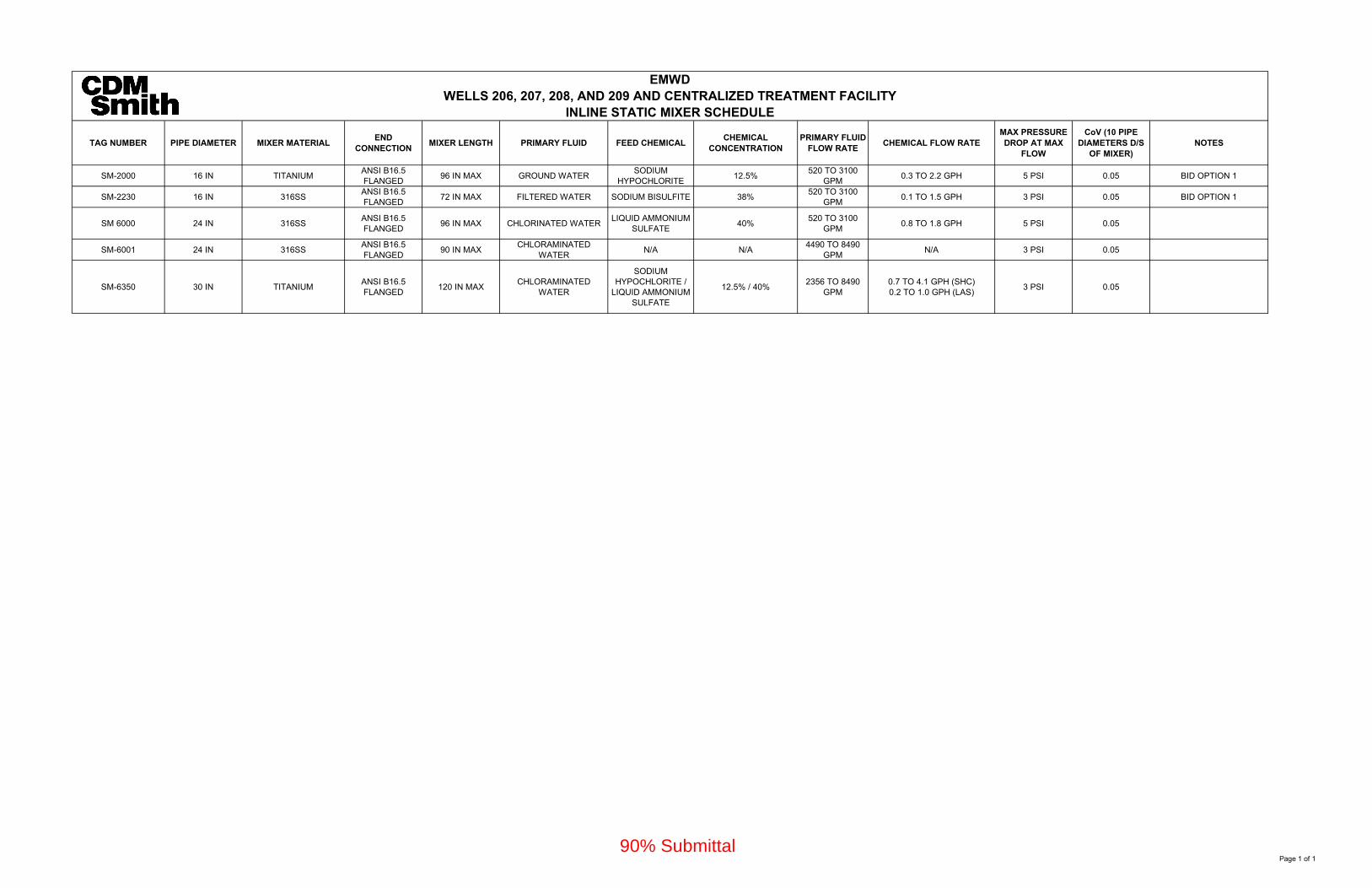
TAG NUMBER PIPE DIAMETER MIXER MATERIALEND
CONNECTIONMIXER LENGTH PRIMARY FLUID FEED CHEMICAL
CHEMICAL CONCENTRATION
PRIMARY FLUID FLOW RATE
CHEMICAL FLOW RATEMAX PRESSURE DROP AT MAX
FLOW
CoV (10 PIPE DIAMETERS D/S
OF MIXER)NOTES
SM-2000 16 IN TITANIUMANSI B16.5 FLANGED
96 IN MAX GROUND WATERSODIUM
HYPOCHLORITE12.5%
520 TO 3100 GPM
0.3 TO 2.2 GPH 5 PSI 0.05 BID OPTION 1
SM-2230 16 IN 316SSANSI B16.5 FLANGED
72 IN MAX FILTERED WATER SODIUM BISULFITE 38%520 TO 3100
GPM0.1 TO 1.5 GPH 3 PSI 0.05 BID OPTION 1
SM 6000 24 IN 316SSANSI B16.5 FLANGED
96 IN MAX CHLORINATED WATERLIQUID AMMONIUM
SULFATE40%
520 TO 3100 GPM
0.8 TO 1.8 GPH 5 PSI 0.05
SM-6001 24 IN 316SSANSI B16.5 FLANGED
90 IN MAXCHLORAMINATED
WATERN/A N/A
4490 TO 8490 GPM
N/A 3 PSI 0.05
SM-6350 30 IN TITANIUMANSI B16.5 FLANGED
120 IN MAXCHLORAMINATED
WATER
SODIUM HYPOCHLORITE /
LIQUID AMMONIUM SULFATE
12.5% / 40%2356 TO 8490
GPM0.7 TO 4.1 GPH (SHC)0.2 TO 1.0 GPH (LAS)
3 PSI 0.05
EMWDWELLS 206, 207, 208, AND 209 AND CENTRALIZED TREATMENT FACILITY
INLINE STATIC MIXER SCHEDULE
Page 1 of 190% Submittal

© 2020 CDM Smith 26793-252125 All Rights Reserved May 4, 2021
EMWD End Suction Process Pumps Final Design of Cactus Corridor Facilities 11557 - 1
90% Submittal
SECTION 11557 – END SUCTION PROCESS PUMPS
PART 1 - GENERAL
1.1 RELATED DOCUMENTS
A. Drawings and general provisions of the Contract, including General and Supplementary Conditions and Division 01 Specification Sections, apply to this Section.
1.2 SUMMARY
A. Section includes:
1. Pumping system, including, but not limited to, overhung impeller rotodynamic end suction process pumps, electric motors, and all appurtenances.
2. Supervisory services during installation and field testing of each unit and instructing the regular operating personnel in the proper care, operation and maintenance of the equipment.
B. Application:
1. IX Waste Brine Pumps: Pumping units pump waste brine from the IX Brine Holding Tanks to a tanker truck for subsequent hauling and disposal.
C. Related Requirements:
1. Section 05502 “Metal Fabrications” for fasteners, brackets, and other required miscellaneous metal fabrications.
2. Section 05519 “Post-Installed Anchors and Reinforcing Bars” for post-installed anchors in concrete.
3. Section 09900 “Painting and Protective Coatings” for field painting. 4. Section 16055 “Control-Voltage Electrical Power Cables” for connections and terminations. 5. Section 16160 “A.C. Variable Frequency Drives”. 6. Section 16150 “Induction Motors” for electric motors and accessories normally supplied as
part of equipment assemblies. 7. Section 17040 “Process Control Descriptions”. 8. Section 17005 “General Instrumentation and Control Components” for general
instrumentation requirements.
1.3 ACTION SUBMITTALS
A. If manufacturing techniques differ, completely describe all aspects that do not conform to specifications.
B. Shop Drawings and Product Data:
1. Manufacturer’s literature, bulletins, and/or catalogs describing equipment in sufficient detail to indicate conformance with this Section.
90% Submittal

© 2020 CDM Smith 26793-252125 All Rights Reserved May 4, 2021
EMWD End Suction Process Pumps Final Design of Cactus Corridor Facilities 11557 - 2
90% Submittal
2. Equipment total weight, including weight of single largest item. 3. Certified shop and erection drawing showing details of construction and dimensions. 4. Drawings showing installation of equipment in designated locations including dimensions
and piping connections and based upon field measured dimensions. 5. Complete Bill of Materials. 6. Parts arrangement drawing including materials of construction of each part. 7. Equipment nameplate data. 8. Data on the characteristics and performance of each pump:
a. Catalog sheets showing a family of curves covering full range selection of impeller diameter.
b. Guaranteed Performance Curves:
1) Base on actual shop tests on similar units. 2) Show the specified requirements for head, capacity, efficiency, guaranteed
maximum net positive suction head required (NPSHR), and brake horsepower. 3) Clearly identify Preferred Operating Region (POR) and Allowable Operating
Region (AOR) (refer to ANSI/HI 9.6.3). 4) Plot curves on 8 ½-inch by 11-inch sheets at as large a scale as practical
specifically for proposed pump from no flow at shut off head to pump capacity at minimum specified TDH.
9. Equipment base drawing:
a. Indicate size and location of bolt holes for anchorage plus details of anchorage of equipment to foundation including anchor bolt type, size, materials, embedment depth, and minimum edge distance.
b. Summary of external weight and thrust loads applied to the supporting structure. c. Summary of maximum vertical and horizontal reactions at each anchor bolt
considering all applicable loads and load combinations. d. Submit manufacturer’s specification and data including recommended design values
and physical characteristics for the selected anchors to the concrete foundation.
10. Description of surface preparation, shop painting, and protective coatings. 11. Complete master wiring diagrams, elementary or control schematics, including coordination
with electrical equipment and control devices, and suitable outline drawings showing such details as are necessary to locate conduit stub-ups and field wiring.
12. Data for electric motors in accordance with Section 16150 “Induction Motors”.
1.4 INFORMATIONAL SUBMITTALS
A. Manufacturer's Certificates:
1. Certify that products meet or exceed specified requirements. 2. Certify bearing life. 3. Certify setting plan, with tolerances, for anchor bolts.
B. Test and Evaluation Reports:
90% Submittal

© 2020 CDM Smith 26793-252125 All Rights Reserved May 4, 2021
EMWD End Suction Process Pumps Final Design of Cactus Corridor Facilities 11557 - 3
90% Submittal
1. Dynamic Vibration Analysis Report:
a. Submit prior to manufacturing equipment. b. Include backup information and sufficient detail to confirm that the specified
requirements have been met. c. Include a statement of guarantee that the required critical speed analyses were
completed and the specified limitations met.
C. Manufacturer Instructions:
1. Delivery, storage and handling instructions. 2. Installation instructions, including anchoring.
D. Source Quality-Control Submittals:
1. Schedule including factory testing and anticipated delivery dates of equipment to job site. 2. Shop testing procedures, pump and piping set up, equipment to be used and testing
tolerances. 3. Certified results of hydrostatic testing. 4. Certified shop hydraulic performance testing results. 5. Certified motor test data as described in Section 16150 “Induction Motors”.
E. Field Quality-Control Submittals:
1. Documentation from Manufacturer’s representative attesting that equipment has been properly installed and is ready for startup and testing.
2. Field testing procedures, equipment to be used, and testing tolerances. 3. Field testing results.
F. Qualifications Statement: Manufacturer Qualifications, as required by Article Quality Assurance.
1.5 CLOSEOUT SUBMITTALS
A. Operation and Maintenance Manual:
1. Provide an Operating and Maintenance Manual for equipment specified herein, specifically prepared for this installation and including all required drawings, equipment and materials information, descriptions, complete bill of materials, etc., as required to instruct operating and maintenance personnel unfamiliar with such equipment.
2. Recommended summer and winter grades of lubricants including references to equal products of other manufacturers and recommended lubrication intervals.
B. Warranty Documentation: Submit warranty complying with requirements of Section 01770 “Closeout Procedures.”
C. Project Record Documents:
1. Submit Project Record Documents recording actual locations and final orientation of all equipment and accessories.
90% Submittal

© 2020 CDM Smith 26793-252125 All Rights Reserved May 4, 2021
EMWD End Suction Process Pumps Final Design of Cactus Corridor Facilities 11557 - 4
90% Submittal
2. Include field measured dimensions for actual equipment locations and all piping connections.
1.6 MAINTENANCE MATERIAL SUBMITTALS
A. Manufacturer's Recommended Spare Parts List:
1. Include gaskets, packing, and related materials. 2. List all bearings by the bearing manufacturer's numbers only. 3. Include Manufacturer's current price for each item; pricing to remain in effect for not less
than one year after Substantial Completion.
B. Prepare spare parts for long term of storage and pack in containers that clearly identify contents with indelible markings.
C. Provide the following spare parts –one set:
1. One mechanical seal. 2. One complete set of gaskets, “O”-rings, etc. 3. One set of pump and motor radial and thrust bearings. 4. One impeller matching installed impellers with lock nut.
1.7 QUALITY ASSURANCE
A. Manufacturer Qualifications:
1. Company specializing in manufacturing products specified in this Section with minimum five years of experience.
2. Minimum of five operating installations with pumps of the same size or larger and in the same service as specified herein.
B. Manufacture pumps in accordance with Hydraulic Institute Standards, except where otherwise specified.
1.8 DELIVERY, STORAGE AND HANDLING
A. Inspection: Accept materials on Site in Manufacturer’s original packaging and inspect for damage. As necessary, provide inspection report to Manufacturer identifying any damage and rework necessary prior to installation.
B. Storage: Store pumps and all appurtenances according to Manufacturer’s instructions.
C. Do not disassemble factory assembled parts and components for shipment unless written permission received from Engineer.
D. Storage:
1. Follow Manufacturer's detailed recommendations.
90% Submittal

© 2020 CDM Smith 26793-252125 All Rights Reserved May 4, 2021
EMWD End Suction Process Pumps Final Design of Cactus Corridor Facilities 11557 - 5
90% Submittal
2. Protect parts and materials from damage or deterioration, moisture and dust by storing in clean, dry location remote from construction operations areas.
3. Protect unpainted finished iron and steel surfaces from rust and corrosion. 4. Protect finished surfaces of exposed flanges with wood or equivalent blank flanges. 5. Protect bearings against formation of rust per bearing manufacturer’s recommendations. For
bearings that are not pre-lubricated, apply corrosion inhibiting treatment for protection during transportation, storage, handling, installation, and lapse of time prior to start-up.
6. Intermittently manually rotate equipment prior to start-up to ensure distribution of lubricant.
1.9 FIELD CONDITIONS
A. Ambient temperature range: 20 to 120 degrees F.
B. Elevation above sea level: 1,584 feet.
C. Field Measurements: As applicable confirm field measurements and interferences prior to fabrication. Indicate field measurements on Shop Drawings.
1.10 WARRANTY
A. Provide Manufacturer’s warranty for pumping system.
B. Warranty Period: One years from date of Substantial Completion.
C. Manufacturer’s warranty period runs concurrently with the Contractor’s warranty period. No exception to this provision is allowed.
D. Warrant equipment free from defects in workmanship, design and materials. If any part of the equipment should fail during the warranty period, replace and restore unit(s) to service.
PART 2 - PRODUCTS
2.1 MANUFACTURERS
A. Subject to compliance with requirements, provide products by one of these manufacturers:
1. Fybroc 2. Or equal.
2.2 PERFORMANCE AND DESIGN CRITERIA
A. Performance Standards:
1. ANSI/HI 9.6.3 Rotodynamic Pumps – Guideline for Operating Regions. 2. ANSI/HI 9.6.4 Rotodynamic Pumps for Vibration Measurements and Allowable Values. 3. ANSI/HI 9.6.8 Rotodynamic Pumps – Guidelines for Dynamics of Pumping Machines. 4. ANSI/HI 14.1-14.2 Rotodynamic Pumps for Nomenclature and Definitions.
90% Submittal

© 2020 CDM Smith 26793-252125 All Rights Reserved May 4, 2021
EMWD End Suction Process Pumps Final Design of Cactus Corridor Facilities 11557 - 6
90% Submittal
5. ANSI/HI 14.3 Rotodynamic Pumps for Design and Application. 6. ANSI/HI 14.6 Rotodynamic Pumps for Hydraulic Performance Acceptance Tests.
B. Performance:
1. Pumps of same service type identical in every respect with all parts interchangeable. 2. Provide each pump for design conditions listed herein and for operation within the system
head curve envelope as attached. 3. Head – Capacity Performance Curve: continuously rising from runout to shutoff with no
points of inflection at any operational speed for stable operation within the AOR. 4. Operate throughout the specified range within the vibration limitations specified herein. 5. Section 01882 “Seismic Performance”.
C. Anchor Bolts:
1. Pump and motor base(s) to be rigidly and accurately anchored into position, precisely leveled and aligned, so that completed installation is free from stress or distortion.
2. Sleeve type cast-in anchor bolts are strongly recommended due to the typical damp conditions. Select bracketed text associated with anchor bolt type selected. For high moisture conditions consider Type 316 stainless steel.
3. Furnish and install Type 316 stainless steel cast-in anchor bolts installed in sleeves or post-installed adhesive anchors, plates, nuts and washers under Section 05502 “Metal Fabrications”.
a. Bolt size, arrangement, embedment, and edge distance conforming to recommendations and instructions of Manufacturer.
b. Anchor bolt configuration and installation in accordance with API RP 686 and ACI 318-08.
c. Stainless Steel Anchor Bolt Nuts: Monel. d. Anchor Bolt Threads: Apply anti-seize compound of molybdenum disulfide base such
as Molycoat G or approved equal.
D. Design Criteria:
1. Pumped Fluid:
a. Waste Salt Brine. b. Specific Gravity: Up to 1.2. c. Solids Concentration: Negligible. d. Temperature Range: 40 to 95 degrees F.
2. Number of Units: 2; 1 Duty / 1 Standby. 3. Location: Outdoors. 4. Service/Flow Stream Identifier: BW. 5. Pump Equipment Tag Numbers:
a. P-3810. b. P-3820.
6. Configuration: Horizontal, flexibly coupled.
90% Submittal
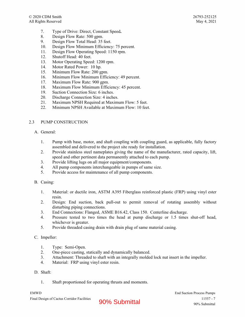
© 2020 CDM Smith 26793-252125 All Rights Reserved May 4, 2021
EMWD End Suction Process Pumps Final Design of Cactus Corridor Facilities 11557 - 7
90% Submittal
7. Type of Drive: Direct, Constant Speed. 8. Design Flow Rate: 500 gpm. 9. Design Flow Total Head: 35 feet. 10. Design Flow Minimum Efficiency: 75 percent. 11. Design Flow Operating Speed: 1150 rpm. 12. Shutoff Head: 40 feet. 13. Motor Operating Speed: 1200 rpm. 14. Motor Rated Power: 10 hp. 15. Minimum Flow Rate: 200 gpm. 16. Minimum Flow Minimum Efficiency: 49 percent. 17. Maximum Flow Rate: 900 gpm. 18. Maximum Flow Minimum Efficiency: 45 percent. 19. Suction Connection Size: 6 inches. 20. Discharge Connection Size: 4 inches. 21. Maximum NPSH Required at Maximum Flow: 5 feet. 22. Minimum NPSH Available at Maximum Flow: 10 feet.
2.3 PUMP CONSTRUCTION
A. General:
1. Pump with base, motor, and shaft coupling with coupling guard, as applicable, fully factory assembled and delivered to the project site ready for installation.
2. Provide stainless steel nameplates giving the name of the manufacturer, rated capacity, lift, speed and other pertinent data permanently attached to each pump.
3. Provide lifting lugs on all major equipment/components. 4. All pump components interchangeable in pumps of same size. 5. Provide access for maintenance of all pump components.
B. Casing:
1. Material: or ductile iron, ASTM A395 Fiberglass reinforced plastic (FRP) using vinyl ester resin.
2. Design: End suction, back pull-out to permit removal of rotating assembly without disturbing piping connections.
3. End Connections: Flanged, ASME B16.42, Class 150. Centerline discharge. 4. Pressure tested to two times the head at pump discharge or 1.5 times shut-off head,
whichever is greater. 5. Provide threaded casing drain with drain plug of same material casing.
C. Impeller:
1. Type: Semi-Open. 2. One-piece casting, statically and dynamically balanced. 3. Attachment: Threaded to shaft with an integrally molded lock nut insert in the impeller. 4. Material: FRP using vinyl ester resin.
D. Shaft:
1. Shaft proportioned for operating thrusts and moments.
90% Submittal

© 2020 CDM Smith 26793-252125 All Rights Reserved May 4, 2021
EMWD End Suction Process Pumps Final Design of Cactus Corridor Facilities 11557 - 8
90% Submittal
2. Material: Stainless Steel, ASTM A276/A276M, Type 316. 3. Sleeve: Integral with impeller.
E. Bearings (radial and thrust):
1. Type: Anti-friction, ball or roller. 2. Minimum L-10 Life: 50,000 hours at continuous maximum load and speed, according to
ABMA 9 (Ball) or 11 (Roller). 3. Lubrication: Oil or Grease.
F. Bearing Housing:
1. Cast iron ASTM A48, Class 30 or better with epoxy or powder coating. 2. Fully enclosed, dust and moisture proof. housing. 3. Oil lubricated: Provide shaft oil seals, oil fill and drain taps, and oil level indication. 4. Grease lubricated: Provide grease seals and provision for re-greasing.
G. Mechanical Seals:
1. Single outside mechanical seal. 2. Silicon carbide seal faces, ground and polished. Type 316 housing and Hastelloy-C springs. 3. Fluoroelastomer gaskets. 4. Protective guard for rotating components. 5. Manufacturer:
a. John Crane. b. Flowserve. c. Or equal.
6. Provide API Standard 682, Standard Seal Piping Plan 32.
H. Pump Base:
1. Mount pump and motor assembly on a base of FRP to support all weight and operating loads of pump and motor.
2. Anchorage:
a. Provide all foundation bolts, plates, nuts, washers and setting templates required for installation.
b. Anchors: Type 316 stainless steel with silicon bronze or Monel nuts, conforming to the requirements of Section 05502 “Metal Fabrications”.
c. Grout as specified in Section 03600 “Grouting”.
I. Factory Coatings:
1. Finish coat all surfaces in accordance with manufacturer’s standard practice and Section 09900 “Painting and Protective Coatings” prior to shipment. Color selected by Engineer from Manufacturer’s standard selection.
90% Submittal

© 2020 CDM Smith 26793-252125 All Rights Reserved May 4, 2021
EMWD End Suction Process Pumps Final Design of Cactus Corridor Facilities 11557 - 9
90% Submittal
2.4 DRIVER
A. Motor:
1. Comply with Section 16150 “Induction Motors”. 2. Pump power not exceeding motor nameplate rating at 1.0 service factor at any point on
pump characteristic curve. 3. Power Data:
a. Horsepower: As indicated above. b. 460 Volt, three phase, 60 Hz. c. Constant speed. d. Service Factor: 1.15 (constant speed). e. Starting Method: Full Voltage. Comply with Section 16480 “Motor Control Centers,
Switchboards, and Panelboards”.
4. Environmental Data:
a. Load Type: Variable Torque. b. Continuous duty, 40 degrees C ambient, 1,584 feet maximum elevation.
5. Physical Data:
a. Construction and nameplate: comply with Section 16150 “Induction Motors”. b. Orientation: Horizontal. c. Solid shaft. d. Speed: 1200 RPM. e. Enclosure: TEFC. f. Premium Efficiency.
6. Features and Accessories:
a. Winding Temperature Protection: Resistance Temperature Detectors. b. Space heaters.
B. Direct Drive (Sleeve Coupling):
1. Manufacturer List:
a. Dodge Division of ABB Motors and Mechanical Inc. b. T. B. Woods Inc. c. Lovejoy Inc.
2. Pump directly connected to its driver by sleeve type elastomeric flexible shaft coupling, to provide for angular, parallel, and axial misalignment, absorb torsional shock, and dampen torsional vibration.
3. Provide spacer type coupling with center drop-out section for horizontal installations. 4. Size coupling to transmit the motor nameplate driving speed and torque with 1.5 service
factor and to accommodate unavoidable shaft misalignment. 5. Double flexing for application to four-bearing systems. 6. Flanges of sintered carbon steel. Sleeve of EPDM or neoprene.
90% Submittal

© 2020 CDM Smith 26793-252125 All Rights Reserved May 4, 2021
EMWD End Suction Process Pumps Final Design of Cactus Corridor Facilities 11557 - 10
90% Submittal
7. OSHA compliant, fabricated steel or expanded metal coupling guard, galvanized after fabrication.
2.5 ACCESSORIES
A. Pressure Gauges:
1. In accordance with Section 17005 “General Instrumentation and Control Components”. 2. Provide diaphragm seals in accordance with Section 17005 “General Instrumentation and
Control Components”. 3. Provide cartridge type pressure snubbers to reduce gauge pointer pulsations. 4. Install in tapped holes on piping adjacent to pump suction and discharge.
2.6 SOURCE QUALITY CONTROL
A. Provide shop inspection and testing of completed assembly.
B. Dynamic Vibration Analysis:
1. Completed by Pump Manufacturer in accordance with ANSI/HI 9.6.8. 2. Complete prior to fabrication of pumping units. 3. Analysis Level: Level 1 Simple Calculations. 4. Minimum Frequency Separation Margins:
a. Level 1 Analysis: 25%. b. Level 2 Analysis: 15%. c. Level 3 Analysis: 15%.
5. Submit certification that analysis has been performed on the specific pump/motor combination to be furnished under this Contract demonstrating conformance to these criteria.
C. Shop Test:
1. Perform shop hydrostatic and performance tests of each pump furnished under this Section in accordance with ANSI/HI 14.6, American National Standard for Rotodynamic Pumps for Hydraulic Performance Acceptance Tests, Acceptance Grade 1U.
2. Submit certified test results including pump performance curves showing head, flow, brake horsepower and pump efficiency for each pump.
D. Motor shop testing in accordance with Section 16150 “Induction Motors”.
PART 3 - EXECUTION
3.1 EXAMINATION
A. Verify that items provided by other Sections of Work are ready to receive Work of this Section.
90% Submittal
© 2020 CDM Smith 26793-252125 All Rights Reserved May 4, 2021
EMWD End Suction Process Pumps Final Design of Cactus Corridor Facilities 11557 - 11
90% Submittal
B. Verify layout, orientation and connections.
C. Examine roughing-in for Backwash Waste Facility piping to verify actual locations of piping connections before equipment installation.
D. Proceed with installation only after unsatisfactory conditions have been corrected.
3.2 INSTALLATION
A. Install pumping units as shown and according to Manufacturer’s instructions.
B. Install pumping units on concrete foundation to elevation to align with piping as shown.
C. Equipment Base Anchorage:
1. Rigidly and accurately anchor equipment base into position on concrete foundation with cast-in-place anchors or post-installed adhesive anchors.
2. Use expansive, non-shrink low exothermic epoxy grout, Five Star DP Epoxy Grout or equal, mixed and applied according to manufacturer’s directions.
3. Remove or back down jacking bolts prior to placing grout. 4. Protect all bolt threads during placement of grout. 5. Fill space between anchor bolts and bolt sleeves with expanding urethane foam.
D. Connect piping accurately aligned with pump flanges, imposing no external loading on the pump.
E. Provide and connect power and control conduit and wiring to make system operational and ready for startup.
F. Provide lubricants in accordance with Manufacturer’s recommendations.
G. Flush piping with clean water.
3.3 FIELD QUALITY CONTROL AND SYSTEM STARTUP
A. Prior to system startup, submit installation documentation from equipment Manufacturer’s representative attesting that equipment has been properly installed and is ready for startup and testing.
B. Prior to operating system or components, perform the following:
1. Check pump and motor alignment. 2. Check for proper motor rotation. 3. Check pump and drive units for proper lubrication. 4. Prepare and submit field test data log sheet. 5. Flush pump and piping with clean water. 6. Hydrostatically test system piping. 7. Test all control interfaces. 8. Test all hardwired and software interlocks associated with the system. 9. Complete point to point I/O check. 10. Calibrate and test all instrument functions and settings.
90% Submittal

© 2020 CDM Smith 26793-252125 All Rights Reserved May 4, 2021
EMWD End Suction Process Pumps Final Design of Cactus Corridor Facilities 11557 - 12
90% Submittal
11. Supply power necessary to complete the field tests via Project-installed power supply system or alternative sources provided by Contractor.
C. Startup and Performance Testing:
1. Operate pump on clear water at design point for continuous period of two hours, under supervision of manufacturer's representative and in presence of Engineer. Confirm pump operation at secondary design points, as applicable, with period of operation at Engineer’s discretion.
2. Record operating performance data at 15 minute intervals: flow, head, pump speed and power required. Utilize approved field test data log sheets.
3. Flow Measurement: utilize timed-drawdown test or timed-fill test, installed flow meter, or temporary flow meter provided by Contractor.
4. Head (pressure) Measurement: Utilize installed or Contactor furnished pressure gauges on pump suction and pump discharge.
5. Pump Speed: utilize tachometer. 6. Power: Utilize volt and ampere (or kilowatt) meters. 7. Check pump and motor for high bearing temperature and excessive noise or vibration
according to Manufacturer instructions. 8. Check for motor overload by taking ampere readings. 9. Under direction of Manufacturer’s representative, adjust, repair, modify, or replace system
components that fail to perform as specified and rerun tests. 10. Submit written report tabulating equipment tested, test results, problems encountered, and
corrective action taken within two weeks after test completion.
D. If pump performance does not meet specified requirements, take corrective measures or remove and replace pumps and retest as necessary to demonstrate compliance with the specified requirements.
E. Manufacturer Services:
1. Provide on-site services of manufacturer's representative experienced in installation of equipment provided under this Section.
2. Services include equipment installation, inspection, start-up, field testing and instructing Owner's personnel in operation and maintenance of equipment.
3. On-site services to meet minimum time requirements listed below. Time requirements do not relieve Contractor of obligation to provide sufficient service to place equipment in satisfactory operation.
4. Installation/Inspection:
a. 1 day. b. Inspect grouting, location of anchor bolts, setting, leveling, alignment, field erection,
coordination of piping, electrical and miscellaneous utility connections.
5. Startup/Testing:
a. 1 day. b. Place equipment into operation and make necessary adjustments. c. Complete functional and performance testing.
6. Operation and Maintenance Instruction:
90% Submittal

© 2020 CDM Smith 26793-252125 All Rights Reserved May 4, 2021
EMWD End Suction Process Pumps Final Design of Cactus Corridor Facilities 11557 - 13
90% Submittal
a. 1 day. b. Instruct representatives of the Owner on proper operation and maintenance. Provide
training agenda and utilize approved O&M manuals.
END OF SECTION 11557
90% Submittal
© 2020 CDM Smith 26793-252125 All Rights Reserved May 4, 2021
EMWD Detailed Vertical Turbine Pumps Final Design of Cactus Corridor Facilities 11936.1 - 1
90% Submittal
SECTION 11936.1 – DETAILED VERTICAL TURBINE PUMPS
PART 1 - GENERAL
1.1 SYSTEM DESCRIPTION
A. The Product Water Pump Station vertical turbine pumps will be installed in suction cans connected to a ground level gravity storage tank. The pumps will discharge chloraminated potable water into a transmission main that feeds adjacent pressure zones of the EMWD service area. The pumps will be controlled with variable speed drives to deliver a flow rate or pressure as determined by the system control logic. Additional submittal, performance, and material requirements are provided in this Section as a supplement to Section 11936, Vertical Turbine Pumps.
1.2 ADDITIONAL SUBMITTAL REQUIREMENTS
A. Submit the following, in addition to the submittals required by Section 11005, General Mechanical and Equipment Provisions, Section 11936, Vertical Turbine Pumps, and associated specification sections:
1. ANSI/NSF 61 and ANSI/NSF 372 certification documentation 2. Certified pump curves
a. Include information specified in Section 11936-1.03.B as well as the following:
1) Pump performance and efficiency (in addition to bowl performance and efficiency) 2) Specified condition points
3. Dynamic analysis report submittal including backup documentation and a statement of guarantee that the critical speed analyses as required in Paragraph 1.3 of this Section have been completed and that the specified limitations will be met.
4. Factory test procedures 5. Factory test reports
1.3 DYNAMIC ANALYSIS
A. Prior to manufacture, provide a submittal indicating that the required vibration analyses outlined herein have been performed and that the specified limitations will be met. For the dynamic vibration analysis described, minimum and maximum operating speeds will be in accordance with the operating speeds required to satisfy the conditions of operation specified in Article 2.1. The dynamic vibration analysis required by the following paragraphs shall be performed by Mechanical Solutions Inc. (MSI) of Whippany, NJ, DynaTech Engineering, Inc. of Auburn, CA or Engineering Dynamics Inc. (EDI) of San Antonio, TX. The pump manufacturer may perform the analysis subject to providing evidence that the person overseeing the analysis has performed a minimum of 25 analyses on equipment of similar or larger flow and head capacity.
90% Submittal

© 2020 CDM Smith 26793-252125 All Rights Reserved May 4, 2021
EMWD Detailed Vertical Turbine Pumps Final Design of Cactus Corridor Facilities 11936.1 - 2
90% Submittal
1. Structural dynamic analysis of the combined pump/motor system including the nearby foundation and the piping out to the first pipe restraint or expansion joint. Analysis shall not simply assume the foundation is rigid rather it shall incorporate foundation design shown on the Drawings. The structural dynamic analysis shall predict that no first or second bending mode frequencies will exist within a pump speed range from 20 percent below minimum operating speed to 20 percent above maximum operating speed.
2. A lateral rotordynamic analysis of the pump rotating system (i.e., motor rotor, line shafting, couplings, bowl shafting and impellers, etc.) shall identify and predict that the first lateral critical speed shall have a separation margin of at least 20 percent above the maximum pump speed or 20 percent below the minimum pump speed. If a design modification (i.e., such as changing the bearing span or shaft diameter) cannot resolve a separation margin deficiency or is not practical, a forced damped response analysis shall be performed to demonstrate that the pump will function properly over the speed range.
3. A torsional rotordynamic analysis of the complete rotating system (pump, motor, intermediate shafting, and coupling) shall identify and predict that no torsional natural frequencies occur within a separation margin extending from 20 percent below to 20 percent above the specified pump operating speed range. Additionally, no natural frequencies shall be +/- 10% of 2x times running speed, line frequency, 2x line frequency, vane pass frequency, and VFD control frequencies (if applicable). If a design modification (i.e., such as a shaft diameter change or different coupling arrangement) cannot resolve a separation margin deficiency or is not practical, a forced damped response analysis shall be performed to show that infinite life will be achieved with a safety factor of at least two.
4. Campbell diagrams shall be submitted, documenting the structural lateral, rotating component lateral, and torsional analysis results, graphically demonstrating the separation margins specified above.
5. Maximum vibration velocity in inches per second RMS, measured in the field, shall conform to the requirements of ANSI/HI 9.6.4.
PART 2 - PRODUCTS
2.1 PUMP CONSTRUCTION AND MATERIALS
A. Provide pump construction and materials that meet the requirements in Section 11936, Vertical Turbine Pumps and Table 11936.1-1 below. Table 11936.1-1 takes precedent in the case of conflict between the two sections. Materials not specified shall be selected by the manufacturer to be compatible with the pumped fluid and in accordance with ANSI/AWWA E-103 Horizontal and Vertical Line-Shaft Pumps.
B. Pumps shall be certified to ANSI/NSF 61 Drinking Water System Components – Health Effects and ANSI/NSF 372 Drinking Water System Components – Lead Content.
C. Provide seal flush piping to the mechanical seals per API Plan 13 and seal manufacturer’s recommendations.
TABLE 11936.1-1 PUMP CONSTRUCTION AND MATERIALS
Component Material/Construction Pump Bowls ASTM A48 Cast Iron, CL30
90% Submittal

© 2020 CDM Smith 26793-252125 All Rights Reserved May 4, 2021
EMWD Detailed Vertical Turbine Pumps Final Design of Cactus Corridor Facilities 11936.1 - 3
90% Submittal
Bowl and Pump Hardware Type 316SS Wear Rings Type 410SS or 420SS, 316SS, or 952 Bronze Pump Impellers ASTM B148 UNS C95800 cast nickel aluminum bronze, UNS 95200
cast aluminum bronze, or ASTM A743 CF-8M cast stainless steel Impeller Lock Collets ASTM A743 CF-8M cast stainless steel Pump Shaft 17-4 PH Stainless Steel or Nitronic 50 Pump Bearings Bismuth tin bronze (ASTM B505 Alloy C89835) Pump Discharge Head ASTM A36 fabricated carbon steel Line Shaft 17-4 PH Stainless Steel or Nitronic 50, open line-shaft, product
lubricated Vortex Supressor 316SS
D. All steel and iron components, including the interior and exterior of the column pipe, discharge head, suction can, and bowls shall be prepared and coated with NSF 61 approved epoxy per Section 09900, Painting and Protective Coatings.
2.2 ACCESSORIES
A. In addition to the accessories specified in Section 11396 – 2.03, provide:
1. Discharge air valve with throttling device.
a. Type: dual port throttling device to regulate the exhaust of air on pump startup and to admit large volumes of air on pump shut-down. The throttling device shall be adjustable.
b. Size: 2-inch c. Products:
1) AWWA C512, ANSI/NSF 61 and 372 2) Valmatic model 102ST, 3) Apco model 144DAT, or equal.
2.3 FACTORY PUMP TESTS AND INSPECTIONS
A. Provide access for Engineer to inspect any equipment to be furnished under this Section prior to shipment from place of manufacture. Engineer will witness the factory pump tests.
B. Factory test each pumping unit as described in ANSI/HI 14.6, American National Standard for Rotodynamic Pumps for Hydraulic Performance Acceptance Tests.
C. At least 30 days prior to commencement of factory testing, submit a Factory Test Plan for the Engineer to review and approve. The Factory Test Plan shall include, but not be limited to: detailed step-by-step procedures of how the tests will be completed; diagrams showing test set-up and instrument locations; product data for testing instruments and equipment including accuracy tolerances and calibrations when applicable; preliminary data logs listing the data points that will be collected; sample calculations for any values that will be calculated during the tests such as pump efficiency; and a projected schedule for the type of test to be performed and the number of pumps that will be tested each day.
90% Submittal

© 2020 CDM Smith 26793-252125 All Rights Reserved May 4, 2021
EMWD Detailed Vertical Turbine Pumps Final Design of Cactus Corridor Facilities 11936.1 - 4
90% Submittal
D. Perform vibration measurements at conditions tested during the factory tests. Vibration levels during factor tests are for reference only and not a condition of acceptance.
E. Test each pump with the laboratory motor and VFD.
F. Perform hydrostatic test on the pressure-containing parts in accordance with ANSI/HI 14.6 prior to pump shipment. Hydrostatic test will not be witnessed by the Engineer.
G. Visually inspect cast surfaces of all components per MSS SP-55.
H. Factory pump tests shall be the basis of acceptance of the hydraulic performance of the pumps. Factory test pumps prior to shipment in accordance with the Hydraulic Institute standards. Flow rate, total pump head, hydraulic pump efficiency, and brake horsepower shall be tested and recorded for at least seven points on the pump performance curve. Test shall be performed to demonstrate that the pumps meet ANSI/HI 14.6 acceptance grades as specified in Table 11936.1-2. The seven points shall include the points specified in Table 11936.1-2. If any pump tested fails to meet any specification requirement it will be modified until it meets all specification requirements. If any pump tested fails to meet the flow rate, pump head or pump efficiency requirements for any of the conditions listed in Article “Performance Requirements” of this specification and all reasonable attempts to correct the inefficiency are unsuccessful, the pump(s) shall be replaced with a unit(s) that meets the specified requirements. Factory pump performance tests will be witnessed by the Engineer.
I. Submit certified pump performance curves, including total pump head, flow rate, pump efficiency and total brake horsepower for each pump supplied. Test data shall be submitted for approval by the Engineer prior to shipment.
J. All meters, gauges, and other test instruments shall be calibrated within the manufacturer's established time period prior to the scheduled test and certified calibration data shall be provided. If the Manufacturer has no ISO standard calibration period, Hydraulic Institute Standards shall govern.
K. The pumps shall be performance tested at actual design speeds for test conditions equal to and below the Rated Condition point specified in Table 11936.1-2. Use of affinity laws is not allowed.
2.4 PERFORMANCE REQUIREMENTS
A. Provide pumps that meet the requirements in Section 11936, Vertical Turbine Pumps and Table 11936.1-2 below. Table 11936.1-2 takes precedent in the case of conflict between the two sections.
B. Provide pumps designed to operate within the system curves depicted in Figure 11936.1-1.
90% Submittal

© 2020 CDM Smith 26793-252125 All Rights Reserved May 4, 2021
EMWD Detailed Vertical Turbine Pumps Final Design of Cactus Corridor Facilities 11936.1 - 5
90% Submittal
TABLE 11396.1-2 PUMPING UNIT DESIGN AND PERFORMANCE REQUIREMENTS
Parameter/System Product Water Pump Station Number of Pumping Units (this Phase) 4 (3 duty + 1 standby) Equipment Tags PMP-6210, -6220, -6230, -6240, -6250 (future) Number of Pump Cans 5 Pump Can Outside Diameter 36-in Pump Can Minimum Working Pressure 75 psig Minimum Discharge Nozzle Diameter 12-in Maximum Brake Horsepower 180 hp Motor Horsepower 200 hp Maximum Motor Speed 1,200 rpm Pump Shutoff Head Range 250 – 400 FT Acceptable Manufacturers Floway 18MKM
Peerless 16HXB Patterson
Rat
ed
Con
ditio
n1 Capacity 2,356 gpm
Pump Head 205 ft (173 ft static)
Pump Efficiency 81% Maximum NPSH3 20 ft Factory Pump Test Acceptance Grade 1U
Con
ditio
n A
2 Capacity 3,300 gpm
Pump Head 138 ft (131 ft static) Pump Efficiency 76% Maximum NPSH3 30 ft
Factory Pump Test Acceptance Grade 1E
Con
ditio
n B
3 Capacity 1400 gpm
Pump Head 175 ft (173 ft static) Min Pump Efficiency 66% Maximum NPSH3 20 ft
Factory Pump Test Acceptance Grade 1E
Con
ditio
n C
4 Capacity 1400 gpm
Pump Head 133 ft (131ft static) Min Pump Efficiency 67% Min Suction hydraulic grade6 n/a
Notes: 1. Rated condition shall be the guaranteed performance required for the station to achieve its firm pumping capacity with all duty pumps operating (including future phase) against maximum anticipated system head. 2. Condition A shall be the estimated ‘runout’ condition when a single pump is operating at full speed against minimum anticipated system head. The exact point will vary by pump manufacturer based on the intersection with the system curves attached (Figure 11396A-1). This is not intended to be a common operating condition since the pumps will be equipped with VFDs, but shall still fall on the published pump curve and within the allowable operating region (AOR). 3. Condition B shall be when a single pump is running at minimum required flow at maximum anticipated system head. This point shall be achieved at the reduced speed necessary to achieve the specified condition and shall be above the pump’s minimum continuous stable flow (MSCF) and within the AOR. 4. Condition C shall be when a single pump is running at minimum required flow at minimum anticipated system head. This point shall be achieve at the reduced speed necessary to achieve the specified condition and shall be above the pumps MSCF and within the AOR.
90% Submittal

© 2020 CDM Smith 26793-252125 All Rights Reserved May 4, 2021
EMWD Detailed Vertical Turbine Pumps Final Design of Cactus Corridor Facilities 11936.1 - 6
90% Submittal
END OF SECTION 11936.1
90% Submittal

© 2020 CDM Smith 26793-252125 All Rights Reserved May 4, 2021
EMWD Detailed Deep Well Vertical Turbine Pumps Final Design of Cactus Corridor Facilities 11937.1 - 1
90% Submittal
SECTION 11937.1 – DETAILED DEEP WELL VERTICAL TURBINE PUMPS
PART 1 GENERAL
1.1 SYSTEM DESCRIPTION
A. The groundwater production well pumps will be installed in vertical drilled groundwater wells remote and near the Central Treatment Plant. The pumps will pump untreated groundwater into transmission mains and through the Central Treatment Plant treatment process before being stored in the Product Water Forebays. The pumps will be controlled with variable speed drives to deliver a flow rate or pressure as determined by the system control logic. Additional submittal, performance, and material requirements are provided in this Section as a supplement to Section 11937, Deep Well Vertical Turbine Pumps.
1.2 ADDITIONAL SUBMITTAL REQUIREMENTS
A. Submit the following, in addition to the submittals required by Section 11005, General Mechanical and Equipment Provisions, Section 11937, Deep Well Vertical Turbine Pumps, and associated specification sections:
1. ANSI/NSF 61 and ANSI/NSF 372 certification documentation 2. Certified pump curves
a. Include information specified in Section 11936-1.03.B as well as the following:
1) Pump performance and efficiency (in addition to bowl performance and efficiency)
2) Specified condition points
3. Dynamic analysis report submittal including backup documentation and a statement of guarantee that the critical speed analyses as required in Paragraph 1.3 of this Section have been completed and that the specified limitations will be met.
4. Factory test procedures 5. Factory test reports
1.3 DYNAMIC ANALYSIS
A. Prior to manufacture, provide a submittal indicating that the required vibration analyses outlined herein have been performed and that the specified limitations will be met. For the dynamic vibration analysis described, minimum and maximum operating speeds will be in accordance with the operating speeds required to satisfy the conditions of operation specified in Article 2.1. The dynamic vibration analysis required by the following paragraphs shall be performed by Mechanical Solutions Inc. (MSI) of Whippany, NJ, DynaTech Engineering, Inc. of Auburn, CA or Engineering Dynamics Inc. (EDI) of San Antonio, TX. The pump manufacturer may perform the analysis subject to providing evidence that the person overseeing the analysis has performed a minimum of 25 analyses on equipment of similar or larger flow and head capacity.
90% Submittal

© 2020 CDM Smith 26793-252125 All Rights Reserved May 4, 2021
EMWD Detailed Deep Well Vertical Turbine Pumps Final Design of Cactus Corridor Facilities 11937.1 - 2
90% Submittal
1. Structural dynamic analysis of the combined pump/motor system including the nearby foundation and the piping out to the first pipe restraint or expansion joint. Analysis shall not simply assume the foundation is rigid rather it shall incorporate foundation design shown on the Drawings. The structural dynamic analysis shall predict that no first or second bending mode frequencies will exist within a pump speed range from 20 percent below minimum operating speed to 20 percent above maximum operating speed.
2. A lateral rotordynamic analysis of the pump rotating system (i.e., motor rotor, line shafting, couplings, bowl shafting and impellers, etc.) shall identify and predict that the first lateral critical speed shall have a separation margin of at least 20 percent above the maximum pump speed or 20 percent below the minimum pump speed. If a design modification (i.e., such as changing the bearing span or shaft diameter) cannot resolve a separation margin deficiency or is not practical, a forced damped response analysis shall be performed to demonstrate that the pump will function properly over the speed range.
3. A torsional rotordynamic analysis of the complete rotating system (pump, motor, intermediate shafting, and coupling) shall identify and predict that no torsional natural frequencies occur within a separation margin extending from 20 percent below to 20 percent above the specified pump operating speed range. Additionally, no natural frequencies shall be +/- 10% of 2x times running speed, line frequency, 2x line frequency, vane pass frequency, and VFD control frequencies (if applicable). If a design modification (i.e., such as a shaft diameter change or different coupling arrangement) cannot resolve a separation margin deficiency or is not practical, a forced damped response analysis shall be performed to show that infinite life will be achieved with a safety factor of at least two.
4. Campbell diagrams shall be submitted, documenting the structural lateral, rotating component lateral, and torsional analysis results, graphically demonstrating the separation margins specified above.
5. Maximum vibration velocity in inches per second RMS, measured in the field, shall conform to the requirements of ANSI/HI 9.6.4.
PART 2 PRODUCTS
2.1 PUMP CONSTRUCTION AND MATERIALS
A. Provide pump construction and materials that meet the requirements in Section 11937, Deep Well Vertical Turbine Pumps and Table 11937.1-1 below. Table 11937.1-1 takes precedent in the case of conflict between the two sections. Materials not specified shall be selected by the manufacturer to be compatible with the pumped fluid and in accordance with ANSI/AWWA E-103 Horizontal and Vertical Line-Shaft Pumps.
TABLE 11937.1-1 PUMP CONSTRUCTION AND MATERIALS
Component Material/Construction Pump Discharge Head ASTM A36 fabricated carbon steel Outer Column Pipe ASTM A53 Grade B steel or ASTM A120 steel Line Shaft 416SS Line Shaft Bearings ASTM B505 Alloy C89835 Bismuth Tin Bronze Shaft Enclosing Tube ASTM A120 Steel, SCH 80 Pump Bowls ASTM A48 CL30 Cast Iron, Enamel Lined Pump Impellers ASTM B148 UNS C95800 cast nickel aluminum bronze, C95200
aluminum bronze, or ASTM A743 CF-8M cast stainless steel Impeller Lock Collets ASTM A743 CF-8M cast stainless steel Bowl and pump hardware 316SS
90% Submittal

© 2020 CDM Smith 26793-252125 All Rights Reserved May 4, 2021
EMWD Detailed Deep Well Vertical Turbine Pumps Final Design of Cactus Corridor Facilities 11937.1 - 3
90% Submittal
TABLE 11937.1-1 PUMP CONSTRUCTION AND MATERIALS Pump Shaft ASTM A582 416SS Pump Bearings ASTM B505 Alloy C89835 Bismuth Tin Bronze Strainer 316SS
B. All steel and iron components, including the interior and exterior of the column pipe, discharge head and bowls shall be prepared and coated with NSF 61 approved epoxy per Section 09900, Painting and Protective Coatings.
2.2 ACCESSORIES
A. In addition to the accessories specified in Section 11397, provide:
1. Discharge air valve with throttling device.
a. Type: dual port throttling device to regulate the exhaust of air on pump startup and to admit large volumes of air on pump shut-down. The throttling device shall be adjustable
b. Size: 2-inch c. Products:
1) AWWA C512, ANSI/NSF 61 and 372 2) Valmatic model 102ST, 3) Apco model 144DAT, or equal.
2.3 FACTORY PUMP TESTS AND INPSECTIONS
A. Provide access for Engineer to inspect any equipment to be furnished under this Section prior to shipment from place of manufacture. Engineer will witness the factory pump tests.
B. Factory test each pumping unit (bowls only) as described in ANSI/HI 14.6, American National Standard for Rotodynamic Pumps for Hydraulic Performance Acceptance Tests.
C. At least 30 days prior to commencement of factory testing, submit a Factory Test Plan for the Engineer to review and approve. The Factory Test Plan shall include, but not be limited to: detailed step-by-step procedures of how the tests will be completed; diagrams showing test set-up and instrument locations; product data for testing instruments and equipment including accuracy tolerances and calibrations when applicable; preliminary data logs listing the data points that will be collected; sample calculations for any values that will be calculated during the tests such as pump efficiency; and a projected schedule for the type of test to be performed and the number of pumps that will be tested each day.
D. Perform vibration measurements at conditions tested during the factory tests. Vibration levels during factor tests are for reference only and not a condition of acceptance.
E. Test each pump with the laboratory motor and VFD.
F. Perform hydrostatic test on the pressure-containing parts in accordance with ANSI/HI 14.6 prior to pump shipment. Hydrostatic test will not be witnessed by the Engineer.
G. Visually inspect cast surfaces of all components per MSS SP-55.
90% Submittal
© 2020 CDM Smith 26793-252125 All Rights Reserved May 4, 2021
EMWD Detailed Deep Well Vertical Turbine Pumps Final Design of Cactus Corridor Facilities 11937.1 - 4
90% Submittal
H. Factory pump tests shall be the basis of acceptance of the hydraulic performance of the pumps. Factory test pumps prior to shipment in accordance with the Hydraulic Institute standards. Flow rate, total pump head, hydraulic pump efficiency, and brake horsepower shall be tested and recorded for at least seven points on the pump performance curve. Test shall be performed to demonstrate that the pumps meet ANSI/HI 14.6 acceptance grades as specified in Table 11937.1-2. The seven points shall include the points specified in Table 11937.1-2. If any pump tested fails to meet any specification requirement it will be modified until it meets all specification requirements. If any pump tested fails to meet the flow rate, pump head or pump efficiency requirements for any of the conditions listed in Article “Performance Requirements” of this specification and all reasonable attempts to correct the inefficiency are unsuccessful, the pump(s) shall be replaced with a unit(s) that meets the specified requirements. Factory pump performance tests will be witnessed by the Engineer.
I. Submit certified pump performance curves, including total pump head, flow rate, pump efficiency and total brake horsepower for each pump supplied. Test data shall be submitted for approval by the Engineer prior to shipment.
J. All meters, gauges, and other test instruments shall be calibrated within the manufacturer's established time period prior to the scheduled test and certified calibration data shall be provided. If the Manufacturer has no ISO standard calibration period, Hydraulic Institute Standards shall govern.
K. The pumps shall be performance tested at actual design speeds for test conditions equal to and below the Rated Condition point specified in Table 11937.1-2. Use of affinity laws is not allowed.
2.4 PERFORMANCE REQUIREMENTS
A. Provide pumps that meet the requirements in Section 11937, Deep Well Vertical Turbine Pumps and Table 11937.1-2 below. Table 11937.1-2 takes precedent in the case of conflict between the two sections.
B. Provide pumps designed to operate within the system curves depicted in Figure 11937.1-1, -2, and -3.
90% Submittal

© 2020 CDM Smith 26793-252125 All Rights Reserved May 4, 2021
EMWD Detailed Deep Well Vertical Turbine Pumps Final Design of Cactus Corridor Facilities 11937.1 - 5
90% Submittal
TABLE 11397.1-2 PUMPING UNIT DESIGN AND PERFORMANCE REQUIREMENTS
Parameter/System Well 206 (NW1)
Well 207 (NW2)
Well 208 (Santiago)
Well 209 (Victoriano)
Number of Pumping Units 1 1 1 1
Equipment Tag PMP-1400 PMP-1600 PMP-1000 PMP-1200 Approx. Slab Elevation at Well 1584 ft 1582 ft 1512 ft 1494 ft Minimum Well Pumping Water Elevation
1403 ft 1403 ft 1330 ft 1320 ft
Inside Diameter of Well Casing 14 in 14 in 14 in 14 in Maximum Number of Stages 9 9 6 8 Minimum Column Diameter 6 in 6 in 10 in 10 in Discharge Diameter 6 in 6 in 8 in 8 in Maximum Brake Horsepower 85 hp 85 hp 180 hp 180 hp Motor Horsepower 100 hp 100 hp 200 hp 200 hp Maximum Motor Speed 1,800 rpm 1,800 rpm 1,800 rpm 1,800 rpm Pump Shutoff Head Range 520– 640 ft 520– 640 ft 620-840 ft 640-850 ft Acceptable Manufacturers Floway 10JKM
Peerless M10LB
Floway 10JKM Peerless M10LB
Floway 11JKM Peerless M12LD
Floway 11JKM Peerless M12LD
Rat
ed C
ondi
tion1 Capacity 520 gpm 520 gpm 770 gpm 770 gpm
Bowl Head 434 ft (410 ft static)
434 ft (410 ft static)
526 ft (478 ft static)
539 ft (488 ft static)
Bowl Efficiency 78 78 81% 81% Maximum NPSH3 20 ft 20 ft 20 ft 20 ft Factory Pump Test Acceptance Grade
1U 1U 1U 1U
Con
ditio
n A
2
Capacity 780 gpm 780 gpm 1030 gpm 1080 gpm Bowl Head 240 ft (212 ft
static) 240 ft (212 ft static)
330 ft (275 ft static)
340 ft (286 ft static)
Bowl Efficiency 65% 65% 72% 72% Maximum NPSH3 30 ft 30 ft 30 ft 30 ft
Factory Pump Test Acceptance Grade
1E 1E 1E 1E
Con
ditio
n B
3
Capacity 250 gpm 250 gpm 400 gpm 400 gpm Bowl Head 415 ft (410 ft
static) 415 ft (410 ft static)
495 ft (478 ft static)
500 ft (488 ft static)
Bowl Efficiency 60% 60% 65% 65% Maximum NPSH3 20 ft 20 ft 20 ft 20 ft
Factory Pump Test Acceptance Grade
1E 1E 1E 1E
Con
ditio
n C
4
Capacity 250 gpm 250 gpm 400 gpm 400 gpm
Bowl Head 215 ft (212 ft static)
215 ft (212 ft static)
295 ft (275 ft static)
300 ft (286 ft static)
Bowl Efficiency 70% 70% 70% 72% Maximum NPSH3 20 ft 20 ft 20 ft 20 ft
Factory Pump Test Acceptance Grade
1E 1E 1E 1E
Notes: 1. Rated condition shall be the guaranteed performance required for the station to achieve its firm pumping capacity with all duty pumps operating (including future phase) against maximum anticipated system head. 2. Condition A shall be the estimated ‘runout’ condition when a single pump is operating at full speed against minimum anticipated system head. The exact point will vary by pump manufacturer based on the intersection with the system curves attached (Figure 11937.1-1 -2, and -3). This is not intended to be a common operating condition since the pumps will be equipped with VFDs, but shall still fall on the published pump curve and within the allowable operating region (AOR).
90% Submittal
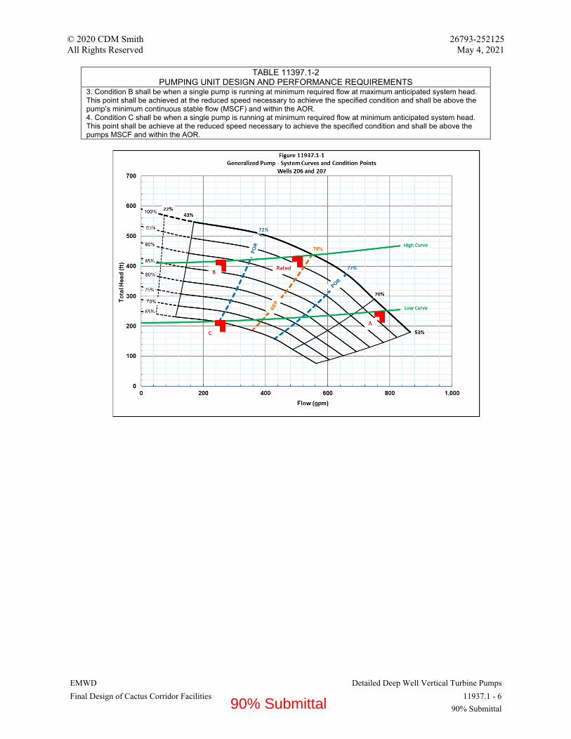
© 2020 CDM Smith 26793-252125 All Rights Reserved May 4, 2021
EMWD Detailed Deep Well Vertical Turbine Pumps Final Design of Cactus Corridor Facilities 11937.1 - 6
90% Submittal
TABLE 11397.1-2 PUMPING UNIT DESIGN AND PERFORMANCE REQUIREMENTS
3. Condition B shall be when a single pump is running at minimum required flow at maximum anticipated system head. This point shall be achieved at the reduced speed necessary to achieve the specified condition and shall be above the pump’s minimum continuous stable flow (MSCF) and within the AOR. 4. Condition C shall be when a single pump is running at minimum required flow at minimum anticipated system head. This point shall be achieve at the reduced speed necessary to achieve the specified condition and shall be above the pumps MSCF and within the AOR.
90% Submittal

© 2020 CDM Smith 26793-252125 All Rights Reserved May 4, 2021
EMWD Detailed Deep Well Vertical Turbine Pumps Final Design of Cactus Corridor Facilities 11937.1 - 7
90% Submittal
END OF SECTION 11937.1
90% Submittal

© 2020 CDM Smith 26793-252125
All Rights Reserved May 4, 2021
EMWD Fiberglass Reinforced Plastic Tanks
Final Design of Cactus Corridor Facilities 13230 - 1
90% Submittal
SECTION 13230 - FIBERGLASS REINFORCED PLASTIC TANKS
PART 1 - GENERAL
1.1 RELATED DOCUMENTS
A. Drawings and general provisions of the Contract, including General and Supplementary
Conditions and Division 01 Specification Sections, apply to this Section.
1.2 SUMMARY
A. Section includes:
1. Vertical, cylindrical, shop fabricated fiberglass reinforced plastic tanks for chemical
storage with accessories and anchorage.
2. Vertical, cylindrical, shop fabricated fiberglass reinforced plastic tanks for water and
brine preparation & brine waste storage with accessories and anchorage.
3. Vertical, cylindrical, shop fabricated fiberglass reinforced plastic tanks for brine making
with accessories and anchorage.
B. Liquids stored: Refer to Tank Table at end of this document.
C. Related Requirements:
1. Section 03300 “Cast-in-Place Concrete” for requirements for concrete support pad.
2. Division 15 for pipes, tubes, fittings, and valves as apply to specific application.
3. Section 11222.00 “Peristaltic Metering Pumps".
1.3 DEFINITIONS
A. FRP: Fiberglass-reinforced plastic.
B. RTP-1: American Society of Mechanical Engineers (ASME), Standard for Reinforced
Thermoset Plastic Corrosion Resistant Equipment.
1.4 COORDINATION
A. Coordinate Work of this Section with location and placement of utilities and piping.
1.5 PREINSTALLATION MEETINGS
A. Convene minimum one week prior to commencing installation work of this Section.
1.6 SCHEDULING
A. Section 01310 “Project Control Schedule” for scheduling requirements.
90% Submittal

© 2020 CDM Smith 26793-252125
All Rights Reserved May 4, 2021
EMWD Fiberglass Reinforced Plastic Tanks
Final Design of Cactus Corridor Facilities 13230 - 2
90% Submittal
B. Schedule Work of this Section after concrete Work for support pad and prior to connecting
utility and piping Work.
1.7 ACTION SUBMITTALS
A. Section 01330 “Submittal Procedures” for submittals requirements.
B. Product Data:
1. Ladder and ladder safety devices.
2. Information concerning materials of construction and fabrication.
3. Reinforcement product data.
4. Anchor bolt, fastening hardware, gasket and elastomer data.
5. Resin used, including a statement from the resin manufacturer that the materials used are
suitable for the intended service, as determined by ASTM C581.
6. Heating element, insulation and jacket data.
7. Tank base padding material.
C. Shop Drawings:
1. Wall thicknesses (shell, head and base) with laminate sequence.
2. Width, thickness and sequence of joint overlays.
3. Access openings/manways and cover size, orientation, fabrication details, materials and
thickness.
4. Internal and external pipe/ladder/handrail/accessory support bracket quantity, locations
and fabrication details.
5. Description of the post-curing procedure, where required, with the heating method and
proposed time-temperature curve.
6. Complete plan, elevation, and sectional drawings showing critical dimensions.
7. Ladder and ladder safety device details.
8. Handrail details.
9. Anchoring system details including anchor bolt embedment length.
10. Tare weight of the tanks.
11. Tank labeling text, size, layout and locations.
12. Heating and insulating details including wiring diagrams and power requirements (if
specified).
13. For buried tanks: Buoyancy calculations assuming a flooded trench and an empty tank
and concrete anchor details.
D. Samples:
1. Representative sample, at least 6 x 6-inch size showing exterior surface and finish color.
2. 6 x 6-inch segment of manway cutout.
1.8 DELEGATED DESIGN SUBMITTAL
A. Signed and sealed Shop Drawings with design calculations stamped by a Professional Engineer
with a statement that design and engineering calculations are in accordance with this Section,
ASME RTP-1 and the California State Building Code.
90% Submittal
© 2020 CDM Smith 26793-252125
All Rights Reserved May 4, 2021
EMWD Fiberglass Reinforced Plastic Tanks
Final Design of Cactus Corridor Facilities 13230 - 3
90% Submittal
B. Assumptions for determination of shell thickness, nozzle reinforcement, and special elements of
vessel construction and support. Wall thicknesses calculations per ASTM D1998.
C. Include structural design criteria used for the tank and anchorage design (including
recommendations for anchor bolt size, strength and embedment depth per ACI 318) and a
tabulation of all loads imparted on the foundation by the tank.
D. Anchorage and/or hold down device calculations stamped by a professional civil or structural
engineer registered in the State of California demonstrating that each tank will adequately
transfer seismic, wind and hydraulic forces from the vessels to the anchor bolts at the
foundation. Submit with the calculations a tabulation of all loads imparted on the foundation by
the tank.
1.9 INFORMATIONAL SUBMITTALS
A. Manufacturer's Certificate:
1. Products meet or exceed specified requirements.
2. Certified list of tank installations storing same liquid and concentration, in service for
period of not less than five years.
B. Manufacturer Instructions: Detailed instructions on installation requirements, including tank
handling procedures, anchoring, and layout.
C. Source Quality-Control Submittals: Results of shop tests and inspections. After fabrication and
prior to shipping, submit Factory Quality Control Report prepared by fabricator’s Inspector and
Certifying Inspector for tanks to be RTP-1 stamped, with certification by signature, containing
for each tank:
1. The type and quantity of materials used tank construction, in the form of as-built shop
drawings.
2. Confirmation that dimension and laminate thicknesses match the structural design and
approved shop drawings.
3. Results of visual inspections of components during and after assembly.
4. Results of Barcol Hardness tests per ASTM D2583.
5. Results of Acetone Sensitivity tests.
6. Actual time-temperature curve for post cure.
7. Results of laminate burn-out tests to measure glass content of the corrosion barrier and
the structural layer per ASTM D2584.
8. Results of hydrostatic tests on the finished tank. Provide notice of any tank flaws
observed during hydrostatic tests within 24 hours.
9. Representative laminate samples of both the cylindrical shell and the heads from nozzle
cut-outs. Polish one edge of each cut-out to a high sheen to allow visual inspection of the
laminate. Tanks found to not meet the design specifications based upon examination of
the samples, or comparison of submitted samples to the finished tanks; may be rejected.
D. Field Quality-Control Submittals:
1. Results of Contractor-furnished tests and inspections.
2. Owner Installation Certificate: Signed and dated certificate from manufacturer's
representative that tank has been properly installed and is ready for filling.
90% Submittal

© 2020 CDM Smith 26793-252125
All Rights Reserved May 4, 2021
EMWD Fiberglass Reinforced Plastic Tanks
Final Design of Cactus Corridor Facilities 13230 - 4
90% Submittal
E. Manufacturer Reports: Test reports in accordance with AWWA D120 for buried tanks.
F. Qualifications Statements:
1. Registered Professional Engineer, state of registration, and resume for tank design
engineer.
2. Fabricator’s Inspector (Quality Control Supervisor), with reporting relationship within
the Fabricator’s organization.
3. Certifying Inspector, for tank required to have ASME RTP-1 Certification.
1.10 CLOSEOUT SUBMITTALS
A. See Section 01770 “Closeout Procedures” for closeout procedures requirements.
B. Field Quality-Control Submittals: Results of Contractor-furnished tests and inspections.
C. Manufacturer Reports: Certify that tank has been installed according to manufacturer
instructions.
D. Project Record Documents: Actual locations and final orientation of tank and accessories.
E. Operation and Maintenance Data: For tanks, accessories, and appurtenances to include in
emergency, operation, and maintenance manuals.
1.11 QUALITY ASSURANCE
A. Materials in Contact with Potable Water: Certified according to NSF 61 and 372.
B. Centrifugally cast tanks are not allowed under this Specification.
C. Subcontracted tank or component fabrication is not allowed under this Specification.
D. Chemical storage tanks shall be supplied by a single manufacturer.
1.12 QUALIFICATIONS
A. Manufacturer: Company specializing in manufacturing products specified in this Section with
minimum ten years' experience.
B. Licensed Professional: Professional engineer experienced in the design of specified Work and
licensed in State of California.
1.13 DELIVERY, STORAGE, AND HANDLING
A. See Section 01600 “Product Requirements” for transporting, handling, storing, and protecting
products requirements.
B. Deliver materials in manufacturer's packaging including application instructions.
90% Submittal
© 2020 CDM Smith 26793-252125
All Rights Reserved May 4, 2021
EMWD Fiberglass Reinforced Plastic Tanks
Final Design of Cactus Corridor Facilities 13230 - 5
90% Submittal
C. Inspection: Accept materials on Site in manufacturer's original packaging and inspect for
damage.
D. Store materials according to manufacturer instructions.
E. Protection:
1. The Manufacturer is responsible for packaging to prevent damage to the tanks during
normal transit and handling.
2. Protect materials from moisture and dust by storing in clean, dry location remote from
construction operations areas.
3. Provide additional protection according to manufacturer instructions.
4. Protect flange faces and other openings with a minimum 1/2-inch thick wooden blind
flange secured in place with temporary nuts and bolts in each bolt hole to prevent
entrance of dirt, water and debris.
5. Provide instructions for unloading and installation of the tanks, using lifting and tailing
lugs as needed for handling by for crane, fork truck or similar device. Do not use
nozzles, manways, or other fittings for lifting.
6. Wrap ladders, railings, sight gages and other components removed for shipment to
prevent damage during shipment.
7. To prevent damage to the corrosion barrier, do not ship loose components inside the
tanks.
1.14 EXISTING CONDITIONS
A. Field Measurements:
1. Verify field measurements prior to fabrication.
2. Indicate field measurements on Shop Drawings.
1.15 WARRANTY
A. See Section 01770 “Closeout Procedures” for warranties requirements.
PART 2 - PRODUCTS
2.1 PERFORMANCE AND DESIGN CRITERIA
A. Design Safety Factors:
1. Internal Pressure for Contact Molding: 10:1.
2. Strain Limit for Filament Winding: 0.001 inches/inch.
3. Vacuum Collapse: 5:1.
B. Joint Strength: Equal to shell strength.
C. Design for the most severe combinations of conditions in accordance with ASME RTP-1
requirements using Type II and X laminates, considering where applicable:
90% Submittal

© 2020 CDM Smith 26793-252125
All Rights Reserved May 4, 2021
EMWD Fiberglass Reinforced Plastic Tanks
Final Design of Cactus Corridor Facilities 13230 - 6
90% Submittal
1. Internal positive and negative pressure requirements
2. Temperature
3. Static head
4. Wind, seismic, snow and live loads
5. Accessory loads (ladders, handrails, platforms, etc.)
6. Transportation and erection loads
7. Stiffener rings
8. Secondary bond overlays
9. Flange thickness
10. Lifting lugs, hold-down flanges, lugs, ring supports, legs, etc.
11. Knuckle radius of bottom
12. Compressive loading
13. Thermal expansion stresses
14. Internal supports for pipes and baffles.
D. Exclude the corrosion barrier, insulation layer and external jacket from the structural design
calculations.
E. Loads:
1. Design for the load forces resulting from expansion and contraction of the equipment due
to temperature changes, including atmospheric, tank contents and heat tracing.
2. Design for all loads (dead loads, live loads, wind loads, seismic loads, impact loads,
vibrations, thermal loads and internal liquid or solid loads) as required by code and as
specified herein.
3. Tank top heads: design to support a 250-lb point load on a 4-inch by 4-inch area with a
maximum deflection of the lesser of ½ percent of the tank diameter or ½-inch at the area
where the load is applied, with no damage to the tank.
4. Dead loads: design for the weights of all materials of construction incorporated into the
structure including, but not limited to fixed equipment and equipment bases, piping,
machinery and all other items permanently affixed to the tank.
5. Snow loads: design per ASCE 7. Refer to parameters listed in the Tank Tables.
6. Wind loads: design per ASCE 7. Refer to parameters listed in the Tank Tables.
7. Seismic loads: design per ASCE 7. Refer to parameters listed in the Tank Tables.
2.2 FRP CHEMICAL STORAGE TANKS
A. Manufacturers:
1. Plas-Tanks Industries, Inc., Hamilton, Ohio;
2. R.L. Industries, Fairfield, Ohio;
3. An-Cor Industrial Plastics, Inc., North Tonawanda, New York;
4. Diamond Fiberglass, Victoria, Texas;
5. Substitutions: As specified in Section 01600 “Product Requirements.”
B. Description:
1. Construction Method:
a. Filament Wound, chopped strand and hand layup.
b. Comply with ASME/ANSI RTP-1.
90% Submittal

© 2020 CDM Smith 26793-252125
All Rights Reserved May 4, 2021
EMWD Fiberglass Reinforced Plastic Tanks
Final Design of Cactus Corridor Facilities 13230 - 7
90% Submittal
c. Comply with ASTM D3299 and D4097, and Acceptance Level II requirements of
ASTM D2563.
2. Configuration:
a. Orientation: Vertical.
b. Bottom: Flat.
c. Top: Integral and closed.
3. Materials:
a. Use same resin throughout construction of each tank.
b. Furnish Nexus or C-veil to meet requirements.
4. Minimum total laminate thickness excluding corrosion barrier regardless of theoretical
design requirements.
a. Shell: 5/16-inch
b. Dished head: 5/16-inch
c. Floor: ½-inch
2.3 FRP WATER/BRINE STORAGE TANKS
A. Manufacturers:
1. Plas-Tanks Industries, Inc., Hamilton, Ohio;
2. R.L. Industries, Fairfield, Ohio;
3. An-Cor Industrial Plastics, Inc., North Tonawanda, New York;
4. Diamond Fiberglass, Victoria, Texas;
5. Substitutions: As specified in Section 01600 “Product Requirements.”
B. Description:
1. Construction Method:
a. Filament Wound, chopped strand and hand layup.
b. Comply with ASTM D3299 and D4097, and Acceptance Level II requirements of
ASTM D2563.
2. Configuration:
a. Orientation: Vertical.
b. Bottom: Flat.
c. Top: Integral and closed.
3. Materials:
a. Isophthalic polyester resin.
b. Exterior: Provide translucent protective coating with ultraviolet inhibitors for tanks
installed outdoors.
c. Lifting lugs: 304SS.
d. Use same resin throughout construction of each tank.
e. Furnish C-veil to meet requirements.
90% Submittal
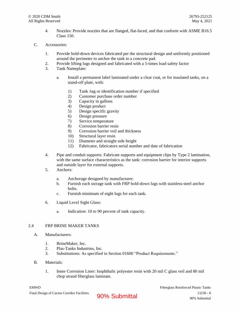
© 2020 CDM Smith 26793-252125
All Rights Reserved May 4, 2021
EMWD Fiberglass Reinforced Plastic Tanks
Final Design of Cactus Corridor Facilities 13230 - 8
90% Submittal
4. Nozzles: Provide nozzles that are flanged, flat-faced, and that conform with ASME B16.5
Class 150.
C. Accessories:
1. Provide hold-down devices fabricated per the structural design and uniformly positioned
around the perimeter to anchor the tank to a concrete pad.
2. Provide lifting lugs designed and fabricated with a 5-times load safety factor
3. Tank Nameplate:
a. Install a permanent label laminated under a clear coat, or for insulated tanks, on a
stand-off plate, with:
1) Tank /tag or identification number if specified
2) Customer purchase order number
3) Capacity in gallons
4) Design product
5) Design specific gravity
6) Design pressure
7) Service temperature
8) Corrosion barrier resin
9) Corrosion barrier veil and thickness
10) Structural layer resin
11) Diameter and straight side height
12) Fabricator, fabricators serial number and date of fabrication
4. Pipe and conduit supports: Fabricate supports and equipment clips by Type 2 lamination,
with the same surface characteristics as the tank: corrosion barrier for interior supports
and outside layer for external supports.
5. Anchors:
a. Anchorage designed by manufacturer.
b. Furnish each storage tank with FRP hold-down lugs with stainless-steel anchor
bolts.
c. Furnish minimum of eight lugs for each tank.
6. Liquid Level Sight Glass:
a. Indication: 10 to 90 percent of tank capacity.
2.4 FRP BRINE MAKER TANKS
A. Manufacturers:
1. BrineMaker, Inc.
2. Plas-Tanks Industries, Inc.
3. Substitutions: As specified in Section 01600 “Product Requirements.”
B. Materials:
1. Inner Corrosion Liner: Isophthalic polyester resin with 20 mil C glass veil and 80 mil
chop strand fiberglass laminate.
90% Submittal

© 2020 CDM Smith 26793-252125
All Rights Reserved May 4, 2021
EMWD Fiberglass Reinforced Plastic Tanks
Final Design of Cactus Corridor Facilities 13230 - 9
90% Submittal
2. Exterior: Provide translucent protective coating with ultraviolet inhibitors.
3. Lifting lugs: 304SS.
4. Use same resin throughout construction of each tank.
C. Requirements:
1. Coarse grade of solar salt: 45 tons minimum
2. Tank diameter: 144 inches
3. Straight side shell: 15’-0” maximum
4. Include four anchor lugs and two lifting lugs
5. Flanged nozzles and manways:
a. Salt Fill Line: 4-inch
b. Brine Outlet: 2-inch
c. Water Inlet: 1-inch
d. Vent: 8-inch with dust bag
e. Drain: 2-inch
f. Top Manway: 24-inch
g. Side Manway: 24-inch
h. Instrument Sensor: 2-inch
6. Furnish ladder with cage per OSHA standards.
7. Accessories:
a. Brine level controller and indicator.
b. Provide hold-down devices fabricated per the structural design and uniformly
positioned around the perimeter to anchor the tank to a concrete pad.
c. Provide lifting lugs designed and fabricated with a 5-times load safety factor
8. Anchors:
a. Anchorage designed by manufacturer.
b. Furnish each storage tank with FRP hold-down lugs with stainless-steel anchor
bolts.
2.5 LAMINATES FOR CHEMICAL STORAGE TANKS
A. Resin:
1. Premium-grade, corrosion-resistant bisphenol-A epoxy vinyl ester resin (Bis-A EVER)
that has been evaluated in a laminate in accordance with ASTM C-581 and has been
determined by previous documented service to be acceptable for the service conditions.
2. Acceptable resins for tanks not requiring a flame spread rating:
a. AOC Vipel F010
b. Ashland Derakane 411
c. Ashland Hetron 922
d. Reichhold Dion 9100
e. Interplastic CoREZYN 8300
90% Submittal

© 2020 CDM Smith 26793-252125
All Rights Reserved May 4, 2021
EMWD Fiberglass Reinforced Plastic Tanks
Final Design of Cactus Corridor Facilities 13230 - 10
90% Submittal
3. Acceptable resins for tanks requiring a flame spread rate of less than or equal to 25 (Class
1 per ASTM E84) using brominated resins. Antimony oxide synergists may be used in
the structural layer and outside surface, but not in the corrosion barrier:
a. AOC Vipel K02c22
b. Ashland Derakane 510
c. Ashland Hetron FR922
d. Reichhold Dion VER9300FR
e. Interplastic CoREZYN 8440
4. Resin Grade: same resin throughout the entire tank.
5. Pigments, dyes, thixotropic agents, antimony oxides and fillers are not allowed in the
corrosion barrier:
6. Exterior Surface:
a. A thixotropic agent that does not interfere with visual inspection of laminate
quality, or with the required corrosion resistance of the laminate, may be added for
viscosity control.
b. Confirm with the resin supplier prior to use that the thixotropic agent will not
reduce the laminate resistance to the anticipated corrosive chemical environment,
such as from splash exposure.
7. Resin pastes made from the same resin used for the corrosion barrier are permitted to fill
crevices before overlay, provided the use is within the limitation set in ASME RTP-1.
8. Catalyst/Initiator System for all Layers:
a. Methylethyl Ketone Peroxide/ Cobalt Naphthenate (MEKP/ CoNap),
b. except where otherwise listed in Tank Tables where indicated to use Benzoyl
Peroxide/N,N-dimethylanaline (BPO/DMA).
c. Avoid excessive laminate exotherm.
B. Reinforcement Materials:
1. All reinforcement treated with sizing chemically compatible with the resin system to
ensure full wet-out.
2. Inner surface reinforcement per Tank Tables:
a. C glass veils
b. Apertured polyester veils (Precision Fabrics 1.3 ounce/square yard, 100-0010-048
or approved equal)
3. Chopped Strand Mat for the Corrosion Barrier: ECR glass, Owens Corning Advantex or
approved equal.
4. Chopped Strand Mat for Bedding the Structural Layer After Curing the Corrosion
Barrier, and in the Structural Layer: Chopped E-type or ECR or equal glass fiber, 1.5
oz/sf, bonded together using a resinous binder.
5. Filament Glass for Winding the Structural Layer: E-type or ECR glass.
6. Woven Roving for the Structural Layer: E-type or ECR glass.
7. Outside Surface Reinforcement (outside the insulation): A-glass or C-glass veil.
C. Fabrication:
1. Shop Fabricate Tanks: Field assembly is limited to mounting accessories.
90% Submittal

© 2020 CDM Smith 26793-252125
All Rights Reserved May 4, 2021
EMWD Fiberglass Reinforced Plastic Tanks
Final Design of Cactus Corridor Facilities 13230 - 11
90% Submittal
2. Vertical Joints (in axial direction): Not allowed.
3. Apply catalyst, initiators and other ingredients using a volume or weight control
mechanism.
4. Fully cure the corrosion barrier, and then promptly apply the structural layer, keeping
within the time limit to avoid a need to roughen the exposed face of the corrosion barrier
on the mandrel or mold.
5. Tank Heads (top and bottom):
a. Fabricate by contact molding complete with the corrosion barrier structural layer
and outside layer.
b. Apply attachment and knuckle reinforcement overlays to secure the heads to the
shell following RTP-1 requirements.
6. Cylindrical Shell: Fabricate by filament winding, chopped strand roving and woven
roving as required by the structural design.
7. Shell to Head, Shell to Shell, and Nozzle Joints (secondary bonds):
a. Fabricate per RTP-1 with overlapping layers of glass and resin,
b. Finish with corrosion barrier and outside surface laminates as specified for the
tank,
c. Use Type II laminates, except Type I laminates for the corrosion barrier.
8. Outside Layer:
a. Fabricate with paraffinated resin containing an ultra violet absorber which does not
inhibit resin cure.
b. Pigment may be added to the outside layer for additional ultra violet protection and
appearance, if so indicated in Tank Tables.
9. Exposed Edges or Ends of Fittings, Covers, Flanges, Nozzles, and Appurtenances:
Fabricate with the same resin finish coat used in the inner corrosion barrier, containing
paraffinated resin in the top coat.
10. Sloped Bottoms: Where indicated in Tank Tables, fabricate with a ¼-inch per foot
internal slope using end-grain balsa wood or approved structural foam sandwiched
between the internal corrosion barrier and its structural support layer, and the structural
layer on the bottom of the tank under the balsa wood.
11. Visual Inspection: Refer to Tank Tables for required visual inspection level, referencing
RTP-1 and limits to the size and number of pits, foreign inclusions, dry spots, air bubbles,
pinholes, pimples and delaminations.
12. Grind and repair areas containing defects exceeding the allowable size and number.
2.6 NOZZLES, MANWAYS AND COVERS FOR CHEMICAL STORAGE TANKS
A. Design nozzles in accordance with ANSI/ASME RTP-1 for 50 psig.
B. Fabricate nozzle necks and flange faces by the hand lay-up, Type II laminate, with the same
corrosion barrier as the tank wall.
1. Compression molded and resin transfer molded fittings are prohibited.
2. Outer diameters and drilling: per ANSI 16.5
3. Flange faces: Flat and true to plus/minus 1/32-inch
90% Submittal

© 2020 CDM Smith 26793-252125
All Rights Reserved May 4, 2021
EMWD Fiberglass Reinforced Plastic Tanks
Final Design of Cactus Corridor Facilities 13230 - 12
90% Submittal
4. Back of Flanges around each Bolt Hole: Spot face as needed for the diameter of a
standard ANSI washer, flat and parallel to the flange face.
C. Nozzle Fabrication:
1. ½-degree flange face angle tolerance from perpendicular with respect to tank vertical and
radial centerlines.
2. Flush type, except penetrating, dip tube or siphon as listed in Tank Schedules.
3. With plate or conical gussets to the outside diameter of the flange for all nozzles 4-in
diameter and smaller.
D. Blind flange and manways fittings:
1. Fume tight, with full face gaskets. Refer to Tank Tables for gasket materials.
2. Bolting hardware materials of construction: refer to Tank Tables. Apply anti-seize paste
to bolt threads.
E. Fabricate top head removable inspection covers (for up to 18-inch diameter):
1. To mount on nozzle neck with no flange.
2. Include a drip lip around the perimeter on the underside of the cover, approximately ¼-
inch diameter less than the inside of the nozzle neck.
3. Include a FRP cover handle.
2.7 LADDERS, RAILINGS AND PLATFORMS
A. Provide all necessary assembly and mounting hardware.
B. Support ladder feet from the concrete floor, bolted thereto.
C. Make all other connections to purpose-fabricated supports integral with the tank. Fittings and
hardware penetrating the tank are not allowed. Avoid interference with tank nozzle access.
D. Mounting hardware: Refer to Tank Tables.
E. Ladder Requirements:
1. Refer to Tables for materials of construction.
2. Comply with applicable 29 CFR 1910.23, OSHA Standards and the building code, with a
strength safety factor of 2.0.
3. Ladder design
a. 18-inch clear width
b. 1.25-inch diameter fluted rungs spaced at 12-inches
c. 7 to 10-inch stand-off from the tank
d. Extend to tank-top railing height, with access from the tank top via self-closing
safety gate
e. Pigmented safety yellow with polyurethane top coat containing UV protection for
outdoor exposure (except if unpainted galvanized ladder is specified).
f. Manufactured with isophthalic polyester resin by pultrusion, except hand lay-up
cage hoops may be used.
F. Tank Top Perimeter Railings Requirements:
90% Submittal

© 2020 CDM Smith 26793-252125
All Rights Reserved May 4, 2021
EMWD Fiberglass Reinforced Plastic Tanks
Final Design of Cactus Corridor Facilities 13230 - 13
90% Submittal
1. Refer to the FRP Tank Schedule for materials of construction.
2. Comply with applicable 29 CFR 1910.29 OSHA Standards and the local building code.
3. Railing design:
a. Include top rail, mid rail and kick plate with curved or with octagonal perimeter to
match the tank circumference.
b. Pigmented safety yellow with polyurethane top coat containing UV protection for
outdoor exposure (except if unpainted galvanized railing is specified).
2.8 INSULATION AND JACKETS FOR CHEMICAL STORAGE TANKS
A. Complete attachment of nozzles, gussets, secondary bonds and other attachments to the tank
prior to applying insulation.
B. Complete visual inspections and other quality control tests, repairs and post cure prior to
applying insulation.
C. For insulated tanks, enclose the entire side shell and top of the tank with insulation and FRP
jacket.
D. Insulation:
1. Refer to Tank Table for insulation thickness.
2. K factor of not less than 5.3 BTU-inch/hour/square foot/degree F per ASTM C518.
3. Water absorption of less than 0.7% by volume after 24 hours immersion per ASTM C272
4. ITW Insulation Systems Trymer 200L polyisocyanurate foam or approved equal.
E. Jacket over the insulation:
1. Structural layer: Type X on the shell and Type II on the top head, not less than 150 mils
thick.
2. Outside surface: 10-mil surfacing veil reinforced with C or A glass. Fabricate with
paraffinated resin containing pigment and an ultra violet absorber which does not inhibit
resin cure.
2.9 TANK ACCESSORIES
A. Provide hold-down devices fabricated per the structural design and uniformly positioned around
the perimeter to anchor the tank to a concrete pad.
B. Provide lifting lugs designed and fabricated with a 5-times load safety factor
C. Tank Nameplate:
1. Install a permanent label laminated under a clear coat, or for insulated tanks, on a stand-
off plate, with:
a. Tank /tag or identification number if specified
b. Customer purchase order number
c. Capacity in gallons
d. Design product
e. Design specific gravity
90% Submittal
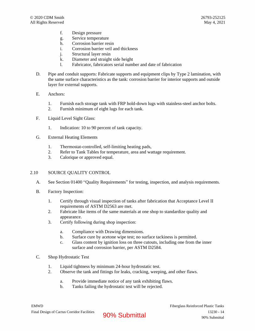
© 2020 CDM Smith 26793-252125
All Rights Reserved May 4, 2021
EMWD Fiberglass Reinforced Plastic Tanks
Final Design of Cactus Corridor Facilities 13230 - 14
90% Submittal
f. Design pressure
g. Service temperature
h. Corrosion barrier resin
i. Corrosion barrier veil and thickness
j. Structural layer resin
k. Diameter and straight side height
l. Fabricator, fabricators serial number and date of fabrication
D. Pipe and conduit supports: Fabricate supports and equipment clips by Type 2 lamination, with
the same surface characteristics as the tank: corrosion barrier for interior supports and outside
layer for external supports.
E. Anchors:
1. Furnish each storage tank with FRP hold-down lugs with stainless-steel anchor bolts.
2. Furnish minimum of eight lugs for each tank.
F. Liquid Level Sight Glass:
1. Indication: 10 to 90 percent of tank capacity.
G. External Heating Elements
1. Thermostat-controlled, self-limiting heating pads,
2. Refer to Tank Tables for temperature, area and wattage requirement.
3. Calorique or approved equal.
2.10 SOURCE QUALITY CONTROL
A. See Section 01400 “Quality Requirements” for testing, inspection, and analysis requirements.
B. Factory Inspection:
1. Certify through visual inspection of tanks after fabrication that Acceptance Level II
requirements of ASTM D2563 are met.
2. Fabricate like items of the same materials at one shop to standardize quality and
appearance.
3. Certify following during shop inspection:
a. Compliance with Drawing dimensions.
b. Surface cure by acetone wipe test; no surface tackiness is permitted.
c. Glass content by ignition loss on three cutouts, including one from the inner
surface and corrosion barrier, per ASTM D2584.
C. Shop Hydrostatic Test
1. Liquid tightness by minimum 24-hour hydrostatic test.
2. Observe the tank and fittings for leaks, cracking, weeping, and other flaws.
a. Provide immediate notice of any tank exhibiting flaws.
b. Tanks failing the hydrostatic test will be rejected.
90% Submittal

© 2020 CDM Smith 26793-252125
All Rights Reserved May 4, 2021
EMWD Fiberglass Reinforced Plastic Tanks
Final Design of Cactus Corridor Facilities 13230 - 15
90% Submittal
3. Rinse the tank with potable water after the test and remove all standing water prior to
shipment.
4. Include results of the hydrostatic tests in the final inspection report.
D. Post Cure:
1. Refer to the Tank Tables for tanks requiring post cure. In addition, the following tanks
require post-cure:
a. All tanks fabricated with a Benzoyl Peroxide/N,N-dimethylanaline (BPO/DMA)
catalyst/initiator system.
b. Inadequately cured tanks and/or repaired tanks.
2. Post cure manway covers and blind flanges loose from the tank (remove gaskets).
3. Post cure in a dry-heat convective oven with the time and temperature ramp and hold
plan recommended by the resin supplier, considering the laminate volume and thickness,
as documented in the approved shop drawings.
4. After post cure, document the inspections and tests.
a. Visual inspection, including the entire internal corrosion barrier for cracking,
crazing and other visual defects.
b. Test secondary bonds and areas repaired for Acetone Sensitivity and Barcol
Hardness.
c. Report signature: By the Inspector (Fabricator’s Quality Control Supervisor), and
by the Certifying Inspector for tanks required to have RTP-1 Certification.
E. Repairs:
1. Refer to RTP-1 Appendix M-7 for allowable repairs and procedures.
2. Grind out and repair flaws exceeding inspection criteria, and if necessary to meet cure
requirements.
3. Retest repaired areas, cure and report results for:
a. Acetone Sensitivity
b. Barcol hardness, to achieve at least 90% of resin manufacturer’s standard.
4. For inadequately cured resin, post cure the tank, if approved in advance by the:
a. Fabricator’s Inspector and
b. For tanks to be RTP-1 Certified also by the Certifying Inspector.
c. Refer 3.02 for post cure requirement.
F. Certificate of Compliance:
1. If manufacturer is approved by authorities having jurisdiction, submit certificate of
compliance indicating Work performed at manufacturer's facility conforms to Contract
Documents.
G. Submit Factory Test Report, approved and signed by the Fabricator’s Quality Control
Supervisor which includes for each tank:
1. Inspection records.
2. Results of hydrostatic testing.
3. Test reports of physical properties of standard laminates.
90% Submittal
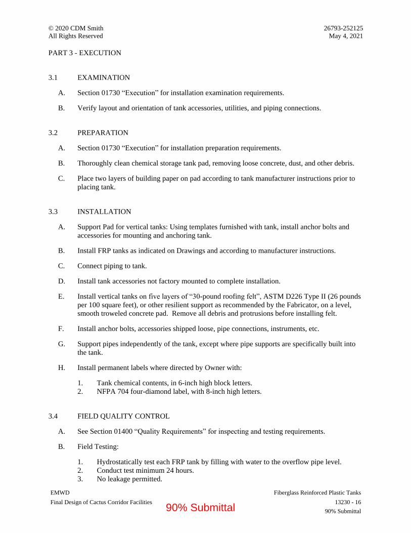
© 2020 CDM Smith 26793-252125
All Rights Reserved May 4, 2021
EMWD Fiberglass Reinforced Plastic Tanks
Final Design of Cactus Corridor Facilities 13230 - 16
90% Submittal
PART 3 - EXECUTION
3.1 EXAMINATION
A. Section 01730 “Execution” for installation examination requirements.
B. Verify layout and orientation of tank accessories, utilities, and piping connections.
3.2 PREPARATION
A. Section 01730 “Execution” for installation preparation requirements.
B. Thoroughly clean chemical storage tank pad, removing loose concrete, dust, and other debris.
C. Place two layers of building paper on pad according to tank manufacturer instructions prior to
placing tank.
3.3 INSTALLATION
A. Support Pad for vertical tanks: Using templates furnished with tank, install anchor bolts and
accessories for mounting and anchoring tank.
B. Install FRP tanks as indicated on Drawings and according to manufacturer instructions.
C. Connect piping to tank.
D. Install tank accessories not factory mounted to complete installation.
E. Install vertical tanks on five layers of “30-pound roofing felt”, ASTM D226 Type II (26 pounds
per 100 square feet), or other resilient support as recommended by the Fabricator, on a level,
smooth troweled concrete pad. Remove all debris and protrusions before installing felt.
F. Install anchor bolts, accessories shipped loose, pipe connections, instruments, etc.
G. Support pipes independently of the tank, except where pipe supports are specifically built into
the tank.
H. Install permanent labels where directed by Owner with:
1. Tank chemical contents, in 6-inch high block letters.
2. NFPA 704 four-diamond label, with 8-inch high letters.
3.4 FIELD QUALITY CONTROL
A. See Section 01400 “Quality Requirements” for inspecting and testing requirements.
B. Field Testing:
1. Hydrostatically test each FRP tank by filling with water to the overflow pipe level.
2. Conduct test minimum 24 hours.
3. No leakage permitted.
90% Submittal

© 2020 CDM Smith 26793-252125
All Rights Reserved May 4, 2021
EMWD Fiberglass Reinforced Plastic Tanks
Final Design of Cactus Corridor Facilities 13230 - 17
90% Submittal
C. Manufacturer Services: Furnish services of manufacturer's representative experienced in
installation of products supplied for not less than 2 days on Site for installation, inspection,
startup, field testing, and instructing Owner's personnel in operation and maintenance of
equipment.
D. Equipment Acceptance: Adjust, repair, modify, or replace components failing to perform as
specified and rerun tests.
E. Furnish installation certificate from equipment manufacturer's representative attesting that
equipment has been properly installed and is ready for startup and testing.
3.5 FINAL CLEANING
A. After hydrostatic testing, clean the tank with a mild detergent. Do not use abrasives.
B. Rinse with potable water spray and remove all standing water.
3.6 ATTACHMENTS
A. FRP Tank Tables.
END OF SECTION 13230
90% Submittal
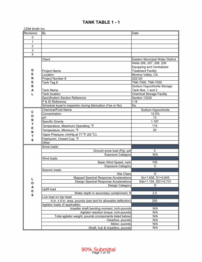
CDM Smith Inc.Revisions By Date
0
1
2
34
Client Eastern Municipal Water District
Project Name
Wells 206, 207, 208, 209 Equipping and Centralized Treatment Facility
Location Moreno Valley, CAProject Number # 252125Tank Tag # TNK-7000, TNK-7050
Tank NameSodium Hypochlorite Storage Tank Nos. 1 and 2
Tank location Chemical Storage FacilitySpecification Section Reference Section 13230P & ID Reference I-18Schedule buyer's inspection during fabrication (Yes or No) No
Chemical/Fluid Name Sodium HypochloriteConcentration 12.5%pH 13Specific Gravity 1.187
Temperature, Maximum Operating, oF 115
Temperature, Minimum, oF 20
Vapor Pressure, mmHg at 77 oF (25 oC)Flashpoint, Closed Cup, oFOtherSnow loads
Ground snow load (Pg), psf 0Exposure Category N/A
Wind loadsBasic Wind Speed, mph 105
Exposure Category CSeismic loads
Site Class DMapped Spectral Response Accelerations Ss=1.656, S1=0.645.Design Spectral Response Accelerations Sds=1.104, SD1=0.731
Design Category DUplift load
Water depth in secondary containment, ft 2.5Live load on top head
4-in. x 4-in. area, pounds (see text for allowable deflection) 250Agitator loads (if applicable)
Impeller shaft bending moment, inch-pounds N/AAgitator reaction torque, inch-pounds N/A
Total agitator weight, pounds (components listed below) N/A-Gearbox, pounds N/A
-Motor, puonds N/A-Shaft, hub & impellers, pounds N/A
TANK TABLE 1 - 1
CONTENTS
GENERAL
LOADS
Page 1 of 1990% Submittal

Design By RTP-1Fabricate By
RTP-1 XASTM D3299 and ASTM D4097
RTP-1 Certification Stamp Required (Yes or No) YesCB Excluded From Structural Calculations YesFire Retardant Structural Layer (Yes or No) YesFire Retardant Outside Surface (Yes or No) YesWall Thickness Taper With Height Allowed? NoDesign Positive Pressure, inches w.g.. (select)
Atmospheric (0)10-inches w.g.. (for vent extension w indoor tank) X
Design Negative Pressure (select)Atmospheric (0)
10-inches w.g. (for vent extension w indoor tank) XOther
Volume (To Overflow Flange), gal 2750
Diameter, Inches 84Straight Side (Including Freeboard), Inches 124Top
Dished XFlat
OpenBottom
Flat XSloped
Laminate Type (I= random strand mat, RSM) I, Hand lay-upResin See Spec TextResin content, inner surface 80 to 90%Resin content, inner layer 70 to 75%Catalyst-cure system (selection one)
(All tanks except sodium NaOCl) MEKP/CoNap(NaOCl Tanks) BPO/DMA X
Contact molding method Hand lay-upInner surface reinforcement, RSM veil (pick type)
(for acids and neutral chemical tanks) 2 C-glass(special for alkalis & fluosilicic acid tanks) 2 polyester
(special for NaOCl tanks) 1 C-glass and 2 polyester XInner layer reinforcement, 1.5 oz/sq ft RSM ECR glassThickness, inner surfaces plus inner layer, mils (pick thickness)
100 mils(special for alkalis, fluosilicic acid and NaOCl) 150 mils X
DESIGN
TANK
GEOMETRY
CORROSION
BARRIER
Page 2 of 1990% Submittal

Structural Layer (SL) ShellBedding layer between Corrosion Barrier and Structural Layer (1) 1.5 oz/sf RSMResin See Spec TextLaminate type (X= filament wound, II= random strand mat/woven rove)
X
Glass content for Type X 60% to 70%Resin content for Type II 35% to 45%Fire retardancy performance to meet ASTM-E84 (Yes or No) YesCatalyst-cure system MEKP/CoNapPigment allowed in SL NoMinimum thickness Per RTP-1Structural Layer Contact Molded Head, bottom and nozzles (SL)Laminate type (II= random strand mat/woven rove) IIResin and glass system Same as shell
Note- Outside surface not required under insulationLaminate type Random strand matOuter surface reinforcement, RSM veil 1 C-glass or A-glassResin content for Type II 40% +/-Resin See Spec TextFire retardancy performance to meet ASTM-E84 (Yes or No) YesCatalyst-cure system MEKP/CoNapWax additive to prevent air inhibition of cure YesUV protection YesPigment allowed (Yes or No) NoMinimum thickness, mils 10
Post cure required (Yes or No) YesDimensional tolerances RTP-1Inner surface and corrosion barrier visual inspection criteria RTP-1 Level 2Inner surface and corrosion barrier, maximum repair to pass 3% of areaStructural layer visual inspection criteria RTP-1 Level 2Structural layer, maximum repair to pass 10% of areaOutside surface visual inspection criteria RTP-1 Level 2Outside surface, maximum repair to pass 10% of areaBarcol Hardness, not less than % of resin manufacturer's spec. 0.9Acetone Sensitivity PassHydrostatic test PassSigned report Yes
OUTSIDE
SURFACE
POSTCURE &
INSPECTIONS
STRUCTURAL
LAYER
Page 3 of 1990% Submittal

Insulation and jacket required (Yes or No) NoThickness, inches
Self-Limiting Heating (Yes or No) No
Temperature setting, oFPower, watts/ft2
Voltage and phasesLocation on tank
Total area heated, ft2Agitator mounting rails required (Yes or No) NoLadders
Pultruded FRP, isophthalic polyester resin, yellow safety color XGalvanized steel
Painted steel, yellow-safety-color paintBolting hardware (pick galvanize or 304SS) 304SS
Lifting lugs304SS X
Galvanized steelAnchor lugs and dogs
304SS316SS
Titanium (for sodium hypochlorite) XBlind flange bolting
316SSHastelloy C276 (for hydochloric acid and ferric chloride)
Titanium (for sodium hypochlorite) XBlind flange gaskets
EPDMPVDFViton X
Other
ACCESSORIES AND HARDWARE
Page 4 of 1990% Submittal
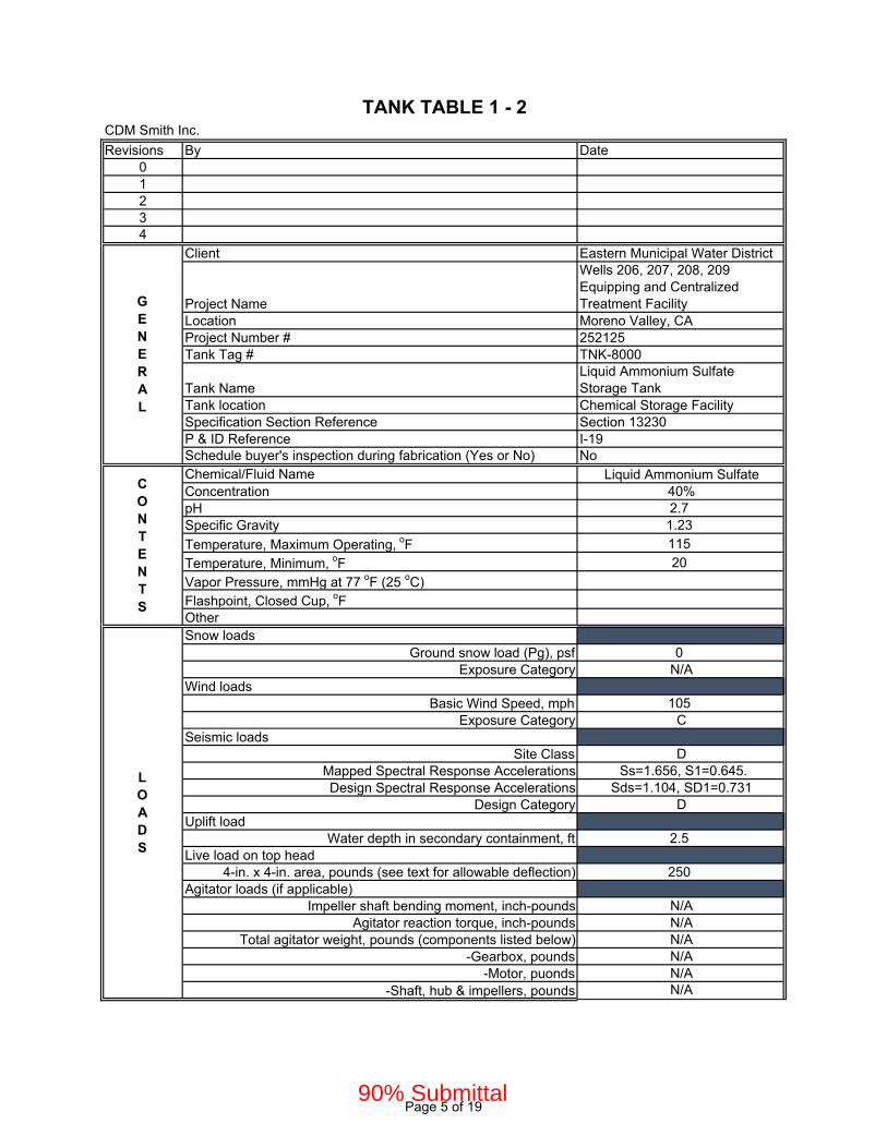
CDM Smith Inc.
Revisions By Date01234
Client Eastern Municipal Water District
Project Name
Wells 206, 207, 208, 209 Equipping and Centralized Treatment Facility
Location Moreno Valley, CAProject Number # 252125Tank Tag # TNK-8000
Tank NameLiquid Ammonium Sulfate Storage Tank
Tank location Chemical Storage FacilitySpecification Section Reference Section 13230P & ID Reference I-19Schedule buyer's inspection during fabrication (Yes or No) NoChemical/Fluid Name Liquid Ammonium SulfateConcentration 40%pH 2.7Specific Gravity 1.23
Temperature, Maximum Operating, oF 115
Temperature, Minimum, oF 20
Vapor Pressure, mmHg at 77 oF (25 oC)Flashpoint, Closed Cup, oFOtherSnow loads
Ground snow load (Pg), psf 0Exposure Category N/A
Wind loadsBasic Wind Speed, mph 105
Exposure Category CSeismic loads
Site Class DMapped Spectral Response Accelerations Ss=1.656, S1=0.645.Design Spectral Response Accelerations Sds=1.104, SD1=0.731
Design Category DUplift load
Water depth in secondary containment, ft 2.5Live load on top head
4-in. x 4-in. area, pounds (see text for allowable deflection) 250Agitator loads (if applicable)
Impeller shaft bending moment, inch-pounds N/AAgitator reaction torque, inch-pounds N/A
Total agitator weight, pounds (components listed below) N/A-Gearbox, pounds N/A
-Motor, puonds N/A-Shaft, hub & impellers, pounds N/A
TANK TABLE 1 - 2
GENERAL
CONTENTS
LOADS
Page 5 of 1990% Submittal
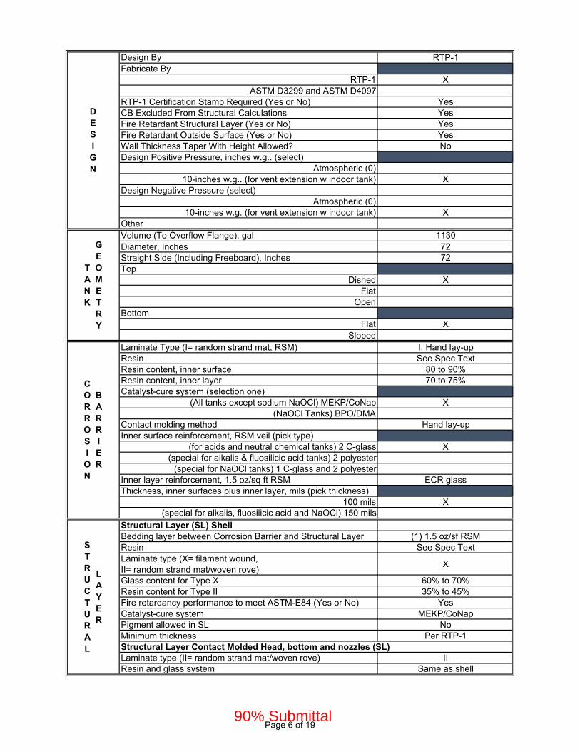
Design By RTP-1Fabricate By
RTP-1 XASTM D3299 and ASTM D4097
RTP-1 Certification Stamp Required (Yes or No) YesCB Excluded From Structural Calculations YesFire Retardant Structural Layer (Yes or No) YesFire Retardant Outside Surface (Yes or No) YesWall Thickness Taper With Height Allowed? NoDesign Positive Pressure, inches w.g.. (select)
Atmospheric (0)10-inches w.g.. (for vent extension w indoor tank) X
Design Negative Pressure (select)Atmospheric (0)
10-inches w.g. (for vent extension w indoor tank) XOtherVolume (To Overflow Flange), gal 1130Diameter, Inches 72Straight Side (Including Freeboard), Inches 72Top
Dished XFlat
OpenBottom
Flat XSloped
Laminate Type (I= random strand mat, RSM) I, Hand lay-upResin See Spec TextResin content, inner surface 80 to 90%Resin content, inner layer 70 to 75%Catalyst-cure system (selection one)
(All tanks except sodium NaOCl) MEKP/CoNap X(NaOCl Tanks) BPO/DMA
Contact molding method Hand lay-upInner surface reinforcement, RSM veil (pick type)
(for acids and neutral chemical tanks) 2 C-glass X(special for alkalis & fluosilicic acid tanks) 2 polyester
(special for NaOCl tanks) 1 C-glass and 2 polyesterInner layer reinforcement, 1.5 oz/sq ft RSM ECR glassThickness, inner surfaces plus inner layer, mils (pick thickness)
100 mils X(special for alkalis, fluosilicic acid and NaOCl) 150 mils
Structural Layer (SL) ShellBedding layer between Corrosion Barrier and Structural Layer (1) 1.5 oz/sf RSMResin See Spec TextLaminate type (X= filament wound, II= random strand mat/woven rove)
X
Glass content for Type X 60% to 70%Resin content for Type II 35% to 45%Fire retardancy performance to meet ASTM-E84 (Yes or No) YesCatalyst-cure system MEKP/CoNapPigment allowed in SL NoMinimum thickness Per RTP-1Structural Layer Contact Molded Head, bottom and nozzles (SL)Laminate type (II= random strand mat/woven rove) IIResin and glass system Same as shell
DESIGN
TANK
GEOMETRY
CORROSION
BARRIER
STRUCTURAL
LAYER
Page 6 of 1990% Submittal
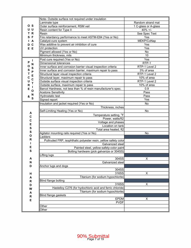
Note- Outside surface not required under insulationLaminate type Random strand matOuter surface reinforcement, RSM veil 1 C-glass or A-glassResin content for Type II 40% +/-Resin See Spec TextFire retardancy performance to meet ASTM-E84 (Yes or No) YesCatalyst-cure system MEKP/CoNapWax additive to prevent air inhibition of cure YesUV protection YesPigment allowed (Yes or No) NoMinimum thickness, mils 10
Post cure required (Yes or No) YesDimensional tolerances RTP-1Inner surface and corrosion barrier visual inspection criteria RTP-1 Level 2Inner surface and corrosion barrier, maximum repair to pass 3% of areaStructural layer visual inspection criteria RTP-1 Level 2Structural layer, maximum repair to pass 10% of areaOutside surface visual inspection criteria RTP-1 Level 2Outside surface, maximum repair to pass 10% of areaBarcol Hardness, not less than % of resin manufacturer's spec. 0.9Acetone Sensitivity PassHydrostatic test PassSigned report Yes
Insulation and jacket required (Yes or No) NoThickness, inches
Self-Limiting Heating (Yes or No) No
Temperature setting, oFPower, watts/ft2
Voltage and phasesLocation on tank
Total area heated, ft2Agitator mounting rails required (Yes or No) NoLadders
Pultruded FRP, isophthalic polyester resin, yellow safety colorGalvanized steel
Painted steel, yellow-safety-color paintBolting hardware (pick galvanize or 304SS)
Lifting lugs304SS X
Galvanized steelAnchor lugs and dogs
304SS316SS X
Titanium (for sodium hypochlorite)Blind flange bolting
316SS XHastelloy C276 (for hydochloric acid and ferric chloride)
Titanium (for sodium hypochlorite)Blind flange gaskets
EPDM XPVDF
OtherOther
ACCESSORIES AND HARDWARE
OUTSIDE
SURFACE
POSTCURE &
INSPECTIONS
Page 7 of 1990% Submittal

CDM Smith Inc.
Revisions By Date01234
Client Eastern Municipal Water District
Project Name
Wells 206, 207, 208, 209 Equipping and Centralized Treatment Facility
Location Moreno Valley, CAProject Number # 252125Tank Tag # TNK-8400Tank Name Sodium Bisulfite Storage TankTank location Chemical Storage FacilitySpecification Section Reference Section 13230P & ID Reference I-20Schedule buyer's inspection during fabrication (Yes or No) NoChemical/Fluid Name Sodium BisulfiteConcentration 38%pH 3.5 - 5.3Specific Gravity 1.33
Temperature, Maximum Operating, oF 115
Temperature, Minimum, oF 20
Vapor Pressure, mmHg at 77 oF (25 oC)Flashpoint, Closed Cup, oFOtherSnow loads
Ground snow load (Pg), psf 0Exposure Category N/A
Wind loadsBasic Wind Speed, mph 105
Exposure Category CSeismic loads
Site Class DMapped Spectral Response Accelerations Ss=1.656, S1=0.645.Design Spectral Response Accelerations Sds=1.104, SD1=0.731
Design Category DUplift load
Water depth in secondary containment, ft 2.5Live load on top head
4-in. x 4-in. area, pounds (see text for allowable deflection) 250Agitator loads (if applicable)
Impeller shaft bending moment, inch-pounds N/AAgitator reaction torque, inch-pounds N/A
Total agitator weight, pounds (components listed below) N/A-Gearbox, pounds N/A
-Motor, puonds N/A-Shaft, hub & impellers, pounds N/A
TANK TABLE 1 - 3 (Optional Bid Item No. 1)
GENERAL
CONTENTS
LOADS
Page 8 of 1990% Submittal

Design By RTP-1Fabricate By
RTP-1 XASTM D3299 and ASTM D4097
RTP-1 Certification Stamp Required (Yes or No) YesCB Excluded From Structural Calculations YesFire Retardant Structural Layer (Yes or No) YesFire Retardant Outside Surface (Yes or No) YesWall Thickness Taper With Height Allowed? NoDesign Positive Pressure, inches w.g.. (select)
Atmospheric (0)10-inches w.g.. (for vent extension w indoor tank) X
Design Negative Pressure (select)Atmospheric (0)
10-inches w.g. (for vent extension w indoor tank) XOtherVolume (To Overflow Flange), gal 300Diameter, Inches 48Straight Side (Including Freeboard), Inches 48Top
Dished XFlat
OpenBottom
Flat XSloped
Laminate Type (I= random strand mat, RSM) I, Hand lay-upResin See Spec TextResin content, inner surface 80 to 90%Resin content, inner layer 70 to 75%Catalyst-cure system (selection one)
(All tanks except sodium NaOCl) MEKP/CoNap X(NaOCl Tanks) BPO/DMA
Contact molding method Hand lay-upInner surface reinforcement, RSM veil (pick type)
(for acids and neutral chemical tanks) 2 C-glass X(special for alkalis & fluosilicic acid tanks) 2 polyester
(special for NaOCl tanks) 1 C-glass and 2 polyesterInner layer reinforcement, 1.5 oz/sq ft RSM ECR glassThickness, inner surfaces plus inner layer, mils (pick thickness)
100 mils X(special for alkalis, fluosilicic acid and NaOCl) 150 mils
Structural Layer (SL) ShellBedding layer between Corrosion Barrier and Structural Layer (1) 1.5 oz/sf RSMResin See Spec TextLaminate type (X= filament wound, II= random strand mat/woven rove)
X
Glass content for Type X 60% to 70%Resin content for Type II 35% to 45%Fire retardancy performance to meet ASTM-E84 (Yes or No) YesCatalyst-cure system MEKP/CoNapPigment allowed in SL NoMinimum thickness Per RTP-1Structural Layer Contact Molded Head, bottom and nozzles (SL)Laminate type (II= random strand mat/woven rove) IIResin and glass system Same as shell
DESIGN
TANK
GEOMETRY
CORROSION
BARRIER
STRUCTURAL
LAYER
Page 9 of 1990% Submittal
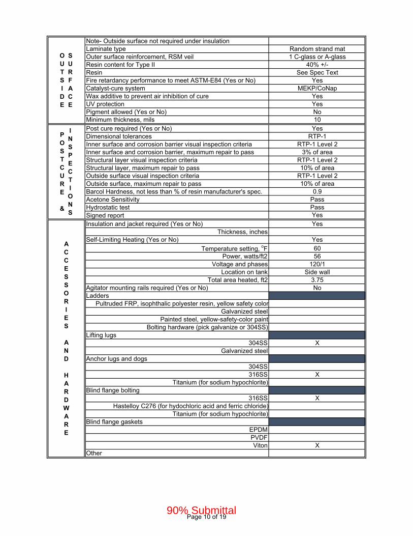
Note- Outside surface not required under insulationLaminate type Random strand matOuter surface reinforcement, RSM veil 1 C-glass or A-glassResin content for Type II 40% +/-Resin See Spec TextFire retardancy performance to meet ASTM-E84 (Yes or No) YesCatalyst-cure system MEKP/CoNapWax additive to prevent air inhibition of cure YesUV protection YesPigment allowed (Yes or No) NoMinimum thickness, mils 10
Post cure required (Yes or No) YesDimensional tolerances RTP-1Inner surface and corrosion barrier visual inspection criteria RTP-1 Level 2Inner surface and corrosion barrier, maximum repair to pass 3% of areaStructural layer visual inspection criteria RTP-1 Level 2Structural layer, maximum repair to pass 10% of areaOutside surface visual inspection criteria RTP-1 Level 2Outside surface, maximum repair to pass 10% of areaBarcol Hardness, not less than % of resin manufacturer's spec. 0.9Acetone Sensitivity PassHydrostatic test PassSigned report Yes
Insulation and jacket required (Yes or No) YesThickness, inches
Self-Limiting Heating (Yes or No) Yes
Temperature setting, oF 60Power, watts/ft2 56
Voltage and phases 120/1Location on tank Side wall
Total area heated, ft2 3.75Agitator mounting rails required (Yes or No) NoLadders
Pultruded FRP, isophthalic polyester resin, yellow safety colorGalvanized steel
Painted steel, yellow-safety-color paintBolting hardware (pick galvanize or 304SS)
Lifting lugs304SS X
Galvanized steelAnchor lugs and dogs
304SS316SS X
Titanium (for sodium hypochlorite)Blind flange bolting
316SS XHastelloy C276 (for hydochloric acid and ferric chloride)
Titanium (for sodium hypochlorite)Blind flange gaskets
EPDMPVDFViton X
Other
OUTSIDE
SURFACE
POSTCURE &
INSPECTIONS
ACCESSORIES AND HARDWARE
Page 10 of 1990% Submittal
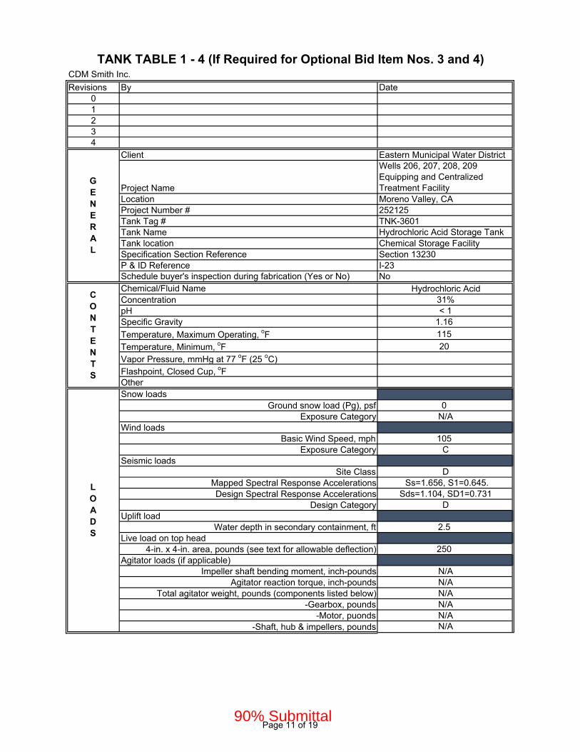
CDM Smith Inc.
Revisions By Date01234
Client Eastern Municipal Water District
Project Name
Wells 206, 207, 208, 209 Equipping and Centralized Treatment Facility
Location Moreno Valley, CAProject Number # 252125Tank Tag # TNK-3601Tank Name Hydrochloric Acid Storage TankTank location Chemical Storage FacilitySpecification Section Reference Section 13230P & ID Reference I-23Schedule buyer's inspection during fabrication (Yes or No) NoChemical/Fluid Name Hydrochloric AcidConcentration 31%pH < 1Specific Gravity 1.16
Temperature, Maximum Operating, oF 115
Temperature, Minimum, oF 20
Vapor Pressure, mmHg at 77 oF (25 oC)Flashpoint, Closed Cup, oFOtherSnow loads
Ground snow load (Pg), psf 0Exposure Category N/A
Wind loadsBasic Wind Speed, mph 105
Exposure Category CSeismic loads
Site Class DMapped Spectral Response Accelerations Ss=1.656, S1=0.645.Design Spectral Response Accelerations Sds=1.104, SD1=0.731
Design Category DUplift load
Water depth in secondary containment, ft 2.5Live load on top head
4-in. x 4-in. area, pounds (see text for allowable deflection) 250Agitator loads (if applicable)
Impeller shaft bending moment, inch-pounds N/AAgitator reaction torque, inch-pounds N/A
Total agitator weight, pounds (components listed below) N/A-Gearbox, pounds N/A
-Motor, puonds N/A-Shaft, hub & impellers, pounds N/A
TANK TABLE 1 - 4 (If Required for Optional Bid Item Nos. 3 and 4)
GENERAL
CONTENTS
LOADS
Page 11 of 1990% Submittal

Design By RTP-1Fabricate By
RTP-1 XASTM D3299 and ASTM D4097
RTP-1 Certification Stamp Required (Yes or No) YesCB Excluded From Structural Calculations YesFire Retardant Structural Layer (Yes or No) YesFire Retardant Outside Surface (Yes or No) YesWall Thickness Taper With Height Allowed? NoDesign Positive Pressure, inches w.g.. (select)
Atmospheric (0)10-inches w.g.. (for vent extension w indoor tank) X
Design Negative Pressure (select)Atmospheric (0)
10-inches w.g. (for vent extension w indoor tank) XOtherVolume (To Overflow Flange), gal 300Diameter, Inches 48Straight Side (Including Freeboard), Inches 48Top
Dished XFlat
OpenBottom
Flat XSloped
Laminate Type (I= random strand mat, RSM) I, Hand lay-upResin See Spec TextResin content, inner surface 80 to 90%Resin content, inner layer 70 to 75%Catalyst-cure system (selection one)
(All tanks except sodium NaOCl) MEKP/CoNap X(NaOCl Tanks) BPO/DMA
Contact molding method Hand lay-upInner surface reinforcement, RSM veil (pick type)
(for acids and neutral chemical tanks) 2 C-glass X(special for alkalis & fluosilicic acid tanks) 2 polyester
(special for NaOCl tanks) 1 C-glass and 2 polyesterInner layer reinforcement, 1.5 oz/sq ft RSM ECR glassThickness, inner surfaces plus inner layer, mils (pick thickness)
100 mils X(special for alkalis, fluosilicic acid and NaOCl) 150 mils
Structural Layer (SL) ShellBedding layer between Corrosion Barrier and Structural Layer (1) 1.5 oz/sf RSMResin See Spec TextLaminate type (X= filament wound, II= random strand mat/woven rove)
X
Glass content for Type X 60% to 70%Resin content for Type II 35% to 45%Fire retardancy performance to meet ASTM-E84 (Yes or No) YesCatalyst-cure system MEKP/CoNapPigment allowed in SL NoMinimum thickness Per RTP-1Structural Layer Contact Molded Head, bottom and nozzles (SL)Laminate type (II= random strand mat/woven rove) IIResin and glass system Same as shell
DESIGN
TANK
GEOMETRY
CORROSION
BARRIER
STRUCTURAL
LAYER
Page 12 of 1990% Submittal

Note- Outside surface not required under insulationLaminate type Random strand matOuter surface reinforcement, RSM veil 1 C-glass or A-glassResin content for Type II 40% +/-Resin See Spec TextFire retardancy performance to meet ASTM-E84 (Yes or No) YesCatalyst-cure system MEKP/CoNapWax additive to prevent air inhibition of cure YesUV protection YesPigment allowed (Yes or No) NoMinimum thickness, mils 10
Post cure required (Yes or No) YesDimensional tolerances RTP-1Inner surface and corrosion barrier visual inspection criteria RTP-1 Level 2Inner surface and corrosion barrier, maximum repair to pass 3% of areaStructural layer visual inspection criteria RTP-1 Level 2Structural layer, maximum repair to pass 10% of areaOutside surface visual inspection criteria RTP-1 Level 2Outside surface, maximum repair to pass 10% of areaBarcol Hardness, not less than % of resin manufacturer's spec. 0.9Acetone Sensitivity PassHydrostatic test PassSigned report Yes
Insulation and jacket required (Yes or No) NoThickness, inches
Self-Limiting Heating (Yes or No) No
Temperature setting, oFPower, watts/ft2
Voltage and phasesLocation on tank
Total area heated, ft2Agitator mounting rails required (Yes or No) NoLadders
Pultruded FRP, isophthalic polyester resin, yellow safety colorGalvanized steel
Painted steel, yellow-safety-color paintBolting hardware (pick galvanize or 304SS)
Lifting lugs304SS X
Galvanized steelAnchor lugs and dogs
304SS316SS X
Titanium (for sodium hypochlorite)Blind flange bolting
316SSHastelloy C276 (for hydochloric acid and ferric chloride) X
Titanium (for sodium hypochlorite)Blind flange gaskets
EPDMPVDFViton X
Other
OUTSIDE
SURFACE
POSTCURE &
INSPECTIONS
ACCESSORIES AND HARDWARE
Page 13 of 1990% Submittal
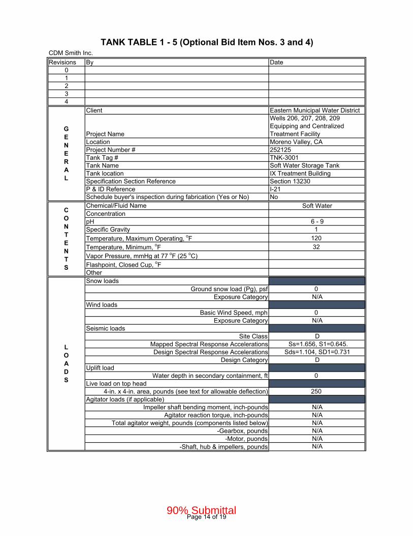
CDM Smith Inc.
Revisions By Date01234
Client Eastern Municipal Water District
Project Name
Wells 206, 207, 208, 209 Equipping and Centralized Treatment Facility
Location Moreno Valley, CAProject Number # 252125Tank Tag # TNK-3001Tank Name Soft Water Storage TankTank location IX Treatment BuildingSpecification Section Reference Section 13230P & ID Reference I-21Schedule buyer's inspection during fabrication (Yes or No) NoChemical/Fluid Name Soft WaterConcentrationpH 6 - 9Specific Gravity 1
Temperature, Maximum Operating, oF 120
Temperature, Minimum, oF 32
Vapor Pressure, mmHg at 77 oF (25 oC)Flashpoint, Closed Cup, oFOtherSnow loads
Ground snow load (Pg), psf 0Exposure Category N/A
Wind loadsBasic Wind Speed, mph 0
Exposure Category N/ASeismic loads
Site Class DMapped Spectral Response Accelerations Ss=1.656, S1=0.645.Design Spectral Response Accelerations Sds=1.104, SD1=0.731
Design Category DUplift load
Water depth in secondary containment, ft 0Live load on top head
4-in. x 4-in. area, pounds (see text for allowable deflection) 250Agitator loads (if applicable)
Impeller shaft bending moment, inch-pounds N/AAgitator reaction torque, inch-pounds N/A
Total agitator weight, pounds (components listed below) N/A-Gearbox, pounds N/A
-Motor, puonds N/A-Shaft, hub & impellers, pounds N/A
TANK TABLE 1 - 5 (Optional Bid Item Nos. 3 and 4)
GENERAL
CONTENTS
LOADS
Page 14 of 1990% Submittal

Design By ASTM D3299Fabricate By
RTP-1ASTM D3299 and ASTM D4097 X
RTP-1 Certification Stamp Required (Yes or No) NoCB Excluded From Structural Calculations YesFire Retardant Structural Layer (Yes or No) YesFire Retardant Outside Surface (Yes or No) YesWall Thickness Taper With Height Allowed? NoDesign Positive Pressure, inches w.g.. (select)
Atmospheric (0) X10-inches w.g.. (for vent extension w indoor tank)
Design Negative Pressure (select)Atmospheric (0) X
10-inches w.g. (for vent extension w indoor tank)OtherVolume (To Overflow Flange), gal 2945Diameter, Inches 96Straight Side (Including Freeboard), Inches 102Top
Dished XFlat
OpenBottom
Flat XSloped
Laminate Type (I= random strand mat, RSM) I, Hand lay-upResin See Spec TextResin content, inner surface 80 to 90%Resin content, inner layer 70 to 75%Catalyst-cure system (selection one)
(All tanks except sodium NaOCl) MEKP/CoNap X(NaOCl Tanks) BPO/DMA
Contact molding method Hand lay-upInner surface reinforcement, RSM veil (pick type)
(for acids and neutral chemical tanks) 2 C-glass X(special for alkalis & fluosilicic acid tanks) 2 polyester
(special for NaOCl tanks) 1 C-glass and 2 polyesterInner layer reinforcement, 1.5 oz/sq ft RSM E glassThickness, inner surfaces plus inner layer, mils (pick thickness)
100 mils X(special for alkalis, fluosilicic acid and NaOCl) 150 mils
Structural Layer (SL) ShellBedding layer between Corrosion Barrier and Structural Layer (1) 1.5 oz/sf RSMResin See Spec TextLaminate type (X= filament wound, II= random strand mat/woven rove)
X
Glass content for Type X 60% to 70%Resin content for Type II 35% to 45%Fire retardancy performance to meet ASTM-E84 (Yes or No) YesCatalyst-cure system MEKP/CoNapPigment allowed in SL NoMinimum thickness Per ASTM D3299Structural Layer Contact Molded Head, bottom and nozzles (SL)Laminate type (II= random strand mat/woven rove) IIResin and glass system Same as shell
DESIGN
TANK
GEOMETRY
CORROSION
BARRIER
STRUCTURAL
LAYER
Page 15 of 1990% Submittal

Note- Outside surface not required under insulationLaminate type Random strand matOuter surface reinforcement, RSM veil 1 C-glass or A-glassResin content for Type II 40% +/-Resin See Spec TextFire retardancy performance to meet ASTM-E84 (Yes or No) YesCatalyst-cure system MEKP/CoNapWax additive to prevent air inhibition of cure YesUV protection NoPigment allowed (Yes or No) NoMinimum thickness, mils 10
Post cure required (Yes or No) YesDimensional tolerances ASTM D3299Inner surface and corrosion barrier visual inspection criteria ASTM C582Inner surface and corrosion barrier, maximum repair to pass 5% of areaStructural layer visual inspection criteria ASTM C582Structural layer, maximum repair to pass 5% of areaOutside surface visual inspection criteria ASTM C582Outside surface, maximum repair to pass 5% of areaBarcol Hardness, not less than % of resin manufacturer's spec. 0.9Acetone Sensitivity PassHydrostatic test PassSigned report Yes
Insulation and jacket required (Yes or No) NoThickness, inches
Self-Limiting Heating (Yes or No) No
Temperature setting, oFPower, watts/ft2
Voltage and phasesLocation on tank
Total area heated, ft2Agitator mounting rails required (Yes or No) NoLadders
Pultruded FRP, isophthalic polyester resin, yellow safety color XGalvanized steel
Painted steel, yellow-safety-color paintBolting hardware (pick galvanize or 304SS) Galvanized
Lifting lugs304SS X
Galvanized steelAnchor lugs and dogs
304SS316SS X
Titanium (for sodium hypochlorite)Blind flange bolting
316SS XHastelloy C276 (for hydochloric acid and ferric chloride)
Titanium (for sodium hypochlorite)Blind flange gaskets
EPDM XPVDF
OtherOther
OUTSIDE
SURFACE
POSTCURE &
INSPECTIONS
ACCESSORIES AND HARDWARE
Page 16 of 1990% Submittal

CDM Smith Inc.
Revisions By Date01234
Client Eastern Municipal Water District
Project Name
Wells 206, 207, 208, 209 Equipping and Centralized Treatment Facility
Location Moreno Valley, CAProject Number # 252125
Tank Tag #TNK-3801, TNK-3802, TNK-3803, TNK-3804
Tank Name IX Waste Brine Holding TankTank location YardSpecification Section Reference Section 13230P & ID Reference I-24Schedule buyer's inspection during fabrication (Yes or No) NoChemical/Fluid Name Salt BrineConcentrationpH 6 - 9Specific Gravity 1.2
Temperature, Maximum Operating, oF 115
Temperature, Minimum, oF 20
Vapor Pressure, mmHg at 77 oF (25 oC)Flashpoint, Closed Cup, oFOtherSnow loads
Ground snow load (Pg), psf 0Exposure Category N/A
Wind loadsBasic Wind Speed, mph 0
Exposure Category N/ASeismic loads
Site Class DMapped Spectral Response Accelerations Ss=1.656, S1=0.645.Design Spectral Response Accelerations Sds=1.104, SD1=0.731
Design Category DUplift load
Water depth in secondary containment, ft 0Live load on top head
4-in. x 4-in. area, pounds (see text for allowable deflection) 250Agitator loads (if applicable)
Impeller shaft bending moment, inch-pounds N/AAgitator reaction torque, inch-pounds N/A
Total agitator weight, pounds (components listed below) N/A-Gearbox, pounds N/A
-Motor, puonds N/A-Shaft, hub & impellers, pounds N/A
TANK TABLE 1 - 6 (Optional Bid Item Nos. 3 and 4)
GENERAL
CONTENTS
LOADS
Page 17 of 1990% Submittal

Design By ASTM D3299Fabricate By
RTP-1ASTM D3299 and ASTM D4097 X
RTP-1 Certification Stamp Required (Yes or No) NoCB Excluded From Structural Calculations YesFire Retardant Structural Layer (Yes or No) YesFire Retardant Outside Surface (Yes or No) YesWall Thickness Taper With Height Allowed? NoDesign Positive Pressure, inches w.g.. (select)
Atmospheric (0) X10-inches w.g.. (for vent extension w indoor tank)
Design Negative Pressure (select)Atmospheric (0) X
10-inches w.g. (for vent extension w indoor tank)OtherVolume (To Overflow Flange), gal 13180Diameter, Inches 144Straight Side (Including Freeboard), Inches 195Top
Dished XFlat
OpenBottom
Flat XSloped
Laminate Type (I= random strand mat, RSM) I, Hand lay-upResin See Spec TextResin content, inner surface 80 to 90%Resin content, inner layer 70 to 75%Catalyst-cure system (selection one)
(All tanks except sodium NaOCl) MEKP/CoNap X(NaOCl Tanks) BPO/DMA
Contact molding method Hand lay-upInner surface reinforcement, RSM veil (pick type)
(for acids and neutral chemical tanks) 2 C-glass X(special for alkalis & fluosilicic acid tanks) 2 polyester
(special for NaOCl tanks) 1 C-glass and 2 polyesterInner layer reinforcement, 1.5 oz/sq ft RSM E glassThickness, inner surfaces plus inner layer, mils (pick thickness)
100 mils X(special for alkalis, fluosilicic acid and NaOCl) 150 mils
Structural Layer (SL) ShellBedding layer between Corrosion Barrier and Structural Layer (1) 1.5 oz/sf RSMResin See Spec TextLaminate type (X= filament wound, II= random strand mat/woven rove)
X
Glass content for Type X 60% to 70%Resin content for Type II 35% to 45%Fire retardancy performance to meet ASTM-E84 (Yes or No) YesCatalyst-cure system MEKP/CoNapPigment allowed in SL NoMinimum thickness Per ASTM D3299Structural Layer Contact Molded Head, bottom and nozzles (SL)Laminate type (II= random strand mat/woven rove) IIResin and glass system Same as shell
STRUCTURAL
LAYER
DESIGN
TANK
GEOMETRY
CORROSION
BARRIER
Page 18 of 1990% Submittal
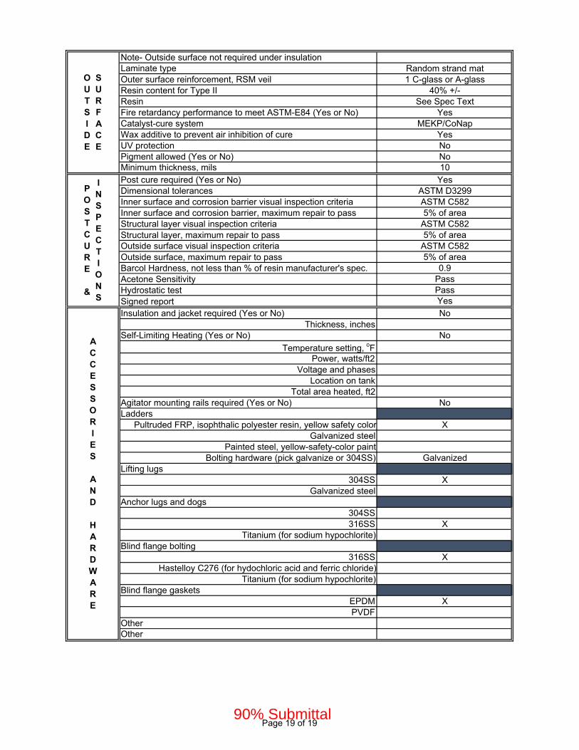
Note- Outside surface not required under insulationLaminate type Random strand matOuter surface reinforcement, RSM veil 1 C-glass or A-glassResin content for Type II 40% +/-Resin See Spec TextFire retardancy performance to meet ASTM-E84 (Yes or No) YesCatalyst-cure system MEKP/CoNapWax additive to prevent air inhibition of cure YesUV protection NoPigment allowed (Yes or No) NoMinimum thickness, mils 10
Post cure required (Yes or No) YesDimensional tolerances ASTM D3299Inner surface and corrosion barrier visual inspection criteria ASTM C582Inner surface and corrosion barrier, maximum repair to pass 5% of areaStructural layer visual inspection criteria ASTM C582Structural layer, maximum repair to pass 5% of areaOutside surface visual inspection criteria ASTM C582Outside surface, maximum repair to pass 5% of areaBarcol Hardness, not less than % of resin manufacturer's spec. 0.9Acetone Sensitivity PassHydrostatic test PassSigned report Yes
Insulation and jacket required (Yes or No) NoThickness, inches
Self-Limiting Heating (Yes or No) No
Temperature setting, oFPower, watts/ft2
Voltage and phasesLocation on tank
Total area heated, ft2Agitator mounting rails required (Yes or No) NoLadders
Pultruded FRP, isophthalic polyester resin, yellow safety color XGalvanized steel
Painted steel, yellow-safety-color paintBolting hardware (pick galvanize or 304SS) Galvanized
Lifting lugs304SS X
Galvanized steelAnchor lugs and dogs
304SS316SS X
Titanium (for sodium hypochlorite)Blind flange bolting
316SS XHastelloy C276 (for hydochloric acid and ferric chloride)
Titanium (for sodium hypochlorite)Blind flange gaskets
EPDM XPVDF
OtherOther
OUTSIDE
SURFACE
POSTCURE &
INSPECTIONS
ACCESSORIES AND HARDWARE
Page 19 of 1990% Submittal

© 2020 CDM Smith 26793-252125
All Rights Reserved May 4, 2021
EMWD Metal Building Systems
Final Design of Cactus Corridor Facilities 13341 - 1
90% Submittal
SECTION 13341 - METAL BUILDING SYSTEMS
PART 1 - GENERAL
1.1 RELATED DOCUMENTS
A. Drawings and general provisions of the Contract, including General and Supplementary
Conditions and Division 01 Specification Sections, apply to this Section.
1.2 SUMMARY
A. Section Includes:
1. Structural-steel framing.
2. Metal roof panels.
3. Metal wall panels.
4. Accessories.
B. Related Requirements:
1. Section 05502 "Metal Fabrications" for miscellaneous metal and accessories.
2. Section 07412 "Standing Seam Metal Roof Panels" for metal roofing.
1.3 DEFINITIONS
A. Terminology Standard: See MBMA's "Metal Building Systems Manual" for definitions of terms
for metal building system construction not otherwise defined in this Section or in standards
referenced by this Section.
1.4 COORDINATION
A. Coordinate sizes and locations of concrete foundations and casting of anchor-rod inserts into
foundation walls and footings. Anchor rod installation, concrete, reinforcement, and formwork
requirements are specified in Section 03300 "Cast-in-Place Concrete."
B. Coordinate metal panel assemblies with rain drainage work, flashing, trim, and construction of
supports and other adjoining work to provide a leakproof, secure, and noncorrosive installation.
1.5 PREINSTALLATION MEETINGS
A. Preinstallation Conference: Conduct conference at Project site.
1. Review methods and procedures related to metal building systems including, but not
limited to, the following:
90% Submittal
© 2020 CDM Smith 26793-252125
All Rights Reserved May 4, 2021
EMWD Metal Building Systems
Final Design of Cactus Corridor Facilities 13341 - 2
90% Submittal
a. Condition of foundations and other preparatory work performed by other trades.
b. Structural load limitations.
c. Construction schedule. Verify availability of materials and erector's personnel,
equipment, and facilities needed to make progress and avoid delays.
d. Required tests, inspections, and certifications.
e. Unfavorable weather and forecasted weather conditions and impact on
construction schedule.
2. Review methods and procedures related to metal roof panel assemblies including, but not
limited to, the following:
a. Compliance with requirements for purlin and rafter conditions, including flatness
and attachment to structural members.
b. Structural limitations of purlins and rafters during and after roofing.
c. Flashings, special roof details, roof drainage, roof penetrations, equipment curbs,
and condition of other construction that will affect metal roof panels.
d. Temporary protection requirements for metal roof panel assembly during and after
installation.
e. Roof observation and repair after metal roof panel installation.
3. Review methods and procedures related to metal wall panel assemblies including, but not
limited to, the following:
a. Compliance with requirements for support conditions, including alignment
between and attachment to structural members.
b. Structural limitations of girts and columns during and after wall panel installation.
c. Flashings, special siding details, wall penetrations, openings, and condition of
other construction that will affect metal wall panels.
d. Temporary protection requirements for metal wall panel assembly during and after
installation.
e. Wall observation and repair after metal wall panel installation.
1.6 ACTION SUBMITTALS
A. Product Data: For each type of metal building system component.
1. Include construction details, material descriptions, dimensions of individual components
and profiles, and finishes for the following:
a. Metal roof panels.
b. Metal wall panels.
B. Shop Drawings: Indicate components by others. Include full building plan, elevations, sections,
details and the following:
1. Anchor-Rod Plans: Submit anchor-rod plans and templates before foundation work
begins. Include location, diameter, and minimum required projection of anchor rods
required to attach metal building to foundation. Indicate column reactions at each
location.
90% Submittal

© 2020 CDM Smith 26793-252125
All Rights Reserved May 4, 2021
EMWD Metal Building Systems
Final Design of Cactus Corridor Facilities 13341 - 3
90% Submittal
2. Structural-Framing Drawings: Show complete fabrication of primary and secondary
framing; include provisions for openings. Indicate welds and bolted connections,
distinguishing between shop and field applications. Include transverse cross-sections.
3. Metal Roof and Wall Panel Layout Drawings: Show layouts of panels including methods
of support. Include details of edge conditions, joints, panel profiles, corners, anchorages,
clip spacing, trim, flashings, closures, and special details. Distinguish between factory-
and field-assembled work; show locations of exposed fasteners.
a. Show roof-mounted items including roof hatches, equipment supports, pipe
supports and penetrations, lighting fixtures, and items mounted on roof curbs.
b. Show wall-mounted items including personnel doors, vehicular doors, windows,
louvers, and lighting fixtures.
c. Show translucent panels.
4. Accessory Drawings: Include details of the following items, at a scale of not less than 1-
1/2 inches per 12 inches:
a. Flashing and trim.
b. Gutters.
c. Downspouts.
C. Samples for Initial Selection: For units with factory-applied finishes.
1.7 DELEGATED-DESIGN SUBMITTALS
A. For metal building systems.
1. Include analysis data indicating compliance with performance requirements and design
data signed and sealed by the qualified professional engineer responsible for their
preparation.
1.8 INFORMATIONAL SUBMITTALS
A. Qualification Data: For erector manufacturer.
B. Welding certificates.
C. Letter of Design Certification: Signed and sealed by a qualified professional engineer. Include
the following:
1. Name and location of Project.
2. Order number.
3. Name of manufacturer.
4. Name of Contractor.
5. Building dimensions including width, length, height, and roof slope.
6. Indicate compliance with AISC standards for hot-rolled steel and AISI standards for cold-
rolled steel, including edition dates of each standard.
7. Governing building code and year of edition.
90% Submittal
© 2020 CDM Smith 26793-252125
All Rights Reserved May 4, 2021
EMWD Metal Building Systems
Final Design of Cactus Corridor Facilities 13341 - 4
90% Submittal
8. Design Loads: Include dead load, roof live load, collateral loads, roof snow load,
deflection, wind loads/speeds and exposure, seismic design category or effective peak
velocity-related acceleration/peak acceleration, and auxiliary loads (cranes).
9. Load Combinations: Indicate that loads were applied acting simultaneously with
concentrated loads, according to governing building code.
10. Building-Use Category: Indicate category of building use and its effect on load
importance factors.
D. Erector Certificates: For qualified erector, from manufacturer.
E. Material Test Reports: For each of the following products:
1. Structural steel including chemical and physical properties.
2. Bolts, nuts, and washers including mechanical properties and chemical analysis.
3. Tension-control, high-strength, bolt-nut-washer assemblies.
4. Shop primers.
5. Nonshrink grout.
F. Source quality-control reports.
G. Field quality-control reports.
H. Surveys: Show final elevations and locations of major members. Indicate discrepancies between
actual installation and the Contract Documents. Have surveyor who performed surveys certify
their accuracy.
I. Sample Warranties: For special warranties.
1.9 CLOSEOUT SUBMITTALS
A. Maintenance Data: For metal panel finishes to include in maintenance manuals.
1.10 QUALITY ASSURANCE
A. Manufacturer Qualifications: A qualified manufacturer.
1. Accreditation: Manufacturer's facility accredited according to the International
Accreditation Service's AC472, "Accreditation Criteria for Inspection Programs for
Manufacturers of Metal Building Systems."
2. Engineering Responsibility: Preparation of comprehensive engineering analysis and Shop
Drawings by a professional engineer who is legally qualified to practice in jurisdiction
where Project is located.
B. Erector Qualifications: An experienced erector who specializes in erecting and installing work
similar in material, design, and extent to that indicated for this Project and who is acceptable to
manufacturer.
C. Welding Qualifications: Qualify procedures and personnel according to the following:
1. AWS D1.1/D1.1M, "Structural Welding Code - Steel."
90% Submittal
© 2020 CDM Smith 26793-252125
All Rights Reserved May 4, 2021
EMWD Metal Building Systems
Final Design of Cactus Corridor Facilities 13341 - 5
90% Submittal
2. AWS D1.3, "Structural Welding Code - Sheet Steel."
D. Land Surveyor Qualifications: A professional land surveyor who practices in jurisdiction where
Project is located and who is experienced in providing surveying services of the kind indicated.
1.11 DELIVERY, STORAGE, AND HANDLING
A. Deliver components, sheets, panels, and other manufactured items so as not to be damaged or
deformed. Package metal panels for protection during transportation and handling.
B. Unload, store, and erect metal panels in a manner to prevent bending, warping, twisting, and
surface damage.
C. Stack metal panels horizontally on platforms or pallets, covered with suitable weathertight and
ventilated covering. Store metal panels to ensure dryness, with positive slope for drainage of
water. Do not store metal panels in contact with other materials that might cause staining,
denting, or other surface damage.
1.12 FIELD CONDITIONS
A. Weather Limitations: Proceed with panel installation only when weather conditions permit
metal panels to be installed according to manufacturers' written instructions and warranty
requirements.
1.13 WARRANTY
A. Special Warranty on Metal Panel Finishes: Manufacturer agrees to repair finish or replace metal
panels that show evidence of deterioration of factory-applied finishes within specified warranty
period.
1. Exposed Panel Finish: Deterioration includes, but is not limited to, the following:
a. Color fading more than 5 Hunter units when tested according to ASTM D2244.
b. Chalking in excess of a No. 8 rating when tested according to ASTM D4214.
c. Cracking, checking, peeling, or failure of paint to adhere to bare metal.
2. Finish Warranty Period: 20 years from date of Substantial Completion.
B. Special Weathertightness Warranty for Standing-Seam Metal Roof Panels: Manufacturer agrees
to repair or replace standing-seam metal roof panel assemblies that leak or otherwise fail to
remain weathertight within specified warranty period.
1. Warranty Period: 20 years from date of Substantial Completion.
90% Submittal
© 2020 CDM Smith 26793-252125
All Rights Reserved May 4, 2021
EMWD Metal Building Systems
Final Design of Cactus Corridor Facilities 13341 - 6
90% Submittal
PART 2 - PRODUCTS
2.1 MANUFACTURERS
A. Manufacturers: Subject to compliance with requirements, provide products by one of the
following, or approved equal:
1. Butler Manufacturing Company; a division of BlueScope Buildings North America, Inc.
2. Nucor Corporation, Nucor Buildings Group.
3. Varco-Pruden Buildings; a division of BlueScope Buildings North America, Inc.
4. Vulcan Steel Structures, Inc.
B. Source Limitations: Obtain metal building system components, including primary and
secondary framing and metal panel assemblies, from single source from single manufacturer.
2.2 SYSTEM DESCRIPTION
A. Provide a complete, integrated set of mutually dependent components and assemblies that form
a metal canopy system capable of withstanding structural and other loads, thermally induced
movement, and exposure to weather without failure or infiltration of water into building
interior.
B. Primary-Frame Type:
1. Rigid Clear Span: Solid-member, structural-framing system without interior columns.
2. Rigid Modular: Solid-member, structural-framing system with interior columns.
3. Truss-Frame Clear Span: Truss-member, structural-framing system without interior
columns.
4. Truss-Frame Modular: Truss-member, structural-framing system with interior columns.
5. Lean-to: Solid- or truss-member, structural-framing system, designed to be partially
supported by another structure.
C. End-Wall Framing: Engineer end walls to be expandable. Provide primary frame, capable of
supporting full-bay design loads, and no end-wall columns.
D. Eave Height: Minimum height as indicated by nominal height on Drawings, with maximum
height of structure not to exceed height indicated on Drawings..
E. Bay Spacing: As indicated on Drawings.
F. Roof Slope: 4 inches per 12 inches.
G. Roof System: Manufacturer's standard standing-seam, vertical-rib, metal roof panels. Match
building metal roofs per Specification 07412, Standing Seam Metal Roof Panels.
H. Fire-rated Wall System: Manufacturer's standard concealed-fastener, flush-profile, foamed-
insulation-core metal wall panels.
90% Submittal

© 2020 CDM Smith 26793-252125
All Rights Reserved May 4, 2021
EMWD Metal Building Systems
Final Design of Cactus Corridor Facilities 13341 - 7
90% Submittal
2.3 PERFORMANCE REQUIREMENTS
A. Delegated Design: Engage a qualified professional engineer, as defined in Section 01400
"Quality Requirements," to design metal building system.
B. Structural Performance: Metal building systems shall withstand the effects of gravity loads and
the following loads and stresses within limits and under conditions indicated according to
procedures in MBMA's "Metal Building Systems Manual."
1. Design Loads: As indicated on Drawings.
2. Deflection and Drift Limits: Design metal building system assemblies to withstand
serviceability design loads without exceeding deflections and drift limits recommended in
AISC Steel Design Guide No. 3 "Serviceability Design Considerations for Steel
Buildings."
3. Deflection and Drift Limits: No greater than the following:
a. Purlins and Rafters: Vertical deflection of 1/240 of the span.
b. Girts: Horizontal deflection of 1/240 of the span.
c. Metal Roof Panels: Vertical deflection of 1/360 of the span.
d. Metal Wall Panels: Horizontal deflection of 1/180 of the span.
e. Design secondary-framing system to accommodate deflection of primary framing
and construction tolerances, and to maintain clearances at openings.
f. Lateral Drift: Maximum of 1/200 of the building height.
C. Seismic Performance: Metal building system shall withstand the effects of earthquake motions
determined according to ASCE/SEI 7. See Section 01882 for additional design criteria.
D. Thermal Movements: Allow for thermal movements from ambient and surface temperature
changes by preventing buckling, opening of joints, overstressing of components, failure of joint
sealants, failure of connections, and other detrimental effects. Base calculations on surface
temperatures of materials due to both solar heat gain and nighttime-sky heat loss.
1. Temperature Change: 120 deg F, ambient; 180 deg F, material surfaces.
E. Fire-Resistance Ratings: Where assemblies are indicated to have a fire-resistance rating, provide
metal panel assemblies identical to those of assemblies tested for fire resistance per
ASTM E119 or ASTM E108 by a qualified testing agency. Identify products with appropriate
markings of applicable testing agency.
1. Indicate design designations from UL's "Fire Resistance Directory," FM Global's
"Approval Guide," or from the listings of another qualified testing agency.
F. Fire Propagation Characteristics: Exterior wall assemblies containing foam plastics pass
NFPA 285 fire test.
G. Structural Performance for Metal Roof and Wall Panels: Provide metal panel systems capable
of withstanding the effects of the following loads, based on testing according to ASTM E1592:
1. Wind Loads: As indicated on Drawings and as provided in Section 01882.
90% Submittal
© 2020 CDM Smith 26793-252125
All Rights Reserved May 4, 2021
EMWD Metal Building Systems
Final Design of Cactus Corridor Facilities 13341 - 8
90% Submittal
H. Water Penetration for Metal Roof Panels: No water penetration when tested according to
ASTM E1646 at the following test-pressure difference:
1. Test-Pressure Difference: 2.86 lbf/sq. ft..
I. Wind-Uplift Resistance: Provide metal roof panel assemblies that comply with UL 580 for
wind-uplift-resistance class indicated.
1. Uplift Rating: UL 90.
J. FM Global Listing: Provide metal roof panels and component materials that comply with
requirements in FM Global 4471 as part of a panel roofing system and that are listed in FM
Global's "Approval Guide" for Class 1 or noncombustible construction, as applicable. Identify
materials with FM Global markings.
1. Fire/Windstorm Classification: Class 1A- 90.
2. Hail Resistance: MH.
K. Energy Star Listing: Roof panels that are listed on the DOE's ENERGY STAR "Roof Products
Qualified Product List" for steep-slope roof products.
L. Energy Performance: Provide roof panels according to one of the following when tested
according to CRRC-1:
1. Three-year, aged, solar reflectance of not less than 0.55 and emissivity of not less than
0.75.
2. Three-year, aged, Solar Reflectance Index of not less than 64 when calculated according
to ASTM E1980.
2.4 STRUCTURAL-STEEL FRAMING
A. Structural Steel: Comply with AISC 360, "Specification for Structural Steel Buildings."
B. Bolted Connections: Comply with RCSC's "Specification for Structural Joints Using High-
Strength Bolts."
C. Cold-Formed Steel: Comply with AISI's "North American Specification for the Design of Cold-
Formed Steel Structural Members" for design requirements and allowable stresses.
D. Primary Framing: Manufacturer's standard primary-framing system, designed to withstand
required loads and specified requirements. Primary framing includes transverse and lean-to
frames; rafters, rake, and canopy beams; sidewall, intermediate, end-wall, and corner columns;
and wind bracing.
1. General: Provide frames with attachment plates, bearing plates, and splice members.
Factory drill for field-bolted assembly. Provide frame span and spacing indicated.
a. Slight variations in span and spacing may be acceptable if necessary to comply
with manufacturer's standard, as approved by Engineer.
90% Submittal

© 2020 CDM Smith 26793-252125
All Rights Reserved May 4, 2021
EMWD Metal Building Systems
Final Design of Cactus Corridor Facilities 13341 - 9
90% Submittal
2. Rigid Clear-Span Frames: I-shaped frame sections fabricated from shop-welded, built-up
steel plates or structural-steel shapes. Interior columns are not permitted.
3. Rigid Modular Frames: I-shaped frame sections fabricated from shop-welded, built-up
steel plates or structural-steel shapes. Provide interior columns fabricated from round
steel pipes or tubes, or shop-welded, built-up steel plates.
4. Truss-Frame, Clear-Span Frames: Rafter frames fabricated from joist girders, and I-
shaped column sections fabricated from shop-welded, built-up steel plates or structural-
steel shapes. Interior columns are not permitted.
5. Frame Configuration: Single gable.
6. Exterior Column: Uniform depth.
7. Rafter: Uniform depth or Tapered.
E. End-Wall Framing: Manufacturer's standard primary end-wall framing fabricated for field-
bolted assembly to comply with the following:
1. End-Wall and Corner Columns: I-shaped sections fabricated from structural-steel shapes;
shop-welded or built-up steel plate.
F. Secondary Framing: Manufacturer's standard secondary framing, including purlins, girts, eave
struts, flange bracing, base members, gable angles, clips, headers, jambs, and other
miscellaneous structural members. Unless otherwise indicated, fabricate framing from either
cold-formed, structural-steel sheet or roll-formed, metallic-coated steel sheet, prepainted with
coil coating, to comply with the following:
1. Purlins: C- or Z-shaped sections; fabricated from built-up steel plates, steel sheet, or
structural-steel shapes; minimum 2-1/2-inch-wide flanges.
a. Depth: As needed to comply with system performance requirements.
2. Purlins: Steel joists of depths indicated on Drawings.
3. Girts: C- or Z-shaped sections; fabricated from built-up steel plates, steel sheet, or
structural-steel shapes. Form ends of Z-sections with stiffening lips angled 40 to 50
degrees from flange, with minimum 2-1/2-inch-wide flanges.
a. Depth: As required to comply with system performance requirements.
4. Eave Struts: Unequal-flange, C-shaped sections; fabricated from built-up steel plates,
steel sheet, or structural-steel shapes; to provide adequate backup for metal panels.
5. Flange Bracing: Minimum 2-by-2-by-1/8-inch structural-steel angles or 1-inch-diameter,
cold-formed structural tubing to stiffen primary-frame flanges.
6. Sag Bracing: Minimum 1-by-1-by-1/8-inch structural-steel angles.
7. Base or Sill Angles: Manufacturer's standard base angle, minimum 3-by-2-inch,
fabricated from zinc-coated (galvanized) steel sheet.
8. Purlin and Girt Clips: Manufacturer's standard clips fabricated from steel sheet. Provide
galvanized clips where clips are connected to galvanized framing members.
9. Framing for Openings: Channel shapes; fabricated from cold-formed, structural-steel
sheet or structural-steel shapes. Frame head and jamb of door openings and head, jamb,
and sill of other openings.
10. Miscellaneous Structural Members: Manufacturer's standard sections fabricated from
cold-formed, structural-steel sheet; built-up steel plates; or zinc-coated (galvanized) steel
sheet; designed to withstand required loads.
90% Submittal
© 2020 CDM Smith 26793-252125
All Rights Reserved May 4, 2021
EMWD Metal Building Systems
Final Design of Cactus Corridor Facilities 13341 - 10
90% Submittal
G. Canopy Framing: Manufacturer's standard structural-framing system, designed to withstand
required loads; fabricated from shop-welded, built-up steel plates or structural-steel shapes.
Provide frames with attachment plates and splice members, factory drilled for field-bolted
assembly.
1. Type: Straight-beam, eave type or Purlin-extension type.
H. Bracing: Provide adjustable wind bracing as follows:
1. Rigid Portal Frames: Fabricated from shop-welded, built-up steel plates or structural-steel
shapes to match primary framing; of size required to withstand design loads.
2. Diaphragm Action of Metal Panels: Design metal building to resist wind forces through
diaphragm action of metal panels.
I. Anchor Rods: Headed anchor rods as indicated in Anchor Rod Plan for attachment of metal
building to foundation.
J. Materials:
1. W-Shapes: ASTM A992/A992M; ASTM A572/A572M, Grade 50 or 55; or
ASTM A529/A529M, Grade 50 or 55.
2. Channels, Angles, M-Shapes, and S-Shapes: ASTM A36/A36M; ASTM A572/A572M,
Grade 50 or 55; or ASTM A529/A529M, Grade 50 or 55.
3. Plate and Bar: ASTM A36/A36M; ASTM A572/A572M, Grade 50 or 55; or
ASTM A529/A529M, Grade 50 or 55.
4. Steel Pipe: ASTM A53/A53M, Type E or S, Grade B.
5. Cold-Formed Hollow Structural Sections: ASTM A500, Grade B or C, structural tubing.
6. Structural-Steel Sheet: Hot-rolled, ASTM A1011/A1011M, Structural Steel (SS), Grades
30 through 55, or High-Strength Low-Alloy Steel (HSLAS) or High-Strength Low-Alloy
Steel with Improved Formability (HSLAS-F), Grades 45 through 70; or cold-rolled,
ASTM A1008/A1008M, Structural Steel (SS), Grades 25 through 80, or HSLAS, Grades
45 through 70.
7. Metallic-Coated Steel Sheet: ASTM A653/A653M, SS, Grades 33 through 80, or HSLAS
or HSLAS-F, Grades 50 through 80; with G60 coating designation; mill phosphatized.
8. Metallic-Coated Steel Sheet prepainted with Coil Coating: Steel sheet, metallic coated by
the hot-dip process and prepainted by the coil-coating process to comply with
ASTM A755/A755M.
a. Zinc-Coated (Galvanized) Steel Sheet: ASTM A653/A653M, SS, Grades 33
through 80, or HSLAS or HSLAS-F, Grades 50 through 80; with G90 coating
designation.
b. Aluminum-Zinc Alloy-Coated Steel Sheet: ASTM A792/A792M, SS, Grade 50 or
80; with Class AZ50 coating.
9. Non-High-Strength Bolts, Nuts, and Washers: ASTM A307, Grade A, carbon-steel, hex-
head bolts; ASTM A563 carbon-steel hex nuts; and ASTM F844 plain (flat) steel
washers.
a. Finish: Hot-dip zinc coating, ASTM F2329, Class C.
90% Submittal

© 2020 CDM Smith 26793-252125
All Rights Reserved May 4, 2021
EMWD Metal Building Systems
Final Design of Cactus Corridor Facilities 13341 - 11
90% Submittal
10. High-Strength Bolts, Nuts, and Washers: ASTM F3125/F3125M, Grade A325, Type 1,
heavy-hex steel structural bolts; ASTM A563, Grade DH, heavy-hex carbon-steel nuts;
and ASTM F436/F436M, Type 1, hardened carbon-steel washers.
a. Finish: Hot-dip zinc coating, ASTM F2329, Class C.
11. High-Strength Bolts, Nuts, and Washers: ASTM F3125/F3125M, Grade A490, Type 1,
heavy-hex steel structural bolts; ASTM A563, Grade DH, heavy-hex carbon-steel nuts;
and ASTM F436/F436M, Type 1, hardened carbon-steel washers; all with plain finish.
12. Tension-Control, High-Strength Bolt-Nut-Washer Assemblies: ASTM F3125/F3125M,
Grade F1852, Type 1, heavy-hex head assemblies consisting of steel structural bolts with
splined ends; ASTM A563, Grade DH, heavy-hex carbon-steel nuts; and
ASTM F436/F436M, Type 1 hardened carbon-steel washers.
a. Finish: Mechanically deposited zinc coating, ASTM B695, Class 50.
13. Headed Anchor Rods: ASTM F1554, Grade 36.
a. Configuration: Straight.
b. Nuts: ASTM A563 heavy-hex carbon steel.
c. Plate Washers: ASTM A36/A36M carbon steel.
d. Washers: ASTM F436 hardened carbon steel.
e. Finish: Hot-dip zinc coating, ASTM F2329, Class C.
14. Threaded Rods: ASTM A193/A193M.
a. Nuts: ASTM A563 heavy-hex carbon steel.
b. Washers: ASTM F436 hardened carbon steel.
c. Finish: Hot-dip zinc coating, ASTM F2329, Class C.
K. Finish: Factory primed. Apply specified primer immediately after cleaning and pretreating.
1. Clean and prepare in accordance with SSPC-SP2.
2. Coat with manufacturer's standard primer. Apply primer to primary and secondary
framing to a minimum dry film thickness of 1 mil.
a. Prime secondary framing formed from uncoated steel sheet to a minimum dry film
thickness of 0.5 mil on each side.
2.5 METAL ROOF PANELS
A. Standing-Seam, Vertical-Rib, Metal Roof Panels: Formed with vertical ribs at panel edges and
intermediate stiffening ribs symmetrically spaced between ribs; designed for sequential
installation by mechanically attaching panels to supports using concealed clips located under
one side of panels and engaging opposite edge of adjacent panels. See section 07410, Standing
Seam Metal Roof Panels.
1. Material: Zinc-coated (galvanized) or aluminum-zinc alloy-coated steel sheet, 0.024-inch
nominal uncoated steel thickness. Prepainted by the coil-coating process to comply with
ASTM A755/A755M.
90% Submittal

© 2020 CDM Smith 26793-252125
All Rights Reserved May 4, 2021
EMWD Metal Building Systems
Final Design of Cactus Corridor Facilities 13341 - 12
90% Submittal
a. Exterior Finish: Three-coat fluoropolymer.
b. Color: As selected by Engineer from manufacturer's full range.
2. Panel Coverage: 16 inches.
3. Panel Height: 2 inches.
B. Finishes:
1. Exposed Coil-Coated Finish:
a. Two-Coat Fluoropolymer: AAMA 621. Fluoropolymer finish containing not less
than 70 percent PVDF resin by weight in color coat. Prepare, pretreat, and apply
coating to exposed metal surfaces to comply with coating and resin manufacturers'
written instructions.
b. Three-Coat Fluoropolymer: AAMA 621. Fluoropolymer finish containing not less
than 70 percent PVDF resin by weight in both color coat and clear topcoat.
Prepare, pretreat, and apply coating to exposed metal surfaces to comply with
coating and resin manufacturers' written instructions.
2. Concealed Finish: Apply pretreatment and manufacturer's standard white or light-colored
acrylic or polyester backer finish, consisting of prime coat and wash coat with a
minimum total dry film thickness of 0.5 mil.
2.6 ACCESSORIES
A. General: Provide accessories as standard with metal building system manufacturer and as
specified. Fabricate and finish accessories at the factory to greatest extent possible, by
manufacturer's standard procedures and processes. Comply with indicated profiles and with
dimensional and structural requirements.
1. Form exposed sheet metal accessories that are without excessive oil-canning, buckling,
and tool marks and that are true to line and levels indicated, with exposed edges folded
back to form hems.
B. Roof Panel Accessories: Provide components required for a complete metal roof panel assembly
including copings, fasciae, corner units, ridge closures, clips, sealants, gaskets, fillers, closure
strips, and similar items. Match material and finish of metal roof panels unless otherwise
indicated.
1. Closures: Provide closures at eaves and ridges, fabricated of same material as metal roof
panels.
2. Clips: Manufacturer's standard, formed from steel sheet, designed to withstand negative-
load requirements.
3. Cleats: Manufacturer's standard, mechanically seamed cleats formed from steel sheet.
4. Backing Plates: Provide metal backing plates at panel end splices, fabricated from
material recommended by manufacturer.
5. Closure Strips: Closed-cell, expanded, cellular, rubber or crosslinked, polyolefin-foam or
closed-cell laminated polyethylene; minimum 1-inch-thick, flexible closure strips; cut or
premolded to match metal roof panel profile. Provide closure strips where indicated or
necessary to ensure weathertight construction.
90% Submittal
© 2020 CDM Smith 26793-252125
All Rights Reserved May 4, 2021
EMWD Metal Building Systems
Final Design of Cactus Corridor Facilities 13341 - 13
90% Submittal
6. Thermal Spacer Blocks: Where metal panels attach directly to purlins, provide thermal
spacer blocks of thickness required to provide 1-inch standoff; fabricated from extruded
polystyrene.
C. Flashing and Trim: Zinc-coated (galvanized) or aluminum-zinc alloy-coated steel sheet, 0.018-
inch nominal uncoated steel thickness, prepainted with coil coating; finished to match adjacent
metal panels.
1. Provide flashing and trim as required to seal against weather and to provide finished
appearance. Locations include, but are not limited to, eaves, rakes, corners, bases, framed
openings, ridges, fasciae, and fillers.
2. Opening Trim: Zinc-coated (galvanized) or aluminum-zinc alloy-coated steel sheet,
0.030-inch nominal uncoated steel thickness, prepainted with coil coating. Trim head and
jamb of door openings, and head, jamb, and sill of other openings.
D. Gutters: Zinc-coated (galvanized) or aluminum-zinc alloy-coated steel sheet, 0.018-inch
nominal uncoated steel thickness, prepainted with coil coating; finished to match roof fascia and
rake trim. Match profile of gable trim, complete with end pieces, outlet tubes, and other special
pieces as required. Fabricate in minimum 96-inch-long sections, sized according to SMACNA's
"Architectural Sheet Metal Manual."
1. Gutter Supports: Fabricated from same material and finish as gutters.
2. Strainers: Bronze, copper, or aluminum wire ball type at outlets.
E. Downspouts: Zinc-coated (galvanized) or aluminum-zinc alloy-coated steel sheet, 0.018-inch
nominal uncoated steel thickness, prepainted with coil coating; finished to match metal wall
panels. Fabricate in minimum 10-foot-long sections, complete with formed elbows and offsets.
1. Mounting Straps: Fabricated from same material and finish as gutters.
2.7 FABRICATION
A. General: Design components and field connections required for erection to permit easy
assembly.
1. Mark each piece and part of the assembly to correspond with previously prepared
erection drawings, diagrams, and instruction manuals.
2. Fabricate structural framing to produce clean, smooth cuts and bends. Punch holes of
proper size, shape, and location. Members shall be free of cracks, tears, and ruptures.
B. Tolerances: Comply with MBMA's "Metal Building Systems Manual" for fabrication and
erection tolerances.
C. Primary Framing: Shop fabricate framing components to indicated size and section, with
baseplates, bearing plates, stiffeners, and other items required for erection welded into place.
Cut, form, punch, drill, and weld framing for bolted field assembly.
1. Make shop connections by welding or by using high-strength bolts.
2. Join flanges to webs of built-up members by a continuous, submerged arc-welding
process.
90% Submittal

© 2020 CDM Smith 26793-252125
All Rights Reserved May 4, 2021
EMWD Metal Building Systems
Final Design of Cactus Corridor Facilities 13341 - 14
90% Submittal
3. Brace compression flange of primary framing with steel angles or cold-formed structural
tubing between frame web and purlin web or girt web, so flange compressive strength is
within allowable limits for any combination of loadings.
4. Weld clips to frames for attaching secondary framing if applicable, or punch for bolts.
5. Shop Priming: Prepare surfaces for shop priming according to SSPC-SP 2. Shop prime
primary framing with specified primer after fabrication.
D. Secondary Framing: Shop fabricate framing components to indicated size and section by roll
forming or break forming, with baseplates, bearing plates, stiffeners, and other plates required
for erection welded into place. Cut, form, punch, drill, and weld secondary framing for bolted
field connections to primary framing.
1. Make shop connections by welding or by using non-high-strength bolts.
2. Shop Priming: Prepare uncoated surfaces for shop priming according to SSPC-SP 2.
Shop prime uncoated secondary framing with specified primer after fabrication.
E. Metal Panels: Fabricate and finish metal panels at the factory to greatest extent possible, by
manufacturer's standard procedures and processes, as necessary to fulfill indicated performance
requirements. Comply with indicated profiles and with dimensional and structural requirements.
1. Provide panel profile, including major ribs and intermediate stiffening ribs, if any, for full
length of metal panel.
2.8 SOURCE QUALITY CONTROL
A. Special Inspection: Owner will engage a qualified special inspector to perform source quality
control inspections and to submit reports.
1. Accredited Manufacturers: Special inspections will not be required if fabrication is
performed by an IAS AC472-accredited manufacturer approved by authorities having
jurisdiction to perform such Work without special inspection.
a. After fabrication, submit copy of certificate of compliance to authorities having
jurisdiction, certifying that Work was performed according to Contract
requirements.
PART 3 - EXECUTION
3.1 EXAMINATION
A. Examine substrates, areas, and conditions, with erector present, for compliance with
requirements for installation tolerances and other conditions affecting performance of the Work.
B. Before erection proceeds, survey elevations and locations of concrete- and masonry-bearing
surfaces and locations of anchor rods, bearing plates, and other embedments to receive
structural framing, with erector present, for compliance with requirements and metal building
system manufacturer's tolerances.
1. Engage land surveyor to perform surveying.
90% Submittal
© 2020 CDM Smith 26793-252125
All Rights Reserved May 4, 2021
EMWD Metal Building Systems
Final Design of Cactus Corridor Facilities 13341 - 15
90% Submittal
C. Proceed with erection only after unsatisfactory conditions have been corrected.
3.2 PREPARATION
A. Clean and prepare surfaces to be painted according to manufacturer's written instructions for
each particular substrate condition.
B. Provide temporary shores, guys, braces, and other supports during erection to keep structural
framing secure, plumb, and in alignment against temporary construction loads and loads equal
in intensity to design loads. Remove temporary supports when permanent structural framing,
connections, and bracing are in place unless otherwise indicated.
3.3 ERECTION OF STRUCTURAL FRAMING
A. Erect metal building system according to manufacturer's written instructions and drawings.
B. Do not field cut, drill, or alter structural members without written approval from metal building
system manufacturer's professional engineer.
C. Set structural framing accurately in locations and to elevations indicated, according to AISC
specifications referenced in this Section. Maintain structural stability of frame during erection.
D. Base and Bearing Plates: Clean concrete- and masonry-bearing surfaces of bond-reducing
materials, and roughen surfaces prior to setting plates. Clean bottom surface of plates.
1. Set plates for structural members on wedges, shims, or setting nuts as required.
2. Tighten anchor rods after supported members have been positioned and plumbed. Do not
remove wedges or shims but, if protruding, cut off flush with edge of plate before
packing with grout.
3. Promptly pack grout solidly between bearing surfaces and plates so no voids remain.
Neatly finish exposed surfaces; protect grout and allow to cure. Comply with
manufacturer's written installation instructions for shrinkage-resistant grouts.
E. Align and adjust structural framing before permanently fastening. Before assembly, clean
bearing surfaces and other surfaces that will be in permanent contact with framing. Perform
necessary adjustments to compensate for discrepancies in elevations and alignment.
1. Level and plumb individual members of structure.
2. Make allowances for difference between temperature at time of erection and mean
temperature when structure will be completed and in service.
F. Primary Framing and End Walls: Erect framing level, plumb, rigid, secure, and true to line.
Level baseplates to a true even plane with full bearing to supporting structures, set with double-
nutted anchor bolts. Use grout to obtain uniform bearing and to maintain a level base-line
elevation. Moist-cure grout for not less than seven days after placement.
1. Make field connections using high-strength bolts installed according to RCSC's
"Specification for Structural Joints Using High-Strength Bolts" for bolt type and joint
type specified.
90% Submittal
© 2020 CDM Smith 26793-252125
All Rights Reserved May 4, 2021
EMWD Metal Building Systems
Final Design of Cactus Corridor Facilities 13341 - 16
90% Submittal
a. Joint Type: Snug tightened or pretensioned as required by manufacturer.
G. Secondary Framing: Erect framing level, plumb, rigid, secure, and true to line. Field bolt
secondary framing to clips attached to primary framing.
1. Provide rake or gable purlins with tight-fitting closure channels and fasciae.
2. Locate and space wall girts to suit openings such as doors and windows.
3. Provide supplemental framing at entire perimeter of openings, including doors, windows,
louvers, ventilators, and other penetrations of roof and walls.
H. Bracing: Install bracing in roof and sidewalls where indicated on erection drawings.
1. Tighten rod and cable bracing to avoid sag.
2. Locate interior end-bay bracing only where indicated.
I. Framing for Openings: Provide shapes of proper design and size to reinforce openings and to
carry loads and vibrations imposed, including equipment furnished under mechanical and
electrical work. Securely attach to structural framing.
J. Erection Tolerances: Maintain erection tolerances of structural framing within AISC 303.
3.4 METAL PANEL INSTALLATION, GENERAL
A. Fabricate and finish metal panels and accessories at the factory, by manufacturer's standard
procedures and processes, as necessary to fulfill indicated performance requirements
demonstrated by laboratory testing. Comply with indicated profiles and with dimensional and
structural requirements.
B. On-Site Fabrication: Subject to compliance with requirements of this Section, metal panels may
be fabricated on-site using UL-certified, portable roll-forming equipment if panels are of same
profile and warranted by manufacturer to be equal to factory-formed panels. Fabricate
according to equipment manufacturer's written instructions and to comply with details shown.
C. Examination: Examine primary and secondary framing to verify that structural-panel support
members and anchorages have been installed within alignment tolerances required by
manufacturer.
1. Examine roughing-in for components and systems penetrating metal panels, to verify
actual locations of penetrations relative to seams before metal panel installation.
D. General: Anchor metal panels and other components of the Work securely in place, with
provisions for thermal and structural movement.
1. Field cut metal panels as required for doors, windows, and other openings. Cut openings
as small as possible, neatly to size required, and without damage to adjacent metal panel
finishes.
a. Field cutting of metal panels by torch is not permitted unless approved in writing
by manufacturer.
2. Install metal panels perpendicular to structural supports unless otherwise indicated.
90% Submittal

© 2020 CDM Smith 26793-252125
All Rights Reserved May 4, 2021
EMWD Metal Building Systems
Final Design of Cactus Corridor Facilities 13341 - 17
90% Submittal
3. Flash and seal metal panels with weather closures at perimeter of openings and similar
elements. Fasten with self-tapping screws.
4. Locate and space fastenings in uniform vertical and horizontal alignment.
5. Locate metal panel splices over structural supports with end laps in alignment.
6. Lap metal flashing over metal panels to allow moisture to run over and off the material.
E. Lap-Seam Metal Panels: Install screw fasteners using power tools with controlled torque
adjusted to compress EPDM washers tightly without damage to washers, screw threads, or
metal panels. Install screws in predrilled holes.
1. Arrange and nest side-lap joints so prevailing winds blow over, not into, lapped joints.
Lap ribbed or fluted sheets one full rib corrugation. Apply metal panels and associated
items for neat and weathertight enclosure. Avoid "panel creep" or application not true to
line.
F. Metal Protection: Where dissimilar metals contact each other or corrosive substrates, protect
against galvanic action by painting contact surfaces with corrosion-resistant coating, by
applying rubberized-asphalt underlayment to each contact surface, or by other permanent
separation as recommended by metal roof panel manufacturer.
G. Joint Sealers: Install gaskets, joint fillers, and sealants where indicated and where required for
weatherproof performance of metal panel assemblies. Provide types of gaskets, fillers, and
sealants indicated; or, if not indicated, provide types recommended by metal panel
manufacturer.
1. Seal metal panel end laps with double beads of tape or sealant the full width of panel.
Seal side joints where recommended by metal panel manufacturer.
2. Prepare joints and apply sealants to comply with requirements in Section 07920 "Joint
Sealants."
3.5 METAL ROOF PANEL INSTALLATION
A. General: Provide metal roof panels of full length from eave to ridge unless otherwise indicated
or restricted by shipping limitations.
1. Install ridge caps as metal roof panel work proceeds.
2. Flash and seal metal roof panels with weather closures at eaves and rakes. Fasten with
self-tapping screws.
B. Standing-Seam Metal Roof Panels: Fasten metal roof panels to supports with concealed clips at
each standing-seam joint, at location and spacing and with fasteners recommended by
manufacturer.
1. Install clips to supports with self-drilling or self-tapping fasteners.
2. Install pressure plates at locations indicated in manufacturer's written installation
instructions.
3. Snap Joint: Nest standing seams and fasten together by interlocking and completely
engaging factory-applied sealant.
4. Seamed Joint: Crimp standing seams with manufacturer-approved motorized seamer tool
so that clip, metal roof panel, and factory-applied sealant are completely engaged.
90% Submittal
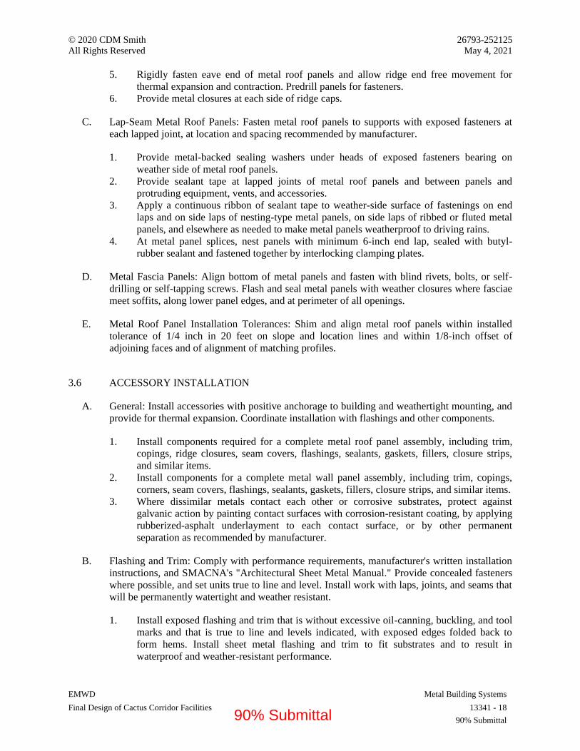
© 2020 CDM Smith 26793-252125
All Rights Reserved May 4, 2021
EMWD Metal Building Systems
Final Design of Cactus Corridor Facilities 13341 - 18
90% Submittal
5. Rigidly fasten eave end of metal roof panels and allow ridge end free movement for
thermal expansion and contraction. Predrill panels for fasteners.
6. Provide metal closures at each side of ridge caps.
C. Lap-Seam Metal Roof Panels: Fasten metal roof panels to supports with exposed fasteners at
each lapped joint, at location and spacing recommended by manufacturer.
1. Provide metal-backed sealing washers under heads of exposed fasteners bearing on
weather side of metal roof panels.
2. Provide sealant tape at lapped joints of metal roof panels and between panels and
protruding equipment, vents, and accessories.
3. Apply a continuous ribbon of sealant tape to weather-side surface of fastenings on end
laps and on side laps of nesting-type metal panels, on side laps of ribbed or fluted metal
panels, and elsewhere as needed to make metal panels weatherproof to driving rains.
4. At metal panel splices, nest panels with minimum 6-inch end lap, sealed with butyl-
rubber sealant and fastened together by interlocking clamping plates.
D. Metal Fascia Panels: Align bottom of metal panels and fasten with blind rivets, bolts, or self-
drilling or self-tapping screws. Flash and seal metal panels with weather closures where fasciae
meet soffits, along lower panel edges, and at perimeter of all openings.
E. Metal Roof Panel Installation Tolerances: Shim and align metal roof panels within installed
tolerance of 1/4 inch in 20 feet on slope and location lines and within 1/8-inch offset of
adjoining faces and of alignment of matching profiles.
3.6 ACCESSORY INSTALLATION
A. General: Install accessories with positive anchorage to building and weathertight mounting, and
provide for thermal expansion. Coordinate installation with flashings and other components.
1. Install components required for a complete metal roof panel assembly, including trim,
copings, ridge closures, seam covers, flashings, sealants, gaskets, fillers, closure strips,
and similar items.
2. Install components for a complete metal wall panel assembly, including trim, copings,
corners, seam covers, flashings, sealants, gaskets, fillers, closure strips, and similar items.
3. Where dissimilar metals contact each other or corrosive substrates, protect against
galvanic action by painting contact surfaces with corrosion-resistant coating, by applying
rubberized-asphalt underlayment to each contact surface, or by other permanent
separation as recommended by manufacturer.
B. Flashing and Trim: Comply with performance requirements, manufacturer's written installation
instructions, and SMACNA's "Architectural Sheet Metal Manual." Provide concealed fasteners
where possible, and set units true to line and level. Install work with laps, joints, and seams that
will be permanently watertight and weather resistant.
1. Install exposed flashing and trim that is without excessive oil-canning, buckling, and tool
marks and that is true to line and levels indicated, with exposed edges folded back to
form hems. Install sheet metal flashing and trim to fit substrates and to result in
waterproof and weather-resistant performance.
90% Submittal

© 2020 CDM Smith 26793-252125
All Rights Reserved May 4, 2021
EMWD Metal Building Systems
Final Design of Cactus Corridor Facilities 13341 - 19
90% Submittal
2. Expansion Provisions: Provide for thermal expansion of exposed flashing and trim. Space
movement joints at a maximum of 10 feet with no joints allowed within 24 inches of
corner or intersection. Where lapped or bayonet-type expansion provisions cannot be
used or would not be sufficiently weather resistant and waterproof, form expansion joints
of intermeshing hooked flanges, not less than 1 inch deep, filled with mastic sealant
(concealed within joints).
C. Gutters: Join sections with riveted-and-soldered or lapped-and-sealed joints. Attach gutters to
eave with gutter hangers spaced as required for gutter size, but not more than 36 inches o.c.
using manufacturer's standard fasteners. Provide end closures and seal watertight with sealant.
Provide for thermal expansion.
D. Downspouts: Join sections with 1-1/2-inch telescoping joints. Provide fasteners designed to
hold downspouts securely 1 inch away from walls; locate fasteners at top and bottom and at
approximately 60 inches o.c. in between.
1. Provide elbows at base of downspouts to direct water away from building.
2. Tie downspouts to underground drainage system indicated.
E. Circular Roof Ventilators: Set ventilators complete with necessary hardware, anchors, dampers,
weather guards, rain caps, and equipment supports. Mount ventilators on flat level base. Install
preformed filler strips at base to seal ventilator to metal roof panels.
F. Continuous Roof Ventilators: Set ventilators complete with necessary hardware, anchors,
dampers, weather guards, rain caps, and equipment supports. Join sections with splice plates
and end-cap skirt assemblies where required to achieve indicated length. Install preformed filler
strips at base to seal ventilator to metal roof panels.
G. Pipe Flashing: Form flashing around pipe penetration and metal roof panels. Fasten and seal to
panel as recommended by manufacturer.
3.7 FIELD QUALITY CONTROL
A. Special Inspections: Owner will engage a qualified special inspector to perform field quality
control special inspections and to submit reports.
B. Product will be considered defective if it does not pass tests and inspections.
C. Prepare test and inspection reports.
3.8 CLEANING AND PROTECTION
A. Repair damaged galvanized coatings on galvanized items with galvanized repair paint according
to ASTM A780/A780M and manufacturer's written instructions.
B. Remove and replace glass that has been broken, chipped, cracked, abraded, or damaged during
construction period.
90% Submittal
© 2020 CDM Smith 26793-252125
All Rights Reserved May 4, 2021
EMWD Metal Building Systems
Final Design of Cactus Corridor Facilities 13341 - 20
90% Submittal
C. Touchup Painting: After erection, promptly clean, prepare, and prime or reprime field
connections, rust spots, and abraded surfaces of prime-painted structural framing, bearing
plates, and accessories.
1. Clean and prepare surfaces by SSPC-SP 2, "Hand Tool Cleaning," or by SSPC-SP 3,
"Power Tool Cleaning."
2. Apply a compatible primer of same type as shop primer used on adjacent surfaces.
D. Touchup Painting: Cleaning and touchup painting are specified in Section 09911 "Exterior
Painting" and Section 09912 "Interior Painting."
E. Metal Panels: Remove temporary protective coverings and strippable films, if any, as metal
panels are installed. On completion of metal panel installation, clean finished surfaces as
recommended by metal panel manufacturer. Maintain in a clean condition during construction.
1. Replace metal panels that have been damaged or have deteriorated beyond successful
repair by finish touchup or similar minor repair procedures.
END OF SECTION 13341
90% Submittal

© 2020 CDM Smith 26793-252125 All Rights Reserved May 4, 2021
EMWD Actuators for Process Valves and Gates Final Design of Cactus Corridor Facilities 13446.1 - 1
90% Submittal
SECTION 13446.1 - ACTUATORS FOR PROCESS VALVES AND GATES
PART 1 - GENERAL
1.1 RELATED DOCUMENTS
A. Drawings and general provisions of the Contract, including General and Supplementary Conditions and Division 01 Specification Sections, apply to this Section.
1.2 SUMMARY
A. Section Includes: Following types of actuators for linear, multi-turn, and quarter turn valves:
1. Manual actuators. 2. Electric motor actuators.
B. Related Requirements:
1. Section 13446 “Valve and Gate Operations”. 2. Section 05502 “Metal Fabrications” for miscellaneous metalwork and fasteners as
required. 3. Section 09900 “Painting and Protective Coatings” for product and execution
requirements. 4. Section 15065 “Hangers and Supports for Process Piping” for hangers, anchors, sleeves,
and sealing of piping to adjacent structures.
1.3 DEFINITIONS
A. Where the term “valve” alone is used in this Section, it applies to both valves and gates as the corresponding text context dictates.
1.4 COORDINATION
A. Coordinate Work of this Section with installation of valves and accessories.
1.5 SUBMITTALS
A. Section 01330 “Submittal Procedures” for submittals requirements.
B. Product Data: Manufacturer information for actuator with model number and size indicated.
C. Shop Drawings:
90% Submittal

© 2020 CDM Smith 26793-252125 All Rights Reserved May 4, 2021
EMWD Actuators for Process Valves and Gates Final Design of Cactus Corridor Facilities 13446.1 - 2
90% Submittal
1. Parts list, materials, sizes, position indicators, limit switches, control system, actuator mounting, wiring diagrams, control system schematics with external interfaces on assembly drawings.
2. Actuator Shop Drawings with respective valve submittal.
D. Manufacturer's Certificate: Products meet or exceed specified requirements.
E. Manufacturer Instructions: Special procedures and placement requirements.
F. Source Quality-Control Submittals: Results of factory tests and inspections and provide required certifications.
G. Field Quality-Control Submittals: Results of Contractor-furnished tests and inspections.
H. Qualifications Statements:
1. Qualifications for manufacturer and installer. 2. Manufacturer's approval of installer.
I. American Iron and Steel (AIS): Certification of compliance with requirements
1.6 CLOSEOUT SUBMITTALS
A. Section 01770 “Closeout Procedures” for submittals requirements.
B. Project Record Documents: Documentation of actual locations and types of actuators.
1.7 QUALITY ASSURANCE
A. Minimum NEMA Enclosure Classification:
1. Non-submergence Installations: NEMA 4X. 2. Submergence Installations: NEMA 6P/IP68.
B. Perform Work according to Eastern Municipal Water District standards.
C. Single Source Requirements:
1. Furnish electric motor actuators in the scope of the project by the same manufacturer. Coordinate this requirement with actuated valves and gates included in scope of vender furnished equipment.
D. Mate actuators to equipment at equipment manufacturers or integrators facility.
1. Test assembled product. Certify ready for installation prior to shipment to job site. 2. For extremely large assemblies requiring disassembly for installation, the actuator may be
disassembled for shipment and remounted in the field.
90% Submittal

© 2020 CDM Smith 26793-252125 All Rights Reserved May 4, 2021
EMWD Actuators for Process Valves and Gates Final Design of Cactus Corridor Facilities 13446.1 - 3
90% Submittal
1.8 QUALIFICATIONS
A. Manufacturer: Company specializing in manufacturing products specified in this Section with minimum five years’ experience.
1.9 DELIVERY, STORAGE, AND HANDLING
A. Section 01600 “Product Requirements: for transporting, handling, storing, and protecting products requirements.
B. Inspection: Accept materials on Site in manufacturer's original packaging and inspect for damage.
C. Store materials according to manufacturer instructions.
D. Protection:
1. Protect materials from moisture and dust by storing in clean, dry location remote from construction operations areas.
2. Furnish temporary end caps and closures on piping and fittings and maintain in place until installation.
3. Provide additional protection according to manufacturer instructions.
1.10 EXISTING CONDITIONS
A. Field Measurements:
1. Verify field measurements prior to fabrication. 2. Indicate field measurements on Shop Drawings.
1.11 WARRANTY
A. Section 01770 “Closeout Procedures” for warranties requirements.
PART 2 - PRODUCTS
2.1 GENERAL
A. Refer to valve schedule for actuator type, accessories, and sizing information.
B. Provide clockwise closed actuation unless otherwise noted on the valve and gate schedule.
C. Supply chain actuators for manual valves located 7 feet,or higher above finished floor.
90% Submittal

© 2020 CDM Smith 26793-252125 All Rights Reserved May 4, 2021
EMWD Actuators for Process Valves and Gates Final Design of Cactus Corridor Facilities 13446.1 - 4
90% Submittal
2.2 ACCESSORIES
A. Extension Stems and Stem Guides:
1. Extension stems and couplings to actuate recessed, buried, below slab valves and gates via operating nut or floor stand mounted actuator.
2. Stem Extensions and Stem Couplings: Alloy steel, hardware of Type 316 stainless-steel unless specified otherwise in the respective slide gate specification.
3. Stem and Stem Couplings: Rated for five times the maximum input torque capacity of the actuator.
4. Adjustable, Cast Iron Wall Bracket Type Stem Guides: Include bronze or UHMW bushing.
5. Spacing: 10 feetspacing or at spacing calculated by manufacturer to prevent buckling with a safety factor of 2 based on design thrust, shaft material and shaft size.
B. Torque Tubes:
1. Supply where shown on the Drawings or Valve and Gate Schedule. 2. Supported by/mated to valve bonnet/yoke. 3. Sized by supplier for the required actuator torque. 4. Drilled specifically for valve and actuator bolt pattern. 5. Internal extension keyed or shaped specifically to mate to valve shaft and fabricated of
316 stainless steel. 6. Internal extension designed for axial adjustment for mating purposes.
C. Chain Wheels:
1. Supply for manual valves 3 inchdiameter or larger mounted 7 feetand greater above operating floor level.
2. Type: Sprocket rim with chain and floating chain guide. 3. Chain Wheel and Guides Materials: Cast iron with hot-dip galvanized chain. 4. Chain Length: Extend to 5-1/2 feetabove operating floor level. 5. Chain Storage: Include where chains may interfere with personnel egress; made with
high-strength thermoplastic polymer in safety orange color.
a. Basis-of-Design: Trumbull, Model ‘Chain Up’ as manufactured by Trumball Manufacturing, Inc., or equal.
6. Chain Wall Hooks: Include where feasible to prevent chain from impeding personnel egress.
2.3 MANUAL ACTUATORS
A. Operating Nuts:
1. 2 inchcast iron AWWA design.
a. Painted Carbon Steel Tee Handle Operator: 2 inchAWWA nut socket end extension length for nut actuated valves where nuts are recessed in valve boxes.
b. Tee Extension Length: Determine based on nut height as shown on Drawings with handle height approximately 3 feetabove operating surface.
90% Submittal

© 2020 CDM Smith 26793-252125 All Rights Reserved May 4, 2021
EMWD Actuators for Process Valves and Gates Final Design of Cactus Corridor Facilities 13446.1 - 5
90% Submittal
2. Operating Nuts Recessed on Concrete: Cast iron floor box with cover and tee handle operator with 2 inchAWWA nut socket end.
3. Nut Operated Non-Rising Stem Buried Valves: Cast iron bonnet skirts, extension pipes valve box and cover. Stem extensions with AWWA nut end to elevation shown on the Drawings or scheduled.
4. Two tee handles for every ten buried or encased non-rising stem application with 2 inchAWWA operating nut.
B. Gear-Assisted Manual Valve Actuators:
1. Provide:
a. For manually actuated valves and gates larger than 8 inchnominal diameter and for ball and plug valves 6 inchand larger.
b. With power actuators where torque requirements dictate.
2. Comply with AWWA C504. 3. Handwheel Diameter: 8 inch 4. Maximum Handwheel Pull: 40 lbsmaximum. 5. Housings: Cast or ductile iron. 6. Worm or helical gear type. 7. Gears: Hardened steel, machine cut and mated. 8. Bearings: Permanently lubricated bronze. 9. Input and Output Shafts: Sealed with greased, waterproof machine shaft seals. 10. Filled with waterproof grease and designed for submerged service where scheduled. 11. Handwheel: Removable.
a. Diameter: 8 inchup to 12 inchvalve size. b. Diameter: 12 inchdiameter up to 16 inchvalve size. c. Diameter: 18 inchdiameter for larger than 16 inchvalve size. d. Maximum Diameter: 24 inchdiameter.
12. Include mechanical top mounted valve position indication, opening direction, and adjustable stops.
2.4 ELECTRIC MOTOR ACTUATORS
A. General:
1. Where specified on the Valve Schedule. 2. Comply with AWWA C542. 3. Power Supply: 120 Volt, 1 Phase, 60 Hertz.
B. 120 Volt Power Actuators:
1. Actuators to have reversing motor, reduction gearing, local position indicator, position limit switches, provision for manual override, 100 to 1000 in-lbstorque range and motor thermal and electronic control protection.
2. Enclosure:
a. Cast aluminum or steel alloy. b. Powder coated or fusion bonded epoxy finish.
90% Submittal

© 2020 CDM Smith 26793-252125 All Rights Reserved May 4, 2021
EMWD Actuators for Process Valves and Gates Final Design of Cactus Corridor Facilities 13446.1 - 6
90% Submittal
c. NEMA 4.
3. Power Train:
a. Self-locking planetary epicyclical gear design. b. Hardened steel or Hardened bronze alloy gears with bronze bearings. c. Housing Penetrations: Seal with mechanical seals. d. Housing: Equip with space heaters. e. Mounting System: ISO 5211.
4. Actuator for Open/Close/Jog Reversing Service: Proportional/modulating service where required in the equipment specifications or Instrumentation Drawings.
5. Motors:
a. Design for valve actuation service. b. Insulation: Class F. c. Split phase capacitor protection. d. Duty Cycle: 40 percent at 100 degrees Ffor open/close duty, and 100 percent for
modulating duty. e. 90-Degree Travel Time: 10 to 20 seconds depending on actuator size. f. Actuator Switches: Have two SPDT 15 Amp rated switches for remote open/close
valve position indication.
6. Products: Subject to compliance with requirements, provide one of the following or equal:
a. AUMA SQ/SQR as manufactured by AUMA Riester GmbH & Co. KG b. EIM TEC2 as manufactured by Emerson Electric Co. c. REXA XPAC by REXA Inc.
2.5 SOURCE QUALITY CONTROL
A. Section 01400 “Quality Requirements” for testing, inspection, and analysis requirements.
B. Factory Testing:
1. Shop inspect and test completed assemblies. 2. Factory performance test each actuator and supply individual test certificates. Submit test
certificates prior to shipment of valve actuators. Test equipment to simulate a typical valve and gate load, and record the following parameters:
a. No load current. b. Current at maximum torque setting. c. Stall current. d. Torque at maximum torque setting. e. Stall torque. f. Test voltage and frequency. g. Flash test voltage. h. Actuator output speed.
C. Certificate of Compliance:
90% Submittal

© 2020 CDM Smith 26793-252125 All Rights Reserved May 4, 2021
EMWD Actuators for Process Valves and Gates Final Design of Cactus Corridor Facilities 13446.1 - 7
90% Submittal
1. If manufacturer is approved by authorities having jurisdiction, submit certificate of compliance indicating Work performed at manufacturer's facility conforms to Contract Documents.
PART 3 - EXECUTION
3.1 EXAMINATION
A. Section 01730 “Execution,” for installation examination requirements.
B. Verify field dimensions are as indicated on Shop Drawings.
3.2 INSTALLATION
A. Install products plumb, square, and true according to manufacturer’s published installation instructions.
B. Securely mount actuators using brackets or hardware specifically designed for attachment to valves/gates.
C. Extend chain actuators to 5-1/2 feetabove operating floor level.
3.3 FIELD QUALITY CONTROL
A. Section 01400 “Quality Requirements” for inspecting and testing requirements.
3.4 ADJUSTING
A. Occupancy Adjustments: If requested within 12 months of date of Substantial Completion, provide on-site assistance in adjusting system to suit actual occupied conditions. Perform adjustments during normal occupancy hours.
3.5 DEMONSTRATIONS
A. Refer to Section 01790 "Demonstration and Training."
B. Engage a factory-authorized service representative to train Owner's maintenance personnel to adjust, operate, and maintain actuators.
1. Time Duration: Allow four hours during a single day.
END OF SECTION 13446.1
90% Submittal
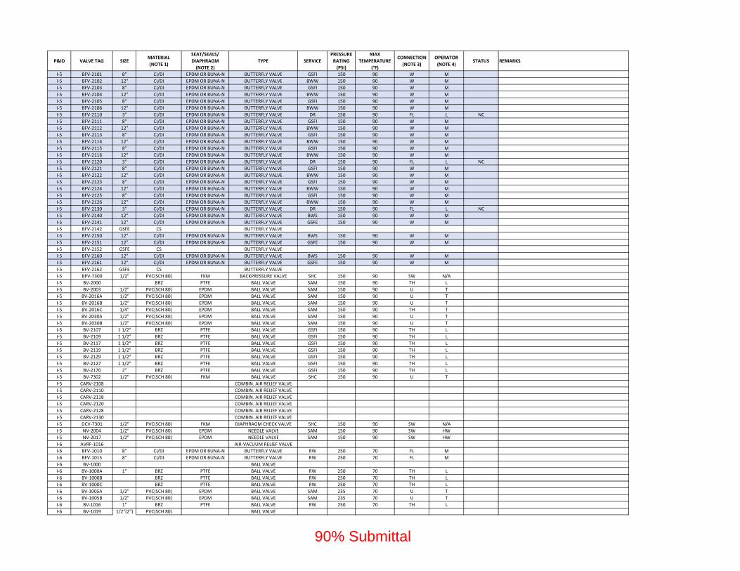
P&ID VALVE TAG SIZEMATERIAL
(NOTE 1)
SEAT/SEALS/
DIAPHRAGM
(NOTE 2)
TYPE SERVICE
PRESSURE
RATING
(PSI)
MAX
TEMPERATURE
(°F)
CONNECTION
(NOTE 3)
OPERATOR
(NOTE 4)STATUS REMARKS
I‐5 BFV‐2101 8" CI/DI EPDM OR BUNA‐N BUTTERFLY VALVE GSFI 150 90 W M
I‐5 BFV‐2102 12" CI/DI EPDM OR BUNA‐N BUTTERFLY VALVE BWW 150 90 W M
I‐5 BFV‐2103 8" CI/DI EPDM OR BUNA‐N BUTTERFLY VALVE GSFI 150 90 W M
I‐5 BFV‐2104 12" CI/DI EPDM OR BUNA‐N BUTTERFLY VALVE BWW 150 90 W M
I‐5 BFV‐2105 8" CI/DI EPDM OR BUNA‐N BUTTERFLY VALVE GSFI 150 90 W M
I‐5 BFV‐2106 12" CI/DI EPDM OR BUNA‐N BUTTERFLY VALVE BWW 150 90 W M
I‐5 BFV‐2110 3" CI/DI EPDM OR BUNA‐N BUTTERFLY VALVE DR 150 90 FL L NC
I‐5 BFV‐2111 8" CI/DI EPDM OR BUNA‐N BUTTERFLY VALVE GSFI 150 90 W M
I‐5 BFV‐2112 12" CI/DI EPDM OR BUNA‐N BUTTERFLY VALVE BWW 150 90 W M
I‐5 BFV‐2113 8" CI/DI EPDM OR BUNA‐N BUTTERFLY VALVE GSFI 150 90 W M
I‐5 BFV‐2114 12" CI/DI EPDM OR BUNA‐N BUTTERFLY VALVE BWW 150 90 W M
I‐5 BFV‐2115 8" CI/DI EPDM OR BUNA‐N BUTTERFLY VALVE GSFI 150 90 W M
I‐5 BFV‐2116 12" CI/DI EPDM OR BUNA‐N BUTTERFLY VALVE BWW 150 90 W M
I‐5 BFV‐2120 3" CI/DI EPDM OR BUNA‐N BUTTERFLY VALVE DR 150 90 FL L NC
I‐5 BFV‐2121 8" CI/DI EPDM OR BUNA‐N BUTTERFLY VALVE GSFI 150 90 W M
I‐5 BFV‐2122 12" CI/DI EPDM OR BUNA‐N BUTTERFLY VALVE BWW 150 90 W M
I‐5 BFV‐2123 8" CI/DI EPDM OR BUNA‐N BUTTERFLY VALVE GSFI 150 90 W M
I‐5 BFV‐2124 12" CI/DI EPDM OR BUNA‐N BUTTERFLY VALVE BWW 150 90 W M
I‐5 BFV‐2125 8" CI/DI EPDM OR BUNA‐N BUTTERFLY VALVE GSFI 150 90 W M
I‐5 BFV‐2126 12" CI/DI EPDM OR BUNA‐N BUTTERFLY VALVE BWW 150 90 W M
I‐5 BFV‐2130 3" CI/DI EPDM OR BUNA‐N BUTTERFLY VALVE DR 150 90 FL L NC
I‐5 BFV‐2140 12" CI/DI EPDM OR BUNA‐N BUTTERFLY VALVE BWS 150 90 W M
I‐5 BFV‐2141 12" CI/DI EPDM OR BUNA‐N BUTTERFLY VALVE GSFE 150 90 W M
I‐5 BFV‐2142 GSFE CS BUTTERFLY VALVE
I‐5 BFV‐2150 12" CI/DI EPDM OR BUNA‐N BUTTERFLY VALVE BWS 150 90 W M
I‐5 BFV‐2151 12" CI/DI EPDM OR BUNA‐N BUTTERFLY VALVE GSFE 150 90 W M
I‐5 BFV‐2152 GSFE CS BUTTERFLY VALVE
I‐5 BFV‐2160 12" CI/DI EPDM OR BUNA‐N BUTTERFLY VALVE BWS 150 90 W M
I‐5 BFV‐2161 12" CI/DI EPDM OR BUNA‐N BUTTERFLY VALVE GSFE 150 90 W M
I‐5 BFV‐2162 GSFE CS BUTTERFLY VALVE
I‐5 BPV‐7300 1/2" PVC(SCH 80) FKM BACKPRESSURE VALVE SHC 150 90 SW N/A
I‐5 BV‐2000 BRZ PTFE BALL VALVE SAM 150 90 TH L
I‐5 BV‐2003 1/2" PVC(SCH 80) EPDM BALL VALVE SAM 150 90 U T
I‐5 BV‐2016A 1/2" PVC(SCH 80) EPDM BALL VALVE SAM 150 90 U T
I‐5 BV‐2016B 1/2" PVC(SCH 80) EPDM BALL VALVE SAM 150 90 U T
I‐5 BV‐2016C 1/4" PVC(SCH 80) EPDM BALL VALVE SAM 150 90 TH T
I‐5 BV‐2030A 1/2" PVC(SCH 80) EPDM BALL VALVE SAM 150 90 U T
I‐5 BV‐2030B 1/2" PVC(SCH 80) EPDM BALL VALVE SAM 150 90 U T
I‐5 BV‐2107 1 1/2" BRZ PTFE BALL VALVE GSFI 150 90 TH L
I‐5 BV‐2109 1 1/2" BRZ PTFE BALL VALVE GSFI 150 90 TH L
I‐5 BV‐2117 1 1/2" BRZ PTFE BALL VALVE GSFI 150 90 TH L
I‐5 BV‐2119 1 1/2" BRZ PTFE BALL VALVE GSFI 150 90 TH L
I‐5 BV‐2129 1 1/2" BRZ PTFE BALL VALVE GSFI 150 90 TH L
I‐5 BV‐2127 1 1/2" BRZ PTFE BALL VALVE GSFI 150 90 TH L
I‐5 BV‐2170 2" BRZ PTFE BALL VALVE GSFI 150 90 TH L
I‐5 BV‐7302 1/2" PVC(SCH 80) FKM BALL VALVE SHC 150 90 U T
I‐5 CARV‐2108 COMBIN. AIR RELIEF VALVE
I‐5 CARV‐2110 COMBIN. AIR RELIEF VALVE
I‐5 CARV‐2118 COMBIN. AIR RELIEF VALVE
I‐5 CARV‐2120 COMBIN. AIR RELIEF VALVE
I‐5 CARV‐2128 COMBIN. AIR RELIEF VALVE
I‐5 CARV‐2130 COMBIN. AIR RELIEF VALVE
I‐5 DCV‐7301 1/2" PVC(SCH 80) FKM DIAPHRAGM CHECK VALVE SHC 150 90 SW N/A
I‐5 NV‐2004 1/2" PVC(SCH 80) EPDM NEEDLE VALVE SAM 150 90 SW HW
I‐5 NV‐2017 1/2" PVC(SCH 80) EPDM NEEDLE VALVE SAM 150 90 SW HW
I‐6 AVRF‐1016 AIR‐VACUUM RELIEF VALVE
I‐6 BFV‐1010 8" CI/DI EPDM OR BUNA‐N BUTTERFLY VALVE RW 250 70 FL M
I‐6 BFV‐1015 8" CI/DI EPDM OR BUNA‐N BUTTERFLY VALVE RW 250 70 FL M
I‐6 BV‐1000 BALL VALVE
I‐6 BV‐1000A 1" BRZ PTFE BALL VALVE RW 250 70 TH L
I‐6 BV‐1000B BRZ PTFE BALL VALVE RW 250 70 TH L
I‐6 BV‐1000C BRZ PTFE BALL VALVE RW 250 70 TH L
I‐6 BV‐1005A 1/2" PVC(SCH 80) EPDM BALL VALVE SAM 235 70 U T
I‐6 BV‐1005B 1/2" PVC(SCH 80) EPDM BALL VALVE SAM 235 70 U T
I‐6 BV‐1016 1" BRZ PTFE BALL VALVE RW 250 70 TH L
I‐6 BV‐1019 1/2"(2") PVC(SCH 80) BALL VALVE
90% Submittal

P&ID VALVE TAG SIZEMATERIAL
(NOTE 1)
SEAT/SEALS/
DIAPHRAGM
(NOTE 2)
TYPE SERVICE
PRESSURE
RATING
(PSI)
MAX
TEMPERATURE
(°F)
CONNECTION
(NOTE 3)
OPERATOR
(NOTE 4)STATUS REMARKS
I‐6 CV‐1000 8" CI/DI EPDM CHECK VALVE RW 250 70 FL N/A
I‐6 DCV‐1018 1/2"(2") PVC(SCH 80) DIAPHRAGM CHECK VALVE
I‐6 NV‐1005 1/2" PVC(SCH 80) EPDM NEEDLE VALVE SAM 235 70 SW HW
I‐6 PREGV‐1017 1/2"(2") PVC(SCH 80) PRESSURE REG. VALVE
I‐6 SV‐1000 SOLENOID VALVE
I‐7 AVRF‐1200 AIR‐VACUUM RELIEF VALVE
I‐7 AVRF‐1216 AIR‐VACUUM RELIEF VALVE
I‐7 BFV‐1210 8" CI/DI EPDM OR BUNA‐N BUTTERFLY VALVE RW 250 70 FL M
I‐7 BFV‐1215 8" CI/DI EPDM OR BUNA‐N BUTTERFLY VALVE RW 250 70 FL M
I‐7 BV‐1200 BALL VALVE RW
I‐7 BV‐1200A 1" BRZ PTFE BALL VALVE SAM 250 70 TH L
I‐7 BV‐1200B BRZ PTFE BALL VALVE SAM 250 70 TH L
I‐7 BV‐1200C BRZ PTFE BALL VALVE RW 250 70 TH L
I‐7 BV‐1205A 1/2" PVC(SCH 80) EPDM BALL VALVE RW 235 70 U T
I‐7 BV‐1205B 1/2" PVC(SCH 80) EPDM BALL VALVE SAM 235 70 U T
I‐7 BV‐1216 1" BRZ PTFE BALL VALVE RW 250 70 TH L
I‐7 CV‐1200 8" CI/DI EPDM CHECK VALVE SHC 250 70 FL N/A
I‐7 NV‐1205 1/2" PVC(SCH 80) EPDM NEEDLE VALVE SAM 235 70 SW HW
I‐7 SV‐1200 SOLENOID VALVE
I‐8 AVRF‐1400 AIR‐VACUUM RELIEF VALVE
I‐8 AVRF‐1416 AIR‐VACUUM RELIEF VALVE
I‐8 BFV‐1410 8" CI/DI EPDM OR BUNA‐N BUTTERFLY VALVE RW 250 70 FL M
I‐8 BFV‐1415 8" CI/DI EPDM OR BUNA‐N BUTTERFLY VALVE RW 250 70 FL M
I‐8 BV‐1400 BALL VALVE RW
I‐8 BV‐1400A 1" BRZ PTFE BALL VALVE SAM 250 70 TH L
I‐8 BV‐1400B BRZ PTFE BALL VALVE SAM 250 70 TH L
I‐8 BV‐1400C BRZ PTFE BALL VALVE RW 250 70 TH L
I‐8 BV‐1405A 1/2" PVC(SCH 80) EPDM BALL VALVE RW 235 70 U T
I‐8 BV‐1405B 1/2" PVC(SCH 80) EPDM BALL VALVE SAM 235 70 U T
I‐8 BV‐1416 BRZ PTFE BALL VALVE RW 250 70 TH L
I‐8 CV‐1400 8" CI/DI EPDM CHECK VALVE SHC 250 70 FL N/A
I‐8 NV‐1405 1/2" PVC(SCH 80) EPDM NEEDLE VALVE SAM 235 70 SW HW
I‐8 SV‐1400 SOLENOID VALVE
I‐9 AVRF‐1600 AIR‐VACUUM RELIEF VALVE
I‐9 AVRF‐1616 AIR‐VACUUM RELIEF VALVE
I‐9 BFV‐1610 8" CS EPDM OR BUNA‐N BUTTERFLY VALVE RW 250 70 FL M
I‐9 BFV‐1615 8" CS EPDM OR BUNA‐N BUTTERFLY VALVE RW 250 70 FL M
I‐9 BV‐1600 BALL VALVE RW
I‐9 BV‐1600A 1" BRZ PTFE BALL VALVE SAM 250 70 TH L
I‐9 BV‐1600B BRZ PTFE BALL VALVE SAM 250 70 TH L
I‐9 BV‐1600C BRZ PTFE BALL VALVE RW 250 70 TH L
I‐9 BV‐1605A 1/2" PVC(SCH 80) EPDM BALL VALVE RW 235 70 U T
I‐9 BV‐1605B 1/2" PVC(SCH 80) EPDM BALL VALVE SAM 235 70 U T
I‐9 BV‐1616 BRZ PTFE BALL VALVE RW 250 70 TH L
I‐9 CV‐1600 8" CI/DI EPDM CHECK VALVE SHC 250 70 FL N/A
I‐9 NV‐1605 1/2" PVC(SCH 80) EPDM NEEDLE VALVE SAM 235 70 SW HW
I‐9 SV‐1600 SOLENOID VALVE
I‐10 BFV‐2211 14" CI/DI EPDM OR BUNA‐N BUTTERFLY VALVE GSFE 150 90 FL HW
I‐10 BFV‐2212 14" CI/DI EPDM OR BUNA‐N BUTTERFLY VALVE GSFE 150 90 FL HW
I‐10 BFV‐2221 14" CI/DI EPDM OR BUNA‐N BUTTERFLY VALVE GACI 150 90 FL HW
I‐10 BFV‐2222 14" CI/DI EPDM OR BUNA‐N BUTTERFLY VALVE GACI 150 90 FL HW
I‐10 BPV‐2251 1/2" PVC(SCH 80) FKM GATE VALVE SBS 150 90 SW N/A
I‐10 BV‐2020A 1/2" 304SS EPDM BALL VALVE GSFE 150 90 TH L
I‐10 BV‐2020B 1" 304SS EPDM BALL VALVE DR 150 90 TH L
I‐10 BV‐2201A BALL VALVE
I‐10 BV‐2201B BRZ PTFE BALL VALVE GACI 150 90 TH L
I‐10 BV‐2210A 1/2" 304SS EPDM BALL VALVE GSFE 150 90 TH L
I‐10 BV‐2210B 1" 304SS EPDM BALL VALVE DR 150 90 TH L
I‐10 BV‐2210C BRZ PTFE BALL VALVE GSFE 150 90 TH L
I‐10 BV‐2210D BRZ PTFE BALL VALVE GACI 150 90 TH L
I‐10 BV‐2220C BRZ PTFE BALL VALVE GSFE 150 90 TH L
I‐10 BV‐2220D BRZ PTFE BALL VALVE GACI 150 90 TH L
I‐10 BV‐2235A 1/2" PVC(SCH 80) EPDM BALL VALVE SAM 150 90 U T
I‐10 BV‐2235B 1/2" PVC(SCH 80) EPDM BALL VALVE SAM 150 90 U T
I‐10 BV‐2235C 1/4" PVC(SCH 80) EPDM BALL VALVE SAM 150 90 TH T
I‐10 BV‐2240A 1/2" PVC(SCH 80) EPDM BALL VALVE SAM 150 90 U T
90% Submittal

P&ID VALVE TAG SIZEMATERIAL
(NOTE 1)
SEAT/SEALS/
DIAPHRAGM
(NOTE 2)
TYPE SERVICE
PRESSURE
RATING
(PSI)
MAX
TEMPERATURE
(°F)
CONNECTION
(NOTE 3)
OPERATOR
(NOTE 4)STATUS REMARKS
I‐10 BV‐2240B 1/2" PVC(SCH 80) EPDM BALL VALVE SAM 150 90 U T
I‐10 BV‐2240C 1/4" PVC(SCH 80) EPDM BALL VALVE SAM 150 90 TH T
I‐10 BV‐2253 1/2" PVC(SCH 80) FKM BALL VALVE SBS 150 90 U N/A
I‐10 BV‐2254 BALL VALVE
I‐10 DCV‐2252 1/2" PVC(SCH 80) FKM DIAPHRAGM CHECK VALVE SBS 150 90 U N/A
I‐10 NV‐2235 1/2" PVC(SCH 80) EPDM NEEDLE VALVE SAM 150 90 SW HW
I‐10 NV‐2240 1/2" PVC(SCH 80) EPDM NEEDLE VALVE SAM 150 90 SW HW
I‐11 BFPV‐4005 BACKFLOW PREVENT. VALVE
I‐11 BFV‐4001 10" CI/DI EPDM‐P BUTTERFLY VALVE BWS 150 90 FL HW
I‐11 BFV‐4002 10" CI/DI EPDM‐P BUTTERFLY VALVE BWS 150 90 FL M
I‐11 BPV‐4003 1/2" PVC(SCH 80) FKM BACKPRESSURE VALVE SHC 150 90 U N/A
I‐11 BV‐4003 1/2" PVC(SCH 80) FKM BALL VALVE SHC 150 90 U T
I‐11 BV‐4010A 1/2" PVC(SCH 80) EPDM BALL VALVE SAM 150 90 U T
I‐11 BV‐4010B 1/2" PVC(SCH 80) EPDM BALL VALVE SAM 150 90 U T
I‐11 BV‐4010C 1/2" PVC(SCH 80) EPDM BALL VALVE SAM 150 90 U T
I‐11 BV‐4010D 1/2" PVC(SCH 80) EPDM BALL VALVE SAM 150 90 U T
I‐11 BV‐4010E 3" BRZ PTFE BALL VALVE SAM 150 90 TH L
I‐11 BV‐4010F 1/2" PVC(SCH 80) EPDM BALL VALVE GACE 150 90 U T
I‐11 CARV‐4010 COMBIN. AIR RELIEF VALVE
I‐11 DCV‐4003 1/2" PVC(SCH 80) EPDM DIAPHRAGM CHECK VALVE SHC 150 90 SW N/A
I‐11 NV‐4010A 1/2" PVC(SCH 80) EPDM NEEDLE VALVE SAM 150 90 SW HW
I‐11 NV‐4010B 1/2" PVC(SCH 80) EPDM NEEDLE VALVE SAM 150 90 SW HW
I‐11 PREGV‐4002 6" DI EPDM‐P PRESSURE REDUCING VALVE BWS 150 90 FL N/A
I‐12 BFV‐4101 10" CI/DI EPDM OR BUNA‐N BUTTERFLY VALVE GACI 150 90 FL M MODULATING, REMOTE CONTROL STATION
I‐12 BFV‐4102 10" CS BUTTERFLY VALVE
I‐12 BFV‐4111 10" CI/DI EPDM OR BUNA‐N BUTTERFLY VALVE GACI 150 90 W HW
I‐12 BFV‐4112 10" CI/DI EPDM OR BUNA‐N BUTTERFLY VALVE BWW 150 90 W HW
I‐12 BFV‐4113 10" CI/DI EPDM OR BUNA‐N BUTTERFLY VALVE GACI 150 90 W HW
I‐12 BFV‐4114 10" CI/DI EPDM OR BUNA‐N BUTTERFLY VALVE GACE 150 90 W HW
I‐12 BFV‐4116 10" CI/DI EPDM OR BUNA‐N BUTTERFLY VALVE GACE 150 90 W HW
I‐12 BFV‐4121 10" CI/DI EPDM OR BUNA‐N BUTTERFLY VALVE GACI 150 90 W HW
I‐12 BFV‐4122 10" CI/DI EPDM OR BUNA‐N BUTTERFLY VALVE BWW 150 90 W HW
I‐12 BFV‐4123 10" CI/DI EPDM OR BUNA‐N BUTTERFLY VALVE GACI 150 90 W HW
I‐12 BFV‐4124 10" CI/DI EPDM OR BUNA‐N BUTTERFLY VALVE GACE 150 90 W HW
I‐12 BFV‐4125 10" CI/DI EPDM OR BUNA‐N BUTTERFLY VALVE BWS 150 90 W HW
I‐12 BFV‐4126 10" CI/DI EPDM OR BUNA‐N BUTTERFLY VALVE GACE 150 90 W HW
I‐12 BV‐4110A 4" SS304 PTFE BALL VALVE GAC 150 90 FL L
I‐12 BV‐4110B 1" BRZ PTFE BALL VALVE AIR 150 90 TH L
I‐12 BV‐4110C 1" BRZ PTFE BALL VALVE AIR 150 90 TH L
I‐12 BV‐4110D 2" BRZ PTFE BALL VALVE PW 150 90 TH L
I‐12 BV‐4110E 1/2" BRZ PTFE BALL VALVE SAM 150 90 TH L
I‐12 BV‐4110F 1/2" BRZ PTFE BALL VALVE SAM 150 90 TH L
I‐12 BV‐4110G 1/2" BRZ PTFE BALL VALVE SAM 150 90 TH L
I‐12 BV‐4110H 1/2" BRZ PTFE BALL VALVE SAM 150 90 TH L
I‐12 BV‐4110I 1" BRZ PTFE BALL VALVE AIR 150 90 TH L
I‐12 BV‐4110J 4" SS304 PTFE BALL VALVE GAC 150 90 FL L
I‐12 BV‐4110K 2" BRZ PTFE BALL VALVE GACI 150 90 TH L
I‐12 BV‐4110L 2" BRZ PTFE BALL VALVE DR 150 90 TH L
I‐12 BV‐4111A BRZ PTFE BALL VALVE SAM 150 90 TH L
I‐12 BV‐4111B BRZ PTFE BALL VALVE GACE 150 90 TH L
I‐12 BV‐4114A BRZ PTFE BALL VALVE GACI 150 90 TH L
I‐12 BV‐4114B BRZ PTFE BALL VALVE SAM 150 90 TH L
I‐12 BV‐4120A 4" SS304 PTFE BALL VALVE GAC 150 90 FL L
I‐12 BV‐4120B 1" BRZ PTFE BALL VALVE AIR 150 90 TH L
I‐12 BV‐4120C 1" BRZ PTFE BALL VALVE AIR 150 90 TH L
I‐12 BV‐4120D 2" BRZ PTFE BALL VALVE PW 150 90 TH L
I‐12 BV‐4120E BRZ PTFE BALL VALVE SAM 150 90 TH L
I‐12 BV‐4120F BRZ PTFE BALL VALVE SAM 150 90 TH L
I‐12 BV‐4120G BRZ PTFE BALL VALVE SAM 150 90 TH L
I‐12 BV‐4120H BRZ PTFE BALL VALVE SAM 150 90 TH L
I‐12 BV‐4120I 1" BRZ PTFE BALL VALVE AIR 150 90 TH L
I‐12 BV‐4120J 4" SS304 PTFE BALL VALVE GAC 150 90 FL L
I‐12 BV‐4120P 2" BRZ PTFE BALL VALVE DR 150 90 TH L
I‐12 BV‐4120Q 2" BRZ PTFE BALL VALVE GACI 150 90 TH L
I‐12 BV‐4121A PTFE BALL VALVE GACE 150 90 TH L
I‐12 BV‐4121B PTFE BALL VALVE SAM 150 90 TH L
90% Submittal

P&ID VALVE TAG SIZEMATERIAL
(NOTE 1)
SEAT/SEALS/
DIAPHRAGM
(NOTE 2)
TYPE SERVICE
PRESSURE
RATING
(PSI)
MAX
TEMPERATURE
(°F)
CONNECTION
(NOTE 3)
OPERATOR
(NOTE 4)STATUS REMARKS
I‐12 BV‐4124A PTFE BALL VALVE SAM 150 90 TH L
I‐12 BV‐4124B PTFE BALL VALVE GACI 150 90 TH L
I‐12 BV‐4128 1/2" PVC_80 EPDM BALL VALVE SAM 150 90 TH L
I‐12 CARV‐4110 COMBIN. AIR RELIEF VALVE
I‐12 CARV‐4120 COMBIN. AIR RELIEF VALVE
I‐12 CV‐4127 10" CI/DI EPDM CHECK VALVE GACE 150 90 FL N/A
I‐12 PRV‐4120 PRESSURE RELIEF VALVE
I‐13 AVRF‐5102 AIR‐VACUUM RELIEF VALVE
I‐13 BV‐5005 BALL VALVE SAM
I‐13 BV‐5010A BALL VALVE SAM
I‐13 BV‐5010B BALL VALVE SAM
I‐13 BV‐5020A BALL VALVE SAM
I‐13 BV‐5020B BALL VALVE SAM
I‐13 BV‐5101 BALL VALVE LAS
I‐13 BV‐5102 1" CS BALL VALVE LAS
I‐13 BV‐5201 1/2" PVC_80 BALL VALVE LAS
I‐13 BV‐5201A BALL VALVE SAM
I‐13 BV‐5201B BALL VALVE SAM
I‐13 BV‐5201C BALL VALVE SAM
I‐13 BV‐5201D BALL VALVE SAM
I‐13 BV‐5201E BALL VALVE SAM
I‐13 BV‐5202A BALL VALVE SAM
I‐13 BV‐5202B BALL VALVE SAM
I‐13 CV‐5010 8" CS CHECK VALVE SAM
I‐13 CV‐5020 8" CS CHECK VALVE SAM
I‐13 PV‐5001A 12" PVC(C900) PLUG VALVE IW
I‐13 PV‐5001B 8" CS PLUG VALVE IW
I‐13 PV‐5001C 8" PVC(C900) PLUG VALVE EFF
I‐13 PV‐5001E 4" CS PLUG VALVE
I‐13 PV‐5001F 4" CS PLUG VALVE
I‐13 PV‐5010A 8" CS PLUG VALVE PW
I‐13 PV‐5010B 8" CS PLUG VALVE SAM
I‐13 PV‐5020A 8" CS PLUG VALVE SAM
I‐13 PV‐5020B 8" CS PLUG VALVE SAM
I‐13 PV‐5201 8" CS PLUG VALVE
I‐13 PV‐5201A 8" SS316 PLUG VALVE DR
I‐13 PV‐5201B 8" CS PLUG VALVE PW
I‐13 PV‐5202A 8" CS PLUG VALVE PW
I‐13 PV‐5202B 8" CS PLUG VALVE PW
I‐14 BFV‐6001 24" CI/DI EPDM‐P BUTTERFLY VALVE IW 150 90 FL HW
I‐14 BFV‐6005 24" CI/DI EPDM‐P BUTTERFLY VALVE IW 150 90 FL M MODULATING
I‐14 BFV‐6016 16" CI/DI EPDM‐P BUTTERFLY VALVE PW 150 90 FL HW
I‐14 BPV‐6000 1/2" PVC(SCH 80) FKM BACKPRESSURE VALVE LAS 150 90 SW N/A
I‐14 BV‐6000 1/2" PVC(SCH 80) FKM BALL VALVE LAS 150 90 U T
I‐14 BV‐6002 1/2" PVC(SCH 80) FKM BALL VALVE IW 150 90 U T
I‐14 BV‐6006 2" BRZ PTFE BALL VALVE PW 150 90 TH L
I‐14 BV‐6007 BRZ PTFE BALL VALVE PW 150 90 TH L
I‐14 BV‐6010A 1/2" PVC(SCH 80) EPDM BALL VALVE NIXE 150 90 U T
I‐14 BV‐6010B PVC(SCH 80) EPDM BALL VALVE SAM 150 90 TH T
I‐14 BV‐6010C BALL VALVE
I‐14 BV‐6011A 1/2" PVC(SCH 80) FKM BALL VALVE PW 150 90 U T
I‐14 BV‐6011B PVC(SCH 80) FKM BALL VALVE SAM 150 90 TH T
I‐14 BV‐6011C 1/2" PVC(SCH 80) BALL VALVE
I‐14 BV‐6012A 1/2" PVC(SCH 80) FKM BALL VALVE PW 150 90 U T
I‐14 BV‐6012B 1/2" PVC(SCH 80) FKM BALL VALVE SAM 150 90 U T
I‐14 BV‐6012C 1 1/2" XLPE(CON) BALL VALVE
I‐14 BV‐6014 PVC(SCH 80) FKM BALL VALVE PW 150 90 TH T
I‐14 BV‐6015A 1/2" PVC(SCH 80) FKM BALL VALVE PW 150 90 U T
I‐14 BV‐6015B PVC(SCH 80) FKM BALL VALVE PW 150 90 U T
I‐14 BV‐6015C PVC(SCH 80) FKM BALL VALVE SAM 150 90 TH T
I‐14 CARV‐6006 COMBIN. AIR RELIEF VALVE
I‐14 DCV‐6000 1/2" PVC(SCH 80) FKM DIAPHRAGM CHECK VALVE LAS 150 90 SW N/A
I‐14 NV‐6010 PVC(SCH 80) EPDM NEEDLE VALVE NIXE 150 90 SW HW
I‐14 NV‐6012 PVC(SCH 80) FKM NEEDLE VALVE PW 150 90 SW HW
I‐14 NV‐6014 PVC(SCH 80) FKM NEEDLE VALVE PW 150 90 SW HW
I‐14 NV‐6015 PVC(SCH 80) FKM NEEDLE VALVE PW 150 90 SW HW
90% Submittal

P&ID VALVE TAG SIZEMATERIAL
(NOTE 1)
SEAT/SEALS/
DIAPHRAGM
(NOTE 2)
TYPE SERVICE
PRESSURE
RATING
(PSI)
MAX
TEMPERATURE
(°F)
CONNECTION
(NOTE 3)
OPERATOR
(NOTE 4)STATUS REMARKS
I‐14 PREGV‐6004 16" DI FKM PRESSURE REDUCING VALVE IW 150 90 FL N/A
I‐15 BFV‐6016A 30" CI/DI EPDM‐P BUTTERFLY VALVE PW 150 90 FL HW
I‐15 BFV‐6016B 30" CI/DI EPDM‐P BUTTERFLY VALVE PW 150 90 FL HW
I‐15 BFV‐6110A 12" CI/DI EPDM‐P BUTTERFLY VALVE PW 150 90 FL HW NC
I‐15 BFV‐6110B 30" CI/DI EPDM‐P BUTTERFLY VALVE PW 150 90 FL BSN
I‐15 BFV‐6120A 12" CI/DI EPDM‐P BUTTERFLY VALVE PW 150 90 FL HW NC
I‐15 BFV‐6120B 30" CI/DI EPDM‐P BUTTERFLY VALVE PW 150 90 FL BSN
I‐15 BV‐6110A 1/2" SS304 PTFE BALL VALVE SAM 150 90 TH L
I‐15 BV‐6110B 1/2" SS304 PTFE BALL VALVE SAM 150 90 TH L
I‐15 BV‐6110C 1/2" SS304 PTFE BALL VALVE SAM 150 90 TH L
I‐15 BV‐6120A 1/2" SS304 PTFE BALL VALVE SAM 150 90 TH L
I‐15 BV‐6120B 1/2" SS304 PTFE BALL VALVE SAM 150 90 TH L
I‐15 BV‐6120C 1/2" SS304 PTFE BALL VALVE SAM 150 90 TH L
I‐16 AVRF‐6120A AIR‐VACUUM RELIEF VALVE
I‐16 AVRF‐6210B AIR‐VACUUM RELIEF VALVE
I‐16 AVRF‐6220A AIR‐VACUUM RELIEF VALVE
I‐16 AVRF‐6220B AIR‐VACUUM RELIEF VALVE
I‐16 AVRF‐6230A AIR‐VACUUM RELIEF VALVE
I‐16 AVRF‐6230B AIR‐VACUUM RELIEF VALVE
I‐16 AVRF‐6240A AIR‐VACUUM RELIEF VALVE
I‐16 AVRF‐6240B AIR‐VACUUM RELIEF VALVE
I‐16 AVRF‐6250A AIR‐VACUUM RELIEF VALVE
I‐16 BFV‐6210B 14" CI/DI EPDM‐P BUTTERFLY VALVE PW 150 90 FL HW
I‐16 BFV‐6220B 14" CI/DI EPDM‐P BUTTERFLY VALVE PW 150 90 FL HW
I‐16 BFV‐6230B 14" CI/DI EPDM‐P BUTTERFLY VALVE PW 150 90 FL HW
I‐16 BFV‐6240B 14" CI/DI EPDM‐P BUTTERFLY VALVE PW 150 90 FL HW
I‐16 BFV‐6265 16" CI/DI EPDM‐P BUTTERFLY VALVE PW 150 90 FL HW
I‐16 BFV‐6267 16" CI/DI EPDM‐P BUTTERFLY VALVE PW 150 90 FL HW
I‐16 BPV‐6266 16" DI FKM GATE VALVE PW 150 90 FL N/A
I‐16 BV‐6210A 1" BRZ PTFE BALL VALVE PW 150 90 TH L
I‐16 BV‐6210B 2" BRZ PTFE BALL VALVE PW 150 90 TH L
I‐16 BV‐6210C BRZ PTFE BALL VALVE PW 150 90 TH L
I‐16 BV‐6220A 1" BRZ PTFE BALL VALVE PW 150 90 TH L
I‐16 BV‐6220B 2" BRZ PTFE BALL VALVE PW 150 90 TH L
I‐16 BV‐6220C BRZ PTFE BALL VALVE PW 150 90 TH L
I‐16 BV‐6230A 1" BRZ PTFE BALL VALVE PW 150 90 TH L
I‐16 BV‐6230B 2" BRZ PTFE BALL VALVE PW 150 90 TH L
I‐16 BV‐6230C BRZ PTFE BALL VALVE PW 150 90 TH L
I‐16 BV‐6240A 1" BRZ PTFE BALL VALVE PW 150 90 TH L
I‐16 BV‐6240B 2" BRZ PTFE BALL VALVE PW 150 90 TH L
I‐16 BV‐6240C BRZ PTFE BALL VALVE PW 150 90 TH L
I‐16 BV‐6250A 1" BRZ PTFE BALL VALVE PW 150 90 TH L
I‐16 BV‐6265 BRZ PTFE BALL VALVE PW 150 90 TH L
I‐16 CV‐6210 14" CI/DI EPDM‐P CHECK VALVE PW 150 90 FL N/A
I‐16 CV‐6220 14" CI/DI EPDM‐P CHECK VALVE PW 150 90 FL N/A
I‐16 CV‐6230 14" CI/DI EPDM‐P CHECK VALVE PW 150 90 FL N/A
I‐16 CV‐6240 14" CI/DI EPDM‐P CHECK VALVE PW 150 90 FL N/A
I‐16 GV‐6210A 18" DI EPDM‐P GATE VALVE PW 150 90 FL BSN
I‐16 GV‐6220A 18" DI EPDM‐P GATE VALVE PW 150 90 FL BSN
I‐16 GV‐6230A 18" DI EPDM‐P GATE VALVE PW 150 90 FL BSN
I‐16 GV‐6240A 18" DI EPDM‐P GATE VALVE PW 150 90 FL BSN
I‐16 GV‐6250A 18" DI EPDM‐P GATE VALVE PW 150 90 FL BSN
I‐17 BFV‐6340A 30" CI/DI EPDM‐P BUTTERFLY VALVE PW 150 90 FL HW
I‐17 BFV‐6340B 30" CI/DI EPDM‐P BUTTERFLY VALVE PW 150 90 FL HW
I‐17 BFV‐6350A 18" CI/DI EPDM‐P BUTTERFLY VALVE PW 150 90 FL HW
I‐17 BFV‐6350B 18" CI/DI EPDM‐P BUTTERFLY VALVE PW 150 90 FL HW
I‐17 BPV‐7040 1/2" PVC(SCH 80) FKM BACKPRESSURE VALVE SHC 150 90 TH N/A
I‐17 BPV‐8040 1/2" PVC(SCH 80) FKM BACKPRESSURE VALVE LAS 150 90 TH N/A
I‐17 BV‐6305A 1/2" PVC(SCH 80) FKM BALL VALVE SAM 150 90 U T
I‐17 BV‐6305B PVC(SCH 80) FKM BALL VALVE SAM 150 90 TH T
I‐17 BV‐6305C 1/2" PVC(SCH 80) BALL VALVE
I‐17 BV‐6310 1 1/2" SS316 PTFE BALL VALVE CA 150 120 TH L
I‐17 BV‐6320 1 1/2" SS316 PTFE BALL VALVE CA 150 120 TH L
I‐17 BV‐6330A 1 1/2" SS316 PTFE BALL VALVE CA 150 120 TH L
I‐17 BV‐6330B SS316 PTFE BALL VALVE CA 150 120 TH L
I‐17 BV‐6330C 1 1/2" SS316 PTFE BALL VALVE CA 150 120 TH L
90% Submittal

P&ID VALVE TAG SIZEMATERIAL
(NOTE 1)
SEAT/SEALS/
DIAPHRAGM
(NOTE 2)
TYPE SERVICE
PRESSURE
RATING
(PSI)
MAX
TEMPERATURE
(°F)
CONNECTION
(NOTE 3)
OPERATOR
(NOTE 4)STATUS REMARKS
I‐17 BV‐6330D 1 1/2" SS316 PTFE BALL VALVE CA 150 120 TH L
I‐17 BV‐6330E SS316 PTFE BALL VALVE CA 150 120 TH L
I‐17 BV‐6330F 1 1/2" SS316 PTFE BALL VALVE CA 150 120 TH L
I‐17 BV‐6330G SS316 PTFE BALL VALVE CA 150 120 TH L
I‐17 BV‐6330H 1 1/2" SS316 PTFE BALL VALVE CA 150 120 TH L
I‐17 BV‐6330J 1 1/2" SS316 PTFE BALL VALVE CA 150 120 TH L
I‐17 BV‐6335 SS316 PTFE BALL VALVE CA 150 120 TH L
I‐17 BV‐6336 1 1/2" SS316 PTFE BALL VALVE CA 150 120 TH L
I‐17 BV‐6338 1 1/2" SS316 PTFE BALL VALVE CA 150 120 TH L
I‐17 BV‐6339 SS316 PTFE BALL VALVE CA 150 120 TH L
I‐17 BV‐6340 1/2" BRZ PTFE BALL VALVE CA 150 120 TH L
I‐17 BV‐6340A BRZ PTFE BALL VALVE PW 150 90 TH L
I‐17 BV‐6340B BRZ PTFE BALL VALVE PW 150 90 TH L
I‐17 BV‐6340C BRZ PTFE BALL VALVE PW 150 90 TH L
I‐17 BV‐6340D BRZ PTFE BALL VALVE PW 150 90 TH L
I‐17 BV‐6341 1 1/2" CA PTFE BALL VALVE CA 150 120 TH L
I‐17 BV‐6343 1 1/2" CA PTFE BALL VALVE CA 150 120 TH L
I‐17 BV‐6350 1/2"(2") PP BALL VALVE
I‐17 BV‐7041 1/2" PVC(SCH 80) FKM BALL VALVE SHC 150 90 U T
I‐17 BV‐8041 1/2" PVC(SCH 80) FKM BALL VALVE LAS 150 90 U T
I‐17 CV‐6340 1 1/2" SS316 PTFE CHECK VALVE CA 150 120 TH N/A
I‐17 DCV‐7040 1/2" PVC(SCH 80) FKM DIAPHRAGM CHECK VALVE SHC 150 90 SW N/A
I‐17 DCV‐8040 1/2" PVC(SCH 80) FKM DIAPHRAGM CHECK VALVE LAS 150 90 SW N/A
I‐17 NV‐6305 PVC(SCH 80) FKM NEEDLE VALVE SAM 150 90 SW HW
I‐17 PREGV‐6305 PVC(SCH 80) FKM PRESSURE REDUCING VALVE SAM 150 90 SW N/A
I‐17 PREGV‐6350 12" CI/DI FKM PRESSURE REDUCING VALVE PW 150 90 FL N/A
I‐17 PRV‐6330 PRESSURE RELIEF VALVE
I‐17 PRV‐6340 PRESSURE RELIEF VALVE
I‐17 SV‐6330 BRA BUNA‐N SOLENOID VALVE CA 150 120 TH S NC
I‐17 SV‐6337 1 1/2" SS316 FKM SOLENOID VALVE CA 150 120 TH S NO
I‐17 SV‐6342 1 1/2" SS316 FKM SOLENOID VALVE CA 150 120 TH S NC
I‐18 BPV‐7210 1/2" PVC(SCH 80) FKM BACKPRESSURE VALVE SHC 150 90 SW N/A
I‐18 BPV‐7220 1/2" PVC(SCH 80) FKM BACKPRESSURE VALVE SHC 150 90 SW N/A
I‐18 BPV‐7230 1/2" PVC(SCH 80) FKM BACKPRESSURE VALVE SHC 150 90 SW N/A
I‐18 BV‐7000A 1/2" PVC(SCH 80) FKM BALL VALVE SHC 150 90 U T
I‐18 BV‐7000B 3" PVC(SCH 80) FKM BALL VALVE SHC 150 90 U T
I‐18 BV‐7000C PVC(SCH 80) FKM BALL VALVE SHC 150 90 U T
I‐18 BV‐7000D 1" PVC(SCH 80) FKM BALL VALVE SHC 150 90 U T
I‐18 BV‐7000E 2" PVC(SCH 80) FKM BALL VALVE SHC 150 90 U T
I‐18 BV‐7000F 3/4" PVC(SCH 80) FKM BALL VALVE SHC 150 90 U T
I‐18 BV‐7010 2" PVC(SCH 80) FKM BALL VALVE SHC 150 90 U M
I‐18 BV‐7050A 1/2" PVC(SCH 80) FKM BALL VALVE SHC 150 90 U T
I‐18 BV‐7050B 3" PVC(SCH 80) FKM BALL VALVE SHC 150 90 U T
I‐18 BV‐7050C PVC(SCH 80) FKM BALL VALVE SHC 150 90 U T
I‐18 BV‐7050D 1" PVC(SCH 80) FKM BALL VALVE SHC 150 90 U T
I‐18 BV‐7050E 2" PVC(SCH 80) FKM BALL VALVE SHC 150 90 U T
I‐18 BV‐7050F 3/4" PVC(SCH 80) FKM BALL VALVE SHC 150 90 U T
I‐18 BV‐7060 2" PVC(SCH 80) FKM BALL VALVE SHC 150 90 U M
I‐18 BV‐7110A 2" PVC(SCH 80) FKM BALL VALVE SHC 150 90 U T
I‐18 BV‐7110C 1/2" PVC(SCH 80) FKM BALL VALVE SHC 150 90 U T
I‐18 BV‐7110D 1" PVC(SCH 80) FKM BALL VALVE SHC 150 90 U T
I‐18 BV‐7110E 1/2" PVC(SCH 80) FKM BALL VALVE SHC 150 90 U T
I‐18 BV‐7110F 2" PVC(SCH 80) FKM BALL VALVE SHC 150 90 U T
I‐18 BV‐7110G PVC(SCH 80) FKM BALL VALVE SHC 150 90 U T
I‐18 BV‐7110H 1/2" PVC(SCH 80) FKM BALL VALVE SHC 150 90 U T
I‐18 BV‐7110I 3/4" PVC(SCH 80) BALL VALVE
I‐18 BV‐7120E 1/2" PVC(SCH 80) FKM BALL VALVE SHC 150 90 U T
I‐18 BV‐7120F 2" PVC(SCH 80) FKM BALL VALVE SHC 150 90 U T
I‐18 BV‐7120G PVC(SCH 80) FKM BALL VALVE SHC 150 90 U T
I‐18 BV‐7120H 1/2" PVC(SCH 80) FKM BALL VALVE SHC 150 90 U T
I‐18 BV‐7130C 1/2" PVC(SCH 80) FKM BALL VALVE SHC 150 90 U T
I‐18 BV‐7130D 1" PVC(SCH 80) FKM BALL VALVE SHC 150 90 U T
I‐18 BV‐7130E PVC(SCH 80) FKM BALL VALVE SHC 150 90 U T
I‐18 BV‐7130F 2" PVC(SCH 80) FKM BALL VALVE SHC 150 90 U T
I‐18 BV‐7130G PVC(SCH 80) FKM BALL VALVE SHC 150 90 U T
I‐18 BV‐7130H 1/2" PVC(SCH 80) FKM BALL VALVE SHC 150 90 U T
90% Submittal

P&ID VALVE TAG SIZEMATERIAL
(NOTE 1)
SEAT/SEALS/
DIAPHRAGM
(NOTE 2)
TYPE SERVICE
PRESSURE
RATING
(PSI)
MAX
TEMPERATURE
(°F)
CONNECTION
(NOTE 3)
OPERATOR
(NOTE 4)STATUS REMARKS
I‐18 BV‐7130I 3/4" PVC(SCH 80) BALL VALVE
I‐18 BV‐7140E PVC(SCH 80) FKM BALL VALVE SHC 150 90 U T
I‐18 BV‐7140F 2" PVC(SCH 80) FKM BALL VALVE SHC 150 90 U T
I‐18 BV‐7140G PVC(SCH 80) FKM BALL VALVE SHC 150 90 U T
I‐18 BV‐7140H 1/2" PVC(SCH 80) FKM BALL VALVE SHC 150 90 U T
I‐18 BV‐7150C 1/2" PVC(SCH 80) FKM BALL VALVE SHC 150 90 U T
I‐18 BV‐7150D 1" PVC(SCH 80) FKM BALL VALVE SHC 150 90 U T
I‐18 BV‐7150E PVC(SCH 80) FKM BALL VALVE SHC 150 90 U T
I‐18 BV‐7150F 2" PVC(SCH 80) FKM BALL VALVE SHC 150 90 U T
I‐18 BV‐7150G PVC(SCH 80) FKM BALL VALVE SHC 150 90 U T
I‐18 BV‐7150H 1/2" PVC(SCH 80) FKM BALL VALVE SHC 150 90 U T
I‐18 BV‐7150I 3/4" PVC(SCH 80) BALL VALVE
I‐18 BV‐7160E PVC(SCH 80) FKM BALL VALVE SHC 150 90 U T
I‐18 BV‐7160F 2" PVC(SCH 80) FKM BALL VALVE SHC 150 90 U T
I‐18 BV‐7160G PVC(SCH 80) FKM BALL VALVE SHC 150 90 U T
I‐18 BV‐7160H 1/2" PVC(SCH 80) FKM BALL VALVE SHC 150 90 U T
I‐18 BV‐7210A PVC(SCH 80) FKM BALL VALVE SHC 150 90 U T
I‐18 BV‐7210B 3" PVC(SCH 80) FKM BALL VALVE SHC 150 90 U T
I‐18 BV‐7210C 1/2" PVC(SCH 80) FKM BALL VALVE SHC 150 90 U T
I‐18 BV‐7210D 1/2" PVC(SCH 80) FKM BALL VALVE SHC 150 90 U T
I‐18 BV‐7220A PVC(SCH 80) FKM BALL VALVE SHC 150 90 U T
I‐18 BV‐7220B 3" PVC(SCH 80) FKM BALL VALVE SHC 150 90 U T
I‐18 BV‐7220C 1/2" PVC(SCH 80) FKM BALL VALVE SHC 150 90 U T
I‐18 BV‐7220D 1/2" PVC(SCH 80) FKM BALL VALVE SHC 150 90 U T
I‐18 BV‐7230A PVC(SCH 80) FKM BALL VALVE SHC 150 90 U T
I‐18 BV‐7230B 3" PVC(SCH 80) FKM BALL VALVE SHC 150 90 U T
I‐18 BV‐7230C 1/2" PVC(SCH 80) FKM BALL VALVE SHC 150 90 U T
I‐18 BV‐7230D 1/2" PVC(SCH 80) FKM BALL VALVE SHC 150 90 U T
I‐18 DCV‐7210 1/2" PVC(SCH 80) FKM DIAPHRAGM CHECK VALVE SHC 150 90 SW N/A
I‐18 DCV‐7220 1/2" PVC(SCH 80) FKM DIAPHRAGM CHECK VALVE SHC 150 90 SW N/A
I‐18 DCV‐7230 1/2" PVC(SCH 80) FKM DIAPHRAGM CHECK VALVE SHC 150 90 SW N/A
I‐19 BPV‐8210 1/2" PVC(SCH 80) FKM BACKPRESSURE VALVE LAS 150 90 SW N/A
I‐19 BPV‐8220 1/2" PVC(SCH 80) FKM BACKPRESSURE VALVE LAS 150 90 SW N/A
I‐19 BV‐8000A 1/2" PVC(SCH 80) FKM BALL VALVE LAS 150 90 U T
I‐19 BV‐8000B 3" PVC(SCH 80) FKM BALL VALVE LAS 150 90 U T
I‐19 BV‐8000C PVC(SCH 80) FKM BALL VALVE LAS 150 90 U T
I‐19 BV‐8000D 1" PVC(SCH 80) FKM BALL VALVE LAS 150 90 U T
I‐19 BV‐8000H 2" PVC(SCH 80) FKM BALL VALVE LAS 150 90 U T
I‐19 BV‐8000J 3/4" PVC(SCH 80) FKM BALL VALVE LAS 150 90 U T
I‐19 BV‐8110A 2" PVC(SCH 80) FKM BALL VALVE LAS 150 90 U T
I‐19 BV‐8110B 1/2" PVC(SCH 80) FKM BALL VALVE LAS 150 90 U T
I‐19 BV‐8110C 1" PVC(SCH 80) FKM BALL VALVE LAS 150 90 U T
I‐19 BV‐8110D 1/2" PVC(SCH 80) FKM BALL VALVE LAS 150 90 U T
I‐19 BV‐8110E 2" PVC(SCH 80) FKM BALL VALVE LAS 150 90 U T
I‐19 BV‐8110F PVC(SCH 80) FKM BALL VALVE LAS 150 90 U T
I‐19 BV‐8110G 1/2" PVC(SCH 80) FKM BALL VALVE LAS 150 90 U T
I‐19 BV‐8120D 1/2" PVC(SCH 80) FKM BALL VALVE LAS 150 90 U T
I‐19 BV‐8120E 2" PVC(SCH 80) FKM BALL VALVE LAS 150 90 U T
I‐19 BV‐8120F PVC(SCH 80) FKM BALL VALVE LAS 150 90 U T
I‐19 BV‐8120G 1/2" PVC(SCH 80) FKM BALL VALVE LAS 150 90 U T
I‐19 BV‐8130A 2" PVC(SCH 80) FKM BALL VALVE LAS 150 90 U T
I‐19 BV‐8130B 1/2" PVC(SCH 80) FKM BALL VALVE LAS 150 90 U T
I‐19 BV‐8130C 1" PVC(SCH 80) FKM BALL VALVE LAS 150 90 U T
I‐19 BV‐8130D 1/2" PVC(SCH 80) FKM BALL VALVE LAS 150 90 U T
I‐19 BV‐8130E 2" PVC(SCH 80) FKM BALL VALVE LAS 150 90 U T
I‐19 BV‐8130F PVC(SCH 80) FKM BALL VALVE LAS 150 90 U T
I‐19 BV‐8130G 1/2" PVC(SCH 80) FKM BALL VALVE LAS 150 90 U T
I‐19 BV‐8140D 1/2" PVC(SCH 80) FKM BALL VALVE LAS 150 90 U T
I‐19 BV‐8140E 2" PVC(SCH 80) FKM BALL VALVE LAS 150 90 U T
I‐19 BV‐8140F PVC(SCH 80) FKM BALL VALVE LAS 150 90 U T
I‐19 BV‐8140G 1/2" PVC(SCH 80) FKM BALL VALVE LAS 150 90 U T
I‐19 BV‐8210A PVC(SCH 80) FKM BALL VALVE LAS 150 90 U T
I‐19 BV‐8210B 3" PVC(SCH 80) FKM BALL VALVE LAS 150 90 U T
I‐19 BV‐8210C 1/2" PVC(SCH 80) FKM BALL VALVE LAS 150 90 U T
I‐19 BV‐8210D 1/2" PVC(SCH 80) FKM BALL VALVE LAS 150 90 U T
I‐19 BV‐8220A PVC(SCH 80) FKM BALL VALVE LAS 150 90 U T
90% Submittal

P&ID VALVE TAG SIZEMATERIAL
(NOTE 1)
SEAT/SEALS/
DIAPHRAGM
(NOTE 2)
TYPE SERVICE
PRESSURE
RATING
(PSI)
MAX
TEMPERATURE
(°F)
CONNECTION
(NOTE 3)
OPERATOR
(NOTE 4)STATUS REMARKS
I‐19 BV‐8220B 3" PVC(SCH 80) FKM BALL VALVE LAS 150 90 U T
I‐19 BV‐8220C 1/2" PVC(SCH 80) FKM BALL VALVE LAS 150 90 U T
I‐19 BV‐8220D 1/2" PVC(SCH 80) FKM BALL VALVE LAS 150 90 U T
I‐19 DCV‐8210 1/2" PVC(SCH 80) FKM DIAPHRAGM CHECK VALVE LAS 150 90 SW N/A
I‐19 DCV‐8220 1/2" PVC(SCH 80) FKM DIAPHRAGM CHECK VALVE LAS 150 90 SW N/A
I‐20 BPV‐8530 1/2" PVC(SCH 80) FKM BACKPRESSURE VALVE SBS 150 90 SW N/A
I‐20 BV‐8400A 1/2" PVC(SCH 80) FKM BALL VALVE SBS 150 90 U T
I‐20 BV‐8400B 3" PVC(SCH 80) FKM BALL VALVE SBS 150 90 U T
I‐20 BV‐8400C PVC(SCH 80) FKM BALL VALVE SBS 150 90 U T
I‐20 BV‐8400D 1" PVC(SCH 80) FKM BALL VALVE SBS 150 90 U T
I‐20 BV‐8400E 2" PVC(SCH 80) FKM BALL VALVE SBS 150 90 U T
I‐20 BV‐8400F 3/4" PVC(SCH 80) FKM BALL VALVE SBS 150 90 U T
I‐20 BV‐8400G 1" PVC(SCH 80) FKM BALL VALVE SBS 150 90 U T
I‐20 BV‐8400H 1" PVC(SCH 80) FKM BALL VALVE SBS 150 90 U T
I‐20 BV‐8510A 2" PVC(SCH 80) FKM BALL VALVE SBS 150 90 U T
I‐20 BV‐8510B 1/2" PVC(SCH 80) FKM BALL VALVE SBS 150 90 U T
I‐20 BV‐8510C 1" PVC(SCH 80) FKM BALL VALVE SBS 150 90 U T
I‐20 BV‐8510D 1/2" PVC(SCH 80) FKM BALL VALVE SBS 150 90 U T
I‐20 BV‐8510E 2" PVC(SCH 80) FKM BALL VALVE SBS 150 90 U T
I‐20 BV‐8510F PVC(SCH 80) FKM BALL VALVE SBS 150 90 U T
I‐20 BV‐8510G 1/2" PVC(SCH 80) FKM BALL VALVE SBS 150 90 U T
I‐20 BV‐8520D 1/2" PVC(SCH 80) FKM BALL VALVE SBS 150 90 U T
I‐20 BV‐8520E 2" PVC(SCH 80) FKM BALL VALVE SBS 150 90 U T
I‐20 BV‐8520F PVC(SCH 80) FKM BALL VALVE SBS 150 90 U T
I‐20 BV‐8520G 1/2" PVC(SCH 80) FKM BALL VALVE SBS 150 90 U T
I‐20 BV‐8530 PVC(SCH 80) FKM BALL VALVE SBS 150 90 U T
I‐20 BV‐8530A 3" PVC(SCH 80) FKM BALL VALVE SBS 150 90 U T
I‐20 BV‐8530B 1/2" PVC(SCH 80) FKM BALL VALVE SBS 150 90 U T
I‐20 BV‐8530C 1/2" PVC(SCH 80) FKM BALL VALVE SBS 150 90 U T
I‐20 DCV‐8530 1/2" PVC(SCH 80) FKM DIAPHRAGM CHECK VALVE SBS 150 90 SW N/A
I‐21 BFV‐3103A 16" CI/DI EPDM OR BUNA‐N BUTTERFLY VALVE NIXI 150 90 FL HW
I‐21 BFV‐3103B 16" CI/DI EPDM OR BUNA‐N BUTTERFLY VALVE NIXI 150 90 FL HW
I‐21 BFV‐3303A 16" CI/DI EPDM OR BUNA‐N BUTTERFLY VALVE NIXE 150 90 FL HW
I‐21 BFV‐3303B 16" CI/DI EPDM OR BUNA‐N BUTTERFLY VALVE NIXE 150 90 FL HW
I‐21 BV‐3001A 1 1/2" PVC(SCH 80) BALL VALVE
I‐21 BV‐3001B 2" PVC(SCH 80) BALL VALVE
I‐21 BV‐3001C 1" BALL VALVE
I‐21 BV‐3010A 1 1/2" PVC(SCH 80) EPDM‐P BALL VALVE SW 150 90 U T
I‐21 BV‐3010B PVC(SCH 80) EPDM‐P BALL VALVE SW 150 90 U T
I‐21 BV‐3010C PVC(SCH 80) EPDM‐P BALL VALVE SW 150 90 U T
I‐21 BV‐3010D 1 1/2" PVC(SCH 80) EPDM‐P BALL VALVE SW 150 90 U T
I‐21 BV‐3020A 1 1/2" PVC(SCH 80) EPDM‐P BALL VALVE SW 150 90 U T
I‐21 BV‐3020B PVC(SCH 80) EPDM‐P BALL VALVE SW 150 90 U T
I‐21 BV‐3020C PVC(SCH 80) EPDM‐P BALL VALVE SW 150 90 U T
I‐21 BV‐3020D 1 1/2" PVC(SCH 80) EPDM‐P BALL VALVE SW 150 90 U T
I‐21 BV‐3030A 1 1/2" PVC(SCH 80) EPDM‐P BALL VALVE SW 150 90 U T
I‐21 BV‐3030B PVC(SCH 80) EPDM‐P BALL VALVE SW 150 90 U T
I‐21 BV‐3030C PVC(SCH 80) EPDM‐P BALL VALVE SW 150 90 U T
I‐21 BV‐3030D 1 1/2" PVC(SCH 80) EPDM‐P BALL VALVE SW 150 90 U T
I‐21 BV‐3040A 1 1/2" PVC(SCH 80) EPDM‐P BALL VALVE SW 150 90 U T
I‐21 BV‐3040B PVC(SCH 80) EPDM‐P BALL VALVE SW 150 90 U T
I‐21 BV‐3040C PVC(SCH 80) EPDM‐P BALL VALVE SW 150 90 U T
I‐21 BV‐3040D 1 1/2" PVC(SCH 80) EPDM‐P BALL VALVE SW 150 90 U T
I‐21 BV‐3101A 1 1/2" PVC(SCH 80) EPDM‐P BALL VALVE SW 150 90 U T
I‐21 BV‐3101B 1 1/2" PVC(SCH 80) EPDM‐P BALL VALVE SW 150 90 U T
I‐21 BV‐3102A 1 1/2" PVC(SCH 80) EPDM‐P BALL VALVE SW 150 90 U T
I‐21 BV‐3102B 1 1/2" PVC(SCH 80) EPDM‐P BALL VALVE SW 150 90 U T
I‐21 BV‐3104A 2" PVC(SCH 80) EPDM‐P BALL VALVE BR 150 90 U T
I‐21 BV‐3104B 2" PVC(SCH 80) EPDM‐P BALL VALVE BR 150 90 U T
I‐21 BV‐3105A 1/2" PVC(SCH 80) FKM BALL VALVE HCL 150 90 U T
I‐21 BV‐3105B 1/2" PVC(SCH 80) FKM BALL VALVE HCL 150 90 U T
I‐21 BV‐3107 PVC(SCH 80) EPDM‐P BALL VALVE SW 150 90 U T
I‐21 BV‐3301 PVC(SCH 80) EPDM‐P BALL VALVE BW 150 90 U T
I‐21 BV‐3302 PVC(SCH 80) EPDM‐P BALL VALVE BW 150 90 U T
I‐21 BV‐3304 PVC(SCH 80) FKM BALL VALVE NIXE 150 90 U T
I‐21 CV‐3010 1 1/2" PVC(SCH 80) EPDM‐P CHECK VALVE SW 150 90 SW N/A
90% Submittal

P&ID VALVE TAG SIZEMATERIAL
(NOTE 1)
SEAT/SEALS/
DIAPHRAGM
(NOTE 2)
TYPE SERVICE
PRESSURE
RATING
(PSI)
MAX
TEMPERATURE
(°F)
CONNECTION
(NOTE 3)
OPERATOR
(NOTE 4)STATUS REMARKS
I‐21 CV‐3020 1 1/2" PVC(SCH 80) EPDM‐P CHECK VALVE SW 150 90 SW N/A
I‐21 CV‐3030 1 1/2" PVC(SCH 80) EPDM‐P CHECK VALVE SW 150 90 SW N/A
I‐21 CV‐3040 1 1/2" PVC(SCH 80) EPDM‐P CHECK VALVE SW 150 90 SW N/A
I‐21 SV‐3001 1 1/2" PVC(SCH 80) FKM SOLENOID VALVE SW 150 90 SW S
I‐22 BV‐3400A 2" PVC(SCH 80) FKM BALL VALVE CW 150 90 U T
I‐22 BV‐3400B 2" PVC(SCH 80) FKM BALL VALVE CW 150 90 U T
I‐22 BV‐3400C 2" PVC(SCH 80) FKM BALL VALVE SW 150 90 U T
I‐22 BV‐3401 3/8" PVC(SCH 80) FKM BALL VALVE BR 150 90 U T
I‐22 BV‐3405 2" PVC(SCH 80) FKM SOLENOID VALVE SW 150 90 U S NC
I‐22 BV‐3410B 2" PVC(SCH 80) BALL VALVE
I‐22 BV‐3410C 2" PVC(SCH 80) FKM BALL VALVE SW 150 90 U T
I‐22 BV‐3410E PVC(SCH 80) FKM BALL VALVE BR 150 90 U T
I‐22 BV‐3410F 1/2" PVC(SCH 80) FKM BALL VALVE BR 150 90 U T
I‐22 BV‐3410G 2" PVC(SCH 80) FKM BALL VALVE BR 150 90 U T
I‐22 BV‐3420B 3" PVC(SCH 80) BALL VALVE
I‐22 BV‐3420C 2" PVC(SCH 80) FKM BALL VALVE SW 150 90 U T
I‐22 BV‐3420E PVC(SCH 80) FKM BALL VALVE BR 150 90 U T
I‐22 BV‐3420F 1/2" PVC(SCH 80) FKM BALL VALVE BR 150 90 U T
I‐22 BV‐3420G 2" PVC(SCH 80) FKM BALL VALVE BR 150 90 U T
I‐22 BV‐3430A BALL VALVE
I‐22 BV‐3430B BALL VALVE
I‐22 BV‐3430C BALL VALVE
I‐22 BV‐3430D BALL VALVE
I‐22 BV‐3430E BALL VALVE
I‐22 BV‐3430F BALL VALVE
I‐22 BV‐3430G BALL VALVE
I‐22 BV‐3440A BALL VALVE
I‐22 BV‐3440B BALL VALVE
I‐22 BV‐3440C BALL VALVE
I‐22 BV‐3440D BALL VALVE
I‐22 BV‐3440E BALL VALVE
I‐22 BV‐3440F BALL VALVE
I‐22 BV‐3440G BALL VALVE
I‐22 BV‐3510A 2" PVC(SCH 80) FKM BALL VALVE BR 150 90 U T
I‐22 BV‐3510B FKM BALL VALVE BR 150 90 U T
I‐22 BV‐3510C FKM BALL VALVE BR 150 90 U T
I‐22 BV‐3510D 2" PVC(SCH 80) FKM BALL VALVE BR 150 90 U T
I‐22 BV‐3510E FKM BALL VALVE BR 150 90 U T
I‐22 BV‐3510F FKM BALL VALVE BR 150 90 U T
I‐22 BV‐3510G 2" PVC(SCH 80) FKM BALL VALVE BR 150 90 U T
I‐22 BV‐3520A 2" PVC(SCH 80) FKM BALL VALVE BR 150 90 U T
I‐22 BV‐3520B FKM BALL VALVE BR 150 90 U T
I‐22 BV‐3520C FKM BALL VALVE BR 150 90 U T
I‐22 BV‐3520D 2" PVC(SCH 80) FKM BALL VALVE BR 150 90 U T
I‐22 BV‐3520E FKM BALL VALVE BR 150 90 U T
I‐22 BV‐3520F FKM BALL VALVE BR 150 90 U T
I‐22 BV‐3520G 2" PVC(SCH 80) FKM BALL VALVE BR 150 90 U T
I‐22 CV‐3510 2" PVC(SCH 80) FKM CHECK VALVE BR 150 90 SW N/A
I‐22 CV‐3520 2" PVC(SCH 80) FKM CHECK VALVE BR 150 90 SW N/A
I‐22 DCV‐3400 2" PVC(SCH 80) FKM DIAPHRAGM CHECK VALVE SW 150 90 SW N/A
I‐22 SV‐3410 1 1/2" PVC(SCH 80) FKM SOLENOID VALVE BW 150 90 SW S NC
I‐23 BCV‐3630 1/2" PVC(SCH 80) FKM BALL CHECK VALVE HCL 150 90 SW N/A
I‐23 BPV‐3630 1/2" PVC(SCH 80) FKM BACKPRESSURE VALVE HCL 150 90 SW N/A
I‐23 BV‐3601A 1/2" PVC(SCH 80) FKM BALL VALVE HCL 150 90 U T
I‐23 BV‐3601B 3" PVC(SCH 80) FKM BALL VALVE HCL 150 90 U T
I‐23 BV‐3601C PVC(SCH 80) FKM BALL VALVE HCL 150 90 U T
I‐23 BV‐3601D 1" PVC(SCH 80) FKM BALL VALVE HCL 150 90 U T
I‐23 BV‐3601E 2" PVC(SCH 80) FKM BALL VALVE HCL 150 90 U T
I‐23 BV‐3601F 3/4" PVC(SCH 80) FKM BALL VALVE HCL 150 90 U T
I‐23 BV‐3601G 1" PVC(SCH 80) FKM BALL VALVE HCL 150 90 U T
I‐23 BV‐3601H 1" PVC(SCH 80) FKM BALL VALVE HCL 150 90 U T
I‐23 BV‐3610A 2" PVC(SCH 80) FKM BALL VALVE HCL 150 90 U T
I‐23 BV‐3610B 1/2" PVC(SCH 80) FKM BALL VALVE HCL 150 90 U T
I‐23 BV‐3610C 1" PVC(SCH 80) FKM BALL VALVE HCL 150 90 U T
I‐23 BV‐3610D 1/2" PVC(SCH 80) FKM BALL VALVE HCL 150 90 U T
I‐23 BV‐3610E 2" PVC(SCH 80) FKM BALL VALVE HCL 150 90 U T
90% Submittal

P&ID VALVE TAG SIZEMATERIAL
(NOTE 1)
SEAT/SEALS/
DIAPHRAGM
(NOTE 2)
TYPE SERVICE
PRESSURE
RATING
(PSI)
MAX
TEMPERATURE
(°F)
CONNECTION
(NOTE 3)
OPERATOR
(NOTE 4)STATUS REMARKS
I‐23 BV‐3610F PVC(SCH 80) FKM BALL VALVE HCL 150 90 U T
I‐23 BV‐3610G 1/2" PVC(SCH 80) FKM BALL VALVE HCL 150 90 U T
I‐23 BV‐3620D 1/2" PVC(SCH 80) FKM BALL VALVE HCL 150 90 U T
I‐23 BV‐3620E 2" PVC(SCH 80) FKM BALL VALVE HCL 150 90 U T
I‐23 BV‐3620F PVC(SCH 80) FKM BALL VALVE HCL 150 90 U T
I‐23 BV‐3620G 1/2" PVC(SCH 80) FKM BALL VALVE HCL 150 90 U T
I‐23 BV‐3630A PVC(SCH 80) FKM BALL VALVE HCL 150 90 U T
I‐23 BV‐3630B 3" PVC(SCH 80) FKM BALL VALVE HCL 150 90 U T
I‐23 BV‐3630C 1/2"(2") PVC(SCH 80) FKM BALL VALVE HCL 150 90 U T
I‐23 BV‐3630D 1/2" PVC(SCH 80) FKM BALL VALVE HCL 150 90 U T
I‐24 BV‐3801 4" PVC(SCH 80) FKM BALL VALVE BW 150 90 U T
I‐24 BV‐3802 4" PVC(SCH 80) FKM BALL VALVE BW 150 90 U T
I‐24 BV‐3803 4" PVC(SCH 80) FKM BALL VALVE BW 150 90 U T
I‐24 BV‐3804 4" PVC(SCH 80) FKM BALL VALVE BW 150 90 U T
I‐24 BV‐3805 2" PVC(SCH 80) BALL VALVE
I‐24 BV‐3810A 6" PVC(SCH 80) FKM BALL VALVE BW 150 90 U T
I‐24 BV‐3810B FKM BALL VALVE BW 150 90 U T
I‐24 BV‐3810C 4" PVC(SCH 80) FKM BALL VALVE BW 150 90 U T
I‐24 BV‐3820A 6" PVC(SCH 80) FKM BALL VALVE BW 150 90 U T
I‐24 BV‐3820B FKM BALL VALVE BW 150 90 U T
I‐24 BV‐3820C 4" PVC(SCH 80) FKM BALL VALVE BW 150 90 U T
I‐24 CV‐3810 4" PVC(SCH 80) FKM CHECK VALVE BW 150 90 SW N/A
I‐24 CV‐3820 4" PVC(SCH 80) FKM CHECK VALVE BW 150 90 SW N/A
I‐24 SV‐3801 1 1/2" PVC(SCH 80) FKM SOLENOID VALVE BW 150 90 SW S NC
I‐24 SV‐3802 1 1/2" PVC(SCH 80) FKM SOLENOID VALVE BW 150 90 SW S NC
I‐24 SV‐3803 1 1/2" PVC(SCH 80) FKM SOLENOID VALVE BW 150 90 SW S NC
I‐24 SV‐3804 1 1/2" PVC(SCH 80) FKM SOLENOID VALVE BW 150 90 SW S NC
I‐25 BFV‐3900A 14" CS BUTTERFLY VALVE
I‐25 BFV‐3900B 14" CS BUTTERFLY VALVE
I‐25 BFV‐3900C 14" CS BUTTERFLY VALVE
I‐25 BFV‐3900D 14" CS BUTTERFLY VALVE
I‐25 BV‐3900B BALL VALVE
I‐25 BV‐3900C 1/2" BALL VALVE
I‐25 BV‐3900D BALL VALVE
I‐25 BV‐3900E 1" BALL VALVE
I‐25 BV‐3900F BALL VALVE
I‐25 BV‐3900G 1/2" BALL VALVE
I‐25 BV‐3900H BALL VALVE
I‐25 BV‐3900I 1" BALL VALVE
I‐25 BV‐3910A BALL VALVE
I‐25 BV‐3910B BALL VALVE
I‐25 BV‐3910C 1" BALL VALVE
I‐26 AVRF‐3910A AIR‐VACUUM RELIEF VALVE
I‐26 AVRF‐3910B AIR‐VACUUM RELIEF VALVE
I‐26 BFV‐3910 12" CS BUTTERFLY VALVE
I‐26 BFV‐3911A 10" CI/DI EPDM OR BUNA‐N BUTTERFLY VALVE BWW 150 90 W HW
I‐26 BFV‐3911B 10" CI/DI EPDM OR BUNA‐N BUTTERFLY VALVE BWW 150 90 W HW
I‐26 BFV‐3912A 10" CI/DI EPDM OR BUNA‐N BUTTERFLY VALVE PIXI 150 90 W HW
I‐26 BFV‐3912B 10" CI/DI EPDM OR BUNA‐N BUTTERFLY VALVE PIXI 150 90 W HW
I‐26 BFV‐3913A 10" CI/DI EPDM OR BUNA‐N BUTTERFLY VALVE PIXI 150 90 W HW
I‐26 BFV‐3913B 10" CI/DI EPDM OR BUNA‐N BUTTERFLY VALVE PIXI 150 90 W HW
I‐26 BFV‐3914A 10" CI/DI EPDM OR BUNA‐N BUTTERFLY VALVE PIXE 150 90 W HW
I‐26 BFV‐3914B 10" CI/DI EPDM OR BUNA‐N BUTTERFLY VALVE PIXE 150 90 W HW
I‐26 BFV‐3915A 12" CI/DI EPDM OR BUNA‐N BUTTERFLY VALVE PIXI 150 90 W HW
I‐26 BFV‐3915B 10" CI/DI EPDM OR BUNA‐N BUTTERFLY VALVE PIXI 150 90 W HW
I‐26 BFV‐3918 12" CI/DI EPDM OR BUNA‐N BUTTERFLY VALVE PIXE 150 90 FL HW
I‐26 BPV‐3912A 4" DI BUNA‐N PRESSURE RELIEF VALVE PIXI 150 90 FL N/A
I‐26 BPV‐3912B 4" DI BUNA‐N PRESSURE RELIEF VALVE PIXI 150 90 FL N/A
I‐26 BV‐3910AA 1" BRZ PTFE BALL VALVE CA 150 90 TH L
I‐26 BV‐3910AB 4" SS304 PTFE BALL VALVE IX 150 90 FL L
I‐26 BV‐3910AC 1" BRZ PTFE BALL VALVE CA 150 90 TH L
I‐26 BV‐3910AD 2" BRZ PTFE BALL VALVE PW 150 90 TH L
I‐26 BV‐3910AE 1/2" BRZ PTFE BALL VALVE SAM 150 90 TH L
I‐26 BV‐3910AF 1/2" BRZ PTFE BALL VALVE SAM 150 90 TH L
I‐26 BV‐3910AG 1/2" BRZ PTFE BALL VALVE SAM 150 90 TH L
I‐26 BV‐3910AH 1/2" BRZ PTFE BALL VALVE SAM 150 90 TH L
90% Submittal

P&ID VALVE TAG SIZEMATERIAL
(NOTE 1)
SEAT/SEALS/
DIAPHRAGM
(NOTE 2)
TYPE SERVICE
PRESSURE
RATING
(PSI)
MAX
TEMPERATURE
(°F)
CONNECTION
(NOTE 3)
OPERATOR
(NOTE 4)STATUS REMARKS
I‐26 BV‐3910AI 2" BRZ PTFE BALL VALVE PIXI 150 90 TH L
I‐26 BV‐3910AJ 1" BRZ PTFE BALL VALVE CA 150 90 TH L
I‐26 BV‐3910AK 4" SS304 PTFE BALL VALVE IX 150 90 FL L
I‐26 BV‐3910AL BRZ PTFE BALL VALVE PIXE 150 90 TH L
I‐26 BV‐3910AM BRZ PTFE BALL VALVE PIXI 150 90 TH L
I‐26 BV‐3910BA 1" BRZ PTFE BALL VALVE CA 150 90 TH L
I‐26 BV‐3910BB 4" SS304 PTFE BALL VALVE IX 150 90 FL L
I‐26 BV‐3910BC 1" BRZ PTFE BALL VALVE CA 150 90 TH L
I‐26 BV‐3910BD 2" BRZ PTFE BALL VALVE PW 150 90 TH L
I‐26 BV‐3910BE 1/2" BRZ PTFE BALL VALVE SAM 150 90 TH L
I‐26 BV‐3910BF 1/2" BRZ PTFE BALL VALVE SAM 150 90 TH L
I‐26 BV‐3910BG 1/2" BRZ PTFE BALL VALVE SAM 150 90 TH L
I‐26 BV‐3910BH 1/2" BRZ PTFE BALL VALVE SAM 150 90 TH L
I‐26 BV‐3910BI 2" BRZ PTFE BALL VALVE PIXI 150 90 TH L
I‐26 BV‐3910BJ 1" BRZ PTFE BALL VALVE CA 150 90 TH L
I‐26 BV‐3910BK 4" SS304 PTFE BALL VALVE IX 150 90 FL L
I‐26 BV‐3910BL BRZ PTFE BALL VALVE PIXE 150 90 TH L
I‐26 BV‐3910BM BRZ PTFE BALL VALVE PIXI 150 90 TH L
I‐26 BV‐3911AA BRZ PTFE BALL VALVE PIXE 150 90 TH L
I‐26 BV‐3911AB BRZ PTFE BALL VALVE SAM 150 90 TH L
I‐26 BV‐3913AA BRZ PTFE BALL VALVE PIXI 150 90 TH L
I‐26 BV‐3913AB BRZ PTFE BALL VALVE SAM 150 90 TH L
I‐26 BV‐3913BA BRZ PTFE BALL VALVE SAM 150 90 TH L
I‐26 BV‐3913BB BRZ PTFE BALL VALVE PIXI 150 90 TH L
I‐26 BV‐3916 4" SS304 PTFE BALL VALVE PIXE 150 90 FL L
I‐26 BV‐39211BA BRZ PTFE BALL VALVE PIXE 150 90 TH L
I‐26 BV‐39211BB BRZ PTFE BALL VALVE SAM 150 90 TH L
I‐26 CV‐3917 12" CI/DI EPDM CHECK VALVE PIXE 150 90 FL N/A
I‐27 BPV‐1052 1/2"(2") PE(PVC_40) BACKPRESSURE VALVE
I‐27 BV‐1020A 1/2" PVC(SCH 80) BALL VALVE
I‐27 BV‐1020B 3" PVC(SCH 80) BALL VALVE
I‐27 BV‐1020C BALL VALVE
I‐27 BV‐1020D 1" PVC(SCH 80) BALL VALVE
I‐27 BV‐1021 2" PVC(SCH 80) BALL VALVE
I‐27 BV‐1022 1/2" PVC(SCH 80) BALL VALVE
I‐27 BV‐1023 3/4" PVC(SCH 80) BALL VALVE
I‐27 BV‐1024 1/2" PVC(SCH 80) BALL VALVE
I‐27 BV‐1025 1" PVC(SCH 80) BALL VALVE
I‐27 BV‐1030A 1/2" PVC(SCH 80) BALL VALVE
I‐27 BV‐1030B 2" PVC(SCH 80) BALL VALVE
I‐27 BV‐1030C BALL VALVE
I‐27 BV‐1030D 1/2" PVC(SCH 80) BALL VALVE
I‐27 BV‐1040A 1/2" PVC(SCH 80) BALL VALVE
I‐27 BV‐1040B 2" PVC(SCH 80) BALL VALVE
I‐27 BV‐1040C BALL VALVE
I‐27 BV‐1040D 1/2" PVC(SCH 80) BALL VALVE
I‐27 BV‐1050 BALL VALVE
I‐27 BV‐1053 3" PVC(SCH 40) BALL VALVE
I‐27 BV‐1054 1/2"(2") PE(PVC_40) BALL VALVE
I‐27 BV‐1055 1/2" PVC(SCH 80) BALL VALVE
I‐27 DCV‐1051 1/2"(2") PE(PVC_40) DIAPHRAGM CHECK VALVE
I‐27 PRV‐1030 PRESSURE RELIEF VALVE
I‐27 PRV‐1040 PRESSURE RELIEF VALVE
90% Submittal
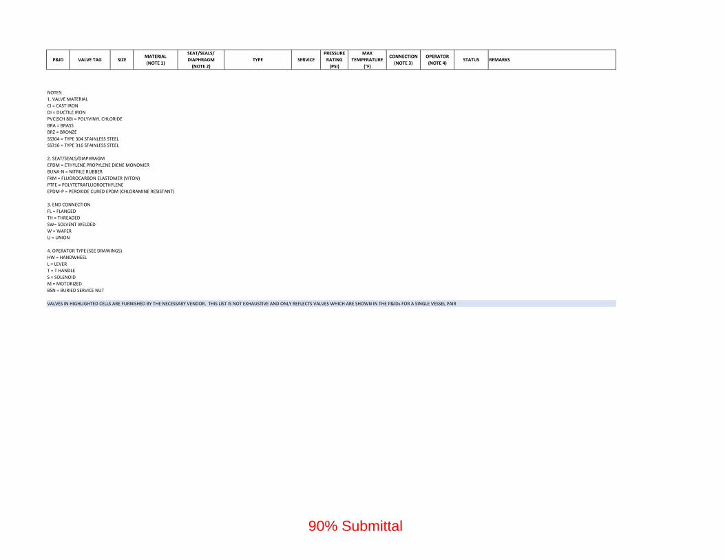
P&ID VALVE TAG SIZEMATERIAL
(NOTE 1)
SEAT/SEALS/
DIAPHRAGM
(NOTE 2)
TYPE SERVICE
PRESSURE
RATING
(PSI)
MAX
TEMPERATURE
(°F)
CONNECTION
(NOTE 3)
OPERATOR
(NOTE 4)STATUS REMARKS
SS304 = TYPE 304 STAINLESS STEEL
VALVES IN HIGHLIGHTED CELLS ARE FURNISHED BY THE NECESSARY VENDOR. THIS LIST IS NOT EXHAUSTIVE AND ONLY REFLECTS VALVES WHICH ARE SHOWN IN THE P&IDs FOR A SINGLE VESSEL PAIR
SS316 = TYPE 316 STAINLESS STEEL
NOTES:
1. VALVE MATERIAL
PVC(SCH 80) = POLYVINYL CHLORIDE
BRZ = BRONZE
BRA = BRASS
DI = DUCTILE IRON
CI = CAST IRON
BSN = BURIED SERVICE NUT
3. END CONNECTION
FL = FLANGED
TH = THREADED
SW= SOLVENT WELDED
4. OPERATOR TYPE (SEE DRAWINGS)
HW = HANDWHEEL
L = LEVER
M = MOTORIZED
W = WAFER
U = UNION
T = T HANDLE
2. SEAT/SEALS/DIAPHRAGM
S = SOLENOID
EPDM‐P = PEROXIDE CURED EPDM (CHLORAMINE RESISTANT)
EPDM = ETHYLENE PROPYLENE DIENE MONOMER
BUNA‐N = NITRILE RUBBER
FKM = FLUOROCARBON ELASTOMER (VITON)
PTFE = POLYTETRAFLUOROETHYLENE
90% Submittal

© 2021 CDM Smith 26793-252125
All Rights Reserved May 4, 2021
EMWD Sleeves and Sleeve Seals for Plumbing Piping
Final Design of Cactus Corridor Facilities 15013 - 1
90% Submittal
SECTION 15013 - SLEEVES AND SLEEVE SEALS FOR PLUMBING PIPING
PART 1 - GENERAL
1.1 RELATED DOCUMENTS
A. Drawings and general provisions of the Contract, including General and Supplementary
Conditions and Division 01 Specification Sections, apply to this Section.
1.2 SUMMARY
A. Section Includes:
1. Sleeves.
2. Stack-sleeve fittings.
3. Sleeve-seal systems.
4. Sleeve-seal fittings.
5. Grout.
6. Silicone sealants.
1.3 ACTION SUBMITTALS
A. Product Data: For each type of product.
1.4 INFORMATIONAL SUBMITTALS
A. Field quality-control reports.
PART 2 - PRODUCTS
2.1 SLEEVES
A. Cast-Iron Pipe Sleeves: Cast or fabricated of cast or ductile iron and equivalent to ductile-iron
pressure pipe, with plain ends and integral waterstop collar.
B. PVC Pipe Sleeves: ASTM D1785, Schedule 40.
C. Molded-PVC Sleeves: With nailing flange for attaching to wooden forms.
90% Submittal
© 2021 CDM Smith 26793-252125
All Rights Reserved May 4, 2021
EMWD Sleeves and Sleeve Seals for Plumbing Piping
Final Design of Cactus Corridor Facilities 15013 - 2
90% Submittal
2.2 STACK-SLEEVE FITTINGS
A. Description: Manufactured, Dura-coated or Duco-coated cast-iron sleeve with integral clamping
flange for use in waterproof floors and roofs. Include clamping ring, bolts, and nuts for
membrane flashing.
1. Underdeck Clamp: Clamping ring with setscrews.
2.3 SLEEVE-SEAL SYSTEMS
A. Description:
1. Modular sealing-element unit, designed for field assembly, for filling annular space
between piping and sleeve.
2. Designed to form a hydrostatic seal of 20 psig minimum.
3. Sealing Elements: EPDM-rubber interlocking links shaped to fit surface of pipe. Include
type and number required for pipe material and size of pipe.
4. Pressure Plates: Carbon steel.
5. Connecting Bolts and Nuts: Stainless steel of length required to secure pressure plates to
sealing elements.
2.4 SLEEVE-SEAL FITTINGS
A. Description: Manufactured plastic, sleeve-type, waterstop assembly made for imbedding in
concrete slab or wall.
B. Plastic or rubber waterstop collar with center opening to match piping OD.
2.5 GROUT
A. Description: Nonshrink, for interior and exterior sealing openings in non-fire-rated walls or
floors.
B. Standard: ASTM C1107/C1107M, Grade B, post-hardening and volume-adjusting, dry,
hydraulic-cement grout.
C. Design Mix: 5000-psi, 28-day compressive strength.
D. Packaging: Premixed and factory packaged.
2.6 SILICONE SEALANTS
A. Silicone, S, NS, 25, NT: Single-component, nonsag, plus 25 percent and minus 25 percent
movement capability, nontraffic-use, neutral-curing silicone joint sealant, ASTM C920, Type S,
Grade NS, Class 25, Use NT.
B. Silicone, S, P, 25, T, NT: Single-component, pourable, plus 25 percent and minus 25 percent
movement capability, traffic- and nontraffic-use, neutral-curing silicone joint sealant;
90% Submittal

© 2021 CDM Smith 26793-252125
All Rights Reserved May 4, 2021
EMWD Sleeves and Sleeve Seals for Plumbing Piping
Final Design of Cactus Corridor Facilities 15013 - 3
90% Submittal
ASTM C920, Type S, Grade P, Class 25, Uses T and NT. Grade P Pourable (self-leveling)
formulation is for opening in floors and other horizontal surfaces that are not fire rated.
C. Silicone Foam: Multicomponent, silicone-based liquid elastomers that, when mixed, expand and
cure in place to produce a flexible, nonshrinking foam.
PART 3 - EXECUTION
3.1 SLEEVE INSTALLATION
A. Install sleeves for piping passing through penetrations in floors, partitions, roofs, and walls.
B. For sleeves that will have sleeve-seal system installed, select sleeves of size large enough to
provide 1-inch annular clear space between piping and concrete slabs and walls.
1. Sleeves are not required for core-drilled holes.
C. Install sleeves in concrete floors, concrete roof slabs, and concrete walls as new slabs and walls
are constructed.
1. Permanent sleeves are not required for holes in slabs formed by molded-PE or -PP
sleeves.
2. Cut sleeves to length for mounting flush with both surfaces.
a. Exception: Extend sleeves installed in floors of mechanical equipment areas or
other wet areas 2 inches above finished floor level.
3. Using grout or silicone sealant, seal the space outside of sleeves in slabs and walls
without sleeve-seal system.
D. Install sleeves for pipes passing through interior partitions.
1. Cut sleeves to length for mounting flush with both surfaces.
2. Install sleeves that are large enough to provide 1/4-inch annular clear space between
sleeve and pipe or pipe insulation.
3. Seal annular space between sleeve and piping or piping insulation; use joint sealants
appropriate for size, depth, and location of joint.
E. Fire-Resistance-Rated Penetrations, Horizontal Assembly Penetrations, and Smoke Barrier
Penetrations: Maintain indicated fire or smoke rating of walls, partitions, ceilings, and floors at
pipe penetrations. Seal pipe penetrations with fire- and smoke-stop materials. Comply with
requirements for firestopping and fill materials specified in Section 07841 "Penetration
Firestopping."
3.2 STACK-SLEEVE-FITTING INSTALLATION
A. Install stack-sleeve fittings in new slabs as slabs are constructed.
Ensure fireproofing materialsare not needed for penetrationof fire rated assemblies(coordinate w/ 3.1 E.)
90% Submittal
© 2021 CDM Smith 26793-252125
All Rights Reserved May 4, 2021
EMWD Sleeves and Sleeve Seals for Plumbing Piping
Final Design of Cactus Corridor Facilities 15013 - 4
90% Submittal
1. Install fittings that are large enough to provide 1/4-inch annular clear space between
sleeve and pipe or pipe insulation.
2. Secure flashing between clamping flanges for pipes penetrating floors with membrane
waterproofing. Comply with requirements for flashing specified in Section 07620 "Sheet
Metal Flashing and Trim."
3. Install section of cast-iron soil pipe to extend sleeve to 2 inches above finished floor
level.
4. Extend cast-iron sleeve fittings below floor slab as required to secure clamping ring if
ring is specified.
5. Use silicone sealant to seal the space around outside of stack-sleeve fittings.
B. Fire-Resistance-Rated Penetrations, Horizontal Assembly Penetrations, and Smoke Barrier
Penetrations: Maintain indicated fire or smoke rating of floors at pipe penetrations. Seal pipe
penetrations with fire- and smoke-stop materials. Comply with requirements for firestopping
specified in Section 07841 "Penetration Firestopping."
3.3 SLEEVE-SEAL-SYSTEM INSTALLATION
A. Install sleeve-seal systems in sleeves in exterior concrete walls and slabs-on-grade at service
piping entries into building.
B. Select type, size, and number of sealing elements required for piping material and size and for
sleeve ID or hole size. Position piping in center of sleeve. Center piping in penetration,
assemble sleeve-seal system components, and install in annular space between piping and
sleeve. Tighten bolts against pressure plates that cause sealing elements to expand and make a
watertight seal.
3.4 SLEEVE-SEAL-FITTING INSTALLATION
A. Install sleeve-seal fittings in new walls and slabs as they are constructed.
B. Assemble fitting components of length to be flush with both surfaces of concrete slabs and
walls. Position waterstop flange to be centered in concrete slab or wall.
C. Secure nailing flanges to concrete forms.
D. Use grout or silicone sealant to seal the space around outside of sleeve-seal fittings.
3.5 FIELD QUALITY CONTROL
A. Perform the following tests and inspections:
1. Leak Test: After allowing for a full cure, test sleeves and sleeve seals for leaks. Repair
leaks and retest until no leaks exist.
B. Sleeves and sleeve seals will be considered defective if they do not pass tests and inspections.
C. Prepare test and inspection reports.
90% Submittal

© 2021 CDM Smith 26793-252125
All Rights Reserved May 4, 2021
EMWD Sleeves and Sleeve Seals for Plumbing Piping
Final Design of Cactus Corridor Facilities 15013 - 5
90% Submittal
3.6 SLEEVE AND SLEEVE-SEAL SCHEDULE
A. Use sleeves and sleeve seals for the following piping-penetration applications:
1. Exterior Concrete Walls above Grade:
a. Piping Smaller Than NPS 6: Cast-iron pipe sleeves or Sleeve-seal fittings.
b. Piping NPS 6 and Larger: Cast-iron pipe sleeves or Sleeve-seal fittings.
2. Exterior Concrete Walls below Grade:
a. Piping Smaller Than NPS 6: Cast-iron pipe sleeves with sleeve-seal system.
1) Select sleeve size to allow for 1-inch annular clear space between piping and
sleeve for installing sleeve-seal system.
b. Piping NPS 6 and Larger: Cast-iron pipe sleeves with sleeve-seal system.
1) Select sleeve size to allow for 1-inch annular clear space between piping and
sleeve for installing sleeve-seal system.
3. Concrete Slabs-on-Grade:
a. Piping Smaller Than NPS 6: Cast-iron pipe sleeves with sleeve-seal system.
1) Select sleeve size to allow for 1-inch annular clear space between piping and
sleeve for installing sleeve-seal system.
b. Piping NPS 6 and Larger: Cast-iron pipe sleeves with sleeve-seal system.
1) Select sleeve size to allow for 1-inch annular clear space between piping and
sleeve for installing sleeve-seal system.
4. Interior Partitions:
a. Piping Smaller Than NPS 6: Galvanized Steel pipe sleeves.
END OF SECTION 15013
90% Submittal

© 2021 CDM Smith 26793-252125
All Rights Reserved May 4, 2021
EMWD Identification for Plumbing Piping and Equipment
Final Design of Cactus Corridor Facilities 15035 - 1
90% Submittal
SECTION 15035 - IDENTIFICATION FOR PLUMBING PIPING AND EQUIPMENT
PART 1 - GENERAL
1.1 RELATED DOCUMENTS
A. Drawings and general provisions of the Contract, including General and Supplementary
Conditions and Division 01 Specification Sections, apply to this Section.
1.2 SUMMARY
A. Section Includes:
1. Equipment labels.
2. Pipe labels.
3. Valve tags.
1.3 ACTION SUBMITTALS
A. Product Data: For each type of product indicated.
B. Samples: For color, letter style, and graphic representation required for each identification
material and device.
C. Equipment Label Schedule: Include a listing of all equipment to be labeled with the proposed
content for each label.
D. Valve numbering scheme.
E. Valve Schedules: For each piping system to include in maintenance manuals.
PART 2 - PRODUCTS
2.1 EQUIPMENT LABELS
A. Metal Labels for Equipment:
1. Material and Thickness: stainless steel, 0.025-inch minimum thickness, and having
predrilled or stamped holes for attachment hardware.
2. Letter Color: Black.
3. Background Color: White.
4. Minimum Label Size: Length and width vary for required label content, but not less than
2-1/2 by 3/4 inch.
5. Minimum Letter Size: 1/4 inch for name of units if viewing distance is less than 24
inches, 1/2 inch for viewing distances up to 72 inches, and proportionately larger lettering
90% Submittal

© 2021 CDM Smith 26793-252125
All Rights Reserved May 4, 2021
EMWD Identification for Plumbing Piping and Equipment
Final Design of Cactus Corridor Facilities 15035 - 2
90% Submittal
for greater viewing distances. Include secondary lettering two-thirds to three-quarters the
size of principal lettering.
6. Fasteners: Stainless-steel rivets or self-tapping screws.
7. Adhesive: Contact-type permanent adhesive, compatible with label and with substrate.
B. Label Content: Include equipment's Drawing designation or unique equipment number,
Drawing numbers where equipment is indicated (plans, details, and schedules), and the
Specification Section number and title where equipment is specified.
C. Equipment Label Schedule: For each item of equipment to be labeled, on 8-1/2-by-11-inch bond
paper. Tabulate equipment identification number, and identify Drawing numbers where
equipment is indicated (plans, details, and schedules) and the Specification Section number and
title where equipment is specified. Equipment schedule shall be included in operation and
maintenance data.
2.2 PIPE LABELS
A. General Requirements for Manufactured Pipe Labels: Preprinted, color-coded, with lettering
indicating service, and showing flow direction.
B. Pretensioned Pipe Labels: Precoiled, semirigid plastic formed to cover full circumference of
pipe and to attach to pipe without fasteners or adhesive.
C. Self-Adhesive Pipe Labels: Printed plastic with contact-type, permanent-adhesive backing.
D. Pipe Label Contents: Include identification of piping service using same designations or
abbreviations as used on Drawings; also include pipe size and an arrow indicating flow
direction.
1. Flow-Direction Arrows: Integral with piping-system service lettering to accommodate
both directions or as separate unit on each pipe label to indicate flow direction.
2. Lettering Size: At least 1/2 inch for viewing distances up to 72 inches and proportionately
larger lettering for greater viewing distances.
2.3 VALVE TAGS
A. Valve Tags: Stamped or engraved with 1/4-inch letters for piping system abbreviation and 1/2-
inch numbers.
1. Tag Material: stainless steel, 0.025-inch minimum thickness, and having predrilled or
stamped holes for attachment hardware.
2. Fasteners: Brass wire-link chain or beaded chain or S-hook.
B. Valve Schedules: For each piping system, on 8-1/2-by-11-inch bond paper. Tabulate valve
number, piping system, system abbreviation (as shown on valve tag), location of valve (room or
space), normal-operating position (open, closed, or modulating), and variations for
identification. Mark valves for emergency shutoff and similar special uses.
1. Valve-tag schedule shall be included in operation and maintenance data.
90% Submittal

© 2021 CDM Smith 26793-252125
All Rights Reserved May 4, 2021
EMWD Identification for Plumbing Piping and Equipment
Final Design of Cactus Corridor Facilities 15035 - 3
90% Submittal
PART 3 - EXECUTION
3.1 PREPARATION
A. Clean piping and equipment surfaces of substances that could impair bond of identification
devices, including dirt, oil, grease, release agents, and incompatible primers, paints, and
encapsulants.
3.2 GENERAL INSTALLATION REQUIREMENTS
A. Coordinate installation of identifying devices with completion of covering and painting of
surfaces where devices are to be applied.
B. Coordinate installation of identifying devices with locations of access panels and doors.
C. Install identifying devices before installing acoustical ceilings and similar concealment.
3.3 EQUIPMENT LABEL INSTALLATION
A. Install or permanently fasten labels on each major item of mechanical equipment.
B. Locate equipment labels where accessible and visible.
3.4 PIPE LABEL INSTALLATION
A. Pipe Label Locations: Locate pipe labels where piping is exposed or above accessible ceilings
in finished spaces; machine rooms; accessible maintenance spaces such as shafts, tunnels, and
plenums; and exterior exposed locations as follows:
1. Near each valve and control device.
2. Near each branch connection, excluding short takeoffs for fixtures and terminal units.
Where flow pattern is not obvious, mark each pipe at branch.
3. Near penetrations through walls, floors, ceilings, and inaccessible enclosures.
4. At access doors, manholes, and similar access points that permit view of concealed
piping.
5. Near major equipment items and other points of origination and termination.
6. Spaced at maximum intervals of 50 feet along each run. Reduce intervals to 25 feet in
areas of congested piping and equipment.
7. On piping above removable acoustical ceilings. Omit intermediately spaced labels.
B. Directional Flow Arrows: Arrows shall be used to indicate direction of flow in pipes, including
pipes where flow is allowed in both directions.
C. Pipe Label Color Schedule:
1. Domestic Water Piping:
a. Background: Safety green.
90% Submittal
© 2021 CDM Smith 26793-252125
All Rights Reserved May 4, 2021
EMWD Identification for Plumbing Piping and Equipment
Final Design of Cactus Corridor Facilities 15035 - 4
90% Submittal
b. Letter Colors: White.
2. Drainage Piping:
a. Background Color: Safety black.
b. Letter Color: Black.
3. Tepid Water Piping:
a. Background: Safety green.
b. Letter Colors: White.
3.5 VALVE-TAG INSTALLATION
A. Install tags on valves and control devices in piping systems, except check valves, valves within
factory-fabricated equipment units, shutoff valves, faucets, convenience and lawn-watering hose
connections, and similar roughing-in connections of end-use fixtures and units. List tagged
valves in a valve schedule.
B. Valve-Tag Application Schedule: Tag valves according to size, shape, and color scheme and
with captions similar to those indicated in the following subparagraphs:
1. Valve-Tag Size and Shape:
a. Cold Water: 2 inches square.
b. Hot Water: 2 inches square.
2. Valve-Tag Colors:
a. Cold Water: Natural.
b. Hot Water: Natural.
3. Letter Colors:
a. Cold Water: White
b. Hot Water: White.
3.6 WARNING-TAG INSTALLATION
A. Write required message on, and attach warning tags to, equipment and other items where
required.
END OF SECTION 15035
90% Submittal

© 2021 CDM Smith 26793-252125
All Rights Reserved May 4, 2021
EMWD Common Motor Requirements for HVAC Equipment
Final Design of Cactus Corridor Facilities 15042 - 1
90% Submittal
SECTION 15042 - COMMON MOTOR REQUIREMENTS FOR HVAC EQUIPMENT
PART 1 - GENERAL
1.1 RELATED DOCUMENTS
A. Drawings and general provisions of the Contract, including General and Supplementary
Conditions and Division 01 Specification Sections, apply to this Section.
1.2 SUMMARY
A. Section includes general requirements for single-phase and polyphase, general-purpose,
horizontal, small and medium, squirrel-cage induction motors for use on alternating-current
power systems up to 600 V and installed at equipment manufacturer's factory or shipped
separately by equipment manufacturer for field installation.
1.3 COORDINATION
A. Coordinate features of motors, installed units, and accessory devices to be compatible with the
following:
1. Motor controllers.
2. Torque, speed, and horsepower requirements of the load.
3. Ratings and characteristics of supply circuit and required control sequence.
4. Ambient and environmental conditions of installation location.
PART 2 - PRODUCTS
2.1 GENERAL MOTOR REQUIREMENTS
A. Comply with NEMA MG 1 unless otherwise indicated.
B. Comply with IEEE 841 for severe-duty motors.
2.2 MOTOR CHARACTERISTICS
A. Duty: Continuous duty at ambient temperature of 105 deg F and at altitude of 3300 feet above
sea level.
B. Capacity and Torque Characteristics: Sufficient to start, accelerate, and operate connected loads
at designated speeds, at installed altitude and environment, with indicated operating sequence,
and without exceeding nameplate ratings or considering service factor.
90% Submittal

© 2021 CDM Smith 26793-252125
All Rights Reserved May 4, 2021
EMWD Common Motor Requirements for HVAC Equipment
Final Design of Cactus Corridor Facilities 15042 - 2
90% Submittal
2.3 POLYPHASE MOTORS
A. Description: NEMA MG 1, Design B, medium induction motor.
B. Efficiency: Premium efficient, as defined in NEMA MG 1.
C. Service Factor: 1.15.
D. Multispeed Motors: Variable torque.
1. For motors with 2:1 speed ratio, consequent pole, single winding.
2. For motors with other than 2:1 speed ratio, separate winding for each speed.
E. Multispeed Motors: Separate winding for each speed.
F. Rotor: Random-wound, squirrel cage.
G. Bearings: Regreasable, shielded, antifriction ball bearings suitable for radial and thrust loading.
H. Temperature Rise: Match insulation rating.
I. Insulation: Class F.
J. Code Letter Designation:
1. Motors 15 HP and Larger: NEMA starting Code F or Code G.
2. Motors Smaller Than 15 HP: Manufacturer's standard starting characteristic.
K. Enclosure Material: Cast iron for motor frame sizes 324T and larger; rolled steel for motor
frame sizes smaller than 324T.
2.4 ADDITIONAL REQUIREMENTS FOR POLYPHASE MOTORS
A. Motors Used with Reduced-Voltage and Multispeed Controllers: Match wiring connection
requirements for controller with required motor leads. Provide terminals in motor terminal box,
suited to control method.
B. Motors Used with Variable-Frequency Controllers:
1. Windings: Copper magnet wire with moisture-resistant insulation varnish, designed and
tested to resist transient spikes, high frequencies, and short time rise pulses produced by
pulse-width-modulated inverters.
2. Premium-Efficient Motors: Class B temperature rise; Class F insulation.
3. Inverter-Duty Motors: Class F temperature rise; Class H insulation.
4. Thermal Protection: Comply with NEMA MG 1 requirements for thermally protected
motors.
5. Provide grounding rings or straps on motors with variable frequency controller.
C. Severe-Duty Motors: Comply with IEEE 841, with 1.15 minimum service factor.
90% Submittal

© 2021 CDM Smith 26793-252125
All Rights Reserved May 4, 2021
EMWD Common Motor Requirements for HVAC Equipment
Final Design of Cactus Corridor Facilities 15042 - 3
90% Submittal
2.5 SINGLE-PHASE MOTORS
A. Motors larger than 1/20 hp shall be one of the following, to suit starting torque and
requirements of specific motor application:
1. Permanent-split capacitor.
2. Split phase.
3. Capacitor start, inductor run.
4. Capacitor start, capacitor run.
B. Multispeed Motors: Variable-torque, permanent-split-capacitor type.
C. Bearings: Prelubricated, antifriction ball bearings or sleeve bearings suitable for radial and
thrust loading.
D. Motors 1/20 HP and Smaller: Shaded-pole type.
E. Thermal Protection: Internal protection to automatically open power supply circuit to motor
when winding temperature exceeds a safe value calibrated to temperature rating of motor
insulation. Thermal-protection device shall automatically reset when motor temperature returns
to normal range.
2.6 ELECTRONICALLY COMMUTATED MOTOR (ECM)
A. Synchronous, constant torque, ECM with permanent magnet rotor. Rotor magnets to be time-
stable, nontoxic ceramic magnets (Sr-Fe).
B. Driven by a frequency converter with an integrated power factor correction filter. Conventional
induction motors will not be acceptable.
C. Variable-speed motors should be furnished as, "inverter-duty", rated with proper insulation and
grounding rings or conductors.
D. Each motor with an integrated variable-frequency drive, tested as one unit by manufacturer.
E. Motor speed adjustable over full range from 0 rpm to maximum scheduled speed.
F. Variable motor speed to be controlled by a 0- to 10 V-dc or 4- to 20-mA input.
G. Integrated motor protection verified by UL to protect the fan against over-/undervoltage,
overtemperature of motor and/or electronics, overcurrent, locked rotor, and dry run (no-load
condition).
PART 3 - EXECUTION (NOT USED)
END OF SECTION 15042
90% Submittal

© 2021 CDM Smith 26793-252125
All Rights Reserved May 4, 2021
EMWD Sleeves and Sleeve Seals for HVAC Piping
Final Design of Cactus Corridor Facilities 15044 - 1
90% Submittal
SECTION 15044 - SLEEVES AND SLEEVE SEALS FOR HVAC PIPING
PART 1 - GENERAL
1.1 RELATED DOCUMENTS
A. Drawings and general provisions of the Contract, including General and Supplementary
Conditions and Division 01 Specification Sections, apply to this Section.
1.2 SUMMARY
A. Section Includes:
1. Sleeves.
2. Stack-sleeve fittings.
3. Sleeve-seal systems.
4. Grout.
5. Silicone sealants.
1.3 ACTION SUBMITTALS
A. Product Data: For each type of product.
PART 2 - PRODUCTS
2.1 SLEEVES
A. Cast-Iron Pipe Sleeves: Cast or fabricated of cast or ductile iron and equivalent to ductile-iron
pressure pipe, with plain ends and integral water-stop collar.
B. Steel Pipe Sleeves: ASTM A53/A53M, Type E, Grade B, Schedule 40, zinc coated, with plain
ends and integral welded water-stop collar.
2.2 STACK-SLEEVE FITTINGS
A. Description: Manufactured, galvanized cast-iron sleeve with integral cast flashing flange for use
in waterproof floors and roofs. Include clamping ring, bolts, and nuts for membrane flashing.
1. Underdeck Clamp: Clamping ring with setscrews.
2.3 SLEEVE-SEAL SYSTEMS
A. Description:
90% Submittal
© 2021 CDM Smith 26793-252125
All Rights Reserved May 4, 2021
EMWD Sleeves and Sleeve Seals for HVAC Piping
Final Design of Cactus Corridor Facilities 15044 - 2
90% Submittal
1. Modular sealing-element unit, designed for field assembly, for filling annular space
between piping and sleeve.
2. Designed to form a hydrostatic seal of 20-psig minimum.
3. Sealing Elements: EPDM-rubber interlocking links shaped to fit surface of pipe. Include
type and number required for pipe material and size.
4. Pressure Plates: Carbon steel.
5. Connecting Bolts and Nuts: Carbon steel, with corrosion-resistant coating, ASTM B 633
of length required to secure pressure plates to sealing elements.
2.4 GROUT
A. Description: Non shrink, recommended for interior and exterior sealing openings in nonfire-
rated walls or floors.
B. Standard: ASTM C1107/C1107M, Grade B, post-hardening and volume-adjusting, dry,
hydraulic-cement grout.
C. Design Mix: 5000-psi, 28-day compressive strength.
D. Packaging: Premixed and factory packaged.
2.5 SILICONE SEALANTS
A. Silicone, S, NS, 25, NT: Single-component, non-sag, plus 25 percent and minus 25 percent
movement capability, nontraffic-use, neutral-curing silicone joint sealant, ASTM C 920,
Type S, Grade NS, Class 25, use NT.
B. Silicone Foam: Multicomponent, silicone-based liquid elastomers that, when mixed, expand and
cure in place to produce a flexible, non-shrinking foam.
PART 3 - EXECUTION
3.1 SLEEVE INSTALLATION
A. Install sleeves for piping passing through penetrations in floors, partitions, roofs, and walls.
B. For sleeves that will have sleeve-seal system installed, select sleeves of size large enough to
provide 1-inch annular clear space between piping and concrete slabs and walls.
1. Sleeves are not required for core-drilled holes.
C. Install sleeves in concrete floors, concrete roof slabs, and concrete walls as new slabs and walls
are constructed.
1. Permanent sleeves are not required for holes in slabs formed by molded-PE or -PP
sleeves.
2. Cut sleeves to length for mounting flush with both surfaces.
90% Submittal

© 2021 CDM Smith 26793-252125
All Rights Reserved May 4, 2021
EMWD Sleeves and Sleeve Seals for HVAC Piping
Final Design of Cactus Corridor Facilities 15044 - 3
90% Submittal
a. Exception: Extend sleeves installed in floors of mechanical equipment areas or
other wet areas 2 inches above finished floor level.
3. Using grout or silicone sealant, seal space outside of sleeves in slabs and walls without
sleeve-seal system.
D. Install sleeves for pipes passing through interior partitions.
1. Cut sleeves to length for mounting flush with both surfaces.
2. Install sleeves that are large enough to provide 1/4-inch annular clear space between
sleeve and pipe or pipe insulation.
3. Seal annular space between sleeve and piping or piping insulation; use sealants
appropriate for size, depth, and location of joint.
E. Fire-Resistance-Rated Penetrations, Horizontal Assembly Penetrations, and Smoke-Barrier
Penetrations: Maintain indicated fire or smoke rating of walls, partitions, ceilings, and floors at
pipe penetrations. Seal pipe penetrations with fire- and smoke-stop materials.
3.2 STACK-SLEEVE-FITTING INSTALLATION
A. Install stack-sleeve fittings in new slabs as slabs are constructed.
1. Install fittings that are large enough to provide 1/4-inch annular clear space between
sleeve and pipe or pipe insulation.
2. Secure flashing between clamping flanges for pipes penetrating floors with membrane
waterproofing. Comply with requirements for flashing specified in Section 076200
"Sheet Metal Flashing and Trim."
3. Install section of cast-iron soil pipe to extend sleeve to 3 inches above finished floor
level.
4. Extend cast-iron sleeve fittings below floor slab as required to secure clamping ring if
ring is specified.
5. Using waterproof silicone sealant, seal space between top hub of stack-sleeve fitting and
pipe.
B. Fire-Resistance-Rated, Horizontal Assembly, and Smoke Barrier Penetrations: Maintain
indicated fire or smoke rating of floors at pipe penetrations. Seal pipe penetrations with fire- and
smoke-stop materials. Comply with requirements for firestopping specified in Section 07841
"Penetration Firestopping."
3.3 SLEEVE-SEAL-SYSTEM INSTALLATION
A. Install sleeve-seal systems in sleeves in exterior concrete walls and slabs-on-grade at service
piping entries into building.
B. Select type, size, and number of sealing elements required for piping material and size and for
sleeve ID or hole size. Position piping in center of sleeve. Center piping in penetration,
assemble sleeve-seal-system components, and install in annular space between piping and
sleeve. Tighten bolts against pressure plates that cause sealing elements to expand and make a
watertight seal.
90% Submittal

© 2021 CDM Smith 26793-252125
All Rights Reserved May 4, 2021
EMWD Sleeves and Sleeve Seals for HVAC Piping
Final Design of Cactus Corridor Facilities 15044 - 4
90% Submittal
3.4 FIELD QUALITY CONTROL
A. Perform the following tests and inspections:
1. Leak Test: After allowing for a full cure, test sleeves and sleeve seals for leaks. Repair
leaks and retest until no leaks exist.
B. Sleeves and sleeve seals will be considered defective if they do not pass tests and inspections.
3.5 SLEEVE AND SLEEVE-SEAL SCHEDULE
A. Use sleeves and sleeve seals for the following piping-penetration applications:
1. Exterior Concrete Walls Above Grade: Steel Pipe Sleeve.
2. Exterior Concrete Walls Below Grade: Cast-iron pipe sleeves with sleeve-seal system.
a. Select sleeve size to allow for 1-inch annular clear space between piping and
sleeve for installing sleeve-seal system.
3. Concrete Slabs-on-Grade: Steel pipe sleeves with sleeve-seal system.
a. Select sleeve size to allow for 1-inch annular clear space between piping and
sleeve for installing sleeve-seal system.
4. Interior Partitions: Steel Pipe Sleeve.
END OF SECTION 15044
90% Submittal
© 2021 CDM Smith 26793-252125 All Rights Reserved May 4, 2021
Escutcheons for HVAC Piping EMWD 15045 - 1 Final Design of Cactus Corridor Facilities 90% Submittal
SECTION 15045 - ESCUTCHEONS FOR HVAC PIPING
PART 1 - GENERAL
1.1 RELATED DOCUMENTS
A. Drawings and general provisions of the Contract, including General and Supplementary Conditions and Division 01 Specification Sections, apply to this Section.
1.2 SUMMARY
A. Section Includes:
1. Escutcheons.
1.3 ACTION SUBMITTALS
A. Product Data: For each type of product.
PART 2 - PRODUCTS
2.1 ESCUTCHEONS
A. One-Piece, Stainless-Steel Type: With polished stainless-steel finish.
PART 3 - EXECUTION
3.1 INSTALLATION
A. Install escutcheons for piping penetrations of walls, ceilings, and finished floors.
B. Install escutcheons with ID to closely fit around pipe, tube, and insulation of piping and with OD that completely covers opening.
3.2 FIELD QUALITY CONTROL
A. Using new materials, replace broken and damaged escutcheons and floor plates.
END OF SECTION 15045
90% Submittal
© 2020 CDM Smith 26793-252125
All Rights Reserved May 4, 2021
EMWD Hangers and Supports for Process Piping
Final Design of Cactus Corridor Facilities 15065 - 1
90% Submittal
SECTION 15065 - HANGERS AND SUPPORTS FOR PROCESS PIPING
PART 1 - GENERAL
1.1 RELATED DOCUMENTS
A. Drawings and general provisions of the Contract, including General and Supplementary
Conditions and Division 01 Specification Sections, apply to this Section.
1.2 SUMMARY
A. This specification requires Contractor to delegate pipe support design to a pipe support design
engineer hired by the Contractor. Where the Drawings show support types and/or locations,
they shall be analyzed for adequacy to support loads and stresses calculated by the pipe support
designer, modified if required, installed generally where shown, and integrated with the pipe
support system design provided by the Contractor.
B. Related Requirements:
1. Section 03150 "Formwork for Cast-in-Place Concrete" for execution requirements for
placement of sleeves in concrete forms specified by this Section.
2. Section 03300 "Cast-in-Place Concrete" for execution requirements for placement of
concrete housekeeping pads specified by this Section.
3. Section 09900 "Painting and Protective Coating" for product and execution requirements
for painting specified by this Section.
4. Section 15061 “Steel Cylinder Water Pipe.”
1.3 DEFINITIONS
A. Ferrous Metal: Iron, steel, stainless steel, and alloys with iron as principal component.
B. Wetted or submerged: Submerged, less than 1-foot above liquid surface, below top of channel
or tank wall, under cover or slab of channel or tank, or in other damp locations.
C. “Pipe” or “piping” shall mean all piping, piping system(s), hose, tube, fittings, joints, valves,
and similar appurtenances.
D. Supports: wherever the word “supports” or “pipe supports” are used, they shall mean pipe
supports, hangers, structural connections, concrete inserts (if allowed), anchors, guides, bolts,
expansion units, restraints and all restraint, hanging, supporting, allowing controlled expansion,
or other means of attaching piping along with the necessary appurtenances.
1.4 COORDINATION
A. Coordinate Work of this Section with piping and equipment connections specified in other
Sections and indicated on Drawings.
90% Submittal

© 2020 CDM Smith 26793-252125
All Rights Reserved May 4, 2021
EMWD Hangers and Supports for Process Piping
Final Design of Cactus Corridor Facilities 15065 - 2
90% Submittal
1.5 PREINSTALLATION MEETINGS
A. Convene minimum one week prior to commencing Work of this Section.
1.6 ACTION SUBMITTALS
A. Product Data: Submit manufacturer's catalog data including load capacity.
B. Shop Drawings: Submit scaled piping layouts for each system. Indicate flow stream, pipe
size(s) material(s), schedule(s), lining(s), critical dimensions between pipes, equipment and
building features. Indicate by schedule pipe hanger/support type and locations. Provide detail of
each type of hangers, supports, anchors, and guides.
C. Delegated Design Submittals: Support System Design:
1. Engage the services of an independent registered professional engineer licensed in the
State of California ordinarily engaged in the business of pipe support systems analysis
and design, to analyze system piping and service conditions, and to develop a detailed
support system design, specific to the piping material, pipe joints, valves, and piping
appurtenances proposed for use.
a. The proposed support system engineer shall have at least 5 years of experience in
the analysis and design of similar systems, including the use of commercial and
custom pipe supports and in the use of commercial pipe stress software programs.
b. Engineer pre-approved support system engineering groups include the following:
1) J. Blanco Associates, Inc. Hawthorne, NJ.
2) Fenny Engineering Company, Venice, FL.
3) LCI Engineering, Ottawa, Ontario, Canada.
2. The support system design shall include:
a. Criteria by piping system.
b. Summary of Contractor-selected related components including joints, class, valves,
appurtenances, etc., and commercial supports and especially including pipe
materials.
c. Dead weight and dynamic analysis, including system thermal effects and pressure
thrusts. Computer-based software system equivalent to Bentley Systems AutoPIPE
or SST Systems CAEPIPE.
1) Present each system in an isometric graphic and show the resolved and
resultant force and moment systems, as well as all recommended hangers,
supports, anchors, restraints, and expansion/flexible joints.
d. Submit a support system design to the Engineer for review. The submittal needs to
be stamped by a professional engineer registered in State of California
e. All aspects of the analysis and design to comply with the provisions of ANSI
B31.3 and the referenced standards.
f. Coordinate support arrangements to eliminate interference with similar systems to
be installed under HVAC, Plumbing, and Electrical; to account for structural
90% Submittal

© 2020 CDM Smith 26793-252125
All Rights Reserved May 4, 2021
EMWD Hangers and Supports for Process Piping
Final Design of Cactus Corridor Facilities 15065 - 3
90% Submittal
expansion joints and to maintain access for both personnel and for the removal of
equipment.
D. Manufacturers' Instructions: Submit special procedures and assembly of components.
1.7 INFORMATIONAL SUBMITTALS
A. Manufacturer's Certificate: Certify that products meet or exceed specified requirements.
B. Welders' Certificate: Submit welders' certification of compliance with AWS D1.1, verifying
qualification within previous 12 months.
C. Qualifications Statements:
1. Submit qualifications for manufacturer, fabricator, installer, and licensed professional.
2. Submit manufacturer's approval of installer.
1.8 DELIVERY, STORAGE AND HANDLING
A. All supports and hangers shall be crated, delivered and uncrated so as to protect against any
damage.
B. All parts shall be properly protected so that no damage or deterioration shall occur during a
prolonged delay from the time of shipment until installation is completed.
C. Finished metal surfaces not galvanized, that are not of stainless-steel construction, or that are
not coated, shall be grease coated, to prevent rust and corrosion.
1.9 QUALITY ASSURANCE
A. Perform Work according to AWS D1.1 for welding hanger and support attachments to building
structure.
1.10 QUALIFICATIONS
A. Manufacturer: Company specializing in manufacturing Products specified in this Section with
minimum three years' experience.
B. Fabricator: Company specializing in fabricating products specified in this Section with
minimum three years' experience.
C. Installer: Company specializing in performing Work of this Section with minimum three years'
experience.
D. Licensed Professional: Professional engineer experienced in design of specified Work and
licensed in State of California.
90% Submittal

© 2020 CDM Smith 26793-252125
All Rights Reserved May 4, 2021
EMWD Hangers and Supports for Process Piping
Final Design of Cactus Corridor Facilities 15065 - 4
90% Submittal
1.11 DELIVERY, STORAGE, AND HANDLING
A. Inspection: Accept materials on-Site in original factory packaging, labeled with manufacturer's
identification.
B. Protect products from weather and construction traffic, dirt, water, chemical, and damage by
storing in original packaging.
1.12 EXISTING CONDITIONS
A. Field Measurements: Verify field measurements prior to fabrication. Indicate field
measurements on Shop Drawings.
PART 2 - PRODUCTS
2.1 GENERAL
A. Support pipe and appurtenances connected to equipment to prevent any strain being imposed on
the equipment. Comply with manufacturer’s requirements regarding piping loads being or not
being transmitted to their equipment. Submit certification stating that such requirements have
been met.
B. Support and secure all pipe and tubing in the intended position and alignment to prevent
significant stresses in the pipe or tubing material, valves, fittings, and other pipe appurtenances.
Design all supports to adequately secure the pipe against excessive dislocation due to thermal
expansion and contraction, internal flow forces, and all probable external forces such as
equipment, pipe, and personnel contact. Any structural steel members required to brace any
piping from excessive dislocation shall conform to the applicable requirements of Section
05502 “Metal Fabrications” and shall be furnished and installed under this Section.
C. Contractor may propose minor adjustments to the piping arrangements in order to simplify the
supports, or in order to resolve minor conflicts in the work. Such an adjustment might involve
minor change to a pipe centerline elevation so that a single trapeze support may be used.
D. Where flexible sleeve, split ring, vibration, or other couplings are required at equipment, tanks,
etc., the end opposite to the piece of equipment, tank, etc., shall be rigidly supported to prevent
transfer of force systems to the equipment. Do not install fixed or restraining supports between
a flexible coupling and the piece of equipment.
E. Where couplings or unions are provided to facilitate dismantling of the piping, provides
supports such that piping on both side of the coupling or union is supported when the coupling
or union is removed.
F. Pipe supports:
1. Shall not induce point loadings but shall distribute pipe loads evenly along the pipe
circumference.
2. Provide supports at changes in direction and elsewhere as shown in the Drawings or as
specified herein.
90% Submittal

© 2020 CDM Smith 26793-252125
All Rights Reserved May 4, 2021
EMWD Hangers and Supports for Process Piping
Final Design of Cactus Corridor Facilities 15065 - 5
90% Submittal
3. No piping shall be supported from other piping or from metal stairs, ladders, and
walkways, unless specifically directed or authorized by the Engineer.
4. Provide pipe supports to minimize lateral forces through valves, both sides of flexible
split ring type couplings and sleeve type couplings, and to minimize all pipe forces on
pump housings. Pump housings shall not be utilized to support connecting pipes.
5. Effects of thermal expansion and contraction of the pipe to be accounted for in the pipe
support selection and installation.
G. Insofar as is possible, floor supports shall be given preference. Where specifically indicated,
concrete supports, as shown on the Drawings, may be used. Base elbow and base tees shall be
supported on concrete pedestals.
H. Include in the piping system analysis all restraints, flexible connections, expansion items, and
related items as included in other specifications and shown on the Drawings.
2.2 PERFORMANCE REQUIREMENTS/DESIGN CRITERIA
A. All supports and appurtenances shall be standard products from approved manufacturers
wherever possible, and shall be adequate to maintain the supported load in proper position
under all operating conditions. Any reference to a specific figure number of a specific
manufacturer is for the purpose of establishing a type and quality of product and shall not be
considered as proprietary. Note that different materials required, as specified in Part 2
MATERIALS, may require different figures or model numbers than those shown.
1. The minimum working factor of safety for all items, with the exception of springs, shall
be five times the ultimate tensile strength of the material, assuming 10 feet of water-filled
pipe being supported and normal test pressures.
2. Design for all loads using a safety factor of 5.
B. Piping schedule is included in the contract drawings.
C. All items shall be designed with strength and stiffness to support, restrain, and allow expansion
of the respective pipes under the maximum combination of peak loading conditions to include
pipe weight, liquid weight, liquid movement and pressure forces, thermal expansion and
contraction, vibrations, and all probable externally applied forces.
D. Support spacing shall be per ASME B31.1.
E. Complete design details of the pipe system components shall be submitted for review and
approval as specified in Part 1. No support shall be installed without approved support system
Drawings.
F. The pipe support system shall not impose loads on the supporting structures in excess of the
loads for which the supporting structure is designed.
G. Seismic Design and restraint requirements, in accordance with the Structural Design criteria.
90% Submittal
© 2020 CDM Smith 26793-252125
All Rights Reserved May 4, 2021
EMWD Hangers and Supports for Process Piping
Final Design of Cactus Corridor Facilities 15065 - 6
90% Submittal
2.3 MATERIALS
A. For support of metallic pipe:
1. Submerged, buried, or within outdoor structures (vaults, etc.): Type 316 stainless steel
(SS).
2. Within chemical areas: Vinyl ester fiberglass reinforced plastic (FRP) for pipe size up to
2 inch, epoxy coated steel for 2-1/2 inches size and larger.
3. Other locations: steel with galvanizing where noted, or if not otherwise noted, coating as
required in Division 09 Finished Painting.
4. Additional requirements (including dielectric insulation): see following paragraphs.
B. For support of non-metallic pipe:
1. Submerged, buried, or within vaults: Type 316 stainless steel or FRP.
2. Within chemical areas: vinyl ester FRP.
3. Other locations: steel with galvanizing where noted, or if not otherwise noted, coating as
required in Division 09 Finished Painting; all with local stress protection shields.
4. Additional requirements (including stress protection shields): see following paragraphs
C. Wherever stainless steel is noted, it shall be Type 316 unless noted otherwise.
2.4 INSULATION
A. See Article ACCESSORIES and Drawings.
2.5 SUPPORT AND RESTRAINT SYSTEMS
A. Steel or Ductile Iron Piping:
1. Cast iron and ductile iron, steel, and stainless-steel piping shall be supported at a
maximum support spacing of 10 feet with a minimum of one support per pipe section at
the joints.
2. Support spacing for ductile iron, steel, and stainless-steel piping 2-in and smaller
diameter shall not exceed 5 feet.
B. Copper Piping:
1. Supports for copper pipe shall be copper plated or shall have a 1/16 inch plastic coating.
2. Support spacing for copper piping and tubing 2 inch and smaller diameter shall not
exceed 5 feet and greater than 2 inch diameter shall not exceed 8 feet.
3. Where pipe supports come in contact with copper piping, provide protection from
galvanic corrosion by: wrapping pipe with 1/16 inch thick neoprene sheet material and
galvanized protection shield; isolators similar to Cooper B-Line B3195CT; or copper-
plated or PVC-coated hangers and supports.
C. Non-Metallic Piping:
90% Submittal

© 2020 CDM Smith 26793-252125
All Rights Reserved May 4, 2021
EMWD Hangers and Supports for Process Piping
Final Design of Cactus Corridor Facilities 15065 - 7
90% Submittal
1. All uninsulated non-metallic piping such as PVC, CPVC, HDPE, PVDF, etc., shall be
protected from local stress concentrations at each support point. Protection shall be
provided by non-metallic protection shields or other method as approved by the Engineer.
a. Where pipes are bottom supported 180 degrees, arc shields shall be furnished.
Where 360-degree arc support is required, such as U-bolts, protection shields shall
be provided for the entire pipe circumference. All U-bolts or clamps for non-
metallic pipes shall be plastic coated.
b. Protection shields shall have an 18-gauge minimum thickness, not be less than 12
inches in length, and be securely fastened to pipe with Type 316 stainless steel
straps not less than 1/2 inch wide.
2. Individually supported PVC pipes shall be supported as recommended by the pipe
manufacturer except that support-spacing shall be manufacturers recommendation minus
2-ft. down to 5 ft spacing recommendation, then spacing shall be 3 feet.
3. Supports for horizontal multiple PVC plastic piping:
a. Shall be continuous wherever possible.
b. Multiple, suspended, horizontal plastic PVC pipe runs, where possible, shall be
supported by ladder type cable trays such as: Husky Ladder Flange Out by
MPHusky; or equal.
c. Rung spacing shall be 12 inches. Tray width shall be approximately 6 inch for
single runs and 12 inchesfor double runs.
d. Ladder type cable trays shall be furnished complete with all hanger rods, rod
couplings, concrete inserts, hanger clips, etc., required for a complete support
system. Individual plastic pipes shall be secured to the rungs of the cable tray by
strap clamps or fasteners similar to: Globe, Series 600; Unistrut Pipe/Conduit
Clamps and Hangers; or equal.
e. Spacing between clamps shall not exceed 9 feet. The cable trays shall provide
continuous support along the length of the pipe. Individual clamps, hangers, and
supports in contact with plastic PVC pipe shall provide firm support but not so
firm as to prevent longitudinal movement due to thermal expansion and
contraction.
D. Framing Support System
1. See Part 2 MATERIALS for materials of construction.
2. Beams: Size such that beam stress does not exceed 25000 psi and maximum deflection
does not exceed 1/240 of span.
3. Column Members: Size in accordance with manufacturer's recommended method.
4. Support Loads: Calculate using weight of pipes filled with water.
5. Maximum Spans:
a. Steel and ductile iron pipe, 3-inch diameter and larger: 10 feetcenters, unless
otherwise shown.
b. Other pipelines and special situations: Same as noted in previous paragraphs.
Supplementary hangers and supports may be required.
E. All vertical pipes shall be supported at each floor or at intervals of not more than 12 feet by
approved pipe collars, clamps, brackets, or wall rests and at all points necessary to ensure rigid
90% Submittal

© 2020 CDM Smith 26793-252125
All Rights Reserved May 4, 2021
EMWD Hangers and Supports for Process Piping
Final Design of Cactus Corridor Facilities 15065 - 8
90% Submittal
construction. All vertical pipes passing through pipe sleeves shall be secured using a pipe
collar.
2.6 ANCHOR BOLTS/SYSTEMS
A. Anchoring Devices: Design, size, and space support anchoring devices, including anchor bolts,
inserts, and other devices used to anchor support, to withstand shear, and pullout loads imposed
by loading and spacing on each particular support. DO NOTE USE ADHESIVE ANCHOR
BOLTS ON ANY PIPE SUPPORT HUNG FROM A ROOF OR CEILING, unless specifically
noted otherwise.
B. All post-installed anchors in concrete shall have current published ICC-ES Evaluation Report
indicating the anchor is approved for installation in cracked concrete.
C. The latest edition of the following specification and recommended practices shall become part
of this specification as if written herein. Wherever requirements conflict, the more stringent
shall govern.
1. ACI 318, Appendix D.
2. ACI 355.2, Mechanical Anchors “Qualification of Post-Installed Mechanical Anchors in
Concrete”
3. Anchor manufacturer’s published installation requirements.
D. Expansion anchors:
1. The length of expansion bolts shall be sufficient to place the wedge portion of the bolt a
minimum of 1 inch behind the steel reinforcement.
2. Manufacturers:
a. Power-Stud+ SD4 and Power-Stud+ SD6 by Powers Fasteners, Brewster, NY.
b. Kwik Bolt as manufactured by Hilti USA, Tulsa, Oklahoma.
c. Wej-it by Wej-it Expansion Products, Inc., Broomfield, Colorado.
E. Unless otherwise noted: Use Type 304 stainless steel anchoring parts/bolts and hardware for
non-submerged supports, Type 316 stainless steel for submerged anchors.
F. Size of anchor bolts as designed by manufacturer, 1/2 inch minimum diameter, or as shown on
the Drawings.
G. Anchors to concrete in chemical areas shall be epoxy secured vinyl ester FRP all thread,
insertion depth and size as required by the manufacturer for the design loads. Nuts, bolts and
hardware shall all be vinyl ester FRP construction.
2.7 HANGER RODS
A. Where use of steel is allowed, hanger rods shall be hot-rolled steel, machine-threaded, and,
except for stainless steel, galvanized after fabrication. The strength of the rod shall be based on
its root diameter.
90% Submittal
© 2020 CDM Smith 26793-252125
All Rights Reserved May 4, 2021
EMWD Hangers and Supports for Process Piping
Final Design of Cactus Corridor Facilities 15065 - 9
90% Submittal
1. Hanger rods shall be attached to concrete structures using single or continuous concrete
inserts by the named support manufacturers above. Where use of steel is allowed, inserts
shall be malleable iron or steel with galvanized finish.
2. Beam-clamps, C-clamps, or welded-beam attachments shall be used for attaching hanger
rods to structural steel members.
B. Minimum rod size for metallic rod hangers: (* For pipe diameters less than 14 inch, if using
pipe roller, use 2 hanger rods with minimum diameter noted below for pipe's diameter).
Nominal Pipe / Tube Diameter Minimum Hanger Rod Diameter
1 Less than 2-1/2 inch
1/4 inch*
2 3 to 8 inches 1/2 inch
3 10 to 14 inches
3/4 inch*
4 16 to 20 inches 2 at 1 inch
5 24 inches 2 at 1-1/4 inch
6 30 inches 2 at 1-1/2 inch
2.8 SINGLE PIPE HANGERS
A. Unless otherwise indicated, pipe hangers and supports shall be standard catalogued components,
conforming to the requirements of MSS-41, 58, or 69 and shall be of the following type:
1. Anvil International.
2. Equal models by: Carpenter & Patterson, Inc., Wobum, MA; Cooper B-Line; Gulf State
Manufacturing; or Unistrut Northeast, Cambridge, Massachusetts.
B. Single pipes shall be supported by hangers suspended by hanger rods from structural steel
members, concrete ceilings, bottom of trapeze hangers, and wall-mounted steel angle brackets.
C. Where pipes are near walls, beams, columns, etc., and located an excessive distance from
ceilings or underside of beams, welded steel wall brackets similar to Carpenter and Patterson,
Figure Nos. 68, 79, 84, or 139 shall be used for hanging pipe. Where single pipes rest on top of
bracket pipe supports, attachments shall meet requirements as specified under multiple pipe
hangers.
2.9 MULTIPLE PIPE HANGERS
A. Suspended multiple pipes, running parallel in the same horizontal plane that are adjacent to each
other, shall be suspended by trapeze type hangers or wall brackets. Where use of steel is
allowed, trapeze hangers shall consist of galvanized structural steel channel supported from
galvanized threaded rod or attached to concrete walls, columns, or structural steel support
members. See previous paragraphs about multiple PVC pipe supports.
90% Submittal

© 2020 CDM Smith 26793-252125
All Rights Reserved May 4, 2021
EMWD Hangers and Supports for Process Piping
Final Design of Cactus Corridor Facilities 15065 - 10
90% Submittal
B. Except as otherwise specified herein, pipe anchors used for attaching pipe to trapeze or multiple
pipe wall brackets shall be anchor or pipe chairs similar to:
1. Anvil Fig. 175.
2. Cooper B-Line B3147A or B3147B.
3. Where use of steel is allowed, material of construction shall be galvanized steel. Chair U
bolts shall be tightened to allow freedom of movement for normal expansion and
contraction except where pipe must be anchored to control direction of movement or act
as a thrust anchor.
2.10 SINGLE PIPE SUPPORTS FROM BELOW
A. Single pipes located in a horizontal plane close to the floor shall be Pedestal type: Schedule 40
pipe stanchion, saddle, and anchoring flange.
1. Nonadjustable Saddle: MSS SP 58, Type 37 with U-Bolt:
a. Anvil, Figure 259.
b. Cooper B-Line, Figure B3090.
2. Adjustable Saddle: MSS SP 58, Type 38 without clamp:
a. Anvil, Figure 264.
b. Cooper B-Line, Figure B3093.
B. Pipes less than 3 inch in diameter:
1. Hold in position by supports fabricated from steel C channel, welded post base similar to
Unistrut, Figure P2072A, where use of steel is allowed; and pipe clamps similar to
Unistrut, Figures P1109 through 26.
2. Where required to assure adequate support, fabricate supports using two vertical
members and post bases connected by horizontal member of sufficient load capacity to
support pipe.
3. Fasten supports to nearby walls or other structural member to provide horizontal rigidity.
4. More than one pipe may be supported from a common fabricated support.
C. Pipes 3 inch in diameter and larger
1. Support by adjustable stanchions.
2. Provide at least 4-inch adjustment
3. Flange mount to floor.
D. Use yoked saddles for piping whose centerline elevation is 18 inch or greater above the floor
and for all exterior installations.
E. Pipe roller type supports shall be used where required to accommodate thermal movement in
conjunction with axial supports.
90% Submittal
© 2020 CDM Smith 26793-252125
All Rights Reserved May 4, 2021
EMWD Hangers and Supports for Process Piping
Final Design of Cactus Corridor Facilities 15065 - 11
90% Submittal
2.11 WALL SUPPORTED SINGLE AND MULTIPLE PIPES
A. Single or multiple pipes located adjacent to walls, columns, or other structural members shall be
supported using welded steel wall brackets, where use of steel is allowed, as manufactured by
Carpenter and Patterson, Figure No. 69, 84, or 139.
B. Where noted, multiple pipes may be supported on C-channel with steel brackets similar to
Unistrut pipe clamps; with pipe anchor chairs; or equal.
C. Individual pipes, up to 8-in diameter, where noted, may use MSS Type 8 pipe clamps as noted
on the Drawings.
D. Securely fasten all members to wall, column, etc., using double-expansion shields or other
method as approved by the Engineer. Provide additional wall bearing plates as required.
2.12 BASE ANCHOR SUPPORT
A. Bend Support: Where pipes change direction from horizontal to vertical via a bend, install a
welded or cast base bend support to carry the load. Fasten to the floor, pipe stanchion, or
concrete pedestal using expansion anchors or other method as approved by the Engineer.
B. Concrete Supports: Where indicated, securely fasten pipe bends to concrete supports with
suitable metal bands as required and approved by the Engineer. Isolate piping from poured
concrete with a neoprene insert.
2.13 VERTICAL PIPE SUPPORTS
A. Where vertical pipes are not supported by a Unistrut type system as specified, they shall be
supported in one of the following methods.
1. For pipes 1/4 to 2 inch in diameter:
a. Provide extension hanger ring with an extension rod and hanger flange.
b. The rod diameter shall be as recommended by the manufacturer for the type of
pipe to be supported.
c. Where use of steel is allowed, the hanger ring shall be steel- or PVC-clad
depending on the supported pipe material of construction. The hanger ring shall be
equal to Carpenter & Patterson, Figure Nos. 81.
d. Where use of steel is allowed, the anchor flange shall be galvanized malleable iron
similar to Carpenter and Patterson, Figure No. 85.
2. For pipes equal to or greater than 2 inchin diameter:
a. Extended pipe clamps similar to Carpenter & Patterson, Figure No. 267 may be
used.
b. Attach hanger to concrete structures using double expansion shields.
c. Attach hanger to metal support members using welding lugs similar to Carpenter
& Patterson, Figure No. 114.
90% Submittal
© 2020 CDM Smith 26793-252125
All Rights Reserved May 4, 2021
EMWD Hangers and Supports for Process Piping
Final Design of Cactus Corridor Facilities 15065 - 12
90% Submittal
B. Pipe supports shall be provided for closely spaced vertical piping systems required to provide a
rigid installation. The interval of vertical support spacing shall be as specified, but in no case
shall vertical interval exceed 12 feet. The support system shall consist of a framework suitably
anchored to floors, ceilings, or roofs.
C. Unless otherwise specified, shown, or specifically approved by the Engineer, vertical runs
exceeding 12 feetshall be supported by base elbows/tees, clamps, brackets, wall rests, and pipe
collars, all located as required to ensure a rigid installation.
D. Pipe riser clamps, per MSS SP58, shall be used to support all vertical pipes extending through
floor slabs. Where use of steel is allowed, riser clamps shall be galvanized steel manufactured
by:
1. Carpenter & Patterson, Figure No. 128.
2. Anvil, Figure 261.
3. Cooper B-Line, Figure B3373.
4. Or equal.
E. Copper-clad or PVC-coated clamps shall be used on copper pipes. Insulation shall be removed
from insulated pipes prior to installing riser clamps. Insulation shall not be damaged by clamp
installation.
2.14 SPECIAL SUPPORTS
A. Frame Work Supports:
1. Vertical and horizontal supporting members shall be U-shaped channels similar to
Unistrut, Series P1000. Vertical piping shall be secured to the horizontal members by
pipe clamps or pipe straps. See pipe clamp and strap requirements.
2. For piping 3 inch and smaller, framework shall be as manufactured by:
a. The Unistrut Corporation.
b. Power-Strut (or Ackinstrut where fiberglass systems are specified).
c. Multi-Strut by Carpenter-Paterson.
d. Or equal.
3. For piping larger than 3 inches, the support frame shall be fabricated from structural
stainless steel or steel shapes, depending upon the support location, and secured through
the use of drop in, adhesive or expansion anchors.
4. The assemblies shall be furnished complete with all nuts, bolts, and fittings required for a
complete assembly including end caps for all Unistrut members.
5. Electrical Conduit Support: Under Division 26.
6. The design of each individual framing system shall be the responsibility of the
Contractor. Submit shop drawings, and show all details of the installation, including
dimensions and types of supports. In all instances the completed frame shall be
adequately braced to provide a complete rigid structure when all the piping has been
attached. See also Article SUPPORT AND RESTRAINT.
B. Supports not otherwise described in this Section shall be fabricated or constructed from
standard structural stainless steel or steel shapes in accordance with applicable provisions of
90% Submittal

© 2020 CDM Smith 26793-252125
All Rights Reserved May 4, 2021
EMWD Hangers and Supports for Process Piping
Final Design of Cactus Corridor Facilities 15065 - 13
90% Submittal
Section 05502 “Metal Fabrications,” or Unistrut-type frame; have anchor hardware similar to
items previously specified herein; shall meet the minimum requirements listed below; and be
subject to the approval of the Engineer.
C. Additional Pipe Support Situations:
1. Supporting Multiple Chemical and Related Piping:
a. Location: Indicated on Drawings or otherwise required, especially adjacent to
chemical pumps.
b. Use: Framework support.
c. Materials: FRP, with proper local stress protection.
2.15 SHOP FACTORY FINISHING
A. Prepare and prime metallic (except stainless steel) supports in accordance with Division 09.
2.16 ACCESSORIES
A. Insulation Shield: Install on insulated non-steel piping. Oversize the rollers and supports, as
required. Manufacturers:
1. Anvil, Figure 167.
2. Cooper B-Line, Series B3151.
B. Welding Insulation Saddle: Install on insulated metal pipe. Oversize the rollers and supports,
as required. Manufacturers:
1. Anvil, Figure 160.
2. Cooper B-Line, Series B3160.
C. Vibration Isolation Pad: Install under base flange of pedestal type pipe supports adjacent to
equipment, and where required to isolate vibration.
1. Isolation pads to be neoprene, waffle type.
2. Manufacturers:
a. Mason Industries, Type W.
b. Korfund.
D. Dielectric Barrier
1. Install between carbon steel members and copper or stainless-steel pipe.
2. Install between stainless steel supports and non-stainless-steel ferrous metal piping.
3. All stainless-steel piping shall be isolated from all ferrous materials, including galvanized
steel by use of neoprene sheet material and protection shields.
E. Electrical Isolation: Install 1/4 by 3 inch neoprene rubber wrap between submerged metal pipe
and oversized clamps.
90% Submittal

© 2020 CDM Smith 26793-252125
All Rights Reserved May 4, 2021
EMWD Hangers and Supports for Process Piping
Final Design of Cactus Corridor Facilities 15065 - 14
90% Submittal
PART 3 - EXECUTION
3.1 EXAMINATION
A. Verify field dimensions as indicated on Shop Drawings.
3.2 INSTALLATION
A. Obtain permission from Engineer before using powder-actuated anchors.
B. Obtain permission from Engineer before drilling or cutting structural members.
C. Inserts:
1. Install inserts for placement in concrete forms. Before setting inserts, all drawings and
figures shall be checked that have a direct bearing on the pipe location. Responsibility for
the proper location of pipe supports is included under this Section.
2. Install inserts for suspending hangers from reinforced concrete slabs and sides of
reinforced concrete beams.
3. Provide hooked rod to concrete reinforcement section for inserts carrying pipe 4 in and
larger.
D. Pipe Hangers and Supports:
1. Install according to: ASME B31.1.
2. Support horizontal piping as indicated on Shop Drawings, depending upon pipe size.
3. Install hangers with minimum 1/2 in space between finished covering and adjacent Work.
4. Place hangers within 12 in of each horizontal elbow.
5. Use hangers with 1-1/2 in minimum vertical adjustment.
6. Support horizontal cast iron pipe adjacent to each hub, with 5 feet maximum spacing
between hangers.
7. Support vertical piping at every floor. Support vertical cast iron pipe at each floor at hub.
8. Where piping is installed in parallel and at same elevation, provide multiple pipe or
trapeze hangers.
9. Support riser piping independently of connected horizontal piping.
10. Provide copper-plated hangers and supports for copper piping.
11. Design hangers for pipe movement without disengagement of supported pipe.
12. Support piping independently so that equipment is not stressed by piping weight or
expansion in piping system.
13. Support large or heavy valves, fittings, and appurtenances independently of connected
piping.
14. Provide welded steel brackets where piping is to be run adjacent to building walls or
columns.
15. Use beam clamps where piping is to be suspended from building steel.
16. Insulated Piping: Provide two bolted clamps designed to accommodate insulated piping.
17. Use offset clamps where pipes are indicated as offset from wall surfaces.
18. Proceed with installation of piping and supports only after any building structural work
has been completed and new concrete has reached its 28-day compressive strength.
90% Submittal

© 2020 CDM Smith 26793-252125
All Rights Reserved May 4, 2021
EMWD Hangers and Supports for Process Piping
Final Design of Cactus Corridor Facilities 15065 - 15
90% Submittal
19. The installation of pipe support systems shall not interfere with the operation of any
overhead bridge cranes, monorails, access hatches, etc. No piping shall be supported from
stairs, other pipes, ladders, and walkways unless authorized by the Engineer.
20. Repair mounting surfaces to original condition after attachments are made.
21. Brace horizontal pipe movements by both longitudinal and lateral sway bracing.
22. Where supports are required in areas to receive chemical resistant seamless flooring,
install supports prior to application of flooring system.
E. Insulation:
1. Provide clearance in hangers and from structure and other equipment for installation of
insulation.
F. Equipment Bases and Supports:
1. Provide housekeeping pads as detailed on Drawings.
2. Using templates furnished with equipment, install anchor bolts and accessories for
mounting and anchoring equipment.
3. Construct supports of steel members, formed steel channel, or steel pipe and fittings.
Brace and fasten with flanges bolted to structure.
Provide rigid anchors for pipes after vibration isolation components are installed.
G. Prime Coat:
1. Prime coat exposed steel hangers and supports.
2. Conform to Section 09910 “Painting.”
3. Hangers and supports located in crawl spaces, pipe shafts, and suspended ceiling spaces
are not considered exposed.
3.3 FIELD QUALITY CONTROL
A. All pipe support systems shall be tested after installation in conjunction with the respective
piping pressure tests. If any part of the pipe support system proves to be defective or inadequate,
it shall be repaired, augmented or replaced to the satisfaction of the Engineer.
B. After the work is installed, but before it is filled for start-up and testing, the Support System
Design Engineer shall inspect the work and shall certify its complete adequacy. Each system
shall be inspected and certified in the same way.
C. Submit a report, including all field modifications and including all certificates.
1. Insert state where project is located
2. The report shall bear the stamp of a professional engineer registered in State of California
and shall be subject to the review of the Engineer.
END OF SECTION 15065
90% Submittal

© 2021 CDM Smith 26793-252125
All Rights Reserved May 4, 2021
EMWD Identification for HVAC Piping and Equipment
Final Design of Cactus Corridor Facilities 15066 - 1
90% Submittal
SECTION 15066 - IDENTIFICATION FOR HVAC PIPING AND EQUIPMENT
PART 1 - GENERAL
1.1 RELATED DOCUMENTS
A. Drawings and general provisions of the Contract, including General and Supplementary
Conditions and Division 01 Specification Sections, apply to this Section.
1.2 SUMMARY
A. Section Includes:
1. Equipment labels.
2. Pipe labels.
3. Duct labels.
1.3 ACTION SUBMITTALS
A. Product Data: For each type of product.
B. Samples: For color, letter style, and graphic representation required for each identification
material and device.
C. Equipment Label Schedule: Include a listing of all equipment to be labeled with the proposed
content for each label.
PART 2 - PRODUCTS
2.1 EQUIPMENT LABELS
A. Metal Labels for Equipment:
1. Material and Thickness: Stainless steel, 0.025-inch minimum thickness, and having
predrilled or stamped holes for attachment hardware.
2. Letter Color: White.
3. Background Color: Black.
4. Minimum Label Size: Length and width vary for required label content, but not less than
2-1/2 by 3/4 inch.
5. Minimum Letter Size: 1/4 inch for name of units if viewing distance is less than 24
inches, 1/2 inch for viewing distances up to 72 inches, and proportionately larger lettering
for greater viewing distances. Include secondary lettering two-thirds to three-quarters the
size of principal lettering.
6. Fasteners: Stainless-steel rivets or self-tapping screws.
7. Adhesive: Contact-type permanent adhesive, compatible with label and with substrate.
90% Submittal
© 2021 CDM Smith 26793-252125
All Rights Reserved May 4, 2021
EMWD Identification for HVAC Piping and Equipment
Final Design of Cactus Corridor Facilities 15066 - 2
90% Submittal
B. Label Content: Include equipment's Drawing designation or unique equipment number, drawing
numbers where equipment is indicated (plans, details, and schedules), and the Specification
Section number and title where equipment is specified.
C. Equipment Label Schedule: For each item of equipment to be labeled, on 8-1/2-by-11-inch bond
paper. Tabulate equipment identification number and identify Drawing numbers where
equipment is indicated (plans, details, and schedules) and the Specification Section number and
title where equipment is specified. Equipment schedule shall be included in operation and
maintenance data.
2.2 PIPE LABELS
A. General Requirements for Manufactured Pipe Labels: Preprinted, color-coded, with lettering
indicating service, and showing flow direction according to ASME A13.1.
B. Pretensioned Pipe Labels: Pre-coiled, semirigid plastic formed to cover full circumference of
pipe and to attach to pipe without fasteners or adhesive.
C. Pipe Label Contents: Include identification of piping service using same designations or
abbreviations as used on Drawings; also include pipe size and an arrow indicating flow
direction.
1. Flow-Direction Arrows: Integral with piping system service lettering to accommodate
both directions or as separate unit on each pipe label to indicate flow direction.
2. Lettering Size: At least 1/2 inch for viewing distances up to 72 inches and proportionately
larger lettering for greater viewing distances.
2.3 DUCT LABELS
A. Material and Thickness: Multilayer, multicolor, plastic labels for mechanical engraving, 1/8
inch thick, and having predrilled holes for attachment hardware.
B. Maximum Temperature: Able to withstand temperatures up to 160 deg F.
C. Minimum Label Size: Length and width vary for required label content, but not less than 2-1/2
by 3/4 inch.
D. Minimum Letter Size: 1/4 inch for name of units if viewing distance is less than 24 inches, 1/2
inch for viewing distances up to 72 inches, and proportionately larger lettering for greater
viewing distances. Include secondary lettering two-thirds to three-quarters the size of principal
lettering.
E. Fasteners: Stainless-steel rivets or self-tapping screws.
F. Adhesive: Contact-type permanent adhesive, compatible with label and with substrate.
G. Duct Label Contents: Include identification of duct service using same designations or
abbreviations as used on Drawings; also include duct size and an arrow indicating flow
direction.
90% Submittal

© 2021 CDM Smith 26793-252125
All Rights Reserved May 4, 2021
EMWD Identification for HVAC Piping and Equipment
Final Design of Cactus Corridor Facilities 15066 - 3
90% Submittal
1. Flow-Direction Arrows: Integral with duct system service lettering to accommodate both
directions or as separate unit on each duct label to indicate flow direction.
PART 3 - EXECUTION
3.1 PREPARATION
A. Clean piping and equipment surfaces of substances that could impair bond of identification
devices, including dirt, oil, grease, release agents, and incompatible primers, paints, and
encapsulants.
3.2 GENERAL INSTALLATION REQUIREMENTS
A. Coordinate installation of identifying devices with completion of covering and painting of
surfaces where devices are to be applied.
B. Coordinate installation of identifying devices with locations of access panels and doors.
C. Install identifying devices before installing acoustical ceilings and similar concealment.
3.3 EQUIPMENT LABEL INSTALLATION
A. Install or permanently fasten labels on each major item of mechanical equipment.
B. Locate equipment labels where accessible and visible.
3.4 PIPE LABEL INSTALLATION
A. Pipe Label Locations: Locate pipe labels where piping is exposed or above accessible ceilings
in finished spaces; mechanical rooms; accessible maintenance spaces such as shafts, tunnels,
and plenums; and exterior exposed locations as follows:
1. Near each valve and control device.
2. Near each branch connection, excluding short takeoffs for fixtures and terminal units.
Where flow pattern is not obvious, mark each pipe at branch.
3. Near penetrations and on both sides of through walls, floors, ceilings, and inaccessible
enclosures.
4. At access doors, manholes, and similar access points that permit view of concealed
piping.
5. Near major equipment items and other points of origination and termination.
6. Spaced at maximum intervals of 25 feet along each run.
B. Directional Flow Arrows: Arrows shall be used to indicate direction of flow in pipes, including
pipes where flow is allowed in both directions.
90% Submittal

© 2021 CDM Smith 26793-252125
All Rights Reserved May 4, 2021
EMWD Identification for HVAC Piping and Equipment
Final Design of Cactus Corridor Facilities 15066 - 4
90% Submittal
3.5 DUCT LABEL INSTALLATION
A. Install plastic-laminated duct labels with permanent adhesive on air ducts in the following color
codes:
1. Blue: For cold-air supply ducts.
2. Green: For exhaust-, outside-, relief-, and return-air ducts.
B. Locate labels near points where ducts enter into and exit from concealed spaces and at
maximum intervals of 25 feet in each space where ducts are exposed or concealed by removable
ceiling system.
END OF SECTION 15066
90% Submittal

© 2020 CDM Smith 26793-252125 All Rights Reserved May 4, 2021
EMWD Chemical Hosing and Tubing Final Design of Cactus Corridor Facilities 15075 - 1
90% Submittal
SECTION 15075 - CHEMICAL HOSING AND TUBING
PART 1 - GENERAL
1.1 RELATED DOCUMENTS
A. Drawings and general provisions of the Contract, including General and Supplementary Conditions and Division 01 Specification Sections, apply to this Section.
1.2 SUMMARY
A. Section includes chemical hosing, tubing, and appurtenances.
B. Related Requirements:
1. Section 09910 ”Painting and Protective Coating.” 2. Section 11240 ”Chemical Metering Pumps.” 3. Section 15106 ”Thermoplastic process pipe.” 4. Section 15065 “Hangers and Supports for Process Piping.” 5. Section 15104 “Ball Valves.”
1.3 ABBREVIATIONS
A. CSM – chlorosulfonyl polyethylene (Hypalon®).
B. EPDM – ethylene propylene diene monomer.
C. FKM – fluoro rubber (Viton®).
D. NBR – acrylonitrile butadiene.
E. PE – polyethylene.
F. PP – polypropylene.
G. PTFE – polytetrafluoroethylene (Teflon®).
H. PVC – polyvinyl chloride.
I. PVDF - polyvinylidene fluoride (Kynar®).
1.4 ACTION SUBMITTALS
A. Product Data: For each type of product.
90% Submittal

© 2020 CDM Smith 26793-252125 All Rights Reserved May 4, 2021
EMWD Chemical Hosing and Tubing Final Design of Cactus Corridor Facilities 15075 - 2
90% Submittal
1. Include description of chemical resistance of chemical hosing/tubing, fittings and all appurtenances that will come in contact with chemicals.
2. Physical data information on each hosing/tubing material, including bend radius, tensile strength, hardness.
3. Written documentation of NSF-61 certification. 4. Written documentation that hose/tubing fittings supplied under this Section and intended
for direct connection to pumps or hard piping are compatible with each pump or piping system and that no additional adapters, couplings, reducers, etc. will be required.
1.5 INFORMATIONAL SUBMITTALS
A. Installation instructions and exploded views of fittings and hosing couplings.
B. Material Certificates: For each type of hosing/tubing.
1. Certification letter stating that hosing/tubing is compatible with chemical service intended.
C. Field Quality Control Reports.
1.6 CLOSEOUT SUBMITTALS
A. Operation and Maintenance Data: For hosing/tubing, and appurtenances to include in operation and maintenance manuals.
1.7 MAINTENANCE MATERIAL SUBMITTALS
A. Provide special tools required for installation and maintenance of the chemical hosing/tubing.
1. Package tools in a steel case, clearly and indelibly marked on the exterior to indicate equipment for which tools are intended.
1.8 QUALITY ASSURANCE
A. Manufacturer Qualifications: Provide chemical hosing/tubing by a manufacturer experienced and qualified in the manufacturer of the chemical hosing/tubing.
1. Guarantee that the hosing/tubing supplied is adequate and suitable for the intended service.
B. Single Source: Provide hose/tubing, and appurtenances by a single manufacturer to the greatest extent possible.
C. Provide hose/tubing lengths to the maximum possible to avoid the use of splices and multiple hose/tubing configurations.
PART 2 - PRODUCTS
90% Submittal

© 2020 CDM Smith 26793-252125 All Rights Reserved May 4, 2021
EMWD Chemical Hosing and Tubing Final Design of Cactus Corridor Facilities 15075 - 3
90% Submittal
2.1 SYSTEM DESCRIPTION
A. Provide chemical hosing/tubing to be used for chemical metering pump discharge service to transport chemicals specified.
B. Provide chemical hosing installed where indicated on the Drawings in chemical containment areas and civil yard piping installed in continuous, uncut lengths in secondary containment pipe between structures and chemical junction boxes.
2.2 MATERIALS
A. Provide type of hosing/tubing lines as indicated on the Drawings and as specified.
B. Length of hosing/tubing: Adequate for device intended.
C. Provide hosing/tubing compatible with chemical service.
D. Hosing/tubing burst pressure: At least 3 times the pressure rating.
E. Hose-to-hose joints (couplings) must be readily accessible (above-grade or in vaults). No couplings are allowed inside casing or containment pipe.
F. Material Schedule: As follows for the chemical service and locations specified:
Service Discharge Location
Type of Hosing/Tubing
Minimum Pressure Rating at 70 degrees F
Size
Sodium Hypochlorite
Green Sand Filters
PE 100 psi 1/2-inch I.D.
Sodium Hypochlorite
GAC Anti-Siphon Loop
PE 100 psi 1/2- inch I.D.
Sodium Hypochlorite
Product Water Pump Station
PE 100 psi 1/2-inch I.D.
Sodium Bisulfite Green Sand Filters
PP 100 psi 1/2-inch I.D.
Liquid Ammonium Sulfate
Blending Station PE 100 psi 1/2-inch I.D.
Liquid Ammonium Sulfate
Product Water Pump Station
PE 100 psi 1/2-inch I.D.
90% Submittal

© 2020 CDM Smith 26793-252125 All Rights Reserved May 4, 2021
EMWD Chemical Hosing and Tubing Final Design of Cactus Corridor Facilities 15075 - 4
90% Submittal
Service Discharge Location
Type of Hosing/Tubing
Minimum Pressure Rating at 70 degrees F
Size
Hydrochloric Acid (If required)
Staggered Bed IX
PP 100 psi 1/2-inch I.D.
2.3 EQUIPMENT
A. Liquid Ammonium Sulfate (LAS) Hosing/Tubing:
1. Hosing/Tubing for LAS solution: PE.
a. As indicted on the Drawings.
2. Coupled by use of HDPE hose barb couplings with hose clamps as recommended by manufacturer:
a. Hose Barb Couplings Pressure Rating: Minimum 120 psi. b. Connections to PVC Fittings and Valves: PVC hose adaptors and stainless-steel
collar clamps.
3. Hosing/Tubing Minimum Pressure Rating: 100 psi at 70 degrees F 4. Hose Clamps: Titanium or Hastelloy C hose clamps. 5. Compression couplings for connection to equipment:
a. Compression Coupling Pressure Rating: Minimum 150 psi (1 MPa). b. O-rings and Seals: FKM
B. Sodium Hypochlorite (SHC) Hosing/Tubing:
1. Hosing/Tubing for SHC solution: PE.
a. As indicted on the Drawings.
2. Coupled by use of HDPE hose barb couplings with hose clamps as recommended by manufacturer:
a. Hose Barb Couplings Pressure Rating: Minimum 125 psi. b. Connections to PVC Fittings and Valves: PVC hose adaptors and stainless-steel
collar clamps.
3. Tubing Minimum Working Pressure Rating: 100 psi at 70 degrees F 4. Hose Clamps: Titanium hose clamps. 5. Compression couplings for connection to equipment:
a. Compression Coupling Pressure Rating: Minimum 150 psi (1 MPa). b. O-rings and Seals: CSM.
90% Submittal
© 2020 CDM Smith 26793-252125 All Rights Reserved May 4, 2021
EMWD Chemical Hosing and Tubing Final Design of Cactus Corridor Facilities 15075 - 5
90% Submittal
C. Sodium Bisulfite (SBS) Hosing/Tubing:
1. Hosing/Tubing for SBS solution: PP.
a. As indicted on the Drawings.
2. Coupled by use of HDPE hose barb couplings with hose clamps as recommended by manufacturer:
a. Hose Barb Couplings Pressure Rating: Minimum 125 psi. b. Connections to PVC Fittings and Valves: PVC hose adaptors and stainless-steel
collar clamps.
3. Tubing Minimum Working Pressure Rating: 100 psi at 70 degrees F 4. Hose Clamps: 316SS hose clamps. 5. Compression couplings for connection to equipment:
a. Compression Coupling Pressure Rating: Minimum 150 psi (1 MPa). b. O-rings and Seals: FKM.
D. Hydrochloric Acid (HA) Hosing/Tubing:
1. Hosing/Tubing for HA solution: PP.
a. As indicted on the Drawings.
2. Coupled by use of PVC or PP hose barb couplings with hose clamps as recommended by manufacturer:
a. Hose Barb Couplings Pressure Rating: Minimum 125 psi. b. Connections to PVC Fittings and Valves: PVC hose adaptors and stainless-steel
collar clamps.
3. Tubing Minimum Working Pressure Rating: 100 psi at 70 degrees F. 4. Hose Clamps: Hastelloy C hose clamps. 5. Compression couplings for connection to equipment:
a. Compression Coupling Pressure Rating: Minimum 150 psi (1 MPa). b. O-rings and Seals: FKM.
PART 3 - EXECUTION
3.1 EXAMINATION
A. Examine areas and conditions, with Installer present, for compliance with requirements for installation tolerances and other conditions affecting performance of the Work.
B. Examine roughing-in for piping to verify actual locations of piping connections before installation.
90% Submittal

© 2020 CDM Smith 26793-252125 All Rights Reserved May 4, 2021
EMWD Chemical Hosing and Tubing Final Design of Cactus Corridor Facilities 15075 - 6
90% Submittal
C. Proceed with installation only after unsatisfactory conditions have been corrected.
3.2 INSTALLATION
A. Install chemical hosing/tubing and appurtenances in accordance with the manufacturer's technical data and printed instructions.
B. Connect chemical hosing/tubing to all valves and pipe using hose-to-pipe adapters with flanged connections per technical data and printed instructions of the manufacturer.
C. Install so that hosing pulls do not have any joints between pull points.
1. Make hose/tube connections only at above grade connection points, and junction boxes. 2. Pull hosing/tubing through containment piping using procedures similar to pulling
electrical cable through conduit. 3. Carefully monitor pulling force such that the hosing/tubing is not extruded, kinked or
damaged in any manner. 4. If required, lubricate hosing/tubing with commercial conductor lubricant to minimize
pulling force.
D. Install hosing/tubing in the chemical junction boxes to provide sufficient excess hosing/tubing to prevent flow impediment, kinking, or placing strain or stress on the hosing/tubing. Install chemical hosing/tubing to meet the hosing/tubing manufacturer’s minimum bend radius allowance. Take extra precaution to ensure these requirements are met when changing direction in the chemical junction box.
E. Secure hosing/tubing such that bend radius and clamp or cable-tie installation does not cause crimping or collapse of the pipe wall.
F. Field cut hosing/tubing to required length. Make cut ends square, reamed and cleaned prior to connecting.
G. Connect chemical hosing/tubing to pumps and pipe transitions using tube compression by male thread (or female thread) adaptor couplings. Seal threaded ends with Teflon tape. Couple compression side per technical data and printed instructions of the manufacturer.
3.3 FIELD QUALITY CONTROL
A. Coordinate all field tests in this Section with field tests for connected piping and equipment included in other sections. Leak testing of hosing/tubing must be completed before connecting to piping or equipment. Field tests include all equipment and materials included under this Section.
B. Submit field test procedures.
C. Subject all chemical hosing/tubing lines to a hydrostatic pressure test for 12 hours at 100 psi test pressure, or the maximum test pressure recommended by the manufacturer. Repair all leaks and retest lines until no leaks occur.
90% Submittal

© 2020 CDM Smith 26793-252125 All Rights Reserved May 4, 2021
EMWD Chemical Hosing and Tubing Final Design of Cactus Corridor Facilities 15075 - 7
90% Submittal
D. If the performance of any part of the system does not meet the requirements specified, take corrective measures and remove and replace materials and equipment with materials and equipment that satisfies the conditions specified.
E. All expenses associated with field testing, including any corrective action, are borne by the Contractor.
END OF SECTION 15075
90% Submittal
© 2020 CDM Smith 26793-252125 All Rights Reserved May 4, 2021
EMWD Process Piping Insulation Final Design of Cactus Corridor Facilities 15082 - 1
90% Submittal
SECTION 15082 - PROCESS PIPING INSULATION
PART 1 - GENERAL
1.1 RELATED DOCUMENTS
A. Drawings and general provisions of the Contract, including General and Supplementary Conditions and Division 01 Specification Sections, apply to this Section.
1.2 SUMMARY
A. Section Includes:
1. Process piping insulation for sodium bisulfite service lines. 2. Jacketing. 3. Accessories.
B. Related Requirements:
1. Section 07841 “Penetration Firestopping” for product requirements for firestopping and placement by this Section.
2. Section 09900 “Painting and Protective Coating” for execution requirements for painting insulation jackets and coverings as specified by this Section.
1.3 PREINSTALLATION MEETINGS
A. Convene minimum one week prior to commencing Work of this Section.
1.4 ACTION SUBMITTALS
A. See Section 01330 “Submittal Procedures” for submittals requirements.
B. Product Data: Product description, thermal characteristics, list of materials, and thickness for each service and location.
C. Samples: Submit two samples of representative size, illustrating each insulation type.
1.5 INFORMATIONAL SUBMITTALS
A. Manufacturer's Certificate: Products meet or exceed specified requirements.
B. Manufacturer's Instructions: Manufacturer's published literature indicating recommended installation procedures.
C. Qualifications Statements:
1. Qualifications for manufacturer and applicator.
90% Submittal

© 2020 CDM Smith 26793-252125 All Rights Reserved May 4, 2021
EMWD Process Piping Insulation Final Design of Cactus Corridor Facilities 15082 - 2
90% Submittal
2. Manufacturer's approval of applicator.
1.6 QUALITY ASSURANCE
A. Test pipe insulation for maximum flame-spread index of 25 and maximum smoke-developed index not exceeding 450, according to ASTM E84.
B. Comply with ASTM C585 for inner and outer diameters of pipe insulation.
C. Factory-fabricated fitting covers according to ASTM C450.
1.7 QUALIFICATIONS
A. Manufacturer: Company specializing in manufacturing products specified in this Section with minimum three years' experience.
B. Applicator: Company specializing in performing Work of this Section with minimum three years' experience.
1.8 DELIVERY, STORAGE, AND HANDLING
A. See Section 01600 “Product Requirements” for transporting, handling, storing, and protecting products requirements.
B. Accept materials on-Site in original factory packaging, labeled with manufacturer's identification, including product density and thickness.
C. Inspection: Accept insulation on-Site in manufacturer's packaging. Inspect for damage.
D. Store insulation according to manufacturer's instructions.
E. Protection:
1. Protect materials from moisture and dust by storing in clean, dry location remote from construction operations areas.
2. Provide additional protection according to manufacturer instructions.
1.9 AMBIENT CONDITIONS
A. See Section 01500 “Temporary Facilities and Controls” for ambient condition control facilities for product storage and installation requirements.
B. Install insulation only when ambient temperature and humidity conditions are within ranges as recommended by manufacturer.
C. Maintain recommended temperature and humidity before, during, and after installation for minimum of 24 hours.
90% Submittal
© 2020 CDM Smith 26793-252125 All Rights Reserved May 4, 2021
EMWD Process Piping Insulation Final Design of Cactus Corridor Facilities 15082 - 3
90% Submittal
1.10 EXISTING CONDITIONS
A. Field Measurements:
1. Verify field measurements prior to fabrication. 2. Indicate field measurements on Shop Drawings.
1.11 WARRANTY
A. See Section 01770 “Closeout Procedures” for warranties requirements.
PART 2 - PRODUCTS
2.1 MANUFACTURERS
A. Glass Fiber and Mineral Fiber Insulation:
1. Manufacturers:
a. CertainTeed Corporation b. Johns Manville c. Knauf Insulation
2. Substitutions: Section 01600 “Product Requirements”.
2.2 PIPE INSULATION
A. Type P-1: Molded glass fiber.
1. Comply with ASTM C547. Comply with ASTM C795 for application on austenitic stainless steel.
2. Thermal Conductivity: 0.23 Btu-in./h-ft.-deg. F at 75 degrees F. 3. Operating Temperature Range: Zero to 850 degrees F.
2.3 PIPE INSULATION JACKETS
A. Aluminum Pipe Jacket:
1. Comply with ASTM B209. 2. Sheet Thickness: 0.016 inches. 3. Finish: Smooth. 4. Joining: Longitudinal slip joints with 2-inch laps. 5. Fitting Covers: Description: Die-shaped, with factory-attached protective liner.
a. Thickness: 0.016 inches.
6. Metal Jacket Bands:
90% Submittal

© 2020 CDM Smith 26793-252125 All Rights Reserved May 4, 2021
EMWD Process Piping Insulation Final Design of Cactus Corridor Facilities 15082 - 4
90% Submittal
a. Width: 3/8 inches. b. Thickness and Material: 0.015 inches aluminum.
7. Indoor Vapor-Retarder Finish: Vinyl emulsion, acrylic.
a. Compatible with insulation. b. Color: White.
8. Indoor Vapor-Retarder Finish: Cloth, untreated.
a. Weight: 9 oz./sq. yd.
2.4 PIPE INSULATION ACCESSORIES
A. Vapor-Retarder Lap Adhesive: Compatible with insulation.
B. Covering Adhesive Mastic: Compatible with insulation.
C. Piping 1-1/2-Inch Diameter and Smaller:
1. Galvanized-steel insulation protection shield. 2. Comply with MSS SP-69, Type 40. 3. Length: Based on pipe size and insulation thickness.
D. Piping 2-Inch Diameter and Larger:
1. Wood insulation saddle, hard maple. 2. Inserts Length: Not less than 6 inches. 3. Thickness and Contour: Match adjoining insulation.
PART 3 - EXECUTION
3.1 EXAMINATION
A. See Section 01730 “Execution” for examination and installation requirements.
B. Verify that piping has been tested before applying insulation materials.
C. Verify that surfaces are clean and dry, with foreign material removed.
3.2 INSTALLATION - PIPING SYSTEMS
A. Piping Exposed to View in Finished Spaces: Locate insulation and cover seams in least visible locations.
B. Fire-Rated Penetrations:
1. Continue insulation through penetrations of building assemblies or portions of assemblies having fire-resistance rating of one hour or less.
2. Provide intumescent firestopping when continuing insulation through assembly.
90% Submittal

© 2020 CDM Smith 26793-252125 All Rights Reserved May 4, 2021
EMWD Process Piping Insulation Final Design of Cactus Corridor Facilities 15082 - 5
90% Submittal
3. Finish at supports, protrusions, and interruptions.
C. Hot Piping Systems Less than 140 degrees F.
1. Factory-applied or field-applied standard jackets, secured with outward-clinch expanding staples or pressure-sensitive adhesive system on standard factory-applied jacket and butt strips, or both.
2. Fittings, Joints, and Valves:
a. Insulate with like material and thickness as adjoining pipe. b. Finish with glass cloth and adhesive or PVC fitting covers.
3. Do not insulate unions and flanges at equipment; bevel and seal ends of insulation at such locations.
D. Hot Piping Systems Greater than 140 degrees F:
1. Factory-applied or field-applied standard jackets, securing with outward-clinch expanding staples or pressure-sensitive adhesive system on standard factory-applied jacket and butt strips, or both.
2. Fittings, Joints, and Valves:
a. Insulate with like material and thickness as adjoining pipe. b. Finish with glass cloth and adhesive or PVC fitting covers.
3. Insulate flanges and unions at equipment.
E. Inserts and Shields:
1. Piping 1-1/2 inch Diameter and Smaller: Install galvanized- steel shield between pipe hanger and insulation.
2. Piping 2 inch Diameter and Larger:
a. Install insert between support shield and piping, and under finish jacket. b. Insert Configuration: Minimum 6 inches long, of thickness and contour matching
adjoining insulation; may be factory fabricated. c. Insert Material: Compression-resistant insulating material suitable for planned
temperature range and service.
3. Piping Supported by Roller-Type Pipe Hangers: Install galvanized- steel shield between roller and inserts.
F. Piping Exposed in Equipment Rooms or Finished Spaces (Less than 10 feet above Finished Floor): Finish with aluminum jacket.
G. Piping Exterior to Building:
1. Insulate fittings, joints, and valves with insulation of like material and thickness as adjoining pipe, and finish with glass-mesh-reinforced, vapor-retarder cement.
2. Cover with aluminum jacket with seams located at 3- or 9-o'clock position on side of horizontal piping, with overlap facing down to shed water, or on bottom side of horizontal piping.
90% Submittal

© 2020 CDM Smith 26793-252125 All Rights Reserved May 4, 2021
EMWD Process Piping Insulation Final Design of Cactus Corridor Facilities 15082 - 6
90% Submittal
H. Buried Piping:
1. Insulate only where insulation manufacturer recommends insulation product may be installed in trench or tunnel, or direct buried.
2. Install factory-fabricated assembly with inner all-purpose service jacket, with self-sealing lap, and asphalt-impregnated open-mesh glass fabric with 1-mil-thick aluminum foil sandwiched between three layers of bituminous compound.
3. Face outer surface with polyester film.
I. Prepare pipe insulation for finish painting as specified in Section 09900 “Painting and Protective Coating.”
END OF SECTION 15082
90% Submittal

© 2021 CDM Smith 26793-252125
All Rights Reserved May 4, 2021
EMWD Plumbing Piping Insulation
Final Design of Cactus Corridor Facilities 15087 - 1
90% Submittal
SECTION 15087 - PLUMBING PIPING INSULATION
PART 1 - GENERAL
1.1 RELATED DOCUMENTS
A. Drawings and general provisions of the Contract, including General and Supplementary
Conditions and Division 01 Specification Sections, apply to this Section.
1.2 SUMMARY
A. Section includes insulating the following plumbing piping services:
1. Domestic cold-water piping.
2. Domestic hot-water piping.
3. Domestic recirculating hot-water piping.
1.3 COORDINATION
A. Coordinate sizes and locations of supports, hangers, and insulation shields specified in
Section 15140 "Hangers and Supports for Plumbing Piping and Equipment."
B. Coordinate clearance requirements with piping Installer for piping insulation application.
Before preparing piping Shop Drawings, establish and maintain clearance requirements for
installation of insulation and field-applied jackets and finishes and for space required for
maintenance.
1.4 SCHEDULING
A. Schedule insulation application after pressure testing systems and, where required, after
installing and testing heat tracing. Insulation application may begin on segments that have
satisfactory test results.
B. Complete installation and concealment of plastic materials as rapidly as possible in each area of
construction.
1.5 ACTION SUBMITTALS
A. Product Data: For each type of product. Include thermal conductivity, water-vapor permeance
thickness, and jackets (both factory- and field-applied if any).
90% Submittal

© 2021 CDM Smith 26793-252125
All Rights Reserved May 4, 2021
EMWD Plumbing Piping Insulation
Final Design of Cactus Corridor Facilities 15087 - 2
90% Submittal
1.6 QUALITY ASSURANCE
A. Installer Qualifications: Skilled mechanics who have successfully completed an apprenticeship
program or another craft training program certified by the Department of Labor, Bureau of
Apprenticeship and Training.
B. Surface-Burning Characteristics: For insulation and related materials, as determined by testing
identical products in accordance with ASTM E84 by a testing agency acceptable to authorities
having jurisdiction. Factory label insulation and jacket materials and adhesive, mastic, tapes,
and cement material containers, with appropriate markings of applicable testing agency.
1. Insulation Installed Indoors: Flame-spread index of 25 or less and smoke-developed
index of 50 or less.
2. Insulation Installed Outdoors: Flame-spread index of 75 or less and smoke-developed
index of 150 or less.
C. Comply with the following applicable standards and other requirements specified for
miscellaneous components:
1. Supply and Drain Protective Shielding Guards: ICC A117.1.
1.7 DELIVERY, STORAGE, AND HANDLING
A. Packaging: Insulation material containers shall be marked by manufacturer with appropriate
ASTM standard designation, type and grade, and maximum use temperature.
PART 2 - PRODUCTS
2.1 INSULATION MATERIALS
A. Comply with requirements in "Piping Insulation Schedule, General," "Indoor Piping Insulation
Schedule," "Outdoor, Aboveground Piping Insulation Schedule," and "Outdoor, Underground
Piping Insulation Schedule" articles for where insulating materials shall be applied.
B. Products shall not contain asbestos, lead, mercury, or mercury compounds.
C. Products that come into contact with stainless steel shall have a leachable chloride content of
less than 50 ppm when tested in accordance with ASTM C871.
D. Insulation materials for use on austenitic stainless steel shall be qualified as acceptable in
accordance with ASTM C795.
E. Foam insulation materials shall not use CFC or HCFC blowing agents in the manufacturing
process.
F. Cellular Glass: Inorganic, incombustible, foamed or cellulated glass with annealed, rigid,
hermetically sealed cells. Comply with ASTM C552.
1. Block Insulation: ASTM C 552, Type I.
90% Submittal

© 2021 CDM Smith 26793-252125
All Rights Reserved May 4, 2021
EMWD Plumbing Piping Insulation
Final Design of Cactus Corridor Facilities 15087 - 3
90% Submittal
2. Preformed Pipe Insulation: Type II, Class 1, without jacket.
3. Preformed Pipe Insulation: Type II, Class 2, with factory-applied jacket.
4. Factory fabricate shapes in accordance with ASTM C450 and ASTM C585.
5. Factory-applied jacket requirements are specified in “Factory-Applied Jackets” Article.
G. Flexible Elastomeric: Closed-cell, sponge- or expanded-rubber materials. Comply with
ASTM C534/C534M, Type I for tubular materials.
H. Mineral-Fiber, Preformed Pipe: Mineral or glass fibers bonded with a thermosetting resin.
Comply with ASTM C547.
1. Preformed Pipe Insulation: Type I, Grade A.
2. 850 deg F Factory fabricate shapes in accordance with ASTM C450 and ASTM C585.
3. Factory-applied jacket requirements are specified in "Factory-Applied Jackets" Article.
2.2 ADHESIVES
A. Materials shall be compatible with insulation materials, jackets, and substrates and for bonding
insulation to itself and to surfaces to be insulated, unless otherwise indicated.
B. Cellular-Glass Adhesive: Two-component, thermosetting urethane adhesive containing no
flammable solvents, with a service temperature range of minus 100 to plus 200 deg F.
C. Flexible Elastomeric and Polyolefin Adhesive: Solvent-based adhesive.
1. Flame-spread index shall be 25 or less and smoke-developed index shall be 50 or less as
tested in accordance with ASTM E84.
2. Wet Flash Point: Below 0 deg F
3. 40 to 200 deg F
4. Color: Black
D. Mineral-Fiber Adhesive: Comply with MIL-A-3316C, Class 2, Grade A.
E. ASJ Adhesive and FSK Jacket Adhesive: Comply with MIL-A-3316C, Class 2, Grade A, for
bonding insulation jacket lap seams and joints.
F. PVC Jacket Adhesive: Compatible with PVC jacket.
2.3 MASTICS AND COATINGS
A. Materials shall be compatible with insulation materials, jackets, and substrates.
B. Vapor-Barrier Mastic, Water Based: Suitable for indoor use on below-ambient services.
1. Water-Vapor Permeance: Comply with ASTM E96/E96M or ASTM F1249.
2. Service Temperature Range: 0 to plus 180 deg F.
3. Comply with MIL-PRF-19565C, Type II, for permeance requirements.
4. Color: White.
90% Submittal
© 2021 CDM Smith 26793-252125
All Rights Reserved May 4, 2021
EMWD Plumbing Piping Insulation
Final Design of Cactus Corridor Facilities 15087 - 4
90% Submittal
C. Vapor-Retarder Mastic, Solvent Based, Indoor Use: Suitable for indoor use on below-ambient
services.
1. Water-Vapor Permeance: Comply with ASTM E96/E96M or ASTM F1249.
2. Service Temperature Range: 0 to 180 deg F.
3. Color: White.
D. Vapor-Retarder Mastic, Solvent Based, Outdoor Use: Suitable for outdoor use on below-
ambient services.
1. Water-Vapor Permeance: Comply with ASTM E96/E96M or ASTM F1249.
2. Service Temperature Range: Minus 50 to plus 220 deg F.
3. Color: White.
E. Breather Mastic: Water based; suitable for indoor and outdoor use on above-ambient services.
1. Water-Vapor Permeance: ASTM E96/E96M, greater than 1.0 perm at manufacturer’s
recommended dry film thickness.
2. Service Temperature Range: 0 to plus 180 deg F.
3. Color: White.
2.4 LAGGING ADHESIVES
A. Adhesives shall comply with MIL-A-3316C, Class I, Grade A, and shall be compatible with
insulation materials, jackets, and substrates.
1. Fire-resistant, water-based lagging adhesive and coating for use indoors to adhere fire-
resistant lagging cloths over pipe insulation.
2. Service Temperature Range: 20 to plus 180 deg F
3. Color: White.
2.5 SEALANTS
A. Materials shall be as recommended by the insulation manufacturer and shall be compatible with
insulation materials, jackets, and substrates.
B. Joint Sealants:
1. Permanently flexible, elastomeric sealant.
2. Service Temperature Range: Minus 58 to plus 176 deg F.
3. Color: White or gray.
C. FSK and Metal Jacket Flashing Sealants:
1. Fire- and water-resistant, flexible, elastomeric sealant.
2. Service Temperature Range: Minus 40 to plus 250 deg F.
3. Color: Aluminum.
D. ASJ Flashing Sealants and PVC Jacket Flashing Sealants:
90% Submittal

© 2021 CDM Smith 26793-252125
All Rights Reserved May 4, 2021
EMWD Plumbing Piping Insulation
Final Design of Cactus Corridor Facilities 15087 - 5
90% Submittal
1. Fire- and water-resistant, flexible, elastomeric sealant.
2. Service Temperature Range: Minus 40 to plus 250 deg F.
3. Color: White.
2.6 FACTORY-APPLIED JACKETS
A. Insulation system schedules indicate factory-applied jackets on various applications. When
factory-applied jackets are indicated, comply with the following:
1. ASJ: White, kraft-paper, fiberglass-reinforced scrim with aluminum-foil backing;
complying with ASTM C1136, Type I.
2. ASJ-SSL: ASJ with self-sealing, pressure-sensitive, acrylic-based adhesive covered by a
removable protective strip; complying with ASTM C1136, Type I.
3. FSK Jacket: Aluminum-foil, fiberglass-reinforced scrim with kraft-paper backing;
complying with ASTM C1136, Type II.
2.7 FIELD-APPLIED JACKETS
A. Field-applied jackets shall comply with ASTM C1136, Type I, unless otherwise indicated.
B. PVC Jacket: High-impact-resistant, UV-resistant PVC complying with ASTM D1784,
Class 16354-C; thickness as scheduled; roll stock ready for shop or field cutting and forming.
Thickness is indicated in field-applied jacket schedules.
1. Adhesive: As recommended by jacket material manufacturer.
2. Factory-fabricated fitting covers to match jacket if available; otherwise, field fabricate.
a. Shapes: 45- and 90-degree, short- and long-radius elbows, tees, valves, flanges,
unions, reducers, end caps, soil-pipe hubs, traps, mechanical joints, and P-trap and
supply covers for lavatories.
C. Metal Jacket:
1. Aluminum Jacket: Comply with ASTM B209, Alloy 3003, 3005, 3105, or 5005,
Temper H-14.
a. Sheet and roll stock ready for shop or field sizing.
b. Finish and thickness are indicated in field-applied jacket schedules.
c. Moisture Barrier for Indoor Applications: 1-mil-thick, heat-bonded polyethylene
and kraft paper.
d. Moisture Barrier for Outdoor Applications: 3-mil-thick, heat-bonded polyethylene
and kraft paper.
e. Factory-Fabricated Fitting Covers:
1) Same material, finish, and thickness as jacket.
2) Preformed two-piece or gore, 45- and 90-degree, short- and long-radius
elbows.
3) Tee covers.
4) Flange and union covers.
90% Submittal
© 2021 CDM Smith 26793-252125
All Rights Reserved May 4, 2021
EMWD Plumbing Piping Insulation
Final Design of Cactus Corridor Facilities 15087 - 6
90% Submittal
5) End caps.
6) Beveled collars.
7) Valve covers.
8) Field fabricate fitting covers only if factory-fabricated fitting covers are not
available.
2.8 TAPES
A. ASJ Tape: White vapor-retarder tape matching factory-applied jacket with acrylic adhesive,
complying with ASTM C1136.
1. Width: 3 inches
2. Thickness: 11.5 mils.
3. Adhesion: 90 ounces force/inch in width.
4. Elongation: 2 percent.
5. Tensile Strength: 40 lbf/inch in width.
6. ASJ Tape Disks and Squares: Precut disks or squares of ASJ tape.
B. FSK Tape: Foil-face, vapor-retarder tape matching factory-applied jacket with acrylic adhesive;
complying with ASTM C1136.
1. Width: 3 inches.
2. Thickness: 6.5 mils.
3. Adhesion: 90 ounces force/inch in width.
4. Elongation: 2 percent.
5. Tensile Strength: 40 lbf/inch in width.
6. FSK Tape Disks and Squares: Precut disks or squares of FSK tape.
C. PVC Tape: White vapor-retarder tape matching field-applied PVC jacket with acrylic adhesive;
suitable for indoor and outdoor applications.
1. Width: 2 inches.
2. Thickness: 6 mils.
3. Adhesion: 64 ounces force/inch in width.
4. Elongation: 500 percent.
5. Tensile Strength: 18 lbf/inch in width.
D. Aluminum-Foil Tape: Vapor-retarder tape with acrylic adhesive.
1. Width: 2 inches.
2. Thickness: 3.7 mils.
3. Adhesion: 100 ounces force/inch in width.
4. Elongation: 5 percent.
5. Tensile Strength: 34 lbf/inch in width.
2.9 SECUREMENTS
A. Bands:
90% Submittal

© 2021 CDM Smith 26793-252125
All Rights Reserved May 4, 2021
EMWD Plumbing Piping Insulation
Final Design of Cactus Corridor Facilities 15087 - 7
90% Submittal
1. Stainless Steel: ASTM A240/A240M, Type 304 or Type 316; 0.015 inch thick, 1/2 inch
wide with wing seal or closed seal.
2. Aluminum: ASTM B209, Alloy 3003, 3005, 3105, or 5005; Temper H-14, 0.020 inch
thick, 1/2 inch wide with wing seal or closed seal.
B. Staples: Outward-clinching insulation staples, nominal 3/4-inch-wide, stainless steel or Monel.
C. Wire: 0.062-inch soft-annealed, galvanized steel.
2.10 PROTECTIVE SHIELDING GUARDS
A. Protective Shielding Pipe Covers:
1. Description: Manufactured plastic wraps for covering plumbing fixture hot- and cold-
water supplies and trap and drain piping. Comply with Americans with Disabilities Act
(ADA) requirements.
B. Protective Shielding Piping Enclosures:
1. Description: Manufactured plastic enclosure for covering plumbing fixture hot- and cold-
water supplies and trap and drain piping. Comply with ADA requirements.
PART 3 - EXECUTION
3.1 EXAMINATION
A. Examine substrates and conditions for compliance with requirements for installation tolerances
and other conditions affecting performance of insulation application.
1. Verify that systems to be insulated have been tested and are free of defects.
2. Verify that surfaces to be insulated are clean and dry.
B. Proceed with installation only after unsatisfactory conditions have been corrected.
3.2 PREPARATION
A. Clean and dry surfaces to receive insulation. Remove materials that will adversely affect
insulation application.
B. Clean and prepare surfaces to be insulated. Before insulating, apply a corrosion coating to
insulated surfaces as follows:
1. Stainless Steel: Coat 300 series stainless steel with an epoxy primer 5 mils thick and an
epoxy finish 5 mils thick if operating in a temperature range of between 140 and 300
deg F. Consult coating manufacturer for appropriate coating materials and application
methods for operating temperature range.
90% Submittal
© 2021 CDM Smith 26793-252125
All Rights Reserved May 4, 2021
EMWD Plumbing Piping Insulation
Final Design of Cactus Corridor Facilities 15087 - 8
90% Submittal
2. Carbon Steel: Coat carbon steel operating at a service temperature of between 32 and 300
deg F with an epoxy coating. Consult coating manufacturer for appropriate coating
materials and application methods for operating temperature range.
C. Coordinate insulation installation with the tradesman installing heat tracing. Comply with
requirements for heat tracing that apply to insulation.
D. Mix insulating cements with clean potable water; if insulating cements are to be in contact with
stainless steel surfaces, use demineralized water.
3.3 GENERAL INSTALLATION REQUIREMENTS
A. Install insulation materials, accessories, and finishes with smooth, straight, and even surfaces;
free of voids throughout the length of piping including fittings, valves, and specialties.
B. Install insulation materials, forms, vapor barriers or retarders, jackets, and of thicknesses
required for each item of pipe system, as specified in insulation system schedules.
C. Install accessories compatible with insulation materials and suitable for the service. Install
accessories that do not corrode, soften, or otherwise attack insulation or jacket in either wet or
dry state.
D. Install insulation with longitudinal seams at top and bottom of horizontal runs.
E. Install multiple layers of insulation with longitudinal and end seams staggered.
F. Do not weld brackets, clips, or other attachment devices to piping, fittings, and specialties.
G. Keep insulation materials dry during storage, application, and finishing. Replace insulation
materials that get wet.
H. Install insulation with tight longitudinal seams and end joints. Bond seams and joints with
adhesive recommended by insulation material manufacturer.
I. Install insulation with least number of joints practical.
J. Where vapor barrier is indicated, seal joints, seams, and penetrations in insulation at hangers,
supports, anchors, and other projections with vapor-barrier mastic.
1. Install insulation continuously through hangers and around anchor attachments.
2. For insulation application where vapor barriers are indicated, extend insulation on anchor
legs from point of attachment to supported item to point of attachment to structure. Taper
and seal ends attached to structure with vapor-barrier mastic.
3. Install insert materials and insulation to tightly join the insert. Seal insulation to
insulation inserts with adhesive or sealing compound recommended by insulation
material manufacturer.
4. Cover inserts with jacket material matching adjacent pipe insulation. Install shields over
jacket, arranged to protect jacket from tear or puncture by hanger, support, and shield.
K. Apply adhesives, mastics, and sealants at manufacturer's recommended coverage rate and wet
and dry film thicknesses.
90% Submittal

© 2021 CDM Smith 26793-252125
All Rights Reserved May 4, 2021
EMWD Plumbing Piping Insulation
Final Design of Cactus Corridor Facilities 15087 - 9
90% Submittal
L. Install insulation with factory-applied jackets as follows:
1. Draw jacket tight and smooth.
2. Cover circumferential joints with 3-inch-wide strips, of same material as insulation
jacket. Secure strips with adhesive and outward-clinching staples along both edges of
strip, spaced 4 inches o.c.
3. Overlap jacket longitudinal seams at least 1-1/2 inches. Install insulation with
longitudinal seams at bottom of pipe. Clean and dry surface to receive self-sealing lap.
Staple laps with outward-clinching staples along edge at 4 inches o.c.
a. For below-ambient services, apply vapor-barrier mastic over staples.
4. Cover joints and seams with tape, in accordance with insulation material manufacturer's
written instructions, to maintain vapor seal.
5. Where vapor barriers are indicated, apply vapor-barrier mastic on seams and joints and at
ends adjacent to pipe flanges and fittings.
M. Cut insulation in a manner to avoid compressing insulation more than 25 percent of its nominal
thickness.
N. Finish installation with systems at operating conditions. Repair joint separations and cracking
due to thermal movement.
O. Repair damaged insulation facings by applying same facing material over damaged areas.
Extend patches at least 4 inches beyond damaged areas. Adhere, staple, and seal patches in
similar fashion to butt joints.
P. For above-ambient services, do not install insulation to the following:
1. Vibration-control devices.
2. Testing agency labels and stamps.
3. Nameplates and data plates.
4. Cleanouts.
3.4 PENETRATIONS
A. Insulation Installation at Roof Penetrations: Install insulation continuously through roof
penetrations.
1. Seal penetrations with flashing sealant.
2. For applications requiring only indoor insulation, terminate insulation above roof surface
and seal with joint sealant. For applications requiring indoor and outdoor insulation,
install insulation for outdoor applications tightly joined to indoor insulation ends. Seal
joint with joint sealant.
3. Extend jacket of outdoor insulation outside roof flashing at least 2 inches below top of
roof flashing.
4. Seal jacket to roof flashing with flashing sealant.
B. Insulation Installation at Underground Exterior Wall Penetrations: Terminate insulation flush
with sleeve seal. Seal terminations with flashing sealant.
90% Submittal

© 2021 CDM Smith 26793-252125
All Rights Reserved May 4, 2021
EMWD Plumbing Piping Insulation
Final Design of Cactus Corridor Facilities 15087 - 10
90% Submittal
C. Insulation Installation at Aboveground Exterior Wall Penetrations: Install insulation
continuously through wall penetrations.
1. Seal penetrations with flashing sealant.
2. For applications requiring only indoor insulation, terminate insulation inside wall surface
and seal with joint sealant. For applications requiring indoor and outdoor insulation,
install insulation for outdoor applications tightly joined to indoor insulation ends. Seal
joint with joint sealant.
3. Extend jacket of outdoor insulation outside wall flashing and overlap wall flashing at
least 2 inches.
4. Seal jacket to wall flashing with flashing sealant.
D. Insulation Installation at Interior Wall and Partition Penetrations (That Are Not Fire Rated):
Install insulation continuously through walls and partitions.
E. Insulation Installation at Fire-Rated Wall and Partition Penetrations: Install insulation
continuously through penetrations of fire-rated walls and partitions.
1. Comply with requirements in Section 07841 "Penetration Firestopping" for firestopping
and fire-resistive joint sealers.
F. Insulation Installation at Floor Penetrations:
1. Pipe: Install insulation continuously through floor penetrations.
2. Seal penetrations through fire-rated assemblies. Comply with requirements in
Section 07841 "Penetration Firestopping."
3.5 GENERAL PIPE INSULATION INSTALLATION
A. Requirements in this article generally apply to all insulation materials except where more
specific requirements are specified in various pipe insulation material installation articles.
B. Insulation Installation on Fittings, Valves, Strainers, Flanges, Mechanical Couplings, and
Unions:
1. Install insulation over fittings, valves, strainers, flanges, mechanical couplings, unions,
and other specialties with continuous thermal and vapor-retarder integrity unless
otherwise indicated.
2. Insulate pipe elbows using preformed fitting insulation or mitered fittings made from
same material and density as that of adjacent pipe insulation. Each piece shall be butted
tightly against adjoining piece and bonded with adhesive. Fill joints, seams, voids, and
irregular surfaces with insulating cement finished to a smooth, hard, and uniform contour
that is uniform with adjoining pipe insulation.
3. Insulate tee fittings with preformed fitting insulation or sectional pipe insulation of same
material and thickness as that used for adjacent pipe. Cut sectional pipe insulation to fit.
Butt each section closely to the next and hold in place with tie wire. Bond pieces with
adhesive.
4. Insulate valves using preformed fitting insulation or sectional pipe insulation of same
material, density, and thickness as that used for adjacent pipe. Overlap adjoining pipe
insulation by not less than 2 times the thickness of pipe insulation, or one pipe diameter,
90% Submittal

© 2021 CDM Smith 26793-252125
All Rights Reserved May 4, 2021
EMWD Plumbing Piping Insulation
Final Design of Cactus Corridor Facilities 15087 - 11
90% Submittal
whichever is thicker. For valves, insulate up to and including the bonnets, valve stuffing-
box studs, bolts, and nuts. Fill joints, seams, and irregular surfaces with insulating
cement.
5. Insulate strainers using preformed fitting insulation or sectional pipe insulation of same
material, density, and thickness as used for adjacent pipe. Overlap adjoining pipe
insulation by not less than 2 times the thickness of pipe insulation, or one pipe diameter,
whichever is thicker. Fill joints, seams, and irregular surfaces with insulating cement.
Insulate strainers, so strainer basket flange or plug can be easily removed and replaced
without damaging the insulation and jacket. Provide a removable reusable insulation
cover. For below-ambient services, provide a design that maintains vapor barrier.
6. Insulate flanges, mechanical couplings, and unions, using a section of oversized
preformed pipe insulation. Overlap adjoining pipe insulation by not less than 2 times the
thickness of pipe insulation, or one pipe diameter, whichever is thicker. Stencil or label
the outside insulation jacket of each union with the word “union” matching size and color
of pipe labels.
7. Cover segmented insulated surfaces with a layer of finishing cement and coat with a
mastic. Install vapor-barrier mastic for below-ambient services and a breather mastic for
above-ambient services. Reinforce the mastic with fabric-reinforcing mesh. Trowel the
mastic to a smooth and well-shaped contour.
8. For services not specified to receive a field-applied jacket, except for flexible elastomeric
and polyolefin, install fitted PVC cover over elbows, tees, strainers, valves, flanges, and
unions. Terminate ends with PVC end caps. Tape PVC covers to adjoining insulation
facing using PVC tape.
C. Insulate instrument connections for thermometers, pressure gages, pressure temperature taps,
test connections, flow meters, sensors, switches, and transmitters on insulated pipes. Shape
insulation at these connections by tapering it to and around the connection with insulating
cement and finish with finishing cement, mastic, and flashing sealant.
D. Install removable insulation covers at locations indicated. Installation shall conform to the
following:
1. Make removable flange and union insulation from sectional pipe insulation of same
thickness as that on adjoining pipe. Install same insulation jacket as that of adjoining pipe
insulation.
2. When flange and union covers are made from sectional pipe insulation, extend insulation
from flanges or union at least 2 times the insulation thickness over adjacent pipe
insulation on each side of flange or union. Secure flange cover in place with stainless-
steel or aluminum bands. Select band material compatible with insulation and jacket.
3. Construct removable valve insulation covers in same manner as for flanges, except divide
the two-part section on the vertical center line of valve body.
4. When covers are made from block insulation, make two halves, each consisting of
mitered blocks wired to stainless steel fabric. Secure this wire frame, with its attached
insulation, to flanges with tie wire. Extend insulation at least 2 inches over adjacent pipe
insulation on each side of valve. Fill space between flange or union cover and pipe
insulation with insulating cement. Finish cover assembly with insulating cement applied
in two coats. After first coat is dry, apply and trowel second coat to a smooth finish.
5. Unless a PVC jacket is indicated in field-applied jacket schedules, finish exposed
surfaces with a metal jacket.
90% Submittal

© 2021 CDM Smith 26793-252125
All Rights Reserved May 4, 2021
EMWD Plumbing Piping Insulation
Final Design of Cactus Corridor Facilities 15087 - 12
90% Submittal
3.6 INSTALLATION OF CELLULAR-GLASS INSULATION
A. Insulation Installation on Straight Pipes and Tubes:
1. Secure each layer of insulation to pipe with wire or bands, and tighten bands without
deforming insulation materials.
2. Where vapor barriers are indicated, seal longitudinal seams, end joints, and protrusions
with vapor-barrier mastic and joint sealant.
3. For insulation with factory-applied jackets on above-ambient services, secure laps with
outward-clinched staples at 6 inches o.c.
4. For insulation with factory-applied jackets on below-ambient services, do not staple
longitudinal tabs. Instead, secure tabs with additional adhesive, as recommended by
insulation material manufacturer, and seal with vapor-barrier mastic and flashing sealant.
B. Insulation Installation on Pipe Flanges:
1. Install preformed pipe insulation to outer diameter of pipe flange.
2. Make width of insulation section same as overall width of flange and bolts, plus twice the
thickness of pipe insulation.
3. Fill voids between inner circumference of flange insulation and outer circumference of
adjacent straight pipe segments with cut sections of cellular-glass block insulation of
same thickness as that of pipe insulation.
4. Install jacket material with manufacturer's recommended adhesive, overlap seams at least
1 inch, and seal joints with flashing sealant.
C. Insulation Installation on Pipe Fittings and Elbows:
1. Install preformed sections of same material as that of straight segments of pipe insulation
when available. Secure according to manufacturer's written instructions.
2. When preformed sections of insulation are not available, install mitered sections of
cellular-glass insulation. Secure insulation materials with wire or bands.
D. Insulation Installation on Valves and Pipe Specialties:
1. Install preformed sections of cellular-glass insulation to valve body.
2. Arrange insulation to permit access to packing and to allow valve operation without
disturbing insulation.
3. Install insulation to flanges as specified for flange insulation application.
3.7 INSTALLATION OF FLEXIBLE ELASTOMERIC INSULATION
A. Seal longitudinal seams and end joints with manufacturer's recommended adhesive to eliminate
openings in insulation that allow passage of air to surface being insulated.
B. Insulation Installation on Pipe Flanges:
1. Install pipe insulation to outer diameter of pipe flange.
2. Make width of insulation section same as overall width of flange and bolts, plus twice the
thickness of pipe insulation.
90% Submittal

© 2021 CDM Smith 26793-252125
All Rights Reserved May 4, 2021
EMWD Plumbing Piping Insulation
Final Design of Cactus Corridor Facilities 15087 - 13
90% Submittal
3. Fill voids between inner circumference of flange insulation and outer circumference of
adjacent straight pipe segments with cut sections of sheet insulation of same thickness as
that of pipe insulation.
4. Secure insulation to flanges and seal seams with manufacturer's recommended adhesive
to eliminate openings in insulation that allow passage of air to surface being insulated.
C. Insulation Installation on Pipe Fittings and Elbows:
1. Install mitered sections of pipe insulation.
2. Secure insulation materials and seal seams with manufacturer's recommended adhesive to
eliminate openings in insulation that allow passage of air to surface being insulated.
D. Insulation Installation on Valves and Pipe Specialties:
1. Install preformed valve covers manufactured of same material as that of pipe insulation
when available.
2. When preformed valve covers are not available, install cut sections of pipe and sheet
insulation to valve body. Arrange insulation to permit access to packing and to allow
valve operation without disturbing insulation.
3. Install insulation to flanges as specified for flange insulation application.
4. Secure insulation to valves and specialties, and seal seams with manufacturer's
recommended adhesive to eliminate openings in insulation that allow passage of air to
surface being insulated.
3.8 INSTALLATION OF MINERAL-FIBER INSULATION
A. Insulation Installation on Straight Pipes and Tubes:
1. Secure each layer of preformed pipe insulation to pipe with wire or bands, and tighten
bands without deforming insulation materials.
2. Where vapor barriers are indicated, seal longitudinal seams, end joints, and protrusions
with vapor-barrier mastic and joint sealant.
3. For insulation with factory-applied jackets on above-ambient surfaces, secure laps with
outward-clinched staples at 6 inches o.c.
4. For insulation with factory-applied jackets on below-ambient surfaces, do not staple
longitudinal tabs. Instead, secure tabs with additional adhesive, as recommended by
insulation material manufacturer, and seal with vapor-barrier mastic and flashing sealant.
B. Insulation Installation on Pipe Flanges:
1. Install preformed pipe insulation to outer diameter of pipe flange.
2. Make width of insulation section same as overall width of flange and bolts, plus twice the
thickness of pipe insulation.
3. Fill voids between inner circumference of flange insulation and outer circumference of
adjacent straight pipe segments with mineral-fiber blanket insulation.
4. Install jacket material with manufacturer's recommended adhesive, overlap seams at least
1 inch, and seal joints with flashing sealant.
C. Insulation Installation on Pipe Fittings and Elbows:
90% Submittal
© 2021 CDM Smith 26793-252125
All Rights Reserved May 4, 2021
EMWD Plumbing Piping Insulation
Final Design of Cactus Corridor Facilities 15087 - 14
90% Submittal
1. Install preformed sections of same material as that of straight segments of pipe insulation
when available.
2. When preformed insulation elbows and fittings are not available, install mitered sections
of pipe insulation, to a thickness equal to adjoining pipe insulation. Secure insulation
materials with wire or bands.
D. Insulation Installation on Valves and Pipe Specialties:
1. Install preformed sections of same material as that of straight segments of pipe insulation
when available.
2. When preformed sections are not available, install mitered sections of pipe insulation to
valve body.
3. Arrange insulation to permit access to packing and to allow valve operation without
disturbing insulation.
4. Install insulation to flanges as specified for flange insulation application.
3.9 FIELD-APPLIED JACKET INSTALLATION
A. Where glass-cloth jackets are indicated, install directly over bare insulation or insulation with
factory-applied jackets.
1. Draw jacket smooth and tight to surface with 2-inch overlap at seams and joints.
2. Embed glass cloth between two 0.062-inch-thick coats of lagging adhesive.
3. Completely encapsulate insulation with coating, leaving no exposed insulation.
B. Where FSK jackets are indicated, install as follows:
1. Draw jacket material smooth and tight.
2. Install lap or joint strips with same material as jacket.
3. Secure jacket to insulation with manufacturer's recommended adhesive.
4. Install jacket with 1-1/2-inch laps at longitudinal seams and 3-inch-wide joint strips at
end joints.
5. Seal openings, punctures, and breaks in vapor-retarder jackets and exposed insulation
with vapor-barrier mastic.
C. Where PVC jackets are indicated, install with 1-inch overlap at longitudinal seams and end
joints. Seal with manufacturer's recommended adhesive.
1. Apply two continuous beads of adhesive to seams and joints, one bead under lap and the
finish bead along seam and joint edge.
D. Where metal jackets are indicated, install with 2-inch overlap at longitudinal seams and end
joints. Overlap longitudinal seams arranged to shed water. Seal end joints with weatherproof
sealant recommended by insulation manufacturer. Secure jacket with stainless steel bands 12
inches o.c. and at end joints.
90% Submittal

© 2021 CDM Smith 26793-252125
All Rights Reserved May 4, 2021
EMWD Plumbing Piping Insulation
Final Design of Cactus Corridor Facilities 15087 - 15
90% Submittal
3.10 FINISHES
A. Insulation with ASJ, Glass-Cloth, or Other Paintable Jacket Material: Paint jacket with paint
system identified below and as specified in Section 09911 "Exterior Painting" and
Section 09912 "Interior Painting."
1. Flat Acrylic Finish: Two finish coats over a primer that is compatible with jacket material
and finish coat paint. Add fungicidal agent to render fabric mildew proof.
a. Finish Coat Material: Interior, flat, latex-emulsion size.
B. Flexible Elastomeric Thermal Insulation: After adhesive has fully cured, apply two coats of
insulation manufacturer's recommended protective coating.
C. Color: Final color as selected by Engineer. Vary first and second coats to allow visual
inspection of the completed Work.
D. Do not field paint aluminum or stainless-steel jackets.
3.11 FIELD QUALITY CONTROL
A. Perform tests and inspections with the assistance of a factory-authorized service representative.
B. Tests and Inspections: Inspect pipe, fittings, strainers, and valves, randomly selected by
Engineer, by removing field-applied jacket and insulation in layers in reverse order of their
installation. Extent of inspection shall be limited to three locations of straight pipe, three
locations of threaded fittings, three locations of welded fittings, two locations of threaded
strainers, two locations of welded strainers, three locations of threaded valves, and three
locations of flanged valves for each pipe service defined in the "Piping Insulation Schedule,
General" Article.
C. All insulation applications will be considered defective if they do not pass tests and inspections.
D. Prepare test and inspection reports.
3.12 PIPING INSULATION SCHEDULE, GENERAL
A. Acceptable preformed pipe and tubular insulation materials and thicknesses are identified for
each piping system and pipe size range. If more than one material is listed for a piping system,
selection from materials listed is Contractor's option.
B. Items Not Insulated: Unless otherwise indicated, do not install insulation on the following:
1. Drainage piping located in crawl spaces.
2. Underground piping.
3. Chrome-plated pipes and fittings unless there is a potential for personnel injury.
90% Submittal

© 2021 CDM Smith 26793-252125
All Rights Reserved May 4, 2021
EMWD Plumbing Piping Insulation
Final Design of Cactus Corridor Facilities 15087 - 16
90% Submittal
3.13 INDOOR PIPING INSULATION SCHEDULE
A. Domestic Cold Water:
1. NPS 1 and Smaller: Insulation shall have a minimum R-value of R-7.7 and shall be one
of the following:
a. Cellular Glass: 1 inch thick.
b. Flexible Elastomeric: 1 inch thick.
c. Mineral-Fiber, Preformed Pipe Insulation, Type I: 1 inch thick.
d. Phenolic: 1 inch thick.
e. Polyolefin: 1 inch thick.
2. NPS 1-1/4 and Larger: Insulation shall have a minimum R-value of R-12.5 and shall
be one of the following:
a. Cellular Glass: 1-1/2 inches thick.
b. Flexible Elastomeric: 1 inch thick.
c. Mineral-Fiber, Preformed Pipe Insulation, Type I: 1 inch thick.
d. Phenolic: 1 inch thick.
e. Polyolefin: 1 inch thick.
B. Domestic Hot and Recirculated Hot Water:
1. NPS 1 and Smaller: Insulation shall have a minimum R-value of R-7.7 and be one of the
following:
a. Cellular Glass: 1 inches thick.
b. Flexible Elastomeric: 1 inch thick.
c. Mineral-Fiber, Preformed Pipe Insulation, Type I: 1 inch thick.
d. Phenolic: 1 inch thick.
e. Polyolefin: 1 inch thick.
2. NPS 1-1/4 and Larger: Insulation shall have a minimum R-value of R-12.5 and shall
be one of the following:
a. Cellular Glass: 1-1/2 inches thick.
b. Flexible Elastomeric: 1-1/2 inch thick.
c. Mineral-Fiber, Preformed Pipe Insulation, Type I: 1-1/2 inch thick.
d. Phenolic: 1-1/2 inch thick.
e. Polyolefin: 1-1/2 inch thick.
C. Exposed Domestic Water, Domestic Hot Water, and Stops for Plumbing Fixtures for People
with Disabilities:
1. All Pipe Sizes: Insulation shall be one of the following:
a. Flexible Elastomeric: 1-1/2 inch thick.
b. Mineral-Fiber, Preformed Pipe Insulation, Type I: 1-1/2 inch thick.
c. Polyolefin: 1-1/2 inch thick.
90% Submittal

© 2021 CDM Smith 26793-252125
All Rights Reserved May 4, 2021
EMWD Plumbing Piping Insulation
Final Design of Cactus Corridor Facilities 15087 - 17
90% Submittal
3.14 OUTDOOR, ABOVEGROUND PIPING INSULATION SCHEDULE
A. Domestic Water Piping:
1. All Pipe Sizes: Insulation shall have a minimum R-value of R-12.5 and shall be one of
the following:
a. Cellular Glass: 2 inches thick.
b. Flexible Elastomeric: 2 inches thick.
c. Mineral-Fiber, Preformed Pipe Insulation, Type I: 2 inches thick.
d. Phenolic: 2 inches thick.
e. Polyolefin: 2 inches thick.
B. Domestic Hot and Recirculated Hot Water:
1. All Pipe Sizes: Insulation shall have a minimum R-value of R-12.5 and shall be one of
the following:
a. Cellular Glass: 2 inches thick.
b. Flexible Elastomeric: 2 inches thick.
c. Mineral-Fiber, Preformed Pipe Insulation, Type I: 2 inches thick.
d. Phenolic: 2 inches thick.
e. Polyolefin: 2 inches thick.
3.15 INDOOR, FIELD-APPLIED JACKET SCHEDULE
A. Install jacket over insulation material. For insulation with factory-applied jacket, install the
field-applied jacket over the factory-applied jacket.
B. If more than one material is listed, selection from materials listed is Contractor's option.
C. Piping, Concealed:
1. None.
D. Piping, Exposed:
1. None.
3.16 OUTDOOR, FIELD-APPLIED JACKET SCHEDULE
A. Install jacket over insulation material. For insulation with factory-applied jacket, install the
field-applied jacket over the factory-applied jacket.
B. If more than one material is listed, selection from materials listed is Contractor's option.
C. Piping, Concealed:
1. None.
90% Submittal

© 2021 CDM Smith 26793-252125
All Rights Reserved May 4, 2021
EMWD Plumbing Piping Insulation
Final Design of Cactus Corridor Facilities 15087 - 18
90% Submittal
D. Piping, Exposed:
1. PVC: 40 mils thick.
2. Aluminum: 0.016 inch thick.
3.17 UNDERGROUND, FIELD-APPLIED INSULATION JACKET
A. For underground direct-buried piping applications, install underground direct-buried jacket over
insulation material.
END OF SECTION 15087
90% Submittal

© 2021 CDM Smith 26793-252125
All Rights Reserved May 4, 2021
EMWD Duct Insulation
Final Design of Cactus Corridor Facilities 15091 - 1
90% Submittal
SECTION 15091 - DUCT INSULATION
PART 1 - GENERAL
1.1 RELATED DOCUMENTS
A. Drawings and general provisions of the Contract, including General and Supplementary
Conditions and Division 01 Specification Sections, apply to this Section.
1.2 SUMMARY
A. Section includes insulating the following duct services:
1. Indoor, concealed and exposed supply, exhaust and outdoor air.
B. Related Sections:
1. Section 15712 "Metal Ducts" for duct liners.
1.3 COORDINATION
A. Coordinate sizes and locations of supports, hangers, and insulation shields specified in
Section 15061 "Hangers and Supports for HVAC Piping and Equipment."
B. Coordinate clearance requirements with duct Installer for duct insulation application. Before
preparing ductwork Shop Drawings, establish and maintain clearance requirements for
installation of insulation and field-applied jackets and finishes and for space required for
maintenance.
1.4 SCHEDULING
A. Schedule insulation application after pressure testing systems. Insulation application may begin
on segments that have satisfactory test results.
B. Complete installation and concealment of plastic materials as rapidly as possible in each area of
construction.
1.5 ACTION SUBMITTALS
A. Product Data: For each type of product indicated. Include thermal conductivity, water-vapor
permeance thickness, and jackets (both factory- and field-applied if any).
B. Shop Drawings: Include plans, elevations, sections, details, and attachments to other work.
90% Submittal

© 2021 CDM Smith 26793-252125
All Rights Reserved May 4, 2021
EMWD Duct Insulation
Final Design of Cactus Corridor Facilities 15091 - 2
90% Submittal
1. Detail application of protective shields, saddles, and inserts at hangers for each type of
insulation and hanger.
2. Detail insulation application at elbows, fittings, dampers, specialties and flanges for each
type of insulation.
3. Detail application of field-applied jackets.
4. Detail application at linkages of control devices.
1.6 INFORMATIONAL SUBMITTALS
A. Qualification Data: For qualified Installer.
B. Material Test Reports: From a qualified testing agency acceptable to authorities having
jurisdiction indicating, interpreting, and certifying test results for compliance of insulation
materials, sealers, attachments, cements, and jackets, with requirements indicated. Include dates
of tests and test methods employed.
C. Field quality-control reports.
1.7 QUALITY ASSURANCE
A. Installer Qualifications: Skilled mechanics who have successfully completed an apprenticeship
program or another craft training program certified by the Department of Labor, Bureau of
Apprenticeship and Training.
B. Surface-Burning Characteristics: For insulation and related materials, as determined by testing
identical products according to ASTM E84, by a testing agency acceptable to authorities having
jurisdiction. Factory label insulation and jacket materials and adhesive, mastic, tapes, and
cement material containers, with appropriate markings of applicable testing agency.
1. Insulation Installed Indoors: Flame-spread index of 25 or less, and smoke-developed
index of 50 or less.
1.8 DELIVERY, STORAGE, AND HANDLING
A. Packaging: Insulation material containers shall be marked by manufacturer with appropriate
ASTM standard designation, type and grade, and maximum use temperature.
PART 2 - PRODUCTS
2.1 INSULATION MATERIALS
A. Comply with requirements in "Duct Insulation Schedule, General," "Indoor Duct and Plenum
Insulation Schedule," and "Aboveground, Outdoor Duct and Plenum Insulation Schedule"
articles for where insulating materials shall be applied.
B. Products shall not contain asbestos, lead, mercury, or mercury compounds.
90% Submittal
© 2021 CDM Smith 26793-252125
All Rights Reserved May 4, 2021
EMWD Duct Insulation
Final Design of Cactus Corridor Facilities 15091 - 3
90% Submittal
C. Products that come in contact with stainless steel shall have a leachable chloride content of less
than 50 ppm when tested according to ASTM C871.
D. Insulation materials for use on austenitic stainless steel shall be qualified as acceptable
according to ASTM C795.
E. Foam insulation materials shall not use CFC or HCFC blowing agents in the manufacturing
process.
F. Mineral-Fiber Blanket Insulation: Mineral or glass fibers bonded with a thermosetting resin.
Comply with ASTM C553, Type II and ASTM C1290, Factory-applied jacket requirements are
specified in "Factory-Applied Jackets" Article.
G. Mineral-Fiber Board Insulation: Mineral or glass fibers bonded with a thermosetting resin.
Comply with ASTM C612, Type IA or Type IB. Factory-applied jacket requirements are
specified in "Factory-Applied Jackets" Article.
2.2 FIRE-RATED INSULATION SYSTEMS
A. Fire-Rated Board: Structural-grade, press-molded, xonolite calcium silicate, fireproofing board
suitable for operating temperatures up to 1700 deg F. Comply with ASTM C656, Type II,
Grade 6. Tested and certified to provide a 2-hour fire rating by an NRTL acceptable to
authorities having jurisdiction.
B. Fire-Rated Blanket: High-temperature, flexible, blanket insulation with FSK jacket that is tested
and certified to provide a 2-hour fire rating by an NRTL acceptable to authorities having
jurisdiction.
2.3 ADHESIVES
A. Materials shall be compatible with insulation materials, jackets, and substrates and for bonding
insulation to itself and to surfaces to be insulated unless otherwise indicated.
B. Mineral-Fiber Adhesive: Comply with MIL-A-3316C, Class 2, Grade A.
C. ASJ Adhesive, and FSK Jacket Adhesive: Comply with MIL-A-3316C, Class 2, Grade A for
bonding insulation jacket lap seams and joints.
2.4 MASTICS AND COATINGS
A. Materials shall be compatible with insulation materials, jackets, and substrates.
B. Vapor-Retarder Mastic: Water based; suitable for indoor use on below ambient services.
1. Water-Vapor Permeance: Comply with ASTM C755, Section 7.2.2, Table 2, for
insulation type and service conditions.
2. Service Temperature Range: Minus 20 to plus 180 deg F.
C. Vapor-Retarder Mastic: Solvent based; suitable for indoor use on below ambient services.
90% Submittal

© 2021 CDM Smith 26793-252125
All Rights Reserved May 4, 2021
EMWD Duct Insulation
Final Design of Cactus Corridor Facilities 15091 - 4
90% Submittal
1. Water-Vapor Permeance: Comply with ASTM C755, Section 7.2.2, Table 2, for
insulation type and service conditions.
2. Service Temperature Range: 0 to 180 deg F.
D. Vapor-Retarder Mastic: Solvent based; suitable for outdoor use on below ambient services.
1. Water-Vapor Permeance: Comply with ASTM C755, Section 7.2.2, Table 2, for
insulation type and service conditions.
2. Service Temperature Range: Minus 50 to plus 220 deg F.
E. Breather Mastic: Water based; suitable for indoor and outdoor use on above ambient services.
1. Water-Vapor Permeance: ASTM E96, greater than 1.0 perm at manufacturer's
recommended dry film thickness.
2. Service Temperature Range: Minus 20 to plus 180 deg F.
2.5 SEALANTS
A. FSK and Metal Jacket Flashing Sealants:
1. Materials shall be compatible with insulation materials, jackets, and substrates.
2. Fire- and water-resistant, flexible, elastomeric sealant.
3. Service Temperature Range: Minus 40 to plus 250 deg F.
4. Color: Aluminum.
B. ASJ Flashing Sealants, and Vinyl and PVC Jacket Flashing Sealants:
1. Materials shall be compatible with insulation materials, jackets, and substrates.
2. Fire- and water-resistant, flexible, elastomeric sealant.
3. Service Temperature Range: Minus 40 to plus 250 deg F.
4. Color: White.
2.6 FACTORY-APPLIED JACKETS
A. Insulation system schedules indicate factory-applied jackets on various applications. When
factory-applied jackets are indicated, comply with the following:
1. FSK Jacket: Aluminum-foil, fiberglass-reinforced scrim with kraft-paper backing;
complying with ASTM C1136, Type II.
2.7 FIELD-APPLIED JACKETS
A. Field-applied jackets shall comply with ASTM C921, Type I, unless otherwise indicated.
B. Metal Jacket:
1. Aluminum Jacket: Comply with ASTM B209, Alloy 3003, 3005, 3105, or 5005,
Temper H-14.
90% Submittal

© 2021 CDM Smith 26793-252125
All Rights Reserved May 4, 2021
EMWD Duct Insulation
Final Design of Cactus Corridor Facilities 15091 - 5
90% Submittal
a. Sheet and roll stock ready for shop or field sizing.
b. Finish and thickness are indicated in field-applied jacket schedules.
c. Moisture Barrier for Indoor Applications: 1-mil-thick, heat-bonded polyethylene
and kraft paper.
d. Moisture Barrier for Outdoor Applications: 3-mil-thick, heat-bonded polyethylene
and kraft paper.
2.8 TAPES
A. ASJ Tape: White vapor-retarder tape matching factory-applied jacket with acrylic adhesive,
complying with ASTM C1136.
1. Width: 3 inches.
2. Thickness: 11.5 mils.
3. Adhesion: 90 ounces force/inch in width.
4. Elongation: 2 percent.
5. Tensile Strength: 40 lbf/inch in width.
6. ASJ Tape Disks and Squares: Precut disks or squares of ASJ tape.
B. FSK Tape: Foil-face, vapor-retarder tape matching factory-applied jacket with acrylic adhesive;
complying with ASTM C1136.
1. Width: 3 inches.
2. Thickness: 6.5 mils.
3. Adhesion: 90 ounces force/inch in width.
4. Elongation: 2 percent.
5. Tensile Strength: 40 lbf/inch in width.
6. FSK Tape Disks and Squares: Precut disks or squares of FSK tape.
C. Aluminum-Foil Tape: Vapor-retarder tape with acrylic adhesive.
1. Width: 2 inches.
2. Thickness: 3.7 mils.
3. Adhesion: 100 ounces force/inch in width.
4. Elongation: 5 percent.
5. Tensile Strength: 34 lbf/inch in width.
2.9 SECUREMENTS
A. Bands:
1. Stainless Steel: ASTM A167 or ASTM A240/A240M, Type 304 or Type 316; 0.015 inch
thick, 1/2 inch wide with wing seal or closed seal.
2. Springs: Twin spring set constructed of stainless steel with ends flat and slotted to accept
metal bands. Spring size determined by manufacturer for application.
B. Staples: Outward-clinching insulation staples, nominal 3/4-inch-wide, stainless steel or Monel.
C. Wire: 0.062-inch soft-annealed, stainless steel.
90% Submittal
© 2021 CDM Smith 26793-252125
All Rights Reserved May 4, 2021
EMWD Duct Insulation
Final Design of Cactus Corridor Facilities 15091 - 6
90% Submittal
2.10 CORNER ANGLES
A. Stainless-Steel Corner Angles: 0.024 inch thick, minimum 1 by 1 inch, stainless steel according
to ASTM A167 or ASTM A240/A240M, Type 304 or Type 316.
PART 3 - EXECUTION
3.1 EXAMINATION
A. Examine substrates and conditions for compliance with requirements for installation tolerances
and other conditions affecting performance of insulation application.
1. Verify that systems to be insulated have been tested and are free of defects.
2. Verify that surfaces to be insulated are clean and dry.
B. Proceed with installation only after unsatisfactory conditions have been corrected.
3.2 PREPARATION
A. Surface Preparation: Clean and dry surfaces to receive insulation. Remove materials that will
adversely affect insulation application.
3.3 GENERAL INSTALLATION REQUIREMENTS
A. Install insulation materials, accessories, and finishes with smooth, straight, and even surfaces;
free of voids throughout the length of ducts and fittings.
B. Install insulation materials, vapor barriers or retarders, jackets, and thicknesses required for
each item of duct system as specified in insulation system schedules.
C. Install accessories compatible with insulation materials and suitable for the service. Install
accessories that do not corrode, soften, or otherwise attack insulation or jacket in either wet or
dry state.
D. Install insulation with longitudinal seams at top and bottom of horizontal runs.
E. Install multiple layers of insulation with longitudinal and end seams staggered.
F. Keep insulation materials dry during application and finishing.
G. Install insulation with tight longitudinal seams and end joints. Bond seams and joints with
adhesive recommended by insulation material manufacturer.
H. Install insulation with least number of joints practical.
I. Where vapor barrier is indicated, seal joints, seams, and penetrations in insulation at hangers,
supports, anchors, and other projections with vapor-barrier mastic.
90% Submittal
© 2021 CDM Smith 26793-252125
All Rights Reserved May 4, 2021
EMWD Duct Insulation
Final Design of Cactus Corridor Facilities 15091 - 7
90% Submittal
1. Install insulation continuously through hangers and around anchor attachments.
2. For insulation application where vapor barriers are indicated, extend insulation on anchor
legs from point of attachment to supported item to point of attachment to structure. Taper
and seal ends at attachment to structure with vapor-barrier mastic.
3. Install insert materials and install insulation to tightly join the insert. Seal insulation to
insulation inserts with adhesive or sealing compound recommended by insulation
material manufacturer.
J. Apply adhesives, mastics, and sealants at manufacturer's recommended coverage rate and wet
and dry film thicknesses.
K. Install insulation with factory-applied jackets as follows:
1. Draw jacket tight and smooth.
2. Cover circumferential joints with 3-inch wide strips, of same material as insulation
jacket. Secure strips with adhesive and outward clinching staples along both edges of
strip, spaced 4 inches o.c.
3. Overlap jacket longitudinal seams at least 1-1/2 inches. Clean and dry surface to receive
self-sealing lap. Staple laps with outward clinching staples along edge at 4 inches o.c.
a. For below ambient services, apply vapor-barrier mastic over staples.
4. Cover joints and seams with tape, according to insulation material manufacturer's written
instructions, to maintain vapor seal.
5. Where vapor barriers are indicated, apply vapor-barrier mastic on seams and joints and at
ends adjacent to duct flanges and fittings.
L. Cut insulation in a manner to avoid compressing insulation more than 75 percent of its nominal
thickness.
M. Finish installation with systems at operating conditions. Repair joint separations and cracking
due to thermal movement.
N. Repair damaged insulation facings by applying same facing material over damaged areas.
Extend patches at least 4 inches beyond damaged areas. Adhere, staple, and seal patches similar
to butt joints.
3.4 PENETRATIONS
A. Insulation Installation at Roof Penetrations: Install insulation continuously through roof
penetrations.
1. Seal penetrations with flashing sealant.
2. For applications requiring only indoor insulation, terminate insulation above roof surface
and seal with joint sealant. For applications requiring indoor and outdoor insulation,
install insulation for outdoor applications tightly joined to indoor insulation ends. Seal
joint with joint sealant.
3. Extend jacket of outdoor insulation outside roof flashing at least 2 inches below top of
roof flashing.
4. Seal jacket to roof flashing with flashing sealant.
90% Submittal
© 2021 CDM Smith 26793-252125
All Rights Reserved May 4, 2021
EMWD Duct Insulation
Final Design of Cactus Corridor Facilities 15091 - 8
90% Submittal
B. Insulation Installation at Aboveground Exterior Wall Penetrations: Install insulation
continuously through wall penetrations.
1. Seal penetrations with flashing sealant.
2. For applications requiring only indoor insulation, terminate insulation inside wall surface
and seal with joint sealant. For applications requiring indoor and outdoor insulation,
install insulation for outdoor applications tightly joined to indoor insulation ends. Seal
joint with joint sealant.
3. Extend jacket of outdoor insulation outside wall flashing and overlap wall flashing at
least 2 inches.
4. Seal jacket to wall flashing with flashing sealant.
C. Insulation Installation at Interior Wall and Partition Penetrations (That Are Not Fire Rated):
Install insulation continuously through walls and partitions.
D. Insulation Installation at Fire-Rated Wall and Partition Penetrations: Terminate insulation at fire
damper sleeves for fire-rated wall and partition penetrations. Externally insulate damper sleeves
to match adjacent insulation and overlap duct insulation at least 2 inches.
1. Comply with requirements in Section 078413 "Penetration Firestopping."
3.5 INSTALLATION OF MINERAL-FIBER INSULATION
A. Blanket Insulation Installation on Ducts and Plenums: Secure with adhesive and insulation pins.
1. Apply adhesives according to manufacturer's recommended coverage rates per unit area,
for 100 percent coverage of duct and plenum surfaces.
2. Apply adhesive to entire circumference of ducts and to all surfaces of fittings and
transitions.
3. Install either capacitor-discharge-weld pins and speed washers or cupped-head, capacitor-
discharge-weld pins on sides and bottom of horizontal ducts and sides of vertical ducts as
follows:
a. On duct sides with dimensions 18 inches and smaller, place pins along longitudinal
centerline of duct. Space 3 inches maximum from insulation end joints, and 16
inches o.c.
b. On duct sides with dimensions larger than 18 inches, place pins 16 inches o.c. each
way, and 3 inches maximum from insulation joints. Install additional pins to hold
insulation tightly against surface at cross bracing.
c. Pins may be omitted from top surface of horizontal, rectangular ducts and plenums.
d. Do not overcompress insulation during installation.
e. Impale insulation over pins and attach speed washers.
f. Cut excess portion of pins extending beyond speed washers or bend parallel with
insulation surface. Cover exposed pins and washers with tape matching insulation
facing.
4. For ducts and plenums with surface temperatures below ambient, install a continuous
unbroken vapor barrier. Create a facing lap for longitudinal seams and end joints with
insulation by removing 2 inches from one edge and one end of insulation segment.
Secure laps to adjacent insulation section with 1/2-inch outward-clinching staples, 1 inch
90% Submittal
© 2021 CDM Smith 26793-252125
All Rights Reserved May 4, 2021
EMWD Duct Insulation
Final Design of Cactus Corridor Facilities 15091 - 9
90% Submittal
o.c. Install vapor barrier consisting of factory- or field-applied jacket, adhesive, vapor-
barrier mastic, and sealant at joints, seams, and protrusions.
a. Repair punctures, tears, and penetrations with tape or mastic to maintain vapor-
barrier seal.
b. Install vapor stops for ductwork and plenums operating below 50 deg Fat 18-foot
intervals. Vapor stops shall consist of vapor-barrier mastic applied in a Z-shaped
pattern over insulation face, along butt end of insulation, and over the surface.
Cover insulation face and surface to be insulated a width equal to two times the
insulation thickness, but not less than 3 inches.
5. Overlap unfaced blankets a minimum of 2 inches on longitudinal seams and end joints.
At end joints, secure with steel bands spaced a maximum of 18 inches o.c.
6. Install insulation on rectangular duct elbows and transitions with a full insulation section
for each surface. Install insulation on round and flat-oval duct elbows with individually
mitered gores cut to fit the elbow.
7. Insulate duct stiffeners, hangers, and flanges that protrude beyond insulation surface with
6-inch-wide strips of same material used to insulate duct. Secure on alternating sides of
stiffener, hanger, and flange with pins spaced 6 inches o.c.
B. Board Insulation Installation on Ducts and Plenums: Secure with adhesive and insulation pins.
1. Apply adhesives according to manufacturer's recommended coverage rates per unit area,
for 100 percent coverage of duct and plenum surfaces.
2. Apply adhesive to entire circumference of ducts and to all surfaces of fittings and
transitions.
3. Install either capacitor-discharge-weld pins and speed washers or cupped-head, capacitor-
discharge-weld pins on sides and bottom of horizontal ducts and sides of vertical ducts as
follows:
a. On duct sides with dimensions 18 inches and smaller, place pins along longitudinal
centerline of duct. Space 3 inches maximum from insulation end joints, and 16
inches o.c.
b. On duct sides with dimensions larger than 18 inches, space pins 16 inches o.c. each
way, and 3 inches maximum from insulation joints. Install additional pins to hold
insulation tightly against surface at cross bracing.
c. Pins may be omitted from top surface of horizontal, rectangular ducts and plenums.
d. Do not overcompress insulation during installation.
e. Cut excess portion of pins extending beyond speed washers or bend parallel with
insulation surface. Cover exposed pins and washers with tape matching insulation
facing.
4. For ducts and plenums with surface temperatures below ambient, install a continuous
unbroken vapor barrier. Create a facing lap for longitudinal seams and end joints with
insulation by removing 2 inches from one edge and one end of insulation segment.
Secure laps to adjacent insulation section with 1/2-inch outward-clinching staples, 1 inch
o.c. Install vapor barrier consisting of factory- or field-applied jacket, adhesive, vapor-
barrier mastic, and sealant at joints, seams, and protrusions.
a. Repair punctures, tears, and penetrations with tape or mastic to maintain vapor-
barrier seal.
90% Submittal
© 2021 CDM Smith 26793-252125
All Rights Reserved May 4, 2021
EMWD Duct Insulation
Final Design of Cactus Corridor Facilities 15091 - 10
90% Submittal
b. Install vapor stops for ductwork and plenums operating below 50 deg F at 18-foot
intervals. Vapor stops shall consist of vapor-barrier mastic applied in a Z-shaped
pattern over insulation face, along butt end of insulation, and over the surface.
Cover insulation face and surface to be insulated a width equal to two times the
insulation thickness, but not less than 3 inches.
5. Install insulation on rectangular duct elbows and transitions with a full insulation section
for each surface. Groove and score insulation to fit as closely as possible to outside and
inside radius of elbows. Install insulation on round and flat-oval duct elbows with
individually mitered gores cut to fit the elbow.
6. Insulate duct stiffeners, hangers, and flanges that protrude beyond insulation surface with
6-inch-wide strips of same material used to insulate duct. Secure on alternating sides of
stiffener, hanger, and flange with pins spaced 6 inches o.c.
3.6 FIELD-APPLIED JACKET INSTALLATION
A. Where FSK jackets are indicated, install as follows:
1. Draw jacket material smooth and tight.
2. Install lap or joint strips with same material as jacket.
3. Secure jacket to insulation with manufacturer's recommended adhesive.
4. Install jacket with 1-1/2-inch laps at longitudinal seams and 3-inch-wide joint strips at
end joints.
5. Seal openings, punctures, and breaks in vapor-retarder jackets and exposed insulation
with vapor-barrier mastic.
B. Where metal jackets are indicated, install with 2-inch overlap at longitudinal seams and end
joints. Overlap longitudinal seams arranged to shed water. Seal end joints with weatherproof
sealant recommended by insulation manufacturer. Secure jacket with stainless-steel bands 12
inches o.c. and at end joints.
3.7 FIRE-RATED INSULATION SYSTEM INSTALLATION
A. Where fire-rated insulation system is indicated, secure system to ducts and duct hangers and
supports to maintain a continuous fire rating.
B. Insulate duct access panels and doors to achieve same fire rating as duct.
C. Install firestopping at penetrations through fire-rated assemblies. Fire-stop systems are specified
in Section 078413 "Penetration Firestopping."
3.8 FIELD QUALITY CONTROL
A. Perform tests and inspections.
B. Tests and Inspections:
1. Inspect ductwork by removing field-applied jacket and insulation in layers in reverse
order of their installation.
90% Submittal

© 2021 CDM Smith 26793-252125
All Rights Reserved May 4, 2021
EMWD Duct Insulation
Final Design of Cactus Corridor Facilities 15091 - 11
90% Submittal
C. All insulation applications will be considered defective Work if sample inspection reveals
noncompliance with requirements.
3.9 DUCT INSULATION SCHEDULE, GENERAL
A. Plenums and Ducts Requiring Insulation:
1. Indoor, concealed supply and outdoor air.
2. Indoor, exposed supply and outdoor air.
3. Indoor, concealed return located in unconditioned space.
4. Indoor, exposed return located in unconditioned space.
5. Indoor, concealed exhaust between isolation damper and penetration of building exterior.
6. Indoor, exposed exhaust between isolation damper and penetration of building exterior.
7. Outdoor, concealed supply and return.
8. Outdoor, exposed supply and return.
B. Items Not Insulated:
1. Factory-insulated flexible ducts.
2. Factory-insulated plenums and casings.
3. Flexible connectors.
4. Vibration-control devices.
5. Factory-insulated access panels and doors.
6. Exposed ductwork located in the area it serves.
3.10 INDOOR DUCT AND PLENUM INSULATION SCHEDULE
A. Exposed, round and rectangular, supply-air, return-air, exhaust-air and outside-air duct
insulation shall be one of the following:
1. Mineral-Fiber Blanket: 2-inches thick, 1.5-lb/cu. ft. nominal density and minimum R-
value of R-8.
2. Mineral-Fiber Board: 2-inches thick, 1.5-lb/cu. ft. nominal density and minimum R-value
of R-8.
3.11 INDOOR, FIELD-APPLIED JACKET SCHEDULE
A. Install jacket over insulation material. For insulation with factory-applied jacket, install the
field-applied jacket over the factory-applied jacket.
B. If more than one material is listed, selection from materials listed is Contractor's option.
C. Ducts and Plenums, Exposed:
1. None.
END OF SECTION 15091
90% Submittal

© 2020 CDM Smith 26793-252125 All Rights Reserved May 4, 2021
EMWD Detailed Butterfly Valves Final Design of Cactus Corridor Facilities 15103.1 - 1
90% Submittal
SECTION 15103.1 – DETAILED BUTTERFLY VALVES
PART 1 - GENERAL
1.1 RELATED DOCUMENTS
A. Drawings and general provisions of the Contract, including General and Supplementary Conditions and Division 01 Specification Sections, apply to this Section.
1.2 SUMMARY
A. Section Includes:
1. AWWA butterfly valves. 2. Double offset high performance butterfly valves.
1.3 ACTION SUBMITTALS
A. Section 01330 “Submittal Procedures” for submittal requirements.
B. Valve Schedule:
1. Submit valve schedule populated with all Division 15 process valves specified for this project. Include all information shown on the Valve Schedule included in this project.
2. Approval of valve schedule submittal to precede all individual valve submittals. All subsequent individual valve submittals to include the approved valve tag number or group on the submittal cover sheet.
C. Valve Tags:
1. Materials, dimensions and thickness of tags, materials and gauge of cable and splicing hardware.
2. Color palate for Owner selection. 3. Full scale drawing of sample with lettering dimensions and scribe depth. 4. Valve tag lettering provided with Valve Schedule above.
D. Power Actuator Data:
1. Sizing calculations
a. Provide fluid pressure and velocity sizing basis. b. Provide maximum valve torque based on disc shape and flow direction. c. Clearly indicate safety factors and mechanical ratios of any intermediate gearing.
2. Maximum output torque of actuator and intermediate gearing. 3. Details of actuator mounting, including orientation of actuator and intermediate gearing. 4. Dimensional drawing of actuator assembled on valve.
90% Submittal

© 2020 CDM Smith 26793-252125 All Rights Reserved May 4, 2021
EMWD Detailed Butterfly Valves Final Design of Cactus Corridor Facilities 15103.1 - 2
90% Submittal
5. Pneumatic/Hydraulic pressure requirements, electrical power supply, plumbing connection sizes and locations.
6. Wiring diagram, control wiring and protocol. 7. Valve cavitation limits for positioning, modulating and control valves mated to power
actuator.
E. Shop Drawings: Valve and actuator model number and size, valve parts list, materials of each part including material standard designation (ASTM or other), position indicators, limit switches, actuator mounting.
F. Provide certified hydrostatic test data, per manufacturer's standard procedure or MSS-SP-61 for all valves.
1.4 INFORMATIONAL SUBMITTALS
A. Manufacturer Instructions: Submit installation and operation instructions for each component including valve, actuator, gearbox, and any included instrumentation.
B. Source Quality-Control Submittals: Indicate results of integrators facility tests and manufacturers factory tests and inspections.
C. Field Quality-Control Submittals: Indicate results of Contractor-furnished tests and inspections.
D. Qualifications Statement:
1. Submit qualifications for manufacturer and licensed professional.
1.5 CLOSEOUT SUBMITTALS
A. Section 01770 “Closeout Procedures” for submittal requirements.
B. Section 01783 “Project Record Documents” for record actual locations of valves and actuators.
1.6 QUALITY ASSURANCE
A. Test valves in accordance with AWWA C504, API 598, MSS SP61 as applicable for types listed herein.
B. Provide Installation Inspection and Operator Training per Section 01790 “Demonstration and Training.”
C. Provide testing and inspection certificates.
90% Submittal

© 2020 CDM Smith 26793-252125 All Rights Reserved May 4, 2021
EMWD Detailed Butterfly Valves Final Design of Cactus Corridor Facilities 15103.1 - 3
90% Submittal
PART 2 - PRODUCTS
2.1 AWWA BUTTERFLY VALVES
A. Manufacturers:
1. Per EMWD’s Approved Materials List. 2. Substitutions: As specified in Section 01600 “Product Requirements.”
B. Description:
1. Comply with AWWA C504, Class 150B. Flanged end connections per ASME B16.1. 2. Pressure Rating: 150 psig. 3. Maximum Process Fluid Temperature: 80 deg. F. 4. Body Style: Short Body Flanged. 5. Shaft: One or two-piece, mechanically secured to disc, capable for mechanical separation
from disc without damage to shaft or disc. 6. Bearings: Self-lubricating. 7. Shaft Seals/Packing:
a. Self-compensating rubber or split V-type- primary means. b. Multiple O-rings for up to 24-inch. c. Pull down seals using a square braid of graphite fiber for over 24-inch. d. Retained by bolted retainer plate or gland, clips not acceptable. e. Retained by stuffing box with follower gland for over 24-inch. f. Replacement without removal of valve from line. g. Adjustment without disturbing actuator assembly for over 24-inch.
8. Seats:
a. Mounting: On body or disc. b. For body mounted seats, supply machined metal seating edges on disc. Seats
mechanically retained and adjustable with common tools for valves larger than 24-inch.
c. For disc mounted seats, fasten with a segmented or one-piece machined metal retaining ring, and self-locking bolts or set screws, fully adjustable with common tools. Machined metal seat ring installed in the valve body.
d. Type: Resilient and replaceable. Field adjustable and replaceable.
C. Actuator:
1. Per valve schedule. 2. Gear Actuators for Manual/ Actuated Valves: Per Section 13446 and 13446.1
D. Materials:
1. Body: Cast iron, ASTM A126 or Ductile iron, ASTM A536. 2. Stem: ASTM A276 Type 304 SS. 3. Disc: Ductile iron, ASTM A536 or ASTM A351 CF8N. 4. Seats:
90% Submittal
© 2020 CDM Smith 26793-252125 All Rights Reserved May 4, 2021
EMWD Detailed Butterfly Valves Final Design of Cactus Corridor Facilities 15103.1 - 4
90% Submittal
a. Elastomer: EPDM (chloramine resistant required downstream of liquid ammonium sulfate addition).
b. Retaining Ring: ASTM A276 Type 316 SS. c. Seat Ring: ASTM A276 Type 316 SS.
5. Bearings:
a. Sleeve: Nylatron or PTFE. b. Thrust: Bronze ASTM 763, Alloy C99500.
6. Connecting Hardware: ASTM A276 Type 316 SS.
2.2 HIGH PERFORMANCE BUTTERFLY VALVES
A. Manufacturers:
1. Cameron WKM DynaCentric. 2. Bray Series 40. 3. Powell 1572/3072. 4. Jamesbury Model 815L. 5. Crane Flowseal Soft Seat. 6. Tyco K-Lok 360/362 and 370/372.
B. Description:
1. Comply with MSS SP 25, 44, 55, 61, 67, 68, API 609, ANSI B16.5, 16.34, 16.47, ISO 5211.
2. Minimum Working Pressure:
a. Fluid Service 150 psig.
3. Maximum Process Fluid Temperature:
a. Fluid service 100 deg. F.
4. Body Style: Wafer. 5. Disc: eccentric, double offset design. 6. Shaft: single or two-piece design, taper pinned. Capable for mechanical separation from
disc without damage to shaft or disc. 7. Bearings: Self-lubricating. 8. Shaft Seals/Packing:
a. Multiple square rings. b. Multiple V-rings. c. mechanically retained. d. Blow out proof retainer.
9. Seats:
a. Mechanically retained.
90% Submittal

© 2020 CDM Smith 26793-252125 All Rights Reserved May 4, 2021
EMWD Detailed Butterfly Valves Final Design of Cactus Corridor Facilities 15103.1 - 5
90% Submittal
b. Energized. c. Located in body. d. Resilient and replaceable. Field replaceable.
C. Actuator:
1. Electrically actuated per Section 13446.1
D. Materials:
1. Body: Carbon steel ASTM A216, Class B. 2. Stem: ASTM A276 Type 316 SS. 3. Disc: ASTM A351 CF8M 316 SS. 4. Taper pins: ASTM A564 Type 630 SS 5. Seat elastomer: virgin PTFE 6. Seat retainer: ASTM A276, Type 316 7. Shaft Bearings: PTFE encapsulated Type 316 SS 8. Thrust Bearings: Type 316 SS 9. Shaft Seals: Teflon Chevron packing 10. Seal Retaining rings and thrust washers: ASTM Type 316 SS.
E. NSF 61 compliant for potable water service valves.
PART 3 - EXECUTION
3.1 EXAMINATION
A. As specified in Section 01730 “Execution” for submittal requirements for compliance with this Section.
3.2 INSTALLATION
A. According to Manufacturer’s Instructions.
B. Van Stone flanges shall not be used with industrial butterfly valves, or other piping system components having an elastomer liner that is used as a gasket.
3.3 FIELD QUALITY CONTROL
A. Section 014000 “Quality Requirements”- Requirements for inspecting and testing.
B. Valve Field Testing:
1. Test for proper alignment. 2. Demonstrate operation without undue noise, vibration, or overheating. 3. Functional Test:
90% Submittal

© 2020 CDM Smith 26793-252125 All Rights Reserved May 4, 2021
EMWD Detailed Butterfly Valves Final Design of Cactus Corridor Facilities 15103.1 - 6
90% Submittal
a. Prior to system startup, inspect valves and actuators for proper alignment, quiet operation, proper connection and satisfactory performance.
b. After installation, open and close all manual valves to show the valve operates smoothly from full open to full close and without leakage. Record the results of this testing.
c. Cycle valves equipped with electric actuators 5 times from full open to full closed to exhibit operation without vibration, jamming, leakage, or overheating. Record the results of this testing.
END OF SECTION 15103.1
90% Submittal

© 2020 CDM Smith 26793-252125
All Rights Reserved May 4, 2021
EMWD Thermoplastic Process Pipe
Final Design of Cactus Corridor Facilities 15106 - 1
90% Submittal
SECTION 15106 - THERMOPLASTIC PROCESS PIPE
PART 1 - GENERAL
1.1 RELATED DOCUMENTS
A. Drawings and general provisions of the Contract, including General and Supplementary
Conditions and Division 01 Specification Sections, apply to this Section.
1.2 SUMMARY
A. Section Includes:
1. PVC pipe.
2. Fittings.
3. Accessories for plastic piping.
B. Related Requirements:
1. Section 15064 “Plastic (PVC) Pressure Water Pipe & Fittings” for below-grade PVC pipe
and fittings (AWWA C900 pipe)
2. Section 15140 "Hangers and Supports for Process Piping" for hangers, anchors, sleeves,
and sealing of piping to adjacent structures.
1.3 COORDINATION
A. Coordinate Work of this Section with piping and equipment connections specified in other
Sections and indicated on Drawings.
1.4 PREINSTALLATION MEETINGS
A. Convene minimum one week prior to commencing Work of this Section.
1.5 SUBMITTALS
A. Section 01330 "Submittal Procedures" for requirements for submittals.
B. Product Data: Submit manufacturer's catalog information regarding pipe and fittings.
C. Shop Drawings: Indicate layout of piping systems, including equipment, critical dimensions,
sizes, materials lists, location of all fittings, valves, and in-line accessories.
D. Manufacturer's Certificate: Certify that products meet or exceed specified requirements.
90% Submittal

© 2020 CDM Smith 26793-252125
All Rights Reserved May 4, 2021
EMWD Thermoplastic Process Pipe
Final Design of Cactus Corridor Facilities 15106 - 2
90% Submittal
E. Manufacturer’s recommended butt fusion welding procedures identifying all quality control
checks during the fusion procedure including the minimum and maximum allowable bead
formation during the heat soak process and the final weld roll back process for the various size
pipes.
F. Manufacturer to provide a sample joint for each size pipe to be supplied that is 12-in long and
has two heat fusion welds that identifies the manufacturer’s minimum and maximum allowable
bead thicknesses. Provide documentation that the sample was pressure tested to 150 psi or the
specified pressure.
G. Delegated Design Submittals: Submit signed and sealed Shop Drawings with design
calculations and assumptions for pipe sizes and sizing methods.
H. Source Quality-Control Submittals: Indicate results of factory tests and inspections.
I. Field Quality-Control Submittals: Indicate results of Contractor-furnished tests and inspections.
J. Qualifications Statements:
1. Submit qualifications for manufacturer, installer, and licensed professional.
2. Submit manufacturer's approval of installer.
1.6 CLOSEOUT SUBMITTALS
A. Section 01770 “Closeout Procedures”: Requirements for submittals.
B. Project Record Documents: Record actual locations of piping, valves and other appurtenances,
connections, and centerline elevations.
C. Identify and describe unexpected variations to subsoil conditions or discovery of uncharted
utilities.
1.7 QUALITY ASSURANCE
A. Permanently mark each length of pipe with manufacturer's name or trademark and indicate
conformance to standards.
B. Materials in Contact with Potable Water: Certified according to NSF 61.
1.8 QUALIFICATIONS
A. Manufacturer: Company specializing in manufacturing products specified in this Section with
minimum three years' experience.
B. Installer: Company specializing in performing Work of this Section with minimum three years'
experience.
C. Licensed Professional: Professional engineer experienced in design of specified Work and
licensed in State of California.
90% Submittal
© 2020 CDM Smith 26793-252125
All Rights Reserved May 4, 2021
EMWD Thermoplastic Process Pipe
Final Design of Cactus Corridor Facilities 15106 - 3
90% Submittal
1.9 DELIVERY, STORAGE, AND HANDLING
A. Section 01600 "Product Requirements" for requirements for transporting, handling, storing, and
protecting products.
B. Inspection:
1. Accept materials on Site in manufacturer's original packaging and inspect for damage.
2. Manufacturer's Packaging: Comply with ASTM D3892.
C. Storage: Store materials according to manufacturer instructions.
D. Protection:
1. Protect materials from puncture, abrasion, moisture, dust, and UV by storing in clean, dry
location remote from construction operations areas.
2. Protect piping and appurtenances by storing off ground.
3. Provide additional protection according to manufacturer instructions.
1.10 AMBIENT CONDITIONS
A. Section 01500 "Temporary Facilities and Controls" for requirements for ambient condition
control facilities for product storage and installation.
B. Minimum and Maximum Temperatures: Do not install pipe when temperature is below 40
degrees F or above 90 degrees F if pipe is exposed to direct sunlight.
C. UV Protection: Provide pipe installed above ground or outside with UV protection.
1.11 EXISTING CONDITIONS
A. Field Measurements:
1. Verify field measurements prior to fabrication.
2. Indicate field measurements on Shop Drawings.
PART 2 - PRODUCTS
2.1 PVC PIPE, TUBE, AND FITTINGS
A. PVC Pipe and Fittings:
1. Pipe and Fittings:
a. Comply with ASTM D1785, Class 12454.
b. Schedule: 80.
c. Fittings: ASTM D2467, Schedule 80, socket.
90% Submittal
© 2020 CDM Smith 26793-252125
All Rights Reserved May 4, 2021
EMWD Thermoplastic Process Pipe
Final Design of Cactus Corridor Facilities 15106 - 4
90% Submittal
2. Joints: ASTM D2855, socket, solvent welded.
3. Where indicated on the Drawings: Flanges, comply with ASME B16.5, rated for
maximum 150 psig working pressure.
a. Van Stone flanges shall not be used with pinch valves, industrial butterfly valves;
elastomer bellows style expansion joints or other piping system components
having an elastomer liner (rubber seat) that is used as a gasket.
2.2 FINISHES
A. Coat machined faces of metallic flanges with temporary rust-inhibitive coating.
2.3 ACCESSORIES
A. PVC Piping:
1. Flange Bolting:
a. Hex-Head Bolts: Stainless steel; ASTM Grade 316.
b. Hex-Head Nuts: Stainless steel; ASTM Grade 316.
2. Flange Gaskets:
a. Type: Full faced.
b. Material: EPDM, FKM, or as appropriate for intended service.
c. Comply with ASME B16.21.
3. Solvent Cement:
a. Comply with ASTM D2564.
b. Formulated for use with sodium hypochlorite and other caustic solutions.
c. Primers: Comply with ASTM F656.
B. Section 01400 "Quality Requirements" for requirements for testing, inspection, and analysis.
C. Provide shop inspection and testing of completed pipe sections.
D. Certificate of Compliance:
1. If manufacturer is approved by authorities having jurisdiction, submit certificate of
compliance indicating Work performed at manufacturer's facility conforms to Contract
Documents.
2. Specified shop tests are not required for Work performed by approved manufacturer.
90% Submittal

© 2020 CDM Smith 26793-252125
All Rights Reserved May 4, 2021
EMWD Thermoplastic Process Pipe
Final Design of Cactus Corridor Facilities 15106 - 5
90% Submittal
PART 3 - EXECUTION
3.1 EXAMINATION
A. Section 01730 “Execution”: Requirements for installation examination.
B. Verify that field dimensions are as indicated on Shop Drawings.
C. Inspect existing flanges for nonstandard bolt hole configurations or design and verify that new
pipe and flange mate properly.
3.2 PREPARATION
A. Section 01730 “Execution”: Requirements for installation preparation.
B. Ream pipe ends, remove burrs, and bevel plain-end pipe.
C. Thoroughly clean pipe and fittings before installation.
D. Cleaning: Clean surfaces to remove foreign substances.
3.3 INSTALLATION
A. Comply with ASME B31.3 and B31.9.
B. Run piping straight along alignment as indicated on Shop Drawings, with minimum number of
joints.
C. Fittings:
1. According to manufacturer instructions.
2. Gaskets:
a. Clean seats thoroughly.
b. Wipe gaskets clean prior to installation.
3. Tighten bolts progressively, drawing up bolts on opposite sides until bolts are uniformly
tight; use torque wrench to tighten bolts to manufacturer instructions.
D. Provide required upstream and downstream clearances from devices as indicated.
E. Install piping with sufficient slopes for venting or drainage of liquids and condensate to low
points.
F. Support exposed piping as specified in Section 15140 “Hangers and Supports for Process
Piping.”
G. Disinfection: Disinfect potable-water piping in accordance with AWWA C651.
90% Submittal

© 2020 CDM Smith 26793-252125
All Rights Reserved May 4, 2021
EMWD Thermoplastic Process Pipe
Final Design of Cactus Corridor Facilities 15106 - 6
90% Submittal
H. Field Cuts: According to pipe manufacturer instructions.
I. Joining:
1. Primers and Cleaners: Comply with ASTM F402.
2. PVC Solvent-Cemented Joints: Comply with ASTM D2855.
J. Insulation: As indicated on Shop Drawings.
3.4 TOLERANCES
A. Section 01400 "Quality Requirements" for requirements for tolerances.
B. Laying Tolerances: 5/8-inch
3.5 FIELD QUALITY CONTROL
A. Section 01400 "Quality Requirements" for requirements for inspecting and testing.
B. Inspection:
1. Inspect for piping defects that may be detrimental as determined by the Engineer.
2. Repair damaged piping, or provide new, undamaged pipe.
3. After installation, inspect for proper supports and interferences.
C. Pressure Testing:
1. Test Pressure: Not less than 150 psig.
2. Conduct hydrostatic test for minimum two hours.
3. Filling:
a. Fill section to be tested with water slowly and expel air from piping at high points.
b. Install corporation cocks at high points.
c. Close air vents and corporation cocks after air is expelled.
d. Raise pressure to specified test pressure.
4. Observe joints, fittings, and valves under test.
5. Remove and renew cracked pipe, joints, fittings, and valves showing visible leakage and
retest.
6. Leakage:
a. Correct visible deficiencies and continue testing at same test pressure for
additional two hours to determine leakage rate.
b. Maintain pressure within plus or minus 5 psi of test pressure.
c. Leakage is defined as quantity of water supplied to piping necessary to maintain
test pressure during period of test.
d. Correct visible leaks and repeat test to verify no leaks at the required test pressures.
90% Submittal

© 2020 CDM Smith 26793-252125
All Rights Reserved May 4, 2021
EMWD Thermoplastic Process Pipe
Final Design of Cactus Corridor Facilities 15106 - 7
90% Submittal
3.6 CLEANING
A. Sections 01730 “Execution” and 01770 “Closeout Procedures”: Requirements for cleaning.
B. Keep pipe interior clean as installation progresses.
C. Clean pipe interior of soil, grit, shavings, and other debris after pipe installation.
END OF SECTION 15106
90% Submittal

© 2020 CDM Smith 26793-252125 All Rights Reserved May 4, 2021
EMWD Miscellaneous Valves Final Design of Cactus Corridor Facilities 15117 - 1
90% Submittal
SECTION 15117 – MISCELLANEOUS VALVES
PART 1 - GENERAL
1.1 RELATED DOCUMENTS
A. Drawings and general provisions of the Contract, including General and Supplementary Conditions and Division 01 Specification Sections, apply to this Section.
1.2 SUMMARY
A. Section Includes:
1. Solenoid valves for general process applications. 2. Solenoid valves for brine. 3. Solenoid valves for air. 4. Stainless steel needle valves for sample flow control. 5. Thermoplastic needle valves for sample flow control. 6. Thermoplastic pressure relief valves. 7. Thermoplastic backpressure valves. 8. Thermoplastic diaphragm check valves.
1.3 COORDINATION
A. Section 01310 "Project Management and Coordination" for requirements for coordination.
B. Coordinate Work of this Section with process piping Work as specified in other Sections and as indicated on Drawings. Note that solenoid valves may be shown on Electrical and/or Mechanical Drawings, or may only be specified, but if so specified or shown, shall be provided.
C. Provide needle valves for flow control to analyzers as shown on the P&IDs. Provide stainless steel needle valves for connections to metallic piping and PVC needle valves for connection to PVC piping.
1.4 ACTION SUBMITTALS
A. Section 01330 "Submittal Procedures" for requirements for submittals.
B. Product Data: Submit manufacturer information, indicating materials of construction, wiring diagrams, and compliance with indicated standards.
C. Manufacturer's Certificate: Certify that products meet or exceed specified requirements.
90% Submittal

© 2020 CDM Smith 26793-252125 All Rights Reserved May 4, 2021
EMWD Miscellaneous Valves Final Design of Cactus Corridor Facilities 15117 - 2
90% Submittal
1.5 INFORMATIONAL SUBMITTALS
A. Manufacturer Instructions: Submit detailed instructions on installation requirements, including storage and handling procedures.
B. Source Quality-Control Submittals: Indicate results of factory tests and inspections.
C. Field Quality-Control Submittals: Indicate results of Contractor-furnished tests and inspections.
D. Qualifications Statement:
1. Submit qualifications for manufacturer.
1.6 QUALITY ASSURANCE
A. Materials in Contact with Potable Water: Certified to NSF 61 and NSF 372.
1.7 QUALIFICATIONS
A. Manufacturer: Company specializing in manufacturing products specified in this Section with minimum three years' experience.
1.8 DELIVERY, STORAGE, AND HANDLING
A. Section 01600 "Product Requirements" for requirements for transporting, handling, storing, and protecting products.
B. Inspection: Accept materials on Site in manufacturer's original packaging and inspect for damage.
C. Store materials according to manufacturer instructions.
D. Protection:
1. Protect materials from moisture and dust by storing in clean, dry location remote from construction operations areas.
2. Provide additional protection according to manufacturer instructions.
1.9 EXISTING CONDITIONS
A. Field Measurements:
1. Verify field measurements prior to fabrication. 2. Indicate field measurements on Shop Drawings.
90% Submittal
© 2020 CDM Smith 26793-252125 All Rights Reserved May 4, 2021
EMWD Miscellaneous Valves Final Design of Cactus Corridor Facilities 15117 - 3
90% Submittal
1.10 WARRANTY
A. Section 01770 "Closeout Procedures" for requirements for warranties.
PART 2 - PRODUCTS
2.1 GENERAL SERVICE SOLENOID VALVES
A. Manufacturers:
1. Solenoid valves less than 2”: Red Hat Valve by ASCO Valve, similar by Circle Seal Controls-Atkomatic Valve Co.
2. Solenoid valves 2” or greater: Type A by Magnatrol Valve Corp 3. Substitutions: As specified in Section 01600 - Product Requirements.
B. Description:
1. Minimum Working Pressure: 150 psig at 70 degrees F. 2. Minimum Working Pressure Differential: 0 psig. 3. Maximum Fluid Temperature: As indicated in valve schedule. 4. Coil: Continuous duty. 5. Operation: As indicated in valve schedule. 6. Electrical Characteristics: As indicated in valve schedule. 7. End Connections: Threaded. 8. Conduit Connection: Threaded. 9. Valves 2” in size or larger shall include a manual override actuated by a handle-levered
plunger mounted to the bottom of the valve body. These valves must be mounted in a horizontal run of piping, with the solenoid up in the vertical position.
C. Materials:
1. Body: Brass. 2. Trim and Spring: Stainless steel. 3. Seals: PTFE.
2.2 BRINE SOLENOID VALVES
A. Manufacturers
1. Plast-O-Matic 2. George Fischer (GF+) 3. Substitutions: As specified in Section 01600 - Product Requirements.
B. Description:
1. Minimum Working Pressure: 150 psig at 70 degrees F. 2. Minimum Working Pressure Differential: 0 psig. 3. Maximum Fluid Temperature: As indicated in valve schedule. 4. Coil: Continuous duty.
90% Submittal

© 2020 CDM Smith 26793-252125 All Rights Reserved May 4, 2021
EMWD Miscellaneous Valves Final Design of Cactus Corridor Facilities 15117 - 4
90% Submittal
5. Operation: As indicated in valve schedule. 6. Electrical Characteristics: As indicated in valve schedule. 7. End Connections: Threaded. 8. Conduit Connection: Standard DIN.
C. Materials:
1. Body: PVC 2. Bellows: PTFE 3. Seals: EPDM
2.3 AIR SOLENOID VALVES
A. Manufacturers:
1. Asco 2. Substitutions: As specified in Section 01600 - Product Requirements.
B. Description:
1. Minimum Working Pressure: 175 psig at 70 degrees F. 2. Minimum Working Pressure Differential: 0 psig. 3. Maximum Fluid Temperature: As indicated in valve schedule. 4. Coil: Continuous duty. 5. Operation: As indicated in valve schedule. 6. Electrical Characteristics: As indicated in valve schedule. 7. End Connections: Threaded. 8. Conduit Connection: Threaded.
C. Materials:
1. Body: Stainless steel. 2. Trim and Spring: Stainless steel. 3. Seals: PTFE.
2.4 STAINLESS STEEL NEEDLE VALVES
A. Manufacturers
1. Swagelok 2. Substitutions: As specified in Section 01600 - Product Requirements
B. Description
1. Pattern: Straight 2. Minimum working Pressure: 125 psi 3. Maximum test pressure: 200 psi. 4. Maximum Fluid Temperature: As indicated in valve schedule. 5. Operation: Manual. 6. End Connections: Threaded.
90% Submittal

© 2020 CDM Smith 26793-252125 All Rights Reserved May 4, 2021
EMWD Miscellaneous Valves Final Design of Cactus Corridor Facilities 15117 - 5
90% Submittal
C. Materials
1. Body: 316SS 2. Bonnet: 316SS 3. Needle: ASTM A564 stainless steel 4. Packing and seals: Graphite/glass-filled PTFE 5. Trim and hardware: 316SS
2.5 THERMOPLASTIC NEEDLE VALVES
A. Manufacturers
1. Hayward Flow Control 2. Substitutions: As specified in Section 01600 - Product Requirements
B. Description
1. Pattern: Globe 2. Minimum working Pressure: 150 psi 3. Maximum Fluid Temperature: As indicated in valve schedule. 4. Operation: Manual. 5. End Connections: Threaded.
C. Materials
1. Body: PVC 2. Bonnet: PVC 3. Needle: PVC 4. Seals: FKM 5. Seat: PTFE
2.6 THERMOPLASTIC PRESSURE RELIEF VALVES
A. Manufacturers
1. Plast-O-Matic 2. Griffco 3. George Fischer (GF+) 4. Substitutions: As specified in Section 01600 - Product Requirements
B. Description
1. Normally closed valve to maintain a maximum upstream pressure regardless of changing flow rate. Valve opens fully when upstream pressure rises above setpoint.
2. Type: One-piece construction; Spring-operated. 3. Diaphragm seal isolating spring chamber. 4. End Connections: Solvent Welded.
C. Performance and Design Criteria:
90% Submittal

© 2020 CDM Smith 26793-252125 All Rights Reserved May 4, 2021
EMWD Miscellaneous Valves Final Design of Cactus Corridor Facilities 15117 - 6
90% Submittal
1. Flow Rate: As indicated in valve schedule 2. Set Point Pressure: As indicated in valve schedule
a. Range: Field adjustable from near zero to 110 percent.
D. Materials:
1. Body: PVC. 2. Seals:
a. For Sodium Hypochlorite and Sodium Bisulfite: FKM b. For Liquid Ammonium Sulfate and Hydrochloric Acid: EPDM
3. Stem, Nut, and Spring: Stainless steel.
2.7 THERMOPLASTIC BACKPRESSURE VALVES
A. Manufacturers
1. Plast-O-Matic 2. Griffco 3. George Fischer (GF+) 4. Substitutions: As specified in Section 01600 - Product Requirements
B. Description
1. Normally open valve to maintain a minimum upstream pressure regardless of changing flow rate and varying downstream pressure. Valve closes fully when upstream pressure falls below setpoint.
2. Type: One-piece construction; Spring-operated. 3. Diaphragm seal isolating spring chamber. 4. End Connections: Solvent Welded.
C. Performance and Design Criteria:
1. Flow Rate: As indicated in valve schedule 2. Set Point Pressure: As indicated in valve schedule
a. Range: Field adjustable from near zero to 110 percent.
D. Materials:
1. Body: PVC. 2. Seals:
a. For Sodium Hypochlorite and Sodium Bisulfite: FKM b. For Liquid Ammonium Sulfate and Hydrochloric Acid: EPDM
3. Stem, Nut, and Spring: Stainless steel.
90% Submittal

© 2020 CDM Smith 26793-252125 All Rights Reserved May 4, 2021
EMWD Miscellaneous Valves Final Design of Cactus Corridor Facilities 15117 - 7
90% Submittal
2.8 THERMOPLASTIC DIAPHRAGM CHECK VALVES
A. Manufacturers:
1. Plast-O-Matic 2. Asahi/America 3. Ipex 4. Substitutions: As specified in Section 01600 - Product Requirements.
B. Description: 1. Check valve using an elastomeric disc (diaphragm) that allows flow in one direction but
prevents flow in the opposite direction 2. Body: PVC 3. Diaphragm:
a. For Sodium Hypochlorite and Sodium Bisulfite service: FKM or PTFE b. For Liquid Ammonium Sulfate and Hydrochloric Acid service: EPDM
4. Seals:
a. For Sodium Hypochlorite and Sodium Bisulfite service: FKM or PTFE b. For Liquid Ammonium Sulfate and Hydrochloric Acid service: EPDM
5. Connection: Socket type. For sizes where only NPT threaded connections are available, provide leak-tight couplings for connection to socket-welded PVC pipe.
6. Maximum cracking pressure: 5 psi 7. Minimum sealing back pressure: 0.5 psi 8. Pressure rating: 150 psi forward pressure and 100 psi back pressure
C. Maximum temperature rating: 180F
2.9 SOURCE QUALITY CONTROL
A. Section 01400 "Quality Requirements" for requirements for testing, inspection, and analysis.
B. Provide shop inspection and testing of completed assembly.
C. Certificate of Compliance:
1. If manufacturer is approved by authorities having jurisdiction, submit certificate of compliance indicating Work performed at manufacturer's facility conforms to Contract Documents.
90% Submittal
© 2020 CDM Smith 26793-252125 All Rights Reserved May 4, 2021
EMWD Miscellaneous Valves Final Design of Cactus Corridor Facilities 15117 - 8
90% Submittal
PART 3 - EXECUTION
3.1 INSTALLATION
A. In accordance with manufacturer’s instructions.
B. Install protective strainers upstream of solenoid valves, pressure-reducing valves, and pressure-sustaining valves.
3.2 FIELD QUALITY CONTROL
A. Section 014000 “Quality Requirements”- Requirements for inspecting and testing.
B. Valve Field Testing:
1. Test for proper alignment. 2. Demonstrate operation without undue noise, vibration, or overheating. 3. Functional Test:
a. Prior to system startup, inspect valves and actuators for proper alignment, quiet operation, proper connection and satisfactory performance.
b. After installation, open and close all manual valves to show the valve operates smoothly from full open to full close and without leakage. Record the results of this testing.
c. Cycle valves equipped with electric actuators 5 times from full open to full closed to exhibit operation without vibration, jamming, leakage, or overheating. Record the results of this testing.
d. Operate pressure control and pressure relief valves to show they perform their specified function at some time prior to placing the piping system in continuous operation. Record the results of this testing.
END OF SECTION 15117
90% Submittal
© 2021 CDM Smith 26793-252125
All Rights Reserved May 4, 2021
EMWD Domestic Water Piping
Final Design of Cactus Corridor Facilities 15132 - 1
90% Submittal
SECTION 15132 - DOMESTIC WATER PIPING
PART 1 - GENERAL
1.1 RELATED DOCUMENTS
A. Drawings and general provisions of the Contract, including General and Supplementary
Conditions and Division 01 Specification Sections, apply to this Section.
1.2 SUMMARY
A. Section Includes:
1. Copper tube and fittings.
2. Piping joining materials.
3. Encasement for piping.
4. Transition fittings.
5. Dielectric fittings.
1.3 ACTION SUBMITTALS
A. Product Data: For transition fittings and dielectric fittings.
1.4 INFORMATIONAL SUBMITTALS
A. System purging and disinfecting activities report.
B. Field quality-control reports.
PART 2 - PRODUCTS
2.1 PIPING MATERIALS
A. Comply with requirements in "Piping Schedule" Article for applications of pipe, tube, fitting
materials, and joining methods for specific services, service locations, and pipe sizes.
B. Potable-water piping and components shall comply with NSF 14 and NSF 61 Annex G. Plastic
piping components shall be marked with "NSF-pw."
C. Comply with NSF 372 for low lead.
90% Submittal

© 2021 CDM Smith 26793-252125
All Rights Reserved May 4, 2021
EMWD Domestic Water Piping
Final Design of Cactus Corridor Facilities 15132 - 2
90% Submittal
2.2 COPPER TUBE AND FITTINGS
A. Hard Copper Tube: ASTM B88, Type L and ASTM B88, Type M water tube, drawn temper.
B. Soft Copper Tube: ASTM B88, Type K and ASTM B88, Type L water tube, annealed temper.
C. Cast-Copper, Solder-Joint Fittings: ASME B16.18, pressure fittings.
D. Wrought-Copper, Solder-Joint Fittings: ASME B16.22, wrought-copper pressure fittings.
E. Bronze Flanges: ASME B16.24, Class 150, with solder-joint ends.
F. Copper Unions:
1. MSS SP-123.
2. Cast-copper-alloy, hexagonal-stock body.
3. Ball-and-socket, metal-to-metal seating surfaces.
4. Solder-joint or threaded ends.
G. Copper Pressure-Seal-Joint Fittings:
1. Fittings for NPS 2 and Smaller: Wrought-copper fitting with EPDM-rubber, O-ring seal
in each end.
2. Fittings for NPS 2-1/2 to NPS 4: Cast-bronze or wrought-copper fitting with EPDM-
rubber, O-ring seal in each end.
H. Copper Push-on-Joint Fittings:
1. Description:
a. Cast-copper fitting complying with ASME B16.18 or wrought-copper fitting
complying with ASME B 16.22.
I. Copper-Tube, Extruded-Tee Connections:
1. Description: Tee formed in copper tube according to ASTM F2014.
J. Appurtenances for Grooved-End Copper Tubing:
1. Bronze Fittings for Grooved-End, Copper Tubing: ASTM B75/B75M copper tube or
ASTM B584 bronze castings.
2. Mechanical Couplings for Grooved-End Copper Tubing:
a. Copper-tube dimensions and design similar to AWWA C606.
b. Ferrous housing sections.
c. EPDM-rubber gaskets suitable for hot and cold water.
d. Bolts and nuts.
e. Minimum Pressure Rating: 300 psig.
90% Submittal

© 2021 CDM Smith 26793-252125
All Rights Reserved May 4, 2021
EMWD Domestic Water Piping
Final Design of Cactus Corridor Facilities 15132 - 3
90% Submittal
2.3 PIPING JOINING MATERIALS
A. Pipe-Flange Gasket Materials:
1. AWWA C110/A21.10, rubber, flat face, 1/8 inch thick or ASME B16.21, nonmetallic
and asbestos free unless otherwise indicated.
2. Full-face or ring type unless otherwise indicated.
B. Metal, Pipe-Flange Bolts and Nuts: ASME B18.2.1, carbon steel unless otherwise indicated.
C. Solder Filler Metals: ASTM B32, lead-free alloys.
D. Flux: ASTM B813, water flushable.
E. Brazing Filler Metals: AWS A5.8M/A5.8, BCuP Series, copper-phosphorus alloys for general-
duty brazing unless otherwise indicated.
F. Plastic, Pipe-Flange Gaskets, Bolts, and Nuts: Type and material recommended by piping
system manufacturer unless otherwise indicated.
2.4 ENCASEMENT FOR PIPING
A. Standard: ASTM A674 or AWWA C105/A21.5.
B. Form: tube.
2.5 TRANSITION FITTINGS
A. General Requirements:
1. Same size as pipes to be joined.
2. Pressure rating at least equal to pipes to be joined.
3. End connections compatible with pipes to be joined.
B. Fitting-Type Transition Couplings: Manufactured piping coupling or specified piping system
fitting.
C. Sleeve-Type Transition Coupling: AWWA C219.
2.6 DIELECTRIC FITTINGS
A. General Requirements: Assembly of copper alloy and ferrous materials with separating
nonconductive insulating material. Include end connections compatible with pipes to be joined.
B. Dielectric Unions:
1. Standard: ASSE 1079.
2. Pressure Rating: 125 psig minimum at 180 deg F.
3. End Connections: Solder-joint copper alloy and threaded ferrous.
90% Submittal
© 2021 CDM Smith 26793-252125
All Rights Reserved May 4, 2021
EMWD Domestic Water Piping
Final Design of Cactus Corridor Facilities 15132 - 4
90% Submittal
C. Dielectric Flanges:
1. Standard: ASSE 1079.
2. Factory-fabricated, bolted, companion-flange assembly.
3. Pressure Rating: 125 psig minimum at 180 deg F.
4. End Connections: Solder-joint copper alloy and threaded ferrous; threaded solder-joint
copper alloy and threaded ferrous.
D. Dielectric-Flange Insulating Kits:
1. Nonconducting materials for field assembly of companion flanges.
2. Pressure Rating: 150 psig.
3. Gasket: Neoprene or phenolic.
4. Bolt Sleeves: Phenolic or polyethylene.
5. Washers: Phenolic with steel backing washers.
E. Dielectric Nipples:
1. Standard: IAPMO PS 66.
2. Electroplated steel nipple complying with ASTM F1545.
3. Pressure Rating and Temperature: 300 psig at 225 deg F.
4. End Connections: Male threaded or grooved.
5. Lining: Inert and noncorrosive, propylene.
PART 3 - EXECUTION
3.1 EARTHWORK
A. Comply with requirements in Section 02201 "Construction Methods and Earthwork" for
excavating, trenching, and backfilling.
3.2 PIPING INSTALLATION
A. Drawing plans, schematics, and diagrams indicate general location and arrangement of domestic
water piping. Indicated locations and arrangements are used to size pipe and calculate friction
loss, expansion, and other design considerations. Install piping as indicated unless deviations to
layout are approved on coordination drawings.
B. Install copper tubing under building slab according to CDA's "Copper Tube Handbook."
C. Install underground copper tube in PE encasement according to ASTM A674 or
AWWA C105/A21.5.
D. Install shutoff valve, hose-end drain valve, strainer, pressure gage, and test tee with valve inside
the building at each domestic water-service entrance.
E. Install shutoff valve immediately upstream of each dielectric fitting.
90% Submittal
© 2021 CDM Smith 26793-252125
All Rights Reserved May 4, 2021
EMWD Domestic Water Piping
Final Design of Cactus Corridor Facilities 15132 - 5
90% Submittal
F. Install water-pressure-reducing valves downstream from shutoff valves. Comply with
requirements for pressure-reducing valves in Section 15135 "Domestic Water Piping
Specialties."
G. Install domestic water piping level with 0.25 percent slope downward toward drain and plumb.
H. Rough-in domestic water piping for water-meter installation according to utility company's
requirements.
I. Install piping concealed from view and protected from physical contact by building occupants
unless otherwise indicated and except in equipment rooms and service areas.
J. Install piping indicated to be exposed and piping in equipment rooms and service areas at right
angles or parallel to building walls. Diagonal runs are prohibited unless specifically indicated
otherwise.
K. Install piping above accessible ceilings to allow sufficient space for ceiling panel removal, and
coordinate with other services occupying that space.
L. Install piping to permit valve servicing.
M. Install nipples, unions, special fittings, and valves with pressure ratings the same as or higher
than the system pressure rating used in applications below unless otherwise indicated.
N. Install piping free of sags and bends.
O. Install fittings for changes in direction and branch connections.
P. Install unions in copper tubing at final connection to each piece of equipment, machine, and
specialty.
Q. Install sleeves for piping penetrations of walls, ceilings, and floors. Comply with requirements
for sleeves specified in Section 15013 "Sleeves and Sleeve Seals for Plumbing Piping."
R. Install sleeve seals for piping penetrations of concrete walls and slabs. Comply with
requirements for sleeve seals specified in Section 15013 "Sleeves and Sleeve Seals for
Plumbing Piping."
S. Install escutcheons for piping penetrations of walls, ceilings, and floors.
3.3 JOINT CONSTRUCTION
A. Ream ends of pipes and tubes and remove burrs. Bevel plain ends of steel pipe.
B. Remove scale, slag, dirt, and debris from inside and outside of pipes, tubes, and fittings before
assembly.
C. Threaded Joints: Thread pipe with tapered pipe threads according to ASME B1.20.1. Cut
threads full and clean using sharp dies. Ream threaded pipe ends to remove burrs and restore
full ID. Join pipe fittings and valves as follows:
90% Submittal

© 2021 CDM Smith 26793-252125
All Rights Reserved May 4, 2021
EMWD Domestic Water Piping
Final Design of Cactus Corridor Facilities 15132 - 6
90% Submittal
1. Apply appropriate tape or thread compound to external pipe threads.
2. Damaged Threads: Do not use pipe or pipe fittings with threads that are corroded or
damaged.
D. Brazed Joints for Copper Tubing: Comply with CDA's "Copper Tube Handbook," "Brazed
Joints" chapter.
E. Soldered Joints for Copper Tubing: Apply ASTM B813, water-flushable flux to end of tube.
Join copper tube and fittings according to ASTM B828 or CDA's "Copper Tube Handbook."
F. Pressure-Sealed Joints for Copper Tubing: Join copper tube and pressure-seal fittings with tools
recommended by fitting manufacturer.
G. Push-on Joints for Copper Tubing: Clean end of tube. Measure insertion depth with
manufacturer's depth gage. Join copper tube and push-on-joint fittings by inserting tube to
measured depth.
H. Extruded-Tee Connections: Form tee in copper tube according to ASTM F2014. Use tool
designed for copper tube; drill pilot hole, form collar for outlet, dimple tube to form seating
stop, and braze branch tube into collar.
I. Joint Construction for Grooved-End Copper Tubing: Make joints according to AWWA C606.
Roll groove ends of tubes. Lubricate and install gasket over ends of tubes or tube and fitting.
Install coupling housing sections over gasket with keys seated in tubing grooves. Install and
tighten housing bolts.
J. Flanged Joints: Select appropriate asbestos-free, nonmetallic gasket material in size, type, and
thickness suitable for domestic water service. Join flanges with gasket and bolts according to
ASME B31.9.
K. Joint Construction for Solvent-Cemented Plastic Piping: Clean and dry joining surfaces. Join
pipe and fittings according to the following:
1. Comply with ASTM F402 for safe-handling practice of cleaners, primers, and solvent
cements. Apply primer.
2. CPVC Piping: Join according to ASTM D2846/D2846M Appendix.
3. PVC Piping: Join according to ASTM D2855.
L. Joints for Dissimilar-Material Piping: Make joints using adapters compatible with materials of
both piping systems.
3.4 TRANSITION FITTING INSTALLATION
A. Install transition couplings at joints of dissimilar piping.
B. Transition Fittings in Underground Domestic Water Piping:
1. Fittings for NPS 1-1/2 and Smaller: Fitting-type coupling.
2. Fittings for NPS 2 and Larger: Sleeve-type coupling.
90% Submittal

© 2021 CDM Smith 26793-252125
All Rights Reserved May 4, 2021
EMWD Domestic Water Piping
Final Design of Cactus Corridor Facilities 15132 - 7
90% Submittal
C. Transition Fittings in Aboveground Domestic Water Piping NPS 2 and Smaller: Plastic-to-metal
transition fittings or unions.
3.5 DIELECTRIC FITTING INSTALLATION
A. Install dielectric fittings in piping at connections of dissimilar metal piping and tubing.
B. Dielectric Fittings for NPS 2 and Smaller: Use dielectric couplings.
C. Dielectric Fittings for NPS 2-1/2 to NPS 4: Use dielectric flange kits.
D. Dielectric Fittings for NPS 5 and Larger: Use dielectric flange kits.
3.6 INSTALLATION OF HANGERS AND SUPPORTS
A. Comply with requirements for seismic-restraint devices specified in Section 15033 "Vibration
and Seismic Controls for Plumbing Piping and Equipment."
B. Comply with requirements for pipe hangers, supports, and anchor devices in Section 15140
"Hangers and Supports for Plumbing Piping and Equipment."
1. Vertical Piping: MSS Type 8 or 42, clamps.
2. Individual, Straight, Horizontal Piping Runs:
a. 100 Feet and Less: MSS Type 1, adjustable, steel clevis hangers.
b. Longer Than 100 Feet: MSS Type 43, adjustable roller hangers.
c. Longer Than 100 Feet if Indicated: MSS Type 49, spring cushion rolls.
3. Multiple, Straight, Horizontal Piping Runs 100 Feet or Longer: MSS Type 44, pipe rolls.
Support pipe rolls on trapeze.
4. Base of Vertical Piping: MSS Type 52, spring hangers.
C. Install hangers for copper tubing and piping, with maximum horizontal spacing and minimum
rod diameters, to comply with MSS-58, locally enforced codes, and authorities having
jurisdiction requirements, whichever are most stringent.
D. Support horizontal piping within 12 inches of each fitting.
E. Support vertical runs of copper tubing and piping to comply with MSS-58, locally enforced
codes, and authorities having jurisdiction requirements, whichever are most stringent.
3.7 CONNECTIONS
A. Drawings indicate general arrangement of piping, fittings, and specialties.
B. When installing piping adjacent to equipment and machines, allow space for service and
maintenance.
90% Submittal

© 2021 CDM Smith 26793-252125
All Rights Reserved May 4, 2021
EMWD Domestic Water Piping
Final Design of Cactus Corridor Facilities 15132 - 8
90% Submittal
C. Connect domestic water piping to exterior water-service piping. Use transition fitting to join
dissimilar piping materials.
D. Connect domestic water piping to water-service piping with shutoff valve; extend and connect
to the following:
1. Domestic Water Booster Pumps: Cold-water suction and discharge piping.
2. Water Heaters: Cold-water inlet and hot-water outlet piping in sizes indicated, but not
smaller than sizes of water heater connections.
3. Plumbing Fixtures: Cold- and hot-water-supply piping in sizes indicated, but not smaller
than that required by plumbing code.
4. Equipment: Cold- and hot-water-supply piping as indicated, but not smaller than
equipment connections. Provide shutoff valve and union for each connection. Use flanges
instead of unions for NPS 2-1/2 and larger.
3.8 IDENTIFICATION
A. Identify system components. Comply with requirements for identification materials and
installation in Section 15035 "Identification for Plumbing Piping and Equipment."
B. Label pressure piping with system operating pressure.
3.9 FIELD QUALITY CONTROL
A. Perform the following tests and inspections:
1. Piping Inspections:
a. Do not enclose, cover, or put piping into operation until it has been inspected and
approved by authorities having jurisdiction.
b. During installation, notify authorities having jurisdiction at least one day before
inspection must be made. Perform tests specified below in presence of authorities
having jurisdiction:
1) Roughing-in Inspection: Arrange for inspection of piping before concealing
or closing in after roughing in and before setting fixtures.
2) Final Inspection: Arrange for authorities having jurisdiction to observe tests
specified in "Piping Tests" Subparagraph below and to ensure compliance
with requirements.
c. Reinspection: If authorities having jurisdiction find that piping will not pass tests
or inspections, make required corrections and arrange for reinspection.
d. Reports: Prepare inspection reports and have them signed by authorities having
jurisdiction.
2. Piping Tests:
a. Fill domestic water piping. Check components to determine that they are not air
bound and that piping is full of water.
90% Submittal

© 2021 CDM Smith 26793-252125
All Rights Reserved May 4, 2021
EMWD Domestic Water Piping
Final Design of Cactus Corridor Facilities 15132 - 9
90% Submittal
b. Test for leaks and defects in new piping and parts of existing piping that have been
altered, extended, or repaired. If testing is performed in segments, submit a
separate report for each test, complete with diagram of portion of piping tested.
c. Leave new, altered, extended, or replaced domestic water piping uncovered and
unconcealed until it has been tested and approved. Expose work that was covered
or concealed before it was tested.
d. Cap and subject piping to static water pressure of 50 psig above operating pressure,
without exceeding pressure rating of piping system materials. Isolate test source
and allow it to stand for four hours. Leaks and loss in test pressure constitute
defects that must be repaired.
e. Repair leaks and defects with new materials, and retest piping or portion thereof
until satisfactory results are obtained.
f. Prepare reports for tests and for corrective action required.
B. Domestic water piping will be considered defective if it does not pass tests and inspections.
C. Prepare test and inspection reports.
3.10 ADJUSTING
A. Perform the following adjustments before operation:
1. Close drain valves, hydrants, and hose bibbs.
2. Open shutoff valves to fully open position.
3. Open throttling valves to proper setting.
4. Adjust balancing valves in hot-water-circulation return piping to provide adequate flow.
a. Manually adjust ball-type balancing valves in hot-water-circulation return piping
to provide hot-water flow in each branch.
b. Adjust calibrated balancing valves to flows indicated.
5. Remove plugs used during testing of piping and for temporary sealing of piping during
installation.
6. Remove and clean strainer screens. Close drain valves and replace drain plugs.
7. Remove filter cartridges from housings and verify that cartridges are as specified for
application where used and are clean and ready for use.
8. Check plumbing specialties and verify proper settings, adjustments, and operation.
3.11 CLEANING
A. Clean and disinfect potable domestic water piping as follows:
1. Purge new piping and parts of existing piping that have been altered, extended, or
repaired before using.
2. Use purging and disinfecting procedures prescribed by authorities having jurisdiction; if
methods are not prescribed, use procedures described in either AWWA C651 or
AWWA C652 or follow procedures described below:
90% Submittal
© 2021 CDM Smith 26793-252125
All Rights Reserved May 4, 2021
EMWD Domestic Water Piping
Final Design of Cactus Corridor Facilities 15132 - 10
90% Submittal
a. Flush piping system with clean, potable water until dirty water does not appear at
outlets.
b. Fill and isolate system according to either of the following:
1) Fill system or part thereof with water/chlorine solution with at least 50 ppm
of chlorine. Isolate with valves and allow to stand for 24 hours.
2) Fill system or part thereof with water/chlorine solution with at least 200
ppm of chlorine. Isolate and allow to stand for three hours.
c. Flush system with clean, potable water until no chlorine is in water coming from
system after the standing time.
d. Repeat procedures if biological examination shows contamination.
e. Submit water samples in sterile bottles to authorities having jurisdiction.
B. Clean non-potable domestic water piping as follows:
1. Purge new piping and parts of existing piping that have been altered, extended, or
repaired before using.
2. Use purging procedures prescribed by authorities having jurisdiction or; if methods are
not prescribed, follow procedures described below:
a. Flush piping system with clean, potable water until dirty water does not appear at
outlets.
b. Submit water samples in sterile bottles to authorities having jurisdiction. Repeat
procedures if biological examination shows contamination.
C. Prepare and submit reports of purging and disinfecting activities. Include copies of water-
sample approvals from authorities having jurisdiction.
D. Clean interior of domestic water piping system. Remove dirt and debris as work progresses.
3.12 PIPING SCHEDULE
A. Transition and special fittings with pressure ratings at least equal to piping rating may be used
in applications below unless otherwise indicated.
B. Flanges and unions may be used for aboveground piping joints unless otherwise indicated.
C. Fitting Option: Extruded-tee connections and brazed joints may be used on aboveground copper
tubing.
D. Under-building-slab, domestic water, building-service piping, NPS 3 and smaller, shall be the
following:
1. Soft copper tube ASTM B88, Type L; wrought-copper, solder-joint fittings; and brazed
joints.
E. Aboveground domestic water piping shall be one of the following:
1. Hard copper tube, ASTM B88, Type L or ASTM B88, Type M; copper pressure-seal-
joint fittings; and pressure-sealed joints.
90% Submittal

© 2021 CDM Smith 26793-252125
All Rights Reserved May 4, 2021
EMWD Domestic Water Piping
Final Design of Cactus Corridor Facilities 15132 - 11
90% Submittal
2. Hard copper tube, ASTM B88, Type Lor ASTM B88, Type M; copper push-on-joint
fittings; and push-on joints.
3.13 VALVE SCHEDULE
A. Drawings indicate valve types to be used. Where specific valve types are not indicated, the
following requirements apply:
1. Shutoff Duty: Use ball or gate valves for piping NPS 2 and smaller. Use butterfly, ball, or
gate valves with flanged ends for piping NPS 2-1/2 and larger.
2. Hot-Water Circulation Piping, Balancing Duty: Memory-stop balancing valves.
3. Drain Duty: Hose-end drain valves.
B. Use check valves to maintain correct direction of domestic water flow to and from equipment.
END OF SECTION 15132
90% Submittal

© 2021 CDM Smith 26793-252125
All Rights Reserved May 4, 2021
EMWD Domestic Water Piping Specialties
Final Design of Cactus Corridor Facilities 15135 - 1
90% Submittal
SECTION 15135 - DOMESTIC WATER PIPING SPECIALTIES
PART 1 - GENERAL
1.1 RELATED DOCUMENTS
A. Drawings and general provisions of the Contract, including General and Supplementary
Conditions and Division 01 Specification Sections, apply to this Section.
1.2 SUMMARY
A. Section Includes:
1. Vacuum breakers.
2. Backflow preventers.
3. Balancing valves.
4. Temperature-actuated, water mixing valves.
5. Strainers.
6. Hose bibbs.
7. Water-hammer arresters.
8. Air vents.
9. Trap-seal primer systems.
10. Specialty valves.
11. Flexible connectors.
12. Water meters.
B. Related Requirements:
1. Section 15132 "Domestic Water Piping" for water meters.
1.3 ACTION SUBMITTALS
A. Product Data: For each type of product.
B. Shop Drawings: For domestic water piping specialties.
1. Include diagrams for power, signal, and control wiring.
1.4 INFORMATIONAL SUBMITTALS
A. Field quality-control reports.
90% Submittal

© 2021 CDM Smith 26793-252125
All Rights Reserved May 4, 2021
EMWD Domestic Water Piping Specialties
Final Design of Cactus Corridor Facilities 15135 - 2
90% Submittal
1.5 CLOSEOUT SUBMITTALS
A. Operation and Maintenance Data: For domestic water piping specialties to include in
emergency, operation, and maintenance manuals.
PART 2 - PRODUCTS
2.1 GENERAL REQUIREMENTS FOR PIPING SPECIALTIES
A. Potable-water piping and components shall comply with NSF 61 Annex G.
2.2 PERFORMANCE REQUIREMENTS
A. Minimum Working Pressure for Domestic Water Piping Specialties: 125 psig unless otherwise
indicated.
2.3 VACUUM BREAKERS
A. Pipe-Applied, Atmospheric-Type Vacuum Breakers:
1. Standard: ASSE 1001.
2. Size: NPS 1/4 to NPS 3, as required to match connected piping.
3. Body: Bronze.
4. Inlet and Outlet Connections: Threaded.
5. Finish: Rough bronze.
B. Hose-Connection Vacuum Breakers:
1. Standard: ASSE 1011.
2. Body: Bronze, nonremovable, with manual drain.
3. Outlet Connection: Garden-hose threaded complying with ASME B1.20.7.
4. Finish: Rough bronze.
2.4 BACKFLOW PREVENTERS
A. Reduced-Pressure-Principle Backflow Preventers:
1. Standard: ASSE 1013.
2. Operation: Continuous-pressure applications.
3. Pressure Loss: 12 psig maximum, through middle third of flow range.
4. Body: Bronze for NPS 2 and smaller; stainless steel for NPS 2-1/2 and larger.
5. End Connections: Threaded for NPS 2 and smaller; flanged for NPS 2-1/2 and larger.
6. Configuration: Designed for horizontal, straight-through flow.
7. Accessories:
a. Valves NPS 2 and Smaller: Ball type with threaded ends on inlet and outlet.
90% Submittal

© 2021 CDM Smith 26793-252125
All Rights Reserved May 4, 2021
EMWD Domestic Water Piping Specialties
Final Design of Cactus Corridor Facilities 15135 - 3
90% Submittal
b. Valves NPS 2-1/2 and Larger: Outside-screw and yoke-gate type with flanged ends
on inlet and outlet.
c. Air-Gap Fitting: ASME A112.1.2, matching backflow-preventer connection.
8. Description: Factory calibrated, with gages, fittings, hoses, and carrying case with test-
procedure instructions.
2.5 TEMPERATURE-ACTUATED, WATER MIXING VALVES
A. Water-Temperature Limiting Devices:
1. Standard: ASSE 1017.
2. Pressure Rating: 125 psig.
3. Type: Thermostatically controlled, water mixing valve.
4. Material: Bronze body with corrosion-resistant interior components.
5. Connections: Threaded inlets and outlet.
6. Accessories: Check stops on hot- and cold-water supplies, and adjustable, temperature-
control handle.
7. Tempered-Water Setting: 85 deg F.
8. Valve Finish: Chrome plated.
2.6 STRAINERS FOR DOMESTIC WATER PIPING
A. Y-Pattern Strainers:
1. Pressure Rating: 125 psig minimum unless otherwise indicated.
2. Body: Bronze for NPS 2 and smaller.
3. End Connections: Threaded for NPS 2 and smaller; flanged for NPS 2-1/2 and larger.
4. Screen: Stainless steel with round perforations unless otherwise indicated.
5. Perforation Size:
a. Strainers NPS 2 and Smaller: 0.020 inch.
b. Strainers NPS 2-1/2 to NPS 4: 0.045 inch.
6. Drain: Factory-installed, hose-end drain valve.
2.7 HOSE BIBBS
A. Hose Bibbs:
1. Standard: ASME A112.18.1 for sediment faucets.
2. Body Material: Bronze.
3. Seat: Bronze, replaceable.
4. Supply Connections: NPS 1/2 or NPS 3/4 threaded or solder-joint inlet.
5. Outlet Connection: Garden-hose thread complying with ASME B1.20.7.
6. Pressure Rating: 125 psig.
7. Vacuum Breaker: field-installation, nonremovable, drainable, hose-connection vacuum
breaker complying with ASSE 1011.
90% Submittal

© 2021 CDM Smith 26793-252125
All Rights Reserved May 4, 2021
EMWD Domestic Water Piping Specialties
Final Design of Cactus Corridor Facilities 15135 - 4
90% Submittal
8. Finish for Service Areas: Rough bronze.
9. Operation for Equipment Rooms: Wheel handle or operating key.
10. Operation for Service Areas: Operating key.
11. Include operating key with each operating-key hose bibb.
2.8 WATER-HAMMER ARRESTERS
A. Water-Hammer Arresters:
1. Standard: ASSE 1010 or PDI-WH 201.
2. Type: Copper tube with piston.
3. Size: ASSE 1010, Sizes AA and A through F, or PDI-WH 201, Sizes A through F.
2.9 AIR VENTS
A. Bolted-Construction Automatic Air Vents:
1. Body: Bronze.
2. Pressure Rating and Temperature: 125-psig minimum pressure rating at 140 deg F.
3. Float: Replaceable, corrosion-resistant metal.
4. Mechanism and Seat: Stainless steel.
5. Size: NPS 3/8 minimum inlet.
6. Inlet and Vent Outlet End Connections: Threaded.
B. Welded-Construction Automatic Air Vents:
1. Body: Stainless steel.
2. Pressure Rating: 150-psig minimum pressure rating.
3. Float: Replaceable, corrosion-resistant metal.
4. Mechanism and Seat: Stainless steel.
5. Size: NPS 3/8 minimum inlet.
6. Inlet and Vent Outlet End Connections: Threaded.
2.10 FLEXIBLE CONNECTORS
A. Stainless-Steel-Hose Flexible Connectors: Corrugated-stainless-steel tubing with stainless-steel
wire-braid covering and ends welded to inner tubing.
1. Working-Pressure Rating: Minimum 200 psig.
2. End Connections NPS 2 and Smaller: Threaded steel-pipe nipple.
3. End Connections NPS 2-1/2 and Larger: Flanged steel nipple.
2.11 WATER METERS
A. Displacement-Type Water Meters:
1. Description:
90% Submittal

© 2021 CDM Smith 26793-252125
All Rights Reserved May 4, 2021
EMWD Domestic Water Piping Specialties
Final Design of Cactus Corridor Facilities 15135 - 5
90% Submittal
a. Standard: AWWA C700.
b. Pressure Rating: 150-psig working pressure.
c. Body Design: Nutating disc; totalization meter.
d. Registration: In gallons or cubic feet as required by utility company.
e. Case: Bronze.
f. End Connections: Threaded.
B. Remote Registration System: Direct-reading type complying with AWWA C706; modified with
signal-transmitting assembly, low-voltage connecting wiring, and remote register assembly as
required by utility company.
C. Remote Registration System: Encoder type complying with AWWA C707; modified with
signal-transmitting assembly, low-voltage connecting wiring, and remote register assembly as
required by utility company.
PART 3 - EXECUTION
3.1 INSTALLATION
A. Install backflow preventers in each water supply to mechanical equipment and systems and to
other equipment and water systems that may be sources of contamination. Comply with
authorities having jurisdiction.
1. Locate backflow preventers in same room as connected equipment or system.
2. Install drain for backflow preventers with atmospheric-vent drain connection with air-gap
fitting, fixed air-gap fitting, or equivalent positive pipe separation of at least two pipe
diameters in drain piping and pipe-to-floor drain. Locate air-gap device attached to or
under backflow preventer. Simple air breaks are unacceptable for this application.
3. Do not install bypass piping around backflow preventers.
B. Install temperature-actuated, water mixing valves with check stops or shutoff valves on inlets
and with shutoff valve on outlet.
1. Install cabinet-type units recessed in or surface mounted on wall as specified.
C. Install water-hammer arresters in water piping according to PDI-WH 201.
D. Install air vents at high points of water piping. Install drain piping and discharge onto floor
drain.
3.2 CONNECTIONS
A. Comply with requirements for ground equipment in Section 16050 “Basic Electrical Materials
and Methods”.
B. Fire-retardant-treated-wood blocking is specified in Section 16050 “Basic Electrical Materials
and Methods” for electrical connections.
90% Submittal
© 2021 CDM Smith 26793-252125
All Rights Reserved May 4, 2021
EMWD Domestic Water Piping Specialties
Final Design of Cactus Corridor Facilities 15135 - 6
90% Submittal
3.3 LABELING AND IDENTIFYING
A. Equipment Nameplates and Signs: Install engraved plastic-laminate equipment nameplate or
sign on or near each of the following:
1. Pressure vacuum breakers.
2. Reduced-pressure-principle backflow preventers.
3. Calibrated balancing valves.
4. Primary, thermostatic, water mixing valves.
5. Trap-seal primer systems.
B. Distinguish among multiple units, inform operator of operational requirements, indicate safety
and emergency precautions, and warn of hazards and improper operations, in addition to
identifying unit. Nameplates and signs are specified in Section 15035 "Identification for
Plumbing Piping and Equipment."
3.4 FIELD QUALITY CONTROL
A. Perform the following tests and inspections:
1. Test each reduced-pressure-principle backflow preventer according to authorities having
jurisdiction and the device's reference standard.
B. Domestic water piping specialties will be considered defective if they do not pass tests and
inspections.
C. Prepare test and inspection reports.
3.5 ADJUSTING
A. Set field-adjustable pressure set points of water pressure-reducing valves.
B. Set field-adjustable flow set points of balancing valves.
C. Set field-adjustable temperature set points of temperature-actuated, water mixing valves.
END OF SECTION 15135
90% Submittal

© 2021 CDM Smith 26793-252125
All Rights Reserved May 4, 2021
EMWD Hangers and Supports for Plumbing Piping and Equipment
Final Design of Cactus Corridor Facilities 15140 - 1
90% Submittal
SECTION 15140 - HANGERS AND SUPPORTS FOR PLUMBING PIPING AND EQUIPMENT
PART 1 - GENERAL
1.1 RELATED DOCUMENTS
A. Drawings and general provisions of the Contract, including General and Supplementary
Conditions and Division 01 Specification Sections, apply to this Section.
1.2 SUMMARY
A. Section Includes:
1. Metal pipe hangers and supports.
2. Trapeze pipe hangers.
3. Metal framing systems.
4. Fastener systems.
5. Pipe-positioning systems.
6. Equipment supports.
1.3 ACTION SUBMITTALS
A. Product Data: For each type of product.
B. Shop Drawings: Signed and sealed by a qualified professional engineer. Show fabrication and
installation details and include calculations for the following:
1. Trapeze pipe hangers.
2. Metal framing systems.
3. Pipe stands.
4. Equipment supports.
1.4 DELEGATED-DESIGN SUBMITTALS
A. For trapeze hangers indicated to comply with performance requirements and design criteria,
including analysis data signed and sealed by the California registered professional engineer
responsible for their preparation.
1. Detail fabrication and assembly of trapeze hangers.
2. Include design calculations for designing trapeze hangers.
1.5 INFORMATIONAL SUBMITTALS
A. Welding certificates.
90% Submittal

© 2021 CDM Smith 26793-252125
All Rights Reserved May 4, 2021
EMWD Hangers and Supports for Plumbing Piping and Equipment
Final Design of Cactus Corridor Facilities 15140 - 2
90% Submittal
1.6 QUALITY ASSURANCE
A. Structural-Steel Welding Qualifications: Qualify procedures and personnel according to
AWS D1.1/D1.1M.
B. Pipe Welding Qualifications: Qualify procedures and operators according to 2015 ASME Boiler
and Pressure Vessel Code, Section IX.
PART 2 - PRODUCTS
2.1 PERFORMANCE REQUIREMENTS
A. Delegated Design: Engage a qualified California registered professional engineer, as defined in
Section 01400 "Quality Requirements," to design trapeze pipe hangers and equipment supports.
B. Structural Performance: Hangers and supports for plumbing piping and equipment shall
withstand the effects of gravity loads and stresses within limits and under conditions indicated
according to ASCE/SEI 7.
1. Design supports for multiple pipes, including pipe stands, capable of supporting
combined weight of supported systems, system contents, and test water.
2. Design equipment supports capable of supporting combined operating weight of
supported equipment and connected systems and components.
3. Design seismic-restraint hangers and supports for piping and equipment.
2.2 METAL PIPE HANGERS AND SUPPORTS
A. Carbon-Steel Pipe Hangers and Supports:
1. Description: MSS SP-58, Types 1 through 58, factory-fabricated components.
2. Galvanized Metallic Coatings: Pregalvanized, hot-dip galvanized, or electro-galvanized.
3. Nonmetallic Coatings: Plastic coated or epoxy powder coated.
4. Padded Hangers: Hanger with fiberglass or other pipe insulation pad or cushion to
support bearing surface of piping.
5. Hanger Rods: Continuous-thread rod, nuts, and washer made of carbon steel.
B. Copper Pipe and Tube Hangers:
1. Description: MSS SP-58, Types 1 through 58, copper-coated-steel, factory-fabricated
components.
2. Hanger Rods: Continuous-thread rod, nuts, and washer made of stainless steel.
2.3 TRAPEZE PIPE HANGERS
A. Description: MSS SP-58, Type 59, shop- or field-fabricated pipe-support assembly, made from
structural-carbon-steel shapes, with MSS SP-58 carbon-steel hanger rods, nuts, saddles, and U-
bolts.
90% Submittal

© 2021 CDM Smith 26793-252125
All Rights Reserved May 4, 2021
EMWD Hangers and Supports for Plumbing Piping and Equipment
Final Design of Cactus Corridor Facilities 15140 - 3
90% Submittal
1. Galvanized Metallic Coatings: Pregalvanized, hot-dip galvanized, or electro-galvanized.
2. Nonmetallic Coatings: Plastic coated or epoxy powder coated.
3. Padded Hangers: Hanger with fiberglass or other pipe insulation pad or cushion to
support bearing surface of piping.
4. Hanger Rods: Continuous-thread rod, nuts, and washer made of carbon steel.
2.4 METAL FRAMING SYSTEMS
A. MFMA Manufacturer Metal Framing Systems:
1. Description: Shop- or field-fabricated pipe-support assembly, made of steel channels,
accessories, fittings, and other components for supporting multiple parallel pipes.
2. Standard: Comply with MFMA-4, factory-fabricated components for field assembly.
3. Channels: Continuous slotted galvanized steel channel with inturned lips.
4. Channel Width: Selected for applicable load criteria.
5. Channel Nuts: Formed or stamped nuts or other devices designed to fit into channel slot
and, when tightened, prevent slipping along channel.
6. Hanger Rods: Continuous-thread rod, nuts, and washer made of stainless steel.
2.5 FASTENER SYSTEMS
A. Powder-Actuated Fasteners: Threaded-steel stud, for use in hardened portland cement concrete,
with pull-out, tension, and shear capacities appropriate for supported loads and building
materials where used.
B. Mechanical-Expansion Anchors: Insert-wedge-type anchors, for use in hardened portland
cement concrete, with pull-out, tension, and shear capacities appropriate for supported loads and
building materials where used.
1. Indoor Applications: stainless steel.
2. Outdoor Applications: Stainless steel.
2.6 PIPE-POSITIONING SYSTEMS
A. Description: IAPMO PS 42 positioning system composed of metal brackets, clips, and straps for
positioning piping in pipe spaces; for plumbing fixtures in commercial applications.
2.7 EQUIPMENT SUPPORTS
A. Description: Welded, shop- or field-fabricated equipment support made from structural-carbon-
steel shapes.
2.8 MATERIALS
A. Carbon Steel: ASTM A1011/A1011M.
B. Structural Steel: ASTM A36/A36M carbon-steel plates, shapes, and bars; black and galvanized.
90% Submittal

© 2021 CDM Smith 26793-252125
All Rights Reserved May 4, 2021
EMWD Hangers and Supports for Plumbing Piping and Equipment
Final Design of Cactus Corridor Facilities 15140 - 4
90% Submittal
C. Stainless Steel: ASTM A240/A240M.
D. Grout: ASTM C1107/C1107M, factory-mixed and -packaged, dry, hydraulic-cement, nonshrink
and nonmetallic grout; suitable for interior and exterior applications.
1. Properties: Nonstaining, noncorrosive, and nongaseous.
2. Design Mix: 5000-psi, 28-day compressive strength.
PART 3 - EXECUTION
3.1 APPLICATION
A. Comply with requirements in Section 07841 "Penetration Firestopping" for firestopping
materials and installation, for penetrations through fire-rated walls, ceilings, and assemblies.
B. Strength of Support Assemblies: Where not indicated, select sizes of components, so strength
will be adequate to carry present and future static loads within specified loading limits.
Minimum static design load used for strength determination shall be weight of supported
components plus 200 lb.
3.2 HANGER AND SUPPORT INSTALLATION
A. Metal Pipe-Hanger Installation: Comply with MSS SP-58. Install hangers, supports, clamps,
and attachments as required to properly support piping from building structure.
B. Metal Trapeze Pipe-Hanger Installation: Comply with MSS SP-58. Arrange for grouping of
parallel runs of horizontal piping, and support together on field-fabricated trapeze pipe hangers.
1. Pipes of Various Sizes: Support together and space trapezes for smallest pipe size, or
install intermediate supports for smaller-diameter pipes as specified for individual pipe
hangers.
2. Field fabricate from ASTM A36/A36M carbon-steel shapes selected for loads being
supported. Weld steel according to AWS D1.1/D1.1M.
C. Metal Framing System Installation: Arrange for grouping of parallel runs of piping, and support
together on field-assembled metal framing systems.
D. Thermal Hanger-Shield Installation: Install in pipe hanger or shield for insulated piping.
E. Fastener System Installation:
1. Install powder-actuated fasteners for use in lightweight concrete or concrete slabs less
than 4 inches thick in concrete, after concrete is placed and completely cured. Use
operators that are licensed by powder-actuated tool manufacturer. Install fasteners
according to powder-actuated tool manufacturer's operating manual.
2. Install mechanical-expansion anchors in concrete, after concrete is placed and completely
cured. Install fasteners according to manufacturer's written instructions.
90% Submittal
© 2021 CDM Smith 26793-252125
All Rights Reserved May 4, 2021
EMWD Hangers and Supports for Plumbing Piping and Equipment
Final Design of Cactus Corridor Facilities 15140 - 5
90% Submittal
F. Pipe Stand Installation:
1. Pipe Stand Types, except Curb-Mounted Type: Assemble components and mount on
smooth roof surface. Do not penetrate roof membrane.
2. Curb-Mounted-Type Pipe Stands: Assemble components or fabricate pipe stand and
mount on permanent, stationary roof curb. See Section 07720 "Roof Accessories" for
curbs.
G. Pipe-Positioning-System Installation: Install support devices to make rigid supply and waste
piping connections to each plumbing fixture.
H. Install hangers and supports complete with necessary attachments, inserts, bolts, rods, nuts,
washers, and other accessories.
I. Equipment Support Installation: Fabricate from welded-structural-steel shapes.
J. Install hangers and supports to allow controlled thermal and seismic movement of piping
systems, to permit freedom of movement between pipe anchors, and to facilitate action of
expansion joints, expansion loops, expansion bends, and similar units.
K. Install lateral bracing with pipe hangers and supports to prevent swaying.
L. Install building attachments within concrete slabs or attach to structural steel. Install additional
attachments at concentrated loads, including valves, flanges, and strainers, NPS 2-1/2 and larger
and at changes in direction of piping. Install concrete inserts before concrete is placed; fasten
inserts to forms, and install reinforcing bars through openings at top of inserts.
M. Load Distribution: Install hangers and supports, so that piping live and dead loads and stresses
from movement will not be transmitted to connected equipment.
N. Pipe Slopes: Install hangers and supports to provide indicated pipe slopes and to not exceed
maximum pipe deflections allowed by ASME B31.9 for building services piping.
O. Insulated Piping:
1. Attach clamps and spacers to piping.
a. Piping Operating Above Ambient Air Temperature: Clamp may project through
insulation.
b. Piping Operating Below Ambient Air Temperature: Use thermal hanger-shield
insert with clamp sized to match OD of insert.
c. Do not exceed pipe stress limits allowed by ASME B31.9 for building services
piping.
2. Install MSS SP-58, Type 39 protection saddles if insulation without vapor barrier is
indicated. Fill interior voids with insulation that matches adjoining insulation.
a. Option: Thermal hanger-shield inserts may be used. Include steel weight-
distribution plate for pipe NPS 4 and larger if pipe is installed on rollers.
90% Submittal

© 2021 CDM Smith 26793-252125
All Rights Reserved May 4, 2021
EMWD Hangers and Supports for Plumbing Piping and Equipment
Final Design of Cactus Corridor Facilities 15140 - 6
90% Submittal
3. Install MSS SP-58, Type 40 protective shields on cold piping with vapor barrier. Shields
shall span an arc of 180 degrees.
a. Option: Thermal hanger-shield inserts may be used. Include steel weight-
distribution plate for pipe NPS 4 and larger if pipe is installed on rollers.
4. Shield Dimensions for Pipe: Not less than the following:
a. NPS 1/4 to NPS 3-1/2: 12 inches long and 0.048 inch thick.
b. NPS 4: 12 inches long and 0.06 inch thick.
c. NPS 5 and NPS 6: 18 inches long and 0.06 inch thick.
d. NPS 8 to NPS 14: 24 inches long and 0.075 inch thick.
e. NPS 16 to NPS 24: 24 inches long and 0.105 inch thick.
5. Pipes NPS 8 and Larger: Include wood or reinforced calcium-silicate-insulation inserts of
length at least as long as protective shield.
6. Thermal Hanger Shields: Install with insulation of same thickness as piping insulation.
3.3 EQUIPMENT SUPPORTS
A. Fabricate structural-steel stands to suspend equipment from structure overhead or to support
equipment above floor.
B. Grouting: Place grout under supports for equipment, and make bearing surface smooth.
C. Provide lateral bracing, to prevent swaying, for equipment supports.
3.4 METAL FABRICATIONS
A. Cut, drill, and fit miscellaneous metal fabrications for trapeze pipe hangers and equipment
supports.
B. Fit exposed connections together to form hairline joints. Field weld connections that cannot be
shop welded because of shipping size limitations.
C. Field Welding: Comply with AWS D1.1/D1.1M procedures for shielded, metal arc welding;
appearance and quality of welds; and methods used in correcting welding work; and with the
following:
1. Use materials and methods that minimize distortion and develop strength and corrosion
resistance of base metals.
2. Obtain fusion without undercut or overlap.
3. Remove welding flux immediately.
4. Finish welds at exposed connections, so no roughness shows after finishing and so
contours of welded surfaces match adjacent contours.
3.2 O.4 - consider editing section toeliminate sizes not included in the project.
90% Submittal

© 2021 CDM Smith 26793-252125
All Rights Reserved May 4, 2021
EMWD Hangers and Supports for Plumbing Piping and Equipment
Final Design of Cactus Corridor Facilities 15140 - 7
90% Submittal
3.5 ADJUSTING
A. Hanger Adjustments: Adjust hangers to distribute loads equally on attachments and to achieve
indicated slope of pipe.
B. Trim excess length of continuous-thread hanger and support rods to 1-1/2 inches.
3.6 HANGER AND SUPPORT SCHEDULE
A. Specific hanger and support requirements are in Sections specifying piping systems and
equipment.
B. Comply with MSS SP-58 for pipe-hanger selections and applications that are not specified in
piping system Sections.
C. Use hangers and supports with galvanized metallic coatings for piping and equipment that will
not have field-applied finishes.
D. Use nonmetallic coatings on attachments for electrolytic protection where attachments are in
direct contact with copper tubing.
E. Use carbon-steel pipe hangers and supports, metal trapeze pipe hangers and metal framing
systems and attachments for general service applications.
F. Use stainless-steel pipe hangers and stainless-steel attachments for hostile environment
applications.
G. Use copper-plated pipe hangers and copper attachments for copper piping and tubing.
H. Use padded hangers for piping that is subject to scratching.
I. Use thermal hanger-shield inserts for insulated piping and tubing.
J. Horizontal-Piping Hangers and Supports: Unless otherwise indicated and except as specified in
piping system Sections, install the following types:
1. Adjustable, Steel Clevis Hangers (MSS Type 1): For suspension of noninsulated or
insulated, stationary pipes NPS 1/2 to NPS 30.
2. Yoke-Type Pipe Clamps (MSS Type 2): For suspension of up to 1050 deg F pipes NPS 4
to NPS 24, requiring up to 4 inches of insulation.
3. Carbon- or Alloy-Steel, Double-Bolt Pipe Clamps (MSS Type 3): For suspension of
pipes NPS 3/4 to NPS 36, requiring clamp flexibility and up to 4 inches of insulation.
4. Steel Pipe Clamps (MSS Type 4): For suspension of cold and hot pipes NPS 1/2 to
NPS 24 if little or no insulation is required.
5. Pipe Hangers (MSS Type 5): For suspension of pipes NPS 1/2 to NPS 4, to allow off-
center closure for hanger installation before pipe erection.
6. Adjustable, Swivel Split- or Solid-Ring Hangers (MSS Type 6): For suspension of
noninsulated, stationary pipes NPS 3/4 to NPS 8.
7. Adjustable, Steel Band Hangers (MSS Type 7): For suspension of noninsulated,
stationary pipes NPS 1/2 to NPS 8.
90% Submittal
© 2021 CDM Smith 26793-252125
All Rights Reserved May 4, 2021
EMWD Hangers and Supports for Plumbing Piping and Equipment
Final Design of Cactus Corridor Facilities 15140 - 8
90% Submittal
8. Adjustable Band Hangers (MSS Type 9): For suspension of noninsulated, stationary
pipes NPS 1/2 to NPS 8.
9. Adjustable, Swivel-Ring Band Hangers (MSS Type 10): For suspension of noninsulated,
stationary pipes NPS 1/2 to NPS 8.
10. Split Pipe Ring with or without Turnbuckle Hangers (MSS Type 11): For suspension of
noninsulated, stationary pipes NPS 3/8 to NPS 8.
11. Extension Hinged or Two-Bolt Split Pipe Clamps (MSS Type 12): For suspension of
noninsulated, stationary pipes NPS 3/8 to NPS 3.
12. U-Bolts (MSS Type 24): For support of heavy pipes NPS 1/2 to NPS 30.
13. Clips (MSS Type 26): For support of insulated pipes not subject to expansion or
contraction.
14. Pipe Saddle Supports (MSS Type 36): For support of pipes NPS 4 to NPS 36, with steel-
pipe base stanchion support and cast-iron floor flange or carbon-steel plate.
15. Pipe Stanchion Saddles (MSS Type 37): For support of pipes NPS 4 to NPS 36, with
steel-pipe base stanchion support and cast-iron floor flange or carbon-steel plate, and
with U-bolt to retain pipe.
16. Adjustable Pipe Saddle Supports (MSS Type 38): For stanchion-type support for pipes
NPS 2-1/2 to NPS 36 if vertical adjustment is required, with steel-pipe base stanchion
support and cast-iron floor flange.
17. Single-Pipe Rolls (MSS Type 41): For suspension of pipes NPS 1 to NPS 30, from two
rods if longitudinal movement caused by expansion and contraction occurs.
18. Adjustable Roller Hangers (MSS Type 43): For suspension of pipes NPS 2-1/2 to
NPS 24, from single rod if horizontal movement caused by expansion and contraction
occurs.
19. Complete Pipe Rolls (MSS Type 44): For support of pipes NPS 2 to NPS 42 if
longitudinal movement caused by expansion and contraction occurs but vertical
adjustment is unnecessary.
20. Pipe Roll and Plate Units (MSS Type 45): For support of pipes NPS 2 to NPS 24 if small
horizontal movement caused by expansion and contraction occurs and vertical adjustment
is unnecessary.
21. Adjustable Pipe Roll and Base Units (MSS Type 46): For support of pipes NPS 2 to
NPS 30 if vertical and lateral adjustment during installation, in addition to expansion and
contraction, is required.
K. Vertical-Piping Clamps: Unless otherwise indicated and except as specified in piping system
Sections, install the following types:
1. Extension Pipe or Riser Clamps (MSS Type 8): For support of pipe risers NPS 3/4 to
NPS 24.
2. Carbon- or Alloy-Steel Riser Clamps (MSS Type 42): For support of pipe risers NPS 3/4
to NPS 24 if longer ends are required for riser clamps.
L. Hanger-Rod Attachments: Unless otherwise indicated and except as specified in piping system
Sections, install the following types:
1. Steel Turnbuckles (MSS Type 13): For adjustment of up to 6 inches for heavy loads.
2. Steel Clevises (MSS Type 14): For 120 to 450 deg F piping installations.
3. Swivel Turnbuckles (MSS Type 15): For use with MSS Type 11 split pipe rings.
4. Malleable-Iron Sockets (MSS Type 16): For attaching hanger rods to various types of
building attachments.
5. Steel Weldless Eye Nuts (MSS Type 17): For 120 to 450 deg F piping installations.
90% Submittal

© 2021 CDM Smith 26793-252125
All Rights Reserved May 4, 2021
EMWD Hangers and Supports for Plumbing Piping and Equipment
Final Design of Cactus Corridor Facilities 15140 - 9
90% Submittal
M. Building Attachments: Unless otherwise indicated and except as specified in piping system
Sections, install the following types:
1. Steel or Malleable-Concrete Inserts (MSS Type 18): For upper attachment to suspend
pipe hangers from concrete ceiling.
2. Top-Beam C-Clamps (MSS Type 19): For use under roof installations with bar-joist
construction, to attach to top flange of structural shape.
3. Side-Beam or Channel Clamps (MSS Type 20): For attaching to bottom flange of beams,
channels, or angles.
4. Center-Beam Clamps (MSS Type 21): For attaching to center of bottom flange of beams.
5. Welded Beam Attachments (MSS Type 22): For attaching to bottom of beams if loads are
considerable and rod sizes are large.
6. C-Clamps (MSS Type 23): For structural shapes.
7. Top-Beam Clamps (MSS Type 25): For top of beams if hanger rod is required tangent to
flange edge.
8. Side-Beam Clamps (MSS Type 27): For bottom of steel I-beams.
9. Steel-Beam Clamps with Eye Nuts (MSS Type 28): For attaching to bottom of steel I-
beams for heavy loads.
10. Linked-Steel Clamps with Eye Nuts (MSS Type 29): For attaching to bottom of steel I-
beams for heavy loads, with link extensions.
11. Malleable-Beam Clamps with Extension Pieces (MSS Type 30): For attaching to
structural steel.
12. Welded-Steel Brackets: For support of pipes from below or for suspending from above
by using clip and rod. Use one of the following for indicated loads:
a. Light (MSS Type 31): 750 lb.
b. Medium (MSS Type 32): 1500 lb.
c. Heavy (MSS Type 33): 3000 lb.
13. Side-Beam Brackets (MSS Type 34): For sides of steel or wooden beams.
14. Plate Lugs (MSS Type 57): For attaching to steel beams if flexibility at beam is required.
15. Horizontal Travelers (MSS Type 58): For supporting piping systems subject to linear
horizontal movement where headroom is limited.
N. Saddles and Shields: Unless otherwise indicated and except as specified in piping system
Sections, install the following types:
1. Steel-Pipe-Covering Protection Saddles (MSS Type 39): To fill interior voids with
insulation that matches adjoining insulation.
2. Protection Shields (MSS Type 40): Of length recommended in writing by manufacturer
to prevent crushing insulation.
3. Thermal Hanger-Shield Inserts: For supporting insulated pipe.
O. Spring Hangers and Supports: Unless otherwise indicated and except as specified in piping
system Sections, install the following types:
1. Restraint-Control Devices (MSS Type 47): Where indicated to control piping movement.
2. Spring Cushions (MSS Type 48): For light loads if vertical movement does not exceed 1-
1/4 inches.
3. Spring-Cushion Roll Hangers (MSS Type 49): For equipping Type 41 roll hanger with
springs.
90% Submittal

© 2021 CDM Smith 26793-252125
All Rights Reserved May 4, 2021
EMWD Hangers and Supports for Plumbing Piping and Equipment
Final Design of Cactus Corridor Facilities 15140 - 10
90% Submittal
4. Spring Sway Braces (MSS Type 50): To retard sway, shock, vibration, or thermal
expansion in piping systems.
5. Variable-Spring Hangers (MSS Type 51): Preset to indicated load, and limit variability
factor to 25 percent to allow expansion and contraction of piping system from hanger.
6. Variable-Spring Base Supports (MSS Type 52): Preset to indicated load, and limit
variability factor to 25 percent to allow expansion and contraction of piping system from
base support.
7. Variable-Spring Trapeze Hangers (MSS Type 53): Preset to indicated load, and limit
variability factor to 25 percent to allow expansion and contraction of piping system from
trapeze support.
8. Constant Supports: For critical piping stress and if necessary to avoid transfer of stress
from one support to another support, critical terminal, or connected equipment. Include
auxiliary stops for erection, hydrostatic test, and load-adjustment capability. These
supports include the following types:
a. Horizontal (MSS Type 54): Mounted horizontally.
b. Vertical (MSS Type 55): Mounted vertically.
c. Trapeze (MSS Type 56): Two vertical-type supports and one trapeze member.
P. Comply with MSS SP-58 for trapeze pipe-hanger selections and applications that are not
specified in piping system Sections.
Q. Comply with MFMA-103 for metal framing system selections and applications that are not
specified in piping system Sections.
R. Use powder-actuated fasteners or mechanical-expansion anchors instead of building
attachments where required in concrete construction.
S. Use pipe-positioning systems in pipe spaces behind plumbing fixtures to support supply and
waste piping for plumbing fixtures.
END OF SECTION 15140
90% Submittal

© 2021 CDM Smith 26793-252125
All Rights Reserved May 4, 2021
EMWD Sanitary Waste and Vent Piping
Final Design of Cactus Corridor Facilities 15153 - 1
90% Submittal
SECTION 15153 - SANITARY WASTE AND VENT PIPING
PART 1 - GENERAL
1.1 RELATED DOCUMENTS
A. Drawings and general provisions of the Contract, including General and Supplementary
Conditions and Division 01 Specification Sections, apply to this Section.
1.2 SUMMARY
A. Section Includes:
1. Hub-and-spigot, cast-iron soil pipe and fittings.
2. Hubless, cast-iron soil pipe and fittings.
3. PVC pipe and fittings.
4. Specialty pipe fittings.
5. Encasement for underground metal piping.
1.3 ACTION SUBMITTALS
A. Product Data: For each type of product.
1.4 WARRANTY
A. Listed manufacturers to provide labeling and warranty of their respective products.
PART 2 - PRODUCTS
2.1 PERFORMANCE REQUIREMENTS
A. Components and installation shall be capable of withstanding the following minimum working
pressure unless otherwise indicated:
1. Soil, Waste, and Vent Piping: 10-foot head of water.
2.2 PIPING MATERIALS
A. Piping materials shall bear label, stamp, or other markings of specified testing agency.
B. Comply with requirements in "Piping Schedule" Article for applications of pipe, tube, fitting
materials, and joining methods for specific services, service locations, and pipe sizes.
90% Submittal

© 2021 CDM Smith 26793-252125
All Rights Reserved May 4, 2021
EMWD Sanitary Waste and Vent Piping
Final Design of Cactus Corridor Facilities 15153 - 2
90% Submittal
2.3 HUB-AND-SPIGOT, CAST-IRON SOIL PIPE AND FITTINGS
A. Pipe and Fittings: ASTM A74, Service class(es).
B. Gaskets: ASTM C564, rubber.
C. Caulking Materials: ASTM B29, pure lead and oakum or hemp fiber.
2.4 HUBLESS, CAST-IRON SOIL PIPE AND FITTINGS
A. Pipe and Fittings: ASTM A888 or CISPI 301.
B. Single-Stack Aerator Fittings: ASME B16.45, hubless, cast-iron aerator and deaerator drainage
fittings.
C. CISPI, Hubless-Piping Couplings:
1. Standards: ASTM C1277 and CISPI 310.
2. Description: Stainless-steel corrugated shield with stainless-steel bands and tightening
devices; and ASTM C564, rubber sleeve with integral, center pipe stop.
D. Heavy-Duty, Hubless-Piping Couplings:
1. Standards: ASTM C1277 and ASTM C1540.
2. Description: Stainless-steel shield with stainless-steel bands and tightening devices; and
ASTM C564, rubber sleeve with integral, center pipe stop.
E. Cast-Iron, Hubless-Piping Couplings:
1. Standard: ASTM C1277.
2. Description: Two-piece ASTM A48/A48M, cast-iron housing; stainless-steel bolts and
nuts; and ASTM C564, rubber sleeve with integral, center pipe stop.
2.5 PVC PIPE AND FITTINGS
A. Comply with NSF 14, "Plastics Piping Systems Components and Related Materials," for plastic
piping components. Include marking with "NSF-dwv" for plastic drain, waste, and vent piping
and "NSF-sewer" for plastic sewer piping.
B. Solid-Wall PVC Pipe: ASTM D2665, drain, waste, and vent.
C. PVC Pipe Schedule 40: ASTM F794.
D. PVC Socket Fittings: ASTM D2665, made to ASTM D3311, drain, waste, and vent patterns and
to fit Schedule 40 pipe.
E. Adhesive Primer: ASTM F656.
F. Solvent Cement: ASTM D2564.
90% Submittal

© 2021 CDM Smith 26793-252125
All Rights Reserved May 4, 2021
EMWD Sanitary Waste and Vent Piping
Final Design of Cactus Corridor Facilities 15153 - 3
90% Submittal
2.6 SPECIALTY PIPE FITTINGS
A. Transition Couplings:
1. Fitting-Type Transition Couplings: Manufactured piping coupling or specified piping
system fitting.
2. Unshielded, Nonpressure Transition Couplings:
a. Standard: ASTM C1173.
b. Description: Elastomeric, sleeve-type, reducing or transition pattern. Include shear
ring and corrosion-resistant-metal tension band and tightening mechanism on each
end.
c. End Connections: Same size as and compatible with pipes to be joined.
d. Sleeve Materials:
1) For Cast-Iron Soil Pipes: ASTM C564, rubber.
2) For Plastic Pipes: ASTM F477, elastomeric seal or ASTM D5926, PVC.
3) For Dissimilar Pipes: ASTM D5926, PVC or other material compatible with
pipe materials being joined.
3. Shielded, Nonpressure Transition Couplings:
a. Standard: ASTM C1460.
b. Description: Elastomeric or rubber sleeve with full-length, corrosion-resistant
outer shield and corrosion-resistant-metal tension band and tightening mechanism
on each end.
c. End Connections: Same size as and compatible with pipes to be joined.
B. Dielectric Fittings:
1. Dielectric Unions:
a. Description:
1) Standard: ASSE 1079.
2) Pressure Rating: 125 psig minimum at 180 deg F.
3) End Connections: Solder-joint copper alloy and threaded ferrous.
2. Dielectric Flanges:
a. Description:
1) Standard: ASSE 1079.
2) Factory-fabricated, bolted, companion-flange assembly.
3) Pressure Rating: 125 psig minimum at 180 deg F.
4) End Connections: Solder-joint copper alloy and threaded ferrous; threaded
solder-joint copper alloy and threaded ferrous.
3. Dielectric-Flange Insulating Kits:
a. Description:
90% Submittal
© 2021 CDM Smith 26793-252125
All Rights Reserved May 4, 2021
EMWD Sanitary Waste and Vent Piping
Final Design of Cactus Corridor Facilities 15153 - 4
90% Submittal
1) Nonconducting materials for field assembly of companion flanges.
2) Pressure Rating: 150 psig.
3) Gasket: Neoprene or phenolic.
4) Bolt Sleeves: Phenolic or polyethylene.
5) Washers: Phenolic with steel backing washers.
4. Dielectric Nipples:
a. Description:
1) Standard: IAPMO PS 66.
2) Electroplated steel nipple.
3) Pressure Rating: 300 psig at 225 deg F.
4) End Connections: Male threaded or grooved.
5) Lining: Inert and noncorrosive, propylene.
2.7 ENCASEMENT FOR UNDERGROUND METAL PIPING
A. Standard: ASTM A674 or AWWA C105/A 21.5.
B. Material: high-density, cross-laminated polyethylene film of 0.004-inch minimum thickness.
C. Form: Tube.
D. Color: Black.
PART 3 - EXECUTION
3.1 EARTHWORK
A. Comply with requirements for excavating, trenching, and backfilling specified in Section 02300
"Earthwork."
3.2 PIPING INSTALLATION
A. Drawing plans, schematics, and diagrams indicate general location and arrangement of piping
systems.
1. Indicated locations and arrangements were used to size pipe and calculate friction loss,
expansion, pump sizing, and other design considerations.
2. Install piping as indicated unless deviations to layout are approved on coordination
drawings.
B. Install piping in concealed locations unless otherwise indicated and except in equipment rooms
and service areas.
90% Submittal

© 2021 CDM Smith 26793-252125
All Rights Reserved May 4, 2021
EMWD Sanitary Waste and Vent Piping
Final Design of Cactus Corridor Facilities 15153 - 5
90% Submittal
C. Install piping indicated to be exposed and piping in equipment rooms and service areas at right
angles or parallel to building walls. Diagonal runs are prohibited unless specifically indicated
otherwise.
D. Install piping above accessible ceilings to allow sufficient space for ceiling panel removal.
E. Install piping to permit valve servicing.
F. Install piping at indicated slopes.
G. Install piping free of sags and bends.
H. Install fittings for changes in direction and branch connections.
I. Install piping to allow application of insulation.
J. Make changes in direction for soil and waste drainage and vent piping using appropriate
branches, bends, and long-sweep bends.
1. Sanitary tees and short-sweep 1/4 bends may be used on vertical stacks if change in
direction of flow is from horizontal to vertical.
2. Use long-turn, double Y-branch and 1/8-bend fittings if two fixtures are installed back to
back or side by side with common drainpipe.
a. Straight tees, elbows, and crosses may be used on vent lines.
3. Do not change direction of flow more than 90 degrees.
4. Use proper size of standard increasers and reducers if pipes of different sizes are
connected.
a. Reducing size of waste piping in direction of flow is prohibited.
K. Lay buried building waste piping beginning at low point of each system.
1. Install true to grades and alignment indicated, with unbroken continuity of invert. Place
hub ends of piping upstream.
2. Install required gaskets according to manufacturer's written instructions for use of
lubricants, cements, and other installation requirements.
3. Maintain swab in piping and pull past each joint as completed.
L. Install soil and waste and vent piping at the following minimum slopes unless otherwise
indicated:
1. Building Sanitary Waste: 2 percent downward in direction of flow for piping NPS 3 and
smaller; 1 percent downward in direction of flow for piping NPS 4 and larger.
2. Horizontal Sanitary Waste Piping: 2 percent downward in direction of flow.
3. Vent Piping: 1 percent down toward vertical fixture vent or toward vent stack.
M. Install aboveground PVC piping according to ASTM D2665.
N. Install engineered soil and waste and vent piping systems as follows:
90% Submittal

© 2021 CDM Smith 26793-252125
All Rights Reserved May 4, 2021
EMWD Sanitary Waste and Vent Piping
Final Design of Cactus Corridor Facilities 15153 - 6
90% Submittal
1. Combination Waste and Vent: Comply with standards of authorities having jurisdiction.
2. Hubless, Single-Stack Drainage System: Comply with ASME B16.45 and hubless,
single-stack aerator fitting manufacturer's written installation instructions.
3. Reduced-Size Venting: Comply with standards of authorities having jurisdiction.
O. Plumbing Specialties:
1. Install cleanouts at grade and extend to where building sanitary drains connect to building
sanitary sewers in sanitary waste gravity-flow piping.
a. Install cleanout fitting with closure plug inside the building in sanitary drainage
force-main piping.
b. Comply with requirements for cleanouts specified in Section 15154 "Sanitary
Waste Piping Specialties."
2. Install drains in sanitary waste gravity-flow piping.
a. Comply with requirements for drains specified in Section 15154 "Sanitary Waste
Piping Specialties."
P. Do not enclose, cover, or put piping into operation until it is inspected and approved by
authorities having jurisdiction.
Q. Install sleeves for piping penetrations of walls, ceilings, and floors.
1. Comply with requirements for sleeves specified in Section 15013 "Sleeves and Sleeve
Seals for Plumbing Piping."
R. Install sleeve seals for piping penetrations of concrete walls and slabs.
1. Comply with requirements for sleeve seals specified in Section 15013 "Sleeves and
Sleeve Seals for Plumbing Piping."
S. Install escutcheons for piping penetrations of walls, ceilings, and floors.
3.3 JOINT CONSTRUCTION
A. Join hub-and-spigot, cast-iron soil piping with gasket joints according to CISPI's "Cast Iron Soil
Pipe and Fittings Handbook" for compression joints.
B. Join hub-and-spigot, cast-iron soil piping with calked joints according to CISPI's "Cast Iron Soil
Pipe and Fittings Handbook" for lead-and-oakum calked joints.
C. Join hubless, cast-iron soil piping according to CISPI 310 and CISPI's "Cast Iron Soil Pipe and
Fittings Handbook" for hubless-piping coupling joints.
D. Threaded Joints: Thread pipe with tapered pipe threads according to ASME B1.20.1.
1. Cut threads full and clean using sharp dies.
2. Ream threaded pipe ends to remove burrs and restore full ID. Join pipe fittings and valves
as follows:
90% Submittal

© 2021 CDM Smith 26793-252125
All Rights Reserved May 4, 2021
EMWD Sanitary Waste and Vent Piping
Final Design of Cactus Corridor Facilities 15153 - 7
90% Submittal
a. Apply appropriate tape or thread compound to external pipe threads unless dry seal
threading is specified.
b. Damaged Threads: Do not use pipe or pipe fittings with threads that are corroded
or damaged.
c. Do not use pipe sections that have cracked or open welds.
E. Grooved Joints: Cut groove ends of pipe according to AWWA C606. Lubricate and install
gasket over ends of pipes or pipe and fitting. Install coupling housing sections, over gasket, with
keys seated in piping grooves. Install and tighten housing bolts.
F. Flanged Joints: Align bolt holes. Select appropriate gasket material, size, type, and thickness.
Install gasket concentrically positioned. Use suitable lubricants on bolt threads. Torque bolts in
cross pattern.
G. Plastic, Nonpressure-Piping, Solvent-Cement Joints: Clean and dry joining surfaces. Join pipe
and fittings according to the following:
1. Comply with ASTM F402 for safe-handling practice of cleaners, primers, and solvent
cements.
2. ABS Piping: Join according to ASTM D2235 and ASTM D 2661 appendixes.
3. PVC Piping: Join according to ASTM D2855 and ASTM D 2665 appendixes.
3.4 SPECIALTY PIPE FITTING INSTALLATION
A. Transition Couplings:
1. Install transition couplings at joints of piping with small differences in ODs.
2. In Waste Drainage Piping: Shielded, nonpressure transition couplings.
3. In Aboveground Force Main Piping: Fitting-type transition couplings.
4. In Underground Force Main Piping:
a. NPS 1-1/2 and Smaller: Fitting-type transition couplings.
b. NPS 2 and Larger: Pressure transition couplings.
B. Dielectric Fittings:
1. Install dielectric fittings in piping at connections of dissimilar metal piping and tubing.
2. Dielectric Fittings for NPS 2 and Smaller: Use dielectric unions.
3. Dielectric Fittings for NPS 2-1/2 to NPS 4: Use dielectric flange kits.
4. Dielectric Fittings for NPS 5 and Larger: Use dielectric flange kits.
3.5 INSTALLATION OF HANGERS AND SUPPORTS
A. Comply with requirements for pipe hanger and support devices and installation specified in
Section 15140 "Hangers and Supports for Plumbing Piping and Equipment."
1. Install carbon-steel pipe hangers for horizontal piping in noncorrosive environments.
2. Install stainless-steel pipe hangers for horizontal piping in corrosive environments.
3. Install carbon-steel pipe support clamps for vertical piping in noncorrosive environments.
90% Submittal

© 2021 CDM Smith 26793-252125
All Rights Reserved May 4, 2021
EMWD Sanitary Waste and Vent Piping
Final Design of Cactus Corridor Facilities 15153 - 8
90% Submittal
4. Install stainless-steel pipe support clamps for vertical piping in corrosive environments.
5. Vertical Piping: MSS Type 8 or Type 42, clamps.
6. Install individual, straight, horizontal piping runs:
a. 100 Feet and Less: MSS Type 1, adjustable, steel clevis hangers.
b. Longer Than 100 Feet: MSS Type 43, adjustable roller hangers.
c. Longer Than 100 Feet if Indicated: MSS Type 49, spring cushion rolls.
7. Multiple, Straight, Horizontal Piping Runs 100 Feet or Longer: MSS Type 44, pipe rolls.
Support pipe rolls on trapeze.
8. Base of Vertical Piping: MSS Type 52, spring hangers.
B. Install hangers for cast-iron soil piping, with maximum horizontal spacing and minimum rod
diameters to comply with MSS-58, locally enforced codes, and authorities having jurisdiction
requirements, whichever are most stringent.
C. Install hangers for PVC piping, with maximum horizontal spacing and minimum rod diameters
to comply with manufacturer’s written instructions, locally enforced codes, and authorities
having jurisdiction requirements, whichever are most stringent.
D. Support horizontal piping and tubing within 12 inches of each fitting and coupling.
E. Support vertical runs of soil piping to comply with MSS-58, locally enforced codes, and
authorities having jurisdiction requirements, whichever are most stringent.
F. Support vertical runs for PVC piping to comply with manufacturer’s written instructions,
locally enforced codes, and authorities having jurisdiction requirements, whichever are most
stringent.
3.6 CONNECTIONS
A. Drawings indicate general arrangement of piping, fittings, and specialties.
B. Connect soil and waste piping to exterior sanitary sewerage piping. Use transition fitting to join
dissimilar piping materials.
C. Connect waste and vent piping to the following:
1. Plumbing Fixtures: Connect waste piping in sizes indicated, but not smaller than required
by plumbing code.
2. Plumbing Fixtures and Equipment: Connect atmospheric vent piping in sizes indicated,
but not smaller than required by authorities having jurisdiction.
3. Plumbing Specialties: Connect waste and vent piping in sizes indicated, but not smaller
than required by plumbing code.
4. Install test tees (wall cleanouts) in conductors near floor and floor cleanouts with cover
flush with floor.
5. Equipment: Connect waste piping as indicated.
a. Provide shutoff valve if indicated and union for each connection.
b. Use flanges instead of unions for connections NPS 2-1/2 and larger.
90% Submittal
© 2021 CDM Smith 26793-252125
All Rights Reserved May 4, 2021
EMWD Sanitary Waste and Vent Piping
Final Design of Cactus Corridor Facilities 15153 - 9
90% Submittal
D. Where installing piping adjacent to equipment, allow space for service and maintenance of
equipment.
E. Make connections according to the following unless otherwise indicated:
1. Install unions, in piping NPS 2 and smaller, adjacent to each valve and at final connection
to each piece of equipment.
2. Install flanges, in piping NPS 2-1/2 and larger, adjacent to flanged valves and at final
connection to each piece of equipment.
3.7 IDENTIFICATION
A. Identify exposed sanitary waste and vent piping.
B. Comply with requirements for identification specified in Section 15035 "Identification for
Plumbing Piping and Equipment."
3.8 FIELD QUALITY CONTROL
A. During installation, notify authorities having jurisdiction at least 24 hours before inspection
must be made. Perform tests specified below in presence of authorities having jurisdiction.
1. Roughing-in Inspection: Arrange for inspection of piping before concealing or closing-in
after roughing-in and before setting fixtures.
2. Final Inspection: Arrange for final inspection by authorities having jurisdiction to
observe tests specified below and to ensure compliance with requirements.
B. Reinspection: If authorities having jurisdiction find that piping will not pass test or inspection,
make required corrections and arrange for reinspection.
C. Reports: Prepare inspection reports and have them signed by authorities having jurisdiction.
D. Test sanitary waste and vent piping according to procedures of authorities having jurisdiction
or, in absence of published procedures, as follows:
1. Test for leaks and defects in new piping and parts of existing piping that have been
altered, extended, or repaired.
a. If testing is performed in segments, submit separate report for each test, complete
with diagram of portion of piping tested.
2. Leave uncovered and unconcealed new, altered, extended, or replaced waste and vent
piping until it has been tested and approved.
a. Expose work that was covered or concealed before it was tested.
3. Roughing-in Plumbing Test Procedure: Test waste and vent piping except outside leaders
on completion of roughing-in.
90% Submittal

© 2021 CDM Smith 26793-252125
All Rights Reserved May 4, 2021
EMWD Sanitary Waste and Vent Piping
Final Design of Cactus Corridor Facilities 15153 - 10
90% Submittal
a. Close openings in piping system and fill with water to point of overflow, but not
less than 10-foot head of water.
b. From 15 minutes before inspection starts to completion of inspection, water level
must not drop.
c. Inspect joints for leaks.
4. Finished Plumbing Test Procedure: After plumbing fixtures have been set and traps filled
with water, test connections and prove they are gastight and watertight.
a. Plug vent-stack openings on roof and building drains where they leave building.
Introduce air into piping system equal to pressure of 1-inch wg.
b. Use U-tube or manometer inserted in trap of water closet to measure this pressure.
c. Air pressure must remain constant without introducing additional air throughout
period of inspection.
d. Inspect plumbing fixture connections for gas and water leaks.
5. Repair leaks and defects with new materials and retest piping, or portion thereof, until
satisfactory results are obtained.
6. Prepare reports for tests and required corrective action.
E. Test force-main piping according to procedures of authorities having jurisdiction or, in absence
of published procedures, as follows:
1. Leave uncovered and unconcealed new, altered, extended, or replaced force-main piping
until it has been tested and approved.
a. Expose work that was covered or concealed before it was tested.
2. Cap and subject piping to static-water pressure of 50 psig above operating pressure,
without exceeding pressure rating of piping system materials.
a. Isolate test source and allow to stand for four hours.
b. Leaks and loss in test pressure constitute defects that must be repaired.
3. Repair leaks and defects with new materials and retest piping, or portion thereof, until
satisfactory results are obtained.
4. Prepare reports for tests and required corrective action.
3.9 CLEANING AND PROTECTION
A. Clean interior of piping. Remove dirt and debris as work progresses.
B. Protect sanitary waste and vent piping during remainder of construction period to avoid
clogging with dirt and debris and to prevent damage from traffic and construction work.
C. Place plugs in ends of uncompleted piping at end of day and when work stops.
D. Exposed PVC Piping: Protect plumbing vents exposed to sunlight with two coats of water-based
latex paint.
E. Repair damage to adjacent materials caused by waste and vent piping installation.
90% Submittal

© 2021 CDM Smith 26793-252125
All Rights Reserved May 4, 2021
EMWD Sanitary Waste and Vent Piping
Final Design of Cactus Corridor Facilities 15153 - 11
90% Submittal
3.10 PIPING SCHEDULE
A. Flanges and unions may be used on aboveground pressure piping unless otherwise indicated.
B. Aboveground, soil and waste piping NPS 4 and smaller shall be any of the following:
1. Service class, cast-iron soil pipe and fittings; gaskets; and gasketed joints.
2. Hubless, cast-iron soil pipe and fittings, CISPI hubless-piping couplings; and coupled
joints.
C. Aboveground, vent piping NPS 4 and smaller shall be any of the following:
1. Service class, cast-iron soil pipe and fittings; gaskets; and gasketed joints.
2. Hubless, cast-iron soil pipe and fittings; CISPI hubless-piping couplings; and coupled
joints.
3. Solid-wall PVC pipe, PVC socket fittings, and solvent-cemented joints.
4. Dissimilar Pipe-Material Couplings: Shielded, nonpressure transition couplings.
D. Underground, soil, waste, and vent piping NPS 4 and smaller shall be any of the following:
1. Service class, cast-iron soil piping; gaskets; and gasketed joints.
END OF SECTION 15153
90% Submittal
© 2021 CDM Smith 26793-252125
All Rights Reserved May 4, 2021
EMWD Sanitary Waste Piping Specialties
Final Design of Cactus Corridor Facilities 15154 - 1
90% Submittal
SECTION 15154 - SANITARY WASTE PIPING SPECIALTIES
PART 1 - GENERAL
1.1 RELATED DOCUMENTS
A. Drawings and general provisions of the Contract, including General and Supplementary
Conditions and Division 01 Specification Sections, apply to this Section.
1.2 SUMMARY
A. Section Includes:
1. Backwater valves.
2. Cleanouts.
3. Roof flashing assemblies.
4. Miscellaneous sanitary drainage piping specialties.
1.3 DEFINITIONS
A. PVC: Polyvinyl chloride.
1.4 ACTION SUBMITTALS
A. Product Data: For each type of product.
1.5 CLOSEOUT SUBMITTALS
A. Operation and Maintenance Data: For sanitary waste piping specialties to include in emergency,
operation, and maintenance manuals.
PART 2 - PRODUCTS
2.1 ASSEMBLY DESCRIPTIONS
A. Sanitary waste piping specialties shall bear label, stamp, or other markings of specified testing
agency.
B. Comply with NSF 14 for plastic sanitary waste piping specialty components.
C. Electrical Components, Devices, and Accessories: Listed and labeled as defined in NFPA 70, by
a qualified testing, and marked for intended location and application.
90% Submittal
© 2021 CDM Smith 26793-252125
All Rights Reserved May 4, 2021
EMWD Sanitary Waste Piping Specialties
Final Design of Cactus Corridor Facilities 15154 - 2
90% Submittal
2.2 CLEANOUTS
A. Cast-Iron Exposed Floor Cleanouts:
1. Standard: ASME A112.36.2M for adjustable housing cleanout.
2. Size: Same as connected branch.
3. Type: Adjustable housing
4. Body or Ferrule: Cast iron.
5. Clamping Device: Required.
6. Outlet Connection: Spigot.
7. Closure: ABS or Brass plug with straight threads and gasket.
8. Adjustable Housing Material: Cast iron.
9. Frame and Cover Material and Finish: Nickel-bronze, copper alloy.
10. Frame and Cover Shape: Round.
11. Top Loading Classification: Heavy Duty.
12. Riser: ASTM A74, Service class, cast-iron drainage pipe fitting and riser to cleanout.
2.3 ROOF FLASHING ASSEMBLIES
A. Roof Flashing Assemblies :
1. Description: Manufactured assembly made of 4.0-lb/sq. ft., 0.0625-inch thick, lead
flashing collar and skirt extending at least 6 inches from pipe, with galvanized-steel boot
reinforcement and counterflashing fitting.
a. Open-Top Vent Cap: Without cap.
b. Low-Silhouette Vent Cap: With vandal-proof vent cap.
c. Extended Vent Cap: With field-installed, vandal-proof vent cap.
2.4 MISCELLANEOUS SANITARY DRAINAGE PIPING SPECIALTIES
A. Open Drains:
1. Description: Shop or field fabricate from ASTM A74, Service class, hub-and-spigot, cast-
iron soil-pipe fittings. Include P-trap, hub-and-spigot riser section; and where required,
increaser fitting joined with ASTM C564 rubber gaskets.
2. Size: Same as connected waste piping with increaser fitting of size indicated.
B. Deep-Seal Traps:
1. Description: Cast-iron or bronze casting, with inlet and outlet matching connected piping
and cleanout trap-seal primer valve connection.
2. Size: Same as connected waste piping.
a. NPS 2: 4-inch-minimum water seal.
b. NPS 2-1/2 and Larger: 5-inch-minimum water seal.
C. Floor-Drain, Trap-Seal Primer Fittings:
90% Submittal
© 2021 CDM Smith 26793-252125
All Rights Reserved May 4, 2021
EMWD Sanitary Waste Piping Specialties
Final Design of Cactus Corridor Facilities 15154 - 3
90% Submittal
1. Description: Cast iron, with threaded inlet and threaded or spigot outlet, and trap-seal
primer valve connection.
2. Size: Same as floor drain outlet with NPS 1/2 side inlet.
D. Air-Gap Fittings:
1. Standard: ASME A112.1.2, for fitting designed to ensure fixed, positive air gap between
installed inlet and outlet piping.
2. Body: Bronze or cast iron.
3. Inlet: Opening in top of body.
4. Outlet: Larger than inlet.
5. Size: Same as connected waste piping and with inlet large enough for associated indirect
waste piping.
E. Sleeve Flashing Device:
1. Description: Manufactured, cast-iron fitting, with clamping device that forms sleeve for
pipe floor penetrations of floor membrane. Include galvanized-steel pipe extension in top
of fitting that will extend 2 inches above finished floor and galvanized-steel pipe
extension in bottom of fitting that will extend through floor slab.
2. Size: As required for close fit to riser or stack piping.
F. Stack Flashing Fittings:
1. Description: Counterflashing-type, cast-iron fitting, with bottom recess for terminating
roof membrane, and with threaded or hub top for extending vent pipe.
2. Size: Same as connected stack vent or vent stack.
G. Vent Caps:
1. Description: Cast-iron body with threaded or hub inlet and vandal-proof design. Include
vented hood and setscrews to secure to vent pipe.
2. Size: Same as connected stack vent or vent stack.
PART 3 - EXECUTION
3.1 INSTALLATION
A. Install cleanouts in aboveground piping and building drain piping according to the following,
unless otherwise indicated:
1. Size same as drainage piping up to NPS 4. Use NPS 4 for larger drainage piping unless
larger cleanout is indicated.
2. Locate at each change in direction of piping greater than 45 degrees.
3. Locate at minimum intervals of 50 feet for piping NPS 4 and smaller and 100 feet for
larger piping.
4. Locate at base of each vertical soil and waste stack.
90% Submittal

© 2021 CDM Smith 26793-252125
All Rights Reserved May 4, 2021
EMWD Sanitary Waste Piping Specialties
Final Design of Cactus Corridor Facilities 15154 - 4
90% Submittal
B. For floor cleanouts for piping below floors, install cleanout deck plates with top flush with
finished floor.
C. For cleanouts located in concealed piping, install cleanout wall access covers, of types
indicated, with frame and cover flush with finished wall.
D. Install roof flashing assemblies on sanitary stack vents and vent stacks that extend through roof.
Comply with requirements in Section 07620 "Sheet Metal Flashing and Trim."
E. Install flashing fittings on sanitary stack vents and vent stacks that extend through roof. Comply
with requirements in Section 07620 "Sheet Metal Flashing and Trim."
F. Assemble open drain fittings and install with top of hub 2 inches above floor.
G. Install deep-seal traps on floor drains and other waste outlets, if indicated.
H. Install floor-drain, trap-seal primer fittings on inlet to floor drains that require trap-seal primer
connection.
1. Exception: Fitting may be omitted if trap has trap-seal primer connection.
2. Size: Same as floor drain inlet.
I. Install air-gap fittings on draining-type backflow preventers and on indirect-waste piping
discharge into sanitary drainage system.
J. Install sleeve and sleeve seals with each riser and stack passing through floors with waterproof
membrane.
K. Install vent caps on each vent pipe passing through roof.
L. Install wood-blocking reinforcement for wall-mounting-type specialties.
M. Install traps on plumbing specialty drain outlets. Omit traps on indirect wastes unless trap is
indicated.
3.2 CONNECTIONS
A. Comply with requirements in Section 15153 "Sanitary Waste and Vent Piping" for piping
installation requirements. Drawings indicate general arrangement of piping, fittings, and
specialties.
B. Install piping adjacent to equipment to allow service and maintenance.
C. Ground equipment according to Section 16050 “Basic Electrical Materials and Methods”.
D. Connect wiring according to Section 16050 "Low-Voltage Electrical Power Conductors and
Cables."
90% Submittal

© 2021 CDM Smith 26793-252125
All Rights Reserved May 4, 2021
EMWD Sanitary Waste Piping Specialties
Final Design of Cactus Corridor Facilities 15154 - 5
90% Submittal
3.3 FLASHING INSTALLATION
A. Comply with requirements in Section 07620 "Sheet Metal Flashing and Trim."
B. Fabricate flashing from single piece unless large pans, sumps, or other drainage shapes are
required.
C. Install sheet flashing on pipes, sleeves, and specialties passing through or embedded in floors
and roofs with waterproof membrane.
1. Pipe Flashing: Sleeve type, matching pipe size, with minimum length of 10 inches, and
skirt or flange extending at least 8 inches around pipe.
2. Sleeve Flashing: Flat sheet, with skirt or flange extending at least 8 inches around sleeve.
3. Embedded Specialty Flashing: Flat sheet, with skirt or flange extending at least 8 inches
around specialty.
D. Set flashing on floors and roofs in solid coating of bituminous cement.
E. Secure flashing into sleeve and specialty clamping ring or device.
F. Install flashing for piping passing through roofs with counterflashing or commercially made
flashing fittings, according to Section 07620 "Sheet Metal Flashing and Trim."
G. Extend flashing up vent pipe passing through roofs and turn down into pipe, or secure flashing
into cast-iron sleeve having calking recess.
3.4 LABELING AND IDENTIFYING
A. Distinguish among multiple units, inform operator of operational requirements, indicate safety
and emergency precautions, and warn of hazards and improper operations, in addition to
identifying unit.
1. Nameplates and signs are specified in Section 15035 "Identification for Plumbing Piping
and Equipment."
3.5 FIELD QUALITY CONTROL
A. Tests and Inspections:
1. Leak Test: After installation, charge system and test for leaks. Repair leaks and retest
until no leaks exist.
2. Test and adjust controls and safeties. Replace damaged and malfunctioning controls and
equipment.
3.6 PROTECTION
A. Protect drains during remainder of construction period to avoid clogging with dirt or debris and
to prevent damage from traffic or construction work.
90% Submittal

© 2021 CDM Smith 26793-252125
All Rights Reserved May 4, 2021
EMWD Sanitary Waste Piping Specialties
Final Design of Cactus Corridor Facilities 15154 - 6
90% Submittal
B. Place plugs in ends of uncompleted piping at end of each day or when work stops.
END OF SECTION 15154
90% Submittal
© 2021 CDM Smith 26793-252125
All Rights Reserved May 4, 2021
EMWD Sanitary Drains
Final Design of Cactus Corridor Facilities 15155 - 1
90% Submittal
SECTION 15155 - SANITARY DRAINS
PART 1 - GENERAL
1.1 RELATED DOCUMENTS
A. Drawings and general provisions of the Contract, including General and Supplementary
Conditions and Division 01 Specification Sections, apply to this Section.
1.2 SUMMARY
A. Section Includes:
1. Floor drains.
1.3 DEFINITIONS
A. PVC: Polyvinyl chloride.
1.4 ACTION SUBMITTALS
A. Product Data: For each type of product.
PART 2 - PRODUCTS
2.1 DRAIN ASSEMBLIES
A. Sanitary drains shall bear label, stamp, or other markings of specified testing agency.
B. Comply with NSF 14 for plastic sanitary piping specialty components.
2.2 FLOOR DRAINS
A. Cast-Iron Floor Drains FD-1:
1. Standard: ASME A112.6.3.
2. Pattern: Area floor drain with 7-inch adjustable top.
3. Pipe Size: 4-inch.
4. Outlet Connection: Push on.
5. Body Material: Epoxy coated cast iron.
6. Seepage Flange: Required.
7. Anchor Flange: Required.
8. Clamping Device: Required.
90% Submittal

© 2021 CDM Smith 26793-252125
All Rights Reserved May 4, 2021
EMWD Sanitary Drains
Final Design of Cactus Corridor Facilities 15155 - 2
90% Submittal
9. Outlet: Bottom.
10. Strainer: Adjustable heel proof nickel bronze.
11. Top Loading Classification: Heavy Duty.
12. Funnel: Not required.
13. Inlet Fitting: Gray iron, with threaded inlet and threaded or spigot outlet.
14. Manufacturer: Watts FD-300, Zurn 415N or equal.
B. Cast-Iron Floor Drains FD-2:
1. Standard: ASME A112.6.3.
2. Pattern: Area floor drain with 7-inch adjustable top.
3. Pipe Size: 4-inch.
4. Outlet Connection: Push on.
5. Body Material: Epoxy coated cast iron.
6. Seepage Flange: Required.
7. Anchor Flange: Required.
8. Clamping Device: Required.
9. Outlet: Bottom.
10. Strainer: Adjustable heel proof nickel bronze.
11. Top Loading Classification: Heavy Duty.
12. Funnel: Not required.
13. Inlet Fitting: Gray iron, with threaded inlet and threaded or spigot outlet.
14. Manufacturer: Watts FD-300, Zurn 415N or equal.
C. Cast-Iron Floor Drains FD-3:
1. Standard: ASME A112.6.3.
2. Pattern: Floor drain with round funnel.
3. Pipe Size: 2-inch.
4. Outlet Connection: Push on.
5. Body Material: Epoxy coated cast iron.
6. Seepage Flange: Required.
7. Anchor Flange: Required.
8. Clamping Device: Reversible clamping collar with primary and secondary weepholes.
9. Outlet: Bottom.
10. Strainer: Adjustable heel proof nickel bronze.
11. Top Loading Classification: Heavy Duty.
12. Funnel: 4-inch round Nickle Bronze.
13. Inlet Fitting: Gray iron, with threaded inlet and threaded or spigot outlet.
14. Manufacturer: Watts FD-100-EF or equal.
D. Cast-Iron Floor Drains FD-4:
1. Standard: ASME A112.6.3.
2. Pattern: Floor drain with round funnel.
3. Pipe Size: 2-inch.
4. Outlet Connection: Push on.
5. Body Material: Epoxy coated cast iron.
6. Seepage Flange: Required.
7. Anchor Flange: Required.
8. Clamping Device: Reversible clamping collar with primary and secondary weepholes.
90% Submittal

© 2021 CDM Smith 26793-252125
All Rights Reserved May 4, 2021
EMWD Sanitary Drains
Final Design of Cactus Corridor Facilities 15155 - 3
90% Submittal
9. Outlet: Bottom.
10. Strainer: Adjustable heel proof nickel bronze.
11. Top Loading Classification: Heavy Duty.
12. Funnel: 4-inch round Nickle Bronze.
13. Inlet Fitting: Gray iron, with threaded inlet and threaded or spigot outlet with trap primer.
14. Manufacturer: Watts FD-100-EF or equal.
PART 3 - EXECUTION
3.1 INSTALLATION
A. Install floor drains at low points of surface areas to be drained. Set grates of drains flush with
finished floor, unless otherwise indicated.
1. Position floor drains for easy access and maintenance.
2. Set floor drains below elevation of surrounding finished floor to allow floor drainage.
3. Set with grates depressed according to the following drainage area radii:
a. Radius, 30 Inches or Less: Equivalent to 1 percent slope, but not less than 1/4-inch
total depression.
b. Radius, 30 to 60 Inches: Equivalent to 1 percent slope.
c. Radius, 60 Inches or Larger: Equivalent to 1 percent slope, but not greater than 1-
inch total depression.
4. Install floor-drain flashing collar or flange, so no leakage occurs between drain and
adjoining flooring.
a. Maintain integrity of waterproof membranes where penetrated.
5. Install individual traps for floor drains connected to sanitary building drain, unless
otherwise indicated.
B. Install trench drains at low points of surface areas to be drained.
1. Set grates of drains flush with finished surface, unless otherwise indicated.
C. Comply with ASME A112.3.1 for installation of stainless-steel channel drainage systems.
1. Install on support devices, so that top will be flush with adjacent surface.
D. Install FRP channel drainage system components on support devices, so that top will be flush
with adjacent surface.
E. Install plastic channel drainage system components on support devices, so that top will be flush
with adjacent surface.
F. Install open drain fittings with top of hub 2 inches above floor.
3.1 B - Are trench drainsincluded in project? If so,include details/specs withindesign documents.
90% Submittal
© 2021 CDM Smith 26793-252125
All Rights Reserved May 4, 2021
EMWD Sanitary Drains
Final Design of Cactus Corridor Facilities 15155 - 4
90% Submittal
3.2 CONNECTIONS
A. Comply with requirements in Section 15153 "Sanitary Waste and Vent Piping" for piping
installation requirements. Drawings indicate general arrangement of piping, fittings, and
specialties.
B. Install piping adjacent to equipment to allow service and maintenance.
3.3 LABELING AND IDENTIFYING
A. Distinguish among multiple units, inform operator of operational requirements, indicate safety
and emergency precautions, and warn of hazards and improper operations, in addition to
identifying unit. Nameplates and signs are specified in Section 15035 "Identification for
Plumbing Piping and Equipment."
3.4 PROTECTION
A. Protect drains during remainder of construction period to avoid clogging with dirt or debris and
to prevent damage from traffic or construction work.
B. Place plugs in ends of uncompleted piping at end of each day or when work stops.
END OF SECTION 15155
90% Submittal
© 2021 CDM Smith 26793-252125
All Rights Reserved May 4, 2021
EMWD Facility Fuel-Oil Piping
Final Design of Cactus Corridor Facilities 15241 - 1
90% Submittal
SECTION 15241 - FACILITY FUEL-OIL PIPING
PART 1 - GENERAL
1.1 RELATED DOCUMENTS
A. Drawings and general provisions of the Contract, including General and Supplementary
Conditions and Division 01 Specification Sections, apply to this Section.
1.2 SUMMARY
A. Section Includes:
1. Fuel-oil transfer pumps system
2. Fuel-oil filtration and conditioning system
3. Fuel-oil filling station.
4. Fuel-oil pipes, tubes, and fittings.
5. Double-containment piping and fittings.
6. Piping specialties.
7. Joining materials.
8. Specialty valves.
9. Mechanical leak-detection valves.
10. Leak detection and monitoring system.
11. Labels and identification.
1.3 DEFINITIONS
A. Exposed, Interior Installations: Exposed to view indoors. Examples include finished occupied
spaces and mechanical equipment rooms.
B. Exposed, Exterior Installations: Exposed to view outdoors or subject to outdoor ambient
temperatures and weather conditions. Examples include rooftop locations.
C. Finished Spaces: Spaces other than mechanical and electrical equipment rooms, furred spaces,
pipe and duct shafts, unheated spaces immediately below roof, spaces above ceilings,
unexcavated spaces, crawlspaces, and tunnels.
1.4 ACTION SUBMITTALS
A. Product Data: For each type of product.
1. Include construction details, material descriptions, and dimensions of individual
components and profiles.
2. Include, where applicable, rated capacities, operating characteristics, electrical
characteristics, and furnished specialties and accessories.
90% Submittal

© 2021 CDM Smith 26793-252125
All Rights Reserved May 4, 2021
EMWD Facility Fuel-Oil Piping
Final Design of Cactus Corridor Facilities 15241 - 2
90% Submittal
3. For valves, include pressure rating, capacity, settings, and electrical connection data of
selected models.
B. Shop Drawings: For fuel-oil piping.
1. Include plans, elevations sections, hangers, and supports for multiple pipes.
2. Include details of location of anchors, alignment guides, and expansion joints and loops.
1.5 DELEGATED-DESIGN SUBMITTALS
A. For fuel-oil piping indicated to comply with performance requirements and design criteria.
1. Include analysis data signed and sealed by the qualified professional engineer responsible
for their preparation.
2. Detail fabrication and assembly of anchors and seismic restraints.
3. Design Calculations: Calculate requirements for selecting seismic restraints.
4. Detail fabrication and assembly of pipe anchors, hangers, supports for multiple pipes, and
attachments of the same to building structure.
1.6 INFORMATIONAL SUBMITTALS
A. Coordination Drawings:
1. Plans and details, drawn to scale, on which fuel-oil piping is shown and coordinated with
other installations, using input from installers of the items involved.
2. Site Survey: Plans, drawn to scale, on which fuel-oil piping and tanks are shown and
coordinated with other services and utilities.
B. Welding certificates.
C. Field quality-control reports.
1.7 CLOSEOUT SUBMITTALS
A. Operation and Maintenance Data: For fuel-oil equipment and accessories to include in
emergency, operation, and maintenance manuals.
1.8 MAINTENANCE MATERIAL SUBMITTALS
A. Furnish extra materials that match products installed and that are packaged with protective
covering for storage and identified with labels describing contents.
1.9 QUALITY ASSURANCE
A. Steel Support Welding Qualifications: Qualify procedures and personnel according to
AWS D1.1/D1.1M, "Structural Welding Code - Steel."
90% Submittal

© 2021 CDM Smith 26793-252125
All Rights Reserved May 4, 2021
EMWD Facility Fuel-Oil Piping
Final Design of Cactus Corridor Facilities 15241 - 3
90% Submittal
B. Pipe Welding Qualifications: Qualify procedures and personnel according to ASME Boiler and
Pressure Vessel Code.
1.10 DELIVERY, STORAGE, AND HANDLING
A. Lift and support fuel-oil storage tanks only at designated lifting or supporting points, as shown
on Shop Drawings. Do not move or lift tanks unless empty.
B. Deliver pipes and tubes with factory-applied end caps. Maintain end caps through shipping,
storage, and handling to prevent pipe end damage and to prevent entrance of dirt, debris, and
moisture.
C. Store pipes and tubes with protective PE coating to avoid damaging the coating and to protect
from direct sunlight.
1.11 WARRANTY
A. Special Warranty: Manufacturer agrees to repair or replace components of flexible, double-
containment piping and related equipment that fail in materials or workmanship within specified
warranty period.
1. Failures due to defective materials or workmanship for materials including piping,
dispenser sumps, water-tight sump entry boots, terminations, and other end fittings.
2. Warranty Period: 1 year from date of Substantial Completion.
PART 2 - PRODUCTS
2.1 SYSTEM DESCRIPTION
A. Electrical Components, Devices, and Accessories: Listed and labeled as defined in NFPA 70, by
a qualified testing agency, and marked for intended location and application.
B. Comply with ASME B31.9, "Building Services Piping," for fuel-oil piping materials,
installation, testing, and inspecting.
C. Fuel-Oil Valves: Comply with UL 842 and have service mark initials "WOG" permanently
marked on valve body.
D. Comply with requirements of the EPA and of state and local authorities having jurisdiction.
Include recording of fuel-oil piping.
2.2 AUTOMATIC FUEL OIL TRANSFER PUMPS SYSTEM
A. Acceptable manufacturers: Simplex Inc., Preferred Utilities or equal
B. General System Description and Requirements:
90% Submittal

© 2021 CDM Smith 26793-252125
All Rights Reserved May 4, 2021
EMWD Facility Fuel-Oil Piping
Final Design of Cactus Corridor Facilities 15241 - 4
90% Submittal
1. Provide factory assembled, packaged self-contained, automatic fuel oil transfer and
monitoring system to ensure a reliable supply of fuel oil to the emergency generators with
components factory piped and mounted inside weatherproof enclosure with spill
containment.
2. The system shall include:
a. Automatic duplex lead/ lag pump set.
b. Storage tank and day tank level monitoring.
c. Leak detection and monitoring.
d. LCD operator display
e. Time and date stamped alarm and event summary.
3. The system shall be network compatible with other elements of fuel supply system and
include the capability to simultaneously communicate to a Supervisory Control and Data
Acquisition system (SCADA), Building Automation System (BAS) or Building
Management System (BMS) via Modbus protocol, Ethernet TCP/IP, or BACnet IP
protocol.
4. The system shall be the standard product of a single manufacturer. Custom, job-
fabricated products shall not be acceptable.
5. The self-contained system shall consist of the following principal elements:
a. Duplex pumps.
b. Valves, gauges, and sensors.
c. Controller and control panel.
d. Pad mountable enclosure, suitable for outdoor installation.
C. Pump Set Control Cabinet:
1. The pump set and control cabinet shall be completely factory pre-wired and tested to
ensure job site reliability. The pump set and control cabinet shall be the product of one
manufacturer for single source responsibility. Provide a factory assembled NEMA 3R
enclosure with all operator interface control switches, indicators and displays physically
separated from any field terminations.
2. The control cabinet shall be manufactured and labeled in accordance with UL 508.
D. Controller: The fuel oil transfer pumps system controller shall be PLC-based digital controller
equipped with a color touchscreen Operating Interface Terminal (OIT) for pump status, storage
tank level indication, alarm listing, and troubleshooting functions. The following indications,
alarms, pushbuttons, and control switches shall be provided as minimum:
1. Lead pump selection – auto/manual
2. Pump status – off/ run/ standby
3. Day tank status – normal/ high/ low/ leak
4. Main tank status – normal/ high/ low/ leak
5. System Enclosure “Leak Detection” Alarm
6. Three most recent alarms
90% Submittal
© 2021 CDM Smith 26793-252125
All Rights Reserved May 4, 2021
EMWD Facility Fuel-Oil Piping
Final Design of Cactus Corridor Facilities 15241 - 5
90% Submittal
The touchscreens shall be capable to communicate to an external controller, building
automation system, or energy management system via Modbus, Ethernet TCP/IP, or BACnet IP
protocol.
E. Alarms: The control system shall record and annunciate the following alarms: pump thermal
overload, pump loss of flow, pump set failure, day tank leak, day tank high level and day tank
low level. The control system shall record the following events: pump started, pump control
switch in “off” position, pump set prime test OK, and pump selected as lead.
F. Fuel Pump Alternation and Lead-Lag Operation:
1. Provide automatic, microprocessor-based day tank level control. The lead fuel pump shall
be energized when day tank fuel level falls below 50%. The lead pump shall continue to
operate until the day tank level is greater than 80%. Upon the next call for fuel, the lead
pump shall be automatically alternated.
2. The control system shall automatically energize the lag pump upon detecting a low level
condition (40% full condition). Both pumps shall then continue to operate until the level
of fuel reaches the high level point (90% full condition).
3. Upon detection of loss of flow or lead pump thermal overload, the control system shall
automatically energize the lag pump and de-energize the lead pump.
G. Automatic Pump Prime and Suction Line Integrity Check:
1. The control system shall include a real-time clock and must be capable of automatically
energizing the lead pump once every day. This is to verify suction piping integrity and
pump prime and verify pump operation.
2. Once the lead pump has proven satisfactory operation, the lag pump shall be energized
and run through the same test.
3. These tests shall be recorded in the controller memory with a time/ date stamp for later
verification.
4. If either lead or lag pump fails any of these tests, the control system shall generate an
audible and visual alarm and log the “failed pump” condition.
H. Main Storage Tank Monitoring:
1. The control system shall include main storage tank level sensor and discriminating leak
sensor monitoring. Provide a continuous display of tank content, in both gallons and
inches of product, within the main storage tank.
2. Tank alarm displays shall not interfere with the display of the tank content. Provide data
recall of the instantaneous display of tank content at the time of leak alarm condition.
3. The control system shall include an overfill alarm circuit test pushbutton to provide
instantaneous proving of audible and visual alarm circuitry associated with instrument
overfill alarm contact.
I. Pumps, Valves, Piping and Mounting:
1. Provide a duplex pump set that is factory assembled with components piped and mounted
inside weatherproof containment enclosure with plugged drain connection. The
containment enclosure shall be sized to contain (capture) potential leaks from all factory
installed piping and components. Pipe shall be schedule 40 ASTM A-53 Grade “A” with
ANSI B16.3 Class 150 malleable iron threaded fittings.
90% Submittal
© 2021 CDM Smith 26793-252125
All Rights Reserved May 4, 2021
EMWD Facility Fuel-Oil Piping
Final Design of Cactus Corridor Facilities 15241 - 6
90% Submittal
2. Transfer Pumps: Transfer pumps shall be factory assembled, positive displacement gear
pump type, cast iron housing with mechanical shaft seal. High vacuum, prime maintenance
and lift performance. Motor shall be AC dire-drive, TEFC construction, continuous duty
performance. Pump that have aluminum, brass, or bronze housings or rotors are not
acceptable. Packing gland equipped pumps, close-coupled pumps, carbonator shaft mounted
pumps or centrifugal pumps are not acceptable.
3. Pump isolation valves: Provide and install one valve on the suction and discharge side of each
pump. Isolation valves will allow off-line pump maintenance without system loss of
availability. Isolation valves shall be ball type valves to provide full flow while open and
positive shutoff when closed.
4. Check valves: Provide and install on the discharge side of each pump
5. Oil Strainers: Provide and install simplex strainers with 40 mesh baskets on the suction side
of each pump.
6. Relief Valves: Provide and install relief valves sized to relieve the full outlet flow of the pump
without causing the pump motor to overload or any component’s pressure rating to be
exceeded if the discharge is inadvertently valved off. Relief valves must be externally
mounted from the pumps and piped to the return line in the field according to NFPA 30.
Pump internal relief valves shall not be accepted.
7. Containment Enclosure Leak Detection Switch: Provide, install, and wire a float operated
containment basin leak detection switch to shut off the pump and energize an audible and
visual alarm should a leak be detected. The level sensor shall be a plasma welded stainless
steel construction. Electrical connections shall be contained in a NEMA 4 junction box
J. Pump Automatic Sequencing Flow Switch
1. Provide a time delayed flow sensing switch on the discharge of the pump set to energize the
lag pump should the lead pump fail to maintain flow. Flow switch shall be vane operated to
actuate a single double throw snap switch. Switch shall be factory wired to the control cabinet
for alarm and backup pump operation. Switch shall be rated for 250 PSIG. Provide a flow
switch outlet isolation valve for maintaining the flow switch without draining the fuel system
K. Enclosure: Provide the filtration system with factory packaged pad-mountable weatherproof
enclosure suitable for outdoor installation:
1. Welded construction.
2. NEMA 3R
3. Hinged and lockable service access doors, with rain gutters.
4. Leak containment basin integral to enclosure floor, including leak detector.
5. Lifting eyes.
6. Forklift channels.
7. Bolt-down feet.
2.3 AUTOMATIC FUEL OIL FILTRATION AND CONDITIOING SYSTEM
A. Acceptable manufacturers: Simplex Inc., Preferred Utilities or equal.
B. General System Description and Requirements:
90% Submittal

© 2021 CDM Smith 26793-252125
All Rights Reserved May 4, 2021
EMWD Facility Fuel-Oil Piping
Final Design of Cactus Corridor Facilities 15241 - 7
90% Submittal
1. Provide factory assembled, packaged self-contained, automatic fuel oil filtering and
conditioning system to maintain quality of fuel oil held in extended storage with
components factory piped and mounted inside an enclosure with spill containment.
2. The system shall include transfer pump, leak monitoring, LCD operator display, time and
date stamped alarm and event summary.
3. The system shall be network compatible with other elements of fuel supply system and
include the capability to simultaneously communicate to a Supervisory Control and Data
Acquisition system (SCADA), Building Automation System (BAS) or Building
Management System (BMS) via Modbus protocol, Ethernet TCP/IP, or BACnet IP
protocol.
4. The system shall be the standard product of a single manufacturer. Custom, job-
fabricated products shall not be acceptable.
5. The self-contained system shall consist of the following principal elements:
a. Transfer pump.
b. Three stage filtration and water removal elements.
c. Valves, gauges, and sensors.
d. Controller
e. Pad mountable enclosure, suitable for outdoor installation.
C. Pump Set Control Cabinet:
1. The pump set and control cabinet shall be completely factory pre-wired and tested to
ensure job site reliability. The pump set and control cabinet shall be the product of one
manufacturer for single source responsibility. Provide a factory assembled NEMA 3R
enclosure with all operator interface control switches, indicators and displays physically
separated from any field terminations.
2. The control cabinet shall be manufactured and labeled in accordance with UL 508.
D. Controller: The fuel filtration and conditioning system shall include UL 508 listed, NEMA 4
enclosed, digital controller with the following features:
1. PLC-based digital controller.
2. Capable to communicate to an external controller, building automation system, or energy
management system via Modbus, Ethernet TCP/IP, or BACnet IP protocol
3. Equipped with a color touchscreen Operating Interface Terminal (OIT) for pump status,
alarm listing, and troubleshooting functions
4. Time of day, day of week, interval programming timing.
5. Analog to digital inputs for:
a. Pressure differential across strainer.
b. Pressure differential across filters.
c. Pressure differential across coalescer.
6. Point sensing inputs for:
a. Fuel Flow
b. Leak sensing
c. Coalescer water detection
90% Submittal
© 2021 CDM Smith 26793-252125
All Rights Reserved May 4, 2021
EMWD Facility Fuel-Oil Piping
Final Design of Cactus Corridor Facilities 15241 - 8
90% Submittal
7. Display of the following data:
a. Pressure differentials across strainer, filters and coalescer.
b. Filtration history.
c. No fuel flow alarm.
d. Leak alarm.
e. Water in Coalescer alarm.
f. Service strainer alarm.
g. Service pre-filter alarm.
h. Service coalescer alarm.
8. User programmable for:
a. Filtration cycle.
b. Delivery history.
c. Fuel quality history.
9. System Hand-Off-Auto switch.
10. Alarm reset pushbutton.
E. Alarms: The control system shall record and annunciate the following alarms: pump thermal
overload, pump loss of flow, pump failure, and leak detection.
F. Pump, Filtration, Valves, Piping and Mounting:
1. Provide self-contained fuel oil filtration and conditioning system that is factory
assembled with components piped and mounted inside containment enclosure with
plugged drain connection. The containment enclosure shall be sized to contain (capture)
potential leaks from all factory installed piping and components. Pipe shall be schedule
40 ASTM A-53 Grade “A” with ANSI B16.3 Class 150 malleable iron threaded fittings.
2. Transfer Pump: Transfer pump shall be factory assembled, positive displacement gear pump,
cast iron housing with mechanical shaft seal. High vacuum, prime maintenance and lift
performance. Motor shall be AC dire-drive, TEFC construction, continuous duty
performance. Pump that have aluminum, brass, or bronze housings or rotors are not
acceptable. Packing gland equipped pumps, close-coupled pumps, carbonator shaft mounted
pumps or centrifugal pumps are not acceptable.
3. Valves: Provide and install one valve on the suction and discharge side of each pump.
Isolation valves will allow off-line pump maintenance without system loss of availability.
Isolation valves shall be ball type valves to provide full flow while open and positive shutoff
when closed.
4. Check valves: Provide and install on the discharge side of each pump.
5. Filtration Devices: Provide and install filter elements to provide filtration for particulate and
water removal. Three stages of fuel oil dewatering and cleaning shall be provided:
a. Inlet Strainer: Removal of large particulates. Install simplex basket type strainer on
the suction side of the pump. 100-mesh, stainless steel screen, cleanable basket,
cast-iron strainer body with NPT screw thread connection. Equipped with pressure
differential switch.
b. Pre-Filter: Particulate filtration to 10 microns. Disposable micro-glass media, spin-
on type. Equipped with pressure differential sensors and gauge.
90% Submittal
© 2021 CDM Smith 26793-252125
All Rights Reserved May 4, 2021
EMWD Facility Fuel-Oil Piping
Final Design of Cactus Corridor Facilities 15241 - 9
90% Submittal
c. Final Filter: particulate filtration to 2 microns. Disposable media, canister type
construction. Equipped with pressure differential sensors and gauge.
d. Water Separation: Water coalescer and separator, semi-permanent, canister type
construction. Equipped with pressure differential sensors and gauge
6. Relief Valves: Provide and install relief valves sized to relieve the full outlet flow of the pump
without causing the pump motor to overload or any component’s pressure rating to be
exceeded if the discharge is inadvertently valved off. Relief valves must be externally
mounted from the pumps and piped to the return line in the field according to NFPA 30.
Pump internal relief valves shall not be accepted.
7. Containment Enclosure Leak Detection Switch: Provide, install, and wire a float operated
containment basin leak detection switch to shut off the pump and energize an audible and
visual alarm should a leak be detected. The level sensor shall be a plasma welded stainless
steel construction. Electrical connections shall be contained in a NEMA 4 junction box.
G. Pump performance:
1. Filtration Rate: 8 hours nominal filtration cycle once per week.
2. Pump flow: 1200 gallons-per-hour at 50 psi.
3. Power Requirements: 115 Volts/1 Phase/60 HZ
H. Fuel Filtration and Conditioning System Operation: The fuel oil filtration and conditioning
system shall have an adjustable automatic start and run time. The operator shall be able to set
the system to run at a certain time every day or week.
I. Filters Monitoring: Each Filter shall have a differential pressure switch piped across it to
indicate when the filter needs to be changed. The switch shall provide indication on the main
filtration control cabinet to alert operators and sound a horn. The differential pressure switch
shall provide clear indication of strainer basket status with the use of a Tri-Colored Scale Plate
with GREEN denoting Clean, YELLOW denoting Change and RED denoting dirty strainer.
J. Automatic Pump Safety Integrity Check Test: The Control system shall include a battery
backed, real time clock and must be capable of automatically energizing the filtration pump
once every day with a test. This is to verify filtration suction piping integrity, pump prime, and
verify pump operation. Once the pump has been operated and proved operational, the test shall
be recorded in the controller memory with a Time/Date stamp for later verification. If the pump
fails the test, the control system shall generate an audible and visual alarm and log the “Failed
Pump” condition.
K. Enclosure: Provide the filtration system with factory packaged pad-mountable enclosure
suitable for outdoor installation:
1. Welded construction.
2. NEMA 3R
3. Hinged and lockable service access doors, with rain gutters.
4. Leak containment basin integral to enclosure floor, including leak detector.
5. Lifting eyes.
6. Forklift channels.
7. Bolt-down feet.
90% Submittal
© 2021 CDM Smith 26793-252125
All Rights Reserved May 4, 2021
EMWD Facility Fuel-Oil Piping
Final Design of Cactus Corridor Facilities 15241 - 10
90% Submittal
2.4 AUTOMATIC FUEL OIL FILLING STATION
A. Acceptable manufacturers: Simplex Inc., Preferred Utilities or equal.
B. General System Description and Requirements:
1. Provide factory assembled, packaged self-contained, automatic fuel oil filling station for
control and filling operation to aboveground fuel storage tanks that are filled from a
bumper truck with components factory piped and mounted inside an enclosure with spill
containment.
2. The system shall include overfill prevention, automatic fill shutoff, leak monitoring, and
controller with LCD operator display.
3. The control cabinet shall be manufactured and labeled in accordance with UL 508.
C. Fuel filling station shall be free standing, tank mountable with lockable full weatherproof
NEMA 3R enclosure and spill containment seven gallons sump.
D. Fuel filling station shall include:
1. Quick disconnect hose coupling with duct plug for fuel delivery truck connection.
2. Check valve.
3. Electrically operated shut-off valve.
4. Hand pump (1 gallons-per-minute capacity) for spill containment with shut-off and check
valve.
5. Ground stud.
6. Controller includes:
a. Level transmitter.
b. Digital level indicator scaled in percent level.
c. Tank full visual alarm.
d. High level visual alarm.
e. Tank leak alarm.
f. Audible alarm horn activated by alarms above.
g. Powe available indicator.
h. Control power on-off switch.
i. Valve open-close pushbutton.
j. NEMA 3R enclosure.
2.5 PERFORMANCE REQUIREMENTS
A. Maximum Operating-Pressure Ratings: 50-psig.
B. Delegated Design: Engage a qualified professional engineer, as defined in Section 01400
"Quality Requirements," to design restraints and anchors and multiple pipe supports and
hangers for fuel-oil piping.
90% Submittal

© 2021 CDM Smith 26793-252125
All Rights Reserved May 4, 2021
EMWD Facility Fuel-Oil Piping
Final Design of Cactus Corridor Facilities 15241 - 11
90% Submittal
2.6 FUEL-OIL PIPES, TUBES, AND FITTINGS
A. See "Outdoor Piping Installation" and "Indoor Piping Installation" articles for where pipes,
tubes, fittings, and joining materials are applied in various services.
B. Steel Pipe: ASTM A53/A53M, black steel, Schedule 40, Type E or S, Grade B.
1. Malleable-Iron Threaded Fittings: ASME B16.3, Class 150, standard pattern.
2. Wrought-Steel Welding Fittings: ASTM A234/A234M, for butt and socket welding.
3. Unions: ASME B16.39, Class 150, malleable iron with brass-to-iron seat, ground joint,
and threaded ends.
4. Forged-Steel Flanges and Flanged Fittings: ASME B16.5, minimum Class 150, including
bolts, nuts, and gaskets of the following material group, end connections, and facings:
a. Material Group: 1.1.
b. End Connections: Threaded or butt welding to match pipe.
c. Lapped Face: Not permitted underground.
d. Gasket Materials: Asbestos free, ASME B16.20 metallic, or ASME B16.21
nonmetallic, gaskets compatible with fuel oil.
e. Bolts and Nuts: ASME B18.2.1, cadmium-plated steel.
5. Protective Coating for Underground Piping: Factory-applied, three-layer coating of
epoxy, adhesive, and PE.
a. Joint Cover Kits: Epoxy paint, adhesive, and heat-shrink PE sleeves.
2.7 DOUBLE-CONTAINMENT PIPE AND FITTINGS
A. Flexible, Metallic, Double-Containment Piping: Comply with UL 971A.
1. Pipe Materials:
a. Metallic Lining: ASTM A240/ASTM A240M Type 316 corrugated stainless-steel
tubing.
b. Carrier Pipe: Fluoropolymer tube.
c. Jacket: UV stabilized.
2. Watertight sump entry boots, pipe adapters with test ports and tubes, coaxial fittings, and
couplings.
3. Minimum Operating Pressure Rating: 150 psig.
4. Plastic to Steel Pipe Transition Fittings: Factory-fabricated fittings with plastic end
matching or compatible with carrier piping, and steel pipe end complying with
ASTM A 53/A 53M, black steel, Schedule 40, Type E or S, Grade B.
5. Include design and fabrication of double-containment pipe and fitting assemblies with
provision for field installation of cable leak-detection system in annular space between
carrier and containment piping.
B. Rigid, Double-Containment Piping: Comply with UL 971.
90% Submittal
© 2021 CDM Smith 26793-252125
All Rights Reserved May 4, 2021
EMWD Facility Fuel-Oil Piping
Final Design of Cactus Corridor Facilities 15241 - 12
90% Submittal
1. RTRP: ASTM D2996 or ASTM D2997 carrier and containment piping and mechanical
couplings to seal carrier and containment piping or individually bonded joints.
a. Minimum Operating-Pressure Rating for RTRP NPS 2 and NPS 3: 150 psig.
b. Minimum Operating-Pressure Rating for RTRP NPS 4 and NPS 6: 125 psig.
Compliance with UL 971 is not required for NPS 6 and larger piping.
c. Fittings: RTRF complying with ASTM D 2996 or ASTM D 2997 and made by
RTRP manufacturer; watertight sump entry boots, termination, or other end
fittings.
2. Leak-Detection System: Include design and fabrication of double-containment pipe and
fitting assemblies with provision for field installation of cable leak-detection system in
annular space between carrier and containment piping.
2.8 PIPING SPECIALTIES
A. Metallic Flexible Connectors:
1. Listed and labeled for aboveground and underground applications by an NRTL
acceptable to authorities having jurisdiction.
2. Stainless-steel bellows with woven, flexible, bronze or stainless-steel, wire-reinforcing
protective jacket.
3. Minimum Operating Pressure: 150 psig.
4. End Connections: Socket, flanged, or threaded end to match connected piping.
5. Maximum Length: 30 inches
6. Swivel end, 50-psig maximum operating pressure.
7. Factory-furnished anode for connection to cathodic protection.
B. Y-Pattern Strainers:
1. Body: ASTM A 126, Class B, cast iron with bolted cover and bottom drain connection.
2. End Connections: Threaded ends for NPS 2 and smaller; flanged ends for NPS 2-1/2 and
larger.
3. Strainer Screen: 60-mesh startup strainer and perforated stainless-steel basket with 50
percent free area.
4. CWP Rating: 125 psig.
C. Basket Strainers:
1. Body: ASTM A 126, Class B, high-tensile cast iron with bolted cover and bottom drain
connection.
2. End Connections: Threaded ends for NPS 2 and smaller; flanged ends for NPS 2-1/2 and
larger.
3. Strainer Screen: 60-mesh startup strainer and perforated stainless-steel basket with 50
percent free area.
4. CWP Rating: 125 psig.
D. T-Pattern Strainers:
90% Submittal

© 2021 CDM Smith 26793-252125
All Rights Reserved May 4, 2021
EMWD Facility Fuel-Oil Piping
Final Design of Cactus Corridor Facilities 15241 - 13
90% Submittal
1. Body: Ductile or malleable iron with removable access coupling and end cap for strainer
maintenance.
2. End Connections: Grooved ends.
3. Strainer Screen: 60-mesh startup strainer and perforated stainless-steel basket with 57
percent free area.
4. CWP Rating: 750 psig.
E. Manual Air Vents:
1. Body: Bronze.
2. Internal Parts: Nonferrous.
3. Operator: Screwdriver or thumbscrew.
4. Inlet Connection: NPS 1/2.
5. Discharge Connection: NPS 1/8.
6. CWP Rating: 150 psig.
7. Maximum Operating Temperature: 225 deg F.
2.9 JOINING MATERIALS
A. Joint Compound and Tape for Threaded Joints: Suitable for fuel oil.
B. Welding Filler Metals: Comply with AWS D10.12/D10.12M for welding materials appropriate
for wall thickness and chemical analysis of steel pipe being welded.
C. Bonding Adhesive for RTRP and RTRF: As recommended by piping and fitting manufacturer.
2.10 SPECIALTY VALVES
A. Pressure Relief Valves:
1. Listed and labeled for fuel-oil service by an NRTL acceptable to authorities having
jurisdiction.
2. Body: Brass, bronze, or cast steel.
3. Springs: Stainless steel, interchangeable.
4. Seat and Seal: Nitrile rubber.
5. Orifice: Stainless steel, interchangeable.
6. Factory-Applied Finish: Baked enamel.
7. Maximum Inlet Pressure: 150 psig.
8. Relief Pressure Setting: 60 psig.
B. Oil Safety Valves:
1. Listed and labeled for fuel-oil service by an NRTL acceptable to authorities having
jurisdiction.
2. Body: Brass, bronze, or cast steel.
3. Springs: Stainless steel.
4. Seat and Diaphragm: Nitrile rubber.
5. Orifice: Stainless steel, interchangeable.
6. Factory-Applied Finish: Baked enamel.
90% Submittal
© 2021 CDM Smith 26793-252125
All Rights Reserved May 4, 2021
EMWD Facility Fuel-Oil Piping
Final Design of Cactus Corridor Facilities 15241 - 14
90% Submittal
7. Manual override port.
8. Maximum Inlet Pressure: 60 psig.
9. Maximum Outlet Pressure: 3 psig.
C. Emergency Shutoff Valves:
1. Listed and labeled for fuel-oil service by an NRTL acceptable to authorities having
jurisdiction.
2. Double poppet valve.
3. Body: ASTM A 126, cast iron.
4. Disk: FPM.
5. Poppet Spring: Stainless steel.
6. Stem: Plated brass.
7. O-Ring: FPM.
8. Packing Nut: PTFE-coated brass.
9. Fusible link to close valve at 165 deg F.
10. Thermal relief to vent line pressure buildup due to fire.
11. Air test port.
12. Maximum Operating Pressure: 0.5 psig.
2.11 MECHANICAL LEAK-DETECTION VALVES
A. Listed and labeled for fuel-oil service by an NRTL acceptable to authorities having jurisdiction.
B. Body: ASTM A 126, cast iron.
C. O-Rings: Elastomeric compatible with fuel oil.
D. Piston and Stem Seals: PTFE.
E. Stem and Spring: Stainless steel.
F. Piston Cylinder: Burnished brass.
G. Indicated Leak Rate: Maximum 3 gph at 10 psig.
H. Leak Indication: Reduced flow.
2.12 LEAK-DETECTION AND MONITORING SYSTEM
A. Cable and Sensor System: Comply with UL 1238.
1. Calibrated leak-detection and monitoring system with probes and other sensors and
remote alarm panel for fuel-oil piping.
2. Include fittings and devices required for testing.
90% Submittal

© 2021 CDM Smith 26793-252125
All Rights Reserved May 4, 2021
EMWD Facility Fuel-Oil Piping
Final Design of Cactus Corridor Facilities 15241 - 15
90% Submittal
2.13 LABELS AND IDENTIFICATION
A. Detectable Warning Tape: Acid- and alkali-resistant PE film warning tape manufactured for
marking and identifying underground utilities, a minimum of 6 inches wide and 4 mils thick,
continuously inscribed with a description of utility, with metallic core encased in a protective
jacket for corrosion protection, detectable by metal detector when tape is buried up to 30 inches
deep; colored yellow.
2.14 PIPE LABEL INSTALLATION
A. Pipe Label Locations: Locate pipe labels where piping is exposed in finished spaces and
exterior exposed locations as follows:
1. Near each valve and control device.
2. Near each branch connection. Where flow pattern is not obvious, mark each pipe at
branch.
3. Near penetrations and on both sides of through walls, floors, and inaccessible enclosures.
4. At access doors, manholes, and similar access points that permit view of concealed
piping.
5. Near major equipment items and other points of origination and termination.
6. Spaced at maximum intervals of 25 feet along each run.
B. Directional Flow Arrows: Arrows shall be used to indicate direction of flow in pipes, including
pipes where flow is allowed in both directions.
C. Fuel Oil Pipe Label Color Schedule:
1. Background: Yellow.
2. Letter Colors: Black.
PART 3 - EXECUTION
3.1 EXAMINATION
A. Examine areas for compliance with requirements for installation tolerances and other conditions
affecting performance of fuel-oil piping.
B. Examine installation of fuel-burning equipment and fuel-handling and storage equipment to
verify actual locations of piping connections before installing fuel-oil piping.
C. Proceed with installation only after unsatisfactory conditions have been corrected.
3.2 EARTHWORK
A. Comply with requirements in Section 02201 "Construction Methods and Earthwork" for
excavating, trenching, and backfilling.
90% Submittal

© 2021 CDM Smith 26793-252125
All Rights Reserved May 4, 2021
EMWD Facility Fuel-Oil Piping
Final Design of Cactus Corridor Facilities 15241 - 16
90% Submittal
3.3 PREPARATION
A. Close equipment shutoff valves before turning off fuel oil to premises or piping section.
B. Comply with NFPA 30 and NFPA 31 requirements for prevention of accidental ignition.
3.4 OUTDOOR PIPING INSTALLATION
A. Install Underground Fuel-Oil Piping Buried:
1. Under Compacted Backfill: 18 inches below finished grade.
2. Under Asphalt 2 Inches Thick: 8 inches below bottom of asphalt.
3. Under 4 Inches of Reinforced Concrete in Areas Subject to Vehicle Traffic: 4 inches
below bottom of concrete.
4. If fuel-oil piping is installed with less than 12 inches of cover to finished grade, install in
containment piping.
5. Comply with requirements in Section 02201 "Construction Methods and Earthwork" for
excavating, trenching, and backfilling.
B. Steel Piping with Protective Coating:
1. Apply joint cover kits to pipe after joining, to cover, seal, and protect joints.
2. Repair damage to PE coating on pipe as recommended in writing by protective coating
manufacturer. Review protective coating damage with Engineer prior to repair.
3. Replace pipe having damaged PE coating with new pipe.
C. Install double-containment, fuel-oil pipe at a minimum slope of 1 percent downward toward
fuel-oil storage tank sump.
D. Install vent pipe at a minimum slope of 2 percent downward toward fuel-oil storage tank sump.
E. Assemble and install entry boots for pipe penetrations through sump sidewalls for liquid-tight
joints.
F. Install metal pipes and tubes, fittings, valves, and flexible connectors at piping connections to
AST and UST.
G. Install fittings for changes in direction in rigid pipe.
H. Install system components with pressure rating equal to or greater than system operating
pressure.
3.5 INDOOR PIPING INSTALLATION
A. Drawing plans, schematics, and diagrams indicate general location and arrangement of piping
systems. Indicated locations and arrangements are used to size pipe and calculate friction loss,
expansion, and other design considerations. Install piping as indicated unless deviations to
layout are approved on Coordination Drawings.
90% Submittal

© 2021 CDM Smith 26793-252125
All Rights Reserved May 4, 2021
EMWD Facility Fuel-Oil Piping
Final Design of Cactus Corridor Facilities 15241 - 17
90% Submittal
B. Arrange for pipe spaces, chases, slots, sleeves, and openings in building structure during
progress of construction to allow for mechanical installations.
C. Install piping in concealed locations unless otherwise indicated and except in equipment rooms
and service areas.
D. Install piping indicated to be exposed and piping in equipment rooms and service areas at right
angles or parallel to building walls. Diagonal runs are prohibited unless specifically indicated
otherwise.
E. Install piping above accessible ceilings at a height that allows sufficient space for ceiling panel
removal.
F. Install piping free of sags and bends.
G. Install fittings for changes in direction and branch connections.
H. Comply with requirements for equipment specifications for roughing-in requirements.
I. Conceal pipe installations in walls, pipe spaces, or utility spaces; above ceilings; below grade or
floors; and in floor channels unless indicated to be exposed to view.
J. Prohibited Locations:
1. Do not install fuel-oil piping in or through HVAC ducts and plenums, clothes or trash
chutes, chimneys or gas vents (flues), ventilating ducts, or dumbwaiter or elevator shafts.
2. Do not install fuel-oil piping in solid walls or partitions.
K. Use eccentric reducer fittings to make reductions in pipe sizes. Install fittings with level side
down.
L. Connect branch piping from top or side of horizontal piping.
M. Install unions in pipes NPS 2 and smaller at final connection to each piece of equipment and
elsewhere as indicated. Unions are not required on flanged devices.
N. Do not use fuel-oil piping as grounding electrode.
O. Install sleeves and sleeve seals for piping penetrations of walls, ceilings, and floors. Comply
with requirements for sleeves specified in Section 15044 "Sleeves and Sleeve Seals for HVAC
Piping."
P. Install escutcheons for piping penetrations of walls, ceilings, and floors. Comply with
requirements for escutcheons specified in Section 15045 "Escutcheons for HVAC Piping."
3.6 VALVE INSTALLATION
A. Install manual fuel-oil shutoff valves on branch connections to fuel-oil appliance.
B. Install valves in accessible locations.
90% Submittal

© 2021 CDM Smith 26793-252125
All Rights Reserved May 4, 2021
EMWD Facility Fuel-Oil Piping
Final Design of Cactus Corridor Facilities 15241 - 18
90% Submittal
C. Install oil safety valves at inlet of each oil-fired appliance.
D. Install pressure relief valves in distribution piping between the supply and return lines.
E. Install one-piece, bronze ball valve with hose end connection at low points in fuel-oil piping.
F. Install manual air vents at high points in fuel-oil piping.
G. Install emergency shutoff valves at dispensers.
3.7 PIPING JOINT CONSTRUCTION
A. Ream ends of pipes and tubes and remove burrs.
B. Remove scale, slag, dirt, and debris from inside and outside of pipe and fittings before
assembly.
C. Threaded Joints: Thread pipe with tapered pipe threads according to ASME B1.20.1. Cut
threads full and clean using sharp dies. Ream threaded pipe ends to remove burrs and restore
full ID. Join pipe fittings and valves as follows:
1. Apply appropriate tape or thread compound to external pipe threads unless dry seal
threading is specified.
2. Damaged Threads: Do not use pipe or pipe fittings with threads that are corroded or
damaged. Do not use pipe sections that have cracked or open welds.
D. Welded Joints: Construct joints according to AWS D10.12/D10.12M, using qualified processes
and welding operators according to "Quality Assurance" Article.
1. Bevel plain ends of steel pipe.
2. Patch factory-applied protective coating as recommended by manufacturer at field welds
and where damage to coating occurs during construction.
E. Brazed Joints: Construct joints according to AWS's "Brazing Handbook," "Pipe and Tubing"
Chapter.
F. Flanged Joints: Install gasket material, size, type, and thickness for service application. Install
gasket concentrically positioned.
G. Flared Joints: Comply with SAE J513. Tighten finger tight then use wrench according to fitting
manufacturer's written instructions. Do not overtighten.
H. Fiberglass-Bonded Joints: Prepare pipe ends and fittings, apply adhesive, and join according to
pipe manufacturer's written instructions.
3.8 HANGER AND SUPPORT INSTALLATION
A. Install hangers for horizontal steel piping with the following maximum spacing and minimum
rod sizes:
90% Submittal
© 2021 CDM Smith 26793-252125
All Rights Reserved May 4, 2021
EMWD Facility Fuel-Oil Piping
Final Design of Cactus Corridor Facilities 15241 - 19
90% Submittal
1. NPS 1-1/4 and Smaller: Maximum span, 84 inches; minimum rod size, 3/8 inch.
2. NPS 1-1/2: Maximum span, 108 inches; minimum rod size, 3/8 inch.
3. NPS 2: Maximum span, 10 feet; minimum rod size, 3/8 inch.
4. NPS 2-1/2: Maximum span, 11 feet; minimum rod size, 1/2 inch.
5. NPS 3: Maximum span, 12 feet; minimum rod size, 1/2 inch.
6. NPS 4: Maximum span, 13 feet; minimum rod size, 5/8 inch.
B. Support vertical steel pipe at each floor and at spacing not greater than 15 feet.
C. Install hangers for horizontal, drawn-temper copper tubing with the following maximum
spacing and minimum rod sizes:
1. NPS 3/4 and Smaller: Maximum span, 60 inches; minimum rod size, 3/8 inch.
2. NPS 1: Maximum span, 72 inches; minimum rod size, 3/8 inch.
3. NPS 1-1/4: Maximum span, 84 inches; minimum rod size, 3/8 inch.
4. NPS 1-1/2 and NPS 2: Maximum span, 96 inches; minimum rod size, 3/8 inch.
5. NPS 2-1/2: Maximum span, 108 inches; minimum rod size, 1/2 inch.
6. NPS 3: Maximum span, 10 feet; minimum rod size, 1/2 inch.
7. NPS 4: Maximum span, 11 feet; minimum rod size, 5/8 inch.
D. Support vertical copper tube at each floor and at spacing not greater than 10 feet.
3.9 LEAK-DETECTION AND MONITORING SYSTEM INSTALLATION
A. Install leak-detection and monitoring system. Install alarm panel inside building where
indicated.
B. Double-Containment, Fuel-Oil Piping: Install leak-detection sensor cable probes in interstitial
space of double-containment piping.
3.10 CONNECTIONS
A. Where installing piping adjacent to equipment, allow space for service and maintenance.
B. Install unions, in piping NPS 2 and smaller, adjacent to each valve and at final connection to
each piece of equipment having threaded pipe connection.
C. Install flanges, in piping NPS 2-1/2 and larger, adjacent to flanged valves and at final
connection to each piece of equipment having flanged pipe connection.
D. Connect piping to equipment with shutoff valve and union. Install union between valve and
equipment.
E. Install flexible piping connectors at final connection to burners or oil-fired appliances.
3.11 LABELING AND IDENTIFYING
A. Nameplates, pipe identification, valve tags, and signs are specified in Section 15066
"Identification for HVAC Piping and Equipment."
90% Submittal

© 2021 CDM Smith 26793-252125
All Rights Reserved May 4, 2021
EMWD Facility Fuel-Oil Piping
Final Design of Cactus Corridor Facilities 15241 - 20
90% Submittal
B. Equipment Nameplates and Signs: Install engraved plastic-laminate equipment nameplates and
signs on or near each service regulator, service meter, and earthquake valve.
1. Text: In addition to identifying unit, distinguish between multiple units; inform operator
of operational requirements; indicate safety and emergency precautions; and warn of
hazards and improper operations.
C. Install detectable warning tape directly above fuel-oil piping, 12 inches below finished grade,
except 6 inches below subgrade under pavements and slabs. Terminate tracer wire in an
accessible area, and identify as "tracer wire" for future use with plastic-laminate sign.
1. Piping: Over underground fuel-oil distribution piping.
3.12 FIELD QUALITY CONTROL
A. Pressure Test Piping: Minimum hydrostatic or pneumatic test-pressures measured at highest
point in system:
1. Fuel-Oil Distribution Piping: Minimum 5 psig for minimum 30 minutes.
2. Fuel-Oil, Double-Containment Piping:
a. Carrier Pipe: Minimum 5 psig for minimum 30 minutes.
b. Containment Conduit: Minimum 5 psig for minimum 60 minutes.
3. Suction Piping: Minimum 20-in. Hg for minimum 30 minutes.
4. Isolate storage tanks if test pressure in piping will cause pressure in storage tanks to
exceed 10 psig.
B. Inspect and test fuel-oil piping according to NFPA 31, "Tests of Piping" Paragraph; and
according to requirements of authorities having jurisdiction.
C. Test leak-detection and monitoring system for accuracy by manually operating sensors and
checking against alarm panel indication.
D. Test and adjust controls and safeties. Replace damaged and malfunctioning controls and
equipment.
E. Bleed air from fuel-oil piping using manual air vents.
F. Fuel-oil piping and equipment will be considered defective if it does not pass tests and
inspections.
G. Prepare test and inspection reports.
3.13 OUTDOOR PIPING SCHEDULE
A. Underground Fuel-Oil Piping: Rigid, double-containment piping. Size indicated is carrier-pipe
size.
B. Underground fuel-oil-tank fill and vent piping shall be one of the following:
90% Submittal
© 2021 CDM Smith 26793-252125
All Rights Reserved May 4, 2021
EMWD Facility Fuel-Oil Piping
Final Design of Cactus Corridor Facilities 15241 - 21
90% Submittal
1. NPS 2 and Smaller: Steel pipe, steel or malleable-iron threaded fittings, and threaded
joints. Coat pipe and fittings with protective coating for steel piping.
2. NPS 2-1/2and Larger: Steel pipe, steel welding fittings, and welded joints. Coat pipe and
fittings with protective coating for steel piping.
C. Containment Conduit: Steel pipe with wrought-steel fittings and welded joints. Coat pipe and
fittings with protective coating for steel piping.
D. Aboveground fuel-oil piping shall be one of the following:
1. NPS 2 and Smaller: Steel pipe, steel or malleable-iron threaded fittings, and threaded
joints.
2. NPS 2-1/2 and Larger: Steel pipe, steel welding fittings, and welded joints.
3.14 INDOOR PIPING SCHEDULE
A. Aboveground fuel-oil piping shall be one of the following:
1. NPS 1/2 and Smaller: Steel pipe, steel or malleable-iron threaded fittings, and threaded
joints.
2. NPS 5/8 to NPS 2: Steel pipe, steel or malleable-iron threaded fittings, and threaded
joints.
3. NPS 2-1/2 and Larger: Steel pipe, steel fittings, and welded or flanged joint.
3.15 SHUTOFF VALVE SCHEDULE
A. Valves for aboveground distribution piping NPS 2 and smaller shall be one of the following:
1. One-piece, bronze ball valve with bronze trim.
2. Two-piece, full-port, bronze ball valves with bronze trim.
B. Distribution piping valves for pipe NPS 2-1/2 and larger shall be one of the following:
1. Two-piece, full-port, bronze ball valves with bronze trim.
2. Bronze, nonlubricated plug valve.
C. Valves in branch piping for single appliance shall be one of the following:
1. One-piece, bronze ball valve with bronze trim.
2. Two-piece, full-port, bronze ball valves with bronze trim.
END OF SECTION 15241
90% Submittal
© 2020 CDM Smith 26793-252125 All Rights Reserved May 4, 2021
EMWD Facility Aboveground Fuel-Oil Storage Tanks Final Design of Cactus Corridor Facilities 15273 - 1
90% Submittal
SECTION 15273 - FACILITY ABOVEGROUND FUEL-OIL STORAGE TANKS
PART 1 - GENERAL
1.1 RELATED DOCUMENTS
A. Drawings and general provisions of the Contract, including General and Supplementary Conditions and Division 01 Specification Sections, apply to this Section.
1.2 SUMMARY
A. Section Includes:
1. Concrete-vaulted, steel, fuel-oil ASTs.
1.3 DEFINITIONS
A. AST: Aboveground storage tank.
1.4 ACTION SUBMITTALS
A. Product Data: For each type of product.
1. Include construction details, material descriptions, and dimensions of individual components and profiles.
2. Include rated capacities, operating characteristics, electrical characteristics, and furnished specialties and accessories.
3. Fuel-oil storage tank accessories.
B. Shop Drawings:
1. Include plans, elevations, sections, and ballast pads and anchors, and lifting or supporting points.
2. Indicate dimensions, components, and location and size of each field connection. 3. Shop Drawing Scale: 1/4 inch per foot.
1.5 INFORMATIONAL SUBMITTALS
A. Site Survey: Plans, drawn to scale, on which fuel-oil storage tanks are shown and coordinated with other services and utilities.
B. Qualification Data: For qualified professional engineer.
C. Seismic Qualification Data: For ASTs, accessories, and components, from manufacturer.
90% Submittal

© 2020 CDM Smith 26793-252125 All Rights Reserved May 4, 2021
EMWD Facility Aboveground Fuel-Oil Storage Tanks Final Design of Cactus Corridor Facilities 15273 - 2
90% Submittal
1. Basis for Certification: Indicate whether withstand certification is based on actual test of assembled components or on calculation.
2. Dimensioned Outline Drawings of Equipment Unit: Identify center of gravity and locate and describe mounting and anchorage provisions.
3. Detailed description of equipment anchorage devices on which the certification is based and their installation requirements.
D. Brazing certificates.
E. Welding certificates.
F. Field quality-control reports.
G. Sample Warranty: For special warranty.
1.6 CLOSEOUT SUBMITTALS
A. Operation and Maintenance Data: For fuel-oil equipment and accessories to include in emergency, operation, and maintenance manuals.
1.7 QUALITY ASSURANCE
A. EPA Compliance: Comply with EPA and state and local authorities having jurisdiction. Include recording of fuel-oil storage tanks and monitoring of tanks.
B. Steel Support Welding Qualifications: Qualify procedures and personnel according to AWS D1.1/D1.1M, "Structural Welding Code - Steel."
1.8 WARRANTY
A. Special Warranty: Manufacturer agrees to repair or replace components of fuel-oil storage tanks that fail in materials or workmanship within specified warranty period.
1. Storage Tanks:
a. Failures include, but are not limited to, the following when used for storage of fuel oil at temperatures not exceeding 150 deg F:
1) Structural failures including cracking, breakup, and collapse. 2) Corrosion failure including external and internal corrosion of steel tanks.
b. Warranty Period: 30 years from date of Substantial Completion.
90% Submittal

© 2020 CDM Smith 26793-252125 All Rights Reserved May 4, 2021
EMWD Facility Aboveground Fuel-Oil Storage Tanks Final Design of Cactus Corridor Facilities 15273 - 3
90% Submittal
PART 2 - PRODUCTS
2.1 PERFORMANCE REQUIREMENTS
A. Delegated Design: Engage a qualified professional engineer, as defined in Section 01400 "Quality Requirements," to design restraint and anchors for fuel-oil ASTs, and equipment, including comprehensive engineering analysis, using performance requirements and design criteria indicated.
B. Seismic Performance: Factory-installed support attachments for AST shall withstand the effects of earthquake motions determined according to ASCE/SEI 7.
1. The term "withstand" means "the unit will remain in place without separation of any parts when subjected to the seismic forces specified and the unit will be fully operational after the seismic event."
2.2 CONCRETE-VAULTED, STEEL, FUEL-OIL AST
A. Manufacturers: Subject to compliance with requirements, provide products by one of the following:
1. Cardinal Tank Corp. 2. ConVault, Inc.
B. Description: UL 142, UL 2085, and STI F941; thermally insulated, fire-resistant and protected, double-wall, horizontal, steel tank; with primary- and secondary-containment walls and insulation and with interstitial space.
C. Construction: Fabricated with welded, carbon steel and insulation and encased in concrete that will protect from bullets; suitable for operation at atmospheric pressure and for storing fuel oil with specific gravity up to 1.1 and with test temperature according to UL 2085.
D. Capacities and Characteristics:
1. Treatment Plant:
a. Capacity: 3000 Gallons. b. Length: See drawings. c. Connection Sizes: Fuel tank shall have the following connections as minimum, see
HVAC drawings for detailed layout:
1) Fill Line: 4 NPS. 2) Vent Line: 3 NPS. 3) Fuel Outlet: 2 NPS. 4) Fuel Return: 2 NPS>. 5) Fuel Filtration System Inlet: 2 NPS 6) Fuel Filtration System Return: 2 NPS 7) Day Tank Fuel Return: 2 NPS 8) Gage: 2 NPS.
90% Submittal

© 2020 CDM Smith 26793-252125 All Rights Reserved May 4, 2021
EMWD Facility Aboveground Fuel-Oil Storage Tanks Final Design of Cactus Corridor Facilities 15273 - 4
90% Submittal
d. Manholes:
1) Number Required: 1. 2) Diameter: 24-inches.
2. Well 208:
a. Capacity: 250 Gallons. b. Length: See drawings. c. Connection Sizes: Fuel tank shall have the following connections as minimum, see
HVAC drawings for detailed layout:
1) Fill Line: 3 NPS. 2) Vent Line: 3 NPS. 3) Fuel Outlet: 2 NPS. 4) Fuel Return: 2 NPS. 5) Fuel Filtration System Inlet: 2 NPS 6) Fuel Filtration System Return: 2 NPS 7) Gage: 2 NPS.
d. Manholes:
1) Number Required: 1. 2) Diameter: 24 inches.
E. Fuel-Oil Grade Number: Grade No. 2 Diesel.
2.3 FUEL-OIL STORAGE DAY TANK
A. Provide and install diesel fuel oil day tank constructed in accordance with UL 142 and NFPA 30 standards. Tank shall be UL 142 approved and labeled.
B. Location: Day tank shall be above-ground type located and installed within the generator room.
C. Construction: Day tank shall be made of heavy gauge steel, welded construction, with removable welded weatherproof cover. Tank shall be provided with atmospheric vent cap with screen and UL listed pressure operated emergency vent cap. Opening pressure shall be 0.5 psig; full opening pressure 2.5 psig. Limits shall be marked on top of each vent.
D. Finish: Tank interior shall be coated with permanent, rust inhibiting, two-part epoxy. Tank exterior shall be provided with chemical resistant enamel finish and rust resistant primer.
E. Tank Connections and Fittings: Fuel fill, inlet and return shall be supplied with factory installed drop tubes. Day tank shall include the following pipe connections and fittings:
1. 1-inch NPT engine fuel supply. 2. 1-inch NPT engine fuel return. 3. 3-inch NPT for emergency vent. 4. 1-inch NPT overflow. 5. 1-inch NPT alternate fuel return.
90% Submittal
© 2020 CDM Smith 26793-252125 All Rights Reserved May 4, 2021
EMWD Facility Aboveground Fuel-Oil Storage Tanks Final Design of Cactus Corridor Facilities 15273 - 5
90% Submittal
6. 4-inch NPT atmospheric vent. 7. 1-inch plugged drain. 8. 2-inch gasketed manual fill cap. 9. Removable gasketed inspection plate.
F. Containment Rupture Basin: Provide tank with welded steel containment basin to prevent fuel spelling in the event of tank leakage. The Rupture Basin shall consist of a welded steel top, welded heavy gauge steal structure sized a minimum of 160% capacity of tank capacity. Exterior shall be finished in an oil resistant, textured enamel. Consult tank manufacturers about capacities available for size of set in Project. See discussion of fuel tanks in the Evaluations.
G. Capacity: Day tank shall be sized to provide the generator with a minimum run time of one hour.
H. Level Controls: Level Controls shall have four float operated switches factory installed in the day tank. Levels of control:
1. Emergency high-level alarm and total pump shutdown (90% capacity) 2. Pump off (80% capacity) 3. Pump on (50% capacity) 4. Emergency low-level secondary pump on and annunciation (40% capacity).
Unit shall be suitable for pressures to 150 psi and shall be made entirely of non-ferrous material. Electrical connections shall be contained in a weatherproof NEMA 4X junction box.
I. Leak Detection: Provide day tank with a float operated containment basin leak detection switch to shut off the pump and energize an audible and visual alarm in case of fuel leak into the containment basin.
J. Fuel Level Gauge: Provide the tank with direct-reading fuel level gauge and level control probe.
K. Fuel Return Pump: Pump shall be positive displacement gear pump type, cast iron housing with mechanical shaft seal. High vacuum, prime maintenance and lift performance. Motor shall be AC dire-drive, TEFC construction. Pump that have aluminum, brass, or bronze housings or rotors are not acceptable. Packing gland equipped pumps, close-coupled pumps, carbonator shaft mounted pumps or centrifugal pumps are not acceptable.
L. Factory Testing: Fuel oil day tank hydrostatic testing is required to ensure tightness prior to shipment. The minimum pressure for testing the tank shall be five psi. The hydrostatic pressure shall be maintained until all joints and connections have been visually inspected for leaks, but in no case for less than one-half hour. The tank shall not show any permanent deformation as a result of the test. The Rupture basin (open top) shall be hydrostatic tested prior to shipment. The basin shall maintain a full water level while all joints and connections are visually inspected for leaks. The test shall be run for no less than one-half hour. The owners and or the consulting engineer, at their discretion, shall observe these tests.
M. All fuel piping including fittings and accessories between the day tank and the generator shall be provided and installed within the generator enclosure by the generator manufacturer.
N. All fuel piping including fittings and accessories between the day tank and fuel storage tanks are provided and installed by others.
90% Submittal

© 2020 CDM Smith 26793-252125 All Rights Reserved May 4, 2021
EMWD Facility Aboveground Fuel-Oil Storage Tanks Final Design of Cactus Corridor Facilities 15273 - 6
90% Submittal
2.4 FUEL-OIL AST ACCESSORIES
A. Threaded pipe connection fittings on top of tank for (include cast-iron plugs for shipping):
1. Tank fill with overfill valve and UL listed overfill enclosure. 2. Fuel supply. 3. Fuel return. 4. Tank vent. 5. Primary and secondary emergency vents. 6. Tank interstitial leak detection. 7. Fuel filtration system supply. 8. Fuel filtration system return. 9. Fuel level sensor. 10. Tank manway. 11. Tank level gauge.
B. Striker Plates: Inside tank, on bottom below fill, vent, sounding, gage, and other tube openings.
C. Lifting Lugs: For handling and installation.
D. Supply Tube: Extension of supply piping fitting into tank, terminating 6 inches above tank bottom and cut at a 45-degree angle.
E. Sounding and Gage Tubes: Extension of fitting into tank, terminating 6 inches above tank bottom and cut at a 45-degree angle.
2.5 LIQUID-LEVEL GAGE SYSTEM
A. Manufacturers: Subject to compliance with requirements, provide products by the following:
1. Warrick Controls Inc. 2. Gems Sensors & Controls Inc. 3. Or equal.
B. Description: Calibrated liquid-level gage system complying with UL 1238 with probes or other sensors and remote annunciator panel.
C. Annunciator Panel: With visual and audible, high-tank-level and low-tank-level alarms; fuel indicator with registration in gallons; and overfill alarm. Include gage volume range that covers fuel-oil storage capacity.
D. Controls: Electrical, operating on 120-V ac.
2.6 LEAK-DETECTION AND MONITORING SYSTEM
A. Cable and Sensor System: Comply with UL 1238.
1. Manufacturers: Subject to compliance with requirements, provide products by one of the following:
90% Submittal
© 2020 CDM Smith 26793-252125 All Rights Reserved May 4, 2021
EMWD Facility Aboveground Fuel-Oil Storage Tanks Final Design of Cactus Corridor Facilities 15273 - 7
90% Submittal
a. Warrick Controls Inc. b. Gems Sensors & Controls Inc. c. Or equal.
2. Calibrated leak-detection and monitoring system with probes and other sensors and remote alarm panel for fuel-oil storage tanks and fuel-oil piping.
3. Include fittings and devices required for testing. 4. Controls: Electrical, operating on 120-V ac. 5. Calibrated liquid-level gage complying with UL 1238 with probes or other sensors and
remote annunciator panel. 6. Remote Annunciator Panel: With visual and audible, high-tank-level and low-tank-level
alarms; fuel indicator with registration in gallons; and overfill alarm. Include gage volume range that covers fuel-oil storage capacity.
7. Controls: Electrical, operating on 120-V ac.
2.7 FUEL OIL
A. Diesel Fuel Oil: ASTM D975, Grade No. 2-D, general purpose, high volatility.
2.8 SOURCE QUALITY CONTROL
A. Pressure test and inspect fuel-oil storage tanks, after fabrication and before shipment, according to ASME and the following:
1. Horizontal, Double-Wall Steel ASTs: UL 142, STI F921, and STI R931. 2. Horizontal, Containment-Dike, Steel ASTs: UL 142 and STI F911. 3. Horizontal, Concrete-Vaulted and Insulated, Steel ASTs: UL 142 and UL 2085.
B. Affix standards organization's code stamp.
PART 3 - EXECUTION
3.1 EXAMINATION
A. Examine roughing-in for aboveground fuel-oil storage tanks to verify actual locations.
B. Proceed with installation only after unsatisfactory conditions have been corrected.
3.2 EARTHWORK
A. Comply with requirements in Section 02201 "Construction Methods and Earthwork" for excavating, trenching, and backfilling.
B. Allow for cast-in-place, concrete base.
90% Submittal

© 2020 CDM Smith 26793-252125 All Rights Reserved May 4, 2021
EMWD Facility Aboveground Fuel-Oil Storage Tanks Final Design of Cactus Corridor Facilities 15273 - 8
90% Submittal
3.3 FUEL-OIL AST INSTALLATION
A. Install tank bases and supports.
B. Concrete Bases: Anchor AST to concrete base according to equipment manufacturer's written instructions and according to seismic codes at Project.
1. Construct concrete bases of dimensions indicated, but not less than 4 inches larger in both directions than supported unit.
2. Install dowel rods to connect concrete base to concrete floor. Unless otherwise indicated, install dowel rods on 18-inch centers around the full perimeter of the base.
3. Install epoxy-coated anchor bolts for supported equipment that extend through concrete base, and anchor into structural concrete floor.
4. Place and secure anchorage devices. Use supported equipment manufacturer's setting drawings, templates, diagrams, instructions, and directions furnished with items to be embedded.
5. Install anchor bolts to elevations required for proper attachment to supported equipment. 6. Use 3000-psig, 28-day, compressive-strength concrete and reinforcement as specified in
Section 03300 "Cast-in-Place Concrete."
C. Connect piping and vent fittings.
D. Install ground connections.
E. Install tank leak-detection and monitoring devices.
F. Install steel ASTs according to STI R912.
G. Install insulated and concrete-vaulted, steel ASTs according to STI R942.
H. Fill storage tanks with fuel oil.
3.4 LIQUID-LEVEL GAGE SYSTEM INSTALLATION
A. Install liquid-level gage system. Install panel inside building where indicated.
3.5 LEAK-DETECTION AND MONITORING SYSTEM INSTALLATION
A. Install leak-detection and monitoring system. Install alarm panel inside building where indicated.
1. Double-Wall, Fuel-Oil Storage Tanks: Install probes or use factory-installed integral probes in interstitial space.
2. Double-Containment, Fuel-Oil Piping: Install leak-detection sensor probes in fuel-oil storage tank containment sumps and at low points in piping.
3. Install liquid-level gage.
90% Submittal
© 2020 CDM Smith 26793-252125 All Rights Reserved May 4, 2021
EMWD Facility Aboveground Fuel-Oil Storage Tanks Final Design of Cactus Corridor Facilities 15273 - 9
90% Submittal
3.6 LABELING AND IDENTIFYING
A. Nameplates, pipe identification, and signs are specified in Section 15065 "Identification for HVAC Piping and Equipment."
3.7 FIELD QUALITY CONTROL
A. Manufacturer's Field Service: Engage a factory-authorized service representative to test and inspect components, assemblies, and equipment installations, including connections.
B. Perform the following tests and inspections with the assistance of a factory-authorized service representative:
1. Tanks: Minimum hydrostatic or compressed-air test pressures for fuel-oil storage tanks that have not been factory tested and do not bear the ASME code stamp or a listing mark acceptable to authorities having jurisdiction:
a. Single-Wall Tanks: Minimum 3 psig and maximum 5 psig. b. Double-Wall Tanks:
1) Inner Tanks: Minimum 3 psig and maximum 5 psig. 2) Interstitial Space: Minimum 3 psig and maximum 5 psig, or 5.3-in. Hg
vacuum.
c. Where vertical height of fill and vent pipes is such that the static head imposed on the bottom of the tank is greater than 10 psig, hydrostatically test the tank and fill and vent pipes to a pressure equal to the static head thus imposed.
d. Maintain the test pressure for one hour.
C. ASTs will be considered defective if they do not pass tests and inspections.
D. Prepare test and inspection reports.
END OF SECTION 15273
90% Submittal
© 2021 CDM Smith 26793-252125
All Rights Reserved May 4, 2021
EMWD Commercial Water Closets
Final Design of Cactus Corridor Facilities 15421 - 1
90% Submittal
SECTION 15421 - COMMERCIAL WATER CLOSETS
PART 1 - GENERAL
1.1 RELATED DOCUMENTS
A. Drawings and general provisions of the Contract, including General and Supplementary
Conditions and Division 01 Specification Sections, apply to this Section.
1.2 SUMMARY
A. Section Includes:
1. Water closets.
2. Flushometer valves.
3. Toilet seats.
4. Supports.
1.3 DEFINITIONS
A. Effective Flush Volume: Average of two reduced flushes and one full flush per fixture.
B. Remote Water Closet: Located more than 30 feet from other drain line connections or fixture
and where less than 1.5 drainage fixture units are upstream of the drain line connection.
1.4 ACTION SUBMITTALS
A. Product Data: For each type of product.
1. Include construction details, material descriptions, dimensions of individual components
and profiles, and finishes for water closets.
2. Include rated capacities, operating characteristics, electrical characteristics, and furnished
specialties and accessories.
B. Shop Drawings: Include diagrams for power, signal, and control wiring.
1.5 CLOSEOUT SUBMITTALS
A. Operation and Maintenance Data: For flushometer valves and electronic sensors to include in
operation and maintenance manuals.
90% Submittal
© 2021 CDM Smith 26793-252125
All Rights Reserved May 4, 2021
EMWD Commercial Water Closets
Final Design of Cactus Corridor Facilities 15421 - 2
90% Submittal
PART 2 - PRODUCTS
2.1 FLOOR-MOUNTED, BOTTOM-OUTLET WATER CLOSETS
A. Water Closets: Floor mounted, bottom outlet, back spud.
1. Bowl:
a. Standards: ASME A112.19.2/CSA B45.1 and ASME A112.19.5.
b. Material: Vitreous china.
c. Type: Siphon jet.
d. Style: Flushometer valve.
e. Height: Standard.
f. Rim Contour: Elongated.
2. Water Consumption: 1.28 gal. per flush.
a. Spud Size and Location: NPS 1-1/2; back.
b. Color: White.
3. Bowl-to-Drain Connecting Fitting: ASME A112.4.3.
2.2 FLUSHOMETER VALVES
A. Solenoid-Actuator, Diaphragm Flushometer Valves:
1. Standard: ASSE 1037.
2. Minimum Pressure Rating: 125 psig.
3. Features: Include integral check stop and backflow-prevention device.
4. Material: Brass body with corrosion-resistant components.
5. Exposed Flushometer-Valve Finish: Chrome plated.
6. Panel Finish: Chrome plated or stainless steel.
7. Style: Exposed.
8. Actuator: Solenoid complying with UL 1951, and listed and labeled as defined in
NFPA 70, by a qualified testing agency, and marked for intended location and
application.
9. Trip Mechanism: Battery-powered electronic sensor complying with UL 1951, and listed
and labeled as defined in NFPA 70, by a qualified testing agency, and marked for
intended location and application.
10. Consumption: 1.28 gal. per flush.
11. Minimum Inlet: NPS 1.
12. Minimum Outlet: NPS 1-1/4.
2.3 TOILET SEATS
A. Toilet Seats:
1. Standard: IAPMO/ANSI Z124.5.
2. Material: Plastic.
Part 2 should becoordinated w/ applicableADA requirements.
90% Submittal
© 2021 CDM Smith 26793-252125
All Rights Reserved May 4, 2021
EMWD Commercial Water Closets
Final Design of Cactus Corridor Facilities 15421 - 3
90% Submittal
3. Type: Commercial Standard.
4. Shape: Elongated rim, open front.
5. Hinge: Self-sustaining, check.
6. Hinge Material: Noncorroding metal.
7. Seat Cover: Required.
8. Color: White.
2.4 SUPPORTS
A. Water Closet Carrier:
1. Standard: ASME A112.6.1M.
2. Description: Waste-fitting assembly, as required to match drainage piping material and
arrangement with faceplates, couplings gaskets, and feet; bolts and hardware matching
fixture.
PART 3 - EXECUTION
3.1 EXAMINATION
A. Examine roughing-in of water supply and sanitary drainage and vent piping systems to verify
actual locations of piping connections before water-closet installation.
B. Examine walls and floors for suitable conditions where water closets will be installed.
C. Proceed with installation only after unsatisfactory conditions have been corrected.
3.2 INSTALLATION
A. Water-Closet Installation:
1. Install level and plumb according to roughing-in drawings.
2. Install floor-mounted water closets on bowl-to-drain connecting fitting attachments to
piping or building substrate.
3. Install accessible, wall-mounted water closets at mounting height for
handicapped/elderly, according to ICC/ANSI A117.1.
B. Support Installation:
1. Install supports, affixed to building substrate, for floor-mounted, back-outlet water
closets.
2. Use carrier supports with waste-fitting assembly and seal.
3. Install floor-mounted, back-outlet water closets attached to building floor substrate, onto
waste-fitting seals; and attach to support.
4. Install wall-mounted, back-outlet water-closet supports with waste-fitting assembly and
waste-fitting seals; and affix to building substrate.
90% Submittal

© 2021 CDM Smith 26793-252125
All Rights Reserved May 4, 2021
EMWD Commercial Water Closets
Final Design of Cactus Corridor Facilities 15421 - 4
90% Submittal
C. Flushometer-Valve Installation:
1. Install flushometer-valve, water-supply fitting on each supply to each water closet.
2. Attach supply piping to supports or substrate within pipe spaces behind fixtures.
3. Install lever-handle flushometer valves for accessible water closets with handle mounted
on open side of water closet.
4. Install actuators in locations that are easy for people with disabilities to reach.
5. Install fresh batteries in battery-powered, electronic-sensor mechanisms.
D. Install toilet seats on water closets.
E. Wall Flange and Escutcheon Installation:
1. Install wall flanges or escutcheons at piping wall penetrations in exposed, finished
locations and within cabinets and millwork.
2. Install deep-pattern escutcheons if required to conceal protruding fittings.
3. Comply with escutcheon requirements specified in Section 15014 "Escutcheons for
Plumbing Piping."
F. Joint Sealing:
1. Seal joints between water closets and walls and floors using sanitary-type, one-part,
mildew-resistant silicone sealant.
2. Match sealant color to water-closet color.
3. Comply with sealant requirements specified in Section 07920 "Sealants and Caulking."
3.3 CONNECTIONS
A. Connect water closets with water supplies and soil, waste, and vent piping. Use size fittings
required to match water closets.
B. Comply with water piping requirements specified in Section 15132 "Domestic Water Piping."
C. Comply with soil and waste piping requirements specified in Section 15153 "Sanitary Waste
and Vent Piping."
D. Where installing piping adjacent to water closets, allow space for service and maintenance.
3.4 ADJUSTING
A. Operate and adjust water closets and controls. Replace damaged and malfunctioning water
closets, fittings, and controls.
B. Adjust water pressure at flushometer valves to produce proper flow.
C. Install fresh batteries in battery-powered, electronic-sensor mechanisms.
90% Submittal

© 2021 CDM Smith 26793-252125
All Rights Reserved May 4, 2021
EMWD Commercial Water Closets
Final Design of Cactus Corridor Facilities 15421 - 5
90% Submittal
3.5 CLEANING AND PROTECTION
A. Clean water closets and fittings with manufacturers' recommended cleaning methods and
materials.
B. Install protective covering for installed water closets and fittings.
C. Do not allow use of water closets for temporary facilities unless approved in writing by Owner.
END OF SECTION 15421
90% Submittal
© 2021 CDM Smith 26793-252125
All Rights Reserved May 4, 2021
EMWD Commercial Urinals
Final Design of Cactus Corridor Facilities 15422 - 1
90% Submittal
SECTION 15422 - COMMERCIAL URINALS
PART 1 - GENERAL
1.1 RELATED DOCUMENTS
A. Drawings and general provisions of the Contract, including General and Supplementary
Conditions and Division 01 Specification Sections, apply to this Section.
1.2 SUMMARY
A. Section Includes:
1. Urinals.
2. Flushometer valves.
3. Supports.
1.3 ACTION SUBMITTALS
A. Product Data: For each type of product.
1. Include construction details, material descriptions, dimensions of individual components
and profiles, and finishes for urinals.
2. Include rated capacities, operating characteristics, electrical characteristics, and furnished
specialties and accessories.
1.4 CLOSEOUT SUBMITTALS
A. Operation and Maintenance Data: For flushometer valves and electronic sensors to include in
operation and maintenance manuals.
PART 2 - PRODUCTS
2.1 WALL-HUNG URINALS
A. Urinals: Wall hung, bottom outlet, washout.
1. Fixture:
a. Standards: ASME A112.19.2/CSA B45.1 and ASME A112.19.5.
b. Material: Vitreous china.
c. Drain: Separate removable chrome-plated dome strainer with chrome-plated,
NPS 1-1/2 tailpiece.
d. Strainer or Trapway: Manufacturer's standard strainer and NPS 1-1/2 tailpiece.
90% Submittal

© 2021 CDM Smith 26793-252125
All Rights Reserved May 4, 2021
EMWD Commercial Urinals
Final Design of Cactus Corridor Facilities 15422 - 2
90% Submittal
e. Inlet Spud Size and Location: NPS 3/4; top.
f. Outlet Size and Location: NPS 1-1/2; bottom.
g. Color: White.
2. Waste Fitting:
a. Standard: ASME A112.18.2/CSA B125.2.
b. Trap:
1) Size: NPS 1-1/2.
2) Material: Stainless-steel, two-piece trap and swivel elbow with 0.012-inch-
thick stainless-steel tube to wall; and stainless-steel wall flange.
3. Support: Type II Urinal Carrier with hanger and bearing plates.
4. Urinal Mounting Height: Standard.
2.2 URINAL FLUSHOMETER VALVES
A. Solenoid-Actuator, Diaphragm Flushometer Valves:
1. Standard: ASSE 1037.
2. Minimum Pressure Rating: 125 psig.
3. Features: Include integral check stop and backflow-prevention device.
4. Material: Brass body with corrosion-resistant components.
5. Exposed Flushometer-Valve Finish: Chrome plated.
6. Panel Finish: Chrome plated or stainless steel.
7. Style: Exposed.
8. Actuator: Solenoid complying with UL 1951; listed and labeled as defined in NFPA 70,
by a qualified testing agency; and marked for intended location and application.
9. Trip Mechanism: Battery-powered electronic sensor complying with UL 1951; listed and
labeled as defined in NFPA 70, by a qualified testing agency; and marked for intended
location and application.
10. Consumption: 0.5 gal. per flush.
11. Minimum Inlet: NPS 3/4.
12. Minimum Outlet: NPS 3/4.
2.3 SUPPORTS
A. Type II Urinal Carrier:
1. Standard: ASME A112.6.1M.
PART 3 - EXECUTION
3.1 EXAMINATION
A. Examine roughing-in of water supply and sanitary drainage and vent piping systems to verify
actual locations of piping connections before urinal installation.
90% Submittal
© 2021 CDM Smith 26793-252125
All Rights Reserved May 4, 2021
EMWD Commercial Urinals
Final Design of Cactus Corridor Facilities 15422 - 3
90% Submittal
B. Examine walls and floors for suitable conditions where urinals will be installed.
C. Proceed with installation only after unsatisfactory conditions have been corrected.
3.2 INSTALLATION
A. Urinal Installation:
1. Install urinals level and plumb according to roughing-in drawings.
2. Install wall-hung, back-outlet urinals onto waste fitting seals and attached to supports.
3. Install wall-hung, bottom-outlet urinals with tubular waste piping attached to supports.
4. Install accessible, wall-mounted urinals at mounting height for the handicapped/elderly,
according to ICC/ANSI A117.1.
5. Install trap-seal liquid in waterless urinals.
B. Support Installation:
1. Install supports, affixed to building substrate, for wall-hung urinals.
2. Use off-floor carriers with waste fitting and seal for back-outlet urinals.
3. Use carriers without waste fitting for urinals with tubular waste piping.
4. Use chair-type carrier supports with rectangular steel uprights for accessible urinals.
C. Flushometer-Valve Installation:
1. Install flushometer-valve water-supply fitting on each supply to each urinal.
2. Attach supply piping to supports or substrate within pipe spaces behind fixtures.
3. Install lever-handle flushometer valves for accessible urinals with handle mounted on
open side of compartment.
4. Install fresh batteries in battery-powered, electronic-sensor mechanisms.
D. Wall Flange and Escutcheon Installation:
1. Install wall flanges or escutcheons at piping wall penetrations in exposed, finished
locations.
2. Install deep-pattern escutcheons if required to conceal protruding fittings.
3. Comply with escutcheon requirements specified in Section 15014 "Escutcheons for
Plumbing Piping."
E. Joint Sealing:
1. Seal joints between urinals and walls and floors using sanitary-type, one-part, mildew-
resistant silicone sealant.
2. Match sealant color to urinal color.
3. Comply with sealant requirements specified in Section 07920 "Joint Sealants."
3.3 CONNECTIONS
A. Connect urinals with water supplies and soil, waste, and vent piping. Use size fittings required
to match urinals.
90% Submittal
© 2021 CDM Smith 26793-252125
All Rights Reserved May 4, 2021
EMWD Commercial Urinals
Final Design of Cactus Corridor Facilities 15422 - 4
90% Submittal
B. Comply with water piping requirements specified in Section 15132 "Domestic Water Piping."
C. Comply with soil and waste piping requirements specified in Section 15153 "Sanitary Waste
and Vent Piping."
D. Where installing piping adjacent to urinals, allow space for service and maintenance.
3.4 ADJUSTING
A. Operate and adjust urinals and controls. Replace damaged and malfunctioning urinals, fittings,
and controls.
B. Adjust water pressure at flushometer valves to produce proper flow.
C. Install fresh batteries in battery-powered, electronic-sensor mechanisms.
3.5 CLEANING AND PROTECTION
A. Clean urinals and fittings with manufacturers' recommended cleaning methods and materials.
B. Install protective covering for installed urinals and fittings.
C. Do not allow use of urinals for temporary facilities unless approved in writing by Owner.
END OF SECTION 15422
90% Submittal

© 2021 CDM Smith 26793-252125
All Rights Reserved May 4, 2021
EMWD Commercial Lavatories
Final Design of Cactus Corridor Facilities 15423 - 1
90% Submittal
SECTION 15423 - COMMERCIAL LAVATORIES
PART 1 - GENERAL
1.1 RELATED DOCUMENTS
A. Drawings and general provisions of the Contract, including General and Supplementary
Conditions and Division 01 Specification Sections, apply to this Section.
1.2 SUMMARY
A. Section Includes:
1. Lavatories.
2. Shampoo bowls.
3. Faucets.
4. Supply fittings.
5. Waste fittings.
6. Supports.
1.3 ACTION SUBMITTALS
A. Product Data: For each type of product.
1. Include construction details, material descriptions, dimensions of individual components
and profiles, and finishes for lavatories.
2. Include rated capacities, operating characteristics, electrical characteristics, and furnished
specialties and accessories.
B. Shop Drawings: Include diagrams for power, signal, and control wiring of automatic faucets.
1.4 INFORMATIONAL SUBMITTALS
A. Coordination Drawings: Counter cutout templates for mounting of counter-mounted lavatories.
1.5 CLOSEOUT SUBMITTALS
A. Operation and Maintenance Data: For lavatories and faucets to include in operation and
maintenance manuals.
1. In addition to items specified in Section 01430 “Maintenance Manual Requirements”
include the following:
a. Servicing and adjustments of automatic faucets.
90% Submittal
© 2021 CDM Smith 26793-252125
All Rights Reserved May 4, 2021
EMWD Commercial Lavatories
Final Design of Cactus Corridor Facilities 15423 - 2
90% Submittal
PART 2 - PRODUCTS
2.1 VITREOUS-CHINA, WALL-MOUNTED LAVATORIES
A. Lavatory: Vitreous china, wall mounted, with back.
1. Fixture:
a. Standard: ASME A112.19.2/CSA B45.1.
b. Type: For wall hanging.
c. Nominal Size: Oval, 23 by 15 inches.
d. Faucet-Hole Punching: Three holes, 2-inch centers.
e. Faucet-Hole Location: Top.
f. Color: White.
g. Mounting Material: Chair carrier.
2. Faucet: Solid-Brass, Automatically Operated Lavatory Faucets.
3. Support: Type II, concealed-arm lavatory carrier with escutcheons.
4. Lavatory Mounting Height: Handicapped/elderly according to ICC A117.1.
2.2 SHAMPOO BOWLS
A. Shampoo Bowls: Plastic.
1. Fixture:
a. Standard: ANSI Z124.3 or ANSI Z124.6.
b. Material: Plastic.
c. Bowl: Shaped for head rest.
d. Nominal Size: 19 by 19 by 10 inches.
e. Color: White.
f. Mounting Material: Wall bracket.
2. Faucet: Manufacturer's standard with vacuum breaker complying with ASME A112.18.3
and with hose spray head.
3. Waste Fittings: Comply with requirements in "Waste Fittings" Article except as follows:
a. Drain: Cup type with hair basket and NPS 1-1/2 tailpiece.
b. Trap Size: NPS 1-1/2.
2.3 SOLID-BRASS, AUTOMATICALLY OPERATED LAVATORY FAUCETS
A. NSF Standard: Comply with NSF 372 for faucet materials that will be in contact with potable
water.
B. Lavatory Faucets: Automatic-type, battery-powered, electronic-sensor-operated, mixing, solid-
brass valve.
1. Standards: ASME A112.18.1/CSA B125.1 and UL 1951.
Coordinate w/ specification section10280.
90% Submittal

© 2021 CDM Smith 26793-252125
All Rights Reserved May 4, 2021
EMWD Commercial Lavatories
Final Design of Cactus Corridor Facilities 15423 - 3
90% Submittal
2. Electrical Components, Devices, and Accessories: Listed and labeled as defined in
NFPA 70, by a qualified testing agency, and marked for intended location and
application.
3. General: Include hot- and cold-water indicators; coordinate faucet inlets with supplies
and fixture hole punchings; coordinate outlet with spout and fixture receptor.
4. Body Type: Single hole.
5. Body Material: Commercial, solid brass.
6. Finish: Polished chrome plate.
7. Maximum Flow Rate: 0.5 gpm.
8. Mounting Type: Deck, concealed.
9. Spout: Swivel, gooseneck type.
10. Spout Outlet: Aerator.
2.4 LAMINAR-FLOW, FAUCET-SPOUT OUTLETS
A. NSF Standard: Comply with NSF 372 for faucet-spout-outlet materials that will be in contact
with potable water.
B. Description: Chrome-plated-brass, faucet-spout outlet that produces non-aerating, laminar
stream. Include external or internal thread that mates with faucet outlet for attachment to faucets
where indicated and flow-rate range that includes flow of faucet.
2.5 SUPPLY FITTINGS
A. NSF Standard: Comply with NSF 372 for supply-fitting materials that will be in contact with
potable water.
B. Standard: ASME A112.18.1/CSA B125.1.
C. Supply Piping: Chrome-plated-brass pipe or chrome-plated copper tube matching water-supply
piping size. Include chrome-plated-brass or stainless-steel wall flange.
D. Supply Stops: Chrome-plated-brass, one-quarter-turn, ball-type or compression valve with inlet
connection matching supply piping.
E. Risers:
1. NPS 1/2.
2. Chrome-plated, soft-copper flexible tube or ASME A112.18.6, braided- or corrugated-
stainless-steel, flexible hose riser.
2.6 WASTE FITTINGS
A. Standard: ASME A112.18.2/CSA B125.2.
B. Drain: Grid type with NPS 1-1/4 offset and straight tailpiece.
C. Trap:
90% Submittal

© 2021 CDM Smith 26793-252125
All Rights Reserved May 4, 2021
EMWD Commercial Lavatories
Final Design of Cactus Corridor Facilities 15423 - 4
90% Submittal
1. Size: NPS 1-1/4.
2. Material: Stainless-steel, two-piece trap and swivel elbow with 0.012-inch-thick
stainless-steel tube to wall; and stainless-steel wall flange.
2.7 SUPPORTS
A. Type II Lavatory Carrier:
1. Standard: ASME A112.6.1M.
B. Type III Lavatory Carrier:
1. Standard: ASME A112.6.1M.
PART 3 - EXECUTION
3.1 EXAMINATION
A. Examine roughing-in of water supply and sanitary drainage and vent piping systems to verify
actual locations of piping connections before lavatory installation.
B. Examine counters and walls for suitable conditions where lavatories will be installed.
C. Proceed with installation only after unsatisfactory conditions have been corrected.
3.2 INSTALLATION
A. Install lavatories level and plumb according to roughing-in drawings.
B. Install supports, affixed to building substrate, for wall-mounted lavatories.
C. Install accessible wall-mounted lavatories at handicapped/elderly mounting height for people
with disabilities or the elderly, according to ICC/ANSI A117.1.
D. Install wall flanges or escutcheons at piping wall penetrations in exposed, finished locations.
Use deep-pattern escutcheons if required to conceal protruding fittings. Comply with
escutcheon requirements specified in Section 15014 "Escutcheons for Plumbing Piping."
E. Seal joints between lavatories, counters, and walls using sanitary-type, one-part, mildew-
resistant silicone sealant. Match sealant color to fixture color. Comply with sealant requirements
specified in Section 07920 "Joint Sealants."
F. Install protective shielding pipe covers and enclosures on exposed supplies and waste piping of
accessible lavatories. Comply with requirements in Section 15087 "Plumbing Piping
Insulation."
90% Submittal

© 2021 CDM Smith 26793-252125
All Rights Reserved May 4, 2021
EMWD Commercial Lavatories
Final Design of Cactus Corridor Facilities 15423 - 5
90% Submittal
3.3 CONNECTIONS
A. Connect fixtures with water supplies, stops, and risers, and with traps, soil, waste, and vent
piping. Use size fittings required to match fixtures.
B. Comply with water piping requirements specified in Section 15132 "Domestic Water Piping."
C. Comply with soil and waste piping requirements specified in Section 15153 "Sanitary Waste
and Vent Piping."
3.4 ADJUSTING
A. Operate and adjust lavatories and controls. Replace damaged and malfunctioning lavatories,
fittings, and controls.
B. Adjust water pressure at faucets to produce proper flow.
C. Install fresh batteries in battery-powered, electronic-sensor mechanisms.
3.5 CLEANING AND PROTECTION
A. After completing installation of lavatories, inspect and repair damaged finishes.
B. Clean lavatories, faucets, and other fittings with manufacturers' recommended cleaning methods
and materials.
C. Provide protective covering for installed lavatories and fittings.
D. Do not allow use of lavatories for temporary facilities unless approved in writing by Owner.
END OF SECTION 15423
90% Submittal

© 2021 CDM Smith 26793-252125
All Rights Reserved May 4, 2021
EMWD Electric, Domestic-Water Heaters
Final Design of Cactus Corridor Facilities 15476 - 1
90% Submittal
SECTION 15476 - ELECTRIC, DOMESTIC-WATER HEATERS
PART 1 - GENERAL
1.1 RELATED DOCUMENTS
A. Drawings and general provisions of the Contract, including General and Supplementary
Conditions and Division 01 Specification Sections, apply to this Section.
1.2 SUMMARY
A. Section Includes:
1. Commercial, electric, storage, domestic-water heaters.
2. Flow-control, electric, tankless, domestic-water heaters.
3. Domestic-water heater accessories.
1.3 ACTION SUBMITTALS
A. Product Data: For each type of product.
1. Include rated capacities, operating characteristics, electrical characteristics, and furnished
specialties and accessories.
B. Shop Drawings:
1. Include diagrams for power, signal, and control wiring.
1.4 INFORMATIONAL SUBMITTALS
A. Product Certificates: For each type of commercial and tankless, electric, domestic-water heater.
B. Domestic-Water Heater Labeling: Certified and labeled by testing agency acceptable to
authorities having jurisdiction.
1.5 CLOSEOUT SUBMITTALS
A. Operation and Maintenance Data: For electric, domestic-water heaters to include in emergency,
operation, and maintenance manuals.
1.6 COORDINATION
A. Coordinate sizes and locations of concrete bases with actual equipment provided.
90% Submittal
© 2021 CDM Smith 26793-252125
All Rights Reserved May 4, 2021
EMWD Electric, Domestic-Water Heaters
Final Design of Cactus Corridor Facilities 15476 - 2
90% Submittal
1.7 WARRANTY
A. Special Warranty: Manufacturer agrees to repair or replace components of electric, domestic-
water heaters that fail in materials or workmanship within specified warranty period.
1. Failures include, but are not limited to, the following:
a. Structural failures including storage tank and supports.
b. Faulty operation of controls.
c. Deterioration of metals, metal finishes, and other materials beyond normal use.
2. Warranty Periods: From date of Substantial Completion.
a. Commercial, Electric, Storage, Domestic-Water Heaters:
1) Storage Tank: Five years.
2) Controls and Other Components: Five years.
b. Electric, Tankless, Domestic-Water Heaters: Five year(s).
c. Expansion Tanks: Five years.
PART 2 - PRODUCTS
2.1 PERFORMANCE REQUIREMENTS
A. Electrical Components, Devices, and Accessories: Listed and labeled as defined in NFPA 70, by
an NRTL, and marked for intended location and use.
B. ASHRAE/IES Compliance: Applicable requirements in ASHRAE/IES 90.1.
C. ASME Compliance: Where ASME-code construction is indicated, fabricate and label
commercial, domestic-water heater storage tanks to comply with ASME Boiler and Pressure
Vessel Code: Section VIII, Division 1.
D. NSF Compliance: Fabricate and label equipment components that will be in contact with
potable water to comply with NSF 61 and NSF 372.
2.2 COMMERCIAL, ELECTRIC, DOMESTIC-WATER HEATERS
A. Commercial, Electric, Storage, Domestic-Water Heaters:
1. Source Limitations: Obtain domestic-water heaters from single source from single
manufacturer.
2. Standard: UL 1453.
3. Storage-Tank Construction: ASME-code, steel vertical arrangement.
a. Tappings: Factory fabricated of materials compatible with tank and piping
connections. Attach tappings to tank before testing.
90% Submittal

© 2021 CDM Smith 26793-252125
All Rights Reserved May 4, 2021
EMWD Electric, Domestic-Water Heaters
Final Design of Cactus Corridor Facilities 15476 - 3
90% Submittal
1) NPS 2 and Smaller: Threaded ends in accordance with ASME B1.20.1.
2) NPS 2-1/2 and Larger: Flanged ends in accordance with ASME B16.5 for
steel and stainless-steel flanges, and in accordance with ASME B16.24 for
copper and copper-alloy flanges.
b. Pressure Rating: 150 psig.
c. Interior Finish: Comply with NSF 61 and NSF 372 barrier materials for potable-
water tank linings, including extending lining material into tappings.
4. Factory-Installed, Storage-Tank Appurtenances:
a. Anode Rod: Replaceable magnesium.
b. Drain Valve: Corrosion-resistant metal with hose-end connection.
c. Insulation: Comply with ASHRAE/IES 90.1.
d. Jacket: Steel with enameled finish or high-impact composite material.
e. Heating Elements: Electric, screw-in or bolt-on immersion type arranged in
multiples of three.
f. Temperature Control: Adjustable thermostat.
g. Safety Controls: High-temperature-limit and low-water cutoff devices or systems.
h. Relief Valves: ASME rated and stamped for combination temperature-and-
pressure relief valves. Include one or more relief valves with total relieving
capacity at least as great as heat input, and include pressure setting less than
working-pressure rating of domestic-water heater. Select one relief valve with
sensing element that extends into storage tank.
5. Special Requirements: NSF 5 construction.
2.3 ELECTRIC, TANKLESS, DOMESTIC-WATER HEATERS
A. Flow-Control, Electric, Tankless, Domestic-Water Heaters:
1. Source Limitations: Obtain domestic-water heaters from single source from single
manufacturer.
2. Standard: UL 499 for electric, tankless, (domestic-water heater) heating appliance.
3. Construction: Copper piping or tubing complying with NSF 61 and NSF 372 barrier
materials for potable water, without storage capacity.
a. Connections: ASME B1.20.1 pipe thread.
b. Pressure Rating: 150 psig.
c. Heating Element: Resistance heating system.
d. Temperature Control: Flow-control fitting.
e. Safety Control: High-temperature-limit cutoff device or system.
f. Jacket: Aluminum or steel with enameled finish or plastic.
4. Support: Bracket for wall mounting.
2.4 DOMESTIC-WATER HEATER ACCESSORIES
A. Domestic-Water Expansion Tanks:
90% Submittal

© 2021 CDM Smith 26793-252125
All Rights Reserved May 4, 2021
EMWD Electric, Domestic-Water Heaters
Final Design of Cactus Corridor Facilities 15476 - 4
90% Submittal
1. Source Limitations: Obtain domestic-water expansion tanks from single source from
single manufacturer.
2. Description: Steel pressure-rated tank constructed with welded joints and factory-
installed butyl-rubber diaphragm. Include air precharge to minimum system-operating
pressure at tank.
3. Construction:
a. Tappings: Factory-fabricated steel, welded to tank before testing and labeling.
Include ASME B1.20.1 pipe thread.
b. Interior Finish: Comply with NSF 61 and NSF 372 barrier materials for potable-
water tank linings, including extending finish into and through tank fittings and
outlets.
c. Air-Charging Valve: Factory installed.
B. Drain Pans: Corrosion-resistant metal with raised edge. Include dimensions not less than base of
domestic-water heater, and include drain outlet not less than NPS 3/4 with ASME B1.20.1 pipe
threads.
C. Combination Temperature-and-Pressure Relief Valves: ASME rated and stamped. Include
relieving capacity at least as great as heat input, and include pressure setting less than working-
pressure rating of domestic-water heater. Select relief valves with sensing element that extends
into storage tank.
D. Vacuum Relief Valves: ANSI Z21.22/CSA 4.4.
E. Domestic-Water Heater Stands: Manufacturer's factory-fabricated steel stand for floor
mounting, capable of supporting domestic-water heater and water. Include dimension that will
support bottom of domestic-water heater a minimum of 18 inches above the floor.
F. Domestic-Water Heater Mounting Brackets: Manufacturer's factory-fabricated steel bracket for
wall mounting, capable of supporting domestic-water heater and water.
2.5 SOURCE QUALITY CONTROL
A. Factory Tests: Test and inspect domestic-water heaters specified to be ASME-code
construction, in accordance with ASME Boiler and Pressure Vessel Code.
B. Hydrostatically test commercial domestic-water heaters to minimum of one and one-half times
pressure rating before shipment.
C. Electric, domestic-water heaters will be considered defective if they do not pass tests and
inspections.
D. Prepare test and inspection reports.
90% Submittal
© 2021 CDM Smith 26793-252125
All Rights Reserved May 4, 2021
EMWD Electric, Domestic-Water Heaters
Final Design of Cactus Corridor Facilities 15476 - 5
90% Submittal
PART 3 - EXECUTION
3.1 DOMESTIC-WATER HEATER INSTALLATION
A. Commercial, Electric, Domestic-Water Heater Mounting: Install commercial, electric,
domestic-water heaters on concrete base. Comply with requirements for concrete bases
specified in Section 03300 "Cast-in-Place Concrete."
1. Exception: Omit concrete bases for commercial, electric, domestic-water heaters if
installation on stand, bracket, suspended platform, or directly on floor is indicated.
2. Maintain manufacturer's recommended clearances.
3. Arrange units so controls and devices that require servicing are accessible.
4. Install dowel rods to connect concrete base to concrete floor. Unless otherwise indicated,
install dowel rods on 18-inch centers around the full perimeter of concrete base.
5. For supported equipment, install epoxy-coated anchor bolts that extend through concrete
base and anchor into structural concrete floor.
6. Place and secure anchorage devices. Use setting drawings, templates, diagrams,
instructions, and directions furnished with items to be embedded.
7. Install anchor bolts to elevations required for proper attachment to supported equipment.
8. Anchor domestic-water heaters to substrate.
B. Electric, Tankless, Domestic-Water Heater Mounting: Install electric, tankless, domestic-water
heaters at least 18 inches above floor on wall bracket.
1. Maintain manufacturer's recommended clearances.
2. Arrange units so controls and devices that require servicing are accessible.
3. Place and secure anchorage devices. Use setting drawings, templates, diagrams,
instructions, and directions furnished with items to be embedded.
4. Install anchor bolts to elevations required for proper attachment to supported equipment.
5. Anchor domestic-water heaters to substrate.
C. Install electric, domestic-water heaters level and plumb, in accordance with layout drawings,
original design, and referenced standards. Maintain manufacturer's recommended clearances.
Arrange units so controls and devices needing service are accessible.
1. Install shutoff valves on domestic-water-supply piping to domestic-water heaters and on
domestic-hot-water outlet piping.
D. Install combination temperature-and-pressure relief valves in top portion of storage tanks. Use
relief valves with sensing elements that extend into tanks. Extend domestic-water heater relief-
valve outlet, with drain piping same as domestic-water piping in continuous downward pitch,
and discharge by positive air gap onto closest floor drain.
E. Install water-heater drain piping as indirect waste to spill by positive air gap into open drains or
over floor drains. Install hose-end drain valves at low points in water piping for electric,
domestic-water heaters that do not have tank drains. Comply with requirements for hose-end
drain valves specified in Section 15135 "Domestic Water Piping Specialties."
F. Install thermometers on inlet and outlet piping of domestic-water heaters.
90% Submittal
© 2021 CDM Smith 26793-252125
All Rights Reserved May 4, 2021
EMWD Electric, Domestic-Water Heaters
Final Design of Cactus Corridor Facilities 15476 - 6
90% Submittal
G. Fill electric, domestic-water heaters with water.
H. Charge domestic-water expansion tanks with air to required system pressure.
I. Install dielectric fittings in all locations where piping of dissimilar metals is to be joined. The
wetted surface of the dielectric fitting contacted by potable water shall contain less than 0.25
percent of lead by weight.
3.2 PIPING CONNECTIONS
A. Comply with requirements for piping specified in Section 15132 "Domestic Water Piping."
Drawings indicate general arrangement of piping, fittings, and specialties.
B. Where installing piping adjacent to electric, domestic-water heaters, allow space for service and
maintenance of water heaters. Arrange piping for easy removal of domestic-water heaters.
3.3 IDENTIFICATION
A. Identify system components. Comply with requirements for identification specified in
Section 15035 "Identification for Plumbing Piping and Equipment."
3.4 FIELD QUALITY CONTROL
A. Manufacturer's Field Service: Engage a factory-authorized service representative to test and
inspect components, assemblies, and equipment installations, including connections.
B. Tests and Inspections:
1. Leak Test: After installation, charge system and test for leaks. Repair leaks and retest
until no leaks exist.
2. Operational Test: After electrical circuitry has been energized, start units to confirm
proper operation.
3. Test and adjust controls and safeties. Replace damaged and malfunctioning controls and
equipment.
C. Electric, domestic-water heaters will be considered defective if they do not pass tests and
inspections.
D. Prepare test and inspection reports.
3.5 DEMONSTRATION
A. Train Owner's maintenance personnel to adjust, operate, and maintain commercial and tankless,
electric, domestic-water heaters.
END OF SECTION 15476
90% Submittal

© 2021 CDM Smith 26793-252125
All Rights Reserved May 4, 2021
EMWD Refrigerant Piping
Final Design of Cactus Corridor Facilities 15505 - 1
90% Submittal
SECTION 15505 - REFRIGERANT PIPING
PART 1 - GENERAL
1.1 RELATED DOCUMENTS
A. Drawings and general provisions of the Contract, including General and Supplementary
Conditions and Division 01 Specification Sections, apply to this Section.
1.2 SUMMARY
A. Section Includes:
1. Refrigerant pipes and fittings.
2. Refrigerants.
1.3 ACTION SUBMITTALS
A. Product Data: For each type of valve, refrigerant piping, and piping specialty.
B. Shop Drawings:
1. Show layout of refrigerant piping and specialties, including pipe, tube, and fitting sizes;
flow capacities; valve arrangements and locations; slopes of horizontal runs; oil traps;
double risers; wall and floor penetrations; and equipment connection details.
2. Show piping size and piping layout, including oil traps, double risers, specialties, and
pipe and tube sizes to accommodate, as a minimum, equipment provided, elevation
difference between compressor and evaporator, and length of piping to ensure proper
operation and compliance with warranties of connected equipment.
3. Show interface and spatial relationships between piping and equipment.
4. Submit letter of acceptance for the refrigeration system design by the equipment
manufacturer or their authorized representative.
1.4 INFORMATIONAL SUBMITTALS
A. Welding certificates.
B. Field quality-control reports.
C. Total weight, type and number of refrigerant in system(s).
1.5 CLOSEOUT SUBMITTALS
A. Operation and Maintenance Data: For refrigerant valves and piping specialties to include in
maintenance manuals.
90% Submittal
© 2021 CDM Smith 26793-252125
All Rights Reserved May 4, 2021
EMWD Refrigerant Piping
Final Design of Cactus Corridor Facilities 15505 - 2
90% Submittal
1.6 QUALITY ASSURANCE
A. Welding Qualifications: Qualify procedures and personnel according to 2010 ASME Boiler and
Pressure Vessel Code: Section IX, "Welding and Brazing Qualifications."
B. Comply with ASHRAE 15, "Safety Code for Refrigeration Systems."
C. Comply with ASME B31.5, "Refrigeration Piping and Heat Transfer Components."
1.7 PRODUCT STORAGE AND HANDLING
A. Store piping with end caps in place to ensure that piping interior and exterior are clean when
installed.
PART 2 - PRODUCTS
2.1 PERFORMANCE REQUIREMENTS
A. Line Test Pressure for Refrigerant R-410A:
1. Suction Lines for Air-Conditioning Applications: 300 psig.
2. Suction Lines for Heat-Pump Applications: 535 psig.
3. Hot-Gas and Liquid Lines: 535 psig.
2.2 COPPER TUBE AND FITTINGS
A. Copper Tube: ASTM B280, Type ACR.
B. Wrought-Copper Fittings: ASME B16.22.
C. Wrought-Copper Unions: ASME B16.22.
D. Solder Filler Metals: ASTM B32. Use 95-5 tin antimony or alloy HB solder to join copper
socket fittings on copper pipe.
E. Brazing Filler Metals: AWS A5.8/A5.8M.
F. Flexible Connectors:
1. Body: Tin-bronze bellows with woven, flexible, tinned-bronze-wire-reinforced protective
jacket.
2. End Connections: Socket ends.
3. Offset Performance: Capable of minimum 3/4-inch misalignment in minimum 7-inch-
long assembly.
4. Working Pressure Rating: Factory test at minimum 500 psig.
5. Maximum Operating Temperature: 250 deg F.
90% Submittal

© 2021 CDM Smith 26793-252125
All Rights Reserved May 4, 2021
EMWD Refrigerant Piping
Final Design of Cactus Corridor Facilities 15505 - 3
90% Submittal
2.3 REFRIGERANTS
A. R-410A.
PART 3 - EXECUTION
3.1 PIPING INSTALLATION
A. Drawing plans, schematics, and diagrams indicate general location and arrangement of piping
systems; install piping in accordance with air conditioning unit manufacturer recommendations.
B. Install refrigerant piping according to ASHRAE 15.
C. Install piping indicated to be exposed and piping in equipment rooms and service areas at right
angles or parallel to building walls. Diagonal runs are prohibited unless specifically indicated
otherwise.
D. Install piping adjacent to machines to allow service and maintenance.
E. Install piping free of sags and bends.
F. Install fittings for changes in direction and branch connections.
G. Select system components with pressure rating equal to or greater than system operating
pressure.
H. Install piping as short and direct as possible, with a minimum number of joints, elbows, and
fittings.
I. Arrange piping to allow inspection and service of refrigeration equipment.
J. Install refrigerant piping in protective conduit where installed belowground.
K. Install refrigerant piping in rigid or flexible conduit in locations where exposed to mechanical
injury.
L. Slope refrigerant piping as follows:
1. Install horizontal hot-gas discharge piping with a uniform slope downward away from
compressor.
2. Install horizontal suction lines with a uniform slope downward to compressor.
3. Install traps and double risers to entrain oil in vertical runs (a properly sized refrigerant
riser may be used if only on/off compressor operation is used.
4. Liquid lines may be installed level.
M. When brazing or soldering, remove solenoid-valve coils and sight glasses; also remove valve
stems, seats, and packing, and accessible internal parts of refrigerant specialties. Do not apply
heat near expansion-valve bulb.
90% Submittal
© 2021 CDM Smith 26793-252125
All Rights Reserved May 4, 2021
EMWD Refrigerant Piping
Final Design of Cactus Corridor Facilities 15505 - 4
90% Submittal
N. Install piping with adequate clearance between pipe and adjacent walls and hangers or between
pipes for insulation installation.
O. Identify refrigerant piping according to Section 15065 "Identification for HVAC Piping and
Equipment."
P. Install sleeves for piping penetrations of walls, ceilings, and floors. Comply with requirements
for sleeves specified in Section 15044 "Sleeves and Sleeve Seals for HVAC Piping."
Q. Install sleeve seals for piping penetrations of concrete walls and slabs. Comply with
requirements for sleeve seals specified in Section 15044 "Sleeves and Sleeve Seals for HVAC
Piping."
R. Install escutcheons for piping penetrations of walls, ceilings, and floors.
3.2 PIPE JOINT CONSTRUCTION
A. Ream ends of pipes and tubes and remove burrs. Bevel plain ends of steel pipe.
B. Remove scale, slag, dirt, and debris from inside and outside of pipe and fittings before
assembly.
C. Fill pipe and fittings with an inert gas (nitrogen or carbon dioxide), during brazing or welding,
to prevent scale formation.
D. Soldered Joints: Construct joints according to ASTM B828 or CDA's "Copper Tube
Handbook."
E. Brazed Joints: Construct joints according to AWS's "Brazing Handbook," Chapter "Pipe and
Tube."
1. Use Type BCuP (copper-phosphorus) alloy for joining copper socket fittings with copper
pipe.
2. Use Type BAg (cadmium-free silver) alloy for joining copper with bronze or steel.
F. Welded Joints: Construct joints according to AWS D10.12M/D10.12.
G. Flanged Joints: Select appropriate gasket material, size, type, and thickness for service
application. Install gasket concentrically positioned. Use suitable lubricants on bolt threads.
3.3 INSTALLATION OF HANGERS AND SUPPORTS
A. Suction line hangers shall be sized for pipe insulation outside diameter.
B. Install hangers for copper tubing with maximum horizontal spacing and minimum rod
diameters, to comply with MSS-58, locally enforced codes, and authorities having jurisdiction
requirements, whichever are most stringent.
C. Support horizontal piping within 12 inches of each fitting.
90% Submittal
© 2021 CDM Smith 26793-252125
All Rights Reserved May 4, 2021
EMWD Refrigerant Piping
Final Design of Cactus Corridor Facilities 15505 - 5
90% Submittal
D. Support vertical runs of copper tubing to comply with MSS-58, locally enforced codes, and
authorities having jurisdiction requirements, whichever are most stringent.
3.4 FIELD QUALITY CONTROL
A. Perform the following tests and inspections:
1. Comply with ASME B31.5, Chapter VI.
2. Test refrigerant piping, specialties, and receivers. Isolate compressor, condenser,
evaporator, and safety devices from test pressure if they are not rated above the test
pressure.
3. Test high- and low-pressure side piping of each system separately at not less than the
pressures indicated in "Performance Requirements" Article.
a. Fill system with nitrogen to the required test pressure.
b. System shall maintain test pressure at the manifold gage throughout duration of
test.
c. Test joints and fittings with electronic leak detector or by brushing a small amount
of soap and glycerin solution over joints.
d. Remake leaking joints using new materials, and retest until satisfactory results are
achieved.
B. Prepare test and inspection reports.
3.5 SYSTEM CHARGING
A. Charge system using the following procedures:
1. Install core in filter dryers after leak test but before evacuation.
2. Evacuate entire refrigerant system with a vacuum pump to 500 micrometers. If vacuum
holds for 12 hours, system is ready for charging.
3. Break vacuum with refrigerant gas, allowing pressure to build up to 2 psig.
4. Charge system with a new filter-dryer core in charging line.
3.6 ADJUSTING
A. Adjust thermostatic expansion valve to obtain proper evaporator superheat.
B. Adjust high- and low-pressure switch settings to avoid short cycling in response to fluctuating
suction pressure.
C. Adjust set-point temperature of air-conditioning or chilled-water controllers to the system
design temperature.
D. Perform the following adjustments before operating the refrigeration system, according to
manufacturer's written instructions:
1. Verify that compressor oil level is correct.
2. Open compressor suction and discharge valves.
90% Submittal

© 2021 CDM Smith 26793-252125
All Rights Reserved May 4, 2021
EMWD Refrigerant Piping
Final Design of Cactus Corridor Facilities 15505 - 6
90% Submittal
3. Open refrigerant valves except bypass valves that are used for other purposes.
4. Check open compressor-motor alignment and verify lubrication for motors and bearings.
E. Replace core of replaceable filter dryer after system has been adjusted and after design flow
rates and pressures are established.
END OF SECTION 15505
90% Submittal

© 2021 CDM Smith 26793-252125
All Rights Reserved May 4, 2021
EMWD Metal Ducts
Final Design of Cactus Corridor Facilities 15712 - 1
90% Submittal
SECTION 15712 - METAL DUCTS
PART 1 - GENERAL
1.1 RELATED DOCUMENTS
A. Drawings and general provisions of the Contract, including General and Supplementary
Conditions and Division 01 Specification Sections, apply to this Section.
1.2 SUMMARY
A. Section Includes:
1. Single-wall rectangular ducts and fittings.
2. Single-wall round ducts and fittings.
3. Sheet metal materials.
4. Sealants and gaskets.
5. Hangers and supports.
6. Seismic-restraint devices.
B. Related Sections:
1. Section 15905 "Testing, Adjusting, and Balancing for HVAC" for testing, adjusting, and
balancing requirements for metal ducts.
2. Section 15715 "Air Duct Accessories" for dampers, sound-control devices, duct-
mounting access doors and panels, turning vanes, and flexible ducts.
1.3 DEFINITIONS
A. OSHPD: Office of Statewide Health Planning and Development (State of California).
1.4 ACTION SUBMITTALS
A. Product Data: For each type of the following products:
1. Liners and adhesives.
2. Sealants and gaskets.
3. Seismic-restraint devices.
B. Shop Drawings:
1. Fabrication, assembly, and installation, including plans, elevations, sections, components,
and attachments to other work.
2. Factory- and shop-fabricated ducts and fittings.
3. Duct layout indicating sizes, configuration, liner material, and static-pressure classes.
4. Elevation of top and bottom of ducts.
90% Submittal

© 2021 CDM Smith 26793-252125
All Rights Reserved May 4, 2021
EMWD Metal Ducts
Final Design of Cactus Corridor Facilities 15712 - 2
90% Submittal
5. Dimensions of all duct runs from building grid lines.
6. Fittings.
7. Reinforcement and spacing.
8. Seam and joint construction.
9. Penetrations through fire-rated and other partitions.
10. Equipment installation based on equipment being used on Project.
11. Locations for duct accessories, including dampers, turning vanes, and access doors and
panels.
12. Hangers and supports, including methods for duct and building attachment, seismic
restraints, and vibration isolation.
1.5 DELEGATED-DESIGN SUBMITTALS
A. Design Calculations: Calculations, including analysis data signed and sealed by the qualified
professional engineer responsible for their preparation for selecting hangers and supports and
seismic restraints.
1.6 INFORMATIONAL SUBMITTALS
A. Coordination Drawings: A single set of plans, drawn to scale, showing the items described in
this Section, and coordinated with all building trades.
B. Welding certificates.
C. Field quality-control reports.
1.7 QUALITY ASSURANCE
A. Welding Qualifications: Qualify procedures and personnel in accordance with the following:
1. AWS D1.1/D1.1M, "Structural Welding Code - Steel," for hangers and supports.
2. AWS D9.1/D9.1M, "Sheet Metal Welding Code," for duct joint and seam welding.
PART 2 - PRODUCTS
2.1 PERFORMANCE REQUIREMENTS
A. Delegated Duct Design: Duct construction, including sheet metal thicknesses, seam and joint
construction, reinforcements, and hangers and supports, shall comply with SMACNA's "HVAC
Duct Construction Standards - Metal and Flexible" and with performance requirements and
design criteria indicated in "Duct Schedule" Article.
B. Structural Performance: Duct hangers and supports and seismic restraints shall withstand the
effects of gravity and seismic loads and stresses within limits and under conditions described in
SMACNA's "HVAC Duct Construction Standards - Metal and Flexible" and SMACNA's
"Seismic Restraint Manual: Guidelines for Mechanical Systems - OSHPD Edition."
90% Submittal
© 2021 CDM Smith 26793-252125
All Rights Reserved May 4, 2021
EMWD Metal Ducts
Final Design of Cactus Corridor Facilities 15712 - 3
90% Submittal
1. Seismic Hazard Level (SHL): A.
2. Connection Level: 1.
C. Airstream Surfaces: Surfaces in contact with airstream shall comply with requirements in
ASHRAE 62.1.
D. ASHRAE Compliance: Applicable requirements in ASHRAE 62.1, Section 5 - "Systems and
Equipment," and Section 7 - "Construction and System Startup."
E. ASHRAE/IES Compliance: Applicable requirements in ASHRAE/IES 90.1, Section 6.4.4 -
"HVAC System Construction and Insulation."
F. Duct Dimensions: Unless otherwise indicated, all duct dimensions indicated on Drawings are
inside clear dimensions and do not include insulation or duct wall thickness.
2.2 SINGLE-WALL RECTANGULAR DUCTS AND FITTINGS
A. General Fabrication Requirements: Comply with SMACNA's "HVAC Duct Construction
Standards - Metal and Flexible" based on indicated static-pressure class unless otherwise
indicated.
1. Construct ducts of galvanized sheet steel unless otherwise indicated.
B. Transverse Joints: Fabricate joints in accordance with SMACNA's "HVAC Duct Construction
Standards - Metal and Flexible," Figure 2-1, "Rectangular Duct/Transverse Joints," for static-
pressure class, applicable sealing requirements, materials involved, duct-support intervals, and
other provisions in SMACNA's "HVAC Duct Construction Standards - Metal and Flexible."
1. For ducts with longest side less than 36 inches, select joint types in accordance with
Figure 2-1.
2. For ducts with longest side 36 inches or greater, use flange joint connector Type T-22, T-
24, T-24A, T-25a, or T-25b. Factory-fabricated flanged duct connection system may be
used if submitted and approved by engineer of record.
C. Longitudinal Seams: Select seam types and fabricate in accordance with SMACNA's "HVAC
Duct Construction Standards - Metal and Flexible," Figure 2-2, "Rectangular Duct/Longitudinal
Seams," for static-pressure class, applicable sealing requirements, materials involved, duct-
support intervals, and other provisions in SMACNA's "HVAC Duct Construction Standards -
Metal and Flexible
D. Elbows, Transitions, Offsets, Branch Connections, and Other Duct Construction: Select types
and fabricate in accordance with SMACNA's "HVAC Duct Construction Standards - Metal and
Flexible," Ch. 4, "Fittings and Other Construction," for static-pressure class, applicable sealing
requirements, materials involved, duct-support intervals, and other provisions in SMACNA's
"HVAC Duct Construction Standards - Metal and Flexible."
90% Submittal
© 2021 CDM Smith 26793-252125
All Rights Reserved May 4, 2021
EMWD Metal Ducts
Final Design of Cactus Corridor Facilities 15712 - 4
90% Submittal
2.3 SINGLE-WALL ROUND DUCTS AND FITTINGS
A. General Fabrication Requirements: Comply with SMACNA's "HVAC Duct Construction
Standards - Metal and Flexible," Ch. 3, "Round, Oval, and Flexible Duct," based on indicated
static-pressure class unless otherwise indicated.
1. Construct ducts of galvanized sheet steel unless otherwise indicated.
B. Transverse Joints: Select joint types and fabricate in accordance with SMACNA's "HVAC Duct
Construction Standards - Metal and Flexible," Figure 3-1, "Round Duct Transverse Joints," for
static-pressure class, applicable sealing requirements, materials involved, duct-support intervals,
and other provisions in SMACNA's "HVAC Duct Construction Standards - Metal and
Flexible."
1. Transverse Joints in Ducts Larger Than 60 Inches in Diameter: Flanged.
C. Longitudinal Seams: Select seam types and fabricate in accordance with SMACNA's "HVAC
Duct Construction Standards - Metal and Flexible," Figure 3-2, "Round Duct Longitudinal
Seams," for static-pressure class, applicable sealing requirements, materials involved, duct-
support intervals, and other provisions in SMACNA's "HVAC Duct Construction Standards -
Metal and Flexible."
1. Fabricate round ducts larger than 90 inches in diameter with butt-welded longitudinal
seams.
2. Fabricate flat-oval ducts larger than 72 inches in width (major dimension) with butt-
welded longitudinal seams.
D. Tees and Laterals: Select types and fabricate in accordance with SMACNA's "HVAC Duct
Construction Standards - Metal and Flexible," Figure 3-5, "90 Degree Tees and Laterals," and
Figure 3-6, "Conical Tees," for static-pressure class, applicable sealing requirements, materials
involved, duct-support intervals, and other provisions in SMACNA's "HVAC Duct
Construction Standards - Metal and Flexible."
2.4 SHEET METAL MATERIALS
A. General Material Requirements: Comply with SMACNA's "HVAC Duct Construction
Standards - Metal and Flexible" for acceptable materials, material thicknesses, and duct
construction methods unless otherwise indicated. Sheet metal materials shall be free of pitting,
seam marks, roller marks, stains, discolorations, and other imperfections.
B. Galvanized Sheet Steel: Comply with ASTM A653/A653M.
1. Galvanized Coating Designation: G60.
2. Finishes for Surfaces Exposed to View: Mill phosphatized.
C. Factory- or Shop-Applied Antimicrobial Coating:
1. Apply to the surface of sheet metal that will form the interior surface of the duct. An
untreated clear coating shall be applied to the exterior surface.
90% Submittal

© 2021 CDM Smith 26793-252125
All Rights Reserved May 4, 2021
EMWD Metal Ducts
Final Design of Cactus Corridor Facilities 15712 - 5
90% Submittal
2. Antimicrobial compound shall be tested for efficacy by an NRTL and registered by the
EPA for use in HVAC systems.
3. Coating containing the antimicrobial compound shall have a hardness of 2H, minimum,
when tested in accordance with ASTM D3363.
4. Surface-Burning Characteristics: Maximum flame-spread index of 25 and maximum
smoke-developed index of 50 when tested in accordance with UL 723; certified by an
NRTL.
5. Antimicrobial coating on sheet metal is not required for duct containing liner treated with
antimicrobial coating.
D. Reinforcement Shapes and Plates: ASTM A36/A36M, steel plates, shapes, and bars; black and
galvanized.
E. Tie Rods: Galvanized steel, 1/4-inch minimum diameter for lengths 36 inches or less; 3/8-inch
minimum diameter for lengths longer than 36 inches.
F. Insulation Pins and Washers:
1. Cupped-Head, Capacitor-Discharge-Weld Pins: Copper- or zinc-coated steel pin, fully
annealed for capacitor-discharge welding, 0.135-inch diameter shank, length to suit depth
of insulation indicated with integral 1-1/2-inch galvanized carbon-steel washer.
2. Insulation-Retaining Washers: Self-locking washers formed from 0.016-inch thick
galvanized steel; with beveled edge sized as required to hold insulation securely in place,
but not less than 1-1/2 inches in diameter.
G. General Sealant and Gasket Requirements: Surface-burning characteristics for sealants and
gaskets shall be a maximum flame-spread index of 25 and a maximum smoke-developed index
of 50 when tested in accordance with UL 723; certified by an NRTL.
H. Two-Part Tape Sealing System:
1. Tape: Woven cotton fiber impregnated with mineral gypsum and modified
acrylic/silicone activator to react exothermically with tape to form hard, durable, airtight
seal.
2. Tape Width: 4inches.
3. Sealant: Modified styrene acrylic.
4. Water resistant.
5. Mold and mildew resistant.
6. Maximum Static-Pressure Class: 10 inch wg, positive and negative.
7. Service: Indoor and outdoor.
8. Service Temperature: Minus 40 to plus 200 deg F.
9. Substrate: Compatible with galvanized sheet steel, stainless steel, or aluminum.
10. Sealant shall have a VOC content of 420 g/L or less.
11. Sealant shall comply with the testing and product requirements of the California
Department of Public Health's "Standard Method for the Testing and Evaluation of
Volatile Organic Chemical Emissions from Indoor Sources Using Environmental
Chambers."
I. Water-Based Joint and Seam Sealant:
1. Application Method: Brush on.
90% Submittal
© 2021 CDM Smith 26793-252125
All Rights Reserved May 4, 2021
EMWD Metal Ducts
Final Design of Cactus Corridor Facilities 15712 - 6
90% Submittal
2. Solids Content: Minimum 65 percent.
3. Shore A Hardness: Minimum 20.
4. Water resistant.
5. Mold and mildew resistant.
6. VOC: Maximum 75 g/L (less water).
7. Maximum Static-Pressure Class: 10 inch wg, positive and negative.
8. Service: Indoor or outdoor.
9. Substrate: Compatible with galvanized sheet steel, stainless steel, or aluminum sheets.
J. Solvent-Based Joint and Seam Sealant:
1. Application Method: Brush on.
2. Base: Synthetic rubber resin.
3. Solvent: Toluene and heptane.
4. Solids Content: Minimum 60 percent.
5. Shore A Hardness: Minimum 60.
6. Water resistant.
7. Mold and mildew resistant.
8. Sealant shall have a VOC content of 420 g/L or less.
9. Sealant shall comply with the testing and product requirements of the California
Department of Public Health's "Standard Method for the Testing and Evaluation of
Volatile Organic Chemical Emissions from Indoor Sources Using Environmental
Chambers."
10. Maximum Static-Pressure Class: 10-inch wg, positive or negative.
11. Service: Indoor or outdoor.
12. Substrate: Compatible with galvanized sheet steel, stainless steel, or aluminum sheets.
K. Flanged Joint Sealant: Comply with ASTM C920.
1. General: Single-component, acid-curing, silicone, elastomeric.
2. Type: S.
3. Grade: NS.
4. Class: 25.
5. Use: O.
6. Sealant shall have a VOC content of 420 g/L or less.
7. Sealant shall comply with the testing and product requirements of the California
Department of Public Health's "Standard Method for the Testing and Evaluation of
Volatile Organic Chemical Emissions from Indoor Sources Using Environmental
Chambers."
L. Flange Gaskets: Butyl rubber, neoprene, or EPDM polymer with polyisobutylene plasticizer.
M. Round Duct Joint O-Ring Seals:
1. Seal shall provide maximum leakage class of 3 cfm/100 sq. ft. at 1-inch wg and shall be
rated for10-inch wg static-pressure class, positive or negative.
2. EPDM O-ring to seal in concave bead in coupling or fitting spigot.
3. Double-lipped, EPDM O-ring seal, mechanically fastened to factory-fabricated couplings
and fitting spigots.
90% Submittal
© 2021 CDM Smith 26793-252125
All Rights Reserved May 4, 2021
EMWD Metal Ducts
Final Design of Cactus Corridor Facilities 15712 - 7
90% Submittal
2.5 HANGERS AND SUPPORTS
A. Hanger Rods for Noncorrosive Environments: Galvanized-steel rods and nuts.
B. Hanger Rods for Corrosive Environments: Stainless-steel rods and nuts.
C. Strap and Rod Sizes: Comply with SMACNA's "HVAC Duct Construction Standards - Metal
and Flexible," Table 5-1, "Rectangular Duct Hangers Minimum Size," and Table 5-2,
"Minimum Hanger Sizes for Round Duct."
D. Steel Cables for Galvanized-Steel Ducts: Galvanized steel complying with ASTM A603.
E. Steel Cable End Connections: Galvanized-steel assemblies with brackets, swivel, and bolts
designed for duct hanger service; with an automatic-locking and clamping device.
F. Duct Attachments: Sheet metal screws, blind rivets, or self-tapping metal screws; compatible
with duct materials.
G. Trapeze and Riser Supports:
1. Supports for Galvanized-Steel Ducts: Galvanized-steel shapes and plates.
2.6 SEISMIC-RESTRAINT DEVICES
A. General Requirements for Restraint Components: Rated strengths, features, and applications
shall be as defined in reports by OSHPD, in State of California.
1. Structural Safety Factor: Allowable strength in tension, shear, and pullout force of
components shall be at least four times the maximum seismic forces to which they will be
subjected.
B. Channel Support System: Shop- or field-fabricated support assembly made of slotted steel
channels rated in tension, compression, and torsion forces and with accessories for attachment
to braced component at one end and to building structure at the other end. Include matching
components and corrosion-resistant coating.
C. Restraint Cables: ASTM A603, galvanized-steel cables with end connections made of
galvanized-steel assemblies with brackets, swivel, and bolts designed for restraining cable
service; and with an automatic-locking and clamping device or double-cable clips.
D. Hanger Rod Stiffener: Reinforcing steel angle clamped to hanger rod.
E. Mechanical Anchor Bolts: Drilled-in and stud-wedge or female-wedge type. Select anchor bolts
with strength required for anchor and as tested in accordance with ASTM E488/E488M.
90% Submittal

© 2021 CDM Smith 26793-252125
All Rights Reserved May 4, 2021
EMWD Metal Ducts
Final Design of Cactus Corridor Facilities 15712 - 8
90% Submittal
PART 3 - EXECUTION
3.1 DUCT INSTALLATION
A. Drawing plans, schematics, and diagrams indicate general location and arrangement of duct
system. Indicated duct locations, configurations, and arrangements were used to size ducts and
calculate friction loss for air-handling equipment sizing and for other design considerations.
Install duct systems as indicated unless deviations to layout are approved on Shop Drawings and
coordination drawings.
B. Install ducts in accordance with SMACNA's "HVAC Duct Construction Standards - Metal and
Flexible" unless otherwise indicated.
C. Install ducts in maximum practical lengths with fewest possible joints.
D. Install factory- or shop-fabricated fittings for changes in direction, size, and shape and for
branch connections.
E. Unless otherwise indicated, install ducts vertically and horizontally, and parallel and
perpendicular to building lines.
F. Install ducts close to walls, overhead construction, columns, and other structural and permanent
enclosure elements of building.
G. Install ducts with a clearance of 1 inch, plus allowance for insulation thickness.
H. Route ducts to avoid passing through transformer vaults and electrical equipment rooms and
enclosures.
I. Where ducts pass through non-fire-rated interior partitions and exterior walls and are exposed to
view, cover the opening between the partition and duct or duct insulation with sheet metal
flanges of same metal thickness as the duct. Overlap openings on four sides by at least 1-1/2
inches.
J. Protect duct interiors from moisture, construction debris and dust, and other foreign materials
both before and after installation.
K. Elbows: Use long-radius elbows wherever they fit.
1. Fabricate 90-degree rectangular mitered elbows to include turning vanes.
2. Fabricate 90-degree round elbows with a minimum of three segments for 12 inches and
smaller and a minimum of five segments for 14 inches and larger.
L. Branch Connections: Use lateral or conical branch connections.
3.2 INSTALLATION OF EXPOSED DUCTWORK
A. Protect ducts exposed in finished spaces from being dented, scratched, or damaged.
90% Submittal
© 2021 CDM Smith 26793-252125
All Rights Reserved May 4, 2021
EMWD Metal Ducts
Final Design of Cactus Corridor Facilities 15712 - 9
90% Submittal
B. Trim duct sealants flush with metal. Create a smooth and uniform exposed bead. Do not use
two-part tape sealing system.
C. Grind welds to provide smooth surface free of burrs, sharp edges, and weld splatter. When
welding stainless steel with a No. 3 or 4 finish, grind the welds flush, polish the exposed welds,
and treat the welds to remove discoloration caused by welding.
D. Maintain consistency, symmetry, and uniformity in arrangement and fabrication of fittings,
hangers and supports, duct accessories, and air outlets.
E. Repair or replace damaged sections and finished work that does not comply with these
requirements.
3.3 DUCT SEALING
A. Seal ducts for duct static-pressure, seal classes, and leakage classes specified in "Duct
Schedule" Article in accordance with SMACNA's "HVAC Duct Construction Standards - Metal
and Flexible."
B. Seal ducts at a minimum to the following seal classes in accordance with SMACNA's "HVAC
Duct Construction Standards - Metal and Flexible":
1. Comply with SMACNA's "HVAC Duct Construction Standards - Metal and Flexible."
2. Outdoor, Supply-Air Ducts: Seal Class A.
3. Outdoor, Exhaust Ducts: Seal Class C.
4. Outdoor, Return-Air Ducts: Seal Class C.
5. Unconditioned Space, Supply-Air Ducts in Pressure Classes 2-Inch wg and Lower: Seal
Class B.
6. Unconditioned Space, Supply-Air Ducts in Pressure Classes Higher Than 2-Inch wg: Seal
Class A.
7. Unconditioned Space, Exhaust Ducts: Seal Class C.
8. Unconditioned Space, Return-Air Ducts: Seal Class B.
9. Conditioned Space, Supply-Air Ducts in Pressure Classes 2-Inch wg and Lower: Seal
Class C.
10. Conditioned Space, Supply-Air Ducts in Pressure Classes Higher Than 2-Inch wg: Seal
Class B.
11. Conditioned Space, Exhaust Ducts: Seal Class B.
12. Conditioned Space, Return-Air Ducts: Seal Class C.
3.4 HANGER AND SUPPORT INSTALLATION
A. Comply with SMACNA's "HVAC Duct Construction Standards - Metal and Flexible,"
Chapter 5, "Hangers and Supports."
B. Building Attachments: Concrete inserts, powder-actuated fasteners, or structural-steel fasteners
appropriate for construction materials to which hangers are being attached.
1. Where practical, install concrete inserts before placing concrete.
2. Install powder-actuated concrete fasteners after concrete is placed and completely cured.
90% Submittal

© 2021 CDM Smith 26793-252125
All Rights Reserved May 4, 2021
EMWD Metal Ducts
Final Design of Cactus Corridor Facilities 15712 - 10
90% Submittal
3. Use powder-actuated concrete fasteners for standard-weight aggregate concretes or for
slabs more than 4 inches thick.
4. Do not use powder-actuated concrete fasteners for lightweight-aggregate concretes or for
slabs less than 4 inches thick.
5. Do not use powder-actuated concrete fasteners for seismic restraints.
C. Hanger Spacing: Comply with SMACNA's "HVAC Duct Construction Standards - Metal and
Flexible," Table 5-1, "Rectangular Duct Hangers Minimum Size," and Table 5-2, "Minimum
Hanger Sizes for Round Duct," for maximum hanger spacing; install hangers and supports
within 24 inches of each elbow and within 48 inches of each branch intersection.
D. Hangers Exposed to View: Threaded rod and angle or channel supports.
E. Support vertical ducts with steel angles or channel secured to the sides of the duct with welds,
bolts, sheet metal screws, or blind rivets; support at each floor and at a maximum intervals of 16
feet.
F. Install upper attachments to structures. Select and size upper attachments with pull-out, tension,
and shear capacities appropriate for supported loads and building materials where used.
3.5 SEISMIC-RESTRAINT-DEVICE INSTALLATION
A. Install ducts with hangers and braces designed to support the duct and to restrain against seismic
forces required by applicable building codes. Comply with SMACNA's "Seismic Restrain
Manual: Guidelines for Mechanical Systems - OSHPD Edition."
B. Select seismic-restraint devices with capacities adequate to carry present and future static and
seismic loads.
C. Install cables so they do not bend across edges of adjacent equipment or building structure.
D. Install cable restraints on ducts that are suspended with vibration isolators.
E. Install seismic-restraint devices using methods approved by OSHPD.
F. Attachment to Structure: If specific attachment is not indicated, anchor bracing and restraints to
structure, to flanges of beams, to upper truss chords of bar joists, or to concrete members.
G. Drilling for and Setting Anchors:
1. Identify position of reinforcing steel and other embedded items prior to drilling holes for
anchors. Do not damage existing reinforcement or embedded items during drilling.
Notify Engineer if reinforcing steel or other embedded items are encountered during
drilling. Locate and avoid prestressed tendons, electrical and telecommunications
conduit, and gas lines.
2. Do not drill holes in concrete or masonry until concrete, mortar, or grout has achieved
full design strength.
3. Wedge Anchors: Protect threads from damage during anchor installation. Heavy-duty
sleeve anchors shall be installed with sleeve fully engaged in the structural element to
which anchor is to be fastened.
90% Submittal
© 2021 CDM Smith 26793-252125
All Rights Reserved May 4, 2021
EMWD Metal Ducts
Final Design of Cactus Corridor Facilities 15712 - 11
90% Submittal
4. Set anchors to manufacturer's recommended torque, using a torque wrench.
5. Install zinc-coated steel anchors for interior applications and stainless-steel anchors for
applications exposed to weather.
3.6 CONNECTIONS
A. Make connections to equipment with flexible connectors complying with Section 15715 "Air
Duct Accessories."
B. Comply with SMACNA's "HVAC Duct Construction Standards - Metal and Flexible" for
branch, outlet and inlet, and terminal unit connections.
3.7 FIELD QUALITY CONTROL
A. Perform tests and inspections.
B. Leakage Tests:
1. Comply with SMACNA's "HVAC Air Duct Leakage Test Manual." Submit a test report
for each test.
2. Test all supply, return, exhaust and outside air ductwork systems shown on drawings.
3. Disassemble, reassemble, and seal segments of systems to accommodate leakage testing
and for compliance with test requirements.
4. Testing of each duct section is to be performed with access doors, coils, filters, dampers,
and other duct-mounted devices in place as designed. No devices are to be removed or
blanked off so as to reduce or prevent additional leakage.
5. Test for leaks before applying external insulation.
6. Conduct tests at static pressures equal to maximum design pressure of system or section
being tested. If static-pressure classes are not indicated, test system at maximum system
design pressure. Do not pressurize systems above maximum design operating pressure.
7. Give seven days' advance notice for testing.
C. Duct System Cleanliness Tests:
1. Visually inspect duct system to ensure that no visible contaminants are present.
2. Test metal duct system for cleanliness in accordance with "Description of Method 3 -
NADCA Vacuum Test" in NADCA ACR, "Assessment, Cleaning and Restoration of
HVAC Systems."
a. Acceptable Cleanliness Level: Net weight of debris collected on the filter media
shall not exceed 0.75 mg/100 sq. cm.
D. Duct system will be considered defective if it does not pass tests and inspections.
E. Prepare test and inspection reports.
3.8 DUCT CLEANING
A. Clean new duct system(s) before testing, adjusting, and balancing.
3.7 - Ensure leakage testing included inproject complies with Energy Code &coordinate w/ 15905 section 3.8.
90% Submittal

© 2021 CDM Smith 26793-252125
All Rights Reserved May 4, 2021
EMWD Metal Ducts
Final Design of Cactus Corridor Facilities 15712 - 12
90% Submittal
B. Use service openings for entry and inspection.
1. Provide openings with access panels appropriate for duct static-pressure and leakage
class at dampers, coils, and any other locations where required for inspection and
cleaning access. Provide insulated panels for insulated or lined duct. Patch insulation and
liner as recommended by duct liner manufacturer. Comply with Section 15715 "Air Duct
Accessories" for access panels and doors.
2. Disconnect and reconnect flexible ducts as needed for cleaning and inspection.
3. Remove and reinstall ceiling to gain access during the cleaning process.
C. Clean the following components by removing surface contaminants and deposits:
1. Air outlets and inlets (registers, grilles, and diffusers).
2. Supply, return, and exhaust fans including fan housings, plenums (except ceiling supply
and return plenums), scrolls, blades or vanes, shafts, baffles, dampers, and drive
assemblies.
3. Air-handling unit internal surfaces and components including mixing box, coil section,
air wash systems, spray eliminators, condensate drain pans, humidifiers and
dehumidifiers, filters and filter sections, and condensate collectors and drains.
4. Coils and related components.
5. Return-air ducts, dampers, actuators, and turning vanes except in ceiling plenums and
mechanical equipment rooms.
6. Supply-air ducts, dampers, actuators, and turning vanes.
7. Dedicated exhaust and ventilation components and makeup air systems.
D. Mechanical Cleaning Methodology:
1. Clean metal duct systems using mechanical cleaning methods that extract contaminants
from within duct systems and remove contaminants from building.
2. Use vacuum-collection devices that are operated continuously during cleaning. Connect
vacuum device to downstream end of duct sections so areas being cleaned are under
negative pressure.
3. Use mechanical agitation to dislodge debris adhered to interior duct surfaces without
damaging integrity of metal ducts, duct liner, or duct accessories.
4. Clean coils and coil drain pans in accordance with NADCA ACR. Keep drain pan
operational. Rinse coils with clean water to remove latent residues and cleaning
materials; comb and straighten fins.
5. Provide drainage and cleanup for wash-down procedures.
6. Antimicrobial Agents and Coatings: Apply EPA-registered antimicrobial agents if fungus
is present. Apply antimicrobial agents in accordance with manufacturer's written
instructions after removal of surface deposits and debris.
3.9 STARTUP
A. Air Balance: Comply with requirements in Section 15905 "Testing, Adjusting, and Balancing
for HVAC."
90% Submittal

© 2021 CDM Smith 26793-252125
All Rights Reserved May 4, 2021
EMWD Metal Ducts
Final Design of Cactus Corridor Facilities 15712 - 13
90% Submittal
3.10 DUCT SCHEDULE
A. Fabricate ducts with galvanized sheet steel except as otherwise indicated and as follows:
1. Fabricate all ducts to achieve SMACNA pressure class, seal class, and leakage class as
indicated below.
2. Ducts Connected to Wall Mounted Packaged Air Conditioning Units:
a. Pressure Class: Positive 2-inch wg.
b. Minimum SMACNA Seal Class: C.
c. SMACNA Leakage Class for Rectangular: 16.
d. SMACNA Leakage Class for Round: 8.
3. Ducts Connected to Constant-Volume Air-Handling Units (AHU-1 and AHU-2):
a. Pressure Class: Positive 3-.
b. Minimum SMACNA Seal Class: B.
c. SMACNA Leakage Class for Rectangular: 8.
d. SMACNA Leakage Class for Round: 4
4. Ducts Connected to Equipment Not Listed above:
a. Pressure Class: Positive or negative 2-inch wg.
b. Minimum SMACNA Seal Class: C.
c. SMACNA Leakage Class for Rectangular: 16.
d. SMACNA Leakage Class for Round and Flat Oval: 8.
B. Exhaust Ducts:
1. Ducts Connected to Fans Exhausting (ASHRAE 62.1, Class 1 and 2) Air:
a. Pressure Class: Negative 2-.
b. Minimum SMACNA Seal Class: C if negative pressure, and A if positive pressure.
c. SMACNA Leakage Class for Rectangular: 16.
d. SMACNA Leakage Class for Round: 8.
C. Intermediate Reinforcement:
1. Galvanized-Steel Ducts: Galvanized steel.
D. Elbow Configuration:
1. Rectangular Duct: Comply with SMACNA's "HVAC Duct Construction Standards -
Metal and Flexible," Figure 4-2, "Rectangular Elbows."
a. Velocity 1000 fpm or Lower:
1) Radius Type RE 1 with minimum 0.5 radius-to-diameter ratio.
2) Mitered Type RE 4 without vanes.
b. Velocity 1000 to 1500 fpm:
90% Submittal

© 2021 CDM Smith 26793-252125
All Rights Reserved May 4, 2021
EMWD Metal Ducts
Final Design of Cactus Corridor Facilities 15712 - 14
90% Submittal
1) Radius Type RE 1 with minimum 1.0 radius-to-diameter ratio.
2) Radius Type RE 3 with minimum 0.5 radius-to-diameter ratio and two
vanes.
3) Mitered Type RE 2 with vanes complying with SMACNA's "HVAC Duct
Construction Standards - Metal and Flexible," Figure 4-3, "Vanes and Vane
Runners," and Figure 4-4, "Vane Support in Elbows."
c. Velocity 1500 fpm or Higher:
1) Radius Type RE 1 with minimum 1.5 radius-to-diameter ratio.
2) Radius Type RE 3 with minimum 1.0 radius-to-diameter ratio and two
vanes.
3) Mitered Type RE 2 with vanes complying with SMACNA's "HVAC Duct
Construction Standards - Metal and Flexible," Figure 4-3, "Vanes and Vane
Runners," and Figure 4-4, "Vane Support in Elbows."
2. Rectangular Duct: Comply with SMACNA's "HVAC Duct Construction Standards -
Metal and Flexible," Figure 4-2, "Rectangular Elbows."
a. Radius Type RE 1 with minimum 1.5 radius-to-diameter ratio.
b. Radius Type RE 3 with minimum 1.0 radius-to-diameter ratio and two vanes.
c. Mitered Type RE 2 with vanes complying with SMACNA's "HVAC Duct
Construction Standards - Metal and Flexible," Figure 4-3, "Vanes and Vane
Runners," and Figure 4-4, "Vane Support in Elbows."
3. Round Duct: Comply with SMACNA's "HVAC Duct Construction Standards - Metal and
Flexible," Figure 3-4, "Round Duct Elbows."
a. Minimum Radius-to-Diameter Ratio and Elbow Segments: Comply with
SMACNA's "HVAC Duct Construction Standards - Metal and Flexible," Table 3-
1, "Mitered Elbows." Elbows with less than 90-degree change of direction have
proportionately fewer segments.
1) Velocity 1000 fpm or Lower: 0.5 radius-to-diameter ratio and three
segments for 90-degree elbow.
2) Velocity 1000 to 1500 fpm: 1.0 radius-to-diameter ratio and four segments
for 90-degree elbow.
3) Velocity 1500 fpmor Higher: 1.5 radius-to-diameter ratio and five segments
for 90-degree elbow.
4) Radius-to Diameter Ratio: 1.5.
b. Round Elbows, 12 Inches and Smaller in Diameter: Stamped or pleated.
c. Round Elbows, 14Inches and Larger in Diameter: Standing seam.
E. Branch Configuration:
1. Rectangular Duct: Comply with SMACNA's "HVAC Duct Construction Standards -
Metal and Flexible," Figure 4-6, "Branch Connection."
a. Rectangular Main to Rectangular Branch: 45-degree entry.
b. Rectangular Main to Round Branch: Conical spin in.
90% Submittal

© 2021 CDM Smith 26793-252125
All Rights Reserved May 4, 2021
EMWD Metal Ducts
Final Design of Cactus Corridor Facilities 15712 - 15
90% Submittal
2. Round and Flat Oval: Comply with SMACNA's "HVAC Duct Construction Standards -
Metal and Flexible," Figure 3-5, "90 Degree Tees and Laterals," and Figure 3-6, "Conical
Tees." Saddle taps are permitted in existing duct.
a. Velocity 1000 fpm or Lower: 90-degree tap.
b. Velocity 1000 to 1500 fpm: Conical tap.
c. Velocity 1500 fpm or Higher: 45-degree lateral.
END OF SECTION 15712
90% Submittal
© 2021 CDM Smith 26793-252125
All Rights Reserved May 4, 2021
EMWD Air Duct Accessories
Final Design of Cactus Corridor Facilities 15715 - 1
90% Submittal
SECTION 15715 - AIR DUCT ACCESSORIES
PART 1 - GENERAL
1.1 RELATED DOCUMENTS
A. Drawings and general provisions of the Contract, including General and Supplementary
Conditions and Division 01 Specification Sections, apply to this Section.
1.2 SUMMARY
A. Section Includes:
1. Manual volume dampers.
2. Fire dampers.
3. Flange connectors.
4. Duct silencers.
5. Turning vanes.
6. Duct-mounted access doors.
7. Flexible connectors.
8. Duct security bars.
9. Duct accessory hardware.
1.3 ACTION SUBMITTALS
A. Product Data: For each type of product.
1. For duct silencers, include pressure drop and dynamic insertion loss data. Include
breakout noise calculations for high transmission loss casings.
B. Shop Drawings: For duct accessories. Include plans, elevations, sections, details and
attachments to other work.
1. Detail duct accessories fabrication and installation in ducts and other construction.
Include dimensions, weights, loads, and required clearances; and method of field
assembly into duct systems and other construction. Include the following:
a. Special fittings.
b. Manual volume damper installations.
c. Duct security bars.
1.4 CLOSEOUT SUBMITTALS
A. Operation and Maintenance Data: For air duct accessories to include in operation and
maintenance manuals.
90% Submittal

© 2021 CDM Smith 26793-252125
All Rights Reserved May 4, 2021
EMWD Air Duct Accessories
Final Design of Cactus Corridor Facilities 15715 - 2
90% Submittal
1.5 MAINTENANCE MATERIAL SUBMITTALS
A. Furnish extra materials that match products installed and that are packaged with protective
covering for storage and identified with labels describing contents.
PART 2 - PRODUCTS
2.1 ASSEMBLY DESCRIPTION
A. Comply with NFPA 90A, "Installation of Air Conditioning and Ventilating Systems," and with
NFPA 90B, "Installation of Warm Air Heating and Air Conditioning Systems."
B. Comply with SMACNA's "HVAC Duct Construction Standards - Metal and Flexible" for
acceptable materials, material thicknesses, and duct construction methods unless otherwise
indicated. Sheet metal materials shall be free of pitting, seam marks, roller marks, stains,
discolorations, and other imperfections.
2.2 MATERIALS
A. Galvanized Sheet Steel: Comply with ASTM A653/A653M.
1. Galvanized Coating Designation: G60.
2. Exposed-Surface Finish: Mill phosphatized.
B. Reinforcement Shapes and Plates: Galvanized-steel reinforcement where installed on
galvanized sheet metal ducts; compatible materials for aluminum and stainless-steel ducts.
C. Tie Rods: Galvanized steel, 1/4-inch minimum diameter for lengths 36 inches or less; 3/8-inch
minimum diameter for lengths longer than 36 inches.
2.3 MANUAL VOLUME DAMPERS
A. Low-Leakage, Steel, Manual Volume Dampers:
1. Comply with AMCA 500-D testing for damper rating.
2. Low-leakage rating, with linkage outside airstream, and bearing AMCA's Certified
Ratings Seal for both air performance and air leakage.
3. Suitable for horizontal or vertical applications.
4. Frames:
a. 0.094-inch thick, galvanized sheet steel.
b. Mitered and welded corners.
c. Flanges for attaching to walls and flangeless frames for installing in ducts.
5. Blades:
a. Multiple or single blade.
b. Parallel- or opposed-blade design.
90% Submittal

© 2021 CDM Smith 26793-252125
All Rights Reserved May 4, 2021
EMWD Air Duct Accessories
Final Design of Cactus Corridor Facilities 15715 - 3
90% Submittal
c. Stiffen damper blades for stability.
d. Galvanized, roll-formed steel, 0.064 inch thick.
6. Blade Axles: Stainless steel.
7. Bearings:
a. Oil-impregnated stainless-steel sleeve.
b. Dampers in ducts with pressure classes of 3-inch wg or less shall have axles full
length of damper blades and bearings at both ends of operating shaft.
8. Blade Seals: Neoprene.
9. Jamb Seals: Cambered stainless steel.
10. Tie Bars and Brackets: Galvanized steel.
11. Accessories:
a. Include locking device to hold single-blade dampers in a fixed position without
vibration.
B. Jackshaft:
1. Size: 0.5-inch diameter.
2. Material: Galvanized-steel pipe rotating within pipe-bearing assembly mounted on
supports at each mullion and at each end of multiple-damper assemblies.
3. Length and Number of Mountings: As required to connect linkage of each damper in
multiple-damper assembly.
C. Damper Hardware:
1. Zinc-plated, die-cast core with dial and handle made of 3/32-in thick zinc-plated steel,
and a 3/4-inch hexagon locking nut.
2. Include center hole to suit damper operating-rod size.
3. Include elevated platform for insulated duct mounting.
2.4 FIRE DAMPERS
A. Type: Static; rated and labeled according to UL 555 by an NRTL.
B. Closing rating in ducts up to 4-inch wg static pressure class and minimum 2000-fpm velocity.
C. Fire Rating: 1-1/2 hours.
D. Frame: Curtain type with blades outside airstream except when located behind grille where
blades may be inside airstream; fabricated with roll-formed, galvanized steel; with mitered and
interlocking corners; gauge in accordance with UL listing.
E. Mounting Sleeve: Factory- or field-installed, galvanized sheet steel; gauge in accordance with
UL listing.
F. Mounting Orientation: Vertical or horizontal as indicated.
G. Blades: Roll-formed, interlocking, galvanized sheet steel; gauge in accordance with UL listing.
90% Submittal

© 2021 CDM Smith 26793-252125
All Rights Reserved May 4, 2021
EMWD Air Duct Accessories
Final Design of Cactus Corridor Facilities 15715 - 4
90% Submittal
H. Horizontal Dampers: Include blade lock and stainless-steel closure spring.
I. Heat-Responsive Device: Replaceable, 165 deg F rated, fusible links.
2.5 FLANGE CONNECTORS
A. Description: Add-on or roll-formed, factory-fabricated, slide-on transverse flange connectors,
gaskets, and components.
B. Material: Galvanized steel.
C. Gauge and Shape: Match connecting ductwork.
2.6 DUCT SILENCERS
A. General Requirements:
1. Factory fabricated.
2. Fire-Performance Characteristics: Adhesives, sealants, packing materials, and accessory
materials shall have flame-spread index not exceeding 25 and smoke-developed index not
exceeding 50 when tested according to ASTM E84.
3. Airstream Surfaces: Surfaces in contact with the airstream shall comply with
requirements in ASHRAE 62.1.
B. Shape:
1. Rectangular straight with splitters or baffles.
2. Round straight with center bodies or pods.
3. Rectangular elbow with splitters or baffles.
4. Round elbow with center bodies or pods.
5. Rectangular transitional with splitters or baffles.
C. Rectangular Silencer Outer Casing: ASTM A653/A653M, G60, galvanized sheet steel, 0.040
inch.
D. Inner Casing and Baffles: ASTM A653/A653M, G60 galvanized sheet metal, 0.040 inch thick,
and with 1/8-inch diameter perforations.
E. Connection Sizes: Match connecting ductwork unless otherwise indicated.
F. Principal Sound-Absorbing Mechanism:
1. Controlled impedance membranes and broadly tuned resonators without absorptive
media.
2. Dissipative type with fill material.
a. Fill Material: Acoustic grade glass fiber
b. Erosion Barrier: Polymer bag enclosing fill, and heat sealed before assembly.
90% Submittal
© 2021 CDM Smith 26793-252125
All Rights Reserved May 4, 2021
EMWD Air Duct Accessories
Final Design of Cactus Corridor Facilities 15715 - 5
90% Submittal
G. Fabricate silencers to form rigid units that will not pulsate, vibrate, rattle, or otherwise react to
system pressure variations. Do not use mechanical fasteners for unit assemblies.
1. Joints: Lock formed and sealed or flanged connections.
2. Suspended Units: Factory-installed suspension hooks or lugs attached to frame in
quantities and spaced to prevent deflection or distortion.
3. Reinforcement: Cross or trapeze angles for rigid suspension.
H. Accessories:
1. Factory-installed end caps to prevent contamination during shipping.
2. Removable splitters.
I. Source Quality Control: Test according to ASTM E477.
1. Record acoustic ratings, including dynamic insertion loss and generated-noise power
levels with an airflow of at least 2000-fpm face velocity.
2. Leak Test: Test units for airtightness at 200 percent of associated fan static pressure or 6-
inch wg static pressure, whichever is greater.
2.7 TURNING VANES
A. Manufactured Turning Vanes for Metal Ducts: Curved blades of galvanized sheet steel; support
with bars perpendicular to blades set; set into vane runners suitable for duct mounting.
1. Acoustic Turning Vanes: Fabricate airfoil-shaped aluminum extrusions with perforated
faces and fibrous-glass fill.
B. Manufactured Turning Vanes for Nonmetal Ducts: Fabricate curved blades of resin-bonded
fiberglass with acrylic polymer coating; support with bars perpendicular to blades set; set into
vane runners suitable for duct mounting.
C. General Requirements: Comply with SMACNA's "HVAC Duct Construction Standards - Metal
and Flexible"; Figures 4-3, "Vanes and Vane Runners," and 4-4, "Vane Support in Elbows."
D. Vane Construction: Double wall.
2.8 DUCT-MOUNTED ACCESS DOORS
A. Duct-Mounted Access Doors: Fabricate access panels according to SMACNA's "HVAC Duct
Construction Standards - Metal and Flexible"; Figures 7-2, "Duct Access Doors and Panels,"
and 7-3, "Access Doors - Round Duct."
1. Door:
a. Double wall, rectangular.
b. Galvanized sheet metal with insulation fill and thickness as indicated for duct
pressure class.
c. Vision panel.
d. Hinges and Latches: 1-by-1-inch butt or piano hinge and cam latches.
90% Submittal

© 2021 CDM Smith 26793-252125
All Rights Reserved May 4, 2021
EMWD Air Duct Accessories
Final Design of Cactus Corridor Facilities 15715 - 6
90% Submittal
e. Fabricate doors airtight and suitable for duct pressure class.
2. Frame: Galvanized sheet steel, with bend-over tabs and foam gaskets.
3. Number of Hinges and Locks:
a. Access Doors Less Than 12 Inches Square: No hinges and two sash locks.
b. Access Doors up to 18 Inches Square: Two hinges and two sash locks.
c. Access Doors up to 24 by 48 Inches: Continuous and two compression latches.
d. Access Doors Larger Than 24 by 48 Inches: Continuous and two compression
latches with outside and inside handles.
2.9 FLEXIBLE CONNECTORS
A. Materials: Flame-retardant or noncombustible fabrics.
B. Coatings and Adhesives: Comply with UL 181, Class 1.
C. Indoor System, Flexible Connector Fabric: Glass fabric double coated with neoprene.
1. Minimum Weight: 26 oz./sq. yd.
2. Tensile Strength: 480 lbf/inch in the warp and 360 lbf/inch in the filling.
3. Service Temperature: Minus 40 to plus 200 deg F.
2.10 DUCT SECURITY BARS
A. Description: Field-fabricated duct security bars.
B. Configuration:
1. Sleeve: 3/16-inch, continuously welded steel frames with 1-1/2-by-1-1/2-by-1/8-inch
angle frame furnished loose for field welding on other end. To be poured in place or set
with concrete block or welded or bolted to wall, one side only. Duct connections on both
sides.
2. Horizontal Bars: 2 by 1/4 inch.
3. Vertical Bars: 2 by 1/4 inch.
4. Bar Spacing: 6 inches.
5. Mounting: Bar extends 6 inches into wall.
2.11 DUCT ACCESSORY HARDWARE
A. Instrument Test Holes: Cast iron or cast aluminum to suit duct material, including screw cap
and gasket. Size to allow insertion of pitot tube and other testing instruments and of length to
suit duct-insulation thickness.
B. Adhesives: High strength, quick setting, neoprene based, waterproof, and resistant to gasoline
and grease.
90% Submittal

© 2021 CDM Smith 26793-252125
All Rights Reserved May 4, 2021
EMWD Air Duct Accessories
Final Design of Cactus Corridor Facilities 15715 - 7
90% Submittal
PART 3 - EXECUTION
3.1 INSTALLATION
A. Install duct accessories according to applicable details in SMACNA's "HVAC Duct
Construction Standards - Metal and Flexible" for metal ducts and in NAIMA AH116, "Fibrous
Glass Duct Construction Standards," for fibrous-glass ducts.
B. Install duct accessories of materials suited to duct materials; use galvanized-steel accessories in
galvanized-steel and fibrous-glass ducts, stainless-steel accessories in stainless-steel ducts, and
aluminum accessories in aluminum ducts.
C. Install backdraft dampers at inlet of exhaust fans or exhaust ducts as close as possible to exhaust
fan unless otherwise indicated.
D. Install volume dampers at points on supply, return, and exhaust systems where branches extend
from larger ducts. Where dampers are installed in ducts having duct liner, install dampers with
hat channels of same depth as liner, and terminate liner with nosing at hat channel.
1. Install steel volume dampers in steel ducts.
2. Install aluminum volume dampers in aluminum ducts.
E. Set dampers to fully open position before testing, adjusting, and balancing.
F. Install test holes at fan inlets and outlets and elsewhere as indicated.
G. Install duct security bars. Construct duct security bars from 0.164-inchsteel sleeve, continuously
welded at all joints and 1/2-inch diameter steel bars, 6 inches o.c. in each direction in center of
sleeve. Weld each bar to steel sleeve and each crossing bar. Weld 2-1/2-by-2-1/2-by-1/4-inch
steel angle to 4 sides and both ends of sleeve. Connect duct security bars to ducts with flexible
connections. Provide 12-by-12-inch hinged access panel with cam lock in duct in each side of
sleeve.
H. Install duct access doors on sides of ducts to allow for inspecting, adjusting, and maintaining
accessories and equipment at the following locations:
1. On both sides of duct coils.
2. At outdoor-air intakes and mixed-air plenums.
3. At drain pans and seals.
4. Downstream from manual volume dampers, control dampers, backdraft dampers, and
equipment.
5. Adjacent to and close enough to fire or smoke dampers, to reset or reinstall fusible links.
Access doors for access to fire or smoke dampers having fusible links shall be pressure
relief access doors and shall be outward operation for access doors installed upstream
from dampers and inward operation for access doors installed downstream from dampers.
6. At each change in direction and at maximum 50-foot spacing.
7. Upstream from turning vanes.
8. Control devices requiring inspection.
9. Elsewhere as indicated.
90% Submittal

© 2021 CDM Smith 26793-252125
All Rights Reserved May 4, 2021
EMWD Air Duct Accessories
Final Design of Cactus Corridor Facilities 15715 - 8
90% Submittal
I. Install access doors with swing against duct static pressure.
J. Access Door Sizes:
1. One-Hand or Inspection Access: 8 by 5 inches.
2. Two-Hand Access: 12 by 6 inches.
3. Head and Hand Access: 18 by 10 inches.
4. Head and Shoulders Access: 21 by 14 inches.
5. Body Access: 25 by 14 inches.
6. Body plus Ladder Access: 25 by 17 inches.
K. Label access doors according to Section 15065 "Identification for HVAC Piping and
Equipment" to indicate the purpose of access door.
L. Install flexible connectors to connect ducts to equipment.
M. Connect flexible ducts to metal ducts with adhesive plus sheet metal screws.
N. Install duct test holes where required for testing and balancing purposes.
O. Install thrust limits at centerline of thrust, symmetrical on both sides of equipment. Attach thrust
limits at centerline of thrust and adjust to a maximum of 1/4-inch movement during start and
stop of fans.
3.2 FIELD QUALITY CONTROL
A. Tests and Inspections:
1. Operate dampers to verify full range of movement.
2. Inspect locations of access doors and verify that purpose of access door can be
performed.
3. Operate fire, smoke, and combination fire and smoke dampers to verify full range of
movement and verify that proper heat-response device is installed.
4. Inspect turning vanes for proper and secure installation.
5. Operate remote damper operators to verify full range of movement of operator and
damper.
END OF SECTION 15715
90% Submittal

© 2021 CDM Smith 26793-252125
All Rights Reserved May 4, 2021
EMWD HVAC Power Ventilators
Final Design of Cactus Corridor Facilities 15724 - 1
90% Submittal
SECTION 15724 - HVAC POWER VENTILATORS
PART 1 - GENERAL
1.1 RELATED DOCUMENTS
A. Drawings and general provisions of the Contract, including General and Supplementary
Conditions and Division 01 Specification Sections, apply to this Section.
1.2 SUMMARY
A. Section Includes:
1. Centrifugal ventilators - roof upblast and sidewall.
2. Centrifugal ventilators, square in line.
1.3 ACTION SUBMITTALS
A. Product Data: For each type of product.
1. Construction details, material descriptions, dimensions of individual components and
profiles, and finishes for fans.
2. Rated capacities, operating characteristics, and furnished specialties and accessories.
3. Certified fan performance curves with system operating conditions indicated.
4. Certified fan sound-power ratings.
5. Motor ratings and electrical characteristics, plus motor and electrical accessories.
6. Material thickness and finishes, including color charts.
7. Dampers, including housings, linkages, and operators.
8. Fan speed controllers.
B. Shop Drawings:
1. Include plans, elevations, sections, and attachment details.
2. Include details of equipment assemblies. Indicate dimensions, weights, loads, required
clearances, method of field assembly, components, and location and size of each field
connection.
3. Include diagrams for power, signal, and control wiring.
4. Design Calculations: Calculate requirements for selecting vibration isolators and seismic
restraints.
1.4 CLOSEOUT SUBMITTALS
A. Operation and Maintenance Data: For HVAC power ventilators to include in normal and
emergency, operation, and maintenance manuals.
90% Submittal

© 2021 CDM Smith 26793-252125
All Rights Reserved May 4, 2021
EMWD HVAC Power Ventilators
Final Design of Cactus Corridor Facilities 15724 - 2
90% Submittal
1.5 MAINTENANCE MATERIAL SUBMITTALS
A. Furnish extra materials that match products installed and that are packaged with protective
covering for storage and identified with labels describing contents.
1. Belts: One set(s) for each belt-driven unit.
PART 2 - PRODUCTS
2.1 CENTRIFUGAL VENTILATORS - SIDEWALL
A. Configuration: Centrifugal sidewall ventilator.
B. Housing: Removable spun aluminum; square, one-piece aluminum base with venturi inlet cone.
C. Fan Wheels: Aluminum hub and wheel with backward-inclined blades.
D. Belt Drives:
1. Resiliently mounted to housing.
2. Fan Shaft: Turned, ground, and polished steel; keyed to wheel hub.
3. Shaft Bearings: Permanently lubricated, permanently sealed, self-aligning ball bearings;
minimum ABMA9.
4. Fan Pulleys: Cast iron or cast steel with split, tapered bushing; dynamically balanced at
factory.
5. Motor Pulleys: Adjustable pitch for use with motors through 5 hp. Select pulley so pitch
adjustment is at the middle of adjustment range at fan design conditions. Provide fixed
pitch for use with motors larger than 5 hp.
6. Fan and motor isolated from exhaust airstream.
E. Accessories:
1. Bird Screens: Removable, 1/2-inch mesh, aluminum.
2. Wall Mount Adapter: Attach wall-mounted fan to wall.
2.2 CENTRIFUGAL VENTILATORS - SQUARE IN-LINE
A. Description: Square in-line centrifugal fans.
B. Housing:
1. Housing Material: Aluminum.
2. Housing Coating: Epoxy coated.
3. Housing Construction: Side panels shall be easily removable for service. Include inlet
and outlet flanges, and support bracket adaptable to floor, side wall, or ceiling mounting.
C. Belt-Driven Units: Motor mounted on adjustable base, with adjustable sheaves, enclosures
around belts within fan housing, and lubricating tubes from fan bearings extended to outside of
fan housing.
90% Submittal

© 2021 CDM Smith 26793-252125
All Rights Reserved May 4, 2021
EMWD HVAC Power Ventilators
Final Design of Cactus Corridor Facilities 15724 - 3
90% Submittal
D. Fan Wheels: Aluminum airfoil blades welded to aluminum hub.
E. Accessories:
1. Access for Inspection, Cleaning, and Maintenance: Comply with requirements in
ASHRAE 62.1.
2. Companion Flanges: For inlet and outlet duct connections.
3. Fan Guards: 1/2- by 1-inch mesh of galvanized steel in removable frame. Provide guard
for inlet or outlet for units not connected to ductwork.
4. Motor and Drive Cover (Belt Guard): Epoxy-coated steel.
2.3 MOTORS
A. Comply with NEMA designation, temperature rating, service factor, and efficiency
requirements for motors specified in Section 15042 "Common Motor Requirements for HVAC
Equipment."
1. Motor Sizes: Minimum size as indicated. If not indicated, large enough so driven load
will not require motor to operate in service factor range above 1.0.
2.4 SOURCE QUALITY CONTROL
A. Electrical Components, Devices, and Accessories: Listed and labeled as defined in NFPA 70, by
an NRTL, and marked for intended location and application.
B. AMCA Certification: Fans shall comply with AMCA 11 and bear the AMCA-Certified Ratings
Seal.
C. Fan Sound Ratings: Comply with AMCA 311, and label fans with the AMCA-Certified Ratings
Seal. Sound ratings shall comply with AMCA 301. The fans shall be tested according to
AMCA 300.
D. Fan Performance Ratings: Comply with AMCA 211 and label fans with AMCA-Certified
Rating Seal. The fans shall be tested for air performance - flow rate, fan pressure, power, fan
efficiency, air density, speed of rotation, and fan efficiency - according to
AMCA 210/ASHRAE 51.
E. Operating Limits: Classify according to AMCA 99.
F. UL Standards: Power ventilators shall comply with UL 705. Power ventilators for use for
restaurant kitchen exhaust shall also comply with UL 762.
PART 3 - EXECUTION
3.1 INSTALLATION OF HVAC POWER VENTILATORS
A. Install power ventilators level and plumb.
90% Submittal
© 2021 CDM Smith 26793-252125
All Rights Reserved May 4, 2021
EMWD HVAC Power Ventilators
Final Design of Cactus Corridor Facilities 15724 - 4
90% Submittal
B. Install units with clearances for service and maintenance.
C. Label units according to requirements specified in Section 15065 "Identification for HVAC
Piping and Equipment."
3.2 DUCTWORK CONNECTIONS
A. Drawings indicate general arrangement of ducts and duct accessories. Make final duct
connections with flexible connectors. Flexible connectors are specified in Section 15715 "Air
Duct Accessories."
3.3 ELECTRICAL CONNECTIONS
A. Connect wiring according to Section 160502 “Basic Electrical Materials and Methods”.
B. Ground equipment according to Section 16050 “Basic Electrical Materials and Methods”.
C. Install electrical devices furnished by manufacturer, but not factory mounted, according to
NFPA 70 and NECA 1.
1. Nameplate shall be laminated acrylic or melamine plastic signs, as specified in
Section 16070 "Identification for Electrical Systems."
2. Nameplate shall be laminated acrylic or melamine plastic signs with a black background
and engraved white letters at least 1/2 inch high.
3.4 CONTROL CONNECTIONS
A. Install control and electrical power wiring to field-mounted control devices.
B. Connect control wiring according to Section 16055 "Control-Voltage Electrical Power Cables."
3.5 FIELD QUALITY CONTROL
A. Perform tests and inspections with the assistance of a factory-authorized service representative.
B. Tests and Inspections:
1. Verify that shipping, blocking, and bracing are removed.
2. Verify that unit is secure on mountings and supporting devices and that connections to
ducts and electrical components are complete. Verify that proper thermal-overload
protection is installed in motors, starters, and disconnect switches.
3. Verify that there is adequate maintenance and access space.
4. Verify that cleaning and adjusting are complete.
5. Disconnect fan drive from motor, verify proper motor rotation direction, and verify fan
wheel free rotation and smooth bearing operation. Reconnect fan drive system, align and
adjust belts, and install belt guards.
6. Adjust belt tension.
7. Adjust damper linkages for proper damper operation.
90% Submittal

© 2021 CDM Smith 26793-252125
All Rights Reserved May 4, 2021
EMWD HVAC Power Ventilators
Final Design of Cactus Corridor Facilities 15724 - 5
90% Submittal
8. Verify lubrication for bearings and other moving parts.
9. Verify that manual and automatic volume control dampers in connected ductwork
systems are in fully open position.
10. Disable automatic temperature-control operators, energize motor and adjust fan to
indicated rpm, and measure and record motor voltage and amperage.
11. Shut unit down and reconnect automatic temperature-control operators.
12. Remove and replace malfunctioning units and retest as specified above.
C. Test and adjust controls and safeties. Controls and equipment will be considered defective if
they do not pass tests and inspections.
D. Prepare test and inspection reports.
3.6 ADJUSTING
A. Adjust damper linkages for proper damper operation.
B. Adjust belt tension.
C. Comply with requirements in Section 15905 "Testing, Adjusting, and Balancing for HVAC" for
testing, adjusting, and balancing procedures.
D. Replace fan and motor pulleys as required to achieve design airflow.
E. Lubricate bearings.
3.7 DEMONSTRATION
A. Train Owner's maintenance personnel to adjust, operate, and maintain centrifugal fans.
END OF SECTION 15724
90% Submittal

© 2021 CDM Smith 26793-252125
All Rights Reserved May 4, 2021
EMWD Packaged Terminal Air-Conditioners, Outdoor, Wall-Mounted Units
Final Design of Cactus Corridor Facilities 15806 - 1
90% Submittal
SECTION 15806 - PACKAGED TERMINAL AIR-CONDITIONERS, OUTDOOR, WALL-MOUNTED
UNITS
PART 1 - GENERAL
1.1 RELATED DOCUMENTS
A. Drawings and general provisions of the Contract, including General and Supplementary
Conditions and Division 01 Specification Sections, apply to this Section.
1.2 SUMMARY
A. Section includes packaged, terminal, outdoor, wall-mounted air conditioners.
1.3 ACTION SUBMITTALS
A. Product Data: For each type of product. Include rated capacities, operating characteristics,
electrical characteristics, and furnished specialties and accessories.
B. Shop Drawings: For packaged, terminal air conditioners.
1. Include plans, elevations, sections, details for wall penetrations, seismic bracing, and
attachments to other work.
2. Include details of equipment assemblies. Indicate dimensions, weights, loads, required
clearances, method of field assembly, components, and location and size of each field
connection.
3. Include diagrams for power, signal, and control wiring.
1.4 INFORMATIONAL SUBMITTALS
A. Product Test Reports: For packaged, terminal air conditioners, for tests performed by
manufacturer and witnessed by a qualified testing agency.
B. Field quality-control reports.
1.5 CLOSEOUT SUBMITTALS
A. Operation and Maintenance Data: For packaged, terminal air conditioners to include in
emergency, operation, and maintenance manuals.
1.6 WARRANTY
A. Special Warranty: Manufacturer agrees to repair or replace components of packaged, terminal
air conditioners that fail in materials or workmanship within specified warranty period.
90% Submittal

© 2021 CDM Smith 26793-252125
All Rights Reserved May 4, 2021
EMWD Packaged Terminal Air-Conditioners, Outdoor, Wall-Mounted Units
Final Design of Cactus Corridor Facilities 15806 - 2
90% Submittal
1. Warranty Period: Manufacturer's standard, but not less than one year from date of
Substantial Completion, including components and labor.
PART 2 - PRODUCTS
2.1 MANUFACTURERS
A. Design is based on products manufactured by Bard Manufacturing Company, or equal.
2.2 MANUFACTURED UNITS
A. Description: Factory-assembled and -tested, self-contained, packaged, terminal air conditioner
with room cabinet, electric refrigeration system and temperature controls; fully charged with
refrigerant and filled with oil; with hardwired chassis and circuit breaker.
B. Electrical Components, Devices, and Accessories: Listed and labeled as defined in NFPA 70, by
a qualified testing agency, and marked for intended location and application.
C. ASHRAE Compliance: Applicable requirements in ASHRAE 62.1, Section 4 - "Outdoor Air
Quality," Section 5 - "Systems and Equipment," Section 6 - "Ventilation Rate Procedures," and
Section 7 - "Construction and Startup."
D. ASHRAE/IES Compliance: Applicable requirements in latest edition of ASHRAE/IES 90.1,
2019 edition.
E. AHRI Rating: Applicable requirements in ANSI/AHRI 390.
F. UL 1995 listed
2.3 CHASSIS
A. Cabinet: Sloped top, steel with removable front panel with concealed latches. Cabinet exterior
and interior components:
1. Mounting: On exterior wall.
2. Discharge Grille: Extruded-aluminum discharge grille with adjustable directional control
of air discharged into the room.
3. Return Grille: Extruded-aluminum grille.
4. Finish: Baked enamel
5. Access Door: Hinged door in top of cabinet for access to controls.
6. Insulation: Cooling and heating sections fully insulated with 1-inch-thick fiberglass
insulation.
7. Finish of Interior Surfaces: Surfaces in contact with the airstream shall comply with
requirements in ASHRAE 62.1.
8. Wall Brackets and Sleeves: Galvanized steel.
90% Submittal
© 2021 CDM Smith 26793-252125
All Rights Reserved May 4, 2021
EMWD Packaged Terminal Air-Conditioners, Outdoor, Wall-Mounted Units
Final Design of Cactus Corridor Facilities 15806 - 3
90% Submittal
B. Refrigeration System: Direct-expansion indoor coil with capillary restrictor and hermetically
sealed, scroll compressor with liquid line filter dryer, externally equalized expansion valve,
high-pressure switch, low-pressure switch, vibration isolation, and overload protection.
1. Evaporator and Condenser Coils: Seamless copper tubes mechanically expanded into
aluminum fins.
2. Constant-pressure expansion valve.
3. Reversing valve.
4. Charge: R-410A.
C. Indoor Fan: Squirrel-cage type; with multi speed motor(s).
D. Filters: 2-inch, pleated, disposable MERV 8, serviceable from front of the unit.
E. Condensate Drain: Coated galvanized-steel drain pan and piping to direct condensate to
building drainage system.
2.4 CONTROLS
A. Control Module: Unit-mounted digital panel with touchpad temperature control and with
touchpad for heating, cooling, and fan operation. Include the following features:
1. High-pressure control with automatic reset.
2. Low-pressure control with automatic reset.
3. Compressor control module for anti-cycling protection.
4. Low ambient control, which permits operation down to 0°F.
5. An alarm relay, which has a set of normally open and normally closed dry contacts to
provide the ability to signal a shutdown condition on either high or low-pressure controls.
6. A room thermostat, which provides single stage cooling with a sub-base to control fan
operation.
7. All control wiring shall be physically separated from the power wiring.
A. Outdoor Air: Motorized intake damper. Open intake when unit indoor-air fan runs. Damper
opens to minimum position when blower is on and closes when blower is off.
B. Economizer Operation: Motorized intake-air damper controlled by an enthalpy sensor and a
mixed-air sensor to provide natural cooling when the outdoor air temperature is favorable.
2.5 SOURCE QUALITY CONTROL
A. Unit Performance Ratings: Factory test to comply with AHRI 390, "Performance Rating for
Single Package Vertical Air-Conditioner and Heat Pump”.
90% Submittal
© 2021 CDM Smith 26793-252125
All Rights Reserved May 4, 2021
EMWD Packaged Terminal Air-Conditioners, Outdoor, Wall-Mounted Units
Final Design of Cactus Corridor Facilities 15806 - 4
90% Submittal
PART 3 - EXECUTION
3.1 INSTALLATION
A. Install units level and plumb, maintaining manufacturer's recommended clearances and
tolerances.
B. Install wall sleeves in finished wall assembly; seal and weatherproof. Joint-sealant materials and
applications are specified in Section 07920 "Joint Sealants."
C. Install and anchor wall sleeves to withstand, without damage to equipment and structure,
seismic forces required by building code.
3.2 CONNECTIONS
A. Install piping adjacent to machine to allow service and maintenance.
3.3 FIELD QUALITY CONTROL
A. Perform the following tests and inspections with the assistance of a factory-authorized service
representative:
1. Inspect for and remove shipping bolts, blocks, and tie-down straps.
2. After installing packaged, terminal air conditioners and after electrical circuitry has been
energized, test for compliance with requirements.
3. Unit is level on base and is flashed in exterior wall.
4. Unit casing has no visible damage.
5. Compressor, air-cooled condenser coil, and fans have no visible damage.
6. Labels are clearly visible.
7. Controls are connected and operable.
8. Shipping bolts, blocks, and tie-down straps are removed.
9. Filters are installed and clean.
10. Drain pan and drain line are installed correctly.
11. Electrical wiring installation complies with manufacturer's submittal and installation
requirements in electrical Sections.
12. Installation: Perform startup checks according to manufacturer's written instructions,
including the following:
a. Lubricate bearings on fan.
b. Check fan-wheel rotation for correct direction without vibration and binding.
13. Operational Test: After electrical circuitry has been energized, start units to confirm
proper motor rotation and unit operation.
14. Test and adjust controls and safeties. Replace damaged and malfunctioning controls and
equipment.
B. After performance test, change filters.
90% Submittal

© 2021 CDM Smith 26793-252125
All Rights Reserved May 4, 2021
EMWD Packaged Terminal Air-Conditioners, Outdoor, Wall-Mounted Units
Final Design of Cactus Corridor Facilities 15806 - 5
90% Submittal
C. Packaged, terminal air conditioners will be considered defective if they do not pass tests and
inspections.
D. Prepare test and inspection reports.
3.4 ADJUSTING
A. Adjust initial temperature set points.
B. Set field-adjustable switches and circuit-breaker trip ranges as indicated.
3.5 DEMONSTRATION
A. Engage a factory-authorized service representative to train Owner's maintenance personnel to
adjust, operate, and maintain packaged, terminal air conditioners.
END OF SECTION 15806
90% Submittal

© 2021 CDM Smith 26793-252125
All Rights Reserved May 4, 2021
EMWD Split-System Air-Conditioners
Final Design of Cactus Corridor Facilities 15816 - 1
90% Submittal
SECTION 15816 - SPLIT-SYSTEM AIR-CONDITIONERS
PART 1 - GENERAL
1.1 RELATED DOCUMENTS
A. Drawings and general provisions of the Contract, including General and Supplementary
Conditions and Division 01 Specification Sections, apply to this Section.
1.2 SUMMARY
A. Section includes split-system air-conditioning and heat-pump units consisting of separate
evaporator-fan and compressor-condenser components.
1.3 ACTION SUBMITTALS
A. Product Data: For each type of product indicated. Include rated capacities, operating
characteristics, and furnished specialties and accessories. Include performance data in terms of
capacities, outlet velocities, static pressures, sound power characteristics, motor requirements,
and electrical characteristics.
B. Shop Drawings: Include plans, elevations, sections, details, and attachments to other work.
1. Detail equipment assemblies and indicate dimensions, weights, loads, required
clearances, method of field assembly, components, and location and size of each field
connection.
2. Wiring Diagrams: For power, signal, and control wiring.
1.4 CLOSEOUT SUBMITTALS
A. Operation and Maintenance Data: For split-system air-conditioning units to include in
emergency, operation, and maintenance manuals.
1.5 MAINTENANCE MATERIAL SUBMITTALS
A. Furnish extra materials that match products installed and that are packaged with protective
covering for storage and identified with labels describing contents.
1. Filters: Two set(s) for each air-handling unit.
2. Fan Belts: Two set(s) for each air-handling unit fan.
90% Submittal
© 2021 CDM Smith 26793-252125
All Rights Reserved May 4, 2021
EMWD Split-System Air-Conditioners
Final Design of Cactus Corridor Facilities 15816 - 2
90% Submittal
1.6 QUALITY ASSURANCE
A. Electrical Components, Devices, and Accessories: Listed and labeled as defined in NFPA 70, by
a qualified testing agency, and marked for intended location and application.
B. ASHRAE Compliance:
1. Fabricate and label refrigeration system to comply with ASHRAE 15, "Safety Standard
for Refrigeration Systems.", 2019 edition.
2. ASHRAE Compliance: Applicable requirements in ASHRAE 62.1, 2019 edition,
Section 4 - "Outdoor Air Quality," Section 5 - "Systems and Equipment," Section 6 - "
Procedures," and Section 7 - "Construction and System Start-up."
C. ASHRAE/IES Compliance: Applicable requirements in ASHRAE/IES 90.1.
1.7 COORDINATION
A. Coordinate sizes and locations of concrete bases with actual equipment provided. Cast anchor-
bolt inserts into bases. Concrete, reinforcement, and formwork are specified in Section 03300
"Cast-in-Place Concrete."
1.8 WARRANTY
A. Special Warranty: Manufacturer's standard form in which manufacturer agrees to repair or
replace components of split-system air-conditioning units that fail in materials or workmanship
within specified warranty period.
1. Warranty Period:
a. For Compressor: Five year(s) from date of Substantial Completion.
b. For Parts: One year(s) from date of Substantial Completion.
c. For Labor: One year(s) from date of Substantial Completion.
PART 2 - PRODUCTS
2.1 MANUFACTURERS
A. Acceptable manufacturers are Trane, Carrier, Lennox or approved equal.
2.2 INDOOR UNITS
A. Floor-Mounted, Evaporator-Fan Components: Factory assembled, vertical configuration,
bottom air return, UL 1995 certified.
1. Cabinet:
90% Submittal

© 2021 CDM Smith 26793-252125
All Rights Reserved May 4, 2021
EMWD Split-System Air-Conditioners
Final Design of Cactus Corridor Facilities 15816 - 3
90% Submittal
a. Zinc coated, heavy gauge, galvanized steel with removable access panels for
maintenance.
b. Baked enamel finish meets a minimum of 600 hours salt spray test performed in in
accordance with ASTM B117.
c. Provision for forklift lifting at unit base.
d. Insulation: Completely insulated with foil faced, cleanable, fire retardant,
permanent, odorless glass fiber material.
2. Condensate Drain Pans:
a. Fabricated with one percent slope in at least two planes to collect condensate from
cooling coils (including coil piping connections, coil headers, and return bends)
and to direct water toward drain connection.
b. Double-wall, stainless-steel sheet with space between walls filled with foam
insulation and moisture-tight seal.
c. Drain Connection: Located at lowest point of pan and sized to prevent overflow.
Terminate with threaded nipple on both ends of pan.
d. Units with stacked coils shall have an intermediate drain pan to collect condensate
from top coil.
e. Removable for cleaning.
3. Evaporator Refrigerant Coil: Dual circuit, copper tube, with mechanically bonded
aluminum fins, distributors and thermal-expansion valves. Factory pressure and leak
tested to 449 psig. Comply with AHRI standard 340-360.
4. Fan: Double inlet, double width, forward curved centrifugal fan with belt drive and
permanently lubricated bearings.
5. Fan Motors:
a. Comply with NEMA designation, temperature rating, service factor, enclosure
type, and efficiency requirements specified in Section 15042 "Common Motor
Requirements for HVAC Equipment."
b. Multitapped, multispeed with internal thermal protection and permanent
lubrication.
c. Enclosure Type: Totally enclosed, fan cooled.
d. NEMA Premium (TM) efficient motors as defined in NEMA MG 1.
e. Controllers, Electrical Devices, and Wiring: Comply with requirements for
electrical devices and connections specified in electrical Sections.
6. Air Filtration Section:
a. General Requirements for Air Filtration Section:
1) Comply with NFPA 90A.
2) Minimum MERV 8.
3) Filter-Holding Frames: Arranged for flat or angular orientation, with access
doors on both sides of unit. Filters shall be removable from one side or lifted
out from access plenum.
90% Submittal

© 2021 CDM Smith 26793-252125
All Rights Reserved May 4, 2021
EMWD Split-System Air-Conditioners
Final Design of Cactus Corridor Facilities 15816 - 4
90% Submittal
2.3 OUTDOOR UNITS
A. Air-Cooled, Compressor-Condenser Components:
1. Casing:
a. Zinc coated, heavy gauge, galvanized steel with removable access panels for
maintenance.
b. Baked enamel finish meets ASTM B117 600 hours salt spray test.
c. Provision for forklift lifting at unit base.
2. Refrigeration System: Dual compressor with two separate and independent refrigeration
circuits, each equipped with integral subcooling circuit, reversing valves, external high-
pressure and low-pressure cutout devices, evaporator defrost control, phase loss monitor,
loss of charge protection and factory installed liquid line filter dryers.
3. Compressors: Two direct drive hermetically sealed scroll compressors with crankcase
heaters and mounted on vibration isolation device. Compressor motor shall have thermal-
and current-sensitive motor overload devices, start capacitor, relay, and contactor.
4. Refrigerant: R-410A
5. Condenser Coil: Epoxy coated fins and tubes, copper tube mechanically bonded to
aluminum fins, factory pressure and leak tested to 660 psig. Provide with factory installed
painted galvanized steel hail guards.
6. Condenser Fan: Aluminum-propeller type, directly connected to motor, statistically and
dynamically balanced.
7. Condenser Motor: Permanently lubricated, with integral current and thermal overload
protection.
8. Low Ambient Kit: Permits operation down to 0 deg F.
9. Service Valves: Field installed refrigerant suction and liquid lines service valves with
gauge ports.
10. Vibration Isolators: Field installed neoprene-in-shear vibration isolators.
11. Comply with AHRI standard 340-360.
PART 3 - EXECUTION
3.1 INSTALLATION
A. Install units level and plumb.
B. Install evaporator-fan components using manufacturer's standard mounting devices securely
fastened to building structure.
C. Equipment Mounting:
1. Install ground-mounted, compressor-condenser components on cast-in-place concrete
equipment base(s). Comply with requirements for equipment bases and foundations
specified in Section 03300 "Cast-in-Place Concrete."
D. Install and connect pre-charged refrigerant tubing to component's quick-connect fittings. Install
tubing to allow access to unit.
90% Submittal

© 2021 CDM Smith 26793-252125
All Rights Reserved May 4, 2021
EMWD Split-System Air-Conditioners
Final Design of Cactus Corridor Facilities 15816 - 5
90% Submittal
3.2 CONNECTIONS
A. Where piping is installed adjacent to unit, allow space for service and maintenance of unit.
B. Duct Connections: Duct installation requirements are specified in Section 15712 "Metal Ducts."
Drawings indicate the general arrangement of ducts. Connect supply ducts to split-system air-
conditioning units with flexible duct connectors. Flexible duct connectors are specified in
Section 15715 "Air Duct Accessories."
3.3 FIELD QUALITY CONTROL
A. Manufacturer's Field Service: Engage a factory-authorized service representative to inspect, test,
and adjust components, assemblies, and equipment installations, including connections.
B. Perform tests and inspections.
1. Manufacturer's Field Service: Engage a factory-authorized service representative to
inspect components, assemblies, and equipment installations, including connections, and
to assist in testing.
C. Tests and Inspections:
1. Leak Test: After installation, charge system and test for leaks. Repair leaks and retest
until no leaks exist.
2. Operational Test: After electrical circuitry has been energized, start units to confirm
proper motor rotation and unit operation.
3. Test and adjust controls and safeties. Replace damaged and malfunctioning controls and
equipment.
D. Remove and replace malfunctioning units and retest as specified above.
E. Prepare test and inspection reports.
3.4 STARTUP SERVICE
A. Engage a factory-authorized service representative to perform startup service.
1. Complete installation and startup checks according to manufacturer's written instructions.
3.5 DEMONSTRATION
A. Engage a factory-authorized service representative to train Owner's maintenance personnel to
adjust, operate, and maintain units.
END OF SECTION 15816
90% Submittal

© 2021 CDM Smith 26793-252125
All Rights Reserved May 4, 2021
EMWD Testing, Adjusting, and Balancing for HVAC
Final Design of Cactus Corridor Facilities 15905 - 1
90% Submittal
SECTION 15905 - TESTING, ADJUSTING, AND BALANCING FOR HVAC
PART 1 - GENERAL
1.1 RELATED DOCUMENTS
A. Drawings and general provisions of the Contract, including General and Supplementary
Conditions and Division 01 Specification Sections, apply to this Section.
1.2 SUMMARY
A. Section Includes:
1. Balancing Air Systems:
a. Constant-volume air systems.
2. Duct leakage tests.
1.3 DEFINITIONS
A. AABC: Associated Air Balance Council.
B. NEBB: National Environmental Balancing Bureau.
C. TAB: Testing, adjusting, and balancing.
D. TABB: Testing, Adjusting, and Balancing Bureau.
E. TAB Specialist: An independent entity meeting qualifications to perform TAB work.
1.4 INFORMATIONAL SUBMITTALS
A. Qualification Data: Within 30 days of Contractor's Notice to Proceed, submit documentation
that the TAB specialist and this Project's TAB team members meet the qualifications specified
in "Quality Assurance" Article.
B. Contract Documents Examination Report: Within 30 days of Contractor's Notice to Proceed,
submit the Contract Documents review report as specified in Part 3.
C. Strategies and Procedures Plan: Within 30 days of Contractor's Notice to Proceed, submit TAB
strategies and step-by-step procedures as specified in "Preparation" Article.
D. System Readiness Checklists: Within 30 days of Contractor's Notice to Proceed, submit system
readiness checklists as specified in "Preparation" Article.
90% Submittal
© 2021 CDM Smith 26793-252125
All Rights Reserved May 4, 2021
EMWD Testing, Adjusting, and Balancing for HVAC
Final Design of Cactus Corridor Facilities 15905 - 2
90% Submittal
E. Examination Report: Submit a summary report of the examination review required in
"Examination" Article.
F. Certified TAB reports.
G. Sample report forms.
H. Instrument calibration reports, to include the following:
1. Instrument type and make.
2. Serial number.
3. Application.
4. Dates of use.
5. Dates of calibration.
1.5 QUALITY ASSURANCE
A. TAB Specialists Qualifications: Certified by NEBB or TABB.
1. TAB Field Supervisor: Employee of the TAB specialist and certified by NEBB or
TABB.
2. TAB Technician: Employee of the TAB specialist and certified by NEBB or TABB as a
TAB technician.
B. Instrumentation Type, Quantity, Accuracy, and Calibration: Comply with requirements in
ASHRAE 111, Section 4, "Instrumentation."
C. ASHRAE/IES 90.1 Compliance: Applicable requirements in ASHRAE/IES 90.1,
Section 6.7.2.3 - "System Balancing."
1.6 FIELD CONDITIONS
A. Cooperate with Owner during TAB operations to minimize conflicts with Owner's operations.
PART 2 - PRODUCTS (NOT USED)
PART 3 - EXECUTION
3.1 EXAMINATION
A. Examine the Contract Documents to become familiar with Project requirements and to discover
conditions in systems designs that may preclude proper TAB of systems and equipment.
B. Examine installed systems for balancing devices, such as test ports, gage cocks, thermometer
wells, flow-control devices, balancing valves and fittings, and manual volume dampers. Verify
that locations of these balancing devices are applicable for intended purpose and are accessible.
90% Submittal
© 2021 CDM Smith 26793-252125
All Rights Reserved May 4, 2021
EMWD Testing, Adjusting, and Balancing for HVAC
Final Design of Cactus Corridor Facilities 15905 - 3
90% Submittal
C. Examine the approved submittals for HVAC systems and equipment.
D. Examine design data including HVAC system descriptions, statements of design assumptions
for environmental conditions and systems output, and statements of philosophies and
assumptions about HVAC system and equipment controls.
E. Examine ceiling plenums and underfloor air plenums used for supply, return, or relief air to
verify that they are properly separated from adjacent areas. Verify that penetrations in plenum
walls are sealed and fire-stopped if required.
F. Examine equipment performance data including fan curves.
1. Relate performance data to Project conditions and requirements, including system effects
that can create undesired or unpredicted conditions that cause reduced capacities in all or
part of a system.
2. Calculate system-effect factors to reduce performance ratings of HVAC equipment when
installed under conditions different from the conditions used to rate equipment
performance. To calculate system effects for air systems, use tables and charts found in
AMCA 201, "Fans and Systems," or in SMACNA's "HVAC Systems - Duct Design."
Compare results with the design data and installed conditions.
G. Examine system and equipment installations and verify that field quality-control testing,
cleaning, and adjusting specified in individual Sections have been performed.
H. Examine test reports specified in individual system and equipment Sections.
I. Examine HVAC equipment and verify that bearings are greased, belts are aligned and tight,
filters are clean, and equipment with functioning controls is ready for operation.
J. Examine heat-transfer coils for correct piping connections and for clean and straight fins.
K. Examine operating safety interlocks and controls on HVAC equipment.
L. Report deficiencies discovered before and during performance of TAB procedures. Observe and
record system reactions to changes in conditions. Record default set points if different from
indicated values.
3.2 PREPARATION
A. Prepare a TAB plan that includes the following:
1. Equipment and systems to be tested.
2. Strategies and step-by-step procedures for balancing the systems.
3. Instrumentation to be used.
4. Sample forms with specific identification for all equipment.
B. Perform system-readiness checks of HVAC systems and equipment to verify system readiness
for TAB work. Include, at a minimum, the following:
1. Airside:
90% Submittal

© 2021 CDM Smith 26793-252125
All Rights Reserved May 4, 2021
EMWD Testing, Adjusting, and Balancing for HVAC
Final Design of Cactus Corridor Facilities 15905 - 4
90% Submittal
a. Verify that leakage and pressure tests on air distribution systems have been
satisfactorily completed.
b. Duct systems are complete with terminals installed.
c. Volume, smoke, and fire dampers are open and functional.
d. Clean filters are installed.
e. Fans are operating, free of vibration, and rotating in correct direction.
f. Automatic temperature-control systems are operational.
g. Windows and doors are installed.
h. Suitable access to balancing devices and equipment is provided.
3.3 GENERAL PROCEDURES FOR TESTING AND BALANCING
A. Perform testing and balancing procedures on each system according to the procedures contained
in SMACNA's "HVAC Systems - Testing, Adjusting, and Balancing" and in this Section.
B. Cut insulation, ducts, pipes, and equipment cabinets for installation of test probes to the
minimum extent necessary for TAB procedures.
1. After testing and balancing, patch probe holes in ducts with same material and thickness
as used to construct ducts.
2. After testing and balancing, install test ports and duct access doors that comply with
requirements in Section 15715 "Air Duct Accessories."
3. Install and join new insulation that matches removed materials. Restore insulation,
coverings, vapor barrier, and finish according to Section 15091 "Duct Insulation,".
C. Mark equipment and balancing devices, including damper-control positions, valve position
indicators, fan-speed-control levers, and similar controls and devices, with paint or other
suitable, permanent identification material to show final settings.
D. Take and report testing and balancing measurements in inch-pound (IP) and units.
3.4 GENERAL PROCEDURES FOR BALANCING AIR SYSTEMS
A. Prepare test reports for both fans and outlets. Obtain manufacturer's outlet factors and
recommended testing procedures. Cross-check the summation of required outlet volumes with
required fan volumes.
B. Prepare schematic diagrams of systems' "as-built" duct layouts.
C. Determine the best locations in main and branch ducts for accurate duct-airflow measurements.
D. Check airflow patterns from the outdoor-air louvers and dampers and the return- and exhaust-air
dampers through the supply-fan discharge and mixing dampers.
E. Locate start-stop and disconnect switches, electrical interlocks, and motor starters.
F. Verify that motor starters are equipped with properly sized thermal protection.
G. Check dampers for proper position to achieve desired airflow path.
90% Submittal

© 2021 CDM Smith 26793-252125
All Rights Reserved May 4, 2021
EMWD Testing, Adjusting, and Balancing for HVAC
Final Design of Cactus Corridor Facilities 15905 - 5
90% Submittal
H. Check for airflow blockages.
I. Check condensate drains for proper connections and functioning.
J. Check for proper sealing of air-handling-unit components.
K. Verify that air duct system is sealed as specified in Section 15712 "Metal Ducts."
3.5 PROCEDURES FOR CONSTANT-VOLUME AIR SYSTEMS
A. Adjust fans to deliver total indicated airflows within the maximum allowable fan speed listed by
fan manufacturer.
1. Measure total airflow.
a. Set outside-air, return-air, and relief-air dampers for proper position that simulates
minimum outdoor-air conditions.
b. Where duct conditions allow, measure airflow by Pitot-tube traverse. If necessary,
perform multiple Pitot-tube traverses to obtain total airflow.
c. Where duct conditions are not suitable for Pitot-tube traverse measurements, a coil
traverse may be acceptable.
d. If a reliable Pitot-tube traverse or coil traverse is not possible, measure airflow at
terminals and calculate the total airflow.
2. Measure fan static pressures as follows:
a. Measure static pressure directly at the fan outlet or through the flexible connection.
b. Measure static pressure directly at the fan inlet or through the flexible connection.
c. Measure static pressure across each component that makes up the air-handling
system.
d. Report artificial loading of filters at the time static pressures are measured.
3. Review Record Documents to determine variations in design static pressures versus
actual static pressures. Calculate actual system-effect factors. Recommend adjustments to
accommodate actual conditions.
4. Obtain approval from Engineer for adjustment of fan speed higher or lower than
indicated speed. Comply with requirements in HVAC Sections for air-handling units for
adjustment of fans, belts, and pulley sizes to achieve indicated air-handling-unit
performance.
5. Do not make fan-speed adjustments that result in motor overload. Consult equipment
manufacturers about fan-speed safety factors. Modulate dampers and measure fan-motor
amperage to ensure that no overload occurs. Measure amperage in full-cooling, full-
heating, economizer, and any other operating mode to determine the maximum required
brake horsepower.
B. Adjust volume dampers for main duct, submain ducts, and major branch ducts to indicated
airflows.
1. Measure airflow of submain and branch ducts.
2. Adjust submain and branch duct volume dampers for specified airflow.
90% Submittal

© 2021 CDM Smith 26793-252125
All Rights Reserved May 4, 2021
EMWD Testing, Adjusting, and Balancing for HVAC
Final Design of Cactus Corridor Facilities 15905 - 6
90% Submittal
3. Re-measure each submain and branch duct after all have been adjusted.
C. Adjust air inlets and outlets for each space to indicated airflows.
1. Set airflow patterns of adjustable outlets for proper distribution without drafts.
2. Measure inlets and outlets airflow.
3. Adjust each inlet and outlet for specified airflow.
4. Re-measure each inlet and outlet after they have been adjusted.
D. Verify final system conditions.
1. Re-measure and confirm that minimum outdoor, return, and relief airflows are within
design. Readjust to design if necessary.
2. Re-measure and confirm that total airflow is within design.
3. Re-measure all final fan operating data, rpms, volts, amps, and static profile.
4. Mark all final settings.
5. Test system in economizer mode. Verify proper operation and adjust if necessary.
6. Measure and record all operating data.
7. Record final fan-performance data.
3.6 PROCEDURES FOR CONDENSING UNITS
A. Verify proper rotation of fans.
B. Measure entering- and leaving-air temperatures.
C. Record fan and motor operating data.
3.7 PROCEDURES FOR HEAT-TRANSFER COILS
A. Measure, adjust, and record the following data for each refrigerant coil:
1. Dry-bulb temperature of entering and leaving air.
2. Wet-bulb temperature of entering and leaving air.
3. Airflow.
3.8 DUCT LEAKAGE TESTS
A. Witness the duct pressure testing performed by Installer.
B. Verify that proper test methods are used and that leakage rates are within specified tolerances.
C. Report deficiencies observed.
3.9 CONTROLS VERIFICATION
A. In conjunction with system balancing, perform the following:
90% Submittal

© 2021 CDM Smith 26793-252125
All Rights Reserved May 4, 2021
EMWD Testing, Adjusting, and Balancing for HVAC
Final Design of Cactus Corridor Facilities 15905 - 7
90% Submittal
1. Verify temperature control system is operating within the design limitations.
2. Confirm that the sequences of operation are in compliance with Contract Documents.
3. Verify that controllers are calibrated and function as intended.
4. Verify that controller set points are as indicated.
5. Verify the operation of lockout or interlock systems.
6. Verify the operation of damper actuators.
7. Verify that controlled devices are properly installed and connected to correct controller.
8. Verify that controlled devices travel freely and are in position indicated by controller:
open, closed, or modulating.
9. Verify location and installation of sensors to ensure that they sense only intended
temperature, humidity, or pressure.
B. Reporting: Include a summary of verifications performed, remaining deficiencies, and
variations from indicated conditions.
3.10 TOLERANCES
A. Set HVAC system's airflow rates and water flow rates within the following tolerances:
1. Supply, Return, and Exhaust Fans and Equipment with Fans: Plus or minus 10 percent.
2. Air Outlets and Inlets: Plus or minus 10 percent.
B. Maintaining pressure relationships as designed shall have priority over the tolerances specified
above.
3.11 FINAL REPORT
A. General: Prepare a certified written report; tabulate and divide the report into separate sections
for tested systems and balanced systems.
1. Include a certification sheet at the front of the report's binder, signed and sealed by the
certified testing and balancing engineer.
2. Include a list of instruments used for procedures, along with proof of calibration.
3. Certify validity and accuracy of field data.
B. Final Report Contents: In addition to certified field-report data, include the following:
1. Fan curves.
2. Manufacturers' test data.
3. Field test reports prepared by system and equipment installers.
4. Other information relative to equipment performance; do not include Shop Drawings and
Product Data.
C. General Report Data: In addition to form titles and entries, include the following data:
1. Title page.
2. Name and address of the TAB specialist.
3. Project name.
4. Project location.
90% Submittal

© 2021 CDM Smith 26793-252125
All Rights Reserved May 4, 2021
EMWD Testing, Adjusting, and Balancing for HVAC
Final Design of Cactus Corridor Facilities 15905 - 8
90% Submittal
5. Engineer's name and address.
6. Engineer's name and address.
7. Contractor's name and address.
8. Report date.
9. Signature of TAB supervisor who certifies the report.
10. Table of Contents with the total number of pages defined for each section of the report.
Number each page in the report.
11. Summary of contents including the following:
a. Indicated versus final performance.
b. Notable characteristics of systems.
c. Description of system operation sequence if it varies from the Contract
Documents.
12. Nomenclature sheets for each item of equipment.
13. Data for terminal units, including manufacturer's name, type, size, and fittings.
14. Notes to explain why certain final data in the body of reports vary from indicated values.
15. Test conditions for fans performance forms including the following:
a. Settings for outdoor-, return-, and exhaust-air dampers.
b. Conditions of filters.
c. Cooling coil, wet- and dry-bulb conditions.
d. Fan drive settings including settings and percentage of maximum pitch diameter.
e. Other system operating conditions that affect performance.
D. System Diagrams: Include schematic layouts of air distribution systems. Present each system
with single-line diagram and include the following:
1. Quantities of outdoor, supply, return, and exhaust airflows.
2. Duct, outlet, and inlet sizes.
3. Balancing stations.
4. Position of balancing devices.
E. Air-Handling-Unit Test Reports: For air-handling units with coils, include the following:
1. Unit Data:
a. Unit identification.
b. Location.
c. Make and type.
d. Model number and unit size.
e. Manufacturer's serial number.
f. Unit arrangement and class.
g. Discharge arrangement.
h. Sheave make, size in inches, and bore.
i. Center-to-center dimensions of sheave and amount of adjustments in inches.
j. Number, make, and size of belts.
k. Number, type, and size of filters.
2. Motor Data:
90% Submittal
© 2021 CDM Smith 26793-252125
All Rights Reserved May 4, 2021
EMWD Testing, Adjusting, and Balancing for HVAC
Final Design of Cactus Corridor Facilities 15905 - 9
90% Submittal
a. Motor make, and frame type and size.
b. Horsepower and rpm.
c. Volts, phase, and hertz.
d. Full-load amperage and service factor.
e. Sheave make, size in inches, and bore.
f. Center-to-center dimensions of sheave and amount of adjustments in inches.
3. Test Data (Indicated and Actual Values):
a. Total airflow rate in cfm.
b. Total system static pressure in inches wg.
c. Fan rpm.
d. Discharge static pressure in inches wg.
e. Filter static-pressure differential in inches wg.
f. Cooling-coil static-pressure differential in inches wg.
g. Outdoor airflow in cfm.
h. Return airflow in cfm.
i. Outdoor-air damper position.
j. Return-air damper position.
F. Fan Test Reports: For supply, return, and exhaust fans, include the following:
1. Fan Data:
a. System identification.
b. Location.
c. Make and type.
d. Model number and size.
e. Manufacturer's serial number.
f. Arrangement and class.
g. Sheave make, size in inches, and bore.
h. Center-to-center dimensions of sheave and amount of adjustments in inches.
2. Motor Data:
a. Motor make, and frame type and size.
b. Horsepower and rpm.
c. Volts, phase, and hertz.
d. Full-load amperage and service factor.
e. Sheave make, size in inches, and bore.
f. Center-to-center dimensions of sheave, and amount of adjustments in inches.
g. Number, make, and size of belts.
3. Test Data (Indicated and Actual Values):
a. Total airflow rate in cfm.
b. Total system static pressure in inches wg.
c. Fan rpm.
d. Discharge static pressure in inches wg.
e. Suction static pressure in inches wg.
90% Submittal

© 2021 CDM Smith 26793-252125
All Rights Reserved May 4, 2021
EMWD Testing, Adjusting, and Balancing for HVAC
Final Design of Cactus Corridor Facilities 15905 - 10
90% Submittal
G. Round, Flat-Oval, and Rectangular Duct Traverse Reports: Include a diagram with a grid
representing the duct cross-section and record the following:
1. Report Data:
a. System and air-handling-unit number.
b. Location and zone.
c. Traverse air temperature in deg F.
d. Duct static pressure in inches wg.
e. Duct size in inches.
f. Duct area in sq. ft.
g. Indicated airflow rate in cfm.
h. Indicated velocity in fpm.
i. Actual airflow rate in cfm.
j. Actual average velocity in fpm.
k. Barometric pressure in psig.
H. Instrument Calibration Reports:
1. Report Data:
a. Instrument type and make.
b. Serial number.
c. Application.
d. Dates of use.
e. Dates of calibration.
3.12 VERIFICATION OF TAB REPORT
A. The TAB specialist's test and balance engineer shall conduct the inspection in the presence of
Owner and Construction Manager.
B. Engineer, Owner, or Construction Manager shall randomly select measurements, documented in
the final report, to be rechecked. Rechecking shall be limited to either 10 percent of the total
measurements recorded or the extent of measurements that can be accomplished in a normal 8-
hour business day.
C. If rechecks yield measurements that differ from the measurements documented in the final
report by more than the tolerances allowed, the measurements shall be noted as "FAILED."
D. If the number of "FAILED" measurements is greater than 10 percent of the total measurements
checked during the final inspection, the testing and balancing shall be considered incomplete
and shall be rejected.
E. If TAB work fails, proceed as follows:
1. TAB specialists shall recheck all measurements and make adjustments. Revise the final
report and balancing device settings to include all changes; resubmit the final report and
request a second final inspection.
90% Submittal

© 2021 CDM Smith 26793-252125
All Rights Reserved May 4, 2021
EMWD Testing, Adjusting, and Balancing for HVAC
Final Design of Cactus Corridor Facilities 15905 - 11
90% Submittal
2. If the second final inspection also fails, Owner may contract the services of another TAB
specialist to complete TAB work according to the Contract Documents and deduct the
cost of the services from the original TAB specialist's final payment.
3. If the second verification also fails, Owner or Engineer may contact AABC Headquarters
regarding the AABC National Performance Guaranty.
F. Prepare test and inspection reports.
END OF SECTION 15905
90% Submittal
© 2021 CDM Smith 26793-252125 All Rights Reserved May 4, 2021
EMWD Control-Voltage Electrical Power Cables Final Design of Cactus Corridor Facilities 16055 - 1
90% Submittal
SECTION 16055 - CONTROL-VOLTAGE ELECTRICAL POWER CABLES
PART 1 - GENERAL
1.1 RELATED DOCUMENTS
A. Drawings and general provisions of the Contract, including General and Supplementary Conditions and Division 01 Specification Sections, apply to this Section.
1.2 SUMMARY
A. Section Includes:
1. Category 6 balanced twisted pair cable. 2. Balanced twisted pair cabling hardware. 3. RS-485 cabling.
1.3 DEFINITIONS
A. EMI: Electromagnetic interference.
B. Low Voltage: As defined in NFPA 70 for circuits and equipment operating at less than 50 V or for remote-control and signaling power-limited circuits.
C. Plenum: A space forming part of the air distribution system to which one or more air ducts are connected. An air duct is a passageway, other than a plenum, for transporting air to or from heating, ventilating, or air-conditioning equipment.
D. RCDD: Registered Communications Distribution Designer.
1.4 ACTION SUBMITTALS
A. Product Data: For each type of product.
B. Samples: Provide samples of proposed wire in 12 inch size, type of insulation and voltage stenciled on the jacket.
1.5 INFORMATIONAL SUBMITTALS
A. Qualification Data: For testing agency, RCDD, layout technician, installation supervisor, and field inspector.
B. Source quality-control reports.
C. Field quality-control reports.
90% Submittal

© 2021 CDM Smith 26793-252125 All Rights Reserved May 4, 2021
EMWD Control-Voltage Electrical Power Cables Final Design of Cactus Corridor Facilities 16055 - 2
90% Submittal
1.6 QUALITY ASSURANCE
A. Testing Agency Qualifications: Accredited by NETA.
1. Testing Agency's Field Supervisor and Technician(s): Currently certified by BICSI as an RCDD to supervise on-site testing.
PART 2 - PRODUCTS
2.1 PERFORMANCE REQUIREMENTS
A. Electrical Components, Devices, and Accessories: Listed and labeled as defined in NFPA 70, by a qualified testing agency, and marked for intended location and application.
B. Flame Travel and Smoke Density in Plenums: As determined by testing identical products according to NFPA 262, by a qualified testing agency. Identify products for installation in plenums with appropriate markings of applicable testing agency.
1. Flame Travel Distance: 60 inches or less. 2. Peak Optical Smoke Density: 0.5 or less. 3. Average Optical Smoke Density: 0.15 or less.
C. Flame Travel and Smoke Density for Riser Cables in Non-Plenum Building Spaces: As determined by testing identical products according to UL 1666.
D. Flame Travel and Smoke Density for Cables in Non-Riser Applications and Non-Plenum Building Spaces: As determined by testing identical products according to UL 1685.
E. RoHS compliant.
2.2 CATEGORY 6 BALANCED TWISTED PAIR CABLE
A. Description: Four-pair, balanced-twisted pair cable, with internal spline, certified to meet transmission characteristics of Category 6 cable at frequencies up to 250MHz.
B. Manufacturers: Subject to compliance with requirements, available manufacturers offering products that may be incorporated into the Work include, but are not limited to the following:
1. Belden, Inc. 2. Berk-Tek Leviton; a Nexans/Leviton alliance. 3. General Cable; Prysmian Group North America. 4. Superior Essex Inc. 5. Or Equal
C. Standard: Comply with NEMA WC 66/ICEA S-116-732 and TIA-568-C.2 for Category 6 cables.
D. Conductors: 100-ohm, 23 AWG solid copper.
90% Submittal
© 2021 CDM Smith 26793-252125 All Rights Reserved May 4, 2021
EMWD Control-Voltage Electrical Power Cables Final Design of Cactus Corridor Facilities 16055 - 3
90% Submittal
E. Shielding/Screening: Shielded twisted pairs (FTP).
F. Cable Rating: Riser.
G. Jacket: Yellow thermoplastic.
2.3 BALANCED TWISTED PAIR CABLE HARDWARE
A. Description: Hardware designed to connect, splice, and terminate balanced twisted pair copper communications cable.
B. Manufacturers: Subject to compliance with requirements, available manufacturers offering products that may be incorporated into the Work include, but are not limited to the following:
1. 3M. 2. Belden, Inc. 3. Berk-Tek Leviton; a Nexans/Leviton alliance. 4. General Cable; Prysmian Group North America. 5. Panduit Corp. 6. Superior Essex Inc.
C. General Requirements for Balanced Twisted Pair Cable Hardware:
1. Comply with the performance requirements of Category 6. 2. Comply with TIA-568-C.2, IDC type, with modules designed for punch-down caps or
tools. 3. Cables shall be terminated with connecting hardware of same category or higher.
D. Source Limitations: Obtain balanced twisted pair cable hardware from same manufacturer as balanced twisted pair cable, from single source.
E. Connecting Blocks: 110-style IDC for Category 6. Provide blocks for the number of cables terminated on the block, plus 25 percent spare, integral with connector bodies, including plugs and jacks where indicated.
F. Cross-Connect: Modular array of connecting blocks arranged to terminate building cables and permit interconnection between cables.
1. Number of Terminals per Field: One for each conductor in assigned cables.
G. Patch Panel: Modular panels housing numbered jack units with IDC-type connectors at each jack location for permanent termination of pair groups of installed cables.
1. Features:
a. Universal T568A and T568B wiring labels. b. Labeling areas adjacent to conductors. c. Replaceable connectors. d. 24 or 48 ports.
2. Construction: 16-gauge steel and mountable on 19-inch equipment racks.
90% Submittal

© 2021 CDM Smith 26793-252125 All Rights Reserved May 4, 2021
EMWD Control-Voltage Electrical Power Cables Final Design of Cactus Corridor Facilities 16055 - 4
90% Submittal
3. Number of Jacks per Field: One for each four-pair conductor group of indicated cables, plus spares and blank positions adequate to suit specified expansion criteria.
H. Patch Cords: Factory-made, four-pair cables in 36-inchlengths; terminated with an eight-position modular plug at each end.
1. Patch cords shall have bend-relief-compliant boots and color-coded icons to ensure performance. Patch cords shall have latch guards to protect against snagging.
2. Patch cords shall have color-coded boots for circuit identification.
I. Plugs and Plug Assemblies:
1. Male; eight-position; color-coded modular telecommunications connector designed for termination of a single four-pair 100-ohm unshielded or shielded balanced twisted pair cable.
2. Comply with IEC 60603-7-1, IEC 60603-7-2, IEC 60603-7-3, IEC 60603-7-4, and IEC 60603-7.5.
3. Marked to indicate transmission performance.
J. Jacks and Jack Assemblies:
1. Female; eight-position; modular; fixed telecommunications connector designed for termination of a single four-pair 100-ohm unshielded or shielded balanced twisted pair cable.
2. Designed to snap-in to a patch panel or faceplate. 3. Standards:
a. Category 6, unshielded balanced twisted pair cable shall comply with IEC 60603-7-4.
b. Category 6, shielded balanced twisted pair cable shall comply with IEC 60603-7.5.
4. Marked to indicate transmission performance.
K. Faceplate:
1. Four port, vertical single-gang faceplates designed to mount to single-gang wall boxes. 2. Ten port, vertical double-gang faceplates designed to mount to double-gang wall boxes. 3. Plastic Faceplate: High-impact plastic. Coordinate color with Section 16050 "Basic
Electrical Materials and Methods." 4. Metal Faceplate: Stainless steel, complying with requirements in 16050 "Basic Electrical
Materials and Methods.." 5. For use with snap-in jacks accommodating any combination of balanced twisted pair,
optical fiber, and coaxial work area cords.
a. Flush mounting jacks, positioning the cord at a 45-degree angle.
L. Legend:
1. Machine printed, in the field, using adhesive-tape label. 2. Snap-in, clear-label covers and machine-printed paper inserts.
90% Submittal

© 2021 CDM Smith 26793-252125 All Rights Reserved May 4, 2021
EMWD Control-Voltage Electrical Power Cables Final Design of Cactus Corridor Facilities 16055 - 5
90% Submittal
2.4 RS-485 CABLE
A. Standard Cable: NFPA 70, Type CMG.
1. Paired, one pair, twisted, No. 22 AWG, stranded (7x30) tinned-copper conductors. 2. PVC insulation. 3. Unshielded. 4. PVC jacket. 5. Flame Resistance: Comply with UL 1685.
2.5 SOURCE QUALITY CONTROL
A. Testing Agency: Engage a qualified testing agency to evaluate cables.
B. Factory test twisted pair cables according to TIA-568-C.2.
C. Cable will be considered defective if it does not pass tests and inspections.
D. Prepare test and inspection reports.
PART 3 - EXECUTION
3.1 EXAMINATION
A. Test cables on receipt at Project site.
1. Test each pair of twisted pair cable for open and short circuits.
3.2 INSTALLATION OF RACEWAYS AND BOXES
A. Comply with requirements in Section 16050 "Basic Electrical Materials and Methods" for raceway selection and installation requirements for boxes, conduits, and wireways as supplemented or modified in this Section.
1. Outlet boxes shall be no smaller than 2 inches wide, 3 inches high, and 2-1/2 inches deep. 2. Outlet boxes for cables shall be no smaller than 4 inches square by 1-1/2 inches deep with
extension ring sized to bring edge of ring to within 1/8 inch of the finished wall surface. 3. Flexible metal conduit shall not be used.
B. Comply with TIA-569-D for pull-box sizing and length of conduit and number of bends between pull points.
C. Install manufactured conduit sweeps and long-radius elbows if possible.
D. Raceway Installation in Equipment Rooms:
90% Submittal

© 2021 CDM Smith 26793-252125 All Rights Reserved May 4, 2021
EMWD Control-Voltage Electrical Power Cables Final Design of Cactus Corridor Facilities 16055 - 6
90% Submittal
1. Position conduit ends adjacent to a corner on backboard if a single piece of plywood is installed, or in the corner of the room if multiple sheets of plywood are installed around perimeter walls of the room.
2. Install cable trays to route cables if conduits cannot be located in these positions. 3. Secure conduits to backboard if entering the room from overhead. 4. Extend conduits 3 inches above finished floor. 5. Install metal conduits with grounding bushings and connect with grounding conductor to
grounding system.
E. Backboards: Install backboards with 96-inch dimension vertical. Butt adjacent sheets tightly and form smooth gap-free corners and joints.
3.3 INSTALLATION OF CONDUCTORS AND CABLES
A. Comply with NECA 1.
B. General Requirements for Cabling:
1. Comply with TIA-568-C Series of standards. 2. Comply with BICSI ITSIMM, Ch. 5, "Copper Structured Cabling Systems." 3. Terminate all conductors; no cable shall contain unterminated elements. Make
terminations only at indicated outlets, terminals, and cross-connect and patch panels. 4. Cables may not be spliced and shall be continuous from terminal to terminal. Do not
splice cable between termination, tap, or junction points. 5. Cables serving a common system may be grouped in a common raceway. Install network
cabling and control wiring and cable in separate raceway from power wiring. Do not group conductors from different systems or different voltages.
6. Secure and support cables at intervals not exceeding 30 inches and not more than 6 inches from cabinets, boxes, fittings, outlets, racks, frames, and terminals.
7. Bundle, lace, and train conductors to terminal points without exceeding manufacturer's limitations on bending radii, but not less than radii specified in BICSI ITSIMM, Ch. 5, "Copper Structured Cabling Systems." Install lacing bars and distribution spools.
8. Do not install bruised, kinked, scored, deformed, or abraded cable. Remove and discard cable if damaged during installation and replace it with new cable.
9. Cold-Weather Installation: Bring cable to room temperature before dereeling. Do not use heat lamps for heating.
10. Pulling Cable: Comply with BICSI ITSIMM, Ch. 5, "Copper Structured Cabling Systems." Monitor cable pull tensions.
11. Support: Do not allow cables to lie on removable ceiling tiles. 12. Secure: Fasten securely in place with hardware specifically designed and installed so as
to not damage cables. 13. Provide strain relief. 14. Keep runs short. Allow extra length for connecting to terminals. Do not bend cables in a
radius less than 10 times the cable OD. Use sleeves or grommets to protect cables from vibration at points where they pass around sharp corners and through penetrations.
15. Ground wire shall be copper, and grounding methods shall comply with IEEE C2. Demonstrate ground resistance.
90% Submittal
© 2021 CDM Smith 26793-252125 All Rights Reserved May 4, 2021
EMWD Control-Voltage Electrical Power Cables Final Design of Cactus Corridor Facilities 16055 - 7
90% Submittal
C. Balanced Twisted Pair Cable Installation:
1. Comply with TIA-568-C.2. 2. Do not untwist balanced twisted pair cables more than 1/2 inch at the point of termination
to maintain cable geometry.
D. Separation from EMI Sources:
1. Comply with BICSI TDMM and TIA-569-D recommendations for separating unshielded copper voice and data communications cable from potential EMI sources including electrical power lines and equipment.
2. Separation between open communications cables or cables in nonmetallic raceways and unshielded power conductors and electrical equipment shall be as follows:
a. Electrical Equipment or Circuit Rating Less Than 2 kVA: A minimum of 5 inches. b. Electrical Equipment or Circuit Rating between 2 and 5 kVA: A minimum of 12
inches. c. Electrical Equipment or Circuit Rating More Than 5 kVA: A minimum of 24
inches.
3. Separation between communications cables in grounded metallic raceways and unshielded power lines or electrical equipment shall be as follows:
a. Electrical Equipment or Circuit Rating Less Than 2 kVA: A minimum of 2-1/2 inches.
b. Electrical Equipment or Circuit Rating between 2 and 5 kVA: A minimum of 6 inches.
c. Electrical Equipment or Circuit Rating More Than 5 kVA: A minimum of 12 inches.
4. Separation between communications cables in grounded metallic raceways and power lines and electrical equipment located in grounded metallic conduits or enclosures shall be as follows:
a. Electrical Equipment or Circuit Rating Less Than 2 kVA: No requirement. b. Electrical Equipment or Circuit Rating between 2 and 5 kVA: A minimum of 3
inches. c. Electrical Equipment or Circuit Rating More Than 5 kVA: A minimum of 6
inches.
5. Separation between Communications Cables and Electrical Motors and Transformers, 5 kVA or 5 HP and Larger: A minimum of 48 inches.
6. Separation between Communications Cables and Fluorescent Fixtures: A minimum of 5 inches.
3.4 REMOVAL OF CONDUCTORS AND CABLES
A. Remove abandoned conductors and cables. Abandoned conductors and cables are those installed that are not terminated at equipment and are not identified with a tag for future use.
90% Submittal
© 2021 CDM Smith 26793-252125 All Rights Reserved May 4, 2021
EMWD Control-Voltage Electrical Power Cables Final Design of Cactus Corridor Facilities 16055 - 8
90% Submittal
3.5 FIRESTOPPING
A. Comply with requirements in Section 17841 "Penetration Firestopping."
B. Comply with TIA-569-D, Annex A, "Firestopping."
C. Comply with BICSI TDMM, "Firestopping" Chapter.
3.6 GROUNDING
A. For data communication wiring, comply with TIA-607-B and with BICSI TDMM, "Bonding and Grounding (Earthing)" Chapter.
B. For low-voltage control wiring and cabling, comply with requirements in Section 16050 "Basic Electrical Materials and Methods."
3.7 IDENTIFICATION
A. Comply with requirements for identification specified in Section 16050 "Basic Electrical Materials and Methods."
B. Identify data and communications system components, wiring, and cabling according to TIA-606-B; label printers shall use label stocks, laminating adhesives, and inks complying with UL 969.
C. Identify each wire on each end and at each terminal with a number-coded identification tag. Each wire shall have a unique tag.
3.8 FIELD QUALITY CONTROL
A. Testing Agency: Engage a qualified testing agency to perform tests and inspections.
B. Manufacturer's Field Service: Engage a factory-authorized service representative to test and inspect components, assemblies, and equipment installations, including connections.
C. Perform tests and inspections.
D. Tests and Inspections:
1. Visually inspect cable jacket materials for UL or third-party certification markings. Inspect cabling terminations to confirm color-coding for pin assignments, and inspect cabling connections to confirm compliance with TIA-568-C.1.
2. Visually inspect cable placement, cable termination, grounding and bonding, equipment and patch cords, and labeling of all components.
3. Test cabling for direct-current loop resistance, shorts, opens, intermittent faults, and polarity between conductors. Test operation of shorting bars in connection blocks. Test cables after termination, but not after cross-connection.
90% Submittal

© 2021 CDM Smith 26793-252125 All Rights Reserved May 4, 2021
EMWD Control-Voltage Electrical Power Cables Final Design of Cactus Corridor Facilities 16055 - 9
90% Submittal
a. Test instruments shall meet or exceed applicable requirements in TIA-568-C.2. Perform tests with a tester that complies with performance requirements in its "Test Instruments (Normative)" Annex, complying with measurement accuracy specified in its "Measurement Accuracy (Informative)" Annex. Use only test cords and adapters that are qualified by test equipment manufacturer for channel or link test configuration.
E. Document data for each measurement. Print data for submittals in a summary report that is formatted using Table 10.1 in BICSI TDMM as a guide, or transfer the data from the instrument to the computer, save as text files, print, and submit.
F. End-to-end cabling will be considered defective if it does not pass tests and inspections.
G. Prepare test and inspection reports.
END OF SECTION 16055
90% Submittal

© 2021 CDM Smith 26793-252125
All Rights Reserved May 4, 2021
EMWD Hangers and Supports for Electrical Systems
Final Design of Cactus Corridor Facilities 16057 - 1
90% Submittal
SECTION 16057 - HANGERS AND SUPPORTS FOR ELECTRICAL SYSTEMS
PART 1 - GENERAL
1.1 RELATED DOCUMENTS
A. Drawings and general provisions of the Contract, including General and Supplementary
Conditions and Division 01 Specification Sections, apply to this Section.
1.2 SUMMARY
A. Section Includes:
1. Conduit and cable support devices.
2. Structural steel for fabricated supports and restraints.
3. Mounting, anchoring, and attachment components, including powder-actuated fasteners,
mechanical expansion anchors, concrete inserts, clamps, through bolts, toggle bolts, and
hanger rods.
4. Fabricated metal equipment support assemblies.
B. Related Requirements:
1. Section 11005 “General Mechanical and Equipment Provisions” for products and
installation requirements necessary for compliance with seismic criteria.
2. Section 16050 “Basic Electrical Materials and Methods”.
1.3 ACTION SUBMITTALS
A. Product Data: For each type of product.
1. Include construction details, material descriptions, dimensions of individual components
and profiles, and finishes for the following:
a. Slotted support systems, hardware, and accessories.
b. Clamps.
c. Hangers.
d. Sockets.
e. Eye nuts.
f. Fasteners.
g. Anchors.
h. Saddles.
i. Brackets.
2. Include rated capacities and furnished specialties and accessories.
B. Shop Drawings: Signed and sealed by a qualified professional engineer. For fabrication and
installation details for electrical hangers and support systems.
90% Submittal

© 2021 CDM Smith 26793-252125
All Rights Reserved May 4, 2021
EMWD Hangers and Supports for Electrical Systems
Final Design of Cactus Corridor Facilities 16057 - 2
90% Submittal
1. Hangers. Include product data for components.
2. Slotted support systems.
3. Equipment supports.
4. Vibration Isolation Base Details: Detail fabrication including anchorages and attachments
to structure and to supported equipment. Include adjustable motor bases, rails, and frames
for equipment mounting.
C. Delegated-Design Submittal: For hangers and supports for electrical systems.
1. Include design calculations and details of hangers.
2. Include design calculations for seismic restraints.
1.4 INFORMATIONAL SUBMITTALS
A. Seismic Qualification Data: Certificates, for hangers and supports for electrical equipment and
systems, accessories, and components, from manufacturer.
1. Basis for Certification: Indicate whether withstand certification is based on actual test of
assembled components or on calculation.
2. Dimensioned Outline Drawings of Equipment Unit: Identify center of gravity and locate
and describe mounting and anchorage provisions.
3. Detailed description of equipment anchorage devices on which the certification is based
and their installation requirements.
B. Welding certificates.
1.5 QUALITY ASSURANCE
A. Welding Qualifications: Qualify procedures and personnel according to AWS D1.1/D1.1M or
AWS D1.2/D1.2M.
B. Welding Qualifications: Qualify procedures and personnel according to the following:
1. AWS D1.1/D1.1M.
2. AWS D1.2/D1.2M.
PART 2 - PRODUCTS
2.1 PERFORMANCE REQUIREMENTS
A. Delegated Design: Engage a qualified professional engineer, as defined in Section 01400
"Quality Requirements," to design hanger and support system.
B. Seismic Performance: Hangers and supports shall withstand the effects of earthquake motions
determined according to ASCE/SEI 7.
90% Submittal

© 2021 CDM Smith 26793-252125
All Rights Reserved May 4, 2021
EMWD Hangers and Supports for Electrical Systems
Final Design of Cactus Corridor Facilities 16057 - 3
90% Submittal
1. The term "withstand" means "the supported equipment and systems will remain in place
without separation of any parts when subjected to the seismic forces specified and the
supported equipment and systems will be fully operational after the seismic event."
2. Component Importance Factor: 1.0.
C. Surface-Burning Characteristics: Comply with ASTM E84; testing by a qualified testing
agency. Identify products with appropriate markings of applicable testing agency.
1. Flame Rating: Class 1.
2. Self-extinguishing according to ASTM D635.
2.2 SUPPORT, ANCHORAGE, AND ATTACHMENT COMPONENTS
A. PVC coated steel channel or Fiberglass channel with stainless steel hardware shall be used in
areas designated "CORROSIVE" on the Drawings. Fiberglass channel shall be resistant to the
chemicals present in the area in which it is used.
B. Furnish any and all necessary supports, brackets, conduit sleeves, racks and bracing as required.
All boxes and hardware shall be galvanized zinc plated steel except that stainless steel shall be
used in areas designated as "WET" or "CORROSIVE" on the Drawings.
C. Conduit Supports (Areas Designated as “CORROSIVE”):
1. Trapezes:
a. PVC coated steel beams, channels, struts or fiberglass beams, channels, struts with
stainless steel hangers, bracing, rods, beam clamps, accessories and components
shall be used in areas designated "CORROSIVE" where indicated. Fiberglass
channels shall be resistant to the chemicals resent in the area in which it is used.
2. Flush Mounted Supports:
a. PVC coated steel channels, struts with stainless, accessories and components shall
be used in outdoor areas designated "CORROSIVE" where indicated on the
Drawings.
b. Fiberglass channels, struts with stainless, accessories and components shall be
used in indoor areas designated "CORROSIVE" where indicated on the Drawings.
Fiberglass channels, struts shall be resistant to the chemicals present in the area in
which it is used.
3. Conduit Racks:
a. PVC coated steel conduit racks with stainless, accessories and components shall be
used in indoor areas designated "CORROSIVE" where indicated on the Drawings
b. Fiberglass conduit racks with stainless, accessories and components shall be used
in indoor areas designated "CORROSIVE" where indicated on the Drawings.
Fiberglass channels shall be resistant to the chemicals present in the area in which
it is used.
90% Submittal

© 2021 CDM Smith 26793-252125
All Rights Reserved May 4, 2021
EMWD Hangers and Supports for Electrical Systems
Final Design of Cactus Corridor Facilities 16057 - 4
90% Submittal
4. Conduit Hangers:
a. Stainless steel conduit clamps, rods, beam clamps, bracing, accessories and
components shall be used in areas designated "CORROSIVE" where indicated on
the Drawings.
D. PVC Coated Steel Slotted Support Systems: Preformed steel channels and angles with minimum
13/32-inch-diameter holes at a maximum of 8 inches o.c. in at least one surface.
1. Standard: Comply with MFMA-4 factory-fabricated components for field assembly.
2. Material for Channel, Fittings, and Accessories: Stainless steel, Type 316.
3. Channel Width: Selected for applicable load criteria.
E. Structural Steel for Fabricated Supports and Restraints: ASTM A36/A36M steel plates, shapes,
and bars; black and galvanized.
1. Mechanical-Expansion Anchors: Insert-wedge-type, stainless steel, for use in hardened
portland cement concrete, with tension, shear, and pullout capacities appropriate for
supported loads and building materials where used.
a. Manufacturers: Subject to compliance with requirements, available manufacturers
offering products that may be incorporated into the Work include, but are not
limited to, the following:
1) B-line; Eaton, Electrical Sector.
2) Empire Tool and Manufacturing Co., Inc.
3) Hilti, Inc.
2.3 FABRICATED METAL EQUIPMENT SUPPORT ASSEMBLIES
A. Description: Welded or bolted structural-steel shapes, shop or field fabricated to fit dimensions
of supported equipment.
B. Materials: Comply with requirements in Section 05502 "Metal Fabrications" for steel shapes
and plates.
PART 3 - EXECUTION
3.1 APPLICATION
A. Comply with the following standards for application and installation requirements of hangers
and supports, except where requirements on Drawings or in this Section are stricter:
1. NECA 1.
2. NECA 101
3. NECA 102.
4. NECA 105.
5. NECA 111.
90% Submittal

© 2021 CDM Smith 26793-252125
All Rights Reserved May 4, 2021
EMWD Hangers and Supports for Electrical Systems
Final Design of Cactus Corridor Facilities 16057 - 5
90% Submittal
B. Comply with requirements in Section 07841 "Penetration Firestopping" for firestopping
materials and installation for penetrations through fire-rated walls, ceilings, and assemblies.
C. Comply with requirements for raceways and boxes specified in Section 16050 " Basic Electrical
Materials and Methods."
D. Install trapeze-type supports, sized so capacity can be increased by at least 25 percent in future
without exceeding specified design load limits.
E. Spring-steel clamps designed for supporting single conduits without bolts may be used for 1-1/2
inch and smaller raceways serving branch circuits and communication systems above suspended
ceilings, and for fastening raceways to trapeze supports.
3.2 SUPPORT INSTALLATION
A. Comply with NECA 1 and NECA 101 for installation requirements except as specified in this
article.
B. Raceway Support Methods: In addition to methods described in NECA 1, RMC may be
supported by openings through structure members, according to NFPA 70.
C. Strength of Support Assemblies: Where not indicated, select sizes of components so strength
will be adequate to carry present and future static loads within specified loading limits.
Minimum static design load used for strength determination shall be weight of supported
components plus 200 lb.
D. Mounting and Anchorage of Surface-Mounted Equipment and Components: Anchor and fasten
electrical items and their supports to building structural elements by the following methods
unless otherwise indicated by code:
1. To Wood: Fasten with lag screws or through bolts.
2. To New Concrete: Bolt to concrete inserts.
3. To Masonry: Approved toggle-type bolts on hollow masonry units and expansion anchor
fasteners on solid masonry units.
4. To Existing Concrete: Expansion anchor fasteners.
5. To Steel: Welded threaded studs complying with AWS D1.1/D1.1M, with lock washers
and nuts.
6. To Light Steel: Sheet metal screws.
7. Items Mounted on Hollow Walls and Nonstructural Building Surfaces: Mount cabinets,
panelboards, disconnect switches, control enclosures, pull and junction boxes,
transformers, and other devices on slotted-channel racks attached to substrate by means
that comply with seismic-restraint strength and anchorage requirements.
E. Drill holes for expansion anchors in concrete at locations and to depths that avoid the need for
reinforcing bars.
90% Submittal

© 2021 CDM Smith 26793-252125
All Rights Reserved May 4, 2021
EMWD Hangers and Supports for Electrical Systems
Final Design of Cactus Corridor Facilities 16057 - 6
90% Submittal
3.3 INSTALLATION OF FABRICATED METAL SUPPORTS
A. Comply with installation requirements in Section 05502 "Metal Fabrications" for site-fabricated
metal supports.
B. Cut, fit, and place miscellaneous metal supports accurately in location, alignment, and elevation
to support and anchor electrical materials and equipment.
C. Field Welding: Comply with AWS D1.1/D1.1M.
3.4 CONCRETE BASES
A. Construct concrete bases of dimensions indicated, but not less than 4 inches larger in both
directions than supported unit, and so anchors will be a minimum of 10 bolt diameters from
edge of the base.
B. Use 3000-psi, 28-day compressive-strength concrete. Concrete materials, reinforcement, and
placement requirements are specified in Section 03300 "Cast-in-Place Concrete."
C. Anchor equipment to concrete base as follows:
1. Place and secure anchorage devices. Use supported equipment manufacturer's setting
drawings, templates, diagrams, instructions, and directions furnished with items to be
embedded.
2. Install anchor bolts to elevations required for proper attachment to supported equipment.
3. Install anchor bolts according to anchor-bolt manufacturer's written instructions.
3.5 PAINTING
A. Touchup: Clean field welds and abraded areas of shop paint. Paint exposed areas immediately
after erecting hangers and supports. Use same materials as used for shop painting. Comply with
SSPC-PA 1 requirements for touching up field-painted surfaces.
1. Apply paint by brush or spray to provide minimum dry film thickness of 2.0 mils.
B. Galvanized Surfaces: Clean welds, bolted connections, and abraded areas and apply
galvanizing-repair paint to comply with ASTM A780.
END OF SECTION 16057
90% Submittal

© 2021 CDM Smith 26793-252125
All Rights Reserved May 4, 2021
EMWD Sleeves and Sleeve Seals for Electrical Raceways and Cabling
Final Design of Cactus Corridor Facilities 16064 - 1
90% Submittal
SECTION 16064 - SLEEVES AND SLEEVE SEALS FOR ELECTRICAL RACEWAYS AND
CABLING
PART 1 - GENERAL
1.1 RELATED DOCUMENTS
A. Drawings and general provisions of the Contract, including General and Supplementary
Conditions and Division 01 Specification Sections, apply to this Section.
1.2 SUMMARY
A. Section Includes:
1. Sleeves for raceway and cable penetration of non-fire-rated construction walls and floors.
2. Sleeve-seal systems.
3. Sleeve-seal fittings.
4. Grout.
5. Silicone sealants.
B. Related Requirements:
1. Section 07841 "Penetration Firestopping" for penetration firestopping installed in fire-
resistance-rated walls, horizontal assemblies, and smoke barriers, with and without
penetrating items.
1.3 ACTION SUBMITTALS
A. Product Data: For each type of product.
PART 2 - PRODUCTS
2.1 SLEEVES
A. Wall Sleeves:
1. Steel Pipe Sleeves: ASTM A53/A53M, Type E, Grade B, Schedule 40, zinc coated, plain
ends.
2. Cast-Iron Pipe Sleeves: Cast or fabricated "wall pipe," equivalent to ductile-iron pressure
pipe, with plain ends and integral waterstop unless otherwise indicated.
B. Sleeves for Conduits Penetrating Non-Fire-Rated Gypsum Board Assemblies: Galvanized-steel
sheet; 0.0239-inch minimum thickness; round tube closed with welded longitudinal joint, with
tabs for screw-fastening the sleeve to the board.
90% Submittal

© 2021 CDM Smith 26793-252125
All Rights Reserved May 4, 2021
EMWD Sleeves and Sleeve Seals for Electrical Raceways and Cabling
Final Design of Cactus Corridor Facilities 16064 - 2
90% Submittal
C. PVC-Pipe Sleeves: ASTM D1785, Schedule 40.
D. Molded-PVC Sleeves: With nailing flange for attaching to wooden forms.
E. Molded-PE or -PP Sleeves: Removable, tapered-cup shaped, and smooth outer surface with
nailing flange for attaching to wooden forms.
F. Sleeves for Rectangular Openings:
1. Material: Galvanized sheet steel.
2. Minimum Metal Thickness:
a. For sleeve cross-section rectangle perimeter less than 50 inches and with no side
larger than 16 inches, thickness shall be 0.052 inch.
b. For sleeve cross-section rectangle perimeter 50 inches or more and one or more
sides larger than 16 inches, thickness shall be 0.138 inch.
2.2 SLEEVE-SEAL SYSTEMS
A. Description: Modular sealing device, designed for field assembly, to fill annular space between
sleeve and raceway or cable.
1. Manufacturers: Subject to compliance with requirements, available manufacturers
offering products that may be incorporated into the Work include, but are not limited to
the following:
a. Advance Products & Systems, Inc.
b. CALPICO, Inc.
c. Metraflex Company (The).
2. Sealing Elements: EPDM rubber interlocking links shaped to fit surface of pipe. Include
type and number required for pipe material and size of pipe.
3. Pressure Plates: Stainless steel.
4. Connecting Bolts and Nuts: Stainless steel of length required to secure pressure plates to
sealing elements.
2.3 SLEEVE-SEAL FITTINGS
A. Description: Manufactured plastic, sleeve-type, waterstop assembly made for embedding in
concrete slab or wall. Unit shall have plastic or rubber waterstop collar with center opening to
match piping OD.
1. Manufacturers: Subject to compliance with requirements, available manufacturers
offering products that may be incorporated into the Work include, but are not limited to
the following:
a. HoldRite; Reliance Worldwide Company.
90% Submittal
© 2021 CDM Smith 26793-252125
All Rights Reserved May 4, 2021
EMWD Sleeves and Sleeve Seals for Electrical Raceways and Cabling
Final Design of Cactus Corridor Facilities 16064 - 3
90% Submittal
2.4 GROUT
A. Description: Nonshrink; recommended for interior and exterior sealing openings in non-fire-
rated walls or floors.
B. Standard: ASTM C1107/C1107M, Grade B, post-hardening and volume-adjusting, dry,
hydraulic-cement grout.
C. Design Mix: 5000-psi, 28-day compressive strength.
D. Packaging: Premixed and factory packaged.
2.5 SILICONE SEALANTS
A. Silicone Sealants: Single-component, silicone-based, neutral-curing elastomeric sealants of
grade indicated below.
1. Grade: Pourable (self-leveling) formulation for openings in floors and other horizontal
surfaces that are not fire rated.
B. Silicone Foams: Multicomponent, silicone-based liquid elastomers that, when mixed, expand
and cure in place to produce a flexible, nonshrinking foam.
PART 3 - EXECUTION
3.1 SLEEVE INSTALLATION FOR NON-FIRE-RATED ELECTRICAL PENETRATIONS
A. Comply with NECA 1.
B. Comply with NEMA VE 2 for cable tray and cable penetrations.
C. Sleeves for Conduits Penetrating Above-Grade Non-Fire-Rated Concrete and Masonry-Unit
Floors and Walls:
1. Interior Penetrations of Non-Fire-Rated Walls and Floors:
a. Seal annular space between sleeve and raceway or cable, using joint sealant
appropriate for size, depth, and location of joint. Comply with requirements in
Section 07920 "Joint Sealants."
b. Seal space outside of sleeves with mortar or grout. Pack sealing material solidly
between sleeve and wall so no voids remain. Tool exposed surfaces smooth;
protect material while curing.
2. Use pipe sleeves unless penetration arrangement requires rectangular sleeved opening.
3. Size pipe sleeves to provide 1/4-inch annular clear space between sleeve and raceway or
cable unless sleeve seal is to be installed or unless seismic criteria require different
clearance.
90% Submittal

© 2021 CDM Smith 26793-252125
All Rights Reserved May 4, 2021
EMWD Sleeves and Sleeve Seals for Electrical Raceways and Cabling
Final Design of Cactus Corridor Facilities 16064 - 4
90% Submittal
4. Install sleeves for wall penetrations unless core-drilled holes or formed openings are
used. Install sleeves during erection of walls. Cut sleeves to length for mounting flush
with both surfaces of walls. Deburr after cutting.
5. Install sleeves for floor penetrations. Extend sleeves installed in floors 2 inches above
finished floor level. Install sleeves during erection of floors.
D. Sleeves for Conduits Penetrating Non-Fire-Rated Gypsum Board Assemblies:
1. Use circular metal sleeves unless penetration arrangement requires rectangular sleeved
opening.
2. Seal space outside of sleeves with approved joint compound for gypsum board
assemblies.
E. Roof-Penetration Sleeves: Seal penetration of individual raceways and cables with flexible
boot-type flashing units applied in coordination with roofing work.
F. Aboveground, Exterior-Wall Penetrations: Seal penetrations using steel pipe sleeves and
mechanical sleeve seals. Select sleeve size to allow for 1-inch annular clear space between pipe
and sleeve for installing mechanical sleeve seals.
3.2 SLEEVE-SEAL-SYSTEM INSTALLATION
A. Install sleeve-seal systems in sleeves in exterior concrete walls and slabs-on-grade at raceway
entries into building.
B. Install type and number of sealing elements recommended by manufacturer for raceway or
cable material and size. Position raceway or cable in center of sleeve. Assemble mechanical
sleeve seals and install in annular space between raceway or cable and sleeve. Tighten bolts
against pressure plates that cause sealing elements to expand and make watertight seal.
3.3 SLEEVE-SEAL-FITTING INSTALLATION
A. Install sleeve-seal fittings in new walls and slabs as they are constructed.
B. Assemble fitting components of length to be flush with both surfaces of concrete slabs and
walls. Position waterstop flange to be centered in concrete slab or wall.
C. Secure nailing flanges to concrete forms.
D. Using grout, seal the space around outside of sleeve-seal fittings.
END OF SECTION 16064
90% Submittal

© 2021 CDM Smith 26793-252125 All Rights Reserved May 4, 2021
EMWD Lighting Control Devices Final Design of Cactus Corridor Facilities 16092 - 1
90% Submittal
SECTION 16092 - LIGHTING CONTROL DEVICES
PART 1 - GENERAL
1.1 RELATED DOCUMENTS
A. Drawings and general provisions of the Contract, including General and Supplementary Conditions and Division 01 Specification Sections, apply to this Section.
1.2 SUMMARY
A. Section Includes:
1. Photoelectric switches. 2. Standalone daylight-harvesting switching and dimming controls. 3. Indoor occupancy and vacancy sensors. 4. Digital timer light switches. 5. High-bay occupancy sensors. 6. Outdoor motion sensors. 7. Lighting contactors.
B. Related Requirements:
1. Section 16050 " Basic Electrical Materials and Methods " for manual light switches.
1.3 ACTION SUBMITTALS
A. Product Data: For each type of product.
B. Shop Drawings:
1. Show installation details for the following:
a. Occupancy sensors. b. Vacancy sensors.
2. Interconnection diagrams showing field-installed wiring. 3. Include diagrams for power, signal, and control wiring.
1.4 INFORMATIONAL SUBMITTALS
A. Field quality-control reports.
B. Sample Warranty: For manufacturer's warranties.
90% Submittal

© 2021 CDM Smith 26793-252125 All Rights Reserved May 4, 2021
EMWD Lighting Control Devices Final Design of Cactus Corridor Facilities 16092 - 2
90% Submittal
1.5 CLOSEOUT SUBMITTALS
A. Operation and Maintenance Data: For each type of lighting control device to include in operation and maintenance manuals.
1.6 WARRANTY
A. Manufacturer's Warranty: Manufacturer and Installer agree to repair or replace lighting control devices that fail(s) in materials or workmanship within specified warranty period.
1. Failures include, but are not limited to, the following:
a. Faulty operation of lighting control devices.
2. Warranty Period: Two year(s) from date of Substantial Completion.
PART 2 - PRODUCTS
2.1 ELECTRONIC TIME SWITCHES
A. Manufacturers: Subject to compliance with requirements, provide products by one of the following:
1. Cooper Industries, Inc. 2. Intermatic, Inc. 3. Leviton Manufacturing Co., Inc. 4. NSi Industries LLC.
B. Electronic Time Switches: Solid state, programmable, with alphanumeric display; complying with UL 917.
1. Listed and labeled as defined in NFPA 70 and marked for intended location and application.
2. Contact Configuration: DPDT. 3. Contact Rating: 30-A inductive or resistive, 240-V ac. 4. Programs: Two on-off set points on a 24-hour schedule, allowing different set points for
each day of the week. 5. Circuitry: Allow connection of a photoelectric relay as substitute for on-off function of a
program. 6. Astronomic Time: All channels. 7. Automatic daylight savings time changeover. 8. Battery Backup: Not less than seven days reserve, to maintain schedules and time clock.
2.2 OUTDOOR PHOTOELECTRIC SWITCHES, SOLID STATE, FLEXIBLE MOUNTING
A. Manufacturers: Subject to compliance with requirements, provide products by one of the following:
90% Submittal

© 2021 CDM Smith 26793-252125 All Rights Reserved May 4, 2021
EMWD Lighting Control Devices Final Design of Cactus Corridor Facilities 16092 - 3
90% Submittal
1. Cooper Industries, Inc. 2. Intermatic, Inc. 3. Leviton Manufacturing Co., Inc. 4. NSi Industries LLC.
B. Description: Solid state, with DPST dry contacts rated for 1800 VA inductive, to operate connected relay, contactor coils, or microprocessor input; complying with UL 773A, and compatible with ballasts and LED lamps.
1. Listed and labeled as defined in NFPA 70, by an agency NRTL, and marked for intended location and application.
2. Light-Level Monitoring Range: 1.5 to 10 fc, with an adjustment for turn-on and turn-off levels within that range, and a directional lens in front of the photocell to prevent fixed light sources from causing turn-off.
3. Time Delay: Fifteen-second minimum, to prevent false operation. 4. Surge Protection: Metal-oxide varistor. 5. Mounting: Twist lock complies with ANSI C136.10, with base-and-stem mounting or
stem-and-swivel mounting accessories as required to direct sensor to the north sky exposure.
6. Failure Mode: Luminaire stays ON.
2.3 OUTDOOR PHOTOELECTRIC SWITCHES, SOLID STATE, LUMINAIRE-MOUNTED
A. Description: Solid state, with DPST dry contacts rated for 1800 VA inductive, to operate connected load, complying with UL 773, and compatible with CFL and LED lamps.
1. Listed and labeled as defined in NFPA 70, by a qualified testing agency, and marked for intended location and application.
2. Light-Level Monitoring Range: 1.5 to 10 fc, with an adjustment for turn-on and turn-off levels within that range.
3. Time Delay: Thirty-second minimum, to prevent false operation. 4. Lightning Arrester: Air-gap type. 5. Mounting: Twist lock complying with ANSI C136.10, with base. 6. Failure Mode: Luminaire stays ON.
2.4 DAYLIGHT-HARVESTING DIMMING CONTROLS, ANALOG
A. Manufacturers: Subject to compliance with requirements, provide products by one of the following:
1. Cooper Industries, Inc. 2. Hubbell Control Solutions; Hubbell Incorporated, Lighting. 3. Leviton Manufacturing Co., Inc. 4. Lithonia Lighting; Acuity Brands Lighting, Inc.
B. Description: Sensing daylight and electrical lighting levels, the system adjusts the indoor electrical lighting levels. As daylight increases, the lights are dimmed.
1. Lighting control set point is based on two lighting conditions:
90% Submittal

© 2021 CDM Smith 26793-252125 All Rights Reserved May 4, 2021
EMWD Lighting Control Devices Final Design of Cactus Corridor Facilities 16092 - 4
90% Submittal
a. When no daylight is present (target level). b. When significant daylight is present.
2. System programming is done with two hand-held, remote-control tools.
a. Initial setup tool. b. Tool for occupants to adjust the target levels by increasing the set point up to 25
percent, or by minimizing the electric lighting level.
C. Ceiling-Mounted Dimming Controls: Solid-state, light-level sensor unit, with integrated power pack mounted on luminaire, to detect changes in indoor lighting levels that are perceived by the eye.
D. Electrical Components, Devices, and Accessories:
1. Listed and labeled as defined in NFPA 70, by a qualified testing agency, and marked for intended location and application.
2. Sensor Output: 0- to 10-V dc to operate luminaires. Sensor is powered by controller unit. 3. Light-Level Sensor Set-Point Adjustment Range: 20 to 60 fc.
E. Power Pack: Dry contacts rated for 20-A LED load at 120- and 277-V ac, for 13-A. Sensor has 24-V dc, 150-mA, Class 2 power source, as defined by NFPA 70.
1. LED status lights to indicate load status.
2.5 DAYLIGHT-HARVESTING DIMMING CONTROLS, DIGITAL
A. Description: Sensing daylight and electrical lighting levels, the system adjusts the indoor electrical lighting levels. As daylight increases, lights are dimmed.
1. Lighting control set point is based on the following two lighting conditions:
a. When no daylight is present (target level). b. When significant daylight is present.
2. System programming is done with two hand-held, remote-control tools.
a. Initial setup tool. b. Tool for occupants to adjust the target levels by increasing the set point up to 25
percent, or by minimizing the electric lighting level.
B. Ceiling-Mounted Dimming Controls: Solid-state, light-level sensor unit, with integrated power pack, to detect changes in indoor lighting levels that are perceived by the eye.
C. Electrical Components, Devices, and Accessories:
1. Listed and labeled as defined in NFPA 70, by a qualified testing agency, and marked for intended location and application.
2. Sensor Output: 0- to 10-V dc to operate luminaires. Sensor is powered by controller unit. 3. Light-Level Sensor Set-Point Adjustment Range: 20 to 60 fc.
90% Submittal

© 2021 CDM Smith 26793-252125 All Rights Reserved May 4, 2021
EMWD Lighting Control Devices Final Design of Cactus Corridor Facilities 16092 - 5
90% Submittal
D. Power Pack: Digital controller capable of accepting 3 RJ45 inputs with two outputs rated for 16-A LED at 120- and 277-V ac. Sensor has 24-V dc Class 2 power source, as defined by NFPA 70.
1. With integral current monitoring. 2. Compatible with digital addressable lighting interface.
2.6 INDOOR OCCUPANCY AND VACANCY SENSORS
A. Manufacturers: Subject to compliance with requirements, provide products by one of the following:
1. Cooper Industries, Inc. 2. Hubbell Control Solutions; Hubbell Incorporated, Lighting. 3. Intermatic, Inc. 4. Leviton Manufacturing Co., Inc. 5. Lithonia Lighting; Acuity Brands Lighting, Inc. 6. Lutron Electronics Co., Inc.
B. General Requirements for Sensors:
1. Solid-state indoor occupancy and vacancy sensors. 2. Dual technology. 3. Integrated power pack. 4. Hardwired connection to switch. 5. Listed and labeled as defined in NFPA 70, by a qualified testing agency, and marked for
intended location and application. 6. Operation:
a. Occupancy Sensor: Unless otherwise indicated, turn lights on when coverage area is occupied, and turn them off when unoccupied; with a time delay for turning lights off, adjustable over a minimum range of 1 to 15 minutes.
b. Vacancy Sensor: Unless otherwise indicated, lights are manually turned on and sensor turns lights off when the room is unoccupied; with a time delay for turning lights off, adjustable over a minimum range of 1 to 15 minutes.
c. Combination Sensor: Unless otherwise indicated, sensor shall be programmed to turn lights on when coverage area is occupied and turn them off when unoccupied, or to turn off lights that have been manually turned on; with a time delay for turning lights off, adjustable over a minimum range of 1 to 15 minutes.
7. Sensor Output: Contacts rated to operate the connected relay, complying with UL 773A. 8. Power: Line voltage. 9. Power Pack: Dry contacts rated for 20-A LED load at 120- and 277-V ac, for 13-A
tungsten at 120-V ac, and for 1 hp at 120-V ac. Sensor has 24-V dc, 150-mA, Class 2 power source, as defined by NFPA 70.
10. Mounting:
a. Sensor: Suitable for mounting in any position on a standard outlet box. b. Relay: Externally mounted through a 1/2-inch knockout in a standard electrical
enclosure.
90% Submittal
© 2021 CDM Smith 26793-252125 All Rights Reserved May 4, 2021
EMWD Lighting Control Devices Final Design of Cactus Corridor Facilities 16092 - 6
90% Submittal
c. Time-Delay and Sensitivity Adjustments: Recessed and concealed behind hinged door.
11. Indicator: Digital display, to show when motion is detected during testing and normal operation of sensor.
12. Bypass Switch: Override the "on" function in case of sensor failure. 13. Automatic Light-Level Sensor: Adjustable from 2 to 200 fc; turn lights off when selected
lighting level is present.
C. Dual-Technology Type: Detect occupants in coverage area using PIR and ultrasonic detection methods. The particular technology or combination of technologies that control on-off functions is selectable in the field by operating controls on unit.
1. Sensitivity Adjustment: Separate for each sensing technology. 2. Detector Sensitivity: Detect occurrences of 6-inch-minimum movement of any portion of
a human body that presents a target of not less than 36 sq. in., and detect a person of average size and weight moving not less than 12 inches in either a horizontal or a vertical manner at an approximate speed of 12 inches/s.
3. Detection Coverage (Standard Room): Detect occupancy anywhere within a circular area of 1000 sq. ft. when mounted on a 96-inch-high ceiling.
4. Detection Coverage (Room, Wall Mounted): Detect occupancy anywhere within a 180-degree pattern centered on the sensor over an area of 3000 square feet when mounted 48 inches above finished floor.
2.7 HIGH-BAY OCCUPANCY SENSORS
A. Description: Solid-state unit. The unit is designed to operate with the lamp and ballasts indicated.
1. Listed and labeled as defined in NFPA 70, by a qualified testing agency, and marked for intended location and application.
2. Operation: Turn lights on when coverage area is occupied, and to half-power when unoccupied; with a time delay for turning lights to half-power that is adjustable over a minimum range of 1 to 16 minutes.
3. Continuous Lamp Monitoring: When lamps are dimmed continuously for 24 hours, automatically turn lamps on to full power for 15 minutes for every 24 hours of continuous dimming.
4. Power: Line voltage. 5. Operating Ambient Conditions: 32 to 149 deg F. 6. Mounting: Threaded pipe. 7. Time-Delay and Sensitivity Adjustments: Recessed and concealed behind hinged door. 8. Detector Technology: PIR. 9. Power and dimming control from the luminaire ballast that has been modified to include
the dimming capacitor and MyzerPORT option.
B. Detector Coverage: User selectable by interchangeable PIR lenses, suitable for mounting heights from 12 to 50 feet.
C. Accessories: Obtain manufacturer's installation and maintenance kit with laser alignment tool for sensor positioning and power port connectors.
90% Submittal
© 2021 CDM Smith 26793-252125 All Rights Reserved May 4, 2021
EMWD Lighting Control Devices Final Design of Cactus Corridor Facilities 16092 - 7
90% Submittal
2.8 OUTDOOR MOTION SENSORS
A. Description: Solid-state outdoor motion sensors.
1. Listed and labeled as defined in NFPA 70, by a qualified testing agency, and marked for intended location and application, and shall comply with California Title 24.
2. PIR type, weatherproof. Detect occurrences of 6-inch-minimum movement of any portion of a human body that presents a target of not less than 36 sq. in. Comply with UL 773A.
3. Switch Rating:
a. Luminaire-Mounted Sensor: 1000-W incandescent, 500-VA fluorescent/LED. b. Separately Mounted Sensor: Dry contacts rated for 20-A LED load at 120- and
277-V ac, for 13-A tungsten at 120-V ac, and for 1 hp at 120-V ac. Sensor has 24-V dc, 150-mA, Class 2 power source, as defined by NFPA 70.
4. Switch Type: SP, dual circuit. 5. Voltage: Dual voltage, 120- and 277-V type. 6. Detector Coverage:
a. Standard Range: 210-degree field of view, with a minimum coverage area of 900 sq. ft.
b. Long Range: 180-degree field of view and 110-foot detection range.
7. Ambient-Light Override: Concealed, field-adjustable, light-level sensor from 10 to 150 fc. The switch prevents the lights from turning on when the light level is higher than the set point of the sensor.
8. Concealed, field-adjustable, "off" time-delay selector at up to 30 minutes. 9. Adaptive Technology: Self-adjusting circuitry detects and memorizes usage patterns of
the space and help eliminate false "off" switching. 10. Operating Ambient Conditions: Suitable for operation in ambient temperatures ranging
from minus 40 to plus 130 deg F, rated as "raintight" according to UL 773A.
2.9 LIGHTING CONTACTORS
A. Manufacturers: Subject to compliance with requirements, provide products by one of the following:
1. Allen-Bradley/Rockwell Automation. 2. ASCO Power Technologies. 3. Eaton.
B. Description: Electrically operated and electrically held, combination-type lighting contactors with nonfused disconnect, complying with NEMA ICS 2 and UL 508.
1. Current Rating for Switching: Listing or rating consistent with type of load served, including tungsten filament, inductive, and high-inrush ballast (ballast with 15 percent or less THD of normal load current).
2. Fault Current Withstand Rating: Equal to or exceeding the available fault current at the point of installation.
3. Enclosure: Comply with NEMA 250.
90% Submittal

© 2021 CDM Smith 26793-252125 All Rights Reserved May 4, 2021
EMWD Lighting Control Devices Final Design of Cactus Corridor Facilities 16092 - 8
90% Submittal
4. Provide with control and pilot devices as indicated on Drawings, matching the NEMA type specified for the enclosure.
2.10 CONDUCTORS AND CABLES
A. Power Wiring to Supply Side of Remote-Control Power Sources: Not smaller than No. 12 AWG. Comply with requirements in Section 260519 "Low-Voltage Electrical Power Conductors and Cables."
B. Classes 2 and 3 Control Cable: Multiconductor cable with stranded-copper conductors not smaller than No. 18 AWG. Comply with requirements in Section 260519 "Low-Voltage Electrical Power Conductors and Cables."
C. Class 1 Control Cable: Multiconductor cable with stranded-copper conductors not smaller than No. 14 AWG. Comply with requirements in Section 260519 "Low-Voltage Electrical Power Conductors and Cables."
PART 3 - EXECUTION
3.1 EXAMINATION
A. Examine lighting control devices before installation. Reject lighting control devices that are wet, moisture damaged, or mold damaged.
B. Examine walls and ceilings for suitable conditions where lighting control devices will be installed.
C. Proceed with installation only after unsatisfactory conditions have been corrected.
3.2 SENSOR INSTALLATION
A. Comply with NECA 1.
B. Coordinate layout and installation of ceiling-mounted devices with other construction that penetrates ceilings or is supported by them, including light fixtures, HVAC equipment, smoke detectors, fire-suppression systems, and partition assemblies.
C. Install and aim sensors in locations to achieve not less than 90-percent coverage of areas indicated. Do not exceed coverage limits specified in manufacturer's written instructions.
3.3 CONTACTOR INSTALLATION
A. Comply with NECA 1.
B. Mount electrically held lighting contactors with elastomeric isolator pads to eliminate structure-borne vibration unless contactors are installed in an enclosure with factory-installed vibration isolators.
90% Submittal

© 2021 CDM Smith 26793-252125 All Rights Reserved May 4, 2021
EMWD Lighting Control Devices Final Design of Cactus Corridor Facilities 16092 - 9
90% Submittal
3.4 WIRING INSTALLATION
A. Comply with NECA 1.
B. Wiring Method: Comply with Section 260519 "Low-Voltage Electrical Power Conductors and Cables." Minimum conduit size is 1/2 inch.
C. Wiring within Enclosures: Comply with NECA 1. Separate power-limited and nonpower-limited conductors according to conductor manufacturer's written instructions.
D. Size conductors according to lighting control device manufacturer's written instructions unless otherwise indicated.
E. Splices, Taps, and Terminations: Make connections only on numbered terminal strips in junction, pull, and outlet boxes; terminal cabinets; and equipment enclosures.
3.5 IDENTIFICATION
A. Identify components and power and control wiring according to Section 260553 "Identification for Electrical Systems."
1. Identify controlled circuits in lighting contactors. 2. Identify circuits or luminaires controlled by photoelectric and occupancy sensors at each
sensor.
B. Label time switches and contactors with a unique designation.
3.6 FIELD QUALITY CONTROL
A. Perform the following tests and inspections:
1. Operational Test: After installing time switches and sensors, and after electrical circuitry has been energized, start units to confirm proper unit operation.
2. Test and adjust controls and safeties. Replace damaged and malfunctioning controls and equipment.
B. Lighting control devices will be considered defective if they do not pass tests and inspections.
C. Prepare test and inspection reports.
3.7 ADJUSTING
A. Occupancy Adjustments: When requested within 12 months from date of Substantial Completion, provide on-site assistance in adjusting lighting control devices to suit actual occupied conditions. Provide up to two visits to Project during other-than-normal occupancy hours for this purpose.
1. For occupancy and motion sensors, verify operation at outer limits of detector range. Set time delay to suit Owner's operations.
90% Submittal

© 2021 CDM Smith 26793-252125 All Rights Reserved May 4, 2021
EMWD Lighting Control Devices Final Design of Cactus Corridor Facilities 16092 - 10
90% Submittal
2. For daylighting controls, adjust set points and deadband controls to suit Owner's operations.
3. Align high-bay occupancy sensors using manufacturer's laser aiming tool.
3.8 DEMONSTRATION
A. Coordinate demonstration of products specified in this Section with demonstration requirements for low-voltage, programmable lighting control systems specified in Section 260943.16 "Addressable-Luminaire Lighting Controls" and Section 260943.23 "Relay-Based Lighting Controls."
B. Train Owner's maintenance personnel to adjust, operate, and maintain lighting control devices.
END OF SECTION 16092
90% Submittal

© 2021 CDM Smith 26793-252125
All Rights Reserved May 4, 2021
EMWD Low-Voltage Transformers
Final Design of Cactus Corridor Facilities 16191 - 1
90% Submittal
SECTION 16191 - LOW-VOLTAGE TRANSFORMERS
PART 1 - GENERAL
1.1 RELATED DOCUMENTS
A. Drawings and general provisions of the Contract, including General and Supplementary
Conditions and Division 01 Specification Sections, apply to this Section.
1.2 SUMMARY
A. Section Includes:
1. Two-winding transformers.
B. Related Requirements:
1. Section 03300 “Cast-In-Place Concrete”: Housekeeping pads.
2. Section 16050 “Basic Electrical Materials and Methods”.
3. Section 16057 “Hangers and Supports for Electrical Systems”.
1.3 ACTION SUBMITTALS
A. Refer to Section 01330 “Submittal Procedures” for submittal procedures.
B. Product Data: Submit outline and support point dimensions of enclosures and accessories, unit
weight, voltage, kVA, and impedance ratings and characteristics, NEMA rating of the
enclosure, compliance with the latest energy efficiency standard certification, tap
configurations, insulation system type, and rated temperature rise.
1.4 INFORMATIONAL SUBMITTALS
A. Test and Evaluation Reports: Indicate loss data, efficiency at 25, 50, 75 and 100 percent rated
load, and sound level.
B. Source Quality Control Submittals: Indicate results of shop tests and inspections.
C. Field Quality Control Submittals: Indicate results of Contractor furnished tests and inspections.
1.5 CLOSEOUT SUBMITTALS
A. Refer to Section 01770 “Closeout Procedures” for closeout procedures.
B. Record Documentation: Record actual locations of transformers.
90% Submittal
© 2021 CDM Smith 26793-252125
All Rights Reserved May 4, 2021
EMWD Low-Voltage Transformers
Final Design of Cactus Corridor Facilities 16191 - 2
90% Submittal
1.6 QUALIFICATIONS
A. Manufacturer: Company specializing in manufacturing products specified in this section with
minimum ten years documented experience.
1.7 DELIVERY, STORAGE, AND HANDLING
A. Store in clean, dry space. Maintain factory wrapping or provide additional canvas or plastic
cover to protect units from dirt, water, construction debris, and traffic.
B. Handle in accordance with manufacturer's written instructions. Lift only with lugs provided.
Handle carefully to avoid damage to transformer internal components, enclosure, and finish.
PART 2 - PRODUCTS
2.1 TWO-WINDING TRANSFORMERS
A. Manufacturers: Subject to compliance with requirements, provide products by one of the
following:
1. Eaton.
2. Siemens Industry, Inc., Energy Management Division.
3. Square D; Schneider Electric USA.
B. Substitutions: Not Permitted.
C. Description: NEMA ST 20, factory-assembled, air-cooled, dry type transformers, ratings as
indicated on Drawings.
1. Meet energy efficiency requirements of the US Dept of Energy Standards, 10 CFR Part
431 (2016).
D. Operation:
1. Primary Voltage: as indicated on Drawings.
2. Secondary Voltage: as indicated on Drawings.
3. Insulation system and average winding temperature rise for rated kVA as follows:
a. 1-15 kVA: Class 180 with 115 degrees C rise.
b. 16-500 kVA: Class 220 with 115 degrees C rise.
c. Case temperature: Do not exceed 35 degrees C rise above ambient at warmest
point at full load.
4. Winding Taps:
a. Transformers Less than 15 kVA: Two 2.5 percent below and two 2.5 percent
above rated voltage, full capacity taps on primary winding.
b. Transformers 15 kVA and Larger: Four 2.5 percent below and two 2.5 percent
above rated voltage, full capacity taps on primary winding.
90% Submittal

© 2021 CDM Smith 26793-252125
All Rights Reserved May 4, 2021
EMWD Low-Voltage Transformers
Final Design of Cactus Corridor Facilities 16191 - 3
90% Submittal
5. Sound Levels: NEMA ST 20.
6. Basic Impulse Level: 10kV.
7. Mounting:
a. 1-15 kVA: Suitable for wall mounting or as shown on drawings.
b. 16-75 kVA: Suitable for wall, floor, or trapeze mounting.
c. Larger than 75 kVA: Suitable for floor mounting.
E. Materials:
1. Ground core and coil assembly to enclosure by means of visible flexible copper
grounding strap.
2. Coil Conductors: Continuous copper windings with terminations brazed or welded.
3. Enclosure: NEMA ST 20, Type 1 ventilated and suitable for the environment in which
the transformer is installed as indicated on the electrical area classification drawings.
Furnish lifting eyes or brackets.
F. Fabrication:
1. Isolate core and coil from enclosure using vibration-absorbing mounts.
2. Nameplate: Stainless steel name plate showing all the data required by the applicable
codes and standards. Include the following data as minimum:
a. Manufacturer’s name.
b. Rated kVA.
c. Frequency (in Hz).
d. Primary and secondary Voltage.
e. Connection data.
f. Insulation Class.
g. Temperature Rise.
h. Percent Impedance.
2.2 SOURCE QUALITY CONTROL
A. Production test each unit according to NEMA ST20.
PART 3 - EXECUTION
3.1 EXAMINATION
A. Refer to Section 01730 “Execution” for requirements for installation examinations.
B. Verify mounting supports are properly sized and located including concealed bracing in walls.
3.2 PREPARATION
A. Refer to Section 01730 “Execution” for requirements for installation preparations.
90% Submittal

© 2021 CDM Smith 26793-252125
All Rights Reserved May 4, 2021
EMWD Low-Voltage Transformers
Final Design of Cactus Corridor Facilities 16191 - 4
90% Submittal
B. Provide concrete pads under provisions of Section 03300 “Cast-In Place Concrete”.
3.3 DEMOLITION
A. Disconnect and remove abandoned transformers.
B. Maintain access and adequate ventilation to existing transformers and other installations
remaining active and requiring access and ventilation. Modify installation or provide access
panel or ventilation grilles.
3.4 INSTALLATION
A. Set transformer plumb and level.
B. Use flexible conduit, in accordance with Section 16050 “Basic Electrical Materials and
Methods”, 2 feet minimum length, for connections to transformer case. Make conduit
connections to side panel of enclosure.
C. Support transformers in accordance with Section 16057 “Hangers and Supports for Electrical
Systems”.
1. Mount wall-mounted transformers using integral flanges or accessory brackets furnished
by manufacturer.
2. Mount floor-mounted transformers on vibration isolating pads suitable for isolating
transformer noise from building structure.
3. Mount trapeze-mounted transformers as indicated on Drawings.
D. Provide seismic restraints.
E. Install grounding and bonding in accordance with Section 16050 “Basic Electrical Materials and
Methods”.
3.5 FIELD QUALITY CONTROL
A. Refer to Section 01730 “Execution” for requirements for testing, adjusting and balancing.
B. Inspect and test in accordance with NETA ATS, except Section 4.
C. Perform inspections and tests listed in NETA ATS, Section 7.2.1.
3.6 ADJUSTING
A. Refer to Section 01730 “Execution” for testing, adjusting and balancing.
B. Measure primary and secondary voltages and make appropriate tap adjustments.
90% Submittal

© 2021 CDM Smith 26793-252125
All Rights Reserved May 4, 2021
EMWD Low-Voltage Transformers
Final Design of Cactus Corridor Facilities 16191 - 5
90% Submittal
3.7 CLEANING
A. Refer to Section 01730 “Execution” and Section 01770 “Closeout Procedures” for requirements
for cleaning.
B. Clean existing transformers to remain or to be reinstalled.
END OF SECTION 16191
90% Submittal

© 2021 CDM Smith 26793-252125
All Rights Reserved May 4, 2021
EMWD Low-Voltage Transformers for Load Centers
Final Design of Cactus Corridor Facilities 16225 - 1
90% Submittal
SECTION 16225 - LOW-VOLTAGE TRANSFORMERS FOR LOAD CENTERS
PART 1 - GENERAL
1.1 RELATED DOCUMENTS
A. Drawings and general provisions of the Contract, including General and Supplementary
Conditions and Division 01 Specification Sections, apply to this Section.
1.2 SUMMARY
A. Section includes transformers load centers.
B. Related Sections:
1. Section 16050 “Basic Electrical Materials and Methods.”
2. Section 16057 “Hangers and Supports for Electrical Systems”.
3. Section 16191 “Low-Voltage Transformers”.
1.3 ACTION SUBMITTALS
A. Refer to Section 01330 “Submittal Procedures” for submittal procedures.
B. Product Data: Submit outline and support point dimensions of enclosures and accessories, unit
weight, voltage, kVA, and impedance ratings and characteristics, tap configurations, insulation
system type, rated temperature rise, panel schedule, and short circuit withstand rating of the
assembly.
1.4 CLOSEOUT SUBMITTALS
A. Refer to Section 01770 “Closeout Procedures” for closeout procedures.
B. Project Record Documents: Record actual locations of transformer load centers.
1.5 QUALIFICATIONS
A. Manufacturer: Company specializing in manufacturing products specified in this section with
minimum ten years of experience.
1.6 COORDINATION
A. Refer to Section 01310 “Project Management and Coordination” for coordination and project
conditions.
90% Submittal

© 2021 CDM Smith 26793-252125
All Rights Reserved May 4, 2021
EMWD Low-Voltage Transformers for Load Centers
Final Design of Cactus Corridor Facilities 16225 - 2
90% Submittal
B. Coordinate Work with installation of concealed bracing in walls to support transformers.
PART 2 - PRODUCTS
2.1 TRANSFORMER LOAD CENTERS
A. Manufacturers: Subject to compliance with requirements, provide products by one of the
following:
1. Eaton.
2. Siemens Industry, Inc., Energy Management Division.
3. Square D; Schneider Electric USA.
4. Substitutions: Not Permitted.
B. Product Description: NEMA ST 20, transformer distribution unit with integral primary,
secondary, and branch circuit breakers.
C. Primary Voltage: As indicated on the drawings.
D. Secondary Voltage: As indicated on the drawings.
E. Molded Case Circuit Breakers: UL 489, bolt-on type thermal magnetic trip circuit breakers,
with common trip handle for poles, listed as Type SWD for lighting circuits, Class A ground
fault interrupter circuit breakers where indicated. Do not use tandem circuit breakers.
F. Short circuit withstand rating: As indicated on the panel schedules.
G. Enclosure: NEMA ST 20, non-ventilated Type as indicated on the drawing. Furnish lifting eyes
or brackets
H. Mounting: Wall.
PART 3 - EXECUTION
3.1 EXAMINATION
A. Refer to Section 01310 “Project Management and Coordination” for coordination and project
conditions.
B. Verify mounting supports are properly sized and located, including concealed bracing in walls.
3.2 EXISTING WORK
A. Disconnect and remove abandoned transformer load centers.
90% Submittal

© 2021 CDM Smith 26793-252125
All Rights Reserved May 4, 2021
EMWD Low-Voltage Transformers for Load Centers
Final Design of Cactus Corridor Facilities 16225 - 3
90% Submittal
B. Maintain access and adequate ventilation to existing transformer load centers and other
installations remaining active and requiring access and ventilation. Modify installation or
provide access panel or ventilation grilles.
C. Clean and repair existing transformer load centers to remain or to be reinstalled.
3.3 INSTALLATION
A. Set transformer load center plumb and level.
B. Use flexible conduit, in accordance with Section 16050 “Basic Electrical Materials and
Methods”, 2 feet minimum length, for connections to unit case. Make conduit connections to
side panel of enclosure.
C. Height: 6 feet to top of load center.
D. Provide typed circuit directory for each branch circuit load center. Revise directory to reflect
circuiting changes required to balance phase loads.
E. Install engraved plastic nameplates in accordance with Section 16050 “Basic Electrical
Materials and Methods.”
F. Support units in accordance with Section 16057 “Hangars and Supports for Electrical Systems”.
Mount using integral flanges or accessory brackets furnished by manufacturer.
G. Install grounding and bonding in accordance with Section 16050 “Basic Electrical Materials and
Methods.”
3.4 FIELD QUALITY CONTROL
A. Section 01730 "Execution" for field inspecting, testing, adjusting, and balancing.
B. Inspect and test in accordance with NETA ATS, except Section 4.
C. Perform transformer inspections and tests listed in NETA ATS, Section 7.2.1.
D. Perform load center inspections and tests listed in NETA ATS, Section 7.6.1.1.
3.5 ADJUSTING
A. Refer to Section 01730 “Execution” for testing, adjusting, and balancing.
B. Measure primary and secondary voltages and make appropriate tap adjustments.
END OF SECTION 16225
90% Submittal

© 2021 CDM Smith 26793-252125 All Rights Reserved May 4, 2021
EMWD Low-Voltage Switchgear Final Design of Cactus Corridor Facilities 16230 - 1
90% Submittal
SECTION 16230 - LOW-VOLTAGE SWITCHGEAR
PART 1 - GENERAL
1.1 RELATED DOCUMENTS
A. Drawings and general provisions of the Contract, including General and Supplementary Conditions and Division 01 Specification Sections, apply to this Section.
1.2 SUMMARY
A. Section includes metal-enclosed, low-voltage switchgear, with drawout power circuit breakers and metering and control accessories.
1. Switchgear structure. 2. Requirements for indoor switchgear. 3. Requirements for outdoor switchgear. 4. Circuit breakers. 5. Arc-flash limiting feeder circuit breakers. 6. Zone-selective interlocking. 7. Network protectors. 8. Surge suppression. 9. Control power supply, 120-V ac. 10. Control power supply, 24-V dc. 11. Instrumentation and control. 12. Maintenance tools. 13. Identification. 14. Source quality control.
B. Related Requirements:
1. Short-Circuit/Coordination and Arc-Flash Hazard Study will be provided by the Engineer.
1.3 ACTION SUBMITTALS
A. Product Data: For each type of product.
1. Include construction details, material descriptions, dimensions of individual components and profiles, and finishes for switchgear.
2. Include rated capacities, operating characteristics, electrical characteristics, and furnished specialties and accessories.
B. Shop Drawings: For low-voltage switchgear.
90% Submittal

© 2021 CDM Smith 26793-252125 All Rights Reserved May 4, 2021
EMWD Low-Voltage Switchgear Final Design of Cactus Corridor Facilities 16230 - 2
90% Submittal
1. System Power One-Line Diagrams: Depict power sources, feeders, distribution components, and major loads. Include data for low-voltage power switchgear and connections as follows:
a. Frame size of each circuit breaker. b. Trip rating for each circuit breaker.
2. Include BOM, master drawing index, plans, elevations, sections, shipping splits, and mounting details.
3. Include details of equipment assemblies. Indicate dimensions, weights, loads, required clearances, method of field assembly, components, and location and size of each field connection.
4. Wire Termination Diagrams and Schedules: Include diagrams for power, signal, and control wiring. Identify terminals and wiring designations and color-codes to facilitate installation, operation, and maintenance. Indicate recommended types, wire sizes, and circuiting arrangements for field-installed wiring, and show circuit protection features. Differentiate between manufacturer-installed and field-installed wiring.
5. Block Diagram: Show interconnections between components specified in this Section and devices furnished with power distribution system components. Indicate data communication paths and identify networks, data buses, data gateways, concentrators, and other devices used. Describe characteristics of network and other data communication lines.
6. Indicate short-time and short-circuit current rating of switchgear assembly. 7. Include features, characteristics, ratings, and factory settings of individual overcurrent
protective devices and auxiliary components. 8. Include mimic-bus diagram.
1.4 DELEGATED-DESIGN SUBMITTALS
A. For low-voltage switchgear.
1. Comply with Section 16040 "Short-Circuit/Coordination Study and Arc-Flash Hazard Study "
1.5 INFORMATIONAL SUBMITTALS
A. Coordination Drawings: Floor plans showing dimensioned layout, required working clearances, and required area above and around the low-voltage switchgear where pipe and ducts are prohibited.
B. Qualification Data: For testing agency.
C. Seismic Qualification Data: Certificates, for switchgear, accessories, and components, from manufacturer.
1. Basis for Certification: Indicate whether withstand certification is based on actual test of assembled components or on calculation.
2. Dimensioned Outline Drawings of Equipment Unit: Identify center of gravity and locate and describe mounting and anchorage provisions.
90% Submittal

© 2021 CDM Smith 26793-252125 All Rights Reserved May 4, 2021
EMWD Low-Voltage Switchgear Final Design of Cactus Corridor Facilities 16230 - 3
90% Submittal
3. Detailed description of equipment anchorage devices on which the certification is based and their installation requirements.
D. Source quality-control reports.
E. Field quality-control reports.
1.6 CLOSEOUT SUBMITTALS
A. Operation and Maintenance Data: For equipment to include in emergency, operation, and maintenance manuals.
1. In addition to items specified in Section 01430 “Maintenance Manual Requirements” include the following:
a. Time-current curves (on full-size logarithmic paper) of the main secondary breaker and largest secondary feeder device.
b. Lists of spare parts and replacement components recommended for storage at Project site.
c. Detailed instructions covering operation under both normal and abnormal conditions.
d. Hard copies of manufacturer's operating specifications, user's guides for software and hardware, and PDF files on a USB storage device of hard-copy Submittal.
B. Software and Firmware Operational Documentation:
1. Software operating and upgrade manuals. 2. Program Software Backup: On USB media or compact disk, complete with data files. 3. Device address list. 4. Printout of software application and graphic screens.
1.7 MAINTENANCE MATERIAL SUBMITTALS
A. Furnish extra materials that match products installed and that are packaged with protective covering for storage and identified with labels describing contents.
1. Fuses: One for every three of each type and rating, but no fewer than three of each for the following:
a. Potential transformers. b. Control power circuits.
2. Drawout Circuit Breakers: One of each type and rating used for circuit breaker in the switchgear.
B. System Power Riser Diagram: For each switchgear, post on the wall at each location, using non-fugitive ink on high-quality paper.
90% Submittal
© 2021 CDM Smith 26793-252125 All Rights Reserved May 4, 2021
EMWD Low-Voltage Switchgear Final Design of Cactus Corridor Facilities 16230 - 4
90% Submittal
1.8 QUALITY ASSURANCE
A. Testing Agency Qualifications: Accredited by NETA.
1. Testing Agency's Field Supervisor: Certified by NETA to supervise on-site testing.
1.9 DELIVERY, STORAGE, AND HANDLING
A. Indoor Switchgear Storage: Store in a dry, clean location, placed on a level surface to prevent strain and possible distortion. During the construction period, provide protection against dust, dirt, falling objects, dripping water, water, excessive moisture, and other possible causes of damage to the equipment. Any temporary covering shall not restrict ventilation and may not be removed until the equipment is ready for installation. Store indoor equipment within a heated building.
B. When provisions for temporary power connection are provided as part of the switchgear assembly, provisions shall be included to prevent energization of primary buses or connections by means of backfeed through fuses or control power transformers connected to the primary buses or connections.
C. If outdoor switchgear cannot be installed and energized, temporary power shall be provided for the operation of the space heaters provided so as to prevent condensation of moisture within the housing.
D. Ventilation openings shall be left open to permit proper air circulation.
1.10 FIELD CONDITIONS
A. Ambient Environment Ratings:
1. Ambient Temperature Rating: Not less than minus 22 deg F and not exceeding 104 deg F. 2. Humidity Rating: Less than 95 percent (noncondensing). 3. Altitude Rating: Not exceeding 6600 feet. 4. The effect of solar radiation is insignificant.
PART 2 - PRODUCTS
2.1 MANUFACTURERS
A. Manufacturers: Subject to compliance with requirements, provide products by one of the following:
1. Allen Bradley. 2. Eaton. 3. ABB. 4. Square D; Schneider Electric USA.
90% Submittal

© 2021 CDM Smith 26793-252125 All Rights Reserved May 4, 2021
EMWD Low-Voltage Switchgear Final Design of Cactus Corridor Facilities 16230 - 5
90% Submittal
2.2 SYSTEM DESCRIPTION
A. Description: Metal-enclosed, low-voltage switchgear with drawout power circuit breakers, with accessories and metering components.
1. Electrical Components, Devices, and Accessories: Listed and labeled as defined in NFPA 70, by a qualified testing agency, and marked for intended location and application.
2. Comply with IEEE C37.20.1. 3. Listed and labeled as complying with UL 1558.
2.3 PERFORMANCE REQUIREMENTS
A. Seismic Performance: Switchgear shall withstand the effects of earthquake motions determined according to ASCE/SEI 7.
1. The term "withstand" means "the assembly will remain in place without separation of any parts when subjected to the seismic forces specified and the assembly will be fully operational after the seismic event."
2. Component Importance Factor: 1.0.
B. Capacities and Characteristics:
1. Nominal System Voltage: 480/277 V, four wire, 60 Hz. 2. Rated Power Frequency: 60 Hz. 3. Rated Insulation Level: Power frequency withstand shall be not less than 2.2-kV rms. 4. Rated Continuous Current:
a. Main-Bus Continuous: As Indicated on the Drawing. b. Vertical Section Bus Riser: Equal to the frame size of the low-voltage power
circuit breaker connected to that riser.
5. Rated Short-Circuit Withstand Current: 65,000 A symmetrical. 6. Short-Time and Short-Circuit Current: Match rating of integrated short-circuit current
rating.
2.4 SWITCHGEAR STRUCTURE
A. Bus isolation barriers shall be arranged to isolate line bus from load bus at each main and tie circuit breaker. Extend section barriers between main and tie circuit breakers to the rear of the section.
B. Allow the following circuit-breaker functions to be performed when the compartment door is closed:
1. Operate manual charging system. 2. Open and close the circuit breaker. 3. Examine and adjust the trip unit. 4. Read the breaker nameplate.
90% Submittal

© 2021 CDM Smith 26793-252125 All Rights Reserved May 4, 2021
EMWD Low-Voltage Switchgear Final Design of Cactus Corridor Facilities 16230 - 6
90% Submittal
C. Install instrument compartments when additional space is required for metering and instrumentation. Allow for routing of instrumentation, control and communications wires, and cables.
D. Switchgear Bus:
1. Use bus bars to connect compartments and vertical sections. Cable connections are not permitted.
2. Main Phase Bus: Uniform capacity the entire length of assembly. 3. Neutral Bus: 100 percent of phase-bus ampacity unless otherwise indicated. Equip bus
with pressure-connector terminations for outgoing circuit neutral conductors. Include braces for neutral-bus extensions for busway feeders.
4. Ground Bus: Uniform capacity the entire length of assembly, with pressure connector terminations for feeder and branch-circuit ground conductors, minimum size 1/4 by 2 inches.
5. Vertical Section Bus Size: Comply with IEEE C37.20.1, including allowance for spare circuit breakers and spaces for future circuit breakers.
6. Bus Material and Connections:
a. Phase- and Neutral-Bus Material: Hard-drawn copper of 98 percent minimum conductivity, with copper feeder circuit-breaker line connections.
b. Use copper for connecting circuit-breaker line to copper bus. c. Contact Surfaces of Buses: Silver plated. d. Feeder Circuit-Breaker Load Terminals: Silver-plated copper bus extensions
equipped with pressure connectors for outgoing circuit conductors.
7. Provide for future extensions from either end of main phase, neutral, and ground bus by means of predrilled bolt-holes and connecting links.
8. Bus-Bar Insulation: Individual bus bars wrapped with factory-applied, flame-retardant tape or spray-applied, flame-retardant insulation.
a. Sprayed Insulation Thickness: 3 mils, minimum. b. Bolted Bus Joints: Insulate with secure joint covers that can easily be removed and
reinstalled.
E. Circuit-Breaker Compartment:
1. Drawout Features: Circuit-breaker mounting assembly equipped with a racking mechanism to position circuit breaker and hold it rigidly in connected, test, disconnected, and withdrawn positions. Include the following features:
a. Provide circuit-breaker racking system with positive stops at connected, test, disconnected, and withdrawn positions.
b. Interlocks: Prevent racking of circuit breaker to or from connected position when it is closed, and prevent closure of circuit breaker unless it is in connected, test, or disconnected position.
c. Circuit-Breaker Positioning: Permit the racking of an open circuit breaker to or from connected, test, and disconnected positions only when the compartment door is closed unless live parts are covered by a full dead-front shield. Permit manual withdrawal of an open circuit breaker to a position for removal from the structure.
90% Submittal

© 2021 CDM Smith 26793-252125 All Rights Reserved May 4, 2021
EMWD Low-Voltage Switchgear Final Design of Cactus Corridor Facilities 16230 - 7
90% Submittal
When compartment door is open, status for connection devices for different positions includes the following:
1) Test Position: Primary disconnects disengaged, and secondary disconnect devices and ground contact engaged.
2) Disconnected Position: Primary and secondary devices and ground contact disengaged.
d. Primary Disconnect: Mount on the stationary part of the compartment. Disconnect shall consist of a set of contacts extending to the rear through an insulating support barrier, and of corresponding moving finger contacts on the power circuit-breaker studs, which engage in only the connected position. Assembly shall provide multiple silver-to-silver full floating, spring-loaded, high-pressure-point contacts with uniform pressure on each finger. Load studs shall connect to bus extensions that terminate in solderless terminals in the rear cable compartment.
e. Secondary Disconnect: Floating terminals mounted on the stationary part of the compartment that engage mating contacts at the front of breaker.
f. Provide a verification of positive ground contact between the circuit breaker and its compartment when the accessory cover is removed while the circuit breaker is in connected, test, disconnected, and withdrawn positions.
g. Place 2400-A frame and larger circuit breakers at the bottom of switchgear.
F. Auxiliary Compartments: Match and align with basic switchgear assembly. Include the following:
1. Bus transition sections. 2. Hinged front panels for access to metering, accessory, and blank compartments.
G. Pull Boxes: Pull box on top of switchgear for extra room for pulling cable, with removable top, front, and side covers and with ventilation provisions adequate to maintain air temperature in pull box within same limits as switchgear.
1. Set pull box back from front to clear circuit-breaker lifting mechanism. 2. Pull-Box Bottom: Insulating, fire-resistant material with separate holes for cable drops
into switchgear. 3. Cable Supports: Arranged to ease cabling and adequate to support cables, including those
for future installation.
2.5 ADDITIONAL REQUIREMENTS FOR INDOOR SWITCHGEAR
A. Enclosure Rating: Indoor, NEMA 1, gasketed.
B. Enclosure Material: Steel.
C. Enclosure Finish: IEEE C37.20.1, manufacturer's standard gray finish over a rust-inhibiting primer on phosphatizing-treated metal surfaces.
D. Enclosure Rear Panels: Removable and hinged, to allow access to rear interior of switchgear.
90% Submittal

© 2021 CDM Smith 26793-252125 All Rights Reserved May 4, 2021
EMWD Low-Voltage Switchgear Final Design of Cactus Corridor Facilities 16230 - 8
90% Submittal
2.6 CIRCUIT BREAKERS
A. Drawout type, unfused, power operated, with electronic trip devices. Comply with IEEE C37.13, IEEE C37.13a, and UL 1066.
B. Ratings: For continuous, interrupting, and short-time current ratings for each circuit breaker; voltage and frequency ratings same as switchgear. Comply with IEEE C37.16.
1. Circuit breakers shall have 30-cycle short-time withstand ratings equal to their symmetrical interrupting ratings through 85,000 A, whether or not equipped with instantaneous trip protection.
C. Equip the main circuit breaker with an Arc-Flash Maintenance Setting switch for use as a temporary arc-flash incident energy-reduction device during maintenance activities on the switchgear.
1. Provide a manual switch on the compartment door to switch the circuit-breaker short-time tripping characteristics to instantaneous with minimum pickup setting, to reduce the danger from potential arc-flash at downstream equipment.
2. Provide a lock feature for the switch so that it may be locked in either the off or on maintenance-mode position.
3. Provide a blue LED indicating light to indicate that the switch is in maintenance mode. 4. Provide dry relay contacts on each switch for annunciation of the switch position.
D. Operating Mechanism: Mechanically and electrically trip-free, stored-energy operating mechanism with the following features:
1. Normal Closing Speed: Independent of both control and operator. 2. Slow Closing Speed: Optional with operator for inspection and adjustment. 3. Stored-Energy Mechanism: Electrically charged. 4. Operating Handle: One for each circuit breaker capable of manual operation. 5. Electric Close Button: One for each electrically operated circuit breaker. 6. Provide an interlock to discharge the stored energy mechanism before the circuit breaker
can be withdrawn from its compartment. 7. Operation counter.
E. Operator Display: Located on the face of the circuit breaker.
1. Electrical operation buttons to open and close the circuit breaker. 2. Indicating Lights: To indicate circuit breaker is open or closed, for main and bus tie
circuit breakers interlocked either with each other or with external devices. An energized or hot condition shall be indicated by a red light. The de-energized, open, and safe condition shall be indicated by a green light.
3. Indicator to show the position of the circuit-breaker contacts, status of the closing springs, and circuit-breaker position in its compartment.
4. Provide a "charged-not OK to close" indicator when closing springs are charged but circuit breaker is not ready to close.
F. Overcurrent Protective Tripping: Microprocessor-based, programmable, time-current shaping adjustments; complete with current transformers and sensors and the following features:
90% Submittal
© 2021 CDM Smith 26793-252125 All Rights Reserved May 4, 2021
EMWD Low-Voltage Switchgear Final Design of Cactus Corridor Facilities 16230 - 9
90% Submittal
1. Programmable functions independent of each other in both action and adjustment.
a. Long-time setting. b. Long-time-delay with selectable I2T or I4T curve shaping. c. Short-time setting. d. Short-time-delay with flat or selectable I2T curve shaping. e. Instantaneous trip.
2. Field-adjustable, time-current characteristics. 3. Current Adjustability: Dial settings and rating plugs on trip units, or sensors on circuit
breakers, or a combination of these methods. 4. Three bands, minimum, for long-time- and short-time-delay functions; marked
"minimum," "intermediate," and "maximum." 5. Pickup Points:
a. Five minimum, for long-time- and short-time-trip functions. Equip short-time-trip function for switchable I-squared-T operation.
b. Five minimum, for instantaneous-trip functions.
G. Ground-Fault Protection:
1. Ground-fault protection with at least three short-time-delay settings and three trip-time-delay bands; adjustable current pickup.
2. Trip Indication: Labeled, battery-powered lights or mechanical targets on trip device to indicate type of fault.
3. Test Form: Provide each ground-fault relay with information sheets describing system-testing instructions, and with a test form; comply with UL 1558.
H. Metering:
1. Accuracy: 0.5 percent of reading, complying with ANSI C12.20. 2. Values shall be rms average over a period of one second.
a. Current: Each phase, neutral and three-phase average. b. Voltage: L-L for each phase, L-L three-phase average, L-N each phase, and L-N
three-phase average. c. Active Power (kW): Each phase and three-phase total. d. Reactive Power (kVAr): Each phase and three-phase total. e. Apparent Power (kVA): Each phase and three-phase total. f. Power Factor: Each phase and three-phase total. g. Active Energy (kWh): Three-phase total.
I. Auxiliary Contacts:
1. Contacts and switches required for normal circuit-breaker operation, sufficient for interlocking and remote indication of circuit-breaker position.
2. Spare auxiliary switches, at least two, unless otherwise indicated. Each switch shall consist of two Type A and two Type B contacts wired through secondary disconnect devices to a terminal block in stationary circuit-breaker compartment.
90% Submittal

© 2021 CDM Smith 26793-252125 All Rights Reserved May 4, 2021
EMWD Low-Voltage Switchgear Final Design of Cactus Corridor Facilities 16230 - 10
90% Submittal
J. Arc Chutes: Readily removable from associated circuit breaker when it is in disconnected position, and arranged to permit inspection of contacts without removing circuit breaker from switchgear.
K. Padlocking Provisions: For installing at least three padlocks on each circuit breaker to secure its enclosure and prevent movement of drawout mechanism.
L. Key Interlocks: Arranged to prevent opening or closing of interlocked circuit breakers, except in a specified sequence. Include mountings and hardware for future installation of key interlocks.
2.7 ARC-FLASH LIMITING FEEDER CIRCUIT BREAKERS
A. Feeder circuit breakers shall be without current-limiting fuses, listed as complying with UL 1066.
B. Short-circuit withstand current rating shall be 200 kA.
C. Equip the arc-flash limiting feeder circuit breakers with Arc-Flash Maintenance Setting switch for use as a temporary arc-flash incident energy-reduction device during maintenance activities on that feeder.
1. Provide a manual switch on the compartment door to switch the circuit-breaker short-time tripping characteristics to instantaneous with minimum pickup setting, to reduce the danger from potential arc-flash at downstream equipment.
2. Provide a lock feature for the switch so that it may be locked in either the off or on maintenance-mode position.
3. Provide a blue LED indicating light to indicate that the switch is in maintenance mode. 4. Provide dry relay contacts on each switch for annunciation of the switch position.
2.8 ZONE-SELECTIVE INTERLOCKING
A. Trip units for indicated circuit breakers shall include zone-interlocking capability for the short-time delay and ground-fault delay trip functions for system coordination and arc energy reduction. Zone-interlocking system shall restrain the tripping of an upstream circuit breaker and allow the circuit breaker closest to the fault to trip with no intentional time delay. In the event that the downstream breaker does not trip, the upstream breaker shall trip after the preset time delay. Zone-interlock system shall be factory wired and tested for circuit breakers within the switchgear.
2.9 SURGE SUPPRESSION
A. Surge Suppression: Factory installed as an integral part of low-voltage switchgear, complying with UL 1449 SPD, Type 1, with the following features and accessories:
1. Integral disconnect switch. 2. Internal thermal protection that disconnects the SPD before damaging internal suppressor
components. 3. Indicator light display for protection status.
90% Submittal

© 2021 CDM Smith 26793-252125 All Rights Reserved May 4, 2021
EMWD Low-Voltage Switchgear Final Design of Cactus Corridor Facilities 16230 - 11
90% Submittal
4. Form-C contacts rated at 5-A 250-V ac, one NO and one NC, for remote monitoring of protection status.
5. Surge counter.
2.10 CONTROL POWER SUPPLY, 120-V AC
A. Control Power Transformer: Supply 120-V control circuits through dry-type control power transformers, include secondary disconnect devices.
1. Place transformers larger than 3 kVA in separate compartments at the bottom of the vertical section, including the related primary and secondary fuses.
a. Secondary windings connected through relay(s) to control bus to affect an automatic transfer scheme.
2. Control Power Fuses: Primary and secondary fuses provide current-limiting and overload protection.
2.11 INSTRUMENTATION AND CONTROL
A. Power Distribution Equipment shall be web enabled, direct connected to the Local Area Network (LAN) or Intranet.
B. Ethernet Connectivity:
1. Install a multipoint, RS-485 Modbus serial communications network within the switchgear to interconnect all breaker trip units, protective relays, drives, and metering devices equipped with communications.
2. Serial communications network shall be wired to an Ethernet gateway in the switchgear. Gateway shall be web enabled, with integral network port and embedded web server with factory-configured firmware and HTML-formatted web pages for viewing of power monitoring and equipment status information from switchgear devices equipped with digital communication ports.
3. LAN shall consist of a multipoint, RS-485 Modbus serial communication network to interconnect all breaker trip units, protective relays, drives, and metering devices equipped with communications. Serial communication network shall be connected to Ethernet server that functions as a gateway and server, providing data access via 100 Base-T LAN.
4. Server Configuration:
a. Initial network parameters set using a standard web browser. Connect via a local operator interface, or an RJ-45 port accessible from front of equipment.
b. Network server shall be factory programmed with embedded HTML-formatted web pages that are user configurable and that provide detailed communication diagnostic information for serial and Ethernet ports as status of RS-485 network; with internal memory management information pages for viewing using a standard web browser.
c. Password-protected login, with password administration accessible from the LAN using a standard web browser.
90% Submittal

© 2021 CDM Smith 26793-252125 All Rights Reserved May 4, 2021
EMWD Low-Voltage Switchgear Final Design of Cactus Corridor Facilities 16230 - 12
90% Submittal
d. Operating Software: Suitable for local access; firewall protected.
5. All serial communications devices within the equipment shall be addressed at the factory and tested.
C. Instrument Transformers: Comply with IEEE C57.13. Instrument transformers may not be used to power space conditioning equipment associated with outdoor switchgear, of for power to convenience receptacles and lighting.
1. Potential Transformers: Secondary voltage rating of 120 V and NEMA C12.11 Accuracy class of 0.3 with burdens of W, X, and Y.
2. Current Transformers: Burden and Accuracy class suitable for connected relays, meters, and instruments.
D. Power Monitoring: Separately mounted, modular, permanently installed, solid-state, digital I/O multifunction metering instrument for power and energy metering and monitoring, complying with UL 61010-1.
1. Capable of metering four-wire Y, three-wire Y, three-wire delta, and single-phase power systems.
2. Equipped with security lock to protect revenue-related metering from unauthorized and accidental changes.
3. Comply with IEC 60529 degree of protection code of IP65 for the front of meter, and code of IP30 for the body.
4. Overvoltage: Comply with UL 61010-1 overvoltage withstand rating for CAT III. 5. Accuracy:
a. Comply with ANSI C12.20, Class 0.5. b. Neutral Current Measurement: Not more than 0.65 percent. c. Power Factor: 1.0 percent. d. Frequency: 0.1 percent. e. THD: 1.0 percent. f. Waveform Sampling: 64 per cycle.
6. Data Link: Ethernet connectivity specified in this article. 7. Meter Physical Characteristics:
a. Display: Backlit LCD with antiglare and scratch-resistant lens. b. Display of Metered Values: One screen to show at least three user-selected values
displayed at the same time. Selections available to display shall include the following:
1) All meters. 2) Measurements. 3) THD. 4) Energy. 5) Demand. 6) Minimum and maximum values. 7) Power demand.
90% Submittal

© 2021 CDM Smith 26793-252125 All Rights Reserved May 4, 2021
EMWD Low-Voltage Switchgear Final Design of Cactus Corridor Facilities 16230 - 13
90% Submittal
8. Sampling Rate: Continuously sample and record voltage and current at a rate not less than 64 samples per cycle, simultaneously on all voltage and current channels of the meter.
9. Meters:
a. Instantaneous, rms:
1) Current: Each phase, neutral and three-phase average. 2) Voltage: L-L for each phase, L-L three-phase average, L-N each phase, and
L-N three-phase average. 3) Active Power (kW): Each phase and three-phase total. 4) Reactive Power (kVAr): Each phase and three-phase total. 5) Apparent Power (kVA): Each phase and three-phase total. 6) Power Factor: Each phase and three-phase total.
b. Energy:
1) Active Energy (kWh): Three-phase total.
c. Demand, Derived from Instantaneous rms Meters:
1) Current: Present and maximum. 2) Active: Present and maximum. 3) Reactive: Present and maximum. 4) Apparent: Present and maximum/
d. Power Quality Measurements:
1) THD: Current and voltage from measurements simultaneously from the same cycle, as can be calculated from the specified sampling rate.
10. I/O: Two optically isolated digital outputs for KYZ pulsing or control. Output signal characteristics shall be 150 mA at 200 V.
a. KYZ Pulse: Generate standard KYZ pulses for a user-defined increment of metered active energy as follows:
1) User-defined pulse output, associated with kWh. 2) User-defined pulse output, associated with kVArh.
11. Capacities and Characteristics:
a. Circuit Connections:
1) Voltage: Measurement autoranging, 60- to 400-V ac L-N. Connect to instrument-grade potential transformers secondary at 120 V. Meter impedance shall be 2 Mohms L-L or greater.
2) Overload Tolerance: 1500-V ac, rms, continuously. 3) Current: Connect to instrument-grade current transformer with a metering
range of 5 mA to 6 A. Overcurrent tolerance of the instrument shall be 10 A
90% Submittal

© 2021 CDM Smith 26793-252125 All Rights Reserved May 4, 2021
EMWD Low-Voltage Switchgear Final Design of Cactus Corridor Facilities 16230 - 14
90% Submittal
continuous, 50 A for 10 seconds once per hour, and 120 A for one second per hour.
4) Frequency: 45 to 65 Hz. 5) Time: Input from a GPS receiver to synchronize the internal clock of the
instrument and to time-synchronize this instrument with the network to a deviation of not greater than 1 ms.
2.12 POWER TRANSFER CONFIGURATIONS
A. Factory-installed and -tested controls of circuit breakers to accomplish automatic transfer controls for switchgear having two power sources.
1. The source transfer controls shall be designed and manufactured by the Switchgear Manufacturer. No subcontracting or third-party will be permitted to design or furnish the switchgear controls.
B. Relays: Comply with IEEE C37.90, types and settings as indicated; with test blocks and plugs.
C. Control Wiring:
1. Factory installed, complete with bundling, lacing, and protection. 2. Provide flexible conductors for No. 8 AWG and smaller, for conductors across hinges
and for conductors for interconnections between shipping units. 3. Install plugs in control wiring at shipping splits.
D. Two-Breaker Transfer Control:
1. Two-breaker transfer control shall provide for a switchgear assembly with a common load bus and normally energized low-voltage power sources, designated "normal" and "standby," connected to the load bus. Circuit breakers connecting the two power sources to the load bus shall be controlled by a microprocessor-based automatic transfer control. Power for the transfer control shall be from the voltage sensing transformers.
2. In automatic mode, the load bus is connected to the normal power source. When the normal source fails, the control shall automatically open the normal power source and close the standby source circuit breaker.
3. Sequence of Operation:
a. Default operation shall be with the normal source main breaker closed and the standby main breaker open. On detection of an undervoltage to the line side of the normal main breaker and after a field-adjustable time delay, that main breaker shall open and after an additional field-adjustable time delay, the standby breaker shall close restoring power to the facility.
b. On restoration of voltage to the line side of the normal main breaker and after a field-adjustable time delay, the standby main breaker shall open and after a field-adjustable time delay, the normal main breaker shall close.
4. Field-Adjustable Transfer Parameters:
a. Delay the transfer from the normal power source to the standby power source and from the standby power source to the normal source. The time delay is to allow the
90% Submittal

© 2021 CDM Smith 26793-252125 All Rights Reserved May 4, 2021
EMWD Low-Voltage Switchgear Final Design of Cactus Corridor Facilities 16230 - 15
90% Submittal
load voltage to decay before reconnecting to another power source. Delay range: zero seconds to 30 minutes.
b. Delay the initiation of the transfer sequence. The time delay is recommended to override a momentary power outage or voltage fluctuation. Delay range: zero seconds to 120 seconds.
c. Delay the transfer from the standby power source to the normal power source. Delay range: zero seconds to 30 minutes.
d. A relay with contact that changes state when the power is available on the normal source and a relay with contact that changes state when the power is available on the standby source.
5. Controls and Indicators: Besides the delay setting controls, provide the following:
a. Interlocks or relay control to prevent transfer when either of the two controlled circuit breakers are tripped due to overcurrent or ground fault.
b. Transfer-control automatic and manual selector.
1) Interlock shall prevent paralleling of the two power sources in manual mode.
c. Open-close control switch for manual electrical operation of each controlled circuit breaker.
d. Selector to place control into programming mode. e. Circuit-breaker control switch for each of the normal and standby source breakers,
providing open and close operation. f. Push button to initiate manual retransfer to the normal source when the transfer
controller is in automatic mode. g. Meters and display to show the following:
1) Voltage and frequency of both sources. 2) A multiline display showing the following:
a) Set points of timers, and voltage pickup and dropout set points. b) Date, time, and reason for at least the last 10 transfers. Display may
show the information for one transfer at a time using a scrolling control, with the others held in memory.
c) When the control system is in the transferring process, display shall show delay countdown in seconds.
h. LED indicator lights to show the following:
1) Normal source available. 2) Standby source available. 3) Normal source connected. 4) Standby source connected. 5) Load bus energized.
6. Voltage Transformers: Primary and secondary protection and disconnecting means for sensing functions and control power.
7. Voltage Sensing Relays: Microprocessor-based ANSI No. 27/47 voltage detection relays for three-phase undervoltage protection and negative sequence voltage protection.
90% Submittal

© 2021 CDM Smith 26793-252125 All Rights Reserved May 4, 2021
EMWD Low-Voltage Switchgear Final Design of Cactus Corridor Facilities 16230 - 16
90% Submittal
2.13 DIFFERENTIAL GROUND-FAULT PROTECTION
A. Description: Ground-fault protection system for three-phase, four-wire switchgear having multiple sources shall be devised by manufacturer to insure that the proper main or tie breaker(s) operate properly in normal and emergency conditions. Switchgear shall include additional current transformers, ground-fault relays, interlocks, wiring, and accessories to avoid nuisance tripping of circuit breakers connected to the main bus of the switchgear. Ensure that the following occurs on the main bus:
1. A ground fault at any location in the switchgear shall trip the system. 2. Combination of normal current flow and ground-fault current flow shall trip the system. 3. Circulating currents through the neutral due to multiple grounds and sources external to
the immediate low-voltage power sources shall not trip the system. 4. System shall not trip if there is no ground fault, during normal current flow. 5. System shall not trip due to large single-phase currents.
B. Relays: Comply with IEEE C37.90, with test blocks and plugs.
C. Control Wiring:
1. Factory installed, complete with bundling, lacing, and protection. 2. Provide flexible conductors for No. 8 AWG and smaller, for conductors across hinges
and for conductors for interconnections between shipping units. 3. Install plugs in control wiring at shipping splits.
2.14 MAINTENANCE TOOLS
A. Description: Furnish tools and miscellaneous items required for circuit-breaker and switchgear test, inspection, maintenance, and operation.
B. Include the following:
1. Portable test set for testing all functions of circuit-breaker, solid-state trip devices without removal from switchgear.
2. Relay and meter test plugs suitable for testing switchgear meters and switchgear class relays.
3. Portable test set for testing all functions of circuit-breaker, solid-state trip devices without removal from switchgear.
4. Racking handle to move circuit breaker manually between connected and disconnected positions.
C. Circuit-Breaker Removal Apparatus: Overhead-circuit-breaker lifting device, track mounted at top front of switchgear and complete with hoist and lifting yokes matching each size of drawout circuit breaker installed.
D. Spare-Fuse Cabinet: Identified and compartmented steel box or cabinet with lockable door.
E. Storage for Manual: Include a rack or holder, near the operating instructions, for a copy of maintenance manual.
90% Submittal

© 2021 CDM Smith 26793-252125 All Rights Reserved May 4, 2021
EMWD Low-Voltage Switchgear Final Design of Cactus Corridor Facilities 16230 - 17
90% Submittal
2.15 IDENTIFICATION
A. Compartment Nameplates: as described in Section 16050 "Basic Electrical Materials and Methods," for each compartment, mounted with corrosion-resistant screws.
B. Mimic Bus: Continuous mimic bus, arranged in single-line diagram format, using symbols and lettered designations consistent with approved mimic-bus diagram.
1. Mimic-bus segments coordinated with devices in switchgear sections to which applied, to produce a concise visual presentation of principal switchgear components and connections.
2. Medium: Painted graphics, as selected by Engineer. 3. Color: Contrasting with factory-finish background; as selected by Engineer from
manufacturer's full range.
2.16 SOURCE QUALITY CONTROL
A. Testing: Test and inspect low-voltage switchgear according to IEEE C37.20.1. Drawout circuit breakers need not be tested in the assembly if they are tested separately.
1. Dielectric Tests: Perform power-frequency withstand tests to demonstrate the ability of the insulation system to withstand the voltages listed in IEEE C37.20.1. The voltage is to be increased gradually from zero to the required test value within 5 to 10 seconds and shall be held at that value for one minute.
2. Perform mechanical operation tests to ensure proper functioning of operating mechanism, mechanical interlocks, and interchangeability of removable elements that are designed to be interchangeable.
3. Test the effectiveness of grounding of each metal-case instrument transformer frame or case.
4. Verify that control wiring is correct by verifying continuity. Perform electrical operation of component devices to ensure that they function properly and in the intended sequence.
5. Perform the control wiring insulation tests. 6. Verify correct polarity of the connections between instrument transformers and meters
and relays.
B. All serial communications devices within the equipment shall be addressed at the factory and tested to verify reliable communications to the equipment's Ethernet gateway.
C. Low-voltage switchgear assembly will be considered defective if it does not pass tests and inspections.
D. Prepare test and inspection reports.
E. Owner will witness required factory tests. Notify Engineer at least 14 days before date of tests and indicate their approximate duration.
90% Submittal

© 2021 CDM Smith 26793-252125 All Rights Reserved May 4, 2021
EMWD Low-Voltage Switchgear Final Design of Cactus Corridor Facilities 16230 - 18
90% Submittal
PART 3 - EXECUTION
3.1 EXAMINATION
A. Examine areas and space conditions for compliance with requirements for secondary unit substations and other conditions affecting performance of the Work.
B. Examine roughing-in of conduits and grounding systems to verify the following:
1. Wiring entries comply with layout requirements. 2. Entries are within conduit-entry tolerances specified by manufacturer, and no feeders will
have to cross the section barriers to reach load or line lugs.
C. Examine walls, floors, roofs, and concrete bases for suitable conditions where switchgear will be installed.
D. Verify that ground connections are in place and that requirements in Section 16050 "Basic Electrical Materials and Methods" have been met. Maximum ground resistance shall be five ohms at the switchgear location.
E. On delivery of switchgear and prior to unloading, inspect equipment for damage.
1. Verify that tie rods and chains are undamaged and tight, and that blocking and bracing are tight.
2. Verify that there is no evidence of load shifting in transit, and that readings from transportation shock recorders, if equipped, are within manufacturer's written instructions.
3. Examine switchgear for external damage, including dents or scratches in doors and sill, and termination provisions.
4. Compare switchgear and accessories received with the bill of materials to verify that the shipment is complete. Verify that switchgear and accessories comply with manufacturer's written instructions and Shop Drawings. If the shipment is incomplete or does not comply with Project requirements, notify manufacturer in writing immediately.
5. Unload switchgear, observing packing label warnings and handling instructions. 6. Open compartment doors and inspect components for damage or displaced parts, loose or
broken connections, cracked or chipped insulators, bent mounting flanges, dirt or foreign material, and water or moisture.
F. Handling:
1. Handle switchgear, according to manufacturer's written instructions; avoid damage to the enclosure, termination compartments, base, frame, tank, and internal components. Do not subject switchgear to impact, jolting, jarring, or rough handling.
2. Protect switchgear compartments against the entrance of dust, rain, and snow. 3. Transport switchgear upright, to avoid internal stresses on equipment mounting
assemblies. Do not tilt or tip switchgear. 4. Use spreaders or a lifting beam to obtain a vertical lift and to protect switchgear from
straps bearing against the enclosure. Lifting cable pull angles may not be greater than 15 degrees from vertical.
5. Do not damage structure when handling switchgear.
90% Submittal

© 2021 CDM Smith 26793-252125 All Rights Reserved May 4, 2021
EMWD Low-Voltage Switchgear Final Design of Cactus Corridor Facilities 16230 - 19
90% Submittal
G. Proceed with installation only after examinations are complete and unsatisfactory conditions have been corrected.
3.2 INSTALLATION
A. Install switchgear on cast-in-place concrete equipment base(s). Comply with requirements for equipment bases and foundations specified in Section 03300 "Cast-in-Place Concrete."
B. Comply with requirements for vibration isolation and seismic-control devices specified in Section 16057 "Hangers and Supports for Electrical Systems", Section 16480 “Motor Control Centers, Switchboards, and Panelboards” and Section 01882 “Seismic Performance Requirements.”
C. Maintain minimum clearances and workspace at equipment according to manufacturer's written instructions and NFPA 70.
3.3 CONNECTIONS
A. Ground equipment according to Section 16050 "Basic Electrical Materials and Methods."
B. Grounding Connections at Exterior Locations:
1. Install tinned bare copper conductors not smaller than No. 4/0 AWG, for ground conductors buried not less than 30 inches below grade interconnecting the grounding electrodes.
2. Bond surge arrester and neutrals directly to the switchgear enclosure and then to the grounding electrode system with bare copper conductors, sized as indicated.
3. Keep lead lengths as short as practicable with no kinks or sharp bends. 4. Make joints in grounding conductors and loops by exothermic weld or compression
connector.
C. Terminate all grounding and bonding conductors on a common equipment grounding terminal on the switchgear enclosure. Install supplemental terminal bars, lugs, and bonding jumpers as required to accommodate the number of conductors for termination.
D. Complete switchgear grounding and surge-protector connections prior to making any other electrical connections.
3.4 IDENTIFICATION
A. Comply with the installation requirements for labels and signs specified in Section 16050 "Basic Electrical Materials and Methods."
B. Install warning signs as required to comply with OSHA 29 CFR 1910.269.
3.5 FIELD QUALITY CONTROL
A. Testing Agency: Engage a qualified testing agency to perform tests and inspections.
90% Submittal

© 2021 CDM Smith 26793-252125 All Rights Reserved May 4, 2021
EMWD Low-Voltage Switchgear Final Design of Cactus Corridor Facilities 16230 - 20
90% Submittal
B. Perform tests and inspections with the assistance of a factory-authorized service representative.
C. Tests and Inspections:
1. Comply with provisions of NFPA 70B, "Testing and Test Methods" Chapter and of NETA ATS.
2. After installing switchgear and after electrical circuitry has been energized, test for compliance with requirements.
3. Perform each visual and mechanical inspection and electrical test stated in NETA ATS. Certify compliance with test parameters.
4. Visual and Mechanical Inspection:
a. Verify that fuse and circuit-breaker sizes and types correspond to Drawings and coordination study.
b. Verify that current and voltage transformer ratios correspond to Drawings. c. Inspect bolted electrical connections for high resistance using one of the following
two methods:
1) Use a low-resistance ohmmeter to compare bolted-connection resistance values to values of similar connections. Investigate values that deviate from those of similar bolted connections by more than 50 percent of the lowest value.
2) Verify tightness of accessible bolted electrical connections by calibrated torque-wrench method according to manufacturer's published data or NETA ATS, Table 100.12. Bolt-torque levels shall be according to manufacturer's published data. In the absence of manufacturer's published data, use NETA ATS, Table 100.12.
d. Confirm correct operation and sequencing of electrical and mechanical interlock systems.
1) Attempt closure on locked-open devices. Attempt to open locked-closed devices.
2) Make key exchange with devices operated in off-normal positions.
e. Verify appropriate lubrication on moving current-carrying parts and on moving and sliding surfaces.
f. Inspect insulators for evidence of physical damage or contaminated surfaces. g. Verify correct barrier and shutter installation and operation. h. Exercise active components. i. Inspect mechanical indicating devices for correct operation. j. Verify that filters are in place and that vents are clear. k. Perform visual and mechanical inspection of instrument transformers according to
"Instrument Transformer Field Tests" Paragraph. l. Inspect control power transformers.
1) Inspect for physical damage, cracked insulation, broken leads, tightness of connections, defective wiring, and overall general condition.
2) Verify that primary and secondary fuse or circuit-breaker ratings match Drawings.
90% Submittal
© 2021 CDM Smith 26793-252125 All Rights Reserved May 4, 2021
EMWD Low-Voltage Switchgear Final Design of Cactus Corridor Facilities 16230 - 21
90% Submittal
3) Verify correct functioning of drawout disconnecting and grounding contacts and interlocks.
5. Electrical Tests:
a. Perform dc voltage insulation-resistance tests on each bus section, phase-to-phase and phase-to-ground, for one minute. If the bus temperature is other than plus or minus 20 deg C, adjust the resulting resistance as provided in NETA ATS, Table 100.11.
1) Insulation-resistance values of bus insulation shall be according to manufacturer's published data. In the absence of manufacturer's published data, comply with NETA ATS, Table 100.1. Investigate and correct values of insulation resistance less than manufacturer's written instructions or NETA ATS, Table 100.1.
2) Do not proceed to the dielectric withstand voltage tests until insulation-resistance levels are raised above minimum values.
b. Perform a dielectric withstand voltage test on each bus section, phase-to-ground with phases not under test grounded, according to manufacturer's published data. If manufacturer has no recommendation for this test, it shall be conducted according to NETA ATS, Table 100.2. Apply the test voltage for one minute.
1) If no evidence of distress or insulation failure is observed by the end of the total time of voltage application during the dielectric withstand test, the test specimen is considered to have passed the test.
c. Perform insulation-resistance tests on control wiring for ground. Applied potential shall be 500-V dc for 300-V rated cable and 1000-V dc for 600-V rated cable. Test duration shall be one minute. For units with solid-state components or control devices that cannot tolerate the applied voltage, follow the manufacturer's written instruction.
1) Minimum insulation-resistance values of control wiring shall not be less than 2 megohms.
d. Control Power Transformers:
1) Perform insulation-resistance tests. Perform measurements from winding-to-winding and each winding-to-ground. Insulation-resistance values of winding insulation shall be according to manufacturer's published data. In the absence of manufacturer's published data, comply with NETA ATS, Table 100.1. Investigate and correct values of insulation resistance less than manufacturer's written instructions or NETA ATS, Table 100.1.
2) Perform secondary wiring integrity test. Disconnect transformer at secondary terminals and connect secondary wiring to a rated secondary voltage source. Verify correct potential at all devices.
3) Verify correct secondary voltage by energizing the primary winding with system voltage. Measure secondary voltage with the secondary wiring disconnected.
90% Submittal
© 2021 CDM Smith 26793-252125 All Rights Reserved May 4, 2021
EMWD Low-Voltage Switchgear Final Design of Cactus Corridor Facilities 16230 - 22
90% Submittal
4) Verify correct function of control transfer relays located in the switchgear with multiple control power sources.
e. Voltage Transformers:
1) Perform secondary wiring integrity test. Verify correct potential at all devices.
2) Verify secondary voltages by energizing the primary winding with system voltage.
f. Perform current-injection tests on the entire current circuit in each section of switchgear.
1) Perform current tests by secondary injection with magnitudes such that a minimum 1.0-A current flows in the secondary circuit. Verify correct magnitude of current at each device in the circuit.
g. Perform system function tests according to "System Function Tests" Article. h. Verify operation of space heaters. i. Perform phasing checks on double-ended or dual-source switchgear to ensure
correct bus phasing from each source.
D. Circuit-Breaker Field Tests:
1. Visual and Mechanical Inspection:
a. Inspect physical and mechanical condition. b. Inspect anchorage, alignment, and grounding. c. Verify that all maintenance devices are available for servicing and operating the
breaker. d. Verify the unit is clean. e. Verify that the arc chutes are intact. f. Inspect moving and stationary contacts for condition and alignment. g. Verify that primary and secondary contact wipe and other dimensions vital to
satisfactory operation of the breaker are correct. h. Perform mechanical operator and contact alignment tests on both the breaker and
its operating mechanism according to manufacturer's published data. i. Verify cell fit and element alignment. j. Verify racking mechanism operation. k. Verify appropriate lubrication on moving current-carrying parts and on moving
and sliding surfaces. l. Perform adjustments for final protective-device settings according to coordination
study provided by Owner. m. Record as-found and as-left operation counter readings.
2. Electrical Tests:
a. Perform insulation-resistance tests for one minute on each pole, phase-to-phase and phase-to ground with switch closed, and across each open pole. Apply voltage according to manufacturer's published data. In the absence of manufacturer's published data, use NETA ATS, Table 100.1. Insulation-resistance values shall be
90% Submittal

© 2021 CDM Smith 26793-252125 All Rights Reserved May 4, 2021
EMWD Low-Voltage Switchgear Final Design of Cactus Corridor Facilities 16230 - 23
90% Submittal
according to manufacturer's published data. In the absence of manufacturer's published data, comply with NETA ATS, Table 100.1. Values of insulation resistance less than Table 100.1 or manufacturer's written instructions shall be investigated.
b. Measure contact resistance across each power contact of the circuit breaker. Microhm or dc millivolt drop values shall not exceed the high levels of the normal range as indicated in manufacturer's published data. In the absence of manufacturer's published data, investigate values that deviate from adjacent poles or similar switches by more than 50 percent of the lowest value.
c. Determine long-time pickup and delay by primary current injection. Long-time pickup values shall be as specified, and the trip characteristic shall not exceed manufacturer's published time-current characteristic tolerance band, including adjustment factors. If manufacturer's curves are unavailable, trip times shall not exceed the value shown in NETA ATS, Table 100.7.
d. Determine short-time pickup and delay by primary current injection. Short-time pickup values shall be as specified, and the trip characteristic shall not exceed manufacturer's published time-current tolerance band.
e. Determine ground-fault pickup and delay by primary current injection. Ground-fault pickup values shall be as specified, and the trip characteristic shall not exceed manufacturer's published time-current tolerance band.
f. Determine instantaneous pickup value by primary current injection. Instantaneous pickup values shall be as specified and within manufacturer's published tolerances. In the absence of manufacturer's published data, comply with NETA ATS, Table 100.8.
g. Perform minimum pickup voltage tests on shunt trip and close coils according to manufacturer's published data. Minimum pickup voltage of the shunt trip and close coils shall comply with manufacturer's published data. In the absence of manufacturer's published data, comply with NETA ATS, Table 100.20.
h. Measure fuse resistance. Investigate fuse-resistance values that deviate from each other by more than 15 percent.
i. Verify correct operation of any auxiliary features, such as trip and pickup indicators, zone interlocking, electrical close and trip operation, trip-free operation, antipump function, and trip-unit battery condition. Reset trip logs and indicators. Auxiliary features shall operate according to manufacturer's published data.
j. Verify operation of charging mechanism. Charging mechanism shall operate according to manufacturer's published data.
E. Instrument Transformer Field Tests:
1. Visual and Mechanical Inspection:
a. Verify that equipment nameplate data complies with the Contract Documents. b. Inspect physical and mechanical condition. c. Verify correct connection of transformers with system requirements. d. Verify that adequate clearances exist between primary and secondary circuit
wiring. e. Verify that the unit is clean. f. Inspect bolted electrical connections for high resistance using one of the following
two methods:
90% Submittal

© 2021 CDM Smith 26793-252125 All Rights Reserved May 4, 2021
EMWD Low-Voltage Switchgear Final Design of Cactus Corridor Facilities 16230 - 24
90% Submittal
1) Use a low-resistance ohmmeter to compare bolted-connection resistance values to values of similar connections. Investigate values that deviate from those of similar bolted connections by more than 50 percent of the lowest value.
2) Verify tightness of accessible bolted electrical connections by calibrated torque-wrench method according to manufacturer's published data or NETA ATS, Table 100.12. Bolt-torque levels shall be according to manufacturer's published data. In the absence of manufacturer's published data, use NETA ATS, Table 100.12.
g. Verify that required grounding and shorting connections provide contact. h. Verify correct operation of transformer withdrawal mechanism and grounding
operation. i. Verify correct primary and secondary fuse sizes for voltage transformers. j. Verify appropriate lubrication on moving current-carrying parts and on moving
and sliding surfaces.
2. Electrical Tests of Current Transformers:
a. Perform insulation-resistance test of each current transformer and its secondary wiring for ground at 1000-V dc for one minute. For units with solid-state components that cannot tolerate the applied voltage, follow manufacturer's written instructions. Investigate and correct values of insulation resistance less than manufacturer's written instructions or NETA ATS, Table 100.5.
b. Perform a polarity test of each current transformer according to IEEE C57.13.1. Polarity results shall agree with transformer markings.
c. Perform a ratio-verification test using the voltage or current method according to IEEE C57.13.1. Ratio errors shall be according to IEEE C57.13.
d. Perform an excitation test on transformers used for relaying applications according to IEEE C57.13.1. Excitation results shall match the curve supplied by manufacturer or be according to IEEE C57.13.1.
e. Measure current circuit burdens at transformer terminals according to IEEE C57.13.1. Measured burdens shall be compared to, and shall match, instrument transformer ratings.
f. Perform insulation-resistance tests on the primary winding with the secondary grounded. Test voltages shall be according to NETA ATS, Table 100.5.
g. Perform dielectric withstand tests on the primary winding with the secondary grounded. Test voltages shall be according to NETA ATS, Table 100.9.
h. Perform power-factor or dissipation-factor tests according to test equipment manufacturer's published data.
i. Verify that current transformer secondary circuits are grounded and have only one grounding point according to IEEE C57.13.3. That grounding point should be located as specified by Engineer in Project Drawings.
3. Electrical Tests of Voltage Transformers:
a. Perform insulation-resistance tests, winding-to-winding and winding-to-ground. Test voltages shall be applied for one minute according to NETA ATS Table 100.5. For units with solid-state components that cannot tolerate the applied voltage, follow manufacturer's written instructions. Investigate and correct values
90% Submittal

© 2021 CDM Smith 26793-252125 All Rights Reserved May 4, 2021
EMWD Low-Voltage Switchgear Final Design of Cactus Corridor Facilities 16230 - 25
90% Submittal
of insulation resistance less than manufacturer's written instructions or NETA ATS, Table 100.5.
b. Perform a polarity test on each transformer to verify the polarity marks or H1-X1 relationship as applicable. Polarity results shall agree with transformer markings.
c. Perform a turns-ratio test on all tap positions. Ratio errors shall be according to IEEE C57.13.
d. Measure voltage circuit burdens at transformer terminals. Measured burdens shall be compared to, and shall match, instrument transformer ratings.
e. Perform a dielectric withstand test on the primary windings with the secondary windings connected to ground. Dielectric voltage shall be according to NETA ATS, Table 100.9. Test voltage shall be applied for one minute. If no evidence of distress or insulation failure is observed by the end of the total time of voltage application during the dielectric withstand test, the primary windings are considered to have passed the test.
f. Perform power-factor or dissipation-factor tests according to test equipment manufacturer's published data. Power-factor or dissipation-factor values shall be according to manufacturer's published data. In the absence of manufacturer's published data, use test equipment manufacturer's published data.
g. Verify that voltage transformer secondary circuits are grounded and have only one grounding point according to IEEE C57.13.3. Test results shall indicate that the circuits are grounded at only one point.
F. Ground-Resistance Test:
1. Visual and Mechanical Inspection:
a. Verify that ground system complies with the Contract Documents and with NFPA 70, Article 250, "Grounding and Bonding."
b. Inspect physical and mechanical condition. Grounding system electrical and mechanical connections shall be free of corrosion.
c. Inspect bolted electrical connections for high resistance using one of the following two methods:
1) Use a low-resistance ohmmeter to compare bolted-connection resistance values to values of similar connections. Investigate values that deviate from those of similar bolted connections by more than 50 percent of the lowest value.
2) Verify tightness of accessible bolted electrical connections by calibrated torque-wrench method according to manufacturer's published data or NETA ATS, Table 100.12. Bolt-torque levels shall be according to manufacturer's published data. In the absence of manufacturer's published data, use NETA ATS, Table 100.12.
d. Inspect anchorage.
2. Electrical Tests:
a. Perform fall-of-potential or alternative test according to IEEE 81 on the main grounding electrode or system. Resistance between the main grounding electrode and ground shall be no more than 5 ohms.
90% Submittal

© 2021 CDM Smith 26793-252125 All Rights Reserved May 4, 2021
EMWD Low-Voltage Switchgear Final Design of Cactus Corridor Facilities 16230 - 26
90% Submittal
b. Perform point-to-point tests to determine the resistance between the main grounding system and all major electrical equipment frames, system neutral, and derived neutral points. Investigate point-to-point resistance values that exceed 0.5 ohms. Compare equipment nameplate data with the Contract Documents.
c. Inspect physical and mechanical condition. d. Inspect bolted electrical connections for high resistance using one of the following
two methods:
1) Use a low-resistance ohmmeter to compare bolted-connection resistance values to values of similar connections. Investigate values that deviate from those of similar bolted connections by more than 50 percent of the lowest value.
2) Verify tightness of accessible bolted electrical connections by calibrated torque-wrench method according to manufacturer's published data or NETA ATS, Table 100.12. Bolt-torque levels shall be according to manufacturer's published data. In the absence of manufacturer's published data, use NETA ATS, Table 100.12.
G. Metering Devices Field Tests:
1. Visual and Mechanical Inspection:
a. Inspect physical and mechanical condition. b. Inspect bolted electrical connections for high resistance using one of the following
two methods:
1) Use a low-resistance ohmmeter to compare bolted-connection resistance values to values of similar connections. Investigate values that deviate from those of similar bolted connections by more than 50 percent of the lowest value.
2) Verify tightness of accessible bolted electrical connections by calibrated torque-wrench method according to manufacturer's published data or NETA ATS, Table 100.12. Bolt-torque levels shall be according to manufacturer's published data. In the absence of manufacturer's published data, use NETA ATS, Table 100.12.
c. Inspect cover gasket, cover glass, condition of spiral spring, disk clearance, contacts, and case shorting contacts, as applicable.
d. Verify that the unit is clean. e. Verify freedom of movement, end play, and alignment of rotating disk(s).
2. Electrical Tests:
a. Verify accuracy of meters at all cardinal points. Meter accuracy shall be according to manufacturer's published data.
b. Calibrate meters according to manufacturer's published data. Calibration results shall be within manufacturer's published tolerances.
c. Verify all instrument multipliers. Instrument multipliers shall be according to system design specifications.
90% Submittal

© 2021 CDM Smith 26793-252125 All Rights Reserved May 4, 2021
EMWD Low-Voltage Switchgear Final Design of Cactus Corridor Facilities 16230 - 27
90% Submittal
d. Verify that current transformer and voltage transformer secondary circuits are intact. Test results shall confirm the integrity of the secondary circuits of current and voltage transformers.
H. Microprocessor-Based Protective Relay Field Tests:
1. Visual and Mechanical Inspection:
a. Record model number, style number, serial number, firmware revision, software revision, and rated control voltage.
b. Verify operation of LEDs, display, and targets. c. Record passwords for each access level. d. Clean the front panel and remove foreign material from the case. e. Check tightness of connections. f. Verify that the frame is grounded according to manufacturer's written instructions. g. Download settings from the relay. Print a copy of the settings for the report and
compare the settings to those specified in the coordination study.
2. Electrical Tests:
a. Perform insulation-resistance tests from each circuit to the grounded frame according to manufacturer's published data.
b. Apply voltage or current to analog inputs, and verify correct registration of the relay meter functions.
c. Check functional operation of each element used in the protection scheme as follows:
1) ANSI No. 27, Undervoltage Relay:
a) Determine dropout voltage. b) Determine time delay. c) Determine time delay at a second point on the timing curve for
inverse time relays.
2) ANSI No. 32, Directional Power Relay:
a) Determine minimum pickup at maximum torque angle. b) Determine closing zone. c) Determine maximum torque angle. d) Determine time delay. e) Verify time delay at a second point on the timing curve for inverse
time relays.
3) ANSI No. 46, Current Balance Relay:
a) Determine pickup of each unit. b) Determine percent slope. c) Determine time delay.
4) ANSI No. 46N, Negative Sequence Current Relay:
90% Submittal
© 2021 CDM Smith 26793-252125 All Rights Reserved May 4, 2021
EMWD Low-Voltage Switchgear Final Design of Cactus Corridor Facilities 16230 - 28
90% Submittal
a) Determine negative sequence alarm level. b) Determine negative sequence minimum trip level. c) Determine maximum time delay. d) Verify two points on the I-two-squared-T curve.
5) ANSI No. 47, Phase Sequence or Phase Balance Voltage Relay:
a) Determine positive sequence voltage to close the NO contact. b) Determine positive sequence voltage to open the NC contact
(undervoltage trip). c) Verify negative sequence trip. d) Determine time delay to close the NO contact with sudden application
of 120 percent of pickup. e) Determine time delay to close the NC contact on removal of voltage
when previously set to rated system voltage.
6) ANSI No. 50, Instantaneous Overcurrent Relay:
a) Determine pickup. b) Determine dropout.
7) ANSI No. 51, Time Overcurrent:
a) Determine minimum pickup. b) Determine time delay at two points on the time current curve.
8) ANSI No. 64, Ground Detector Relay:
a) Determine maximum impedance to ground causing relay pickup.
9) ANSI No. 67, Directional Overcurrent Relay:
a) Determine directional unit minimum pickup at maximum torque angle.
b) Determine closing zone.
d. Control Verification:
1) Functional Tests:
a) Check operation of all active digital inputs. b) Check output contacts or SCRs, preferably by operating the
controlled device, such as circuit breaker, auxiliary relay, or alarm. c) Check internal logic functions used in protection scheme. d) On completion of testing, reset minimum/maximum recorders,
communications statistics, fault counters, sequence-of-events recorder, and event records.
2) In-Service Monitoring: After the equipment is initially energized, measure magnitude and phase angle of inputs and verify expected values.
90% Submittal

© 2021 CDM Smith 26793-252125 All Rights Reserved May 4, 2021
EMWD Low-Voltage Switchgear Final Design of Cactus Corridor Facilities 16230 - 29
90% Submittal
I. Ground-Fault Protection Field Tests: Evaluate the interconnected system according to switchgear manufacturer's written instructions.
1. Determine the proper location of the sensors around the bus of the circuit to be protected. This determination may be done visually, with knowledge of which bus is involved.
2. Verify the grounding points of the system to determine that ground paths do not exist that would bypass the sensors. Use high-voltage testers and resistance bridges.
3. Test the installed system for correct response by application of full-scale current into the equipment to duplicate a ground-fault condition, or by equivalent means such as by simulated fault current generated by the following:
a. A coil around the sensors. b. A separate test winding in the sensors.
4. Record the test results on the test form provided with the instructions provided by manufacturer.
J. Switchgear components will be considered defective if they do not pass tests and inspections.
K. Remove and replace defective units and retest.
L. Prepare test and inspection reports. Record as-left set points of adjustable devices.
3.6 SYSTEM FUNCTION TESTS
A. System function tests shall prove the correct interaction of sensing, processing, and action devices. Perform system function tests after field quality-control tests have been completed and all components have passed specified tests.
1. Develop test parameters and perform tests for the purpose of evaluating performance of integral components and their functioning as a complete unit within design requirements and manufacturer's published data.
2. Verify the correct operation of interlock safety devices for fail-safe functions in addition to design function.
3. Verify the correct operation of sensing devices, alarms, and indicating devices.
B. Switchgear will be considered defective if it does not pass tests and inspections.
C. Prepare test and inspection reports.
3.7 FOLLOW-UP SERVICE
A. Voltage Monitoring and Adjusting: After Substantial Completion, but not more than six months after Final Acceptance, and if requested by Owner, perform the following voltage monitoring:
1. During a period of normal load cycles as evaluated by Owner, perform seven days of three-phase voltage recording at the outgoing section of each piece of switchgear. Use voltmeters with calibration traceable to NIST standards and with a chart speed of not less than 1 inch per hour. Voltage unbalance greater than 1 percent between phases, or
90% Submittal

© 2021 CDM Smith 26793-252125 All Rights Reserved May 4, 2021
EMWD Low-Voltage Switchgear Final Design of Cactus Corridor Facilities 16230 - 30
90% Submittal
deviation of phase voltage from the nominal value by more than plus or minus 5 percent during the test period, is unacceptable.
2. Corrective Action: If test results are unacceptable, perform the following corrective action, as appropriate:
a. Adjust switchgear taps. b. Prepare written request for voltage adjustment by electric utility.
3. Retests: Repeat monitoring, after corrective action has been performed, until specified results are obtained.
4. Report:
a. Prepare a written report covering monitoring performed and corrective action taken.
B. Infrared Inspection: Perform the survey during periods of maximum possible loading. Remove covers prior to inspection.
1. After Substantial Completion, but not more than 60 days after Final Acceptance, perform infrared inspection of the electrical power connections of switchgear.
2. Instrument: Inspect distribution systems with imaging equipment capable of detecting a minimum temperature difference of 1 deg C at 30 deg C.
3. Record of Infrared Inspection: Prepare a certified report that identifies the testing technician and equipment used and that lists the results as follows:
a. Description of equipment to be tested. b. Discrepancies. c. Temperature difference between the area of concern and the reference area. d. Probable cause of temperature difference. e. Areas inspected. Identify inaccessible and unobservable areas and equipment. f. Identify load conditions at time of inspection. g. Provide photographs and thermograms of the deficient area.
4. Act on inspection results according to recommendations in NETA ATS, Table 100.18. Correct possible and probable deficiencies as soon as Owner's operations permit. Retest until deficiencies are corrected.
3.8 SOFTWARE SERVICE AGREEMENT
A. Technical Support: Beginning at Substantial Completion, service agreement shall include software support for two years.
B. Upgrade Service: At Substantial Completion, update software to latest version. Install and program software upgrades that become available within two years from date of Substantial Completion. Upgrading software shall include operating system and new or revised licenses for using software.
1. Upgrade Notice: At least 30 days to allow Owner to schedule and access the system and to upgrade computer equipment if necessary.
90% Submittal

© 2021 CDM Smith 26793-252125 All Rights Reserved May 4, 2021
EMWD Low-Voltage Switchgear Final Design of Cactus Corridor Facilities 16230 - 31
90% Submittal
3.9 TRAINING
A. Engage a factory-authorized service representative to train Owner's maintenance personnel to adjust, operate, and maintain switchgear.
END OF SECTION 16230
90% Submittal

© 2021 CDM Smith 26793-252125
All Rights Reserved May 4, 2021
EMWD Electrical Cabinets and Enclosures
Final Design of Cactus Corridor Facilities 16273 - 1
90% Submittal
SECTION 16273 - ELECTRICAL CABINETS AND ENCLOSURES
PART 1 - GENERAL
1.1 RELATED DOCUMENTS
A. Drawings and general provisions of the Contract, including General and Supplementary
Conditions and Division 01 Specification Sections, apply to this Section.
1.2 SUMMARY
A. Section Includes:
1. Hinged cover enclosures.
2. Cabinets.
3. Terminal blocks.
4. Accessories.
B. Related Requirements:
1. Section 16050 “Basic Electrical Materials and Methods.”
2. Section 16057 “Hangers and Supports for Electrical Systems”.
3. Section 16950 “Custom Control Panels”.
1.3 SUBMITTALS
A. Section 01330 "Submittal Procedures" for submittal procedures.
B. Product Data: Submit manufacturer's standard data for enclosures, cabinets, and terminal
blocks.
C. Manufacturer's Instructions: Submit application conditions and limitations of use stipulated by
product testing agency specified under Regulatory Requirements. Include instructions for
storage, handling, protection, examination, preparation, and installation of product.
1.4 MAINTENANCE MATERIAL SUBMITTALS
A. Extra Stock Materials:
1. Furnish two of each key.
1.5 QUALIFICATIONS
A. Manufacturer: Company specializing in manufacturing Products specified in this section with
minimum three years’ experience.
90% Submittal

© 2021 CDM Smith 26793-252125
All Rights Reserved May 4, 2021
EMWD Electrical Cabinets and Enclosures
Final Design of Cactus Corridor Facilities 16273 - 2
90% Submittal
PART 2 - PRODUCTS
2.1 HINGED COVER ENCLOSURES
A. Control panel enclosures shall be standard manufactured enclosures, whenever possible, and
shall be as manufactured by Hoffman Engineering, Rittal, Stalin, or equal.
B. Dimensions
1. The Instrumentation and Control Subcontractor (ICS) and/or manufacturer of the
packaged equipment system shall be responsible to design and size all panel enclosures
based upon:
a. Available space in area, as indicated on the Drawings.
b. Equipment and device requirements for components located within the control
panel enclosure.
2. The size of the control panel enclosures as indicated on the Drawings is based on
preliminary, non-certified, information and as such these sizes are to be used as a general
guideline.
C. Type NEMA 1 and NEMA 12 Enclosures for Indoor Installation
1. Unless specified otherwise, enclosures rated NEMA 12 shall be provided for all indoor
panels located in dry, non-corrosive areas. Where panels are located in dry, non-
corrosive areas and are required to be ventilated for cooling (fan or non-fan cooled),
enclosures shall be rated NEMA 1 gasketed.
2. NEMA 1 gasketed enclosures shall be designed to house electrical controls, terminals,
and instruments and shall provide protection from dust and dirt.
3. NEMA 12 enclosures shall be designed to house electrical controls, terminals, and
instruments, and shall provide protection from dust, dirt, and oil.
D. Type NEMA 4X Enclosures for Outdoor and Indoor (Wet or Corrosive Locations) Installation
1. Unless specified otherwise, enclosures rated NEMA 4X shall be provided for all outdoor
panels and indoor panels located in wet, corrosive areas.
2. NEMA 4X enclosures shall be designed to house electrical controls, terminals, and
instruments and shall provide protection from dust, dirt, oil, water, and corrosion.
3. In general, NEMA 4X enclosures shall be constructed of stainless steel. NEMA 4X
enclosures constructed of non-metallic fiberglass reinforced polyester resin shall be
provided only where specifically indicated on the Drawings or specified in individual
specification sections for packaged equipment systems.
E. Refer to Section 16950 “Custom Control Panels” for additional requirements.
90% Submittal
© 2021 CDM Smith 26793-252125
All Rights Reserved May 4, 2021
EMWD Electrical Cabinets and Enclosures
Final Design of Cactus Corridor Facilities 16273 - 3
90% Submittal
PART 3 - EXECUTION
3.1 DEMOLITION
A. Remove abandoned cabinets and enclosures. Patch surfaces.
B. Maintain access to existing cabinets and enclosures and other installations remaining active and
requiring access. Modify installation or provide access panel.
C. Extend existing cabinets and enclosures using materials and methods compatible with existing
electrical installations, or as specified.
3.2 REPAIR
A. Repair existing cabinets and enclosures to remain or to be reinstalled.
3.3 INSTALLATION
A. Install enclosures and boxes plumb. Anchor securely to wall and structural supports at each
corner in accordance with Section 16057 “Hangers and Supports for Electrical Systems.”
B. Install cabinet fronts plumb.
3.4 CLEANING
A. Clean existing cabinets and enclosures to remain or to be reinstalled.
B. Clean electrical parts to remove conductive and harmful materials.
C. Remove dirt and debris from enclosure.
D. Clean finishes and touch up damage.
END OF SECTION 16273
90% Submittal
© 2021 CDM Smith 26793-252125
All Rights Reserved May 4, 2021
EMWD Fuses
Final Design of Cactus Corridor Facilities 16283 - 1
90% Submittal
SECTION 16283 - FUSES
PART 1 - GENERAL
1.1 RELATED DOCUMENTS
A. Drawings and general provisions of the Contract, including General and Supplementary
Conditions and Division 01 Specification Sections, apply to this Section.
1.2 SUMMARY
A. Section Includes:
1. Cartridge fuses rated 600 V AC and less for use in the following:
a. Control circuits.
b. Motor-control centers.
c. Panelboards.
d. Switchgear.
e. Enclosed controllers.
f. Enclosed switches.
1.3 ACTION SUBMITTALS
A. Product Data: For each type of product. Include construction details, material descriptions,
dimensions of individual components. Include the following for each fuse type indicated:
1. Ambient Temperature Adjustment Information: If ratings of fuses have been adjusted to
accommodate ambient temperatures, provide list of fuses with adjusted ratings.
a. For each fuse having adjusted ratings, include location of fuse, original fuse rating,
local ambient temperature, and adjusted fuse rating.
b. Provide manufacturer's technical data on which ambient temperature adjustment
calculations are based.
2. Dimensions and manufacturer's technical data on features, performance, electrical
characteristics, and ratings.
3. Current-limitation curves for fuses with current-limiting characteristics.
4. Time-current coordination curves (average melt) and current-limitation curves
(instantaneous peak let-through current) for each type and rating of fuse. Submit in PDF
format.
5. Fuse sizes for elevator feeders and elevator disconnect switches.
90% Submittal
© 2021 CDM Smith 26793-252125
All Rights Reserved May 4, 2021
EMWD Fuses
Final Design of Cactus Corridor Facilities 16283 - 2
90% Submittal
1.4 CLOSEOUT SUBMITTALS
A. Operation and Maintenance Data: For fuses to include in emergency, operation, and
maintenance manuals. In addition to items specified in Section 01770 "Closeout Procedures,"
Section 01430 "Maintenance Manual Requirements," include the following:
1. Ambient temperature adjustment information.
2. Current-limitation curves for fuses with current-limiting characteristics.
3. Time-current coordination curves (average melt) and current-limitation curves
(instantaneous peak let-through current) for each type and rating of fuse used on the
Project. Submit in electronic format suitable for use in coordination software and in PDF
format.
4. Coordination charts and tables and related data.
1.5 MAINTENANCE MATERIAL SUBMITTALS
A. Furnish extra materials that match products installed and that are packaged with protective
covering for storage and identified with labels describing contents.
1. Fuses: Equal to 10 percent of quantity installed for each size and type, but no fewer than
three of each size and type.
1.6 FIELD CONDITIONS
A. Where ambient temperature to which fuses are directly exposed is less than 40 deg F or more
than 100 deg F, apply manufacturer's ambient temperature adjustment factors to fuse ratings.
PART 2 - PRODUCTS
2.1 MANUFACTURERS
A. Manufacturers: Subject to compliance with requirements, available manufacturers offering
products that may be incorporated into the Work include, but are not limited to the following:
1. Bussmann; Eaton, Electrical Sector.
2. Littelfuse, Inc.
3. Mersen USA.
B. Source Limitations: Obtain fuses, for use within a specific product or circuit, from single source
from single manufacturer.
2.2 CARTRIDGE FUSES
A. Characteristics: NEMA FU 1, current-limiting, nonrenewable cartridge fuses with voltage
ratings consistent with circuit voltages.
1. Type RK-1: 600-V, zero- to 600-A rating, 200 kAIC.
90% Submittal

© 2021 CDM Smith 26793-252125
All Rights Reserved May 4, 2021
EMWD Fuses
Final Design of Cactus Corridor Facilities 16283 - 3
90% Submittal
2. Type RK-5: 600-V, zero- to 600-A rating, 200 kAIC.
3. Type CC: 600-V, zero- to 30-A rating, 200 kAIC.
4. Type CD: 600-V, 31- to 60-A rating, 200 kAIC.
5. Type J: 600-V, zero- to 600-A rating, 200 kAIC.
6. Type L: 600-V, 601- to 6000-A rating, 200 kAIC.
7. Type T: 600-V, zero- to 800-A rating, 200 kAIC.
B. Electrical Components, Devices, and Accessories: Listed and labeled as defined in NFPA 70, by
a qualified testing agency, and marked for intended location and application.
C. Comply with NEMA FU 1 for cartridge fuses.
D. Comply with NFPA 70.
E. Coordinate fuse ratings with utilization equipment nameplate limitations of maximum fuse size
and with system short-circuit current levels.
PART 3 - EXECUTION
3.1 EXAMINATION
A. Examine fuses before installation. Reject fuses that are moisture damaged or physically
damaged.
B. Examine holders to receive fuses for compliance with installation tolerances and other
conditions affecting performance, such as rejection features.
C. Examine utilization equipment nameplates and installation instructions. Install fuses of sizes
and with characteristics appropriate for each piece of equipment.
D. Evaluate ambient temperatures to determine if fuse rating adjustment factors must be applied to
fuse ratings.
E. Proceed with installation only after unsatisfactory conditions have been corrected.
3.2 FUSE APPLICATIONS
A. Cartridge Fuses:
1. Power Electronics Circuits: Class J, high speed.
2. Other Branch Circuits: Class RK1, time delay.
3. Control Transformer Circuits: Class CC, time delay, control transformer duty.
4. Provide open-fuse indicator fuses or fuse covers with open fuse indication.
3.3 INSTALLATION
A. Install fuses in fusible devices. Arrange fuses so rating information is readable without
removing fuse.
90% Submittal

© 2021 CDM Smith 26793-252125
All Rights Reserved May 4, 2021
EMWD Fuses
Final Design of Cactus Corridor Facilities 16283 - 4
90% Submittal
3.4 IDENTIFICATION
A. Install labels complying with requirements for identification specified in Section 16050 “Basic
Electrical Materials and Methods.” and indicating fuse replacement information inside of door
of each fused switch and adjacent to each fuse block, socket, and holder.
END OF SECTION 16283
90% Submittal
© 2021 CDM Smith 26793-252125
All Rights Reserved May 4, 2021
EMWD Diesel Emergency Engine Generators
Final Design of Cactus Corridor Facilities 16322 - 1
90% Submittal
SECTION 16322 - DIESEL EMERGENCY ENGINE GENERATORS
PART 1 - GENERAL
1.1 RELATED DOCUMENTS
A. Drawings and general provisions of the Contract, including General and Supplementary
Conditions and Division 01 Specification Sections, apply to this Section.
1.2 SUMMARY
A. Section includes packaged diesel engine generators for emergency use with the following
features:
1. Diesel engine.
2. Diesel fuel-oil system.
3. Control and monitoring.
4. Generator overcurrent and fault protection.
5. Generator, exciter, and voltage regulator.
6. Vibration isolation devices.
7. Active Diesel Particulate Filter
8. Finishes.
B. Related Requirements:
1. Section "16250 Automatic Transfer Switch" for transfer switches, including sensors and
relays to initiate automatic-starting and -stopping signals for engine generators.
2. Section 16069 "Seismic Controls for Electrical Systems."
1.3 DEFINITIONS
A. EPS: Emergency power supply.
B. EPSS: Emergency power supply system.
C. Operational Bandwidth: The total variation, from the lowest to highest value of a parameter
over the range of conditions indicated, expressed as a percentage of the nominal value of the
parameter.
1.4 ACTION SUBMITTALS
A. Product Data: For each type of product.
1. Include rated capacities, operating characteristics, electrical characteristics, and furnished
specialties and accessories.
2. Include thermal damage curve for generator.
90% Submittal

© 2021 CDM Smith 26793-252125
All Rights Reserved May 4, 2021
EMWD Diesel Emergency Engine Generators
Final Design of Cactus Corridor Facilities 16322 - 2
90% Submittal
3. Include time-current characteristic curves for generator protective device.
4. Include fuel consumption in gallons per hour at 0.8 power factor at 0.5, 0.75, and 1.0
times generator capacity.
5. Include generator efficiency at 0.8 power factor at 0.5, 0.75, and 1.0 times generator
capacity.
6. Include airflow requirements for cooling and combustion air in cubic feet per minute at
0.8 power factor, with air-supply temperature of 95, 80, 70, and 50 deg F. Provide
Drawings indicating requirements and limitations for location of air intake and exhausts.
7. Include generator characteristics, including, but not limited to, kilowatt rating, efficiency,
reactances, and short-circuit current capability.
B. Shop Drawings:
1. Include plans and elevations for engine generator and other components specified.
Indicate access requirements affected by height of subbase fuel tank.
2. Include details of equipment assemblies. Indicate dimensions, weights, loads, required
clearances, method of field assembly, components, and location and size of each field
connection.
3. Identify fluid drain ports and clearance requirements for proper fluid drain.
4. Design calculations for selecting vibration isolators and seismic restraints and for
designing vibration isolation bases.
5. Vibration Isolation Base Details: Detail fabrication, including anchorages and
attachments to structure and supported equipment. Include base weights.
6. Include diagrams for power, signal, and control wiring. Complete schematic, wiring, and
interconnection diagrams showing terminal markings for EPS equipment and functional
relationship between all electrical components.
1.5 INFORMATIONAL SUBMITTALS
A. Qualification Data: For manufacturer.
B. Seismic Qualification Data: Certificates for engine generator, accessories, and components,
from manufacturer.
1. Basis for Certification: Indicate whether withstand certification is based on actual test of
assembled components or on calculation.
2. Dimensioned Outline Drawings of Equipment Unit: With engine and generator mounted
on rails, identify center of gravity and total weight, external silencer, subbase-mounted
fuel tank, and each piece of equipment not integral to the engine generator, and locate
and describe mounting and anchorage provisions.
3. Detailed description of equipment anchorage devices on which the certification is based
and their installation requirements.
C. Source Quality-Control Reports: Including, but not limited to, the following:
1. Certified summary of prototype-unit test report.
2. Certified Test Reports: For components and accessories that are equivalent, but not
identical, to those tested on prototype unit.
3. Report of factory test on units to be shipped for this Project, showing evidence of
compliance with specified requirements.
90% Submittal

© 2021 CDM Smith 26793-252125
All Rights Reserved May 4, 2021
EMWD Diesel Emergency Engine Generators
Final Design of Cactus Corridor Facilities 16322 - 3
90% Submittal
4. Report of sound generation.
5. Report of exhaust emissions showing compliance with applicable regulations.
6. Certified Torsional Vibration Compatibility: Comply with NFPA 110.
D. Field quality-control reports.
E. Warranty: Manufacturer’s standard warranty for a minimum of 24 months after substantial
completion.
1.6 CLOSEOUT SUBMITTALS
A. Operation and Maintenance Data: For engine generators to include in emergency, operation, and
maintenance manuals.
1. In addition to items specified in Section 01430 "Maintenance Manual Requirements"
include the following:
a. List of tools and replacement items recommended to be stored at Project for ready
access. Include part and drawing numbers, current unit prices, and source of
supply.
b. Operating instructions laminated and mounted adjacent to generator location.
c. Training plan.
1.7 MAINTENANCE MATERIAL SUBMITTALS
A. Furnish extra materials that match products installed and that are packaged with protective
covering for storage and identified with labels describing contents.
1. Fuses: One for every 10 of each type and rating, but no fewer than one of each.
2. Indicator Lamps: Two for every six of each type used, but no fewer than two of each.
3. Filters: One set each of lubricating oil, fuel, and combustion-air filters.
4. Tools: Each tool listed by part number in operations and maintenance manual.
1.8 QUALITY ASSURANCE
A. Installer Qualifications: An authorized representative who is trained and approved by
manufacturer.
B. Testing Agency Qualifications: Accredited by NETA.
1. Testing Agency's Field Supervisor: Certified by NETA to supervise on-site testing.
1.9 WARRANTY
A. Manufacturer's Warranty: Manufacturer agrees to repair or replace components of packaged
engine generators and associated auxiliary components that fail in materials or workmanship
within specified warranty period.
90% Submittal

© 2021 CDM Smith 26793-252125
All Rights Reserved May 4, 2021
EMWD Diesel Emergency Engine Generators
Final Design of Cactus Corridor Facilities 16322 - 4
90% Submittal
1. Warranty Period: Two years from date of Substantial Completion.
1.10 UNIT PERFORMANCE
A. Submit calculations for review based on the criteria for each generator set below. The
calculations shall meet all criteria listed in Part 2 of this specification.
B. General Performance Requirements
1. The installation including this generator set is intended to meet the requirements of NEC
Article 702.
2. The generator shall be located indoors.
3. Environmental Conditions: Engine generator system shall withstand the following
environmental conditions without mechanical or electrical damage or degradation of
performance capability:
a. Ambient Temperature: 5 to 104 deg F.
b. Relative Humidity: Zero to 95 percent.
c. Altitude: Sea level to 1650 feet, contractor to field verify for final generator
calculations.
4. The Generator shall be capable of starting the following loads. Generator shall be capable
of accepting load from each step with a maximum frequency dip of 10 percent and a
maximum voltage dip of 20 percent.
C. Treatment Plant
1. The generator shall have a continuous duty rating of not less than 1500 kW.
a. Step 1:
Building Loads (HVAC, Lighting, etc). This should be no less than 275 kVA at 0.8
power factor.
b. Step 2:
Backwash Pump No. 1- 75HP
c. Step 3:
IX Regen Pump No. 1- 20HP
IX Displacement Pump No. 1- 10HP
IX Brine Waste Pump No. 1- 10HP
IX ISEP Unit- 10HP
d. Step 4:
GAC Valve BFV-4002- 1HP
GAC Valve BFV-1- 1HP
GAC Valve BFV-4101- 1HP
GAC Valve BFV-4201- 1HP
GAC Valve BFV- 4301- 1HP
e. Step 5:
Well 206 Pump-100HP
Well 206 Mainline Valve- 1HP
Well 206 Blow off Valve- 1HP
MPZ-CHEM- 13.5KW
90% Submittal
© 2021 CDM Smith 26793-252125
All Rights Reserved May 4, 2021
EMWD Diesel Emergency Engine Generators
Final Design of Cactus Corridor Facilities 16322 - 5
90% Submittal
Well 206 Main Line Valve- 1HP
f. Step 6:
Well 207 Pump-100HP
Well 207 Main Line Valve- 1HP
Well 207 Blow off Valve- 1HP
Well 207 Main Line Valve- 1HP
g. Step 7:
Finished Water Pump No. 1-200HP
h. Step 8:
Finished Water Pump No. 2-200HP
i. Step 9:
Finished Water Pump No. 3-200HP
j. Step 10:
Finished Water pump No. 4-200HP
D. Well 208
1. The generator shall have a continuous duty rating of not less than 250 kW.
a. Step 1:
Building Loads (HVAC, Lighting, etc). This should be no less than 35 kVA at 0.8
power factor.
b. Step 2:
Well 208 Pump- 200HP
PART 2 - PRODUCTS
2.1 MANUFACTURERS
A. Manufacturers: Subject to compliance with requirements, provide products by one of the
following:
1. Caterpillar, Inc.; Electric Power Division.
2. Cummins Power Generation.
3. Kohler Power Systems.
B. Source Limitations: Obtain packaged engine generators and auxiliary components from single
source from single manufacturer.
2.2 PERFORMANCE REQUIREMENTS
A. Seismic Performance: Engine generator housing, subbase fuel tank,day tank, engine generator,
batteries, battery racks, silencers, sound attenuating equipment, accessories, and components
shall withstand the effects of earthquake motions determined according to ASCE/SEI 7.
1. The term "withstand" means "the unit will remain in place without separation of any parts
when subjected to the seismic forces specified and the unit will be fully operational after
the seismic event."
90% Submittal

© 2021 CDM Smith 26793-252125
All Rights Reserved May 4, 2021
EMWD Diesel Emergency Engine Generators
Final Design of Cactus Corridor Facilities 16322 - 6
90% Submittal
2. Component Importance Factor: 1.0.
B. B11 Compliance: Comply with B11.19.
C. NFPA Compliance:
1. Comply with NFPA 37.
2. Comply with NFPA 70.
3. Comply with NFPA 110 requirements for Level 2 EPSS.
D. UL Compliance: Comply with UL 2200.
E. Engine Exhaust Emissions:
1. Generators above 750 HP: Comply with EPA Tier 2 requirements and applicable state
and local government requirements.
2. Generators 175 HP to 750HP: Comply with EPA Tier 3 requirements and applicable state
and local government requirements.
3. Comply with SCAQMD CARB requirements.
F. Noise Emission: Comply with applicable state and local government requirements for
maximum noise level at adjacent property boundaries due to sound emitted by engine generator,
including engine, engine exhaust, engine cooling-air intake and discharge, and other
components of installation.
2.3 ENGINE GENERATOR ASSEMBLY DESCRIPTION
A. Factory-assembled and -tested, water-cooled engine, with brushless generator and accessories.
B. Electrical Components, Devices, and Accessories: Listed and labeled as defined in NFPA 70, by
a qualified testing agency, and marked for intended location and application.
C. Service Load:
1. Treatment Plant: 1500kVA.
2. Well 208: 250kVA.
D. Power Factor: 0.8, lagging.
E. Frequency: 60 Hz
F. Voltage: 480 V ac.
G. Phase: Three-phase, four-wire wye.
H. Induction Method: Naturally aspirated.
I. Governor: Adjustable isochronous, with speed sensing.
90% Submittal

© 2021 CDM Smith 26793-252125
All Rights Reserved May 4, 2021
EMWD Diesel Emergency Engine Generators
Final Design of Cactus Corridor Facilities 16322 - 7
90% Submittal
J. Mounting Frame: Structural steel framework to maintain alignment of mounted components
without depending on concrete foundation. Provide lifting attachments sized and spaced to
prevent deflection of base during lifting and moving.
1. Rigging Diagram: Inscribed on metal plate permanently attached to mounting frame to
indicate location and lifting capacity of each lifting attachment and engine generator
center of gravity.
K. Capacities and Characteristics:
1. Power Output Ratings: Nominal ratings as indicated at 0.8 power factor excluding power
required for the continued and repeated operation of the unit and auxiliaries.
2. Nameplates: For each major system component to identify manufacturer's name and
address, and model and serial number of component.
L. Engine Generator Performance for Sensitive Loads:
1. Oversizing generator compared with the rated power output of the engine is permissible
to meet specified performance.
a. Nameplate Data for Oversized Generator: Show ratings required by the Contract
Documents rather than ratings that would normally be applied to generator size
installed.
2. Steady-State Voltage Operational Bandwidth: 1 percent of rated output voltage, from no
load to full load.
3. Transient Voltage Performance: Not more than 10 percent variation for 50 percent step-
load increase or decrease. Voltage shall recover and remain within the steady-state
operating band within 0.5 second.
4. Steady-State Frequency Operational Bandwidth: Plus or minus 0.25 percent of rated
frequency, from no load to full load.
5. Steady-State Frequency Stability: When system is operating at any constant load within
the rated load, there shall be no random speed variations outside the steady-state
operational band and no hunting or surging of speed.
6. Transient Frequency Performance: Less than 2-Hz variation for 50 percent step-load
increase or decrease. Frequency shall recover and remain within the steady-state
operating band within three seconds.
7. Output Waveform: At no load, harmonic content, measured line to neutral, shall not
exceed 2 percent total with no slot ripple. Telephone influence factor, determined
according to NEMA MG 1, shall not exceed 50 percent.
8. Sustained Short-Circuit Current: For a three-phase, bolted short circuit at system output
terminals, system shall supply a minimum of 300 percent of rated full-load current for not
less than 10 seconds and then clear the fault automatically, without damage to winding
insulation or other generator system components.
9. Excitation System: Performance shall be unaffected by voltage distortion caused by
nonlinear load.
a. Provide permanent magnet excitation for power source to voltage regulator.
10. Start Time: 10 seconds.
90% Submittal

© 2021 CDM Smith 26793-252125
All Rights Reserved May 4, 2021
EMWD Diesel Emergency Engine Generators
Final Design of Cactus Corridor Facilities 16322 - 8
90% Submittal
2.4 DIESEL ENGINE
A. Fuel: ASTM D975 diesel fuel oil, Grade 2-D S15.
1. A diesel engine requiring a premium fuel will not be considered.
B. Rated Engine Speed: 1800 rpm.
C. Lubrication System: Engine or skid mounted.
1. Filter and Strainer: Rated to remove 90 percent of particles 5 micrometers and smaller
while passing full flow.
2. Thermostatic Control Valve: Control flow in system to maintain optimum oil
temperature. Unit shall be capable of full flow and is designed to be fail-safe.
3. Crankcase Drain: Arranged for complete gravity drainage to an easily removable
container with no disassembly and without use of pumps, siphons, special tools, or
appliances.
D. Jacket Coolant Heater: Electric-immersion type, factory installed in coolant jacket system.
Comply with NFPA 110 requirements for Level 1 equipment for heater capacity and with
UL 499.
E. Cooling System: Closed loop, liquid cooled, with radiator factory mounted on engine generator
mounting frame and integral engine-driven coolant pump.
1. Coolant: Solution of 50 percent ethylene-glycol-based antifreeze and 50 percent water,
with anticorrosion additives as recommended by engine manufacturer.
2. Size of Radiator: Adequate to contain expansion of total system coolant, from cold start
to 110 percent load condition.
3. Expansion Tank: Constructed of welded steel plate and rated to withstand maximum
closed-loop coolant-system pressure for engine used. Equip with gage glass and petcock.
4. Temperature Control: Self-contained, thermostatic-control valve modulates coolant flow
automatically to maintain optimum constant coolant temperature as recommended by
engine manufacturer.
5. Coolant Hose: Flexible assembly with inside surface of nonporous rubber and outer
covering of aging-, UV-, and abrasion-resistant fabric.
a. Rating: 50-psig maximum working pressure with coolant at 180 deg F, and
noncollapsible under vacuum.
b. End Fittings: Flanges or steel pipe nipples with clamps to suit piping and equipment
connections.
F. Muffler/Silencer: Semicritical type, sized as recommended by engine manufacturer and selected
with exhaust piping system to not exceed engine manufacturer's engine backpressure
requirements.
1. Generator Exhaust A-weighted sound power level:
a. Treatment Plant: 86 dBA.
b. Well 208: 78 dBA.
90% Submittal

© 2021 CDM Smith 26793-252125
All Rights Reserved May 4, 2021
EMWD Diesel Emergency Engine Generators
Final Design of Cactus Corridor Facilities 16322 - 9
90% Submittal
G. Air-Intake Filter: Standard-duty, engine-mounted air cleaner with replaceable dry-filter element
and "blocked filter" indicator.
H. Starting System: 24lectric, with negative ground.
1. Components: Sized so they are not damaged during a full engine-cranking cycle, with
ambient temperature at maximum specified in "Performance Requirements" Article.
2. Cranking Motor: Heavy-duty unit that automatically engages and releases from engine
flywheel without binding.
3. Battery: Lead acid, with capacity within ambient temperature range specified in
"Performance Requirements" Article to provide specified cranking cycle at least three
times without recharging.
4. Battery Cable: Size as recommended by engine manufacturer for cable length indicated.
Include required interconnecting conductors and connection accessories.
5. Battery Stand: Factory-fabricated, two-tier metal with acid-resistant finish designed to
hold the quantity of battery cells required and to maintain the arrangement to minimize
lengths of battery interconnections.
6. Battery-Charging Alternator: Factory mounted on engine with solid-state voltage
regulation and 35-A minimum continuous rating.
7. Battery Charger: Current-limiting, automatic-equalizing, and float-charging type
designed for lead-acid batteries. Unit shall comply with UL 1236 and include the
following features:
a. Operation: Equalizing-charging rate of 10 A shall be initiated automatically after
battery has lost charge until an adjustable equalizing voltage is achieved at battery
terminals. Unit shall then be automatically switched to a lower float-charging
mode and shall continue to operate in that mode until battery is discharged again.
b. Automatic Temperature Compensation: Adjust float and equalize voltages for
variations in ambient temperature from minus 40 deg F to 140 deg F to prevent
overcharging at high temperatures and undercharging at low temperatures.
c. Automatic Voltage Regulation: Maintain constant output voltage regardless of input
voltage variations up to plus or minus 10 percent.
d. Ammeter and Voltmeter: Flush mounted in door. Meters shall indicate charging
rates.
e. Safety Functions: Sense abnormally low battery voltage and close contacts
providing low battery voltage indication on control and monitoring panel. Sense
high battery voltage and loss of ac input or dc output of battery charger. Either
condition shall close contacts that provide a battery-charger malfunction indication
at system control and monitoring panel.
f. Enclosure and Mounting: NEMA 250, Type 1 wall-mounted cabinet.
2.5 DIESEL FUEL-OIL SYSTEM
A. Comply with NFPA 30.
B. Piping: Fuel-oil piping shall be Schedule 40 black steel, complying with requirements in
Section 15241 "Facility Fuel-Oil Piping." Cast iron, aluminum, copper, and galvanized steel
shall not be used in the fuel-oil system.
90% Submittal
© 2021 CDM Smith 26793-252125
All Rights Reserved May 4, 2021
EMWD Diesel Emergency Engine Generators
Final Design of Cactus Corridor Facilities 16322 - 10
90% Submittal
C. Main Fuel Pump: Mounted on engine to provide primary fuel flow under starting and load
conditions.
D. Fuel Filtering: Remove water and contaminants larger than 1 micron.
E. Relief-Bypass Valve: Automatically regulates pressure in fuel line and returns excess fuel to
source.
F. Fuel-Oil Storage Tank: Comply with requirements in Section 15273 "Facility Aboveground
Fuel-Oil Storage Tanks".
1. Fuel Tank Capacity:
a. Treatment Plant: 24 hours continuous full load operation.
b. Well 208: 24 hours continuous full load operation minus the capacity of the
subbase fuel tank.
2. Duplex Fuel-Oil Transfer Pump: Comply with requirements in Section 15261 "Facility
Fuel-Oil Pumps."
G. Day Tank: Comply with UL 142, freestanding, factory-fabricated fuel tank assembly, with
integral, float-controlled transfer pump and the following features:
1. Containment: Integral rupture basin with a capacity of 150 percent of nominal capacity of
day tank.
a. Leak Detector: Locate in rupture basin and connect to provide audible and visual
alarm in the event of day-tank leak.
2. Tank Capacity: As recommended by engine manufacturer for an uninterrupted period of
operation at 100 percent of rated power output of engine generator system without being
refilled.
a. Treatment Plant: Maximum of 120 gallons.
b. Well 208: Day tank not required.
3. Pump Capacity: Exceeds maximum flow of fuel drawn by engine-mounted fuel-supply
pump at 110 percent of rated capacity, including fuel returned from engine.
4. Low-Level Alarm Sensor: Liquid-level device operates alarm contacts at 25 percent of
normal fuel level.
5. High-Level Alarm Sensor: Liquid-level device operates alarm and redundant fuel-shutoff
contacts at midpoint between overflow level and 100 percent of normal fuel level.
6. Piping Connections: Factory-installed fuel-supply and return lines, from tank to engine;
local fuel fill; vent line; overflow line; and tank drain line with shutoff valve.
7. Redundant High-Level Fuel Shutoff: Actuated by high-level alarm sensor in day tank to
operate a separate motor control device that disconnects day-tank pump motor. Sensor
shall signal solenoid valve, located in fuel suction line between fuel storage tank and day
tank, to close. Both actions shall remain in shutoff state until manually reset. Shutoff
action shall initiate an alarm signal to control panel but shall not shut down engine
generator.
90% Submittal

© 2021 CDM Smith 26793-252125
All Rights Reserved May 4, 2021
EMWD Diesel Emergency Engine Generators
Final Design of Cactus Corridor Facilities 16322 - 11
90% Submittal
H. Subbase-Mounted, Double-Wall, Fuel-Oil Tank: Factory installed and piped, complying with
UL 142 fuel-oil tank. Features include the following:
1. Tank level indicator.
2. Fuel-Tank Capacity:
a. Treatment Plant: Subbase tank not required.
b. Well 208: Maximum of 120 gallons.
3. Leak detection in interstitial space.
4. Vandal-resistant fill cap.
5. Containment Provisions: Comply with requirements of authorities having jurisdiction.
2.6 CONTROL AND MONITORING
A. Automatic-Starting System Sequence of Operation: When mode-selector switch on the control
and monitoring panel is in the automatic position, remote-control contacts in one or more
separate automatic transfer switches initiate starting and stopping of engine generator. When
mode-selector switch is switched to the on position, engine generator starts. The off position of
same switch initiates engine generator shutdown. When engine generator is running, specified
system or equipment failures or derangements automatically shut down engine generator and
initiate alarms.
B. Manual-Starting System Sequence of Operation: Switching on-off switch on the generator
control panel to the on position starts engine generator. The off position of same switch initiates
engine generator shutdown. When engine generator is running, specified system or equipment
failures or derangements automatically shut down engine generator and initiate alarms.
C. Provide minimum run time control set for 30 minutes, with override only by operation of a
remote emergency-stop switch.
D. Comply with UL 508A.
E. Configuration: Operating and safety indications, protective devices, basic system controls, and
engine gages shall be grouped in a common control and monitoring panel mounted on the
engine generator. Mounting method shall isolate the control panel from engine generator
vibration. Panel shall be powered from the engine generator battery.
F. Control and Monitoring Panel:
1. Digital controller with integrated LCD display, controls, and microprocessor, capable of
local and remote control, monitoring, and programming, with battery backup.
2. Instruments: Located on the control and monitoring panel and viewable during operation.
a. Engine lubricating-oil pressure gage.
b. Engine-coolant temperature gage.
c. DC voltmeter (alternator battery charging).
d. Running-time meter.
e. AC voltmeter, connected to a phase selector switch.
f. AC ammeter, connected to a phase selector switch.
90% Submittal

© 2021 CDM Smith 26793-252125
All Rights Reserved May 4, 2021
EMWD Diesel Emergency Engine Generators
Final Design of Cactus Corridor Facilities 16322 - 12
90% Submittal
g. AC frequency meter.
h. Generator-voltage-adjusting rheostat.
3. Controls and Protective Devices: Controls, shutdown devices, and common visual alarm
indication as required by NFPA 110 for Level 2 system, including the following:
a. Cranking control equipment.
b. Run-Off-Auto switch.
c. Control switch not in automatic position alarm.
d. Overcrank alarm.
e. Overcrank shutdown device.
f. Low water temperature alarm.
g. High engine temperature pre-alarm.
h. High engine temperature.
i. High engine temperature shutdown device.
j. Overspeed alarm.
k. Overspeed shutdown device.
l. Low-fuel main tank.
1) Low-fuel-level alarm shall be initiated when the level falls below that
required for operation for the duration required for the indicated EPSS class.
m. Coolant low-level alarm.
n. Coolant low-level shutdown device.
o. Coolant high-temperature prealarm.
p. Coolant high-temperature alarm.
q. Coolant low-temperature alarm.
r. Coolant high-temperature shutdown device.
s. Battery high-voltage alarm.
t. Low-cranking voltage alarm.
u. Battery-charger malfunction alarm.
v. Battery low-voltage alarm.
w. Lamp test.
x. Contacts for local and remote common alarm.
y. Remote manual-stop shutdown device.
z. Air shutdown damper alarm when used.
aa. Air shutdown damper shutdown device when used.
bb. Generator overcurrent-protective-device not-closed alarm.
G. Connection to Datalink:
1. A separate terminal block, factory wired to Form C dry contacts, for each alarm and
status indication.
2. Provide connections for datalink transmission of indications to remote data terminals via
Ethernet. Data system connections to terminals are covered in Section 16090 "Electrical
Power Monitoring and Control."
3. Ethernet Connectivity:
a. A multipoint, RS-485 Modbus serial communications network shall be included
within the equipment to interconnect breaker trip units, protective relays, drives, and
metering devices equipped with communications.
90% Submittal
© 2021 CDM Smith 26793-252125
All Rights Reserved May 4, 2021
EMWD Diesel Emergency Engine Generators
Final Design of Cactus Corridor Facilities 16322 - 13
90% Submittal
b. Serial communications network shall be wired to an Ethernet server in the incoming
section of the equipment. Hardware and cabling required for the connection to the
network shall be included within the power distribution equipment.
c. Serial communications devices within the equipment shall be factory addressed and
tested to verify reliable communications to the equipment's Ethernet Server.
H. Common Remote Panel with Common Audible Alarm: Comply with NFPA 110 requirements
for Level 2 systems. Include necessary contacts and terminals in control and monitoring panel.
Remote panel shall be powered from the engine generator battery.
I. Supporting Items: Include sensors, transducers, terminals, relays, and other devices and include
wiring required to support specified items. Locate sensors and other supporting items on engine
or generator unless otherwise indicated.
J. Remote Emergency-Stop Switch: Flush; wall mounted, unless otherwise indicated; and labeled.
Push button shall be protected from accidental operation.
2.7 GENERATOR OVERCURRENT AND FAULT PROTECTION
A. Overcurrent protective devices for the entire EPSS shall be coordinated to optimize selective
tripping when a short circuit occurs. Coordination of protective devices shall consider both
utility and EPSS as the voltage source.
1. Overcurrent protective devices for the EPSS shall be accessible only to authorized
personnel.
B. Generator Circuit Breaker: Molded-case, electronic-trip type; 100 percent rated; complying with
UL 489.
1. Tripping Characteristics: Adjustable long-time and short-time delay and instantaneous.
2. Trip Settings: Selected to coordinate with generator thermal damage curve.
3. Shunt Trip: Connected to trip breaker when engine generator is shut down by other
protective devices.
4. Mounting: Adjacent to or integrated with control and monitoring panel.
C. Generator Protector: Microprocessor-based unit shall continuously monitor current level in each
phase of generator output, integrate generator heating effect over time, and predict when
thermal damage of alternator will occur. When signaled by generator protector or other engine
generator protective devices, a shunt-trip device in the generator disconnect switch shall open
the switch to disconnect the generator from load circuits. Protector performs the following
functions:
1. Initiates a generator overload alarm when generator has operated at an overload
equivalent to 110 percent of full-rated load for 60 seconds. Indication for this alarm is
integrated with other engine generator malfunction alarms. Contacts shall be available for
load shed functions.
2. Under single- or three-phase fault conditions, regulates generator to 300 percent of rated
full-load current for up to 10 seconds.
90% Submittal

© 2021 CDM Smith 26793-252125
All Rights Reserved May 4, 2021
EMWD Diesel Emergency Engine Generators
Final Design of Cactus Corridor Facilities 16322 - 14
90% Submittal
3. As overcurrent heating effect on the generator approaches the thermal damage point of
the unit, protector switches the excitation system off, opens the generator disconnect
device, and shuts down the engine generator.
4. Senses clearing of a fault by other overcurrent devices and controls recovery of rated
voltage to avoid overshoot.
2.8 GENERATOR, EXCITER, AND VOLTAGE REGULATOR
A. Comply with NEMA MG 1.
B. Drive: Generator shaft shall be directly connected to engine shaft. Exciter shall be rotated
integrally with generator rotor.
C. Electrical Insulation: Class H or Class F.
D. Stator-Winding Leads: Brought out to terminal box to permit future reconnection for other
voltages if required. Provide 12-lead alternator.
E. Range: Provide limited range of output voltage by adjusting the excitation level.
F. Construction shall prevent mechanical, electrical, and thermal damage due to vibration,
overspeed up to 125 percent of rating, and heat during operation at 110 percent of rated
capacity.
G. Enclosure: Dripproof.
H. Voltage Regulator: Solid-state type, separate from exciter, providing performance as specified
and as required by NFPA 110.
1. Adjusting Rheostat on Control and Monitoring Panel: Provide plus or minus 5 percent
adjustment of output-voltage operating band.
2. Maintain voltage within 15 percent on one step, full load.
3. Provide anti-hunt provision to stabilize voltage.
4. Maintain frequency within 5 percent and stabilize at rated frequency within two seconds.
I. Strip Heater: Thermostatically controlled unit arranged to maintain stator windings above dew
point.
J. Windings: Two-thirds pitch stator winding and fully linked amortisseur winding.
K. Subtransient Reactance: 12 percent, maximum.
2.9 VIBRATION ISOLATION DEVICES
A. Restrained Spring Isolators: Freestanding, steel, open-spring isolators with seismic restraint.
1. Housing: Steel with resilient, vertical-limit stops to prevent spring extension due to wind
loads or if weight is removed; factory-drilled baseplate bonded to 1/4-inch- thick,
elastomeric isolator pad attached to baseplate underside; and adjustable equipment-
mounting and -leveling bolt that acts as blocking during installation.
90% Submittal

© 2021 CDM Smith 26793-252125
All Rights Reserved May 4, 2021
EMWD Diesel Emergency Engine Generators
Final Design of Cactus Corridor Facilities 16322 - 15
90% Submittal
2. Outside Spring Diameter: Not less than 80 percent of compressed height of the spring at
rated load.
3. Minimum Additional Travel: 50 percent of required deflection at rated load.
4. Lateral Stiffness: More than 80 percent of rated vertical stiffness.
5. Overload Capacity: Support 200 percent of rated load, fully compressed, without
deformation or failure.
6. Minimum Deflection: 1 inch.
B. Comply with requirements in Section 15264 "Hydronic Piping Specialties" for vibration
isolation and flexible connector materials for steel piping.
C. Comply with requirements in Section 15712 "Metal Ducts" for vibration isolation and flexible
connector materials for exhaust shroud and ductwork.
D. Vibration isolation devices shall not be used to accommodate misalignments or to make bends.
2.10 ACTIVE DIESEL PARTICULATE FILTER (DPF)
A. Filter Manufacturer: California Air Resource Board (CARB) verified to Level 3+ for emissions
reduction.
B. Performance Requirements:
1. Minimum of 80 percent porous, and regenerate when energized electrically, independent
of exhaust temperatures.
2. Differential Pressure Sensors: Included to initiate and control regeneration process as a
function of backpressure. Backpressure must not exceed 90 percent of engine
manufacturer’s specification.
3. AC Power: Receive from Genset or a secondary external source and operate only when
Genset is in operation. DPF system converts AC to DC power, to be used to energize
filter cartridges to oxidize collected PM.
4. Power Consumption (Fuel): Limit to a maximum of 2 percent of rated generator.
5. Minimum Reduction Requirements:
a. PM Reduction: 85 percent.
b. Hydrocarbon reduction: 75 percent.
c. Carbon Monoxide reduction: 85 percent.
d. Nitrogen Dioxide reduction: 40 percent.
C. Sizing: Limit backpressure to a maximum of 90 percent of allowable limit specified by engine
manufacturer.
1. Mounting: Suitable for horizontal mounting, with flanged inlet(s) and outlet(s).
2. Engine Exhaust Outlets: Coupled to DPF(s) by means of adequately sized section of
corrugated flex.
3. Flex Connector(s): Flanged at both ends for mating to engine and exhaust system.
D. Warnings: Give operators visual notification and contact closure when:
1. Operating normally.
90% Submittal
© 2021 CDM Smith 26793-252125
All Rights Reserved May 4, 2021
EMWD Diesel Emergency Engine Generators
Final Design of Cactus Corridor Facilities 16322 - 16
90% Submittal
2. Backpressure exceeds normal operating conditions.
E. Operation: Able to operate effectively
1. Within engine manufacturer’s recommended operating profile, while operating within
acceptable backpressure range as specified by engine manufacturer.
2. Without limiting variation in engine loading levels and/or number of cold starts beyond
specification by engine manufacturer.
2.11 FINISHES
A. Indoor and Outdoor Enclosures and Components: Manufacturer's standard finish over
corrosion-resistant pretreatment and compatible primer.
2.12 SOURCE QUALITY CONTROL
A. Prototype Testing: Factory test engine generator using same engine model, constructed of
identical or equivalent components and equipped with identical or equivalent accessories.
1. Tests: Comply with NFPA 110, Level 1 Energy Converters and with IEEE 115.
B. Project-Specific Equipment Tests: Before shipment, factory test engine generator and other
system components and accessories manufactured specifically for this Project. Perform tests at
rated load and power factor. Include the following tests:
1. Test components and accessories furnished with installed unit that are not identical to
those on tested prototype to demonstrate compatibility and reliability.
2. Test generator, exciter, and voltage regulator as a unit.
3. Full-load run.
4. Maximum power.
5. Voltage regulation.
6. Transient and steady-state governing.
7. Single-step load pickup.
8. Safety shutdown.
9. Report factory test results within 10 days of completion of test.
PART 3 - EXECUTION
3.1 EXAMINATION
A. Examine areas, equipment bases, and conditions, with Installer present, for compliance with
requirements for installation and other conditions affecting packaged engine generator
performance.
B. Examine roughing-in for piping systems and electrical connections. Verify actual locations of
connections before packaged engine generator installation.
C. Proceed with installation only after unsatisfactory conditions have been corrected.
90% Submittal

© 2021 CDM Smith 26793-252125
All Rights Reserved May 4, 2021
EMWD Diesel Emergency Engine Generators
Final Design of Cactus Corridor Facilities 16322 - 17
90% Submittal
3.2 PREPARATION
A. Interruption of Existing Electrical Service: Do not interrupt electrical service to facilities
occupied by Owner or others unless permitted under the following conditions and then only
after arranging to provide temporary electrical service according to requirements indicated:
1. Notify Owner no fewer than five working days in advance of proposed interruption of
electrical service.
2. Do not proceed with interruption of electrical service without Owner's written
permission.
3.3 INSTALLATION
A. Comply with NECA 1 and NECA 404.
B. Comply with packaged engine generator manufacturers' written installation and alignment
instructions and with NFPA 110.
C. Equipment Mounting:
1. Install packaged engine generators on cast-in-place concrete equipment bases. Comply
with requirements for equipment bases and foundations specified in Section 03300 "Cast-
in-Place Concrete."
2. Coordinate size and location of concrete bases for packaged engine generators. Cast
anchor-bolt inserts into bases. Concrete, reinforcement, and formwork requirements are
specified with concrete.
3. Install packaged engine generator with restrained spring isolators having a minimum
deflection of 1 inch on 4-inch- high concrete base. Secure sets to anchor bolts installed in
concrete bases. Concrete base construction is specified in Section 16069 "Seismic
Controls for Electrical Systems."
D. Install packaged engine generator to provide access, without removing connections or
accessories, for periodic maintenance.
E. Exhaust System: Install Schedule 40 black steel piping with welded joints and connect to engine
muffler. Install thimble at wall. Piping shall be same diameter as muffler outlet.
1. Piping materials and installation requirements are specified in Section 15245 "Hydronic
Piping."
2. Install flexible connectors and steel piping materials according to requirements in
Section 15264 "Hydronic Piping Specialties."
3. Insulate muffler/silencer and exhaust system components according to requirements in
Section 15093 "HVAC Piping Insulation."
4. Install isolating thimbles where exhaust piping penetrates combustible surfaces with a
minimum of 9 inches of clearance from combustibles.
F. Drain Piping: Install condensate drain piping to muffler drain outlet with a shutoff valve,
stainless-steel flexible connector, and Schedule 40 black steel pipe with welded joints.
90% Submittal
© 2021 CDM Smith 26793-252125
All Rights Reserved May 4, 2021
EMWD Diesel Emergency Engine Generators
Final Design of Cactus Corridor Facilities 16322 - 18
90% Submittal
1. Piping materials and installation requirements are specified in Section 15245 "Hydronic
Piping."
2. Drain piping valves, connectors, and installation requirements are specified in
Section 15264 "Hydronic Piping Specialties."
G. Fuel Piping:
1. Diesel storage tanks, tank accessories, piping, valves, and specialties for fuel systems are
specified in Section 15241 "Facility Fuel-Oil Piping."
2. Copper and galvanized steel shall not be used in the fuel-oil piping system.
H. Electrical Wiring: Install electrical devices furnished by equipment manufacturers but not
specified to be factory mounted.
3.4 CONNECTIONS
A. Piping installation requirements are specified in other Sections. Drawings indicate general
arrangement of piping and specialties.
B. Connect fuel, cooling-system, and exhaust-system piping adjacent to packaged engine generator
to allow space for service and maintenance.
C. Connect cooling-system water piping to engine generator and with flexible connectors.
D. Connect engine exhaust pipe to engine with flexible connector.
E. Connect fuel piping to engines with a gate valve and union and flexible connector.
1. Additional requirements for diesel storage tanks, tank accessories, piping, valves, and
specialties for fuel systems are specified in Section 15241 "Facility Fuel-Oil Piping."
F. Ground equipment according to Section 16050 “Basic Electrical Materials and Methods.”
G. Connect wiring according to Section 16050 " Basic Electrical Materials and Methods " Provide
a minimum of one 90-degree bend in flexible conduit routed to the engine generator from a
stationary element.
H. Balance single-phase loads to obtain a maximum of 10 percent unbalance between any two
phases.
3.5 IDENTIFICATION
A. Identify system components according to Section 15065 "Identification for HVAC Piping and
Equipment" and Section 16050 “Basic Electrical Materials and Methods.”
B. Install a sign indicating the generator neutral is bonded to the main service neutral at the main
service location.
90% Submittal

© 2021 CDM Smith 26793-252125
All Rights Reserved May 4, 2021
EMWD Diesel Emergency Engine Generators
Final Design of Cactus Corridor Facilities 16322 - 19
90% Submittal
3.6 FIELD QUALITY CONTROL
A. Manufacturer's Field Service: Engage a factory-authorized service representative to test and
inspect components, assemblies, and equipment installations, including connections.
1. Perform tests recommended by manufacturer and in "Visual and Mechanical Inspection"
and "Electrical and Mechanical Tests" subparagraphs below, as specified in the
NETA ATS. Certify compliance with test parameters.
a. Visual and Mechanical Inspection:
1) Compare equipment nameplate data with Drawings and the Specifications.
2) Inspect physical and mechanical condition.
3) Inspect anchorage, alignment, and grounding.
4) Verify that the unit is clean.
b. Electrical and Mechanical Tests:
1) Perform insulation-resistance tests according to IEEE 43.
a) Machines Larger Than 200 hp (150 kW): Test duration shall be 10
minutes. Calculate polarization index.
b) Machines 200 hp (150 kW) or Less: Test duration shall be one
minute. Calculate the dielectric-absorption ratio.
2) Test protective relay devices.
3) Verify phase rotation, phasing, and synchronized operation as required by
the application.
4) Functionally test engine shutdown for low oil pressure, overtemperature,
overspeed, and other protection features as applicable.
5) Conduct performance test according to NFPA 110.
6) Verify correct functioning of the governor and regulator.
2. NFPA 110 Acceptance Tests: Perform tests required by NFPA 110 that are additional to
those specified here, including, but not limited to, single-step full-load pickup test.
3. Battery Tests: Equalize charging of battery cells according to manufacturer's written
instructions. Record individual cell voltages.
a. Measure charging voltage and voltages between available battery terminals for
full-charging and float-charging conditions. Check electrolyte level and specific
gravity under both conditions.
b. Test for contact integrity of all connectors. Perform an integrity load test and a
capacity load test for the battery.
c. Verify acceptance of charge for each element of the battery after discharge.
d. Verify that measurements are within manufacturer's specifications.
4. Battery-Charger Tests: Verify specified rates of charge for both equalizing and float-
charging conditions.
5. System Integrity Tests: Methodically verify proper installation, connection, and integrity
of each element of engine generator system before and during system operation. Check
for air, exhaust, and fluid leaks.
90% Submittal

© 2021 CDM Smith 26793-252125
All Rights Reserved May 4, 2021
EMWD Diesel Emergency Engine Generators
Final Design of Cactus Corridor Facilities 16322 - 20
90% Submittal
6. Exhaust-System Back-Pressure Test: Use a manometer with a scale exceeding 40-inch
wg. Connect to exhaust line close to engine exhaust manifold. Verify that back pressure
at full-rated load is within manufacturer's written allowable limits for the engine.
7. Exhaust Emissions Test: Comply with applicable government test criteria.
8. Voltage and Frequency Transient Stability Tests: Use recording oscilloscope to measure
voltage and frequency transients for 50 and 100 percent step-load increases and
decreases, and verify that performance is as specified.
9. Harmonic-Content Tests: Measure harmonic content of output voltage at 25 percent and
100 percent of rated linear load. Verify that harmonic content is within specified limits.
10. Noise-Level Tests: Measure A-weighted level of noise emanating from engine generator
installation, including engine exhaust and cooling-air intake and discharge, at four
locations on the property line, and compare measured levels with required values.
B. Coordinate tests with tests for transfer switches, and run them concurrently.
C. Test instruments shall have been calibrated within the past 12 months, traceable to NIST
Calibration Services, and adequate for making positive observation of test results. Make
calibration records available for examination on request.
D. Leak Test: After installation, charge exhaust, coolant, and fuel systems and test for leaks. Repair
leaks and retest until no leaks exist.
E. Operational Test: After electrical circuitry has been energized, start units to confirm proper
motor rotation and unit operation for generator and associated equipment.
F. Test and adjust controls and safeties. Replace damaged and malfunctioning controls and
equipment.
G. Remove and replace malfunctioning units and retest as specified above.
H. Retest: Correct deficiencies identified by tests and observations, and retest until specified
requirements are met.
I. Report results of tests and inspections in writing. Record adjustable relay settings and measured
insulation resistances, time delays, and other values and observations. Attach a label or tag to
each tested component, indicating satisfactory completion of tests.
J. Infrared Scanning: After Substantial Completion, but not more than 60 days after final
acceptance, perform an infrared scan of each power wiring termination and each bus connection
while running with maximum load. Remove all access panels, so terminations and connections
are accessible to portable scanner.
1. Follow-up Infrared Scanning: Perform an additional follow-up infrared scan 11 months
after date of Substantial Completion.
2. Instrument: Use an infrared scanning device designed to measure temperature or to detect
significant deviations from normal values. Provide calibration record for device.
3. Record of Infrared Scanning: Prepare a certified report that identifies terminations and
connections checked and that describes scanning results. Include notation of deficiencies
detected, remedial action taken, and observations after remedial action.
90% Submittal

© 2021 CDM Smith 26793-252125
All Rights Reserved May 4, 2021
EMWD Diesel Emergency Engine Generators
Final Design of Cactus Corridor Facilities 16322 - 21
90% Submittal
3.7 STARTING OF SYSTEMS
A. Upon completion of the installation and tests listed in Section 3.6 above and as soon as
conditions permit, the Contractor and the service representative for the manufacturer of the
generator unit shall test the generator unit and associated electrical circuits and controls in the
presence of the Engineer to assure that the system functions as specified. Before conducting the
onsite field tests, submit a copy of the proposed test data log sheet for the Engineer’s approval.
1. Prior to scheduling the test, notify the Engineer in writing that all requirements and
provisions of the Contract Documents have been fulfilled, that all apparatus shall be
clean, properly adjusted and ready for operation and that the Operation and Maintenance
Manuals specified in Paragraph 1.6, have been submitted.
2. The manufacturers' representatives shall make such changes in wiring or connections and
such adjustments, repairs or replacements necessary to make the circuit, device or control
system function as specified and otherwise comply with the Contract Documents.
B. The test shall consist of four hours of continuous operation of the unit using a portable resistive
load bank. Adjust the load bank load to provide one half hour each at 25 percent, 50 percent,
and 75 percent of full load followed by the remaining operating time at rated standby load.
Furnish the portable load bank, all connecting cables, metering equipment, and other equipment
or devices required to perform the onsite testing. During the test record results at 30-minute
intervals. Testing shall include verification of proper voltage regulation, transient voltage dip
and recovery time, and voltage and current balance.
C. As part of the field test, test each of the automatic alarm and shutdown devices and record the
respective values at which the devices will alarm and/or stop the engine. Perform any
adjustments required in the devices to make the operating values correspond to those
recommended by the engine manufacturer and as recorded during the shop test.
D. After the load bank test has been completed, connect the generator to the station load, and
perform additional testing utilizing the main circuit breaker to simulate a utility power failure,
to demonstrate the generator unit’s ability to meet the automatic starting, load transfer, and
motor starting requirements as specified under Paragraph 1.10, utilizing facility load as
available. Operate the facility on generator power for at least 30 minutes then restore utility
power via the main circuit breaker, to cause the transfer switching to reset and shut down the
generator. Record generator operating parameters as specified above.
E. If the generator unit fails to fulfill the performance requirements of this Specification, take
corrective action and retest the system to assure full compliance. Include all expenses associated
with the field tests, including any corrective action, and retesting as part of the scope of work of
this Section.
F. The Equipment manufacturer shall refill the diesel fuel tanks after the field tests have been
successfully completed and accepted by the Engineer and Owner.
3.8 MAINTENANCE SERVICE
A. Initial Maintenance Service: Beginning at Substantial Completion, maintenance service shall
include 12 months' full maintenance by skilled employees of manufacturer's authorized service
representative. Include quarterly preventive maintenance and exercising to check for proper
90% Submittal

© 2021 CDM Smith 26793-252125
All Rights Reserved May 4, 2021
EMWD Diesel Emergency Engine Generators
Final Design of Cactus Corridor Facilities 16322 - 22
90% Submittal
starting, load transfer, and running under load. Include routine preventive maintenance as
recommended by manufacturer and adjusting as required for proper operation. Parts shall be
manufacturer's authorized replacement parts and supplies.
3.9 TRAINING
A. Engage a factory-authorized service representative to train Owner's maintenance personnel to
adjust, operate, and maintain packaged engine generators.
END OF SECTION 16322
90% Submittal

© 2021 CDM Smith 26793-252125
All Rights Reserved May 4, 2021
EMWD LED Interior Lighting
Final Design of Cactus Corridor Facilities 16513 - 1
90% Submittal
SECTION 16513 - LED INTERIOR LIGHTING
PART 1 - GENERAL
1.1 RELATED DOCUMENTS
A. Drawings and general provisions of the Contract, including General and Supplementary
Conditions and Division 01 Specification Sections, apply to this Section.
1.2 SUMMARY
A. Section includes interior LED luminaires.
1.3 DEFINITIONS
A. CCT: Correlated color temperature.
B. CRI: Color Rendering Index.
C. Fixture: See "Luminaire."
D. IP: International Protection or Ingress Protection Rating.
E. LED: Light-emitting diode.
F. Lumen: Measured output of lamp and luminaire, or both.
G. Luminaire: Complete lighting unit, including lamp, reflector, and housing.
1.4 ACTION SUBMITTALS
A. Product Data: For each type of product.
1. Arrange in order of luminaire designation.
2. Include data on features, accessories, and finishes.
3. Include physical description and dimensions of luminaires.
4. Include emergency lighting units, including batteries and chargers.
5. Include life, output (lumens, CCT, and CRI), and energy-efficiency data.
6. Photometric data and adjustment factors based on laboratory tests, complying with IES
"Lighting Measurements Testing and Calculation Guides" for each luminaire type. The
adjustment factors shall be for lamps and accessories identical to those indicated for the
luminaire as applied in this Project IES LM-79 and IES LM-80.
a. Manufacturers' Certified Data: Photometric data certified by manufacturer's
laboratory with a current accreditation under the National Voluntary Laboratory
Accreditation Program for Energy Efficient Lighting Products.
90% Submittal

© 2021 CDM Smith 26793-252125
All Rights Reserved May 4, 2021
EMWD LED Interior Lighting
Final Design of Cactus Corridor Facilities 16513 - 2
90% Submittal
b. Testing Agency Certified Data: For indicated luminaires, photometric data
certified by a qualified independent testing agency. Photometric data for remaining
luminaires shall be certified by manufacturer.
B. Shop Drawings: For nonstandard or custom luminaires.
1. Include plans, elevations, sections, and mounting and attachment details.
2. Include details of luminaire assemblies. Indicate dimensions, weights, loads, required
clearances, method of field assembly, components, and location and size of each field
connection.
3. Include diagrams for power, signal, and control wiring.
C. Product Schedule: For luminaires and lamps. Use same designations indicated on Drawings.
1.5 INFORMATIONAL SUBMITTALS
A. Seismic Qualification Data: For luminaires, accessories, and components, from manufacturer.
1. Basis for Certification: Indicate whether withstand certification is based on actual test of
assembled components or on calculation.
2. Dimensioned Outline Drawings of Equipment Unit: Identify center of gravity and locate
and describe mounting and anchorage provisions.
3. Detailed description of equipment anchorage devices on which the certification is based
and their installation requirements.
B. Product Certificates: For each type of luminaire.
C. Product Test Reports: For each type of luminaire, for tests performed by manufacturer and
witnessed by a qualified testing agency.
D. Sample warranty.
1.6 CLOSEOUT SUBMITTALS
A. Operation and Maintenance Data: For luminaires and lighting systems to include in operation
and maintenance manuals.
1. Provide a list of all lamp types used on Project; use ANSI and manufacturers' codes.
1.7 MAINTENANCE MATERIAL SUBMITTALS
A. Furnish extra materials that match products installed and that are packaged with protective
covering for storage and identified with labels describing contents.
1. Diffusers and Lenses: One for every 100 of each type and rating installed. Furnish at least
one of each type.
2. Globes and Guards: One for every 20 of each type and rating installed. Furnish at least
one of each type.
90% Submittal

© 2021 CDM Smith 26793-252125
All Rights Reserved May 4, 2021
EMWD LED Interior Lighting
Final Design of Cactus Corridor Facilities 16513 - 3
90% Submittal
1.8 QUALITY ASSURANCE
A. Luminaire Photometric Data Testing Laboratory Qualifications: Luminaire manufacturer's
laboratory that is accredited under the NVLAP for Energy Efficient Lighting Products.
B. Luminaire Photometric Data Testing Laboratory Qualifications: Provided by an independent
agency, with the experience and capability to conduct the testing indicated, that is an NRTL as
defined by OSHA in 29 CFR 1910.7, accredited under the NVLAP for Energy Efficient
Lighting Products, and complying with the applicable IES testing standards.
C. Provide luminaires from a single manufacturer for each luminaire type.
D. Each luminaire type shall be binned within a three-step MacAdam Ellipse to ensure color
consistency among luminaires.
1.9 DELIVERY, STORAGE, AND HANDLING
A. Protect finishes of exposed surfaces by applying a strippable, temporary protective covering
before shipping.
1.10 WARRANTY
A. Warranty: Manufacturer and Installer agree to repair or replace components of luminaires that
fail in materials or workmanship within specified warranty period.
B. Warranty Period: Five year(s) from date of Substantial Completion.
PART 2 - PRODUCTS
2.1 PERFORMANCE REQUIREMENTS
A. Seismic Performance: Luminaires shall withstand the effects of earthquake motions determined
according to ASCE/SEI 7.
B. Seismic Performance: Luminaires and lamps shall be labeled vibration and shock resistant.
1. The term "withstand" means "the luminaire will remain in place without separation of
any parts when subjected to the seismic forces specified."
C. Ambient Temperature: 41 to 104 deg F.
1. Relative Humidity: Zero to 100 percent.
D. Altitude: Sea level to 1000 feet.
90% Submittal

© 2021 CDM Smith 26793-252125
All Rights Reserved May 4, 2021
EMWD LED Interior Lighting
Final Design of Cactus Corridor Facilities 16513 - 4
90% Submittal
2.2 LUMINAIRE REQUIREMENTS
A. Electrical Components, Devices, and Accessories: Listed and labeled as defined in NFPA 70, by
a qualified testing agency, and marked for intended location and application.
B. Factory-Applied Labels: Comply with UL 1598. Locate labels where they will be readily visible
to service personnel, but not seen from normal viewing angles.
1. Label shall include the following lamp characteristics:
C. Recessed luminaires shall comply with NEMA LE 4.
D. NRTL Compliance: Luminaires for hazardous locations shall be listed and labeled for indicated
class and division of hazard by an NRTL.
E. FM Global Compliance: Luminaires for hazardous locations shall be listed and labeled for
indicated class and division of hazard by FM Global.
F. California Title 24 compliant.
G. Refer to Light Fixture schedule for additional requirement.
2.3 MATERIALS
A. Metal Parts:
1. Free of burrs and sharp corners and edges.
2. Sheet metal components shall be steel unless otherwise indicated.
3. Form and support to prevent warping and sagging.
B. Steel:
1. ASTM A36/A36M for carbon structural steel.
2. ASTM A568/A568M for sheet steel.
C. Stainless Steel:
1. 1. Manufacturer's standard grade.
2. 2. Manufacturer's standard type, ASTM A240/240 M.
D. Galvanized Steel: ASTM A653/A653M.
E. Aluminum: ASTM B209.
2.4 METAL FINISHES
A. Variations in finishes are unacceptable in the same piece. Variations in finishes of adjoining
components are acceptable if they are within the range of approved Samples and if they can be
and are assembled or installed to minimize contrast.
90% Submittal

© 2021 CDM Smith 26793-252125
All Rights Reserved May 4, 2021
EMWD LED Interior Lighting
Final Design of Cactus Corridor Facilities 16513 - 5
90% Submittal
2.5 LUMINAIRE SUPPORT
A. Comply with requirements in Section 16057 "Hangers and Supports for Electrical Systems" for
channel and angle iron supports and nonmetallic channel and angle supports.
B. Single-Stem Hangers: 1/2-inch steel tubing with swivel ball fittings and ceiling canopy. Finish
same as luminaire.
C. Wires: ASTM A641/A641M, Class 3, soft temper, zinc-coated steel, 12 gage.
D. Rod Hangers: 3/16-inch minimum diameter, cadmium-plated, threaded steel rod.
E. Hook Hangers: Integrated assembly matched to luminaire, line voltage, and equipment with
threaded attachment, cord, and locking-type plug.
PART 3 - EXECUTION
3.1 EXAMINATION
A. Examine substrates, areas, and conditions, with Installer present, for compliance with
requirements for installation tolerances and other conditions affecting performance of the Work.
B. Examine roughing-in for luminaire to verify actual locations of luminaire and electrical
connections before luminaire installation.
C. Proceed with installation only after unsatisfactory conditions have been corrected.
3.2 TEMPORARY LIGHTING
A. If approved by the Engineer, use selected permanent luminaires for temporary lighting. When
construction is sufficiently complete, clean luminaires used for temporary lighting.
3.3 INSTALLATION
A. Comply with NECA 1.
B. Install luminaires level, plumb, and square with ceilings and walls unless otherwise indicated.
C. Supports:
1. Sized and rated for luminaire weight.
2. Able to maintain luminaire position after cleaning and re-lamping.
3. Provide support for luminaire without causing deflection of ceiling or wall.
4. Luminaire-mounting devices shall be capable of supporting a horizontal force of 100
percent of luminaire weight and a vertical force of 400 percent of luminaire weight.
D. Flush-Mounted Luminaires:
90% Submittal

© 2021 CDM Smith 26793-252125
All Rights Reserved May 4, 2021
EMWD LED Interior Lighting
Final Design of Cactus Corridor Facilities 16513 - 6
90% Submittal
1. Secured to outlet box.
2. Attached to ceiling structural members at four points equally spaced around
circumference of luminaire.
3. Trim ring flush with finished surface.
E. Wall-Mounted Luminaires:
1. Attached to structural members in walls.
2. Do not attach luminaires directly to gypsum board.
F. Suspended Luminaires:
1. Ceiling Mount:
a. Two 5/32-inch- diameter aircraft cable supports.
b. Pendant mount with 5/32-inch- diameter aircraft cable supports.
c. Hook mount.
2. Pendants and Rods: Where longer than 48 inches, brace to limit swinging.
3. Stem-Mounted, Single-Unit Luminaires: Suspend with twin-stem hangers. Support with
approved outlet box and accessories that hold stem and provide damping of luminaire
oscillations. Support outlet box vertically to building structure using approved devices.
4. Continuous Rows of Luminaires: Use tubing or stem for wiring at one point and tubing or
rod for suspension for each unit length of luminaire chassis, including one at each end.
5. Do not use ceiling grid as support for pendant luminaires. Connect support wires or rods
to building structure.
G. Comply with requirements in Section 16050 "Basic Electrical Materials and Methods" for
wiring connections.
3.4 IDENTIFICATION
A. Identify system components, wiring, cabling, and terminals. Comply with requirements for
identification specified in Section 16050 “Basic Electrical Materials and Methods.”
3.5 FIELD QUALITY CONTROL
A. Perform the following tests and inspections:
1. Operational Test: After installing luminaires, switches, and accessories, and after
electrical circuitry has been energized, test units to confirm proper operation.
2. Test for Emergency Lighting: Interrupt power supply to demonstrate proper operation.
Verify transfer from normal power to battery power and retransfer to normal.
B. Luminaire will be considered defective if it does not pass operation tests and inspections.
C. Prepare test and inspection reports.
END OF SECTION 16513
90% Submittal

© 2021 CDM Smith 26793-252125
All Rights Reserved May 4, 2021
EMWD Emergency and Exit Lighting
Final Design of Cactus Corridor Facilities 16522 - 1
90% Submittal
SECTION 16522 - EMERGENCY AND EXIT LIGHTING
PART 1 - GENERAL
1.1 RELATED DOCUMENTS
A. Drawings and general provisions of the Contract, including General and Supplementary
Conditions and Division 01 Specification Sections, apply to this Section.
1.2 SUMMARY
A. Section Includes:
1. Emergency lighting units.
2. Exit signs.
3. Luminaire supports.
1.3 DEFINITIONS
A. CCT: Correlated color temperature.
B. CRI: Color Rendering Index.
C. Emergency Lighting Unit: A lighting unit with internal or external emergency battery powered
supply and the means for controlling and charging the battery and unit operation.
D. Fixture: See "Luminaire".
E. Lumen: Measured output of lamp and luminaire, or both.
F. Luminaire: Complete lighting unit, including lamp, reflector, and housing.
1.4 ACTION SUBMITTALS
A. Product Data: For each type of emergency lighting unit, exit sign, and emergency lighting
support.
1. Include data on features, accessories, and finishes.
2. Include physical description of the unit and dimensions.
3. Battery and charger for light units.
4. Include life, output of luminaire (lumens, CCT, and CRI), and energy-efficiency data.
5. Include photometric data and adjustment factors based on laboratory tests, complying
with IES LM-45, for each luminaire type.
a. Photometric data shall be certified by manufacturer.
90% Submittal

© 2021 CDM Smith 26793-252125
All Rights Reserved May 4, 2021
EMWD Emergency and Exit Lighting
Final Design of Cactus Corridor Facilities 16522 - 2
90% Submittal
b. Manufacturers' Certified Data: Photometric data certified by manufacturer's
laboratory with a current accreditation under the National Voluntary Laboratory
Accreditation Program for Energy Efficient Lighting Products.
B. Shop Drawings: For nonstandard or custom luminaires.
1. Include plans, elevations, sections, and mounting and attachment details.
2. Include details of equipment assemblies. Indicate dimensions, weights, loads, required
clearances, method of field assembly, components, and location and size of each field
connection.
3. Include diagrams for power, signal, and control wiring.
C. Product Schedule:
1. For emergency lighting units. Use same designations indicated on Drawings.
2. For exit signs. Use same designations indicated on Drawings.
1.5 INFORMATIONAL SUBMITTALS
A. Product Certificates: For each type of luminaire.
B. Seismic Qualification Data: For luminaires, accessories, and components, from manufacturer.
1. Basis for Certification: Indicate whether withstand certification is based on actual test of
assembled components or on calculation.
2. Dimensioned Outline Drawings of Equipment Unit: Identify center of gravity and locate
and describe mounting and anchorage provisions.
3. Detailed description of equipment anchorage devices on which the certification is based
and their installation requirements.
4. Provide seismic qualification certificate for each piece of equipment.
C. Product Test Reports: For each luminaire for tests performed by manufacturer and witnessed by
a qualified testing agency.
D. Sample Warranty: For manufacturer's special warranty.
1.6 CLOSEOUT SUBMITTALS
A. Operation and Maintenance Data: For luminaires and lighting systems to include in emergency,
operation, and maintenance manuals.
1. Provide a list of all lamp types used on Project; use ANSI and manufacturers' codes.
1.7 MAINTENANCE MATERIAL SUBMITTALS
A. Furnish extra materials that match products installed and that are packaged with protective
covering for storage and identified with labels describing contents.
90% Submittal
© 2021 CDM Smith 26793-252125
All Rights Reserved May 4, 2021
EMWD Emergency and Exit Lighting
Final Design of Cactus Corridor Facilities 16522 - 3
90% Submittal
1. Luminaire-mounted, emergency battery pack: One for every 20 emergency lighting units.
Furnish at least one of each type.
2. Diffusers and Lenses: One for every 100 of each type and rating installed. Furnish at least
one of each type.
3. Globes and Guards: One for every 20 of each type and rating installed. Furnish at least
one of each type.
1.8 QUALITY ASSURANCE
A. Luminaire Photometric Data Testing Laboratory Qualifications: Luminaire manufacturer's
laboratory that is accredited under the National Volunteer Laboratory Accreditation Program for
Energy Efficient Lighting Products.
B. Luminaire Photometric Data Testing Laboratory Qualifications: Provided by an independent
agency, with the experience and capability to conduct the testing indicated, that is an NRTL as
defined by OSHA in 29 CFR 1910.7, accredited under the National Volunteer Laboratory
Accreditation Program for Energy Efficient Lighting Products, and complying with the
applicable IES testing standards.
C. FM Global Compliance: Luminaires for hazardous locations shall be listed and labeled for
indicated class and division of hazard by FM Global.
1.9 DELIVERY, STORAGE, AND HANDLING
A. Protect finishes of exposed surfaces by applying a strippable, temporary protective covering
before shipping.
1.10 WARRANTY
A. Warranty: Manufacturer and Installer agree to repair or replace components of luminaires that
fail in materials or workmanship within specified warranty period.
1. Warranty Period: Five year(s) from date of Substantial Completion.
B. Special Warranty for Emergency Lighting Batteries: Manufacturer's standard form in which
manufacturer of battery-powered emergency lighting unit agrees to repair or replace
components of rechargeable batteries that fail in materials or workmanship within specified
warranty period.
1. Warranty Period for Emergency Power Unit Batteries: Seven years from date of
Substantial Completion. Full warranty shall apply for first two years and prorated
warranty for the remaining five years
2. Warranty Period for Self-Powered Exit Sign Batteries: Seven years from date of
Substantial Completion. Full warranty shall apply for first two years and prorated
warranty for the remaining five years
90% Submittal
© 2021 CDM Smith 26793-252125
All Rights Reserved May 4, 2021
EMWD Emergency and Exit Lighting
Final Design of Cactus Corridor Facilities 16522 - 4
90% Submittal
PART 2 - PRODUCTS
2.1 PERFORMANCE REQUIREMENTS
A. Seismic Performance: Luminaires shall withstand the effects of earthquake motions determined
according to ASCE/SEI 7.
1. The term "withstand" means "the luminaire will remain in place without separation of
any parts when subjected to the seismic forces specified and the luminaire will be fully
operational during and after the seismic event."
2.2 GENERAL REQUIREMENTS FOR EMERGENCY LIGHTING
A. Electrical Components, Devices, and Accessories: Listed and labeled as defined in NFPA 70, by
a qualified testing agency, and marked for intended location and application.
B. NRTL Compliance: Fabricate and label emergency lighting units, exit signs, and batteries to
comply with UL 924.
C. Comply with NFPA 70 and NFPA 101.
D. Internal Type Emergency Power Unit: Self-contained, modular, battery-inverter unit, factory
mounted within luminaire body and compatible with ballast.
1. Emergency Connection: Operate continuously at an output of 1100 lumens upon loss of
normal power. Connect unswitched circuit to battery-inverter unit and switched circuit to
luminaire ballast.
2. Operation: Relay automatically turns lamp on when power-supply circuit voltage drops to
80 percent of nominal voltage or below. Lamp automatically disconnects from battery
when voltage approaches deep-discharge level. When normal voltage is restored, relay
disconnects lamps from battery, and battery is automatically recharged and floated on
charger.
3. Environmental Limitations: Rate equipment for continuous operation under the following
conditions unless otherwise indicated:
a. Ambient Temperature: Less than 0 deg F or exceeding 104 deg F, with an average
value exceeding 95 deg F over a 24-hour period.
b. Ambient Storage Temperature: Not less than minus 4 deg F and not exceeding 140
deg F.
c. Humidity: More than 95 percent (condensing).
d. Altitude: Exceeding 3300 feet.
4. Test Push-Button and Indicator Light: Visible and accessible without opening luminaire
or entering ceiling space.
a. Push Button: Push-to-test type, in unit housing, simulates loss of normal power
and demonstrates unit operability.
b. Indicator Light: LED indicates normal power on. Normal glow indicates trickle
charge; bright glow indicates charging at end of discharge cycle.
90% Submittal

© 2021 CDM Smith 26793-252125
All Rights Reserved May 4, 2021
EMWD Emergency and Exit Lighting
Final Design of Cactus Corridor Facilities 16522 - 5
90% Submittal
5. Battery: Sealed, maintenance-free, nickel-cadmium type.
6. Charger: Fully automatic, solid-state, constant-current type with sealed power transfer
relay.
7. Remote Test: Switch in handheld remote device aimed in direction of tested unit initiates
coded infrared signal. Signal reception by factory-installed infrared receiver in tested unit
triggers simulation of loss of its normal power supply, providing visual confirmation of
either proper or failed emergency response.
8. Integral Self-Test: Factory-installed electronic device automatically initiates code-
required test of unit emergency operation at required intervals. Test failure is annunciated
by an integral audible alarm and a flashing red LED.
2.3 EMERGENCY LIGHTING
A. General Requirements for Emergency Lighting Units: Self-contained units.
B. Emergency Luminaires:
C. Emergency Lighting Unit:
1. Emergency Lighting Unit: as indicated on the Light Fixture Schedule.
2.4 EXIT SIGNS
A. General Requirements for Exit Signs: Comply with UL 924; for sign colors, visibility,
luminance, and lettering size, comply with authorities having jurisdiction.
B. Internally Lighted Signs:
1. As indicated on the Light Fixture Schedule.
2. Lamps for AC Operation: LEDs; 50,000 hours minimum rated lamp life.
3. Self-Powered Exit Signs (Battery Type): Internal emergency power unit.
2.5 MATERIALS
A. Metal Parts:
1. Free of burrs and sharp corners and edges.
2. Sheet metal components shall be steel unless otherwise indicated.
3. Form and support to prevent warping and sagging.
B. Doors, Frames, and Other Internal Access:
1. Smooth operating, free of light leakage under operating conditions.
2. Designed to permit re-lamping without use of tools.
3. Designed to prevent doors, frames, lenses, diffusers, and other components from falling
accidentally during re-lamping and when secured in operating position.
90% Submittal
© 2021 CDM Smith 26793-252125
All Rights Reserved May 4, 2021
EMWD Emergency and Exit Lighting
Final Design of Cactus Corridor Facilities 16522 - 6
90% Submittal
C. Diffusers and Globes:
1. Prismatic acrylic.
2. Acrylic: 100 percent virgin acrylic plastic, with high resistance to yellowing and other
changes due to aging, exposure to heat, and UV radiation.
3. Lens Thickness: At least 0.125 inch minimum unless otherwise indicated.
D. Housings:
1. Extruded aluminum housing.
2. Clear finish.
E. Conduit: Rigid galvanized steel, minimum 3/4 inch in diameter.
2.6 METAL FINISHES
A. Appearance of Finished Work: Noticeable variations in same piece are not acceptable.
Variations in appearance of adjoining components are acceptable if they are within the range of
approved Samples and are assembled or installed to minimize contrast.
2.7 LUMINAIRE SUPPORT COMPONENTS
A. Comply with requirements in Section 16057 "Hangers and Supports for Electrical Systems" for
channel and angle iron supports and nonmetallic channel and angle supports.
B. Support Wires: ASTM A641/A641M, Class 3, soft temper, zinc-coated steel, 12 gage.
PART 3 - EXECUTION
3.1 EXAMINATION
A. Examine substrates, areas, and conditions, with Installer present, for compliance with
requirements for conditions affecting performance of luminaires.
B. Examine roughing-in for luminaire to verify actual locations of luminaire and electrical
connections before luminaire installation.
C. Examine walls, floors, roofs, and ceilings for suitable conditions where emergency lighting
luminaires will be installed.
D. Proceed with installation only after unsatisfactory conditions have been corrected.
3.2 INSTALLATION
A. Comply with NECA 1.
B. Install luminaires level, plumb, and square with ceilings and walls unless otherwise indicated.
90% Submittal

© 2021 CDM Smith 26793-252125
All Rights Reserved May 4, 2021
EMWD Emergency and Exit Lighting
Final Design of Cactus Corridor Facilities 16522 - 7
90% Submittal
C. Install lamps in each luminaire.
D. Supports:
1. Sized and rated for luminaire and emergency power unit weight.
2. Able to maintain luminaire position when testing emergency power unit.
3. Provide support for luminaire and emergency power unit without causing deflection of
ceiling or wall.
4. Luminaire-mounting devices shall be capable of supporting a horizontal force of 100
percent of luminaire and emergency power unit weight and vertical force of 400 percent
of luminaire weight.
E. Wall-Mounted Luminaire Support:
1. Attached to structural members in walls.
2. Do not attach luminaires directly to gypsum board.
F. Suspended Luminaire Support:
1. Pendants and Rods: Where longer than 48 inches, brace to limit swinging.
2. Stem-Mounted, Single-Unit Luminaires: Suspend with twin-stem hangers. Support with
approved outlet box and accessories that hold stem and provide damping of luminaire
oscillations. Support outlet box vertically to building structure using approved devices.
3. Continuous Rows of Luminaires: Use tubing or stem for wiring at one point and tubing or
rod for suspension for each unit length of luminaire chassis, including one at each end.
4. Do not use ceiling grid as support for pendant luminaires. Connect support wires or rods
to building structure.
G. Ceiling Grid Mounted Luminaires:
1. Secure to any required outlet box.
2. Secure emergency power unit using approved fasteners in a minimum of four locations,
spaced near corners of emergency power unit.
3. Use approved devices and support components to connect luminaire to ceiling grid and
building structure in a minimum of four locations, spaced near corners of luminaire.
3.3 IDENTIFICATION
A. Identify system components, wiring, cabling, and terminals. Comply with requirements for
identification specified in Section 16050 “Basic Electrical Materials and Methods.”
3.4 FIELD QUALITY CONTROL
A. Perform the following tests and inspections:
1. Test for Emergency Lighting: Interrupt power supply to demonstrate proper operation.
Verify transfer from normal power to battery power and retransfer to normal.
B. Luminaire will be considered defective if it does not pass operation tests and inspections.
90% Submittal

© 2021 CDM Smith 26793-252125
All Rights Reserved May 4, 2021
EMWD Emergency and Exit Lighting
Final Design of Cactus Corridor Facilities 16522 - 8
90% Submittal
C. Prepare test and inspection reports.
3.5 STARTUP SERVICE
A. Perform startup service:
1. Charge emergency power units and batteries minimum of one hour and depress switch to
conduct short-duration test.
2. Charge emergency power units and batteries minimum of 24 hours and conduct one-hour
discharge test.
3.6 ADJUSTING
A. Adjustments: Within 12 months of date of Substantial Completion, provide on-site visit to do
the following:
1. Inspect all luminaires. Replace lamps, emergency power units, batteries, signs, or
luminaires that are defective.
a. Parts and supplies shall be manufacturer's authorized replacement parts and
supplies.
2. Conduct short-duration tests on all emergency lighting.
END OF SECTION 16522
90% Submittal

© 2021 CDM Smith 26793-252125
All Rights Reserved May 4, 2021
EMWD Lighting Poles and Standards
Final Design of Cactus Corridor Facilities 16551 - 1
90% Submittal
SECTION 16551 - LIGHTING POLES AND STANDARDS
PART 1 - GENERAL
1.1 RELATED DOCUMENTS
A. Drawings and general provisions of the Contract, including General and Supplementary
Conditions and Division 01 Specification Sections, apply to this Section.
1.2 SUMMARY
A. Section Includes:
1. Poles and accessories for support of luminaires.
2. Luminaire-lowering devices.
1.3 DEFINITIONS
A. EPA: Equivalent projected area.
B. Luminaire: Complete luminaire.
C. Pole: Luminaire-supporting structure, including tower used for large-area illumination.
D. Standard: See "Pole."
1.4 ACTION SUBMITTALS
A. Product Data: For each pole, accessory, and luminaire-supporting device, arranged as indicated.
1. Include data on construction details, profiles, EPA, cable entrances, materials,
dimensions, weight, rated design load, and ultimate strength of individual components.
2. Include finishes for lighting poles and luminaire-supporting devices.
3. Anchor bolts.
B. Shop Drawings:
1. Include plans, elevations, sections, and mounting and attachment details.
2. Include details of equipment assemblies. Indicate dimensions, weights, loads, required
clearances, method of field assembly, components, and location and size of each field
connection.
3. Detail fabrication and assembly of poles and pole accessories.
4. Anchor bolt templates keyed to specific poles and certified by manufacturer.
5. Method and procedure of pole installation. Include manufacturer's written installations.
90% Submittal

© 2021 CDM Smith 26793-252125
All Rights Reserved May 4, 2021
EMWD Lighting Poles and Standards
Final Design of Cactus Corridor Facilities 16551 - 2
90% Submittal
1.5 DELEGATED-DESIGN SUBMITTAL
A. For pole bases, including analysis data signed and sealed by the qualified professional engineer
responsible for their preparation.
1. Include plans, elevations, sections, and mounting and attachment details.
2. Indicate dimensions, weights, loads, required clearances, method of field assembly,
components, and location and size of each field connection.
1.6 INFORMATIONAL SUBMITTALS
A. Pole and Support Component Certificates: Signed by manufacturers of poles, certifying that
products are designed for indicated load requirements according to AASHTO LTS-6-M and that
load imposed by luminaire and attachments has been included in design. The certification shall
be based on design calculations signed and sealed by a professional engineer.
B. Qualification Data: For Installer and testing agency.
C. Seismic Qualification Data: For accessories, and components, from manufacturer.
1. Basis for Certification: Indicate whether withstand certification is based on actual test of
assembled components or on calculation.
2. Dimensioned Outline Drawings of Equipment Unit: Identify center of gravity and locate
and describe mounting and anchorage provisions.
3. Detailed description of equipment anchorage devices on which the certification is based
and their installation requirements.
D. Material Test Reports:
1. For each foundation component, by a qualified testing agency.
2. For each pole, by a qualified testing agency.
E. Source quality-control reports.
F. Field quality-control reports.
G. Sample Warranty: Manufacturer's standard warranty.
H. Soil test reports.
1.7 CLOSEOUT SUBMITTALS
A. Operation and Maintenance Data: For poles to include in emergency, operation, and
maintenance manuals.
1. In addition to items specified in Section 01430 "Maintenance Manual Requirements"
include pole inspection and repair procedures.
90% Submittal
© 2021 CDM Smith 26793-252125
All Rights Reserved May 4, 2021
EMWD Lighting Poles and Standards
Final Design of Cactus Corridor Facilities 16551 - 3
90% Submittal
1.8 MAINTENANCE MATERIAL SUBMITTALS
A. Pole repair materials.
1.9 QUALITY ASSURANCE
A. Testing Agency Qualifications: Qualified according to ASTM C1093 for foundation testing.
1.10 DELIVERY, STORAGE, AND HANDLING
A. Package aluminum poles for shipping according to ASTM B660.
B. Store poles on decay-resistant skids at least 12 inches above grade and vegetation. Support
poles to prevent distortion and arrange to provide free air circulation.
1.11 WARRANTY
A. Special Warranty: Manufacturer agrees to repair or replace components of pole(s) that fail in
materials or workmanship; that corrode; or that fade, stain, perforate, erode, or chalk due to
effects of weather or solar radiation within a specified warranty period. Manufacturer may
exclude lightning damage, hail damage, vandalism, abuse, or unauthorized repairs from special
warranty period.
1. Warranty Period: Five years from date of Substantial Completion.
PART 2 - PRODUCTS
2.1 PERFORMANCE REQUIREMENTS
A. Delegated Design: Engage a qualified professional engineer, as defined in Section 01400
"Quality Requirements," to design pole foundation and pole power system.
B. Seismic Performance: Foundation and pole shall withstand the effects of earthquake motions
determined according to ASCE/SEI 7.
1. The term "withstand" means "the system will remain in place without separation of any
parts when subjected to the seismic forces specified and the system will be fully
operational after the seismic event."
2. Component Importance Factor: 1.0.
3. See Section 01882 for additional requirements and design criteria.
C. Structural Characteristics: Comply with AASHTO LTS-6-M.
D. Dead Load: Weight of luminaire and its horizontal and vertical supports, lowering devices, and
supporting structure, applied according to AASHTO LTS-6-M.
E. Live Load: Single load of 500 lbf distributed according to AASHTO LTS-6-M.
90% Submittal

© 2021 CDM Smith 26793-252125
All Rights Reserved May 4, 2021
EMWD Lighting Poles and Standards
Final Design of Cactus Corridor Facilities 16551 - 4
90% Submittal
F. Ice Load: Load of 3 lbf/sq. ft., applied according to AASHTO LTS-6-M for applicable areas on
the Ice Load Map.
G. Wind Load: Pressure of wind on pole and luminaire, calculated and applied according to
AASHTO LTS-6-M.
1. Basic wind speed for calculating wind load for poles 50 feet high or less is 105 mph.
a. Wind Importance Factor: 1.0.
b. Minimum Design Life: 25 years.
c. Velocity Conversion Factor: 1.0.
H. Strength Analysis: For each pole, multiply the actual EPA of luminaires and brackets by a factor
of 1.1 to obtain the EPA to be used in pole selection strength analysis.
I. Luminaire Attachment Provisions: Comply with luminaire manufacturers' mounting
requirements. Use stainless-steel fasteners and mounting bolts unless otherwise indicated.
2.2 STEEL POLES
A. Source Limitations: Obtain poles from single manufacturer or producer.
B. Poles: Comply with ASTM A240/A240M, stainless steel with a minimum yield of 55,000 psig;
one-piece construction up to 40 feet in height with access handhole in pole wall.
1. Shape: Square, straight.
2. Mounting Provisions: Butt flange for bolted mounting on foundation or breakaway
support.
C. Brackets for Luminaires: Detachable, cantilever, without underbrace.
1. Adaptor fitting welded to pole, allowing the bracket to be bolted to the pole-mounted
adapter, then bolted together with stainless-steel bolts.
2. Cross Section: Tapered oval, with straight tubular end section to accommodate luminaire.
Match pole material and finish.
D. Pole-Top Tenons: Fabricated to support luminaire or luminaires and brackets indicated, and
securely fastened to pole top.
E. Fasteners: Stainless steel, size and type as determined by manufacturer. Corrosion-resistant
items compatible with support components.
1. Materials: Compatible with poles and standards as well as the substrates to which poles
and standards are fastened and shall not cause galvanic action at contact points.
2. Anchor Bolts, Leveling Nuts, Bolt Caps, and Washers: Hot-dip galvanized after
fabrication unless otherwise indicated.
F. Grounding and Bonding Lugs: Welded 1/2-inch threaded lug, complying with requirements in
Section 16050 “Basic Electrical Materials and Methods” listed for attaching grounding and
bonding conductors of type and size indicated, and accessible through handhole.
90% Submittal
© 2021 CDM Smith 26793-252125
All Rights Reserved May 4, 2021
EMWD Lighting Poles and Standards
Final Design of Cactus Corridor Facilities 16551 - 5
90% Submittal
G. Prime-Coat Finish: Manufacturer's standard prime-coat finish ready for field painting.
H. Galvanized Finish: After fabrication, hot-dip galvanize according to ASTM A123/A123M.
I. Factory-Painted Finish: Comply with NAAMM's "Metal Finishes Manual for Architectural and
Metal Products" recommendations for applying and designating finishes.
1. Surface Preparation: Clean surfaces according to SSPC-SP 1 to remove dirt, oil, grease,
and other contaminants that could impair paint bond. Grind welds and polish surfaces to a
smooth, even finish. Remove mill scale and rust, if present, from uncoated steel,
according to SSPC-SP 5/NACE No. 1 or SSPC-SP 8.
2. Interior Surfaces of Pole: One coat of bituminous paint, or otherwise treat for equal
corrosion protection.
3. Exterior Surfaces: Manufacturer's standard finish consisting of one or more coats of
primer and two finish coats of high gloss, high-build polyurethane enamel.
a. Color: As indicated by manufacturer's designations.
2.3 MOUNTING HARDWARE
A. Anchor Bolts: Manufactured to ASTM F1554, Grade 55, with a minimum yield strength of
55,000 psi.
1. Galvanizing: Hot dip galvanized according to ASTM A153, Class C.
2. Threading: Uniform National Coarse, Class 2A.
B. Nuts: ASTM A563, Grade A, Heavy-Hex
1. Galvanizing: Hot dip galvanized according to ASTM A153, Class C.
2. Two nuts provided per anchor bolt, shipped with nuts pre-assembled to the anchor bolts.
C. Washers: ASTM F436, Type 1.
1. Galvanizing: Hot dip galvanized according to ASTM A153, Class C.
2. One washer(s) provided per anchor bolt.
2.4 GENERAL FINISH REQUIREMENTS
A. Protect mechanical finishes on exposed surfaces from damage by applying a strippable,
temporary protective covering before shipping.
B. Appearance of Finished Work: Noticeable variations in same piece are unacceptable. Variations
in appearance of adjoining components are acceptable if they are within the range of approved
Samples and are assembled or installed to minimize contrast.
90% Submittal

© 2021 CDM Smith 26793-252125
All Rights Reserved May 4, 2021
EMWD Lighting Poles and Standards
Final Design of Cactus Corridor Facilities 16551 - 6
90% Submittal
PART 3 - EXECUTION
3.1 EXAMINATION
A. Examine areas and conditions, with Installer present, for compliance with requirements for
installation tolerances and other conditions affecting performance of the Work.
B. Examine poles, luminaire-mounting devices, lowering devices, and pole accessories before
installation. Components that are scratched, dented, marred, wet, moisture damaged, or visibly
damaged are considered defective.
C. Examine roughing-in for foundation and conduit to verify actual locations of installation.
D. Proceed with installation only after unsatisfactory conditions have been corrected.
3.2 POLE FOUNDATION
A. Pre-Cast Foundations: Factory fabricated, with structural steel complying with
ASTM A36/A36M and hot-dip galvanized according to ASTM A123/A123M; and with top-
plate and mounting bolts to match pole-base flange and strength required to support pole,
luminaire, and accessories. Concrete, reinforcement, and formwork are specified in
Section 03300 "Cast-in-Place Concrete."
B. Direct-Buried Foundations: Install to depth indicated on Drawings, but not less than as
indicated. Add backfill as shown on Drawings. To ensure a plumb installation, continuously
check pole orientation with plumb bob while tamping.
C. Anchor Bolts: Install plumb using manufacturer-supplied steel template, uniformly spaced.
3.3 POLE INSTALLATION
A. Alignment: Align pole foundations and poles for optimum directional alignment of luminaires
and their mounting provisions on pole.
B. Concrete Pole Foundations: Set anchor bolts according to anchor-bolt templates furnished by
pole manufacturer. Concrete materials, installation, and finishing requirements are specified in
Section 03300 "Cast-in-Place Concrete."
C. Foundation-Mounted Poles: Mount pole with leveling nuts and tighten top nuts to torque level
according to pole manufacturer's written instructions.
1. Use anchor bolts and nuts selected to resist seismic forces defined for the application and
approved by manufacturer.
2. Grout void between pole base and foundation. Use nonshrink or expanding concrete
grout firmly packed to fill space.
3. Install base covers unless otherwise indicated.
4. Use a short piece of 1/2 -inch diameter pipe to make a drain hole through grout. Arrange
to drain condensation from interior of pole.
90% Submittal
© 2021 CDM Smith 26793-252125
All Rights Reserved May 4, 2021
EMWD Lighting Poles and Standards
Final Design of Cactus Corridor Facilities 16551 - 7
90% Submittal
D. Poles and Pole Foundations Set in Concrete-Paved Areas: Install poles with a minimum 6-inch-
wide, unpaved gap between the pole or pole foundation and the edge of the adjacent concrete
slab. Fill unpaved ring with pea gravel. Insert material to a level 1 inch below top of concrete
slab.
E. Raise and set pole using web fabric slings (not chain or cable) at locations indicated by
manufacturer.
3.4 CORROSION PREVENTION
A. Aluminum: Do not use in contact with earth or concrete. When in direct contact with a
dissimilar metal, protect aluminum using insulating fittings or treatment.
B. Steel Conduits: Comply with requirements in Section 16050 "Basic Electrical Materials and
Methods". In concrete foundations, wrap conduit with 0.010-inch-thick, pipe-wrapping plastic
tape applied with a 50-percent overlap.
3.5 GROUNDING
A. Ground Metal Poles and Support Structures: Comply with requirements in Section 16050
“Basic Electrical Materials and Methods.”
1. Install grounding electrode for each pole unless otherwise indicated.
2. Install grounding conductor pigtail in the base for connecting luminaire to grounding
system.
B. Ground Nonmetallic Poles and Support Structures: Comply with requirements in Section 16050
“Basic Electrical Materials and Methods.”
1. Install grounding electrode for each pole.
2. Install grounding conductor and conductor protector.
3. Ground metallic components of pole accessories and foundation.
3.6 IDENTIFICATION
A. Identify system components, wiring, cabling, and terminals. Comply with requirements for
identification specified in Section 16050 “Basic Electrical Materials and Methods.”
3.7 FIELD QUALITY CONTROL
A. Special Inspections: Engage a qualified special inspector to perform the following special
inspections:
1. Inspect poles for nicks, mars, dents, scratches, and other damage.
2. System function tests.
END OF SECTION 16551
90% Submittal

© 2021 CDM Smith 26793-252125
All Rights Reserved May 4, 2021
EMWD LED Exterior Lighting
Final Design of Cactus Corridor Facilities 16553 - 1
90% Submittal
SECTION 16553 – LED EXTERIOR LIGHTING
PART 1 - GENERAL
1.1 RELATED DOCUMENTS
A. Drawings and general provisions of the Contract, including General and Supplementary
Conditions and Division 01 Specification Sections, apply to this Section.
1.2 SUMMARY
A. Section Includes:
1. Exterior solid-state luminaires that are designed for and exclusively use LED lamp
technology.
2. Luminaire supports.
3. Luminaire-mounted photoelectric relays.
B. Related Requirements:
1. Section 16092 "Lighting Control Devices" for automatic control of lighting, including
time switches, photoelectric relays, occupancy sensors, and multipole lighting relays and
contactors.
2. Section 16551 "Lighting Poles and Standards" for poles and standards used to support
exterior lighting equipment.
1.3 DEFINITIONS
A. CCT: Correlated color temperature.
B. CRI: Color rendering index.
C. Fixture: See "Luminaire."
D. IP: International Protection or Ingress Protection Rating.
E. Lumen: Measured output of lamp and luminaire, or both.
F. Luminaire: Complete lighting unit, including lamp, reflector, and housing.
1.4 ACTION SUBMITTALS
A. Product Data: For each type of luminaire.
1. Arrange in order of luminaire designation.
2. Include data on features, accessories, and finishes.
90% Submittal

© 2021 CDM Smith 26793-252125
All Rights Reserved May 4, 2021
EMWD LED Exterior Lighting
Final Design of Cactus Corridor Facilities 16553 - 2
90% Submittal
3. Include physical description and dimensions of luminaire.
4. Lamps, include life, output (lumens, CCT, and CRI), and energy-efficiency data.
5. Photometric data and adjustment factors based on laboratory tests, complying with IES
Lighting Measurements Testing and Calculation Guides, of each luminaire type. The
adjustment factors shall be for lamps and accessories identical to those indicated for the
luminaire as applied in this Project IES LM-79 and IES LM-80.
a. Manufacturer's Certified Data: Photometric data certified by manufacturer's
laboratory with a current accreditation under the NVLAP for Energy Efficient
Lighting Products.
6. Wiring diagrams for power, control, and signal wiring.
7. Photoelectric relays.
8. Means of attaching luminaires to supports and indication that the attachment is suitable
for components involved.
B. Product Schedule: For luminaires and lamps. Use same designations indicated on Drawings.
1.5 DELEGATED-DESIGN SUBMITTALS
A. For luminaire supports:
1. Include design calculations for luminaire supports and seismic restraints.
B. Lighting Calculations:
1. Include scaled lighting design calculation results in PDF format. Lighting calculations
shall include lumen values at ground level.
2. Lighting calculation grid shall be 5 feet by 5 feet.
3. Include contours for 0.1, 0.5, and 1.0 footcandle values.
4. Include input data such as fixture mounting heights, light loss depreciation factors, fixture
lumen values.
1.6 INFORMATIONAL SUBMITTALS
A. Qualification Data: For testing laboratory providing photometric data for luminaires.
B. Seismic Qualification Data: For luminaires, accessories, and components, from manufacturer.
1. Basis for Certification: Indicate whether withstand certification is based on actual test of
assembled components or on calculation.
2. Dimensioned Outline Drawings of Equipment Unit: Identify center of gravity and locate
and describe mounting and anchorage provisions.
3. Detailed description of equipment anchorage devices on which the certification is based
and their installation requirements.
C. Product Certificates: For each type of the following:
1. Luminaire.
2. Photoelectric relay.
90% Submittal

© 2021 CDM Smith 26793-252125
All Rights Reserved May 4, 2021
EMWD LED Exterior Lighting
Final Design of Cactus Corridor Facilities 16553 - 3
90% Submittal
D. Product Test Reports: For each luminaire, for tests performed by manufacturer and witnessed by
a qualified testing agency.
E. Source quality-control reports.
F. Sample warranty.
1.7 CLOSEOUT SUBMITTALS
A. Operation and Maintenance Data: For luminaires and photoelectric relays to include in
operation and maintenance manuals.
1. Provide a list of all lamp types used on Project. Use ANSI and manufacturers' codes.
2. Provide a list of all photoelectric relay types used on Project; use manufacturers' codes.
1.8 MAINTENANCE MATERIAL SUBMITTALS
A. Furnish extra materials that match products installed and that are packaged with protective
covering for storage and identified with labels describing contents.
1. LED source/drivers: One for every 20 of each type and rating installed. Furnish at least
one of each type.
2. Glass, Acrylic, and Plastic Lenses, Covers, and Other Optical Parts: One for every 100 of
each type and rating installed. Furnish at least one of each type.
3. Diffusers and Lenses: One for every 100 of each type and rating installed. Furnish at least
one of each type.
4. Globes and Guards: One for every 20 of each type and rating installed. Furnish at least
one of each type.
1.9 QUALITY ASSURANCE
A. Luminaire Photometric Data Testing Laboratory Qualifications: Luminaire manufacturers'
laboratory that is accredited under the NVLAP for Energy Efficient Lighting Products.
B. Provide luminaires from a single manufacturer for each luminaire type.
C. Each luminaire type shall be binned within a three-step MacAdam Ellipse to ensure color
consistency among luminaires.
1.10 DELIVERY, STORAGE, AND HANDLING
A. Protect finishes of exposed surfaces by applying a strippable, temporary protective covering
prior to shipping.
90% Submittal

© 2021 CDM Smith 26793-252125
All Rights Reserved May 4, 2021
EMWD LED Exterior Lighting
Final Design of Cactus Corridor Facilities 16553 - 4
90% Submittal
1.11 FIELD CONDITIONS
A. Verify existing and proposed utility structures prior to the start of work associated with
luminaire installation.
B. Mark locations of exterior luminaires for approval by Engineer prior to the start of luminaire
installation.
1.12 WARRANTY
A. Warranty: Manufacturer and Installer agree to repair or replace components of luminaires that
fail in materials or workmanship within specified warranty period.
1. Failures include, but are not limited to, the following:
a. Structural failures, including luminaire support components.
b. Faulty operation of luminaires and accessories.
c. Deterioration of metals, metal finishes, and other materials beyond normal
weathering.
2. Warranty Period: 5 year(s) from date of Substantial Completion.
PART 2 - PRODUCTS
2.1 PERFORMANCE REQUIREMENTS
A. Seismic Performance: Luminaires shall withstand the effects of earthquake motions determined
according to ASCE/SEI 7.
2.2 LUMINAIRE REQUIREMENTS
A. Electrical Components, Devices, and Accessories: Listed and labeled as defined in NFPA 70, by
a qualified testing agency, and marked for intended location and application.
B. UL Compliance: Comply with UL 1598 and listed for wet location.
C. Lamp base complying with ANSI C81.61.
D. Source Limitations: Obtain each type of luminaire from single source from a single
manufacturer.
2.3 MATERIALS
A. Metal Parts: Free of burrs and sharp corners and edges.
B. Sheet Metal Components: Corrosion-resistant aluminum. Form and support to prevent warping
and sagging.
90% Submittal

© 2021 CDM Smith 26793-252125
All Rights Reserved May 4, 2021
EMWD LED Exterior Lighting
Final Design of Cactus Corridor Facilities 16553 - 5
90% Submittal
C. Doors, Frames, and Other Internal Access: Smooth operating, free of light leakage under
operating conditions, and designed to permit relamping without use of tools. Designed to
prevent doors, frames, lenses, diffusers, and other components from falling accidentally during
relamping and when secured in operating position. Doors shall be removable for cleaning or
replacing lenses.
D. Diffusers and Globes:
1. Acrylic Diffusers: 100 percent virgin acrylic plastic, with high resistance to yellowing
and other changes due to aging, exposure to heat, and UV radiation.
2. Glass: Annealed crystal glass unless otherwise indicated.
3. Lens Thickness: At least 0.125 inch minimum unless otherwise indicated.
E. Lens and Refractor Gaskets: Use heat- and aging-resistant resilient gaskets to seal and cushion
lenses and refractors in luminaire doors.
F. Reflecting surfaces shall have minimum reflectance as follows unless otherwise indicated:
1. White Surfaces: 85 percent.
2. Specular Surfaces: 83 percent.
3. Diffusing Specular Surfaces: 75 percent.
G. Housings:
1. Rigidly formed, weather- and light-tight enclosure that will not warp, sag, or deform in
use.
2. Provide filter/breather for enclosed luminaires.
H. Factory-Applied Labels: Comply with UL 1598. Include recommended lamps. Labels shall be
located where they will be readily visible to service personnel, but not seen from normal
viewing angles when lamps are in place.
1. Label shall include the following lamp characteristics:
a. "USE ONLY" and include specific lamp type.
b. Lamp diameter, shape, size, wattage and coating.
c. CCT and CRI for all luminaires.
2.4 FINISHES
A. Variations in Finishes: Noticeable variations in same piece are unacceptable. Variations in
appearance of adjoining components are acceptable if they are within the range of approved
Samples and are assembled or installed to minimize contrast.
B. Luminaire Finish: Manufacturer's standard paint applied to factory-assembled and -tested
luminaire before shipping. Where indicated, match finish process and color of pole or support
materials.
90% Submittal

© 2021 CDM Smith 26793-252125
All Rights Reserved May 4, 2021
EMWD LED Exterior Lighting
Final Design of Cactus Corridor Facilities 16553 - 6
90% Submittal
C. Factory-Applied Finish for Aluminum Luminaires: Comply with NAAMM's "Metal Finishes
Manual for Architectural and Metal Products" for recommendations for applying and
designating finishes.
1. Finish designations prefixed by AA comply with the system established by the
Aluminum Association for designating aluminum finishes.
D. Factory-Applied Finish for Steel Luminaires: Comply with NAAMM's "Metal Finishes Manual
for Architectural and Metal Products" for recommendations for applying and designating
finishes.
1. Surface Preparation: Clean surfaces to comply with SSPC-SP 1, to remove dirt, oil,
grease, and other contaminants that could impair paint bond. Grind welds and polish
surfaces to a smooth, even finish. Remove mill scale and rust, if present, from uncoated
steel, complying with SSPC-SP 5/NACE No. 1 or SSPC-SP 8.
2. Exterior Surfaces: Manufacturer's standard finish consisting of one or more coats of
primer and two finish coats of high-gloss, high-build polyurethane enamel.
2.5 LUMINAIRE SUPPORT COMPONENTS
A. Comply with requirements in Section 16057 "Hangers and Supports for Electrical Systems" for
channel and angle iron supports and nonmetallic channel and angle supports.
PART 3 - EXECUTION
3.1 EXAMINATION
A. Examine substrates, areas, and conditions, with Installer present, for compliance with
requirements for installation tolerances and other conditions affecting performance of the Work.
B. Examine roughing-in for luminaire electrical conduit to verify actual locations of conduit
connections before luminaire installation.
C. Examine walls, roofs, and canopy ceilings and overhang ceilings for suitable conditions where
luminaires will be installed.
D. Proceed with installation only after unsatisfactory conditions have been corrected.
3.2 TEMPORARY LIGHTING
A. If approved by the Engineer, use selected permanent luminaires for temporary lighting. When
construction is substantially complete, clean luminaires used for temporary lighting and install
new lamps.
3.3 GENERAL INSTALLATION REQUIREMENTS
A. Comply with NECA 1.
90% Submittal
© 2021 CDM Smith 26793-252125
All Rights Reserved May 4, 2021
EMWD LED Exterior Lighting
Final Design of Cactus Corridor Facilities 16553 - 7
90% Submittal
B. Use fastening methods and materials selected to resist seismic forces defined for the application
and approved by manufacturer.
C. Install lamps in each luminaire.
D. Fasten luminaire to structural support.
E. Supports:
1. Sized and rated for luminaire weight.
2. Able to maintain luminaire position after cleaning and relamping.
3. Support luminaires without causing deflection of finished surface.
4. Luminaire-mounting devices shall be capable of supporting a horizontal force of 100
percent of luminaire weight and a vertical force of 400 percent of luminaire weight.
F. Wall-Mounted Luminaire Support:
1. Attached to a minimum 1/8 inch backing plate attached to wall structural members.
G. Wiring Method: Install cables in raceways. Conceal raceways and cables.
H. Install luminaires at height and aiming angle as indicated on Drawings.
I. Coordinate layout and installation of luminaires with other construction.
J. Adjust luminaires that require field adjustment or aiming.
K. Comply with requirements in Section 16050 “Basic Electrical Materials and Methods” for
wiring connections and wiring methods.
3.4 CORROSION PREVENTION
A. Aluminum: Do not use in contact with earth or concrete. When in direct contact with a
dissimilar metal, protect aluminum by insulating fittings or treatment.
B. Steel Conduits: Comply with Section 16050 “Basic Electrical Materials and Methods.." In
concrete foundations, wrap conduit with 0.010-inch-thick, pipe-wrapping plastic tape applied
with a 50 percent overlap.
3.5 IDENTIFICATION
A. Identify system components, wiring, cabling, and terminals. Comply with requirements for
identification specified in Section 16050 “Basic Electrical Materials and Methods.”
3.6 FIELD QUALITY CONTROL
A. Inspect each installed luminaire for damage. Replace damaged luminaires and components.
90% Submittal

© 2021 CDM Smith 26793-252125
All Rights Reserved May 4, 2021
EMWD LED Exterior Lighting
Final Design of Cactus Corridor Facilities 16553 - 8
90% Submittal
B. Perform the following tests and inspections with the assistance of a factory-authorized service
representative:
1. Operational Test: After installing luminaires, switches, and accessories, and after
electrical circuitry has been energized, test units to confirm proper operation.
2. Verify operation of photoelectric controls.
C. Illumination Tests:
1. Measure light intensities at night. Use photometers with calibration referenced to NIST
standards. Comply with the following IES testing guide(s):
a. IES LM-50.
b. IES LM-64.
c. IES LM-72.
2. Operational Test: After installing luminaires, switches, and accessories, and after
electrical circuitry has been energized, test units to confirm proper operation.
D. Luminaire will be considered defective if it does not pass tests and inspections.
E. Prepare a written report of tests, inspections, observations, and verifications indicating and
interpreting results. If adjustments are made to lighting system, retest to demonstrate
compliance with standards.
3.7 DEMONSTRATION
A. Engage a factory-authorized service representative to train Owner's maintenance personnel to
adjust, operate, and maintain luminaires.
3.8 ADJUSTING
A. Occupancy Adjustments: When requested within 12 months of date of Substantial Completion,
provide on-site assistance in adjusting the direction of aim of luminaires to suit occupied
conditions. Make up to two visits to Project during other-than-normal hours for this purpose.
Some of this work may be required during hours of darkness.
1. During adjustment visits, inspect all luminaires. Replace lamps or luminaires that are
defective.
2. Parts and supplies shall be manufacturer's authorized replacement parts and supplies.
3. Adjust the aim of luminaires in the presence of the Engineer.
END OF SECTION 16553
90% Submittal

© 2021 CDM Smith 26793-252125 All Rights Reserved May 4, 2021
EMWD Underground Ducts and Raceways for Electrical Systems Final Design of Cactus Corridor Facilities 16600 - 1
90% Submittal
SECTION 16600 - UNDERGROUND DUCTS AND RACEWAYS FOR ELECTRICAL SYSTEMS
PART 1 - GENERAL
A. Drawings and general provisions of the Contract, including General and Supplementary Conditions and Division 01 Specification Sections, apply to this Section.
1.2 SUMMARY
A. Section Includes:
1. Metal conduits and fittings, including GRC and PVC-coated steel conduit. 2. Rigid nonmetallic duct. 3. Duct accessories. 4. Precast concrete handholes. 5. Polymer concrete handholes and boxes with polymer concrete cover. 6. Fiberglass handholes and boxes with polymer concrete cover. 7. Fiberglass handholes and boxes. 8. High-density plastic boxes.
B. Related Requirements:
1. Section 16050 “Basic Electrical Materials and Methods”.
1.3 DEFINITIONS
A. Direct Buried: Duct or a duct bank that is buried in the ground, without any additional casing materials such as concrete.
B. Duct: A single duct or multiple ducts. Duct may be either installed singly or as component of a duct bank.
C. Duct Bank:
1. Two or more ducts installed in parallel, with or without additional casing materials. 2. Multiple duct banks.
D. GRC: Galvanized rigid (steel) conduit.
E. Trafficways: Locations where vehicular or pedestrian traffic is a normal course of events.
1.4 ACTION SUBMITTALS
A. Product Data: For each type of product.
1. Include duct-bank materials, including spacers and miscellaneous components.
90% Submittal

© 2021 CDM Smith 26793-252125 All Rights Reserved May 4, 2021
EMWD Underground Ducts and Raceways for Electrical Systems Final Design of Cactus Corridor Facilities 16600 - 2
90% Submittal
2. Include duct, conduits, and their accessories, including elbows, end bells, bends, fittings, and solvent cement.
3. Include accessories for manholes, handholes, boxes. 4. Include underground-line warning tape.
B. Shop Drawings:
1. Precast or Factory-Fabricated Underground Utility Structures:
a. Include plans, elevations, sections, details, attachments to other work, and accessories.
b. Include duct entry provisions, including locations and duct sizes. c. Include reinforcement details. d. Include frame and cover design and manhole chimneys. e. Include ladder details. f. Include grounding details. g. Include dimensioned locations of cable rack inserts, pulling-in and lifting irons,
and sumps. h. Include joint details.
1.5 INFORMATIONAL SUBMITTALS
A. Coordination Drawings: For duct and duct bank. Show duct profiles and coordination with other utilities and underground structures.
1. Include plans and sections, drawn to scale, and show bends and locations of expansion fittings.
2. Drawings shall be signed and sealed by a qualified professional engineer.
B. Qualification Data: For professional engineer and testing agency responsible for testing nonconcrete handholes and boxes.
C. Product Certificates: For concrete and steel used in precast concrete manholes and handholes, as required by ASTM C858.
D. Source quality-control reports.
E. Field quality-control reports.
1.6 MAINTENANCE MATERIALS SUBMITTALS
A. Furnish extra materials that match products installed and that are packaged with protective covering for storage and identified with labels describing contents.
B. Furnish cable-support stanchions, arms, insulators, and associated fasteners in quantities equal to 5 percent of quantity of each item installed.
90% Submittal

© 2021 CDM Smith 26793-252125 All Rights Reserved May 4, 2021
EMWD Underground Ducts and Raceways for Electrical Systems Final Design of Cactus Corridor Facilities 16600 - 3
90% Submittal
1.7 QUALITY ASSURANCE
A. Testing Agency Qualifications: Qualified according to ASTM E329 for testing indicated.
1.8 FIELD CONDITIONS
A. Interruption of Existing Electrical Service: Do not interrupt electrical service to facilities occupied by Owner or others unless permitted under the following conditions, and then only after arranging to provide temporary electrical service according to requirements indicated:
1. Notify Construction Manager and Owner no fewer than five days in advance of proposed interruption of electrical service.
2. Do not proceed with interruption of electrical service without Owner's written permission.
B. Ground Water: Assume ground-water level is at grade level unless a lower water table is noted on Drawings.
PART 2 - PRODUCTS
2.1 METAL CONDUIT AND FITTINGS
A. Coated Steel Conduit: PVC-coated GRC.
2.2 RIGID NONMETALLIC DUCT
A. Underground Plastic Utilities Duct: Type EPC-40-PVC RNC, complying with NEMA TC 2 and UL 651, with matching fittings complying with NEMA TC 3 by same manufacturer as duct.
2.3 DUCT ACCESSORIES
A. Duct Spacers: Factory-fabricated, rigid, PVC interlocking spacers; sized for type and size of duct with which used, and selected to provide minimum duct spacing indicated while supporting duct during concreting or backfilling.
1. Manufacturers: Subject to compliance with requirements, available manufacturers offering products that may be incorporated into the Work include, but are not limited to the following:
a. Allied Tube & Conduit; Atkore International. b. Cantex Inc. c. Underground Devices, Inc.
B. Underground-Line Warning Tape: Comply with requirements for underground-line warning tape specified in Section 16050 “Basic Electrical Materials and Methods.”
90% Submittal

© 2021 CDM Smith 26793-252125 All Rights Reserved May 4, 2021
EMWD Underground Ducts and Raceways for Electrical Systems Final Design of Cactus Corridor Facilities 16600 - 4
90% Submittal
2.4 PRECAST MANHOLES
A. Comply with requirements for manholes and pull boxes specified in Section 16050 “BasicElectrical Materials and Methods.”
B. Duct Entrances in Manhole Walls: Cast end-bell or duct-terminating fitting in wall for eachentering duct.
1. Type and size shall match fittings to duct to be terminated.2. Fittings shall align with elevations of approaching duct and be located near interior
corners of manholes to facilitate racking of cable.
C. Ground Rod Sleeve: Provide a 3-inch PVC sleeve in manhole floors 2 inches from the walladjacent to, but not underneath, the duct entering the structure.
D. Joint Sealant: Asphaltic-butyl material with adhesion, cohesion, flexibility, and durabilityproperties necessary to withstand maximum hydrostatic pressures at the installation locationwith the ground-water level at grade.
2.5 SOURCE QUALITY CONTROL
A. Test and inspect precast concrete utility structures according to ASTM C1037.
PART 3 - EXECUTION
3.1 PREPARATION
A. Coordinate layout and installation of duct, duct bank, manholes, handholes, and boxes with finalarrangement of other utilities, site grading, and surface features as determined in the field.Notify Engineer if there is a conflict between areas of excavation and existing structures orarchaeological sites to remain.
B. Coordinate elevations of duct and duct-bank entrances into manholes, handholes, and boxeswith final locations and profiles of duct and duct banks, as determined by coordination withother utilities, underground obstructions, and surface features. Revise locations and elevationsas required to suit field conditions and to ensure that duct and duct bank will drain to manholesand handholes, and as approved by Engineer.
C. Clear and grub vegetation to be removed, and protect vegetation to remain. Remove andstockpile topsoil for reapplication.
3.2 UNDERGROUND DUCT APPLICATION
A. Duct for Electrical Feeders 600 V and Less: Type EPC-40-PVC RNC, concrete-encased unlessotherwise indicated.
B. Bored Underground Duct: Type EPEC-40-HDPE unless otherwise indicated.
90% Submittal

© 2021 CDM Smith 26793-252125 All Rights Reserved May 4, 2021
EMWD Underground Ducts and Raceways for Electrical Systems Final Design of Cactus Corridor Facilities 16600 - 5
90% Submittal
C. Stub-ups: Concrete-encased PVC-coated GRC.
3.3 UNDERGROUND ENCLOSURE APPLICATION
A. Handholes and Boxes for 600 V and Less:
1. Units in Roadways Driveway, Parking Lot, Off-Roadway Locations and Other Deliberate Traffic Paths: Precast concrete. AASHTO HB 17, H-20 structural load rating.
2. Units in Sidewalk and Similar Applications with a Safety Factor for Nondeliberate Loading by Vehicles: Precast concrete, AASHTO HB 17, H-10 structural load rating.
3. Cover design load shall not exceed the design load of the handhole or box.
B. Manholes: Precast concrete.
1. Units Located in Roadways and Other Deliberate Traffic Paths: H-20 structural load rating according to AASHTO HB 17.
3.4 EARTHWORK
A. Excavation and Backfill: Comply with Section 02221 " Trenching, Backfilling, and Compacting ," but do not use heavy-duty, hydraulic-operated, compaction equipment.
B. Restoration: Replace area immediately after backfilling is completed or after construction vehicle traffic in immediate area is complete.
C. Restore surface features at areas disturbed by excavation and re-establish original grades unless otherwise indicated. Replace removed sod immediately after backfilling is completed.
D. Restore areas disturbed by trenching, storing of dirt, cable laying, and other work. Restore vegetation and include necessary topsoiling, fertilizing, liming, seeding, sodding, sprigging, and mulching. Comply with Section 02950 "Trees, Plants and Ground Covers."
E. Cut and patch existing pavement in the path of underground duct, duct bank, and underground structures according to "Cutting and Patching" Article in Section 01730 "Execution."
3.5 DUCT AND DUCT-BANK INSTALLATION
A. Where indicated on Drawings, install duct, spacers, and accessories into the duct-bank configuration shown. Duct installation requirements in this Section also apply to duct bank.
B. Install duct according to NEMA TCB 2.
C. Slope: Pitch duct a minimum slope of 1:300 down toward manholes and handholes and away from buildings and equipment. Slope duct from a high point between two manholes, to drain in both directions.
D. Curves and Bends: Use 5-degree angle couplings for small changes in direction. Use manufactured long sweep bends with a minimum radius of 48 inches 12.5 feet 25 feet, both horizontally and vertically, at other locations unless otherwise indicated.
90% Submittal

© 2021 CDM Smith 26793-252125 All Rights Reserved May 4, 2021
EMWD Underground Ducts and Raceways for Electrical Systems Final Design of Cactus Corridor Facilities 16600 - 6
90% Submittal
1. Duct shall have maximum of two 90-degree bends or the total of all bends shall be no more 180 degrees between pull points.
E. Joints: Use solvent-cemented joints in duct and fittings and make watertight according to manufacturer's written instructions. Stagger couplings so those of adjacent duct do not lie in same plane.
F. End Bell Entrances to Manholes and Concrete and Polymer Concrete Handholes: Use end bells, spaced approximately 10 inches o.c. for 5-inch duct, and vary proportionately for other duct sizes.
1. Begin change from regular spacing to end-bell spacing 10 feet from the end bell, without reducing duct slope and without forming a trap in the line.
2. Expansion and Deflection Fittings: Install an expansion and deflection fitting in each duct in the area of disturbed earth adjacent to manhole or handhole. Install an expansion fitting near the center of all straight line direct-buried duct with calculated expansion of more than 3/4 inch.
3. Grout end bells into structure walls from both sides to provide watertight entrances.
G. Building Wall Penetrations: Make a transition from underground duct to GRC at least 10 feet outside the building wall, without reducing duct line slope away from the building and without forming a trap in the line. Use fittings manufactured for RNC-to-GRC transition. Install GRC penetrations of building walls as specified in Section 16064 "Sleeves and Sleeve Seals for Electrical Raceways and Cabling."
H. Sealing: Provide temporary closure at terminations of duct with pulled cables. Seal spare duct at terminations. Use sealing compound and plugs to withstand at least 15-psig hydrostatic pressure.
I. Pulling Cord: Install 200-lbf- test nylon cord in empty ducts.
J. Concrete-Encased Ducts and Duct Bank:
1. Excavate trench bottom to provide firm and uniform support for duct. Prepare trench bottoms as specified in Section 02300 "Earthwork" for pipes less than 6 inches in nominal diameter.
2. Width: Excavate trench 12 inches wider than duct on each side. 3. Depth: Install so top of duct envelope is at least 24 inches below finished grade. 4. Support duct on duct spacers coordinated with duct size, duct spacing, and outdoor
temperature. 5. Spacer Installation: Place spacers close enough to prevent sagging and deforming of duct,
with not less than four spacers per 20 feet of duct. Place spacers within 24 inches of duct ends. Secure spacers to earth and to duct to prevent floating during concreting. Tie entire assembly together using fabric straps; do not use tie wires or reinforcing steel that may form conductive or magnetic loops around ducts or duct groups.
6. Minimum Space between Duct: 3 inches between edge of duct and exterior envelope wall, 2 inches between ducts for like services, and 12 inches between power and communications/analog signal ducts.
7. Elbows: Use manufactured GRC elbows for stub-ups, at building entrances, and at changes of direction in duct run.
90% Submittal

© 2021 CDM Smith 26793-252125 All Rights Reserved May 4, 2021
EMWD Underground Ducts and Raceways for Electrical Systems Final Design of Cactus Corridor Facilities 16600 - 7
90% Submittal
a. Couple RNC duct to GRC with adapters designed for this purpose, and encase coupling with 3 inches of concrete.
b. Stub-ups to Outdoor Equipment: Extend concrete-encased GRC horizontally a minimum of 60 inches from edge of base. Install insulated grounding bushings on terminations at equipment.
1) Stub-ups shall be minimum 4 inches above finished floor and minimum 3 inches from conduit side to edge of slab
c. Stub-ups to Indoor Equipment: Extend concrete-encased GRC horizontally a minimum of 60 inches from edge of wall. Install insulated grounding bushings on terminations at equipment.
1) Stub-ups shall be minimum 4 inches above finished floor and no less than 3 inches from conduit side to edge of slab.
2)
8. Reinforcement: Reinforce concrete-encased duct where crossing disturbed earth and where indicated. Arrange reinforcing rods and ties without forming conductive or magnetic loops around ducts or duct groups.
9. Concrete Cover: Install a minimum of 3 inches of concrete cover between edge of duct to exterior envelope wall, 2 inches between duct of like services, and 4 inches between power and communications ducts.
10. Concreting Sequence: Pour each run of envelope between manholes or other terminations in one continuous operation.
a. Start at one end and finish at the other, allowing for expansion and contraction of duct as its temperature changes during and after the pour. Use expansion fittings installed according to manufacturer's written instructions, or use other specific measures to prevent expansion-contraction damage.
b. If more than one pour is necessary, terminate each pour in a vertical plane and install 3/4-inch reinforcing-rod dowels extending a minimum of 18 inches into concrete on both sides of joint near corners of envelope.
11. Pouring Concrete: Comply with requirements in "Concrete Placement" Article in Section 03300 "Cast-in-Place Concrete." Place concrete carefully during pours to prevent voids under and between duct and at exterior surface of envelope. Do not allow a heavy mass of concrete to fall directly onto ducts. Allow concrete to flow around duct and rise up in middle, uniformly filling all open spaces. Do not use power-driven agitating equipment unless specifically designed for duct-installation application.
K. Underground-Line Warning Tape: Bury conducting underground line specified in Section 16050 “Basic Electrical Materials and Methods.” no less than 12 inches above all concrete-encased duct and duct banks and approximately 12 inches below grade. Align tape parallel to and within 3 inches of centerline of duct bank. Provide an additional warning tape for each 12-inch increment of duct-bank width over a nominal 18 inches. Space additional tapes 12 inches apart, horizontally.
90% Submittal

© 2021 CDM Smith 26793-252125 All Rights Reserved May 4, 2021
EMWD Underground Ducts and Raceways for Electrical Systems Final Design of Cactus Corridor Facilities 16600 - 8
90% Submittal
3.6 INSTALLATION OF CONCRETE MANHOLES, HANDHOLES, AND BOXES
A. Elevations:
1. Manhole Roof: Install with rooftop at least 15 inches below finished grade. 2. Manhole Frame: In paved areas and trafficways, set frames flush with finished grade. Set
other manhole frames 1 inch above finished grade. 3. Handhole Covers: In paved areas and trafficways, set surface flush with finished grade.
Set covers of other handholes 1 inch above finished grade. 4. Where indicated, cast handhole cover frame integrally with handhole structure.
B. Drainage: Install drains in bottom of manholes where indicated. Coordinate with drainage provisions indicated.
C. Manhole Access: Circular opening in manhole roof; sized to match cover size.
1. Manholes with Fixed Ladders: Offset access opening from manhole centerlines to align with ladder.
2. Install chimney, constructed of precast concrete collars and rings, to support cast-iron frame to connect cover with manhole roof opening. Provide moisture-tight masonry joints and waterproof grouting for frame to chimney.
D. Fixed Manhole Ladders: Arrange to provide for safe entry with maximum clearance from cables and other items in manholes.
E. Field-Installed Bolting Anchors in Manholes and Concrete Handholes: Do not drill deeper than 3-7/8 inches for manholes and 2 inches for handholes, for anchor bolts installed in the field. Use a minimum of two anchors for each cable stanchion.
3.7 GROUNDING
A. Ground underground ducts and utility structures according to Section 16050 “Basic Electrical Materials and Methods.”
3.8 FIELD QUALITY CONTROL
A. Perform the following tests and inspections:
1. Demonstrate capability and compliance with requirements on completion of installation of underground duct, duct bank, and utility structures.
2. Pull solid aluminum or wood test mandrel through duct to prove joint integrity and adequate bend radii, and test for out-of-round duct. Provide a minimum 12-inch- long mandrel equal to duct size minus 1/4 inch. If obstructions are indicated, remove obstructions and retest.
3. Test manhole and handhole grounding to ensure electrical continuity of grounding and bonding connections. Measure and report ground resistance as specified in Section 16050 "Basic Electrical Materials and Methods".
B. Correct deficiencies and retest as specified above to demonstrate compliance.
90% Submittal

© 2021 CDM Smith 26793-252125 All Rights Reserved May 4, 2021
EMWD Underground Ducts and Raceways for Electrical Systems Final Design of Cactus Corridor Facilities 16600 - 9
90% Submittal
C. Prepare test and inspection reports.
3.9 CLEANING
A. Pull leather-washer-type duct cleaner, with graduated washer sizes, through full length of duct until duct cleaner indicates that duct is clear of dirt and debris. Follow with rubber duct swab for final cleaning and to assist in spreading lubricant throughout ducts.
B. Clean internal surfaces of manholes, including sump.
1. Sweep floor, removing dirt and debris. 2. Remove foreign material.
END OF SECTION 16600
90% Submittal

© 2021 CDM Smith 26793-252125
All Rights Reserved May 4, 2021
EMWD Custom Control Panels
Final Design of Cactus Corridor Facilities 16950 - 1
90% Submittal
SECTION 16950 – CUSTOM CONTROL PANELS
PART 1 - GENERAL
1.1 RELATED DOCUMENTS
A. Drawings and general provisions of the Contract, including General and Supplementary Conditions
and Division 01 Specification Sections, apply to this Section.
1.2 SUMMARY
A. Section includes industrial control panels with the following features:
1. Control and monitoring devices.
2. Accessories.
B. Related Requirements:
1. Section 16950 “Custom Control Panels”
2. Division 16 for electrical work
3. Division 11 for process automation requirements
1.3 DEFINITIONS
A. CPT: Control power transformer
B. GFCI: Ground-fault circuit interrupter
C. MCCB: Molded-case circuit breaker
D. MCP: Motor circuit protector
E. NEC: National Electrical Code
F. SCCR: Short-circuit current rating
G. SPD: Surge protective device
H. UL: Underwriter’s Laboratories
1.4 ACTION SUBMITTALS
A. Per 16950 “Custom Control Panel” requirements.
90% Submittal

© 2021 CDM Smith 26793-252125
All Rights Reserved May 4, 2021
EMWD Custom Control Panels
Final Design of Cactus Corridor Facilities 16950 - 2
90% Submittal
1.5 CLOSEOUT SUBMITTALS
A. Per 16950 “Custom Control Panel” requirements.
1.6 MAINTENANCE MATERIAL SUBMITTALS
A. Per 16950 “Custom Control Panel” requirements.
1.7 QUALITY ASSURANCE
A. Per 16950 “Custom Control Panel” requirements.
1.8 DELIVERY, STORAGE, AND HANDLING
A. Per 16950 “Custom Control Panel” requirements.
1.9 FIELD CONDITIONS
A. Ambient Environment Ratings: Rate equipment for continuous operation under the following
conditions unless otherwise indicated:
1. Ambient Temperature: Not less than 23 deg F and not exceeding 104 deg F.
2. Altitude: Not exceeding 1800 feet for electromagnetic and manual devices.
1.10 WARRANTY
A. Manufacturer's Warranty: Manufacturer agrees to repair or replace control panels that fail in
materials or workmanship within specified warranty period.
B. Special Warranty: Manufacturer's standard form in which manufacturer agrees to repair or replace
SPD that fails in materials or workmanship within specified warranty period.
1. SPD Warranty Period: Five years from date of Substantial Completion.
PART 2 - PRODUCTS
2.1 GENERAL REQUIREMENTS
A. Fabricate and test panelboards according to IEEE 344 to withstand seismic forces defined in
Section 16069 "Seismic Controls for Electrical Systems."
B. Electrical Components, Devices, and Accessories: Listed and labeled as defined in NFPA 70, by a
qualified testing agency, and marked for intended location and application.
C. Comply with NEMA 250: Enclosures for Electrical Equipment (1000 Volts Maximum).
90% Submittal

© 2021 CDM Smith 26793-252125
All Rights Reserved May 4, 2021
EMWD Custom Control Panels
Final Design of Cactus Corridor Facilities 16950 - 3
90% Submittal
D. Comply with NEMA ICS 6: Industrial Control and Systems: Enclosures.
E. Comply with NFPA 70.
F. Comply with UL 508A.
G. Complete and fully functional control to manually or automatically operate the control system as
specified herein and in other applicable sections of these specifications. Include manufacturer’s
recommended safety devices to protect operators. All control devices, unless specified otherwise,
mounted in the Control Panel.
H. The control panel shall operate on a power supply of 120 volts, 1-phase, 60 hertz unless otherwise
noted.
I. SCCR: Control panels with main breakers of 125 amps or less shall have SCCR of 10kA, unless
specifically noted elsewhere.
2.2 ENCLOSURES
A. Per 16950 “Custom Control Panel” requirements.
B. Outdoor enclosures shall be provided with sun shields.
2.3 COMPONENTS
A. Main Breaker: Thermal-magnetic air circuit breaker, Schneider Electric/Square D PowerPact Type
BG (125 amp frame, 10kAIC) or equal.
B. SPD: The control panel shall be provided with a surge protective device (SPD) rated for 100kA per
mode for the incoming power and in compliance with Section 264313. SPD shall be mounted
within the control panel enclosure. Lead lengths shall not be longer than 12 inches from the main
circuit breaker.
2.4 CONTROL DEVICES AND ACCESSORIES
A. Per 16950 “Custom Control Panel” requirements.
B. Failure Alarm Horn and Beacon Light:
1. Alarm horn: weatherproof rated with gasket (Federal Signal Corporation, Cat. #350 or equal)
for NEMA 4X applications.
2. Alarm beacon: Red lens and solid-state flasher (Ingam Products Inc. LRX-40 or equal) for
NEMA 4X applications.
3. Silence and reset pushbuttons shall be furnished. A common failure reset pushbutton shall be
provided to reset the alarm conditions (reset shall occur only if fault condition has been
cleared).
C. Panel-Mounted Digital Indicators
90% Submittal
© 2021 CDM Smith 26793-252125
All Rights Reserved May 4, 2021
EMWD Custom Control Panels
Final Design of Cactus Corridor Facilities 16950 - 4
90% Submittal
1. Manufacturers:
a. Manufacturers and their products are subject to compliance with requirements.
Provide one of the following:
b. Precision Digital ProVu Series.
c. Red Lion Controls PAXDP Series.
d. Or equal
2. Type: Digital indicator.
3. Function/Performance:
a. Accuracy: Plus or minus 0.25 percent of calibrated range.
b. Operating Temperature: -4 to 158 degrees F.
c. Input: One (1) 4 to 20 mA.
d. Output: One (1) 4 to 20 mA.
e. Digital Outputs: Two (2) Form C programmable contacts rated for 5A at 120/240
VAC.
f. Display: 0.56-inch-high efficiency, 5-digit LED display, sunlight readable.
g. Indicator Failure: Failure of the indicator will not cause failure of the 4-20 mA loop.
4. Physical:
a. Suitable for panel mounting.
b. Case size nominal 2.5-inch-high by 5-inch-wide by 6 inch deep.
c. Programmable via integrated keypad.
d. Power Requirements: 120 VAC/60 Hz.
D. Breather assemblies, to maintain interior pressure and release condensation in Type 4X enclosures
installed outdoors or in unconditioned interior spaces subject to humidity and temperature swings.
2.5 WIRING
A. Per 16950 “Custom Control Panel” requirements.
2.6 IDENTIFICATION
A. Per 16950 “Custom Control Panel” requirements.
PART 3 - EXECUTION
3.1 INSTALLATION
A. Comply with NECA 1.
B. Comply with requirements for seismic control devices specified in Section 01882 "Seismic
Performance Requirements."
C. Inspect anchorage, alignment, grounding, and clearances.
90% Submittal

© 2021 CDM Smith 26793-252125
All Rights Reserved May 4, 2021
EMWD Custom Control Panels
Final Design of Cactus Corridor Facilities 16950 - 5
90% Submittal
D. Compare equipment nameplate data for compliance with Drawings and Specifications.
E. Verify that electrical wiring installation complies with manufacturer's written installation
requirements.
F. Identify system components, wiring, cabling, and terminals. Comply with requirements for
identification specified in Section 16950 "Custom Control Panels."
3.2 STARTUP SERVICE
A. Site tests per 16950 “Custom Control Panel” requirements.
B. Complete startup checks according to manufacturer’s written instructions.
C. Prepare test and inspection reports.
D. Install a set of legible “as built” control panel drawings (11x17 or 8.5 x 11), in the storage pocket.
3.3 DEMONSTRATION
A. Train Owner's maintenance personnel to adjust, operate, and maintain equipment.
END OF SECTION 16950
90% Submittal

© 2021 CDM Smith 26793-252125
All Rights Reserved May 4, 2021
EMWD Commissioning of Electrical Systems
Final Design of Cactus Corridor Facilities 16990 - 1
90% Submittal
SECTION 16990 - COMMISSIONING OF ELECTRICAL SYSTEMS
PART 1 - GENERAL
1.1 RELATED DOCUMENTS
A. Drawings and general provisions of the Contract, including General and Supplementary
Conditions and other Division 01 Specification Sections, apply to this Section.
1.2 SUMMARY
A. Section includes Cx process requirements for the following electrical components, systems,
assemblies, and equipment:
1. Electrical equipment connected to Normal power systems, including the following:
a. Motor-control centers.
b. Transformers.
c. secondary service electrical systems.
d. Distribution and branch-circuit panelboards.
e. Grounding systems.
2. Electrical equipment connected to Essential power systems that provide an alternative
source of power in the absence of power from the Normal power system, including the
following:
a. Motor-control centers.
b. Grounding systems.
c. Generators.
3. Controls and instrumentation, including the following:
a. Equipment monitoring systems.
b. Electrical metering and metering system.
c. Lighting control systems.
d. Security systems.
4. Systems testing and verification, including Normal and Essential power systems, and
transitions from Normal to Essential power systems and back.
B. Related Requirements:
1. Section 01910 "General Commissioning Requirements" for general Cx process
requirements and CxA responsibilities.
90% Submittal

© 2021 CDM Smith 26793-252125
All Rights Reserved May 4, 2021
EMWD Commissioning of Electrical Systems
Final Design of Cactus Corridor Facilities 16990 - 2
90% Submittal
1.3 DEFINITIONS
A. BoD: Basis-of-Design Document, as defined in Section 01910 "General Commissioning
Requirements."
B. Cx: Commissioning, as defined in Section 01910 "General Commissioning Requirements."
C. CxA: Commissioning Authority, as defined in Section 01910 "General Commissioning
Requirements."
D. Essential Power Systems: A power system that a facility transitions to in the absence of Normal
power. This power includes all systems classified as "standby" or "emergency," including
"legally required."
E. Low Voltage: 600 V and below.
F. Medium Voltage: 601 V and above.
G. Normal Power Systems: A power system that provides primary power to a facility.
H. OPR: Owner's Project Requirements, as defined in Section 01910 "General Commissioning
Requirements."
I. "Systems," "Assemblies," "Subsystems," "Equipment," and "Components": Where these terms
are used together or separately, they shall mean "as-built" systems, assemblies, subsystems,
equipment, and components.
1.4 INFORMATIONAL SUBMITTALS
A. Qualification Data: Most recent certification documents for electrical testing technician.
B. Construction Checklists: Include the following and comply with requirements in Section 01910
"General Commissioning Requirements" for construction checklists:
1. Instrumentation and control for electrical systems.
2. Instrumentation and control for lighting control systems.
3. Low-voltage power cables.
4. Control voltage power cables.
5. Electrical feeders and branch circuits.
6. Dry-type transformers.
7. Instrument transformers.
8. Switchgear and switchboard assemblies rated 1200 A or greater.
9. Motor-control centers.
10. Low-voltage motor starters.
11. Low-voltage air circuit breakers.
12. Low-voltage insulated case circuit breakers.
13. Low-voltage network protectors.
14. Low-voltage surge protective devices.
15. Protective relays.
16. Metering devices.
90% Submittal

© 2021 CDM Smith 26793-252125
All Rights Reserved May 4, 2021
EMWD Commissioning of Electrical Systems
Final Design of Cactus Corridor Facilities 16990 - 3
90% Submittal
17. Molded-case circuit breakers.
18. Low-voltage power circuit breakers.
19. Grounding systems.
20. Ground-fault protection systems.
21. Panelboards.
22. Receptacles and devices.
23. Engine generators.
24. Automatic transfer switches.
25. Variable-frequency drives.
26. AC induction motors and generators.
27. Battery systems.
28. Battery chargers.
29. Lighting.
1.5 CLOSEOUT SUBMITTALS
A. Operation and Maintenance Data: For electrical systems and components to include in operation
and maintenance manuals.
1.6 QUALITY ASSURANCE
A. Electrical Testing Technician Qualifications: Neta certified technicians to perform electrical
Construction Checklist verification tests, Construction Checklist verification test
demonstrations, Cx tests, and Cx test demonstrations shall have the following minimum
qualifications:
1. Journey level or equivalent skill level. Vocational school four-year-program graduate or
an Associate's degree in electrical systems, or similar field. Degree may be offset by three
years' experience as an apprentice or a journey-level electrician. Generally, required
knowledge includes electrical and HVAC&R concepts, building operations, and
application and use of tools and instrumentation to measure performance of electrical
equipment, assemblies, and systems.
2. Minimum three years' experience installing, servicing, and operating systems
manufactured by approved manufacturer.
B. Testing Equipment and Instrumentation Quality and Calibration: For test equipment and
instrumentation required to perform electrical Cx work, perform the following:
1. Submit test equipment and instrumentation list. For each equipment or instrument,
identify the following:
a. Equipment/instrument identification number.
b. Planned Cx application or use.
c. Manufacturer, make, model, and serial number.
d. Calibration history, including certificates from agencies that calibrate the
equipment and instrumentation.
2. Test equipment and instrumentation shall meet the following criteria:
90% Submittal

© 2021 CDM Smith 26793-252125
All Rights Reserved May 4, 2021
EMWD Commissioning of Electrical Systems
Final Design of Cactus Corridor Facilities 16990 - 4
90% Submittal
a. Capable of testing and measuring performance within the specified acceptance
criteria.
b. Be calibrated at manufacturer's recommended intervals with current calibration
tags permanently affixed to the instrument being used.
c. Be maintained in good repair and operating condition throughout duration of use
on Project.
d. Be recalibrated/repaired if dropped or damaged in any way since last calibrated.
C. Proprietary Test Instrumentation and Tools:
1. Equipment Manufacturer's Proprietary Instrumentation and Tools: For installed
equipment included in the Cx process, test instrumentation and tools manufactured or
prescribed by equipment manufacturer to service, calibrate, adjust, repair, or otherwise
work on its equipment or required as a condition of equipment warranty, perform the
following:
a. Submit proprietary instrumentation and tools list. For each instrument or tool,
identify the following:
1) Instrument or tool identification number.
2) Equipment schedule designation of equipment for which the instrument or
tool is required.
3) Manufacturer, make, model, and serial number.
4) Calibration history, including certificates from agencies that calibrate the
instrument or tool, where appropriate.
b. Include a separate list of proprietary test instrumentation and tools in operation and
maintenance manuals.
c. Electrical proprietary test instrumentation and tools become property of Owner at
the time of Substantial Completion.
PART 2 - PRODUCTS (NOT USED)
PART 3 - EXECUTION
3.1 CONSTRUCTION CHECKLISTS
A. Prepare detailed construction checklists for electrical systems, subsystems, equipment, and
components. Complete and submit construction checklists.
3.2 GENERAL TESTING REQUIREMENTS
A. Certify that electrical systems, subsystems, and equipment have been installed, calibrated, and
started and that they are operating according to the Contract Documents and approved Shop
Drawings and submittals.
90% Submittal
© 2021 CDM Smith 26793-252125
All Rights Reserved May 4, 2021
EMWD Commissioning of Electrical Systems
Final Design of Cactus Corridor Facilities 16990 - 5
90% Submittal
B. Certify that electrical instrumentation and control systems have been completed and calibrated,
that they are operating according to the Contract Documents and approved Shop Drawings and
submittals, and that pretest set points have been recorded.
C. Set systems, subsystems, and equipment into operating mode to be tested according to approved
test procedures (for example, normal shutdown, normal auto position, normal manual position,
unoccupied cycle, emergency power, and alarm conditions).
D. Measure capacities and effectiveness of systems, assemblies, subsystems, equipment, and
components, including operational and control functions to verify compliance with acceptance
criteria.
E. Test systems, assemblies, subsystems, equipment, and components operating modes, interlocks,
control responses, and responses to abnormal or emergency conditions, and response according
to acceptance criteria.
F. Construction Checklists: Prepare and submit detailed construction checklists for electrical
systems, subsystems, equipment, and components.
1. Contributors to development of construction checklists shall include, but are not limited
to, the following:
a. Electrical systems and equipment installers.
b. Electrical instrumentation and controls installers.
G. Perform tests using design conditions, whenever possible.
1. Simulated conditions may, with approval of Engineer, be imposed using an artificial load
when it is impractical to test under design conditions. Before simulating conditions,
calibrate testing instruments. Provide equipment to simulate loads. Set simulated
conditions as directed by CxA, and document simulated conditions and methods of
simulation. After tests, return configurations and settings to normal operating conditions.
2. Cx test procedures may direct that set points be altered when simulating conditions is
impractical.
3. Cx test procedures may direct that sensor values be altered with a signal generator when
design or simulating conditions and altering set points are impractical.
H. If tests cannot be completed because of a deficiency outside the scope of the electrical system,
document the deficiency and report it to Owner. After deficiencies are resolved, reschedule
tests.
I. If seasonal testing is specified, complete appropriate initial performance tests and
documentation and schedule seasonal tests.
J. Comply with Construction Checklist requirements, including material verification, installation
checks, startup, and performance tests requirements specified in Sections specifying electrical
systems and equipment.
K. Provide technicians, instrumentation, tools, and equipment to complete and document the
following:
90% Submittal

© 2021 CDM Smith 26793-252125
All Rights Reserved May 4, 2021
EMWD Commissioning of Electrical Systems
Final Design of Cactus Corridor Facilities 16990 - 6
90% Submittal
1. Performance tests.
2. Demonstration of a sample of performance tests.
3. Cx tests.
4. Cx test demonstrations.
3.3 Cx TESTS FOR ELECTRICAL SYSTEMS
A. Verification of Normal Power System Operation:
1. Prerequisites: Acceptance of results for construction checklists for Division 26 electrical
components associated with Normal power system.
2. Equipment and Systems to Be Tested: Division 26 electrical equipment.
3. Test Purpose: Verify operation of Normal power system.
4. Test Conditions: Energize components of Normal power system, one at a time.
5. Acceptance Criteria: Proper operation of Normal power system over a 24-hour period.
B. Verification of Essential Power System Operation:
1. Prerequisites:
a. Acceptance of results for construction checklists for Division 26 electrical
components associated with Essential power system.
b. Completion of "Verification of Normal Power System Operation" tests.
2. Equipment and Systems to Be Tested: Division 26 electrical equipment.
3. Test Purpose: Verify operation of Essential power system.
4. Test Conditions:
a. Energize components of Normal power system.
b. Simulate a failure of Normal power system.
5. Acceptance Criteria: Transfer of power from Normal to Essential power system within
OPR.
C. Verification of Control and Instrumentation:
1. Prerequisites: Acceptance of results for construction checklists.
a. Section 16090 "Electrical Power Monitoring and Control."
b. Section 16480 " Motor Control Centers, Switchboards, and Panelboards."
D. Test Purpose: Verify operation of control and monitoring systems for Normal and Essential
power systems.
E. Test Conditions:
1. Energize components of Normal power system.
2. Test operation of equipment.
F. Acceptance Criteria: Operation of equipment according to OPR.
90% Submittal

© 2021 CDM Smith 26793-252125
All Rights Reserved May 4, 2021
EMWD Commissioning of Electrical Systems
Final Design of Cactus Corridor Facilities 16990 - 7
90% Submittal
END OF SECTION 16990
90% Submittal

© 2021 CDM Smith 26793-252125 All Rights Reserved May 4, 2021
EMWD Detailed Field Instruments Schedule Final Design of Cactus Corridor Facilities 17005.1 - 1
90% Submittal
SPECIFICATIONS-DETAILED PROVISIONS
SECTION 17005.1-Detailed Field Instruments Schedule
The following field instruments (Appendix A) shall be provided.
END OF SECTION 17005.1
90% Submittal

© 2021 CDM Smith 26793-252125 All Rights Reserved May 4, 2021
EMWD Detailed Field Instruments Schedule Final Design of Cactus Corridor Facilities 17005.1 - 2
90% Submittal
APPENDIX A
DETAILED FIELD INSTRUMENTS SCHEDULE
90% Submittal
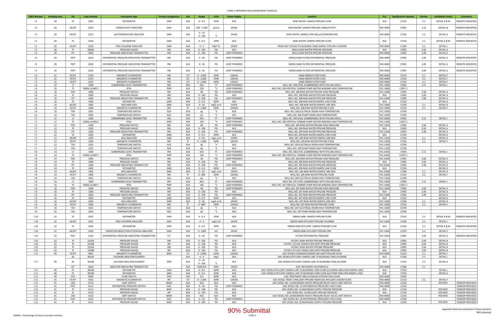
17005.1‐APPENDIX FIELD INSTRUMENT SCHEDULE
DWG Number Drawing Area ISA Loop Number Instrument type Process Designation Size Range Units Power Supply Location PLC Specification Number Section Installation Detail Comments
I‐5 20 FE 2005 ROTAMETER SAM N/A 0 ‐ 0.3 GPM N/A RAW WATER SAMPLE PIPELINE FLOW N/A 17220 2.1 DETAIL K & M REMOTE MOUNTED
I‐5 20 AE/AIT 2010 CONDUCTIVITY ANALYZER SAM N/A 200 ‐ 5,000 µS/cm 24VDC RAW WATER SAMPLE PIPELINE CONDUCTIVITY RIO‐4000 17005 2.13 DETAIL M REMOTE MOUNTED
I‐5 20 AE/AIT 2015 pH/TEMPERATURE ANALYZER SAM N/A0 ‐ 14
0 ‐ 100
‐oF
24VDC RAW WATER SAMPLE PIPELINE pH/TEMPERATURE RIO‐4000 17250 2.1 DETAIL K REMOTE MOUNTED
I‐5 20 FE 2018 ROTAMETER SAM N/A 0 ‐ 0.3 GPM N/A RAW WATER SAMPLE PIPELINE FLOW N/A 17220 2.1 DETAIL K & M REMOTE MOUNTED
I‐5 20 AE/AIT 2020 FREE CHLORINE ANALYZER SAM N/A 0 ‐ 5 mg/L Cl2 24VDC FROM GAC SYSTEM TO BLENDING TANK SAMPLE PIPELINE CHLORINE RIO‐4000 17260 2.1 DETAIL L
I‐5 20 PI 2000A PRESSURE GAUGE RW N/A 0 ‐ 100 PSI N/A WELLS RAW WATER PIPELINE PRESSURE N/A 17005 2.04 DETAIL A
I‐5 20 PIT 2000 PRESSURE INDICATING TRANSMITTER RW N/A 0 ‐ 100 PSI LOOP POWERED WELLS RAW WATER PIPELINE PRESSURE RIO‐4000 17005 2.08 DETAIL D
I‐5 20 PDIT 2010 DIFFERENTIAL PRESSURE INDICATING TRANSMITTER RW N/A 0 ‐ 20 PSI LOOP POWERED GREEN SAND FILTERS DIFFERENTIAL PRESSURE RIO‐4000 17005 2.09 DETAIL G REMOTE MOUNTED
I‐5 20 PDIT 2020 DIFFERENTIAL PRESSURE INDICATING TRANSMITTER RW N/A 0 ‐ 20 PSI LOOP POWERED GREEN SAND FILTERS DIFFERENTIAL PRESSURE RIO‐4000 17005 2.09 DETAIL G REMOTE MOUNTED
I‐5 20 PDIT 2030 DIFFERENTIAL PRESSURE INDICATING TRANSMITTER RW N/A 0 ‐ 20 PSI LOOP POWERED GREEN SAND FILTERS DIFFERENTIAL PRESSURE RIO‐4000 17005 2.09 DETAIL G REMOTE MOUNTED
I‐5 21 FE/FIT 2145 MAGNETIC FLOWMETER RW 12" 0 ‐ 2,000 GPM 120VAC SAND GREEN FILTER FLOW RIO‐4000 17210 2.1 DETAIL F
I‐5 21 FE/FIT 2155 MAGNETIC FLOWMETER RW 12" 0 ‐ 2,000 GPM 120VAC SAND GREEN FILTER FLOW RIO‐4000 17210 2.1 DETAIL F
I‐5 21 FE/FIT 2165 MAGNETIC FLOWMETER RW 12" 0 ‐ 2,000 GPM 120VAC SAND GREEN FILTER FLOW RIO‐4000 17210 2.1 DETAIL F
I‐6 10 LT 1000 SUBMERSIBLE LEVEL TRANSMITTER RW N/A N/A FT LOOP POWERED WELL NO. 208 LEVEL (SUBMERSIBLE WITH STILLING WELL) PLC‐1000 17005 2.11 DETAIL J
I‐6 10 TE 1000A, B AND C RTDs PMP N/A 250 oF LOOP POWERED WELL NO. 208 VERTICAL TURBINE PUMP MOTOR WINDING HIGH TEMPERATURE PLC‐1000 11937.1
I‐6 10 PSH 1000 PRESSURE SWITCH RW N/A 80 PSI LOOP POWERED WELL NO. 208 RAW WATER PIPELINE HIGH PRESSURE PLC‐1000 17005 2.06 DETAIL A
I‐6 10 PI 1000 PRESSURE GAUGE RW N/A 0 ‐ 100 PSI N/A WELL NO. 208 RAW WATER PIPELINE PRESSURE N/A 17005 2.04 DETAIL A
I‐6 10 PIT 1000 PRESSURE INDICATING TRANSMITTER RW N/A 0 ‐ 100 PSI LOOP POWERED WELL NO. 208 RAW WATER PIPELINE PRESSURE PLC‐1000 17005 2.08 DETAIL D
I‐6 10 FE 1005 ROTAMETER SAM N/A 0 ‐ 0.3 GPM N/A WELL NO. 208 RAW WATER SAMPLE LINE FLOW N/A 17220 DETAIL O
I‐6 10 AE/AIT 1005 NO3 ANALYZER SAM N/A 0 ‐ 50 mg/L as N 24VDC WELL NO. 208 RAW WATER SAMPLE LINE NO3 PLC‐1000 17240 2.1 DETAIL O
I‐6 10 FE/FIT 1006 MAGNETIC FLOWMETER RW 8" 0 ‐ 1,000 GPM 120VAC WELL NO. 208 RAW WATER PIPELINE FLOW PLC‐1000 17210 2.1 DETAIL F
I‐6 10 TSH 1001 TEMPERATURE SWITCH N/A N/A 85 oF N/A WELL NO. 208 ELECTRICAL ROOM HIGH TEMPERATURE PLC‐1000 15700
I‐6 10 TSH 1002 TEMPERATURE SWITCH N/A N/A 85 oF N/A WELL NO. 208 PUMP ROOM HIGH TEMPERATURE PLC‐1000 15700
I‐7 12 LT 1200 SUBMERSIBLE LEVEL TRANSMITTER RW N/A N/A FT LOOP POWERED WELL NO. 209 LEVEL (SUBMERSIBLE WITH STILLING WELL) PLC‐6200 17005 2.11 DETAIL J
I‐7 12 TE 1200A, B AND C RTDs PMP N/A 250 oF LOOP POWERED WELL NO. 209 VERTICAL TURBINE PUMP MOTOR WINDING HIGH TEMPERATURE PLC‐1200 11937.1
I‐7 12 PSH 1200 PRESSURE SWITCH RW N/A 80 PSI LOOP POWERED WELL NO. 209 RAW WATER PIPELINE HIGH PRESSURE PLC‐1200 17005 2.06 DETAIL A
I‐7 12 PI 1200 PRESSURE GAUGE RW N/A 0 ‐ 100 PSI N/A WELL NO. 209 RAW WATER PIPELINE PRESSURE N/A 17005 2.04 DETAIL A
I‐7 12 PIT 1200 PRESSURE INDICATING TRANSMITTER RW N/A 0 ‐ 100 PSI LOOP POWERED WELL NO. 209 RAW WATER PIPELINE PRESSURE PLC‐1200 17005 2.08 DETAIL D
I‐7 12 FE 1205 ROTAMETER SAM N/A 0 ‐ 0.3 GPM N/A WELL NO. 209 RAW WATER SAMPLE LINE FLOW N/A 17220 DETAIL O
I‐7 12 AE/AIT 1205 NO3 ANALYZER SAM N/A 0 ‐ 50 mg/L as N 24VDC WELL NO. 209 RAW WATER SAMPLE LINE NO4 PLC‐1200 17240 2.1 DETAIL O
I‐7 12 FE/FIT 1206 MAGNETIC FLOWMETER RW 8" 0 ‐ 1,000 GPM 120VAC WELL NO. 209 RAW WATER PIPELINE FLOW PLC‐1200 17210 2.1 DETAIL F
I‐7 12 TSH 1201 TEMPERATURE SWITCH N/A N/A 85 oF N/A WELL NO. 209 ELECTRICAL ROOM HIGH TEMPERATURE PLC‐1200 15700
I‐7 12 TSH 1202 TEMPERATURE SWITCH N/A N/A 85oF N/A WELL NO. 209 PUMP ROOM HIGH TEMPERATURE PLC‐1200 15700
I‐8 14 LT 1400 SUBMERSIBLE LEVEL TRANSMITTER RW N/A N/A FT LOOP POWERED WELL NO. 206 LEVEL (SUBMERSIBLE WITH STILLING WELL) PLC‐6200 17005 2.11 DETAIL J
I‐8 14 TE 1400A, B AND C RTDs PMP N/A 250 oF LOOP POWERED WELL NO. 206 VERTICAL TURBINE PUMP MOTOR WINDING HIGH TEMPERATURE PLC‐6200 11937.1
I‐8 14 PSH 1400 PRESSURE SWITCH RW N/A 40 PSI LOOP POWERED WELL NO. 206 RAW WATER PIPELINE HIGH PRESSURE PLC‐6200 17005 2.06 DETAIL A
I‐8 14 PI 1400 PRESSURE GAUGE RW N/A 0 ‐ 100 PSI N/A WELL NO. 206 RAW WATER PIPELINE PRESSURE N/A 17005 2.04 DETAIL A
I‐8 14 PIT 1400 PRESSURE INDICATING TRANSMITTER RW N/A 0 ‐ 100 PSI LOOP POWERED WELL NO. 206 RAW WATER PIPELINE PRESSURE PLC‐6200 17005 2.08 DETAIL D
I‐8 14 FE 1405 ROTAMETER SAM N/A 0 ‐ 0.3 GPM N/A WELL NO. 206 RAW WATER SAMPLE LINE FLOW N/A 17220 DETAIL O
I‐8 14 AE/AIT 1405 NO3 ANALYZER SAM N/A 0 ‐ 50 mg/L as N 24VDC WELL NO. 206 RAW WATER SAMPLE LINE NO3 PLC‐6200 17240 2.1 DETAIL O
I‐8 14 FE/FIT 1406 MAGNETIC FLOWMETER RW 8" 0 ‐ 800 GPM 120VAC WELL NO. 206 RAW WATER PIPELINE FLOW PLC‐6200 17210 2.1 DETAIL F
I‐8 14 TSH 1401 TEMPERATURE SWITCH N/A N/A 85 oF N/A WELL NO. 206 ELECTRICAL ROOM HIGH TEMPERATURE PLC‐1200 15700
I‐9 16 LT 1600 SUBMERSIBLE LEVEL TRANSMITTER RW N/A N/A FT LOOP POWERED WELL NO. 207 LEVEL (SUBMERSIBLE WITH STILLING WELL) PLC‐1600 17005 2.11 DETAIL J
I‐9 16 TE 1600A, B AND C RTDs PMP N/A 250 oF LOOP POWERED WELL NO. 207 VERTICAL TURBINE PUMP MOTOR WINDING HIGH TEMPERATURE PLC‐1600 11937.1
I‐9 16 PSH 1600 PRESSURE SWITCH RW N/A 40 PSI LOOP POWERED WELL NO. 207 RAW WATER PIPELINE HIGH PRESSURE PLC‐1600 17005 2.06 DETAIL A
I‐9 16 PI 1600 PRESSURE GAUGE RW N/A 0 ‐ 100 PSI N/A WELL NO. 207 RAW WATER PIPELINE PRESSURE N/A 17005 2.04 DETAIL A
I‐9 16 PIT 1600 PRESSURE INDICATING TRANSMITTER RW N/A 0 ‐ 100 PSI LOOP POWERED WELL NO. 207 RAW WATER PIPELINE PRESSURE PLC‐1600 17005 2.08 DETAIL D
I‐9 16 FE 1605 ROTAMETER SAM N/A 0 ‐ 0.3 GPM N/A WELL NO. 207 RAW WATER SAMPLE LINE FLOW N/A 17220 DETAIL O
I‐9 16 AE/AIT 1605 NO3 ANALYZER SAM N/A 0 ‐ 50 mg/L as N 24VDC WELL NO. 207 RAW WATER SAMPLE LINE NO3 PLC‐1600 17240 2.1 DETAIL O
I‐9 16 FE/FIT 1606 MAGNETIC FLOWMETER RW 8" 0 ‐ 800 GPM 120VAC WELL NO. 207 RAW WATER PIPELINE FLOW PLC‐1600 17210 2.1 DETAIL F
I‐9 16 TSH 1601 TEMPERATURE SWITCH N/A N/A 85 oF N/A WELL NO. 207 ELECTRICAL ROOM HIGH TEMPERATURE PLC‐1600 15700
I‐9 16 TSH 1602 TEMPERATURE SWITCH N/A N/A 85 oF N/A WELL NO. 207 PUMP ROOM HIGH TEMPERATURE PLC‐1600 15700
I‐10 22 FE 2201 ROTAMETER SAM N/A 0 ‐ 0.3 GPM N/A GREEN SAND SAMPLE PIPELINE FLOW N/A 17220 2.1 DETAIL K & M REMOTE MOUNTED
I‐10 22 AE/AIT 2201 FREE CHLORINE ANALYZER SAM N/A 0 ‐ 5 mg/L Cl2 24VDC GREEN SAND EFFLUENT PIPELINE CHLORINE PLC‐1600 17260 2.1 DETAIL L
I‐10 22 FE 2202 ROTAMETER SAM N/A 0 ‐ 0.3 GPM N/A GREEN SAND EFFLUENT SAMPLE PIPELINE FLOW N/A 17220 2.1 DETAIL K & M REMOTE MOUNTED
I‐10 22 AE/AIT 2202 OXIDATION REDUCTION POTENTIAL ANALYZER SAM N/A +/‐ 1000 mV 24VDC GREEN SAND EFFLUENT PIPELINE ORP PLC‐1600 17270 2.1 DETAIL S
I‐10 22 PDIT 2210 DIFFERENTIAL PRESSURE INDICATING TRANSMITTER FLT N/A 0 ‐ 40 PSI LOOP POWERED FILTERS DIFFERENTIAL PRESSURE PLC‐1600 17005 2.09 DETAIL G REMOTE MOUNTED
I‐10 22 PI 2210A PRESSURE GAUGE RW N/A 0 ‐ 100 PSI N/A FILTER 1 RAW WATER PIPELINE PRESSURE N/A 17005 2.04 DETAIL B
I‐10 22 PI 2210B PRESSURE GAUGE INF N/A 0 ‐ 100 PSI N/A FILTER 1 TO GAC VESSELS INFLUENT PIPELINE PRESSURE N/A 17005 2.04 DETAIL B
I‐10 22 PI 2220A PRESSURE GAUGE RW N/A 0 ‐ 100 PSI N/A FILTER 2 RAW WATER PIPELINE PRESSURE N/A 17005 2.04 DETAIL B
I‐10 22 PI 2220B PRESSURE GAUGE INF N/A 0 ‐ 100 PSI N/A FILTER 2 TO GAC VESSELS INFLUENT PIPELINE PRESSURE N/A 17005 2.04 DETAIL B
I‐11 40 FE/FIT 4001 MAGNETIC FLOWMETER BWS 12" 0 ‐ 2,000 GPM 120VAC GAC VESSELS COMMON HEADER INFLUENT PIPELINE FLOW RIO‐4000 17210 2.1 DETAIL F
AE 4010A CHLORINE ANALYZER ELEMENT N/A 0 ‐ 5 mg/L N/A GAC VESSELS EFFLUENT SAMPLE LINE TO BLENDING TANK CHLORINE N/A 17260 2.1 DETAIL L
AE 4010B pH/TEMP ANALYZER ELEMENT N/A0 ‐ 14
0 ‐ 100
‐oF
N/A GAC VESSELS EFFLUENT SAMPLE LINE TO BLENDING TANK pH/TEMP N/A 17250 2.1 DETAIL K
AIT 4010 ANALYZER INDICATING TRANSMITTER N/A VARIOUS PPM 24VDC GAC TREATMENT PH/TEMP/CL2 RIO‐4000 17280 2.1
I‐11 40 FE 4010A ROTAMETER SAM N/A 0 ‐ 0.2 GPM N/A GAC VESSELS EFFLUENT SAMPLE LINE TO BLENDING TANK FLOW (CHLORINE ANALYZER SAMPLE LINE) N/A 17220 DETAIL L
I‐11 40 FE 4010B ROTAMETER SAM N/A 0 ‐ 0.3 GPM N/A GAC VESSELS EFFLUENT SAMPLE LINE TO BLENDING TANK FLOW (pH/TEMP ANALYZER SAMPLE LINE) N/A 17220 DETAIL K
I‐11 40 FSH 4000 FLOW SWITCH EWS N/A 0.4 GPM N/A GAC TREATMENT AREA EYEWASH STATION HIGH FLOW RIO‐4000 15430
I‐12 41 FE/FIT 4101 MAGNETIC FLOWMETER INF 10" 0 ‐ 1,000 GPM 120VAC GAC VESSEL TRAIN 1 INFLUENT PIPELINE FROM GAC INFLUENT HEADER FLOW RIO‐4000 17210 2.1 DETAIL F
I‐12 41 ZSO 4113 LIMIT SWITCH BWW N/A N/A N/A N/A GAC VESSEL NO. 1A BACKWASH WASTE PRESSURE RELIEF VALVE LIMIT SWITCH RIO‐4000 11250 PER MFR. VENDOR PROVIDED
I‐12 41 PDIT 4112 DIFFERENTIAL PRESSURE SWITCH GAC N/A 0 ‐ 50 PSI LOOP POWERED GAC VESSEL NO. 1A DIFFERENTIAL PRESSUREE HIGH FLOW RIO‐4000 11250 VENDOR PROVIDED
I‐12 41 PI 4111 PRESSURE GAUGE BWS N/A 0 ‐ 100 PSI N/A GAC VESSEL NO. 1A BACKWASH SUPPLY PIPELINE PRESSURE N/A 11250 PER MFR. VENDOR PROVIDED
I‐12 41 PI 4114 PRESSURE GAUGE INF N/A 0 ‐ 100 PSI N/A GAC VESSEL NO. 1A INFLUENT PIPELINE PRESSURE N/A 11250 PER MFR. VENDOR PROVIDED
I‐12 41 ZSO 4123 LIMIT SWITCH BWW N/A N/A N/A N/A GAC VESSEL NO. 1B BACKWASH WASTE PRESSURE RELIEF VALVE LIMIT SWITCH RIO‐4000 11250 PER MFR. VENDOR PROVIDED
I‐12 41 PDIT 4122 DIFFERENTIAL PRESSURE SWITCH GAC N/A 0 ‐ 50 PSI LOOP POWERED GAC VESSEL NO. 1B DIFFERENTIAL PRESSUREE HIGH FLOW RIO‐4000 11250 VENDOR PROVIDED
I‐12 41 PI 4121 PRESSURE GAUGE BWS N/A 0 ‐ 100 PSI N/A GAC VESSEL NO. 1B BACKWASH SUPPLY PIPELINE PRESSURE N/A 11250 PER MFR. VENDOR PROVIDED
I‐11 40 SAM
EMWD ‐ Final Design of Cactus Corridor Facilities 11OF 4
Appendix Field Instrumentation Process Systems
90% Submittal90% Submittal
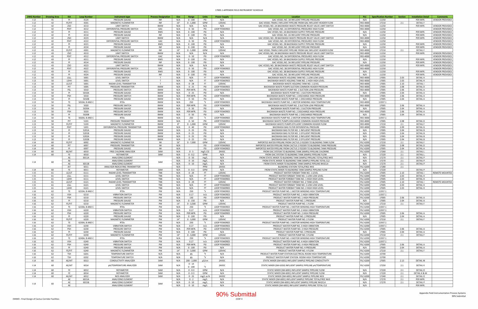
17005.1‐APPENDIX FIELD INSTRUMENT SCHEDULE
DWG Number Drawing Area ISA Loop Number Instrument type Process Designation Size Range Units Power Supply Location PLC Specification Number Section Installation Detail Comments
I‐12 41 PI 4124 PRESSURE GAUGE INF N/A 0 ‐ 100 PSI N/A GAC VESSEL NO. 1B INFLUENT PIPELINE PRESSURE N/A 11250 PER MFR. VENDOR PROVIDED
I‐12 42 FE/FIT 4201 MAGNETIC FLOWMETER INF 10" 0 ‐ 1,000 GPM 120VAC GAC VESSEL TRAIN 2 INFLUENT PIPELINE FROM GAC INFLUENT HEADER FLOW RIO‐4000 17210 2.1 DETAIL F
I‐12 42 ZSO 4213 LIMIT SWITCH BWW N/A N/A N/A N/A GAC VESSEL NO. 2A BACKWASH WASTE PRESSURE RELIEF VALVE LIMIT SWITCH RIO‐4000 11250 PER MFR. VENDOR PROVIDED
I‐12 42 PDIT 4212 DIFFERENTIAL PRESSURE SWITCH GAC N/A 0 ‐ 50 PSI LOOP POWERED GAC VESSEL NO. 2A DIFFERENTIAL PRESSUREE HIGH FLOW RIO‐4000 11250 VENDOR PROVIDED
I‐12 42 PI 4211 PRESSURE GAUGE BWS N/A 0 ‐ 100 PSI N/A GAC VESSEL NO. 2A BACKWASH SUPPLY PIPELINE PRESSURE N/A 11250 PER MFR. VENDOR PROVIDED
I‐12 42 PI 4214 PRESSURE GAUGE INF N/A 0 ‐ 100 PSI N/A GAC VESSEL NO. 2A INFLUENT PIPELINE PRESSURE N/A 11250 PER MFR. VENDOR PROVIDED
I‐12 42 ZSO 4223 LIMIT SWITCH BWW N/A N/A N/A N/A GAC VESSEL NO. 2B BACKWASH WASTE PRESSURE RELIEF VALVE LIMIT SWITCH RIO‐4000 11250 PER MFR. VENDOR PROVIDED
I‐12 42 PDIT 4222 DIFFERENTIAL PRESSURE SWITCH GAC N/A 0 ‐ 50 PSI LOOP POWERED GAC VESSEL NO. 2B DIFFERENTIAL PRESSUREE HIGH FLOW RIO‐4000 11250 VENDOR PROVIDED
I‐12 42 PI 4221 PRESSURE GAUGE BWS N/A 0 ‐ 100 PSI N/A GAC VESSEL NO. 2B BACKWASH SUPPLY PIPELINE PRESSURE N/A 11250 PER MFR. VENDOR PROVIDED
I‐12 42 PI 4224 PRESSURE GAUGE INF N/A 0 ‐ 100 PSI N/A GAC VESSEL NO. 2B INFLUENT PIPELINE PRESSURE N/A 11250 PER MFR. VENDOR PROVIDED
I‐12 43 FE/FIT 4301 MAGNETIC FLOWMETER INF 10" 0 ‐ 1,000 GPM 120VAC GAC VESSEL TRAIN 3 INFLUENT PIPELINE FROM GAC INFLUENT HEADER FLOW RIO‐4000 17210 2.1 DETAIL F
I‐12 43 ZSO 4313 LIMIT SWITCH BWW N/A N/A N/A N/A GAC VESSEL NO. 3A BACKWASH WASTE PRESSURE RELIEF VALVE LIMIT SWITCH RIO‐4000 11250 PER MFR. VENDOR PROVIDED
I‐12 43 PDIT 4312 DIFFERENTIAL PRESSURE SWITCH GAC N/A 0 ‐ 50 PSI LOOP POWERED GAC VESSEL NO. 3A DIFFERENTIAL PRESSUREE HIGH FLOW RIO‐4000 11250 VENDOR PROVIDED
I‐12 43 PI 4311 PRESSURE GAUGE BWS N/A 0 ‐ 100 PSI N/A GAC VESSEL NO. 3A BACKWASH SUPPLY PIPELINE PRESSURE N/A 11250 PER MFR. VENDOR PROVIDED
I‐12 43 PI 4314 PRESSURE GAUGE INF N/A 0 ‐ 100 PSI N/A GAC VESSEL NO. 3A INFLUENT PIPELINE PRESSURE N/A 11250 PER MFR. VENDOR PROVIDED
I‐12 43 ZSO 4323 LIMIT SWITCH BWW N/A N/A N/A N/A GAC VESSEL NO. 3B BACKWASH WASTE PRESSURE RELIEF VALVE LIMIT SWITCH RIO‐4000 11250 PER MFR. VENDOR PROVIDED
I‐12 43 PDIT 4322 DIFFERENTIAL PRESSURE SWITCH GAC N/A 0 ‐ 50 PSI LOOP POWERED GAC VESSEL NO. 3B DIFFERENTIAL PRESSUREE HIGH FLOW RIO‐4000 11250 VENDOR PROVIDED
I‐12 43 PI 4321 PRESSURE GAUGE BWS N/A 0 ‐ 100 PSI N/A GAC VESSEL NO. 3B BACKWASH SUPPLY PIPELINE PRESSURE N/A 11250 PER MFR. VENDOR PROVIDED
I‐12 43 PI 4324 PRESSURE GAUGE INF N/A 0 ‐ 100 PSI N/A GAC VESSEL NO. 3B INFLUENT PIPELINE PRESSURE N/A 11250 PER MFR. VENDOR PROVIDED
I‐13 50 LSLL 5001 LEVEL SWITCH T N/A N/A FT LOOP POWERED BACKWASH WASTE HOLDING TANK NO. 1 LOW LOW LEVEL RIO‐4000 17005 2.03 DETAIL H
I‐13 50 LSHH 5001 LEVEL SWITCH T N/A N/A FT LOOP POWERED BACKWASH WASTE HOLDING TANK NO. 1 HIGH HIGH LEVEL RIO‐4000 17005 2.03 DETAIL H
I‐13 50 LE/LIT 5001 RADAR LEVEL TRANSMITTER T N/A 0 ‐ 28 FT 120VAC BACKWASH WASTE HOLDING TANK NO. 1 LEVEL RIO‐4000 17005 2.10 DETAIL I
I‐13 50 PIT 5005 PRESSURE TRANSMITTER BWW N/A 0 ‐ 25 PSI LOOP POWERED BACKWASH WASTE PUMPS SUCTION COMMON HEADER PRESSURE RIO‐4000 17005 2.08 DETAIL D
I‐13 50 PSL 5010 PRESSURE SWITCH BWW N/A PER MFR. PSI LOOP POWERED BACKWASH WASTE PUMP NO. 1 SUCTION LOW PRESSURE RIO‐4000 17005 2.06 DETAIL A
I‐13 50 PI 5010A PRESSURE GAUGE BWW N/A 0 ‐ 25 PSI N/A BACKWASH WASTE PUMP NO. 1 SUCTION PRESSURE N/A 17005 2.04 DETAIL A
I‐13 50 PSH 5010 PRESSURE SWITCH BWW N/A PER MFR. PSI LOOP POWERED BACKWASH WASTE PUMP NO. 1 DISCHARGE HIGH PRESSURE RIO‐4000 17005 2.06 DETAIL A
I‐13 50 PI 5010B PRESSURE GAUGE BWW N/A 0 ‐ 50 PSI N/A BACKWASH WASTE PUMP NO. 1 DISCHARGE PRESSURE N/A 17005 2.04 DETAIL A
I‐13 50 TE 5010A, B AND C RTDs BWW N/A 250 oF LOOP POWERED BACKWASH WASTE PUMP NO. 1 MOTOR WINDING HIGH TEMPERATURE RIO‐4000 11937.1
I‐13 50 PSL 5020 PRESSURE SWITCH BWW N/A PER MFR. PSI LOOP POWERED BACKWASH WASTE PUMP NO. 2 SUCTION LOW PRESSURE RIO‐4000 17005 2.06 DETAIL A
I‐13 50 PI 5020A PRESSURE GAUGE BWW N/A 0 ‐ 50 PSI N/A BACKWASH WASTE PUMP NO. 2 SUCTION PRESSURE N/A 17005 2.04 DETAIL A
I‐13 50 PSH 5020 PRESSURE SWITCH BWW N/A PER MFR. PSI LOOP POWERED BACKWASH WASTE PUMP NO. 2 DISCHARGE HIGH PRESSURE RIO‐4000 17005 2.06 DETAIL A
I‐13 50 PI 5020B PRESSURE GAUGE BWW N/A 0 ‐ 50 PSI N/A BACKWASH WASTE PUMP NO. 2 DISCHARGE PRESSURE N/A 17005 2.04 DETAIL A
I‐13 50 TE 5020A, B AND C RTDs BWW N/A 250 oF LOOP POWERED BACKWASH WASTE PUMP NO. 2 MOTOR WINDING HIGH TEMPERATURE RIO‐4000 11937.1
I‐13 50 PIT 5101 PRESSURE TRANSMITTER BWW N/A 0 ‐ 50 PSI LOOP POWERED BACKWASH WASTE PUMPS DISCHARGE COMMON HEADER PRESSURE RIO‐4000 17005 2.08 DETAIL D
I‐13 50 FE/FIT 5103 MAGNETIC FLOWMETER BWW 8" 0 ‐ 1,000 GPM 120VAC BACKWASH WASTE PUMPS EFFLUENT COMMON HEADER FLOW RIO‐4000 17210 2.1 DETAIL F
I‐13 50 PDIT 5201 DIFFERENTIAL PRESSURE TRANSMITTER BWW N/A 0 ‐ 40 PSI LOOP POWERED BACKWASH BAG FILTER DIFFERENTIAL PRESSURE RIO‐4000 17005 2.09 DETAIL G
I‐13 50 PI 5201A PRESSURE GAUGE BWW N/A 0 ‐ 25 PSI N/A BACKWASH BAG FILTER NO. 1 INFLUENT PRESSURE N/A 17005 2.04 DETAIL B
I‐13 50 PI 5201B PRESSURE GAUGE BWW N/A 0 ‐ 25 PSI N/A BACKWASH BAG FILTER NO. 1 EFFLUENT PRESSURE N/A 17005 2.04 DETAIL B
I‐13 50 PI 5202A PRESSURE GAUGE BWW N/A 0 ‐ 25 PSI N/A BACKWASH BAG FILTER NO. 2 INFLUENT PRESSURE N/A 17005 2.04 DETAIL B
I‐13 50 PI 5202B PRESSURE GAUGE BWW N/A 0 ‐ 25 PSI N/A BACKWASH BAG FILTER NO. 2 EFFLUENT PRESSURE N/A 17005 2.04 DETAIL B
I‐14 60 FE/FIT 6002 MAGNETIC FLOWMETER IW 16" 0 ‐ 7,000 GPM 120VAC IMPORTED WATER PIPELINE FROM CACTUS 2 FEEDER TO BLENDING TANK FLOW PLC‐6200 17210 2.1 DETAIL F
I‐14 60 PIT 6007 PRESSURE TRANSMITTER IW N/A PSI LOOP POWERED IMPORTED WATER PIPELINE FROM CACTUS 2 FEEDER TO BLENDING TANK PRESSURE PLC‐6200 17005 2.08 DETAIL D
I‐14 60 PI 6007 PRESSURE GAUGE IW N/A PSI LOOP POWERED IMPORTED WATER PIPELINE FROM CACTUS 2 FEEDER TO BLENDING TANK PRESSURE PLC‐6200 17005 2.04 DETAIL A
I‐14 60 AE/AIT 6010 FREE CHLORINE ANALYZER SAM N/A 0 ‐ 5 mg/L Cl2 24VDC FROM GAC SYSTEM TO BLENDING TANK SAMPLE PIPELINE CHLORINE PLC‐6200 17260 2.1 DETAIL L
I‐14 60 FE 6010 ROTAMETER SAM N/A 0 ‐ 0.2 GPM N/A FROM GAC SYSTEM TO BLENDING TANK SAMPLE PIPELINE FLOW N/A 17220 2.1 DETAIL L
AE 6011A ANALYZING ELEMENT N/A 0 ‐ 50 mg/L N/A FROM STATIC MIXER TO BLENDING TANK SAMPLE PIPELINE TOTAL/FREE NH3 N/A 17270 2.1 DETAIL P
AE ANALYZING ELEMENT N/A 0 ‐ 10 mg/L N/A FROM STATIC MIXER TO BLENDING TANK SAMPLE PIPELINE TOTAL CL2 N/A 17270 2.1 DETAIL P
AE 6011B ANALYZING ELEMENT N/A 0 ‐ 10 mg/L N/A FROM STATIC MIXER TO BLENDING TANK SAMPLE PIPELINE NH2CL4 N/A 17270 2.1 DETAIL P
AIT 6011 ANALYZER INDICATING TRANSMITTER N/A PPM 24VDC BLENDING STATION TOTAL/FREE NH3 PLC‐6200 17280 2.1
I‐14 60 FE 6011 ROTAMETER SAM N/A 0 ‐ 0.3 GPM N/A FROM STATIC MIXER TO BLENDING TANK SAMPLE PIPELINE FLOW N/A 17220 DETAIL P
I‐15 61 LE/LIT 6111 RADAR LEVEL TRANSMITTER TNK N/A 0 ‐ 29 FT 120VAC PRODUCT WATER FOREBAY TANK NO. 1 LEVEL PLC‐6200 17005 2.10 DETAIL I REMOTE MOUNTED
I‐15 61 LSLL 6111 LEVEL SWITCH TNK N/A N/A FT LOOP POWERED PRODUCT WATER FOREBAY TANK NO. 1 LOW LOW LEVEL PLC‐6200 17005 2.03 DETAIL H
I‐15 61 LSHH 6111 LEVEL SWITCH TNK N/A N/A FT LOOP POWERED PRODUCT WATER FOREBAY TANK NO. 1 HIGH HIGH LEVEL PLC‐6200 17005 2.03 DETAIL H
I‐15 61 LE/LIT 6121 RADAR LEVEL TRANSMITTER TNK N/A 0 ‐ 29 FT 120VAC PRODUCT WATER FOREBAY NO. 2 TANK LEVEL PLC‐6200 17005 2.10 DETAIL I REMOTE MOUNTED
I‐15 61 LSLL 6121 LEVEL SWITCH TNK N/A N/A FT LOOP POWERED PRODUCT WATER FOREBAY TANK NO. 2 LOW LOW LEVEL PLC‐6200 17005 2.03 DETAIL H
I‐15 61 LSHH 6121 LEVEL SWITCH TNK N/A N/A FT LOOP POWERED PRODUCT WATER FOREBAY TANK NO. 2 HIGH HIGH LEVEL PLC‐6200 17005 2.03 DETAIL H
I‐16 62 TE 6210A, B AND C RTDs PW N/A 250 oF LOOP POWERED PRODUCT WATER PUMP NO. 1 MOTOR WINDING HIGH TEMPERATURE PLC‐6200 11937.1
I‐16 62 VSH 6210 VIBRATION SWITCH PW N/A 0.17 in/s LOOP POWERED PRODUCT WATER PUMP NO. 1 HIGH VIBRATION PLC‐6200 11937.1
I‐16 62 PSH 6210 PRESSURE SWITCH PW N/A 130 PSI LOOP POWERED PRODUCT WATER PUMP NO. 1 HIGH PRESSURE PLC‐6200 17005 2.06 DETAIL A
I‐16 62 PI 6210 PRESSURE GAUGE PW N/A 0 ‐ 150 PSI N/A PRODUCT WATER PUMP NO. 1 PRESSURE N/A 17005 2.04 DETAIL A
I‐16 62 FE/FIT 6210 MAGNETIC FLOWMETER PW 14" 0 ‐ 3,500 GPM 120VAC PRODUCT WATER PUMP NO. 1 FLOW PLC‐6200 17210 2.1 DETAIL F
I‐16 62 TE 6220A, B AND C RTDs PW N/A 250 oF LOOP POWERED PRODUCT WATER PUMP NO. 2 MOTOR WINDING HIGH TEMPERATURE PLC‐6200 11937.1
I‐16 62 VSH 6220 VIBRATION SWITCH PW N/A 0.17 in/s LOOP POWERED PRODUCT WATER PUMP NO. 2 HIGH VIBRATION PLC‐6200 11937.1
I‐16 62 PSH 6220 PRESSURE SWITCH PW N/A PER MFR. PSI LOOP POWERED PRODUCT WATER PUMP NO. 2 HIGH PRESSURE PLC‐6200 17005 2.06 DETAIL A
I‐16 62 PI 6220 PRESSURE GAUGE PW N/A 0 ‐ 100 PSI N/A PRODUCT WATER PUMP NO. 2 PRESSURE N/A 17005 2.04 DETAIL A
I‐16 62 FE/FIT 6220 MAGNETIC FLOWMETER PW 14" 0 ‐ 3,000 GPM 120VAC PRODUCT WATER PUMP NO. 2 FLOW PLC‐6200 17210 2.1 DETAIL F
I‐16 62 TE 6230A, B AND C RTDs PW N/A 250 oF LOOP POWERED PRODUCT WATER PUMP NO. 3 MOTOR WINDING HIGH TEMPERATURE PLC‐6200 11937.1
I‐16 62 VSH 6230 VIBRATION SWITCH PW N/A 0.17 in/s LOOP POWERED PRODUCT WATER PUMP NO. 3 HIGH VIBRATION PLC‐6200 11937.1
I‐16 62 PSH 6230 PRESSURE SWITCH PW N/A PER MFR. PSI LOOP POWERED PRODUCT WATER PUMP NO. 3 HIGH PRESSURE PLC‐6200 17005 2.06 DETAIL A
I‐16 62 PI 6230 PRESSURE GAUGE PW N/A 0 ‐ 100 PSI N/A PRODUCT WATER PUMP NO. 3 PRESSURE N/A 17005 2.04 DETAIL A
I‐16 62 FE/FIT 6230 MAGNETIC FLOWMETER PW 14" 0 ‐ 3,000 GPM 120VAC PRODUCT WATER PUMP NO. 3 FLOW PLC‐6200 17210 2.1 DETAIL F
I‐16 62 TE 6240A, B AND C RTDs PW N/A 250 oF LOOP POWERED PRODUCT WATER PUMP NO. 4 MOTOR WINDING HIGH TEMPERATURE PLC‐6200 11937.1
I‐16 62 VSH 6240 VIBRATION SWITCH PW N/A 0.17 in/s LOOP POWERED PRODUCT WATER PUMP NO. 4 HIGH VIBRATION PLC‐6200 11937.1
I‐16 62 PSH 6240 PRESSURE SWITCH PW N/A PER MFR. PSI LOOP POWERED PRODUCT WATER PUMP NO. 4 HIGH PRESSURE PLC‐6200 17005 2.06 DETAIL A
I‐16 62 PI 6240 PRESSURE GAUGE PW N/A 0 ‐ 100 PSI N/A PRODUCT WATER PUMP NO. 4 PRESSURE N/A 17005 2.04 DETAIL A
I‐16 62 FE/FIT 6240 MAGNETIC FLOWMETER PW 14" 0 ‐ 3,000 GPM 120VAC PRODUCT WATER PUMP NO. 4 FLOW PLC‐6200 17210 2.1 DETAIL F
I‐16 62 TSH 6201 TEMPERATURE SWITCH N/A N/A 85 oF N/A PRODUCT WATER PUMP STATION ELECTRICAL ROOM HIGH TEMPERATURE PLC‐6200 15700
I‐16 62 TSH 6202 TEMPERATURE SWITCH N/A N/A 85 oF N/A PRODUCT WATER PUMP STATION ROOM HIGH TEMPERATURE PLC‐6200 15700
I‐14 60 AE/AIT 6013 CONDUCTIVITY ANALYZER SAM N/A 200 ‐ 2,000 µS/cm 24VDC STATIC MIXER (SM‐6001) INFLUENT SAMPLE PIPELINE CONDUCTIVITY PLC‐6200 17005 2.13 DETAIL M
I‐14 60 AE/AIT 6014 pH/TEMPERATURE ANALYZER SAM N/A0 ‐ 14
0 ‐ 100
‐oF
24VDC STATIC MIXER (SM‐6350) INFLUENT SAMPLE PIPELINE pH/TEMPERATURE PLC‐6200 17250 2.1 DETAIL K
I‐14 60 FE 6012 ROTAMETER SAM N/A 0 ‐ 0.3 GPM N/A STATIC MIXER (SM‐6001) INFLUENT SAMPLE PIPELINE FLOW N/A 17220 2.1 DETAIL O
I‐14 60 FE 6014 ROTAMETER SAM N/A 0 ‐ 0.3 GPM N/A STATIC MIXER (SM‐6001) INFLUENT SAMPLE PIPELINE FLOW N/A 17220 2.1 DETAIL K & M
I‐14 60 AE/AIT 6012 NO3 ANALYZER SAM N/A 0 ‐ 25 mg/L as N 24VDC STATIC MIXER (SM‐6001) INFLUENT SAMPLE PIPELINE NO3 PLC‐6200 17240 2.1 DETAIL O
AE 6015A ANALYZING ELEMENT N/A 0 ‐ 2 mg/L N/A STATIC MIXER (SM‐6001) INFLUENT SAMPLE PIPELINE TOTAL/FREE NH3 N/A 17270 2.1 PER MFR.
AE 6015B ANALYZING ELEMENT N/A 0 ‐ 10 mg/L N/A STATIC MIXER (SM‐6001) INFLUENT SAMPLE PIPELINE NH2CL4 N/A 17270 2.1 DETAIL P
AE ANALYZING ELEMENT N/A 0 ‐ 10 mg/L N/A STATIC MIXER (SM‐6001) INFLUENT SAMPLE PIPELINE TOTAL CL2 N/A PER MFR.
I‐14 60 SAM
SAM60I‐14
EMWD ‐ Final Design of Cactus Corridor Facilities 22OF 4
Appendix Field Instrumentation Process Systems
90% Submittal90% Submittal
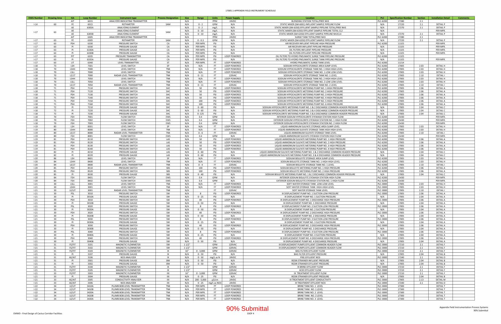
17005.1‐APPENDIX FIELD INSTRUMENT SCHEDULE
DWG Number Drawing Area ISA Loop Number Instrument type Process Designation Size Range Units Power Supply Location PLC Specification Number Section Installation Detail Comments
AIT 6015 ANALYZER INDICATING TRANSMITTER N/A PPM 24VDC BLENDING STATION TOTAL/FREE NH3 PLC‐6200 17280 2.1
I‐14 60 FE 6015 ROTAMETER SAM N/A 0 ‐ 2 GPM N/A STATIC MIXER (SM‐6001) INFLUENT SAMPLE PIPELINE FLOW N/A 17220 2.1 DETAIL P
AE 6305A ANALYZING ELEMENT N/A 0 ‐ 2 mg/L N/A STATIC MIXER (SM‐6350) EFFLUENT SAMPLE PIPELINE TOTAL/FREE NH3 N/A 17270 2.1 DETAIL P
AE ANALYZING ELEMENT N/A 0 ‐ 10 mg/L N/A STATIC MIXER (SM‐6350) EFFLUENT SAMPLE PIPELINE TOTAL CL2 N/A PER MFR.
AE 6305B ANALYZING ELEMENT N/A 0 ‐ 10 mg/L N/A STATIC MIXER (SM‐6350) EFFLUENT SAMPLE PIPELINE NH2CL4 N/A 17270 2.1 DETAIL P
AIT 6305 ANALYZER INDICATING TRANSMITTER N/A PPM 24VDC SURGE TANK TOTAL/FREE NH3 PLC‐6200 17280 2.1
I‐17 63 FE 6305 ROTAMETER SAM N/A 0 ‐ 0.3 GPM N/A STATIC MIXER (SM‐6350) EFFLUENT SAMPLE PIPELINE FLOW N/A 17220 2.1 DETAIL P
I‐17 63 PSH 6330 PRESSURE SWITCH CA N/A PER MFR. PSI N/A AIR RECEIVER INFLUENT PIPELINE HIGH PRESSURE PLC‐6200 11325 PER MFR.
I‐17 63 PI 6330 PRESSURE GAUGE CA N/A PER MFR. PSI N/A AIR RECEIVER INFLUENT PIPELINE PRESSURE N/A 11325 PER MFR.
I‐17 63 PI 6330A PRESSURE GAUGE CA N/A PER MFR. PSI N/A OIL FILTERS INFLUENT PIPELINE PRESSURE N/A 11325 PER MFR.
I‐17 63 PI 6330B PRESSURE GAUGE CA N/A PER MFR. PSI N/A OIL FILTERS EFFLUENT PIPELINE PRESSURE N/A 11325 PER MFR.
I‐17 63 PIT 6335 PRESSURE TRANSMITTER CA N/A PER MFR. PSI LOOP POWERED OIL FILTERS TO HYDRO PNEUMATIC SURGE TANK PIPELINE PRESSURE PLC‐6200 11325
I‐17 63 PI 6335A PRESSURE GAUGE CA N/A PER MFR. PSI N/A OIL FILTERS TO HYDRO PNEUMATIC SURGE TANK PIPELINE PRESSURE N/A 11325 PER MFR.
I‐17 63 LIT 6340 LEVEL TRANSMITTER ST N/A PER MFR. FT LOOP POWERED HYDRO PNEUMATIC SURGE TANK LEVEL PLC‐6200 11214
I‐18 73 LSH 7301 LEVEL SWITCH SP N/A N/A FT LOOP POWERED SODIUM HYPOCHLORITE STORAGE AREA SUMP LEVEL PLC‐6200 17005 2.03 DETAIL H
I‐18 70 LSHH 7000 LEVEL SWITCH TNK N/A N/A FT LOOP POWERED SODIUM HYPOCHLORITE STORAGE TANK NO. 1 HIGH HIGH LEVEL PLC‐6200 17005 2.03 DETAIL H
I‐18 70 LSLL 7000 LEVEL SWITCH TNK N/A N/A FT LOOP POWERED SODIUM HYPOCHLORITE STORAGE TANK NO. 1 LOW LOW LEVEL PLC‐6200 17005 2.03 DETAIL H
I‐18 70 LE/LT 7000 RADAR LEVEL TRANSMITTER TNK N/A 0 ‐ 11 FT 120VAC SODIUM HYPOCHLORITE STORAGE TANK NO. 1 LEVEL PLC‐6200 17005 2.10 DETAIL I
I‐18 70 LSHH 7050 LEVEL SWITCH TNK N/A N/A FT LOOP POWERED SODIUM HYPOCHLORITE STORAGE TANK NO. 2 HIGH HIGH LEVEL PLC‐6200 17005 2.03 DETAIL H
I‐18 70 LSLL 7050 LEVEL SWITCH TNK N/A N/A FT LOOP POWERED SODIUM HYPOCHLORITE STORAGE TANK NO. 2 LOW LOW LEVEL PLC‐6200 17005 2.03 DETAIL H
I‐18 70 LE/LT 7050 RADAR LEVEL TRANSMITTER TNK N/A 0 ‐ 11 FT 120VAC SODIUM HYPOCHLORITE STORAGE TANK NO. 2 LEVEL PLC‐6200 17005 2.10 DETAIL I
I‐18 71 PSH 7110 PRESSURE SWITCH SHC N/A 50 PSI LOOP POWERED SODIUM HYPOCHLORITE METERING PUMP NO. 1 HIGH PRESSURE PLC‐6200 17005 2.06 DETAIL A
I‐18 71 PSH 7120 PRESSURE SWITCH SHC N/A 50 PSI LOOP POWERED SODIUM HYPOCHLORITE METERING PUMP NO. 2 HIGH PRESSURE PLC‐6200 17005 2.06 DETAIL A
I‐18 71 PSH 7130 PRESSURE SWITCH SHC N/A 50 PSI LOOP POWERED SODIUM HYPOCHLORITE METERING PUMP NO. 3 HIGH PRESSURE PLC‐6200 17005 2.06 DETAIL A
I‐18 71 PSH 7140 PRESSURE SWITCH SHC N/A 50 PSI LOOP POWERED SODIUM HYPOCHLORITE METERING PUMP NO. 4 HIGH PRESSURE PLC‐6200 17005 2.06 DETAIL A
I‐18 71 PSH 7150 PRESSURE SWITCH SHC N/A 100 PSI LOOP POWERED SODIUM HYPOCHLORITE METERING PUMP NO. 5 HIGH PRESSURE PLC‐6200 17005 2.06 DETAIL A
I‐18 71 PSH 7160 PRESSURE SWITCH SHC N/A 100 PSI LOOP POWERED SODIUM HYPOCHLORITE METERING PUMP NO. 6 HIGH PRESSURE PLC‐6200 17005 2.06 DETAIL A
I‐18 72 PI 7210 PRESSURE GAUGE SHC N/A 0 ‐ 60 PSI N/A SODIUM HYPOCHLORITE METERING PUMP NO. 1 & 2 DISCHARGE COMMON HEADER PRESSURE N/A 17005 2.04 DETAIL C
I‐18 72 PI 7220 PRESSURE GAUGE SHC N/A 0 ‐ 60 PSI N/A SODIUM HYPOCHLORITE METERING PUMP NO. 3 & 4 DISCHARGE COMMON HEADER PRESSURE N/A 17005 2.04 DETAIL C
I‐18 72 PI 7230 PRESSURE GAUGE SHC N/A 0 ‐125 PSI N/A SODIUM HYPOCHLORITE METERING PUMP NO. 5 & 6 DISCHARGE COMMON HEADER PRESSURE N/A 17005 2.04 DETAIL C
I‐18 70 FSH 7001 FLOW SWITCH EWS N/A 0.4 GPM N/A INTERIOR SODIUM HYPOCHLORITE EYEWASH STATION HIGH FLOW PLC‐6200 15430 PER MFR.
I‐18 70 FSH 7002 FLOW SWITCH EWS N/A 0.4 GPM N/A EXTERIOR SODIUM HYPOCHLORITE EYEWASH STATION NO. 1 HIGH FLOW PLC‐6200 15430 PER MFR.
I‐18 70 FSH 7003 FLOW SWITCH EWS N/A 0.4 GPM N/A EXTERIOR SODIUM HYPOCHLORITE EYEWASH STATION NO. 2 HIGH FLOW PLC‐6200 15430 PER MFR.
I‐19 83 LSH 8301 LEVEL SWITCH SP N/A N/A FT LOOP POWERED LIQUID AMMONIUM SULFATE STORAGE AREA SUMP LEVEL PLC‐6200 17005 2.03 DETAIL H
I‐19 80 LSHH 8000 LEVEL SWITCH TNK N/A N/A FT LOOP POWERED LIQUID AMMONIUM SULFATE STORAGE TANK HIGH HIGH LEVEL PLC‐6200 17005 2.03 DETAIL H
I‐19 80 LE/LT 8000 RADAR LEVEL TRANSMITTER TNK N/A 0 ‐ 6 FT 120VAC LIQUID AMMONIUM SULFATE STORAGE TANK LEVEL PLC‐6200 17005 2.10 DETAIL I
I‐19 80 FSH 8001 FLOW SWITCH EWS N/A 0.4 GPM N/A LIQUID AMMONIUM SULFATE EYEWASH STATION HIGH FLOW PLC‐6200 15430 PER MFR.
I‐19 81 PSH 8110 PRESSURE SWITCH LAS N/A 50 PSI LOOP POWERED LIQUID AMMONIUM SULFATE METERING PUMP NO. 1 HIGH PRESSURE PLC‐6200 17005 2.06 DETAIL A
I‐19 81 PSH 8120 PRESSURE SWITCH LAS N/A 50 PSI LOOP POWERED LIQUID AMMONIUM SULFATE METERING PUMP NO. 2 HIGH PRESSURE PLC‐6200 17005 2.06 DETAIL A
I‐19 81 PSH 8130 PRESSURE SWITCH LAS N/A 50 PSI LOOP POWERED LIQUID AMMONIUM SULFATE METERING PUMP NO. 3 HIGH PRESSURE PLC‐6200 17005 2.06 DETAIL A
I‐19 81 PSH 8140 PRESSURE SWITCH LAS N/A 50 PSI LOOP POWERED LIQUID AMMONIUM SULFATE METERING PUMP NO. 4 HIGH PRESSURE PLC‐6200 17005 2.06 DETAIL A
I‐19 82 PI 8210 PRESSURE GAUGE LAS N/A 0 ‐ 60 PSI N/A LIQUID AMMONIUM SULFATE METERING PUMP NO. 1 & 2 DISCHARGE COMMON HEADER PRESSURE N/A 17005 2.04 DETAIL C
I‐19 82 PI 8220 PRESSURE GAUGE LAS N/A 0 ‐ 60 PSI N/A LIQUID AMMONIUM SULFATE METERING PUMP NO. 3 & 4 DISCHARGE COMMON HEADER PRESSURE N/A 17005 2.04 DETAIL C
I‐20 86 LSH 8601 LEVEL SWITCH SP N/A N/A FT LOOP POWERED SODIUM BISULFITE STORAGE AREA SUMP LEVEL PLC‐6200 17005 2.03 DETAIL H
I‐20 84 LSHH 8400 LEVEL SWITCH TNK N/A N/A FT LOOP POWERED SODIUM BISULFITE STORAGE TANK NO. 1 HIGH HIGH LEVEL PLC‐6200 17005 2.03 DETAIL H
I‐20 84 LE/LT 8400 RADAR LEVEL TRANSMITTER TNK N/A 0 ‐ 4 FT 120VAC SODIUM BISULFITE STORAGE TANK NO. 1 LEVEL PLC‐6200 17005 2.10 DETAIL I
I‐20 85 PSH 8510 PRESSURE SWITCH SBS N/A 100 PSI LOOP POWERED SODIUM BISULFITE METERING PUMP NO. 1 HIGH PRESSURE PLC‐6200 17005 2.06 DETAIL A
I‐20 85 PSH 8520 PRESSURE SWITCH SBS N/A 100 PSI LOOP POWERED SODIUM BISULFITE METERING PUMP NO. 2 HIGH PRESSURE PLC‐6200 17005 2.06 DETAIL A
I‐20 85 PI 8530 PRESSURE GAUGE SBS N/A 0 ‐ 40 PSI N/A SODIUM BISULFITE METERING PUMP NO. 1 & 2 DISCHARGE COMMON HEADER PRESSURE N/A 17005 2.04 DETAIL C
I‐20 84 FSH 8401 FLOW SWITCH EWS N/A 0.4 GPM N/A INTERIOR SODIUM BISULFITE EYEWASH STATION HIGH FLOW PLC‐6200 15430 PER MFR.
I‐20 84 FSH 8402 FLOW SWITCH EWS N/A 0.4 GPM N/A EXTERIOR SODIUM BISULFITE EYEWASH STATION NO. 1 HIGH FLOW PLC‐6200 15430 PER MFR.
I‐21 30 LSLL 3001 LEVEL SWITCH TNK N/A N/A FT LOOP POWERED SOFT WATER STORAGE TANK LOW‐LOW LEVEL PLC‐3000 17005 2.03 DETAIL H
I‐21 30 LSHH 3001 LEVEL SWITCH TNK N/A N/A FT LOOP POWERED SOFT WATER STORAGE TANK HIGH‐HIGH LEVEL PLC‐3000 17005 2.03 DETAIL H
I‐21 30 LE/LIT 3001 RADAR LEVEL TRANSMITTER TNK N/A FT 120VAC SOFT WATER STORAGE TANK LEVEL PLC‐3000 17005 2.10 DETAIL I
I‐21 30 PSL 3010 PRESSURE SWITCH SW N/A 8 PSI LOOP POWERED IX DISPLACEMENT PUMP NO. 1 SUCTION LOW PRESSURE PLC‐3000 17005 2.06 DETAIL A
I‐21 30 PI 3010A PRESSURE GAUGE SW N/A 0 ‐ 25 PSI N/A IX DISPLACEMENT PUMP NO. 1 SUCTION PRESSURE N/A 17005 2.04 DETAIL A
I‐21 30 PSH 3010 PRESSURE SWITCH SW N/A 40 PSI LOOP POWERED IX DISPLACEMENT PUMP NO. 1 DISCHARGE HIGH PRESSURE PLC‐3000 17005 2.06 DETAIL A
I‐21 30 PI 3010B PRESSURE GAUGE SW N/A 0 ‐ 50 PSI N/A IX DISPLACEMENT PUMP NO. 1 DISCHARGE PRESSURE N/A 17005 2.04 DETAIL A
I‐21 30 PSL 3020 PRESSURE SWITCH SW N/A 8 PSI LOOP POWERED IX DISPLACEMENT PUMP NO. 2 SUCTION LOW PRESSURE PLC‐3000 17005 2.06 DETAIL A
I‐21 30 PI 3020A PRESSURE GAUGE SW N/A 0 ‐ 50 PSI N/A IX DISPLACEMENT PUMP NO. 2 SUCTION PRESSURE N/A 17005 2.04 DETAIL A
I‐21 30 PSH 3020 PRESSURE SWITCH SW N/A 40 PSI LOOP POWERED IX DISPLACEMENT PUMP NO. 2 DISCHARGE HIGH PRESSURE PLC‐3000 17005 2.06 DETAIL A
I‐21 30 PI 3020B PRESSURE GAUGE SW N/A 0 ‐ 50 PSI N/A IX DISPLACEMENT PUMP NO. 2 DISCHARGE PRESSURE N/A 17005 2.04 DETAIL A
I‐21 30 PSL 3030 PRESSURE SWITCH SW N/A 8 PSI LOOP POWERED IX DISPLACEMENT PUMP NO. 3 SUCTION LOW PRESSURE PLC‐3000 17005 2.06 DETAIL A
I‐21 30 PI 3030A PRESSURE GAUGE SW N/A 0 ‐ 25 PSI N/A IX DISPLACEMENT PUMP NO. 3 SUCTION PRESSURE N/A 17005 2.04 DETAIL A
I‐21 30 PSH 3030 PRESSURE SWITCH SW N/A 40 PSI LOOP POWERED IX DISPLACEMENT PUMP NO. 3 DISCHARGE HIGH PRESSURE PLC‐3000 17005 2.06 DETAIL A
I‐21 30 PI 3030B PRESSURE GAUGE SW N/A 0 ‐ 50 PSI N/A IX DISPLACEMENT PUMP NO. 3 DISCHARGE PRESSURE N/A 17005 2.04 DETAIL A
I‐21 30 PSL 3040 PRESSURE SWITCH SW N/A 8 PSI LOOP POWERED IX DISPLACEMENT PUMP NO. 4 SUCTION LOW PRESSURE PLC‐3000 17005 2.06 DETAIL A
I‐21 30 PI 3040A PRESSURE GAUGE SW N/A 0 ‐ 25 PSI N/A IX DISPLACEMENT PUMP NO. 4 SUCTION PRESSURE N/A 17005 2.04 DETAIL A
I‐21 30 PSH 3040 PRESSURE SWITCH SW N/A 40 PSI LOOP POWERED IX DISPLACEMENT PUMP NO. 4 DISCHARGE HIGH PRESSURE PLC‐3000 17005 2.06 DETAIL A
I‐21 30 PI 3040B PRESSURE GAUGE SW N/A 0 ‐ 50 PSI N/A IX DISPLACEMENT PUMP NO. 4 DISCHARGE PRESSURE N/A 17005 2.04 DETAIL A
I‐21 31 FE/FIT 3101 MAGNETIC FLOWMETER SW 1 1/2" GPM 120VAC IX DISPLACEMENT PUMPS EFFLUENT COMMON HEADER FLOW PLC‐3000 17210 2.1 DETAIL F
I‐21 31 FE/FIT 3102 MAGNETIC FLOWMETER SW 1 1/2" GPM 120VAC IX DISPLACEMENT PUMPS EFFLUENT COMMON HEADER FLOW PLC‐3000 17210 2.1 DETAIL F
I‐21 31 FE/FIT 3103 MAGNETIC FLOWMETER IX 16" 0 ‐ 3,000 GPM 120VAC BAG FILTERS EFFLUENT FLOW PLC‐3000 17210 2.1 DETAIL F
I‐21 31 PI 3107 PRESSURE GAUGE IX N/A 0 ‐ 50 PSI N/A BAG FILTER EFFLUENT PRESSURE N/A 17005 2.04 DETAIL B
I‐21 31 AE/AIT 3106 NO3 ANALYZER IX N/A 0 ‐ 50 mg/L as N 24VDC PIXE EFFLUENT NO3 PLC‐3000 17240 2.1 DETAIL O
I‐21 31 PI 3301 PRESSURE GAUGE BW N/A 0 ‐ 50 PSI N/A RESIN STRAINER INFLUENT PRESSURE N/A 17005 2.04 DETAIL B
I‐21 31 PI 3302 PRESSURE GAUGE BW N/A 0 ‐ 50 PSI N/A RESIN STRAINER EFFLUENT PRESSURE N/A 17005 2.04 DETAIL B
I‐21 31 FE/FIT 3104 MAGNETIC FLOWMETER IX 1 1/2" GPM 120VAC IX BRINE EFFLUENT FLOW PLC‐3000 17210 2.1 DETAIL F
I‐21 31 FE/FIT 3105 MAGNETIC FLOWMETER IX 1 1/2" GPM 120VAC ACID EFFLUENT FLOW PLC‐3000 17210 2.1 DETAIL F
I‐21 33 FE/FIT 3303 MAGNETIC FLOWMETER IXI 16" 0 ‐ 3,000 GPM 120VAC IX TREATMENT EFFLUENT FLOW PLC‐3000 17210 2.1 DETAIL F
I‐21 33 PI 3304 PRESSURE GAUGE IXI N/A 0 ‐ 25 PSI N/A RESIN STRAINER EFFLUENT PRESSURE N/A 17005 2.04 DETAIL B
I‐21 33 AE/AIT 3305 CONDUCTIVITY ANALYZER IXI N/A 200 ‐ 5,000 µS/cm 24VDC IX TREATMENT EFFLUENT CONDUCTIVITY PLC‐3000 17005 2.13 DETAIL M
I‐21 33 AE/AIT 3306 NO3 ANALYZER IXI N/A 0 ‐ 25 mg/L as NO3 24VDC IX TREATMENT EFFLUENT NO3 PLC‐3000 17240 2.1 DETAIL O
I‐22 34 LE/LIT 3410A PLUMB BOB LEVEL TRANSMITTER TNK N/A PER MFR. FT LOOP POWERED BRINE TANK NO. 1 LEVEL PLC‐3000 17300 DETAIL T
I‐22 34 LE/LIT 3410B PLUMB BOB LEVEL TRANSMITTER TNK N/A PER MFR. FT LOOP POWERED BRINE TANK NO. 1 LEVEL PLC‐3000 17300 DETAIL T
I‐22 34 LE/LIT 3420A PLUMB BOB LEVEL TRANSMITTER TNK N/A PER MFR. FT LOOP POWERED BRINE TANK NO. 2 LEVEL PLC‐3000 17300 DETAIL T
I‐22 34 LE/LIT 3420B PLUMB BOB LEVEL TRANSMITTER TNK N/A PER MFR. FT LOOP POWERED BRINE TANK NO. 2 LEVEL PLC‐3000 17300 DETAIL T
I‐22 34 LE/LIT 3430A PLUMB BOB LEVEL TRANSMITTER TNK N/A PER MFR. FT LOOP POWERED BRINE TANK NO. 3 LEVEL PLC‐3000 17300 DETAIL T
I‐17 63 SAM
EMWD ‐ Final Design of Cactus Corridor Facilities 33OF 4
Appendix Field Instrumentation Process Systems
90% Submittal90% Submittal

17005.1‐APPENDIX FIELD INSTRUMENT SCHEDULE
DWG Number Drawing Area ISA Loop Number Instrument type Process Designation Size Range Units Power Supply Location PLC Specification Number Section Installation Detail Comments
I‐22 34 LE/LIT 3430B PLUMB BOB LEVEL TRANSMITTER TNK N/A PER MFR. FT LOOP POWERED BRINE TANK NO. 3 LEVEL PLC‐3000 17300 DETAIL T
I‐22 34 LE/LIT 3440A PLUMB BOB LEVEL TRANSMITTER TNK N/A PER MFR. FT LOOP POWERED BRINE TANK NO. 4 LEVEL PLC‐3000 17300 DETAIL T
I‐22 34 LE/LIT 3440B PLUMB BOB LEVEL TRANSMITTER TNK N/A PER MFR. FT LOOP POWERED BRINE TANK NO. 4 LEVEL PLC‐3000 17300 DETAIL T
I‐22 35 PSL 3510 PRESSURE SWITCH BR N/A 8 PSI LOOP POWERED IX REGEN PUMP NO. 1 SUCTION LOW PRESSURE PLC‐3000 17005 2.06 DETAIL A
I‐22 35 PI 3510A PRESSURE GAUGE BR N/A 0 ‐ 25 PSI N/A IX REGEN PUMP NO. 1 SUCTION PRESSURE N/A 17005 2.04 DETAIL A
I‐22 35 PSH 3510 PRESSURE SWITCH BR N/A 40 PSI LOOP POWERED IX REGEN PUMP NO. 1 DISCHARGE HIGH PRESSURE PLC‐3000 17005 2.06 DETAIL A
I‐22 35 PI 3510B PRESSURE GAUGE BR N/A 0 ‐ 50 PSI N/A IX REGEN PUMP NO. 1 DISCHARGE PRESSURE N/A 17005 2.04 DETAIL A
I‐22 35 PSL 3520 PRESSURE SWITCH BR N/A 8 PSI LOOP POWERED IX REGEN PUMP NO. 2 SUCTION LOW PRESSURE PLC‐3000 17005 2.06 DETAIL A
I‐22 35 PI 3520A PRESSURE GAUGE BR N/A 0 ‐ 25 PSI N/A IX REGEN PUMP NO. 2 SUCTION PRESSURE N/A 17005 2.04 DETAIL A
I‐22 35 PSH 3520 PRESSURE SWITCH BR N/A 40 PSI LOOP POWERED IX REGEN PUMP NO. 2 DISCHARGE HIGH PRESSURE PLC‐3000 17005 2.06 DETAIL A
I‐22 35 PI 3520B PRESSURE GAUGE BR N/A 0 ‐ 50 PSI N/A IX REGEN PUMP NO. 2 DISCHARGE PRESSURE N/A 17005 2.04 DETAIL A
I‐22 35 PDI 3510 DIFFERENTIAL PRESSURE GAUGE BR N/A 0 ‐ 50 PSI N/A BASKET STRAINER NO.1 DIFF. PRESSURE N/A 17005 2.04 DETAIL A
I‐22 35 PDI 3520 DIFFERENTIAL PRESSURE GAUGE BR N/A 0 ‐ 50 PSI N/A BASKET STRAINER NO.1 DIFF. PRESSURE N/A 17005 2.04 DETAIL A
I‐23 37 FSH 3700 FLOW SWITCH EWS N/A 0.4 GPM N/A INTERIOR IX CHEMICALS EYEWASH STATION HIGH FLOW PLC‐3000 15430 PER MFR.
I‐23 36 LSH 3640 LEVEL SWITCH SP N/A N/A FT LOOP POWERED HYDROCHLORIC ACID STORAGE AREA SUMP LEVEL PLC‐3000 17005 2.03 DETAIL H
I‐23 36 LSHH 3601 LEVEL SWITCH TNK N/A N/A FT LOOP POWERED HYDROCHLORIC ACID STORAGE TANK NO. 1 HIGH HIGH LEVEL PLC‐3000 17005 2.03 DETAIL H
I‐23 36 LE/LT 3601 RADAR LEVEL TRANSMITTER TNK N/A 0 ‐ 4 FT 120VAC HYDROCHLORIC ACID STORAGE TANK NO. 1 LEVEL PLC‐3000 17005 2.10 DETAIL I
I‐23 36 PSH 3610 PRESSURE SWITCH HCL N/A 30 PSI LOOP POWERED HYDROCHLORIC ACID METERING PUMP NO. 1 HIGH PRESSURE PLC‐3000 17005 2.06 DETAIL A
I‐23 36 PSH 3620 PRESSURE SWITCH HCL N/A 30 PSI LOOP POWERED HYDROCHLORIC ACID METERING PUMP NO. 2 HIGH PRESSURE PLC‐3000 17005 2.06 DETAIL A
I‐23 36 PI 3630 PRESSURE GAUGE HCL N/A 0 ‐ 40 PSI N/A HYDROCHLORIC ACID METERING PUMP NO. 1 & 2 DISCHARGE COMMON HEADER PRESSURE N/A 17005 2.04 DETAIL C
I‐24 38 LSHH 3801 LEVEL SWITCH TNK N/A N/A FT LOOP POWERED IX BRINE WASTE STORAGE TANK NO. 1 HIGH HIGH LEVEL RIO‐4000 17005 2.03 DETAIL H
I‐24 38 LSLL 3801 LEVEL SWITCH TNK N/A N/A FT LOOP POWERED IX BRINE WASTE STORAGE TANK NO. 1 LOW LOW LEVEL RIO‐4000 17005 2.03 DETAIL H
I‐24 38 LE/LT 3801 RADAR LEVEL TRANSMITTER TNK N/A 0 ‐ 16 FT 120VAC IX BRINE WASTE STORAGE TANK NO. 1 LEVEL RIO‐4000 17005 2.10 DETAIL I
I‐24 38 LSHH 3802 LEVEL SWITCH TNK N/A N/A FT LOOP POWERED IX BRINE WASTE STORAGE TANK NO. 2 HIGH HIGH LEVEL RIO‐4000 17005 2.03 DETAIL H
I‐24 38 LSLL 3802 LEVEL SWITCH TNK N/A N/A FT LOOP POWERED IX BRINE WASTE STORAGE TANK NO. 2 LOW LOW LEVEL RIO‐4000 17005 2.03 DETAIL H
I‐24 38 LE/LT 3802 RADAR LEVEL TRANSMITTER TNK N/A 0 ‐ 16 FT 120VAC IX BRINE WASTE STORAGE TANK NO. 2 LEVEL RIO‐4000 17005 2.10 DETAIL I
I‐24 38 LSHH 3803 LEVEL SWITCH TNK N/A N/A FT LOOP POWERED IX BRINE WASTE STORAGE TANK NO. 3 HIGH HIGH LEVEL RIO‐4000 17005 2.03 DETAIL H
I‐24 38 LSLL 3803 LEVEL SWITCH TNK N/A N/A FT LOOP POWERED IX BRINE WASTE STORAGE TANK NO. 3 LOW LOW LEVEL RIO‐4000 17005 2.03 DETAIL H
I‐24 38 LE/LT 3803 RADAR LEVEL TRANSMITTER TNK N/A 0 ‐ 16 FT 120VAC IX BRINE WASTE STORAGE TANK NO. 3 LEVEL RIO‐4000 17005 2.10 DETAIL I
I‐24 38 LSHH 3804 LEVEL SWITCH TNK N/A N/A FT LOOP POWERED IX BRINE WASTE STORAGE TANK NO. 4 HIGH HIGH LEVEL RIO‐4000 17005 2.03 DETAIL H
I‐24 38 LSLL 3804 LEVEL SWITCH TNK N/A N/A FT LOOP POWERED IX BRINE WASTE STORAGE TANK NO. 4 LOW LOW LEVEL RIO‐4000 17005 2.03 DETAIL H
I‐24 38 LE/LT 3804 RADAR LEVEL TRANSMITTER TNK N/A 0 ‐ 16 FT 120VAC IX BRINE WASTE STORAGE TANK NO. 4 LEVEL RIO‐4000 17005 2.10 DETAIL I
I‐24 38 PI 3810 PRESSURE GAUGE BR N/A 0 ‐ 50 PSI N/A IX BRINE WASTE METERING PUMP NO. 1 DISCHARGE PRESSURE N/A 17005 2.04 DETAIL C
I‐24 38 PI 3820 PRESSURE GAUGE BR N/A 0 ‐ 50 PSI N/A IX BRINE WASTE METERING PUMP NO. 2 DISCHARGE PRESSURE N/A 17005 2.04 DETAIL C
I‐25 39 PDIT 3900 DIFFERENTIAL PRESSURE INDICATING TRANSMITTER FLT N/A 0 ‐ 40 PSI LOOP POWERED IX BAG FILTERS DIFFERENTIAL PRESSURE PLC‐1600 17005 2.09 DETAIL G REMOTE MOUNTED
I‐25 39 PI 3900A PRESSURE GAUGE PIXI N/A 0 ‐ 100 PSI N/A IX BAG FILTER 1 INFLUENT PIPELINE PRESSURE N/A 17005 2.04 DETAIL B
I‐25 39 PI 3900B PRESSURE GAUGE PIXI N/A 0 ‐ 100 PSI N/A IX BAG FILTER 1 TO IX VESSELS INFLUENT PIPELINE PRESSURE N/A 17005 2.04 DETAIL B
I‐25 39 PI 3900C PRESSURE GAUGE PIXI N/A 0 ‐ 100 PSI N/A IX BAG FILTER 2 INFLUENT PIPELINE PRESSURE N/A 17005 2.04 DETAIL B
I‐25 39 PI 3900D PRESSURE GAUGE PIXI N/A 0 ‐ 100 PSI N/A IX BAG FILTER 2 TO IX VESSELS INFLUENT PIPELINE PRESSURE N/A 17005 2.04 DETAIL B
I‐26 39 FE/FIT 3910 MAGNETIC FLOWMETER IXI 12" 0 ‐ 1,500 GPM 120VAC IX PERCHLORATE VESSEL TRAIN 1 INFLUENT PIPELINE FROM GAC INFLUENT HEADER FLOW RIO‐4000 17210 2.1 DETAIL F
I‐26 39 ZSO 3912A LIMIT SWITCH BWW N/A N/A N/A N/A IX PERCHLORATE VESSEL NO. 1A BACKWASH WASTE PRESSURE RELIEF VALVE LIMIT SWITCH RIO‐4000 11250 PER MFR. VENDOR PROVIDED
I‐26 39 PDIT 3910A DIFFERENTIAL PRESSURE TRANSMITTER IX N/A 0 ‐ 50 PSI LOOP POWERED IX PERCHLORATE VESSEL NO. 1A DIFFERENTIAL PRESSURE RIO‐4000 11250 VENDOR PROVIDED
I‐26 39 PI 3911A PRESSURE GAUGE BWS N/A 0 ‐ 100 PSI N/A IX PERCHLORATE VESSEL NO. 1A BACKWASH SUPPLY PIPELINE PRESSURE N/A 11250 PER MFR. VENDOR PROVIDED
I‐26 39 PI 3913A PRESSURE GAUGE IXI N/A 0 ‐ 100 PSI N/A IX PERCHLORATE VESSEL NO. 1A INFLUENT PIPELINE PRESSURE N/A 11250 PER MFR. VENDOR PROVIDED
I‐26 39 ZSO 3912B LIMIT SWITCH BWW N/A N/A N/A N/A IX PERCHLORATE VESSEL NO. 1B BACKWASH WASTE PRESSURE RELIEF VALVE LIMIT SWITCH RIO‐4000 11250 PER MFR. VENDOR PROVIDED
I‐26 39 PDIT 3910B DIFFERENTIAL PRESSURE TRANSMITTER IX N/A 0 ‐ 50 PSI LOOP POWERED IX PERCHLORATE VESSEL NO. 1B DIFFERENTIAL PRESSURE RIO‐4000 11250 VENDOR PROVIDED
I‐26 39 PI 3911B PRESSURE GAUGE BWS N/A 0 ‐ 100 PSI N/A IX PERCHLORATE VESSEL NO. 1B BACKWASH SUPPLY PIPELINE PRESSURE N/A 11250 PER MFR. VENDOR PROVIDED
I‐26 39 PI 3913B PRESSURE GAUGE IXI N/A 0 ‐ 100 PSI N/A IX PERCHLORATE VESSEL NO. 1B INFLUENT PIPELINE PRESSURE N/A 11250 PER MFR. VENDOR PROVIDED
I‐26 39 FE/FIT 3920 MAGNETIC FLOWMETER IXI 12" 0 ‐ 1,500 GPM 120VAC IX PERCHLORATE VESSEL TRAIN 2 INFLUENT PIPELINE FROM IX INFLUENT HEADER FLOW RIO‐4000 17210 2.1 DETAIL F
I‐26 39 ZSO 3922A LIMIT SWITCH BWW N/A N/A N/A N/A IX PERCHLORATE VESSEL NO. 2A BACKWASH WASTE PRESSURE RELIEF VALVE LIMIT SWITCH RIO‐4000 11250 PER MFR. VENDOR PROVIDED
I‐26 39 PDIT 3920A DIFFERENTIAL PRESSURE TRANSMITTER IX N/A 0 ‐ 50 PSI LOOP POWERED IX PERCHLORATE VESSEL NO. 2A DIFFERENTIAL PRESSURE RIO‐4000 11250 VENDOR PROVIDED
I‐26 39 PI 3921A PRESSURE GAUGE BWS N/A 0 ‐ 100 PSI N/A IX PERCHLORATE VESSEL NO. 2A BACKWASH SUPPLY PIPELINE PRESSURE N/A 11250 PER MFR. VENDOR PROVIDED
I‐26 39 PI 3923A PRESSURE GAUGE IXI N/A 0 ‐ 100 PSI N/A IX PERCHLORATE VESSEL NO. 2A INFLUENT PIPELINE PRESSURE N/A 11250 PER MFR. VENDOR PROVIDED
I‐26 39 ZSO 3922B LIMIT SWITCH BWW N/A N/A N/A N/A IX PERCHLORATE VESSEL NO. 2B BACKWASH WASTE PRESSURE RELIEF VALVE LIMIT SWITCH RIO‐4000 11250 PER MFR. VENDOR PROVIDED
I‐26 39 PDIT 3920B DIFFERENTIAL PRESSURE TRANSMITTER IX N/A 0 ‐ 50 PSI LOOP POWERED IX PERCHLORATE VESSEL NO. 2B DIFFERENTIAL PRESSURE RIO‐4000 11250 VENDOR PROVIDED
I‐26 39 PI 3921B PRESSURE GAUGE BWS N/A 0 ‐ 100 PSI N/A IX PERCHLORATE VESSEL NO. 2B BACKWASH SUPPLY PIPELINE PRESSURE N/A 11250 PER MFR. VENDOR PROVIDED
I‐26 39 PI 3923B PRESSURE GAUGE IXI N/A 0 ‐ 100 PSI N/A IX PERCHLORATE VESSEL NO. 2B INFLUENT PIPELINE PRESSURE N/A 11250 PER MFR. VENDOR PROVIDED
I‐26 39 FE/FIT 3901C MAGNETIC FLOWMETER IXI 12" 0 ‐ 1,000 GPM 120VAC IX PERCHLORATE VESSEL TRAIN 3 INFLUENT PIPELINE FROM IX INFLUENT HEADER FLOW RIO‐4000 17210 2.1 DETAIL F
I‐26 39 ZSO 3912C LIMIT SWITCH BWW N/A N/A N/A N/A IX PERCHLORATE VESSEL NO. 3A BACKWASH WASTE PRESSURE RELIEF VALVE LIMIT SWITCH RIO‐4000 11250 PER MFR. VENDOR PROVIDED
I‐27 10 LSH 1023 LEVEL SWITCH SP N/A 0 ‐ 50 FT LOOP POWERED SODIUM HYPOCHLORITE STORAGE AREA SUMP LEVEL PLC‐6200 17005 2.03 DETAIL H
I‐27 10 LSHH 1020 LEVEL SWITCH TNK N/A 0 ‐ 100 FT LOOP POWERED SODIUM HYPOCHLORITE STORAGE TANK NO. 1 HIGH HIGH LEVEL PLC‐6200 17005 2.03 DETAIL H
I‐27 10 LSLL 1020 LEVEL SWITCH TNK N/A 0 ‐ 100 FT LOOP POWERED SODIUM HYPOCHLORITE STORAGE TANK NO. 1 LOW LOW LEVEL PLC‐6200 17005 2.03 DETAIL H
I‐27 10 LE/LT 1020 RADAR LEVEL TRANSMITTER TNK N/A 0‐100 FT 120VAC SODIUM HYPOCHLORITE STORAGE TANK NO. 1 LEVEL PLC‐6200 17005 2.10 DETAIL I
I‐27 10 PSH 1030 PRESSURE SWITCH SHC N/A 0 ‐ 50 PSI LOOP POWERED SODIUM HYPOCHLORITE METERING PUMP NO. 1 HIGH PRESSURE PLC‐6200 17005 2.06 DETAIL A
I‐27 10 PSH 1040 PRESSURE SWITCH SHC N/A 0 ‐ 100 PSI LOOP POWERED SODIUM HYPOCHLORITE METERING PUMP NO. 2 HIGH PRESSURE PLC‐6200 17005 2.06 DETAIL A
I‐27 10 PI 1050 PRESSURE GAUGE SHC N/A 0 ‐ 100 PSI N/A SODIUM HYPOCHLORITE METERING PUMP NO. 1 & 2 DISCHARGE COMMON HEADER PRESSURE N/A 17005 2.04 DETAIL C
I‐27 10 FSH 1021 FLOW SWITCH EWS N/A 0.4 GPM N/A EXTERIOR SODIUM HYPOCHLORITE EYEWASH STATION NO. 1 HIGH FLOW PLC‐6200 15430 PER MFR.
EMWD ‐ Final Design of Cactus Corridor Facilities 44OF 4
Appendix Field Instrumentation Process Systems
90% Submittal90% Submittal

© 2021 CDM Smith 26793-252125
All Rights Reserved May 4, 2021
EMWD Configuration of HMI Software
Final Design of Cactus Corridor Facilities 17006 - 1
90% Submittal
SECTION 17006 - CONFIGURATION OF HMI SOFTWARE
PART 1 - GENERAL
1.1 RELATED DOCUMENTS
A. Drawings and general provisions of the Contract, including General and Supplementary
Conditions and Division 01 Specification Sections, apply to this Section.
1.2 SUMMARY
A. If referred to anywhere else in the project manual, AESS services include, but are not limited to,
those services specified in this Section.
B. Provide new screens to all the new Human Machine Interface touchscreen displays (HMI).
C. Provide all programming, configuration, and related services required to achieve a fully
integrated and operational system. Control of all equipment to be in conformity with the
Contract Drawings, process control descriptions, specifications, engineering data, instructions,
and recommendations of the equipment manufacturer. Coordinate the control system for proper
operation with related equipment and materials furnished by other suppliers under other
Sections of these specifications and with related existing equipment. Include the following
information:
1. Configuration of the HMI System Software, Operator Interface Terminals, and drivers
provided for all equipment shown on the drawings, including equipment provided by
vendor package systems.
2. Configuration of any alarm dialer provided.
3. Configuration of system reports using the Reporting Software provided.
4. Communications and functionality data between all connected devices (such as PLCs)
and the HMI software packages, including devices supplied by others, as depicted on the
system architecture drawings in order to provide a comprehensive working system of data
collection, storage and reporting.
D. Coordinate all work with plant operating personnel to minimize impacts on daily operation.
Note delays caused for any reason and formally submit to the Engineer and the Owner in the
form of a letter.
E. Related Requirements:
1. 17005 “General Instrumentation and Control Components”.
2. 17010 “Programmable Logic Controller”.
3. 17040 “Process Control Description”.
4. 17020 “Process Control System Input-Output List”.
90% Submittal

© 2021 CDM Smith 26793-252125
All Rights Reserved May 4, 2021
EMWD Configuration of HMI Software
Final Design of Cactus Corridor Facilities 17006 - 2
90% Submittal
1.3 DEFINITIONS
A. Applications Engineering System Supplier (AESS): The entity who provides all programming,
configuration, and related services for the control system equipment provided by the PCSS.
B. Input/Output (I/O): Analog or digital field instrument signals to be received and interpreted by a
PLC.
C. Human Machine Interface (HMI): A hardware component of the HMI used for SCADA control
and monitoring.
D. Process Control System Supplier (PCSS): The entity responsible for providing all materials,
equipment, labor, and services required to achieve a fully integrated and operational control
system.
E. Programmable Logic Controller (PLC): A ruggedized programmable computer used for
industrial automation.
1.4 PREINSTALLATION MEETINGS
A. Refer to Section 17005 “General Instrumentation and Control Components”. The meetings
below are in addition to the meetings specified in that section.
B. Schedule and conduct a standards and conventions workshop. The purpose of this workshop is
to review the standards, conventions, and methodologies that will be used to program and
develop the programs (i.e., HMI and PLC databases, HMI graphics, and PLC programming,
etc.) and will solicit Engineer and Owner's input. Submit an agenda with examples for items to
be discussed at client workshop.
C. Schedule and conduct a draft graphics review meeting. The purpose of this meeting is to present
draft graphics for the Owner's and Engineer's review and feedback prior to creating the full set
of graphics for review. For repetitive graphics such as graphics for multiple process trains,
include an example of the first graphic only for discussion. Include discussion of process and
overview displays, examples of pop-ups, trends, and system navigation tools. Expect major
comments and incorporate any changes resulting from those comments.
D. Schedule and conduct a second graphics review meeting. The purpose of this meeting is to
finalize the process of building the required HMI system. This meeting will be held after return
of the draft graphics submittal and incorporation of comments. At this meeting, present the
actual software displays, databases, security system, reports, and the like. The Owner will make
comments on the system for incorporation prior to factory test. Bring a working system to allow
for live demonstration of graphics.
E. Schedule and conduct a factory-testing coordination meeting, two weeks prior to factory testing.
The purpose of this meeting is to discuss the specifics of proposed tests and provide a forum for
coordinating required factory testing.
F. Schedule and conduct a field-testing coordination meeting, two weeks prior to field testing. The
purpose of this meeting is to discuss specifics of proposed tests and provide a forum for
coordinating required field-testing.
90% Submittal

© 2021 CDM Smith 26793-252125
All Rights Reserved May 4, 2021
EMWD Configuration of HMI Software
Final Design of Cactus Corridor Facilities 17006 - 3
90% Submittal
1.5 ACTION SUBMITTALS
A. Provide all required submittals in accordance with Section 01330 “Submittal Procedures.”
Provide the submittals listed below at a minimum:
1. System Standards and Conventions.
2. Operator Interface.
3. Controller Program.
B. System Standards and Conventions Submittal:
1. Following the standards and conventions workshop, submit standards and conventions to
be used on this project. Define the submittal, at a minimum:
a. Graphic display standards, including color conventions, equipment symbols,
display format, equipment control pop-up displays, trend displays, and display
navigation. Include samples of each proposed type of graphic display (i.e.,
overview, detail, diagnostic, tabular, etc.) and a proposed graphic hierarchy.
b. System naming conventions, such as graphic displays naming, database naming,
tag names, and computer naming.
c. System configuration, including network addressing and PLC/RTU addressing.
d. Alarm configuration standards, including priorities and logging.
e. Security configuration standards, including user groups and privileges.
f. PLC/RTU standard programming modules, including analog input scaling, flow
totalization, equipment runtime, motor start/stop, valve open/close, and any other
standard logic planned to be used.
2. To facilitate the Owner's future operation and maintenance, use the submitted standards
and conventions as basis for programming and configuration of the system. Do not begin
the system programming and configuration prior to the System Standards and
Conventions Submittal.
C. Operator Interface
1. Following the approval of the standards and conventions submittal, submit a draft of all
proposed graphic displays, examples of each type of pop-up (faceplate) displays, and
examples of trends. For those graphics, which will be duplicated more than once for
similar type of equipment, submit graphics for the first equipment only.
2. Following the draft graphics review meeting and prior to the factory test, submit a ready-
for testing version of all graphic displays. These graphics should be completely finished
other than the incorporation of comments and changes resulting from testing.
3. Submitted graphic displays and trends are to be no less than 8.5 inches by 11 inches and
in full color.
D. Controller Program Submittal
1. For each controller, submit the following using the controller manufacturer's built in
printing functions. Electronic submission of Adobe Portable Document Format ("pdf")
files in lieu of paper submittals is acceptable. Review will be for general program
organization, level of documentation, and overall programming standards (basic pump
90% Submittal

© 2021 CDM Smith 26793-252125
All Rights Reserved May 4, 2021
EMWD Configuration of HMI Software
Final Design of Cactus Corridor Facilities 17006 - 4
90% Submittal
and valve control, for example). The review will not attempt to confirm the logic works
correctly for every loop.
a. PLC programs showing ladder logic, function block, high level language or other
controller language used. Include individual rung, network, and/or command
descriptions with abundant comments to clearly identify function and intent of
each code segment. Each logic segment shall be clearly presented, the function of
each timer described, the purpose of each subroutine call labeled and defined, etc.
Program documentation shall be sufficiently clear to allow determination of
compliance with the process control requirements included in the control
descriptions and with the Drawings. The submittal shall demonstrate that all logic
provided under this project follows the same structure and format and reflects a
common programming approach.
b. Submit a memory usage report for the controller. This report shall indicate total
memory capacity and unused memory capacity.
c. Submit cross reference index of I/O allocation and controller memory address.
Every physical I/O point as well calculated or virtual I/O required for the
implementation of the process scheme shall be included.
2. Submit details of control system communication. Submit a "memory map" or other
means showing which signals are exchanged between PLCs. Also submit a HMI tag
database showing all signals exchanged between the PLCs and HMI. Any specific
communication block memory addresses shall be defined.
1.6 INFORMATIONAL SUBMITTALS
A. Refer to Section 17005 “General Instrumentation and Control Components”.
1.7 CLOSEOUT SUBMITTALS
A. Refer to Section 17005 “General Instrumentation and Control Components”.
PART 2 - PRODUCTS (NOT USED)
PART 3 - EXECUTION
3.1 GENERAL
A. The system specified performs the following generalized functions:
1. Allows the operator to control equipment such as pumps and valves as shown on the
Drawings and as defined in Section 17040 “Process Control Descriptions.”
2. Perform real-time process control, including proportional integral derivative control
action, sequencing, and process calculations.
3. Collect, calculate, and store accurate, reliable operating information for present and
future uses.
90% Submittal

© 2021 CDM Smith 26793-252125
All Rights Reserved May 4, 2021
EMWD Configuration of HMI Software
Final Design of Cactus Corridor Facilities 17006 - 5
90% Submittal
4. Assist remote site operating personnel by noting and communicating of normal operating
conditions and equipment failures.
5. Accumulate and store equipment running times for use in preventative maintenance.
6. Provide color graphic displays and reports for use by the system operating and
supervisory personnel.
7. Provide trending for analog values.
8. Provide control system diagnostics.
9. Perform process control functions including PID, calculations, sequencing, timing, in the
process controller. The HMI software performs the real-time database, graphic screens,
program development, set point modification, data archiving, etc.
10. Allow the operator to manually control (by keyboard entry and mouse type pointing
device) the status of pumps, valves, e.g., on/off, open/close, setpoint value,) when
viewing the appropriate graphic screen on the HMI.
3.2 GRAPHIC DISPLAYS - GENERAL
A. Ensure displays contain and continuously update the displayed process variables, date and time
of day, with process values showing in engineering units. Incorporate on displays:
1. References to both instrumentation tag numbers and plant equipment numbers.
2. Process variables on their associated display(s) with correct engineering units.
3. Process variables with their associated data quality flags.
B. Operator commands related to controlling field devices or system attributes require multiple
keystrokes or mouse actions to protect against inadvertent operations. Confirmation to the
operator for the selected point to be controlled is provided, at which time a cancellation of the
control can be affected.
C. Process graphic displays are depicted from the P&ID's, site plan drawings, mechanical drawings
and electrical drawings included in these Contract Documents. The graphic displays include
process flow streams, process structures, and all major items of process equipment and control
devices in a schematic format.
D. Include on main graphical screens a title bar, main graphic area, navigational buttons, and alarm
summary bar.
1. Title bar displayed on the top of each screen and include display name, description and
time/date.
2. Main graphical area contains primary screen data in graphical format.
3. Navigational buttons include a minimum of main menu, trends, main alarm summary,
and security log in.
4. Alarm summary bar displays the last three valid alarms on the bottom of each screen.
E. Provide animation to mimic level changes in tanks or vessels. Valve colors to change when
opened and closed.
F. Adjust from the operator interface timers, setpoints, alarm actuation levels, unless specifically
noted. Operator entered values shall be limited by upper and lower bounds. If an entry is
outside those bounds the entry will be rejected and a warning message displayed.
90% Submittal

© 2021 CDM Smith 26793-252125
All Rights Reserved May 4, 2021
EMWD Configuration of HMI Software
Final Design of Cactus Corridor Facilities 17006 - 6
90% Submittal
G. Ensure the system show field conditions with text that can alternate (i.e., OPEN/CLOSE,
START/STOP, HIGH/LOW) and change color correspondingly. Field devices that are tri-state
must be represented in three conditions.
H. Ensure conditions in the field designated as alarm conditions report to the operator workstation,
actuate an audible alarm, and provide a visual blinking image on the associated graphic page.
Display alarms and events on the screen and archived.
I. Identify interlocks that affect equipment operation both by alarm and HMI indication.
J. Check analog inputs for out of range (via high and low limit checks) and alarmed.
K. Label process flow streams and color-code using the project color schedule in Division 09.
Identify structures and equipment by name and appropriate equipment and loop tags.
L. Color coding for equipment status and alarms is as follows:
1. Red for on or open.
2. Green for off or closed.
3. Active, unacknowledged alarms are indicated by flashing amber.
4. Active, acknowledged alarms are indicated solid amber.
M. Automatically record alarm and events should any of the following sequences or events occur:
1. Date/Time entry.
2. Limit changes.
3. Commanded or un-commanded change of any point.
4. Alarm conditions.
5. PLC activation or deactivation.
6. Operator login or logout activity.
N. There may be additional general programming requirements listed in Part 1 of the Section
17040 “Process Control Descriptions” that impact the HMI configuration.
3.3 SPECIFIC GRAPHIC SCREENS
A. At a minimum, provide the following types of graphic screen indicated below.
1. Plant Overview screen including a site plan representation, indicating the geographic
location of each process and building.
2. Main menu screen linking all screens and process areas; complete and logical listing
names and number of all screens.
3. Overall plant process block flow diagram screen showing major processes in block form
with flow arrows. Each block includes a text description of key individual treatment
processes. Navigational buttons to the individual treatment processes can be performed
by pressing on the text description.
4. Individual treatment process screens graphically screening key process variables and
equipment. Features:
a. No operator entries are available from these screens.
90% Submittal

© 2021 CDM Smith 26793-252125
All Rights Reserved May 4, 2021
EMWD Configuration of HMI Software
Final Design of Cactus Corridor Facilities 17006 - 7
90% Submittal
b. Individual process flow screens for each process include all process components,
including tanks, pumps, blowers, mixers, drives, flow meters, valves, mechanical
devices, as well as manual shutoff and isolation valves.
c. These diagrams are generally depicted from the P&ID's with at least 1 screen per
P&ID on average.
5. Individual unit process screens depicted from the P&ID's are used for control and screen
of each major item of process equipment, process variables, and control devices,
including pumps, blowers, valves, gates, mixers, and drives. Navigational buttons consist
of the P&ID's flow arrows to other individual unit processes. The unit process screens
provide the ability for the operator to go to individual equipment popup screens. These
diagrams are generally depicted from the P&ID's with at least 2 screens per P&ID on
average.
6. Provide popup screens for each piece of equipment to start/stop equipment, open / close
valves, implement automatic control, adjust set points, establish and adjust tuning
parameters, set alarm limits and initiate a sequence.
7. PLC system diagnostic screens, showing the operational status, and fault conditions of all
PLC components, including processors, I/O modules, OIT's, power supplies and UPS
units.
8. Communications diagnostic screens, showing the details of network status,
communications status of all major components including Operator Workstations,
peripheral devices and network components.
9. Maintenance screens display the raw value for each analog and digital I/O point in the
system. They allow the operators/maintenance personnel to enter an override value for an
analog point that is then used by the system instead of the value read from the input card /
communications link.
10. Trend screens with the capability to screen up to eight, operator assigned, analog and/or
digital process variables. Each analog value will be shown on a trend screen.
11. Main alarm summary screen includes the following information for each alarm: Time,
tag name, description, alarm type, current value and status. An acknowledge alarm button
acknowledges all new unacknowledged alarms. Display alarms in the alarm summary
screen and in the alarm banner as follows:
a. Unacknowledged and active alarm: Displayed on screen, blinking
b. Acknowledged and active alarm: Displayed on screen, not blinking.
c. Unacknowledged and inactive alarm: Displayed on screen,. Text/background
(Reverse video) of the alarm displayed in a different color than active alarms.
d. Acknowledged and inactive alarm: Not displayed in banner.
12. Analog variable screens showing a tabular summary of all plant process variables, in
operator assigned groupings.
3.4 SECURITY
A. Configure and implement the system with security to prevent unauthorized access. The system
allows authorized changes to system operation through defined user accounts and password
verification.
B. Coordinate with Owner user account information, including login name and password for each
account.
90% Submittal

© 2021 CDM Smith 26793-252125
All Rights Reserved May 4, 2021
EMWD Configuration of HMI Software
Final Design of Cactus Corridor Facilities 17006 - 8
90% Submittal
C. Assign security levels of "display only," "operator mode," "supervisor mode," and "engineer
mode" through assignable passwords. On system startup, automatically enter the "display only"
security level. In the "display only" mode, information is available to be displayed on the
screen, but no changes may be made. In the "operator mode," changes may be made to process
set points, times, etc.; however, the overall control concepts may not be modified. In the
"supervisor mode," all operator functions can be modified, and any special reports or critical
process set points (data can be modified; however, the overall control concepts may not be
modified). In the "engineer mode" level, all user modifiable parameters of the system are
available for modification.
3.5 ALARM/EQUIPMENT STATUS REPORTING
A. Display on the alarm log all alarms as they occur. Include on the alarm message the time of
occurrence, tag name, tag number, and whether it is a low, high, or failure alarm. When the
point in alarm returns to normal, the time, point identification number, and return to normal are
displayed. Include on all reports the plant equipment number of the associated device.
B. Log the equipment status whenever a change in status occurs (i.e., start, stop). Include on the
equipment status log the time, equipment name, tag number, and the particular change in status.
3.6 TESTING
A. Refer to Section 17005 “General Instrumentation and Control Components”.
B. Supplement to Field Testing requirements
1. Prior to leaving the site, use the Owner's programming computer to monitor all PLC
processors online, make on-line changes, upload and download the processor to ensure
programming software version compatibility.
2. Loop Tuning – Tune all PID control loops (single or cascade) following device
installation but prior to commencement of the Functional Demonstration Test.
a. Achieve optimal loop tuning either by auto-tuning software or manually by trial
and error, Ziegler-Nichols step-response method, or other documented process
tuning method.
b. Determine and configure optimal tuning parameters to assure stable, steady state
operation of final control elements running under the control PID. Adjust each
control loop that includes anti-reset windup features to provide optimum response
following startup from an integral action saturation condition.
c. Tune all PID control loops to eliminate excessive oscillating final control elements.
Adjust loop parameters to achieve a decay ratio of 1/4 or better. In addition,
achieve loop steady state at least as fast as the loop response time associated with
critical damping.
d. Verify loop performance and stability by step changes to setpoint in the field.
e. Submit loop tuning documentation as specified in Part 1 of this Section.
90% Submittal

© 2021 CDM Smith 26793-252125
All Rights Reserved May 4, 2021
EMWD Configuration of HMI Software
Final Design of Cactus Corridor Facilities 17006 - 9
90% Submittal
3.7 TRAINING
A. Refer to Section 17005 “General Instrumentation and Control Components” for general training
requirements
B. Furnish training as shown in the table below.
Description Minimum
Course
Duration
(hours)
Maximum
Number of
Trainees
per Course
Number
of Times
Course to
be Given
Intended
Audience
Onsite Training
Control System Overview
Seminar
2 12 1 Management
Operator Training (Pre start-up) 8 12 1 Operations
Operator Training (Post start-up) 8 12 1 Operations
Software Maintenance 2 2 1 Maintenance
C. Control System Overview Seminar:
1. Provide Control System Overview seminar for the Owner's personnel at the Owner's
facility. The objective of this seminar is to provide personnel with an overview
understanding of the Control System. Target the seminar material to the Owner's
management, engineering, and other non-operations personnel. The seminar includes, but
not limited to, the following:
a. An overview of the Control system explaining how the hardware and software
supplied under this Contract is used for the operation and control of the facilities.
b. A block diagram presentation of the Control system showing how and what
information flow within the system and what each functional unit does.
c. An explanation of the operator interfaces including a demonstration of how to use
an operator's workstation to monitor, control, navigate, display trends, and all other
operational features of the system. Address outside of this course a discussion of
process control of individual processes.
d. A walkthrough of the installed system explaining each of the items covered in the
functional units' discussion. Discuss the features and functions of operator controls
and interfaces.
D. Operator Control System Training (pre- or post start-up):
1. Cover during operator training plant operation with the control system and use of the
HMI display screens, including at a minimum all the following items:
a. Basics of HMI control and navigation.
b. Alarming and Interlocks.
c. Auto functionality of automated processes and HMI control.
d. Failure modes of equipment and operator responses.
2. Hold a minimum of two operator-training sessions (Pre-Startup) for operators one week
before system startup. Use the Simulator specified in this project for the pre-startup
90% Submittal

© 2021 CDM Smith 26793-252125
All Rights Reserved May 4, 2021
EMWD Configuration of HMI Software
Final Design of Cactus Corridor Facilities 17006 - 10
90% Submittal
training. Hold additional one or two operator-training sessions (Post-Startup) for
operators one week after system startup.
3. Hold operator training at the convenience of the Owner. Hold this training during the day,
late at night, or very early in the morning to accommodate the Owner's shift schedule.
4. Operator training is introductory in nature during pre-startup training and more in-depth
and detailed during post-startup training.
5. At a minimum, provide the following teaching aids for distribution during Operator
training sessions:
a. Preliminary O&M Manuals (pre-startup); Final O&M Manuals (post-startup).
b. P&IDs.
c. Daily syllabus.
6. Fifty percent of the Operator training is "hands on" utilizing the installed Control System
to the fullest extent possible. Confirm the operability of the Control System before
commencing training. Training performed using a non-functioning Control System is not
permitted.
E. Software Maintenance:
1. Provide training of how to back-up PLCs, HMIs, and any other software in this system.
2. Provide training on all aspects covered in the O&M Software Maintenance Manuals.
3. Provide training on PLC program structure, HMI configuration structure, tips in how to
edit programming code, and other items which will supplement the maintenance staff's
ability to edit and maintain the programs.
END OF SECTION 17006
90% Submittal

© 2021 CDM Smith 26793-252125 All Rights Reserved May 4, 2021
EMWD Process Control System Input/Output List Final Design of Cactus Corridor Facilities 17020 - 1
90% Submittal
SECTION 17020 - PROCESS CONTROL SYSTEM INPUT/OUTPUT LIST
PART 1 - GENERAL
1.1 RELATED DOCUMENTS
A. Drawings and general provisions of the Contract, including General and Supplementary Conditions and Division 01 Specification Sections, apply to this Section.
1.2 SUMMARY
A. Section includes process control system Input-Output (I/O) lists.
B. Related Requirements:
1. Section 17005 “General Instrumentation and Control Components” for I/O list submittal requirements.
1.3 DEFINITIONS
A. Input/Output (I/O): Analog or digital field instrument signals to be received and interpreted by a PLC.
B. Programmable Logic Controller (PLC): A ruggedized programmable computer used for indus-trial automation.
1.4 ACTION SUBMITTALS
A. Process Controller Input/Output (I/O) Schedule:
1. Submit complete I/O schedule as specified in Section 17005 “General Instrumentation and Control Components”.
2. An electronic copy of this I/O list can be requested from the Engineer for use in preparing the I/O list submittal.
1.5 CLOSEOUT SUBMITTALS
A. Refer to Section 17005 “General Instrumentation and Control Components”.
PART 2 - PRODUCTS (NOT USED)
PART 3 - EXECUTION (NOT USED)
END OF SECTION 17020
90% Submittal

© 2021 CDM Smith 26793-252125 All Rights Reserved May 4, 2021
EMWD Process Control System Input/Output List Final Design of Cactus Corridor Facilities 17020 - 2
90% Submittal
APPENDIX A PROCESS CONTROLLER I/O SCHEDULE
90% Submittal
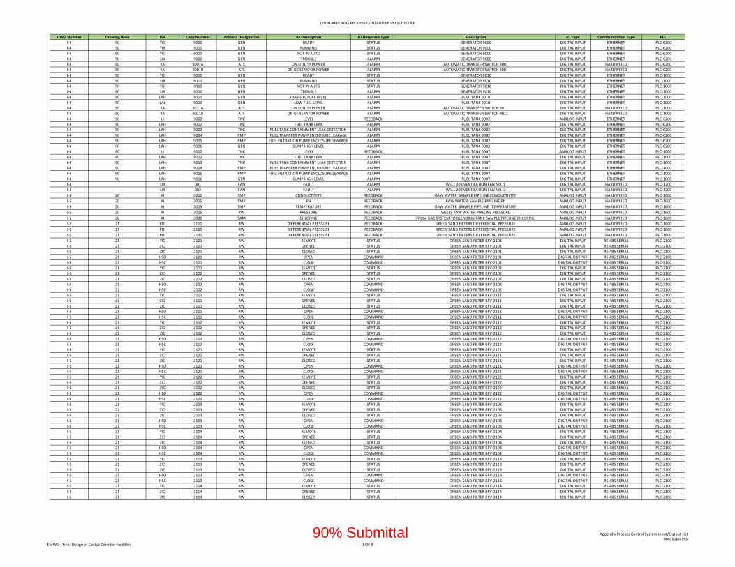
17020‐APPENDIX PROCESS CONTROLLER I/O SCHEDULE
DWG Number Drawing Area ISA Loop Number Process Designation IO Description IO Response Type Description IO Type Communication Type PLC
I‐4 90 YIC 9000 GEN READY STATUS GENERATOR 9000 DIGITAL INPUT ETHERNET PLC‐6200
I‐4 90 YIR 9000 GEN RUNNING STATUS GENERATOR 9000 DIGITAL INPUT ETHERNET PLC‐6200
I‐4 90 YIC 9000 GEN NOT IN AUTO STATUS GENERATOR 9000 DIGITAL INPUT ETHERNET PLC‐6200
I‐4 90 UA 9000 GEN TROUBLE ALARM GENERATOR 9000 DIGITAL INPUT ETHERNET PLC‐6200
I‐4 90 YA 9001A ATS ON UTILITY POWER ALARM AUTOMATIC TRANSFER SWITCH 9001 DIGITAL INPUT HARDWIRED PLC‐6200
I‐4 90 YA 9001B ATS ON GENERATOR POWER ALARM AUTOMATIC TRANSFER SWITCH 9001 DIGITAL INPUT HARDWIRED PLC‐6200
I‐4 90 YIC 9010 GEN READY STATUS GENERATOR 9010 DIGITAL INPUT ETHERNET PLC‐1000
I‐4 90 YIR 9010 GEN RUNNING STATUS GENERATOR 9010 DIGITAL INPUT ETHERNET PLC‐1000
I‐4 90 YIC 9010 GEN NOT IN AUTO STATUS GENERATOR 9010 DIGITAL INPUT ETHERNET PLC‐1000
I‐4 90 UA 9010 GEN TROUBLE ALARM GENERATOR 9010 DIGITAL INPUT ETHERNET PLC‐1000
I‐4 90 LAH 9010 GEN OVERFILL FUEL LEVEL ALARM FUEL TANK 9010 DIGITAL INPUT ETHERNET PLC‐1000
I‐4 90 LAL 9010 GEN LOW FUEL LEVEL ALARM FUEL TANK 9010 DIGITAL INPUT ETHERNET PLC‐1000
I‐4 90 YA 9011A ATS ON UTILITY POWER ALARM AUTOMATIC TRANSFER SWITCH 9011 DIGITAL INPUT HARDWIRED PLC‐1000
I‐4 90 YA 9011B ATS ON GENERATOR POWER ALARM AUTOMATIC TRANSFER SWITCH 9011 DIGITAL INPUT HARDWIRED PLC‐1000
I‐4 90 LI 9002 TNK LEVEL FEEDBACK FUEL TANK 9002 ANALOG INPUT ETHERNET PLC‐6200
I‐4 90 LAH 9002 TNK FUEL TANK LEAK ALARM FUEL TANK 9002 DIGITAL INPUT ETHERNET PLC‐6200
I‐4 90 LAH 9003 TNK FUEL TANK CONTAINMENT LEAK DETECTION ALARM FUEL TANK 9002 DIGITAL INPUT ETHERNET PLC‐6200
I‐4 90 LAH 9004 PMP FUEL TRANSFER PUMP ENCLOSURE LEAKAGE ALARM FUEL TANK 9002 DIGITAL INPUT ETHERNET PLC‐6200
I‐4 90 LAH 9005 PMP FUEL FILTRATION PUMP ENCLOSURE LEAKAGE ALARM FUEL TANK 9002 DIGITAL INPUT ETHERNET PLC‐6200
I‐4 90 LAH 9006 GEN SUMP HIGH LEVEL ALARM FUEL TANK 9002 DIGITAL INPUT ETHERNET PLC‐6200
I‐4 90 LI 9012 TNK LEVEL FEEDBACK FUEL TANK 9007 ANALOG INPUT ETHERNET PLC‐1000
I‐4 90 LAH 9012 TNK FUEL TANK LEAK ALARM FUEL TANK 9007 DIGITAL INPUT ETHERNET PLC‐1000
I‐4 90 LAH 9013 TNK FUEL TANK CONTAINMENT LEAK DETECTION ALARM FUEL TANK 9007 DIGITAL INPUT ETHERNET PLC‐1000
I‐4 90 LAH 9014 PMP FUEL TRANSFER PUMP ENCLOSURE LEAKAGE ALARM FUEL TANK 9007 DIGITAL INPUT ETHERNET PLC‐1000
I‐4 90 LAH 9015 PMP FUEL FILTRATION PUMP ENCLOSURE LEAKAGE ALARM FUEL TANK 9007 DIGITAL INPUT ETHERNET PLC‐1000
I‐4 90 LAH 9016 GEN SUMP HIGH LEVEL ALARM FUEL TANK 9007 DIGITAL INPUT ETHERNET PLC‐1000
I‐4 UA 001 FAN FAULT ALARM WELL 209 VENTILATION FAN NO. 1 DIGITAL INPUT HARDWIRED PLC‐1200
I‐4 UA 002 FAN FAULT ALARM WELL 209 VENTILATION FAN NO. 2 DIGITAL INPUT HARDWIRED PLC‐1200
I‐5 20 AI 2010 SMP CONDUCTIVITY FEEDBACK RAW WATER SAMPLE PIPELINE CONDUCTIVITY ANALOG INPUT HARDWIRED PLC‐1600
I‐5 20 AI 2015 SMP PH FEEDBACK RAW WATER SAMPLE PIPELINE Ph ANALOG INPUT HARDWIRED PLC‐1600
I‐5 20 AI 2015 SMP TEMPERATURE FEEDBACK RAW WATER SAMPLE PIPELINE TEMPERATURE ANALOG INPUT HARDWIRED PLC‐1600
I‐5 20 AI 2015 RW PRESSURE FEEDBACK WELLS RAW WATER PIPELINE PRESSURE ANALOG INPUT HARDWIRED PLC‐1600
I‐5 20 AI 2020 SAM CHLORINE FEEDBACK FROM GAC SYSTEM TO BLENDING TANK SAMPLE PIPELINE CHLORINE ANALOG INPUT HARDWIRED PLC‐1600
I‐5 21 PDI 2110 RW DIFFERENTIAL PRESSURE FEEDBACK GREEN SAND FILTERS DIFFERENTIAL PRESSURE ANALOG INPUT HARDWIRED PLC‐1600
I‐5 21 PDI 2120 RW DIFFERENTIAL PRESSURE FEEDBACK GREEN SAND FILTERS DIFFERENTIAL PRESSURE ANALOG INPUT HARDWIRED PLC‐1600
I‐5 21 PDI 2130 RW DIFFERENTIAL PRESSURE FEEDBACK GREEN SAND FILTERS DIFFERENTIAL PRESSURE ANALOG INPUT HARDWIRED PLC‐1600
I‐5 21 YIC 2101 RW REMOTE STATUS GREEN SAND FILTER BFV‐2101 DIGITAL INPUT RS‐485 SERIAL PLC‐2100
I‐5 21 ZIO 2101 RW OPENED STATUS GREEN SAND FILTER BFV‐2101 DIGITAL INPUT RS‐485 SERIAL PLC‐2100
I‐5 21 ZIC 2101 RW CLOSED STATUS GREEN SAND FILTER BFV‐2101 DIGITAL INPUT RS‐485 SERIAL PLC‐2100
I‐5 21 HSO 2101 RW OPEN COMMAND GREEN SAND FILTER BFV‐2101 DIGITAL OUTPUT RS‐485 SERIAL PLC‐2100
I‐5 21 HSC 2101 RW CLOSE COMMAND GREEN SAND FILTER BFV‐2101 DIGITAL OUTPUT RS‐485 SERIAL PLC‐2100
I‐5 21 YIC 2102 RW REMOTE STATUS GREEN SAND FILTER BFV‐2102 DIGITAL INPUT RS‐485 SERIAL PLC‐2100
I‐5 21 ZIO 2102 RW OPENED STATUS GREEN SAND FILTER BFV‐2102 DIGITAL INPUT RS‐485 SERIAL PLC‐2100
I‐5 21 ZIC 2102 RW CLOSED STATUS GREEN SAND FILTER BFV‐2102 DIGITAL INPUT RS‐485 SERIAL PLC‐2100
I‐5 21 HSO 2102 RW OPEN COMMAND GREEN SAND FILTER BFV‐2102 DIGITAL OUTPUT RS‐485 SERIAL PLC‐2100
I‐5 21 HSC 2102 RW CLOSE COMMAND GREEN SAND FILTER BFV‐2102 DIGITAL OUTPUT RS‐485 SERIAL PLC‐2100
I‐5 21 YIC 2111 RW REMOTE STATUS GREEN SAND FILTER BFV‐2111 DIGITAL INPUT RS‐485 SERIAL PLC‐2100
I‐5 21 ZIO 2111 RW OPENED STATUS GREEN SAND FILTER BFV‐2111 DIGITAL INPUT RS‐485 SERIAL PLC‐2100
I‐5 21 ZIC 2111 RW CLOSED STATUS GREEN SAND FILTER BFV‐2111 DIGITAL INPUT RS‐485 SERIAL PLC‐2100
I‐5 21 HSO 2111 RW OPEN COMMAND GREEN SAND FILTER BFV‐2111 DIGITAL OUTPUT RS‐485 SERIAL PLC‐2100
I‐5 21 HSC 2111 RW CLOSE COMMAND GREEN SAND FILTER BFV‐2111 DIGITAL OUTPUT RS‐485 SERIAL PLC‐2100
I‐5 21 YIC 2112 RW REMOTE STATUS GREEN SAND FILTER BFV‐2112 DIGITAL INPUT RS‐485 SERIAL PLC‐2100
I‐5 21 ZIO 2112 RW OPENED STATUS GREEN SAND FILTER BFV‐2112 DIGITAL INPUT RS‐485 SERIAL PLC‐2100
I‐5 21 ZIC 2112 RW CLOSED STATUS GREEN SAND FILTER BFV‐2112 DIGITAL INPUT RS‐485 SERIAL PLC‐2100
I‐5 21 HSO 2112 RW OPEN COMMAND GREEN SAND FILTER BFV‐2112 DIGITAL OUTPUT RS‐485 SERIAL PLC‐2100
I‐5 21 HSC 2112 RW CLOSE COMMAND GREEN SAND FILTER BFV‐2112 DIGITAL OUTPUT RS‐485 SERIAL PLC‐2100
I‐5 21 YIC 2121 RW REMOTE STATUS GREEN SAND FILTER BFV‐2121 DIGITAL INPUT RS‐485 SERIAL PLC‐2100
I‐5 21 ZIO 2121 RW OPENED STATUS GREEN SAND FILTER BFV‐2121 DIGITAL INPUT RS‐485 SERIAL PLC‐2100
I‐5 21 ZIC 2121 RW CLOSED STATUS GREEN SAND FILTER BFV‐2121 DIGITAL INPUT RS‐485 SERIAL PLC‐2100
I‐5 21 HSO 2121 RW OPEN COMMAND GREEN SAND FILTER BFV‐2121 DIGITAL OUTPUT RS‐485 SERIAL PLC‐2100
I‐5 21 HSC 2121 RW CLOSE COMMAND GREEN SAND FILTER BFV‐2121 DIGITAL OUTPUT RS‐485 SERIAL PLC‐2100
I‐5 21 YIC 2122 RW REMOTE STATUS GREEN SAND FILTER BFV‐2122 DIGITAL INPUT RS‐485 SERIAL PLC‐2100
I‐5 21 ZIO 2122 RW OPENED STATUS GREEN SAND FILTER BFV‐2122 DIGITAL INPUT RS‐485 SERIAL PLC‐2100
I‐5 21 ZIC 2122 RW CLOSED STATUS GREEN SAND FILTER BFV‐2122 DIGITAL INPUT RS‐485 SERIAL PLC‐2100
I‐5 21 HSO 2122 RW OPEN COMMAND GREEN SAND FILTER BFV‐2122 DIGITAL OUTPUT RS‐485 SERIAL PLC‐2100
I‐5 21 HSC 2122 RW CLOSE COMMAND GREEN SAND FILTER BFV‐2122 DIGITAL OUTPUT RS‐485 SERIAL PLC‐2100
I‐5 21 YIC 2103 RW REMOTE STATUS GREEN SAND FILTER BFV‐2103 DIGITAL INPUT RS‐485 SERIAL PLC‐2100
I‐5 21 ZIO 2103 RW OPENED STATUS GREEN SAND FILTER BFV‐2103 DIGITAL INPUT RS‐485 SERIAL PLC‐2100
I‐5 21 ZIC 2103 RW CLOSED STATUS GREEN SAND FILTER BFV‐2103 DIGITAL INPUT RS‐485 SERIAL PLC‐2100
I‐5 21 HSO 2103 RW OPEN COMMAND GREEN SAND FILTER BFV‐2103 DIGITAL OUTPUT RS‐485 SERIAL PLC‐2100
I‐5 21 HSC 2103 RW CLOSE COMMAND GREEN SAND FILTER BFV‐2103 DIGITAL OUTPUT RS‐485 SERIAL PLC‐2100
I‐5 21 YIC 2104 RW REMOTE STATUS GREEN SAND FILTER BFV‐2104 DIGITAL INPUT RS‐485 SERIAL PLC‐2100
I‐5 21 ZIO 2104 RW OPENED STATUS GREEN SAND FILTER BFV‐2104 DIGITAL INPUT RS‐485 SERIAL PLC‐2100
I‐5 21 ZIC 2104 RW CLOSED STATUS GREEN SAND FILTER BFV‐2104 DIGITAL INPUT RS‐485 SERIAL PLC‐2100
I‐5 21 HSO 2104 RW OPEN COMMAND GREEN SAND FILTER BFV‐2104 DIGITAL OUTPUT RS‐485 SERIAL PLC‐2100
I‐5 21 HSC 2104 RW CLOSE COMMAND GREEN SAND FILTER BFV‐2104 DIGITAL OUTPUT RS‐485 SERIAL PLC‐2100
I‐5 21 YIC 2113 RW REMOTE STATUS GREEN SAND FILTER BFV‐2113 DIGITAL INPUT RS‐485 SERIAL PLC‐2100
I‐5 21 ZIO 2113 RW OPENED STATUS GREEN SAND FILTER BFV‐2113 DIGITAL INPUT RS‐485 SERIAL PLC‐2100
I‐5 21 ZIC 2113 RW CLOSED STATUS GREEN SAND FILTER BFV‐2113 DIGITAL INPUT RS‐485 SERIAL PLC‐2100
I‐5 21 HSO 2113 RW OPEN COMMAND GREEN SAND FILTER BFV‐2113 DIGITAL OUTPUT RS‐485 SERIAL PLC‐2100
I‐5 21 HSC 2113 RW CLOSE COMMAND GREEN SAND FILTER BFV‐2113 DIGITAL OUTPUT RS‐485 SERIAL PLC‐2100
I‐5 21 YIC 2114 RW REMOTE STATUS GREEN SAND FILTER BFV‐2114 DIGITAL INPUT RS‐485 SERIAL PLC‐2100
I‐5 21 ZIO 2114 RW OPENED STATUS GREEN SAND FILTER BFV‐2114 DIGITAL INPUT RS‐485 SERIAL PLC‐2100
I‐5 21 ZIC 2114 RW CLOSED STATUS GREEN SAND FILTER BFV‐2114 DIGITAL INPUT RS‐485 SERIAL PLC‐2100
EMWD ‐ Final Design of Cactus Corridor Facilities 1 OF 9
Appendix Process Control System Input/Output List
90% Submittal90% Submittal
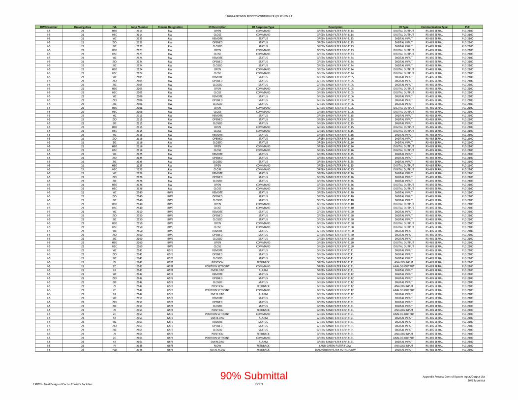
17020‐APPENDIX PROCESS CONTROLLER I/O SCHEDULE
DWG Number Drawing Area ISA Loop Number Process Designation IO Description IO Response Type Description IO Type Communication Type PLC
I‐5 21 HSO 2114 RW OPEN COMMAND GREEN SAND FILTER BFV‐2114 DIGITAL OUTPUT RS‐485 SERIAL PLC‐2100
I‐5 21 HSC 2114 RW CLOSE COMMAND GREEN SAND FILTER BFV‐2114 DIGITAL OUTPUT RS‐485 SERIAL PLC‐2100
I‐5 21 YIC 2123 RW REMOTE STATUS GREEN SAND FILTER BFV‐2123 DIGITAL INPUT RS‐485 SERIAL PLC‐2100
I‐5 21 ZIO 2123 RW OPENED STATUS GREEN SAND FILTER BFV‐2123 DIGITAL INPUT RS‐485 SERIAL PLC‐2100
I‐5 21 ZIC 2123 RW CLOSED STATUS GREEN SAND FILTER BFV‐2123 DIGITAL INPUT RS‐485 SERIAL PLC‐2100
I‐5 21 HSO 2123 RW OPEN COMMAND GREEN SAND FILTER BFV‐2123 DIGITAL OUTPUT RS‐485 SERIAL PLC‐2100
I‐5 21 HSC 2123 RW CLOSE COMMAND GREEN SAND FILTER BFV‐2123 DIGITAL OUTPUT RS‐485 SERIAL PLC‐2100
I‐5 21 YIC 2124 RW REMOTE STATUS GREEN SAND FILTER BFV‐2124 DIGITAL INPUT RS‐485 SERIAL PLC‐2100
I‐5 21 ZIO 2124 RW OPENED STATUS GREEN SAND FILTER BFV‐2124 DIGITAL INPUT RS‐485 SERIAL PLC‐2100
I‐5 21 ZIC 2124 RW CLOSED STATUS GREEN SAND FILTER BFV‐2124 DIGITAL INPUT RS‐485 SERIAL PLC‐2100
I‐5 21 HSO 2124 RW OPEN COMMAND GREEN SAND FILTER BFV‐2124 DIGITAL OUTPUT RS‐485 SERIAL PLC‐2100
I‐5 21 HSC 2124 RW CLOSE COMMAND GREEN SAND FILTER BFV‐2124 DIGITAL OUTPUT RS‐485 SERIAL PLC‐2100
I‐5 21 YIC 2105 RW REMOTE STATUS GREEN SAND FILTER BFV‐2105 DIGITAL INPUT RS‐485 SERIAL PLC‐2100
I‐5 21 ZIO 2105 RW OPENED STATUS GREEN SAND FILTER BFV‐2105 DIGITAL INPUT RS‐485 SERIAL PLC‐2100
I‐5 21 ZIC 2105 RW CLOSED STATUS GREEN SAND FILTER BFV‐2105 DIGITAL INPUT RS‐485 SERIAL PLC‐2100
I‐5 21 HSO 2105 RW OPEN COMMAND GREEN SAND FILTER BFV‐2105 DIGITAL OUTPUT RS‐485 SERIAL PLC‐2100
I‐5 21 HSC 2105 RW CLOSE COMMAND GREEN SAND FILTER BFV‐2105 DIGITAL OUTPUT RS‐485 SERIAL PLC‐2100
I‐5 21 YIC 2106 RW REMOTE STATUS GREEN SAND FILTER BFV‐2106 DIGITAL INPUT RS‐485 SERIAL PLC‐2100
I‐5 21 ZIO 2106 RW OPENED STATUS GREEN SAND FILTER BFV‐2106 DIGITAL INPUT RS‐485 SERIAL PLC‐2100
I‐5 21 ZIC 2106 RW CLOSED STATUS GREEN SAND FILTER BFV‐2106 DIGITAL INPUT RS‐485 SERIAL PLC‐2100
I‐5 21 HSO 2106 RW OPEN COMMAND GREEN SAND FILTER BFV‐2106 DIGITAL OUTPUT RS‐485 SERIAL PLC‐2100
I‐5 21 HSC 2106 RW CLOSE COMMAND GREEN SAND FILTER BFV‐2106 DIGITAL OUTPUT RS‐485 SERIAL PLC‐2100
I‐5 21 YIC 2115 RW REMOTE STATUS GREEN SAND FILTER BFV‐2115 DIGITAL INPUT RS‐485 SERIAL PLC‐2100
I‐5 21 ZIO 2115 RW OPENED STATUS GREEN SAND FILTER BFV‐2115 DIGITAL INPUT RS‐485 SERIAL PLC‐2100
I‐5 21 ZIC 2115 RW CLOSED STATUS GREEN SAND FILTER BFV‐2115 DIGITAL INPUT RS‐485 SERIAL PLC‐2100
I‐5 21 HSO 2115 RW OPEN COMMAND GREEN SAND FILTER BFV‐2115 DIGITAL OUTPUT RS‐485 SERIAL PLC‐2100
I‐5 21 HSC 2115 RW CLOSE COMMAND GREEN SAND FILTER BFV‐2115 DIGITAL OUTPUT RS‐485 SERIAL PLC‐2100
I‐5 21 YIC 2116 RW REMOTE STATUS GREEN SAND FILTER BFV‐2116 DIGITAL INPUT RS‐485 SERIAL PLC‐2100
I‐5 21 ZIO 2116 RW OPENED STATUS GREEN SAND FILTER BFV‐2116 DIGITAL INPUT RS‐485 SERIAL PLC‐2100
I‐5 21 ZIC 2116 RW CLOSED STATUS GREEN SAND FILTER BFV‐2116 DIGITAL INPUT RS‐485 SERIAL PLC‐2100
I‐5 21 HSO 2116 RW OPEN COMMAND GREEN SAND FILTER BFV‐2116 DIGITAL OUTPUT RS‐485 SERIAL PLC‐2100
I‐5 21 HSC 2116 RW CLOSE COMMAND GREEN SAND FILTER BFV‐2116 DIGITAL OUTPUT RS‐485 SERIAL PLC‐2100
I‐5 21 YIC 2125 RW REMOTE STATUS GREEN SAND FILTER BFV‐2125 DIGITAL INPUT RS‐485 SERIAL PLC‐2100
I‐5 21 ZIO 2125 RW OPENED STATUS GREEN SAND FILTER BFV‐2125 DIGITAL INPUT RS‐485 SERIAL PLC‐2100
I‐5 21 ZIC 2125 RW CLOSED STATUS GREEN SAND FILTER BFV‐2125 DIGITAL INPUT RS‐485 SERIAL PLC‐2100
I‐5 21 HSO 2125 RW OPEN COMMAND GREEN SAND FILTER BFV‐2125 DIGITAL OUTPUT RS‐485 SERIAL PLC‐2100
I‐5 21 HSC 2125 RW CLOSE COMMAND GREEN SAND FILTER BFV‐2125 DIGITAL OUTPUT RS‐485 SERIAL PLC‐2100
I‐5 21 YIC 2126 RW REMOTE STATUS GREEN SAND FILTER BFV‐2126 DIGITAL INPUT RS‐485 SERIAL PLC‐2100
I‐5 21 ZIO 2126 RW OPENED STATUS GREEN SAND FILTER BFV‐2126 DIGITAL INPUT RS‐485 SERIAL PLC‐2100
I‐5 21 ZIC 2126 RW CLOSED STATUS GREEN SAND FILTER BFV‐2126 DIGITAL INPUT RS‐485 SERIAL PLC‐2100
I‐5 21 HSO 2126 RW OPEN COMMAND GREEN SAND FILTER BFV‐2126 DIGITAL OUTPUT RS‐485 SERIAL PLC‐2100
I‐5 21 HSC 2126 RW CLOSE COMMAND GREEN SAND FILTER BFV‐2126 DIGITAL OUTPUT RS‐485 SERIAL PLC‐2100
I‐5 21 YIC 2140 BWS REMOTE STATUS GREEN SAND FILTER BFV‐2140 DIGITAL INPUT RS‐485 SERIAL PLC‐2100
I‐5 21 ZIO 2140 BWS OPENED STATUS GREEN SAND FILTER BFV‐2140 DIGITAL INPUT RS‐485 SERIAL PLC‐2100
I‐5 21 ZIC 2140 BWS CLOSED STATUS GREEN SAND FILTER BFV‐2140 DIGITAL INPUT RS‐485 SERIAL PLC‐2100
I‐5 21 HSO 2140 BWS OPEN COMMAND GREEN SAND FILTER BFV‐2140 DIGITAL OUTPUT RS‐485 SERIAL PLC‐2100
I‐5 21 HSC 2140 BWS CLOSE COMMAND GREEN SAND FILTER BFV‐2140 DIGITAL OUTPUT RS‐485 SERIAL PLC‐2100
I‐5 21 YIC 2150 BWS REMOTE STATUS GREEN SAND FILTER BFV‐2150 DIGITAL INPUT RS‐485 SERIAL PLC‐2100
I‐5 21 ZIO 2150 BWS OPENED STATUS GREEN SAND FILTER BFV‐2150 DIGITAL INPUT RS‐485 SERIAL PLC‐2100
I‐5 21 ZIC 2150 BWS CLOSED STATUS GREEN SAND FILTER BFV‐2150 DIGITAL INPUT RS‐485 SERIAL PLC‐2100
I‐5 21 HSO 2150 BWS OPEN COMMAND GREEN SAND FILTER BFV‐2150 DIGITAL OUTPUT RS‐485 SERIAL PLC‐2100
I‐5 21 HSC 2150 BWS CLOSE COMMAND GREEN SAND FILTER BFV‐2150 DIGITAL OUTPUT RS‐485 SERIAL PLC‐2100
I‐5 21 YIC 2160 BWS REMOTE STATUS GREEN SAND FILTER BFV‐2160 DIGITAL INPUT RS‐485 SERIAL PLC‐2100
I‐5 21 ZIO 2160 BWS OPENED STATUS GREEN SAND FILTER BFV‐2160 DIGITAL INPUT RS‐485 SERIAL PLC‐2100
I‐5 21 ZIC 2160 BWS CLOSED STATUS GREEN SAND FILTER BFV‐2160 DIGITAL INPUT RS‐485 SERIAL PLC‐2100
I‐5 21 HSO 2160 BWS OPEN COMMAND GREEN SAND FILTER BFV‐2160 DIGITAL OUTPUT RS‐485 SERIAL PLC‐2100
I‐5 21 HSC 2160 BWS CLOSE COMMAND GREEN SAND FILTER BFV‐2160 DIGITAL OUTPUT RS‐485 SERIAL PLC‐2100
I‐5 21 YIC 2141 GSFE REMOTE STATUS GREEN SAND FILTER BFV‐2141 DIGITAL INPUT RS‐485 SERIAL PLC‐2100
I‐5 21 ZIO 2141 GSFE OPENED STATUS GREEN SAND FILTER BFV‐2141 DIGITAL INPUT RS‐485 SERIAL PLC‐2100
I‐5 21 ZIC 2141 GSFE CLOSED STATUS GREEN SAND FILTER BFV‐2141 DIGITAL INPUT RS‐485 SERIAL PLC‐2100
I‐5 21 ZI 2141 GSFE POSITION FEEDBACK GREEN SAND FILTER BFV‐2141 ANALOG INPUT RS‐485 SERIAL PLC‐2100
I‐5 21 ZC 2141 GSFE POSITION SETPOINT COMMAND GREEN SAND FILTER BFV‐2141 ANALOG OUTPUT RS‐485 SERIAL PLC‐2100
I‐5 21 YA 2141 GSFE OVERLOAD ALARM GREEN SAND FILTER BFV‐2141 DIGITAL INPUT RS‐485 SERIAL PLC‐2100
I‐5 21 YIC 2142 GSFE REMOTE STATUS GREEN SAND FILTER BFV‐2142 DIGITAL INPUT RS‐485 SERIAL PLC‐2100
I‐5 21 ZIO 2142 GSFE OPENED STATUS GREEN SAND FILTER BFV‐2142 DIGITAL INPUT RS‐485 SERIAL PLC‐2100
I‐5 21 ZIC 2142 GSFE CLOSED STATUS GREEN SAND FILTER BFV‐2142 DIGITAL INPUT RS‐485 SERIAL PLC‐2100
I‐5 21 ZI 2142 GSFE POSITION FEEDBACK GREEN SAND FILTER BFV‐2142 ANALOG INPUT RS‐485 SERIAL PLC‐2100
I‐5 21 ZC 2142 GSFE POSITION SETPOINT COMMAND GREEN SAND FILTER BFV‐2142 ANALOG OUTPUT RS‐485 SERIAL PLC‐2100
I‐5 21 YA 2142 GSFE OVERLOAD ALARM GREEN SAND FILTER BFV‐2142 DIGITAL INPUT RS‐485 SERIAL PLC‐2100
I‐5 21 YIC 2151 GSFE REMOTE STATUS GREEN SAND FILTER BFV‐2151 DIGITAL INPUT RS‐485 SERIAL PLC‐2100
I‐5 21 ZIO 2151 GSFE OPENED STATUS GREEN SAND FILTER BFV‐2151 DIGITAL INPUT RS‐485 SERIAL PLC‐2100
I‐5 21 ZIC 2151 GSFE CLOSED STATUS GREEN SAND FILTER BFV‐2151 DIGITAL INPUT RS‐485 SERIAL PLC‐2100
I‐5 21 ZI 2151 GSFE POSITION FEEDBACK GREEN SAND FILTER BFV‐2151 ANALOG INPUT RS‐485 SERIAL PLC‐2100
I‐5 21 ZC 2151 GSFE POSITION SETPOINT COMMAND GREEN SAND FILTER BFV‐2151 ANALOG OUTPUT RS‐485 SERIAL PLC‐2100
I‐5 21 YA 2151 GSFE OVERLOAD ALARM GREEN SAND FILTER BFV‐2151 DIGITAL INPUT RS‐485 SERIAL PLC‐2100
I‐5 21 YIC 2161 GSFE REMOTE STATUS GREEN SAND FILTER BFV‐2161 DIGITAL INPUT RS‐485 SERIAL PLC‐2100
I‐5 21 ZIO 2161 GSFE OPENED STATUS GREEN SAND FILTER BFV‐2161 DIGITAL INPUT RS‐485 SERIAL PLC‐2100
I‐5 21 ZIC 2161 GSFE CLOSED STATUS GREEN SAND FILTER BFV‐2161 DIGITAL INPUT RS‐485 SERIAL PLC‐2100
I‐5 21 ZI 2161 GSFE POSITION FEEDBACK GREEN SAND FILTER BFV‐2161 ANALOG INPUT RS‐485 SERIAL PLC‐2100
I‐5 21 ZC 2161 GSFE POSITION SETPOINT COMMAND GREEN SAND FILTER BFV‐2161 ANALOG OUTPUT RS‐485 SERIAL PLC‐2100
I‐5 21 YA 2161 GSFE OVERLOAD ALARM GREEN SAND FILTER BFV‐2161 DIGITAL INPUT RS‐485 SERIAL PLC‐2100
I‐5 21 FI 2145 GSFE FLOW FEEDBACK SAND GREEN FILTER FLOW ANALOG INPUT RS‐485 SERIAL PLC‐2100
I‐5 21 FQI 2145 GSFE TOTAL FLOW FEEDBACK SAND GREEN FILTER TOTAL FLOW DIGITAL INPUT RS‐485 SERIAL PLC‐2100
EMWD ‐ Final Design of Cactus Corridor Facilities 2 OF 9
Appendix Process Control System Input/Output List
90% Submittal90% Submittal
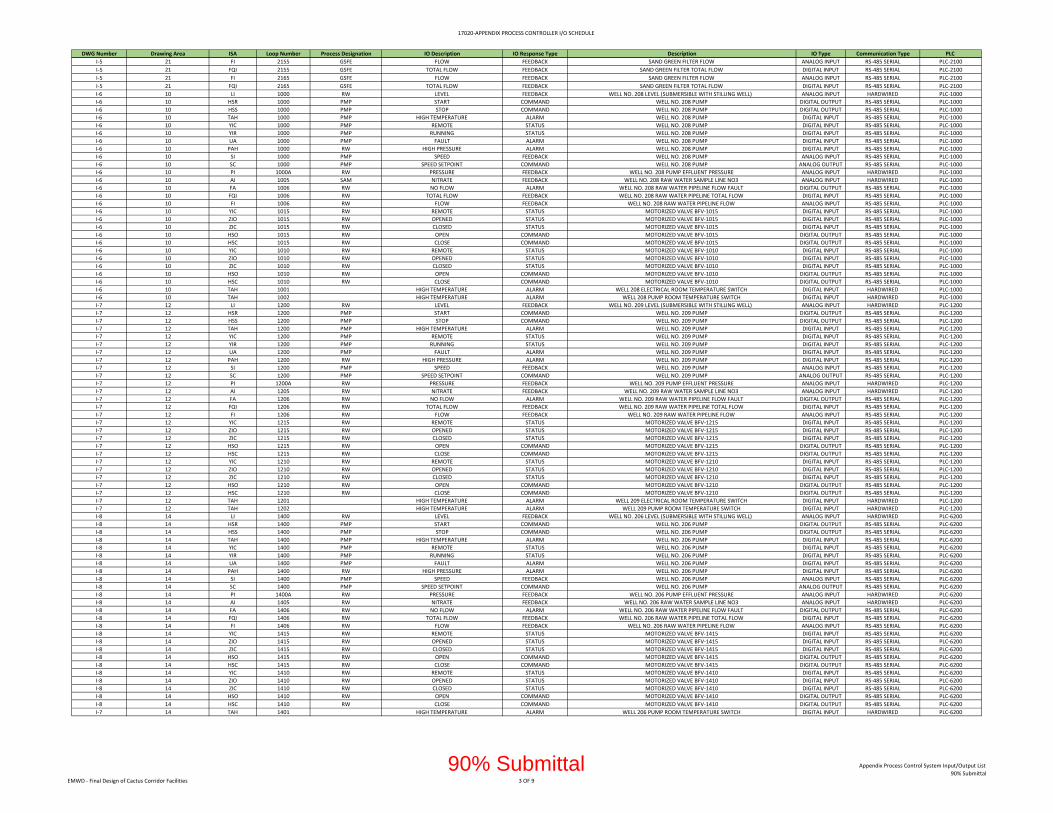
17020‐APPENDIX PROCESS CONTROLLER I/O SCHEDULE
DWG Number Drawing Area ISA Loop Number Process Designation IO Description IO Response Type Description IO Type Communication Type PLC
I‐5 21 FI 2155 GSFE FLOW FEEDBACK SAND GREEN FILTER FLOW ANALOG INPUT RS‐485 SERIAL PLC‐2100
I‐5 21 FQI 2155 GSFE TOTAL FLOW FEEDBACK SAND GREEN FILTER TOTAL FLOW DIGITAL INPUT RS‐485 SERIAL PLC‐2100
I‐5 21 FI 2165 GSFE FLOW FEEDBACK SAND GREEN FILTER FLOW ANALOG INPUT RS‐485 SERIAL PLC‐2100
I‐5 21 FQI 2165 GSFE TOTAL FLOW FEEDBACK SAND GREEN FILTER TOTAL FLOW DIGITAL INPUT RS‐485 SERIAL PLC‐2100
I‐6 10 LI 1000 RW LEVEL FEEDBACK WELL NO. 208 LEVEL (SUBMERSIBLE WITH STILLING WELL) ANALOG INPUT HARDWIRED PLC‐1000
I‐6 10 HSR 1000 PMP START COMMAND WELL NO. 208 PUMP DIGITAL OUTPUT RS‐485 SERIAL PLC‐1000
I‐6 10 HSS 1000 PMP STOP COMMAND WELL NO. 208 PUMP DIGITAL OUTPUT RS‐485 SERIAL PLC‐1000
I‐6 10 TAH 1000 PMP HIGH TEMPERATURE ALARM WELL NO. 208 PUMP DIGITAL INPUT RS‐485 SERIAL PLC‐1000
I‐6 10 YIC 1000 PMP REMOTE STATUS WELL NO. 208 PUMP DIGITAL INPUT RS‐485 SERIAL PLC‐1000
I‐6 10 YIR 1000 PMP RUNNING STATUS WELL NO. 208 PUMP DIGITAL INPUT RS‐485 SERIAL PLC‐1000
I‐6 10 UA 1000 PMP FAULT ALARM WELL NO. 208 PUMP DIGITAL INPUT RS‐485 SERIAL PLC‐1000
I‐6 10 PAH 1000 RW HIGH PRESSURE ALARM WELL NO. 208 PUMP DIGITAL INPUT RS‐485 SERIAL PLC‐1000
I‐6 10 SI 1000 PMP SPEED FEEDBACK WELL NO. 208 PUMP ANALOG INPUT RS‐485 SERIAL PLC‐1000
I‐6 10 SC 1000 PMP SPEED SETPOINT COMMAND WELL NO. 208 PUMP ANALOG OUTPUT RS‐485 SERIAL PLC‐1000
I‐6 10 PI 1000A RW PRESSURE FEEDBACK WELL NO. 208 PUMP EFFLUENT PRESSURE ANALOG INPUT HARDWIRED PLC‐1000
I‐6 10 AI 1005 SAM NITRATE FEEDBACK WELL NO. 208 RAW WATER SAMPLE LINE NO3 ANALOG INPUT HARDWIRED PLC‐1000
I‐6 10 FA 1006 RW NO FLOW ALARM WELL NO. 208 RAW WATER PIPELINE FLOW FAULT DIGITAL OUTPUT RS‐485 SERIAL PLC‐1000
I‐6 10 FQI 1006 RW TOTAL FLOW FEEDBACK WELL NO. 208 RAW WATER PIPELINE TOTAL FLOW DIGITAL INPUT RS‐485 SERIAL PLC‐1000
I‐6 10 FI 1006 RW FLOW FEEDBACK WELL NO. 208 RAW WATER PIPELINE FLOW ANALOG INPUT RS‐485 SERIAL PLC‐1000
I‐6 10 YIC 1015 RW REMOTE STATUS MOTORIZED VALVE BFV‐1015 DIGITAL INPUT RS‐485 SERIAL PLC‐1000
I‐6 10 ZIO 1015 RW OPENED STATUS MOTORIZED VALVE BFV‐1015 DIGITAL INPUT RS‐485 SERIAL PLC‐1000
I‐6 10 ZIC 1015 RW CLOSED STATUS MOTORIZED VALVE BFV‐1015 DIGITAL INPUT RS‐485 SERIAL PLC‐1000
I‐6 10 HSO 1015 RW OPEN COMMAND MOTORIZED VALVE BFV‐1015 DIGITAL OUTPUT RS‐485 SERIAL PLC‐1000
I‐6 10 HSC 1015 RW CLOSE COMMAND MOTORIZED VALVE BFV‐1015 DIGITAL OUTPUT RS‐485 SERIAL PLC‐1000
I‐6 10 YIC 1010 RW REMOTE STATUS MOTORIZED VALVE BFV‐1010 DIGITAL INPUT RS‐485 SERIAL PLC‐1000
I‐6 10 ZIO 1010 RW OPENED STATUS MOTORIZED VALVE BFV‐1010 DIGITAL INPUT RS‐485 SERIAL PLC‐1000
I‐6 10 ZIC 1010 RW CLOSED STATUS MOTORIZED VALVE BFV‐1010 DIGITAL INPUT RS‐485 SERIAL PLC‐1000
I‐6 10 HSO 1010 RW OPEN COMMAND MOTORIZED VALVE BFV‐1010 DIGITAL OUTPUT RS‐485 SERIAL PLC‐1000
I‐6 10 HSC 1010 RW CLOSE COMMAND MOTORIZED VALVE BFV‐1010 DIGITAL OUTPUT RS‐485 SERIAL PLC‐1000
I‐6 10 TAH 1001 HIGH TEMPERATURE ALARM WELL 208 ELECTRICAL ROOM TEMPERATURE SWITCH DIGITAL INPUT HARDWIRED PLC‐1000
I‐6 10 TAH 1002 HIGH TEMPERATURE ALARM WELL 208 PUMP ROOM TEMPERATURE SWITCH DIGITAL INPUT HARDWIRED PLC‐1000
I‐7 12 LI 1200 RW LEVEL FEEDBACK WELL NO. 209 LEVEL (SUBMERSIBLE WITH STILLING WELL) ANALOG INPUT HARDWIRED PLC‐1200
I‐7 12 HSR 1200 PMP START COMMAND WELL NO. 209 PUMP DIGITAL OUTPUT RS‐485 SERIAL PLC‐1200
I‐7 12 HSS 1200 PMP STOP COMMAND WELL NO. 209 PUMP DIGITAL OUTPUT RS‐485 SERIAL PLC‐1200
I‐7 12 TAH 1200 PMP HIGH TEMPERATURE ALARM WELL NO. 209 PUMP DIGITAL INPUT RS‐485 SERIAL PLC‐1200
I‐7 12 YIC 1200 PMP REMOTE STATUS WELL NO. 209 PUMP DIGITAL INPUT RS‐485 SERIAL PLC‐1200
I‐7 12 YIR 1200 PMP RUNNING STATUS WELL NO. 209 PUMP DIGITAL INPUT RS‐485 SERIAL PLC‐1200
I‐7 12 UA 1200 PMP FAULT ALARM WELL NO. 209 PUMP DIGITAL INPUT RS‐485 SERIAL PLC‐1200
I‐7 12 PAH 1200 RW HIGH PRESSURE ALARM WELL NO. 209 PUMP DIGITAL INPUT RS‐485 SERIAL PLC‐1200
I‐7 12 SI 1200 PMP SPEED FEEDBACK WELL NO. 209 PUMP ANALOG INPUT RS‐485 SERIAL PLC‐1200
I‐7 12 SC 1200 PMP SPEED SETPOINT COMMAND WELL NO. 209 PUMP ANALOG OUTPUT RS‐485 SERIAL PLC‐1200
I‐7 12 PI 1200A RW PRESSURE FEEDBACK WELL NO. 209 PUMP EFFLUENT PRESSURE ANALOG INPUT HARDWIRED PLC‐1200
I‐7 12 AI 1205 RW NITRATE FEEDBACK WELL NO. 209 RAW WATER SAMPLE LINE NO3 ANALOG INPUT HARDWIRED PLC‐1200
I‐7 12 FA 1206 RW NO FLOW ALARM WELL NO. 209 RAW WATER PIPELINE FLOW FAULT DIGITAL OUTPUT RS‐485 SERIAL PLC‐1200
I‐7 12 FQI 1206 RW TOTAL FLOW FEEDBACK WELL NO. 209 RAW WATER PIPELINE TOTAL FLOW DIGITAL INPUT RS‐485 SERIAL PLC‐1200
I‐7 12 FI 1206 RW FLOW FEEDBACK WELL NO. 209 RAW WATER PIPELINE FLOW ANALOG INPUT RS‐485 SERIAL PLC‐1200
I‐7 12 YIC 1215 RW REMOTE STATUS MOTORIZED VALVE BFV‐1215 DIGITAL INPUT RS‐485 SERIAL PLC‐1200
I‐7 12 ZIO 1215 RW OPENED STATUS MOTORIZED VALVE BFV‐1215 DIGITAL INPUT RS‐485 SERIAL PLC‐1200
I‐7 12 ZIC 1215 RW CLOSED STATUS MOTORIZED VALVE BFV‐1215 DIGITAL INPUT RS‐485 SERIAL PLC‐1200
I‐7 12 HSO 1215 RW OPEN COMMAND MOTORIZED VALVE BFV‐1215 DIGITAL OUTPUT RS‐485 SERIAL PLC‐1200
I‐7 12 HSC 1215 RW CLOSE COMMAND MOTORIZED VALVE BFV‐1215 DIGITAL OUTPUT RS‐485 SERIAL PLC‐1200
I‐7 12 YIC 1210 RW REMOTE STATUS MOTORIZED VALVE BFV‐1210 DIGITAL INPUT RS‐485 SERIAL PLC‐1200
I‐7 12 ZIO 1210 RW OPENED STATUS MOTORIZED VALVE BFV‐1210 DIGITAL INPUT RS‐485 SERIAL PLC‐1200
I‐7 12 ZIC 1210 RW CLOSED STATUS MOTORIZED VALVE BFV‐1210 DIGITAL INPUT RS‐485 SERIAL PLC‐1200
I‐7 12 HSO 1210 RW OPEN COMMAND MOTORIZED VALVE BFV‐1210 DIGITAL OUTPUT RS‐485 SERIAL PLC‐1200
I‐7 12 HSC 1210 RW CLOSE COMMAND MOTORIZED VALVE BFV‐1210 DIGITAL OUTPUT RS‐485 SERIAL PLC‐1200
I‐7 12 TAH 1201 HIGH TEMPERATURE ALARM WELL 209 ELECTRICAL ROOM TEMPERATURE SWITCH DIGITAL INPUT HARDWIRED PLC‐1200
I‐7 12 TAH 1202 HIGH TEMPERATURE ALARM WELL 209 PUMP ROOM TEMPERATURE SWITCH DIGITAL INPUT HARDWIRED PLC‐1200
I‐8 14 LI 1400 RW LEVEL FEEDBACK WELL NO. 206 LEVEL (SUBMERSIBLE WITH STILLING WELL) ANALOG INPUT HARDWIRED PLC‐6200
I‐8 14 HSR 1400 PMP START COMMAND WELL NO. 206 PUMP DIGITAL OUTPUT RS‐485 SERIAL PLC‐6200
I‐8 14 HSS 1400 PMP STOP COMMAND WELL NO. 206 PUMP DIGITAL OUTPUT RS‐485 SERIAL PLC‐6200
I‐8 14 TAH 1400 PMP HIGH TEMPERATURE ALARM WELL NO. 206 PUMP DIGITAL INPUT RS‐485 SERIAL PLC‐6200
I‐8 14 YIC 1400 PMP REMOTE STATUS WELL NO. 206 PUMP DIGITAL INPUT RS‐485 SERIAL PLC‐6200
I‐8 14 YIR 1400 PMP RUNNING STATUS WELL NO. 206 PUMP DIGITAL INPUT RS‐485 SERIAL PLC‐6200
I‐8 14 UA 1400 PMP FAULT ALARM WELL NO. 206 PUMP DIGITAL INPUT RS‐485 SERIAL PLC‐6200
I‐8 14 PAH 1400 RW HIGH PRESSURE ALARM WELL NO. 206 PUMP DIGITAL INPUT RS‐485 SERIAL PLC‐6200
I‐8 14 SI 1400 PMP SPEED FEEDBACK WELL NO. 206 PUMP ANALOG INPUT RS‐485 SERIAL PLC‐6200
I‐8 14 SC 1400 PMP SPEED SETPOINT COMMAND WELL NO. 206 PUMP ANALOG OUTPUT RS‐485 SERIAL PLC‐6200
I‐8 14 PI 1400A RW PRESSURE FEEDBACK WELL NO. 206 PUMP EFFLUENT PRESSURE ANALOG INPUT HARDWIRED PLC‐6200
I‐8 14 AI 1405 RW NITRATE FEEDBACK WELL NO. 206 RAW WATER SAMPLE LINE NO3 ANALOG INPUT HARDWIRED PLC‐6200
I‐8 14 FA 1406 RW NO FLOW ALARM WELL NO. 206 RAW WATER PIPELINE FLOW FAULT DIGITAL OUTPUT RS‐485 SERIAL PLC‐6200
I‐8 14 FQI 1406 RW TOTAL FLOW FEEDBACK WELL NO. 206 RAW WATER PIPELINE TOTAL FLOW DIGITAL INPUT RS‐485 SERIAL PLC‐6200
I‐8 14 FI 1406 RW FLOW FEEDBACK WELL NO. 206 RAW WATER PIPELINE FLOW ANALOG INPUT RS‐485 SERIAL PLC‐6200
I‐8 14 YIC 1415 RW REMOTE STATUS MOTORIZED VALVE BFV‐1415 DIGITAL INPUT RS‐485 SERIAL PLC‐6200
I‐8 14 ZIO 1415 RW OPENED STATUS MOTORIZED VALVE BFV‐1415 DIGITAL INPUT RS‐485 SERIAL PLC‐6200
I‐8 14 ZIC 1415 RW CLOSED STATUS MOTORIZED VALVE BFV‐1415 DIGITAL INPUT RS‐485 SERIAL PLC‐6200
I‐8 14 HSO 1415 RW OPEN COMMAND MOTORIZED VALVE BFV‐1415 DIGITAL OUTPUT RS‐485 SERIAL PLC‐6200
I‐8 14 HSC 1415 RW CLOSE COMMAND MOTORIZED VALVE BFV‐1415 DIGITAL OUTPUT RS‐485 SERIAL PLC‐6200
I‐8 14 YIC 1410 RW REMOTE STATUS MOTORIZED VALVE BFV‐1410 DIGITAL INPUT RS‐485 SERIAL PLC‐6200
I‐8 14 ZIO 1410 RW OPENED STATUS MOTORIZED VALVE BFV‐1410 DIGITAL INPUT RS‐485 SERIAL PLC‐6200
I‐8 14 ZIC 1410 RW CLOSED STATUS MOTORIZED VALVE BFV‐1410 DIGITAL INPUT RS‐485 SERIAL PLC‐6200
I‐8 14 HSO 1410 RW OPEN COMMAND MOTORIZED VALVE BFV‐1410 DIGITAL OUTPUT RS‐485 SERIAL PLC‐6200
I‐8 14 HSC 1410 RW CLOSE COMMAND MOTORIZED VALVE BFV‐1410 DIGITAL OUTPUT RS‐485 SERIAL PLC‐6200
I‐7 14 TAH 1401 HIGH TEMPERATURE ALARM WELL 206 PUMP ROOM TEMPERATURE SWITCH DIGITAL INPUT HARDWIRED PLC‐6200
EMWD ‐ Final Design of Cactus Corridor Facilities 3 OF 9
Appendix Process Control System Input/Output List
90% Submittal90% Submittal
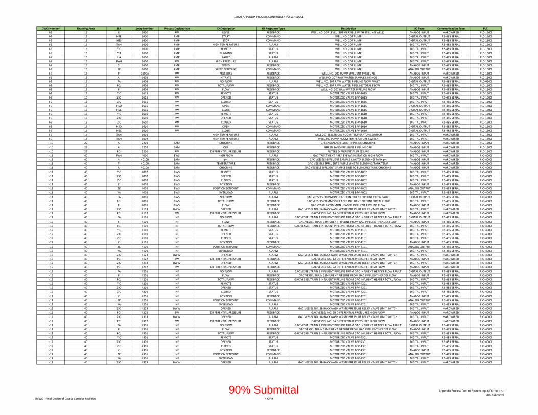
17020‐APPENDIX PROCESS CONTROLLER I/O SCHEDULE
DWG Number Drawing Area ISA Loop Number Process Designation IO Description IO Response Type Description IO Type Communication Type PLC
I‐9 16 LI 1600 RW LEVEL FEEDBACK WELL NO. 207 LEVEL (SUBMERSIBLE WITH STILLING WELL) ANALOG INPUT HARDWIRED PLC‐1600
I‐9 16 HSR 1600 PMP START COMMAND WELL NO. 207 PUMP DIGITAL OUTPUT RS‐485 SERIAL PLC‐1600
I‐9 16 HSS 1600 PMP STOP COMMAND WELL NO. 207 PUMP DIGITAL OUTPUT RS‐485 SERIAL PLC‐1600
I‐9 16 TAH 1600 PMP HIGH TEMPERATURE ALARM WELL NO. 207 PUMP DIGITAL INPUT RS‐485 SERIAL PLC‐1600
I‐9 16 YIC 1600 PMP REMOTE STATUS WELL NO. 207 PUMP DIGITAL INPUT RS‐485 SERIAL PLC‐1600
I‐9 16 YIR 1600 PMP RUNNING STATUS WELL NO. 207 PUMP DIGITAL INPUT RS‐485 SERIAL PLC‐1600
I‐9 16 UA 1600 PMP FAULT ALARM WELL NO. 207 PUMP DIGITAL INPUT RS‐485 SERIAL PLC‐1600
I‐9 16 PAH 1600 RW HIGH PRESSURE ALARM WELL NO. 207 PUMP DIGITAL INPUT RS‐485 SERIAL PLC‐1600
I‐9 16 SI 1600 PMP SPEED FEEDBACK WELL NO. 207 PUMP ANALOG INPUT RS‐485 SERIAL PLC‐1600
I‐9 16 SC 1600 PMP SPEED SETPOINT COMMAND WELL NO. 207 PUMP ANALOG OUTPUT RS‐485 SERIAL PLC‐1600
I‐9 16 PI 1600A RW PRESSURE FEEDBACK WELL NO. 207 PUMP EFFLUENT PRESSURE ANALOG INPUT HARDWIRED PLC‐1600
I‐9 16 AI 1605 RW NITRATE FEEDBACK WELL NO. 207 RAW WATER SAMPLE LINE NO3 ANALOG INPUT HARDWIRED PLC‐1600
I‐9 16 FA 1606 RW NO FLOW ALARM WELL NO. 207 RAW WATER PIPELINE FLOW FAULT DIGITAL OUTPUT RS‐485 SERIAL PLC‐6200
I‐9 16 FQI 1606 RW TOTAL FLOW FEEDBACK WELL NO. 207 RAW WATER PIPELINE TOTAL FLOW DIGITAL INPUT RS‐485 SERIAL PLC‐1600
I‐9 16 FI 1606 RW FLOW FEEDBACK WELL NO. 207 RAW WATER PIPELINE FLOW ANALOG INPUT RS‐485 SERIAL PLC‐1600
I‐9 16 YIC 1615 RW REMOTE STATUS MOTORIZED VALVE BFV‐1615 DIGITAL INPUT RS‐485 SERIAL PLC‐1600
I‐9 16 ZIO 1615 RW OPENED STATUS MOTORIZED VALVE BFV‐1615 DIGITAL INPUT RS‐485 SERIAL PLC‐1600
I‐9 16 ZIC 1615 RW CLOSED STATUS MOTORIZED VALVE BFV‐1615 DIGITAL INPUT RS‐485 SERIAL PLC‐1600
I‐9 16 HSO 1615 RW OPEN COMMAND MOTORIZED VALVE BFV‐1615 DIGITAL OUTPUT RS‐485 SERIAL PLC‐1600
I‐9 16 HSC 1615 RW CLOSE COMMAND MOTORIZED VALVE BFV‐1615 DIGITAL OUTPUT RS‐485 SERIAL PLC‐1600
I‐9 16 YIC 1610 RW REMOTE STATUS MOTORIZED VALVE BFV‐1610 DIGITAL INPUT RS‐485 SERIAL PLC‐1600
I‐9 16 ZIO 1610 RW OPENED STATUS MOTORIZED VALVE BFV‐1610 DIGITAL INPUT RS‐485 SERIAL PLC‐1600
I‐9 16 ZIC 1610 RW CLOSED STATUS MOTORIZED VALVE BFV‐1610 DIGITAL INPUT RS‐485 SERIAL PLC‐1600
I‐9 16 HSO 1610 RW OPEN COMMAND MOTORIZED VALVE BFV‐1610 DIGITAL OUTPUT RS‐485 SERIAL PLC‐1600
I‐9 16 HSC 1610 RW CLOSE COMMAND MOTORIZED VALVE BFV‐1610 DIGITAL OUTPUT RS‐485 SERIAL PLC‐1600
I‐9 16 TAH 1601 HIGH TEMPERATURE ALARM WELL 207 ELECTRICAL ROOM TEMPERATURE SWITCH DIGITAL INPUT HARDWIRED PLC‐1600
I‐9 16 TAH 1602 HIGH TEMPERATURE ALARM WELL 207 PUMP ROOM TEMPERATURE SWITCH DIGITAL INPUT HARDWIRED PLC‐1600
I‐10 22 AI 2201 SAM CHLORINE FEEDBACK GREENSAND EFFLUENT PIPELINE CHLORINE ANALOG INPUT HARDWIRED PLC‐1600
I‐10 22 AI 2202 SAM ORP FEEDBACK GREEN SAND EFFLUENT PIPELINE ORP ANALOG INPUT HARDWIRED PLC‐1600
I‐10 22 PDI 2210 RW DIFFERENTIAL PRESSURE FEEDBACK FILTERS DIFFERENTIAL PRESSURE ANALOG INPUT HARDWIRED PLC‐1600
I‐11 40 FAH 4000 EWS HIGH FLOW ALARM GAC TREATMENT AREA EYEWASH STATION HIGH FLOW DIGITAL INPUT HARDWIRED RIO‐4000
I‐11 40 AI 4010B SAM pH FEEDBACK GAC VESSELS EFFLUENT SAMPLE LINE TO BLENDING TANK pH ANALOG INPUT HARDWIRED RIO‐4000
I‐11 40 TI 4010B SAM TEMPERATURE FEEDBACK GAC VESSELS EFFLUENT SAMPLE LINE TO BLENDING TANK TEMP ANALOG INPUT HARDWIRED RIO‐4000
I‐11 40 AI 4010A SAM CHLORINE FEEDBACK GAC VESSELS EFFLUENT SAMPLE LINE TO BLENDING TANK CHLORINE ANALOG INPUT HARDWIRED RIO‐4000
I‐11 40 YIC 4002 BWS REMOTE STATUS MOTORIZED VALVE BFV‐4002 DIGITAL INPUT RS‐485 SERIAL RIO‐4000
I‐11 40 ZIO 4002 BWS OPENED STATUS MOTORIZED VALVE BFV‐4002 DIGITAL INPUT RS‐485 SERIAL RIO‐4000
I‐11 40 ZIC 4002 BWS CLOSED STATUS MOTORIZED VALVE BFV‐4002 DIGITAL INPUT RS‐485 SERIAL RIO‐4000
I‐11 40 ZI 4002 BWS POSITION FEEDBACK MOTORIZED VALVE BFV‐4002 ANALOG INPUT RS‐485 SERIAL RIO‐4000
I‐11 40 ZC 4002 BWS POSITION SETPOINT COMMAND MOTORIZED VALVE BFV‐4002 ANALOG OUTPUT RS‐485 SERIAL RIO‐4000
I‐11 40 YA 4002 BWS OVERLOAD ALARM MOTORIZED VALVE BFV‐4002 DIGITAL INPUT RS‐485 SERIAL RIO‐4000
I‐11 40 FA 4001 BWS NO FLOW ALARM GAC VESSELS COMMON HEADER INFLUENT PIPELINE FLOW FAULT DIGITAL OUTPUT RS‐485 SERIAL RIO‐4000
I‐11 40 FQI 4001 BWS TOTAL FLOW FEEDBACK GAC VESSELS COMMON HEADER INFLUENT PIPELINE TOTAL FLOW DIGITAL INPUT RS‐485 SERIAL RIO‐4000
I‐11 40 FI 4001 BWS FLOW FEEDBACK GAC VESSELS COMMON HEADER INFLUENT PIPELINE FLOW ANALOG INPUT RS‐485 SERIAL RIO‐4000
I‐12 40 ZIO 4113 BWW OPENED ALARM GAC VESSEL NO. 1A BACKWASH WASTE PRESSURE RELIEF VALVE LIMIT SWITCH DIGITAL INPUT HARDWIRED RIO‐4000
I‐12 40 PDI 4112 BW DIFFERENTIAL PRESSURE FEEDBACK GAC VESSEL NO. 1A DIFFERENTIAL PRESSUREE HIGH FLOW ANALOG INPUT HARDWIRED RIO‐4000
I‐12 40 FA 4101 INF NO FLOW ALARM GAC VESSEL TRAIN 1 INFLUENT PIPELINE FROM GAC INFLUENT HEADER FLOW FAULT DIGITAL OUTPUT RS‐485 SERIAL RIO‐4000
I‐12 40 FI 4101 INF FLOW FEEDBACK GAC VESSEL TRAIN 1 INFLUENT PIPELINE FROM GAC INFLUENT HEADER FLOW ANALOG INPUT RS‐485 SERIAL RIO‐4000
I‐12 40 FQI 4101 INF TOTAL FLOW FEEDBACK GAC VESSEL TRAIN 1 INFLUENT PIPELINE FROM GAC INFLUENT HEADER TOTAL FLOW DIGITAL INPUT RS‐485 SERIAL RIO‐4000
I‐12 40 YIC 4101 INF REMOTE STATUS MOTORIZED VALVE BFV‐4101 DIGITAL INPUT RS‐485 SERIAL RIO‐4000
I‐12 40 ZIO 4101 INF OPENED STATUS MOTORIZED VALVE BFV‐4101 DIGITAL INPUT RS‐485 SERIAL RIO‐4000
I‐12 40 ZIC 4101 INF CLOSED STATUS MOTORIZED VALVE BFV‐4101 DIGITAL INPUT RS‐485 SERIAL RIO‐4000
I‐12 40 ZI 4101 INF POSITION FEEDBACK MOTORIZED VALVE BFV‐4101 ANALOG INPUT RS‐485 SERIAL RIO‐4000
I‐12 40 ZC 4101 INF POSITION SETPOINT COMMAND MOTORIZED VALVE BFV‐4101 ANALOG OUTPUT RS‐485 SERIAL RIO‐4000
I‐12 40 YA 4101 INF OVERLOAD ALARM MOTORIZED VALVE BFV‐4101 DIGITAL INPUT RS‐485 SERIAL RIO‐4000
I‐12 40 ZIO 4123 BWW OPENED ALARM GAC VESSEL NO. 1A BACKWASH WASTE PRESSURE RELIEF VALVE LIMIT SWITCH DIGITAL INPUT HARDWIRED RIO‐4000
I‐12 40 PDI 4122 BW DIFFERENTIAL PRESSURE FEEDBACK GAC VESSEL NO. 1A DIFFERENTIAL PRESSUREE HIGH FLOW ANALOG INPUT HARDWIRED RIO‐4000
I‐12 40 ZIO 4213 BWW OPENED ALARM GAC VESSEL NO. 2A BACKWASH WASTE PRESSURE RELIEF VALVE LIMIT SWITCH DIGITAL INPUT HARDWIRED RIO‐4000
I‐12 40 PDI 4212 BW DIFFERENTIAL PRESSURE FEEDBACK GAC VESSEL NO. 2A DIFFERENTIAL PRESSUREE HIGH FLOW ANALOG INPUT HARDWIRED RIO‐4000
I‐12 40 FA 4201 INF NO FLOW ALARM GAC VESSEL TRAIN 2 INFLUENT PIPELINE FROM GAC INFLUENT HEADER FLOW FAULT DIGITAL OUTPUT RS‐485 SERIAL RIO‐4000
I‐12 40 FI 4201 INF FLOW FEEDBACK GAC VESSEL TRAIN 2 INFLUENT PIPELINE FROM GAC INFLUENT HEADER FLOW ANALOG INPUT RS‐485 SERIAL RIO‐4000
I‐12 40 FQI 4201 INF TOTAL FLOW FEEDBACK GAC VESSEL TRAIN 2 INFLUENT PIPELINE FROM GAC INFLUENT HEADER TOTAL FLOW DIGITAL INPUT RS‐485 SERIAL RIO‐4000
I‐12 40 YIC 4201 INF REMOTE STATUS MOTORIZED VALVE BFV‐4201 DIGITAL INPUT RS‐485 SERIAL RIO‐4000
I‐12 40 ZIO 4201 INF OPENED STATUS MOTORIZED VALVE BFV‐4201 DIGITAL INPUT RS‐485 SERIAL RIO‐4000
I‐12 40 ZIC 4201 INF CLOSED STATUS MOTORIZED VALVE BFV‐4201 DIGITAL INPUT RS‐485 SERIAL RIO‐4000
I‐12 40 ZI 4201 INF POSITION FEEDBACK MOTORIZED VALVE BFV‐4201 ANALOG INPUT RS‐485 SERIAL RIO‐4000
I‐12 40 ZC 4201 INF POSITION SETPOINT COMMAND MOTORIZED VALVE BFV‐4201 ANALOG OUTPUT RS‐485 SERIAL RIO‐4000
I‐12 40 YA 4201 INF OVERLOAD ALARM MOTORIZED VALVE BFV‐4201 DIGITAL INPUT RS‐485 SERIAL RIO‐4000
I‐12 40 ZIO 4223 BWW OPENED ALARM GAC VESSEL NO. 2B BACKWASH WASTE PRESSURE RELIEF VALVE LIMIT SWITCH DIGITAL INPUT HARDWIRED RIO‐4000
I‐12 40 PDI 4222 BW DIFFERENTIAL PRESSURE FEEDBACK GAC VESSEL NO. 2B DIFFERENTIAL PRESSUREE HIGH FLOW ANALOG INPUT HARDWIRED RIO‐4000
I‐12 40 ZIO 4313 BWW OPENED ALARM GAC VESSEL NO. 3A BACKWASH WASTE PRESSURE RELIEF VALVE LIMIT SWITCH DIGITAL INPUT HARDWIRED RIO‐4000
I‐12 40 PDI 4312 BW DIFFERENTIAL PRESSURE FEEDBACK GAC VESSEL NO. 3A DIFFERENTIAL PRESSUREE HIGH FLOW ANALOG INPUT HARDWIRED RIO‐4000
I‐12 40 FA 4301 INF NO FLOW ALARM GAC VESSEL TRAIN 2 INFLUENT PIPELINE FROM GAC INFLUENT HEADER FLOW FAULT DIGITAL OUTPUT RS‐485 SERIAL RIO‐4000
I‐12 40 FI 4301 INF FLOW FEEDBACK GAC VESSEL TRAIN 2 INFLUENT PIPELINE FROM GAC INFLUENT HEADER FLOW ANALOG INPUT RS‐485 SERIAL RIO‐4000
I‐12 40 FQI 4301 INF TOTAL FLOW FEEDBACK GAC VESSEL TRAIN 2 INFLUENT PIPELINE FROM GAC INFLUENT HEADER TOTAL FLOW DIGITAL INPUT RS‐485 SERIAL RIO‐4000
I‐12 40 YIC 4301 INF REMOTE STATUS MOTORIZED VALVE BFV‐4301 DIGITAL INPUT RS‐485 SERIAL RIO‐4000
I‐12 40 ZIO 4301 INF OPENED STATUS MOTORIZED VALVE BFV‐4301 DIGITAL INPUT RS‐485 SERIAL RIO‐4000
I‐12 40 ZIC 4301 INF CLOSED STATUS MOTORIZED VALVE BFV‐4301 DIGITAL INPUT RS‐485 SERIAL RIO‐4000
I‐12 40 ZI 4301 INF POSITION FEEDBACK MOTORIZED VALVE BFV‐4301 ANALOG INPUT RS‐485 SERIAL RIO‐4000
I‐12 40 ZC 4301 INF POSITION SETPOINT COMMAND MOTORIZED VALVE BFV‐4301 ANALOG OUTPUT RS‐485 SERIAL RIO‐4000
I‐12 40 YA 4301 INF OVERLOAD ALARM MOTORIZED VALVE BFV‐4301 DIGITAL INPUT RS‐485 SERIAL RIO‐4000
I‐12 40 ZIO 4323 BWW OPENED ALARM GAC VESSEL NO. 3B BACKWASH WASTE PRESSURE RELIEF VALVE LIMIT SWITCH DIGITAL INPUT HARDWIRED RIO‐4000
EMWD ‐ Final Design of Cactus Corridor Facilities 4 OF 9
Appendix Process Control System Input/Output List
90% Submittal90% Submittal
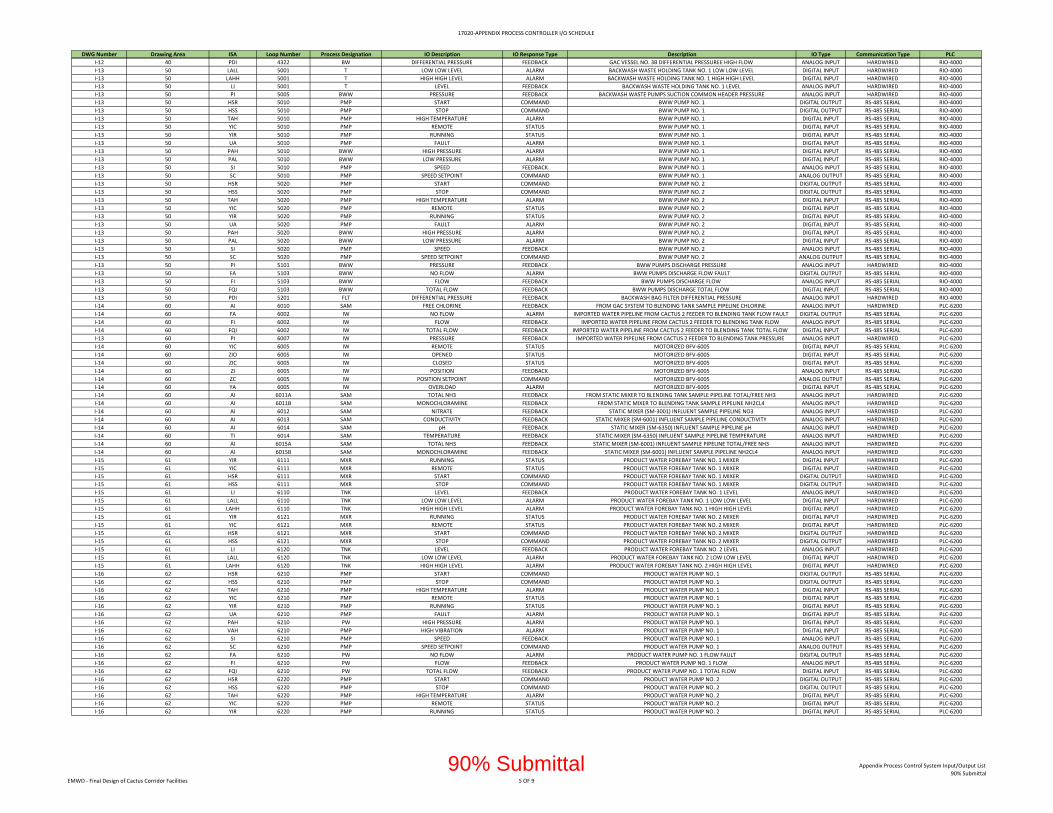
17020‐APPENDIX PROCESS CONTROLLER I/O SCHEDULE
DWG Number Drawing Area ISA Loop Number Process Designation IO Description IO Response Type Description IO Type Communication Type PLC
I‐12 40 PDI 4322 BW DIFFERENTIAL PRESSURE FEEDBACK GAC VESSEL NO. 3B DIFFERENTIAL PRESSUREE HIGH FLOW ANALOG INPUT HARDWIRED RIO‐4000
I‐13 50 LALL 5001 T LOW LOW LEVEL ALARM BACKWASH WASTE HOLDING TANK NO. 1 LOW LOW LEVEL DIGITAL INPUT HARDWIRED RIO‐4000
I‐13 50 LAHH 5001 T HIGH HIGH LEVEL ALARM BACKWASH WASTE HOLDING TANK NO. 1 HIGH HIGH LEVEL DIGITAL INPUT HARDWIRED RIO‐4000
I‐13 50 LI 5001 T LEVEL FEEDBACK BACKWASH WASTE HOLDING TANK NO. 1 LEVEL ANALOG INPUT HARDWIRED RIO‐4000
I‐13 50 PI 5005 BWW PRESSURE FEEDBACK BACKWASH WASTE PUMPS SUCTION COMMON HEADER PRESSURE ANALOG INPUT HARDWIRED RIO‐4000
I‐13 50 HSR 5010 PMP START COMMAND BWW PUMP NO. 1 DIGITAL OUTPUT RS‐485 SERIAL RIO‐4000
I‐13 50 HSS 5010 PMP STOP COMMAND BWW PUMP NO. 1 DIGITAL OUTPUT RS‐485 SERIAL RIO‐4000
I‐13 50 TAH 5010 PMP HIGH TEMPERATURE ALARM BWW PUMP NO. 1 DIGITAL INPUT RS‐485 SERIAL RIO‐4000
I‐13 50 YIC 5010 PMP REMOTE STATUS BWW PUMP NO. 1 DIGITAL INPUT RS‐485 SERIAL RIO‐4000
I‐13 50 YIR 5010 PMP RUNNING STATUS BWW PUMP NO. 1 DIGITAL INPUT RS‐485 SERIAL RIO‐4000
I‐13 50 UA 5010 PMP FAULT ALARM BWW PUMP NO. 1 DIGITAL INPUT RS‐485 SERIAL RIO‐4000
I‐13 50 PAH 5010 BWW HIGH PRESSURE ALARM BWW PUMP NO. 1 DIGITAL INPUT RS‐485 SERIAL RIO‐4000
I‐13 50 PAL 5010 BWW LOW PRESSURE ALARM BWW PUMP NO. 1 DIGITAL INPUT RS‐485 SERIAL RIO‐4000
I‐13 50 SI 5010 PMP SPEED FEEDBACK BWW PUMP NO. 1 ANALOG INPUT RS‐485 SERIAL RIO‐4000
I‐13 50 SC 5010 PMP SPEED SETPOINT COMMAND BWW PUMP NO. 1 ANALOG OUTPUT RS‐485 SERIAL RIO‐4000
I‐13 50 HSR 5020 PMP START COMMAND BWW PUMP NO. 2 DIGITAL OUTPUT RS‐485 SERIAL RIO‐4000
I‐13 50 HSS 5020 PMP STOP COMMAND BWW PUMP NO. 2 DIGITAL OUTPUT RS‐485 SERIAL RIO‐4000
I‐13 50 TAH 5020 PMP HIGH TEMPERATURE ALARM BWW PUMP NO. 2 DIGITAL INPUT RS‐485 SERIAL RIO‐4000
I‐13 50 YIC 5020 PMP REMOTE STATUS BWW PUMP NO. 2 DIGITAL INPUT RS‐485 SERIAL RIO‐4000
I‐13 50 YIR 5020 PMP RUNNING STATUS BWW PUMP NO. 2 DIGITAL INPUT RS‐485 SERIAL RIO‐4000
I‐13 50 UA 5020 PMP FAULT ALARM BWW PUMP NO. 2 DIGITAL INPUT RS‐485 SERIAL RIO‐4000
I‐13 50 PAH 5020 BWW HIGH PRESSURE ALARM BWW PUMP NO. 2 DIGITAL INPUT RS‐485 SERIAL RIO‐4000
I‐13 50 PAL 5020 BWW LOW PRESSURE ALARM BWW PUMP NO. 2 DIGITAL INPUT RS‐485 SERIAL RIO‐4000
I‐13 50 SI 5020 PMP SPEED FEEDBACK BWW PUMP NO. 2 ANALOG INPUT RS‐485 SERIAL RIO‐4000
I‐13 50 SC 5020 PMP SPEED SETPOINT COMMAND BWW PUMP NO. 2 ANALOG OUTPUT RS‐485 SERIAL RIO‐4000
I‐13 50 PI 5101 BWW PRESSURE FEEDBACK BWW PUMPS DISCHARGE PRESSURE ANALOG INPUT HARDWIRED RIO‐4000
I‐13 50 FA 5103 BWW NO FLOW ALARM BWW PUMPS DISCHARGE FLOW FAULT DIGITAL OUTPUT RS‐485 SERIAL RIO‐4000
I‐13 50 FI 5103 BWW FLOW FEEDBACK BWW PUMPS DISCHARGE FLOW ANALOG INPUT RS‐485 SERIAL RIO‐4000
I‐13 50 FQI 5103 BWW TOTAL FLOW FEEDBACK BWW PUMPS DISCHARGE TOTAL FLOW DIGITAL INPUT RS‐485 SERIAL RIO‐4000
I‐13 50 PDI 5201 FLT DIFFERENTIAL PRESSURE FEEDBACK BACKWASH BAG FILTER DIFFERENTIAL PRESSURE ANALOG INPUT HARDWIRED RIO‐4000
I‐14 60 AI 6010 SAM FREE CHLORINE FEEDBACK FROM GAC SYSTEM TO BLENDING TANK SAMPLE PIPELINE CHLORINE ANALOG INPUT HARDWIRED PLC‐6200
I‐14 60 FA 6002 IW NO FLOW ALARM IMPORTED WATER PIPELINE FROM CACTUS 2 FEEDER TO BLENDING TANK FLOW FAULT DIGITAL OUTPUT RS‐485 SERIAL PLC‐6200
I‐14 60 FI 6002 IW FLOW FEEDBACK IMPORTED WATER PIPELINE FROM CACTUS 2 FEEDER TO BLENDING TANK FLOW ANALOG INPUT RS‐485 SERIAL PLC‐6200
I‐14 60 FQI 6002 IW TOTAL FLOW FEEDBACK IMPORTED WATER PIPELINE FROM CACTUS 2 FEEDER TO BLENDING TANK TOTAL FLOW DIGITAL INPUT RS‐485 SERIAL PLC‐6200
I‐13 60 PI 6007 IW PRESSURE FEEDBACK IMPORTED WATER PIPELINE FROM CACTUS 2 FEEDER TO BLENDING TANK PRESSURE ANALOG INPUT HARDWIRED PLC‐6200
I‐14 60 YIC 6005 IW REMOTE STATUS MOTORIZED BFV‐6005 DIGITAL INPUT RS‐485 SERIAL PLC‐6200
I‐14 60 ZIO 6005 IW OPENED STATUS MOTORIZED BFV‐6005 DIGITAL INPUT RS‐485 SERIAL PLC‐6200
I‐14 60 ZIC 6005 IW CLOSED STATUS MOTORIZED BFV‐6005 DIGITAL INPUT RS‐485 SERIAL PLC‐6200
I‐14 60 ZI 6005 IW POSITION FEEDBACK MOTORIZED BFV‐6005 ANALOG INPUT RS‐485 SERIAL PLC‐6200
I‐14 60 ZC 6005 IW POSITION SETPOINT COMMAND MOTORIZED BFV‐6005 ANALOG OUTPUT RS‐485 SERIAL PLC‐6200
I‐14 60 YA 6005 IW OVERLOAD ALARM MOTORIZED BFV‐6005 DIGITAL INPUT RS‐485 SERIAL PLC‐6200
I‐14 60 AI 6011A SAM TOTAL NH3 FEEDBACK FROM STATIC MIXER TO BLENDING TANK SAMPLE PIPELINE TOTAL/FREE NH3 ANALOG INPUT HARDWIRED PLC‐6200
I‐14 60 AI 6011B SAM MONOCHLORAMINE FEEDBACK FROM STATIC MIXER TO BLENDING TANK SAMPLE PIPELINE NH2CL4 ANALOG INPUT HARDWIRED PLC‐6200
I‐14 60 AI 6012 SAM NITRATE FEEDBACK STATIC MIXER (SM‐3001) INFLUENT SAMPLE PIPELINE NO3 ANALOG INPUT HARDWIRED PLC‐6200
I‐14 60 AI 6013 SAM CONDUCTIVITY FEEDBACK STATIC MIXER (SM‐6001) INFLUENT SAMPLE PIPELINE CONDUCTIVITY ANALOG INPUT HARDWIRED PLC‐6200
I‐14 60 AI 6014 SAM pH FEEDBACK STATIC MIXER (SM‐6350) INFLUENT SAMPLE PIPELINE pH ANALOG INPUT HARDWIRED PLC‐6200
I‐14 60 TI 6014 SAM TEMPERATURE FEEDBACK STATIC MIXER (SM‐6350) INFLUENT SAMPLE PIPELINE TEMPERATURE ANALOG INPUT HARDWIRED PLC‐6200
I‐14 60 AI 6015A SAM TOTAL NH3 FEEDBACK STATIC MIXER (SM‐6001) INFLUENT SAMPLE PIPELINE TOTAL/FREE NH3 ANALOG INPUT HARDWIRED PLC‐6200
I‐14 60 AI 6015B SAM MONOCHLORAMINE FEEDBACK STATIC MIXER (SM‐6001) INFLUENT SAMPLE PIPELINE NH2CL4 ANALOG INPUT HARDWIRED PLC‐6200
I‐15 61 YIR 6111 MXR RUNNING STATUS PRODUCT WATER FOREBAY TANK NO. 1 MIXER DIGITAL INPUT HARDWIRED PLC‐6200
I‐15 61 YIC 6111 MXR REMOTE STATUS PRODUCT WATER FOREBAY TANK NO. 1 MIXER DIGITAL INPUT HARDWIRED PLC‐6200
I‐15 61 HSR 6111 MXR START COMMAND PRODUCT WATER FOREBAY TANK NO. 1 MIXER DIGITAL OUTPUT HARDWIRED PLC‐6200
I‐15 61 HSS 6111 MXR STOP COMMAND PRODUCT WATER FOREBAY TANK NO. 1 MIXER DIGITAL OUTPUT HARDWIRED PLC‐6200
I‐15 61 LI 6110 TNK LEVEL FEEDBACK PRODUCT WATER FOREBAY TANK NO. 1 LEVEL ANALOG INPUT HARDWIRED PLC‐6200
I‐15 61 LALL 6110 TNK LOW LOW LEVEL ALARM PRODUCT WATER FOREBAY TANK NO. 1 LOW LOW LEVEL DIGITAL INPUT HARDWIRED PLC‐6200
I‐15 61 LAHH 6110 TNK HIGH HIGH LEVEL ALARM PRODUCT WATER FOREBAY TANK NO. 1 HIGH HIGH LEVEL DIGITAL INPUT HARDWIRED PLC‐6200
I‐15 61 YIR 6121 MXR RUNNING STATUS PRODUCT WATER FOREBAY TANK NO. 2 MIXER DIGITAL INPUT HARDWIRED PLC‐6200
I‐15 61 YIC 6121 MXR REMOTE STATUS PRODUCT WATER FOREBAY TANK NO. 2 MIXER DIGITAL INPUT HARDWIRED PLC‐6200
I‐15 61 HSR 6121 MXR START COMMAND PRODUCT WATER FOREBAY TANK NO. 2 MIXER DIGITAL OUTPUT HARDWIRED PLC‐6200
I‐15 61 HSS 6121 MXR STOP COMMAND PRODUCT WATER FOREBAY TANK NO. 2 MIXER DIGITAL OUTPUT HARDWIRED PLC‐6200
I‐15 61 LI 6120 TNK LEVEL FEEDBACK PRODUCT WATER FOREBAY TANK NO. 2 LEVEL ANALOG INPUT HARDWIRED PLC‐6200
I‐15 61 LALL 6120 TNK LOW LOW LEVEL ALARM PRODUCT WATER FOREBAY TANK NO. 2 LOW LOW LEVEL DIGITAL INPUT HARDWIRED PLC‐6200
I‐15 61 LAHH 6120 TNK HIGH HIGH LEVEL ALARM PRODUCT WATER FOREBAY TANK NO. 2 HIGH HIGH LEVEL DIGITAL INPUT HARDWIRED PLC‐6200
I‐16 62 HSR 6210 PMP START COMMAND PRODUCT WATER PUMP NO. 1 DIGITAL OUTPUT RS‐485 SERIAL PLC‐6200
I‐16 62 HSS 6210 PMP STOP COMMAND PRODUCT WATER PUMP NO. 1 DIGITAL OUTPUT RS‐485 SERIAL PLC‐6200
I‐16 62 TAH 6210 PMP HIGH TEMPERATURE ALARM PRODUCT WATER PUMP NO. 1 DIGITAL INPUT RS‐485 SERIAL PLC‐6200
I‐16 62 YIC 6210 PMP REMOTE STATUS PRODUCT WATER PUMP NO. 1 DIGITAL INPUT RS‐485 SERIAL PLC‐6200
I‐16 62 YIR 6210 PMP RUNNING STATUS PRODUCT WATER PUMP NO. 1 DIGITAL INPUT RS‐485 SERIAL PLC‐6200
I‐16 62 UA 6210 PMP FAULT ALARM PRODUCT WATER PUMP NO. 1 DIGITAL INPUT RS‐485 SERIAL PLC‐6200
I‐16 62 PAH 6210 PW HIGH PRESSURE ALARM PRODUCT WATER PUMP NO. 1 DIGITAL INPUT RS‐485 SERIAL PLC‐6200
I‐16 62 VAH 6210 PMP HIGH VIBRATION ALARM PRODUCT WATER PUMP NO. 1 DIGITAL INPUT RS‐485 SERIAL PLC‐6200
I‐16 62 SI 6210 PMP SPEED FEEDBACK PRODUCT WATER PUMP NO. 1 ANALOG INPUT RS‐485 SERIAL PLC‐6200
I‐16 62 SC 6210 PMP SPEED SETPOINT COMMAND PRODUCT WATER PUMP NO. 1 ANALOG OUTPUT RS‐485 SERIAL PLC‐6200
I‐16 62 FA 6210 PW NO FLOW ALARM PRODUCT WATER PUMP NO. 1 FLOW FAULT DIGITAL OUTPUT RS‐485 SERIAL PLC‐6200
I‐16 62 FI 6210 PW FLOW FEEDBACK PRODUCT WATER PUMP NO. 1 FLOW ANALOG INPUT RS‐485 SERIAL PLC‐6200
I‐16 62 FQI 6210 PW TOTAL FLOW FEEDBACK PRODUCT WATER PUMP NO. 1 TOTAL FLOW DIGITAL INPUT RS‐485 SERIAL PLC‐6200
I‐16 62 HSR 6220 PMP START COMMAND PRODUCT WATER PUMP NO. 2 DIGITAL OUTPUT RS‐485 SERIAL PLC‐6200
I‐16 62 HSS 6220 PMP STOP COMMAND PRODUCT WATER PUMP NO. 2 DIGITAL OUTPUT RS‐485 SERIAL PLC‐6200
I‐16 62 TAH 6220 PMP HIGH TEMPERATURE ALARM PRODUCT WATER PUMP NO. 2 DIGITAL INPUT RS‐485 SERIAL PLC‐6200
I‐16 62 YIC 6220 PMP REMOTE STATUS PRODUCT WATER PUMP NO. 2 DIGITAL INPUT RS‐485 SERIAL PLC‐6200
I‐16 62 YIR 6220 PMP RUNNING STATUS PRODUCT WATER PUMP NO. 2 DIGITAL INPUT RS‐485 SERIAL PLC‐6200
EMWD ‐ Final Design of Cactus Corridor Facilities 5 OF 9
Appendix Process Control System Input/Output List
90% Submittal90% Submittal
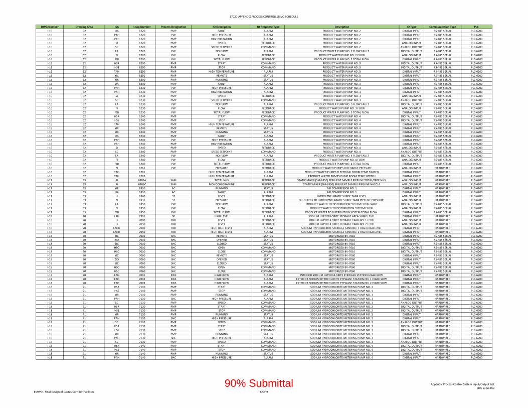
17020‐APPENDIX PROCESS CONTROLLER I/O SCHEDULE
DWG Number Drawing Area ISA Loop Number Process Designation IO Description IO Response Type Description IO Type Communication Type PLC
I‐16 62 UA 6220 PMP FAULT ALARM PRODUCT WATER PUMP NO. 2 DIGITAL INPUT RS‐485 SERIAL PLC‐6200
I‐16 62 PAH 6220 PW HIGH PRESSURE ALARM PRODUCT WATER PUMP NO. 2 DIGITAL INPUT RS‐485 SERIAL PLC‐6200
I‐16 62 VAH 6220 PMP HIGH VIBRATION ALARM PRODUCT WATER PUMP NO. 2 DIGITAL INPUT RS‐485 SERIAL PLC‐6200
I‐16 62 SI 6220 PMP SPEED FEEDBACK PRODUCT WATER PUMP NO. 2 ANALOG INPUT RS‐485 SERIAL PLC‐6200
I‐16 62 SC 6220 PMP SPEED SETPOINT COMMAND PRODUCT WATER PUMP NO. 2 ANALOG OUTPUT RS‐485 SERIAL PLC‐6200
I‐16 62 FA 6220 PW NO FLOW ALARM PRODUCT WATER PUMP NO. 2 FLOW FAULT DIGITAL OUTPUT RS‐485 SERIAL PLC‐6200
I‐16 62 FI 6220 PW FLOW FEEDBACK PRODUCT WATER PUMP NO. 2 FLOW ANALOG INPUT RS‐485 SERIAL PLC‐6200
I‐16 62 FQI 6220 PW TOTAL FLOW FEEDBACK PRODUCT WATER PUMP NO. 2 TOTAL FLOW DIGITAL INPUT RS‐485 SERIAL PLC‐6200
I‐16 62 HSR 6230 PMP START COMMAND PRODUCT WATER PUMP NO. 3 DIGITAL OUTPUT RS‐485 SERIAL PLC‐6200
I‐16 62 HSS 6230 PMP STOP COMMAND PRODUCT WATER PUMP NO. 3 DIGITAL OUTPUT RS‐485 SERIAL PLC‐6200
I‐16 62 TAH 6230 PMP HIGH TEMPERATURE ALARM PRODUCT WATER PUMP NO. 3 DIGITAL INPUT RS‐485 SERIAL PLC‐6200
I‐16 62 YIC 6230 PMP REMOTE STATUS PRODUCT WATER PUMP NO. 3 DIGITAL INPUT RS‐485 SERIAL PLC‐6200
I‐16 62 YIR 6230 PMP RUNNING STATUS PRODUCT WATER PUMP NO. 3 DIGITAL INPUT RS‐485 SERIAL PLC‐6200
I‐16 62 UA 6230 PMP FAULT ALARM PRODUCT WATER PUMP NO. 3 DIGITAL INPUT RS‐485 SERIAL PLC‐6200
I‐16 62 PAH 6230 PW HIGH PRESSURE ALARM PRODUCT WATER PUMP NO. 3 DIGITAL INPUT RS‐485 SERIAL PLC‐6200
I‐16 62 VAH 6230 PMP HIGH VIBRATION ALARM PRODUCT WATER PUMP NO. 3 DIGITAL INPUT RS‐485 SERIAL PLC‐6200
I‐16 62 SI 6230 PMP SPEED FEEDBACK PRODUCT WATER PUMP NO. 3 ANALOG INPUT RS‐485 SERIAL PLC‐6200
I‐16 62 SC 6230 PMP SPEED SETPOINT COMMAND PRODUCT WATER PUMP NO. 3 ANALOG OUTPUT RS‐485 SERIAL PLC‐6200
I‐16 62 FA 6230 PW NO FLOW ALARM PRODUCT WATER PUMP NO. 3 FLOW FAULT DIGITAL OUTPUT RS‐485 SERIAL PLC‐6200
I‐16 62 FI 6230 PW FLOW FEEDBACK PRODUCT WATER PUMP NO. 3 FLOW ANALOG INPUT RS‐485 SERIAL PLC‐6200
I‐16 62 FQI 6230 PW TOTAL FLOW FEEDBACK PRODUCT WATER PUMP NO. 3 TOTAL FLOW DIGITAL INPUT RS‐485 SERIAL PLC‐6200
I‐16 62 HSR 6240 PMP START COMMAND PRODUCT WATER PUMP NO. 4 DIGITAL OUTPUT RS‐485 SERIAL PLC‐6200
I‐16 62 HSS 6240 PMP STOP COMMAND PRODUCT WATER PUMP NO. 4 DIGITAL OUTPUT RS‐485 SERIAL PLC‐6200
I‐16 62 TAH 6240 PMP HIGH TEMPERATURE ALARM PRODUCT WATER PUMP NO. 4 DIGITAL INPUT RS‐485 SERIAL PLC‐6200
I‐16 62 YIC 6240 PMP REMOTE STATUS PRODUCT WATER PUMP NO. 4 DIGITAL INPUT RS‐485 SERIAL PLC‐6200
I‐16 62 YIR 6240 PMP RUNNING STATUS PRODUCT WATER PUMP NO. 4 DIGITAL INPUT RS‐485 SERIAL PLC‐6200
I‐16 62 UA 6240 PMP FAULT ALARM PRODUCT WATER PUMP NO. 4 DIGITAL INPUT RS‐485 SERIAL PLC‐6200
I‐16 62 PAH 6240 PW HIGH PRESSURE ALARM PRODUCT WATER PUMP NO. 4 DIGITAL INPUT RS‐485 SERIAL PLC‐6200
I‐16 62 VAH 6240 PMP HIGH VIBRATION ALARM PRODUCT WATER PUMP NO. 4 DIGITAL INPUT RS‐485 SERIAL PLC‐6200
I‐16 62 SI 6240 PMP SPEED FEEDBACK PRODUCT WATER PUMP NO. 4 ANALOG INPUT RS‐485 SERIAL PLC‐6200
I‐16 62 SC 6240 PMP SPEED SETPOINT COMMAND PRODUCT WATER PUMP NO. 4 ANALOG OUTPUT RS‐485 SERIAL PLC‐6200
I‐16 62 FA 6240 PW NO FLOW ALARM PRODUCT WATER PUMP NO. 4 FLOW FAULT DIGITAL OUTPUT RS‐485 SERIAL PLC‐6200
I‐16 62 FI 6240 PW FLOW FEEDBACK PRODUCT WATER PUMP NO. 4 FLOW ANALOG INPUT RS‐485 SERIAL PLC‐6200
I‐16 62 FQI 6240 PW TOTAL FLOW FEEDBACK PRODUCT WATER PUMP NO. 4 TOTAL FLOW DIGITAL INPUT RS‐485 SERIAL PLC‐6200
I‐16 62 PI 6265 PW PRESSURE FEEDBACK PRODUCT WATER PUMPS DISCHARGE PRESSURE ANALOG INPUT HARDWIRED PLC‐6200
I‐16 62 TAH 6201 HIGH TEMPERATURE ALARM PRODUCT WATER PUMPS ELECTRICAL ROOM TEMP SWITCH DIGITAL INPUT HARDWIRED PLC‐6200
I‐16 62 TAH 6202 HIGH TEMPERATURE ALARM PRODUCT WATER PUMPS PUMP ROOM TEMP SWITCH DIGITAL INPUT HARDWIRED PLC‐6200
I‐17 63 AI 6305A SAM TOTAL NH3 FEEDBACK STATIC MIXER (SM‐6350) EFFLUENT SAMPLE PIPELINE TOTAL/FREE NH3 ANALOG INPUT HARDWIRED PLC‐6200
I‐17 63 AI 6305C SAM MONOCHLORAMINE FEEDBACK STATIC MIXER (SM‐6350) EFFLUENT SAMPLE PIPELINE NH2CL4 ANALOG INPUT HARDWIRED PLC‐6200
I‐17 63 YIR 6310 AC RUNNING STATUS AIR COMPRESSOR NO. 1 DIGITAL INPUT HARDWIRED PLC‐6200
I‐17 63 UA 6310 AC FAULT ALARM AIR COMPRESSOR NO. 1 DIGITAL INPUT HARDWIRED PLC‐6200
I‐17 63 LI 6340 ST LEVEL FEEDBACK HYDRO PNEUMATIC SURGE TANK LEVEL ANALOG INPUT HARDWIRED PLC‐6200
I‐17 63 PI 6335 ST PRESSURE FEEDBACK OIL FILTERS TO HYDRO PNEUMATIC SURGE TANK PIPELINE PRESSURE ANALOG INPUT HARDWIRED PLC‐6200
I‐17 63 FA 6350 PW NO FLOW ALARM PRODUCT WATER TO DISTRIBUTION SYSTEM FLOW FAULT DIGITAL OUTPUT RS‐485 SERIAL PLC‐6200
I‐17 63 FI 6350 PW FLOW FEEDBACK PRODUCT WATER TO DISTRIBUTION SYSTEM FLOW ANALOG INPUT RS‐485 SERIAL PLC‐6200
I‐17 63 FQI 6350 PW TOTAL FLOW FEEDBACK PRODUCT WATER TO DISTRIBUTION SYSTEM TOTAL FLOW DIGITAL INPUT RS‐485 SERIAL PLC‐6200
I‐18 70 LAH 7301 SP HIGH LEVEL ALARM SODIUM HYPOCHLORITE STORAGE AREA SUMP LEVEL DIGITAL INPUT HARDWIRED PLC‐6200
I‐18 70 LI 7000 TNK LEVEL FEEDBACK SODIUM HYPOCHLORITE STORAGE TANK NO. 1 LEVEL ANALOG INPUT HARDWIRED PLC‐6200
I‐18 70 LI 7050 TNK LEVEL FEEDBACK SODIUM HYPOCHLORITE STORAGE TANK NO. 2 LEVEL ANALOG INPUT HARDWIRED PLC‐6200
I‐18 70 LAHH 7000 TNK HIGH HIGH LEVEL ALARM SODIUM HYPOCHLORITE STORAGE TANK NO. 1 HIGH HIGH LEVEL DIGITAL INPUT HARDWIRED PLC‐6200
I‐18 70 LAHH 7050 TNK HIGH HIGH LEVEL ALARM SODIUM HYPOCHLORITE STORAGE TANK NO. 2 HIGH HIGH LEVEL DIGITAL INPUT HARDWIRED PLC‐6200
I‐18 70 YIC 7010 SHC REMOTE STATUS MOTORIZED BV‐7010 DIGITAL INPUT RS‐485 SERIAL PLC‐6200
I‐18 70 ZIO 7010 SHC OPENED STATUS MOTORIZED BV‐7010 DIGITAL INPUT RS‐485 SERIAL PLC‐6200
I‐18 70 ZIC 7010 SHC CLOSED STATUS MOTORIZED BV‐7010 DIGITAL INPUT RS‐485 SERIAL PLC‐6200
I‐18 70 HSO 7010 SHC OPEN COMMAND MOTORIZED BV‐7010 DIGITAL OUTPUT RS‐485 SERIAL PLC‐6200
I‐18 70 HSC 7010 SHC CLOSE COMMAND MOTORIZED BV‐7010 DIGITAL OUTPUT RS‐485 SERIAL PLC‐6200
I‐18 70 YIC 7060 SHC REMOTE STATUS MOTORIZED BV‐7060 DIGITAL INPUT RS‐485 SERIAL PLC‐6200
I‐18 70 ZIO 7060 SHC OPENED STATUS MOTORIZED BV‐7060 DIGITAL INPUT RS‐485 SERIAL PLC‐6200
I‐18 70 ZIC 7060 SHC CLOSED STATUS MOTORIZED BV‐7060 DIGITAL INPUT RS‐485 SERIAL PLC‐6200
I‐18 70 HSO 7060 SHC OPEN COMMAND MOTORIZED BV‐7060 DIGITAL OUTPUT RS‐485 SERIAL PLC‐6200
I‐18 70 HSC 7060 SHC CLOSE COMMAND MOTORIZED BV‐7060 DIGITAL OUTPUT RS‐485 SERIAL PLC‐6200
I‐18 70 FAH 7001 EWS HIGH FLOW ALARM INTERIOR SODIUM HYPOCHLORITE EYEWASH STATION HIGH FLOW DIGITAL INPUT HARDWIRED PLC‐6200
I‐18 70 FAH 7002 EWS HIGH FLOW ALARM EXTERIOR SODIUM HYPOCHLORITE EYEWASH STATION NO. 1 HIGH FLOW DIGITAL INPUT HARDWIRED PLC‐6200
I‐18 70 FAH 7003 EWS HIGH FLOW ALARM EXTERIOR SODIUM HYPOCHLORITE EYEWASH STATION NO. 2 HIGH FLOW DIGITAL INPUT HARDWIRED PLC‐6200
I‐18 71 HSR 7110 PMP START COMMAND SODIUM HYDROCHLORITE METERING PUMP NO. 1 DIGITAL OUTPUT HARDWIRED PLC‐6200
I‐18 71 HSS 7110 PMP STOP COMMAND SODIUM HYDROCHLORITE METERING PUMP NO. 1 DIGITAL OUTPUT HARDWIRED PLC‐6200
I‐18 71 YIR 7110 PMP RUNNING STATUS SODIUM HYDROCHLORITE METERING PUMP NO. 1 DIGITAL INPUT HARDWIRED PLC‐6200
I‐18 71 PAH 7110 SHC HIGH PRESSURE ALARM SODIUM HYDROCHLORITE METERING PUMP NO. 1 DIGITAL INPUT HARDWIRED PLC‐6200
I‐18 71 SC 7110 PMP SPEED COMMAND SODIUM HYDROCHLORITE METERING PUMP NO. 1 ANALOG OUTPUT HARDWIRED PLC‐6200
I‐18 71 HSR 7120 PMP START COMMAND SODIUM HYDROCHLORITE METERING PUMP NO. 2 DIGITAL OUTPUT HARDWIRED PLC‐6200
I‐18 71 HSS 7120 PMP STOP COMMAND SODIUM HYDROCHLORITE METERING PUMP NO. 2 DIGITAL OUTPUT HARDWIRED PLC‐6200
I‐18 71 YIR 7120 PMP RUNNING STATUS SODIUM HYDROCHLORITE METERING PUMP NO. 2 DIGITAL INPUT HARDWIRED PLC‐6200
I‐18 71 PAH 7120 SHC HIGH PRESSURE ALARM SODIUM HYDROCHLORITE METERING PUMP NO. 2 DIGITAL INPUT HARDWIRED PLC‐6200
I‐18 71 SC 7120 PMP SPEED COMMAND SODIUM HYDROCHLORITE METERING PUMP NO. 2 ANALOG OUTPUT HARDWIRED PLC‐6200
I‐18 71 HSR 7130 PMP START COMMAND SODIUM HYDROCHLORITE METERING PUMP NO. 3 DIGITAL OUTPUT HARDWIRED PLC‐6200
I‐18 71 HSS 7130 PMP STOP COMMAND SODIUM HYDROCHLORITE METERING PUMP NO. 3 DIGITAL OUTPUT HARDWIRED PLC‐6200
I‐18 71 YIR 7130 PMP RUNNING STATUS SODIUM HYDROCHLORITE METERING PUMP NO. 3 DIGITAL INPUT HARDWIRED PLC‐6200
I‐18 71 PAH 7130 SHC HIGH PRESSURE ALARM SODIUM HYDROCHLORITE METERING PUMP NO. 3 DIGITAL INPUT HARDWIRED PLC‐6200
I‐18 71 SC 7130 PMP SPEED COMMAND SODIUM HYDROCHLORITE METERING PUMP NO. 3 ANALOG OUTPUT HARDWIRED PLC‐6200
I‐18 71 HSR 7140 PMP START COMMAND SODIUM HYDROCHLORITE METERING PUMP NO. 4 DIGITAL OUTPUT HARDWIRED PLC‐6200
I‐18 71 HSS 7140 PMP STOP COMMAND SODIUM HYDROCHLORITE METERING PUMP NO. 4 DIGITAL OUTPUT HARDWIRED PLC‐6200
I‐18 71 YIR 7140 PMP RUNNING STATUS SODIUM HYDROCHLORITE METERING PUMP NO. 4 DIGITAL INPUT HARDWIRED PLC‐6200
I‐18 71 PAH 7140 SHC HIGH PRESSURE ALARM SODIUM HYDROCHLORITE METERING PUMP NO. 4 DIGITAL INPUT HARDWIRED PLC‐6200
EMWD ‐ Final Design of Cactus Corridor Facilities 6 OF 9
Appendix Process Control System Input/Output List
90% Submittal90% Submittal
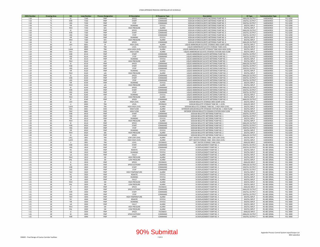
17020‐APPENDIX PROCESS CONTROLLER I/O SCHEDULE
DWG Number Drawing Area ISA Loop Number Process Designation IO Description IO Response Type Description IO Type Communication Type PLC
I‐18 71 SC 7140 PMP SPEED COMMAND SODIUM HYDROCHLORITE METERING PUMP NO. 4 ANALOG OUTPUT HARDWIRED PLC‐6200
I‐18 71 HSR 7150 PMP START COMMAND SODIUM HYDROCHLORITE METERING PUMP NO. 5 DIGITAL OUTPUT HARDWIRED PLC‐6200
I‐18 71 HSS 7150 PMP STOP COMMAND SODIUM HYDROCHLORITE METERING PUMP NO. 5 DIGITAL OUTPUT HARDWIRED PLC‐6200
I‐18 71 YIR 7150 PMP RUNNING STATUS SODIUM HYDROCHLORITE METERING PUMP NO. 5 DIGITAL INPUT HARDWIRED PLC‐6200
I‐18 71 PAH 7150 SHC HIGH PRESSURE ALARM SODIUM HYDROCHLORITE METERING PUMP NO. 5 DIGITAL INPUT HARDWIRED PLC‐6200
I‐18 71 SC 7150 PMP SPEED COMMAND SODIUM HYDROCHLORITE METERING PUMP NO. 5 ANALOG OUTPUT HARDWIRED PLC‐6200
I‐18 71 HSR 7160 PMP START COMMAND SODIUM HYDROCHLORITE METERING PUMP NO. 6 DIGITAL OUTPUT HARDWIRED PLC‐6200
I‐18 71 HSS 7160 PMP STOP COMMAND SODIUM HYDROCHLORITE METERING PUMP NO. 6 DIGITAL OUTPUT HARDWIRED PLC‐6200
I‐18 71 YIR 7160 PMP RUNNING STATUS SODIUM HYDROCHLORITE METERING PUMP NO. 6 DIGITAL INPUT HARDWIRED PLC‐6200
I‐18 71 PAH 7160 SHC HIGH PRESSURE ALARM SODIUM HYDROCHLORITE METERING PUMP NO. 6 DIGITAL INPUT HARDWIRED PLC‐6200
I‐18 71 SC 7160 PMP SPEED COMMAND SODIUM HYDROCHLORITE METERING PUMP NO. 6 ANALOG OUTPUT HARDWIRED PLC‐6200
I‐19 83 LAH 8301 SP HIGH LEVEL ALARM LIQUID AMMONIUM SULFATE STORAGE AREA SUMP LEVEL DIGITAL INPUT HARDWIRED PLC‐6200
I‐19 80 LI 8000 TNK LEVEL FEEDBACK LIQUID AMMONIUM SULFATE STORAGE TANK LEVEL ANALOG INPUT HARDWIRED PLC‐6200
I‐19 80 LAHH 8000 TNK HIGH HIGH LEVEL ALARM LIQUID AMMONIUM SULFATE STORAGE TANK HIGH HIGH LEVEL DIGITAL INPUT HARDWIRED PLC‐6200
I‐19 80 FAH 8001 EWS HIGH FLOW ALARM LIQUID AMMONIUM SULFATE EYEWASH STATION HIGH FLOW DIGITAL INPUT HARDWIRED PLC‐6200
I‐19 81 HSR 8110 PMP START COMMAND LIQUID AMMONIUM SULFATE METERING PUMP NO. 1 DIGITAL OUTPUT HARDWIRED PLC‐6200
I‐19 81 HSS 8110 PMP STOP COMMAND LIQUID AMMONIUM SULFATE METERING PUMP NO. 1 DIGITAL OUTPUT HARDWIRED PLC‐6200
I‐19 81 YIR 8110 PMP RUNNING STATUS LIQUID AMMONIUM SULFATE METERING PUMP NO. 1 DIGITAL INPUT HARDWIRED PLC‐6200
I‐19 81 PAH 8110 LAS HIGH PRESSURE ALARM LIQUID AMMONIUM SULFATE METERING PUMP NO. 1 DIGITAL INPUT HARDWIRED PLC‐6200
I‐19 81 SC 8110 PMP SPEED COMMAND LIQUID AMMONIUM SULFATE METERING PUMP NO. 1 ANALOG OUTPUT HARDWIRED PLC‐6200
I‐19 81 HSR 8120 PMP START COMMAND LIQUID AMMONIUM SULFATE METERING PUMP NO. 2 DIGITAL OUTPUT HARDWIRED PLC‐6200
I‐19 81 HSS 8120 PMP STOP COMMAND LIQUID AMMONIUM SULFATE METERING PUMP NO. 2 DIGITAL OUTPUT HARDWIRED PLC‐6200
I‐19 81 YIR 8120 PMP RUNNING STATUS LIQUID AMMONIUM SULFATE METERING PUMP NO. 2 DIGITAL INPUT HARDWIRED PLC‐6200
I‐19 81 PAH 8120 LAS HIGH PRESSURE ALARM LIQUID AMMONIUM SULFATE METERING PUMP NO. 2 DIGITAL INPUT HARDWIRED PLC‐6200
I‐19 81 SC 8120 PMP SPEED COMMAND LIQUID AMMONIUM SULFATE METERING PUMP NO. 2 ANALOG OUTPUT HARDWIRED PLC‐6200
I‐19 81 HSR 8130 PMP START COMMAND LIQUID AMMONIUM SULFATE METERING PUMP NO. 3 DIGITAL OUTPUT HARDWIRED PLC‐6200
I‐19 81 HSS 8130 PMP STOP COMMAND LIQUID AMMONIUM SULFATE METERING PUMP NO. 3 DIGITAL OUTPUT HARDWIRED PLC‐6200
I‐19 81 YIR 8130 PMP RUNNING STATUS LIQUID AMMONIUM SULFATE METERING PUMP NO. 3 DIGITAL INPUT HARDWIRED PLC‐6200
I‐19 81 PAH 8130 LAS HIGH PRESSURE ALARM LIQUID AMMONIUM SULFATE METERING PUMP NO. 3 DIGITAL INPUT HARDWIRED PLC‐6200
I‐19 81 SC 8130 PMP SPEED COMMAND LIQUID AMMONIUM SULFATE METERING PUMP NO. 3 ANALOG OUTPUT HARDWIRED PLC‐6200
I‐19 81 HSR 8140 PMP START COMMAND LIQUID AMMONIUM SULFATE METERING PUMP NO. 4 DIGITAL OUTPUT HARDWIRED PLC‐6200
I‐19 81 HSS 8140 PMP STOP COMMAND LIQUID AMMONIUM SULFATE METERING PUMP NO. 4 DIGITAL OUTPUT HARDWIRED PLC‐6200
I‐19 81 YIR 8140 PMP RUNNING STATUS LIQUID AMMONIUM SULFATE METERING PUMP NO. 4 DIGITAL INPUT HARDWIRED PLC‐6200
I‐19 81 PAH 8140 LAS HIGH PRESSURE ALARM LIQUID AMMONIUM SULFATE METERING PUMP NO. 4 DIGITAL INPUT HARDWIRED PLC‐6200
I‐19 81 SC 8140 PMP SPEED COMMAND LIQUID AMMONIUM SULFATE METERING PUMP NO. 4 ANALOG OUTPUT HARDWIRED PLC‐6200
I‐20 86 LAH 8601 SP HIGH LEVEL ALARM SODIUM BISULFITE STORAGE AREA SUMP LEVEL DIGITAL INPUT HARDWIRED PLC‐6200
I‐20 84 LI 8400 TNK LEVEL FEEDBACK SODIUM BISULFITE STORAGE TANK NO. 1 LEVEL ANALOG INPUT HARDWIRED PLC‐6200
I‐20 84 LAHH 8400 TNK HIGH HIGH LEVEL ALARM SODIUM BISULFITE STORAGE TANK NO. 1 HIGH HIGH LEVEL DIGITAL INPUT HARDWIRED PLC‐6200
I‐20 84 FAH 8401 EWS HIGH FLOW ALARM EXTERIOR SODIUM BISULFITE EYEWASH STATION NO. 1 HIGH FLOW DIGITAL INPUT HARDWIRED PLC‐6200
I‐20 84 FAH 8402 EWS HIGH FLOW ALARM INTERIOR SODIUM BISULFITE EYEWASH STATION HIGH FLOW DIGITAL INPUT HARDWIRED PLC‐6200
I‐20 85 HSR 8510 PMP START COMMAND SODIUM BISULFITE METERING PUMP NO. 1 DIGITAL OUTPUT HARDWIRED PLC‐6200
I‐20 85 HSS 8510 PMP STOP COMMAND SODIUM BISULFITE METERING PUMP NO. 1 DIGITAL OUTPUT HARDWIRED PLC‐6200
I‐20 85 YIR 8510 PMP RUNNING STATUS SODIUM BISULFITE METERING PUMP NO. 1 DIGITAL INPUT HARDWIRED PLC‐6200
I‐20 85 PAH 8510 SBS HIGH PRESSURE ALARM SODIUM BISULFITE METERING PUMP NO. 1 DIGITAL INPUT HARDWIRED PLC‐6200
I‐20 85 SC 8510 PMP SPEED COMMAND SODIUM BISULFITE METERING PUMP NO. 1 ANALOG OUTPUT HARDWIRED PLC‐6200
I‐20 85 HSR 8520 PMP START COMMAND SODIUM BISULFITE METERING PUMP NO. 2 DIGITAL OUTPUT HARDWIRED PLC‐6200
I‐20 85 HSS 8520 PMP STOP COMMAND SODIUM BISULFITE METERING PUMP NO. 2 DIGITAL OUTPUT HARDWIRED PLC‐6200
I‐20 85 YIR 8520 PMP RUNNING STATUS SODIUM BISULFITE METERING PUMP NO. 2 DIGITAL INPUT HARDWIRED PLC‐6200
I‐20 85 PAH 8520 SBS HIGH PRESSURE ALARM SODIUM BISULFITE METERING PUMP NO. 2 DIGITAL INPUT HARDWIRED PLC‐6200
I‐20 85 SC 8520 PMP SPEED COMMAND SODIUM BISULFITE METERING PUMP NO. 2 ANALOG OUTPUT HARDWIRED PLC‐6200
I‐21 30 LALL 3001 TNK LOW LOW LEVEL ALARM SOFT WATER STORAGE TANK LOW‐LOW LEVEL DIGITAL INPUT HARDWIRED PLC‐3000
I‐21 30 LAHH 3001 TNK HIGH HIGH LEVEL ALARM SOFT WATER STORAGE TANK HIGH‐HIGH LEVEL DIGITAL INPUT HARDWIRED PLC‐3000
I‐21 30 LI 3001 TNK LEVEL FEEDBACK SOFT WATER STORAGE TANK LEVEL ANALOG INPUT HARDWIRED PLC‐3000
I‐21 30 HSR 3010 PMP START COMMAND IX DISPLACEMENT PUMP NO. 1 DIGITAL OUTPUT RS‐485 SERIAL PLC‐3000
I‐21 30 HSS 3010 PMP STOP COMMAND IX DISPLACEMENT PUMP NO. 1 DIGITAL OUTPUT RS‐485 SERIAL PLC‐3000
I‐21 30 YIC 3010 PMP REMOTE STATUS IX DISPLACEMENT PUMP NO. 1 DIGITAL INPUT RS‐485 SERIAL PLC‐3000
I‐21 30 YIR 3010 PMP RUNNING STATUS IX DISPLACEMENT PUMP NO. 1 DIGITAL INPUT RS‐485 SERIAL PLC‐3000
I‐21 30 UA 3010 PMP FAULT ALARM IX DISPLACEMENT PUMP NO. 1 DIGITAL INPUT RS‐485 SERIAL PLC‐3000
I‐21 30 PAH 3010 SW HIGH PRESSURE ALARM IX DISPLACEMENT PUMP NO. 1 DIGITAL INPUT RS‐485 SERIAL PLC‐3000
I‐21 30 PAL 3010 SW LOW PRESSURE ALARM IX DISPLACEMENT PUMP NO. 1 DIGITAL INPUT RS‐485 SERIAL PLC‐3000
I‐21 30 SI 3010 PMP SPEED FEEDBACK IX DISPLACEMENT PUMP NO. 1 ANALOG INPUT RS‐485 SERIAL PLC‐3000
I‐21 30 SC 3010 PMP SPEED SETPOINT COMMAND IX DISPLACEMENT PUMP NO. 1 ANALOG OUTPUT RS‐485 SERIAL PLC‐3000
I‐21 30 HSR 3020 PMP START COMMAND IX DISPLACEMENT PUMP NO. 2 DIGITAL OUTPUT RS‐485 SERIAL PLC‐3000
I‐21 30 HSS 3020 PMP STOP COMMAND IX DISPLACEMENT PUMP NO. 2 DIGITAL OUTPUT RS‐485 SERIAL PLC‐3000
I‐21 30 TAH 3020 PMP HIGH TEMPERATURE ALARM IX DISPLACEMENT PUMP NO. 2 DIGITAL INPUT RS‐485 SERIAL PLC‐3000
I‐21 30 YIC 3020 PMP REMOTE STATUS IX DISPLACEMENT PUMP NO. 2 DIGITAL INPUT RS‐485 SERIAL PLC‐3000
I‐21 30 YIR 3020 PMP RUNNING STATUS IX DISPLACEMENT PUMP NO. 2 DIGITAL INPUT RS‐485 SERIAL PLC‐3000
I‐21 30 UA 3020 PMP FAULT ALARM IX DISPLACEMENT PUMP NO. 2 DIGITAL INPUT RS‐485 SERIAL PLC‐3000
I‐21 30 PAH 3020 SW HIGH PRESSURE ALARM IX DISPLACEMENT PUMP NO. 2 DIGITAL INPUT RS‐485 SERIAL PLC‐3000
I‐21 30 PAL 3020 SW LOW PRESSURE ALARM IX DISPLACEMENT PUMP NO. 2 DIGITAL INPUT RS‐485 SERIAL PLC‐3000
I‐21 30 SI 3020 PMP SPEED FEEDBACK IX DISPLACEMENT PUMP NO. 2 ANALOG INPUT RS‐485 SERIAL PLC‐3000
I‐21 30 SC 3020 PMP SPEED SETPOINT COMMAND IX DISPLACEMENT PUMP NO. 2 ANALOG OUTPUT RS‐485 SERIAL PLC‐3000
I‐21 30 HSR 3030 PMP START COMMAND IX DISPLACEMENT PUMP NO. 3 DIGITAL OUTPUT RS‐485 SERIAL PLC‐3000
I‐21 30 HSS 3030 PMP STOP COMMAND IX DISPLACEMENT PUMP NO. 3 DIGITAL OUTPUT RS‐485 SERIAL PLC‐3000
I‐21 30 TAH 3030 PMP HIGH TEMPERATURE ALARM IX DISPLACEMENT PUMP NO. 3 DIGITAL INPUT RS‐485 SERIAL PLC‐3000
I‐21 30 YIC 3030 PMP REMOTE STATUS IX DISPLACEMENT PUMP NO. 3 DIGITAL INPUT RS‐485 SERIAL PLC‐3000
I‐21 30 YIR 3030 PMP RUNNING STATUS IX DISPLACEMENT PUMP NO. 3 DIGITAL INPUT RS‐485 SERIAL PLC‐3000
I‐21 30 UA 3030 PMP FAULT ALARM IX DISPLACEMENT PUMP NO. 3 DIGITAL INPUT RS‐485 SERIAL PLC‐3000
I‐21 30 PAH 3030 SW HIGH PRESSURE ALARM IX DISPLACEMENT PUMP NO. 3 DIGITAL INPUT RS‐485 SERIAL PLC‐3000
I‐21 30 PAL 3030 SW LOW PRESSURE ALARM IX DISPLACEMENT PUMP NO. 3 DIGITAL INPUT RS‐485 SERIAL PLC‐3000
I‐21 30 SI 3030 PMP SPEED FEEDBACK IX DISPLACEMENT PUMP NO. 3 ANALOG INPUT RS‐485 SERIAL PLC‐3000
I‐21 30 SC 3030 PMP SPEED SETPOINT COMMAND IX DISPLACEMENT PUMP NO. 3 ANALOG OUTPUT RS‐485 SERIAL PLC‐3000
I‐21 30 HSR 3040 PMP START COMMAND IX DISPLACEMENT PUMP NO. 4 DIGITAL OUTPUT RS‐485 SERIAL PLC‐3000
EMWD ‐ Final Design of Cactus Corridor Facilities 7 OF 9
Appendix Process Control System Input/Output List
90% Submittal90% Submittal

17020‐APPENDIX PROCESS CONTROLLER I/O SCHEDULE
DWG Number Drawing Area ISA Loop Number Process Designation IO Description IO Response Type Description IO Type Communication Type PLC
I‐21 30 HSS 3040 PMP STOP COMMAND IX DISPLACEMENT PUMP NO. 4 DIGITAL OUTPUT RS‐485 SERIAL PLC‐3000
I‐21 30 TAH 3040 PMP HIGH TEMPERATURE ALARM IX DISPLACEMENT PUMP NO. 4 DIGITAL INPUT RS‐485 SERIAL PLC‐3000
I‐21 30 YIC 3040 PMP REMOTE STATUS IX DISPLACEMENT PUMP NO. 4 DIGITAL INPUT RS‐485 SERIAL PLC‐3000
I‐21 30 YIR 3040 PMP RUNNING STATUS IX DISPLACEMENT PUMP NO. 4 DIGITAL INPUT RS‐485 SERIAL PLC‐3000
I‐21 30 UA 3040 PMP FAULT ALARM IX DISPLACEMENT PUMP NO. 4 DIGITAL INPUT RS‐485 SERIAL PLC‐3000
I‐21 30 PAH 3040 SW HIGH PRESSURE ALARM IX DISPLACEMENT PUMP NO. 4 DIGITAL INPUT RS‐485 SERIAL PLC‐3000
I‐21 30 PAL 3040 SW LOW PRESSURE ALARM IX DISPLACEMENT PUMP NO. 4 DIGITAL INPUT RS‐485 SERIAL PLC‐3000
I‐21 30 SI 3040 PMP SPEED FEEDBACK IX DISPLACEMENT PUMP NO. 4 ANALOG INPUT RS‐485 SERIAL PLC‐3000
I‐21 30 SC 3040 PMP SPEED SETPOINT COMMAND IX DISPLACEMENT PUMP NO. 4 ANALOG OUTPUT RS‐485 SERIAL PLC‐3000
I‐21 31 FA 3101 SW NO FLOW ALARM IX DISPLACEMENT PUMPS EFFLUENT COMMON HEADER FLOW FAULT DIGITAL OUTPUT RS‐485 SERIAL PLC‐3000
I‐21 31 FI 3101 SW FLOW FEEDBACK IX DISPLACEMENT PUMPS EFFLUENT COMMON HEADER FLOW ANALOG INPUT RS‐485 SERIAL PLC‐3000
I‐21 31 FQI 3101 SW TOTAL FLOW FEEDBACK IX DISPLACEMENT PUMPS EFFLUENT COMMON HEADER TOTAL FLOW DIGITAL INPUT RS‐485 SERIAL PLC‐3000
I‐21 31 FA 3102 SW NO FLOW ALARM IX DISPLACEMENT PUMPS EFFLUENT COMMON HEADER FLOW FAULT DIGITAL OUTPUT RS‐485 SERIAL PLC‐3000
I‐21 31 FI 3102 SW FLOW FEEDBACK IX DISPLACEMENT PUMPS EFFLUENT COMMON HEADER FLOW ANALOG INPUT RS‐485 SERIAL PLC‐3000
I‐21 31 FQI 3102 SW TOTAL FLOW FEEDBACK IX DISPLACEMENT PUMPS EFFLUENT COMMON HEADER TOTAL FLOW DIGITAL INPUT RS‐485 SERIAL PLC‐3000
I‐21 31 FA 3103 SW NO FLOW ALARM IX PERCHLORATE EFFLUENT FLOW FAULT DIGITAL OUTPUT RS‐485 SERIAL PLC‐3000
I‐21 31 FI 3103 SW FLOW FEEDBACK IX PERCHLORATE EFFLUENT FLOW ANALOG INPUT RS‐485 SERIAL PLC‐3000
I‐21 31 FQI 3103 SW TOTAL FLOW FEEDBACK IX PERCHLORATE EFFLUENT TOTAL FLOW DIGITAL INPUT RS‐485 SERIAL PLC‐3000
I‐21 31 AI 3106 SMP NITRATE FEEDBACK PIXE EFFLUENT NO3 ANALOG INPUT HARDWIRED PLC‐3000
I‐21 31 FA 3104 SW NO FLOW ALARM IX BRINE EFFLUENT FLOW FAULT DIGITAL OUTPUT RS‐485 SERIAL PLC‐3000
I‐21 31 FI 3104 SW FLOW FEEDBACK IX BRINE EFFLUENT FLOW ANALOG INPUT RS‐485 SERIAL PLC‐3000
I‐21 31 FQI 3104 SW TOTAL FLOW FEEDBACK IX BRINE EFFLUENT TOTAL FLOW DIGITAL INPUT RS‐485 SERIAL PLC‐3000
I‐21 31 FA 3105 SW NO FLOW ALARM ACID EFFLUENT FLOW FAULT DIGITAL OUTPUT RS‐485 SERIAL PLC‐3000
I‐21 31 FI 3105 SW FLOW FEEDBACK ACID EFFLUENT FLOW ANALOG INPUT RS‐485 SERIAL PLC‐3000
I‐21 31 FQI 3105 SW TOTAL FLOW FEEDBACK ACID EFFLUENT TOTAL FLOW DIGITAL INPUT RS‐485 SERIAL PLC‐3000
I‐21 33 FA 3303 SW NO FLOW ALARM IX TREATMENT EFFLUENT FLOW FAULT DIGITAL OUTPUT RS‐485 SERIAL PLC‐3000
I‐21 33 FI 3303 SW FLOW FEEDBACK IX TREATMENT EFFLUENT FLOW ANALOG INPUT RS‐485 SERIAL PLC‐3000
I‐21 33 FQI 3303 SW TOTAL FLOW FEEDBACK IX TREATMENT EFFLUENT TOTAL FLOW DIGITAL INPUT RS‐485 SERIAL PLC‐3000
I‐21 33 AI 3305 SMP CONDUCTIVITY FEEDBACK IX TREATMENT EFFLUENT CONDUCTIVITY ANALOG INPUT HARDWIRED PLC‐3000
I‐21 33 AI 3306 SMP NITRATE FEEDBACK IX TREATMENT EFFLUENT NO3 ANALOG INPUT HARDWIRED PLC‐3000
I‐22 34 HSS 3405 SV OPEN/CLOSE COMMAND MOTORIZED BV‐3405 DIGITAL OUTPUT HARDWIRED PLC‐3000
I‐22 34 LI 3410A TNK HIGH LEVEL STATUS BRINE TANK NO. 1 LEVEL ANALOG INPUT HARDWIRED PLC‐3000
I‐22 34 LI 3410B TNK HIGH LEVEL STATUS BRINE TANK NO. 1 LEVEL ANALOG INPUT HARDWIRED PLC‐3000
I‐22 34 HSS 3410 SV OPEN/CLOSE COMMAND MOTORIZED BV‐3410 DIGITAL OUTPUT HARDWIRED PLC‐3000
I‐22 34 LI 3420A TNK HIGH LEVEL STATUS BRINE TANK NO. 2 LEVEL ANALOG INPUT HARDWIRED PLC‐3000
I‐22 34 LI 3420B TNK HIGH LEVEL STATUS BRINE TANK NO. 2 LEVEL ANALOG INPUT HARDWIRED PLC‐3000
I‐22 34 HSS 3420 SV OPEN/CLOSE COMMAND MOTORIZED BV‐3420 DIGITAL OUTPUT HARDWIRED PLC‐3000
I‐22 34 LI 3430A TNK HIGH LEVEL STATUS BRINE TANK NO. 3 LEVEL ANALOG INPUT HARDWIRED PLC‐3000
I‐22 34 LI 3430B TNK HIGH LEVEL STATUS BRINE TANK NO. 3 LEVEL ANALOG INPUT HARDWIRED PLC‐3000
I‐22 34 HSS 3430 SV OPEN/CLOSE COMMAND MOTORIZED BV‐3430 DIGITAL OUTPUT HARDWIRED PLC‐3000
I‐22 34 LI 3440A TNK HIGH LEVEL STATUS BRINE TANK NO. 4 LEVEL ANALOG INPUT HARDWIRED PLC‐3000
I‐22 34 LI 3440B TNK HIGH LEVEL STATUS BRINE TANK NO. 4 LEVEL ANALOG INPUT HARDWIRED PLC‐3000
I‐22 34 HSS 3440 SV OPEN/CLOSE COMMAND MOTORIZED BV‐3440 DIGITAL OUTPUT HARDWIRED PLC‐3000
I‐22 34 YIC 3450 PMP REMOTE STATUS WATER SOFTENER PUMP NO. 1 DIGITAL INPUT HARDWIRED PLC‐3000
I‐22 34 YIR 3450 PMP RUNNING STATUS WATER SOFTENER PUMP NO. 1 DIGITAL INPUT HARDWIRED PLC‐3000
I‐22 34 UA 3450 PMP FAULT ALARM WATER SOFTENER PUMP NO. 1 DIGITAL INPUT HARDWIRED PLC‐3000
I‐22 34 HSR 3450 PMP START COMMAND WATER SOFTENER PUMP NO. 1 DIGITAL OUTPUT HARDWIRED PLC‐3000
I‐22 34 HSS 3450 PMP STOP COMMAND WATER SOFTENER PUMP NO. 1 DIGITAL OUTPUT HARDWIRED PLC‐3000
I‐22 34 YIC 3460 PMP REMOTE STATUS WATER SOFTENER PUMP NO. 2 DIGITAL INPUT HARDWIRED PLC‐3000
I‐22 34 YIR 3460 PMP RUNNING STATUS WATER SOFTENER PUMP NO. 2 DIGITAL INPUT HARDWIRED PLC‐3000
I‐22 34 UA 3460 PMP FAULT ALARM WATER SOFTENER PUMP NO. 2 DIGITAL INPUT HARDWIRED PLC‐3000
I‐22 34 HSR 3460 PMP START COMMAND WATER SOFTENER PUMP NO. 2 DIGITAL OUTPUT HARDWIRED PLC‐3000
I‐22 34 HSS 3460 PMP STOP COMMAND WATER SOFTENER PUMP NO. 2 DIGITAL OUTPUT HARDWIRED PLC‐3000
I‐22 35 HSS 3510 PMP STOP COMMAND IX REGEN PUMP NO. 1 DIGITAL OUTPUT RS‐485 SERIAL PLC‐3000
I‐22 35 YIC 3510 PMP REMOTE STATUS IX REGEN PUMP NO. 1 DIGITAL INPUT RS‐485 SERIAL PLC‐3000
I‐22 35 YIR 3510 PMP RUNNING STATUS IX REGEN PUMP NO. 1 DIGITAL INPUT RS‐485 SERIAL PLC‐3000
I‐22 35 UA 3510 PMP FAULT ALARM IX REGEN PUMP NO. 1 DIGITAL INPUT RS‐485 SERIAL PLC‐3000
I‐22 35 PAH 3510 BR HIGH PRESSURE ALARM IX REGEN PUMP NO. 1 DIGITAL INPUT RS‐485 SERIAL PLC‐3000
I‐22 35 PAL 3510 BR LOW PRESSURE ALARM IX REGEN PUMP NO. 1 DIGITAL INPUT RS‐485 SERIAL PLC‐3000
I‐22 35 SI 3510 PMP SPEED FEEDBACK IX REGEN PUMP NO. 1 ANALOG INPUT RS‐485 SERIAL PLC‐3000
I‐22 35 SC 3510 PMP SPEED SETPOINT COMMAND IX REGEN PUMP NO. 1 ANALOG OUTPUT RS‐485 SERIAL PLC‐3000
I‐22 35 HSR 3520 PMP START COMMAND IX REGEN PUMP NO. 2 DIGITAL OUTPUT RS‐485 SERIAL PLC‐3000
I‐22 35 HSS 3520 PMP STOP COMMAND IX REGEN PUMP NO. 2 DIGITAL OUTPUT RS‐485 SERIAL PLC‐3000
I‐22 35 YIC 3520 PMP REMOTE STATUS IX REGEN PUMP NO. 2 DIGITAL INPUT RS‐485 SERIAL PLC‐3000
I‐22 35 YIR 3520 PMP RUNNING STATUS IX REGEN PUMP NO. 2 DIGITAL INPUT RS‐485 SERIAL PLC‐3000
I‐22 35 UA 3520 PMP FAULT ALARM IX REGEN PUMP NO. 2 DIGITAL INPUT RS‐485 SERIAL PLC‐3000
I‐22 35 PAH 3520 BR HIGH PRESSURE ALARM IX REGEN PUMP NO. 2 DIGITAL INPUT RS‐485 SERIAL PLC‐3000
I‐22 35 PAL 3520 BR LOW PRESSURE ALARM IX REGEN PUMP NO. 2 DIGITAL INPUT RS‐485 SERIAL PLC‐3000
I‐22 35 SI 3520 PMP SPEED FEEDBACK IX REGEN PUMP NO. 2 ANALOG INPUT RS‐485 SERIAL PLC‐3000
I‐22 35 SC 3520 PMP SPEED SETPOINT COMMAND IX REGEN PUMP NO. 2 ANALOG OUTPUT RS‐485 SERIAL PLC‐3000
I‐23 37 FAH 3700 EWS HIGH FLOW ALARM INTERIOR IX CHEMICALS EYEWASH STATION DIGITAL INPUT HARDWIRED PLC‐3000
I‐23 36 LAH 3640 SP HIGH LEVEL ALARM HYDROCHLORIC ACID STORAGE AREA SUMP LEVEL DIGITAL INPUT HARDWIRED PLC‐3000
I‐23 36 LI 3601 TNK LEVEL FEEDBACK HYDROCHLORIC ACID STORAGE TANK NO. 1 LEVEL ANALOG INPUT HARDWIRED PLC‐3000
I‐23 36 LALL 3601 TNK HIGH HIGH LEVEL ALARM HYDROCHLORIC ACID STORAGE TANK NO. 1 LOW LOW LEVEL DIGITAL INPUT HARDWIRED PLC‐3000
I‐23 36 LAHH 3601 TNK HIGH HIGH LEVEL ALARM HYDROCHLORIC ACID STORAGE TANK NO. 1 HIGH HIGH LEVEL DIGITAL INPUT HARDWIRED PLC‐3000
I‐23 36 HSR 3610 PMP START COMMAND HYDROCHLORIC ACID METERING PUMP NO. 1 DIGITAL OUTPUT HARDWIRED PLC‐3000
I‐23 36 HSS 3610 PMP STOP COMMAND HYDROCHLORIC ACID METERING PUMP NO. 1 DIGITAL OUTPUT HARDWIRED PLC‐3000
I‐23 36 YIR 3610 PMP RUNNING STATUS HYDROCHLORIC ACID METERING PUMP NO. 1 DIGITAL INPUT HARDWIRED PLC‐3000
I‐23 36 PAH 3610 HCL HIGH PRESSURE ALARM HYDROCHLORIC ACID METERING PUMP NO. 1 DIGITAL INPUT HARDWIRED PLC‐3000
I‐23 36 SC 3610 PMP SPEED COMMAND HYDROCHLORIC ACID METERING PUMP NO. 1 ANALOG OUTPUT HARDWIRED PLC‐3000
I‐23 36 HSR 3620 PMP START COMMAND HYDROCHLORIC ACID METERING PUMP NO. 2 DIGITAL OUTPUT HARDWIRED PLC‐3000
I‐23 36 HSS 3620 PMP STOP COMMAND HYDROCHLORIC ACID METERING PUMP NO. 2 DIGITAL OUTPUT HARDWIRED PLC‐3000
EMWD ‐ Final Design of Cactus Corridor Facilities 8 OF 9
Appendix Process Control System Input/Output List
90% Submittal90% Submittal

17020‐APPENDIX PROCESS CONTROLLER I/O SCHEDULE
DWG Number Drawing Area ISA Loop Number Process Designation IO Description IO Response Type Description IO Type Communication Type PLC
I‐23 36 YIR 3620 PMP RUNNING STATUS HYDROCHLORIC ACID METERING PUMP NO. 2 DIGITAL INPUT HARDWIRED PLC‐3000
I‐23 36 PAH 3620 HCL HIGH PRESSURE ALARM HYDROCHLORIC ACID METERING PUMP NO. 2 DIGITAL INPUT HARDWIRED PLC‐3000
I‐23 36 SC 3620 PMP SPEED COMMAND HYDROCHLORIC ACID METERING PUMP NO. 2 ANALOG OUTPUT HARDWIRED PLC‐3000
I‐24 38 LALL 3801 TNK LOW LOW LEVEL ALARM IX BRINE WASTE STORAGE TANK NO. 1 LOW LOW LEVEL DIGITAL INPUT HARDWIRED RIO‐4000
I‐24 38 LAHH 3801 TNK HIGH HIGH LEVEL ALARM IX BRINE WASTE STORAGE TANK NO. 1 HIGH HIGH LEVEL DIGITAL INPUT HARDWIRED RIO‐4000
I‐24 38 LI 3801 TNK LEVEL FEEDBACK IX BRINE WASTE STORAGE TANK NO. 1 LEVEL ANALOG INPUT HARDWIRED RIO‐4000
I‐24 38 LALL 3802 TNK LOW LOW LEVEL ALARM IX BRINE WASTE STORAGE TANK NO. 2 LOW LOW LEVEL DIGITAL INPUT HARDWIRED RIO‐4000
I‐24 38 LAHH 3802 TNK HIGH HIGH LEVEL ALARM IX BRINE WASTE STORAGE TANK NO. 2 HIGH HIGH LEVEL DIGITAL INPUT HARDWIRED RIO‐4000
I‐24 38 LI 3802 TNK LEVEL FEEDBACK IX BRINE WASTE STORAGE TANK NO. 2 LEVEL ANALOG INPUT HARDWIRED RIO‐4000
I‐24 38 LALL 3803 TNK LOW LOW LEVEL ALARM IX BRINE WASTE STORAGE TANK NO. 3 LOW LOW LEVEL DIGITAL INPUT HARDWIRED RIO‐4000
I‐24 38 LAHH 3803 TNK HIGH HIGH LEVEL ALARM IX BRINE WASTE STORAGE TANK NO. 3 HIGH HIGH LEVEL DIGITAL INPUT HARDWIRED RIO‐4000
I‐24 38 LI 3803 TNK LEVEL FEEDBACK IX BRINE WASTE STORAGE TANK NO. 3 LEVEL ANALOG INPUT HARDWIRED RIO‐4000
I‐24 38 LALL 3804 TNK LOW LOW LEVEL ALARM IX BRINE WASTE STORAGE TANK NO. 4 LOW LOW LEVEL DIGITAL INPUT HARDWIRED RIO‐4000
I‐24 38 LAHH 3804 TNK HIGH HIGH LEVEL ALARM IX BRINE WASTE STORAGE TANK NO. 4 HIGH HIGH LEVEL DIGITAL INPUT HARDWIRED RIO‐4000
I‐24 38 LI 3804 TNK LEVEL FEEDBACK IX BRINE WASTE STORAGE TANK NO. 4 LEVEL ANALOG INPUT HARDWIRED RIO‐4000
I‐24 38 HSR 3810 PMP START COMMAND IX BRINE WASTE METERING PUMP NO. 1 DIGITAL OUTPUT RS‐485 SERIAL RIO‐4000
I‐24 38 HSS 3810 PMP STOP COMMAND IX BRINE WASTE METERING PUMP NO. 1 DIGITAL OUTPUT RS‐485 SERIAL RIO‐4000
I‐24 38 YIC 3810 PMP REMOTE STATUS IX BRINE WASTE METERING PUMP NO. 1 DIGITAL INPUT RS‐485 SERIAL RIO‐4000
I‐24 38 YIR 3810 PMP RUNNING STATUS IX BRINE WASTE METERING PUMP NO. 1 DIGITAL INPUT RS‐485 SERIAL RIO‐4000
I‐24 38 UA 3810 PMP FAULT ALARM IX BRINE WASTE METERING PUMP NO. 1 DIGITAL INPUT RS‐485 SERIAL RIO‐4000
I‐24 38 HSR 3820 PMP START COMMAND IX BRINE WASTE METERING PUMP NO. 2 DIGITAL OUTPUT RS‐485 SERIAL RIO‐4000
I‐24 38 HSS 3820 PMP STOP COMMAND IX BRINE WASTE METERING PUMP NO. 2 DIGITAL OUTPUT RS‐485 SERIAL RIO‐4000
I‐24 38 YIC 3820 PMP REMOTE STATUS IX BRINE WASTE METERING PUMP NO. 2 DIGITAL INPUT RS‐485 SERIAL RIO‐4000
I‐24 38 YIR 3820 PMP RUNNING STATUS IX BRINE WASTE METERING PUMP NO. 2 DIGITAL INPUT RS‐485 SERIAL RIO‐4000
I‐24 38 UA 3820 PMP FAULT ALARM IX BRINE WASTE METERING PUMP NO. 2 DIGITAL INPUT RS‐485 SERIAL RIO‐4000
I‐25 39 PDI 3900 PIXI DIFFERENTIAL PRESSURE FEEDBACK IX BAG FILTERS DIFFERENTIAL PRESSURE ANALOG INPUT HARDWIRED RIO‐4000
I‐26 39 ZIO 3912A BWW HIGH FLOW ALARM IX PERCHLORATE VESSEL NO. 1A BACKWASH WASTE PRESSURE RELIEF VALVE LIMIT SWITCH DIGITAL INPUT HARDWIRED RIO‐4000
I‐26 39 PDI 3910A BW DIFFERENTIAL PRESSURE FEEDBACK IX PERCHLORATE VESSEL NO. 1A DIFFERENTIAL PRESSURE ANALOG INPUT HARDWIRED RIO‐4000
I‐26 39 FA 3910A IXI NO FLOW ALARM PERCHLORATE VESSEL TRAIN 1 INFLUENT PIPELINE FROM GAC INFLUENT HEADER FLOW FAUL DIGITAL OUTPUT RS‐485 SERIAL RIO‐4000
I‐26 39 FI 3910 IXI FLOW FEEDBACK IX PERCHLORATE VESSEL TRAIN 1 INFLUENT PIPELINE FROM GAC INFLUENT HEADER FLOW ANALOG INPUT RS‐485 SERIAL RIO‐4000
I‐26 39 FQI 3910 IXI TOTAL FLOW FEEDBACK PERCHLORATE VESSEL TRAIN 1 INFLUENT PIPELINE FROM GAC INFLUENT HEADER TOTAL FLOW DIGITAL INPUT RS‐485 SERIAL RIO‐4000
I‐26 39 YIC 3910 IXI REMOTE STATUS MOTORIZED BFV‐3910 DIGITAL INPUT RS‐485 SERIAL RIO‐4000
I‐26 39 ZIO 3910 IXI OPENED STATUS MOTORIZED BFV‐3910 DIGITAL INPUT RS‐485 SERIAL RIO‐4000
I‐26 39 ZIC 3910 IXI CLOSED STATUS MOTORIZED BFV‐3910 DIGITAL INPUT RS‐485 SERIAL RIO‐4000
I‐26 39 ZI 3910 IXI POSITION FEEDBACK MOTORIZED BFV‐3910 ANALOG INPUT RS‐485 SERIAL RIO‐4000
I‐26 39 ZC 3910 IXI POSITION SETPOINT COMMAND MOTORIZED BFV‐3910 ANALOG OUTPUT RS‐485 SERIAL RIO‐4000
I‐26 39 YA 3910 IXI OVERLOAD ALARM MOTORIZED BFV‐3910 DIGITAL INPUT RS‐485 SERIAL RIO‐4000
I‐26 39 ZIO 3912B BWW HIGH FLOW ALARM IX PERCHLORATE VESSEL NO. 1B BACKWASH WASTE PRESSURE RELIEF VALVE LIMIT SWITCH DIGITAL INPUT HARDWIRED RIO‐4000
I‐26 39 PDI 3910B BW DIFFERENTIAL PRESSURE FEEDBACK IX PERCHLORATE VESSEL NO. 1B DIFFERENTIAL PRESSURE ANALOG INPUT HARDWIRED RIO‐4000
I‐26 39 ZIO 3922A BWW HIGH FLOW ALARM IX PERCHLORATE VESSEL NO. 2A BACKWASH WASTE PRESSURE RELIEF VALVE LIMIT SWITCH DIGITAL INPUT HARDWIRED RIO‐4000
I‐26 39 PDI 3920A BW DIFFERENTIAL PRESSURE FEEDBACK IX PERCHLORATE VESSEL NO. 2A DIFFERENTIAL PRESSURE ANALOG INPUT HARDWIRED RIO‐4000
I‐26 39 FA 3920A IXI NO FLOW ALARM PERCHLORATE VESSEL TRAIN 2 INFLUENT PIPELINE FROM GAC INFLUENT HEADER FLOW FAUL DIGITAL OUTPUT RS‐485 SERIAL RIO‐4000
I‐26 39 FI 3920 IXI FLOW FEEDBACK IX PERCHLORATE VESSEL TRAIN 2 INFLUENT PIPELINE FROM GAC INFLUENT HEADER FLOW ANALOG INPUT RS‐485 SERIAL RIO‐4000
I‐26 39 FQI 3920 IXI TOTAL FLOW FEEDBACK PERCHLORATE VESSEL TRAIN 2 INFLUENT PIPELINE FROM GAC INFLUENT HEADER TOTAL FLOW DIGITAL INPUT RS‐485 SERIAL RIO‐4000
I‐26 39 YIC 3920 IXI REMOTE STATUS MOTORIZED BFV‐3920 DIGITAL INPUT RS‐485 SERIAL RIO‐4000
I‐26 39 ZIO 3920 IXI OPENED STATUS MOTORIZED BFV‐3920 DIGITAL INPUT RS‐485 SERIAL RIO‐4000
I‐26 39 ZIC 3920 IXI CLOSED STATUS MOTORIZED BFV‐3920 DIGITAL INPUT RS‐485 SERIAL RIO‐4000
I‐26 39 ZI 3920 IXI POSITION FEEDBACK MOTORIZED BFV‐3920 ANALOG INPUT RS‐485 SERIAL RIO‐4000
I‐26 39 ZC 3920 IXI POSITION SETPOINT COMMAND MOTORIZED BFV‐3920 ANALOG OUTPUT RS‐485 SERIAL RIO‐4000
I‐26 39 YA 3920 IXI OVERLOAD ALARM MOTORIZED BFV‐3920 DIGITAL INPUT RS‐485 SERIAL RIO‐4000
I‐26 39 ZIO 3922B BWW HIGH FLOW ALARM IX PERCHLORATE VESSEL NO. 2B BACKWASH WASTE PRESSURE RELIEF VALVE LIMIT SWITCH DIGITAL INPUT HARDWIRED RIO‐4000
I‐26 39 PDI 3920B BW DIFFERENTIAL PRESSURE FEEDBACK IX PERCHLORATE VESSEL NO. 2B DIFFERENTIAL PRESSURE ANALOG INPUT HARDWIRED RIO‐4000
I‐27 10 LAH 1023 SP HIGH LEVEL ALARM WELL 208 SODIUM HYPOCHLORITE STORAGE AREA SUMP LEVEL DIGITAL INPUT HARDWIRED PLC‐1000
I‐27 10 LI 1020 TNK LEVEL FEEDBACK WELL 208 SODIUM HYPOCHLORITE STORAGE TANK NO. 1 LEVEL ANALOG INPUT HARDWIRED PLC‐1000
I‐27 10 LALL 1020 TNK LOW LOW LEVEL ALARM WELL 208 SODIUM HYPOCHLORITE STORAGE TANK NO. 1 LOW LOW LEVEL DIGITAL INPUT HARDWIRED PLC‐1000
I‐27 10 LAHH 1020 TNK HIGH HIGH LEVEL ALARM WELL 208 SODIUM HYPOCHLORITE STORAGE TANK NO. 1 HIGH HIGH LEVEL DIGITAL INPUT HARDWIRED PLC‐1000
I‐27 10 FAH 1021 EWS HIGH FLOW ALARM WELL 208 EXTERIOR SODIUM HYPOCHLORITE EYEWASH STATION NO. 1 HIGH FLOW DIGITAL INPUT HARDWIRED PLC‐1000
I‐27 10 FAH 1022 EWS HIGH FLOW ALARM WELL 208 INTERIOR SODIUM HYPOCHLORITE EYEWASH STATION HIGH FLOW DIGITAL INPUT HARDWIRED PLC‐1000
I‐27 10 HSR 1030 PMP START COMMAND WELL 208 SODIUM HYPOCHLORITE METERING PUMP NO. 1 DIGITAL OUTPUT HARDWIRED PLC‐1000
I‐27 10 HSS 1030 PMP STOP COMMAND WELL 208 SODIUM HYPOCHLORITE METERING PUMP NO. 1 DIGITAL OUTPUT HARDWIRED PLC‐1000
I‐27 10 YIR 1030 PMP RUNNING STATUS WELL 208 SODIUM HYPOCHLORITE METERING PUMP NO. 1 DIGITAL INPUT HARDWIRED PLC‐1000
I‐27 10 PAH 1030 SHC HIGH PRESSURE ALARM WELL 208 SODIUM HYPOCHLORITE METERING PUMP NO. 1 DIGITAL INPUT HARDWIRED PLC‐1000
I‐27 10 SC 1030 PMP SPEED COMMAND WELL 208 SODIUM HYPOCHLORITE METERING PUMP NO. 1 ANALOG OUTPUT HARDWIRED PLC‐1000
I‐27 10 HSR 1040 PMP START COMMAND WELL 208 SODIUM HYPOCHLORITE METERING PUMP NO. 2 DIGITAL OUTPUT HARDWIRED PLC‐1000
I‐27 10 HSS 1040 PMP STOP COMMAND WELL 208 SODIUM HYPOCHLORITE METERING PUMP NO. 2 DIGITAL OUTPUT HARDWIRED PLC‐1000
I‐27 10 YIR 1040 PMP RUNNING STATUS WELL 208 SODIUM HYPOCHLORITE METERING PUMP NO. 2 DIGITAL INPUT HARDWIRED PLC‐1000
I‐27 10 PAH 1040 SHC HIGH PRESSURE ALARM WELL 208 SODIUM HYPOCHLORITE METERING PUMP NO. 2 DIGITAL INPUT HARDWIRED PLC‐1000
I‐27 10 SC 1040 PMP SPEED COMMAND WELL 208 SODIUM HYPOCHLORITE METERING PUMP NO. 2 ANALOG OUTPUT HARDWIRED PLC‐1000
EMWD ‐ Final Design of Cactus Corridor Facilities 9 OF 9
Appendix Process Control System Input/Output List
90% Submittal90% Submittal

© 2021 CDM Smith 26793-252125
All Rights Reserved May 4, 2021
EMWD Switches and Routers
Final Design of Cactus Corridor Facilities 17030 - 1
90% Submittal
SECTION 17030 - SWITCHES AND ROUTERS
PART 1 - GENERAL
1.1 RELATED DOCUMENTS
A. Drawings and general provisions of the Contract, including General and Supplementary
Conditions and Division 01 Specification Sections, apply to this Section.
1.2 SUMMARY
A. Section includes switches and routers.
B. Related Requirements:
1. Section 17005 “General Instrumentation and Control Components” for submittal
requirements.
2. Section 16055 “Control-Voltage Electrical Power Cables”.
3. Section 16950 “Custom Control Panels”.
4. Section 17010 “Programmable Logic Controller”.
1.3 DEFINITIONS
A. Fiber optic Ethernet switch (FOES): An Ethernet based networking device with a combination
of fiber optic and copper physical connections.
B. Local Area Network (LAN): A localized group of network devices (e.g. buildings, homes,
offices, etc..).
C. Managed Ethernet switch (MES): An Ethernet based networking device that permits the
management, configuration, and monitoring of a local area network.
D. Power over Ethernet (PoE): A method of providing electrical current over an Ethernet
connection.
E. Small form-factor pluggable (SFP): A hot-pluggable network interface module connecting a
device motherboard (Ethernet switch, router, etc..) to a fiber optic or copper networking cable.
F. Virtual Private Network (VPN): An encrypted connection between a private network and a
public network (the internet).
G. Wide Area Network (WAN): A network that covers a broad geographic area, typically through
use of a public network (e.g. communication across cities, national boundaries, etc..).
90% Submittal
© 2021 CDM Smith 26793-252125
All Rights Reserved May 4, 2021
EMWD Switches and Routers
Final Design of Cactus Corridor Facilities 17030 - 2
90% Submittal
1.4 ACTION SUBMITTALS
A. Product Data: For each type of product.
1. Refer to Section 17005 “General Instrumentation and Control Components”.
B. Shop Drawings:
1. Refer to Section 17005 “General Instrumentation and Control Components”.
1.5 INFORMATIONAL SUBMITTALS
A. Refer to Section 17005 “General Instrumentation and Control Components”.
B. Product Test Reports: For each switch or media converter for tests performed by manufacturer
and witnessed by a qualified testing agency.
C. Evaluation Reports: For switch or media converter.
1.6 CLOSEOUT SUBMITTALS
A. Refer to Section 17005 “General Instrumentation and Control Components”.
1.7 MAINTENANCE MATERIAL SUBMITTALS
A. Furnish extra materials, from the same product run, that match products installed and that are
packaged with protective covering for storage and identified with labels describing contents.
1. One switch of each type provided.
2. One media converter of each type provided.
3. Manufacturer's cables - one of each type installed.
4. Five-10ft Shielded CAT 6 cables with connectors installed.
1.8 QUALITY ASSURANCE
A. Provide components compatible with functions required to form complete working system.
1.9 TECHNOLOGY OBSOLESCENCE MITIGATION
A. Due to rapidly evolving technology of the equipment specified herein, the requirements
specified are to establish a baseline for the type of equipment required. Provide the current
version of hardware and software of similar specification at the time of purchase equivalent in
cost to that which is specified. The procedure for submitting and releasing the equipment is as
follows:
1. PCSS to submit for approval the required data for the equipment as part of the Hardware
and Software Packages Submittal.
90% Submittal
© 2021 CDM Smith 26793-252125
All Rights Reserved May 4, 2021
EMWD Switches and Routers
Final Design of Cactus Corridor Facilities 17030 - 3
90% Submittal
2. Order equipment as late as possible dependent on the construction schedule to ensure the
latest equipment available is provided. Just prior to ordering, resubmit for approval the
required data of the latest available hardware and software equivalent in cost to that
which is specified. Do not order equipment more than 3 months prior to when it is needed
to be continuously used on the project.
3. The specific hardware and software in this section that are that will adhere to this
requirement are as follows:
a. Industrial Managed Ethernet Switch.
b. Media converter.
1.10 DELIVERY, STORAGE, AND HANDLING
A. Refer to Section 01600 “Product Requirements” for delivery, storage, and handling
requirements.
1.11 FIELD CONDITIONS
A. Refer to Section 17005 “General Instrumentation and Control Components”.
1.12 WARRANTY
A. Refer to Section 17005 “General Instrumentation and Control Components”.
B. Manufacturer's Warranty: Manufacturer agrees to repair or replace components of computers
that fail(s) in materials or workmanship within specified warranty period.
1. Warranty Period: Provide next day on-site service covering parts and labor for 5 year(s)
from date of purchase another milestone date if long project and you anticipate product
purchased early and sitting on shelf. The on-site service is to be performed by an
authorized representative of the manufacturer.
PART 2 - PRODUCTS
2.1 SYSTEM DESCRIPTION
A. Electrical Components, Devices, and Accessories: Listed and labeled as defined in NFPA 70, by
a qualified testing agency, and marked for intended location and application.
2.2 INDUSTRIAL MANAGED ETHERNET SWITCH (LAYER 2)
A. Manufacturers:
1. Manufacturers and their products are subject to compliance with requirements. Provide
one of the following:
90% Submittal
© 2021 CDM Smith 26793-252125
All Rights Reserved May 4, 2021
EMWD Switches and Routers
Final Design of Cactus Corridor Facilities 17030 - 4
90% Submittal
a. Moxa: EDS series.
b. Hirschmann RS series
c. Substitutions: Or approved equal.
B. General:
1. Provide a DIN rail mountable industrial managed Ethernet switch for connection to the
network as shown in the Drawings and specified herein.
2. Provide ethernet switches by the same manufacturer for the project as possible, regardless
of type.
C. Physical Features:
1. SFP slots: : 1G/10G SFP ports, quantity as required by the system architecture drawing.
2. Copper ports: : 10/100/1000BaseT(X) ports, quantity as required by the system
architecture drawing or 8 port minimum.
3. Operating temperature: 0 to 130 degrees F
4. Power: redundant 24VDC power input.
5. Enclosure: Metal case.
6. Rating: UL Class 1, Division 2 Groups A, B, C, and D.
D. Network Features:
1. Layer 2 switching.
2. Spanning Tree Protocol (STP).
3. Rapid Spanning Tree Protocol (RSTP) (IEEE 802.1w).
4. Full duplex on all port.
5. Auto negotiation and manual configurable speed and duplex.
6. Wire speed switching fabric.
7. IGMP snooping.
8. IGMP filtering.
9. Configuration password protected.
10. Configuration backup capability required.
11. SNMP V3.
12. Lock port function for blocking unauthorized access based on MAC address.
E. Additional Features:
1. Provide dry contact rated for 120 VAC 5A to be used for common trouble alarm and
programmable alarm. If the contact cannot use 120 VAC 5A, provide the necessary 24
VDC power from the PLC panel and provide interposing relays in the PLC panel.
2.3 INDUSTRIAL MANAGED ETHERNET SWITCH (LAYER 3)
A. Manufacturers:
1. Manufacturers and their products are subject to compliance with requirements. Provide
one of the following:
90% Submittal
© 2021 CDM Smith 26793-252125
All Rights Reserved May 4, 2021
EMWD Switches and Routers
Final Design of Cactus Corridor Facilities 17030 - 5
90% Submittal
a. Allen-Bradley: Stratix 5410 series.
b. Hirschmann MSP series
c. Substitutions: Or approved equal.
B. General:
1. Provide a DIN rail/Rack mountable industrial managed Ethernet switch for connection to
the network as shown in the Drawings and specified herein.
2. Provide ethernet switches by the same manufacturer for the project as possible, regardless
of type.
C. Physical Features:
1. SFP slots: : 1G/10G SFP ports, quantity as required by the system architecture drawing.
2. Copper ports: : 10/100/1000BaseT(X) ports, quantity as required by the system
architecture drawing or 8 port minimum.
3. Operating temperature: 0 to 130 degrees F
4. Power: redundant 24VDC power input.
5. Enclosure: Metal case.
6. Rating: UL Class 1, Division 2 Groups A, B, C, and D.
D. Network Features:
1. Layer 3 switching.
2. Spanning Tree Protocol (STP).
3. Rapid Spanning Tree Protocol (RSTP) (IEEE 802.1w).
4. Full duplex on all port.
5. Auto negotiation and manual configurable speed and duplex.
6. Wire speed switching fabric.
7. IGMP snooping.
8. IGMP filtering.
9. Configuration password protected.
10. Configuration backup capability required.
11. SNMP V3.
12. Lock port function for blocking unauthorized access based on MAC address.
E. Additional Features:
1. Provide dry contact rated for 120 VAC 5A to be used for common trouble alarm and
programmable alarm. If the contact cannot use 120 VAC 5A, provide the necessary 24
VDC power from the PLC panel and provide interposing relays in the PLC panel.
2.4 RS-485 SERIAL TO ETHERNET CONVERTER
A. Manufacturers
1. Manufacturers and their products are subject to compliance with requirements. Provide
the following:
a. Red Lion ICM Series.
90% Submittal
© 2021 CDM Smith 26793-252125
All Rights Reserved May 4, 2021
EMWD Switches and Routers
Final Design of Cactus Corridor Facilities 17030 - 6
90% Submittal
b. Substitutions: Or approved equal.
B. General:
1. Provide a RS-485 Serial to ethernet converter as shown in the Drawings.
C. Physical Features:
1. RJ45 port: 10/100/1000BaseT(X).
2. RS-485 Serial: Modbus RTU capability as shown in the Drawings.
3. Operating temperature: 0 to 50 degrees.
4. Power: 24 VDC.
5. Enclosure: DIN-rail mountable.
D. Additional Features:
1. Equip the converter with a programmable dry contact rated for 120 VAC 5A used for
common trouble alarm. If the contact cannot use 120 VAC 5A, provide the necessary 24
VDC power from the PLC panel and provide interposing relays in the PLC panel.
PART 3 - EXECUTION
3.1 EXAMINATION
A. Examine walls, floors, roofs, and rooms for suitable conditions where switches or media
converters will be installed.
B. Prepare written report, endorsed by Installer, listing conditions detrimental to performance.
C. Proceed with installation only after unsatisfactory conditions have been corrected.
3.2 INSTALLATION
A. Comply with NECA 1.
B. Wiring Method: Conceal conductors and cables in accessible ceilings, walls, and floors where
possible.
C. Wiring within Enclosures: Bundle, lace, and train conductors to terminal points with no excess
and without exceeding manufacturer's limitations on bending radii.
3.3 CONNECTIONS
A. Refer to Section 16050 “Basic Electrical Materials and Methods”.
90% Submittal

© 2021 CDM Smith 26793-252125
All Rights Reserved May 4, 2021
EMWD Switches and Routers
Final Design of Cactus Corridor Facilities 17030 - 7
90% Submittal
3.4 IDENTIFICATION
A. Refer to drawings for tagging designations.
3.5 FIELD QUALITY CONTROL
A. Perform the tests and inspections:
1. Section 17005 “General Instrumentation and Control Components”.
B. Switchers and routers will be considered defective if it does not pass tests and inspections.
C. Prepare test and inspection reports in accordance with the following:
1. Section 17005 “General Instrumentation and Control Components”.
3.6 STARTUP SERVICE
A. Perform startup service.
1. Complete installation and startup checks according to manufacturer's written instructions.
2. For Managed Ethernet Switches:
a. Enable the lock port function to block unauthorized access based on MAC address
for each switch and router. Assign static IP addresses to devices connecting to
switch.
b. Lock down all spare switch and router ports.
3.7 SOFTWARE SERVICE AGREEMENT
A. Technical Support: Beginning at Substantial Completion, ensure service agreement includes
software support for two years.
B. Upgrade Service: At Substantial Completion, update software to latest version. Install and
program software upgrades that become available within two years from date of Substantial
Completion. Ensure upgrading software includes operating system and new or revised licenses
for using software.
1. Upgrade Notice: At least 30 days in advance to allow Owner to schedule and access the
system and to upgrade computer equipment if necessary.
3.8 DEMONSTRATION
A. Train Owner's maintenance personnel to adjust, operate, and maintain units.
END OF SECTION 17030
90% Submittal

© 2021 CDM Smith 26793-252125
All Rights Reserved May 4, 2021
EMWD Device Network Equipment
Final Design of Cactus Corridor Facilities 17035 - 1
90% Submittal
SECTION 17035 - DEVICE NETWORK EQUIPMENT
PART 1 - GENERAL
1.1 RELATED DOCUMENTS
A. Drawings and general provisions of the Contract, including General and Supplementary
Conditions and Division 01 Specification Sections, apply to this Section.
1.2 SUMMARY
A. Section includes operator interface terminals.
B. Related Requirements:
1. Section 17005 “General Instrumentation and Control Components” for submittal
requirements.
2. Section 16055 “Control-Voltage Electrical Power Cables”.
3. Section 16950 “Custom Control Panels”.
4. Section 17010 “Programmable Logic Controller”.
1.3 DEFINITIONS
A. Not Used.
1.4 ACTION SUBMITTALS
A. Product Data: For each type of product.
1. Refer to Section 17005 “General Instrumentation and Control Components”.
B. Shop Drawings:
1. Refer to Section 17005 “General Instrumentation and Control Components”.
1.5 INFORMATIONAL SUBMITTALS
A. Refer to Section 17005 “General Instrumentation and Control Components”.
1.6 CLOSEOUT SUBMITTALS
A. Refer to Section 17005 “General Instrumentation and Control Components”.
90% Submittal
© 2021 CDM Smith 26793-252125
All Rights Reserved May 4, 2021
EMWD Device Network Equipment
Final Design of Cactus Corridor Facilities 17035 - 2
90% Submittal
1.7 MAINTENANCE MATERIAL SUBMITTALS
1. None.
1.8 QUALITY ASSURANCE
A. Provide components compatible with functions required to form complete working system.
1.9 DELIVERY, STORAGE, AND HANDLING
A. Refer to Section 01600 “Product Requirements” for delivery, storage, and handling
requirements.
1.10 FIELD CONDITIONS
A. Refer to Section 17005 “General Instrumentation and Control Components”.
1.11 WARRANTY
A. Refer to Section 17005 “General Instrumentation and Control Components”.
PART 2 - PRODUCTS
2.1 MODBUS NETWORK DEVICES
A. MODBUS TAP MODULE
1. Provide Modbus Tap Modules at spur connections. Maintain spur length to less than 20m
(65.6 ft). Maintain total length of all spurs on the network to less than 200 meters (656
ft).
2. Provide screw connections.
3. Manufacturer:
a. Schneider
b. Phoenix Contact
c. Or Equal.
B. MODBUS REPEATER
1. Provide Modbus RTU repeaters where the total Modbus network length is within 5% of
the manufacturer’s recommended maximum length (for 19.2k baud network, maximum is
1.2 kilometers or 3,900 feet).
2. Features:
a. Baud Rate: Switch-selectable from 300 to 38.4K baud,
90% Submittal

© 2021 CDM Smith 26793-252125
All Rights Reserved May 4, 2021
EMWD Device Network Equipment
Final Design of Cactus Corridor Facilities 17035 - 3
90% Submittal
b. Network Termination Resistor: Two terminal blocks and 120 ohm resistors
provided to terminate both ends of the RS-485 network
c. RS-485 Wiring Connectors: Terminal blocks with screw clamps for 14- 26AWG
d. Power Wiring Connections: Terminal block with screw clamps for 12-18AWG
e. Operating Temperature Range: -25 to 60°C (-13 to 140°F)
f. Isolation: withstand 1500V AC surge for 60 seconds (250V AC or 354V DC
continuous)
3. Install within the PCS Panel where the segment originates.
4. Manufacturer:
a. Schneider Electric
b. Phoenix Contact
c. Or Equal.
C. TERMINATING RESISTOR
1. Unless otherwise indicated, provide 120 ohm terminating resistor for network at the
beginning of the segment and at the last device on the segment.
2. Coordinate with device manufacturer connection requirements to determine if a particular
device needs a line polarization and if the device implements, or can implement such a
line polarization. If one or several devices need polarization, one pair of resistors must be
connected on the RS-485 balanced pair:
a. A Pull-Up Resistor to a 5V Voltage on D1 circuit,
b. A Pull-Down Resistor to the common circuit on D0 circuit.
D. In this case, a polarization of the pair must be implemented at one location for the whole Serial
Bus. This point is to choose on the master device (PLC) or on its Tap. Other devices must not
implement any polarization. The maximum number of devices authorized on such a MODBUS
Serial Line is reduced by 4 from a MODBUS without polarization.
E. MODBUS TERMINATION BOX
1. Except for components mounted in PLC cabinet, Modbus components (Modbus Tap
Module and Terminating Resistors) shall be mounted in a NEMA 4X 316L stainless steel
enclosures. Drop lines shall be landed on screw terminals on both ends. Components
within panels shall be mounted on stainless steel sub plates.
PART 3 - EXECUTION
3.1 EXAMINATION
A. Examine walls, floors, roofs, and rooms for suitable conditions where device network
equipment will be installed.
B. Prepare written reports, endorsed by Installer, listing conditions detrimental to performance.
C. Proceed with installation only after unsatisfactory conditions have been corrected.
90% Submittal

© 2021 CDM Smith 26793-252125
All Rights Reserved May 4, 2021
EMWD Device Network Equipment
Final Design of Cactus Corridor Facilities 17035 - 4
90% Submittal
3.2 INSTALLATION
A. Comply with NECA 1.
B. Wiring Method: Conceal conductors and cables in accessible ceilings, walls, and floors where
possible.
C. Wiring within Enclosures: Bundle, lace, and train conductors to terminal points with no excess
and without exceeding manufacturer's limitations on bending radii.
3.3 CONNECTIONS
A. Refer to Section 16050 “Basic Electrical Materials and Methods”.
3.4 IDENTIFICATION
A. Refer to drawings for tagging designations.
3.5 FIELD QUALITY CONTROL
A. Testing Agency: Engage a qualified testing agency to perform tests and inspections.
B. Manufacturer's Field Service: Engage a factory-authorized service representative to test and
inspect components, assemblies, and equipment installations, including connections.
C. Perform the following tests and inspections:
1. Section 17005 “General Instrumentation and Control Components”.
D. Modbus network will be considered defective if it does not pass tests and inspections.
E. Prepare test and inspection reports in accordance with the following:
1. Section 17005 “General Instrumentation and Control Components”.
3.6 STARTUP SERVICE
A. Perform startup service.
1. Complete installation and startup checks according to manufacturer's written instructions.
3.7 SOFTWARE SERVICE AGREEMENT
A. Not Required.
90% Submittal

© 2021 CDM Smith 26793-252125
All Rights Reserved May 4, 2021
EMWD Device Network Equipment
Final Design of Cactus Corridor Facilities 17035 - 5
90% Submittal
3.8 DEMONSTRATION
A. Train Owner's maintenance personnel to adjust, operate, and maintain units.
END OF SECTION 17035
90% Submittal

© 2020 CDM Smith 26793-252125 All Rights Reserved May 4, 2021
EMWD Process Control Descriptions Final Design of Cactus Corridor Facilities 17040 - 1
90% Submittal
SECTION 17040 - PROCESS CONTROL DESCRIPTIONS
PART 1 - GENERAL
1.1 RELATED DOCUMENTS
A. Drawings and general provisions of the Contract, including General and Supplementary Conditions and Division 01 Specification Sections, apply to this Section.
1.2 SUMMARY
A. Applications Engineer System Supplier (AESS) Programming Scope
1. Develop the control system applications to implement the process control descriptions for all new and existing systems. This Section is provided to define control strategies to be used for PLC programming of the system.
2. The Contract Documents are a single integrated document, and as such, all Drawings, Specifications Divisions and Specifications Sections apply. It is the responsibility of the Contractor and Subcontractors to review all Sections to ensure a complete and coordinated project.
3. The PCSS is cautioned to read this Section and all related Sections and their entirety prior to starting any programming. Many general control strategies and requirements are defined once in the body of this Section. Implement of these general strategies throughout this Contract unless specifically directed otherwise in the individual loop process control descriptions.
4. Follow loop and device tagging criteria shown on the Drawings without exception. 5. Establish programming approach and database/variable identification standards prior to
performing any programming work. Review the proposed standards and conventions with the Owner during the coordination workshop required by Section 17006 “Configuration of HMI Software.”
B. Related Requirements:
1. Section 17005 General Instrumentation and Control Components 2. Section 17010 Programmable Logic Controller 3. Section 17006 Configuration of HMI Software
1.3 DEFINITIONS
A. Applications Engineering System Supplier (AESS): The entity who provides all programming, configuration, and related services for the control system equipment provided by the PCSS.
B. Human Machine Interface (HMI): A software-based user interface with supervisory level control and of machine level equipment.
C. Input/Output (I/O): Analog or digital field instrument signals to be received and interpreted by a PLC.
90% Submittal

© 2020 CDM Smith 26793-252125 All Rights Reserved May 4, 2021
EMWD Process Control Descriptions Final Design of Cactus Corridor Facilities 17040 - 2
90% Submittal
D. Operator Interface Terminal (OIT): Display panel with Graphical display interface used fordevice level control and monitoring.
E. Process Control System Supplier (PCSS): The entity responsible for providing all materials,equipment, labor, and services required to achieve a fully integrated and operational controlsystem.
F. Programmable Logic Controller (PLC): A ruggedized programmable computer used forindustrial automation.
G. Supervisor Control and Data Acquisition (SCADA): Hardware and software components usedfor high-level supervisory monitoring of industrial processes. Typical devices that are part ofthe SCADA network include computers, PLCs, Ethernet switches, and HMIs.
PART 2 - PRODUCTS (NOT USED)
PART 3 - EXECUTION
3.1 GENERAL
A. The control descriptions are broken into a hierarchical layer concept. There may be one layer ormultiple layers per loop, depending upon that loop. An example of multiple layered loop is asfollows. The lowest layer of control, local control, is at that piece of equipment or that piece ofequipment's panel or drive. The second layer of control is at an intermediate control panelbetween the equipment and the SCADA I/O or vendor's PLC I/O. The third layer is at thevendor's PLC or microprocessor touchscreen station. The highest layer of control is by theSCADA PLC System with its associated operator workstations (OWS) in the main controlroom, remote office locations, and satellite locations Human Machine Interface (HMI). TheSCADA PLC/OWS refers to both the SCADA PLC, which does the actual monitoring andcontrol logic for the process equipment, and the SCADA operator workstation (OWS), whichare computers that have graphical software that interface to the PLC software for monitoringand implementing all operator-required tasks to control that process equipment. Any functionsdone in the operator workstations also take place at all the SCADA HMI’s.
B. Loop Numbering
1. The control descriptions are separated into areas and sorted by loop number. The loopindex has four columns associated with it; Process Area, Area Number, Loop Number,and Drawing (s). The following is a list of areas and the loop numbers associated witheach area.
Process Area Loop
Number Drawing (s)
Well Pump. 208 1000-1199 I-6
Well Pump 209 1200-1299 I-7
Well Pump 206 1400-1499 I-8
Well Pump 207 1600-1699 I-9
Raw Water and Sand Green Filters 2000-2199 I-5
90% Submittal
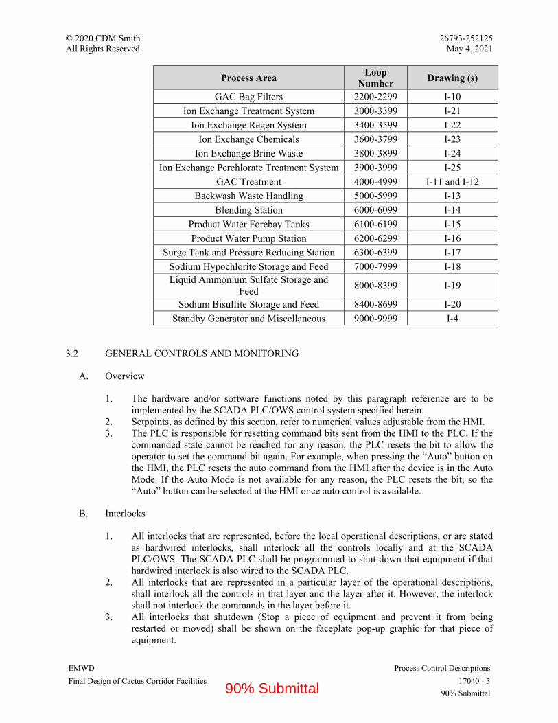
© 2020 CDM Smith 26793-252125 All Rights Reserved May 4, 2021
EMWD Process Control Descriptions Final Design of Cactus Corridor Facilities 17040 - 3
90% Submittal
Process Area Loop
Number Drawing (s)
GAC Bag Filters 2200-2299 I-10
Ion Exchange Treatment System 3000-3399 I-21
Ion Exchange Regen System 3400-3599 I-22
Ion Exchange Chemicals 3600-3799 I-23
Ion Exchange Brine Waste 3800-3899 I-24
Ion Exchange Perchlorate Treatment System 3900-3999 I-25
GAC Treatment 4000-4999 I-11 and I-12
Backwash Waste Handling 5000-5999 I-13
Blending Station 6000-6099 I-14
Product Water Forebay Tanks 6100-6199 I-15
Product Water Pump Station 6200-6299 I-16
Surge Tank and Pressure Reducing Station 6300-6399 I-17
Sodium Hypochlorite Storage and Feed 7000-7999 I-18Liquid Ammonium Sulfate Storage and
Feed 8000-8399 I-19
Sodium Bisulfite Storage and Feed 8400-8699 I-20
Standby Generator and Miscellaneous 9000-9999 I-4
3.2 GENERAL CONTROLS AND MONITORING
A. Overview
1. The hardware and/or software functions noted by this paragraph reference are to beimplemented by the SCADA PLC/OWS control system specified herein.
2. Setpoints, as defined by this section, refer to numerical values adjustable from the HMI.3. The PLC is responsible for resetting command bits sent from the HMI to the PLC. If the
commanded state cannot be reached for any reason, the PLC resets the bit to allow theoperator to set the command bit again. For example, when pressing the “Auto” button onthe HMI, the PLC resets the auto command from the HMI after the device is in the AutoMode. If the Auto Mode is not available for any reason, the PLC resets the bit, so the“Auto” button can be selected at the HMI once auto control is available.
B. Interlocks
1. All interlocks that are represented, before the local operational descriptions, or are statedas hardwired interlocks, shall interlock all the controls locally and at the SCADAPLC/OWS. The SCADA PLC shall be programmed to shut down that equipment if thathardwired interlock is also wired to the SCADA PLC.
2. All interlocks that are represented in a particular layer of the operational descriptions,shall interlock all the controls in that layer and the layer after it. However, the interlockshall not interlock the commands in the layer before it.
3. All interlocks that shutdown (Stop a piece of equipment and prevent it from beingrestarted or moved) shall be shown on the faceplate pop-up graphic for that piece ofequipment.
90% Submittal

© 2020 CDM Smith 26793-252125 All Rights Reserved May 4, 2021
EMWD Process Control Descriptions Final Design of Cactus Corridor Facilities 17040 - 4
90% Submittal
C. Motors
1. Motors can be started manually by the operator at the HMI, or automatically by thecontrol strategy.
2. The SCADA system stops a motor or drive in its program if it does not receive the autoor remote status or one of its software interlocks trips. If the drive or motor is in hand orlocal, it will continue to run but the SCADA start/stop output will be open.
3. If a motor stops for any reason, it cannot be re-started automatically once the problemwith the motor has been resolved. A manual reset from the OWS is required to resumeoperation.
4. Motors that have a LOR selector indicate to the operator that the pump is being run in the"Local" position. A motor is being run in "Local" when the "Remote" position is not trueand the run confirm status is true. If not in "Remote", the SCADA PLC output contact tostop (shutdown) the pump from SCADA is open.
5. Automatic control strategies are defined in individual loop descriptions.6. Hardwired and software interlocks are defined in individual loop descriptions.7. Provide monitoring for the following hardwired signals at the SCADA/HMI:
a. Pump Runningb. Pump in Remotec. Pump Faultd. Pump E-Stope. Pump/Motor High Temperature (where applicable)f. Pump Low Suction Pressure (where applicable)g. Pump High Discharge Pressure (where applicable)h. Pump Speed (Variable Speed Pumps Only)
8. Provide the following control from the SCADA/HMI:
a. Pump Start/Stop Controlb. Pump Speed Control (Variable Speed Pumps Only)
D. Mixers
1. Mixer can be started or stopped manually by the operator at the HMI, or automatically bythe control strategy.
2. Automatic control strategies are defined in individual loop descriptions with theircorresponding process variable used for control.
3. Hardwired and software interlocks are defined in individual loop descriptions.4. Provide monitoring for the following hardwired signals at the SCADA/HMI:
a. Mixer Runningb. Mixer In Remote
5. Provide the following control from the SCADA/HMI:
a. Mixer Start Commandb. Mixer Stop Command
E. Valves
90% Submittal
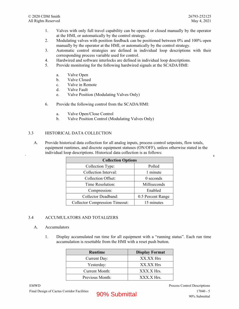
© 2020 CDM Smith 26793-252125 All Rights Reserved May 4, 2021
EMWD Process Control Descriptions Final Design of Cactus Corridor Facilities 17040 - 5
90% Submittal
1. Valves with only full travel capability can be opened or closed manually by the operatorat the HMI, or automatically by the control strategy.
2. Modulating valves with position feedback can be positioned between 0% and 100% openmanually by the operator at the HMI, or automatically by the control strategy.
3. Automatic control strategies are defined in individual loop descriptions with theircorresponding process variable used for control.
4. Hardwired and software interlocks are defined in individual loop descriptions.5. Provide monitoring for the following hardwired signals at the SCADA/HMI:
a. Valve Openb. Valve Closedc. Valve in Remoted. Valve Faulte. Valve Position (Modulating Valves Only)
6. Provide the following control from the SCADA/HMI:
a. Valve Open/Close Controlb. Valve Position Control (Modulating Valves Only)
3.3 HISTORICAL DATA COLLECTION
A. Provide historical data collection for all analog inputs, process control setpoints, flow totals,equipment runtimes, and discrete equipment statuses (ON/OFF), unless otherwise stated in theindividual loop descriptions. Historical data collection is as follows:
Collection Options
Collection Type: Polled
Collection Interval: 1 minute
Collection Offset: 0 seconds
Time Resolution: Milliseconds
Compression: Enabled
Collector Deadband: 0.5 Percent Range
Collector Compression Timeout: 15 minutes
3.4 ACCUMULATORS AND TOTALIZERS
A. Accumulators
1. Display accumulated run time for all equipment with a “running status”. Each run timeaccumulation is resettable from the HMI with a reset push button.
Runtime Display Format
Current Day: XX.XX Hrs
Yesterday: XX.XX Hrs
Current Month: XXX.X Hrs.
Previous Month: XXX.X Hrs.
90% Submittal
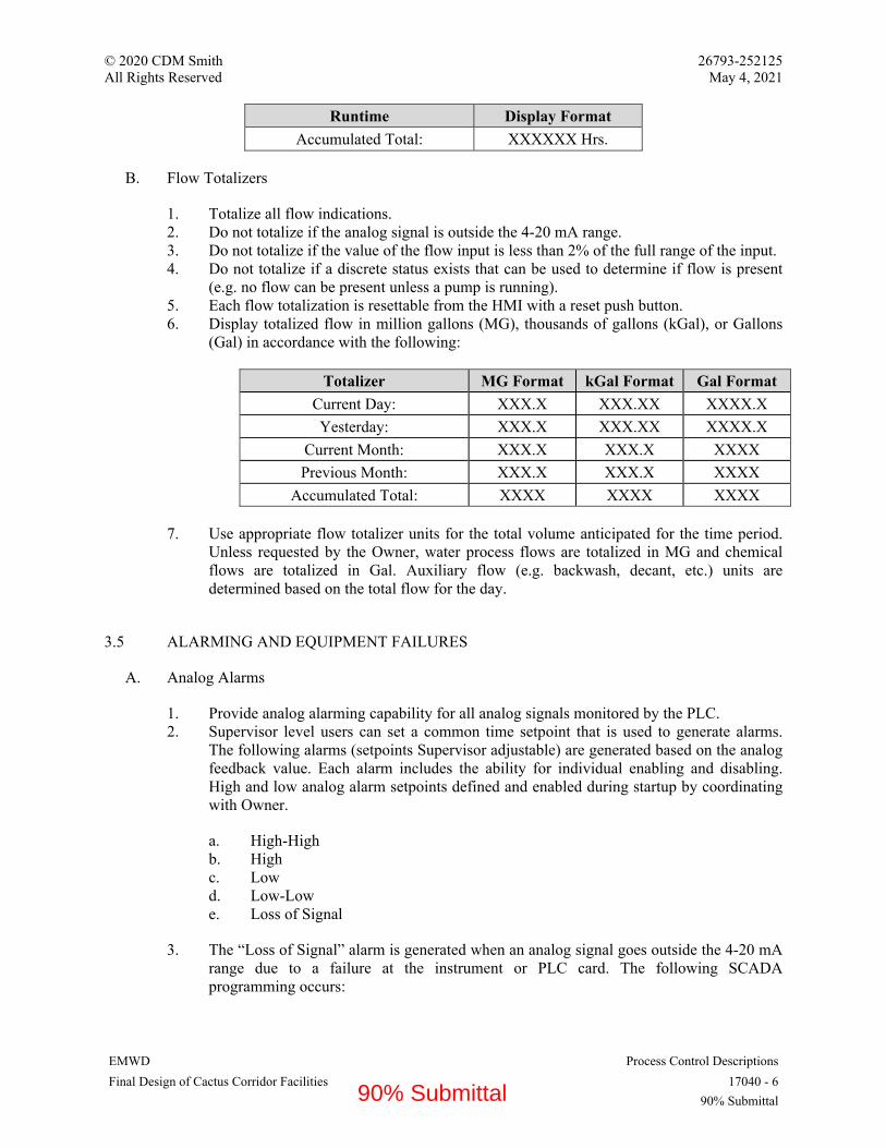
© 2020 CDM Smith 26793-252125 All Rights Reserved May 4, 2021
EMWD Process Control Descriptions Final Design of Cactus Corridor Facilities 17040 - 6
90% Submittal
Runtime Display Format
Accumulated Total: XXXXXX Hrs.
B. Flow Totalizers
1. Totalize all flow indications.2. Do not totalize if the analog signal is outside the 4-20 mA range.3. Do not totalize if the value of the flow input is less than 2% of the full range of the input.4. Do not totalize if a discrete status exists that can be used to determine if flow is present
(e.g. no flow can be present unless a pump is running).5. Each flow totalization is resettable from the HMI with a reset push button.6. Display totalized flow in million gallons (MG), thousands of gallons (kGal), or Gallons
(Gal) in accordance with the following:
Totalizer MG Format kGal Format Gal Format
Current Day: XXX.X XXX.XX XXXX.X
Yesterday: XXX.X XXX.XX XXXX.X
Current Month: XXX.X XXX.X XXXX
Previous Month: XXX.X XXX.X XXXX
Accumulated Total: XXXX XXXX XXXX
7. Use appropriate flow totalizer units for the total volume anticipated for the time period.Unless requested by the Owner, water process flows are totalized in MG and chemicalflows are totalized in Gal. Auxiliary flow (e.g. backwash, decant, etc.) units aredetermined based on the total flow for the day.
3.5 ALARMING AND EQUIPMENT FAILURES
A. Analog Alarms
1. Provide analog alarming capability for all analog signals monitored by the PLC.2. Supervisor level users can set a common time setpoint that is used to generate alarms.
The following alarms (setpoints Supervisor adjustable) are generated based on the analogfeedback value. Each alarm includes the ability for individual enabling and disabling.High and low analog alarm setpoints defined and enabled during startup by coordinatingwith Owner.
a. High-Highb. Highc. Lowd. Low-Lowe. Loss of Signal
3. The “Loss of Signal” alarm is generated when an analog signal goes outside the 4-20 mArange due to a failure at the instrument or PLC card. The following SCADAprogramming occurs:
90% Submittal

© 2020 CDM Smith 26793-252125 All Rights Reserved May 4, 2021
EMWD Process Control Descriptions Final Design of Cactus Corridor Facilities 17040 - 7
90% Submittal
a. If the analog signal is used in a control loop or ratio control loop, that loop isplaced into manual.
b. If the analog signal is used in a calculation, that calculation uses the last goodanalog signal. If the calculation is used in a control loop, that loop is placed intomanual.
4. Provide a “calibration mode” which holds the last value prior to calibration mode beingactivated. When active, clearly indicate the instrument is in calibration mode on any localHMI system.
B. Discrete Alarms
1. Program all discrete alarm signals wired to the PLC (float switches, pressure switches,overload alarms, etc.) to alarm after an adjustable time delay expires. The maximumalarm delay for Safety related alarms (e.g. E-stop) is 500ms. Set each alarm timer duringstartup.
C. Motor Failures
1. Supervisor level users can set a common time setpoint that is used to generate thefollowing alarms:
a. Motors being remotely controlled generate a “fail to start” alarm when the PLCsends the “start” command to the motor and it does not receive a running statusfrom the motor after a supervisor adjustable time setpoint. When a “fail to start”alarm is generated, the start output command from the PLC is de-energized and themotor is prevented from starting until a reset is issued from the HMI.
b. Motors being remotely controlled generate a “fail to stop” alarm when the PLCsends the “stop” command to the motor and it continues to run after a supervisoradjustable time setpoint.
c. Motors with adjustable speed control generate a “speed deviation” alarm when themotor is running and the PLC sends a speed setpoint to the motor and it does notreach the correct speed (with a deadband, initially set to 10%) within a supervisoradjustable time setpoint. The motor remains running if the “speed deviation” alarmis activated.
D. Valve Failures
1. Supervisor level users can set a common time setpoint that is used to generate thefollowing alarms. When a valve position alarm is active, the PLC output is maintainedunless explicitly stated in the individual loop descriptions (e.g. a fail to open alarm doesnot trigger the PLC to close the valve).
a. All discrete valves (open-close) being remotely controlled generate a “fail-to-open” alarm when the PLC sends the “open” command to the valve and it does notreach the “opened” limit within a supervisor adjustable time setpoint.
b. All discrete valves (open-close) being remotely controlled generate a “fail-to-close” alarm when the PLC sends the “close” command to the valve and it does notreach the “closed” limit within a supervisor adjustable time setpoint.
90% Submittal

© 2020 CDM Smith 26793-252125 All Rights Reserved May 4, 2021
EMWD Process Control Descriptions Final Design of Cactus Corridor Facilities 17040 - 8
90% Submittal
c. All modulating valves (positioning) being remotely controlled generate a “fail-to-position” alarm when the valve feedback does not match the PLC commanded position within a supervisor adjustable time setpoint.
E. Logic Requirements for Loss of Power and Restoration
1. Program motors to restart on normal power if that motor is still in auto when the motor stops due to a power outage. If a motor stops and the LOR switch is not in Remote, do not restart the motor automatically by the SCADA system without operator or SCADA logic intervention. Thus, the only way that motor when placed back in auto can be started by the SCADA system is if the operator reinitiates the start command for that motor on the OWS or when that motor control at the OWS is placed in complete automatic mode.
2. Program motorized valves as fail in place. Fail in place means that the valve does not change or react when power is lost. The valve position does not need to reset (either fully close or fully open) during the loss of power. It remains in the position it was during the power loss.
3.6 AUTOMATIC CONTROLS
A. Lead/Lag and Duty/Standby Strategy
1. Pump Priority
a. When pumps are called to operate by the automatic sequence, the order of their priority is determined by the following mode selection.
1) Operator Mode: The operator manually selects the priority of each pump (Lead/Lag/Standby/Offline) using radio buttons on a popup display. The order can be changed at any time, but no two pumps can be selected to have the same priority. The pump cannot run in automatic mode if placed offline.
2) Alternation Mode: The pump priorities are rotated each time the pumps are stopped.
3) Timed Mode: The pump priorities are determined by the runtime of the pump. The pump with the lowest runtime becomes the lead pump. The second lowest runtime becomes the lag, etc. The PLC determines the pump priority when either all pumps are stopped by the strategy, or when the pumps have been running for longer than an adjustable time setpoint.
2. Operation
a. If the individual loop description requires that the pumps operate in the Lead/Lag/Standby mode, the lag is called to start when the following conditions are met after a time delay. If more than one lag pump is included in the strategy (e.g. Lead/Lag 1/Lag 2/Standby), the sequence repeats.
1) The lead pump is running at maximum speed. 2) The process variable being controlled is more than 5% from the target value
(e.g. for flow control, the flow must be 5% below the target).
90% Submittal
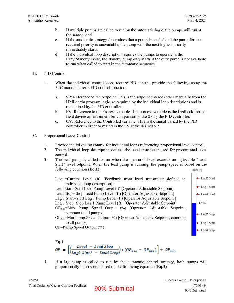
© 2020 CDM Smith 26793-252125 All Rights Reserved May 4, 2021
EMWD Process Control Descriptions Final Design of Cactus Corridor Facilities 17040 - 9
90% Submittal
b. If multiple pumps are called to run by the automatic logic, the pumps will run at the same speed.
c. If the automatic strategy determines that a pump is needed and the pump for the required priority is unavailable, the pump with the next highest priority immediately starts.
d. If the individual loop description requires the pumps to operate in the Duty/Standby mode, the standby pump only starts if the duty pump is not available to run when called to start in the automatic sequence.
B. PID Control
1. When the individual control loops require PID control, provide the following using the PLC manufacturer’s PID control function.
a. SP: Reference to the Setpoint. This is the setpoint entered (ether manually from the HMI or via program logic, as required by the individual loop description) and is maintained by the PID controller.
b. PV: Reference to the Process variable. The process variable is the feedback from a field device or instrument for comparison to the SP by the PID controller.
c. CV: Reference to the Controlled variable. This is the signal varied by the PID controller in order to maintain the PV at the desired SP.
C. Proportional Level Control
1. Provide the following control for individual loops referencing proportional level control. 2. The individual loop description defines the level transducer used for proportional level
control. 3. The lead pump is called to run when the measured level exceeds an adjustable “Lead
Start” level setpoint. When the lead pump is running, the pump speed is based on the following equation (Eq.1): Level=Current Level (ft) [Feedback from level transmitter defined in
individual loop description]] Lead Start=Start Lead Pump Level (ft) [Operator Adjustable Setpoint] Lead Stop= Stop Lead Pump Level (ft) [Operator Adjustable Setpoint] Lag 1 Start=Start Lag 1 Pump Level (ft) [Operator Adjustable Setpoint] Lag 1 Stop=Stop Lag 1 Pump Level (ft) [Operator Adjustable Setpoint] OPmax=Max Pump Speed Output (%) [Operator Adjustable Setpoint,
common to all pumps] OPmin=Min Pump Speed Output (%) [Operator Adjustable Setpoint, common
to all pumps] OP=Pump Speed Output (%) Eq.1
4. If a lag pump is called to run by the automatic control strategy, both pumps will proportionally ramp speed based on the following equation (Eq.2):
90% Submittal

© 2020 CDM Smith 26793-252125 All Rights Reserved May 4, 2021
EMWD Process Control Descriptions Final Design of Cactus Corridor Facilities 17040 - 10
90% Submittal
Eq.2
5. Equation 2 is repeated for all successive lag pumps called into operation. For example, if the Lag2 pump is called to run, Equation 2 modified to substitute Lag1 setpoints with Lag2 setpoint, and Lag2 setpoints with Lag3 setpoints.
D. Cascade Level Control
1. When using cascade level control, the speed of the pump is automatically adjusted to maintain a level setpoint using a PID level controller. The setpoint to the PID controller is in engineering units (i.e. feet, inches) and adjustable from the HMI. The output of the level PID controller is a flow, which becomes the flow setpoint (SP) to a flow PID controller.
E. Chemical Flow Pacing
1. Provide the following control for individual loops referencing automatic flow pacing. 2. The individual loop description defines the process flow meter used for flow pacing. 3. Control the speed of the chemical feed pump proportionally to the flow rate. An
adjustable “Dosage Setpoint” (mg/L) and “Chemical Weight Setpoint” (lb/gal) are entered from the HMI. The feed rate calculation is based on the following equation (Eq.1): FR=Chemical Feed Rate (Gal/hr) [Calculated in Eq. 1] Dose=Chemical Dose HMI Setpoint (mg/L) [Operator Adjustable Setpoint] Flow=Process Flow Rate (MGD) [Feedback from Flowmeter defined in individual loop
description] Weight=Chemical Weight HMI Setpoint (lb/gal) [Operator Adjustable Setpoint] Weight=Solution Density (lbs/gal) X Solutions Strength (%,w/w) Eq.1
An HMI adjustable setpoint allows the operator to enter the feed pump capacity in gallons per hour. The pump speed output is calculated as follows (Eq. 2):
OP=Pump Speed Output (%)[Calculated in Eq. 2] FR=Feed Rate Calculated in Eq. 1 [Calculated in Eq. 1] PC=Feed Pump Capacity (gal.hr) [Operator Adjustable Setpoint] PS=Feed Pump Stroke (%) [Operator Adjustable Setpoint, initially set at 100%]
Eq.2
90% Submittal
© 2020 CDM Smith 26793-252125 All Rights Reserved May 4, 2021
EMWD Process Control Descriptions Final Design of Cactus Corridor Facilities 17040 - 11
90% Submittal
F. Chemical Trim Control
1. Provide the following control for individual loops referencing automatic trim control. Note that trim control is not used as a replacement to chemical flow pacing. Therefore, when trim control is required, flow pacing is also required.
2. The individual loop description defines the process analyzer used for trimming the flow pacing strategy.
3. When trim control is enabled, the pump output calculated by the flow pacing strategy is adjusted using the feedback from the process analyzer. From the HMI, the operator can enter a desired trim setpoint (mg/L). Trim control requires a PID controller in which the output is a bias (mg/L) added to the chemical feed rate calculation. Note that the bias may be either positive or negative.
4. The bias calculated by the PID is limited to an operator defined maximum adjustment setpoint. The bias calculated by the PID cannot influence the flow pacing feed rate more than the maximum adjustment setpoint.
5. To limit the frequency of chemical dosage adjustments, the operator can enter a lag time setpoint (in minutes) associated with the time it takes for the process analyzer to measure a change associated with a step change to the chemical feed rate. The lag time will be the time between PID update cycles. The lag time is determined during field startup.
90% Submittal
© 2020 CDM Smith 26793-252125 All Rights Reserved May 4, 2021
EMWD Process Control Descriptions Final Design of Cactus Corridor Facilities 17040 - 12
90% Submittal
PART 4 - INDIVIDUAL CONTROL DESCRIPTIONS AND CONTROL SEQUENCES
LOOP INDEX
LOOP No. LOOP DESCRIPTION PAGE No. 4.1 LOOP 1000 RAW WATER WELL NO. 208 LEVEL ............................................................... 16 4.2 LOOP 1000 RAW WATER WELL PUMP NO. 208 ................................................................. 16 4.3 LOOP 1000 RAW WATER WELL PUMP NO. 208 PRESSURE ............................................ 17 4.4 LOOP 1001-1002 WELL 208 ROOM TEMPERATURE CONTROL ...................................... 17 4.5 LOOP 1005 RAW WATER WELL PUMP NO. 208 NITRATE ............................................... 18 4.6 LOOP 1006 RAW WATER WELL PUMP NO. 208 FLOW ..................................................... 18 4.7 LOOP 1010 & 1015 RAW WATER WELL PUMP NO. 208 DISCHARGE ISOLATION VALVES ................................................................................................................................................. 19 4.8 LOOP 1020 WELL 208 SODIUM HYPOCHLORITE TANKS LEVEL .................................. 20 4.9 LOOP 1021 WELL 208 SODIUM HYPOCHLORITE EYEWASH STATION (SODIUM HYPOCHLORITE PUMP AREA) ......................................................................................................... 20 4.10 LOOP 1022 WELL 208 SODIUM HYPOCHLORITE EYEWASH STATION (EXTERIOR FILL STATION) ..................................................................................................................................... 21 4.11 LOOP 1030-1040 WELL 208 SODIUM HYPOCHLORITE PUMP NO. 1 & NO. 2 ............... 21 4.12 LOOP 1023 WELL 208 SODIUM HYPOCHLORITE SUMP LEVEL ALARM ..................... 22 4.14 LOOP 1200 RAW WATER WELL PUMP NO. 209 ................................................................. 23 4.15 LOOP 1200 RAW WATER WELL PUMP NO. 209 PRESSURE ............................................ 24 4.16 LOOP 1201-1202 WELL 209 ROOM TEMPERATURE CONTROL ...................................... 25 4.17 LOOP 1205 RAW WATER WELL PUMP NO. 209 NITRATE ............................................... 25 4.18 LOOP 1206 RAW WATER WELL PUMP NO. 209 FLOW ..................................................... 26 4.19 LOOP 1210 & 1215 RAW WATER WELL PUMP NO. 209 DISCHARGE ISOLATION VALVES ................................................................................................................................................. 26 4.21 LOOP 1400 RAW WATER WELL PUMP NO. 206 ................................................................. 28 4.22 LOOP 1400 RAW WATER WELL PUMP NO. 206 PRESSURE ............................................ 28 4.23 LOOP 1401 WELL 206 ROOM TEMPERATURE CONTROL ............................................... 29 4.24 LOOP 1405 RAW WATER WELL PUMP NO. 206 NITRATE ............................................... 29 4.25 LOOP 1406 RAW WATER WELL PUMP NO. 206 FLOW ..................................................... 30 4.26 LOOP 1410 & 1415 RAW WATER WELL PUMP NO. 206 DISCHARGE ISOLATION VALVES ................................................................................................................................................. 30 4.28 LOOP 1600 RAW WATER WELL PUMP NO. 207 ................................................................. 32 4.29 LOOP 1600 RAW WATER WELL PUMP NO. 207 PRESSURE ............................................ 33 4.30 LOOP 1601-1602 WELL 207 ROOM TEMPERATURE CONTROL ...................................... 33 4.31 LOOP 1605 RAW WATER WELL PUMP NO. 207 NITRATE ............................................... 33 4.32 LOOP 1606 RAW WATER WELL PUMP NO. 207 FLOW ..................................................... 34 4.33 LOOP 1610 & 1615 RAW WATER WELL PUMP NO. 207 DISCHARGE ISOLATION VALVES ................................................................................................................................................. 34 4.34 LOOP 2000 RAW WATER GREENSAND FILTERS INFLUENT PRESSURE ..................... 35 4.35 LOOP 2010 RAW WATER CONDUCTIVITY ......................................................................... 36 4.36 LOOP 2015 RAW WATER pH AND TEMPERATURE .......................................................... 36 4.37 LOOP 2020 RAW WATER FREE CHLORINE ........................................................................ 37 4.38 LOOP 2101-2106 GREENSAND FILTER NO. 1 RAW WATER INFLUENT CONTROL ... 37 4.39 LOOP 2110 GREENSAND FILTER NO. 1 ............................................................................... 38 4.40 LOOP 2111-2116 GREENSAND FILTER NO. 2 RAW WATER INFLUENT CONTROL ... 39 4.41 LOOP 2120 GREENSAND FILTER NO. 2 ............................................................................... 39
90% Submittal
© 2020 CDM Smith 26793-252125 All Rights Reserved May 4, 2021
EMWD Process Control Descriptions Final Design of Cactus Corridor Facilities 17040 - 13
90% Submittal
4.42 LOOP 2121-2126 GREENSAND FILTER NO. 3 RAW WATER INFLUENT CONTROL ... 39 4.43 LOOP 2130 GREENSAND FILTER NO. 3 ............................................................................... 39 4.44 LOOP 2140 GREENSAND FILTER NO. 1 BACKWASH SUPPLY ...................................... 39 4.45 LOOP 2141 GREENSAND FILTER NO. 1 EFFLUENT MODULATING VALVE ............... 40 4.46 LOOP 2145 GREENSAND FILTER NO. 1 EFFLUENT FLOW.............................................. 41 4.47 LOOP 2142 GREENSAND FILTER NO. 1 FILTER-TO-WASTE MODULATING VALVE 42 4.48 LOOP 2150 GREENSAND FILTER NO. 2 BACKWASH SUPPLY ...................................... 43 4.49 LOOP 2151 GREENSAND FILTER NO. 2 EFFLUENT MODULATING VALVE ............... 43 4.50 LOOP 2155 GREENSAND FILTER NO. 2 EFFLUENT FLOW.............................................. 43 4.51 LOOP 2152 GREENSAND FILTER NO. 2 FILTER-TO-WASTE MODULATING VALVE 43 4.52 LOOP 2160 GREENSAND FILTER NO. 3 BACKWASH SUPPLY ...................................... 43 4.53 LOOP 2161 GREENSAND FILTER NO. 3 EFFLUENT MODULATING VALVE ............... 44 4.54 LOOP 2165 GREENSAND FILTER NO. 3 EFFLUENT FLOW.............................................. 44 4.55 LOOP 2162 GREENSAND FILTER NO. 2 FILTER-TO-WASTE MODULATING VALVE 44 4.56 LOOP 2210 GAC BAG FILTERS DIFFERENTIAL PRESSURE ............................................ 44 4.57 LOOP 2235 BAG FILTERS EFFLUENT FREE CHLORINE .................................................. 45 4.58 LOOP 2240 BAG FILTERS EFFLUENT OXIDATION REDUCTION POTENTIAL (ORP) 45 4.59 LOOP 3001 SOFT WATER TANK LEVEL .............................................................................. 46 4.60 LOOP 3010-3020 IX DISPLACEMENT PUMPS ..................................................................... 46 4.61 LOOP 3101 IX DISPLACEMENT PUMPS DISCHARGE FLOW .......................................... 47 4.62 LOOP 3030-3040 IX RINSE PUMPS ........................................................................................ 48 4.63 LOOP 3102 IX RINSE PUMPS DISCHARGE FLOW ............................................................. 49 4.64 LOOP 3200 STAGGERED BED IX TREATMENT SYSTEM CONTROL ............................. 49 4.65 LOOP 3103 IX TREATMENT INFLUENT FLOW (BAG FILTERS) ..................................... 50 4.66 LOOP 3104 IX TREATMENT REGENERANT FLOW (IX BRINE) ...................................... 50 4.67 LOOP 3105 IX TREATMENT DE-SCALANT FLOW (HYDROCHLORIC ACID) .............. 51 4.68 LOOP 3106 BAG FILTER EFFLUENT NITRATE .................................................................. 51 4.69 LOOP 3303 IX TREATMENT EFFLUENT FLOW .................................................................. 52 4.70 LOOP 3305 IX TREATMENT EFFLUENT CONDUCTIVITY ............................................... 52 4.71 LOOP 3306 IX TREATMENT EFFLUENT NITRATE ............................................................ 52 4.72 LOOP 3410-3440 BRINE TANKS LEVEL ............................................................................... 53 4.73 LOOP 3510-3520 IX REGEN PUMPS ...................................................................................... 54 4.74 LOOP 3601 HYDROCHLORIC ACID TANK LEVEL ............................................................ 56 4.75 LOOP 3610-3620 HYDROCHLORIC ACID PUMP NO. 1 & NO. 2 ....................................... 57 4.76 LOOP 3640 HYDROCHLORIC ACID SUMP LEVEL ALARM ............................................. 58 4.77 LOOP 3801-3804 IX BRINE WASTE TANKS ......................................................................... 58 4.78 LOOP 3810-3820 IX BRINE WASTE PUMPS ......................................................................... 59 4.79 LOOP 3900 IX BAG FILTERS DIFFERENTIAL PRESSURE ................................................ 60 4.80 LOOP 3910 IX PERCHLORATE VESSEL TRAIN NO. 1 INFLUENT FLOW BALANCING AND MONITORING ............................................................................................................................. 60 4.81 LOOP 3920 IX PERCHLORATE VESSEL TRAIN NO. 2 INFLUENT FLOW BALANCING AND MONITORING ............................................................................................................................. 61 4.82 LOOP 3910A-3910B IX PERCHLORATE VESSEL TRAIN 1 ................................................ 62 4.83 LOOP 3920A-3920B IX PERCHLORATE VESSEL TRAIN 2 ................................................ 62 4.33 LOOP 4000 GAC TREATMENT AREA EYEWASH STATION ............................................ 62 4.34 LOOP 4001 BACKWASH WATER SUPPLY FLOW .............................................................. 63 4.35 LOOP 4002 BACKWASH WATER SUPPLY MODULATING VALVE ................................ 63 4.36 LOOP 4010 TREATED WATER CHLORINE, pH AND TEMPERATURE ........................... 64 4.37 LOOP 4101 GAC TRAIN NO. 1 INFLUENT FLOW BALANCING AND MONITORING .. 65 4.38 LOOP 4110-4120 GAC TRAIN 1 SYSTEM .............................................................................. 66 4.39 LOOP 4210-4220 GAC TRAIN 2 SYSTEM .............................................................................. 67
90% Submittal
© 2020 CDM Smith 26793-252125 All Rights Reserved May 4, 2021
EMWD Process Control Descriptions Final Design of Cactus Corridor Facilities 17040 - 14
90% Submittal
4.40 LOOP 4310-4320 GAC TRAIN 3 SYSTEM .............................................................................. 67 4.41 LOOP 5001 BACKWASH WASTE HOLDING TANK LEVEL .............................................. 67 4.42 LOOP 5005 BACKWASH WASTE PUMP SUCTION PRESSURE ........................................ 68 4.43 LOOP 5010-5020 BACKWASH WASTE PUMPS ................................................................... 68 4.44 LOOP 5101 BACKWASH WASTE PUMP DISCHARGE PRESSURE .................................. 69 4.45 LOOP 5103 BACKWASH WASTE PUMPS DISCHARGE FLOW ........................................ 70 4.46 LOOP 5201 BACKWASH WASTE BAG FILTERS DIFFERENTIAL PRESSURE ............... 70 4.47 LOOP 6002 CACTUS 2 FEEDER FLOW ................................................................................. 71 4.48 LOOP 6005 CACTUS 2 FEEDER FLOW CONTROL VALVE ............................................... 71 4.49 LOOP 6007 CACTUS 2 FEEDER PRESSURE ......................................................................... 73 4.50 LOOP 6010 POST-DISINFECTION FREE CHLORINE ......................................................... 73 4.51 LOOP 6011 POST-CHLORAMINATION TOTAL/ FREE AMONIA AND MONOCHLORAMINE .......................................................................................................................... 74 4.52 LOOP 6012 PRODUCT WATER NITRATE ............................................................................ 74 4.53 LOOP 6013 PRODUCT WATER CONDUCTIVITY ............................................................... 74 4.54 LOOP 6014 PRODUCT WATER pH AND TEMPERATURE ................................................. 75 4.55 LOOP 6015 BLENDED PRODUCT WATER TOTAL/ FREE AMONIA AND MONOCHLORAMINE ......................................................................................................................... 75 4.56 LOOP 6110 & 6120 PRODUCT WATER FOREBAY TANKS LEVEL .................................. 76 4.57 LOOP 6111 & 6121 PRODUCT WATER FOREBAY TANKS MIXERS ............................... 77 4.58 LOOP 6201-6202 PRODUCT WATER PUMP STATION ROOM TEMPERATURE CONTROL .............................................................................................................................................. 77 4.2 LOOP 6210-6240 PRODUCT WATER PUMP STATION ....................................................... 78 4.59 LOOP 6210-6240 PRODUCT WATER PUMP DISCHARGE FLOW ..................................... 79 4.60 LOOP 6265 PRODUCT WATER PUMP DISCHARGE PRESSURE ...................................... 79 4.61 LOOP 6305 PRODUCT WATER TOTAL/ FREE AMONIA AND MONOCHLORAMINE DOWNSTREAM OF CHEMICAL INJECTION ................................................................................... 80 4.62 LOOP 6310-6340 SURGE TANK AND PRESSURE REDUCING STATION ........................ 80 4.63 LOOP 7000-7050 SODIUM HYPOCHLORITE TANKS LEVEL ............................................ 81 4.64 LOOP 7001 SODIUM HYPOCHLORITE EYEWASH STATION (SODIUM HYPOCHLORITE PUMP AREA) ......................................................................................................... 82 4.65 LOOP 7002 SODIUM HYPOCHLORITE EYEWASH STATION (EXTERIOR SODIUM HYPOCHLORITE PUMP AREA) ......................................................................................................... 82 4.66 LOOP 7010 & 7060 SODIUM HYPOCHLORITE TANKS ISOLATION VALVES ............... 83 4.67 LOOP 7110-7120 SODIUM HYPOCHLORITE PUMP NO. 1 & NO. 2 .................................. 84 4.68 LOOP 7130-7140 SODIUM HYPOCHLORITE PUMP NO. 3 & NO. 4 .................................. 85 4.69 LOOP 7150-7160 SODIUM HYPOCHLORITE PUMP NO. 5 & NO. 6 .................................. 85 4.70 LOOP 7301 SODIUM HYPOCHLORITE SUMP LEVEL ALARM ........................................ 86 4.71 LOOP 8000 LIQUID AMMONIUM SULFATE TANK LEVEL .............................................. 86 4.72 LOOP 8001 LIQUID AMMONIUM SULFATE EYEWASH STATION (EXTERIOR FILL STATION) .............................................................................................................................................. 87 4.73 LOOP 8002 LIQUID AMMONIUM SULFATE EYEWASH STATION (LIQUID AMMONIUM SULFATE PUMP AREA) ............................................................................................. 88 4.74 LOOP 8110-8120 LIQUID AMMONIUM SULFATE PUMP NO. 1 & NO. 2 ......................... 88 4.75 LOOP 8130-8140 LIQUID AMMONIUM SULFATE PUMP NO. 3 & NO. 4 ......................... 89 4.76 LOOP 8301 LIQUID AMMONIUM SULFATE SUMP LEVEL ALARM ............................... 90 4.77 LOOP 8400 SODIUM BISULFITE TANK LEVEL .................................................................. 90 4.78 LOOP 8402 SODIUM BISULFITE EYEWASH STATION (SODIUM BISULFITE PUMP AREA) .................................................................................................................................................... 91 4.79 LOOP 8510-8520 SODIUM BISULFITE PUMP NO. 1 & NO. 2 ............................................. 92 4.80 LOOP 8601 SODIUM BISULFITE SUMP LEVEL ALARM ................................................... 93
90% Submittal

© 2020 CDM Smith 26793-252125 All Rights Reserved May 4, 2021
EMWD Process Control Descriptions Final Design of Cactus Corridor Facilities 17040 - 15
90% Submittal
4.81 LOOP 9000-9001 TREATMENT SITE STANDBY GENERATOR ........................................ 93 4.82 LOOP 9002-9006 TREATMENT SITE FUEL TANK MONITORING .................................... 94 4.83 LOOP 9010 WELL 208 STANDBY GENERATOR ................................................................. 94 4.84 LOOP 9012-9016 WELL 208 SITE FUEL TANK MONITORING .......................................... 95
90% Submittal
© 2020 CDM Smith 26793-252125 All Rights Reserved May 4, 2021
EMWD Process Control Descriptions Final Design of Cactus Corridor Facilities 17040 - 16
90% Submittal
4.1 LOOP 1000 RAW WATER WELL NO. 208 LEVEL
A. General:
1. Continuous monitoring of well groundwater level by means of a pressure level system to SCADA.
B. P&ID: I-6
C. Equipment: LT-1000
D. Software Interlocks:
1. Low level will stop the Raw Water Well Pump described in Loops 1000.
E. Control:
1. None
F. Alarms/Monitoring:
1. Provide analog alarming as described in Article 3.5 of this section.
G. Data Collection:
1. Provide historical data collection as described in Article 3.3 of this section.
4.2 LOOP 1000 RAW WATER WELL PUMP NO. 208
A. General:
1. Raw water pump with variable speed drive transfers water from the well to the centralized treatment facility.
B. P&ID: I-6
C. Equipment: PMP-1000, PSH-1000, PI-1000, TE-1000A, TE-1000B, TE-1000C, SV-1000
D. Hardwired Interlocks:
1. The pump cannot run if the following alarms are detected:
a. E-Stop b. High Motor Temperature c. High Discharge Pressure
E. Software Interlocks:
1. If the well groundwater level is low (Loop 1000), the SCADA system stops the pump.
90% Submittal

© 2020 CDM Smith 26793-252125 All Rights Reserved May 4, 2021
EMWD Process Control Descriptions Final Design of Cactus Corridor Facilities 17040 - 17
90% Submittal
2. If the product water level is high (Loops 6111 & 6121), the SCADA system stops the pump.
3. If both isolation valves are closed
F. Control:
1. Provide manual control, flow PID control, and cascade level control, as described in Article 3.6. The process variable to the flow PID controller is the measured raw water flow (Loop 1006) and the output of the flow PID is pump speed (%). The process variable to the cascade level PID controller is the level measured in the product tanks (Loop 6111 & 6121) and the output of the cascade level PID is a flow setpoint (MGD), which becomes the flow setpoint (SP) to the flow PID.
G. Alarms/Monitoring:
1. Provide the motor control, monitoring, runtime accumulation, and failure alarming, as described in Articles 3.2, 3.4, and 3.5 of this section.
H. Data Collection:
1. Provide historical data collection as described in Article 3.3 of this section.
4.3 LOOP 1000 RAW WATER WELL PUMP NO. 208 PRESSURE
A. General:
1. Continuous monitoring of raw water pressure by means of a pressure transmitter to SCADA. The pressure transmitter is primarily used for monitoring Well Pump discharge pressure.
B. P&ID: I-6
C. Equipment: PIT-1000
D. Control:
1. None.
E. Alarms/Monitoring:
1. Provide pressure and analog alarming as described in Article 3.5 of this section.
F. Data Collection:
1. Provide historical data collection as described in Article 3.3 of this section.
4.4 LOOP 1001-1002 WELL 208 ROOM TEMPERATURE CONTROL
A. General:
90% Submittal
© 2020 CDM Smith 26793-252125 All Rights Reserved May 4, 2021
EMWD Process Control Descriptions Final Design of Cactus Corridor Facilities 17040 - 18
90% Submittal
1. Programming of Well 208 electrical and pump room temperature controls shall be completed by HVAC vendor. See Division 15 for details.
B. P&ID: I-6
C. Equipment: TSH-1001, TSH-1002
D. Alarms/Monitoring:
1. Provide discrete alarming as described in Article 3.5 of this section.
E. Data Collection:
1. Provide historical data collection as described in Article 3.3 of this section.
4.5 LOOP 1005 RAW WATER WELL PUMP NO. 208 NITRATE
A. General:
1. Continuous monitoring of nitrate measurement by means of a nitrate analyzer at the well pump discharge pipeline to SCADA.
B. P&ID: I-6
C. Equipment: AE/AIT-1005
D. Control:
1. None
E. Alarms/Monitoring:
1. Provide nitrate indication and analog alarming as described in Article 3.5 of this section.
F. Data Collection:
1. Provide historical data collection as described in Article 3.3 of this section.
4.6 LOOP 1006 RAW WATER WELL PUMP NO. 208 FLOW
A. General:
1. Continuous monitoring of raw water flow by means of a flow transmitter to SCADA.
B. P&ID: I-6
C. Equipment: FE/FIT-1006
D. Control:
90% Submittal

© 2020 CDM Smith 26793-252125 All Rights Reserved May 4, 2021
EMWD Process Control Descriptions Final Design of Cactus Corridor Facilities 17040 - 19
90% Submittal
1. Raw water flow indication used to control the Raw Water Well Pump described in Loop 1000.
E. Alarms/Monitoring:
1. Provide flow totalization and analog alarming as described in Articles 3.4 and 3.5 of this section.
F. Data Collection:
1. Provide historical data collection as described in Article 3.3 of this section.
4.6.1 LOOP 1010 & 1015 RAW WATER WELL PUMP NO. 208 DISCHARGE ISOLATION VALVES
A. General:
1. Well pump flow discharge will be controlled by two motorized control valves. The control motorized valve BFV-1010 opens and closes as required to pump the flow to the centralized treatment facility. The control motorized valve BFV-1015 opens and closes as required to pump the flow to the blow-off pond.
2. Open/Stop/Close and Position control available at the local control station or from SCADA/HMI.
B. P&ID: I-6
C. Equipment: BFV-1010 & BFV-1015
D. Software Interlocks:
1. If the valve is not in “REMOTE”, the SCADA system places the valve in SCADA manual.
2. If the valve has a fault, the SCADA system places the valve in SCADA manual. 3. The valve BFV-1010 shall not open if BFV-1015 is not closed. BFV-1015 shall not open
if BFV-1010 is not closed. Only one valve shall be open at time. 4. Valve BFV-1010 or valve BFV-1015 shall be open before calling the respective well
pump to run.
E. Control:
1. Valve can be positioned at the local control station if the Local/Off/Remote selector is in “LOCAL”. If the selector is in the “REMOTE” position, control is transferred to SCADA. The valve can be controlled at SCADA in “MANUAL” mode. In “MANUAL” mode, the operator manually positions the valve from the HMI.
2. The control motorized valve BFV-1010 opens and closes as required to pump the flow to the centralized treatment facility. The control motorized valve BFV-1015 opens and closes as required to pump the flow to the blow-off pond. Both valves will be initiated manually by the operator from the local control panel or at the SCADA HMI. No auto control is requested for these valves. Only one valve can be open at a time and one valve shall be opened when the well pumps start running.
90% Submittal

© 2020 CDM Smith 26793-252125 All Rights Reserved May 4, 2021
EMWD Process Control Descriptions Final Design of Cactus Corridor Facilities 17040 - 20
90% Submittal
3. On startup, the discharge valve will be closed, and the blow-off valve will be opened. The pump will start and flow through the blow-off for an Operator adjustable amount of time, then the discharge valve will be opened, and the blow-off valve will be closed. The pump doesn't need to be off during transitions, but it won't be allowed to start unless one of the valves is open.
F. Alarms/Monitoring:
1. Provide valve control, monitoring, and failure alarming as described in Articles 3.2 and 3.5 of this section.
G. Data Collection:
1. Provide historical data collection as described in Article 3.3 of this section.
4.7 LOOP 1020 WELL 208 SODIUM HYPOCHLORITE TANKS LEVEL
A. General:
1. One sodium hypochlorite tank will be installed with a level transmitter and level switches for level monitoring and pump control. Continuous monitoring of tank level by means of a radar level and float switches to SCADA. The floats switches shall also be used as backup for the fill station and interlocking of the pumps.
B. P&ID: I-27
C. Equipment: TNK-1020, LE/LIT-1020, LSHH-1020, LSLL-1020
D. Software Interlocks:
1. Low level will stop the Sodium Hypochlorite Pumps described in Loops 1030-1040. 2. Level monitoring will warn the operators when the tank is almost empty and when the
tank is full during the tank fill process.
E. Control:
1. None
F. Alarms/Monitoring:
1. Provide analog alarming as described in Article 3.5 of this section.
G. Data Collection:
1. Provide historical data collection as described in Article 3.3 of this section.
4.8 LOOP 1021 WELL 208 SODIUM HYPOCHLORITE EYEWASH STATION (SODIUM HYPOCHLORITE PUMP AREA)
A. General:
90% Submittal

© 2020 CDM Smith 26793-252125 All Rights Reserved May 4, 2021
EMWD Process Control Descriptions Final Design of Cactus Corridor Facilities 17040 - 21
90% Submittal
1. Sodium Hypochlorite pump area eyewash alarms will be displayed on the HMI screen to alarm the operator.
B. P&ID: I-27
C. Equipment: EWS-1021, FSH-1021
D. Control:
1. None
E. Alarms/Monitoring:
1. Provide discrete alarming as described in Article 3.5 of this section.
F. Data Collection:
1. Provide historical data collection as described in Article 3.3 of this section.
4.9 LOOP 1022 WELL 208 SODIUM HYPOCHLORITE EYEWASH STATION (EXTERIOR FILL STATION)
A. General:
1. Exterior Sodium Hypochlorite pump area eyewash alarms will be displayed on the HMI screen to alarm the operator.
B. P&ID: I-27
C. Equipment: EWS-1022, FSH-1022
D. Control:
1. None
E. Alarms/Monitoring:
1. Provide discrete alarming as described in Article 3.5 of this section.
F. Data Collection:
1. Provide historical data collection as described in Article 3.3 of this section.
4.10 LOOP 1030-1040 WELL 208 SODIUM HYPOCHLORITE PUMP NO. 1 & NO. 2
A. General:
1. Two sodium hypochlorite pumps with variable speed drives are provided to inject the chemical prior to the Blending Station.
90% Submittal

© 2020 CDM Smith 26793-252125 All Rights Reserved May 4, 2021
EMWD Process Control Descriptions Final Design of Cactus Corridor Facilities 17040 - 22
90% Submittal
B. P&ID: I-27
C. Equipment: PMP-1030, PSH-1030, PI-1050, PMP-1040, PSH-1040
D. Software Interlocks:
1. If high pump discharge pressure (PSH) is detected, the PLC shall stop the pump, and issue an alarm.
E. Control:
1. Sodium Hypochlorite Pump No. 1 and No. 2 operate in a duty/standby configuration as described in Article 3.6.A. Provide manual control, Chemical Flow Pacing control and Chemical Trim Control as described in Article 3.6. E & F respectively. The process variable to the Chemical Flow Pacing controller is the measured total flow from the Well 208 Pump (Loop 1006) and the output of the flow pacing is pump speed (%) to maintain the desire dosage. The process transmitter to the chemical trim control is the measured chlorine at AIT/AE-XXXX.
2. Manual control:
Local Control Station:
Local: When the LOCAL/OFF/REMOTE selector switch (HS) is in the “LOCAL” position, pump’s motor shall run via START/STOP pushbuttons from LCS. The speed shall be adjusted by LOCAL increase/decrease speed pushbuttons.
Off: When the LOCAL/OFF/REMOTE selector switch (HS) is in the "OFF" position, the pump shall STOP.
Remote: When the LOCAL/OFF/REMOTE selector switch (HS) is in the "REMOTE" position, control of the pump is transferred to the SCADA /HMI.
F. Alarms/Monitoring:
1. Provide the motor control, monitoring, runtime accumulation, and failure alarming, as described in Articles 3.2, 3.4, and 3.5 of this section.
G. Data Collection:
1. Provide historical data collection as described in Article 3.3 of this section.
4.11 LOOP 1023 WELL 208 SODIUM HYPOCHLORITE SUMP LEVEL ALARM
A. General:
1. Sodium Hypochlorite sump will be installed with a level switch for level monitoring. High level alarms will be displayed on the HMI screen to alarm the operator.
B. P&ID: I-27
90% Submittal

© 2020 CDM Smith 26793-252125 All Rights Reserved May 4, 2021
EMWD Process Control Descriptions Final Design of Cactus Corridor Facilities 17040 - 23
90% Submittal
C. Equipment: LSH-1023
D. Control:
1. None
E. Alarms/Monitoring:
1. Provide discrete alarming as described in Article 3.5 of this section.
F. Data Collection:
1. Provide historical data collection as described in Article 3.3 of this section.
4.12 LOOP 1200 RAW WATER WELL NO. 209 LEVEL
A. General:
1. Continuous monitoring of well groundwater level by means of a pressure level system to SCADA.
B. P&ID: I-7
C. Equipment: LT-1200
D. Software Interlocks:
1. Low level will stop the Raw Water Well Pump described in Loops 1200.
E. Control:
1. None
F. Alarms/Monitoring:
1. Provide analog alarming as described in Article 3.5 of this section.
G. Data Collection:
1. Provide historical data collection as described in Article 3.3 of this section.
4.13 LOOP 1200 RAW WATER WELL PUMP NO. 209
A. General:
1. Raw water pump with variable speed drive transfers water from the well to the centralized treatment facility.
B. P&ID: I-7
90% Submittal
© 2020 CDM Smith 26793-252125 All Rights Reserved May 4, 2021
EMWD Process Control Descriptions Final Design of Cactus Corridor Facilities 17040 - 24
90% Submittal
C. Equipment: PMP-1200, PSH-1200, PI-1200
D. Hardwired Interlocks:
1. The pump cannot run if the following alarms are detected:
a. E-Stop b. High Motor Temperature c. High Discharge Pressure
E. Software Interlocks:
1. If the well level is low (Loop 1200), the SCADA system stops the pump. 2. If the product water level is high (Loops 6111 & 6121), the SCADA system stops the
pump.
F. Control:
1. Provide manual control, flow PID control, and cascade level control, as described in Article 3.6. The process variable to the flow PID controller is the measured raw water flow (Loop 1206) and the output of the flow PID is pump speed (%). The process variable to the cascade level PID controller is the level measured in the product tanks (Loop 6111 & 6121) and the output of the cascade level PID is a flow setpoint (MGD), which becomes the flow setpoint (SP) to the flow PID.
G. Alarms/Monitoring:
1. Provide the motor control, monitoring, runtime accumulation, and failure alarming, as described in Articles 3.2, 3.4, and 3.5 of this section.
H. Data Collection:
1. Provide historical data collection as described in Article 3.3 of this section.
4.14 LOOP 1200 RAW WATER WELL PUMP NO. 209 PRESSURE
A. General:
1. Continuous monitoring of raw water pressure by means of a pressure transmitter to SCADA. The pressure transmitter is primarily used for monitoring Well Pump discharge pressure.
B. P&ID: I-7
C. Equipment: PIT-1200
D. Control:
1. None
E. Alarms/Monitoring:
90% Submittal

© 2020 CDM Smith 26793-252125 All Rights Reserved May 4, 2021
EMWD Process Control Descriptions Final Design of Cactus Corridor Facilities 17040 - 25
90% Submittal
1. Provide pressure and analog alarming as described in Article 3.5 of this section.
F. Data Collection:
1. Provide historical data collection as described in Article 3.3 of this section.
4.15 LOOP 1201-1202 WELL 209 ROOM TEMPERATURE CONTROL
A. General:
1. Programming of Well 209 electrical and pump room temperature controls shall be completed by HVAC vendor. See Division 15 for details.
B. P&ID: I-7
C. Equipment: TSH-1201, TSH-1202
D. Alarms/Monitoring:
1. Provide discrete alarming as described in Article 3.5 of this section.
E. Data Collection:
1. Provide historical data collection as described in Article 3.3 of this section.
4.16 LOOP 1205 RAW WATER WELL PUMP NO. 209 NITRATE
A. General:
1. Continuous monitoring of nitrate measurement by means of a nitrate analyzer at the well pump discharge pipeline to SCADA.
B. P&ID: I-7
C. Equipment: AE/AIT-1205
D. Control:
1. None
E. Alarms/Monitoring:
1. Provide nitrate indication and analog alarming as described in Article 3.5 of this section.
F. Data Collection:
1. Provide historical data collection as described in Article 3.3 of this section.
90% Submittal
© 2020 CDM Smith 26793-252125 All Rights Reserved May 4, 2021
EMWD Process Control Descriptions Final Design of Cactus Corridor Facilities 17040 - 26
90% Submittal
4.17 LOOP 1206 RAW WATER WELL PUMP NO. 209 FLOW
A. General:
1. Continuous monitoring of raw water flow by means of a flow transmitter to SCADA.
B. P&ID: I-7
C. Equipment: FE/FIT-1206
D. Control:
1. Raw water flow indication used to control the Raw Water Well Pump described in Loop 1200.
E. Alarms/Monitoring:
1. Provide flow totalization and analog alarming as described in Articles 3.4 and 3.5 of this section.
F. Data Collection:
1. Provide historical data collection as described in Article 3.3 of this section.
4.17.1 LOOP 1210 & 1215 RAW WATER WELL PUMP NO. 209 DISCHARGE ISOLATION VALVES
A. General:
1. Well pump flow discharge will be controlled by two motorized control valves. The control motorized valve BFV-1210 opens and closes as required to pump the flow to the centralized treatment. The control motorized valve BFV-1215 opens and closes as required to pump the flow to the sewer. Both valves will be initiated manually by the operator from the local control panel or at the SCADA HMI. No auto control is requested for these valves. Only one valve can be open at a time and one valve shall be opened when the well pumps start running.
2. On startup, the discharge valve will be closed, and the blow-off valve will be opened. The pump will start and flow through the blow-off for an Operator adjustable amount of time, then the discharge valve will be opened, and the blow-off valve will be closed. The pump doesn't need to be off during transitions, but it won't be allowed to start unless one of the valves is open.
3. Open/Stop/Close and Position control available at the local control station or from SCADA/HMI.
B. P&ID: I-7
C. Equipment: BFV-1210 & BFV-1215
D. Software Interlocks:
90% Submittal

© 2020 CDM Smith 26793-252125 All Rights Reserved May 4, 2021
EMWD Process Control Descriptions Final Design of Cactus Corridor Facilities 17040 - 27
90% Submittal
1. If the valve is not in “REMOTE”, the SCADA system places the valve in SCADA manual.
2. If the valve has a fault, the SCADA system places the valve in SCADA manual. 3. The valve BFV-1210 shall not open if BFV-1215 is not closed. BFV-1015 shall not open
if BFV-1210 is not closed. Only one valve shall be open at time. 4. Valve BFV-1210 or valve BFV-1215 shall be open before call the respective well pump
to run.
E. Control:
1. Valve can be positioned at the local control station if the Local/Off/Remote selector is in “LOCAL”. If the selector is in the “REMOTE” position, control is transferred to SCADA. The valve can be controlled at SCADA in “MANUAL” mode. In “MANUAL” mode, the operator manually positions the valve from the HMI.
F. Alarms/Monitoring:
1. Provide valve control, monitoring, and failure alarming as described in Articles 3.2 and 3.5 of this section.
G. Data Collection:
1. Provide historical data collection as described in Article 3.3 of this section.
4.18 LOOP 1400 RAW WATER WELL NO. 206 LEVEL
A. General:
1. Continuous monitoring of well groundwater level by means of a pressure level system to SCADA.
B. P&ID: I-8
C. Equipment: LT-1400
D. Software Interlocks:
1. Low level will stop the Raw Water Well Pump described in Loops 1400.
E. Control:
1. None
F. Alarms/Monitoring:
1. Provide analog alarming as described in Article 3.5 of this section.
G. Data Collection:
1. Provide historical data collection as described in Article 3.3 of this section.
90% Submittal

© 2020 CDM Smith 26793-252125 All Rights Reserved May 4, 2021
EMWD Process Control Descriptions Final Design of Cactus Corridor Facilities 17040 - 28
90% Submittal
4.19 LOOP 1400 RAW WATER WELL PUMP NO. 206
A. General:
1. Raw water pump with variable speed drive transfers water from the well to the centralized treatment facility.
B. P&ID: I-8
C. Equipment: PMP-1400, PSH-1400, PI-1400
D. Hardwired Interlocks:
1. The pump cannot run if the following alarms are detected:
a. E-Stop b. High Motor Temperature c. High Discharge Pressure
E. Software Interlocks:
1. If the well level is low (Loop 1400), the SCADA system stops the pump. 2. If the product water level is high (Loops 6111 & 6121), the SCADA system stops the
pump. 3. If both isolation valves are closed
F. Control:
1. Provide manual control, flow PID control, and cascade level control, as described in Article 3.6. The process variable to the flow PID controller is the measured raw water flow (Loop 1406) and the output of the flow PID is pump speed (%). The process variable to the cascade level PID controller is the level measured in the product tanks (Loop 6111 & 6121) and the output of the cascade level PID is a flow setpoint (MGD), which becomes the flow setpoint (SP) to the flow PID.
G. Alarms/Monitoring:
1. Provide the motor control, monitoring, runtime accumulation, and failure alarming, as described in Articles 3.2, 3.4, and 3.5 of this section.
H. Data Collection:
1. Provide historical data collection as described in Article 3.3 of this section.
4.20 LOOP 1400 RAW WATER WELL PUMP NO. 206 PRESSURE
A. General:
1. Continuous monitoring of raw water pressure by means of a pressure transmitter to SCADA. The pressure transmitter is primarily used for monitoring Well Pump discharge pressure.
90% Submittal

© 2020 CDM Smith 26793-252125 All Rights Reserved May 4, 2021
EMWD Process Control Descriptions Final Design of Cactus Corridor Facilities 17040 - 29
90% Submittal
B. P&ID: I-8
C. Equipment: PIT-1400
D. Control:
1. None
E. Alarms/Monitoring:
1. Provide pressure and analog alarming as described in Article 3.5 of this section.
F. Data Collection:
1. Provide historical data collection as described in Article 3.3 of this section.
4.21 LOOP 1401 WELL 206 ROOM TEMPERATURE CONTROL
G. General:
1. Programming of Well 206 pump room temperature control shall be completed by HVAC vendor. See Division 15 for details.
H. P&ID: I-8
I. Equipment: TSH-1401
J. Alarms/Monitoring:
1. Provide discrete alarming as described in Article 3.5 of this section.
K. Data Collection:
1. Provide historical data collection as described in Article 3.3 of this section.
4.22 LOOP 1405 RAW WATER WELL PUMP NO. 206 NITRATE
A. General:
1. Continuous monitoring of nitrate measurement by means of a nitrate analyzer at the well pump discharge pipeline to SCADA.
B. P&ID: I-8
C. Equipment: AE/AIT-1405
D. Control:
1. None
90% Submittal

© 2020 CDM Smith 26793-252125 All Rights Reserved May 4, 2021
EMWD Process Control Descriptions Final Design of Cactus Corridor Facilities 17040 - 30
90% Submittal
E. Alarms/Monitoring:
1. Provide nitrate indication and analog alarming as described in Article 3.5 of this section.
F. Data Collection:
1. Provide historical data collection as described in Article 3.3 of this section.
4.23 LOOP 1406 RAW WATER WELL PUMP NO. 206 FLOW
A. General:
1. Continuous monitoring of raw water flow by means of a flow transmitter to SCADA.
B. P&ID: I-8
C. Equipment: FE/FIT-1406
D. Control:
1. Raw water flow indication used to control the Raw Water Well Pump described in Loop 1400.
E. Alarms/Monitoring:
1. Provide flow totalization and analog alarming as described in Articles 3.4 and 3.5 of this section.
F. Data Collection:
1. Provide historical data collection as described in Article 3.3 of this section.
4.23.1 LOOP 1410 & 1415 RAW WATER WELL PUMP NO. 206 DISCHARGE ISOLATION VALVES
A. General:
1. Well pump flow discharge will be controlled by two motorized control valves. The control motorized valve BFV-1410 opens and closes as required to pump the flow to the centralized treatment. The control motorized valve BFV-1415 opens and closes as required to pump the flow to the blow-off pond. Both valves will be initiated manually by the operator from the local control panel or at the SCADA HMI. No auto control is requested for these valves. Only one valve can be open at a time and one valve shall be opened when the well pumps start running.
2. On startup, the discharge valve will be closed, and the blow-off valve will be opened. The pump will start and flow through the blow-off for an Operator adjustable amount of time, then the discharge valve will be opened, and the blow-off valve will be closed. The pump doesn't need to be off during transitions, but it won't be allowed to start unless one of the valves is open.
90% Submittal

© 2020 CDM Smith 26793-252125 All Rights Reserved May 4, 2021
EMWD Process Control Descriptions Final Design of Cactus Corridor Facilities 17040 - 31
90% Submittal
3. Open/Stop/Close and Position control available at the local control station or from SCADA/HMI.
B. P&ID: I-8
C. Equipment: BFV-1410 & BFV-1415
D. Software Interlocks:
1. If the valve is not in “REMOTE”, the SCADA system places the valve in SCADA manual.
2. If the valve has a fault, the SCADA system places the valve in SCADA manual. 3. The valve BFV-1410 shall not open if BFV-1415 is not closed. BFV-1415 shall not open
if BFV-1410 is not closed. Only one valve shall be open at time. 4. Valve BFV-1410 or valve BFV-1415 shall be open before call the respective well pump
to run.
E. Control:
1. Valve can be positioned at the local control station if the Local/Off/Remote selector is in “LOCAL”. If the selector is in the “REMOTE” position, control is transferred to SCADA. The valve can be controlled at SCADA in “MANUAL” mode. In “MANUAL” mode, the operator manually positions the valve from the HMI.
F. Alarms/Monitoring:
1. Provide valve control, monitoring, and failure alarming as described in Articles 3.2 and 3.5 of this section.
G. Data Collection:
1. Provide historical data collection as described in Article 3.3 of this section.
4.24 LOOP 1600 RAW WATER WELL NO. 207 LEVEL
A. General:
1. Continuous monitoring of well groundwater level by means of a pressure level system to SCADA.
B. P&ID: I-9
C. Equipment: LT-1600
D. Software Interlocks:
1. Low level will stop the Raw Water Well Pump described in Loops 1600.
E. Control:
1. None
90% Submittal
© 2020 CDM Smith 26793-252125 All Rights Reserved May 4, 2021
EMWD Process Control Descriptions Final Design of Cactus Corridor Facilities 17040 - 32
90% Submittal
F. Alarms/Monitoring:
1. Provide analog alarming as described in Article 3.5 of this section.
G. Data Collection:
1. Provide historical data collection as described in Article 3.3 of this section.
4.25 LOOP 1600 RAW WATER WELL PUMP NO. 207
A. General:
1. Raw water pump with variable speed drive transfers water from the well to the centralized treatment facility.
B. P&ID: I-9
C. Equipment: PMP-1600, PSH-1600, PI-1600
D. Hardwired Interlocks:
1. The pump cannot run if the following alarms are detected:
a. E-Stop b. High Motor Temperature c. High Discharge Pressure
E. Software Interlocks:
1. If the well level is low (Loop 1600), the SCADA system stops the pump. 2. If the product water level is high (Loops 6111 & 6121), the SCADA system stops the
pump.
3. If both isolation valves are closed.
F. Control:
1. Provide manual control, flow PID control, and cascade level control, as described in Article 3.6. The process variable to the flow PID controller is the measured raw water flow (Loop 1606) and the output of the flow PID is pump speed (%). The process variable to the cascade level PID controller is the level measured in the product tanks (Loop 6111 & 6121) and the output of the cascade level PID is a flow setpoint (MGD), which becomes the flow setpoint (SP) to the flow PID.
G. Alarms/Monitoring:
1. Provide the motor control, monitoring, runtime accumulation, and failure alarming, as described in Articles 3.2, 3.4, and 3.5 of this section.
H. Data Collection:
90% Submittal

© 2020 CDM Smith 26793-252125 All Rights Reserved May 4, 2021
EMWD Process Control Descriptions Final Design of Cactus Corridor Facilities 17040 - 33
90% Submittal
1. Provide historical data collection as described in Article 3.3 of this section.
4.26 LOOP 1600 RAW WATER WELL PUMP NO. 207 PRESSURE
A. General:
1. Continuous monitoring of raw water pressure by means of a pressure transmitter to SCADA. The pressure transmitter is primarily used for monitoring Well Pump discharge pressure.
B. P&ID: I-9
C. Equipment: PIT-1600
D. Control:
1. None
E. Alarms/Monitoring:
1. Provide pressure and analog alarming as described in Article 3.5 of this section.
F. Data Collection:
1. Provide historical data collection as described in Article 3.3 of this section.
4.27 LOOP 1601-1602 WELL 207 ROOM TEMPERATURE CONTROL
A. General:
1. Programming of Well 207 electrical and pump room temperature controls shall be completed by HVAC vendor. See Division 15 for details.
B. P&ID: I-9
C. Equipment: TSH-1601, TSH-1602
D. Alarms/Monitoring:
1. Provide discrete alarming as described in Article 3.5 of this section.
E. Data Collection:
1. Provide historical data collection as described in Article 3.3 of this section.
4.28 LOOP 1605 RAW WATER WELL PUMP NO. 207 NITRATE
A. General:
90% Submittal

© 2020 CDM Smith 26793-252125 All Rights Reserved May 4, 2021
EMWD Process Control Descriptions Final Design of Cactus Corridor Facilities 17040 - 34
90% Submittal
1. Continuous monitoring of nitrate measurement by means of a nitrate analyzer at the well pump discharge pipeline to SCADA.
B. P&ID: I-9
C. Equipment: AE/AIT-1605
D. Control:
1. None
E. Alarms/Monitoring:
1. Provide nitrate indication and analog alarming as described in Article 3.5 of this section.
F. Data Collection:
1. Provide historical data collection as described in Article 3.3 of this section.
4.29 LOOP 1606 RAW WATER WELL PUMP NO. 207 FLOW
A. General:
1. Continuous monitoring of raw water flow by means of a flow transmitter to SCADA.
B. P&ID: I-9
C. Equipment: FE/FIT-1606
D. Control:
1. Raw water flow indication used to control the Raw Water Well Pump described in Loop 1600.
E. Alarms/Monitoring:
1. Provide flow totalization and analog alarming as described in Articles 3.4 and 3.5 of this section.
F. Data Collection:
1. Provide historical data collection as described in Article 3.3 of this section.
4.29.1 LOOP 1610 & 1615 RAW WATER WELL PUMP NO. 207 DISCHARGE ISOLATION VALVES
A. General:
1. Well pump flow discharge will be controlled by two motorized control valves. The control motorized valve BFV-1610 opens and closes as required to pump the flow to the
90% Submittal

© 2020 CDM Smith 26793-252125 All Rights Reserved May 4, 2021
EMWD Process Control Descriptions Final Design of Cactus Corridor Facilities 17040 - 35
90% Submittal
centralized treatment. The control motorized valve BFV-1615 opens and closes as required to pump the flow to the blow-off pond. Both valves will be initiated manually by the operator from the local control panel or at the SCADA HMI. No auto control is requested for these valves. Only one valve can be open at a time and one valve shall be opened when the well pumps start running.
2. On startup, the discharge valve will be closed, and the blow-off valve will be opened. The pump will start and flow through the blow-off for an Operator adjustable amount of time, then the discharge valve will be opened, and the blow-off valve will be closed. The pump doesn't need to be off during transitions, but it won't be allowed to start unless one of the valves is open.
3. Open/Stop/Close and Position control available at the local control station or from SCADA/HMI.
B. P&ID: I-9
C. Equipment: BFV-1610 & BFV-1615
D. Software Interlocks:
1. If the valve is not in “REMOTE”, the SCADA system places the valve in SCADA manual.
2. If the valve has a fault, the SCADA system places the valve in SCADA manual. 3. The valve BFV-1610 shall not open if BFV-1615 is not closed. BFV-1015 shall not open
if BFV-1610 is not closed. Only one valve shall be open at time. 4. Valve BFV-1610 or valve BFV-1615 shall be open before call the respective well pump
to run.
E. Control:
1. Valve can be positioned at the local control station if the Local/Off/Remote selector is in “LOCAL”. If the selector is in the “REMOTE” position, control is transferred to SCADA. The valve can be controlled at SCADA in “MANUAL” mode. In “MANUAL” mode, the operator manually positions the valve from the HMI.
F. Alarms/Monitoring:
1. Provide valve control, monitoring, and failure alarming as described in Articles 3.2 and 3.5 of this section.
G. Data Collection:
1. Provide historical data collection as described in Article 3.3 of this section.
4.30 LOOP 2000 RAW WATER GREEN SAND FILTERS INFLUENT PRESSURE
A. General:
1. Continuous monitoring of green sand filters raw water influent pressure by means of a pressure transmitter to SCADA.
90% Submittal

© 2020 CDM Smith 26793-252125 All Rights Reserved May 4, 2021
EMWD Process Control Descriptions Final Design of Cactus Corridor Facilities 17040 - 36
90% Submittal
B. P&ID: I-5
C. Equipment: PIT-2000
D. Control:
1. Raw water pressure indication used to control the Raw Water Well Pumps described in Loop 1000-1600. A high pressure alarm (PAH-2000) on the pressure transmitter on the common inlet side of the sand filters will be used to monitor pressure downstream of the well pumps. If the pressure reaches the high pressure setpoint an alarm from the SCADA will alert the operator. Operator shall notice the alarm and from the SCADA manually decide to shutdown the well pump on duty.
E. Alarms/Monitoring:
1. Provide pressure and analog alarming as described in Article 3.5 of this section.
F. Data Collection:
1. Provide historical data collection as described in Article 3.3 of this section.
4.31 LOOP 2010 RAW WATER CONDUCTIVITY
A. General:
1. Continuous monitoring of raw water conductivity by means of a conductivity transmitter to SCADA.
B. P&ID: I-5
C. Equipment: AE/AIT-2010
D. Control:
1. None
E. Alarms/Monitoring:
1. Provide analog alarming as described in Article 3.5 of this section.
4.32 LOOP 2015 RAW WATER pH AND TEMPERATURE
A. General:
1. Continuous monitoring of raw water pH/Temperature by means of a pH/Temperature transmitter to SCADA.
B. P&ID: I-5
C. Equipment: AE/AIT-2015
90% Submittal

© 2020 CDM Smith 26793-252125 All Rights Reserved May 4, 2021
EMWD Process Control Descriptions Final Design of Cactus Corridor Facilities 17040 - 37
90% Submittal
D. Control:
1. None
E. Alarms/Monitoring:
1. Provide analog alarming as described in Article 3.5 of this section.
F. Data Collection:
1. Provide historical data collection as described in Article 3.3 of this section.
4.33 LOOP 2020 RAW WATER FREE CHLORINE
A. General:
1. Continuous monitoring of raw water free chlorine by means of the chlorine transmitter to SCADA.
B. P&ID: I-5
C. Equipment: AE/AIT-2020
D. Control
1. None
E. Alarms/Monitoring:
1. Provide analog alarming as described in Article 3.5 of this section.
F. Data Collection:
1. Provide historical data collection as described in Article 3.3 of this section.
4.34 LOOP 2101-2106 GREEN SAND FILTER NO. 1 RAW WATER INFLUENT CONTROL
A. General:
1. Raw water influent to each green sand filter will be introduced by three motorized valves that open to allow water to flow to the three filter cells or close to allow for backwashing. A second set of three motorized valves on the inlet side of the filter open during backwashing (only one filter cell is backwashed at a time) to divert waste flow to the Backwash Waste Holding Tank.
2. The normal operation of the filter influent and backwash waste valves should be in Remote-Auto.
3. Open/Stop/Close and Position control available at the local control station or from SCADA/HMI.
B. P&ID: I-5
90% Submittal

© 2020 CDM Smith 26793-252125 All Rights Reserved May 4, 2021
EMWD Process Control Descriptions Final Design of Cactus Corridor Facilities 17040 - 38
90% Submittal
C. Equipment: BFV-2101, BFV-2102, BFV-2103, BFV-2104, BFV-2105 and BFV-2106
D. Software Interlocks:
1. If the valve is not in “REMOTE”, the SCADA system places the valve in SCADA manual.
2. If the valve has a fault, the SCADA system places the valve in SCADA manual.
E. Control:
1. Valve can be positioned at the local control station if the Local/Off/Remote selector is in “LOCAL”. If the selector is in the “REMOTE” position, control is transferred to SCADA. The valve can be controlled at SCADA in “MANUAL” mode. In “MANUAL” mode, the operator manually positions the valve from the HMI.
F. Alarms/Monitoring:
1. Provide valve control, monitoring, and failure alarming as described in Articles 3.2 and 3.5 of this section.
G. Data Collection:
1. Provide historical data collection as described in Article 3.3 of this section.
4.35 LOOP 2110 GREEN SAND FILTER NO. 1
A. General:
1. Each green sand filter is installed with a Differential Pressure Transmitter for continuous monitoring of filter differential pressure. The differential pressure data will be monitored by the operators team for tracking filter operation.
B. P&ID: I-5
C. Equipment: GSF-2110, PDIT-2110
D. Control:
1. None
E. Alarms/Monitoring:
1. Provide analog and discrete alarming as described in Article 3.5 of this section.
F. Data Collection:
1. Provide historical data collection as described in Article 3.3 of this section.
90% Submittal
© 2020 CDM Smith 26793-252125 All Rights Reserved May 4, 2021
EMWD Process Control Descriptions Final Design of Cactus Corridor Facilities 17040 - 39
90% Submittal
4.36 LOOP 2111-2116 GREEN SAND FILTER NO. 2 RAW WATER INFLUENT CONTROL
A. General:
1. Functionally identical to Green sand Filter No. 1 Influent Control Loop 2101-2106.
B. P&ID: I-5
C. Equipment: BFV-2111, BFV-2112, BFV-2113, BFV-2114, BFV-2115 and BFV-2116
4.37 LOOP 2120 GREEN SAND FILTER NO. 2
A. General:
1. Functionally identical to Green sand Filter No. 1 Loop 2110.
B. P&ID: I-5
C. Equipment: GSF-2120, PDIT-2120
4.38 LOOP 2121-2126 GREEN SAND FILTER NO. 3 RAW WATER INFLUENT CONTROL
A. General:
1. Functionally identical to Green sand Filter No. 1 Influent Control Loop 2101-2106.
B. P&ID: I-5
C. Equipment: BFV-2121, BFV-2122, BFV-2123, BFV-2124, BFV-2125 and BFV-2126
4.39 LOOP 2130 GREEN SAND FILTER NO. 3
A. General:
1. Functionally identical to Green sand Filter No. 1 Loop 2110.
B. P&ID: I-5
C. Equipment: GSF-2130, PDIT-2130
4.40 LOOP 2140 GREEN SAND FILTER NO. 1 BACKWASH SUPPLY
A. General:
1. Each of the three filter cells is backwashed separately, in sequential fashion. 2. Common to all filter cells, the filter effluent valve (BFV-2141) first closes and the
backwash supply valve (BFV-2140) opens. The raw water inlet isolation valve of the
90% Submittal

© 2020 CDM Smith 26793-252125 All Rights Reserved May 4, 2021
EMWD Process Control Descriptions Final Design of Cactus Corridor Facilities 17040 - 40
90% Submittal
filter cell being backwashed closes and the backwash outlet valve of the filter cell being backwashed opens.
3. Backwash water is introduced to the filter cell by modulating BFV-4002. The vendor PLC sends a backwash flow signal to the master PLC which will control the valve via a flow control PID controller. The actual flow signal, per FIT-4001, will be provided as feedback to the vendor PLC for monitoring and alarm purposes.
4. The normal operation of the filter backwash supply valve should be in Remote-Auto. 5. Open/Stop/Close and Position control available at the local control station or from
SCADA/HMI.
B. P&ID: I-5, I-11
C. Equipment: BFV-2140
D. Software Interlocks:
1. If the valve is not in “REMOTE”, the SCADA system places the valve in SCADA manual.
2. If the valve has a fault, the SCADA system places the valve in SCADA manual.
E. Control:
1. Valve can be positioned at the local control station if the Local/Off/Remote selector is in “LOCAL”. If the selector is in the “REMOTE” position, control is transferred to SCADA. The valve can be controlled at SCADA in “AUTO” mode. In “AUTO” mode, the valve opens when filter reaches terminal headloss setpoint, measured by PDIT-2110; cell backwash waste valves open/close one at a time. Only one filter can backwash at a time.
F. Alarms/Monitoring:
1. Provide valve control, monitoring, and failure alarming as described in Articles 3.2 and 3.5 of this section.
G. Data Collection:
1. Provide historical data collection as described in Article 3.3 of this section.
4.41 LOOP 2141 GREEN SAND FILTER NO. 1 EFFLUENT MODULATING VALVE
A. General:
1. Open/Stop/Close and Position control available at the local control station or from SCADA/HMI. The flow control motorized valve BFV-2141 modulates open and close as required to maintain the desired filter effluent flow.
B. P&ID: I-5
C. Equipment: BFV-2141
90% Submittal
© 2020 CDM Smith 26793-252125 All Rights Reserved May 4, 2021
EMWD Process Control Descriptions Final Design of Cactus Corridor Facilities 17040 - 41
90% Submittal
D. Software Interlocks:
1. If the valve is not in “REMOTE”, the SCADA system places the valve in SCADA manual.
2. If the valve has a fault, the SCADA system places the valve in SCADA manual. 3. If the filter reaches the maximum differential pressure setpoint (operator adjustable
setpoint via the HMI), a backwash will be requested and the SCADA system closes the valve.
E. Control:
1. Valve can be positioned at the local control station if the Local/Off/Remote selector is in “LOCAL”. If the selector is in the “REMOTE” position, control is transferred to SCADA. The valve can be controlled at SCADA in “MANUAL” mode. In “MANUAL” mode, the operator manually initiates the valve opening from the HMI. The SCADA/PLC will control the position of flow control valve based on flow setpoints. The motorized valve opening shall be controlled by a flow control PID controller to achieve the filter effluent flow setpoint. Flow transmitter will be the process variable providing information of flow to the PID controller.
2. The flow PID will use filter flow meter (loop 2145) to adjust the position of the control valve to generate a target flow rate setpoint.
3. The modulating valve will be running in automatic and controlled by the flow PID controller. The flow control motorized valve BFV-2141 will be modulated open and close as required to maintain the target flow on FIT-2145. Flow rate setpoint will be operator’s adjustable values from the HMI.
F. Alarms/Monitoring:
1. Provide valve control, monitoring, and failure alarming as described in Articles 3.2 and 3.5 of this section.
G. Data Collection:
1. Provide historical data collection as described in Article 3.3 of this section.
4.42 LOOP 2145 GREEN SAND FILTER NO. 1 EFFLUENT FLOW
A. General:
1. Continuous monitoring of green sand filter effluent flow by means of a flow transmitter to SCADA.
B. P&ID: I-5
C. Equipment: FE/FIT-2145
D. Control:
1. None
90% Submittal

© 2020 CDM Smith 26793-252125 All Rights Reserved May 4, 2021
EMWD Process Control Descriptions Final Design of Cactus Corridor Facilities 17040 - 42
90% Submittal
E. Alarms/Monitoring:
1. Provide flow totalization and analog alarming as described in Articles 3.4 and 3.5 of this section.
F. Data Collection:
1. Provide historical data collection as described in Article 3.3 of this section.
4.43 LOOP 2142 GREEN SAND FILTER NO. 1 FILTER-TO-WASTE MODULATING VALVE
A. General:
1. Open/Stop/Close and Position control available at the local control station or from SCADA/HMI. The flow control motorized valve BFV-2142 modulates open and close as required to maintain the desired filter-to-waste flow to the backwash tank.
B. P&ID: I-5
C. Equipment: BFV-2142
D. Software Interlocks:
1. If the valve is not in “REMOTE”, the SCADA system places the valve in SCADA manual.
2. If the valve has a fault, the SCADA system places the valve in SCADA manual. 3. If the filter has completed a backwash cycle, the SCADA system opens the valve.
E. Control:
1. Valve can be positioned at the local control station if the Local/Off/Remote selector is in “LOCAL”. If the selector is in the “REMOTE” position, control is transferred to SCADA. The valve can be controlled at SCADA in “MANUAL” mode. In “MANUAL” mode, the operator manually initiates the valve opening from the HMI. The SCADA/PLC will control the position of flow control valve based on flow setpoints. The motorized valve opening shall be controlled by a flow control PID controller to achieve the sand filter effluent flow setpoint. Flow transmitter will be the process variable providing information of flow to the PID controller.
2. The flow PID will use filter flow meter (loop 2145) to adjust the position of the control valve to generate a target flow rate setpoint.
3. The modulating valve will be running in automatic and controlled by the flow PID controller. The flow control motorized valve BFV-2142 will be modulated open and close as required to maintain the target flow on FIT-2145. Flow rate setpoint will be operator’s adjustable values from the HMI.
F. Alarms/Monitoring:
1. Provide valve control, monitoring, and failure alarming as described in Articles 3.2 and 3.5 of this section.
G. Data Collection:
90% Submittal
© 2020 CDM Smith 26793-252125 All Rights Reserved May 4, 2021
EMWD Process Control Descriptions Final Design of Cactus Corridor Facilities 17040 - 43
90% Submittal
1. Provide historical data collection as described in Article 3.3 of this section.
4.44 LOOP 2150 GREEN SAND FILTER NO. 2 BACKWASH SUPPLY
A. General:
1. Functionally identical to Green sand Filter No. 1 GAC treatment influent control Loop 2140.
B. P&ID: I-5
C. Equipment: BFV-2150
4.45 LOOP 2151 GREEN SAND FILTER NO. 2 EFFLUENT MODULATING VALVE
A. General:
1. Functionally identical to Green sand Filter No. 1 effluent modulating valve Loop 2141.
B. P&ID: I-5
C. Equipment: BFV-2151
4.46 LOOP 2155 GREEN SAND FILTER NO. 2 EFFLUENT FLOW
A. General:
1. Functionally identical to Green sand Filter No. 1 effluent flow Loop 2145.
B. P&ID: I-5
C. Equipment: FE/FIT-2155
4.47 LOOP 2152 GREEN SAND FILTER NO. 2 FILTER-TO-WASTE MODULATING VALVE
A. General:
1. Functionally identical to Green sand Filter No. 1 filter-to-waste modulating valve Loop 2142.
B. P&ID: I-5
C. Equipment: BFV-2152
4.48 LOOP 2160 GREEN SAND FILTER NO. 3 BACKWASH SUPPLY
A. General:
90% Submittal

© 2020 CDM Smith 26793-252125 All Rights Reserved May 4, 2021
EMWD Process Control Descriptions Final Design of Cactus Corridor Facilities 17040 - 44
90% Submittal
1. Functionally identical to Green sand Filter No. 1 GAC treatment influent control Loop 2140.
B. P&ID: I-5
C. Equipment: BFV-2160
4.49 LOOP 2161 GREEN SAND FILTER NO. 3 EFFLUENT MODULATING VALVE
A. General:
1. Functionally identical to Green sand Filter No. 1 effluent modulating valve Loop 2141.
B. P&ID: I-5
C. Equipment: BFV-2161
4.50 LOOP 2165 GREEN SAND FILTER NO. 3 EFFLUENT FLOW
A. General:
1. Functionally identical to Green sand Filter No. 1 effluent flow Loop 2145.
B. P&ID: I-5
C. Equipment: FE/FIT-2165
4.51 LOOP 2162 GREEN SAND FILTER NO. 2 FILTER-TO-WASTE MODULATING VALVE
A. General:
1. Functionally identical to Green sand Filter No. 1 filter-to-waste modulating valve Loop 2142.
B. P&ID: I-5
C. Equipment: BFV-2162
4.52 LOOP 2210 GAC BAG FILTERS DIFFERENTIAL PRESSURE
A. General:
1. Continuous monitoring of GAC bag filters differential pressure by means of a differential pressure transmitter to SCADA. The differential pressure data will be used by the operators for GAC bag filters maintenance purposes.
B. P&ID: I-10
90% Submittal

© 2020 CDM Smith 26793-252125 All Rights Reserved May 4, 2021
EMWD Process Control Descriptions Final Design of Cactus Corridor Facilities 17040 - 45
90% Submittal
C. Equipment: PDIT-2210, FLT-2210, PI-2210A, PI-2210B, FLT-2220, PI-2220A, PI-2220B
D. Control:
1. None.
E. Alarms/Monitoring:
1. Provide differential pressure and analog alarming as described in Article 3.5 of this section.
F. Data Collection:
1. Provide historical data collection as described in Article 3.3 of this section.
4.53 LOOP 2235 GREEN SAND FILTERS EFFLUENT FREE CHLORINE
A. General:
1. Continuous monitoring of green sand filter effluent free chlorine by means of the chlorine transmitter to SCADA.
B. P&ID: I-10
C. Equipment: AE/AIT-2235
D. Control
1. None
E. Alarms/Monitoring:
1. Provide analog alarming as described in Article 3.5 of this section.
F. Data Collection:
1. Provide historical data collection as described in Article 3.3 of this section.
4.53.1 LOOP 2240 GREEN SAND FILTERS EFFLUENT OXIDATION REDUCTION POTENTIAL (ORP)
A. General:
1. Continuous monitoring of green sand filters effluent ORP after sodium bisulfite dosing by means of the ORP transmitter to SCADA.
B. P&ID: I-10
C. Equipment: AE/AIT-2240
90% Submittal
© 2020 CDM Smith 26793-252125 All Rights Reserved May 4, 2021
EMWD Process Control Descriptions Final Design of Cactus Corridor Facilities 17040 - 46
90% Submittal
D. Control
1. None
E. Alarms/Monitoring:
1. Provide analog alarming as described in Article 3.5 of this section.
F. Data Collection:
1. Provide historical data collection as described in Article 3.3 of this section.
4.54 LOOP 3001 SOFT WATER TANK LEVEL
A. General:
1. One soft water tank will be installed with level transmitter and level switches for level monitoring and pump control. Continuous monitoring of tank level by means of a radar level and float switches to SCADA. The floats switches shall also be used as backup control of pumps.
B. P&ID: I-21
C. Equipment: TNK-3001, LE/LIT-3001, LSH-3001, LSL-3001
D. Software Interlocks:
1. Low level will stop the IX Displacement Pumps described in Loops 3010-3040 and the IX Rinse Pumps and open the Soft Water Inlet Valve.
2. High level will close the Soft Water Inlet Valve.
E. Control:
1. None
F. Alarms/Monitoring:
1. Provide analog alarming as described in Article 3.5 of this section.
G. Data Collection:
1. Provide historical data collection as described in Article 3.3 of this section.
4.55 LOOP 3010-3020 IX DISPLACEMENT PUMPS
A. General:
1. Two Ion Exchange (IX) displacement pumps with variable speed drives transfer soft water from the soft water tank to IX treatment system.
90% Submittal
© 2020 CDM Smith 26793-252125 All Rights Reserved May 4, 2021
EMWD Process Control Descriptions Final Design of Cactus Corridor Facilities 17040 - 47
90% Submittal
B. P&ID: I-21
C. Equipment: PMP-3010, PSL-3010, PI-3010A, PSH-3010, PI-3010B, PMP-3020, PSL-3020, PI-3020A, PSH-3020, PI-3020B
D. Hardwired Interlocks:
1. The pump cannot run if the following alarms are detected:
a. E-Stop b. Low Suction Pressure c. High Motor Temperature d. High Discharge Pressure
E. Software Interlocks:
1. If the soft water tank level is low (Loop 3001), the SCADA system stops the pump.
F. Control:
1. Two centrifugal pumps will operate, one duty and one standby configuration. Provide manual control, flow PID control, and cascade level control, as described in Article 3.6. The process variable to the flow PID controller is the measured soft water flow (Loop 3101-3102) and the output of the flow PID is pump speed (%). The process variable to the cascade level PID controller is the level measured in the soft water tank (Loop 3001) and the output of the cascade level PID is a flow setpoint (MGD), which becomes the flow setpoint (SP) to the flow PID.
G. Alarms/Monitoring:
1. Provide the motor control, monitoring, runtime accumulation, and failure alarming, as described in Articles 3.2, 3.4, and 3.5 of this section.
H. Data Collection:
1. Provide historical data collection as described in Article 3.3 of this section.
4.56 LOOP 3101 IX DISPLACEMENT PUMPS DISCHARGE FLOW
A. General:
1. Continuous monitoring of IX displacement pumps flow by means of a flow transmitter to SCADA. IX displacement pumps flow indication used to control the IX Displacement Pumps described in Loop 3010-3040.
B. P&ID: I-21
C. Equipment: FE/FIT-3101
D. Control:
90% Submittal
© 2020 CDM Smith 26793-252125 All Rights Reserved May 4, 2021
EMWD Process Control Descriptions Final Design of Cactus Corridor Facilities 17040 - 48
90% Submittal
1. None.
E. Alarms/Monitoring:
1. Provide flow totalization and analog alarming as described in Articles 3.4 and 3.5 of this section.
F. Data Collection:
1. Provide historical data collection as described in Article 3.3 of this section.
4.57 LOOP 3030-3040 IX RINSE PUMPS
G. General:
1. Two Ion Exchange (IX) rinse pumps with variable speed drives transfer soft water from the soft water tank to IX treatment system.
H. P&ID: I-21
I. Equipment: PMP-3030, PSL-3030, PI-3030A, PSH-3030, PI-3030B, PMP-3040, PSL-3040, PI-3040A, PSH-3040, PI-3040B
J. Hardwired Interlocks:
1. The pump cannot run if the following alarms are detected:
a. E-Stop b. Low Suction Pressure c. High Motor Temperature d. High Discharge Pressure
K. Software Interlocks:
1. If the soft water tank level is low (Loop 3001), the SCADA system stops the pump.
L. Control:
1. Two centrifugal pumps will operate, one duty and one standby configuration. Provide manual control, flow PID control, and cascade level control, as described in Article 3.6. The process variable to the flow PID controller is the measured soft water flow (Loop 3101-3102) and the output of the flow PID is pump speed (%). The process variable to the cascade level PID controller is the level measured in the soft water tank (Loop 3001) and the output of the cascade level PID is a flow setpoint (MGD), which becomes the flow setpoint (SP) to the flow PID.
M. Alarms/Monitoring:
1. Provide the motor control, monitoring, runtime accumulation, and failure alarming, as described in Articles 3.2, 3.4, and 3.5 of this section.
90% Submittal

© 2020 CDM Smith 26793-252125 All Rights Reserved May 4, 2021
EMWD Process Control Descriptions Final Design of Cactus Corridor Facilities 17040 - 49
90% Submittal
N. Data Collection:
1. Provide historical data collection as described in Article 3.3 of this section.
4.58 LOOP 3102 IX RINSE PUMPS DISCHARGE FLOW
O. General:
1. Continuous monitoring of IX rinse pumps flow by means of a flow transmitter to SCADA.
P. P&ID: I-21
Q. Equipment: FE/FIT-3102
R. Control:
1. IX displacement pumps flow indication used to control the IX Displacement Pumps described in Loop 3010-3040.
S. Alarms/Monitoring:
1. Provide flow totalization and analog alarming as described in Articles 3.4 and 3.5 of this section.
T. Data Collection:
1. Provide historical data collection as described in Article 3.3 of this section.
4.59 LOOP 3200 STAGGERED BED IX TREATMENT SYSTEM CONTROL
A. General:
1. Programming of staggered bed IX treatment system shall be completed by IX treatment vendor. See Division 11 for details.
B. P&ID: I-21
C. Equipment: TS-3200
D. Alarms/Monitoring:
1. Provide discrete alarming as described in Article 3.5 of this section.
E. Data Collection:
1. Provide historical data collection as described in Article 3.3 of this section.
90% Submittal

© 2020 CDM Smith 26793-252125 All Rights Reserved May 4, 2021
EMWD Process Control Descriptions Final Design of Cactus Corridor Facilities 17040 - 50
90% Submittal
4.60 LOOP 3103 STAGGERED BED IX TREATMENT INFLUENT FLOW (BAG FILTERS)
A. General:
1. Continuous monitoring of bag filters flow to IX treatment by means of a flow transmitter to SCADA. The flow indication is primarily used for monitoring bag filters flow to the IX treatment.
B. P&ID: I-21
C. Equipment: FE/FIT-3103
D. Control:
1. None.
E. Alarms/Monitoring:
1. Provide flow totalization and analog alarming as described in Articles 3.4 and 3.5 of this section.
F. Data Collection:
1. Provide historical data collection as described in Article 3.3 of this section.
4.61 LOOP 3104 IX TREATMENT REGENERANT FLOW (IX BRINE)
A. General:
1. Continuous monitoring of IX brine flow to IX treatment by means of a flow transmitter to SCADA. The flow indication is primarily used for monitoring IX brine flow to the IX treatment.
B. P&ID: I-21
C. Equipment: FE/FIT-3104
D. Control:
1. None.
E. Alarms/Monitoring:
1. Provide flow totalization and analog alarming as described in Articles 3.4 and 3.5 of this section.
F. Data Collection:
1. Provide historical data collection as described in Article 3.3 of this section.
90% Submittal

© 2020 CDM Smith 26793-252125 All Rights Reserved May 4, 2021
EMWD Process Control Descriptions Final Design of Cactus Corridor Facilities 17040 - 51
90% Submittal
4.62 LOOP 3105 IX TREATMENT DE-SCALANT FLOW (HYDROCHLORIC ACID)
A. General:
1. Continuous monitoring of Hydrochloric Acid flow to IX treatment by means of a flow transmitter to SCADA. The flow indication is primarily used for monitoring hydrochloric acid flow to the IX treatment.
B. P&ID: I-21
C. Equipment: FE/FIT-3105
D. Control:
1. None.
E. Alarms/Monitoring:
1. Provide flow totalization and analog alarming as described in Articles 3.4 and 3.5 of this section.
F. Data Collection:
1. Provide historical data collection as described in Article 3.3 of this section.
4.63 LOOP 3106 STAGGERED BED EFFLUENT NITRATE
A. General:
1. Continuous monitoring of nitrate measurement by means of a nitrate analyzer at the bag filters discharge pipeline to SCADA.
B. P&ID: I-21
C. Equipment: AE/AIT-3106
D. Control:
1. None
E. Alarms/Monitoring:
1. Provide nitrate indication and analog alarming as described in Article 3.5 of this section.
F. Data Collection:
1. Provide historical data collection as described in Article 3.3 of this section.
90% Submittal

© 2020 CDM Smith 26793-252125 All Rights Reserved May 4, 2021
EMWD Process Control Descriptions Final Design of Cactus Corridor Facilities 17040 - 52
90% Submittal
4.64 LOOP 3303 IX TREATMENT EFFLUENT FLOW
A. General:
1. Continuous monitoring of IX treatment flow by means of a flow transmitter to SCADA. The flow indication is primarily used for monitoring IX effluent flow.
B. P&ID: I-21
C. Equipment: FE/FIT-3303
D. Control:
1. None.
E. Alarms/Monitoring:
1. Provide flow totalization and analog alarming as described in Articles 3.4 and 3.5 of this section.
F. Data Collection:
1. Provide historical data collection as described in Article 3.3 of this section.
4.65 LOOP 3305 IX TREATMENT EFFLUENT CONDUCTIVITY
A. General:
1. Continuous monitoring of IX treatment effluent conductivity by means of a conductivity transmitter to SCADA.
B. P&ID: I-21
C. Equipment: AE/AIT-3305
D. Control:
1. None
E. Alarms/Monitoring:
1. Provide analog alarming as described in Article 3.5 of this section.
4.66 LOOP 3306 IX TREATMENT EFFLUENT NITRATE
A. General:
1. Continuous monitoring of nitrate measurement by means of a nitrate analyzer at the IX treatment discharge pipeline to SCADA.
90% Submittal

© 2020 CDM Smith 26793-252125 All Rights Reserved May 4, 2021
EMWD Process Control Descriptions Final Design of Cactus Corridor Facilities 17040 - 53
90% Submittal
B. P&ID: I-21
C. Equipment: AE/AIT-3306
D. Control:
1. None
E. Alarms/Monitoring:
1. Provide nitrate indication and analog alarming as described in Article 3.5 of this section.
F. Data Collection:
1. Provide historical data collection as described in Article 3.3 of this section.
4.67 LOOP 3410-3440 BRINE TANKS LEVEL
A. General:
1. IX brine waste and soft water discharge to the brine tanks will be controlled by two solenoid valves. The solenoid valves open and close as required based on level to send flow to the associated brine tank. Open/Close control available from SCADA/HMI.
2. Four brine tanks will be installed with level transmitters for salt and water (brine) level monitoring and pump control. Continuous monitoring of tanks level by means of a plumb-bob type (salt level) and pressure type (water/brine level) level to SCADA.
B. P&ID: I-22
C. Equipment: SV-3405, SV-3410, TNK-3410, LT-3410A, LT-3410B, TNK-3420, LT-3420A, LT-3420B, TNK-3430, LT-3430A, LT-3430B, TNK-3440, LT-3440A, LT-3440B
D. Software Interlocks:
1. Low level in respective tank will stop the IX Regen Pumps described in Loops 3510-3520.
2. High level in respective tank will close the Soft Water and Brine Waste solenoid valves. 3. The soft water solenoid valve shall open when the brine tank water level reaches the low
level setpoint and close when the brine tank water level reaches the high level setpoint. 4. If late regen cycle brine waste and/or rinse water is available to be sent to the brine tank
and the brine tank is not at high level, the soft water solenoid valve will close and the brine waste solenoid valve will open. The brine waste solenoid valve will close when the regen cycle is complete or if the brine tank reaches high level.
E. Control:
1. The valve can be controlled at SCADA in “MANUAL” mode. In “MANUAL” mode, the operator manually positions the valve from the HMI.
2. Valve controlled at SCADA in “Auto” mode will be controlled based on its associated water level transmitter.
90% Submittal

© 2020 CDM Smith 26793-252125 All Rights Reserved May 4, 2021
EMWD Process Control Descriptions Final Design of Cactus Corridor Facilities 17040 - 54
90% Submittal
F. Alarms/Monitoring:
1. Provide valve control, monitoring, and failure alarming as described in Articles 3.2 and 3.5 of this section.
2. Provide analog alarming as described in Article 3.5 of this section.
G. Data Collection:
1. Provide historical data collection as described in Article 3.3 of this section.
4.68 LOOP 3450-3460 WATER SOFTENER BOOSTER PUMPS
A. General:
1. Two water softener booster pumps with constant speed drives transfer nitrate IX effluent from the staggered bed IX treatment effluent to water softener.
B. P&ID: I-22
C. Equipment: PMP-3450, PMP-3460
D. Hardwired Interlocks:
1. The pump cannot run if the following alarms are detected: a. E-Stop
E. Software Interlocks:
1. If the respective brine tank level is high (Loop 3410 to 3440), the SCADA system stops the pump.
2.
F. Control:
1. Two centrifugal or gear pumps will operate, one duty and one standby configuration. Provide manual control, duty/standby control as described in Article 3.6.
2. Manual control:
Local Control Station:
Local: When the LOCAL/OFF/REMOTE selector switch (HS) is in the “LOCAL” position, pump’s motor shall run via START/STOP pushbuttons from LCS. The speed shall be adjusted by LOCAL increase/decrease speed pushbuttons.
Off: When the LOCAL/OFF/REMOTE selector switch (HS) is in the "OFF" position, the pump shall STOP.
90% Submittal

© 2020 CDM Smith 26793-252125 All Rights Reserved May 4, 2021
EMWD Process Control Descriptions Final Design of Cactus Corridor Facilities 17040 - 55
90% Submittal
Remote: When the LOCAL/OFF/REMOTE selector switch (HS) is in the "REMOTE" position, control of the pump is transferred to the SCADA /HMI.
G. Alarms/Monitoring:
1. Provide the motor control, monitoring, runtime accumulation, and failure alarming, as described in Articles 3.2, 3.4, and 3.5 of this section.
H. Data Collection:
1. Provide historical data collection as described in Article 3.3 of this section.
4.69 LOOP 3510-3520 IX REGEN PUMPS
I. General:
1. Two IX regen pumps with variable speed drives transfer brine from the brine tanks to IX treatment system.
J. P&ID: I-22
K. Equipment: PMP-3510, PSL-3510, PI-3510A, PSH-3510, PI-3510B, PMP-3520, PSL-3520, PI-3520A, PSH-3520, PI-3520B
L. Hardwired Interlocks:
1. The pump cannot run if the following alarms are detected:
a. E-Stop b. Low Suction Pressure c. High Motor Temperature d. High Discharge Pressure
M. Software Interlocks:
1. If the respective brine tank level is low (Loop 3410 to 3440), the SCADA system stops the pump.
2. If the soft water storage tank level is high-high (Loop 3001), the SCADA system stops the pump.
N. Control:
1. Two centrifugal or gear pumps will operate, one duty and one standby configuration. Provide manual control, flow PID control, and cascade level control, as described in Article 3.6. The process variable to the flow PID controller is the measured brine flow (Loop 3104) and the output of the flow PID is pump speed (%).
2. Manual control:
90% Submittal

© 2020 CDM Smith 26793-252125 All Rights Reserved May 4, 2021
EMWD Process Control Descriptions Final Design of Cactus Corridor Facilities 17040 - 56
90% Submittal
VFD:
Local: When the LOCAL/OFF/REMOTE selector switch (HS) is in the “LOCAL” position, pump’s motor shall run via START/STOP pushbuttons from VFD. The speed shall be adjusted by LOCAL increase/decrease speed pushbuttons.
Off: When the LOCAL/OFF/REMOTE selector switch (HS) is in the "OFF" position, the pump shall STOP.
Remote: When the LOCAL/OFF/REMOTE selector switch (HS) is in the "REMOTE" position, control of the pump is transferred to the SCADA /HMI.
O. Alarms/Monitoring:
1. Provide the motor control, monitoring, runtime accumulation, and failure alarming, as described in Articles 3.2, 3.4, and 3.5 of this section.
P. Data Collection:
1. Provide historical data collection as described in Article 3.3 of this section.
4.70 LOOP 3601 HYDROCHLORIC ACID TANK LEVEL
A. General:
1. One Hydrochloric Acid tank will be installed with a level transmitter and level switches for level monitoring and pump control. Continuous monitoring of tank level by means of a radar level and float switch to SCADA. The float switch shall also be used as backup for the fill station and interlocking of the pumps.
B. P&ID: I-23
C. Equipment: TNK-3601, LE/LIT-3601, LSHH-3601, LSLL-3601
D. Software Interlocks:
1. Low level will stop the Hydrochloric Acid Pumps described in Loops 3610-3620. 2. Level monitoring will warn the operators when the tank is almost empty and when the
tank is full during the tank fill process.
E. Control:
1. None
F. Alarms/Monitoring:
1. Provide analog alarming as described in Article 3.5 of this section.
G. Data Collection:
90% Submittal

© 2020 CDM Smith 26793-252125 All Rights Reserved May 4, 2021
EMWD Process Control Descriptions Final Design of Cactus Corridor Facilities 17040 - 57
90% Submittal
1. Provide historical data collection as described in Article 3.3 of this section.
4.71 LOOP 3610-3620 HYDROCHLORIC ACID PUMP NO. 1 & NO. 2
A. General:
1. Two Hydrochloric Acid pumps with variable speed drives are provided to inject the chemical prior to the IX treatment.
B. P&ID: I-23
C. Equipment: PMP-3610, PSH-3610, PI-3630, PMP-3620, PSH-3620
D. Software Interlocks:
1. If high pump discharge pressure (PSH) is detected, the PLC shall stop the pump, and issue an alarm.
E. Control:
1. Hydrochloric Acid Pump No. 1 and No. 2 operate in a duty/standby configuration as described in Article 3.6.A. Provide manual control, Chemical Flow Pacing control and Chemical Trim Control as described in Article 3.6. E & F respectively. The process variable to Chemical Flow Pacing controller is the measured rinse water flow from the IX Rinse Pumps (Loop 3102) and the output of the flow pacing is pump speed (%) to maintain the desire dosage.
2. Manual control:
Local Control Station:
Local: When the LOCAL/OFF/REMOTE selector switch (HS) is in the “LOCAL” position, pump’s motor shall run via START/STOP pushbuttons from LCS. The speed shall be adjusted by LOCAL increase/decrease speed pushbuttons.
Off: When the LOCAL/OFF/REMOTE selector switch (HS) is in the "OFF" position, the pump shall STOP.
Remote: When the LOCAL/OFF/REMOTE selector switch (HS) is in the "REMOTE" position, control of the pump is transferred to the SCADA /HMI.
F. Alarms/Monitoring:
1. Provide the motor control, monitoring, runtime accumulation, and failure alarming, as described in Articles 3.2, 3.4, and 3.5 of this section.
G. Data Collection:
1. Provide historical data collection as described in Article 3.3 of this section.
90% Submittal
© 2020 CDM Smith 26793-252125 All Rights Reserved May 4, 2021
EMWD Process Control Descriptions Final Design of Cactus Corridor Facilities 17040 - 58
90% Submittal
4.72 LOOP 3640 HYDROCHLORIC ACID SUMP LEVEL ALARM
A. General:
1. Hydrochloric Acid sump will be installed with a level switch for level monitoring. High level alarms will be displayed on the HMI screen to alarm the operator.
B. P&ID: I-23
C. Equipment: LSH-3640
D. Control:
1. None
E. Alarms/Monitoring:
1. Provide discrete alarming as described in Article 3.5 of this section.
F. Data Collection:
1. Provide historical data collection as described in Article 3.3 of this section.
4.73 LOOP 3801-3804 IX BRINE WASTE TANKS
A. General:
1. IX treatment flow discharge to the IX brine waste holding tanks will be controlled by four solenoid valves. The solenoid valve open and close as required based on level to send flow to the associated brine waste holding tank. Open/Close control available from SCADA/HMI.
2. The four brine waste tanks will be installed with a level transmitter and level switches for level monitoring and pump control. Continuous monitoring of tanks level by means of a radar level and float switches to SCADA. The floats switches shall also be used as backup control of pumps.
B. P&ID: I-24
C. Equipment: SV-3801, SV-3802, SV-3803, SV-3804, TNK-3801, LE/LIT-3801, LSHH-3801, LSLL-3801, TNK-3802, LE/LIT-3802, LSHH-3802, LSLL-3802, TNK-3803, LE/LIT-3803, LSHH-3803, LSLL-3803, TNK-3804, LE/LIT-3804, LSHH-3804, LSLL-3804
D. Software Interlocks:
1. Low level will stop the Brine Waste Pumps described in Loops 3810-3820. 2. High level will trigger an alarm. 3. High-high level on the brine waste holding tank will call to close the associated solenoid
valves. 4. The solenoid valve shall not open if any of the other solenoid valves is not closed. Only
one valve shall be open at time.
90% Submittal
© 2020 CDM Smith 26793-252125 All Rights Reserved May 4, 2021
EMWD Process Control Descriptions Final Design of Cactus Corridor Facilities 17040 - 59
90% Submittal
E. Control:
1. The valve can be controlled at SCADA in “MANUAL” mode. In “MANUAL” mode, the operator manually positions the valve from the HMI.
2. Valve controlled at SCADA in “Auto” mode will be controlled based on its associate brine waste holding tank level condition.
F. Alarms/Monitoring:
1. Provide valve control, monitoring, and failure alarming as described in Articles 3.2 and 3.5 of this section.
2. Provide analog alarming as described in Article 3.5 of this section.
G. Data Collection:
1. Provide historical data collection as described in Article 3.3 of this section.
4.74 LOOP 3810-3820 IX BRINE WASTE PUMPS
A. General:
1. Two IX Brine Waste pumps with constant speed drives transfer water from the IX Brine Waste Holding tanks to be disposed out of the facility.
B. P&ID: I-24
C. Equipment: PMP-3810, PI-3810, PMP-3820, PI-3820
D. Hardwired Interlocks: a. None
E. Software Interlocks:
1. If the Brine Waste holding tank level is low (Loop 3810 & 3820), the SCADA system stops the pump.
F. Control:
1. Brine Waste Pumps 1 and 2 operate in a duty/standby configuration. The pumps will be controlled at SCADA in “MANUAL” mode only as described in Article 3.6. In “MANUAL” mode, the operator manually positions the valve from the HMI.
2. Pumps will not start in “Auto” mode but will stop based on its associate brine waste holding tank low-low level condition (Loop 3810-3820). Levels will be used to protect the pumps.
G. Alarms/Monitoring:
1. Provide the monitoring, runtime accumulation, and failure alarming, as described in Articles 3.2, 3.4, and 3.5 of this section.
90% Submittal
© 2020 CDM Smith 26793-252125 All Rights Reserved May 4, 2021
EMWD Process Control Descriptions Final Design of Cactus Corridor Facilities 17040 - 60
90% Submittal
H. Data Collection:
1. Provide historical data collection as described in Article 3.3 of this section.
4.75 LOOP 3900 IX BAG FILTERS DIFFERENTIAL PRESSURE
A. General:
1. Continuous monitoring of IX bag filters differential pressure by means of a differential pressure transmitter to SCADA. The differential pressure data will be used by the operators for IX bag filters maintenance purposes.
B. P&ID: I-25
C. Equipment: PDIT-3900, FLT-3900A, PI-3900A, PI-3900B, FLT-3900B, PI-3900C, PI-3900D
D. Control:
1. None.
E. Alarms/Monitoring:
1. Provide differential pressure and analog alarming as described in Article 3.5 of this section.
F. Data Collection:
1. Provide historical data collection as described in Article 3.3 of this section.
4.75.1 LOOP 3910 IX PERCHLORATE VESSEL TRAIN NO. 1 INFLUENT FLOW BALANCING AND MONITORING
A. General:
1. IX perchlorate influent to each vessel skid will be balanced by a modulating flow control valve. The flow control motorized valve BFV-3910 modulates open and close as required to maintain the desired flow through the pair of vessels.
2. Under this mode, the normal operation of the valve should be in Remote-Auto. A flow meter will be installed in the IX perchlorate train influent pipeline to continuously monitor the influent flow.
B. P&ID: I-26
C. Equipment: FE/FIT-3910, BFV-3910
D. Software Interlocks:
1. If the valve is not in “REMOTE”, the SCADA system places the valve in SCADA manual.
90% Submittal
© 2020 CDM Smith 26793-252125 All Rights Reserved May 4, 2021
EMWD Process Control Descriptions Final Design of Cactus Corridor Facilities 17040 - 61
90% Submittal
2. If the valve has a fault, the SCADA system places the valve in SCADA manual.
E. Control:
1. Valve can be positioned at the local control station if the Local/Off/Remote selector is in “LOCAL”. If the selector is in the “REMOTE” position, control is transferred to SCADA. The valve can be controlled at SCADA in “MANUAL” mode or “AUTO” mode. In “MANUAL” mode, the operator manually positions the valve from the HMI. In “AUTO” mode the SCADA/PLC will control the position of flow control valve based on flow set points.
2. The motorized valve opening shall be controlled by a flow control PID controller to achieve even flow between the IX perchlorate vessel pairs. Flow transmitters will be the process variable providing information of flow to the PID controller.
3. The flow PID will use the total flow from all the IX perchlorate trains influent flow meters to adjust the position of the control valve to divide the flow by the vessel pairs and generate a target flow per vessel pair. The control logic is to achieve even flow between the vessel pairs.
4. The modulating valve will be running in automatic and controlled by the flow PID controller. The flow control motorized valve BFV-3910 will be modulated open and close as required to maintain the target flow on FIT-3910.
5. Even flow distribution will be maintained by adjusting the influent flow (FIT-39X0) to each pair using a modulating butterfly valve (BFV-39X0). The valve position does not to reset (either fully close or fully open) when treatment go offline because a loss of power. It remains in the position it was previous of loss power and during restoration.
6. Rinsing of the IX media after installation, or purging following an extended shutdown, will be a manual process.
F. Alarms/Monitoring:
1. Provide flow totalization and analog alarming as described in Articles 3.4 and 3.5 of this section.
2. Provide valve control, monitoring, and failure alarming as described in Articles 3.2 and 3.5 of this section.
G. Data Collection:
1. Provide historical data collection as described in Article 3.3 of this section.
4.75.2 LOOP 3920 IX PERCHLORATE VESSEL TRAIN NO. 2 INFLUENT FLOW BALANCING AND MONITORING
A. General:
1. Functionally identical to IX Perchlorate Train No. 1 influent flow balancing and monitoring Loop 3910.
B. P&ID: I-26
C. Equipment: FE/FIT-3920, BFV-3920
90% Submittal

© 2020 CDM Smith 26793-252125 All Rights Reserved May 4, 2021
EMWD Process Control Descriptions Final Design of Cactus Corridor Facilities 17040 - 62
90% Submittal
4.76 LOOP 3910A-3910B IX PERCHLORATE VESSEL TRAIN 1
A. General:
1. Each IX perchlorate train is composed of two IX Vessels. Each vessel is installed with a differential pressure transmitter for continuous monitoring of IX vessel differential pressure. The differential pressure data will be used by the operators for IX vessels maintenance purposes.
2. A pressure relief valve is installed in the IX inlet pipeline for each vessel. A limit switch is installed on the pressure relief valve to monitor if valve is opened. The limit switch sends an electronic indication that the valve is opened.
B. P&ID: I-26
C. Equipment: IX-3910A, PDIT-3910A, PI-3911A, ZSO-3912A, PI-3913A, IX-3910B, PDIT-3910B, PI-3911B, ZSO-3912B, PI-3913B
D. Control:
1. Activation of the pressure relief valve limit switch will alert the operator that valves is opened. Operator shall manually shutdown the well pumps to investigate the treatment status.
E. Alarms/Monitoring:
1. Provide analog and discrete alarming as described in Article 3.5 of this section.
F. Data Collection:
1. Provide historical data collection as described in Article 3.3 of this section.
4.77 LOOP 3920A-3920B IX PERCHLORATE VESSEL TRAIN 2
A. General:
1. Functionally identical to IX Perchlorate Train 1 Loop 3910A-3910B.
B. P&ID: I-26
C. Equipment: IX-3920A, PDIT-3920A, PI-3921A, ZSO-3922A, PI-3923A, IX-3920B, PDIT-3920B, PI-3921B, ZSO-3922B, PI-3923B
4.33 LOOP 4000 GAC TREATMENT AREA EYEWASH STATION
A. General:
1. GAC treatment area eyewash alarms will be displayed on the HMI screen to alarm the operator.
B. P&ID: I-11
90% Submittal

© 2020 CDM Smith 26793-252125 All Rights Reserved May 4, 2021
EMWD Process Control Descriptions Final Design of Cactus Corridor Facilities 17040 - 63
90% Submittal
C. Equipment: EWS-4000, FSH-4000
D. Control:
1. None
E. Alarms/Monitoring:
1. Provide discrete alarming as described in Article 3.5 of this section.
F. Data Collection:
1. Provide historical data collection as described in Article 3.3 of this section.
4.34 LOOP 4001 BACKWASH WATER SUPPLY FLOW
A. General:
1. Continuous monitoring of backwash water supply flow to the GAC system by means of a flow transmitter to SCADA. Backwash water supply flow indication is primarily used for monitoring distribution flow to the GAC system.
B. P&ID: I-11
C. Equipment: FE/FIT-4001
D. Control:
1. None
E. Alarms/Monitoring:
1. Provide flow totalization and analog alarming as described in Articles 3.4 and 3.5 of this section.
F. Data Collection:
1. Provide historical data collection as described in Article 3.3 of this section.
4.35 LOOP 4002 BACKWASH WATER SUPPLY MODULATING VALVE
A. General:
1. Open/Stop/Close and Position control available at the local control station or from SCADA/HMI. The flow control motorized valve BFV-4002 modulates open and close as required to maintain the desired backwash flow through the pair of vessels.
B. P&ID: I-11
C. Equipment: BFV-4002
90% Submittal

© 2020 CDM Smith 26793-252125 All Rights Reserved May 4, 2021
EMWD Process Control Descriptions Final Design of Cactus Corridor Facilities 17040 - 64
90% Submittal
D. Software Interlocks:
1. If the valve is not in “REMOTE”, the SCADA system places the valve in SCADA manual.
2. If the valve has a fault, the SCADA system places the valve in SCADA manual. 3. If the backwash waste holding tank level is high-high (Loop 5001 & 5002), the
SCADA system closes the valve.
E. Control:
1. Valve can be positioned at the local control station if the Local/Off/Remote selector is in “LOCAL”. If the selector is in the “REMOTE” position, control is transferred to SCADA. The valve can be controlled at SCADA in “MANUAL” mode. In “MANUAL” mode, the operator manually initiates the valve opening from the HMI. From the HMI the operator will enter the backwash duration and the backwash flowrate. The SCADA/PLC will control the position of flow control valve based on flow setpoints. The motorized valve opening shall be controlled by a flow control PID controller to achieve the backwash flow. Flow transmitter will be the process variable providing information of flow to the PID controller.
2. The flow PID will use water distribution flow meter (loop 4001) to adjust the position of the control valve to generate a target flow rate setpoint for a set duration.
3. The modulating valve will be running in automatic and controlled by the flow PID controller. The flow control motorized valve BFV-4002 will be modulated open and close as required to maintain the target flow on FIT-4001. Flow rate and duration setpoint will be operator’s adjustable values from the HMI.
F. Alarms/Monitoring:
1. Provide valve control, monitoring, and failure alarming as described in Articles 3.2 and 3.5 of this section.
G. Data Collection:
1. Provide historical data collection as described in Article 3.3 of this section.
4.36 LOOP 4010 TREATED WATER CHLORINE, pH AND TEMPERATURE
A. General:
1. Continuous monitoring of treated water chlorine and pH/Temperature by means of the chlorine and pH/Temperature transmitter to SCADA.
B. P&ID: I-11
C. Equipment: AE-4010A, AE-4010B, AIT-4010
D. Control:
90% Submittal

© 2020 CDM Smith 26793-252125 All Rights Reserved May 4, 2021
EMWD Process Control Descriptions Final Design of Cactus Corridor Facilities 17040 - 65
90% Submittal
1. None
E. Alarms/Monitoring:
1. Provide analog alarming as described in Article 3.5 of this section.
F. Data Collection:
1. Provide historical data collection as described in Article 3.3 of this section.
4.37 LOOP 4101 GAC TRAIN NO. 1 INFLUENT FLOW BALANCING AND MONITORING
A. General:
1. GAC influent to each vessel skid will be controlled by a modulating flow control valve. The flow control motorized valve BFV-4101 modulates open and close as required to maintain the desired flow through the pair of vessels.
2. Under this mode, the normal operation of the valve should be in Remote-Auto. A flow meter will be installed in the GAC train influent pipeline to continuously monitor the influent flow.
B. P&ID: I-12
C. Equipment: FE/FIT-4101, BFV-4101
D. Software Interlocks:
1. If the valve is not in “REMOTE”, the SCADA system places the valve in SCADA manual.
2. If the valve has a fault, the SCADA system places the valve in SCADA manual.
E. Control:
1. Valve can be positioned at the local control station if the Local/Off/Remote selector is in “LOCAL”. If the selector is in the “REMOTE” position, control is transferred to SCADA. The valve can be controlled at SCADA in “MANUAL” mode or “AUTO” mode. In “MANUAL” mode, the operator manually positions the valve from the HMI. In “AUTO” mode the SCADA/PLC will control the position of flow control valve based on flow set points.
2. The motorized valve opening shall be controlled by a flow control PID controller to achieve even flow between the GAC vessel pairs. Flow transmitters will be the process variable providing information of flow to the PID controller.
3. The flow PID will use either flow signals from the existing well pump or the total flow from all the GAC trains influent flow meters to adjust the position of the control valve to divide the flow by the vessel pairs and generate a target flow per vessel pair. The control logic is to achieve even flow between the vessel pairs.
4. The modulating valve will be running in automatic and controlled by the flow PID controller. The flow control motorized valve BFV-4101 will be modulated open and close as required to maintain the target flow on FIT-4101.
90% Submittal
© 2020 CDM Smith 26793-252125 All Rights Reserved May 4, 2021
EMWD Process Control Descriptions Final Design of Cactus Corridor Facilities 17040 - 66
90% Submittal
5. Even flow distribution will be maintained by adjusting the influent flow (FI-4X01) to each pair using a modulating butterfly valve (BFV-4X01). The valve position does not to reset (either fully close or fully open) when treatment go offline because a loss of power. It remains in the position it was previous of loss power and during restoration.
6. Rinsing of the GAC media after installation, or purging following an extended shutdown, will be a manual process.
F. Alarms/Monitoring:
1. Provide flow totalization and analog alarming as described in Articles 3.4 and 3.5 of this section.
2. Provide valve control, monitoring, and failure alarming as described in Articles 3.2 and 3.5 of this section.
G. Data Collection:
1. Provide historical data collection as described in Article 3.3 of this section.
4.38 LOOP 4110-4120 GAC TRAIN 1 SYSTEM
A. General:
1. Each GAC train is composed of two GAC Vessels. Each vessel is installed with a Differential Pressure Transmitter for continuous monitoring of GAC vessel differential pressure. The differential pressure data will be using by the operators for GAC vessels maintenance purposes.
2. A pressure relief valve is installed in the GAC backwash pipeline for each vessel. A limit switch is installed in the pressure relief valve discharge to monitoring if valve is opened. The limit switch sends an electronic indication that valve is opened and flow is passing thru the valve.
B. P&ID: I-12
C. Equipment: GAC-4110, PDIT-4112, PI-4111, ZSO-4113, PI-4114, GAC-4120, PDIT-4122, PI-4121, ZSO-4123, PI-4124
90% Submittal
© 2020 CDM Smith 26793-252125 All Rights Reserved May 4, 2021
EMWD Process Control Descriptions Final Design of Cactus Corridor Facilities 17040 - 67
90% Submittal
D. Control: 1. Activation of the pressure relief valve limit switch will alert the operator that valves is
opened. Operator shall manually shutdown the well pumps to investigate the treatment status.
2. The differential pressure is used to alert the operators that a backwash is required, however, the backwash is a manually initiated process. The backwashing process itself will be described in the vendor’s O&M documentation.
E. Alarms/Monitoring:
1. Provide analog and discrete alarming as described in Article 3.5 of this section.
F. Data Collection:
1. Provide historical data collection as described in Article 3.3 of this section.
4.39 LOOP 4210-4220 GAC TRAIN 2 SYSTEM
A. General:
1. Functionally identical to GAC Train 1 Loop 4110-4120.
B. P&ID: I-12
C. Equipment: GAC-4210, PDIT-4212, PI-4211, ZSO-4213, PI-4214, GAC-4220, PDIT-4222, PI-4221, ZSO-4223, PI-4224
4.40 LOOP 4310-4320 GAC TRAIN 3 SYSTEM
A. General:
1. Functionally identical to GAC Train 1 Loop 4110-4120.
B. P&ID: I-12
C. Equipment: GAC-4310, PDIT-4312, PI-4311, ZSO-4313, PI-4314, GAC-4320, PDIT-4322, PI-4321, ZSO-4323, PI-4324
4.41 LOOP 5001 BACKWASH WASTE HOLDING TANK LEVEL
A. General:
1. One Backwash waste holding tank will be installed with a level transmitter and level switches for level monitoring and pump control. Continuous monitoring of tank level by means of an radar level and float switches to SCADA. The floats switches shall also be used as backup control of pumps.
B. P&ID: I-13
90% Submittal

© 2020 CDM Smith 26793-252125 All Rights Reserved May 4, 2021
EMWD Process Control Descriptions Final Design of Cactus Corridor Facilities 17040 - 68
90% Submittal
C. Equipment: TNK-5001, LE/LIT-5001, LSHH-5001, LSLL-5001
D. Software Interlocks:
1. Low level will stop the Backwash Waste Pumps described in Loops 5010-5020. 2. High level will start the Backwash Waste Pumps described in Loops 5010-5020. 3. High-High level will stop the Raw Water Well Pumps described on Loops 1000, 1200,
1400 and 1600
E. Control:
1. None
F. Alarms/Monitoring:
1. Provide analog alarming as described in Article 3.5 of this section.
G. Data Collection:
1. Provide historical data collection as described in Article 3.3 of this section.
4.42 LOOP 5005 BACKWASH WASTE PUMP SUCTION PRESSURE
A. General:
1. Continuous monitoring of backwash water pump suction pressure by means of a pressure transmitter to SCADA. The pressure transmitter is primarily used for monitoring pump suction pressure.
B. P&ID: I-13
C. Equipment: PIT-5005
D. Control:
1. None
E. Alarms/Monitoring:
1. Provide pressure and analog alarming as described in Article 3.5 of this section.
F. Data Collection:
1. Provide historical data collection as described in Article 3.3 of this section.
4.43 LOOP 5010-5020 BACKWASH WASTE PUMPS
A. General:
90% Submittal

© 2020 CDM Smith 26793-252125 All Rights Reserved May 4, 2021
EMWD Process Control Descriptions Final Design of Cactus Corridor Facilities 17040 - 69
90% Submittal
1. Two backwash waste pumps with variable speed drives transfer water from the backwash waster holding tanks to the sanitary sewer.
B. P&ID: I-13
C. Equipment: PMP-5010, PSL-5010, PI-5010A, PSH-5010, PI-5010B, PMP-5020, PSL-5020, PI-50200A, PSH-5020, PI-5020B, TE-5010A, TE-5010B, TE-5010C, TE-5020A, TE-5020B, TE-5020C
D. Hardwired Interlocks:
1. The pump cannot run if the following alarms are detected:
a. E-Stop b. Low Suction Pressure c. High Motor Temperature d. High Discharge Pressure
E. Software Interlocks:
1. If the backwash waste holding tank level is low (Loop 5001), the SCADA system stops the pump.
2. If the backwash waste holding tank level is high (Loop 5001), the SCADA system starts the pump.
F. Control:
1. Backwash Waste Pumps 1 and 2 operate in a duty/standby configuration. Provide manual control, flow PID control, and cascade level control, as described in Article 3.6. The process variable to the flow PID controller is the measured backwash waste flow (Loop 5103) and the output of the flow PID is pump speed (%). The process variable to the cascade level PID controller is the level measured in the Backwash Waste Holding Tank (Loop 5001) and the output of the cascade level PID is a flow setpoint (MGD), which becomes the flow setpoint (SP) to the flow PID. Levels will be used to protect the pumps.
G. Alarms/Monitoring:
1. Provide the motor control, monitoring, runtime accumulation, and failure alarming, as described in Articles 3.2, 3.4, and 3.5 of this section.
H. Data Collection:
1. Provide historical data collection as described in Article 3.3 of this section.
4.44 LOOP 5101 BACKWASH WASTE PUMP DISCHARGE PRESSURE
A. General:
90% Submittal

© 2020 CDM Smith 26793-252125 All Rights Reserved May 4, 2021
EMWD Process Control Descriptions Final Design of Cactus Corridor Facilities 17040 - 70
90% Submittal
1. Continuous monitoring of backwash waste pump discharge pressure by means of a pressure transmitter to SCADA. The pressure transmitter is primarily used for monitoring pump discharge pressure.
B. P&ID: I-13
C. Equipment: PIT-5101
D. Control:
1. None
E. Alarms/Monitoring:
1. Provide pressure and analog alarming as described in Article 3.5 of this section.
F. Data Collection:
1. Provide historical data collection as described in Article 3.3 of this section.
4.45 LOOP 5103 BACKWASH WASTE PUMPS DISCHARGE FLOW
A. General:
1. Continuous monitoring of backwash waste pumps flow by means of a flow transmitter to SCADA.
B. P&ID: I-13
C. Equipment: FE/FIT-5103
D. Control:
1. Backwash water pump flow indication used to control the Backwash Waste Pump described in Loop 5010-5020.
E. Alarms/Monitoring:
1. Provide flow totalization and analog alarming as described in Articles 3.4 and 3.5 of this section.
F. Data Collection:
1. Provide historical data collection as described in Article 3.3 of this section.
4.46 LOOP 5201 BACKWASH WASTE BAG FILTERS DIFFERENTIAL PRESSURE
A. General:
90% Submittal

© 2020 CDM Smith 26793-252125 All Rights Reserved May 4, 2021
EMWD Process Control Descriptions Final Design of Cactus Corridor Facilities 17040 - 71
90% Submittal
1. Continuous monitoring of backwash waste bag filter differential pressure by means of a differential pressure transmitter to SCADA. The differential pressure data will be used by the operators for bag filter maintenance purposes.
B. P&ID: I-13
C. Equipment: PDIT-5201, FLT-5201, FLT-5202, PI-5201A, PI-5201B, PI-5202A, PI-5202B
D. Control:
1. None
E. Alarms/Monitoring:
1. Provide differential pressure and analog alarming as described in Article 3.5 of this section.
F. Data Collection:
1. Provide historical data collection as described in Article 3.3 of this section.
4.47 LOOP 6002 CACTUS 2 FEEDER FLOW
A. General:
1. Continuous monitoring of Cactus 2 Feeder flow by means of a flow transmitter to SCADA.
B. P&ID: I-14
C. Equipment: FE/FIT-6002
D. Control:
1. Cactus 2 Feeder flow indication used to control the Cactus 2 Feeder Modulated Valve described in Loop 6005.
E. Alarms/Monitoring:
1. Provide flow totalization and analog alarming as described in Articles 3.4 and 3.5 of this section.
F. Data Collection:
1. Provide historical data collection as described in Article 3.3 of this section.
4.48 LOOP 6005 CACTUS 2 FEEDER FLOW CONTROL VALVE
A. General:
90% Submittal

© 2020 CDM Smith 26793-252125 All Rights Reserved May 4, 2021
EMWD Process Control Descriptions Final Design of Cactus Corridor Facilities 17040 - 72
90% Submittal
1. Cactus 2 Feeder flow discharge will be controlled by a modulating flow control valve. The flow control motorized valve BFV-6005 modulates open and close as required to maintain the desired the Cactus 2 Feeder flow to the Blending Station.
2. Open/Stop/Close and Position control available at the local control station or from SCADA/HMI.
B. P&ID: I-14
C. Equipment: BFV-6005
D. Software Interlocks:
1. If the valve is not in “REMOTE”, the SCADA system places the valve in SCADA manual.
2. If the valve has a fault, the SCADA system places the valve in SCADA manual. 3. The operator will enter the initial flow setpoint, the input modulating flow ratio and the
blending flow setpoint in the SCADA HMI. The valve will modulate for the initial flow setpoint. The valve will open until the flow meter FIT-6002 match the initial flow setpoint. An adjustable time delay will give a duration between the valve initiation and when the valve started to modulate to change the blending calculation flow.
4. Once the initial flow is established, the valve will modulate to achieve the operator adjustable blending ratio setpoint of treated groundwater to imported water.
E. Control:
1. Valve can be positioned at the local control station if the Local/Off/Remote selector is in “LOCAL”. If the selector is in the “REMOTE” position, control is transferred to SCADA. The valve can be controlled at SCADA in “MANUAL” mode or “AUTO” mode. In “MANUAL” mode, the operator manually positions the valve from the HMI. In “AUTO” mode the SCADA/PLC will control the position of flow control valve based on flow set points.
2. The motorized valve opening shall be controlled by a flow control PID controller to achieve an adjustable blending flow ratio value. Flow transmitter (FIT-6002) will be the process variable providing information of flow to the PID controller.
3. The flow PID will use either flow signals from the existing well pumps or the total flow from all the GAC trains influent flow meters to adjust the position of the control valve to generate a target blending flow ratio per the Cactus Feeder.
4. The modulating valve will be running in automatic and controlled by the flow PID controller. The flow control motorized valve BFV-6005 will be modulated open and close as required to maintain the target flow on FIT-6002.
F. Alarms/Monitoring:
1. Provide valve control, monitoring, and failure alarming as described in Articles 3.2 and 3.5 of this section.
G. Data Collection:
1. Provide historical data collection as described in Article 3.3 of this section.
90% Submittal
© 2020 CDM Smith 26793-252125 All Rights Reserved May 4, 2021
EMWD Process Control Descriptions Final Design of Cactus Corridor Facilities 17040 - 73
90% Submittal
4.49 LOOP 6007 CACTUS 2 FEEDER PRESSURE
A. General:
1. Continuous monitoring of Cactus 2 Feeder pressure by means of a pressure transmitter to SCADA. The pressure transmitter is primarily used for monitoring blending influent pressure.
B. P&ID: I-14
C. Equipment: PIT-6007
D. Control:
1. None
E. Alarms/Monitoring:
1. Provide pressure and analog alarming as described in Article 3.5 of this section.
F. Data Collection:
1. Provide historical data collection as described in Article 3.3 of this section.
4.50 LOOP 6010 POST-DISINFECTION FREE CHLORINE
A. General:
1. Continuous monitoring of post-disinfection free chlorine by means of the chlorine transmitter to SCADA.
B. P&ID: I-14
C. Equipment: AE/AIT-6010
D. Control:
1. None
E. Alarms/Monitoring:
1. Provide analog alarming as described in Article 3.5 of this section.
F. Data Collection:
1. Provide historical data collection as described in Article 3.3 of this section.
90% Submittal
© 2020 CDM Smith 26793-252125 All Rights Reserved May 4, 2021
EMWD Process Control Descriptions Final Design of Cactus Corridor Facilities 17040 - 74
90% Submittal
4.50.1 LOOP 6011 POST-CHLORAMINATION TOTAL/ FREE AMONIA AND MONOCHLORAMINE
A. General:
1. Continuous monitoring of post-chloramination total/free ammonia and monochloramines by means of monochloramines transmitter to SCADA.
B. P&ID: I-14
C. Equipment: AE-6011A, AE-6011B, AIT-6011
D. Control:
1. None
E. Alarms/Monitoring:
1. Provide analog alarming as described in Article 3.5 of this section.
F. Data Collection:
1. Provide historical data collection as described in Article 3.3 of this section.
4.51 LOOP 6012 PRODUCT WATER NITRATE
A. General:
1. Continuous monitoring of nitrate measurement by means of a nitrate analyzer at the product water discharge pipeline to SCADA.
B. P&ID: I-14
C. Equipment: AE/AIT-6012
D. Control:
1. None
E. Alarms/Monitoring:
1. Provide nitrate indication and analog alarming as described in Article 3.5 of this section.
F. Data Collection:
1. Provide historical data collection as described in Article 3.3 of this section.
4.52 LOOP 6013 PRODUCT WATER CONDUCTIVITY
A. General:
90% Submittal

© 2020 CDM Smith 26793-252125 All Rights Reserved May 4, 2021
EMWD Process Control Descriptions Final Design of Cactus Corridor Facilities 17040 - 75
90% Submittal
1. Continuous monitoring of Product Water Conductivity by means of a conductivity transmitter to SCADA.
B. P&ID: I-14
C. Equipment: AE/AIT-6013
D. Control:
1. None
E. Alarms/Monitoring:
1. Provide analog alarming as described in Article 3.5 of this section.
4.53 LOOP 6014 PRODUCT WATER pH AND TEMPERATURE
A. General:
1. Continuous monitoring of Product Water pH/Temperature by means of a pH/Temperature transmitter to SCADA.
B. P&ID: I-14
C. Equipment: AE/AIT-6014
D. Control:
1. None
E. Alarms/Monitoring:
1. Provide analog alarming as described in Article 3.5 of this section.
F. Data Collection:
1. Provide historical data collection as described in Article 3.3 of this section.
4.54 LOOP 6015 BLENDED PRODUCT WATER TOTAL/ FREE AMONIA AND MONOCHLORAMINE
A. General:
1. Continuous monitoring of blended product water total/free ammonia and monochloramines by means of monochloramines transmitter to SCADA.
B. P&ID: I-14
C. Equipment: AE-6015A, AE-6015B, AIT-6015
90% Submittal

© 2020 CDM Smith 26793-252125 All Rights Reserved May 4, 2021
EMWD Process Control Descriptions Final Design of Cactus Corridor Facilities 17040 - 76
90% Submittal
D. Control:
1. None
E. Alarms/Monitoring:
1. Provide analog alarming as described in Article 3.5 of this section.
F. Data Collection:
1. Provide historical data collection as described in Article 3.3 of this section.
4.55 LOOP 6110 & 6120 PRODUCT WATER FOREBAY TANKS LEVEL
A. General:
1. Two product water forebay tanks will be installed with a level transmitter and level switches for level monitoring and pump control. Continuous monitoring of tanks level by means of an radar level and float switches to SCADA. The floats switches shall also be used as backup control of pumps. Level setpoints will be used to monitoring and control of well pumps, product water pumps and tank mixers. Level setpoints are operator adjustable values which shall be adjusted by the operator in the SCADA HMI.
B. P&ID: I-15
C. Equipment: TNK-6110, LE/LIT-6110, LSHH-6110, LSLL-6110, TNK-6120, LE/LIT-6120, LSHH-6120, LSLL-6120
D. Software Interlocks:
1. Low-Low level will stop the Product Water Forebay Tank Mixer described in Loops 6111 & 6121 and will alert the operator that the tank’s level is below the mixer level.
2. Low level will start the Well Pumps described in Loops 1000, 1200, 1400 and 1600. 3. High level will stop the Well Pumps described in Loops 1000, 1200, 1400 and 1600. 4. High-High level will alert the operator that the tank’s level is above the permitted level
and production shall stop.
E. Control:
1. None
F. Alarms/Monitoring:
1. Provide analog alarming as described in Article 3.5 of this section.
G. Data Collection:
1. Provide historical data collection as described in Article 3.3 of this section.
90% Submittal
© 2020 CDM Smith 26793-252125 All Rights Reserved May 4, 2021
EMWD Process Control Descriptions Final Design of Cactus Corridor Facilities 17040 - 77
90% Submittal
4.56 LOOP 6111 & 6121 PRODUCT WATER FOREBAY TANKS MIXERS
A. General:
1. One mixer is provided in each Product Water Forebay Tank. The mixer provides continuous mixing of the tank contents.
B. P&ID: I-15
C. Equipment: MXR-6111, MXR-6120
D. Hardwired Interlocks: a. None
E. Software Interlocks:
1. If the mixer is not in “AUTO”, the SCADA system places the mixer in SCADA manual. 2. If the Product Water Forebay Tank level is low-low (Loop 6110 & 6120), the SCADA
system stops the mixer. 3. If the Product Water Forebay Tank level is low (Loop 6110 & 6120), the SCADA
system starts the mixer.
F. Control:
1. The mixer will be running continuously. To protect the mixer, the tank shall be operated with a minimum water level. The tank low-low level shall send an alarm signal to the SCADA, stop the mixer, and alert the operator that the tank’s level is below the mixer allowable level.
2. If the mixer is stopped at low-low level, it will re-start when the tank reached the low level that is set by the loops 6110 and 6120.
G. Alarms/Monitoring:
1. Provide the motor control, monitoring, runtime accumulation, and failure alarming, as described in Articles 3.2, 3.4, and 3.5 of this section.
H. Data Collection:
1. Provide historical data collection as described in Article 3.3 of this section.
4.57 LOOP 6201-6202 PRODUCT WATER PUMP STATION ROOM TEMPERATURE CONTROL
A. General:
1. Programming of electrical and pump room temperature controls shall be completed by HVAC vendor. See Division 15 for details.
B. P&ID: I-16
C. Equipment: TSH-6201, TSH-6202
90% Submittal
© 2020 CDM Smith 26793-252125 All Rights Reserved May 4, 2021
EMWD Process Control Descriptions Final Design of Cactus Corridor Facilities 17040 - 78
90% Submittal
D. Alarms/Monitoring:
1. Provide discrete alarming as described in Article 3.5 of this section.
E. Data Collection:
1. Provide historical data collection as described in Article 3.3 of this section.
4.2 LOOP 6210-6240 PRODUCT WATER PUMP STATION
A. General:
1. Four product water pumps with variable speed drives transfer water from the Product Water Forebay tanks to the distribution system.
B. P&ID: I-16
C. Equipment: PMP-6210, PSH-6210, PI-6210, PMP-6220, PSH-6220, PI-6220, PMP-6230, PSH-6230, PI-6230, PMP-6240, PSH-6240, PI-6240, TE-6210A, TE-6210B, TE-6210C, TE-6220A, TE-6220B, TE-6220C, TE-6230A, TE-6230B, TE-6230C, TE-6240A, TE-6240B, TE-6240C, VSH-6210, VSH-6220, VSH-6230, VSH-6240
D. Hardwired Interlocks:
1. The pump cannot run if the following alarms are detected:
a. E-Stop b. High Motor Vibration c. High Motor Temperature d. High Discharge Pressure
E. Software Interlocks:
1. If the Product Water Forebay tank level is low (Loop 6110, 6120), the SCADA system stops the pump.
F. Control:
1. Four vertical turbine pumping units will operate, three duty and one standby configuration. Provide manual control, flow PID control, and cascade level control, as described in Article 3.6. The process variable to the flow PID controller is the measured product water flow (Loop 6210-6240) and the output of the flow PID is pump speed (%). The process variable to the cascade level PID controller is the level measured in the Product Water Forebay Tanks (Loop 6110 & 6120) and the output of the cascade level PID is a flow setpoint (MGD), which becomes the flow setpoint (SP) to the flow PID.
2. Manual control:
Local Control Station:
Local: When the LOCAL/OFF/REMOTE selector switch (HS) is in the “LOCAL” position, pump’s VFD shall run via START/STOP
90% Submittal

© 2020 CDM Smith 26793-252125 All Rights Reserved May 4, 2021
EMWD Process Control Descriptions Final Design of Cactus Corridor Facilities 17040 - 79
90% Submittal
pushbuttons from LCS. The speed shall be adjusted by LOCAL increase/decrease speed pushbuttons.
Off: When the LOCAL/OFF/REMOTE selector switch (HS) is in the "OFF" position, the pump shall STOP.
Remote: When the LOCAL/OFF/REMOTE selector switch (HS) is in the "REMOTE" position, control of the pump is transferred to the SCADA /HMI.
G. Alarms/Monitoring:
1. Provide the motor control, monitoring, runtime accumulation, and failure alarming, as described in Articles 3.2, 3.4, and 3.5 of this section.
H. Data Collection:
1. Provide historical data collection as described in Article 3.3 of this section.
4.58 LOOP 6210-6240 PRODUCT WATER PUMP DISCHARGE FLOW
A. General:
1. Continuous monitoring of each product water pump flow by means of a flow transmitter in each pump discharge line to SCADA.
B. P&ID: I-16
C. Equipment: FE/FIT-6210, FE/FIT-6220, FE/FIT-6230, FE/FIT-6240
D. Control:
1. Product water pump flow indication used to control the Product Water Pump described in Loop 6210-6240.
E. Alarms/Monitoring:
1. Provide flow totalization and analog alarming as described in Articles 3.4 and 3.5 of this section.
F. Data Collection:
1. Provide historical data collection as described in Article 3.3 of this section.
4.59 LOOP 6265 PRODUCT WATER PUMP DISCHARGE PRESSURE
A. General:
90% Submittal
© 2020 CDM Smith 26793-252125 All Rights Reserved May 4, 2021
EMWD Process Control Descriptions Final Design of Cactus Corridor Facilities 17040 - 80
90% Submittal
1. Continuous monitoring of product water pump discharge pressure by means of a pressure transmitter to SCADA. The pressure transmitter is primarily used for monitoring product water pump discharge pressure.
B. P&ID: I-16
C. Equipment: PIT-6265
D. Control:
1. None
E. Alarms/Monitoring:
1. Provide pressure and analog alarming as described in Article 3.5 of this section.
F. Data Collection:
1. Provide historical data collection as described in Article 3.3 of this section.
4.60 LOOP 6305 PRODUCT WATER TOTAL/ FREE AMONIA AND MONOCHLORAMINE DOWNSTREAM OF CHEMICAL INJECTION
A. General:
1. Continuous monitoring of product water total/free ammonia and monochloramines downstream of the residual trim chemical injection by means of monochloramines transmitter to SCADA.
B. P&ID: I-17
C. Equipment: AE-6305A, AE-6305B, AIT-6305
D. Control:
1. None
E. Alarms/Monitoring:
1. Provide analog alarming as described in Article 3.5 of this section.
F. Data Collection:
1. Provide historical data collection as described in Article 3.3 of this section.
4.61 LOOP 6310-6340 SURGE TANK AND PRESSURE REDUCING STATION
A. General:
90% Submittal
© 2020 CDM Smith 26793-252125 All Rights Reserved May 4, 2021
EMWD Process Control Descriptions Final Design of Cactus Corridor Facilities 17040 - 81
90% Submittal
1. One surge tank will be provided to protect the distribution system from pressure transients. A pressure reducing station will be installed for pressure control to a lower pressure zone. The air compressors, AC-6310 and AC-6320, (duty/standby) are started and stopped as required to provide compressed air to equipment, via compressed air receiver tank (AR-6330) to keep the pressure on the surge tank. The surge tank and compressed air system is a package system provided by the surge tank supplier.
B. P&ID: I-17
C. Equipment: AC-6310, AC-6320, PSH-6330, PI-6330, AR-6330, PI-6330A, PI-6330B, PIT-6335, PI-6335A, ST-6340, LIT-6340
D. Software Interlocks:
1. he level installed on the surge tank will be monitoring the level on the tank. Level and level alarms will be detected on the SCADA.
2. A pressure transmitter (PIT-6335) will be installed in the discharge line to monitoring the air pressure. If the low pressure setpoint limit is detected, the SCADA system shall generate a low pressure alarm.
E. Control:
1. The surge tank and air compressor will be operated and controlled by the surge tank vendor controller. The air compressor skid will be operated to maintain a set air pressure. The air compressor system shall be designed to be operated automatically. If the air receiver (AR-6330) pressure drops based on PIT-6335, the air compressor will turn on automatically.
F. Alarms/Monitoring:
1. Provide analog and discrete alarming as described in Article 3.5 of this section.
G. Data Collection:
1. Provide historical data collection as described in Article 3.3 of this section.
4.62 LOOP 7000-7050 SODIUM HYPOCHLORITE TANKS LEVEL
A. General:
1. Two sodium hypochlorite tanks will be installed with a level transmitter and level switches for level monitoring and pump control. Continuous monitoring of tanks level by means of an radar level and float switches to SCADA. The floats switches shall also be used as backup for the fill station and interlocking of the pumps.
B. P&ID: I-18
C. Equipment: TNK-7000, LE/LIT-7000, LSHH-7000, LSLL-7000, TNK-7050, LE/LIT-7050, LSHH-7050, LSLL-7050
D. Software Interlocks:
90% Submittal

© 2020 CDM Smith 26793-252125 All Rights Reserved May 4, 2021
EMWD Process Control Descriptions Final Design of Cactus Corridor Facilities 17040 - 82
90% Submittal
1. Low level will stop the Sodium Hypochlorite Pumps described in Loops 7110-7140. 2. Level monitoring will warn the operators when the tank is almost empty and when the
tank is full during the tank fill process.
E. Control:
1. None
F. Alarms/Monitoring:
1. Provide analog alarming as described in Article 3.5 of this section.
G. Data Collection:
1. Provide historical data collection as described in Article 3.3 of this section.
4.63 LOOP 7001 SODIUM HYPOCHLORITE EYEWASH STATION (SODIUM HYPOCHLORITE PUMP AREA)
A. General:
1. Sodium Hypochlorite pump area eyewash alarms will be displayed on the HMI screen to alarm the operator.
B. P&ID: I-18
C. Equipment: EWS-7001, FSH-7001
D. Control:
1. None
E. Alarms/Monitoring:
1. Provide discrete alarming as described in Article 3.5 of this section.
F. Data Collection:
1. Provide historical data collection as described in Article 3.3 of this section.
4.64 LOOP 7002 SODIUM HYPOCHLORITE EYEWASH STATION (EXTERIOR SODIUM HYPOCHLORITE PUMP AREA)
A. General:
1. Exterior Sodium Hypochlorite pump area eyewash alarms will be displayed on the HMI screen to alarm the operator.
B. P&ID: I-18
90% Submittal

© 2020 CDM Smith 26793-252125 All Rights Reserved May 4, 2021
EMWD Process Control Descriptions Final Design of Cactus Corridor Facilities 17040 - 83
90% Submittal
C. Equipment: EWS-7002, FSH-7002
D. Control:
1. None
E. Alarms/Monitoring:
1. Provide discrete alarming as described in Article 3.5 of this section.
F. Data Collection:
1. Provide historical data collection as described in Article 3.3 of this section.
4.65 LOOP 7010 & 7060 SODIUM HYPOCHLORITE TANKS ISOLATION VALVES
A. General:
1. Sodium hypochlorite flow discharge will be controlled by two motorized control valves. The control motorized valve opens and closes as required to transfer the chemical from the tank to the chemical pumps. The control valve will be open or close remotely by the operator from the SCADA.
2. Open/Stop/Close control available at the local control station or from SCADA/HMI.
B. P&ID: I-18
C. Equipment: BV-7010 & BV-7060
D. Software Interlocks:
1. If the valve is not in “REMOTE”, the SCADA system places the valve in SCADA manual.
2. If the valve has a fault, the SCADA system places the valve in SCADA manual.
E. Control:
1. Valve can be positioned at the local control station if the Local/Off/Remote selector is in “LOCAL”. If the selector is in the “REMOTE” position, control is transferred to SCADA. The valve can be controlled at SCADA in “MANUAL” mode. In “MANUAL” mode, the operator manually positions the valve from the HMI.
F. Alarms/Monitoring:
1. Provide valve control, monitoring, and failure alarming as described in Articles 3.2 and 3.5 of this section.
G. Data Collection:
1. Provide historical data collection as described in Article 3.3 of this section.
90% Submittal
© 2020 CDM Smith 26793-252125 All Rights Reserved May 4, 2021
EMWD Process Control Descriptions Final Design of Cactus Corridor Facilities 17040 - 84
90% Submittal
4.66 LOOP 7110-7120 SODIUM HYPOCHLORITE PUMP NO. 1 & NO. 2
A. General:
1. Two sodium hypochlorite pumps with variable speed drives are provided to inject the chemical into the treated water for primary disinfection.
B. P&ID: I-18
C. Equipment: PMP-7110, PSH-7110, PI-7210, PMP-7120, PSH-7120
D. Software Interlocks:
1. If high pump discharge pressure (PSH) is detected, the PLC shall stop the pump, and issue an alarm.
E. Control:
1. Sodium Hypochlorite Pump No. 1 and No. 2 operate in a duty/standby configuration as described in Article 3.6.A. Provide manual control, Chemical Flow Pacing control and Chemical Trim Control as described in Article 3.6. E & F respectively. The process variable to the Chemical Flow Pacing controller is the measured total flow from the GAC vessels (Loop 4101, 4201 and 4301) and the output of the flow pacing is pump speed (%) to maintain the desire dosage. The process transmitter to the chemical trim control is the measured chlorine at AIT/AE-4010.
2. Manual control:
Local Control Station:
Local: When the LOCAL/OFF/REMOTE selector switch (HS) is in the “LOCAL” position, pump’s motor shall run via START/STOP pushbuttons from LCS. The speed shall be adjusted by LOCAL increase/decrease speed pushbuttons.
Off: When the LOCAL/OFF/REMOTE selector switch (HS) is in the "OFF" position, the pump shall STOP.
Remote: When the LOCAL/OFF/REMOTE selector switch (HS) is in the "REMOTE" position, control of the pump is transferred to the SCADA /HMI.
F. Alarms/Monitoring:
1. Provide the motor control, monitoring, runtime accumulation, and failure alarming, as described in Articles 3.2, 3.4, and 3.5 of this section.
G. Data Collection:
1. Provide historical data collection as described in Article 3.3 of this section.
90% Submittal

© 2020 CDM Smith 26793-252125 All Rights Reserved May 4, 2021
EMWD Process Control Descriptions Final Design of Cactus Corridor Facilities 17040 - 85
90% Submittal
4.67 LOOP 7130-7140 SODIUM HYPOCHLORITE PUMP NO. 3 & NO. 4
A. General:
1. Two sodium hypochlorite pumps with variable speed drives are provided to inject the chemical prior to the distribution system for residual trim.
B. P&ID: I-18
C. Equipment: PMP-7130, PSH-7130, PI-7220, PMP-7140, PSH-7140
D. Software Interlocks:
1. If high pump discharge pressure (PSH) is detected, the PLC shall stop the pump, and issue an alarm.
E. Control:
1. Sodium Hypochlorite Pump No. 3 and No. 4 operate in a duty/standby configuration as described in Article 3.6.A. Provide manual control, Chemical Flow Pacing control and Chemical Trim Control as described in Article 3.6. E & F respectively. The process variable to the Chemical Flow Pacing controller is the measured total flow from the Product Water Pumps (Loop 6210, 6220, 6230 and 6240) and the output of the flow pacing is pump speed (%) to maintain the desire dosage. The process transmitter to the chemical trim control is the measured chlorine at AIT/AE-6305.
F. Alarms/Monitoring:
1. Provide the motor control, monitoring, runtime accumulation, and failure alarming, as described in Articles 3.2, 3.4, and 3.5 of this section.
G. Data Collection:
1. Provide historical data collection as described in Article 3.3 of this section.
4.68 LOOP 7150-7160 SODIUM HYPOCHLORITE PUMP NO. 5 & NO. 6
A. General:
1. Two sodium hypochlorite pumps with variable speed drives are provided to inject the chemical prior to the green sand filters.
B. P&ID: I-18
C. Equipment: PMP-7150, PSH-7150, PI-7230, PMP-7160, PSH-7160
D. Software Interlocks:
1. If high pump discharge pressure (PSH) is detected, the PLC shall stop the pump, and issue an alarm.
90% Submittal

© 2020 CDM Smith 26793-252125 All Rights Reserved May 4, 2021
EMWD Process Control Descriptions Final Design of Cactus Corridor Facilities 17040 - 86
90% Submittal
E. Control:
1. Sodium Hypochlorite Pump No. 5 and No. 6 operate in a duty/standby configuration as described in Article 3.6.A. Provide manual control, Chemical Flow Pacing control and Chemical Trim Control as described in Article 3.6. E & F respectively. The process variable to the Chemical Flow Pacing controller is the measured total effluent flow from the Green Sand Filters (Loop 1006, 1205, 1405 and 1605) and the output of the flow pacing is pump speed (%) to maintain the desire dosage. The process transmitter to the chemical trim control is the measured chlorine at AIT/AE-2020.
F. Alarms/Monitoring:
1. Provide the motor control, monitoring, runtime accumulation, and failure alarming, as described in Articles 3.2, 3.4, and 3.5 of this section.
G. Data Collection:
1. Provide historical data collection as described in Article 3.3 of this section.
4.69 LOOP 7301 SODIUM HYPOCHLORITE SUMP LEVEL ALARM
A. General:
1. Sodium Hypochlorite sump will be installed with a level switch for level monitoring. High level alarms will be displayed on the HMI screen to alarm the operator.
B. P&ID: I-19
C. Equipment: LSH-7301
D. Control:
1. None
E. Alarms/Monitoring:
1. Provide discrete alarming as described in Article 3.5 of this section.
F. Data Collection:
1. Provide historical data collection as described in Article 3.3 of this section.
4.70 LOOP 8000 LIQUID AMMONIUM SULFATE TANK LEVEL
A. General:
1. One liquid ammonium sulfate tank will be installed with a level transmitter and level switches for level monitoring and pump control. Continuous monitoring of tank level by means of an radar level and float switch to SCADA. The floats switch shall also be used as backup for the fill station and interlocking of the pumps.
90% Submittal
© 2020 CDM Smith 26793-252125 All Rights Reserved May 4, 2021
EMWD Process Control Descriptions Final Design of Cactus Corridor Facilities 17040 - 87
90% Submittal
B. P&ID: I-19
C. Equipment: TNK-8000, LE/LIT-8000, LSHH-8000, LSLL-8000
D. Software Interlocks:
1. Low level will stop the Liquid Ammonium Sulfate Pumps described in Loops 8110-8140.
2. Level monitoring will warn the operators when the tank is almost empty and when the tank is full during the tank fill process.
E. Control:
1. None
F. Alarms/Monitoring:
1. Provide analog alarming as described in Article 3.5 of this section.
G. Data Collection:
1. Provide historical data collection as described in Article 3.3 of this section.
4.71 LOOP 8001 LIQUID AMMONIUM SULFATE EYEWASH STATION (EXTERIOR FILL STATION)
A. General:
1. Exterior Liquid Ammonium Sulfate fill station area eyewash alarms will be displayed on the HMI screen to alarm the operator.
B. P&ID: I-19
C. Equipment: EWS-8001, FSH-8001
D. Control:
1. None
E. Alarms/Monitoring:
1. Provide discrete alarming as described in Article 3.5 of this section.
F. Data Collection:
1. Provide historical data collection as described in Article 3.3 of this section.
90% Submittal

© 2020 CDM Smith 26793-252125 All Rights Reserved May 4, 2021
EMWD Process Control Descriptions Final Design of Cactus Corridor Facilities 17040 - 88
90% Submittal
4.72 LOOP 8002 LIQUID AMMONIUM SULFATE EYEWASH STATION (LIQUID AMMONIUM SULFATE PUMP AREA)
A. General:
1. Liquid Ammonium Sulfate pump area eyewash alarms will be displayed on the HMI screen to alarm the operator.
B. P&ID: I-19
C. Equipment: EWS-8002, FSH-8002
D. Control:
1. None
E. Alarms/Monitoring:
1. Provide discrete alarming as described in Article 3.5 of this section.
F. Data Collection:
1. Provide historical data collection as described in Article 3.3 of this section.
4.73 LOOP 8110-8120 LIQUID AMMONIUM SULFATE PUMP NO. 1 & NO. 2
A. General:
1. Two Liquid Ammonium Sulfate pumps with variable speed drives are provided to inject the chemical prior to the Blending Station.
B. P&ID: I-19
C. Equipment: PMP-8110, PSH-8110, PI-8210, PMP-8120, PSH-8120
D. Software Interlocks:
1. If high pump discharge pressure (PSH) is detected, the PLC shall stop the pump, and issue an alarm.
E. Control:
1. Liquid Ammonium Sulfate Pump No. 1 and No. 2 operate in a duty/standby configuration as described in Article 3.6.A. Provide manual control, Chemical Flow Pacing control and Chemical Trim Control as described in Article 3.6. E & F respectively.. The process variable to Chemical Flow Pacing controller is the measured effluent flow from the IX Treatment System (Loop 3303) and the output of the flow pacing is pump speed (%) to maintain the desire dosage. The process transmitter to the chemical trim control is the measured chlorine at AIT/AE-6011.
2. Manual control:
90% Submittal
© 2020 CDM Smith 26793-252125 All Rights Reserved May 4, 2021
EMWD Process Control Descriptions Final Design of Cactus Corridor Facilities 17040 - 89
90% Submittal
Local Control Station:
Local: When the LOCAL/OFF/REMOTE selector switch (HS) is in the “LOCAL” position, pump’s motor shall run via START/STOP pushbuttons from LCS. The speed shall be adjusted by LOCAL increase/decrease speed pushbuttons.
Off: When the LOCAL/OFF/REMOTE selector switch (HS) is in the "OFF" position, the pump shall STOP.
Remote: When the LOCAL/OFF/REMOTE selector switch (HS) is in the "REMOTE" position, control of the pump is transferred to the SCADA /HMI.
F. Alarms/Monitoring:
1. Provide the motor control, monitoring, runtime accumulation, and failure alarming, as described in Articles 3.2, 3.4, and 3.5 of this section.
G. Data Collection:
1. Provide historical data collection as described in Article 3.3 of this section.
4.74 LOOP 8130-8140 LIQUID AMMONIUM SULFATE PUMP NO. 3 & NO. 4
A. General:
1. Two Liquid Ammonium Sulfate pumps with variable speed drives are provided to inject the chemical prior to the distribution system for residual trim.
B. P&ID: I-19
C. Equipment: PMP-8130, PSH-8130, PI-8220, PMP-8140, PSH-8140
D. Software Interlocks:
1. If high pump discharge pressure (PSH) is detected, the PLC shall stop the pump, and issue an alarm.
E. Control:
1. Liquid Ammonium Sulfate Pump No. 3 and No. 4 operate in a duty/standby configuration as described in Article 3.6.A. Provide manual control, Chemical Flow Pacing control and Chemical Trim Control as described in Article 3.6. E & F respectively. The process variable to the Chemical Flow Pacing controller is the measured total flow from the Product Water Pumps (Loop 6210, 6220, 6230 and 6240) and the output of the flow pacing is pump speed (%) to maintain the desire dosage. The process transmitter to the chemical trim control is the measured chlorine at AIT/AE-6305.
2. Manual control:
90% Submittal
© 2020 CDM Smith 26793-252125 All Rights Reserved May 4, 2021
EMWD Process Control Descriptions Final Design of Cactus Corridor Facilities 17040 - 90
90% Submittal
Local Control Station:
Local: When the LOCAL/OFF/REMOTE selector switch (HS) is in the “LOCAL” position, pump’s motor shall run via START/STOP pushbuttons from LCS. The speed shall be adjusted by LOCAL increase/decrease speed pushbuttons.
Off: When the LOCAL/OFF/REMOTE selector switch (HS) is in the "OFF" position, the pump shall STOP.
Remote: When the LOCAL/OFF/REMOTE selector switch (HS) is in the "REMOTE" position, control of the pump is transferred to the SCADA /HMI.
F. Alarms/Monitoring:
1. Provide the motor control, monitoring, runtime accumulation, and failure alarming, as described in Articles 3.2, 3.4, and 3.5 of this section.
G. Data Collection:
1. Provide historical data collection as described in Article 3.3 of this section.
4.75 LOOP 8301 LIQUID AMMONIUM SULFATE SUMP LEVEL ALARM
A. General:
1. Liquid Ammonium Sulfate sump will be installed with a level switch for level monitoring. High level alarms will be displayed on the HMI screen to alarm the operator.
B. P&ID: I-19
C. Equipment: LSH-8301
D. Control:
1. None
E. Alarms/Monitoring:
1. Provide discrete alarming as described in Article 3.5 of this section.
F. Data Collection:
1. Provide historical data collection as described in Article 3.3 of this section.
4.76 LOOP 8400 SODIUM BISULFITE TANK LEVEL
A. General:
90% Submittal

© 2020 CDM Smith 26793-252125 All Rights Reserved May 4, 2021
EMWD Process Control Descriptions Final Design of Cactus Corridor Facilities 17040 - 91
90% Submittal
1. One sodium bisulfite tank will be installed with a level transmitter and level switches for level monitoring and pump control. Continuous monitoring of tank level by means of a radar level and float switch to SCADA. The floats switches shall also be used as backup for the fill station and interlocking of the pumps.
B. P&ID: I-20
C. Equipment: TNK-8400, LE/LIT-8400, LSHH-8400, LSLL-8400
D. Software Interlocks:
1. Low level will stop the Sodium Bisulfite Pumps described in Loops 8510-8520. 2. Level monitoring will warn the operators when the tank is almost empty and when the
tank is full during the tank fill process.
E. Control:
1. None
F. Alarms/Monitoring:
1. Provide analog alarming as described in Article 3.5 of this section.
G. Data Collection:
1. Provide historical data collection as described in Article 3.3 of this section.
4.77 LOOP 8402 SODIUM BISULFITE EYEWASH STATION (SODIUM BISULFITE PUMP AREA)
A. General:
1. Sodium Bisulfite pump area eyewash alarms will be displayed on the HMI screen to alarm the operator.
B. P&ID: I-20
C. Equipment: EWS-8402, FSH-8402
D. Control:
1. None
E. Alarms/Monitoring:
1. Provide discrete alarming as described in Article 3.5 of this section.
F. Data Collection:
1. Provide historical data collection as described in Article 3.3 of this section.
90% Submittal
© 2020 CDM Smith 26793-252125 All Rights Reserved May 4, 2021
EMWD Process Control Descriptions Final Design of Cactus Corridor Facilities 17040 - 92
90% Submittal
4.78 LOOP 8510-8520 SODIUM BISULFITE PUMP NO. 1 & NO. 2
A. General:
1. Two Sodium Bisulfite pumps with variable speed drives are provided to inject the chemical prior to the Bag Filters.
B. P&ID: I-20
C. Equipment: PMP-8510, PSH-8510, PI-8530, PMP-8520, PSH-8520
D. Software Interlocks:
1. If high pump discharge pressure (PSH) is detected, the PLC shall stop the pump, and issue an alarm.
E. Control:
1. Sodium Bisulfite Pump No. 1 and No. 2 operate in a duty/standby configuration as described in Article 3.6.A. Provide manual control, Chemical Flow Pacing control and Chemical Trim Control as described in Article 3.6. E & F respectively. The process variable to Chemical Flow Pacing controller is the measured total net effluent flow from the Green Sand Filters (Loop 2145, 2155 and 2165) and the output of the flow pacing is pump speed (%) to maintain the desire dosage. The process transmitter to the chemical trim control is the measured ORP at AIT/AE-2240.
2. Manual control:
Local Control Station:
Local: When the LOCAL/OFF/REMOTE selector switch (HS) is in the “LOCAL” position, pump’s motor shall run via START/STOP pushbuttons from LCS. The speed shall be adjusted by LOCAL increase/decrease speed pushbuttons.
Off: When the LOCAL/OFF/REMOTE selector switch (HS) is in the "OFF" position, the pump shall STOP.
Remote: When the LOCAL/OFF/REMOTE selector switch (HS) is in the "REMOTE" position, control of the pump is transferred to the SCADA /HMI.
F. Alarms/Monitoring:
1. Provide the motor control, monitoring, runtime accumulation, and failure alarming, as described in Articles 3.2, 3.4, and 3.5 of this section.
G. Data Collection:
1. Provide historical data collection as described in Article 3.3 of this section.
90% Submittal
© 2020 CDM Smith 26793-252125 All Rights Reserved May 4, 2021
EMWD Process Control Descriptions Final Design of Cactus Corridor Facilities 17040 - 93
90% Submittal
4.79 LOOP 8601 SODIUM BISULFITE SUMP LEVEL ALARM
A. General:
1. Sodium Bisulfite sump will be installed with a level switch for level monitoring. High level alarms will be displayed on the HMI screen to alarm the operator.
B. P&ID: I-20
C. Equipment: LSH-8601
D. Control:
1. None
E. Alarms/Monitoring:
1. Provide discrete alarming as described in Article 3.5 of this section.
F. Data Collection:
1. Provide historical data collection as described in Article 3.3 of this section.
4.80 LOOP 9000-9001 TREATMENT SITE STANDBY GENERATOR
A. General:
1. Monitoring standby generator status for the Cactus Corridor Treatment Site.
B. P&ID: I-4
C. Equipment: GEN-9000, ATS-9001
D. Software Interlock:
1. When utility power is unavailable, the generator automatically shall supply power to treatment equipment. There will be a 10 to 20 second delay between a utility outage and when the generator comes on-line. Similarly, when the generator transfers back to utility power, there will be 5 to 10 second interruption of power. The equipment shall not be allowed to be operated until the one-minute generator run timer has expired. The generator run timer shall begin timing when the following occurs: The generator is running (YIR-9000) and the power is not on utility power (YA-9001A). It is on generator power (YA-9001B). After the run timer has expired, the equipment is allowed to operate.
2. The PLC program will include delay timers to stagger equipment starts such that the loads will be bringing online in sequence in accordance with the generator step loads.
E. Control:
1. None
F. Alarms/Monitoring:
90% Submittal

© 2020 CDM Smith 26793-252125 All Rights Reserved May 4, 2021
EMWD Process Control Descriptions Final Design of Cactus Corridor Facilities 17040 - 94
90% Submittal
1. Provide discrete alarming as described in Article 3.5 of this section.
G. Data Collection:
1. Provide historical data collection as described in Article 3.3 of this section.
4.81 LOOP 9002-9006 TREATMENT SITE FUEL TANK MONITORING
A. General:
1. Programming of the Treatment site diesel tank system (tank and pumps) controls shall be completed by diesel tank vendor. See Division 15 for details. At minimum the following monitoring signals shall be displayed on the SCADA to warn operators of any fuel leak on the facility: Fuel tank level, fuel tank leak, fuel tank secondary containment leak detection, fuel transfer pump enclosure leakage, fuel filtration pump enclosure leakage, sump high level.
B. P&ID: I-4
C. Equipment: LIT-9002, LSH-9002, LSH-9003, LSH-9004, LSH-9005, LSH-9006
D. Alarms/Monitoring:
1. Provide discrete alarming as described in Article 3.5 of this section.
E. Data Collection:
1. Provide historical data collection as described in Article 3.3 of this section.
4.82 LOOP 9010 WELL 208 STANDBY GENERATOR
A. General:
1. Monitoring standby generator status for the Well 208 Site.
B. P&ID: I-4
C. Equipment: GEN-9010, ATS-9011
D. Software Interlock:
1. When utility power is unavailable, the generator automatically shall supply power to treatment equipment. There will be a 10 to 20 second delay between a utility outage and when the generator comes on-line. Similarly, when the generator transfers back to utility power, there will be 5 to 10 second interruption of power. The equipment shall not be allowed to be operated until the one-minute generator run timer has expired. The generator run timer shall begin timing when the following occurs: The generator is running (YIR-9010) the power is not on utility power (YA-9011A). It is on generator power (YA-9011B). After the run timer has expired, the equipment is allowed to operate.
90% Submittal

© 2020 CDM Smith 26793-252125 All Rights Reserved May 4, 2021
EMWD Process Control Descriptions Final Design of Cactus Corridor Facilities 17040 - 95
90% Submittal
2. The PLC program will include delay timers to stagger equipment starts such that the loads will be bringing online in sequence in accordance with the generator step loads.
E. Control:
1. None
F. Alarms/Monitoring:
1. Provide discrete alarming as described in Article 3.5 of this section.
G. Data Collection:
1. Provide historical data collection as described in Article 3.3 of this section.
4.83 LOOP 9012-9016 WELL 208 SITE FUEL TANK MONITORING
A. General:
1. Programming of the Well 208 site diesel tank system (tank and pumps) controls shall be completed by diesel tank vendor. See Division 15 for details. At minimum the following monitoring signals shall be displayed on the SCADA to warn operators of any fuel leak on the facility: Fuel tank level, fuel tank leak, fuel tank secondary containment leak detection, fuel transfer pump enclosure leakage, fuel filtration pump enclosure leakage, sump high level.
B. P&ID: I-4
C. Equipment: LIT-9012, LSH-9012, LSH-9013, LSH-9014, LSH-9015, LSH-9016
D. Alarms/Monitoring:
1. Provide discrete alarming as described in Article 3.5 of this section.
E. Data Collection:
1. Provide historical data collection as described in Article 3.3 of this section.
END OF SECTION 17040
90% Submittal

© 2021 CDM Smith 26793-252125 All Rights Reserved May 4, 2021
EMWD Detailed Magnetic Flowmeters Final Design of Cactus Corridor Facilities 17210.1 - 1
90% Submittal
SPECIFICATIONS-DETAILED PROVISIONS
SECTION 17210.1-Detailed Magnetic Flowmeters
The following magnetic flow measuring system (Appendix A) shall be provided.
END OF SECTION 17210.1
90% Submittal

© 2021 CDM Smith 26793-252125 All Rights Reserved May 4, 2021
EMWD Detailed Magnetic Flowmeters Final Design of Cactus Corridor Facilities 17210.1 - 2
90% Submittal
APPENDIX A
DETAILED MAGNETIC FLOWMETERS
90% Submittal

17210.1‐DETAILED MAGNETIC FLOWMETERS
DWG Number Drawing Area ISA Loop Number Instrument type Process Designation Size Range Units Power Supply Location PLC Specification Number Section Installation Detail Comments
I‐5 21 FE/FIT 2145 MAGNETIC FLOWMETER RW 12" 0 ‐ 2,000 GPM 120VAC SAND GREEN FILTER FLOW RIO‐4000 17210 2.1 DETAIL F
I‐5 21 FE/FIT 2155 MAGNETIC FLOWMETER RW 12" 0 ‐ 2,000 GPM 120VAC SAND GREEN FILTER FLOW RIO‐4000 17210 2.1 DETAIL F
I‐5 21 FE/FIT 2165 MAGNETIC FLOWMETER RW 12" 0 ‐ 2,000 GPM 120VAC SAND GREEN FILTER FLOW RIO‐4000 17210 2.1 DETAIL F
I‐6 10 FE/FIT 1006 MAGNETIC FLOWMETER RW 8" 0 ‐ 1,000 GPM 120VAC WELL NO. 208 RAW WATER PIPELINE FLOW PLC‐1000 17210 2.1 DETAIL F
I‐7 12 FE/FIT 1206 MAGNETIC FLOWMETER RW 8" 0 ‐ 1,000 GPM 120VAC WELL NO. 209 RAW WATER PIPELINE FLOW PLC‐1200 17210 2.1 DETAIL F
I‐8 14 FE/FIT 1406 MAGNETIC FLOWMETER RW 8" 0 ‐ 800 GPM 120VAC WELL NO. 206 RAW WATER PIPELINE FLOW PLC‐6200 17210 2.1 DETAIL F
I‐9 16 FE/FIT 1606 MAGNETIC FLOWMETER RW 8" 0 ‐ 800 GPM 120VAC WELL NO. 207 RAW WATER PIPELINE FLOW PLC‐1600 17210 2.1 DETAIL F
I‐11 40 FE/FIT 4001 MAGNETIC FLOWMETER BWS 12" 0 ‐ 2,000 GPM 120VAC GAC VESSELS COMMON HEADER INFLUENT PIPELINE FLOW RIO‐4000 17210 2.1 DETAIL F
I‐12 41 FE/FIT 4101 MAGNETIC FLOWMETER INF 10" 0 ‐ 1,000 GPM 120VAC GAC VESSEL TRAIN 3 INFLUENT PIPELINE FROM GAC INFLUENT HEADER FLOW RIO‐4000 17210 2.1 DETAIL F
I‐12 42 FE/FIT 4201 MAGNETIC FLOWMETER INF 10" 0 ‐ 1,000 GPM 120VAC GAC VESSEL TRAIN 2 INFLUENT PIPELINE FROM GAC INFLUENT HEADER FLOW RIO‐4000 17210 2.1 DETAIL F
I‐12 43 FE/FIT 4301 MAGNETIC FLOWMETER INF 10" 0 ‐ 1,000 GPM 120VAC GAC VESSEL TRAIN 1 INFLUENT PIPELINE FROM GAC INFLUENT HEADER FLOW RIO‐4000 17210 2.1 DETAIL F
I‐13 50 FE/FIT 5103 MAGNETIC FLOWMETER BWW 8" 0 ‐ 1,000 GPM 120VAC BACKWASH WASTE PUMPS EFFLUENT COMMON HEADER FLOW RIO‐4000 17210 2.1 DETAIL F
I‐14 60 FE/FIT 6002 MAGNETIC FLOWMETER IW 16" 0 ‐ 7,000 GPM 120VAC IMPORTED WATER PIPELINE FROM CACTUS 2 FEEDER TO BLENDING TANK FLOW PLC‐6200 17210 2.1 DETAIL F
I‐16 62 FE/FIT 6210 MAGNETIC FLOWMETER PW 14" 0 ‐ 3,500 GPM 120VAC PRODUCT WATER PUMP NO. 1 FLOW PLC‐6200 17210 2.1 DETAIL F
I‐16 62 FE/FIT 6220 MAGNETIC FLOWMETER PW 14" 0 ‐ 3,000 GPM 120VAC PRODUCT WATER PUMP NO. 2 FLOW PLC‐6200 17210 2.1 DETAIL F
I‐16 62 FE/FIT 6230 MAGNETIC FLOWMETER PW 14" 0 ‐ 3,000 GPM 120VAC PRODUCT WATER PUMP NO. 3 FLOW PLC‐6200 17210 2.1 DETAIL F
I‐16 62 FE/FIT 6240 MAGNETIC FLOWMETER PW 14" 0 ‐ 3,000 GPM 120VAC PRODUCT WATER PUMP NO. 4 FLOW PLC‐6200 17210 2.1 DETAIL F
I‐21 31 FE/FIT 3101 MAGNETIC FLOWMETER SW 1 1/2" GPM 120VAC IX DISPLACEMENT PUMPS EFFLUENT COMMON HEADER FLOW PLC‐3000 17210 2.1 DETAIL F
I‐21 31 FE/FIT 3102 MAGNETIC FLOWMETER SW 1 1/2" GPM 120VAC IX DISPLACEMENT PUMPS EFFLUENT COMMON HEADER FLOW PLC‐3000 17210 2.1 DETAIL F
I‐21 31 FE/FIT 3103 MAGNETIC FLOWMETER IX 16" 0 ‐ 3,000 GPM 120VAC BAG FILTERS EFFLUENT FLOW PLC‐3000 17210 2.1 DETAIL F
I‐21 31 FE/FIT 3104 MAGNETIC FLOWMETER IX 1 1/2" GPM 120VAC IX BRINE EFFLUENT FLOW PLC‐3000 17210 2.1 DETAIL F
I‐21 31 FE/FIT 3105 MAGNETIC FLOWMETER IX 1 1/2" GPM 120VAC ACID EFFLUENT FLOW PLC‐3000 17210 2.1 DETAIL F
I‐21 33 FE/FIT 3303 MAGNETIC FLOWMETER IXI 16" 0 ‐ 3,000 GPM 120VAC IX TREATMENT EFFLUENT FLOW PLC‐3000 17210 2.1 DETAIL F
I‐26 39 FE/FIT 3910 MAGNETIC FLOWMETER IXI 12" 0 ‐ 1,500 GPM 120VAC IX PERCHLORATE VESSEL TRAIN 1 INFLUENT PIPELINE FROM GAC INFLUENT HEADER FLOW RIO‐4000 17210 2.1 DETAIL F
I‐26 39 FE/FIT 3920 MAGNETIC FLOWMETER IXI 12" 0 ‐ 1,500 GPM 120VAC IX PERCHLORATE VESSEL TRAIN 2 INFLUENT PIPELINE FROM IX INFLUENT HEADER FLOW RIO‐4000 17210 2.1 DETAIL F
I‐26 39 FE/FIT 3901C MAGNETIC FLOWMETER IXI 12" 0 ‐ 1,000 GPM 120VAC IX PERCHLORATE VESSEL TRAIN 3 INFLUENT PIPELINE FROM IX INFLUENT HEADER FLOW RIO‐4000 17210 2.1 DETAIL F
EMWD ‐ Final Design of Cactus Corridor Facilities 1 OF 1DETAILED MAGNETIC FLOWMETERS
90% Submittal
90% Submittal
© 2021 CDM Smith 26793-252125
All Rights Reserved May 4, 2021
EMWD Variable Area Flow Meters
Final Design of Cactus Corridor Facilities 17220 - 1
90% Submittal
SECTION 17220 - VARIABLE AREA FLOW METERS
PART 1 - GENERAL
1.1 RELATED DOCUMENTS
A. Drawings and general provisions of the Contract, including General and Supplementary Condi-
tions and Division 01 Specification Sections, apply to this Section.
1.2 SUMMARY
A. Section includes variable area flow meters.
B. Related Requirements:
1. Section 17005 “General Instrumentation and Control Components.”
2. Section 17005.1 “Detailed Field Instrument Schedule.”
1.3 ACTION SUBMITTALS
A. Product Data: For each type of product.
1. Refer to Section 17005 “General Instrumentation and Control Components”.
B. Shop Drawings:
1. Refer to Section 17005 “General Instrumentation and Control Components”.
1.4 INFORMATIONAL SUBMITTALS
A. Refer to Section 17005 General Instrumentation and Control Components for any Process Con-
trol System Supplier (PCSS) requirements regarding informational submittals for instruments.
B. Product Test Reports: For each Variable Are Flow Meter, for tests performed by manufacturer.
C. Evaluation Reports: For Variable Are Flow Meter.
1.5 CLOSEOUT SUBMITTALS
A. Refer to Section 17005 “General Instrumentation and Control Components”.
90% Submittal

© 2021 CDM Smith 26793-252125
All Rights Reserved May 4, 2021
EMWD Variable Area Flow Meters
Final Design of Cactus Corridor Facilities 17220 - 2
90% Submittal
1.6 MAINTENANCE MATERIAL SUBMITTALS
A. Furnish extra materials, from the same product run, that match products installed and that are
packaged with protective covering for storage and identified with labels describing contents.
1. One flow meter for each type of flow meter provided.
B. Furnish a manufacturer’s certificate of conformance.
1.7 QUALITY ASSURANCE
A. Provide components compatible with functions required to form complete working system.
B. Ensure that materials of construction of wetted parts are compatible with process liquid.
C. Provide a manufacturer’s certificate of conformance (i.e. calibration certificate) confirming the
accuracy of the flow meter’s specified flow range(s) has been factory verified.
D. Refer to Section 01600 “Product Requirements” for delivery, storage, and handling require-
ments.
1.8 FIELD CONDITIONS
A. Refer to Section 17005 “General Instrumentation and Control Components”.
1.9 WARRANTY
A. Refer to Section 17005 “General Instrumentation and Control Components”.
B. Refer to Section 01770 “Closeout Procedures” for warranty requirements.
PART 2 - PRODUCTS
2.1 ROTAMETERS – TUBE TYPE
A. Manufacturers:
1. Manufacturers and their products are subject to compliance with requirements. Provide
one of the following:
a. Dwyer Instruments, Inc.
b. KOBOLD Instruments, Inc.
c. Brooks Instrument, LLC
d. Substitutions: Or approved equal
90% Submittal
© 2021 CDM Smith 26793-252125
All Rights Reserved May 4, 2021
EMWD Variable Area Flow Meters
Final Design of Cactus Corridor Facilities 17220 - 3
90% Submittal
B. Performance and Design Criteria:
1. Design: According to AWWA M33.
2. Flow Rate Range: 0 to 2 GPM.
3. Scale: Zero to 10 markings.
4. Accuracy: Plus or minus 5 percent of full scale.
5. Maximum Operating Temperature: 150 degrees F.
6. Maximum Operating Pressure: 100 PSIG.
C. Materials:
1. Tube Shield: Polycarbonate plastic or Clear Acrylic.
2. Flow Tubes: Polycarbonate plastic or Clear Acrylic.
3. Floats: Stainless steel.
4. Wetted Parts: Buna-N.
5. End Fittings: Stainless steel or PVC.
2.2 SOURCE QUALITY CONTROL
A. Section 01400 “Quality Requirements” for testing, inspection, and analysis requirements.
B. Provide shop inspection and testing of completed assembly.
PART 3 - EXECUTION
3.1 EXAMINATION
A. Examine walls, floors, roofs, and process area for suitable conditions where variable area flow
meters will be installed.
B. Prepare written report, endorsed by Installer, listing conditions detrimental to performance.
C. Proceed with installation only after unsatisfactory conditions have been corrected.
3.2 INSTALLATION
A. By manufacture installation recommendations.
3.3 IDENTIFICATION
A. Refer to Drawings for tagging designations.
3.4 FIELD QUALITY CONTROL
A. Perform the tests and inspections in accordance with the following:
90% Submittal

© 2021 CDM Smith 26793-252125
All Rights Reserved May 4, 2021
EMWD Variable Area Flow Meters
Final Design of Cactus Corridor Facilities 17220 - 4
90% Submittal
1. Section 17005 “General Instrumentation and Control Components”.
A. Instrument will be considered defective if it does not pass manufacturer’s standard tests and
inspections. A Certificate of Compliance shall be provided with the shipment of each device
attesting that these checks have been performed.
B. Prepare test and inspection reports in accordance with the following:
1. Section 17005 “General Instrumentation and Control Components”.
END OF SECTION 17220
90% Submittal
© 2021 CDM Smith 26793-252125
All Rights Reserved May 4, 2021
EMWD Flow Switches
Final Design of Cactus Corridor Facilities 17230 - 1
90% Submittal
SECTION 17230 - FLOW SWITCHES
PART 1 - GENERAL
1.1 RELATED DOCUMENTS
A. Drawings and general provisions of the Contract, including General and Supplementary
Conditions and Division 01 Specification Sections, apply to this Section.
1.2 SUMMARY
A. Section includes flow switches.
B. Related Requirements:
1. Section 17005 “General Instrumentation and Control Components.”
2. Section 17005.1 “Detailed Field Instrument Schedule.”
1.3 DEFINITIONS
A. Double Pole Double Throw (DPDT): A switch with 2 inputs and 4 outputs. Each input has 2
corresponding outputs to control.
1.4 ACTION SUBMITTALS
A. Product Data: For each type of product.
1. Refer to Section 17005 “General Instrumentation and Control Components”.
B. Shop Drawings:
1. Refer to Section 17005 “General Instrumentation and Control Components”.
1.5 INFORMATIONAL SUBMITTALS
A. Refer to Section 17005 “General Instrumentation and Control Components” for any PCSS
requirements regarding informational submittals for instruments.
B. Product Test Reports: For each Flow Switch, for tests performed by manufacturer and witnessed
by a qualified testing agency.
C. Evaluation Reports: For Flow Switch.
90% Submittal

© 2021 CDM Smith 26793-252125
All Rights Reserved May 4, 2021
EMWD Flow Switches
Final Design of Cactus Corridor Facilities 17230 - 2
90% Submittal
1.6 CLOSEOUT SUBMITTALS
A. Refer to Section 17005 “General Instrumentation and Control Components”.
1.7 MAINTENANCE MATERIAL SUBMITTALS
A. Furnish extra materials, from the same product run, that match products installed and that are
packaged with protective covering for storage and identified with labels describing contents.
1. One flow switch for each type of flow switch provided.
B. Furnish a manufacturer’s certificate of conformance.
1.8 QUALITY ASSURANCE
A. Provide components compatible with functions required to form complete working system.
B. Ensure that materials of construction of wetted parts are compatible with process liquid.
C. Materials in Contact with Potable Water: Certified to NSF 61 and NSF 372.
1.9 DELIVERY, STORAGE, AND HANDLING
A. Refer to Section 01600 “Product Requirements” for delivery, storage, and handling require-
ments.
1.10 FIELD CONDITIONS
A. Refer to Section 17005 “General Instrumentation and Control Components”.
1.11 WARRANTY
A. Refer to Section 17005 “General Instrumentation and Control Components”.
B. Refer to Section 01770 “Closeout Procedures” for warranty requirements.
PART 2 - PRODUCTS
2.1 VANE ACATUATED FLOW SWITCHES
A. Manufacturers:
1. Manufacturers and their products are subject to compliance with requirements. Provide
one of the following:
90% Submittal
© 2021 CDM Smith 26793-252125
All Rights Reserved May 4, 2021
EMWD Flow Switches
Final Design of Cactus Corridor Facilities 17230 - 3
90% Submittal
a. Magnetrol - F50 and F10.
b. Dwyer - Flotect Series.
c. Substitutions: Or approved equal.
B. Type
1. Vane or disc actuated flow switch.
2. Switch magnetically linked to vane or disc actuated mechanism
C. Function/Performance:
1. Output: Form 2C (DPDT) snap action, hermetically sealed switch, rated for 10 amps,
125/250 volts AC.
D. Physical:
1. Provide flow body for switches for process pipe sizes of 3/4 to 1-1/2 inches. Mount
switches directly on process pipe for pipe sizes greater than 1-1/2 inch. Provide mounting
assembly for pipe.
2. Provide Type 316 stainless steel flow body and all wetted parts.
3. Switch housing: NEMA 4X (IP65) and where installed in hazardous areas, approved for
Class I, Division 1, Groups C and D.
PART 3 - EXECUTION
3.1 EXAMINATION
A. Examine walls, floors, roofs, and process area for suitable conditions where flow switches will
be installed.
B. Prepare written report, endorsed by Installer, listing conditions detrimental to performance.
C. Proceed with installation only after unsatisfactory conditions have been corrected.
3.2 INSTALLATION
A. Comply with NECA 1.
B. Wiring Method: Conceal conductors and cables in accessible ceilings, walls, and floors where
possible.
C. Wiring within Enclosures: Bundle, lace, and train conductors to terminal points with no excess
and without exceeding manufacturer's limitations on bending radii.
3.3 CONNECTIONS
A. Refer to Section 16050 “Basic Electrical Materials and Methods”.
90% Submittal

© 2021 CDM Smith 26793-252125
All Rights Reserved May 4, 2021
EMWD Flow Switches
Final Design of Cactus Corridor Facilities 17230 - 4
90% Submittal
3.4 IDENTIFICATION
A. Refer to Drawings for tagging designations.
3.5 FIELD QUALITY CONTROL
A. Perform the tests and inspections in accordance with the following:
1. Section 17005 “General Instrumentation and Control Components”.
B. Instrument will be considered defective if it does not pass tests and inspections.
C. Prepare test and inspection reports in accordance with the following:
1. Section 17005 “General Instrumentation and Control Components”.
3.6 STARTUP SERVICE
A. Perform startup service.
1. Complete installation and startup checks according to manufacturer's written instructions.
2. The start-up services include calibration, oversight of installations of the switch, and
start-up of the switch in order to provide reliable measurement at the instrument. The
factory-authorized service representative or manufacturer shall work with the PCSS and
AESS to verify the switch sends correct information to the control system (i.e., that the
scaling and units are the same at the instrument and on the control system’s operator
interface/PLC). Submit an instrument calibration report in order to document the
calibration procedure of the instruments.
3.7 MAINTENANCE SERVICE
A. PCSS Maintenance Service required for this instrument: Refer to Section 17005 “General In-
strumentation and Control Components”.
B. Vendor Maintenance Service: Beginning at Substantial Completion, maintenance service shall
include 12 months' full maintenance by manufacturer's authorized service representative.
Include annual preventive maintenance, repair or replacement of worn or defective components,
lubrication, cleaning, and adjusting as required for proper operation. Parts and supplies shall be
manufacture's authorized replacement parts and supplies.
3.8 DEMONSTRATION
A. Train Owner's maintenance personnel to adjust, operate, and maintain units.
B. While starting up the instruments, the manufacturer to provide training to the Owner's
instrumentation technicians as follows:
1. How to calibrate, install, troubleshoot, read the diagnostics, and maintain the switch.
90% Submittal

© 2021 CDM Smith 26793-252125
All Rights Reserved May 4, 2021
EMWD Flow Switches
Final Design of Cactus Corridor Facilities 17230 - 5
90% Submittal
2. Training to be provided one time and last up to two hours in the field.
END OF SECTION 17230
90% Submittal

© 2021 CDM Smith 26793-252125
All Rights Reserved May 4, 2021
EMWD Multi-Parameter Analyzer Transmitter
Final Design of Cactus Corridor Facilities 17240 - 1
90% Submittal
SECTION 17240 - MULTI-PARAMETER ANALYZER TRANSMITTER
PART 1 - GENERAL
1.1 RELATED DOCUMENTS
A. Drawings and general provisions of the Contract, including General and Supplementary
Conditions and Division 01 Specification Sections, apply to this Section.
1.2 SUMMARY
A. Section includes multi-parameter analyzer transmitter.
B. Related Requirements:
1. Section 17005 “General Instrumentation and Control Components for submittal
requirements.”
2. Section 17005.1 “Detailed Field Instrument Schedule.”
3. Section 17260 “Nitrate Analyzers.”
4. Section 17270 “pH/Temp Analyzers.”
5. Section 17280 “Chlorine Analyzers.”
6. Section 17290 “Monochloramines Analyzers.”
1.3 DEFINITIONS
A. Section 172XX “Sections for liquid analytical measurement”: The XX in the number indicates
all spec sections starting with the first 3 numbers (indicating a category described in the
accompanying text) are included in the reference.
1.4 ACTION SUBMITTALS
A. Product Data: For each type of product.
1. Refer to Section 17005 “General Instrumentation and Control Components.”
B. Shop Drawings:
1. Refer to Section 17005 “General Instrumentation and Control Components.”
1.5 INFORMATIONAL SUBMITTALS
A. Refer to Section 17005 “General Instrumentation and Control Components” for any PCSS
requirements regarding informational submittals for instruments.
90% Submittal

© 2021 CDM Smith 26793-252125
All Rights Reserved May 4, 2021
EMWD Multi-Parameter Analyzer Transmitter
Final Design of Cactus Corridor Facilities 17240 - 2
90% Submittal
B. Product Test Reports: For each Multi-Parameter Analyzer Transmitter, for tests performed by
manufacturer and witnessed by a qualified testing agency.
C. Evaluation Reports: For Multi-Parameter Analyzer Transmitter.
1.6 CLOSEOUT SUBMITTALS
A. Refer to Section 17005 “General Instrumentation and Control Components.”
1.7 MAINTENANCE MATERIAL SUBMITTALS
A. Furnish extra materials, from the same product run, that match products installed and that are
packaged with protective covering for storage and identified with labels describing contents.
1. One Multi-Parameter Analyzer for each type provided.
B. Furnish a manufacturer’s certificate of conformance.
1.8 DELIVERY, STORAGE, AND HANDLING
A. Refer to Section 01600 “Product Requirements” for delivery, storage, and handling
requirements.
1.9 DELIVERY, STORAGE, AND HANDLING
A. Refer to Section 01600 “Product Requirements” for delivery, storage, and handling
requirements.
1.10 FIELD CONDITIONS
A. Refer to Section 17005 “General Instrumentation and Control Components.”
1.11 WARRANTY
A. Refer to Section 17005 General Instrumentation and Control Components.
B. Refer to Section 01770 “Closeout Procedures” for warranty requirements.
PART 2 - PRODUCTS
2.1 MULTI-PARAMETER ANALYZER TRANSMITTER
A. Manufacturers:
90% Submittal
© 2021 CDM Smith 26793-252125
All Rights Reserved May 4, 2021
EMWD Multi-Parameter Analyzer Transmitter
Final Design of Cactus Corridor Facilities 17240 - 3
90% Submittal
1. Manufacturers and their products are subject to compliance with requirements. Provide
one of the following:
a. Endress & Hauser – Liquiline CM Series.
b. Hach – SC1000.
c. Substitutions: Or approved equal.
B. Type:
1. Microprocessor-based, intelligent transmitter compatible with multiple sensor (digital or
analog) inputs.
C. Function/Performance:
1. Accuracy: ± 0.1 percent of span.
2. Repeatability: ± 0.05 percent of span.
3. Response Time: 60 seconds to 90 percent of value on a step change.
4. Temperature Compensation: Compensation over entire temperature range of the
instrument.
5. Environmental Conditions: 14 to 131 degrees F and 5 to 95 percent relative humidity.
6. Hardwired Outputs:
a. Minimum: Six (6) 4-20mA outputs.
b. Minimum: Six (6) SPDT configurable relays, rated 5A at 120VAC.
7. Network Communications:
a. Modbus RTU /RS485.
8. Diagnostics: On screen instructions and display of self-diagnostics.
D. Physical:
1. Transmitter: Suitable for surface or pipe stand mounting.
2. Enclosure: NEMA 4X (IP65).
3. Power Requirements: 120VAC powered.
E. Accessories:
1. For rapid attachment and exchange of sensor, provide sensor connection cable and plug
between the transmitter and the analyzer sensor.
2. Provide connection box for analyzers.
PART 3 - EXECUTION
3.1 EXAMINATION
A. Examine walls, floors, roofs, and process area for suitable conditions where multi-parameter
analyzer transmitter will be installed.
90% Submittal

© 2021 CDM Smith 26793-252125
All Rights Reserved May 4, 2021
EMWD Multi-Parameter Analyzer Transmitter
Final Design of Cactus Corridor Facilities 17240 - 4
90% Submittal
B. Prepare written report, endorsed by Installer, listing conditions detrimental to performance.
C. Proceed with installation only after unsatisfactory conditions have been corrected.
3.2 INSTALLATION
A. Comply with NECA 1.
B. Wiring Method: Conceal conductors and cables in accessible ceilings, walls, and floors where
possible.
C. Wiring within Enclosures: Bundle, lace, and train conductors to terminal points with no excess
and without exceeding manufacturer's limitations on bending radii.
3.3 CONNECTIONS
A. Refer to Section 16050 “Basic Electrical Materials and Methods”.
3.4 IDENTIFICATION
A. Refer to drawings for tagging designations.
3.5 FIELD QUALITY CONTROL
A. Perform the tests and inspections in accordance with the following:
1. Section 17005 “General Instrumentation and Control Components.”
B. Instrument will be considered defective if it does not pass tests and inspections.
C. Prepare test and inspection reports in accordance with the following:
1. Section 17005 “General Instrumentation and Control Components.”
3.6 STARTUP SERVICE
A. Perform startup service.
1. Complete installation and startup checks according to manufacturer's written instructions.
2. The start-up services include calibration, oversight of installations of the transmitter, and
start-up of the transmitter in order to provide reliable measurement at the instrument. The
factory-authorized service representative or manufacturer shall work with the PCSS and
AESS to verify the transmitter sends correct information to the control system (i.e., that
the scaling and units are the same at the instrument and on the control system’s operator
interface/PLC). Submit an instrument calibration report in order to document the
calibration procedure of the instruments.
90% Submittal
© 2021 CDM Smith 26793-252125
All Rights Reserved May 4, 2021
EMWD Multi-Parameter Analyzer Transmitter
Final Design of Cactus Corridor Facilities 17240 - 5
90% Submittal
3.7 MAINTENANCE SERVICE
A. PCSS Maintenance Service required for this instrument: Refer to Section 17005 “General
Instrumentation and Control Components.”
B. Vendor Maintenance Service: Beginning at Substantial Completion, maintenance service shall
include 12 months' full maintenance by manufacturer's authorized service representative.
Include annual preventive maintenance, repair or replacement of worn or defective components,
lubrication, cleaning, and adjusting as required for proper operation. Parts and supplies shall be
manufacture's authorized replacement parts and supplies.
3.8 DEMONSTRATION
A. Train Owner's maintenance personnel to adjust, operate, and maintain units.
B. While starting up the instruments, the manufacturer to provide training to the Owner's
instrumentation technicians as follows:
1. How to calibrate, install, troubleshoot, read the diagnostics, and maintain the transmitter.
2. Training to be provided one time and last up to two hours in the field.
END OF SECTION 17240
90% Submittal

© 2021 CDM Smith 26793-252125
All Rights Reserved May 4, 2021
EMWD Single Parameter Analyzer Transmitter
Final Design of Cactus Corridor Facilities 17250 - 1
90% Submittal
SECTION 17250 - SINGLE PARAMETER ANALYZER TRANSMITTER
PART 1 - GENERAL
1.1 RELATED DOCUMENTS
A. Drawings and general provisions of the Contract, including General and Supplementary
Conditions and Division 01 Specification Sections, apply to this Section.
1.2 SUMMARY
A. Section includes single parameter analyzer transmitters.
B. Related Requirements:
1. Section 17005 “General Instrumentation and Control Components for submittal
requirements.”
2. Section 17005.1 “Detailed Field Instrument Schedule.”
3. Section 17260 “Nitrate Analyzers.”
4. Section 17270 “pH/Temp Analyzers.”
5. Section 17280 “Chlorine Analyzers.”
6. Section 17290 “Monochloramines Analyzers.”
1.3 DEFINITIONS
A. Section 172XX “Sections for liquid analytical measurement”: The XX in the number indicates
all spec sections starting with the first 3 numbers (indicating a category described in the
accompanying text) are included in the reference.
B. Single Pole Double Throw (SPDT): A switch with one input and two outputs.
1.4 ACTION SUBMITTALS
A. Product Data: For each type of product.
1. Refer to Section 17005 “General Instrumentation and Control Components.”
B. Shop Drawings:
1. Refer to Section 17005 “General Instrumentation and Control Components.”
1.5 INFORMATIONAL SUBMITTALS
A. Refer to Section 17005 “General Instrumentation and Control Components.” for any PCSS
requirements regarding informational submittals for instruments.
90% Submittal
© 2021 CDM Smith 26793-252125
All Rights Reserved May 4, 2021
EMWD Single Parameter Analyzer Transmitter
Final Design of Cactus Corridor Facilities 17250 - 2
90% Submittal
B. Product Test Reports: For each Single Parameter Analyzer Transmitter, for tests performed by
manufacturer and witnessed by a qualified testing agency.
C. Evaluation Reports: For Single Parameter Analyzer Transmitter .
1.6 CLOSEOUT SUBMITTALS
A. Refer to Section 17005 “General Instrumentation and Control Components.”
1.7 MAINTENANCE MATERIAL SUBMITTALS
A. Furnish extra materials, from the same product run, that match products installed and that are
packaged with protective covering for storage and identified with labels describing contents.
1. One Single Parameter for each type provided.
B. Furnish a manufacturer’s certificate of conformance.
1.8 DELIVERY, STORAGE, AND HANDLING
A. Refer to Section 01600 “Product Requirements” for delivery, storage, and handling
requirements.
1.9 DELIVERY, STORAGE, AND HANDLING
A. Refer to Section 01600 “Product Requirements” for delivery, storage, and handling
requirements.
1.10 FIELD CONDITIONS
A. Refer to Section 17005 “General Instrumentation and Control Components.”
1.11 WARRANTY
A. Refer to Section 17005 “General Instrumentation and Control Components”.
B. Refer to Section 01770 “Closeout Procedures” for warranty requirements.
PART 2 - PRODUCTS
2.1 SINGLE-PARAMETER ANALYZER TRANSMITTER
A. Manufacturers:
90% Submittal
© 2021 CDM Smith 26793-252125
All Rights Reserved May 4, 2021
EMWD Single Parameter Analyzer Transmitter
Final Design of Cactus Corridor Facilities 17250 - 3
90% Submittal
1. Manufacturers and their products are subject to compliance with requirements. Provide
one of the following:
a. Endress & Hauser – Liquiline CM Series.
b. Hach – SC200.
c. Substitutions: Or approved equal.
B. Type:
1. Microprocessor-based, intelligent transmitter compatible with a minimum of sensor
(digital or analog) inputs.
C. Function/Performance:
1. Accuracy: ± 0.1 percent of span.
2. Repeatability: ± 0.05 percent of span.
3. Response Time: 60 seconds to 90 percent of value on a step change.
4. Temperature Compensation: Compensation over entire temperature range of the
instrument.
5. Environmental Conditions: 14 to 131 degrees F and 5 to 95 percent relative humidity.
6. Hardwired Outputs:
a. Minimum: Two (2) 4-20mA outputs.
b. Minimum: Four (4) SPDT configurable relays, rated 5A at 120VAC.
7. Network Communications:
a. Modbus/RS485.
8. Diagnostics: On screen instructions and display of self-diagnostics.
D. Physical:
1. Transmitter: Suitable for surface or pipe stand mounting.
2. Enclosure: NEMA 4X (IP65).
3. Power Requirements: 120VAC powered.
E. Accessories:
1. For rapid attachment and exchange of sensor, provide sensor connection cable and plug
between the transmitter and the analyzer sensor.
2. Provide connection box for analyzers.
PART 3 - EXECUTION
3.1 EXAMINATION
A. Examine walls, floors, roofs, and process area for suitable conditions where single parameter
analyzer transmitter will be installed.
90% Submittal

© 2021 CDM Smith 26793-252125
All Rights Reserved May 4, 2021
EMWD Single Parameter Analyzer Transmitter
Final Design of Cactus Corridor Facilities 17250 - 4
90% Submittal
B. Prepare written report, endorsed by Installer, listing conditions detrimental to performance.
C. Proceed with installation only after unsatisfactory conditions have been corrected.
3.2 INSTALLATION
A. Comply with NECA 1.
B. Wiring Method: Conceal conductors and cables in accessible ceilings, walls, and floors where
possible.
C. Wiring within Enclosures: Bundle, lace, and train conductors to terminal points with no excess
and without exceeding manufacturer's limitations on bending radii.
3.3 CONNECTIONS
A. Refer to Section 16050 “Basic Electrical Materials and Methods”.
3.4 IDENTIFICATION
A. Refer to drawings for tagging designations.
3.5 FIELD QUALITY CONTROL
A. Perform the tests and inspections in accordance with the following:
1. Section 17005 “General Instrumentation and Control Components.”
B. Instrument will be considered defective if it does not pass tests and inspections.
C. Prepare test and inspection reports in accordance with the following:
1. Section 17005 “General Instrumentation and Control Components.”
3.6 STARTUP SERVICE
A. Perform startup service.
1. Complete installation and startup checks according to manufacturer's written instructions.
2. The start-up services include calibration, oversight of installations of the transmitter, and
start-up of the transmitter in order to provide reliable measurement at the instrument. The
factory-authorized service representative or manufacturer shall work with the PCSS and
AESS to verify the transmitter sends correct information to the control system (i.e., that
the scaling and units are the same at the instrument and on the control system’s operator
interface/PLC). Submit an instrument calibration report in order to document the
calibration procedure of the instruments.
90% Submittal
© 2021 CDM Smith 26793-252125
All Rights Reserved May 4, 2021
EMWD Single Parameter Analyzer Transmitter
Final Design of Cactus Corridor Facilities 17250 - 5
90% Submittal
3.7 MAINTENANCE SERVICE
A. PCSS Maintenance Service required for this instrument: Refer to Section 17005 “General
Instrumentation and Control Components.”
B. Vendor Maintenance Service: Beginning at Substantial Completion, maintenance service shall
include 12 months' full maintenance by manufacturer's authorized service representative.
Include annual preventive maintenance, repair or replacement of worn or defective components,
lubrication, cleaning, and adjusting as required for proper operation. Parts and supplies shall be
manufacture's authorized replacement parts and supplies.
3.8 DEMONSTRATION
A. Train Owner's maintenance personnel to adjust, operate, and maintain units.
B. While starting up the instruments, the manufacturer to provide training to the Owner's
instrumentation technicians as follows:
1. How to calibrate, install, troubleshoot, read the diagnostics, and maintain the transmitter.
2. Training to be provided one time and last up to two hours in the field.
END OF SECTION 17250
90% Submittal
© 2021 CDM Smith 26793-252125
All Rights Reserved May 4, 2021
EMWD Nitrate Analyzers
Final Design of Cactus Corridor Facilities 17260 - 1
90% Submittal
SECTION 17260 - NITRATE ANALYZERS
PART 1 - GENERAL
1.1 RELATED DOCUMENTS
A. Drawings and general provisions of the Contract, including General and Supplementary
Conditions and Division 01 Specification Sections, apply to this Section.
1.2 SUMMARY
A. Section includes nitrate analyzers.
B. Related Requirements:
1. Section 17005 “General Instrumentation and Control Components for submittal
requirements.”
2. Section 17005.1 “Detailed Field Instrument Schedule.”
3. Section 17240 “Multi-Parameter Analyzer Transmitters.”
4. Section 17250 “Single Parameter Analyzer Transmitters.”
1.3 ACTION SUBMITTALS
A. Product Data: For each type of product.
1. Refer to Section 17005 “General Instrumentation and Control Components.”
B. Shop Drawings:
1. Refer to Section 17005 “General Instrumentation and Control Components.”
1.4 INFORMATIONAL SUBMITTALS
A. Refer to Section 17005 “General Instrumentation and Control Components” for any PCSS
requirements regarding informational submittals for instruments.
B. Product Test Reports: For each Nitrate Analyzer, for tests performed by manufacturer and
witnessed by a qualified testing agency.
C. Evaluation Reports: For Nitrate Analyzer.
1.5 CLOSEOUT SUBMITTALS
A. Refer to Section 17005 “General Instrumentation and Control Components.”
90% Submittal

© 2021 CDM Smith 26793-252125
All Rights Reserved May 4, 2021
EMWD Nitrate Analyzers
Final Design of Cactus Corridor Facilities 17260 - 2
90% Submittal
1.6 MAINTENANCE MATERIAL SUBMITTALS
A. Furnish extra materials, from the same product run, that match products installed and that are
packaged with protective covering for storage and identified with labels describing contents.
1. One Nitrate Analyzer for each type provided.
B. Furnish a manufacturer’s certificate of conformance.
1.7 QUALITY ASSURANCE
A. Provide components compatible with functions required to form complete working system.
B. Ensure that materials of construction of wetted parts are compatible with process liquid.
C. Materials in Contact with Potable Water: Certified to NSF 61 and NSF 372.
1.8 DELIVERY, STORAGE, AND HANDLING
A. Refer to Section 01600 “Product Requirements” for delivery, storage, and handling
requirements.
1.9 FIELD CONDITIONS
A. Refer to Section 17005 “General Instrumentation and Control Components.”
1.10 WARRANTY
A. Refer to Section 17005 ”General Instrumentation and Control Components”.
B. Refer to Section 01770 “Closeout Procedures” for warranty requirements.
PART 2 - PRODUCTS
2.1 NITRATE ANALYZER – IN-SITU
A. Manufacturers:
1. Manufacturers and their products are subject to compliance with requirements. Provide
one of the following:
a. Hach –NITRATAX plus sc.
b. Substitutions: Or approved equal.
90% Submittal

© 2021 CDM Smith 26793-252125
All Rights Reserved May 4, 2021
EMWD Nitrate Analyzers
Final Design of Cactus Corridor Facilities 17260 - 3
90% Submittal
B. Type:
1. Continuous, self-cleaning, in-situ, and fully automatic measuring system utilizing UV
technology as a measuring principle for nitrate (NO3-N) concentration.
C. Function/Performance:
1. Measuring Range: 0-100 mg/L as NO3
2. Accuracy: Plus or minus 0.5mg/L, or 3 percent, whichever is greater.
3. Minimum Detection Limit: 0.2 mg/L.
4. Operating Temperature: 32 to 113 degrees F.
5. Response Time: 60 seconds or better.
D. Physical:
1. Stainless-steel housing.
E. Required Accessories:
1. Sensor cable.
2. Pneumatic/ self-cleaning system.
F. Manufacturer Start-up and Training services:
1. Provide manufacturer's start-up and training services as specified in the start-up and
training services paragraph.
2.2 TRANSMITTER
A. Manufacturer:
1. Same manufacturer as nitrate analyzers, and in accordance with Section 17250 “Single
Parameter Analyzer Transmitters,” as required by the instrument device schedule.
PART 3 - EXECUTION
3.1 EXAMINATION
A. Examine walls, floors, roofs, and process area for suitable conditions where nitrate analyzer will
be installed.
B. Prepare written report, endorsed by Installer, listing conditions detrimental to performance.
C. Proceed with installation only after unsatisfactory conditions have been corrected.
3.2 INSTALLATION
A. Comply with NECA 1.
90% Submittal
© 2021 CDM Smith 26793-252125
All Rights Reserved May 4, 2021
EMWD Nitrate Analyzers
Final Design of Cactus Corridor Facilities 17260 - 4
90% Submittal
B. Wiring Method: Conceal conductors and cables in accessible ceilings, walls, and floors where
possible.
C. Wiring within Enclosures: Bundle, lace, and train conductors to terminal points with no excess
and without exceeding manufacturer's limitations on bending radii.
3.3 CONNECTIONS
A. Refer to Section 16050 “Basic Electrical Materials and Methods".
3.4 IDENTIFICATION
A. Refer to drawings for tagging designations.
3.5 FIELD QUALITY CONTROL
A. Perform the tests and inspections in accordance with the following:
1. Section 17005 “General Instrumentation and Control Components.”
B. Instrument will be considered defective if it does not pass tests and inspections.
C. Prepare test and inspection reports in accordance with the following:
1. Section 17005 “General Instrumentation and Control Components.”
3.6 STARTUP SERVICE
A. Perform startup service.
1. Complete installation and startup checks according to manufacturer's written instructions.
2. The start-up services include calibration, oversight of installations of the transmitter, and
start-up of the transmitter in order to provide reliable measurement at the instrument. The
factory-authorized service representative or manufacturer shall work with the PCSS and
AESS to verify the transmitter sends correct information to the control system (i.e., that
the scaling and units are the same at the instrument and on the control system’s operator
interface/PLC). Submit an instrument calibration report in order to document the
calibration procedure of the instruments.
3.7 MAINTENANCE SERVICE
A. PCSS Maintenance Service required for this instrument: Refer to Section 17005 “General
Instrumentation and Control Components.”
B. Vendor Maintenance Service: Beginning at Substantial Completion, maintenance service shall
include 12 months' full maintenance by manufacturer's authorized service representative.
Include annual preventive maintenance, repair or replacement of worn or defective components,
90% Submittal

© 2021 CDM Smith 26793-252125
All Rights Reserved May 4, 2021
EMWD Nitrate Analyzers
Final Design of Cactus Corridor Facilities 17260 - 5
90% Submittal
lubrication, cleaning, and adjusting as required for proper operation. Parts and supplies shall be
manufacture's authorized replacement parts and supplies.
3.8 DEMONSTRATION
A. Train Owner's maintenance personnel to adjust, operate, and maintain units.
B. While starting up the instruments, the manufacturer to provide training to the Owner's
instrumentation technicians as follows:
1. How to calibrate, install, troubleshoot, read the diagnostics, and maintain the transmitter.
2. Training to be provided one time and last up to two hours in the field.
END OF SECTION 17260
90% Submittal

© 2021 CDM Smith 26793-252125
All Rights Reserved May 4, 2021
EMWD Ph/Orp Analyzers
Final Design of Cactus Corridor Facilities 17270 - 1
90% Submittal
SECTION 17270 - pH/ORP ANALYZERS
PART 1 - GENERAL
1.1 RELATED DOCUMENTS
A. Drawings and general provisions of the Contract, including General and Supplementary Condi-
tions and Division 01 Specification Sections, apply to this Section.
1.2 SUMMARY
A. Section includes pH-ORP analyzer.
B. Related Requirements:
1. Section 17005 “General Instrumentation and Control Components for submittal require-
ments.”
2. Section 17005.1 “Detailed Field Instrument Schedule.”
3. Section 17240 “Multi-Parameter Analyzer Transmitters.”
4. Section 17250 “Single Parameter Analyzer Transmitters.”
1.3 ACTION SUBMITTALS
A. Product Data: For each type of product.
1. Refer to Section 17005 “General Instrumentation and Control Components.”
B. Shop Drawings:
1. Refer to 17005 “General Instrumentation and Control Components.”
1.4 INFORMATIONAL SUBMITTALS
A. Refer to Section 17005 “General Instrumentation and Control Components” for any PCSS re-
quirements regarding informational submittals for instruments.
B. Product Test Reports: For each pH and ORP analyzers, for tests performed by manufacturer and
witnessed by a qualified testing agency.
C. Evaluation Reports: For pH and ORP analyzers.
1.5 CLOSEOUT SUBMITTALS
A. Refer to Section 17005 “General Instrumentation and Control Components.”
90% Submittal

© 2021 CDM Smith 26793-252125
All Rights Reserved May 4, 2021
EMWD Ph/Orp Analyzers
Final Design of Cactus Corridor Facilities 17270 - 2
90% Submittal
1.6 MAINTENANCE MATERIAL SUBMITTALS
A. Furnish extra materials, from the same product run, that match products installed and that are
packaged with protective covering for storage and identified with labels describing contents.
1. One pH-OPR Analyzer for each type provided.
2. Miscellaneous: One year supply of items recommended by the manufacturer of the
equipment including all reagents, pH probes, batteries, chart paper, calibration standards
as needed to operate and maintain the furnished equipment.
B. Furnish a manufacturer’s certificate of conformance.
1.7 QUALITY ASSURANCE
A. Provide components compatible with functions required to form complete working system.
B. Ensure that materials of construction of wetted parts are compatible with process liquid.
C. Materials in Contact with Potable Water: Certified to NSF 61 and NSF 372.
1.8 DELIVERY, STORAGE, AND HANDLING
A. Refer to Section 01600 “Product Requirements” for delivery, storage, and handling require-
ments.
1.9 FIELD CONDITIONS
A. Refer to Section 17005 “General Instrumentation and Control Components.”
1.10 WARRANTY
A. Refer to Section 17005 “General Instrumentation and Control Components”.
B. Refer to Section 01770 “Closeout Procedures” for warranty requirements.
PART 2 - PRODUCTS
2.1 pH FIELD ANALYZERS
A. Manufacturers:
1. Manufacturers and their products are subject to compliance with requirements. Provide
one of the following:
a. Foxboro – 871pH.
b. HACH – pHD Sensor.
90% Submittal

© 2021 CDM Smith 26793-252125
All Rights Reserved May 4, 2021
EMWD Ph/Orp Analyzers
Final Design of Cactus Corridor Facilities 17270 - 3
90% Submittal
c. Rosemount – Model 389.
d. Substitutions: Or approved equal.
B. Type:
1. pH-sensitive glass membrane electrode, double or triple-junction reference electrode and
ground electrode with integral preamplifier.
2. For submersion or flow-through application as indicated on the Drawings or in the
Instrument Device Schedule.
C. Function/Performance:
1. Range: 0 to 14.
2. Temperature Compensation: Temperature element integral to sensor for temperature
compensation.
D. Physical:
1. Flat glass or shrouded pH electrode.
2. Sensor assembly constructed of PVDF, Tefzel, or similar material.
3. Sealed electrodes.
E. Required Accessories:
1. Manufacturer's cable for connection of sensor to transmitter. Length of cable as required
by installation indicated on Drawings.
2. One year's supply of consumables for calibration.
3. Handrail mounting kit where indicated on the Drawings.
2.2 OXIDATION REDUCTION POTENTIAL (ORP) FIELD ANALYZER
A. Manufacturers:
1. Manufacturers and their products are subject to compliance with requirements. Provide
one of the following:
a. Foxboro – 871A.
b. HACH – pHD Sensor.
c. Rosemount – Model 399 ORP.
d. s::can – redo::lyser II.
e. WTW – SensoLyt PtA/ Pt.
f. Substitutions: Or approved equal.
B. Type:
1. Platinum ORP electrode, double junction reference electrode, and ground electrode with
integral preamplifier.
2. Flow-through application.
90% Submittal
© 2021 CDM Smith 26793-252125
All Rights Reserved May 4, 2021
EMWD Ph/Orp Analyzers
Final Design of Cactus Corridor Facilities 17270 - 4
90% Submittal
C. Function/Performance:
1. Range: Plus or minus 1500 mV.
D. Physical:
1. Shrouded electrode for physical protection.
2. Sensor assembly constructed of PVDF, Tefzel, or similar material.
3. Sealed electrodes.
E. Required Accessories:
1. Manufacturer's cable for connection of sensor to transmitter. Length of cable as required
by installation indicated on Drawings.
2.3 TRANSMITTER
A. Manufacturer:
1. Same manufacturer as pH analyzers, and in accordance with Section 17240 “Multi-
Parameter Analyzer Transmitters”.
PART 3 - EXECUTION
3.1 EXAMINATION
A. Examine walls, floors, roofs, and process area for suitable conditions where pH-ORP analyzers
will be installed.
B. Prepare written report, endorsed by Installer, listing conditions detrimental to performance.
C. Proceed with installation only after unsatisfactory conditions have been corrected.
3.2 INSTALLATION
A. Comply with NECA 1.
B. Wiring Method: Conceal conductors and cables in accessible ceilings, walls, and floors where
possible.
C. Wiring within Enclosures: Bundle, lace, and train conductors to terminal points with no excess
and without exceeding manufacturer's limitations on bending radii.
3.3 CONNECTIONS
A. Refer to Section 16050 “Basic Electrical Materials and Methods".
90% Submittal
© 2021 CDM Smith 26793-252125
All Rights Reserved May 4, 2021
EMWD Ph/Orp Analyzers
Final Design of Cactus Corridor Facilities 17270 - 5
90% Submittal
3.4 IDENTIFICATION
A. Refer to drawings for tagging designations.
3.5 FIELD QUALITY CONTROL
A. Perform the tests and inspections in accordance with the following:
1. Section 17005 “General Instrumentation and Control Components.”
B. Instrument will be considered defective if it does not pass tests and inspections.
C. Prepare test and inspection reports in accordance with the following:
1. Section 17005” General Instrumentation and Control Components.”
3.6 STARTUP SERVICE
A. Perform startup service.
1. Complete installation and startup checks according to manufacturer's written instructions.
2. The start-up services include calibration, oversight of installations of the transmitter, and
start-up of the transmitter in order to provide reliable measurement at the instrument. The
factory-authorized service representative or manufacturer shall work with the PCSS and
AESS to verify the transmitter sends correct information to the control system (i.e., that
the scaling and units are the same at the instrument and on the control system’s operator
interface/PLC). Submit an instrument calibration report in order to document the
calibration procedure of the instruments.
3.7 MAINTENANCE SERVICE
A. PCSS Maintenance Service required for this instrument: Refer to Section 17005 “General In-
strumentation and Control Components.”
B. Vendor Maintenance Service: Beginning at Substantial Completion, maintenance service shall
include 12 months' full maintenance by manufacturer's authorized service representative.
Include annual preventive maintenance, repair or replacement of worn or defective components,
lubrication, cleaning, and adjusting as required for proper operation. Parts and supplies shall be
manufacture's authorized replacement parts and supplies.
3.8 DEMONSTRATION
A. Train Owner's maintenance personnel to adjust, operate, and maintain units.
B. While starting up the instruments, the manufacturer to provide training to the Owner's
instrumentation technicians as follows:
1. How to calibrate, install, troubleshoot, read the diagnostics, and maintain the transmitter.
90% Submittal

© 2021 CDM Smith 26793-252125
All Rights Reserved May 4, 2021
EMWD Ph/Orp Analyzers
Final Design of Cactus Corridor Facilities 17270 - 6
90% Submittal
2. Training to be provided one time and last up to two hours in the field.
END OF SECTION 17270
90% Submittal

© 2021 CDM Smith 26793-252125
All Rights Reserved May 4, 2021
EMWD Chlorine Analyzers
Final Design of Cactus Corridor Facilities 17280 - 1
90% Submittal
SECTION 17280 - CHLORINE ANALYZERS
PART 1 - GENERAL
1.1 RELATED DOCUMENTS
A. Drawings and general provisions of the Contract, including General and Supplementary
Conditions and Division 01 Specification Sections, apply to this Section.
1.2 SUMMARY
A. Section includes chlorine analyzer.
B. Related Requirements:
1. Section 17005 “General Instrumentation and Control Components for submittal
requirements.”
2. Section 17005.1 “Detailed Field Instrument Schedule.”
3. Section 17240 “Multi-Parameter Analyzer Transmitters.”
4. Section 17250 “Single Parameter Analyzer Transmitters.”
1.3 ACTION SUBMITTALS
A. Product Data: For each type of product.
1. Refer to Section 17005 “General Instrumentation and Control Components.”
B. Shop Drawings:
1. Refer to Section 17005 “General Instrumentation and Control Components.”
1.4 INFORMATIONAL SUBMITTALS
A. Refer to Section 17005 “General Instrumentation and Control Components” for any PCSS
requirements regarding informational submittals for instruments.
B. Product Test Reports: For each Chlorine Analyzer, for tests performed by manufacturer and
witnessed by a qualified testing agency.
C. Evaluation Reports: For Chlorine Analyzer.
1.5 CLOSEOUT SUBMITTALS
A. Refer to Section 17005 “General Instrumentation and Control Components.”
90% Submittal

© 2021 CDM Smith 26793-252125
All Rights Reserved May 4, 2021
EMWD Chlorine Analyzers
Final Design of Cactus Corridor Facilities 17280 - 2
90% Submittal
1.6 MAINTENANCE MATERIAL SUBMITTALS
A. Furnish extra materials, from the same product run, that match products installed and that are
packaged with protective covering for storage and identified with labels describing contents.
1. One Chlorine Analyzer for each type provided.
B. Furnish a manufacturer’s certificate of conformance.
1.7 QUALITY ASSURANCE
A. Provide components compatible with functions required to form complete working system.
B. Ensure that materials of construction of wetted parts are compatible with process liquid.
C. Materials in Contact with Potable Water: Certified to NSF 61 and NSF 372.
1.8 DELIVERY, STORAGE, AND HANDLING
A. Refer to Section 01600 “Product Requirements” for delivery, storage, and handling
requirements.
1.9 FIELD CONDITIONS
A. Refer to Section 17005 “General Instrumentation and Control Components.”
1.10 WARRANTY
A. Refer to Section 17005 “General Instrumentation and Control Components”.
B. Refer to Section 01770 “Closeout Procedures” for warranty requirements.
PART 2 - PRODUCTS
2.1 CHLORINE RESIDUAL ANALYZER - COLORIMETRIC
A. Manufacturers:
1. Manufacturers and their products are subject to compliance with requirements. Provide
one of the following:
a. HACH Model CL17 Chlorine Analyzer.
b. Substitutions: Or approved equal.
90% Submittal

© 2021 CDM Smith 26793-252125
All Rights Reserved May 4, 2021
EMWD Chlorine Analyzers
Final Design of Cactus Corridor Facilities 17280 - 3
90% Submittal
B. Type:
1. Microprocessor based electronic transmitter/converter flow-through sample cell.
2. Colorimetric chlorine analyzer for monitoring of free or total residual chlorine.
3. Instrument chemistry will employ N, N-diethyl-p-phenylenediamine (DPD) method.
4. Other methods of chlorine measurement such as amperometric, potentiometric, and
iodometric that employ electrodes or other electrochemical techniques are not acceptable.
C. Function/Performance:
1. Accuracy:
a. Below 20 mg/l: Plus or minus 5 percent of full scale or 0.03 mg/l, whichever is
greater.
b. Between 20 and 50mg/l: Plus or minus 5 percent of reading between 20 and 50
mg/l.
2. Resolution: 0.01 mg/l.
3. Range: 0-5 mg/l.
4. Ambient temperature range: 35 to 122 degrees F.
5. Output: Isolated 4-20 mA output and 3 programmable alarm contacts rated for 5A at 230
VAC.
6. Display: Dot matrix or LCD type displaying chlorine residual in PPM.
7. Diagnostics: On screen instructions and self-diagnostics.
8. Response: 90 percent of full scale within 2 minutes.
D. Physical:
1. Analyzers suitable for surface mounting.
2. Power Requirements: 120 VAC/60 Hz.
3. Electronics enclosure NEMA 4X.
E. Accessories Required:
1. Provide one year's supply of manufacturer recommended consumables including, but not
limited to, reagents and annual maintenance kits.
2. Provide 2 spare fuses (if not included as part of a maintenance kit).
F. Manufacturer Start-up and Training services:
1. Provide manufacturer's start-up and training services as specified in the start-up and
training services article.
PART 3 - EXECUTION
3.1 EXAMINATION
A. Examine walls, floors, roofs, and process area for suitable conditions where chlorine analyzer
will be installed.
90% Submittal
© 2021 CDM Smith 26793-252125
All Rights Reserved May 4, 2021
EMWD Chlorine Analyzers
Final Design of Cactus Corridor Facilities 17280 - 4
90% Submittal
B. Prepare written report, endorsed by Installer, listing conditions detrimental to performance.
C. Proceed with installation only after unsatisfactory conditions have been corrected.
3.2 INSTALLATION
A. Comply with NECA 1.
B. Wiring Method: Conceal conductors and cables in accessible ceilings, walls, and floors where
possible.
C. Wiring within Enclosures: Bundle, lace, and train conductors to terminal points with no excess
and without exceeding manufacturer's limitations on bending radii.
3.3 CONNECTIONS
A. Refer to Section 16050 “Basic Electrical Materials and Methods”.
3.4 IDENTIFICATION
A. Refer to drawings for tagging designations.
3.5 FIELD QUALITY CONTROL
A. Perform the tests and inspections in accordance with the following:
1. Section 17005 “General Instrumentation and Control Components.”
B. Instrument will be considered defective if it does not pass tests and inspections.
C. Prepare test and inspection reports in accordance with the following:
1. Section 17005 “General Instrumentation and Control Components.”
3.6 STARTUP SERVICE
A. Perform startup service.
1. Complete installation and startup checks according to manufacturer's written instructions.
2. The start-up services include calibration, oversight of installations of the transmitter, and
start-up of the transmitter in order to provide reliable measurement at the instrument. The
factory-authorized service representative or manufacturer shall work with the PCSS and
AESS to verify the transmitter sends correct information to the control system (i.e., that
the scaling and units are the same at the instrument and on the control system’s operator
interface/PLC). Submit an instrument calibration report in order to document the
calibration procedure of the instruments.
90% Submittal

© 2021 CDM Smith 26793-252125
All Rights Reserved May 4, 2021
EMWD Chlorine Analyzers
Final Design of Cactus Corridor Facilities 17280 - 5
90% Submittal
3.7 MAINTENANCE SERVICE
A. PCSS Maintenance Service required for this instrument: Refer to Section 17005 “General
Instrumentation and Control Components”.
B. Vendor Maintenance Service: Beginning at Substantial Completion, maintenance service shall
include 12 months' full maintenance by manufacturer's authorized service representative.
Include annual preventive maintenance, repair or replacement of worn or defective components,
lubrication, cleaning, and adjusting as required for proper operation. Parts and supplies shall be
manufacture's authorized replacement parts and supplies.
3.8 DEMONSTRATION
A. Train Owner's maintenance personnel to adjust, operate, and maintain units.
B. While starting up the instruments, the manufacturer to provide training to the Owner's
instrumentation technicians as follows:
1. How to calibrate, install, troubleshoot, read the diagnostics, and maintain the transmitter.
2. Training to be provided one time and last up to two hours in the field.
END OF SECTION 17280
90% Submittal

© 2021 CDM Smith 26793-252125
All Rights Reserved May 4, 2021
EMWD Monochloramine Analyzers
Final Design of Cactus Corridor Facilities 17290 - 1
90% Submittal
SECTION 17290 - MONOCHLORAMINE ANALYZERS
PART 1 - GENERAL
1.1 RELATED DOCUMENTS
A. Drawings and general provisions of the Contract, including General and Supplementary
Conditions and Division 01 Specification Sections, apply to this Section.
1.2 SUMMARY
A. Section includes monochloramine analyzers.
B. Related Requirements:
1. Section 17005 “General Instrumentation and Control Components for submittal
requirements.”
2. Section 17005.1 “Detailed Field Instrument Schedule.”
3. Section 17240 “Multi-Parameter Analyzer Transmitters.”
4. Section 17250 “Single Parameter Analyzer Transmitters.”
1.3 ACTION SUBMITTALS
A. Product Data: For each type of product.
1. Refer to Section 17005 “General Instrumentation and Control Components.”
B. Shop Drawings:
1. Refer to Section 17005 “General Instrumentation and Control Components.”
1.4 INFORMATIONAL SUBMITTALS
A. Refer to Section 17005 “General Instrumentation and Control Components” for any PCSS
requirements regarding informational submittals for instruments.
B. Product Test Reports: For each Monochloramine analyzer, for tests performed by manufacturer
and witnessed by a qualified testing agency.
C. Evaluation Reports: For Monochloramine analyzer.
1.5 CLOSEOUT SUBMITTALS
A. Refer to Section 17005 “General Instrumentation and Control Components.”
90% Submittal

© 2021 CDM Smith 26793-252125
All Rights Reserved May 4, 2021
EMWD Monochloramine Analyzers
Final Design of Cactus Corridor Facilities 17290 - 2
90% Submittal
1.6 MAINTENANCE MATERIAL SUBMITTALS
A. Furnish extra materials, from the same product run, that match products installed and that are
packaged with protective covering for storage and identified with labels describing contents.
1. One Monochloramine Analyzer for each type provided.
B. Furnish a manufacturer’s certificate of conformance.
1.7 QUALITY ASSURANCE
A. Provide components compatible with functions required to form complete working system.
B. Ensure that materials of construction of wetted parts are compatible with process liquid.
C. Materials in Contact with Potable Water: Certified to NSF 61 and NSF 372.
1.8 DELIVERY, STORAGE, AND HANDLING
A. Refer to Section 01600 “Product Requirements” for delivery, storage, and handling
requirements.
1.9 FIELD CONDITIONS
A. Refer to Section 17005 “General Instrumentation and Control Components.”
1.10 WARRANTY
A. Refer to Section 17005 “General Instrumentation and Control Components”.
B. Refer to Section 01770 “Closeout Procedures” for warranty requirements.
PART 2 - PRODUCTS
2.1 AMMONIA MONOCHLORAMINE ANALYZER
A. Manufacturers:
1. Manufacturers and their products are subject to compliance with requirements. Provide
one of the following:
a. ChemScan UV-2250/S .
b. HACH 5500sc Ammonia Monochloramine Analyzer.
c. Substitutions: Or approved equal.
90% Submittal
© 2021 CDM Smith 26793-252125
All Rights Reserved May 4, 2021
EMWD Monochloramine Analyzers
Final Design of Cactus Corridor Facilities 17290 - 3
90% Submittal
B. Type:
1. Microprocessor based electronic transmitter/converter with sample cell.
2. Continuous monitoring of total and free ammonia and monochloramine.
3. Instrument chemistry employs modified phenate method for colorimetric measurement of
monochloramine.
4. Parallel analysis where the excess of hypochlorite at the correct pH provides total
ammonia concentration via direct colorimetric measurement.
5. Free ammonia concentration measurement determined as a difference between the
monochloramine and total ammonia values that were measured directly by colorimetry.
C. Function/Performance:
1. Range: Free Ammonia: 0.02 - 1.00 mg/L as N
Total Ammonia: 0.02 - 2.00 mg/L as N
Monochloramine: 0.05 - 5.0 mg/L as Cl2
2. Detection Limit: 0.02 mg/L as Cl2 (0.01 mg/L (as N)).
3. Accuracy:
a. From 41 to 104 degrees FPlus or minus 5 percent or 0.01 PPM (as N), whichever
is greater.
b. From 104 to 122 degrees FPlus or minus 10 percent or 0.02 PPM (as N),
whichever is greater.
4. Repeatability: 3 percent or 0.01 PPM (as N), whichever is greater.
5. Response time: 90 percent of full scale within 5 minutes.
6. Sample pressure: 2 to 100 PSI, as determined by preset pressure regulator.
7. Storage temperature range: -4 to 104 degrees F.
8. Operating temperature range: 41 to 122 degrees F.
9. Relative humidity: 5 to 95 percent, non-condensing.
10. Output: Four (4) Isolated 4-20 mA output and four (4) SPDT (Form C) programmable
alarm contacts rated for 5A at 230 VAC.
11. Automatic calibration using installed 2-point standard.
12. Continuous purge of sample to drain.
13. Analyzer operates LED slight source at peak wavelength of 650nm.
D. Physical:
1. Sample Streams: 2, with programmable sequence.
2. Ability to intake grab samples for internal measurement and dispense grab samples for
external verification.
3. Separate discharge lines for unchanged (bypass) and contaminated sample (waste).
4. Analyzers suitable for surface mounting.
5. Power Requirements: 120 VAC/60 Hz.
6. Electronics enclosure NEMA 4X.
7. Enclosure material: Polycarbonate/ABS Alloy
8. Hardware: Type 316 stainless-steel.
9. Display: LCD type with dashboard view, displaying measurements, recent calibration
information, and reagent status.
90% Submittal

© 2021 CDM Smith 26793-252125
All Rights Reserved May 4, 2021
EMWD Monochloramine Analyzers
Final Design of Cactus Corridor Facilities 17290 - 4
90% Submittal
E. Accessories Required:
1. Provide one year's supply of manufacturer recommended consumables including, but not
limited to, reagents, sample filtration kits, colorimeter cleaning kits, and annual
maintenance kits.
2. Provide 2 spare fuses (if not included as part of a maintenance kit).
F. Manufacturer Start-up and Training services:
1. Provide manufacturer's start-up and training services as specified in the start-up and
training services article.
PART 3 - EXECUTION
3.1 EXAMINATION
A. Examine walls, floors, roofs, and process area for suitable conditions where monochloramine
analyzer will be installed.
B. Prepare written report, endorsed by Installer, listing conditions detrimental to performance.
C. Proceed with installation only after unsatisfactory conditions have been corrected.
3.2 INSTALLATION
A. Comply with NECA 1.
B. Wiring Method: Conceal conductors and cables in accessible ceilings, walls, and floors where
possible.
C. Wiring within Enclosures: Bundle, lace, and train conductors to terminal points with no excess
and without exceeding manufacturer's limitations on bending radii.
3.3 CONNECTIONS
A. Refer to Section 16050 “Basic Electrical Materials and Methods”.
3.4 IDENTIFICATION
A. Refer to drawings for tagging designations.
3.5 FIELD QUALITY CONTROL
A. Perform the tests and inspections in accordance with the following:
1. Section 17005 “General Instrumentation and Control Components.”
90% Submittal
© 2021 CDM Smith 26793-252125
All Rights Reserved May 4, 2021
EMWD Monochloramine Analyzers
Final Design of Cactus Corridor Facilities 17290 - 5
90% Submittal
B. Instrument will be considered defective if it does not pass tests and inspections.
C. Prepare test and inspection reports in accordance with the following:
1. Section 17005 “General Instrumentation and Control Components.”
3.6 STARTUP SERVICE
A. Perform startup service.
1. Complete installation and startup checks according to manufacturer's written instructions.
3.7 MAINTENANCE SERVICE
A. PCSS Maintenance Service required for this instrument: Refer to Section 17005 “General
Instrumentation and Control Components.”
B. Vendor Maintenance Service: Beginning at Substantial Completion, maintenance service shall
include 12 months' full maintenance by manufacturer's authorized service representative.
Include annual preventive maintenance, repair or replacement of worn or defective components,
lubrication, cleaning, and adjusting as required for proper operation. Parts and supplies shall be
manufacture's authorized replacement parts and supplies.
3.8 DEMONSTRATION
A. Train Owner's maintenance personnel to adjust, operate, and maintain units.
B. While starting up the instruments, the manufacturer to provide training to the Owner's
instrumentation technicians as follows:
1. How to calibrate, install, troubleshoot, read the diagnostics, and maintain the transmitter.
2. Training to be provided one time and last up to two hours in the field.
END OF SECTION 17290
90% Submittal

© 2021 CDM Smith 26793-252125 All Rights Reserved May 4, 2021
EMWD Pressure and Differential Pressure Type Level Meters Final Design of Cactus Corridor Facilities 17300 - 1
90% Submittal
SECTION 17300 - PRESSURE AND DIFFERENTIAL PRESSURE TYPE LEVEL METERS
PART 1 - GENERAL
1.1 RELATED DOCUMENTS
A. Drawings and general provisions of the Contract, including General and Supplementary Conditions and Division 01 Specification Sections, apply to this Section.
1.2 SUMMARY
A. Section includes pressure and differential pressure type level meters.
B. Related Requirements:
1. Section 17005 “General Instrumentation and Control Components for submittal require-ments.”
2. Section 17005.1 “Detailed Field Instrument Schedule.”
1.3 ACTION SUBMITTALS
A. Product Data: For each type of product.
1. Refer to Section 17005 “General Instrumentation and Control Components for submittal requirements.”
B. Shop Drawings:
1. Refer to Section 17005 “General Instrumentation and Control Components for submittal requirements.”
1.4 INFORMATIONAL SUBMITTALS
A. Refer to Section 13610 “Process Control and Enterprise Management Systems General Provisions” for any PCSS requirements regarding informational submittals for instruments.
B. Product Test Reports: For each pressure type level meter, for tests performed by manufacturer and witnessed by a qualified testing agency.
1.5 CLOSEOUT SUBMITTALS
A. Refer to Section 13610 “Process Control and Enterprise Management System General Provisions.”
90% Submittal

© 2021 CDM Smith 26793-252125 All Rights Reserved May 4, 2021
EMWD Pressure and Differential Pressure Type Level Meters Final Design of Cactus Corridor Facilities 17300 - 2
90% Submittal
1.6 MAINTENANCE MATERIAL SUBMITTALS
A. Furnish extra materials, from the same product run, that match products installed and that are packaged with protective covering for storage and identified with labels describing contents.
1. One level meter for each type provided.
B. Furnish a manufacturer’s certificate of conformance.
1.7 QUALITY ASSURANCE
A. Provide components compatible with functions required to form complete working system.
B. Ensure that materials of construction of wetted parts are compatible with process liquid.
C. Materials in Contact with Potable Water: Certified to NSF 61 and NSF 372.
1.8 DELIVERY, STORAGE, AND HANDLING
A. Refer to Section 01600 “Product Requirements” for delivery, storage, and handling require-ments.
1.9 FIELD CONDITIONS
A. Refer to Section 13610 “Process Control and Enterprise Management System General Provisions.”
1.10 WARRANTY
A. Refer to Section 17005 “General Instrumentation and Control Components”.
B. Refer to Section 01770 “Closeout Procedures” for warranty requirements.
PART 2 - PRODUCTS
2.1 FLANGED MOUNTED DIFFERENTIAL PRESSURE (LEVEL) TRANSMITTERS (OPEN TO ATMOSPHERE TANK)
A. Manufacturers:
1. Manufacturers and their products are subject to compliance with requirements. Provide one of the following:
a. ABB. b. Foxboro. c. Model 3051L by Rosemount.
90% Submittal
© 2021 CDM Smith 26793-252125 All Rights Reserved May 4, 2021
EMWD Pressure and Differential Pressure Type Level Meters Final Design of Cactus Corridor Facilities 17300 - 3
90% Submittal
d. Or equal
B. Type:
1. Flanged mounted, microprocessor based, intelligent type.
C. Function/Performance:
1. Range: Standard range of the manufacturer closest to the pressure range to be metered. 2. Accuracy: 0.075 percent of span. 3. Operating Temperature: -4 to 176 degrees F. 4. Temperature Effect: Combined temperature effects less than 0.2 percent of maximum
span per -2 degrees F temperature change. 5. Output: 4-20 mA DC linear with pressure or level with HART protocol. Zero adjustable
over the range of the instrument provided calibrated span is greater than the minimum calibrated span.
6. Stability: 0.05 percent of upper range limit for 1 year. 7. Display: Digital indicator displaying level in the engineering units indicated in the
Instrument Device Schedule. 8. Self-diagnostics with transmitter failure driving output to above or below out of range
limits. 9. Simulation capability for inputs and loop outputs. 10. Test terminals available to ease connection for test equipment without opening the loop. 11. Registers that record minimum and maximum pressure and temperatures transmitter has
been exposed to. 12. Run-time clock available to determine usage for warranty purposes. 5-year warranty on
this clock reading is included. 13. Over-range protection to 150 percent of the maximum pressure of the system being
monitored by the instrument.
D. Physical:
1. Enclosure: NEMA 4X (IP66), explosion proof, approved for Class I, Division 1, Groups C and D (Exx d IIC T5).
2. Process Wetted Parts: Type 316L stainless-steel, unless otherwise indicated in the instrument schedule.
3. Teflon gaskets and O-rings. 4. Flange: ANSI 3-inch, 150 lb. (DN 80, PN 25 or 40) carbon steel lower flange. High side
left open to atmosphere. 5. Power supply: 24VDC loop power. 6. Sensor Fill Fluid: Silicone.
E. Required Accessories:
1. Provide span and zero adjustment at each transmitter and through the handheld programming unit.
2. Provide capillary seals and capillary filled cable for the low side flange connection suitable to the process liquid being metered if transmitter is mounted above or below flanged connection. Seal filled with silicone.
90% Submittal
© 2021 CDM Smith 26793-252125 All Rights Reserved May 4, 2021
EMWD Pressure and Differential Pressure Type Level Meters Final Design of Cactus Corridor Facilities 17300 - 4
90% Submittal
2.2 SOURCE QUALITY CONTROL
A. Section 01400 “Quality Requirements” for testing, inspection, and analysis.
B. Provide shop inspection and testing of completed assembly.
PART 3 - EXECUTION
3.1 EXAMINATION
A. Examine walls, floors, roofs, and process area for suitable conditions where pressure and differential pressure level meters will be installed.
B. Prepare written report, endorsed by Installer, listing conditions detrimental to performance.
C. Proceed with installation only after unsatisfactory conditions have been corrected.
3.2 INSTALLATION
A. Comply with NECA 1.
B. Wiring Method: Conceal conductors and cables in accessible ceilings, walls, and floors where possible.
C. Wiring within Enclosures: Bundle, lace, and train conductors to terminal points with no excess and without exceeding manufacturer's limitations on bending radii.
3.3 CONNECTIONS
A. Refer to Section 16056 “Grounding and Bonding for Electrical Systems.”
3.4 IDENTIFICATION
A. Refer to drawings for tagging designations.
3.5 FIELD QUALITY CONTROL
A. Perform the tests and inspections in accordance with the following:
1. Section 17005 “General Instrumentation and Control Components.”
B. Instrument will be considered defective if it does not pass tests and inspections.
C. Prepare test and inspection reports in accordance with the following:
1. Section 17005 “General Instrumentation and Control Components.”
90% Submittal

© 2021 CDM Smith 26793-252125 All Rights Reserved May 4, 2021
EMWD Pressure and Differential Pressure Type Level Meters Final Design of Cactus Corridor Facilities 17300 - 5
90% Submittal
3.6 STARTUP SERVICE
A. Perform startup service.
1. Complete installation and startup checks according to manufacturer's written instructions.
3.7 MAINTENANCE SERVICE
A. PCSS Maintenance Service required for this instrument: Refer to Section 17005 “General In-strumentation and Control Components.”
B. Vendor Maintenance Service: Beginning at Substantial Completion, maintenance service shall include 12 months' full maintenance by manufacturer's authorized service representative. In-clude annual preventive maintenance, repair or replacement of worn or defective components, lubrication, cleaning, and adjusting as required for proper operation. Parts and supplies shall be manufacture's authorized replacement parts and supplies.
3.8 DEMONSTRATION
A. Train Owner's maintenance personnel to adjust, operate, and maintain units.
B. While starting up the instruments, the manufacturer to provide training to the Owner's instrumentation technicians as follows:
1. How to calibrate, install, troubleshoot, read the diagnostics, and maintain the sensor and transmitter.
2. Training to be provided one time and last up to two hours in the field.
END OF SECTION 17300
90% Submittal


![\ ] q § n ' § b](https://static.fdokumen.com/doc/165x107/633204227f0d9c38da013cb8/-q-n-b.jpg)