Specification Bulletin 242-31
28
Conditions of Sale STANDARD: Seller’s standard conditions of sale set forth in Price Sheet 150 apply, except as modified under “WARRANTY QUALIFICATIONS” on page 2. SPECIAL TO THIS PRODUCT: INCLUSIONS: SMD-20 and SMD-40 Mountings Complete mountings include fuse-unit end fittings. Fuse-unit end fittings for SMD-40 Power Fuses include Silencer. A choice of connector arrangements is available with complete mountings as listed in the table on page 13. Specify the connector arrangement desired by adding the appropriate suffix letter to the catalog number of the selected mounting. Each overhead—pole-top style SMD-20 Mounting includes mounting bracket and hardware. EXCLUSIONS: SMD-20 and SMD-40 Mountings Mountings do not include fuse units. SM-4® and SM-5® Mountings Complete mountings and live parts do not include holders or refill units. Complete mountings and live parts do not include connectors. Various connectors are available as listed in the table on page 14. Specify quantity and catalog number of connectors desired. SPECIFICATION DEVIATIONS: SMD-20 and SMD-40 Mountings Live parts are not available separately for SMD-20 and SMD-40 Power Fuses. Station style SMD-20 and SMD-40 Mountings are offered with a choice of Cypoxy® a or porcelain station post insulators. The standard insulator color is gray. When mountings are to be provided with special insulators, consult your nearest S&C Sales Office for availability. Station style mountings (except station—right-angle style) can be supplied less insulators; add suffix “-Z1” to the catalog number. Station style mountings (except station—right-angle style) of a given voltage rating can be provided with insulators of the next lower voltage rating—add suffix “-Z2” to the catalog number, or the next higher voltage rating—add suffix “-Z3” to the catalog number. f Station style mountings cannot be supplied less bases. Station style mountings (except station—right-angle style) can be supplied with tin-plated terminal pads. To specify, add suffix “-Z5” to the catalog number. Overhead—pole-top style SMD-20 Mountings cannot be supplied less insulators. SM-4 and SM-5 Mountings SM-4 and SM-5 Mountings are offered with a choice of Cypoxy or porcelain station post insulators. The standard insulator color is gray. When mountings are to be provided with special insulators, consult your nearest S&C Sales Office for availability. Mountings can be supplied less insulators; add suffix “-Z1” to the catalog number. Mountings of a given voltage rating can be provided with insulators of the next lower voltage rating—add suffix “-Z2” to the catalog number, or the next higher voltage rating—add suffix “-Z3” to the catalog number. f Mountings can be supplied less bases but including insulators, add suffix “-Z4” to the catalog number. Mountings can be supplied with tin-plated terminal pads. To specify, add suffix “-Z5” to the catalog number. Disconnect style parallel SM-5 Power Fuses are furnished with aluminum terminal pads as a standard feature. a Cypoxy is the S&C trademark for S&C’s cycloaliphatic epoxy resin system. Cypoxy is nontracking, self-scouring, nonweathering . . . there’s never a compromise of insulation integrity. S&C Cypoxy station post insulators meet or exceed the electrical and mechanical-strength requirements established in ANSI Standard C29.9 (1983) for porcelain standard-strength station post insulators. f Mountings rated 4.8 kV or 7.2 kV cannot be provided with lower rated insulators. Fuse mountings rated 14.4 kV provided with insulators of the next lower voltage rating will be furnished with porcelain station post insulators rated 7.2 kV, T.R. No. 202. Fuse mountings rated 34.5 kV pro- vided with insulators of the next higher voltage rating will be furnished with porcelain station post insulators rated 46 kV, T.R. No. 214. Specifications d S&C Power Fuses—Types SM and SMD are manufactured in accordance with a quality system certified to ISO 9001:2000, and they are Rural Utilities Service (RUS) accepted. S&C Power Fuses Types SM-4, SM-5, SMD-20, and SMD-40 d Outdoor Distribution (4.16 kV through 34.5 kV) For use with SM Refill Units or SMU Fuse Units October 4, 2010 © S&C Electric Company Specification Bulletin 242-31
-
Upload
khangminh22 -
Category
Documents
-
view
0 -
download
0
Transcript of Specification Bulletin 242-31
Conditions of Sale
STANDARD: Seller’s standard conditions of sale set forth in Price Sheet 150 apply, except as modified under “WARRANTY QUALIFICATIONS” on page 2.
SPECIAL TO THIS PRODUCT:
INCLUSIONS:
SMD-20 and SMD-40 MountingsComplete mountings include fuse-unit end fittings. Fuse-unit end fittings for SMD-40 Power Fuses include Silencer.
A choice of connector arrangements is available with complete mountings as listed in the table on page 13. Specify the connector arrangement desired by adding the appropriate suffix letter to the catalog number of the selected mounting.
Each overhead—pole-top style SMD-20 Mounting includes mounting bracket and hardware.
EXCLUSIONS:
SMD-20 and SMD-40 MountingsMountings do not include fuse units.
SM-4® and SM-5® Mountings Complete mountings and live parts do not include holders or refill units.
Complete mountings and live parts do not include con nectors. Various connectors are available as listed in the table on page 14. Specify quantity and catalog number of connectors desired.
SPECIFICATION DEVIATIONS:
SMD-20 and SMD-40 MountingsLive parts are not available separately for SMD-20 and SMD-40 Power Fuses.
Station style SMD-20 and SMD-40 Mountings are offered with a choice of Cypoxy®a or porcelain station post insulators.
The standard insulator color is gray. When mountings are to be provided with special insulators, consult your nearest S&C Sales Office for availability.
Station style mountings (except station—right-angle style) can be supplied less insulators; add suffix “-Z1” to the catalog number.
Station style mountings (except station—right-angle style) of a given voltage rating can be provided with insu lators of the next lower voltage rating—add suffix “-Z2” to the catalog number, or the next higher voltage rating—add suffix “-Z3” to the catalog number.f
Station style mountings cannot be supplied less bases.
Station style mountings (except station—right-angle style) can be supplied with tin-plated terminal pads. To specify, add suffix “-Z5” to the catalog number.
Overhead—pole-top style SMD-20 Mountings cannot be supplied less insulators.
SM-4 and SM-5 MountingsSM-4 and SM-5 Mountings are offered with a choice of Cypoxy or porcelain station post insulators.
The standard insulator color is gray. When mountings are to be provided with special insulators, consult your nearest S&C Sales Office for availability.
Mountings can be supplied less insulators; add suffix “-Z1” to the catalog number.
Mountings of a given voltage rating can be provided with insulators of the next lower voltage rating—add suf fix “-Z2” to the catalog number, or the next higher voltage rating—add suffix “-Z3” to the catalog number.f
Mountings can be supplied less bases but including insulators, add suffix “-Z4” to the catalog number.
Mountings can be supplied with tin-plated terminal pads. To specify, add suffix “-Z5” to the catalog number. Disconnect style parallel SM-5 Power Fuses are furnished with aluminum terminal pads as a standard feature.
a Cypoxy is the S&C trademark for S&C’s cycloaliphatic epoxy resin system. Cypoxy is nontracking, self-scouring, nonweathering . . . there’s never a compromise of insulation integrity. S&C Cypoxy station post insu lators meet or exceed the electrical and mechanical-strength require ments established in ANSI Standard C29.9 (1983) for porcelain standard-strength station post insulators.f Mountings rated 4.8 kV or 7.2 kV cannot be provided with lower rated insulators. Fuse mountings rated 14.4 kV provided with insulators of the next lower voltage rating will be furnished with porcelain station post insulators rated 7.2 kV, T.R. No. 202. Fuse mountings rated 34.5 kV pro-vided with insulators of the next higher voltage rating will be furnished with porcelain station post insulators rated 46 kV, T.R. No. 214.
Specifications
d S&C Power Fuses—Types SM and SMD are manufactured in accordance with a quality system certified to ISO 9001:2000, and they are Rural Utilities Service (RUS) accepted.
S&C Power FusesTypes SM- 4, SM-5, SMD-20, and SMD-40dOutdoor Distribution (4.16 kV through 34.5 kV)
For use with SM Refill Units or SMU Fuse Units
October 4, 2010© S&C Electric Company Specification Bulletin 242-31
Conditions of Sale—Continued
WARRANTY QUALIFICATIONS:
SMD-20 and SMD-40 MountingsThe standard warranty contained in seller’s standard con ditions of sale (as set forth in Price Sheet 150) does not apply to S&C SMD-20 or SMD-40 Mountings when installed in conjunction with fuse units or end fittings of other than S&C manufacture, nor does it apply to S&C fuse units or end fittings installed in mountings of other than S&C manufacture.
SM-4 and SM-5 MountingsFor the standard warranty contained in seller’s standard conditions of sale (as set forth in Price Sheet 150) to apply to live parts when ordered separately, the live parts must be assembled on mountings in accordance with S&C Instruction Sheet 252-505.
The standard warranty contained in seller’s standard conditions of sale (as set forth in Price Sheet 150) does not apply to S&C SM Mountings when installed in con junction with fuses of other than S&C manufacture.
S&C Power Fuses — Types SM-4, SM-5, SMD-20, and SMD-40
2 S&C Specification Bulletin 242-31
How to Order a Complete Power Fuse
Types SMD-20 and SMD-401. Obtain the catalog number of the desired mounting
from the column entitled, “Mounting” on pages 4 and 5. Note: Live parts for SMD-20 or SMD-40 Power Fuses cannot be ordered separately.
2. Obtain the catalog number of the applicable SMU-20 or SMU-40 fuse unit from the tables on pages 7 through 9, taking care to match the voltage rating of the fuse unit to that of the mounting.
3. Select the desired connector arrangement from the table on page 13. Add the indicated suffix letter to the catalog number of the mounting selected in Step 1, above.
4. Obtain the catalog number of desired conversion kits, parts, and maintenance supplies from the tables listed on page 15.
How to Order Handling ToolsObtain the catalog number(s) of recommended handling tool(s) from the table on page 15. Refer to Specification Bulletin 851-31.
Types SM-4 and SM-51. Obtain the catalog number of the desired mounting from
the column entitled, “Mounting” on page 6. If only live parts are desired, refer to the “LIVE PARTS” table on page 16.
2. Obtain the catalog number of the applicable holder from the “Holder” column on page 6, reading from the same line in which the selected mounting is listed.
3. Obtain the catalog number of the applicable refill unit from the tables on pages 10 through 12, taking care to match the voltage rating of the refill unit to that of the mounting. Note: For each mounting rated 720E amperes, order two holders and two refill units.
4. Obtain the catalog number of the desired connector from the table on page 14. Order two connectors for each mounting or set of live parts.
5. Obtain the catalog number of desired parts from the table listed on page 16.
How to Order Handling ToolsObtain the catalog number(s) of recommended handling tools(s) from the table on page 16. Refer to Specification Bulletin 851-31.
S&C Power Fuses — Types SM-4, SM-5, SMD-20, and SMD-40
S&C Specification Bulletin 242-31 3

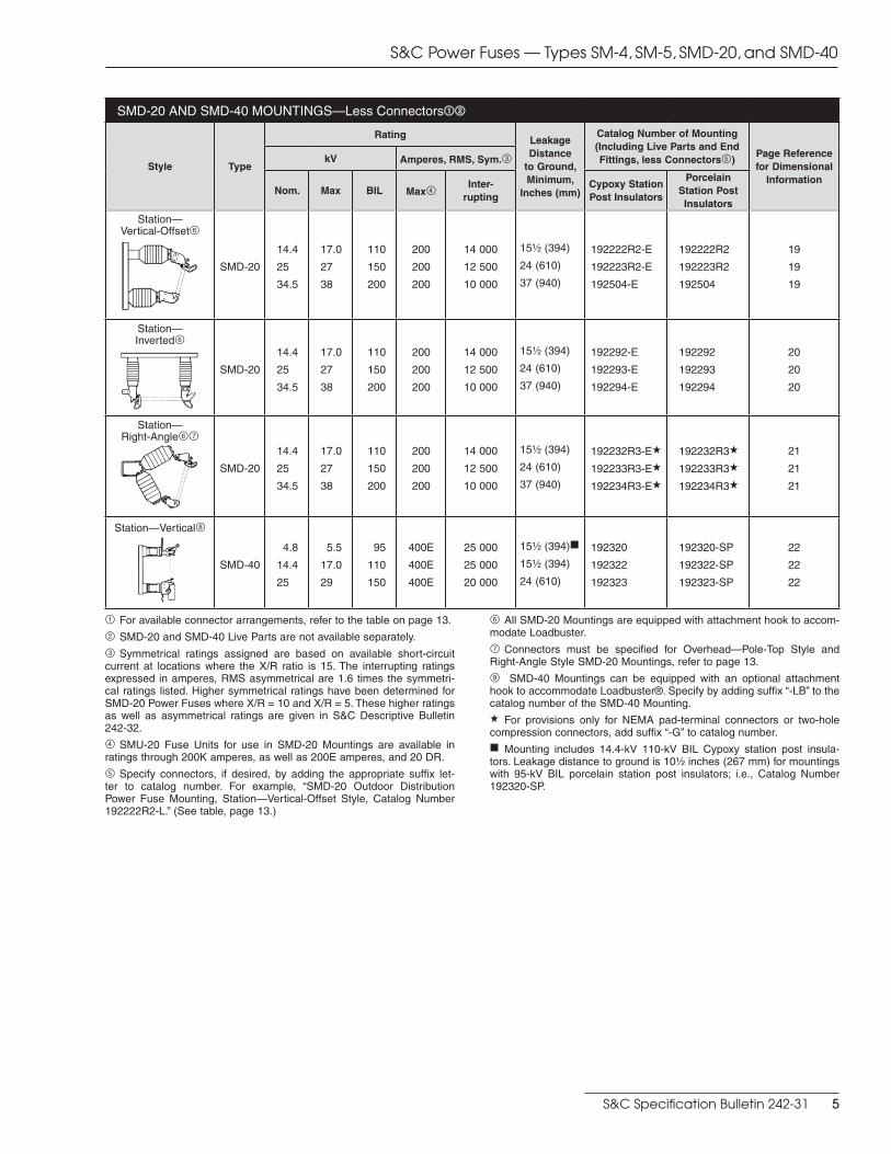
1 For available connector arrangements, refer to the table on page 13.
2 SMD-20 and SMD-40 Live Parts are not available separately.
3 Symmetrical ratings assigned are based on available short-circuit cur rent at locations where the X/R ratio is 15. The interrupting ratings expressed in amperes, RMS asymmetrical are 1.6 times the symmetrical ratings listed. Higher symmetrical ratings have been determined for SMD-20 Power Fuses where X/R = 10 and X/R = 5. These higher ratings as well as asymmetrical ratings are given in S&C Descriptive Bulletin 242-32.
4 SMU-20 Fuse Units for use in SMD-20 Mountings are available in ratings through 200K amperes, as well as 200E amperes, and 20 DR.
5 Specify connectors, if desired, by adding the appropriate suffix let-ter to catalog number. For example, “SMD-20 Outdoor Distribution Power Fuse Mounting, Station—Vertical-Offset Style, Catalog Number 192222R2-L.” (See table, page 13.)
6 All SMD-20 Mountings are equipped with attachment hook to accom-modate Loadbuster.
7 Connectors must be specified for Overhead—Pole-Top Style and Right-Angle Style SMD-20 Mountings, refer to the table on page 13.d Also suitable for protection of single-phase-to-neutral circuits (lines or transformers) on 20/34.5 GrY-kV systems.k Leakage distance to ground is 26 inches (660 mm) for Catalog Number 92143R3, 30 inches (762 mm) for Catalog Number 92123R3-P.a For provisions only for NEMA pad-terminal connectors or two-hole compression connectors, add suffix “-G” to catalog number.h Meets 170 kV BIL rating requirement of IEC Publication 282-2.
SMD-20 AND SMD-40 MOUNTINGS—Less Connectors12
Style Type
Rating Leakage Distance
to Ground, Minimum,
Inches (mm)
Mounting (including Live Parts and End Fittings,
less Connectors5) Page Reference for Dimensional
InformationkV
Amperes, RMS, Sym.3
Polymer Insulators
Porcelain Insulators
Nom. Max BIL Max4 Inter- rupting
Catalog Number
Catalog Number
Overhead—Pole-Top67
SMD-20
14.4
14.4
25d
25d
17.0
17.0
27
27
125
150
150
150
200
200
200
200
14 000
14 000
12 500
12 500
11 (279)
17 (432)
17 (432)
26 (660)k
—
92142R3-Pa
—
92123R3-Pa
92122R3a
92142R3a
92123R3a
92143R3ah
17
17
17
17
Overhead—Pole-Top67
SMD-20 34.5 38 200 200 10 000 25Z\x (648) — 92544R3a 18
S&C Power Fuses — Types SM-4, SM-5, SMD-20, and SMD-40
4 S&C Specification Bulletin 242-31
SMD-20 AND SMD-40 MOUNTINGS—Less Connectors12
Style Type
Rating Leakage Distance
to Ground, Minimum,
Inches (mm)
Catalog Number of Mounting (Including Live Parts and End Fittings, less Connectors5)
Page Reference for Dimensional
Information
kV Amperes, RMS, Sym.3
Nom. Max BIL Max4 Inter- rupting
Cypoxy Station Post Insulators
Porcelain Station Post Insulators
Station— Vertical-Offset6
SMD-20
14.4
25
34.5
17.0
27
38
110
150
200
200
200
200
14 000
12 500
10 000
15Z\x (394)
24 (610)
37 (940)
192222R2-E
192223R2-E
192504-E
192222R2
192223R2
192504
19
19
19
Station— Inverted6
SMD-20
14.4
25
34.5
17.0
27
38
110
150
200
200
200
200
14 000
12 500
10 000
15Z\x (394)
24 (610)
37 (940)
192292-E
192293-E
192294-E
192292
192293
192294
20
20
20
Station— Right-Angle67
SMD-20
14.4
25
34.5
17.0
27
38
110
150
200
200
200
200
14 000
12 500
10 000
15Z\x (394)
24 (610)
37 (940)
192232R3-Ea
192233R3-Ea
192234R3-Ea
192232R3a
192233R3a
192234R3a
21
21
21
Station—Vertical8
SMD-40
4.8
14.4
25
5.5
17.0
29
95
110
150
400E
400E
400E
25 000
25 000
20 000
15Z\x (394)f
15Z\x (394)
24 (610)
192320
192322
192323
192320-SP
192322-SP
192323-SP
22
22
22
1 For available connector arrangements, refer to the table on page 13.
2 SMD-20 and SMD-40 Live Parts are not available separately.
3 Symmetrical ratings assigned are based on available short-circuit cur rent at locations where the X/R ratio is 15. The interrupting ratings expressed in amperes, RMS asymmetrical are 1.6 times the symmetri-cal ratings listed. Higher symmetrical ratings have been determined for SMD-20 Power Fuses where X/R = 10 and X/R = 5. These higher ratings as well as asymmetrical ratings are given in S&C Descriptive Bulletin 242-32.
4 SMU-20 Fuse Units for use in SMD-20 Mountings are available in ratings through 200K amperes, as well as 200E amperes, and 20 DR.
5 Specify connectors, if desired, by adding the appropriate suffix let-ter to catalog number. For example, “SMD-20 Outdoor Distribution Power Fuse Mounting, Station—Vertical-Offset Style, Catalog Number 192222R2-L.” (See table, page 13.)
6 All SMD-20 Mountings are equipped with attachment hook to accom-modate Loadbuster.
7 Connectors must be specified for Overhead—Pole-Top Style and Right-Angle Style SMD-20 Mountings, refer to page 13.
8 SMD-40 Mountings can be equipped with an optional attachment hook to accommodate Loadbuster®. Specify by adding suffix “-LB” to the catalog number of the SMD-40 Mounting.a For provisions only for NEMA pad-terminal connectors or two-hole compression connectors, add suffix “-G” to catalog number.f Mounting includes 14.4-kV 110-kV BIL Cypoxy station post insula-tors. Leakage distance to ground is 10Z\x inches (267 mm) for mountings with 95-kV BIL porcelain station post insulators; i.e., Catalog Number 192320-SP.
S&C Power Fuses — Types SM-4, SM-5, SMD-20, and SMD-40
S&C Specification Bulletin 242-31 5

SM MOUNTINGS AND HOLDERS—Less Refill Units
Style Type
Rating Catalog Number Page
Reference for Dimensional Information
kVAmperes, RMS,
Sym.1Mounting2 (Including Live Parts, less
Connectors3 less Holder)Holder4
Nom. Max BIL MaxInter-
ruptingCypoxy Station Post Insulators
Porcelain Station Post Insulators
Disconnect 180° Opening
Vertical5SM-4
7.2
14.4
25
34.5
34.5
8.3
17.0
27
38
38
95
110
150
150
200
200E
200E
200E
200E
200E
15 600
12 500
9 400
6 250
6 250
190501R1-Ef
190502R1-E
190503R1-E
—
190504R1-E
190501R1
190502R1
190503R1
190054
190504R1
86051
86052
86053
86054
86054
23
23
23
23
23
SM-5
7.2
7.2
14.4
14.4
25
34.5
34.5
8.3
8.3
17.0
17.0
27
38
38
95
95
110
110
150
150
200
400E
720E
400E
720E
300E
300E
300E
26 000
26 000
34 000d
25 000k
20 000
17 500
17 500
190601R2-Ef
190561R3-Ef
190602R2-E
190562R3-E
190603R2-E
—
190604R2-E
190601R2
190561R3
190602R2
190562R3
190603R2
190064
190604R2
86151R2
86151R2l
86152R2
86152R2l
86153R2
86154R2
86154R2
24
25
24
25
24
24
24
Disconnect 90° Opening
Inverted
SM-5
7.2
14.4
25
34.5
34.5
8.3
17.0
27
38
38
95
110
150
150
200
400E
400E
300E
300E
300E
26 000
34 000d
20 000
17 500
17 500
190801R2-Ef
190802R2-E
190803R2-E
—
190804R2-E
190801R2
190802R2
190803R2
190084
190804R2
86191R2
86192R2
86193R2
86194R2
86194R2
26
26
26
26
26
Non-Disconnect Vertical
SM-4
7.2
14.4
25
34.5
34.5
8.3
17.0
27
38
38
95
110
150
150
200
200E
200E
200E
200E
200E
15 600
12 500
9 400
6 250
6 250
190301R1-Efh
190302R1-Eh
190303R1-Eh
—
190304R1-Eh
190301R1h
190302R1h
190303R1h
190034h
190304R1h
86041
86042
86043
86044
86044
SM-5
7.2
14.4
25
34.5
34.5
8.3
17.0
27
38
38
95
110
150
150
200
400E
400E
300E
300E
300E
26 000
34 000d
20 000
17 500
17 500
190401R2-Efh
190402R2-Eh
190403R2-Eh
—
190404R2-Eh
190401R2h
190402R2h
190403R2h
190044h
190404R2h
86141R2
86142R2
86143R2
86144R2
86144R2
Non-Disconnect Upright
SM-4
7.2
14.4
25
34.5
34.5
8.3
17.0
27
38
38
95
110
150
150
200
200E
200E
200E
200E
200E
15 600
12 500
9 400
6 250
6 250
190301R1-Efh
190302R1-Eh
190303R1-Eh
—
190304R1-Eh
190301R1h
190302R1h
190303R1h
190034h
190304R1h
86281h
86282
86283
86284h
86284h
SM-5
7.2
14.4
25
34.5
34.5
8.3
17.0
27
38
38
95
110
150
150
200
400E
400E
300E
300E
300E
26 000
34 000d
20 000
17 500
17 500
190401R2-Efh
190402R2-Eh
190403R2-Eh
—
190404R2-Eh
190401R2h
190402R2h
190403R2h
190044h
190404R2h
86381R2
86382R2
86383R2
86384R2
86384R2
1 Symmetrical ratings assigned are based on available short-circuit cur rent at locations where the X/R ratio is 15. The interrupting ratings expressed in amperes, RMS asymmetrical are 1.6 times the symmetri-cal ratings listed. Higher symmetrical ratings have been determined for these fuses applied at lower system voltages and in locations where X/R = 10 and X/R = 5. These higher ratings as well as asymmetrical ratings are given in S&C Descriptive Bulletin 242-30.
2 For live parts furnished separately, refer to the table on page 16.
3 For available connectors, refer to the table on page 14.
4 Holder does not carry Snuffler or Silencer.
5 All SM-4 Mountings in the Disconnect 180° Opening Vertical Style can be equipped with attachment hook to accommodate Loadbuster. Specify by adding suffix “-LB” to catalog number of the mounting.d 60-hertz rating. For systems rated above 15.5 kV through 17.0 kV, interrupting rating is 25,000 amperes, RMS symmetrical, 50/60 hertz.k 60-hertz rating.f Mounting includes 14.4-kV 110-kV BIL Cypoxy station post insulators. h Product discontinued.l Two holders required with each mounting.
S&C Power Fuses — Types SM-4, SM-5, SMD-20, and SMD-40
6 S&C Specification Bulletin 242-31
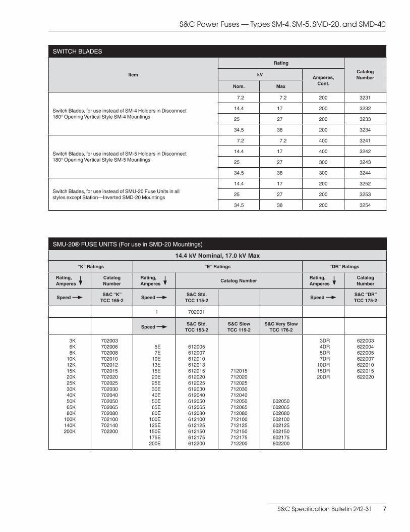
SWITCH BLADES
Item
Rating
Catalog Number
kVAmperes,
Cont.Nom. Max
Switch Blades, for use instead of SM-4 Holders in Disconnect 180° Opening Vertical Style SM-4 Mountings
7.2 7.2 200 3231
14.4 17 200 3232
25 27 200 3233
34.5 38 200 3234
Switch Blades, for use instead of SM-5 Holders in Disconnect 180° Opening Vertical Style SM-5 Mountings
7.2 7.2 400 3241
14.4 17 400 3242
25 27 300 3243
34.5 38 300 3244
Switch Blades, for use instead of SMU-20 Fuse Units in all styles except Station—Inverted SMD-20 Mountings
14.4 17 200 3252
25 27 200 3253
34.5 38 200 3254
SMU-20® FUSE UNITS (For use in SMD-20 Mountings)
14.4 kV Nominal, 17.0 kV Max
“K” Ratings “E” Ratings “DR” Ratings
Rating, Amperes
Catalog Number
Rating, Amperes
Catalog NumberRating, Amperes
Catalog Number
Speed S&C “K”
TCC 165-2Speed
S&C Std. TCC 115-2
Speed S&C “DR” TCC 175-2
1 702001
Speed S&C Std.
TCC 153-2S&C Slow TCC 119-2
S&C Very Slow TCC 176-2
3K6K8K
10K 12K 15K 20K 25K 30K 40K 50K 65K 80K
100K140K200K
702003702006702008702010702012702015702020702025702030702040702050702065702080702100702140702200
5E 7E
10E 13E 15E 20E 25E 30E 40E 50E 65E 80E
100E125E150E175E200E
612005612007612010612013612015612020612025612030612040612050612065612080612100612125612150612175612200
712015712020712025712030712040712050712065712080712100712125712150712175712200
602050602065602080602100602125602150602175602200
3DR4DR5DR7DR
10DR15DR20DR
622003622004622005622007622010622015622020
S&C Power Fuses — Types SM-4, SM-5, SMD-20, and SMD-40
S&C Specification Bulletin 242-31 7
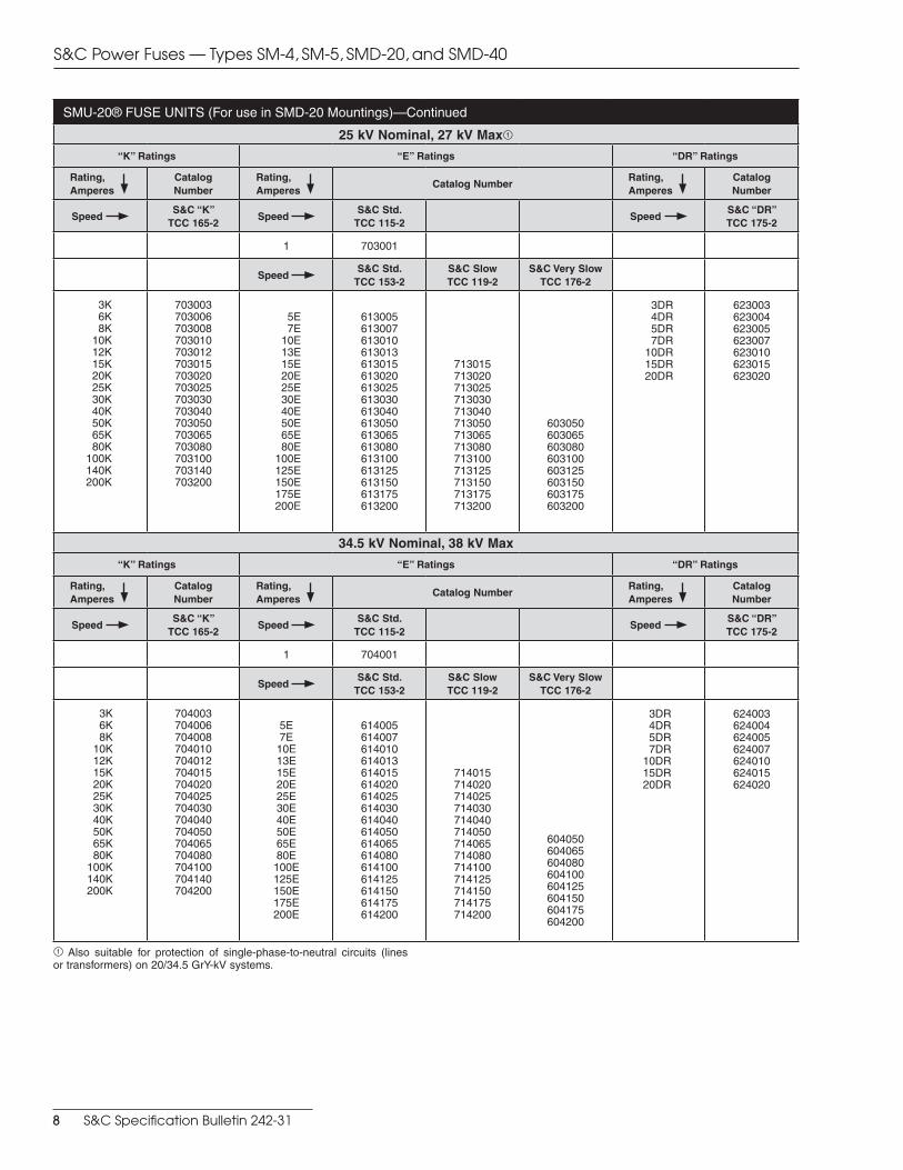
SMU-20® FUSE UNITS (For use in SMD-20 Mountings)—Continued
25 kV Nominal, 27 kV Max1
“K” Ratings “E” Ratings “DR” Ratings
Rating, Amperes
Catalog Number
Rating, Amperes
Catalog NumberRating, Amperes
Catalog Number
Speed S&C “K”
TCC 165-2Speed
S&C Std. TCC 115-2
Speed S&C “DR” TCC 175-2
1 703001
Speed S&C Std.
TCC 153-2S&C Slow TCC 119-2
S&C Very Slow TCC 176-2
3K6K8K
10K12K15K20K25K30K40K50K65K80K
100K140K200K
703003703006703008703010703012703015703020703025703030703040703050703065703080703100703140703200
5E7E
10E13E15E20E25E30E40E50E65E80E
100E125E150E175E200E
613005613007613010613013613015613020613025613030613040613050613065613080613100613125613150613175613200
713015713020713025713030713040713050713065713080713100713125713150713175713200
603050603065603080603100603125603150603175603200
3DR4DR5DR7DR
10DR15DR20DR
623003623004623005623007623010623015623020
34.5 kV Nominal, 38 kV Max
“K” Ratings “E” Ratings “DR” Ratings
Rating, Amperes
Catalog Number
Rating, Amperes
Catalog NumberRating, Amperes
Catalog Number
Speed S&C “K”
TCC 165-2Speed
S&C Std. TCC 115-2
Speed S&C “DR” TCC 175-2
1 704001
Speed S&C Std.
TCC 153-2S&C Slow TCC 119-2
S&C Very Slow TCC 176-2
3K6K8K
10K12K15K20K25K30K40K50K65K80K
100K140K200K
704003704006704008704010704012704015704020704025704030704040704050704065704080704100704140704200
5E7E
10E13E15E20E25E30E40E50E65E80E
100E125E150E175E200E
614005614007614010614013614015614020614025614030614040614050614065614080614100614125614150614175614200
714015714020714025714030714040714050714065714080714100714125714150714175714200
604050604065604080604100604125604150604175604200
3DR4DR5DR7DR
10DR15DR20DR
624003624004624005624007624010624015624020
1 Also suitable for protection of single-phase-to-neutral circuits (lines or transformers) on 20/34.5 GrY-kV systems.
S&C Power Fuses — Types SM-4, SM-5, SMD-20, and SMD-40
8 S&C Specification Bulletin 242-31
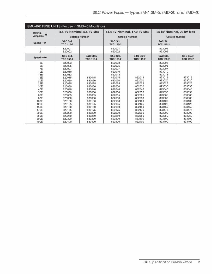
SMU-40® FUSE UNITS (For use in SMD-40 Mountings)
Rating, Amperes
4.8 kV Nominal, 5.5 kV Max 14.4 kV Nominal, 17.0 kV Max 25 kV Nominal, 29 kV Max
Catalog Number Catalog Number Catalog Number
Speed S&C Std.
TCC 115-2S&C Std.
TCC 115-2S&C Std.
TCC 115-2
12
820001820002
822001822002
823001823002
Speed S&C Std.
TCC 153-2S&C Slow TCC 119-2
S&C Std. TCC 153-2
S&C Slow TCC 119-2
S&C Std. TCC 153-2
S&C Slow TCC 119-2
3E5E7E
10E 13E 15E 20E 25E 30E 40E 50E 65E 80E100E125E150E175E200E250E300E400E
820003820005820007820010820013820015820020820025820030820040820050820065820080820100820125820150820175820200820250820300820400
830015830020830025830030830040830050830065830080830100830125830150830175830200830250830300830400
822003822005822007822010822013822015822020822025822030822040822050822065822080822100822125822150822175822200822250822300822400
832015832020832025832030832040832050832065832080832100832125832150832175832200832250832300832400
823003823005823007823010823013823015823020823025823030823040823050823065823080823100823125823150823175823200823250823300823400
833015833020833025833030833040833050833065833080833100833125833150833175833200833250833300833400
S&C Power Fuses — Types SM-4, SM-5, SMD-20, and SMD-40
S&C Specification Bulletin 242-31 9
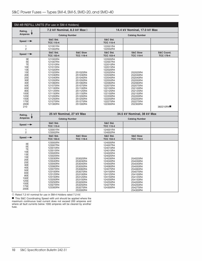
SM-4® REFILL UNITS (For use in SM-4 Holders)
Rating, Amperes
7.2 kV Nominal, 8.3 kV Max1 14.4 kV Nominal, 17.0 kV Max
Catalog Number Catalog Number
Speed S&C Std.
TCC 115-4S&C Std.
TCC 115-4
12
121001R4121002R4
122001R4122002R4
Speed S&C Std.
TCC 153-4S&C Slow TCC 119-4
S&C Std. TCC 153-4
S&C Slow TCC 119-4
S&C Coord. TCC 179-4
3E5E7E
10E 13E 15E 20E 25E 30E 40E 50E 65E 80E100E125E150E175E200E210
121005R4121007R4121010R4121015R4121020R4121025R4121030R4121040R4121050R4121060R4121075R4121100R4121125R4121150R4121200R4121250R4121275R4121300R4
251025R4251030R4251040R4251050R4251060R4251075R4251100R4251125R4251150R4251200R4251250R4251275R4251300R4
122005R4122007R4122010R4122015R4122020R4122025R4122030R4122040R4122050R4122060R4122075R4122100R4122125R4122150R4122200R4122250R4122275R4122300R4
252025R4252030R4252040R4252050R4252060R4252075R4252100R4252125R4252150R4252200R4252250R4252275R4252300R4
382210R4f
Rating, Amperes
25 kV Nominal, 27 kV Max 34.5 kV Nominal, 38 kV Max
Catalog Number Catalog Number
Speed S&C Std.
TCC 115-4S&C Std.
TCC 115-4
12
123001R4123002R4
124001R4124002R4
Speed S&C Std.
TCC 153-4S&C Slow TCC 119-4
S&C Std. TCC 153-4
S&C Slow TCC 119-4
3E5E7E
10E 13E 15E 20E 25E 30E 40E 50E 65E 80E100E125E150E175E200E
123005R4123007R4123010R4123015R4123020R4123025R4123030R4123040R4123050R4123060R4123075R4123100R4123125R4123150R4123200R4123250R4123275R4123300R4
253025R4253030R4253040R4253050R4253060R4253075R4253100R4253125R4253150R4253200R4253250R4253275R4253300R4
124005R4124007R4124010R4124015R4124020R4124025R4124030R4124040R4124050R4124060R4124075R4124100R4124125R4124150R4124200R4124250R4124275R4124300R4
254025R4254030R4254040R4254050R4254060R4254075R4254100R4254125R4254150R4254200R4254250R4254275R4254300R4
1 Rated 7.2 kV nominal for use in SM-4 Holders rated 7.2 kV.f This S&C Coordinating Speed refill unit should be applied where the maximum continuous load current does not exceed 200 amperes and where all fault currents below 1000 amperes will be cleared by another fuse.
S&C Power Fuses — Types SM-4, SM-5, SMD-20, and SMD-40
10 S&C Specification Bulletin 242-31
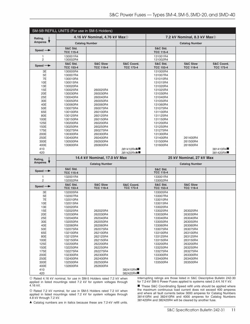
SM-5® REFILL UNITS (For use in SM-5 Holders)
Rating, Amperes
4.16 kV Nominal, 4.76 kV Max1 7.2 kV Nominal, 8.3 kV Max2
Catalog Number Catalog Number
Speed S&C Std.
TCC 115-4S&C Std.
TCC 115-4
12
130001R4130002R4
131001R4131002R4
Speed S&C Std.
TCC 153-4S&C Slow TCC 119-4
S&C Coord. TCC 173-4
S&C Std. TCC 153-4
S&C Slow TCC 119-4
S&C Coord. TCC 173-4
3E5E7E
10E 13E 15E 20E 25E 30E 40E 50E 65E 80E100E125E150E175E200E250E300E400E
130005R4130007R4130010R4130015R4130020R4130025R4130030R4130040R4130050R4130060R4130075R4130100R4130125R4130150R4130200R4130250R4130275R4130300R4130400R4130500R4130600R4
260025R4260030R4260040R4260050R4260060R4260075R4260100R4260125R4260150R4260200R4260250R4260275R4260300R4260400R4260500R4260600R4
131005R4131007R4131010R4131015R4131020R4131025R4131030R4131040R4131050R4131060R4131075R4131100R4131125R4131150R4131200R4131250R4131275R4131300R4131400R4131500R4131600R4
261400R4261500R4261600R4
410420
381410R4df381420R4df
381410R4f381420R4f
Rating, Amperes
14.4 kV Nominal, 17.0 kV Max 25 kV Nominal, 27 kV Max
Catalog Number Catalog Number
Speed S&C Std.
TCC 115-4S&C Std.
TCC 115-4
12
132001R4132002R4
133001R4133002R4
Speed S&C Std. TCC 153-4
S&C Slow TCC 119-4
S&C Coord. TCC 173-4
S&C Std. TCC 153-4
S&C Slow TCC 119-4
3E5E7E
10E 13E 15E 20E 25E 30E 40E 50E 65E 80E100E125E150E175E200E250E300E400E410420
132005R4132007R4132010R4132015R4132020R4132025R4132030R4132040R4132050R4132060R4132075R4132100R4132125R4132150R4132200R4132250R4132275R4132300R4132400R4132500R4132600R4
262025R4262030R4262040R4262050R4262060R4262075R4262100R4262125R4262150R4262200R4262250R4262275R4262300R4262400R4262500R4262600R4
382410R4f382420R4f
133005R4133007R4133010R4133015R4133020R4133025R4133030R4133040R4133050R4133060R4133075R4133100R4133125R4133150R4133200R4133250R4133275R4133300R4133400R4133500R4
263025R4263030R4263040R4263050R4263060R4263075R4263100R4263125R4263150R4263200R4263250R4263275R4263300R4263400R4263500R4
1 Rated 4.16 kV nominal, for use in SM-5 Holders rated 7.2 kV when applied in listed mountings rated 7.2 kV for system voltages through 4.16 kV.
2 Rated 7.2 kV nominal, for use in SM-5 Holders rated 7.2 kV when applied in listed mountings rated 7.2 kV for system voltages through 4.8 kV through 7.2 kV.d Catalog numbers are in italics because these are 7.2-kV refill units.
Interrupting ratings are those listed in S&C Descriptive Bulletin 242-30 for 7.2-kV SM-5 Power Fuses applied to systems rated 2.4/4.16 Y kV.f These S&C Coordinating Speed refill units should be applied where the maximum continuous load current does not exceed 400 amperes and where all fault currents below 3000 amperes for Catalog Numbers 381410R4 and 382410R4 and 4000 amperes for Catalog Numbers 381420R4 and 382420R4 will be cleared by another fuse.
S&C Power Fuses — Types SM-4, SM-5, SMD-20, and SMD-40
S&C Specification Bulletin 242-31 11
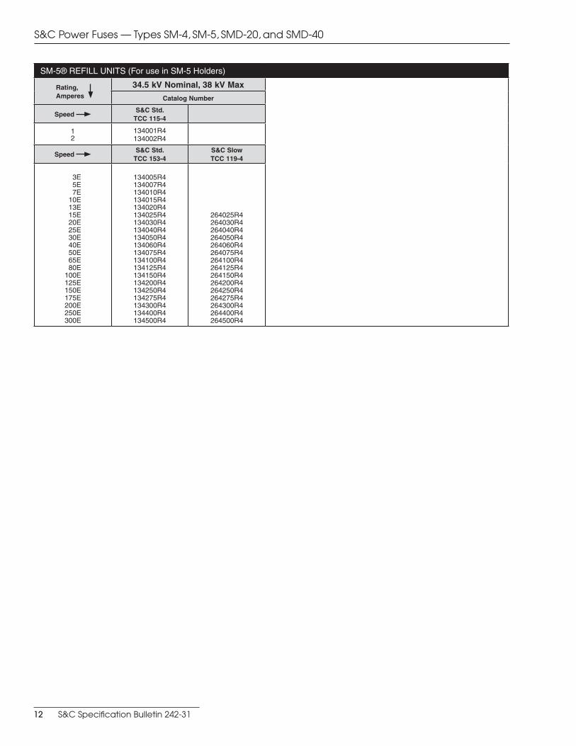
SM-5® REFILL UNITS (For use in SM-5 Holders)
Rating, Amperes
34.5 kV Nominal, 38 kV Max
Catalog Number
Speed S&C Std.
TCC 115-4
12
134001R4134002R4
Speed S&C Std.
TCC 153-4S&C Slow TCC 119-4
3E5E7E
10E13E15E20E25E30E40E50E65E80E
100E125E150E175E200E250E300E
134005R4134007R4134010R4134015R4134020R4134025R4134030R4134040R4134050R4134060R4134075R4134100R4134125R4134150R4134200R4134250R4134275R4134300R4134400R4134500R4
264025R4264030R4264040R4264050R4264060R4264075R4264100R4264125R4264150R4264200R4264250R4264275R4264300R4264400R4264500R4
S&C Power Fuses — Types SM-4, SM-5, SMD-20, and SMD-40
12 S&C Specification Bulletin 242-31
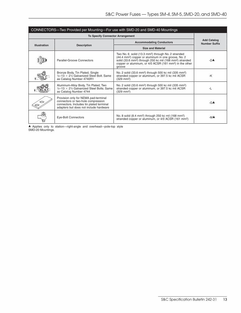
CONNECTORS—Two Provided per Mounting—For use with SMD-20 and SMD-40 Mountings
To Specify Connector Arrangement
Add Catalog Number SuffixIllustration Description
Accommodating Conductors
Size and Material
Parallel-Groove Connectors
Two No. 6 solid (13.3 mm2) through No. 2 stranded (44.4 mm2) copper or aluminum in one groove, No. 2 solid (33.6 mm2) through 250 kc mil (168 mm2) stranded copper or aluminum, or 4/0 ACSR (161 mm2) in the other groove
-Dd
Bronze Body, Tin Plated, Single Z\x –13 3 2Z\x Galvanized Steel Bolt. Same as Catalog Number 4740R1
No. 2 solid (33.6 mm2) through 500 kc mil (335 mm2) stranded copper or aluminum, or 397.5 kc mil ACSR (329 mm2)
-K
Aluminum-Alloy Body, Tin Plated, Two Z\x –13 3 2Z\x Galvanized Steel Bolts. Same as Catalog Number 4744
No. 2 solid (33.6 mm2) through 500 kc mil (335 mm2) stranded copper or aluminum, or 397.5 kc mil ACSR(329 mm2)
-L
Provision only for NEMA pad-terminal connectors or two-hole compression connectors. Includes tin plated terminal adapters but does not include hardware
-Gd
Eye-Bolt Connectors No. 8 solid (8.4 mm2) through 250 kc mil (168 mm2) stranded copper or aluminum, or 4/0 ACSR (161 mm2) -Md
d Applies only to station—right-angle and overhead—pole-top style SMD-20 Mountings.
S&C Power Fuses — Types SM-4, SM-5, SMD-20, and SMD-40
S&C Specification Bulletin 242-31 13
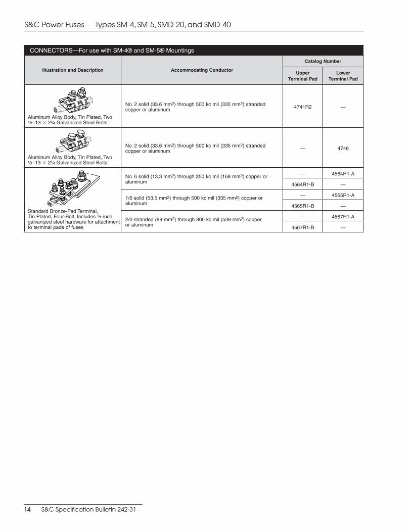
CONNECTORS—For use with SM-4® and SM-5® Mountings
Illustration and Description Accommodating Conductor
Catalog Number
Upper Terminal Pad
Lower Terminal Pad
Aluminum Alloy Body, Tin Plated, Two Z\x –13 3 2C\v Galvanized Steel Bolts
No. 2 solid (33.6 mm2) through 500 kc mil (335 mm2) stranded copper or aluminum 4741R2 —
Aluminum Alloy Body, Tin Plated, Two Z\x –13 3 2Z\v Galvanized Steel Bolts
No. 2 solid (33.6 mm2) through 500 kc mil (335 mm2) stranded copper or aluminum — 4746
Standard Bronze-Pad Terminal, Tin Plated, Four-Bolt. Includes Z\x-inch galvanized steel hardware for attachment to terminal pads of fuses
No. 6 solid (13.3 mm2) through 250 kc mil (168 mm2) copper or aluminum
— 4564R1-A
4564R1-B —
1/0 solid (53.5 mm2) through 500 kc mil (335 mm2) copper or aluminum
— 4565R1-A
4565R1-B —
2/0 stranded (89 mm2) through 800 kc mil (539 mm2) copper or aluminum
— 4567R1-A
4567R1-B —
S&C Power Fuses — Types SM-4, SM-5, SMD-20, and SMD-40
14 S&C Specification Bulletin 242-31
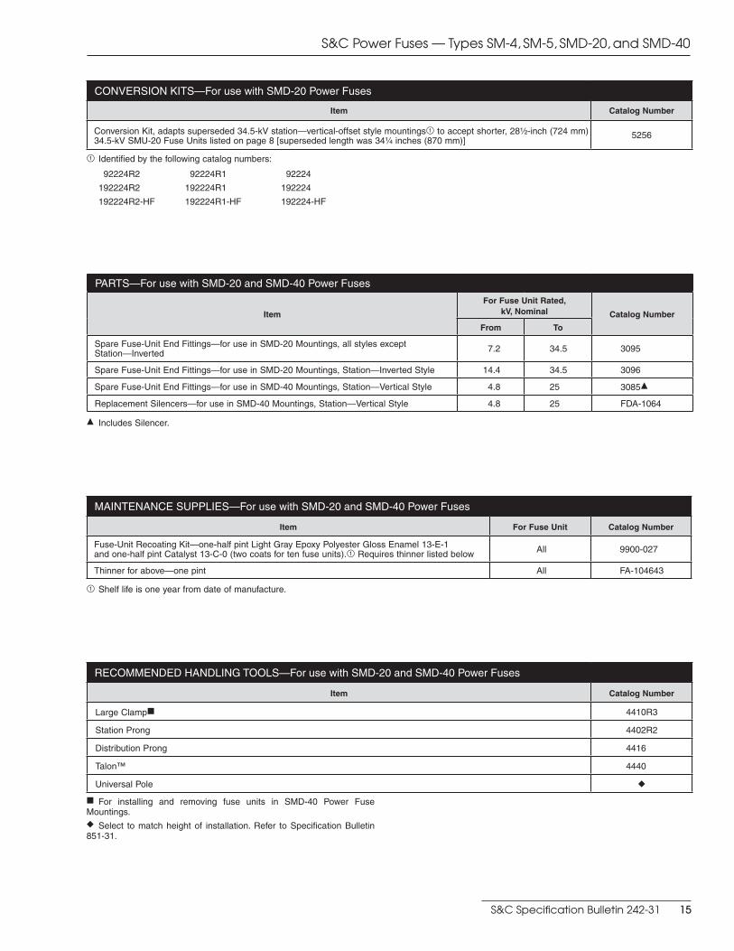
MAINTENANCE SUPPLIES—For use with SMD-20 and SMD-40 Power Fuses
Item For Fuse Unit Catalog Number
Fuse-Unit Recoating Kit—one-half pint Light Gray Epoxy Polyester Gloss Enamel 13-E-1 and one-half pint Catalyst 13-C-0 (two coats for ten fuse units).1 Requires thinner listed below All 9900-027
Thinner for above—one pint All FA-104643
1 Shelf life is one year from date of manufacture.
CONVERSION KITS—For use with SMD-20 Power Fuses
Item Catalog Number
Conversion Kit, adapts superseded 34.5-kV station—vertical-offset style mountings1 to accept shorter, 28Z\x-inch (724 mm) 34.5-kV SMU-20 Fuse Units listed on page 8 [superseded length was 34Z\v inches (870 mm)]
5256
1 Identified by the following catalog numbers:
92224R2
192224R2
192224R2-HF
92224R1
192224R1
192224R1-HF
92224
192224
192224-HF
PARTS—For use with SMD-20 and SMD-40 Power Fuses
Item
For Fuse Unit Rated, kV, Nominal Catalog Number
From To
Spare Fuse-Unit End Fittings—for use in SMD-20 Mountings, all styles exceptStation—Inverted 7.2 34.5 3095
Spare Fuse-Unit End Fittings—for use in SMD-20 Mountings, Station—Inverted Style 14.4 34.5 3096
Spare Fuse-Unit End Fittings—for use in SMD-40 Mountings, Station—Vertical Style 4.8 25 3085d
Replacement Silencers—for use in SMD-40 Mountings, Station—Vertical Style 4.8 25 FDA-1064
d Includes Silencer.
RECOMMENDED HANDLING TOOLS—For use with SMD-20 and SMD-40 Power Fuses
Item Catalog Number
Large Clampf 4410R3
Station Prong 4402R2
Distribution Prong 4416
Talon™ 4440
Universal Pole l
f For installing and removing fuse units in SMD-40 Power Fuse Mount ings.l Select to match height of installation. Refer to Specification Bulletin 851-31.
S&C Power Fuses — Types SM-4, SM-5, SMD-20, and SMD-40
S&C Specification Bulletin 242-31 15
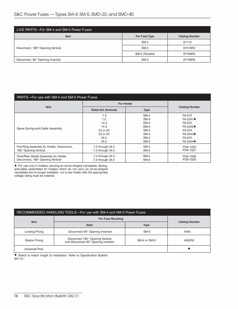
LIVE PARTS—For SM-4 and SM-5 Power Fuses
Item For Fuse Type Catalog Number
Disconnect, 180° Opening Vertical
SM-4 87119
SM-5 87519R2
SM-5 (Parallel) 87169R3
Disconnect, 90° Opening Inverted SM-5 87199R2
PARTS—For use with SM-4 and SM-5 Power Fuses
ItemFor Holder
Catalog NumberRated (kV, Nominal) Type
Spare Spring-and-Cable Assembly
7.27.214.414.4
23 or 2523 or 25
34.534.5
SM-4SM-5SM-4SM-5SM-4SM-5SM-4SM-5
FA-972FA-2341dFA-973FA-2342dFA-974FA-2343dFA-975FA-2344d
Pull-Ring Assembly for Holder, Disconnect, 180° Opening Vertical
7.2 through 34.57.2 through 34.5
SM-4SM-5
FDA-1025FDA-1027
Pivot/Rain Shield Assembly for Holder,Disconnect, 180° Opening Vertical
7.2 through 34.57.2 through 34.5
SM-4SM-5
FDA-1028FDA-1029
d For use only in holders carrying an arrow-shaped nameplate. Spring-and-cable assemblies for holders which do not carry an arrow-shaped nameplate are no longer available—so a new holder with the appropriate voltage rating must be ordered.
l Select to match height of installation. Refer to Specification Bulletin 851-31.
RECOMMENDED HANDLING TOOLS—For use with SM-4 and SM-5 Power Fuses
ItemFor Fuse Mounting
Catalog NumberStyle Type
Locking Prong Disconnect 90° Opening Inverted SM-5 4404
Station Prong Disconnect 180° Opening Verticaland Disconnect 90° Opening Inverted SM-4 or SM-5 4402R2
Universal Pole l
S&C Power Fuses — Types SM-4, SM-5, SMD-20, and SMD-40
16 S&C Specification Bulletin 242-31
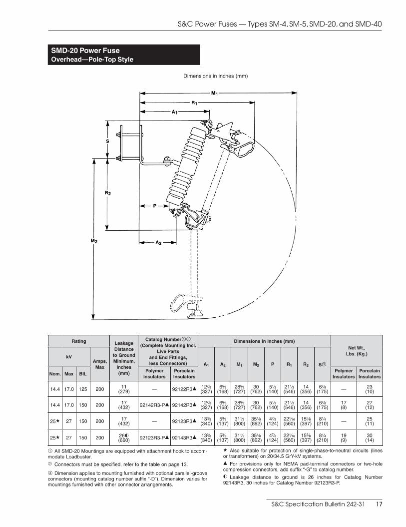
SMD-20 Power FuseOverhead—Pole-Top Style
Dimensions in inches (mm)
Rating Leakage Distance
to Ground Minimum,
Inches (mm)
Catalog Number12 (Complete Mounting Incl.
Live Parts and End Fittings, less Connectors)
Dimensions in Inches (mm)Net Wt.,
Lbs. (Kg.)kV
Amps, Max
A1 A2 M1 M2 P R1 R2 S3
Nom. Max BILPolymer
InsulatorsPorcelain Insulators
Polymer Insulators
Porcelain Insulators
14.4 17.0 125 200 11(279) — 92122R3d 12M\,
(327)6B\,
(168)28B\,(727)
30(762)
5Z\x(140)
21Z\x(546)
14(356)
6M\,(175) — 23
(10)
14.4 17.0 150 200 17(432) 92142R3-Pd 92142R3d 12M\,
(327)6B\,
(168)28B\,(727)
30(762)
5Z\x(140)
21Z\x(546)
14(356)
6M\,(175)
17(8)
27(12)
25a 27 150 200 17(432) — 92123R3d 13C\,
(340)5C\,
(137)31Z\x(800)
35Z\,(892)
4M\,(124)
22Z\zn(560)
15B\,(397)
8Z\v(210) — 25
(11)
25a 27 150 200 26j(660) 92123R3-Pd 92143R3d 13C\,
(340)5C\,
(137)31Z\x(800)
35Z\,(892)
4M\,(124)
22Z\zn(560)
15B\,(397)
8Z\v(210)
19(9)
30(14)
1 All SMD-20 Mountings are equipped with attachment hook to accom-modate Loadbuster.2 Connectors must be specified, refer to the table on page 13.
3 Dimension applies to mounting furnished with optional parallel-groove connectors (mounting catalog number suffix “-D”). Dimension varies for mountings furnished with other connector arrangements.
a Also suitable for protection of single-phase-to-neutral circuits (lines or transformers) on 20/34.5 GrY-kV systems.d For provisions only for NEMA pad-terminal connectors or two-hole compression connectors, add suffix “-G” to catalog number.j Leakage distance to ground is 26 inches for Catalog Number 92143R3, 30 inches for Catalog Number 92123R3-P.
S&C Power Fuses — Types SM-4, SM-5, SMD-20, and SMD-40
S&C Specification Bulletin 242-31 17
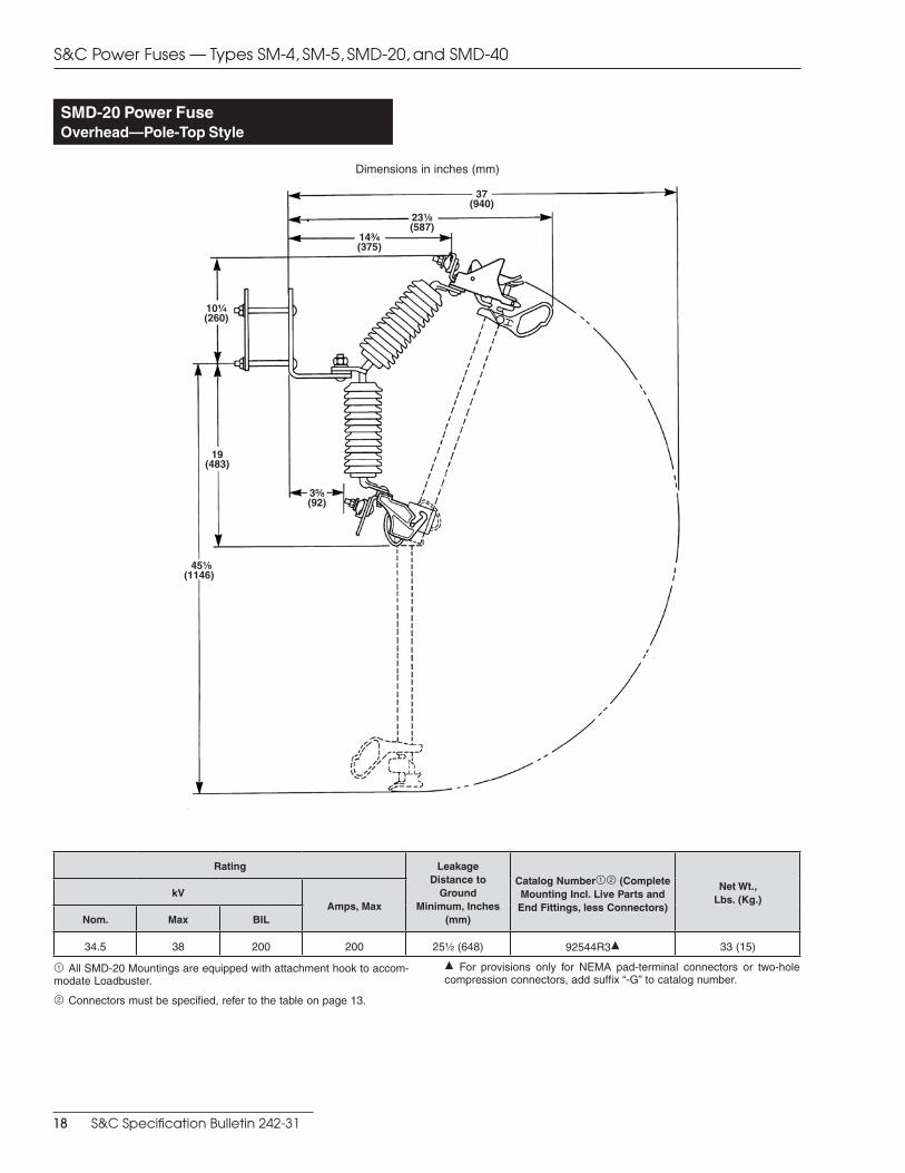
37(940)
19 (483)
10Z\v (260)
45Z\, (1146)
3B\,(92)
23Z\,(587)
14C\v(375)
SMD-20 Power FuseOverhead—Pole-Top Style
Dimensions in inches (mm)
Rating Leakage Distance to
Ground Minimum, Inches
(mm)
Catalog Number12 (Complete Mounting Incl. Live Parts and End Fittings, less Connectors)
Net Wt., Lbs. (Kg.)
kVAmps, Max
Nom. Max BIL
34.5 38 200 200 25Z\x (648) 92544R3d 33 (15)
1 All SMD-20 Mountings are equipped with attachment hook to accom-modate Loadbuster.
2 Connectors must be specified, refer to the table on page 13.
d For provisions only for NEMA pad-terminal connectors or two-hole compression connectors, add suffix “-G” to catalog number.
S&C Power Fuses — Types SM-4, SM-5, SMD-20, and SMD-40
18 S&C Specification Bulletin 242-31
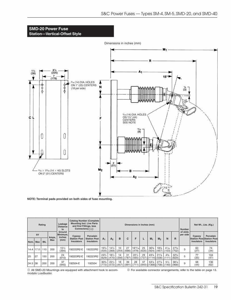
SMD-20 Power FuseStation—Vertical-Offset Style
NOTE: Terminal pads provided on both sides of fuse mounting.
>\zn (14) DIA. HOLESON 10 (25) CENTERS (18 per side)
>\zn (14) DIA. HOLESON 1C\v0 (44)CENTERSSEE NOTE
>\zn 3 1>\zn (14 3 40) SLOTSON 20 (51) CENTERS
8M\,(225)
2(51)
1Z\x(38)
B\zn(8)
7(178)
Z\, (3)
Dimensions in inches (mm)
Rating Leakage Distance
to Ground
Minimum, Inches (mm)
Catalog Number (Complete Mounting Incl. Live Parts
and End Fittings, less Connectors)12
Dimensions in Inches (mm)
Number of slots per side
Net Wt., Lbs. (Kg.)
kVAmps, Max
Cypoxy Station Post Insulators
Porcelain Station Post Insulators
A1 A2 B C F L M1 M2 N RCypoxy
Station Post Insulators
Porcelain Station Post InsulatorsNom. Max BIL
14.4 17.0 110 200 15Z\x(394) 192222R2-E 192222R2 19M\,
(505)14Z\x(368)
10(254)
27(686)
18ZC\zn(478)
25(635)
36C\,(924)
18C\,(467)
4Z\zn(103)
27B\,(702) 3 60
(27)74
(34)
25 27 150 200 24(610) 192223R2-E 192223R2 24C\v
(629)18Z\x(470)
14(356)
31(787)
22Z\v(565)
29(737)
43M\,(1114)
21M\,(556)
4C\,(111)
32B\,(829) 5 77
(35)104(47)
34.5 38 200 200 37(940) 192504-E 192504 30C\,
(772)22Z\x(572)
18(457)
39(991)
28(711)
37(940)
53M\,(1368)
27M\,(708)
5Z\x(140)
38Z\,(968) 9 98
(44)136(62)
1 All SMD-20 Mountings are equipped with attachment hook to accom-modate Loadbuster.
2 For available connector arrangements, refer to the table on page 13.
S&C Power Fuses — Types SM-4, SM-5, SMD-20, and SMD-40
S&C Specification Bulletin 242-31 19
>\zn (14) DIA. HOLESON 10 (25) CENTERS
>\zn (14) DIA. HOLESON 1C\v0 (44)CENTERS
>\zn 3 1>\zn SLOTS(14 3 40)
8M\,
(225)2
(51)1Z\x
(38)7
(178)
3Z\x (89)
C\v (19)
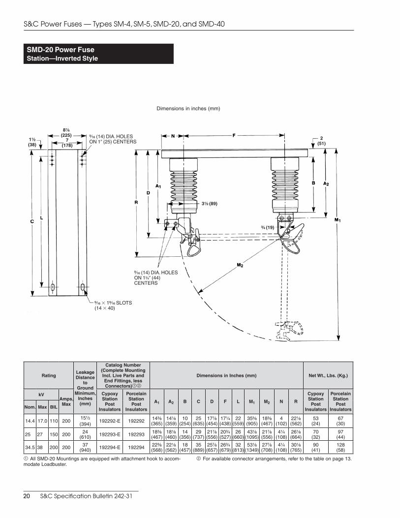
SMD-20 Power FuseStation—Inverted Style
Dimensions in inches (mm)
RatingLeakage Distance
to Ground
Minimum, Inches (mm)
Catalog Number (Complete Mounting Incl. Live Parts and End Fittings, less Connectors)12
Dimensions in Inches (mm) Net Wt., Lbs. (Kg.)
kVAmps, Max
Cypoxy Station
Post Insulators
Porcelain Station
Post Insulators
A1 A2 B C D F L M1 M2 N R
Cypoxy Station
Post Insulators
Porcelain Station
Post InsulatorsNom. Max BIL
14.4 17.0 110 20015Z\x
(394)192292-E 192292 14C\,
(365)14Z\,(359)
10(254)
25(635)
17M\,(454)
17Z\v(438)
22(559)
35B\,(905)
18C\,(467)
4(102)
22Z\,(562)
53(24)
67(30)
25 27 150 200 24(610) 192293-E 192293 18C\,
(467)18Z\,(460)
14(356)
29(737)
21M\,(556)
20C\v(527)
26(660)
43Z\,(1095)
21M\,(556)
4Z\v(108)
26Z\,(664)
70(32)
97(44)
34.5 38 200 200 37(940) 192294-E 192294 22C\,
(568)22Z\,(562)
18(457)
35(889)
25M\,(657)
26C\v(679)
32(813)
53Z\,(1349)
27M\,(708)
4Z\v(108)
30Z\,(765)
90(41)
128(58)
1 All SMD-20 Mountings are equipped with attachment hook to accom-modate Loadbuster.
2 For available connector arrangements, refer to the table on page 13.
S&C Power Fuses — Types SM-4, SM-5, SMD-20, and SMD-40
20 S&C Specification Bulletin 242-31

ZZ\zn (17) DIA. HOLES
3Z\x(89)
2Z\x(64)
2Z\x(64)
3 (76)
1 (25)
5 (127)
1Z\x(38)
ZZ\zn (17) DIA. HOLES (4)
1(25)
3(76)
3(76)
3(76)
1 (25)
1 (25)
SMD-20 Power FuseStation—Right-Angle Style
Dimensions in inches (mm)
Rating Leakage Distance
to Ground Minimum,
Inches (mm)
Catalog Number (Complete Mounting Incl. Live Parts
and End Fittings, less Connectors)12
Dimensions in Inches (mm) Net Wt., Lbs. (Kg.)
kVAmps, Max
Cypoxy Station Post Insulators
Porcelain Station Post Insulators
A1 A2 B M1 M2 R1 R2
Cypoxy Station
Post Insulators
Porcelain Station
Post Insulators
Nom. Max BIL
14.4 17.0 110 200 15Z\x(394) 192232R3-Ed 192232R3d 21B\,
(549)17
(432)10
(254)39Z\x
(1003)35Z\v(895)
30B\,(778)
17B\,(448)
50(23)
64(29)
25 27 150 200 24(610) 192233R3-Ed 192233R3d 25C\v
(654)20C\,(518)
14(356)
46C\,(1178)
41Z\x(1054)
34C\v(883)
20C\,(518)
60(27)
87(39)
34.5 38 200 200 37(940) 192234R3-Ed 192234R3d 29Z\,
(740)22Z\,(562)
18(457)
54Z\,(1375)
51Z\,(1299)
38Z\,(968)
24(610)
72(33)
110(50)
1 All SMD-20 Mountings are equipped with attachment hook to accom-modate Loadbuster.
2 Connectors must be specified, refer to the table on page 13.
d For provisions only for NEMA pad-terminal connectors or two-hole compression connectors, add suffix “-G” to catalog number.
S&C Power Fuses — Types SM-4, SM-5, SMD-20, and SMD-40
S&C Specification Bulletin 242-31 21
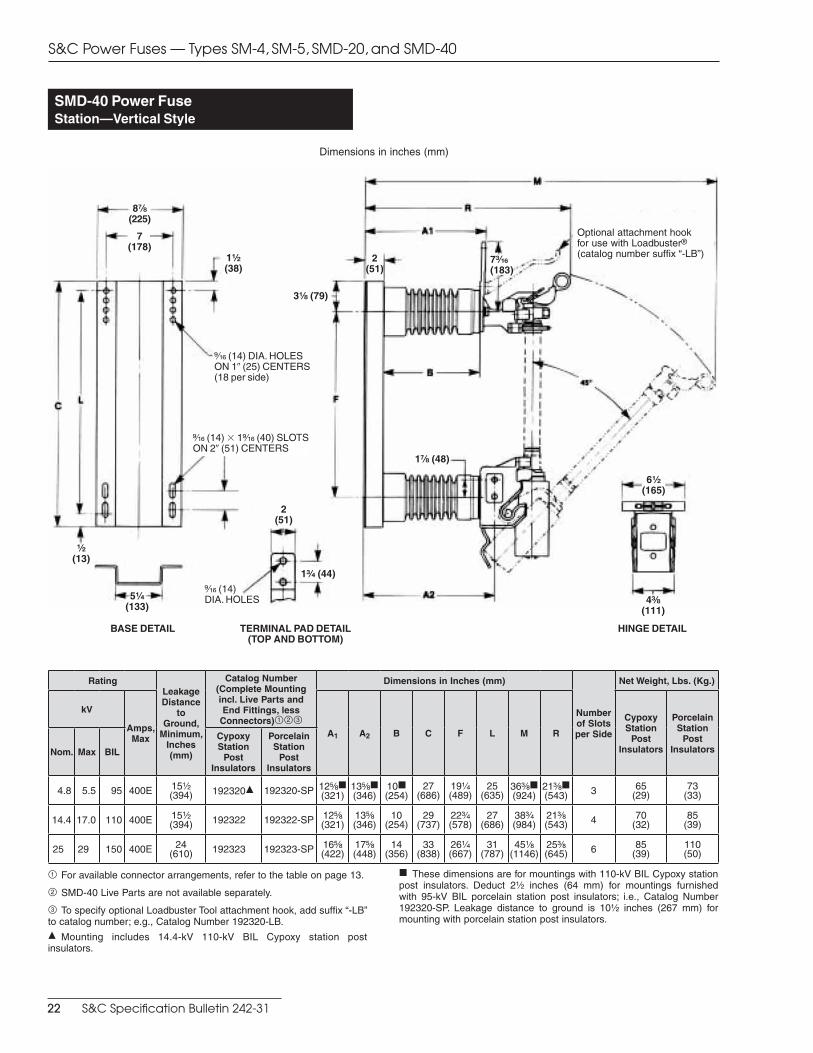
SMD-40 Power FuseStation—Vertical Style
Dimensions in inches (mm)
RatingLeakage Distance
to Ground,
Minimum, Inches (mm)
Catalog Number (Complete Mounting incl. Live Parts and End Fittings, less
Connectors)123
Dimensions in Inches (mm)
Number of Slots per Side
Net Weight, Lbs. (Kg.)
kV
Amps, Max A1 A2 B C F L M R
Cypoxy Station
Post Insulators
Porcelain Station
Post InsulatorsNom. Max BIL
Cypoxy Station
Post Insulators
Porcelain Station
Post Insulators
4.8 5.5 95 400E 15Z\x(394) 192320d 192320-SP 12B\,f
(321)13B\,f(346)
10f(254)
27(686)
19Z\v(489)
25(635)
36C\,f(924)
21C\,f(543) 3 65
(29)73
(33)
14.4 17.0 110 400E 15Z\x(394) 192322 192322-SP 12B\,
(321)13B\,(346)
10(254)
29(737)
22C\v(578)
27(686)
38C\v(984)
21C\,(543) 4 70
(32)85
(39)
25 29 150 400E 24(610) 192323 192323-SP 16B\,
(422)17B\,(448)
14(356)
33(838)
26Z\v(667)
31(787)
45Z\,(1146)
25C\,(645) 6 85
(39)110(50)
1 For available connector arrangements, refer to the table on page 13.
2 SMD-40 Live Parts are not available separately.
3 To specify optional Loadbuster Tool attachment hook, add suffix “-LB” to catalog number; e.g., Catalog Number 192320-LB.d Mounting includes 14.4-kV 110-kV BIL Cypoxy station post insulators.
f These dimensions are for mountings with 110-kV BIL Cypoxy station post insulators. Deduct 2Z\x inches (64 mm) for mountings furnished with 95-kV BIL porcelain station post insulators; i.e., Catalog Number 192320-SP. Leakage distance to ground is 10Z\x inches (267 mm) for mounting with porcelain station post insulators.
TERMINAL PAD DETAIL (TOP AND BOTTOM)
BASE DETAIL HINGE DETAIL
6Z\x(165)
>\zn (14) DIA. HOLES ON 10 (25) CENTERS (18 per side)
>\zn (14) 3 1>\zn (40) SLOTS ON 20 (51) CENTERS
4C\, (111)
8M\,(225)
7(178)
1Z\x (38)
2(51)
5Z\v(133)
Z\x (13)
1C\v (44)
1M\, (48)
3Z\, (79)
2(51)
7C\zn(183)
>\zn (14) DIA. HOLES
Optional attachment hook for use with Loadbuster® (catalog number suffix “-LB”)
S&C Power Fuses — Types SM-4, SM-5, SMD-20, and SMD-40
22 S&C Specification Bulletin 242-31
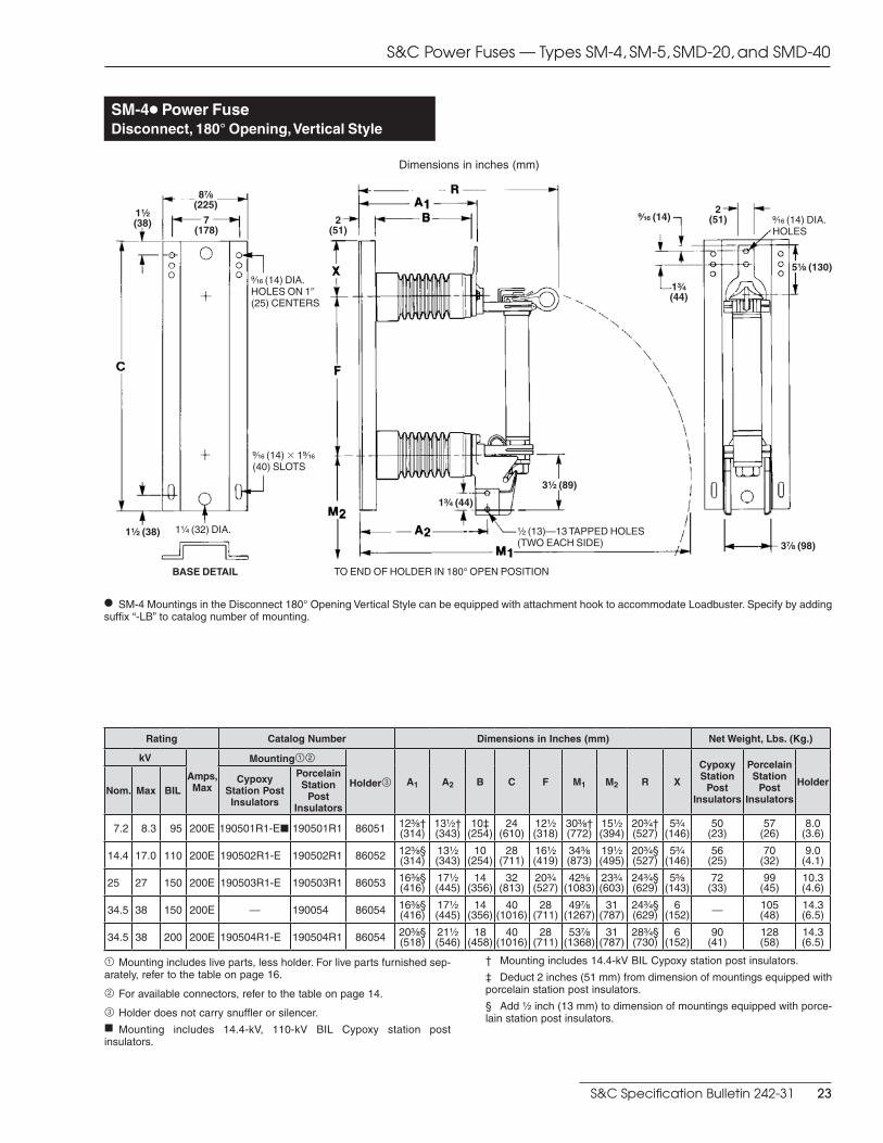
SM-4h Power FuseDisconnect, 180° Opening, Vertical Style
Dimensions in inches (mm)
h SM-4 Mountings in the Disconnect 180° Opening Vertical Style can be equipped with attachment hook to accommodate Loadbuster. Specify by add ing suffix “-LB” to catalog number of mounting.
1Z\x(38)
8M\,(225)
1C\v (44)
1C\v (44)
3Z\x (89)
3M\, (98)
5Z\, (130)>\zn (14) DIA. HOLES ON 10 (25) CENTERS
>\zn (14) DIA. HOLES
1Z\v (32) DIA.
BASE DETAIL
1Z\x (38)
>\zn (14) 3 1>\zn (40) SLOTS
>\zn (14)
Z\x (13)—13 TAPPED HOLES (TWO EACH SIDE)
TO END OF HOLDER IN 180° OPEN POSITION
7(178)
2 (51)
2 (51)
Rating Catalog Number Dimensions in Inches (mm) Net Weight, Lbs. (Kg.)
kV
Amps, Max
Mounting12
Holder3 A1 A2 B C F M1 M2 R X
Cypoxy Station
Post Insulators
Porcelain Station
Post Insulators
HolderNom. Max BIL
Cypoxy Station Post Insulators
Porcelain Station
Post Insulators
7.2 8.3 95 200E 190501R1-Ej 190501R1 86051 12C\,†(314)
13Z\x†(343)
10‡(254)
24(610)
12Z\x(318)
30C\,†(772)
15Z\x(394)
20C\v†(527)
5C\v(146)
50(23)
57(26)
8.0(3.6)
14.4 17.0 110 200E 190502R1-E 190502R1 86052 12C\,§(314)
13Z\x(343)
10(254)
28(711)
16Z\x(419)
34C\,(873)
19Z\x(495)
20C\v§(527)
5C\v(146)
56(25)
70(32)
9.0(4.1)
25 27 150 200E 190503R1-E 190503R1 86053 16C\,§(416)
17Z\x(445)
14(356)
32(813)
20C\v(527)
42B\,(1083)
23C\v(603)
24C\v§(629)
5B\,(143)
72(33)
99(45)
10.3(4.6)
34.5 38 150 200E — 190054 86054 16C\,§(416)
17Z\x(445)
14(356)
40(1016)
28(711)
49M\,(1267)
31(787)
24C\v§(629)
6(152) — 105
(48)14.3(6.5)
34.5 38 200 200E 190504R1-E 190504R1 86054 20C\,§(518)
21Z\x(546)
18(458)
40(1016)
28(711)
53M\,(1368)
31(787)
28C\v§(730)
6(152)
90(41)
128(58)
14.3(6.5)
1 Mounting includes live parts, less holder. For live parts furnished sep-arately, refer to the table on page 16.
2 For available connectors, refer to the table on page 14.
3 Holder does not carry snuffler or silencer.f Mounting includes 14.4-kV, 110-kV BIL Cypoxy station post insulators.
† Mounting includes 14.4-kV BIL Cypoxy station post insulators.
‡ Deduct 2 inches (51 mm) from dimension of mountings equipped with porcelain station post insulators.
§ Add Z\x inch (13 mm) to dimension of mountings equipped with porce-lain station post insulators.
S&C Power Fuses — Types SM-4, SM-5, SMD-20, and SMD-40
S&C Specification Bulletin 242-31 23
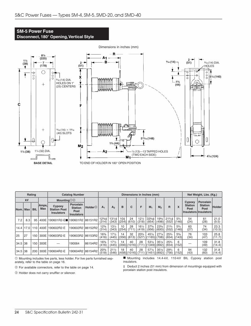
SM-5 Power FuseDisconnect, 180° Opening, Vertical Style
Dimensions in inches (mm)
1Z\x(38)
8M\,(225)
1C\v (44)
1C\v (44)
5ZC\zn (148)
4M\, (124)
5Z\x (140)>\zn (14) DIA. HOLES ON 10 (25) CENTERS
>\zn (14) DIA. HOLES
1Z\v (32) DIA.
BASE DETAIL
1Z\x (38)
>\zn (14) 3 1>\zn (40) SLOTS
>\zn (14)
Z\x (13)—13 TAPPED HOLES (TWO EACH SIDE)
TO END OF HOLDER IN 180° OPEN POSITION
7(178)
2 (51)
2 (51)
Rating Catalog Number Dimensions in Inches (mm) Net Weight, Lbs. (Kg.)
kV
Amps, Max
Mounting12
Holder3 A1 A2 B C F M1 M2 R X
Cypoxy Station
Post Insulators
Porcelain Station
Post Insulators
HolderNom. Max BIL
Cypoxy Station Post Insulators
Porcelain Station
Post Insulators
7.2 8.3 95 400E 190601R2-Ej 190601R2 86151R2 12C\,‡(314)
13Z\x‡(343)
10‡(254)
24(610)
12Z\x(318)
33B\,‡(854)
19B\,(498)
21C\v‡(552)
5C\v(146)
54(24)
61(28)
21.0(9.5)
14.4 17.0 110 400E 190602R2-E 190602R2 86152R2 12C\,(314)
13Z\x(343)
10(254)
28(711)
16Z\x(419)
37B\,(956)
23B\,(600)
21C\v(552)
5C\v(146)
60(27)
74(34)
23.3(10.5)
25 27 150 300E 190603R2-E 190603R2 86153R2 16C\,(416)
17Z\x(445)
14(356)
32(813)
20C\v(527)
45M\,(1165)
27M\,(708)
25C\v(654)
5B\,(143)
76(34)
103(47)
25.8(11.7)
34.5 38 150 300E — 190064 86154R2 16C\,(416)
17Z\x(445)
14(356)
40(1016)
28(711)
53Z\,(1349)
35Z\,(892)
25C\v(654)
6(152) — 109
(49)31.8
(14.4)
34.5 38 200 300E 190604R2-E 190604R2 86154R2 20C\,(518)
21Z\x(546)
18(458)
40(1016)
28(711)
57Z\,(1451)
35Z\,(892)
29C\v(756)
6(152)
94(43)
132(60)
31.8(14.4)
1 Mounting includes live parts, less holder. For live parts furnished sep-arately, refer to the table on page 16.
2 For available connectors, refer to the table on page 14.
3 Holder does not carry snuffler or silencer.
f Mounting includes 14.4-kV, 110-kV BIL Cypoxy station post insulators.
‡ Deduct 2 inches (51 mm) from dimension of mountings equipped with porcelain station post insulators.
S&C Power Fuses — Types SM-4, SM-5, SMD-20, and SMD-40
24 S&C Specification Bulletin 242-31
1Z\x(38)
1Z\v (32) DIA.
>\zn (14) 3 1>\zn (40) SLOTS
>\zn (14) DIA. HOLES ON 10 (25) CEN TERS
1Z\x(38)
7(178)
8M\,(225)
5C\v (146)
10 (254) 10(254)
>\zn (14) DIA. HOLES
11Z\,
(283)
3(76) B\,
(16)
1C\v (44)
3 (76)
2(51)
B\, (16)
6 (152)
>\zn (14) DIA. HOLES
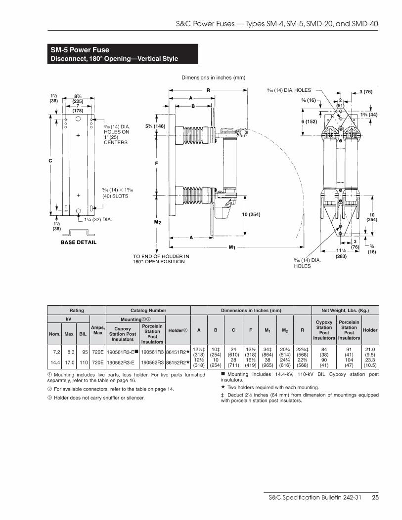
SM-5 Power FuseDisconnect, 180° Opening—Vertical Style
Dimensions in inches (mm)
Rating Catalog Number Dimensions in Inches (mm) Net Weight, Lbs. (Kg.)
kV
Amps, Max
Mounting12
Holder3 A B C F M1 M2 R
Cypoxy Station
Post Insulators
Porcelain Station
Post Insulators
HolderNom. Max BIL
Cypoxy Station Post Insulators
Porcelain Station
Post Insulators
7.2
14.4
8.3
17.0
95
110
720E
720E
190561R3-Ef
190562R3-E
190561R3
190562R3
86151R2a
86152R2a
12Z\x‡(318)12Z\x(318)
10‡(254)
10(254)
24(610)
28(711)
12Z\x(318)16Z\x(419)
34‡(864)
38(965)
20Z\v(514)24Z\v(616)
22C\,‡(568)22C\,(568)
84(38)90
(41)
91(41)104(47)
21.0(9.5)23.3
(10.5)
1 Mounting includes live parts, less holder. For live parts furnished separately, refer to the table on page 16.
2 For available connectors, refer to the table on page 14.
3 Holder does not carry snuffler or silencer.
f Mounting includes 14.4-kV, 110-kV BIL Cypoxy station post insulators. a Two holders required with each mounting.
‡ Deduct 2Z\x inches (64 mm) from dimension of mountings equipped with porcelain station post insulators.
S&C Power Fuses — Types SM-4, SM-5, SMD-20, and SMD-40
S&C Specification Bulletin 242-31 25

1Z\x (38) 1Z\x (38)
7(178)
8M\, (225)
1Z\v (32) DIA.>\zn (14) 3 1>\zn (40) SLOTS >\zn (14) DIA. HOLES ON
10 (25) CENTERS
2 (51)
1C\v (44)
>\zn (14) DIA. HOLES
5Z\,(130)3Z\v
(83)
3C\v (95)
>\zn (14)
1C\v(44)
Z\x (13)–13TAPPED HOLES(TWO EACHSIDE)
SM-5 Power FuseDisconnect, 90° Opening, Inverted Style
Dimensions in inches (mm)
Rating Catalog Number Dimensions in Inches (mm) Net Weight, Lbs. (Kg.)
kV
Amps, Max
Mounting12
Holder3 A1 A2 B C F M R X
Cypoxy Station
Post Insulators
Porcelain Station
Post Insulators
HolderNom. Max BIL
Cypoxy Station Post Insulators
Porcelain Station
Post Insulators
7.2 8.3 95 400E 190801R2-Ef 190801R2 86191R2 12C\,‡(314)
13Z\x‡(343)
10‡(254)
24(610)
12Z\x(318)
39C\,‡(1000)
20M\,‡(530)
5C\v(146)
53(24)
60(27)
23.5(10.7)
14.4 17.0 110 400E 190802R2-E 190802R2 86192R2 12C\,(314)
13Z\x(343)
10(254)
28(711)
16Z\x(419)
43C\,(1102)
20M\,(530)
5C\v(146)
59(27)
73(33)
25.8(11.7)
25 27 150 300E 190803R2-E 190803R2 86193R2 16C\,(416)
17Z\x(445)
14(356)
32(813)
20C\v(527)
51B\,(1311)
24M\,(632)
5B\,(143)
75(34)
102(46)
28.3(12.8)
34.5 38 150 300E — 190084 86194R2 16C\,(416)
17Z\x(445)
14(356)
40(1016)
28(711)
62M\,(1597)
24M\,(632)
6(152) — 108
(49)34.3
(15.5)
34.5 38 200 300E 190804R2-E 190804R2 86194R2 20C\,(518)
21Z\x(546)
18(458)
40(1016)
28(711)
62M\,(1597)
28M\,(733)
6(152)
93(42)
131(59)
34.3(15.5)
1 Mounting includes live parts, less holder. For live parts furnished sep-arately, refer to the table on page 16.
2 For available connectors, refer to the table on page 14.
3 Holder does not carry snuffler or silencer.
f Mounting includes 14.4-kV, 110-kV BIL Cypoxy station post insulators.
‡ Deduct 2 inches (51 mm) from dimension of mountings equipped with porcelain station post insulators.
S&C Power Fuses — Types SM-4, SM-5, SMD-20, and SMD-40
26 S&C Specification Bulletin 242-31


Prin
ted
in U
.S.A
.