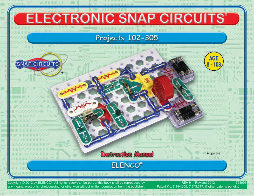
Project 242 - Elenco Electronics
288
Copyright © 2012 by ELENCO ® All rights reserved. No part of this book shall be reproduced by 753098 any means; electronic, photocopying, or otherwise without written permission from the publisher. REV-H Revised 2012 Patent #‘s: 7,144,255, 7,273,377, & other patents pending Project 242
-
Upload
khangminh22 -
Category
Documents
-
view
0 -
download
0
Transcript of Project 242 - Elenco Electronics
Copyright © 2012 by ELENCO® All rights reserved. No part of this book shall be reproduced by 753098any means; electronic, photocopying, or otherwise without written permission from the publisher.
REV-H Revised 2012Patent #‘s: 7,144,255, 7,273,377, & other patents pending
Project 242
-1-
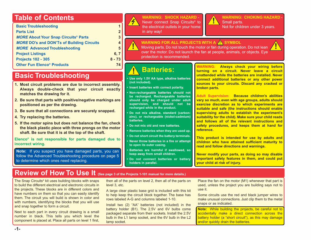
Table of ContentsBasic Troubleshooting 1Parts List 2MORE About Your Snap Circuits® Parts 3MORE DO’s and DON’Ts of Building Circuits 4MORE Advanced Troubleshooting 5Project Listings 6, 7Projects 102 - 305 8 - 73Other Fun Elenco® Products 74
1. Most circuit problems are due to incorrect assembly.Always double-check that your circuit exactlymatches the drawing for it.
2. Be sure that parts with positive/negative markings arepositioned as per the drawing.
3. Be sure that all connections are securely snapped.
4. Try replacing the batteries.
5. If the motor spins but does not balance the fan, checkthe black plastic piece with three prongs on the motorshaft. Be sure that it is at the top of the shaft.
Elenco® is not responsible for parts damaged due toincorrect wiring.
Basic Troubleshooting
Note: If you suspect you have damaged parts, you canfollow the Advanced Troubleshooting procedure on page 5to determine which ones need replacing.
Review of How To Use It (See page 3 of the Projects 1-101 manual for more details.)
The Snap Circuits® kit uses building blocks with snapsto build the different electrical and electronic circuits inthe projects. These blocks are in different colors andhave numbers on them so that you can easily identifythem. The circuit you will build is shown in color andwith numbers, identifying the blocks that you will useand snap together to form a circuit.
Next to each part in every circuit drawing is a smallnumber in black. This tells you which level thecomponent is placed at. Place all parts on level 1 first,
then all of the parts on level 2, then all of the parts onlevel 3, etc.
A large clear plastic base grid is included with this kitto help keep the circuit block together. The base hasrows labeled A-G and columns labeled 1-10.
Install two (2) “AA” batteries (not included) in thebattery holder (B1). The 2.5V and 6V bulbs comepackaged separate from their sockets. Install the 2.5Vbulb in the L1 lamp socket, and the 6V bulb in the L2lamp socket.
Place the fan on the motor (M1) whenever that part isused, unless the project you are building says not touse it.
Some circuits use the red and black jumper wires tomake unusual connections. Just clip them to the metalsnaps or as indicated.
Note: While building the projects, be careful not toaccidentally make a direct connection across thebattery holder (a “short circuit”), as this may damageand/or quickly drain the batteries.
WARNING: SHOCK HAZARD -Never connect Snap Circuits® tothe electrical outlets in your homein any way!
WARNING FOR ALL PROJECTS WITH A SYMBOLMoving parts. Do not touch the motor or fan during operation. Do not leanover the motor. Do not launch the fan at people, animals, or objects. Eyeprotection is recommended.
!!
WARNING: CHOKING HAZARD - Small parts.Not for children under 3 years.
!
Batteries:• Use only 1.5V AA type, alkaline batteries
(not included).
• Insert batteries with correct polarity.
• Non-rechargeable batteries should notbe recharged. Rechargeable batteriesshould only be charged under adultsupervision, and should not berecharged while in the product.
• Do not mix alkaline, standard (carbon-zinc), or rechargeable (nickel-cadmium)batteries.
• Do not mix old and new batteries.
• Remove batteries when they are used up.
• Do not short circuit the battery terminals.
• Never throw batteries in a fire or attemptto open its outer casing.
• Batteries are harmful if swallowed, sokeep away from small children.
• Do not connect batteries or batteryholders in parallel.
!WARNING: Always check your wiring beforeturning on a circuit. Never leave a circuitunattended while the batteries are installed. Neverconnect additional batteries or any other powersources to your circuits. Discard any cracked orbroken parts.
Adult Supervision: Because children’s abilitiesvary so much, even with age groups, adults shouldexercise discretion as to which experiments aresuitable and safe (the instructions should enablesupervising adults to establish the experiment’ssuitability for the child). Make sure your child readsand follows all of the relevant instructions andsafety procedures, and keeps them at hand forreference.
This product is intended for use by adults andchildren who have attained sufficient maturity toread and follow directions and warnings.
Never modify your parts, as doing so may disableimportant safety features in them, and could putyour child at risk of injury.
!
-2-
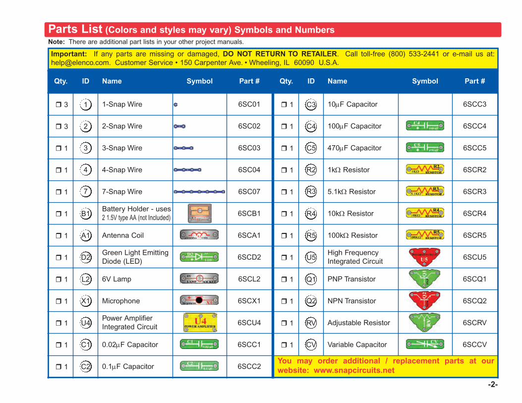
Qty. ID Name Symbol Part # Qty. ID Name Symbol Part #
r 3 1-Snap Wire 6SC01 r 1 10μF Capacitor 6SCC3
r 3 2-Snap Wire 6SC02 r 1 100μF Capacitor 6SCC4
r 1 3-Snap Wire 6SC03 r 1 470μF Capacitor 6SCC5
r 1 4-Snap Wire 6SC04 r 1 1kΩ Resistor 6SCR2
r 1 7-Snap Wire 6SC07 r 1 5.1kΩ Resistor 6SCR3
r 1Battery Holder - uses2 1.5V type AA (not Included) 6SCB1 r 1 10kΩ Resistor 6SCR4
r 1 Antenna Coil 6SCA1 r 1 100kΩ Resistor 6SCR5
r 1Green Light EmittingDiode (LED) 6SCD2 r 1
High FrequencyIntegrated Circuit 6SCU5
r 1 6V Lamp 6SCL2 r 1 PNP Transistor 6SCQ1
r 1 Microphone 6SCX1 r 1 NPN Transistor 6SCQ2
r 1Power AmplifierIntegrated Circuit 6SCU4 r 1 Adjustable Resistor 6SCRV
r 1 0.02μF Capacitor 6SCC1 r 1 Variable Capacitor 6SCCV
r 1 0.1μF Capacitor 6SCC2You may order additional / replacement parts at ourwebsite: www.snapcircuits.net
D2
A1
B1
7
4
3
2
1
L2
X1
U4
C1
C2
U5
R5
R4
R3
R2
C5
C4
C3
Q1
Q2
RV
CV
Note: There are additional part lists in your other project manuals.
Important: If any parts are missing or damaged, DO NOT RETURN TO RETAILER. Call toll-free (800) 533-2441 or e-mail us at:[email protected]. Customer Service • 150 Carpenter Ave. • Wheeling, IL 60090 U.S.A.
Parts List (Colors and styles may vary) Symbols and Numbers
-3-
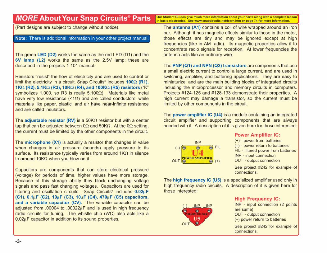
(Part designs are subject to change without notice).
Note: There is additional information in your other project manual.
The green LED (D2) works the same as the red LED (D1) and the6V lamp (L2) works the same as the 2.5V lamp; these aredescribed in the projects 1-101 manual.
Resistors “resist” the flow of electricity and are used to control orlimit the electricity in a circuit. Snap Circuits® includes 100Ω (R1),1KΩ (R2), 5.1KΩ (R3), 10KΩ (R4), and 100KΩ (R5) resistors (“K”symbolizes 1,000, so R3 is really 5,100Ω). Materials like metalhave very low resistance (<1Ω) and are called conductors, whilematerials like paper, plastic, and air have near-infinite resistanceand are called insulators.
The adjustable resistor (RV) is a 50KΩ resistor but with a centertap that can be adjusted between 0Ω and 50KΩ. At the 0Ω setting,the current must be limited by the other components in the circuit.
The microphone (X1) is actually a resistor that changes in valuewhen changes in air pressure (sounds) apply pressure to itssurface. Its resistance typically varies from around 1KΩ in silenceto around 10KΩ when you blow on it.
Capacitors are components that can store electrical pressure(voltage) for periods of time, higher values have more storage.Because of this storage ability they block unchanging voltagesignals and pass fast changing voltages. Capacitors are used forfiltering and oscillation circuits. Snap Circuits® includes 0.02μF(C1), 0.1μF (C2), 10μF (C3), 10μF (C4), 470μF (C5) capacitors,and a variable capacitor (CV). The variable capacitor can beadjusted from .00004 to .00022μF and is used in high frequencyradio circuits for tuning. The whistle chip (WC) also acts like a0.02μF capacitor in addition to its sound properties.
The antenna (A1) contains a coil of wire wrapped around an ironbar. Although it has magnetic effects similar to those in the motor,those effects are tiny and may be ignored except at highfrequencies (like in AM radio). Its magnetic properties allow it toconcentrate radio signals for reception. At lower frequencies theantenna acts like an ordinary wire.
The PNP (Q1) and NPN (Q2) transistors are components that usea small electric current to control a large current, and are used inswitching, amplifier, and buffering applications. They are easy tominiaturize, and are the main building blocks of integrated circuitsincluding the microprocessor and memory circuits in computers.Projects #124-125 and #128-133 demonstrate their properties. Ahigh current may damage a transistor, so the current must belimited by other components in the circuit.
The power amplifier IC (U4) is a module containing an integratedcircuit amplifier and supporting components that are alwaysneeded with it. A description of it is given here for those interested:
MORE About Your Snap Circuits® Parts
The high frequency IC (U5) is a specialized amplifier used only inhigh frequency radio circuits. A description of it is given here forthose interested:
INPFIL
(+)OUT
(–)
Power Amplifier IC:(+) - power from batteries(–) - power return to batteriesFIL - filtered power from batteriesINP - input connectionOUT - output connection
See project #242 for example ofconnections.
High Frequency IC:INP - input connection (2 pointsare same)OUT - output connection (–) power return to batteries
See project #242 for example ofconnections.
INP INP(–)
OUT
Our Student Guides give much more information about your parts along with a complete lessonin basic electronics. See www.snapcircuits.net/learn.htm or page 74 for more information.
-4-
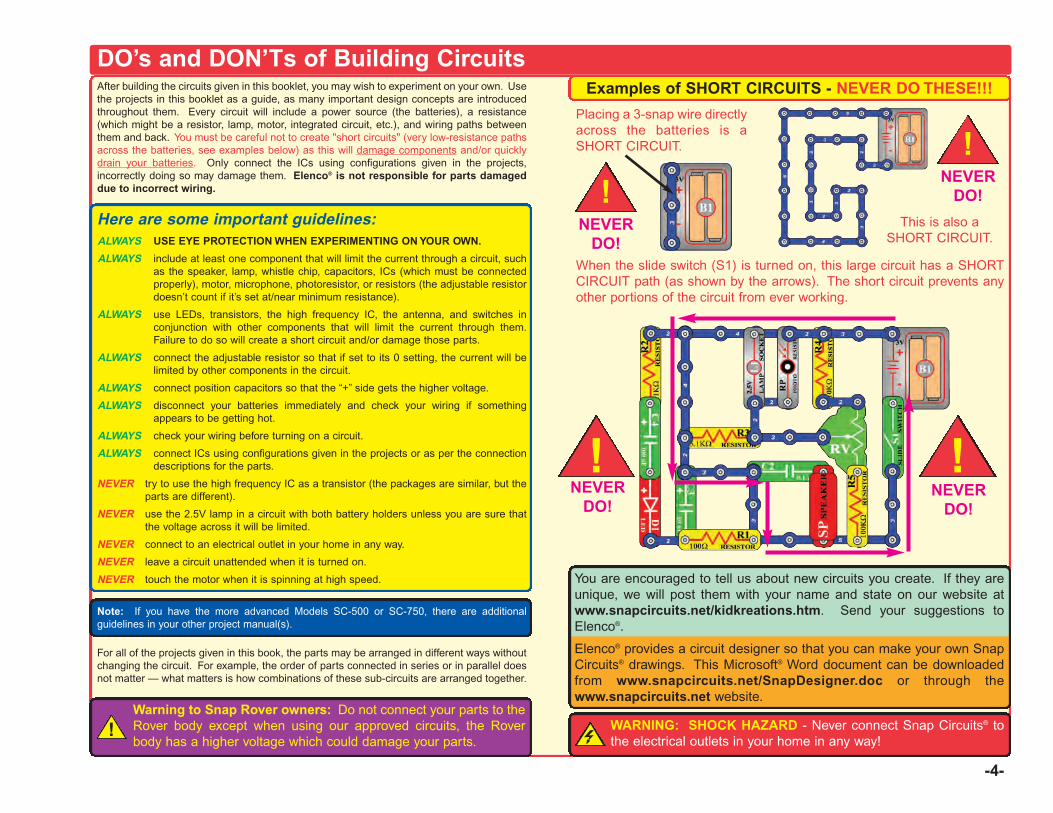
DO’s and DON’Ts of Building CircuitsAfter building the circuits given in this booklet, you may wish to experiment on your own. Usethe projects in this booklet as a guide, as many important design concepts are introducedthroughout them. Every circuit will include a power source (the batteries), a resistance(which might be a resistor, lamp, motor, integrated circuit, etc.), and wiring paths betweenthem and back. You must be careful not to create "short circuits" (very low-resistance pathsacross the batteries, see examples below) as this will damage components and/or quicklydrain your batteries. Only connect the ICs using configurations given in the projects,incorrectly doing so may damage them. Elenco® is not responsible for parts damageddue to incorrect wiring.
Here are some important guidelines:ALWAYS USE EYE PROTECTION WHEN EXPERIMENTING ON YOUR OWN.
ALWAYS include at least one component that will limit the current through a circuit, suchas the speaker, lamp, whistle chip, capacitors, ICs (which must be connectedproperly), motor, microphone, photoresistor, or resistors (the adjustable resistordoesn’t count if it’s set at/near minimum resistance).
ALWAYS use LEDs, transistors, the high frequency IC, the antenna, and switches inconjunction with other components that will limit the current through them.Failure to do so will create a short circuit and/or damage those parts.
ALWAYS connect the adjustable resistor so that if set to its 0 setting, the current will belimited by other components in the circuit.
ALWAYS connect position capacitors so that the “+” side gets the higher voltage.
ALWAYS disconnect your batteries immediately and check your wiring if somethingappears to be getting hot.
ALWAYS check your wiring before turning on a circuit.
ALWAYS connect ICs using configurations given in the projects or as per the connectiondescriptions for the parts.
NEVER try to use the high frequency IC as a transistor (the packages are similar, but theparts are different).
NEVER use the 2.5V lamp in a circuit with both battery holders unless you are sure thatthe voltage across it will be limited.
NEVER connect to an electrical outlet in your home in any way.
NEVER leave a circuit unattended when it is turned on.
NEVER touch the motor when it is spinning at high speed.
Note: If you have the more advanced Models SC-500 or SC-750, there are additionalguidelines in your other project manual(s).
For all of the projects given in this book, the parts may be arranged in different ways withoutchanging the circuit. For example, the order of parts connected in series or in parallel doesnot matter — what matters is how combinations of these sub-circuits are arranged together.
Examples of SHORT CIRCUITS - NEVER DO THESE!!!
You are encouraged to tell us about new circuits you create. If they areunique, we will post them with your name and state on our website atwww.snapcircuits.net/kidkreations.htm. Send your suggestions toElenco®.
Elenco® provides a circuit designer so that you can make your own SnapCircuits® drawings. This Microsoft® Word document can be downloadedfrom www.snapcircuits.net/SnapDesigner.doc or through thewww.snapcircuits.net website.
WARNING: SHOCK HAZARD - Never connect Snap Circuits® tothe electrical outlets in your home in any way!
Placing a 3-snap wire directlyacross the batteries is aSHORT CIRCUIT.
This is also aSHORT CIRCUIT.
When the slide switch (S1) is turned on, this large circuit has a SHORTCIRCUIT path (as shown by the arrows). The short circuit prevents anyother portions of the circuit from ever working.
NEVERDO!
Warning to Snap Rover owners: Do not connect your parts to theRover body except when using our approved circuits, the Roverbody has a higher voltage which could damage your parts.
!
!NEVER
DO!
!
!!NEVER
DO!NEVER
DO!
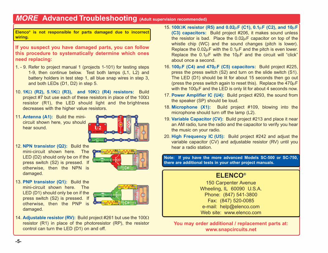
MORE Advanced Troubleshooting (Adult supervision recommended)
Elenco® is not responsible for parts damaged due to incorrectwiring.
If you suspect you have damaged parts, you can followthis procedure to systematically determine which onesneed replacing:
1. - 9. Refer to project manual 1 (projects 1-101) for testing steps1-9, then continue below. Test both lamps (L1, L2) andbattery holders in test step 1, all blue snap wires in step 3,and both LEDs (D1, D2) in step 5.
10. 1KΩ (R2), 5.1KΩ (R3), and 10KΩ (R4) resistors: Buildproject #7 but use each of these resistors in place of the 100Ωresistor (R1), the LED should light and the brightnessdecreases with the higher value resistors.
11. Antenna (A1): Build the mini-circuit shown here, you shouldhear sound.
12. NPN transistor (Q2): Build themini-circuit shown here. TheLED (D2) should only be on if thepress switch (S2) is pressed. Ifotherwise, then the NPN isdamaged.
13. PNP transistor (Q1): Build themini-circuit shown here. TheLED (D1) should only be on if thepress switch (S2) is pressed. Ifotherwise, then the PNP isdamaged.
14. Adjustable resistor (RV): Build project #261 but use the 100Ωresistor (R1) in place of the photoresistor (RP), the resistorcontrol can turn the LED (D1) on and off.
15. 100ΩK resistor (R5) and 0.02μF (C1), 0.1μF (C2), and 10μF(C3) capacitors: Build project #206, it makes sound unlessthe resistor is bad. Place the 0.02μF capacitor on top of thewhistle chip (WC) and the sound changes (pitch is lower).Replace the 0.02μF with the 0.1μF and the pitch is even lower.Replace the 0.1μF with the 10μF and the circuit will “click”about once a second.
16. 100μF (C4) and 470μF (C5) capacitors: Build project #225,press the press switch (S2) and turn on the slide switch (S1).The LED (D1) should be lit for about 15 seconds then go out(press the press switch again to reset this). Replace the 470μFwith the 100μF and the LED is only lit for about 4 seconds now.
17. Power Amplifier IC (U4): Build project #293, the sound fromthe speaker (SP) should be loud.
18. Microphone (X1): Build project #109, blowing into themicrophone should turn off the lamp (L2).
19. Variable Capacitor (CV): Build project #213 and place it nearan AM radio, tune the radio and the capacitor to verify you hearthe music on your radio.
20. High Frequency IC (U5): Build project #242 and adjust thevariable capacitor (CV) and adjustable resistor (RV) until youhear a radio station.
Note: If you have the more advanced Models SC-500 or SC-750,there are additional tests in your other project manuals.
ELENCO®
150 Carpenter AvenueWheeling, IL 60090 U.S.A.
Phone: (847) 541-3800Fax: (847) 520-0085
e-mail: [email protected] site: www.elenco.com
You may order additional / replacement parts at:www.snapcircuits.net
-5-
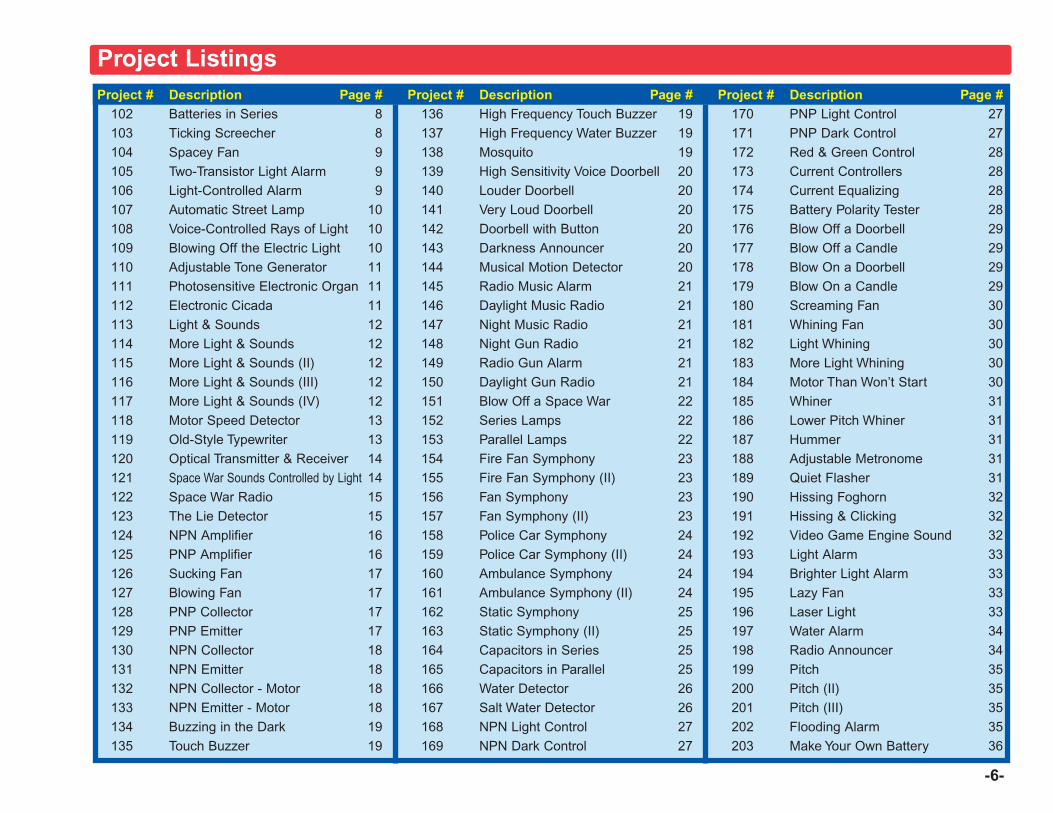
Project # Description Page #102 Batteries in Series 8103 Ticking Screecher 8104 Spacey Fan 9105 Two-Transistor Light Alarm 9106 Light-Controlled Alarm 9107 Automatic Street Lamp 10108 Voice-Controlled Rays of Light 10109 Blowing Off the Electric Light 10110 Adjustable Tone Generator 11111 Photosensitive Electronic Organ 11112 Electronic Cicada 11113 Light & Sounds 12114 More Light & Sounds 12115 More Light & Sounds (II) 12116 More Light & Sounds (III) 12117 More Light & Sounds (IV) 12118 Motor Speed Detector 13119 Old-Style Typewriter 13120 Optical Transmitter & Receiver 14121 Space War Sounds Controlled by Light 14122 Space War Radio 15123 The Lie Detector 15124 NPN Amplifier 16125 PNP Amplifier 16126 Sucking Fan 17127 Blowing Fan 17128 PNP Collector 17129 PNP Emitter 17130 NPN Collector 18131 NPN Emitter 18132 NPN Collector - Motor 18133 NPN Emitter - Motor 18134 Buzzing in the Dark 19135 Touch Buzzer 19
Project # Description Page #136 High Frequency Touch Buzzer 19137 High Frequency Water Buzzer 19138 Mosquito 19139 High Sensitivity Voice Doorbell 20140 Louder Doorbell 20141 Very Loud Doorbell 20142 Doorbell with Button 20143 Darkness Announcer 20144 Musical Motion Detector 20145 Radio Music Alarm 21146 Daylight Music Radio 21147 Night Music Radio 21148 Night Gun Radio 21149 Radio Gun Alarm 21150 Daylight Gun Radio 21151 Blow Off a Space War 22152 Series Lamps 22153 Parallel Lamps 22154 Fire Fan Symphony 23155 Fire Fan Symphony (II) 23156 Fan Symphony 23157 Fan Symphony (II) 23158 Police Car Symphony 24159 Police Car Symphony (II) 24160 Ambulance Symphony 24161 Ambulance Symphony (II) 24162 Static Symphony 25163 Static Symphony (II) 25164 Capacitors in Series 25165 Capacitors in Parallel 25166 Water Detector 26167 Salt Water Detector 26168 NPN Light Control 27169 NPN Dark Control 27
Project # Description Page #170 PNP Light Control 27171 PNP Dark Control 27172 Red & Green Control 28173 Current Controllers 28174 Current Equalizing 28175 Battery Polarity Tester 28176 Blow Off a Doorbell 29177 Blow Off a Candle 29178 Blow On a Doorbell 29179 Blow On a Candle 29180 Screaming Fan 30181 Whining Fan 30182 Light Whining 30183 More Light Whining 30184 Motor Than Won’t Start 30185 Whiner 31186 Lower Pitch Whiner 31187 Hummer 31188 Adjustable Metronome 31189 Quiet Flasher 31190 Hissing Foghorn 32191 Hissing & Clicking 32192 Video Game Engine Sound 32193 Light Alarm 33194 Brighter Light Alarm 33195 Lazy Fan 33196 Laser Light 33197 Water Alarm 34198 Radio Announcer 34199 Pitch 35200 Pitch (II) 35201 Pitch (III) 35202 Flooding Alarm 35203 Make Your Own Battery 36
-6-
Project Listings
-7-
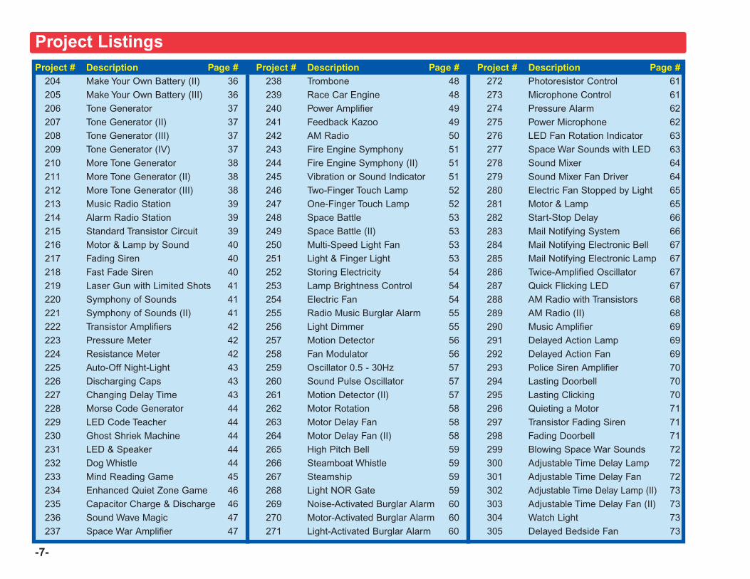
Project # Description Page #204 Make Your Own Battery (II) 36205 Make Your Own Battery (III) 36206 Tone Generator 37207 Tone Generator (II) 37208 Tone Generator (III) 37209 Tone Generator (IV) 37210 More Tone Generator 38211 More Tone Generator (II) 38212 More Tone Generator (III) 38213 Music Radio Station 39214 Alarm Radio Station 39215 Standard Transistor Circuit 39216 Motor & Lamp by Sound 40217 Fading Siren 40218 Fast Fade Siren 40219 Laser Gun with Limited Shots 41220 Symphony of Sounds 41221 Symphony of Sounds (II) 41222 Transistor Amplifiers 42223 Pressure Meter 42224 Resistance Meter 42225 Auto-Off Night-Light 43226 Discharging Caps 43227 Changing Delay Time 43228 Morse Code Generator 44229 LED Code Teacher 44230 Ghost Shriek Machine 44231 LED & Speaker 44232 Dog Whistle 44233 Mind Reading Game 45234 Enhanced Quiet Zone Game 46235 Capacitor Charge & Discharge 46236 Sound Wave Magic 47237 Space War Amplifier 47
Project # Description Page #238 Trombone 48239 Race Car Engine 48240 Power Amplifier 49241 Feedback Kazoo 49242 AM Radio 50243 Fire Engine Symphony 51244 Fire Engine Symphony (II) 51245 Vibration or Sound Indicator 51246 Two-Finger Touch Lamp 52247 One-Finger Touch Lamp 52248 Space Battle 53249 Space Battle (II) 53250 Multi-Speed Light Fan 53251 Light & Finger Light 53252 Storing Electricity 54253 Lamp Brightness Control 54254 Electric Fan 54255 Radio Music Burglar Alarm 55256 Light Dimmer 55257 Motion Detector 56258 Fan Modulator 56259 Oscillator 0.5 - 30Hz 57260 Sound Pulse Oscillator 57261 Motion Detector (II) 57262 Motor Rotation 58263 Motor Delay Fan 58264 Motor Delay Fan (II) 58265 High Pitch Bell 59266 Steamboat Whistle 59267 Steamship 59268 Light NOR Gate 59269 Noise-Activated Burglar Alarm 60270 Motor-Activated Burglar Alarm 60271 Light-Activated Burglar Alarm 60
Project # Description Page #272 Photoresistor Control 61273 Microphone Control 61274 Pressure Alarm 62275 Power Microphone 62276 LED Fan Rotation Indicator 63277 Space War Sounds with LED 63278 Sound Mixer 64279 Sound Mixer Fan Driver 64280 Electric Fan Stopped by Light 65281 Motor & Lamp 65282 Start-Stop Delay 66283 Mail Notifying System 66284 Mail Notifying Electronic Bell 67285 Mail Notifying Electronic Lamp 67286 Twice-Amplified Oscillator 67287 Quick Flicking LED 67288 AM Radio with Transistors 68289 AM Radio (II) 68290 Music Amplifier 69291 Delayed Action Lamp 69292 Delayed Action Fan 69293 Police Siren Amplifier 70294 Lasting Doorbell 70295 Lasting Clicking 70296 Quieting a Motor 71297 Transistor Fading Siren 71298 Fading Doorbell 71299 Blowing Space War Sounds 72300 Adjustable Time Delay Lamp 72301 Adjustable Time Delay Fan 72302 Adjustable Time Delay Lamp (II) 73303 Adjustable Time Delay Fan (II) 73304 Watch Light 73305 Delayed Bedside Fan 73
Project Listings
-8-
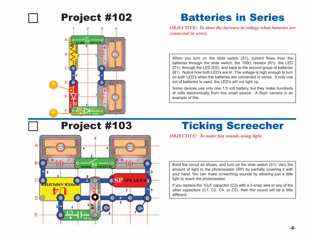
Project #102OBJECTIVE: To show the increase in voltage when batteries areconnected in series.
When you turn on the slide switch (S1), current flows from thebatteries through the slide switch, the 100Ω resistor (R1), the LED(D1), through the LED (D2), and back to the second group of batteries(B1). Notice how both LED’s are lit. The voltage is high enough to turnon both LED’s when the batteries are connected in series. If only oneset of batteries is used, the LED’s will not light up.
Some devices use only one 1.5 volt battery, but they make hundredsof volts electronically from this small source. A flash camera is anexample of this.
Batteries in Series
Project #103OBJECTIVE: To make fun sounds using light.
Build the circuit as shown, and turn on the slide switch (S1). Vary theamount of light to the photoresistor (RP) by partially covering it withyour hand. You can make screeching sounds by allowing just a littlelight to reach the photoresistor.
If you replace the 10μF capacitor (C3) with a 3-snap wire or any of theother capacitors (C1, C2, C4, or C5), then the sound will be a littledifferent.
Ticking Screecher
+
+
-9-
Project #104Spacey Fan
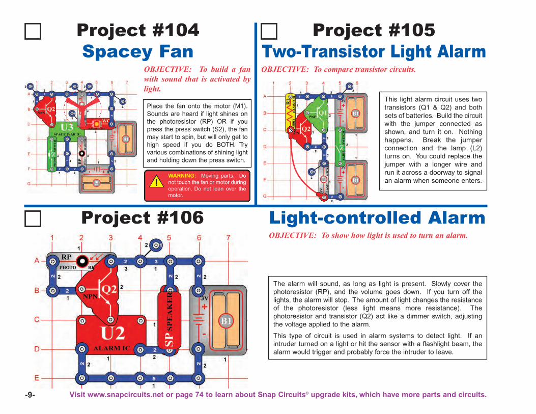
OBJECTIVE: To build a fanwith sound that is activated bylight.
Place the fan onto the motor (M1).Sounds are heard if light shines onthe photoresistor (RP) OR if youpress the press switch (S2), the fanmay start to spin, but will only get tohigh speed if you do BOTH. Tryvarious combinations of shining lightand holding down the press switch.
Project #106OBJECTIVE: To show how light is used to turn an alarm.
The alarm will sound, as long as light is present. Slowly cover thephotoresistor (RP), and the volume goes down. If you turn off thelights, the alarm will stop. The amount of light changes the resistanceof the photoresistor (less light means more resistance). Thephotoresistor and transistor (Q2) act like a dimmer switch, adjustingthe voltage applied to the alarm.
This type of circuit is used in alarm systems to detect light. If anintruder turned on a light or hit the sensor with a flashlight beam, thealarm would trigger and probably force the intruder to leave.
Light-controlled Alarm
Project #105Two-Transistor Light AlarmOBJECTIVE: To compare transistor circuits.
This light alarm circuit uses twotransistors (Q1 & Q2) and bothsets of batteries. Build the circuitwith the jumper connected asshown, and turn it on. Nothinghappens. Break the jumperconnection and the lamp (L2)turns on. You could replace thejumper with a longer wire andrun it across a doorway to signalan alarm when someone enters.!
WARNING: Moving parts. Donot touch the fan or motor duringoperation. Do not lean over themotor.
Visit www.snapcircuits.net or page 74 to learn about Snap Circuits® upgrade kits, which have more parts and circuits.
-10-
Project #107
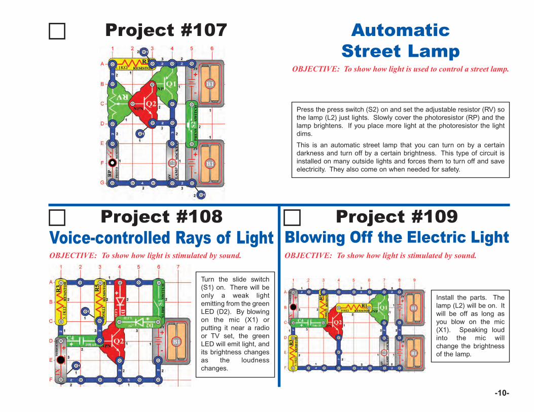
OBJECTIVE: To show how light is used to control a street lamp.
Press the press switch (S2) on and set the adjustable resistor (RV) sothe lamp (L2) just lights. Slowly cover the photoresistor (RP) and thelamp brightens. If you place more light at the photoresistor the lightdims.
This is an automatic street lamp that you can turn on by a certaindarkness and turn off by a certain brightness. This type of circuit isinstalled on many outside lights and forces them to turn off and saveelectricity. They also come on when needed for safety.
AutomaticStreet Lamp
Project #108Voice-controlled Rays of LightOBJECTIVE: To show how light is stimulated by sound.
Turn the slide switch(S1) on. There will beonly a weak lightemitting from the greenLED (D2). By blowingon the mic (X1) orputting it near a radioor TV set, the greenLED will emit light, andits brightness changesas the loudnesschanges.
Project #109Blowing Off the Electric LightOBJECTIVE: To show how light is stimulated by sound.
Install the parts. Thelamp (L2) will be on. Itwill be off as long asyou blow on the mic(X1). Speaking loudinto the mic willchange the brightnessof the lamp.
-11-
Project #110
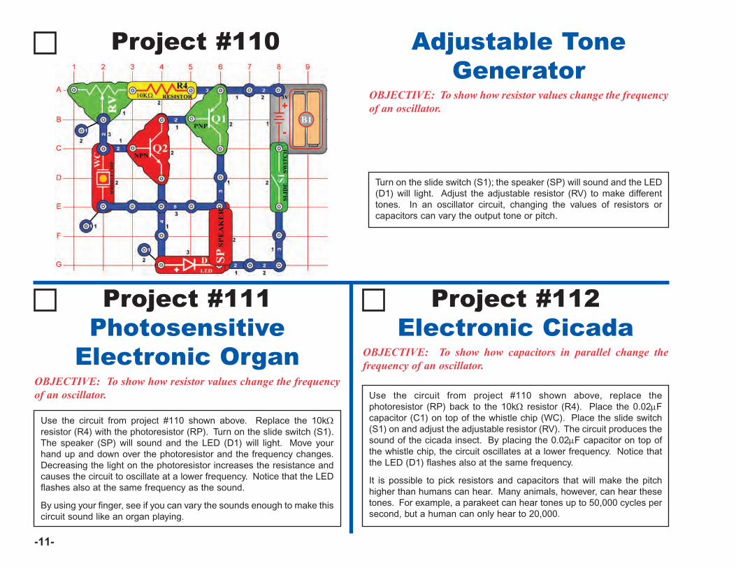
OBJECTIVE: To show how resistor values change the frequencyof an oscillator.
Turn on the slide switch (S1); the speaker (SP) will sound and the LED(D1) will light. Adjust the adjustable resistor (RV) to make differenttones. In an oscillator circuit, changing the values of resistors orcapacitors can vary the output tone or pitch.
Adjustable ToneGenerator
OBJECTIVE: To show how resistor values change the frequencyof an oscillator.
Project #112Electronic Cicada
OBJECTIVE: To show how capacitors in parallel change thefrequency of an oscillator.
Use the circuit from project #110 shown above, replace thephotoresistor (RP) back to the 10kΩ resistor (R4). Place the 0.02μFcapacitor (C1) on top of the whistle chip (WC). Place the slide switch(S1) on and adjust the adjustable resistor (RV). The circuit produces thesound of the cicada insect. By placing the 0.02μF capacitor on top ofthe whistle chip, the circuit oscillates at a lower frequency. Notice thatthe LED (D1) flashes also at the same frequency.
It is possible to pick resistors and capacitors that will make the pitchhigher than humans can hear. Many animals, however, can hear thesetones. For example, a parakeet can hear tones up to 50,000 cycles persecond, but a human can only hear to 20,000.
Use the circuit from project #110 shown above. Replace the 10kΩresistor (R4) with the photoresistor (RP). Turn on the slide switch (S1).The speaker (SP) will sound and the LED (D1) will light. Move yourhand up and down over the photoresistor and the frequency changes.Decreasing the light on the photoresistor increases the resistance andcauses the circuit to oscillate at a lower frequency. Notice that the LEDflashes also at the same frequency as the sound.
By using your finger, see if you can vary the sounds enough to make thiscircuit sound like an organ playing.
Project #111Photosensitive
Electronic Organ
-12-
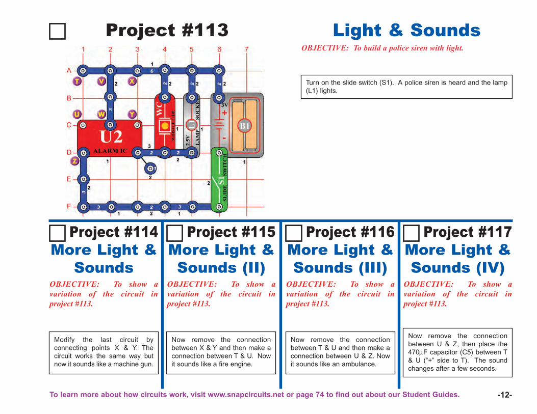
OBJECTIVE: To build a police siren with light.
Turn on the slide switch (S1). A police siren is heard and the lamp(L1) lights.
Project #114More Light &
SoundsOBJECTIVE: To show avariation of the circuit inproject #113.
Modify the last circuit byconnecting points X & Y. Thecircuit works the same way butnow it sounds like a machine gun.
OBJECTIVE: To show avariation of the circuit inproject #113.
Project #116More Light &Sounds (III)
OBJECTIVE: To show avariation of the circuit inproject #113.
Project #117More Light &Sounds (IV)
OBJECTIVE: To show avariation of the circuit inproject #113.
Project #113 Light & Sounds
Project #115More Light &Sounds (II)
Now remove the connectionbetween X & Y and then make aconnection between T & U. Nowit sounds like a fire engine.
Now remove the connectionbetween T & U and then make aconnection between U & Z. Nowit sounds like an ambulance.
Now remove the connectionbetween U & Z, then place the470μF capacitor (C5) between T& U (“+” side to T). The soundchanges after a few seconds.
To learn more about how circuits work, visit www.snapcircuits.net or page 74 to find out about our Student Guides.
-13-
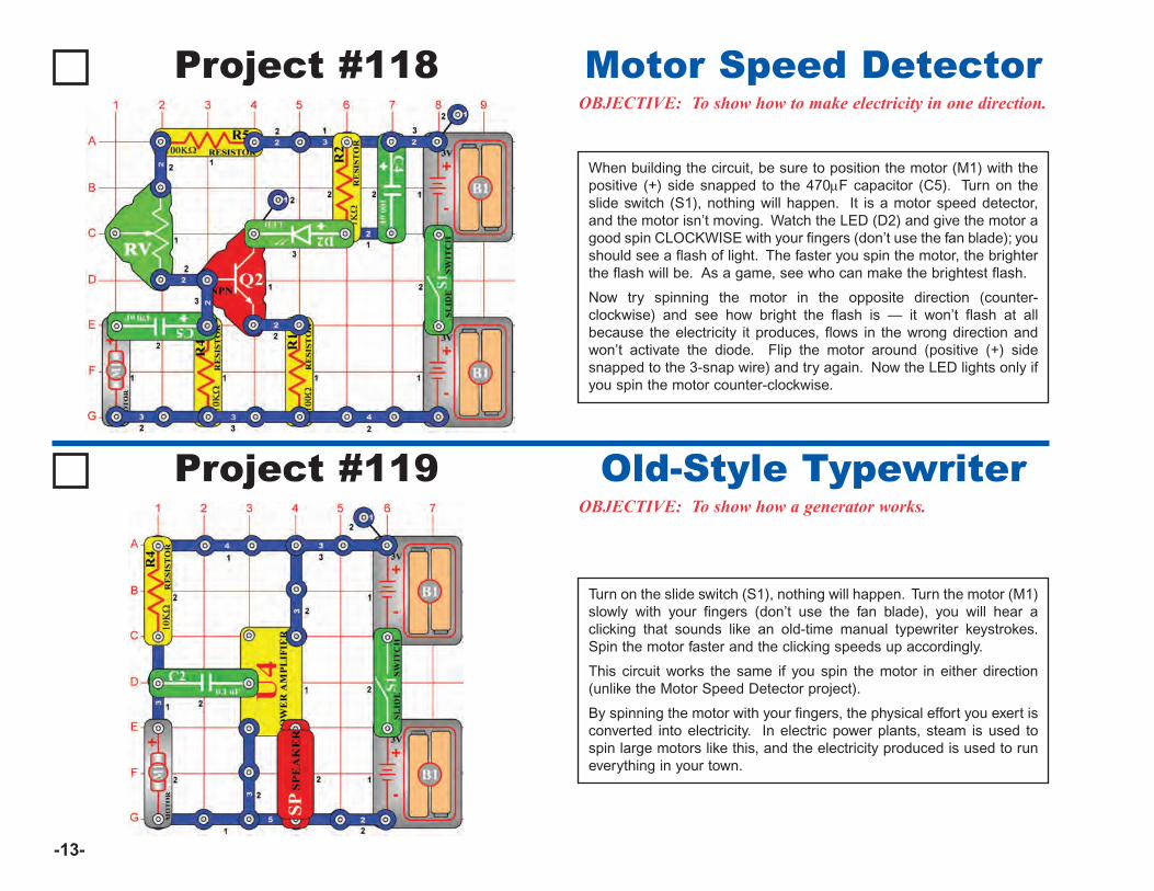
Project #118OBJECTIVE: To show how to make electricity in one direction.
When building the circuit, be sure to position the motor (M1) with thepositive (+) side snapped to the 470μF capacitor (C5). Turn on theslide switch (S1), nothing will happen. It is a motor speed detector,and the motor isn’t moving. Watch the LED (D2) and give the motor agood spin CLOCKWISE with your fingers (don’t use the fan blade); youshould see a flash of light. The faster you spin the motor, the brighterthe flash will be. As a game, see who can make the brightest flash.
Now try spinning the motor in the opposite direction (counter-clockwise) and see how bright the flash is — it won’t flash at allbecause the electricity it produces, flows in the wrong direction andwon’t activate the diode. Flip the motor around (positive (+) sidesnapped to the 3-snap wire) and try again. Now the LED lights only ifyou spin the motor counter-clockwise.
Motor Speed Detector
Project #119OBJECTIVE: To show how a generator works.
Turn on the slide switch (S1), nothing will happen. Turn the motor (M1)slowly with your fingers (don’t use the fan blade), you will hear aclicking that sounds like an old-time manual typewriter keystrokes.Spin the motor faster and the clicking speeds up accordingly.
This circuit works the same if you spin the motor in either direction(unlike the Motor Speed Detector project).
By spinning the motor with your fingers, the physical effort you exert isconverted into electricity. In electric power plants, steam is used tospin large motors like this, and the electricity produced is used to runeverything in your town.
Old-Style Typewriter
-14-
Project #120
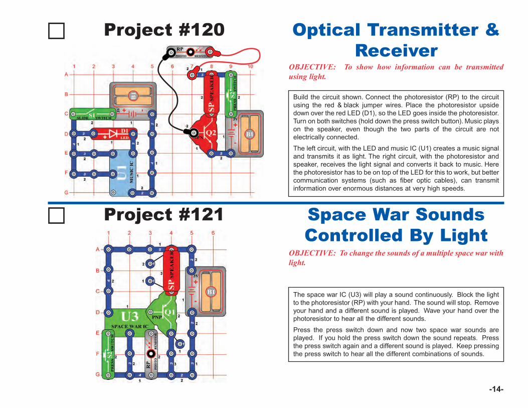
OBJECTIVE: To show how information can be transmittedusing light.
Build the circuit shown. Connect the photoresistor (RP) to the circuitusing the red & black jumper wires. Place the photoresistor upsidedown over the red LED (D1), so the LED goes inside the photoresistor.Turn on both switches (hold down the press switch button). Music playson the speaker, even though the two parts of the circuit are notelectrically connected.
The left circuit, with the LED and music IC (U1) creates a music signaland transmits it as light. The right circuit, with the photoresistor andspeaker, receives the light signal and converts it back to music. Herethe photoresistor has to be on top of the LED for this to work, but bettercommunication systems (such as fiber optic cables), can transmitinformation over enormous distances at very high speeds.
Optical Transmitter &Receiver
Project #121
OBJECTIVE: To change the sounds of a multiple space war withlight.
The space war IC (U3) will play a sound continuously. Block the lightto the photoresistor (RP) with your hand. The sound will stop. Removeyour hand and a different sound is played. Wave your hand over thephotoresistor to hear all the different sounds.
Press the press switch down and now two space war sounds areplayed. If you hold the press switch down the sound repeats. Pressthe press switch again and a different sound is played. Keep pressingthe press switch to hear all the different combinations of sounds.
Space War SoundsControlled By Light
-15-
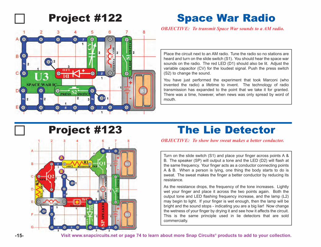
Project #122OBJECTIVE: To transmit Space War sounds to a AM radio.
Place the circuit next to an AM radio. Tune the radio so no stations areheard and turn on the slide switch (S1). You should hear the space warsounds on the radio. The red LED (D1) should also be lit. Adjust thevariable capacitor (CV) for the loudest signal. Push the press switch(S2) to change the sound.
You have just performed the experiment that took Marconi (whoinvented the radio) a lifetime to invent. The technology of radiotransmission has expanded to the point that we take it for granted.There was a time, however, when news was only spread by word ofmouth.
Space War Radio
Project #123OBJECTIVE: To show how sweat makes a better conductor.
Turn on the slide switch (S1) and place your finger across points A &B. The speaker (SP) will output a tone and the LED (D2) will flash atthe same frequency. Your finger acts as a conductor connecting pointsA & B. When a person is lying, one thing the body starts to do issweat. The sweat makes the finger a better conductor by reducing itsresistance.
As the resistance drops, the frequency of the tone increases. Lightlywet your finger and place it across the two points again. Both theoutput tone and LED flashing frequency increase, and the lamp (L2)may begin to light. If your finger is wet enough, then the lamp will bebright and the sound stops - indicating you are a big liar! Now changethe wetness of your finger by drying it and see how it affects the circuit.This is the same principle used in lie detectors that are soldcommercially.
The Lie Detector
Visit www.snapcircuits.net or page 74 to learn about more Snap Circuits® products to add to your collection.
-16-
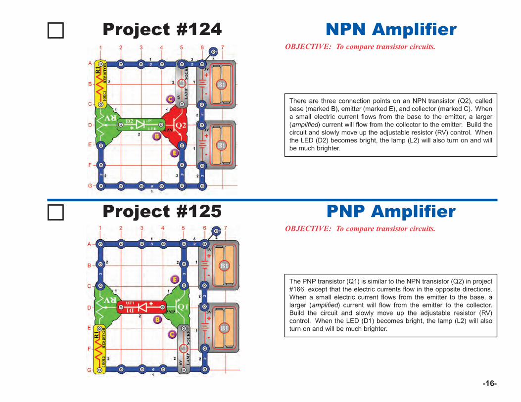
Project #124OBJECTIVE: To compare transistor circuits.
There are three connection points on an NPN transistor (Q2), calledbase (marked B), emitter (marked E), and collector (marked C). Whena small electric current flows from the base to the emitter, a larger(amplified) current will flow from the collector to the emitter. Build thecircuit and slowly move up the adjustable resistor (RV) control. Whenthe LED (D2) becomes bright, the lamp (L2) will also turn on and willbe much brighter.
NPN Amplifier
Project #125OBJECTIVE: To compare transistor circuits.
The PNP transistor (Q1) is similar to the NPN transistor (Q2) in project#166, except that the electric currents flow in the opposite directions.When a small electric current flows from the emitter to the base, alarger (amplified) current will flow from the emitter to the collector.Build the circuit and slowly move up the adjustable resistor (RV)control. When the LED (D1) becomes bright, the lamp (L2) will alsoturn on and will be much brighter.
PNP Amplifier
-17-
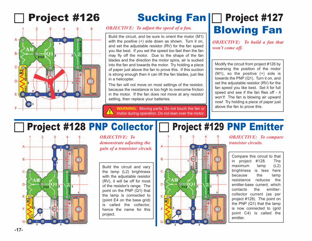
Project #126 Sucking FanOBJECTIVE: To adjust the speed of a fan.
Project #128 PNP CollectorOBJECTIVE: Todemonstrate adjusting thegain of a transistor circuit.
OBJECTIVE: To build a fan thatwon’t come off.
Modify the circuit from project #126 byreversing the position of the motor(M1), so the positive (+) side istowards the PNP (Q1). Turn it on, andset the adjustable resistor (RV) for thefan speed you like best. Set it for fullspeed and see if the fan flies off - itwon’t! The fan is blowing air upwardnow! Try holding a piece of paper justabove the fan to prove this.
Project #127Blowing Fan
Project #129 PNP EmitterOBJECTIVE: To comparetransistor circuits.
Compare this circuit to thatin project #128. Themaximum lamp (L2)brightness is less herebecause the lampresistance reduces theemitter-base current, whichcontacts the emitter-collector current (as perproject #128). The point onthe PNP (Q1) that the lampis now connected to (gridpoint C4) is called theemitter.
Build the circuit, and be sure to orient the motor (M1)with the positive (+) side down as shown. Turn it on,and set the adjustable resistor (RV) for the fan speedyou like best. If you set the speed too fast then the fanmay fly off the motor. Due to the shape of the fanblades and the direction the motor spins, air is suckedinto the fan and towards the motor. Try holding a pieceof paper just above the fan to prove this. If this suctionis strong enough then it can lift the fan blades, just likein a helicopter. The fan will not move on most settings of the resistor,because the resistance is too high to overcome frictionin the motor. If the fan does not move at any resistorsetting, then replace your batteries.
Build the circuit and varythe lamp (L2) brightnesswith the adjustable resistor(RV), it will be off for mostof the resistor’s range. Thepoint on the PNP (Q1) thatthe lamp is connected to(point E4 on the base grid)is called the collector,hence the name for thisproject.
!WARNING: Moving parts. Do not touch the fan ormotor during operation. Do not lean over the motor.
-18-
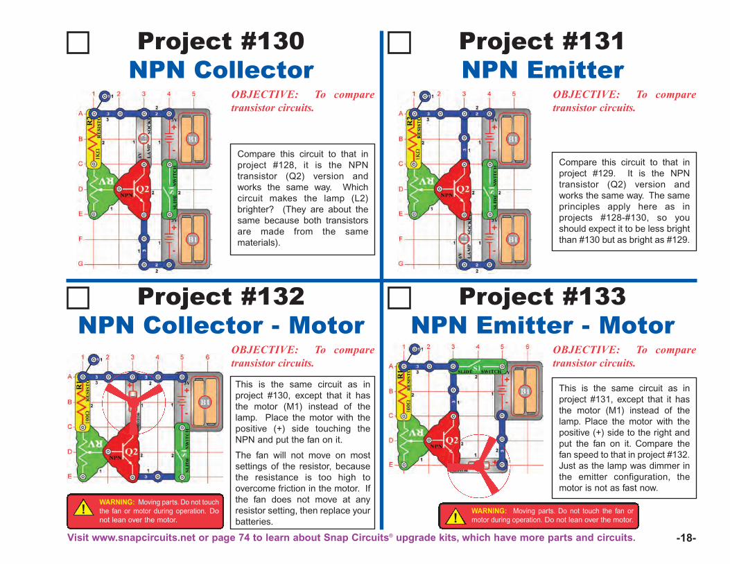
Project #130NPN Collector
OBJECTIVE: To comparetransistor circuits.
Project #131NPN Emitter
Compare this circuit to that inproject #128, it is the NPNtransistor (Q2) version andworks the same way. Whichcircuit makes the lamp (L2)brighter? (They are about thesame because both transistorsare made from the samematerials).
OBJECTIVE: To comparetransistor circuits.
Compare this circuit to that inproject #129. It is the NPNtransistor (Q2) version andworks the same way. The sameprinciples apply here as inprojects #128-#130, so youshould expect it to be less brightthan #130 but as bright as #129.
Project #132NPN Collector - Motor
OBJECTIVE: To comparetransistor circuits.
Project #133NPN Emitter - Motor
This is the same circuit as inproject #130, except that it hasthe motor (M1) instead of thelamp. Place the motor with thepositive (+) side touching theNPN and put the fan on it.
The fan will not move on mostsettings of the resistor, becausethe resistance is too high toovercome friction in the motor. Ifthe fan does not move at anyresistor setting, then replace yourbatteries.
OBJECTIVE: To comparetransistor circuits.
This is the same circuit as inproject #131, except that it hasthe motor (M1) instead of thelamp. Place the motor with thepositive (+) side to the right andput the fan on it. Compare thefan speed to that in project #132.Just as the lamp was dimmer inthe emitter configuration, themotor is not as fast now.
!WARNING: Moving parts. Do not touchthe fan or motor during operation. Donot lean over the motor.
Visit www.snapcircuits.net or page 74 to learn about Snap Circuits® upgrade kits, which have more parts and circuits.
!WARNING: Moving parts. Do not touch the fan ormotor during operation. Do not lean over the motor.
-19-
Project #134
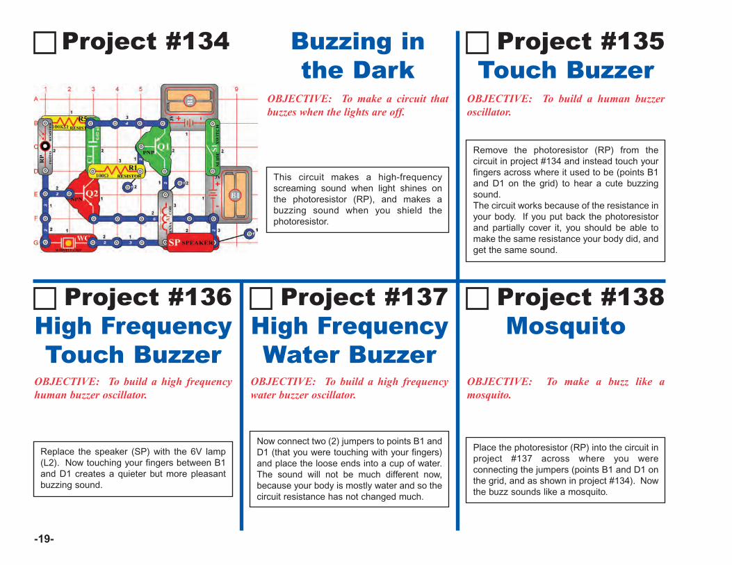
OBJECTIVE: To make a circuit thatbuzzes when the lights are off.
Buzzing inthe Dark
Project #136High FrequencyTouch Buzzer
OBJECTIVE: To build a high frequencyhuman buzzer oscillator.
Replace the speaker (SP) with the 6V lamp(L2). Now touching your fingers between B1and D1 creates a quieter but more pleasantbuzzing sound.
Project #137High FrequencyWater Buzzer
OBJECTIVE: To build a high frequencywater buzzer oscillator.
Now connect two (2) jumpers to points B1 andD1 (that you were touching with your fingers)and place the loose ends into a cup of water.The sound will not be much different now,because your body is mostly water and so thecircuit resistance has not changed much.
Project #138 Mosquito
OBJECTIVE: To make a buzz like amosquito.
Place the photoresistor (RP) into the circuit inproject #137 across where you wereconnecting the jumpers (points B1 and D1 onthe grid, and as shown in project #134). Nowthe buzz sounds like a mosquito.
Project #135 Touch Buzzer
OBJECTIVE: To build a human buzzeroscillator.
Remove the photoresistor (RP) from thecircuit in project #134 and instead touch yourfingers across where it used to be (points B1and D1 on the grid) to hear a cute buzzingsound.The circuit works because of the resistance inyour body. If you put back the photoresistorand partially cover it, you should be able tomake the same resistance your body did, andget the same sound.
This circuit makes a high-frequencyscreaming sound when light shines onthe photoresistor (RP), and makes abuzzing sound when you shield thephotoresistor.
-20-
Project #139
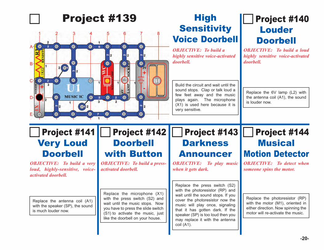
Project #141Very LoudDoorbell
OBJECTIVE: To build a veryloud, highly-sensitive, voice-activated doorbell.
Replace the antenna coil (A1)with the speaker (SP), the soundis much louder now.
OBJECTIVE: To build a press-activated doorbell.
Project #143 Darkness
AnnouncerOBJECTIVE: To play musicwhen it gets dark.
OBJECTIVE: To detect whensomeone spins the motor.
Project #142 Doorbell
with Button
Replace the microphone (X1)with the press switch (S2) andwait until the music stops. Nowyou have to press the slide switch(S1) to activate the music, justlike the doorbell on your house.
Replace the press switch (S2)with the photoresistor (RP) andwait until the sound stops. If youcover the photoresistor now themusic will play once, signalingthat it has gotten dark. If thespeaker (SP) is too loud then youmay replace it with the antennacoil (A1).
Replace the photoresistor (RP)with the motor (M1), oriented ineither direction. Now spinning themotor will re-activate the music.
Project #144 Musical
Motion Detector
OBJECTIVE: To build a loudhighly sensitive voice-activateddoorbell.
Replace the 6V lamp (L2) withthe antenna coil (A1), the soundis louder now.
Project #140 Louder
DoorbellOBJECTIVE: To build ahighly sensitive voice-activateddoorbell.
Build the circuit and wait until thesound stops. Clap or talk loud afew feet away and the musicplays again. The microphone(X1) is used here because it isvery sensitive.
HighSensitivity
Voice Doorbell
-21-
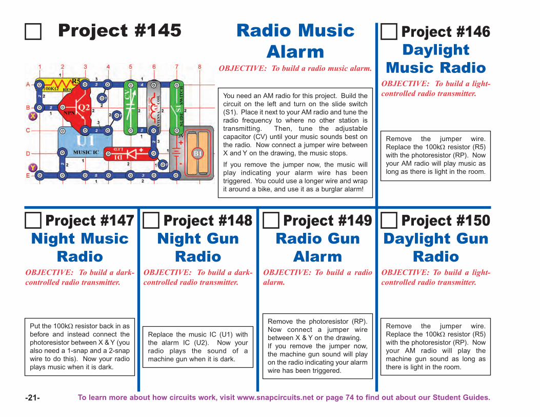
Project #145 Radio MusicAlarm
OBJECTIVE: To build a radio music alarm.
Project #147Night Music
RadioOBJECTIVE: To build a dark-controlled radio transmitter.
Put the 100kΩ resistor back in asbefore and instead connect thephotoresistor between X & Y (youalso need a 1-snap and a 2-snapwire to do this). Now your radioplays music when it is dark.
OBJECTIVE: To build a dark-controlled radio transmitter.
Project #149 Radio Gun
AlarmOBJECTIVE: To build a radioalarm.
OBJECTIVE: To build a light-controlled radio transmitter.
Project #148 Night Gun
Radio
Replace the music IC (U1) withthe alarm IC (U2). Now yourradio plays the sound of amachine gun when it is dark.
Remove the photoresistor (RP).Now connect a jumper wirebetween X & Y on the drawing. If you remove the jumper now,the machine gun sound will playon the radio indicating your alarmwire has been triggered.
Remove the jumper wire.Replace the 100kΩ resistor (R5)with the photoresistor (RP). Nowyour AM radio will play themachine gun sound as long asthere is light in the room.
Project #150 Daylight Gun
Radio
OBJECTIVE: To build a light-controlled radio transmitter.
Project #146 Daylight
Music Radio
Remove the jumper wire.Replace the 100kΩ resistor (R5)with the photoresistor (RP). Nowyour AM radio will play music aslong as there is light in the room.
You need an AM radio for this project. Build thecircuit on the left and turn on the slide switch(S1). Place it next to your AM radio and tune theradio frequency to where no other station istransmitting. Then, tune the adjustablecapacitor (CV) until your music sounds best onthe radio. Now connect a jumper wire betweenX and Y on the drawing, the music stops.
If you remove the jumper now, the music willplay indicating your alarm wire has beentriggered. You could use a longer wire and wrapit around a bike, and use it as a burglar alarm!
To learn more about how circuits work, visit www.snapcircuits.net or page 74 to find out about our Student Guides.
-22-
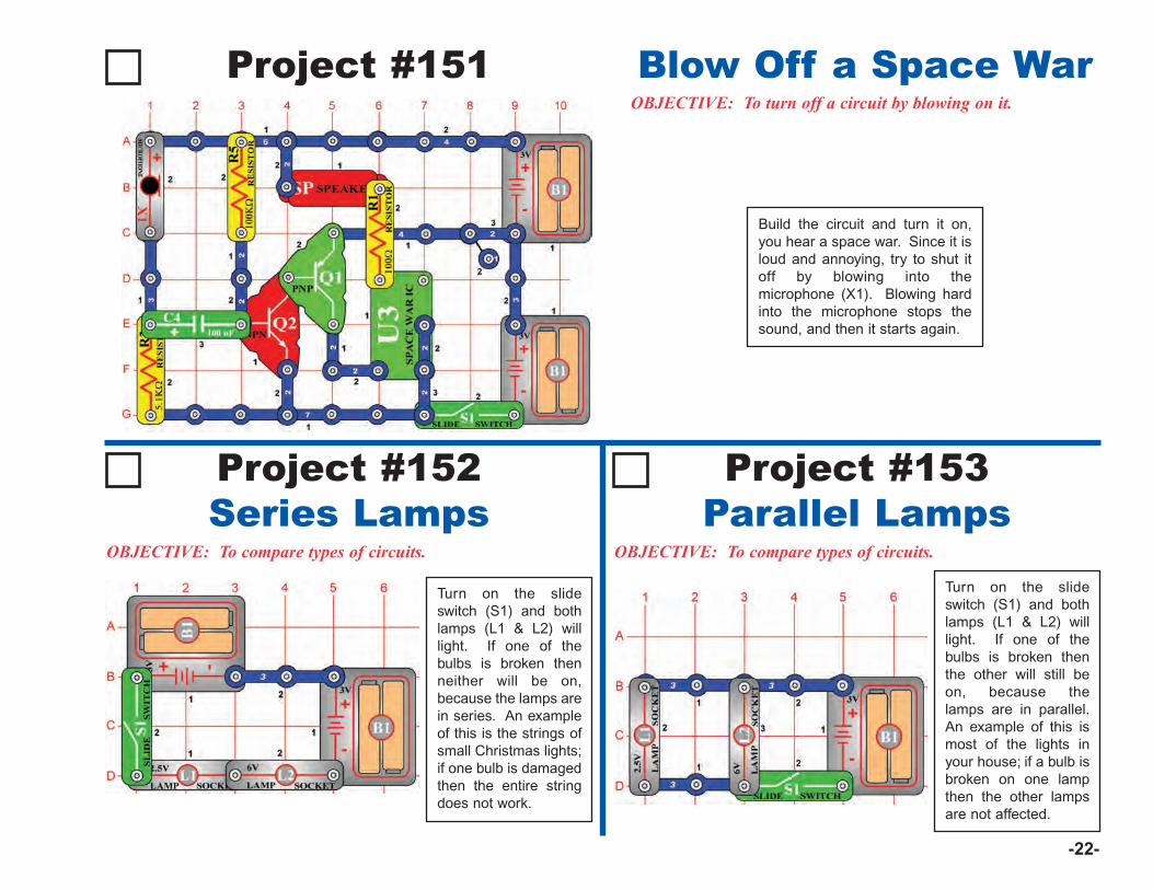
Project #151OBJECTIVE: To turn off a circuit by blowing on it.
Blow Off a Space War
Project #152Series Lamps
OBJECTIVE: To compare types of circuits.
Turn on the slideswitch (S1) and bothlamps (L1 & L2) willlight. If one of thebulbs is broken thenneither will be on,because the lamps arein series. An exampleof this is the strings ofsmall Christmas lights;if one bulb is damagedthen the entire stringdoes not work.
Project #153Parallel Lamps
OBJECTIVE: To compare types of circuits.
Build the circuit and turn it on,you hear a space war. Since it isloud and annoying, try to shut itoff by blowing into themicrophone (X1). Blowing hardinto the microphone stops thesound, and then it starts again.
Turn on the slideswitch (S1) and bothlamps (L1 & L2) willlight. If one of thebulbs is broken thenthe other will still beon, because thelamps are in parallel.An example of this ismost of the lights inyour house; if a bulb isbroken on one lampthen the other lampsare not affected.
-23-
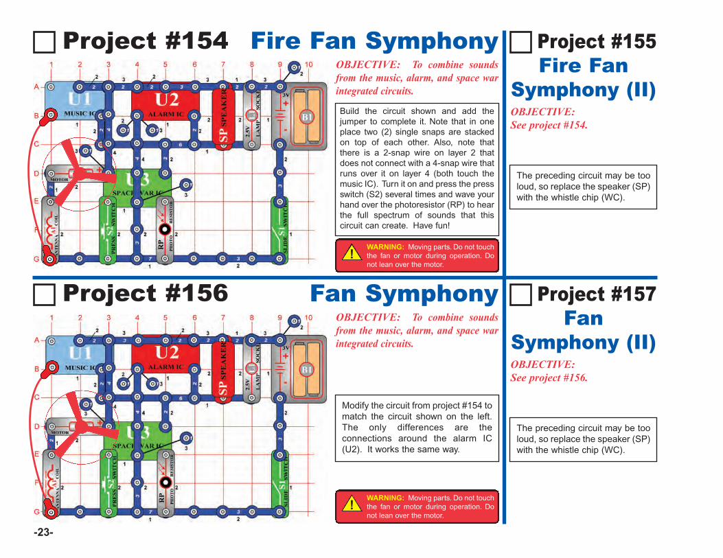
Project #154 Fire Fan SymphonyOBJECTIVE: To combine soundsfrom the music, alarm, and space warintegrated circuits.
OBJECTIVE:See project #156.
The preceding circuit may be tooloud, so replace the speaker (SP)with the whistle chip (WC).
Project #157 Fan
Symphony (II)
OBJECTIVE:See project #154.
Project #155Fire Fan
Symphony (II)
Project #156 Fan SymphonyOBJECTIVE: To combine soundsfrom the music, alarm, and space warintegrated circuits.
Modify the circuit from project #154 tomatch the circuit shown on the left.The only differences are theconnections around the alarm IC(U2). It works the same way.
The preceding circuit may be tooloud, so replace the speaker (SP)with the whistle chip (WC).
Build the circuit shown and add thejumper to complete it. Note that in oneplace two (2) single snaps are stackedon top of each other. Also, note thatthere is a 2-snap wire on layer 2 thatdoes not connect with a 4-snap wire thatruns over it on layer 4 (both touch themusic IC). Turn it on and press the pressswitch (S2) several times and wave yourhand over the photoresistor (RP) to hearthe full spectrum of sounds that thiscircuit can create. Have fun!
!WARNING: Moving parts. Do not touchthe fan or motor during operation. Donot lean over the motor.
!WARNING: Moving parts. Do not touchthe fan or motor during operation. Donot lean over the motor.
-24-
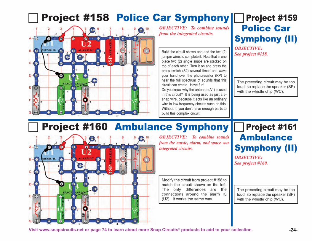
Project #158 Police Car SymphonyOBJECTIVE: To combine soundsfrom the integrated circuits.
OBJECTIVE:See project #160.
The preceding circuit may be tooloud, so replace the speaker (SP)with the whistle chip (WC).
Project #161 Ambulance
Symphony (II)
OBJECTIVE:See project #158.
Project #159Police Car
Symphony (II)
Project #160 Ambulance SymphonyOBJECTIVE: To combine soundsfrom the music, alarm, and space warintegrated circuits.
Modify the circuit from project #158 tomatch the circuit shown on the left.The only differences are theconnections around the alarm IC(U2). It works the same way.
The preceding circuit may be tooloud, so replace the speaker (SP)with the whistle chip (WC).
Build the circuit shown and add the two (2)jumper wires to complete it. Note that in oneplace two (2) single snaps are stacked ontop of each other. Turn it on and press thepress switch (S2) several times and waveyour hand over the photoresistor (RP) tohear the full spectrum of sounds that thiscircuit can create. Have fun! Do you know why the antenna (A1) is usedin this circuit? It is being used as just a 3-snap wire, because it acts like an ordinarywire in low frequency circuits such as this.Without it, you don’t have enough parts tobuild this complex circuit.
Visit www.snapcircuits.net or page 74 to learn about more Snap Circuits® products to add to your collection.
-25-
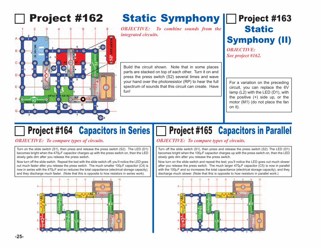
Project #162 Static Symphony
OBJECTIVE:See project #162.
Project #163Static
Symphony (II)
Project #164 Capacitors in SeriesOBJECTIVE: To compare types of circuits.
Project #165 Capacitors in ParallelOBJECTIVE: To compare types of circuits.
Turn on the slide switch (S1), then press and release the press switch (S2). The LED (D1)becomes bright when the 470μF capacitor charges up with the press switch on, then the LEDslowly gets dim after you release the press switch.
Now turn off the slide switch. Repeat the test with the slide swtich off; you’ll notice the LED goesout much faster after you release the press switch. The much smaller 100μF capacitor (C4) isnow in series with the 470μF and so reduces the total capacitance (electrical storage capacity),and they discharge much faster. (Note that this is opposite to how resistors in series work).
Turn off the slide switch (S1), then press and release the press switch (S2). The LED (D1)becomes bright when the 100μF capacitor charges up with the press switch on, then the LEDslowly gets dim after you release the press switch.
Now turn on the slide switch and repeat the test; you’ll notice the LED goes out much slowerafter you release the press switch. The much larger 470μF capacitor (C5) is now in parallelwith the 100μF and so increases the total capacitance (electrical storage capacity), and theydischarge much slower. (Note that this is opposite to how resistors in parallel work.)
OBJECTIVE: To combine sounds from theintegrated circuits.
For a variation on the precedingcircuit, you can replace the 6Vlamp (L2) with the LED (D1), withthe positive (+) side up, or themotor (M1) (do not place the fanon it).
Build the circuit shown. Note that in some placesparts are stacked on top of each other. Turn it on andpress the press switch (S2) several times and waveyour hand over the photoresistor (RP) to hear the fullspectrum of sounds that this circuit can create. Havefun!

-26-
Project #166OBJECTIVE: To show how water conducts electricity.
Build the circuit at left and connect the two jumpers to it, but leave theloose ends of the jumpers lying on the table initially. Turn on the slideswitch (S1) - the LED (D1) will be dark because the air separating thejumpers has very high resistance. Touch the loose jumper ends toeach other and the LED will be bright, because with a directconnection there is no resistance separating the jumpers.
Now take the loose ends of the jumpers and place them in a cup ofwater, without letting them touch each other. The LED should be dimlylit, indicating you have detected water!
For this experiment, your LED brightness may vary depending uponyour local water supply. Pure water (like distilled water) has very highresistance, but drinking water has impurities mixed in that increaseelectrical conduction.
Water Detector
Project #167OBJECTIVE: To show how adding salt to water changes water’selectrical characteristics.
Place the jumpers in a cup of water as in the preceding project; theLED (D1) should be dimly lit. Slowly add salt to the water and see howthe LED brightness changes, mix it a little so it dissolves. It will slowlybecome very bright as you add more salt. You can use this bright LEDcondition as a saltwater detector! You can then reduce the LEDbrightness by adding more water to dilute the salt.
Take another cup of water and try adding other household substanceslike sugar to see if they increase the LED brightness as the salt did.
Saltwater Detector
-27-
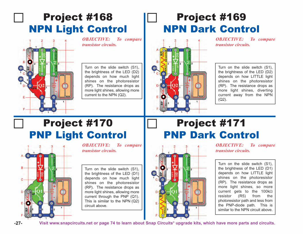
Project #168NPN Light Control
OBJECTIVE: To comparetransistor circuits.
Project #169NPN Dark Control
Turn on the slide switch (S1),the brightness of the LED (D2)depends on how much lightshines on the photoresistor(RP). The resistance drops asmore light shines, allowing morecurrent to the NPN (Q2).
OBJECTIVE: To comparetransistor circuits.
Turn on the slide switch (S1),the brightness of the LED (D2)depends on how LITTLE lightshines on the photoresistor(RP). The resistance drops asmore light shines, divertingcurrent away from the NPN(Q2).
Project #170PNP Light Control
OBJECTIVE: To comparetransistor circuits.
Project #171PNP Dark Control
Turn on the slide switch (S1),the brightness of the LED (D1)depends on how much lightshines on the photoresistor(RP). The resistance drops asmore light shines, allowing morecurrent through the PNP (Q1).This is similar to the NPN (Q2)circuit above.
OBJECTIVE: To comparetransistor circuits.
Turn on the slide switch (S1),the brightness of the LED (D1)depends on how LITTLE lightshines on the photoresistor(RP). The resistance drops asmore light shines, so morecurrent gets to the 100kΩresistor (R5) from thephotoresistor path and less fromthe PNP-diode path. This issimilar to the NPN circuit above.
Visit www.snapcircuits.net or page 74 to learn about Snap Circuits® upgrade kits, which have more parts and circuits.
-28-
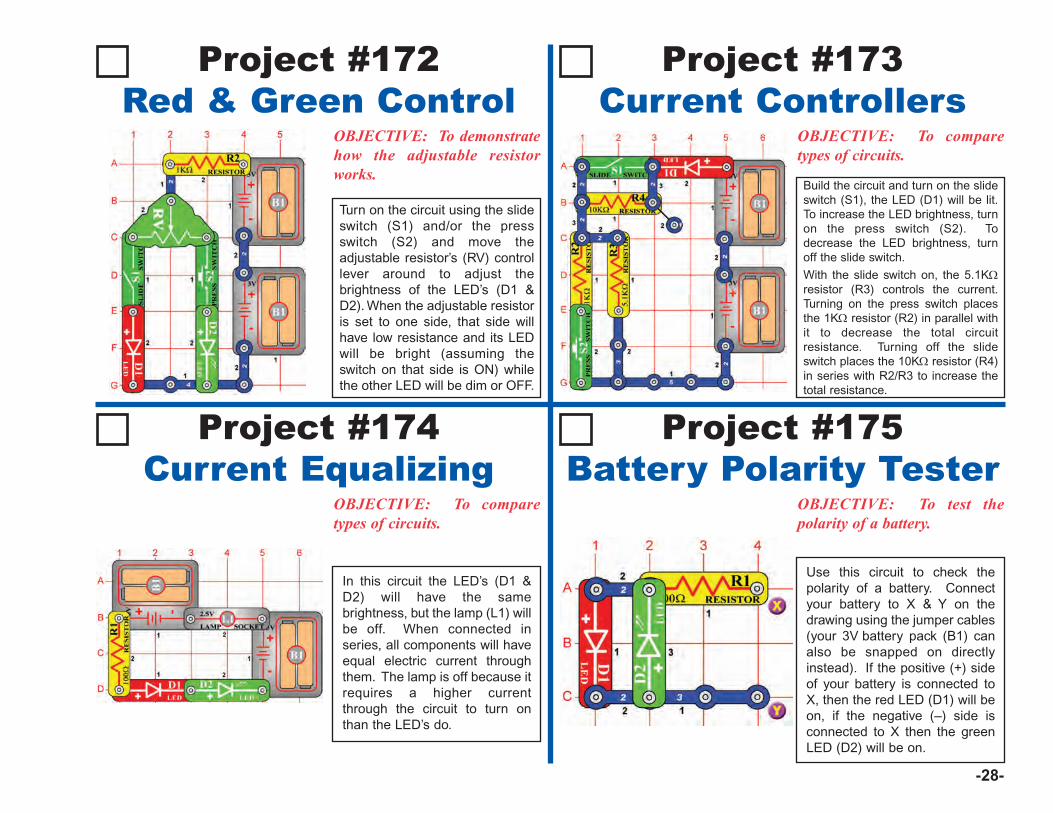
Project #172Red & Green Control
OBJECTIVE: To demonstratehow the adjustable resistorworks.
Project #173Current Controllers
Turn on the circuit using the slideswitch (S1) and/or the pressswitch (S2) and move theadjustable resistor’s (RV) controllever around to adjust thebrightness of the LED’s (D1 &D2). When the adjustable resistoris set to one side, that side willhave low resistance and its LEDwill be bright (assuming theswitch on that side is ON) whilethe other LED will be dim or OFF.
OBJECTIVE: To comparetypes of circuits.
Build the circuit and turn on the slideswitch (S1), the LED (D1) will be lit.To increase the LED brightness, turnon the press switch (S2). Todecrease the LED brightness, turnoff the slide switch.
With the slide switch on, the 5.1KΩresistor (R3) controls the current.Turning on the press switch placesthe 1KΩ resistor (R2) in parallel withit to decrease the total circuitresistance. Turning off the slideswitch places the 10KΩ resistor (R4)in series with R2/R3 to increase thetotal resistance.
Project #174Current Equalizing
OBJECTIVE: To comparetypes of circuits.
Project #175Battery Polarity Tester
In this circuit the LED’s (D1 &D2) will have the samebrightness, but the lamp (L1) willbe off. When connected inseries, all components will haveequal electric current throughthem. The lamp is off because itrequires a higher currentthrough the circuit to turn onthan the LED’s do.
OBJECTIVE: To test thepolarity of a battery.
Use this circuit to check thepolarity of a battery. Connectyour battery to X & Y on thedrawing using the jumper cables(your 3V battery pack (B1) canalso be snapped on directlyinstead). If the positive (+) sideof your battery is connected toX, then the red LED (D1) will beon, if the negative (–) side isconnected to X then the greenLED (D2) will be on.

-29-
Project #176 Blow Off a DoorbellOBJECTIVE: To turn off a circuitby blowing on it.
OBJECTIVE: To turn on acircuit by blowing on it.
Replace the speaker (SP) withthe 6V lamp (L2). Blowing intothe microphone (X1) turns on thelight, and then it goes off again.
Project #179Blow On a
Candle
OBJECTIVE: To turn off acircuit by blowing on it.
Project #177Blow Off a
Candle
Project #178 Blow On a DoorbellOBJECTIVE: To turn on a circuitby blowing on it.
Build the circuit and turn it on, musicplays for a few moments and thenstops. Blow into the microphone (X1)and it plays; it plays as long as youkeep blowing.
Replace the speaker (SP) withthe 6V lamp (L2). Blowing hardinto the microphone (X1) turnsoff the light briefly.
Build the circuit and turn it on; musicplays. Since it is loud and annoying,try to shut it off by blowing into themicrophone (X1). Blowing hard intothe microphone stops the music, andthen it starts again.
-30-
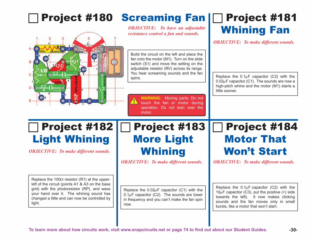
Project #180OBJECTIVE: To have an adjustableresistance control a fan and sounds.
Screaming Fan
Project #182Light Whining
OBJECTIVE: To make different sounds.
Replace the 100Ω resistor (R1) at the upper-left of the circuit (points A1 & A3 on the basegrid) with the photoresistor (RP), and waveyour hand over it. The whining sound haschanged a little and can now be controlled bylight.
Project #183More Light
WhiningOBJECTIVE: To make different sounds.
Replace the 0.02μF capacitor (C1) with the0.1μF capacitor (C2). The sounds are lowerin frequency and you can’t make the fan spinnow.
Project #184 Motor ThatWon’t Start
OBJECTIVE: To make different sounds.
Replace the 0.1μF capacitor (C2) with the10μF capacitor (C3), put the positive (+) sidetowards the left). It now makes clickingsounds and the fan moves only in smallbursts, like a motor that won’t start.
Project #181 Whining Fan
OBJECTIVE: To make different sounds.
Replace the 0.1μF capacitor (C2) with the0.02μF capacitor (C1). The sounds are now ahigh-pitch whine and the motor (M1) starts alittle sooner.
Build the circuit on the left and place thefan onto the motor (M1). Turn on the slideswitch (S1) and move the setting on theadjustable resistor (RV) across its range.You hear screaming sounds and the fanspins.
!WARNING: Moving parts. Do nottouch the fan or motor duringoperation. Do not lean over themotor.
To learn more about how circuits work, visit www.snapcircuits.net or page 74 to find out about our Student Guides.
-31-
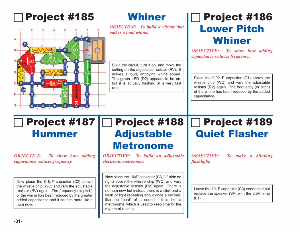
Project #185OBJECTIVE: To build a circuit thatmakes a loud whine.
Whiner
Project #187Hummer
OBJECTIVE: To show how addingcapacitance reduces frequency.
Now place the 0.1μF capacitor (C2) abovethe whistle chip (WC) and vary the adjustableresistor (RV) again. The frequency (or pitch)of the whine has been reduced by the greateradded capacitance and it sounds more like ahum now.
Project #188AdjustableMetronome
OBJECTIVE: To build an adjustableelectronic metronome.
Now place the 10μF capacitor (C3, “+” side onright) above the whistle chip (WC) and varythe adjustable resistor (RV) again. There isno hum now but instead there is a click and aflash of light repeating about once a second,like the “beat” of a sound. It is like ametronome, which is used to keep time for therhythm of a song.
Project #189 Quiet Flasher
OBJECTIVE: To make a blinkingflashlight.
Leave the 10μF capacitor (C3) connected butreplace the speaker (SP) with the 2.5V lamp(L1).
Project #186 Lower Pitch
WhinerOBJECTIVE: To show how addingcapacitance reduces frequency.
Place the 0.02μF capacitor (C1) above thewhistle chip (WC) and vary the adjustableresistor (RV) again. The frequency (or pitch)of the whine has been reduced by the addedcapacitance.
Build the circuit, turn it on, and move thesetting on the adjustable resistor (RV). Itmakes a loud, annoying whine sound.The green LED (D2) appears to be on,but it is actually flashing at a very fastrate.
-32-
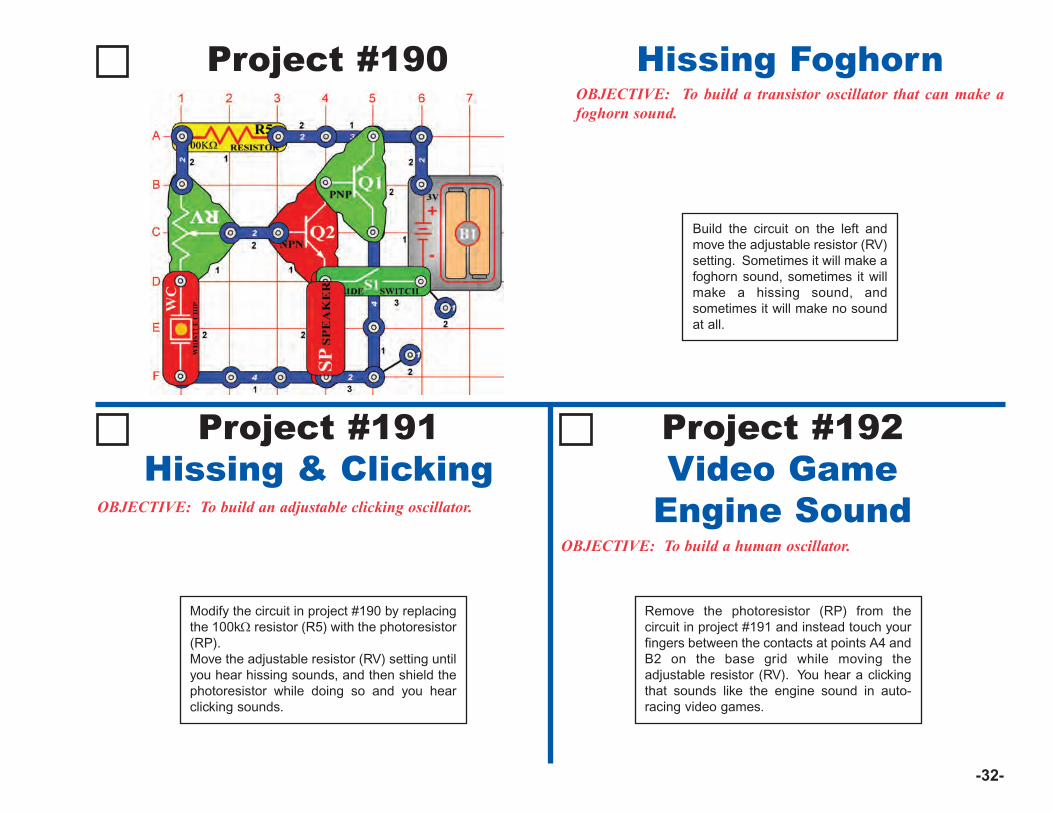
Project #190OBJECTIVE: To build a transistor oscillator that can make afoghorn sound.
Hissing Foghorn
Project #191Hissing & Clicking
OBJECTIVE: To build an adjustable clicking oscillator.
Modify the circuit in project #190 by replacingthe 100kΩ resistor (R5) with the photoresistor(RP).Move the adjustable resistor (RV) setting untilyou hear hissing sounds, and then shield thephotoresistor while doing so and you hearclicking sounds.
OBJECTIVE: To build a human oscillator.
Build the circuit on the left andmove the adjustable resistor (RV)setting. Sometimes it will make afoghorn sound, sometimes it willmake a hissing sound, andsometimes it will make no soundat all.
Project #192Video Game
Engine Sound
Remove the photoresistor (RP) from thecircuit in project #191 and instead touch yourfingers between the contacts at points A4 andB2 on the base grid while moving theadjustable resistor (RV). You hear a clickingthat sounds like the engine sound in auto-racing video games.
-33-
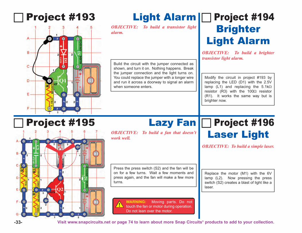
Project #193 Light AlarmOBJECTIVE: To build a transistor lightalarm.
OBJECTIVE: To build a simple laser.
Replace the motor (M1) with the 6Vlamp (L2). Now pressing the pressswitch (S2) creates a blast of light like alaser.
Project #196 Laser Light
OBJECTIVE: To build a brightertransistor light alarm.
Project #195 Lazy FanOBJECTIVE: To build a fan that doesn’twork well.
Press the press switch (S2) and the fan will beon for a few turns. Wait a few moments andpress again, and the fan will make a few moreturns.
Modify the circuit in project #193 byreplacing the LED (D1) with the 2.5Vlamp (L1) and replacing the 5.1kΩresistor (R3) with the 100Ω resistor(R1). It works the same way but isbrighter now.
Build the circuit with the jumper connected asshown, and turn it on. Nothing happens. Breakthe jumper connection and the light turns on.You could replace the jumper with a longer wireand run it across a doorway to signal an alarmwhen someone enters.
Project #194Brighter
Light Alarm
!WARNING: Moving parts. Do nottouch the fan or motor during operation.Do not lean over the motor.
Visit www.snapcircuits.net or page 74 to learn about more Snap Circuits® products to add to your collection.
-34-
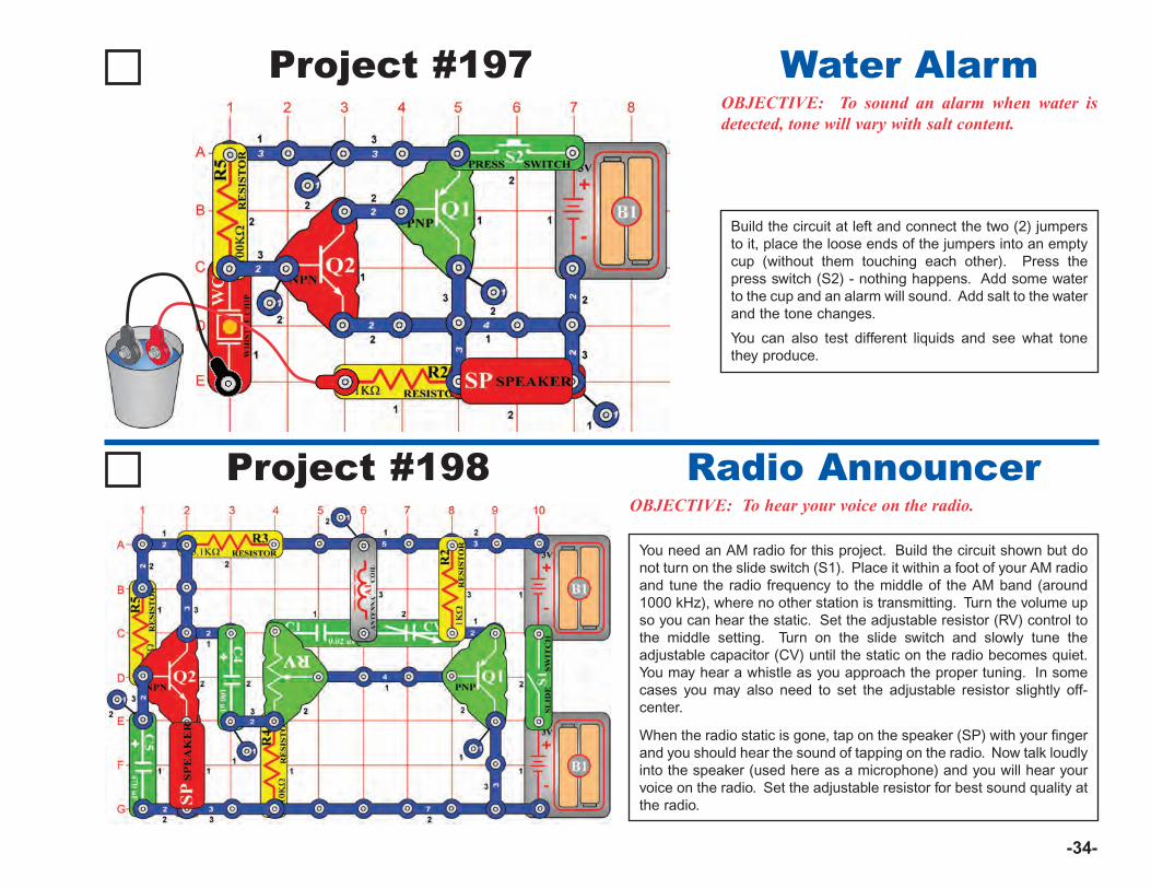
Project #197OBJECTIVE: To sound an alarm when water isdetected, tone will vary with salt content.
Build the circuit at left and connect the two (2) jumpersto it, place the loose ends of the jumpers into an emptycup (without them touching each other). Press thepress switch (S2) - nothing happens. Add some waterto the cup and an alarm will sound. Add salt to the waterand the tone changes.
You can also test different liquids and see what tonethey produce.
Water Alarm
Project #198OBJECTIVE: To hear your voice on the radio.
You need an AM radio for this project. Build the circuit shown but donot turn on the slide switch (S1). Place it within a foot of your AM radioand tune the radio frequency to the middle of the AM band (around1000 kHz), where no other station is transmitting. Turn the volume upso you can hear the static. Set the adjustable resistor (RV) control tothe middle setting. Turn on the slide switch and slowly tune theadjustable capacitor (CV) until the static on the radio becomes quiet.You may hear a whistle as you approach the proper tuning. In somecases you may also need to set the adjustable resistor slightly off-center.
When the radio static is gone, tap on the speaker (SP) with your fingerand you should hear the sound of tapping on the radio. Now talk loudlyinto the speaker (used here as a microphone) and you will hear yourvoice on the radio. Set the adjustable resistor for best sound quality atthe radio.
Radio Announcer
-35-
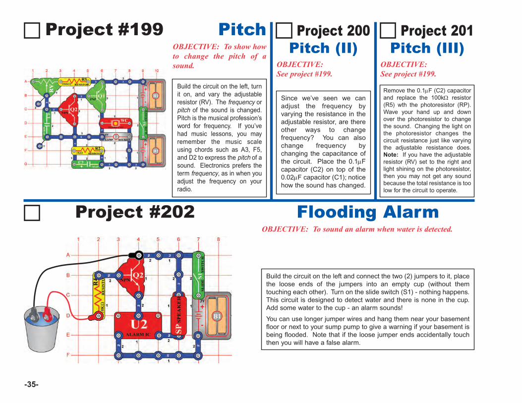
Project 201Pitch (III)
OBJECTIVE:See project #199.
Project #202OBJECTIVE: To sound an alarm when water is detected.
Flooding Alarm
Project #199 PitchOBJECTIVE: To show howto change the pitch of asound.
Project 200Pitch (II)
OBJECTIVE:See project #199.
Remove the 0.1μF (C2) capacitorand replace the 100kΩ resistor(R5) wth the photoresistor (RP).Wave your hand up and downover the photoresistor to changethe sound. Changing the light onthe photoresistor changes thecircuit resistance just like varyingthe adjustable resistance does.Note: If you have the adjustableresistor (RV) set to the right andlight shining on the photoresistor,then you may not get any soundbecause the total resistance is toolow for the circuit to operate.
Build the circuit on the left, turnit on, and vary the adjustableresistor (RV). The frequency orpitch of the sound is changed.Pitch is the musical profession’sword for frequency. If you’vehad music lessons, you mayremember the music scaleusing chords such as A3, F5,and D2 to express the pitch of asound. Electronics prefers theterm frequency, as in when youadjust the frequency on yourradio.
Build the circuit on the left and connect the two (2) jumpers to it, placethe loose ends of the jumpers into an empty cup (without themtouching each other). Turn on the slide switch (S1) - nothing happens.This circuit is designed to detect water and there is none in the cup.Add some water to the cup - an alarm sounds!
You can use longer jumper wires and hang them near your basementfloor or next to your sump pump to give a warning if your basement isbeing flooded. Note that if the loose jumper ends accidentally touchthen you will have a false alarm.
Since we’ve seen we canadjust the frequency byvarying the resistance in theadjustable resistor, are thereother ways to changefrequency? You can alsochange frequency bychanging the capacitance ofthe circuit. Place the 0.1μFcapacitor (C2) on top of the0.02μF capacitor (C1); noticehow the sound has changed.
-36-
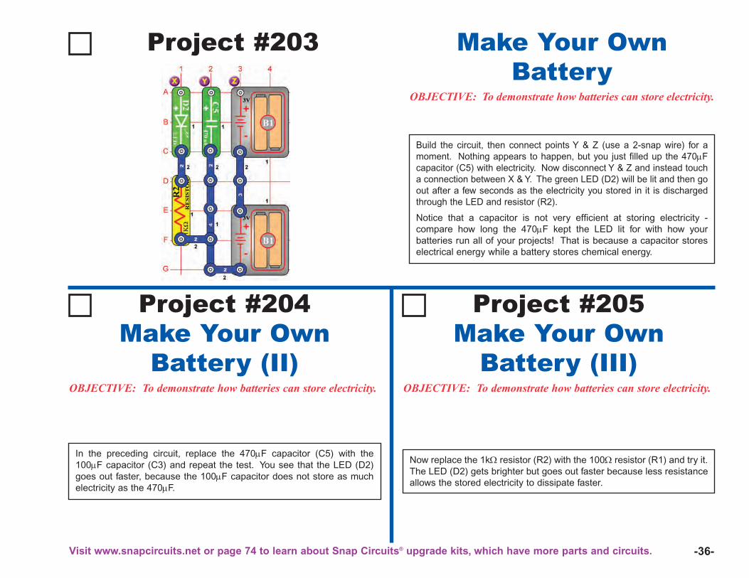
Project #203
OBJECTIVE: To demonstrate how batteries can store electricity.
Build the circuit, then connect points Y & Z (use a 2-snap wire) for amoment. Nothing appears to happen, but you just filled up the 470μFcapacitor (C5) with electricity. Now disconnect Y & Z and instead toucha connection between X & Y. The green LED (D2) will be lit and then goout after a few seconds as the electricity you stored in it is dischargedthrough the LED and resistor (R2).
Notice that a capacitor is not very efficient at storing electricity -compare how long the 470μF kept the LED lit for with how yourbatteries run all of your projects! That is because a capacitor storeselectrical energy while a battery stores chemical energy.
Make Your OwnBattery
OBJECTIVE: To demonstrate how batteries can store electricity. OBJECTIVE: To demonstrate how batteries can store electricity.
Now replace the 1kΩ resistor (R2) with the 100Ω resistor (R1) and try it.The LED (D2) gets brighter but goes out faster because less resistanceallows the stored electricity to dissipate faster.
In the preceding circuit, replace the 470μF capacitor (C5) with the100μF capacitor (C3) and repeat the test. You see that the LED (D2)goes out faster, because the 100μF capacitor does not store as muchelectricity as the 470μF.
Project #204Make Your Own
Battery (II)
Project #205Make Your Own
Battery (III)
Visit www.snapcircuits.net or page 74 to learn about Snap Circuits® upgrade kits, which have more parts and circuits.
-37-
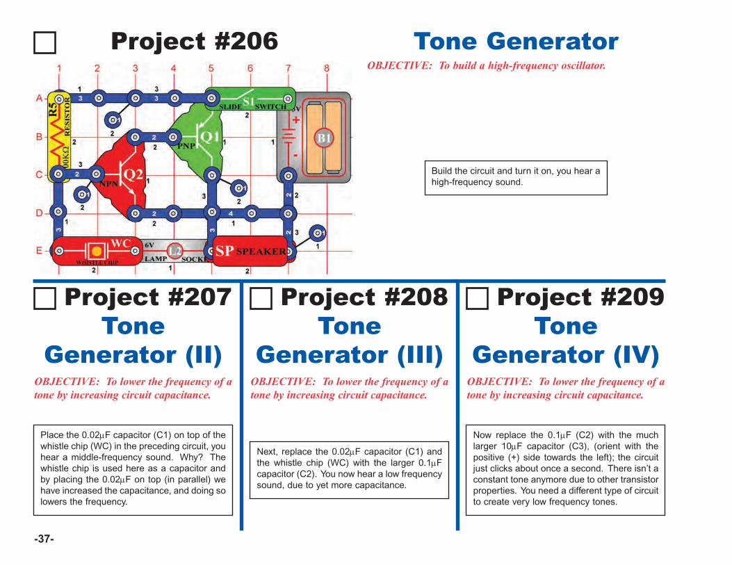
Project #206OBJECTIVE: To build a high-frequency oscillator.
Tone Generator
Project #207Tone
Generator (II)OBJECTIVE: To lower the frequency of atone by increasing circuit capacitance.
Place the 0.02μF capacitor (C1) on top of thewhistle chip (WC) in the preceding circuit, youhear a middle-frequency sound. Why? Thewhistle chip is used here as a capacitor andby placing the 0.02μF on top (in parallel) wehave increased the capacitance, and doing solowers the frequency.
Project #208Tone
Generator (III)OBJECTIVE: To lower the frequency of atone by increasing circuit capacitance.
Next, replace the 0.02μF capacitor (C1) andthe whistle chip (WC) with the larger 0.1μFcapacitor (C2). You now hear a low frequencysound, due to yet more capacitance.
Project #209 Tone
Generator (IV)OBJECTIVE: To lower the frequency of atone by increasing circuit capacitance.
Now replace the 0.1μF (C2) with the muchlarger 10μF capacitor (C3), (orient with thepositive (+) side towards the left); the circuitjust clicks about once a second. There isn’t aconstant tone anymore due to other transistorproperties. You need a different type of circuitto create very low frequency tones.
Build the circuit and turn it on, you hear ahigh-frequency sound.
-38-
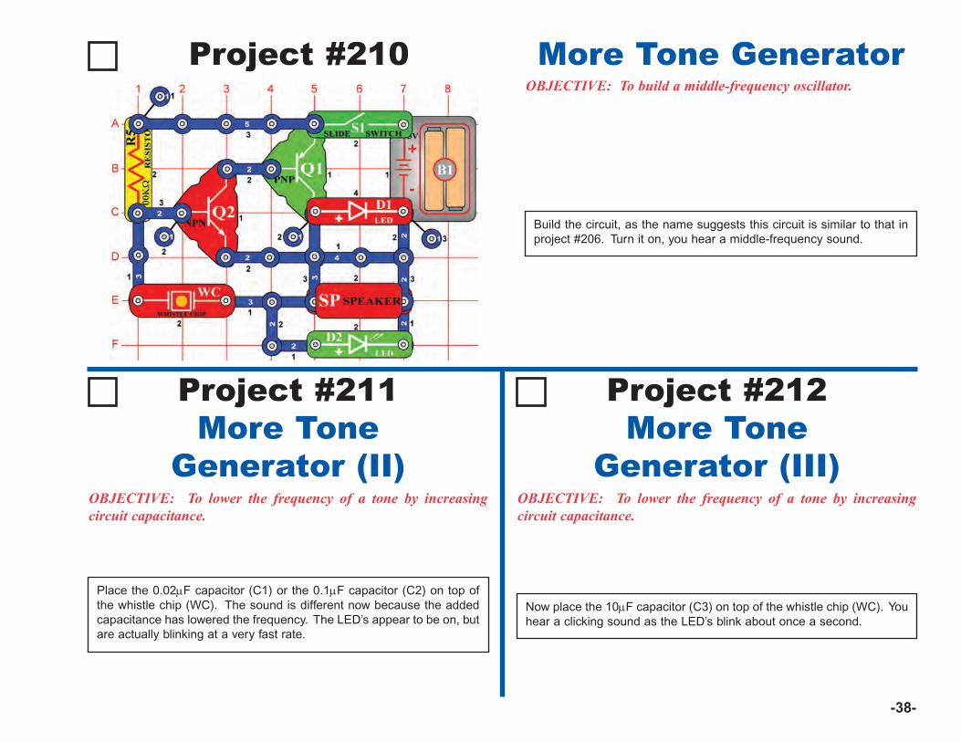
Project #210OBJECTIVE: To build a middle-frequency oscillator.
Build the circuit, as the name suggests this circuit is similar to that inproject #206. Turn it on, you hear a middle-frequency sound.
More Tone Generator
OBJECTIVE: To lower the frequency of a tone by increasingcircuit capacitance.
OBJECTIVE: To lower the frequency of a tone by increasingcircuit capacitance.
Now place the 10μF capacitor (C3) on top of the whistle chip (WC). Youhear a clicking sound as the LED’s blink about once a second.
Place the 0.02μF capacitor (C1) or the 0.1μF capacitor (C2) on top ofthe whistle chip (WC). The sound is different now because the addedcapacitance has lowered the frequency. The LED’s appear to be on, butare actually blinking at a very fast rate.
Project #211More Tone
Generator (II)
Project #212More Tone
Generator (III)
-39-
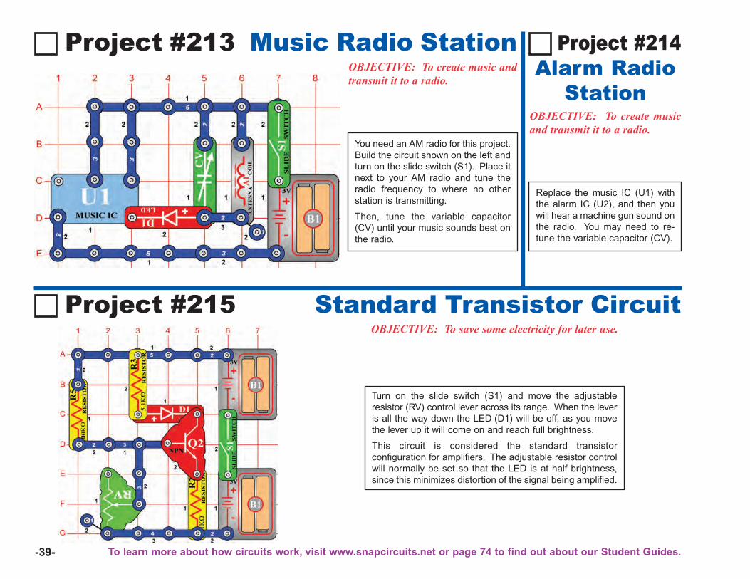
Project #213 Music Radio StationOBJECTIVE: To create music andtransmit it to a radio.
OBJECTIVE: To create musicand transmit it to a radio.
Project #214Alarm Radio
Station
Project #215 Standard Transistor CircuitOBJECTIVE: To save some electricity for later use.
Turn on the slide switch (S1) and move the adjustableresistor (RV) control lever across its range. When the leveris all the way down the LED (D1) will be off, as you movethe lever up it will come on and reach full brightness.
This circuit is considered the standard transistorconfiguration for amplifiers. The adjustable resistor controlwill normally be set so that the LED is at half brightness,since this minimizes distortion of the signal being amplified.
Replace the music IC (U1) withthe alarm IC (U2), and then youwill hear a machine gun sound onthe radio. You may need to re-tune the variable capacitor (CV).
You need an AM radio for this project.Build the circuit shown on the left andturn on the slide switch (S1). Place itnext to your AM radio and tune theradio frequency to where no otherstation is transmitting.
Then, tune the variable capacitor(CV) until your music sounds best onthe radio.
To learn more about how circuits work, visit www.snapcircuits.net or page 74 to find out about our Student Guides.
-40-
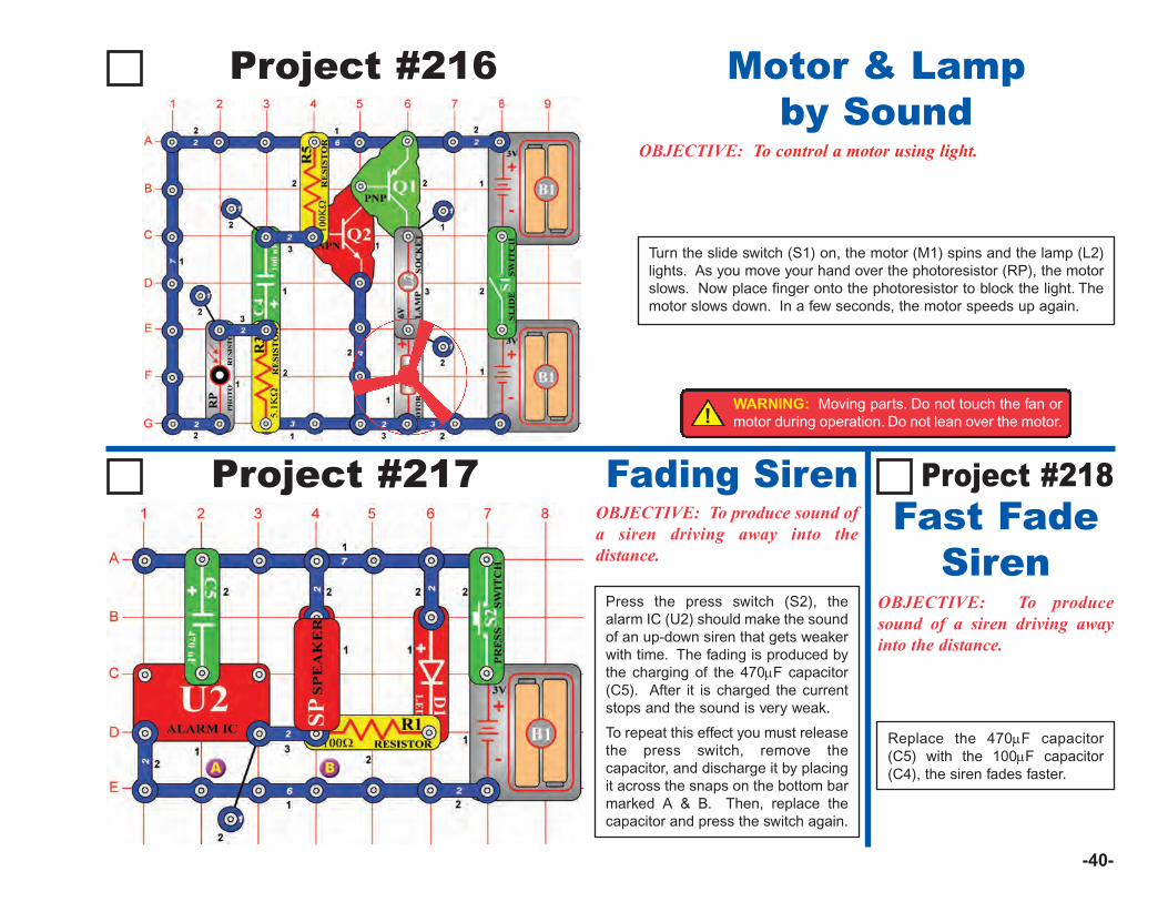
Project #217 Fading SirenOBJECTIVE: To produce sound ofa siren driving away into thedistance.
OBJECTIVE: To producesound of a siren driving awayinto the distance.
Replace the 470μF capacitor(C5) with the 100μF capacitor(C4), the siren fades faster.
Press the press switch (S2), thealarm IC (U2) should make the soundof an up-down siren that gets weakerwith time. The fading is produced bythe charging of the 470μF capacitor(C5). After it is charged the currentstops and the sound is very weak.
To repeat this effect you must releasethe press switch, remove thecapacitor, and discharge it by placingit across the snaps on the bottom barmarked A & B. Then, replace thecapacitor and press the switch again.
Project #218Fast Fade
Siren
Project #216
OBJECTIVE: To control a motor using light.
Turn the slide switch (S1) on, the motor (M1) spins and the lamp (L2)lights. As you move your hand over the photoresistor (RP), the motorslows. Now place finger onto the photoresistor to block the light. Themotor slows down. In a few seconds, the motor speeds up again.
Motor & Lampby Sound
!WARNING: Moving parts. Do not touch the fan ormotor during operation. Do not lean over the motor.
-41-
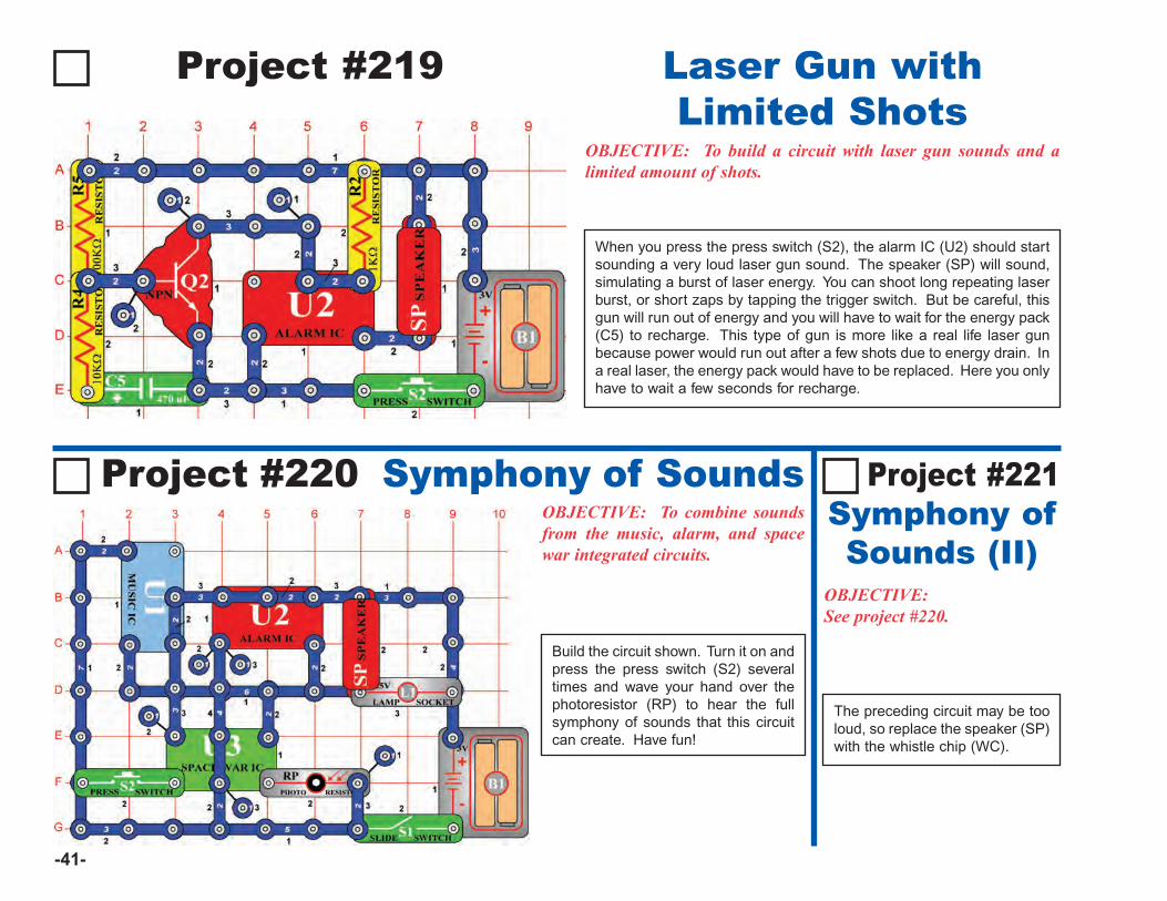
Project #219 Laser Gun withLimited Shots
OBJECTIVE: To build a circuit with laser gun sounds and alimited amount of shots.
Project #220 Symphony of SoundsOBJECTIVE: To combine soundsfrom the music, alarm, and spacewar integrated circuits.
OBJECTIVE:See project #220.
The preceding circuit may be tooloud, so replace the speaker (SP)with the whistle chip (WC).
Build the circuit shown. Turn it on andpress the press switch (S2) severaltimes and wave your hand over thephotoresistor (RP) to hear the fullsymphony of sounds that this circuitcan create. Have fun!
When you press the press switch (S2), the alarm IC (U2) should startsounding a very loud laser gun sound. The speaker (SP) will sound,simulating a burst of laser energy. You can shoot long repeating laserburst, or short zaps by tapping the trigger switch. But be careful, thisgun will run out of energy and you will have to wait for the energy pack(C5) to recharge. This type of gun is more like a real life laser gunbecause power would run out after a few shots due to energy drain. Ina real laser, the energy pack would have to be replaced. Here you onlyhave to wait a few seconds for recharge.
Project #221Symphony ofSounds (II)
-42-
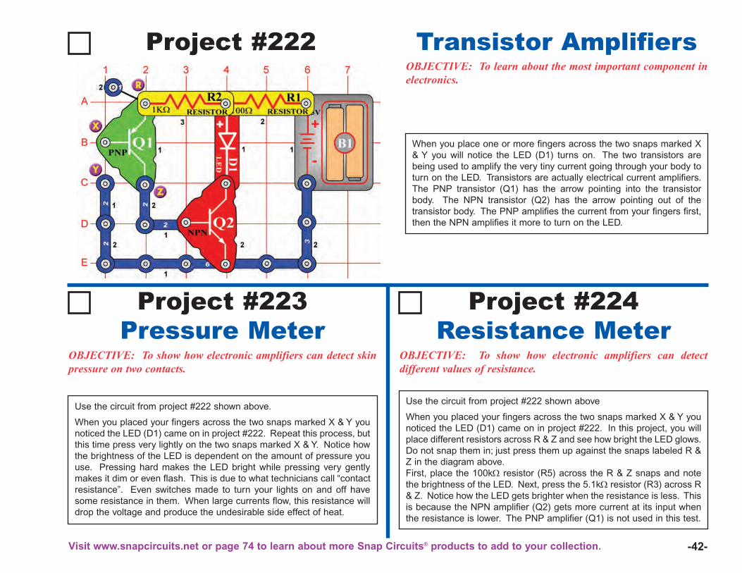
Project #222OBJECTIVE: To learn about the most important component inelectronics.
Transistor Amplifiers
OBJECTIVE: To show how electronic amplifiers can detect skinpressure on two contacts.
OBJECTIVE: To show how electronic amplifiers can detectdifferent values of resistance.
Use the circuit from project #222 shown above.
When you placed your fingers across the two snaps marked X & Y younoticed the LED (D1) came on in project #222. Repeat this process, butthis time press very lightly on the two snaps marked X & Y. Notice howthe brightness of the LED is dependent on the amount of pressure youuse. Pressing hard makes the LED bright while pressing very gentlymakes it dim or even flash. This is due to what technicians call “contactresistance”. Even switches made to turn your lights on and off havesome resistance in them. When large currents flow, this resistance willdrop the voltage and produce the undesirable side effect of heat.
Project #223Pressure Meter
Project #224Resistance Meter
When you place one or more fingers across the two snaps marked X& Y you will notice the LED (D1) turns on. The two transistors arebeing used to amplify the very tiny current going through your body toturn on the LED. Transistors are actually electrical current amplifiers.The PNP transistor (Q1) has the arrow pointing into the transistorbody. The NPN transistor (Q2) has the arrow pointing out of thetransistor body. The PNP amplifies the current from your fingers first,then the NPN amplifies it more to turn on the LED.
Use the circuit from project #222 shown above
When you placed your fingers across the two snaps marked X & Y younoticed the LED (D1) came on in project #222. In this project, you willplace different resistors across R & Z and see how bright the LED glows.Do not snap them in; just press them up against the snaps labeled R &Z in the diagram above.First, place the 100kΩ resistor (R5) across the R & Z snaps and notethe brightness of the LED. Next, press the 5.1kΩ resistor (R3) across R& Z. Notice how the LED gets brighter when the resistance is less. Thisis because the NPN amplifier (Q2) gets more current at its input whenthe resistance is lower. The PNP amplifier (Q1) is not used in this test.
Visit www.snapcircuits.net or page 74 to learn about more Snap Circuits® products to add to your collection.
-43-
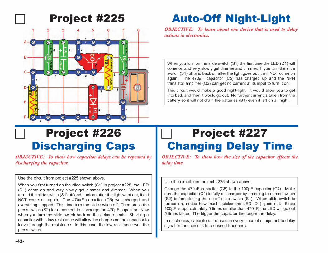
Project #225OBJECTIVE: To learn about one device that is used to delayactions in electronics.
Auto-Off Night-Light
OBJECTIVE: To show how capacitor delays can be repeated bydischarging the capacitor.
OBJECTIVE: To show how the size of the capacitor effects thedelay time.
Use the circuit from project #225 shown above.
When you first turned on the slide switch (S1) in project #225, the LED(D1) came on and very slowly got dimmer and dimmer. When youturned the slide switch (S1) off and back on after the light went out, it didNOT come on again. The 470μF capacitor (C5) was charged andeverything stopped. This time turn the slide switch off. Then press thepress switch (S2) for a moment to discharge the 470μF capacitor. Nowwhen you turn the slide switch back on the delay repeats. Shorting acapacitor with a low resistance will allow the charges on the capacitor toleave through the resistance. In this case, the low resistance was thepress switch.
Project #226Discharging Caps
Project #227Changing Delay Time
When you turn on the slide switch (S1) the first time the LED (D1) willcome on and very slowly get dimmer and dimmer. If you turn the slideswitch (S1) off and back on after the light goes out it will NOT come onagain. The 470μF capacitor (C5) has charged up and the NPNtransistor amplifier (Q2) can get no current at its input to turn it on.
This circuit would make a good night-light. It would allow you to getinto bed, and then it would go out. No further current is taken from thebattery so it will not drain the batteries (B1) even if left on all night.
Use the circuit from project #225 shown above.
Change the 470μF capacitor (C5) to the 100μF capacitor (C4). Makesure the capacitor (C4) is fully discharged by pressing the press switch(S2) before closing the on-off slide switch (S1). When slide switch isturned on, notice how much quicker the LED (D1) goes out. Since100μF is approximately 5 times smaller than 470μF, the LED will go out5 times faster. The bigger the capacitor the longer the delay.
In electronics, capacitors are used in every piece of equipment to delaysignal or tune circuits to a desired frequency.

-44-
Project #228 Morse Code GeneratorOBJECTIVE: To make a Morse code generator and learn togenerate code.
Project #229LED CodeTeacher
OBJECTIVE: A method oflearning the Morse code withoutall the noise.
Use the circuit from project #228shown above. Replace thespeaker with a 100Ω resistor (R1)so you can practice generatingthe Morse code without the loudspeaker. Have someone transmitcode and watch the LED. Tellthem the letter or number aftereach is generated. When youhave learned code, replace thespeaker.
OBJECTIVE: To make a ghostlike special effect from the Morsecode generator.
Project #231 LED &
SpeakerOBJECTIVE: To improveMorse code skills and visualrecognition.
OBJECTIVE: To make anoscillator that only a dog canhear.
Project #230 Ghost Shriek
Machine
Use the circuit from project #228shown above, but change the 1kΩresistor (R2) to a 10kΩ resistor(R4), and 0.1μF capacitor (C2) tothe whistle chip (WC). Whileholding the press switch (S2)down, adjust both the adjustableresistor (RV) and the whistle chipfor a ghost like sound. At certainsettings, sound may stop or getvery faint.
Use the circuit from project #228shown above. Try and find aperson that already knows theMorse code to send you amessage with both sound andLED flashing. Try in a dark roomfirst so LED (D1) is easier to see.Morse code is still used by manyamateur radio operators to sendmessages around the world.
Use the circuit from project #228shown above, but change the 1kΩresistor (R2) to the 100Ω resistor(R1). While holding down the pressswitch (S2), move the slider on theadjustable resistor (RV) around.When the slider is near the 100Ωresistor you won’t hear any sound,but the circuit is still working. Thisoscillator circuit is making soundwaves at a frequency too high foryour ears to hear. But your dog mayhear it, because dogs can hearhigher frequencies than people can.
Project #232 Dog Whistle
When you press down on the press switch (S2) you will hear a tone.By pressing and releasing the press switch you can generate long andshort tones called Morse code. For International code, a short tone isrepresented by a “+”, and a long tone by a “–”. See the chart belowfor letter or number followed by code.
A + –B – + + +C – + – +D – + +E +F + + – +
G – – +H + + + +I + +J + – – –K – + –L + – + +
M – –N – +O – – –P + – – +Q – – + –R + – +
S + + +T –U + + –V + + + –W + – –X – + + –
Y – + – –Z – – + +1 + – – – –2 + + – – –3 + + + – –4 + + + + –
5 + + + + +6 – + + + +7 – – + + +8 – – – + +9 – – – – +0 – – – – –
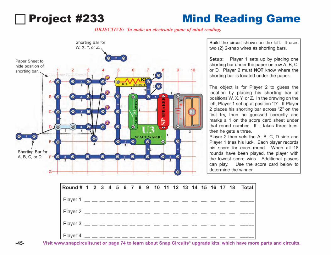
-45-
Project #233 Mind Reading GameOBJECTIVE: To make an electronic game of mind reading.
Build the circuit shown on the left. It usestwo (2) 2-snap wires as shorting bars.
Setup: Player 1 sets up by placing oneshorting bar under the paper on row A, B, C,or D. Player 2 must NOT know where theshorting bar is located under the paper.
The object is for Player 2 to guess thelocation by placing his shorting bar atpositions W, X, Y, or Z. In the drawing on theleft, Player 1 set up at position “D”. If Player2 places his shorting bar across “Z” on thefirst try, then he guessed correctly andmarks a 1 on the score card sheet underthat round number. If it takes three tries,then he gets a three.Player 2 then sets the A, B, C, D side andPlayer 1 tries his luck. Each player recordshis score for each round. When all 18rounds have been played, the player withthe lowest score wins. Additional playerscan play. Use the score card below todetermine the winner.
Round # 1 2 3 4 5 6 7 8 9 10 11 12 13 14 15 16 17 18 Total
Player 1 __ __ __ __ __ __ __ __ __ __ __ __ __ __ __ __ __ __ _____
Player 2 __ __ __ __ __ __ __ __ __ __ __ __ __ __ __ __ __ __ _____
Player 3 __ __ __ __ __ __ __ __ __ __ __ __ __ __ __ __ __ __ _____
Player 4 __ __ __ __ __ __ __ __ __ __ __ __ __ __ __ __ __ __ _____
Shorting Bar forA, B, C, or D.
Paper Sheet tohide position ofshorting bar.
Shorting Bar forW, X, Y, or Z.
Visit www.snapcircuits.net or page 74 to learn about Snap Circuits® upgrade kits, which have more parts and circuits.
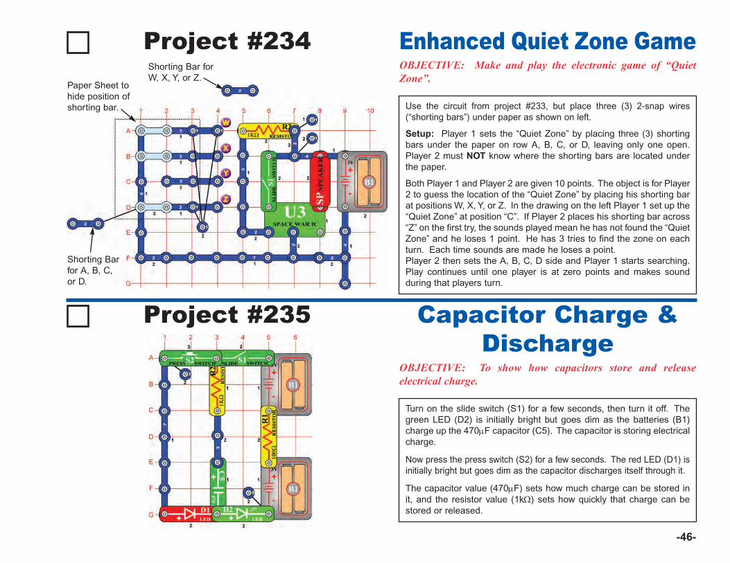
-46-
Project #234OBJECTIVE: Make and play the electronic game of “QuietZone”.
Use the circuit from project #233, but place three (3) 2-snap wires(“shorting bars”) under paper as shown on left.
Setup: Player 1 sets the “Quiet Zone” by placing three (3) shortingbars under the paper on row A, B, C, or D, leaving only one open.Player 2 must NOT know where the shorting bars are located underthe paper.
Both Player 1 and Player 2 are given 10 points. The object is for Player2 to guess the location of the “Quiet Zone” by placing his shorting barat positions W, X, Y, or Z. In the drawing on the left Player 1 set up the“Quiet Zone” at position “C”. If Player 2 places his shorting bar across“Z” on the first try, the sounds played mean he has not found the “QuietZone” and he loses 1 point. He has 3 tries to find the zone on eachturn. Each time sounds are made he loses a point.Player 2 then sets the A, B, C, D side and Player 1 starts searching.Play continues until one player is at zero points and makes soundduring that players turn.
Enhanced Quiet Zone Game
Project #235
OBJECTIVE: To show how capacitors store and releaseelectrical charge.
Turn on the slide switch (S1) for a few seconds, then turn it off. Thegreen LED (D2) is initially bright but goes dim as the batteries (B1)charge up the 470μF capacitor (C5). The capacitor is storing electricalcharge.
Now press the press switch (S2) for a few seconds. The red LED (D1) isinitially bright but goes dim as the capacitor discharges itself through it.
The capacitor value (470μF) sets how much charge can be stored init, and the resistor value (1kΩ) sets how quickly that charge can bestored or released.
Capacitor Charge &Discharge
Shorting Barfor A, B, C,or D.
Paper Sheet tohide position ofshorting bar.
Shorting Bar forW, X, Y, or Z.
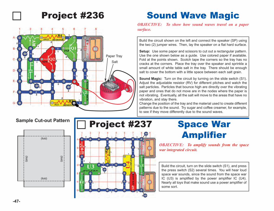
-47-
Project #236OBJECTIVE: To show how sound waves travel on a papersurface.
Sound Wave Magic
Project #237
OBJECTIVE: To amplify sounds from the spacewar integrated circuit.
Build the circuit, turn on the slide switch (S1), and pressthe press switch (S2) several times. You will hear loudspace war sounds, since the sound from the space warIC (U3) is amplified by the power amplifier IC (U4).Nearly all toys that make sound use a power amplifier ofsome sort.
Space WarAmplifier
Build the circuit shown on the left and connect the speaker (SP) usingthe two (2) jumper wires. Then, lay the speaker on a flat hard surface.
Setup: Use some paper and scissors to cut out a rectangular pattern.Use the one shown below as a guide. Use colored paper if available.Fold at the points shown. Scotch tape the corners so the tray has nocracks at the corners. Place the tray over the speaker and sprinkle asmall amount of white table salt in the tray. There should be enoughsalt to cover the bottom with a little space between each salt grain.
Sound Magic: Turn on the circuit by turning on the slide switch (S1).Adjust the adjustable resistor (RV) for different pitches and watch thesalt particles. Particles that bounce high are directly over the vibratingpaper and ones that do not move are in the nodes where the paper isnot vibrating. Eventually, all the salt will move to the areas that have novibration, and stay there.Change the position of the tray and the material used to create differentpatterns due to the sound. Try sugar and coffee creamer, for example,to see if they move differently due to the sound waves.
Paper Tray
Salt
Sample Cut-out Pattern
(fold)
(fold)
(fold)
(fold)

-48-
Project #238Trombone
OBJECTIVE: To build an electronic trombone that changes pitchof note with slider bar.
When you turn on the slide switch (S1) the trombone should start playing.To change the pitch of the note, simply slide the adjustable resistor (RV)control back and forth. By turning the slide switch on and off and movingthe slider, you will be able to play a song much like a trombone playermakes music. The switch represents air going through the trombone, andthe adjustable resistor control is the same as a trombone slider bar. Thecircuit may be silent at some positions of the resistor control.
Project #239Race Car Engine
OBJECTIVE: To show how changing frequency changes thesound to a different special effect.
Use the circuit from project #238 shown on the left, but change the0.02μF capacitor (C1) to a 10μF capacitor (C3). Make sure the positive(+) mark on the capacitor is NOT on the resistor (R2) side when you snapit in.
When the slide switch (S1) is turned on, you should hear a very lowfrequency oscillation. By sliding the adjustable resistor (RV) control upand down, you should be able to make the sound of a race car engine asit’s motor speeds up and slows down.
To learn more about how circuits work, visit www.snapcircuits.net or page 74 to find out about our Student Guides.
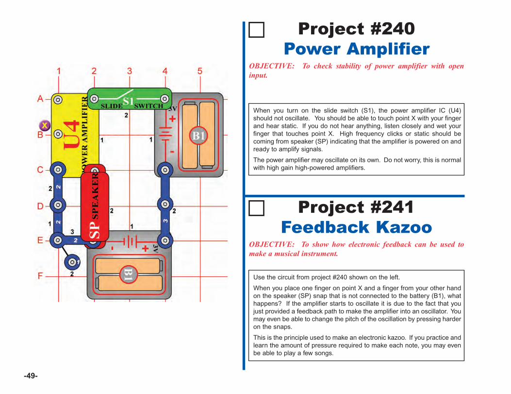
-49-
Project #240Power Amplifier
OBJECTIVE: To check stability of power amplifier with openinput.
When you turn on the slide switch (S1), the power amplifier IC (U4)should not oscillate. You should be able to touch point X with your fingerand hear static. If you do not hear anything, listen closely and wet yourfinger that touches point X. High frequency clicks or static should becoming from speaker (SP) indicating that the amplifier is powered on andready to amplify signals.
The power amplifier may oscillate on its own. Do not worry, this is normalwith high gain high-powered amplifiers.
Project #241Feedback Kazoo
OBJECTIVE: To show how electronic feedback can be used tomake a musical instrument.
Use the circuit from project #240 shown on the left.
When you place one finger on point X and a finger from your other handon the speaker (SP) snap that is not connected to the battery (B1), whathappens? If the amplifier starts to oscillate it is due to the fact that youjust provided a feedback path to make the amplifier into an oscillator. Youmay even be able to change the pitch of the oscillation by pressing harderon the snaps.
This is the principle used to make an electronic kazoo. If you practice andlearn the amount of pressure required to make each note, you may evenbe able to play a few songs.
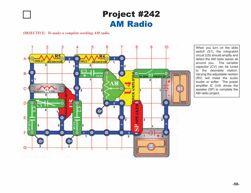
-50-
Project #242
OBJECTIVE: To make a complete working AM radio.
When you turn on the slideswitch (S1), the integratedcircuit (U5) should amplify anddetect the AM radio waves allaround you. The variablecapacitor (CV) can be tunedto the desirable station.Varying the adjustable resistor(RV) will make the audiolouder or softer. The poweramplifier IC (U4) drives thespeaker (SP) to complete theAM radio project.
AM Radio
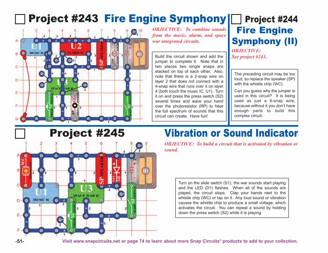
-51-
Project #243 Fire Engine SymphonyOBJECTIVE: To combine soundsfrom the music, alarm, and spacewar integrated circuits.
OBJECTIVE:See project #243.
Project #244Fire Engine
Symphony (II)
Project #245 Vibration or Sound IndicatorOBJECTIVE: To build a circuit that is activated by vibration orsound.
Turn on the slide switch (S1), the war sounds start playingand the LED (D1) flashes. When all of the sounds areplayed, the circuit stops. Clap your hands next to thewhistle chip (WC) or tap on it. Any loud sound or vibrationcauses the whistle chip to produce a small voltage, whichactivates the circuit. You can repeat a sound by holdingdown the press switch (S2) while it is playing.
The preceding circuit may be tooloud, so replace the speaker (SP)with the whistle chip (WC).
Can you guess why the jumper isused in this circuit? It is beingused as just a 6-snap wire,because without it you don’t haveenough parts to build thiscomplex circuit.
Build the circuit shown and add thejumper to complete it. Note that intwo places two single snaps arestacked on top of each other. Also,note that there is a 2-snap wire onlayer 2 that does not connect with a4-snap wire that runs over it on layer4 (both touch the music IC, U1). Turnit on and press the press switch (S2)several times and wave your handover the photoresistor (RP) to hearthe full spectrum of sounds that thiscircuit can create. Have fun!
Visit www.snapcircuits.net or page 74 to learn about more Snap Circuits® products to add to your collection.
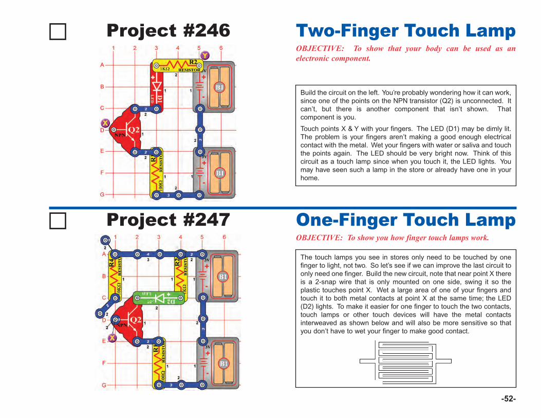
-52-
Project #246OBJECTIVE: To show that your body can be used as anelectronic component.
Build the circuit on the left. You’re probably wondering how it can work,since one of the points on the NPN transistor (Q2) is unconnected. Itcan’t, but there is another component that isn’t shown. Thatcomponent is you.
Touch points X & Y with your fingers. The LED (D1) may be dimly lit.The problem is your fingers aren’t making a good enough electricalcontact with the metal. Wet your fingers with water or saliva and touchthe points again. The LED should be very bright now. Think of thiscircuit as a touch lamp since when you touch it, the LED lights. Youmay have seen such a lamp in the store or already have one in yourhome.
Two-Finger Touch Lamp
Project #247OBJECTIVE: To show you how finger touch lamps work.
The touch lamps you see in stores only need to be touched by onefinger to light, not two. So let’s see if we can improve the last circuit toonly need one finger. Build the new circuit, note that near point X thereis a 2-snap wire that is only mounted on one side, swing it so theplastic touches point X. Wet a large area of one of your fingers andtouch it to both metal contacts at point X at the same time; the LED(D2) lights. To make it easier for one finger to touch the two contacts,touch lamps or other touch devices will have the metal contactsinterweaved as shown below and will also be more sensitive so thatyou don’t have to wet your finger to make good contact.
One-Finger Touch Lamp
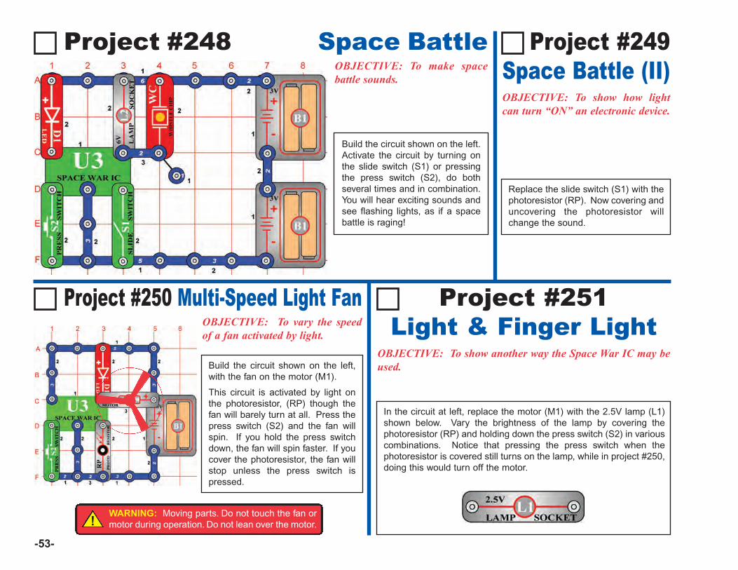
-53-
Project #248 Space BattleOBJECTIVE: To make spacebattle sounds.
Project #250 Multi-Speed Light FanOBJECTIVE: To vary the speedof a fan activated by light.
OBJECTIVE: To show how lightcan turn “ON” an electronic device.
Replace the slide switch (S1) with thephotoresistor (RP). Now covering anduncovering the photoresistor willchange the sound.
Project #249 Space Battle (II)
Project #251Light & Finger Light
OBJECTIVE: To show another way the Space War IC may beused.
In the circuit at left, replace the motor (M1) with the 2.5V lamp (L1)shown below. Vary the brightness of the lamp by covering thephotoresistor (RP) and holding down the press switch (S2) in variouscombinations. Notice that pressing the press switch when thephotoresistor is covered still turns on the lamp, while in project #250,doing this would turn off the motor.
Build the circuit shown on the left.Activate the circuit by turning onthe slide switch (S1) or pressingthe press switch (S2), do bothseveral times and in combination.You will hear exciting sounds andsee flashing lights, as if a spacebattle is raging!
Build the circuit shown on the left,with the fan on the motor (M1).
This circuit is activated by light onthe photoresistor, (RP) though thefan will barely turn at all. Press thepress switch (S2) and the fan willspin. If you hold the press switchdown, the fan will spin faster. If youcover the photoresistor, the fan willstop unless the press switch ispressed.
!WARNING: Moving parts. Do not touch the fan ormotor during operation. Do not lean over the motor.
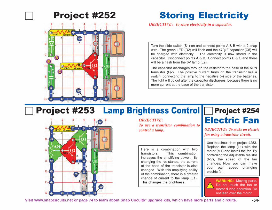
-54-
Project #252 Storing ElectricityOBJECTIVE: To store electricity in a capacitor.
Project #253 Lamp Brightness ControlOBJECTIVE:To use a transistor combination tocontrol a lamp. OBJECTIVE: To make an electric
fan using a transistor circuit.
Use the circuit from project #253.Replace the lamp (L1) with themotor (M1) and install the fan. Bycontrolling the adjustable resistor(RV), the speed of the fanchanges. Now you can makeyour own speed changingelectric fan.
Here is a combination with twotransistors. This combinationincreases the amplifying power. Bychanging the resistance, the currentat the base of the transistor is alsochanged. With this amplifying abilityof the combination, there is a greaterchange of current to the lamp (L1).This changes the brightness.
Turn the slide switch (S1) on and connect points A & B with a 2-snapwire. The green LED (D2) will flash and the 470μF capacitor (C5) willbe charged with electricity. The electricity is now stored in thecapacitor. Disconnect points A & B. Connect points B & C and therewill be a flash from the 6V lamp (L2).
The capacitor discharges through the resistor to the base of the NPNtransistor (Q2). The positive current turns on the transistor like aswitch, connecting the lamp to the negative (–) side of the batteries.The light will go out after the capacitor discharges, because there is nomore current at the base of the transistor.
Project #254Electric Fan
!WARNING: Moving parts.Do not touch the fan ormotor during operation. Donot lean over the motor.
Visit www.snapcircuits.net or page 74 to learn about Snap Circuits® upgrade kits, which have more parts and circuits.
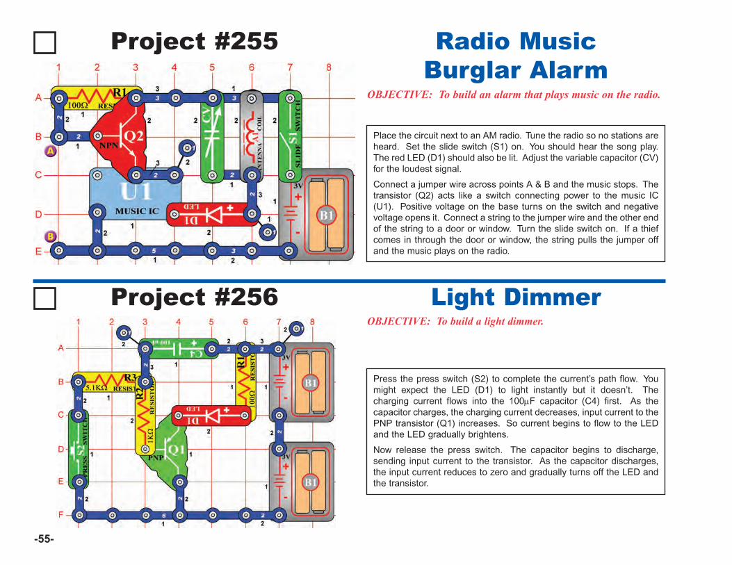
-55-
Project #255
OBJECTIVE: To build an alarm that plays music on the radio.
Place the circuit next to an AM radio. Tune the radio so no stations areheard. Set the slide switch (S1) on. You should hear the song play.The red LED (D1) should also be lit. Adjust the variable capacitor (CV)for the loudest signal.
Connect a jumper wire across points A & B and the music stops. Thetransistor (Q2) acts like a switch connecting power to the music IC(U1). Positive voltage on the base turns on the switch and negativevoltage opens it. Connect a string to the jumper wire and the other endof the string to a door or window. Turn the slide switch on. If a thiefcomes in through the door or window, the string pulls the jumper offand the music plays on the radio.
Radio MusicBurglar Alarm
Project #256OBJECTIVE: To build a light dimmer.
Press the press switch (S2) to complete the current’s path flow. Youmight expect the LED (D1) to light instantly but it doesn’t. Thecharging current flows into the 100μF capacitor (C4) first. As thecapacitor charges, the charging current decreases, input current to thePNP transistor (Q1) increases. So current begins to flow to the LEDand the LED gradually brightens.
Now release the press switch. The capacitor begins to discharge,sending input current to the transistor. As the capacitor discharges,the input current reduces to zero and gradually turns off the LED andthe transistor.
Light Dimmer
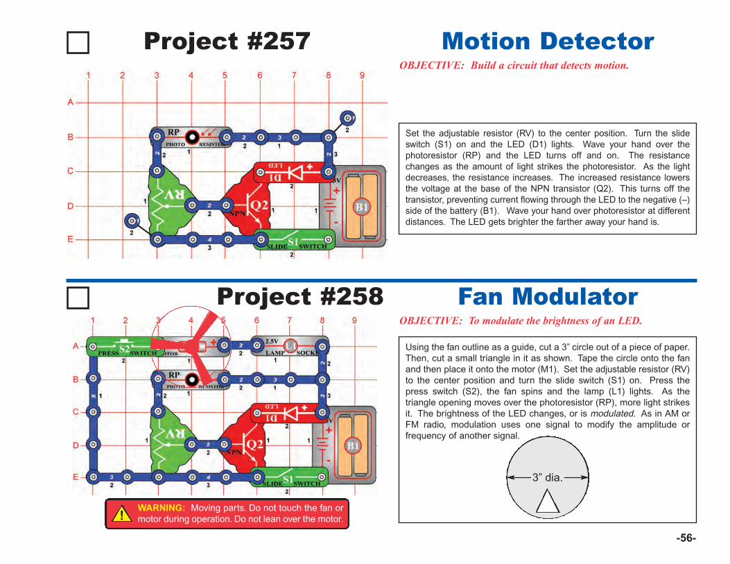
-56-
Project #257OBJECTIVE: Build a circuit that detects motion.
Set the adjustable resistor (RV) to the center position. Turn the slideswitch (S1) on and the LED (D1) lights. Wave your hand over thephotoresistor (RP) and the LED turns off and on. The resistancechanges as the amount of light strikes the photoresistor. As the lightdecreases, the resistance increases. The increased resistance lowersthe voltage at the base of the NPN transistor (Q2). This turns off thetransistor, preventing current flowing through the LED to the negative (–)side of the battery (B1). Wave your hand over photoresistor at differentdistances. The LED gets brighter the farther away your hand is.
Motion Detector
Project #258OBJECTIVE: To modulate the brightness of an LED.
Using the fan outline as a guide, cut a 3” circle out of a piece of paper.Then, cut a small triangle in it as shown. Tape the circle onto the fanand then place it onto the motor (M1). Set the adjustable resistor (RV)to the center position and turn the slide switch (S1) on. Press thepress switch (S2), the fan spins and the lamp (L1) lights. As thetriangle opening moves over the photoresistor (RP), more light strikesit. The brightness of the LED changes, or is modulated. As in AM orFM radio, modulation uses one signal to modify the amplitude orfrequency of another signal.
Fan Modulator
3” dia.
!WARNING: Moving parts. Do not touch the fan ormotor during operation. Do not lean over the motor.
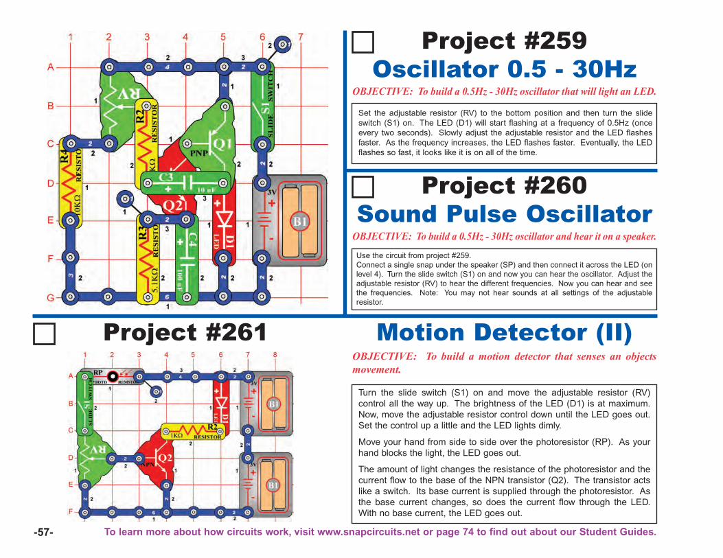
-57-
Project #261OBJECTIVE: To build a motion detector that senses an objectsmovement.
Turn the slide switch (S1) on and move the adjustable resistor (RV)control all the way up. The brightness of the LED (D1) is at maximum.Now, move the adjustable resistor control down until the LED goes out.Set the control up a little and the LED lights dimly.
Move your hand from side to side over the photoresistor (RP). As yourhand blocks the light, the LED goes out.
The amount of light changes the resistance of the photoresistor and thecurrent flow to the base of the NPN transistor (Q2). The transistor actslike a switch. Its base current is supplied through the photoresistor. Asthe base current changes, so does the current flow through the LED.With no base current, the LED goes out.
Motion Detector (II)
Project #259Oscillator 0.5 - 30Hz
OBJECTIVE: To build a 0.5Hz - 30Hz oscillator that will light an LED.
Set the adjustable resistor (RV) to the bottom position and then turn the slideswitch (S1) on. The LED (D1) will start flashing at a frequency of 0.5Hz (onceevery two seconds). Slowly adjust the adjustable resistor and the LED flashesfaster. As the frequency increases, the LED flashes faster. Eventually, the LEDflashes so fast, it looks like it is on all of the time.
Project #260Sound Pulse Oscillator
OBJECTIVE: To build a 0.5Hz - 30Hz oscillator and hear it on a speaker.
Use the circuit from project #259. Connect a single snap under the speaker (SP) and then connect it across the LED (onlevel 4). Turn the slide switch (S1) on and now you can hear the oscillator. Adjust theadjustable resistor (RV) to hear the different frequencies. Now you can hear and seethe frequencies. Note: You may not hear sounds at all settings of the adjustableresistor.
To learn more about how circuits work, visit www.snapcircuits.net or page 74 to find out about our Student Guides.
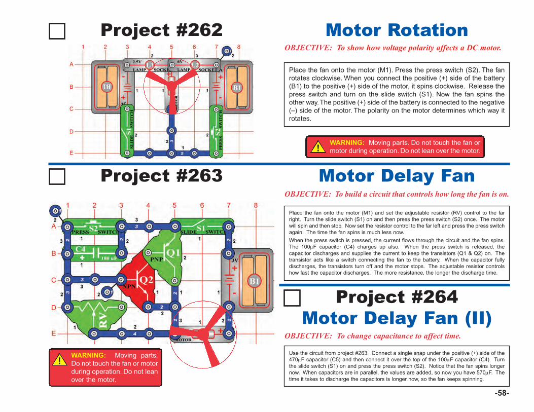
-58-
Project #262OBJECTIVE: To show how voltage polarity affects a DC motor.
Place the fan onto the motor (M1). Press the press switch (S2). The fanrotates clockwise. When you connect the positive (+) side of the battery(B1) to the positive (+) side of the motor, it spins clockwise. Release thepress switch and turn on the slide switch (S1). Now the fan spins theother way. The positive (+) side of the battery is connected to the negative(–) side of the motor. The polarity on the motor determines which way itrotates.
Motor Rotation
OBJECTIVE: To build a circuit that controls how long the fan is on.
Place the fan onto the motor (M1) and set the adjustable resistor (RV) control to the farright. Turn the slide switch (S1) on and then press the press switch (S2) once. The motorwill spin and then stop. Now set the resistor control to the far left and press the press switchagain. The time the fan spins is much less now.
When the press switch is pressed, the current flows through the circuit and the fan spins.The 100μF capacitor (C4) charges up also. When the press switch is released, thecapacitor discharges and supplies the current to keep the transistors (Q1 & Q2) on. Thetransistor acts like a switch connecting the fan to the battery. When the capacitor fullydischarges, the transistors turn off and the motor stops. The adjustable resistor controlshow fast the capacitor discharges. The more resistance, the longer the discharge time.
Project #264Motor Delay Fan (II)
OBJECTIVE: To change capacitance to affect time.
Use the circuit from project #263. Connect a single snap under the positive (+) side of the470μF capacitor (C5) and then connect it over the top of the 100μF capacitor (C4). Turnthe slide switch (S1) on and press the press switch (S2). Notice that the fan spins longernow. When capacitors are in parallel, the values are added, so now you have 570μF. Thetime it takes to discharge the capacitors is longer now, so the fan keeps spinning.
Project #263 Motor Delay Fan!
WARNING: Moving parts. Do not touch the fan ormotor during operation. Do not lean over the motor.
!WARNING: Moving parts.Do not touch the fan or motorduring operation. Do not leanover the motor.

-59-
OBJECTIVE: To build a high pitch bell.
Build the circuit shown and press the press switch (S2). The circuitstarts to oscillate. This generates the sound of a high pitch bell.
Project #266Steamboat Whistle
OBJECTIVE: To build a steamboat whistle.
Using the circuit in project #265, connect the 0.02μF capacitor (C1)across the whistle chip (WC). Press the press switch (S2). Thecircuit now generates the sound of a steamboat.
Project #267Steamship
OBJECTIVE: To generate thesound of a steamship.
Using the circuit in Project #265,connect the 0.1μF capacitor (C2)across the whistle chip. Press thepress switch (S2). The circuit nowgenerates the sound of a steamship.
Project #268 Light NOR GateOBJECTIVE: To build a NOR gate.
Build the circuit on the left. You will find thatthe lamp (L1) is on when neither the slideswitch (S1) NOR the press switch (S2) areon. This is referred to as an NOR gate inelectronics and is important in computerlogic.
Example: If neither condition X NORcondition Y are true, then executeinstruction Z.
Project #265 High Pitch Bell
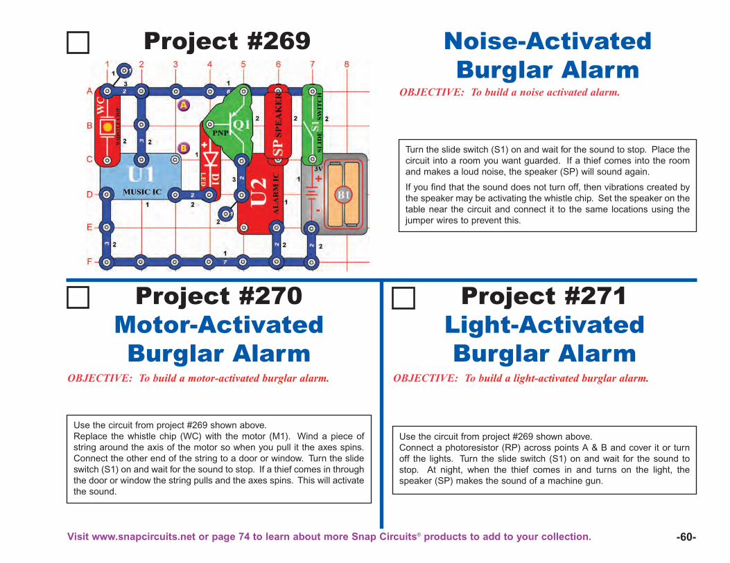
-60-
Project #269
OBJECTIVE: To build a noise activated alarm.
Noise-ActivatedBurglar Alarm
OBJECTIVE: To build a motor-activated burglar alarm. OBJECTIVE: To build a light-activated burglar alarm.
Use the circuit from project #269 shown above.Replace the whistle chip (WC) with the motor (M1). Wind a piece ofstring around the axis of the motor so when you pull it the axes spins.Connect the other end of the string to a door or window. Turn the slideswitch (S1) on and wait for the sound to stop. If a thief comes in throughthe door or window the string pulls and the axes spins. This will activatethe sound.
Project #270Motor-ActivatedBurglar Alarm
Project #271Light-ActivatedBurglar Alarm
Turn the slide switch (S1) on and wait for the sound to stop. Place thecircuit into a room you want guarded. If a thief comes into the roomand makes a loud noise, the speaker (SP) will sound again.
If you find that the sound does not turn off, then vibrations created bythe speaker may be activating the whistle chip. Set the speaker on thetable near the circuit and connect it to the same locations using thejumper wires to prevent this.
Use the circuit from project #269 shown above.Connect a photoresistor (RP) across points A & B and cover it or turnoff the lights. Turn the slide switch (S1) on and wait for the sound tostop. At night, when the thief comes in and turns on the light, thespeaker (SP) makes the sound of a machine gun.
Visit www.snapcircuits.net or page 74 to learn about more Snap Circuits® products to add to your collection.
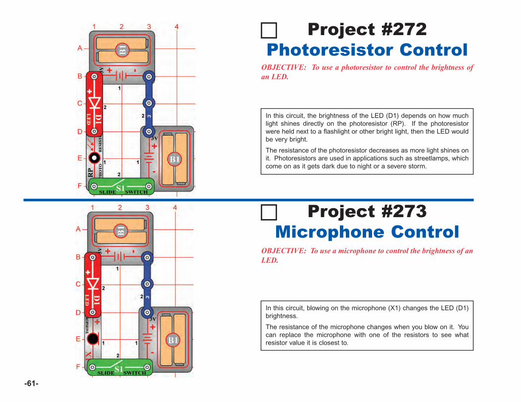
-61-
Project #272Photoresistor Control
OBJECTIVE: To use a photoresistor to control the brightness ofan LED.
In this circuit, the brightness of the LED (D1) depends on how muchlight shines directly on the photoresistor (RP). If the photoresistorwere held next to a flashlight or other bright light, then the LED wouldbe very bright.
The resistance of the photoresistor decreases as more light shines onit. Photoresistors are used in applications such as streetlamps, whichcome on as it gets dark due to night or a severe storm.
Project #273Microphone Control
OBJECTIVE: To use a microphone to control the brightness of anLED.
In this circuit, blowing on the microphone (X1) changes the LED (D1)brightness.
The resistance of the microphone changes when you blow on it. Youcan replace the microphone with one of the resistors to see whatresistor value it is closest to.
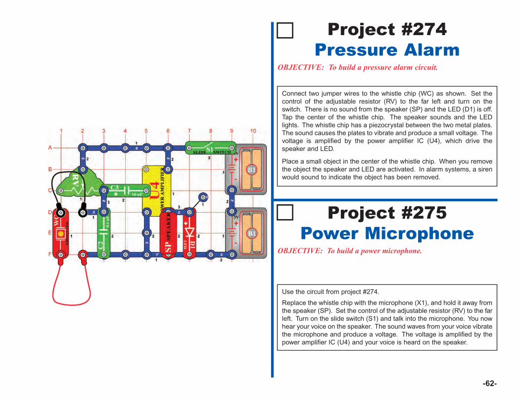
-62-
Project #274Pressure Alarm
OBJECTIVE: To build a pressure alarm circuit.
Connect two jumper wires to the whistle chip (WC) as shown. Set thecontrol of the adjustable resistor (RV) to the far left and turn on theswitch. There is no sound from the speaker (SP) and the LED (D1) is off.Tap the center of the whistle chip. The speaker sounds and the LEDlights. The whistle chip has a piezocrystal between the two metal plates.The sound causes the plates to vibrate and produce a small voltage. Thevoltage is amplified by the power amplifier IC (U4), which drive thespeaker and LED.
Place a small object in the center of the whistle chip. When you removethe object the speaker and LED are activated. In alarm systems, a sirenwould sound to indicate the object has been removed.
Project #275Power Microphone
OBJECTIVE: To build a power microphone.
Use the circuit from project #274.
Replace the whistle chip with the microphone (X1), and hold it away fromthe speaker (SP). Set the control of the adjustable resistor (RV) to the farleft. Turn on the slide switch (S1) and talk into the microphone. You nowhear your voice on the speaker. The sound waves from your voice vibratethe microphone and produce a voltage. The voltage is amplified by thepower amplifier IC (U4) and your voice is heard on the speaker.
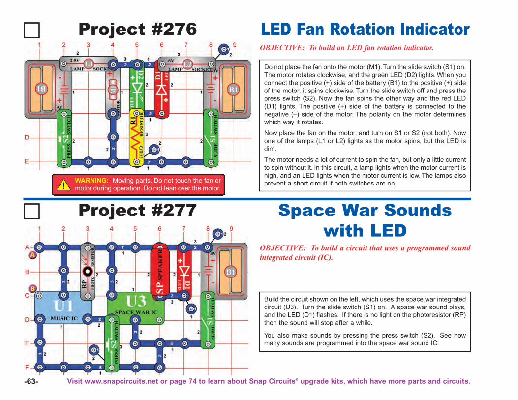
-63-
Project #277
OBJECTIVE: To build a circuit that uses a programmed soundintegrated circuit (IC).
Space War Soundswith LED
Project #276OBJECTIVE: To build an LED fan rotation indicator.
Do not place the fan onto the motor (M1). Turn the slide switch (S1) on.The motor rotates clockwise, and the green LED (D2) lights. When youconnect the positive (+) side of the battery (B1) to the positive (+) sideof the motor, it spins clockwise. Turn the slide switch off and press thepress switch (S2). Now the fan spins the other way and the red LED(D1) lights. The positive (+) side of the battery is connected to thenegative (–) side of the motor. The polarity on the motor determineswhich way it rotates.
Now place the fan on the motor, and turn on S1 or S2 (not both). Nowone of the lamps (L1 or L2) lights as the motor spins, but the LED isdim.
The motor needs a lot of current to spin the fan, but only a little currentto spin without it. In this circuit, a lamp lights when the motor current ishigh, and an LED lights when the motor current is low. The lamps alsoprevent a short circuit if both switches are on.
LED Fan Rotation Indicator
Build the circuit shown on the left, which uses the space war integratedcircuit (U3). Turn the slide switch (S1) on. A space war sound plays,and the LED (D1) flashes. If there is no light on the photoresistor (RP)then the sound will stop after a while.
You also make sounds by pressing the press switch (S2). See howmany sounds are programmed into the space war sound IC.
Visit www.snapcircuits.net or page 74 to learn about Snap Circuits® upgrade kits, which have more parts and circuits.
!WARNING: Moving parts. Do not touch the fan ormotor during operation. Do not lean over the motor.

-64-
Project #278OBJECTIVE: To connect two sound IC’s together.
In the circuit, the outputs from the alarm (U2) and music (U1) IC’s areconnected together. The sounds from both IC’s are played at the sametime.
Sound Mixer
Project #279
OBJECTIVE: To connect two sound IC’s together to drive twoLED’s and a motor.
Build the circuit shown on the left. Place the fan onto the motor (M1).
In the circuit, the alarm IC (U2) and the music IC (U1) are connectedtogether. The sounds from both IC’s can be played at the same time.Press the press switch (S2). The music IC plays and the green LED(D2) lights. Now turn on the slide switch (S1) and press the pressswitch again. You should hear the sounds from both IC’s playing. Asthe alarm IC plays, it also drives the fan and the red LED (D1).
Sound Mixer FanDriver
!WARNING: Moving parts. Do not touch the fan ormotor during operation. Do not lean over the motor.
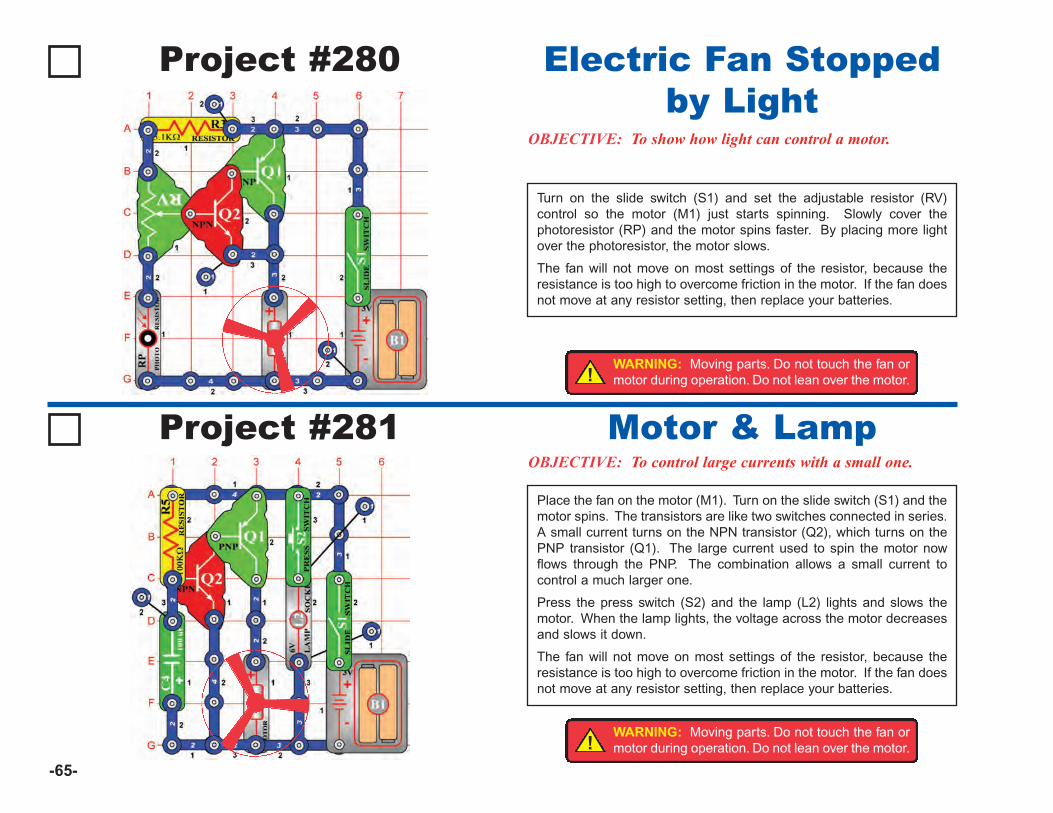
-65-
Project #280
OBJECTIVE: To show how light can control a motor.
Turn on the slide switch (S1) and set the adjustable resistor (RV)control so the motor (M1) just starts spinning. Slowly cover thephotoresistor (RP) and the motor spins faster. By placing more lightover the photoresistor, the motor slows.
The fan will not move on most settings of the resistor, because theresistance is too high to overcome friction in the motor. If the fan doesnot move at any resistor setting, then replace your batteries.
Electric Fan Stoppedby Light
Project #281OBJECTIVE: To control large currents with a small one.
Place the fan on the motor (M1). Turn on the slide switch (S1) and themotor spins. The transistors are like two switches connected in series.A small current turns on the NPN transistor (Q2), which turns on thePNP transistor (Q1). The large current used to spin the motor nowflows through the PNP. The combination allows a small current tocontrol a much larger one.
Press the press switch (S2) and the lamp (L2) lights and slows themotor. When the lamp lights, the voltage across the motor decreasesand slows it down.
The fan will not move on most settings of the resistor, because theresistance is too high to overcome friction in the motor. If the fan doesnot move at any resistor setting, then replace your batteries.
Motor & Lamp!
WARNING: Moving parts. Do not touch the fan ormotor during operation. Do not lean over the motor.
!WARNING: Moving parts. Do not touch the fan ormotor during operation. Do not lean over the motor.
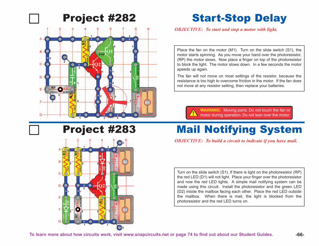
-66-
Project #282OBJECTIVE: To start and stop a motor with light.
Place the fan on the motor (M1). Turn on the slide switch (S1), themotor starts spinning. As you move your hand over the photoresistor,(RP) the motor slows. Now place a finger on top of the photoresistorto block the light. The motor slows down. In a few seconds the motorspeeds up again.
The fan will not move on most settings of the resistor, because theresistance is too high to overcome friction in the motor. If the fan doesnot move at any resistor setting, then replace your batteries.
Start-Stop Delay
Project #283OBJECTIVE: To build a circuit to indicate if you have mail.
Turn on the slide switch (S1). If there is light on the photoresistor (RP)the red LED (D1) will not light. Place your finger over the photoresistorand now the red LED lights. A simple mail notifying system can bemade using this circuit. Install the photoresistor and the green LED(D2) inside the mailbox facing each other. Place the red LED outsidethe mailbox. When there is mail, the light is blocked from thephotoresistor and the red LED turns on.
Mail Notifying System!
WARNING: Moving parts. Do not touch the fan ormotor during operation. Do not lean over the motor.
To learn more about how circuits work, visit www.snapcircuits.net or page 74 to find out about our Student Guides.
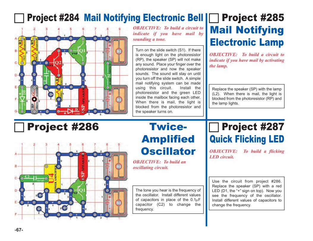
-67-
Project #284 Mail Notifying Electronic BellOBJECTIVE: To build a circuit toindicate if you have mail bysounding a tone.
OBJECTIVE: To build a flickingLED circuit.
Use the circuit from project #286.Replace the speaker (SP) with a redLED (D1, the “+” sign on top). Now yousee the frequency of the oscillator.Install different values of capacitors tochange the frequency.
Project #287Quick Flicking LED
OBJECTIVE: To build a circuit toindicate if you have mail by activatingthe lamp.
Project #286
OBJECTIVE: To build anoscillating circuit.
The tone you hear is the frequency ofthe oscillator. Install different valuesof capacitors in place of the 0.1μFcapacitor (C2) to change thefrequency.
Replace the speaker (SP) with the lamp(L2). When there is mail, the light isblocked from the photoresistor (RP) andthe lamp lights.
Turn on the slide switch (S1). If thereis enough light on the photoresistor(RP), the speaker (SP) will not makeany sound. Place your finger over thephotoresistor and now the speakersounds. The sound will stay on untilyou turn off the slide switch. A simplemail notifying system can be madeusing this circuit. Install thephotoresistor and the green LEDinside the mailbox facing each other.When there is mail, the light isblocked from the photoresistor andthe speaker turns on.
Project #285Mail NotifyingElectronic Lamp
Twice-AmplifiedOscillator
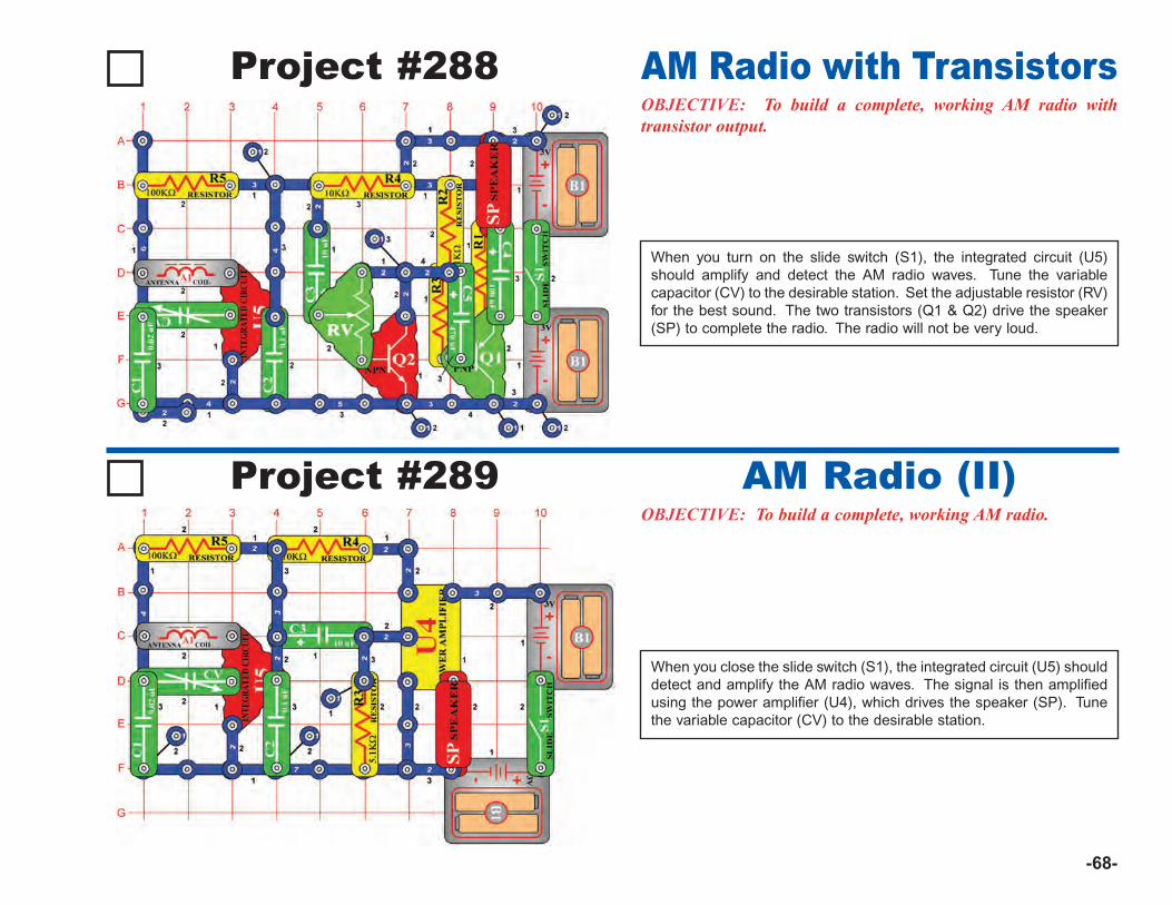
-68-
Project #288OBJECTIVE: To build a complete, working AM radio withtransistor output.
AM Radio with Transistors
Project #289OBJECTIVE: To build a complete, working AM radio.
When you close the slide switch (S1), the integrated circuit (U5) shoulddetect and amplify the AM radio waves. The signal is then amplifiedusing the power amplifier (U4), which drives the speaker (SP). Tunethe variable capacitor (CV) to the desirable station.
AM Radio (II)
When you turn on the slide switch (S1), the integrated circuit (U5)should amplify and detect the AM radio waves. Tune the variablecapacitor (CV) to the desirable station. Set the adjustable resistor (RV)for the best sound. The two transistors (Q1 & Q2) drive the speaker(SP) to complete the radio. The radio will not be very loud.
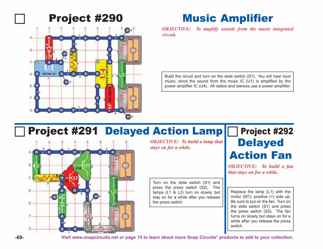
-69-
Project #290OBJECTIVE: To amplify sounds from the music integratedcircuit.
Build the circuit and turn on the slide switch (S1). You will hear loudmusic, since the sound from the music IC (U1) is amplified by thepower amplifier IC (U4). All radios and stereos use a power amplifier.
Music Amplifier
Project #291 Delayed Action LampOBJECTIVE: To build a lamp thatstays on for a while.
OBJECTIVE: To build a fanthat stays on for a while.
Replace the lamp (L1) with themotor (M1), positive (+) side up.Be sure to put on the fan. Turn onthe slide switch (S1) and pressthe press switch (S2). The fanturns on slowly but stays on for awhile after you release the pressswitch.
Turn on the slide switch (S1) andpress the press switch (S2). Thelamps (L1 & L2) turn on slowly, butstay on for a while after you releasethe press switch.
Project #292Delayed
Action Fan
Visit www.snapcircuits.net or page 74 to learn about more Snap Circuits® products to add to your collection.
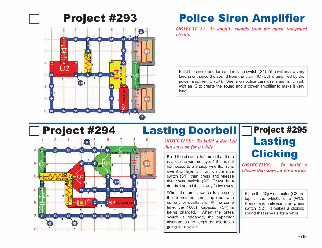
-70-
Project #293 Police Siren AmplifierOBJECTIVE: To amplify sounds from the music integratedcircuit.
Build the circuit and turn on the slide switch (S1). You will hear a veryloud siren, since the sound from the alarm IC (U2) is amplified by thepower amplifier IC (U4). Sirens on police cars use a similar circuit,with an IC to create the sound and a power amplifier to make it veryloud.
Project #294 Lasting DoorbellOBJECTIVE: To build a doorbellthat stays on for a while.
OBJECTIVE: To build aclicker that stays on for a while.
Place the 10μF capacitor (C3) ontop of the whistle chip (WC).Press and release the pressswitch (S2). It makes a clickingsound that repeats for a while.
Build the circuit at left, note that thereis a 4-snap wire on layer 1 that is notconnected to a 3-snap wire that runsover it on layer 3. Turn on the slideswitch (S1), then press and releasethe press switch (S2). There is adoorbell sound that slowly fades away.
When the press switch is pressed,the transistors are supplied withcurrent for oscillation. At the sametime, the 100μF capacitor (C4) isbeing charged. When the pressswitch is released, the capacitordischarges and keeps the oscillationgoing for a while.
Project #295LastingClicking
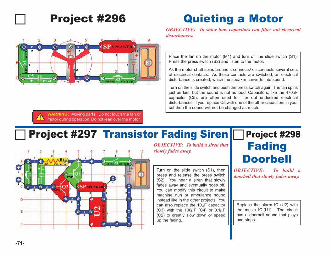
-71-
Project #296OBJECTIVE: To show how capacitors can filter out electricaldisturbances.
Place the fan on the motor (M1) and turn off the slide switch (S1).Press the press switch (S2) and listen to the motor.
As the motor shaft spins around it connects/ disconnects several setsof electrical contacts. As these contacts are switched, an electricaldisturbance is created, which the speaker converts into sound.
Turn on the slide switch and push the press switch again. The fan spinsjust as fast, but the sound is not as loud. Capacitors, like the 470μFcapacitor (C5), are often used to filter out undesired electricaldisturbances. If you replace C5 with one of the other capacitors in yourset then the sound will not be changed as much.
Quieting a Motor
Project #297 Transistor Fading SirenOBJECTIVE: To build a siren thatslowly fades away.
OBJECTIVE: To build adoorbell that slowly fades away.
Replace the alarm IC (U2) withthe music IC (U1). The circuithas a doorbell sound that playsand stops.
Turn on the slide switch (S1), thenpress and release the press switch(S2). You hear a siren that slowlyfades away and eventually goes off.You can modify this circuit to makemachine gun or ambulance soundinstead like in the other projects. Youcan also replace the 10μF capacitor(C3) with the 100μF (C4) or 0.1μF(C2) to greatly slow down or speedup the fading.
Project #298Fading
Doorbell
!WARNING: Moving parts. Do not touch the fan ormotor during operation. Do not lean over the motor.
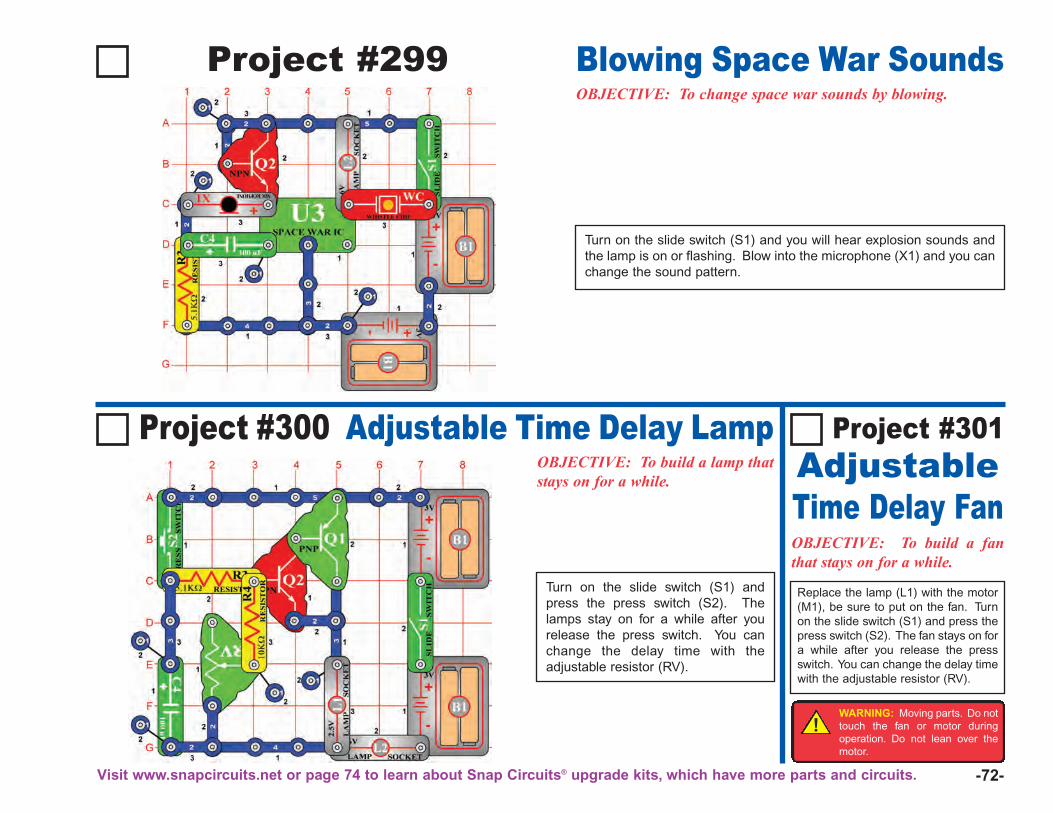
-72-
Project #299OBJECTIVE: To change space war sounds by blowing.
Turn on the slide switch (S1) and you will hear explosion sounds andthe lamp is on or flashing. Blow into the microphone (X1) and you canchange the sound pattern.
Blowing Space War Sounds
Project #300 Adjustable Time Delay LampOBJECTIVE: To build a lamp thatstays on for a while.
OBJECTIVE: To build a fanthat stays on for a while.
Replace the lamp (L1) with the motor(M1), be sure to put on the fan. Turnon the slide switch (S1) and press thepress switch (S2). The fan stays on fora while after you release the pressswitch. You can change the delay timewith the adjustable resistor (RV).
Turn on the slide switch (S1) andpress the press switch (S2). Thelamps stay on for a while after yourelease the press switch. You canchange the delay time with theadjustable resistor (RV).
Project #301AdjustableTime Delay Fan
!WARNING: Moving parts. Do nottouch the fan or motor duringoperation. Do not lean over themotor.
Visit www.snapcircuits.net or page 74 to learn about Snap Circuits® upgrade kits, which have more parts and circuits.
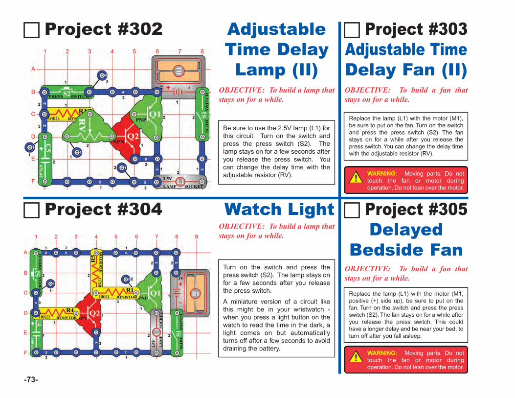
-73-
Project #302
OBJECTIVE: To build a lamp thatstays on for a while.
OBJECTIVE: To build a fan thatstays on for a while.
Replace the lamp (L1) with the motor (M1,positive (+) side up), be sure to put on thefan. Turn on the switch and press the pressswitch (S2). The fan stays on for a while afteryou release the press switch. This couldhave a longer delay and be near your bed, toturn off after you fall asleep.
Project #305 Delayed
Bedside Fan
OBJECTIVE: To build a fan thatstays on for a while.
Project #304 Watch LightOBJECTIVE: To build a lamp thatstays on for a while.
Turn on the switch and press thepress switch (S2). The lamp stays onfor a few seconds after you releasethe press switch.
A miniature version of a circuit likethis might be in your wristwatch -when you press a light button on thewatch to read the time in the dark, alight comes on but automaticallyturns off after a few seconds to avoiddraining the battery.
Replace the lamp (L1) with the motor (M1),be sure to put on the fan. Turn on the switchand press the press switch (S2). The fanstays on for a while after you release thepress switch. You can change the delay timewith the adjustable resistor (RV).
Be sure to use the 2.5V lamp (L1) forthis circuit. Turn on the switch andpress the press switch (S2). Thelamp stays on for a few seconds afteryou release the press switch. Youcan change the delay time with theadjustable resistor (RV).
Project #303Adjustable TimeDelay Fan (II)
AdjustableTime DelayLamp (II)
!WARNING: Moving parts. Do nottouch the fan or motor duringoperation. Do not lean over the motor.
!WARNING: Moving parts. Do nottouch the fan or motor duringoperation. Do not lean over the motor.
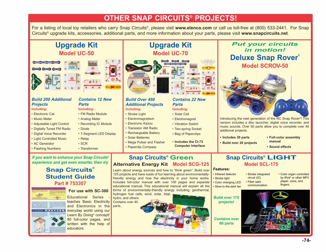
-74-
OTHER SNAP CIRCUITS® PROJECTS!For a listing of local toy retailers who carry Snap Circuits®, please visit www.elenco.com or call us toll-free at (800) 533-2441. For SnapCircuits® upgrade kits, accessories, additional parts, and more information about your parts, please visit www.snapcircuits.net.
Build 200 AdditionalProjectsIncluding:
• Electronic Cat
• Music Meter
• Adjustable Light Control
• Digitally Tuned FM Radio
• Digital Voice Recorder
• Light Controlled Music
• AC Generator
• Flashing Numbers
Contains 12 NewPartsIncluding:
• FM Radio Module
• Analog Meter
• Recording IC Module
• Diode
• 7-Segment LED Display
• Relay
• SCR
• Transformer
Upgrade KitModel UC-50
Build Over 450Additional ProjectsIncluding:
• Strobe Light• Electromagnetism• Electronic Kazoo• Transistor AM Radio• Rechargeable Battery• Solar Batteries• Mega Pulser and Flasher• Paperclip Compass
Contains 22 NewPartsIncluding:
• Solar Cell
• Electromagnet
• Vibration Switch
• Two-spring Socket
• Bag of Paperclips
• Includes the CI-73Computer Interface
Upgrade KitModel UC-70
Deluxe Snap Rover®
Model SCROV-50
Introducing the next generation of the RC Snap Rover®! Thisversion includes a disc launcher, digital voice recorder, andmusic sounds. Over 50 parts allow you to complete over 40additional projects.
Snap Circuits® GreenAlternative Energy Kit Model SCG-125
If you want to enhance your Snap Circuits®
experience and get even smarter, then try
For use with SC-300
Educational Series -teaches Basic Electricityand Electronics in theeveryday world using ourLearn By Doing® concept! 80 full-color pages, andwritten with the help ofeducators.
Snap Circuits®
Student GuidePart # 753307
Put your circuitsin motion!
Learn about energy sources and how to “think green”. Build over125 projects and have loads of fun learning about environmentally-friendly energy and how the electricity in your home works.Includes full-color manual with over 100 pages and separateeducational manual. This educational manual will explain all theforms of environmentally-friendly energy including: geothermal,hydrogen fuel cells, wind, solar, tidal,hydro, and others. Contains over 40 parts.
Snap Circuits® LIGHTModel SCL-175
• Infrared detector• Strobe light• Color changing LED• Glow-in-the-dark fan
• Strobe integratedcircuit (IC)
• Fiber opticcommunication
• Color organ controlledby iPod® or other MP3player, voice, andfingers.
Build over 175projects!
Contains over60 parts
• Includes 30 parts
• Build over 20 projects
• Full-color assemblymanual
• Sound effects
Features:

ELENCO®
150 Carpenter AvenueWheeling, IL 60090
(847) 541-3800Website: www.elenco.com
www.snapcircuits.nete-mail: [email protected]
Copyright © 2012, 2010 by Elenco® Electronics, Inc. All rights reserved. No part of this book shall be reproduced by 753104any means; electronic, photocopying, or otherwise without written permission from the publisher.
REV-D Revised 2012
Project 317

-1-
Table of ContentsBasic Troubleshooting 1Parts List 2MORE About Your Snap Circuits® Parts 3, 4MORE Advanced Troubleshooting 4MORE DO’s and DON’Ts of Building Circuits 5Project Listings 6, 7Projects 306-511 8 - 61Other Snap Circuits® Products 62
1. Most circuit problems are due to incorrect assembly.Always double-check that your circuit exactlymatches the drawing for it.
2. Be sure that parts with positive/negative markings arepositioned as per the drawing.
3. Be sure that all connections are securely snapped.
4. Try replacing the batteries.
5. If the motor spins but does not balance the fan, checkthe black plastic piece with three prongs on the motorshaft. Be sure that it is at the top of the shaft.
Elenco® is not responsible for parts damaged due toincorrect wiring.
Basic Troubleshooting
Note: If you suspect you have damaged parts, you canfollow the Advanced Troubleshooting procedure on page 4to determine which ones need replacing.
Review of How To Use It (See page 3 of the Projects 1-101 manual for more details.)
The Snap Circuits® kit uses building blocks with snapsto build the different electrical and electronic circuits inthe projects. These blocks are in different colors andhave numbers on them so that you can easily identifythem. The circuit you will build is shown in color andwith numbers, identifying the blocks that you will useand snap together to form a circuit.
Next to each part in every circuit drawing is a smallnumber in black. This tells you which level thecomponent is placed at. Place all parts on level 1 first,
then all of the parts on level 2, then all of the parts onlevel 3, etc.
A large clear plastic base grid is included with this kitto help keep the circuit block together. The base hasrows labeled A-G and columns labeled 1-10.
Install two (2) “AA” batteries (not included) in thebattery holder (B1). The 2.5V and 6V bulbs comepackaged separate from their sockets. Install the 2.5Vbulb in the L1 lamp socket, and the 6V bulb in the L2lamp socket.
Place the fan on the motor (M1) whenever that part isused, unless the project you are building says not touse it.
Some circuits use the red and black jumper wires tomake unusual connections. Just clip them to the metalsnaps or as indicated.
Note: While building the projects, be careful not toaccidentally make a direct connection across thebattery holder (a “short circuit”), as this may damageand/or quickly drain the batteries.
WARNING: SHOCK HAZARD -Never connect Snap Circuits® tothe electrical outlets in your homein any way!
WARNING FOR ALL PROJECTS WITH A SYMBOLMoving parts. Do not touch the motor or fan during operation. Do not leanover the motor. Do not launch the fan at people, animals, or objects. Eyeprotection is recommended.
!!
WARNING: CHOKING HAZARD - Small parts.Not for children under 3 years.
!
Batteries:• Use only 1.5V AA type, alkaline batteries
(not included).
• Insert batteries with correct polarity.
• Non-rechargeable batteries should notbe recharged. Rechargeable batteriesshould only be charged under adultsupervision, and should not berecharged while in the product.
• Do not mix alkaline, standard (carbon-zinc), or rechargeable (nickel-cadmium)batteries.
• Do not mix old and new batteries.
• Remove batteries when they are used up.
• Do not short circuit the battery terminals.
• Never throw batteries in a fire or attemptto open its outer casing.
• Batteries are harmful if swallowed, sokeep away from small children.
• Do not connect batteries or batteryholders in parallel.
!WARNING: Always check your wiring beforeturning on a circuit. Never leave a circuitunattended while the batteries are installed. Neverconnect additional batteries or any other powersources to your circuits. Discard any cracked orbroken parts.
Adult Supervision: Because children’s abilitiesvary so much, even with age groups, adults shouldexercise discretion as to which experiments aresuitable and safe (the instructions should enablesupervising adults to establish the experiment’ssuitability for the child). Make sure your child readsand follows all of the relevant instructions andsafety procedures, and keeps them at hand forreference.
This product is intended for use by adults andchildren who have attained sufficient maturity toread and follow directions and warnings.
Never modify your parts, as doing so may disableimportant safety features in them, and could putyour child at risk of injury.
!
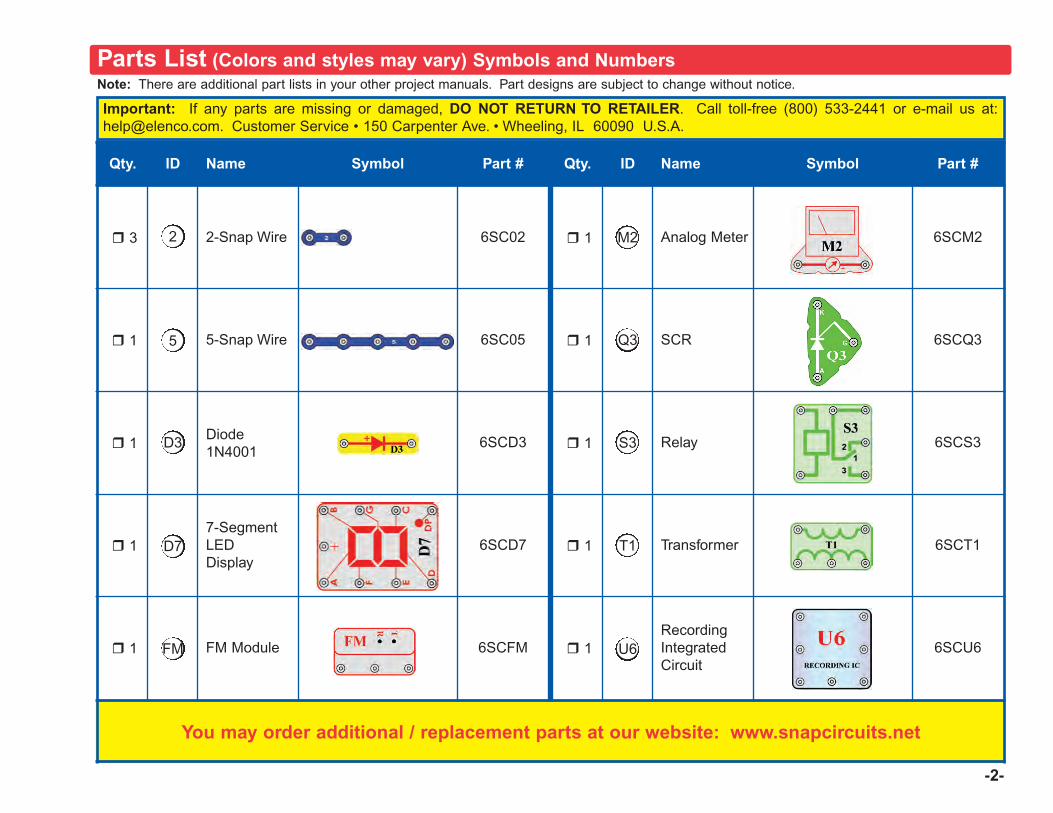
-2-
Qty. ID Name Symbol Part # Qty. ID Name Symbol Part #
r 3 2-Snap Wire 6SC02 r 1 Analog Meter 6SCM2
r 1 5-Snap Wire 6SC05 r 1 SCR 6SCQ3
r 1Diode 1N4001
6SCD3 r 1 Relay 6SCS3
r 17-SegmentLEDDisplay
6SCD7 r 1 Transformer 6SCT1
r 1 FM Module 6SCFM r 1RecordingIntegratedCircuit
6SCU6
You may order additional / replacement parts at our website: www.snapcircuits.net
Q3
M2
FM
D3
5
2
S3
T1
U6
D7
Note: There are additional part lists in your other project manuals. Part designs are subject to change without notice.
Important: If any parts are missing or damaged, DO NOT RETURN TO RETAILER. Call toll-free (800) 533-2441 or e-mail us at:[email protected]. Customer Service • 150 Carpenter Ave. • Wheeling, IL 60090 U.S.A.
Parts List (Colors and styles may vary) Symbols and Numbers
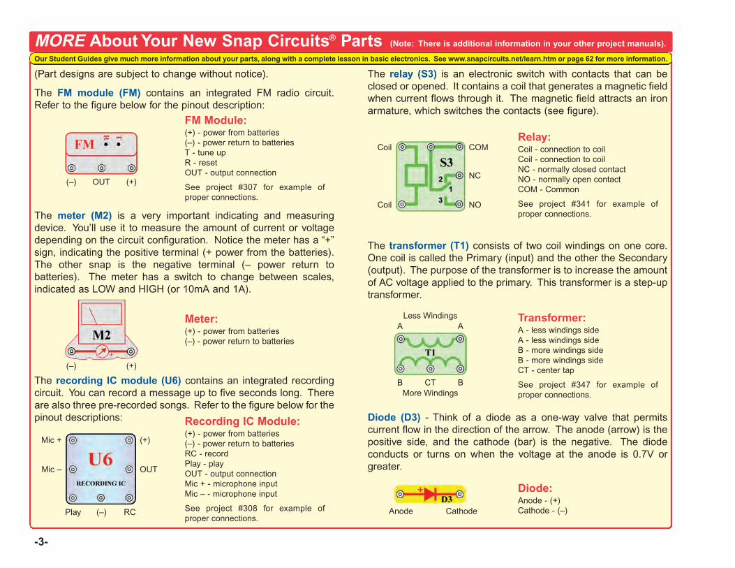
-3-
(Part designs are subject to change without notice).
The FM module (FM) contains an integrated FM radio circuit.Refer to the figure below for the pinout description:
The meter (M2) is a very important indicating and measuringdevice. You’ll use it to measure the amount of current or voltagedepending on the circuit configuration. Notice the meter has a “+”sign, indicating the positive terminal (+ power from the batteries).The other snap is the negative terminal (– power return tobatteries). The meter has a switch to change between scales,indicated as LOW and HIGH (or 10mA and 1A).
The recording IC module (U6) contains an integrated recordingcircuit. You can record a message up to five seconds long. Thereare also three pre-recorded songs. Refer to the figure below for thepinout descriptions:
The relay (S3) is an electronic switch with contacts that can beclosed or opened. It contains a coil that generates a magnetic fieldwhen current flows through it. The magnetic field attracts an ironarmature, which switches the contacts (see figure).
The transformer (T1) consists of two coil windings on one core.One coil is called the Primary (input) and the other the Secondary(output). The purpose of the transformer is to increase the amountof AC voltage applied to the primary. This transformer is a step-uptransformer.
Diode (D3) - Think of a diode as a one-way valve that permitscurrent flow in the direction of the arrow. The anode (arrow) is thepositive side, and the cathode (bar) is the negative. The diodeconducts or turns on when the voltage at the anode is 0.7V orgreater.
MORE About Your New Snap Circuits® Parts (Note: There is additional information in your other project manuals).
(+)OUT(–)
FM Module:(+) - power from batteries(–) - power return to batteriesT - tune upR - resetOUT - output connection
See project #307 for example ofproper connections.
(+)
OUT
(–)
Recording IC Module:(+) - power from batteries(–) - power return to batteriesRC - recordPlay - playOUT - output connectionMic + - microphone inputMic – - microphone input
See project #308 for example ofproper connections.
RCPlay
Mic –
Mic +
COMRelay:Coil - connection to coilCoil - connection to coilNC - normally closed contactNO - normally open contactCOM - Common
See project #341 for example ofproper connections.
Coil
Coil NO
NC
BCTB
Transformer:A - less windings sideA - less windings sideB - more windings sideB - more windings sideCT - center tap
See project #347 for example ofproper connections.
AA
Anode
Diode:Anode - (+)Cathode - (–)Cathode
(+)(–)
Meter:(+) - power from batteries(–) - power return to batteries
Less Windings
More Windings
Our Student Guides give much more information about your parts, along with a complete lesson in basic electronics. See www.snapcircuits.net/learn.htm or page 62 for more information.
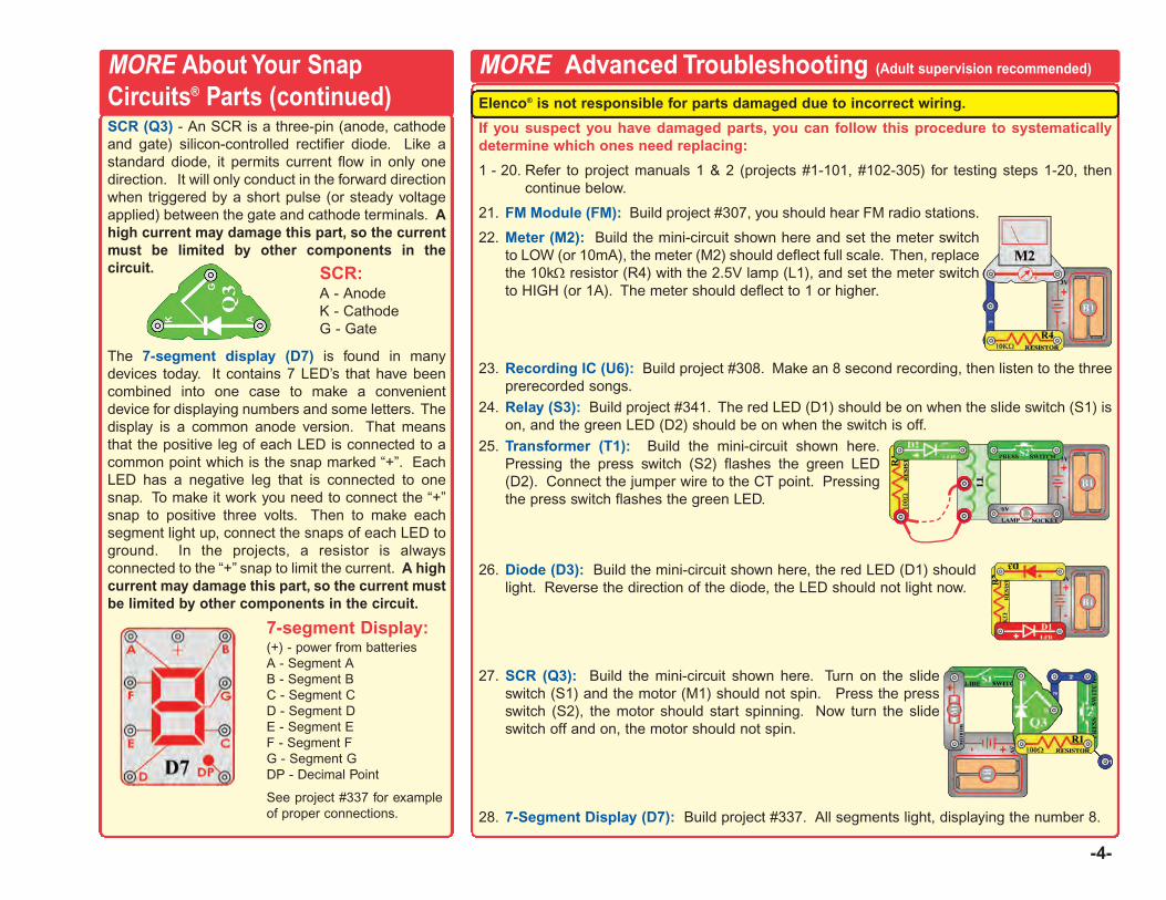
Elenco® is not responsible for parts damaged due to incorrect wiring.
If you suspect you have damaged parts, you can follow this procedure to systematicallydetermine which ones need replacing:
1 - 20. Refer to project manuals 1 & 2 (projects #1-101, #102-305) for testing steps 1-20, thencontinue below.
21. FM Module (FM): Build project #307, you should hear FM radio stations.
22. Meter (M2): Build the mini-circuit shown here and set the meter switchto LOW (or 10mA), the meter (M2) should deflect full scale. Then, replacethe 10kΩ resistor (R4) with the 2.5V lamp (L1), and set the meter switchto HIGH (or 1A). The meter should deflect to 1 or higher.
23. Recording IC (U6): Build project #308. Make an 8 second recording, then listen to the threeprerecorded songs.
24. Relay (S3): Build project #341. The red LED (D1) should be on when the slide switch (S1) ison, and the green LED (D2) should be on when the switch is off.
25. Transformer (T1): Build the mini-circuit shown here.Pressing the press switch (S2) flashes the green LED(D2). Connect the jumper wire to the CT point. Pressingthe press switch flashes the green LED.
26. Diode (D3): Build the mini-circuit shown here, the red LED (D1) shouldlight. Reverse the direction of the diode, the LED should not light now.
27. SCR (Q3): Build the mini-circuit shown here. Turn on the slideswitch (S1) and the motor (M1) should not spin. Press the pressswitch (S2), the motor should start spinning. Now turn the slideswitch off and on, the motor should not spin.
28. 7-Segment Display (D7): Build project #337. All segments light, displaying the number 8.
-4-
SCR (Q3) - An SCR is a three-pin (anode, cathodeand gate) silicon-controlled rectifier diode. Like astandard diode, it permits current flow in only onedirection. It will only conduct in the forward directionwhen triggered by a short pulse (or steady voltageapplied) between the gate and cathode terminals. Ahigh current may damage this part, so the currentmust be limited by other components in thecircuit.
The 7-segment display (D7) is found in manydevices today. It contains 7 LED’s that have beencombined into one case to make a convenientdevice for displaying numbers and some letters. Thedisplay is a common anode version. That meansthat the positive leg of each LED is connected to acommon point which is the snap marked “+”. EachLED has a negative leg that is connected to onesnap. To make it work you need to connect the “+”snap to positive three volts. Then to make eachsegment light up, connect the snaps of each LED toground. In the projects, a resistor is alwaysconnected to the “+” snap to limit the current. A highcurrent may damage this part, so the current mustbe limited by other components in the circuit.
SCR:A - AnodeK - CathodeG - Gate
7-segment Display:(+) - power from batteriesA - Segment AB - Segment BC - Segment CD - Segment DE - Segment EF - Segment FG - Segment GDP - Decimal Point
See project #337 for exampleof proper connections.
MORE Advanced Troubleshooting (Adult supervision recommended)MORE About Your SnapCircuits® Parts (continued)

-5-
MORE DO’s and DON’Ts of Building CircuitsAfter building the circuits given in this booklet, you may wish to experiment on your own. Usethe projects in this booklet as a guide, as many important design concepts are introducedthroughout them. Every circuit will include a power source (the batteries), a resistance(which might be a resistor, lamp, motor, integrated circuit, etc.), and wiring paths betweenthem and back. You must be careful not to create “short circuits” (very low-resistance pathsacross the batteries, see examples below) as this will damage components and/or quicklydrain your batteries. Only connect the IC’s using configurations given in the projects,incorrectly doing so may damage them. Elenco® is not responsible for parts damageddue to incorrect wiring.
Here are some important guidelines:ALWAYS USE EYE PROTECTION WHEN EXPERIMENTING ON YOUR OWN.
ALWAYS include at least one component that will limit the current through a circuit, suchas the speaker, lamp, whistle chip, capacitors, IC’s (which must be connectedproperly), motor, microphone, photoresistor, or fixed resistors.
ALWAYS use the 7-segment display, LED’s, transistors, the high frequency IC, the SCR,the antenna, and switches in conjunction with other components that willlimit the current through them. Failure to do so will create a short circuitand/or damage those parts.
ALWAYS connect the adjustable resistor so that if set to its 0 setting, the current will belimited by other components in the circuit.
ALWAYS connect position capacitors so that the “+” side gets the higher voltage.
ALWAYS disconnect your batteries immediately and check your wiring if somethingappears to be getting hot.
ALWAYS check your wiring before turning on a circuit.
ALWAYS connect IC’s, the FM module, and the SCR using configurations given inthe projects or as per the connection descriptions for the parts.
NEVER try to use the high frequency IC as a transistor (the packages are similar, but theparts are different).
NEVER use the 2.5V lamp in a circuit with both battery holders unless you are sure thatthe voltage across it will be limited.
NEVER connect to an electrical outlet in your home in any way.
NEVER leave a circuit unattended when it is turned on.
NEVER touch the motor when it is spinning at high speed.
Note: If you have the more advanced Model SC-750, there are additional guidelines in yourother project manual.
For all of the projects given in this book, the parts may be arranged in different ways withoutchanging the circuit. For example, the order of parts connected in series or in parallel doesnot matter — what matters is how combinations of these sub-circuits are arranged together.
Examples of SHORT CIRCUITS - NEVER DO THESE!!!
You are encouraged to tell us about new circuits you create. If they areunique, we will post them with your name and state on our website atwww.snapcircuits.net/kidkreations.htm. Send your suggestions toElenco®.
Elenco® provides a circuit designer so that you can make your own SnapCircuits® drawings. This Microsoft® Word document can be downloadedfrom www.snapcircuits.net/SnapDesigner.doc or through thewww.snapcircuits.net web site.
WARNING: SHOCK HAZARD - Never connect Snap Circuits® tothe electrical outlets in your home in any way!
Placing a 3-snap wire directlyacross the batteries is aSHORT CIRCUIT.
This is also aSHORT CIRCUIT.
When the slide switch (S1) is turned on, this large circuit has a SHORTCIRCUIT path (as shown by the arrows). The short circuit prevents anyother portions of the circuit from ever working.
NEVERDO!
Warning to Snap Rover owners: Do not connect your parts to theRover body except when using our approved circuits, the Roverbody has a higher voltage which could damage your parts.
!
!NEVER
DO!
!
!!NEVER
DO! NEVERDO!
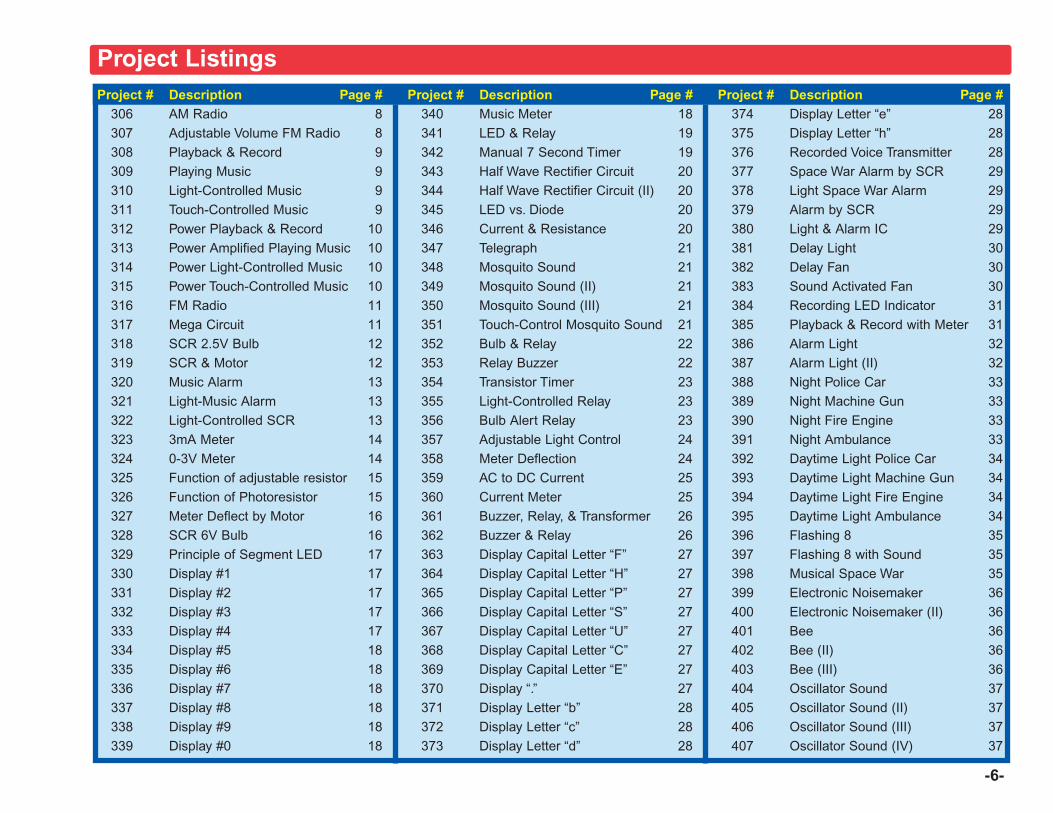
Project # Description Page #306 AM Radio 8307 Adjustable Volume FM Radio 8308 Playback & Record 9309 Playing Music 9310 Light-Controlled Music 9311 Touch-Controlled Music 9312 Power Playback & Record 10313 Power Amplified Playing Music 10314 Power Light-Controlled Music 10315 Power Touch-Controlled Music 10316 FM Radio 11317 Mega Circuit 11318 SCR 2.5V Bulb 12319 SCR & Motor 12320 Music Alarm 13321 Light-Music Alarm 13322 Light-Controlled SCR 13323 3mA Meter 14324 0-3V Meter 14325 Function of adjustable resistor 15326 Function of Photoresistor 15327 Meter Deflect by Motor 16328 SCR 6V Bulb 16329 Principle of Segment LED 17330 Display #1 17331 Display #2 17332 Display #3 17333 Display #4 17334 Display #5 18335 Display #6 18336 Display #7 18337 Display #8 18338 Display #9 18339 Display #0 18
Project # Description Page #340 Music Meter 18341 LED & Relay 19342 Manual 7 Second Timer 19343 Half Wave Rectifier Circuit 20344 Half Wave Rectifier Circuit (II) 20345 LED vs. Diode 20346 Current & Resistance 20347 Telegraph 21348 Mosquito Sound 21349 Mosquito Sound (II) 21350 Mosquito Sound (III) 21351 Touch-Control Mosquito Sound 21352 Bulb & Relay 22353 Relay Buzzer 22354 Transistor Timer 23355 Light-Controlled Relay 23356 Bulb Alert Relay 23357 Adjustable Light Control 24358 Meter Deflection 24359 AC to DC Current 25360 Current Meter 25361 Buzzer, Relay, & Transformer 26362 Buzzer & Relay 26363 Display Capital Letter “F” 27364 Display Capital Letter “H” 27365 Display Capital Letter “P” 27366 Display Capital Letter “S” 27367 Display Capital Letter “U” 27368 Display Capital Letter “C” 27369 Display Capital Letter “E” 27370 Display “.” 27371 Display Letter “b” 28372 Display Letter “c” 28373 Display Letter “d” 28
Project # Description Page #374 Display Letter “e” 28375 Display Letter “h” 28376 Recorded Voice Transmitter 28377 Space War Alarm by SCR 29378 Light Space War Alarm 29379 Alarm by SCR 29380 Light & Alarm IC 29381 Delay Light 30382 Delay Fan 30383 Sound Activated Fan 30384 Recording LED Indicator 31385 Playback & Record with Meter 31386 Alarm Light 32387 Alarm Light (II) 32388 Night Police Car 33389 Night Machine Gun 33390 Night Fire Engine 33391 Night Ambulance 33392 Daytime Light Police Car 34393 Daytime Light Machine Gun 34394 Daytime Light Fire Engine 34395 Daytime Light Ambulance 34396 Flashing 8 35397 Flashing 8 with Sound 35398 Musical Space War 35399 Electronic Noisemaker 36400 Electronic Noisemaker (II) 36401 Bee 36402 Bee (II) 36403 Bee (III) 36404 Oscillator Sound 37405 Oscillator Sound (II) 37406 Oscillator Sound (III) 37407 Oscillator Sound (IV) 37
-6-
Project Listings
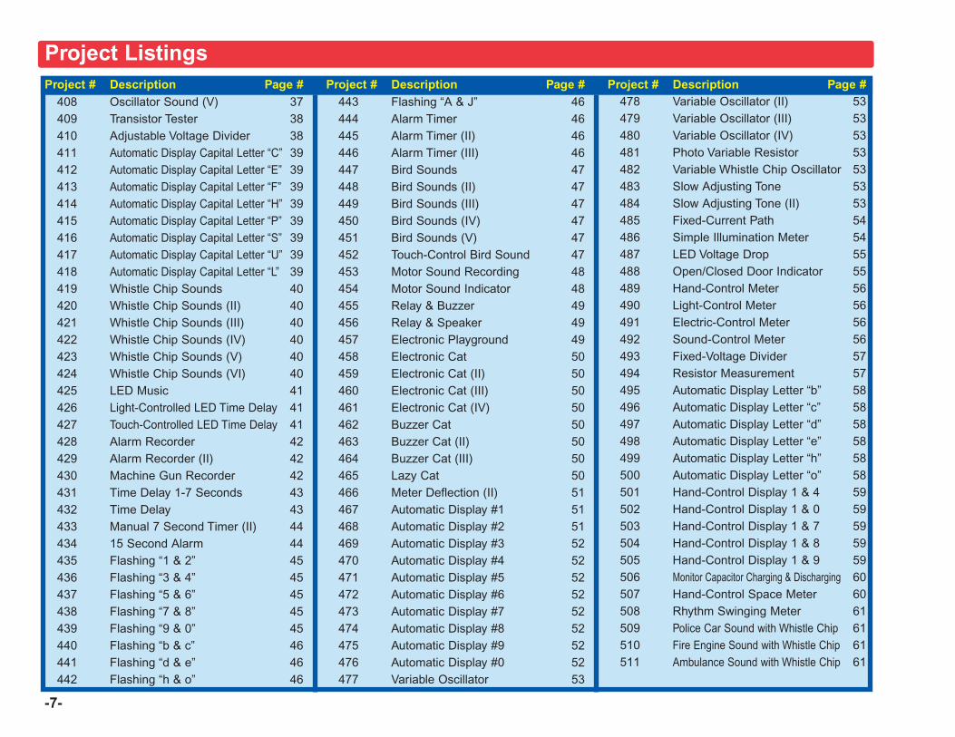
-7-
Project # Description Page #408 Oscillator Sound (V) 37409 Transistor Tester 38410 Adjustable Voltage Divider 38411 Automatic Display Capital Letter “C” 39412 Automatic Display Capital Letter “E” 39413 Automatic Display Capital Letter “F” 39414 Automatic Display Capital Letter “H” 39415 Automatic Display Capital Letter “P” 39416 Automatic Display Capital Letter “S” 39417 Automatic Display Capital Letter “U” 39418 Automatic Display Capital Letter “L” 39419 Whistle Chip Sounds 40420 Whistle Chip Sounds (II) 40421 Whistle Chip Sounds (III) 40422 Whistle Chip Sounds (IV) 40423 Whistle Chip Sounds (V) 40424 Whistle Chip Sounds (VI) 40425 LED Music 41426 Light-Controlled LED Time Delay 41427 Touch-Controlled LED Time Delay 41428 Alarm Recorder 42429 Alarm Recorder (II) 42430 Machine Gun Recorder 42431 Time Delay 1-7 Seconds 43432 Time Delay 43433 Manual 7 Second Timer (II) 44434 15 Second Alarm 44435 Flashing “1 & 2” 45436 Flashing “3 & 4” 45437 Flashing “5 & 6” 45438 Flashing “7 & 8” 45439 Flashing “9 & 0” 45440 Flashing “b & c” 46441 Flashing “d & e” 46442 Flashing “h & o” 46
Project # Description Page #443 Flashing “A & J” 46444 Alarm Timer 46445 Alarm Timer (II) 46446 Alarm Timer (III) 46447 Bird Sounds 47448 Bird Sounds (II) 47449 Bird Sounds (III) 47450 Bird Sounds (IV) 47451 Bird Sounds (V) 47452 Touch-Control Bird Sound 47453 Motor Sound Recording 48454 Motor Sound Indicator 48455 Relay & Buzzer 49456 Relay & Speaker 49457 Electronic Playground 49458 Electronic Cat 50459 Electronic Cat (II) 50460 Electronic Cat (III) 50461 Electronic Cat (IV) 50462 Buzzer Cat 50463 Buzzer Cat (II) 50464 Buzzer Cat (III) 50465 Lazy Cat 50466 Meter Deflection (II) 51467 Automatic Display #1 51468 Automatic Display #2 51469 Automatic Display #3 52470 Automatic Display #4 52471 Automatic Display #5 52472 Automatic Display #6 52473 Automatic Display #7 52474 Automatic Display #8 52475 Automatic Display #9 52476 Automatic Display #0 52477 Variable Oscillator 53
Project # Description Page #478 Variable Oscillator (II) 53479 Variable Oscillator (III) 53480 Variable Oscillator (IV) 53481 Photo Variable Resistor 53482 Variable Whistle Chip Oscillator 53483 Slow Adjusting Tone 53484 Slow Adjusting Tone (II) 53485 Fixed-Current Path 54486 Simple Illumination Meter 54487 LED Voltage Drop 55488 Open/Closed Door Indicator 55489 Hand-Control Meter 56490 Light-Control Meter 56491 Electric-Control Meter 56492 Sound-Control Meter 56493 Fixed-Voltage Divider 57494 Resistor Measurement 57495 Automatic Display Letter “b” 58496 Automatic Display Letter “c” 58497 Automatic Display Letter “d” 58498 Automatic Display Letter “e” 58499 Automatic Display Letter “h” 58500 Automatic Display Letter “o” 58501 Hand-Control Display 1 & 4 59502 Hand-Control Display 1 & 0 59503 Hand-Control Display 1 & 7 59504 Hand-Control Display 1 & 8 59505 Hand-Control Display 1 & 9 59506 Monitor Capacitor Charging & Discharging 60507 Hand-Control Space Meter 60508 Rhythm Swinging Meter 61509 Police Car Sound with Whistle Chip 61510 Fire Engine Sound with Whistle Chip 61511 Ambulance Sound with Whistle Chip 61
Project Listings
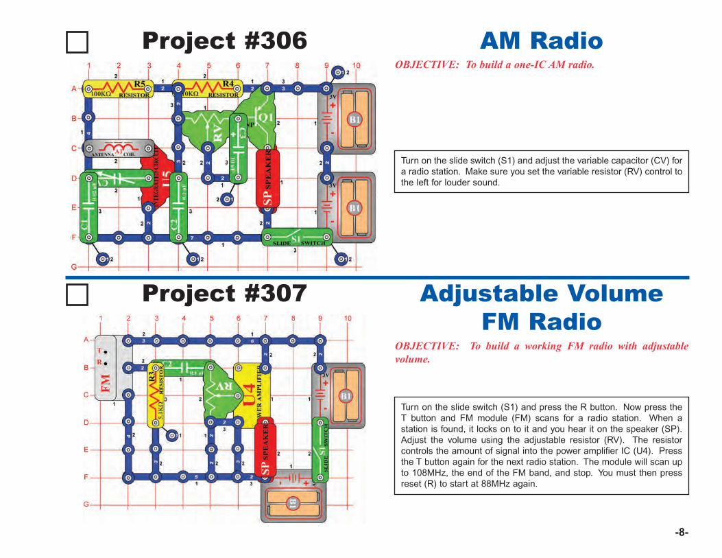
-8-
Project #306OBJECTIVE: To build a one-IC AM radio.
Turn on the slide switch (S1) and adjust the variable capacitor (CV) fora radio station. Make sure you set the variable resistor (RV) control tothe left for louder sound.
AM Radio
Project #307
OBJECTIVE: To build a working FM radio with adjustablevolume.
Turn on the slide switch (S1) and press the R button. Now press theT button and FM module (FM) scans for a radio station. When astation is found, it locks on to it and you hear it on the speaker (SP).Adjust the volume using the adjustable resistor (RV). The resistorcontrols the amount of signal into the power amplifier IC (U4). Pressthe T button again for the next radio station. The module will scan upto 108MHz, the end of the FM band, and stop. You must then pressreset (R) to start at 88MHz again.
Adjustable VolumeFM Radio
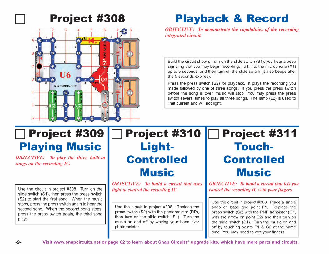
-9-
Project #308
Build the circuit shown. Turn on the slide switch (S1), you hear a beepsignaling that you may begin recording. Talk into the microphone (X1)up to 5 seconds, and then turn off the slide switch (it also beeps afterthe 5 seconds expires).
Press the press switch (S2) for playback. It plays the recording youmade followed by one of three songs. If you press the press switchbefore the song is over, music will stop. You may press the pressswitch several times to play all three songs. The lamp (L2) is used tolimit current and will not light.
Playback & RecordOBJECTIVE: To demonstrate the capabilities of the recordingintegrated circuit.
OBJECTIVE: To play the three built-insongs on the recording IC.
Use the circuit in project #308. Turn on theslide switch (S1), then press the press switch(S2) to start the first song. When the musicstops, press the press switch again to hear thesecond song. When the second song stops,press the press switch again, the third songplays.
Playing MusicProject #309
OBJECTIVE: To build a circuit that useslight to control the recording IC.
Light-Controlled
Music
Project #310
OBJECTIVE: To build a circuit that lets youcontrol the recording IC with your fingers.
Touch-Controlled
Music
Project #311
Use the circuit in project #308. Replace thepress switch (S2) with the photoresistor (RP),then turn on the slide switch (S1). Turn themusic on and off by waving your hand overphotoresistor.
Use the circuit in project #308. Place a singlesnap on base grid point F1. Replace thepress switch (S2) with the PNP transistor (Q1,with the arrow on point E2) and then turn onthe slide switch (S1). Turn the music on andoff by touching points F1 & G2 at the sametime. You may need to wet your fingers.
Visit www.snapcircuits.net or page 62 to learn about Snap Circuits® upgrade kits, which have more parts and circuits.
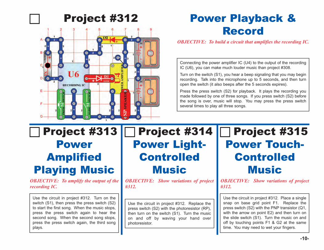
-10-
Project #312
Connecting the power amplifier IC (U4) to the output of the recordingIC (U6), you can make much louder music than project #308.
Turn on the switch (S1), you hear a beep signaling that you may beginrecording. Talk into the microphone up to 5 seconds, and then turnopen the switch (it also beeps after the 5 seconds expires).
Press the press switch (S2) for playback. It plays the recording youmade followed by one of three songs. If you press switch (S2) beforethe song is over, music will stop. You may press the press switchseveral times to play all three songs.
Power Playback &Record
OBJECTIVE: To build a circuit that amplifies the recording IC.
OBJECTIVE: To amplify the output of therecording IC.
Use the circuit in project #312. Turn on theswitch (S1), then press the press switch (S2)to start the first song. When the music stops,press the press switch again to hear thesecond song. When the second song stops,press the press switch again, the third songplays.
PowerAmplified
Playing Music
Project #313
OBJECTIVE: Show variations of project#312.
Power Light-Controlled
Music
Project #314
OBJECTIVE: Show variations of project#312.
Power Touch-Controlled
Music
Project #315
Use the circuit in project #312. Replace thepress switch (S2) with the photoresistor (RP),then turn on the switch (S1). Turn the musicon and off by waving your hand overphotoresistor.
Use the circuit in project #312. Place a singlesnap on base grid point F1. Replace thepress switch (S2) with the PNP transistor (Q1,with the arrow on point E2) and then turn onthe slide switch (S1). Turn the music on andoff by touching points F1 & G2 at the sametime. You may need to wet your fingers.
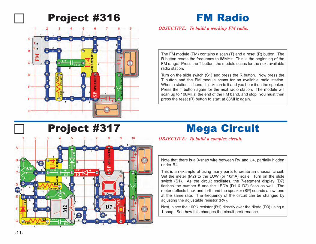
-11-
Project #316OBJECTIVE: To build a working FM radio.
The FM module (FM) contains a scan (T) and a reset (R) button. TheR button resets the frequency to 88MHz. This is the beginning of theFM range. Press the T button, the module scans for the next availableradio station.
Turn on the slide switch (S1) and press the R button. Now press theT button and the FM module scans for an available radio station.When a station is found, it locks on to it and you hear it on the speaker.Press the T button again for the next radio station. The module willscan up to 108MHz, the end of the FM band, and stop. You must thenpress the reset (R) button to start at 88MHz again.
FM Radio
Project #317OBJECTIVE: To build a complex circuit.
Note that there is a 3-snap wire between RV and U4, partially hiddenunder R4.
This is an example of using many parts to create an unusual circuit.Set the meter (M2) to the LOW (or 10mA) scale. Turn on the slideswitch (S1). As the circuit oscillates, the 7-segment display (D7)flashes the number 5 and the LED’s (D1 & D2) flash as well. Themeter deflects back and forth and the speaker (SP) sounds a low toneat the same rate. The frequency of the circuit can be changed byadjusting the adjustable resistor (RV).
Next, place the 100Ω resistor (R1) directly over the diode (D3) using a1-snap. See how this changes the circuit performance.
Mega Circuit
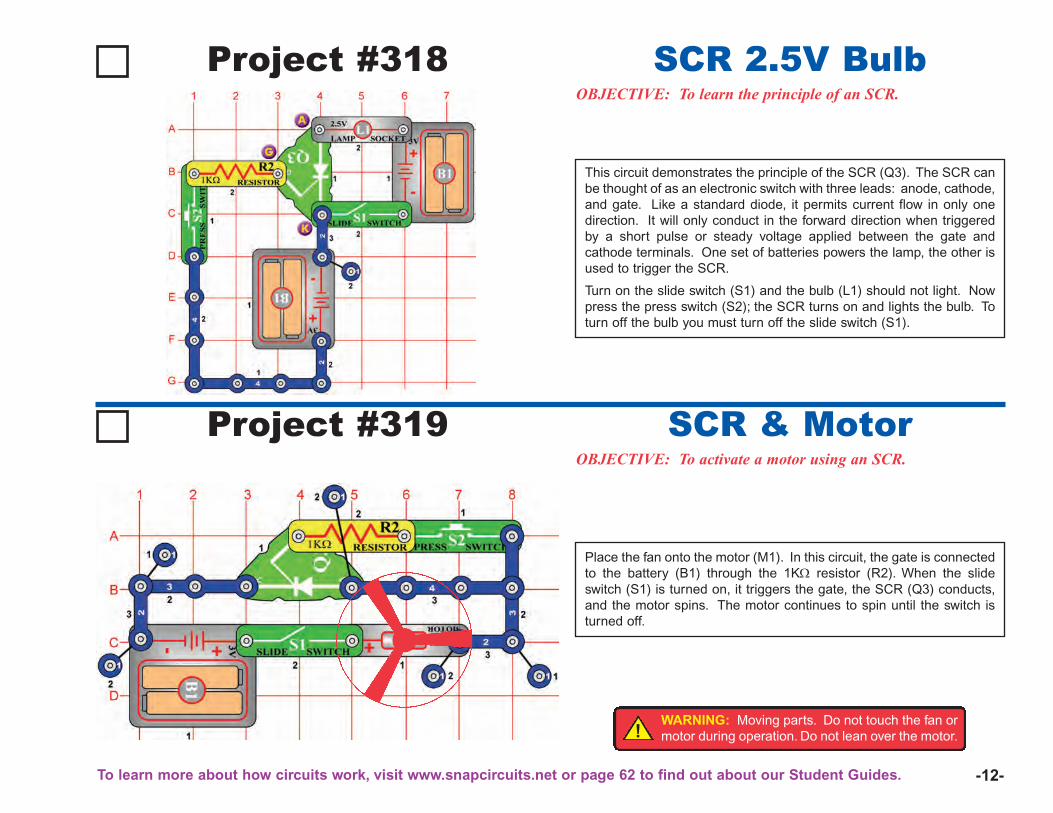
-12-
Project #318OBJECTIVE: To learn the principle of an SCR.
This circuit demonstrates the principle of the SCR (Q3). The SCR canbe thought of as an electronic switch with three leads: anode, cathode,and gate. Like a standard diode, it permits current flow in only onedirection. It will only conduct in the forward direction when triggeredby a short pulse or steady voltage applied between the gate andcathode terminals. One set of batteries powers the lamp, the other isused to trigger the SCR.
Turn on the slide switch (S1) and the bulb (L1) should not light. Nowpress the press switch (S2); the SCR turns on and lights the bulb. Toturn off the bulb you must turn off the slide switch (S1).
SCR 2.5V Bulb
Project #319OBJECTIVE: To activate a motor using an SCR.
SCR & Motor
Place the fan onto the motor (M1). In this circuit, the gate is connectedto the battery (B1) through the 1KΩ resistor (R2). When the slideswitch (S1) is turned on, it triggers the gate, the SCR (Q3) conducts,and the motor spins. The motor continues to spin until the switch isturned off.
!WARNING: Moving parts. Do not touch the fan ormotor during operation. Do not lean over the motor.
To learn more about how circuits work, visit www.snapcircuits.net or page 62 to find out about our Student Guides.
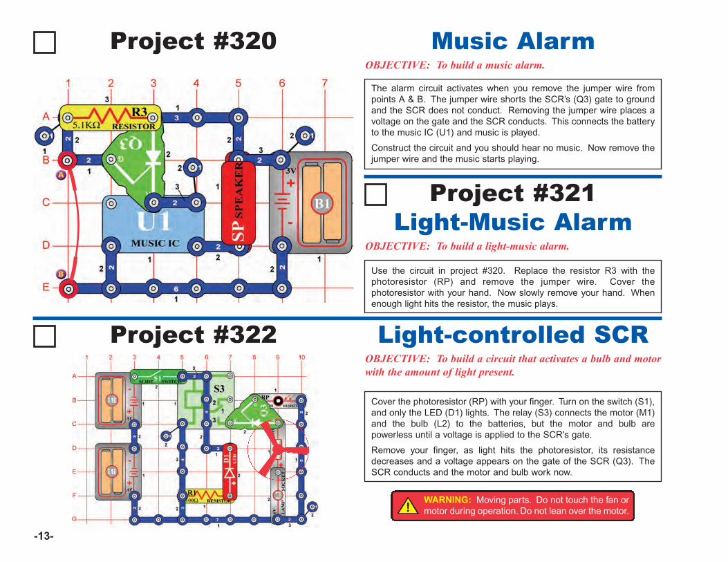
-13-
Project #320OBJECTIVE: To build a music alarm.
The alarm circuit activates when you remove the jumper wire frompoints A & B. The jumper wire shorts the SCR’s (Q3) gate to groundand the SCR does not conduct. Removing the jumper wire places avoltage on the gate and the SCR conducts. This connects the batteryto the music IC (U1) and music is played.
Construct the circuit and you should hear no music. Now remove thejumper wire and the music starts playing.
Music Alarm
Project #321
OBJECTIVE: To build a light-music alarm.
Light-Music Alarm
Use the circuit in project #320. Replace the resistor R3 with thephotoresistor (RP) and remove the jumper wire. Cover thephotoresistor with your hand. Now slowly remove your hand. Whenenough light hits the resistor, the music plays.
Project #322OBJECTIVE: To build a circuit that activates a bulb and motorwith the amount of light present.
Cover the photoresistor (RP) with your finger. Turn on the switch (S1),and only the LED (D1) lights. The relay (S3) connects the motor (M1)and the bulb (L2) to the batteries, but the motor and bulb arepowerless until a voltage is applied to the SCR's gate.
Remove your finger, as light hits the photoresistor, its resistancedecreases and a voltage appears on the gate of the SCR (Q3). TheSCR conducts and the motor and bulb work now.
Light-controlled SCR
!WARNING: Moving parts. Do not touch the fan ormotor during operation. Do not lean over the motor.
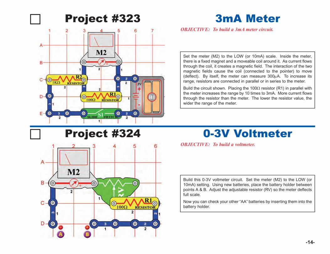
-14-
Project #323OBJECTIVE: To build a 3mA meter circuit.
3mA Meter
Project #324OBJECTIVE: To build a voltmeter.
0-3V Voltmeter
Build this 0-3V voltmeter circuit. Set the meter (M2) to the LOW (or10mA) setting. Using new batteries, place the battery holder betweenpoints A & B. Adjust the adjustable resistor (RV) so the meter deflectsfull scale.
Now you can check your other “AA” batteries by inserting them into thebattery holder.
Set the meter (M2) to the LOW (or 10mA) scale. Inside the meter,there is a fixed magnet and a moveable coil around it. As current flowsthrough the coil, it creates a magnetic field. The interaction of the twomagnetic fields cause the coil (connected to the pointer) to move(deflect). By itself, the meter can measure 300μA. To increase itsrange, resistors are connected in parallel or in series to the meter.
Build the circuit shown. Placing the 100Ω resistor (R1) in parallel withthe meter increases the range by 10 times to 3mA. More current flowsthrough the resistor than the meter. The lower the resistor value, thewider the range of the meter.

-15-
Project #325
OBJECTIVE: To understand the function of the adjustable resistor.
An adjustable resistor is a normal resistor with an additional arm contact.The arm moves along the resistive material and taps off the desiredresistance.The slider on the adjustable resistor moves the arm contact and sets theresistance between the bottom (point C1) pin and the center pin (pointB2). The remaining resistance is between the center and top pin. Forexample, when the slider is all the way down, there is minimal resistancebetween the bottom and center pins (usually 0Ω) and maximumresistance between the center and top pins. The resistance between thetop (point A1) and bottom (point A3) pins will always be the totalresistance, (50kΩ for your part).Set the meter (M2) to the LOW (or 10mA) scale. Adjust the adjustableresistor (RV) for maximum resistance by setting the slider to the top. Themeter only deflects part of the way. As you move the slider down,decreasing the resistance, the meter deflects more.
Function ofAdjustable Resistor
Project #326
OBJECTIVE: To understand the function of the photoresistor.
Build the circuit shown. Set the meter (M2) to the LOW (or 10mA)scale. The photoresistor (RP) is a light-sensitive resistor. Its valuechanges from nearly infinite in total darkness to about 1,000Ω when abright light shines on it.
The meter reading changes as the resistance changes in the circuit.When the lights are on, the meter points to a higher number on thescale. When the lights are OFF, the pointer will point to a lower numberon the scale. This means that the resistance of the photoresistor ischanging according to the amount of light in the room.
Function ofphotoresistor
Visit www.snapcircuits.net or page 62 to learn about more Snap Circuits® products to add to your collection.
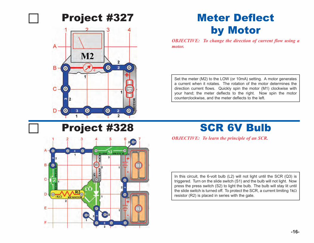
-16-
Project #328OBJECTIVE: To learn the principle of an SCR.
In this circuit, the 6-volt bulb (L2) will not light until the SCR (Q3) istriggered. Turn on the slide switch (S1) and the bulb will not light. Nowpress the press switch (S2) to light the bulb. The bulb will stay lit untilthe slide switch is turned off. To protect the SCR, a current limiting 1kΩresistor (R2) is placed in series with the gate.
SCR 6V Bulb
Project #327
OBJECTIVE: To change the direction of current flow using amotor.
Set the meter (M2) to the LOW (or 10mA) setting. A motor generatesa current when it rotates. The rotation of the motor determines thedirection current flows. Quickly spin the motor (M1) clockwise withyour hand; the meter deflects to the right. Now spin the motorcounterclockwise, and the meter deflects to the left.
Meter Deflectby Motor
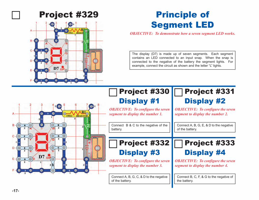
-17-
Project #329
OBJECTIVE: To demonstrate how a seven segment LED works.
The display (D7) is made up of seven segments. Each segmentcontains an LED connected to an input snap. When the snap isconnected to the negative of the battery the segment lights. Forexample, connect the circuit as shown and the letter “L” lights.
Principle ofSegment LED
Project #330
OBJECTIVE: To configure the sevensegment to display the number 1.
Connect B & C to the negative of thebattery.
Display #1OBJECTIVE: To configure the sevensegment to display the number 2.
Connect A, B, G, E, & D to the negativeof the battery.
Display #2
OBJECTIVE: To configure the sevensegment to display the number 3.
Connect A, B, G, C, & D to the negativeof the battery.
Display #3OBJECTIVE: To configure the sevensegment to display the number 4.
Connect B, C, F, & G to the negative ofthe battery.
Display #4
Project #331
Project #332 Project #333
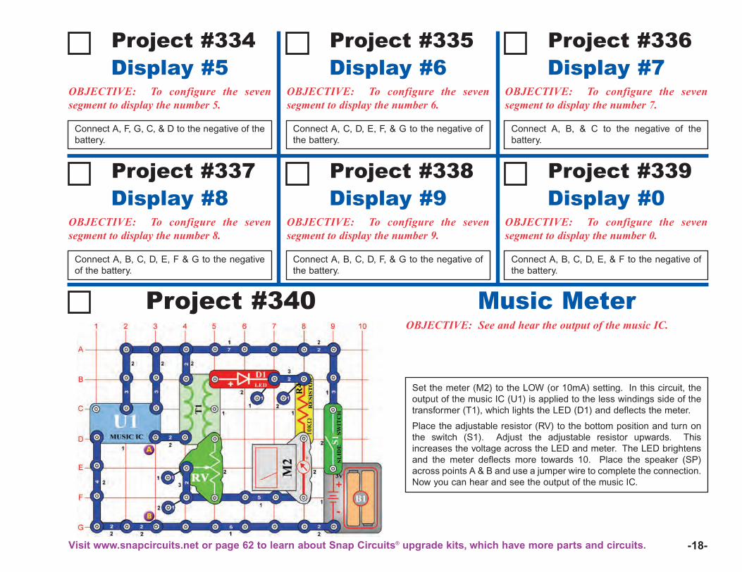
-18-
Project #334
OBJECTIVE: To configure the sevensegment to display the number 5.
Connect A, F, G, C, & D to the negative of thebattery.
Display #5Project #335
OBJECTIVE: To configure the sevensegment to display the number 6.
Connect A, C, D, E, F, & G to the negative ofthe battery.
Display #6Project #336
OBJECTIVE: To configure the sevensegment to display the number 7.
Connect A, B, & C to the negative of thebattery.
Display #7
Project #337
OBJECTIVE: To configure the sevensegment to display the number 8.
Connect A, B, C, D, E, F & G to the negativeof the battery.
Display #8Project #338
OBJECTIVE: To configure the sevensegment to display the number 9.
Connect A, B, C, D, F, & G to the negative ofthe battery.
Display #9Project #339
OBJECTIVE: To configure the sevensegment to display the number 0.
Connect A, B, C, D, E, & F to the negative ofthe battery.
Display #0
Project #340OBJECTIVE: See and hear the output of the music IC.
Set the meter (M2) to the LOW (or 10mA) setting. In this circuit, theoutput of the music IC (U1) is applied to the less windings side of thetransformer (T1), which lights the LED (D1) and deflects the meter.
Place the adjustable resistor (RV) to the bottom position and turn onthe switch (S1). Adjust the adjustable resistor upwards. Thisincreases the voltage across the LED and meter. The LED brightensand the meter deflects more towards 10. Place the speaker (SP)across points A & B and use a jumper wire to complete the connection.Now you can hear and see the output of the music IC.
Music Meter
Visit www.snapcircuits.net or page 62 to learn about Snap Circuits® upgrade kits, which have more parts and circuits.
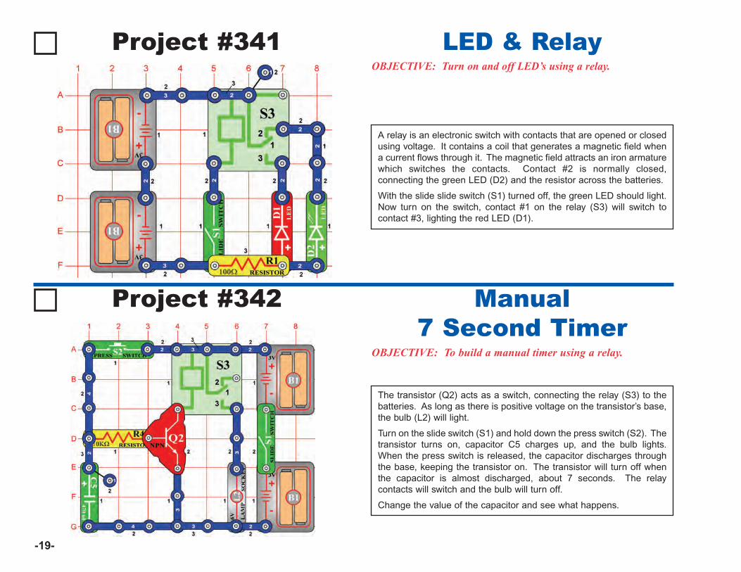
-19-
Project #341OBJECTIVE: Turn on and off LED’s using a relay.
A relay is an electronic switch with contacts that are opened or closedusing voltage. It contains a coil that generates a magnetic field whena current flows through it. The magnetic field attracts an iron armaturewhich switches the contacts. Contact #2 is normally closed,connecting the green LED (D2) and the resistor across the batteries.
With the slide slide switch (S1) turned off, the green LED should light.Now turn on the switch, contact #1 on the relay (S3) will switch tocontact #3, lighting the red LED (D1).
LED & Relay
Project #342
OBJECTIVE: To build a manual timer using a relay.
The transistor (Q2) acts as a switch, connecting the relay (S3) to thebatteries. As long as there is positive voltage on the transistor’s base,the bulb (L2) will light.
Turn on the slide switch (S1) and hold down the press switch (S2). Thetransistor turns on, capacitor C5 charges up, and the bulb lights.When the press switch is released, the capacitor discharges throughthe base, keeping the transistor on. The transistor will turn off whenthe capacitor is almost discharged, about 7 seconds. The relaycontacts will switch and the bulb will turn off.
Change the value of the capacitor and see what happens.
Manual7 Second Timer
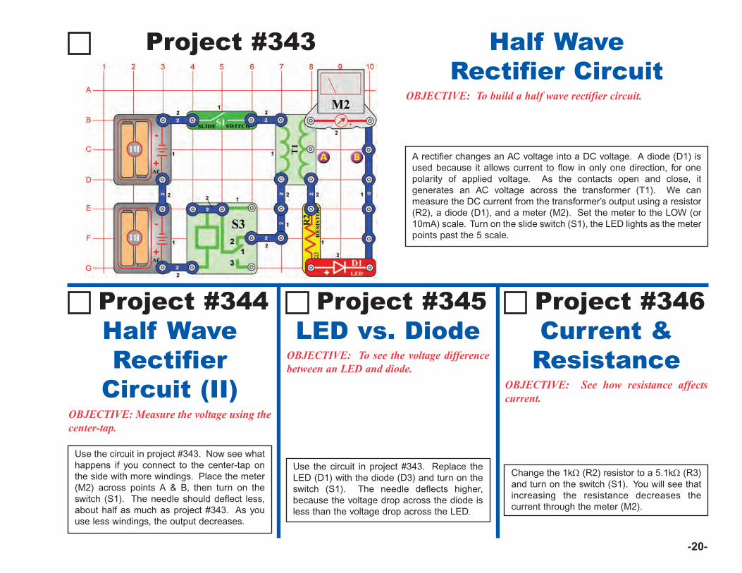
-20-
Project #343
OBJECTIVE: To build a half wave rectifier circuit.
A rectifier changes an AC voltage into a DC voltage. A diode (D1) isused because it allows current to flow in only one direction, for onepolarity of applied voltage. As the contacts open and close, itgenerates an AC voltage across the transformer (T1). We canmeasure the DC current from the transformer’s output using a resistor(R2), a diode (D1), and a meter (M2). Set the meter to the LOW (or10mA) scale. Turn on the slide switch (S1), the LED lights as the meterpoints past the 5 scale.
Half WaveRectifier Circuit
OBJECTIVE: Measure the voltage using thecenter-tap.
Use the circuit in project #343. Now see whathappens if you connect to the center-tap onthe side with more windings. Place the meter(M2) across points A & B, then turn on theswitch (S1). The needle should deflect less,about half as much as project #343. As youuse less windings, the output decreases.
Half WaveRectifier
Circuit (II)
Project #344
OBJECTIVE: To see the voltage differencebetween an LED and diode.
Use the circuit in project #343. Replace theLED (D1) with the diode (D3) and turn on theswitch (S1). The needle deflects higher,because the voltage drop across the diode isless than the voltage drop across the LED.
LED vs. DiodeProject #345
OBJECTIVE: See how resistance affectscurrent.
Change the 1kΩ (R2) resistor to a 5.1kΩ (R3)and turn on the switch (S1). You will see thatincreasing the resistance decreases thecurrent through the meter (M2).
Current &Resistance
Project #346
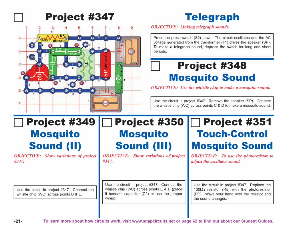
-21-
Project #347OBJECTIVE: Making telegraph sounds.
Press the press switch (S2) down. The circuit oscillates and the ACvoltage generated from the transformer (T1) drives the speaker (SP).To make a telegraph sound, depress the switch for long and shortperiods.
Telegraph
OBJECTIVE: Show variations of project#347.
Use the circuit in project #347. Connect thewhistle chip (WC) across points B & E.
MosquitoSound (II)
Project #349
OBJECTIVE: Show variations of project#347.
MosquitoSound (III)
Project #350
OBJECTIVE: To use the photoresistor toadjust the oscillator sound.
Touch-ControlMosquito Sound
Project #351
OBJECTIVE: Use the whistle chip to make a mosquito sound.
Use the circuit in project #347. Remove the speaker (SP). Connectthe whistle chip (WC) across points C & D to make a mosquito sound.
Mosquito SoundProject #348
Use the circuit in project #347. Connect thewhistle chip (WC) across points E & D (placeit beneath capacitor (C2) or use the jumperwires).
Use the circuit in project #347. Replace the100kΩ resistor (R5) with the photoresistor(RP). Wave your hand over the resistor andthe sound changes.
To learn more about how circuits work, visit www.snapcircuits.net or page 62 to find out about our Student Guides.
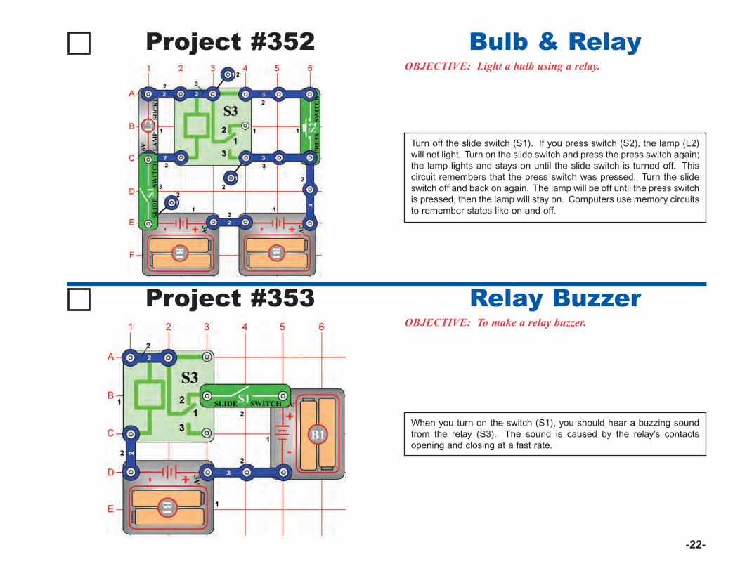
-22-
Project #353OBJECTIVE: To make a relay buzzer.
When you turn on the switch (S1), you should hear a buzzing soundfrom the relay (S3). The sound is caused by the relay’s contactsopening and closing at a fast rate.
Relay Buzzer
Project #352OBJECTIVE: Light a bulb using a relay.
Bulb & Relay
Turn off the slide switch (S1). If you press switch (S2), the lamp (L2)will not light. Turn on the slide switch and press the press switch again;the lamp lights and stays on until the slide switch is turned off. Thiscircuit remembers that the press switch was pressed. Turn the slideswitch off and back on again. The lamp will be off until the press switchis pressed, then the lamp will stay on. Computers use memory circuitsto remember states like on and off.
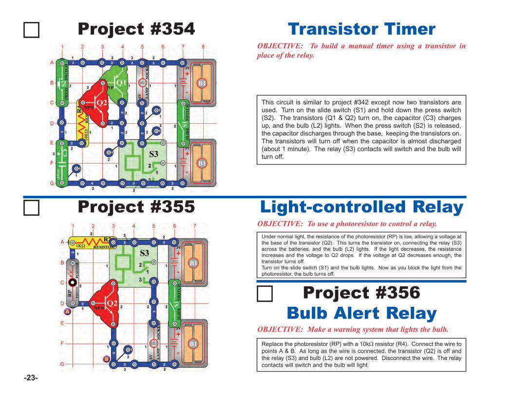
Project #355OBJECTIVE: To use a photoresistor to control a relay.
Under normal light, the resistance of the photoresistor (RP) is low, allowing a voltage atthe base of the transistor (Q2). This turns the transistor on, connecting the relay (S3)across the batteries, and the bulb (L2) lights. If the light decreases, the resistanceincreases and the voltage to Q2 drops. If the voltage at Q2 decreases enough, thetransistor turns off.Turn on the slide switch (S1) and the bulb lights. Now as you block the light from thephotoresistor, the bulb turns off.
Light-controlled Relay
OBJECTIVE: Make a warning system that lights the bulb.
Replace the photoresistor (RP) with a 10kΩ resistor (R4). Connect the wire topoints A & B. As long as the wire is connected, the transistor (Q2) is off andthe relay (S3) and bulb (L2) are not powered. Disconnect the wire. The relaycontacts will switch and the bulb will light.
Bulb Alert RelayProject #356
-23-
Project #354OBJECTIVE: To build a manual timer using a transistor inplace of the relay.
This circuit is similar to project #342 except now two transistors areused. Turn on the slide switch (S1) and hold down the press switch(S2). The transistors (Q1 & Q2) turn on, the capacitor (C3) chargesup, and the bulb (L2) lights. When the press switch (S2) is released,the capacitor discharges through the base, keeping the transistors on.The transistors will turn off when the capacitor is almost discharged(about 1 minute). The relay (S3) contacts will switch and the bulb willturn off.
Transistor Timer
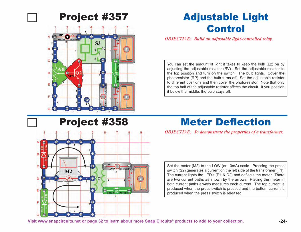
-24-
Project #357
OBJECTIVE: Build an adjustable light-controlled relay.
You can set the amount of light it takes to keep the bulb (L2) on byadjusting the adjustable resistor (RV). Set the adjustable resistor tothe top position and turn on the switch. The bulb lights. Cover thephotoresistor (RP) and the bulb turns off. Set the adjustable resistorto different positions and then cover the photoresistor. Note that onlythe top half of the adjustable resistor affects the circuit. If you positionit below the middle, the bulb stays off.
Adjustable LightControl
Project #358OBJECTIVE: To demonstrate the properties of a transformer.
Set the meter (M2) to the LOW (or 10mA) scale. Pressing the pressswitch (S2) generates a current on the left side of the transformer (T1).The current lights the LED’s (D1 & D2) and deflects the meter. Thereare two current paths as shown by the arrows. Placing the meter inboth current paths always measures each current. The top current isproduced when the press switch is pressed and the bottom current isproduced when the press switch is released.
Meter Deflection
Visit www.snapcircuits.net or page 62 to learn about more Snap Circuits® products to add to your collection.
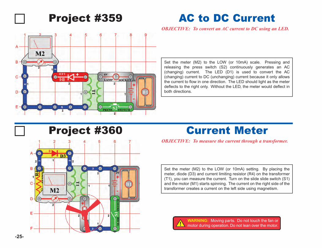
Project #360OBJECTIVE: To measure the current through a transformer.
Set the meter (M2) to the LOW (or 10mA) setting. By placing themeter, diode (D3) and current limiting resistor (R4) on the transformer(T1), you can measure the current. Turn on the slide slide switch (S1)and the motor (M1) starts spinning. The current on the right side of thetransformer creates a current on the left side using magnetism.
Current Meter
-25-
Project #359OBJECTIVE: To convert an AC current to DC using an LED.
Set the meter (M2) to the LOW (or 10mA) scale. Pressing andreleasing the press switch (S2) continuously generates an AC(changing) current. The LED (D1) is used to convert the AC(changing) current to DC (unchanging) current because it only allowsthe current to flow in one direction. The LED should light as the meterdeflects to the right only. Without the LED, the meter would deflect inboth directions.
AC to DC Current
!WARNING: Moving parts. Do not touch the fan ormotor during operation. Do not lean over the motor.
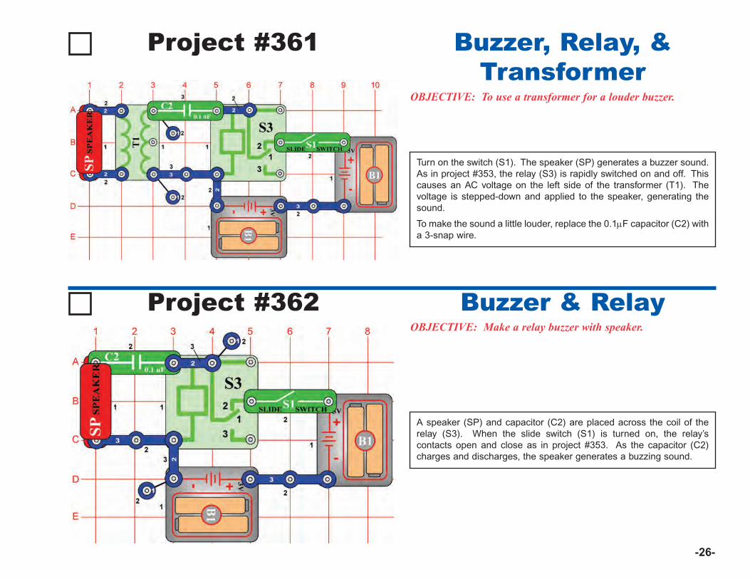
-26-
Project #361
OBJECTIVE: To use a transformer for a louder buzzer.
Turn on the switch (S1). The speaker (SP) generates a buzzer sound.As in project #353, the relay (S3) is rapidly switched on and off. Thiscauses an AC voltage on the left side of the transformer (T1). Thevoltage is stepped-down and applied to the speaker, generating thesound.
To make the sound a little louder, replace the 0.1μF capacitor (C2) witha 3-snap wire.
Buzzer, Relay, &Transformer
Project #362OBJECTIVE: Make a relay buzzer with speaker.
A speaker (SP) and capacitor (C2) are placed across the coil of therelay (S3). When the slide switch (S1) is turned on, the relay’scontacts open and close as in project #353. As the capacitor (C2)charges and discharges, the speaker generates a buzzing sound.
Buzzer & Relay
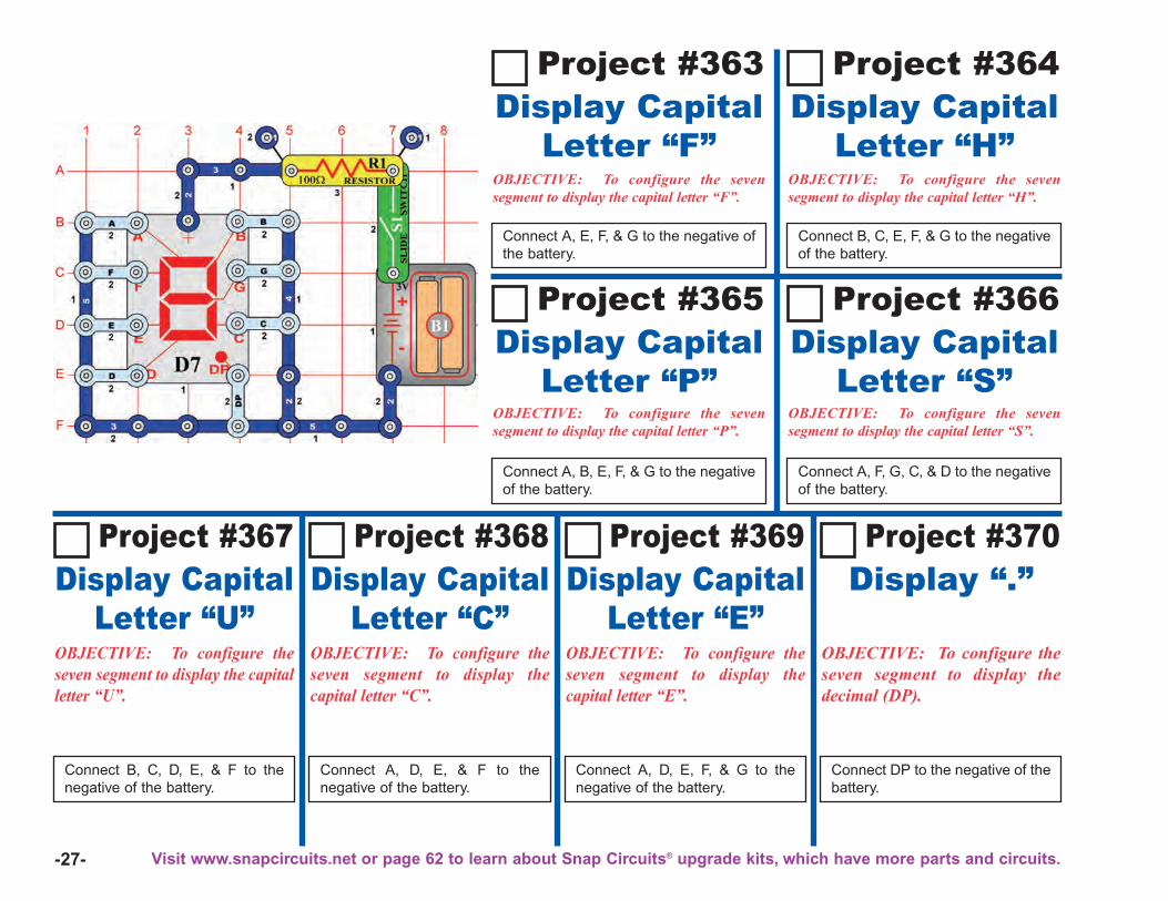
-27-
Project #363
OBJECTIVE: To configure the sevensegment to display the capital letter “F”.
Connect A, E, F, & G to the negative ofthe battery.
Display CapitalLetter “F”
OBJECTIVE: To configure the sevensegment to display the capital letter “H”.
Connect B, C, E, F, & G to the negativeof the battery.
Display CapitalLetter “H”
OBJECTIVE: To configure the sevensegment to display the capital letter “P”.
Connect A, B, E, F, & G to the negativeof the battery.
Display CapitalLetter “P”
OBJECTIVE: To configure the sevensegment to display the capital letter “S”.
Connect A, F, G, C, & D to the negativeof the battery.
Display CapitalLetter “S”
Project #364
Project #365 Project #366
Project #367
OBJECTIVE: To configure theseven segment to display the capitalletter “U”.
Connect B, C, D, E, & F to thenegative of the battery.
Display CapitalLetter “U”
Project #370
OBJECTIVE: To configure theseven segment to display thedecimal (DP).
Connect DP to the negative of thebattery.
Display “.”Project #369
OBJECTIVE: To configure theseven segment to display thecapital letter “E”.
Connect A, D, E, F, & G to thenegative of the battery.
Display CapitalLetter “E”
Project #368
OBJECTIVE: To configure theseven segment to display thecapital letter “C”.
Connect A, D, E, & F to thenegative of the battery.
Display CapitalLetter “C”
Visit www.snapcircuits.net or page 62 to learn about Snap Circuits® upgrade kits, which have more parts and circuits.
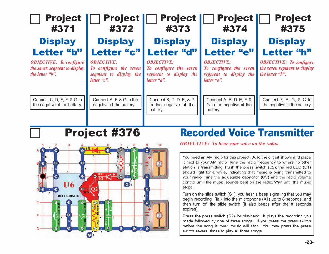
-28-
Project #376OBJECTIVE: To hear your voice on the radio.
You need an AM radio for this project. Build the circuit shown and placeit next to your AM radio. Tune the radio frequency to where no otherstation is transmitting. Push the press switch (S2); the red LED (D1)should light for a while, indicating that music is being transmitted toyour radio. Tune the adjustable capacitor (CV) and the radio volumecontrol until the music sounds best on the radio. Wait until the musicstops.
Turn on the slide switch (S1), you hear a beep signaling that you maybegin recording. Talk into the microphone (X1) up to 8 seconds, andthen turn off the slide switch (it also beeps after the 8 secondsexpires).
Press the press switch (S2) for playback. It plays the recording youmade followed by one of three songs. If you press the press switchbefore the song is over, music will stop. You may press the pressswitch several times to play all three songs.
Recorded Voice Transmitter
Project#371
OBJECTIVE: To configurethe seven segment to displaythe letter “b”.
Connect C, D, E, F, & G tothe negative of the battery.
DisplayLetter “b”
Project#372
OBJECTIVE: To configure the sevensegment to display theletter “c”.
Connect A, F, & G to thenegative of the battery.
DisplayLetter “c”
Project#373
OBJECTIVE: To configure the sevensegment to display theletter “d”.
Connect B, C, D, E, & Gto the negative of thebattery.
DisplayLetter “d”
Project#374
OBJECTIVE: To configure the sevensegment to display theletter “e”.
Connect A, B, D, E, F, &G to the negative of thebattery.
DisplayLetter “e”
Project#375
OBJECTIVE: To configurethe seven segment to displaythe letter “h”.
Connect F, E, G, & C tothe negative of the battery.
DisplayLetter “h”
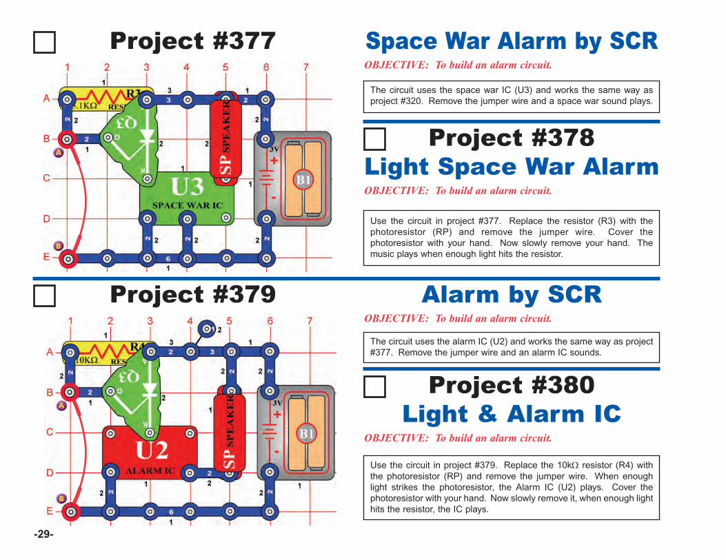
-29-
Project #377OBJECTIVE: To build an alarm circuit.
The circuit uses the space war IC (U3) and works the same way asproject #320. Remove the jumper wire and a space war sound plays.
Space War Alarm by SCR
Project #379OBJECTIVE: To build an alarm circuit.
Alarm by SCR
Project #378
OBJECTIVE: To build an alarm circuit.
Use the circuit in project #377. Replace the resistor (R3) with thephotoresistor (RP) and remove the jumper wire. Cover thephotoresistor with your hand. Now slowly remove your hand. Themusic plays when enough light hits the resistor.
Light Space War Alarm
The circuit uses the alarm IC (U2) and works the same way as project#377. Remove the jumper wire and an alarm IC sounds.
Project #380
OBJECTIVE: To build an alarm circuit.
Use the circuit in project #379. Replace the 10kΩ resistor (R4) withthe photoresistor (RP) and remove the jumper wire. When enoughlight strikes the photoresistor, the Alarm IC (U2) plays. Cover thephotoresistor with your hand. Now slowly remove it, when enough lighthits the resistor, the IC plays.
Light & Alarm IC
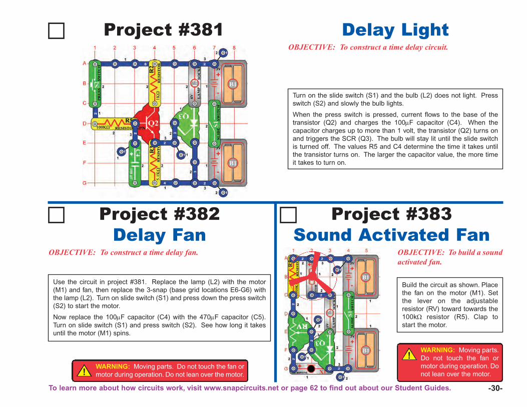
-30-
Project #381OBJECTIVE: To construct a time delay circuit.
Turn on the slide switch (S1) and the bulb (L2) does not light. Pressswitch (S2) and slowly the bulb lights.
When the press switch is pressed, current flows to the base of thetransistor (Q2) and charges the 100μF capacitor (C4). When thecapacitor charges up to more than 1 volt, the transistor (Q2) turns onand triggers the SCR (Q3). The bulb will stay lit until the slide switchis turned off. The values R5 and C4 determine the time it takes untilthe transistor turns on. The larger the capacitor value, the more timeit takes to turn on.
Delay Light
Project #382 Project #383
OBJECTIVE: To construct a time delay fan.
Delay FanOBJECTIVE: To build a soundactivated fan.
Sound Activated Fan
Use the circuit in project #381. Replace the lamp (L2) with the motor(M1) and fan, then replace the 3-snap (base grid locations E6-G6) withthe lamp (L2). Turn on slide switch (S1) and press down the press switch(S2) to start the motor.
Now replace the 100μF capacitor (C4) with the 470μF capacitor (C5).Turn on slide switch (S1) and press switch (S2). See how long it takesuntil the motor (M1) spins.
Build the circuit as shown. Placethe fan on the motor (M1). Setthe lever on the adjustableresistor (RV) toward towards the100kΩ resistor (R5). Clap tostart the motor.
!WARNING: Moving parts. Do not touch the fan ormotor during operation. Do not lean over the motor.
To learn more about how circuits work, visit www.snapcircuits.net or page 62 to find out about our Student Guides.
!WARNING: Moving parts.Do not touch the fan ormotor during operation. Donot lean over the motor.
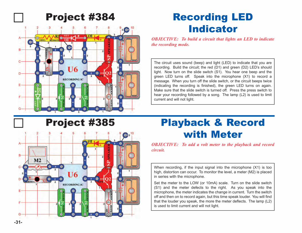
-31-
Project #384
OBJECTIVE: To build a circuit that lights an LED to indicatethe recording mode.
Recording LEDIndicator
Project #385
OBJECTIVE: To add a volt meter to the playback and recordcircuit.
When recording, if the input signal into the microphone (X1) is toohigh, distortion can occur. To monitor the level, a meter (M2) is placedin series with the microphone.
Set the meter to the LOW (or 10mA) scale. Turn on the slide switch(S1) and the meter defects to the right. As you speak into themicrophone, the meter indicates the change in current. Turn the switchoff and then on to record again, but this time speak louder. You will findthat the louder you speak, the more the meter deflects. The lamp (L2)is used to limit current and will not light.
Playback & Recordwith Meter
The circuit uses sound (beep) and light (LED) to indicate that you arerecording. Build the circuit; the red (D1) and green (D2) LED’s shouldlight. Now turn on the slide switch (S1). You hear one beep and thegreen LED turns off. Speak into the microphone (X1) to record amessage. When you turn off the slide switch, or the circuit beeps twice(indicating the recording is finished), the green LED turns on again.Make sure that the slide switch is turned off. Press the press switch tohear your recording followed by a song. The lamp (L2) is used to limitcurrent and will not light.
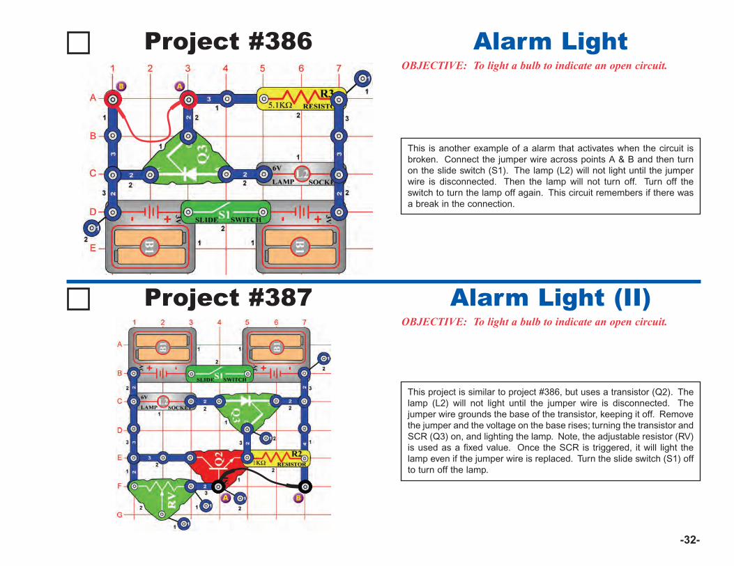
-32-
Project #386OBJECTIVE: To light a bulb to indicate an open circuit.
Alarm Light
Project #387 Alarm Light (II)
This is another example of a alarm that activates when the circuit isbroken. Connect the jumper wire across points A & B and then turnon the slide switch (S1). The lamp (L2) will not light until the jumperwire is disconnected. Then the lamp will not turn off. Turn off theswitch to turn the lamp off again. This circuit remembers if there wasa break in the connection.
OBJECTIVE: To light a bulb to indicate an open circuit.
This project is similar to project #386, but uses a transistor (Q2). Thelamp (L2) will not light until the jumper wire is disconnected. Thejumper wire grounds the base of the transistor, keeping it off. Removethe jumper and the voltage on the base rises; turning the transistor andSCR (Q3) on, and lighting the lamp. Note, the adjustable resistor (RV)is used as a fixed value. Once the SCR is triggered, it will light thelamp even if the jumper wire is replaced. Turn the slide switch (S1) offto turn off the lamp.
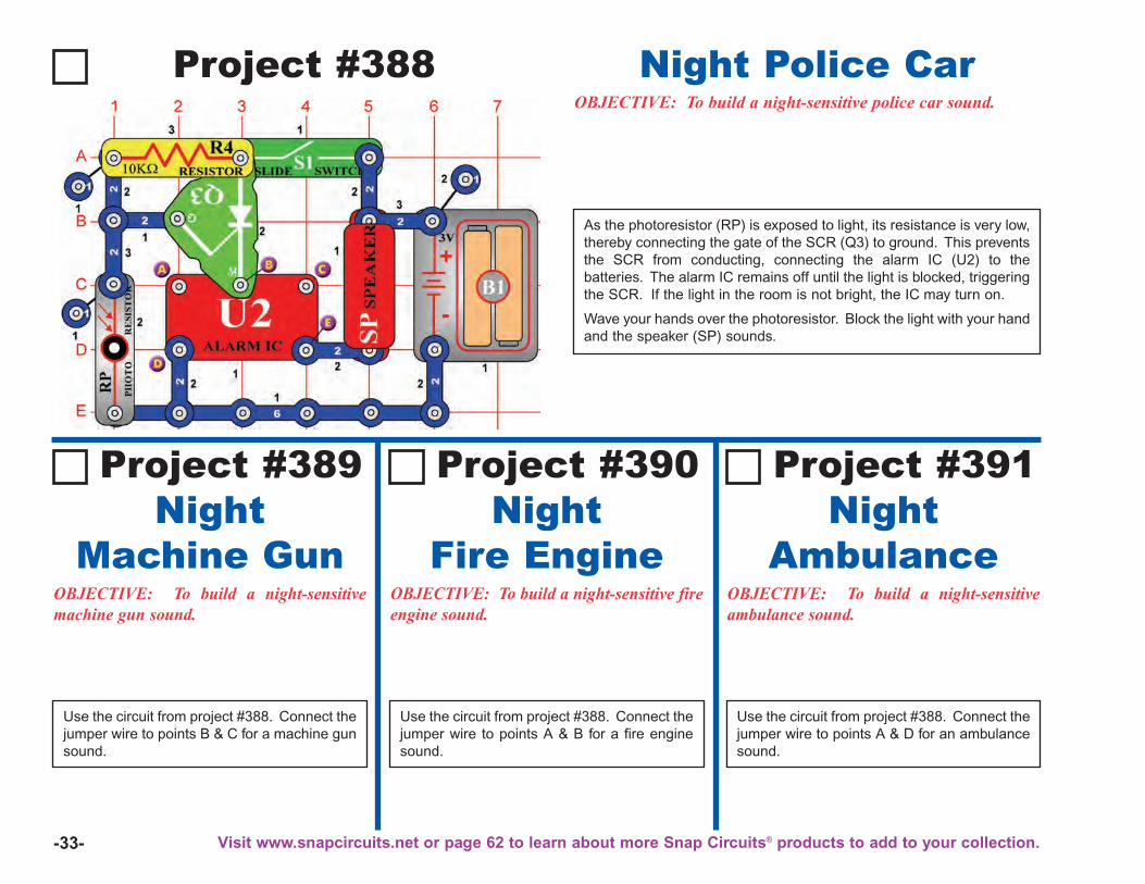
-33-
Project #388OBJECTIVE: To build a night-sensitive police car sound.
As the photoresistor (RP) is exposed to light, its resistance is very low,thereby connecting the gate of the SCR (Q3) to ground. This preventsthe SCR from conducting, connecting the alarm IC (U2) to thebatteries. The alarm IC remains off until the light is blocked, triggeringthe SCR. If the light in the room is not bright, the IC may turn on.
Wave your hands over the photoresistor. Block the light with your handand the speaker (SP) sounds.
Night Police Car
OBJECTIVE: To build a night-sensitivemachine gun sound.
Use the circuit from project #388. Connect thejumper wire to points B & C for a machine gunsound.
NightMachine Gun
Project #389
OBJECTIVE: To build a night-sensitive fireengine sound.
NightFire Engine
Project #390
OBJECTIVE: To build a night-sensitiveambulance sound.
NightAmbulance
Project #391
Use the circuit from project #388. Connect thejumper wire to points A & B for a fire enginesound.
Use the circuit from project #388. Connect thejumper wire to points A & D for an ambulancesound.
Visit www.snapcircuits.net or page 62 to learn about more Snap Circuits® products to add to your collection.
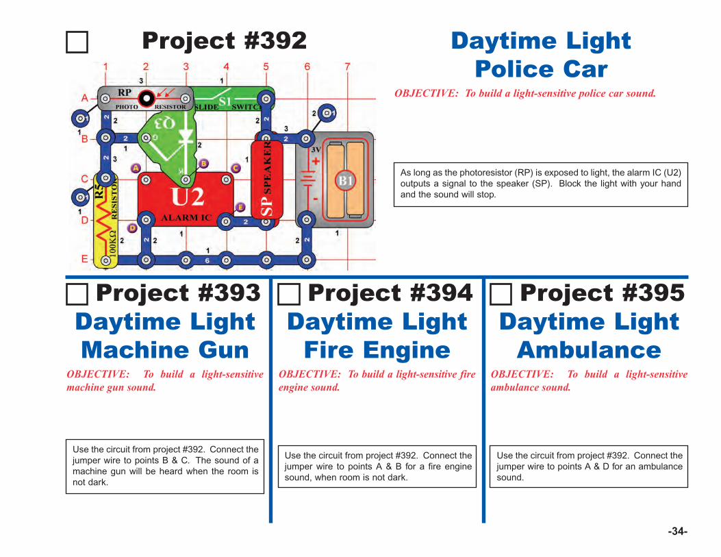
-34-
Project #392
OBJECTIVE: To build a light-sensitive police car sound.
As long as the photoresistor (RP) is exposed to light, the alarm IC (U2)outputs a signal to the speaker (SP). Block the light with your handand the sound will stop.
Daytime LightPolice Car
OBJECTIVE: To build a light-sensitivemachine gun sound.
Use the circuit from project #392. Connect thejumper wire to points B & C. The sound of amachine gun will be heard when the room isnot dark.
Daytime LightMachine Gun
Project #393
OBJECTIVE: To build a light-sensitive fireengine sound.
Daytime LightFire Engine
Project #394
OBJECTIVE: To build a light-sensitiveambulance sound.
Daytime LightAmbulance
Project #395
Use the circuit from project #392. Connect thejumper wire to points A & B for a fire enginesound, when room is not dark.
Use the circuit from project #392. Connect thejumper wire to points A & D for an ambulancesound.
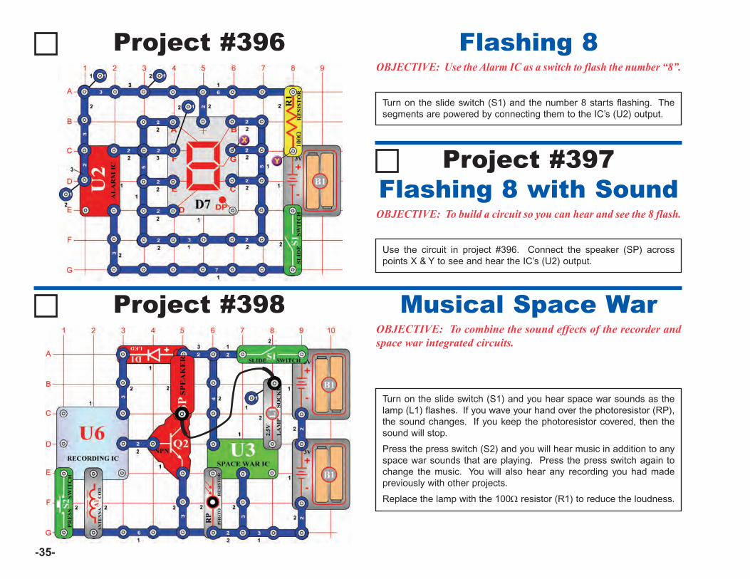
-35-
Project #396 Flashing 8OBJECTIVE: Use the Alarm IC as a switch to flash the number “8”.
Turn on the slide switch (S1) and the number 8 starts flashing. Thesegments are powered by connecting them to the IC’s (U2) output.
Flashing 8 with SoundOBJECTIVE: To build a circuit so you can hear and see the 8 flash.
Use the circuit in project #396. Connect the speaker (SP) acrosspoints X & Y to see and hear the IC’s (U2) output.
Project #397
Project #398
Turn on the slide switch (S1) and you hear space war sounds as thelamp (L1) flashes. If you wave your hand over the photoresistor (RP),the sound changes. If you keep the photoresistor covered, then thesound will stop.
Press the press switch (S2) and you will hear music in addition to anyspace war sounds that are playing. Press the press switch again tochange the music. You will also hear any recording you had madepreviously with other projects.
Replace the lamp with the 100Ω resistor (R1) to reduce the loudness.
Musical Space WarOBJECTIVE: To combine the sound effects of the recorder andspace war integrated circuits.
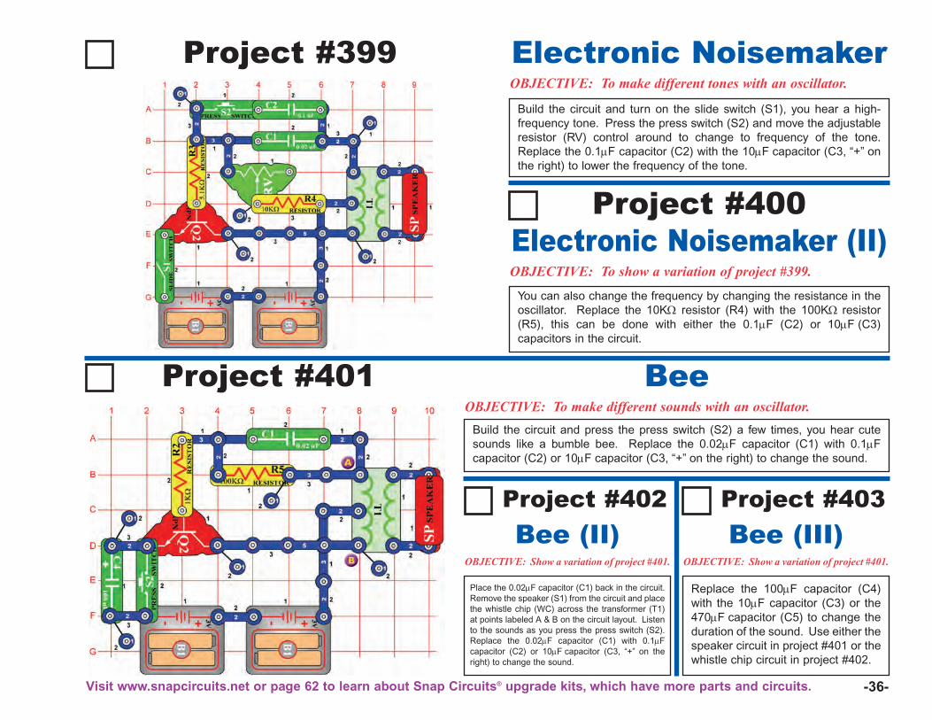
-36-
Project #399OBJECTIVE: To make different tones with an oscillator.
Build the circuit and turn on the slide switch (S1), you hear a high-frequency tone. Press the press switch (S2) and move the adjustableresistor (RV) control around to change to frequency of the tone.Replace the 0.1μF capacitor (C2) with the 10μF capacitor (C3, “+” onthe right) to lower the frequency of the tone.
Electronic Noisemaker
OBJECTIVE: To show a variation of project #399.
You can also change the frequency by changing the resistance in theoscillator. Replace the 10KΩ resistor (R4) with the 100KΩ resistor(R5), this can be done with either the 0.1μF (C2) or 10μF (C3)capacitors in the circuit.
Electronic Noisemaker (II)Project #400
Project #401OBJECTIVE: To make different sounds with an oscillator.
Build the circuit and press the press switch (S2) a few times, you hear cutesounds like a bumble bee. Replace the 0.02μF capacitor (C1) with 0.1μFcapacitor (C2) or 10μF capacitor (C3, “+” on the right) to change the sound.
Bee
OBJECTIVE: Show a variation of project #401.
Place the 0.02μF capacitor (C1) back in the circuit.Remove the speaker (S1) from the circuit and placethe whistle chip (WC) across the transformer (T1)at points labeled A & B on the circuit layout. Listento the sounds as you press the press switch (S2).Replace the 0.02μF capacitor (C1) with 0.1μFcapacitor (C2) or 10μF capacitor (C3, “+” on theright) to change the sound.
Bee (II)Project #402
Bee (III)Project #403
OBJECTIVE: Show a variation of project #401.
Replace the 100μF capacitor (C4)with the 10μF capacitor (C3) or the470μF capacitor (C5) to change theduration of the sound. Use either thespeaker circuit in project #401 or thewhistle chip circuit in project #402.
Visit www.snapcircuits.net or page 62 to learn about Snap Circuits® upgrade kits, which have more parts and circuits.
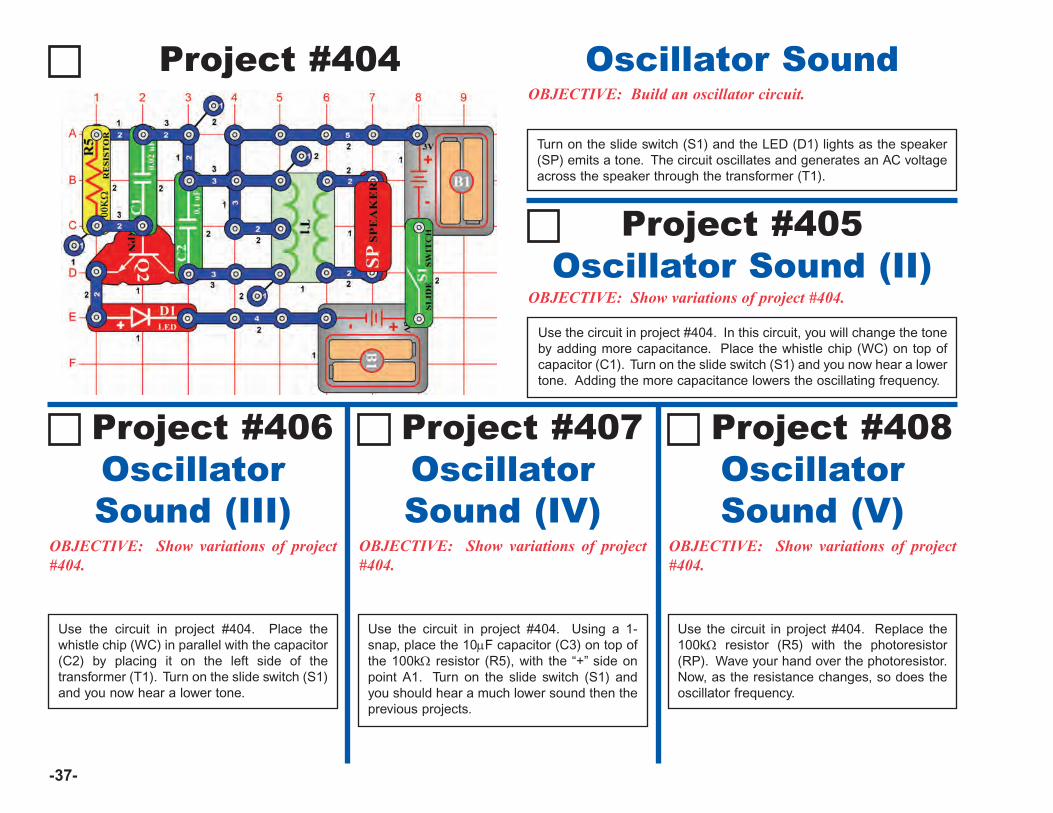
-37-
Project #404OBJECTIVE: Build an oscillator circuit.
Turn on the slide switch (S1) and the LED (D1) lights as the speaker(SP) emits a tone. The circuit oscillates and generates an AC voltageacross the speaker through the transformer (T1).
Oscillator Sound
OBJECTIVE: Show variations of project#404.
Use the circuit in project #404. Place thewhistle chip (WC) in parallel with the capacitor(C2) by placing it on the left side of thetransformer (T1). Turn on the slide switch (S1)and you now hear a lower tone.
OscillatorSound (III)
Project #406
OBJECTIVE: Show variations of project#404.
OscillatorSound (IV)
Project #407
OBJECTIVE: Show variations of project#404.
OscillatorSound (V)
Project #408
OBJECTIVE: Show variations of project #404.
Use the circuit in project #404. In this circuit, you will change the toneby adding more capacitance. Place the whistle chip (WC) on top ofcapacitor (C1). Turn on the slide switch (S1) and you now hear a lowertone. Adding the more capacitance lowers the oscillating frequency.
Oscillator Sound (II)Project #405
Use the circuit in project #404. Using a 1-snap, place the 10μF capacitor (C3) on top ofthe 100kΩ resistor (R5), with the “+” side onpoint A1. Turn on the slide switch (S1) andyou should hear a much lower sound then theprevious projects.
Use the circuit in project #404. Replace the100kΩ resistor (R5) with the photoresistor(RP). Wave your hand over the photoresistor.Now, as the resistance changes, so does theoscillator frequency.
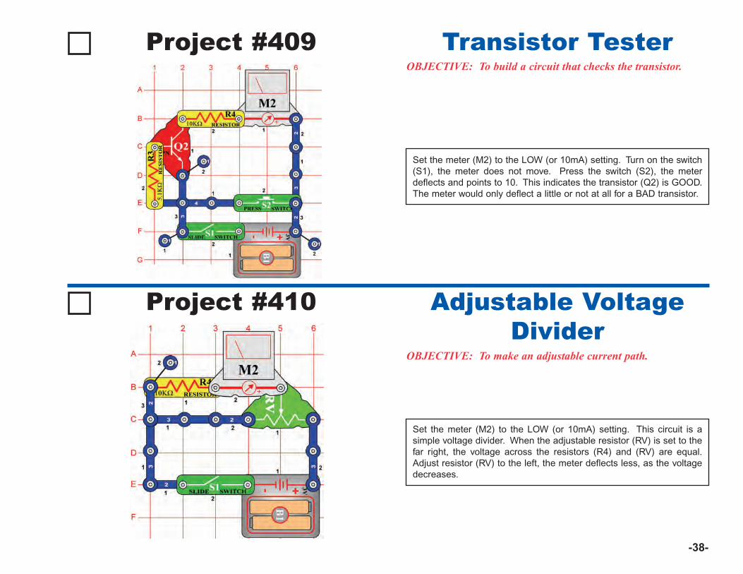
-38-
Project #409OBJECTIVE: To build a circuit that checks the transistor.
Set the meter (M2) to the LOW (or 10mA) setting. Turn on the switch(S1), the meter does not move. Press the switch (S2), the meterdeflects and points to 10. This indicates the transistor (Q2) is GOOD.The meter would only deflect a little or not at all for a BAD transistor.
Transistor Tester
Project #410
OBJECTIVE: To make an adjustable current path.
Set the meter (M2) to the LOW (or 10mA) setting. This circuit is asimple voltage divider. When the adjustable resistor (RV) is set to thefar right, the voltage across the resistors (R4) and (RV) are equal.Adjust resistor (RV) to the left, the meter deflects less, as the voltagedecreases.
Adjustable VoltageDivider
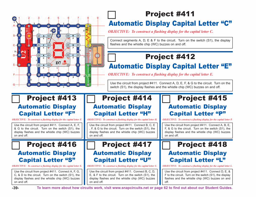
-39-
OBJECTIVE: To construct a flashing display for the capital letter C.
Connect segments A, D, E & F to the circuit. Turn on the switch (S1), the displayflashes and the whistle chip (WC) buzzes on and off.
Automatic Display Capital Letter “C”Project #411
OBJECTIVE: To construct a flashing display for the capital letter E.
Use the circuit from project #411. Connect A, D, E, F, & G to the circuit. Turn on theswitch (S1), the display flashes and the whistle chip (WC) buzzes on and off.
Automatic Display Capital Letter “E”Project #412
Project #413
OBJECTIVE: To construct a flashing display for the capital letter F.
Use the circuit from project #411. Connect A, E, F,& G to the circuit. Turn on the switch (S1), thedisplay flashes and the whistle chip (WC) buzzeson and off.
Automatic DisplayCapital Letter “F”
Project #414
OBJECTIVE: To construct a flashing display for the capital letter H.
Use the circuit from project #411. Connect B, C, E, F, & G to the circuit. Turn on the switch (S1), thedisplay flashes and the whistle chip (WC) buzzeson and off.
Automatic DisplayCapital Letter “H”
Project #415
OBJECTIVE: To construct a flashing display for the capital letter P.
Use the circuit from project #411. Connect A, B, E,F, & G to the circuit. Turn on the switch (S1), thedisplay flashes and the whistle chip (WC) buzzeson and off.
Automatic DisplayCapital Letter “P”
Project #416
OBJECTIVE: To construct a flashing display for the capital letter S.
Use the circuit from project #411. Connect A, F, G,C, & D to the circuit. Turn on the switch (S1), thedisplay flashes and the whistle chip (WC) buzzeson and off.
Automatic DisplayCapital Letter “S”
Project #417
OBJECTIVE: To construct a flashing display for the capital letter U.
Use the circuit from project #411. Connect B, C, D,E, & F to the circuit. Turn on the switch (S1), thedisplay flashes and the whistle chip (WC) buzzeson and off.
Automatic DisplayCapital Letter “U”
Project #418
OBJECTIVE: To construct a flashing display for the capital letter L.
Use the circuit from project #411. Connect D, E, &F to the circuit. Turn on the switch (S1), the displayflashes and the whistle chip (WC) buzzes on andoff.
Automatic DisplayCapital Letter “L”
To learn more about how circuits work, visit www.snapcircuits.net or page 62 to find out about our Student Guides.
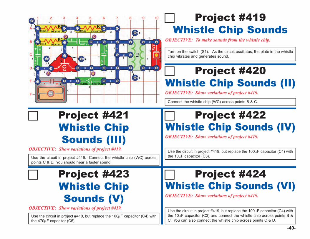
-40-
OBJECTIVE: Show variations of project #419.
Connect the whistle chip (WC) across points B & C.
Whistle Chip Sounds (II)Project #420
OBJECTIVE: Show variations of project #419.
Whistle ChipSounds (III)
Project #421
OBJECTIVE: Show variations of project #419.
Whistle Chip Sounds (VI)Project #424
OBJECTIVE: To make sounds from the whistle chip.
Turn on the switch (S1). As the circuit oscillates, the plate in the whistlechip vibrates and generates sound.
Whistle Chip SoundsProject #419
Use the circuit in project #419. Connect the whistle chip (WC) acrosspoints C & D. You should hear a faster sound.
OBJECTIVE: Show variations of project #419.
Whistle ChipSounds (V)
Project #423
Use the circuit in project #419, but replace the 100μF capacitor (C4) withthe 470μF capacitor (C5).
Use the circuit in project #419, but replace the 100μF capacitor (C4) withthe 10μF capacitor (C3).
OBJECTIVE: Show variations of project #419.
Whistle Chip Sounds (IV)Project #422
Use the circuit in project #419, but replace the 100μF capacitor (C4) withthe 10μF capacitor (C3) and connect the whistle chip across points B &C. You can also connect the whistle chip across points C & D.
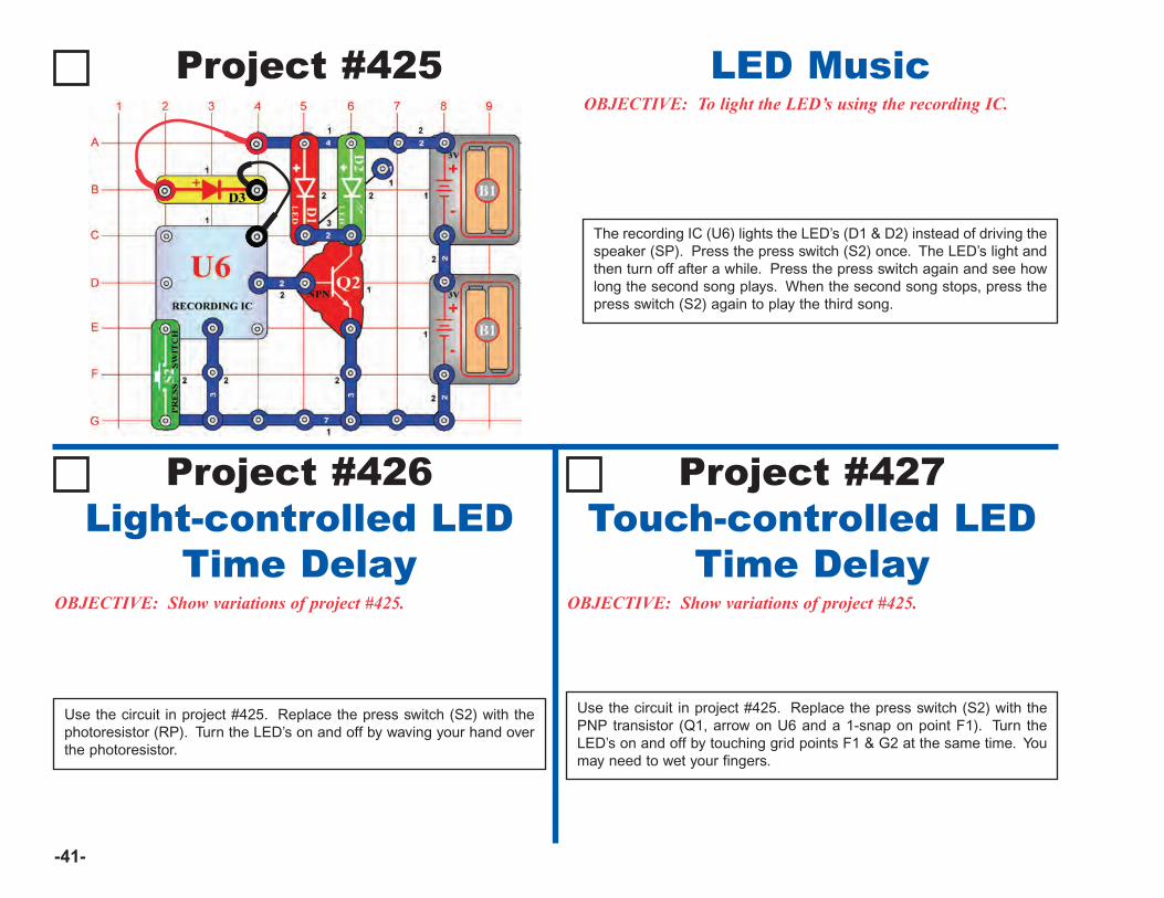
-41-
Project #425OBJECTIVE: To light the LED’s using the recording IC.
The recording IC (U6) lights the LED’s (D1 & D2) instead of driving thespeaker (SP). Press the press switch (S2) once. The LED’s light andthen turn off after a while. Press the press switch again and see howlong the second song plays. When the second song stops, press thepress switch (S2) again to play the third song.
LED Music
Project #426 Project #427
OBJECTIVE: Show variations of project #425.
Light-controlled LEDTime Delay
OBJECTIVE: Show variations of project #425.
Touch-controlled LEDTime Delay
Use the circuit in project #425. Replace the press switch (S2) with thephotoresistor (RP). Turn the LED’s on and off by waving your hand overthe photoresistor.
Use the circuit in project #425. Replace the press switch (S2) with thePNP transistor (Q1, arrow on U6 and a 1-snap on point F1). Turn theLED’s on and off by touching grid points F1 & G2 at the same time. Youmay need to wet your fingers.
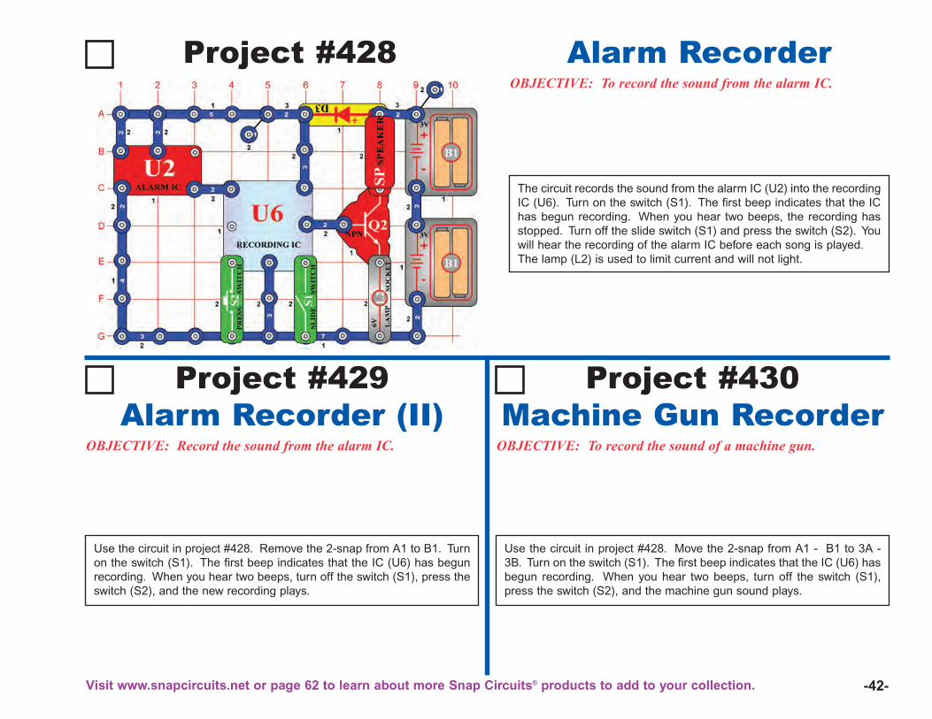
-42-
Project #428OBJECTIVE: To record the sound from the alarm IC.
The circuit records the sound from the alarm IC (U2) into the recordingIC (U6). Turn on the switch (S1). The first beep indicates that the IChas begun recording. When you hear two beeps, the recording hasstopped. Turn off the slide switch (S1) and press the switch (S2). Youwill hear the recording of the alarm IC before each song is played.The lamp (L2) is used to limit current and will not light.
Alarm Recorder
Project #429 Project #430
OBJECTIVE: Record the sound from the alarm IC.
Alarm Recorder (II)OBJECTIVE: To record the sound of a machine gun.
Machine Gun Recorder
Use the circuit in project #428. Remove the 2-snap from A1 to B1. Turnon the switch (S1). The first beep indicates that the IC (U6) has begunrecording. When you hear two beeps, turn off the switch (S1), press theswitch (S2), and the new recording plays.
Use the circuit in project #428. Move the 2-snap from A1 - B1 to 3A -3B. Turn on the switch (S1). The first beep indicates that the IC (U6) hasbegun recording. When you hear two beeps, turn off the switch (S1),press the switch (S2), and the machine gun sound plays.
Visit www.snapcircuits.net or page 62 to learn about more Snap Circuits® products to add to your collection.

-43-
The length of time the motor (M1) runs depends on the position of theadjustable resistor (RV). When the press switch (S2) is pressed, the470μF capacitor (C5) charges. As the press switch is released, C5discharges through the resistors R4 and RV, turning the transistor (Q2)on. Transistor Q2 connects the relay (S3) to the batteries, the contactsswitch, and the motor (M1) spins. As the voltage decreases, Q2 will turnoff and the motor will stop spinning.
Setting RV to the right (large resistance) sets a long discharge time. Tothe left, a short discharge time.
Turn on the switch (S1), the red LED (D1) lights. Now press and releasethe switch (S2), the bulb lights and the motor spins.
Project #431Time Delay1-7 Seconds
OBJECTIVE: To build a time delay circuit.
Project #432Time Delay
OBJECTIVE: To see how the capacitor value affects the time.
Use the circuit in project #431. Replace the 470μF capacitor (C5) withthe 100μF capacitor (C4). Set the adjustable resistor (RV) to the far right,turn on the switch (S1), then press and release the switch (S2). Themotor (M1) spins and bulb (L2) lights for about 3 seconds. Adjust theadjustable resistor to the left for a much shorter time.
!WARNING: Moving parts. Do not touch the fan ormotor during operation. Do not lean over the motor.
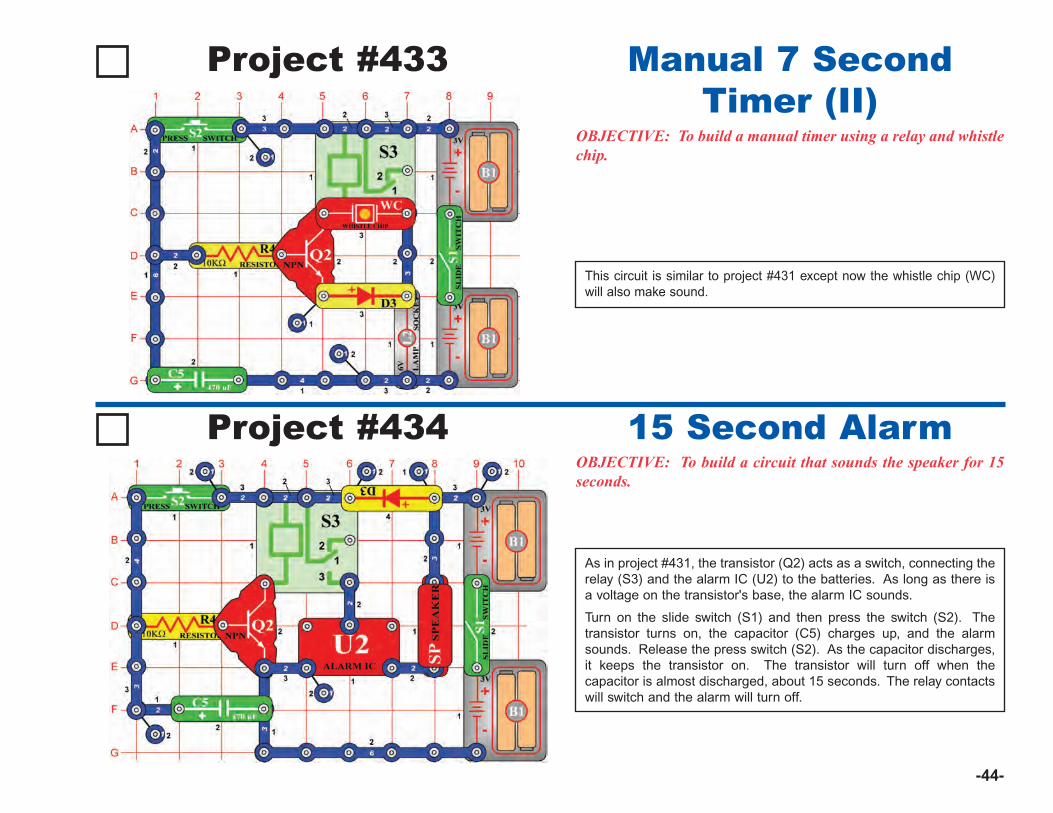
-44-
Project #433
OBJECTIVE: To build a manual timer using a relay and whistlechip.
This circuit is similar to project #431 except now the whistle chip (WC)will also make sound.
Manual 7 SecondTimer (II)
Project #434OBJECTIVE: To build a circuit that sounds the speaker for 15seconds.
As in project #431, the transistor (Q2) acts as a switch, connecting therelay (S3) and the alarm IC (U2) to the batteries. As long as there isa voltage on the transistor's base, the alarm IC sounds.
Turn on the slide switch (S1) and then press the switch (S2). Thetransistor turns on, the capacitor (C5) charges up, and the alarmsounds. Release the press switch (S2). As the capacitor discharges,it keeps the transistor on. The transistor will turn off when thecapacitor is almost discharged, about 15 seconds. The relay contactswill switch and the alarm will turn off.
15 Second Alarm
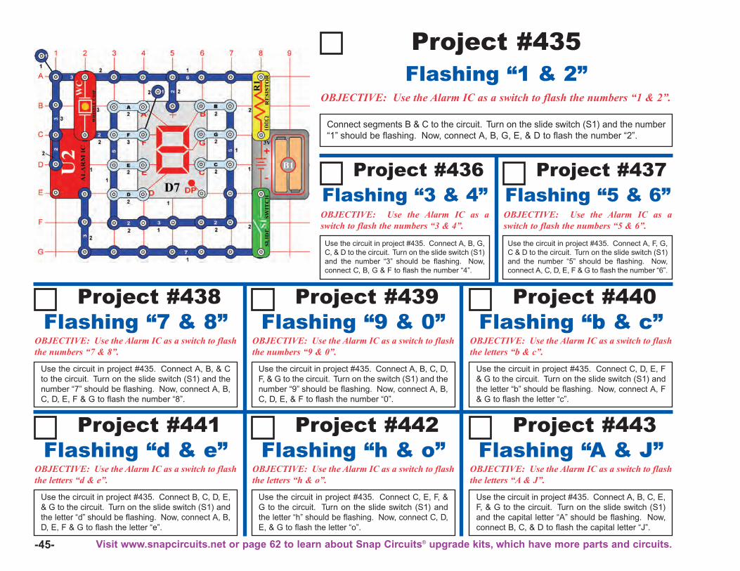
-45-
Project #441 Project #442
OBJECTIVE: Use the Alarm IC as a switch to flash the numbers “1 & 2”.
Connect segments B & C to the circuit. Turn on the slide switch (S1) and the number“1” should be flashing. Now, connect A, B, G, E, & D to flash the number “2”.
OBJECTIVE: Use the Alarm IC as a switch to flashthe letters “d & e”.
Flashing “d & e”
Use the circuit in project #435. Connect B, C, D, E,& G to the circuit. Turn on the slide switch (S1) andthe letter “d” should be flashing. Now, connect A, B,D, E, F & G to flash the letter “e”.
OBJECTIVE: Use the Alarm IC as a switch to flashthe letters “h & o”.
Flashing “h & o”
Use the circuit in project #435. Connect C, E, F, &G to the circuit. Turn on the slide switch (S1) andthe letter “h” should be flashing. Now, connect C, D,E, & G to flash the letter “o”.
Project #436
OBJECTIVE: Use the Alarm IC as aswitch to flash the numbers “3 & 4”.
Flashing “3 & 4”
Use the circuit in project #435. Connect A, B, G,C, & D to the circuit. Turn on the slide switch (S1)and the number “3” should be flashing. Now,connect C, B, G & F to flash the number “4”.
Project #437
OBJECTIVE: Use the Alarm IC as aswitch to flash the numbers “5 & 6”.
Flashing “5 & 6”
Use the circuit in project #435. Connect A, F, G,C & D to the circuit. Turn on the slide switch (S1)and the number “5” should be flashing. Now,connect A, C, D, E, F & G to flash the number “6”.
Project #438 Project #439 Project #440
OBJECTIVE: Use the Alarm IC as a switch to flashthe numbers “7 & 8”.
Flashing “7 & 8”
Use the circuit in project #435. Connect A, B, & Cto the circuit. Turn on the slide switch (S1) and thenumber “7” should be flashing. Now, connect A, B,C, D, E, F & G to flash the number “8”.
OBJECTIVE: Use the Alarm IC as a switch to flashthe numbers “9 & 0”.
Flashing “9 & 0”
Use the circuit in project #435. Connect A, B, C, D,F, & G to the circuit. Turn on the switch (S1) and thenumber “9” should be flashing. Now, connect A, B,C, D, E, & F to flash the number “0”.
OBJECTIVE: Use the Alarm IC as a switch to flashthe letters “b & c”.
Flashing “b & c”
Use the circuit in project #435. Connect C, D, E, F& G to the circuit. Turn on the slide switch (S1) andthe letter “b” should be flashing. Now, connect A, F& G to flash the letter “c”.
Project #443
OBJECTIVE: Use the Alarm IC as a switch to flashthe letters “A & J”.
Flashing “A & J”
Use the circuit in project #435. Connect A, B, C, E,F, & G to the circuit. Turn on the slide switch (S1)and the capital letter “A” should be flashing. Now,connect B, C, & D to flash the capital letter “J”.
Flashing “1 & 2”Project #435
Visit www.snapcircuits.net or page 62 to learn about Snap Circuits® upgrade kits, which have more parts and circuits.
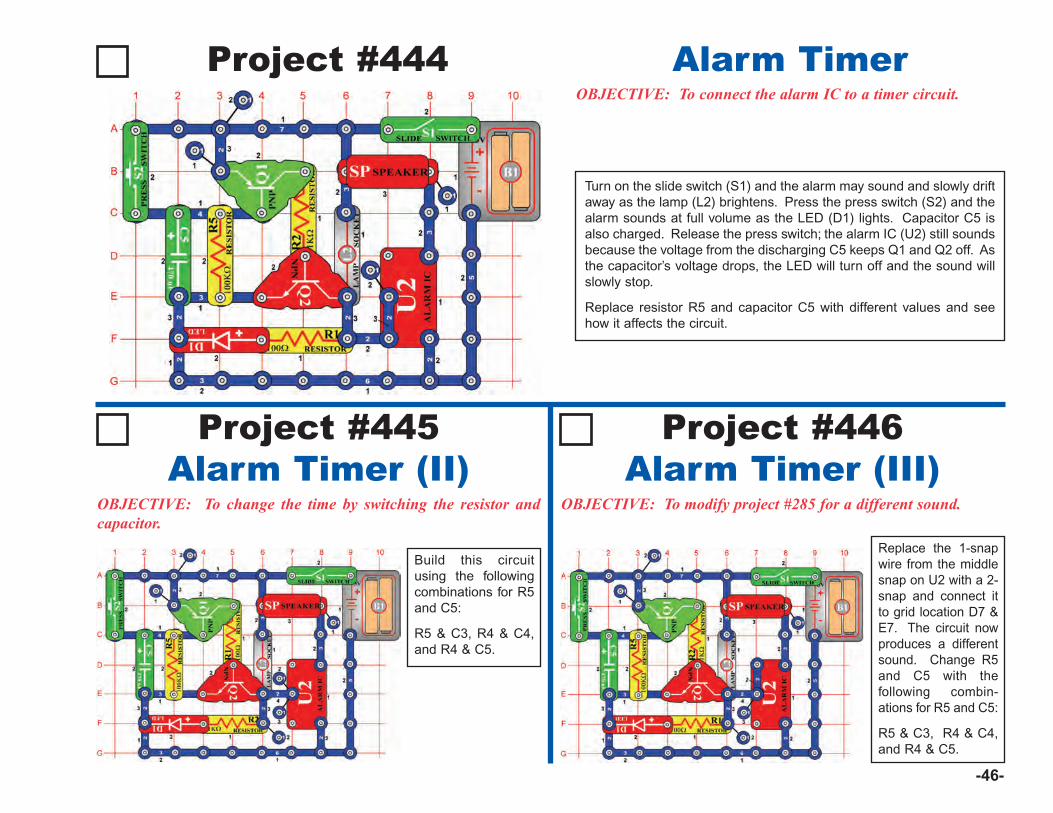
-46-
Project #445Alarm Timer (II)
OBJECTIVE: To change the time by switching the resistor andcapacitor.
Project #446Alarm Timer (III)
Build this circuitusing the followingcombinations for R5and C5:
R5 & C3, R4 & C4,and R4 & C5.
OBJECTIVE: To modify project #285 for a different sound.
Project #444OBJECTIVE: To connect the alarm IC to a timer circuit.
Alarm Timer
Turn on the slide switch (S1) and the alarm may sound and slowly driftaway as the lamp (L2) brightens. Press the press switch (S2) and thealarm sounds at full volume as the LED (D1) lights. Capacitor C5 isalso charged. Release the press switch; the alarm IC (U2) still soundsbecause the voltage from the discharging C5 keeps Q1 and Q2 off. Asthe capacitor’s voltage drops, the LED will turn off and the sound willslowly stop.
Replace resistor R5 and capacitor C5 with different values and seehow it affects the circuit.
Replace the 1-snapwire from the middlesnap on U2 with a 2-snap and connect itto grid location D7 &E7. The circuit nowproduces a differentsound. Change R5and C5 with thefollowing combin-ations for R5 and C5:
R5 & C3, R4 & C4,and R4 & C5.
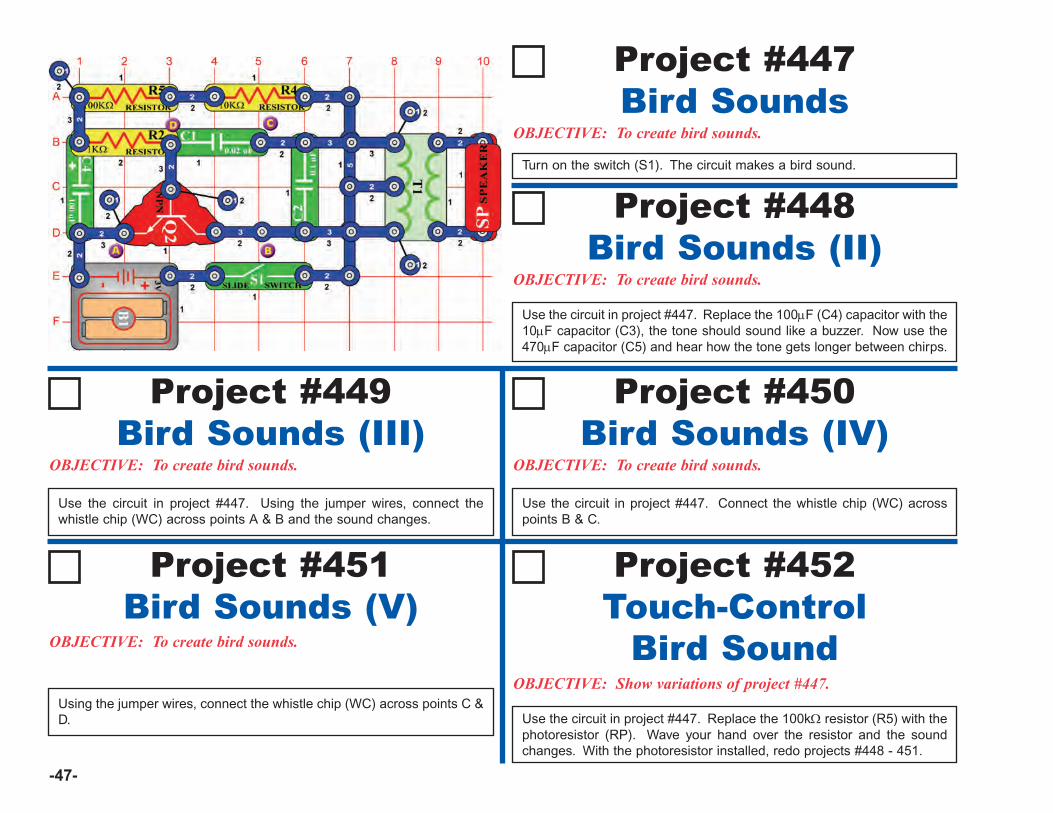
-47-
OBJECTIVE: To create bird sounds.
Turn on the switch (S1). The circuit makes a bird sound.
Bird SoundsProject #447
OBJECTIVE: To create bird sounds.
Use the circuit in project #447. Replace the 100μF (C4) capacitor with the10μF capacitor (C3), the tone should sound like a buzzer. Now use the470μF capacitor (C5) and hear how the tone gets longer between chirps.
Bird Sounds (II)Project #448
OBJECTIVE: To create bird sounds.
Use the circuit in project #447. Using the jumper wires, connect thewhistle chip (WC) across points A & B and the sound changes.
Bird Sounds (III)Project #449
OBJECTIVE: To create bird sounds.
Use the circuit in project #447. Connect the whistle chip (WC) acrosspoints B & C.
Bird Sounds (IV)Project #450
OBJECTIVE: To create bird sounds.
Use the circuit in project #447. Replace the 100kΩ resistor (R5) with thephotoresistor (RP). Wave your hand over the resistor and the soundchanges. With the photoresistor installed, redo projects #448 - 451.
Bird Sounds (V)Project #451
OBJECTIVE: Show variations of project #447.Using the jumper wires, connect the whistle chip (WC) across points C &D.
Touch-ControlBird Sound
Project #452
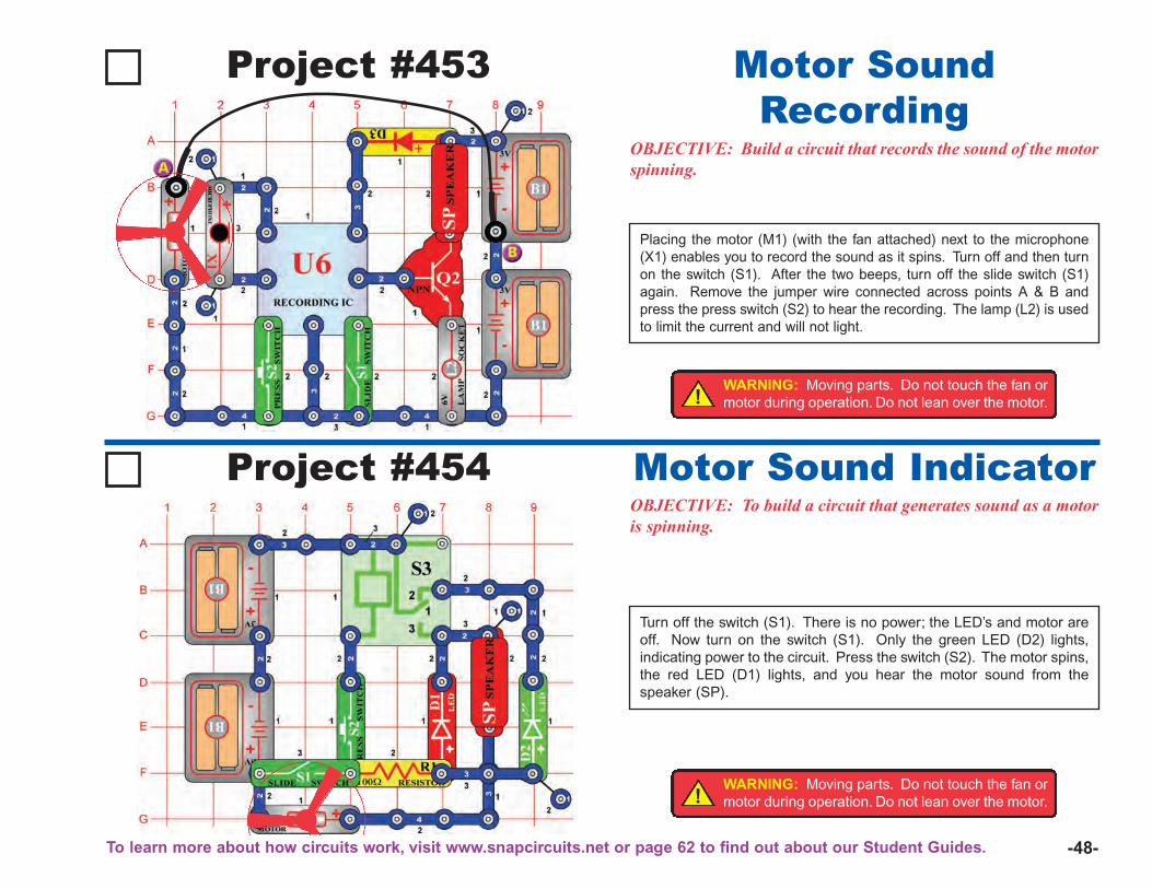
-48-
Project #453
OBJECTIVE: Build a circuit that records the sound of the motorspinning.
Placing the motor (M1) (with the fan attached) next to the microphone(X1) enables you to record the sound as it spins. Turn off and then turnon the switch (S1). After the two beeps, turn off the slide switch (S1)again. Remove the jumper wire connected across points A & B andpress the press switch (S2) to hear the recording. The lamp (L2) is usedto limit the current and will not light.
Motor SoundRecording
Project #454OBJECTIVE: To build a circuit that generates sound as a motoris spinning.
Turn off the switch (S1). There is no power; the LED’s and motor areoff. Now turn on the switch (S1). Only the green LED (D2) lights,indicating power to the circuit. Press the switch (S2). The motor spins,the red LED (D1) lights, and you hear the motor sound from thespeaker (SP).
Motor Sound Indicator
!WARNING: Moving parts. Do not touch the fan ormotor during operation. Do not lean over the motor.
!WARNING: Moving parts. Do not touch the fan ormotor during operation. Do not lean over the motor.
To learn more about how circuits work, visit www.snapcircuits.net or page 62 to find out about our Student Guides.
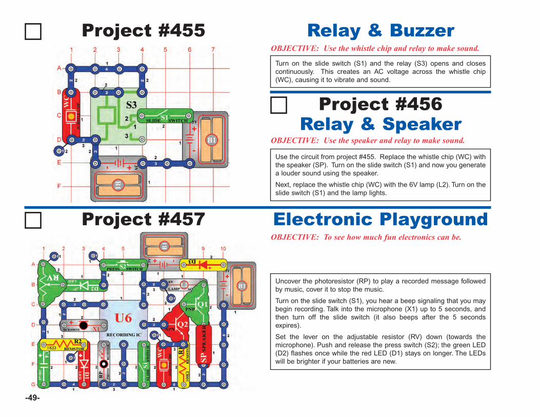
-49-
Project #455OBJECTIVE: Use the whistle chip and relay to make sound.
Turn on the slide switch (S1) and the relay (S3) opens and closescontinuously. This creates an AC voltage across the whistle chip(WC), causing it to vibrate and sound.
Relay & Buzzer
Project #456
Project #457
OBJECTIVE: Use the speaker and relay to make sound.Relay & Speaker
OBJECTIVE: To see how much fun electronics can be.
Electronic Playground
Use the circuit from project #455. Replace the whistle chip (WC) withthe speaker (SP). Turn on the slide switch (S1) and now you generatea louder sound using the speaker.
Next, replace the whistle chip (WC) with the 6V lamp (L2). Turn on theslide switch (S1) and the lamp lights.
Uncover the photoresistor (RP) to play a recorded message followedby music, cover it to stop the music.
Turn on the slide switch (S1), you hear a beep signaling that you maybegin recording. Talk into the microphone (X1) up to 5 seconds, andthen turn off the slide switch (it also beeps after the 5 secondsexpires).
Set the lever on the adjustable resistor (RV) down (towards themicrophone). Push and release the press switch (S2); the green LED(D2) flashes once while the red LED (D1) stays on longer. The LEDswill be brighter if your batteries are new.
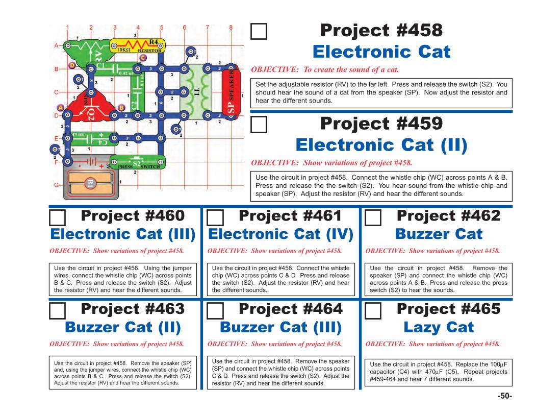
-50-
OBJECTIVE: To create the sound of a cat.
Set the adjustable resistor (RV) to the far left. Press and release the switch (S2). Youshould hear the sound of a cat from the speaker (SP). Now adjust the resistor andhear the different sounds.
Electronic CatProject #458
OBJECTIVE: Show variations of project #458.
Electronic Cat (II)Project #459
Use the circuit in project #458. Connect the whistle chip (WC) across points A & B.Press and release the the switch (S2). You hear sound from the whistle chip andspeaker (SP). Adjust the resistor (RV) and hear the different sounds.
Project #460
OBJECTIVE: Show variations of project #458.
Electronic Cat (III)Project #461 Project #462
Project #463 Project #464 Project #465
Use the circuit in project #458. Using the jumperwires, connect the whistle chip (WC) across pointsB & C. Press and release the switch (S2). Adjustthe resistor (RV) and hear the different sounds.
OBJECTIVE: Show variations of project #458.
Electronic Cat (IV)
Use the circuit in project #458. Connect the whistlechip (WC) across points C & D. Press and releasethe switch (S2). Adjust the resistor (RV) and hearthe different sounds.
OBJECTIVE: Show variations of project #458.
Buzzer Cat
Use the circuit in project #458. Remove thespeaker (SP) and connect the whistle chip (WC)across points A & B. Press and release the pressswitch (S2) to hear the sounds.
OBJECTIVE: Show variations of project #458.
Buzzer Cat (II)
Use the circuit in project #458. Remove the speaker (SP)and, using the jumper wires, connect the whistle chip (WC)across points B & C. Press and release the switch (S2).Adjust the resistor (RV) and hear the different sounds.
OBJECTIVE: Show variations of project #458.
Buzzer Cat (III)
Use the circuit in project #458. Remove the speaker(SP) and connect the whistle chip (WC) across pointsC & D. Press and release the switch (S2). Adjust theresistor (RV) and hear the different sounds.
OBJECTIVE: Show variations of project #458.
Lazy Cat
Use the circuit in project #458. Replace the 100μFcapacitor (C4) with 470μF (C5). Repeat projects#459-464 and hear 7 different sounds.
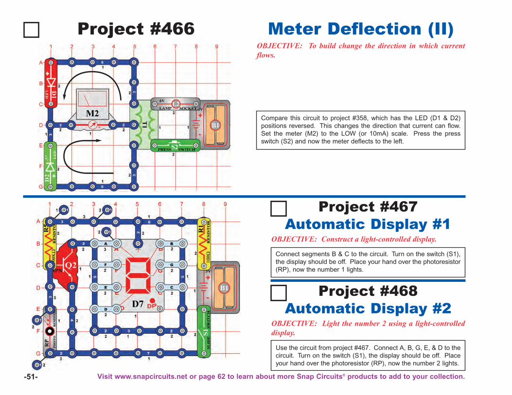
-51-
OBJECTIVE: Construct a light-controlled display.
Connect segments B & C to the circuit. Turn on the switch (S1),the display should be off. Place your hand over the photoresistor(RP), now the number 1 lights.
Automatic Display #1Project #467
OBJECTIVE: Light the number 2 using a light-controlleddisplay.
Use the circuit from project #467. Connect A, B, G, E, & D to thecircuit. Turn on the switch (S1), the display should be off. Placeyour hand over the photoresistor (RP), now the number 2 lights.
Automatic Display #2Project #468
Project #466OBJECTIVE: To build change the direction in which currentflows.
Compare this circuit to project #358, which has the LED (D1 & D2)positions reversed. This changes the direction that current can flow.Set the meter (M2) to the LOW (or 10mA) scale. Press the pressswitch (S2) and now the meter deflects to the left.
Meter Deflection (II)
Visit www.snapcircuits.net or page 62 to learn about more Snap Circuits® products to add to your collection.
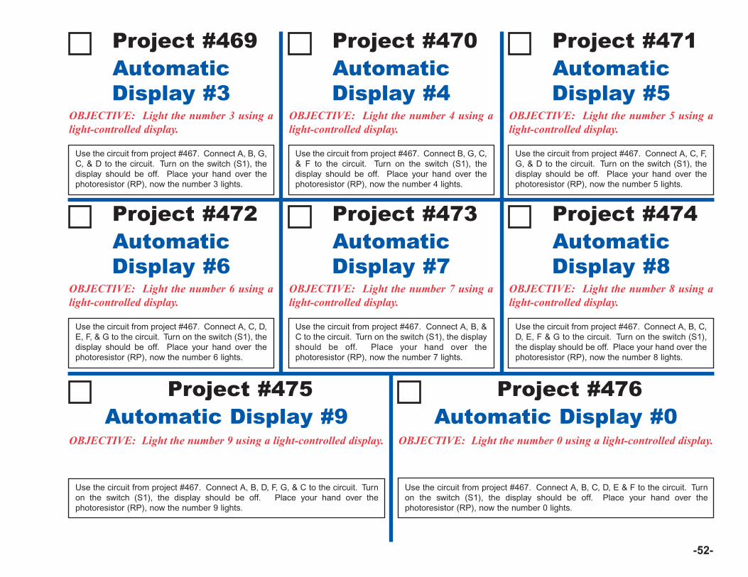
-52-
Project #469
OBJECTIVE: Light the number 3 using alight-controlled display.
Use the circuit from project #467. Connect A, B, G,C, & D to the circuit. Turn on the switch (S1), thedisplay should be off. Place your hand over thephotoresistor (RP), now the number 3 lights.
AutomaticDisplay #3
Project #475
OBJECTIVE: Light the number 9 using a light-controlled display.
Use the circuit from project #467. Connect A, B, D, F, G, & C to the circuit. Turnon the switch (S1), the display should be off. Place your hand over thephotoresistor (RP), now the number 9 lights.
Automatic Display #9Project #476
OBJECTIVE: Light the number 0 using a light-controlled display.
Use the circuit from project #467. Connect A, B, C, D, E & F to the circuit. Turnon the switch (S1), the display should be off. Place your hand over thephotoresistor (RP), now the number 0 lights.
Automatic Display #0
Project #470
OBJECTIVE: Light the number 4 using alight-controlled display.
Use the circuit from project #467. Connect B, G, C,& F to the circuit. Turn on the switch (S1), thedisplay should be off. Place your hand over thephotoresistor (RP), now the number 4 lights.
AutomaticDisplay #4
Project #471
OBJECTIVE: Light the number 5 using alight-controlled display.
Use the circuit from project #467. Connect A, C, F,G, & D to the circuit. Turn on the switch (S1), thedisplay should be off. Place your hand over thephotoresistor (RP), now the number 5 lights.
AutomaticDisplay #5
Project #472
OBJECTIVE: Light the number 6 using alight-controlled display.
Use the circuit from project #467. Connect A, C, D,E, F, & G to the circuit. Turn on the switch (S1), thedisplay should be off. Place your hand over thephotoresistor (RP), now the number 6 lights.
AutomaticDisplay #6
Project #473
OBJECTIVE: Light the number 7 using alight-controlled display.
Use the circuit from project #467. Connect A, B, &C to the circuit. Turn on the switch (S1), the displayshould be off. Place your hand over thephotoresistor (RP), now the number 7 lights.
AutomaticDisplay #7
Project #474
OBJECTIVE: Light the number 8 using alight-controlled display.
Use the circuit from project #467. Connect A, B, C,D, E, F & G to the circuit. Turn on the switch (S1),the display should be off. Place your hand over thephotoresistor (RP), now the number 8 lights.
AutomaticDisplay #8
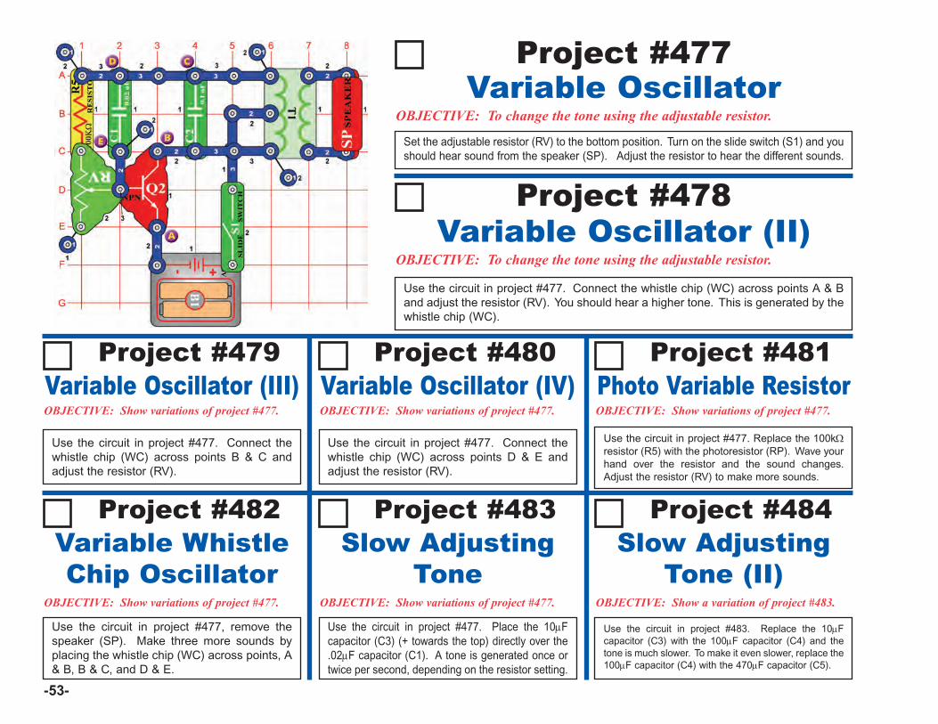
-53-
OBJECTIVE: To change the tone using the adjustable resistor.
Set the adjustable resistor (RV) to the bottom position. Turn on the slide switch (S1) and youshould hear sound from the speaker (SP). Adjust the resistor to hear the different sounds.
Variable OscillatorProject #477
OBJECTIVE: To change the tone using the adjustable resistor.Variable Oscillator (II)
Project #478
Project #479
Use the circuit in project #477. Connect thewhistle chip (WC) across points B & C andadjust the resistor (RV).
Variable Oscillator (III)Project #480
OBJECTIVE: Show variations of project #477.
Variable Oscillator (IV)Project #481
OBJECTIVE: Show variations of project #477.
Photo Variable Resistor
Use the circuit in project #477. Connect the whistle chip (WC) across points A & Band adjust the resistor (RV). You should hear a higher tone. This is generated by thewhistle chip (WC).
Project #482
OBJECTIVE: Show variations of project #477.
Variable WhistleChip Oscillator
Project #483
OBJECTIVE: Show variations of project #477.
Slow AdjustingTone
Project #484
OBJECTIVE: Show a variation of project #483.
Slow AdjustingTone (II)
Use the circuit in project #477. Connect thewhistle chip (WC) across points D & E andadjust the resistor (RV).
Use the circuit in project #477. Replace the 100kΩresistor (R5) with the photoresistor (RP). Wave yourhand over the resistor and the sound changes.Adjust the resistor (RV) to make more sounds.
Use the circuit in project #477, remove thespeaker (SP). Make three more sounds byplacing the whistle chip (WC) across points, A& B, B & C, and D & E.
Use the circuit in project #477. Place the 10μFcapacitor (C3) (+ towards the top) directly over the.02μF capacitor (C1). A tone is generated once ortwice per second, depending on the resistor setting.
Use the circuit in project #483. Replace the 10μFcapacitor (C3) with the 100μF capacitor (C4) and thetone is much slower. To make it even slower, replace the100μF capacitor (C4) with the 470μF capacitor (C5).
OBJECTIVE: Show variations of project #477.
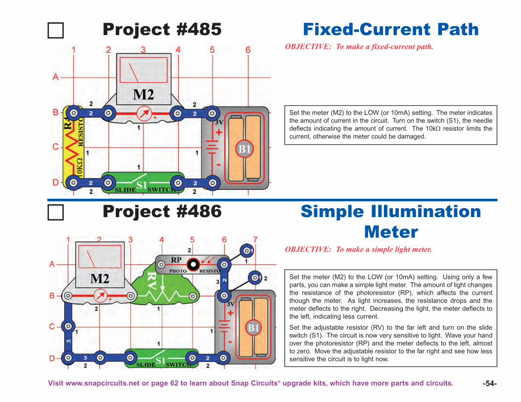
-54-
Project #485OBJECTIVE: To make a fixed-current path.
Set the meter (M2) to the LOW (or 10mA) setting. The meter indicatesthe amount of current in the circuit. Turn on the switch (S1), the needledeflects indicating the amount of current. The 10kΩ resistor limits thecurrent, otherwise the meter could be damaged.
Fixed-Current Path
Project #486
OBJECTIVE: To make a simple light meter.
Set the meter (M2) to the LOW (or 10mA) setting. Using only a fewparts, you can make a simple light meter. The amount of light changesthe resistance of the photoresistor (RP), which affects the currentthough the meter. As light increases, the resistance drops and themeter deflects to the right. Decreasing the light, the meter deflects tothe left, indicating less current.
Set the adjustable resistor (RV) to the far left and turn on the slideswitch (S1). The circuit is now very sensitive to light. Wave your handover the photoresistor (RP) and the meter deflects to the left, almostto zero. Move the adjustable resistor to the far right and see how lesssensitive the circuit is to light now.
Simple IlluminationMeter
Visit www.snapcircuits.net or page 62 to learn about Snap Circuits® upgrade kits, which have more parts and circuits.
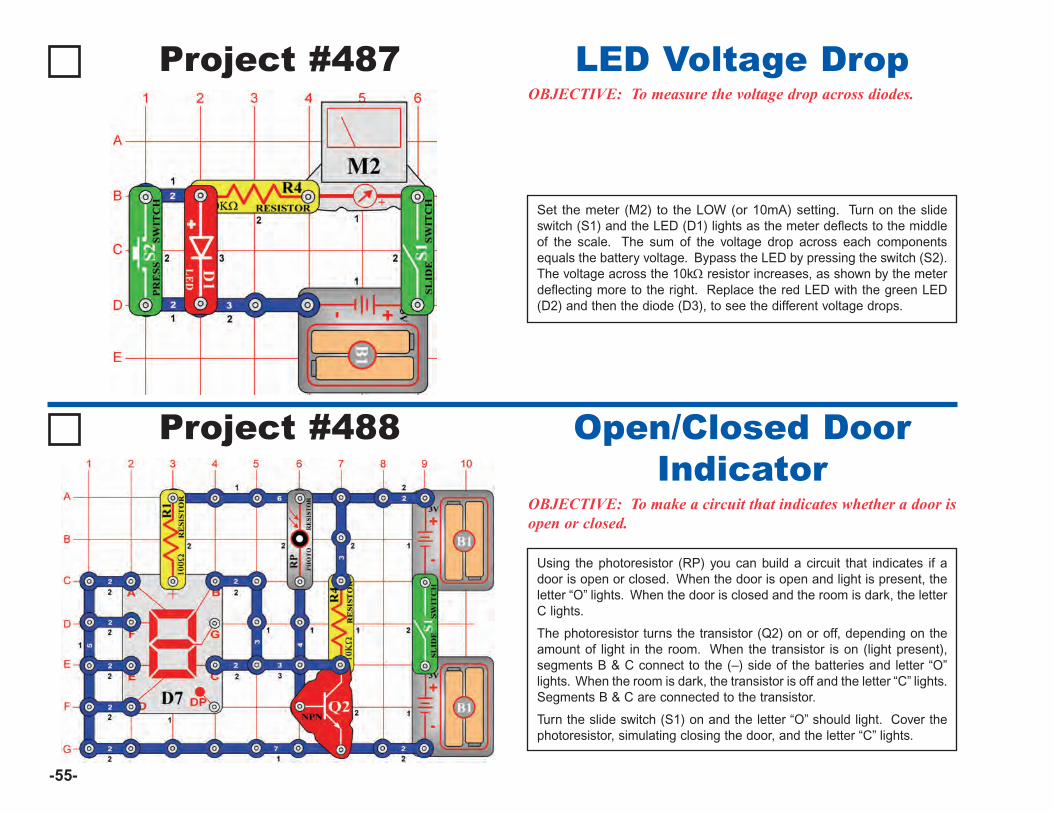
-55-
Project #487OBJECTIVE: To measure the voltage drop across diodes.
Set the meter (M2) to the LOW (or 10mA) setting. Turn on the slideswitch (S1) and the LED (D1) lights as the meter deflects to the middleof the scale. The sum of the voltage drop across each componentsequals the battery voltage. Bypass the LED by pressing the switch (S2).The voltage across the 10kΩ resistor increases, as shown by the meterdeflecting more to the right. Replace the red LED with the green LED(D2) and then the diode (D3), to see the different voltage drops.
LED Voltage Drop
Project #488
OBJECTIVE: To make a circuit that indicates whether a door isopen or closed.
Using the photoresistor (RP) you can build a circuit that indicates if adoor is open or closed. When the door is open and light is present, theletter “O” lights. When the door is closed and the room is dark, the letterC lights.
The photoresistor turns the transistor (Q2) on or off, depending on theamount of light in the room. When the transistor is on (light present),segments B & C connect to the (–) side of the batteries and letter “O”lights. When the room is dark, the transistor is off and the letter “C” lights.Segments B & C are connected to the transistor.
Turn the slide switch (S1) on and the letter “O” should light. Cover thephotoresistor, simulating closing the door, and the letter “C” lights.
Open/Closed DoorIndicator
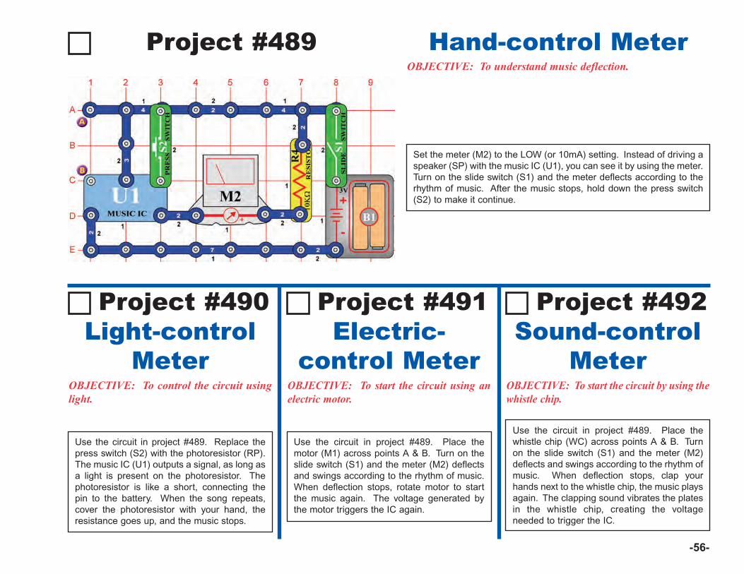
-56-
Project #489
Set the meter (M2) to the LOW (or 10mA) setting. Instead of driving aspeaker (SP) with the music IC (U1), you can see it by using the meter.Turn on the slide switch (S1) and the meter deflects according to therhythm of music. After the music stops, hold down the press switch(S2) to make it continue.
Hand-control MeterOBJECTIVE: To understand music deflection.
OBJECTIVE: To control the circuit usinglight.
Use the circuit in project #489. Replace thepress switch (S2) with the photoresistor (RP).The music IC (U1) outputs a signal, as long asa light is present on the photoresistor. Thephotoresistor is like a short, connecting thepin to the battery. When the song repeats,cover the photoresistor with your hand, theresistance goes up, and the music stops.
Light-controlMeter
Project #490
OBJECTIVE: To start the circuit using anelectric motor.
Electric-control Meter
Project #491
OBJECTIVE: To start the circuit by using thewhistle chip.
Sound-controlMeter
Project #492
Use the circuit in project #489. Place themotor (M1) across points A & B. Turn on theslide switch (S1) and the meter (M2) deflectsand swings according to the rhythm of music.When deflection stops, rotate motor to startthe music again. The voltage generated bythe motor triggers the IC again.
Use the circuit in project #489. Place thewhistle chip (WC) across points A & B. Turnon the slide switch (S1) and the meter (M2)deflects and swings according to the rhythm ofmusic. When deflection stops, clap yourhands next to the whistle chip, the music playsagain. The clapping sound vibrates the platesin the whistle chip, creating the voltageneeded to trigger the IC.
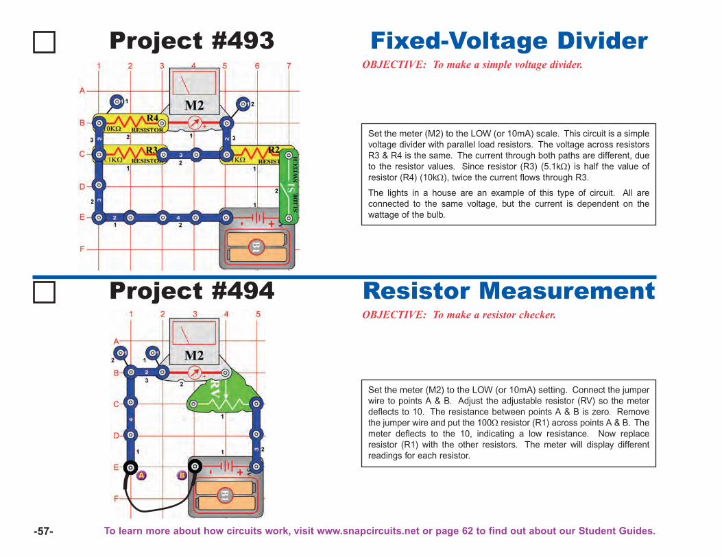
-57-
Project #493OBJECTIVE: To make a simple voltage divider.
Set the meter (M2) to the LOW (or 10mA) scale. This circuit is a simplevoltage divider with parallel load resistors. The voltage across resistorsR3 & R4 is the same. The current through both paths are different, dueto the resistor values. Since resistor (R3) (5.1kΩ) is half the value ofresistor (R4) (10kΩ), twice the current flows through R3.
The lights in a house are an example of this type of circuit. All areconnected to the same voltage, but the current is dependent on thewattage of the bulb.
Fixed-Voltage Divider
Project #494OBJECTIVE: To make a resistor checker.
Set the meter (M2) to the LOW (or 10mA) setting. Connect the jumperwire to points A & B. Adjust the adjustable resistor (RV) so the meterdeflects to 10. The resistance between points A & B is zero. Removethe jumper wire and put the 100Ω resistor (R1) across points A & B. Themeter deflects to the 10, indicating a low resistance. Now replaceresistor (R1) with the other resistors. The meter will display differentreadings for each resistor.
Resistor Measurement
To learn more about how circuits work, visit www.snapcircuits.net or page 62 to find out about our Student Guides.
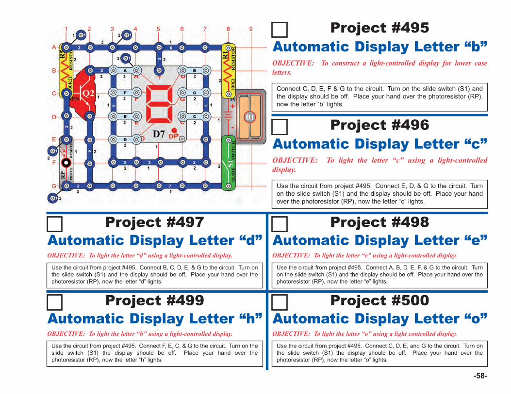
-58-
OBJECTIVE: To construct a light-controlled display for lower caseletters.
Connect C, D, E, F & G to the circuit. Turn on the slide switch (S1) andthe display should be off. Place your hand over the photoresistor (RP),now the letter “b” lights.
Automatic Display Letter “b”Project #495
Project #497
OBJECTIVE: To light the letter “d” using a light-controlled display.
Use the circuit from project #495. Connect B, C, D, E, & G to the circuit. Turn onthe slide switch (S1) and the display should be off. Place your hand over thephotoresistor (RP), now the letter “d” lights.
Automatic Display Letter “d”
OBJECTIVE: To light the letter “c” using a light-controlleddisplay.
Use the circuit from project #495. Connect E, D, & G to the circuit. Turnon the slide switch (S1) and the display should be off. Place your handover the photoresistor (RP), now the letter “c” lights.
Automatic Display Letter “c”Project #496
Project #498
OBJECTIVE: To light the letter “e” using a light-controlled display.
Use the circuit from project #495. Connect A, B, D, E, F, & G to the circuit. Turnon the slide switch (S1) and the display should be off. Place your hand over thephotoresistor (RP), now the letter “e” lights.
Automatic Display Letter “e”
Project #499
OBJECTIVE: To light the letter “h” using a light-controlled display.
Use the circuit from project #495. Connect F, E, C, & G to the circuit. Turn on theslide switch (S1) the display should be off. Place your hand over thephotoresistor (RP), now the letter “h” lights.
Automatic Display Letter “h”Project #500
OBJECTIVE: To light the letter “o” using a light controlled display.
Use the circuit from project #495. Connect C, D, E, and G to the circuit. Turn onthe slide switch (S1) the display should be off. Place your hand over thephotoresistor (RP), now the letter “o” lights.
Automatic Display Letter “o”
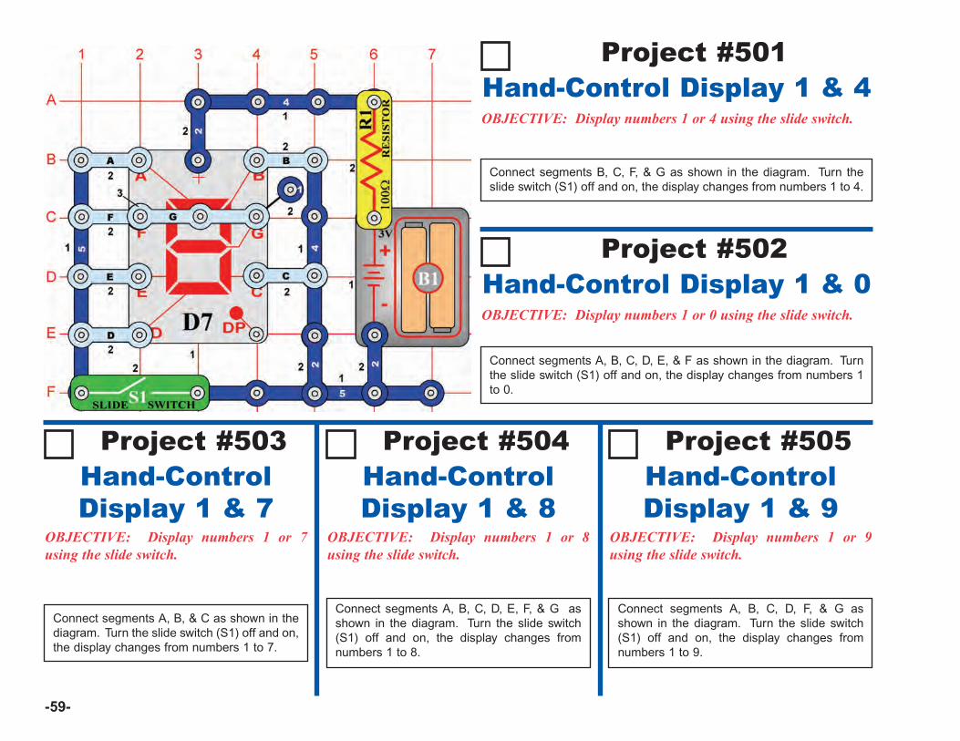
-59-
Project #501
OBJECTIVE: Display numbers 1 or 4 using the slide switch.
Connect segments B, C, F, & G as shown in the diagram. Turn theslide switch (S1) off and on, the display changes from numbers 1 to 4.
Hand-Control Display 1 & 4
Project #502
OBJECTIVE: Display numbers 1 or 0 using the slide switch.
Connect segments A, B, C, D, E, & F as shown in the diagram. Turnthe slide switch (S1) off and on, the display changes from numbers 1to 0.
Hand-Control Display 1 & 0
Project #503
OBJECTIVE: Display numbers 1 or 7using the slide switch.
Connect segments A, B, & C as shown in thediagram. Turn the slide switch (S1) off and on,the display changes from numbers 1 to 7.
Hand-ControlDisplay 1 & 7
Project #504
OBJECTIVE: Display numbers 1 or 8using the slide switch.
Connect segments A, B, C, D, E, F, & G asshown in the diagram. Turn the slide switch(S1) off and on, the display changes fromnumbers 1 to 8.
Hand-ControlDisplay 1 & 8
Project #505
OBJECTIVE: Display numbers 1 or 9using the slide switch.
Connect segments A, B, C, D, F, & G asshown in the diagram. Turn the slide switch(S1) off and on, the display changes fromnumbers 1 to 9.
Hand-ControlDisplay 1 & 9
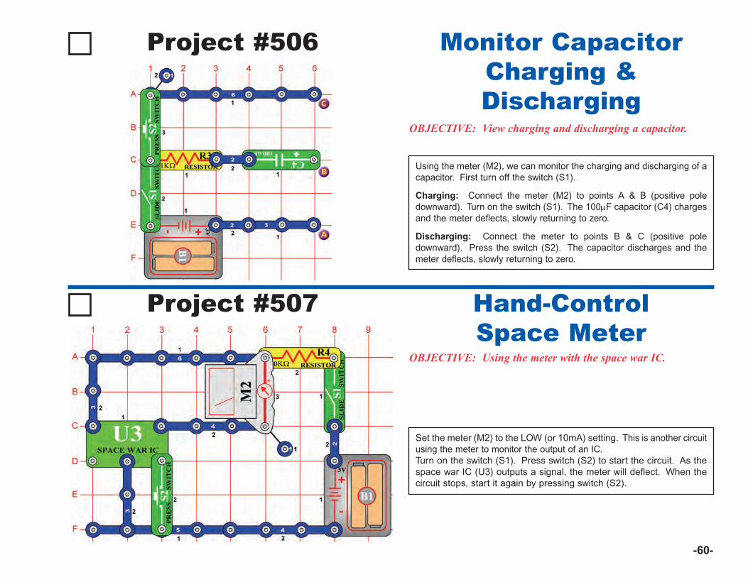
Project #506
OBJECTIVE: View charging and discharging a capacitor.
Using the meter (M2), we can monitor the charging and discharging of acapacitor. First turn off the switch (S1).
Charging: Connect the meter (M2) to points A & B (positive poledownward). Turn on the switch (S1). The 100μF capacitor (C4) chargesand the meter deflects, slowly returning to zero.
Discharging: Connect the meter to points B & C (positive poledownward). Press the switch (S2). The capacitor discharges and themeter deflects, slowly returning to zero.
Monitor CapacitorCharging &Discharging
Project #507
OBJECTIVE: Using the meter with the space war IC.
Set the meter (M2) to the LOW (or 10mA) setting. This is another circuitusing the meter to monitor the output of an IC.Turn on the switch (S1). Press switch (S2) to start the circuit. As thespace war IC (U3) outputs a signal, the meter will deflect. When thecircuit stops, start it again by pressing switch (S2).
Hand-ControlSpace Meter
-60-
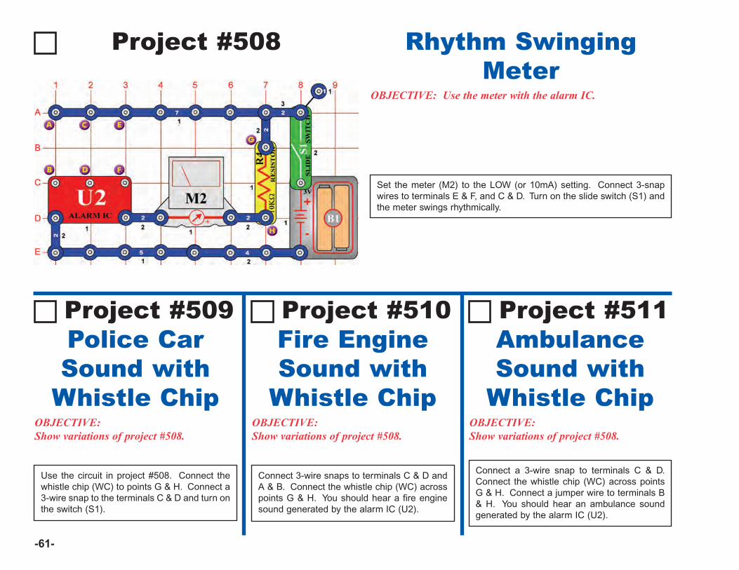
Project #508
OBJECTIVE: Use the meter with the alarm IC.
Set the meter (M2) to the LOW (or 10mA) setting. Connect 3-snapwires to terminals E & F, and C & D. Turn on the slide switch (S1) andthe meter swings rhythmically.
Rhythm SwingingMeter
OBJECTIVE:Show variations of project #508.
Fire EngineSound with
Whistle Chip
Project #510
OBJECTIVE:Show variations of project #508.
AmbulanceSound with
Whistle Chip
Project #511
Connect 3-wire snaps to terminals C & D andA & B. Connect the whistle chip (WC) acrosspoints G & H. You should hear a fire enginesound generated by the alarm IC (U2).
-61-
Connect a 3-wire snap to terminals C & D.Connect the whistle chip (WC) across pointsG & H. Connect a jumper wire to terminals B& H. You should hear an ambulance soundgenerated by the alarm IC (U2).
OBJECTIVE:Show variations of project #508.
Police CarSound with
Whistle Chip
Project #509
Use the circuit in project #508. Connect thewhistle chip (WC) to points G & H. Connect a3-wire snap to the terminals C & D and turn onthe switch (S1).
-62-
OTHER SNAP CIRCUITS® PRODUCTS!For a listing of local toy retailers who carry Snap Circuits®, please visit www.elenco.com or call us toll-free at (800) 533-2441. For SnapCircuits® upgrade kits, accessories, additional parts, and more information about your parts, please visit www.snapcircuits.net.
OTHER FUN ELENCO® PRODUCTSMotion DetectorModel SCP-03
Whenever somebody walks infront of the Motion Detector, thesound of a laser comes out ofthe speaker!
SnaptricityModel SCBE-75
Build Over 75 ProjectsLearn how electricity and magnetism can be used to make eachother, learn about magnetic fields, how the electricity in your homeworks, how switches control the electricity to the lights in yourhome, and how series and parallel circuits affect electricity.
Over 40 parts including: Meter, electromagnet, motor, lamps,switches, fan, compass, and electrodes.
Educational Toy: Projects that relate to electricity in the home andmagnetism and how it is used. Build over 75 projects.
RC Car KitModel FUN-875
Your Turbo King Car will be built fromthe ground up. You’ll learn all aboutgears, motors, printed circuit boards,and integrated circuits from ourdetailed assembly and training manual.You will constructeach section, explorethe circuitry andtroubleshoot it.
300-in-1 Project LabModel MX-908
This lab has everything you need tobuild 300 exciting electronic projects. Ituses spring and breadboard hook-upmethods and includes an easy-to-read,illustrated, lab-style manual. Projectsinclude: Transistor Radio, BurglarAlarm, Metal Detector, and much more!
Titan Tank KitModel 21-531N
The Titan Tank is an infrared remotecontrol kit. Its microprocessor providesfour different channels that allow up tofour Titans to fight each other at thesame time. Makes a sound whenshooting and when it is hit. The Titanmoves using six wheels that can move
forward, backward,right and
left.
Upgrade KitModel UC-80
Deluxe Snap Rover®
Model SCROV-50
Introducing the next generation of the RC SnapRover®! This version includes a disc launcher, digitalvoice recorder, and music sounds. Over 50 partsallow you to complete over 40 additional projects.
If you want to enhance your Snap Circuits®
experience and get even smarter, then try
For use with SC-500Educational Series - teaches BasicElectricity and Electronics in theeveryday world using our Learn ByDoing® concept! 80 full-color pages, and writtenwith the help of educators.
Put your circuitsin motion!
• Includes 30 parts
• Build over 20projects
• Full-colorassembly manual
• Sound effects
Build 250 AdditionalProjectsIncluding:• Strobe light• Electromagnetism• Transistor AM radio• Rechargeable battery• Solar batteries• Mega pulser and
flasher• Paperclip compass
Contains 10 NewPartsIncluding:• Solar cell• Electromagnet• Vibration switch• Two-spring socket• Bag of paperclips
• Plus all experiments contained in the 500-in-1(SC-500)!
• Includes CI-73 Computer Interface!
With this module you will also learnabout and use an oscilloscope andspectrum analyzer, as you buildover 73 BONUS EXPERIMENTSusing your Windows-based PC.Comes with all of the interfaceparts you need and the software.Great for introducing electronicsthrough a computer. Works with allversions of our Snap Circuits®.
Sample Screen ofComputer Experiment
Expansion PartsAC Power Supply
Part #AC-SNAP
Replaces thebatteries inSnap Circuits®.
Snap-to-Pin SetPart # 9JWSC10
Lets you connect SnapCircuits® to a bread-board. 10 wires withreinforced pins, 5 colors,10” length, and unlimitedpossibilies!
Computer Interface forSnap Circuits® Model CI-73
Two-spring SocketPart # ?1
Three-spring SocketPart # ?Q
Eight-Pin IC SocketPart # ?U8
Acts as a Scope and Allows You to See the Signals in the Circuit.
Snap Circuits® GreenAlternative Energy Kit
Model SCG-125Learn about energy sources and how to “thinkgreen”. Build over 125 projects and have loads offun learning about environmentally-friendlyenergy and how the electricity in your homeworks. Includes full-color manual with over 100pages and separate educational manual. Thiseducational manual will explain all the forms ofenvironmentally-friendly energy including:geothermal, hydrogen fuel cells, wind, solar,tidal, hydro, and others. Contains over 40 parts.
Snap Circuits® LIGHTModel SCL-175
• Infrared detector• Strobe light• Color changing LED• Glow-in-the-dark fan• Strobe integrated
circuit (IC)
• Fiber opticcommunication
• Color organ controlledby iPod® or other MP3player, voice, andfingers.
Build over 175projects!
Contains over60 parts
Features:
Custom Storage CaseModel SNAPCASE7
Heavy duty plastic case with 2 customfoam inserts for housing your SnapCircuits® parts. Easy to identify missingcomponents. Also includes a separatesmall case to hold the smallerloose parts.
(for use with SC-500)
Snap Circuits® Student GuidePart # 753307
DetectolabModel EDU-7080
Investigate, analyze, decipher andsolve the crime! Over 65 activities withfingerprints, secret messages, chroma-tography, cipher codes, identitydetection and more... Kit includes 30Xmicroscope and necessary labequipment.

ELENCO®
150 Carpenter AvenueWheeling, IL 60090
(847) 541-3800Website: www.elenco.com
e-mail: [email protected]
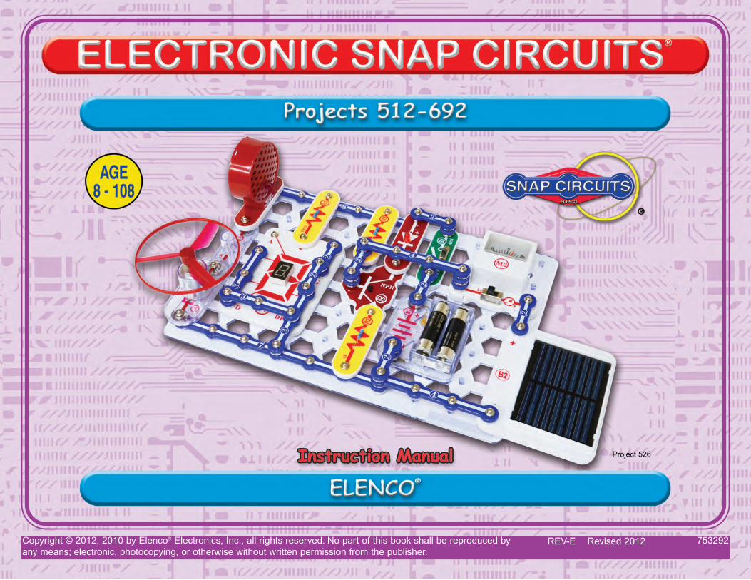
Copyright © 2012, 2010 by Elenco® Electronics, Inc., all rights reserved. No part of this book shall be reproduced by 753292any means; electronic, photocopying, or otherwise without written permission from the publisher.
REV-E Revised 2012
Project 526

-1-
Table of ContentsBasic Troubleshooting 1Parts List 2About the Two-Spring Socket (?1) 3MORE About Your Snap Circuits® Parts 4MORE Advanced Troubleshooting 4MORE DO’s and DON’Ts of Building Circuits 5Project Listings 6, 7Projects 512-692 8 - 84Other Fun Elenco® Products 85 - 86
1. Most circuit problems are due to incorrect assembly.Always double-check that your circuit exactlymatches the drawing for it.
2. Be sure that parts with positive/negative markings arepositioned as per the drawing.
3. Be sure that all connections are securely snapped.
4. Try replacing the batteries.
5. If the motor spins but does not balance the fan, checkthe black plastic piece with three prongs on the motorshaft. Be sure that it is at the top of the shaft.
Elenco® is not responsible for parts damaged due toincorrect wiring.
Basic Troubleshooting
Note: If you suspect you have damaged parts, you canfollow the Advanced Troubleshooting procedure on page 4to determine which ones need replacing.
Review of How To Use It (See page 3 of the Projects 1-101 manual for more details.)
The Snap Circuits® kit uses building blocks with snapsto build the different electrical and electronic circuits inthe projects. These blocks are in different colors andhave numbers on them so that you can easily identifythem. The circuit you will build is shown in color andwith numbers, identifying the blocks that you will useand snap together to form a circuit.
Next to each part in every circuit drawing is a smallnumber in black. This tells you which level thecomponent is placed at. Place all parts on level 1 first,
then all of the parts on level 2, then all of the parts onlevel 3, etc.
A large clear plastic base grid is included with this kitto help keep the circuit block together. The base hasrows labeled A-G and columns labeled 1-10.
Install two (2) “AA” batteries (not included) in thebattery holder (B1). The 2.5V and 6V bulbs comepackaged separate from their sockets. Install the 2.5Vbulb in the L1 lamp socket, and the 6V bulb in the L2lamp socket.
Place the fan on the motor (M1) whenever that part isused, unless the project you are building says not touse it.
Some circuits use the red and black jumper wires tomake unusual connections. Just clip them to the metalsnaps or as indicated.
Note: While building the projects, be careful not toaccidentally make a direct connection across thebattery holder (a “short circuit”), as this may damageand/or quickly drain the batteries.
WARNING: SHOCK HAZARD -Never connect Snap Circuits® tothe electrical outlets in your homein any way!
WARNING FOR ALL PROJECTS WITH A SYMBOLMoving parts. Do not touch the motor or fan during operation. Do not leanover the motor. Do not launch the fan at people, animals, or objects. Eyeprotection is recommended.
!!
WARNING: CHOKING HAZARD - Small parts.Not for children under 3 years.
!
Batteries:• Use only 1.5V AA type, alkaline batteries
(not included).
• Insert batteries with correct polarity.
• Non-rechargeable batteries should notbe recharged. Rechargeable batteriesshould only be charged under adultsupervision, and should not berecharged while in the product.
• Do not mix alkaline, standard (carbon-zinc), or rechargeable (nickel-cadmium)batteries.
• Do not mix old and new batteries.
• Remove batteries when they are used up.
• Do not short circuit the battery terminals.
• Never throw batteries in a fire or attemptto open its outer casing.
• Batteries are harmful if swallowed, sokeep away from small children.
• Do not connect batteries or batteryholders in parallel.
!WARNING: Always check your wiring beforeturning on a circuit. Never leave a circuitunattended while the batteries are installed. Neverconnect additional batteries or any other powersources to your circuits. Discard any cracked orbroken parts.
Adult Supervision: Because children’s abilitiesvary so much, even with age groups, adults shouldexercise discretion as to which experiments aresuitable and safe (the instructions should enablesupervising adults to establish the experiment’ssuitability for the child). Make sure your child readsand follows all of the relevant instructions andsafety procedures, and keeps them at hand forreference.
This product is intended for use by adults andchildren who have attained sufficient maturity toread and follow directions and warnings.
Never modify your parts, as doing so may disableimportant safety features in them, and could putyour child at risk of injury.
!
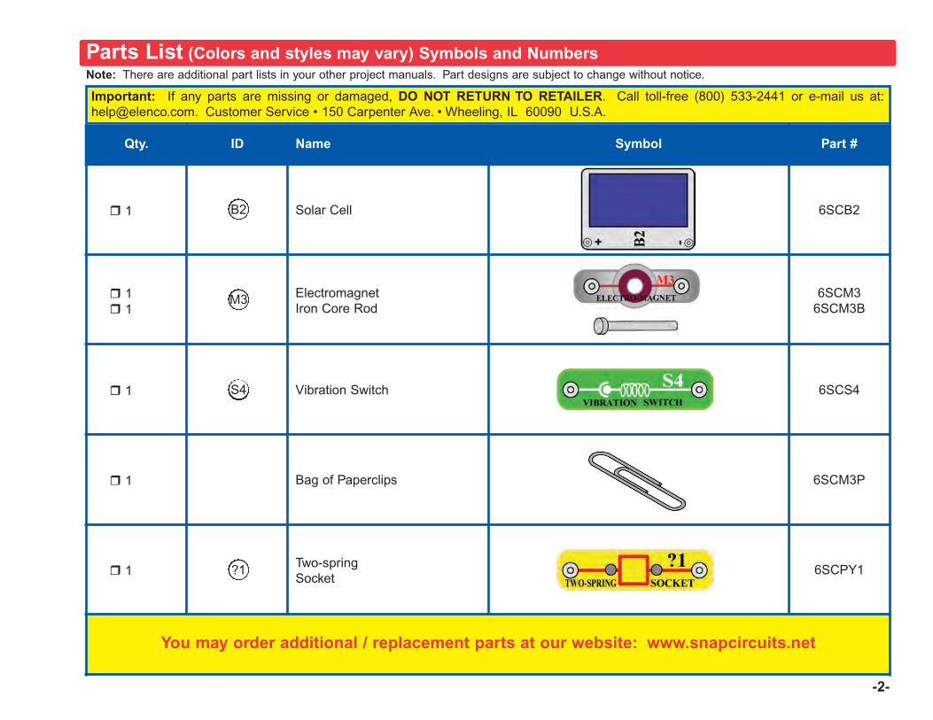
-2-
Note: There are additional part lists in your other project manuals. Part designs are subject to change without notice.
Important: If any parts are missing or damaged, DO NOT RETURN TO RETAILER. Call toll-free (800) 533-2441 or e-mail us at:[email protected]. Customer Service • 150 Carpenter Ave. • Wheeling, IL 60090 U.S.A.
Parts List (Colors and styles may vary) Symbols and Numbers
Qty. ID Name Symbol Part #
r 1 Solar Cell 6SCB2
r 1r 1
ElectromagnetIron Core Rod
6SCM36SCM3B
r 1 Vibration Switch 6SCS4
r 1 Bag of Paperclips 6SCM3P
r 1Two-springSocket
6SCPY1
You may order additional / replacement parts at our website: www.snapcircuits.net
?1
S4
M3
B2
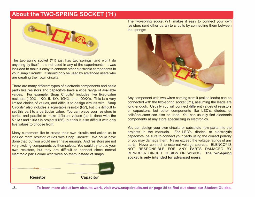
-3-
The two-spring socket (?1) just has two springs, and won’t doanything by itself. It is not used in any of the experiments. It wasincluded to make it easy to connect other electronic components toyour Snap Circuits®. It should only be used by advanced users whoare creating their own circuits.
There are many different types of electronic components and basicparts like resistors and capacitors have a wide range of availablevalues. For example, Snap Circuits® includes five fixed-valueresistors (100Ω, 1KΩ, 5.1KΩ, 10KΩ, and 100KΩ). This is a verylimited choice of values, and difficult to design circuits with. SnapCircuits® also includes a adjustable resistor (RV), but it is difficult toset this part to a particular value. You can place your resistors inseries and parallel to make different values (as is done with the5.1KΩ and 10KΩ in project #166), but this is also difficult with onlyfive values to choose from.
Many customers like to create their own circuits and asked us toinclude more resistor values with Snap Circuits®. We could havedone that, but you would never have enough. And resistors are notvery exciting components by themselves. You could try to use yourown resistors, but they are difficult to connect since normalelectronic parts come with wires on them instead of snaps.
The two-spring socket (?1) makes it easy to connect your ownresistors (and other parts) to circuits by connecting them betweenthe springs:
Any component with two wires coming from it (called leads) can beconnected with the two-spring socket (?1), assuming the leads arelong enough. Usually you will connect different values of resistorsor capacitors, but other components like LED’s, diodes, orcoils/inductors can also be used. You can usually find electroniccomponents at any store specializing in electronics.
You can design your own circuits or substitute new parts into theprojects in the manuals. For LED’s, diodes, or electrolyticcapacitors, be sure to connect your parts using the correct polarityor you may damage them. Never exceed the voltage ratings of anyparts. Never connect to external voltage sources. ELENCO® ISNOT RESPONSIBLE FOR ANY PARTS DAMAGED BYIMPROPER CIRCUIT DESIGN OR WIRING. The two-springsocket is only intended for advanced users.
About the TWO-SPRING SOCKET (?1)
Resistor Capacitor
To learn more about how circuits work, visit www.snapcircuits.net or page 85 to find out about our Student Guides.
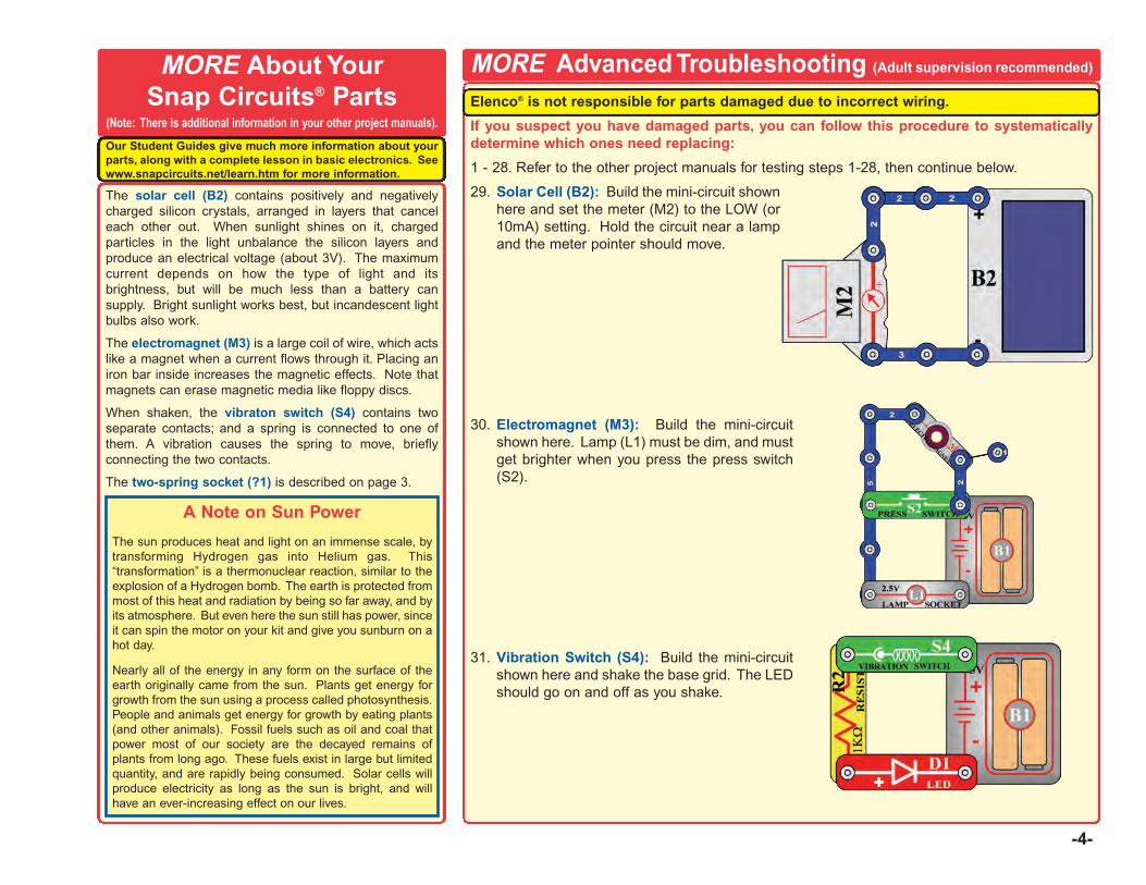
Elenco® is not responsible for parts damaged due to incorrect wiring.
If you suspect you have damaged parts, you can follow this procedure to systematicallydetermine which ones need replacing:
1 - 28. Refer to the other project manuals for testing steps 1-28, then continue below.
29. Solar Cell (B2): Build the mini-circuit shownhere and set the meter (M2) to the LOW (or10mA) setting. Hold the circuit near a lampand the meter pointer should move.
30. Electromagnet (M3): Build the mini-circuitshown here. Lamp (L1) must be dim, and mustget brighter when you press the press switch(S2).
31. Vibration Switch (S4): Build the mini-circuitshown here and shake the base grid. The LEDshould go on and off as you shake.
-4-
The solar cell (B2) contains positively and negativelycharged silicon crystals, arranged in layers that canceleach other out. When sunlight shines on it, chargedparticles in the light unbalance the silicon layers andproduce an electrical voltage (about 3V). The maximumcurrent depends on how the type of light and itsbrightness, but will be much less than a battery cansupply. Bright sunlight works best, but incandescent lightbulbs also work.
The electromagnet (M3) is a large coil of wire, which actslike a magnet when a current flows through it. Placing aniron bar inside increases the magnetic effects. Note thatmagnets can erase magnetic media like floppy discs.
When shaken, the vibraton switch (S4) contains twoseparate contacts; and a spring is connected to one ofthem. A vibration causes the spring to move, brieflyconnecting the two contacts.
The two-spring socket (?1) is described on page 3.
MORE Advanced Troubleshooting (Adult supervision recommended)MORE About YourSnap Circuits® Parts
(Note: There is additional information in your other project manuals).
A Note on Sun Power
The sun produces heat and light on an immense scale, bytransforming Hydrogen gas into Helium gas. This“transformation” is a thermonuclear reaction, similar to theexplosion of a Hydrogen bomb. The earth is protected frommost of this heat and radiation by being so far away, and byits atmosphere. But even here the sun still has power, sinceit can spin the motor on your kit and give you sunburn on ahot day.
Nearly all of the energy in any form on the surface of theearth originally came from the sun. Plants get energy forgrowth from the sun using a process called photosynthesis.People and animals get energy for growth by eating plants(and other animals). Fossil fuels such as oil and coal thatpower most of our society are the decayed remains ofplants from long ago. These fuels exist in large but limitedquantity, and are rapidly being consumed. Solar cells willproduce electricity as long as the sun is bright, and willhave an ever-increasing effect on our lives.
Our Student Guides give much more information about yourparts, along with a complete lesson in basic electronics. Seewww.snapcircuits.net/learn.htm for more information.
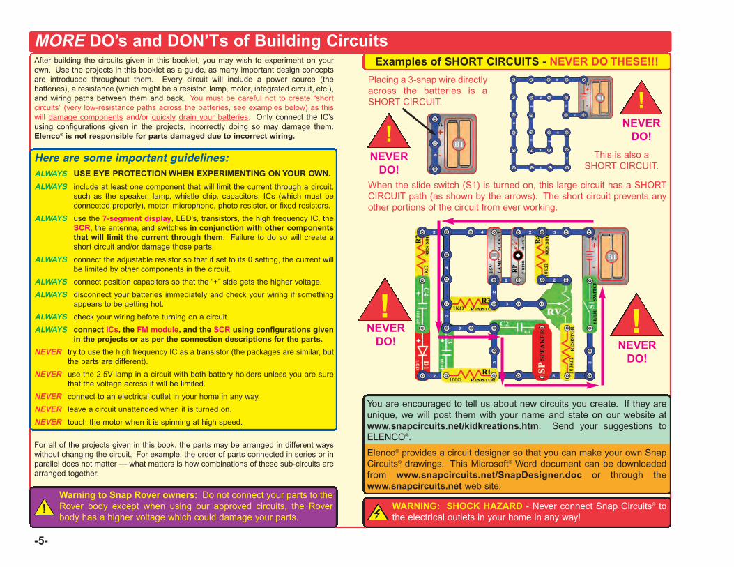
-5-
MORE DO’s and DON’Ts of Building CircuitsAfter building the circuits given in this booklet, you may wish to experiment on yourown. Use the projects in this booklet as a guide, as many important design conceptsare introduced throughout them. Every circuit will include a power source (thebatteries), a resistance (which might be a resistor, lamp, motor, integrated circuit, etc.),and wiring paths between them and back. You must be careful not to create “shortcircuits” (very low-resistance paths across the batteries, see examples below) as thiswill damage components and/or quickly drain your batteries. Only connect the IC’susing configurations given in the projects, incorrectly doing so may damage them.Elenco® is not responsible for parts damaged due to incorrect wiring.
Here are some important guidelines:ALWAYS USE EYE PROTECTION WHEN EXPERIMENTING ON YOUR OWN.
ALWAYS include at least one component that will limit the current through a circuit,such as the speaker, lamp, whistle chip, capacitors, ICs (which must beconnected properly), motor, microphone, photo resistor, or fixed resistors.
ALWAYS use the 7-segment display, LED’s, transistors, the high frequency IC, theSCR, the antenna, and switches in conjunction with other componentsthat will limit the current through them. Failure to do so will create ashort circuit and/or damage those parts.
ALWAYS connect the adjustable resistor so that if set to its 0 setting, the current willbe limited by other components in the circuit.
ALWAYS connect position capacitors so that the “+” side gets the higher voltage.
ALWAYS disconnect your batteries immediately and check your wiring if somethingappears to be getting hot.
ALWAYS check your wiring before turning on a circuit.
ALWAYS connect ICs, the FM module, and the SCR using configurations givenin the projects or as per the connection descriptions for the parts.
NEVER try to use the high frequency IC as a transistor (the packages are similar, butthe parts are different).
NEVER use the 2.5V lamp in a circuit with both battery holders unless you are surethat the voltage across it will be limited.
NEVER connect to an electrical outlet in your home in any way.
NEVER leave a circuit unattended when it is turned on.
NEVER touch the motor when it is spinning at high speed.
For all of the projects given in this book, the parts may be arranged in different wayswithout changing the circuit. For example, the order of parts connected in series or inparallel does not matter — what matters is how combinations of these sub-circuits arearranged together.
Examples of SHORT CIRCUITS - NEVER DO THESE!!!
You are encouraged to tell us about new circuits you create. If they areunique, we will post them with your name and state on our website atwww.snapcircuits.net/kidkreations.htm. Send your suggestions toELENCO®.
Elenco® provides a circuit designer so that you can make your own SnapCircuits® drawings. This Microsoft® Word document can be downloadedfrom www.snapcircuits.net/SnapDesigner.doc or through thewww.snapcircuits.net web site.
WARNING: SHOCK HAZARD - Never connect Snap Circuits® tothe electrical outlets in your home in any way!
Placing a 3-snap wire directlyacross the batteries is aSHORT CIRCUIT.
This is also aSHORT CIRCUIT.
When the slide switch (S1) is turned on, this large circuit has a SHORTCIRCUIT path (as shown by the arrows). The short circuit prevents anyother portions of the circuit from ever working.
NEVERDO!
Warning to Snap Rover owners: Do not connect your parts to theRover body except when using our approved circuits, the Roverbody has a higher voltage which could damage your parts.
!
!NEVER
DO!
!
!!NEVER
DO! NEVERDO!
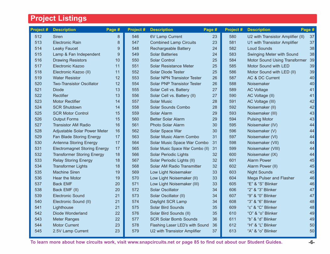
Project # Description Page #
512 Siren 8513 Electronic Rain 8514 Leaky Faucet 9515 Lamp & Fan Independent 9516 Drawing Resistors 10517 Electronic Kazoo 11518 Electronic Kazoo (II) 11519 Water Resistor 12520 Two-Transistor Oscillator 12521 Diode 13522 Rectifier 13523 Motor Rectifier 14524 SCR Shutdown 14525 SCR Motor Control 15526 Output Forms 15527 Transistor AM Radio 16528 Adjustable Solar Power Meter 16529 Fan Blade Storing Energy 17530 Antenna Storing Energy 17531 Electromagnet Storing Energy 17532 Transformer Storing Energy 18533 Relay Storing Energy 18534 Transformer Lights 18535 Machine Siren 19536 Hear the Motor 19537 Back EMF 20538 Back EMF (II) 20539 Electronic Sound 21540 Electronic Sound (II) 21541 Lighthouse 21542 Diode Wonderland 22543 Meter Ranges 22544 Motor Current 23545 2.5V Lamp Current 23
Project # Description Page #
546 6V Lamp Current 23547 Combined Lamp Circuits 23548 Rechargeable Battery 24549 Solar Batteries 24550 Solar Control 25551 Solar Resistance Meter 25552 Solar Diode Tester 25553 Solar NPN Transistor Tester 26554 Solar PNP Transistor Tester 26555 Solar Cell vs. Battery 27556 Solar Cell vs. Battery (II) 27557 Solar Music 28558 Solar Sounds Combo 28559 Solar Alarm 29560 Better Solar Alarm 29561 Photo Solar Alarm 30562 Solar Space War 30563 Solar Music Alarm Combo 31564 Solar Music Space War Combo 31565 Solar Music Space War Combo (II) 31566 Solar Periodic Lights 32567 Solar Periodic Lights (II) 32568 Solar AM Radio Transmitter 32569 Low Light Noisemaker 33570 Low Light Noisemaker (II) 33571 Low Light Noisemaker (III) 33572 Solar Oscillator 34573 Solar Oscillator (II) 34574 Daylight SCR Lamp 34575 Solar Bird Sounds 35576 Solar Bird Sounds (II) 35577 SCR Solar Bomb Sounds 36578 Flashing Laser LED’s with Sound 36579 U2 with Transistor Amplifier 37
Project # Description Page #
580 U2 with Transistor Amplifier (II) 37581 U1 with Transistor Amplifier 37582 Loud Sounds 38583 Swinging Meter with Sound 38584 Motor Sound Using Transformer 39585 Motor Sound with LED 39586 Motor Sound with LED (II) 39587 AC & DC Current 40588 Noisemaker 40589 AC Voltage 41590 AC Voltage (II) 41591 AC Voltage (III) 42592 Noisemaker (II) 42593 Noisemaker (III) 43594 Pulsing Motor 43595 Noisemaker (IV) 44596 Noisemaker (V) 44597 Noisemaker (VI) 44598 Noisemaker (VII) 44599 Noisemaker (VIII) 44600 Noisemaker (IX) 44601 Alarm Power 45602 Alarm Power (II) 45603 Night Sounds 45604 Mega Pulser and Flasher 46605 “E” & “S” Blinker 46606 “2” & “3” Blinker 47607 “9” & “0” Blinker 47608 “3” & “6” Blinker 48609 “c” & “C” Blinker 48610 “O” & “o” Blinker 49611 “b” & “d” Blinker 49612 “H” & “L” Blinker 50613 “A” & “o” Blinker 50
-6-
Project Listings
To learn more about how circuits work, visit www.snapcircuits.net or page 85 to find out about our Student Guides.
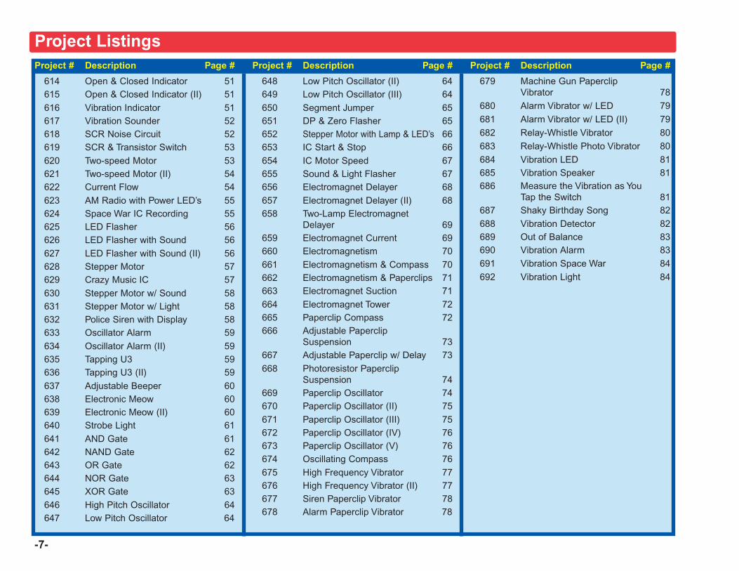
-7-
Project # Description Page #
614 Open & Closed Indicator 51615 Open & Closed Indicator (II) 51616 Vibration Indicator 51617 Vibration Sounder 52618 SCR Noise Circuit 52619 SCR & Transistor Switch 53620 Two-speed Motor 53621 Two-speed Motor (II) 54622 Current Flow 54623 AM Radio with Power LED’s 55624 Space War IC Recording 55625 LED Flasher 56626 LED Flasher with Sound 56627 LED Flasher with Sound (II) 56628 Stepper Motor 57629 Crazy Music IC 57630 Stepper Motor w/ Sound 58631 Stepper Motor w/ Light 58632 Police Siren with Display 58633 Oscillator Alarm 59634 Oscillator Alarm (II) 59635 Tapping U3 59636 Tapping U3 (II) 59637 Adjustable Beeper 60638 Electronic Meow 60639 Electronic Meow (II) 60640 Strobe Light 61641 AND Gate 61642 NAND Gate 62643 OR Gate 62644 NOR Gate 63645 XOR Gate 63646 High Pitch Oscillator 64647 Low Pitch Oscillator 64
Project # Description Page #
648 Low Pitch Oscillator (II) 64649 Low Pitch Oscillator (III) 64650 Segment Jumper 65651 DP & Zero Flasher 65652 Stepper Motor with Lamp & LED’s 66653 IC Start & Stop 66654 IC Motor Speed 67655 Sound & Light Flasher 67656 Electromagnet Delayer 68657 Electromagnet Delayer (II) 68658 Two-Lamp Electromagnet
Delayer 69659 Electromagnet Current 69660 Electromagnetism 70661 Electromagnetism & Compass 70662 Electromagnetism & Paperclips 71663 Electromagnet Suction 71664 Electromagnet Tower 72665 Paperclip Compass 72666 Adjustable Paperclip
Suspension 73667 Adjustable Paperclip w/ Delay 73668 Photoresistor Paperclip
Suspension 74669 Paperclip Oscillator 74670 Paperclip Oscillator (II) 75671 Paperclip Oscillator (III) 75672 Paperclip Oscillator (IV) 76673 Paperclip Oscillator (V) 76674 Oscillating Compass 76675 High Frequency Vibrator 77676 High Frequency Vibrator (II) 77677 Siren Paperclip Vibrator 78678 Alarm Paperclip Vibrator 78
Project # Description Page #
679 Machine Gun PaperclipVibrator 78
680 Alarm Vibrator w/ LED 79681 Alarm Vibrator w/ LED (II) 79682 Relay-Whistle Vibrator 80683 Relay-Whistle Photo Vibrator 80684 Vibration LED 81685 Vibration Speaker 81686 Measure the Vibration as You
Tap the Switch 81687 Shaky Birthday Song 82688 Vibration Detector 82689 Out of Balance 83690 Vibration Alarm 83691 Vibration Space War 84692 Vibration Light 84
Project Listings
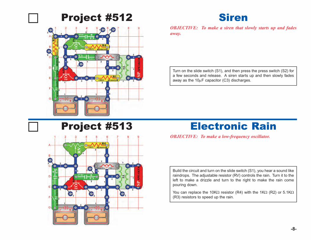
-8-
Project #512OBJECTIVE: To make a siren that slowly starts up and fadesaway.
Turn on the slide switch (S1), and then press the press switch (S2) fora few seconds and release. A siren starts up and then slowly fadesaway as the 10μF capacitor (C3) discharges.
Siren
Project #513OBJECTIVE: To make a low-frequency oscillator.
Build the circuit and turn on the slide switch (S1), you hear a sound likeraindrops. The adjustable resistor (RV) controls the rain. Turn it to theleft to make a drizzle and turn to the right to make the rain comepouring down.
You can replace the 10KΩ resistor (R4) with the 1KΩ (R2) or 5.1KΩ(R3) resistors to speed up the rain.
Electronic Rain
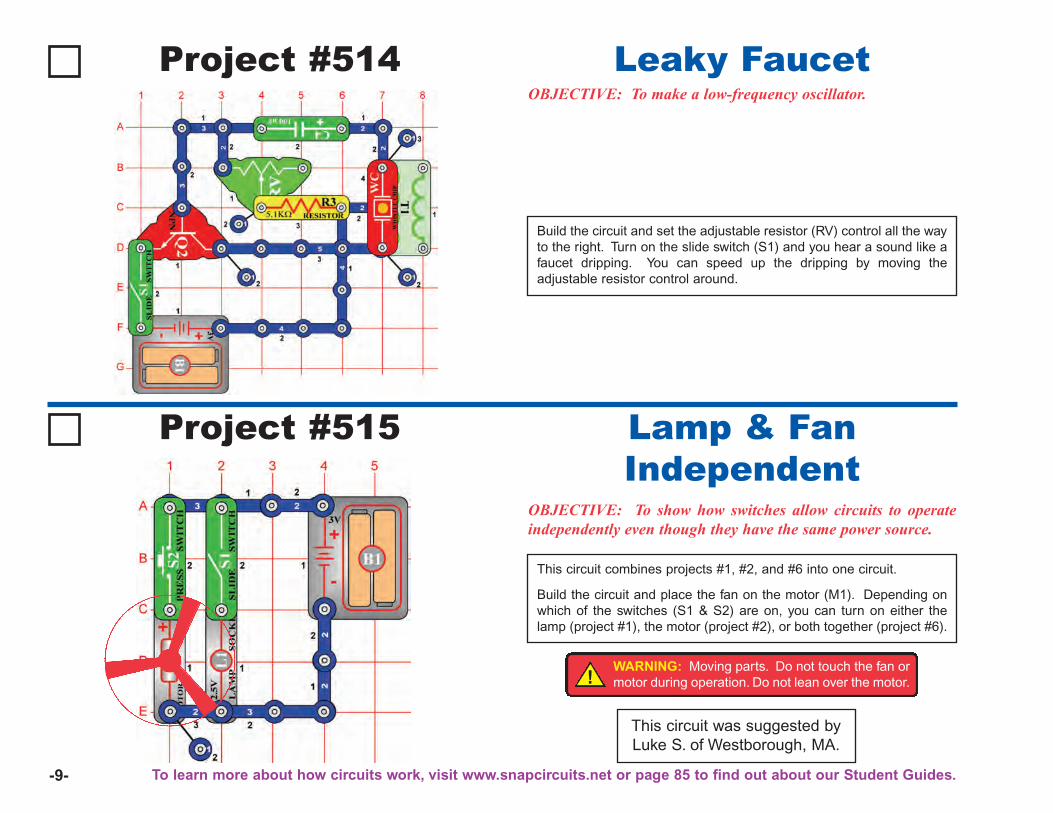
-9-
This circuit was suggested byLuke S. of Westborough, MA.
Project #514OBJECTIVE: To make a low-frequency oscillator.
Build the circuit and set the adjustable resistor (RV) control all the wayto the right. Turn on the slide switch (S1) and you hear a sound like afaucet dripping. You can speed up the dripping by moving theadjustable resistor control around.
Leaky Faucet
Project #515
OBJECTIVE: To show how switches allow circuits to operateindependently even though they have the same power source.
This circuit combines projects #1, #2, and #6 into one circuit.
Build the circuit and place the fan on the motor (M1). Depending onwhich of the switches (S1 & S2) are on, you can turn on either thelamp (project #1), the motor (project #2), or both together (project #6).
Lamp & FanIndependent
!WARNING: Moving parts. Do not touch the fan ormotor during operation. Do not lean over the motor.
To learn more about how circuits work, visit www.snapcircuits.net or page 85 to find out about our Student Guides.
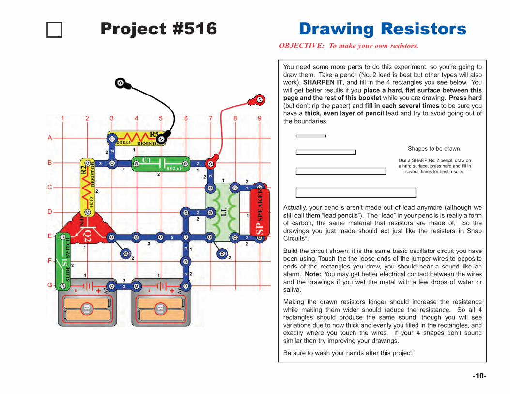
-10-
OBJECTIVE: To make your own resistors.
You need some more parts to do this experiment, so you’re going todraw them. Take a pencil (No. 2 lead is best but other types will alsowork), SHARPEN IT, and fill in the 4 rectangles you see below. Youwill get better results if you place a hard, flat surface between thispage and the rest of this booklet while you are drawing. Press hard(but don’t rip the paper) and fill in each several times to be sure youhave a thick, even layer of pencil lead and try to avoid going out ofthe boundaries.
Actually, your pencils aren’t made out of lead anymore (although westill call them “lead pencils”). The “lead” in your pencils is really a formof carbon, the same material that resistors are made of. So thedrawings you just made should act just like the resistors in SnapCircuits®.
Build the circuit shown, it is the same basic oscillator circuit you havebeen using. Touch the the loose ends of the jumper wires to oppositeends of the rectangles you drew, you should hear a sound like analarm. Note: You may get better electrical contact between the wiresand the drawings if you wet the metal with a few drops of water orsaliva.
Making the drawn resistors longer should increase the resistancewhile making them wider should reduce the resistance. So all 4rectangles should produce the same sound, though you will seevariations due to how thick and evenly you filled in the rectangles, andexactly where you touch the wires. If your 4 shapes don’t soundsimilar then try improving your drawings.
Be sure to wash your hands after this project.
Shapes to be drawn.
Use a SHARP No. 2 pencil, draw ona hard surface, press hard and fill in
several times for best results.
Project #516 Drawing Resistors
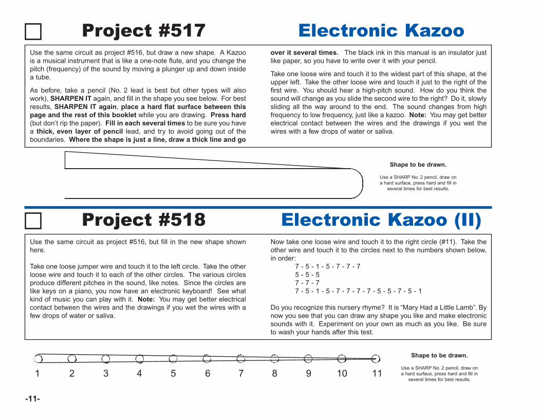
-11-
Shape to be drawn.
Use a SHARP No. 2 pencil, draw ona hard surface, press hard and fill in
several times for best results.
Use the same circuit as project #516, but draw a new shape. A Kazoois a musical instrument that is like a one-note flute, and you change thepitch (frequency) of the sound by moving a plunger up and down insidea tube.
As before, take a pencil (No. 2 lead is best but other types will alsowork), SHARPEN IT again, and fill in the shape you see below. For bestresults, SHARPEN IT again, place a hard flat surface between thispage and the rest of this booklet while you are drawing. Press hard(but don’t rip the paper). Fill in each several times to be sure you havea thick, even layer of pencil lead, and try to avoid going out of theboundaries. Where the shape is just a line, draw a thick line and go
over it several times. The black ink in this manual is an insulator justlike paper, so you have to write over it with your pencil.
Take one loose wire and touch it to the widest part of this shape, at theupper left. Take the other loose wire and touch it just to the right of thefirst wire. You should hear a high-pitch sound. How do you think thesound will change as you slide the second wire to the right? Do it, slowlysliding all the way around to the end. The sound changes from highfrequency to low frequency, just like a kazoo. Note: You may get betterelectrical contact between the wires and the drawings if you wet thewires with a few drops of water or saliva.
Shape to be drawn.
Use a SHARP No. 2 pencil, draw ona hard surface, press hard and fill in
several times for best results.1 2 3 4 5 6 7 8 9 10 11
Project #517 Electronic Kazoo
Project #518 Electronic Kazoo (II)Use the same circuit as project #516, but fill in the new shape shownhere.
Take one loose jumper wire and touch it to the left circle. Take the otherloose wire and touch it to each of the other circles. The various circlesproduce different pitches in the sound, like notes. Since the circles arelike keys on a piano, you now have an electronic keyboard! See whatkind of music you can play with it. Note: You may get better electricalcontact between the wires and the drawings if you wet the wires with afew drops of water or saliva.
Now take one loose wire and touch it to the right circle (#11). Take theother wire and touch it to the circles next to the numbers shown below,in order:
7 - 5 - 1 - 5 - 7 - 7 - 75 - 5 - 57 - 7 - 77 - 5 - 1 - 5 - 7 - 7 - 7 - 7 - 5 - 5 - 7 - 5 - 1
Do you recognize this nursery rhyme? It is “Mary Had a Little Lamb”. Bynow you see that you can draw any shape you like and make electronicsounds with it. Experiment on your own as much as you like. Be sureto wash your hands after this test.
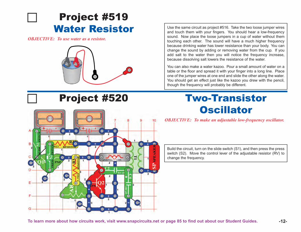
-12-
Use the same circuit as project #516. Take the two loose jumper wiresand touch them with your fingers. You should hear a low-frequencysound. Now place the loose jumpers in a cup of water without themtouching each other. The sound will have a much higher frequencybecause drinking water has lower resistance than your body. You canchange the sound by adding or removing water from the cup. If youadd salt to the water then you will notice the frequency increase,because dissolving salt lowers the resistance of the water.
You can also make a water kazoo. Pour a small amount of water on atable or the floor and spread it with your finger into a long line. Placeone of the jumper wires at one end and slide the other along the water.You should get an effect just like the kazoo you drew with the pencil,though the frequency will probably be different.
Project #519
OBJECTIVE: To use water as a resistor.
Water Resistor
Project #520
OBJECTIVE: To make an adjustable low-frequency oscillator.
Build the circuit, turn on the slide switch (S1), and then press the pressswitch (S2). Move the control lever of the adjustable resistor (RV) tochange the frequency.
Two-TransistorOscillator
To learn more about how circuits work, visit www.snapcircuits.net or page 85 to find out about our Student Guides.
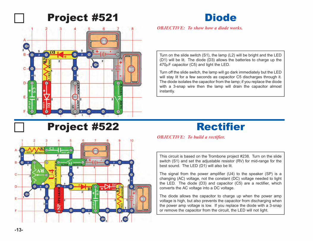
-13-
Turn on the slide switch (S1), the lamp (L2) will be bright and the LED(D1) will be lit. The diode (D3) allows the batteries to charge up the470μF capacitor (C5) and light the LED.
Turn off the slide switch, the lamp will go dark immediately but the LEDwill stay lit for a few seconds as capacitor C5 discharges through it.The diode isolates the capacitor from the lamp; if you replace the diodewith a 3-snap wire then the lamp will drain the capacitor almostinstantly.
Project #521OBJECTIVE: To show how a diode works.
Diode
Project #522OBJECTIVE: To build a rectifier.
Rectifier
This circuit is based on the Trombone project #238. Turn on the slideswitch (S1) and set the adjustable resistor (RV) for mid-range for thebest sound. The LED (D1) will also be lit.
The signal from the power amplifier (U4) to the speaker (SP) is achanging (AC) voltage, not the constant (DC) voltage needed to lightthe LED. The diode (D3) and capacitor (C5) are a rectifier, whichconverts the AC voltage into a DC voltage.
The diode allows the capacitor to charge up when the power ampvoltage is high, but also prevents the capacitor from discharging whenthe power amp voltage is low. If you replace the diode with a 3-snapor remove the capacitor from the circuit, the LED will not light.
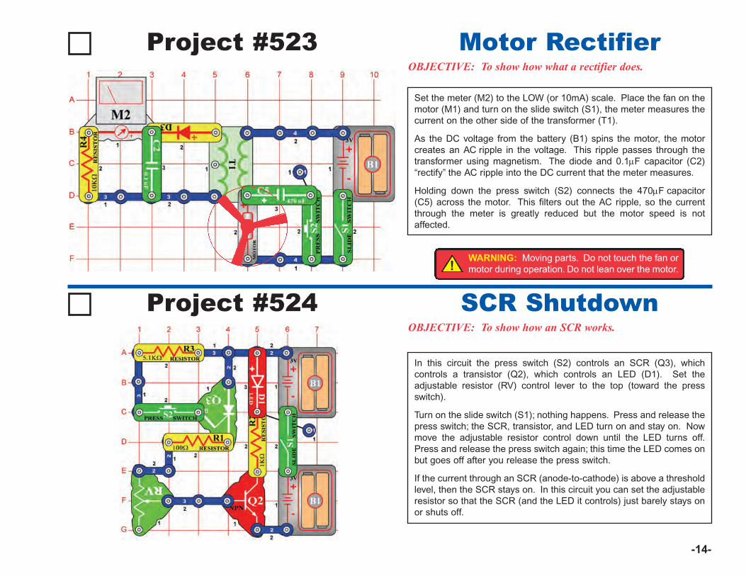
-14-
Set the meter (M2) to the LOW (or 10mA) scale. Place the fan on themotor (M1) and turn on the slide switch (S1), the meter measures thecurrent on the other side of the transformer (T1).
As the DC voltage from the battery (B1) spins the motor, the motorcreates an AC ripple in the voltage. This ripple passes through thetransformer using magnetism. The diode and 0.1μF capacitor (C2)“rectify” the AC ripple into the DC current that the meter measures.
Holding down the press switch (S2) connects the 470μF capacitor(C5) across the motor. This filters out the AC ripple, so the currentthrough the meter is greatly reduced but the motor speed is notaffected.
Project #523OBJECTIVE: To show how what a rectifier does.
Motor Rectifier
Project #524OBJECTIVE: To show how an SCR works.
SCR Shutdown
In this circuit the press switch (S2) controls an SCR (Q3), whichcontrols a transistor (Q2), which controls an LED (D1). Set theadjustable resistor (RV) control lever to the top (toward the pressswitch).
Turn on the slide switch (S1); nothing happens. Press and release thepress switch; the SCR, transistor, and LED turn on and stay on. Nowmove the adjustable resistor control down until the LED turns off.Press and release the press switch again; this time the LED comes onbut goes off after you release the press switch.
If the current through an SCR (anode-to-cathode) is above a thresholdlevel, then the SCR stays on. In this circuit you can set the adjustableresistor so that the SCR (and the LED it controls) just barely stays onor shuts off.
!WARNING: Moving parts. Do not touch the fan ormotor during operation. Do not lean over the motor.
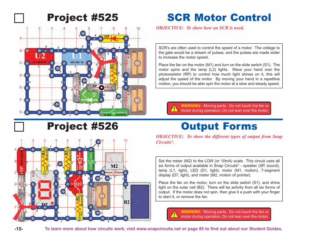
-15-
SCR’s are often used to control the speed of a motor. The voltage tothe gate would be a stream of pulses, and the pulses are made widerto increase the motor speed.
Place the fan on the motor (M1) and turn on the slide switch (S1). Themotor spins and the lamp (L2) lights. Wave your hand over thephotoresistor (RP) to control how much light shines on it, this willadjust the speed of the motor. By moving your hand in a repetitivemotion, you should be able spin the motor at a slow and steady speed.
Project #525OBJECTIVE: To show how an SCR is used.
SCR Motor Control
Project #526OBJECTIVE: To show the different types of output from SnapCircuits®.
Output Forms
Set the meter (M2) to the LOW (or 10mA) scale. This circuit uses allsix forms of output available in Snap Circuits® - speaker (SP, sound),lamp (L1, light), LED (D1, light), motor (M1, motion), 7-segmentdisplay (D7, light), and meter (M2, motion of pointer).
Place the fan on the motor, turn on the slide switch (S1), and shinelight on the solar cell (B2). There will be activity from all six forms ofoutput. If the motor does not spin, then give it a push with your fingerto start it, or remove the fan.
!WARNING: Moving parts. Do not touch the fan ormotor during operation. Do not lean over the motor.
!WARNING: Moving parts. Do not touch the fan ormotor during operation. Do not lean over the motor.
To learn more about how circuits work, visit www.snapcircuits.net or page 85 to find out about our Student Guides.
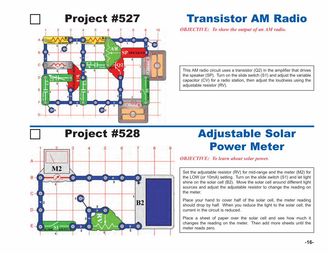
-16-
This AM radio circuit uses a transistor (Q2) in the amplifier that drivesthe speaker (SP). Turn on the slide switch (S1) and adjust the variablecapacitor (CV) for a radio station, then adjust the loudness using theadjustable resistor (RV).
Project #527OBJECTIVE: To show the output of an AM radio.
Transistor AM Radio
Project #528
OBJECTIVE: To learn about solar power.
Adjustable SolarPower Meter
Set the adjustable resistor (RV) for mid-range and the meter (M2) forthe LOW (or 10mA) setting. Turn on the slide switch (S1) and let lightshine on the solar cell (B2). Move the solar cell around different lightsources and adjust the adjustable resistor to change the reading onthe meter.
Place your hand to cover half of the solar cell, the meter readingshould drop by half. When you reduce the light to the solar cell, thecurrent in the circuit is reduced.
Place a sheet of paper over the solar cell and see how much itchanges the reading on the meter. Then add more sheets until themeter reads zero.
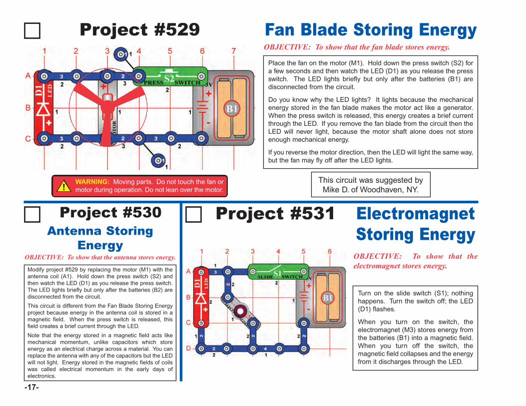
-17-
Turn on the slide switch (S1); nothinghappens. Turn the switch off; the LED(D1) flashes.
When you turn on the switch, theelectromagnet (M3) stores energy fromthe batteries (B1) into a magnetic field.When you turn off the switch, themagnetic field collapses and the energyfrom it discharges through the LED.
Modify project #529 by replacing the motor (M1) with theantenna coil (A1). Hold down the press switch (S2) andthen watch the LED (D1) as you release the press switch.The LED lights briefly but only after the batteries (B2) aredisconnected from the circuit.
This circuit is different from the Fan Blade Storing Energyproject because energy in the antenna coil is stored in amagnetic field. When the press switch is released, thisfield creates a brief current through the LED.
Note that the energy stored in a magnetic field acts likemechanical momentum, unlike capacitors which storeenergy as an electrical charge across a material. You canreplace the antenna with any of the capacitors but the LEDwill not light. Energy stored in the magnetic fields of coilswas called electrical momentum in the early days ofelectronics.
Antenna StoringEnergy
Project #529OBJECTIVE: To show that the fan blade stores energy.
Fan Blade Storing Energy
Project #531
OBJECTIVE: To show that the antenna stores energy.
ElectromagnetStoring Energy
Place the fan on the motor (M1). Hold down the press switch (S2) fora few seconds and then watch the LED (D1) as you release the pressswitch. The LED lights briefly but only after the batteries (B1) aredisconnected from the circuit.
Do you know why the LED lights? It lights because the mechanicalenergy stored in the fan blade makes the motor act like a generator.When the press switch is released, this energy creates a brief currentthrough the LED. If you remove the fan blade from the circuit then theLED will never light, because the motor shaft alone does not storeenough mechanical energy.
If you reverse the motor direction, then the LED will light the same way,but the fan may fly off after the LED lights.
This circuit was suggested byMike D. of Woodhaven, NY.
Project #530
OBJECTIVE: To show that theelectromagnet stores energy.
!WARNING: Moving parts. Do not touch the fan ormotor during operation. Do not lean over the motor.
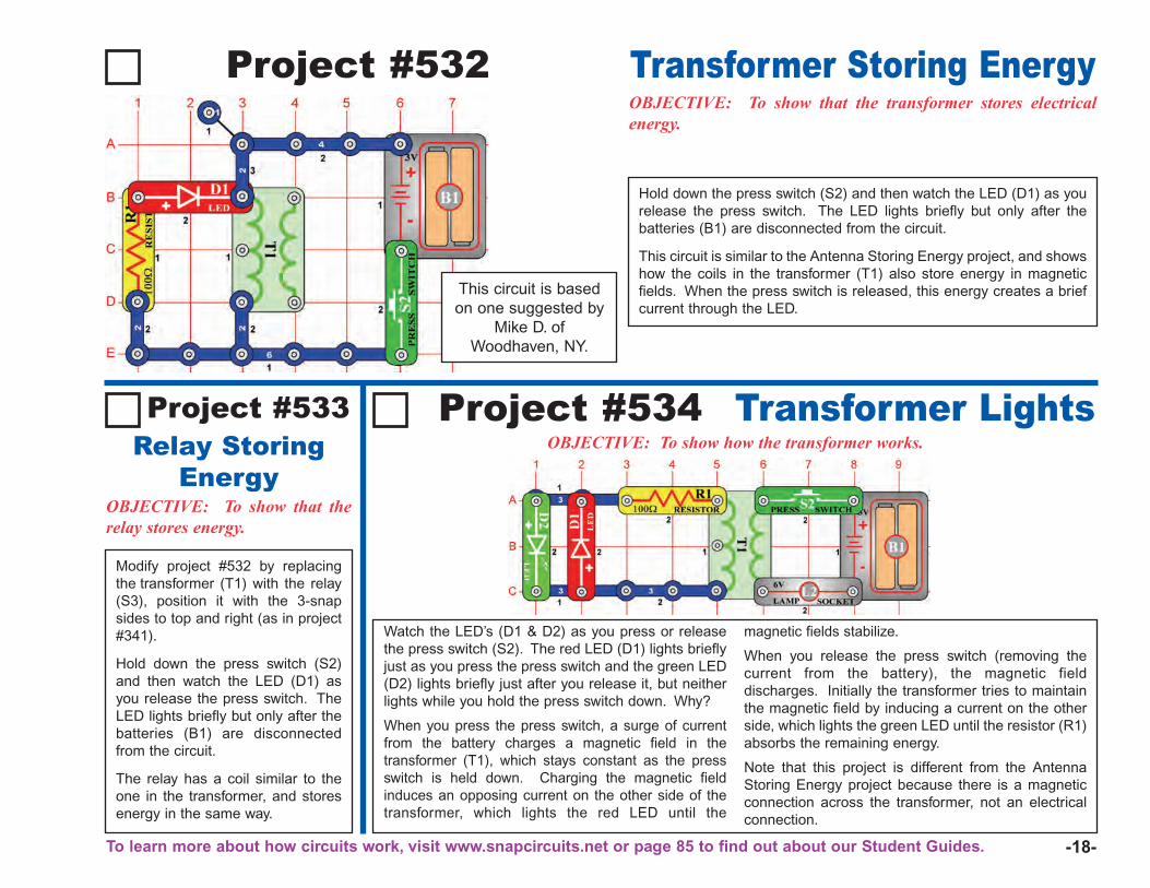
-18-
Watch the LED’s (D1 & D2) as you press or releasethe press switch (S2). The red LED (D1) lights brieflyjust as you press the press switch and the green LED(D2) lights briefly just after you release it, but neitherlights while you hold the press switch down. Why?
When you press the press switch, a surge of currentfrom the battery charges a magnetic field in thetransformer (T1), which stays constant as the pressswitch is held down. Charging the magnetic fieldinduces an opposing current on the other side of thetransformer, which lights the red LED until the
magnetic fields stabilize.
When you release the press switch (removing thecurrent from the battery), the magnetic fielddischarges. Initially the transformer tries to maintainthe magnetic field by inducing a current on the otherside, which lights the green LED until the resistor (R1)absorbs the remaining energy.
Note that this project is different from the AntennaStoring Energy project because there is a magneticconnection across the transformer, not an electricalconnection.
Modify project #532 by replacingthe transformer (T1) with the relay(S3), position it with the 3-snapsides to top and right (as in project#341).
Hold down the press switch (S2)and then watch the LED (D1) asyou release the press switch. TheLED lights briefly but only after thebatteries (B1) are disconnectedfrom the circuit.
The relay has a coil similar to theone in the transformer, and storesenergy in the same way.
Relay StoringEnergy
Project #532OBJECTIVE: To show that the transformer stores electricalenergy.
Transformer Storing Energy
Project #534OBJECTIVE: To show how the transformer works.
Transformer Lights
Hold down the press switch (S2) and then watch the LED (D1) as yourelease the press switch. The LED lights briefly but only after thebatteries (B1) are disconnected from the circuit.
This circuit is similar to the Antenna Storing Energy project, and showshow the coils in the transformer (T1) also store energy in magneticfields. When the press switch is released, this energy creates a briefcurrent through the LED.
Project #533
This circuit is basedon one suggested by
Mike D. ofWoodhaven, NY.
OBJECTIVE: To show that therelay stores energy.
To learn more about how circuits work, visit www.snapcircuits.net or page 85 to find out about our Student Guides.
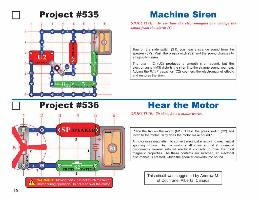
-19-
Project #535
Project #536OBJECTIVE: To show how a motor works.
Hear the Motor
Place the fan on the motor (M1). Press the press switch (S2) andlisten to the motor. Why does the motor make sound?
A motor uses magnetism to convert electrical energy into mechanicalspinning motion. As the motor shaft spins around it connects/disconnects several sets of electrical contacts to give the bestmagnetic properties. As these contacts are switched, an electricaldisturbance is created, which the speaker converts into sound.
This circuit was suggested by Andrew M.of Cochrane, Alberta, Canada
Turn on the slide switch (S1), you hear a strange sound from thespeaker (SP). Push the press switch (S2) and the sound changes toa high-pitch siren.
The alarm IC (U2) produces a smooth siren sound, but theelectromagnet (M3) distorts the siren into the strange sound you hear.Adding the 0.1μF capacitor (C2) counters the electromagnet effectsand restores the siren.
OBJECTIVE: To see how the electromagnet can change thesound from the alarm IC.
Machine Siren
!WARNING: Moving parts. Do not touch the fan ormotor during operation. Do not lean over the motor.
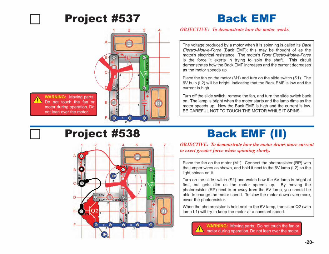
-20-
The voltage produced by a motor when it is spinning is called its BackElectro-Motive-Force (Back EMF); this may be thought of as themotor’s electrical resistance. The motor’s Front Electro-Motive-Forceis the force it exerts in trying to spin the shaft. This circuitdemonstrates how the Back EMF increases and the current decreasesas the motor speeds up.
Place the fan on the motor (M1) and turn on the slide switch (S1). The6V bulb (L2) will be bright, indicating that the Back EMF is low and thecurrent is high.
Turn off the slide switch, remove the fan, and turn the slide switch backon. The lamp is bright when the motor starts and the lamp dims as themotor speeds up. Now the Back EMF is high and the current is low.BE CAREFUL NOT TO TOUCH THE MOTOR WHILE IT SPINS.
Project #537OBJECTIVE: To demonstrate how the motor works.
Back EMF
Project #538OBJECTIVE: To demonstrate how the motor draws more currentto exert greater force when spinning slowly.
Back EMF (II)
Place the fan on the motor (M1). Connect the photoresistor (RP) withthe jumper wires as shown, and hold it next to the 6V lamp (L2) so thelight shines on it.
Turn on the slide switch (S1) and watch how the 6V lamp is bright atfirst, but gets dim as the motor speeds up. By moving thephotoresistor (RP) next to or away from the 6V lamp, you should beable to change the motor speed. To slow the motor down even more,cover the photoresistor.
When the photoresistor is held next to the 6V lamp, transistor Q2 (withlamp L1) will try to keep the motor at a constant speed.
!WARNING: Moving parts.Do not touch the fan ormotor during operation. Donot lean over the motor.
!WARNING: Moving parts. Do not touch the fan ormotor during operation. Do not lean over the motor.
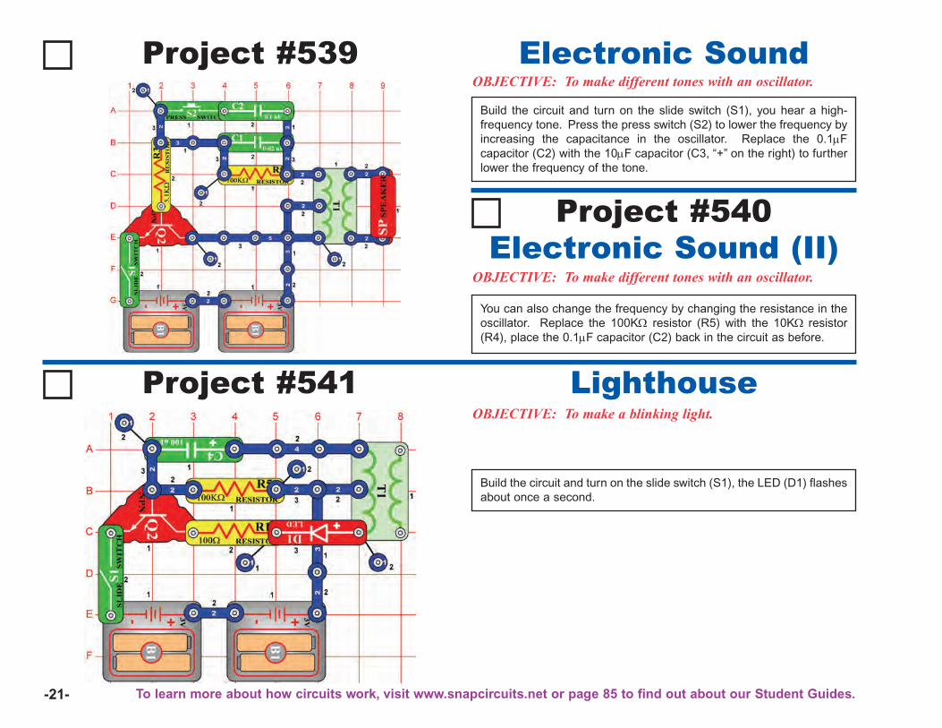
-21-
Build the circuit and turn on the slide switch (S1), you hear a high-frequency tone. Press the press switch (S2) to lower the frequency byincreasing the capacitance in the oscillator. Replace the 0.1μFcapacitor (C2) with the 10μF capacitor (C3, “+” on the right) to furtherlower the frequency of the tone.
Project #539OBJECTIVE: To make different tones with an oscillator.
Electronic Sound
Project #541OBJECTIVE: To make a blinking light.
Lighthouse
Build the circuit and turn on the slide switch (S1), the LED (D1) flashesabout once a second.
You can also change the frequency by changing the resistance in theoscillator. Replace the 100KΩ resistor (R5) with the 10KΩ resistor(R4), place the 0.1μF capacitor (C2) back in the circuit as before.
OBJECTIVE: To make different tones with an oscillator.Electronic Sound (II)
Project #540
To learn more about how circuits work, visit www.snapcircuits.net or page 85 to find out about our Student Guides.
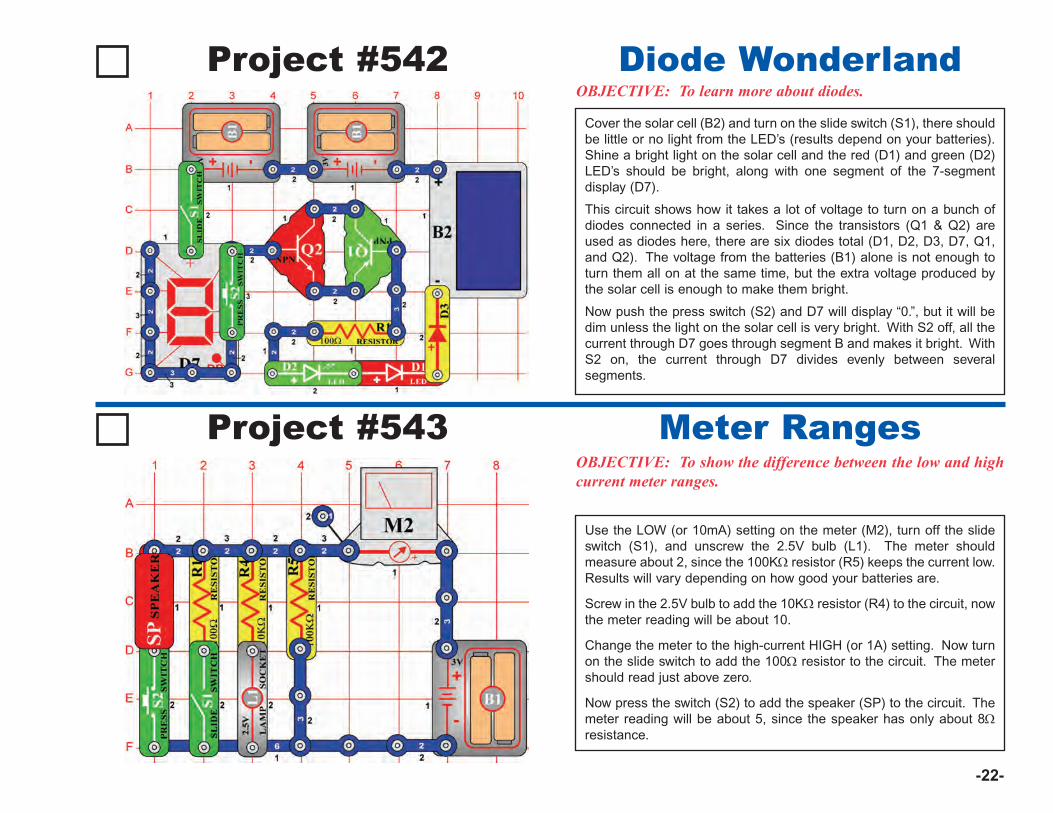
-22-
Cover the solar cell (B2) and turn on the slide switch (S1), there shouldbe little or no light from the LED’s (results depend on your batteries).Shine a bright light on the solar cell and the red (D1) and green (D2)LED’s should be bright, along with one segment of the 7-segmentdisplay (D7).
This circuit shows how it takes a lot of voltage to turn on a bunch ofdiodes connected in a series. Since the transistors (Q1 & Q2) areused as diodes here, there are six diodes total (D1, D2, D3, D7, Q1,and Q2). The voltage from the batteries (B1) alone is not enough toturn them all on at the same time, but the extra voltage produced bythe solar cell is enough to make them bright.
Now push the press switch (S2) and D7 will display “0.”, but it will bedim unless the light on the solar cell is very bright. With S2 off, all thecurrent through D7 goes through segment B and makes it bright. WithS2 on, the current through D7 divides evenly between severalsegments.
Project #542OBJECTIVE: To learn more about diodes.
Diode Wonderland
Project #543OBJECTIVE: To show the difference between the low and highcurrent meter ranges.
Meter Ranges
Use the LOW (or 10mA) setting on the meter (M2), turn off the slideswitch (S1), and unscrew the 2.5V bulb (L1). The meter shouldmeasure about 2, since the 100KΩ resistor (R5) keeps the current low.Results will vary depending on how good your batteries are.
Screw in the 2.5V bulb to add the 10KΩ resistor (R4) to the circuit, nowthe meter reading will be about 10.
Change the meter to the high-current HIGH (or 1A) setting. Now turnon the slide switch to add the 100Ω resistor to the circuit. The metershould read just above zero.
Now press the switch (S2) to add the speaker (SP) to the circuit. Themeter reading will be about 5, since the speaker has only about 8Ωresistance.
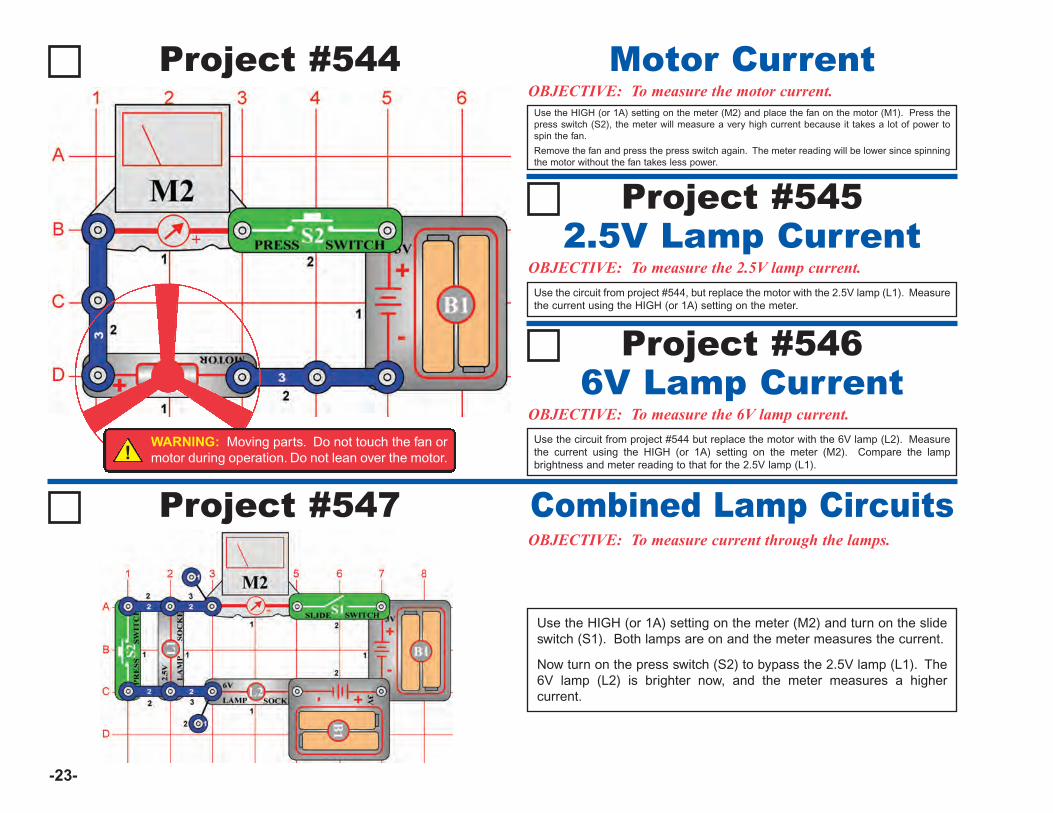
-23-
Use the HIGH (or 1A) setting on the meter (M2) and place the fan on the motor (M1). Press thepress switch (S2), the meter will measure a very high current because it takes a lot of power tospin the fan.
Remove the fan and press the press switch again. The meter reading will be lower since spinningthe motor without the fan takes less power.
Project #544OBJECTIVE: To measure the motor current.
Motor Current
Project #545
OBJECTIVE: To measure the 2.5V lamp current.2.5V Lamp Current
Use the circuit from project #544, but replace the motor with the 2.5V lamp (L1). Measurethe current using the HIGH (or 1A) setting on the meter.
Project #546
OBJECTIVE: To measure the 6V lamp current.6V Lamp Current
Use the circuit from project #544 but replace the motor with the 6V lamp (L2). Measurethe current using the HIGH (or 1A) setting on the meter (M2). Compare the lampbrightness and meter reading to that for the 2.5V lamp (L1).
Project #547OBJECTIVE: To measure current through the lamps.
Combined Lamp Circuits
Use the HIGH (or 1A) setting on the meter (M2) and turn on the slideswitch (S1). Both lamps are on and the meter measures the current.
Now turn on the press switch (S2) to bypass the 2.5V lamp (L1). The6V lamp (L2) is brighter now, and the meter measures a highercurrent.
!WARNING: Moving parts. Do not touch the fan ormotor during operation. Do not lean over the motor.
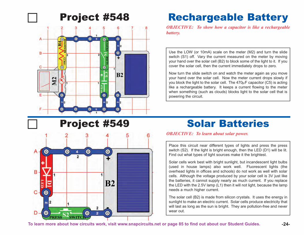
-24-
Use the LOW (or 10mA) scale on the meter (M2) and turn the slideswitch (S1) off. Vary the current measured on the meter by movingyour hand over the solar cell (B2) to block some of the light to it. If youcover the solar cell, then the current immediately drops to zero.
Now turn the slide switch on and watch the meter again as you moveyour hand over the solar cell. Now the meter current drops slowly ifyou block the light to the solar cell. The 470μF capacitor (C5) is actinglike a rechargeable battery. It keeps a current flowing to the meterwhen something (such as clouds) blocks light to the solar cell that ispowering the circuit.
Project #548OBJECTIVE: To show how a capacitor is like a rechargeablebattery.
Rechargeable Battery
Project #549OBJECTIVE: To learn about solar power.
Solar Batteries
Place this circuit near different types of lights and press the pressswitch (S2). If the light is bright enough, then the LED (D1) will be lit.Find out what types of light sources make it the brightest.
Solar cells work best with bright sunlight, but incandescent light bulbs(used in house lamps) also work well. Fluorescent lights (theoverhead lights in offices and schools) do not work as well with solarcells. Although the voltage produced by your solar cell is 3V just likethe batteries, it cannot supply nearly as much current. If you replacethe LED with the 2.5V lamp (L1) then it will not light, because the lampneeds a much higher current.
The solar cell (B2) is made from silicon crystals. It uses the energy insunlight to make an electric current. Solar cells produce electricity thatwill last as long as the sun is bright. They are pollution-free and neverwear out.
To learn more about how circuits work, visit www.snapcircuits.net or page 85 to find out about our Student Guides.

-25-
Build the circuit and turn on the slide switch (S1). If there is sunlighton the solar cell (B2), then the LED (D1) and lamp (L1) will be on.
This circuit uses the solar cell to light the LED and to control the lamp.The solar cell does not produce enough power to run the lamp directly.You can replace the lamp with the motor (M1, “+” side on top) and fan;the motor will spin if there is sunlight on the solar cell.
Project #550OBJECTIVE: To learn about solar power.
Solar Control
Place the circuit near a bright light and set the adjustable resistor (RV) so thatthe meter (M2) reads “10” on the LOW (or 10mA) setting. Now replace the 3-snap between points A & B with another component to test, such as a resistor,capacitor, motor, photoresistor, or lamp. The 100μF (C4) or 470μF (C5)capacitors will give a high reading that slowly drops to zero.
You can also use the two-spring socket (?1) and place your own componentsbetween its springs to test them.
Project #551OBJECTIVE: To test the resistance of your components.Solar Resistance Meter
OBJECTIVE: To learn about solar power.Solar Diode Tester
Use the same circuit to test the red and green LED’s (D1 & D2), and the diode(D3). The diode will give a higher meter reading than the LED’s, and all threewill block current in one direction.
Project #552
!WARNING: Moving parts. Do not touch the fan ormotor during operation. Do not lean over the motor.

-26-
Project #553
OBJECTIVE: To test your NPN transistor.
Solar NPN TransistorTester
This circuit is just like the one in project #551, but tests the NPNtransistor (Q2). The meter will read zero unless both switches (S1 &S2) are on, then the adjustable resistor (RV) sets the current. If youhave the same light and RV setting as project #552 with the diode(D3), then the meter (M2) reading will be higher with the transistor.
You can replace the NPN transistor with the SCR (Q3), it works thesame way in this circuit.
Project #554
OBJECTIVE: To test your PNP transistor.
Solar PNP TransistorTester
This circuit is just like the one in project #551, but tests the PNPtransistor (Q1). The meter (M2) will read zero unless both switches(S1 & S2) are on, then the adjustable resistor (RV) sets the current. Ifyou have the same light and RV setting as project #552 with the diode(D3), then the meter reading will be higher with the transistor.
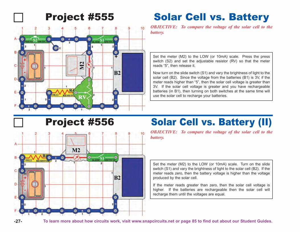
-27-
Project #555OBJECTIVE: To compare the voltage of the solar cell to thebattery.
Solar Cell vs. Battery
Set the meter (M2) to the LOW (or 10mA) scale. Press the pressswitch (S2) and set the adjustable resistor (RV) so that the meterreads “5”, then release it.
Now turn on the slide switch (S1) and vary the brightness of light to thesolar cell (B2). Since the voltage from the batteries (B1) is 3V, if themeter reads higher than “5”, then the solar cell voltage is greater than3V. If the solar cell voltage is greater and you have rechargeablebatteries (in B1), then turning on both switches at the same time willuse the solar cell to recharge your batteries.
Project #556OBJECTIVE: To compare the voltage of the solar cell to thebattery.
Solar Cell vs. Battery (II)
Set the meter (M2) to the LOW (or 10mA) scale. Turn on the slideswitch (S1) and vary the brightness of light to the solar cell (B2). If themeter reads zero, then the battery voltage is higher than the voltageproduced by the solar cell.
If the meter reads greater than zero, then the solar cell voltage ishigher. If the batteries are rechargeable then the solar cell willrecharge them until the voltages are equal.
To learn more about how circuits work, visit www.snapcircuits.net or page 85 to find out about our Student Guides.
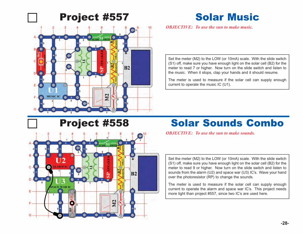
-28-
Project #557OBJECTIVE: To use the sun to make music.
Solar Music
Set the meter (M2) to the LOW (or 10mA) scale. With the slide switch(S1) off, make sure you have enough light on the solar cell (B2) for themeter to read 7 or higher. Now turn on the slide switch and listen tothe music. When it stops, clap your hands and it should resume.
The meter is used to measure if the solar cell can supply enoughcurrent to operate the music IC (U1).
Project #558OBJECTIVE: To use the sun to make sounds.
Solar Sounds Combo
Set the meter (M2) to the LOW (or 10mA) scale. With the slide switch(S1) off, make sure you have enough light on the solar cell (B2) for themeter to read 9 or higher. Now turn on the slide switch and listen tosounds from the alarm (U2) and space war (U3) IC’s. Wave your handover the photoresistor (RP) to change the sounds.
The meter is used to measure if the solar cell can supply enoughcurrent to operate the alarm and space war IC’s. This project needsmore light than project #557, since two IC’s are used here.
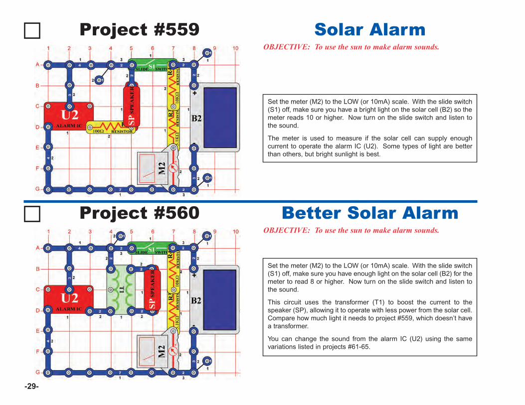
-29-
Project #559OBJECTIVE: To use the sun to make alarm sounds.
Solar Alarm
Set the meter (M2) to the LOW (or 10mA) scale. With the slide switch(S1) off, make sure you have a bright light on the solar cell (B2) so themeter reads 10 or higher. Now turn on the slide switch and listen tothe sound.
The meter is used to measure if the solar cell can supply enoughcurrent to operate the alarm IC (U2). Some types of light are betterthan others, but bright sunlight is best.
Project #560OBJECTIVE: To use the sun to make alarm sounds.
Better Solar Alarm
Set the meter (M2) to the LOW (or 10mA) scale. With the slide switch(S1) off, make sure you have enough light on the solar cell (B2) for themeter to read 8 or higher. Now turn on the slide switch and listen tothe sound.
This circuit uses the transformer (T1) to boost the current to thespeaker (SP), allowing it to operate with less power from the solar cell.Compare how much light it needs to project #559, which doesn’t havea transformer.
You can change the sound from the alarm IC (U2) using the samevariations listed in projects #61-65.
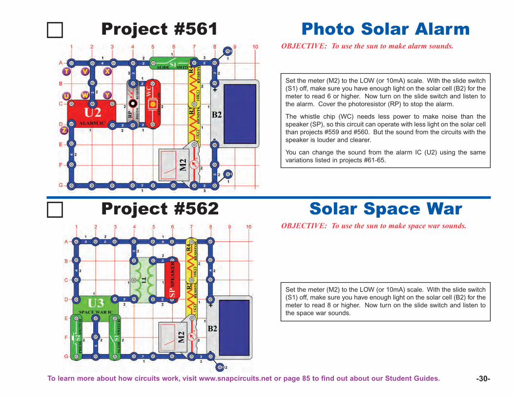
-30-
Project #561OBJECTIVE: To use the sun to make alarm sounds.
Photo Solar Alarm
Project #562OBJECTIVE: To use the sun to make space war sounds.
Solar Space War
Set the meter (M2) to the LOW (or 10mA) scale. With the slide switch(S1) off, make sure you have enough light on the solar cell (B2) for themeter to read 8 or higher. Now turn on the slide switch and listen tothe space war sounds.
Set the meter (M2) to the LOW (or 10mA) scale. With the slide switch(S1) off, make sure you have enough light on the solar cell (B2) for themeter to read 6 or higher. Now turn on the slide switch and listen tothe alarm. Cover the photoresistor (RP) to stop the alarm.
The whistle chip (WC) needs less power to make noise than thespeaker (SP), so this circuit can operate with less light on the solar cellthan projects #559 and #560. But the sound from the circuits with thespeaker is louder and clearer.
You can change the sound from the alarm IC (U2) using the samevariations listed in projects #61-65.
To learn more about how circuits work, visit www.snapcircuits.net or page 85 to find out about our Student Guides.
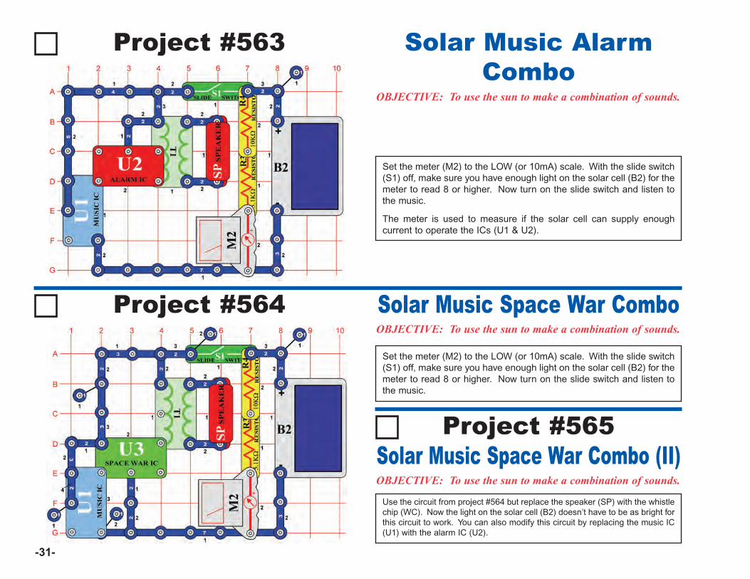
-31-
Project #563
OBJECTIVE: To use the sun to make a combination of sounds.
Solar Music AlarmCombo
Project #564OBJECTIVE: To use the sun to make a combination of sounds.
Solar Music Space War Combo
Set the meter (M2) to the LOW (or 10mA) scale. With the slide switch(S1) off, make sure you have enough light on the solar cell (B2) for themeter to read 8 or higher. Now turn on the slide switch and listen tothe music.
Set the meter (M2) to the LOW (or 10mA) scale. With the slide switch(S1) off, make sure you have enough light on the solar cell (B2) for themeter to read 8 or higher. Now turn on the slide switch and listen tothe music.
The meter is used to measure if the solar cell can supply enoughcurrent to operate the ICs (U1 & U2).
OBJECTIVE: To use the sun to make a combination of sounds.
Solar Music Space War Combo (II)Use the circuit from project #564 but replace the speaker (SP) with the whistlechip (WC). Now the light on the solar cell (B2) doesn’t have to be as bright forthis circuit to work. You can also modify this circuit by replacing the music IC(U1) with the alarm IC (U2).
Project #565
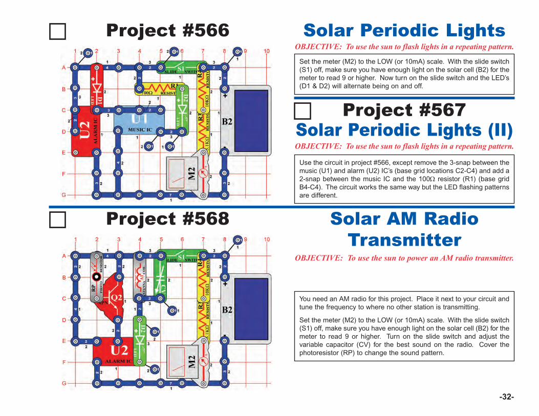
-32-
Project #566OBJECTIVE: To use the sun to flash lights in a repeating pattern.Solar Periodic Lights
Project #568
OBJECTIVE: To use the sun to power an AM radio transmitter.
Solar AM RadioTransmitter
You need an AM radio for this project. Place it next to your circuit andtune the frequency to where no other station is transmitting.
Set the meter (M2) to the LOW (or 10mA) scale. With the slide switch(S1) off, make sure you have enough light on the solar cell (B2) for themeter to read 9 or higher. Turn on the slide switch and adjust thevariable capacitor (CV) for the best sound on the radio. Cover thephotoresistor (RP) to change the sound pattern.
Set the meter (M2) to the LOW (or 10mA) scale. With the slide switch(S1) off, make sure you have enough light on the solar cell (B2) for themeter to read 9 or higher. Now turn on the slide switch and the LED’s(D1 & D2) will alternate being on and off.
OBJECTIVE: To use the sun to flash lights in a repeating pattern.Solar Periodic Lights (II)
Project #567
Use the circuit in project #566, except remove the 3-snap between themusic (U1) and alarm (U2) IC’s (base grid locations C2-C4) and add a2-snap between the music IC and the 100Ω resistor (R1) (base gridB4-C4). The circuit works the same way but the LED flashing patternsare different.
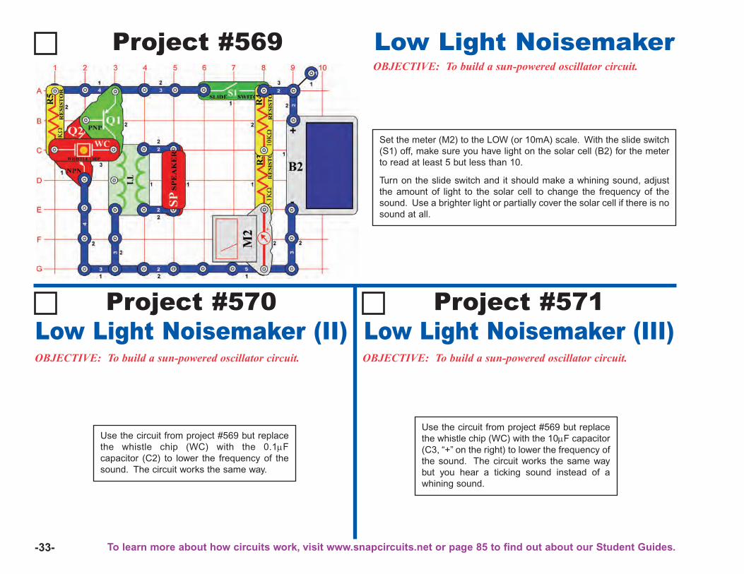
-33-
Project #569OBJECTIVE: To build a sun-powered oscillator circuit.
Low Light Noisemaker
Project #570Low Light Noisemaker (II)OBJECTIVE: To build a sun-powered oscillator circuit.
Use the circuit from project #569 but replacethe whistle chip (WC) with the 0.1μFcapacitor (C2) to lower the frequency of thesound. The circuit works the same way.
OBJECTIVE: To build a sun-powered oscillator circuit.
Project #571Low Light Noisemaker (III)
Set the meter (M2) to the LOW (or 10mA) scale. With the slide switch(S1) off, make sure you have light on the solar cell (B2) for the meterto read at least 5 but less than 10.
Turn on the slide switch and it should make a whining sound, adjustthe amount of light to the solar cell to change the frequency of thesound. Use a brighter light or partially cover the solar cell if there is nosound at all.
Use the circuit from project #569 but replacethe whistle chip (WC) with the 10μF capacitor(C3, “+” on the right) to lower the frequency ofthe sound. The circuit works the same waybut you hear a ticking sound instead of awhining sound.
To learn more about how circuits work, visit www.snapcircuits.net or page 85 to find out about our Student Guides.
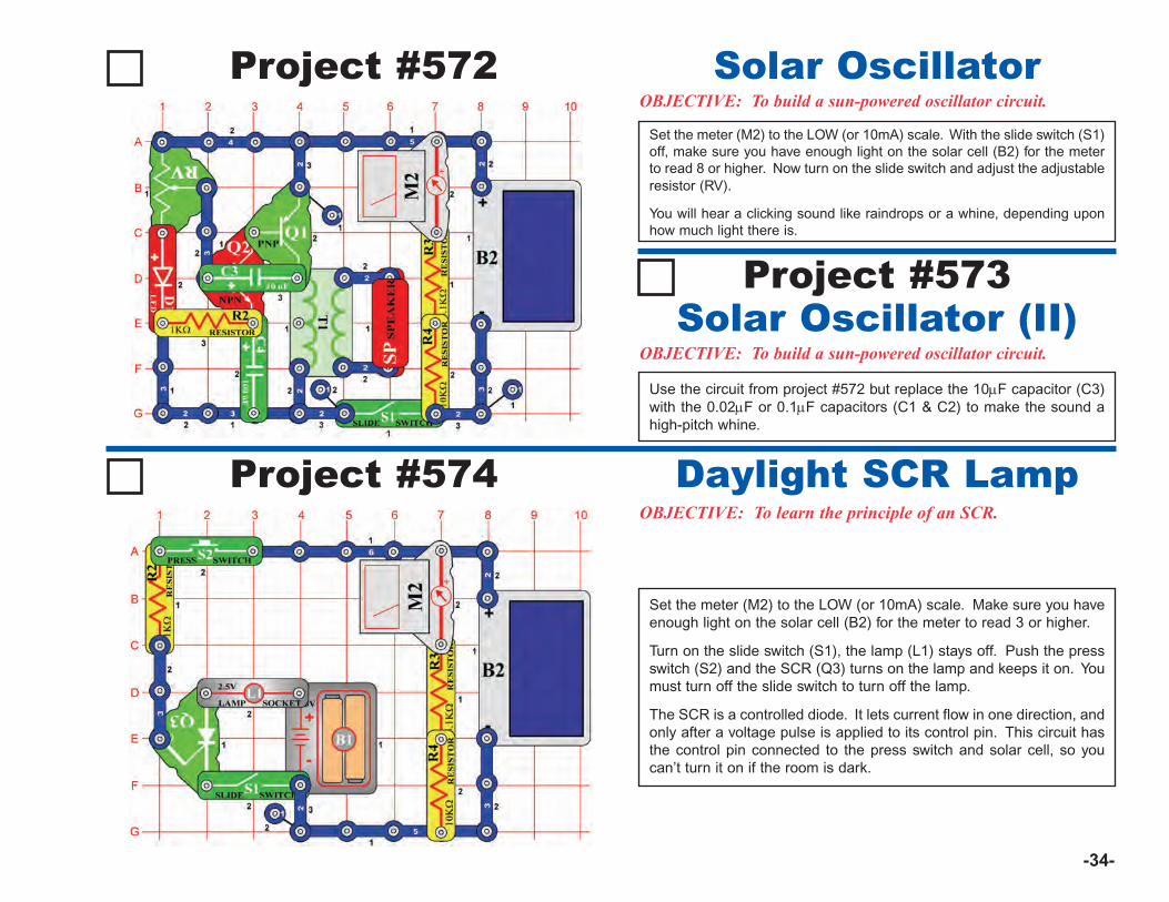
-34-
Project #572OBJECTIVE: To build a sun-powered oscillator circuit.
Solar Oscillator
Project #574OBJECTIVE: To learn the principle of an SCR.
Daylight SCR Lamp
Set the meter (M2) to the LOW (or 10mA) scale. Make sure you haveenough light on the solar cell (B2) for the meter to read 3 or higher.
Turn on the slide switch (S1), the lamp (L1) stays off. Push the pressswitch (S2) and the SCR (Q3) turns on the lamp and keeps it on. Youmust turn off the slide switch to turn off the lamp.
The SCR is a controlled diode. It lets current flow in one direction, andonly after a voltage pulse is applied to its control pin. This circuit hasthe control pin connected to the press switch and solar cell, so youcan’t turn it on if the room is dark.
Set the meter (M2) to the LOW (or 10mA) scale. With the slide switch (S1)off, make sure you have enough light on the solar cell (B2) for the meterto read 8 or higher. Now turn on the slide switch and adjust the adjustableresistor (RV).
You will hear a clicking sound like raindrops or a whine, depending uponhow much light there is.
OBJECTIVE: To build a sun-powered oscillator circuit.Solar Oscillator (II)
Project #573
Use the circuit from project #572 but replace the 10μF capacitor (C3)with the 0.02μF or 0.1μF capacitors (C1 & C2) to make the sound ahigh-pitch whine.
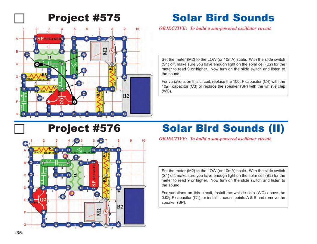
-35-
Project #575OBJECTIVE: To build a sun-powered oscillator circuit.
Solar Bird Sounds
Set the meter (M2) to the LOW (or 10mA) scale. With the slide switch(S1) off, make sure you have enough light on the solar cell (B2) for themeter to read 9 or higher. Now turn on the slide switch and listen tothe sound.
For variations on this circuit, replace the 100μF capacitor (C4) with the10μF capacitor (C3) or replace the speaker (SP) with the whistle chip(WC).
Project #576OBJECTIVE: To build a sun-powered oscillator circuit.
Solar Bird Sounds (II)
Set the meter (M2) to the LOW (or 10mA) scale. With the slide switch(S1) off, make sure you have enough light on the solar cell (B2) for themeter to read 9 or higher. Now turn on the slide switch and listen tothe sound.
For variations on this circuit, install the whistle chip (WC) above the0.02μF capacitor (C1), or install it across points A & B and remove thespeaker (SP).

-36-
Project #577OBJECTIVE: To learn the principle of an SCR.
SCR Solar Bomb Sounds
Set the meter (M2) to the LOW (or 10mA) scale. With the slide switch(S1) off, make sure you have enough light on the solar cell (B2) for themeter to read 8 or higher. Turn on the slide switch now; nothinghappens. Press the press switch (S2) and you hear an explosion ofsounds, which continues until you turn off the slide switch.
Project #578
OBJECTIVE: To build a laser sounding circuit.
Flashing Laser LED’swith Sound
When you press the press switch (S2), the integrated circuit (U2)should sound like a laser gun. The red (D1) and green (D2) LED’s willflash simulating a burst of light. You can shoot long repeating laserbursts or short zaps by tapping the press switch.
To learn more about how circuits work, visit www.snapcircuits.net or page 85 to find out about our Student Guides.
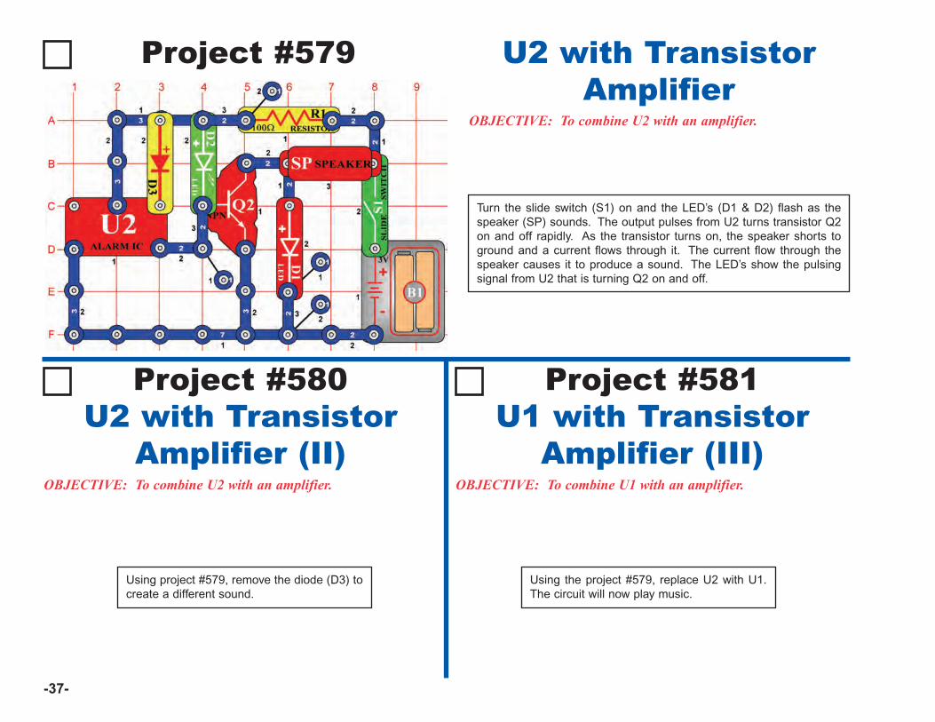
-37-
Project #579
OBJECTIVE: To combine U2 with an amplifier.
U2 with TransistorAmplifier
Project #580U2 with Transistor
Amplifier (II)OBJECTIVE: To combine U2 with an amplifier.
Using project #579, remove the diode (D3) tocreate a different sound.
OBJECTIVE: To combine U1 with an amplifier.
Project #581U1 with Transistor
Amplifier (III)
Turn the slide switch (S1) on and the LED’s (D1 & D2) flash as thespeaker (SP) sounds. The output pulses from U2 turns transistor Q2on and off rapidly. As the transistor turns on, the speaker shorts toground and a current flows through it. The current flow through thespeaker causes it to produce a sound. The LED’s show the pulsingsignal from U2 that is turning Q2 on and off.
Using the project #579, replace U2 with U1.The circuit will now play music.
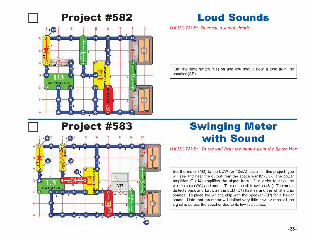
-38-
Project #582OBJECTIVE: To create a sound circuit.
Loud Sounds
Turn the slide switch (S1) on and you should hear a tone from thespeaker (SP).
Project #583
OBJECTIVE: To see and hear the output from the Space War
Swinging Meterwith Sound
Set the meter (M2) to the LOW (or 10mA) scale. In this project, youwill see and hear the output from the space war IC (U3). The poweramplifier IC (U4) amplifies the signal from U3 in order to drive thewhistle chip (WC) and meter. Turn on the slide switch (S1). The meterdeflects back and forth, as the LED (D1) flashes and the whistle chipsounds. Replace the whistle chip with the speaker (SP) for a loudersound. Note that the meter will deflect very little now. Almost all thesignal is across the speaker due to its low resistance.
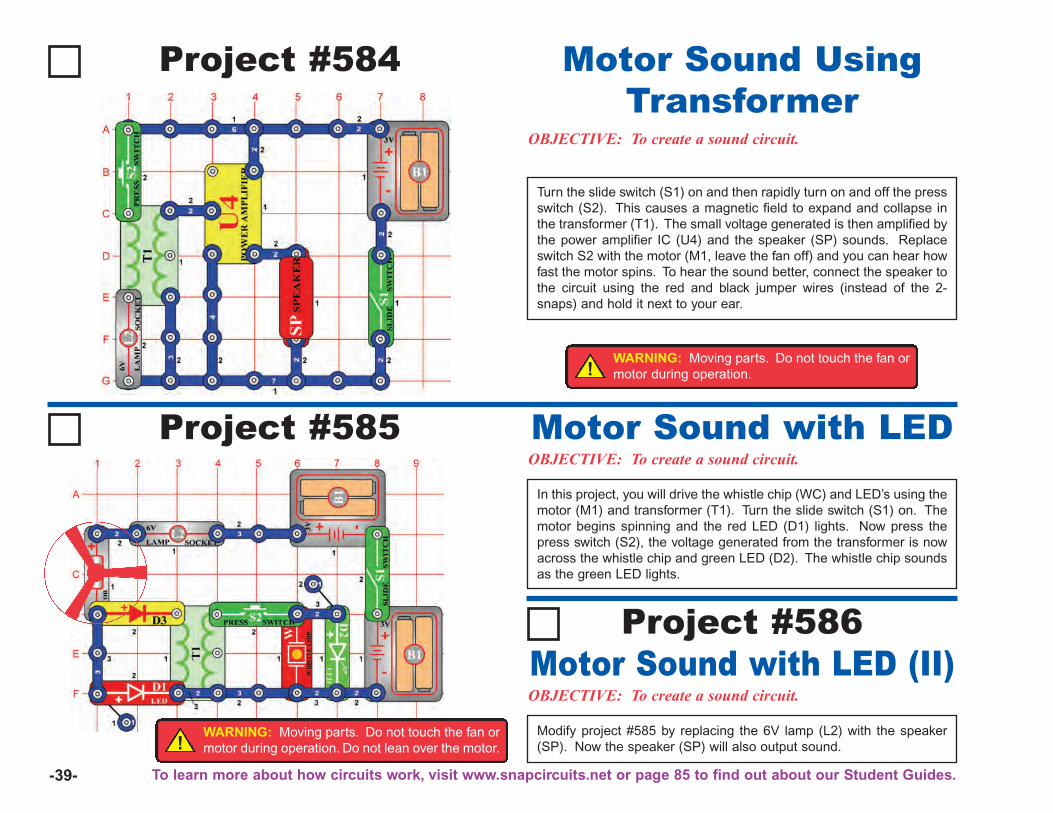
-39-
Project #584
OBJECTIVE: To create a sound circuit.
Motor Sound UsingTransformer
Project #585OBJECTIVE: To create a sound circuit.Motor Sound with LEDIn this project, you will drive the whistle chip (WC) and LED’s using themotor (M1) and transformer (T1). Turn the slide switch (S1) on. Themotor begins spinning and the red LED (D1) lights. Now press thepress switch (S2), the voltage generated from the transformer is nowacross the whistle chip and green LED (D2). The whistle chip soundsas the green LED lights.
OBJECTIVE: To create a sound circuit.Motor Sound with LED (II)
Project #586
Modify project #585 by replacing the 6V lamp (L2) with the speaker(SP). Now the speaker (SP) will also output sound.!
WARNING: Moving parts. Do not touch the fan ormotor during operation. Do not lean over the motor.
Turn the slide switch (S1) on and then rapidly turn on and off the pressswitch (S2). This causes a magnetic field to expand and collapse inthe transformer (T1). The small voltage generated is then amplified bythe power amplifier IC (U4) and the speaker (SP) sounds. Replaceswitch S2 with the motor (M1, leave the fan off) and you can hear howfast the motor spins. To hear the sound better, connect the speaker tothe circuit using the red and black jumper wires (instead of the 2-snaps) and hold it next to your ear.
!WARNING: Moving parts. Do not touch the fan ormotor during operation.
To learn more about how circuits work, visit www.snapcircuits.net or page 85 to find out about our Student Guides.
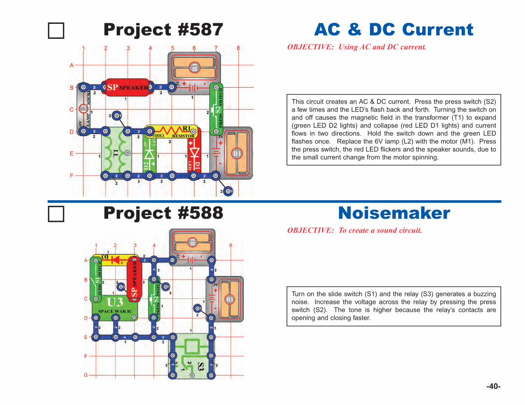
-40-
Project #587OBJECTIVE: Using AC and DC current.
AC & DC Current
This circuit creates an AC & DC current. Press the press switch (S2)a few times and the LED’s flash back and forth. Turning the switch onand off causes the magnetic field in the transformer (T1) to expand(green LED D2 lights) and collapse (red LED D1 lights) and currentflows in two directions. Hold the switch down and the green LEDflashes once. Replace the 6V lamp (L2) with the motor (M1). Pressthe press switch, the red LED flickers and the speaker sounds, due tothe small current change from the motor spinning.
Project #588OBJECTIVE: To create a sound circuit.
Noisemaker
Turn on the slide switch (S1) and the relay (S3) generates a buzzingnoise. Increase the voltage across the relay by pressing the pressswitch (S2). The tone is higher because the relay’s contacts areopening and closing faster.
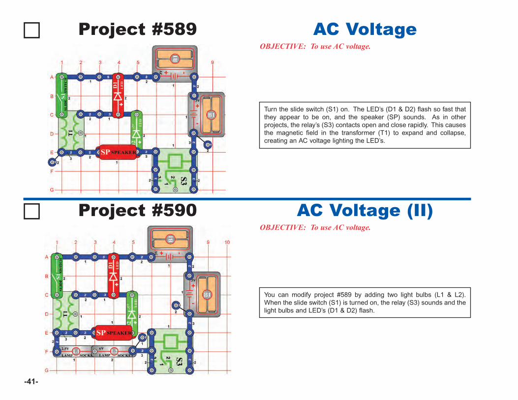
-41-
Project #589OBJECTIVE: To use AC voltage.
AC Voltage
Turn the slide switch (S1) on. The LED’s (D1 & D2) flash so fast thatthey appear to be on, and the speaker (SP) sounds. As in otherprojects, the relay’s (S3) contacts open and close rapidly. This causesthe magnetic field in the transformer (T1) to expand and collapse,creating an AC voltage lighting the LED’s.
Project #590OBJECTIVE: To use AC voltage.
AC Voltage (II)
You can modify project #589 by adding two light bulbs (L1 & L2).When the slide switch (S1) is turned on, the relay (S3) sounds and thelight bulbs and LED’s (D1 & D2) flash.
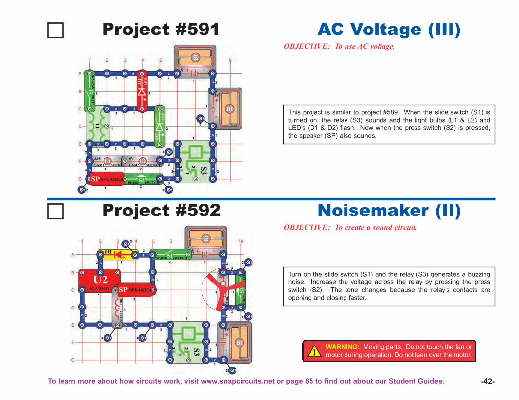
-42-
Project #591OBJECTIVE: To use AC voltage.
AC Voltage (III)
This project is similar to project #589. When the slide switch (S1) isturned on, the relay (S3) sounds and the light bulbs (L1 & L2) andLED’s (D1 & D2) flash. Now when the press switch (S2) is pressed,the speaker (SP) also sounds.
Project #592OBJECTIVE: To create a sound circuit.
Noisemaker (II)
Turn on the slide switch (S1) and the relay (S3) generates a buzzingnoise. Increase the voltage across the relay by pressing the pressswitch (S2). The tone changes because the relay’s contacts areopening and closing faster.
!WARNING: Moving parts. Do not touch the fan ormotor during operation. Do not lean over the motor.
To learn more about how circuits work, visit www.snapcircuits.net or page 85 to find out about our Student Guides.
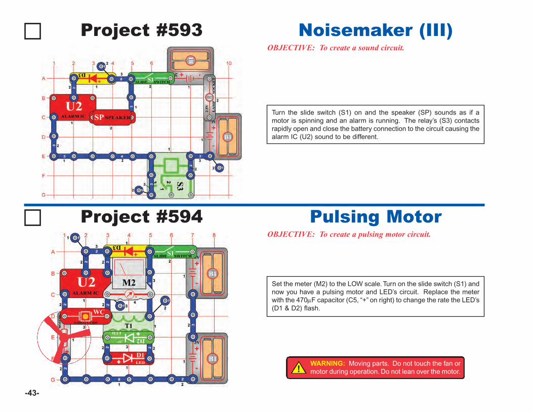
-43-
Project #594OBJECTIVE: To create a pulsing motor circuit.
Pulsing Motor
Set the meter (M2) to the LOW scale. Turn on the slide switch (S1) andnow you have a pulsing motor and LED’s circuit. Replace the meterwith the 470μF capacitor (C5, “+” on right) to change the rate the LED’s(D1 & D2) flash.
Project #593OBJECTIVE: To create a sound circuit.
Noisemaker (III)
Turn the slide switch (S1) on and the speaker (SP) sounds as if amotor is spinning and an alarm is running. The relay’s (S3) contactsrapidly open and close the battery connection to the circuit causing thealarm IC (U2) sound to be different.
!WARNING: Moving parts. Do not touch the fan ormotor during operation. Do not lean over the motor.
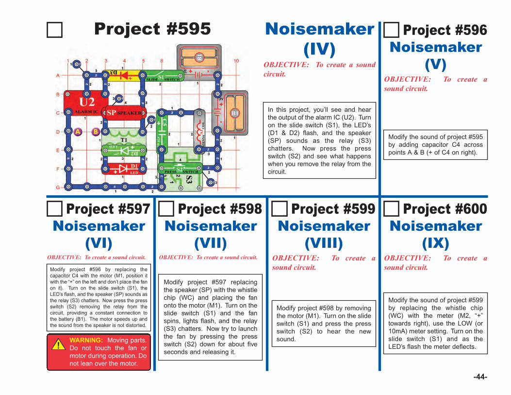
-44-
Project #595 Noisemaker(IV)
OBJECTIVE: To create a soundcircuit.
Project #597Noisemaker
(VI)OBJECTIVE: To create a sound circuit.
Project #599 Noisemaker
(VIII)OBJECTIVE: To create asound circuit.
OBJECTIVE: To create asound circuit.
Project #598 Noisemaker
(VII)
Modify project #598 by removingthe motor (M1). Turn on the slideswitch (S1) and press the pressswitch (S2) to hear the newsound.
Modify the sound of project #599by replacing the whistle chip(WC) with the meter (M2, “+”towards right), use the LOW (or10mA) meter setting. Turn on theslide switch (S1) and as theLED’s flash the meter deflects.
Project #600 Noisemaker
(IX)
OBJECTIVE: To create asound circuit.
Project #596 Noisemaker
(V)
Modify the sound of project #595by adding capacitor C4 acrosspoints A & B (+ of C4 on right).
In this project, you’ll see and hearthe output of the alarm IC (U2). Turnon the slide switch (S1), the LED’s(D1 & D2) flash, and the speaker(SP) sounds as the relay (S3)chatters. Now press the pressswitch (S2) and see what happenswhen you remove the relay from thecircuit.
Modify project #596 by replacing thecapacitor C4 with the motor (M1, position itwith the “+” on the left and don’t place the fanon it). Turn on the slide switch (S1), theLED’s flash, and the speaker (SP) sounds asthe relay (S3) chatters. Now press the pressswitch (S2) removing the relay from thecircuit, providing a constant connection tothe battery (B1). The motor speeds up andthe sound from the speaker is not distorted.
!WARNING: Moving parts.Do not touch the fan ormotor during operation. Donot lean over the motor.
OBJECTIVE: To create a sound circuit.
Modify project #597 replacingthe speaker (SP) with the whistlechip (WC) and placing the fanonto the motor (M1). Turn on theslide switch (S1) and the fanspins, lights flash, and the relay(S3) chatters. Now try to launchthe fan by pressing the pressswitch (S2) down for about fiveseconds and releasing it.
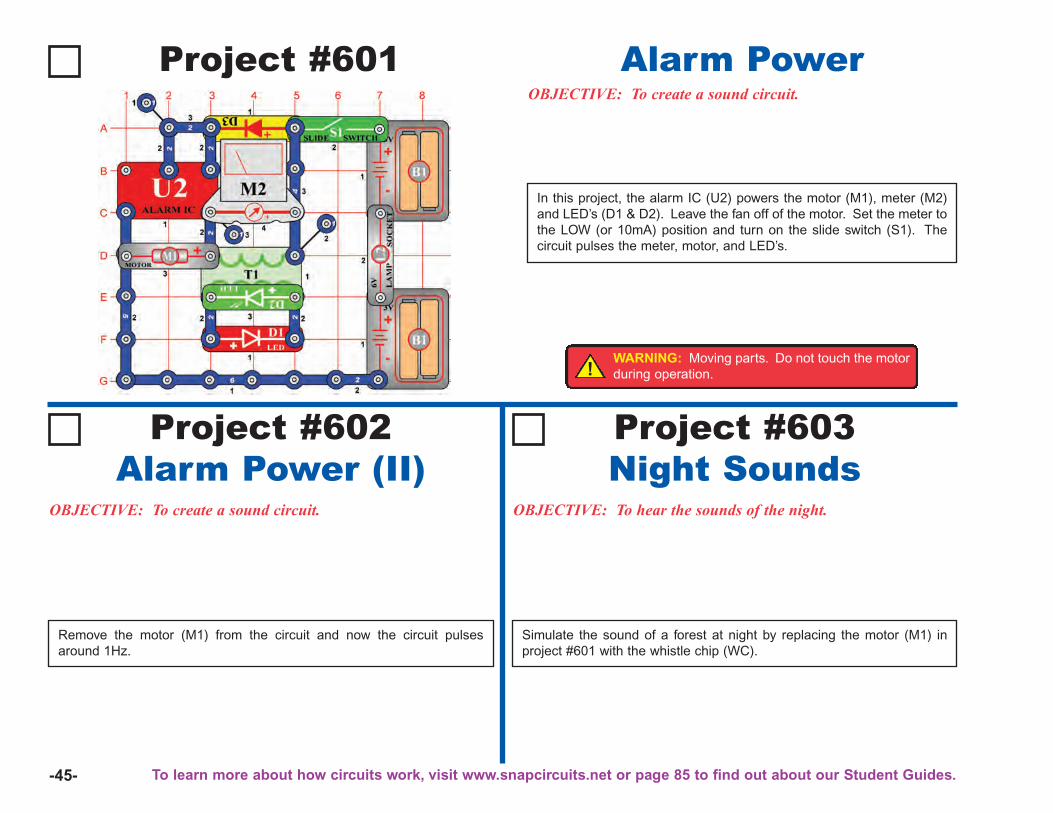
-45-
Project #601OBJECTIVE: To create a sound circuit.
Alarm Power
Project #602Alarm Power (II)
OBJECTIVE: To create a sound circuit. OBJECTIVE: To hear the sounds of the night.
Project #603Night Sounds
In this project, the alarm IC (U2) powers the motor (M1), meter (M2)and LED’s (D1 & D2). Leave the fan off of the motor. Set the meter tothe LOW (or 10mA) position and turn on the slide switch (S1). Thecircuit pulses the meter, motor, and LED’s.
Remove the motor (M1) from the circuit and now the circuit pulsesaround 1Hz.
Simulate the sound of a forest at night by replacing the motor (M1) inproject #601 with the whistle chip (WC).
!WARNING: Moving parts. Do not touch the motorduring operation.
To learn more about how circuits work, visit www.snapcircuits.net or page 85 to find out about our Student Guides.
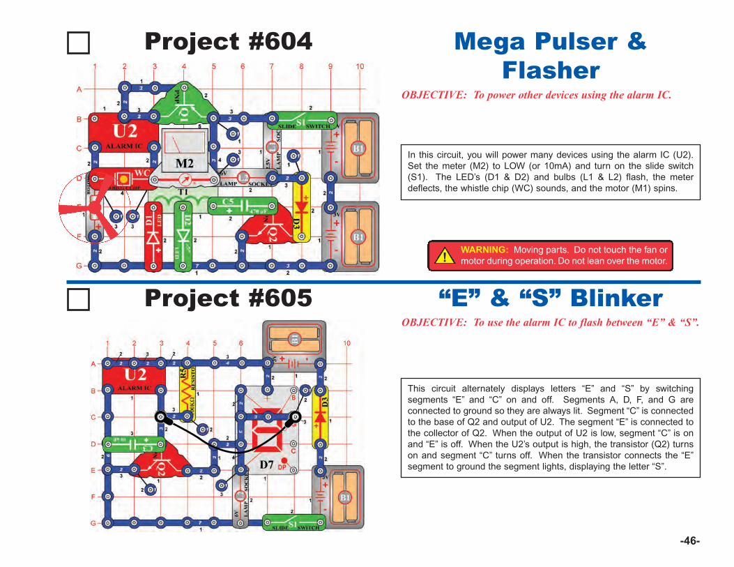
-46-
Project #604
OBJECTIVE: To power other devices using the alarm IC.
Mega Pulser &Flasher
In this circuit, you will power many devices using the alarm IC (U2).Set the meter (M2) to LOW (or 10mA) and turn on the slide switch(S1). The LED’s (D1 & D2) and bulbs (L1 & L2) flash, the meterdeflects, the whistle chip (WC) sounds, and the motor (M1) spins.
Project #605OBJECTIVE: To use the alarm IC to flash between “E” & “S”.
“E” & “S” Blinker
This circuit alternately displays letters “E” and “S” by switchingsegments “E” and “C” on and off. Segments A, D, F, and G areconnected to ground so they are always lit. Segment “C” is connectedto the base of Q2 and output of U2. The segment “E” is connected tothe collector of Q2. When the output of U2 is low, segment “C” is onand “E” is off. When the U2’s output is high, the transistor (Q2) turnson and segment “C” turns off. When the transistor connects the “E”segment to ground the segment lights, displaying the letter “S”.
!WARNING: Moving parts. Do not touch the fan ormotor during operation. Do not lean over the motor.
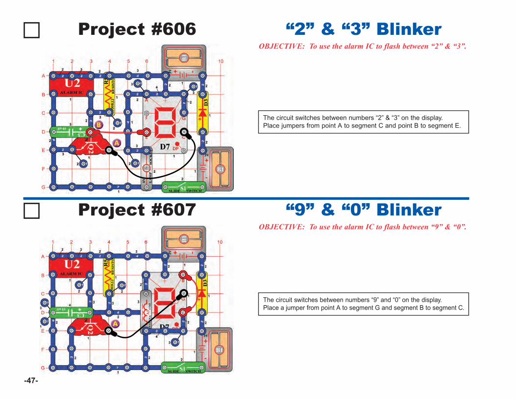
-47-
Project #606OBJECTIVE: To use the alarm IC to flash between “2” & “3”.
“2” & “3” Blinker
The circuit switches between numbers “2” & “3” on the display. Place jumpers from point A to segment C and point B to segment E.
Project #607OBJECTIVE: To use the alarm IC to flash between “9” & “0”.
“9” & “0” Blinker
The circuit switches between numbers “9” and “0” on the display.Place a jumper from point A to segment G and segment B to segment C.
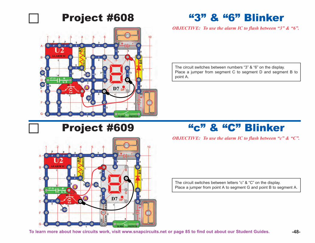
-48-
Project #608OBJECTIVE: To use the alarm IC to flash between “3” & “6”.
“3” & “6” Blinker
The circuit switches between numbers “3” & “6” on the display.Place a jumper from segment C to segment D and segment B topoint A.
Project #609OBJECTIVE: To use the alarm IC to flash between “c” & “C”.
“c” & “C” Blinker
The circuit switches between letters “c” & “C” on the display.Place a jumper from point A to segment G and point B to segment A.
To learn more about how circuits work, visit www.snapcircuits.net or page 85 to find out about our Student Guides.
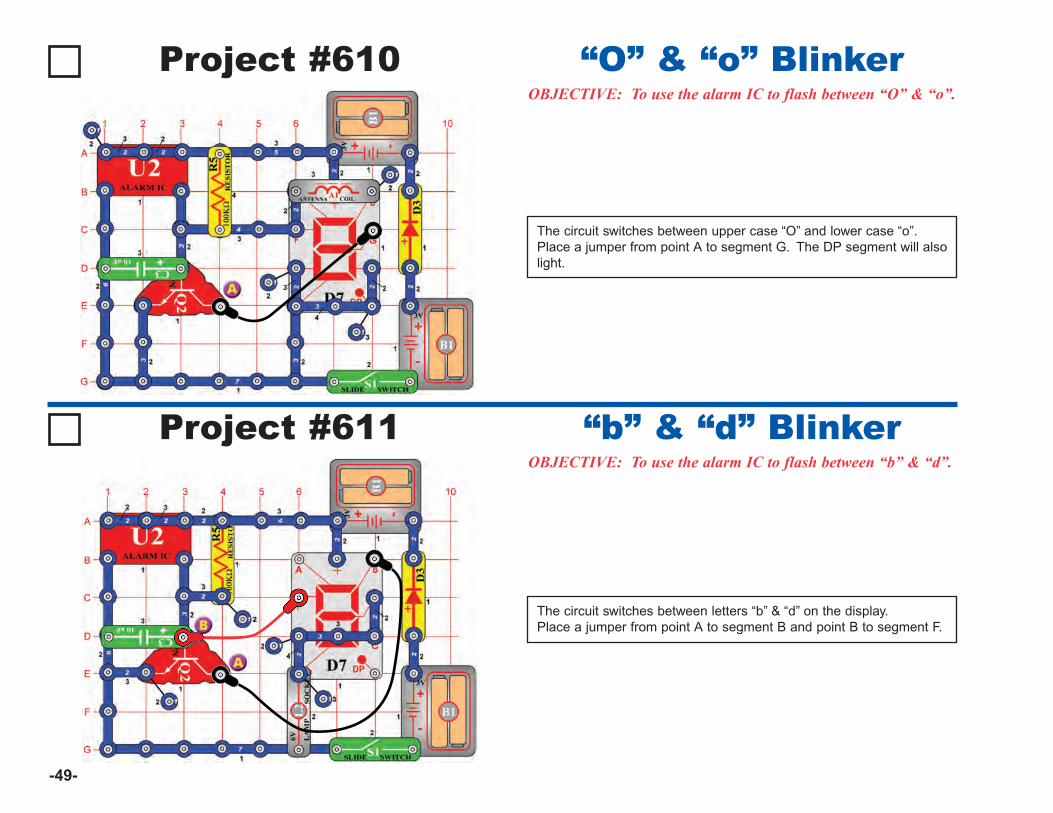
-49-
Project #610OBJECTIVE: To use the alarm IC to flash between “O” & “o”.
“O” & “o” Blinker
The circuit switches between upper case “O” and lower case “o”.Place a jumper from point A to segment G. The DP segment will alsolight.
Project #611OBJECTIVE: To use the alarm IC to flash between “b” & “d”.
“b” & “d” Blinker
The circuit switches between letters “b” & “d” on the display.Place a jumper from point A to segment B and point B to segment F.
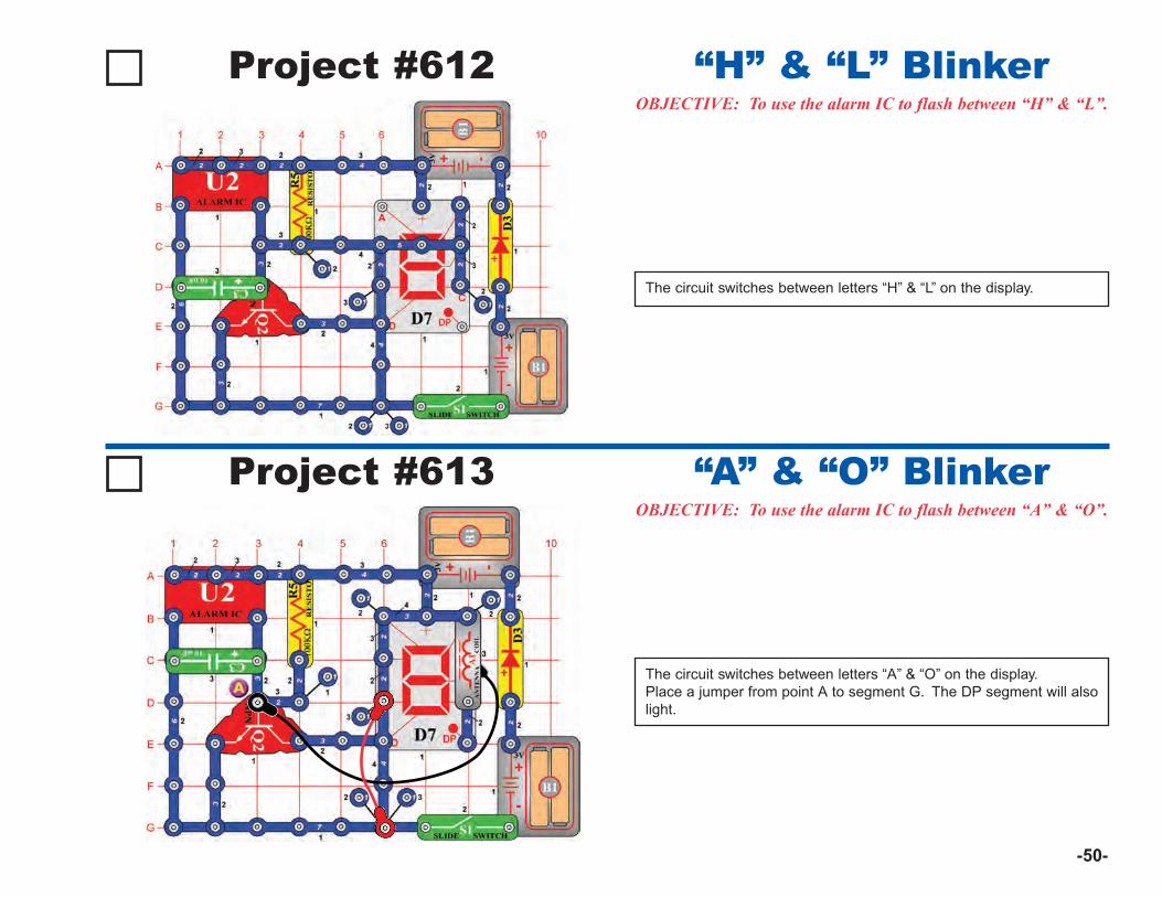
-50-
Project #612OBJECTIVE: To use the alarm IC to flash between “H” & “L”.
“H” & “L” Blinker
The circuit switches between letters “H” & “L” on the display.
Project #613OBJECTIVE: To use the alarm IC to flash between “A” & “O”.
“A” & “O” Blinker
The circuit switches between letters “A” & “O” on the display.Place a jumper from point A to segment G. The DP segment will alsolight.
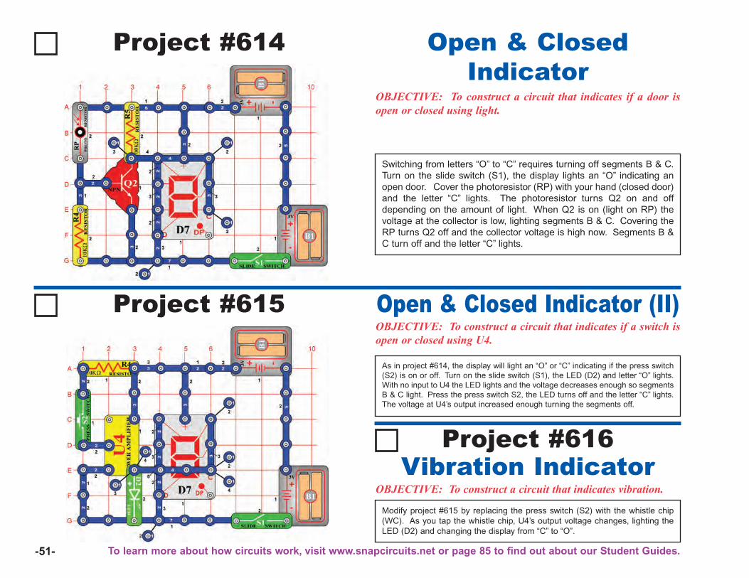
-51-
Project #614
OBJECTIVE: To construct a circuit that indicates if a door isopen or closed using light.
Open & ClosedIndicator
Switching from letters “O” to “C” requires turning off segments B & C.Turn on the slide switch (S1), the display lights an “O” indicating anopen door. Cover the photoresistor (RP) with your hand (closed door)and the letter “C” lights. The photoresistor turns Q2 on and offdepending on the amount of light. When Q2 is on (light on RP) thevoltage at the collector is low, lighting segments B & C. Covering theRP turns Q2 off and the collector voltage is high now. Segments B &C turn off and the letter “C” lights.
Project #615OBJECTIVE: To construct a circuit that indicates if a switch isopen or closed using U4.
Open & Closed Indicator (II)
As in project #614, the display will light an “O” or “C” indicating if the press switch(S2) is on or off. Turn on the slide switch (S1), the LED (D2) and letter “O” lights.With no input to U4 the LED lights and the voltage decreases enough so segmentsB & C light. Press the press switch S2, the LED turns off and the letter “C” lights.The voltage at U4’s output increased enough turning the segments off.
OBJECTIVE: To construct a circuit that indicates vibration.Vibration Indicator
Project #616
Modify project #615 by replacing the press switch (S2) with the whistle chip(WC). As you tap the whistle chip, U4’s output voltage changes, lighting theLED (D2) and changing the display from “C” to “O”.
To learn more about how circuits work, visit www.snapcircuits.net or page 85 to find out about our Student Guides.
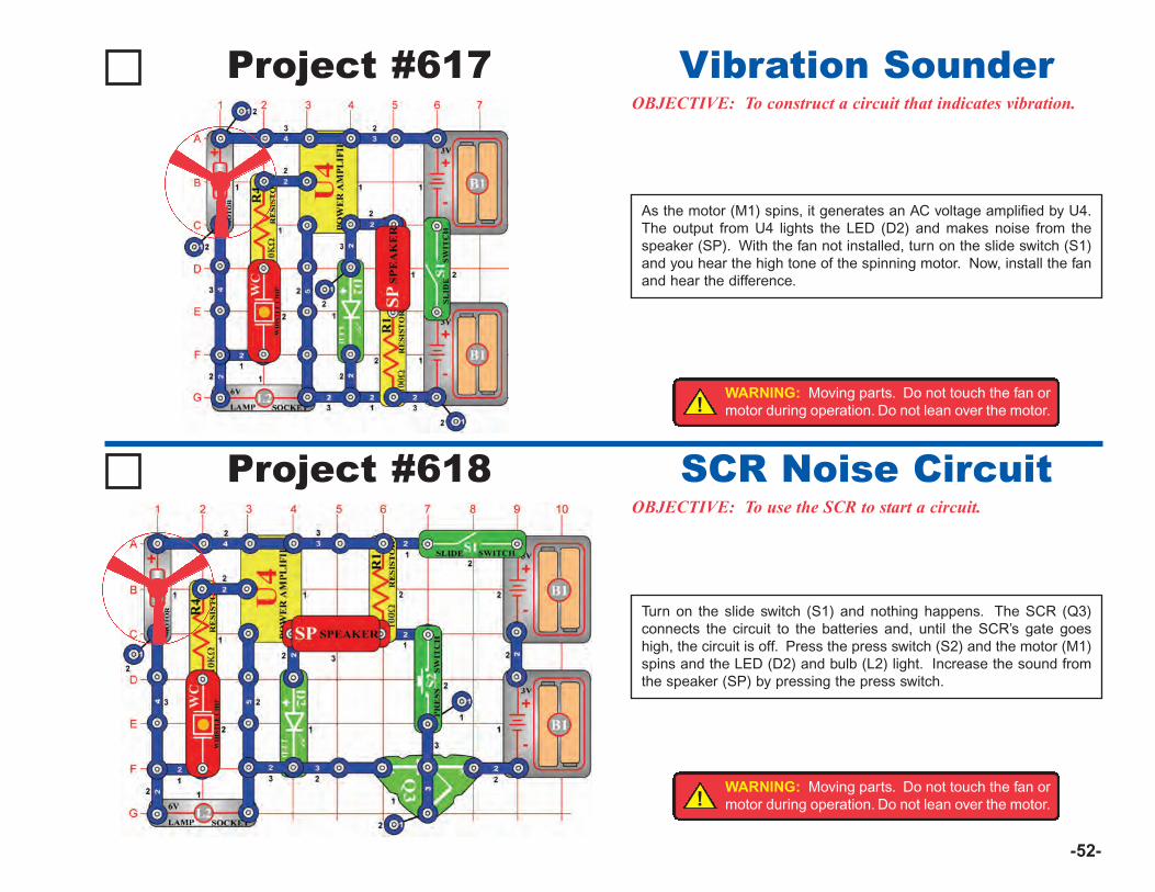
-52-
Project #617OBJECTIVE: To construct a circuit that indicates vibration.
Vibration Sounder
Project #618OBJECTIVE: To use the SCR to start a circuit.
SCR Noise Circuit
Turn on the slide switch (S1) and nothing happens. The SCR (Q3)connects the circuit to the batteries and, until the SCR’s gate goeshigh, the circuit is off. Press the press switch (S2) and the motor (M1)spins and the LED (D2) and bulb (L2) light. Increase the sound fromthe speaker (SP) by pressing the press switch.
As the motor (M1) spins, it generates an AC voltage amplified by U4.The output from U4 lights the LED (D2) and makes noise from thespeaker (SP). With the fan not installed, turn on the slide switch (S1)and you hear the high tone of the spinning motor. Now, install the fanand hear the difference.
!WARNING: Moving parts. Do not touch the fan ormotor during operation. Do not lean over the motor.
!WARNING: Moving parts. Do not touch the fan ormotor during operation. Do not lean over the motor.
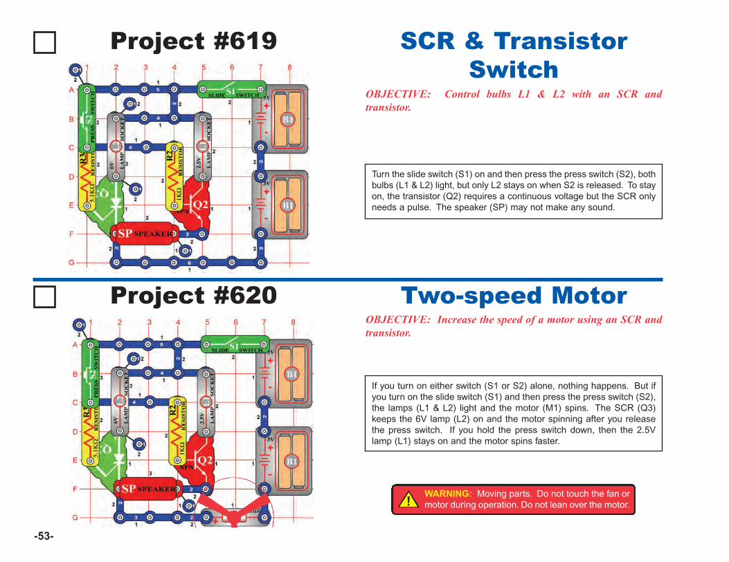
-53-
Project #619
OBJECTIVE: Control bulbs L1 & L2 with an SCR andtransistor.
SCR & TransistorSwitch
Turn the slide switch (S1) on and then press the press switch (S2), bothbulbs (L1 & L2) light, but only L2 stays on when S2 is released. To stayon, the transistor (Q2) requires a continuous voltage but the SCR onlyneeds a pulse. The speaker (SP) may not make any sound.
Project #620OBJECTIVE: Increase the speed of a motor using an SCR andtransistor.
Two-speed Motor
If you turn on either switch (S1 or S2) alone, nothing happens. But ifyou turn on the slide switch (S1) and then press the press switch (S2),the lamps (L1 & L2) light and the motor (M1) spins. The SCR (Q3)keeps the 6V lamp (L2) on and the motor spinning after you releasethe press switch. If you hold the press switch down, then the 2.5Vlamp (L1) stays on and the motor spins faster.
!WARNING: Moving parts. Do not touch the fan ormotor during operation. Do not lean over the motor.
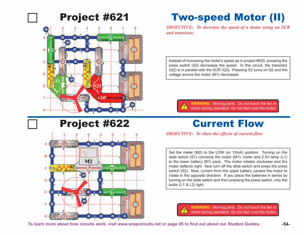
-54-
Project #621OBJECTIVE: To decrease the speed of a motor using an SCRand transistor.
Two-speed Motor (II)
Instead of increasing the motor’s speed as in project #620, pressing thepress switch (S2) decreases the speed. In this circuit, the transistor(Q2) is in parallel with the SCR (Q3). Pressing S2 turns on Q2 and thevoltage across the motor (M1) decreases.
Project #622OBJECTIVE: To show the effects of current flow.
Current Flow
Set the meter (M2) to the LOW (or 10mA) position. Turning on theslide switch (S1) connects the motor (M1), meter and 2.5V lamp (L1)to the lower battery (B1) pack. The motor rotates clockwise and themeter deflects right. Now turn off the slide switch and press the pressswitch (S2). Now, current from the upper battery causes the motor torotate in the opposite direction. If you place the batteries in series byturning on the slide switch and then pressing the press switch, only thebulbs (L1 & L2) light.
!WARNING: Moving parts. Do not touch the fan ormotor during operation. Do not lean over the motor.
!WARNING: Moving parts. Do not touch the fan ormotor during operation. Do not lean over the motor.
To learn more about how circuits work, visit www.snapcircuits.net or page 85 to find out about our Student Guides.
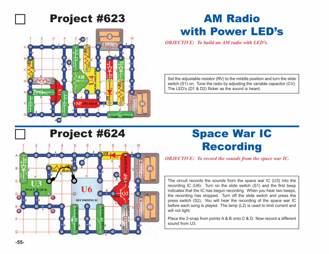
-55-
Project #623
OBJECTIVE: To build an AM radio with LED’s.
AM Radiowith Power LED’s
Set the adjustable resistor (RV) to the middle position and turn the slideswitch (S1) on. Tune the radio by adjusting the variable capacitor (CV).The LED’s (D1 & D2) flicker as the sound is heard.
Project #624
OBJECTIVE: To record the sounds from the space war IC.
Space War ICRecording
The circuit records the sounds from the space war IC (U3) into therecording IC (U6). Turn on the slide switch (S1) and the first beepindicates that the IC has begun recording. When you hear two beeps,the recording has stopped. Turn off the slide switch and press thepress switch (S2). You will hear the recording of the space war ICbefore each song is played. The lamp (L2) is used to limit current andwill not light.
Place the 2-snap from points A & B onto C & D. Now record a differentsound from U3.
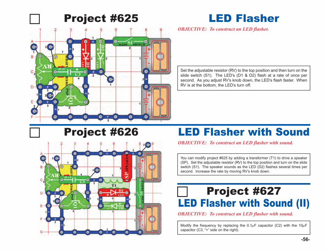
-56-
Project #625OBJECTIVE: To construct an LED flasher.
LED Flasher
Set the adjustable resistor (RV) to the top position and then turn on theslide switch (S1). The LED’s (D1 & D2) flash at a rate of once persecond. As you adjust RV’s knob down, the LED’s flash faster. WhenRV is at the bottom, the LED’s turn off.
Project #626OBJECTIVE: To construct an LED flasher with sound.
LED Flasher with Sound
You can modify project #625 by adding a transformer (T1) to drive a speaker(SP). Set the adjustable resistor (RV) to the top position and turn on the slideswitch (S1). The speaker sounds as the LED (D2) flashes several times persecond. Increase the rate by moving RV’s knob down.
OBJECTIVE: To construct an LED flasher with sound.
LED Flasher with Sound (II)Project #627
Modify the frequency by replacing the 0.1μF capacitor (C2) with the 10μFcapacitor (C3, “+” side on the right).
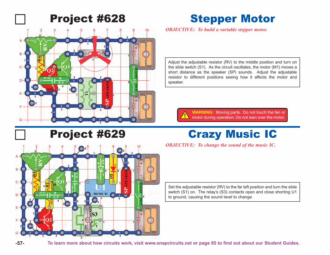
-57-
Project #628OBJECTIVE: To build a variable stepper motor.
Stepper Motor
Adjust the adjustable resistor (RV) to the middle position and turn onthe slide switch (S1). As the circuit oscillates, the motor (M1) moves ashort distance as the speaker (SP) sounds. Adjust the adjustableresistor to different positions seeing how it affects the motor andspeaker.
Project #629OBJECTIVE: To change the sound of the music IC.
Crazy Music IC
Set the adjustable resistor (RV) to the far left position and turn the slideswitch (S1) on. The relay’s (S3) contacts open and close shorting U1to ground, causing the sound level to change.
!WARNING: Moving parts. Do not touch the fan ormotor during operation. Do not lean over the motor.
To learn more about how circuits work, visit www.snapcircuits.net or page 85 to find out about our Student Guides.
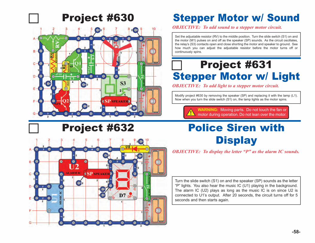
-58-
Project #630OBJECTIVE: To add sound to a stepper motor circuit.Stepper Motor w/ Sound
Modify project #630 by removing the speaker (SP) and replacing it with the lamp (L1).Now when you turn the slide switch (S1) on, the lamp lights as the motor spins.
Set the adjustable resistor (RV) to the middle position. Turn the slide switch (S1) on andthe motor (M1) pulses on and off as the speaker (SP) sounds. As the circuit oscillates,the relay’s (S3) contacts open and close shorting the motor and speaker to ground. Seehow much you can adjust the adjustable resistor before the motor turns off orcontinuously spins.
Project #631
OBJECTIVE: To add light to a stepper motor circuit.Stepper Motor w/ Light
Project #632
OBJECTIVE: To display the letter “P” as the alarm IC sounds.
Police Siren withDisplay
Turn the slide switch (S1) on and the speaker (SP) sounds as the letter“P” lights. You also hear the music IC (U1) playing in the background.The alarm IC (U2) plays as long as the music IC is on since U2 isconnected to U1’s output. After 20 seconds, the circuit turns off for 5seconds and then starts again.
!WARNING: Moving parts. Do not touch the fan ormotor during operation. Do not lean over the motor.
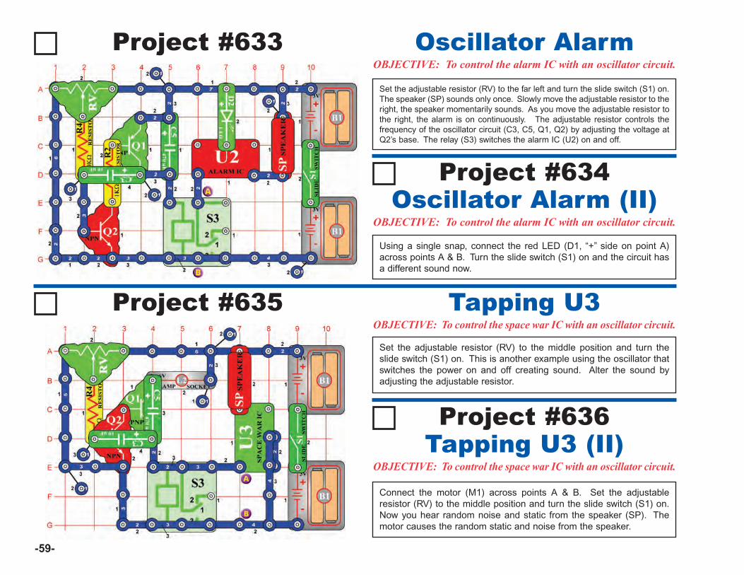
-59-
Project #633OBJECTIVE: To control the alarm IC with an oscillator circuit.
Oscillator AlarmSet the adjustable resistor (RV) to the far left and turn the slide switch (S1) on.The speaker (SP) sounds only once. Slowly move the adjustable resistor to theright, the speaker momentarily sounds. As you move the adjustable resistor tothe right, the alarm is on continuously. The adjustable resistor controls thefrequency of the oscillator circuit (C3, C5, Q1, Q2) by adjusting the voltage atQ2’s base. The relay (S3) switches the alarm IC (U2) on and off.
Project #635OBJECTIVE: To control the space war IC with an oscillator circuit.
Tapping U3Set the adjustable resistor (RV) to the middle position and turn theslide switch (S1) on. This is another example using the oscillator thatswitches the power on and off creating sound. Alter the sound byadjusting the adjustable resistor.
OBJECTIVE: To control the alarm IC with an oscillator circuit.Oscillator Alarm (II)
Project #634
Using a single snap, connect the red LED (D1, “+” side on point A)across points A & B. Turn the slide switch (S1) on and the circuit hasa different sound now.
OBJECTIVE: To control the space war IC with an oscillator circuit.Tapping U3 (II)Project #636
Connect the motor (M1) across points A & B. Set the adjustableresistor (RV) to the middle position and turn the slide switch (S1) on.Now you hear random noise and static from the speaker (SP). Themotor causes the random static and noise from the speaker.
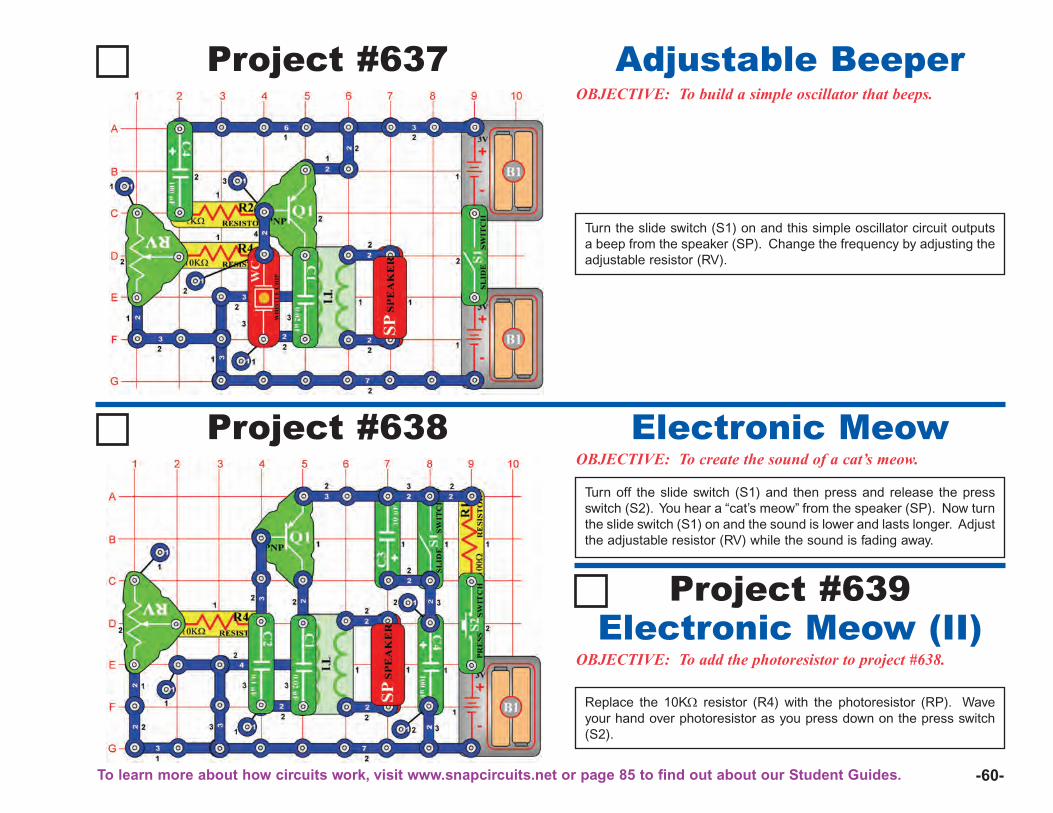
-60-
Project #637OBJECTIVE: To build a simple oscillator that beeps.
Adjustable Beeper
Turn the slide switch (S1) on and this simple oscillator circuit outputsa beep from the speaker (SP). Change the frequency by adjusting theadjustable resistor (RV).
Project #638OBJECTIVE: To create the sound of a cat’s meow.
Electronic MeowTurn off the slide switch (S1) and then press and release the pressswitch (S2). You hear a “cat’s meow” from the speaker (SP). Now turnthe slide switch (S1) on and the sound is lower and lasts longer. Adjustthe adjustable resistor (RV) while the sound is fading away.
OBJECTIVE: To add the photoresistor to project #638.Electronic Meow (II)
Project #639
Replace the 10KΩ resistor (R4) with the photoresistor (RP). Waveyour hand over photoresistor as you press down on the press switch(S2).
To learn more about how circuits work, visit www.snapcircuits.net or page 85 to find out about our Student Guides.
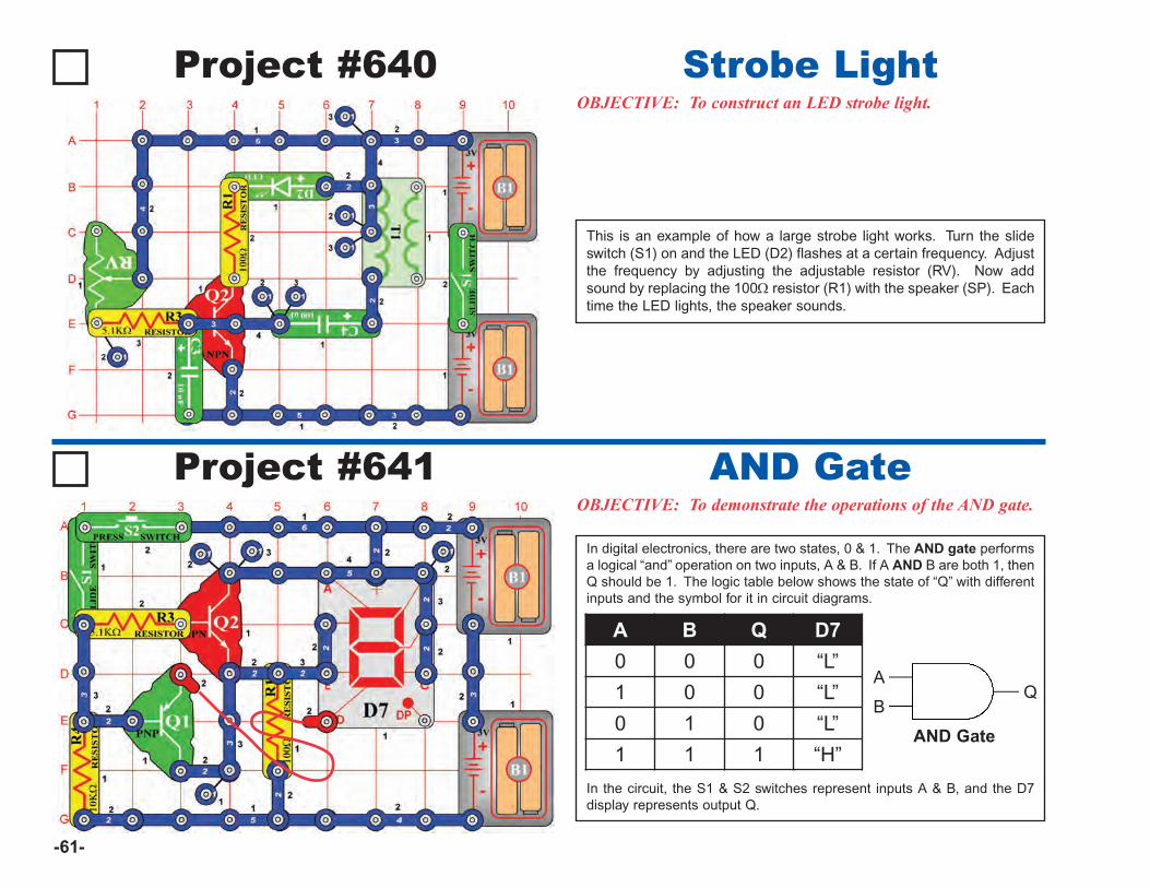
-61-
Project #640OBJECTIVE: To construct an LED strobe light.
Strobe Light
This is an example of how a large strobe light works. Turn the slideswitch (S1) on and the LED (D2) flashes at a certain frequency. Adjustthe frequency by adjusting the adjustable resistor (RV). Now addsound by replacing the 100Ω resistor (R1) with the speaker (SP). Eachtime the LED lights, the speaker sounds.
Project #641OBJECTIVE: To demonstrate the operations of the AND gate.
AND Gate
In digital electronics, there are two states, 0 & 1. The AND gate performsa logical “and” operation on two inputs, A & B. If A AND B are both 1, thenQ should be 1. The logic table below shows the state of “Q” with differentinputs and the symbol for it in circuit diagrams.
In the circuit, the S1 & S2 switches represent inputs A & B, and the D7display represents output Q.
A B Q D7
0 0 0 “L”
1 0 0 “L”
0 1 0 “L”
1 1 1 “H”
A
BQ
AND Gate
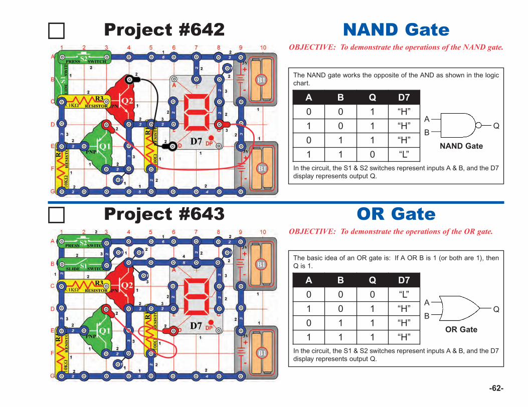
-62-
Project #642OBJECTIVE: To demonstrate the operations of the NAND gate.
NAND Gate
Project #643OBJECTIVE: To demonstrate the operations of the OR gate.
OR Gate
The NAND gate works the opposite of the AND as shown in the logicchart.
In the circuit, the S1 & S2 switches represent inputs A & B, and the D7display represents output Q.
The basic idea of an OR gate is: If A OR B is 1 (or both are 1), thenQ is 1.
In the circuit, the S1 & S2 switches represent inputs A & B, and the D7display represents output Q.
A B Q D7
0 0 1 “H”
1 0 1 “H”
0 1 1 “H”
1 1 0 “L”
A B Q D7
0 0 0 “L”
1 0 1 “H”
0 1 1 “H”
1 1 1 “H”
A
BQ
NAND Gate
A
BQ
OR Gate

-63-
Project #644OBJECTIVE: To demonstrate the operations of the NOR gate.
NOR Gate
Project #645OBJECTIVE: To demonstrate the operations of the “exclusiveor” XOR gate.
XOR Gate
The NOR gate works the opposite of the OR. In the circuit, the S1 &S2 switches represent inputs A & B, and the D7 display representsoutput Q.
In an XOR gate the output “Q” is only high when inputs “A” or “B” is sethigh (1).Using the chart, set the switches (S1 & S2) to the different states. Thedisplay (D7) lights the letter “H” only when either switch is turned on.
A B Q D7
0 0 1 “H”
1 0 0 “L”
0 1 0 “L”
1 1 0 “L”
A B Q D7
0 0 0 –
1 0 1 “H”
0 1 1 “H”
1 1 0 –
A
BQ
XOR Gate
A
BQ
NOR Gate
To learn more about how circuits work, visit www.snapcircuits.net or page 85 to find out about our Student Guides.
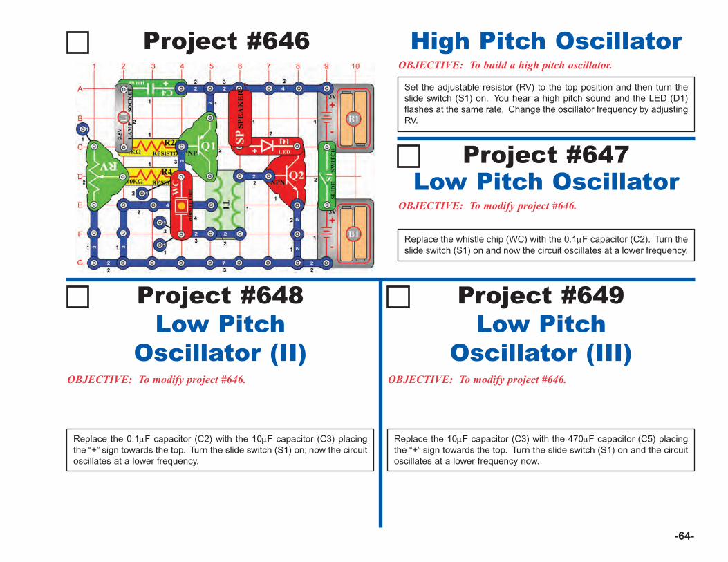
-64-
Project #646OBJECTIVE: To build a high pitch oscillator.
High Pitch Oscillator
Project #648Low Pitch
Oscillator (II)OBJECTIVE: To modify project #646. OBJECTIVE: To modify project #646.
Project #649Low Pitch
Oscillator (III)
Replace the 0.1μF capacitor (C2) with the 10μF capacitor (C3) placingthe “+” sign towards the top. Turn the slide switch (S1) on; now the circuitoscillates at a lower frequency.
Replace the 10μF capacitor (C3) with the 470μF capacitor (C5) placingthe “+” sign towards the top. Turn the slide switch (S1) on and the circuitoscillates at a lower frequency now.
Set the adjustable resistor (RV) to the top position and then turn theslide switch (S1) on. You hear a high pitch sound and the LED (D1)flashes at the same rate. Change the oscillator frequency by adjustingRV.
OBJECTIVE: To modify project #646.
Low Pitch OscillatorProject #647
Replace the whistle chip (WC) with the 0.1μF capacitor (C2). Turn theslide switch (S1) on and now the circuit oscillates at a lower frequency.

-65-
Project #650OBJECTIVE: To use the alarm IC with the 7-segment display.
Segment Jumper
Turn the slide switch (S1) on; segments A, B, and F light and thensegments C, D, and E. The two groups of segments are connected todifferent voltages. As the voltage changes from high to low, thesegments toggle back and forth.
Project #651OBJECTIVE: To use the alarm IC with the 7-segment display.
DP & Zero Flasher
As in project #650, we use the alarm IC (U2) to flash segments andLED’s. Turn the slide switch (S1) on and the number “0” and the greenLED (D2) flash as the speaker (SP) sounds. When they turn off, theDP segment lights.
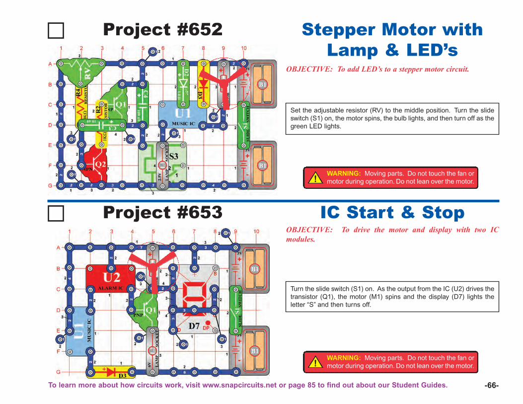
Project #652
OBJECTIVE: To add LED’s to a stepper motor circuit.
Stepper Motor withLamp & LED’s
Set the adjustable resistor (RV) to the middle position. Turn the slideswitch (S1) on, the motor spins, the bulb lights, and then turn off as thegreen LED lights.
-66-
Project #653OBJECTIVE: To drive the motor and display with two ICmodules.
IC Start & Stop
Turn the slide switch (S1) on. As the output from the IC (U2) drives thetransistor (Q1), the motor (M1) spins and the display (D7) lights theletter “S” and then turns off.
!WARNING: Moving parts. Do not touch the fan ormotor during operation. Do not lean over the motor.
To learn more about how circuits work, visit www.snapcircuits.net or page 85 to find out about our Student Guides.
!WARNING: Moving parts. Do not touch the fan ormotor during operation. Do not lean over the motor.
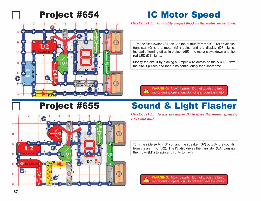
-67-
Project #654OBJECTIVE: To modify project #653 so the motor slows down.
IC Motor Speed
Turn the slide switch (S1) on. As the output from the IC (U2) drives thetransistor (Q1), the motor (M1) spins and the display (D7) lights.Instead of turning off as in project #653, the motor slows down and thered LED (D1) lights.
Modify the circuit by placing a jumper wire across points A & B. Nowthe circuit pulses and then runs continuously for a short time.
Project #655OBJECTIVE: To use the alarm IC to drive the motor, speaker,LED and bulb.
Sound & Light Flasher
Turn the slide switch (S1) on and the speaker (SP) outputs the soundsfrom the alarm IC (U2). The IC also drives the transistor (Q1) causingthe motor (M1) to spin and lights to flash.
!WARNING: Moving parts. Do not touch the fan ormotor during operation. Do not lean over the motor.
!WARNING: Moving parts. Do not touch the fan ormotor during operation. Do not lean over the motor.
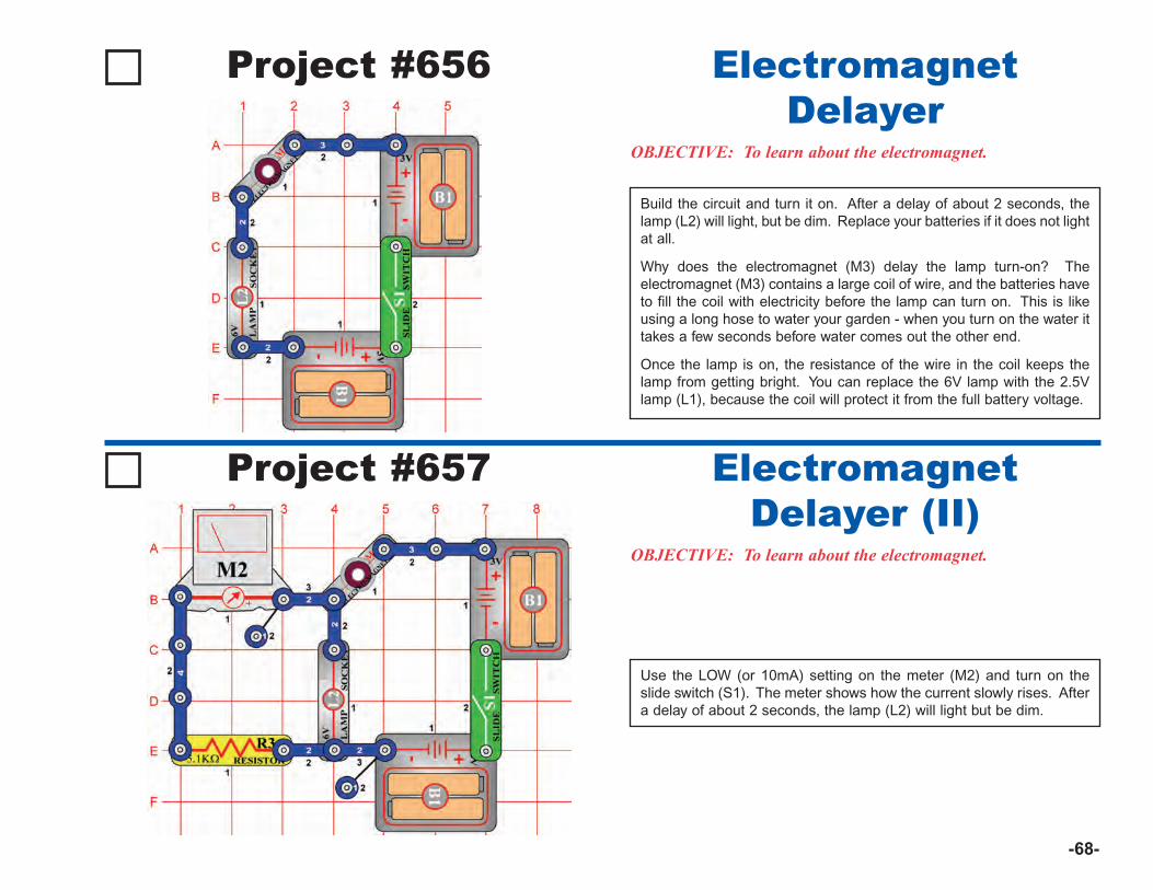
-68-
Project #656
OBJECTIVE: To learn about the electromagnet.
ElectromagnetDelayer
Build the circuit and turn it on. After a delay of about 2 seconds, thelamp (L2) will light, but be dim. Replace your batteries if it does not lightat all.
Why does the electromagnet (M3) delay the lamp turn-on? Theelectromagnet (M3) contains a large coil of wire, and the batteries haveto fill the coil with electricity before the lamp can turn on. This is likeusing a long hose to water your garden - when you turn on the water ittakes a few seconds before water comes out the other end.
Once the lamp is on, the resistance of the wire in the coil keeps thelamp from getting bright. You can replace the 6V lamp with the 2.5Vlamp (L1), because the coil will protect it from the full battery voltage.
Project #657
OBJECTIVE: To learn about the electromagnet.
ElectromagnetDelayer (II)
Use the LOW (or 10mA) setting on the meter (M2) and turn on theslide switch (S1). The meter shows how the current slowly rises. Aftera delay of about 2 seconds, the lamp (L2) will light but be dim.
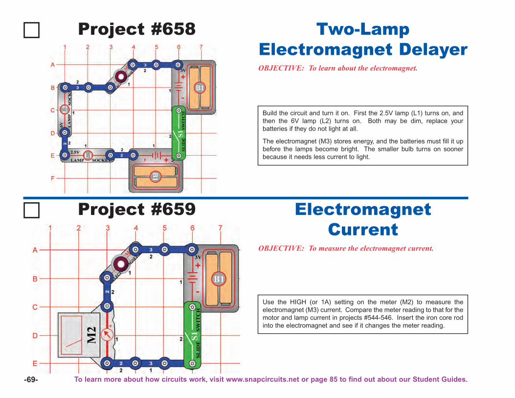
-69-
Project #658
OBJECTIVE: To learn about the electromagnet.
Two-LampElectromagnet Delayer
Build the circuit and turn it on. First the 2.5V lamp (L1) turns on, andthen the 6V lamp (L2) turns on. Both may be dim, replace yourbatteries if they do not light at all.
The electromagnet (M3) stores energy, and the batteries must fill it upbefore the lamps become bright. The smaller bulb turns on soonerbecause it needs less current to light.
Project #659
OBJECTIVE: To measure the electromagnet current.
ElectromagnetCurrent
Use the HIGH (or 1A) setting on the meter (M2) to measure theelectromagnet (M3) current. Compare the meter reading to that for themotor and lamp current in projects #544-546. Insert the iron core rodinto the electromagnet and see if it changes the meter reading.
To learn more about how circuits work, visit www.snapcircuits.net or page 85 to find out about our Student Guides.

-70-
Project #660OBJECTIVE: To learn how electricity and magnetism arerelated.
Electromagnetism
Project #661 Electromagnetism & Compass
You need a compass for this project (not included). Use the circuitfrom project #660, with the iron core rod in the electromagnet (M3).You may want to use the slide switch (S1) in place of the press switch(S2), but only turn it on as needed or you will quickly drain yourbatteries.Turn on the slide switch and move the compass around near the edgesof the electromagnet, it will point toward ends of the iron core rod. Byslowly moving the compass around the electromagnet, you can seethe flow of its magnetic field.The earth has a similar magnetic field, due to its iron core. A compasspoints north because it is attracted to this magnetic field. Theelectromagnet creates its own magnetic field, and attracts thecompass in a similar way.
Put the iron core rod into the electromagnet (M3). Press the press switch (S2)and place the electromagnet (M3) near some iron objects like a refrigerator ora hammer, it will be attracted to them. You can use it to pick up iron objects,such as nails.
Electricity and magnetism are closely related, and an electric current flowing ina coil of wire has a magnetic field just like a normal magnet. Placing an ironrod through the coil magnifies this magnetic field. Notice that when theelectromagnet is attracted to an iron object, its attraction is strongest at theends of the iron core rod. If you remove the iron core rod from theelectromagnet then its magnetic properties are greatly reduced – try this:
If you place the electromagnet upside down under a large object like a table,you can suspend it there. Be careful though, since it will fall when you releasethe press switch.
You can use this circuit to see which things are made of iron. Other metals likecopper or aluminum will not be attracted to the electromagnet.
Magnetic Field
Compass
OBJECTIVE: To learn how electricity and magnetism arerelated.
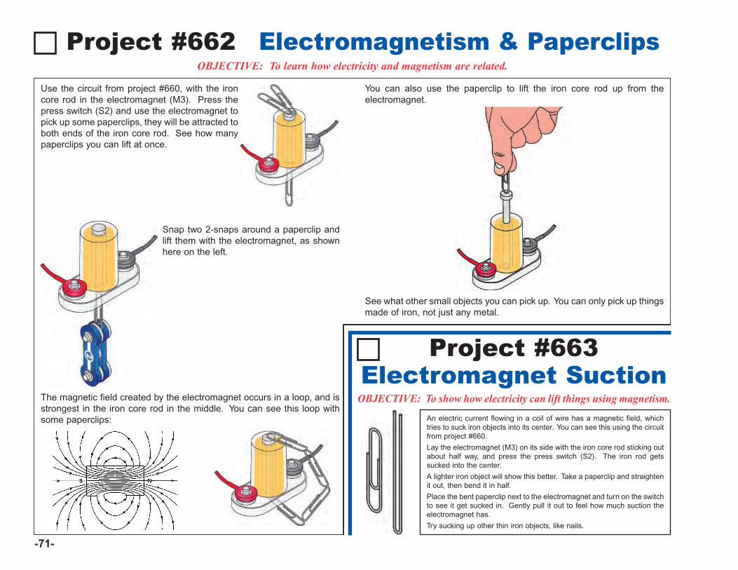
Use the circuit from project #660, with the ironcore rod in the electromagnet (M3). Press thepress switch (S2) and use the electromagnet topick up some paperclips, they will be attracted toboth ends of the iron core rod. See how manypaperclips you can lift at once.
Snap two 2-snaps around a paperclip andlift them with the electromagnet, as shownhere on the left.
The magnetic field created by the electromagnet occurs in a loop, and isstrongest in the iron core rod in the middle. You can see this loop withsome paperclips:
You can also use the paperclip to lift the iron core rod up from theelectromagnet.
See what other small objects you can pick up. You can only pick up thingsmade of iron, not just any metal.
-71-
Project #662OBJECTIVE: To learn how electricity and magnetism are related.
Electromagnetism & Paperclips
Project #663
OBJECTIVE: To show how electricity can lift things using magnetism.
Electromagnet SuctionAn electric current flowing in a coil of wire has a magnetic field, whichtries to suck iron objects into its center. You can see this using the circuitfrom project #660.
Lay the electromagnet (M3) on its side with the iron core rod sticking outabout half way, and press the press switch (S2). The iron rod getssucked into the center.
A lighter iron object will show this better. Take a paperclip and straightenit out, then bend it in half.
Place the bent paperclip next to the electromagnet and turn on the switchto see it get sucked in. Gently pull it out to feel how much suction theelectromagnet has.
Try sucking up other thin iron objects, like nails.
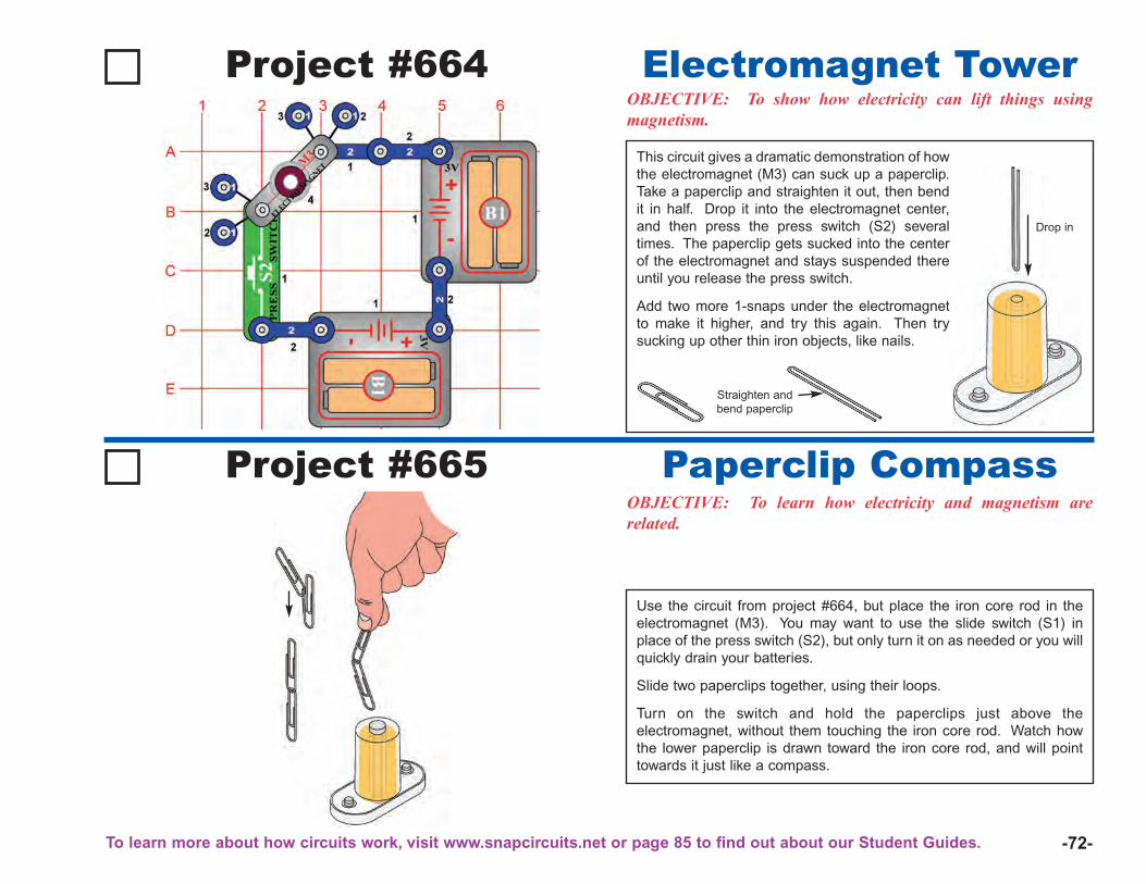
-72-
Project #664OBJECTIVE: To show how electricity can lift things usingmagnetism.
Electromagnet Tower
Project #665OBJECTIVE: To learn how electricity and magnetism arerelated.
Paperclip Compass
Use the circuit from project #664, but place the iron core rod in theelectromagnet (M3). You may want to use the slide switch (S1) inplace of the press switch (S2), but only turn it on as needed or you willquickly drain your batteries.
Slide two paperclips together, using their loops.
Turn on the switch and hold the paperclips just above theelectromagnet, without them touching the iron core rod. Watch howthe lower paperclip is drawn toward the iron core rod, and will pointtowards it just like a compass.
This circuit gives a dramatic demonstration of howthe electromagnet (M3) can suck up a paperclip.Take a paperclip and straighten it out, then bendit in half. Drop it into the electromagnet center,and then press the press switch (S2) severaltimes. The paperclip gets sucked into the centerof the electromagnet and stays suspended thereuntil you release the press switch.
Add two more 1-snaps under the electromagnetto make it higher, and try this again. Then trysucking up other thin iron objects, like nails.
Straighten andbend paperclip
Drop in
To learn more about how circuits work, visit www.snapcircuits.net or page 85 to find out about our Student Guides.
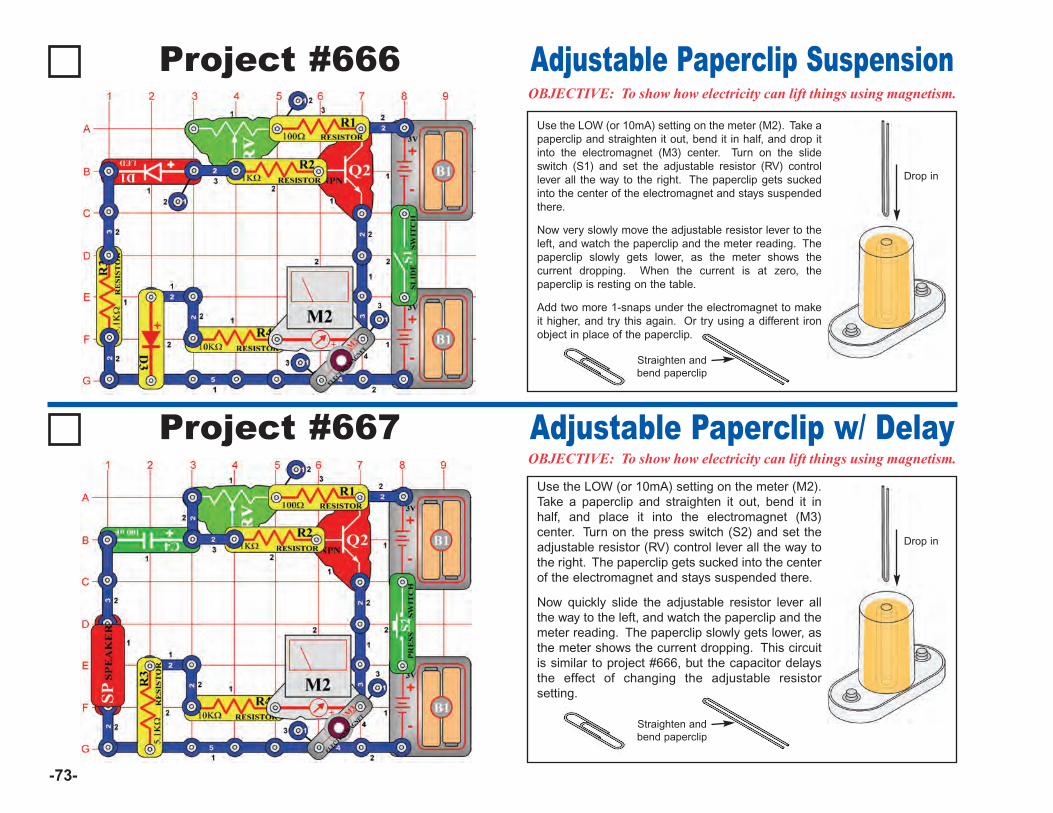
Straighten andbend paperclip
-73-
Project #666 Adjustable Paperclip Suspension
Project #667OBJECTIVE: To show how electricity can lift things using magnetism.
Adjustable Paperclip w/ DelayUse the LOW (or 10mA) setting on the meter (M2).Take a paperclip and straighten it out, bend it inhalf, and place it into the electromagnet (M3)center. Turn on the press switch (S2) and set theadjustable resistor (RV) control lever all the way tothe right. The paperclip gets sucked into the centerof the electromagnet and stays suspended there.
Now quickly slide the adjustable resistor lever allthe way to the left, and watch the paperclip and themeter reading. The paperclip slowly gets lower, asthe meter shows the current dropping. This circuitis similar to project #666, but the capacitor delaysthe effect of changing the adjustable resistorsetting.
Use the LOW (or 10mA) setting on the meter (M2). Take apaperclip and straighten it out, bend it in half, and drop itinto the electromagnet (M3) center. Turn on the slideswitch (S1) and set the adjustable resistor (RV) controllever all the way to the right. The paperclip gets suckedinto the center of the electromagnet and stays suspendedthere.
Now very slowly move the adjustable resistor lever to theleft, and watch the paperclip and the meter reading. Thepaperclip slowly gets lower, as the meter shows thecurrent dropping. When the current is at zero, thepaperclip is resting on the table.
Add two more 1-snaps under the electromagnet to makeit higher, and try this again. Or try using a different ironobject in place of the paperclip.
Drop in
Straighten andbend paperclip
OBJECTIVE: To show how electricity can lift things using magnetism.
Drop in
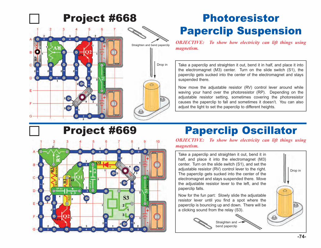
-74-
Project #668
OBJECTIVE: To show how electricity can lift things usingmagnetism.
PhotoresistorPaperclip Suspension
Project #669OBJECTIVE: To show how electricity can lift things usingmagnetism.
Paperclip Oscillator
Take a paperclip and straighten it out, bend it inhalf, and place it into the electromagnet (M3)center. Turn on the slide switch (S1), and set theadjustable resistor (RV) control lever to the right.The paperclip gets sucked into the center of theelectromagnet and stays suspended there. Movethe adjustable resistor lever to the left, and thepaperclip falls.
Now for the fun part: Slowly slide the adjustableresistor lever until you find a spot where thepaperclip is bouncing up and down. There will bea clicking sound from the relay (S3).
Take a paperclip and straighten it out, bend it in half, and place it intothe electromagnet (M3) center. Turn on the slide switch (S1), thepaperclip gets sucked into the center of the electromagnet and stayssuspended there.
Now move the adjustable resistor (RV) control lever around whilewaving your hand over the photoresistor (RP). Depending on theadjustable resistor setting, sometimes covering the photoresistorcauses the paperclip to fall and sometimes it doesn’t. You can alsoadjust the light to set the paperclip to different heights.
Drop in
Straighten andbend paperclip
Drop in
Straighten and bend paperclip
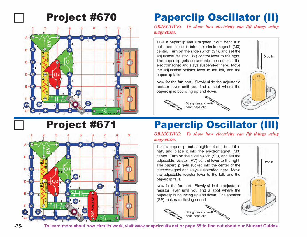
-75-
Project #670OBJECTIVE: To show how electricity can lift things usingmagnetism.
Paperclip Oscillator (II)
Project #671OBJECTIVE: To show how electricity can lift things usingmagnetism.
Paperclip Oscillator (III)
Take a paperclip and straighten it out, bend it inhalf, and place it into the electromagnet (M3)center. Turn on the slide switch (S1), and set theadjustable resistor (RV) control lever to the right.The paperclip gets sucked into the center of theelectromagnet and stays suspended there. Movethe adjustable resistor lever to the left, and thepaperclip falls.
Now for the fun part: Slowly slide the adjustableresistor lever until you find a spot where thepaperclip is bouncing up and down. The speaker(SP) makes a clicking sound.
Take a paperclip and straighten it out, bend it inhalf, and place it into the electromagnet (M3)center. Turn on the slide switch (S1), and set theadjustable resistor (RV) control lever to the right.The paperclip gets sucked into the center of theelectromagnet and stays suspended there. Movethe adjustable resistor lever to the left, and thepaperclip falls.
Now for the fun part: Slowly slide the adjustableresistor lever until you find a spot where thepaperclip is bouncing up and down.
Drop in
Straighten andbend paperclip
Drop in
Straighten andbend paperclip
To learn more about how circuits work, visit www.snapcircuits.net or page 85 to find out about our Student Guides.
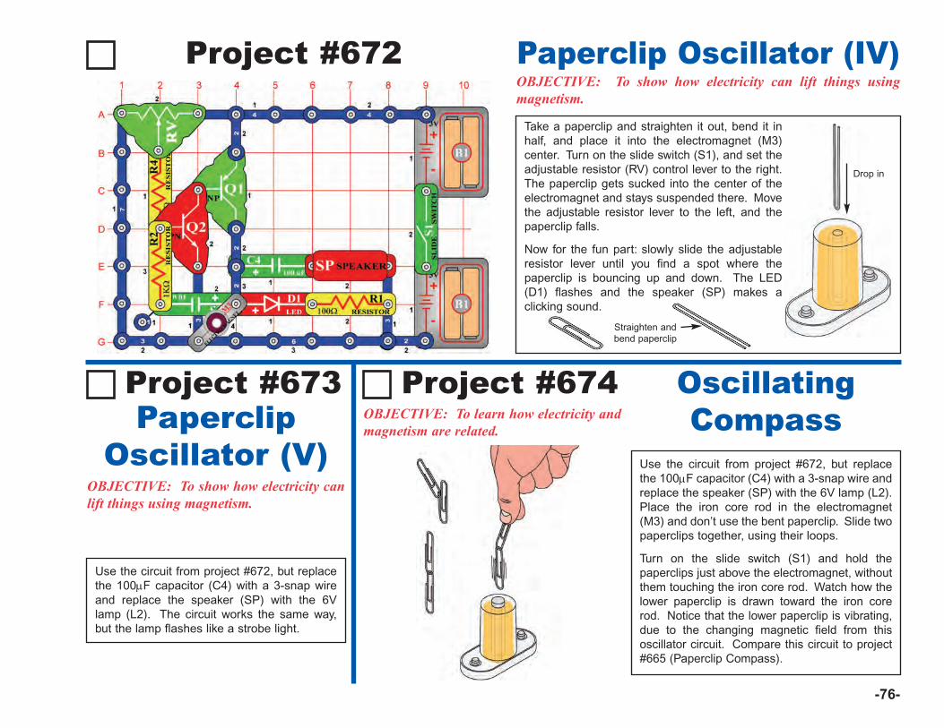
Straighten andbend paperclip
-76-
Project #672OBJECTIVE: To show how electricity can lift things usingmagnetism.
Paperclip Oscillator (IV)
OBJECTIVE: To show how electricity canlift things using magnetism.
Take a paperclip and straighten it out, bend it inhalf, and place it into the electromagnet (M3)center. Turn on the slide switch (S1), and set theadjustable resistor (RV) control lever to the right.The paperclip gets sucked into the center of theelectromagnet and stays suspended there. Movethe adjustable resistor lever to the left, and thepaperclip falls.
Now for the fun part: slowly slide the adjustableresistor lever until you find a spot where thepaperclip is bouncing up and down. The LED(D1) flashes and the speaker (SP) makes aclicking sound.
Drop in
Project #673OBJECTIVE: To learn how electricity andmagnetism are related.
OscillatingCompass
Use the circuit from project #672, but replacethe 100μF capacitor (C4) with a 3-snap wireand replace the speaker (SP) with the 6Vlamp (L2). The circuit works the same way,but the lamp flashes like a strobe light.
Project #674
Use the circuit from project #672, but replacethe 100μF capacitor (C4) with a 3-snap wire andreplace the speaker (SP) with the 6V lamp (L2).Place the iron core rod in the electromagnet(M3) and don’t use the bent paperclip. Slide twopaperclips together, using their loops.
Turn on the slide switch (S1) and hold thepaperclips just above the electromagnet, withoutthem touching the iron core rod. Watch how thelower paperclip is drawn toward the iron corerod. Notice that the lower paperclip is vibrating,due to the changing magnetic field from thisoscillator circuit. Compare this circuit to project#665 (Paperclip Compass).
PaperclipOscillator (V)
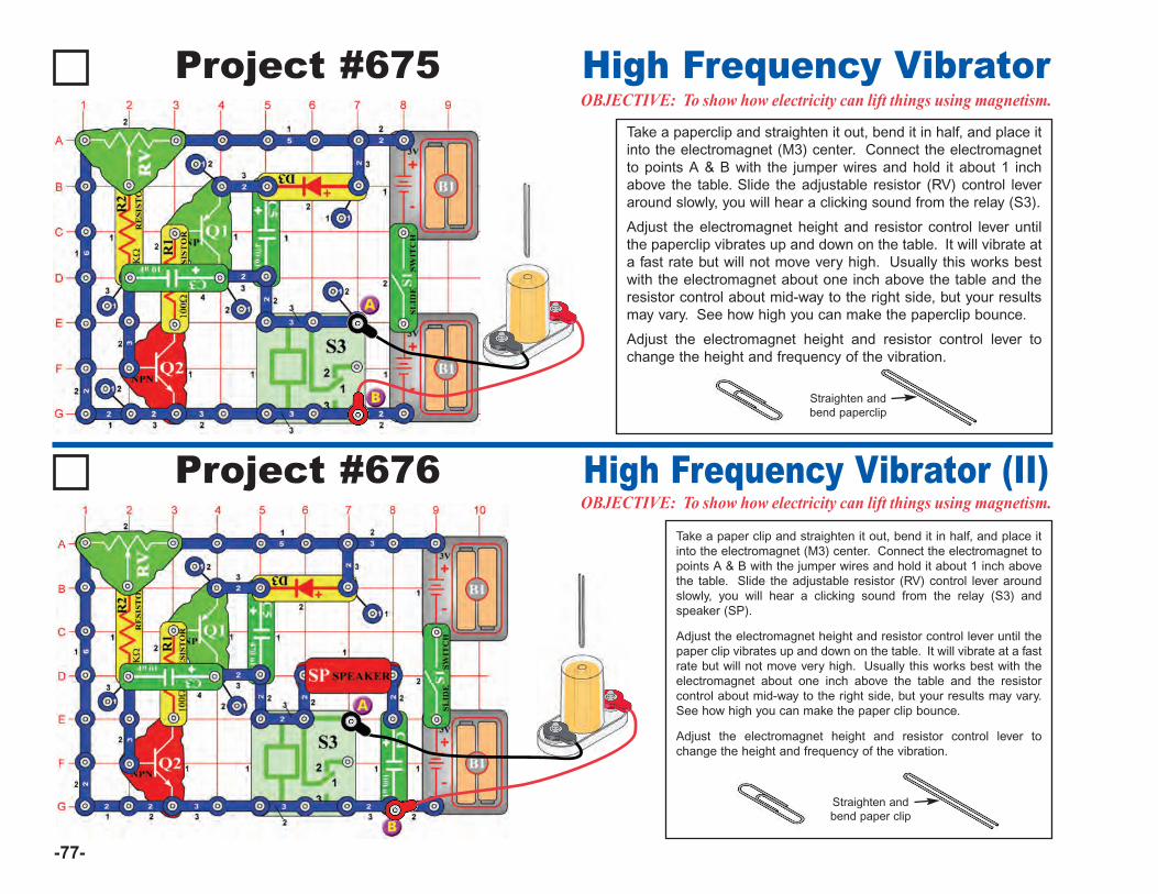
-77-
Project #675OBJECTIVE: To show how electricity can lift things using magnetism.High Frequency Vibrator
Project #676OBJECTIVE: To show how electricity can lift things using magnetism.High Frequency Vibrator (II)
Take a paperclip and straighten it out, bend it in half, and place itinto the electromagnet (M3) center. Connect the electromagnetto points A & B with the jumper wires and hold it about 1 inchabove the table. Slide the adjustable resistor (RV) control leveraround slowly, you will hear a clicking sound from the relay (S3).
Adjust the electromagnet height and resistor control lever untilthe paperclip vibrates up and down on the table. It will vibrate ata fast rate but will not move very high. Usually this works bestwith the electromagnet about one inch above the table and theresistor control about mid-way to the right side, but your resultsmay vary. See how high you can make the paperclip bounce.
Adjust the electromagnet height and resistor control lever tochange the height and frequency of the vibration.
Straighten andbend paperclip
Take a paper clip and straighten it out, bend it in half, and place itinto the electromagnet (M3) center. Connect the electromagnet topoints A & B with the jumper wires and hold it about 1 inch abovethe table. Slide the adjustable resistor (RV) control lever aroundslowly, you will hear a clicking sound from the relay (S3) andspeaker (SP).
Adjust the electromagnet height and resistor control lever until thepaper clip vibrates up and down on the table. It will vibrate at a fastrate but will not move very high. Usually this works best with theelectromagnet about one inch above the table and the resistorcontrol about mid-way to the right side, but your results may vary.See how high you can make the paper clip bounce.
Adjust the electromagnet height and resistor control lever tochange the height and frequency of the vibration.
Straighten andbend paper clip
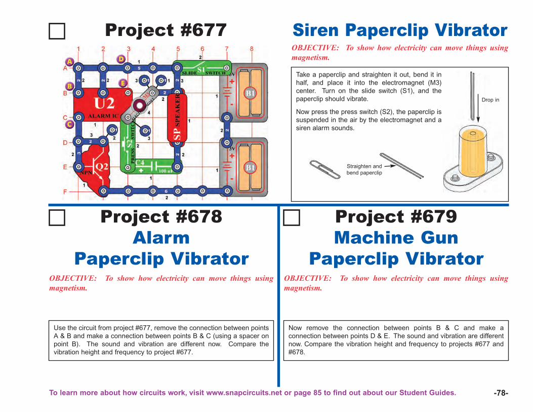
-78-
Project #677OBJECTIVE: To show how electricity can move things usingmagnetism.
Siren Paperclip Vibrator
Take a paperclip and straighten it out, bend it inhalf, and place it into the electromagnet (M3)center. Turn on the slide switch (S1), and thepaperclip should vibrate.
Now press the press switch (S2), the paperclip issuspended in the air by the electromagnet and asiren alarm sounds.
Drop in
Straighten andbend paperclip
Project #678Alarm
Paperclip VibratorOBJECTIVE: To show how electricity can move things usingmagnetism.
OBJECTIVE: To show how electricity can move things usingmagnetism.
Project #679Machine Gun
Paperclip Vibrator
Use the circuit from project #677, remove the connection between pointsA & B and make a connection between points B & C (using a spacer onpoint B). The sound and vibration are different now. Compare thevibration height and frequency to project #677.
Now remove the connection between points B & C and make aconnection between points D & E. The sound and vibration are differentnow. Compare the vibration height and frequency to projects #677 and#678.
To learn more about how circuits work, visit www.snapcircuits.net or page 85 to find out about our Student Guides.
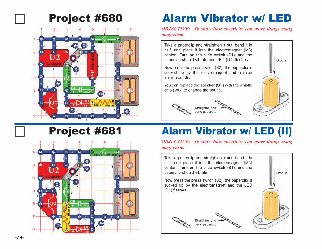
-79-
Project #680OBJECTIVE: To show how electricity can move things usingmagnetism.
Alarm Vibrator w/ LED
Take a paperclip and straighten it out, bend it inhalf, and place it into the electromagnet (M3)center. Turn on the slide switch (S1), and thepaperclip should vibrate and LED (D1) flashes.
Now press the press switch (S2), the paperclip issucked up by the electromagnet and a sirenalarm sounds.
You can replace the speaker (SP) with the whistlechip (WC) to change the sound.
Drop in
Straighten andbend paperclip
Project #681OBJECTIVE: To show how electricity can move things usingmagnetism.
Alarm Vibrator w/ LED (II)
Take a paperclip and straighten it out, bend it inhalf, and place it into the electromagnet (M3)center. Turn on the slide switch (S1), and thepaperclip should vibrate.
Now press the press switch (S2), the paperclip issucked up by the electromagnet and the LED(D1) flashes.
Drop in
Straighten andbend paperclip
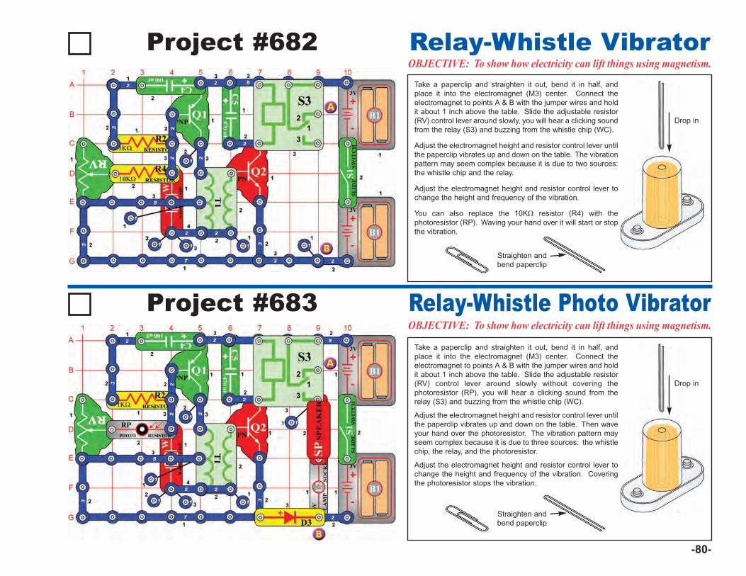
-80-
Project #682OBJECTIVE: To show how electricity can lift things using magnetism.Relay-Whistle Vibrator
Take a paperclip and straighten it out, bend it in half, andplace it into the electromagnet (M3) center. Connect theelectromagnet to points A & B with the jumper wires and holdit about 1 inch above the table. Slide the adjustable resistor(RV) control lever around slowly, you will hear a clicking soundfrom the relay (S3) and buzzing from the whistle chip (WC).
Adjust the electromagnet height and resistor control lever untilthe paperclip vibrates up and down on the table. The vibrationpattern may seem complex because it is due to two sources:the whistle chip and the relay.
Adjust the electromagnet height and resistor control lever tochange the height and frequency of the vibration.
You can also replace the 10KΩ resistor (R4) with thephotoresistor (RP). Waving your hand over it will start or stopthe vibration.
Drop in
Straighten andbend paperclip
Project #683OBJECTIVE: To show how electricity can lift things using magnetism.Relay-Whistle Photo Vibrator
Take a paperclip and straighten it out, bend it in half, andplace it into the electromagnet (M3) center. Connect theelectromagnet to points A & B with the jumper wires and holdit about 1 inch above the table. Slide the adjustable resistor(RV) control lever around slowly without covering thephotoresistor (RP), you will hear a clicking sound from therelay (S3) and buzzing from the whistle chip (WC).
Adjust the electromagnet height and resistor control lever untilthe paperclip vibrates up and down on the table. Then waveyour hand over the photoresistor. The vibration pattern mayseem complex because it is due to three sources: the whistlechip, the relay, and the photoresistor.
Adjust the electromagnet height and resistor control lever tochange the height and frequency of the vibration. Coveringthe photoresistor stops the vibration.
Drop in
Straighten andbend paperclip
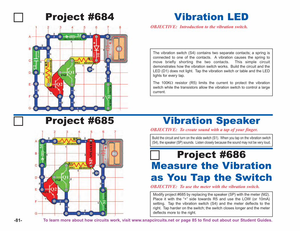
-81-
Project #684OBJECTIVE: Introduction to the vibration switch.
Vibration LED
The vibration switch (S4) contains two separate contacts; a spring isconnected to one of the contacts. A vibration causes the spring tomove briefly shorting the two contacts. This simple circuitdemonstrates how the vibration switch works. Build the circuit and theLED (D1) does not light. Tap the vibration switch or table and the LEDlights for every tap.
The 100KΩ resistor (R5) limits the current to protect the vibrationswitch while the transistors allow the vibration switch to control a largecurrent.
Project #685OBJECTIVE: To create sound with a tap of your finger.
Vibration Speaker
OBJECTIVE: To use the meter with the vibration switch.
Modify project #685 by replacing the speaker (SP) with the meter (M2).Place it with the “+” side towards R5 and use the LOW (or 10mA)setting. Tap the vibration switch (S4) and the meter deflects to theright. Tap harder on the switch; the switch closes longer and the meterdeflects more to the right.
Measure the Vibrationas You Tap the Switch
Project #686
Build the circuit and turn on the slide switch (S1). When you tap on the vibration switch(S4), the speaker (SP) sounds. Listen closely because the sound may not be very loud.
To learn more about how circuits work, visit www.snapcircuits.net or page 85 to find out about our Student Guides.
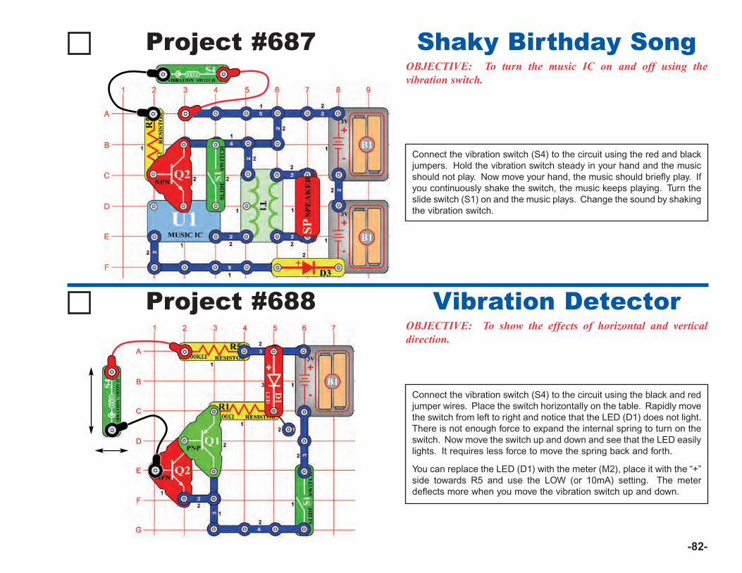
-82-
Project #687OBJECTIVE: To turn the music IC on and off using thevibration switch.
Shaky Birthday Song
Connect the vibration switch (S4) to the circuit using the red and blackjumpers. Hold the vibration switch steady in your hand and the musicshould not play. Now move your hand, the music should briefly play. Ifyou continuously shake the switch, the music keeps playing. Turn theslide switch (S1) on and the music plays. Change the sound by shakingthe vibration switch.
Project #688OBJECTIVE: To show the effects of horizontal and verticaldirection.
Vibration Detector
Connect the vibration switch (S4) to the circuit using the black and redjumper wires. Place the switch horizontally on the table. Rapidly movethe switch from left to right and notice that the LED (D1) does not light.There is not enough force to expand the internal spring to turn on theswitch. Now move the switch up and down and see that the LED easilylights. It requires less force to move the spring back and forth.
You can replace the LED (D1) with the meter (M2), place it with the “+”side towards R5 and use the LOW (or 10mA) setting. The meterdeflects more when you move the vibration switch up and down.
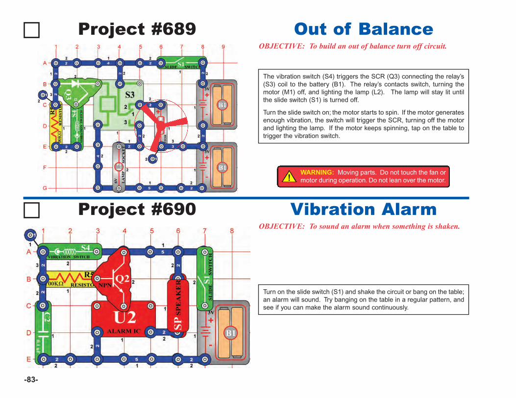
-83-
Project #689OBJECTIVE: To build an out of balance turn off circuit.
Out of Balance
Project #690OBJECTIVE: To sound an alarm when something is shaken.
Vibration Alarm
Turn on the slide switch (S1) and shake the circuit or bang on the table;an alarm will sound. Try banging on the table in a regular pattern, andsee if you can make the alarm sound continuously.
The vibration switch (S4) triggers the SCR (Q3) connecting the relay’s(S3) coil to the battery (B1). The relay’s contacts switch, turning themotor (M1) off, and lighting the lamp (L2). The lamp will stay lit untilthe slide switch (S1) is turned off.
Turn the slide switch on; the motor starts to spin. If the motor generatesenough vibration, the switch will trigger the SCR, turning off the motorand lighting the lamp. If the motor keeps spinning, tap on the table totrigger the vibration switch.
!WARNING: Moving parts. Do not touch the fan ormotor during operation. Do not lean over the motor.
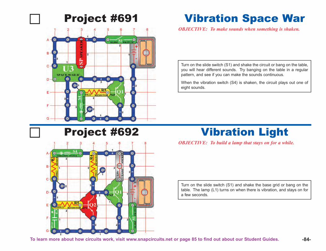
-84-
Project #691OBJECTIVE: To make sounds when something is shaken.
Vibration Space War
Turn on the slide switch (S1) and shake the circuit or bang on the table,you will hear different sounds. Try banging on the table in a regularpattern, and see if you can make the sounds continuous.
When the vibration switch (S4) is shaken, the circuit plays out one ofeight sounds.
Project #692OBJECTIVE: To build a lamp that stays on for a while.
Vibration Light
Turn on the slide switch (S1) and shake the base grid or bang on thetable. The lamp (L1) turns on when there is vibration, and stays on fora few seconds.
To learn more about how circuits work, visit www.snapcircuits.net or page 85 to find out about our Student Guides.
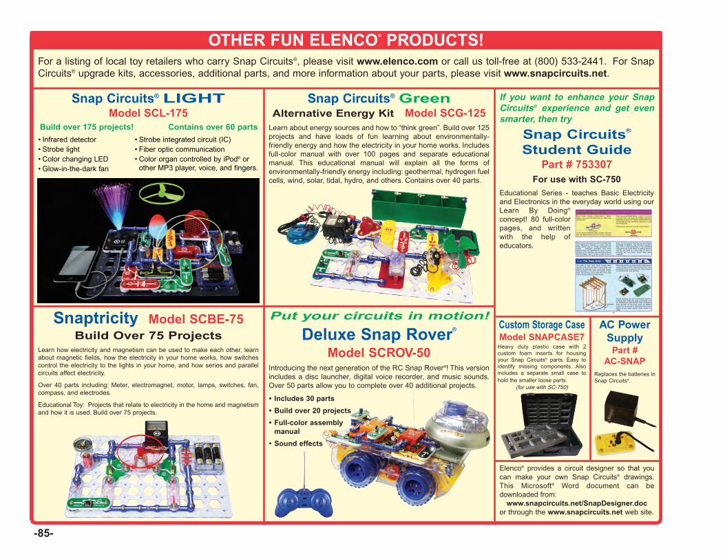
-85-
OTHER FUN ELENCO® PRODUCTS!For a listing of local toy retailers who carry Snap Circuits®, please visit www.elenco.com or call us toll-free at (800) 533-2441. For SnapCircuits® upgrade kits, accessories, additional parts, and more information about your parts, please visit www.snapcircuits.net.
Elenco® provides a circuit designer so that youcan make your own Snap Circuits® drawings.This Microsoft® Word document can bedownloaded from:
www.snapcircuits.net/SnapDesigner.docor through the www.snapcircuits.net web site.
Snaptricity Model SCBE-75Build Over 75 Projects
Learn how electricity and magnetism can be used to make each other, learnabout magnetic fields, how the electricity in your home works, how switchescontrol the electricity to the lights in your home, and how series and parallelcircuits affect electricity.
Over 40 parts including: Meter, electromagnet, motor, lamps, switches, fan,compass, and electrodes.
Educational Toy: Projects that relate to electricity in the home and magnetismand how it is used. Build over 75 projects.
Deluxe Snap Rover®
Model SCROV-50Introducing the next generation of the RC Snap Rover®! This versionincludes a disc launcher, digital voice recorder, and music sounds.Over 50 parts allow you to complete over 40 additional projects.
Put your circuits in motion!
• Includes 30 parts
• Build over 20 projects
• Full-color assemblymanual
• Sound effects
Snap Circuits® GreenAlternative Energy Kit Model SCG-125
Learn about energy sources and how to “think green”. Build over 125projects and have loads of fun learning about environmentally-friendly energy and how the electricity in your home works. Includesfull-color manual with over 100 pages and separate educationalmanual. This educational manual will explain all the forms ofenvironmentally-friendly energy including: geothermal, hydrogen fuelcells, wind, solar, tidal, hydro, and others. Contains over 40 parts.
Snap Circuits® LIGHTModel SCL-175
Build over 175 projects! Contains over 60 parts
If you want to enhance your SnapCircuits® experience and get evensmarter, then try
For use with SC-750Educational Series - teaches Basic Electricityand Electronics in the everyday world using ourLearn By Doing®
concept! 80 full-colorpages, and writtenwith the help ofeducators.
Snap Circuits®
Student GuidePart # 753307
AC PowerSupply
Part #AC-SNAP
Replaces the batteries inSnap Circuits®.
Custom Storage CaseModel SNAPCASE7
Heavy duty plastic case with 2custom foam inserts for housingyour Snap Circuits® parts. Easy toidentify missing components. Alsoincludes a separate small case tohold the smaller loose parts.
(for use with SC-750)
• Infrared detector• Strobe light• Color changing LED• Glow-in-the-dark fan
• Strobe integrated circuit (IC)• Fiber optic communication• Color organ controlled by iPod® or
other MP3 player, voice, and fingers.
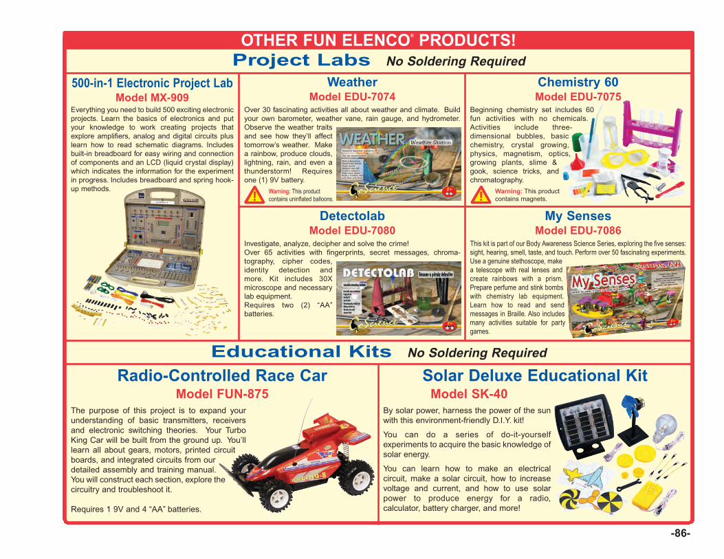
-86-
OTHER FUN ELENCO® PRODUCTS!Project Labs No Soldering Required
Educational Kits No Soldering Required
500-in-1 Electronic Project LabModel MX-909
The purpose of this project is to expand yourunderstanding of basic transmitters, receiversand electronic switching theories. Your TurboKing Car will be built from the ground up. You’lllearn all about gears, motors, printed circuitboards, and integrated circuits from ourdetailed assembly and training manual.You will construct each section, explore thecircuitry and troubleshoot it.
Requires 1 9V and 4 “AA” batteries.
Radio-Controlled Race CarModel FUN-875
By solar power, harness the power of the sunwith this environment-friendly D.I.Y. kit!
You can do a series of do-it-yourselfexperiments to acquire the basic knowledge ofsolar energy.
You can learn how to make an electricalcircuit, make a solar circuit, how to increasevoltage and current, and how to use solarpower to produce energy for a radio,calculator, battery charger, and more!
Solar Deluxe Educational KitModel SK-40
Everything you need to build 500 exciting electronicprojects. Learn the basics of electronics and putyour knowledge to work creating projects thatexplore amplifiers, analog and digital circuits pluslearn how to read schematic diagrams. Includesbuilt-in breadboard for easy wiring and connectionof components and an LCD (liquid crystal display)which indicates the information for the experimentin progress. Includes breadboard and spring hook-up methods.
Beginning chemistry set includes 60fun activities with no chemicals.Activities include three-dimensional bubbles, basicchemistry, crystal growing,physics, magnetism, optics,growing plants, slime &gook, science tricks, andchromatography.
Warning: This productcontains magnets.`
Chemistry 60Model EDU-7075
This kit is part of our Body Awareness Science Series, exploring the five senses:sight, hearing, smell, taste, and touch. Perform over 50 fascinating experiments.Use a genuine stethoscope, makea telescope with real lenses andcreate rainbows with a prism.Prepare perfume and stink bombswith chemistry lab equipment.Learn how to read and sendmessages in Braille. Also includesmany activities suitable for partygames.
My SensesModel EDU-7086
Over 30 fascinating activities all about weather and climate. Buildyour own barometer, weather vane, rain gauge, and hydrometer.Observe the weather traitsand see how they’ll affecttomorrow’s weather. Makea rainbow, produce clouds,lightning, rain, and even athunderstorm! Requiresone (1) 9V battery.
WeatherModel EDU-7074
Warning: This productcontains uninflated balloons.`
Investigate, analyze, decipher and solve the crime!Over 65 activities with fingerprints, secret messages, chroma-tography, cipher codes,identity detection andmore. Kit includes 30Xmicroscope and necessarylab equipment.Requires two (2) “AA”batteries.
DetectolabModel EDU-7080

ELENCO®
150 Carpenter AvenueWheeling, IL 60090
(847) 541-3800Website: www.elenco.com
e-mail: [email protected]
Copyright © 2005 by Elenco® Electronics, Inc. All rights reserved. No part of this book shall be reproduced by REV-B Revised 2005 753293any means; electronic, photocopying, or otherwise without written permission from the publisher.
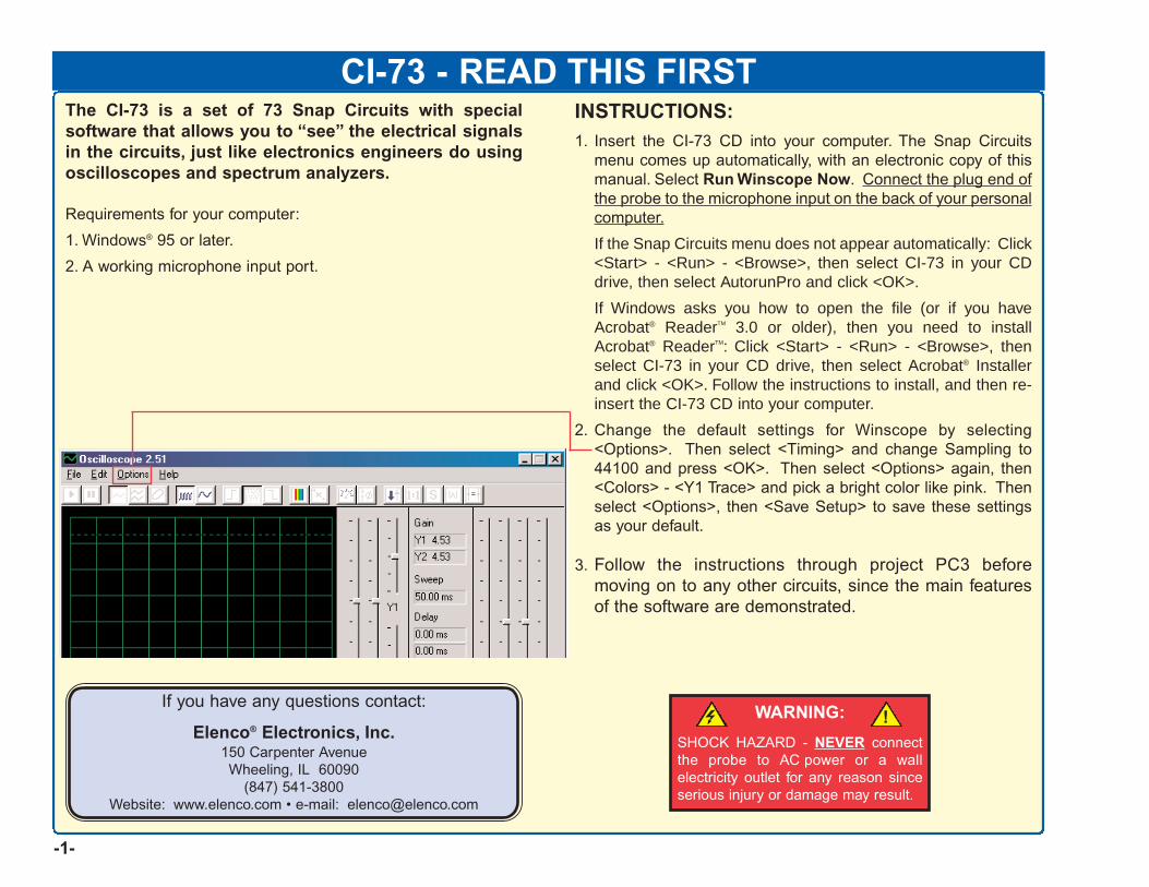
If you have any questions contact:
Elenco® Electronics, Inc.150 Carpenter AvenueWheeling, IL 60090
(847) 541-3800Website: www.elenco.com • e-mail: [email protected]
WARNING:
SHOCK HAZARD - NEVER connectthe probe to AC power or a wallelectricity outlet for any reason sinceserious injury or damage may result.
-1-
CI-73 - READ THIS FIRSTThe CI-73 is a set of 73 Snap Circuits with specialsoftware that allows you to “see” the electrical signalsin the circuits, just like electronics engineers do usingoscilloscopes and spectrum analyzers.
Requirements for your computer:
1. Windows® 95 or later.
2. A working microphone input port.
INSTRUCTIONS:1. Insert the CI-73 CD into your computer. The Snap Circuits
menu comes up automatically, with an electronic copy of thismanual. Select Run Winscope Now. Connect the plug end ofthe probe to the microphone input on the back of your personalcomputer.
If the Snap Circuits menu does not appear automatically: Click<Start> - <Run> - <Browse>, then select CI-73 in your CDdrive, then select AutorunPro and click <OK>.
If Windows asks you how to open the file (or if you haveAcrobat® ReaderTM 3.0 or older), then you need to installAcrobat® ReaderTM: Click <Start> - <Run> - <Browse>, thenselect CI-73 in your CD drive, then select Acrobat® Installerand click <OK>. Follow the instructions to install, and then re-insert the CI-73 CD into your computer.
2. Change the default settings for Winscope by selecting<Options>. Then select <Timing> and change Sampling to44100 and press <OK>. Then select <Options> again, then<Colors> - <Y1 Trace> and pick a bright color like pink. Thenselect <Options>, then <Save Setup> to save these settingsas your default.
3. Follow the instructions through project PC3 beforemoving on to any other circuits, since the main featuresof the software are demonstrated.
!
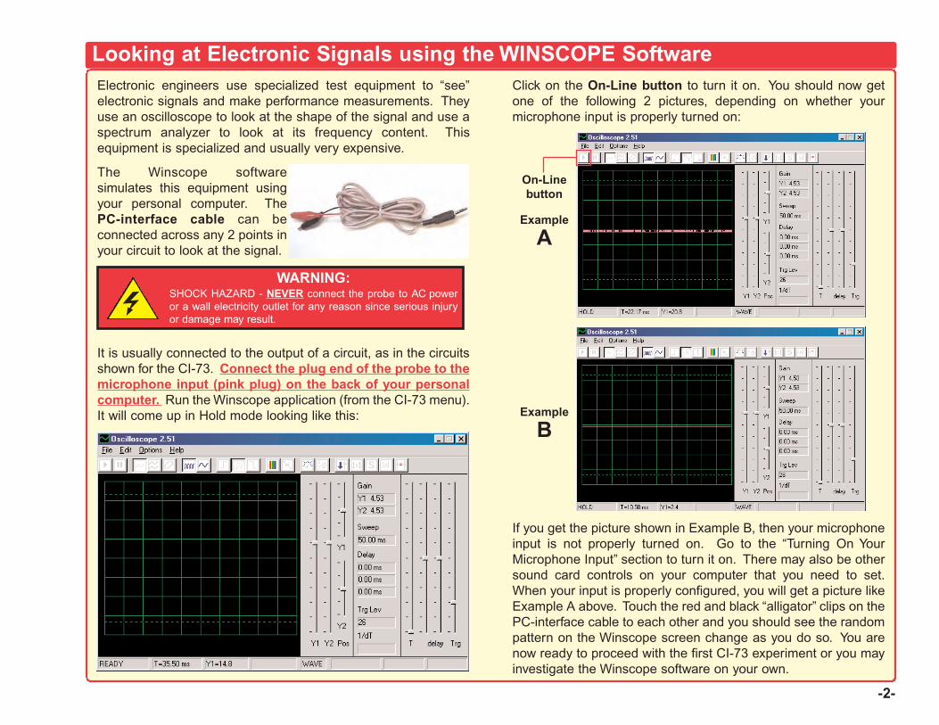
-2-
Electronic engineers use specialized test equipment to “see”electronic signals and make performance measurements. Theyuse an oscilloscope to look at the shape of the signal and use aspectrum analyzer to look at its frequency content. Thisequipment is specialized and usually very expensive.
The Winscope softwaresimulates this equipment usingyour personal computer. ThePC-interface cable can beconnected across any 2 points inyour circuit to look at the signal.
It is usually connected to the output of a circuit, as in the circuitsshown for the CI-73. Connect the plug end of the probe to themicrophone input (pink plug) on the back of your personalcomputer. Run the Winscope application (from the CI-73 menu).It will come up in Hold mode looking like this:
Click on the On-Line button to turn it on. You should now getone of the following 2 pictures, depending on whether yourmicrophone input is properly turned on:
If you get the picture shown in Example B, then your microphoneinput is not properly turned on. Go to the “Turning On YourMicrophone Input” section to turn it on. There may also be othersound card controls on your computer that you need to set.When your input is properly configured, you will get a picture likeExample A above. Touch the red and black “alligator” clips on thePC-interface cable to each other and you should see the randompattern on the Winscope screen change as you do so. You arenow ready to proceed with the first CI-73 experiment or you mayinvestigate the Winscope software on your own.
Looking at Electronic Signals using the WINSCOPE Software
WARNING:SHOCK HAZARD - NEVER connect the probe to AC poweror a wall electricity outlet for any reason since serious injuryor damage may result.
Example
A
Example
B
On-Linebutton
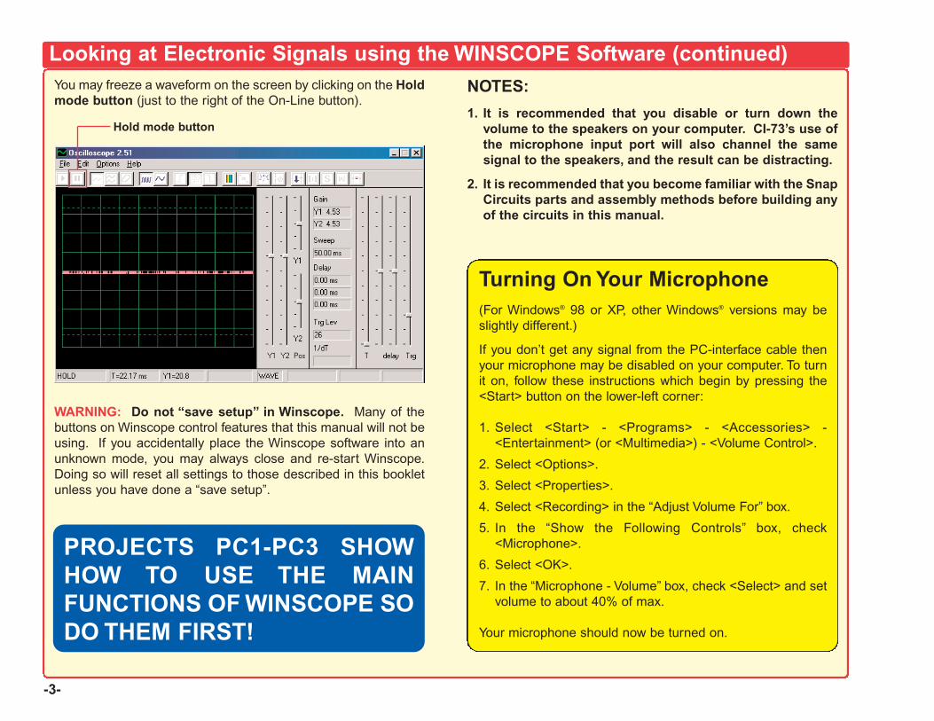
-3-
You may freeze a waveform on the screen by clicking on the Holdmode button (just to the right of the On-Line button).
WARNING: Do not “save setup” in Winscope. Many of thebuttons on Winscope control features that this manual will not beusing. If you accidentally place the Winscope software into anunknown mode, you may always close and re-start Winscope.Doing so will reset all settings to those described in this bookletunless you have done a “save setup”.
NOTES:
1. It is recommended that you disable or turn down thevolume to the speakers on your computer. CI-73’s use ofthe microphone input port will also channel the samesignal to the speakers, and the result can be distracting.
2. It is recommended that you become familiar with the SnapCircuits parts and assembly methods before building anyof the circuits in this manual.
Looking at Electronic Signals using the WINSCOPE Software (continued)
Hold mode button
PROJECTS PC1-PC3 SHOWHOW TO USE THE MAINFUNCTIONS OF WINSCOPE SODO THEM FIRST!
Turning On Your Microphone(For Windows® 98 or XP, other Windows® versions may beslightly different.)
If you don’t get any signal from the PC-interface cable thenyour microphone may be disabled on your computer. To turnit on, follow these instructions which begin by pressing the<Start> button on the lower-left corner:
1. Select <Start> - <Programs> - <Accessories> -<Entertainment> (or <Multimedia>) - <Volume Control>.
2. Select <Options>.
3. Select <Properties>.
4. Select <Recording> in the “Adjust Volume For” box.
5. In the “Show the Following Controls” box, check<Microphone>.
6. Select <OK>.
7. In the “Microphone - Volume” box, check <Select> and setvolume to about 40% of max.
Your microphone should now be turned on.
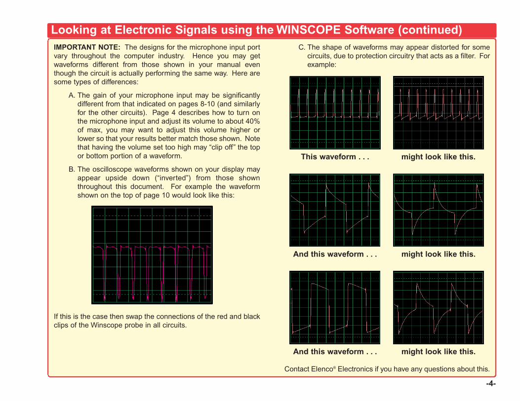
-4-
IMPORTANT NOTE: The designs for the microphone input portvary throughout the computer industry. Hence you may getwaveforms different from those shown in your manual eventhough the circuit is actually performing the same way. Here aresome types of differences:
A. The gain of your microphone input may be significantlydifferent from that indicated on pages 8-10 (and similarlyfor the other circuits). Page 4 describes how to turn onthe microphone input and adjust its volume to about 40%of max, you may want to adjust this volume higher orlower so that your results better match those shown. Notethat having the volume set too high may “clip off” the topor bottom portion of a waveform.
B. The oscilloscope waveforms shown on your display mayappear upside down (“inverted”) from those shownthroughout this document. For example the waveformshown on the top of page 10 would look like this:
If this is the case then swap the connections of the red and blackclips of the Winscope probe in all circuits.
C. The shape of waveforms may appear distorted for somecircuits, due to protection circuitry that acts as a filter. Forexample:
Looking at Electronic Signals using the WINSCOPE Software (continued)
This waveform . . . might look like this.
And this waveform . . . might look like this.
And this waveform . . . might look like this.
Contact Elenco® Electronics if you have any questions about this.
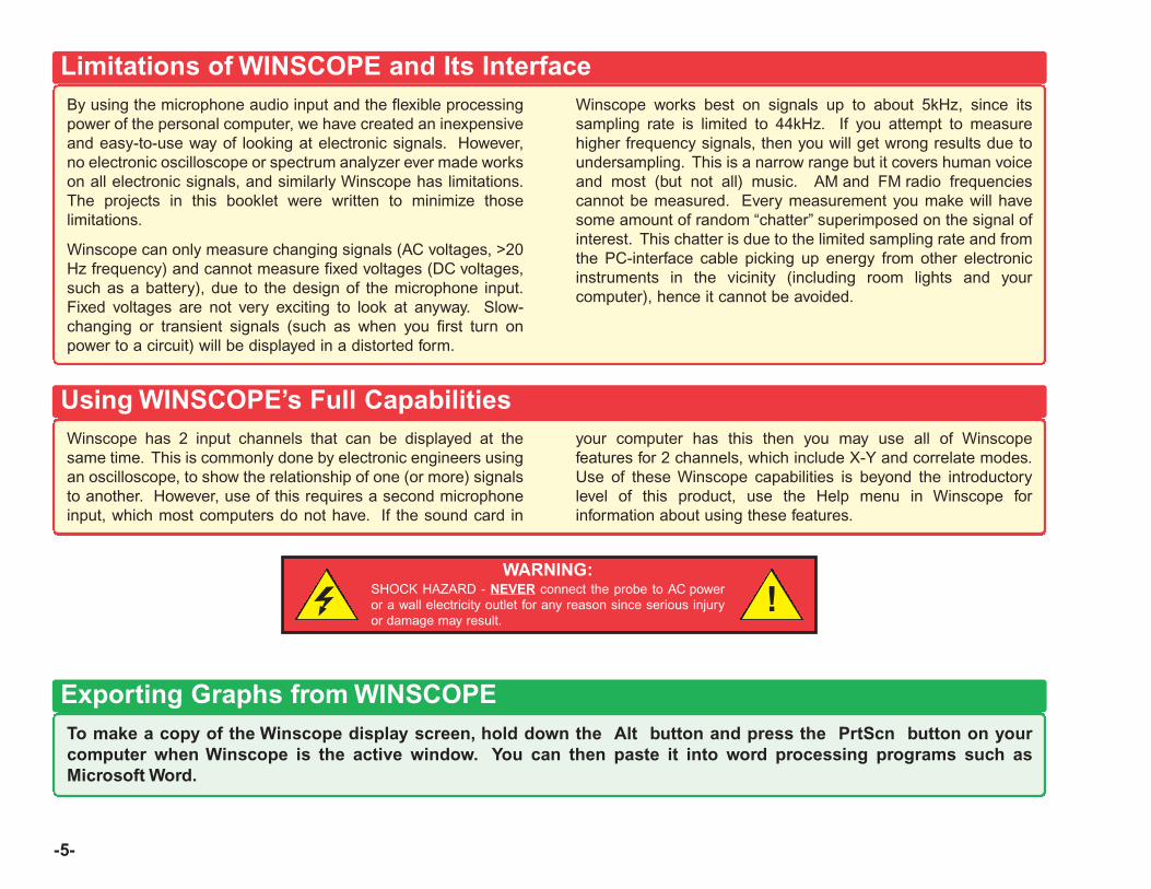
-5-
By using the microphone audio input and the flexible processingpower of the personal computer, we have created an inexpensiveand easy-to-use way of looking at electronic signals. However,no electronic oscilloscope or spectrum analyzer ever made workson all electronic signals, and similarly Winscope has limitations.The projects in this booklet were written to minimize thoselimitations.
Winscope can only measure changing signals (AC voltages, >20Hz frequency) and cannot measure fixed voltages (DC voltages,such as a battery), due to the design of the microphone input.Fixed voltages are not very exciting to look at anyway. Slow-changing or transient signals (such as when you first turn onpower to a circuit) will be displayed in a distorted form.
Winscope works best on signals up to about 5kHz, since itssampling rate is limited to 44kHz. If you attempt to measurehigher frequency signals, then you will get wrong results due toundersampling. This is a narrow range but it covers human voiceand most (but not all) music. AM and FM radio frequenciescannot be measured. Every measurement you make will havesome amount of random “chatter” superimposed on the signal ofinterest. This chatter is due to the limited sampling rate and fromthe PC-interface cable picking up energy from other electronicinstruments in the vicinity (including room lights and yourcomputer), hence it cannot be avoided.
Limitations of WINSCOPE and Its Interface
Winscope has 2 input channels that can be displayed at thesame time. This is commonly done by electronic engineers usingan oscilloscope, to show the relationship of one (or more) signalsto another. However, use of this requires a second microphoneinput, which most computers do not have. If the sound card in
your computer has this then you may use all of Winscopefeatures for 2 channels, which include X-Y and correlate modes.Use of these Winscope capabilities is beyond the introductorylevel of this product, use the Help menu in Winscope forinformation about using these features.
Using WINSCOPE’s Full Capabilities
WARNING:SHOCK HAZARD - NEVER connect the probe to AC poweror a wall electricity outlet for any reason since serious injuryor damage may result.
!
To make a copy of the Winscope display screen, hold down the Alt button and press the PrtScn button on yourcomputer when Winscope is the active window. You can then paste it into word processing programs such asMicrosoft Word.
Exporting Graphs from WINSCOPE
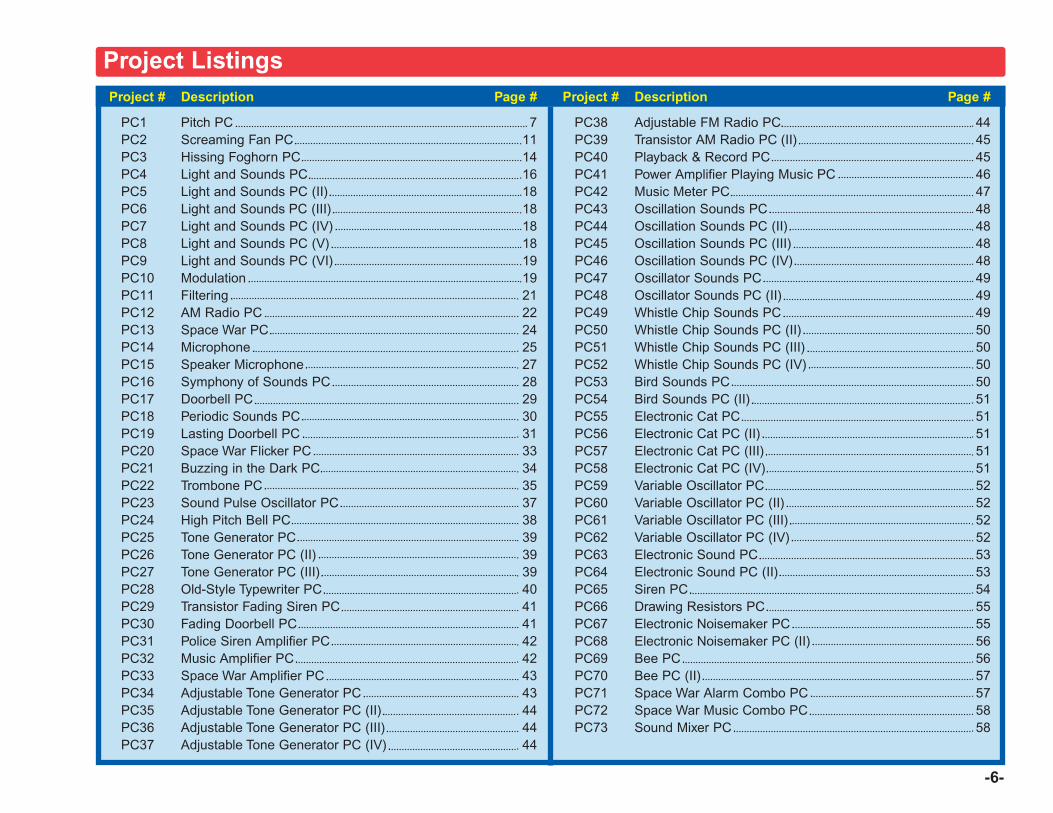
-6-
Project # Description Page #
PC1 Pitch PC 7PC2 Screaming Fan PC 11PC3 Hissing Foghorn PC 14PC4 Light and Sounds PC 16PC5 Light and Sounds PC (II) 18PC6 Light and Sounds PC (III) 18PC7 Light and Sounds PC (IV) 18PC8 Light and Sounds PC (V) 18PC9 Light and Sounds PC (VI) 19PC10 Modulation 19PC11 Filtering 21PC12 AM Radio PC 22PC13 Space War PC 24PC14 Microphone 25PC15 Speaker Microphone 27PC16 Symphony of Sounds PC 28PC17 Doorbell PC 29PC18 Periodic Sounds PC 30PC19 Lasting Doorbell PC 31PC20 Space War Flicker PC 33PC21 Buzzing in the Dark PC 34PC22 Trombone PC 35PC23 Sound Pulse Oscillator PC 37PC24 High Pitch Bell PC 38PC25 Tone Generator PC 39PC26 Tone Generator PC (II) 39PC27 Tone Generator PC (III) 39PC28 Old-Style Typewriter PC 40PC29 Transistor Fading Siren PC 41PC30 Fading Doorbell PC 41PC31 Police Siren Amplifier PC 42PC32 Music Amplifier PC 42PC33 Space War Amplifier PC 43PC34 Adjustable Tone Generator PC 43PC35 Adjustable Tone Generator PC (II) 44PC36 Adjustable Tone Generator PC (III) 44 PC37 Adjustable Tone Generator PC (IV) 44
Project # Description Page #
PC38 Adjustable FM Radio PC 44PC39 Transistor AM Radio PC (II) 45PC40 Playback & Record PC 45PC41 Power Amplifier Playing Music PC 46PC42 Music Meter PC 47PC43 Oscillation Sounds PC 48PC44 Oscillation Sounds PC (II) 48PC45 Oscillation Sounds PC (III) 48PC46 Oscillation Sounds PC (IV) 48PC47 Oscillator Sounds PC 49PC48 Oscillator Sounds PC (II) 49PC49 Whistle Chip Sounds PC 49PC50 Whistle Chip Sounds PC (II) 50PC51 Whistle Chip Sounds PC (III) 50PC52 Whistle Chip Sounds PC (IV) 50PC53 Bird Sounds PC 50PC54 Bird Sounds PC (II) 51PC55 Electronic Cat PC 51PC56 Electronic Cat PC (II) 51PC57 Electronic Cat PC (III) 51PC58 Electronic Cat PC (IV) 51PC59 Variable Oscillator PC 52PC60 Variable Oscillator PC (II) 52PC61 Variable Oscillator PC (III) 52PC62 Variable Oscillator PC (IV) 52PC63 Electronic Sound PC 53PC64 Electronic Sound PC (II) 53PC65 Siren PC 54PC66 Drawing Resistors PC 55PC67 Electronic Noisemaker PC 55PC68 Electronic Noisemaker PC (II) 56PC69 Bee PC 56PC70 Bee PC (II) 57PC71 Space War Alarm Combo PC 57PC72 Space War Music Combo PC 58PC73 Sound Mixer PC 58
Project Listings

-7-
Project #PC1OBJECTIVE: To look at the output signal from a transistor oscillator while changing the pitch of the sound.
Pitch PC
You will now be introduced to the Winscope features, and therebybecome familiar with oscilloscopes and spectrum analyzers, andsee some of the most important concepts in electronics. It isrecommended that you already be familiar with the Snap Circuitsparts and assembly methods from the other manuals.
Build the circuit shown and connect the PC-interface cable to themicrophone input on your computer. Turn on the slide switch(S1) and vary the adjustable resistor (RV). The frequency orpitch of the sound is changed. Run the Winscope software andbe sure your microphone input is configured properly, asdescribed earlier.
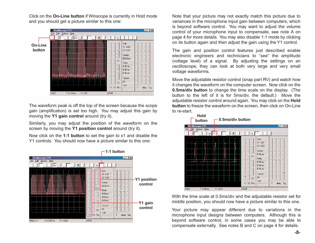
Note that your picture may not exactly match this picture due tovariances in the microphone input gain between computers, whichis beyond software control. You may want to adjust the volumecontrol of your microphone input to compensate, see note A onpage 4 for more details. You may also disable 1:1 mode by clickingon its button again and then adjust the gain using the Y1 control.
The gain and position control features just described enableelectronic engineers and technicians to “see” the amplitude(voltage level) of a signal. By adjusting the settings on anoscilloscope, they can look at both very large and very smallvoltage waveforms.
Move the adjustable resistor control (snap part RV) and watch howit changes the waveform on the computer screen. Now click on the0.5ms/div button to change the time scale on the display. (Thebutton to the left of it is for 5ms/div, the default.) Move theadjustable resistor control around again. You may click on the Holdbutton to freeze the waveform on the screen, then click on On-Lineto re-start.
-8-
Click on the On-Line button if Winscope is currently in Hold modeand you should get a picture similar to this one:
On-Linebutton
The waveform peak is off the top of the screen because the scopegain (amplification) is set too high. You may adjust this gain bymoving the Y1 gain control around (try it).
Similarly, you may adjust the position of the waveform on thescreen by moving the Y1 position control around (try it).
Now click on the 1:1 button to set the gain to x1 and disable theY1 controls. You should now have a picture similar to this one:
1:1 button
Y1 positioncontrol
Y1 gaincontrol
With the time scale at 0.5ms/div and the adjustable resistor set formiddle position, you should now have a picture similar to this one.
Your picture may appear different due to variations in themicrophone input designs between computers. Although this isbeyond software control, in some cases you may be able tocompensate externally. See notes B and C on page 4 for details.
Holdbutton 0.5ms/div button
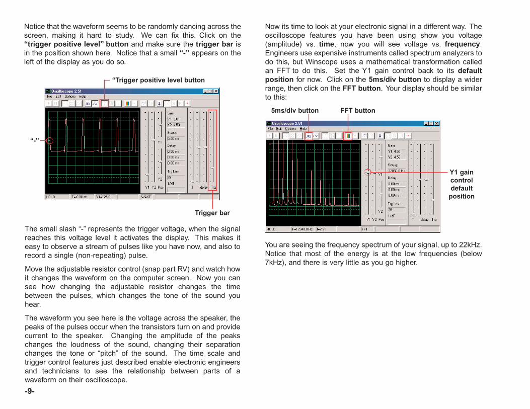
The small slash “-” represents the trigger voltage, when the signalreaches this voltage level it activates the display. This makes iteasy to observe a stream of pulses like you have now, and also torecord a single (non-repeating) pulse.
Move the adjustable resistor control (snap part RV) and watch howit changes the waveform on the computer screen. Now you cansee how changing the adjustable resistor changes the timebetween the pulses, which changes the tone of the sound youhear.
The waveform you see here is the voltage across the speaker, thepeaks of the pulses occur when the transistors turn on and providecurrent to the speaker. Changing the amplitude of the peakschanges the loudness of the sound, changing their separationchanges the tone or “pitch” of the sound. The time scale andtrigger control features just described enable electronic engineersand technicians to see the relationship between parts of awaveform on their oscilloscope.
“Trigger positive level button
-9-
Notice that the waveform seems to be randomly dancing across thescreen, making it hard to study. We can fix this. Click on the“trigger positive level” button and make sure the trigger bar isin the position shown here. Notice that a small “-” appears on theleft of the display as you do so.
“-”
Trigger bar
Now its time to look at your electronic signal in a different way. Theoscilloscope features you have been using show you voltage(amplitude) vs. time, now you will see voltage vs. frequency.Engineers use expensive instruments called spectrum analyzers todo this, but Winscope uses a mathematical transformation calledan FFT to do this. Set the Y1 gain control back to its defaultposition for now. Click on the 5ms/div button to display a widerrange, then click on the FFT button. Your display should be similarto this:
You are seeing the frequency spectrum of your signal, up to 22kHz.Notice that most of the energy is at the low frequencies (below7kHz), and there is very little as you go higher.
5ms/div button FFT button
Y1 gaincontroldefault
position
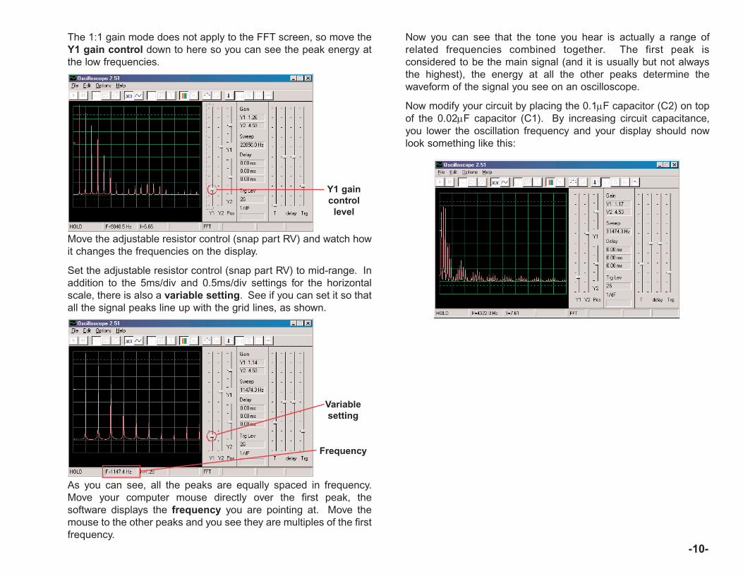
-10-
The 1:1 gain mode does not apply to the FFT screen, so move theY1 gain control down to here so you can see the peak energy atthe low frequencies.
Move the adjustable resistor control (snap part RV) and watch howit changes the frequencies on the display.
Set the adjustable resistor control (snap part RV) to mid-range. Inaddition to the 5ms/div and 0.5ms/div settings for the horizontalscale, there is also a variable setting. See if you can set it so thatall the signal peaks line up with the grid lines, as shown.
Y1 gaincontrol
level
Variablesetting
As you can see, all the peaks are equally spaced in frequency.Move your computer mouse directly over the first peak, thesoftware displays the frequency you are pointing at. Move themouse to the other peaks and you see they are multiples of the firstfrequency.
Frequency
Now you can see that the tone you hear is actually a range ofrelated frequencies combined together. The first peak isconsidered to be the main signal (and it is usually but not alwaysthe highest), the energy at all the other peaks determine thewaveform of the signal you see on an oscilloscope.
Now modify your circuit by placing the 0.1µF capacitor (C2) on topof the 0.02µF capacitor (C1). By increasing circuit capacitance,you lower the oscillation frequency and your display should nowlook something like this:

Now adjust the horizontal scale so the peaks line up with thegridlines as they did before.
Notice that all the peaks went down in frequency by acorresponding amount and many changed in amplitude, that is whyyour ears hear a different sound. Notice also that in this case theleft-most frequency peak no longer is the highest in voltage (yourresults may vary).
Horizontal scale
-11-
Now you can click on the FFT box to return to oscilloscope modeand look at the waveform with the 0.1µF capacitor in the circuit. Youcan observe it with the same settings as before for comparison, butthese settings usually work best:
Project #PC2OBJECTIVE: To demonstrate storage mode.
Screaming Fan PC
!WARNING: Moving parts. Do not touch the fan ormotor during operation.
! WARNING: Do not lean over the motor.
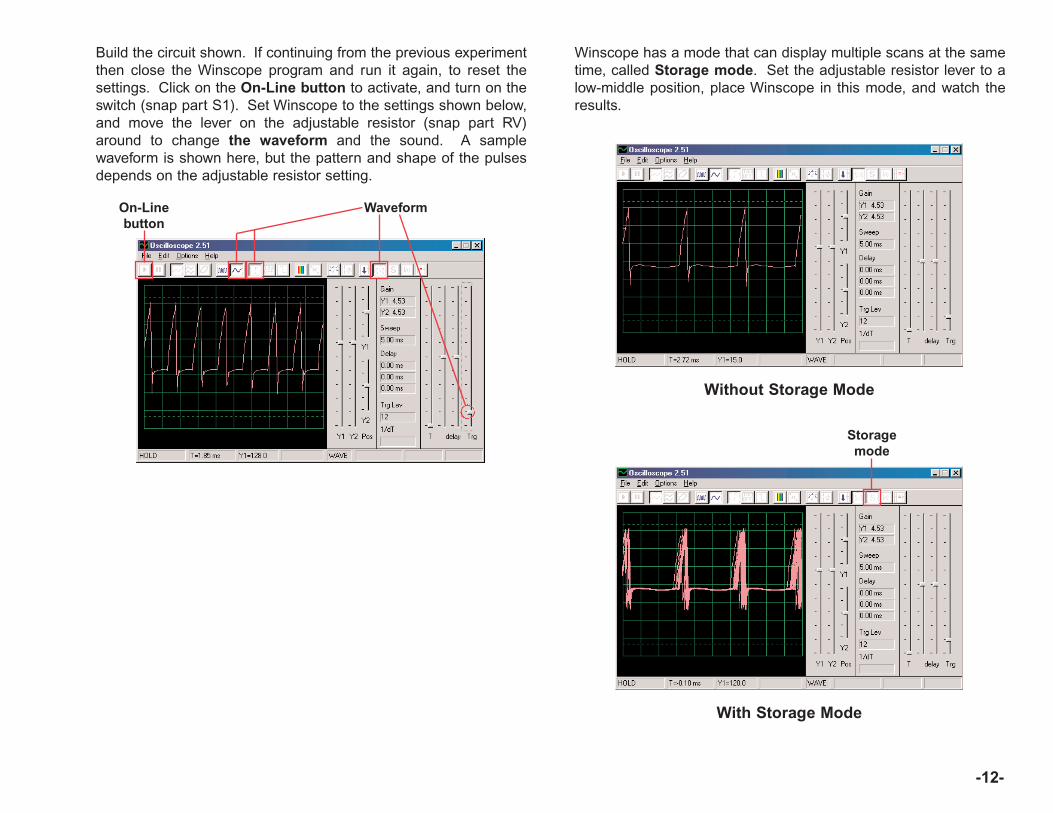
-12-
Build the circuit shown. If continuing from the previous experimentthen close the Winscope program and run it again, to reset thesettings. Click on the On-Line button to activate, and turn on theswitch (snap part S1). Set Winscope to the settings shown below,and move the lever on the adjustable resistor (snap part RV)around to change the waveform and the sound. A samplewaveform is shown here, but the pattern and shape of the pulsesdepends on the adjustable resistor setting.
WaveformOn-Linebutton
Without Storage Mode
Winscope has a mode that can display multiple scans at the sametime, called Storage mode. Set the adjustable resistor lever to alow-middle position, place Winscope in this mode, and watch theresults.
With Storage Mode
Storagemode
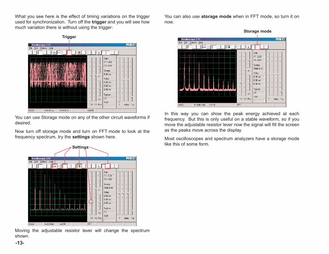
-13-
What you see here is the effect of timing variations on the triggerused for synchronization. Turn off the trigger and you will see howmuch variation there is without using the trigger:
Trigger
You can use Storage mode on any of the other circuit waveforms ifdesired.
Now turn off storage mode and turn on FFT mode to look at thefrequency spectrum, try the settings shown here.
Moving the adjustable resistor lever will change the spectrumshown.
You can also use storage mode when in FFT mode, so turn it onnow.
Storage mode
In this way you can show the peak energy achieved at eachfrequency. But this is only useful on a stable waveform, so if youmove the adjustable resistor lever now the signal will fill the screenas the peaks move across the display.
Most oscilloscopes and spectrum analyzers have a storage modelike this of some form.
Settings
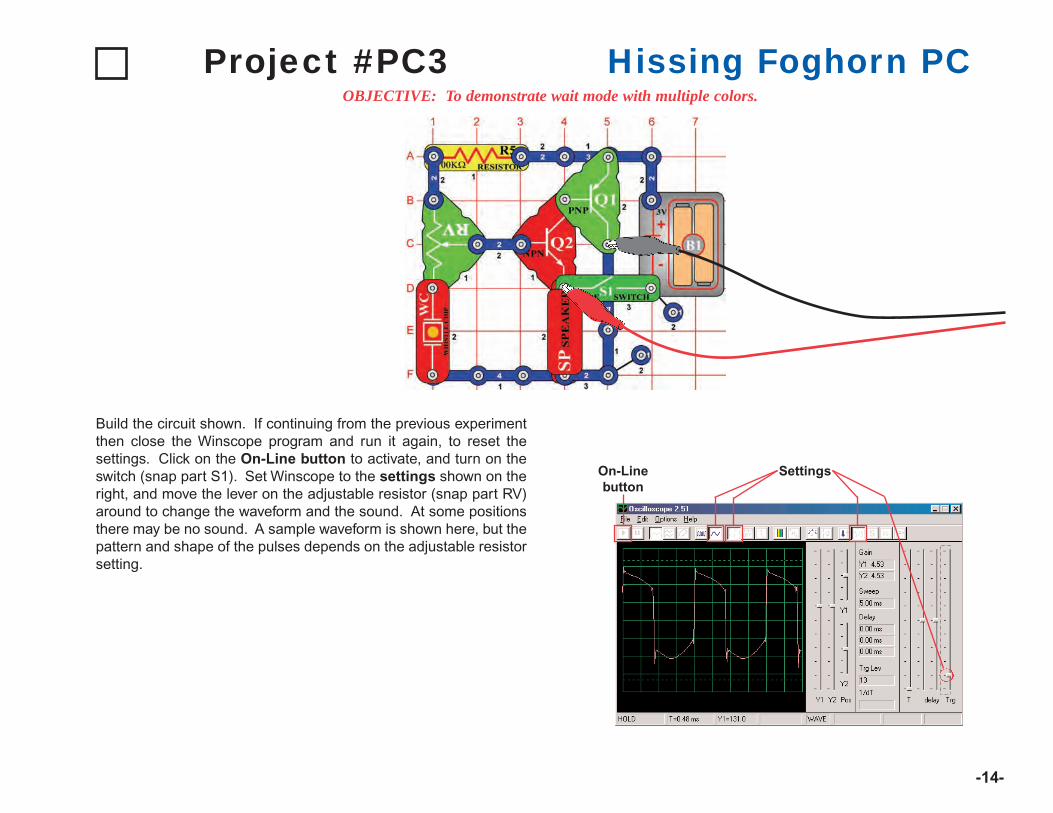
-14-
Project #PC3OBJECTIVE: To demonstrate wait mode with multiple colors.
Hissing Foghorn PC
Build the circuit shown. If continuing from the previous experimentthen close the Winscope program and run it again, to reset thesettings. Click on the On-Line button to activate, and turn on theswitch (snap part S1). Set Winscope to the settings shown on theright, and move the lever on the adjustable resistor (snap part RV)around to change the waveform and the sound. At some positionsthere may be no sound. A sample waveform is shown here, but thepattern and shape of the pulses depends on the adjustable resistorsetting.
On-Linebutton
Settings
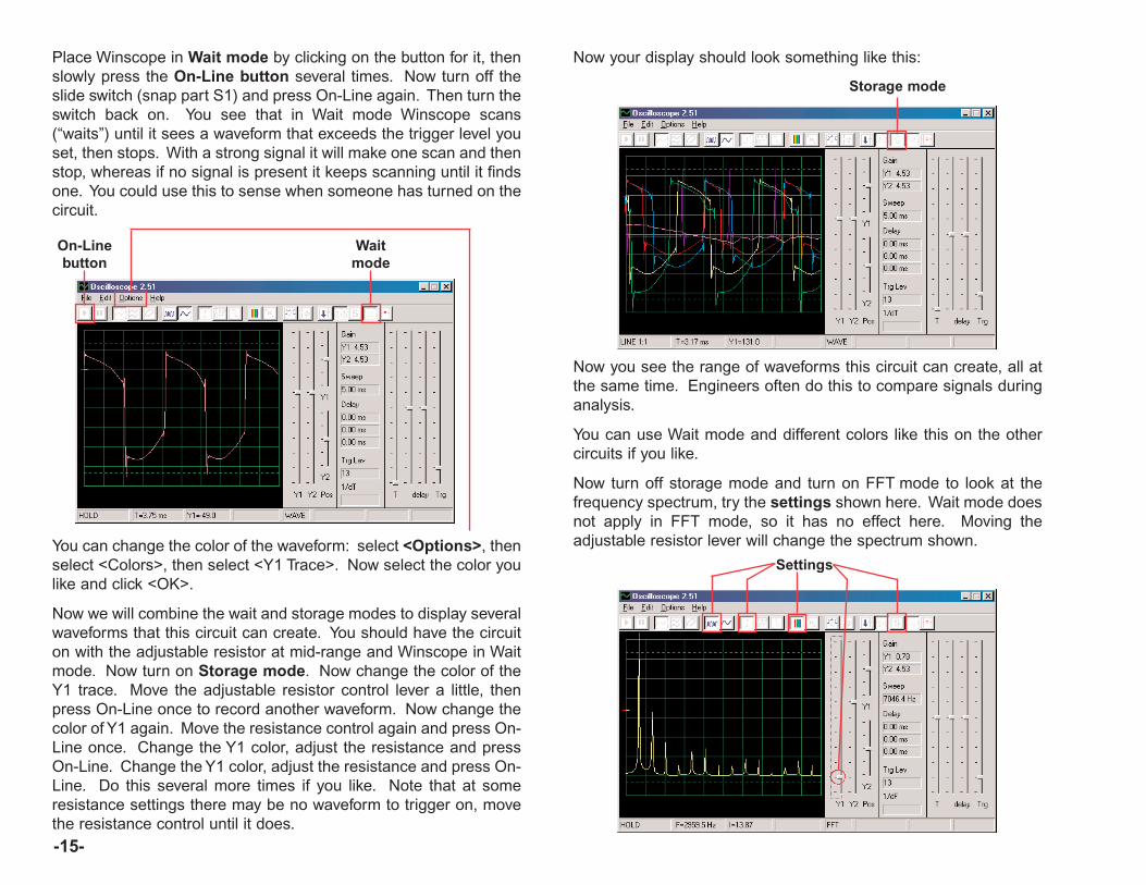
Place Winscope in Wait mode by clicking on the button for it, thenslowly press the On-Line button several times. Now turn off theslide switch (snap part S1) and press On-Line again. Then turn theswitch back on. You see that in Wait mode Winscope scans(“waits”) until it sees a waveform that exceeds the trigger level youset, then stops. With a strong signal it will make one scan and thenstop, whereas if no signal is present it keeps scanning until it findsone. You could use this to sense when someone has turned on thecircuit.
-15-
On-Linebutton
Waitmode
You can change the color of the waveform: select <Options>, thenselect <Colors>, then select <Y1 Trace>. Now select the color youlike and click <OK>.
Now we will combine the wait and storage modes to display severalwaveforms that this circuit can create. You should have the circuiton with the adjustable resistor at mid-range and Winscope in Waitmode. Now turn on Storage mode. Now change the color of theY1 trace. Move the adjustable resistor control lever a little, thenpress On-Line once to record another waveform. Now change thecolor of Y1 again. Move the resistance control again and press On-Line once. Change the Y1 color, adjust the resistance and pressOn-Line. Change the Y1 color, adjust the resistance and press On-Line. Do this several more times if you like. Note that at someresistance settings there may be no waveform to trigger on, movethe resistance control until it does.
Now your display should look something like this:
Storage mode
Now you see the range of waveforms this circuit can create, all atthe same time. Engineers often do this to compare signals duringanalysis.
You can use Wait mode and different colors like this on the othercircuits if you like.
Now turn off storage mode and turn on FFT mode to look at thefrequency spectrum, try the settings shown here. Wait mode doesnot apply in FFT mode, so it has no effect here. Moving theadjustable resistor lever will change the spectrum shown.
Settings

-16-
Project #PC4OBJECTIVE: To look at the output signal from a circuit that makes alarm sounds.
Light & Sounds PC
Build the circuit and connect the Winscope PC-interface cable asshown, the cable should still be connected to the microphone inputon your computer.

If continuing from the previous experiment then close the Winscopeprogram and run it again, to reset the settings. Then use the mouseto set it up as shown here, and turn on the switch (snap part S1).Click on the On-Line button to activate.
You should see a waveform similar to that shown here, but it will beconstantly changing. This is because the siren sound you hear isnot a continuous tone but instead is constantly changing. Note thedifferences in the waveshape for this circuit compared to the circuitin Project PC1.
Your picture may appear different due to variations in themicrophone input designs between computers. See the notes onpage 4 for details.
On-Linebutton
Set up
Click on the FFT button to look at the frequency spectrum.Also set the amplitude and time scales (really amplitude andfrequency scales in FFT mode) to be as shown here.
You should see a fuzzy spectrum similar to that shown here, but itwill be constantly changing. This is because the siren sound youhear is not a continuous tone but instead is constantly changingfrequency, and it spends more time at some frequencies than atothers. Note the differences in the spectrum for this circuitcompared to the circuit in Project PC1.
FFT buttonAmplitude
Time scales
-17-
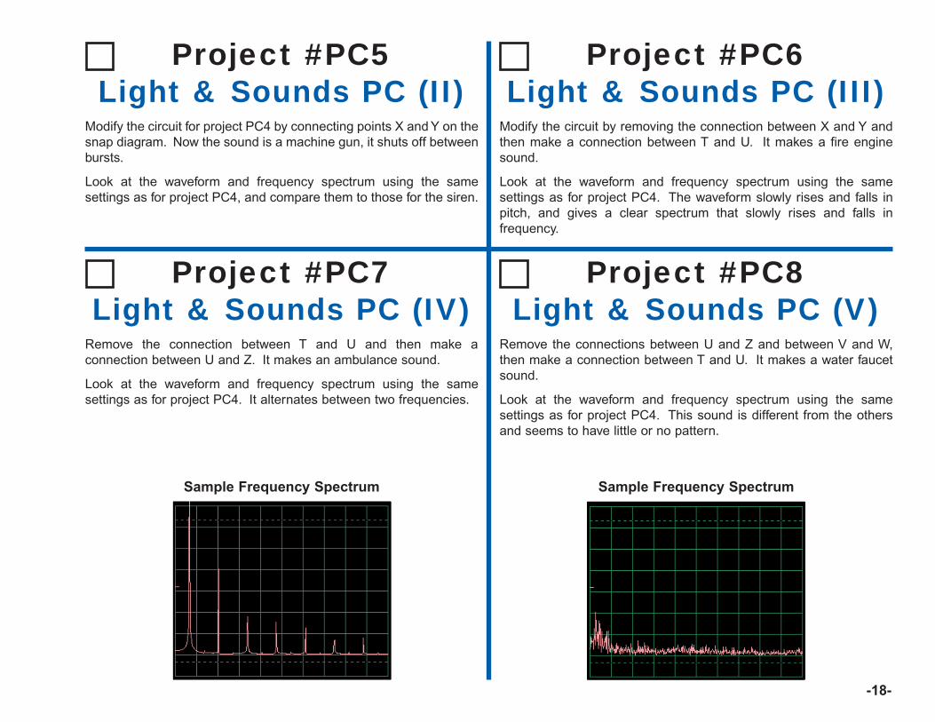
-18-
Sample Frequency Spectrum
Modify the circuit for project PC4 by connecting points X and Y on thesnap diagram. Now the sound is a machine gun, it shuts off betweenbursts.
Look at the waveform and frequency spectrum using the samesettings as for project PC4, and compare them to those for the siren.
Project #PC5Light & Sounds PC (II)
Modify the circuit by removing the connection between X and Y andthen make a connection between T and U. It makes a fire enginesound.
Look at the waveform and frequency spectrum using the samesettings as for project PC4. The waveform slowly rises and falls inpitch, and gives a clear spectrum that slowly rises and falls infrequency.
Project #PC6Light & Sounds PC (III)
Remove the connection between T and U and then make aconnection between U and Z. It makes an ambulance sound.
Look at the waveform and frequency spectrum using the samesettings as for project PC4. It alternates between two frequencies.
Project #PC7Light & Sounds PC (IV)
Remove the connections between U and Z and between V and W,then make a connection between T and U. It makes a water faucetsound.
Look at the waveform and frequency spectrum using the samesettings as for project PC4. This sound is different from the othersand seems to have little or no pattern.
Project #PC8Light & Sounds PC (V)
Sample Frequency Spectrum

-19-
Look at the waveform in oscilloscope mode using the same settingsas earlier in PC4. Replace the whistle chip with the speaker andremove the lamp. Compare the waveform you see now with thatfrom the whistle chip. The amplitude of the waveforms are similarbut yet the sound from the speaker is much louder, since thespeaker is drawing more current.
Project #PC9Light & Sounds PC (VI)
Project #PC10Modulation
OBJECTIVE: To demonstrate AM and FM modulation.
Build the circuit shown. If continuing from the previousexperiment then close the Winscope program and run it again, toreset the settings. Click on the On-Line button to activate, andturn on the switch (snap part S1). If you press the key (snap partS2) then you will hear a siren sound, but it will not be very loud.Click on the 1:1 button to set the gain automatically, then talk orhum into the microphone (snap part X1) and observe how thewaveform changes. You may freeze the waveform by pressingthe Hold button if desired.
Hold button 1:1 button
When you are quiet you just get a stream of pulses with roughlyequal height and width, as shown at left.
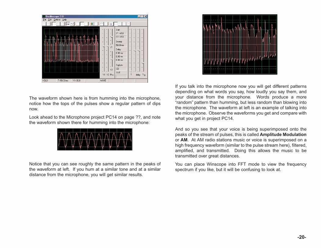
-20-
The waveform shown here is from humming into the microphone,notice how the tops of the pulses show a regular pattern of dipsnow.
Look ahead to the Microphone project PC14 on page ??, and notethe waveform shown there for humming into the microphone:
Notice that you can see roughly the same pattern in the peaks ofthe waveform at left. If you hum at a similar tone and at a similardistance from the microphone, you will get similar results.
If you talk into the microphone now you will get different patternsdepending on what words you say, how loudly you say them, andyour distance from the microphone. Words produce a more“random” pattern than humming, but less random than blowing intothe microphone. The waveform at left is an example of talking intothe microphone. Observe the waveforms you get and compare withwhat you get in project PC14.
And so you see that your voice is being superimposed onto thepeaks of the stream of pulses, this is called Amplitude Modulationor AM. At AM radio stations music or voice is superimposed on ahigh frequency waveform (similar to the pulse stream here), filtered,amplified, and transmitted. Doing this allows the music to betransmitted over great distances.
You can place Winscope into FFT mode to view the frequencyspectrum if you like, but it will be confusing to look at.

-21-
You probably noticed that the width of the pulses in the pulsestream is constantly changing, that is because there is actually asecond type of modulation occurring here. Press the key again andyou hear a siren. A siren is not a stable tone but rather is constantlychanging in frequency. Change the time scale to 0.5ms/div andobserve the range of waveforms:
Time scale
The width of the pulses (or frequency of the signal) is slowly beingchanged, at a regular and repetitive rate. This is an example ofFrequency Modulation, or FM. In AM you use a controlling signal(voice or music) to vary the amplitude of a second signal, in FM youuse the controlling signal to vary the frequency of the other signal.In this circuit the output frequency from the alarm IC is beingcontrolled by a signal created inside the alarm IC, but it could havebeen controlled by humming like you did for the AM (you don’t havethe parts needed to do this).
Look back at the Light & Sounds project PC4 on page 16. It showsseveral different ways of configuring the alarm IC to make differentsounds, all of these are examples of frequency modulation usingdifferent controlling signals created within the alarm IC. It alsoshows examples of the frequency spectrum.
Project #PC11Filtering
With the same circuit as PC10 and the same settings as shown atthe end of PC10, look at the waveform again and then press thekey. Notice how the pulses become more “rounded” when the keyis pressed. The whistle chip (snap part WC) has capacitance thatfilters or smoothes the output signal. Now replace the whistle chipwith the 0.02µF capacitor (snap part C1) and it should look similarthough you won’t hear any sound. You can also look at thefrequency spectrum in FFT mode like in the other projects.
Typical waveform usingwhistle chip
Typical waveform using0.02µµF capacitor
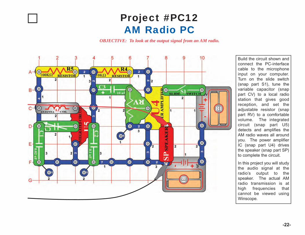
-22-
Project #PC12
OBJECTIVE: To look at the output signal from an AM radio.
Build the circuit shown andconnect the PC-interfacecable to the microphoneinput on your computer.Turn on the slide switch(snap part S1), tune thevariable capacitor (snappart CV) to a local radiostation that gives goodreception, and set theadjustable resistor (snappart RV) to a comfortablevolume. The integratedcircuit (snap part U5)detects and amplifies theAM radio waves all aroundyou. The power amplifierIC (snap part U4) drivesthe speaker (snap part SP)to complete the circuit.
In this project you will studythe audio signal at theradio’s output to thespeaker. The actual AMradio transmission is athigh frequencies thatcannot be viewed usingWinscope.
AM Radio PC
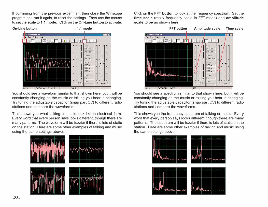
-23-
If continuing from the previous experiment then close the Winscopeprogram and run it again, to reset the settings. Then use the mouseto set the scale to 1:1 mode. Click on the On-Line button to activate.
You should see a waveform similar to that shown here, but it will beconstantly changing as the music or talking you hear is changing.Try tuning the adjustable capacitor (snap part CV) to different radiostations and compare the waveforms.
This shows you what talking or music look like in electrical form.Every word that every person says looks different, though there aremany patterns. The waveform will be fuzzier if there is lots of staticon the station. Here are some other examples of talking and musicusing the same settings above:
On-Line button 1:1 mode
Click on the FFT button to look at the frequency spectrum. Set thetime scale (really frequency scale in FFT mode) and amplitudescale to be as shown here.
You should see a spectrum similar to that shown here, but it will beconstantly changing as the music or talking you hear is changing.Try tuning the adjustable capacitor (snap part CV) to different radiostations and compare the waveforms.
This shows you the frequency spectrum of talking or music. Everyword that every person says looks different, though there are manypatterns. The spectrum will be fuzzier if there is lots of static on thestation. Here are some other examples of talking and music usingthe same settings above:
FFT button Time scaleAmplitude scale
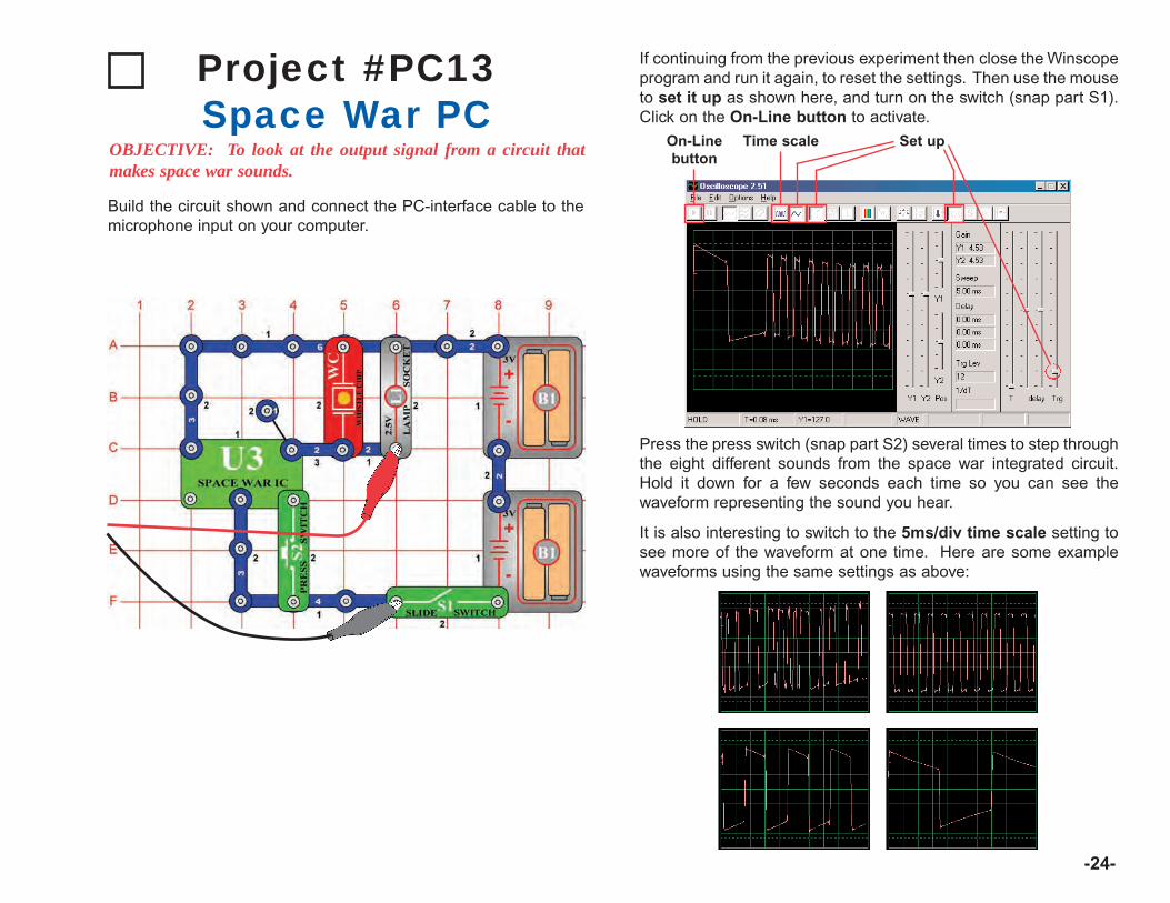
-24-
Build the circuit shown and connect the PC-interface cable to themicrophone input on your computer.
Project #PC13Space War PC
OBJECTIVE: To look at the output signal from a circuit thatmakes space war sounds.
If continuing from the previous experiment then close the Winscopeprogram and run it again, to reset the settings. Then use the mouseto set it up as shown here, and turn on the switch (snap part S1).Click on the On-Line button to activate.
Press the press switch (snap part S2) several times to step throughthe eight different sounds from the space war integrated circuit.Hold it down for a few seconds each time so you can see thewaveform representing the sound you hear.
It is also interesting to switch to the 5ms/div time scale setting tosee more of the waveform at one time. Here are some examplewaveforms using the same settings as above:
On-Linebutton
Set upTime scale
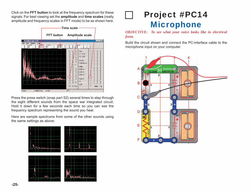
-25-
Click on the FFT button to look at the frequency spectrum for thesesignals. For best viewing set the amplitude and time scales (reallyamplitude and frequency scales in FFT mode) to be as shown here.
FFT button Amplitude scale
Time scale
Press the press switch (snap part S2) several times to step throughthe eight different sounds from the space war integrated circuit.Hold it down for a few seconds each time so you can see thefrequency spectrum representing the sound you hear.
Here are sample spectrums from some of the other sounds usingthe same settings as above:
Build the circuit shown and connect the PC-interface cable to themicrophone input on your computer.
Project #PC14Microphone
OBJECTIVE: To see what your voice looks like in electricalform.
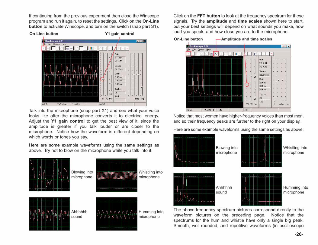
-26-
If continuing from the previous experiment then close the Winscopeprogram and run it again, to reset the settings. Click on the On-Linebutton to activate Winscope, and turn on the switch (snap part S1).
Talk into the microphone (snap part X1) and see what your voicelooks like after the microphone converts it to electrical energy.Adjust the Y1 gain control to get the best view of it, since theamplitude is greater if you talk louder or are closer to themicrophone. Notice how the waveform is different depending onwhich words or tones you say.
Here are some example waveforms using the same settings asabove. Try not to blow on the microphone while you talk into it.
On-Line button Y1 gain control
Blowing intomicrophone
Whistling intomicrophone
Ahhhhhhsound
Humming intomicrophone
Click on the FFT button to look at the frequency spectrum for thesesignals. Try the amplitude and time scales shown here to start,but your best settings will depend on what sounds you make, howloud you speak, and how close you are to the microphone.
Notice that most women have higher-frequency voices than most men,and so their frequency peaks are further to the right on your display.
Here are some example waveforms using the same settings as above:
On-Line button Amplitude and time scales
Blowing intomicrophone
Whistling intomicrophone
Ahhhhhhsound
Humming intomicrophone
The above frequency spectrum pictures correspond directly to thewaveform pictures on the preceding page. Notice that thespectrums for the hum and whistle have only a single big peak.Smooth, well-rounded, and repetitive waveforms (in oscilloscope

mode) have nearly all of their energy at a specific frequency like forthe hum. “Square” or “rectangular” looking waveforms (like inProject PC1) and most music have a series of mathematically-related peaks, while “random” waveforms (like from blowing into themicrophone or several people talking at the same time) have afrequency “blob” instead of distinct peaks.
Project #PC15Speaker Microphone
OBJECTIVE: To see what your voice looks like in electricalform.
A speaker uses electrical energy to create mechanical vibrations.These vibrations create variations in air pressure, called soundwaves, which travel across the room. You “hear” sound when yourears feel these air pressure variations. But if air pressure variationsreach the speaker from another source, they will cause it to vibratetoo. This, in turn, causes the speaker to create a small electricalsignal just like a microphone does (though not very efficiently, sincespeakers were not designed to be microphones).
-27-
Connect the PC-interface cable directly onto the speaker as shown;no other parts are needed here. If continuing from the previousexperiment then close the Winscope program and run it again, toreset the settings. Click on the On-Line button to activate.
Hold the speaker next to your mouth and talk into it to see whatyour voice looks like after the speaker converts it to electricalenergy. Adjust the Y1 gain control to get the best view of it.
Notice that you need to set the gain control higher here than in thepreceding project using the microphone, since speakers were notdesigned to be used in the same way.
You may switch to FFT mode and view the frequency spectrum inthe same manner as for the microphone project PC14.
On-Line button Y1 gain control
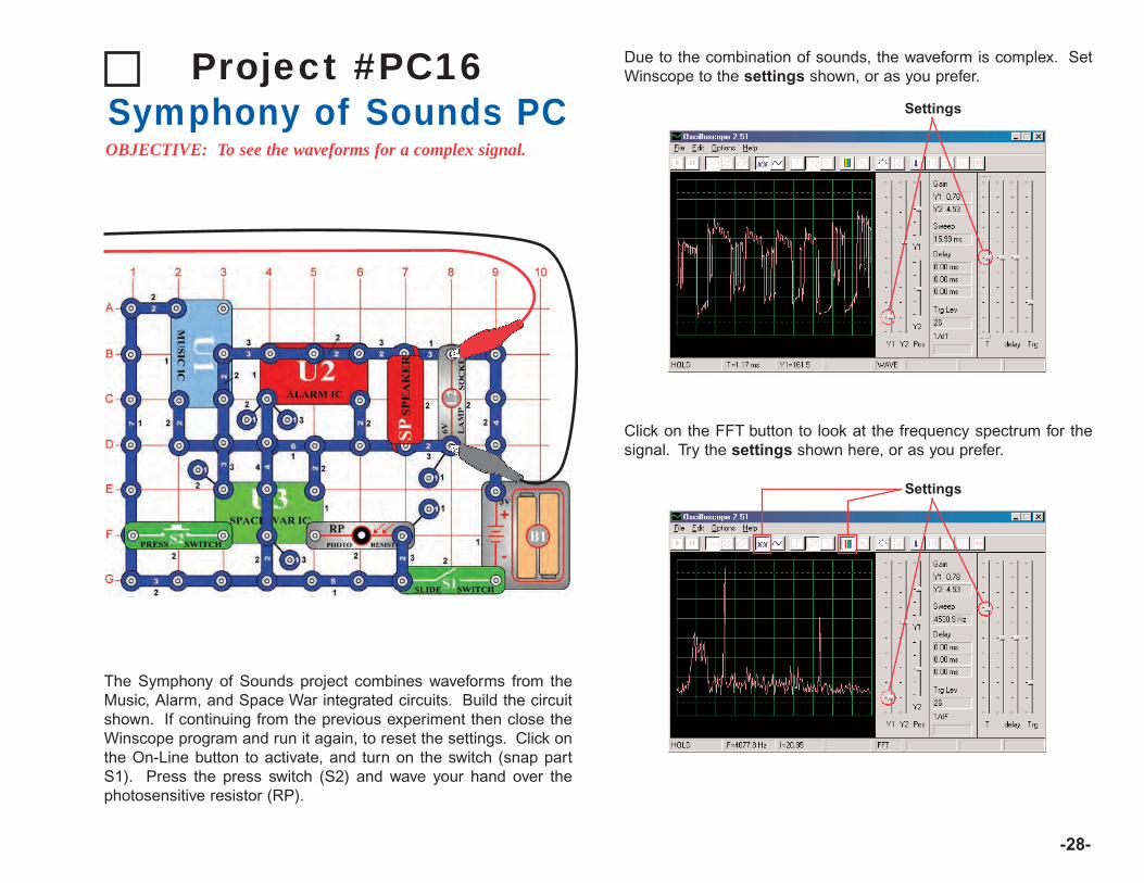
-28-
Project #PC16Symphony of Sounds PCOBJECTIVE: To see the waveforms for a complex signal.
The Symphony of Sounds project combines waveforms from theMusic, Alarm, and Space War integrated circuits. Build the circuitshown. If continuing from the previous experiment then close theWinscope program and run it again, to reset the settings. Click onthe On-Line button to activate, and turn on the switch (snap partS1). Press the press switch (S2) and wave your hand over thephotosensitive resistor (RP).
Due to the combination of sounds, the waveform is complex. SetWinscope to the settings shown, or as you prefer.
Settings
Click on the FFT button to look at the frequency spectrum for thesignal. Try the settings shown here, or as you prefer.
Settings

Project #PC17Doorbell PC
OBJECTIVE: To look at the output of a musical circuit.
-29-
Build the circuit shown. If continuing from the previous experimentthen close the Winscope program and run it again, to reset thesettings. Click on the On-Line button to activate, and turn on theslide switch (snap part S1). Try the settings shown here. Whenthe music stops, press the press switch (part S2) and it will resume.
Settings
Click on the 5ms/div time scale button and on the FFT button tolook at the frequency spectrum for the signal. The Y1 gain controlis set for high gain now, so the higher peaks are off the screen butlots of the lower peaks are visible.
Note that the sound is music and the oscilloscope waveform has a“square” shape, as a result the frequency spectrum has a lot ofpeaks with equal spacing.
Now adjust the gain lower until you see the higher peaks.
5ms/div timescale button Y1 gain controlFFT button

-30-
Project #PC18Periodic Sounds PC
OBJECTIVE: To look at the output of an alternately changingcircuit.
Build the circuit shown. If continuing from the previous experimentthen close the Winscope program and run it again, to reset thesettings. Click on the On-Line button to activate, and turn on theslide switch (snap part S1). Try the settings shown here.
The oscilloscope display alternates between 2 waveforms, the oneshown here and the one on the next page. This one shows somepulses followed by a flat signal, then more pulses, then flat, thenpulses, then flat . . .
This is the second oscilloscope waveform, using the same settings.It is a continuous series of pulses. You can use the Hold button tofreeze the display for easier viewing.
Settings
Hold button
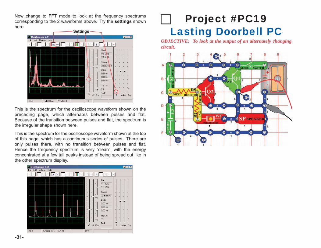
-31-
Now change to FFT mode to look at the frequency spectrumscorresponding to the 2 waveforms above. Try the settings shownhere.
Settings
This is the spectrum for the oscilloscope waveform shown on thepreceding page, which alternates between pulses and flat.Because of the transition between pulses and flat, the spectrum isthe irregular shape shown here.
This is the spectrum for the oscilloscope waveform shown at the topof this page, which has a continuous series of pulses. There areonly pulses there, with no transition between pulses and flat.Hence the frequency spectrum is very “clean”, with the energyconcentrated at a few tall peaks instead of being spread out like inthe other spectrum display.
Project #PC19Lasting Doorbell PC
OBJECTIVE: To look at the output of an alternately changingcircuit.
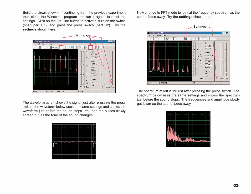
-32-
Build the circuit shown. If continuing from the previous experimentthen close the Winscope program and run it again, to reset thesettings. Click on the On-Line button to activate, turn on the switch(snap part S1), and press the press switch (part S2). Try thesettings shown here.
The waveform at left shows the signal just after pressing the pressswitch, the waveform below uses the same settings and shows thewaveform just before the sound stops. You see the pulses slowlyspread out as the tone of the sound changes.
Settings
Now change to FFT mode to look at the frequency spectrum as thesound fades away. Try the settings shown here.
Settings
The spectrum at left is for just after pressing the press switch. Thespectrum below uses the same settings and shows the spectrumjust before the sound stops. The frequencies and amplitude slowlyget lower as the sound fades away.
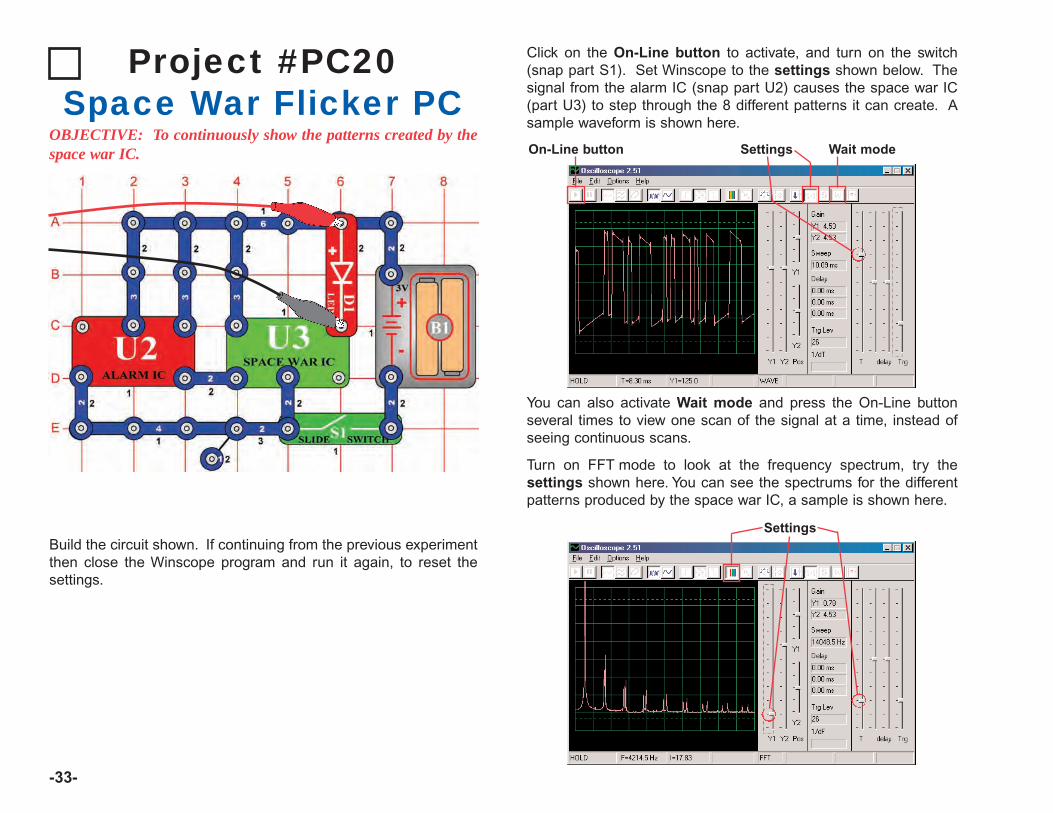
-33-
Project #PC20Space War Flicker PC
OBJECTIVE: To continuously show the patterns created by thespace war IC.
Click on the On-Line button to activate, and turn on the switch(snap part S1). Set Winscope to the settings shown below. Thesignal from the alarm IC (snap part U2) causes the space war IC(part U3) to step through the 8 different patterns it can create. Asample waveform is shown here.
Settings Wait modeOn-Line button
You can also activate Wait mode and press the On-Line buttonseveral times to view one scan of the signal at a time, instead ofseeing continuous scans.
Turn on FFT mode to look at the frequency spectrum, try thesettings shown here. You can see the spectrums for the differentpatterns produced by the space war IC, a sample is shown here.
SettingsBuild the circuit shown. If continuing from the previous experimentthen close the Winscope program and run it again, to reset thesettings.
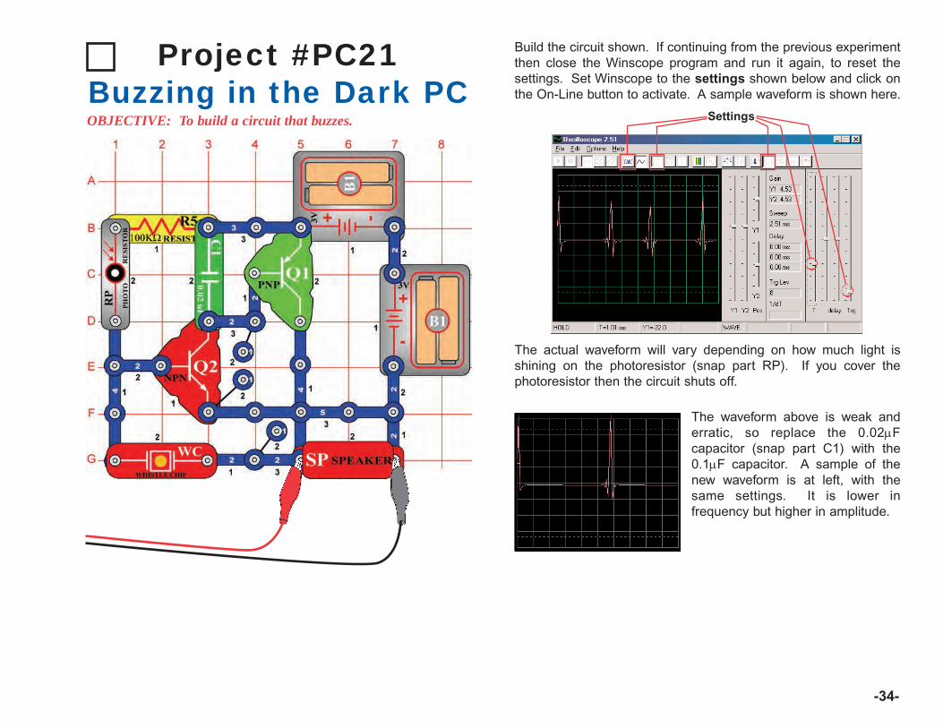
-34-
Project #PC21Buzzing in the Dark PCOBJECTIVE: To build a circuit that buzzes.
Build the circuit shown. If continuing from the previous experimentthen close the Winscope program and run it again, to reset thesettings. Set Winscope to the settings shown below and click onthe On-Line button to activate. A sample waveform is shown here.
The actual waveform will vary depending on how much light isshining on the photoresistor (snap part RP). If you cover thephotoresistor then the circuit shuts off.
Settings
The waveform above is weak anderratic, so replace the 0.02µFcapacitor (snap part C1) with the0.1µF capacitor. A sample of thenew waveform is at left, with thesame settings. It is lower infrequency but higher in amplitude.

-35-
Turn on FFT mode to look at the frequency spectrum, try thesettings shown here.
Now put the 0.02µF capacitor backin place of the 0.1µF capacitor tocompare its spectrum. A sample ison the left, with the sameWinscope settings as above. Aswith the oscilloscope mode, itsspectrum is weaker and moreerratic.
Settings
Project #PC22Trombone PC
OBJECTIVE: To build a circuit that sounds like a trombone.
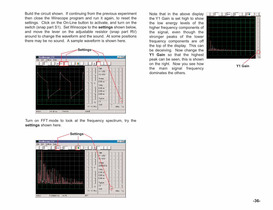
-36-
Build the circuit shown. If continuing from the previous experimentthen close the Winscope program and run it again, to reset thesettings. Click on the On-Line button to activate, and turn on theswitch (snap part S1). Set Winscope to the settings shown below,and move the lever on the adjustable resistor (snap part RV)around to change the waveform and the sound. At some positionsthere may be no sound. A sample waveform is shown here.
Settings
Note that in the above displaythe Y1 Gain is set high to showthe low energy levels of thehigher frequency components ofthe signal, even though thestronger peaks of the lowerfrequency components are offthe top of the display. This canbe deceiving. Now change theY1 Gain so that the highestpeak can be seen, this is shownon the right. Now you see howthe main signal frequencydominates the others.
Turn on FFT mode to look at the frequency spectrum, try thesettings shown here.
Settings
Y1 Gain

-37-
Build the circuit shown. If continuing from the previous experimentthen close the Winscope program and run it again, to reset thesettings. Click on the On-Line button to activate, and turn on theslide switch (snap part S1). Set Winscope to the settings shownon the upper right, and move the lever on the adjustable resistor(snap part RV) around to change the waveform and the sound. Atsome positions there may be no sound. A sample waveform isshown on the upper right.
You can also change to the0.5ms/div scale to take a closerlook at one of the pulses, shown onthe right:
Settings0.5ms/div scale
Turn on FFT mode to look at the frequency spectrum, try thesettings shown here.
Settings
Project #PC23Sound PulseOscillator PC
OBJECTIVE: To build a pulse oscillator.
LED (D1) is onlayer 1 directly
beneath thespeaker (SP).

-38-
Project #PC24High Pitch Bell PC
OBJECTIVE: To build a high pitch bell.
Build the circuit shown. If continuing from the previousexperiment then close the Winscope program and run itagain, to reset the settings. Click on the On-Line button toactivate, and hold down the press switch (snap part S2). SetWinscope to the settings shown on the upper right. Asample waveform is shown on the upper right.
Settings
Turn on FFT mode to look at the frequency spectrum, try thesettings shown here.
Settings
You can change some of the Winscope settings around to view thewaveform and spectrum in different ways if desired. You can alsoplace the 0.02µF capacitor on top of the whistle chip to lower thefrequency.

-39-
Project #PC25Tone Generator PC
OBJECTIVE: To build a high frequency oscillator.
Build the circuit shown. If continuing from the previous experimentthen close the Winscope program and run it again, to reset thesettings. Click on the On-Line button to activate, and turn on theswitch. Set Winscope to the settings shown below. A samplewaveform is shown here.
Settings
Turn on FFT mode to look at the frequency spectrum, try thesettings shown here.
Settings
Modify the circuit for project PC25 by placing the 0.02µF capacitor(C1) on top of the whistle chip (WC). Look at the waveform andfrequency spectrum using the same settings as for project PC19,the frequency is lower now.
Modify the circuit for project PC25 by placing the 0.1µF capacitor(C2) on top of the whistle chip (WC). Look at the waveform andfrequency spectrum using the same settings as for project PC19,but you may want to change the time scale since the frequency ismuch lower now.
Project #PC26Tone Generator PC (II)
Project #PC27Tone Generator PC (III)
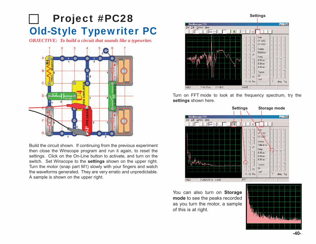
-40-
Project #PC28Old-Style Typewriter PCOBJECTIVE: To build a circuit that sounds like a typewriter.
Build the circuit shown. If continuing from the previous experimentthen close the Winscope program and run it again, to reset thesettings. Click on the On-Line button to activate, and turn on theswitch. Set Winscope to the settings shown on the upper right.Turn the motor (snap part M1) slowly with your fingers and watchthe waveforms generated. They are very erratic and unpredictable.A sample is shown on the upper right.
Settings
Turn on FFT mode to look at the frequency spectrum, try thesettings shown here.
You can also turn on Storagemode to see the peaks recordedas you turn the motor, a sampleof this is at right.
Settings Storage mode
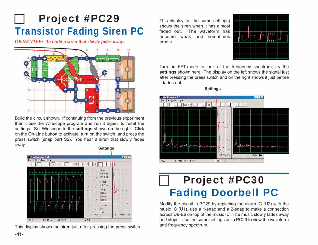
-41-
Project #PC29Transistor Fading Siren PCOBJECTIVE: To build a siren that slowly fades away.
Build the circuit shown. If continuing from the previous experimentthen close the Winscope program and run it again, to reset thesettings. Set Winscope to the settings shown on the right. Clickon the On-Line button to activate, turn on the switch, and press thepress switch (snap part S2). You hear a siren that slowly fadesaway.
This display shows the siren just after pressing the press switch.
Settings
This display (at the same settings)shows the siren when it has almostfaded out. The waveform hasbecome weak and sometimeserratic.
Turn on FFT mode to look at the frequency spectrum, try thesettings shown here. The display on the left shows the signal justafter pressing the press switch and on the right shows it just beforeit fades out.
Settings
Modify the circuit in PC29 by replacing the alarm IC (U2) with themusic IC (U1), use a 1-snap and a 2-snap to make a connectionacross D6-E6 on top of the music IC. The music slowly fades awayand stops. Use the same settings as in PC29 to view the waveformand frequency spectrum.
Project #PC30Fading Doorbell PC
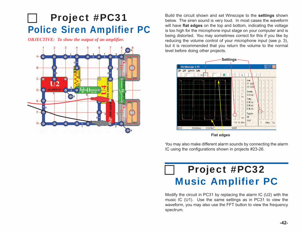
-42-
Project #PC31Police Siren Amplifier PCOBJECTIVE: To show the output of an amplifier.
You may also make different alarm sounds by connecting the alarmIC using the configurations shown in projects #23-26.
Build the circuit shown and set Winscope to the settings shownbelow. The siren sound is very loud. In most cases the waveformwill have flat edges on the top and bottom, indicating the voltageis too high for the microphone input stage on your computer and isbeing distorted. You may sometimes correct for this if you like byreducing the volume control of your microphone input (see p. 3),but it is recommended that you return the volume to the normallevel before doing other projects.
Settings
Flat edges
Modify the circuit in PC31 by replacing the alarm IC (U2) with themusic IC (U1). Use the same settings as in PC31 to view thewaveform, you may also use the FFT button to view the frequencyspectrum.
Project #PC32Music Amplifier PC

Project #PC33Space War Amplifier PC
-43-
Build the circuit shown and use the same settings as in PC31 toview the waveform. Press the switch (S2) to change the soundsand waveform.
Project #PC34Adjustable Tone Generator PC
Build the circuit shown, and try the settings below. Move theadjustable resistor lever to change the frequency. A samplewaveform is shown here.
Settings
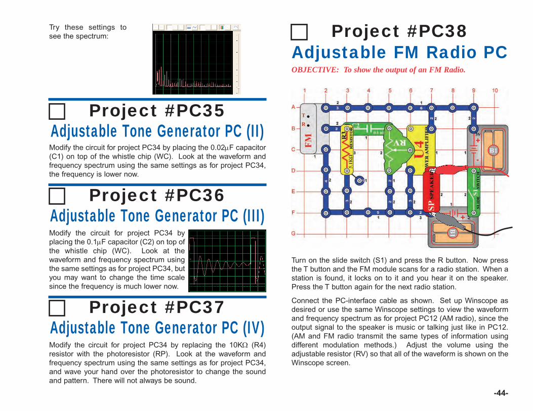
-44-
Try these settings tosee the spectrum:
Modify the circuit for project PC34 by placing the 0.02µF capacitor(C1) on top of the whistle chip (WC). Look at the waveform andfrequency spectrum using the same settings as for project PC34,the frequency is lower now.
Project #PC35Adjustable Tone Generator PC (II)
Modify the circuit for project PC34 byplacing the 0.1µF capacitor (C2) on top ofthe whistle chip (WC). Look at thewaveform and frequency spectrum usingthe same settings as for project PC34, butyou may want to change the time scalesince the frequency is much lower now.
Project #PC36Adjustable Tone Generator PC (III)
Project #PC37Adjustable Tone Generator PC (IV)Modify the circuit for project PC34 by replacing the 10KΩ (R4)resistor with the photoresistor (RP). Look at the waveform andfrequency spectrum using the same settings as for project PC34,and wave your hand over the photoresistor to change the soundand pattern. There will not always be sound.
Turn on the slide switch (S1) and press the R button. Now pressthe T button and the FM module scans for a radio station. When astation is found, it locks on to it and you hear it on the speaker.Press the T button again for the next radio station.
Connect the PC-interface cable as shown. Set up Winscope asdesired or use the same Winscope settings to view the waveformand frequency spectrum as for project PC12 (AM radio), since theoutput signal to the speaker is music or talking just like in PC12.(AM and FM radio transmit the same types of information usingdifferent modulation methods.) Adjust the volume using theadjustable resistor (RV) so that all of the waveform is shown on theWinscope screen.
Project #PC38Adjustable FM Radio PCOBJECTIVE: To show the output of an FM Radio.
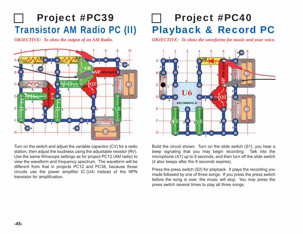
Turn on the switch and adjust the variable capacitor (CV) for a radiostation, then adjust the loudness using the adjustable resistor (RV).Use the same Winscope settings as for project PC12 (AM radio) toview the waveform and frequency spectrum. The waveform will bedifferent from that in projects PC12 and PC38, because thosecircuits use the power amplifier IC (U4) instead of the NPNtransistor for amplification.
Project #PC39Transistor AM Radio PC (II)OBJECTIVE: To show the output of an AM Radio.
-45-
Build the circuit shown. Turn on the slide switch (S1), you hear abeep signaling that you may begin recording. Talk into themicrophone (X1) up to 8 seconds, and then turn off the slide switch(it also beeps after the 8 seconds expires).
Press the press switch (S2) for playback. It plays the recording youmade followed by one of three songs. If you press the press switchbefore the song is over, the music will stop. You may press thepress switch several times to play all three songs.
Project #PC40Playback & Record PCOBJECTIVE: To show the waveforms for music and your voice.
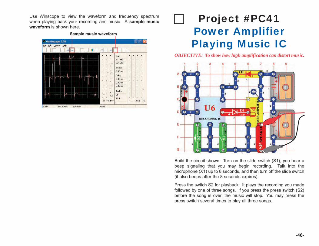
-46-
Use Winscope to view the waveform and frequency spectrumwhen playing back your recording and music. A sample musicwaveform is shown here.
Sample music waveform
Build the circuit shown. Turn on the slide switch (S1), you hear abeep signaling that you may begin recording. Talk into themicrophone (X1) up to 8 seconds, and then turn off the slide switch(it also beeps after the 8 seconds expires).
Press the switch S2 for playback. It plays the recording you madefollowed by one of three songs. If you press the press switch (S2)before the song is over, the music will stop. You may press thepress switch several times to play all three songs.
Project #PC41Power AmplifierPlaying Music IC
OBJECTIVE: To show how high amplification can distort music.

-47-
This recorder IC circuit works the same as in project PC40 exceptthat the power amplifer IC (U4) used here makes the sound muchlouder than in project PC40. If viewed with the same Winscopesettings as in PC40, then the waveform appears as shown below.The output from the recorder IC has not changed, but the flatedges at the top and bottom of the waveform indicate that thehigher amplification is distorting the sound.
Flat edges
Project #PC42Music Meter PC
OBJECTIVE: To show how high amplification can distort music.
Use the LOW (or 10mA) setting on the meter (M2). Set theadjustable resistor (RV) to the bottom position and turn on the slideswitch (S1), you will see a waveform like that shown below. Set theadjustable resistor to the top, and the waveform looks like thatshown on the bottom left, due to lower resistance in the circuit. Asample frequency spectrum is also shown on the bottom right.
Settings
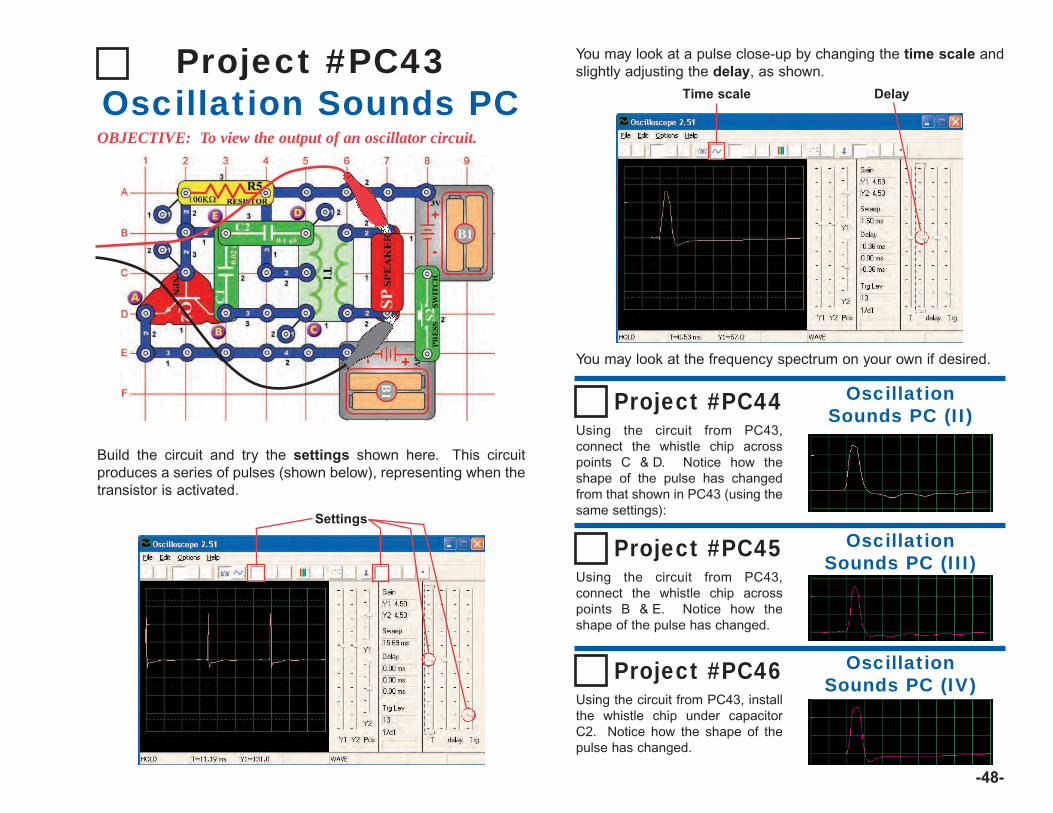
-48-
Project #PC43Oscillation Sounds PC
OBJECTIVE: To view the output of an oscillator circuit.
You may look at a pulse close-up by changing the time scale andslightly adjusting the delay, as shown.
You may look at the frequency spectrum on your own if desired.
Build the circuit and try the settings shown here. This circuitproduces a series of pulses (shown below), representing when thetransistor is activated.
Settings
Time scale Delay
Project #PC44 OscillationSounds PC (II)
Using the circuit from PC43,connect the whistle chip acrosspoints C & D. Notice how theshape of the pulse has changedfrom that shown in PC43 (using thesame settings):
Project #PC45 OscillationSounds PC (III)
Using the circuit from PC43,connect the whistle chip acrosspoints B & E. Notice how theshape of the pulse has changed.
Project #PC46 OscillationSounds PC (IV)
Using the circuit from PC43, installthe whistle chip under capacitorC2. Notice how the shape of thepulse has changed.
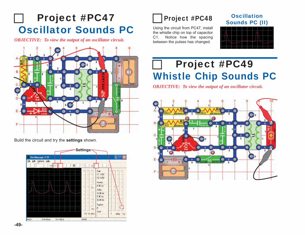
-49-
Project #PC47Oscillator Sounds PC
OBJECTIVE: To view the output of an oscillator circuit.
Build the circuit and try the settings shown.
Settings
Project #PC48 OscillationSounds PC (II)
Using the circuit from PC47, installthe whistle chip on top of capacitorC1. Notice how the spacingbetween the pulses has changed.
Project #PC49Whistle Chip Sounds PCOBJECTIVE: To view the output of an oscillator circuit.
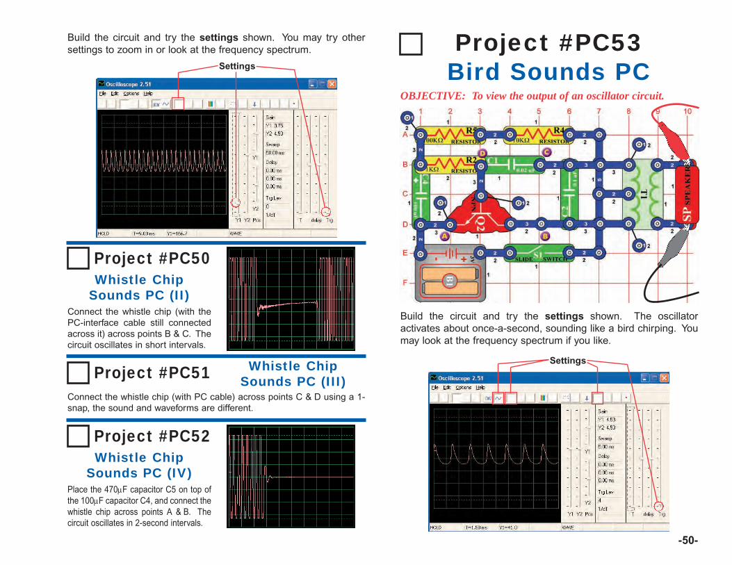
-50-
Build the circuit and try the settings shown. You may try othersettings to zoom in or look at the frequency spectrum.
Settings
Project #PC50Whistle Chip
Sounds PC (II)Connect the whistle chip (with thePC-interface cable still connectedacross it) across points B & C. Thecircuit oscillates in short intervals.
Project #PC51 Whistle ChipSounds PC (III)
Connect the whistle chip (with PC cable) across points C & D using a 1-snap, the sound and waveforms are different.
Project #PC52Whistle Chip
Sounds PC (IV)Place the 470µF capacitor C5 on top ofthe 100µF capacitor C4, and connect thewhistle chip across points A & B. Thecircuit oscillates in 2-second intervals.
Project #PC53Bird Sounds PC
OBJECTIVE: To view the output of an oscillator circuit.
Build the circuit and try the settings shown. The oscillatoractivates about once-a-second, sounding like a bird chirping. Youmay look at the frequency spectrum if you like.
Settings
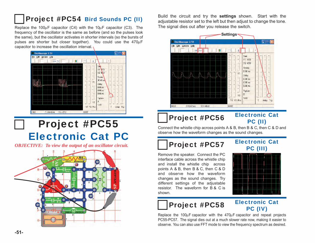
-51-
Project #PC54 Bird Sounds PC (II)Replace the 100µF capacitor (C4) with the 10µF capacitor (C3). Thefrequency of the oscillator is the same as before (and so the pulses lookthe same), but the oscillator activates in shorter intervals (so the bursts ofpulses are shorter but closer together). You could use the 470µFcapacitor to increase the oscillation interval.
Project #PC55Electronic Cat PC
OBJECTIVE: To view the output of an oscillator circuit.
Build the circuit and try the settings shown. Start with theadjustable resistor set to the left but then adjust to change the tone.The signal dies out after you release the switch.
Settings
Project #PC56Connect the whistle chip across points A & B, then B & C, then C & D andobserve how the waveform changes as the sound changes.
Project #PC57Remove the speaker. Connect the PCinterface cable across the whistle chipand install the whistle chip acrosspoints A & B, then B & C, then C & Dand observe how the waveformchanges as the sound changes. Trydifferent settings of the adjustableresistor. The waveform for B & C isshown.
Electronic CatPC (III)
Electronic CatPC (II)
Project #PC58Replace the 100µF capacitor with the 470µF capacitor and repeat projectsPC55-PC57. The signal dies out at a much slower rate now, making it easier toobserve. You can also use FFT mode to view the frequency spectrum as desired.
Electronic CatPC (IV)
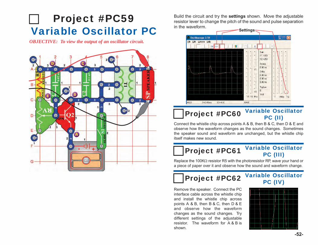
-52-
Project #PC59Variable Oscillator PC
OBJECTIVE: To view the output of an oscillator circuit.
Build the circuit and try the settings shown. Move the adjustableresistor lever to change the pitch of the sound and pulse separationin the waveform.
Settings
Project #PC60Connect the whistle chip across points A & B, then B & C, then D & E andobserve how the waveform changes as the sound changes. Sometimesthe speaker sound and waveform are unchanged, but the whistle chipitself makes new sound.
Project #PC61
Remove the speaker. Connect the PCinterface cable across the whistle chipand install the whistle chip acrosspoints A & B, then B & C, then D & Eand observe how the waveformchanges as the sound changes. Trydifferent settings of the adjustableresistor. The waveform for A & B isshown.
Variable OscillatorPC (III)
Variable OscillatorPC (II)
Project #PC62
Replace the 100KΩ resistor R5 with the photoresistor RP, wave your hand ora piece of paper over it and observe how the sound and waveform change.
Variable OscillatorPC (IV)
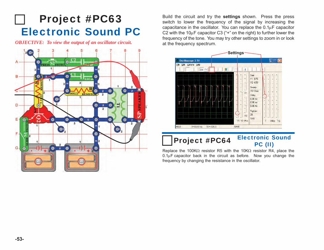
-53-
Project #PC63Electronic Sound PC
OBJECTIVE: To view the output of an oscillator circuit.
Build the circuit and try the settings shown. Press the pressswitch to lower the frequency of the signal by increasing thecapacitance in the oscillator. You can replace the 0.1µF capacitorC2 with the 10µF capacitor C3 (“+” on the right) to further lower thefrequency of the tone. You may try other settings to zoom in or lookat the frequency spectrum.
Settings
Project #PC64Replace the 100KΩ resistor R5 with the 10KΩ resistor R4, place the0.1µF capacitor back in the circuit as before. Now you change thefrequency by changing the resistance in the oscillator.
Electronic SoundPC (II)

-54-
Project #PC65Siren PC
OBJECTIVE: To view the output of a fading siren circuit.
Build the circuit and try the settings shown. Flip on the slideswitch and press the press switch for a few seconds and release.View the waveform as a siren starts up and then slowly fades away.
Settings
Note: Although the amplitude of the pulses appears to be varyingacross the screen (the wider time scale shown below shows thisbetter), this is an illusion caused by the way Winscope measuresthe signal. The amplitude of the pulses is not really varying.
Winscope makes measurements using a 44kHz sampling rate,which is fast enough to measure the frequency of this signal(varying from 1-5kHz). However these pulses have much of theirenergy spread among higher frequencies that approach thesampling rate (see the sample spectrum plots at right), where theamplitude measurement becomes increasingly inaccurate.

-55-
Use the circuit from the Drawing Resistors project #516, butconnect the PC-interface cable across the speaker. Use a pencil todraw the shapes shown in projects #516-518, as per the directionsgiven in those projects. Use Winscope to see how the waveformsand frequency spectrums vary as you move the jumper wiresacross the shapes to change the sounds. A sample is shown here.
Next, place the loose ends of the jumper wires into a cup of water, asper project #519. The waveforms and frequency spectrum you seewill be similar to the resistors you drew, just as the sounds are similar.
Project #PC66Drawing Resistors PC
OBJECTIVE: To draw your own resistors.
Settings
Settings
Build the circuit and try the settings shown. Flip on the slide switchand press the press switch a few times while moving the adjustableresistor control around. View the waveform and frequencyspectrum.
Project #PC67Electronic Noisemaker PCOBJECTIVE: To view the output of an oscillator circuit.
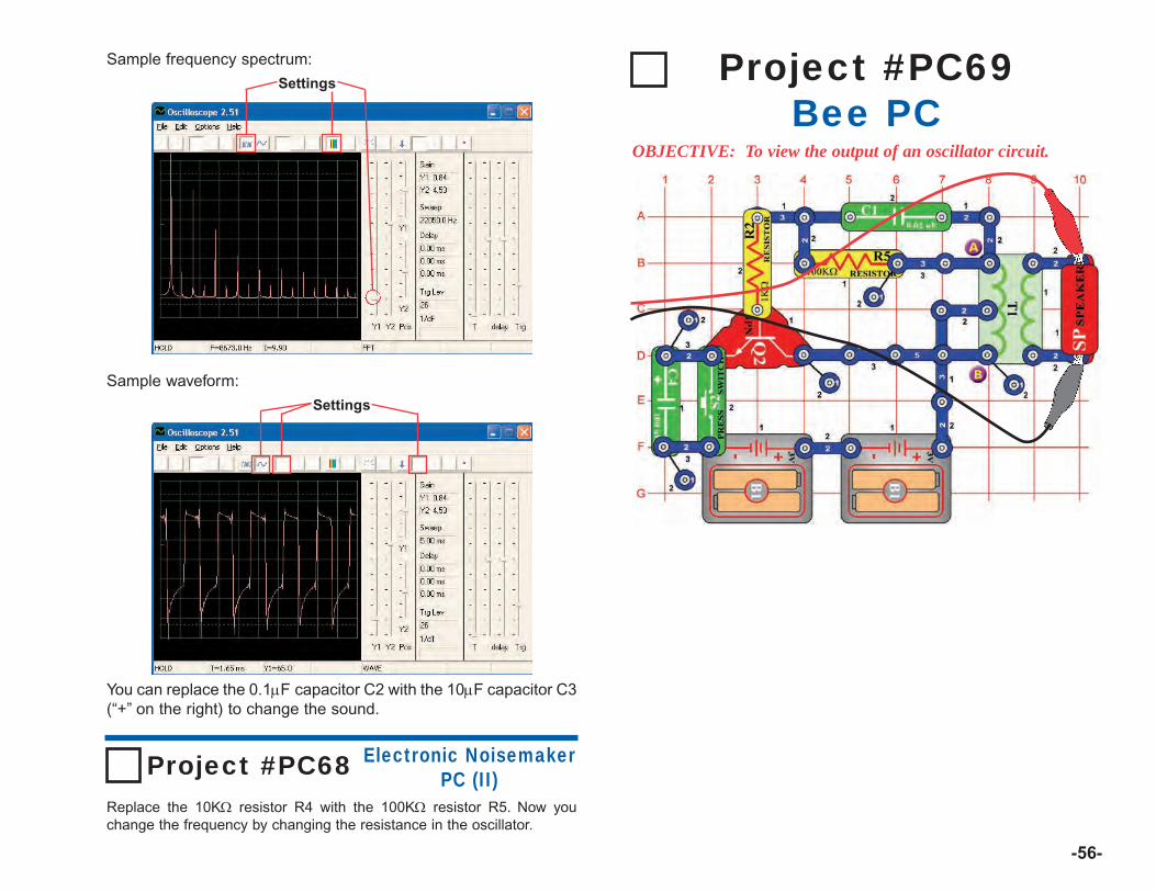
-56-
Sample frequency spectrum:
You can replace the 0.1µF capacitor C2 with the 10µF capacitor C3(“+” on the right) to change the sound.
Settings
Sample waveform:
Settings
Project #PC68Replace the 10KΩ resistor R4 with the 100KΩ resistor R5. Now youchange the frequency by changing the resistance in the oscillator.
Electronic NoisemakerPC (II)
Project #PC69Bee PC
OBJECTIVE: To view the output of an oscillator circuit.
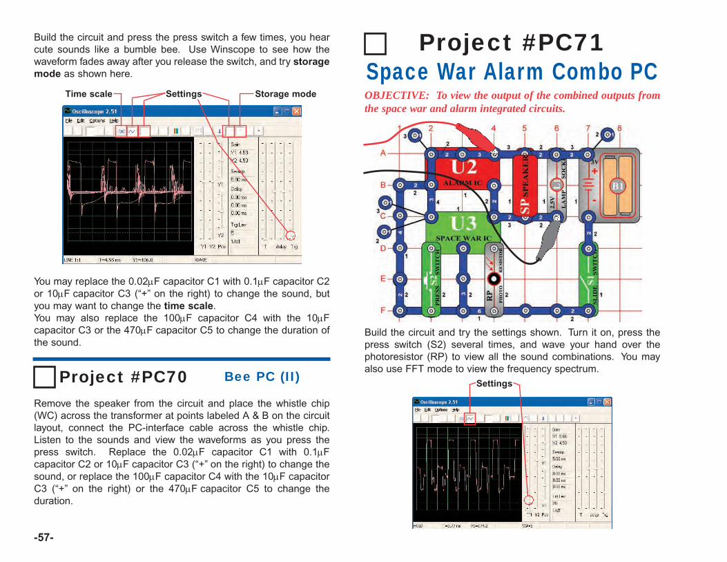
-57-
Build the circuit and press the press switch a few times, you hearcute sounds like a bumble bee. Use Winscope to see how thewaveform fades away after you release the switch, and try storagemode as shown here.
You may replace the 0.02µF capacitor C1 with 0.1µF capacitor C2or 10µF capacitor C3 (“+” on the right) to change the sound, butyou may want to change the time scale.You may also replace the 100µF capacitor C4 with the 10µFcapacitor C3 or the 470µF capacitor C5 to change the duration ofthe sound.
SettingsTime scale Storage mode
Project #PC70Remove the speaker from the circuit and place the whistle chip(WC) across the transformer at points labeled A & B on the circuitlayout, connect the PC-interface cable across the whistle chip.Listen to the sounds and view the waveforms as you press thepress switch. Replace the 0.02µF capacitor C1 with 0.1µFcapacitor C2 or 10µF capacitor C3 (“+” on the right) to change thesound, or replace the 100µF capacitor C4 with the 10µF capacitorC3 (“+” on the right) or the 470µF capacitor C5 to change theduration.
Bee PC (II)
Build the circuit and try the settings shown. Turn it on, press thepress switch (S2) several times, and wave your hand over thephotoresistor (RP) to view all the sound combinations. You mayalso use FFT mode to view the frequency spectrum.
Project #PC71Space War Alarm Combo PCOBJECTIVE: To view the output of the combined outputs fromthe space war and alarm integrated circuits.
Settings

-58--58-
Build the circuit and try the settings shown. Turn it on, press thepress switch (S2) several times, and wave your hand over thephotoresistor (RP) to view all the sound combinations. Comparethe waveform and spectrum to the alarm IC combo circuit.
Project #PC72Space War Music Combo PCOBJECTIVE: To view the output of the combined outputs fromthe space war and music integrated circuits.
Settings
Build the circuit and try the settings shown. Turn it on and viewthe waveforms.
Project #PC73Sound Mixer PC
OBJECTIVE: To view the output of the music and alarmintegrated circuits.
Settings

IMPORTANT NOTICE
Disclaimer Information
Oscilloscope for Windows95® or newer, version 2.51.
OSCILLOSCOPE IS SUPPLIED TO YOU AS IS, AND INNO CASE IS THE AUTHOR OF THIS PROGRAMRESPONSIBLE FOR PERSONAL INJURY, HARDWAREAND/OR DATA DAMAGE, PROPERTY DAMAGE ORPROFIT LOSS ARISING FROM USE OR INABILITY TOUSE THIS SOFTWARE.
THERE IS NO GUARANTEE IMPLIED OR OTHERWISETO THE FITNESS OF THIS OSCILLOSCOPE PROGRAMFOR ANY PARTICULAR PURPOSE. THIS SOFTWAREIS NOT INTENDED FOR INDUSTRIAL ORCOMMERCIAL USE.
Elenco® Electronics, Inc.150 Carpenter AvenueWheeling, IL 60090
(847) 541-3800Website: www.elenco.com
e-mail: [email protected]