
Specialists' Meeting on Heat Exchanging Components of Gas ...
625
International Atomic Energy Agency IWGGCR-9 International Working Group on Gas-Cooled Reactors Specialists' Meeting on Heat Exchanging Components of Gas-Cooled Reactors Dusseldorf Federal Republic of Germany 16-19 April 1984 hosted by Bundesministerium fur Forschung und Technologie 31/42
-
Upload
khangminh22 -
Category
Documents
-
view
0 -
download
0
Transcript of Specialists' Meeting on Heat Exchanging Components of Gas ...

International Atomic Energy Agency IWGGCR-9
International Working Group on Gas-Cooled Reactors
Specialists' Meetingon
Heat Exchanging Components of Gas-Cooled Reactors
DusseldorfFederal Republic of Germany
16-19 April 1984
hosted byBundesministerium fur Forschung und Technologie
3 1 / 4 2

Please be aware that all of the Missing Pages in this document wereoriginally blank pages

Introduction
The Specialists' Meeting on "Heat Exchanging Components of Gas-
cooled Reactors" was held at the Ministry of Economic and Trans-
port of the State North Rhine Westphalia, Diisseldorf, FRG
16-19 April 1984.
The meeting was sponsored by the IAEA on the recommendation of
the International Working Group on Gas-Cooled Reactors and was
hosted by the Federal Ministry of Research and Technology of the
Federal Rebublic of Germany.
The meeting was attended by 62 participants from Austria, France,
Federal Republic of Germany, Japan, Poland, Sweden, Switzerland,
United Kingdom of Great Britain and Northern Ireland and the
United States of America.
The objective of the meeting was to provide a forum, both formal
and informal, for the exchange and discussion of technical infor-
mation relating to heat exchanging and heat conducting components
for gas-cooled reactors.
The technical part of the meeting was divided into eight subject
sessions:
I. Heat exchanging components for process heat
application - design requirements and r/d
programmes
II. Status of the design and construction of
intermediate He/He heat exchangers
III. Design, construction and performance of steam
generators
- 2 -

3
V. Metallic materials and design codes
VI. Design and construction of valves and hot gas
ducts
VII. Description of component test facilities and
test results
VIII. Manufacturing of heat exchanging components
A total of 38 papers were presented by the participants on behalf
of their organizations during the meeting, and an opportunity for
open discussion of the paper topic followed each presentation.

Session I
Heat exchanging components for process heat application
- design requirements and R & D programmes
No 1 Status of the R&D program in the field of the heat
carrying and heat transfer components of the PNP-
project
H. Mausbeck, W. Jansing; Interatom GbmH; FRG
No 2 Design requirements on HTR main components for process
heat application
K. Dumm; Interatom GmbH; FRG
No 3 Helium/helium heat exchangers and hot-gas ducts for the
PNP-project according to the BBC/HRB-concept
H. Schmitt, B. Jiirgens, J. Knaul; Hochtemperatur-Reak-
torbau GmbH; FRG
Session II
Status of the design and construction of intermediate
He/He heat exchangers
No 4 Recent research and development of intermediate heat
exchanger for VHTR plant
A. Shimizu, N. Matsumura, H. Nishikawa, S. Yamada;
Industries, LTD; Japan
No 5 Development of a helium/helium intermediate heat ex-
changer (He/He-IHX) with helical coil tube bundle
A. Czimczik; L. & C. Steinmuller GmbH; FRG
G. Hirschle; Gebr. Sulzer AG; Switzerland
No 6 Improved spacers for high temperature gas-cooled heat
exchangers
L. A. Nordstrom; Swiss Federal Institute for Reactor
Research; Switzerland
- 1 -

r
No 7 Life time test of a partial model of HTGR helium-helium
heat exchanger
M. Kitagawa, H. Hattori, A. Ohtomo, T. Teramae,
J. Hamanaka, M. Itoh, S. Urabe; Ishikawajima-Harima
Heavy Industrie Co., LtD.; Japan
No 8 Development, construction and analysis of the URKO
intermediate heat exchanger, R. Exner, M. Podhorskiy;
Balcke-Durr AG; FRG
No 9 Development of a new type of high-temperature-insula-
tion-material and its application in the PNP-project
R. Burger, R. Ganz; Didier-Werke AG, FRG
No 10 Seismic analysis of a helical coil type heat exchanger
I. Nishiguchi, 0. Baba, H. Yatabe; Japan Atomic Energy
Research Institute; Babcock Hitachi K. K.; Japan
Session III
Design, construction and performance of steam generator
No 11 Design and development of steam generators for the AGR
power stations at Heysham II/Torness
A. N. Charcharos, A. G. Jones; National Nuclear Corpo-
rat ion Ltd.; UK
No 12 Monitoring and performance analysis of AGR boilers
during commissioning and power raising
M. El-Nagdy, R. M. Harrison; Nuclear Engineering
Department; Babcock Power Ltd.; UK
No 13 Experience with the commissioning of helically coiled
advanced gas-cooled reactor boilers
D. B. Kettle; CEGB-Generation Development and Construc-
tion Division; UK
- 2 -

No 14 Investigations of the gas-side heat transfer and flow
characteristics of the AGR steam generators
J. Lis; Central Electricity Research Laboratories; UK
No 15 Effect on inlet and outlet shell side flow and heat
transfer on the performance of HTGR straight tube heat
exchangers
D.P. Carosella; GA Technologies; USA
Session IV
Design, development and fabrication of steam reformers
No 16 Status of an in-line reformer design for modular HTGR
R. Gluck, W. H. Whitling, A. J. Lipps; General Electric
Company; USA
No 17 Development and fabrication of a helium heated steam
reformer
W. Panknin, W. Nowak; L. & C. Steinmuller GmbH; FRG
No 18 Assembly and operation experience of the EVA II - steam
reforming bundle
H. F. NieBen, R. Harth; Kernforschungsanlage Julich GmbH;
W. Kessel; Rheinische Braunkohlenwerke AG; FRG
Session V
Metallic materials and design codes
No 19 Evaluation of materials for heat exchanging components
in advanced helium-cooled reactors
F. Schubert; Kernforschungsanlage Julich GmbH; FRG
No 20a Pressure vessel design codes: A review of their applica-
bility to HTGR components at temperatures above 800°C
P. T. Hughes; General Electric Company; USA
K. Bieniussa; Gesellschaft fur Reaktorsicherheit GmbH,
H. H. Over; Kernforschungsanlage Julich GmbH; FRG
- 3 -
No 20b Status of design code work for metallic high temperature
components
K. Bieniussa; Gesellschaft fur Reaktorsicherheit; FRG
H. J. Seehafer; Interatom? FRG
H. H. Over; Kernforschungsanlage Jiilich GmbH; FRG
P. Hughes; General Electric Company; USA
No 21 Oxide films on austenitic HTR heat exchanger materials
as a tritium barrier
H. P. Buchkremer, R. Hecker, H. Jonas, H. J. Leyers,
D. Stover; Kernf orschungsanlage Jiilich GmbH; FRG
No 22 Effect of creep-fatigue damage relationships upon HTGR
heat exchanging design
D. P. Carosella, M. M. Kozina, J. H. King, M. Basol;
GA Technologies; Combustion Engineering Inc.; USA
Session VI
Design and construction of valves and hot gas ducts
No 23 The Klinger hot gas double axial valve
J. Kruschik; Klinger Engineering; Austria;
H. Hiltgen; Interatom GmbH; FRG
No 24 Two layers thermal insulations tests for designing of
hot gas ducts
T. Nakase, S. Midoriyama, K. Roko, A. Yoshizaki;
Kawasaki Heavy Industries, Ltd.; Japan
No 25 Status of the development on hot gas ducts for HTRs
H. Stehle, E. Klas; Interatom GmbH; FRG
No 26 Graphite and carbon-carbon components for hot gas ducts
in the HTR
G. Popp, U. Gruber, H. Boder, K. Janssen?
Sigri Elektrographit GmbH; FRG
- 4 -
f
No 27 Research on thermal insulation for hot gas ducts
P. Brockerhoff; Kernforschungsanlage Jiilich GmbH; FRG
Session VII
Description of component test facilities and test
results
No 28 Facility for endurance tests of thermal insulations
R. Mauersberger; Hochtemperatur-Reaktorbau GmbH; FRG
No 29 Construction and performance tests of helium engineering
demonstration loop (HENDEL) for VHTR
M. Hishida, T. Tanaka, H. Shimomura, K. Sanokawa;
Japan Atomic Energy Research Institute; Japan
No 30 Testing of high-temperature components in the KVK
W. Jansing; Interatom GmbH; FRG
No 31 WKV-operation experiences with heat exchanging compo-
nents of a nuclear gasification pilot plant
R. Kirchhoff, K. H. van Heek; Bergbau-Forschung GmbH;
FRG
No 32 The test facility EVA II/ADAM II -
Description and operational results
R. Harth, H. F. Niessen, V. Vau;
Kernforschungsanlage Jiilich GmbH; FRG
No 33 Modification of the AVR to a versatile nuclear test
facility for high temperature components
H. Barnert, N. Kirch, E. Ziermann;
Kernforschungsanlage Jiilich GmbH;
Arbeitsgemeinschaft Versuchsreaktor GmbH; FRG
No 34 Heat removal by natural circulation in gas-cooled rod-
bundles
M. Hudina; Swiss Federal Institute for Reactor Research;
Switzerland
5 -

Session VIII
Manufacturing of heat exchanging components
No 35 Manufacture of steam generator units and components for
the AGR power stations at Heysham II/Torness
J. R. Glasgow, K. Parkin? Nuclear Systems Limited; UK
No 36 The use of bimetallic welds in the THTR steam genera-
tors
U. Blumer, H. Fricker, S, Amacker; Sulzer Brothers Ltd.;
Switzerland
No 37 GMA-narrow gap welding of PNP-hot gas collectors
K. Iversen, A. Palussek; Interatom GmbH; FRG
No 38 Forged hollows (alloy 617) for PNP-project
F. Hofmann; Vereinigte Deutsche Metallwerke AG; FRG
S U M M A R Y
Session I: Heat exchanging components for process
heat application - design requirements
and R & D programmes
Session Chairman: E. Balthesen
KFA-Jiilich - PTH -, FRG
The first session of the Specialist's Meeting comprised survey
papers describing the application of heat exchanging components
in nuclear process heat plant concepts in the Federal Republic
of Germany. These concepts are based on He-cooled high tempe-
rature reactors as nuclear heat sources for steam gasification
and hydrogasification of coal and for a thermochemical heat pipe
system. The consideration of the strong interaction between
nuclear heat source and application process illuminated the func-
tion and the main design requirements for the heat ducting and
exchanging components. The component designs are partially de-
pending on different reactor designs. INTERATOM presented the
HTR modular concept consisting of a number of independent small
pebble bed reactor units with a thermal output of 170 MW each.
Each modul can be combined either with a steam reformer in the
primary circuit or with a He/He heat exchanger.
The system company HRB presented a modified THTR pebble bed
reactor embedded in PCRV. This concept fundamentally applies
an intermediate heat transfer circuit with a tandem heat ex-
changer design consisting of a high temperature and a low tempe-
rature unit each.
The process requirements, the gaseous media, the high temperatures
and the necessary application of new materials mean a great techni-
cal challenge for the development, design work as well as
testing.
The result of an extensive component development up to now - al-
though in a relatively early stage - indicate that manufacturing
and supply will be feasible in time. No prohibitive questions
— 2 —

page - 2 -
have been discovered up to now. The present program may be
considered as an effective iteration process between design
work, materials qualification, code evaluation, testing and
requirements specification which ultimately will also contri-
bute to establish the necessary licensing criteria.
Moreover, the papers included descriptions of the capability
and experience from the two large-scale test facilities, the
thermochemical heat pipe system demonstration plant EVA II at
KFA-Jiilich, in which successful steam reformer testing has been
performed, and the multi-purpose component test facility KVK
at INTERATOM Bensberg,where in particular tests of heat ex-
changers in a 10 MW(th) scale are being prepared.

S U M M A R Y :
Session II: Status of the design and construction
of intermediate He/He heat exchanger
Session Chairman: K. Parkin,
NEI, UK
Mr. Shimizu described the recent research and development which
sought and achieved improvements both in potential performance
and economy of manufacture. The use of helically rolled fin tube,
automatic orbital welding and simplified assembly techniques
were highlighted.Discussion included limitation of NDE on helical
tubes in service and insulation on the central tube.
A comprehensive presentation by Mr. Czimczik described the fa-
brication and quality control procedures of the experimental
helical heat exchanger. The importance of results from experimental
tests due to commence early in 1985 was stressed to allow follow
up work.
Mr. Nordstrom presented work done in the selection of an improved
tube spacer grid. Five different geometries were assessed and one
type finally chosen. The comparison of predicted and experimental
performance was considered sufficiently accurate. The work has
been usefully communicated to the USA.
Life time testing of a partial model was the subject of Mr. Itoh.
Three models were used, experiments were described together with
results. Good agreement was observed between predicted and ex-
perimental lives. Data on mechanical strength and other metall-
urgical features was obtained from the experiments. The design
code used was considered appropriate for this model.
Mr. Podhorsky gave a comprehensive description of the U tube
compact heat exchanger.Comparison was made with previous heat
exchanger and design, development work was shown to have brought
- 2 -

page - 2 -
about improvements and made savings in manufacture.
The results indicated insensitivity to gas flow induced vi-
bration and it was suggested that a successful conclusion will
be arrived at within the timescale laid down i.e. Nov 1981 -
Dec 1987.
Insulation aspects of the U tube compact heat exchanger were
covered in detail by Mr. Burger. The basis of this work has
provided solution for other nuclear components.
The session was concluded by a presentation from Mr. Hishida
who described a finite element model of the structure of an
IHX helical tube bundle, vessel and centre pipe. The model
included gap elements to cover for the practical arrangements
where gaps exist to accomodate thermal expansion. In addition
a stopper arrangement was proposed on the centre pipe.
The seven papers presented fully identified the status of design
and construction of intermediate He/He heat exchangers. Several
comparisons were made with earlier designs all resulting in im-
provements particularly regarding economy of manufacture.
S U M M A R Y
Session III: Design, Construction and Performance
of Steam Generators
Session Chairman: R. Gluck
General Electric, USA
This session consisted of the presentation of five papers
dealing with design, construction and performance testing
of a large of steam generator components designed for
application to High Temperature Gas Reactors.
The first four papers given by Messrs. Charcharos, Jones,
El-Nagdy, Kettle and Lis dealt with the United Kingdom ex-
perience with AGR power stations and showed the maturity
steam generator design evolution with particular emphasis
on correlation of analytical methods with performance tests.
The fifth paper given by Mr. Carosella examired the effects
of 90 degree bends on straight tube heat exchanger flow and
heat transfer.

Draf tS U M M A R Y :
Session IV: Design, development and fabrication
of steam reformer
Session Chairman: M. Itoh,-
IHI, Japan
In this session, results of recent design, fabrication and
operation of steam reformer were presented.
Summary of them is as follow:
1. Status of a Reformer Design for a Modular HTGR
in an In-Line Configuration
The focus of the Modular Reactor System (MRS) effort is the
development of generic nuclear heat source capable of supplying
heat to either a steam generator/electric cycle or a high tempe-
rature steam/methane reforming cacle.
This paper presents the results of recent design and analytical
studies conducted to evaluate the feasibility of using a steam/
methane reformer in a vertical In-Line (VIL) arrangement re-
former with the generic nuclear heat source.
2. Development and Fabrication of a Helium-Heated
Steam Reformer
1. For PNP a 96 MW steam reformer is to be designed. It
consists of a bundle with about 300 reformer tubes which
are shrouded by guide tubes.
2. In order to verify experimentally the design, to check the
thermohydraulic layout and to gain know-how for the fabri-
cation a small test reformer ( 5 MW, 18 tubes) is in pro-
duction now.
3. The reformer, fabricated mainly of Inconel 617 will be
be tested in EVA II.

S U M M A R Y :
Session \l: Metallic materials and design codes
Session Chairman: G. Hirschle
SULZER, Switzerland
Five papers were presented in this session that treated a very decisive part
of the HTGR development.
In the first presentation Mr. Schubert reviewed the status of material testing
for the PNP project. Data of four materials which were and still are being
investigated in respect to application for heat exchanging components were
presented. Emphasis was put on Inconel 617 (Nicrofer 5520 Co) for which an
extrapolation of the data to about 70 000 hrs is possible today. Effects of
corrosion and other failure mechanisms in different atmospheres were discussed
in detail.
The present status of design codes was reviewed by Mr. Bieniussa in the second
contribution. Although the existing codes have been established for materials
used at temperatures below 816 °C, the authors conclude that the available
design criteria and material data are sufficient to fabricate and operate
compoments of a prototype plant. In addition Mr. Gluck pointed out in his
presentation that ASME Code Case N-47 should be maintained as a basis for
calculations, and that there is a strong need for design rules simple enough
to be used during the layout period of components.
Mr. Jonas presented in the fourth paper their investigations on in situ growing
oxide layers suitable as tritium barrier. Although self healing of defective
layers is good, the barrier is not yet sufficient in the case of a cold start
of the component.
Referring to recent material test data Mr. Carosella proposed in the last
presentation to use a more conservative relationship for creep fatigue analysis
than given in ASME Code Case N-47. The design of the HTGR steam generator, it
is concluded, has sufficient margin to fulfil this more stringent relationship.

page - 2 -
3. Assembly and Operation Experience of the EVA II
Steam Reforming Bundle
1. The results of behaviour of the bundle consisting
30 tubes during the 6.000 operation hours at tempe-
rature above 800 °C were presented.
2. To simulate the plug-off of tube in a nuclear heated
steam reformer, some experiments were carried out with
groups of tubes shut-off on the process gas side.
3. Preliminary results of the after operation inspection
were presented.

S U M M A R Y
Session VI: Design and construction of valves and hot gas ducts
Session Chairman: Mr. H. Witulski
Ministry of Economic and Transport of the State North
Rhine Westphalia, Duesseldorf, Federal Republic of
Germany
The inner surfaces of prestressed reactor vessels and hot gas ducts of
Gas-Cooled High Temperature Reactors need internal insulation to protect
the pressure bearing walls from high temperatures. The design parameters
of the insulation very closely depend on the reactor type. For the
primary circuit a gas duct with fully ceramic insulation has been
developed by INTERATOM. This insulation consists of a graphite gas
liner, a ceramic fibre insulation and a metallic pressure tube (support
tube). The gas liner is held in position in the support tube by means of
patented ceramic spacers. Coaxial flow is used in the area of the hot
gas duct, i.e. the suppport tube is cooled by the gas flowing back
(42 bar, 300 C). The thermal elongations among the reactor and the
heat-exchangers are compensated by means of two angular bellows.
The internal insulation of the secondary circuit consists of a metallic
internal lining tube and a ceramic fibre insulation which is wrapped
around the former. V-shaped spacers in the insulation prevent axial flow
in the insulating material. The complete insulating system is mounted in
a support tube. This unit is slid into the pressure tube as a slice-in
unit. Therefore the periodic inspection is provided. This insulating
system is used for all the components in the intermediate circuit such as
elbows, compensators and T-pieces.

- 2 -
An extensive experimental programme has to be worked through in order to
qualify the hot gas ducts. In addition to the tests on prototype
components in INTERATOM's component test circuit (KVK), several tests are
being carried out on components and component parts, by the
project-partners, namely the Juelich Nuclear Research Plant (KFA), the
Juelich High Temperature Reactor Construction (HRB) and INTERATOM
(Bensberg). For the primary hot gas duct thermocycling tests have been
successfully carried out by INTERATOM.
For the secondary hot gas duct an original section of about 6 m has been
tested in the KVK up to 2500 hours, with a max. temperature of 950°C.
The experimental work at KFA-Juelich was described by Mr. Broeckerhoff.
The work was started at KFA in 1971 for HHT using three test facilities.
At first metallic foil insulation and stuffed fibre insulating systems
the hot gas ducting shrouds of which were made of metal have been
tested. Because of the elevated helium temperature in case of PNP and
the resulting lower strength of the metallic parts the interest was
directed to rigid ceramic materials for the inner shrouds and spacers.
This led to modified structures which were designed by INTERATOM and
which were also tested at KFA.
The main object of the investigations was to study the influence of
temperature and pressure on the thermal efficiency of the structures. At
first the insulating systems, e.g. the INTERATOM-design with spherical
spacers, their instrumentation and the experiments will be described.
After that the temperature distributions within the insulation and at the
pressure tube are presented. Thermal fluxes and effective thermal
conductivities in axial and circumferential direction of the pressure
tube are given and compared.
Coaxial double walled piping is planned to be used for a primary cooling
system piping of the Very High Temperature Gas-cooled Reactor (VHTR) of

- 3 -
JAERI as described by Mr. Nakase in his paper. The pipe consists of an
outer pressure pipe for the reactor inlet gas flow and an inner pipe with
internal insulations for the reactor outlet gas flow. The internal
insulations are designed to consist of two layers; metal insulation is in
the extremely inside for the higher temperature gas and fibrous insulation
is between the inner pipe and the metal insulation. The thermal
characteristics of inner pipe with two insulation layers are necessary for
the designing of the primary cooling system piping.
Thermal characteristics tests were performed by using Kawasaki's helium
test loop (KH-200), which has two hot gas ducts specimen of 267 A mm
diameter and 5000 mm length with simulated two layers insulation. The one
is installed in a horizontal position and the other is in a vertical
position. The tests were conducted at the temperature of 500 to 1000° C,
the pressure of 20 and 40 kg/cm G, and the flow rate of 100 and 200 g/s.
The distributions of temperature and heat flux at the surface of the ducts
are confirmed to be within an allowable range. The test results were
analyzed, and useful design data of the metal insulation and the fibrous
insulation were obtained.
Valves can be a containment shut-off system or a safety device for the
components of the reactor plant.
The main design features are:
Compact design due to a special valve port configuration with very low
pressure loss
Automatic shut-off in case of accidental pressure loss in the circuit
The flexible metallic sealing system
Gas-static bearings and their basic function
- Cooling system

The development of the gas-static bearings together with frequency
analysis and manufacturing details were explained in a paper from
Mr. Kruschik.
The paper also included results of stress analysis with finite-elements
and its influence on the design specially of the highly stressed
high-temperature components together with the analysis of the influence
of uneven temperature distribution on the valve geometry.

S U M M A R Y
Session VII: Description of component test
facilities and test results
Session Chairman: M. Robin
CEA, France
In this session dealing with the description of component test
facilities and test results 7 papers were presented and dis-
cussed .
Mr. Mauersberger, head of the Division for Experimental Engi-
neering of Hochtemperatur-Reaktobau GmbH reported on their
"Facility for Endurance Tests of Thermal Insulations" that
includes a pressure vessel designed for a 70 bar helium pressure,
a circulator with magnetic bearings capable of a 4.5 kg/sec flow-
rate and the required electrical heaters allowing as 950°C He
temperature and oil or water coolert in order to obtain the
specified temperature gradient through the experimented insul-
ation. The gas purification systems fitted for analytical mea-
surement of the gas impurities. The control system provides for
the thermal cycling of the insulation.
A typical insulation section composed of a pressure tube lined
with a graphite tube wrapped by a fibrous insulation material
with a density of 130 kg/m3 has been tested.
The temperature profiles within the insulation and along the
pressure tube were presented for various helium temperatures and
an important heat leakage effect was apparently determined signi-
ficant heat losses (up to 800 W/m2 with He at 950°C). The exper-
ience gained over a peroid of more than one year shows that oper-
ational requirements can be fullfilled completely.
Mr. Hishida, deputy manager of the HENDEL operating division in
the Department of High Temperature Engineering (JAERI) described
the "Construction and Performance Tests of the Helium Engineering
Demonstration Loop (HENDEL) for VHTR".

- 2 -
- two hot gas ducts were installed and tested in HENDEL. Looking
at the the cross section one see a liner tube made of Hastelloy X
which can be exposed to 1000°C He, a thermal insulation of the
fibrous ceramic insulation divided into three sublayers by
stainless steel foils, and a pressure tube made of miled steel.
Temperature distributions in both axial and circumferential
directions were measered with He at 10 to 40 bar, up to 950°C
flowing at rates of 0.5 to 3.5 kg/sec. The maximum temperature
variation range in the circumferential direction was only 35°C.
In the axial direction the temperature distribution of the
pressure tube was almost uniform. The effective thermal conducti-
vity for both horizontal and vertical duct sections are reported
with values 25 to 30 % higher in the latter case.
Thermal performances of the helium gas coolers, with U- tube or
straight tube bundles are in fair agreement with the values cal-
culated from the equations in the literature (Donohue).
Thermal performances of the heliumheaters (graphite rods heates
by Joule effect) were reported as satisfactory for the 3 .000 h
operation.
Mr. Jansing who is in charge of the INTERATOM helium and sodium
facilities at Bensberg described the "Testing of High Temperature
Components in the KVK" facility of 10 MW(th) that is capable of a
4.3 kg/sec flowrate of helium up to 950°C under 40 bar pressure.
After 5.000 h of operation including 1.200 h at temperatures in
the 900-950°C range it is concluded that
the helium tightness of the system is good (loss 1 kg/day/)
the performances of the gasfired and of the electrical
heaters are satisfactory
helium circulators, steam generator and steam heated helium
preheater operate reliably
the materials selected for internal insulation in hot ducts
are adequate
no inadmissible vibration level is recorded
- the helium atmosphere is easily adjusted to the required
purity

_ T _
a stable chromium oxide protective film developed on material
surfaces in the temperature range 900-950°C
the new process instrumentation and control system Teleperm-M
is easy to operate and reliable
- fast and effective repairs of defects in the helium heaters
are possible.
In summarizing it KVK operators very satisfactorily and can be
easily prepared for other series of component tests.
Mr. Kirchhoff from Bergbau-Forschung GmbH (Essen), leader of the
gasification Pilot Plant reported on the "Operating Experience
with Heat-Exchanging Components of the Semi-Technical Pilot Plant
for Steam Gasification of Coal using heat from HTR" within the
PNP project since 1976. The heat supplied by the HTR is simulated
by an electrically heated helium loop operating at pressures up
to 40 bar and temperatures up to 950°C. In the gasifier coal (in-
cluding caking coal) has been gasified in a 1 m2 fluidized bed
with a height of 4 m at a rate up to 6.4 t/day with a total of
26.600 h of operation. Besides the measurements of data on heat
transfer, gasification kinetics, insulating material and heat
transfer components suitable for operation at high temperature
(up to 950°C) were developed and tested. Particularly interesting
is the good behaviour of the helium tubes immerized in the
fluidized bed of 0.3 mm coal particles. In conclusion it seems
that all the experience required for the design, construction
and operation of a commercial size plant is available.
Mr. Harth, leader for Project EVA 11/ADAM II at KFA Julich, des-
cribed this facility and the related operational results. The
helium circuit represents a complete primary loop of a HTR for
process heat applications, the core being simulated by an elec-
trical heater with a maximum capacity of 11 MW(th) allowing for
950°C helium temperature.
_ 4 -
This high temperature He flows outside the tubes in a steam re-
former, exits at 650°C and enters a steam generator which also
includes an integrated gas circulator with a flowrate of 4
kg/sec. The aim of the tests was to determine the characteristics
of the operation in a wide range of parameters (He pressure 15 to
40 bar, He temperature 800 to 950°C, methane flowrate 0.18 to
0.66 kg/sec. The charge of catalyst (Raschingrings) by vacuum
extraction has been demonstrated, and also the replacement of a
single reformer tube without removal of the bundle.
Dissassembling and reinstallation of the reformer bundle has
been also successfully performed. In total the helium system has
been operated for 7.800 h including a 5.660 h heat transport
cycle. A new steam reformer is prepared for testing whose test
represents the last experimental step before a nuclear demon-
stration is considered.
Dr. Barnert, who is in charge of Process Heat Application
Studies at the Institute for Reactor Development (KFA-Julich)
described the "Modification of the AVR for High Temperature
Process Heat Systems Demonstration". He showed that the AVR
structure and layout allows for this modification that is
important for establishing the feasibility of coupling a nuclear
reactor to a chemical plant. The major part of the discussion
which followed was concerned with problems other than technical
but equally important (strategy of introduction and development
of nuclear process heat systems).
The last paper in the session was presented by Mr. Nordstrom,
leader of the Heat Exchanger Research Group of the Swiss Federal
Institute in Wiirenlingen and deals with "Heat removal by natural
circulation in gas-cooled reactor bundles", a fuel bundle for a
CO2 cooled GCFR being chosen to illustrate the calculation.
The conclusion is that the removal of decay heat by natural
circulation of gas under pressure can be ensured up to 1.5 % of
the nominal power. The temperature distributions in both axial and
radial directions were presented. It is important to take into
account the metal thermal conductivity in order to have a fair
agreement between experiment and calculated.

- 5 -
As a general conclusion, many facilities for testing heat transfer
components are available and operate satisfactorily in the range
of temperature and pressure of interest for the HTR development.
Their operation shows that there exists no technical problem that
cannot be solved before the end of this decade.
S U M M A R Y :
Session VIII: Manufacturing of heat exchanging
components
Session Chairman: J. Kruschik,
KLINGER, Austria
The first paper by Mr. Glasgow and Mr. Parkin gave in a review
of the design and the development: of manufacturing methods for
steam generators units.
The second paper by Mr. Blumer dealt with the method for welding
ferritic to austenitic tube material. The choice of the location
of the weld within the heating surface of the bundle was described
together with metallurgical considerations, the use of filler ma-
terial, stress analysis, etc.
The third paper by Mr. Iversen gave a thorough of GMA-narrow
gap welding and the inspection procedure. This new technic was
development for welding collections of Inconel 617.
Paper four, presented by Mr. Hofmann explained in full detail
the new process for production of forged hollows for collectors
in alloy 617.
These four papers gave a good review on modern manufacturing tech-
nics for nuclear components.

List of Participants and Observers
AUSTRIA
H.-O. FaberÖsterreichisches , ForschungszentrumSeibersdorf GesmbH.Lenaugasse 101082 Wien
FRANCE
M.G. RobinC.E.A., CEN de SaclayDEDR/CRGB.P.No. 2F-91190 GIf-sur-Yvette
FEDERAL REPUBLIC OFGERMANY
M. AndlerINTERATOM GmbH.Postfachn-5060 Bergisch-Gladbach 1
E. ArndtHochtemperatur-Reaktorbau GmbHPostfach 5360D-6800 Mannheim 1
E.R. BalthesenKernforschungsanlage Jü1 ich GmbH.Projektträger HTRPostfach 1913D-5170 Jülich 1
- 2 -

- 2 -
H. BarnertKernforschungsanlage Jü1 ich GmbHInstitut für ReaktorentwicklungPostfach 1913D-5170 Jü 1 ich
F. BerdanKlinger Eng ineeringWiener Straße 17A-2351 Wr. Neudorf
K. BienussaGesellschaft für Reaktorsicherheit mbHSchwerdnergasseD-5000 Köln
P. BröckerhoffKernforschungsanlage Jü1 ich GmbHInstitut für Eaktorbaue lementePostfach 1913D-5170 Julien
R- BurgerDidier-Werke AGEnergie-Techni kDidierstraße 31D-6200 Wiesbaden 12
A. CzimczikL. & C. Steinmüller GmbH.P.O.Box 100855D-5270 Gummersbach
W. DietzINTERATOM GmbH.PostfachD-5060 Bergisch-Gladbach
- 3 -

- 3 -
K.G. DummINTERATOM GmbH.PostfachD-5060 Bergisch-Gladbach
R. ExnerBalcke-Dürr AGHornberger StraßeD-4030 Ratingen
R. GanzDidier-Werke AGEnergie-TechnikDidierstraße 31D-6200 Wiesbaden 12
U. Grubervon Rehlingen Straße 48aD-8902 Neusäss/tfestheim
R. HarthKernforschungsanlage Jü1 ich GmbHProjekt Nukleare FernenergiePostfach 19T3D-5170 Jü 1 ich
F. HofmannVereinigte Deutsche Metallwerke AGGeschäftsoereich Nicxel-TechnologiePostfach 18 20Plettenberger Straße 2D-5980 Werdohl
K. IversenINTERATOM GmbH.PostfachD-5060 Bergisch-Gladbach
H. JonasKernforschungsanlage Jü1 ich GmbHPostfach 1913D-5170 Jülich
- 4 -

- 4 -
M. JurgensHochtemperatur-Reaktorbau GmbHPostfach 1913D-6800 Mannheim
W.T. Jans ingINTERATOM GmbH.PostfachD-5060 Bergisch-Giadbach
J.G. Keeble •Deutsche ICI GmbH.Lyoner Strafle 366000 Frankfurt/Main 71
M. SchaferKernforschungsanlage Julich GmbHProjekt Entwicklungsarbeiten furHochtemperaturreaktor-AnlagenPostfach 1913D-5170 Julich
R. KirchhoffBergbau-Forschung GmbHP.O. Box 1301400-4300 Essen 13
J. KnaulHochtemperatur-Reaktorbau GmbHPostfach 5360D-6800 Mannheim 1
J. KruschikKli nger Engi neeri ngWiener StraBe 17A-2351 Wr. Neudorf
R. MauersbergerHochtemperatur-Reaktorbau GmbHPostfach 2080D-5170 Julich
- 5 -

- 5 -
H.J. MausbeckINTERATOM GmbH.PostfachD-5060 Bergisch-Gladbach
Th. MonsauDer Minister für Wirtschaft, Mittelstand und Verkehrdes Landes Nordrhein-WestfalenHaroldstraße 4D-4000 Düsseldorf
H.F. NießenKernforschungsanlage Julien GmbH.Institut für ReaktorentwicklungPostfach 1913D-5170 Jülich
W. NowakL. &. C. Steinmüller GmbH.Fabrikstraße 1P.O. Box 100855D-5270 Gummersbach
H.-H. OverKernforschungsanlage Jülich GmbH.- IRWP.O. Box 1913D-5170 Jülich
W.K. PankninL. & C. Steinmül1er GmbH,Fabrikstraße 1P.O. Box 100855D-5270 Gummersbach
M. PodhorskyBalcke-Dürr AGHornberger StraßeD-4030 Ratingen
- 6 -

3/- 6 - ^ J
G. PoppSIGRI Elektrographit GmbHW.-V.-Siemens-Straße 18D-8901 Meitingen
H. ReutlerINTERATOM GmbH.PostfachD-5060 Bergisch-Gladbach
H. SchmittHochtemperatur-Reaktorbau GmbHPostfach 5360D-6800 Mannheim 1
F. SchubertKernforschungsanlage Jü1 ich GmbHInstitut für ReaktorwerkstoffePostfach 1913D-5170 Jülich
H.J. SeehaferINTERATOM GmbH.PostfachD-5060 Bergisch-Gladbach
H. StehleINTERATOM GmbH.PostfachD-5060 Bergisch-Gladbach
H. SteinDidier-Werke AGEnergie-TechnikDidierstraße 31D-6200 Wiesbaden 12
-7 -

- 7 -
H. WitulskiDer Minister fur Wirtschaft, Mittelstand und Verkehrdes Landes Nordrhein-WestfalenHaroldstrafte 4D-4000 Dusseldorf
JAPAN
Mr. M. HishidaDeputy General ManagerHENDEL Operation Devision,Department of High Temperature EngineeringTokai Research Establishment,Japan Atomic Energy Research InstituteTokai-mura, Ibaraki-ken 319-11
Mr. M. ItohSection Manager, Energy Develoment CenterIshikawajima-Harima Heavy Industries Co., LtdMarunochi 1-6-2 Chiyoda-ku,Tokyo, Japan
Mr. Akira ShimizuNuclear Plan Engineering and Designing SectionJagasaki Shipyard and Engine Works,Mitsubishi Heavy Industries, Ltd.Nagasaki Shipyard & Engine Works1-1 Akunouramachi Nagasaki 850-91
Nr. T. NakaseKawasaki Heavy Industries, Ltd.4-25 Minamisuna 2-chome, Koto-kuTokyo
POLAND
E. ObrykInstitute of Nucleare PhysicsRadzikowskiego 15231-342 KrakowPoland
- 8 -

- 8 -
SWEDEN
R.I. EkholmStudsvik Energiteknik ABS-61182 Nykoeping
SWITZERLAND
UK
U.R. BlumerSulzer Brothers Ltd.Ch-8400 Winterthur
G. HirschleSulzer Brothers Ltd.Nuclear EngineeringCh.-8401 Winterthur
L.A. NordstroemEidg. Institut für ReaktorforschungCH-5303 Wuerenlingen
A.N. enarenarosReacotr Engineering DepartmentNational Nuclear Cooperation LtdBooths HallChelford Rd.Knutsford, Cheshire WA16 8QZ
M.M. El-NagdyNuclear EngineeringBabcock Power Ltd.165 Great Dover StreetLondon SEI 4YB
- 9 -

- 9 -
J.R. GlasgowNEI Nuclear Systems LtdP.O. Box 13Saltmeadows RoadGatesheadTyne & WearNE8 1YZ
A.G. JonesReacotr Engineering DepartmentNatural Neclear Cooperation LtdBooths HallChelford Rd.Knutsford, Cheshire WA16 8QZ
D.B. K e t t l eC . E . G . B . , GDCD, BARNETT WAYBARNWOOD, G l o u c e s t e r , GL4 7RS
J. LisCentral Electricity Research LaboratoriesKelvin AvenueLeatherhead , Surrey
K. ParkinNEI Nuclear Systems LtdP.O. Box 13Saltmeadows RoadGatesheadTyne & WearNE8 1YZ
- 10 -

USA
IAEA
D. CarosellaGA Technologies IncorporatedP.O. Box 81608San Diego, California 92138
R. GluckAdvance Reactors Systems DeptGeneral Elektric CompanyP.O. Box 508Sunnyvale, California 94086
J. KupitzAdvanced Nuclear Power Technology SectionDivision of Nuclear PowerWagramerstraBe 5P.O. Box 100A - H 0 0 V i e n n a
• - • N o . 1
IAEA
Specialists' Meeting on XA0055810
Heat Exchanging Components of Gas-Cooled Reactors
Dusseldorf, 1 6 - 1 9 April 1984
Status of the R + D Programme in the Field of the Heat
Carrying and Heat Transfer Components of the PNP Project
Hans Mausbeck, Walter Jansing
INTERATOM GMBH, FRG
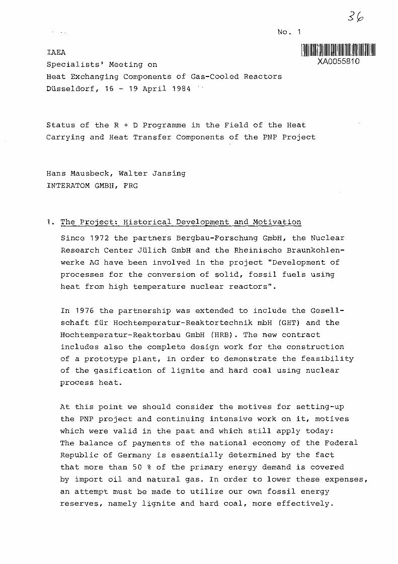
1. The Project: Historical Development and Motivation
Since 1972 the partners Bergbau-Forschung GmbH, the Nuclear
Research Center Jtilich GmbH and the Rheinische Braunkohlen-
werke AG have been involved in the project "Development of
processes for the conversion of solid, fossil fuels using
heat from high temperature nuclear reactors".
In 1976 the partnership was extended to include the Gesell-
schaft fur Hochtemperatur-Reaktortechnik mbH (GHT) and the
Hochtemperatur-Reaktorbau GmbH (HRB). The new contract
includes also the complete design work for the construction
of a prototype plant, in order to demonstrate the feasibility
of the gasification of lignite and hard coal using nuclear
process heat.
At this point we should consider the motives for setting-up
the PNP project and continuing intensive work on it, motives
which were valid in the past and which still apply today:
The balance of payments of the national economy of the Federal
Republic of Germany is essentially determined by the fact
that more than 50 % of the primary energy demand is covered
by import oil and natural gas. In order to lower these expenses,
an attempt must be made to utilize our own fossil energy
reserves, namely lignite and hard coal, more effectively.
-2-
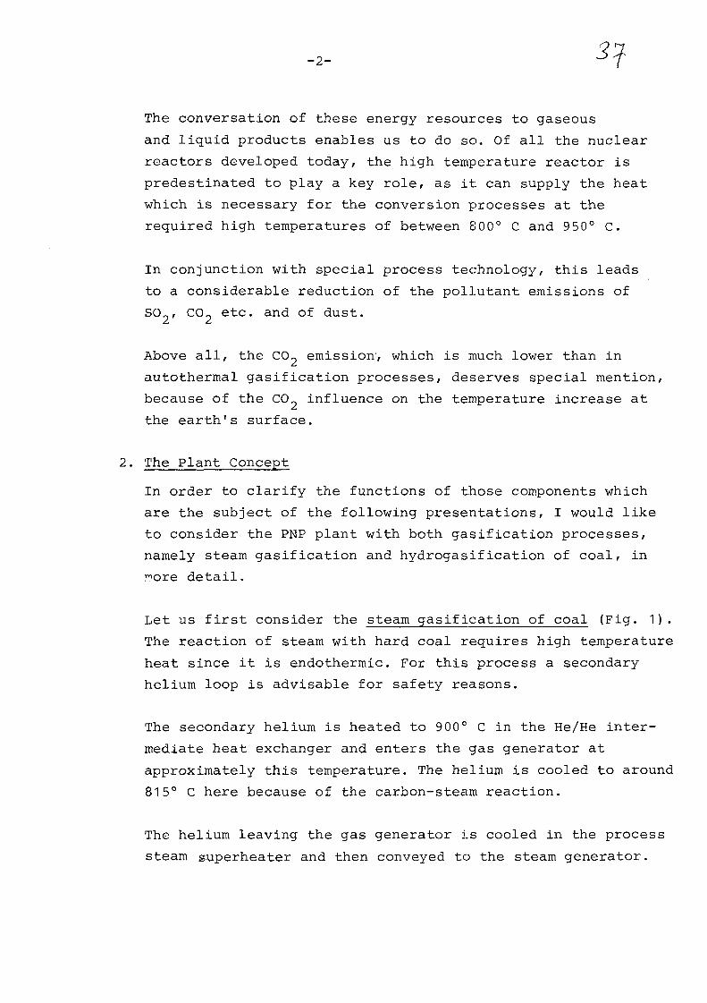
The conversation of these energy resources to gaseous
and liquid products enables us to do so. Of all the nuclear
reactors developed today, the high temperature reactor is
predestinated to play a key role, as it can supply the heat
which is necessary for the conversion processes at the
required high temperatures of between 800° C and 950° C.
In conjunction with special process technology, this leads
to a considerable reduction of the pollutant emissions of
SO , CO2 etc. and of dust.
Above all, the COp emission; which is much lower than in
autothermal gasification processes, deserves special mention,
because of the CO? influence on the temperature increase at
the earth's surface.
2. The Plant Concept
In order to clarify the functions of those components which
are the subject of the following presentations, I would like
to consider the PNP plant with both gasification processes,
namely steam gasification and hydrogasification of coal, in
detail.
Let us first consider the steam gasification of coal (Fig. 1).
The reaction of steam with hard coal requires high temperature
heat since it is endothermic. For this process a secondary
helium loop is advisable for safety reasons.
The secondary helium is heated to 900° C in the He/He inter-
mediate heat exchanger and enters the gas generator at
approximately this temperature. The helium is cooled to around
815° C here because of the carbon-steam reaction.
The helium leaving the gas generator is cooled in the process
steam superheater and then conveyed to the steam generator.

-3-
The raw gas is subjected to a number of further process
steps but it would take too long to describe these in detail.
They are, however, dependent on the desired end product.
In the case of the hydrogasification of coal (Fig. 2),
the dried and ground lignite is fed into a gas generator
into which pure hydrogen flows. The reaction taking place
in the gasifier is exothermic. The residual sulphur-free coke
can, for example, be further gasified in a pressurized coal
gasification plant or can be used as high-grade coke. After
coooling and purification, the raw gas leaving the gas genera-
tor is decomposed into the fractions hydrogen, methane and
carbon monoxide. The H^-gas flow is supplied to the gasifier
via the preheating system, the CO-flow is added to the raw
and process gas, while the CH,-flow is mixed with steam and
fed into the steam reformer.
The CH./HpO mixture is cracked in the tubes of the steam
reformer, which are filled with catalysts, at approximately
800° C and 50 bar in accordance with
CH4 + H2O = CO + 3
CO
This endothermic reaction is maintained by the helium flow
coming from the reactor which is cooled from approximately
950° C to approximately 720° C. After further cooling in the
steam generator to 3 00° C, the helium is reheated to 950° C
in the HTR.
As you can see from the two flowcharts of the steam gasification
and hydrogasification of coal, some components are operated
at such high temperatures that it is impossible to use comparable
components from either conventional technology or nuclear
technology. Therefore it is not astonishing that the development
of components is the major issue in the R -t D work for the
nuclear heat generation system.

-4-
The aim of the development of the circuit components:
Helium/helium intermediate heat exchanger
Steam reformer
Hot gas ducts with all sub-components
Hot gas valve
is to provide functional and licensable components for a
PNP plant.
3. The Large-Scale Test Facilities
Two large-scale test facilities are available to the PNP
project for testing the components to be discussed here:
The methane reforming plant EVA II in the Nuclear Research
Center Julich and the Component Testing Facility (KVK) at
INTERATOM in Bergisch Gladbach.
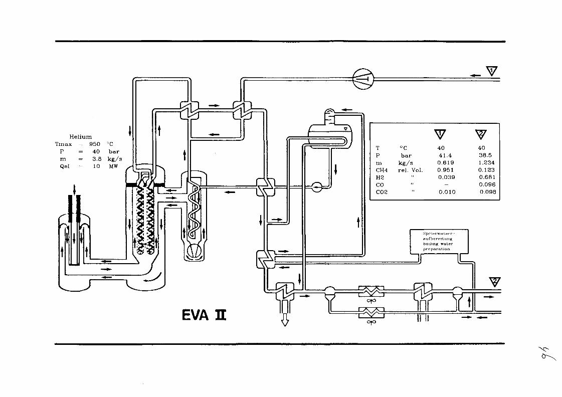
EVA II (Fig. 3) consists of a reformer tube bundle comprising
30 tubes which are heated with helium, and a steam generator,
which is also positioned in the helium loop and supplies the
steam required for reforming the methane. The helium is heated
to the necessary temperature by a 10 MW electric heater. It
cools down while flowing through the reformer tubes from the
bottom to the top. The process gas, which is a mixture of
methane and steam, heats up in counterflow to the helium in
the catalyst bed and chemically converts into C0? and H_.
The product gas flows upwards through a helical tube from a
collecting space in the base, whereby it cools down without
any further chemical reactions. On exiting from the reformer
tube bundle, the helium enters the steam generator and is
then returned to the heater for reheating. One bundle has
already been successfully tested at temperatures of up to
950° C in EVA II.
-5-
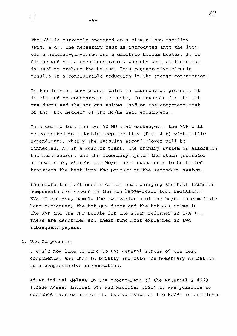
The KVK is currently operated as a single-loop facility
(Fig. 4 a ) . The necessary heat is introduced into the loop
via a natural-gas-fired and a electric helium heater. It is
discharged via a steam generator, whereby part of the steam
is used to preheat the helium. This regenerative circuit
results in a considerable reduction in the energy consumption.
In the initial test phase, which is underway at present, it
is planned to concentrate on tests, for example for the hot
gas ducts and the hot gas valves, and on the component test
of the "hot header" of the He/He heat exchangers.
In order to test the two 10 MW heat exchangers, the KVK will
be converted to a double-loop facility (Fig. 4 b) with little
expenditure, wherby the existing second blower will be
connected. As in a reactor plant, the primary system is allocated
the heat source, and the secondary system the steam generator
as heat sink, whereby the He/He heat exchangers to be tested
transfers the heat from the primary to the secondary system.
Therefore the test models of the heat carrying and heat transfer
components are tested in the two large-scale test facilities
EVA II and KVK, namely the two variants of the He/He intermediate
heat exchanger, the hot gas ducts and the hot gas valve in
the KVK and the PNP bundle for the steam reformer in EVA II.
These are described and their functions explained in two
subsequent papers.
4. The Components
I would now like to come to the general status of the test
components, and then to briefly indicate the momentary situation
in a comprehensive presentation.
After initial delays in the procurement of the material 2.4663
(trade names: Inconel 617 and Nicrofer 5520) it was possible to
commence fabrication of the two variants of the He/He intermediate
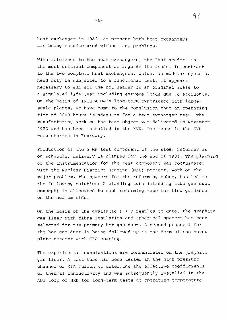
-6-
heat exchanger in 1982. At present both heat exchangers
are being manufactured without any problems.
With reference to the heat exchangers, the "hot header" is
the most critical component as regards its loads. In contrast
to the two complete heat exchangers, which, as modular systems,
need only be subjected to a functional test, it appears
necessary to subject the hot header on an original scale to
a simulated life test including extreme loads due to accidents.
On the basis of INTERATOM's long-term experience with large-
scale plants, we have come to the conslusion that an operating
time of 3000 hours is adequate for a heat exchanger test. The
manufacturing work on the test object was delivered in November
198 3 and has been installed in the KVK. The tests in the KVK
were started in February.
Production of the 5 MW test component of the steam reformer is
on schedule, delivery is planned for the end of 1984. The planning
of the instrumentation for the test component was coordinated
with the Nuclear District Heating (NFE) project. Work on the
major problem, the spacers for the reforming tubes, has led to
the following solution: A cladding tube (cladding tube gas duct
concept) is allocated to each reforming tube for flow guidance
on the helium side.
On the basis of the available R + D results to date, the graphite
gas liner with fibre insulation and spherical spacers has been
selected for the primary hot gas duct. A second proposal for
the hot gas duct is being followed up in the form of the cover
plate concept with CFC coating.
The experimental examinations are concentrated on the graphite
gas liner. A test tube has been tested in the high pressure
channel of KfA Julich to determine the effective coefficients
of thermal conductivity and was subsequently installed in the
ADI loop of HRB for long-term tests at operating temperature.

— 7 —
These test have been started recently.
Two constructions with metallic liner, both having the
same basic concept, are available for the secondary loop.
The tests on the behaviour of the hot gas duct in a horizontal
position have been completed after 2900 operating hours in
KVK. The results for the temperature distribution and heat
losses are very positive. The test in a vertical position
commenced in September 1983. At present work is centred on
the constructive and analytical examination of the design of
further subcomponents of the primary and secondary hot gas
ducts, such as bend, compensator and T-piece.
Initially two variants were followed up for the hot gas valve,
namely the ball valve and the axial valve. But since the end
of 1981 we have only concentrated on the latter. As far as the
constructive design is concerned, the test object has been
prepared for the component test. The complete manufacturing
documents have been submitted and the preliminary examination
has been completed. Manufacture of the sub-component has almost
been finished. It will be delivered and installed in the May
of this year.
A scaled-down version of the axial valve, which has been adapted
to suit the KVK, is part of the operating equipment of the KVK.
Testing of this valve has already supplied valuable results.
Work performed in the past has shown that this component in
particular has been the source of a number of difficulties which
have caused delays in the development of the reference valve.
However, they do not appear to have led to any delay in the
overall component development as yet.
-8-
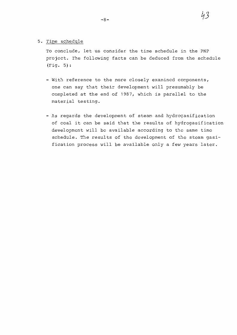
5. Time schedule
To conclude, let us consider the time schedule in the PNP
project. The following facts can be deduced from the schedule
(Fig. 5):
- With reference to the more closely examined components,
one can say that their development will presumably be
completed at the end of 1987, which is parallel to the
material testing.
- As regards the development of steam and hydrogasification
of coal it can be said that the results of hydrogasification
development will be available according to the same time
schedule. The results of the development of the steam gasi-
fication process will be available only a few years later.

Helium Raw Gas Coal
Process SteamSuper Heater
815 °C41,5 bar
950 °C40,5 bar He/He-Heat-Exchanger
Hot GasValve
900 °C Helium41,9 bar
Cold GasValve
789 °C45,7 bar300 °C
41 bar292 °C
39,9 bar 200 °C43,8 bar
Primary Loop
Steam
682 °C41 bar
Steam Generator
Secondary Loop
Row Sheet of the HTR with Steam Gasification of Hard Coal (1/84)

Helium 950 °C• • •50 bar
480 °C, 51 bar Cracked Gas
H2O/CH4 347 °C,56 bar
SteamGenerator
300 °C50,5 bar 2 9 2 X 9 4 9 bar
Gas Separation
Methane
Blower
Primary Loop
Row Sheet of the HTR with Hydrogasif ication of Lignite (1/84)
Residue
HeliumTmax = 950 DC
P = 4 0 barm = 3.8 kg/sQel = 10 MW
hpcisowasstT-nufbcroitungboiling water
TPmCH4H2COC02
°Cbarkg/srel. Vol.
"
4041.40.6190.9510.039-
0.010
V4038.51.2340.1230.6810.0960.098
EVA E

He-Filling
Gas Heater Electric
1
Reduction Valve
Condeneer Dtaeretor
feed Water Tank
-CK>-
FMd Wrter Preheater x PMd Wrtor Pump
i
T I
Storage
ComprBMors
• *« -
Purification System
KVK Single Loop Operation With Test Sections

Me-Prehe«ter
Heading
Gas Heater Electric Heater
Deaerator
Feed Water lank
Feed water Preneater x Feed Water Pump
Storage Tanks
Compressor*
y v00
PurKteaWon System
KVK Double Lxx>p Operation With He/He Heat Exchanger

Steam Gasification-Development- Operation of Small Pilot Plant- Documintatien- Bitic-Eng. of Pilot Plant- Decision for Next Step- Planning of the Pilot Plant- Erection of the Pilot Plant- Operation of the Pilot Plant
Hydrogasification Development:Pilot Plant- Operation with lignite- Planning for Operation with Hard Coal- Decision for this Step- Rebuild of the Plant- Operation with Hard Coal
Optimization and Evaluationof Both Gasification Procedures for Hard Coal
Development of Material/Components- Material Tests- EVA: . NFE-Steim Reformer-Bundle
. PNP-Steam Reformer-Bundle- KVK:. Hot Gas Ducts
. He-He-Heat Exchangers
. Hot Gas Valve- Research and Development
Concept ReviewCoordination and Project ManagementStart of Planning for the Nuclear Process Plant
90 91 92 93
. . . , .
with Steam Reformer and Hydrogasification with He/He-Heat Exchanger and Steam Gasification
PNP Development of the Nuclear Process Heat (as per 1/84)

9*No. 2
111 _____IAEA XA0055811
SPECIALISTS' MEETING ON
HEAT EXCHANGING COMPONENTS OF GAS-COOLED REACTORSD l i s s e l d o r f , F R G . , 1 6 . - 1 9 . A p r i l 1 9 8 4
DESIGN REQUIREMENTS ON HTR MAIN COMPONENTS FOR
PROCESS HEAT APPLICATION
Konrad Dumm
INTERATOM GmbH., FRG.
Introduction
In the field of high temperature reactor application for direct
process heat, KWU-INTERATOM developed the concept of the HTR-module.
The module concept consists of a number of independent small
pebble bed reactor units with a thermal output of 170 MW each.
In direct process heat application each of the modules operates in
combination either with a steam reformer for hydro-gasification of
coal and methane reforming (fig. 1) or with an intermediate He/He-
heat-exchanger for steam-gasification of coal. Reactor and heat
exchanging components are connected by a coaxial gas duct, helium
flow is maintained by an integrated circulator. The primary pressure
inclusion is achieved by steel pressure vessels the technique
of which is well proven in LWR operations.
The design requirements presented in this paper are based on the
KWU-INTERATOM module concept, but to a large extend generally ty-
pical for high temperature components.
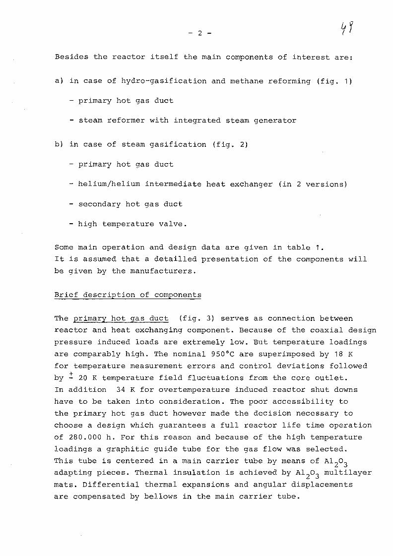
Besides the reactor itself the main components of interest are:
a) in case of hydro-gasification and methane reforming (fig. 1)
- primary hot gas duct
- steam reformer with integrated steam generator
b) in case of steam gasification (fig. 2)
- primary hot gas duct
- helium/helium intermediate heat exchanger (in 2 versions)
- secondary hot gas duct
- high temperature valve.
Some main operation and design data are given in table 1.
It is assumed that a detained presentation of the components will
be given by the manufacturers.
Brief description of components
The primary hot gas duct (fig. 3) serves as connection between
reactor and heat exchanging component. Because of the coaxial design
pressure induced loads are extremely low. But temperature loadings
are comparably high. The nominal 9 50°C are superimposed by 18 K
for temperature measurement errors and control deviations followed
by - 20 K temperature field fluctuations from the core outlet.
In addition 34 K for overtemperature induced reactor shut downs
have to be taken into consideration. The poor accessibility to
the primary hot gas duct however made the decision necessary to
choose a design which guarantees a full reactor life time operation
of 280.000 h. For this reason and because of the high temperature
loadings a graphitic guide tube for the gas flow was selected.
This tube is centered in a main carrier tube by means of Al«O^
adapting pieces. Thermal insulation is achieved by Al^O, multilayer
mats. Differential thermal expansions and angular displacements
are compensated by bellows in the main carrier tube.

- 3 -
Under normal conditions the carrier tube is exposed to a pressure
difference of only 1,5 bar from the outer cold gas side.
The steam reformer is shown in fig. 4. The 950°C helium enters
the lower part and is distributed to the reformer tube bundle which
consists of 199 individual reformer tubes of a tube in tube design.
These reformer tubes are collected in the upper region by a tube
plate which serves as a part of the primary;pressure inclusion.
In order to allow a low temperature design of this primary barrier
the lower side of the tube plate is thermally insulated. The helium
leaves the reformer tube bundle at 720°C and is directed to 6 circura-
ferentially arranged steam: generator modules. High temperature in-
sulations around the reformer- tube bundle and the steam generator
modules serve for a reliable separation of high and low temperature
helium regions, by which an LWR like design of the.primary vessel
becomes possible.
The process gas to be reformed, methan plus steam with a mole
fraction of 1 : 4 is fed to the individual steam reformer tubes
at a temperature of 34 7°C. By means of an individual recuperator
in the upper part of each reformer tube the gas temperature, of
the gas mixture is increased to 56 0°C. Flowing downwards through
the catalizer filled reformer tube, the process gas becomes reformed.
The maximum gas temperature at the lower end amounts to 810°C.
Via an internal return tube the gas enters the recuperator again
at 68 0°C and is cooled down to 4 80°C.
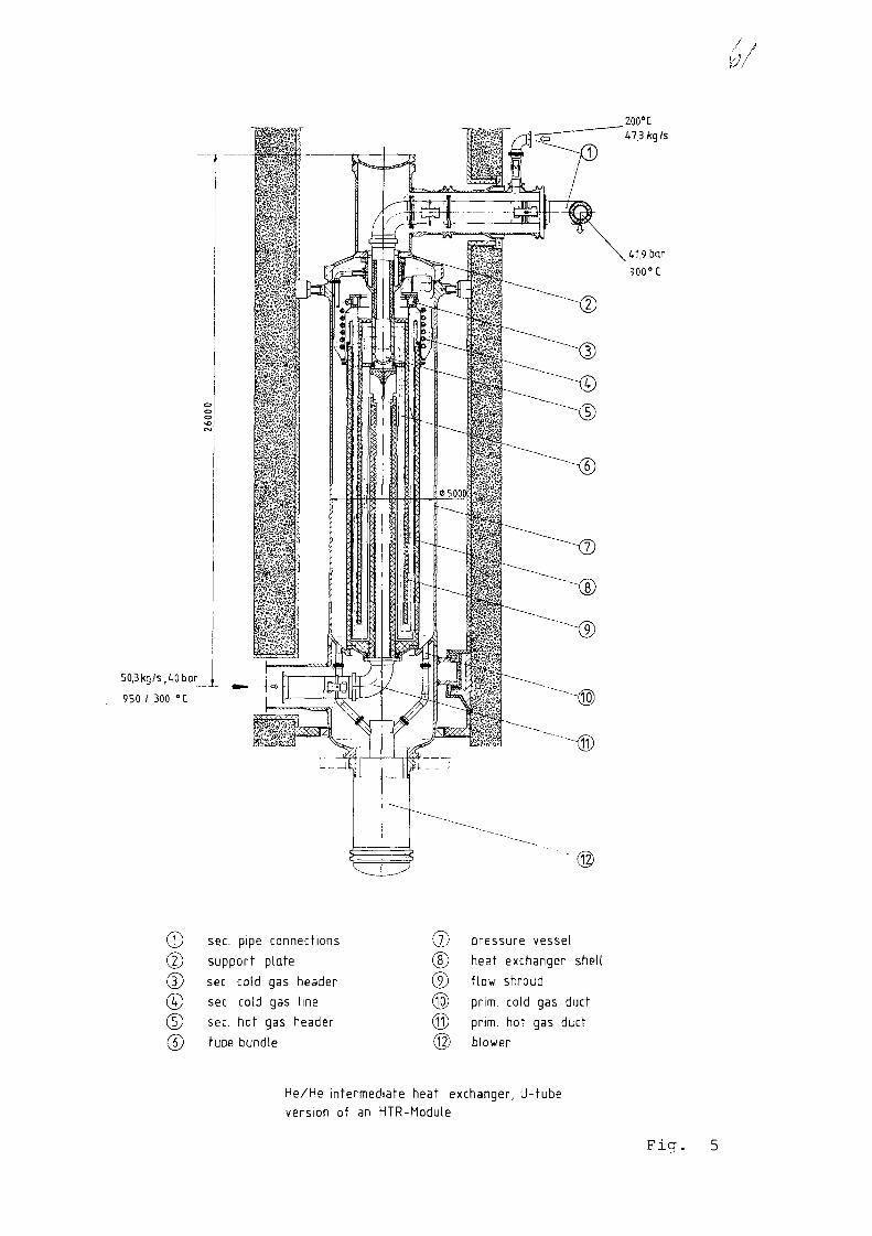
In the field of He/He intermediate heat exchangers two different
designs are under development, a U-tube design and a helical coil
design. Typical for the U-tube design (fig..5) is the arrangement
of the secondary hot gas header in the upper region of the heat
exchanger. Thereby the hot header is exposed mainly to the secondary
helium temperature. The primary helium is directed to the tube
bundle by an insulated internal vertical guide tube. Most of the
thermal expansion of the tube bundle is compensated in the lower
temperature field because of the special design of flow shroud and
insulation. The tubes in the bundle region need to have only
circumferential fixations but no tube weight supports. But never-
theless high temperature resistant anti fretting coatings for

- 4 -
positions where relative movements have to be considered are
necessary.
In the helix design (fig. 6) the secondary hot gas header is
located in the lower region of the component. It is thermally in-
sulated in order to avoid overtemperatures from the primary helium.
A uniform flow distribution to the helix tube bundle is achieved
by an integrated flow distributor. To a certain extend remaining
temperature fluctuations from the core outlet are also reduced in
this device. If a proper distribution of differential thermal
expansions across the whole tube bundle can be realized under all
operating conditions, relative movements between tubes and tube
support structures can be minimised or eventually even avoided.
But again high temperature resistant anti fretting coatings have
to be taken into consideration.
The connection of both types of intermediate heat exchangers to
the secondary helium system and the gasification plant is of
identical design. Inside the primary confinement the secondary hot
gas duct is, like the primary one, of the coaxial design. Outside
the primary cell the coaxial design ends up with isolation valves,
followed by normal single wall pipe work, designed to withstand
the total internal pressure. While the cold leg valve will be of
a normal and experienced design the hot leg valve (fig. 7) represents
a completely new development. It is designed as a pneumatically
controlled double acting valve. In case of a secondary system
pressure relief accident, the valve closes automatically. From
safety considerations the total closure time has to be < 15 s.
Sealing is achieved by movement of the inner cones, which are
positioned in gasstatic bearings, to the seat positions. Temperature
sensitive parts in the inner bearing and control region as well
as the outer pressure housing are insulated with a highly reliable
high temperature insulation. The internals are cooled by helium.
Design temperature for the pressure housing is 400°C.

- 5 -
In the flow direction towards•the gasification plant;the high tempe-
rature valve is followed by the single wall secondary hot gas duct
(fig. 8). In contrast to the primary hot gas duct a metallic liner
was selected. This for different reasons: The design temperature
of 918°C is remarkably lower and allows a metallic system.
The possibly more oxydizing secondary helium atmosphere does not
allow the use of graphite or other carbon products. And of course the
lower cost levels. The basic principle is well known from high
temperature systems. The insulation technique is similar to that
used for the primary hot gas duct. Axial gas flow in the insulation
is avoided by the use of V-type spacers. The design of elbows,
compensating units and T-branches is similar to the straight tube.
Design pressure and temperature for the outer pressure shell are
46 bar and 400°C.
Design requirements and objectives
The general design requirements on these components can be sub-
divided into 3 categories:
1. Requirements which have to be considered for quantitative
analysis and design, mainly related to thermohydraulics
and stress analyses.
2. Requirements for the detained engineering design taking into
account results from 1 and 3.
3. A basic R+D programme initiated by 1 and 2 in order to solve
open problems and to support the design.
All 3 aspects have to work in a steady and continuous interaction.
To point 1: Besides the normal operational conditions the following
points have to be taken into account:
- design over pressures due to safety relief valves
- design over temperatures due to temperature measurement errors,
control deviations, temperature field fluctuations, temp, increases

due to over temperature induced reactor shut down
- temperature transients for normal start up and shut down and for
emergency shut down (e.g. loss of heat sinks)
- pressure transients for normal start up and shut down and for
emergency cases such as pressure relief accidents
- temperature induced loads resulting from hot stand by (reactor
shut down followed by restart)
- thermal and mechanical effects in heat exchanging components
due to failed and plugged tubes
- load effects by influences from outside like earthquakes,
plane crash and gas cloud explosions.
These considerations have to be done very careful; on one side to
fullfill all licencing requests on the other side to avoid any
overconservatism. It is known in the high temperature stress ana-
lyses that overestimations in temperatures can lead to much more
severe design problems than those in pressures. This because of the
very conservative results according to ASME Code Case N 47.
To point 2 In a sound engineering design a number of additional
requirements are of great importance:
- due to repair concept or in case of part life time easy exchange-
ability of the components
- according to regulations or customer requests easy accessibility
to components and their internals for in service inspections
preferably without opening the primary system
- possibilities to localize defects, esp. for repair and e.g.
plugging of defect tubes
7 low stress levels, especially in high temperature regions
- load and weight supports preferably in low temperature regions
- 7 -
- if in the development the construction and test of small prototyps
is considered, this design has to be such that clear extrapola-
tions of design and results to the larger components are possible
- suitable high temperature insulation systems which allow a
strict separation of temperature and mechanical loads
- economic construction
- quality standards to meet the safety related requirements
- use of protective surface coatings to avoid fretting effects in
helium
- use of materials with sufficient toughness being capable for
inservice inspection techniques
- for the steam reformer: easy exchange of the catalyzer
- considerations of flow induced vibrations
- acceptable licensing procedures.
To point 3 As a whole the temperature range up to 1000°C plus
the additionals to be taken into consideration including the safety
requirements for a nuclear plant is a large step towards new fields.
To accomplish the requirements stated before, a basic R+D programme
is absolutely necessary. Reactor components of such new kind
should not be designed straight on in one step on the drawing
boards. A successfull development has to proceed carefully in
a number of single steps:
- material development for high temp, metals and ceramics including
graphit, carbon filament compositions, protective coatings,
high temp, insulations etc.
- fabrication development e.g. narrow gap welding of thick-walled
components such as the secondary hot gas header
- development and tests of quality assurance methods for fabrication
and for inservice inspections
- component parts development and tests
- development, fabrication and test of prototyps
- evaluation of prototyp test results.
These should lead to the final design of the reactor components,
Final remarks
It was the aim of this presented paper to summarize the design
requirements on the main components for the HTR module concept
for direct process heat application.
Papers from the different R+D organisations, manufacturers,
operators of test facilities and pilot plants will give a more
detailled picture to what extend the design goals have already
reached.

TABLE 1. OPERATIONAL DATA
ID
PRIM. HOT GAS DUCT
STEAM REFORMER HE
STEAM REFORMER PROC.GAS.
STEAM GENERATOR HE
STEAM GENERATOR H2O
HE/HE IHX PRIM.
HE/HE IHX SEC.
HIGH TEMP. VALVE
SEC. HOT GAS DUCT
-52LU
PR
ES
Sl
50/40
50
56
113 J
40 1
42 J
42
42
oLU
PR
ES
Sl
1.5*
1.56
75
•ii-tt-Sf
2
42
42
a.UJ
IX
LU
LU
CD
UJ
950
950
347
720
150
950
900
900
900
300
720
480
295
530
295
200
o11
u_
MA
SS
50.3
50.3
34.8
50.3
38
50.3
47.3
47.3
47.3
LUU_
_J
2.8
1.4
1.4
2.8
2.8
1.4
1.4
1.4
1.4
DUE TO COAXIAL DESIGN
MAX. PROC. GAS TEMP. 810°C
FULL PRESSURE DIFFERENCE FOR PRESSURE RELIEF ACCIDENTSIN SECONDARY SYSTEMS HAVE TO BE CONSIDERED

n
'51 bar
. ! _ i - -72CC
HiO * CH
34,8
56
347
kgfs
Dar
°C
steam 113bar,530°C
38 kg/s
feed wafer 150°C
10 600
HTR Module 170MWfh withSteam Reformer and IntegratedSteam Generator Fig. 1
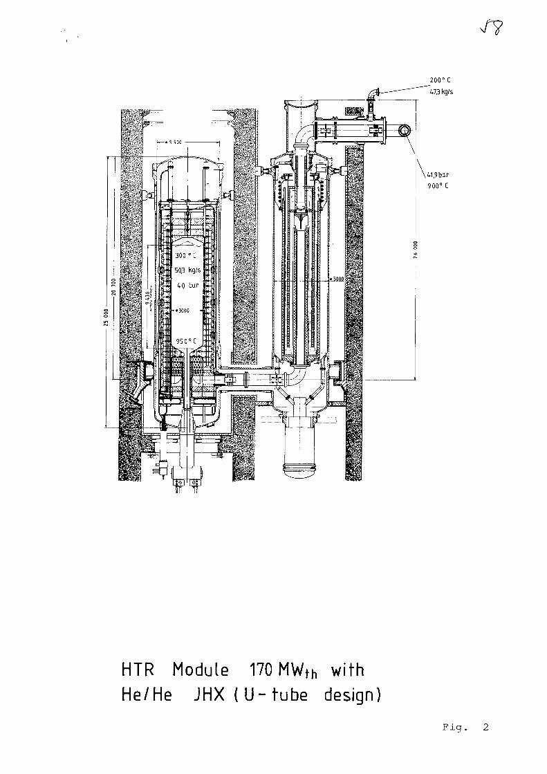
200° C
47,3 kg/s
\ 41,9 bar
900° C
HTR Module 170 MWH, withHe/He JHX { U - t u b e design)
Fig. 2

I 2to(U
Fig.
SZX9LOL0

50,3 kg/s, 50 bjr_
950/300 °C
0 6 0 0 0
process gas
•H 20 • CH4 (4:1)
56 bar
347 °C inlet
51 bar
480 °C ou t l e t
feed water 150 °C
process gas connection
reformer tube tube plate
process gas recuperator
life steam
Helium to steam generators
steam generator tube bundle
steam generator shell
feed water
pressure vessel
steam reformer shell
steam reformer tube bundle
prim.cold gas duct
prim, hot gas distributor
blower
170MWth Steam Reformer with
Integrated Steam GeneratorFicr.
/ ,/
50,3 kg 1%, 40 bar
950 / 300 °C
_200°C47.3 kg Is
^ 41,9 bar
900°C
0 sec. pipe connections
(2) support plate
(D sec. cold gas header
0 sec. cold gas line
0 sec. hot gas header
bundle
(7) pressure vessel
(8) heat exchanger shed
® flow shroud
(JO) prim, cold gas duct
@ prim, hot gas duct
6t) blower
He/He intermediate heat exchanger, U-tubeversion of an HTR-Module
Fig. 5

50,3 kg/s, 1,0 bar
950/300 °C
sec. pipe connections
support plate
sec. hot gas duct
tube bundle
heat exchanger shell
flow shroud
pressure vesselprim, cold gas duct
prim, hot gas flow distributor
sec. hot gas header
blower
170MWfh Helix - He/He JHXFig. 6
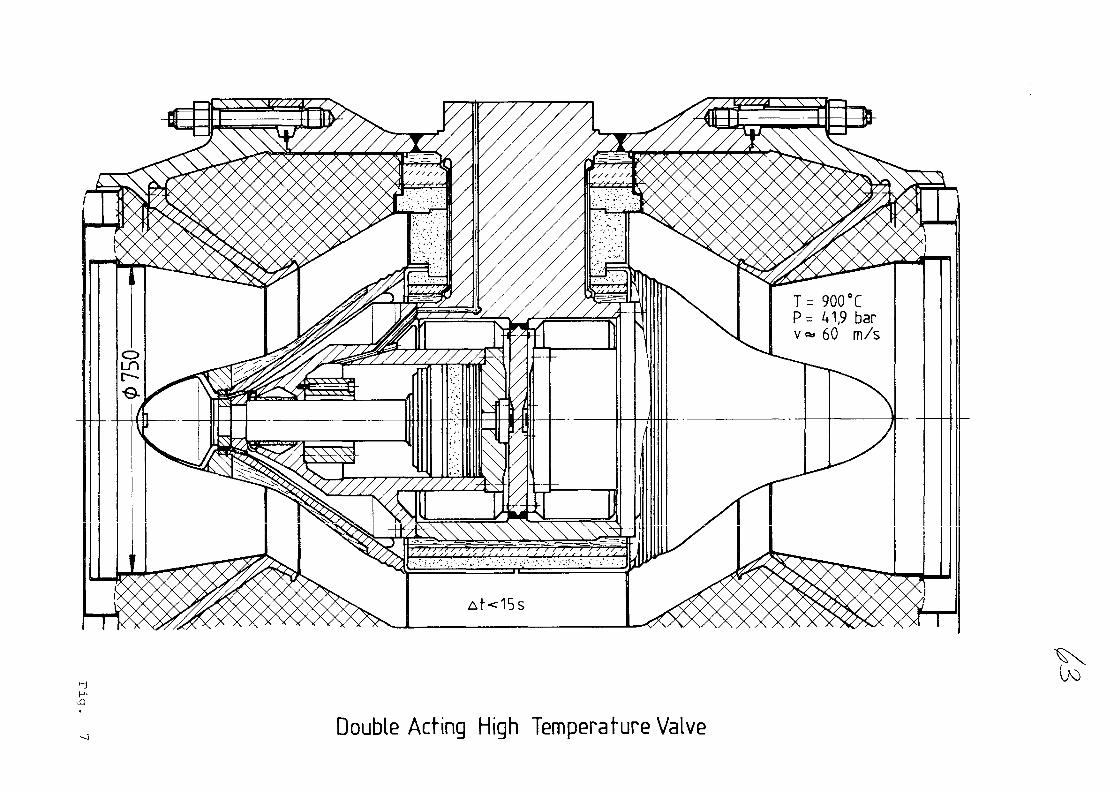
T= 900 CP - 41,9 barv«» 60 m/s
Double Acting High Temperature Valve

op. /desg.900/918"C
42/ 46 bar
oo
oCMCM
ooSecondary Hot Gas Duct,
(test prototyp)

N o . 3
HOCHTEMPERATUR-REAKTORBAU GMBH
PAPER PRESENTED AT THE SPECIALISTS' MEETING
ON HEAT EXCHANGING COMPONENTS OF GAS-COOLED
REACTORS
DLJSSELDORF, APRIL 16. - 19. 1984
XA0055812

HOCHTEMPERATUR-REAKTORBAU GMBH
Helium/Helium Heat Exchangers and Hot-Gas Ducts for the
PNP-Project according to the BBC/HRB Concept
H. Schmitt, B. Jiirgens, J. Knaul
Hochtemperatur-Reaktorbau GmbH, Mannheim
The prototype nuclear process heat plant PNP-1000 is designed
for two coal gasification processes:
1. Steam gasification of hard coal and
2. Hydrogasification of lignite
In both plants the primary system is identical, i.e. that part
of the plant containing the reactor and the components presented
in this context.
Fig. 1 shows the schematic flow diagram of the PNP-plant for
steam gasification of hard coal. The primary system with the
reactor, the heat exchangers and the circulator is shown on the
left side.
In the heat exchangers the heat is transferred to an intermediate
circuit, which is coupled to a gas-factory located outside the
reactor building. At the outlet of the gas-factory SNG (substitute
natural gas - CH.) is supplied for consumption. The steam required
for the gasification process is extracted from the high-pressure
section of the turbine.
A steam generator is installed in the intermediate circuit
supplying the steam required for generating the plant electricity.
Coming back to the primary circuit, Fig. 2 shows a section
of the reactor pressure vessel. It is a prestressed concrete
reactor vessel in which the reactor core with the sperical fuel
elements and the primary components are integrated. The arrangement
of the components corresponds to the well-known THTR design.

_ 2 - HQCHTEMPERAXUR-REAKTOREAU GMBH
At the periphery of the core the helium/helium heat exchangers
are arranged in a tandem design. Each heat exchanger consists
of a high-temperature and a low-temperature unit.
The connections between reactor core and heat exchangers are
effected by the hot-gas ducts. The coupling with the intermediate
circuit is indicated by the green coloured hot and cold lines
of the intermediate circuit and by the connection line between
low- und high-temperature unit of the heat exchanger.
The helium/helium heat exchangers
The helium/helium heat exchangers (Fig. 3) transfer the heat
to the intermediate circuit, during normal operation a? well as
during decay heat removal. For making optimum use of the space,
the heat exchangers are designed in a tandem concept.
One objective of the current research program is to develop
materials which ensure the operation of a heat exchangers for
a reactor liefe time of 40 years. Based on the present state-
of-the-art, this objective has not yet been fully achieved for
those components which are exposed to very high temperature loads.
This tandem design offers the advantage that the high-temperature
unit of the heat exchanger can be removed in case that the design
of the high temperature unit for the overall reactor life time
is not possible. Separation between high temperature and low
temperature units was selected at a temperature of 640°C so that
the material NiCr 23 Co 12 Mo currently envisaged needs to be
used only in the high temperature unit. The temperatures in the
low temperature unit remain within the range of experience of
the well known THTR steam generators. Both units are of approximately
indentical dimensions.
The concept of the heat exchangers in helicoil design is presented
in Fig. 3. The hot primary gas coming from the reactor core

- 3 - HOCHTEMPERATUR-REAKTCRBAU GMBH
passes to the high-temperature heat exchanger, flows upward
between the tube bundles and leaves the unit through windows
located at the periphery of the inner shroud. The primary
helium now cooled down to about 640°C flows through the
annular clearance between inner and outer shroud and through
a connection line well to the low-temperature unit. Flowing
downwards along the tubes, the primary gas is cooled down to
about 293°C is then collected in a plenum and is recirculated
upwards through an annular clearance. The primary gas is then
directed through a connection line and to the circulator
located above.
After compressicn in the circulator the gas flows downward into
the reactor cavity and is recirculated into the core through
the external annular clearance of the hot-gas duct.
The "cold" secondary gas flows to the heating surface tubes
passing through a cylindrical header in the lower part of the
low-temperature heat exchanger. Then the gas flows upward within
the tubes, heated up by the primary gas. The secondary helium is
then forwarded into the high-temperature unit through a connection
line. The heated gas is collected in the upper plenum; it is
directed into the tube bundles through a tube plate and flows
downwards. The hot secondary gas is collected in a cylindrical
header and is then directed to the gas generator.
Of course it is also possible to use a U-bend design heat exchanger
The advantages of the heat exchanger in tandem design are
(Fig. 4):
- Favourable utilization of space in a large single-cavity PCRV
- Limitation of exchange to the high-temperature unit, if any
exchange is necessary
- The compensation required for thermal expansion of the hot
lines is small.

- 4 - HOCHTEMPERATUR-REAKTORBAU GMBH
- The loads resulting from different temperatures of the
heating surface tubes and their fixing devices are low,
- The dimensions cf both units are small, thus facilitating
manufacture and assembly.
- The number of parallel manufacturing steps is increased,
thus permitting a reduction of the construction period.
The following" tasks will have to be performed in future:
- Special attention must be directed to the design of the
secondary hot-gas header which is exposed to the primary
hot helium. The primary hot-gas flow contains temperature
streaks and velocity differences; these effects on the header
have to be limited by structural measures. The influence of
the header on the gas flow must be experimentally investigated.
The routing of the helium lines must be designed so as to
permit uncomplicated inservice inspections.
- The tube plate with a diameter of about 3 m must be designed
to a temperature of about 600°C. In addition to the material
strength problems, aspects of manufacturing must be taken into
account.
- Seals in view of the possible exchange of the high-temperature unit.
The hot gas ducts
The connection between the hot-gas plenum and the heat-exchanging
components represents the hot gas duct (Fig. 5). The hot-gas
duct is composed of the bearing wall and the thermal barrier
applied to the inner surface. The hot gas flows through the
duct at a speed of 60 m/sec.
The thermal barrier is provided to limit the heat exchange between
hot arid cold gas and to protect the bearing wall of the hot-
gas duct against inadmissabiy high temperatures.
The high requirements made for the hot-gas duct are mainly due to
the high hot-gas temperatures. Based on the hot-gas temperature
_ 5 _ HOCHTEMPERATUR-REAKTORBAU GMBH
the design temperature was specified at 10 50°C.
The hot-gas duct is designed as a coaxial line which means that
the bearing wall is exposed to cold gas flowing along its
outside. The material used for the thermal barrier applied
to the inner wall is a ceramic fibre material containing 95 %
of Al-O,,. These fibre blankets are covered by cover plates
according to a design principle proven in the THTR. The thermal
barrier is equipped with convection barriers in order to
avoid longitudinal and transversal gas flow through the fibre
blankets.
Fig, 6 shows the temperature profile in the undisturbed region
of the thermal barrier.
The attachment fixture is composed of an inner stud and an
outer sleeve (s. Fig. 7). Either element of the attachment
fixture is able to accomodate 100 % load. They are elastically
prestressed by plate springs which are cooled by the cold gas,
which permits to balance different expansions. In the hypothetical
event of rupture of an attachment fixture, fragments can not
penetrate into the gas circuit. The fibre blankets are held down
by the cover plates.
The design of a thermal barrier with cover-plates permitting free
movement of each plate with the regard to expansion and shifts,
is of great advantage especially when applied to complicated
duct geometries.
The thermal barrier can be completely mounted in the hot-gas duct
in the manufacturer's workshop. Thus the complete unit composed
of hot-gas duct and thermal barrier is delivered to the construction
site. This results in a considerable facilitation with regard to
assembly.
HOCHTEMPERATUR-REAKTORBAU GMBH
Initially the application of a metal material was analyzed for
the attachment fixtures of the thermal barrier. Detailed strength
analyses and verifications where performed for this material. In
view of the application of a Carbon Fibre Composite - CFC - for
the thermal barrier, this concept will be revised. The equivalent
designs and calculations for the CFC attachment fixture are
underway. Special attention will be directed to the structural
and manufacturing aspects of attachment fixtures and cover-plates
from CFC. The CFC is being further developed within a comprehensive
program under special consideration of the components for which
it is to be applied.
Based on elastic strength calculations, it has been verified for
the attachment fixture of the hot-gas duct thermal barrier that the
selected design is feasable and that it withstands the mechanical
and thermal loads occurring during the operation of the PNP-plant.
The temperatures in the component parts are shown in Fig. 8.
The strength calculations where performed for mechanical and
thermal load cases.
The mechanical load cases include the event of a rapid
depressurization specified as 2 bar/s. That represents the
highest mechanical load.
Based on these load cases calculated within a finite-element
program {temperature and depressurization) 5 load cases can be
generated by superposition and linear conversion, which cover
all operating and accident analyses. Fig. 9 shows the maximum
stresses resulting from superposition for all 5 load cases. The
calculated reference stresses are below the strength limiting
value at 1000°C in all cases.
The analyses have shown that inadmissably high loads do not
have to be expected.

- 7 - HOCHTEMPERATUR-REAKTORBAU GMBH
We suggest the application of this concept because
1. it has a fundamentaly proven design principle
2. it is particularly well-suited for complicated geometries and
3. it can be used fur all HTR-projects currently known.
The present state of the development of the thermal barrier,
the available test results, current tests and available test
facilities permit the supply of this concept.
In conclusion it can be stated that draft solutions and concepts
for the heat-exchanging components of a process heat plant are
available. In part these solutions have been verified by calcu-
lations and feasability analyses, in part also by tests. The
right way towards supplying these components is being pursued.
We have no doubt about their realization. It must, however, not
be disregarded that comprehensive development work remains to be
done both on the components and the materials.

Make-up water
40 bar3O0°C
Cel!-typa wetcooling tower
Low-temperaturehelium/helium
heat exchanger
PrimaryCircuitCirculator
!~?"»i»i:«wgt
203°C
IntermediateCircuit
Circulator
-&JDecay heatremovalheatexchanger
Cooling vratef pumpDecay heatremoval Circulator
CH4
HRB Process Heat Plant forSteam Gasification of Coal
PUP
83.36-3
Abb. 1

Abb.P.

Low temperatureunit
High temperatureunit
Prim.-HeSec-He
hRB He/He-Heat-ExchangerPNP1000
84^4-11
Abb.3

He/He-Heat Exchanger
Abb. 4

Header of theHe/He-heat exchanger(high temperature unit)
s*—i
Primary helium inlet
Bearing wall
Thermal barrier
Secondary heliumoutlet
950°C40 bar
hRB Hot Gas DuctPNP1000
84.24-10
Abb. 5

1000 -
800 -
fioo -
4 0 0 -
C
F
Cov
K
)Derforated
HRB
1
1>
XX
jlate
L
1V>
40
plate
\
\
80
\i;
Thermal barrier Bear
• •MiI
20 r(mm)
Ing tube
PNP Attachment Fixture for Hot Gas Duct Thermal BarrierTemperature in Thermal Barrier - Undisturbed Region
PNP 1000
84.24-5
Abb. 6

KRBAttachment Fixture for
Hot Gas Duct Thermal Barrier in an PNIP Plant
PNP1000
8424-2
Abb.7
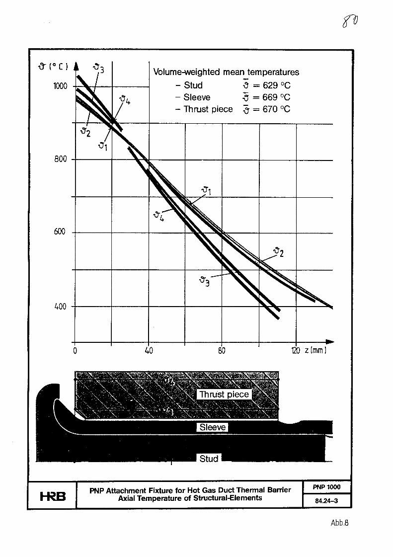
1000
800
600
400
T\
Volume-weighted mean temperatures- Stud 5 - 629 °C- Sleeve <j = 669 °C- Thrust piece # = 670 °C
*3" "~ v40 80 120 z(mm)
hRBPNP Attachment Fixture for Hot Gas Duct Thermal Barrier
Axial Temperature of Structural-ElementsPNP1000
84.24-3
Abb.8

Max. Reference Stresses
Element No.
1
2
3
/4-
1
19,5
379
46,8
24,8
<?v [N/rr
2
10,7
20,9
25,7
13,6
m2] in Lc
3
23,2
11,0
38,0
23,8
ad Case
4
6,3
28,5
74,3
2,0
5
12,8
11.8
56,4
10,2
Load CaseNo.
1
2
3
4
5
Description
p = 0,4 bar Depressurization accident
F=5500 N Operating prestress
Temperature load case
LC 1 + LC3LC2 + LC3
hRB Max. Stresses in StudPNP1000
8424-9
Abb.9
No. 4
Recent Research and Development of Intermediate
Heat Exchanger for VHTR Plant XA0055813
Akira Shimizu*, Noboru Matsumura*Hidetsugu Nishikawa*, Seiya Yamada*
Abstract
This paper describes recent tests which show progress in design ofIntermediate Heat Exchanger (IHX) for high-temperature gas cooled reactorplants developed for process heat application utilizing nuclear thermalenergy.
As the IHX must have a large heat exchanging capacity, the mostimportant consideration is to design a compact heat exchanger having highefficiency.
For the improvement of heat transfer characteristics, tests wereperformed at Mitsubishi Heavy Industries such as, trial manufacturing,heat transfer characteristic tests and nondestructive inspection tests offinned tubes.
Results are as follows;
(1) Finned tubes produced by rolling were able to be wound helicallyby bending machine.
(2) Laboratory tests showed this tube had good heat transfercharacteristics.
(3) There was not much difference between finned tubes and bare tubesfor detection of defects by the eddy current tests.
(4) A trial assembly using the same scale model showed that thepresent design is easy to assemble.
(5) Automatic orbital welding can be adopted for the welding between,tube and tube sheet.
As the result of the experiences gained from these successful tests,the design of the IHX has been greatly improved.
1. Introduction
Design studies of the Experimental 50 MW (t) VHTR plant are beingperformed by the nuclear industries of Japan under the contract ofthe Japan Atomic Energy Research Institute (JAERI).
The Intermediate Heat Exchanger (IHX) is one of the mostimportant components, in which primary helium gas leaving thereactor at around 950°C heats the secondary helium gas for processheat application such as steel manufacture, hydrogen production,coal gasification and coal liquefaction.
There are many R & D items necessary to improve the design ofIHX, and these has been investigated these 10 years.
In this paper tests such as trial manufacturing, heat transfercharacteristics are discussed.
* Nagasaki Shipyard & Engine Works Mitsubishi Heavy Industries, LTD.
- 1 -

2. Description of VHTR plant
The Experimental VHTR is a helium-cooled graphite-moderatedreactor supplying a thermal output of 50 MW. The coolant tempera-ture at the outlet of the reactor is specified as 950°C.
This type of reactor is designed so that nuclear thermal energycan be utilized not only for power generation but also for processheat application such as steel making, hydrogen manufacture coalgasification coal liquefaction.
Coolant circuits consists of 2 loops (A-Loop & B-Loop)
The A-loop is set up for heat removal.The system diagram of the A-loop of the VHTR plant is shown in
Fig.l, and the general arrangement of the A-loop is shown in Fig.2.Primary coolant helium gas from the main gas circulator is heated inthe reactor and leaves the Reactor at 950°C, and enters the Inter-mediate Heat Exchanger (IHX) at 940°C.
Secondary coolant helium gas from the secondary helium gas circu-lator is heated up to the temperature of 905°C and flows to theSteam Generator where it changes water to steam.
3. The structure of the Intermediate Heat Exchanger
The genaral arrangement of IHX designed by Mitsubishi HeavyIndustries is shown in Fig.3, and a sectional view of the IHX isshown in Fig.4.
The heat exchanger consists of a pressure vessel with concentricinlet and outlet nozzles at the bottom. This pressure vessel iscalled the outer shell, and it has an inner container which has aninner thermal insulation placed inside it.
This inner container is called the inner shell, and it houses thehelically coiled tube bundle around a center pipe with inner insula-tion. Between the inner shell and the outer shell is an annularspace where low temperature cooling helium gas flows.
The hot primary helium enters the pressure vessel at the bottomfrom the inner pipe of the concentric pipes. It flows upwardsaround the tube bundle and heats the secondary helium gas whichflows inside the tube.
The primary helium gas leaves the IHX near the top of the vesseland flows to a main helium gas circulator and there it is pressu-rized and flows into the annular space of the concentric duct nearthe top of the heat exchanger. It flows downwards through the annularspace between inner shell and outer shell and leaves the exchangerthrough the annular space of the concentric pipes. Then it flows tothe reactor vessel.
Cold secondary helium gas enters the pressure vessel from the fourinlet nozzles near the top of the vessel.
It flows into the heat transfer tube through the low temperaturemanifold, and then flows downwards through the helically wound tubes.The secondary helium gas receives the heat from the primary helium gasand flows into the center pipe through the high temperature manifold.It flows upwards through the center pipe and leaves the IHX for thesteam generator.
- 2 -
Items of Research and Development for IHX
Fig.5 shows the design items with the related R & D for each partof the IHX.
There are many items necessary to design the IHX. These have beeninvestigated in Japanese laboratories and industries.
In this paper the manufacturing of heat transfer tubes, trialassembly of the tube bundle and the high temperature manifold, heattransfer tests and the results of the eddy current test are discussed.
Test results
5.1 Trial assembly
5.1.1 Purpose of trial assembly
Objectives of manufacture are shown in Fig.6. This model wasselected to test different manufacturing procedures affecting thetube bundle in which heat transfer takes place.
This tube bundle in which heat transfer takes place is the mostimportant part from the view point of heat transfer characteristicsand manufacturing cost. In addition to the tube bundle a hightemperature manifold was also selected.
Test Items are as follows;
1 Development of finned tube
2 Bending of tube into a helix
3 Assembly of tubes and support plates
4 Welding between connecting tube and high temperature manifold
5.1.2 Results of trial assembly
(1) Development of finned tubeIt is well known that the heat transfer characteristics of
finned tube is more efficient than that of plain tube. Butfinned tubes have not been helically wound for the tube bundleof a heat exchanger for temperatures higher than 900°C.
To improve the characteristics father, the angle at whichthe fin is attached to the tube has been increased. In otherwords the lead angle is usually small but that of the improvedfinned tube is almost 45 degrees. As gas flow is almostperpendicular to the axis of the tube, the fin causes turbu-lance in the gas flow and improves heat transfer.
In order to make such a finned tube, cutting by lathe orrolling were considered as a manufacturing method. The costof manufacture by lathe was expensive, therefore rolling waschosen. Though the material was Hasteiloy-XR which is harderthan steel and a large lead angle was difficult to produce,satisfactory fins were made by rolling.
Fig.7 shows this choice of this manufacturing method forthe finned tube.
Fig.17 shows the finned tube manufactured by lathe. Theshape of the fin was very sharp but it was expensive to makethis finned tube.
Fig.18 shows the finned tube manufactured by rolling. Thecost of manufacture is reasonable and high heat transfercharacteristics were demonstrated as will be seen later.
- 3 -
(2) Bending tube into helical coil
Finned tube made of Hastelloy-XR, and plain tubes made ofHastelloy-XR or of carbon steel were bent. Dimensions such asdiameter satisfied the accuracy of design.
(3) Assembly of tube bundle
Trial assembly was performed for the new type of tube bundle.New type of support structure was confirmed to be easy toassemble and not injure the accuracy of coil diameter.
Fig.8 shows the procedure of assembly of the IHX. At firstfinned tubes are produced from plain tubes by rolling. Afterthat, the tubes are wound into a helical coil by a bender.Diameter and pitch are amended by hand bender to necessarytolerances. Cover rings are attached on the tubes for theprotection from wear from the friction between tubes and supportplates.
Tubes are sandwiched by the 3 support plates at the coverrings. The inside support plates and outside support plates arewelded to each other. Support plates are attached at 8 spotsaround the circumference.
Next, the inner tube bundle is inserted into the outer tubebundle. After this operation, each tube layer is hung by tie-rods at the top. The procedure of the model is similar to actualIHX. Table 1 shows one of the advantages of this type of tubebundle is that the each tube can expand freely if its tempera-ture changes because it is not attached to the center pipe.Compared to the type which has support plates attached to acenter pipe, thermal stress of this type is small.
Another advantage of this type of tube bundle is that thetubes and cover rings are not scrached when being attached to thesupport plate.
Table 2 shows the specifications of the assembly model and theactual IHX.
And Fig.19 shows a total view of the model.
(4) Welding between tube and tube sheet
To attach the tube to the high temperature manifold, weldingwas adopted. Butt welding is used between the connecting tubeand the manifold. The outer surface of manifold rises at eachhole like a crater and it is butt welded at the top.
As a result using Hastelloy-XR the weldability between twotubes and the tube sheet was very good.
An X-ray test showed that there was no incomplete fusionand there was no defect. The model for the weldability testis shown in Fig.20.
As many tubes are connected to the manifold in a small area,welding in a narrow space was tested using 5 tubes and a tubesheet. They were made of carbon steel.
The pitch between the tubes was enough to adopt automaticwelding called orbital welding.
- 4 -
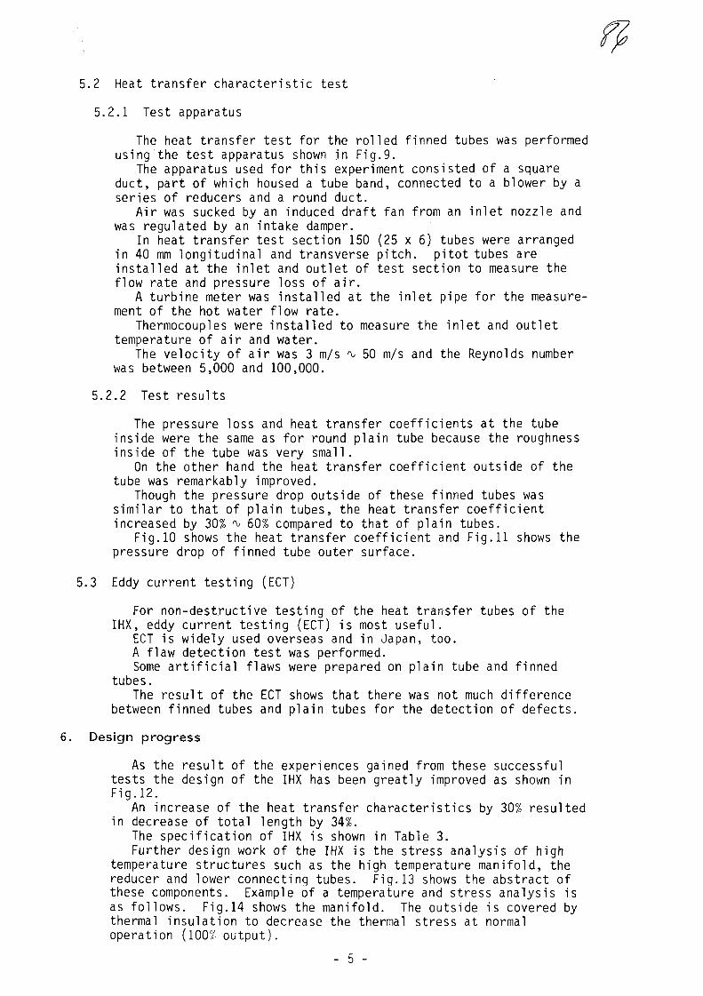
5.2 Heat transfer characteristic test
5.2.1 Test apparatus
The heat transfer test for the rolled finned tubes was performedusing the test apparatus shown in Fig.9.
The apparatus used for this experiment consisted of a squareduct, part of which housed a tube band, connected to a blower by aseries of reducers and a round duct.
Air was sucked by an induced draft fan from an inlet nozzle andwas regulated by an intake damper.
In heat transfer test section 150 (25 x 6) tubes were arrangedin 40 mm longitudinal and transverse pitch, pitot tubes areinstalled at the inlet and outlet of test section to measure theflow rate and pressure loss of air.
A turbine meter was installed at the inlet pipe for the measure-ment of the hot water flow rate.
Thermocouples were installed to measure the inlet and outlettemperature of air and water.
The velocity of air was 3 m/s ̂ 50 m/s and the Reynolds numberwas between 5,000 and 100,000.
5.2.2 Test results
The pressure loss and heat transfer coefficients at the tubeinside were the same as for round plain tube because the roughnessinside of the tube was very small.
On the other hand the heat transfer coefficient outside of thetube was remarkably improved.
Though the pressure drop outside of these finned tubes wassimilar to that of plain tubes, the heat transfer coefficientincreased by 30% ̂ 60% compared to that of plain tubes.
Fig.10 shows the heat transfer coefficient and Fig.11 shows thepressure drop of finned tube outer surface.
5.3 Eddy current testing (ECT)
For non-destructive testing of the heat transfer tubes of theIHX, eddy current testing (ECT) is most useful.
ECT is widely used overseas and in Japan, too.A flaw detection test was performed.Some artificial flaws were prepared on plain tube and finned
tubes.The result of the ECT shows that there was not much difference
between finned tubes and plain tubes for the detection of defects.
6. Design progress
As the result of the experiences gained from these successfultests the design of the IHX has been greatly improved as shown inFig.12.
An increase of the heat transfer characteristics by 30% resultedin decrease of total length by 34%.
The specification of IHX is shown in Table 3.Further design work of the IHX is the stress analysis of high
temperature structures such as the high temperature manifold, thereducer and lower connecting tubes. Fig.13 shows the abstract ofthese components. Example of a temperature and stress analysis isas follows. Fig.14 shows the manifold. The outside is covered bythermal insulation to decrease the thermal stress at normaloperation (100% output).
- 5 -

A part of the manifold which has many holes is called the ligament.High thermal stress occures when the reactor increases or
decreases its output because the change of helium gas temperaturecause the ligament to change its temperature but other parts areslower to change.
Fig.15 and Fig.16 show an example of this phenomenon. Thetemperature of the ligament is the same as that of the helium gas,but at spots away from the ligament the temperature is not so quicklychanged by the temperature change of the helium gas.
So a temperature gradient in the direction of the axis of themanifold causes thermal stress.
The result of inellastic stress analysis showed that the manifoldsatisfies its life time. The analyses for other high temperaturestructures showed the structures are sound.
7. Conclusion
As the result of the experiences gained from these successfultests, many data of characteristic, assembly and inspection wereobtained.
The main results are as follows;
(1) Finned tubes produced by rolling were able to be woundhelically by bending machine.
(2) Laboratory tests showed this tube had good heat trasfercharacteristics.
(3) There was not much difference between finned tubes and baretubes for detection of defects by the eddy current tests.
(4) A trial assembly using the same scale model showed that thepresent design is easy to assemble.
(5) Automatic orbital welding can be adopted for the weldingbetween tube and tube sheet.
By adding the data of corrosion, weldabil ity, creep, creep-fatigue and tribology has been obtained from other tests, the designof the IHX has been greatly improved. The Research and Developmentof IHX is in a final stage.
R E F E R E N C E -
(1) JAERI, "Present Status of Research and Development for Multi-purpose VHTR" Annual report, 1980 % 1983.
(2) JAERI, "Multi-purpose VHTR plant Detail Design (I)" DesignBook.
- 6 -
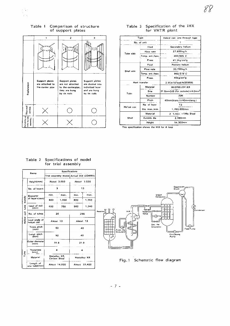
Table 1 Comparison of structureof support plates
Table 3 Specification of the IHXfor VHTR plant
Exp
lanatio
nT
he
rma
lst
ress
Su
itab
ility
of
tube
bun
dle
asse
mbl
y
1
gSupport platesare attached tothe center pipe
XX
2
}\ —*A
Support platesare not attachedto the centerpipe,they are hungby tie rods
oX
3
ri
I
11
, r— •
1"
i
Support platesare divided intoindividual layerand are hungby tie rods
oo
Type
No. of unit
Tube side
Shell side
Fluid
Flow rate
Temp, ent./leav.
Press.
Fluid
Flow rate
Temp, ent./leav.
Press.
Heat transfer
Tube
Helical coil
Shell
Material
Size
Number
Pitch
No. of layer
Dia. max./min.
Material
Outside dia.
Height
Helical coil, onethrough type
1
Secondary helium
27.600kg/h
283/905 C
41.3kg/cm'g
Primary helium
30.700kg/h
940/378' C
40kg/cm*g
2.15x10'kcal/h[25MW|
HASTELLOY-XR
31.8mmO.D.(Fin outside) X 4.0mm1
2 9 6
40mmfl trans. )x40mm|long.)
13
1.760/800mm
2 1/4Cr. - I M o Steel
2.380mm
14.300mm
This specification shows the IHX for A loop
Table 2 Specifications of modelfor trial assembly
Items
Hel
ical
co
il tu
be
bund
leT
ub
e
Height(mm)
No. of layers
Diameterof layers(mm)
Lead of coil(mm)
No. of tubes
Lead angle ofhelical coil
Trans, pitch(mm)
Longi. pitch(mm)
Outer diameter(mm)
Thickness(mm)
Material
Length ofone tube(mm)
Specifications
Trial assembly model
About 3.000
3
min.
8 0 0
6 0 0
max.
1.000
7 5 0
2 6
About 13
5 0
5 0
31.8
4
Hastellov XR.Carbon Steel
About 14.000
Actual IHX |25MWt|
About 7.500
13
min.
8 0 0
5 6 0
max.
1.760
1.240
296
About 13
4 0
4 0
31.8
4
Hastel
About
oy XR
33.400
--..-111
F ig . l Schematic flow diagram
- 7 -
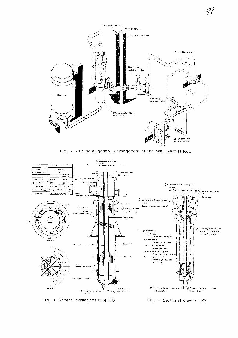
container vesseInner concreat
Secondary Hegas circulator
Fig. 2 Outline of general arrangement of the heat removal loop
o
H - . 1
1.1.1 1.-0
Col l . , T—,,
D,_..,̂ . . . . „
Tu . . S,,.
. . . p . C«..M
H . l
J
P.. . > ,
)H 'C
16 ) T/h'
. , , . .
! i^
i 111
i ..1
! 11. i
*c
•cSecondary helium gas
outlet
(to Steam generator) @ P r i m a r y h e l l u m g a s
outlet
(to Crrculatorl
I © Primary helium ga
(from Circulator)
hol.um gas outlet] ! (T)Pnmnty helium 93s inlet
ho HencloO Itrom Raaclof)
F ig . 3 General ar rangement of IHX F ig . 4 Sectional view of IHX
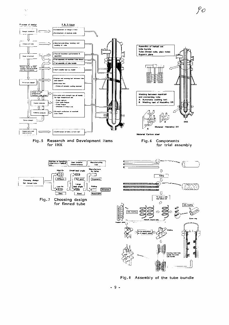
Process of design
Fig. 5 Research and Development itemsfor IHX
Assembly of h*Uc*J coiltub* bundt*Tub* (finrMd tub*, pUin tub*)Support pUt*
W«kiiog b*tw«wi manifokl•nd conn*cting tub*A Automatic wtldmg t**tB W*4ding t*st of HuttNoy XR
Mat«rial : Hutattoy XR
Fig. 6 Componentsfor trial assembly
Eiiinm el b«ndmgtub«« into • h#*C*fCCHI
H**1 trMMfM
ch»r»ctMiatics cott
a
Fig. 7 Choosing designfor finned tube
• • - 1 .
Fig. 8 Assembly of the tube bundle
- 9 -
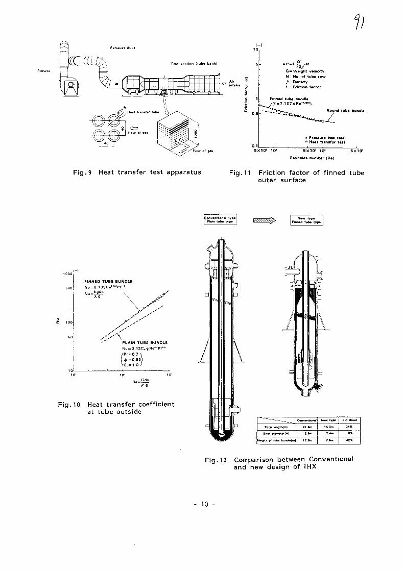
V1 0
G-Weight v^octtyN : No. of tub* row
Dtnsityf : Friction factor
Round tub« bundb
Pr«ssur« loss t*stHwt transfer twt
5x10* 10* 5X104 10* BxlO1
Reynolds numb«r (R«)
Fig. 9 Heat transfer test apparatus Fig, 11 Friction factor of finned tubeouter surface
onventions typ*Pl*in tu6« typ«
N«w typ*Fk>n*d tub* typ«
FINNED TUBE BUNDLENu = 0.139R«°'"Pr"
PLAIN TUBE BUNDLE
r = 0.7=0.95
1010 10- 10'
Re=.Gdo
Fig. 10 Heat transfer coefficientat tube outside
—~~~—___Tot«J Uo«tNml
lt*H diam^wlml
^•l«ht of iwb« bundMm]
Conv*ntion»t
21.Cm
2.ftm
12.8m
N*w tVM
14.3m
7.Un
Cut town
1 %
4 2 %
Fig. 12 Comparison between Conventionaland new design of IHX
- 10 -

Fig. 15 Temperature changein shut down
Fig. 13 Abstractof high temperature structure
Locationfor stress evaluation
Thermal insulation
Fig. 14 Analysis modelfor high temperature manifold
T*mp*ra1ur*
Tim«©69m*n.
Fig. 16 Temperatureand stress distributionafter manual trip
- "11 -

Fig. 17 Finned tube manufacturedby lathe (SUS)
Fig. 18 Rolled finned tube(Hastelloy-XR)
Fig. 20 Partial model of high
temperature manifold
(Hastelloy-XR)
Fig. 19 View of assembled model

No. 5
XA0055814
IAEA Specialists' Meeting on
Heat Exchanging Components of
Gas-Cooled Reactors
Development of a Helium/Helium Intermediate Heat Exchanger
with Helical Coil Tube Bundle
by A. Czimczik (L. & C. Steinmiiller GmbH, FR Germany)
G. Hirschle (Gebr. Sulzer AG, Switzerland)
Dusseldorf, 16. April 1984

— 1 —
Development of a Helium/Helium Intermediate Heat Exchanger
(He/He-IHX) with Helical Coil Tube Bundle
1. Preface
Besides the research and development work leading to the
design basis for the reference heat exchanger, the stages
of development up to the realisation of a nuclear He/He IHX
include, selected experiments in manufacturing techniques
and with individual test components, as well as the design,
manufacture and trial of a representative prototype compo-
nent.
The general features of the helical construction will first
of all be explained, taking into account the manifold spe-
cific requirements placed upon a nuclear component. The
primary and secondary flow path will be discribed. Special
design measures included to fulfil specific requirements
imposed by quality assurance and the need to facilitate re-
peated examination or ease of repair are also explained.
A comparison between reference and test component shows
that the capacity of 10 MW represents a sensible compromise
between a unit capable of providing answers to the techni-
cal problems involved and the cost of this step forward.
The selected size provides a useful test unit for material
processing, manufacture of components and quality control.
The materials used and the new design problems meant that
in constructing the 10 MW test component certain manufac-
turing processes had to be modified or to be developped to-
tally new. The successful use of these methods in the manu-
facture of the test component marks an important step in
the direction of producing such full-scale components.
The process of manufacture and the experience gained so far
are then described.

- 2 -
2. Technical requirements
The more important requirements demanded of the heat ex-
changer, which forms part of the primary enclosure, can be
considered under three aspects.
These are:
- Safety requirements
- Limiting process conditions
- Mechanical design aspects
Among other things, considerations of safety motivated the
following decisions:
- The heat exchanger should be located within the pressure
vessel. This dictates a compact construction and arrange-
ment of all assemblies.
- All surfaces enclosing primary circuits, particularly
weld joints, must be accessible for repeated examination
without having to open the primary circuit.
- In the event of component failure there must be no risk
of primary gas infiltrating into the secondary circuit.
Only one of the limiting conditions imposed by the process
will be mentioned:
The primary helium hinders the formation of oxide layers.
It is therefore possible, that in the higher temperature
range parts which are in contact might weld together by
diffusion. The contact areas of any parts which move rela-
tive by to one another must therefore be protected against
undesired welding or wear by suitable coatings.
For reasons of mechanical design the loads on components,
especially those exposed to high temperatures, must be
minimized. In the given temperature range of 950 °C, even
with the use of high temperature resistant alloys, the
available design reserves are minimal, particularly looking
to the life of 140,000 hrs specified.

- 3 -
3. Main development steps
Although process equipment has been successfully operated
at similar temperatures in many industrial applications,
the design, manufacturing and operational experience avail-
able from such conventional components is not by itself an
adequate foundation for attaining the development objective.
This applies particularly to the problem of approval of
components for use in the nuclear field. For one thing,
work on the relevant codes to be applied in the high
temperature field is not yet complete; for another, the
long-term characteristics of the reference material Inco-
nell 617 or Nicrofer 5520 Co (2.4663) have not so far been
ascertained.
It is therefore necessary to find new ways of proving the
safety of this type of equipment.
The construction and testing of a component which shall be
as representative as possible is regarded as the most im-
portant step in this direction. This component, with a heat
transfer capacity of 10 MW, is at present under construc-
tion.
Before this, and in association with it, manufacturing
tests were carried out on the machining and welding of the
material 2.4663. Special experimental components were tried
out to settle particular questions regarding thermohydrau-
lics and the mechanical behaviour of important parts (hot
headers, coatings, tube sleeves, test bundles for thermal
transfer and flow measurements). Additionally, elastic and
inelastic analysis was undertaken for the assessment of all
critical components.
The soundest basis for ensuring that a product will pass
all acceptance requirements is however a well thought-out
design, which from the very beginning reduces the load on
critical areas to a minimum. Here the helical variant of
the intermediate heat exchanger offers excellent possibili-
ties, since because of its specific constructional features
it provides good compensation for thermal expansion and can
rapidly disperse hot gas stratifications in the tube bundle.
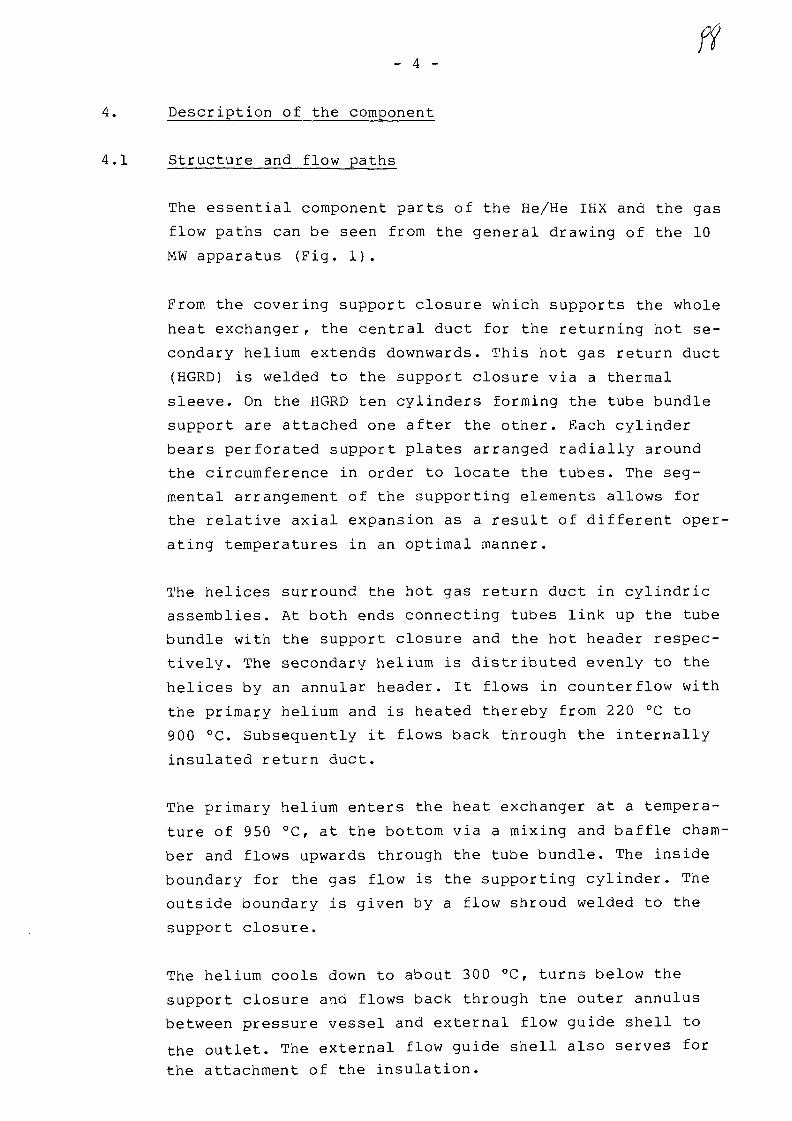
- 4 -
4. Description of the component
4.1 Structure and flow paths
The essential component parts of the He/He IHX and the gas
flow paths can be seen from the general drawing of the 10
MW apparatus (Fig. 1).
From the covering support closure which supports the whole
heat exchanger, the central duct for the returning hot se-
condary helium extends downwards. This hot gas return duct
(HGRD) is welded to the support closure via a thermal
sleeve. On the HGRD ten cylinders forming the tube bundle
support are attached one after the other. Each cylinder
bears perforated support plates arranged radially around
the circumference in order to locate the tubes. The seg-
mental arrangement of the supporting elements allows for
the relative axial expansion as a result of different oper-
ating temperatures in an optimal manner.
The helices surround the hot gas return duct in cylindric
assemblies. At both ends connecting tubes link up the tube
bundle with the support closure and the hot header respec-
tively. The secondary helium is distributed evenly to the
helices by an annular header. It flows in counterflow with
the primary helium and is heated thereby from 220 °C to
900 °C. Subsequently it flows back through the internally
insulated return duct.
The primary helium enters the heat exchanger at a tempera-
ture of 950 °Cr at the bottom via a mixing and baffle cham-
ber and flows upwards through the tube bundle. The inside
boundary for the gas flow is the supporting cylinder. The
outside boundary is given by a flow shroud welded to the
support closure.
The helium cools down to about 300 °C, turns below the
support closure and flows back through the outer annulus
between pressure vessel and external flow guide shell to
the outlet. The external flow guide shell also serves for
the attachment of the insulation.

_ c _
4.2 Technical data and their transferablility
In designing this test component, strong emphasis was laid
on the possibility of applying the experience gained in
manufacture and test running as far as possible to the re-
ference heat exchanger. Pressures, temperatures, tube
dimensions, tube pitching, height of the bundle and helix
pitch are therefore practically identical for both units.
The only major difference is the number of tubes (117 as
against 1482) , which are arranged in 3 and 19 cylindric
tube assemblies respectively. The test bundle is therefore
very largely typical in respect of manufacture, assembly,
selection of material and design details. The flow and heat
transfer characteristics however are strongly influenced by
the number of tube assemblies i.e. where only a few cylin-
ders are involved the boundary bypass gets a disproportio-
nately large influence.
For this reason supplementary component tests and basic
thermohydraulic research are being carried out to prove the
design of this heat exchanger. The tube bundle built for
this purpose is shown in Fig. 2. The cross-wise arrangement
of the tubes can be clearly seen, as well as the support
plates for the tubes. This bundle is at present undergoing
trials at the KFA/Jiilich.

- 6 -
f&O
4.3 Design Features
The central part of the test unit the hot gas return duct,
approximately 20 m long, is constructed in 2.4663 (plus
sections in the cold area of 10 CrMo 910) with a diameter
of approx. 762 mm (Fig. 3). The wall thickness depends on
the local operational temperature and varies between 35 -
60 mm. The individual duct build up from sections which are
welded together by narrow-gap welding.
The hot gas return duct is internally insulated. The insu-
lating system consists of a continuous outer tube in which
shaped sections of compressed Al^O- fibre are inserted
(Fig. 4). Internally, the insulation is covered by indivi-
dual overlapping liner tubes. The internal rings between
these two concentric tubes support the weight of the insu-
lation and also hinder convection through the insulation.
The selected mode of construction permits the complete in-
sulation to be withdrawn and allows periodic inspections of
the hot gas return duct from inside.
The insulation of the outer shell is built up in a similar
manner. It was however not necessary to arrange for
complete cladding of the insulation, since it is only
surrounded by a stagnant helium layer.
The supporting structure of the helices (Fig. 5) consists,
as already has been said, of separate elements which are
slid onto the hot gas return duct one after another and
each welded into position at one end. The points at which
the cylinders overlap and move relatively to one another
are suitably coated.
The helices (Fig. 6) have an inclination angular of approx.
25 ° and are located in the supporting plates with the aid
of sleeves. These tubular sleeves must fulfil three re-
quirements, viz:

- 7 -
- they must compensate for installation tolerances
- they must take the weight of the tubes
- they must function as a protection against wear.
Pairs of sleeves wedged onto the tubes are envisaged for
the temperature range below 700 °C. They however cannot be
used for temperatures above 700 °C, as frictional-type con-
nections become ineffective as a result of the relaxation
of material and subsequent loosening.
Various proposals have been developed for this temperature
range, of which two are illustrated here by way of example
(Fig. 7). To accept the downward forces imposed by the
weight of the tubes, the tube itself must exhibit a
thickening such as a welded-on ring or a built-up weld, as
well as a suitable thrust piece on the supporting plate.
As a protection against high-temperature fretting wear and
to prevent spontaneous welding in the helium atmosphere,
ceramic coatings are applied. The current view is that
layers of zirconium oxide stabilized with yttrium are best
suited to use under PNP conditions. However proof of the
reliability of such protective layers will only be possible
as a result of the projected component tests and especially
test running with the 10 MW unit. For this reason the
intention is to try out various alternative types of tube
holder and coating in the test unit.
The heating surface tubes lead into the hot header
(Fig. 8). Because of its exposed position in the hottest
part of the gas temperature range, this is regarded as
being one of the most heavily-loaded components. A number
of design measures were therefore taken to limit the
severity of the load on this component as much as possible.
First of all, the header and the incoming heat exchanger
tubes are protected against direct impingement by the
primary helium, which might well contain hot gas stratifi-
cations. As the secondary helium has a temperature of
900 °C and is therefore some 50 °C cooler than the primary
helium, an additional internal flow guide tube is fitted to
improve the internal heat transfer in order to keep the
temperature as close as possible to that of the colder
helium.
A third possibility of lessening or preventing impermis-
sible thermal stresses in thickwalled structures as a re-
sult of steep temperature gradients is by careful insula-
tion of endangered areas.

- 9 -
5. Fabrication and quality control
5.1 Welding
5.1.1 Gas-shielded metal arc narrow gap welding
For welding the pipe sections of the hot gas return duct
(HGRD) together, a process known as "gas-shielded metal arc
narrow gap welding" was utilised. This process has the
following special features:
1. A. specially developed wire-weaving mechanism produces a
weaving arc in a narrow gap.
2. The weld puddle is controlled by the shield gas flow to
produce an optimum contact angle between the weld sur-
face and the flanks of the weld.
3. The use of a pulsed arc power source produces a stable
arc and a weld edge with minimum spatter.
The process will be more fully dealt with in another paper.
Welding equipment from Interatom was used in the fabri-
cation.

- 10 -
5.1.2 Other welding work
Tube bundle supporting system
Together with the "Internal Flow Shroud" this assembly
constitutes the major welded-up components which determine
the geometry of the active part of the heat exchanger.
Exact conformity with the prescribed geometry of the flow
duct when locating the helical tube bundle is therefore
important and for this reason the welding and machining of
this parts is a complicated business.
The permissible radial tolerance between the support plate
edges and the internal flow shroud on installation requires
special jigs for welding up the segments of the supporting
structure, consisting of support cylinder, weld-on ring and
support plates. The weld preparation for the connection
between the support plate and support cylinder is shown in
Fig. 9a and that for the connection between the support
cylinder and HGRD in Fig. 9b.
For these welds the hand-manipulated electrode Gritherm
85 R proved reliable in service. Testing according to the
specifications has been demonstrated for all weld connec-
tions whose use is indicated for the full-scale PNP compo-
nent and has been proven by component tests.
Tube weld connections
The weld seams in the heat exchanger tubes (similar-metal
welds in 2.4663 and dissimilar-metal welds 10 CrMo 910/
2.4663) are carried out using the TIG process with station-
ary torch in the downhand position and rotating workpiece.
This process was easy to apply and produced good results.
All welds were radiographed and subjected to surface crack
detection procedures to check their soundness.

- 11 -
Homogenous welding of tubes to the support closure
The 117 tubes of 10 CrMo 910 material were welded from in-
side, using a hand welding gun, to the support closure
which is also of 10 CrMo 910. As preparation for welding a
fine centring ring was machined into the support closure at
the downside Wherein the tube was located. (Fig. 9c).
Special arrangements had to be made to ensure optimal gas
shielding. The welds are made with the tube axes in the
vertical plane, to produce the best possible bead confor-
mation.
5.2 Machining
The more important machining operations on the helical type
intermediate heat exchanger are:
- Deep-hole drilling of the holes and countersinking of the
ring grooves for connection of piping to the support
closure. This work in 10 CrMo 910 material was undertaken
by a specialist firm and presented no problems.
Drilling of the holes and countersinking of the ring
grooves on the hot header (Pig. 8).
The toughness of the 2.4663 material blunted the tools,
which imposed the necessity of frequent tool changes. In
comparison to "normal" steels the cutting speed also had
to be kept very low. Because the area to be machined was
relatively small, it was possible to carry the work out
with normal machine tools. For full-size components it
must be attempted to develop special tools of a suitable
type to facilitate these operations.

- 12 -
- Machining of supporting cylinder with support plate.
The prescribed narrow tolerances meant that special jigs
and fixtures had to be used in machining the supporting
structure segments as well. All surfaces of the segments
which immediately contact other components were speci-
ally machined. The drilling of the support plates was
effected using drilling templates in a specially fitted
holding and chucking device mounted on a horizontal dril-
ling machine with numerically-controlled coordinate input
(for a finished segment after machining, see Fig. 5).
- Final machining of the support closure/HGRD assembly.
The great length of this component {about 21 m) and the
required positional tolerances in respect of linearity
and angularity meant that machining on an oversize lathe
was necessary (Fig. 3). Machining presented no problems
and the tolerances could easily be complied with. The
actual tolerance measured amounted only to some 10 % of
that permitted.
5.3 Protective coating
For the experimental helical type heat exchanger one HGRD
section and one set of connecting tubes, both of 2.4663,
were coated with a triple layer of ZrO2 13 % Y-O-
NiCr A1Y, using the APS-process. The choice of this type of
coating represents the best available knowledge and was
made as a result of the research whicl- is still continuing
on the problem.

- 13 -
5.4 Bending of the helix tubes
Up to now the 3-roll bending process had only been used for
shallow-pitch tube helices. For the He/He Heat Exchanger
the process has now been expanded in experimental proce-
dures to cope also with steeply pitched helices. Besides
the modifications of the machines, this meant that the new
bending parameters had to be found out. The permissible
manufacturing tolerances were worked out by screwing tests
on individual helices.
The tubes of the KFA bundle for thermohydraulic tests were
the first production application of this process. For the
10 MW He/He IHX the tubes were welded together from 4
standard lengths to a total length of around 45 m and then
bent to form helices of about 18 m length and three diffe-
rent diameters of 918, 990 and 1062 mm. The intermediate
diameter helices were given a left-handed helical coil, the
others a right-handed coil. A particular feature in the
production of steep-pitch helices is the great amount of
room required for bending and intermediate storage (Fig.6).
6. Conclusion
The development of a large He/He-IHX (125 MW) for the pro-
totype plant for nuclear process heat (PNP) requires not
only basic engineering but also various experiments on
special structural parts of the component in order to test
manufacture procedures and important details of the design.
Additionally to this, a representative experimental IHX was
designed, which is now in fabrication and which will be
tested early in 1985. Until now already many requirements
connected with IHX are fulfilled. Therefore we are very
confident that after the test runs a large nuclear heat
exchanger can be realized.
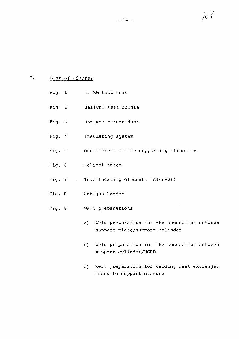
- 14 -
7. List of Figures
Fig. 1 10 MW test unit
Fig. 2 Helical test bundle
Fig. 3 Hot gas return duct
Fig. 4 Insulating system
Fig. 5 One element of the supporting structure
Fig. 6 Helical tubes
Fig. 7 Tube locating elements (sleeves)
Fig. 8 Hot gas header
Fig. 9 Weld preparations
a) Weld preparation for the connection between
support plate/support cylinder
b) Weld preparation for the connection between
support cylinder/HGRD
c) Weld preparation for welding heat exchanger
tubes to support closure
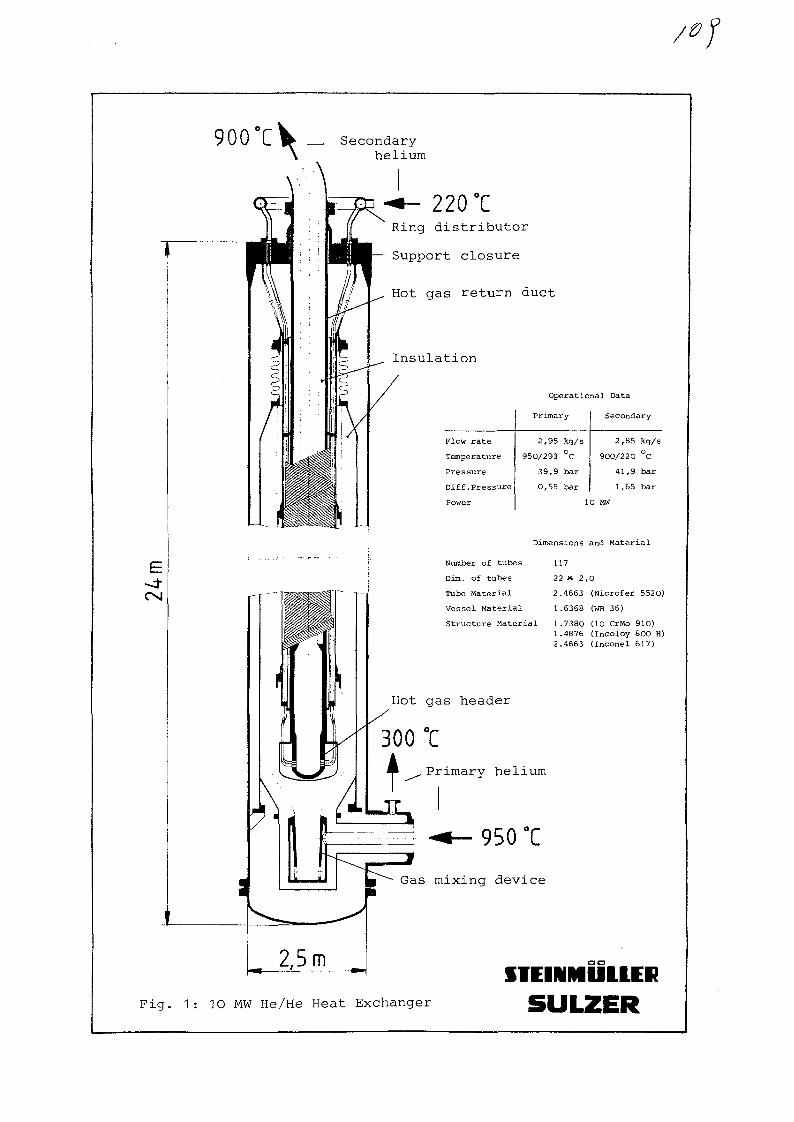
900TV _ Secondaryhelium
-t- 220 °CRing distributor
Support closure
Hot gas return duct
Insulation
Flow rate
Temperature
Pressure
Diff.Pressure
Power
Operational Data
Primary
2,95 kg/s
950/293 °C
39,9 bar
0,55 bar
Secondary
2,85 kg/s
900/220 °C
41,9 bar
1,65 bar
10 MW
Number of tubes
Dim. of tubes
Tube Material
Vessel Material
Structure Material
Dimensions and Material
117
22 X 2,0
2.4663 (Nicrofer 5520)
1.6368 (WB 36)
1.7380 (10 CrMo 910)1.4876 (Incoloy 800 H)2.4663 (Inconel 617)
950 °C
Gas mixing device
ITEIMMUUERFig. 1: 10 MW He/He Heat Exchanger
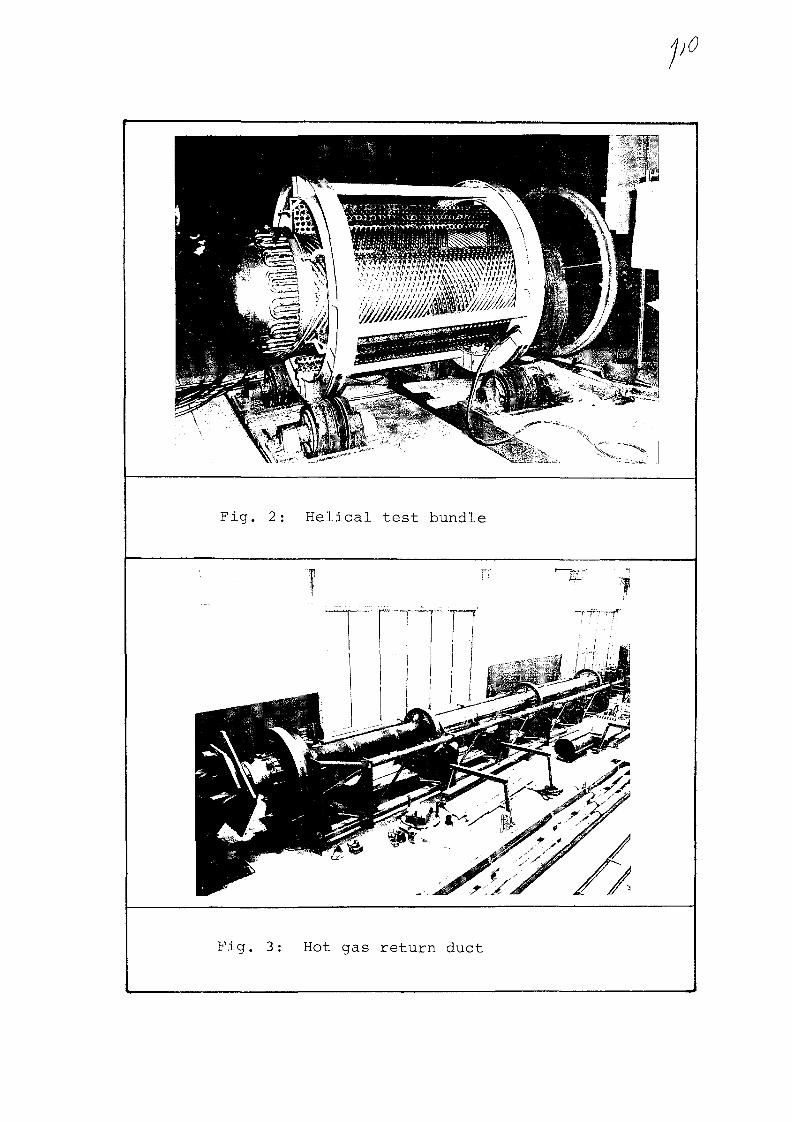
Fig. 2: Helical test bundle
Fig. 3: Hot gas return duct

Fig. 4: Insulating system

o oo
oiO(o<
ooo
oo
o
v-~ •* V
Fig. 5: One element of the supporting structure

Fig. 6:
Helical tubes
Fig. 8:
Hot gas; header

300-700 t
700-900 °C
700-900 C
Fig. 7: Tube locating elements (sleeves)
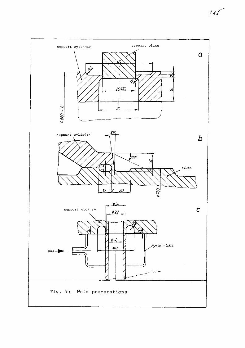
support cylinder support plate
support cylinder
HSRD
gas •
tube
Fig. 9: Weld preparations

No. 6
XA0055815
IMPROVED SPACERS FOR HIGH TEMPERAUTRE GAS-COOLED HEAT EXCHANGERS
L,A. Nordstrom
Swiss Federal Institute for Reactor Research
5303 Wurenlingen / Switzerland
Paper presented at
Specialists's Meeting
on
Heat Exchanging Components of Gas-Cooled Reactors
Diisseldorf, BRD
April 16-19, 1984

-. 1 -
IMPROVED SPACERS FOR HIGH TEMPERATURE GAS-COOLED HEAT EXCHANGERS
by
L.A, Nordstrom / Swiss Federal Institute for Reactor Research
1. INTRODUCTION
Experimental and analytical investigations in the field of heat exchangerthermohydraulics have been performed at EIR for many years. Basic studieshave been carried out on heat transfer and pressure loss for tube bundlesof different geometries and tube surfaces,
As a part of this overall R+D programme for heat exchangers, investigationshave been carried out on spacer pressure loss in bundles with longitudinalflow. An analytical spacer pressure loss model was developed which couldhandle different types of subchannel within the bundle. The model has beenevaluated against experiments, using about 25 spacers of widely differinggeometries.
In a gas-cooled reactor it is important to keep the pressure loss over theprimary circuit heat exchangers to a minimum. In exchangers with grid spacersthese contribute a significant proportion of the overall bundle losses. Forexample, in the HHT Recuperator, with a shell-side pressure loss of 3.5 % ofthe inlet pressure, the spacers cause about one half of this loss. Reducingthe loss to, say, 2.5 % results in an overall increase in plant efficiency bymore than 1 % - a significant improvement.
Preliminary analysis identified 5 geometries in particular which were chosenfor experimental evaluation as part of a joint project with the SULZER Com-pany, to develop a low pressure-loss spacer for HHT heat exchangers (longi-tudinal counter-flow He/He and He/H20 designs). The aim of the tests was toverify the low pressure-loss characteristics of these spacer grid types, aswell as the quality of the results calculated by the computer code analyticalmodel. The experimental and analytical results are compared in this report.
2. EXPERIMENTAL APPARATUS
An open air loop at EIR was used for the tests. The required air flow wasobtained from a rotary compressor. It gave a maximum air flow of 1 kg/s ata pressure of 0,5 bar (above atmospheric). A remotely - controlled motorisedvalve in a bypass pipeline was used to regulate the air flow, and the excessair released to atmosphere. A cooler was used to keep the air temperature ata constant level. A silencer was added to the compressor in order to suppressundesired resonant vibrations.
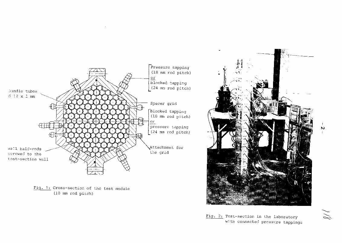
Bundle tubes0 12 x 1 mm
Wall half-rodsscrewed to thetest-section wall
Fig- 1: Cross-section of the test module(18 mm rod pitch)
Pressure tapping(18 mm rod pitch)or
blocked tapping(24 mm rod pitch)
Spacer grid
Blocked tapping(18 mm rod pitch)orpressure tapping(24 mm rod pitch)
Attachment forthe grid
N>
Fig- 2: Test-section in the laboratory
with connected pressure tappings

— 3 —
The test-section allowed two bundle arrangements to be installed, with atube-pitch of 18 or 24 mm (i.e. a pitch-to-^diameter ratio of 1,50 and 2,00,respectively, for a tube of 12 mm O.D,). Half-rods were fixed to the test-section walls to reduce the influence of the wall friction as much as possi-ble. The corner rods were an integral part of the test-section wall. The twobundles consisted of 37 full- and 18 half-tubes (Fig, 1), and 19 full- and12 half-tubes, respectively.
The test-section itself was a precision fabricated piece of 2 meters length(Pig. 2) in two separable halves. The tubes for the bundle and the wall half-rods were also of high precision construction with O.D. of 12,01 t 0.01 mm.The test-section wall and the tubes can be considered as smooth. The bundletubes had solid ends which were rounded at the inlet end. The wall rods weretapered towards the inlet end (Fig. 4).
The longitudinal attachment of the tube bundle to the test-section shell wascarried out at a special grid (Level 6, Fig, 3), holding the tubes at theirends in such a way as to create no extra pressure loss in excess of that ofa normal spacer grid. As ct "flow equaliser" (Level 1) a spacer grid of thesame type as the one to be investigated was normally installed. The spacergrids could be mounted at any level between 2 and 5, allowing one alone ormore together to be tested in the same run.
50
Inletj I
X
pressure taps, 19 x 100 mm
I I I 1 I I I I I I I I I I
level ofspacer grids: 1.
flow equaliser
50
Outlet
possible positionsfor the test grids
spacer used as longi-tudinal fixing pointfor the tube-bundle
Figure 3: Axial arrangement of spacer grids and pressure tappings in thetest-section.

- 4 -
3. MEASUREMENT AND DATA HANDLING
To determine the spacer grid pressure-loss coefficient, Z, as a function ofthe Reynolds Number, Re, the air mass flow was changed and other parameterskept constant (e>g, inlet air temperature). The laminar bundle flow casesare not of interest here and therefore not considered. The range of Re co-vered here is from 10^ up to the maximum achievable for each geometry, i.e.about 105 (p/d = 1.5) and 2 • 1O5 (p/d = 2.0). In order to have good mea-suring conditions, the Mach-number was kept below a value of 0.3,
At each of the 19 measuring levels (Fig. 3), all three pressure tappings wereconnected together to obtain an average value of pressure. From experiencewith other experiments, this arrangement results in a significantly moreaccurate value than the use of only one pressure tapping at each measuringlevel. Obtaining a mean value from many single-point measurements by the useof a rapid-collection data acquisition system, has reduced the scatter signi-ficantly, to about 20 % of the scatter of the single-point values.
For the data analysis and calculation of the spacer pressure-loss coefficients,the EIR computer code "TESERA 2" was used. It plots the pressure data and theresulting Z versus Re. The gradient of the pressure loss between two grids wascalculated by the method of least squares, without fixing any measured pointas a reference. Pressures measured in the disturbed region just downstream ofa grid were neglected when extrapolating inter-spacer pressure profile. Thiseliminated error caused by high turbulence in the near-spacer region, and theloss of a few data points did not significantly affect the accuracy of thefitting of the line to the data.
4, SPACER GRID TYPES
In cooperation with Sulzer Bros., 11 new spacer grid types were constructedas possible low pressure-loss grids suitable for the HHT heat exchangers.Following calculation with the computer model (see Section 6), 5 types werechosen for the experimental investigation reported here, see Fig. 5 to 9. Notedfor each type is the ratio of pitch-to-tube O.D. (p/d), the total height (h),the solidity (O = spacer blocked area in the bundle channel / free flow areain the channel) and the resulting typical spacer pressure-drop coefficients(Z, see Section 5).
Defining the blocked area of a spacer grid is not always straight forward, anddepends upon the geometry. Of the grids presented here, the calculation istrivial for Types B and D, with constant geometry throughout. For Type C, withaxially overlapping plates, the blockage was defined at the level with thesmallest free flow area. In Type A the blocked area does not vary along thespacer, the tube-locating dimple just causing transverse flow inside the spa-cer. However this effect does produce a pressure drop and, after investigation,it was found that approximately 3/4 of the projected area of the Type A dimplesshould be added to the spacer plate blocked area. Supporting this, similar spa-cer geometries have been treated in a corresponding way, and good agreement withexperiment has been obtained.

Fig. 4; View of the test-sectioninlet. Bundle-rods with roundedends.
Fig. 6: Type B, p/d=1.50, h=50 mm0 = 0.285, Z = 0.5+0,05
Fig. 5: Type A, p/d=1.50, h=38 mma - 0.291, Z = 0.76+0.1
Jv*» ̂.4" ^ 7 4
Fig. 7: Type C, p/d=1.50, h=38 mma = 0.191, Z = 0,6+0.05
Fig. 8; Type B, p/d=2.00, h=38 mma = 0.171, Z = 0.21+0.02
Fig, 9: Type D, p/d=2.00, h=38 mm
a = 0,180, Z = 0.26+0.03
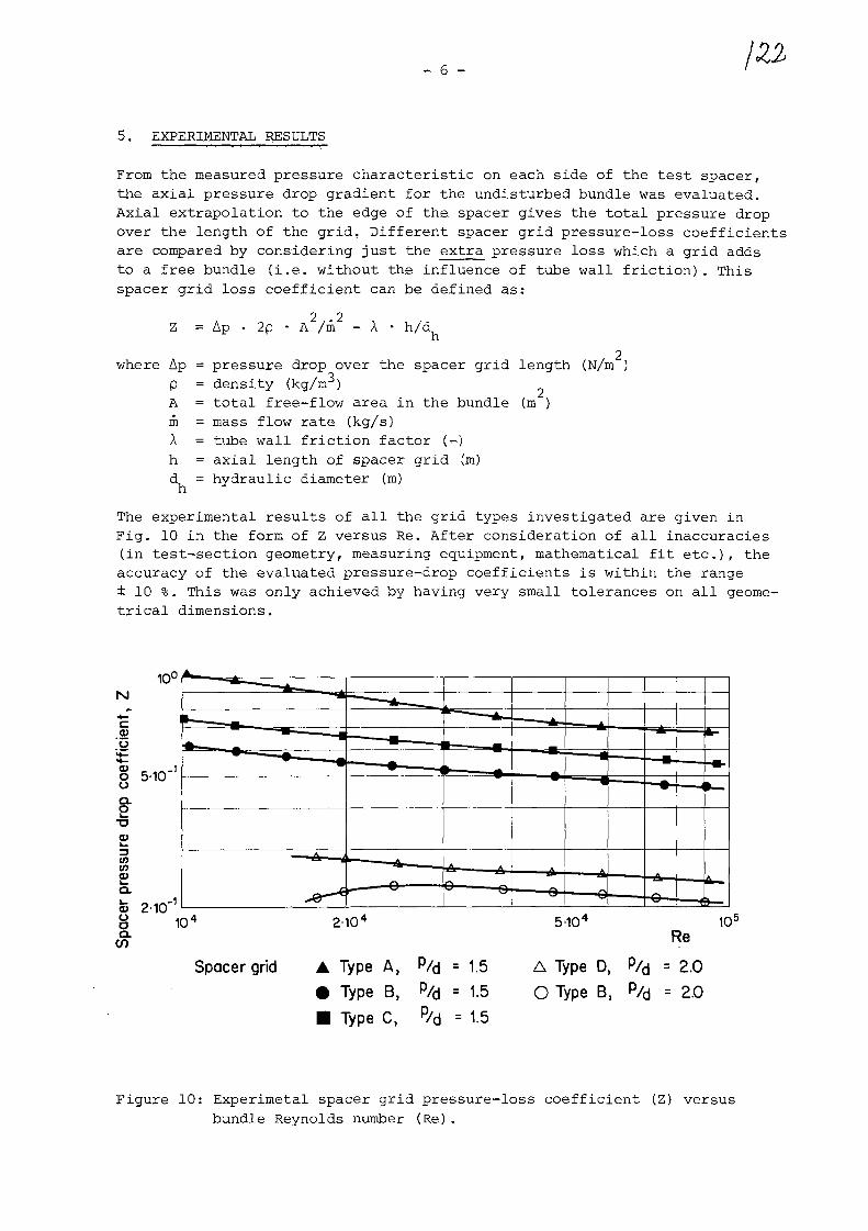
- 6 T
5. EXPERIMENTAL RESULTS
From the measured pressure characteristic on each side of the test spacer,the axial pressure drop gradient for the undisturbed bundle was evaluated.Axial extrapolation to the edge of the spacer gives the total pressure dropover the length of the grid, Different spacer grid pressure-loss coefficientsare compared by considering just the extra pressure loss which a grid addsto a free bundle (i.e. without the influence of tube wall friction). Thisspacer grid loss coefficient can be defined as:
Z = Ap • 2p2 2
• A /m - A h/d.h
where Ap = pressure drop over the spacer grid length (N/n/p = density (kg/m )
A = total free-flow area in the bundlein = mass flow rate (kg/s)A = tube wall friction factor (-)h = axial length of spacer grid (m)
(m2)
d = hydraulic diameter (m)
The experimental results of all the grid types investigated are given inFig. 10 in the form of Z versus Re, After consideration of all inaccuracies(in test-section geometry, measuring equipment, mathematical fit etc.), theaccuracy of the evaluated pressure-drop coefficients is within the range± 10 %. This was only achieved by having very small tolerances on all geome-trical dimensions.
ooQ.
2
10
w
5-10
a> 210CL
-i
Spacer grid A Type A, P/d = 1.5• Type B, P/d = 1.5• Type C, p/d = 1.5
5'10'Re
A Type D, P/d =2.0
O Type B, p/d = 2.0
10a
Figure 10: Experimetal spacer grid pressure-loss coefficient (Z) versusbundle Reynolds number (Re).

_ 1 —
6, ANALYTICAL MODEL AND CALCULATED RESULTS
The EIR analytical model for the prediction of spacer pressure-^loss coeffi-cients has been evaluated and improved over a number of years. To date it hasbeen tested against experimental results from more than 25 spacer grids ofwidely differing geometries. The model can handle different types of subchan-nel within the bundle, such as triangular and square arrays, and differentwall channels, with smooth as well as rough bundles. It separates the pressure-loss coefficient into three components; plate friction (the effect of frictionon the spacer plate), irrecoverable profile loss (effect of the flow arearestriction) and channel wall friction (the effect of friction on the sur-rounding bundle rods or sheath). The model is fully described in /I/. One ofits essential features is that the plate friction coefficient is based on theassumption of the free flow principle. It is necessary to define a Reynolds-number, Re , which governs the transition from a laminar to a turbulent boun-
cdary layer on the spacer grid plate, based on the distance from the leadingedge of the plate. In /I/ a typical value for Re of 8 x 10 is suggested,
^ cbut this can increase to 5 x 10 for very low freestream turbulence and verysmooth surfaces.
Calculation with the analytical model computer code "SPATES" gave the resultsshown in Fig. 11. Three different values of Re were considered: O (direct
ctransition to turbulent flow and no laminar boundary from the leading edge
of the spacer plate), 8 x 10 (transition inside the spacer grid) and 3 x 10^(flow with mainly laminar boundary layer over the spacer plate). The predictedspacer pressure—drop coefficients are, as can be seen from Fig. 11, alwayslower than the experimental results. This confirms the trend from other expe-riments. The best fit is obtained with Re = 0 . The difference between expe-riment and prediction decreases with increasing bundle Reynolds number and,for Re > 3 x 10⁴, is less than 0.1 (p/d = 1.5) or 0.05 (p/d = 2.0) . The rela-tive difference is thus less than - 20 % for the whole range of Re investi-gated.
7. DISCUSSION
A spacer grid represents a local blockage of the bundle channel, characterisedby the solidity (G). The spacer pressure-loss coefficient, Z, is significantlyinfluenced by 0, and is very sensitive to changes in a especially at highera (e.g. a > 0.4). At the design stage of the new spacer types an attempt wasmade to: 1) keep the a-value as low as possible and, 2) distribute theblockage so that the material of the spacer was as close as possible to thetube walls, and not in the middle of the subchannel where the gas-velocity ishighest. Secondary effects, such as the influence on the heat transfer, werenot considered.
It is worth noting here that smaller o- and therefore Z-values, can be obtai-ned by increasing the tube pitch, see for example Type B in Fig. 10. The a-values of the spacer grids reported here are low - giving a small dependenceupon Re. It is therefore possible to define a characteristic mean Z for eachtype (see Fig. 5 to 9), which is good enough for lay-out calculations of heatexchangers.

Type A, % = 1.5
Rec =Rec = 800CX)Rec = 300000experimental results
2-10
Rec=0Rec=80000Rec = 300 000experimental results
10 2-10 2-10
Figure 11: Comparison of predicted and experimental spacer pressure-losscoefficient (Z) versus bundle Reynolds number (Re).

9 -
The influence of the transition Reynolds number as a parameter is obviousand considerable (Fig. 11), Therefore Re must be known as accurately aspossible in order to obtain good analytical prediction of spacer pressure
loss. The value of Re can be found experimentally and this is probably bestc
done by means of accurate velocity measurements in scaled-Hip geometries ofa few typical bundle channels, at a Reynolds number corresponding to thistransition region. A value of Re = 0 gives the best fit between experimen-tal and predicted results for the spacer geometries reported here. This indi-cates that the grid is such a flow disturbance that no laminar boundary layeris possible over it, and the flow is turbulent throughout.
The particular shape of the predicted curve for Re > 0 corresponds to thetransition from laminar to turbulent flow within the spacer. Obviously thehandling of this phenomenon by SPATES is not satisfactory. The transitionoccurs progressively within the spacer, instead of abruptly as programmed inthe code /I/.
The Type B grid was chosen as the best spacer for the recuperators for theHHT-Demonstration Plant. As the spacer constitutes an essential and delicatepart of high temperature heat exchangers with shell-side, longitudinal flowthis type was extensively investigated. Mechanical stability and frettingbehaviour, as well as pressure drop, were tested experimentally and the in-fluence of spacer design and axial separation of grids on the heat exchangerdimensions were investigated analytically /2/.
The R+D work in this field, which EIR is continuing to pursue, is the syste-matic investigation of the influence of different geometrical parameters,such as plate profile and thickness, plate axial length and distribution ofsolidity axially, on the pressure-loss coefficient. The prediction model isalso being critically reviewed and an analytical method is being drawn upfor the calculation of the components for profile pressure drop, instead ofthe semi-empirical equations used in SPATES. Another logical, but as yet un-planned, step would be to investigate the influence of different grid geo-metries used in a heat exchanger on the heat transfer.

10
8. CONCLUSION
• The improvement of low pressure-drop spacer grids for high temperaturegas heat exchangers with longitudinal tube-bundles has been successful.From these results the spacer grids which have been tested have pressure-loss coefficients which are significantly lower than those currently used.
• The accuracy of experimental results of within ±. 10 % is very satisfactoryand was only possible by using very small tolerances in the geometricaldimensions. This accuracy should be adequate for practical use in thelayout of heat exchangers,
• The analytical model slightly underpredicts the spacer pressure loss, inparticular at low bundle Reynolds Number. However, results are sufficient-ly accurate to justify the use of this code for calculation of the pres-sure-loss coefficient of widely differing spacer grid geometries. It isfairly independent of the bundle geometry and can also treat artificiallyroughened rods. The possible spacer geometries it can handle are typical-ly those of honeycombs and rings, but this does not exclude other shapes.Generally speaking, a wide range of grid types are allowed provided theirwebs can be approximated to semiinfinite plates in a free flow, or ringsaround the rods /3/.
• The prediction in the lower Reynolds Number range is not as accurate asat higher Re, and additional work is also required at much higher Rey-nolds Numbers (e.g. 10 ) to prove the validity of the free flow principleunder these conditions. Attemps are therefore still being made to improvethe model.
REFERENCES
/I/ Barroyer, P.; "Analytical Model for the Prediction of Spacer Pressure-Drop Coefficients", EIR-Bericht No. 350, September 1978.
/2/ Nordstrom, L.A., Fischli, H., Sulzer Brothers Ltd, Winterthur, CH-8400,Naegelin, R., Formerly Sulzer Brothers Ltd, now at Swiss Nuclear SafetyDep. (HSK), Wiirenlingen, CH-5303: "Recuperators for the HHT-DemonstrationPlant", Transactions of the ASME, Engineering for Power, Vol. 102, No. 104,October, 1980.
/3/ Barroyer, P.: "Verification of an Analytical Model for the Prediction ofSpacer Pressure Drop Coefficients", EIR-Report SL-R/30, May 1979, Presen-ted at the Specialist Meeting on Heat Transfer, Session VI, Paper 1,Wurenlingen 14 to 16 May, 1979, OECD/NEA GCFR Programme.
XA0055816
IAEA Special ists 'Meeting on HeatExchanging Componentsof Gas-Cooled Reactorsin Duesseldorf, FRG
16-19 April 1984
Life Time Test of A P a r t i a l Model ofHTGR Helium-Helium Heat Exchanger
Masaki Kitagawa, Hiroshi Hattori,Akira Ohtomo, Tetsuo Teramae,Junichi Hamanaka, Mitsuyoshi Itohand Shigemi Urabe
Ishikawajima-Harima Heavy Industries Co., LtdJapan, 100
AB STRACTAuthors had proposed a design guide for the HTGR components and
applied it to the design and construction of the 1.5 Mwt helium heatexchanger test loop for the nuclear steel making under the financialsupport of the Japanese Ministry of International Trade and IndustryIn order to assure that the design method covers all the conceivablefailure mode and has enough safety margin, a series of life time testsof partial model may be needed. For this project, three types of modeltests were performed. A life time test of an partial model of thecenter manifold pipe and eight heat exchanger tubes were described inthis report.
A damage criterion with a set of material constants and a simplifiedmethod for stress-strain analysis for stub tube under three dimensionalload were newly developed and used to predict the lives of each tube.The predicted lives were compared with the experimental lives and goodagreement was found between the two.
The life time test model was evaluated according to the proposeddesign guide and it was found that the guide has a safety factor ofapproximately 200 in life for this particular model.
- 1 -

i. INTRODUCTIONTo develop the structural strength design procedures
for the HTGR components, authors had already proposedan structural design guide which utilizing the Inconel617 and Hastelloy X as the high temperature material,and applied it to the design of a 1.5 Mwt helium heatexchangers test loop. The guide was developed by extend-ing the ASME B & PV Code Case N-47 to the HTGR temperatureand HTGR environments. The main items to have beenmodified (Refs 1,2) were listed in Table 1.
The guide was intended to cover the conceivablefracture modes of the HTGR high temperature componentsand to include certain amount of safety margin to assurethe total safety of the designed components.
In order to increase the reliability of the guide,the life time test of the partial model of the HTGRcomponents is needed. Three type of models were testedin relation to the above mentioned design guide.
CD 1.5 Mwt Helium Test Loop (experimental test loop fornuclear steel making plant) which had been operatedat 1000°C for 2000 hrs (design time was 5000 hrs).
(2) Partial model of the center portion of above 1.5Mwt Helium Heat Exchanger (center pipe + tubes)which had been tested to life time under acceleratedloading condition.
(3) Small components such as heat exchanging tubes whichwere usually run to failure under the variety of loadingconditions.
In this report, the some details of life time testof the partial heat-exchanger-center-pipe-and-tubesmodel is to be described. The model of center pipeand tubes were selected for life time test, becausethe preliminary strength analysis had revealed thatthe highest temperature portion of center pipe and heatexchanger tube assembly is going to be subjected to theseverest damage during the life.
2. EXPERIMENTSFigure 1 shows a schematic diagram of the partial
model tested. The model consists of eight 600 mm diameterhelical coils (25.40 OD, 4t tubes) and 2000 x 20t centerpipe made of Inconel 617. The eight tubes were welded tothe stubs machined on the lower part of the center pipeand the other ends were fixed to the tube supports connectedto the vessel wall. The center pipe is guided and iscapable to be electrically driven along the vessel axis(max. stroke 150 mm; 0 ^ 25 mm/hour).
- 2 -

2.1 Applied Load and Temperature
The center pipe was cyclically moved up and downalong the vessel axis to simulate the thermal expansionstress. The tangential angle between the end of helicalcoil and the first support of the each tube was different,and consequently, the stress on each tube caused bycyclic motion of center pipe differs each other.
To apply the hoop stress to the tubes, the heliumgas of 99.995% purity was charged to the predeterminedpressure. The pressures for tubes varied to producethe variety of damage conditions. The load conditionsof each tube were summarized in Fig. 1. All of theemployed load conditions were set to be more deleteriousthan load conditions of actual components in order toaccelerate the failure of the model.
Load history is shown in Fig. 2. The helium gastemperature was controlled by electric heater so thatthe metal temperature of lowest portion of the helicalcoil was kept at 9 50°C.
3. EXPERIMENTAL RESULTSThe fractured model is shown in Fig. 3. The fracture
occured at the stub portion of the center pipe (not on thewelded joints between the stub and tube). Tubes no. 1^ no.5failed or leaked during the test at the time shown in Fig.2.The time shown in the fiqure is the accumulated time atmax. operating temperature 9 50°C. As for tube no.3 and no.6,the cracks were found from the inside surface of the tube.Tubes no.7 and no.8 had not failed even after the prolongedexposure to 14.7 MPa (150 kgf/cm2).
An example of fractured tube may be seen in Fig. 3.The tubes were generally expanded radially due to theinternal pressure and cyclic bending and the crackswere initiated from inside surface of the tubes.
Damage of other part of the tested model was generallysmall.
Slight amount of decarburization were observed on theoutside and inside surface of the tubes. The internallyoxidized layer was observed near the inside surface ofthe tubes.
All of the welded joint between cubes and stubs werefound sound after the test.
- 3 -

3°
4. LIFE PREDICTION AND SAFETY MARGIN OF THE DESIGN GUIDE
In order to evaluate the accuracy of the life predic-tion method, the lives of the five fractured tubes werecalculated using the following life prediction criteriaand structural analysis method.
4.1 Damage Criteria for Life Prediction
The loading condition of the life time test was suchthat the tubes were expanded outwards under the internalpressure and cyclic bending. The amount of the damagedue to diametral expansion of the tube is so large thatthe linear creep fatigue damage summation rule of thecode case N-47 can not be used. Therefore, a followingfailure criteria which includes the damage due to thestrain accumulation was employed.
^f + ^c + *D = 1 (1)
where <f> _ and <f> is fatigue and creep damage as in C.C.N-47 and <j> is the damage due to unidirectionallyaccumulated strain. Usually, the creep damage is cal-culated by the time ratio on the basis of the staticcreep rupture time. However, under the cyclic strainconditions, the cyclic creep rupture time is known tobe more adequate than the static creep rupture time.Therefore, the creep damage shall be calculated on thebasis of the cyclic creep rupture time, t
On the other hand, the cyclic creep rupture timeis obtained repeating the creep test in a fixed strainrange, and therefore cyclic creep rupture propertyinclude some fatigue damage. Besides, the number ofstrain cycles in the life time test were small. Underthese conditions, the first term of the above equationwas considered to be neglected (or included in the $ ) .
The third term may be called the ductility exhaustiondamage and unidirectional creep rupture ductility, e ,may be used as a base. In order to cover theunidirectional creep failure as well as the cyclic creepfailure, the ductility exhaustion damage $ may bewritten as
re
- 4 -

where t , t are cyclic and static creep rupture time
under a given stress. For Inconel 617, the cyclicrupture time is approximately 10 times as large asthe static creep rupture data, the damage criteriamay be written as
/|t_ + o.9 /§£ = 1 (3)Src r
Fig.4 shows the results of increasing mean strainfatigue test compared with the above failure criteria.It is seen that the above criteria is adequate forthis type of loading.
4.2 Material Properties of Inconel 617
For accurate life time prediction, it is desirableto prepare the material properties of the particulartubes employed in the model at the test temperature.However, that is impractical time- and cost-wise.Therefore, in this work, material properties of themodel tubes at the tested temperature in the testatmosphere were obtained from the data which had beenexisting at the time of life time test.
Constitutive Equations of Creep
Constitutive equation of the code was generatedon the creep data of the plate material, and is shownas follows.
e = kant + 6aqtr + a/E (4)
e : total strain
t : time (hr)
a : stress (kg/mm )
k, B, n, q, r, E : material constants
However, the tube and forged material has the differentgrain size and the different product form. Therefore,their creep equations should be different each other.
Considering these differences, the creep equationof pipe and forged material was assumed to be sameand 1.13 times as large as the code equation value.
Strength reduction factor due to effect ofdecarburization was also considered.
— 5 —

Cyclic creep rupture strength
Cyclic creep rupture strength of the tube and forgedmaterials were estimated from the static creep rupturedata of the tube materials and comparison of staticand cyclic creep strength at 1000°C. The effect of thegrain size on the creep rupture strength was estimated.
Rupture elongation
Although rupture elongation usually depends onthe rupture time, the rupture elongation was assumedto be constant of 0.40 because the variation of therupture time in the life test was small.
4.3 Creep Analysis of the Model and Life time Prediction
For accurate prediction of the life time of the model,the finite element method with 3 dimensional solidelement may be employed to analyze details of the structuralbehaviors including the analysis of the crack propagation.But this kind of approach is usually unpractical becauseit takes too much computing time. Here, a simplifiedanalysis method was proposed and utilized under justifiedassumptions. The details of the method will be publishedelsewhere (3).
The predicted life time obtained using the abovesymplified analysis method under the fracture criteriaand the materials constants described in the precedingparagraphs were summarized in the Table 2. The resultsclearly show that in the tubes no.1 and 2 where thermalexpansion stress is high, the creep damage <j> is large
and that in the tube no.4 and 5 where internal pressure ishigh, the ductility exhaustion damage 4>D is controlling
factor of life. The life was calculated for crackinitiation at the outer and inner surface of the tube.The total life calculated for the leakage of the tubeis expected to be between these calculated lives of innerand outer surfaces because there is only small damagegradient through the thickness of the tube wall.
The predicted life is seen to be in good agreementwith the experimental rupture time shown in Table 2.Although the calculation shows the outer surface failsearlier than the inside surface, the actual failureoccured from inside surface. As described earlier,this may have been caused by the internal oxidationon the inside surface.
4.4 Safety Margin of the Proposed Code
Because this life time test was performed under theenhanced loading condition, it is difficult to meet thedesign requirements given in the code. However, thesafety margin of the code may be estimated by calculatingthe creep life or creep-fatigue life on the basis of thecode method and comparing them with the experimental life.
- 6 -

The creep damage limit for primary stress wasevaluated for the tube no.4 and no.5 because these tubeswere fractured mainly under primary stress, the creepfatigue limit was evaluated for tubes nos.l, 2, 4 and 5.The results are summarized in Table 3.
Besides the safety margin of these items, the proposedother rules had been checked. From the results of calcu-lation, it was found that the most likely fracture modewas the creep-fatigue fracture, and that the minimumsafety margin of the proposed code is more than 200in life.
5. SUMMARY
Following conclusions were obtained from the life time testof the partial model of the HTGR heat exchanger.
(1) The good agreement between the predicted lives andexperimental lives was observed.
(2) A variety of mechanical and metallurgical informationswere obtained.
(3) An appropriateness of the proposed design code wasproved for this model.
ACKNOWLEDGEMENTS
Authors sincerely acknowledge the appropriate suggestionsgiven by Professor Yasuo Mori, Prof. Teruyoshi Udoguchi, Prof.Yoshiaki Yamada,Prof. Masateru Ohnami and other members ofthe special committee on structural strength of hightemperature heat exchanger.
REFERENCES1. M. Kitagawa, J. Hamanaka, T. Umeda, T. Goto, Y. Saiga,
M. Ohnami, T. Udoguchi, "A New Design Code For 1.5Mwt Helium Heat Exchanger", 5th Int. Conf. on StructuralMechanics in Reactor Technology, Berlin, 1979.
2. T. Nakanishi, T. Nakata, M. Ito, and M. Kitagawa, "Developmentof High Temperature Helium Technology for Nuclear HeatUtilization — Review", J. of Society of MechanicalEngineers Japan, Vol. 84 no.757, 1981, pp. 1296 ^1303.
3. T. Teramae and H. Ohya, "Analysis and Design of Structuresand Machinery Employed at High Temperature 1stReport ", IHI Engineering Review, Vol.14, No.2,1981, pp. 69 - 77.
- 7 -
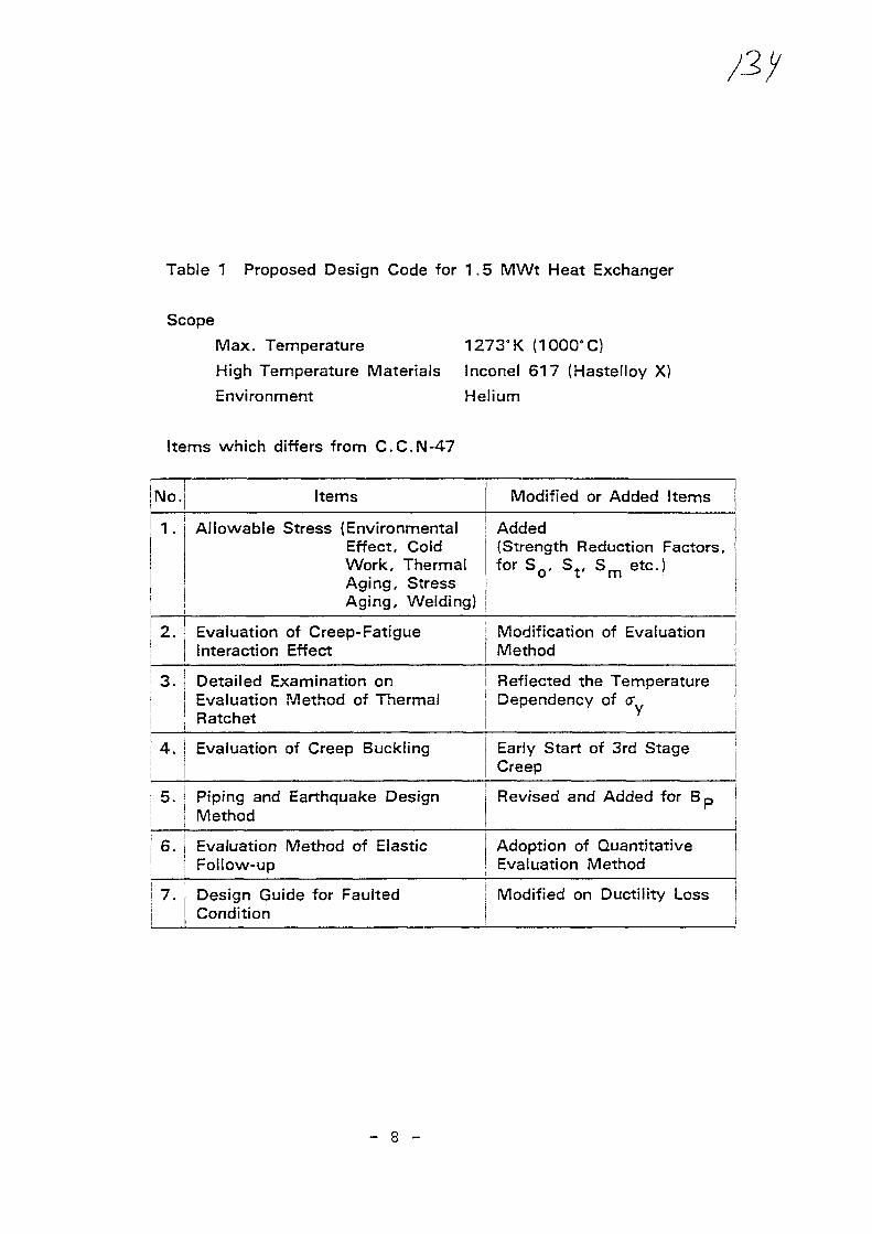
Table 1 Proposed Design Code for 1.5 MWt Heat Exchanger
Scope
Max. Temperature 1273"K (1OOCTC)
High Temperature Materials inconel 617 (Hastelloy X)
Environment Helium
Items which differs from C.C.N-47
Items Modified or Added Items
1 . Allowable Stress (EnvironmentalEffect, ColdWork, ThermalAging, StressAging, Welding}
Added(Strength Reduction Factors,for SQ, S t , S m etc.)
2. ' Evaluation of Creep-FatigueInteraction Effect
Modification of EvaluationMethod
3. Detailed Examination onj Evaluation Method of Thermal; Ratchet
Reflected the TemperatureDependency of <r
4. | Evaluation of Creep Buckling Early Start of 3rd StageCreep
5. ! Piping and Earthquake Designi Method
Revised and Added for B,
6. i Evaluation Method of ElasticI Follow-up
Adoption of QuantitativeEvaluation Method
i 7. Design Guide for FaultedCondition
Modified on Ductility Loss
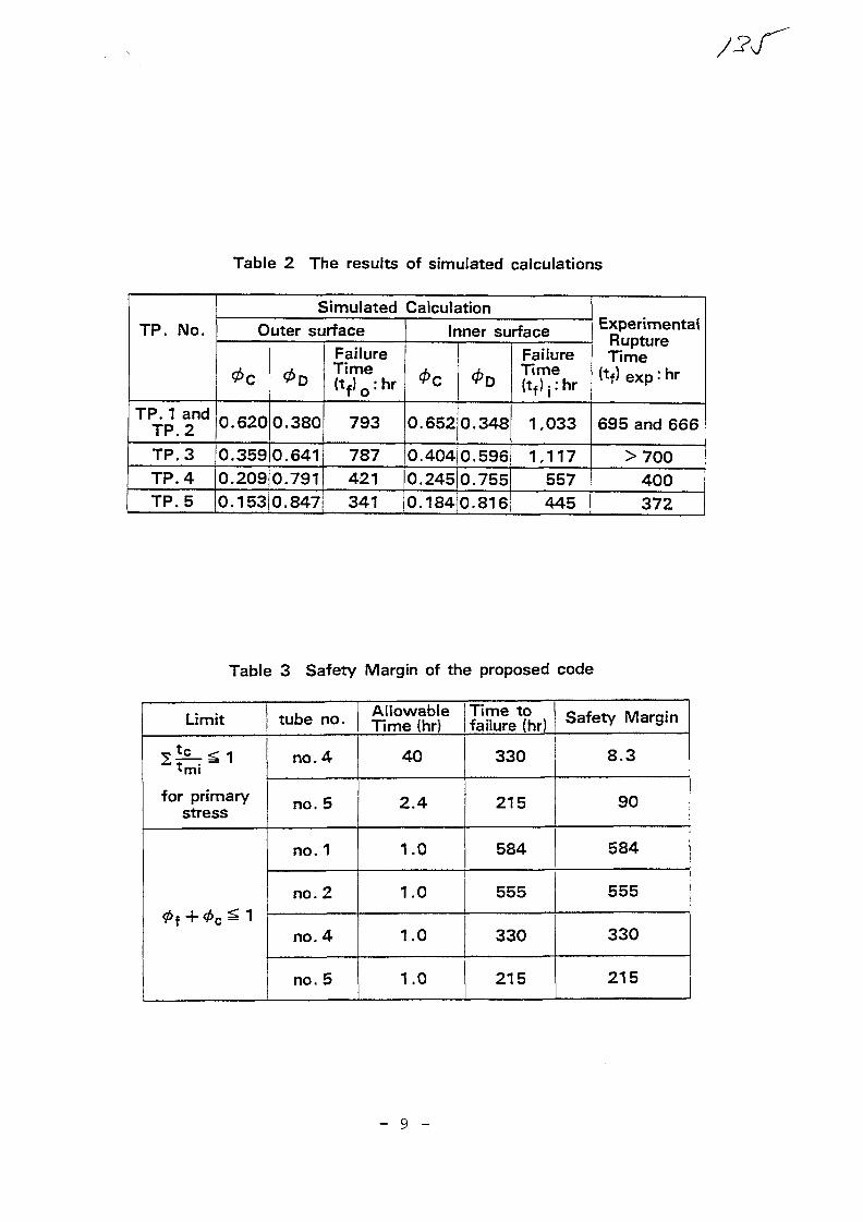
Table 2 The results of simulated calculations
TP. No.
TP. 1 andTP. 2
TP.3TP.4
TP.5
Simulated CalculationOuter surface
0c
0.620
0.359
0.209
0D
0.380
0.641
0.791
0.153|0.847
FailureTime(t f)o :hr
793
787
421
341
Inner surface
0.652
0.404
0.245
0.184
0.348
0.596
0.755
0.816
FailureTime(t f)j:hr
1,033
1,117
557
445
ExperimentalRuptureTime
(tf) exp: hr
695 and 666
>700
400
372
Table 3 Safety Margin of the proposed code
Limit
for primarystress
0 f+0c^1
tube no.
no. 4
no. 5
no. 1
no. 2
no. 4
no. 5
Allowable ITime toTime (hr) I failure (hr)
40
2.4
1.0
1.0
1.0
1.0
330
215
584
555
330
215
Safety Margin
8.3
90
584
555
330
215
- 9 -
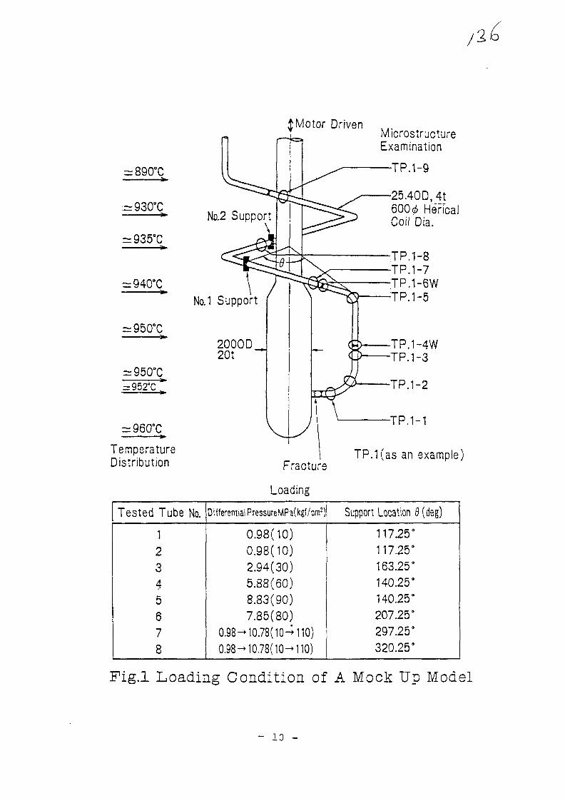
£Motor Driven
= 890°C
:=930°CNo.2 Support
\
= 952°C
TemperatureDistribution
NQ.1 Support
2000D20t
Fracture
Loading
MicrostructureExamination
•TP.1-9
25.40D, 4t600 ̂ HencalCoil Dia.
TP.1-8TP.1-7TP.1-6WTP.1-5
TP.1-4WTP.1-3
TP.1-2
•TP.1-1
TP.1(as an example)
Tested Tube No.
12345678
Differential PressureMPa(kgf/cm2)
0.98(10)0.98(10)2.94(30)5.88(60)8.83(90)7.85(80)
0.98^10.78(10-+110)0.98—10.78( 10—110)
Support Location 8 (deg)
117.25°117.25°163.25°140.25°140.25°207.25°297.25°320.25°
Pig.l Loading Condition of A Mock Up Model
- 10 -

1 1
( - •
1
pio.
E
pipe
CD
CD
O
CD
Eila
c
C J - CCO 1
^ 5 !•a ,,
Ioa
cdCL">
CD
COCOCD
Q .
CDt—i
"oCO
100
75
B 50b
25
0
15.69
13.73
11.77
9.80
7.85
5.88
3.92
1.96
=75mm
4cycles
8= 100mmtf= 25mm/h47cycles
i£=25mm/h11cycles
(48) (91) (237) (613) (701)
-TP.5
TP.6
TP.4
"TP.3
-
,TP.1.
u/
(
1
79)(117)
* •
2,7 &8• • t
(125)
(189)
TP.3
TP.5 Ruptured
' " ( 3 7 2 ) TP.6
TP.4 Ruptured
(440)
TP.1.-2.7&8
(237)
(666) 7
TP.2 Ruptured ( 6 9 5 ( .
I I I !
TP 1'Ruptured
721)
. . i
TP
IP.3
(866)
8
,647
TP.7&8
TP.3&6
(980)
(1 123) "I
-
finis
hed
Te
st
i i
i
160
140
120
100
80
60
40
20
o
CDjnss
CD
Q .
CD
Z3
Oto
100 200 300 400 500 600 700 800 900 1000 1100 1200
Time (h) Note : Numbers in brackets denote elapsed time
Fig.£ Loading histories of fractured heat exchanger tubes
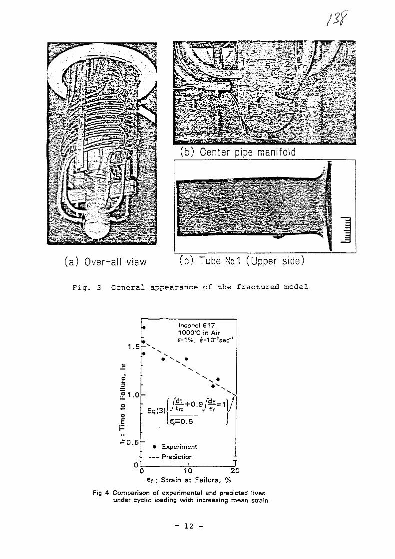
(b) Center pipe manifold
(a) Over-all view (c) Tube No. 1 (Upper side)
Fig. 3 General appearance of the fractured model
Jnconel 6171000"C in Aire=1%. e=103
£1.0
£
.£0.5-
. Eq(3)
^.=0.5
/
• Experiment
-L PredictionT
0 10 20€f ; Strain at Failure, %
Fig 4 Comparison of experimental and predicted livesunder cyclic loading with increasing mean strain
- 12 -
/2fNo. 8
XA0055817
Development, construction and analysis of the URKO intermediate heat exchanger
R. Exner, M. Podhorsky, Balcke-Durr AG, Ratingen
1. Objective
The objective of our development programme is to develop a functionallyefficient He/He intermediate heat exchanger, capable for a heat transfercapacity of 125 or 170 MW and to prove its suitability by carrying outrepresentative tests.
As the vessel represents a barrier between the primary and secondarycircuit the requirements to be met with regard to stability, reliabilityand availability of the components are particularly high.
Special requirements arise as a result of
- the high application temperature up to 950 °C- the necessary service life of 140.000 hours- the high temperature transients and differential pressures to be
expected during operation- the large wall thicknesses needed as a result of this in the high
temperature section where the temperature gradients are significant.
In addition to the requirements made by the plant itself both the
economic efficiency and the ability of the vessel to gain approval have
to be taken into consideration when carrying out the development work.
Furthermore it must be possible to carry out reexamination and repairs on
the components.
Fig. 1 shows the complete project divided up into its main components.
Two years ago when we started work on this the availability of both high-
alloyed steels (e.g. NICROFER 5520) and also the ceramic materials was
very limited. Today, not least as a result of the influence provided by
the heat exchanger development all the necessary semi-products are
available.
Furthermore with the He/He intermediate heat exchanger advances have been
made into temperature ranges for which neither standards nor regulations
with regard to dimensioning for stress exist. The guidelines of the ASME-
Code (Case 1592) only apply up to temperature limits of max. 815 °C.
Parallel to our detailed work on the U-tube concept a series of tests is
being carried out to prove the safety of the concept and to optimize the
components:
- Basic tests
- Component tets
- Tests on partial components (up to a capacity of 10 MW)
- Integral tests (for capacities above 10
A 10 MW test module is being manufactured and will be tested to prove the
safety of the component development.
The engineering work for the reference component commenced at the same
time as the work on the He/He intermediate heat exchanger.
This planning work together with the test results and the experience
gained in the manufacture and testing of the test module will enable the
reference solution to be worked out and an offer for an economic nuclear
component to be submitted.
2. Function of the He/He intermediate heat exchanger
The primary hot gas (950 °C) flows upwards centrally in a duct within the
heat exchanger, is deflected in front of the hot secondary gas header and
is drawn off around the heat exchanger tubes in a concentric annulus.
After a further deflection in the U-bend section the primary helium cools
to a cold gas temperature of 293 °C in a further annulus.
The cold secondary helium (220 °C) is directed into a circular header and
then into the heat exchanger tubes via helical compensation tubes. It
flows into the hot gas header through the U-tubes in counterflow to the
primary helium. The heat exchanger tubes are arranged on involutes in
order to achieve the same packing density in the cold and hot annuli.
As a result of the compact type of construction the diameter of the
concrete cavern is small.
The most important components of the He/He intermediate reheater are:
- Hot gas header and supporting plate.
The URKO heat exchanger differs from the conventional U-tube heat
exchanger in that the separation of the media is guaranteed by two
different components instead of by one single tubesheet.

If}
A coaxial structure with medium at a high temperature in the internal
section of the vessel which guarantees both the thermal symmetry and the
symmetry specific to the-Wow is achieved with this construction.
The form of the hot gas header and the adjacent tube supporting plate was
optimized taking into account all loads (internal pressure, external
forces, temperature gradients) (Fig. 3)
The construction of this element enables it to be placed in a space where
the flow is non-existant.
The header and the tube supporting plate are made of NICROFER 5520
forgings.
Tube bundle and tube supports .
Another part of the exchanger which can be counted as belonging to the
critical sections of the heat exchanger is the tube bundle with the tube
supports in the high temperature section.
As mentioned at the beginning the heat exchanger tubes are arranged
concentrically around the primary hot gas central duct in the case of the
compact U-tube heat exchanger. The hot gas header with the secondary gas
return tube is a determining factor as far as the minimum diameter of the
tube bundle is concerned. For this reason not more than one tube cylinder
or several separate tube packs can be selected for the above output.
From the point of view of the greatest possible representativeness with
regard to the reference component a study proved the optimum to be to
divide the unit into 6 tube packs. (Fig. 4)

The free non-tubed sections were filled with insulation material.
With a diameter of approx.~-2 m the test module therefore correspondsgeometrically to a 30 MW-heat exchanger. Thus the test heat exchanger inthis arrangement is capable of providing all the required information andin addition representative conclusions can be drawn with regard to a30 MW compact U-tube heat exchanger to a certain extent.
The material to be used for the heat exchanger tubes and tube supports isNICROFER 5520.
Support shells.The support shells connect the hot and cold tubesheets and form asignificant part of the supporting system. They also convey the primarygas and very quickly take on its temperature. The tube supports aresupported against the walls of the support shells and in the case of anearthquake they absorb the horizontal loads, which can result from theacceleration of the tubebundle.
Insulation.
Thermal insulation is used in all critical sections of the URKO-He/Heintermediate heat exchanger. This insulation minimalizes the temperaturelosses in the central duct and the hot gas header, guarantees theseparation between the hot and cold branch of the tubebundle and makessure that the wall temperature of some components is reduced.
Pressed fiber mats made of Al203/Al2Si02 will be used as insulationmaterial for the 10 MW test module.
tty
Load supporting and reduction system.
The efficiency of the load reduction system is of particular significance
for the construction of the vessel. The high temperature sections can be
relieved in such a way that a minimum primary load arises as a result of
dead weight and thus the problem zone of the hot section including the
hot bundle section is eased.
The construction described briefly here is distinguished by the following
features:
- the hot header is not charged with primary mass flow and therefore it
is not subjected to any direct primary temperature stress.
- the thermal expansion balance can be determined by the design of the
lengths of the arms (cold/hot branch).
- the secondary gas return tube is not involved in load reduction during
operation. The hot sections are relieved during operation because the
load is reduced via the supporting shell, cold circular header and
spring packs.
- the simple tube shape is the precondition for economic manufacture and
easy reexamination.

3. Analysis of the He/He intermediate heat exchangers
The characteristic feature-of the He-He intermediate heat exchanger of
the U-tube compact construction is the single U-tube bundle which was
proved itself in practice and which expands independently of the load
transfer system. In addition to the pressure and temperature load,
however, the hot header is subjected to a dead load which is dependent on
the temperature. The construction can, however, be designed in such an
advantageous way that this primary load decreases as the temperature
increases and that overloading of the components in the high temperature
section is prevented by automatic regulation.
The aim of the analyses which were carried out was:
- to determine the constructive parameters which guarantee an
advantageous load transfer during the individual load cases,
- to calculate the temperature and stress distributions during the
individual load cases,
- to ensure the stress and strain values,
- to make a statement about material fatigue,
- to prove the insensitivity to vibration.
The analysis has been carried out with the FE-Programme ANSYS on the
CYBER 175 computer.
4. Thermohydraulic calculation model of the He-He intermediate heat
exchanger
As already mentioned it is essential to know the temperature distribution
in the vessel during operation and during the individual load cases.
Fig. 5 is a diagrammatic drawing of the load transfer system. The dis-
placement of the cold tubesheet depends on the support shell temperature,
the header temperature and the relevant temperature expansion
coefficients.
The heat exchanger was "divided up" into 20 sections over its total
height. One element was provided for each material layer in a radial
direction. The primary gas flow was represented by three flow tubes
connected in parallel.
The convection from the primary flow to the outer wall of the secondary
gas tubes was simulated by the first of the three tubes connected in
parallel. The second tube served to provide the convection connection
between the primary flow and the support shell and the third flow tube
provides the connection between he primary flow and the flow shell. The
tube wall of the secondary gas flows was replaced by a concentric
cylinder shell of the same thickness and the equivalent surface area.
The ANSYS-gas flow elements with convection coupling are each constructed
of a transport element and two convection elements. The element is
designed in such a way that the convection heat flows only into the knots
but not over the edge of the element between the knots. For this reason
it is permissible to connect several elements in parallel with a mass
flow which is distributed accordingly.
By connecting the elements a set of equations is obtained which show
pressure and temperature as independent values. The temperature solution
approach which is of interest to us proves not to be linear due to the
temperature dependence of the material values.

In addition to the actual material values the so-called real constants
must be defined for gas flow elements. Geometrical coefficients, the
value of which cannot be- determined from the knot geometry alone, such as
the hydraulic diameter, the area through which the flow passes, the loss
length or the proportional convection area, are determined using these
values. The results of the intermittent calculation for the load case
"cooling down" can be seen in Figs. 6 to 10. In this load case the
primary and secondary helium cools down with a gradient of -1 °C/min.
Fig. 6 shows the change in the primary gas temperature along the path in
the hot and cold channel for a period up to 4 hours.
Figs. 7 and 8 indicate the same temperature patterns as fig. 6 for the
secondary gas temperature and for the tube wall temperature. As is to be
expected it can be seen that the greatest temperature changes occur in
the hot channel. Figs. 9 and 10 show the changes in the radial
temperature pattern as a function of time. Fig. 9 shows the temperature
patterns for the primary and secondary helium temperature, the heat
exchanger tubes and the central tube average temperature as a function at
a distance of 3,6 m above the flow return.
A similar curve is shown in Fig. 10 for the cold channel at a distance of
7,2 m.
Based on the knowledge obtained with regard to the support shell
temperature distribution which is dependent on time it is easy to
calculate the relative displacement of the cold tubesheet as a function
of time. (Fig. 11) This displacement pattern is then required in order to
dimension the sets of springs. It determines the weight distribution and
the distribution of the dead weights during this load case. The solution
described here for load case "cooling down" should then, of course, be
repeated for all relevant load cases.

10
5. The structural model of the hot header
The hot header is of interest from the point of view of material fatigue
because of the relatively high wall thickness of 90 mm, the complicated
geometry with some discontinuities and the high temperatures and
therefore a great deal of attention was paid to it.
The calculation of non steady state temperature distribution were also
carried out using the FE-programme ANSYS. The temperature changes based
on the reuslts of the thermohydraulic system calculation were used as
input data. For example, Fig. 12 shows the curves for the same
temperature in the load case already mentioned, "cooling down". The
greatest temperature difference over the wall occurs in section A-A
(Fig. 13) and determines the stresses calculated elastically here. These
can be seen in Fig. 14. As is to be expected the branch-off point is the
point with the highest reference stresses. Similar calculation models
were also set up for all the other interesting components of the He-He
intermediate heat exchanger.
The analyses carried out have confirmed that the thick-walled "hot
header" is the component which can be expected to suffer the greatest
fatigue damage during its service life. It was possible to safeguard
against the primary stress in all specified load cases without any
problem. This safeguard against stresses is carried out by comparison
with the admissible stresses formed from those material values which are
a function of time as well as those which are not.
The ratcheting analyses according to T-1320 of the ASME Code, Case N47
could also be carried out successfully in all load cases. The calculation
of the intermittent temperature field has shown that the header is only
subject to a greatly reduced temperature change. The reason for this is
the shielding of the "hot header" and not least the stored system heat
which has a \/&ry good damping effect especially in the case of low mass
flows.
11
6. Vibration analysis of the heat exchanger tubes
The operability of the He-He intermediate heat exchanger is only
guaranteed if both the static and the dynamic stress are kept within
limits. It is particularly important to examine this type of stress for
the heat exchanger tubes around which helium flows. It is important to
ensure that the heat exchanger tubes cannot be damaged during the course
of time by a possible vibration. In order to fulfill this requirement a
vibration test was carried out on a model heat exchanger. A segment of
the tube field of which .the geometry was retained, was built into the
wind channel in such a way that the flow conditions which would prevail
in the heat exchanger were correctly simulated (see Fig. 15).
The measured values were recorded on a 32 channel magnetic tape device.
The vibration behaviour of the tubes which had been determined by
calculation was checked in a preliminary test. For this the tubes were
stimulated with harmonic and random vibration using an oscillator. The
vibration behaviour of the tubes tested proved to be similar and
corresponded well with the calculations. In the case of harmonic
vibration the four lower frequencies and a frequency range around 900 Hz
was measured at a constant power level. The random vibration was
simulated by means of a generator which was located in the Fourier
analyzer used.
The test equipment was fitted with 90 tubes for the flow test. It was run
under a total of ten operating conditions at speeds of between 15,7 m/s
and 50 m/s in the smallest inlet cross-section.

IP12
An existing shell programme was used to determine the vibration
conditions of the tubes and the required free values were calculated.
Fig. 16 illustrates the -strain distribution over the whole rolled out
tube surfaced. A realistic outline of the overall vibration state of the
tubes was obtained with the simulation method. The phase angles were
generated with the help of a random number generator. These angles were
inserted in the individual vibration conditions and superimposed. The
result of the simulation process is the frequency distribution of the
strains (Fig. 17).

/si
13
7. Summary
The overall objective of- this development order is indicated in thislecture and the construction of the new type of heat exchanger desribedin brief including the problems involved with carrying out the design inthe time available.
Observations up to now have shown that the compact U-tube heat exchangeris in a position to fulfill the specified requirements. The results ofthe tests carried out and the advanced manufacturing status of the testmodule point to a successful conclusion of our development project.
To conclude we would like to show you some pictures of the interestingphases in the production of the test module.

- 14 -
Legend to the i l lustrat ions
Fig. 1 - The components of PNP
Fig. 2 - Components of the He/He
intermediate reheater (URKO)
Fig. 3 - Hot gas header
Fig. 4 - The tubed and non-tubed sections of the reheater
Fig. 5 - Load transfer system He-He-intermediate heat exchanger
of U-tube compact construction.
Fig. 6 - Primary gas temperature in load case "cooling down".
Fig. 7 - Secondary gas temperature in load case "cooling down".
Fig. 8 - Tube wall temperature in load case "cooling down".
Fig. 9 - Temperature pattern in hot channel H = 3,6 m.
Fig. 10 - Temperature pattern in cold channel H = 7,2 m.
Fig. 11 - Relative displacement in load case "cooling down"
Fig. 12 - Isotherms in the structure of the hot header in the load
case "cool ing down".Fig. 13 - The largest temperature difference in section A-A of the
hot header in load case "cooling down".
Fig. 14 - Reference stresses in the hot header in load case
"cooling down".

- 15 -
Fig. 15 - Arrangement of the measuring points for the vibration test.
Fig. 16 - Type of vibration with the maximum load.
Fig. 17 - Frequency distribution of the strains in the tube.

IL_JF=IF=R
NOV 1981 AUFTRAG
APRIL 1984
\z>VERSUCHSDURCH-
FtiHRUNG
MARZ1985
HERSTEU.UNG emw10 MW-TESTMODULS- Erftilluni <iv Funktion-M*chb*rkeit- Nuktoare Anfordcrungen
MARZ 1986ERPftOBUNG dM
TESTMODULS
Oil 1987
- GmndUgenvcrsuche- BautmhtBrtucbe- TeilksmpwwntsnvertuctM- lnt«gr*tveriuche
- Komtr MaAnahnwn- Nachwws tUr * e Werfcttsff-
•rtchApfung
nia4lunB der VP
f•chmtePrt>f«oni»ptQtMiMMiiictiarunc
125-rl70MWH»4WZWT (URKO)- Boachmns, EKwurt, Koratr.
- R*pariturfconz«p(
\Z> \7?ANGEBOT
HfrHa/ZWr |URKO)125+ 170 mt
PNP-HE-He/ZWT(URKO)
Fig. 1
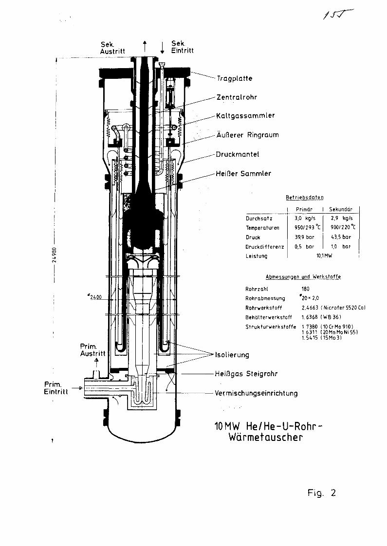
Sek.Austritt
Sek.Eintritt
COer-
Prim.Eintritt
Tragplatte
Zentralrohr
Kaltgassammler
Äußerer Ringraum
Druckmantel
Heißer Sammler
Betriebsdaten
Durchsatz
Temperaturen
Druck
Druckdifferenz
Leistung
Primär3,0 kg/s
950/293
39,9 bar
0,5 bar
°C
Sekundär
2,9 kg/s
900/2 20 °C
¿»3,5 bar
1,0 bar
10,1 MW
Abmessungen und Werks to f f e
180
'20" 2,0
2.4663 (Nicrofer5520Co)
1.6368 (WB36)
Rohrzahl
Rohrabmessung
Rohrwerksfoff
Behälterwerkstoff
Strukturwerkstoffe 1.7380 (10CrMo910)1.6311 (20MnMoNi55)1.5415 (15Mo3)
Isolierung
Heißgas Steigrohr
Vermischungseinrichtung
10MW He/He-U-Rohr-Warmetauscher
Fig. 2
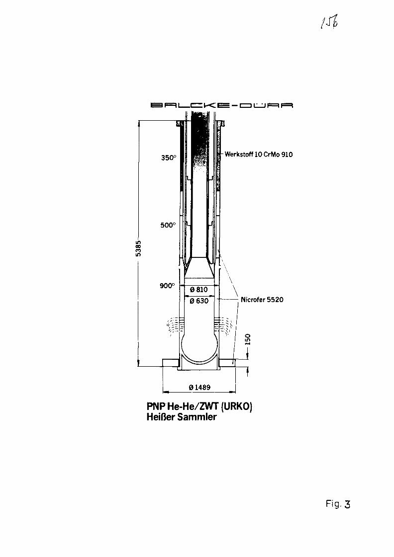
Werkstoff 10 CrMo 910
Nicrofer 5520
PNP He-He/ZWT (URKO)Heifer Sammler
Fig. 3

: K : ^ —
Innerer StromungsmantelSekundargas
Isolierung
AuftererStromungs-mantel
Primargas
Tragmantel
KalterAst Druckbehalter
Primargas HeiBerAst
Zentrales Steigrohr
Aufbau des PNP He-He/ZWT (URKO)
Fig. 4

F=l I CZZ V<L ̂ — CD L_
Tragplatte -
heifJer Sammler
heiRePlatte
WT-Rohreheifter Kanal
Hattemantel
Stromungsmantel
isolierung
Lastabtragesystem URKO
Fig. 5

PrimargastemperalM
Auskuhlen
240
0.0 16.6 33.3 50.0 66.6 83.3 100
Lauflange (%l
Fig. 6

SekundargastempacaturAuskiihlen
i
320
160
0.0 166 33.3 50.0 66.6 83.3 100
Loufldnge (% jFig. 7
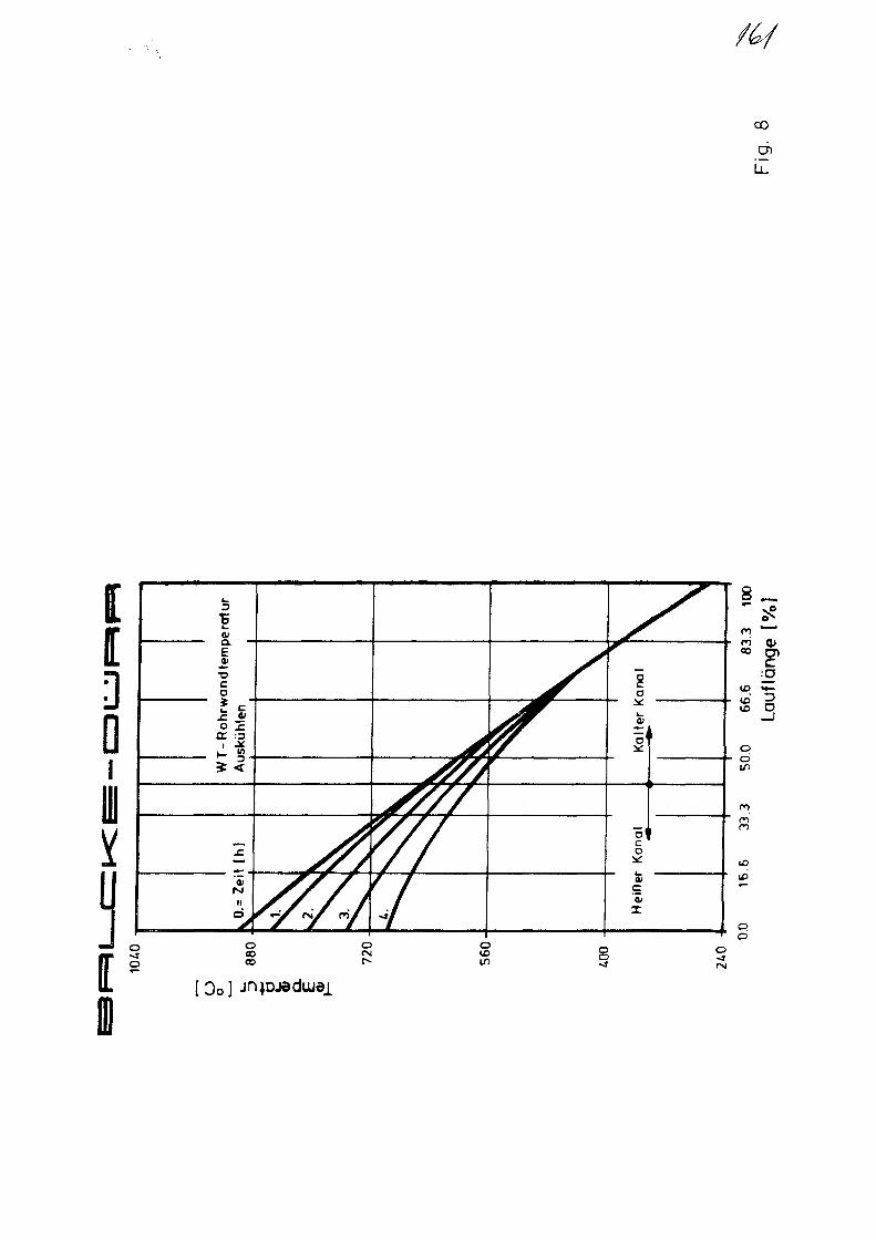
chl l
•5
1
fan
dfe
mf
Iso .c
£E :3
tlh
]
II
/ / / /
7/7
a
Kal
ter
KK
anal
i
a>ca)
I
8 _
ooID
ID
U3
doCOCO
o otoin
ofNJ
[Go]
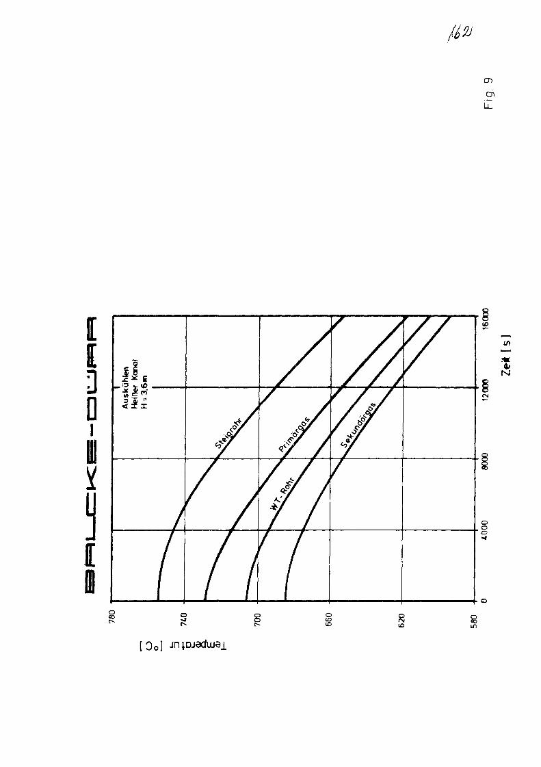
en
LL
Q
01i
I
rsi
[ 0 o ]

i l
*m
0III1
IoID
OIf)
O00
oto o

Relativverschiebung beziiglich der heiflen Rohrplatte [mm]
ino o
o ino
oo
31
M
1
/I
IfM Q
Is*
/ 3
Auskuhlen

Fig.12

15.0
Fig.13
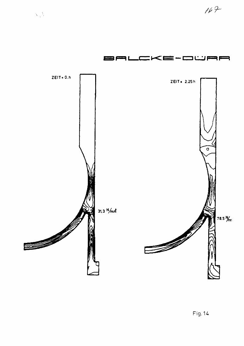
9-
ZEITeO.hZEIT. 2.25h
31.3 %ri?
Fig.U
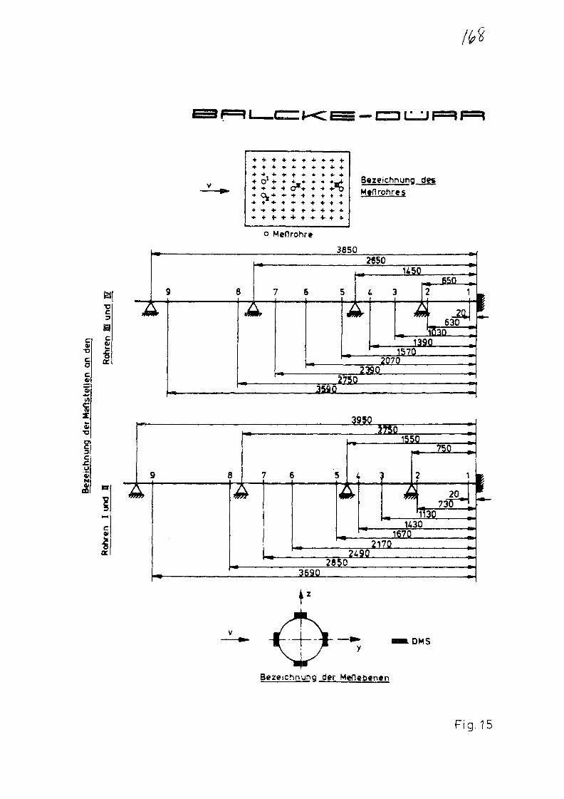
XJ
a
a
Iin
• • * • •4 .
+ OJ •»• • + _ • • * • _ *+ • • * • • • o * + • •» +-T5•* C L + + + •• • • » • • *• • * • • • • • • • + + • •
Bazeichnung desM»flrohre$
o MeOrohr*
3850
3C
I *^^9} ^Wr
39503750
1550
4 3
^ W ^ ^
750
U301670
21702490
26503690
DM5
Bezeichnunq der Meflebcnen
1
Fig. 15

D110
LItI
I
ID
28
I
I
! |
8z
8
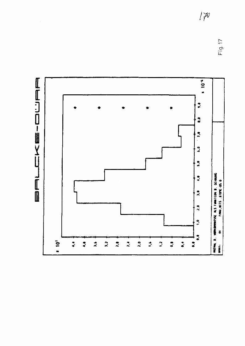
enLL
0
u
1

1
1
1
1
1
1
1
1
1
• — , —
1
~ l —
1
ZUzuzuZI]
zu!
No. 9
T W T ¥ 1 T ¥ ? W »DUFTET! W T K ? A ÉJMfflMíE FEUERFEST-ERZEUGNISSE
INGENIEURLEISTUNGEN
ABTEILUNG ENERGIE-TECHNIK UIUIEII ANLAGENTECHNIK
XA0055818
DEVELOPMENT OF A NEW TYPE OF HIGH-TEMPERATURE INSULATION
MATERIAL AND ITS APPLICATION IN THE PNP PROJECT
by
DipL-MineralogistR. Burger
Dr.-EngineerR. Ganz
DIDIER-WERKE AGDept. Energie-TechnikDidierstraße 31D-6200 WiesbadenFederal Republic of Germany
Specialists' Meeting on Heat Exchanging Components of Gas-Cooled Reactors
Düsseldorf, Federal Republic of Germany, 16-19 April 1984
Aufsichtsrat: Dr. Horst Burgard, Vorsitzender Hauptsitz: Wiesbaden, Ussingstraße 1¿-18 Abteilung Energie-Technik: Wiesbaden 12Vorstand: Dipl.-Kfm. Dr. ¡ur. Martin Bieneck, Vorsitzender Registergericht: Wiesbaden HRB 2376 (Biebrich), DidierstraSe 31Dietrich von Knoop, stellv. Vorsitzender Telefon: (0 01 21) 359-1 Telefon: (0 61 21) 605-0Dr.-Ing. Gerhard Reinhardt, Dr.-Ing. Hans Stollenwerk Telex: 4 186 681 diw d Telex: 4 186 461 difo d

DEVELOPMENT OF A NEW TYPE OF HIGH-TEMPERATURE INSULATION
MATERIAL AND ITS APPLICATION IN THE PNP PROJECT
1. Basis of the Research and Development Program
The following significant operating conditions apply to the prototype plant
for nuclear process heat :
. Temperatures of up to 950 °C
. Pressures of up to 42 bar
Maximum gas velocities of 65 m/sec
Reducing or oxidizing atmosphere, depending on the loop.
All heat-carrying and heat-exchanging components of the PNP have to be
insulated
to protect the metallic structures against temperature,
and
to maintain the thermal efficiency of individual components and
of the entire plant.
Therefore, thermal insulation is of major significance in the PNP project.
Metallic liners in the primary loop fail because of the required service
life under high-temperature conditions. Therefore, in this case, other
materials such as graphite are used. Insulation is achieved by means of
stuffed ceramic fibers.
So this involves an insulation system where the insulating material is
protected against erosion by a non-metallic liner.
The ideal solution is the internal insulation loaded by the gas flow and
which does not require an additional liner.
In conventional technology, also erosion-resistant types of insulation are
well-known which can safely withstand temperatures of up to 1700 °C
and under inert conditions up to far beyond 2000 °C.
The question arises why these materials and insulation systems cannot be
employed.

- 2
The reason is the particular requirements specific to the operation of
a nuclear plant.
Hence, the methods applied in conventional technology cannot be
transferred directly to nuclear technology.
Therefore, before the application of insulating materials and systems
in the PNP, a development program became necessary to satisfy the
specific requirements connected with nuclear components.
The work for developing a PNP-compatible insulating material and
system for the intermediate heat exchanger (URKO and HELIX design)
are performed at DIDlER's in close cooperation and coordination with
. INTERATOM/GHT
and the component suppliers
. BALCKE-DORR AG and
. consortium STEINMULLER GmbH/SULZER AG.
The main fields of the working program are two areas of the
Helium/Helium Intermediate Heat Exchanger (He/He-IHX) :
The primary hot gas riser duct (central line) with internal
insulation loaded by the gas flow (without liner)
and
the intermediate heat exchanger external shell with internal
insulation in the spaces not subjected to gas flow.
The results obtained from this work can be applied directly to the
steam reformer and can be used for hot gas valves and hot gas ducts.
- 3 -
2. Development of the Materials
2.1 Material requirements
The material requirements are governed by
the operating data of the PNP
. the experience gained from conventional insulation techniques,
and
the experience from test facilities (KVK, EVA I/I I AVR, etc.)
The major requirements for the mateiial are
. thermodynamic endurance for an operating period of not less
than 140,000 hours of operation
. bulk density < 1.0 g/cms
. good insulating properties in helium, 40 bar
. resistance in the event of accidents involving sudden pressure loss
adequate mechanical strength
. good thermal shock resistance
. little abrasion during gas flows (v < 65 m/sec)
2.2 Feasible conventional materials
The next figure shows conventional insulating materials that were
discussed as basis at the beginning of the development work.
It can be seen that none of these materials combines all the
properties required.
As experience shows, insulation fire bricks are characterized by-
just satisfactory, but mainly poor resistance to thermal shock.

parameter/dimension
fiber-blanketsA -mats
vacuum-formedfiber-based shapes
insulation firebrick l_ 3^0(bubble alumina)
content of A12O3
/weight-%
bulk density/kg-nf3
porosity/volume-%
< 18o ++
> g 5 + +
cold crushing strength/N-rnirf2 none
thermal conductivity(in air) ,/W-(m-K)"1
thermal shockresistance/cycles ace. to DIN
0,12 ++
< 220 ++
none
0,13 ++
> 30 +
64 -
20 ++
1,3 -
< 10 - o
workabilitymachinabllityresistance againstpressure-loss
thermal conductivity(in helium) +
o +
0
++ excellent
+ good
o satisfactorybad
Conventional types ofhigh-alumina insulation material DIDIER-WERKE S

/
- 5 -
Densified fiber mats and vacuum shaped fiber parts exhibit excellent
resistance to thermal shock, low thermal conductivity, and favorable
behavior in the event of sudden loss accidents.
A disadvantage is their lack of mechanical stability and the low
resistance to abrasion and erosion.
Thus, there is a fair chance that materials on the basis of ceramic
fibers can satisfy the PNP-specific requirements if it becomes possible
to increase the strength without reducing the positive thermal properties.
Hence, the development program was defined :
Adaptation of the conventional fiber materials to the severe marginal
conditions of the PNP by producing Fiber Ceramics of adequate
mechanical strength.
2.3 Fiber Ceramics
2.3.1 Basis
The ceramic fibers used for the development work are obtained from
the binary system SiO2-Al2O3. Two types of ceramic fibers can be
distinguished :
. The glassy fibers manufactured from the molten state by spinning
or blast drawing, the Al2 O3 to SiO2 ratio being 1:1 or 2:1.
. The fiber obtained from a salt solution by the spinning technique
with subsequent annealing, with 95 % by weight Al2 O3 and 5 %
by weight SiO2 .
As far as we know, the glassy fibers are suitable in the PNP project
only for temperatures < 650 °C because of the low thermodynamic
stability.
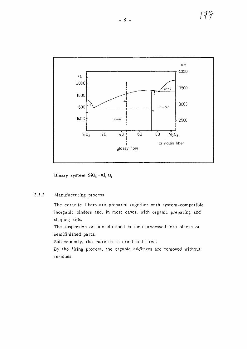
- 6 -
glassy fiber
°F^000
- 3500
- 3000
- 2500
80 A12O3
cristallin fiber
Binary system SiO2 -AI2 O3
2.3.2 Manufacturing process
The ceramic fibers are prepared together with system-compatible
inorganic binders and, in most cases, with organic preparing and
shaping aids.
The suspension or mix obtained is then processed into blanks or
semifinished parts.
Subsequently, the materiai is dried and fired.
By the firing process, the organic additives are removed without
residues.

- 7 -
C e r a a l c d l n d e r
s y s t e i
P r e p a r a t i o n
F o r m i n g
D r y i n g
F i r i n g
M a c n l n i ng
G e n e r a l p r o d u c t i o n f l o w
By selection of the appropriate firing temperature, shrinkage of the
material under service conditions is avoided.
The semifinished product can be formed into shaped parts of
accurate dimensions.

- 8 -
2.3.3 Properties of Fiber Ceramics and Qualification Tests
With the manufacturing techniques developed by DIDIER, Fiber Ceramics
with bulk densities of 200 kg/m5 to 800 kg/m3 can be produced.
In the course of preliminary tests a special binder system was developed
by means of which the strength of the Fiber Ceramics is increased by
the factor 10 to 20 compared with conventional vacuum shaped parts of
the same bulk density.
By varying the density of the Fiber Ceramics, the strength of the
material can be adapted to the respective requirements.
bulk density / kg «m
Al2 O, / SiO2
thermal shock resistance ace. DIN
/ cycles_2
cold crushing strength / N « m m_2
cold flexural strength / M'mm_2
E-Modulus / N *mmthermal expansion 20 °C - 100 °C
600
6,7
< 7
3,2 | 1,5
3,7 j 1,6
4,3 -103 | 0,1 '103
7,5 | 10,0
fiber J_ fiber
Properties of a DIDIER Fiber Ceramic

>"uTOcoo
1.0 -
0,9 -
0,8 -
0,7 -
0,6 -
0,5 -
0,4 -
0.3 -
0,2 -
0,1 -
0,0
•— = Fiber Ceramic bulk density 600 kg/m3
,o_—o— = Fiber Ceramic bulk density 250 kg/m3
—— "— —- *~ ' "
Z,0bar He40 bar He
1 bar He1 bar He
Ibar N2
- -1ba r N2
0 100 200 300 £00 500 600 700
temperature / °C
Thermal conductivity of Fiber Ceramics in air and helium.
800 900 1000
DIDIER-WERKE S

- 10 -
It has been proven that at temperatures > 500 °C materials with bulk
densities ^400 kg/m3 have a lower thermal conductivity than conven-
tional materials.
Before being applied to a nuclear plant component, the Fiber Ceramics
must pass several qualification tests. These have been initiated and
are being performed at present.
Abrasion test
The abrasion test series served for determining the abrasion behavior
of the parts of Fiber Ceramics with plane contact under normal
atmospheric conditions.
The following combinations were selected :
Fiber Ceramics/Fiber Ceramics
Fiber Ceramics/steel
Fiber Ceramics/graphite
. Graphite/graphite
Reactor graphite was used as reference material in these tests.
The cyclic frictional motions and the loads per unit area were selected
to be similar to the He/He intermediate heat exchanger.
As was to be expected, it was revealed that the Fiber Ceramics exhibit
higher abrasion relative to one another than with respect to steel and
graphite, or as regards the graphite/graphite pair.
At the beginning, abrasion is high, but is reduced after approximately
200 cycles and then increases noticeably less.
. Erosion test
In dust-loaden gas flows the produced Fiber Ceramics exhibit
markedly greater abrasion than graphite, but under the test
conditions that could be realized also the behavior of graphite
which is qualified for gas cooled reactors was not acceptable.

- 11 -
In air with a very low dust content and at gas flow velocities of
200 m/sec, Fiber Ceramics show no signs of abrasion according to our
knowledge and experience.
. Other tests
Existing computer programs are reviewed at present for their
suitability to describe the behavior of Fiber Ceramics under PNP
conditions.
In addition, the first series of tests were initiated to determine
the long-term behavior of Fiber Ceramics by means of fatigue
tests.
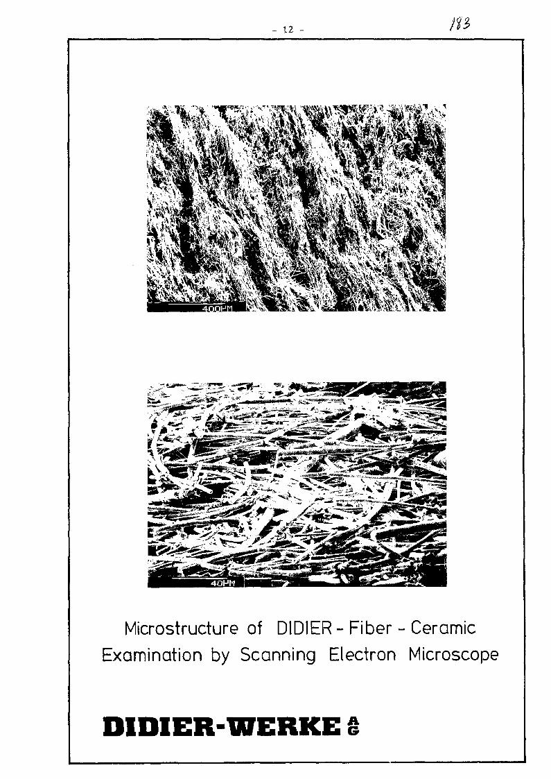
- 12 - in
Microstructure of DIDIER - Fiber - CeramicExamination by Scanning Electron Microscope
DIDIER-WERKE
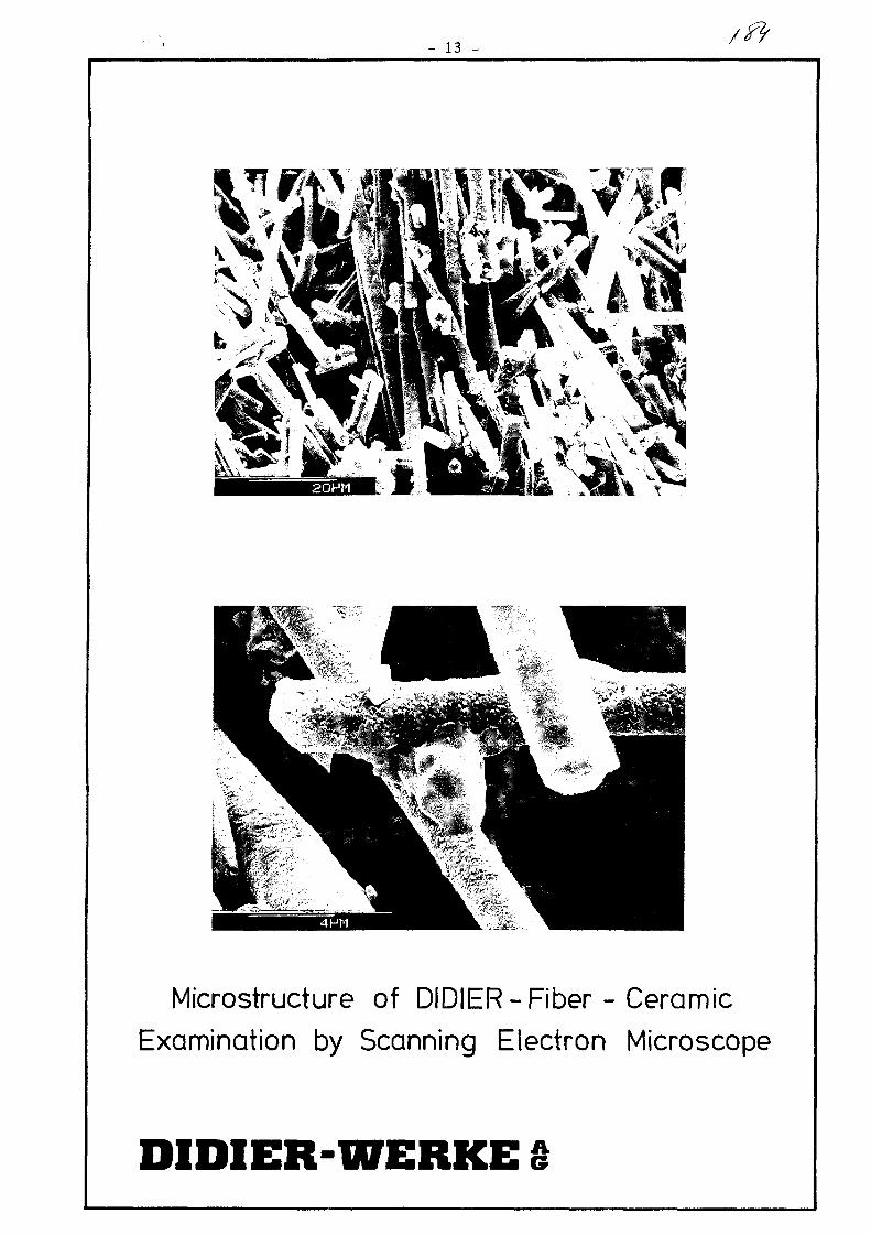
13 -
Microstructure of DIDIER - Fiber - CeramicExamination by Scanning Electron Microscope
DIDIER-WERKE
- 14 -
3. Testing of Structural Parts, Engineering
3.1 Requirements of the insulation system
An insulation system suitable for PNP must satisfy the following
requirements of
a general
and
. a specific nature related to the structural parts.
The general requirements are
. high insulating capability
insensitivity to sudden pressure loss accidents
ease of installation
. prevention or limitation of bypass effects.
Examples of requirements specific to the structural parts are e.g.
the withdrawability of the insulation for repeat tests
special geometric configurations
3.2 Basic design features
The insulation concept for riser ducts proposed by DIDIER at present
is described below :
An external steel shell will be insulated with segmenttype shaped
fiber parts. These shaped parts can be machined to very close
tolerances. Axial joints will be sealed with cylindrical parts, preferably
made of ceramic materials.
The segments can be provided with holes so that an interlinked
insulation can be built up with staggered joints.
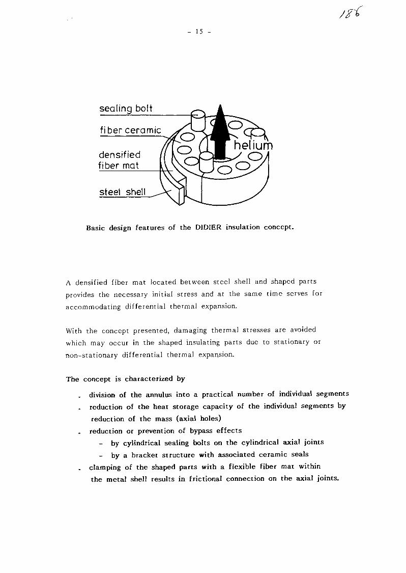
15 -
sealing bolt
fiber ceramic
densifiedfiber mat
steel shell
Basic design features of the DIDIER insulation concept.
A densified fiber mat located between steel shell and shaped parts
provides the necessary initial stress and at the same time serves for
accommodating differential thermal expansion.
With the concept presented, damaging thermal stresses are avoided
which may occur in the shaped insulating parts due to stationary or
non-stationary differential thermal expansion.
The concept is characterized by
. division of the annulus into a practical number of individual segments
. reduction of the heat storage capacity of the individual segments by
reduction of the mass (axial holes)
reduction or prevention of bypass effects
- by cylindrical sealing bolts on the cylindrical axial joints
- by a bracket structure with associated ceramic seals
. clamping of the shaped parts with a flexible fiber mat within
the metal shell results in frictional connection on the axial joints.

- 16 -
The concept developed can be adapted, e.g. by adding holders, depending
on the insulating materials, metallic structural, and marginal conditions.
The concept exhibits the following characteristics :
. low weight in relation to the mechanical strength
pre-assembly is possible outside of the pressure tube (modular
construction)
. the insulation build-up is flexible and can be adapted to a great
many marginal conditions
setting free of fiber particles is reduced to a minimum
the system is capable of compensating manufacturing tolerances
of the metallic components when installed in place.
3.3 Preliminary test of the insulation concept
The insulation system described above was subjected to a preliminary
cyclic test.
Marginal conditions :
air, 1 bar
. temperatures from 20 °C to 1100 °C
heating and cooling down velocity < 10 K.
The shaped fiber parts installed withstood the transients.
Calculated and real operational behavior were compatible as regards the
thermal behavior; the operating conditions were reproducible.
In spite of extensive data acquisition, there was no evidence of damage
to the insulating material or of opening joints.

- 17 -
Shaped Fiber Ceramic for preliminary test of theDIDIER insulation concept.

- 18 -
Testing equipment with data acquisition
4. The New Insulating Material in the PNP Project
The material and insulation system were not yet applied in the PNP
project because the R & D program is not completed and the final
qualification is still pending.
However, the manufacturing process has been developed far enough so
that the insulation of the PNP half axial valve prototype could be
performed like any normal supply and assembly contract.
This lining will be subjected to helium, 40 bar, 918 °C and flow
velocities of up to 70 m/sec.
The following figures show various shaped insulation parts and the
valve body lined with them.
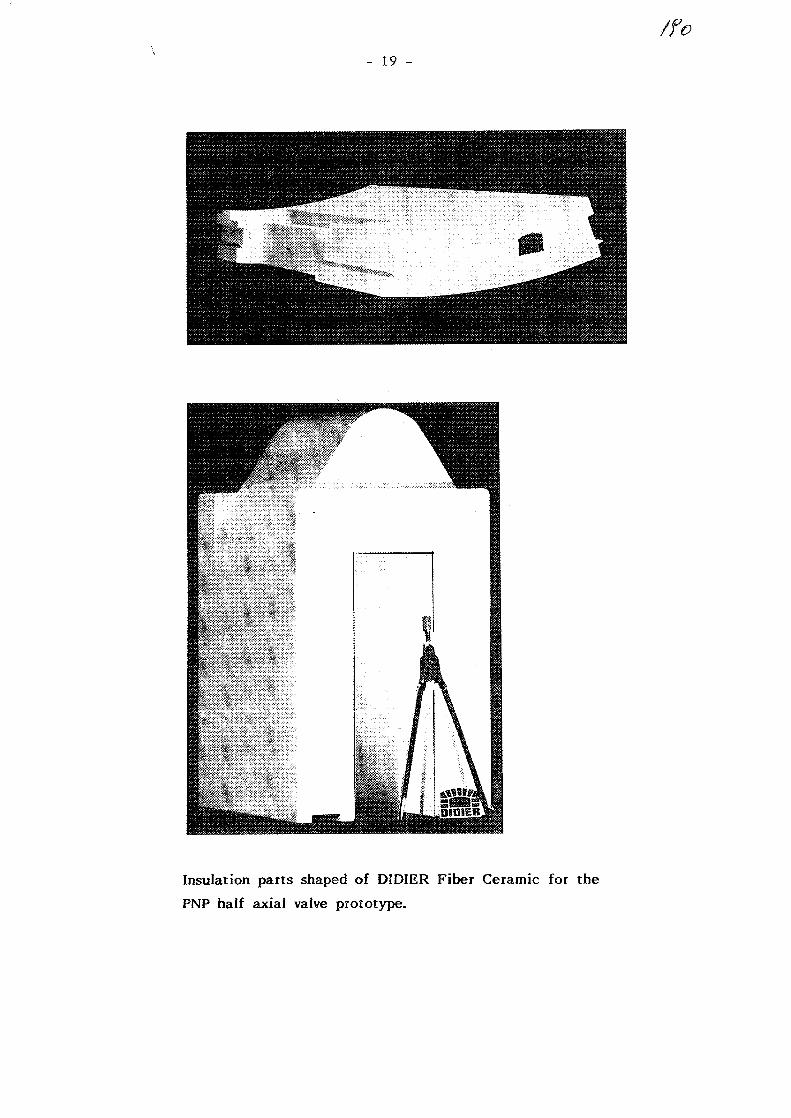
/fo- 19 -
Insulation parts shaped of DIDIER Fiber Ceramic for the
PNP half axial valve prototype.
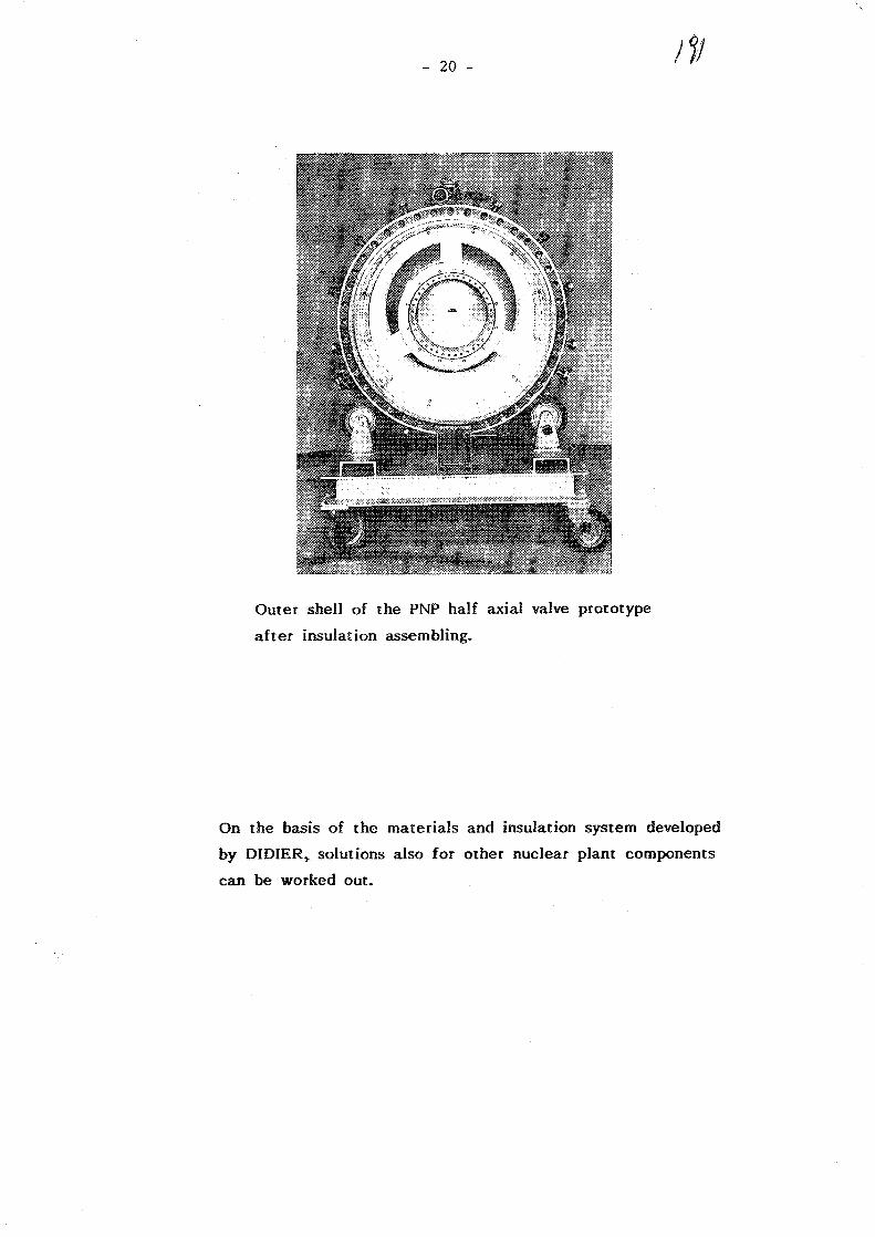
- 20 - /I)
Outer shell of the PNP half axial valve prototype
after insulation assembling.
On the basis of the materials and insulation system developed
by DIDIER, solutions also for other nuclear plant components
can be worked out.

No. 10
XA0055819
Seismic Analysis of a Helical Coil Type Heat Exchanger
Isoharu NISHIGUCHI, Osamu BABA and * Hiroshi YATABE
Japan Atomic Energy Research Institute
* BABCOCK HITACHI K. K.
ABSTRACT
The intermediate heat exchanger (IHX) which forms the reactorcoolant pressure boundary is one of the most important components ofthe Multi-purpose Experimental Very High Temperature Gas-cooledReactor (ex. VHTR) under development at Japan Atomic Energy ResearchInstitute. This paper presents the results of the finite elementmodeling, eigenvalue analysis and dynamic response analysis of theIHX.
For the model ing, the structure of the IHX was separated into ahe Iical tube bundle, inner and outer vessels, and a centerpipe.The eigenvalue analysis was made for each structure with a
detailed three-dimensional finite element mode!. Then thesimplified model of the whole structure of the IHX was constructedusing the result of the eigenvalue analysis.
A dynamic response analysis was made for the simplified modelwith and without stoppers of the helical tube bundle supports andthe centerpipe. The effect of stoppers on the behavior of thecenterpipe, the helical tube, and the connecting tube is discussed.
1. INTRODUCTION
The finite element model (FEM) is a powerful method for structualanalysis, but it is expensive to model a complicated component suchas the IHX which is made up of a centerpipe, inner and outervessels, tube bundle supports and so on. It is especiallyexpensive when a dynamic response analysis is performed because of alarge amount of CPU-time. It is therefore necessary to simplifythe model to some extent. Simplified models using beam, spring andmass elements are often used to carry out dynamic response analyses.
When the modeling is not adequate, however, it is difficult topredict the local vibration behavior of the parts of a componentunder consideration.
We therefore decided to carry out the seismic analysis of the IHXas follows:

i) Regard inner structure of the IHX as an assemblage ofseveral structure elements and make a detailed local model(DL-model) for each structure element.ii) Make the detailed inner structure model (Dl-model) bycombining DL-models.iii) Make the simplified inner structure model (Si-model)using beam, spring and mass elements. In this step, staticFEM analyses are carried out to estimate the stiffness of thejoint between structure elements in case of need.iv) Evaluate the propriety of the Si-model by comparing themode shapes and frequencies of the Si-model with those of theDl-model. Modify the stiffness of the Si-model whennecessary.v) Make the simplified whole structure model (SW-model) bycombining the Si-model with the vessel model which is made upof beam, spring and mass elements.vi) Perform the dynamic response analysis of the SW-modelusing an adequate seismic wave.vii) Perform dynamic response analyses or response spectrumanalyses of structure elements as lower connecting tubes wherelocal vibration behavior should be predicted exactly. At thisstage, time history responses of joints between structureelements obtained in vi) are used as the boundary conditions.
To allow for the thermal expansion, the heat tube bundle supports(HTBS) and the centerpipe are suspended from the upper part of theIHX, and gaps are provided between the centerpipe and the HTBS andbetween the HTBS and the inner vessel. In dynamic responseanalysis, therefore, the effect of gaps should be taken intoconsideration.
2. DESCRIPTION OF THE IHX
The ex. VHTR is made up of 2 loops (A-loop and B-loop) and theIHX is located in each loop. The structure of the A-loop IHX in1981 is shown in Fig.l and Table 1 shows the main specifications ofthe IHX.
Both IHXs have similar structural arrangements. In each IHX,secondary helium gas flows inside heat transfer tubes, while primaryhelium gas flows outside in the opposite direction. The lowtemperature secondary helium gas flows downward in helical tubesfrom the upper tube sheet to the high temperature tube sheet at thebottom of the centerpipe. In the centerpipe the gas flows upwardfrom the high temperature tube sheet to the upper exit nozzle. Onthe other hand, the hot primary helium gas enters the IHX at the

'Ty
bottom and flows upward outside the helical tubes and exits from theupper nozzle on the side of the pressure vessel. After beingpressurized by the gas circulator, primary helium gas enters the IHXonce more at the nozzle located at the upper part of the pressurevessel, and flows down the annular space between the inner vesseland the outer vessel for cooling.
Helical heat transfer tubes are supported by the HTBS as shown inFig.2 and the HTBS, the centerpipe, and the high temperature tubesheet are suspended from the upper part of the IHX and are allowedthermal expansion downward.
The centerpipe and the manifold type high temperature tube sheetare in a body and the relative displacement between the tube sheetand heat tube bottom ends is absorbed by flexibility of theconnecting tubes.
The IHX is located on the floor of the IHX room within thereactor containment vessel as shown in Fig.3.
3. MODELING OF THE IHX
Modeling of the A-loop IHX was carried out according to the flowmentioned above.
* DL-model *To begin with the DL-fliodels were made for the structure elements;-upper and lower connecting tubes,-helical tube bundles and the HTBS,-the centerpipe and the tube sheet.
Fig.4 shows the DL-models of the helical tube bundle and the HTBSand Fig.5 shows the mode shapes of these models obtained by theeigenvalue analysis.
It can be observed that vibration behavior of this structureelement is governed by the stiffness of upper and lower connectingtubes and supporting rods.
* Dl-model *Fig.6 shows the detailed inner structure model which consists of
the helical tube bundle, the HTBS, the centerpipe and so on.Because the vertical stiffness of helical tubes is low enoughcompared with that of the HTBS, tubes were treated as an additionalmass to HTBS. Horizontally, however, because the movement of theHTBS is restrained by helical tubes, beam elements which model theHTBS are jointed by rigid circles.
In the A-loop IHX, 270 tubes are connected to the lower and uppertube sheet and these are modeled by 8 pipes as shown in Fig.6.

tff
* Si-model and SW-ciodel *Based on the Dl-model, a two dimensional Si-model which consists
of beam, pipe and mass elements is made as shown in Fig.7.Fig.8 and Fig.9 show the result of eigenvalue analyses of the
SI-model and the Dl-model using SAP-V^). Mode shapes andfrequencies of these models agree well.
Then the SW-model is made by combining the Si-model with thevessel model which is made of beam, spring and mass elements.
4. DYNAMIC RESPONSE ANALYSIS OF THE IHX
4.1 Modeling and Analytical ConditionsTime history analysis was performed with the SW-model shown in
Fig.10 using the floor response of a design basis earthquake Sg forex. VHTR.
Gap elements are connected between the centerpipe and the HTBSand between the HTBS and the inner vessel. By combining 2 gapelements the condition below is posed between 2 nodes at both endsof gap.
|uj_-uj| > Lgap : closed (works as a spring)
I UJ_-Uj | < Lgap : open
whereUJ_,UJ '• horizontal displacements of 2 nodes at both endsof gap.Lgap : gap length.
By employing the constraint above, behavior of the centerpipe,the HTBS and the inner vessel which contact each other at the rightand the left side of the central axis of the IHX can be simulated.
A general purpose FEM program ANSYS^) was used for the responseanalysis and Rayleigh damping was assumed with 3 % criticaldamping. The Houbolt integration scheme with time step 0.0005 sec.was employed in direct integration.
4.2 ResultsThe results of the response analysis are shown in Fig.11 to
Fig.15. Gap stiffness k=10' kg/cm is assumed in the calculations.Fig.11 and Fig.12 show horizontal displacement response at the
bottom of the high temperature tube sheet calculated with Lgap=0.5cm. In the calculation of Fig.11 the gap element at the bottom ofthe tube sheet is not used and a pair of gap elements between node 1and node 41 which simulates the stopper was employed in thecalculation of Fig.12. It can be observed that horizontal
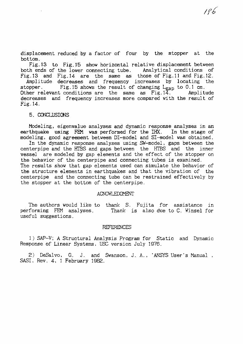
displacement reduced by a factor of four by the stopper at thebottom.
Fig.13 to Fig.15 show horizontal relative displacement betweenboth ends of the lower connecting tube. Analytical conditions ofFig.13 and Fig.14 are the same as those of Fig.11 and Fig.12.Amplitude decreases and frequency increases by locating the
stopper. Fig.15 shows the result of changing Lgap to 0.1 cm.Other relevant conditions are the same as Fig.14. Amplitudedecreases and frequency increases more compared with the result ofFig.14.
5. CONCLUSIONS
Modeling, eigenvalue analyses and dynamic response analyses in anearthquake using FEM was performed for the IHX. In the stage ofmodeling, good agreement between Dl-model and Si-model was obtained.
In the dynamic response analyses using SW-model, gaps between thecenterpipe and the HTBS and gaps between the HTBS and the innervessel are modeled by gap elements and the effect of the stopper onthe behavior of the centerpipe and connecting tubes is examined.The results show that gap elements used can simulate the behavior ofthe structure elements in earthquakes and that the vibration of thecenterpipe and the connecting tube can be restrained effectively bythe stopper at the bottom of the centerpipe.
ACNOVLEDGMENT
The authors would like to thank S. Fujita for assistance inperforming FEM analyses. Thank is also due to C. Winsel foruseful suggestions.
1 ) SAP-V; A Structural Analysis Program for Static and DynamicResponse of Linear Systems, USC version July 1976.
2) DeSalvo, G. J. and Swanson, J. A., 'ANSYS User's Manual ,SASI, Rev. 4, 1 February 1982.

Table 7 Main specif icat ions of I H X
type
heating arcs (m*)
heat tube;size (mm); number
number of layersof coils
material
A loop
helical coil
i j eo
tf 3 1.6 x 41
27 0
1 3
Hastelloy X"R
B loop
helical coil
] 4B5
tf> 2 5.4 x 4 t
474
] 7
Hastelloy XR
20870
?ry Helium
Oolltl
12750
Helium
Fig -1 Intermediate Heat Exchanger (A-loop)
4Supiiotl Lvg
Fig. 2 Tube support structure of the A-loop IHX

ftaaetor Canutmwrit Vessel
kafnellag Machine
Kcaecor Auxiliary
(Auxiliary Kaulpacnt Ant)Kaactor Ancillary kttlMlag(Control Systaa Ar»»)
A-loop IEX
B-leop IKX
Reactor
_ CL +52.0
CL -i3.S *
CL -20.C
Fig.3 Reactor building of the experimental VHTR (A-A section)
tbe colunm the aedion colmm the outenoost column
Fig.4 Modeling of helical tubes and support plates

j V\
tff
1st imi Jrt) moit
Fig.5 Mode shapes of the helical tubes
21570.0
7D.0
Fig.6 Detailed inner structure modelFig.7 Simplified inner structure model
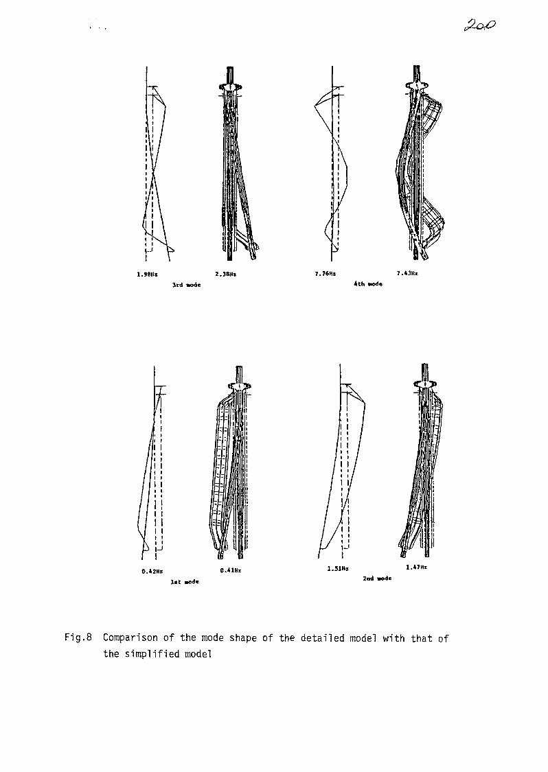
I I
1.9BIIZ 2.38Hz 7.76Ht 7.OHz
3rd ante 4th »ode
O.42HE 0.41Hz
l i t sodc ode
Fig.8 Comparison of the mode shape of the detailed model with that ofthe simplified model
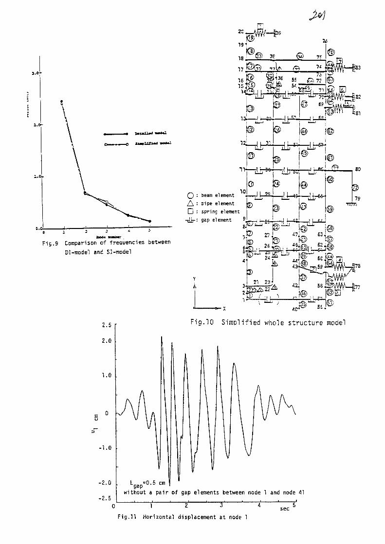
3.0-
F<55) 38
16
l . o -
1.D
13
* - r f
0
_21
-9fr
©
Fig.9 Comparison of frequencies between
Dl-model end Sl-model
ID(_) : beam elementA : pipe elementD : spring element
-[Hi-: gap element 5
7
tA
?c
S)
IWILJJ-&fr
@ ~$mP%!U££.
JUT*5 dlr6^
-w
©-B6-
27 47. £3
( ^ SO
7S
1) 1© 1®2 ^ , , «ifilhi_S
V•A
« i 6 0 ' ^
25jSE
£> f ' * ^ I I TT
56 T
2.5
2.0
1.0
-1.0
-2.0
-2.5
iFig.10 Simplified whole structure model
without a pair of gap elements between node 1 and node 41
0 1 2 3
Fig.11 Horizontal displacement at node 1
4 s e c 5
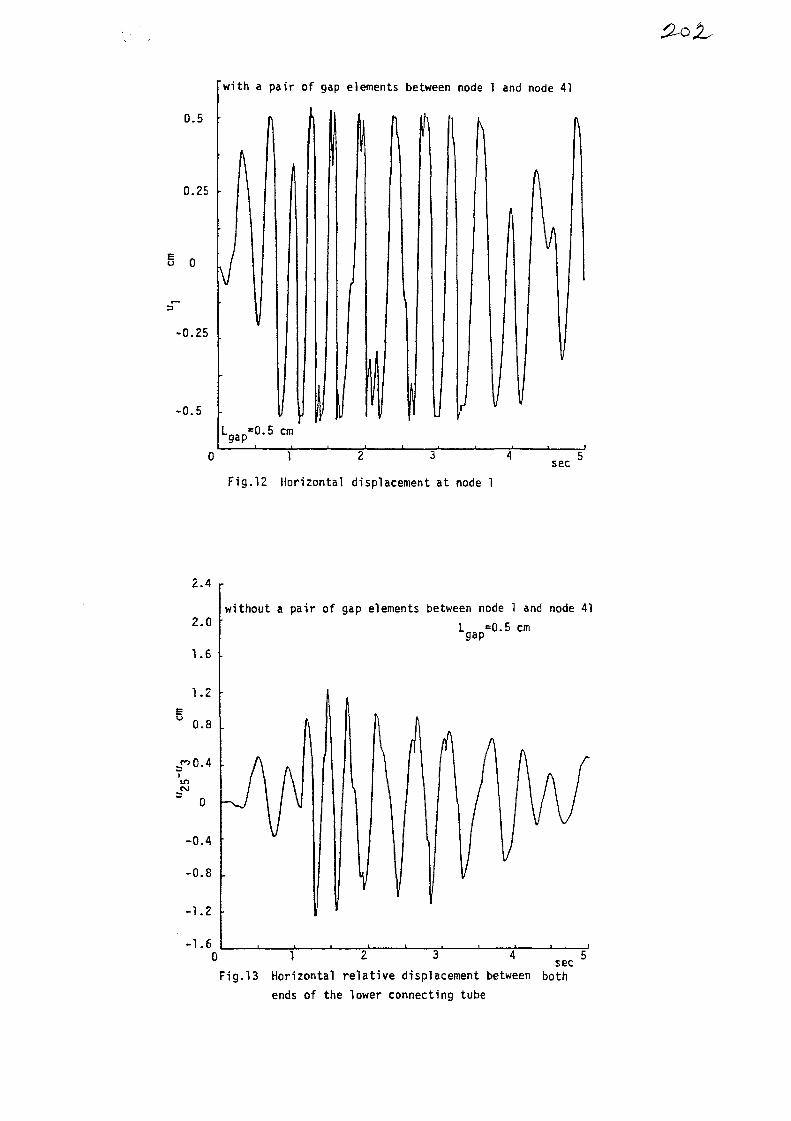
0.5
0.25
B 0
-0.25
-0.5
with a pair of gap elements between node 1 and node 41
0 1 2 3 4
Fig.12 Horizontal displacement at node 1sec
2.4
2.0
1.2
0.8
inCM
-0.4
-0.8
-1.2
-1.6
without a pair of gap elements between node 1 and node 41
0 1 2 3 4 s e c
Fig.13 Horizontal relative displacement between bothends of the lower connecting tube

1.2
1.0
0.8
0.6
0.4
'm 0.2CM
0
-0.2
-0.4
-0.6
-0.8
Lgap*0-5 cm
with a pair of gap elements between node 1 and node 41
secFig.14 Horizontal relative displacement between both
ends of the lower connecting tube
0.20
u
0.12
inc\j
0.04
-0.04
-0.12
with a pair of gap elements between node 1 and node 41
2 3 4 5sec
Fig.15 Horizontal relative displacement between bothends of the lower connecting tube
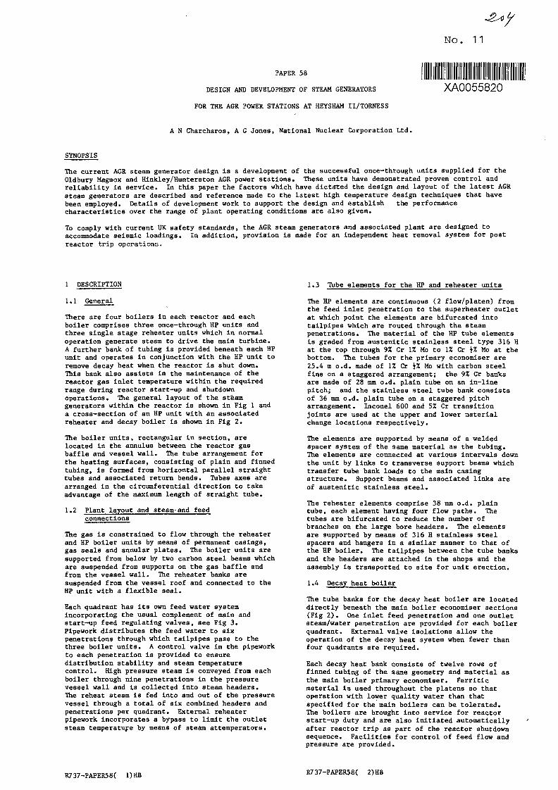
No. 11
PAPER 58
DESIGN AND DEVELOPMENT OF STEAM GENERATORS
FOR THE AGR POWER STATIONS AT HEYSHAM II/TORNESS
XA0055820
A N Charcharos, A G Jones, National Nuclear Corporation Ltd.
SYNOPSIS
The current AGR steam generator design is a development of the successful once-through units supplied for theOldbury Magnox and Hinkley/Hunterston AGR power stations. These units have demonstrated proven control andreliability in service. In this paper the factors which have dictated the design and layout of the latest AGRsteam generators are described and reference made to the latest high temperature design techniques that havebeen employed. Details of development work to support the design and establish the performancecharacteristics over the range of plant operating conditions are also given.
To comply with current UK safety standards, the AGR steam generators and associated plant are designed toaccommodate seismic loadings. In addition, provision is made for an independent heat removal system for postreactor trip operations.
1 DESCRIPTION
1.1 General
There are four boilers in each reactor and eachboiler comprises three once—through HP units andthree single stage reheater units which in normaloperation generate steam to drive the main turbine.A further bank of tubing is provided beneath each HPunit and operates in conjunction with the HP unit toremove decay heat when the reactor is shut down.This bank also assists in the maintenance of thereactor gas inlet temperature within the requiredrange during reactor start-up and shutdownoperations. The general layout of the steamgenerators within the reactor is shown in Fig 1 anda cross-section of an HP unit with an associatedreheater and decay boiler is shown in Fig 2.
The boiler units, rectangular in section, arelocated in the annulus between the reactor gasbaffle and vessel wall. The tube arrangement forthe heating surfaces, consisting of plain and finnedtubing, is formed from horizontal parallel straighttubes and associated return bends. Tubes axes arearranged in the circumferential direction to takeadvantage of the maximum length of straight tube.
1.2 Plant layout and steam'and feedconnections
The gas is constrained to flow through the reheaterand HP boiler units by means of permanent casings,gas seals and annular plates. The boiler units aresupported from below by two carbon steel beams whichare suspended from supports on the gas baffle andfrom the vessel wall. The reheater banks aresuspended from the vessel roof and connected to theHP unit with a flexible seal.
Each quadrant has its own feed water systemincorporating the usual complement of main andstart-up feed regulating valves, see Fig 3.Pipework distributes the feed water to sixpenetrations through which tailpipes pass to thethree boiler units. A control valve in the pipeworkto each penetration is provided to ensuredistribution stability and steam temperaturecontrol. High pressure steam is conveyed from eachboiler through nine penetrations in the pressurevessel wall and is collected into steam headers.The reheat steam is fed into and out of the pressurevessel through a total of six combined headers andpenetrations per quadrant. External reheaterpipework incorporates a bypass to limit the outletsteam temperature by means of steam attemperators.
1.3 Tube elements for the HP and reheater units
The HP elements are continuous (2 flow/platen) fromthe feed inlet penetration to the superheater outletat which point the elements are bifurcated intotailpipes which are routed through the steampenetrations. The material of the HP tube elementsis graded from austenitic stainless steel type 316 Hat the top through 9% Cr 1Z Mo to 1% Cr \% Mo at thebottom. The tubes for the primary economiser are25.4 m o.d. made of \X Cr i% Mo with carbon steelfins on a staggered arrangement; the 9% Cr banksare made of 28 mm o.d. plain tube on an in-linepitch; and the stainless steel tube bank consistsof 36 mm o.d. plain tube on a staggered pitcharrangement. Inconel 600 and 5% Cr transitionjoints are used at the upper and lower materialchange locations respectively.
The elements are supported by means of a weldedspacer system of the same material as the tubing.The elements are connected at various intervals downthe unit by links to transverse support beams whichtransfer tube bank loads to the main casingstructure. Support beams and associated links areof austenitic stainless steel.
The reheater elements comprise 38 mm o.d. plaintube, each element having four flow paths. Thetubes are bifurcated to reduce the number ofbranches on the large bore headers. The elementsare supported by means of 316 H stainless steelspacers and hangers In a similar manner to that ofthe HP boiler. The tailpipes between the tube banksand the headers are attached in the shops and theassembly is transported to site for unit erection.
1.4 Decay heat boiler
The tube banks for the decay heat boiler are locateddirectly beneath the main boiler economiser sections(Fig 2 ) . One inlet feed penetration and one outletsteam/water penetration are provided for each boilerquadrant. External valve Isolations allow theoperation of the decay heat system when fewer thanfour quadrants are required.
Each decay heat bank consists of twelve rows offinned tubing of the same geometry and material asthe main boiler primary economiser. Ferriticmaterial is used throughout the platens so thatoperation with lower quality water than thatspecified for the main boilers can be tolerated.The boilers are brought into service for reactorstart-up duty and are also initiated automaticallyafter reactor trip as part of the reactor shutdownsequence. Facilities for control of feed flow andpressure are provided.
R737-PAPER58( 1)HB R7 37-PAPER58C 2)HB
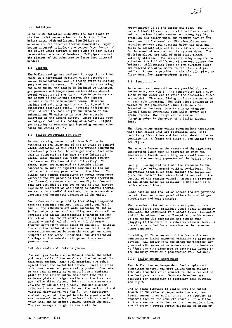
1.5 Tailpipes
1% Cr i% Mo tailpipes pass from the tube plate inthe feed inlet penetration to the bottom of theboiler units with sufficient flexibility toaccommodate Che relative thermal movements. Super-heater internal tailpipes are routed from the top-ofthe boiler units through a tube plate in each outletpenetration to external headers. Tailpipes connectthe platens of the reheaters to large bore internalheaders.
The boiler casings are designed to support the tubebanks in a horizontal position during assembly atworks, transportation and up-ending prior to liftinginto the reactor vessel. In addition to supportingthe tube banks, the casing is designed to withstandgas pressure and temperature differentials duringnormal operation of the plant. Provision is made atthe bottom of the HP unit casings for supportpedestals to the main support beams. Reheatercasings and main unit casings are fabricated fromaustenitic stainless steel. Vertical baffles areprovided over the full height and breadth of theceheater and HP units to improve the acousticbehaviour of the casing cavity. These baffles forman integral part of the casing structure. Flightsare included to minimise gas bypassing between tubebanks and casing walls.
1.7 Boiler supporting structure
An annular ring common to all four boilers isattached to the lower end of the HP units to controlradial expansion of the units and provide convenientattachment points for the main gas seal. Each mainunit is supported at its base by two fabricatedradial beams through pin joint connection betweenthe beams and the base of the unit casing'. Theradial beams are supported by flexible slingsconnected to tubular supports attached to the gasbaffle and to dummy penetration in the liner. Theslings have hinged connections to permit transversemovement and are preset so that in normal operationthe flexural stresses are low, see Fig 4. Connect-ions are provided at the top of the HP unit betweensuperheat penetrations and casing to control thermalmovements in a radial direction, and to accommodatevertical and horizontal expansion of the units.
Each reheater is supported by four slings suspendedfrom the concrete pressure vessel roof, see Fig 1and 2. The reheaters are also connected to the HPboiler unit3 by means of a rolling seal which allowsvertical and radial differential expansion betweenthe reheater and the HP units. A sliding bracketmaintains radial and circumferential alignmentthereby preventing undue loads on the seal. Seismicloads on the boiler structure are reacted throughrestraints connected between the casings and dummysupports on the vessel liner wall and differentialloadings on the reheater slings and the steampenetrations.
1.8 Ga3 seals and division plates
The main gas seals are continuous around the Innerand outer walls of the annulus at the bottom of themain unit casing. Each seal comprises two tubesspaced apart and sandwiched between layers of shimswhich are backed and protected by plates. One tubeof the seal assembly is connected via a membraneplate to the boiler units, the other tube via amembrane plate to ledger sections on the liner andgas baffle skirt plates. Joints In the system arecovered by lap sealing plates. The seals allowrelative thermal movement in both the horizontal andvertical directions, see Fig 5. Low temperaturecoolant tapped off the gas baffle is piped aroundthe bottom of the units to maintain the surroundingvoids cool and to offset leakage through the seal.The gas leakage through the seals will be
approximately 1% of the boiler gas flow. Thecoolant flow, in association with baffles around theunit at various levels serves to prevent hot CO2bypassing the boiler units and flowing down to thelower part of the annulus. Division plates areprovided between each quadrant below the main gasseals to isolate adjacent boiler/circulator systemsin the event of one quadrant being shut down. Thedivision plates are made of mild steel platessuitably stiffened, the structure being adequate towithstand the full differential pressure across theboilers. Differential loads on the division plateare reacted via attachments to the liner and gasbaffle. A door is provided in the division plate atfloor level for inter-quadrant access.
1.9 Penetrations
Two economiser penetrations are provided for eachboiler unit, see Fig 6. The penetration has a tubeplate at the outer end to which the economiser tubesare welded. Flow stabilising orifices are providedat each tube location. The tube plate extension iswelded to the penetration liner tube on site.Attached to the tube plate is a large diameterflanged header comprising feed inlet branch anddrain branch. The flange can be removed forplugging tubes in the event of a boiler elementleak.
The three superheater outlet penetrations associatedwith each boiler unit are fabricated into unitscomprising steam tubes and insulated sheath tube andcomplete with a forged end plate at the inboard end,see Fig 7.
The annulus formed by the sheath and the insulatedpenetration liner tube is provided so that thepenetration sheath tube acting as a cantilever cantake up the vertical expansion of the boiler units.
Cold pull is applied to limit the stresses in thesheath tube during normal working conditions. Theindividual steam tubes pass through the forged endplate and connect into 3team headers mounted on theoutside of the reactor vessel. Access is providedto the steam tubes for blanking in the event of aboiler element leak.
Plate baffles and insulation assemblies are providedon both feed and steam penetrations to control gascirculation and heat transfer.
The reheater inlet and outlet steam penetrationscomprise large bore stainless steel tubes externallyinsulated and contained in a sheath tube. The outerend of the steam tubes is flanged to provide accessto the header for inspection and remote tubeplugging in the event of a reheater element leak. Abranch is provided for connection to the reheatersteam pipework.
Shielding at the outer end of the feed and steampenetrations limits external radiation to acceptablelevels. All boiler feed and steam penetrations areprovided with external secondary retention featuresto limit gas side discharge to acceptable levels inthe unlikely event of a penetration weld failure.
1.10 Boiler annexe components
Each boiler has an independent feed supply withassociated control and trip valves which dividesinto six branches which connect to the outer end ofthe feed penetrations. Separate branches areprovided for connection of emergency feed systems,see Fig 3.
The HP steam pipework is routed from the outletbranch of the external superheate headers; eachheader serves three boiler units. The pipework isanchored back to the concrete vessel. In additionto the steam mains to the turbine, connections fromthe HP steam pipework permit discharge of steam or
R737-PAPER58C 3)HB R737-PAPER58(

water to the start-up vessels, and to the LP ventsystem, via appropriate control valve stations.Provision is also made for pipework to bypass the HPboiler for circuit clean-up operations.
Reheater bypass pipework is. provided between thereheat inlet pipework and the branches on thereheater outlet penetrations, complete with anattemperator device to obtain the required finalreheat steam temperature.
2 FACTORS DICTATING LAY-OUT AMD DESIGN
2.1 Materials
Apart from the requirement to use materials withadequate strength at the specified temperature andpressure, there are four factors governing thechoice of materials in the various sections of thesteam generator. These are:
(i) Gas side oxidation(ii) General water/steam side corrosion(iii) Stress corrosion(iv) Erosion corrosion.
Gas side oxidation
Temperature limits are necessary to avoid excessivegas side oxidation of components for an economicboiler design. It is also necessary to use alloysteels that are compatible with other operationalfactors. The following metal temperature limits areemployed with associated metal loss and oxide growthfor 30 years operation exposed to AGR gas.
Material
Carbon steel(0.1% Si min)
Carbon steel(0.2% Si min)
1% Cr i% Mo(0.2% Si min)
9% Cr 1% Mo(0.62! Si min)
316 SS
Temperature
350"
370°
370°
550"
700°
C
C
C
C
C
Metal
0
0
0
0
0
.17
.29
.29
.51
.33
loss
mm
mm
mm
mm
mm
Oxide growth
0.29
0.38
0.38
0.81
0.28
mm
mm
mm
mm
mm
For structural components interface joints attemperatures above 250°C are fully seal welded wherepossible. Where gas tightness cannot be guaranteed,prescribed gaps are adopted beween faces of weldconnections to accommodate oxide growth. Boltedarrangements are designed to cater for oxide jackingstrains and metal loss at thread forms to preventdisengagement.
Water/steam side corrosion
Allowances for general water/steam side corrosionare included in the tube wall thickness assessmentfor the respective materials of construction. Inaddition allowances to cater for periodic chemicalcleaning of the boiler units due to accumulatedoxides result in the following totals:
Carbon and 1% Cr i% Mo steels
9% Cr 1% Mo steel
316 H SS
Stress corrosion
0.61 mm
0.89 mm
0.18 mm
Occasional wetting of austenitic tube material Isacceptable in the short term provided water qualityIs controlled within defined limits. Potential longterm problems are avoided by using high purity feedwater during power operation and by controllingsteam temperature at entry to the austenitic sectionof the secondary superheater to a nominal minimum of70°C superheat at which droplets are absent. Allweldments are heat treated to condition thematerials.
Erosion corrosion
In regions of high water velocities such as down-stream of control orifices and at tube bends,erosion corrosion can occur resulting In severemetal wastage. The process is a function of anumber of factors including the material compositionof the attacked surface. Tests have shown thatalloy steels are resistant to attack and so thesesteels are used for the water sections of the boilerunits.
Taking account of all the above factors 1% Cr i% Mosteel Is used for the feed Inlet, primary ecotiotnlserand decay heat tube banks. The secondaryeconomiser, evaporator and primary superheater aremade from 9% Cr 1% Mo steel while the upper tubebanks are made of 316 H austenitic stainless steel.
The transition from one tube material to another isprovided by welded joints at interbank locations. A5% Cr \% Mo tube Insert is used between the 1% Crand 9% Cr tubes and an Inconel 600 insert is usedbetween the 9% Cr tubes and the 316 H tubes. Alltube welds are subject to heat treatment.
TABLE 1
BASIC DIMENSIONS AND MATERIALS
Because of metal temperature limits due to gas sideoxidation, it Is necessary to use aus-tenitlc stain-less steel tube for the second stage superheater andreheater tube banks. This material is subject tostress corrosion in aggressive chemical environ-ments .
Component
Reheater tubes
Reheater tailpipes
Reheater platens
Reheater slingsReheater casing
Reheater headers
Secondary super-heater tubesSecondary super-heater tailpipeSecondary super-heater platensTransition tubesPrimary super-heater tubesPrimary super-heater platensEvaporator tubes
Evaporator platens
Secondary economisertubesSecondary economiserplatensTransition tubes
Primary economisertubesPrimary economiserplatensDecay heat boilertubes
Dimensions
38 o.d. x4 thick51 o.d. x4 thick36/unit(staggered)4/unitStiffenedplate 1.5 mlong368 o.d. x3036 o.d. x4 thick38 o.d. x
44/unit(staggered)36 o.d. x 428 o.d. x3.5 thick44/unit(In-line)28 o.d. x3.544/unit(in-line)28 o.d. x0.3544/unit(In-line)28 o.d. xT cJ. J
25.4 o.d. x4 (finned)44/unit(staggered)25.4 o.d. x4 (finned)
Material
316 H SS
316 H SS
Nimonic 80A316 H SS
316 H SS
316 H SS
316 H SS
316 H SS
Inconel 6009% Cr 1% Mo N4T
9% Cr 1% Mo N4T
9% Cr 1% Mo N4T
9% Cr 1% Mo N4T
5% Cr 1% Mo
1% Cr i% Mo
(MS fins)
1% Cr iZ Mo
R737-PAPER58( 5)HB R737-PAPER58( 6)HB
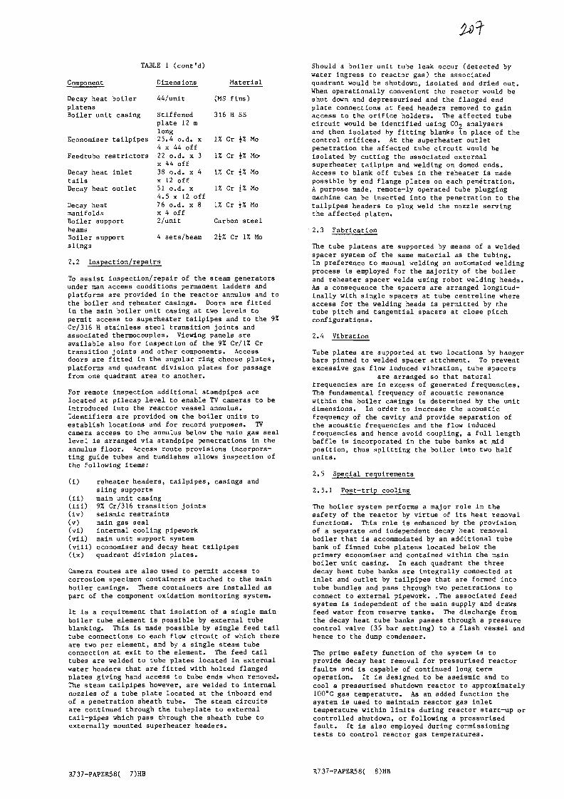
TABLE I ( c o n t ' d )
Component
Decay heat boilerplatensBoiler unit casing
Dimensions
44/unlt
Stiffenedplate 12 mlong
Economiser tailpipes 25.4 o.d. x4 x 44 off
Feedtube restrictors 22 o.d. x 3x 44 off
Decay heat inlettailsDecay heat outlet
Decay heatmanifoldsBoiler supportbeamsBoiler supportslings
38 o.d. x 4x 12 off51 o.d. x4.5 x 12 off76 o.d. x 8x 4 off2/unit
4 sets/beam
2.2 Inspection/repairs
Material
(MS fins)
316 H SS
1% Cr \% Mo
1% Cr \% Mo-
1% Cr \% Mo
U Cr \% Mo
1% Cr \% Mo
Carbon steel
2i% Cr U Mo
To assist inspection/repair of the steam generatorsunder man access conditions permanent ladders andplatforms are provided in the reactor annulus and tothe boiler and reheater casings. Doors are fittedin the main boiler unit casing at two levels topermit access to superheater tailpipes and to the 9%Cr/316 H stainless steel transition joints andassociated thermocouples. Viewing panels areavailable also for inspection of the 9% Cr/1% Crtransition joints and other components. Accessdoors are fitted in the angular ring cheese plates,platforms and quadrant division plates for passagefrom one quadrant area to another.
For remote inspection additional standpipes arelocated at pilecap level to enable TV cameras to beintroduced into the reactor vessel annulus.Identifiers are provided on the boiler units toestablish locations and for record purposes. TVcamera access to the annulus below the main gas seallevel is arranged via standpipe penetrations in theannulus floor. Access route provisions incorpora-ting guide tubes and tundlshes allows inspection ofthe following items:
(i) reheater headers, tailpipes, casings andsling supports
(ii) main unit casing(ill) 9% Cr/316 transition joints(iv) seismic restraints(v) main gas seal(vi) internal cooling pipework(vii) main unit support system(viii) economiser and decay heat tailpipes(ix) quadrant division plates.
Camera routes are also used to permit access tocorrosion specimen containers attached to the mainboiler casings. These containers are installed aspart of the component oxidation monitoring system.
It is a requirement that isolation of a single mainboiler tube element Is possible by external tubeblanking. This is made possible by single feed tailtube connections to each flow circuit of which thereare two per element, and by a single steam tubeconnection at exit to the element. The feed tailtubes are welded to tube plates located in externalwater headers that are fitted with bolted flangedplates giving hand access to tube ends when removed.The steam tailpipes however, are welded to internalnozzles of a tube plate located at the inboard endof a penetration sheath tube. The 3team circuitsare continued through the tubeplate to externaltail-pipes which pass through the sheath tube toexternally mounted superheater headers.
Should a boiler unit tube leak occur (detected bywater ingress to reactor gas) the associatedquadrant would be shutdown, isolated and dried out.When operationally convenient the reactor would beshut down and depressurised and the flanged endplate connections at Eeed headers removed to gainaccess to the orifice holders. The affected tubecircuit would be identified using CO2 analysersand then isolated by fitting blanks in place of thecontrol orifices. At the superheater outletpenetration the affected tube circuit would beisolated by cutting the associated externalsuperheater tailpipe and welding on domed ends.Access to blank off tubes In the reheater is madepossible by end flange plates on each penetration.A purpose made, remote-ly operated tube pluggingmachine can be inserted into the penetration to thetailpipes headers to plug weld the nozzle servingthe affected platen.
2.3 Fabrication
The tube platens are supported by means of a weldedspacer system of the same material as the tubing.In preference to manual welding an automated weldingprocess is employed for the majority of the boilerand reheater spacer welds using robot welding heads.As a consequence the spacers are arranged longitud-inally with single spacers at tube centreline whereaccess for the welding heads is permitted by thetube pitch and tangential spacers at close pitchconfigurations.
2.4 Vibration
Tube plates are supported at two locations by hangerbars pinned to welded spacer attchment. To preventexcessive gas flow induced vibration, tube spacers
are arranged so that naturaltrequencies are in excess of generated frequencies.The fundamental frequency of acoustic resonancewithin the boiler casings is determined by the unitdimensions. In order to Increase the acousticfrequency of the cavity and provide separation ofthe acoustic frequencies and the flow inducedfrequencies and hence avoid coupling, a full lengthbaffle is incorporated in the tube banks at .midposition, thus splitting the boiler into two halfunits.
2.5 Special requirements
2.5.1 Poat-trip cooling
The boiler system performs a major role in thesafety of the reactor by virtue of its heat removalfunctions. This role is enhanced by the provisionof a separate and independent decay heat removalboiler that is accommodated by an additional tubebank of finned tube platens located below theprimary economiser and contained within the mainboiler unit casing. In each quadrant the threedecay heat tube banks are Integrally connected atinlet and outlet by tailpipes that are formed intotube bundles and pass through two penetrations toconnect to external pipework. .The associated feedsystem is independent of the main supply and drawsfeed water from reserve tanks. The discharge fromthe decay heat tube banks passes through a pressurecontrol valve (35 bar setting) to a flash vessel andhence to the dump condenser.
The prime safety function of the system is toprovide decay heat removal for pressurised reactorfaults and is capable of continued long termoperation. It is designed to be aseismic and tocool a pressurised shutdown reactor to approximately100°C gas temperature. As an added function thesystem is used to maintain reactor gas inlettemperature within limits during reactor start-up orcontrolled shutdown, or following a pressurisedfault. It is also employed during commissioningtests to control reactor gas temperatures.
R737-PAPER58( 7)HB R7 37-PAPER58( 8)HB

2.5.2 Seismic
The stations are required to withstand the effectsof an earthquake having a prescribed maximum freefield ground motion considered applicable to UKsites, with a peak acceleration of 0.25 g. Dynamicanalysis of the complete nuclear island has enabledaseismic design conditions to be derived forindividual boiler components. These conditions arein the form of floor response spectra and staticcoefficients.
Initial design has been based on loadings defined bystatic coefficients derived from a design baseearthquake having a peak ground acceleration of0.125 g. These seismic loadings are combined withoperational loads and the resulting stresses arerequired to be within the elastic limits of thematerials of construction. This approach isstrictly applicable only to components having alowest natural frequency of 33 Hz or greater. Asmajor components in the steam generators have lowernatural frequencies a dynamic response of a completerepresentation of the twelve boiler and reheaterunits together with annular ring, supports andrestraining structures has been performed with safeshutdown earthquake inputs. The resultant loads anddisplacements are applied to the individualcomponents in combination with operationalconditions.
Restraining structures include seismic restraintbrackets located at two levels of the boiler casing.A /5th scale model of a boiler unit has beendynamically tested to substantiate the theoreticalmodelling. For external pipework and associatedequipment conventional dynamic analysis methods havebeen used to establish positions of seismicallyqualified restraints and snubbers necessary toaccommodate the safe shutdown earthquake.
Shaker tests have been carried out on valves andactuator assemblies in operating mode to demonstrateseismic capability. Control and instrument cubicleshave been similarly tested.
2.5.3 Safety
It is a requirement for reactor safety that in theunlikely event of a failure of a gas pressure con-tainment component, the rate of depressurlsation ofthe reactor is limited to an acceptable value.Consequently, all boiler steam and feed penetrationsare fitted with gas flow restrictors designed tolimit the free flow area of Q.006 m 2 for anysingle weld failure. The restraints for the majorpenetrations take the form of long seamless pipesextending internally from the outboard end of thepenetrations to low stress regions of the linershutter tubes, (see Fig 7 ) .
For the superheater tailpipe bundles and the minorpenetrations, restrictor plates are used asindicated. Externally, secondary retention flangesare provided at the end forgings and are tied backto the reactor vessel to an anchor plate.
In order to limit external radiation to anacceptable level (a maximum of 20 ntrem/hour duringrefuelling), radiological shielding is provided atthe outer end of the reheater and superheaterpenetrations and on the inner end of the reheaterheaders. The feed inlet and decay heat boilerspenetrations are similarly shielded. Internalshields are fitted to the instrument penetrations.The layout of the external shielding is arranged insections to permit examination of penetration gaspressure retaining welds during station life.
3 PLANT OPERATING CONDITIONS
3.1 General
From a study of the operational envelope for the
reactor and boiler plant a series of Plant OperatingConditions has been identified, together withassociated frequencies over reactor life, andsubsequently assessed for the design substantiationof boiler components. Table 2 gives a simplifiedsummary of POCs and frequencies.
The POCs are classified as Normal, Frequent, Infrequent orLimiting events; test POCs are also identified.
Normal POCs occur during the course of plannedoperation of the reactor and include start-up, poweroperation over the load range, boiler quadrant shut-down and start-up, refuelling activities andcontrolled reactor shutdown operations.
Frequent POCs include reactor trips with variants ofpost-trip cooling, turbine trips, quadrant trips andother plant faults expected to occur several timesduring reactor life.
Infrequent POCs are expected to occur once or lessduring reactor life and component design must assumea once per lifetime basis. Included are majorboiler leak, steam and feed pipework failure, minorreactor depressurisation faults and quadrant tripprotection failures.
Limiting POCs are events which are not expected tooccur but are included in the design otherwise theconsequences could include release of significantradioactivity. It is accepted that these POCs mayrequire extensive remedial action or even write-offof plant. Included in these POCs are major reactordepressurisation, hypothetical failure of a boilerhalf unit feed tube plate, reactor trip from fullpower with minimum post-trip cooling by one mainboiler supplied with emergency boiler feed or by twodecay heat boilers in service.
Test POCs include boiler testing during the combinedengineering tests and power phase commissioning ofthe station.
TABLE 2
SUMMARY OF NORMAL AND FREQUENT POCs
Plant Operating Conditions Frequency
Reactor temperature raising to standby 35
Reactor start-ups with three and four 300boilersCold turbine start-ups to 100% load 100Hot turbine start-ups to 100% load 200Power cycling 100%-80%-100% load 5400Power cycling 100%-60%-100% load 2400Power cycling 100%-40%-100% load 650Refuelling cycles at loads from 30% 200to 100% loadSingle boiler planned shutdowns 150Single boiler trips 150Controlled shutdown from three or four 150quadrant operation to hot reactor standbyReactor trip from operating power level 60Turbine trip - reactor trip 60Loss of feed trip - turbine trip - 30reactor trip
3.2 Operating procedures
Operation of the reactor at power requires the useof three or four boiler quadrants in serviceproducing steam conditions scheduled as appropriatefor the turbine load. The station auto controlsystem ensures that the boilers are operated overthe control range within the defined constraints ofthe boiler plant, in particular tube metaltemperatures and steam superheat at the 9 Cr 1 Mo/TP 316 transition jonts.
For the start-up of the boilers a 'dry start'technique is employed with feed admitted toinitially empty boilers which are uniformly at
R737-PAPER58( 9)HB R737-PAPER58( 10)HB
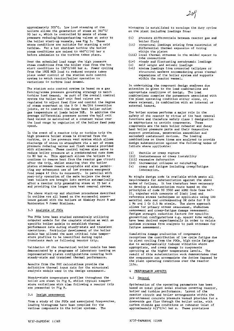
approximately 300°C. Low load steaming of theboilers allows the generation of steam at 360°C/90 bar a, which is controlled by means of steampressure reducing/desuperheating valves at entry tothe boiler start-vip vessels, see Fig 3. Thesesteam conditions are suitable for starting a coldturbine. For a hot shutdown turbine the boilersteam conditions are raised to 460°C/140 bar abefore admission to the turbine takes place.
Over the scheduled load range the high pressuresteam conditions from the boiler rise from the hotstart conditions to 538°C/160 bar a. Power cyclingfrom the 100% MCR load to reduced outputs takesplace under control of the station auto controlsystem to match reactor/boiler operation tovariations in turbine load demand.
The station auto control system is based on a gasforcing/steam pressure governing strategy to matchturbine load demand. As part of the overall controlsystem the boiler half unit feed valves areregulated to adjust feed flow and control the degreeof steam superheat at the 9 Cr 1 Mo/316 transitionjoints, or to control the decay heat boiler outletgas temperature at loads below 50%. In addition theaverage differential pressure across the half unitfeed valves is maintained at a constant value overthe load range by regulation of the boiler feed pumpspeed.
In the event of a reactor trip or turbine trip thehigh pressure boiler steam is diverted from theturbine, to a low pressure vent system which allowsdischarge of steam to atmosphere via a set of steampressure reducing valves and flash vessels providedwith silencers. These control valves also serve toreduce boiler pressure at a predetermined race downto 80 bar a. This approach allows the boilers tocontinue to remove heat from the reactor gas circuitafter the trip, whilst ensuring that the boilerplaten stresses remain acceptable and also permit-ting any subsequent use of low pressure emergencyfeed pumps if this is necessary. In parallel withpost-trip operation of the main boilers the decayheat boilers are brought into service automaticallyafter a reactor trip generating steam at 35 bar aand providing the longer term heat removal system.
The above start-up and shutdown procedures describedin outline are all based on the successful exper-ience gained with the boilers at Hinkley Point B andHunterston B Power Stations.
3.3 Analysis of POCs
The POCs have been studied extensively utilisingcomputer models for the complete station as well asspecific boiler models to establish thermalperformance data during steady-state and transientoperations. Particular development of the boilermodels has allowed the most critical tube temper-ature profiles to be identified during rapidtransients such as following reactor trip.
Validation of the theoretical boiler models has beendemonstrated by a programme of laboratory testing onrepresentative platen configurations covering bothsteady-state and transient thermal performance.
Results from the POC calculations provide thedefinitive thermal input data for the structuralanalysis models used in the design assessment.
Steady-state temperature profiles throughout theboiler are shown In Fig 8, whilst typical temper-ature variations with time following a reactor tripare presented In Fig 9.
3.4 Design assessment
From a study of the POCs and associated frequencies,loading histograms have been compiled for thevarious components in the boiler systems. The
histogram is established to envelope the duty cycleson the plant including loadings from:
(I) pressure differentials between reactor gas andboiler fluid
(ii) structural loadings arising from constraint ofdifferential thermal expansion of tubingwithin the platen
(iii) local thermal stresses in the welded spacer totube connections
(iv) steady and fluctuating aerodynamic loadings(v) self weight and seismic loadings(vi) system loadings from connected tailpipes or
structural members accommodating gross thermalexpansions of the boiler system and supportswithin the reactor vessel.
In undertaking the component design analyses dueattention is given to the load combinations andappropriate conditions of design. The loadcombinations comprise the parameters associated withthe plant operating condition either alone, or,where relevant, in combination with an Internal orexternal hazard.
The boiler system performs a major role in thesafety of the reactor by virtue of its heat removalfunctions and therefore safety class 1 designationis appropriate to certain components. Thesecomponents are the main boiler reheater and decayheat boiler pressure parts and their respectivesupport provisions, penetration assemblies andsecondary containment devices. The loadingcombinations on these items are analysed to providedesign substantiation against the following modes offailure where applicable:
(i) ductile or creep rupture(ii) instantaneous or creep Instability(ill) excessive deformation(iv) incremental collapse or ratcheting(v) creep and fatigue Including creep/fatigue
interaction.
No single design code is available which meets allrequirements for substantiation against the abovemodes of failure. It has therefore been necessaryto develop a substantiation route based on theprinciples of code BS 5500 and ASME Code Case N47-21, together with concepts of limit load andreference stress techniques as applicable using ISOmaterial data and corresponding UK data for 9 Cr1 Mo and 1 Cr 0.5 Mo steels. The above approachallows for primary stress assessment, shakedownassessment and creep-fatigue damage assessment.Fatigue strength reduction factors for specificgeometrical configurations e.g. spacer tube welds,have been derived experimentally in order to relatemaximum stresses from analysis to peak stresses forfatigue assessment.
Cumulative damage evaluation of componentsrecognises the contribution of low cycle fatigue dueto plant cycling from the POCs, high cycle fatiguedue to aerodynamically induced vibration whereappropriate, and creep damage to componentsoperating at the higher temperature levels. Theresult of this substantiation work demonstrates thatthe components can accommodate the duties imposed bythe plant operating conditions over the reactorlife.
4 PERFORMANCE ASPECTS
4.1 General
Optimisation of the operating parameters has beenbased on total plant model studies covering reactor,boiler and turbine performance. Layout of thereactor circuit and boiler arrangements within thepre—stressed concrete pressure vessel provides for adownwards gas flow through the boiler units, withcarbon dioxide gas conditions at reheater inlet ofapproximately 615°C/41 bar a. These provisions
R737-PAPER58( 11)HB R737-PAPER58( 12)HB
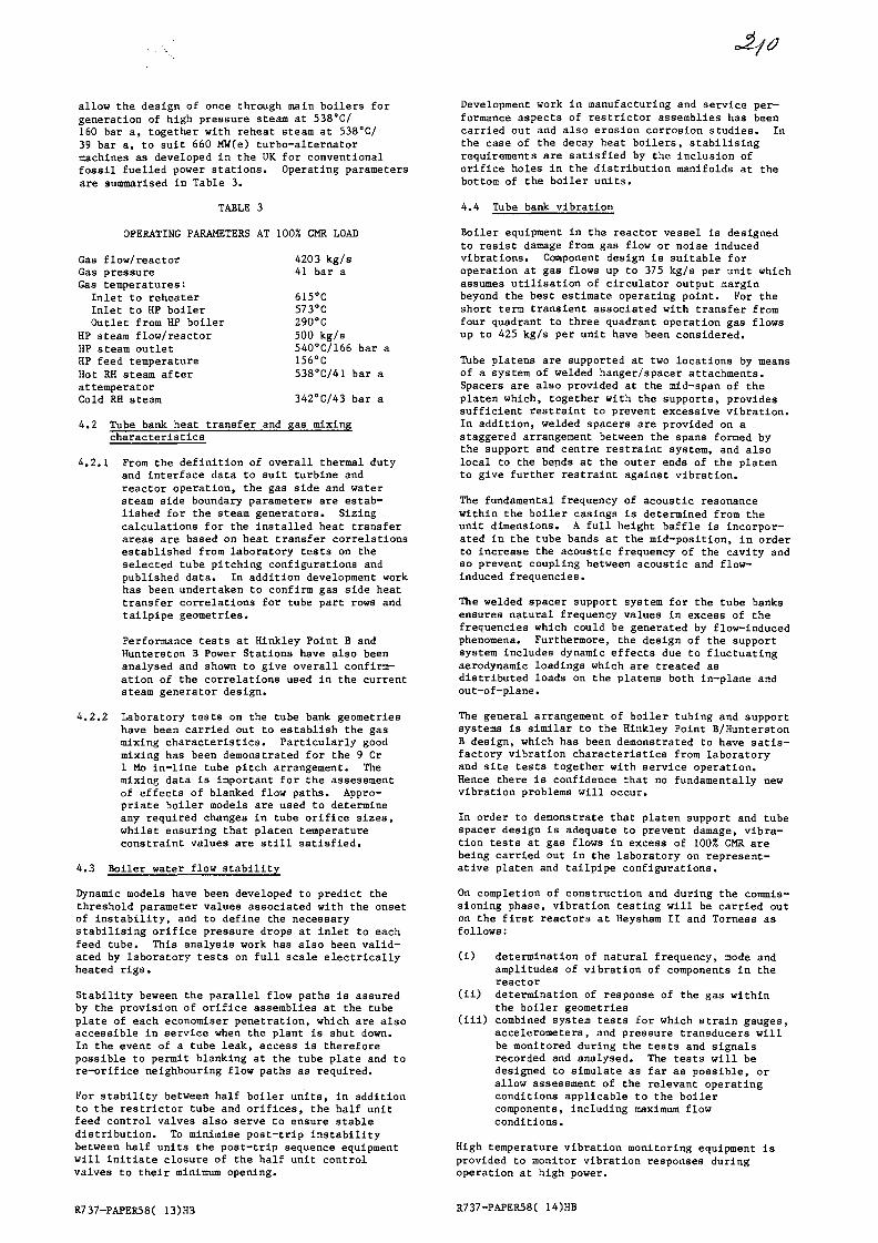
allow the design of once through main boilers forgeneration of high pressure steam at 538°C/160 bar a, together with reheat steam at 538°C/39 bar a, to suit 660 MW(e) turbo-alternatormachines as developed in the UK for conventionalfossil fuelled power stations. Operating parametersare summarised in Table 3.
TABLE 3
OPERATING PARAMETERS AT 100% CMR LOAD
Gas flow/reactorGas pressureGas temperatures:
Inlet to reheaterInlet to HP boilerOutlet from HP boiler
HP steam flow/reactorHP steam outletHP feed temperatureHot RH steam afterattemperatorCold RH steam
4203 kg/s41 bar a
615°C573°C290°C500 kg/s540°C/166 bar a156°C538°C/41 bar a
342°C/43 bar a
4.2 Tube bank heat transfer and gas mixingcharacteristics
4.2.1 From the definition of overall thermal dutyand interface data to suit turbine andreactor operation, the gas 3ide and watersteam side boundary parameters are estab-lished for the steam generators. Sizingcalculations for the installed heat transferareas are based on heat transfer correlationsestablished from laboratory tests on theselected tube pitching configurations andpublished data. In addition development workhas been undertaken to confirm gas side heattransfer correlations for tube part rows andtailpipe geometries.
Performance tests at Hinkley Point B andHunterston B Power Stations have also beenanalysed and shown to give overall confirm-ation of the correlations used in the currentsteam generator design.
4.2.2 Laboratory tests on the tube bank geometrieshave been carried out to establish the gasmixing characteristics. Particularly goodmixing has been demonstrated for the 9 Cr1 Mo in-line tube pitch arrangement. Themixing data is important for the assessmentof effects of blanked flow paths. Appro-priate boiler models are used to determineany required changes in tube orifice sizes,whilst ensuring that platen temperatureconstraint values are still satisfied.
4.3 Boiler water flow stability
Dynamic models have been developed to predict thethreshold parameter values associated with the onsetof instability, and to define the necessarystabilising orifice pressure drops at inlet to eachfeed tube. This analysis work has also been valid-ated by laboratory tests on full scale electricallyheated rigs.
Stability beween the parallel flow paths is assuredby the provision of orifice assemblies at the tubeplate of each economiser penetration, which are alsoaccessible in service when the plant is shut down.In the event of a tube leak, access is thereforepossible to permit blanking at the tube plate and tore—orifice neighbouring flow paths as required.
For stability between half boiler units, in additionto the restrictor tube and orifices, the half unitfeed control valves also serve to ensure stabledistribution. To minimise post-trip instabilitybetween half units the post-trip sequence equipmentwill initiate closure of the half unit controlvalves to their minimum opening.
Development work in manufacturing and service per-formance aspects of restrictor assemblies has beencarried out and also erosion corrosion studies. Inthe case of the decay heat boilers, stabilisingrequirements are satisfied by the inclusion oforifice holes in the distribution manifolds at thebottom of the boiler units.
4.4 Tube bank vibration
Boiler equipment in the reactor vessel is designedto resist damage from gas flow or noise inducedvibrations. Component design is suitable foroperation at gas flows up to 375 kg/s per unit whichassumes utilisation of circulator output marginbeyond the best estimate operating point. For theshort term transient associated with transfer fromfour quadrant to three quadrant operation gas flowsup to 425 kg/s per unit have been considered.
Tube platens are supported at two locations by meansof a system of welded hanger/spacer attachments.Spacers are also provided at the mid-span of theplaten which, together with the supports, providessufficient restraint to prevent excessive vibration.In addition, welded spacers are provided on astaggered arrangement between the spans formed bythe support and centre restraint system, and alsolocal to the bends at the outer ends of the platento give further restraint against vibration.
The fundamental frequency of acoustic resonancewithin the boiler casings is determined from theunit dimensions. A full height baffle is incorpor-ated in the tube bands at the mid-position, in orderto increase the acoustic frequency of the cavity andso prevent coupling between acoustic and flow-induced frequencies.
The welded spacer support system for the tube banksensures natural frequency values in excess of thefrequencies which could be generated by flow-inducedphenomena. Furthermore, the design of the supportsystem includes dynamic effects due to fluctuatingaerodynamic loadings which are treated asdistributed loads on the platens both in-plane andout-of-plane.
The general arrangement of boiler tubing and supportsystems is similar to the Hinkley Point B/HunterstonB design, which has been demonstrated to have satis-factory vibration characteristics from laboratoryand site tests together with service operation.Hence there is confidence that no fundamentally newvibration problems will occur.
In order to demonstrate that platen support and tubespacer design is adequate to prevent damage, vibra-tion tests at gas flows in excess of lOOX CMR arebeing carried out in the laboratory on represent-ative platen and tailpipe configurations.
On completion of construction and during the commis-sioning phase, vibration testing will be carried outon the first reactors at Heysham II and Torness asfollows:
(i) determination of natural frequency, mode andamplitudes of vibration of components in thereactor
(ii) determination of response of the gas withinthe boiler geometries
(iii) combined system tests for which strain gauges,accelerometers, and pressure transducers willbe monitored during the tests and signalsrecorded and analysed. The tests will bedesigned to simulate as far as possible, orallow assessment of the relevant operatingconditions applicable to the boilercomponents, including maximum flowconditions.
High temperature vibration monitoring equipment isprovided to monitor vibration responses duringoperation at high power.
R737-PAPER58( 13)HB R737-PAPER58( 14)HB
2415 DEVELOPMENT
Extensive development work has been undertaken insupport of the design of the steam generators and aschedule of topics covered is given below. Some ofthese will be seen to have application not only togas cooled nuclear steam generators but also toboiler designs in general. On-going work requiringlong term data includes mechanical testing andoxidation/corrosion studies.
5.1 Fabrication development
Spacer-tube geometries. Transition joints. Tubeplates. Casings. Penetrations. Non-destructiveexamination techniques. Heat treatment gascomposition.
5.2 Performance
Temperature measurement at transition joints. Heattransfer at spacer-tube connections. Gas flowdistributions and mixing. Seal leakage. Tube inletflow measurement.
5.3 Tribology
Fretting and wear tests on selected components.
5.4 Mechanical testing
Tensile tests, creep tests, ambient bursting testson tube butt welded and spacer attachment specimens.Transition joint creep tests.
5.5 Noise vibration, fatigue
High cycle fatigue testing spacer tube assemblies.Natural frequencies and damping studies. Acoustictests in pressurised facility. Flow inducedvibration tests in CO2 pressurised rig on platensand tailpipe configurations.
5.6 Oxidation and corrosion
Gas side oxidation. Erosion-corrosion studies.Stress corrosion, corrosion fatigue of transitionjoints.
R737-PAPER58( 15)HB
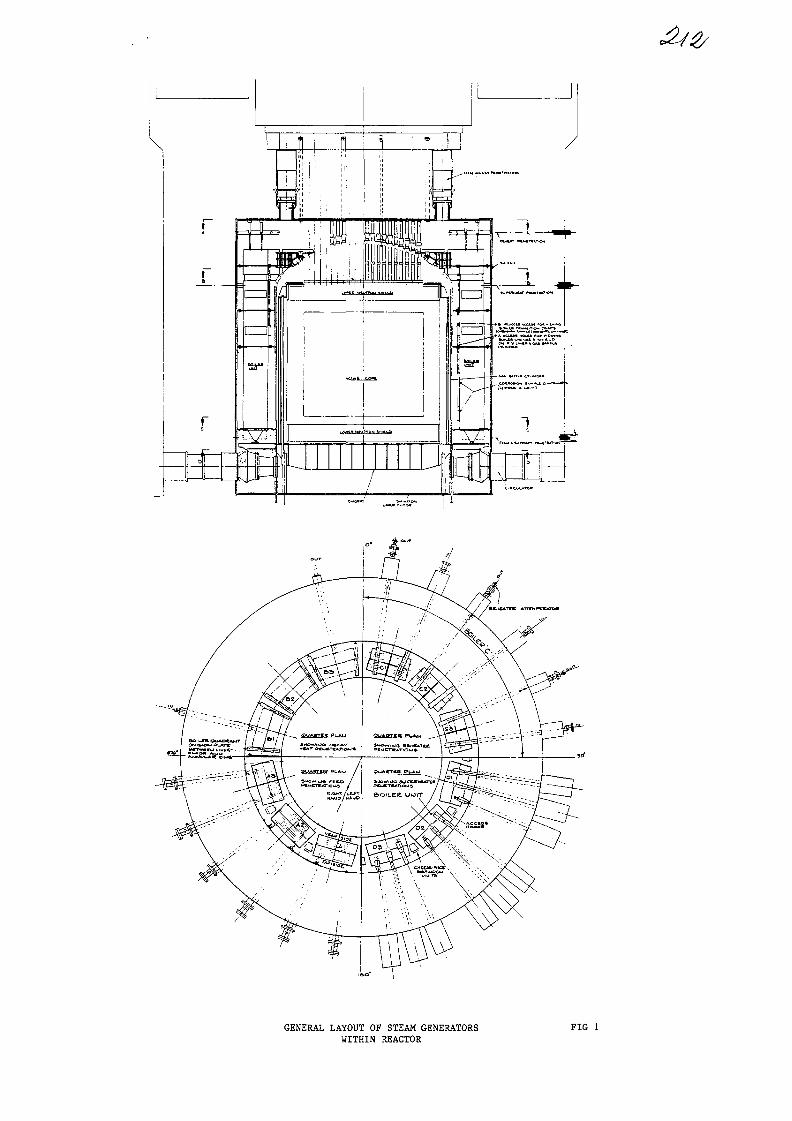
GENERAL LAYOUT OF STEAM GENERATORSWITHIN REACTOR
FIG 1
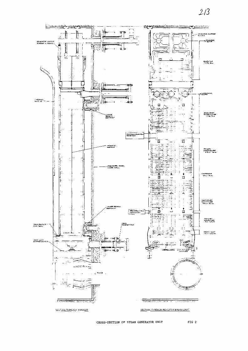
113
SECTION THROUGH ANWLU5 SECTION THROUGH REHEATER^ MAIN UNIT
CROSS-SECTION OF STEAM GENERATOR UNIT FIG 2

I
•afo
REHEATER
MAIN BOILER
DECAY HEATBOILER
OOCIRCULATORS
ATTEMPERATOR
: REHEATBYPASS
OTHERREHEATERS
,-&-&STEAMo
— t S } — 1 * | — dWATER T
L.P. VENTFLASH VESSEL
TURBINESTOP VALVE
«>TEAM
WATER
-iXj 1*»—•-SPRAY WATER OTHER
BOILERS HP L.R
TURBINES
PAIREDBOILER
START UP VESSEL DEAERATOR
HALF -UNIT —VALVES —
EMER6tNCY
FEED
POST TRIP FEED
START UPFEED
OTHER J ^BOILERS
-©-
•A {
MAIN FEED
DECAY HEATFLASH VESSEL
CONDENSER
JSTART UP/STANDBY
PUMPS
M A I N FEED PUMP
RESERVEFEED WATERTANK
• & •
1CONDENSER
DECAY HEATFEED PUMPS
OOAIRCOOLER

CHECK PLATES
DUMMY PENETRATION
OlACRID SUPPORT
SOILER M A I N SUPPORT BEAM
ARRANGEMENT OF MAIN BOILER SUPPORT BEAMAND SLINGS
FIG 4
GAS SEAL TU9ES
MAIN BOILER UNITS ANNULAR RING AND GAS SEAL FIG 5
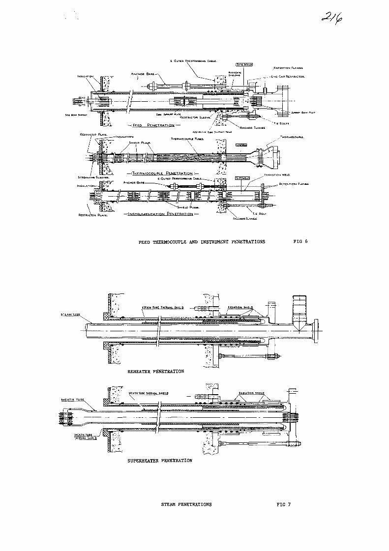
RETENTION FI_*.MSL.
- END CAP RESTRICTOH.
—:THERMOCOUPLE. PENETRATION
t OUTCD PQCSTOEMIN6
TIE BOLT
ANCMOD FLANGE.
FEED THERMOCOUPLE AND INSTRUMENT PENETRATIONS FIG 6
REHEATER PENETRATION
SUPERHEATER PENETRATION
STEAM PENETRATIONS FIG 7

XI?
STEADY-STATE TEMPERATURE PROFILES FIG 8
© R.H. INLET &flSTEMPERfffURE
© H.P. INLET (&flS TEMPERATURE
(3) H. P. OUTLET STEW-1 TEriP.
© M.P. OUTLET
© STEflM
"© WfflTER BOU^DfiRy
REACTOR TRIP TEMPERATURES FIG 9
No. 12
Babcock
MONITORING AND PERFORMANCE ANALYSIS OF AGR BOILERS XA0055821DURING COMMISSIONING AND POWER RAISING
M.EL-NAGDY AND R.M. HARRISONNUCLEAR ENGINEERING DEPARTMENT,
BABCOCK POWER LTD., U.K.
SUMMARY
The installed boiler plant, for two 1300 MW AGR stations, iscomprehensively instrumented for boiler control, performanceassessment and component monitoring to ensure the integrity and safeoperation of the plant during normal and faulty operating conditions.Plant instrumentation and computer systems installed at site forvibration analysis during the engineering runs and data acquisitionduring the power raising stage have been described. The results, fromearly rig investigations and the vibration testing during theunfuelled engineering runs, indicate that the behaviour of the plantwithin the practical range of operating conditions is free fromvibration problems. Also the analysis of the steady state thermal andhydrodynamic behaviour of the boiler plant during the power raisingphase confirms the methods and computer models used for the boilerdesign.
1. INTRODUCTION
The boiler plant for two recently commissioned U.K. AGRstations (Hartlepool and Heysham) consists of 4 boilers perreactor. Each of these boilers incorporates 2 boiler units(pods) which are separated on the primary (gas) side andconnected on the feed side. The boiler section is of the highpressure once-through type with the reheater section above it.These heating surfaces are formed from helically coiled tubescomposed of three materials; mild steel, 9% Cr & 1% Mo and 316stainless steel in the HP section and 316 stainless steel inthe reheating surface. They are arranged (Fig. 1) with all theboiler penetrations at the top (passing through a concretehead), thus enabling the withdrawal of the boiler units forinspection and maintenance.
The boiler heating surfaces are composed of tubes with equallength and connected to common headers at the secondary inletand outlet. For uniform primary temperature distribution atthe boiler inlet and equal primary and secondary flow rates,the axial temperature distribution and thermal duty are thesame for all the tubes. The tube C0£ gas side and steam sidecorrosion, together with the tube material strength propertieshave imposed upper limits on the temperatures of the tube wallsfor the three materials used and a lower limit on thetemperatures of the steam in the austenitic section of theboiler. To achieve optimum power without violating thesetemperature constraints, careful scheduling of the boiler'sterminal parameters is essential. Moreover, due tomanufacturing and assembly tolerances, the boiler behaviour

Babcockcannot be adequately represented using a single tubemeasurement and the 2D characteristics of the boiler must beinvestigated to fully assess its performance.
The boiler control requirements together with the need tounderstand the boiler behaviour have led to a comprehensivemeasurement and instrumentation scheme (Fig. 2) designed tomonitor the boiler constraints and measure the terminalparameters during the various operating conditions of theplant. The instruments provide primary data of the terminalparameters for all the boilers and additional metal, gas andsteam temperatures at various horizontal levels of a speciallyinstrumented boiler unit which is treated as a thermal analogueof the other units. The measurements from the instrumented podare used to interpret and extrapolate to the conditions ofthose uninstrumented units. Also the other pod of the boilercontaining the specially instrumented unit, is fitted withstrain gauges and accelerometers for the measurement of thevibration response of the boilers particularly during theUnfuelled Engineering Runs (UFER).
Although various components had been tested individually inrigs, the Unf uelled Engineering Runs were the first and onlyopportunity to see how the components would behave assembledand in conditions which were dynamically very similar to thosewhich would be experienced during power generation. The UFERprogramme of testing was carried out on the Hartlepool Unit MA7and the Heysham I Unit MA23 during 1980/81 and on the Heysham Iunit MA31 during early 1983. This programme was instigated inorder to confirm the integrity of the boiler components in thereactor gas circuit with respect to vibration due to circulatornoise, gas flow or mechanical transmission from other affectedcomponents. It would also serve to establish operating marginsfor power generation over the station lifetime.
The boiler testing programme during power raising which startedin 1983 is principally aimed at ensuring that operating anddesign limits are not transgressed, providing supplementarydata necessary to understand boiler behaviour and gainingoperating experience of the plant. To achieve these objectivestwo types of testing are carried out; steady state and dynamictests. The latter type of tests involving the whole of theplant rather than simply the boilers themselves, is formonitoring performance and closely associated controlparameters likely to approach operating limits. The steadystate testing which includes symmetric and asymmetricoperations of the plant is designed to check and if necessary,amend the operating schedules and to assess the boilersoperating margins by investigating the sensitivity of theconstraints to the boiler terminal conditions and their spreaddue to systematic and random factors. For symmetricaloperations, the terminal conditions of all the units arematched up with the instrumented unit and for asymmetric tests,the instrumented pod is selected to be the most affected by theprevailing conditions.
BabcockMeasurements, during the testing and power raising programmes,have been continuously collected by the station data processingsystem, the commissioning data logger and temporary recordersand data loggers. The thermal and hydrodynamic measurementsafter suitable corrections, are subsequently used to assist inunderstanding the boiler behaviour and assess the operatingmargins. Collected data are also employed to validate thecomputer model predictions of the plant performance.
2. VIBRATION MONITORING
The boiler components can be divided into two categories forthe purposes of vibration testing and monitoring, according tothe dominant excitation mechanism. Plate-like structures, forinstance baffles, are excited acoustically whilst the vibrationof tubes is largely due to gas flow effects such as vortex -shedding and turbulent buffeting. Theoretical analysis of thevibrational behaviour of the HP and reheater tube banksindicated a large number of modes with some of them close infrequency to predicted excitation frequencies. Thus thepossibility of large-amplitude vibration occurring due topositive-feedback effects was considered. It was alsopostulated that, in an extreme case, the coils themselves,rather than individual tube spans could pulsate (whole boilermodes) with large amplitudes, perhaps assisted by an acousticstanding wave.
2.1 Preliminary Testing
Expected stress levels during UFER were established beforecommissioning by a combination of testing and analysis. Foracoustically dominated components, the instrumented pod (unitMA5) was excited by a loudspeaker. The stresses obtained wereextrapolated to the expected SPL during commissioning. Also, atest bank of 4 helical multistart coils each 40 rows deep wasconstructed to investigate the behaviour of the HP bank. Thishalf scale bank, with the tube span length of the outer coil asthat of the outer coil of the boiler, was extensivelyinstrumented with accelerometers on both tubes and strapsupports and installed inside a pressurised CO2 loop. Contractconditions of gas density and velocity could be achieved oreven exceeded in the rig.
The rig provided data on bank response as functions of gasflow, density and temperature. It was also operatedcontinuously over two 1000 hour periods in order to provideinformation on fretting wear at the tube/strap interface. Thelevel of response, for the conditions prevailing in the AGRboilers was low (accelerometer reading less than lg withcalculated amplitudes less than 0.1mm). Some accelerometerresponse curves (plotted against gas velocity) showed peaks dueto narrow-band excitation, but none was high. The peak tobaseline response ratio (Q) was only around 2 to 5, indicatinghigh damping. The accelerometer results were used to calculatethe expected stresses in the boiler and reheater banks.
Babcock
2.2 Unfuelled Engineering Runs Testing
2.2.1 Instrumentation
The Hartlepool boiler unit MA7 was instrumented with300 strain gauges fitted to around 20 boilercomponents. Also, a limited number of microphones atthe top and bottom of the boiler were used for thedetection of acoustic standing waves and to confirmwhether a component response was due to acousticexcitation. The strain gauge signals were fed via amultiplexer unit to a PDP11 computer connected to aGenrad signal analyser. Fast-Fourier-Transformationwas performed by the analyser on the signals to provider.m.s. and Power Spectral Density plots. The analysercould also provide the cross-correlation and phasebetween two selected signals. All transformed signalswere stored on hard disk and a 14-track tape recorderwas available for recording untransformed signals formore detailed analysis at a later date. Ancillaryequipment included a Hewlett-Packard 3582 signalanalyser for spot checks and an oscilloscope withstorage facility for visual checks on gauge signals.
Heysham I unit MA31 was similarly instrumented with 300accelerometers of which 50 were available to Babcockduring UFER. The signals were analysed with a Hewlett-Packard HP85 computer and recorded on 14 channel tape.
2.2.2 UFER Testing
Contract conditions of gas velocity, density andacoustic velocity at three planes (boiler gas outlet,mid-HP-surface and superheater gas inlet) were achievedby means of varying the Inlet Guide Vanes (IGV's)position, gas temperature and CO2 mixture (withnitrogen). Testing was carried out at threetemperatures 150,246 and 288°C. At each temperature,the gas density was increased in stages and the IGVangle varied in increments of 10°to 2°from fully open(-10°) to almost closed (82°) positions. Testing beganwith the IGV at an intermediate setting (70°) since themaximum acoustic excitation was expected at the nearlyclosed position. On the other hand, maximum flow-induced excitation was expected at the fully openposition. Initially, the gauges were monitored up to2000 Hz frequency, but subsequently up to 250 Hz owingto the low level of response above this frequency.Also, to save time and improve resolution, only aselection of 60 'priority' gauges with consistentlyhigh readings, was monitored at every IGV setting. Theacquisition of data for the Genrad was automaticallycontrolled by programming the PDP11.

BabcockAt the end of each test, the r.m.s. stresses would becompared with the component expected maximum stressesand fatigue/fretting stress limits. For on-lineinterpretation and assessment, PSD plots of some gaugereadings were printed. All the gauges, however, wouldbe monitored on the overnight conditions and whenever aparticular contract condition was reached.
Faulty or noisy gauges were often identified byunusually high stress readings. Examination of the PSDplots would confirm the fault/noise. D/C switching or50 Hz mains pickup due to poor insulation resistancewould be observed on these plots.
The Heysham unit MA31 with accelerometers on coil 19was tested in the same way, but with fewer readings(50) to monitor at a time. Also, the settings of theIGV were refined to 0.5 degree intervals. The main aimof these tests was to investigate boiler resonance oververy narrow frequency/velocity ranges.
2.2.3 Test Results and Conclusions
Stresses measured in all the boiler components werelower than the previously calculated maximum expectedvalues (see Table 1). The stresses of some of theacoustically excited components, such as the top gasbaffle and debris screen were close to the expectedvalues owing to the small degree of pessimism involvedin calculating these values. Careful analyses of thetest results of the coiled tube banks indicate thefollowing:
a) There was no sudden and large take-off in responsethat would indicate the presence of fluidelasticinstability.
b) The excitation was chiefly due to turbulentbuffeting since the dominant frequencies did notchange with gas velocity, and stresses wereapproximately proportional to velocity head, (" V .
c) There was evidence of Strouhal type (proportionalto velocity) excitation of the tubes at around30Hz but the contribution to r.m.s. stress wasminimal. A value of Strouhal number = 0.12 wasderived which agrees well with earlier test work.
d) Cross correlation with pressure transducersrevealed no significant acoustic excitation.
e) There was no coherence between gauges at the topand bottom of the boiler that would indicate awhole boiler mode of vibration.

£23
Babcock
3. THERMAL AND HYDRODYNAMIC DATA MONITORING
3.1 Data Acquisition and Processing
The various data items, necessary for Babcock to effectivelymonitor the boiler plant during the power raising of theHartlepool and Heysham stations are collected and recorded ondisks by the CEGB Station Commissioning and Optimization(SCOOP) computer system [1]. This involves the recording ofsome 200 signals for each station representing the terminalparameters of all the boiler units, the metal and gastemperatures of the heating surfaces of the speciallyinstrumented unit and the helical coils outlet steamtemperatures in the superheater headers.
The recorded disks are despatched regularly from both sites tothe Babcock1s London Offices for processing. Twenty four hoursworth of thermal and hydrodynamic data items, on each disk, areread and processed by the LSI 11/2 computer, in London, whichis connected to a line printer and a graphics screen attachedto a dot printer (fig. 4). The data processing is normallycarried out at three stages, the first of which involves theconversion of the recorded signals to engineering units (if notalready converted at site), detection of transmission, standardtypes and out of range errors and the production of selected(initial) plots representing the variation, with time, of themain plant parameters. These initial plots (usually for 24hours periods) are chosen to enable the following of the mainoperating conditions of the plant and the specification of thedata processing to be carried out at the following stages. Aflow chart, of the main processing operations in the firststage, is shown in fig. 3. An error logger as well as theinitial plots are produced at the end of this stage.
The instrument signals from the stations are scanned at twodifferent rates, a slow scan rate (1 or 10 minutes) and a fastscan rate (3 or 8 seconds). The signals are usually recordedat the low scan rate of 1 or 10 minutes and the fast scan rateis only carried out following the initiation of and duringselected plant transients. The slow scan data items areprocessed further in the second stage which includes theproduction of a diary containing the boilers terminalparameters and a description of the plant states identifiedfrom the interrogation of selected plant parameters such asfeed flow, IGV position and gas circulator speed. Each of themain plant operating states is associated with a unique set ofvalues or range of values of these parameters. Additionalgraphical or tabular outputs may also be obtained at this stageto allow more detailed investigations of the plant conditionsto be carried out. The processing of the slow scan signals isshown diagrammatically in Fig. 4.

Babcock
Following the completion of the initial processing describedearlier, the recorded data items are reduced by performingstatistical analysis on the signals during the steady stateperiods of the plant operation. The reduced information, whichincludes the parameter values at the beginning and end of thesteady state, means and standard deviations, is storedpermanently on disks for future analyses of the plantperformance. Measurements associated with non-steady stateoperating conditions are also reduced and stored on thepermanent disks. The third stage of processing is mainlyconcerned with the preparation of plant data for use as inputdata to the computer models developed specially forinvestigating the thermal performance of the Hartlepool/Heyshamboilers.
Typical plots, produced in the 1st stage of data processing,are given in Fig. 5 which shows the variation, with time, ofthe outlet steam temperatures of boilers C and D and the feedflow of boiler C. Fig. 6, showing the reheater inlet andoutlet steam temperatures and the bypass valve position duringthe connection of the reheater, is typical of the plots whichcan be produced on request at the 2nd stage of processing.
3.2 Components Integrity Monitoring
To safeguard the integrity of the boiler components, that arepredicted to operate close to their design temperature limits,a close watch is kept on the temperatures of these componentsduring the various power raising stages particularly when theplant is operated for the first time at a new set ofconditions. These temperatures are continuously checked andtheir values compared with the predictions and the limitsestablished prior to the power raising programme. When thesetemperatures exceed the recommended limits, the plantconditions, whenever possible, are adjusted to satisfy thelimits. Also the boiler plant terminal conditions aremonitored regularly to compare their values with previoustheoretical predictions and to assess the thermal andhydrodynamic performance of the boilers.
4. BOILERS PERFORMANCE ANALYSIS
The design of the boilers involves the calculation of theheating surfaces and the optimization of thedimensions/arrangement of the tubes forming these surfaceswhich are required to perform a specific thermal duty withinlimited space envelope and specified design margins. Thedesign calculations are frequently performed using computermodels representing the geometrical details and thermal andhydrodynamic characteristics of the boilers and associatedplant. These characteristics are based on the results ofexperimental investigations carried out in test rigs, which areusually idealization of the boiler geometry, to derive generalcorrelations economically and within limited time scale. Underthe actual plant operating conditions, the characteristics may

ISA
Babcock
vary from those derived experimentally and to gain sufficientconfidence in the computer models using the experimentallydetermined characteristics, it is thus necessary to verify themodel predictions using plant data. This data can be obtainedfrom the specially designed tests planned during the powerraising programme.
Following the completion of the thermal design, investigationsof the performance of the boilers under the anticipatedoperating conditions are carried out to determine the thermaloperating cycles for the various boiler components. Thesecycles are subsequently used for the stress analysis and themechanical design of the components. Both simple andsophisticated computer programs, including some of those usedin the design stage of the boiler, are employed to determinethe operating cycles and to establish the plant thermal duty atthe various operating conditions. Two main computer modelswere developed and extensively used by Babcock for the designand performance analyses of the two AGR boiler plants underconsideration. The first of these models is a multibankunidimensional representation of the plant while the othermodel is a two-dimensional representation of the boiler mainheating surfaces. The application of these models andcomparisons of their predictions with early commissioning plantdata are briefly discussed below.
4.1 Multibank Boiler Model
Babcock developed a boiler performance computer program [2]capable of carrying out mono-tube performance calculations onseveral tube banks within a multibank network including once-through steam generators. The primary (heating) fluids whichcan be handled by the program include carbon dioxide and heliumand the secondary fluids are water and steam. The programcontains a number of standard heat transfer and pressure losscorrelations and can accept user written FORTRAN coding forspecial analysis of boiler peripherals. It is also structuredin such a way that a large amount of information, such as thegeometrical details and boiler configuration etc. which are thesame for a number of runs, is stored in data banks. Thesebanks together with the loading conditions form the input datato the program. Although the data banks can be edited by theuser, he is not permitted to modify the data banks and onlyauthorized users are allowed to add new banks which may beaccessed by the program. Initial estimate, for the flows andthe pressures and enthalpies at the terminal points of theheating surfaces, is included in the data banks to enable fastconvergence to the final solution.
Extensive user testing of the program was carried out beforeits release for general use, and it is hoped to be able toverify the program using plant data from the power raisingprogramme testing. The program has also been successfully usedfor the assessment of the boiler performance during start-up [3and 4] of the Hartlepool and Heysham stations. Typical resultsof this assessment are plotted in Figs. 7 and 8 for Hartlepooland Heysham respectively. The plots show the axial profiles,in the HP and R/H sections of the boiler, of the tube, metaland the primary and secondary fluid temperatures.

Babcock
4.2 Two-dimensional Boiler Model
A two-dimensional analysis capability has been added to theBabcock multibank computer program [2] to enable theinvestigation of the asymmetric behaviour of the boiler andallow mixing between the primary streams while the secondaryfluid flow inside the parallel tube paths can vary to maintaina common header to header pressure drop. Two mixingcalculation options are available in the program, in the firstof which the primary flow streams are isolated and equalpressure drop across the bank can be maintained. In the otheroption (equi-pressure) equalisation of the pressure at everysection of the tube bank is carried out, thus allowing atransverse flow between the primary streams to occur. In thelongitudinal direction, the tube bank can be subdivided up to18 sections, and in the transverse direction, the primary fluidis divided into 20 streams. Heat transfer to or from theboundaries of the 2-D banks can be allowed for in thecalculation. Also for the graphical presentation of theresults, the program accesses a plotting file on which theresults from a series of runs for the same configuration can bestored.
Early site data during the start up of the Heysham boilers(phase 3) have been analysed using the part load program [5],The temperature profiles calculated for this phase at threeselected axial locations in the boiler are shown in Figs. 9-12for the isolated streams option. The inlet gas temperatureprofile to the 9% CR section of the boiler and the superheateroutlet steam temperature profiles are plotted in Figs. 9 and10. The metal temperature profiles at the stainless steel/9%Crand the 9% CR/Mild Steel tube transitions are shown in Figs. 11and 12 for the same start-up phase.
5. ACKNOWLEDGEMENT
The authors would like to thank Babcock Power Ltd. for theirpermission to publish this work.
REFERENCES
1. Main, J. - Specification of Plant Data available on theSCOOP (PDP 11) System at Hartlepool Power Station CEGB,Issue 3, July 1981.
2. Woodison, P.M. and Sodha, M.N. - PNB01001 Nuclear BoilerPerformance Program User Manual Babcock Power Ltd., Issue1, November 1982.
3. Teasdale, E.N. - Hartlepool Commissioning - An InitialAssessment of Steady State Boiler Thermal Performanceduring start-up using One Dimensional Models, BabcockPower Ltd., NEDR/07/0288, Issue 1, November 1983.

Babcock
4. Teasdale, E.N. - Heysham Commissioning - An InitialAssessment of Steady State Boiler Thermal Performanceduring start-up using One Dimensional Models, BabcockPower Ltd., NEDR/07/0287, Issue 1, November 1983.
5. Roy, R. - Heysham NPS 2-D Analysis of Phase III using theProgram PNB010. Babcock Power Ltd. NEDR/07/0296, Issue 1,March 1984.
6. Graham, J.P. and Hill, R.B. - Hartlepool Nuclear PowerStation, Boiler Unit Vibration Tests carried out duringthe Unfuelled Engineering Runs, Preliminary Babcock ReportNo. (05)/81/14, March 1981.
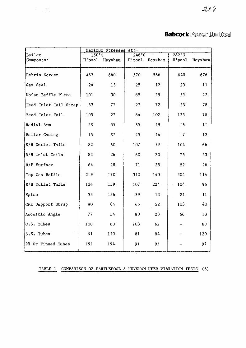
Babcock E
BoilerComponent
Debris Screen
Gas Seal
Noise Baffle Plate
Feed Inlet Tail Strap
Feed Inlet Tail
Radial Arm
Boiler Casing
S/H Outlet Tails
R/H Inlet Tails
R/H Surface
Top Gas Baffle
R/H Outlet Tails
Spine
GFR Support Strap
Acoustic Angle
C.S. Tubes
S.S. Tubes
9% Cr Finned Tubes
Maximum150°C
H'pool
483
24
101
33
105
28
15
82
82
64
219
136
33
90
77
100
61
151
Stresse
Heysham
860
13
30
77
27
55
37
60
26
28
170
159
136
84
54
80
110
194
=s at:-246°C
H'pool
570
25
65
27
84
35
25
107
60
71
312
107
39
65
80
103
81
91
Heysham
566
12
25
72
102
19
14
59
20
25
140
224
13
52
23
62
84
95
282°CH'pool
640
23
59
23
125
16
17
104
75
82
204
104
21
103
66
-
-
-
Heysham
676
11
22
78
78
11
12
66
23
26
114
96
11
40
18
80
120
97
TABLE 1 COMPARISON OF HARTLEPOOL & HEYSHAM UFER VIBRATION TESTS (6)
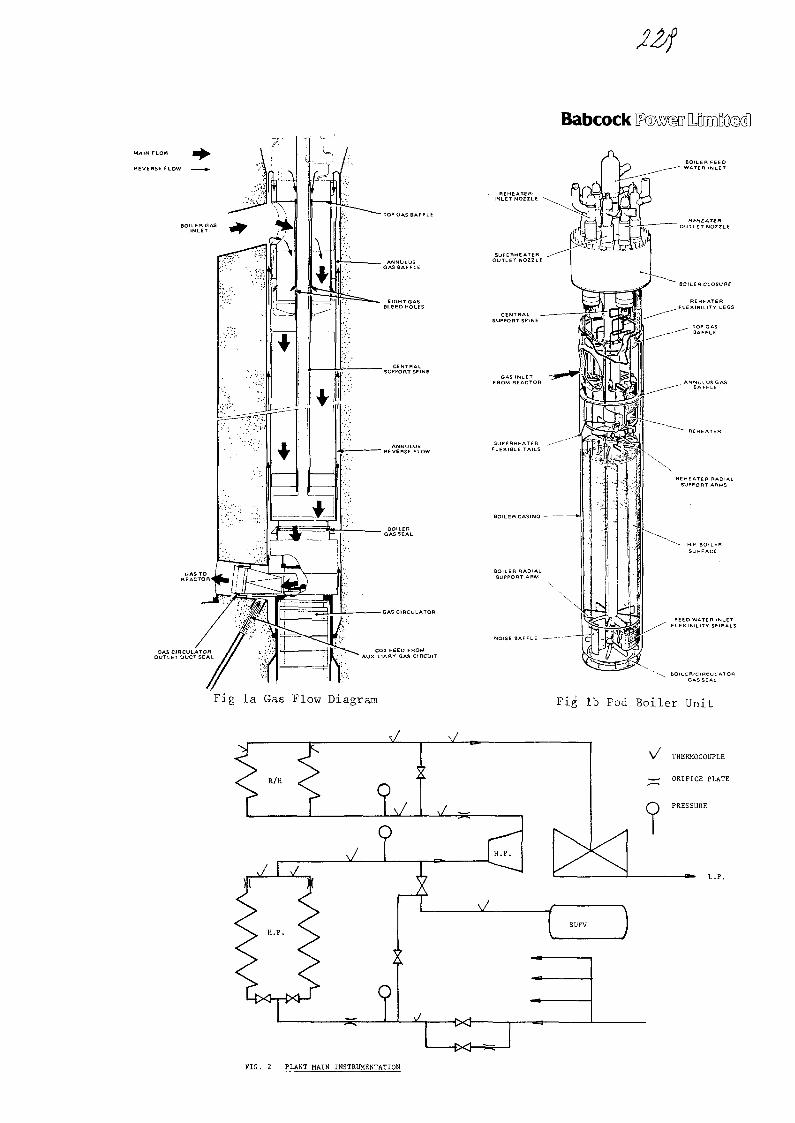
Babcock
M A I N FLOW
REVERSE FLOW
BOILER GAS
- TOP GAS BAFFLE
-GAS CIRCULATOR
NOLSE BAFFLE — —
Fig la Gas Flow Diagram Fig lb Pod Boiler Unit
R/H
J \7
I1
X
x/ —
\ /
-tx}-
V THERMOCOUPLE
• • ORIFICE PLATE
I SUFV I
FIG. 2 PLANT MAIN INSTRUMENTATION

/ SITE DISK /1 (Slow Scan 1\ Data) \
f
PLANT STATES
(Diary)
\
STATISTICS&
DATA CHECKING
\r
DATA EDITING&
REDUCTION
VlANT DATA /
\ PREDICT-/\ION /
\HEADINGS I
\ DATA /
/ PERMANENT
DATA DISK
\
Fig. 4 Data Reduction/Storage (LSI 11/2)
'CEGB[SITE TAPEjV(D4ta)
CONVERSIONTO
ENGINEERINGUNITS
CHECK SIGNALS(Within Range)
SELECTSIGNALS FORPLOTTING
Fig. 3 1st Stage Processing (Error Logger andInitial Plots)

Fig. 5 Initial Plots of the Superheater Outlet Steam TemperatureB and BoilerFeed Flow
BfiBCOCK POWER LTD
n i l
K
a a<vi : • » •
^
./[>
a5"j w"cu
CD
I
-.•.•>
SW
zr
(3 33O 3an±aa3cU3i
O3S/3X) (101J
Fig. 6 Additional Plots of the Reheater Outlet Steam Temperatures beforeand after the Bypass and the Bypass Valve Position
BfiBCOCK POWER LTD
o *-*
COOJ
m00
ISsVD
£
X
uz:
to 33Q) 3aniaa3dw3i
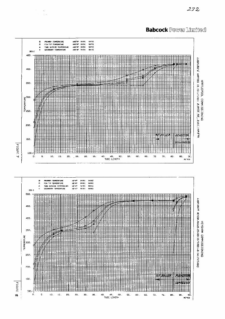
Babcock
• n
ocrm
OEO.C
450. - r
400.
350.
iu300.
a
EUJ _HZSO.
§l s o , F
f
1|E0.
I
J
:
D0A+
4
-
PR
FITU
BE
V
(H
N
BE
cc
T
K
?Y
p
)UT
WR
?
TEh
TEK
5IC
!f 1
t;p
FtIPE
E
D
9
T
m.IMP
R£
RE
ERf
TU
URE
z
HF
HP
HP
HP
m
IR
R l
s
H
H
hi
993
E
F
fi
F
F;
E
H
!H
tH
?H
ftRRR
11]t
E
R3
Rt
»
•
HT
•fT
HT
•fT
=im
R2
mRE
R£
El E 3 M * :
yIS
=- —
-idc
: t i 'i '
Ti• i s
y
i -
S. 10. IS . ZO. . ZS. 30. 35. 40. 45. SO. 5S. 60. 6S. 70. 75. 80 . 85. 9CTUBE LENGTH METRES
X
3omCO
CD
«J
s>
HrTJQO1—
no
SS
I
•z
PRINRRY
FIN TIP TEHPEHflTlflE
TIEE OUTSIDE TEITOWTURE
6ECCND0RY TEMPERRTURE
hCYHP RHTRI RHTR2
HEYHP RHTRI RHTR2
HEYHP RHfRI RHTR2
hCYHP RMrRI RHTR2
5 0 0 . •
450.
§300.
zso.
150.
100.-
0. 5. 10. 15. ZO. ZS. 30. 35. 40. 4S. SO. SS. EO. 65. 70. 75. BO. BS. 90TUBE LENGTH METRES
a;z
1 183
01
UJ
1
m141
3en|
CO
I
_£3ISS I
azzn
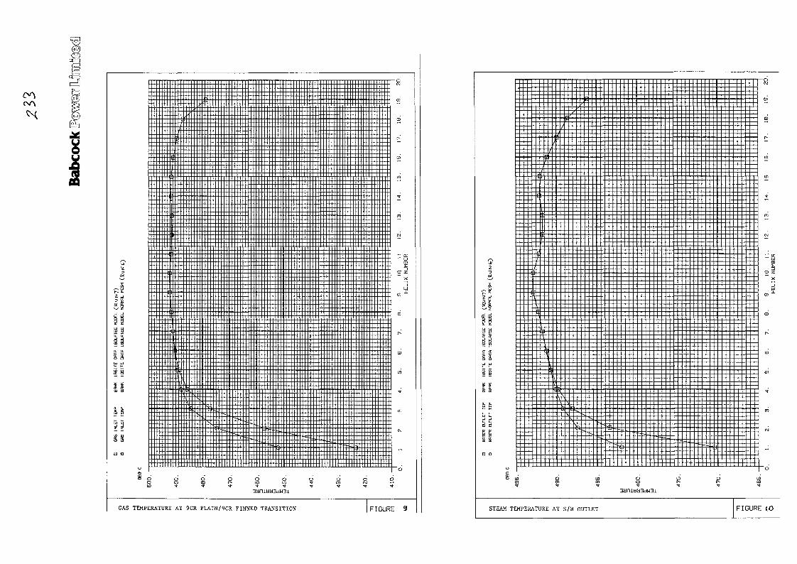
GAS TEMPERATURE AT 9CR PLAIN/9CR FINNED TRANSITION
_ „ _ . _ _ . - - t
_ — .
7
2 _ _ J
s £ : : ; : " ~\~:~ : ; : :ss '
£ £ S § J
gg :::: ::;-:::::
o
S L̂ aCJ) Ui
b ( _ _ - - _ _ _ .
_,;:>. i : = _ , _ _ .
j( j . _ _ _ _ = ^ ^
^ o i/> cD oo t- r-•r n 'ff ^
- - - - FJ
(D
~" a:
.3
X
_ _ en
m
r -
ID
in
„
oL/DI D
STEAM TEMPERATURE AT S/H OUTLET F I G U R E {0

a a
aa
5 5
TUBE OUTSIDE TEMPERATURE AT SS/9CR PLAIN TRANSITION FIGURE 11
•> ?
a ssi &38K t -
s a
5 5§ §
El 0
u
C
-t\ \
\*
\
1i
^
1
\
\4
r
J_< ; ( -/U-
-
J
_ i;
S S S S3 S 3 a n i J 3 d W 3 1 S S S S '
TUBE OUTSIDE TEMPERATURE v\ 9CR FINNED/MS TRANSITIO
CM
0)
0]
r-
ID
Ul
• «
m
— en
10
.NU
T-
X
m
CD
r-
(0
ui
T
m
CvJ
•
ii
FIGURE 12.
No. 13
XA0055822
INTERNATIONAL ATOMIC ENERGY AGENCY
INTERNATIONAL WORKING GROUPON
GAS-COOLED REACTORS
EXPERIENCE WITH THE COMMISSIONING OF HELICALLYCOILED ADVANCED GAS COOLED REACTOR BOILERS
Paper Presented to the Specialist's Meeting onHeat Exchanging Components of Gas Cooled Reactors
Dusseldorf, Federal Republic of Germany16 - 19 April 1984
PRESENTED BY:
D.B. KETTLECEGB — GENERATION DEVELOPMENT AND CONSTRUCTION DIVISION
ABSTRACT
The paper describes aspects of the experience gained duringcommissioning of the helically coiled pod boilers for an advancedgas-cooled reactor. The boiler geometry is shown to be a factorcontributing to gas-side and water-side convection phenomenaencountered during commissioning. Detailed information onthermal performance and vibrational response was obtained fromcommissioning tests on specially instrumented boiler units.

Experience with the Commissioning of Helically Coiled AdvancedGas Cooled Reactor Boilers
Contents
1. Introduction
2. Water-side convection
3. Post-trip syphon
4. Hot gas convection
5. Thermal performance
6. Vibration response
Figures
1. Location of boilers in pressure vessel
2. Boiler steam flow
3. Boiler feed and steam pipework
4. Boiler gas flow

BOILER CLOSURE" (CONCRETE FILLED)
"• B O I L E R L I N E R
- GAS INLET DUCT
FIG. 1 LOCATION OF BOILERS IN PRESSURE VESSEL

Introduction
Hartlepool and Heysham are both twin reactor stations withnominally replicated designs of advanced gas cooled reactors. Thedesign of the concrete pressure vessel differs markedly from theearlier designs for Dungeness and Hinkley Point in that theboilers are located in vertical pods within the wall of thevessel (figure 1).
The most efficient utilisation of the space available within theboiler pods is achieved with a helical boiler geometry. Eachboiler unit incorporates a once-through high pressure boiler anda separate reheater. The boiler unit is suspended within its podfrom the closure head, which seats on a flange in the pod liner.This joint is sealed by 3 concentric O-rings, 2 metallic and onerubber.
The boiler tubing is arranged in 19 concentric, contra-rotatinghelices. The innermost helix has 6 tubes on a helix radius of30cm, and the outermost helix has 24 tubes on a helix radius of120 cm. Inner row tubes are supported at 4 radial positions,while outer row tubes are supported at 8 radial positions.
Three boiler tube materials are used. The reheater and secondarysuperheater tubing is made from Type 316 austenitic stainlesssteel. This material is resistant to corrosion in carbon dioxideat elevated temperatures, but, owing to concern about thepossibility of stress corrosion in wet steam, a minimum superheatmargin is specified. The primary superheater, evaporator andsecondary economiser are made from a ferritic 9% chromium, 1%molybdenum steel. This material is resistant to watersidecorrosion and can be used at temperatures up to about 520°C. Theprimary economiser is made from carbon steel, which is suitablefor operation at temperatures up to about 350°C.
Enhanced heat transfer is obtained by rolled finning of thetubing. The tubing is subsequently heat treated to restore therequired material properties.
There are 8 boiler pod units per reactor and for control purposesthese are connected in pairs on the feed and steam sides. Eachboiler pod unit has one feed header feeding 285 tubes via thefeed tube plate. Tubes are bifurcated at the superheater outlet,and the tailpipes are then routed to the 4 superheater headers.There are, in addition, 2 reheater inlet and 2 reheater outletheaders. A schematic arrangement is shown in figure 2.
Waterside Convection
Before power raising commences on the completed reactor,engineering tests are carried out in which the plant is run atconditions closely matching the proposed operational state.During this period, reactor temperatures are regulated by usingthe gas circulators to input heat, and with boilers operated in aflooded mode to take out heat.
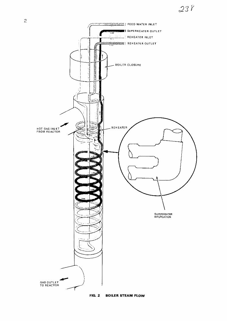
2
HOT GAS INLETFROM REACTOR
1} FEED WATER INLET
II SUPERHEATER OUTLET
REHEATER INLET
:. REHEATER OUTLET
GAS OUTLETTO REACTOR
FIG. 2 BOILER STEAM FLOW

Now, it is a feature of the podded boiler design that both thefeedwater inlet header and the superheater outlet headers arelocated at the top of the boiler unit. During the engineeringtest period, feedwater temperature was typically 100°C andreactor gas temperature 280cC. The density of water decreases byalmost 30% as it heats up over this temperature range. The staticpressure increase down the downcomer is therefore greater thanthe decrease up the riser, and for low flow rates the frictionallosses can be insufficient to maintain a higher pressure in theinlet header than the outlet header. Where circuits are connectedin parallel a potential then exists for flow reversal in somecircuits.
During the engineering tests, thermocouples attached to the feedwater inlet header were observed to increase in temperature onone pod unit per pair, when the feed flow rate was dropped belowa certain level. It was inferred that some slight assymetry inthe operating conditions of the two pod units had led to the feedwater flow going preferentially to one unit, with reverse flowbeing established in the adjacent unit. Figure 3 illustrates thepipework geometry: the secondary steam header is the point atwhich the flow from one pod unit can return in reverse flow intothe adjacent pod unit.
There was some evidence to suggest that recirculation could alsooccur within a boiler pod unit. This can occur via the primarysteam header or between individual tubes connected by abifurcation piece. The evidence for this behaviour came from anobservation that the measured temperature could rise on both ofthe feed headers associated with a pair of pod units.
A series of tests were carried out to establish the minimum flowrate required to avoid recirculation. It was noted during thesetests that a hysteresis effect occurred, with the flowraterequired to suppress recirculation being greater than theflowrate at which it was initiated.
Post-Trip Syphon
On 10 April 1983, power raising had progressed on Reactor 1 atHeysham Power Station to an output of 270 MW(Th). By this timethe boilers had passed through the boil-back phase of start-up,and were passing steam to the dump system. A reactor trip thenoccurred, and all shut-down systems operated satisfactorily.However, some 20 minutes after the trip, although reactortemperatures were dropping in a controlled manner, it was noticedthat the boiler outlet gas temperatures from pairs of boiler podunits were diverging significantly. Differential temperatures ashigh as 100°C were measured between adjacent boiler units.
It was also observed that the feed header temperature was risingon one pod unit in each quadrant.

A*122-5i(PILE CAP LEVEL)
' 2 0 \ B1C/SR/8
FIG. 3 BOILER FEED AND STEAM PIPEWORK

The explanation for these effects is found in the geometry of thesteam pipework (figure 3). The method of boiler operation posttrip is that a feed flow rate of 6-8% MCR is maintained from theemergency boiler feed pumps, with the boilers slowly floodingthrough as reactor circuit temperatures drop. Once the waterlevel reaches the boiler steam outlet header, it falls throughthe steam pipework to the primary header, and thence to thesecondary header, where it combines with flow from the adjacentboiler pod unit. The secondary header is approximately 16 metresbelow the level of the superheater outlet headers.
Once one boiler unit has flooded over, the syphon effect fromthe column of hot water in the outlet pipework pulls feedwaterpreferentialy into the unit, starving the adjacent unit. In fact,reverse flow can be induced in the adjacent unit, with waterbeing sucked backwards through the feed header.
Analysis of the post-trip transient showed that increasing thepressure loss across the pod feed trim valves could prevent thesyphon occurring. Post-trip operation was therefore modified toprovide closure of these valves to a pre-set mechanical stop.Subsequent experience has shown this modification to beeffective.
It was also apparent that the static head of the syphon could besubstantially reduced by providing a pipework cross-connectionbetween the boiler primary headers. Consideration is being givento this as an alternative solution to the syphon problem.
Hot Gas Convection
The advanced gas-cooled reactors are designed for continuedoperation with one shut-down quadrant. When operating in thiscondition, relatively high temperatures have been measured on thefeed headers of the shut-down boiler units. A shut-down boilerunit can be either wet stored or dry stored. Feed headertemperatures were higher for a wet stored boiler unit.
The pressure differential across the reactor core ensuresthat there is a flow of gas at reactor inlet temperature upthrough a shut-down boiler unit. However, commissioningexperience has shown that there is still some ingress of hot gasthrough the boiler gas inlet duct, which circulates into the deadspace below the boiler closure and across the top gas seal(figure 4). This gas heats the boiler support spine, which inturn heats the boiler inlet feed tubing by a mixture of radiationand natural convection. The fluid within the tubing thencirculates into the feed header, producing the high temperaturesmeasured on the plant.
The temperature cycle to which the feed header is subjected whenthe boiler is reconnected is therefore more severe thanoriginally anticipated, but can be accommodated by margins in thedesign.

MAIN FLOW
REVERSE FLOW
BOILER GASINLET
GAS CIRCULATOROUTLET DUCT SEAL
GAS TO WREACTOR I Q V
TOP GAS BAFFLE
ANNULUSGAS BAFFLE
EIGHT GASBLEED HOLES
CENTRALSUPPORT SPINE
ANNULUSREVERSE FLOW
BOILER GAS SEAL
GAS CIRCULATOR
CO2 FEED FROMAUXILIARY GAS CIRCUIT
FIG. 4 BOILER GAS FLOW
J1Y3
Thermal Performance
Prior to Hartlepool and Heysham, advanced gas cooled reactorboilers had been of a rectangular section design, built up from anumber of identical tube platens. The helical boiler design,however, comprises tubes formed to coiled radii varying between30 cm and 120cm. A number of radially asymmetric features wereidentified which could affect the thermal performance of a coiledboiler unit.
The most important of these arises because the reheater tube bankhas a smaller diameter than the high pressure boiler bank. Gasflowing through the reheater and its surrounding annulus, emergeswith a radial temperature and velocity profile which influencesthe performance of the boiler unit situated below the reheater.
Other less important factors taken into consideration are theheat losses to the boiler support spine and casing, and theeffect of coil radius on water-side frictional pressure losses.
Variations in the heat duty for different coils are accommodatedby adjusting the feedwater flow to individual tubes by theselection of different inlet orifices, fitted at the feed inlettubeplate. To confirm that the sizing of the orifices achieves anacceptable boiler thermal performance, two boiler units wereextensively instrumented with thermocouples measuring gas andmetal temperatures.
To date operating data has only been obtained at relatively lowpower levels. Tube metal temperatures at the transition between9% chromium ferritic tubing and type 316 austenitic tubing werelower for small diameter coils adjacent to the central supportspine. This is believed to be attributable to greater heat lossesto the spine resulting from lower feedwater temperatures at lowloads, and there is evidence to show that more uniformtemperature distributions are achieved as power is increased.Extrapolation to higher power levels will be carried out usingthe two-dimensional performance programme described by Mr. Lis.
Vibration Response
Experimental work on a straight tube cross-inclined tube bankrepresenting the Hartlepool and Heysham boiler geometry showed asusceptibility to flow induced vibration. This result promptedmore detailed experimental work on a fully representative coiledtube bank, and led to the fitting of instrumentation to monitorvibration levels on an operating boiler unit.
Accelerometers capable of operating at full reactor temperaturein a high pressure carbon dioxide atmosphere were fittedextensively on boiler tubes and support straps. In addition, anumber of microphones and displacement transducers were fitted atselected locations.

8
Before power raising commenced, tests were carried out atoperating gas densities and velocities. Measured vibration levelswere low and no restriction on power raising was identified.
Monitoring of the vibration instrumentation has continued aspower has been increased, and the low level of response observedduring the engineering runs has been confirmed. The monitoringexercise will continue until full output is achieved in order toestablish whether temperature levels affect the structuralresponse of the boilers. Meanwhile a comprehensive exercise isbeing undertaken to fully analyse the results being obtained.

No. 14
XA0055823
Technology Planning and Research Division
Central Electricity Research Laboratories
INVESTIGATIONS OF THE GAS-SIDE HEATTRANSFER AND FLOW CHARACTERISTICSOF STEAM GENERATORS IN AGR STATIONS
by J. Lis
April 1984

Sfi
INVESTIGATIONS OF THE GAS-SIDE HEAT TRANSFER AND FLOW
CHARACTERISTICS OF STEAM GENERATORS IN AGR STATIONS
J . L i s
Central Electricity Research Laboratories, Leatherhead, Surrey, England
ABSTRACT
This paper describes the experimental and analyticalinvestigations of the gas-side heat transfer and flow characteristics ofsteam generators in the AGR stations carried out by CERL. The majorityof the experimental work on heat transfer and flow characteristics ofclose-packed tube arrangements in cross-flow of gases is carried out in apressurised heat exchanger rig. The rig is operated on-line by adedicated PDP 11/40 computer over the range of Reynolds number lO4 to3 x 10 . Atmospheric wind tunnels employing either small or large scalemodels of the specific sections of steam generators are used for avariety of supplementary and development studies. Various measurementstechniques and, in particular, LDA and hot wire anemometry employed inthese studies are described. The more important aspects of variousinvestigations are illustrated by typical results.
In order to ensure the efficient operation and integrity ofsteam generators under asymmetric boundary conditions a MIX suite of 2-dimensional codes has been developed. The codes calculate the gas andwater/steam flow and temperature distributions in each channel of thesteam generator taking into account thermal mixing in the gas as itpasses through the generator. Application of the MIX codes to thesolution of various operational problems is illustrated by typicalexamples and the continuing exercise of validating the codes againstplant operational data is discussed.

1. INTRODUCTION
The thermal performance of steam generators in gas cooledreactor stations depends primarily on the gas-side heat transfer and flowcharacteristics of the generator tubing. There was very littleinformation available in the literature on these characteristics at thestart of the nuclear power programme in the UK. In particular, therewere no data on the heat transfer and pressure losses in close-pitchedarrangements of finned tubes in cross-flow of gases and almost completelack of understanding of the physical processes in such arrangements.Recognising the importance of accurate information in this field to theefficient and safe operation of the Magnox stations, the CEGB initiated aprogramme of investigations and set up appropriate test facilities atCERL in 1958. The broad objective of these investigations was to developanalytical methods and provide experimental data on heat transfer andflow characteristics of tube arrangements in cross-flow of gases asrequired for the assessment of the design, operational performance andcontrol of steam generators in the gas cooled reactor stations.
The commissioning and operation of once-through steamgenerators in AGR stations has brought to light a variety of new thermalproblems specific to generator tube geometry in each station. In orderto provide rapid and effective solutions to these problems, additionaltest facilities have been set up and appropriate experimental andanalytical studies carried out.
The paper describes the major test facilities employed at CERLfor the investigation of gas-side heat transfer and flow characteristicsof steam generators in the AGR stations. Examples of some more importantexperimental studies are given and illustrated by typical results. Thedevelopment of a MIX suite of multitube steam generator models is brieflydescribed and the application of these models to the solution of thedesign and operational problems discussed.
2. TEST FACILITIES
2.1 Pressurised Gas Heat Exchanger Rig
The first heat exchanger rig at CERL (Davies and Lis, 1960) wasdesigned to cover the range of gas-side Reynolds numbers in steamgenerators of Magnox stations. This range was not wide enough to coverthe envisaged operational requirements of the AGR stations and a new,larger and far more flexible test facility was commissioned in 1965.With some modifications and improvements incorporating the recentadvances in control and measuring techniques, this basic test facilityhas been used almost continuously over the past nineteen years for avariety of investigations.
A general view and a schematic diagram of the pressurised gasheat exchanger rig are shown in Fig. 1 and 2, respectively. Essentially,the rig consists of a closed loop circular duct incorporating acentrifugal fan, electrical heater bank, test section and the necessarycontrol and measuring instrumentation.
The gas is circulated by the fan designed to deliver 2.35 m3/sof C02 at 7 bar and 80°C against a static head of 250 mbar. The fan isdriven by a 165 kW dc motor with a thyristor controlled stepless

regulation of speed from 30 to 1500 rpm. Gas mass flow rate is measuredby a Dall tube with a 1:1.755 throat ratio situated in a 17.25 in boreduct about 25 diameters downstream of the blower. After passing througha supplementary cooler and a 180° elbow incorporating an expansionbellow, the gas flows through a 1:4.5 area ratio diffuser into a 550 kWelectric heater where its temperature is raised up to 150°C. The gastemperature at the heater outlet is controlled by a thyristor unit inconjunction with a set of sensing thermocouples placed at the inlet tothe test section. The transition from the heater bank to the testsection is through a 1:1.6 area ratio diffuser and a 7:1 area ratiocontraction. Each diffuser contains a number of gauzes of appropriatemesh. The pressure vessel containing the test section and its upstreamand downstream instrumented ducts consists of three cylinders. Access tothe test section is obtained by sliding the large diameter cylinder inthe centre (see Fig. 1) over the smaller diameter cylinder on the righthand side.
2.1.1 Test section
The test section (see Fig. la) was designed to allow a quickand easy assembly of test baskets from a standard length of tubing. Itconsists essentially of a frame 460 mm wide and 530 mm high * 1300 mmlong, incorporating two detachable plates with holes drilled to therequired tube pitching configuration. The tubes are usually arrangedvertically between these plates and are connected on the outside by 180°bends to form two or more passes for the cooling water. The same methodof construction is used for assembling cross-inclined test baskets inwhich straight tubes are employed to simulate the configurations ofcounter-rotating helical coils. The two side walls of the frameincorporate thermocouple and hot wire anemometer traversing assemblies.The positioning of these walls and hence the width of the test basketdepends on the transverse pitch of the tubing under investigation and issuitably adjusted to preserve the symmetry of tube arrangement. In thecase of staggered arrangements, this symmetry is also ensured by fittingdummy half tubes to the side walls.
The general arrangement of the rig is sufficiently flexible toincorporate, if required, other types of test section. Thus, forexample, by fitting a suitable transition piece to the inlet and outletinner ducts it was possible to carry out a series of tests on variousarrangements of helical coil heat exchangers with the maximum diameter of1 m.
2.1.2 Cooling Water Circuit
A diagramatic arrangement of the cooling water circuit is shownin Fig. 3. The circuit comprises:
(i) a closed loop, filled with de-ionised water, which cools thetest section, and
(ii) a secondary, raw water loop which provides the heat sink andtemperature control for the primary water loop.
The two loops are interconnected through two shell and tube heatexchangers arranged in series.
- 3 -
The water in the primary loop is circulated by a centrifugalpump delivering up to 4 kg/s at 27.5 bar and driven by a thyristorcontrolled motor. The flow rate is adjusted to the required value by acontrol valve situated immediately downstream of the pump and the waterthen flows through the shell and tube heat exchangers, the meteringsection incorporating an orifice, the test bank, an automatic weigh tankor the by-pass sleeve and then through a de-aerator and back to thepump.
The water flow orifice is regularly calibrated using theautomatic weigh tank and the orifice constant is updated if it hasaltered by ±1% from the value originally determined during commissioning.The weigh tank load cell is separately calibrated by temporarily applyinga pivoted beam with a known effective mass to the weigh tank suspensionlinkage.
2.1.3 Control and Instrumentation
The rig is operated on line by a dedicated PDP 11/40 computer.The rig is connected to the computer via a high level (±10 mV) analogueinput/output multiplexer and by a multichannel digital input outputsystem. All measurements on the rig such as temperatures, absolute anddifferential pressures, flow rates, etc. are converted into 'mV levelsignals by means of suitable transducers. The outputs from thesetransducers are converted into the ±10 mV range for input to the computerby amplifiers which are calibrated on-line for 'zero' and 'gain'. Thesystem also incorporates suitable facilities for on-line calibration ofall transducers.
Control signals for switching on pumps or providing pulses forcontrolling stepper motors are generated using the digital output systemand position information of the on/off variety from the digital inputsystem such as a valve fully open or traverser at limit of travel.Proportional control signals required for various thyristors are obtainedusing the analogue output system.
The continuous data processing, available from the computer,allows comprehensive instrumentation checks and measurement verificationto be carried out prior to and during an experimental run. During thetest sequence, instrument calibrations are carried out at each gaspressure change. Any discrepancy promotes a second calibration check andif this is still unsuccessful the rig is automatically closed down. Forheat transfer and pressure loss tests five complete sets of measurementsare taken at each programmed value of gas-side Reynolds number. Ifconditions are found to be unsteady during the measuring period or theenergy balance is outside the specified range of 0.97 < Iw^g ^ 1.03the analysis of data is suspended and the calibration routine re-introduced. The five sets of measurements are then repeated and, unlessthey are found to be acceptable, the rig is shut down.
All rig circuits are arranged on a 'fail safe1 principle withthe loss of any supply closing the rig down. In addition, a continuoustrain of pulses is generated as a part of the computer program andapplied as a series of signals to an output channel. The suspension ofthese signals for more than 1 s, indicating a computer failure,immediately closes down the rig.
- 4 -
The entire software package for the control of rig operationsand analysis of test results is written in Coral 66.
All temperature measurements on the rig are made with insulatedjunction, sheathed, mineral insulated nickel-chromium/constantanthermocouples. To ensure consistency, the thermocouples were made fromcable produced from the same batch of starting material. Calibrations ofthe representative sample of thermocouples showed deviations less than±0.1K at the maximum operational temperature of 150°C. All thethermocouples are taken to a thermally insulated ambient temperaturereference enclosure, the temperature of which is separately determinedwith thermocouples referred to a melting ice cold junction. Straingauged, diaphragm type pressure transducers are fitted to measure gasstatic pressure in the rig and the differential pressures across the Dalltube, the test section, the gas circulator and the water flow orifices.
2.2 Atmospheric Wind Tunnels
A general arrangement of two atmospheric wind tunnels employedin the investigations of gas-side heat transfer and flow characteristicsof steam generators in the AGR stations is shown in Fig. 4. Both tunnelscan accommodate test baskets from the pressurised heat exchanger for acomplementary or exploratory study of some specific feature of a giventube arrangement. The main application of these tunnels is, however, tothe investigations of gas flow distribution in the scaled up or downmodels of various sections of steam generators using LDA and hot wireanemometry measuring techniques.
2.3 High Temperature Rig
The rig was designed to assist the investigations of specificgas-side problems in steam generators of High Temperature Reactors and toextend the operational range of test facilities for general purposestudies. The maximum values of the more important operating parametersof the rig are as follows:
(i) gas pressure, temperature and flow rate - 15 bar, 500°C,1.4 kg/s of He
(ii) cooling water pressure, temperature and flow rate - 105 bar,280°C, 1.5 kg/s
Similarly to the already described pressurised gas heat exchanger testfacility, this rig consists of a closed loop circular duct incorporatinga Rateau gas blower (ex Dragon project), a 500 kW electrical heater, a 30mm wide x 30 mm high x 60 mm long test section, a helical coil gas towater heat exchanger and the necessary control and measuringinstrumentation. The plain or finned tubes of the test section arearranged in cross-flow to gas and are cooled by the high pressure watercirculating inside them. The rig is operated on-line by a dedicatedcomputer on the same general principles of control and data acquisitionas those used for the pressurised heat exchanger rig.

- 5 -
2.4 Miscellaneous Rigs
From time to time a specific problem arises which cannot beresolved satisfactorily by investigations in the available testfacilities or there is a need to supplement the already obtainedinformation by additional data. In such cases, special purpose test rigsranging in size from bench top facilities to large loops are quicklyconstructed and after providing the required data, dismantled. Over thepast twenty five years many test facilities of this kind have been usedat CERL and only few examples can be given here to illustrate the varietyand range of applications.
One of the first of such rigs was a water loop designed tomeasure heat transfer to water flowing inside short sections of tubeconnected by 180° bends, (Lis and Thelwell, 1963). Accurate data on heattransfer in such arrangements were not available at that time and theinformation was urgently required for the analysis of test results fromthe pressurised heat exchanger rig. The correlation derived from thisinvestigation is still employed by CERL and other organisations workingin this field in the UK.
One of the requirements of the early design studies of the AGRstations was to assess the effects of gas-side oxidation on theperformance of steam generators. A survey of the literature indicatedthat published data on the thermal conductivity of iron oxides differedby almost two orders of magnitude and there were no data on thin oxidelayers in the 'as-formed' conditions. A special apparatus was,therefore, developed and used to measure the thermal conductivity of ironoxide layers 0.025 mm to 0.48 mm thick which formed on low alloy steelsin CO-CO2 gas containing up to 1200 vpm of water at pressures up to 20bar and temperatures up to 600°C (Lis and Kellard, 1968). It was foundthat the thermal conductivity decreased with oxide porosity and themeasured values were effectively correlated as a function of porosity(see Fig. 5).
Prior to the construction of the high temperature rig apreliminary investigation was carried out to assess the effect of varyinggas physical properties on convective heat transfer to a bank of tubes incross-flow (Preece, Lis and Hitchcock, 1975). The general arrangement ofthe gas circuit in a rig specially adapted for this purpose is shown inFig. 6. Both the required mean bulk temperature of the air and the flowrate at the test section were achieved by mixing cool air supplied from ablower with combustion products from a gas-oil-fired combustion chamber.The air bulk to tube wall temperature differences could be varied between100°C and 400°C with the tube wall remaining constant at about 40°C or120°C. It was found that the variation in physical properties could beaccommodated by evaluating all properties in the dimensionless groups ofthe conventional type of correlation at the air bulk temperature.
More recently, a test facility has been constructed and isstill being employed for determining the steady state and transientcharacteristics of various thermocouple assemblies installed in the AGRsteam generators. Precise knowledge of these characteristics isespecially important in the case of CS/9Cr 1 Mo and 9Cr lMo/316 SStransition thermocouples which form a part of the plant protection system

- 6 -
and are also used for control of steam generator operations. A schematicdiagram of the thermocouple response rig is shown in Fig. 7. Thethermocouple assembly under test is mounted in a duct fitted with abellmouth intake through which atmospheric air is drawn. Water isinitially circulated round a by-pass loop containing a heater and whenthe required constant temperature is obtained the flow is diverted by athree-way valve to the test section to provide a step change intemperature. All test section and rig instrumentation is continuouslymonitored until a new steady state has been achieved. The water is thendiverted back to the by-pass loop and air and water flow rates adjustedfor the next test. The rig is controlled on-line to a PDP 11/40 computerand rig operation is entirely automatic.
A new test facility is now being designed to measure the heattransfer and flow characteristics of close-pitched arrangements of tubingin cross-flow under the combined forced/natural convection gas flowconditions. With the increased emphasis on all aspects of safety in theAGR plant operations, accurate information on these characteristics isrequired for the assessment of the decay heat removal duties andtemperature distribution in steam generators under various post-tripconditions. The rig will consist essentially of a vertical closed loopduct about 10 m high, one side of which, incorporating a 125 kWelectrical heater and a gas flow venturi, will constitute the hot leg andthe other side, housing the standard CERL test basket section with theautomatic traversing devices in side walls, the cold leg for the naturalconvection. A centrifugal fan driven by a variable speed motor will beplaced in the bottom return leg of the loop to provide the requiredforced circulation. Full simulation of the steam generator dynamicconditions will be obtained by using SFg gas at 1.4 bar pressure.
2.5 Temperature Calibration Facilities
Comprehensive facilities for calibrating temperature measuringdevices against the accepted references standards form an essential partof support services in the CERL programme of work on steam generators.The most important components of these facilities are: water bath fortemperatures up to 85°C, silicone fluid bath, 80°C to 225°C and nitratebath, 180°C to 625°C. The silicon fluid and nitrate baths are based onthe NPL models (Grace and Hall, 1943) which have been modified byreducing the thermal capacity, fitting directly immersed heaters andusing proportional temperature controllers. The temperature stabilityand uniformity obtained is ±0.02K for the silicon bath and ±0.03K for thenitrate bath.
3. EXPERIMENTAL INVESTIGATIONS
3.1 Heat Transfer and Pressure Loss Characteristics of Close-pitched Tube Arrangements in Cross-flow
The main objective of these investigations is to provideaccurate data required for the assessment of design, control andoperational performance of steam generators in the Magnox and AGRstations. The arrangements of tubing in each steam generator are firsttested at the tender design stage to assess the validity of the designsubmissions and, subsequently, the tests are repeated, as required, todetermine the implications of any design modifications and the effects ofmanufacturing and assembly tolerances.

- 7 -
The measurements of the gas-side heat transfer and pressureloss in a given arrangement of tubing are analyzed using generallyaccepted procedures. The overall heat transfer coefficient, u^, isevaluated from the installed heating surface area and the measured valuesof heat gained by water, qw, and the logarithmic mean of terminaltemperature differences between gas and water, 9m. The mean gas-sideheat transfer coefficient, hg, is then derived from the usualrelationship for thermal resistances of gas, tube wall and water inseries. In calculation of the water-side thermal resistance, anallowance is made for the effects of bends, thermal boundary layerdevelopment and radial temperature distribution by a general correlationproposed by Lis and Thelwell (1963). In the case of finned tubes, themeasured coefficient, ho, is converted into the gas-film heat transfercoefficient, hf, using the fin efficiency proposed by Gardner (1945)with the fin height modified by the addition of a half fin thickness.
The heat transfer results are correlated in the form,
j = Nu Pr~1/3 = a Rem
and log j = A (log Re) (log Re) + B log Re + C
The measurements of pressure loss across the test bank arecarried out under conditions of zero heat flux and correlated in theform,
f = b Ren
and log f = D (log Re) (log Re) + E log Re + F
where f is the pressure loss coefficient defined as the number ofvelocity heads lost per one row of tubing.
For both the heat transfer and pressure loss data, all physicalproperties in the dimensionless parameters are evaluated at the mean gasbulk temperature. For each set of test results, the regression line andthe 95% confidence limits are evaluated by statistical analysis. Typicalexperimental data obtained in the pressurised heat exchanger rig areshown in Fig. 8. It will be seen that the plot of j against Re in thelog-log coordinates has a definite curvature and the best correlation ofdata is obtained by using a second degree polynomial curve. There isalso a characteristic change in the slope of f against Re plot at Re -1.2 x 10⁵ indicating a transition to a flow regime where the pressureloss coefficient becomes independent of the Reynolds number. For themajority of the tube configurations tested so far at CERL, the curvatureof the heat transfer data plots is usually negligible over the range ofReynolds numbers covered and the traditional straight line correlation isperfectly adequate. The characteristic change in the slope of thepressure loss characteristics has been observed to occur for allarrangements of finned tubes at about 8 x 10^ < Re < 1.2 x 10⁵, exceptfor the cross-inclined configurations where the transition in flow regimetakes place at appreciably lower Reynolds numbers.

The reproducibility of results obtained in this type of testson the pressurised heat exchanger rig is illustrated in Fig. 9. The datawere derived over a period of about nine months using the sameconfiguration of plain tubes in three separate series of tests employingair, carbon dioxide and helium.
3.2 Gas Flow Distribution
One of the problems encountered occasionally in the large steamgenerator units employing curved tube arrangements is the maldistributionof gas flow caused by the asymmetries of tube pitching at the casingwalls. With the casing/edge tube gaps larger than those required topreserve the symmetry of tube arrangement there could be a considerableamount of gas by-passing the steam generator, whereas smaller gaps willcause a starvation of gas flow at the edge tubes. In order to providethe information required for the operational control of steam generatorswith such asymmetries (see Section 4) a comprehensive investigation ofthis problem is being carried out at CERL. The measurements of gas flowdistribution are most conveniently carried out on scale-down models ofvarious sections of steam generator. This allows the correctrepresentation of the steam generator aspect ratio and depth within theframe of the standard CERL test section. Banks of full scale finned,tubes representing a relevant part of the steam generator section, arealso used to provide supplementary information.
The measurements of velocity distribution are carried out usinglaser Doppler and hot wire anemometers. For the preliminary measurements(Fallows and Massey, 1982a) a 5 mW He-Ne laser provided the source forthe forward scatter operation of one component counter based DISA system.More recently, the LDA facility has been extended by the addition of a 2WAr laser and a back scatter module. For measurements of velocitiesbetween the narrowly spaced tubes and within the casing/edge tube gaps,the recently developed DISA triple split fibre probes were found to bemost useful. The experience gained so far have shown these probes to bemore rebust and less sensitive to contamination than the classical wireprobes. Trials are now being carried out on the suitability of theseprobes for measurements in the pressurised heat exchanger rig.
The more important characteristics of the by-pass flows werefound to be generally as expected. At the inlet, the velocity profile isdistorted by the movement of gas towards the gap. The velocity withinthe gap increases gradually by the inflow of gas from the body of thebank until an asymptotic value is attained at a bank depth which isfunction of the gap width. Downstream of the bank there is usually anextensive recirculation region of the gas emerging from the gap. It isevident that in order to describe the distribution of gas flow in thiscomplex situation it is necessary to define the magnitude of thetransverse flow component and the development of flow within the gap.The evaluation of the transverse flow is especially important, since,apart from affecting the overall flow distribution, it provides also aconvective component of the overall gas thermal mixing. The magnitude ofthe transverse flow will depend on the transverse pressure gradientsgenerated by the differences in gas velocities and densities across thebank and on the transverse flow resistance factor of a given tube
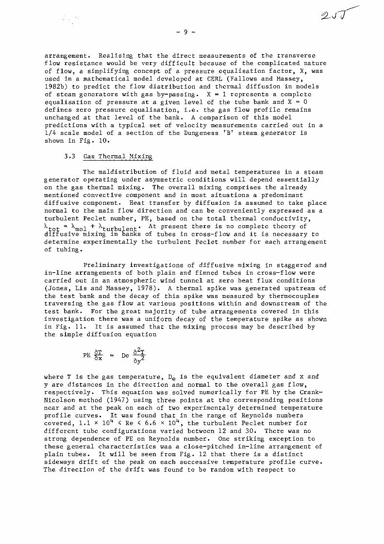
- 9 -
arrangement. Realising that the direct measurements of the transverseflow resistance would be very difficult because of the complicated natureof flow, a simplifying concept of a pressure equalisation factor, X, wasused in a mathematical model developed at CERL (Fallows and Massey,1982b) to predict the flow distribution and thermal diffusion in modelsof steam generators with gas by-passing. X = 1 represents a completeequalisation of pressure at a given level of the tube bank and X = 0defines zero pressure equalisation, i.e. the gas flow profile remainsunchanged at that level of the bank. A comparison of this modelpredictions with a typical set of velocity measurements carried out in a1/4 scale model of a section of the Dungeness TBr steam generator isshown in Fig. 10.
3.3 Gas Thermal Mixing
The maldistribution of fluid and metal temperatures in a steamgenerator operating under asymmetric conditions will depend essentiallyon the gas thermal mixing. The overall mixing comprises the alreadymentioned convective component and in most situations a predominantdiffusive component. Heat transfer by diffusion is assumed to take placenormal to the main flow direction and can be conveniently expressed as aturbulent Peclet number, PE, based on the total thermal conductivity,Xtot = \nol + ^turbulent' A t P r e s e n t there is no complete theory ofdiffusive mixing in banks of tubes in cross-flow and it is necessary todetermine experimentally the turbulent Peclet number for each arrangementof tubing.
Preliminary investigations of diffusive mixing in staggered andin-line arrangements of both plain and finned tubes in cross-flow werecarried out in an atmospheric wind tunnel at zero heat flux conditions(Jones, Lis and Massey, 1978). A thermal spike was generated upstream ofthe test bank and the decay of this spike was measured by thermocouplestraversing the gas flow at various positions within and downstream of thetest bank. For the great majority of tube arrangements covered in thisinvestigation there was a uniform decay of the temperature spike as shownin Fig. 11. It is assumed that the mixing process may be described bythe simple diffusion equation
where T is the gas temperature, De is the equivalent diameter and x andy are distances in the direction and normal to the overall gas flow,respectively. This equation was solved numerically for PE by the Crank-Nicolson method (1947) using three points at the corresponding positionsnear and at the peak on each of two experimentaly determined temperatureprofile curves. It was found that in the range of Reynolds numberscovered, 1.1 x lO*4 < Re < 6.6 x 10^, the turbulent Peclet number fordifferent tube configurations varied between 12 and 30. There was nostrong dependence of PE on Reynolds number. One striking exception tothese general characteristics was a close-pitched in-line arrangement ofplain tubes. It will be seen from Fig. 12 that there is a distinctsideways drift of the peak on each successive temperature profile curve.The direction of the drift was found to be random with respect to
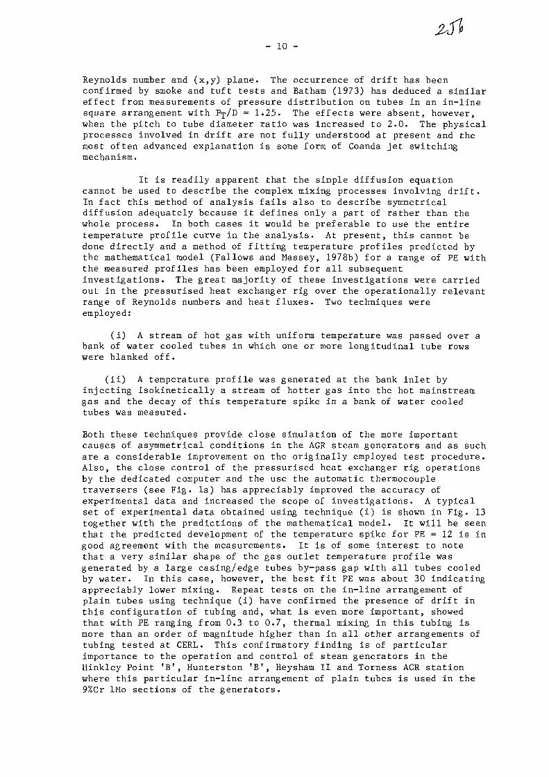
- 10 -
Reynolds number and (x,y) plane. The occurrence of drift has beenconfirmed by smoke and tuft tests and Batham (1973) has deduced a similareffect from measurements of pressure distribution on tubes in an in-linesquare arrangement with P^/D = 1.25. The effects were absent, however,when the pitch to tube diameter ratio was increased to 2.0. The physicalprocesses involved in drift are not fully understood at present and themost often advanced explanation is some form of Coanda jet switchingmechanism.
It is readily apparent that the simple diffusion equationcannot be used to describe the complex mixing processes involving drift.In fact this method of analysis fails also to describe symmetricaldiffusion adequately because it defines only a part of rather than thewhole process. In both cases it would be preferable to use the entiretemperature profile curve in the analysis. At present, this cannot bedone directly and a method of fitting temperature profiles predicted bythe mathematical model (Fallows and Massey, 1978b) for a range of PE withthe measured profiles has been employed for all subsequentinvestigations. The great majority of these investigations were carriedout in the pressurised heat exchanger rig over the operationally relevantrange of Reynolds numbers and heat fluxes. Two techniques wereemployed:
(i) A stream of hot gas with uniform temperature was passed over abank of water cooled tubes in which one or more longitudinal tube rowswere blanked off.
(ii) A temperature profile was generated at the bank inlet byinjecting isokinetically a stream of hotter gas into the hot mainstreamgas and the decay of this temperature spike in a bank of water cooledtubes was measured.
Both these techniques provide close simulation of the more importantcauses of asymmetrical conditions in the AGR steam generators and as suchare a considerable improvement on the originally employed test procedure.Also, the close control of the pressurised heat exchanger rig operationsby the dedicated computer and the use the automatic thermocoupletraversers (see Fig. la) has appreciably improved the accuracy ofexperimental data and increased the scope of investigations. A typicalset of experimental data obtained using technique (i) is shown in Fig. 13together with the predictions of the mathematical model. It will be seenthat the predicted development of the temperature spike for PE = 12 is ingood agreement with the measurements. It is of some interest to notethat a very similar shape of the gas outlet temperature profile wasgenerated by a large casing/edge tubes by-pass gap with all tubes cooledby water. In this case, however, the best fit PE was about 30 indicatingappreciably lower mixing. Repeat tests on the in-line arrangement ofplain tubes using technique (i) have confirmed the presence of drift inthis configuration of tubing and, what is even more Important, showedthat with PE ranging from 0.3 to 0.7, thermal mixing in this tubing ismore than an order of magnitude higher than in all other arrangements oftubing tested at CERL. This confirmatory finding is of particularimportance to the operation and control of steam generators in theHinkley Point 'Br, Hunterston 'B1, Heysham II and Torness AGR stationwhere this particular In-line arrangement of plain tubes is used in the9%Cr IMo sections of the generators.

- 11 -
The improved experimental and analytical techniques haverevealed many new interesting features and, in some cases, veryconsiderable complexity of gas thermal mixing processes in banks of tubesin cross-flow. In an attempt to throw some light on these processes,comprehensive investigations combining detailed measurements of gas flowand temperature fields are being carried out.
3.4 Other Experimental Investigations
The scope of this paper does not allow even brief descriptionof all the major investigations carried out by CERL on the gas-side heattransfer and flow characteristics of steam generators in the AGR andMagnox stations. Some typical examples of these investigations are givenin Section 2.4 in conjunction with the description of miscellaneous testfacilities and few more will be described briefly here to illustrate thewide range of our studies.
A series of comprehensive studies have been undertaken at anearly stage of our programme of work to obtain a better understanding ofthe heat transfer and flow processes within banks of finned tubes incross-flow. In one series of such investigations (Neal and Hitchcock,1966), a four times scale model bank of annular finned tubes in staggeredarrangement was used. The test section was situated inside a Perspexduct of an atmospheric wind tunnel and comprised nine transverse rows offinned tubes. One of these tubes, which could be positioned in any row,had an internal radiant heater and was comprehensively instrumented withthermocouples and miniature disc heat-flux meters. A constanttemperature 0.005 mm dia. hot wire anemometer was used for measurementsof velocity, turbulence and boundary layer development. Thesemeasurements were supplemented by flow visualisation studies using smokeand fine silk tufts. The investigations yielded most valuableinformation on the overall and local heat transfer processes and revealedseveral adverse characteristics of this type of extended surface.
The next logical step in this study was to apply the obtainedinformation to the development of improved heat transfer surfaces fortubes in cross-flow (Neal and Hitchcock, 1970). Preliminaryinvestigations indicated that a rib roughened surface offered the mostpromising solution and a series of tests on the large scale model werecarried out to determine the optimum rib size and pitch. Thepitch/height ratio finally selected was 7.54:1 and tests in thepressurised rig on a set of 38 mm dia. tubes with integrally machinedribs showed a 41% increase in heat transfer at Re = 1.4 x 10⁵ over thecorresponding arrangement of plain tubes. The main reason for thisincrease is the markedly improved heat transfer over the front half ofthe tube (see Fig. 14). Further investigations in this field have led tothe development of tubes with two or more start helically wound ribs. Itis worth noting that this roughened surface should be generally lesssusceptible to the flow induced vibration problems because it cannotsustain any regular shedding of vortices.
4. MIX SUITE OF 2-DIMENSI0NAL STEAM GENERATOR CODES
The MIX suite of codes has been developed to predict the steadystate performance of Magnox and AGR steam generators operating underasymmetric conditions. The codes calculate the distribution of gas,

- 12 -
water/steam and tube wall temperatures along each tube of the steamgenerator for a number of different boundary conditions. The diversityof the various designs of gas heated steam generators in nuclear stationsmade it impractical to perform multi tube calculations for all stationswith a single code. Consequently, codes have been developed forindividual stations or groups of similar stations employing a number ofcommon subroutines, steam tables, gas physical properties and the inputand output routines. The codes comprising the MIX suite are listed inFig. 15.
All codes of the MIX suite are based on the mathematical model,of a multi-pass cross-flow heat exchanger with primary fluid mixingdescribed in a paper by Fallows, Gane, Jones, Lis and Massey (1979).Taking into account the computational capacity of the available mainframe computer and the need to provide a practical and flexible tool forthe steam generator designers and operators, it was assumed that thevariations of the temperature and flow fields in the direction of tubeaxes can be ignored and that 2-dimensional representation would beperfectly adequate for the great majority of applications. Fig. 16 showsa 2-dimensional representation of typical in-line and staggered tubebanks. The shaded region in each of these diagrams indicates thesymmetry units of the banks which are used as the basis of the numericalsolution. On the gas side the model solves the equations of conservationof heat and momentum to determine the gas temperature and flow conditionsrespectively. The heat balance equation relates the convective anddiffusive components of heat transfer in the gas to the loss of heat towater/steam. The turbulent Peclet number, PE, and the gas pressureequalisation factor, X, are input to the model to account for the gasthermal mixing. The distribution of the mainstream gas flow is evaluatedusing appropriate friction factors for each gas stream and any gas by-pass lane present in the tube arrangement. The water/steam flowdistribution is determined by consideration of the pressure losses due tofriction, gravity and acceleration. For a given gas side flow andtemperature distribution the water side temperature/enthalpy distributionis determined from the heat transfer rate equation. The overall heattransfer between the gas and water/steam is evaluated using appropriateheat transfer correlations for gas, metal, water, 2-phase water/steam andsuperheated steam. Additional heat transfer resistances on the gas andwater/steam side may be included as required. The boundary conditionsspecify the gas and water/steam temperature profiles at opposite ends ofthe counterflow steam generator and hence the gas and water-sideequations can only be solved iteratively. Thus the calculation procedureconsists of an inner iteration, which evaluates the gas side heattransfer and flow for a given water flow and temperature distribution,and an outer iteration which adjusts the water flow distribution to meetthe new boundary conditions. The process is repeated until the change ingas temperatures between the successive iterations is less than thespecified value. Each code can be used either to evaluate steamgenerator conditions with the installed feed water flow orifices or todefine the orifices which would give the required water/steam enthalpy ata given position in the steam generator. Additional iterations areincluded in each code to meet the specific operational and controlrequirements of a given type of steam generator. Thus, for example,there are 53 calculation options available in DUNMIX.

- 13 -
5. APPLICATION AND VALIDATION OF MIX CODES
The validation of any new complex mathematical model of theonce-through steam generator is bound to be a prolonged, or, perhaps,even a continuing exercise. The initial steps of such an exercise willinvolve usually comparisons with the predictions of other established,but generally simpler, models and with data obtained from the laboratoryrigs simulating a specific aspect of plant operations. Each completedstep along this route will increase the level of confidence in the modelvalidity. The complete validity can, however, be demonstrated only by agood agreement between the model predictions and plant data obtained overa wide range of operating conditions.
Some comparisons of the predictions of the mathematical modelincorporated into the MIX suite of codes with the rig data have beenalready discussed in Sections 3.2 and 3.3 of this paper. Severalexamples of the initial application of this model to the design andoperational problems in once-through steam generators of the AGR andMagnox stations are given in a paper by Balfour et al. (1979).
One of the first cases of the model application concerned asevere maldistribution of feed flows in the Wylfa steam generatoroperating with a number of water passes blanked off. The problem wascompounded by the dynamic instability of water/steam flows in someplatens. WYLMIX code was used to assess the existing situation and thento evaluate the feed ferrule distribution required to restore theoperating conditions to the design level. Measurements of the individualtube flow rates made at the start of the exercise and after re-ferrulingwere found to be in good agreement with the model predictions.
At an early stage of power raising at Hinkley Point fB' anumber of feed flow orifices became defective causing a severe violationof the 90K minimum steam superheat constraint at the entry to theaustenitic steel sections of the steam generator operating at 82% MCR.As a temporary remedial measure it was decided to operate the generatorsin a 'pinch' mode at a reduced power level. This mode of operationrequired a careful choice of boundary conditions and, in particular, anaccurate definition of feed pressure to ensure the preservation of thesuperheat constraint and the dynamic stability of water/steam flows. Anearly version of HEYMIX was used in conjunction with the dynamicstability code SPOTS to evaluate the required conditions and the steamgenerators operated successfully at about 60% MCR until the modified feedorifices became available.
A comparison of the PODMIX prediction with the plant dataobtained at the early commissioning phases of Heysham I is shown in Fig.17. The main point of interest in the steam generator behaviour was therather unexpected reduction in the tube wall temperatures of theinnermost helices during Phase III which all but disappeared during PhaseIV operations. The power level for both phases was about the same, butPhase IV operated with lower gas flow rate at higher inlet temprature.These differences in the operational boundary conditions had a largeeffect on the steam generator heat losses to the spine and it will beseen that PODMIX accounted for these differences very accurately.
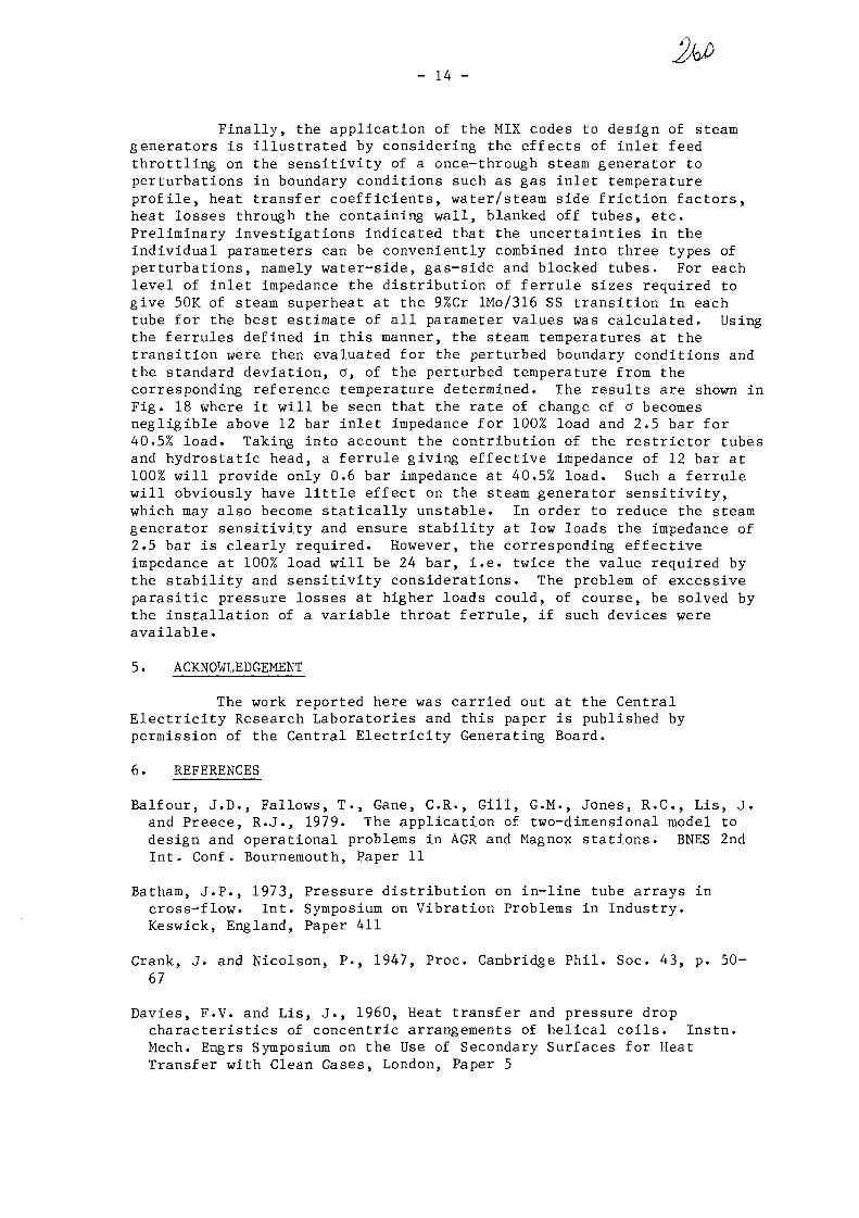
- 14 -
Finally, the application of the MIX codes to design of steamgenerators is illustrated by considering the effects of inlet feedthrottling on the sensitivity of a once-through steam generator toperturbations in boundary conditions such as gas inlet temperatureprofile, heat transfer coefficients, water/steam side friction factors,heat losses through the containing wall, blanked off tubes, etc.Preliminary investigations indicated that the uncertainties in theindividual parameters can be conveniently combined into three types ofperturbations, namely water-side, gas-side and blocked tubes. For eachlevel of inlet impedance the distribution of ferrule sizes required togive 50K of steam superheat at the 9%Cr lMo/316 SS transition in eachtube for the best estimate of all parameter values was calculated. Usingthe ferrules defined in this manner, the steam temperatures at thetransition were then evaluated for the perturbed boundary conditions andthe standard deviation, a, of the perturbed temperature from thecorresponding reference temperature determined. The results are shown inFig. 18 where it will be seen that the rate of change of a becomesnegligible above 12 bar inlet impedance for 100% load and 2.5 bar for40.5% load. Taking into account the contribution of the restrictor tubesand hydrostatic head, a ferrule giving effective impedance of 12 bar at100% will provide only 0.6 bar impedance at 40.5% load. Such a ferrulewill obviously have little effect on the steam generator sensitivity,which may also become statically unstable. In order to reduce the steamgenerator sensitivity and ensure stability at low loads the impedance of2.5 bar is clearly required. However, the corresponding effectiveimpedance at 100% load will be 24 bar, i.e. twice the value required bythe stability and sensitivity considerations. The problem of excessiveparasitic pressure losses at higher loads could, of course, be solved bythe installation of a variable throat ferrule, if such devices wereavailable.
5. ACKNOWLEDGEMENT
The work reported here was carried out at the CentralElectricity Research Laboratories and this paper is published bypermission of the Central Electricity Generating Board.
6. REFERENCES
Balfour, J.D., Fallows, T., Gane, C.R., Gill, G.M., Jones, R.C., Lis, J.and Preece, R.J., 1979. The application of two-dimensional model todesign and operational problems in AGR and Magnox stations. BNES 2ndInt. Conf. Bournemouth, Paper 11
Batham, J.P., 1973, Pressure distribution on in-line tube arrays incross-flow. Int. Symposium on Vibration Problems in Industry.Keswick, England, Paper 411
Crank, J. and Nicolson, P., 1947, Proc. Cambridge Phil. Soc. 43, p. 50-67
Davies, F.V. and Lis, J., 1960, Heat transfer and pressure dropcharacteristics of concentric arrangements of helical coils. Instn.Mech. Engrs Symposium on the Use of Secondary Surfaces for HeatTransfer with Clean Gases, London, Paper 5

- 15 -
Fallows, T., Gane, C.R., Jones, R.C., Lis, J. and Massey, T.H., 1979,CROSSMIX, A mathematical model of multi-pass crossflow heat exchangerwith primary fluid mixing, BNES 2nd Int. Conf, Bournemouth, Paper 38
Fallows, T. and Massey, T.H., 1982a, Studies of nuclear boiler modelswith LDA, Int. Symposium on the Application of LDA to Fluid Mechanics,Lisbon
Fallows, T. and Massey, T.H., 1982b, Flow and gas mixing in heatexchangers with gas by-passing. 7th Int . Heat Transfer Conf., Mlinchen,Paper HX6
Gardner, K.A., 1945, Trans ASME, 6_7_ pp. 621-632
Grace, A. and Hall, J.A., 1943, J. Sci. Inst. 20, 60-63
Jones, R.C., Lis, J. and Massey, T.H., An experimental investigation ofthermal mixing in crossflow tube banks 6th Int. Heat Transfer Conf.,Toronto, Paper HX12
Lis, J. and Thelwell, M.J., 1963, Experimental investigation of turbulentheat transfer in a pipe preceded by a 180° bend. Proc. Instn. Mech.Engrs, 1963-64, 178 (Pt 31(IV)), 17
Lis, J. and Kellard, P.O., 1968, Measurements of the thermal conductivityof thin films of magnetite, Brit. J. Appl. Phys. (J. Phys. D) Ser. 2,Vol. 1, pp 1117-1123
Neal, S.B.H.C. and Hitchcock, 1966, J.A., A study of heat transferprocesses in banks of finned tubes in cross flow, using a large scalemodel technique, 3rd Int. Heat Transfer Conference, Chicago, Paper 110
Neal, S.B.H.C. and Hitchcock, J.A., 1970. The development of improvedheat transfer surfaces for tubes in cross flow using a large scalemodel technique, 4th Int. Heat Transfer Conference, Paris - Versailles,Paper FC7.8
Preece, R.J., Lis, J. and Hitchcock, J.A., 1975. Effect of gas-sidephysical property variations on the heat transfer to a bank of tubes incross flow. Proc. Instn. Mech. Engrs, Vol. 189 17/75, pp 69-75
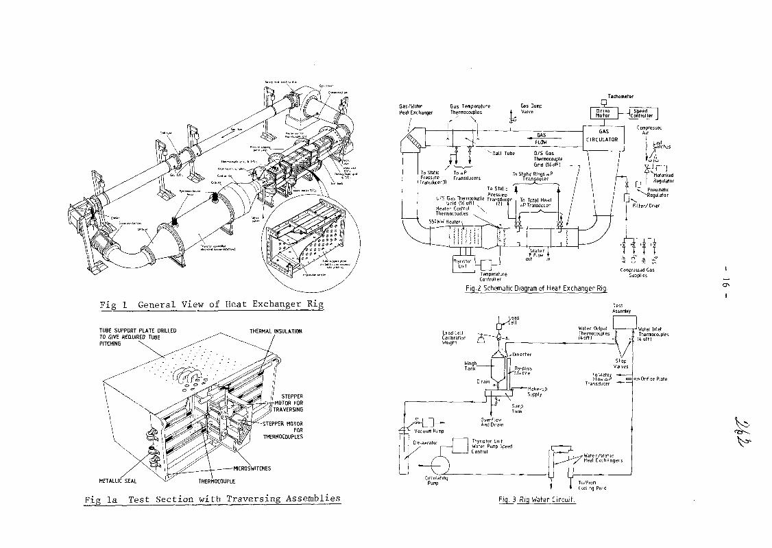
Fig 1 General View of Heat Exchanger Rig
TUBE SUPPORT PLATE DRILLEDTO GIVE REQUIRED TUBEPITCHING
THERMAL INSULATION
STEPPER MOTORFOR
THERMOCOUPLES
-MICROSWITCHES
THERMOCOUPLEMETALLIC SEAL
Fig la Test Section with Traversing Assemblies
Tachometer
Gas/WaterHeat Exchanger
Gas TemperatureThermocouples
To StaticPressure
TransducerlH
rff
Gas DumpValve
BASFLOW
To aPTransducers
HotorisedRegulator
To StaticPressure
U/S Gas Thermocouple TransducerLirid (16 off) ••" *
Heater ControlThermocouples
550 KW Heater
Fig.2 Schematic Diagram of Heat Exchanger Rig.
Fig. 3 Rig Water Circuit.
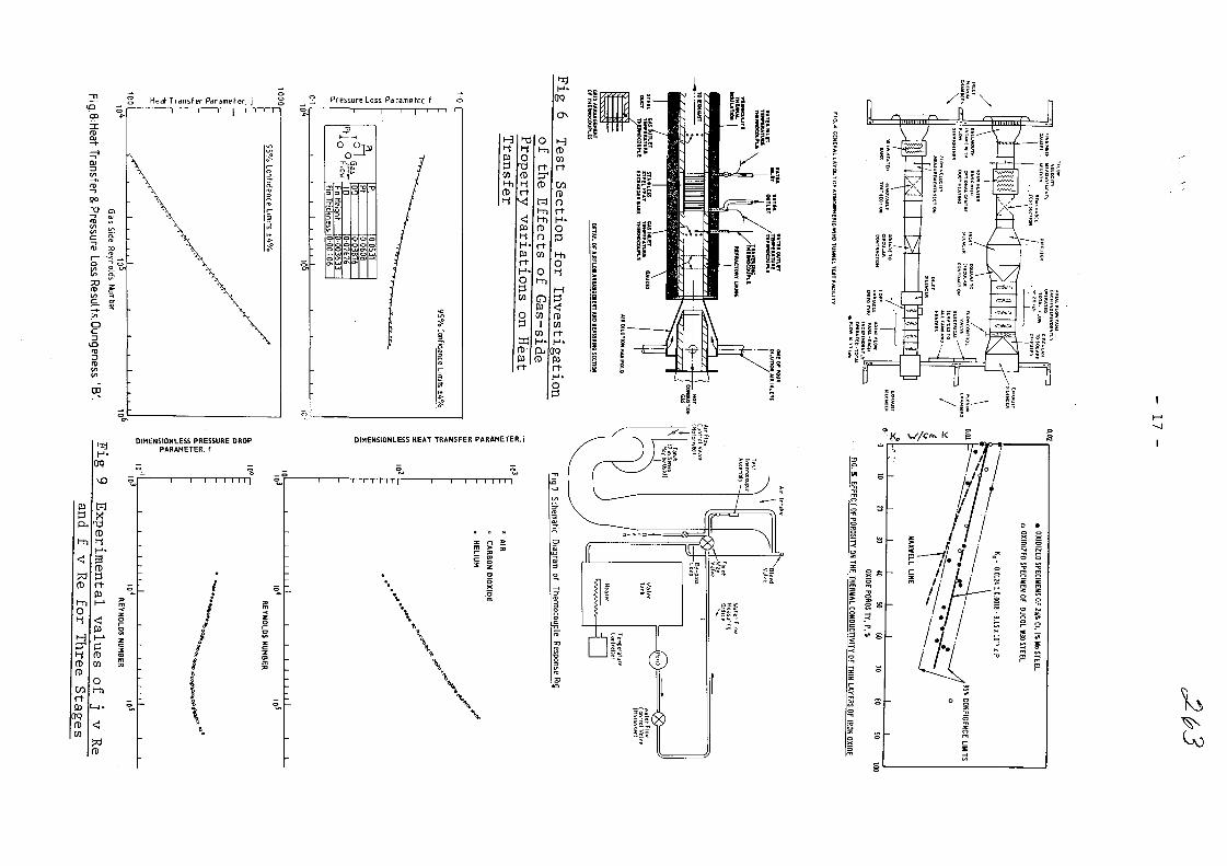
~n *> ^ Pressure Loss Parameter, f
l-hO
H
i-jfD
CoOPfDCO
Fin Thickness
o
Tl
X
OoUl
ID
1002626
oa
o
3
9090
0
-a
DIMENSIONLESS PRESSURE DROPPARAMETER, f
TO
M
fDt-iH -
fD3
?3fD

- 18 -
FimwTon*
t
2
3
4
Ffxtor
0-0?
0-7F
0-80
0-005
X : 1-C
7//4 n~77[ \3+mr\ By pa: ! I ft
f n i / A f-S mm By pot* to)
Axial Position
o o o
O O O
ooo
J6 Longitudinal ftcwi
Hotel Seal* 1 4-29
oo.oo
ooooo
I 2 3 4 3
Fig.TO: Comparison of Predicted Bypass Velocity ProfilesWith Measured Values.
OOOOOOOOOOOOOOOOOOOOoooooooooooooooooooo
DO 300DISTANCE ACROSS DUCT, m
Fig 12 Thermal Mixing in a Closely-Pitched In-line TubeArrangement
80
40
i j _
o 0 2 5 r t 0 5 n 0 7 5 n n
ANGULAR POSITION ON TUBE RADIANS
Fig 14 CircumferentialVariation of HeatTransfer over aRibbed and Plain
Tube Surface
)ooooooooooo°dX INLET (RO«S 0 1)
OH0ISIM!7 OUTLET (RO*S 16 -)
DISTANCE ACROSS DUCT, m
Fig 11 Thermal Mixing in a stag-gered Tube Arrangement
O 96
£ 9*
5 92LU
a- 90 -
K 88 -in
S 86 -
84 -
«2 —
BLANKEDTUBEUB
COOLEDTUBES
STAGGERED TUBE BANK, 14 ROWS OF TUBESTRANSVERSE PITCH 19.22 mmLONGITUDINAL PITCH 32.76mmFINNED TUBES 0.0.18.04mm, FIN HEIGHT3.0mm
• MEASURED BANK OUTLETGAS TEMPERATURE
PREDICTED TEMPERATUREFOR P« -12
100 200 300 400
DISTANCE ACROSS DUCT, mm
Fig 13 Predicted and MeasuredOutlet-Temperatures for aBank with an Edge TubeBlanked
STREAMS i- l j j + l
oooo LEVELS
OCJOONODE ' - r ' i + l
f S Y M M E T R Y 1 1 1l U N I T -L. • I + - L *o
Q ®6. •: Q ; O
LEVELS
i - l
i + l
Fig 16 Node Distribution for TypicalIn-line and staggered Tubefeanks

CROSSMIX
HINKLEY POINT A'SIZEWELL A1
MAGNOXDRUM BOILERS
SERPENTINE TUBES INCYLINDRICAL CASING.
BOILERS OUTSIDECONCRETE PRESSURE
VESSEL
WYLMIX
WYLFA
MAGNOXONCE-THROUGH
SERPENTINETUBES INANNULUS
BETWEEN REACTORAND CONCRETE
PRESSURE VESSEL.BOILERS INSIDE
VESSEL
DUNMIX
DUNGENESS B'
AGR
SERPENTINE TUBESIN ANNULUS
BETWEEN REACTORAND CONCRETE
PRESSURE VESSEL.INTERLEAVED
REHEATER ACOUSTICBAFFLES
PODMIX
HEYSHAM A'HARTLEPOOL
AGR
HELICAL TUBESIN CYLINDRICAL
PODS. MULTI-STARTCONTRA-ROTATING
HELICES OFEQUAL LENGTH
Fig 15 MIX-Suite of Codes
350
o o o o «• S S 8 %
9%Cr1Mo/3l6SSTRANSITION
Measured
Predicted
Ftias* 3o•
Phise U
+
i S 1 CS/9%Cr1Mo* * > TRATRANSITION
8 10 12HELIX NUMBER
Fig.17 Comparison of PODMIX Predictions with Measured TemperaturesetHeysham I during Phase 3 &4 Operations.
HEYMIX
HINKLEY POINT B'HEYSHAM 'B'
AGR
SERPENTINE TUBESIN RECTANGULAR
BOX. COMBINATIONOF PLAIN AND
FINNED TUBES INSTAGGERED AND
INLINE ARRANGEMENTS
30
25
20
WATER-SIDE PERTURBATIONS
40.25% LOAD
GAS-SIDE PERTURBATIONS
10
BLOCKED TUBES
_L5 10 15
INLET IMPEDANCE-BAR
20
Fig 18 Sensitivity of Boiler toInlet Impedance

No. 15
XA0055824
THE EFFECT OF INLET AND OUTLET SHELL -SIDE FLOW AND HEAT TRANSFER ON THE
PERFORMANCE OF HTGR STRAIGHT TUBE HEATEXCHANGERS
D. P. CAROSELLAStaff Engineer
GA Technologies Inc.San Diego, California, USA
ABSTRACT
Since the mid-1970s, various high temperaturegas-cooled reactor (HTGR) steam generator, aux-iliary heat exchanger (AHE), recuperator, and in-termediate heat exchanger (IHX) designs havebeen proposed that use straight tube configurations.Each of these designs requires 90-deg turns in thehelium gas flow at the inlet and/or outlet of thetube bundle.
The design of the steam generator for the HTGRsteam cycle/cogeneration lead plant includes astraight tube superheater (STSH) which incorpo-rates both a 90-deg inlet and outlet turn across thetube bundle. The AHE includes a 90-deg outlet turnacross the tube bundle. Previous GA TechnologiesInc. (GA) recuperator and IHX designs for gas tur-bine and process heat HTGRs have also consideredstraight tube designs with 90-deg bends at the inletand outlet.
To evaluate the effect of these turns on the tubebundle performance, two model air flow tests havebeen performed, and a third is being planned. Fluidflow and heat transfer computer models have alsobeen used to try to determine the effect of these90-deg turns on the tube bundle performance.
As a result of these studies, the following con-clusions can be made:
1. For all of the designs investigated, the 90-deg turns reduced the bundle performance.
2. In designs where the tube pitch-to-diameter
ratio is small (less than 1.3), the 90-deg turns canhave a critical effect on the performance. However,use of design concepts such as flow baffles or smallmodular bundle designs can greatly reduce or elim-inate these problems.
3. The inlet turns are more critical to the designthan the outlet turns.
4. The non-unform temperature profiles result-ing from poor inlet design can result in high thermalstresses in the tubes.
5. Testing to correlate the shell-side heat trans-fer in the region of a 90-deg bend across a tubebundle is required to more fully understand thecharacteristics of this problem.
6. Although the 90-deg turns are not desirable,they are frequently necessary in realistic plant andcomponent designs. However, with the proper anal-ysis and testing, the designs can be developed so asto minimize their adverse effects on tube bundleperformance and thermal stress.
NOMENCLATURE
The following symbols are used in the text and onthe figures in this paper:XT tube pitch-to-diameter ratioRQ bundle outside radiusRj bundle inside radiusRl local bundle radiusV^ local velocityVm mean velocity

INTRODUCTION
The primary coolant heat exchangers used in anHTGR are located in cavities in a prestressed con-crete reactor vessel (PCRV). The axes of these heatexchangers are parallel to the vertical axis of thePCRV (Fig. 1). The primary coolant is transportedto and from the heat exchangers via ducts. Thegeometrical arrangement of the flow paths requiresthe primary coolant to make one or more 90-degturns in the heat exchanger cavity.
For straight tube configurations, the 90-deg turnmust occur while crossing the tube bundle. The flowand heat transfer characteristics of three such con-figurations have been investigated by a combinationof analysis and flow model tests.
References 1 and 2 reported the results of twosuch investigations. By using these results and an-alytical results for a third configuration, an attemptwill be made to characterize both the flow and heattransfer characteristics of straight tube heat ex-changers with 90-deg inlet and/or outlet turns.
DESCRIPTION
Inlet Turns
In the inlet region, flow enters the bundle per-pendicular to the tube bundle vertical axis (Fig. 2).The flow sees both a vertical and a horizontal flowpath. The relative resistance of these paths will es-tablish the flow distribution. In bundles where thetube pitch-to-diameter ratio (XT) is small (less than1.3), the radial flow resistance will cause the flowto travel upward before it reaches the center of thebundle, resulting in excessive flow at the outside ofthe bundle and flow starvation toward the centerof the bundle. In bundles with large (greater than2.0) XT values, the flow distribution will be nearlyuniform.
The inlet flow maldistribution can reduce thebundle performance by two mechanisms. In theflow-starved region, the shell-side film coefficientwill be less than nominal. This reduction of filmcoefficient is partially offset by the higher film coef-ficients in the outer regions of the bundle; generally,
CONTROL ROD DRIVEAND REFUELINGPENETRATIONS
CIRCULATOR
FEEDWATERACCESS SHAFT
STEAMGENERATOR
LINEARPRESTRESSINGSYSTEM
PCRV SUPPORTSTRUCTURE
N-028
A17351
AUXILIARYCIRCULATOR
PRESTRESSEDCONCRETEREACTOR VESSEL
CORE
CIRCUMFERENTIALPRESTRESSINGSYSTEM
CORE AUXILIARYHEAT EXCHANGER
Fig. I. HTGR steam supply system

SHELLFLOW
TUBE ( 1FLOW / U - J
OUTLETSCREEN
BAFFLES IN LETSCREEN
TUBE-SIDE FLOWA17351
Fig. 2. Straight tube configuration
however, the maldistribution of film coefficientsresults in lower performance in the turning region.
The second mechanism can be much more crit-ical than the first. As the flow crosses the bundlein the radial direction, heat transfer between theprimary and secondary coolants causes a radial tem-perature profile to develop in the shell-side fluid.In bundles with flow starvation near the center, theslope of this profile can be very steep. This profilebecomes the inlet temperature distribution into theaxial flow region of the bundle. This temperaturemaldistribution reduces the mean effective tem-perature difference between the primary and sec-ondary coolants, reducing the performance of theaxial portion of the bundle. The combination ofthese two mechanisms can have a major effect onthe performance oi the heat exchanger.
Outlet Turns
The outlet turn compounds the problems result-ing from the inlet turn. As the shell-side fluid travelsradially outward, a radial temperature profile de-velops in the outlet region, further reducing themean effective temperature difference between theprimary and secondary coolants.
Both the inlet and outlet turns contribute to re-duced heat exchanger performance. However, sincethe inlet effect is propagated throughout the lengthof the bundle, it is by far the more critical effect.
Bundles with only an outlet turn are not greatlyaffected by the flow maldistribution in the outletregion.
INVESTIGATIONS
Fluid Flow
The fluid flow characteristics of three straighttube configurations have been investigated by acombination of air flow tests and/or analysis. Eachof these heat exchangers has a different geometry.They represent a spectrum of XT values rangingfrom 1.25 to 2.13. One (the AHE) does not havean inlet turn in the tube bundle. Investigation ofthese three heat exchangers establishes a base forlooking at other straight tube designs that might beencountered in gas-cooled reactor configurations.
Straight Tube Recuperator/IHX Model. A modelof the inlet region of a heat exchanger characteristicof a typical recuperator or IHX used in variousHTGR gas cycle designs was tested to evaluate theflow characteristics of such a design. This modelhad an XT value equal to 1.25.
Reference 1 detailed the results of this investi-gation. They are summarized here.
The model represents a sector of the inlet regionof a recuperator or IHX. Figures 3 and 4 illustratethis test model and a typical flow path.
The measured results from this test model werecompared against calculated results using a net-work flow computer model (SNIFFS, Ref. 3). Fig-ure 5 shows typical test and analytical results forthis test model. The solid line represents the ana-lytical results, while the test data points are rep-resented by circles and squares. Table 1 comparesmeasured and calculated loss coefficients for threedifferent inlet conditions, as tested by this model.The loss coefficient is defined as the ratio of the

1.8
1.4 -
1.2
0.8 -
O
o
> 0.6
0.4 -
0.2 -
20 40 60
OISTANCE FROM INLET FACE (CM)
A17351
1°\ D
\
: \
\ D
\
RADIALFLOWDIRECTION <-
ANALYTICAL
i
O MEASUREDLEFTSIDE
O MEASUREDRIGHT SIDE
ao
\\
\
\
RESULTS
i
DATA:QF MODELDATA:OF MODEL
o
1
80
Photograph of recuperator inlet air flow Fig. 5. Recuperator inlet air flow test: velocitytest model profile, configuration 8
TOPOFTUBEBUNDLE
104 CM
AIR FLOW
A17351
VARIABLEBLOCKEDSCREEN
SUPPORTBAFFLES GRID
LOCATION OFPITOT-STATIC PROBES
Fig. 4. Schematic of recuperator inlet air flow test model

TABLE 1COMPARISON OF TEST AND
ANALYTICAL LOSS COEFFICIENTSFOR RECUPERATOR/IHX
TEST MODEL
TestConfiguration
Loss CoefficientsTest Analytical
6
8
9
125.6
32.1
100.2
158.7
33.6
104.4
pressure drop to the average velocity head in thetube bundle.
The following conclusions were made from theresults of this test:
1. The SNIFFS network flow model could beused to predict the flow distribution and pressureloss characteristics of this type of heat exchanger.
2. The small XT value results in flow starvationat the center of the bundle.
3. A SNIFFS analysis of a complete heat ex-changer of this type showed that the flow maldis-tribution is very rapidly dissipated after leaving theinlet region. However, the maldistribution rede-velops in the outlet turn region.
Auxiliary Heat Exchanger. References 2 and 4report an air flow test on a half-size AHE. This heatexchanger is typical of a straight tube configuration(Fig. 6), with a 90-deg outlet bend and a moderatepitch-to-diameter ratio (1.43). For this test, themeasured data were compared against both aSNIFFS model and a turbulent flow model (COM-MIX, Ref. 5). Figure 7 and Table 2 show typicalresults of this comparison.
The following conclusions can be drawn fromthese results:
1. Both the SNIFFS model and the COMMIXmodel gave adequate predictions of the flow dis-tribution and the pressure drop.
2. As compared to the recuperator/IHX re-sults, the larger XT value resulted in less flow star-vation at the center of the heat exchanger bundle.
Straight Tube Superheater. The geometry of theSTSH is similar to that of the recuperator/IHX.However, the STSH design has a 2.13 XT value.This XT value is 1.7 times greater than the recu-perator/IHX XT value.
PRIMARYCOOLANT'
AXIALFLOWREGION
OUTLETREGION
INLETDUCT
^BAYONETTUBEBUNDLE
HONEYCOMBEDGRID
B
X
HEXAGONALSHROUD
i C
!
PERFORATED
A17351 G R I D
Fig. 6. AHE primary coolant flow path
25
20
I 10
CURVENO.
1
2345
RAOIUS(Ml
0.022
0.064
0.108
0.149
0.192
TESTDATA
0VA
a0
COMMIXSNIFFS
0.3 0.2 0.1 0.1 0.2 0.3
DISTANCE ABOVE TOP DISTANCE BELOW TOP BOTTOM OFOF EXIT SCREEN (M) OF EXIT SCREEN (M) BUNDLE
AI7351
Fig. 7. Radial velocity comparison test: SNIFFS,COMMIX
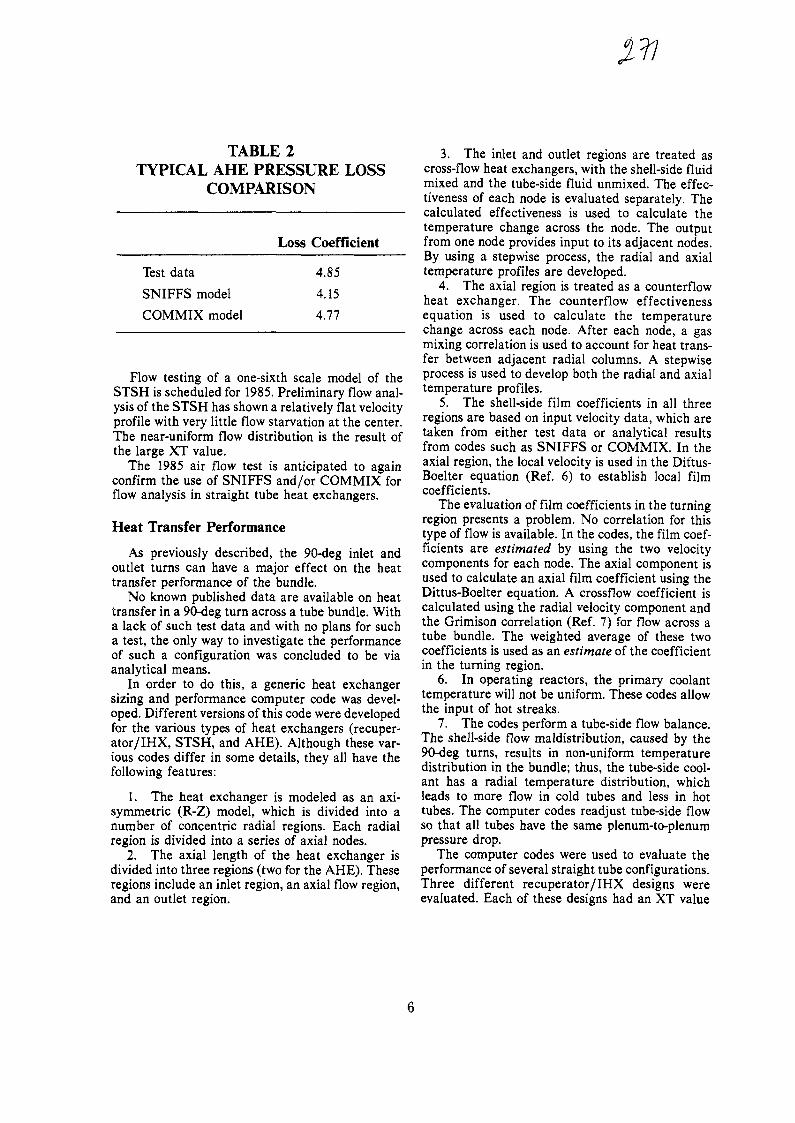
TABLE 2TYPICAL AHE PRESSURE LOSS
COMPARISON
Loss Coefficient
Test dataSNIFFS model
COMMIX model
4.854.15
4.77
Flow testing of a one-sixth scale model of theSTSH is scheduled for 1985. Preliminary flow anal-ysis of the STSH has shown a relatively flat velocityprofile with very little flow starvation at the center.The near-uniform flow distribution is the result ofthe large XT value.
The 1985 air flow test is anticipated to againconfirm the use of SNIFFS and/or COMMIX forflow analysis in straight tube heat exchangers.
Heat Transfer Performance
As previously described, the 90-deg inlet andoutlet turns can have a major effect on the heattransfer performance of the bundle.
No known published data are available on heattransfer in a 90-deg turn across a tube bundle. Witha lack of such test data and with no plans for sucha test, the only way to investigate the performanceof such a configuration was concluded to be viaanalytical means.
In order to do this, a generic heat exchangersizing and performance computer code was devel-oped. Different versions of this code were developedfor the various types of heat exchangers (recuper-ator/IHX, STSH, and AHE). Although these var-ious codes differ in some details, they all have thefollowing features:
1. The heat exchanger is modeled as an axi-symmetric (R-Z) model, which is divided into anumber of concentric radial regions. Each radialregion is divided into a series of axial nodes.
2. The axial length of the heat exchanger isdivided into three regions (two for the AHE). Theseregions include an inlet region, an axial flow region,and an outlet region.
3. The inlet and outlet regions are treated ascross-flow heat exchangers, with the shell-side fluidmixed and the tube-side fluid unmixed. The effec-tiveness of each node is evaluated separately. Thecalculated effectiveness is used to calculate thetemperature change across the node. The outputfrom one node provides input to its adjacent nodes.By using a stepwise process, the radial and axialtemperature profiles are developed.
4. The axial region is treated as a counterflowheat exchanger. The counterflow effectivenessequation is used to calculate the temperaturechange across each node. After each node, a gasmixing correlation is used to account for heat trans-fer between adjacent radial columns. A stepwiseprocess is used to develop both the radial and axialtemperature profiles.
5. The shell-side film coefficients in all threeregions are based on input velocity data, which aretaken from either test data or analytical resultsfrom codes such as SNIFFS or COMMIX. In theaxial region, the local velocity is used in the Dittus-Boelter equation (Ref. 6) to establish local filmcoefficients.
The evaluation of film coefficients in the turningregion presents a problem. No correlation for thistype of flow is available. In the codes, the film coef-ficients are estimated by using the two velocitycomponents for each node. The axial component isused to calculate an axial film coefficient using theDittus-Boelter equation. A crossflow coefficient iscalculated using the radial velocity component andthe Grimison correlation (Ref. 7) for flow across atube bundle. The weighted average of these twocoefficients is used as an estimate of the coefficientin the turning region.
6. In operating reactors, the primary coolanttemperature will not be uniform. These codes allowthe input of hot streaks.
7. The codes perform a tube-side flow balance.The shell-side flow maldistribution, caused by the90-deg turns, results in non-uniform temperaturedistribution in the bundle; thus, the tube-side cool-ant has a radial temperature distribution, whichleads to more flow in cold tubes and less in hottubes. The computer codes readjust tube-side flowso that all tubes have the same plenum-to-plenumpressure drop.
The computer codes were used to evaluate theperformance of several straight tube configurations.Three different recuperator/IHX designs wereevaluated. Each of these designs had an XT value
of 1.25. The recuperator/IHX configurations in-cluded the following:
1. A large monolithic module without inletflow baffles.
2. A large monlithic module with inlet flowbaffles.
3. A cluster of seven small modules, which hada total frontal area and a total number of tubesequal to the frontal area and a number of tubes forthe monolithic module.
The AHE and STSH were also evaluated. Allof the configurations were compared to the appro-priate ideal counterflow designs which do not have90-deg inlet and/or outlet turns.
RESULTS
From this study of three basic configurations,knowledge of the critical parameters which affectthe design of straight tube heat exchangers can bedeveloped.
Figures 8 through 13 illustrate the shell-side flowand temperature characteristics of the various con-figurations. Table 3 compares the various recuper-ator/IHX designs to the ideal counterflow designsfor the same heat duty requirements. Likewise,Table 4 compares the AHE and STSH to their re-spective ideal counterflow designs.
300
280
260
240
220
200
180
MONOLITHIC MODULENO BAFFLES.
MONOLITHIC MODULEWITH BAFFLES
7-MODULECLUSTER
0.2 0.4 0.6 0.8 1.0
A17351RELATIVE RADIUS, (R o - R 4 ) / (Ra - R,)
Fig. 9. Calculated inlet temperature profiles forthree recuperator(IHX flow configurations
2.0
1.6
2 1.2
0.8
MONOLITHIC MODULE, NO BAFFLES
MONOLITHIC MODULE/ " \ WITH BAFFLES
7-MODULECLUSTER
J_
A17351
0.2 0.4 0.6 0.8
RELATIVE RADIUS, IR0 - R £ )/(R0 - R|)
1.0
<
>
<
2.0
1.6
1.2
0.8
0.4 -
/TOP OF OUTLET WINDOW
, BUNDLE MIDPLANE
7.6 CM FROM WINDOW
RADIAL FLOWDIRECTION
10.2
A17351
0.4 0.6
RELATIVE RADIUS<R 0 -R, ) / (R 0 -R| )
0.8 1.0
Fig. 8. Calculated inlet velocity profiles for threerecuperator/IHX flow configurations
Fig. 10. AHE velocity distribution

380
— 360 —
340
320
300
280
TOP OFOUTLETWINDOW'
BOTTOMOF BUNDLE
RADIAL FLOWDIRECTION
0.2 0.4 0.6 0.8 1.0
A17351
RELATIVE RADIUS( R 0 - R , ) / ( R a - R , )
700
680
660
600
580
INLET RADIAL FLOW
INLET TEMP30 CM FROMWINDOW EDGE
OUTLET TEMP 28 CMFROMWINDOWEDGE
OUTLET RADIALFLOW
I I0.2 0.4 0.6
RELATIVE RADIUS
0.8 1.0
A17351
Fig. 13. STSH shell-side temperature distribution
Fig. 11. AHE shell-side temperature distribution
1.6
— * - INLET RADIAL FLOW
BUNDLE MIDPLANEI
INLET WINDOW30 CM FROMEDGE
< 0.4
— ^ ~~ v \
OUTLET WINDOW28 CM FROM EDGE
- * — OUTLET RADIAL FLOW
0.2 0.4 0.6 0.8 1.0
A17351
RELATIVE RADIUS( R 0 - R 1 ) / ( R 0 - R 1 )
Fig. 12. STSH velocity distribution
From the figures and tables, the following ob-servations can be made:
1. The configurations with the small XT valuesare most easily affected by the 90-deg turns. How-ever, the effect of the 9O-deg turn can be greatlyreduced by considering certain design changes.These design changes include the use of flow bafflesor the use of a small-diameter modular design. Flowbaffles force the flow to the center of the bundle,thus reducing flow maldistribution. In small-di-ameter modular designs, the radial flow resistanceis not large enough to allow maldistributions to de-velop. Both of these changes improve the flow andtemperature distribution (Figs. 8 and 9), but at acost of pressure drop and/or envelope space. Forthe HTGR, both envelope space and pressure dropare critical to the design.
2. Configurations, such as the AHE configu-ration, that have only an outlet turn in the tubebundle are least likely to be affected by the turn.Even though flow and temperature maldistributiondevelops in the outlet region, the effect does nottravel the length of the bundle; thus, it is minimized.

TABLE 3SIZING AND PERFORMANCE PARAMETERS
FOR RECUPERATOR/IHX DESIGNS
Required length, m
Pressure drop, kPaShell sideTube side
Ref.Design
16.16
13.6923.72
MonolithicWithoutBaffles
31.24
44.4350.12
MonolithicWith Baffles
15.95
73.0925.30
Cluster of7 Modules
16.67
15.0726.68
TABLE 4SIZING AND PERFORMANCE PARAMETERS FOR AHE AND STSH
Required length, m
Pressure drop, kPaShell sideTube side
Ref.Design
3.92
2.55522.6
AHE
RequiredDesign
4.06
2.57541.2
Ref.Design
15.25
5.55130.8
STSH
RequiredDesign
16.34
5.95136.8
3. Bundles with a large tube pitch-to-diameterratio have the smallest effect on flow and temper-ature distribution (Figs. 12 and 13). However, if theeffect occurs at the inlet (as in the STSH), thissmall effect is propagated along the length of thebundle, thus causing some loss of performance.
In addition to the thermal performance degra-dation that occurs as a result of the 90-deg bends,the resulting temperature maldistributions will re-sult in corresponding tube temperature variations.Table 5 shows that tube temperature variation cal-culated for the various configurations that havebeen investigated as part of this study. In designswhere the tubes are attached at each end to fixedheaders, tube temperature distribution could resultin excessive tube stress. The possibility of excessivetube thermal stress must be part of the evaluationof straight tube designs with fixed headers.
TABLE 5TUBE TEMPERATURE VARIATION
Recuperator/ IHXMonolithic without bafflesMonolithic with bafflesCluster design
AHESTSH
TemperatureVariation
503913
923
CONCLUSIONS
Based on the results of the two air flow tests, thetwo analytical codes, SNIFFS and COMMIX, havebeen shown to adequately predict flow distributionin the 90-deg turns. This conclusion will be furtherverified by the steam generator one-sixth scale airflow tests.
There are no test data to establish a heat transfercorrelation for flow turning 90 deg across a tubebundle. Testing to establish such a correlation isrequired before a general correlation can be devel-oped to predict the effect of the inlet and outletturns on a straight tube heat exchanger.
Lack of the necessary test data led to the use ofanalytical models to predict the heat exchangerperformance. Al though such models cannot exactlypredict performances, they can provide data tomake possible the investigation of various straighttube designs and the elimination of undesirable de-sign features such as small pitch-to-diameter ratiosand large tube thermal stress in Fixed headerdesigns.
ACKNOWLEDGMENT
This work was funded by the San Francisco Op-erations Office of the Department of Energy underContract DE-AT03-84SF11962.
REFERENCES
1. Carosella, D. P., "Experimental and AnalyticalInvestigation of Shell-Side Flow Distribution Ef-fects on Axial Flow Heat Exchangers," Regenera-tive and Recuperative Heat Exchangers, ASMESymposium, Volume HTD-21, November 1981.2. Carosella, D. P., and P. N. Pavlics, "Comparisonof Calculated Results from Two Analytical Modelswith Measured Data from a Heat Exchanger FlowTest," ASME Paper 83-JPGC-NE-15.3. Baccaglini, G. M., "SNIFFS: Single PhaseNonisothermal Fluid Flow Simulator," GA ReportGA-A14501, June 1977.4. Kaufman, J. S., and M. M. Bressler, "AuxiliaryHeat Exchanger Flow Distribution Test," ASMEPaper 83-JPGC-NE-16.5. Sha, W. T., et ai, "COMMIX-1: A Three-Di-mensional Transient Single-Phase Component Com-puter Program for Thermal-Hydraulics Analysis,"Argonne National Laboratory Report ANL-77-96,September 1978.6. Dittus, F. W., and L. M. K. Boelter, Engineer-ing, v. 2, University of California Publications,1930, p. 443.7. Grimison, E. D., "Correlation and Utilizationof New Data on Flow Resistance and Heat Transferfor Cross Flow of Gases Over Tube Banks," Trans.ASME 59, 583-594 (1937).
10

No. 16GEFR-SP-314
DATE APRIL, 1984
TITLE: STATUS OF A REFORMER DESIGN FOR A MODULAR HTGR IN ANIN-LINE CONFIGURATION
AUTHORS: R. GLUCK, W. H. WHITLING, AND A. J . LIPPS XA0055825
Prepared for presentation at
IAEA SPECIALISTS MEETING ON HEAT EXCHANGING COMPONENTSOF GAS COOLED REACTORS
Conference
Held in DUSSELDORF, FRGCity, State
On 16-19 APRIL, 1984Date
This paper contains materialresulting from work performedfor U.S. DEPARTMENT OF ENERGY
Under Contract No. DE-AC03-80ET 34034
This paper has been authored by a contractor of the U.S.Government under Contract No. DE-AC03-80ET 34034Accordingly, the U.S. Government retains a nonexclusive,royalty-free license to publish or reproduce the publishedform of this contribution, or allow others to do so, forU.S. Government purposes.
ADVANCED NUCLEAR TECHNOLOGY OPERATION • GENERAL ELECTRIC COMPANY
SUNNYVALE, CALIFORNIA 94088
G E N E R A L W ELECTRIC 84-02-11
STATUS OF A REFORMER DESIGN FOR A MODULAR HTGRIN AN IN-LINE CONFIGURATION
byR.GLUCK, W.H.WMTLING and A.J.LIPPS
GENERAL ELECTRIC COMPANYSUNNYVALE, CALIFORNIA
INTRODUCTION
For the past several years the General Electric Company has had thetechnical lead on advanced concept studies for the Modular High TemperatureGas Cooled Reactor (HTGR) programs sponsored by the United States Depart-ment of Energy. The focus of the Modular Reactor System (MRS) effort isthe development of a generic nuclear heat source capable of supplying heatto either a steam generator/electric cycle or a high temperature steam/methane reforming cycle. Some early ground rules for this study were thatthe reactor be designed for 950°C direct cycle reforming and that the corebe of the prismatic type. Since the prismatic core required control rodsnear the center of the core, the vertical in-line concept was selected topromote natural circulation cooling of the core for all potential transientsexcept the depressurized core heatup transient. Although the requirementfor a prismatic core has been eliminated for recent cost reduction studies,the vertical in-line configuration has been retained for its potential asthe lowest cost configuration. This paper presents the results of recentdesign and analytical studies conducted to evaluate the feasibility ofusing a steam/methane reformer in a Vertical In-Line (VIL) arrangement withthe generic nuclear heat source.
DESIGN REQUIREMENTS
The requirements for the study of the VIL reformer are presented belowin two broad categories. The first establishes those requirements arisingfrom the overall thrust of the MRS program, while the second establishesthe component functional requirements for the steam reforming process.
MRS PROGRAM REQUIREMENTS
The MRS program has as its primary goal the development of a genericnuclear heat source capable of being utilized either in a steam/electriccycle operating'mode or a steam/methane reforming mode. In arriving at thispeal the project has put primary emphasis on achieving passive safety andreducing construction costs by:
a - utilization of a standardized modular design approach to minimizesite construction activity,
b - utilization of an in ground silo for housing and supporting thepressure vessel,
c - providing passive decay heat removal capability.
Preliminary evaluations showed that a vertical arrangement in which a steamgenerator or steam reformer mounted directly above the reactor vessel would

have many desirable features towards achieving the objectives. The follow-ing programmatic and functional requirements were established for the VILreformer:
1 - Streamlined reactor vessel configuration with the reformermounted in the pressure vessel vertically above the pebble bedcore.
2 - Decay heat removal to be by natural or forced circulation ofprimary coolant gas to the main cooling systems under normal andupset conditions and by natural circulation of primary coolantand natural circulation of external cavity coolant under emer-gency conditions. [Normal, upset and emergency conditions aredefined in terms of frequency and probability for ASME Codedesign purposes.]
VIL REFORMER REQUIREMENTS
The detailed performance and design parameters for the VIL reformerare based on overall plant system analyses, i.e. heat balances, fuelperformance, cere heat-up analyses, etc.. These requirements are summarizedin Table 1.
REFERENCE DESIGN
A typical arrangement of a VIL-MRS is shown in Figure 1. The reactorhas a pebble bed core surrounded by graphite reflectors in the bottom halfof the reactor vessel. The reformer is mounted above the core and directlysupported by the upper half of the lower pressure vessel. Fuel loading,circulator mounting and control rod penetrations are all accomplishedthrough the reactor pressure vessel structure.
The reformer is a baffled shell and tube heat exchanger using bayonettubes attached to tubesheets as shown in Figure 2. The vessel is constructedas a cylindrical shell 4.76 meter (187.5 inch) in diameter, flanged at eachend. The lower section has a conical transition to the flange to enablemating with the reactor pressure vessel. The upper flange mates with anelliptical bolted head that provides closure of the pressure boundary. Allaccess to the vessel internals for installation, inspection and maintenanceof the reformer and steam generator is accomplished through this closure.Penetrations are provided through the cylindrical portion of the vessel forpiping connections of the process gas inlet and outlet, buffer helium,feedwater inlet and steam outlet. The vessel shell also has a ring ledgefor supporting the reformer internal structure and brackets for supportingthe helical coil steam generator.
The reformer internal structure consists of inlet and outlet processgas plenums, each connected by means of bellows expansion joints to theouter vessel nozzles. The inlet plenum is connected to both the upper andlower tubesheet while the outlet plenum is connected to the upper tubesheetonly. The reformer tubes consist of an outer tube 64.5 mm (2.54 inch) indiameter, 10.2 m (33 ft. - 4 in.) long with a monolithic type of reformercatalyst and an inner return tube. The outer tube is attached to andsupported by the lower tubesheet. The inner return tube supports the mono-

lithic catalyst and is attached to and supported by the upper tubesheet.The plenums, in addition to providing flow separation, must provide thestructural flexibility to accommodate the differential thermal growthsresulting from the differences in inlet and outlet process gas tempera-tures. This is accomplished by providing sufficient length to the plenumcylinders.
Directing the process gas flow from the pressure vessel nozzles to theinlet and outlet plenums is accomplished by utilizing flanged, bolted insections having bellows expansion joints. The use of the bellows jointsprovides a means for accommodating the differential thermal growths of thereformer structure relative to the pressure vessel. The flexibility of thebellows joint also allows the tolerances for manufacture, assembly andreplacement to be generous. The use of the bolted flanges provides e meansfor inspection and replacement of internal structural elements.
The reformer tube bundle is shrouded by a cylinder 3.13 meter (123.1inch) in diameter, connected to the lower tubesheet. This cylinder inter-faces with internal reactor flow distribution baffles to direct circulatingcore helium to the reformer inlet and to direct the return path of thehelium. Baffle plates are provided on the shroud to direct the helium flowin a cross flow pattern and to provide lateral support to the reformertubes against flow induced vibration and seismic accelerations. At the topof the shroud, the helium under cross flow conditions, exits at one sideonly. An eccentric distribution baffle is provided to uniformly distributethe flow into the steam generator section. The entire reformer structure issupported by a conical support skirt between the lower tube sheet and theouter vessel.
All internal surfaces of the outer vessel above the top of the steamgenerator, the reformer support cone, and the underside of the lowertubesheet are insulated to minimize temperature gradients and/or long termexposure to elevated temperature conditions. The lower end of the insula-tion will form a juncture with the steam generator shrouding.
FLOW ARRANGEMENT AND LOADINGS
Under normal operating conditions, helium flows upward through thecore and top reflector and exits at 950 C (1742 F). Flow is then directedby internal baffling to the shroud encompassing the reformer tubes. Thehelium after passing through the reformer tube bundle exits the tube shroudat 625 C (1158 F) and flows down the annul us between the reformer andpressure vessel to a helical coil steam generator. Helium exits the steamgenerator at 350 C (660 F) and is returned to the core inlet.
The steam generator tubes are enclosed in their own shroud, whichforms an annulus with the pressure vessel wall. This annulus is closed atthe top to prevent flow from bypassing the steam generator. This creates a"stagnant" helium buffer between the steam generator and the pressurevessel wall which limits the heat transfer to the vessel wall to naturalcirculation convection in the annulus and radiation from the steam generatorshroud. The vessel wall under normal conditions is calculated to be 393 C(740 F) on the inside surface with a mean wall temperature of 371 C (700F). The design temperature of the vessel is established at 400 C (750 F).

The corresponding process gas flow during normal conditions isducted to the inlet plenum where it flows down through the nickelcatalyst in the reformer tubes and returns through the inner tube to theoutlet plenum. The inlet process gas enters the reforming tubes at 482 C(900 F) and is heated by both the reactor helium on the outside of the tubeand by the process gas in the return line to a maximum of 820 C (1508 F).The process gas exits the return line to the outlet plenum at 596 C (1105F).
During normal operating conditions the reactor helium and process gasare maintained at pressure such that the maximum differential pressure loadon the reformer components is 0.42M Pa (60 psi). The differential designpressures for the lifetime loading (300,000 hour) of the reformer compo-nents are shown on Table 2.
During upset and emergency transient conditions the reformerstructure is generally exposed to both increased temperature and increaseddifferential pressure loads for short time loadings (< 100 hour). Theactual service temperature, pressure and duration are functions of thetransients imposed. Maximum pressure loads occur as a result of depressur-ization of coolant on one side of the boundary while pressure is maintainedon the other. Typically these are events such as core depressurization orprocess line rupture accidents. An envelope of the differential pressuresthat can exist on the reformer structures for these type events is alsoshown on Table 2. These short term loading events generally govern thesize of the structural elements of the reformer.
THERMOCHEMICAL PERFORMANCE
Analysis for the steady state reforming behavior of the steam reformerbundles was performed using the DSRDSRN computer code (Ref. 1). This codeuses an empirical chemical kinetics model for the steam methane reactionand assumes that the water shift reaction is at equilibrium. An iterativesolution is employed in order to calculate heat transfer rates and chemicalcompositions in an axial model of an average reformer tube in a tubebundle. The accuracy of this code was verified for single tubes in testsconducted at KFA in the EVA-I test rig. DSRDSGN is a modification of theDSR1 code (Ref. 2) that incorporates the improved crossflow heat exchangeresulting from the inclusion of the baffles. Each baffled flow region isassumed to be characterized by the average helium temperature for thatregion. The pressure drop across each baffled region was calculated inthree steps; the frictional pressure loss across the tubes, a 180 degreeturn from one region to the next, and an orifice pressure drop as thehelium passes between the end of a baffle and the bundle shroud.
Heliun leakage flow through the reformer tube penetrations in thebaffle plates causes a reduction in the heat transfer coefficient from truecross flow. This effect was included in the serpentine flow heat transfercorrelation as a 10% reduction in heat transfer coefficient (Ref. 3). Thishelium leakage also results in a 20% reduction in helium pressure drop a-cross the reformer tubes and baffles.
The performance requirements for the reformer tube bundle wereshown on Table 1. The tube bundle design geometry selected to meet those
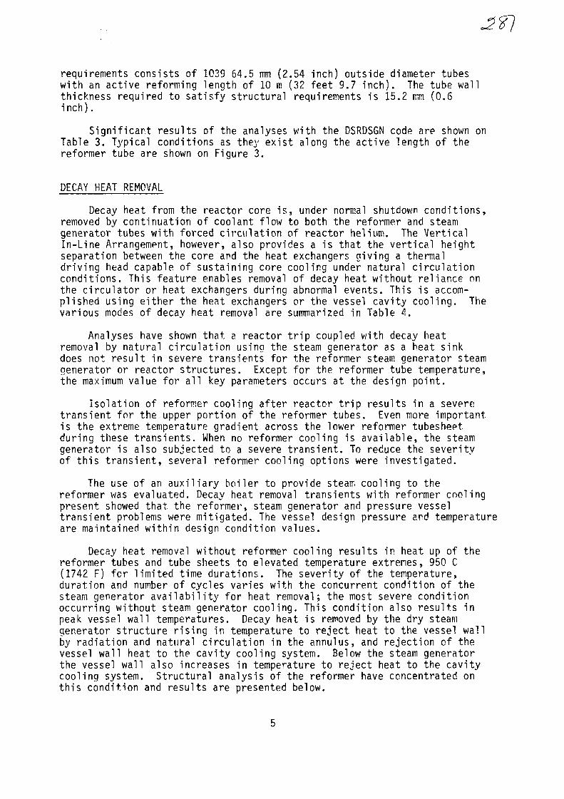
Jf}
requirements consists of 1039 64.5 mm (2.54 inch) outside diameter tubeswith an active reforming length of 10 m (32 feet 9.7 inch). The tube wallthickness required to satisfy structural requirements is 15.2 mm (0.6inch).
Significant results of the analyses with the DSRDSGN code are shown onTable 3. Typical conditions as they exist along the active length of thereformer tube are shown on Figure 3.
DECAY HEAT REMOVAL
Decay heat from the reactor core is, under normal shutdown conditions,removed by continuation of coolant flow to both the reformer and steamgenerator tubes with forced circulation of reactor helium. The VerticalIn-Line Arrangement, however, also provides a is that the vertical heightseparation between the core and the heat exchangers giving a thermaldriving head capable of sustaining core cooling under natural circulationconditions. This feature enables removal of decay heat without reliance onthe circulator or heat exchangers during abnormal events. This is accom-plished using either the heat exchangers or the vessel cavity cooling. Thevarious modes of decay heat removal are summarized in Table 4.
Analyses have shown that a reactor trip coupled with decay heatremoval by natural circulation using the steam generator as a heat sinkdoes not result in severe transients for the reformer steam generator steamgenerator or reactor structures. Except for the reformer tube temperature,the maximum value for all key parameters occurs at the design point.
Isolation of reformer cooling after reactor trip results in a severetransient for the upper portion of the reformer tubes. Even more importantis the extreme temperature gradient across the lower reformer tubesheetduring these transients. When no reformer cooling is available, the steamgenerator is also subjected to a severe transient. To reduce the severityof this transient, several reformer cooling options were investigated.
The use of an auxiliary boiler to provide steam cooling to thereformer was evaluated. Decay heat removal transients with reformer coolingpresent showed that the reformer, steam generator and pressure vesseltransient problems were mitigated. The vessel design pressure and temperatureare maintained within design condition values.
Decay heat removal without reformer cooling results in heat up of thereformer tubes and tube sheets to elevated temperature extremes, 950 C(1742 F) for limited time durations. The severity of the temperature,duration and number of cycles varies with the concurrent condition of thesteam generator availability for heat removal; the most severe conditionoccurring without steam generator cooling. This condition also results inpeak vessel wall temperatures. Decay heat is removed by the dry steamgenerator structure rising in temperature to reject heat to the vessel wallby radiation and natural circulation in the annulus, and rejection of thevessel wall heat to the cavity cooling system. Below the steam generatorthe vessel wall also increases in temperature to reject heat to the cavitycooling system. Structural analysis of the reformer have concentrated onthis condition and results are presented below.
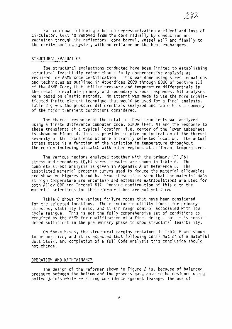
For cool down following a helium depressurization accident and loss ofcirculator, heat is removed from the core radially by conduction andradiation through the reflectors, core barrel, vessel wall and finally tothe cavity cooling system, with no reliance on the heat exchangers.
STRUCTURAL EVALUATION
The structural evaluations conducted have been limited to establishingstructural feasibility rather than a fully comprehensive analysis asrequired for ASME code certification. This was done using stress equationsand techniques as outlined in Appendices 2000 through 8000 of Section IIIof the ASME Code, that utilize pressure and temperature differentials inthe metal to evaluate primary and secondary stress responses. All analyseswere based on elastic methods. No attempt was made to use the more sophis-ticated finite element technique that would be used for a final analysis.Table 2 gives the pressure differentials analyzed and Table 5 is a summaryof the major transient conditions considered.
The thermal response of the metal to these transients was analyzedusing a finite difference computer code, SINDA (Ref. 4) and the response tothese transients at a typical location, i.e. center of the lower tubesheetis shown on Figure 4. This is provided to give an indication of the thermalseverity of the transients at an arbitrarily selected location. The actualstress state is a function of the variation in temperature throughoutthe region including mismatch with other regions at different temperatures.
The various regions analyzed together with the primary (PI ,Pb)stress and secondary (Q,F) stress results are shown in Table 6. Thecomplete stress analysis is given in Appendix A of Reference 5. Theassociated material property curves used to deduce the material allowablesare shown on Figures 5 and 6. From these it is seen that the material dataat high temperature are uncertain and extensive extrapolations are used forboth Alloy 800 and Inconel 617. Pending confirmation of this data thematerial selections for the reformer tubes are not yet firm.
Table 6 shows the various failure modes that have been consideredfor the selected locations. These include ductility limits for primarystresses, stability limits, and strain range control associated with lowcycle fatigue. This is not the fully comprehensive set of conditions asrequired by the ASME for qualification of a final design, but it is consi-dered sufficient in the preliminary phase to show structural feasibility.
On these bases, the structural margins contained in Table 6 are shownto be positive, and it is expected that, following confirmation of a materialdata basis, and completion of a full Code analysis this conclusion shouldnot chanoe.
OPERATION AND MAINTAINANCE
The design of the reformer shown in Figure 2. is, because of balancedpressure between the helium and the process gas, able to be designed usingbolted joints while retaining confidence against leakage. The use of
bellows expansion points also minimizes loadings that would tend to unloadsealing surfaces, and as noted earlier, allows for generous manufacturingand assembly tolerances. The free use of bolted joints enables access tomany structural elements for in-service inspection and replacement ofsub-assemblies if necessary.
FUTURE DEVELOPMENT
The design and analysis of the VIL reformer has progressedsufficiently to be considered a feasible option in future applications ofthe modular HTGR program. Near term plans are to continue developing thedesign with supporting stress analyses in the creep-fatigue regime. Forthe efforts to be meaningful, parallel efforts concentrating on obtainingelevated temperature properties of candidate reformer tube and tube sheetmaterials along with development of failure models are required.
REFERENCES
1. Meyer, D. J., "Description of the DSRDSGN Code: Steam ReformerDesign Code," General Electric Company Report GEFR-OO535, August 1980.
2. Meyer, D. J., Parker, K. M., "DSR1 Analytical Computer Program," DSR2841-6.l-(2), January 1980.
3. Fraas, A. P., Ojisik, M. N., Heat Exchange Design, John Wiley & Sons,1965.
4. SINDA Users Manual, J. F. Smith, NASA Contract 9-10435, TRW Report No.14690-H001-R0-00, April, 1971.
5. "MRS Recomrnendations and Evaluation of a Vertical In Line Reformer,"Gluck, R., Whifling, W. H., Hill, R., Unpublished, Feb. 1984.
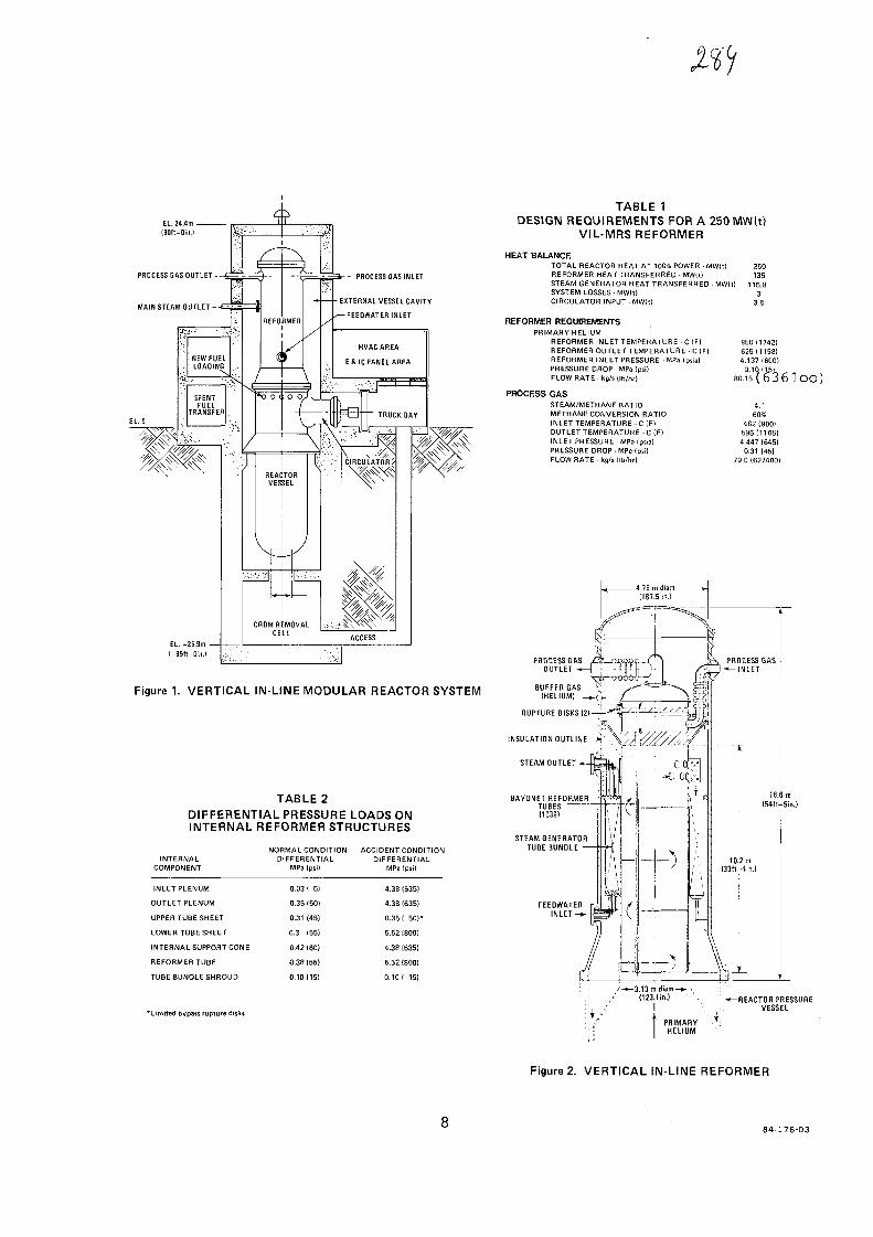
EL. 24.4m -(BOh-din.)
PROCESS GAS OUTLET--
MAIN STEAM OUTLET--
- - PROCESS GAS INLET
EXTERNAL VESSEL CAVITY
— FEEDWATER INLET
EL.-25.9m -<-85fl-0in.)
TABLE 1DESIGN REQUIREMENTS FOR A 250 MW(t)
VIL-MRS REFORMER
REACTORVESSEL
CRDMREMOVALCELL
HEAT BALANCETOTAL REACTOR HEAT AT 100% POWER - MW{0REFORMER HEAT TRANSFERRED - MWIl)STEAM GENERATOR HEAT TRANSFERRED - MWIl]SYSTEM LOSSES • MWWCIRCULATOR INPUT MWft)
REFORMER REQUIREMENTSPRIMARY HELIUM
REFORMER INLET TEMPERATURE C (F)REFORMER OUTLET TEMPERATURE • C (F)REFORMER INLET PRESSURE • MPa (psia)PRESSURE DROP • MPa IpsilFLOW RATE - kg/s ( Ib/M
PROCESS GASSTEAM/METHANE RATIOMETHANE CONVERSION RATIOINLET TEMPERATURE C IF)OUTLET TEMPERATURE -C(F)INLET PRESSURE MPa Ipsia]PRESSURE DROP • MPa (psi)FLOW RATE - kg/s (Ib/hrl
250135
115.83
3.8
950(1742)625(1158)4.137 1600)
4:160%
482 1900]596 11105)4.447 (645)
0.31 (45)79.0 (627400)
Figure 1. VERTICAL IN-LINE MODULAR REACTOR SYSTEM
RUPTURE DISKS (2)-
INSULATION OUTLINE
STEAM OUTLET
TABLE 2DIFFERENTIAL PRESSURE LOADS ONINTERNAL REFORMER STRUCTURES
INTERNALCOMPONENT
INLET PLENUM
OUTLET PLENUM
UPPER TUBE SHEET
LOWER TUBE SHEET
INTERNAL SUPPORT CONE
REFORMER TUBE
TUBE BUNDLE SHROUD
NORMAL CONDITIONDIFFERENTIAL
MPa (psi)
0.03 ( 5)
0.35 (50)
0.31 (45)
0.3 155)
0.42 160)
0.38 (55)
0.10(15)
ACCIDENT CONDITIONDIFFERENTIAL
MPa (psi)
4.38 (635)
4.3B 1635)
0.35 1 50)*
5.52 1800)
4.38 (635)
5.52 (800)
0.10 1 15)
BAYONET REFORMERTUBES[1039)
STEAM GENERATORTUBE BUNDLE
'Limited bypass rupture disks
-3.13 m diam—*- \;: , ' (123.1 in) -t— REACTOR PRESSURE
:; , ..• I \ VESSEL
* PRIMARY •'•HELIUM
Figure 2. VERTICAL IN-LINE REFORMER
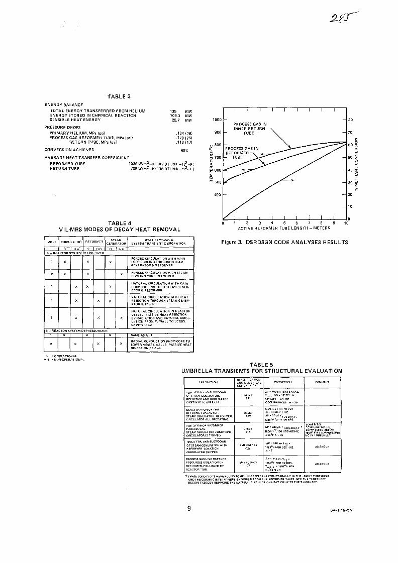
TABLE 3ENERGY BALANCE
TOTAL ENERGY TRANSFERRED FROM HELIUMENERGY STORED IN CHEMICAL REACTIONSENSIBLE HEAT ENERGY
PRESSURE DROPSPRIMARY HELIUM, MPa (psi)PROCESS GAS-REFORMER TUBE, MPa (psi)
RETURN TUBE, MPa Ipsi)
CONVERSION ACHIEVED
AVERAGE HEAT TRANSFER COEFFICIENT
135 MW109.3 MW25.7 MW
.104 (15)
.170 (25)
.118(17)
60%
REFORMER TUBERETURN TUBE
1036W/m2-K(182BTU/Hr-ft2-FI785W/m2-K(138BTU/Hr-f l2-F)
TABLE 4VIL-MRS MODES OF DECAY HEAT REMOVAL
1000
900
>tJJ
§700-
J 600>u
H 500
400
I I I I I
PROCESS GAS ININNER RETURN —v
- TUBE \
PROCESS GAS IN ^ _ _ 3REFORMER^ <
- TUBE \^""^ ^ ^ -
/ I I I I I
I
i— '
/
* -
|
I I
^ = =
I I
I
-
-
-
-
I
- 80
60 |
UJ
50 zO
- 30 !
- 10
0 1 2 3 4 5 6 7 8 9 10ACTIVE REFORMER TUBE LENGTH - METERS
MODE CIRCULATOR REFORMER
#
A - REACTOR SYSTEM PRESS
1
2
3
4
5
X
X
B - REACTOR S
1
2
X
X
X
X
YSTEM
X
X
X
X
EPRES
X
* *
STEAMGENERATOR
RIZEO
X
X
SURIZE
X
X
X
X
oX
X
X
X
HEAT REMOVALSSYSTEM TRANSIENT DESIGNATION
FORCED CIRCULATION WITH MAINLOOP COOLING THROUGH STEAMGENERATORS. REFORMER
FORCED CIRCULATION WITH STEAMCOOLING THRU REFORMER
NATURAL CIRCULATION WITH MAINLOOP COOLING THRU STEAM GENER-ATOR & REFORMER
NATURAL CIRCULATION WITH HEATREJECTION THROUGH STEAM GENER-ATOR (B17& C7I
NATURAL CIRCULATION IN REACTORVESSEL. PASSIVE HEAT REJECTIONBY RADIATION AND NATURAL CIRCU-LATION FROM PVWALL TO VESSELCAVITY <C2a)
SAME AS A - 1
RADIAL CONDUCTION FROM CORE TOLOWER VESSEL WALLS. PASSIVE HEATREJECTION AS A - 4 .
Figure 3. DSRDSGN CODE ANALYSES RESULTS
= OPERATIONAL= NON -OPERATIONAL
TABLE 5UMBRELLA TRANSIENTS FOR STRUCTURAL EVALUATION
DESCRIPTION
ISOLATION AND SLOWDOWNOF STEAM GENERATOR.REFORMER AND CIRCULATORCONTINUE TO OPERATE.
DEACTIVATION OF THEREFORMER CATALYST.STEAM GENERATOR, REFORMER,CIRCULATOR ALL OPERATING.
ISOLATION OF REFORMERPROCESS GAS.STEAM GENERATOR FUNCTIONS.CIRCULATOR IS TRIPPED.
ISOLATION ANDBLOWDOWNOF STEAMGENERATOR WITHREFORMER ISOLATIONCIRCULATOR TRIPPED.
PROCESS GAS LINE RUPTURE.PRECLUDES ISOLATION OFREFORMER, FOLLOWED BYREACTOR TRIP.
CLASSIFICATIONAND NUMERICALDESIGNATION
UPSETB11
UPSETB16
UPSETB17
EMERGENCYC2a
EMERGENCYC7
CONDITIONS
iiP - 700 psi (EXTERNAL)Tm3x S G * 1 1 5 0 ° F l o r
160 HRS. NO. OFOCCURRENCES N = 20
APPLIES FOH 10% OFREFORMER LIFE.AP 1 = G 5 p ! i T T U B E W A L L =173S°F for 14700 HRS.
^ P - 3 3 0 p . i T T U B £ S H E E T .
1600°F* 100 HRS ABOVE
1200°F N » 20
4 P - 3 3 0 p i i T T S =176d°F FOR 520 HRS.N - 7
A P - 7 1 0 p i i T T S -1350°F FOR 32 HRS.TWALL " " S ^ F FOR2HRSN " 7
COMMENT
LOWER T/STEMPERATURE ISSUPPRESSED BELOW1600° F BY SUPPRESSINGNC IN TUBESHEET
AS ABOVE
AS ABOVE
* THESE CONDITIONS WERE FOUND TO 8E UNACCEPTABLE STRUCTURALLY IN THE LOWER TUBESHEETAND THE CERAMIC INSERTS WERE EXTENDED FROM THE REFORMER TUBES INTO THE TUBESHEETREGION THEREBY REDUCING THE NATURAL CIRCULATION HEAT INPUT TO THE TUBESHEET.
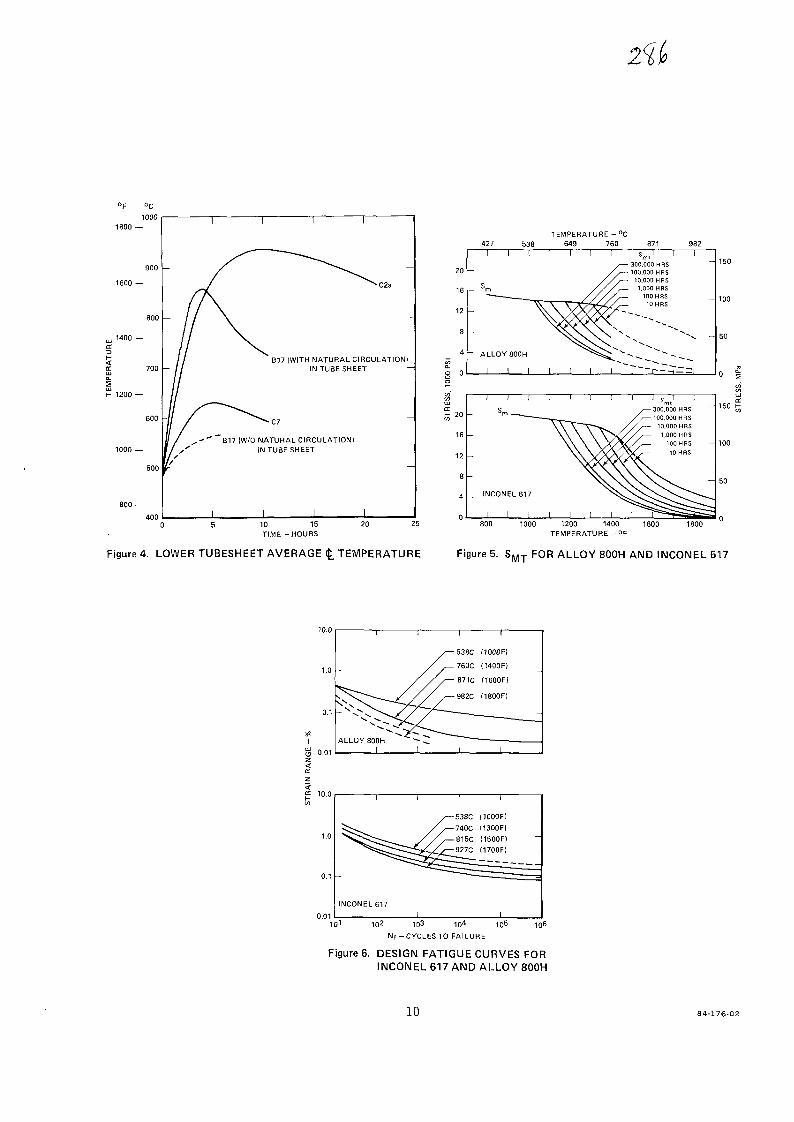
°c1000
1600 —
800
. 1400 —
E 700UJCLEUJ
l- 1200 —
1000 —
400
B17 (WITH NATURAL CIRCULATION)IN TUBE SHEET
B17 IVWO NATURAL CIRCULATION)IN TUBE SHEET
10 15TIME-HOURS
20
Figure 4. LOWER TUBESHEET AVERAGE <£. TEMPERATURE
20
16
12
8
4
0
427 538
1 1 1
—
r- S m
' —
-
~ ALLOY BOOH
1 1 1
TEMPERATURE - °C649 760
1 1 1 1
/ —
/ / ~
8711 W '300,000 HRS100,000 HRS10,000 HRS1,000 HRS
100 HRS10 HRS
1 1 1 1 ?"""~ r- — ^n*—
9821
3UJ
a:t - 20
16
12
3
A
0
I I I ) )
s— m ~—_
Vrvvv \
INCONEL617
I I I I I I
I I J s I 1
y—300.000 HRS ~/,— 100.000 HRS
~^~ ///— 10,000 HRS\ V V / / — 1,000 HBS\X/\//. 100 HRS
V A A / X V — 10 HRS
1 1 ̂ T~1200 1400
TEMPERATURE - °F1600
Figure 5. S M T FOR ALLOY 800H AND INCONEL 617
I !
ALLOY 800H ~~ —•I I
/— 538C
/ — 760C
//— 871C
/ , — 982C
i
(1000FI
(1400F)
(1600F)
(1800F)
• • 1
I
IU.U
1.0
0.1
0.01
I I
^ — .
INCONEL 6171 1
1
/— 538C/ . — 740C
///—815C
i<C/^-927C
^ ^
I
1
(1000F)(1300F)
(1500F)
(1700F)
1
102 103 104 105
N f -CYCLESTO FAILURE
106
Figure 6. DESIGN FATIGUE CURVES FORINCONEL 617 AND ALLOY 800H
10 84-176-02

TABLE 6STRESS ANALYSIS RESULTS
REFORMERTUBES
800H
REFORMERTUBES
617
LOWERTUBESHEET
800H
LOWER T/SSUPPORTCONE800 H
UPPERTUBESHEET
UPPER T/SSUPPORTCYLINDER
CYLINDER
HEAD
STRUCTURALPARAMETER
Pm
INSTABILITYPL + PB + Q+F
DAMAGE FACTOR)
INSTABILITY(DAMAGE FACTOR)
PL + PB
PL + PB + Q
PL + PB + O+ F
Pm
PL + PB + Q
P|_ + Pg + Q+ F
pL + PB
PL + P B +Q
PL + PB + Q+ F
PmPm
INSTABILITY
PmPm
INSTABILITY
Pm
INSTABILITY
LOADINGEVENT
NORMAL IA-3)UPSET (8-16)
EMERG. (C-7)
ALL TRANSIENTS
(A-3)(B-16)(C-7)
PRESSURE ONLY
ALL TRANSIENTS
EMERG. (C-7)
(C-7)
PRESSURE ONLY
(B-17)
NORMAL
EMERG. (C-7)
(C-7)
NORMALEMERG. (C 7)
(C-7)
EMERG. (C-7)
(C-7)
VALUE
239 psi305 psi
710 psi
0.18
239 psi305 psi
3332 psi
6352 psi
25991 psi
0.81
10956 psi
23782 psi
2403 psi
23424 psi
6490 psi
11800 psi
200 psi
1740 psi
15950 psi
550 psi
14575 psi
ALLOWABLE
570 psi720 psi
72987/2.5 =29195 psi
1.0
600 psi800 psi
4830 psi
Smt<s>l118°Fand300Hrs =
14,100 psi3Sm,@1067°Fand
300Hrs =42,300 psi
1.0
S m t @950°F and300Hrs =
14,600 psi
43,800 psi
Sm t<ai005°F =14,400 psi
3S @1179°F<9>1000 Hrs =
37,500 psi
13,400 psi
16,560 psi
1692/2.5 =677 psi
13,400 psi
4794/2.5 =1917 psi
17,160 psi
MARGIN
1.381.36
04LARGE
4.56
1.511.62
LARGELARGE
1.33
0.63
0.23 -
0.33
0.84
LARGE
4.99
0.60
1.06
0.40
2.38
6.70
2.49
0.18
LARGE
PRIMARY MEMBRANE STRESS AT 1735°F617 MARGIN > 800H MARGIN
NATURAL CIRCULATION SUPPRESSED INTUBESHEETRIM/HOLE INTERACTION
CONSERVATIVE BASE ON USE OF "HOLD TIME"FATIGUE CURVES
AP REDUCED BY USE OF RUPTURE DISKS
84-176-01

No. 17- 1 -
XA0055826
Development and Fabrication of a
Helium-Heated Steam Reformer
W. Panknin, W. Nowak
L. & C. Steinmiiller GmbH
Gummersbach, F.R. Germany
1. Introduction
The development of a helium-heated steam reformer for the
Prototype Plant Nuclear Process Heat (PNP) or for a High-
Temperature Reactor Module Plant must satisfy the specific
requirements connected with nuclear components.
Some of the main aspects will be mentionend:
Because the steam reformer is part of the barrier between
primary helium and secondary process gas, all parts of the
primary closure must be accessible without opening the
primary circuit, and in-service inspection should be
possible.
Leakage of the primary gas into the secondary circuit, due
to the failure of component parts, must be impossible.
This is accomplished by maintaining a slight pressure
difference of 2 bar between the two circuits.
Gas streaks in the primary helium with a temperature
difference of about + 20 K in comparison to the average
gas temperature are expected to occur. The resultant
effects must be considered and kept under control. The
layout of the steam reformer must be designed against the
impacts of external events such as seismic loads.

- 2 -
The loss of the secondary heat sink ought not result in
any major damage.
The whole tube bundle must be replacable.
Replacement of the catalyst must be simple and fast.
The design lifetime of the component is 140.000 hrs.
All these requirements are more stringent than those for
conventional steam reformers or other comparable heat ex-
changers. Therefore, a new concept had to be worked out
first, before beginning with the layout and design of the
component.
Here our main objective was, to separate those assemblies
which are exposed to high in-service strains or high
temperatures into structures of a simple geometry and to
assign only one function to each element.
This way we found a concept and design with such a low
stress level in all its relevant parts that the licensing
procedure of the stress analysis is expected to be fea-
sible.
The steam reformer for PNP will have a heat transfer ca-
pacity of about 96 MW. The bundle will consist of roughly
300 tubes. In order to test the new concept and design ex-
perimentally, a steam reformer of smaller capacity (5 MW)
with only 18 tubes was designed and is being fabricated at
the moment. This bundle will be tested in the EVA II pilot
plant at KFA Julich. Because this bundle is comparable in
almost all important details to the large steam reformer,
the flow path and the design, as well as some interesting
manufacturing steps will be explained with respect to this
test steam reformer.
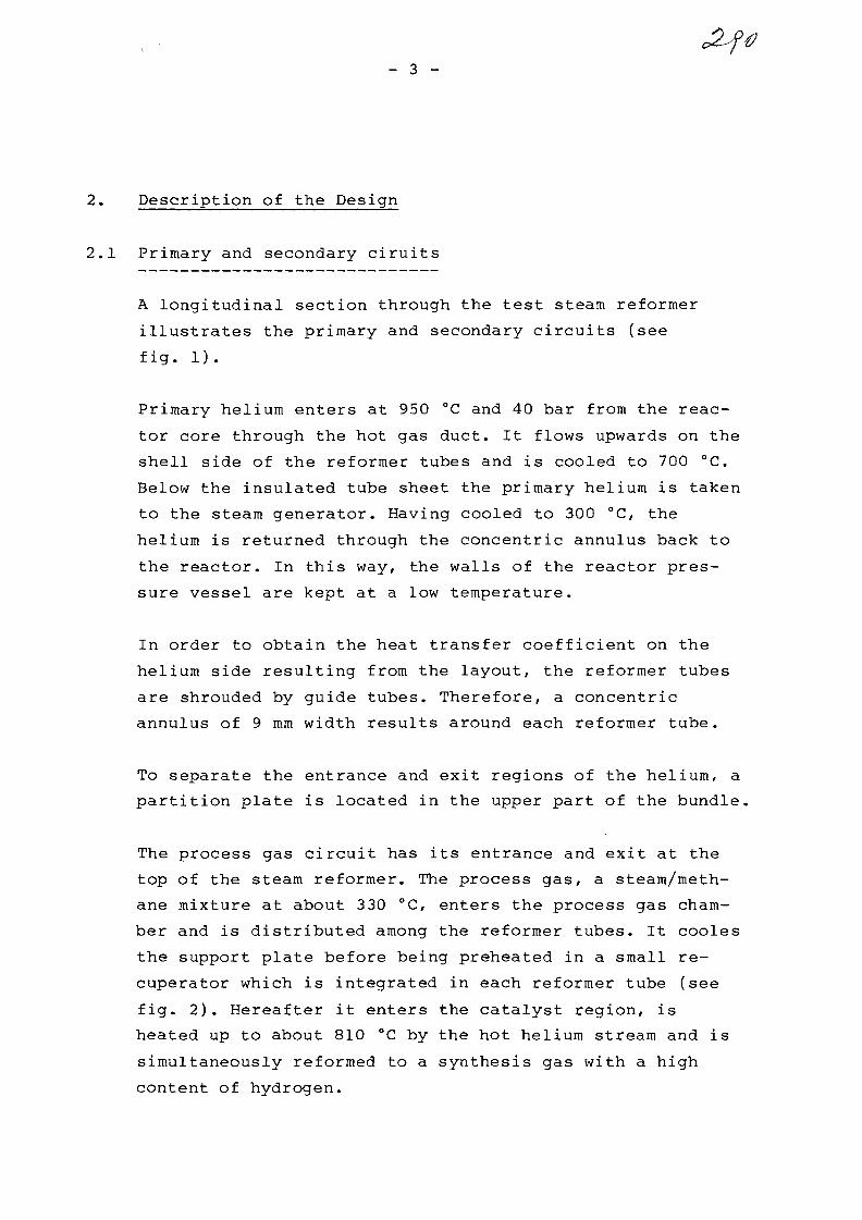
- 3 -
2. Description of the Design
2.1 Primary and secondary ciruits
A longitudinal section through the test steam reformer
illustrates the primary and secondary circuits (see
fig. 1).
Primary helium enters at 950 °C and 40 bar from the reac-
tor core through the hot gas duct. It flows upwards on the
shell side of the reformer tubes and is cooled to 700 °C.
Below the insulated tube sheet the primary helium is taken
to the steam generator. Having cooled to 300 °C, the
helium is returned through the concentric annulus back to
the reactor. In this way, the walls of the reactor pres-
sure vessel are kept at a low temperature.
In order to obtain the heat transfer coefficient on the
helium side resulting from the layout, the reformer tubes
are shrouded by guide tubes. Therefore, a concentric
annulus of 9 mm width results around each reformer tube.
To separate the entrance and exit regions of the helium, a
partition plate is located in the upper part of the bundle.
The process gas circuit has its entrance and exit at the
top of the steam reformer. The process gas, a steam/meth-
ane mixture at about 330 °C, enters the process gas cham-
ber and is distributed among the reformer tubes. It cooles
the support plate before being preheated in a small re-
cuperator which is integrated in each reformer tube (see
fig. 2). Hereafter it enters the catalyst region, is
heated up to about 810 °C by the hot helium stream and is
simultaneously reformed to a synthesis gas with a high
content of hydrogen.

- 4 -
This synthesis gas is cycled back through a return tube,
cooled down to 460 °C in the recuperator and leaves the
steam reformer through the product gas chamber.
2.2 Reformer Tube Bundle
As already mentioned, the tube bundle of the 96 MW com-
ponent consists of about 300 tubes, 120 0 x 10 x 17.000 mm.
The test bundle has 18 tubes and one inspection tube. They
are arranged in a triangular pitch of 200 mm. 13 tubes are
made out of Inconel 617 (2.4663). For comparison reasons
5 tubes are made out of Incoloy 800 H (1.4876 H). Because
such long tubes cannot be manufactured in one step,
shorter tubes, about 2.500 mm long are welded togehter
(see fig. 4). Then they are bored to the final internal
diameter and the outer diameter is machined to the correct
size with the aid of a special lathe.
The tubes are welded to the underside of the support
plate, which is manufactured of material 10 CrMo 910. This
material has to be annealed after welding. Because of the
tube length this is not practicable for the whole bundle.
Therefore the plate is deposition welded first with the
corresponding tube material. Then the plate is heat
treated and finally the tubes are welded to it. Hereafter
no further heat treatment of the plate is necessary.
At the level of the partition plate the guide tubes are
welded to the reformer tubes so that they can freely ex-
pand downwards in the axial direction (see figs. 3 and 5).
The guide tubes with an outer diameter of 144 mm have a
wallthickness of only 3 mm. They are manufactured by a
special flow forming process which produces tubes to very
close tolerances (see fig. 10). In addition this is a
material-saving process.

— 5 —
To maintain the annulus between reformer and guide tube,
spacers are placed every 2 m (see fig. 3). The spacers and
the contacting surfaces of the reformer tubes are coated
with a protective layer against fretting in the helium
atmosphere.
The tubes are freely suspended from the support plate and
held in position by only one more plate, called tube guide
plate (see figs. 1 and 2). Through this guide plate at the
lower end of the reformer they can expand during opera-
tion. The sealing between the inlet and outlet helium flow
is achieved by a partition plate as mentioned above. Ra-
dial and axial displacement of the tubes is possible, be-
cause of the use of expansion joints connecting the par-
tition plate and the guide tubes (see figs. 3 and 7).
There are some advantages of the new concept in comparison
to other wellknown systems. One important characteristic
of the design is that the reformer tubes are kept in
position by only two elements which are as far apart as
possible. Therefore a certain tube distortion is accept-
able and the reaction forces between plates and tubes, as
well as the bending stresses are minimized. No unallowable
stress or even deformation of the tube guide plate or the
tube itself is expected to occur.
Another advantage of this design is the fact that guide
tubes are used for the helium flow. Firstly, this design
does not have an undefinable boundary flow as can usually
be found in similar components. Secondly, the blocking of
individual tubes with a resulting local temperature change
will cause no unallowed interference to the adjoining tu-
bes. Therefore steam reformers of different capacity can
be built by simply chosing the correct number of tubes. In
addition no overall heat transfer measurements are needed
because of the same regular and simple flow in each of the
annuli.
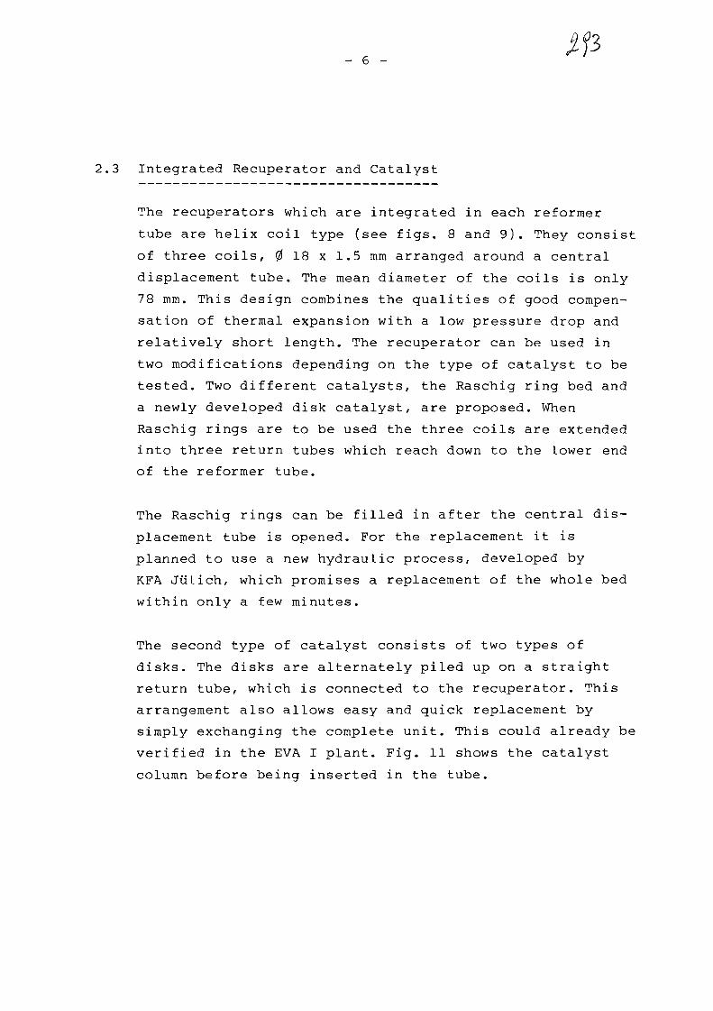
- 6 -
2.3 Integrated Recuperator and Catalyst
The recuperators which are integrated in each reformer
tube are helix coil type (see figs. 8 and 9). They consist
of three coils, 0 18 x 1.5 mm arranged around a central
displacement tube. The mean diameter of the coils is only
78 mm. This design combines the qualities of good compen-
sation of thermal expansion with a low pressure drop and
relatively short length. The recuperator can be used in
two modifications depending on the type of catalyst to be
tested. Two different catalysts, the Raschig ring bed and
a newly developed disk catalyst, are proposed. When
Raschig rings are to be used the three coils are extended
into three return tubes which reach down to the lower end
of the reformer tube.
The Raschig rings can be filled in after the central dis-
placement tube is opened. For the replacement it is
planned to use a new hydraulic process, developed by
KFA Jiilich, which promises a replacement of the whole bed
within only a few minutes.
The second type of catalyst consists of two types of
disks. The disks are alternately piled up on a straight
return tube, which is connected to the recuperator. This
arrangement also allows easy and quick replacement by
simply exchanging the complete unit. This could already be
verified in the EVA I plant. Fig. 11 shows the catalyst
column before being inserted in the tube.

— 7 —
3. Outlook
As already said, the test bundle is in production at the
moment. It is planned to start the experiments at the end
of this year.
The whole test period will last between 1 and 2 years,
thereafter the test bundle will be removed and subjected
to several extensive checks and post-experiment investiga-
tions .
With the experience already gained by the fabrication and
testing of various reformer tube configurations, as well
as with the enlarged knowledge from the design studies,
the development standard should allow the licensing and
subsequent construction of a steam reformer for a nuclear
power plant.

productgas
processgas
primaryhelium ~
product gaschamber
process gaschamber
support plate
insulation
recuperator
primaryhelium
partition plate
reformer tube
tube guideplate
Fig. 1: Steam Reformer (Test-bundle for EVA II)
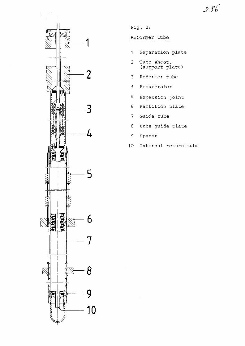
Fig. 2:
Reformer tube
1 Separation plate
2 Tube sheet,
(support plate)
3 Reformer tube
4 Recuperator5 Expansion joint
6 Partition plate
7 Guide tube
8 tube guide plate
9 Spacer
10 Internal return tube
8
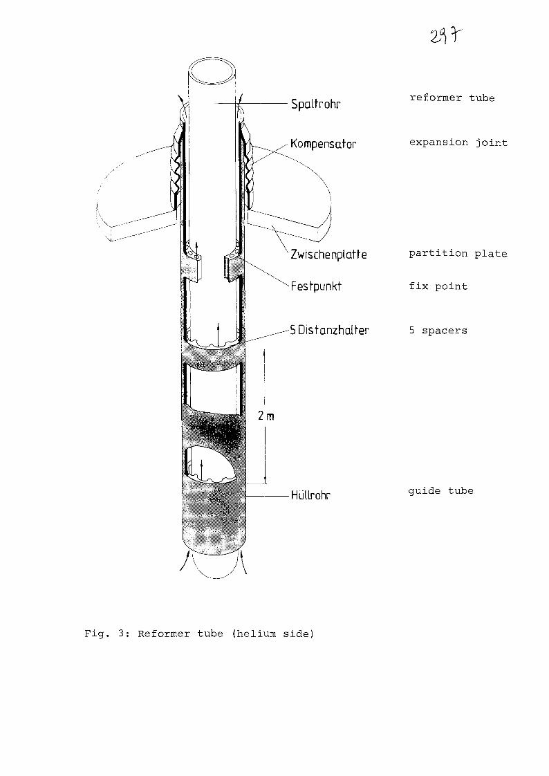
Spaltrohr
Kompensafor
Zwischenplatfe
Festpunkt
5Dist-anzhalter
Hullrohr
reformer tube
expansion joint
partition plate
fix point
5 spacers
guide tube
Fig. 3: Reformer tube (helium side)
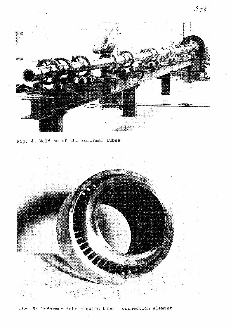
Fig. 4: Welding of the reformer tubes
Fig. 5: Reformer tube - guide tube connection element

HPiili
Fig. 6: Deposition welding
on the tube sheet
Fig. 7: Expansion joints
(between partition plate
and guide-tube)
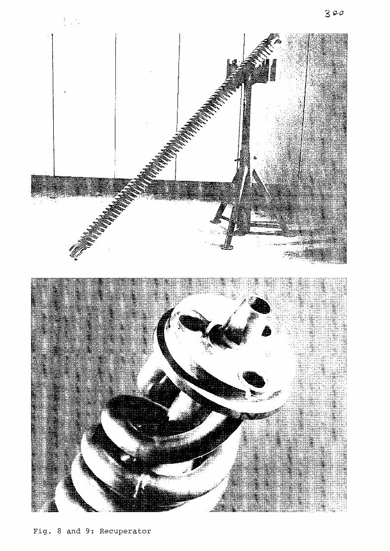
Fig. 8 and 9: Recuperator
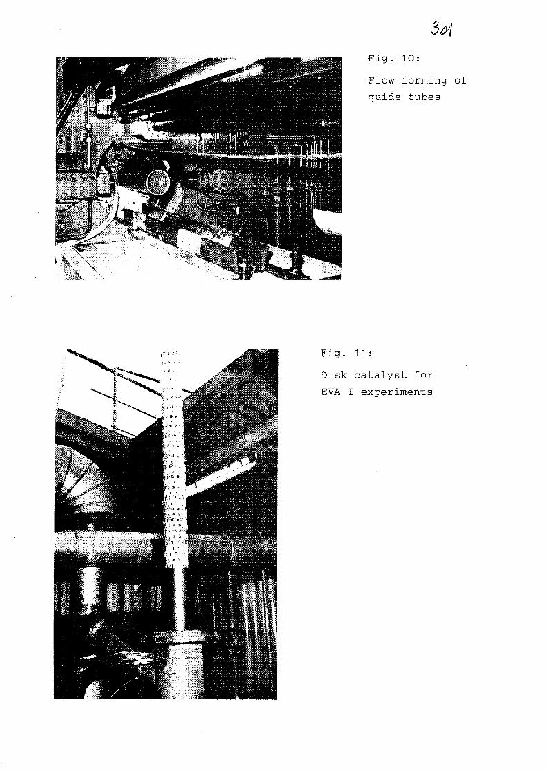
•Fig. 10:
Flow forming of
guide tubes
Fig. 11:
Disk catalyst for
EVA I experiments

No. 18
Assembly and Operation Experience XA0055827
of EVA II Steam Reforming Bundle
H.F. Nieften, R. HarthKernforschungsanlage Jiilich GmbH, Jiilich FRG
W. KeselRheinische Braunkohlenwerke AG, Koln, FRG
The main test component of the experimental facility EVA 11/
ADAM II is a helium heated steam reformer bundle with 30 tubes.
The dimensions of the tubes are 120 mm OD/100 mm ID and a. heated
length of 11 m. The tubes are arranged in the tube sheet in
a triangular pitch, and the diameter of the bundle is 1.2 m.
To achieve a better heat transfer on the helium side, there
are baffles (disk and doughnut) arranged every 250 mm, resulting
an intensive cross counterflow. The helium entering the lower
end of the bundle with a temperature of 950 CC flows upwards,
and is cooled down to a temperature of 600 - 650 °C. After-
wards the helium leaving the bundle is guided to the steam
generator. The bundle is surrounded by an insulation of car-
bon stone bricks, which are inside metallic liners on both
sides. This component is arranged inside a metallic vessel
with a diameter of 2.3 m and a height of 18 m. The "cold" he-
lium flowing back from the circulator to the helium heater
is guided in the gap between the metallic vessel and the car-
bon stone insulation. Fig. 1 shows a scheme of the steam re-
former and fig. 2 a photograph of the bundle itself.
The steam reformer tubes are filled with a catalyst of raschig
ring type. Every 3 tubes have a common feed- and product gas
line. Outside the vessel the 10 feed and the 10 product lines
are connected in central headers. The feed gas streaming down-
wards is heated up and reacts at the same time according to
the steam reforming reaction. The product gas is guided at
the lower end of the steam reformer tubes to two small coiled
returning tubes and flows then upwards. Additional to the well
known advantages of the inner gas return tube (heat back to
the process, lower temperature level for the penetration etc.)
the coiled version has the following advantages:

- 2 -
L06Wst
MTP
D 101
RSO
18.126 mm2.300 mm
54 mm13 Cr Mo 44
171 t50045 bar
Fig. 1: Scheme of the bundlearrangement in the vessel
Fig. 2: Steam reformer bundle
i ill in.Wlhi

3- 3 -
1) Good compensation of differential length in the start-up
and shut-down phase.
2) No possibility of sinking of the catalyst because each coil
carries a part of the catalyst.
After 8 000 hrs operation time, 6 000 hrs with a helium tempera-
ture above 800 °C and a lot of start-ups and shut-downs no
sinking of the catalyst was registrated.
The main tests of the component were related with the power
dependence. The several loads are adjusted by massflow control
but also by the helium enterance temperature. Fig. 3 shows
the temperature of the product gas at the end of the catalyst
bed versus the relation of the mass flows of helium to process
gas at the helium inlet temperatures of 950 °C and 900 °C.
At the design point (helium temperature 950 °C, pressure 40 bar,
helium mass flow 3.2 kg/s) a product gas temperature of 825 °C
results. The approach to the chemical equilibrium is 9 K that
means the content of unvonverted methane in the product gas
is equivalent to an equilibrium temperature of 816 °C (fig. 4 ) .
The dependence of the productgas temperature versus the mass
flow relation is represented by a straight line with an accep-
table accuracy. This type of control has the disadvantage that
the helium exit temperature of the bundle also decreases and
this results in an additional reduced steam production and
extremely there is not enough process steam produced. Therefore
it seems to be necessary at smaller part loads (70 % or less)
to have not only a mass flow control but also a combined mass-
flow-/temperature control. While the maximum process gas tem-
perature has only a very small pressure dependence, there is
a significant dependence for the unconverted methane content
in the product gas, that means at lower pressure that part
of helium heat used for conversion of methane increases. This
results for the Nuclear Chemical Heat Pipe System in a larger
production of chemical heat and for the nuclear process heat
applications in larger production of hydrogen + carbon monoxide.
This could be verified by the experiments. The results are shown
in fig. 5, where the relation of the chemical heat to the energy

- 4 -
900
'PG.MAX
850
800
D Ausiegung
oRSO-Eintr.-Temp. Helium
o ca. 950 °C
• ca.900 °C
1.5m'PG
Fig. 3: Maximum process gas temperature versus relative mass-flow
0,10
RSO.A
0,05
n Ausiegung
RSO-Eintr.-Temp. Helium /Systemdruck
ca.900°C/30bar
/ c a . 900°C/40bar
.ca. 950°C /40bar
1,5PG
Fig. 4: Unconverted methane content versus relative massflow

_ cr _
supplied by the helium heater versus the system pressure is
shown. A similar effect like the pressure reduction has a higher
helium inlet temeperature to the steam reformer bundle. The
temperature dependence is given in fig. 6. Starting with these
results, one can see that it is possible to get a higher effi-
ciency with a lower pressure, or the same efficiency at a lower
helium- and process gas temperature level which results lower
wall temperatures too.
For nuclear heated steam reformers it is planned that in case
of tube cracks the damaged tube has to be plug off. This pro-
cedure causes consequences for the operation of the steam re-
former. A series of experiments, done in the way shown after-
wards, served the investigation of these effects. After a stable
operation point was reached with 3 0 tubes, 3, 6 and upto 9 tubes
were plugged off on the feed side. That means the steam re-
former was operated under constant conditions like mass flow
(helium and process gas), inlet temperatures, pressure etc.
but with 30, 27, 24 and in some cases 21 tubes. The result
of these experiments in the direction of the maximum process
gas temperature are shown in fig. 7. For each plugged-off group
of 3 tubes the process gas temperature decreases 7 K and the
conversion too. The non-fed tubes nearly have helium tempera-
ture in these experiments. Because of the mixing effect of
the cross counter flow on the helium side there are no parts
with significant higher helium temperatures. But it has to
be mentioned, that in case of 6 or more plugged-off tubes,
all loacated in the same quarter, the fed tubes surrounded
by plugged-off tubes have a systematically higher temperature
than those only surrounded by fed tubes. Always the wall tem-
perature of the original situation (30 tubes) will not be reached.
A last series of experiment dealed with the influence of the
steam/methane ratio in the direction of carbon deposit for-
mation. Because of economic reasons a steam/methane ratio as
low as possible inpreferable. Therefore the ratio was system-
atically decreased and at ratios below 2.5 mol/mol in the

- 6 -
.5
30 bar
Fig. 5: Efficiency versus process pressure
850 30O 350
Fig. 6: Efficiency versus helium inlet temperature

- 7 -
process condensate carbon deposits were found. All observations
(no activity loss of catalyst, pressure drop etc.) show that
the carbon was not deposited in the catalyst itself but in
the cooling devices like inner gas return tubes process gas
coolers. Therefore the carbon seems to be formed by the Bondouard
reaction (2 CO —*- C + C0~ ) .
With the end of the year 1983 the succesful experiments with
the bundle were ended. At this time an after-operation inspec-
tion program is on the way.
900
'PG.MAX
[ °C ]
850
800
Systemdruck ca.40bar
RSOEintr.-TempHelium
ca.950°C
ca. 900 °C
berikksichtigte Meflstellerv. 4,7,13,14,20,21
1,5
m"He
'PC
Fig. 7: Maximum process gas temperature with tubes plugged-off

No. 1 9
IAEA - INTERNATIONAL WORKING GROUP ON GAS-COOLED REACTORS
•IIIXA0055828
Specialists' Meeting
on
Heat Exchanging Components of
Gas-Cooled Reactors
Duesseldorf
Federal Republic of Germany
16-19 April 1984
'EVALUATION OF MATERIALS FOR HEAT EXCHANGING COMPONENTS
IN ADVANCED HELIUM-COOLED REACTORS
by
F . Schubert
Kernforschungsanlage Juelich GmbH
Institute for Reactor Materials
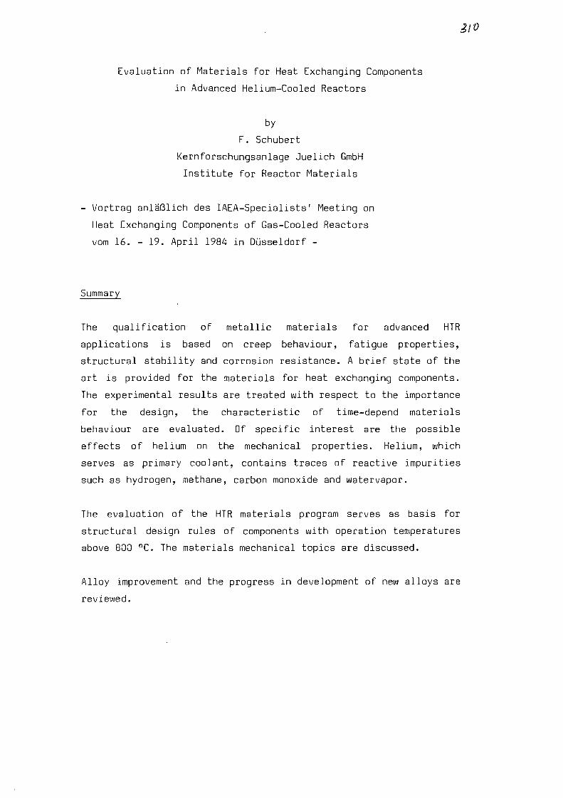
Evaluation of Materials for Heat Exchanging Components
in Advanced Helium-Cooled Reactors
by
F. Schubert
Kernforschungsanlage Juelich GmbH
Institute for Reactor Materials
Vortrag anlaSlich des IAEA-Specialists' Meeting on
Heat Exchanging Components of Gas-Cooled Reactors
vom 16. - 19. April 1984 in Diisseldorf -
Summary
The qualification of metallic materials for advanced HTR
applications is based on creep behaviour, fatigue properties,
structural stability and corrosion resistance. A brief state of the
art is provided for the materials for heat exchanging components.
The experimental results are treated with respect to the importance
for the design, the characteristic of time-depend materials
behaviour are evaluated. Of specific interest are the possible
effects of helium on the mechanical properties. Helium, which
serves as primary coolant, contains traces of reactive impurities
such as hydrogen, methane, carbon monoxide and watervapor.
The evaluation of the HTR materials program serves as basis for
structural design rules of components with operation temperatures
above 800 °C. The materials mechanical topics are discussed.
Alloy improvement and the progress in development of new alloys are
reviewed.
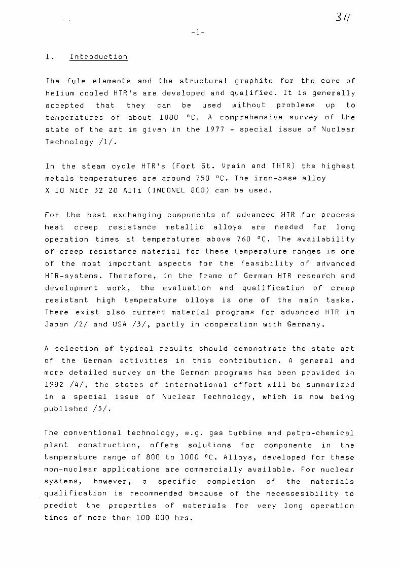
3//
1 . Introduction
The fule elements and the structural graphite for the core of
helium cooled HTR's are developed and qualified. It is generally
accepted that they can be used without problems up to
temperatures of about 1000 °C. A comprehensive survey of the
state of the art is given in the 1977 - special issue of Nuclear
Technology /I/.
In the steam cycle HTR's (Fort St. Vrain and THTR) the highest
metals temperatures are around 750 °C. The iron-base alloy
X 10 NiCr 32 20 AITi (INCONEL 800) can be used.
For the heat exchanging components of advanced HTR for process
heat creep resistance metallic alloys are needed for long
operation times at temperatures above 760 °C. The availability
of creep resistance material for these temperature ranges is one
of the most important aspects for the feasibility of advanced
HTR-systems. Therefore, in the frame of German HTR research and
development work, the evaluation and qualification of creep
resistant high temperature alloys is one of the main tasks.
There exist also current material programs for advanced HTR in
Japan /2/ and USA /3/, partly in cooperation with Germany.
A selection of typical results should demonstrate the state art
of the German activities in this contribution. A general and
more detailed survey on the German programs has been provided in
1982 /4/, the states of international effort will be summarized
in a special issue of Nuclear Technology, which is now being
published /5/.
The conventional technology, e.g. gas turbine and petro-chemical
plant construction, offers solutions for components in the
temperature range of 800 to 1000 °C. Alloys, developed for these
non-nuclear applications are commercially available. For nuclear
systems, however, a specific completion of the materials
qualification is recommended because of the necessesibility to
predict the properties of materials for very long operation
times of more than 100 000 hrs.

-2-
A f u r t h e r a s p e c t o f t h e q u a l i f i c a t i o n of a l l o y s for HTR a p p l i c -
a t i o n s is the e f f e c t of t h e w o r k i n g e n v i r o n m e n t s on t h e
m e c h a n i c a l b e h a v i o u r . T h e f i r s t i n v e s t i g a t i o n s of the e f f e c t s o f
i m p u r e h e l i u m s i m u l a t i o n t h e p r i m a r y c o o l a n t g a s o f an HTR on
the p r o p e r t i e s o f a l l o y s were s t a r t e d in t h e e a r l y 1 9 7 0 s by t h e
O E C D D r a g o n P r o j e c t / 6 / . T h e s t r e s s r u p t u r e and c o r r o s i o n
b e h a v i o u r of v a r i o u s a l l o y s in s i m u l a t e d HTR h e l i u m w e r e
i n v e s t i g a t e d . T h e r e s u l t s of t h e s e t e s t s s h o w e d a s i g n i f i c a n t
i n f l u e n c e o f t h e g a s c o m p o s i t i o n a n d t e m p e r a t u r e on c o r r o s i o n
e f f e c t s ( e . g . , at 8 5 0 - 1 0 0 0 ° C , i n t e r n a l o x i d a t i o n a n d s e v e r e
c a r b u r i z a t i o n w e r e f o u n d ) . H o w e v e r , an e f f e c t o f c o r r o s i o n on
t h e s t r e s s r u p t u r e p r o p e r t i e s w a s n o t c l e a r l y o b s e r v e d .
2 . E x p e c t e d o p e r a t i o n a l c o n d i t i o n s
T h e p r e s e n t p a p e r is e s s e n t i a l l y o r i e n t e d t o w a r d s t h e u s e of a
p e b b l e bed HTR for n u c l e a r p r o c e s s h e a t . In t h e s e c a s e s t h e
h i g h e s t t e m p e r a t u r e s of m e t a l l i c c o m p o n e n t s o c c u r in the h o t g a s
d u c t s , t h e m e t h a n e r e f o r m e r t u b e s a n d t h e h e l i u m / h e l i u m h e a t
e x c h a n g e r . T h e s e c o m p o n e n t s a r e t h e t o p i c s of t h i s s p e c i a l i s t s '
m e e t i n g . In t h e c a s e of n u c l e a r p r o c e s s h e a t , the t h e r m a l p o w e r
of t h e c o r e is t r a n s f e r e d by h e l i u m e i t h e r to t h e r e f o r m e r t u b e s
( m a x i m u m m e t a l s t e m p e r a t u r e 9 0 0 ° C ) in w h i c h h y d r o g e n is
g e n e r a t e d for the h y d r o g a s i f i c a t i o n of c o a l by m e t h a n e r e f o r m i n g
or to t h e t u b e s of t h e i n t e r m e d i a t e h e a t e x c h a n g e r ( m e t a l s
t e m p e r a t u r e of a b o u t 9 3 0 ° C ) , w h i c h is r e q u i r e d in the s t e a m
g a s i f i c a t i o n of h a r d c o a l ( F i g . 1 ) . In o r d e r to a c h i e v e l o n g
s e r v i c e l i v e s the s t r e s s u n d e r n o r m a l o p e r a t i o n a l c o n d i t i o n s is2
k e p t b e l o w 5 N / m m . T h e c o m p o n e n t m u s t w i t h s t a n d a d d i t i o n a l
t e m p e r a t u r e i n c r e a s e s a n d / o r p r e s s u r e t r a n s i e n t s u n d e r up s e t
and e m e r g e n c y c o n d i t i o n s . F o r t h i c k - w a l l e d c o m p o n e n t s w i t h w a l l
t h i c k n e s s t r a n s l a t i o n s , p a r t i c u l a r a t t e n t i o n m u s t be p a i d to
f a t i g u e p h e n o m e n a d u e to s t a r t i n g up a n d s h u t d o w n o p e r a t i o n s .
T h e c o o l a n t is t h e i n e r t g a s h e l i u m , b u t b e c a u s e it c o n t a i n s
s l i g h t i m p u r i t i e s in m b a r r a n g e / 8 / of C O , C H . , H ~ , H ^ O , C O - a n d
N_ r e a c t i o n s c a n be e x p e c t e d w i t h c e r t a i n a l l o y c o n s t i t u e n t s
w h i c h may c a u s e m a t e r i a l p r o p e r t y c h a n g e s . In F i g . 2 s o m e of t h e
s i m u l a t e d H T R - h e l i u m s a r e p r e s e n t e d .
3/3
-3-
Under these operational boundary conditions the design and the
analysis of component behaviour must be outlined. Today, no
accepted structural design rules or codes are avialable so far
for nucler application. The ASME-CC N 47 /I/ contains rules for
the design of nuclear components based on the time dependent
properties for application temperatures up to around 800 °C and
may provide guidelines for high temperature design methods. The
work at present in progress has, however, shown that the rules
and tests given in the code are of only limited use at the
higher temperatures, for two main reasons. Firstly, the
candidate materials have not yet been adopted for nuclear
applications and secondly the material response to the predicted
HTR service conditions proves to be rather different to that at
the lower temperatures for which the code is valid.
The stringent safety and reliability requirements which are
applied to nuclear components demand that, for all postulated
service and upset conditions the design shall ensure against
failure. This can only be achieved if all modes and causes of
failure are known, characterized and controlled by adequate
methods.
For design with time dependent properties at high temperatures,
the following failure modes need to be considered:
failure due to short-term loadings,
failure due to long-term loadings,
failure due to creep-fatigue loadings,
distortion due to incremental collapse and creep
ratcheting.
In addition to the design against failure, a design against
excessive deformation is required to exclude loss of function
and to maintain as far as possible the original design status of
the component. The calculation of component deformation
behaviour requires practicable constitutive equations, which
must be incorporated into the elastic, simplified inelastic or
full inelastic analysis. The equations must reasonably describe
the material response to the loading conditions. Material
failure and deformation limits are derived from the material
properties data.

-4-
3. Materials evaluations
The selection of candidate alloys for the advanced HTR projects
was based on long term creep rupture properties, structural
stability and fabricability. For the highest operating
t e m p e r a t u r e s , solid solution hardened nickel-base alloys were
therefore chosen. To qualify these alloys for nuclear
a p p l i c a t i o n s , extensive test programs have been initiated / 4 , 5,
8, 9/, the principle tasks of which are:
creep-rupture testing of the basic alloys and weldments
determination of the changes in mechanical and physical
properties after long-term exposure under simulated service
c o n d i t i o n s , particularly ductility (end-of-life properties)
high and low cycla fatigue testing
gas-metal-reaction kinetics
influence of high temperature corrosion in simulated
service environments on mechanical and physical properties
creep-fatigue interactions
fracture mechanics studies with special emphasis on the
effects of service environments on crack initiation and
propagation
fracture toughness characteristics
constitutive equations
damage accumulation and estimation of service life
transferability of mechanical properties data to multiaxial
loadings and complex geometries
fretting, friction and wear
development of coatings
influence of irradiation on materials behaviour (for m e t a l -
lic control and absorber rod cladding only)
In addition to the extensive research and test programs for the
qualification of commercial alloys for HTR process heat applic-
ations, efforts have been expended to develop new alloys
designed specifically for high temperature HTR c o m p o n e n t s .
Generally, the primary goals of these developments are improved
high-temperature creep and fatigue strength, better corrosion
resistance in the HTR primary coolant.

-5-
4. Selected commercial alloys
From the groups of high temperature alloys, some NiCr-alloys
have been selected. The nominal compositions are given in
Fig. 3.
The most important criteria for the selection of alloys are the
creep behaviour and the availability of the needed semi-finished
products.
In Fig. 4 average 1 ?o creep strain limit and creep rupture
strength are shown. These data originate from the extrapolation
of a scatterband evaluation /7/. The magnitude of creep strength
indicated the capacity for practicle use.
Among those materials which can still be processed into plate
and tube geometries by hot and cold working INCONEL 617 exhibits
the highest level of creep strength.
INCOLOY 800 H is a well characterized and readily available
material which will be of significance in HTR's for medium
temperatures. In the INCOLOY 800 version it is also used for
tubes in LWR steam generators.
HASTELLOY X has creep strengths between those of INCONEL 617 and
INCOLOY 800 H.
5. Status of materials qualification
5.1 Creep behaviour
With regard to design against creep failure, an alloy is only
sufficiently qualified for technical application if the
long-term data and their scatterbands are fully known and the
influence of opperational atmospheres on the creep properties is
established, so that the design data can be derived.

-6-
From the c o m p a r i s o n of the test r e s u l t s INCONEL 617 r e v e a l s at
the high t e m p e r a t u r e s the best c r e e p s t r e n g t h c h a r a c t e r i s t i c s
/ 1 0 / . There is no i n f l u e n c e of the s i m u l a t e d H T R - h e l i u m on the
l?o creep strain limit and on the creep r u p t u r e strength for this
m a t e r i a l up to about 20 000 h (Fig. 5 ) . This o b s e r v a t i o n is
valid for all a l l o y s i n v e s t i g a t e d . The creep rupture d e f o r m a t i o n
of s p e c i m e n s in s i m u l a t e d H T R - h e l i u m a t m o s p h e r e is in the
s c a t t e r b a n d of v a l u e s o b t a i n e d in a i r . Fig. 6 shows the r e s u l t s
o b t a i n e d on s p e c i m e n s on v a r i o u s INCOLOY 800 H heats tested in
s i m u l a t e d primary c i r c u i t helium (mainly c a r b u r i z i n g under the
c o n d i t i o n s used in the creep r i g s ) in m e t h a n e r e f o r m i n g gas and
in a i r . Up to n o w , no s y s t e m a t i c e f f e c t of the test a t m o s p h e r e
can be seen and a c o m m o n s c a t t e r b a n d i n c l u d i n g all the data
p o i n t s can be d r a w n .
The r u p t u r e e l o n g a t i o n s of INCONEL 617 (Fig. 7) shows a trend
t o w a r d s lower d u c t i l i t y in HTR h e l i u m than in air for s p e c i m e n s
of small d i a m e t e r .
It is well d e m o n s t r a t e d , h o w e v e r , that the b e h a v i o u r of p r e - c a r -
b u r i z e d s p e c i m e n d i f f e r s from that of s p e c i m e n s s u b j e c t to
c o n t i n o u s c a r b u r i z a t i o n during creep t e s t i n g .
For long time d e s i g n v a l u e s , the e x t r a p o l a t i o n m e t h o d s must be
c a r e f u l l y p r o v e d . The usual p a r a m e t e r m e t h o d s , e. g. a c c o r d i n g
to L a r s o n - M i l l e r , as well as g r a p h i c a l m e t h o d s are c o m p a r e d in
r e s p e c t to their a p p l i c a b i l i t y . For the design of heat e x c h a n g e r
and m e t h a n e r e f o r m e r long term design data can be e x t r a p o l a t e d
on the b a s i s of e x p e r i m e n t a l r e s u l t s b e t w e e n 20 000 h and
25 000 h. An e x t r a p o l a t i o n in time with a factor 3 is u s u a l ,
above t h a t , the e x t r a p o l a t e d design v a l u e s b e c o m e more and more
u n c e r t a i n .
For the i n e l a s t i c a n a l y s i s creep laws are r e q u i r e d . They are
d e r i v e d from creep c u r v e s . Some t y p i c a l creep c u r v e s are shown
in F i g . 8. The c u r v e s for INCONEL 617 at 850 °C show the more or
less c l a s s i c a l form with r e c o g n i z a b l e p r i m a r y , s e c o n d a r y and
t e r t i a r y creep r e g i m e s . At 950 °C the creep rate i n c r e a s e from
the b e g i n n i n g of the test with no r e c o g n i z a b l e s e c o n d a r y creep
2/7--7-
regime. However, using a more detailed analysis, the parameter
for Norton's creep law can be derived.
5.2 Behaviour during short-term load
For evaluation short-time loads and inelastic analysis, stress
strain curves are to be used. Several stress-strain diagrams for
HASTLLOY X are shown in schematic form in Fig. 9. At room
temperature and elevated temperatures tensile tests show the
expected stress-strain curves with a straight rise in the
elastic region, following by plastic strengthening above the
0.2?o yield. But, at very high test temperatures (in tests with
constant strain rate) the specimen reach a yield point and
deform than in a way, which can be approximately described
as creep. The beginning of this "creep" depends on the strain
rate .
The deformation at ambient and elevated temperature for the
candidate material can be described by an equation for the
strain in the form of
£ = £ , + £ , + £*- el pi cr
where C - elastic strain; <EL , = plastic strain;
£ = creep strain.ccr K
At high temperatures, however, the plastic fraction may be
neglected and the strain results as
s = S. . + E<~ el cr
The validity of this simplified equation is temperature and
deformation rate dependend.
Results from strain-controlled low cycle fatigue (LCF) tests are
required to assess the influence of thermal cycling during
start-up and shut-down operations and during power changes. The
allowable start-up and shut-down cycles as well as the cycle

t e m p e r a t u r e c h a n g e s are d e t e r m i n e d by using f a t i g u e c u r v e s .
T h e s e design c u r v e s for d i f f e r e n t t e m p e r a t u r e s are derived from
e x p e r i m e n t a l L C F - r e s u l t s using a d e q u a t e safety m a r g i n s . Test
r e s u l t s for the m a t e r i a l INCONEL 617 ( d e t e r m i n e d in air and
h e l i u m ) are given in F i g . 10 / l l / . It may be seen that the
s p e c i m e n s f r e q u e n t l y e x h i b i t higher f a t i g u e life e n d u r a n c e with
equal strain range in s i m u l a t e d HTR h e l i u m . H o w e v e r , d e t a i l e d
i n v e s t i g a t i o n s c o n c e r n i n g the i n f l u e n c e of HTR helium on crack
f o r m a t i o n and crack p r o p a g a t i o n are still r e q u i r e d in order to
u n d e r s t a n d this e f f e c t .
At i n c r e a s i n g t e m p e r a t u r e s the f a t i g u e b e h a v i o u r is i n c r e a s i n g l y
d o m i n a t e d by creep m e c h a n i s m s , this b e c o m e s o b v i o u s when the
d e f o r m a t i o n rate in LCF tests are r e d u c e d . The m a x i m u m s t r e s s in
the 200th c y c l e is p l o t t e d a g a i n s t the strain rate as a
c h a r a c t e r i s t i c value in Fig. 1 1 . The s t r e s s d e c r e a s e s r e m a r k a b l y
with d e c r e a s i n g strain r a t e s . This fact must be a d j u s t e d for, if
an i n e l a s t i c a n a l y s i s of the c o m p o n e n t b e h a v i o u r has to be
p e r f o r m e d .
The e x p e r i m e n t a l r e s u l t s , o b t a i n e d so far, r e a s o n a b l y allow the
d e v e l o p m e n t of design c u r v e s , the e f f e c t of h o l d i n g time should
be further e v a l u a t e d .
5.4 P r o p e r t i e s after l o n g - t e r m a n n e a l i n g
A f t e r l o n g - t e r m a p p l i c a t i o n at high t e m p e r a t u r e s , all high
t e m p e r a t u r e alloy tend to alter their m i c r o s t r u c t u r e . At
e l e v a t e d t e m p e r a t u r e s even the c r e e p r e s i s t a n t m a t e r i a l s are
s u b j e c t to s t r u c t u r a l c h a n g e s w h i c h may i n f l u e n c e their short
time p r o p e r t i e s .
In the s o l u t i o n a n n e a l e d state only a r e s t r i c t e d a m o u n t of
c a r b i d e p r e c i p i t a t i o n is w i t h i n the g r a i n s of the g r a i n
b o u n d a r i e s / 1 2 / . A f t e r an e x p o s u r e , the p r e c i p i t a t e s , e s p e c i a l l y
those formed at the g r a i n b o u n d a r i e s , lead to a c h a n g e in the
d e f o r m a b i l i t y of the a l l o y s . E x p o s e d at 900 °C the R T - i m p a c t
s t r e n g t h of INCONEL 617 and INCOLOY 800 H is reduced due to the
i/f-9-
described changes in carbide precipitation (Fig. 12). But tested
at ageing temperature, these alloys change their temperature
impact strength only slidely.
The RT-impact strength of these resistance alloys, which have to
be used for the high temperature exposed HTR component, are of
minor importance for the design. For the nuclear acceptance
precedures the guide lines cannot be used, which are prescribed
in LWR-codes for steels used at lower application temperatures.
5.5 Corrosion caused by the operating gases
The mechanical properties can also be changed by gas/metal-in-
teraction, e. g. oxidation and internal oxidation, carburization
and decarburization, which are caused by impurities of the
primary coolant gas, helium (compare the nominal impurity levels
in Fig. 2 ) .
The different operation gases lead to different surface scales
dependent on exposure temperature and time and the given alloy
composition.
Some examples of corrosion scales on three alloys after exposure
of approx. 10 000 h in HTR-helium are demonstrated schematically
(Fig. 12) /13/. In the spinel layer of INCOLOY 800 H, formed at
850 °C both carbides and oxides are visible. Up to 40 \im beneath
the scale internal oxidation of aluminium is observed. NIMONIC
86, exposed at 900 °C, displays a Cr?0^ oxide layer with
inclusions of carbides and small particles of residual metallic
matrix. At 950 °C INCONEL 617 in water depleted simulated
HTR-helium forms an Al~0, layer, which completly covers the
surface thus preventing carburization and internal oxidation.
Experimental evidence illuminated also the importance of the
operational gas atmospheres - especially above 900 °C - for the
corrosion in HTR-helium. Small changes in the content of certain
impurities can cause different corrosion phenomena. Extensive
research is under way to understand the importance of the
impurities for the corrosion.

- 1 0 -
A recently developed modell serves as a basis for the lay out of
the tests. It was found that the stability of the corrosion
system is determined by the interaction of carbon in the alloy
with the surface. It is controlled by the stability of carbides
in the alloy matrix and by oxidation and carburization potential
of the atmosphere (Fig. 1 4 ) . Assumed, only chromium acts as a
carbide and oxide former in the alloy /1A/, the different
corrosion effect which can occur may be deduced from a stability
diagram if the kinetic conditions of high gas velocities are
being considered. If the modell predicts the occurance of the
corrosion products properbly - which has to be proved by the
ongoing tests - areas can be identified, where no detrimental
corrosion should be expected. Whenever those boundaries are
exceeded remarkable corrosion effects such as carburization can
occur, which is frequently observed after tests in simulating
HTR-helium atmospheres.
In simulated PNP-helium up to operation temperatures of about
900 °C the gas/metal-reaction are of minor significance for the
mechanical properties. In dependence of the local impurities
levels or at higher temperatures, however, the possibility of
significant decarburization or carburization must be taken into
account. For the design, corrosion effects can be handled by a
wall thickness margin when surface corrosion or internal
oxidation are dominant. If there are significant decarburization
and carburization effects one has to analyse their influence on
the mechanical properties and their impact on the behaviour of
the component.
6 . Possibilities of improving materials for heat exchanging
components
Operational limitation due to the creep strength and corrosion
effects of the commercial alloys asks for improved alloys. Since
alloys for tubes have to be workable and weldable the main
strengthening mechanism such as y- -hardening, which is suitable
for cast turbine blade materials cannot be used. The most
promising opportunity left is solid solution strengthening of
Ni-base alloys. The optimizing studies aim at both the in-
creasing of the creep strength and the improving of the resist-
-11-
ance to carburization in HTR-helium /15/. With an alloy of the
nominal composition: 0.05 C, 1 Si, 1 Mn, 32 Ni, 25 Cr, 20 Fe,
12.5 W (in mass. %) , Thyssen Edelstahlwerke have developed a
material which is highly resistant to carburization and decar-
burization in simulated PNP-helium while featuring the same
creep strength as INCONEL 617 (Fig. 15).
In recent work /16/ it could be demonstrated that in the temper-
ature range, where chromium oxide is no longer stable, a
protective scale due to Titanium and Aluminium content is
formed.
Alloy development programs aimed at high temperature creep
resistant alloys for nuclear heat exchanger have already been
under way in Japan /17/. The creep strength data display certain
improvements compared to those of INCONEL 617. This essential
improvement is achieved by tungsten contents of more than 15 %.
Above 15 ?o NiCrW-alloys are additionally strengthened by the
formation of \A -W precipitates within the grain. The micrograph
(Fig. 16) illustrates their shape and their homogeneous
destribution within the grain. This favourable strengthening
mechanism provides a new alloy development line for HTR
application.
The accessibility high temperature creep strengthening
mechanisms provide a potential for the improvement of creep
strength. In addition the enhanced resistance against
carburization or decarburization can be achieved for a certain
helium impurity composition.
7. Remarks concerning analysis of component behaviour
There is a lack of nuclear structural design rules for the
dimensioning and analysis of the operating behaviour in the very
high temperature range. The art of understanding will be presen-
ted by the paper of Bieniussa et al at this meeting /18/, which
discussed, collected and proposed basics for a design code for
advanced HTR components at temperatures above 800 °C.

- 1 2 -
The r e s u l t s of the o n g o i n g m a t e r i a l s p r o g r a m is one of the b a s i s
for t h e s e i n v e s t i g a t i o n s . R e c o m m a n d a t i o n s c o n c e r n i n g the
a n a l y t i c a l p r o c e d u r e are p r e s e n t l y w o r k e d o u t . A l t h o u g h the d a t a
d e r i v e d from the m a t e r i a l s p r o g r a m are s u f f i c i e n t for
d e t e r m i n i n g p r e l i m i n a r y d e s i g n c h a r a c t e r i s t i c s , f u r t h e r s u p p o r t
is r e q u i r e d from t e s t s w i t h s p e c i m e n u n d e r m u l t i a x i a l l o a d i n g
and w i t h c o m p o n e n t r e l e v a n t g e o m e t r i e s .
The f o l l o w i n g e x p e r i m e n t s w i t h m u l t i a x i a l l o a d s are b e i n g
c a r r i e d out in o r d e r to v e r i f y m o d e l c o m p u t a t i o n s of the
d e f o r m a t i o n and f a i l u r e b e h a v i o u r / 1 9 / :
c r e e p u n d e r e x t e r n a l p r e s s u r e ( o v a l i t y i n f l u e n c e )
c r e e p u n d e r i n t e r n a l p r e s s u r e
c r e e p u n d e r i n t e r n a l p r e s s u r e w i t h s u p e r i m p o s e d
t e n s i l e s t r e s s i n g
s t r a i n c y c l i n g
t o r s i o n a l s t r e s s i n g
f r a c t u r e m e c h a n i c s
c r a c k p r o p a g a t i o n s t u d i e s .
The f i r s t r e s u l t s are c o m p a r e d in the F i g . 1 7 .
In a d d i t i o n to the e v a l u a t i o n of s a f e t y p r o b l e m s t h e s e
e x p e r i m e n t s , s e r v e for v e r i f y i n g m o d e l c o n c e p t s , s i m p l i f i e d
a n a l y s e s and f i n i t e - e l e m e n t m e t h o d s .
A f u r t h e r p o i n t of i n c r e a s i n g e f f o r t m u s t be e x p e r i m e n t s for
l i f e - t i m e p r e d i c t i o n r u l e s .
The c r e e p f a t i g u e i n t e r a c t i o n is f r e q u e n t l y d e t e r m i n e d by m e a n s
of LCF t e s t s w i t h h o l d t i m e s . W h e n t h e s e r e s u l t s ( F i g . 2 0 ) a r e
p l o t t e d in the c o o r d i n a t e s for e x h a u s t i o n of f a t i g u e and of
c r e e p , t h e s e e x p e r i m e n t a l l y o b t a i n e d v a l u e s d e v i a t e c o n s i d e r a b l y
from the s t r a i g h t l i n e e x p e c t e d . A f u n c t i o n a l d e s c r i p t i o n of the
r e s u l t s can be a c h i e v e d , h o w e v e r , u s i n g a m o d i f i e d m o d e l in
w h i c h c r e e p is t a k e n m o r e i n t o c o n s i d e r a t i o n .

-13-
8. Concluding remarks
The evaluation of commercial alloys for high temperature applic-
ation are discussed and their significance for design is shortly
reviewed. Concerning creep behaviour, the so far available
results allow the definition of long term design data for heat
exchanger and methane reformer by extrapolation up to about
70 000 h. The development or preliminary fatigue design curves
is possible. It is postulated that room temperature properties
after overageing are of minor importance for the design.
Corrosion effects can be handled by a wall thickness margin when
surface corrosion or internal oxidation are dominant. In the
case of significant decarburization or carburization effects
their influence on component behaviour has to be analysed. There
is a potential to increase the high temperature creep strength
and improve the corrosion resistance of commercial alloys by
alloy development.
The consideration of structural design rules ask for continuing
research efforts on the following topics:
measurement of long-time data for the base material and
weldments
establishing applicable rules for life time prediction
examining the transferabi1ity of uniaxial data to component
geometries with multiaxial loading.
Some problems are not yet completely resolved, the results
obtained so far in the materials testing program indicate that
it is possible to utilize nuclear high temperature heat for
processes such as coal gasification or methane reforming.

-14-
L I T E R A T U R E
/ I / "Coated P a r t i c l e F u e l s " , Special I s s u e , Nuclear T e c h n o l o g y ,
V o l . 3 5 , pp. 205 - 573 ( 1 9 7 7 ) , ed. T. D. Gulden and
H. Nickel
/ 2 / R. T a n a k a , T. K o n d o , " R e s e a r c h and d e v e l o p m e n t on heat
r e s i s t i n g a l l o y s for n u c l e a r p r o c e s s heating in J a p a n " ,
Nuclear T e c h n o l o g y , in p r i n t .
/ 3 / R. E. E l l u s , I. H. C a t u r i l o , 0. F. K i m b a l l , " E f f e c t s of
s i m u l a t e d HTGR- P r i m a r y C o o l a n t on the S t r u c t u r e and
P r o p e r t i e s of S t r u c t u r a l A l l o y s " , Nuclear T e c h n o l o g y , in
p r i n t .
/ 4 / S t a t u s s e m i n a r " M e t a l l i s c h e W e r k s t o f f e " , D u s s e l d o r f , Januar
1 9 8 2 , Bd. 1 4 , " E n e r g i e p o l i t i k in N o r d r h e i n - W e s t f a l e n
/ 5 / S t a t u s of M e t a l l i c M a t e r i a l s D e v e l o p m e n t for A p p l i c a t i o n in
A d v a n c e d High T e m p e r a t u r e Gas Cooled R e a c t o r s " , s p e c i a l
issue of "Nuclear T e c h n o l o g y " , in p r i n t , e d s . H. N i c k e l , T.
K o n d o , P. L. R i t t e n h o u s e
/ 6 / R. A. K. H u d d l e , "Metals and alloys for very high
t e m p e r a t u r e r e a c t o r s " , R e p r i n t BNES I n t e r n . C o n f . "High
T e m p e r a t u r e R e a c t o r s and P r o c e s s A p p l i c a t i o n " , L o n d o n ,
1 9 7 4 , ISBN 7277 0049
/!/ A S M E - C o d e Case N 47-15 "Class 1 C o m p o n e n t s in E l e v a t e d
T e m p e r a t u r e S e r v i c e , D i v i s i o n 1", The A m e r i c a n Society of
M e c h a n i c a l E n g i n e e r s , New York (1974)
/ 8 / H. N i c k e l , P.L. E n n i s , F. S c h u b e r t , H. S c h u s t e r : " Q u a l i f i -
cation of m e t a l l i c m a t e r i a l s for a p p l i c a t i o n in a d v a n c e d
high t e m p e r a t u r e gas cooled r e a c t o r s " , N u c l e a r T e c h n o l o g y ,
V o l . 58 ( 1 9 8 2 ) , p. 90 - 106

-15-
/9/ H. Nickel, F. Schubert, H. Schuster: "Structural Materials
in Helium-Cooled Reactors Today", Vol. 2, British Nuclear
Energy Soc., London, 1982
/107 F. Schubert, U. Bruch, R. Cook, H. Diehl, M. TeHeesen,
G. Ullrich, H. Weber: "Zeitstandverhalten" in Statusseminar
"Metallische Werkstoffe", Dusseldorf, Jan. 1982, Bd. 14,
"Energiepolitik in NRW"
/ll/ H. P. Meurer, G. GnirG, W. Mergler, G. Raule, H. Schuster:
"Untersuchungen zum Ermudungsverhalten von HTR-Werkstoffen
bei Temperaturen bis zu 1000 °C" in Statusseminar
"Metallische Werkstoffe", Dusseldorf, Jan. 1982, Bd. 14,
"Energypolitik in NRW".
/12/ H. Kirchhofer: "Beitrag zum isothermen Ausscheidungsver-
halten von hochwarmfesten Nickellegierungen", Dissertation
RWTH Aachen (1983)
/13/ H. Schuster, R. Bauer, L. Graham, G. Menken, W. Thiele:
"Corrosion of High Temperature Alloys in the Primary
Circuit Gas of Helium Cooled High Temperature Reactors",
Proceeding 8th Int. Conf. Metallic Corrosion, Dechema
(1981), p. 1601
/14/ W. Quadakkers, H. Schuster: "Corrosion mechanism of nickel
base alloys in the primary coolant gas of high temperature
reactors", anl. 9. ICMC, Toronto, Canada, 1984, Paper 005F-
000299
/15/ B. Huchtemann, L. W. Graham, W. Schendler, P. Schuler, H.
Weber: " Legierungsentwicklung fur einen He/He-Warmetau-
scher" in Statusseminar "Metallische Werkstoffe",
Dusseldorf, Jan. 1982, Bd. 14, "Energiepolitik in NRW"
/16/ P. J. Ennis, A. W. Dean: "Alloy Development for
HTR-Helium", to be published in Nuclear Technology.
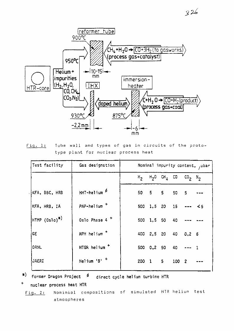
reformer tube!900°C
950°C
Helium+
impurities
CO.CH,CO2,N2)
tH4+H2O-»|CQ+3H2 (to gasworks);sjprocess gas+catalyst)j ^
hO-15l-mm
IHXimmersion
heater
-2,2 mm
^doped helium)
875°C,
I jrocess gas+coal)
~6mm
F i g . 1 : T u b e w a l l a n d t y p e s o f g a s i n c i r c u i t s o f t h e p r o t o -
t y p e p l a n t f o r n u c l e a r p r o c e s s h e a t
Test
KFA,
KFA,
HTMP
GE
ORNl
JAERI
facility
BBC, HRB
HRB, IA
(Oslo)*)
Gas designation
HHT-helium *
PNP-helium +
Oslo Phase 4 +
NPH helium +
HTGR helium +
Helium "B1 +
Nominal
H2
50
500
500
400
500
200
H20
5
1,5
1.5
2,5
0,2
1
impuri
CH4
5
20
50
20
50
5
ty content,
CO
50
15
40
40
40
100
co2
5
—
—
0,2
—
2
,ubar
—
6
1
—
* ' former Dragon Project ** direct cycle helium turbine HTR+ nuclear process heat HTR
F i q . 2 : N o m i n i a l c o m p o s i t i o n s o f s i m u l a t e d HTR h e l i u m t e s t
a t m o s p h e r e s

alloy
INCOLOY 800 H
(X 10 NiCrAITi 32 20)
HASTELLOY X
(NiCr22 Fe 18 Mo)
INCONEL 617
NIMONIC 80 A
nominal composition {wt °/o)
C
0.08
0.07
0.07
0.08
Fe
bai.
18.0
-
-
Ni
32.0
bal.
bai.
bal.
Cr
21.0
22.0
22.0
19.5
Co
—
1.5
12.5
—
Ti
0.4
—
0.4
2.2
Al
0.4
—
1,0
1,4
Mo
—
9.0
9.0
—
others
—
0.6 W
—
Fig. 3: Nominal compositions of selected alloys for heat-
exchanging components
£
01
6
U
X)1
86
1 %
• • • - . . . .
ereep :>traiiT lirnit
N
4 3 io 5
time / h
10
101
86 -
2 -
stress rupture strength
INCONEL 617 -HASTELLOY XNIMONIC 86HASTELLOY S"
102 3 103 3 10A 3 105
time / h
Fig. 4: Creep rupture strength of materials und^r consider-
ation for advanced HTR's
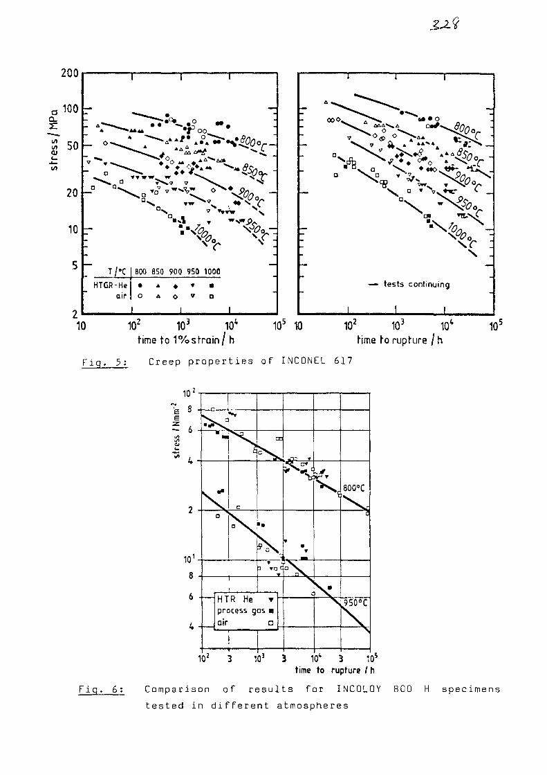
200
T/-CHTGR-He
air
600
o
850 900 950
V
1000
o
00 O.
*O * "*** n*^ ~
'̂ *f o *iSiO ^ "
fl
\
— tests continuing
I I
10 102 10J 10* 10 102
time to 1%strain/h time to rupture /h
Fig. 5: Creep properties of INCONEL 617
10s
10z
s 8
- 6
^ 4
101
8
6
4
m
Ka
•
•a
V
HTR He T -process gas •air •
* ^
wm
T
°\n\
s
800°C
4
9508C
>
10' 10J 105
Fig. 6:
time to rupture / h
Comparison of results for INCOLOY 800 H specimens
tested in different atmospheres

§70aenM 60-at
50
40
30
20
10-
0
900 °C diameter (mm)
-4,54,6-5,05,1 - 6,06,1-7,07 . 1 -
airaAV
0
0
helium••T
•
•
cm
103 io4
F i g . 7:
rupture time/h
Rupture ductility of INCONEL 617
single specimen test
— — — - mulH specimen tesHaverage of two tests}
5x10³ 10* 1,5x10* 2,0x104
Fig . 8: Creep-curves of INCONEL 617
2,5*10*time/h

RT
0 0,5 1strain E (%) «-
F i g . 9: S t r e s s - s t r a i n c u r v e s for H A S T E L L O Y X ( s c h e m a t i c )
750°C850°C950°C
range fordesign curves
10' 10 103
cycles to failure
Fig. 10: LCF results for INCONEL 617

I T I T I
T=850°C
6 10"5 2 4 6 r 4 2 4 6 10'3 2 4 6 10"2
Fig. 11: Max. tensile stress ( 3 72no^ a t cY cle nr. 200
(saturation stress) vs. strain rate in LCF tests
ij .initial values
/(solution treated)
•X
« test at RTo test at 900 »C
INCOLOY 800 H
ageing time [ h ]
Fig. 12: Impact energy for HTR-alloys after isothermal exposure
at 900 °C
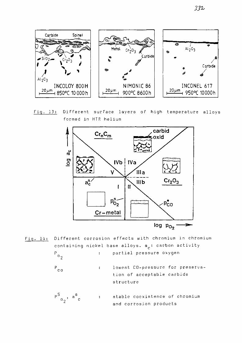
Carbide Spinet
^ S i O
1 //I
A12O3
1
2 - VCr2°3 j
INCOLOY 800H
1 ODU L IU UUUn
Carbide
NIMONIC86900°C8600h
IA12O3
Carbide
INCONEL 61720>jm i 950°C 10000h
F i g . 13 : D i f f e r e n t s u r f a c e l a y e r s o f h i g h t e m p e r a t u r e a l l o y s
f o r m e d in H T R h e l i u m
O
CrnCm
\s
Cr-
V IVb
v\
1
p°rmetal
carbid^oxid
II
log p0.
Fig. 1 4 : Different corrosion effects with chromium in chromium
se a l l o y s , a : carbon a<c
partial pressure oxygen
containing nickel base a l l o y s , a : carbon activity
COlowest C O - p r e s s u r e for pre s e r v a -
tion of accep t a b l e carbide
structure
stable coexistence of chromium
and corrosion products
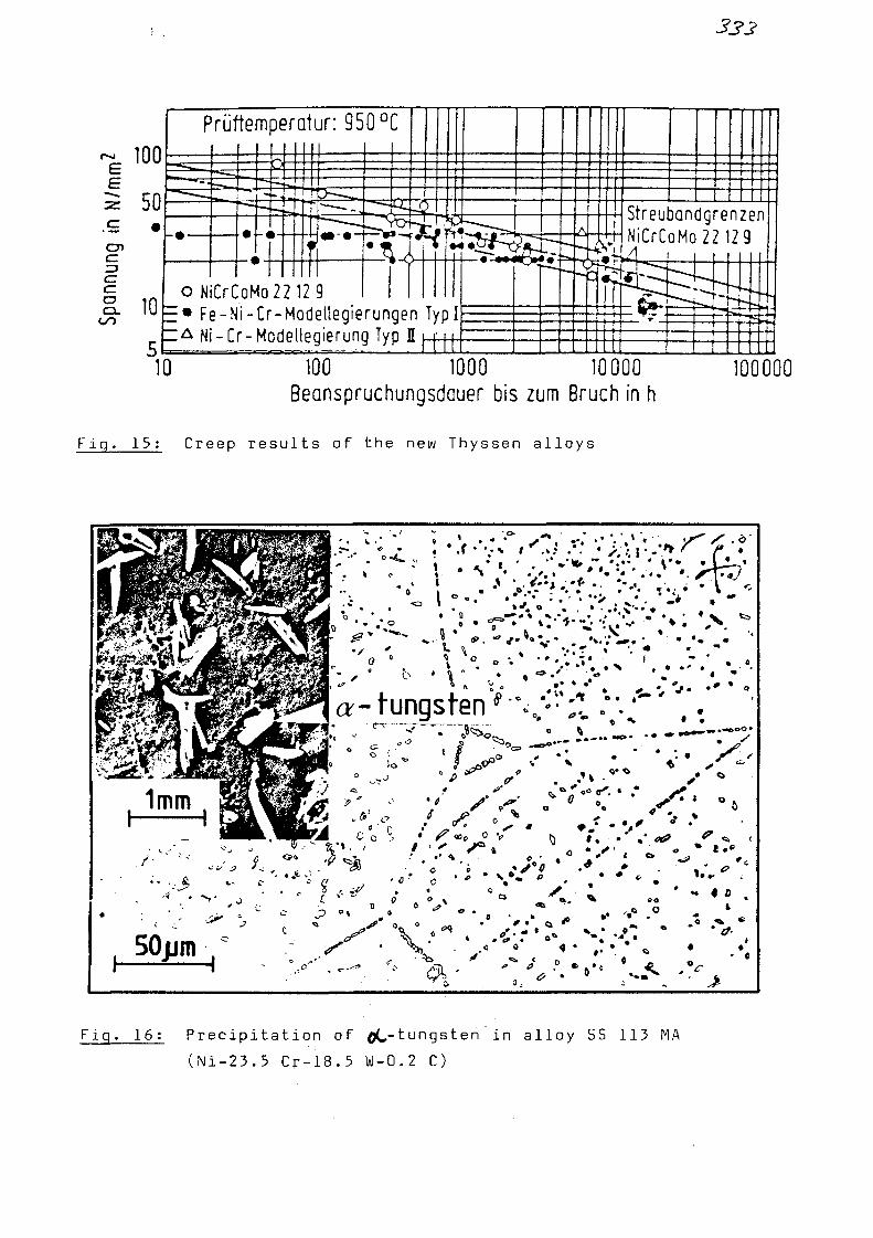
333
Prüftemperatur: 950 °C
StreubandgrenzenNiCrCoMo 22 12 9
o NiCrCoMo 22 12 9E # Fe-Ni-Cr-Modellegierungen TypI~& Ni-Cr-Modellegierung Typ H L O J
100 1000 10000Beanspruchungsdauer bis zum Bruch in h
Fig. 15: Creep results of the new Thyssen alloys
100000
, 50jim-
a- tungsten ' V : : l •'"•;. y
Co \ io ' S t
' V-i
Fig. 16 : Precipitation of flC-tungsten in alloy 55 113 MA
(Ni-23.5 Cr-18.5 W-0.2 C)

•VMl1
•! I *
t 3 c. ' '
L
Fig. 1 7 : Failure of INCOLOY 800 H tubes after m u l t i a x i a l creep
tests
CO -
1.0
0,5-
1 1 1 1 1 1 •
®3 0 *
KA \ ^o 3^3
\ ,X 0=1y°Ai ^\~~h B30 \ .V^o°«3 ^
f 1 1 1 f 1 I
1 1 1 1
1
INCOLOY850°C,
0,3 %0,6%1,0 %1,5 %
i i i
-
800 H _air
•
B
-
1 1 1
0,5 1,0JLNiB
1,5
Fig. 18: Linear damage accumulation for creep-fatigue inter-
action

No. 20 a
GEFR-SP 315
DATE Apr i l , 1984
TITLE: Pressure Vessel Design Codes: A Review of Their Appl icabi l i tyto HTGR Components at Temperatures above 800 C.
AUTHORS: P.T. Hughes, H.H. Over & K. Bieniussa XA0055829
Prepared for presentation at
IAEA Specialists Meeting on Heat ExchangingComponents of Gas Cooled Reactors
Conference
Held in Duesseldorf, FRGCity, State
On 16-19 April 1984Date
This paper contains materialresulting from work performedfor U.S. Department of Energy
Under Contract No. DE-AC03-80ET34034
This paper has been authored by a contractor of the U.S.Government under Contract No. DE-AC03-80ET34034Accordingly, the U.S. Government retains a nonexclusive,royalty-free license to publish or reproduce the publishedform of this contribution, or allow others to do so, forU.S. Government purposes.
ADVANCED NUCLEAR TECHNOLOGY OPERATION ^GENERAL ELECTRIC COMPANY
SUNNYVALE, CALIFORNIA 94088
G E N E R A L W ELECTRIC 84-02-11
INTRODUCTION
The governments of the United States and the Federal Republic of Germanyhave approved of cooperation between the two countries in an endeavor toestablish a structural design code for gas reactor components intendedto operate at temperatures exceeding 800°C. The basis of existing codesand their applicability to gas reactor component design are brieflyreviewed in this paper. This review has raised a number of importantquestions as to the direct applicability of present codes.The status of the US and FRG cooperative efforts to obtain answers tothese questions are presented in a companion paper at this conference.
PRESSURE VESSEL CODE POLICIES
All pressure vessel codes are either based on a policy of "design byrules" or a policy of "design by analysis". Compliance with the rulesis sufficient for safe design with codes of the "design by rules" type.A formal structural evaluation of critical vessel regions and loadinys,for comparison with structural criteria, is the basis of safety in"design by analysis" codes.
The regulations and requirements to be observed in design by rulesconcern geometrical arrangements, dimensions, loading conditionsmaterials and fabrication methods. Estimation of the necessary wallthickness is obtained from elementary calculations which relate apermitted stress at temperature, the principal vessel dimensions and thepressure loading. The regulations and requirements represent asynthesis of satisfactory vessel design and operation. For this reason,they may not be applied to vessels intended for operation attemperatures and in geometrical forms under load conditions whichdiffer from those from which the rules were made.
Codes based on a policy of "design by analysis" enable vessel design toproceed for complex loading conditions or geometric arrangements orboth. In such codes, specific criteria which define the permissiblestress, strain or displacement are stated for both elastic and inelasticbehavior. Specification of a criterion for either stress, strain ordisplacement uniquely specifies the remaining two quantities for thecase of elastic vessel response. This cannot be so for inelasticbehavior, and stress, strain and sometimes displacement, each requireseparate criteria. The structural response to load and temperature forcomparison with criterion may be obtained from experiment but is usuallythe result of calculation.
-2-
LIMITS OF EXISTING CODE APPLICABILITY
The principal pressure vessel codes in use in the U.S. and the FRG arethe following:
FRG- AD - Instructions (3)FRG- TRD - Regulations (4)FRG- KTA - Rules, primary circuit components of light water
reactors, 3201 (5)USA- ASME - Code, Section III (6)USA- ASME - Code, Section VIII (9)USA- ASME - Code, Case N47-17 (1592-17) Class 1 components in
elevated temperature service, Section III, Division (7)
The AD - Instructions, ASME-Code, Section VIII and TRD - Regulations arebased on the policy of "design by rules". They are intended to governthe design and construction of conventional boilers and pressurevessels. The design restrictions imposed by such codes in conjunctionwith the need for a more specific evaluation of safety margin haveresulted in the evolution of "design by analysis" codes for nuclearquality pressure vessels and reactor structures. In the FRG, the KTA -Rules based substantially on ASME - Code, Section III are in force. Thedesign of components to 800°C is governed by ASME- Code Case N-47 in theUS, since the applicability of ASME - Code, Section III is limited totemperatures to about 400°C as are the KTA - Rules.
The limits of applicability of these codes may be summarized as follows:
AD - Instructions, TRD - Regulations and ASME - Code, Section VIIIprovide means by which to calculate vessel wall thicknesses fordefined pressure loading and temperature, for the required servicelife. The allowable stresses are specified based on both timeindependent and time dependent materials behavior. Time dependentallowable stresses are related to both a creep rate and totalservice life creep strain to offer protection against failure bycreep rupture, but other elevated temperature structural phenomenonsuch as creep-fatigue interaction, creep ratcheting and creepcaused enhancement of geometric imperfections are not explicitlycovered.
KTA - Rules and the ASME - Code, Section III permit only anevaluation of structural response to ensure freedom from timeindependent failure modes because of the specified and limitedtemperature range at which they apply. They require first anevaluation of the structural response to primary loads which couldcause bursting or unacceptable deformation, followed by anevaluation of the magnitude and frequency of primary and secondary(self limiting) stresses for comparison with fatigue criteria.

-3-
Whilst stress or strain due to external forces, the self-weight,and pressure sustained by a component, are covered similarly to theprocedures of (3) and (4), elastically calculated stresses, due toall types of loading, for the fatigue evaluation, are permitted tovary over a range of magnitude equal to twice the yield stress (3Sm-criterion). Criterion must be met to ensure that plasticdeformation sustained from strain cycling in the plastic range doesnot impair integrity or function ("shakedown"). Loads from otherthan conditions of normal operation are classified by frequency ofoccurrence and successively greater primary stress limits arepermitted as the loads become less probable.
ASME-Code, Case N-47 includes criteria for "design by analysis" inthe time dependent failure temperature range. These criteria weredeveloped through a number of preceding code cases from thefundamental elevated temperature considerations of ASME-Code,Section VIII. The limit of elastic (linear) approximation tonon-linear creep behavior is defined in ASME-Code, Case N-47 byrestricting to about the 0.1% yield stress, any cycle composed ofelastfcally calculated load and deformation (thermal) stresses. Ifthis restriction cannot be observed, inelastic analysis is requiredto ensure that stress, and cyclic and cumulative strains, meetseparate inelastic criteria. A definition of secondary stress inthe sense of the ASME-Code(s) is not applicable in suchcircumstances and stresses are instead defined as load ordeformation controlled. The upper temperature limit to the use ofa material is governed by creep rupture behavior for which asatisfactory definition requires data which permits well describedscatter bands.
STRUCTURAL DESIGN CONSIDERATIONS FOR HTGR COMPONENTS
The design of components for the high temperature regions of an HTGRplant requires consideration of both time independent and time dependentmaterial properties, the latter characterized by irrecoverable strainand deformation which increase with time. By a process of selectionthrough a formal description of material behavior, and the imposition ofgeometric and fabrication limts in an elevated temperature code,conditions may be arranged such that the list of possible failure modesis restricted. Criteria can then be devised to ensure a remoteprobability of failure in any mode. For pressure vessel structures thefailure mode list should include -

77 r-4-
-ductile rupture-creep rupture due to long term loading-fatigue failure-creep-fatigue failure-fast fracture (failure due to unstable crack growth)-excessive strain due to incremental deformation (cyclic strainaccumulation doe to creep or plasticity or both)-loss of function due to excessive deformation-loss of stability due to short term loading (elastic orelastic-plastic buckling)-loss of stability due to long term loading (creep enhancement ofinitial geometric imperfection)
-environmentally caused material failure (carburization, corrosion,irradiation, etc.)
Quantitative criteria, observance of which will avoid failure in eightof these ten modes are stated in ASME-Code, Case N-47. Failures due toeither ductile fracture or creep rupture are avoided by the definitionof load controlled stress limits. Loss of stability due to both shortand long term loading is avoided by stipulations such that working loadsare substantially less than divergence loads. Calculation of thecumulative strain for comparison with permitted values is the policyused to avoid failure due to creep-fatigue interaction, excessive strainaccumulation from incremental deformation and loss of function becauseof large deformation. These criteria may indeed be suitable for gasreactor components operating at ^er^/ high temperatures but a number ofaspects associated with these criteria require critical investigation.
The effects of service environments on the behavior of materials and thefailure modes of components are not satisfactorily covered in any of theavailable design codes.
ASPECTS OF AN HTGR PRESSURE VESSEL DESIGN CODE
An HTGR pressure vessel design code may very well be based on thegeneral policies of the ASME-Code, Case N-47. A general level ofsecurity should be obtained by placing limits on the magnitude of loadcontrolled stress and strain and a specific security by further stressand strain limits for the combination of load and displacementcontrolled strains. The security necessary for prolonged gas reactoroperation may also require the development of fracture mechanics basedcriteria, environmental effects criteria and until sufficient experienceaccrues, periodic testing of material test coupons and componentssections which have been exposed to reactor operation.
"0™
For the drafting of a design code:
material data sufficient to permit a satisfactory calculation ofthe force distribution in a component must be available
material data to permit evaluation of force distribution in termsof failure modes is required
design margins, which offer protection against approximations anduncertainties must be determined for criteria of stress, strain,load and time :
the nature and extent of periodic component inspection and possibletesting to ensure structural reliability must be considered.
The data required for the materials of HTGR components to permitcalculation of force distribution and force effects in the applicationtemperature range include: ; ,: :
Physcial properties data, such.as
density- thermal conductivity .,.<•. , . :
specific heat ..'.._,thermal expansion coefficientmodulus of elasticityPoisson's ratio
Data for constitutive equations (strain-time laws) to permit •inelastic analysis such as:
form of the equationsconstants and coefficients v
environmental effects ' '
The data required to assess the significance of force distribution andforce effects to stress, strain and displacement for the various failuremodes in the application temperature range must include: :
Impact Strength ;Yield StrengthMaximum Tensile StrengthFracture Elongation and Reduction of AreaCreep Strain Rates .Creep Rupture Strength 'Rupture Elongation ,Fatigue Parameters ...,' ..-.;.' ;

-6-
The structural engineering problems of the sodium-cooled reactor and thehigh temperature behavior of low alloy steel and austenitic stainlesssteel have been major Influences in the drafting of ASME-Code, CaseN-47. The use of nickel based alloys for components in a gas reactorenvironment at temperatures above 800cC however, presents somewhatdifferent engineering problems and materials behavior. Thus, a numberof questions arise for which resolution must be found within the generalASME-Code, Case N-47 policy of "design by analysis" and the descriptionof stress as load controlled or deformation controlled.
A failure mode entitled "environmentally caused material failure" hasbeen introduced. The design measures to avoid this failure modeinclude:
-selection of materials-thickness allowance-surface protection-consideration of the changes in material properties
Use of any one or combination of these measures required clarificationof the following questions:
-Which environmental parameters should be used to describe the processof material property changes lead to environmentally caused failureor accelerated failure in other modes?
-How should material property alterations and environmentally causedstructural effects be specified and presented?
-What should be the basis for placing limits on environmental effects?
-In what form should limits to permissible environmental effects beembodied in design criteria?
A decision to adopt the ASME-Code, Case N-47 policy for the limitationof primary stresses in gas reactor components operating at temperaturesabove 800°C requires resolution of numerous questions which include thef ol 1 owi ng:
-With what strain rate are the time independent strength properties tobe determined?
-Which cross-section factor K is sufficient for restriction of theprimary bending stress in time dependent materials behavior?
-Is the stated equation for accumulation of creep damage appropriate forthe various operating conditions of a gas reactor?
-Is it necessary to specify specific stress limits for welds whichdiffer from those applicable in all regions away from welds?

-7-
Similarly, a number of questions arise when considering the ASME-Code,Case N-47 philosophy with respect to the accumulation of componentmaterial damage due to creep-fatigue:
-Which strain rate and hold time should be used in determining cyclicstrength properties?
-Is the criterion for evaluation of creep-fatigue damage also suitablefor HTGR components?
-What significance have the strain limits criteria and are the allowablevalues acceptable?
-Does it remain an acceptable procedure to dispense with an evaluationof creep-fatigue damage against region specific criteria for weldments?
To provide a sound and thorough basis for the evaluation ofcreep-fatigue damage using inelastic calculations, resolution of thefollowing types of questions must be achieved:
-What manner of tests are practicable and necessary for determining theconstants and coefficients of constitutive equations?
-In what form should the qualification and verification of computationmethods for enelastic analysis be cast?
The definition of criteria to avoid the failure mode of unstable crackgrowth at temperatures below 800°C because of material changesencountered at temperatures above 800°C will be achieved only by answersto the following questions:
-What test methods and analysis criteria should be used to characterizetoughness alternations and crack growth properties?
-In view of inspection difficulties, especially of weldments, shouldfast fracture criteria be formed in terms of fracture mechanicstechniques or a reduction in load and deformation controlled stress andstrain criteria, in combination with certain geometric criteria?
There have been technical arguments to the effect that ASME-Code, CaseN-47 incorporates criteria for creep enhancement of geometricimperfections which are too conservative for load to compensate for lackof margin on time. This situation requires answers to the following typeof question.
-Should there be criteria and margins for time in addition to, orsupplementing, direct criteria and margins for load?

-8-
The intention of a design code is to offer criteria such that for thefactors under design control, the probability of failure is remote.Uncertainties in defining criteria and uncertainties and approximationsin the evaluation of a design to meet these same criteria, require thedefinition of design margins. The factors and effects covered byASME-Code, Case N-47 design margins are not well defined. In addition,there is little useful background of operating vessel experience above800°C by which to justify these design margins. Thus, the followingquestions arise:
-How should a design specification and an HTGR structural code beformally linked from the viewpoint of acceptable failure rates?
-To define specific and quantitative meaning to criteria which embodydesign margins what is the best approach and what theoretical andphysical data base developments are required?
-Which components must be tested to validate criteria and designmargins?
-What possibilities for testing are practicable?
-How are the results of physical testing to be used in comparison withdesign calculations to verify that satisfactory criteria and designmargins have been provided?
-What possibilities for testing are practicable?
-How are the results of physical testing to be used in comparison withdesign calculations to verify that satisfactory criteria and designmargins have been provided?
-Which components when in service require periodic inspection to providefinal code varification and information for improvements?
-Which in service inspection possibilities are practicable and how isthe inspection information to be used to verify or modify criteria andmargins?

(5) REFERENCES
1. Dokumentation Fachkreis "Regelwerk", Nr. 4.01, Anwendung desASME-Code, Case N-47 auf HTR-Komponenten, erforderlicheErganzungenbzw. Überprüfungen, July 1980.
2. Dokumentation Fachkreis "Regelwerk" Nr. 10, Vergleich der Aussagenüber Werkstoffe, Werkstoffverhalten und Werkstoffversagenverschiedener deutscher und amerikanischer Regelwerke hinsichtlichderen Anwendungsmoglichkeiten fur den Werkstoffeinsatz beiTemperaturen oberhalo 800°C, üuni 1980.
3. Ad-Merkblatter
4. Dampfkessel Bestimmungen (TRD)
5. KTA-Regeln, Komponenten des Primarkreises vonLeichtwasserreaktoren, 3201.
6. ASME:ASME Boiler and Pressure Vessel Code, Section III, Rules forConstruction of Nuclear Power Plant Components, Division 1, ASME,New York, 1977.
7. ASME:Cases of ASME Boiler and Pressure Vessel Code, ASME-Code Case N-47-17 (1592-17), Class 1 Components in Elevated Temperature Service,Section III, Division 1, ASME, New York, 1978.
8. ASME:Criteria for Design of Elevated Temperature Class I Components inSection III, Division 1 of the ASME Boiler and Pressure VesselCode, ASME, New York, 1976.
9. ASME:ASME Boiler and Pressure Vessel Code, Section VIII - Division 1,Pressure Vessels, ASME, New York, 1980.

Gesellschaft fur Reaktorsicherheit (GRS) mbH
No. 20b .===.
Specialists1 Meeting on Heat Exchanging
Components of Gas-Cooled Reactors
(Duesseldorf, FRG, 16.-19. April 1984)
Status of Design Code Work
for Metallic High Temperature Components
XA0055830
K. Bieniussa Gesellschaft fur Reaktorsicherheit
5000 Koln 1, Schwertnergasse
H.-J. Seehafer INTERATOM
5060 Bergisch Gladbach 1, Postfach
H.H. Over Kernforschungsanlage Jiilich, IRW
5170 Julich, Postfach
P. Hughes General Electric Company
Sunnyvale, CA USA
Schwertnergasse 1 • 5000 Koln 1 -Telefon (02 21) 20 68-0-Telex 8881 807grsd
Gesellschaftfur Reaktorsicherheit (GRS) mbH
- i -
1. INTRODUCTION
The mechanical components of high temperature gas-cooled
reactors, HTGR, (fig. 1), are exposed to
- temperatures up to about 1000°C and this
- in a more or less corrosive gas environment.
Under these conditions metallic structural materials show a
time-dependent structural behavior. Furthermore changes in
the structure of the material and loss of material in the
surface can result.
The structural material of the components will be stressed
originating from
- load-controlled quantities, for example pressure or dead
weight, and/or
- deformation-controlled quantities, for example thermal
expansion or temperature distribution,
and thus it can suffer
- growing permanent strains and deformations and
- an exhaustion of the material (damage)
both followed by failure.
To avoid a failure of the components the design requires the
consideration of the following structural failure modes (fig. 2)
- ductile rupture due to short-term loadings
- creep rupture due to long-term loadings
- creep-fatigue failure due to cyclic loadings
- excessive strains due to incremental deformation or creep
ratcheting
Schwertnergasse 1 • 5000 Koln 1 -Telefon (02 21) 20 68-0 -Telex 8 881 807 grs d

29*
Gesellschaft fur Reaktorsicherheit (GRS) mbH
- 2 -
- loss of function due to excessive deformations
- loss of stability due to short-term loadings
- loss of stability due to long-terra loadings
- environmentally caused material failure (excessive corrosion)
- fast fracture due to instable crack growth.
With exception of the last mentioned two failure modes, there
exists a design code (ASME Code Case N-47 /I/) for the different
failure modes in the creep regime. The use of this code is
restricted to a small number of materials; the highest tempe-
rature of use, T = 816°C, lying substantially below the intended
temperature of T = 1000°C.
Environmentally caused material failure will be avoided by an
appropriate material selection and/or by taking into account
this effect in the design procedure.
Up to now, a concept for treating fast fracture due to instable
crack growth is not yet available. Nevertheless first test
results indicate, that at higher temperatures a loss of ducti-
lity need not be expected.
Based on the design philosophy of this ASME Code Case /2/ and
further considering the German and American design codes (fig. 3),
the German BMI sponsored Working Group "HTR-Regelwerk" (HTR-Design
Code) has developed first bases for a design code for HTR-
components /3/. Some of the intentions of this group have been
discussed with the American participants of the Subprogram Hate-
rials PWS-Rl "Establishment of the Basis for Structural Design
of Elevated Temperature HTGR-Components". The good agreement in
the object of view has encouraged us to this joint presentation.
Schwertnergasse 1 • 5000 Koln 1 • Telefon (02 21) 20 68-0 • Telex 8 881 807 grs d
Gesellschaftfur Reaktorsicherheit (GRS) mbH
— 3 —
As just have been shown, a great number of structural failure
modes have to be discussed. In the course of this presentation
the current status of design code work for metallic high tempe-
rature components exemplarily shall be demonstrated at the issue:
- exclusion of creep-fatigue failure due to cyclic loadings.
According to our investigations concerning the different compo-
nents and the presupposed loadings, this type of failure mode is
significant for many parts of the HTGR components. Simultaneously
this includes the consideration of the first five failure modes
of (fig. 2).
Schwertnergasse 1 • 5000 Koln 1 • Telefon (02 21) 20 68-0 • Telex 8 881 807 grs d
3?f
Gesellschaftfur Reaktorsicherheit (GRS) mbH
- 4 -
2. DESIGN PHILOSOPHY
For the exclusion of creep-fatigue failure due to cyclic loadings
the design philosophy of the ASME Code, Case N-47, will be kept.
In detail this means (fig. 4):
- The load-controlled stresses alone have to be limited to the
maximum carrying load, taking into account the possibilities
of ductile and creep rupture,
- the load- and deformation-controlled stresses together have
to be discussed with respect to material exhaustion due to
hold-times (creep) and alternating loads (fatigue),
- the accumulated strains calculated.from the load histogram
shall be compared with ratcheting limits; the deformations
caused by the strains shall be checked against functional
requirements.
During the design phase for economic reasons the use of elastic
analysis should be strived for. Up to now, this cannot be
achieved in a sufficient way (fig. 5).
The satisfaction of strain limits using elastic analysis (test 1
to test 4 of the Case N-47) is no longer possible for the tempe-
rature regime above 800°C, because
- either they are too conservative and do not allow a positive
stress report for a reasonable loading time (test 1, test 4),
- or there are restrictions for a stress extreme below the creep
regime, which cannot be guaranteed (test 2, test 3).
Furthermore the creep-fatigue evaluation using elastic analysis
cannot be adopted, because of the great conservatisms
- in the fatigue curve with hold-time effects and
- in the procedure for the creep damage evaluation.
Schwertnergasse 1 • 5000 Koln 1 • Telefon (02 21) 20 68-0 • Telex 8 881 807 grs d
Gesellschaft fur Reaktorsicherheit (GRS) mbH
First comparative calculations, considering the realistic mate-
rial behavior and estimating the inelastic behavior by a simple
relaxation model, demonstrate, that this simplified method
results in
- a too fast decrease of the stresses and
- a too small rise of the strains
in the course of time.
In connection with the relatively low material strength at these
temperatures, this procedure cannot be tolerated. For this reason
at this moment the most promising way in the computing strategy
is
- elastic analysis for load-controlled stresses alone,
- detailed inelastic analysis for load- and deformation-con-
trolled stresses combined and
- further development of simplified methods based on the results
of representative detailed inelastic analyses.
There is no operating experience so far with HTGR-component
(fig. 6). Further more
- the design codes are unproven,
- component test results are rare and
- loading conditions are presupposed.
That is why
- inservice inspection of the components,
- recurrent tests of the components and
- periodic testing of material test coupons
are very important in the design philosophy and require com-
ponents with both simple geometries and a good accessibility
for testing.
As mentioned in other presentations, several component tests
are running. They can help to remove safety additions not needed
and existing uncertainties.
Schwertnergasse 1 • 5000 Koln 1 • Telefon (02 21) 20 68-0 • Telex 8 881 807 grs d
Gesellschaft fur Reaktorsicherheit (GRS) mbH
- 6 -
3 . DESIGN CRITERIA
The load-controlled stresses are classified as primary stresses
(fig. 7) and have to be limited as usual by the time-independent
stress value S and the time-dependent stress value S,. Further-in tmore different loading conditions have to meet the use-fraction
sum criterion, for avoiding a creep rupture.
At high temperatures the time independent strength is a function
of the strain-rate, and the S -value has to be fixed in accor-' m
dance with the loading-rate and perhaps also with modified cri-
teria. The criteria for the definition of the S.-value will be
kept, excepted the criterion of onset of tertiary creep. For the
provided materials the available stress-to-rupture data allow
70,000 operating hours. This statement is based on the assumption,
that extrapolation of data from about 25,000 h to 70,000 h is
permissible.
The combined stress state is evaluated with regard to creep-
fatigue failure (fig. 8), using the linear damage interaction
hypothesis. Therefore fatigue and creep damage (exhaustion) are
computed in accordance with the Case N-47 using the Miner-rule
and the Robinson-rule respectively. Both damage portions added
have to be less than the total creep-fatigue damage factor.
The design curve for computing the fatigue damage portion has
been constructed from the cyclic failure curve as usual incor-
porating a design factor of 2 on strain range or 20 on cycles,
whichever is less. The design curve for computing the creep
damage portion has been constructed from the stress-to-rupture
curve incorporating a design factor of 1/0.9 on stress and
additionally 2 on time, whichever is less. For the different
materials the final shape of the allovable creep-fatigue damage
factor curve will be fixed at a later date.
The strain limits, given in the Case N-47 were kept for this
moment, also the restrictions for weld regions.
Schwertnergasse 1 • 5000 Koln 1 -Telefon (02 21) 20 68-0 -Telex 8 881 807 grsd
Gesellschaftfur Reaktorsicherheit (GRS) mbH
- 7 -
For these design criteria it is presupposed as working hypothesis
that the structural failures for base material and for weld
regions are similar. To clarify this point the following tests
are running:
- creep rupture tests for welds,
- cyclic failure tests for welds and later on
- creep-fatigue failure tests for welds.
Having these results, the very important question can be
answered:
Does it remain an acceptable procedure to dispense with an
evaluation of creep-fatigue damage againt region specific
criteria-for weldments?
As a conclusion (fig. 9) it can be stated, that the available
design criteria and material data are sufficient to fabricate
and operate the metallic components of a prototype HTGR.
With respect to economy and availability further investigations
for the following aspects are desirable:
- long-term material data,
- environmental influence,
- constitutive equations,
- simplified inelastic methods.
Schwertnergasse 1 • 5000 Koln 1 -Telefon (02 21) 20 68-0 -Telex 8 881 807grsd
Gesellschaftfur Reaktorsicherheit (GRS) mbH
4. REFERENCES
/I/ The American Society of Mechanical Engineers:
Cases of ASME-Boiler and Pressure Vessel Code,
Case N-47-18, Class 1 Components in Elevated
Temperature Service, Section III, Division 1
ASME, New York, 198 0
/2/ The American Society of Mechanical Engineers:
Criteria for Design of Elevated Temperature
Class 1 Components in Section III, Division 1,
of the ASME Boiler and Pressure Vessel Code
ASME, New York, 1976
/3/ Fachkreis "Regelwerk"
AbschluBbericht fur Sonderforschungsvorhaben
SR 191 des BMI: Erarbeitung von Grundlagen
zu einem Regelwerk iiber die Auslegung von
HTR-Komponenten fur Anwendungstemperaturen
oberhalb 800°C
KFA Julich, 1984
Schwertnergasse 1 • 5000 Koln 1 • Telefon (02 21) 20 68-0 • Telex 8 881 807 grs d

1 Operating condition-temperature <1000°C- corrosive gas environment
Loading condition- load-controlled (pressure)- deformation-controlled (thermal expansion)
Material behavior- growing strains- material exhaustion (damage)
Component response- failure of component- loss of function
design restrictions
\7safe operation
*™
HTGR METALLIC COMPONENTS(DESIGN ASPECTS)
FIG, 1

ductile rupture due to short-term loadings
creep rupture due to long-term loadings
creep-fatigue failure due to cyclic loadings
excessive strains due to incremental deformation oncreep ratcheting
loss of function due to excessive deformations
loss of stability due to short-term loadings
loss of stability due to long-term loadings
environmentally caused material failure (excessive corrosion)
fast fracture due to instable crack growth
£ HTGR METALLIC COMPONENTSw (FAILURE MODES)
FIG. 2

FRG: KTA safety standard 3201 T < 400 °Cdesign by analysis
FRG: AD - instructional sheets T ^ 550 °Cdesign by rules
FRG: TRD - regulations T ^ 550 °Cdesign by rules
USA: ASME - code, section III T < 427 °Cdesign by analysis
USA: ASME - code, section VIII T < 816 °Cdesign by rules
USA: ASME - code, case N-47 T ^ 816 °Cdesign by analysis
g DESIGN CODES FORw METALLIC COMPONENTS
FIG. 3
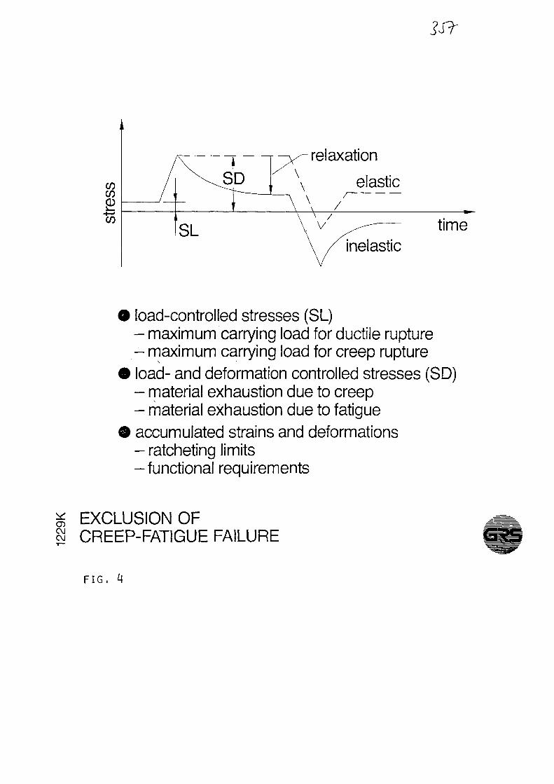
relaxation
elastic/—
/.
inelastic
t ime
load-control led stresses (SL)- max imum carrying load for ductile rupture- max imum carrying load for creep ruptureload- and deformation controlled stresses (SD)- material exhaustion due to creep- material exhaustion due to fatigueaccumulated strains and deformations- ratcheting limits- functional requirements
SIEXCLUSION OFCREEP-FATIGUE FAILURE
F I G .

using elastic analysis
- fo r economic reason strived for- satisfaction of strain limits, no way- creep fatigue evaluation, no way
comparative calculations
- realistic material behavior- estimation with relaxation model- not conservative in results
intended computing strategy
- elastic for load-controlled stresses- inelastic for combined stresses- development of simplified methods
* HTGR COMPONENT COMPUTING STRATEGYCOC\J
FIG, 5

component behavior evaluated with
- unproved design codes- lack of component test experience- presupposed loading conditions
important for a prototype
- inservice inspection of components- recurrent tests of components- periodic testing of material test coupons
planned or running component tests
- HE/HE - heat exchanger- hot gas ducts- hot gas valves
* HTGR DESIGN QUALIFICATION8 BY TESTING
F I G . 6
QUALIFACATION

Q.
3CDto
t
if)
to
t time-independent?
£ = 5%/min
Si So B = 0,5%/min
t'm
strain
=s S/?^ S2/1,5
stress limit: Pm < S
to
time
time-dependent
- < ^ S R (stress-to-^ ^ i rupture)
(stress 1 %)
7-104 time
O( — Opj/1,3
^ S^/1,0
m Sm
use-fraction sum: 2 t/tim ^ B = 1,0
g LIMITATION OF8 LOAD-CONTROLLED STRESSES
F I G . 7
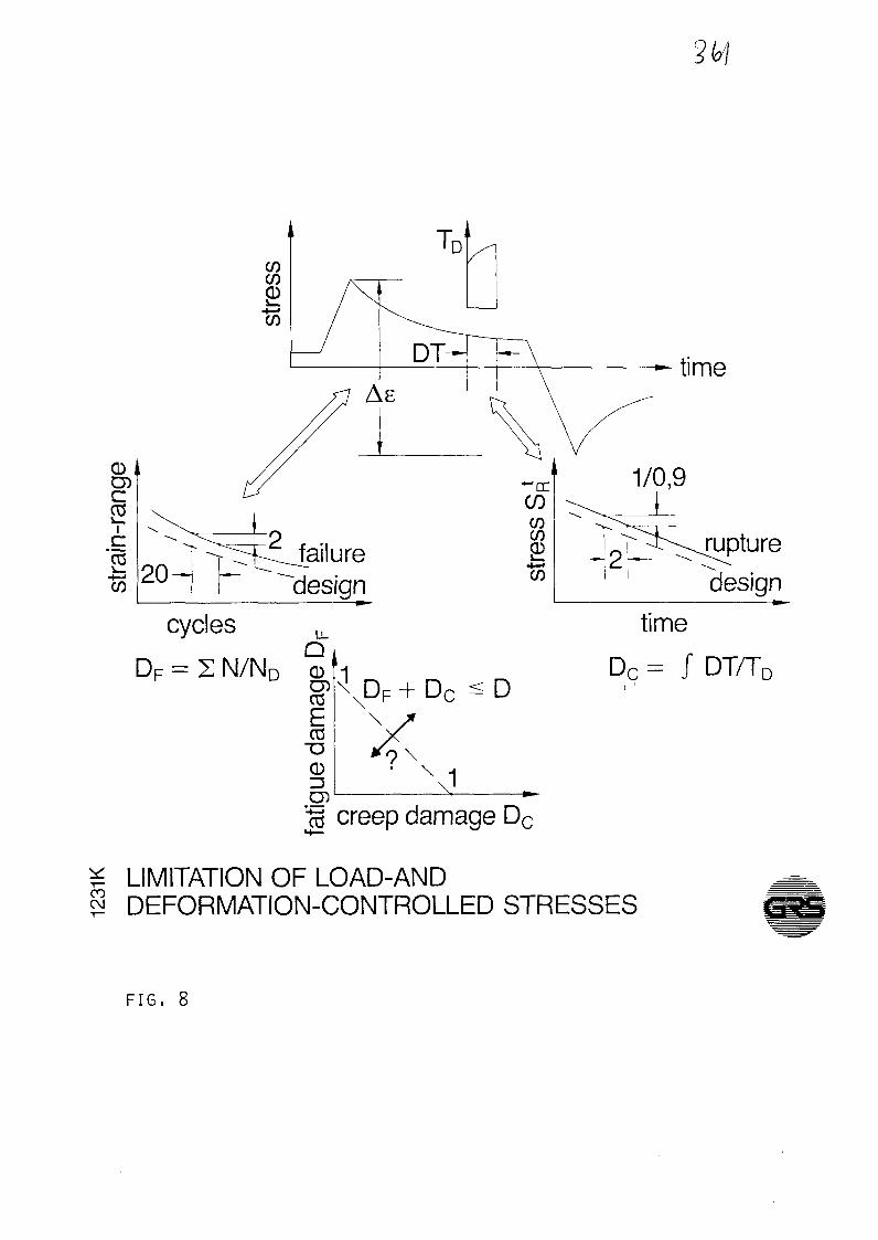
cyclesQ
DF = Z N / N D CD'I§^XDF+DCE
" DCD
time
rupture
design
D
time
Dc = J DT/TD
y\1
"c3 creep damage Dc
COLIMITATION OF LOAD-ANDDEFORMATION-CONTROLLED STRESSES
F I G . 8

design criteria and material dataare sufficient forfabrication and operationof a prototype HTGR
for economy and availability reasonsthe following investigations are desirable
- long-term material data- environmental influence- constitutive equations-simplified inelastic methods
I HTGR DESIGN CODE (CONCLUSION)
F I G . 9
XA0055831
OXIDE FILMS ON AUSTENITIC HTR HEAT EXCHANGER MATERIALS
AS A TRITIUM PERMEATION BARRIER
H.P. Buchkremer, R. Hecker, H. Jonas, H.J. Leyers, D. Stover,
Kernforschungsanlage Jtilich GmbH
Paper for the IAEA Specialist Meeting on
Heat Exchanging Components of Gas-Cooled Reactors
Dusseldorf April 16-19, 1984
In a high-temperature process heat reactor (1), tritium may
inadvertently permeate from the primary circuit into the
secondary circuit through the metallic walls of the heat
exchanging components due to the high gas outlet temperatures
around 1223 K.
The German radiation protection regulations only permit a
concentration of 10 pCi tritium per gramme of the product
gas. On the other hand, hydrogen capable of permeating into
the reactor primary circuit is produced on the secondary
side of the heat exchangers during the foreseen processes.
In order not to reach this limit of 10 pCi/gr it is necessary
to produce very effective tritium permeation barriers, which
also respond to the hydrogen, in order to keep the existing
gas purification system economically efficient. It turned
out during our investigation here that such a permeation
barrier is optimally formed by oxide coatings (corrosion
layers) grown in oxidizing atmospheres where the thickness
of the coatings can reach up to a few |im /3/.
Figure 1 shows the composition of some steels examined by
us. These are centrifugally cast and wrought alloys. The
high-alloy steels on a nickel or iron base envisaged for
the HTR usually have a chromium content of approx. 20 - 25 %.
For this reason, the formation of oxidic corrosion layers
must be expected even for our process gas compositions (presence
of hydrogen possibly in excess of steam, hence relatively
low oxygen partial pressures).

- 2 -
These oxide films grown in situ, as well as oxide coatings
produced in a different way, are known to have an impeding
effect on hydrogen permeation (2), (3).
The attempt to significantly influence even the permeation
behaviour of the bare metal by adding certain alloy components
cannot be successful. Figure 2 shows that various candidate
alloys in the bare state only differ insignificantly with
regard to hydrogen permeation, whereas an oxide coating may
effect changes by orders of magnitude. It can therefore be
stated that the metals predefined for our applications exert
an influence on hydrogen permeation primarily through their
capability to form coherent dense oxide films. In the case
of bare metal, the /p-dependence claimed by Sieverts is observed
over wide pressure ranges. An activation energy for permeation
of approx. 63 kJ/mol is observed for austenitic high-temperature
alloys and of 33 kJ/mol for ferritic materials. Permeation
through the latter is always higher up to 1223 K as compared
to permeation through austenitic materials (assuming otherwise
identical conditions).
The investigations on "coated material" led to the following
results: impeding factors (related to the bare metal, otherwise
identical conditions) of approx. 200 to over 1000 were measured
"in situ", i.e. under process gas atmospheres, with lower
values being obtained at low coating temperatures and higher
values at high temperatures. It was found that a well impeding
layer is obtained if parabolic growth can be observed. It
was equally found that the activation energy for this layer
growth is apparently determined in essence by the migration
of chromium cations with an activation energy of approx.
250-420 kJ/mol which, however, varies significantly depending
on the growth conditions of the layer. This is in agreement
with observations made by other authors (e.g. Hagel (4),
Zink (6) ) .
Oxide layers on the material Incoloy 800H, for example, which

- 3 -
were produced at a certain oxidation potential, are not stable
if they are subsequently subjected to a markedly lower potential
They obviously transform, reaching distinctly elevated impeding
factors after some time - proved by permeation measurements - in
conjunction with activation energies for the layer growth
rising towards 420 kJ/mol. These layers transmuted in such
a way, however, are then stable over wide ranges of the oxygen-1 5potential. (We generally work at potentials <10 bar.)
It may be tentatively assumed that these layers still exhibit
pronounced fractions of spinel structures in iron-containing
materials. A "more impurity-free" chromium oxide layer is
probably produced by reducing the oxidation potential and
simultaneously supplying additional chromium from the substrate
(noticeable from 1123 K upwards to 1173 K). This assumption
is supported by post-examinations which have shown in particular
cases that spinel-richer structures are associated with poorer
impeding factors.
The time-dependent course of the formation of in-situ oxide
scales at different oxidation temperatures is shown in Fig. 3.
After the usual pretreatment by H annealing, rapid oxidation
sets in when process gas is applied, with a clear gradation
being observed as the oxidation temperature rises. The increase
in oxidation temperature from 923 to 1223 K first leads to
a rearrangement of the layer, following which the permeation
flux drops to values similar to those for specimens run iso-
thermally at T=1223 K.
Our oxide films produced in situ show a peculiar behaviour
with regard to the pressure dependence of hydrogen permeation.
In contrast to observations made by other authors and contrary
to the Vp-dependence towards lower pressures as predicted
in general theory, we observe a transition to p-dependency
for good layers (high impeding factor) at relatively high
hydrogen pressures. Below this level, we observe a /p-dependence
virtually over 9 decades! Our observations are illustrated
in Fig. 4.

- 4 -
The deviations from Sieverts ' law observed in the high-pressure
range can be tentatively interpreted by the introduction
of surface reactions. The diffusion process is assumed to
govern the time and all surface reactions are to proceed
rapidly as compared to diffusion. Of the four possible reaction
cases for bare metal in our pressure ranges (cf . e.g. Ash
and Barrer ( 5 ) )
R» = k ' p-(1-u) - k ' \J~ physisorption2 a ~ 2R2 = kp''l~i^ v - k © dissociation
R = k (1-c)6> - k (1-9)-c solution path 1 (A)
R, = k, p ( 1 - ©)( 1-c ) - k ,C'9 one atom goes into solution,
one atom stays on the dissociation
site ;
solution path 2
with k as constants
17 area distribution of physisorbed molecules
c hydrogen concentration, normalized to saturation
<Z> area distribution of dissociated molecules
only the first three are required on the additional assumption
that R and R are in equilibrium with each other, whereas
is to govern the rate. It is then possible to describe2
the p-behaviour for low pressures and the further transition
to the classical /p-behaviour as often observed in the literature
(7). In order to describe the transition from /p - p observed
in connection with our oxide-coated specimens, however, it
is imperative to add process no. 4, unless one prefers to
believe in molecular solubility in the oxide for which no
indications exist. It must therefore be further assumed that
processes 1 and 2 are in equilibrium while 3 and 4 jointly
govern the rate. Based on a two-zone diffusion theory, the
following equation for the impeding factor H is obtained:
H = (1 + D../D. 6/d C.. ./Cn . ) (1)M Ox M,equi Ox,equi
- 5 -
in which C_ ., CM . stand for the respective hydrogenUX ^ SQUl ri , e q U1
equilibrium concentrations in the oxide or metal. These can
be calculated from the equations (A).
Furthermore, D., and D,, denote the diffusion constants of' O x . Mthe metal or oxide, )J and d the respective thicknesses of
the oxide film and membrane. If the solubilities or diffusion
constants known from the literature for metal oxides (8)
are tentatively substituted in equation (1), very high values
for H are obtained, exceeding any value ever observed by
us. We therefore arrive at the conclusion that we are basically
concerned with hydrogen conduction via "point defects", which
is also indicated by the above observation to the effect
that layers defined as "spinel-containing" in surface investi-
gations show poorer inhibition than "purer" Cr?0 layers.
In addition, an activation energy for hydrogen permeation
of approx. 146-162 kJ/mol is observed for good layers as
compared to that of 63 kJ/mol of the metallic substrate.
Pure chromium specimens /9/, which were oxidized under our
conditions, show a qualitatively equal behaviour which also
leads us to conclude that the formation of "pure" chromium
oxide layers is decisive for reaching high impeding factors.
A similar interpretation is suggested by the results shown
in the following Figure 5. They indicate that the activation
energies for H permeation slowly develop towards 146-167 kJ/mol
in the case of coatings under hydrogen/water vapour atmosphere
with rising coating temperature. It has not yet been possible
to clarify in our investigations how the permeation of point
defects (e.g. deviations from the stoichiometry) is influenced
in detail. It is interesting to note that, concerning the
influence of a "pure" chromium oxide layer, our permeation
studies coincide with corrosion studies on these high-temperature
alloys where, in fact, the formation of such a Cr 0. layer
has also been recognized as decisive for protection.

- 6 -
Further findings will have to be derived in order to substantiate
this working hypothesis. This also appears important because
further layer growth might presumably take place through
such "defects" which, of course, could also influence the
corrosion protection properties of the layer. Moreover - as
shown by our experiments - such "defects" are apparently
also points of departure for mechanical defects in connection
with thermal cycles (10).
It can also be seen from Fig. 3 that there is initially no
cover on the first start-up of heat-exchanging units, that
there is no sufficient permeation barrier for the first few
days. For this reason, we have adopted a precoating programme
in cooperation with our industrial partners MAN, Munich,
and Nukem GmbH for the reproducible production of oxide films
by preoxidation using CVD methods (T = 1223-1273 K) with
initial impeding factors of approx. 500. When exposed in
process gas, partial cooling damage can be detected with
subsequent good recovery in the oxidation phases. These layers
already show impeding factors H > 1000 after a few days.
Post-examinations reveal coherent layers mainly consisting
of Cr 0 in this case, too. Much technical effort is presently
being devoted to these preoxidation procedures including
the study of alternative coating methods with a view to short
recovery times. Effective Al 0 layers are being generated,
for instance, by pre-alitizing the base material.
The quality of a permeation protection layer has so far been
characterized by the impeding factor achieved. The tritium
problem can be basically regarded as solved with impeding3
factors of the order of magnitude of H=10 for the steady-state
operation of plants producing process gas. But what will
happen in reality in the event of load fluctuations with
decreases in temperature or even in the case of accidental
shutdowns? In this connection, it is important to examine
the temperature cycling resistance of the oxide layers. Selective
thermal cycling studies with hydrogen as the model gas have
so far been conducted on permeation specimens of the materials
IN-519, Incoloy 800H and Hastelloy X. The material IN-617
- 7 -
is being cycled at present. Two load cases are distinguished
in connection with cycling operations:
1. hot start conditions: starting from the oxidation temper-
ature T=1223 K, cooling to T=573 K is effected at a
temperature change rate of dT/dt = 1 K/min, followed
by heating to T=1223 K;
2. cold start conditions: cooling proceeds to room temperature,
conditions otherwise equal to hot start cycling.
The cooling process involves more or less pronounced damage
of the oxide layers. Our detection systems enable us to separate
different damage mechanisms, for example dominant microcracking
in the temperature range 923 K>T>RT with a peak at T = 473 K,
macrocracking delayed in time at room temperature as well
as a reversible effect (during both cooling and heating)
in the range T 1073 K which we may regard as phase transformation
of spinels .
Macrocracking and phase transformation occur in permeation
layers of IN-519 and Incoloy 800H (both 50 % Fe), increasingly
for coatings with a high oxidation potential, but not in
Hastelloy X (18 % Fe).
The detection system available includes gas chromatography
for H-permeation measurements as well as a measuring channel
for acoustic emission analysis.
Figure £> shows the temperature course of a cycling operation.
Starting from T=1223 K, the sample is cooled to room temperature
and heated again to T=1223 K after a preset holding time.
The values measured by gas chromatography are given in the
lower part of the figure. Starting from a small permeation
flux § at T=1233 K, the signal drops with decreasing temperature.
After reheating to the original oxidation temperature there
is a damage-induced rise in the permeation flux by the amount
A$. With the simultaneous operation of a measuring channel
for acoustic emission analysis, intense swelling acoustic
emission occurs in the range T<675 K, which we assume to

indicate damage events due to microcracking even after room
temperature has been reached. When the temperature rises
"rest" results. The first conclusion is that severe damage
occurs in the cooling phases. The effects of such damage
become noticeable by increased tritium permeation during
the restart of a plant producing process gas.
Quality assessment of permeation impeding scales has been
carried out to date by means of the so-called impeding factorY\ pt vi o (-\ v"
H =0 /$ , i.e. by the ratio of the permeation fluxes
of the bare sample to those of the oxidized one. This character-
ization can be supplemented by specifying the temperature
cycling resistance (TCR) for non-steady state operating con-
ditions. To this end a parameter U = A$/$ O X is defined, where
A$ is the damage-induced change in the permeation flux. U
assumes the value U=0 at 0 % damage and the value U = H-1 at
100 % damage, i.e. the value of the impeding factor originally
present before cycling.
When plotting the acoustic counts during the damage phase
of a thermal cycle against the parameter U in log-log scale
then a correlation is obtained (Fig. 7) from the large number
of measurements on different materials and coating methods.
This correlation shows a clear dependence of the TCR on the
base material of the sample on which the coating has been
grown in situ. Measurements of good TCR can be seen at the
bottom left for the materials Hastelloy X and Incoloy 800H
at small acoustic counts and U 1.
Measurements of poor TCR of the material IN-519 at high acoustic
counts and U 10 are top right. Two measuring series on one
of the Hastelloy X samples, which was however coated at an
extremely unfavourable oxidation potential, are located in
the transition region.
A cycling operation with a sample of centrifugally cast IN-519
in the tritium permeation test stand will serve as an example
of 100 % damage caused exclusively by microcracking (Fig. 8 ) .
Starting from impeding factors H>1000 for both hydrogen per-

_ 9 _
meation as well as tritium permeation in the opposite direction,
the sample was cooled at a low rate of temperature change.
Intense acoustic emission already began at T=875 K. At the
same time the tritium activity rose in the permeation sample
and at T=775 K already displayed a complete loss of impeding
effect. The cycling operation was continued after a holding
time. Acoustic emission showed an intensity peak in the range
of T=475 K.
Complete damage to the oxide layer was also established in
the case of hydrogen permeation measurements during heating
and when reaching the initial temperature again.
A study with numerical computations was compiled for a 50 MW
plant covering the effect of graduated damage of 100, 90
and 50 % on tritium contamination.
Figure 9 shows the time-dependent course of product gas con-
tamination at different damage rates of the permeation-impeding
oxide scales. The steady-state conditions of the plant (0 %
damage) result in contaminations below the statutory limit
of 10 pCi/g. Under so-called "hot start" conditions, i.e.
after cooling the plant to T=573 K, damage rates of 50 %
occur. Subsequently starting heating to T=1223 K does not
result in the 10 pCi/g level being exceeded here either.
Only a "cold start", i.e. after cooling to RT with 90 % damage
rates, exceeds this level for 2-3 days. 100 % damage was
only established in the thermocyclical model investigations
for the material IN-519.
The good regenerability of damaged oxide scales is striking
and can be seen from Fig. 9.
The current status of our investigations can be described
as follows. Suitable methods for highly effective coating
have been developed, by means of which reproducibly high

- 10 -
impeding factors are achieved. The action of the layer has
been described in a phenomenologically consistent manner
by the introduction of surface reactions and is thus largely
clarified /11/, although further supporting data are still
required .
The aim of further work is the industrially required and
economically acceptable precoating of large components including
the use of alternative methods as well as the establishment
of sufficient temperature cycling resistance for these layers.
This also includes improved characterization in connection
with methods of metallographic and surface investigations.
Suitable methods of industrial fabrication are currently
being developed by our partners.
Similar problems and thus in part more stringent requirements
arise in connection with the tritium problem of the fusion
reactor, so that our work described here is also of great
interest there. An additional effect of oxide poisons such
as sulphuric compounds may have to be considered for the
applications envisaged by us (e.g. coal gasification). Our
investigations in this field, which may be of significance
for the petrochemical industry, have only just been commenced.

Literature
/1/ R. Schulten, H. Barnert: Entwicklung der nuklearen Prozeß-
wärme. Erdöl, Erdgas 3/79, Volume 95, March 1979
/2/ P.S. Flint: KAPL 659 Atomic Power Lab. Dec. 51
/3/ H.D. Röhrig, R. Hecker, J. Blumensaat, J. Schaefer:
Nucl. Eng. Des. 34 (1975) 157-167
/4/ W.C. Hagel: Cation Diffusion in Cr 0 . J. Electrochem.
Soc. 108 No. 12 ( 1961 )
/5/ R. Ash, R.M. Barrer: Phil. Mag. 4 (1959) 9
/6/ ü. Zink: Jül-Rep. 1880 (1983)
/!/ J. Ali-Khan, K.J. Dietz, F.G. Waelbroeck, P. Wienhold:
J. of Nucl. Materials 76 and 77 (1978) 337-343
/8/ T.S. Ellemann, L.R. Zumwaldt: Proc. of the Third Topical
Meeting on Controlled Nucl. Fusion Vol. 2 p. 763;
Conf. 780508 Nat. Techn. Inf. Service U.S. Dept. of
Commerce Springfield V.A. 1978
/9/ D. Stöver, H.P. Buchkremer: Paper on "Gase in Metallen"
Deutsche Gesellschaft für Metallkunde e.V.,
Darmstadt, March 28 - 30, 1984
/10/ H. Jonas, R. Heckert, D. Stöver: Symposium on Acoustic
Emission Monitoring and Analysis in Manufacturing, New
Orleans 1984
711/ H.J. Leyers : KFA Report in preparation

Figure Captions
Fig. 1: Chemical composition of the high-temperature alloys
examined
Fig. 2: Permeation values for uncoated and coated high-temper-
ature alloys
Fig. 3: Histogram of in-situ oxidations
Fig. 4: Dependence of hydrogen permeation through oxide films
produced in situ on hydrogen pressure
Fig. 5: Temperature dependence of hydrogen permeation through
Incoloy 802 and oxide layers applied at different
coating temperatures
Fig. 6: Thermal cycling of an Incoloy 800H sample, response
of hydrogen permeation and acoustic emission
Fig, 7: Correlation between acoustic emission and the temperature
stability parameter U
Fig. 8: Thermal cycling of an In-519 sample and effect on
tritium permeation
Fig. 9: Calculated tritium contamination of process gas in
a 50 MW HTR plant in different regeneration phases
of the oxide scales

Nominalzusammensetzung (Gew. %)
Legierung
Knetlegierunq
INCOLOY 800
INCOLOY 800H
INCOLOY 802INCOLOY 807
IN 586INCONEL 617
HASTELLOY X
SchleuderguB
HK 40
MANAURITE 36X
IN 519
IN 638
IN 643
C
0,05
0,080,35
0,080,050,07
0,10
0,45
0,40,3
0,5
0,5
Hn
0,75
0,75
0,75
0,75--
0,5
0,65
1,5
0,75
0,5
Si
0,35
0,5
0,10,1--
0,5
1,75
1,51,0
0,5
0,3
Cr
20,5
21,0
21,0
20,5?5,0
22,0
22,0
24,5
25,0
24,0
26
25
Ni
32
32,5
32,5
40,0Rest
Rest
Rest
19,5
33,0
24,0
RestRest
Co
-
--
8,0
12,5
1,5
-
-
-
15
12
Ti
-
0,40,75
0,45--
-
_
-
--
0,1
Al
-
0,40,60,35-
1,0-
-
-
--
Nb
-
--
---
-
-
1,0
1,51
2
Fe
Rest
RestRest
Rest
-
18,0
Rest
Rest
Rest
16,5
3
Mo
----10,0
9.0
9,0
-
-
--
0,5
Andere
0,25 Cu
5,0 M
0,03 Ce
0,6 W
5,0 W0,1 Zr,9,0 W
Fig. 1
l Incolcy 600 H 6 Tubes (H)- 2 IN 519 1 Tube (K*T)
3 HasteUoy X 10 Tubes (H*Tii. IN 566 5 Tubes IH)5 Hastellcy X 6 Disks ID)6 ^conel 617 2 Tubes (H)
Hj-Konientration Ivpm )
HASTELLOY X
o D INCOLOY 800H
Fig. 2 -Fig. 3

.it;10-'
io-'
10''
10'°
10'"'
10-'
Tritium
Wasserstoff -
os 10" io3 io-' 10-' 10°• PvJ
Fig. 4 Fig. 5
] / TIMEIh)
1
_ . . .
°
_
»
x IN-519o HASTELLOY X• JNCOLOY 800 H
10' u 10?
Fig. 6 Fig. 7
/IpC./g]
° .0'<z
IUM
CO
NT
;
a 10'
\ '00% DAMAGE RATE i
\
20 10 10 » IB 140 160 t l h l
15 I M l
Fig. 8 Fig. 9

XA0055832
•
GA-A17351
THE EFFECT OF INLET AND OUTLETSHELL-SIDE FLOW AND HEAT TRANSFER
ON THE PERFORMANCE OF HTGRSTRAIGHT TUBE HEAT EXCHANGERS
byD. P. CAROSELLA
MARCH 1984
THE EFFECT OF CREEP-FATIGUE DAMAGERELATIONSHIPS UPON HTGRHEAT EXCHANGER DESIGN
M. M. KOZINA, J. H. KINGStaff Engineers
GA Technologies Inc.San Diego, California, USA
and
M.BASOLStaff Engineer
Combustion Engineering Inc.Chattanooga, Tennessee, USA
ABSTRACT
Materials for heat exchangers in the high tem-perature gas-cooled reactor (HTGR) are subjectedto cyclic loading, extending the necessity to designagainst fatigue failure into the temperature regionwhere creep processes become significant. There-fore, the fatigue life must be considered in termsof creep-fatigue interaction. In addition, sinceHTGR heat exchangers are subjected to holds atconstant strain levels or constant stress levels inhigh-temperature environments, the cyclic life issubstantially reduced.
Of major concern in the design and analysis ofHTGR heat exchangers is the accounting for theinteraction of creep and fatigue. The accounting isdone in conformance to the American Society ofMechanical Engineers Boiler and Pressure VesselCode, Code Case N-47, which allows the use of thelinear damage criterion for interaction of creep andfatigue. This method separates the damage incurredin the material into two parts: one due to fatigueand one due to creep. The summation of the creep-fatigue damage must be less than 1.0.
Recent material test data have indicated that theassumption that the summation of creep and fatiguedamage equals unity at failure may not always bevalid for materials like Alloy 800H, which is usedin the higher temperature sections of HTGR steamgenerators. Therefore, a more conservative creep-fatigue damage relationship was postulated for Al-loy 800H. This more conservative bilinear damage
relationship consists of a design locus drawn fromDF = 1.0, D c = 0 to DF = 0.1, D c = 0.1 to DF
= 0, D c = 1.0. DF is the fatigue damage and D c
is the creep damage. A more conservative damagerelationship for 2-1/4 Cr-1 Mo material consistedof including factors that degrade the fatigue curves.These revised relationships were used in a structuralevaluation of the HTGR steam cycle/cogeneration(SC/C) steam generator design.
The HTGR-SC/C steam generator, a once-through type, is comprised of an economizer-evap-orator-superheater (ESS) helical bundle of 2-1/4Cr-1 Mo tubes followed by a superheater of straighttubes of Alloy 800H in the central zone of the steamgenerator. The high-temperature components af-fected by creep-fatigue interaction are the tubingand the superheated steam tubesheet of Alloy800H.
The effects of the revised creep-fatigue damagerelationships were evaluated by: (1) calculating thetemperature-dependent allowable strain range withthe assumed bilinear damage relationship for Alloy800H; (2) calculating the temperature-dependentallowable strain range with reduced fatigue allow-ables for 2-1/4 Cr-1 Mo; and (3) predicting thestrain range in the critical parts by extrapolationof finite element calculations for the second or lastcycle analyzed for each transient to the expectednumber of cycles and hold times.

The preliminary analyses indicate that the Alloy800H tubing and tubesheets have predicted strainssubstantially under the allowables based upon thebilinear damage relationship but that the 2-1/4Cr-1 Mo tubing at the hot end inner radius portionof the EES tube bundle presents a slightly over-stressed situation. It is believed that there is suf-ficient design latitude to resolve this problem in thecontinuing preliminary design. It is concluded thatthe HTGR-SC/C steam generator design has suf-ficient margin to accommodate the more conserv-ative creep-fatigue damage relationships.
INTRODUCTION
In high-temperature power plant components,materials are frequently subjected to cyclic loadingextending the necessity to design against fatiguefailure into the temperature region where creepprocesses become significant. Creep-fatigue inter-action therefore becomes a key phenomenon lim-iting design life.
In the high temperature gas-cooled reactor(HTGR) steam generators, some of the high-tem-perature sections are subjected to creep-fatigue in-teraction. Load changes and shutdowns producemany temperature and stress cycles throughout the40-year life of the plant. The two principal materialsof construction, Alloy 800H and 2-1/4 Cr-1 Mo,are both operated in their respective creep rangesin certain sections of the component. In addition,due to the load changes, they are both subjectedto cumulative fatigue damage. Since the materialsare used to form part of the primary pressure bound-ary of the system, their use is governed by SectionIII, Code Case N-47 of the American Society ofMechanical Engineers (ASME) Boiler and PressureVessel (B&PV) Code (Ref. 1).
This paper will discuss the effects of current andpostulated creep-fatigue damage relationships onthe HTGR steam generator design.
HTGR STEAM GENERATOR DESIGN
In the United States, the HTGR steam cycle/cogeneration (SC/C) reactor is designed for gen-eration of electricity and steam. The steam gener-ation is for chemical process applications. TheHTGR-SC/C reactor is similar in concept to the33O-MW(e) Fort St. Vrain and 40-MW(e) PeachBottom prototype reactors. The Federal Republicof Germany's demonstration thorium high-temper-ature reactor is based upon the same principles andmany similar concepts and technology. The HTGR-SC/C steam generator design is being developedby Combustion Engineering Inc. under subcontractto GA Technologies Inc.
The HTGR steam generator is a once-throughtype. (See Figs. 1 and 2.) It is comprised of a mul-titube helical coil configuration in the economizer-evaporator-superheater (EES) region, followed bystraight tube finishing superheater (STSH) in thecentral core of the module.
Feedwater is supplied to the bottom of the EESby a single side penetration duct and enters theeconomizer through 2-1/4 Cr-1 Mo tubes extend-ing from the feedwater tubesheet located in thedischarge helium flow. The feedwater is then di-rected upward through the tubes in the EES bundlewhere it is converted to steam with a small amountof superheat.
The tubes exit from the top of the helical bundleand are routed to the perimeter of the bundle wherethey are anchored. From here they pass through astagnant helium region where expansion legs andthe bimetallic welds, which join the 2-1/4 Cr-1 Motubes to Alloy 800H tubes, are located. The Alloy800H tubes, which are somewhat larger than theEES tubes, are then routed into the active heliumflow region in the center of the module and straightdown to the helium inlet plenum, thereby formingthe STSH. In this section, the steam temperatureis raised to its discharge condition. Below the he-lium inlet plenum, the tubes are led to the Alloy800H superheater tubesheet.
The hot helium gas emerging from the core flowsto the steam generator through a lower cross-ductand enters the STSH radially through a flow dis-tribution screen. As the gas enters the tube bundle,it takes a 90-deg turn and flows upward throughthe STSH section parallel to the tubes. The gasexits at the top of the STSH and takes a 180-degturn, passes through another flow distributionscreen and proceeds downward over the helicallycoiled tubes in the EES section counterflow to thesteam and water.
The gas flow leaves the EES at its lower end,turns and flows radially outward through dischargeports in the outer shroud and enters the annularregion between the heat exchanger module and thecavity thermal barrier. The helium then exits at thetop end of the annulus and flows to the maincirculator.
Alloy 800H is employed for the higher temper-ature superheater and tubesheet. The lower tem-perature helical superheater, together with theevaporator and economizer sections are designed tobe manufactured from 2-1/4 Cr-1 Mo material inthe annealed condition. All must be designed andanalyzed to Section III, Div. 1 and the high-tem-perature Code Case N-47 of the ASME B&PVCode.

BIMETALLICWELD TO CIRCULATOR
OUTERSHROUD
HELIUMF L O W I ••••-• •>
BAFFLE- - -
MAIN ACCESS >PENETRATION ,
ECONOMISEREVAPORATORSUPERHEATER
STEAM GENERATOR /TO LINER SUPPORT "FLANGE WELD
HELICAL BUNDLE/SUPPORT PLATE
STRAIGHT-TUBESUPERHEATERSUPPORT GRID
FEEDWATERPENETRATION
STRAIGHT-TUBESUPERHEATER
FEEDWATER
Fig. 1. MK IVA steam generator

HELIUMINLETDUCT
GAS INLETSCREEN
SUPERHEATPENETRATION
STRAIGHT-TUBESUPERHEATER
SUPERHEATERTUBESHEET
SEALWELD
FLOWRESTRICTOR/PIPERESTRAINT
Fig. 2. MK IVA steam generator penetration

CREEP-FATIGUE DAMAGERELATIONSHIPS
Because of the HTGR 40-year cyclical life andhigh-temperature requirements, the effects of creepand fatigue and their interaction are concerns insteam generator design. Present rules for analyzingthe creep and fatigue interaction in the existingASME Code Case N-47 include a "linear" damagecriterion wherein the sum of the creep damage andthe fatigue damage must be less than 1.0 (see Fig.3). This method separates the damage incurred inthe material into two parts: one due to fatigue andone due to creep. The fatigue damage is given by:DF = Sn/N, where n = number of creep fatiguecycles accumulated and N is the number of fatiguecycles to failure at the same strain range but witha zero hold time at the maximum and minimumstrains. The creep damage is given by D c = 2At/TD where At is the time at load during the hold
time. TD is the allowable time duration from exist-ing stress to rupture curves for a given stress andthe maximum temperature at the point of interest.To account for creep damage during the shakedownperiod and for the incorporation of damage due tounexpected transients, the allowable duration, TD,is reduced by increasing the value for applied stressfrom the stress-to-rupture curves by 10%.
Recent experimental data (Ref. 2) has indicatedthat the observed sum of creep and fatigue damagefractions at failure for Alloy 800H metallurgicalproperty laboratory test specimens will often be sub-stantially less than unity. This is particularly so fortypical HTGR heat exchanger design conditionsthat incorporate relatively long hold times. Becauseof this apparent discrepancy between the "linear"damage criterion and the observed experimentalresults, a new relationship was postulated for thedesign of heat exchangers when low strain rangesand long hold times are experienced.
Zt/T,,
0.2
Fig. 3. Creep-fatigue linear damage envelope

Analysis of test data has suggested that a "bilin-ear" relationship between creep and fatigue dam-age limits be adopted instead of the 1.0 to 1.0 linearsummation. In this case, the bilinear loci for Alloy800H would be drawn from DF = 1.0 and D c =1.0 and intersecting of DF and Dc = 0.1 (see Fig.4).
For 2-1/4 Cr-1 Mo, the fatigue curves would bedegraded by time-dependent factors which are pres-ently being developed. These are chosen so that"D" values would come out at 1.0. However, moretest data are needed, for both Alloy 800H and2-1/4 Cr-1 Mo, under low strain range and longhold time conditions to ensure that even this newcreep-fatigue damage criterion is not unconservative.
ALLOWABLE STRAIN RANGES FORHTGR-SC/C STEAM GENERATOR
A method to determine the allowable cyclicstrain ranges is described in Ref. 3. Basically, thetime at temperature is determined and a creep dam-age (Dc) value is chosen between 0.1 and 1.0. Theallowable number of hours is then calculated (TD
= hours/Dc). Stress to rupture values are then ob-tained from Ref. 1 to find the stress to cause rupture(trSR) at the chosen temperature and at the calcu-lated allowable hours—(TD). The allowable cyclicstrain range may then be calculated for the monthlyor weekly cycles as follows.
Monthly shutdown cycle:
0 . 9 (TCR CTpreR =
ET -RT
Weekly cycle:
_ 2 (0.9) qSR
ET
where eR = allowable cyclic strain range,ERT = Young's modulus at temperature,ERT = Young's modulus at room
temperature,<7PL = room temperature proportional limit
stress,0.9 = factor required by Ref. 1,<jSR = the stress to cause rupture.
POSTULATED DAMAGE CD')RELATIONSHIP FOR ALLOY 800HFOR ALL TEMPERATURES
0.1 0.2 0.3 0.4 0.5 C.6 0.7 0.8 0.9
2n/l\ld
Fig. 4. Creep-fatigue bilinear damage envelope
6

APPLICATION TO HTGR STEAMGENERATOR DESIGN
In high-temperature components, thermal gra-dients that fluctuate with time lead to three typesof strain-controlled loading cycles. These three ge-neric creep-fatigue loading cycles are shown in Fig.5. Curves (A) and (B) are representative of thestrain cycles that are produced during startup/shut-down cycles with holds at power. Curve (C) is rep-resentative of the loading cycle during load follow-ing, where fluctuations of the thermal gradientoccur while the material remains at high temper-ature. It is worth noting that, although the strainhistories, (A), (B), and (C) comprise strain in onedirection only, creep relaxation will cause the cor-responding stress cycles to shake down to conditionsin which both tensile and compressive stresses areproduced in the cycle. The important parameter,however, is the strain range.
In the present HTGR-SC/C steam generatorstructural analysis, the thermal gradients are lumpedinto two types of critical cyclic loadings: a weeklyload following cycle and a monthly shutdown cycle.The monthly cycle is based on the projected designtotal number of shutdowns, which averages ap-proximately one a month.
Consequently, allowable cyclic strain ranges forboth 2-1/4 Cr-1 Mo and Alloy 800H material wereformulated based upon the lumped loading cycles.Two conservative assumptions used are (1) that thesteam generator tube maximum metal temperaturesdo not vary with power changes and (2) that thesteam generator goes to room temperature and zeropressure differential at each of the 400 shutdowns(one per month over the life of the plant).
Using the calculated strain range (£R), the allowablenumber of cycles (N) can be determined from fa-tigue stress versus number of cycles curves in Ref.1. Knowing the desired number of cycles the fatiguedamage factor DF can be calculated by:
DF = number of cycles/N
The creep damage and fatigue damage factors (Dc
and Dp) are then compared to the total allowabledamage factor (1.0 for 2-1/4 Cr-1 Mo and Fig. 4for Alloy 800H). The allowable strain range canthen be determined by plotting strain range (eR)against damage as in Figs. 6 and 7 and using 90%of the allowed damage. Figure 8 shows the allowedstrain range for Alloy 800H plotted as a functionof maximum material temperature for both weeklyand monthly cycles.
1A) TENSILE HOLD SHUTDOWN CYCLE
IB) COMPRESSIVE HOLD SHUTDOWN CYCLE
TIME
(Cl POWER FLUCTUATION CYCLE
Fig. 5. Generic creep-fatigue strain cycles
CONCLUSIONS
The preliminary structural analysis indicatesthat the more critical components of the steam gen-erator satisfy the ASME Code Case N-47 linearcreep-fatigue interaction damage criterion.
Preliminary design analyses of the steam gen-erator are continuing based upon the postulatedbilinear creep-fatigue interaction relationship. In-dications are that the Alloy 800H tubing and tube-sheets have predicted strains substantially less thanthe allowables based upon the postulated bilineardamage relationship. However, the preliminarystress analysis for the 2-1/4 Cr-1 Mo tubing in thehot end inner radius portion of the EES tube bundleindicates a slightly overstressed situation. It is be-lieved that there is sufficient design latitude to re-solve this problem in the continuing preliminarydesign. Therefore, it is concluded that the HTGR-SC/C steam generator design has sufficient marginto accommodate the postulated bilinear creep-fa-tigue damage relationship.

1.1
1.0
0.9
0.8
0.7
0.6
0.5
0.4
ALLOY 800H AT 650°C(1200°F)FATIGUE DAMAGED 0.001
-WEEKLY LOADFOLLOWING
MONTHLYBASE LOADED
MONTHLY LOADFOLLOWING
I
DAMAGE
LIMIT
0.6 0.7 0.8 0.9 1.0
CYCLIC STRAIN RANGE x 10~3 (IN./IN.)
1.1
Fig, 6. Allowable cyclic strain range at 650°C (1200°F)
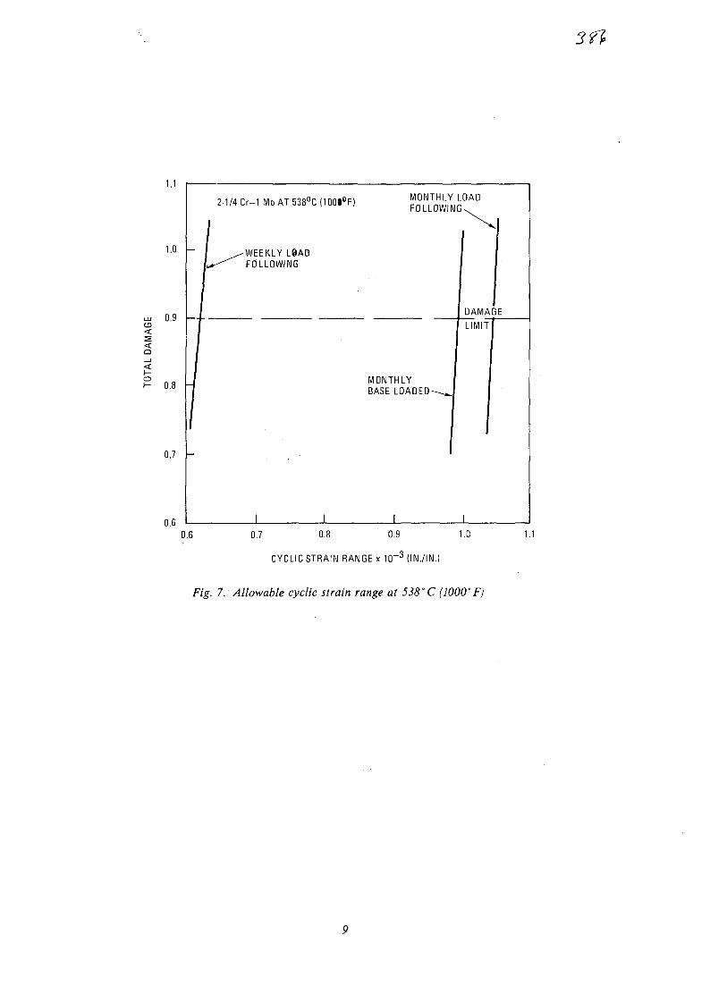
1.1
1.0 -
0.9 -
<
0.8
0.7 -
0.6
0.6
2-1/4
1
rCr-1 MoAT538°C
-WEEKLY L@ADFOLLOWING
I
(100i°F)
1
MONTHLY LOADFOLLOWING.
I
MONTHLY [BASE L0ADED-~_J
1
I
DAMA
LIMIT
3E
1
0.7 0.8 0.9 1.C
CYCLIC STRAIN RANGE x 1 0 " 3 (IN./IN.)
Fig. 7. Allowable cyclic strain range at 538"C (WOO'F)

2.0
1.6
cr> 1.4Io
X
LU
o
I 1.2cr.
1.0
0.8 -
0.6
0.4
ALLOWABLE CYCLICSTRAIN RANGES
MONTHLY LOADFOLLOWING
WEEKLY LOADFOLLOWING
800 900 1000 1100 1200
MAX METAL TEMPERATURE (°F)
1300
Fig. 8. Alloy 8O0H allowable cyclic strain range as a function of temperature
10

ACKNOWLEDGMENT
This work was funded by the San Francisco Op-erations Office of the Department of Energy underContract No. DE-AT03-84SF11963.
REFERENCES
1. "Class 1 Components in Elevated TemperatureService," ASME B&PV Code, Section III, Division1. Code Case N-47-21, December 1981.2. Johnson, W. R., and D. I. Roberts "MaterialsDevelopment for HTGR Heat Exchangers," Jour-nal of Engineering Power 105, October 1983.3. Lewis, A. C , "Allowable Cyclic Strain Rangesfor High Temperature Preliminary Design," GATechnologies unpublished data, August 1983.
11

srfNo. 23
XA0055833
THE KLINGER HOT GAS DOUBLE AXIAL VALVE 1)
by
J. Kruschik 2 ) and H. Hiltgen 3 )
Introduction
The Klinger hot gas valve is a medium controlled double axial valve withadvanced design features and safety function.
It was first proposed by Klinger early in 1976 for the PNP-Project as acontainment shut-off for hot helium (918°C and 42 bar), because a marketresearch has shown that such a valve is not state of present technics.
In the first stage of development a feasibility study had to be made bydetailed design, calculation and by basic experiments for key componentsin close collaboration with Interatom/GHT.
This was 1981 the basis for further design, calculation, construction andexperimental work for such a valve prototype within the new developmentcontract under the support of the MWMV.
The stage of knowledge to that time revealed the following key prioritydevelopment areas:
- Finite element stress analysis for the highly stressed high temperaturemain components.
- Development of an insulation layout based on knowledge of Messrs. Didiera firm also working under the support of MWMV.
- Detailed experimental tests of functionally important structural compo-nents or units of the valve, partly at Klingers (gasstatic bearings,flexible metallic sealing element, aerodynamic and thermohydraulic tests),partly at Interatom (actuator unit and also gasstatic bearings), partly atHRB in Julich (flexible metallic sealing system, aerodynamic and thermo-hydraulic tests).
- Design of a test valve for experimental work in the KVK (test circuit atInteratom) for evaluation of temperature distribution and reliability ofoperation.
- Design of a prototype and extensive testing in the KVK.
1 Presented at the Specialists Meeting on Heat Exchanging Components ofGas-Cooled Reactors of the International Atomic Energy AgencyDusseldorf, 16. - 19. April 1984
2 Klinger Engineering, A-2351 Wiener Neudorf, WienerstraBe 17
3 Interatom, D-5O6O Bergisch Gladbach, Friedr.-Ebert StraBe

- 2 -
Valve Specification
Working/Design pressure 41,9/51 bar
Working temperature 900 + 18° C
Helium mass flow 35,6 kg/sec
Temperature gradient i 2 K/min
Max closing time 15 sec
Leakage rate 10"1 mbar L/sec
Closing cycles per life time 1000
Closing cycles at full temperature 100
Life time over all 40 a
Diameter of gas duct 700 mm
Valve Description
The Klinger double axial valve, Fig. 1, is loaded between the seats with cleanpressurized helium in the closed position to prevent leakage from inlet to outlet.Its dimensions are very compact. It fits practically into the hot gas duct.The weight of this valve is roughly 4,2 to compared with 3 to of the equallength of hot gas duct.
In case of a sudden accidental pressure loss the valve closes automatically bythe flow forces.
The special arrangement of the flow path is responsible for the small dimensionsand also for the low pressure loss: Accelerated flow at the inlet, followed by aring-diffusor, leading to a ring channel with the three struts which connect theinternal cylinder with the two actuators to the outer shell, followed by a ring-infusor and an outlet diffusor after the second seat. This channel is symmetricand there is no preference to flow direction.
This flow path design results in a relatively small seat diameter together withvery low pressure loss, in that case 0,025 bar or^r = 1. These values aretheoretically calculated, but they are sound as many tests with a model in a flowchannel at the Klinger facilities have shown, Fig. 13, 14. The measured value hadbeen^*"= 0,8. But to include adverse influences from fabrication we remain withthe calculated value of __^= 1. These very detailed tests will be repeated andcompleted at the HRB facilities in Julich in the next future for absolute safety.
The corrugated flexible metallic sealing element is a further specific featureof this axial valve. This sealing system together with the basic valve designis subject of Klinger patents.
The piston rod of the actuator slides in gasstatic bearings, having no metalcontact (prevention of welding-together in a clean helium atmosphere) and verylow friction. A further specific feature of that valve. A shock absorberdecelerates the moving mass at the end of the closing stroke.
These basic principles were already included in the very first design early 1976,Fig. 2. The intense development work led to the prototype design, Fig. 1.
The valve actuator is shown in detail in Fig. 3. A prototype actuator has beenbuilt in the last years by Kraftwerk Union Berlin and extensively tested atInteratom, Fig. 15, 16. The results of those tests are already included in thepresent design, Fig. 3, and this actuator is part of the test valve for the KVKand has also been manufactured at Kraftwerk Union Berlin. This modified actuatorof the test valve was already tested succesfully at Interatom short time ago. Normalclosing time is 2 sec. Accidental closing time will be within about 0,3 sec.

- 3 -
The bends in the gas flow path create a rotation of flow and this could inducea rotation of the piston rod with the shut-off cone. Therefore the piston isguided and can't turn. The sealing elements on it are special spring assistedPTFE-rings.
The end positions of the piston rod are indicated pneumatically. The systemconsists of two orifices in series with different bore sizes, whereby the onewith the bigger bore is closed in the end position. The resulting pressurerise is the position signal, see Fig. 6. A redundant-diverse capacitor systemoperates in the piston rod center line.Both actuators as both valve halves are fully independent in respect ofactuation and cooling system.
The gas static bearings operate on the fact, that gas flowing through porousbushes under a certain pressure difference creates a gas cushion, which keepsthe piston rod in suspension. The load bearing capacity is proportional tothe pressure difference.The heavy mass of the piston rod and shut-off cone needs quite a load bearingcapacity and to get also a reasonable clearance in the bearings we took highporosity sintered metal bushes.
This system worked quite well from the start but we got air hammer in certaincases.The problem could be solved in collaboration with Interatom by extensiveexperimental and mathematical work.Today we have manufacturing knowledge to produce such sintered bearings withhigh load capacity within a flow accurancy of 10%, creating no air hammer at all.
. Part of the extensive test programme was the evaluation of frequency responseof this bearing system.We found out by tests and by mathematical analysis that the resonant frequencyis at 20 and 40 Hz. The Klinger frequency test bay is shown in Fig. 17. Theselow resonant frequencies prevent excitation of vibrations from outside,mainly from the gas-stream.
The helium for the gas static bearings is used at the same time as coolant forthe internal valve components, Fig. 4 and 5.The high pressure cooling helium is fed into the valve through the three struts,cools first the inner cylinder and flows from the plenum chamber round theactuating cylinder to the gas static bearings, Fig. 4. Than it cools the hollowpiston rod on the way from the cylinder to the shut-off cone. In the cone noseit is heated first to prevent too high temperature gradients in the shut-offcone and than it flows along the inner face of that cone, Fig. 5, to the headof it, cooling there the flexible metallic sealing element and than it leavesthe valve through the struts.In the closed position of the valve this coolant flow of pressurized cleanhelium cools the valve down and acts as a barrier to prevent leakage ofcontaminated helium from inlet to the outlet.
The struts are cooled by a separate closed circuit helium loop under low pressure,
The flexible metallic sealing system is shown in Fig. 5. It is a corrugated sheetmetal part of Incoloy 800 H, electron-beam welded to the shut-off cone head ofInconel 617. A stop on that head prevents excessive load on the sealing elementin the closed position.A new element has deeper corrugations and they are at the first shut-off deformedplastically and adapted to cone and seat. When the valve is opened again anelastic return spring action takes place and this is the remaining elasticdeflection of the element.
It took intensive experimental work to find the best way of fabrication of suchlarge elements, but at the end we get now quite reasonable results.
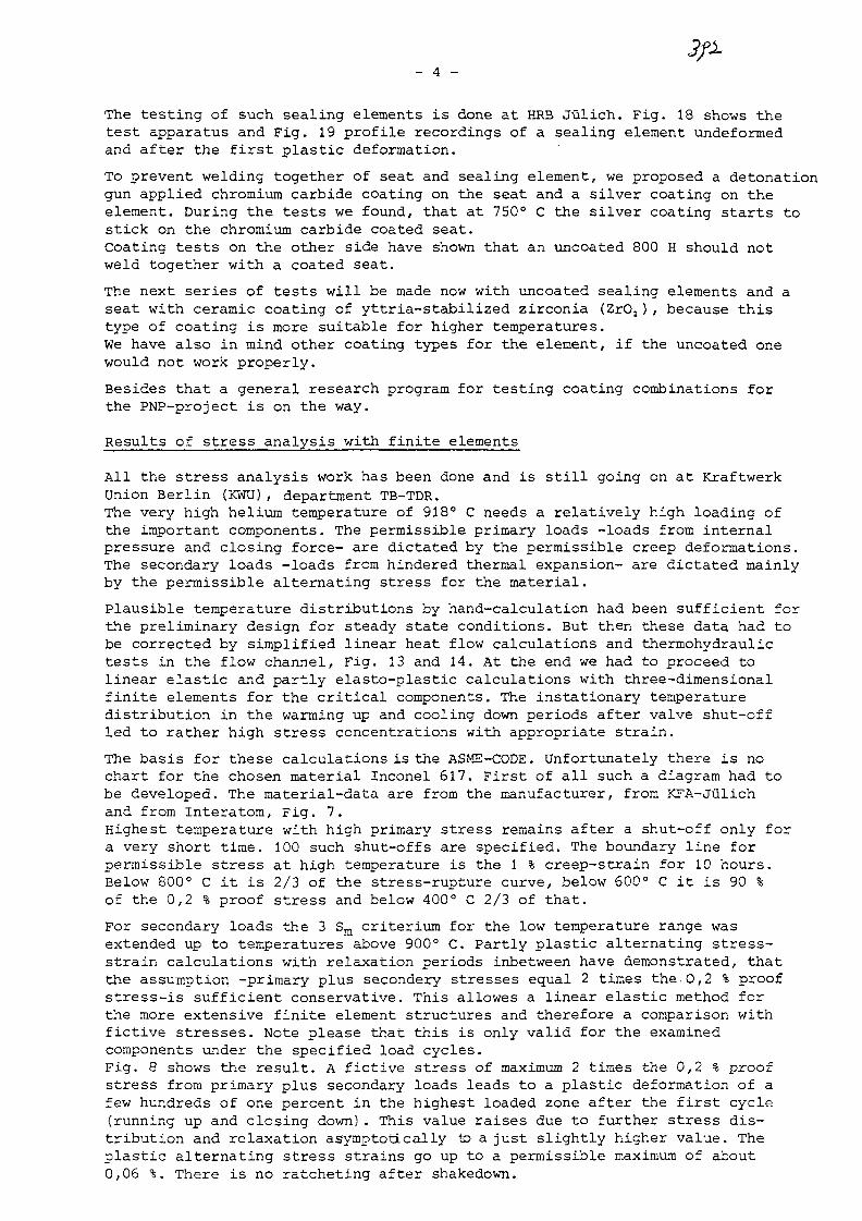
- 4 -
The testing of such sealing elements is done at HRB Julich. Fig. 18 shows thetest apparatus and Fig. 19 profile recordings of a sealing element undeformedand after the first plastic deformation.
To prevent welding together of seat and sealing element, we proposed a detonationgun applied chromium carbide coating on the seat and a silver coating on theelement. During the tests we found, that at 750° C the silver coating starts tostick on the chromium carbide coated seat.Coating tests on the other side have shown that an uncoated 800 H should notweld together with a coated seat.
The next series of tests will be made now with uncoated sealing elements and aseat with ceramic coating of yttria-stabilized zirconia (ZrO2), because thistype of coating is more suitable for higher temperatures.We have also in mind other coating types for the element, if the uncoated onewould not work properly.
Besides that a general research program for testing coating combinations forthe PNP-project is on the way.
Results of stress analysis with finite elements
All the stress analysis work has been done and is still going on at KraftwerkUnion Berlin (KWU), department TB-TDR.The very high helium temperature of 918° C needs a relatively high loading ofthe important components. The permissible primary loads -loads from internalpressure and closing force- are dictated by the permissible creep deformations.The secondary loads -loads from hindered thermal expansion- are dictated mainlyby the permissible alternating stress for the material.
Plausible temperature distributions by hand-calculation had been sufficient forthe preliminary design for steady state conditions. But then these data had tobe corrected by simplified linear heat flow calculations and thermohydraulictests in the flow channel, Fig. 13 and 14. At the end we had to proceed tolinear elastic and partly elasto-plastic calculations with three-dimensionalfinite elements for the critical components. The instationary temperaturedistribution in the warming up and cooling down periods after valve shut-offled to rather high stress concentrations with appropriate strain.
The basis for these calculations is the ASME-CODE. Unfortunately there is nochart for the chosen material Inconel 617. First of all such a diagram had tobe developed. The material-data are from the manufacturer, from KFA-Julichand from Interatom, Fig. 7.Highest temperature with high primary stress remains after a shut-off only fora very short time. 100 such shut-offs are specified. The boundary line forpermissible stress at high temperature is the 1 % creep-strain for 10 hours.Below 800° C it is 2/3 of the stress-rupture curve, below 600° C it is 90 %of the 0,2 % proof stress and below 400° C 2/3 of that.
For secondary loads the 3 S m criterium for the low temperature range wasextended up to temperatures above 900° C. Partly plastic alternating stress-strain calculations with relaxation periods inbetween have demonstrated, thatthe assumption -primary plus secondery stresses equal 2 times the.0,2 % proofstress-is sufficient conservative. This allowes a linear elastic method forthe more extensive finite element structures and therefore a comparison withfictive stresses. Note please that this is only valid for the examinedcomponents under the specified load cycles.
Fig. 8 shows the result. A fictive stress of maximum 2 times the 0,2 % proofstress from primary plus secondary loads leads to a plastic deformation of afew hundreds of one percent in the highest loaded zone after the first cycle(running up and closing down). This value raises due to further stress dis-tribution and relaxation asymptotically to a just slightly higher value. Theplastic alternating stress strains go up to a permissible maximum of about0,06 %. There is no ratcheting after shakedown.

- 5 -
Finite element stress analysis was made so far for the essential structuralcomponents, as central body with struts and inner cylinder, body extensionwith seat-ring and shut-off cone with flexible sealing element.Instationary heat flow calculations have been carried out for the body extensionwith seat-ring and for the shut-off cone head. A specified running up andclosing down period under extreme conditions had been simulated for thesecalculations.For the rest of the structural components the stationary temperatures werecalculated sufficiently accurate by linear heat flow analysis. Uneven tempe-rature distribution by temperature differences in the hot gas stream arethereby hardly recordable. But extreme assumptions for resulting temperaturedistributions in the structure, especially in the struts, helped to get aconservative picture of that effect.
Due to this very elaborate analysis, the design of those structural compo-nents had to be altered many times. For the seat-ring for instance 65 calcu-lations and 8 design variations were necessary to finish up with the presentuncooled shape. The temperature distribution and the resultant linear-elasticcalculated fictive secondary stresses are shown in Fig. 9 and 10.The maximum possible fictive primary stresses due to differential pressureand closing force and the resulting deflection are also shown.The influence of an uneven temperature distribution on the struts is demon-strated in Fig. 11. The stresses hereby are very low. These components havenow their final shape with the necessary factor of safety.
For the shut-off cone also many variants had to be calculated together withthe accompaning design alterations, mainly on the head. But making the wallthickness larger due to the closing forces, the secondary stresses came up,needing an alteration of the cooling ducts and so on. Fig.12 shows the presentstate. Temperature gradients come up to 15 K/mm. This leads with permissibleprimary stresses to unrealistic secondary stresses of about 10 times the 0,2 %proof stress. The about 1300 drillings for the proper coolant flow are stillnot taken into account.
In the chapter before we have mentioned the difficulties with the silvercoating on the flexible metallic sealing element. The temperature limit ofthis silver coating is 800° C and therefore we had to cool extensively. If weaccept an uncoated element -or other types of coatings which stand highertemperatures- we can go up with the temperature and we can use a just slightlycooled shut-off cone, which leads to much lower temperature gradients andtherefore to lower secondary stresses.This will be the next set of calculations. But for verification of all theassumptions and theoretical calculations we do need urgently measured parameters.
Further test programme
To get those parameters we have designed a test valve for experiments in the KVK,Fig. 4 and 6, which is practically a half prototype valve. This test valve hasalso been built by Kraftwerk Union Berlin and is now ready for insertion inthe KVK. The design was going on at the same time as the mentioned structuralcalculations. We noticed soon, that all necessary design alterations could notbe introduced into that test valve, otherwise our test schedule would be indanger. So we uncoupled it. And that was right, because at the present state ofcalculation it is evident, that due to the complex interconnections only ex-perimentally measured parameters can lead to a final layout for the highlyloaded shut-off cone. But we are shure to have in hand a suitable solution ina relatively short time.
The test schedule is shown in Fig. 20. The test valve will be first in the stateshown in Fig. 6. This narrow channel gives with the mass flow in the KVK the sameC<.-values for heat transfer as the full mass flow in the prototype. We shouldtherefore get the real temperatures of all the highly stressed parts.

- 6 -
Further it is possible to install in this test valve a new designed slightlycooled shut-off cone and measure the temperature distribution there. This willgive us the knowledge we need about the necessary parameters.
The valve operation can then be tested with the internals to Fig. 4. This pictureshows a cooled seat in form of a disc. This was also a preliminary design, but itgave too high stress concentrations. But for the test valve we use it, to runfull stroke aad to examine the function of the shock absorber as well as theoverall tightness after shut-off.Fig. 21 shows the center part of that valve and Fig. 22 the shut-off cone.
Besides these extensive tests in the KVK at Interatom, further experimental workwill be done at HRB Julich on the flexible metallic sealing system and on a valvemodel of final shape in the flow channel for investigation of the pressure loss,friction factor and heat transfer value on important sections.
A further development programmeis started for research on the coating sidespecifically tailored for the PNP-conditions.
The Insulation concept
The insulation concept has been laid out in collaboration with Messrs. Didier. Thi:concept is used in the test valve and will be used also in the prototype, if itshows to be sound.
At the inlet and outlet side stuffed A12O3-fibres are used within liners for thegas duct. Between the seats and the center part with the struts vacuum-formedA12O3-parts within liners will be used.The center part itself bears a linerless type of insulation. This insulation isbuilt up of moulded shapes on the inner and outer ring channel surface. Behindthese shapes are vacuum-formed rings and between them and the steel walls is acushion of stuffed Al203 fibres.
Summary
The preceding chapters have shown the intense development work, carried outby Klinger, by Interatom, by HRB-Julich and by Kraftwerk-Union, Berlin.Thanks to the excellent coordinating work by Interatom, all development linesstarted and finished at the right time and with the right results.
As demonstrated, there are only a few points, which wait for a final solution,mainly the shut-off cone, but we are already on the way with it. The same canbe said about the final concept for coatings. We have in hand some solutionsbut we have to find out the optimum by the coming experimental work.
As far as we can foresee the time schedule presented can be kept working, sothat 10 years after the first design sketch a prototype valve for theseextreme conditions will be on test.

KLINGER
Pig.1.Prototype of the KLINGER double axial valve
KLINGER
Fig.2.First rough draft of the KLINGER double axial valve
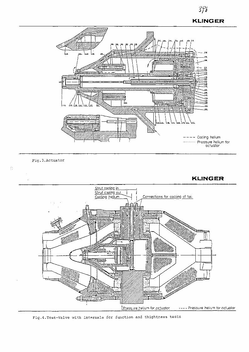
KLINGER
Cooling helium
Pressure helium foractuator
Fig.3.Actuator
KLINGER
Strut cooling inStrut cooling outCooling helium Connections for cooling cf tail
I Pressure helium for_gclugtor Pressure helium for Gctuator
Fig.4.Test-Valve with internals for function and thightness tests
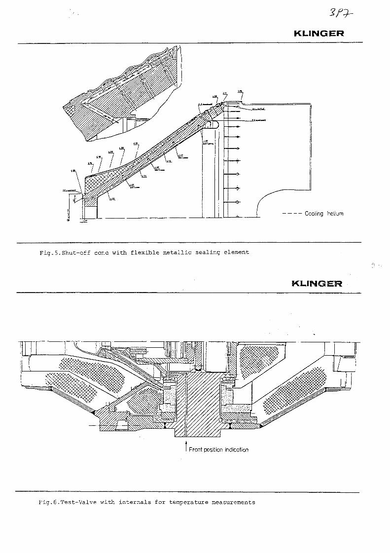
KLINGER
Cooling helium
Fig.5.Shut-off cone with flexible metallic sealing element
KLINGER
Front position indication
Fig.6.Test-Valve with internals for temperature measurements
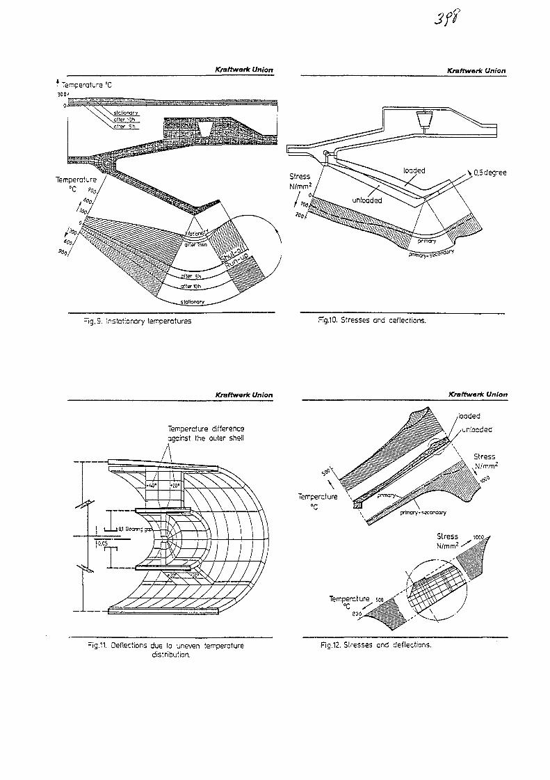
3ft
Kraftwork Union Kraftwork Union
I Temperature °C300^
Fig.9. Instctionary temperatures Fig.10. Stresses and deflections.
Kraftwark Union Kraffwork Union
Tempercture differenceagcinst the outer shed
Fig.11. Deflections due to uneven temperaturedistribution.
loaded
unloaded
StressN/mm2
Fig.12. Stresses and deflections.

Kraftv/ark Union
Fig. 7 Permissible primary stress forInconel 617 according to ASME'
Fig. 14 Valve model
Kraftwark Union
Plastic alternating stress s
Fig* 8 Design limits Fig. 13 Flow channel for aerodynamic andthermohydraulic tests on a valve-model
\
Fig. 15 Actuator unit (Interatom) Fig. 16 Test chamber for the actuator unit
at Interatom
ERB-JULICH
Fig. 17 Test bay for measuring frequency Fig. 13.Test-bay for hot helium test with the Fig. 19.Profile of the corrugated flexibleresponse sealing element at. HRB Julich metallic sealing element
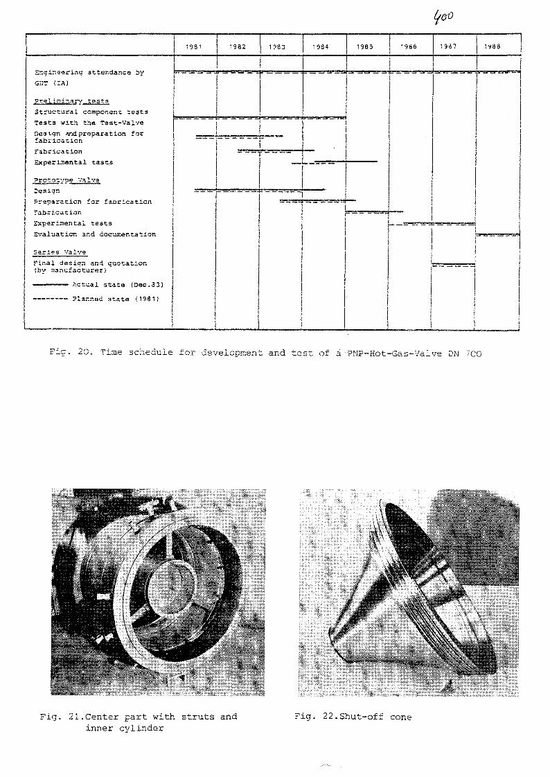
Engineering attendance by
GHT <IA)
Preliminary testa
Structural component test3
Testa with the Tast-valve
Design and preparation forfabrication
rabrication
Exparl.T«ntal tasts
Prototype Valve
Design
Preparation for fabrication
Fabrication
Experimental teats
Evaluation and documentation
Series Valve
Final design and quotation(bv aanufacturer)
1931
A c t u a l s t a t e (Doc.33)
P lanned s t a t a (1981)
tf&Q
1982
T"
1983 1984 1985 1986 1987 1988
iIT" ' ami '-. '-rsj1^1
— _ — - » — —» — —• — ̂
~
"1
Fig. 20. Time schedule for development and test of a PNF-Hot-Gas-Vaive DN 7C0
Fig. 21.Center part with struts andinner cylinder
Fig. 22.Shut-off cone

No. 24
XA0055834
TWO LAYERS THERMAL INSULATIONS TESTSFOR DESIGNING OF HOT GAS DUCTS
by
T. Nakase, S. Midoriyama, K. Roko, A. YoshizakiKAWASAKI HEAVY INDUSTRIES, LTD.
ABSTRACT
Coaxial double walled piping is planned to be used for a primarycooling system piping of the Very High Temperature Gas-cooled Reactor (VHTR)of JAERI. The piping consists of an outer pressure pipe for the reactorinlet gas flow and an inner pipe with internal insulations for the reactoroutlet gas flow. The internal insulations are designed to consist of twolayers; metal insulation is in the extremely inside for the higher tempera-ture gas and fibrous insulation is between the inner pipe and the metalinsulation. The thermal characteristics of inner pipe with two insulationlayers are necessary for the designing of the primary cooling system piping.
Authors performed thermal characteristics tests by using Kawasaki'shelium test loop (KH-200), which has two hot gas ducts test sections of267.4 mm diameter and 5,000 mm length with simulated two layers insulation.The one is installed in a horizontal position and the other is in a verticalposition. The tests were conducted at the temperature of 500 to l,000°C,the pressure of 20 and 40 kg/cm2G, and the flow rate of 100 and 200 g/s.
The distributions of temperatures and heat flux on the surface of theducts are confirmed to be within an allowable range. The test results wereanalyzed, and useful design data of the metal insulation and the fibrousinsulation were obtained.
1. Introduction
The Very High Temperature Gas-cooled Reactor (VHTR) of JAERI is plannedthat the reactor outlet temperature is 950°C, the reactor inlet temperatureis 395°C and the pressure is 40 kg/cm2G. For this operating condition, theprimary cooling system piping has been designed as the coaxial double walledtype shown in Fig. 1, which consists of an outer pressure pipe for thereactor inlet gas flow and an inner pipe with internal insulation for thereactor outlet gas flow. In order to keep the structual integrity of theinner piping, it is protected from very high temperature by the internalinsulation and the continuous cooling with the reactor inlet gas flow.The internal insulation is divided into two layers by a partition pipe tosuppress a natural convection flow across the insulation.
To confirm the thermal performance of the two layers insulation, thermalcharacteristics tests were performed on the condition of helium gas flow byusing Kawasaki's helium test loop (KH-200), including two hot gas duct testsections shown in Fig. 2.
— 1 —

2. Description of the test sections and parameters
(1) Hot gas duct test sections
Two hot gas duct test sections were fabricated simulating the innerpipe of the coaxial double walled piping of VHTR. These two test sectionshave the same dimension except fibrous insulation's packing density. Thediameter of the test section was 267.4 mm and the length was approximately5,000 mm including a bend pipe.
The internal insulation between the pressure pipe and the liner con-sisted of two insulation layers with a partition pipe. The metal insulationmade of inconel 600 was used in the extremely inside insulation layer forthe higher temperature gas, and Kaowool made of A&2O3 and SiO2 was used inthe outside insulation layer.
The core section of metal insulation was made of 32 foils, each 0.05 mmthickness. The insulation consists of alternate layers of plane and dimpledfoils. Three sides of the core section was covered with 0.8 mm thick coverplates. The cover plates were welded in each other. One side of the metalinsulation was opened to make helium gas passage freely. The total thicknessof the metal insulation was 25.3 mm. A gap between the inner cover plateand the liner was 2 mm, and a gap between the outer cover plate and thepartition pipe is 2.4 mm. Z shaped transition pieces were welded on theoutside of the liner and on the inside of the partition pipe. The end coverplate of the metal insulation is welded on the inside of the partition pipe.Thus there is no bypass flow through the gap between the metal insulationand surrounding pipe.
In the case of outside insulation layer, Kaowool was packed between thepressure pipe and the partition pipe. The packing density of the test section"A" is 300 kg/m3, and the test section "B" is 250 kg/m3. The total thicknessof the fibrous insulation was 44.5 mm. Conical shaped transition pieces werewelded on the inside of the pressure pipe to suppress a bypass flow and tosupport the internal insulation.
Two thermocouples were inserted into the center of the liner pipe tomeasure the flowing helium gas temperature. In order to measure the tempera-ture distribution of the insulation, 33 thermocouples are installed on theoutside surface of the partition pipe, 12 thermocouples on the outside surfaceof the transition pieces and 27 thermocouples on the outside surface of thepressure pipe.
(2) Test conditions and measurement
Thermal characteristics tests were performed by using the test loop.
At first, the hot gas duct test section "A" was installed in a horizontalposition and test section "B" was installed in a vertical position. The testswere conducted ranges between 500 and l,000°C of the heater outlet heliumtemperature. The test pressure was 20 and 40 kg/cm2G with the flow rate of100 and 200 g/s. Then the position of the test section "A" and "B" wereexchanged in each other, and tests were continued.
- 2 -

The temperature distribution in the insulation layer and at the surfaceof the pressure pipe were measured with thermocouples and a radiative thermo-meter. The heat flux in the vicinity of the thermocouples on the surfaceof the pressure pipe was measured with a heat flux meter.
3. Test results
(1) Temperature distribution in the insulation layer and on the surface ofthe pressure pipe
Figs. 3 and 4 show the temperature distribution of the test section"A" and "B" respectively at the gas temperature of l,000°C, the pressure of40 kg/cm2G and the flow rate of 200 g/s.
In the case of the test section "A" in the horizontal position, theaverage temperature of the partition pipe was approximately 66t)°C, and thecircumferential and longitudinal temperature distribution was within a rangeof ±25°C of the average temperature. The outside location of metal insulationjoint section was approximately 30°C higher than the other section. This wascaused by the thermal conduction of the metal of the insulation connectingsection. The average temperature on the surface of the pressure pipe wasapproximately 195°C, and the circumferential and longitudinal temperaturedistribution was within a range of ±15°C of the average temperature. No hotspot was observed.
In the case of the test section "B" in the vertical position, the tem-perature distribution was almost same as that of the test section "A".
Fig. 5 shows the temperature distribution at the transition piece ofthe test section "A" at the gas temperature of approximately ls000°C, thepressure of 40 kg/cm^G and the flow rate of 200 g/s. The temperature dis-tribution at the transition piece was close to linear. The circumferencialtemperature difference was within 15°C. As the temperature difference ofthe pressure pipe in the vicinity of the transition piece was approximately5°C, the effect of the transition piece on the temperature distribution ofthe pressure pipe was low.
Fig. 6 shows the heat flux distribution of the test section "A" in thehorizontal position. Each heat flux was measured at the pressure pipe nearthe thermocouples installed on the pressure pipe. The average heat flux wasapproximately 2,060 kcal/m^h and its distribution range was approximatelywithin ±300 kcal/m^h of the average heat flux. There was no abnormal heatflux.
Fig. 7 shows the temperature distribution on the pressure pipe surfaceof the test section "A" measured by a radiative thermometer. Test conditionswere the same as shown in Fig. 3. Both upper side pictures (picture 1A and2A) show the location of the measurement. Center line of each graph in thelower side pictures (picture IB and 2B) shows a temperature of 190°C, andone scale shows 10°C. The temperature distribution measured by the radiativethermometer was within 180 to 210°C. A peak temperature of 240°C in thepicture IB is an influence of an emission of a paint (emissivity = 0.99) of
— 3 —

+ mark shown in the picture 1A. The lower flat temperature distribution inthe picture 2B is an influence of a clamp for a pipe hanger. Other sharpnegative peaks shown in the picture IB and 2B are due to an influence ofcompensating lead of thermocouples. Therefore, no hot spot was detected,and this result agrees with the result shown in Fig. 3.
In case of the test section "B", almost the same results were alsoobtained.
Further, to confirm the effect of the vibration, the authors performeda seismic test by using the test section "B" and compared the thermal dis-tributions before and after seismic loading test. Both the temperaturedistributions agreed well.
(2) Effective thermal conductivity of the insulation layers
Effective thermal conductivity at each test positions were obtained byusing the heat flux, partition pipe surface temperature, pressure pipesurface temperature and room temperature. The calculation method of theeffective thermal conductivity is described in Appendix. The estimatedeffective thermal conductivities of metal insulation and fibrous insulationwere plotted in the Fig. 8 and Fig. 9. The estimated effective thermalconductivities were arranged by using simple regression.
4. Discussion
(1) The regression lines of the effective thermal conductivity
Fig. 10 shows the regression lines of the effective thermal conductivityof the metal insulation of the test section "A" in the horizontal position.The regression line at the helium pressure of 40 kg/cm^G and the flow rateof 200 g/s is higher than the others. The conductivity at the pressure of20 kg/cm2G shows about 10% lower value than that of the test pressure of40 kg/cm^G, and this is thought to be the gas density difference. As theconductivity at the flow rate of 100 g/s and pressure of 40 kg/cm^G is alittle lower than that of the flow rate of 200 g/s and pressure of 40 kg/cm2G,the difference of flow rate is considered to be small effect.
Fig. 11 shows the effective thermal conductivity of the metal insulationof the test section "A" and "B" at the helium pressure of 40 kg/cm2G and theflow rate of 200 g/s. The test results in the horizontal and vertical posi-tion showed a good agreement. The test results of the test section "B" showsrelatively higher thermal conductivity than those of the test section "A".
Fig. 12 shows the effective thermal conductivity of the fibrous insula-tion at the helium pressure of 40 kg/cm2G and flow rate of 200 g/s. Theresults were slightly difference each other, but it is thought to be noremarkable difference due to test positions and insulation packing density.
- 4 -

(2) Comparison of the thermal conductivity
Fig. 13 shows a comparison of the thermal conductivity between afore-mentioned flowing helium test and the stagnant helium test of KHI. Therepresentative lines used in the former test is shown in Fig. 11 and Fig. 12.
The stagnant helium test was conducted by using the full sized diametertest section of the inner piping of VHTR. The internal insulation consistedof two insulation layers; metal insulation was used for the higher tempera-ture insulation layer, and Kaowool was used for the low temperature. Thetest section length was 4,500 mm. Helium gas was charged in the test sectionand heated by an electric heater. The test was conducted at the heliumtemperature of l,000°C and the helium pressure of 40 ^
The measured data of KH-200 almost agreed with those of the full sizedstagnant test data in both cases of the metal insulation and the fibrousinsulation.
5. Conclusions
The following conclusions are obtained-
(1) The temperature distribution with two layers thermal insulations isalmost uniform and no hot spot is observed.
(2) Useful design data of effective thermal conductivity of the metalinsulation and fibrous insulation are obtained.
Reference
(1) T. Nakano, T. lino, T. Hagiwara, S. Takano, High Temperature PipingInsulation Testing. FAPIG No. 94, 1980-3 (in Japanese).
- 5 -

Appendix. Calculating method of the effective thermal conductivity
_ The heat balance model of the two layers thermal insulation systemis shown xn the figure at the lower part. The heat balance of the systemis dxfxned as following equations.
Q = q • TT • D p 0
= a H e . TT. D u ( T H e - T i )
- T 2 )
( T 2 - T 3 )
Partitionpipe
Liner
AD —-i
Pressure Pipe
2TTX
TT ( T3 " T4)
2TTAF
a airA V
2TTAT" T6)
oac
= »air * TT • Dpo(T6 - Tair)
where
Q : heat flux per unit length
a H e : heat transfer coefficient at the inside surface of the liner
a a i r: heat transfer coefficient at the surface of the pressure pipe
AM : effective thermal conductivity of metal insulation
AF : effective thermal conductivity of fibrous insulation
^£ : thermal conductivity of liner
As : thermal conductivity of pertition pipe
Ap : thermal conductivity of pressure pipe
Effective thermal conductivity is obtained by substituting measured q(kcal/m^h), T H e, T 4, T 6 and T a i r into above equations.
- 6 -
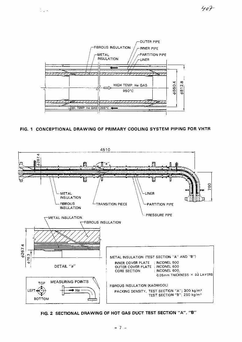
-FIBROUS INSULATION
INSULATION
OUTER PIPE
INNER PIPE
PARTITION PIPE
LINER
" ^ W . • : • ' . • : • : • : • : • * : • ']•:
77 HIGH TEMP. He GAS
950°C 03
LOW. TEMP. He GAS
FIG. 1 CONCEPTIONAL DRAWING OF PRIMARY COOLING SYSTEM PIPING FOR VHTR
4510
tojcslj-e-
-METALINSULATION
-FIBROUSINSULATION
•TRANSITION PIECE
-METAL INSULATION
\-FIBROUS INSULATION
DETAIL "a '
T 0 P MEASURING POINTS
He
BOTTOM
LINER
PARTITION PIPE
PRESSURE PIPE
METAL INSULATION (TEST SECTION " A " AND "B")
INNER COVER PLATE : INCONEL 600OUTER COVER PLATE : INCONEL 600CORE SECTION : INCONEL 600,
0.05mm THICKNESS x 32 LAYERS
FIBROUS INSULATION (KAOWOOL)
PACKING DENSITY, TEST SECTION " A " ; 300TEST SECTION " B " ; 250 kg/m 3
FIG. 2 SECTIONAL DRAWING OF HOT GAS DUCT TEST SECTION "A", "B"
- 7 -

1000
900
800
700o
UJ 600
Z)< 500
LU
LU
400
300
200
PARTITION-PIPE 100
.PRESSURE\PIPE n
x (He GAS)
(PARTITION PIPE SURFACE)
BeB
(PRESSURE PIPE SURFACE)
in i j n
BOTTOM
LINER rt m toFIG. 3 TEMPERATURE DISTRIBUTION OF HORIZONTAL TEST SECTION " A "
(He GAS TEMPERATURE 1000°C, PRESSURE 40 kg/cm2G, FLOW RATE 200g/s}
1000
900
800
_ 700
<UJ
600
500
400
300
200
PARTITION
PRESSURElo
TOP
x (He GAS)
oSoS©
(PARTITION PIPE SURFACE)
(PRESSURE PIPE SURFACE)
in ii nLEFT"*
'BOTTOM
-LINER
FIG. 4 TEMPERATURE DISTRIBUTION OF VERTICAL TEST SECTION " B "
(He GAS TEMPERATURE 1000°C, PRESSURE 40 kg/cm2G, FLOW RATE200 g/s)

700
600
500L>
cc 400
cc
LLJ
( -
PARTITIONvPIPE\ PRESSURE
\PIPE\TOP
xV
LEFT O
300
200
100
D'BOTTOM
'LINER
TEST POSITION
He GAS TEMP.
93 :50!il7l 293
HORIZONTAL
1000°C
TEST PRESSURE 40 kg/cm2GFLOW RATE 200 g/s
•=* He GAS FLOW
KAOWOOL
METALINSULATION
FIG. 5 TEMPERATURE DISTRIBUTION AT THE TRANSITION PIECE ANDVICINITY; TEST SECTION "A"
3000
E
o
X_iU-
<1X1
2000
1000
PARTITION-PIPE
PRESSURE0
\TOP
LEFT©
BOTTOM
LINER
ce © c
©5 ©
in I n
POSITION
He TEMP.
e
o
HORIZONTAL1000°C
TEST PRESSURE 40kg/cm2GFLOW RATE 200 g/s
FIG. 6 HEAT FLUX DISTRIBUTION OF THE TEST SECTION "A'
- 9 -

oI
(PICTURE 1A) (PICTURE 2A)
(PICTURE 1B) (PICTURE 2B)
FIG. 7 TEMPERATURE DISTRIBUTION ON THE PRESSURE PIPE SURFACE MEASURED BYA RADIATIVE THERMOMETER

u
>O
D2Ou
IorLUX
LU>
( -
LU
MEASURING POINTS• TOPG LEFTA BOTTOM
TEST SECTIONPOSITIONHe TEMP.
" A "HORIZONTAL1000°C
REGRESSION LINE OF Xeff
TEST PRESSURE 40kg/cm2GFLOW RATE 200g/s
0.00 100.00 200.00 300.00 400.00 SOO.OO 600.00 700.00
MEAN INSULATION TEMPERATURE (°C)
BOO.00 900.00 1000.00
FIG. 8 CALCULATION RESULT OF EFFECTIVE THERMAL CONDUCTIVITY(METAL INSULATION)
, to
JE -
' (K
ca
0.7
2
~IV
IT\
1— (DCJ in -
Q °2Ou n
< o
XJJ
H S-
—oLUUL »J . — -1X1 o
1.00
p REGRESSION LINE OF Xeff
\
\ ° i £S i A a*^?,———^
MEASURING POINTS• TOP©LEFT^BOTTOM
TEST SECTION " A "POSITION HORIZONTALHe TEMP. 1000°CTESTi PRESSURE 40kg/cm2GFLOW RATE 200g/s
0.00 100.00 ZOO.00 300.00 400.00 500.00 600.00 700.00 BOO.00 SOO.OO 1000-00
MEAN INSULATION TEMPERATURE (°C)
FIG. 9 CALCULATION RESULT OF EFFECTIVE THERMAL CONDUCTIVITY(FIBROUS INSULATION)
- 11 -

uoJZ
E
OO
ECUJX
0.7
0.6
o— 0.5
0.4
0.3
0.2
HOLU n 1
u_ U.I
40kg/cm2G, 200 g/s
40kg/cm2G, 100 g/s
20kg/cm2G, 100 g/s
0.7
0 200 400 600 800 1000
MEAN INSULATION TEMPERATURE (°C)
FIG. 10 EFFECTIVE THERMALCONDUCTIVITY OF THEMETAL INSULATION OFTEST SECTION "A"(HORIZONTAL)
u0.6
o
0.5
3OZoo
0.4
0.3
crI
0.2
LU
£ 0.LJJ
TEST PRESSURE 40kg/cm2GFLOW RATE 200 g/s
TEST SECTION "A" , HORIZONTAL
TEST SECTION "A" , VERTICAL
TEST SECTION "B" , HORIZONTAL
TEST SECTION " B ' \ VERTICAL
0 200 400 600 800 1000
MEAN INSULATION TEMPERATURE (°C)
FIG. 11 EFFECTIVE THERMALCONDUCTIVITY OF THEMETAL INSULATION
0.7
0.6
CO
u- 0.5>-
a2Ou-J 0.3<
UJ
UJ
oS o.i
He PRESSUREFLOW RATE
40kg/cm2G200 g/s
TEST SECTION "A" , HORIZONTAL
TEST SECTION "A" . VERTICAL
TEST SECTION "B " , HORIZONTAL
TEST SECTION "B" , VERTICAL
I i I i I i I i
0.7
0 200 400 600 800 1000MEAN INSULATION TEMPERATURE (°C)
FIG. 12 EFFECTIVE THERMALCONDUCTIVITY OF THEFIBROUS INSULATION
oJZ
E0.6
> °'5
0.4Q2OO
0.3
UJ
0.2
uE o.i
METAL INSULATIONKH-200 TEST
STAGNANT He TEST OF KHI
FIBROUS INSULATIONKH-200 TEST
STAGNANT He TEST OF KHIJ | , I I I T
0 200 400 600 800
MEAN INSULATION TEMPERATURE
1000
FIG. 13 COMPARISON OFTHERMAL CONDUCTIVITY
- 12 -

No. 25
XA0055835IAEA
Specialists' Meeting on
Heat Exchanging Components of Gas-Cooled Reactors
Diisseldorf, 1 6 - 1 9 April 1984
Status of the development of hot gas ducts for HTRs
H. Stehle, E. Klas
INTERATOM GMBH, FRG
1. Introduction
In the PNP nuclear process heat system the heat generated
in the helium cooled core is transfered to the steam re-
former and to the successive steam generator or to the
intermediate heat exchanger by the primary helium via
suitable hot gas ducts. The heat is carried over to the
steam gasifier by the intermediate heat exchanger and a
secondary helium loop.
In both the primary and the secondary loop, the hot gas
ducts are internally insulated by a ceramic fibre insu-
lation to protect the support tube and the pressure housing
from the high helium temperatures. A graphite hot gas liner
will be used for the coaxial primary duct with an annular
gap between support tube and pressure shell for the cold
gas counterflow. A metallic hot gas liner will be installed
in the secondary duct.
2. Operational data and design criteria
The most important operational data for dimensioning and
design are as follows:
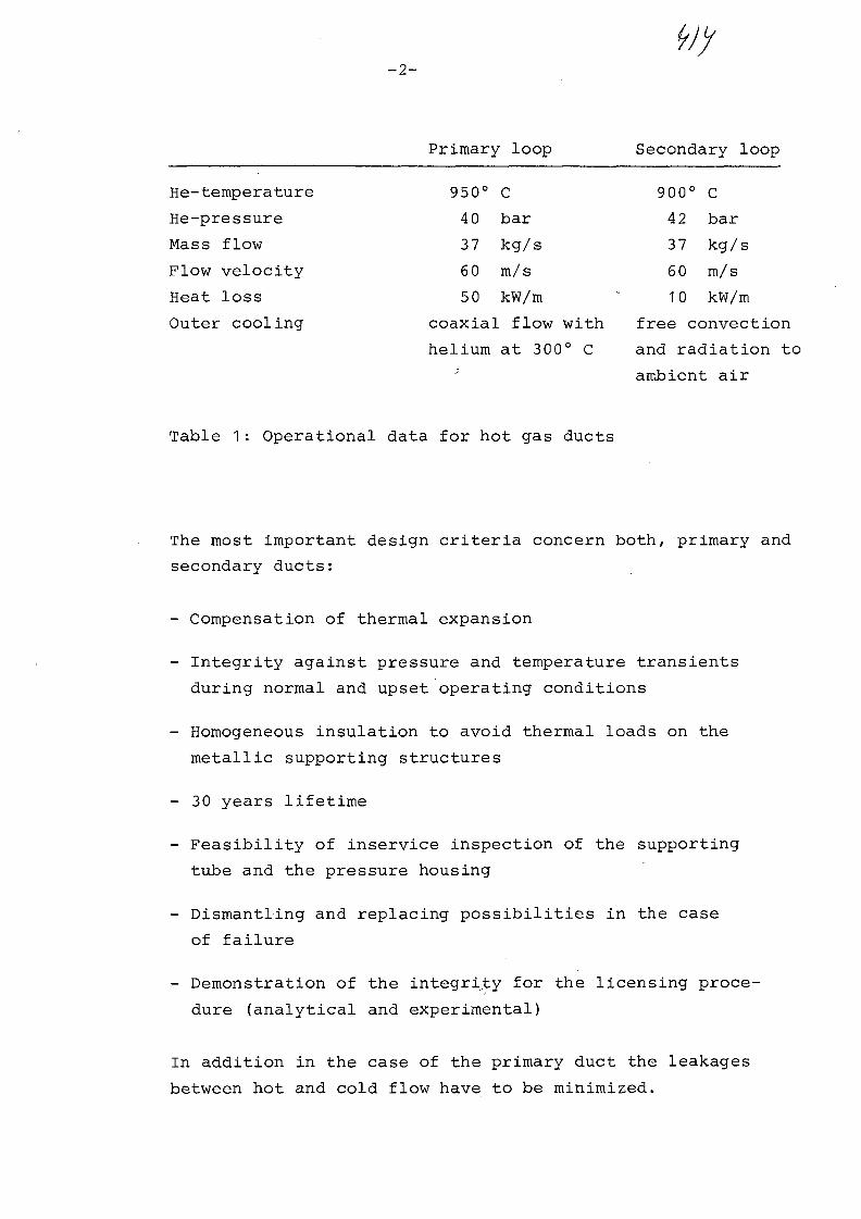
Primary loop Secondary loop
He-temperature
He-pressure
Mass flow
Flow velocity
Heat loss
Outer cooling
950° C
4 0 bar
37 kg/s
60 m/s
50 kW/m
coaxial flow with
helium at 300° C
900° C
4 2 bar
37 kg/s
60 m/s
10 kW/m
free convection
and radiation to
ambient air
Table 1: Operational data for hot gas ducts
The most important design criteria concern both, primary and
secondary ducts:
- Compensation of thermal expansion
- Integrity against pressure and temperature transients
during normal and upset operating conditions
- Homogeneous insulation to avoid thermal loads on the
metallic supporting structures
- 30 years lifetime
- Feasibility of inservice inspection of the supporting
tube and the pressure housing
- Dismantling and replacing possibilities in the case
of failure
- Demonstration of the integrity for the licensing proce-
dure (analytical and experimental)
In addition in the case of the primary duct the leakages
between hot and cold flow have to be minimized.

-3-
3. Design and construction of the hot gas ducts
3.1 Primary hot gas duct
The reference primary duct developed by INTERATOM is
shown in Fig. 1. Fibre mats consisting of aluminium
oxide are wrapped round the graphite hot gas liner.
Graphite foils inserted between the single mats are
used as radial convection barriers. A metal supporting
tube separates the hot gas from the cold gas.. The liner
is positioned radially and axially in the support tube
by high density aluminium oxide supports. These are
arranged in two cross-sections for each liner assembly
unit. Four ceramic ball supports are located in each
cross-setion for the radial alignment. The lower two
supports are rigidly set, the upper two are positioned
with a spring and limit stop. One cone-shaped support
in each cross-section takes care of the axial positioning.
All support elements are inserted from the outside of
the supporting tube through corresponding windows. After
installation, the inserts are welded to be gas-tight. The
single liner units are connected by overlapping grooves
with a calculated axial clearance at ambient temperature.
This clearance will be closed at design temperature.
In principle the same design is used for two compensating
units in the hot gas duct between reactor and heat exchanger
The total unit, hot gas duct and compensating unit are inser
ted into the pressure retaining shell with an annular gap
for the cold helium backflow. This pressure shell is insula-
ted at the outside.
3.2 Secondary hot gas duct
The secondary duct consists of a inner section with a
metallic liner and fibre insulation for flow guidance and
heat insulation, and a outer shell for pressure containment.
This concept has already been applied for different high
temperature loops. The significant advantage of this design

to-4-
is based on two facts:
- The simple procedure for dismantling and for exchange
of internals
- Accessibility of the pressure housing for inservice
inspection
Fig. 2 shows the reference secondary hot gas duct, developped
by INTERATOM. The different parts viewed from the inside to
the outside are:
- The metallic hot gas liner
- The perforated metallic tube for the inner limitation of
the insulation
- The ceramic friction bearing spacers between the two
tubes to exclude the danger of friction welding. The
annular gap allows a pressure balance between the hot
gas channel and the insulation
- The wrapped fibre mats of 95 % aluminium oxide
- The intermediate tube to reduce the radial convection
space
- The wrapped fibre mats of 55 % aluminium oxide
- The support tube
- The V-shaped thermosleeves to limit the axial convection
and to centre the flow guidance tubes
- The support tube for all internals
- The pressure tube into which the assembled support tube
is inserted as a slide-in unit. Each internal assembly
is sealed and fixed at the flange of the pressure tube.
This system, including the slide-in technique, is also used
for the secondary loop elbows and compensators (Fig. 3).

-5-
4. R + D work
The R + D work for the development of the hot gas ducts
can be divided into four main tasks:
a) Material development and testing
b) Component part tests
c) Scaled down component tests
d) 1 : 1 scale component tests
In the meantime, the materials, metals, graphite and ceramics,
have been investigated with good results. The tests listed
under b) to d) are carried out under all expected demands
such as steady state thermal loads, transient temperature
and pressure conditions and, in some cases, superimposed
additional mechanical loads.
The support elements of the primary duct, the ceramic balls
and cone shaped parts, were tested with temperature gradients
and transients and, in addition, with alternating mechanical
loads. These tests demonstrated the integrity of these support
elements.
A similar test programme will be carried out for the pri-
mary graphite liner. A suitable test rig is under construction.
Test operation will start in summer 84.
The assembly method for wrapping the fibre mats was developed
during preliminary tests and the specific assembly data for
the applied insulation qualities were optimized. The fibre
mat insulation can be compressed to such an extent that it
is almost possible to exclude the formation of cavities during
the lifetime.
The extreme requirements in the case of accidents are gene-
rally simulated during the component part tests. The main
objective of the large component tests is to demonstrate the
integrity of the overall assembly under original operating
conditions.

-6-
Important details for improving the design can be
obtained during the assembly work of the component
test sections. The efficiency of the insulation was
proved during thermal examinations in the high pressure
helium channel of the Nuclear Research Centre Jiilich.
First results indicated that the open insulation systems
were severely impaired by free convection, resulting in
thermal loads on the metallic support structures. There-
fore the insulation had to be modified with adequate con-
vection barriers.
With reference to the secondary hot duct insulation a
lot of experience and test results had been obtained from
the preceeding tests for the hot gas piping of the High
Temperature Helium Test Loop KVK at INTERATOM and from
other test facilities. As a result, it was possible to
take these test data into account for the planning and
design of an originally-scaled test section. It was there-
fore possible to install such a large test component of
6 m in lenght in the KVK before the first start-up period
of the test loop. In the meantime this component has endured
about 5000 hours of operation under various conditions
without any indications of failures.
The test component was equipped with thermocouples in
different axial cross-sections. In each measuring plane,
chromel-alumel thermocouples were installed over two per-
pendicular diameters in different radial positions. The
corresponding outer wall temperature can be measured
using resistance thermocouples. The measurements were
carried out in the KVK under different operating conditions
between helium temperatures of 400° C to 950° C and helium
pressures of 14 bar to 4 0 bar.
Figs. 4 and 5 present the radial temperature profiles in
two different measuring planes for a helium temperature
of 936° C and a pressure of 20 bar. The two measuring
planes are situated upstream (B) and downstream (B1) of
the axial extention gap between two liner units. The radial

-7-
temperature profiles are pointed out in all four angular
directions. There are small variations for the different
directions due to geometric disalignments of the metallic
structures, possible inhomogeneities and convection in
the insulation. A remarkable temperature decrease can be
noted across the annular gap between the support tube and
the pressure shell. This decrease is different in the two
measuring planes. A definite explanation of this difference
can be given after improvement of the alignment during
dismantling.
Fig. 6 shows the outer wall temperature of the pressure
tube as a function of the helium temperature. The mean
values of the four measured temperatures in each measuring
plane are marked together with the maximum deviations. All
these deviations are smaller than 10 % of the mean value,
an indication that hot spots do not exist.
The azimuthal temperature distribution around the pressure
tube surface is shown in Fig. 7 for different helium tem-
peratures. The curves represent the relative deviation in
percent from the mean temperature. There is a strong
asymmetry in the vertical direction for low helium tempera-
tures decreasing with increasing helium temperature. This
behaviour clearly shows the influence of free convection
in the insulation, which is characterized by a modified4
Raleigh number for porous materials proportional to p2/T .
The specific heat loss to the environment as a function of
the helium temperature in two measuring planes is shown
in Fig. 8 in W/m2 of the pressure tube surface and in W/m
tube length. The upper curves represent the total heat
loss, the lower ones the convection ratio.
Summarizing all experimental and operational results, the
integrity of the component has been demonstrated and the
design calculations have been confirmed as being conserva-
tive. The measured heat loss at helium design temperature
was less than 70 % of the calculated value.

6000
I-,—, , I;
7N X X X ! *\ X x X VK X>C"TN x X X A ,
OCO
\/. '/. i-r-'X'j-K X X X
O
O
x x x xxX-^^-yvM
SCD
ooo"Si
X X X > r'T A V X rh X x x - ' X x x X V i X \->X A X X X X X X X X f h X ^
Pressure vessel
Support structure
— Insulation
Liner
Displacementbody
Axial support element Radial support element
Detail B Detail CCross-section A-A
Test Section Primary Hot Gas Duct Fig-1

5970
Cross SectionA-B
Insulation
Displacement Space
Support Tube Pressure Vessel 15Mo3 Liner Incoloy 800H
Secondary Hot Gas Duct with Metallic Liner and Fibre Insulation Fig.2
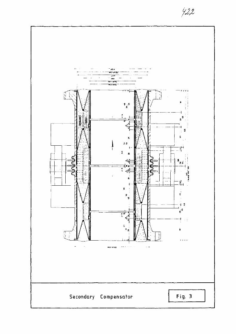
\ s
Secondary Compensator Fig. 3
-2-
The conversation of these energy resources to gaseous
and liquid products enables us to do so. Of all the nuclear
reactors developed today, the high temperature reactor is
predestinated to play a key role, as it can supply the heat
which is necessary for the conversion processes at the
required high temperatures of between 800° C and 950° C.
In conjunction with special process technology, this leads
to a considerable reduction of the pollutant emissions of
SO , CO« etc. and of dust.
Above all, the CO- emission, which is much lower than in
autothermal gasification processes, deserves special mention,
because of the C0_ influence on the temperature increase at
the earth's surface.
2. The Plant Concept
In order to clarify the functions of those components which
are the subject of the following presentations, I would like
to consider the PNP plant with both gasification processes,
namely steam gasification and hydrogasification of coal, in
more detail.
Let us first consider the steam gasification of coal (Fig. 1).
The reaction of steam with hard coal requires high temperature
heat since it is endothermic. For this process a secondary
helium loop is advisable for safety reasons.
The secondary helium is heated to 900° C in the He/He inter-
mediate heat exchanger and enters the gas generator at
approximately this temperature. The helium is cooled to around
815° C here because of the carbon-steam reaction.
The helium leaving the gas generator is cooled in the process
steam superheater and then conveyed to the steam generator.
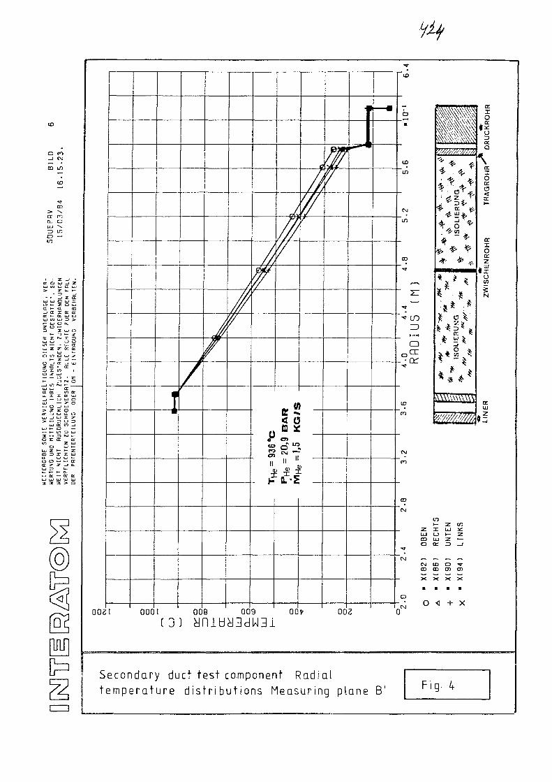
tit
O CO_ 1 <\J
CD> "S.
CL OUJ \
UJ m o cr UJ>• 2 u. i-
• *~ _i z cr! • j tj i C~i i . j *T~
O »- Z Q UJa »- cc m_j a x Q: orD: »- ec UJ ou v) uj D >»— LkJ O U.z o —ZD 3 UJ O
*- =3 »- 2Tor x r** x nUJ (J i_> O
UJ z z a: a:— LU t -
— — O • JZ
a L» u i—D O - - aa: z z JQ.
1 2 3 > •
CZZ)
I•
A
/
J/
////V
< c
pi*11 « «
i
///7/
n—•
0021 0001 008 009 OOfr 002
o ) yniuy3dW3i
bt
e c o n d a r y d u c t t e s t c o m p o n e n t R a d i a ls m p e r a t u r e d i s t r i b u t i o n s M e a s u r i n g p l a n e B '
O
1-01
•
h
0
D
C\J
LO
CO
r
1 1
T
13
.6
4.0
4
Rfl
DIU
S
C\J
m
CD
CM
US
** !3 $̂
•* i *
* ** • •
%'•'////////////
nr iij x:
UJ LJ t— ZCD UJ Z —'o tt: Z3 _i
CM — ~ — ~CVJ to O •«•
co a) co • )— X X X X
a • a aD
LJ_ g- K
OH
RR
UC
KR
U
\a.IOcraV
til
aIOa:z
ZW
ISC
HE
tx.Ill
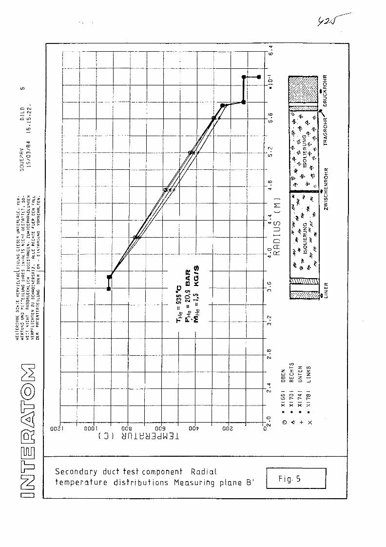
CD OJ_ J OJ
d
LU
o
O i- Z. O iu
j a i it Kai *— cc UJ CDw in u 3 >>— UJ O U.z o —
O Z UJ—. — o»- r> (
j 10 NJ iUJ UJ ta: cc <ii. X X (
e: ^ u a o
U_j »— CD —
LJ U t-i — — a:: z _J a.
- o: - o r a^ 3 3 > o
iIi
i
j
002
Sn
I 000
I
/
f
ft/
i7
(
10 o "\a1
• Q.-2
|a>m
J—a
I 009 009 OOfr 002f ^ l \ J P l l l - J V I 1 3 _ J I I 1 3 lL J J Q I I X U C J J J C J W J J . L
e c o n d a r y duc t t e s t componen t R a d i a l? m p e r a t u r e d i s t r i b u t i o n s M e a s u r i n g p l a n e B'
ID
O
•
CO
10
CM
in
CO
21
IUS
Q
°C£
CD
ro
CM
CO
C\J
LLJ
COo
•«?
CNJ ~CDCD
X
It
o
F c
'* * f
' * * • *
i? UJ ^
CO1— Z COz: Lu icC_> h— ZUJ Z —a : => _>
O -fl- COr~ r- t—
» « B
< + X
1-5
a.Ir
RU
CK
R
a
\
TR
AG
RO
HF
NR
OH
R
cu
f
j
z

cc
1 _>u
_)D
^ 120-•x.
| 1 1 0 --U
inn -IUU
nn
80-
•7 f i _
/ u
(. A _bvj
AV/
i/xi
/ /
/ /
Air
{
400 600 800 1000
^e(ium Temperature °C
0 Measuring Plane B
• Measuring Plane B'
Mean values of the oufs de pressure tutemperature as a funkt ion of hel iumtempera tu re and maximum dev ia t ions
be
Fig .6
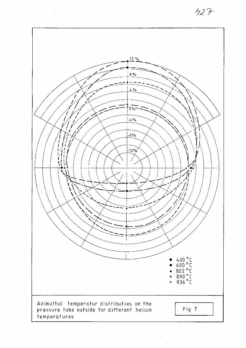
12 %
400 °C• 6 0 0 ° C* 802°C* 890°C+ 936°C
Azimuthal ternperatur d i s t r i bu t i es on thepressure tube outside for d i f fe ren t heliumtempera tu res
Fig. 7
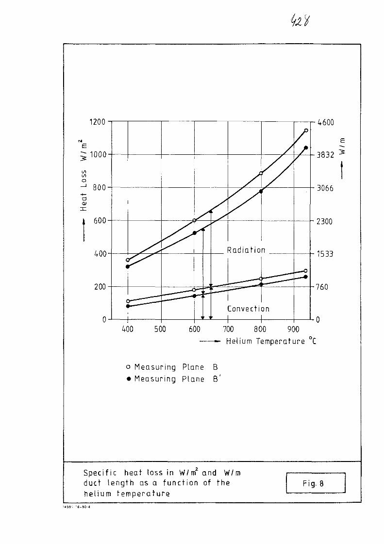
1200
1000
i/i
aCD
800
600
400
200
Convection
4600
3832
3066
2300
1533
760
400 500 600 700 800 900
Helium Temperature °C
o Measuring Plane B
• Measuring Plane B'
Specific heat loss in W/m2 and W/mduct length as a func t ion of thehelium tempera tu re
Fig. 8
U59> 16-S0/4

No. 26
INTERNATIONAL ATOMIC ENERGY AGENCY
Diisseldorf
Federal Republic of Germany
16.-19. April 1984
XA0055836Specialists' Meeting
on
Heat Exchanging Components of
Gas-Cooled Reactors
Graphite and Carbon/Carbon Components for Hot Gas Ducts
by
G. Popp, U. Gruber, H. Boder, K. Janssen
SIGRI ELEKTROGRAPHIT GMBH

GRAPHITE AND CARBON/CARBON COMPONENTS
FOR HOT GAS DUCTS
G. Popp, U. Gruber, H. Boder, K. Janssen
Introduction
The large coal reserves in the Federal Republic of Germany
and the uncertainty of the future energy situation on the
world market make it appear sound policy to devote some
thought to the gasification of coal. For certain chemical
processes, moreover, it would be advantageous to have a
reasonably priced source of process heat available. In
the Federal Republic of Germany this process heat shall be
produced in a high-temperature nuclear reactor (HTR), the
primary heating temperatures being in the range between
950 °C and 1050 °C.
One serious problem in utilisation of high temperature
heat is the temperature resistance of the construction
materials. Even special alloys are scarcely suited for a
lifetime of 40 years. Ceramic materials with high tempera-
ture resistance therefore come into consideration. The ma-
terial include graphite and also CC carbon fibre reinforced
carbon.
As a result of the projects promoted by MWMV Diisseldorf
it has now been demonstrated that both CC and graphite ma-
nufactured from SIGRI GmbH are well suited for use in high
temperature reactor.
*) Ministerium fur Wirtschaft, Mittelstand und Verkehrministry for economy, middle class and traffic
- 2 -
2. Properties required by CC and graphite In HTRs
The properties required by graphite and CC as materials for
the primary hot gas line will now be considered.
Table 1 sets out the specification nowadays required of
a material for the primary hot gas line in a hightempera-
ture reactor. The normal operating temperature will range
from 950 °C to 1050 °C but may rise as high as 1150 "C in
the event of faults. Not even these temperature peaks,
constitutes a*ny problem for CC and graphite. Both these
materials can be used at up to 2500 °C. Another feature
deserving particular mention is the high thermal flux of
4000 W/m2: here, a material like CC, with thermal conduc-
tivity substantially lower than that of super alloys, has
advantages.
A further factor to note is the high gas pressure of 40 bar
although this is taken up by a steel tube surrounding the
inner liner. Approximately, the only forces acting on the
CC/graphite inner tube are the restoring forces of the fibre
insulating mats and any pulsation of the helium. The primary
gas line does not need to be gas-impermeable. The integral
radiation dose amounts to about 10 neutrons/cm2. In order
to prevent corrosion of the secondary hot gas line, being
made of stainless steel, the graphite and CC-material
must be virtually free of chloride and sulphur. This high
degree of purity can be provided by the choice of materials
and appropriate process control during manufacture.

- 3 -
3. Properties of CC and graphite
Table 2 compares the properties of CC and graphite in a
summary. CC and graphite differ substantially in anisotropy,
mechanical properties a summary and fracture mechanics.
Further measurements are neccessary concerning the corrosion
resistance and erosion rate of cc. Should these values pro-
ve adequate, CC will be superior to graphite.
4. Manufacture, Properties
4.1. Manufacture of Graphite
The raw materials used for the manufacture of graphites
are petroleum and pitch cokes and pitch or, less commonly,
synthetic resins as binder. The components are mixed and
the mixture is shaped into "green" artifacts.
In a next step the green artifact is baked at temperatures
of 800 to 1000 °C (pyrolysis of the binder).
The porous baked artifact may be impregnated with pitch
or resins and subsequently heated for carbonisation of
the impregnation.
The final stage of the manufacturing process is graphiti-
zation at temperatures above 2500 °C.

- 4 -If 33
4.2. Average graphite properties
At present there are two grade of reactor graphite with a
good level of properties:
a) Graphite ASR-1RG (SIGRI GmbH)
b) Graphite V 483 H (RINGSDORFF-Werke GmbH)
The most important properties are summarized in Table 3.
The higher strength of the grade V 483 H is due to the
smaller grain size of this grade (0,1 mm) and the isos^atic
compaction procedure (see also Fig. 1 ) . The ASR-1RG graphite
is compacted by vibration moulding (see Fig. 2) and con-
tains larger coke grains ( -\, 1 mm) .
4.3. Dimensions of components with could
be made from reactor graphite
Table 4 provides a survey of the component sizes which can
be manufactured at present. Components of considerably lar-
ger sizes can be manufactured from ASR-1RG graphit rather
than V 4 83 H grade.
The surface roughness of ASR-1RG graphite, however, is not
quite as small as that of grade V 483 H, whose excellent
strength is particularly noteworthy.

4.4. CC manufacture and machining
CC-artifacts are manufactured from carbon fibres and a
resin which is transfered into carbon by thermal pyrolysis,
The actual loading of an artifact can be compensated by
the fibre alignment.
CC can be machined by any of the usual cutting machining
operations, such as turning, milling and drilling. If at
all possible, machining should be carried out under wet
conditions.
4.5. Level of the CC properties
The mechanical properties of two directional CC composite
materials are given in Table 5.
One of these materials is a (0/90°) composite and another is
(0AM5/900) composite which is quasi-isotropic. This is
illustrated in the polare chart (see Fig. 3), for flexural
strength and Young's modulus in flexure.
Subjected to a corresponding high temperature treatment,
the strength values will decline slightly and the Young's
moduli will increase substantially. The 0°-direction al-
ways refers to the warp direction of the composite material,
and the 90°-direction to the direction of the weft.
The advantages of CC are its comparatively high flexural,
tensile strengths, and Young's modulus. The weak point of
CC is the interlaminar shear strength, which is about
10 N/mm2. Fortunately the effect can be compensated for
by a suitable fibre arrangement within the artifact.

- 6 -
The low density of the material, is attractive in compari-
son with super alloys, which are approximately six times
as heavy. One feature of its mechanical behaviour in the
event of damage is controlled fracture, governed by the
nature of the applied load (bending/shear stress) or nearly
brittle fracture in the case of pure tensile stress (see
Fig. 4). The curves apply to room and high temperature.
An idea of the extreme energy absorption of a CC pipe
section under pressure is proveded by Fig. 5. The pipe
can be pressed inwards by approximately 5 cm without any
disastrous crack propagation. The sequence of damage pro-
ceeds fiber fractures to delamination and debonding, fol-
lowed by controlled failure.
The high creep resistance of the material is shown in
Fig. 6. Sample B enters a stationary state without passing
a pronounced transition range, this state being characte-
rized by an extremely low creep rate which is only just
capable of measurement ( ̂ 1 . 10 /h). In contrast
sample A has a more easily measureable creep rate, but
even this is extremely small.
Fig. 7 depicts the thermal conductivity as a function
of the temperature. This is valid for both types of CC
composite.
Perpendicular to the plane of the laminates the thermal
conductivity appears to be largely unaffected by a rise
in temperature, whereas int he laminate plane a slight
increase is observed from room temperature to 1100 °C. So
far as the function of CC as a material for the hot gas
line is concerned (insulating effect), this low thermal
conductivity is a desired property.
5. Components made from CC
5.1. Pipes and similar components
The requirements for pipes and the current feasabiXity of
manufacturing such component are set out for ready refe-
rence in Table 6. The pipe primarily requires straight
lengths up to 700 to 900 mm. These are already technically
feasible. Fig. 8 illustrates, for instance, a pipe with
external ribbed reinforcement, a diameter of 1200 mm, a
height of approximately 1500 mm and wall thickness of 12 mm.
Fig. 9 shows a blow-moulding tool for the superplastic for-
ming of titanium at about 950 "C. This CC tool is approxi-
mately 700 x 1400 mm in size. The design is most complica-
ted due to flanges, retaining loops, bolts with nuts around
the circumference and also the conical geometry. Segmented
securing elements for a large-diameter pipemade for reactor
applications are illustrated in Fig. 10. The boreholes for
securing the segments are clearly visible. The segments are
about 80 mm in height.
5.2. Sheet-like CC components
Among the first components to be manufactured by SIGRI
GmbH were those with sheet-like geometry. One particularly
interesting component is the CC swage block head for a
plant engineering vessel measuring 700 mm diameter x 50 mm
is shown in picture 11. The boreholes and turned-out
hollows were produced afterwards.

5.3. Connecting elements
The use of CC in the high-temperature range as for primary
gas lines, securing structures or heat exchangers demands
thermally resistant connecting elements. Projects promoted
by MWMV-Dusseldorf, however, now enable SIGRI GmbH to de-
monstrate the notable level it has achieved in the produc-
tion of bolts, nuts, loops etc., which are suitable for
HT use and nearly as versatile as those from metal.
A few typical connecting components made from CC are shown.
Fig. 12 and 13 illustrates bolts and nuts of various sizes
with metric threads, which are made from different CC-types
developed with SIGRI GmbH.
Prospects
It has been shown in this paper that CC composite fibre mate-
rial and also graphite are genuine alternatives to metals in
hot gas lines.
CC and graphite know-how has now reached a level which is
arousing great expectations that still more applications will
be develop, eg in the field of high-temperature heat exchangers,
In particular, both materials are suited for use at far higher
temperatures which are totally excluded to metals. We are
convinced that both materials are still at the beginning of
their exploitation in the high-temperature sector.

93?- 9 -
Especially in the case of CC, however, knowledge of component
dimensioning needs to be augmented so that the fibre composite
material can be used under conditions appropriate to its pro-
perties and hence also economically.
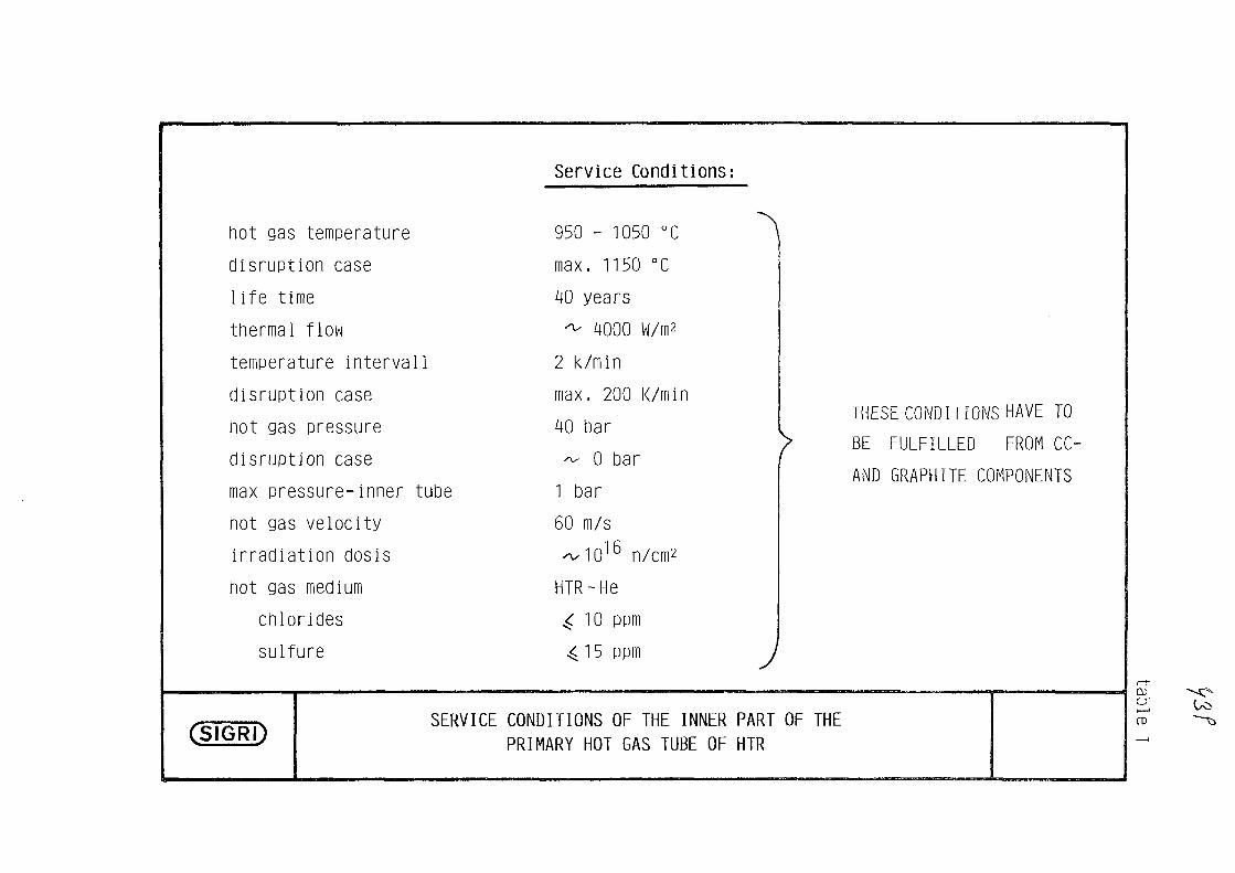
Service Conditions:
hot gas temperature 950 - 1050 °C ^
disruption case max. 1150 °C
1ife time 40 years
thermal flow "̂ 4000 W/m2
temperature interval 1 2 k/min
disruption case max. 200 K/min
hot gas pressure 40 bar
disruption case ^ 0 bar
max pressure-inner tube 1 bar
hot gas velocity 60 m/s
irradiation dosis «^1o''" n/cm2
hot gas medium HTR-He
chlorides ^ 10 ppm
sulfure ^ 15 ppm J
(SIGRI)
THESE CONDITIONS HAVE TO
? BE FULFILLED FROM CC-
AND GRAPHITE COMPONENTS
SERVICE CONDITIONS OF THE INNER PART OF THEPRIMARY HOT GAS TUBE OF HTR
CO
crCD

CC-CHARACTERISTICS
excellent high temperature resistance,useableto 2500 °C
anisotropy of mechanical/physical propertieslow inter laminar shear strength, to consider with constr.
high bending and outstanding tensile strength
small fatigue, creep nearly zero
controlled load-strain failure
excellent thermoschock resistance
high self-damping
very low density
oxidation sensible
low thermal expansion, low heat conductivity
properties of erosion?
irradion properties?
good heat isolation
Cl, S-content attainable ^ 10 ppm
Graph i te-CHARACTERISTICS
excellent high temperature resistance, useable to2500°C
low anisotropy of mechanical/physical
medium bending strength, low tensile strength
small fatigue and very small creep
no controlled load-strain failure
excellent thermoschock resistance
good self-damping
low density
oxidation sensible
low thermal expansion, low heat conductivity
properties of erosion?
good irradion properties
average heat isolation
Cl, S-content attainable / 10 ppm
(SIGRO TYPICAL PROPERTIES OF CC AND GRARilTE IN RELATION TO SERVICE CONDITIONS OF
THE HTR
CO
n>

table 3
ASR-1RG V 483 H
Variant N 1)
1.75
8.98.6
26.5 (30.5)3j27.9 (30.8)3)
19.216.6
67.770.5
3.33.5
116116
29
0.33
Variant S2)
1.79 ( 1 . 8 1 ) 3 )
9.69.2
29.3 (39.7)3)
30.2 (39.3)3)
21.419.4
77.881.3
3.33.5
117114
32
0.13
g/cm3
103
density
dyn, Young'smodulus
bendingstrength
tensilestrength
compressionstrength
linear thermal ex-pansion coeff. 10~5/K(20-500 °C)
thermalconductivity
ash
W/mK
ppm
1
1
1
1
1
permeability cm2/sec
1.79
8.77,7
19.417.1
12.010.9
47.047.2
3.55.9
157136
130
3.2
1)
2)
3)
Variant N: no post densification
Variant S: one post densification with pitch impregnation
first, new properties of a new, not fully tested variant of V 483 H
CSIGRl)Characteristical properties of the
Graphite types ASR-1RG and V 483 H

Fig. 1
1 =
2 =
3 =
4 =
5 =
Frame
Pressure Vessel
High Pressure Liquid
Flexible Form
Form Body
(S1GRI) ISOSTATIC P R E S S I N G 93234

993
Fig. 2
\ \
c 5
2
D>
1 = Vibrator Table
2 = Form
3 = Load
4 = Load Fixing
5 = Vacuum Bonnet
(SlGRl) V I B R A T O R 93334

ASR-1-R6
P o s s i b
cylindrical blocksmax. size 1250 0 mm x 1000 mmprismatic blocksmax. size 600 x 700 x 2700 mmtubes 1250 0 x 1000 mm
advantages : low cost, easyin productionlarge blocks possible
disadvantages: lower strength than V 483 H
CSIGRI)
coarse grains,limited tooling tolerance
SIZES/DIMENSIONS
1 e S i z e s
cylindricamax. sizeprismatic
advantages
V-483-H
1 blocks630 0 x 1600 mmblocks 500 x W O x 1600 mm
: high strengthvery fine grainedhigh tooling tolerance
disadvantages: sophisticated
AND EVALUATIONGRAPHITE
molding proceduresmaller blocks than withASR-1RG
OF REACTOR
CO
crCD

table 5
Bending strength(N/mm2. 23 °C)
(10~5 mbar. 1200 °C)
Youngs modulus (bending)(kN/mm2, 23 °C)
(10~5 mbar. 1200 °C)
Tensile strength(N/mm2, 23 °C)
Youngs modulus (tensile)(kN/mm2. 23 °C)
Compression strength(N/mm2. 23 °C)
Interlaminar shear strength(N/mm2. 23 °C)
Poisson number
Density (g/cm3)
CSIGR!) MECHANICAL0/90°
0°
CC 1501
237
296
58
54
332
66
160
12
0.03
1.45
PROPERTIES OFand 0/+45/90- DIRECTION
0/90° CC 1501 0M5/900
156
43
107
43
91
10
0.21
1.36
CCJ501o

Fig. 3
0
(fjNImm)bb
E (KNImm)0
CSIGRQ Polar diagram within laminat-plane
Bending strength and Young's modulus92434

oo tension (in 45°)
tension (in 0°)
ELONGATION
CSIGR1) Principal Load-Elongation Curves in Tension and Bending Mode
CC 1501r [0/90°J , 1200 °C, 10~5 mbar9313/;
I Q

Fig. 5
CC-pipe section under pressure
in a universal testing machine

2.5
2,0
oo
toCD
0.5
(Yo.)
(SIGRI)
10 15 20
Mat. A(low temp, mat.)
Mat.B(high temp, mat.)
25TIME (h)
30
Creep Experiments - 3-Point-Bending CC 1501- O/9OC
1200 °c, 10"5 mbar, i = 100 MPa = k92834
(Q
cn

-15
I -10
900 [°C] 1100
CSIGRO Thermal Conductivity as a Function of Temperature
CC 1501-[0/90°J und
I Q
9293/i

CC-Component Requirements Actual CC-Component Possibilities
straight CC-components, curved,conical tube components with greatdimensions and max flange 2500 mm 0)
CC-prototype components produced with large dia-meter including flanges
Plane, flat and curved planes, plates(max 500 x 500 mm)
CC-prototyp parts with and without bracing ribs
retainers, attachments and joints likescrews, nuts, tensile and compressionbushings
screws, nuts and stretching loops produced ofof high loading capacity
high accuracy to size without tooling - accuracy to size of very greatcomponents in the range of millimeters
good tooling good tooling and machinability;high potential for integral constructions
° light weight constructions about 6 times lighter than super alloys
CSIGRO FEASIBILITY OF CC-COMPONENTS FOR THE INNER PART OF THE PRIMARYHOT CAS SYSTEM OF THE HTR
cr
CDen

Fig. 8
cc-pipe with external ribbed reinforcement,diameter 1200 mm, height of 1500 mm
Fig. 9
cc-blow-moulding tool for superplasticforming of titanium
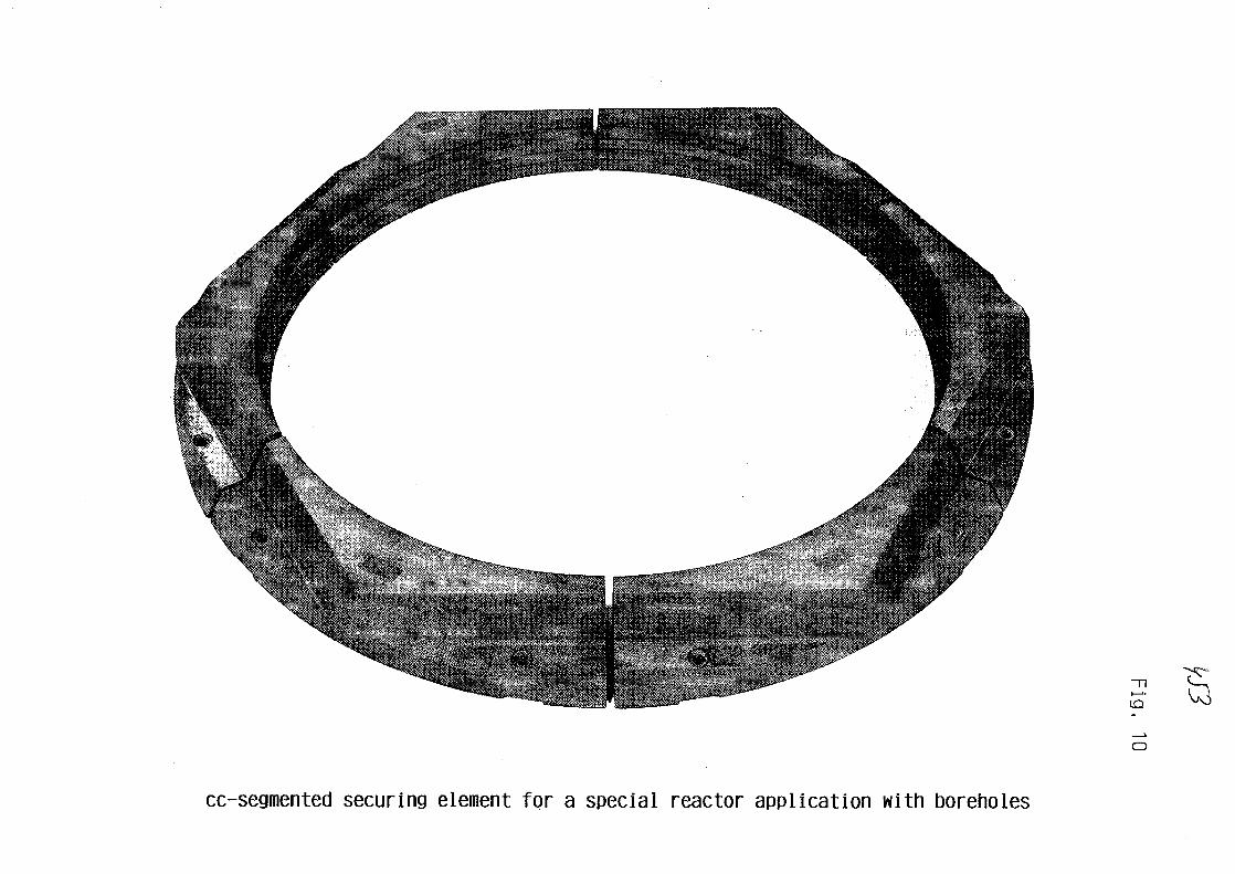
i—'•
cc-segmented securing element for a special reactor application with boreholes

Fig. 11
cc-swage block head for a plantengineering vessel, 700 mm diameter
Fig. 12
cc-bolts and screws in various sizes

Fig. 13
cc-bolts in metric threads
No. 27
XA0055837
Research on thermal insulation for hot gas ducts
P. Brockerhoff
Kernfors chungsanlage Jiilich GmbH
Institut fiir Reaktorbauelemente
Abstract
The inner surfaces of prestressed reactor vessels and hot gas ducts of Gas
Cooled High Temperature Reactors need internal thermal insulation to
protect the pressure bearing walls from high temperatures. The design para-
meters of the insulation depend on the reactor type. In a PNP-plant tempe-
rature and pressure of the cooling medium helium are proposed to be 950 C
and 40 bars, respectively.
The experimental work was started at KFA in 1971 for the HHT-project using
three test facilities. At first metallic foil insulation and stuffed fibre
insulating systems, the hot gas ducting shrouds of which were made of metal,
have been tested. Because of the elevated helium temperature in case of
PNP and the resulting lower strength of the metallic parts the interest was
directed to rigid ceramic materials for the spacers and the inner shrouds.
This led to modified structures designed by the INTERATOM company. Tests
were performed at KFA.
The main object of the investigations was to study the influence of temper-
ature, pressure and axial pressure gradients on the thermal efficiency of
the structures. Moreover, the temperatures within the insulation, at the
pressure tube, and at the elements which bear the inner shrouds were measu-
red. Thermal fluxes and effective thermal conductivities in axial and cir-
cumferential direction of the pressure tube are given, mainly for the INTER-
ATOM-design with sperical spacers.

1. Introduction
In a PNP-plant (Prototype Nuclear Process heat project) the heat generated
in the core is transferred either to the steam reformer for producing hydro-
gen and methanol (HVK) or to the intermediate heat exchanger and steam gas-
ifier for producing methanol (WKV)' through primary and secondary hot gas
ducts, respectively. Because of the helium temperature of 950 °C and the
pressure of 40 bars these ducts need an inner thermal protection system.
Since the insulating systems are filled with pressurized helium and are in
contact with the hot coolant, they have to meet severe requirements. Mate-
rials used must endure all operating conditions over their lifetime. The
components must be able to withstand high pressure transients, when sudden
depressurization will take place.
This causes a high pressure difference between the insulation and the inner
cross section. A high pressure within the insulation and axial pressure
gradients may produce natural or even forced convection. Convection, howe-
ver, must be kept at a low level otherwise the effectiveness of the insu-
lation will be decreased.
In the following at first the test facilities and the insulating systems
tested will be described. After that investigations on a design of INTERATOM
and experimental results are discussed. Finally, some results of fibre in-
sulations tested previously will be presented for comparison.
2. Test facilities and insulations tested
Experimental work was started at KFA in 1971 using the ARGAS-loop described
by Bruners et al. /I/ and the high pressure wind tunnel (HD-channel), see
Grosse and Scholz /2/. An advantage of the HD-channel is the high volume
flow of about 7 m /s thus being four times higher than the one of the ARGAS-
loop. The maximum temperature of the HD-channel is 400 °C compared to 1000 °C
of the ARGAS-test facility. The corresponding pressures are 40 bars and 10
bars, respectively. In the high temperature helium test rig (HHV) which was
erected for testing HHT (direct cycle High Temperature Reactor) components,
the maximum temperature is 850 °C at a pressure of 51 bars. The mass flow is
approximately 200 kg/s. Further details are given by Noack and Weiskopf /3/.

The test objects were mounted horizontally in the test facilities described
above. Experiments in vertical position of the insulations were also car-
ried out with stagnant gas. By means of electrical heaters hot face temper-
atures of 760 C were reached.
The insulating systems which were tested up to now are listed in table 1
1) Metallic foil insulations TABLE 1a) Bobbin design (ARGAS-loop)b) Element design (HD-channel and vert.)c) Element design (HHV-loop)
2) Stuffed fibre insulationsa) One interm. tube (ARGAS-loop, p = 280 kg/m3)b) One interm. tube (HD-channel, p=400 kg/m3)c) Two interm. tubes (HD-channel, p=280kg/m3)d) One interm. tube (HHV-loop, p = 290kg/m3)e) One interm. tube (bend) (HD-channel, p = 217 kg/m3)
3) Ceramic insulationa) Carbon rings (HD-channel and vert.)
U) Fibre blanket insulationsa) Cover plate design (HD-channel, p=178kg/m3)b) KWU/IA design (CFC spacers) (HD-channel, p=130 kg/m3)c) GHT/IA design (Ceramic spacers) (HD-channel, |
Insulating systems
One can roughly discern between metallic, fibrous and rigid ceramic struc-
tures, /4/. The table contains also the test facilities used and the den-
sities of the fibre insulations. It is also mentioned, when experiments
were carried out with the specimen in vertical arrangement.
The metallic insulation of bobbin type was delivered by Darchem/UK for
experiments in the ARGAS-loop. A special foil element insulation was also
designed by Darchem for HHT applications for high axial pressure gradients
and depressurization rates. The foil elements were held together by means
of studs and cover plates. End sections bear the inner gas ducting shrouds.
First measurements showed an excessive influence of gas pressure on the
distribution of thermal fluxes and temperatures around the pressure tube.
This was caused by natural convection within circumferential gaps. By clos-
ing these gaps the thermal efficiency was improved. As a consequence a
similar foil insulation was manufactured for a section of the HHV tubing
system.
Stuffed fibrous insulating systems designed by BBC/Switzerland for straight
tubes were tested as well in the ARGAS-loop as in the HD-channel. The main
components are metallic ducting shrouds, v-shaped end pieces and perforated

yj-f
and intermediate tubes. The annuli were filled with Kaowool the densities3 3
of which are between 280 kg/m and 400 kg/m . The insulation for the HHV-loop was of the same design. The average fibre density of the test section
3 3 3 3was 290 kg/m . Densities of only 230 kg/m , 214 kg/m and 208 kg/m were
reached for the segments of an insulated bend, which was also delivered by
BBC. The design is similar to the insulation for straight tubes.
To study the effects of gaps and fabrication tolerances on the thermal per-
formance an insulation made of five carbon rings was tested in the HD-
channel. It was supplied by the Sigri company in Meitingen. First experi-
ments showed that the existing gaps were too large. As a measure of impro-
vement the rings were sealed to suppress bypass-flow due to axial pressure
gradient.
A fibre blanket insulation with metallic cover plates was manufactured by
BBC. The density of 178 kg/m was achieved by compressing the Kaowool
blankets by means of the cover plates and studs. The additional blanket
insulations were constructed by INTERATOM. Contrary to the BBC design they
did not contain metallic parts. The inner shrouds made of graphite were
held by massive carbon fibre composite (CFC) and ceramic spacers, respec-
tively. The blankets were wound around the inner graphite tubes.
3. Description of insulation with spherical spacers
Fig. 1 shows the scheme of a section of the INTERATOM insulation. The insu-
lation consisted of inner shrouds made of graphite on which the fibre blan-
kets were wrapped. At the hot side Saffil fibres of approximately 95% Al-O^,
at the outer side Cerablanket fibres of 55% A l ^ and 45% SiO2 were used.
The outer and inner diameters of the inner shrouds were 780 mm and 630 mm,
respectively. The Saffil blankets were compressed by means of wire mesh and
\\ water cooling system \Cerablanket\ pressure tube Saffil
inner shroud/spacer elements
FIG. 1.
Scheme of INTERATOM insulation

the blankets at the outside by means of a sheet of metal. The mean fibre3 .
density was approximately 160 kg/m . Ceramic balls consisting of high den-
sity Al 0, or Si^N, were located at one end of the shrouds for supporting
and earthquake damping of the tubes. Additionally, Al-0« or Si-N, elements
are used for fixing the liner in axial direction.
The whole assembly and further details are given in Fig. 2. The insulation
FIG. 2
Pressure tube,
insulation and
instrumention
consisted of 5 sections, the first and fifth of which were used as entrance
and exit passages. Sections 2, 3 and 4 were test pieces. The gaps between
the particular shrouds were for thermal expansion. The length of the pres-
sure tube is 4710 mm. The inner diameter of 930 mm was equivalent to that of
tubes already used earlier. Half tubes are welded to the outside for heat
removal. The eight measuring systems enable to measure thermal fluxes of
the sectors top, bottom, right, and left for the middle part of the insula-
tion. In the flange region there are auxiliary systems for cooling the non
insulated section of the pressure tube. Thermocouples were installed into
the cooling systems and along the outer wall. The positions of the thermo-
couples within the insulation, at spacers and shrouds can be seen from the
six cross sections. In particular, the cross sections A-A and D-D in the
middle of the parts 3 and 4 were instrumentated.
The experiments were carried out in the HD-channel of KFA with air and
helium as cooling media at pressures up to 40 bars. Because of the graphite

corrosion the maximum temperature of the air experiments were restricted
to 300 C. Using helium the highest temperature was 400 °C. The axial pres-
sure gradient was also varied. In total four test runs were conducted.
During the first run the maximum velocity was approximately 20 m/s. In order
to get higher velocities a displacement body was mounted which enabled a
maximum velocity of about 39 m/s. Since the thermal fluxes of these test
runs depended on pressure and pressure gradient another run was conducted
with a closed metallic inner shroud which should eliminate the influence of
axial pressure gradients. The results of this run, however, were not satis-
factory, too. Therefore the insulation was dismantled and rebuilt after
having coiled additional Sigraflex foils together with the fibre blankets
as convection barriers made of graphite. Because of the lack of time only
one test run with the displacement body could be carried out. During the
last series the outer cooling was switched off.
Fig. 3 shows the temperatures of the pressure tube of parts 2, 3 and 4 for
FIG. 3
Temperatures of the
pressure tube
after modificationwithout water cooling —
pG [barl 37.8 376 39.4TG I°C) 402 395 395wG [m/s] 39.4 375 35.7
279 277 282
^^^^^^^^Si^^^^^^^^^^^^^^S^li/icM^^^^^^^^^i
the top position and three test runs. The data for pressure, temperature,
mean velocity and pressure difference of the coolant are given. The lower
curves which stand for the experiments with outer water cooling can be
compared. The slope of the temperatures in the region of the second and
fourth section is caused by the increase of temperature of cooling water.
The temperatures of the third section are approximately constant except the
downstream region for the experiments before the modification, where the
average temperature is 90 °C. The influence of the higher thermal conducti-
vity of the spacer elements is demonstrated. The additional foils increase
the pressure drop in radial direction, thus decreasing wall temperatures to

65 C. Only in the region of the axial spacer the temperature is 70 °C. When
the water cooling is switched off the temperature of the outer wall increases
to 120 C and 150 C, respectively. The heat passing the insulation is trans-
ferred to the outside by natural convection and thermal radiation. Since
the thickness of the fibre blankets was only 75 mm the increase of tempera-
ture by a factor of 2 seems to be high.
In Fig. 4 the total thermal fluxes in dependence upon pressure are given for
helium, part I, which includes the whole section 2 and half of section 3,
and for the first test run. The dependence upon pressure is almost linear.
2500
2000
1500
1000
500
qj^l helium
wG = 20.8 m/s
TG[°C]
397-
301
-O 201
-O 104I
• PG I bar]
FIG. 4 .
Thermal fluxes versus helium
pressure
10 20 30
The maximum flux of 2000 W/m was measured at the gas temperature of 397 °C
and the pressure of 38 bars. It is lower by 55% than in case of the insula-
tion with CFC spacer elements previously tested, /5/. The improvement is
caused by the reduction of the thermal conductivity of the spacer material.
In Fig. 5 the total thermal fluxes of the experiments before and after the
modification are compared. The results are given in dependence upon pressure
3400
3000 -
2000
1000
FIG. 5.
Thermal fluxes versus helium
pressure
40

3
for helium, part I and the experiments with displacement body. In comparison
with the results previously discussed it is striking that with growing
velocity from 20.8 m/s to 38.8 m/s thermal fluxes increase by 50% at the
highest pressure. This is valid for all temperature steps. In the lower
pressure region, however, thermal fluxes are nearly identical in spite of
different velocities. After having modified the insulation the dependence
of the thermal fluxes upon pressure is only weak, as demonstrated by the
dashed lines. Thermal fluxes are remerkably reduced compared to the results
which stand for the unmodified insulation. At the highest pressure and2
temperature thermal flux was only 1500 W/m and thus two times lower. This
reduction is also valid for the other temperature levels. Due to the
reduction of the permeability in radial direction consequently the thermal
fluxes were also reduced.
The efficiency of the convection barriers with regard to the distribution
around the circumference is demonstrated in Fig. 6, where Nusselt numbers
FIG. 6.
Nu number versus helium
pressure
N u before after modification h e l i u m
10 20 30 40
for helium versus pressure are given. The Nusselt number Nu is defined as
the ratio of the effective thermal conductivity of each sector to the con-
ductivity within the insulation, e.g. when gas movement is suppressed. The
results hold for part I, the maximum gas temperature and the average velo-
city of 37.4 m/s. Before the modification of the structure the differences
between top and bottom sectors increase strongly with growing pressure.
Whereas the Nusselt number of the bottom only increases weakly from 1.1 to
1.45, in the top position it increases from 1.7 to 4.4. As shown by the
dashed line the additional foils cause in particular an obvious uniformity
in addition to a reduction of Nusselt number of all sectors. The highest
and lowest values at the highest pressure are 1.38 and 1.15, respectively.
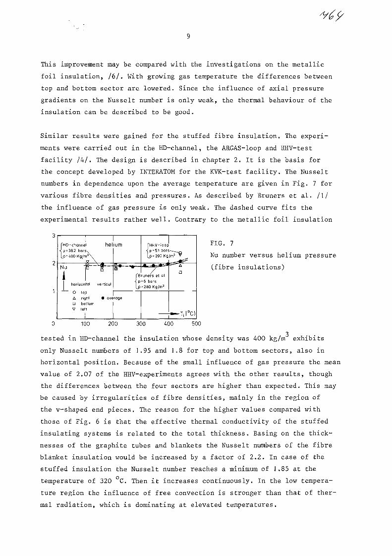
This improvement may be compared with the investigations on the metallic
foil insulation, /6/. With growing gas temperature the differences between
top and bottom sector are lowered. Since the influence of axial pressure
gradients on the Nusselt number is only weak, the thermal behaviour of the
insulation can be described to be good.
Similar results were gained for the stuffed fibre insulation. The experi-
ments were carried out in the HD-channel, the ARGAS-loop and HHV-test
facility /4/. The design is described in chapter 2. It is the basis for
the concept developed by INTERATOM for the KVK-test facility. The Nusselt
numbers in dependence upon the average temperature are given in Fig. 7 for
various fibre densities and pressures. As described by Bruners et al. /I/
the influence of gas pressure is only weak. The dashed curve fits the
experimental results rather well. Contrary to the metallic foil insulation
HD- channel= 38.2 bars.= iOO Kg/m3
helium
Nu
horizontal vertical
O topA righta bottomV left
fHHV-loop"? p=51 b a r s ^ ^ ^[p = 290 Kg/m3 v
Bruners et al.p = 6 barsp=280 Kg/m3
average
Aa
FIG. 7
Nu number versus helium pressure
(fibre insulations)
100 200 300 400 500
tested in HD-channel the insulation whose density was 400 kg/m exhibits
only Nusselt numbers of 1.95 and 1.8 for top and bottom sectors, also in
horizontal position. Because of the small influence of gas pressure the mean
value of 2.07 of the HHV-experiments agrees with the other results, though
the differences between the four sectors are higher than expected. This may
be caused by irregularities of fibre densities, mainly in the region of
the v-shaped end pieces. The reason for the higher values compared with
those of Fig. 6 is that the effective thermal conductivity of the stuffed
insulating systems is related to the total thickness. Basing on the thick-
nesses of the graphite tubes and blankets the Nusselt numbers of the fibre
blanket insulation would be increased by a factor of 2.2. In case of the
stuffed insulation the Nusselt number reaches a minimum of 1.85 at the
temperature of 320 C. Then it increases continuously. In the low tempera-
ture region the influence of free convection is stronger than that of ther-
mal radiation, which is dominating at elevated temperatures.

10
4. Conclusions
A thermal insulation for the primary circuit of a nuclear power station was
tested at KFA. The insulation has been developed by INTERATOM. At first the
design, the instrumentation and the various test runs were described. After
that the experimental results were discussed for helium as coolant. In
particular the constructive improvements were mentioned. Natural and forced
convection were almost suppressed by means of Sigraflex foils. Consequently,
the amount of thermal fluxes and effective thermal conductivities of the
four sectors was almost equal. Finally, the results of the stuffed fibre
insulation previously tested were discussed, the thermal behaviour of which
was quite similar.
5. References
/I/ Bruners, R., Lang, H., Noack, G., JuL-1227 (1975)
111 Grosse, H., Scholz, F., Kerntechnik 7 (4) (1965) 150-158
131 Noack, G. , Weiskopf , H. , J i iL-1403 (1973)
I hi Brockerhoff, P., BNES, Vol. 1, London (1982) 145-150
151 B r o c k e r h o f f , P . , S t a u s e b a c h , D . , Ji iL-1840 (1983)
161 Brockerhoff, P., Scholz, F., IAEA-SM-2OO/3O (1976) 353-362

9G6No. 28
Facility for Endurance Tests of Thermal Insulations
R. MauersbergerXA0055838
Hochtemperatur-Reaktorbau GmbH
Federal Republik of Germany
In the following report the design and construction of
an experimental facility for endurance tests of thermal
insulations is presented. It's name in abreviation is
"ADI" standing for the German words "Anlage zum Dauer-
test von _Isolierungen" .
This test facility was build by HRB in order to investi-
gate the performance of thermal insulation systems of hot
gas ducts for the process heat-reactor-project. The tests
are intended to simulate the conditions of reactor operation,
They include short-time experiments for selection of insu-
lation-concepts and in a second step long-time experiments
as performance tests.
During these tests are measured
the effective heat conductivity
the local heat losses
the temperatur profiles of the insulation, of the
fixing elements and along the wall of the duct
The design-data required to perform all these tasks are
shown in the first picture:

H9- 2 -
The gas-atmosphere must be Helium in tests like in
reactor with regared to the special thermal and
hydraulic properties of Helium and to the influence
of Helium on mechanicle friction and wear.
The hot gas temperature in the PNP-reactor will be
950° C and should be equal in the experiments.
The temperature on the cold side of the insulation
has to be adjustable from 50° C up to 300° C.
The Helium pressure in the hot gas ducts of a HTR-
plant is about 4 2 bar. The ADI was layed out for
70 bar to cover the hole range of interest.
A Helium mass flow has to stream through the insu-
lated test duct in order to realize equal tempera-
tures on the hot side of the insulation. A flow rate
of 4,5 kg/s is sufficient for this requirement.
The axial pressure gradient along the insulation must
be the same as in the reactor, because this has an
essential influence on the heat losses. This pressure
gradient is about 40 Pa/m.
- 3 -
An important part of the test programm is the
realization of temperature cycles. The temperature
transient should be approximately 3° C/min. This
value is - however - depending on the quality of
the test insulation. By temperature cycling the
start-up and shut-down procedures and conditions
of a PNP-reactor are simulated.
Last not least the test of full scaled insulations
must be possible.
A longitudinal section of the ADI-test-vessel is shown
in fig. 2. It has an inner diameter of 2 m and a total
length of 10 m.
The test insulation is mounted in a tube, which is
fastened to two special designed rings. On the out-
side of the tube is welded a cooling-system; it is
divided into longitudinal sections and into circum-
ferential segments in order to measure local heat
losses. The cooling fluid is a special heat-transfer-
oil which can be used up to 350° C.
An electrical heater which is built in a tube, is
inserted into the hot gas duct. Between this tube
and the hot side of the test insulation is an annular
space for the Helium flow.

- 4 -
The hot gas Helium flow along the test insulation
is circulated by an integrated blower. The blower
has an electric motor drive with speed control.
The shaft of this drive has magnetic bearings wor-
king without any friction. This special kind of
bearings allow the endurance tests under Helium
and at high temperature without interruption for
changing the bearings. The axial wheel of the blower
is working at full test temperature up to 950° C.
The blower exhausts the heated Helium from the
electrical heater and presses it into the annular
space along the test insulation mentioned above.
A ceramic guide for the Helium flow is placed
behind the blower wheel. It protects the housing
of the blower drive against high temperature and
guides the Helium flow into the wanted direction.
A similar ceramic guide is placed on the other side
of test duct leading the Helium flow back to the
heater.
A Helium/water-heat-exchanger is integrated in the
other cap of the pressure vessel. It is used for
cooling the Helium purge flow to the gas-purification
and for the Helium which has to be circulated if the
test bench is performing temperature cycles.
The empty volume in the pressure vessel is fulfilled
with an auxiliary insulation of fibrous material.

- 5 -
A survey of the various systems for supply and control
outside of the pressure vessel is given in fig. 3:
The control system for the blower drive and the
magnetic bearings.
The oil-cooling system for the test duct.
The measurement devices for the test-insulation.
The water-cooling system for the whole pressure
vessel.
The energy supply and control for the electrical
heater.
The gas purification system including the analytical
measurement of gas impurities.
All measured data from the test insulation and the operational
components are collected by a data acquisition system. Then
follows data processing and documentation.
The ADI can be driven automatically in normal operation and
in cycling operation. In both cases all security precautions
are taken into account. This self-controlled operation is a
great advantage cause it decreases costs.

- 6 -
In the mean time the experiments with the first test
insulation have been finished and some results are
presented in the fig. 5 to 8.
The set-up construction of the test insulation is very
similar to that one, which was explained in the report
of Mr. Brockerhoff, just before (fig. 5). Within a
pressure tube is a inner liner tube made of graphite.
This tube is supported by special spacer rings. Blan-
ketts of fibrous insulation material are wrapped around
the graphite tube. The density of the fibrous material
is about 130 kg/m3.
A temperature profile within the insulation is shown in
fig. 6. It is remarkable that the temperatures near the
duct decrease so steeply.
The temperature distribution along the wall of the
pressure tube is given in fig. 7. There are remarkable
temperature peaks in the neighbourhood of the spacers
and the temperature differences between upper and lower
side are sometimes considerable.
The heat losses as a function of gas temperature are
shown in fig. 8.
The heat losses of section 2 are higher because this
section includes two spacers.
At present experiments are running with another test
insulation with spherical spacers of Interatom Company.
Mr. Brockerhoff has reported before on the experimental
results of this insulation in the temperature range up
to 400° C. In ADI the temperature range of the measure-
ments will be extended up to 950° C.
The experiences with ADI gained over a period of more
than one year have shown that the specifications and
operational requirements have been fulfilled completely
and very satisfactorily.
The erection of the test facility ADI and the performance
of the tests were sponsored by "Minister fur Wirtschaft,
Mittelstand und Verkehr des Landes Nordrhein-Westfalen".
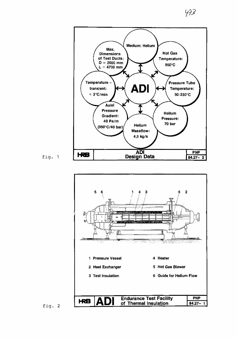
fig. 1
/ Max./ DimensionsI of Test Ducts:V D = 2000 mm\ L = 4700 mm
^ ^ ^ ^ ^
/ \ ^/ Temperature - \transient: K >
\ ± 3°C/min J
[ Pressure
/ Gradient:1 40 Pa/m\(950°C/40 bar)/
KRB
Medium: Helium\ ,\ >
ADI }\ X /\ -̂*-̂ /\/"̂ \/r N/ Af Helium \
Massflow:i 4,5 kg/s J
ADIDesign Data
1 \' Hot Gas \Temperature: j
950°C J
I Pressure Tube \C ) ( Temperature: 1
V 50-330°C J
Helium \Pressure: 1
70 bar I
f^—^^
PNP84.27- 2
fig. 2
5 6 6 2
1 Pressure Vessel
2 Heat Exchanger
3 Test Insulation
4 Heater
5 Hot Gas Blower
6 Guide for Helium Flow
ADI Endurance Test Facilityof Thermal Insulation
PNP84.27- 1

fig. 3
Blower Oil-coolingSystem
Water CoolingSystem
JL
Heater200 kW
AnalyticalMeasurements
Data Acquisition —^ Data Processing Digital and Analog DataDisplay and Output
ADIPrinciple Design of Test Facility
PNP84.27- 4
fig. 4ADI
Test Facility in OperationPNP
84.27-16
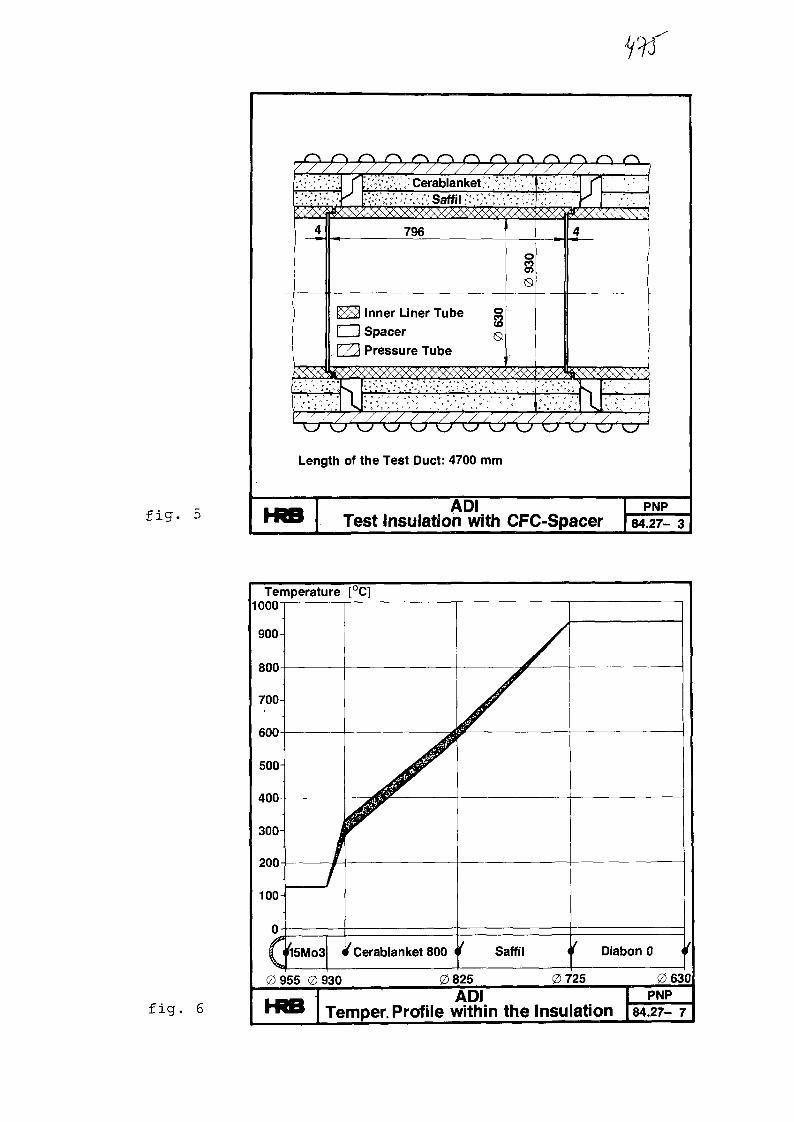
fig. 5
/ //////////////)••:'•''"•':'•'.
4
r ''•yi'l'l'V, •' Cerablanket ;.'•;'; ••K ;-V;': •/.•:•::••: S a f f l l •::"••.'•:•.••.
f~\ / ^ \ / ^ \ /̂ N /̂ k
796
K^i Inner Liner Tube S
1" 1 Spacer Q
X/\ Pressure Tube
0 93
0
iY ' ' / / / / / / / / / / / / /
r4
}
: ; • ; : • :
Length of the Test Duct: 4700 mm
M B ADITest Insulation with CFC-Spacer
PNP84.27- 3
fig. 6
« Cerablanket 800 <r Saffil
Temper. Profile within the Insulation

99$
fig. 7
— Upper Side
Lower Side
tTube (average)
Temperature tTube [°C]
Medium : HeliumAp' : 15 Pa/mPeas = 40 bar
tGas = 946°C (average)trube = 147°C (average)
ADITemper Distrib. along Pressure Tube
PNP84.27-10
fig. 8
q [W/m2
1000
800
600
400
200
P = 40 bar x = Section 1tTube = 150°C (average) a = Section 2
/ y
Y
200 400 600 800 1000
tGas[°C]
ADIHeat Loss of Test Insulation
PNP84.27-12
No. 29
Construction and Performance Tests of Helium Engineering Demonstration
Loop (HENDEL ) for VHTR 111 III 111 III Uli III I I IXA0055839
Makoto HISHIDA, Toshiyuki TANAKA, Hiroaki SHIMOMURA and Knonomo SANOKAWA
Department of High Temperature Engineering
Japan Atomic Energy Research Institute, Japan
1. Introduction
A helium engineering demonstration loop (HENDEL) has been constructed and
operated in the Japan Atomic Energy Research Institute (JAERI) in order to
develop the high-temperature key components of an experimental very high-
temperature gas cooled reactor, like fuel stack, in-core reactor structure,
hot gas duct, intermediate heat exchanger and so on " . Performance tests as
well as demonstration of integrity are carried out with large-size or actual -
size models of key components. The key components to be tested in HENDEL are:
(1) fuel stack and control rod
(2) core-supporting structure, or bottom structure of reactor core exposed
to direct impingement of high-temperature core outlet flow
(3) reactor internal components and structure
(4) high-temperature components in heat removal system: primary and secondary
cooling systems.
HENDEL consists of mother section, adapter section and test section " '.
The mother and adapter section (M+A section) supplies test sections with He gas
flow of required temperature, pressure and flow rate. The first stage of HENDEL
project was to construct the M+A section. The design work of this section was
started in 1978 and construction was completed in March 1982. Up to now, eight
cycles of test operations have been carried out with the M+A section, including
the preliminary test operation in March 1982. During the operation, performance
tests of hot gas ducts and major heat exchanging components of HENDEL were carriec
out. At present HENDEL project is in the second stage, that is, tests with the
first test section (T-, ) have been started and the successive test sections are
being constructed or planned.
This report describes outline of HENDEL test facility and performance
test results of the hot gas ducts and the heat exchanging components.
- 1 -

2. Outline of HENDEL
Figure 1 shows the flow sheet of HENDEL. The M+A section of HENDEL1~5^
consists of No.l mother loop (M, loop), No.2 mother loop (M? loop), adapter
section (A section), purification system, make-up system, water cooling system,
instrumentation and control system, and electrical system,HENDEL has four test
sections of T, - T,. A fuel stack test section, which is the first test sectior
(T,), was constructed in March 1983 and tests are now being performed. The
design work of the second test section (T?) is now under way and it will be
put into operation in March 1986. The third and fourth test section (T3 and T.)
are now being planned.
The M, loop supplies T, test section with He gas flow of the maximum tempera
ture 400°C, the maximum pressure 4.0 MPa and the maximum flow rate 0.4 kg/sec.
The temperature of 400°C and pressure of 4.0 MPa are equal to those of inlet He
gas flow of VHTR reactor core. And the flow rate of 0.4 kg/sec is equal to the
one of two colums fuel stack. The M, loop consists of a gas circulator (B-,),
a He gas heater (H,), a He gas cooler (C,), a mixing thank, a filter, orifice
flow meters and so on.
The M~ loop supplies the test sections T 2 - T« with He gas flow of the
maximum temperature 400°C, the maximum pressure 4.0 MPa and the maximum flow
rate 4.0 kg/sec. The flow rate of 4.0 kg/sec is equal to half the flow rate
in one of the two primary cooling loops for VHTR. And the M2+A loop supplies
the test sections with He gas flow of the maximum temperature 950 - 1000°C,
the maximum pressure 4.0 MPa and the maximum flow rate of 4.0 kg/sec. The
maximum temperature 950 - 1000°C is equal to the mixed mean temperature at
the outlet of VHTR reactor core. The mother and adapter loops consist of He
gas circulator (B-,, B 2 2, B^o, B24^' He gas neaters (H2' H31 ' H32^ a hot gas ducts
(hot gas ducts A,Bj, He gas coolers (Cp, C.,,, C ^ ) , mixing tanks, filters,orifice flow meters and so on.
The purification system consists of CuO beds, molecular sieve traps, active
carbon traps, compressors, heat exchangers and so on. Impurity gases of H2 and
CO become H^O and C02 by oxidation reaction in the CuO bed. Produced Wfl and
C0? together with H?0 and C0? contained in inlet He gas flow are absorbed in
the molecular sieve bed. Impurity gases of 0 o, N^ CH- are absorbed in active
carbon trap of -196°C. The purification system is so designed that contents
of H20, 0 2, N2, C02 and CO can be reduced to bellow 0.1 p.p.m. and those of H 2
and CH. bellow 0.2 p.p.m. at the outlet of the system.
Major heat exchanging components in the M, loop are He gas heater H, and
He gas cooler C-,. And those in the M~ loops and the adapter section are He
- 2 -

gas heaters H~, H.,, and H_?, and He gas coolers C^, C-, and C ^ . Up to now,
the M, loop has been operated 7 cycles and total operation hours are about
3000 hours. And the Mp loop and NL+A loop have been operated 8 cycles, operation
hours being about 3200 hours. During the operation, performance tests of the
hot gas duct A and B installed in the adapter section and major heat exchanging
components in the M+A section were carried out.
3. Thermal performance test of hot gas ducts
As shown in Fig.l, two hot gas ducts are installed in HENDEL. Hot gas duct
A is connected with the main heater H-? and main cooler C~,, and the hot gas
duct B is connected with the main heaters H,, and W~?. Table 2 shows the main
items of the two hot gas ducts. Figure 2 shows a conceptional view of hot gas
duct A. Hastelloy-X is chosen for the liner tube, because it is supposed to
be exposed to He gas flow of 1000°C. The pressure tube is made of mild steel.
In order to maintain the temperature of the pressure tube lower, the internal
thermal insulation is installed outside the liner tube, and is divided into three
sub-layers by stainless steel foils. Fibrous ceramic insulation (Kaowool) whose
main composition is SiO,, and AlpO- is packed in these layers. In the two inner
sub-layers, Kaowool blanket of 0.2 g/cm in density is packed, and in the outmost3
sub-layer Kaowool bulk of 0.25 g/cm in density. V-shape end plates of Hastelloy-are welded to the pressure and liner tubes at intervals of 0.7 - 1.4 m so that
they might prevent bypass or permeation flow of He gas in the insulation layer,
which gives rise to deterioration of insulating characteristics. The basic
configuration of hot gas duct B is almost the same as that of hot gas duct A.
In the present test, temperature distribution of pressure tube and internal
thermal insulation, and heat flux on pressure tube were measured. Additionally,
air flow around the hot gas ducts was visualized with mist of dry ice.
Temperature distribution of whole surface of pressure tubes was measured by C.A.
thermocouples fixed on the pressure tube and a radiation pyrometer. Temperature
distribution of internal thermal insulation was measured by C.A. thermocouples
with metal sheath. Heat flux was measured with heat flux meters. The present
test was performed in the range of He gas temperature of 400 - 950°C, pressure
of 1.0 - 4.0 MPa and flow rate of 0.5 - 3.5 kg/sec.
Figure 3 shows circumferential surface temperature distributions of the
horizontal, vertical and bent tubes of hot gas duct A, measured by fixed thermo-
couples. The maximum temperature variation range in the circumferential
direction was only 15°C. The surface temperature of pressure tube was maximum
at the locations where studs and V-shape end plates were welded to the pressure
- 3 -

tube, and was minimum at flanges and the locations where supporting hangers
were fixed. The maximum and minimum temperatures, however, were ±30°C higher or
lower than average temperature. That is, temperature distribution of pressure
tube was almost uniform. Radial temperature distribution in the internal thermal
insulation was in good agreement with the one calculated by a conduction trudel
taking into consideriation of temperature dependence of effective thermal
conductivity of insulation material.
Figure 4 shows circumferential heat flux distribution of the horizontal,
vertical and bent tubes of hot gas duct A. Heat flux distribution of tubes of
the hot gas duct B was also measured; the heat flux distribution of hot gas
duct A and B was almost uniform.
Effective thermal conductivity of internal thermal insulation layer was
evaluated from the measured heat flux and temperature. Figure 5 shows the
effective thermal conductivity of the present hot gas ducts together with those
of cither hot gas ducts " ' ' or fibrous insulation material itself ' '.
Effective thermal conductivity of the present horizontal tubes of hot gas ducts
A and B is correlated by the following equation:
Xeff(W/m.K) = 0.01963 + 4.702 x 10~4 T(K) (1)
and the one of the vertical tubes is correlated by the following equation:
X ff(W/m«K) = 0.02014 + 6.039 x 10"4 T(K) (2)
Effective thermal conductivity of the vertical tubes was 25 - 30% higher than
that of the horizontal tubes, which might be caused by natural convection
established in internal thermal insulation layers. The presented effective
thermal conductivities shown in Fig.5 are 1 - 2 times larger than the thermal
conductivity of He gas. The difference between the data ' " ' might be
attributed to the difference of composition of fibrous insulation material, packing
method of insulation material, design of internal insulation structure and so
on. Most data lie within the range of -10 - 45% of the present equation (1).
4. Thermal performance test of He gas coolers
In the M+A section of HENDEL, four He gas coolers are installed, which
are C,, Cp, C.,, and C-p. Main items of the coolers are listed in Table 3.
Basic structure of He gas coolers C-,, C«, C^2 is almost the same. U-tubes are
used for heat exchanging tubes which absorb thermal expansion at free end. Cooling
water of atmospheric pressure flows inside the tubes and He gas in the shell
with segmental baffle plates. Arrangement of tubes is staggered equilateral
- 4 -

triangle. Material of tubes is mild steel because of rather lower temperature.
Detailed structure and drawing are presented in references(l-4).
Figure 6 shows a schematic view of He gas cooler C.,,. The structure of1-4)He gas cooler C,-, ' is different from that of other coolers. Straight tubes
are connected to the top and bottom water ring headers, and both ends of tubes
are bent in order to absorb thermal expansion. Inside of the tubes flow
pressurized cooling water for preventing boiling. Cross flow of He gas is produced
by step baffle plates.
The pressure vessels of cooler C_, and C,? have internal thermal insulation
to keep temperature lower, while those of other coolers C-, and C ? have no
internal thermal insulation because of rather lower He gas temperature.
Measured cooling capacities of the coolers C,, C 2, C~, and C-- were respectively
20%, 40 - 50%, 50 - 70% and 40 - 50% higher than the design values.
Figure 7 shows the relatioship between Nusselt number of He gas flow in
the shell and Reynolds number. Nusselt number and Reynolds number are defined
as follows:a *d
Nu --V2- (3)
Re = ̂ ~- (4)g
where, a was calculated from the equation:
a =
where, a. was obtained from the Dittus-Boelter's equation:
a- = 0.023 x ^ x (^i) 0- 8 x Pr0'4
d. vi w
The straight lines in the figure are the correlations for tube bank with
segmental baffle plates, which were presented by Donohue ' and Kern '. The
data measured with the cooler C, agree fairly well with Donohe's correlation,
while the data measured with the coolers C ? and C~? are 10 - 20% higher than
the correlation.
The chain lines are the correlations for tube bank in cross-flow presented
- 5 -

by Zukauskas ' and Fishenden-Saunders . Measured data with the He gas
cooler C_, are 10 - 30% higher than the correlations.
After about 3000 hours' operation, no change in overall heat transfer
coefficient was detected for all the coolers.
5. Thermal performance test of He gas heaters
In the M+A section of HENDEL, four electric heaters are installed, which
are H-, , Ho, Hol and H_o. Main items of the heaters are listed in Table 4.
Basic structural concept is almost the same for all the heaters , schematic
view of the heater W~~ being presented in Fig.8. They have 1 5 - 7 2 heated tubes
in which He gas flows upward and is heated up. The tubes are heated by alternating
3 phase electrical current, heating capacity being 160 - 4700 kW. Material of
the heated tubes for the heaters H,, H? and H_, is Incolloy-800H, because of
relatively lower temperature. On the ohter hand, the heated tubes of heater
H_2 are made of graphite, because tube temperature was estimated to be about
1300°C. The heated tubes are fixed to the top or bottom tube sheet at one end
and kept free at the opposite end. Three tube sheets are provided in each heater,
one for supporting tubes and the rests for preventing vibration. The heated
tubes are electrically insluated from the earth by A1 20 3 or Boron-Nitride in-
sulators. In order to prevent heat loss from the heaters, pressure vessels of the
heaters H. and H? have thermal insulation wrapped on the outer surface. And the
pressure vessel of the heaters H 3 1 and H-p have internal thermal insulation.
Figure 9 shows thermal efficiency of the heaters, which is the ratio of
enthalpy rize of He gas to electric input. Thermal efficiency of all the
heaters is higher than 70%. Namely thermal insulation performance of pressure
vessels of heaters was satisfactory. Temperatures of heated tubes were also
measured and they were in good agreement with the values calculated by Dittus-
Boelter's equation (6). It seemed to indeicate that flow distribution among
heated tubes was almost uniform and no significant bypass flow, which might
deteriorate heat transfer performance, occurred.
6. Conclusion
Thermal performance tests were carried out with the hot gas ducts and the
major heat exchanging components of the M+A section of HENDEL. The following
results were obtained:
(1) The major components were operated for more than 3000 hours without trouble.
(2) Temperature and heat flux distribution on the pressure tube of hot gas
- 6 -

ducts were almost uniform in both circumferential and axial directions.
No hot spot was found.
(3) The correlation for the effective thermal conductivity of the internal
thermal insulation was obtained as follows:
Xeff(W/m.K) = 0.01963 + 4.702 x 10~4-T(K)
(4) The cooling capacity of He gas coolers was 40 - 60% higher than the design
values.
(5) Heat transfer coefficient of shell side of the cooler C, was in good
agreement with Donohne's correlation, while those of the coolers C~ and
C_p w e re 1° - 20% higher than the correlation and that of the cooler
C_, was 10 - 30% higher than Zukauskas1 and Fishenden -Saunders' correlations.
(6) Thermal efficiency of He gas heaters H,, H?, H-, and H-p was as high as
70 - 95%. Flow distribution among heated tubes seemed to be uniform
and no bypass flow likely to occur.
overall heat transfer coefficient
Prandtle number
Temperature
average velocity of fluid intube
thermal conductivity
NOMENCLATURE
d :
Nu :
Re :
um :
Aeff :
v :
diameter of tube
Nusselt number
Reynolds number
average velocity of fluidthrough tube bank
effective thermal con-ductivity
kinematic viscosity
SUBSCRIPT
i :
9 :w :
REFERENCES
inside of tube
gas
water
KPrTua
X
0
s
outside of tube
solid
1)
2)
3)
4)
5)
6)
7)
Japan Atomic Energy Research Institute
(1980 - 1983).
Status of R & D on VHTR in JAERI,
Ishikawa, H. et al
Okamoto, Y. et al.
Izawa, N. et al. :
Tone, H. et al., :
Umeda, T. et al. :•
Nakano, T. et al.
. : ASME 81-WA/NE-9 (1981).
: JAERI-M 82-133 (1982).
JAERI-M 82-122 (1982).
JAERI-M 8309 (1979).
IHI Tech. Bull., 20(6), 416 (1980).
: FAPIG, 94(3) 9 (1980).
- 7 -
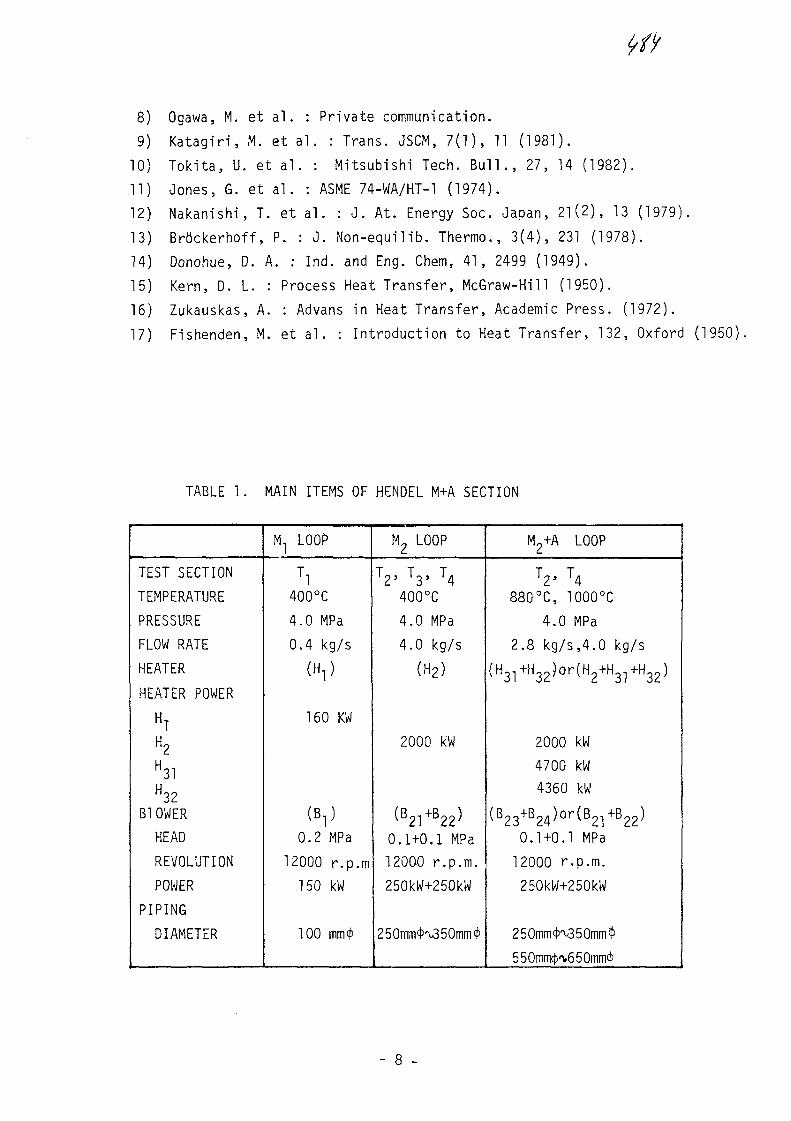
8) Ogawa, M. et al. : Private communication.
9) Katagiri, M. et al. : Trans. JSCM, 7(1), 11 (1981).
TO) Tokita, U. et al. : Mitsubishi Tech. Bull., 27, 14 (1982).
11) Jones, G. et al. : ASME 74-WA/HT-l (1974).
12) Nakanishi, T. et al. : J. At. Energy Soc. Japan, 21(2), 13 (1979).
13) Brtickerhoff, P. : J. Non-equilib. Thermo., 3(4), 231 (1978).
14) Donohue, D. A. : Ind. and Eng. Chem, 41, 2499 (1949).
15) Kern, D. L. : Process Heat Transfer, McGraw-Hill (1950).
16) Zukauskas, A. : Advans in Heat Transfer, Academic Press. (1972).
17) Fishenden, M. et al. : Introduction to Heat Transfer, 132, Oxford (1950)
TABLE 1. MAIN ITEMS OF HENDEL M+A SECTION
TEST SECTION
TEMPERATURE
PRESSURE
FLOW RATE
HEATER
HEATER POWER
HT
H31H32
B1OWER
HEAD
REVOLUTION
POWER
PIPING
DIAMETER
M1 LOOP
Tl400°C
4.0 MPa
0.4 kg/s/ u \
160 KW
(D \ID- I
0.2 MPa
12000 r.p.m150 kW
100 mm*
M2 LOOP
2' 3' 4400°C
4.0 MPa
4.0 kg/s
(H2)
2000 kW
(B21+B22)
0.1+0.1 MPa12000 r.p.m.
250kW+250kW
250mm<K350mm<l>
M2+A LOOP
T2' T4880°C, 1000°C
4.0 MPa
2.8 kg/s,4.0 kg/s
( H31 + H32 ) o r ( H2 + H31 + H32 )
2000 kW
4700 kW4360 kW
(B23+B24)or(B2-!+B22)
0.1+0.1 MPa
12000 r.p.m.
250kW+250kW
25OmmcN35Onim$
550mmcf)'v650mm<}'

TABLE 3 MAIN ITEMS OF He GAS COOLERS TABLE 2 MAIN ITEMS OF HOT GAS DUCTS A AND B
TYPE
FLUID
FLOW RATE (kg/s)
INLET TEMPERATURE (°C)(DESIGN TEMPERATURE)
OUTLET TEMPERATURE (°C)(DESIGN TEMPERATURE)
PRESSURE (MPa)
COOLING CAPACITY (kW)
REYNOLDS NUMBER
OVERALL HEAT TRANSFERCOEFFICIENT (W/m*K)
TOTAL HEAT TRANSFERAREA (m2)
NUMBER OF BAFFLE PLATES
DISTANCE BETWEENBAFFLE PLATES (mm)
THERMAL INSULATION
TUBE
NUMBER
ARRANGEMENT
PITCH (mm)
OUTER DIAMETER (mm)
INNER DIAMETER (mm)
THICKNESS (mm)
LENGTH (mm)
MATERIAL
VESSEL
DIMENSION (mm)
MATERIAL
Ci
EGHENTAL-BAFFLED-TUBE
He/WATER
O.4/2.I
^400/32
313/42
*l. 0/0.4
170^26000/24000
430
1.22
6
150
OUTER INSULATION
14
STAGGERED (EQUI-.ATERAL TRIANGLE)
40
27.2
20.8
3.2
2040
STB35S
230<{ix2300hx20t
STPA22
C2
EGMENTAL-BAFFLED-TUBE
He/WATER
0.4^4.0/28
-^400/32
288/52
4.0/0.4
2300
^-21000/44000
^640
21.8
3530
OUTER INSULATION
132
STAGGERED (EQUI-LATERAL TRIANGLE)
40
25.4
18.4
3.5
2070
STBA22
922<j>x39OOhx36t
SCMV2.SB46
C31
TEP-UP-BAFFLEDTRAIGHT-TUBE
e/PRESSURIZED-ATER
,0.4-\>4.0/26
"M 000/50
550/110
4.0/3.6
6700
M2000/72000
"M32O
16.6
3900
INTERNALINSULATION
54
IN-LINE
100
27.2
22.0
2.6
3600
STBA22S
2000*x9IOOhx50
SB49.SB42
EGMENTAL-BAFFLED-TUBE
He/WATER
0.4VI.O/4O
550/32
382/42
4.0/0.4
3500
•V47O0O/51OOO
18.7
4450
INTERNALINSULATION
64STAGGERED (EQUI-LATERAL TRIANGLE)
70
48.6
41.6
3-51910
STB35S
900<jix630Ohx30t
SB49.SB42
ITEMS
HE GAS TEMPERATURE (MAX.)
HE GAS PRESSURE (MAX.)
DESIGN TEMPERATURE OF
THE PRESSURE TUBE
DIMENSIONPRESSURE
LINER TUBE
LINGTH
MATERIALPRESSURE TUBELINER TUBEV-SHAPE END PLATE
STUD
INSULATION
HOT GAS DUCT A
1000°C
4.0 MPa
350°C
660.4°-D-x22t
355.6°-D-x 6*14 m
SB42
HASTELLOY XHASTELLOY X
HASTELLOY XINCOLLOY 800H
KAOWOOL 1260S
A1 2O 3 47.3%
SiO2 52.3%
Fe2O 0.05%
HOT GAS DUCT B
700°C
4.0 MPa
350°C
355.6°-D-x 6*23.6 m
SB42
INCOLLOY 800H
INCOLLOY 800H
SUS 304
SUS 316
INCOLLOY 800H
KAOWOOL 1260S
A1 2O 3 47.3%
SiO2 52.3%
Fe2O3 0.05%
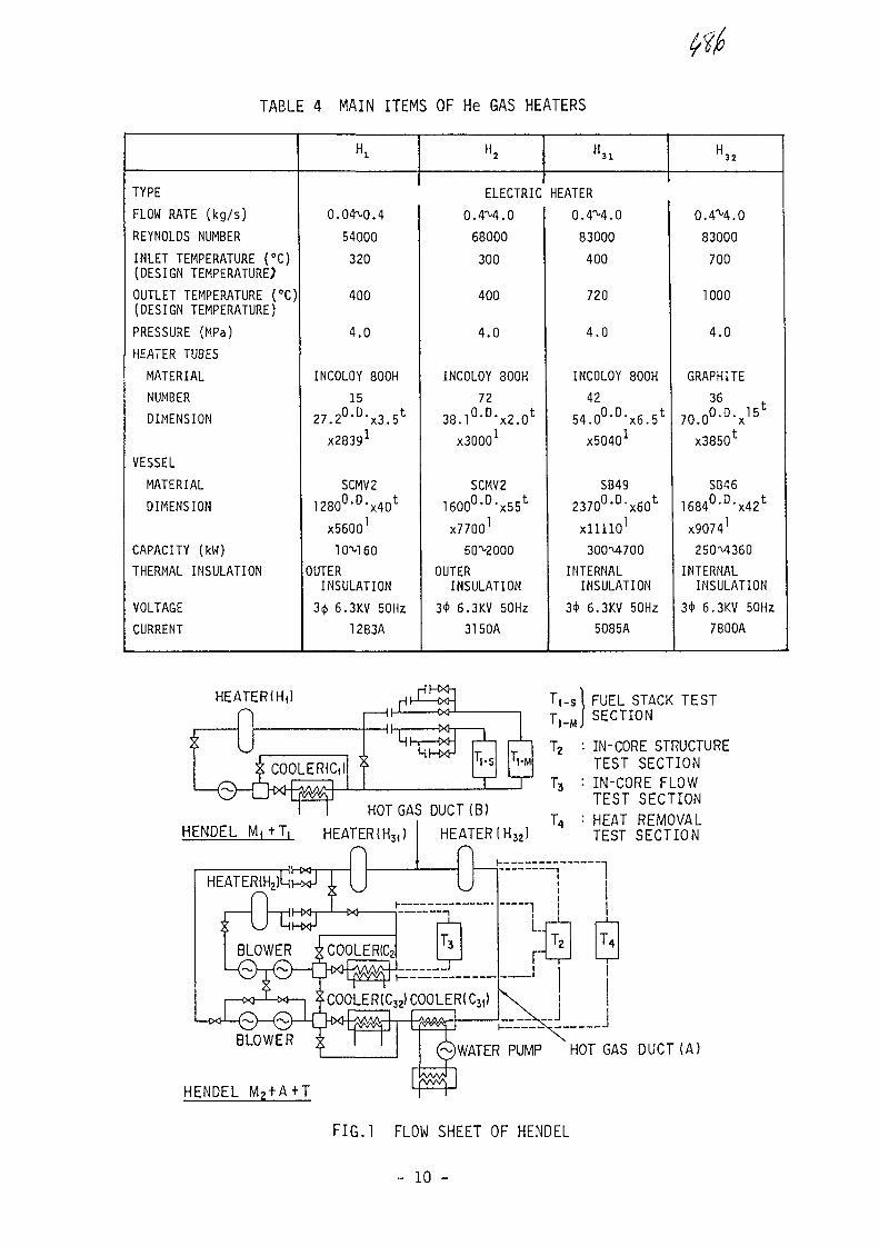
TABLE 4 MAIN ITEMS OF He GAS HEATERS
TYPE
FLOW RATE (kg/s)
REYNOLDS NUMBER
INLET TEMPERATURE (°C)(DESIGN TEMPERATURE;
OUTLET TEMPERATURE (°C)(DESIGN TEMPERATURE)
PRESSURE (MPa)
HEATER TUBES
MATERIAL
NUMBER
DIMENSION
VESSEL
MATERIAL
DIMENSION
CAPACITY (kW)
THERMAL INSULATION
VOLTAGE
CURRENT
0.04ML4
54000
320
400
4.0
INCOLOY 800H
27.2°-D-x3.5t
X28391
SCMV2
1280°-D-x40t
X56001
10"M 60
OUTERINSULATION
3* 6.3KV 50Hz
1283A
H2
ELECTRIC
0.4M.0
68000
300
400
4.0
INCOLOY 800H
38J°-D-x2.0t
X30001
SCMV2
l e o o 0 - 0 ^ *X77OO1
50^2000
OUTERINSULATION
3* 6.3KV 50Hz
3150A
H.i
HEATER
O.4M.0
83000
400
720
4.0
INCOLOY 800H
42
54.0°-D-x6.5t
X50401
SB49
237O°-D>x6Ot
xllllO1
3OOM7OO
INTERNALINSULATION
3* 6.3KV 50Hz
5085A
H 3 2
O.4"M.O
83000
700
1000
4.0
GRAPHITE
36 t7O.0°-D-x15
x3850t
SB46
1684°-D-x42t
X90741
250M360
INTERNALINSULATION
3<t> 6.3KV 50Hz
7800A
HEATERIH,)
COOLERICIb T,..I-M
HOT GAS DUCT(B)HENDEL M ^ T , HEATER{H3()
BLOWER * COOLERS
COOLER (C32) COOLER! Cj,
T , - s l FUEL STACK TESTT, -J SECTION
T2 : IN-CORE STRUCTURETEST SECTION
T3 : IN-CORE FLOWTEST SECTION
L, = HEAT REMOVALTEST SECTION
WATER PUMP HOT GAS DUCT (A)
F I G . l FLOW SHEET OF HENDEL
- 10 -

300
STUD
PRESSURE TUBESEPARATING PLATE
INSULATION
LINER TUBE
200
1 0 0 -
0
SIGN.• •o oa s
LEGENDHORIZONTAL TUBEVERTICAL TU8EBENT TUBE
He GAS TEMPERATURE = 900 °CHe GAS PRESSURE = 4.0 MPaAIR TEMPERATURE = 30 °C
0 [80 360
CIRCUMFERENTIAL ANGLE (DEGREE)
FIG.2 CONCEPTIONAL VIEW OFHOT GAS DUCT A
FIG.4 CIRCUMFERENTIAL HEAT FLUXDISTRIBUTION ON PRESSURETUBE SURFACE (HOT GAS DUCT A)
150
LUCC
a:LUo_
LU
100 -
SIGN.• •o o©—-—«
LEGENDHORIZONTAL TUBEVERTICAL TUBEBENT TUBE
He GAS TEMPERATURE = 900 °CHe GAS PRESSURE =4.0MPaAIR TEMPERATURE =30°C •
NQia6«.IHEEPRE53MPd *PENS.(g/cro3
He GAS(4.0MPa)
*H:HORIZONTAL TUBE *M:INSUUTI0N MATERIAL:
*VIVERTICAL TUBE * * : PRESENT WORK
0 180 360
CIRCUMFERENTIAL ANGLE (DEGREE)
FIG.3 CIRCUMFERENTIAL TEMPERATUREDISTRIBUTION AT PRESSURETUBE SURFACE (HOT GAS DUCT A)
00 200 400 600 800
AVERAGE TEMPERATURE OF INSULATION (°C)
FIG.5 SURVEY OF EFFECTIVE THERMALCONDUCTIVITY OF HOT GASDUCTS WITH INTERNAL THERMALINSULATION AND FIBERINSULATION MATERIALS
- 11 -

HEAT EXCHANGINGTU8E
OUTER SHELL
INNER SHELL
STEP BAFFLEPLATE
STEP BAFFLEPLATE
OUTLET(WATER) N T
RING HEADER(WATER)
INNERSHELL
OUTERSHELL STEP BAFFLE
PLATE
HEATt EXCHANGING8 TUBE
INTERNALINSULATION
RING HEADER(WATER)
PRESSUREVESSEL
INLET(WATER)
WATER JACKET
FIG.6 SCHEMATIC DRAWING OFHe GAS COOLER ( C 3 1 )
- I - ] I I I I—I
• COOLER (Ci )o COOLER (Cz)* COOLER (C3,)a COOLER { C32>
Nu"0.33ReMPr0-3;(FlSHENDEN-SAUNDER5)cc 2LUCQ
i !02
8
b 6
10
fiu=0.23-R8fl'Pr^(-fc) (DONOHUE)
(KERN)
i
6 8 10 2 4 6 810 2
REYNOLDS NUMBER4 6 810
UPPER TUBESHEET A
WATERJACKET
INTERNALINSULATION
POWER SUPPLYTERMINAL
[I6OO
B=Q Rsn
INTERNALINSULATION
3 O He OUTLET=g (1000°C)HEATER ELEMENT(GRAPHITE TUBE)
J I E ROD
MIDDLE TUBE SHEET
PRESSURE VESSEL
LOWER TUBE SHEET
He INLET(700 °C)
FIG.8 SCHEMATIC DRAWING OFHe GAS HEATER W^
~O
UJ
EF
FIC
I
100
80
60
i
•
OA
a-
••*
-
HEATERHEATERHEATERHEATER
O
o o
(((1
C•
A.
1
Hi )H2 )HJI)H32)
—
A
-
L I , ,T6 8(0 2 4 6 8|0 2 4 6 8|0
ELECTRICAL INPUT (KW)
FIG.7 HEAT TRANSFER CHARACTERISTICS OFTUBE BUNDLES OF He GAS COOLERS
FIG.9 EFFICIENCY OF HEATERS
- 12 -

No. 30
••IIIXA0055840
Specialists' Meeting on
Heat Exchanging Components of Gas-Cooled Reactors
Diisseldorf, 1 6 - 1 9 April 1984
Testing of High Temperature Components in the Component
Testing Facility (KVK)
W. Jansing
INTERATOM GMBH, FRG
1. Introduction
The Component Testing Facility (KVK) is used for the
experimental testing of high temperature components
for nuclear coal gasification. It went into operation
in August 82 ofter a planning and construction period
of two and a half years.
2. Design and mode of operation
The main operating data of the KVK are shown in Fig. 1
- The thermal power is 10 MW (maximum 12,8 MW)
- The temperature in the primary system amounts to
950° C (maximum 1000° C)
- The system pressure is 40 bar (maximum 46 bar)
- The nominal flow is 3 kg/s (maximum 4,3 kg/s)
- The helium velocity in the hot-gas duct is 60 m/s
- The maximum achievable temperature transients
are ± 200 K/min
- The maximum achievable pressure transient is 5 bar/s.
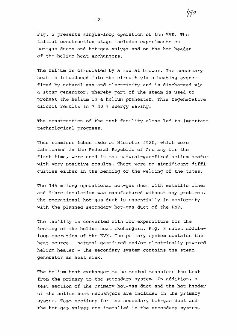
iffO-2-
Fig. 2 presents single-loop operation of the KVK. The
initial construction stage includes experiments on
hot-gas ducts and hot-gas valves and on the hot header
of the helium heat exchangers.
The helium is circulated by a radial blower. The necessary-
heat is introduced into the circuit via a heating system
fired by natural gas and electricity and is discharged via
a steam generator, whereby part of the steam is used to
preheat the helium in a helium preheater. This regenerative
circuit results in a 4 0 % energy saving.
The construction of the test facility alone led to important
technological progress.
Thus seamless tubes made of Nicrofer 5520, which were
fabricated in the Federal Republic of Germany for the
first time, were used in the natural-gas-fired helium heater
with very positive results. There were no significant diffi-
culties either in the bending or the welding of the tubes.
The 145 m long operational hot-gas duct with metallic liner
and fibre insulation was manufactured without any problems.
The operational hot-gas duct is essentially in conformity
with the planned secondary hot-gas duct of the PNP.
The facility is converted with low expenditure for the
testing of the helium heat exchangers. Fig. 3 shows double-
loop operation of the KVK. The primary system contains the
heat source - natural-gas-fired and/or electrically powered
helium heater - the secondary system contains the steam
generator as heat sink.
The helium heat exchanger to be tested transfers the heat
from the primary to the secondary system. In addition, a
test section of the primary hot-gas duct and the hot header
of the helium heat exchangers are included in the primary
system. Test sections for the secondary hot-gas duct and
the hot-gas valves are installed in the secondary system.

-3-
Fig. 4 presents the working and demonstration model
of the facility. The building is 50 m long, 20 m wide
and 25 m high. Some components such as the helium storage
tanks, the coolers and the natural-gas-fired helium heater
are installed outside the building.
The left-hand side of the building accomodates the control
room, parts of the water steam system, the helium auxiliary
facilities and the blowers. The other loop components and
test objects, for example the 10 MW helium heat exchanger, are
located on the right-hand side of the building.
Fig. 5 is a photograph of the outside of the KVK. In the
foreground you can see the helium storage tanks with the
control room and on the left in the background the natural-
gas-fired helium heater.
3. Test projects
Let me now briefly describe the test objects. Fig. 6 shows
the 10 MW He/He heat exchanger with helical tube design
manufactured by the firms Steinmiiller and Sulzer.
The primary helium enters the shell space from the bottom
at a temperature of 950° C and is cooled down to 290° C
by cross flow of the helical heat exchanger tubes. It then
flows back to the primary outlet through the outer annular
space, whereby the pressure shell is simultaneously cooled.
The secondary helium enters the helical tubes with a
temperature of 220° C via the cold gas header and exits
from the heat exchanger with a temperature of 900° C via
the hot header and the central tube.
In comparison to the helical tube heat exchanger, the
U-tube heat exchanger of the firm Balcke-Durr is differently
designed (see-Fig. 7). The hot header is positioned in the
upper part of the heat exchanger and subsequently the central

-4-
tube is shorter. The cold gas header is separated from
the support plate and is suspended by springs. The heat
exchanger tubes are bent in a U-shape. The primary helium
flows along them on the outside.
Fig. 8 presents parts of the test vessel for the two
He/He heat exchangers in the manufacturer's factory.
The photograph gives an impression of the size of the
vessel, which has a diamter of 2,4 m and an overall height
of 25 m. The pressure test will be performed in May of
this year and construction will be completed in August
Fig. 9 is a cross section of the hot header of the two
helium heat exchangers with measuring insert for the
creep buckling test. The test is performed at a differential
pressure of 44 bar and a maximum initial temperature of
992° C, which is steadily decreased to approximately 750° C
in the course of 10 hours.
The next picture (Fig. 10) is a photograph of the hot header
with tube studs and thermocouples for recording the radial
and axial temperature distribution-
The following photograph (Fig. 11) presents the measuring
insert of the hot header for recording the creepage and
buckling distances during assembly. You can see the cooling
coils, which are covered with aluminum foil, and the ceramic
coupling rods. Measuring insert and coupling rods are protected
by an additional insulation.
The first part of this experimental project was performed
on February, 23
For this test, the hot header was heated to a temperature
of 930° C at a pressure of 43,5 bar. This resulted in a
pressure balance between the air inside the header and the
helium on the outside.
-5-
The inside was then relieved to atmospheric pressure
by blowing off the air.
Subsequently the initial temperature of 930° C was
reduced to 680° C at a rate of 25 K/h in the course
of 10 hours.
The overall deformation was determined using 24 dis-
placement transducers. The results are currently being
evaluated.
The next creep buckling test at a temperature of 992° C
is intended to be performed on April 24 e.g. on Tuesday
of next week.
In order to perform creep fatigue tests, the caps of
all 8 64 tube studs are removed and the test object is
exposed to hermocycles between 950° C and 700° C at 40 K/min
as shown in Fig. 12.
This is followed by another creep buckling test.
The next picture (Fig. 13) shows the test section secondary
hot-gas duct with metallic liner and fibre insulation. The
radial dimensions, outer diameter 1220 mm, liner diameter
700 mm are in compliance with those of the PNP.
The next picture (Fig. 14) presents the primary hot-gas
duct with fibre insulation with 95 % AL2O3. The gas liner
is made of graphite. The adjustable supporting elements
made of isostatically compressed AL?O_ position the gas
liner radially and axially.
The following picture (Fig. 15) depicts the sub-component
of the axial hot-gas valve. The valve is cooled and actuated
by helium.
-6-
Fig. 16 gives an overview of the tests which are scheduled
for the KVK in the coming years. These will be described
in greater depth in subsequent lectures.
- The experiments on a test section of the secondary hot-gas
duct, which commenced in 82, will be completed this year,
with the exception of the long-term test. A corresponding
tube bend will be tested in 85/86.
- The primary hot-gas duct and primary compensator will be
tested with the first helium heat exchanger in an integral
test in 85/86.
- The sub-component of the axial hot-gas valve will be
subjected to a number of different tests relating to
thermohydraulics, tightness etc. before a prototype of
the reactor valve is included in a long-term test in 86/87.
- The tests on the hot header, creep buckling test 1,
fatigue test, creep buckling test 2 will take place in
8 4/8 5. They commenced last February.
- The first helium heat exchanger will be delivered at the
beginning of May 1985. The tests will start at the beginning
of October 85 and will continue for a period of 7 months
corresponding to an operating time of approximately 3 000 h.
The second helium heat exchanger will then be installed.
4. Operating experience and test results
To date the KVK has been in operation for 5000 h,1200 h of
which have been at reactor temperatures between 900° C and
950° C. Apart from two leakages in the natural-gas-fired
helium heater and a ground fault in the electric heater,
the operating experience has been very positive.
After approximately 2500 h, a leakage was detected in the
natural-gas-fired helium heater when shutting down the
facility. There was a crack in a bend made of Incoloy 800 H,
which must have formed during the fabrication of the tubes.

-7-
With reference to the electric heater, part of the
perforated liner of the inner insulation had loosened
from a holding plate and caused a ground fault over one
of the segments of the power supply lines. In compliance
with the electric circuitry, 2 of 12 modules were switched
off and the electric heater continued operation with 10 mo-
dules, as planned for such a case. The defective point has
been repaired in the meantime.
To conclude, I would like to list the most important facts
which have been amassed to date. They are summarized in
headlines in Fig. 17.
- The helium tightness of the overall facility is good.
It amounts to < 1 kg/d.
- The combined application of a natural-gas-fired and an
electrically-powered helium heater ensures the high
economy and availability of the facility.
- He-blowers, steam generator and steam-heated helium
preheater operate reliably.
- The selected materials for internal insulations proved
themselves right away.
- The components do not show any inadmissible vibrations.
- The required helium atmosphere can be easily adjusted
using the available helium purification and dosing system.
- The surfaces of materials in the high-temperature zone
between 900° C and 950° C exhibit a stable chromium oxide
protective coating. This is also valid for the included
metal samples, which can be exchanged during operation.

-8-
To date, it has been possible to convert and extend
the KVK without any problems and within a short time.
The new process instrumentation and control system
Teleperm-M is easy to operate and reliable. New operating
conditions can be easily realized by software alterations.
Fast repair of the defects and disturbances in the heaters
was possible.

Component Test Facility
Operating data:
Thermal power
Temperature
Pressure
Row rate
Helium velocity
Temperature transient
Pressure transient
10 MW (max. 12,8 MW)
950 °C (max. 1000 °C)
40 bar (max. 46 bar)
3 kg/s (max. 4,3 kg/s)
60m/s
± 200 K/min
5 bar/s

900 T 9 5 0 C
1A3
2 4 0 ° C
1A11
1AK1T2
5X1
220 °C
1A12
1X3
1X1H1H1T
2121
PrelGasElecHotHot
TeaterHeater
: t n c HeaterGas Duct 1Gas Header f
k TestSection
1T2 Valves Test Sect ion5X1 Waste Heat Bo i ler1X3 Cooler1P2 BlowerSL Shock Line
KVK KomponenfenyersuchskreislaufSINGLE CYCLE ARRANGEMENT

220°C
1X2 Preheater1H1 Gas Heater1H2 Electric Heater1X1 He/He Heat Exchanger1X3 Cooler1 P1 Primary Blower
1T1 Hot Gas Duct Test Section1T2 Valves Test Section5X1 Waste Heat Boiler1X4 Cooler1 P2 Secondary BlowerSL Shock Line
KVK KomponentGnyGrsuchskreislauf
Dual-Cycle Arrangement wi th H G / H G HX

Working and Demonstration Model of the Facility
The KVK is sponsored by the Ministry of Economics, Small Business and TrafficAbb. 4
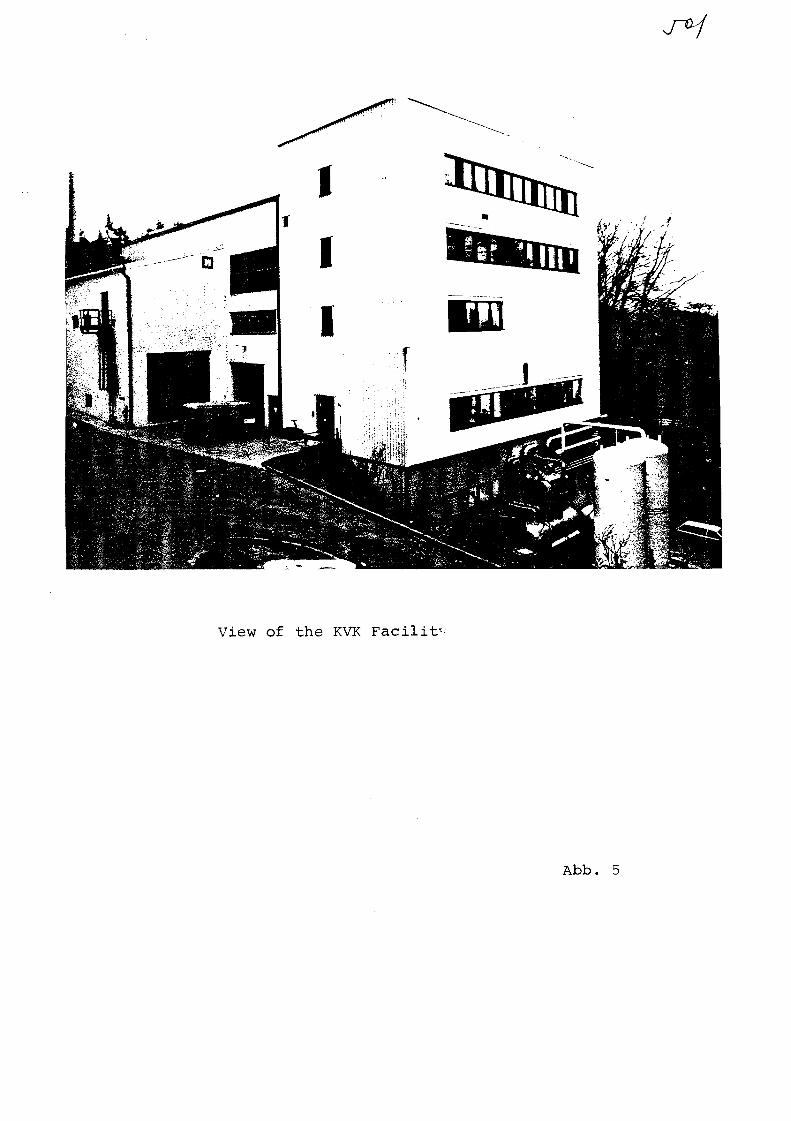
View of the KVK Facilit-
Abb. 5

fbl.
Secondary Outtet
r
PrimaryInlet
Cold Gas Header
Secondary Inlet
Support Plate
Central Hot Gas Duct
Outer Annulus
Pressure Vessel
insulation
i
Flow rate
Temperature
Pressure ,
Diff. Pressure •
Power I
Operational
Primary ;
2,95 kg/s ;
950/293°C ,
39,9 bar
0,55 bar j
Data
Secondary I
2,85 kq/s j
900/220°C :I
41,9 bar i
1,65 bar
10 MW
Dimensions and r
Number of tubes
DtTn. of tubes
Tube Material
Vessel Material
117
'22 "2,0
2.4663
16368
Structure Material 1.73801.4876
Hot Header
Mixing Device
•tatenal
(Nicrofer 55201
(WB36)
(10CrMo910)(Incoloy 800H1
10MW He/He Heat Exchangerin Helical Tube Construction
L_

SecondaryOutlet
SecondaryInlet
PrimaryIntet
Support Plate
Central Duct
Cold Gas Header
Outer Annutus
Pressure Vessel
Hot Header
Flow Rate
Temperature
Pressure
Diff. Pressure
Power
Operational
Primary
3,0 kg/s
950/293
39,9 bar
0,5 bar
Data
'C
10.
Secondary
2,9 kg/s
900>220°C
43.5 bar
1,0 bar
MW
Number of tubes
Tube Dimension
Tube Material
Vessel Material
180
"20 * 2,0
24663 (Nicrofer5520Co)
1.6368 (WB36)
Structure Material 17380 (10CrMo910)16311 (20MnMoNi55)1.5415 (15 Mo 3)
Insulation
Hot Gas Central Duct
Mixing Device
10MW He/He U-TubeHeat Exchanger

Pressure Vessel of the 10 MW He/He Heat Exchanger
Abb. 8

Instrument Penetration
Water Cooling
Strain Gauge Insertion
Test Vessel
Insulation
Liner
Mot Header
864 Tube Nippel
Helium - Inlet
Operational Oata
Temperature 950 °C • 1000°CDiff Pressure 44 bar
Dimensions
Tube Nippet "22x2Hot Headsr * 1020 x 100 WdTtst Visstl •2300x4490Lintr
Material
2 4663 (Nicroter 5S20 Co)2.4663 (Nicroftr 5520Co)1.5415 (15Mo3l1 4876 (Incoly 80QH)
Hot Header Creep Buckling Test s

Hot Header -. Assembly of Thermocouples
Abb. 10
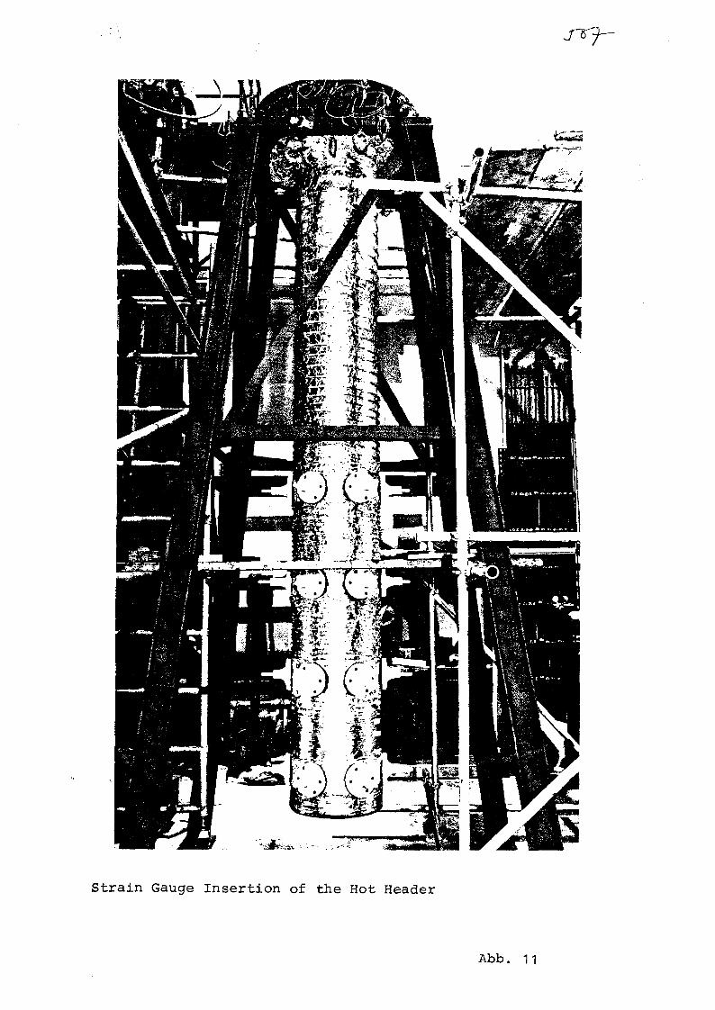
Strain Gauge Insertion of the Hot Header
Abb. 11

Helium-Inlet
Instrument Penetration
Test Vessel
Insulation
Operational Data
Flow 2 kg/s by 9S0°C
Pressure 3 kg/s by 700 ° t
Temperature 700 °C * 9S0°CRamp
Dimensions
Tube Nippel " 2 2 x 2
Hot Header '1020 « 100 Wd
Test Vessel - 2300 «
Liner
Material
2 1.663 (Nicrofer SS20 Col
2 i.663 (N lcroferSS20 Co)
1 5/.15 (15Mo3l
1 (.876 llncoloy 800H1
Hot Header Fatique Test
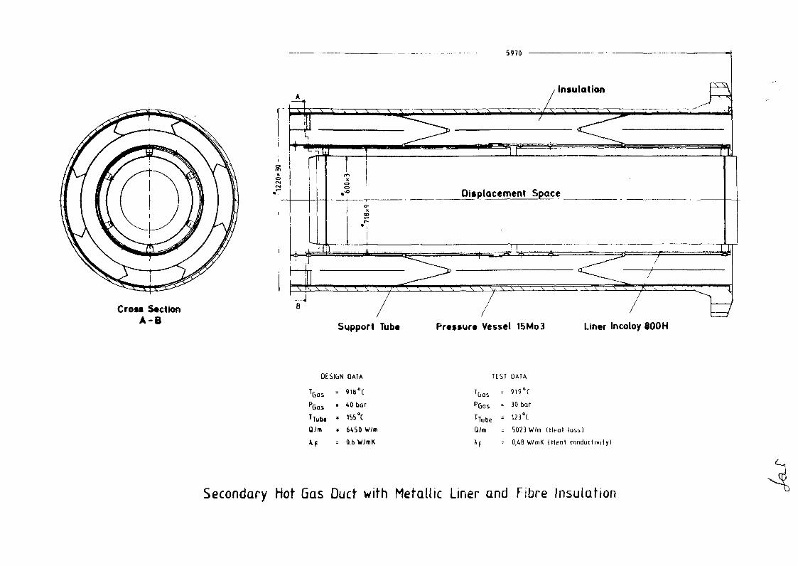
Cross SectionA-B
5970
Insulation
_LL
Displacement Space
N \ \ \ • 7"
Support Tube
,t
-U
- - • • * • - —
Pressure Vessel 15Mo3 Liner Incoloy 800 H
OESIbN
PGQi 'TTub« •
Qlm
*F
DATA
1.0 bar
1S5°C
6<.S0 W/m
0.6 W/mK
TtST
PGQS =
TTube =
Q/m
XF
DAIA
30 bar
123°C
5023 W/m
01.8 W/mK
(Heut
(Heat
loss)
conductivity)
Secondary Hot Gas Duct with Metallic Liner and Fibre Insulation

6000
A x
L < / (_, L.
x x x x
\ X XXXX V
ocsjo
X X X X
x x x x x x x
sCO
o00•a
JXrh x xy, t x x x^x •>t1x >f-lx>;x x x x x x x x
' ' ^ ^ ^ C £ <L
Pressure vessel
Support structure
Insulation
Liner
Displacementbody
/ /
Axial support element Radial support element
Detail B Detail CCross-section A-A
Test Section Primary Hot Gas Duct
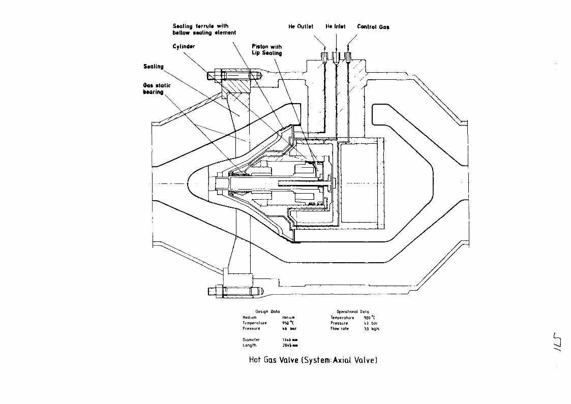
Staling ferrule withbellow ••aling element
Cylinder
He Outlet He Inlet Control Cat
Seating
0a> staticbearing
DesignMediumTemperaturePressure
DiameterLength
DataHtlium9S0*Ct i bar
13*0 M I
OperationalTemperaturePressureFlow rate
Data900 °C1,3 bar3.0 kg/s
Hot Gas Valve (System;Axial Valve)

VersucheMontage
VERSUCHSTERMINPLAN KVK1982 1983 1984 1985
8 1 0 2 4 6 8 1 0 2 4 6 8 1 0 2 4 6 8 1 0
1986
STAND DEZEMBER 1983
1987
_i—i—i i_ i i i i i i i i _
2 4 6 8 10 2 4 6 8 10_ i i i i i I i i i i '
Heißgasleitungen
Sekundärheißgasleitungmit metallischem Liner
Rohrbogen mit metallischem Liner
Primärheißgasleitung
Primärkompensator
Axial-Heißgasarmatur
Teilkomponente
• Thermohydraulik
• Dichtigkeitsuntersuchung
• Stoßdämpfertest
• Funktionsspiele
Betriebsheißgasarmatur (axial)
Prototyp-Armatur
Heißer Sammler
• Kriechbeulversuch Nr. 1
• Ermüdungsversuch
• Kriechbeulversuch Nr. 2
Helium-Wärmetauscher
1. He-Wärmetauscher
2. He-Wärmetauscher
_ .Inspektion
V
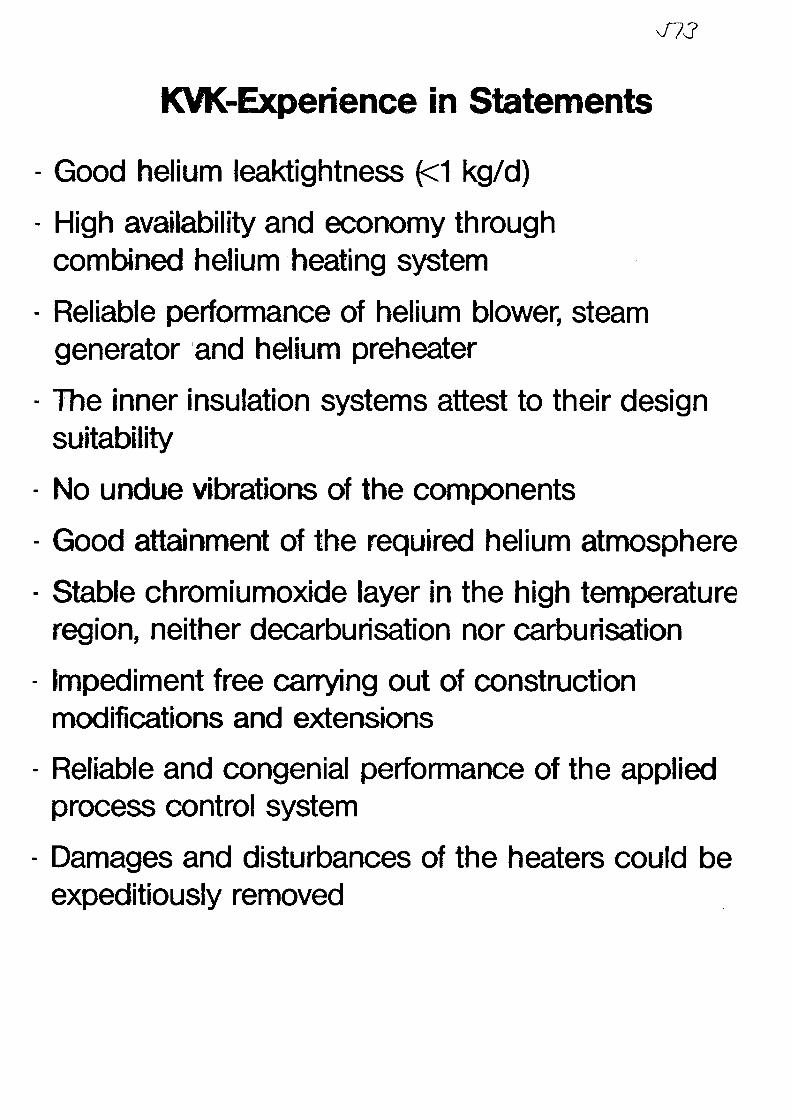
KVK-Experience in Statements
Good helium leaktightness (<1 kg/d)
High availability and economy throughcombined helium heating system
Reliable performance of helium blower, steamgenerator and helium preheater
The inner insulation systems attest to their designsuitability
No undue vibrations of the components
Good attainment of the required helium atmosphere
Stable chromiumoxide layer in the high temperatureregion, neither decarburisation nor carburisation
Impediment free carrying out of constructionmodifications and extensions
Reliable and congenial performance of the appliedprocess control system
Damages and disturbances of the heaters could beexpeditiously removed

No. 31XA0055841
OPERATING EXPERIENCES WITH HEAT-EXCHANGING COMPONENTS OF A
SEMI-TECHNICAL PILOT PLANT FOR STEAM GASIFICATION
OF COAL USING HEAT FROM HTR
Dr.-Ing. R. Kirchhoff and Priv.-Doz. Dr. rer. nat. K.H. van Heek
Bergbau-Forschung GmbH, Essen, FRG
1. Concept and Operation of the Semi-Technical Pilot Plant
Within the framework of the PNP-Project Bergbau-Forschung
GmbH of Essen has been operating a semi-technical plant
for the development of a process of gasifying coal by means
of nuclear heat /I,2,3/. Here gasification is for the first
time implemented in a fluidized bed using the heat of an
electrically heated helium cycle at pressures up to 40 bar
and temperatures normal with a HTR /4,5,6/. The plant - a
general view of which is given on Fig. 1 - serves in a first
Fig. 1: General view of the semi-technical coal gasificationplant on the test premises of Bergbau-Forschungin Essen

- 2 -
line for testing and developing various components as immer-
sion heater, insulations, dosing devices, etc. and, secondly,
for gathering sound data for further planning. The second
objective can, of course, be met only if any and all plant
components function in a way so as to guarantee trouble-
free stationary experimental operation. Fig. 2 is a flow-
sheet of the experimental plant.
COAL
COAL INJECTION
Fig. 2: Flowsheet of the semi-technical pilot plant
The non-caking coal is dose-fed via the pressure lock system
to the top of the gasifier. Caking coal is introduced via
an injection feeder in the fluidized bed on the gasifier
bottom. The injector concept is to prevent agglomeration
of the feed coal. Fresh coal and partly gasified coke shall
be mixed fast and intimately enough so as to avoid any con-
tact and, consequently, sticking together of the fresh coal
particles. The gasification residues will be discharged
through the gasifier bottom by means of a chamber-wheel
serving a system of two parallel locks.

Jib- 3 -
The helium of the heat carrier cycle is heated in an electric
helium heater up to temperatures between 900 and 1000 °C;
from there it flows through the heat exchanger in the fluidized
bed and provides the necessary process heat.
The steam is raised in a gas-fueled steam generator as well
as by heat recovery from raw gas in a pressurized gas cooler.
The product gas leaves the gasifier through the top and
is then fed to a cyclone where entrained fine dust is removed
at relatively high temperatures and discharged through a
system of locks. Subsequently the gas will be cooled. A
scrubbing system serves for cleaning the raw gas and removing
the remaining, untransformed process steam by condensation.
The product gas is then measured and analysed and subsequently
burnt in a flare burner.
Planning of the experimental plant started from 1974. Con-
struction work was commenced in spring of 1975, and the
plant was commissioned in July 1976. Fig. 3 gives the yearly
operational hours, coal throughputs and transformation rates.
The overall operation including commissioning, closing down,
and test operation, amounted to 24 571 hours until Decem-
ber 31st, 1983; 17 848 hours thereof account for hot operation
and 12 611 hours for gasification.
The years 1976 and 1977 were characterized by commissioning
and functional tests as well as by gasification tests for
the purpose of overcoming toothing troubles with process
technology. It was only after this phase that systematical
gasification trials could be run on non-caking feed coals.
The design figure of 4.8 t/d of carbon gasified was slightly
exceeded in 1978 (4.9 t/d). The objective from 1980 onward
was to establish sound data for the gasification of high
volatile bituminous coal with and without addition of a
catalyst.

- 4 -
J7?
Hours of operation : h/a
Coal throughput: t/a
Carbon gasified t/d
1271
2841
111 I1500I l l l
Caking cool
Nonoperating
"up'to 4,9 •:'j up TO 5,6 ;;•:
: . ' v ; . ' • ' • ' • ' • " - • - • ' ' : '
16B1
4259
7 H » » •:•;:•
Illll2404
Illll
211:
mI 1
Decreasing
of'inonces
!
' . ' r • . ' • . " • ' •
;' up to 2,4'£:
1978 1979 1980 1981 1982
•EH
Total hoif^of operation
24571hHours of hotoperation
17B£.8hHours of rodqasificotiofi
H f i i l h
^ ^ ^ Total coalfr j l j l t l throughput
21311Coking cool
1 3 Nonpretreolec
| | Pretreated
. cokuioled carbongasification rate
19B3 1976-1983
Fig. 3: Figures on test operation at the semi-technical plant
In the course of these trials and based on practical experience
we were able to permanently improve the technical performance
of the injector with appertaining feed hoppers, the feed
bottom, the heat exchanger of the gasifier, and the ash
discharge system. It was ultimately the successful tech-
nical achievement of the above components which allows to
entirely control the mechanism of pyrolysis. During 1983
the carbon transformation was increased to 6.4 t/d; coal
throughput was 572 t, 407 t thereof were high volatile bi-
tuminous coal /8,9/.
2. Development of several components
In the following operating experiences concerning gasifier,
helium circuit and the big gas heaters installed in the
plant will be reported.

- 5 -
2.1 Gasifier_with_the_Immersed_Heat_Exchanger
The gasifier (Fig. 4) is a detail taken over from the commer-
cial gasifier in so far as fluidized bed height and arrange-
ment of the heat exchanger tubes are identical with the
large-scale concept. The fluidized bed has a cross-section2
of 1 m and may be up to 4 m high.
Helium
Coal feeding i"ube
Injection feeding steam
Helium
Superheatedsteam
Fig. 4: Gasifier of the semi-technical coal gasification plant

Jli- 6 -
It turned up already during the initial operating phases
during 1976 and 1977 that the insulating properties of the
gasifier brickwork lining were not sufficient. Heat transfer
into the brickwork was not by conduction but rather by con-
vection. Under gasification conditions the steam condensed
in the lining, at saturated steam temperature. The heat
had, consequently, to be taken down within the remaining
insulating brickwork. The chemical and physical structure
of the insulation became that much damaged thereby that
steam by-passes through the brickwork were created. As this
presented a hazard to the pressure shell and also caused
substantially increasing heat losses the insulation had
to be replaced by a concept, in which steam condensation
was prevented.
The heat exchanger - flown through by helium - in the gasi-
fier underwent several modifications as practical experience
was broadened and for complying with the different test
objectives. The first apparatus was a single-flow heat ex-2
changer of roughly 42 m effective surface; the helium flow
was directed around semi-circular tube arches through the
rising descending tubes. Fig. 5 shows the tube bundle prior
to installation.
From October 1977 until June 1979 the device had operated
for 4900 hours, 4350 hours thereof under gasification con-
ditions and with a coal/coke throughput of 470 t. The tem-
perature range was between 800 and 900 °C. After this period
the tubes were in perfect condition. In the summer of 1979
the heat exchanger was replaced by a shorter version. This
was done because subsequently to the trials on non-caking
feed coal it was planned to dose-feed high volatile bituminous
coal through the injector. The tubes had to be shorter to
provide the necessary free space in the coal feed section.
During 1980 the heat exchanger was re-modified since, due
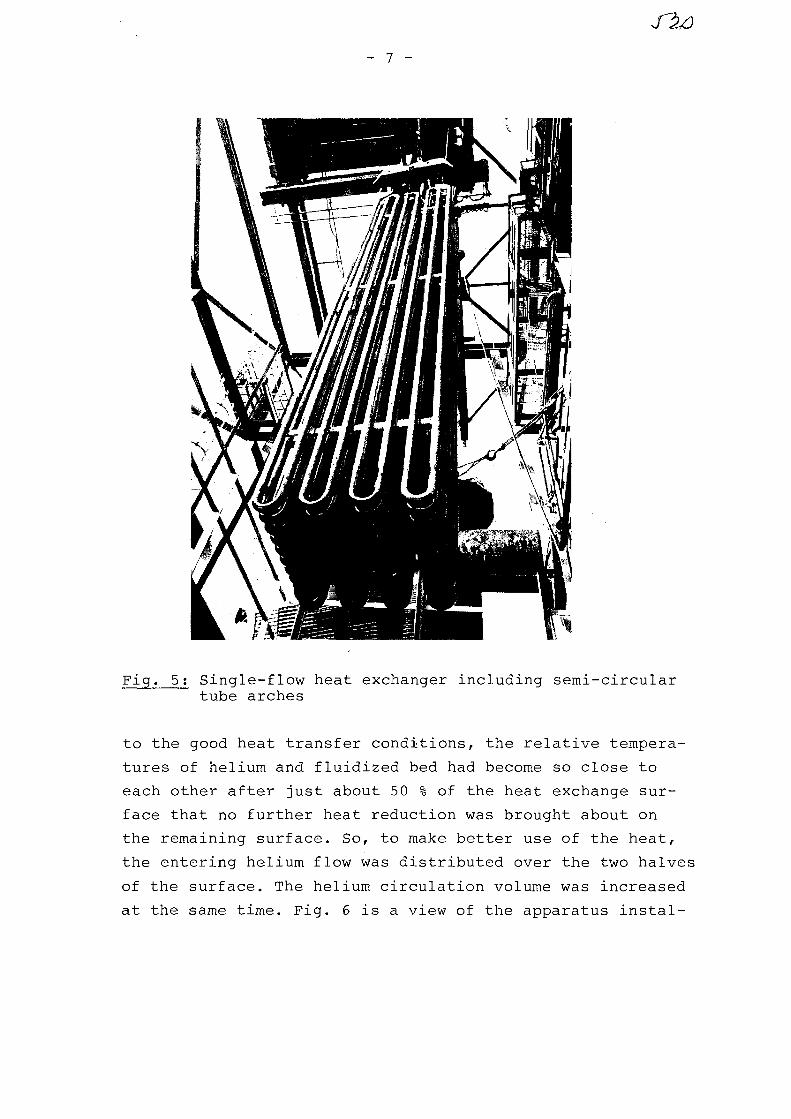
- 7 -
Fig. 5; Single-flow heat exchanger including semi-circulartube arches
to the good heat transfer conditions, the relative tempera-
tures of helium and fluidized bed had become so close to
each other after just about 50 % of the heat exchange sur-
face that no further heat reduction was brought about on
the remaining surface. So, to make better use of the heat,
the entering helium flow was distributed over the two halves
of the surface. The helium circulation volume was increased
at the same time. Fig. 6 is a view of the apparatus instal-

led early in 1982 and which differs from the previous con-
cept mainly by hair pin tube curves instead of semi-cir-
cular tube arches, leaving no space between the rising and
descending immersion-type tubes. This avoids reduction of
the process space in the hair pin area. Such concept en-
larged at the same time the absolute distance between tube
pairs from 62 mm to 142 mm which provides more vertical
freedom of movement to the fluidized bed.
Fig. 6: Heat exchanger in gasifier, hair pin tube arrangement
2.2 Helium_circuit
Another innovation is the helium cycle whose components
operate at 40 bar and up to 1000 °C. Fig. 7 is a drawing
of the different units operating within the high temperature

range with appertaining pipelines conveying hot helium.
The heart of the system is the helium heater consisting
of one vertical pressure vessel of about 9 m height and
an outer diameter of 1.5 m. The helium is heated with elec-
tricity. The resistance heater is a pitch coke fixed bed.
Tube 3
Tubel
Fig. 7: Arrangement of the pipelines for hot helium withinthe semi-technical coal gasification plant
Early in 1976 were carried out initial functional tests
(pressure test, test runs), followed by a two months' trial
run. During this period the circuit was operated both as
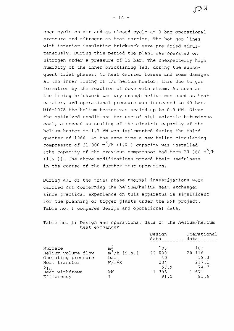
- 10 -
open cycle on air and as closed cycle at 3 bar operational
pressure and nitrogen as heat carrier. The hot gas lines
with interior insulating brickwork were pre-dried simul-
taneously. During this period the plant was operated on
nitrogen under a pressure of 15 bar. The unexpectedly high
humidity of the inner bricklining led, during the subse-
quent trial phases, to heat carrier losses and some damages
at the inner lining of the helium heater, this due to gas
formation by the reaction of coke with steam. As soon as
the lining brickwork was dry enough helium was used as heat
carrier, and operational pressure was increased to 40 bar.
Mid-1978 the helium heater was scaled up to 0.9 MW. Given
the optimized conditions for use of high volatile bituminous
coal, a second up-scaling of the electric capacity of the
helium heater to 1.7 MW was implemented during the third
quarter of 1980. At the same time a new helium circulating
compressor of 21 000 m /h (i.N.) capacity was installed
(the capacity of the previous compressor had been 10 360 m /h
(i.N.)). The above modifications proved their usefulness
in the course of the further test operation.
During all of the trial phase thermal investigations were
carried out concerning the helium/helium heat exchanger
since practical experience on this apparatus is significant
for the planning of bigger plants under the PNP project.
Table no. 1 compares design and operational data.
Table no. 1: Design and operational data of the helium/heliumheat exchanger
SurfaceHelium volume flowOperating pressureHeat transfer6lnHeat withdrawnEfficiency
m2m3/h (i.N.)barW/m2K
kW%
Designdata
10322 000
4023457.9
1 39691.5
Operationaldata
10320 116
39.3217.174.7
1 67191.6
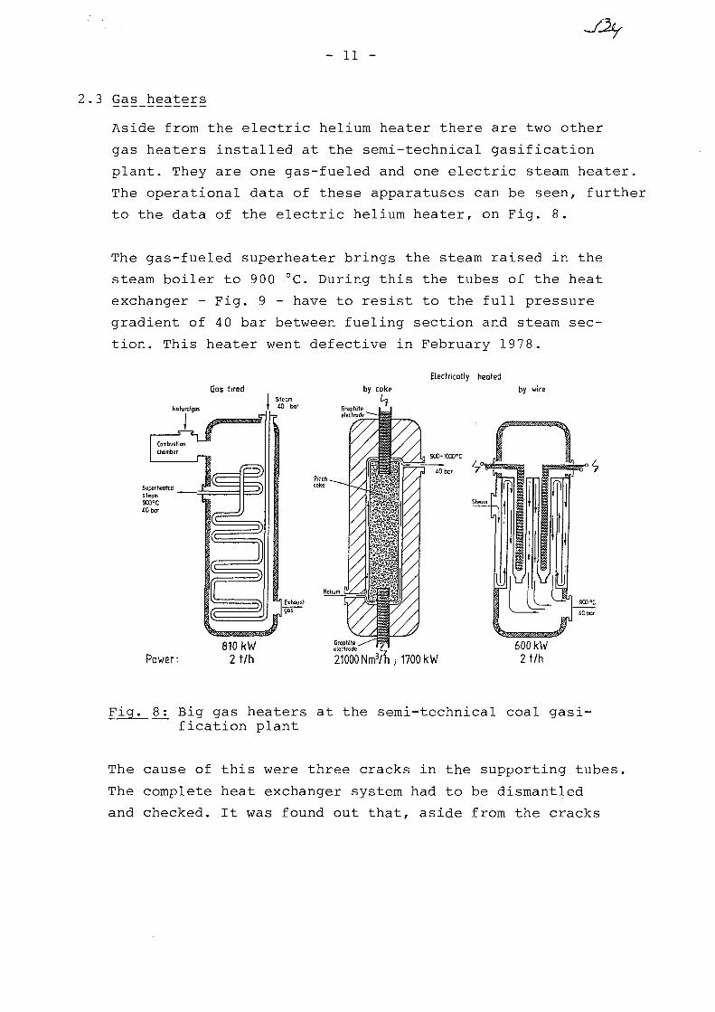
- 11 -
2.3 Gas_heaters
Aside from the electric helium heater there are two other
gas heaters installed at the semi-technical gasification
plant. They are one gas-fueled and one electric steam heater.
The operational data of these apparatuses can be seen, further
to the data of the electric helium heater, on Fig. 8.
The gas-fueled superheater brings the steam raised in the
steam boiler to 900 °C. During this the tubes of the heat
exchanger - Fig. 9 - have to resist to the full pressure
gradient of 40 bar between fueling section and steam sec-
tion. This heater went defective in February 1978.
Electrically heatedGas. fired by wire
Power:810 kW
2 t/h 21000 Nm3/h; 1700 kW600 kW2 t/h
Fig. 8: Big gas heaters at the semi-technical coal gasi-fication plant
The cause of this were three cracks in the supporting tubes,
The complete heat exchanger system had to be dismantled
and checked. It was found out that, aside from the cracks

- 12 -
in the supporting tubes made of 15 Mo 3, tube bundles no. 3
and 4, of 13 Cr Mo 44, showed considerable scaling and were
badly distorted. Tube bundle no. 2, of Incoloy 800, was
free of scaling and hardly distorted. Bundle no. 1, of HK 40,
was in perfect condition. Upon this the supporting tubes
as well as bundles 3 and 4 were manufactured out of Incoloy 800
The new tube bundle - Fig. 9 - has resisted to test operation
without any damages so far.
Fig. 9: Heat exchanger tube bundle of the gas-fueled steamsuperheater

- 13 -
The electric steam superheater consists of a vertical insu-
lated pressure vessel into which process steam is entered
and passed evenly distributed through 36 annular tube gaps
arranged in parallel whereby it is heated up to maximum
900 °C discharge temperature. In the center of the double
tube construction is the electric heat conductor, mounted
on ceramic material, including tmeperature controls at two
different levels in order to protect the heat conductor
from overheating by a cut-out system. In Fig. 10 is repre-
sented the top section of the electric steam superheater
including the heat conductor arrangement. Certain problems
were encountered with the electric steam superheater during
the past. During the spring of 1979 - like in previous years -
the heating wires of the conductor repeatedly went defective
due to inadequate welding connections and excessive material
deposits.
Fig. 10: Heating arrangement in the electric steam superheater
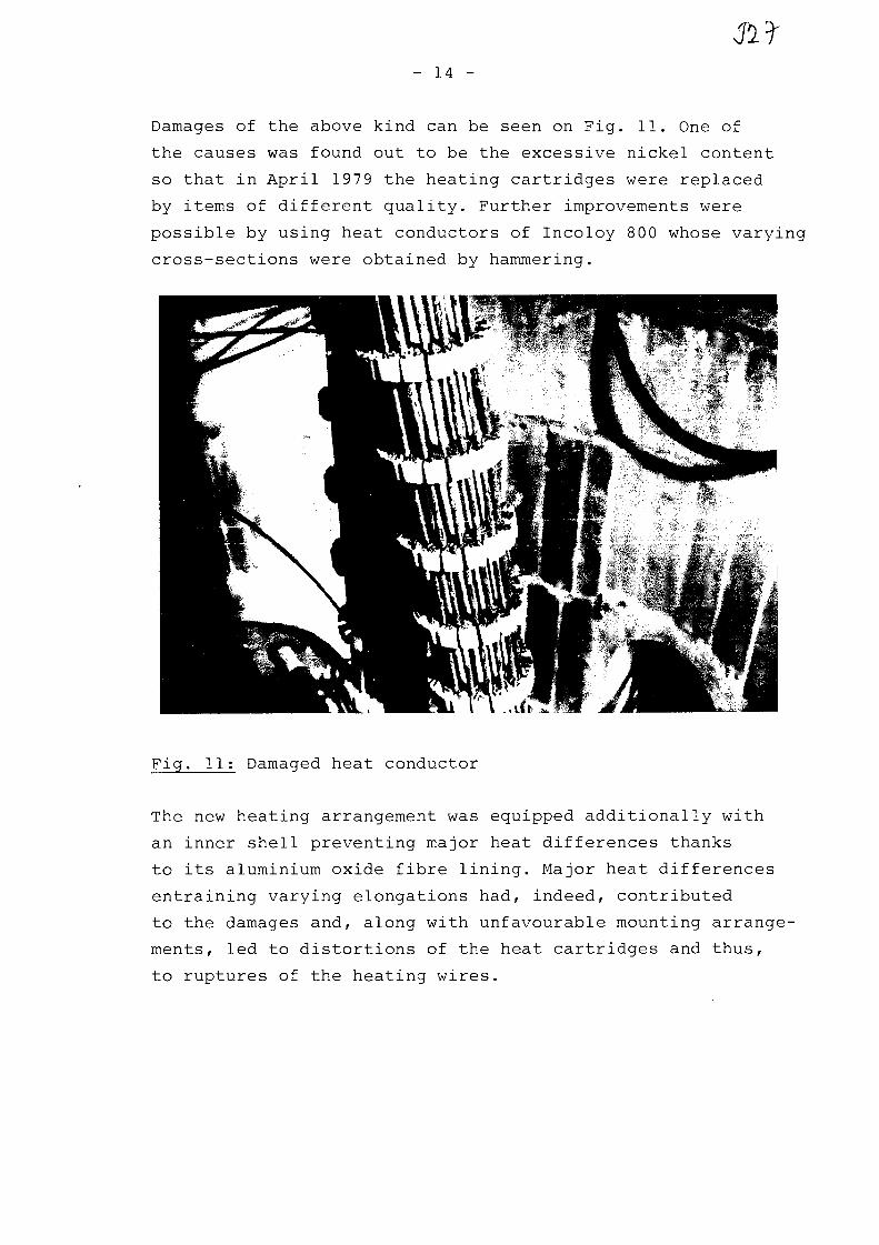
- 14 -
Damages of the above kind can be seen on Fig. 11. One of
the causes was found out to be the excessive nickel content
so that in April 1979 the heating cartridges were replaced
by items of different quality. Further improvements were
possible by using heat conductors of Incoloy 800 whose varying
cross-sections were obtained by hammering.
Fig. 11: Damaged heat conductor
The new heating arrangement was equipped additionally with
an inner shell preventing major heat differences thanks
to its aluminium oxide fibre lining. Major heat differences
entraining varying elongations had, indeed, contributed
to the damages and, along with unfavourable mounting arrange-
ments, led to distortions of the heat cartridges and thus,
to ruptures of the heating wires.

- 15 -
Based on practical experience the installation has been
optimized so that the basical problems are overcome by now.
And there is a sufficient amount of sound data available
to back up the erection of a plant scaled-up in size.
3. Bibliography
/I/ Juntgen, H. and van Heek, K.H.: Coal gasification,- fundamentals and technical application (Karl Thiemig,Munich, 1982)
/2/ Schilling, H.-D.; Bonn, B., and Kraufi, U.: Coal gasi-fication, 3rd edition (Gluckauf GmbH, Essen, 1981)
/3/ Neef, J.H., and Weisbrodt, I.: Coal gasification withheat from high temperature reactors. Objectives andstatus of the project "Prototype plant for nuclearprocess heat (PNP)", Nucl. Engr. Des. 54 (1979), 157-174
/4/ Juntgen, H. and van Heek, K.H.: Gasification of coalwith steam using heat from HTRs, Nucl. Engrg. Des. 34(1975), 59-63
/5/ Feistel, P.P.; Diirrfeld, R. ; van Heek, K.H. and Juntgen, H.Layout of an internally heated gas generator for thesteam gasification of coal, Nucl. Engrg. Des. 34 (1975),147-155
/6/ van Heek, K.H.; Juntgen, H., and Peters, W.: Steamgasification of coal using process heat from HT reactors.Atomenergie/Kerntechnik 40 (1982), 225-246
/I/ Kirchhoff, R. ; van Heek, K.H. and Juntgen, H.: Operationof a semi-technical pilot plant for allothermal pressuregasification of coal using steam. Compendium 80/81,Erdol und Kohle (supplement), pp. 177-179
/8/ van Heek, K.H. and Kirchhoff, R.: Present state ofcoal gasification with nuclear heat. Publication ofpapers read at a conference held at Haus der Technik,Essen. Issue 453, 1982, pp. 59-67.
/9/ Kirchhoff, R.; van Heek, K.H.; Juntgen, H. and Peters, W.:Operation of a Semi-Technical Pilot Plant for Nuclearaided Steam Gasification of Coal. Nucl. Eng. Des. 78(1984), pp. 233-239
No.. 32
Specialists' Meeting
on
Heat Exchanging Components of
Gas-Cooled Reactors
Diisseldorf
16.-19. April 1984
THE TEST FACILITY EVA II/ADAM II
Description and Operational Results
R. Harth, H.F. Niessen, V. Vau
Kernforschungsanlage Julich GmbH
R. Merken
Rheinbraun-Koln
XA0055842
I A E A

THE TEST FACILITY EVA II/ADAM II
- Description and Operational Results -
R. Harth, H.F. Niessen, V. Vau, KFA-Julich
R. Merken, Rheinbraun-Koln
The Nuclear Research Center Juelich (KFA) and the Rheinische
Braunkohlenwerke AG, Cologne, signed the contract for the
R&D project "Nukleare Fernenergie (NFE)" in December 1975.
Among others one task of this project has been the construction
and operation of the test facility EVA II/ADAM II. General aim
of the project work is to elaborate the data necessary for the
design and construction of a heat transport system using the
thermo-chemical cycle steam reforming/methanation.
Fig. 1 shows a view of the complete facility sited at KFA Juelich
It consists mainly of a helium system as heating unit, a steam
reforming system and a methanation unit. The large building in
the background contains the helium loop EVA II. The methanator
ADAM II is located in the foreground. There the synthesis gas
produced in the steam reformer is converted to methane again
and the heat transported by the thermochemical cycle is re-
leased at 650 °C.
The complete facility EVA II/ADAM II has been constructed by
Lurgi Kohle und Mineraloltechnik GmbH, Frankfurt.
In the following the facility EVA II is discribed.
The flow scheme is shown in fig. 2
The helium circuit represents a complete primary loop of a HTGR
for process heat application. The core is simulated by an elec-
trical heater with a maximum power input of 11 MWe.
The helium is heated in the electrical heater up to 950 C.
After passing the hot gas duct the heat is transferred succes-
sively primarily to the steam reformer tubes where the helium

JJ)- 2 -
is cooled down to 650 C and then to the steam generator for
process steam production where the helium is cooled down
to 350 C. An integrated circulator transports the helium
back to the electrical heater by following a coaxial flow
principle.
As process gas a mixture of methane and steam enters the steam
reformer. By means of the endothermic chemical conversion to
synthesis gas it absorbs the heat transferred from the helium.
Fig. 3 shows the steam reformer bundle tested in EVA II.
It consists of 30 tubes. The tube dimensions corresponds to those
in the conventional technique:
. length 11 m
. diameter (internal) 100 mm.
Further characteristics of the steam reformer bundle:
. 4 different alloys have been used forthe reformer tubes
. Raschig-ring-catalyst as conventionally approved
. reformer tubes with internal return pipes
. baffles (disc-and-doughnuts) to intensify thehelium heat transfer.
The steam generator is shown in Fig. 4. This is a induced-single-
circulation boiler, characterized by
. helix design
. 2 layers contrary directed coils
. helium temperature max. 700 C
. steam temperature max. 700 C
. steam pressure max. 55 bar.
Electrical heater, steam reformer and steam generator are linked
together by coaxial hot gas ducts. The thermal insulation sepa-
rating the hot and cold helium flow is made of carbon bricks.
On both sides the insulation is covered by a metallic liner.
Just the colder outside liner is gastight.

- 3 -
The tasks for the plant EVA II are as follows:
. tests of the heat transport by a thermo-chemical cycle
. tests of a complete helium loop equivalent to that of anuclear process heat plant
. tests of steam reformer bundles in a representativesize and design
. functional tests of a steam generator under HTGR likeconditions
. investigation of operational behaviour on normaloperation, partial load and break-down conditions
. description of the operating characteristics bymathematical models.
The main tasks of the investigations in EVA II aim not prior
at the life time of the components but at operation characte-
ristics and behaviour in a wide range of different process
parameters. The main parameters have been changed between
the following limits:
electrical power input
helium mass flow rate
helium pressure
helium temperature
methane mass flow rate
All test runs of the facility EVA II in linkage with ADAM II
could be performed successfully. In the course of the test
program the following tasks have been worked off:
. change of catalyst by vacuum extraction
. replacement of a single reforming tube withoutremoval of the whole bundle
. disassembling and reinstallation of the steam reformingbundle.
In total the helium system has been operated for 7,800 hours.
Thereby the EVA/ADAM heat transport cycle reached 5,660 hours.
3,
1
15
800
o,
8
18
•+• 1 1
-*- 4
-*- 40
+ 950
•*• 0
MWkg/s
bar
°C,66 kg/s.

- 4 -
The test of the first steam reformer has been finished 1983.
The bundle has been removed. It will be disassembled and
the steam reformer tubes will be checked in detail. The facili-
ty EVA II now is under preparation for installation of a new
bundle with a different design.
The test of the component steam reformer in the facility
EVA II represents the last experimental step before entering
into nuclear demonstration.
Acknowledgements
The work described in this paper was performed within the
framework of the project "Nukleare Fernenergie" between
the Kernforschungsanlage Jiilich GmbH, Jvilich and the Rheini-
sche Braunkohlenwerke AG, Cologne, sponsored by the Federal
Minister of Research and Technology, FRG.

Fig. 1: View of the test facility EVA II/ADAM II
EVA 31
TPmCH,H jCOCO,
°CbarkglBrel.Vol.
„
4041.4
0.6190.9S10.039
—0.010
403a5
1.2340.1230.6B1QO960098
Fig. 2: Flow scheme of the facility EVA II

Fig. 3: Steam reformer tube bundle
Fig. 4: The helium heated generator of process steam

No. 33
XA0055843
M o d i f i c a t i o n o f t h e A V R f o r
High Temperature Process Heat Systems-Demonstrat ion
* * **Barnert, H. , Kirch, N. , Ziermann, E.
*Kernf orschungsanlage Jiilich GmbH ( ) **Arbeitsgemeinschaft Versuchsreaktor GmbH ( )
IAEA Specialists' Meeting onHeat Exchanging Components of Gas-Cooled-ReactorsDiisseldorf, Federal Republic of Germany16-19 April 1984
Sponsored byMinisterium fur Wirtschaft, Mittelstand und Verkehrdes Landes Nordrhein-Westfalen

Hodification of tiu. A<fc -forHkjk Temptra-ture faces- {feat
Objectives •.
Systems-Demonstration forHigh Temperature Process HeatApplications
2. Systems- Demonstration forRefinement of Fossils, eg.Ctol into Energy Alcohol
3. Contribution to Specific trtas :ProcCa ct ^peci fi cat (on sLicensing ProceduresA-pproado of 2ero E
4. Investigations for theHorizontal Integration
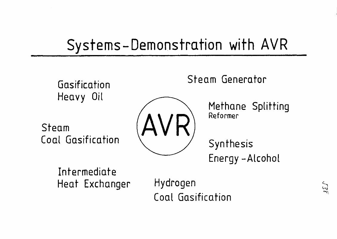
Systems-Demonstration with AVR
Gasification S t e a m G e n e r a t o r
Heavy OilMethane SplittingReformer
SteamCoal Gasification \ ^ y Synthesis
Energy-AlcoholIntermediateHeat Exchanger Hydrogen
Coal Gasification

• /
1. Reactor AVR
1.1 Thermal power of AVR Core1.2 Mean outlet temperature of coolant He1.3 Pressure of coolant He1.4 Mass flow of coolant He1.5 Power existing steam turbine plant:
HTP-Loop
46 MWt950 °C10 bar13 kg/s
50 50
2 Existing Steam Turbine Plant
2.1 Thermal power of the steam generator2.2 Electrical power of the turbine generator2.2 Comparable to (to days) part load
23 MWt9 MWe
50 %
3 High Temperature Process Heat Loop
3.1 Thermal power of the loop3.2 Temperature of the helium at the components3.3 Design temperature of the hot gas duct3.4 Length of the hot gas duct3.5 Inner diameter of the hot gas duct
2 3 MWt950 °C1000 °C60 m480 mm
4 Reformer
4.1 Thermal power of the reformer4.2 Helium temperature, inlet/outlet4.3 Feed methane, volume flow, ca.4.4 Molar ratio H2O:C, ca.4.5 Process gas maximum temperature4.6 Number of reformer tubes
8,5 MWt950/700 °C2500 m V h4 : 1825 °C65
5 Steam generator
5.1 Thermal power of the steam generator5.2 Temperature of the steam
14,5 MW530 °C
6.16.2
Loop circulator
Pressure increase of the circulatorPower of the circulator
1,0 bar500 kW
7 Measurements of the buildings
7.1 Height of the AVR building7.2 Height of the loop building with hall7.3 Height of the loop building without hall7.4 Length x width of the loop building
49 m48 m28 m23 x 14 m

Frischd&mpf Produkt, z.B.
Synthesegas
Einsatz, z.B.
Methan
AVR1 Core2 Steam generator3 2 Circulators4 He T = 950 ° C
High Temperature Process Heat Loop10 Hot gas tube11 Hot gas duct12 Cold gas duct13 Process heat components14 Circulator for the loop
Fig. 2: Principle of the Modification

[
tn\
6,5
1 i
E
oo
950
• M M
a
kCOF
oc_inen
col ofrj o
—————
a •
•
LUQ
^ o ^ .oincn
n(J
trie
a)CO
oO
O o
Aocor—• • • i
A
O JQO 1
©i
><
Pf
/ iPi"lin
CM
oocnf N
od
CM
<
x:
t?> £> o
IfCQ X
o
Ei
oCO
••
i—i
<>
c
LU
KFA-
I

a," = ^ r
AVR1 Core2 Steam generator3 2 Circulators4 Reactor pressure vessel5 Stages6 Containment
High Temperature Process Heat Loop10 Hot gas tubeHHot gas duct12 Cold gas duct13 Reformer14 Steam generator15 Circulator of the loop16 Loop building17 Conncection18 Hall with crane19 Hot cell20 Stack
Fig. 3: AVR-Process Heat Plant, Cross Section

1
AVR1 Reactor2 Turbine house3 Hot shop4 Coolers5 Pump house6 Main gate
High Temperature Process Heat Loop
10 Loop buildingwith High Temperature Process Heat Loop
19 Hot cell20 Stack
Fig. 4: AVR Process Heat Plant, Buildings

//
'IT
• •////•;'>/ , , ; ^ \
br
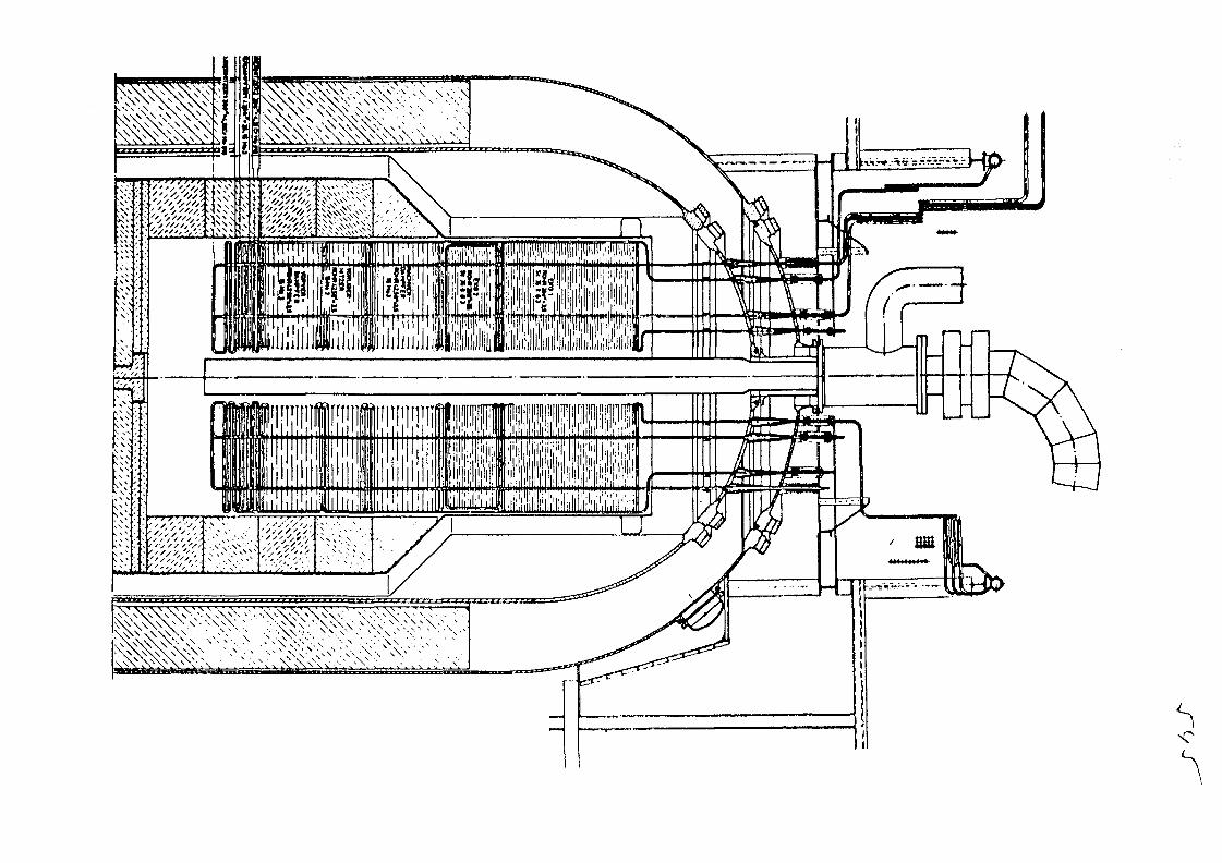
s
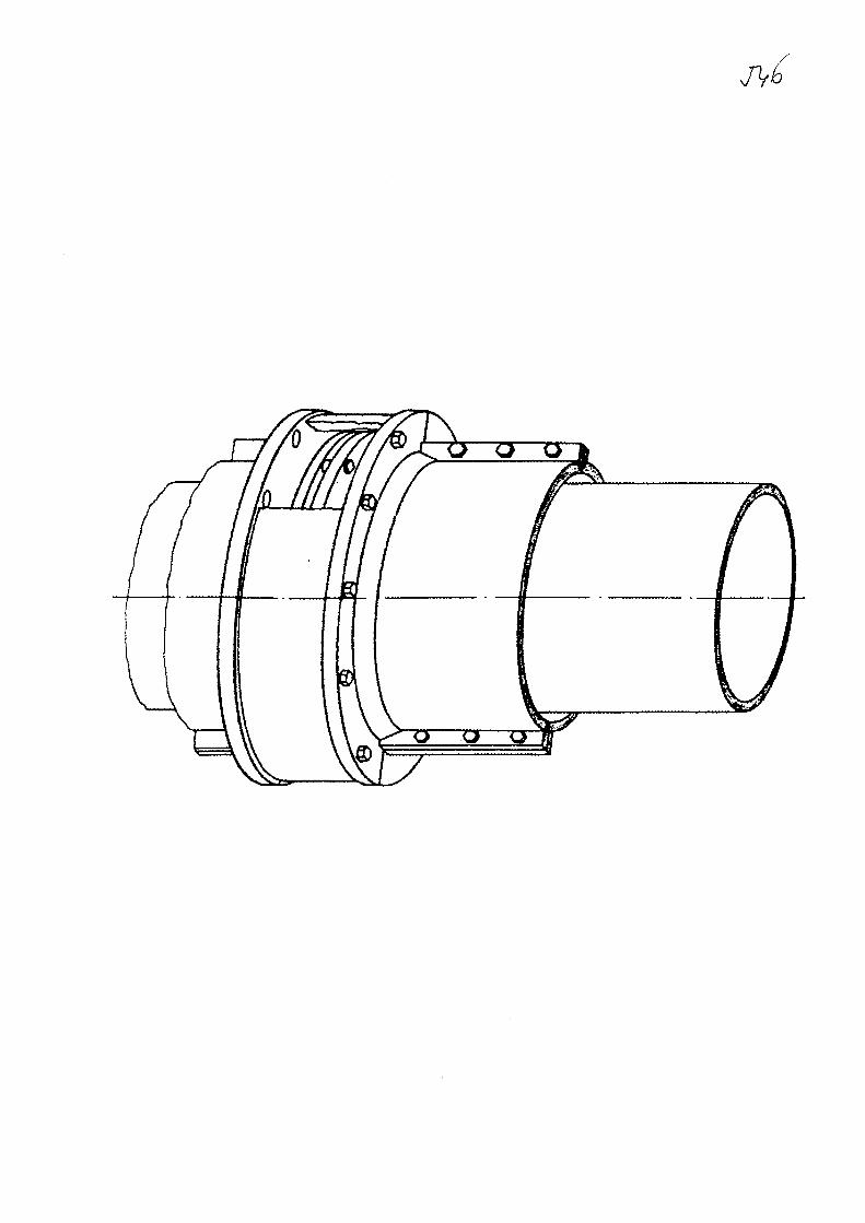

KameraBefeuchtungskorper
-••22,3m
Rohrbefestigung
+18,2 m
Ron/ 075x43
innererauBerer
Reaktorbehalter
+ 10,1m
Vorschubeinrichtung
• 5m
AVR - Deckenref fektor - InspektionZentrales BE- Forderrohr

AVR - Deckenref lektor- InspektionCore - Kamera
CO
640
Core-Kamera/
hydr. Kamera-Bewegungseinricht
J
TrennsteJIe
}\\\\\\\\\\\\\\\\}
155 —4Kupplung
r=200

Tht Work
85 Decision
Operati'on.Of -Wie. AV^
Temp. P+i L o o p
Principles
Conditions ofSafetyLife Time LimitsSpecial tasks attars
85 -86 PL a em (19 a I ndus%
-90

A Novel Horizontaly Integrated Energy System, NHIESZero Emission
DecompositionandCleaning
Stochio metric SynthesisComplementation with andInternalization of Costs Conversion
CH,OH
Final Energy
f(NOx) fcO2
Motor Fuels
EL/
NPH
UraniumNucI.E.HTR -EL
I F PNPH
Electricity
t (N0x) t CO;
Heat

No. 34
•IIIXA0055844
HEAT REMOVAL BY NATURAL CIRCULATION IN GAS-COOLED ROD-BUNDLES
M. Hudina
Swiss Federal Institute for Reactor Research
5303 Wurenlingen / Switzerland
Paper presented at
Specialists' Meeting
on
Heat Exchanging Components of Gas-Cooled Reactors
Dusseldorf, BRD
April 16-19, 1984
HEAT REMOVAL BY NATURAL CIRCULATION IN GAS-COOLED ROD-BUNDLES
by
M. Hudina / Swiss Federal Institute for Reactor Research
1. INTRODUCTION
Experimental and analytical investigations in the field of gas-cooled reac-tor core thermohydraulics have been performed at EIR since 1964, Temperatureand pressure distributions in rod bundles of different geometries and rodsurface finish have been measured over a wide range of flow conditions, star-ting at high turbulent Reynolds numbers (up to 10^), over the transition re-gion and down to the laminar flow regime. The aim of these rod bundle heattransfer and fluid flow experiments was to prove the quality of the resultscalculated by comprehensive subchannel analysis thermal-hydraulic computercodes (code verification procedure) under nominal as well as transitional(part load and low flow) reactor conditions. The measurements were used toassess the reliability of the analytical models and the accuracy of theirpredictions for design purposes.
More detailed information about the experiments, together with measured re-
sults, have been reported earlier /I/, /2/, /3/.
Parallel to the experiments, the fundamental analytical models and correla-tions for bundle thermohydraulics have been studied and incorporated in sub-channel-analysis computer codes /4/, /5/. The experimental results were thencompared with analytical predictions, partially within the framework of inter-national benchmark calculations /6/.
After completion of the standard measurement programme, additional test were
made in order to:- measure the axial and radial temperature distribution in the bundle
together with the pressure drop over the bundle length under naturalcirculation conditions
- calculate these distributions with the aid of subchannel analysis co-des and compare the results with measured data
- prove the capability of analytical predictions to be used for gas—coo-led rod bundle design purposes.

- 2 -
2. EXPERIMENTAL EQUIPMENT
For the tests a high pressure, high temperature loop with CO2 as cooling gaswith the following characteristics was used:
Coolant pressureCoolant temperatureMaximum mass flowHeating power
1-60 bar30-500 °C4,5 kg/s0-1000 kW
The loop was designed to carry out steady state fluid flow and heat transfersingle pin or rod bundle tests over a wide range of fluid flow and heat flux(uniform and power tilt) conditions. The flow scheme of the loop is presentedin Fig. 1. For the investigation of natural circulation the correct positio-ning of the heat exchanger (about 5,7 m higher than mean heat source level)is very important. Further information about the loop can by found in /2/and /3/.
The longitudinal section of the pressure vessel with the 34-rod hexagonal testsection and the cross-section of the bundle with spacer geometry is shown inFig. 2.
The rod pitch-to-diameter ratio of this bundle (Bundle 3 of the AGATHE HEXExperiment) was 1.5.
HEAT EXCHANGER
= temperaturesensor
Figure 1: Experimental Loop 'AGATHE1
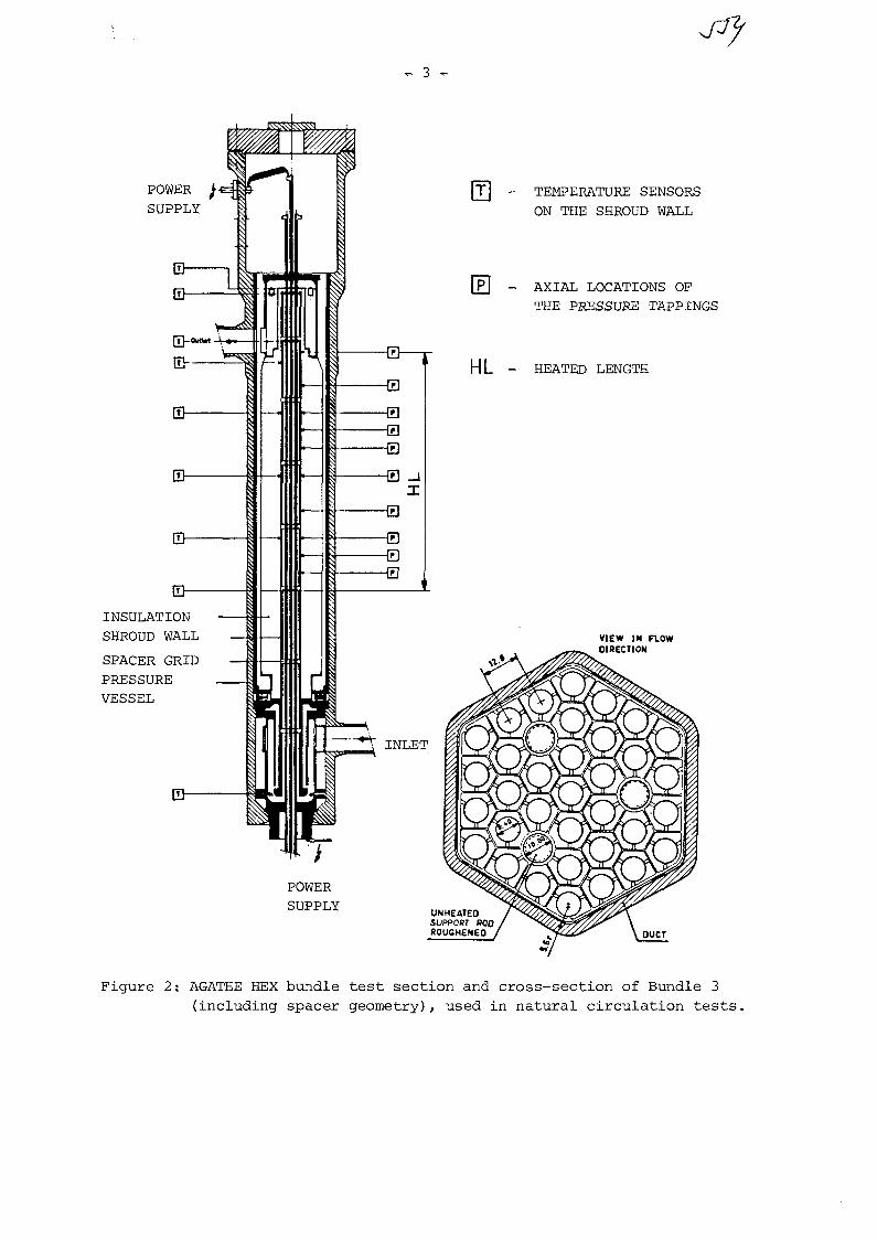
3 -
POWER
SUPPLYTEMPERATURE SENSORS
ON THE SHROUD WALL
AXIAL LOCATIONS OPTHE PRESSURE TAPPINGS
- HEATED LENGTH
INSULATION
SHROUD WALL
SPACER GRIDPRESSUREVESSEL
POWER
SUPPLY
Figure 2: AGATHE HEX bundle test section and cross-section of Bundle 3
(including spacer geometry), used in natural circulation tests.

Jlf— 4 —
3. MEASUREMENTS AND DATA HANDLING
To determine the heat removal capacity of the Loop by natural circulation,runes had been carried out under different system pressure levels, startingfrom vacuum and up to a maximum of 2 MPa. At constant system pressure, themass flow was varied to simulate various situations between blower failureand full isolation of the bundle, using different combinations of valve clo-sure and metering orifices. As a limiting case (isolated bundle) the maininlet valve was closed. The maximum rod temperature was limited to approxi-mately 1000 K. In cases with gas circulation in the whole loop (open maininlet valve) the inlet and outlet gas temperatures (max. 500°C), as well asmaximum cladding temperature, were kept approximately constant. The powerdistribution in the bundle was uniform. For all the tests detailed axial andradial temperature distributions in the bundle were measured and recorded.These data were then used as input for the DRABEX evaluation code which pro-vides a printout of all important information including punched cards as in-put to analytical calculation code. The EIR subchannel analysis computer codeSCRIMP/4/ was used in this investigation.
4. RESULTS
In Fig. 3 the results of the natural circulation heat removal capacity of theAGATHE loop are summarised. The results are strongly influenced by the systempressure but the pressure drop over the section of the loop with built-in ori-fices is also important. 18 % of the nominal heating power can be removed bynatural circulation at nominal system pressure. For the isolated bundle coreand at full system pressure this capacity drops to under 1,5 %, According tothese results it can be assumed that with a suitable arrangement of the pri-mary reactor circuit the residual heat can be removed by natural circulationas long as fast depressurisation of the system and/or extreme blockages ofthe loop free flow area are prevented.
The axial distribution of temperatures for the isolated bundle case is givenin Fig. 4. In contrast to the symmetrical temperature distribution obtainedfor tests under vacuum (heat removal by conduction and radiation only) theinfluence of natural convection in the bundle was clearly observed.
In Fig. 5 the measured and calculated axial temperature distributions for oneparticular run with opened inlet valve is presented. The radial temperaturedistribution (over the bundle cross-section) of this run is given in Fig. 6and 7. The analysis of these results shows that both conduction in the rodsand radiant heat transfer are important heat transfer mechanisms and are tobe included in the analytical models of the codes. The radial temperaturedistributions for one further test run (with maximum mass flow) can be seenin Fig. 8.

- 5 -
In all analysed cases the analytical results slightly overpredict the walltemperatures. Considering that this is on the safe side the predictions canbe judged to be acceptable to fulfil the gas-cooled bundle design accuracyrequirements.
20
Ixl
o0.
5o
oQ-occQ_
15
O 10
t
NOMINAL CONDITIONS :
PRESSURE 2MPa (C02)MAX. ROD SURFACE TEMPERATURE 750°C
PRESSURE DROPOVER VALVE/ORIFICECOMBINATIONMAXIMUM
ISOLATED BUNDLE
1 2— • PRESSURE (MPa)
Figure 3: Cooling capacity of the "AGATHE" test loop with naturalcirculation.
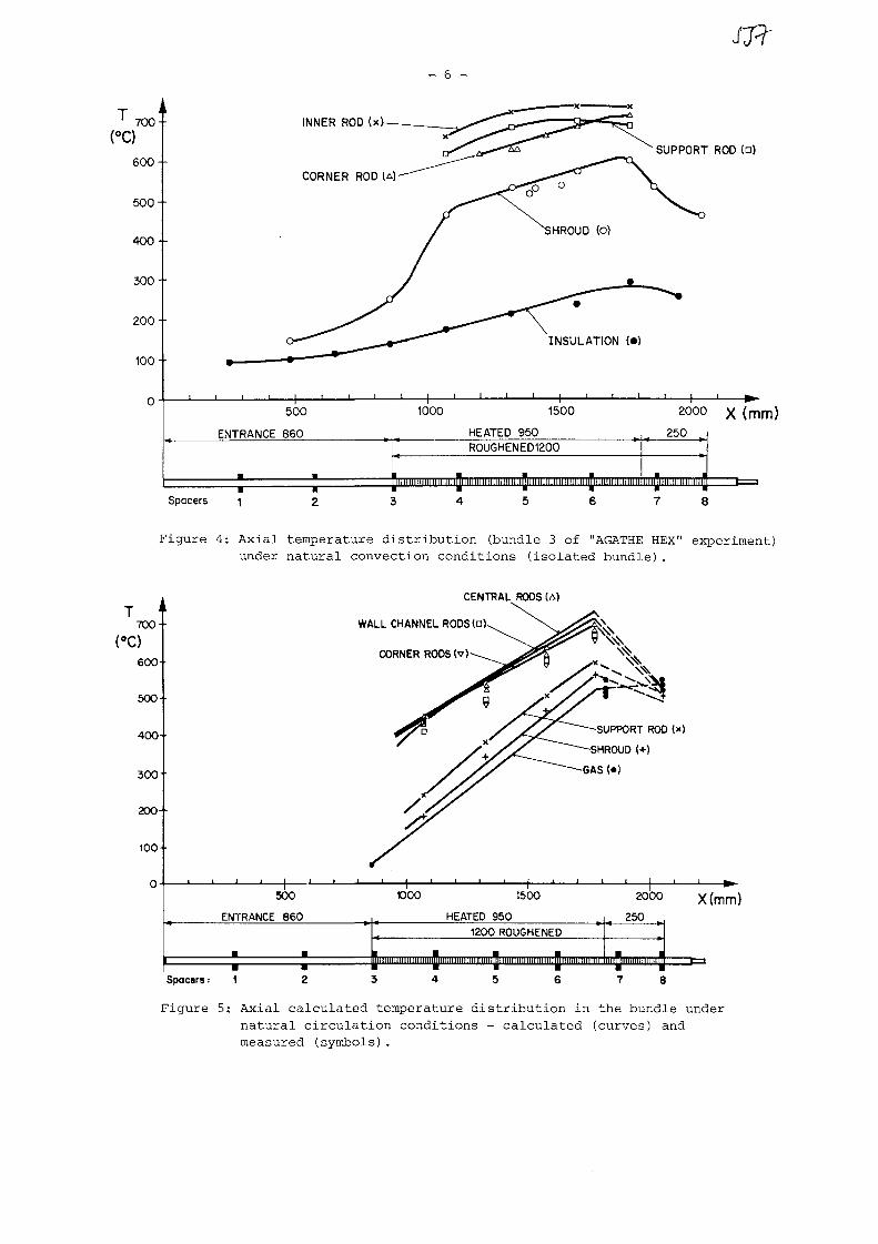
T700 ••
:)
600--
500--
400-•
300
200-•
100-
- 6 -
INNER ROD (x
J7?
SUPPORT ROD {•)
INSULATION (•)
500
ENTRANCE 860
1000 1500
HEATED 950R0UGHENED1200
2000
250
i i m i i n i i i n n i i i n l
(mm)
Spacers 1 2 3 4 5 6 7 8
Figure 4: Axial temperature d i s t r i b u t i o n (bundle 3 of "AGATHE HEX" experiment)under na tu ra l convection condi t ions ( i so la ted bundle ) .
700 ••
:)
600
500-
400-
300-
200--
100 ••
0
CENTRAL RODS (A)
WALL CHANNEL RODS(ak
CORNER RODS(v)-
SUPPORT ROD
HROUD (+)
GAS (•)
500
ENTRANCE 860
Spoors:
1000 1500
HEATED 9501200 ROUGHENED
2000
250
HIM Illlll III HUH III III I I HIM III III M Mil III lit II Illllll 111 II IIIMtlll III Mill Illllltll ••••111 I
8
X(mm)
Figure 5: Axial calculated temperature distribution in the bundle undernatural circulation conditions - calculated (curves) andmeasured (symbols).

jrf- 7 -
a) without consideration ofconduction in the rods andof radiant heat transfer
b) without consideration ofradiant heat transfer
Figure 6: Comparison between measured and calculated temperatures (°c)at the end of heated section (Test run No. 36). Analyticalpredictions are written inside the rods and shroud.

Figure 7: Comparison between measured and calculated temperatures (°c)at the end of heated section (Analytical predictions fortest run No. 36 are written inside the rods and shroud).

- 9 -
Figure 8: Comparison between measured and calculated temperatures ( C) atthe end of heated section (Analytical predictions for testrun No. 35 are written inside the rods and shroud).
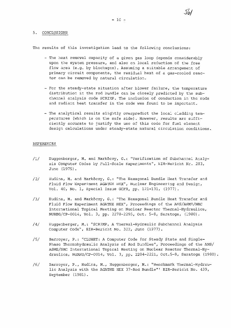
- 10 -
5. CONCLUSIONS
The results of this investigation lead to the following conclusions:
- The heat removal capacity of a given gas loop depends considerablyupon the system pressure, and also on local reduction of the freeflow area (e.g. by blockages). Assuming a suitable arrangement ofprimary circuit components, the residual heat of a gas-cooled reac-tor can be removed by natural circulation.
- For the steady-state situation after blower failure, the temperaturedistribution in the rod bundle can be closely predicted by the sub-channel analysis code SCRIMP. The inclusion of conduction in the rodsand radiant heat transfer in the code was found to be important.
- The analytical results slightly overpredict the local cladding tem-peratures (which is on the safe side). However, results are suffi-ciently accurate to justify the use of this code for fuel elementdesign calculations under steady-state natural circulation conditions.
REFERENCES
/I/ Huggenberger, M. and Markdczy, G,; "Verification of Subchannel Analy-sis Computer Codes by Full-Scale Experiments", EIR-Bericht Nr. 283,June (1975) .
/2/ Hudina, M. and MarkSczy, G.: "The Hexagonal Bundle Heat Transfer andFluid Flow Experiment AGATHE HEX", Nuclear Engineering and Design,Vol. 40, No. 1, Special Issue GCFR, pp. 121-131, (1977).
/3/ Hudina, M. and Mark6czy, G.: "The Hexagonal Bundle Heat Transfer andFluid Flow Experiment AGATHE HEX", Proceedings of the ANS/ASME/NRCInternational Topical Meeting on Nuclear Reactor Thermal-Hydraulics,NUREG/CP-0014, Vol. 3, pp. 2278-2295, Oct. 5-8, Saratoga, (1980).
/4/ Huggenberger, M.: "SCRIMP, A Thermal-Hydraulic Subchannel AnalysisComputer Code", EIR-Bericht No. 322, June (1977).
/5/ Barroyer, P.: "CLUHET: A Computer Code for Steady State and Single-Phase Thermohydraulic Analysis of Rod Bundles", Proceedings of the ANS/ASME/NRC International Topical Meeting on Nuclear Reactor Thermal-Hy-draulics, NUREG/CP-0014, Vol. 3, pp. 2204-2221, Oct.5-8, Saratoga (1980)
/6/ Barroyer, P., Hudina, M., Huggenberger, M.: "Benchmark Thermal-Hydrau-lic Analysis with the AGATHE HEX 37-Rod Bundle"' EIR-Bericht No. 439,September (1981) .
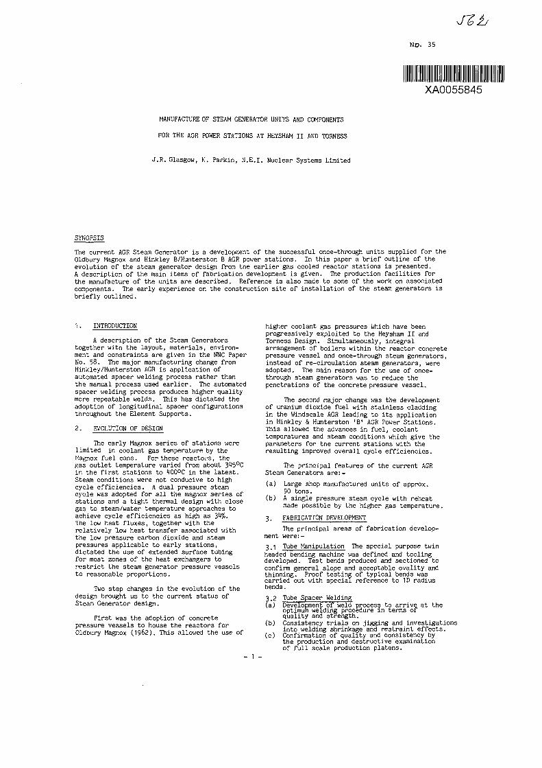
JZb
No. 35
XA0055845
MANUFACTURE OF STEAM GENERATOR UNITS AND COMPONENTS
FOR THE AGF POWER STATIONS AT HEYSHAM II AND TORNESS
J.R. Glasgow, K. Parkin, N.E.I. Nuclear Systems Limited
synopsis
The current AGR Steam. Generator is a development of the successful once-through units supplied for theOldbury Magnox and Hinkley B/Hunterston B AGR power stations. In this paper a brief outline of theevolution of the steam generator design from the earlier gas cooled reactor stations is presented.A description of the main items of fabrication development is given. The production facilities forthe manufacture of the units are described. Reference is also made to some of the work on associatedcomponents. The early experience on the construction site of installation of the steam generators isbriefly outlined.
1. INTRODUCTION
A description of the Steam Generatorstogether with the layout, materials, environ-ment and constraints are given in the NNC PaperNo. 58. The major manufacturing change fromHinkley/Hunterston AGR is application ofautomated spacer welding process rather thanthe manual process used earlier. The automatedspacer welding process produces higher qualitymore repeatable welds. This has dictated theadoption of longitudinal spacer configurationsthroughout the Element Supports.
2. EVOLUTION OF DESIGN
The early Magnox series of stations werelimited in coolant gas temperature by theMagnox fuel cans. For these reactors, thegas outlet temperature varied from about 3^5°Cin the first stations to 400°C in the latest.Steam conditions were not conducive to highcycle efficiencies. A dual pressure steamcycle was adopted for all the magnox series ofstations and a tight thermal design with closegas to steam/water temperature approaches toachieve cycle efficiencies as high as J,k%.The low heat fluxes, together with therelatively low heat transfer associated withthe low pressure carbon dioxide and steampressures applicable to early stations,dictated the use of extended surface tubingfor most zones of the heat exchangers torestrict the steam generator pressure vesselsto reasonable proportions.
Two step changes in the evolution of thedesign brought us to the current status ofSteam Generator design.
First was the adoption of concretepressure vessels to house the reactors forOldbury Magnox (1962). This allowed the use of
higher coolant gas pressures which have beenprogressively exploited to the Heysham II andTorness Design. Simultaneously, integralarrangement of boilers within the reactor concretepressure vessel and once-through steam generators,instead of re-circulation steam generators, wereadopted. The main reason for the use of once-through steam generators was to reduce thepenetrations of the concrete pressure vessel.
The second major change was the developmentof uranium dioxide fuel with stainless claddingin the Windscale AGR leading to its applicationin Hinkley & Hunterston 'B' AGR Power Stations.This allowed the advances in fuel, coolanttemperatures and steam conditions which give theparameters for the current stations with theresulting improved overall cycle efficiencies.
The principal features of the current AGRSteam Generators are:-
(a) Large shop manufactured units of approx.90 tons.
(b) A single pressure steam cycle with reheatmade possible by the higher gas temperature.
3. FABRICATION DEVELOPMENT
The principal areas of fabrication develop-ment were:-
3.1 Tube Manipulation The special purpose twinheaded bending machine was defined and toolingdeveloped. Test bends produced and sectioned toconfirm general slope and acceptable ovality andthinning. Proof testing of typical bends wascarried out with special reference to ID radiusbends.
3.2 Tube Spacer Welding(a) Development of weld process to arrive at the
optimum welding procedure in terms ofquality and strength.
(b) Consistency trials on jigging and investigationsinto welding shrinkage and restraint effects.
(c) Confirmation of quality and consistency bythe production and destructive examinationof full scale production platens.
- 1 -

U. SHOP MANUFACTURETHMLEY 'B' & HUNTERSTON 'B1
A decision was taken some eighteen yearsago to assemble the steam generators forHinkley 'B1 and Hunterston 'B' AGR PowerStations in the works to standards of clean-liness that would comply in full withrequirements for plant in nuclear installations.In addition, the Units were much larger thanhad previously been attempted and thusproduction facilities were critically reviewedresulting in conversion of the existingmanufacturing areas to provide the capabilityto produce the A.G.R. boiler units to thesestandards.
The main production areas were, tubebending, tube butt welding, welding of tubesupports, heat treatment, testing and finalassembly.
Ferritic materials were kept separate butfabricated in parallel with austenitic materialsand the principal innovation was theintroduction of mechanised argon arc tube buttwelding.
Tubes were first welded into long lengths(up to 30 metres), using fixed head argon arcwelding machines, prior to bending intoserpentine sub flow path form. Many of thetube bends were made to a mean radius dimensionequal to one tube diameter.
Sub platens were produced by welding thesub flow paths together using orbital argon arcwelding machines and all butt welds were subjectto radiographic examination.
The sub platens were then made into platensby the attachment of many small spacers acrossthe tubes using manual C02 MIG Dip Transfer.
The platens were then heat treated in anelectric inert gas 'Top Hat1 furnace followedby hydraulic test and a whole surface leak test.Where necessary the ferritic steel platens werecleaned in a special acid cleaning plant priorto transfer into the clean conditions shop whereelement assembly and loading was carried out.
The units were all delivered to site byApril/May 1971, and then there was a long pauseuntil early 1978 when A.G.R. stations atHeysham II and Torness were announced.
5. SHOP MANUFACTUREHEYSHAM II & TORNESS
The production facilities were re-established along the lines already describedbut a large production investment was made tointroduce advanced manufacturing techniques and'A boiler assembly line1 was born.
It had earlier been recognised that nuclearboiler platen manufacture had many features ofrepeatability. For two power stations some12,288 platens are required, subsequently to befurther joined together to make 2112 main boiler
elements, 2112 decay heat elements and 1728reheater elements. Some 116,000 butt welds jointhe tubes together; the platen tubes aresupported and separated by small spacers acrossthe tubes, requiring approx. 8.48 million spacer/tube welds. (Figs.la, 1b, 1c).
Taking into account the advances made inmanufacturing technology, N.E.I. Nuclear Systemsset out to plan and install a small batch/flowline manufacturing capability using some of thetechniques established in earlier A.G.R^programmes. However, significant changesinvolved the introduction of:-
(i) improved fixed and orbital head weldingmachines.
(ii) C.N.C. bending,(iii) robotic spacer/tube welding,(iv) computer controlled inert gas atmosphere
stress relieving furnace.
The above processes take place prior to entryinto the Clean Condition final assembly area butthe manufacturing environment was raised to a levelof control designed to avoid any acid cleaningand thus ensure maintenance of cleanliness up totransfer to clean conditions.
6. A BOILER ASSEMBLY LINE
Raw tubes are fed onto a tube end preparationfacility - incorporating cutting and finishingmachines, (separate machines are used for ferriticand austenitic tubes). They are them moved to amechanical handling system (Fig. 2) for buttwelding into total lengths of 42 metres usingFixed Head TIG welding machines (Fig. 3) whichwere designed and manufactured by N.E.I. NuclearSystems. The mechanical handling system thentransports the tube across the shop through anN.D.T. station onto the bending machine conveyor.The C.N.C. bending machine can bend up to 90 mmdiameter left and right-hand and the completedsub flow path can have as many as 16 bends,(Fig. t). The radius of bend can be as small asone tube diameter with close control on ovalityand thinning.
The sub flow paths from the bending machineare jig assembled for orbital welding, employinga 'U' head orbital TIG welding machine (Fig. 5)developed and manufactured in house. Theequipment incorporates a weld programmablesequencer and arc voltage control, allowing afully automatic weld of high quality andconsistancy.
To weld the tube spacers, a fully automaticmethod has been developed incorporating robots.General views of the installation are shown inFig. 6 & 7.
It is fundamental to the design of theboilers that consistant high quality of weldsis produced. In this case the quality isdependent on:-
(a) consistancy of dimensions of tubes and spacers,(b) consistancy/repeatability of the equipment
employed.
- 2 -

The system is divided into three distinctsections:-
(a) The welding jig.(b) The weld torch positioning system.(c) The welding equipment.
The function of the jig is to position thetube and spacer consistantly in relation to thewelding torch positioning system.
This latter system employs a gantry runningalong a track. Suspended from each gantry aretwo inverted robots, each carrying a weldingtorch.
The welding equipment is based on the MIG/MAG process backed up by improvements in theform of electronic power sources, better wirefeed units and redesigned welding torches.
The workpiece is loaded into a Tube Clamp-ing Frame, and the tubes clamped into position.This ensures correct tube pitching. The frameis then lowered onto a fixed master base andlocated accurately by holes in each corner ofthe frame, which sits onto dowels attached tothe base. The jig master base is fixed in apermanent position on the gantry bed. Besidesthe location dowels the base has numerousfinger devices to receive and hold the spacersin accurately known positions. The spacersare loaded off line, into a magazine which isbasically a rotating barrel with 'pockets' forholding individual spacers. The magazine whichis on wheels is located on the master base.Individual rows of spacers are then loaded bylowering the magazine towards the workpiece.The master base fingers are then actuated andthe magazine raised leaving the spacers inposition for welding. The magazine is thenmoved across the base and each row of spacersloaded. The magazine is removed from the baseand the platen is ready for welding.
The range of weld torch positions islimited by robot reach and is optimised by acombination of gantry and robot movementsallowing full traverse of the workpiece.
The gantries are programmed to stop at anyrequired position along the track. Hence eachrobot is programmed to carry out the desiredwelding sequence associated with that trackstop position.
In more detail the gantry is griven to any-one of a number of pre-determined positions onthe gantry runway. Associated with each ofthese gantry positions is the appropriateprogramme for moving the robots (and hence thewelding torch), through the required weldingpath at the required speed. All positioningand movement of the gantry and robots has to beindividually programmed.
The welding parameters, e.g., current, arcvoltage, wire feed speed, shroud gas flow andthe timing of any changes in these parametersrequired to weld a specific spacer configurationare programmed into a sub routine which can be
called up whenever it is required. Differentspacer geometries have their own individual sub-routines.
Before commencement of platen welding atest piece is welded and the weld examined forshape and penetration. If accepted the gantryis moved to the first position, the appropriatewelding parameter sub routine is called up andwelding is commenced. The two robots then weldall of the spacers within their operating, range.On completion the gantry indexes to a newposition and the process is repeated.
The sequence of indexing and welding iscontinued until the first side is fully welded.
"he second side master base will be alreadyloaded with a platen previously welded on thefirst side. The gantry is moved, to this baseand the whole process recommenced. In thisway the gantry can be kept in continuousproduction.
Four interacting computers control theoperations:-
(a) Robot microprocessors.(b) Gantry mini computer.(c) Weld programmable controller.(d) Memory extension mini computer.
The installation is believed to be one ofthe most advanced applications of robotic weld-ing in the world and todate almost sevenmillion welds have been produced.
7. HEAT TREATMENT
On completion, the boiler platens aresubject to post fabrication heat treatment torelieve stress and restore properties affectedby bending and welding operations. But goodsurface condition of the tubes has to bepreserved to meet the stringent engineeringrequirements. The heat treatment is carriedout in an electric 'Top Hat' furnace whichhas facility for air evacuation prior to fillingwith nitrogen to provide an inert atmospherewith less than 7 parts per million oxygen andwith a dew point of the order of minus 25°C.The furnace is computer controlled can beoperated up to 1060°C and the load can berapidly cooled by circulating the nitrogenthrough integral heat exchangers.
There are two loading bays to allow thecompleted load to be removed from the hearthand a fresh one returned to the furnace withoutdisruption. The loading bays are shown inFig. 8. The furance is in the background.
8. ASSEMBLY OF ELEMENTS
The four platens designated, economiser,lower chrome, upper chrome and superheater arejoined, together via six tube butt welds to forman element. The economiser 5% Cr. transitionpiece is joined to the 9% Cr. lower platen, thelower to upper plates are 9% Cr. throughout andthe upper chrome platen is joined to the 'Inconel'
3 ~

transition piece on the Superheater. Thislatter transition piece already incorporatesa 9% Cr. stub allowing like materials to bewelded to complete the element.
These six welds are ultrasonicallyexamined followed by heat treatment usinglocalised heating elements.
The completed element is 'balledthrough' then hydraulically tested. This testfacility (Fig 9) takes one element at a timesupported on a manipulator to assist fillingand emptying of the deionised water. It alsoallows positioning at any elevation forinspection.
Drying is carried out by blowing drynitrogen through the tube bores after whicha whole surface leak test is performed. Theelements are enclosed in a large box (Fig 10)which is provided with helium gas under slightpressure. Gas samples are taken from eachtube flow path under vacuum conditions andanalysed for traces of helium using a massspectrometer. The element is given a finalclean followed by inspection and thentransferred via a bogie to the cleanconditions area.
9. ASSEMBLY OF BOILER UNITS
The objective of keeping site work to aminimum requires assembly of the boiler unitsin permanent workshops large enough to handlecompleted units and under appropriate cleanconditions.
The facility at Gateshead is 20 metreswide by 18 metres high by 130 metres long andis equipped with two 50 ton overhead non dripcranes. The cranes can be synchronised tolift up to 100 tons with control from onecrane only.
The shop has a sealed floor and isinternally lined to maintain clean conditions.Air conditioning plant provides a slightlypressurised heated atmosphere within thearea to prevent ingress of dirt and moistureand to limit relative humidity to less than50%. In addition to the element transferroller shutter door, a large steel panelledair lock is provided with removable roofsection to allow entry of large componentse.g. casing plates and the despatch ofcompleted Boiler Units. Man access iscontrolled through a manned security gateand is provided through changing rooms andmess rooms which adjoin the shop.
Assembly begins by setting out onecasing side in the horizontal position togetherwith the main tube bank support members toform a jig frame. The elements are thentransferred using a special handling frameover the jig and lowered onto the casingstructure and located in position by meansof permanent tube element support attach-ments and spacers to the casing structural
beams and ties. At the same time a decay heatplaten is loaded into position alongside each mainunit element. This assembly process is repeateduntil 22 elements are in position at which pointthe acoustic baffle is lowered into position andsecured. Figs.11a. 4 11b show units at differentstages of assembly.
A further 22 elements are then assembled tocomplete the sequence. The decay heat elements arewelded to manifolds and the top casing is thenlowered into position and connected to the internalstructural beam and tie members. The two sidecasings are now positioned, clearances checked thenbolted and seal welded. Temporary steel covers arefitted to each end permitting visual inspection ofthe tube surface condition through an integralobservation window which houses a calibratedhygrometer. The unit and tubes are purged andfilled with dry nitrogen, lifted (Fig. 12) andtransferred through the air lock (Fig.13) ontotransportation for delivery to site.
A nitrogen purge gas unit is despatched witheach boiler unit to make good for any nitrogenleakage and thus adjust the internal relativehumidity should this be necessary. Fig. 11 providesa view of a unit leaving the factory.
The reheater section is assembled by buildingthe containment casing and loading it with 36stainless steel elements separated at mid point byan acoustic baffle plate. The elements arepositioned, tied and locked as described earlierfor the main unit. Two stainless steel headersare set up relative to the reheater elements andalso lined up radially to match the shield wallpenetration to which they are eventually joined.
Assembly continues by welding 1tH tailpipesbetween the elements and stubs on the headers.Each weld which is manually made by the T.I.C.process is ultrasonically examined and leak testedusing helium mass spectrometry. A general viewof the assembly area is shown in Fig. 15.
The completed unit is upended for transportationprovided with temporary covers and purged in asimilar manner to the Main Unit for despatch to site(Figs. 16 & IT).
10. ASSOCIATED COMPONENTS
Various components which connect or support theheat exchangers are being produced within the N.E.I.group and at other companies.
Penetrations associated with the Economiser Feed,Decay Heat, Superheater, Reheater and Instrumentationare being manufactured to standards and controlsalready described above. Automated welding techniquesare utilised wherever possible and stringentinspection criteria are being complied with.
The manufacture of the headers and pipework forreheater and superheater sections however currentlyutilise a high degree of manual processes whichrequire great attention to the training, qual-ification and performance of individual craftsmen.Development work is, however progressing, aimed at
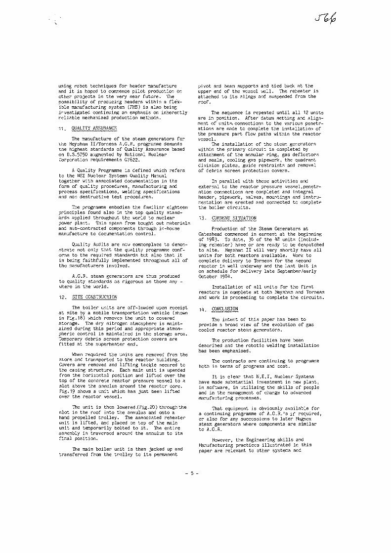
using robot techniques for header manufactureand it is hoped to commence pilot production onother projects in the very near future. Thepossibility of producing headers within a flex-ible manufacturing system (FMS) is also beinginvestigated continuing an emphasis on inherentlyreliable mechanised production methods.
11. QUALITY ASSURANCE
The manufacture of the steam generators forthe Heysham II/Torness A.G.R. programme demandstne highest standards of Quality Assurance basedon B.S.5750 augmented by National NuclearCorporation requirements G7622.
A Quality Programme is defined which refersto the NEI Nuclear Systems Quality Manualtogether with associated documentation in theform of quality procedures, manufacturing andprocess specifications, welding specificationsand non destructive test procedures.
The programme embodies the familiar eighteenprinciples found also in the top quality stand-ards applied throughout the world to nuclearpower plant. This spans from bought out materialsand sub-contracted components through in-housemanufacture to documentation control.
Quality Audits are now commonplace to demon-strate not only that the quality programme conf-orms to the required standards but also that itis being faithfully implemented throughout all ofthe manufacturers involved.
A.G.R. steam generators are thus producedto quality standards as rigorous as those any -where in the world.
12. SITE CONSTRUCTION
The boiler units are off-loaded upon receiptat site by a mobile transportation vehicle (shownin Fig.18) which removes the unit to coveredstorage. The dry nitrogen atmosphere is maint-ained during this period and appropriate atmos-pheric control is maintained in the storage area.Temporary debris screen protection covers arefitted at the superheater end.
When required the units are removed from thestore and transported to the reactor building.Covers are removed and lifting tackle secured tothe casing structure. Each main unit is upendedfrom the horizontal position and lifted over thetop of the concrete reactor pressure vessel to aslot above the annulus around the reactor core.Fig.19 shows a unit which has just been liftedover the reactor vessel.
The unit is then lowered (Fig.2.0) through theslot in the roof into the annulus and onto ahand propelled trolley. The associated reheaterunit is lifted, and placed on top of the mainunit and temporarily bolted to it. The entireassembly is traversed around the annulus to itsfinal position.
The main boiler unit is then jacked up andtransferred from the trolley to its permanent
pivot and beam supports and tied back at theupper end of the vessel wall. The reheater isattached to its slings and suspended from theroof.
The sequence is repeated until all 12 unitsare in position. After datum setting and align-ment of units,connections to the various penetr-ations are made to complete the installation ofthe pressure part flow paths within the reactorvessel.
The installation of the steam generatorswithin the primary circuit is completed byattachment of the annular ring, gas deflectorsand seals, cooling gas pipework, the quadrantdivision plates, guide restraints and removalof debris screen protection covers.
In parallel with these activities andexternal to the reactor pressure vessel,penetr-ation connections are completed and integralheader, pipework, valves, mountings and instru-mentation are erected and connected to completethe boiler circuits.
13- CURRENT SITUATION
Production of the Steam Generators atGateshead commenced in earnest at the beginningof 1983. To date, 36 of the 18 units (includ-ing reheater) have or are ready to be despatchedto site. Heysham II will very shortly have allunits for both reactors available. Work tocomplete delivery to Torness for the secondreactor is well underway and the Last Unit ison schedule for delivery late September/earlyOctober 1981.
Installation of all units for the firstreactors is complete at both Heysham and Tornessand work is proceeding to complete the circuits.
1H. CONCLUSION
The intent of this paper has been toprovide a broad view of the evolution of gascooled reactor steam generators.
The production facilities have beendescribed and the robotic welding installationhas been emphasised.
The contracts are continuing to programmeboth in terms of progress and cost.
It is clear that N.E.I. Nuclear Systemshave made substantial investment in new plant,in software, in utilising the skills of peopleand in the management of change to advancedmanufacturing processes.
That equipment is obviously available fora continuing programme of A.G.R.'s if required,or also for any successions to later Magnoxsteam generators where components are similarto A.G.R.
However, the Engineering skills andManufacturing practices illustrated in thispaper are relevant to other systems and
- 5 -

ffl
indeed to other industrial projects to whichthey could be adapted in line with customerrequirements.
ACKNOWLEDGEMENTS
The authors wish to thank the Managementof N.E.I. Nuclear Systems for permission toproduce this paper and to those colleagues whoprovided assistance in the preparation of thepaper.
- 6 -
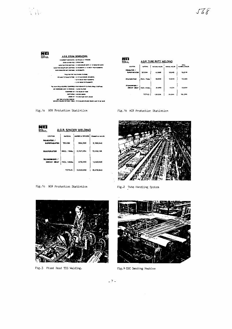
NElA.G.R. STEAM GENERATORS
aftmn co»tnuCT». KVMAM • * TOTMM
UOt •nnOM MU -1 M
t * O * MAM tOUM UWT CaWIM* • M CLCMCKTt * «4 MC&T t^
TMJ» FON Tt* two ram IT*TWN«
Wf H*M TO K U W M K N • t.Ml UAM H U
• 1.111 MCAT MA
tetmmitx or • n » t u i e# T
N E lA.G.R. TUBE BUTT WELDING
UKATOt
MHUTM /
CVAMMMTOA
43,94*
SO.65S
MAMLUL MlDt
18,0* »
12.672
fig.1a AGR Production Statistics Fig.1b AGR Production Statistics
MElA.G.FL SPACER WELDING
••HMTn /
tUHIIHUTn
EVAPORATOR
•COHOMtU /
H C U MAT
2,108,018
1,030,858
Fig.ic AGR Production Statistics t'ig.2 Tube Handling System
Fig.3 Fixed Head TIG Welding. Fig.4 CNC Bending Machine
_ 7 -
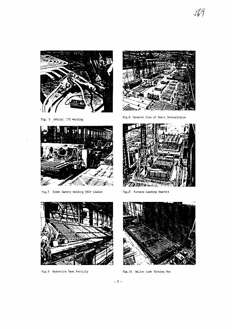
Fig. 5 . Grbita.l TIG WeldingFig.6 General View of Robot Installation
Fig.7 Robot Gantry Welding 9%Cr platen Fig.8 Furnace Loading Hearths
Fig.9 Hydraulic Test Facility Fig.10 Helium Leak Testing Box

f i g . 11a Main Unit assembly in c.l?nn aren. Fig.11b Main Unit assembly in clean area.
Fig.12 Main Unit being l i f t e d . Fig.13 Main Unit being lowered into Airlock.
Fig.1t [-rain Unit leaving Factory
- 9 -

No. 36
S U L Z E R II III III III II11IIXA0055846
IAEA Specialist's Meeting on Heat Exchanging Components of Gas-
Cooled Reactors
Dvisseldorf, 16 - 19 April 1984
THE USE OF BIMETALLIC WELDS IN THE THTR STEAM GENERATORS
U. Blumer, H. Fricker, S. Amacker, SULZER BROTHERS Ltd. Winterthur
1. Introduction
Heat exchanger tubes that operate in the elevated temjterature re-
gion often have to be designed in two qualities of material. The
part which has relatively low tube wall temperatures can be de-
signed with the use of a ferritic material for economical rea-
sons. At a certain temperature level of the wall however, the
creep strength and the stability of this material are no longer
sufficient, and an austenitic tube material has to be provided
for the higher temperature section of the heat exchanger bundle.
This paper deals with welds between the two tubing sections, with
emphasis on their application in the Thorium High Temperature Re-
actor (THTR) steam generators (Fig. 1).
While the tubing of heat exchanger equipment in general needs ca-
reful design to withstand a number of different loading types,
the use of bimetallic welds (BMW) requires special attention to
prevent it from becoming a weak spot in the design.
2. Description of weld
Fig. 2 shows such a weld. The tube dimensions are 25 mm OD and
3.2 mm wall thickness on both sides. The ferritic side is made
of the material 10 Cr Mo 910, a steel containing 21/4 % chromium

SULZER - - -
and 1 % molybdenuin. The austenitic side consists of the alloy
800, a steel with 32 % nickel, 2 0 % chromium and additions of
Ti and Al. The welding is accomplished by TIG using a weld fil-
ler metal in the form of an insert ring. This intermediate ma-
terial is a nickelbase alloy with 20 % chromium,with molybdenum
and Niobium. The high nickel content of this intermediate layer
acts as a barrier for carbon migration and therefore prevents
the decarburization of the ferritic tube.
The welds were heat-treated at 730 °C in order to reduce the
hardness of the ferrite and the residual welding stresses.
3. Locating the weld
For the location of the weld within the heat exchanging surface,
there are reasons to go to higher temperatures and others for
lower temperature. The following considerations show the deter-
mination of an optimum temperature level for the selection of
the proper position of the weld.
Fig. 2 shows the distribution of the wall temperatures along the
tube length for minimum (40 %) and maximum (100 %) power level.
Reasons for selecting higher temperature are:
- saving material costs (non technical)
- the BMW and the following austenitic tubes should not experi-
ence wetting.by evaporating water, as this might cause inter-
cristalline stress corrosion cracking in the alloy 800. There-
fore the location should be well above the vaporization tempe-
rature.

SULZER- 3 -
However, reasons for upper limits of wall temperatures are:
- the creep strength of the ferritic material.
- diffusion of carbon from ferritic to austenitic material,
which could cause a weakened decarbonized zone in the ferrite
near the weld.
- the strain range due to the different coefficients of expansion
increase with the temperature range that the weld experiences.
This might affect fatigue life in addition to the generally re-
duced fatigue strength at higher temperatures.
The distance from the evaporation points is governed by the full
load condition, as can be seen
above evaporation temperature.
load condition, as can be seen in fig. 3. It should be 29 °C
At the chosen location a maximum wall temperature of 526 °C can
be reached at 40 % load. This inculdes 31 °C for deviation from
the ideal, calculated condition. This temperature is well below
the 550 C which we consider as an upper limit. This comes from
experiences that have been gained from failures in the heat-affec-
ted zone of the ferrite above this temperature, as well as from
carbon migration measurements.
4. Tests with THTR welds
Corrosion tests have been performed in order to check the sus-
ceptibility against stress corrosion cracking. Under the applied
stress of 2/3 yield stress at 1 % strain, we did not find any
ruptures.
In addition, fatigue tests have been performed that combine ther-
mal shock with temperature load cycling. The thermal shock stress
is caused by a radial temperature gradient in the tube wall, that

SULZER - 4 -
arises from rapidly cooling the tube inner surface. The tempera-
ture level cycling from ambient temperature to 550 °C and back
causes stresses that have their origin in the different thermal
expansion of the two joining materials.
The following two types of thermal fatigue tests have been per-
formed {fig. 4):
The first test is a long duration cycling with one hour hold time
at 550 C. The thermal gradient across the wall, which is produ-
ced by air cooling after the holdtime, causes a calculated gra-
dient stress of only 54 MPa. Together with the strain range due
to the temperature level cycling, this loading did not have a fai-
lure in 23'000 cycles totalling 35'000 hours of test duration.
The second fatigue tests are short term tests where the specimens
are heated to only 500 C and water quenched. Figure 5 shows the
induction coil configuration for the rapid homogeneous heating of
the weld region. 36*000 cycles were performed without producing
any cracks on the inner or outer tube surface. Fig. 6 shows the
quenching temperatures as a function of time and the maximum
stress that occurs after about 0.5 sec. The comparison of the cal-
culated superimposed stress with fatigue curves showed that the
allowable stresses were exceeded by a factor of 2 and the allow-
able cycles by a factor of 15, respectively. As these factors are
about equal to the inherent safety factors in the fatigue curves,
we can draw the conclusions that the weld behaves as well as the
parent material and can be evaluated for fatigue damage by the
same curves.
5. Stress analysis for the licensing procedure
In the real surrounding of the THTR steam generators the region
of the tube bimetallic weld is subject to a number of loadings
that have to be considered in the design and the analysis. Fig. 7

SULZER S
shows the different kinds of loadings that affect the behaviour
of the weld, in the sequence of their importance on a basis of
calculated stress.
In the following, the evaluation of the stresses for the diffe-
rent loadings is presented in more detail.
Only the conditions at full load are adressed here for simplicity,
although for a complete analysis all relevant operational states
(including transient) have to be considered.
5.1 Thermal gradients
The thermal gradients that are caused by the heat transfer through
the tube walls, have the following values which include a nonuni-
form gas side heat transfer around the circumference: 36 on the
ferrite side and 56 on the austenitic side. The maximum occuring
stresses on the inside of the tube are 73 and 161 MPa respectively.
The higher expansion coefficient and the lower conductivity of the
alloy 800 lead to that much higher stresses.
5.2 Bimetallic thermal stress
The calculation of the stresses due to the different thermal ex-
pansion, assuming constant temperature, is a considerable task,
that has been attempted in different ways in the past. Among the
main problems is the lack of knowledge about the distribution of
the material properties in the weld region.
There are three different basic materials, from the two joining
tubes and the weld filler metal. Through welding, intermediate
alloys are formed, the properties of which are poorly defined
for detailed analysis.

SULZER ~ 6 -
Finite element analyses often have the drawback that they show
singularities at material interfaces and the results are there-
fore dependent on mesh refinement.
In view of these difficulties we consider a simple hand calcu-
lation approach as a sufficient and as the most efficient way
to arrive at the proper order of magnitude of the stresses.
We used thin shell analysis assuming a sudden transition bet-
ween the parent metals. This is a conservative assumption as
the filler metal has properties that are approximately in bet-
ween.
The resulting maximum stresses amount to 115 MPa.
5.3 Thermal tube bending
In ref. (1), the calculation of thermal bending moments in tubes
of helical bundles has been explained and shall not be repeated
here. Due to different temperatures of bundle tubes and support
plates as well as due to nonlinear thermal expansion of the tubes
as a function of bundle height, bending moments are exerted on
the tubes. Fig. 8 shows an additional detailed analysis model
that was used for the assessment of the maximum bending moment.
The calculated stress due to thermal bending at full load was
calculated to be 69 MPa.
However, special consideration was given to the fact, that tubes
can show a phenomenon called "elastic-follow-up" which results
in strain accumulation at the support points. An inelastic ana-
lysis of a pipe segment has shown, that the inelastic strain accu-
mulation can be assessed by multiplying the elastic strain by a
factor of 2.6 for this geometry, material and temperature level,
and in the absence of other loadings.
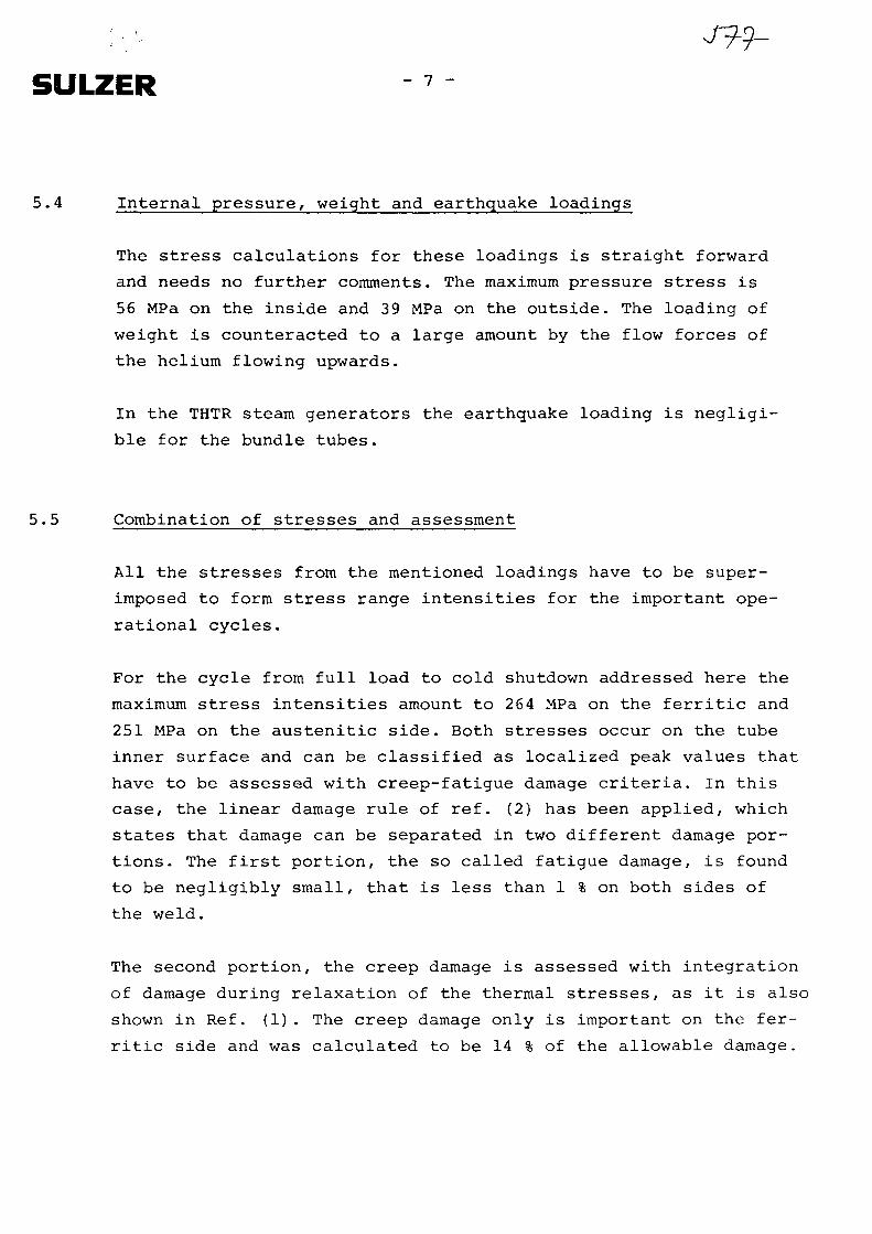
: •.. •• J99-
SULZER 7
5.4 Internal pressure, weight and earthquake loadings
The stress calculations for these loadings is straight forward
and needs no further comments. The maximum pressure stress is
56 MPa on the inside and 39 MPa on the outside. The loading of
weight is counteracted to a large amount by the flow forces of
the helium flowing upwards.
In the THTR steam generators the earthquake loading is negligi-
ble for the bundle tubes.
5.5 Combination of stresses and assessment
All the stresses from the mentioned loadings have to be super-
imposed to form stress range intensities for the important ope-
rational cycles.
For the cycle from full load to cold shutdown addressed here the
maximum stress intensities amount to 264 MPa on the ferritic and
251 MPa on the austenitic side. Both stresses occur on the tube
inner surface and can be classified as localized peak values that
have to be assessed with creep-fatigue damage criteria. In this
case, the linear damage rule of ref. (2) has been applied, which
states that damage can be separated in two different damage por-
tions. The first portion, the so called fatigue damage, is found
to be negligibly small, that is less than 1 % on both sides of
the weld.
The second portion, the creep damage is assessed with integration
of damage during relaxation of the thermal stresses, as it is also
shown in Ref. (1). The creep damage only is important on the fer-
ritic side and was calculated to be 14 % of the allowable damage.

SULZER 8
Calculations have also been done to demonstrate the absence of
ratchetting, which means the accumulation of strain due to repea-
ted cyclic loadings. The elastic-follow-up effects mentioned ear-
lier have been taken into account to show the adequacy of the de-
sign.
6. Conclusions
We have tried to assess the behaviour of the weld by the follo-
wing different approaches:
- design considerations towards proper operational temperature
location
- tests to show the adequacy in corrosion and fatigue behaviour
- detailed analysis of the combined effect of all loadings and
operational cycles.
The results of this work have shown an adequate behaviour of these bi-
metallic welds in the THTR steam generators.
References
"Analysis of heat exchanger bundles operated at eleva-
ted temperatures", U. Blumer, Specialist's Meeting on
Process Heat Applications Technology, IAEA, 1979.
ASME Boiler and Pressure Vessel Code, Code Case N-47-12

SULZER
fe
11
-12
1m
-13
i '
Schnitt durch eine Dampferzeugereinheit zum300-MWe-THTR-Prototyp-KernkraftwerkSchmehausen, BRD
1 Äußerer Abschluß2 Innerer Abschluß3 Zwischenüberhitzer-Dampfaustritt 535°C, 49bar4 Dehnzone5 Hochdruckdampf-Austritt 550 °Cr 186 bar6 Spannbetonbehälter-Durchdringung7 Zwischenüberhitzer-Dampfeintritt 365 °C8 Speisewassereintritt 180 °C9 Kernrohr
10 Heliumaustritt 250 °C11 HD-I-Bündel12 Dampferzeugerhemd13 HD-Il-Bündel14 Zwischenüberhitzer-Bündel15 Heliumeintritt 750 °C
Sectional view of a steam generator unit for the300-MWeTHTR prototype nuclear power stationSchmehausen, FRG
1 Outer closure2 Inner closure3 Reheater steam outlet 535 °C, 49 bar4 Expansion modulus5 HP steam outlet 550°C, 186 bar6 Prestressed concrete vessel penetration7 Reheater steam inlet 365 °C8 Feed-water inlet 180 °C9 Central column
10 Helium outlet 250°C11 HP-l-bundle12 Outer shroud13 HP-ll-bundle14 Reheater bundle15 Helium inlet 750°C
Section d'un générateur de vapeur pour lacentrale nucléaire prototype de 300 MWe THTRde Schmehausen, RFA
1 Fond extérieur2 Fond intérieur3 Sortie de la vapeur du resurchauffeur 535 °C, 49 bars4 Zone de souplesse5 Sortie de la vapeur H P 550 °C, 186 bars6 Pénétration du caisson en béton précontraint7 Entrée de la vapeur du resurchauffeur 365 °C8 Entrée de l'eau d'alimentation 180 °C9 Tube central
10 Sortie d'hélium 250°C11 Faisceau HPI12 Chemise extérieure13 Faisceau HP II14 Faisceau resurchauffeur15 Entrée d'hélium 750 °C

SULZERJV>
Makroschliff
Macrographie
»1\
/ • •
Welding material Mikroschliff
Micrographie
KZ]
x100 Alloy 800
21/4 Cr 1 Mo Welding material
Figure 2 : Section of weld

SULZER 5LM
Tube Length
Fig 3 Nominal Wall Temperature Profiles
Test I
- upper temperature 550 °C
- heating by furnace
- air cooling
- holdtimes totalling
23'000 hours
- 23'000 cycles
- no cracks detected
Test II
- upper temperature 500 °C
- heating by induction coil
- water cooling
- no hold times
- 36'000 cycles
- no cracks detected
Fig. 4: Fatigue tests
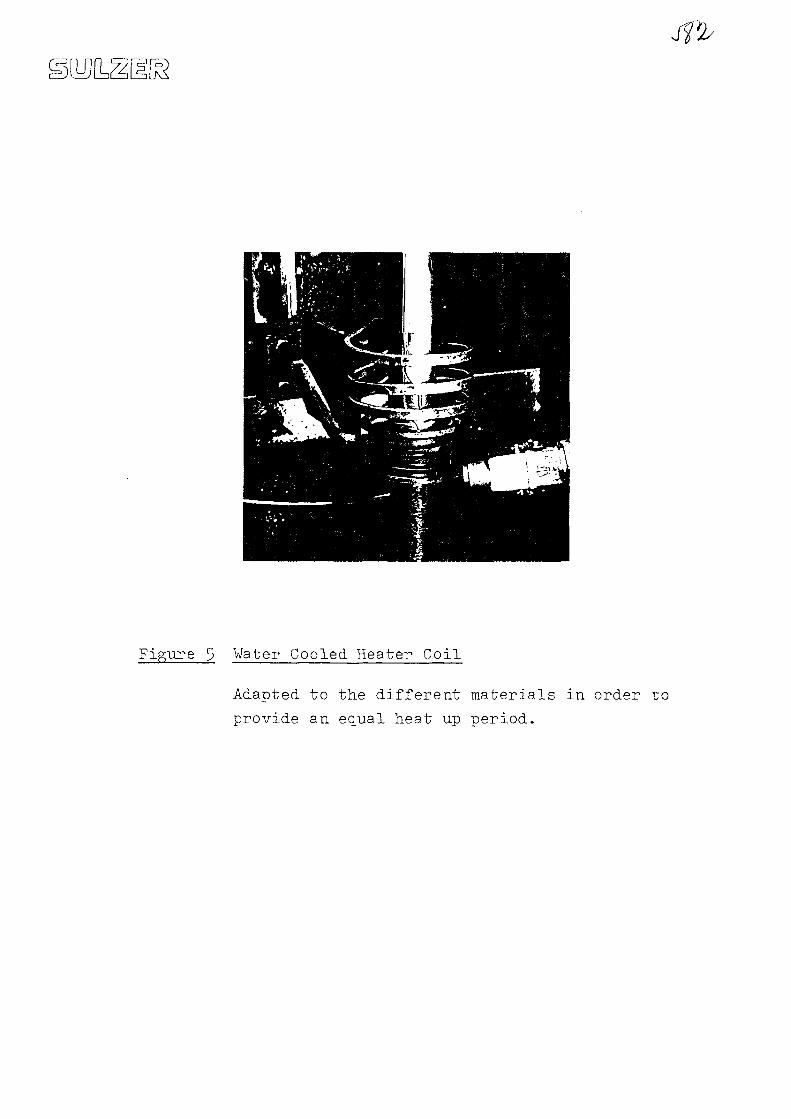
Figure 3 Water Cooled Heater Coil
Adapted to the different materials in order to
provide an equal heat up period.
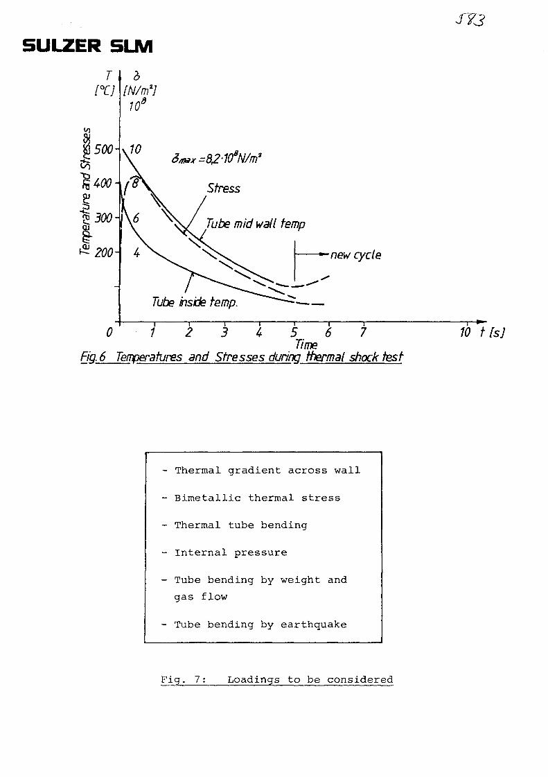
5ULZER SLM
T[XJ [N/m1]
</)
Stress
Tube mid wall temp
•new cycle
Tube inside temp.
0 2 3 4 5 6 7Time
Fig. 6 Temperatures and Stresses during thermal shock test
SY3
10 tfsj
- Thermal gradient across wall
- Bimetallic thermal stress
- Thermal tube bending
- Internal pressure
- Tube bending by weight and
gas flow
- Tube bending by earthquake
Fig. 7: Loadings to be considered
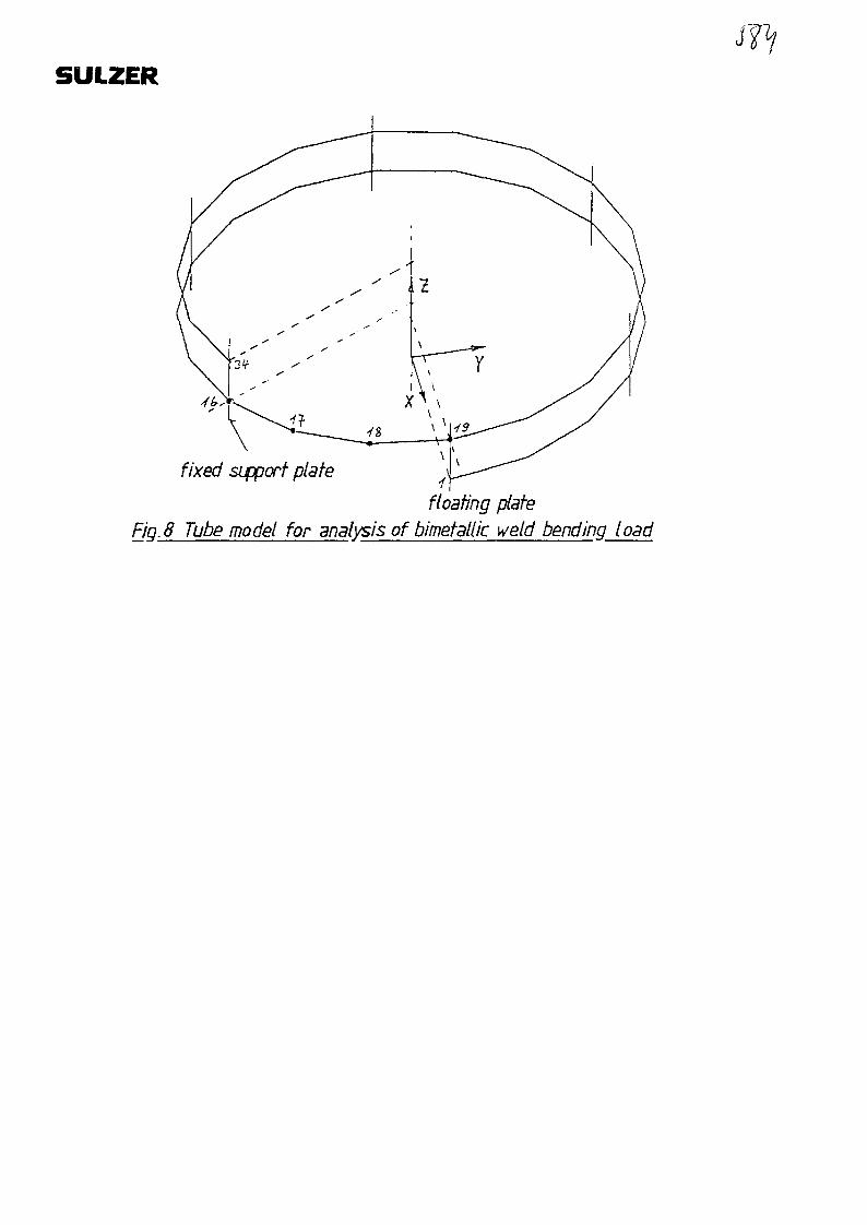
SULZER
fixed sipport plate
floating plateFJQ.8 Tube model for analysis of bimetallic weld bending load
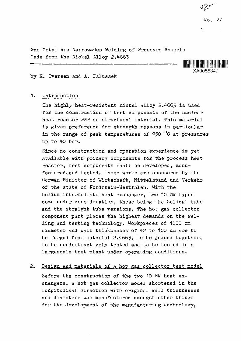
No. 37
1
Gas Metal Arc Narrow-Gap Welding of Pressure Vessels
Made from the Nickel Alloy 2.4663
IllXA0055847
by K. Iversen and A. Palussek
1. Introduction
The highly heat-resistant nickel alloy 2.4663 is used
for the construction of test components of the nuclear
heat reactor PUP as structural material. This material
is given preference for strength reasons in particular
in the range of peak temperatures of 950 °C at pressures
up to 40 bar.
Since no construction and operation experience is yet
available with primary components for the process heat
reactor, test components shall be developed, manu-
factured, and tested. These works are sponsered by the
German Minister of Virtschaft, Mittelstand und Verkehr
of the state of Nordrhein-Westfalen. With the
helium intermediate heat exchanger, two 10 MW types
come under consideration, these being the helical tube
and the straight tube versions. The hot gas collector
component part places the highest demands on the wel-
ding and testing technology. Workpieces of 1000 mm
diameter and wall thicknesses of 42 to 100 mm are to
be forged from material 2.4663, to be joined together,
to be nondestructively tested and to be tested in a
largescale test plant under operating conditions.
2. Design and materials of a hot gas collector test model
Before the construction of the two 10 MW heat ex-
changers, a hot gas collector model shortened in the
longitudinal direction with original wall thicknesses
and diameters was manufactured amongst other things
for the development of the manufacturing technology,
in order to gather in good time experience for the
construction of the components.
Figure 1 shows the design of the hot gas collector
model. Three welds are to be made in the wall thickness
range between 35 - 70 mm. The nickel alloy 2.4663 was
selected as base material and filler wire of the same
composition 1.2 mm diameter was chosen.
Table 1 shows the chemical analyses of base metal, filler
wire and welded joint.
All figures had been within the standards. The burn-out
of the elements aluminum and titanium amounted to 0,19 %•
Therefore limitations of titanium and aluminum to £1,5 %
from the point of embrittlement of the deposited metal
is not necessary according to the latest experiences.
Maximum values of Ti + Al ~ 1#9 % (Al max 1.3 % and
Ti max 0#6 %) were permitted.
3. Welding and testing the hot gas collector model
3.1 Selection of the suitable welding process for the
manufacture_of_the_circular_welds
The manufacture of pressure vessels for the reactor con-
struction necessitates the use of proven reliable welding
procedures. However, with the selection of the welding
procedure neither tested electrodes nor powder for sub-
merged arc have been available for the material 2.4663*
Experience had been gained only for the manual arc wel-
ding processes TIG and GMA each with argon as shielding
gas.
Other welding procedures with high deposition rates like
electro-slag and submerged-arc process could not be used
by means of their hot cracking sensivity caused by the
high heat input. On the other hand efficieny must be an
extremely important point of view if new components are
to be developed. Therefore the decision was made to chose

narrow gap welding with an inert gas.
With expensive base metals and filler wire as well as
high labour costs, the gap width and the side wall angle
effect decisively the quantity of the weld metal to be
filled in, the melting rate and the manufacturing costs.
This applies in particular with larger wall thicknesses,
Fig. 2. According to experience made so far with the nickel
alloy 2.4663, however, the intermediate layer temperature
should be limited to 150 °C, the weld pool size should be
small and overheating of the weld puddle should be
avoided. This led to the selection of a GKA process with
a melting rate of maximum 3 - 5 kg/h. Therefore orLJ-y
single wire processes came into consideration.
For reasons including experience available with pressure
vessels in Japan, the Babcock-Hitachi oscillation flap
process was chosen /~1_7. Fig. 3 and 4 shows the method
of process operation C^.J\ f^bj*
3.2 Qualification 2£_i^£_£§§_S®5ai_§£c_Ba£r!2HzS§2 E£°£eSS
Unfortunately no experience was available for the pro-
duction of circular welds on forged shells of the nickel
alloy 2.4663 with the above-mentioned narrow-gap process.
The same applied for stainless Cr-Ni steels too. There-
fore suitability for welding had to be proven and the
first parameters had to be found with plate samples of
s » 60 mm by fundamental research at the ISF in Aachen/~4^7-
Here it was demonstrated that neither the commercially
used gas mixture of 82 % Ar/18 % COp nor pure argon came
into consideration because of the high arc length and the
too small side wall penetration, Fig. 5« Only the use of
pure helium (99*995 °/°) in combination with the pulse
technique led to a short arc and to a low risk of burn-
back as well as to reduced spattering in the 9 - 11 mm
wide gap. The side wall penetration could be increased
decisively from approx. 0.5 nua to>1 mm and produced
sound welds, Fig. 6.

The low density of the helium had a disadvantageous effect
in the narrow gap because of amongst other things the
formation of very adhesive titanium, aluminum and chromium
oxides on the layer surfaces which could only be removed
by grinding.
At the welding equipment itself, the wire feed system
above all had to be adapted to the significantly stiffer
nickel wire (2.-4-663). The tests in the ISF in Aachen were
concluded successfully after the above-mentioned improve-
ments C^l' The plate samples had to be provided with
an angle of 18° out of the flat for the start of welding
by means of shrinkage.
The continuation of the tests at Interatom took place
initially on circular seams 1000 mm o.d. x 125 mm wall
thickness of 2.4-663. For this the ISF welding data were
taken over and the welding system was completed appro-
priately, Fig. 7. However, because of the impeded
shrinking, heat cracking occurred in the center of the
weld. Only by reducing the layer height, the heat
absorption, the weld pool overheating and the weld pool
size welds could be done successfully without cracks.
Before the optimum data were achieved, single pores and
lack of fusion were found by means of radiographic and
ultrasonic testing. The first circular weld was followed
by the german official TuY process inspection with the
same dimensions.
The root path had been welded manually from the inside
while fillet and the final runs had been welded from the
outside automatically by the narrow gap G-MA process.
For the manual weld Nicrofer S 5520 of 2,4- mm 0 was used
while the automatic GMA process consumed Nicrofer S 5520
wire of 1,2 mm 0 diameter.
All welds had been done in the horizontal position while
the workpiece was turned and the torch was stable. The
opening of the weld preparation was app. 2° to avoid the
squeezing of weld head which was just 7 mm in width by means
of transverse shrinkage, Fig. 8. The opening of the root
srf
gap on the surface was app. 17,8 mm before welding and
lowered down according picture 8 to app. 14 mm before
welding the last path, Fig. 9. The narrow gap welding
with the Babcock-Hitachi-Process is capable of one path
per layer for a gap of 9 - 15 mm and two pathes per layer
till 18 mm.
During this inspection, influences on the welding results
such as not grinding the bead surfaces, welding over of
start and stop points, working out and filling in local
repair places in seam depth and seam width were also tried.
It was shown that welding over ungrinded layers led to
cracks and lack of fusion. All filling layers and the
repair simulations met the required values for BS
according to DIN 8563> Part J. For tbis, however, all
parameters had to be matched exactly to one another and
kept within a close tolerance band. The computer-assisted
welding data monitoring system was here of outstanding
benefit.
After completion of the test weld (81 layers) it was
x-rayed by a linear accelerator. An evaluation of the
films did not lead to a conclusion about weld quality.
It must be stated that good results can be obtained
til 80 mm wall thickness only. The evaluation of the
ultrasonic testing, manually as well as automatically,
Fig. 10, did not show any defect outside tolerance
band. The dye check did not show any defects too.
According to the fixed plan of specimen the forged ring
had to be split up. Six cross sections had to be
examined by TtJV while another 39 had been studied by
INTERATOM. Macro sections did not show any defects
without some minor pores, Fig. 11. Micro sections
(v » 50 or 100:1) did show layers according to speci-
fication but with the exception of some lower area,

where the layers had not been grinded.
In that ungrinded and unsound area lack of fusion as
well as porosity had to "be stated. Most of these defects
had been detected already during x-ray and ultrasonic
testing. The figures of the other testing procedures
are given in table 2.
- £ound_tensile S2ecimen_according_to_DIN_50125
The requirements for the base metal values of Em 2"
700 N/mm2 and Ep 0,2 - 300 N/mm2 were met extremely
close because the lowest value was 302 N/mm . On the
other hand the values of the deposited metal (4-23 N/mm )
as well as the welded Joint (486 N/mm ) exceeded the
specification by far.
The requirements for the yield point had been exceeded
with Ep 0,2 = 328 N/mm but the figures for the ulti-
mate tensile strength did not meet the requirements.
The rupture had been secured in the base metal beyond
the joint. Therefore the weld had met the requirements.
former - 0 : 3 x wall thickness
The following specimen had been taken:
" out of a repaired section bend test specimen
had been taken two for root bend testing and
another two for final layer bend test
* four bend test specimen (two of each for root bend
test and final layer bend test) had been taken from
all around the weld. All specimen did show 180
bend angle without any cracks.

7
notched tar_impact_test_according to_DIN 50115
The specimen had been taken from a place of repair
and from other areas all around the joint. The
requirements of - 40 J was met by all specimen. The
lowest value was shown with 71 J at the weld edge
while the highest was shown with 151 J in the deposited
metal. It can be emphasized that narrow-gap-welds do
show much better results than there is the demand
according to HP 2/1.
With these results the process qualification for the
narrow .gap welding with the single wire snake-wave
process (VP 70) was successfully finished.
According to Fig. 1 three circular seams of different
wall thicknesses (35? 42 and 70 mm) had to be produced.
Narrow-gap welding took place with the welding data proven
in the above-mentioned process inspection. About JO layers
were required for the 70 mm wall thickness, this meant an
average layer height of 2.*? mm. The heat input was 14 kJ/cm,
the welding speed 30 cm/min and the melting rate app.3»8 kg/h.
Radiographic inspections were carried out after about
4-0 mm of weld metal and after laying the final layer
(70 mm). The results of the radiation testing and the
results of the manual as well as computerassisted
mechanized ultrasonic testing, Fig. 9 did show good
harmony.
With the exception of some single pores neither lack
of fusion nor cracks had been detected. After finishing
of the welds (T) and (2) the workpiece had to be oval
shaped followed by welding (seam (^) ) to the bottom,
figure 12.
Fig. 13 shows the figures of transverse and longitudinal
shrinkage depending on wall thickness.

8
4. Summary
The GMA narrow-gap welding process with helium as
shielding gas showed circular welds free of defects up
to s = 126 mm with the nickel alloy 2.4663. The commer-
cially available pulse power source had to be modified at
the shielding gas supply and the wire feed. The selection
of the welding parameters had particular significance. It
was shown that with shrinking-impeded welding of the
circular welds, an overheated weld pool must absolutely
be avoided and that a small weld pool size must be main-
tained. The nickel alloy 2.4663 which contains aluminum
and titanium necessitates grinding of the single layer
surfaces.
However, it remains for the future to show with further
applications if a technical breakthrough of the narrow-
gap welding process with the manufacture of thick-walled
pressure vessels of stainless Cr-Ni steels and nickel
alloys can been made.
5. References
/""1J7 S.Swada, K.Hori, M.Kawahara, M.Takao, I.Asano;
Application of Narrow-Gap Welding Process;
AVS 60th Annual Meeting, 5 April 1979
</"~2 7 C.Ferling; Gas metal arc narrow-gap welding,
a new technology for joining thick plates;
study project of the ISP Aachen, Jan. 1981
/"~3 7 K. Iversen; Review of the process of narrow-gap
welding; Colloquium narrow-gap welding
SLV Duisburg, June 1982
/~4_7 P. Eichhorn, P.Groger; Gas metal arc narrow-gap
welding tests on austenitic chrome-nickel steels
and nickel based alloys; DVS report Vol. 75, 1982

pcr
rx>3rVP.
P
P.<̂
U J
£3
—t-
P-
fDCL
CLfD
"8
oo
balance
_ _ k
O*
oo
en
- *•F-
o
oo
oen
k
oo
0,002 1ot o
0,04
»
p—f-
S.
ca>CL
oQo»
balance
k
>O
J3O
UJ
_-*
o
en
ooenoro
x
en
0,003
0,004
o
ooen1
0,01
OOen
13 Z3
—s
U3
UD40
oooo
3
oo•r>
balance
roeu
UJ
oO N
roo
oo
°oO S
o>o
IAo
tAO
UJo
2$o
IAO
enIA
en
IAOoen
~gen
o"8ro
tA
oIA
en
3D
Z3O
I
T3
OfD
3DX
O
oao
3
Oo*^
balance
I O
o
k
o
UJ
oo ,
IAoV j
IAoV j
r§
rooo
00
oO S
c>"ro
1A
oIA
en
IAoenIA
• 8
IAO
IA
"en
ro3
TD
OCLCLo
O
'—
—J
3 :13
o
nnft)
GD
c
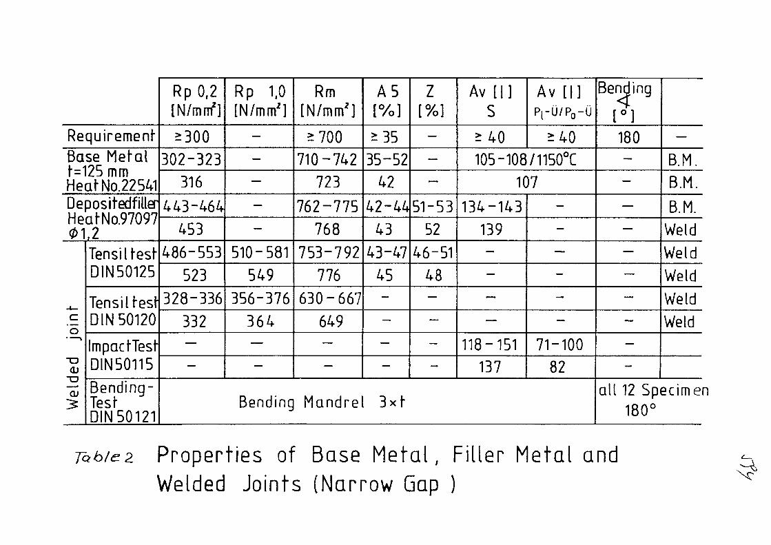
Requirement-Base MefalN125mmHeafNo.22541DepositedfillerHeafNo.9709701,2
join
We
lde
d
Tensill-estDIN50125
Tensiltesf-DIN 50120
Impact-TesfDIN50115
Bending-TesfDIN 50121
RpO,2[N/mrf]
^300
302-323
316
443-464
453
486-553
523
328-336
332—
—
Rp 1.0[N/mm2]
—
—
—
—
—
510-581
549
356-376
364—
—
Rm[N/mm2]
^700
710-742
723
762-775
768
753-792
776
630-667
649—
—
Bending Mandre
A5[%]
^35
35-52
42
42-44
43
43-47
4 5—
—
—
—
Z[%]
—
—
—
51-53
52
46-51
48—
—
—
—
Av [| ]S
>40
Av [|]PrU/P0-U
> 4 0
105-108/1150°C
107
134-143
139—
—
—
—
118-151
137
—
—
—
—
—
—
71-100
82
3 x f
Bending<[ ° ]180—
—
—
—
—
—
—
—
—
—
—
B.M.
B.M.
B.M.
Weld
Weld
Weld
Weld
Weld
all 12 Specimen180°
Properties of Base Metal, Filler Metal andWelded Joints (Narrow Gap )

weld (1
Csl
[7/7 / / /
1350 1020
\ \ \ \ _.\i \ \ \ \ \ 1
O
CO
&
\ \ \ \r\ \ \ \ \
<./// / / /
i>zzzzzzz^
Fig. Hot gas collector
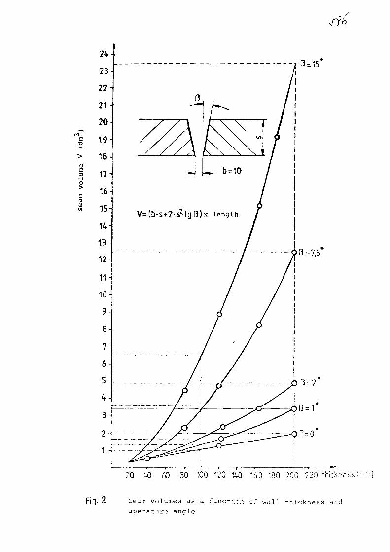
T3
6
Y=[b-S+2sZ^H)x length
20 40 50 30 100 120 140 160 *80 200 220 thickness [mm]
Fig: 2 Seam volumes as a function of wall thickness and
aoerature anale

We !<Jinq d)tec ft o n
Fig.3 Process with oscillating flap - a) Flap plate
b) Feed rollers
c) Contact nozzle
d) Upper gas protection
e) Welding gap
f) Wire electrode
g) Water cooling
h) Front gas protection nozzle
i) Rear gas protection nozzle

input
vD wire feed speed
8 wire deflection
fp oscillation frequency
output
X wave length
Y oscillation
Wire. Def6rsn/r?3

•Jff
Fig. 5 Penetration depending upon type of shielding gasBase metal: X 5 CrNi 18 9
Filler Metal: X 5 CrNi 18 9
The first 6 layers were welded with argon, thefollowing layers with helium

I
•
*
t
j j j
1 Helium
I
>>
Fig. 6 Influence of the shielding gas on the arc lengthand side wall penetration
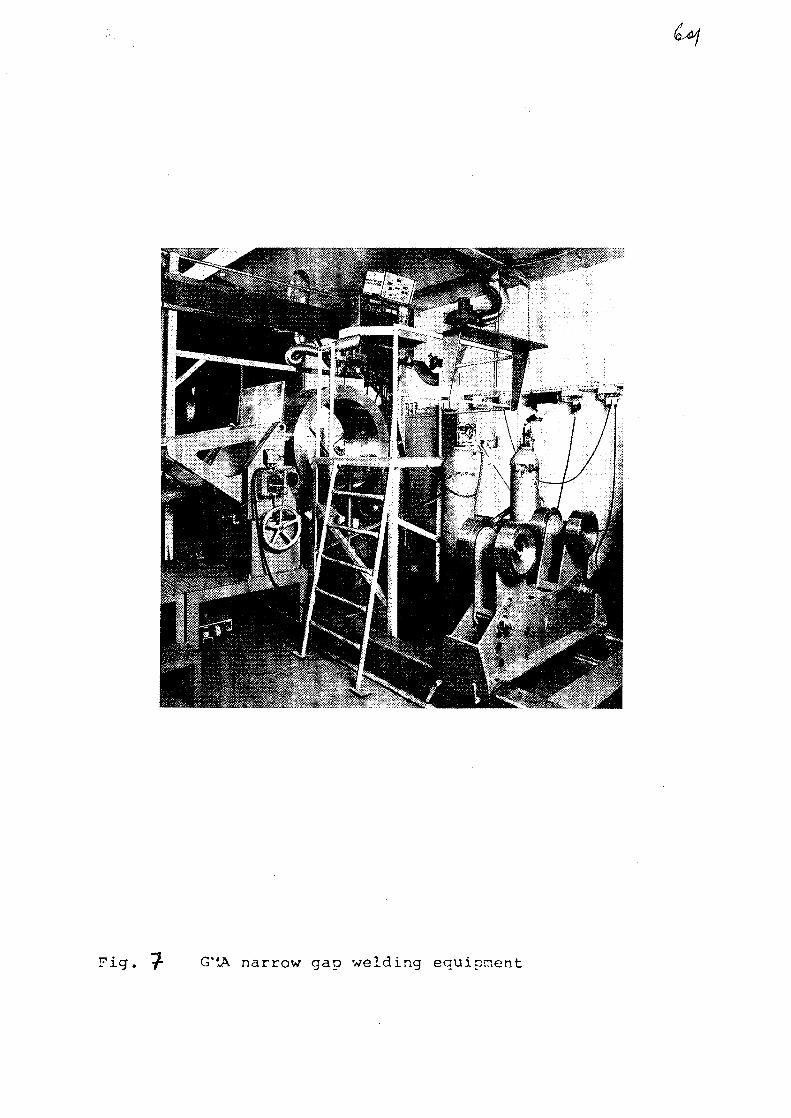
Fig. "$- G'tA narrow gap welding equipment
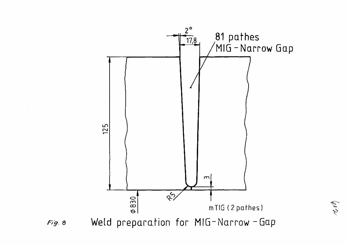
81 pathesMIG -Narrow Gap
mTIG ( 2 p a t h e s )
Wsld preparation for MIG-Narrow-Gap
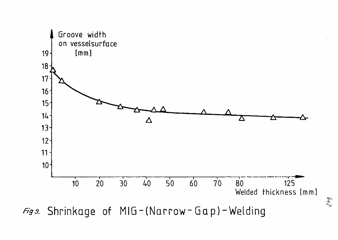
Groove widthon vesselsurface
[mm]
50 60 70 80 125Welded thickness [mm]
Shrinkage of MIG-(Narrow- Gap)-Welding

Fig 1o Fully mechanized ultra-sonic testing of the hot gascollector with computer evaluation

Fig. 44 Narrow gap weld (wall thickness 12^ nun)
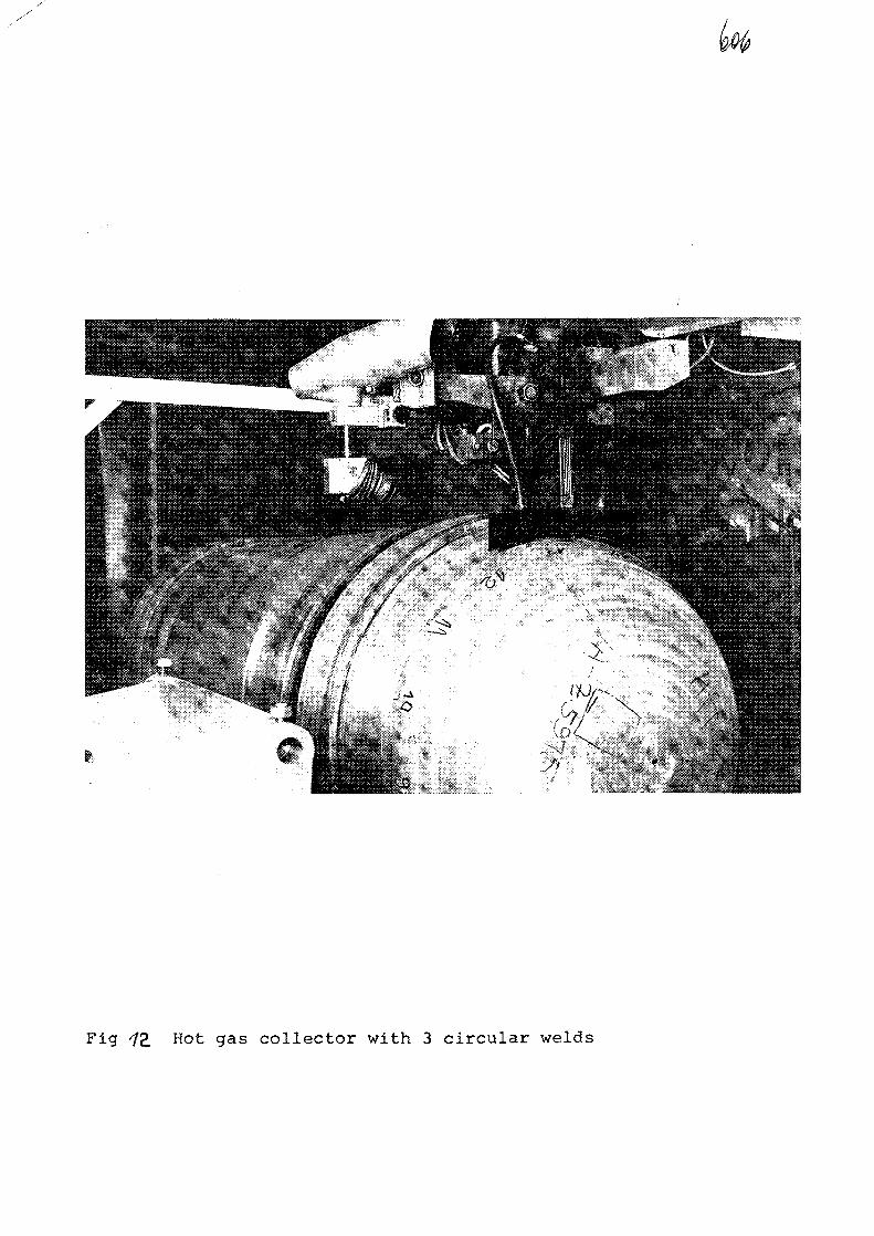
Fig 72, H o t <3as collector with 3 circular welds

Transverseshrinkage
Longitudinalshrinkage
125 [mm]wall thickness
a Longitudinal and transverseshrinkage depending onwall thickness

AXA0055848
FORGED HOLLOWS (ALLOY 617)
for PNP-Hot gas collectors
by F. Hofmann
VEREINIGTE DEUTSCHE METALLWERKE AGGeschaftsbereich Nickel-Technologie
D-5980 Werdohl / West Germany

- 1 - AVDMi
Introduction and Purpose
When the partners of the PNP-project decided to manufacturePNP-components, such as hot gas collectors, from material ofthe type "alloy 617" (DIN material No. 2.4663) the problemwas encountered that the required semi-fabricated products,especially forged hollows weighing several tons each, werenot available. Also at that time it was not known, whetherproducts in this high alloyed high-temperature material couldeven be produced in the required dimensions. As VDM had alreadygathered experience in the production of other semi-fabricatedproducts of this alloy, attempts were made based on this know-ledge to develop manufacturing methods for forged hollows.The aim was to produce hollows as long as possible, to keepcostly welding to a minimum. Welded seams are always critical,during fabrication, as well as on later inspection under actualoperating conditions. On the other hand, of course, the economicsof the production method had to be kept in mind in reaching thegoal of this development.
A three stage plan illustrates the development aims, wherebystage 3 is currently being worked at (figure I). The first twostages involved the production of forged hollows for hot gascollectors for 10 MW heatexchangers designed by Steinmliller/Sulzer and Balcke-Dlirr. Stage 3 encompasses the development ofnecessary forgings for a hot gas collector for a future 125 MWheatexchanger. As, according to current thinking, this entailsapproaching the limits of what is technically feasible and assuch involves a high economical risk. This project is subsi-dized as part of the overall PNP-project.

A
Procedure
A prerequisite for this project were the previously started
investigations studying the influence of the melting method
on the most important properties of the alloy, as for example
the creep rupture properties at high temperatures. These in-
vestigations revealed, that the expensive method of melting
and casting under vacuum (VIM), which is frequently stipulated
for such material, is in fact not necessary. This alloy can
be melted in an open electric arc-furnace, similar to highly
alloyed stainless steels in large heats of for example 30 tons,
and cast into ingots after a VOD treatment.
The advantage of this method is that it facilitates the use
of economical raw materials through corresponding metallur-
gical treatments, as well as the production of large ingots.
Large ingots, however, have to be remelted to minimize segre-
gations in the ingot. These are caused by elements such as
chromium and molybdenum which have a great tendency to segre-
gate. For remelting, the electroslag remelt process (ESR) was
chosen. Compared to other remelt methods, it is economical and
offers certain advantages during subsequent fabrication.
Figure 2 shows the relationship of creep rupture properties of
alloy NICROFER 5520 Co (Alloy 617) to the respectively discussed
melting methods. This diagram clearly reveals that the melting
method selected for this project does not adversely affect the
creep rupture properties of NICROFER 5520 Co (Alloy 617) parti-
cularly at high temperatures. A heat which was melted and cast
under vacuum was used as reference. Of the two casts investigated,
it was found that the creep rupture properties were actually
better above 850 °C for the VOD/ESR processed heat as compared
to the material melted and cast under vacuum.

AFor stage 1 of the project, remelt ingots of approximately 750 mm
in diameter with a weight between 6 to 7 t were produced according
to the melting method described. After dressing, the ingots were
heated up to the forging temperature, upset forged (figure 3 ) ,
pierced with a mandrel (figure 4 ) , and forged to final dimension
over a mandrel in several forging steps (figure 5). Prior to the
final forging operation, it is important to homogenize the forgings
in order to reduce unavoidable microsegregations. The temperature
during the last forging operation is of great siginificance as it
determines the properties of the forged part lateron. Thus the
forgings must be sufficiently and uniformly deformed to obtain a
defined grain structure during the final thermal treatment (fig.6).
This thermal treatment is carried out within the temperature range
1150° - 1200 °C. With this thermal treatment an average grain size
of ASTM 0 could be attained. This avoids any problems during ultra-
sonic testing of the forged hollows for interior defects. The in-
spected forgings (figure 7) were then machined to final dimensions
(figure 8). This production step also necessitated detailed investi-
gations, as alloy NICROFER 5520 Co (Alloy 617) is very difficult to
machine.
For stage 2 of the developmental work, i.e., for the production of
a forged hollow, approx. 2000 mm in length, a larger ingot was
needed to obtain the desired final dimensions. In this case an ingot
850 mm in diameter and weighing approx.8,5 t, was chosen. Fabrication
parameters, similar to those used during stage 1, could be applied.
The increased occurance of microsegregations caused by the larger
ingot diameter had to be compensated by suitable homogenizing treat-
ment. On this occasion, it was noted, that the operating limits of
a 7000 t forging press was reached at individual deformation stages.
During final inspection the hollows were shown to meet the specified
properties and were consequently further processed to hot gas
collectors by the fabricators, (figure 9)

A
Currently work is persued for stage 3 of the developmental project
which entails production of a forged hollow for a hot gas collector
for a future 125 MW heatexchanger. At least in the area of critical
temperature the hot gas collector should consist of one piece, i.e.,
it should be approx. 4000 mm in length. After reviewing the forging
capacities of suitable equipment available in West Germany, it was
determined that an ingot, 1000 mm in diameter and 2700 mm in length,
weighing approx. 17 t was required. For this highly alloyed material,
which is very prone to segregations as already mentioned, this is
certainly a most unusual size, which probably has never been pro-
duced in the past.
During processing the remelted ingot unsuspected problems were en-
countered during electroslag remelting. These, however, were overcome
by adapting process parameters, involving for example the development
of a suitable slag. Figure 10 shows the cast ingot with a diameter
of 1000 mm x 2700 mm and a weight of 17 t. After dressing the surface,
the ingot was heated up to forging temperature. The ingot had to be
upset forged directly without a supporting fine grained shell. Upset
forging was carried out with a forging power of 9000 t. In two stages
the ingot could be reduced approx. 50 % in height by upset forging to
1300 mm. The ingot was forged back to its original shape and once more
upset forged to 1300 mm. This rather costly procedure was deemed
necessary to obtain an allround homogeneous deformation of the ingot
structure, as well as a breaking up of the segregation zones for the
subsequent homogenizing heat treatment. The ingot was then pierced with
a 300 mm diameter mandrel. Before forging could be continued, the rough
forging had to be dressed, to remove upset folds and cracks inside the
hollow. During further processing of the forging, problems were en-
countered with widening and stretching, as the available tools, i.e.,
the forging mandrels were breaking due to insufficient strength. This
problem was overcome by forging in the upper forging temperature range,

- 5 -
AWDM,
which necessitated frequent reheating. The final dimensions attained
were o.d. 1050 mm and i.d. 780 mm with a length of 4400 mm (figure 11).
In order to determine the thermal treatment procedure a sample ring
approx. 300 mm in length was cut off. This sample ring was given a
trial heat treatment in the annealing furnace foreseen to be used for
the actual forged hollow. Results obtained so far, indicate a structure
essentially free of segregations with an average grain size of ASTM 0.
Utilizing these experimentally determined heat treatment parameters,
final annealing of the actual forged hollow is currently beeing con-
ducted.
Future Outlook
Following completion of the thermal treatment of the forged hollow,
it is planned to take samples in various places, in order to examine
the properties of the alloy in the existing product form.
This should particularly show, whether production of forgings of that
dimensions are technically and economically feasible in sophisticated
nickel alloys such as NICROFER 5520 Co (Alloy 617) in future. This
is of importance, not only for the PNP-project, as other applications
also require at least the capability of producing large ingot sizes
in similar alloys. Up to now this could not be considered to be the
latest state of the art, due to the high production risks involved.
As an extension to this development, it is planned to utilize the
forged hollows, to study economic joining methods, such as narrow gap
submerged arc welding. This additional work focuses particularly the
question of economics. Initial experiments have been conducted and
can be said to be promising.

Abb.1
/ \ ] Stufenplan zur Entwicklung geschmiedeter NOW/VDMV Hohlkorper aus dem Werkstoff Nicrofer 5520Co( alloy 617)
Hohlkorperabmessung Blockgewicht
Stufe 1: ca. 1090'740 0 x 1000 (mm)Roh-Gew. ~ 5to
ca. 6 , 7 to
Stufe 2 ca. 880/550 0 x2100(mm)Roh Gew. ~ 6,5to
ca. 8 to
Stufe3: ca. 1050/780 0 x 4400(mm)
Roh-Gew. ~ 16,6 toca. 17 to
Fig. 1 Plan of developmental work
100
10-
ooCOE
en
700 800 900
Temperatur in °C
1000
Fig. 2 Creep rupture strength of NICROFER 5520 Co(alloy 617) related on melting procedure( 0 VIM; XAVOD/ESR)
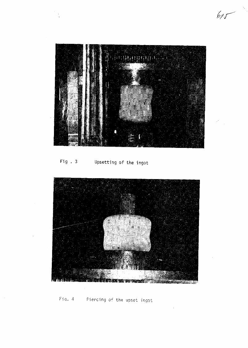
Fig . 3 Upsetting of the ingot
4 Piercing of the upset inqot
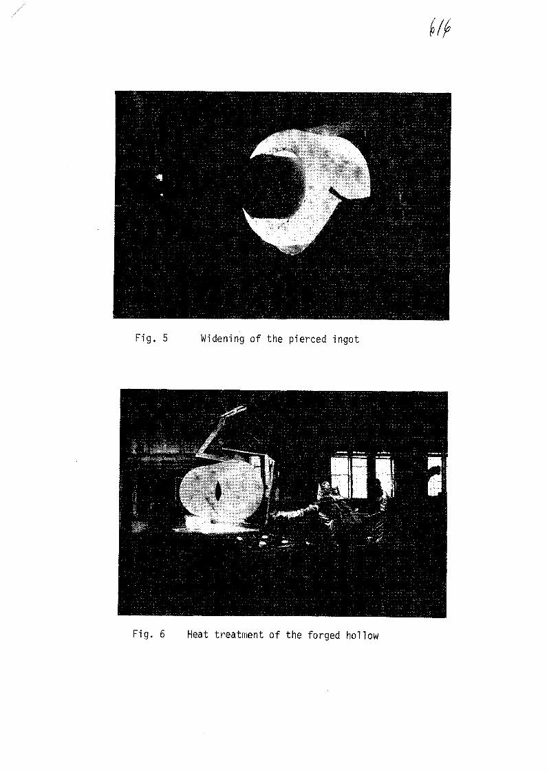
Fig. 5 Widening of the pierced ingot
Fig. 6 Heat treatment of the forged hollow

9-
Fig. 7 Forged hollow before machining
Fig. '8 Machined hollow ready for delivery
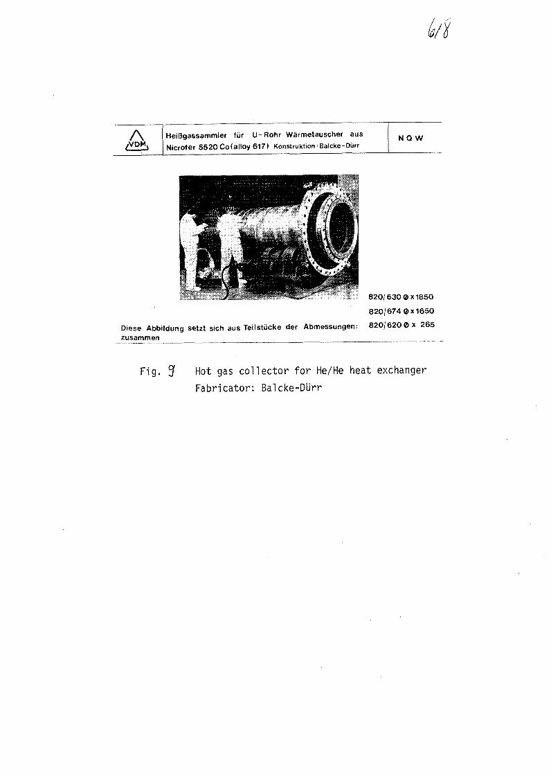
AVDM
HeiBgassammler fiir U-Rohr Warmetauscher ausNicrofer 5520 Co(alloy 617) Konstruktion;Balcke-Diirr
NQ W
820/630 0x1850
820/674 0x1650
Diese Abbildung setzt sich aus Teilstucke der Abmessungen: 820/620© x 265zusammen
Fig. ^ Hot gas collector for He/He heat exchanger
Fabricator: Baicke-Dlirr

C/f
Fig. 40 17 t ESR ingot in NICROFER 5520 Co
A geschmiedeter Hohlkorper aus Nicrofer 5520 CoSchrniedeabmessung: 1050/7800 x 4400mm NOW
Fig. AA Forged hollow in NICROFER 5520 CoDimension: o.d. 1050 mm i.d. 780 mm, length 4400 mm