Shure 1967 Audio Catalog for Sound System Specialists
48
-
Upload
khangminh22 -
Category
Documents
-
view
1 -
download
0
Transcript of Shure 1967 Audio Catalog for Sound System Specialists


2
The prime purpose in the design
of every Shure microphone is
faithful sound reproduction.
All are painstakingly designed,
developed, manufactured and tested
for flawless performance coupled
with longest possible trouble-free
service. Regardless of price,
they will perform according to
specifications and will operate for
years without deviation from
their original standards.
Copyright 1967 by Shure Brothers, Inc.
ENGINEERING LEADERSHIP For well over a quarter century, Shure has made numerous significant contributions to the art of developing and manufacturing acoustical-electrical products and transducers. Indeed, there are parts of the world where imitations and copies of Shure microphones are referred to as "Shure Type" microphones-a quality designation in itself. In fact, there are more Shure Unidyne microphones used in quality public address systems than any other microphone . . . it is truly the microphone that needs no name to be identified. In the field of communications Shure mobile and fixed-station microphones dominate to such a vast degree that they actually outnumber all other brand microphones combined. Many Shure contributions to the field of microphone design rank among the significant engineering "break-throughs." For instance:
"UNIPHASE" N ETWORK-made possible the first, and still most ·effective, single element unidirectional microphone. Refinements over the years have been incorporated to permit more compact design and to apply the network to a number of Shure dynamic, ribbon, crystal and ceramic microphones.
"CONTROLLED MAGNETIC'mr MICROPHONE CARTRIDGES-the "workhorse" of World War II, now the quality standard in mobile communications. Provides high speech intelligibility, ruggedness and stability under prolonged, severe field operating conditions.
"ARMO-DUR" HOUSINGS-a: revolutionary plastic that actually outlasts steel and die-cast cases. Rust-proof, corrosion-free, chip-proof, practically unbreakable, always comfortable to the touch in hot or cold weather, no shock hazard. It is undeniably one of the most durable and practical materials ever used for hand-held microphones.
EFFECTIVE NOISE-CANCELLING MICROPHONES-the Shure SONOBAR provides intelligible communications under severe noise conditions that previously made "readable" transmission impossible. Transmits the voice clearly even where ambient noise is so great the speaker cannot hear himself!
MINIATURE MICROPHONES-some no larger than a paperclip, yet giving excellent performance under extreme temperature and humidity conditions.
"DURACOUSTIC" NON-METALLIC DIAPHRAGMS-do away with all the problems caused by metal microphone diaphragms and the instability inherent in many non-metallic diaphragms. Shure's "Duracoustic" diaphragms provide optimum microphone performance combined with maximum dependability and consistency.
STYLING-Shure strives to design microphones so that they "look as good as they sound." Shure design, incorporating all necessary acoustical considerations and the ultimate in utility and convenience, is the result of constant awareness of current trends in industrial design and the constantly changing standards of microphone users and the requirements of different applications. Consequently, Shure microphones enhance the appearance of any setting and system in which they are used.
GUARANTEE Every Shure microphone·is guaranteed a full year against defects
in materials and workmanship, covering every mechanical and
el.ectrical aspect of the unit. All Armo-Dur cases are uncondi
tionally guaranteed against breakage.
SHURE SERVICE
/
Most Shure microphones have been designed for convenient replacement of the microphone element in the field. These microphone cartridges are found on page 43 of this catalog. Additional service may be obtained through your Shure distributor or directly from the factory. Damaged microphones returned to the factory will be put into "like-new" operating condition, meeting the original performance characteristics, and returned. The service is extremely fast (usually within 48 hours) and costs are low. The fact is, Shure microphones are built to withstand severe operating conditions and seldom require servicing.

F I R ST I N
PUB LIC-A D D R E S S
S OU N D
R EINFO RC EME N T
SY ST EM S
l�ecognizi11g tl1at the quality of i·eprnduction a sound system prnvides is
absolutely limited by the quality of sound put into it by the microphone,
Shure, fol' over a qum·te1· ccntLll'Y, has provided the highest quality micro
phones fo1· public-address use. Shu1·e micrnphones have consistently been
selected by sound engineers and audio specialists for installations where
quality of reproduction or cliflicult ac:oustic:s required a supe1·ior microphone.
Whether a microphone is selected for installation in a theater, nightclub,
auditOl'inm, m usi c: hall, school, church, m eeting hall, gymnasium, legislative
01· .iuclicial chamber . or any other indoor or out.door appli cation, one of the
many Shure rninopl i oues can provide the ideal solution at a reasonable cost.
Shure micrnph ones arc n1ggecl-may be depended upon to deliver consistent
perfOl'mance fo1· years without deviation from their original standards.
Shure rnicrnphone accessories also provide additional versatility and prac
tical value when used with Shure micrnphones. The following pages contain
information 011 Sitlll'e prnducts designed. to give the utmost performance
for public-address use. Also inducled ai·e famous Shm·e microphones for
mobile and fixed-station communications, as well as ham, citizens ban<l,
pagrng and special applications.
3

4
SELECTING THE CORRECT
STEP I PICK-UP PATTERNS
picks up sound
mainly here
(microphone)
(microphone)
• OMNIOIRECTIONAL
. . . . .
. . .
•• .
• .
STEP II F R E Q U E N C Y
R E S P O N S E
Use
Recording, broadcasting, highest quality public address for music and voice
High quality public address for voice and music
Indoor paging systems and public-address systems for voice use
Outrloor paging systems or systems in noisy locations. Ham radio and professional mol>ile and fixed station communications. Maximum intelligibility required.
WHAT I T IS These microphones pick up sound mainly from the front, while suppressing sound and noise coming from the back. The most generally useful unidirectional pickup pattern is the CARDIOID (meaning "heart shaped ") . This pattern will suppress rear sounds at least 70% while pick ing up front sound over a broad area. Sounds 120' to 180' off-axis are almost entirely suppressed .
In addition to the Ca rdioids (The Unidyne Ill, Unidyne II, Unidyne A, and Unisphere Series of Shure unidirectional microp hones) othe1· Shure unidirectional microphon es are described as SuperCardioid (Models 330, 737A). The pickup patterns of these microphones vary from the Cardioid. Check the polar pattern to determine the suitability to your application.
These microphones pick up sound moreor-less evenly from all directions. In effect, they n re nond irectional. They can be hand-held, stand-mounted, or wo1·n around the neck. This type includes the greatest number of microphones, together with the widest price range and response characteristics.
Picks up sound from front and back while suppt·cssing sound from sides, top and bottom.
WHERE TO USE IT The most commonly applied solution to feedback problems. Greatly simplifies planlling of sound installations. With the rear of the microphone rejecting sound, the microphone can be placed so that sound projecting from the l oudspeaker cannot re-cntei· the microphone to generate feedback. Performe1·s can work much further away from unidirectional micro
phones than. with omnidirectional micruphones.
Effectively suppresses audience noises, coughing·, shuffling feet, etc. Ideal for fixed installation before an individual performer or a small group. Pickup of a large group can be effected with multiple microphone installation.
Good for genernl applicat ions where feedback or aud 1eneP noise is no great prol>lem. ExtrenlPly versatile. Practically all ultra -slim "probp'' type m icrophones a1·e omnidirel'lional units-they are ideal for "walk-around'' and inter\·iew situations. (Note: Shure also makes a unidirectional "probe"- the Model 545.) (See pages 8-9)
Ideally suited for use when tw(J performers , 01· groups, are on oµpusite sides of microphone. Allows the same freedom of movement as unidirectional microphone:-;, while solving difficult feedback problems surh as roorns with "hard" ceilings or where lourlspeakcrs arc mountcrl over or to the side of the microphone.
The fidelity of reproduction afforded by the microphone depeJ1ds on three factors of the frequency response: 1. Response Range. In general, the mo1·e extended the frequency response of the
microphone is, the more faithfu I the reproduction will be. 2. Smoothness. A high fidelity microphone is made so that no conspicuous abrupt
peaks or valleys of output occur at any frequency. This results in an essentially smooth frequency response curve.
3. Flatness. A flat frequency response cu1·ve is one showing output remaining at approximately the same level throughout the frequency range. This means that the microphone responds equally well at any frequency, an essential of high fidelity reprnduction.
While the microphone with the widest range, smoothest and flattest frequency response curve will give the highest fidelity, it is not necessarily the best microphone for every application. [For example, a shaped (peaked) response is often devised to achieve added "presence" for microphones used in paging and communications systems.] f'requency response required for various applications is summarized below:
RESPONS E REQUIREMENTS Response Range
50-15,000 Hz
70-10,000 Hz
200- 5,000 Hz
300- 3,500 Hz
Response Character
Plat S mooth
Flat or slightly rising No prnminent peaks
Slightly rising No prominent peaks
Rising A peak in the 2000 to 3500 Hz region is often desirable
Possible Microphones
Ribbon Dynamic
Ribbon Dynamic Some c1·ystals or ceramics
Above plus Son1e Controlled Magnetics
Controlled Magnetic Dynamic Carbon Sorne Ce1·a1nics

MICROPHONE FOR THE APPLICATION
STEP Ill SHURE SERIES NO. 100
200
300
400
500
700
TYPE
CARBON
CERAMIC
RIBBON
CONTROLLED MAGNETIC
DYNAMIC
CRYSTAL
STEP IV PRICE
TYPES OF MICROPHONES
WHAT IT IS Very high output units recommended for mobile communications where intelligibility requires limited frequency response. Needs external power supply. Low impedance.
Similar to crystal microphone in design but uses man-made ceramic element. Economical, superior to crystal for outdoor use. Unaffected by severe temperature and humidity changes. High impedance.
Virtually uniform frequency response. Definitely among the very best available. Fairly high priced. Extremely rugged for normal use in<loors. Adjustable i mpedance.
13alanced armature . . . 1·ugged, stable, high output. Originally developed for the military to combine the advantages of the carbon and dynamic microphone . . . with none of the disath·antages-such as the need for external power supply in a ca1·bon. Has the ability to directly supply any impedance, without transformer. Modestly priced, extremely dependable performance.
Moving-coil microphone, available in a wide i-ange of prices and types. The better dynamic units are among the very best microphones for frequency response. Smooth response (up to :!0,000 Hz.
Good quality at a low p1·ice. Hesponse is somewhat limited (normally about 10,000 Hz 1naximum). Special sealed crystals used in Shure units rnea11 you can use them where humidity is high or outdoors ( excPpt in direct sun over prnlongcd periods). High Impedance.
WHERE TO USE IT Mobile communications. Not recommended for publ ic add1·ess. Very good over extremely wide temperature and humidity con<litions, or where rough handling is encountered.
Wherever price is an important factor. Shure makes omnidirC'ctional and undirecti onal ceramic microphones-all are economical, rugged, attractively styled.
Wherever quality of response is the first considc1·a lion in broadcasting, professional recording, or public address, look to Shure Hibbon microphones (unidirectional and bidirectional). Excellent for music. Not 1·ecommended for outdoor use.
Highly 1·ecommended for the best possible performance in Mobile Communications-truly the Field-Prnved Standard in Mob ile Communicatiims.
Indoors, outdoors-wherever rugged perfo1·mance must be coupled with modest price and suitable response. l rleal for paging, language labs, portable P.A. systems. Omnidirectional only.
The dependable unit where exceptional performance, ruggedness and reliability are required, such as broadcasting and better quality Public Address. Superior in frequency response to ce 1 ·amic, nystal, carbon, and Controlle<l Magnetic units . l:ni<lirectional, omnidirectional.
Crystal units arc primarily used where price is a limiting factor. Very high in output.
While Shure microphones range in price from a few dollars to well over one hundred dollars. it is
well t.o keep in mind that thc.v are the /01cc;/ cost si119/e itcJ11 in the average P.A. system - ·and t.hat their function is critical ! In lruth, the P.A. system can be no better than the microphone that ori1:dnally converts the sound waves into electrical impulses. l 11 general. unidirectional cardioid
rnil'ruphones are the most ex pensive (as a category); however, some fine (juality omnidirectional and bidirectional microphones can cost as much as unidirect.ionals. Where economy is the major fact.or, we suggest that you look to crystal, ceramic or "Controlled Magnetic" units. Where
quality is first and foremost, we recommend ribbons ur dynamics.
5
6
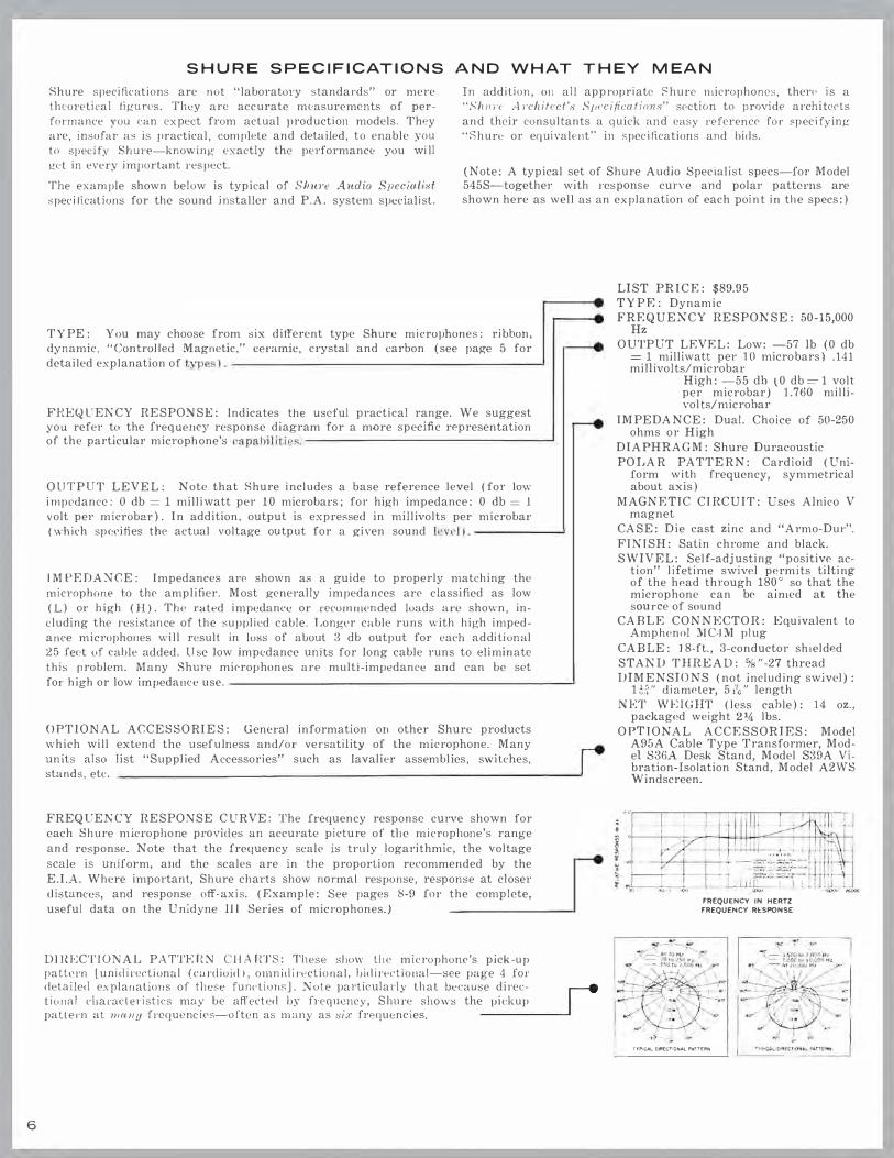
S H U R E S P E C I F I C AT I O N S A N D W H AT T H E Y M E A N
Shure specifieations are not "laboratory standards" or mere theoretical figures. They are accurate measurements of performance you can cxpeet from actual production models. They
are, insofar as is practical, complete and detailed, to enable you to spec:ify Shure-knowing exactly the performance you will
get in every important respect.
In addition, 011 all appropriate Shure microphones, there is a
"Shm·c A1·chitect's S11ccifications" section to provide architc<>ts
and their consultants a quick and easy reference for speci fying
"Shure or equivalent" in specifications and bids.
The example shown below is typical of Shure Audio Specialist specifications for the sound installer and P.A. system specialist.
(Note: A typical set of Shure Audio Specialist specs-for Model 545S-together with response curve a11d polar patterns are shown here as well as an explanation o.f each point in the specs:)
TY PE: You may choose from six different type Shure microphones: ribbon,
dynamic, "Controlled Magnetic," ceramic, crystal and carbon (see page 5 for
detailed explanation of types).-----------------------�
FREQUENCY RESPONSE: lndicates the useful practical range. We suggest you refer to the frequency response diagram for a mQre specific representation of the particular microphone's capabilities. -------------------'
OUTPUT LEVEL: Note that Shure includes a base reference level (for low
impedance: 0 db = 1 milliwatt per 10 microbars; for high impedance: 0 db = 1
volt per microb2r). In addition. output is expressed in millivolts per microbar (which specifi es the actual voltage output for a given sound level).-------'
IMPEDANCE: Impedances arc shown as a guide to properly matching the microphone to the amplifier. Most generally impedances arc classified as low
(L) or high (H). The rated impe<lanc:e or recommended loads are shown, including the resistance of the supplied cable. Longer cable runs with high imped
ance microphones will result in loss of about 3 db output for each additional 25 .feet of cable added. Use low impedance units for long cable runs to eliminate
this problem. Many Shure microphones are multi-impedance and can be set
for high or low impedance use. ---------------------------'
OPTIONAL ACCESSORIES: General in.formation on other Shure products which will extend the usefulness and/or versatility of the microphone. Many
units also list "Supplied Accessories" such as lavalier assemblies, switches,
stands, ek.
FREQUENCY RESPONSE CURVE: The frequency response curve shown for each Shure microphone provides an accurate picture of the microphone's range
and response. Note that the frequency scale is truly logarithmic, the voltage
scale is uniform, a11d the scales are in the proporlion recommended by the
E.I.A. Where important, Shure charts show normal response, response at closer
distances, and response off-axis. (Example: See pages 8-9 for the complete,
useful data on the U nidyne 111 Series of microphones.)
DIJU..:CTIONAL PA TTERN CHARTS: These show the microphone's pick-up pattern Lunidirccliona l (cardioid), ornnidirecLional, bidirectional-see page 4 for detailed explanations of tliese functions]. Note particularly that bec:ause direc- r-e tional cl1arncle1·istics may be affect ed by frequency, Shure shows the pic:kup I pattern al 111r111u frequencies-often as many as six frequencies. ------�
LIST PRICE: $89.95 TYPF.: Dynamic FREQUENCY RESPONSE: 50-15,000
Hz OUTPUT LEVEL: Low: -57 lb (0 db
= 1 milliwatt per 10 micro bars) .141 mil Ii volts/microbar
High: -55 db (0 db=l volt per microbar) 1.760 millivol ts/microbar
IMPEDANCE: Dual. Choice of 50-250 ohms or High
DIAPHRAGM: Shure Duracoustic
POLAR PATTERN: Cardioid (Uniform with frequency, symmetrical about axis)
MAGNETIC CIRCUIT: Uses Alnico V magnet
CASE: Die cast zinc and "Armo-Dur".
FINISH: Salin chrome and black. SWIVEL: Self-adjusting "positive ac-
tion" lifetime swivel permits tilting of the head through 180° so that the microphone can be aimed at the source of sound
CABLE CONNECTOR: Equivalent to Amphenol MC"JM plug
CABLE: ] 8-ft., 3-conductor shielded
STAND THREAD: %"-27 thread DIMENSIONS (not including swivel):
HH" diameter, 5i7c" length
NET WJ-:IGHT (less cable): 14 oz., packaged weight 21A lbs.
OPTIONAL ACCESSORIES: Model A95A Cable Type Transformer, Model S3GA Desk Stand, Model S39A Vibration-Isolation Stand, Model A2WS Windscreen.
-.
FREQUENCY IN HERTZ FREQUENCY Rt"SPONSE
TYPICAL 01R'£CT10NAL P4Tl(PN

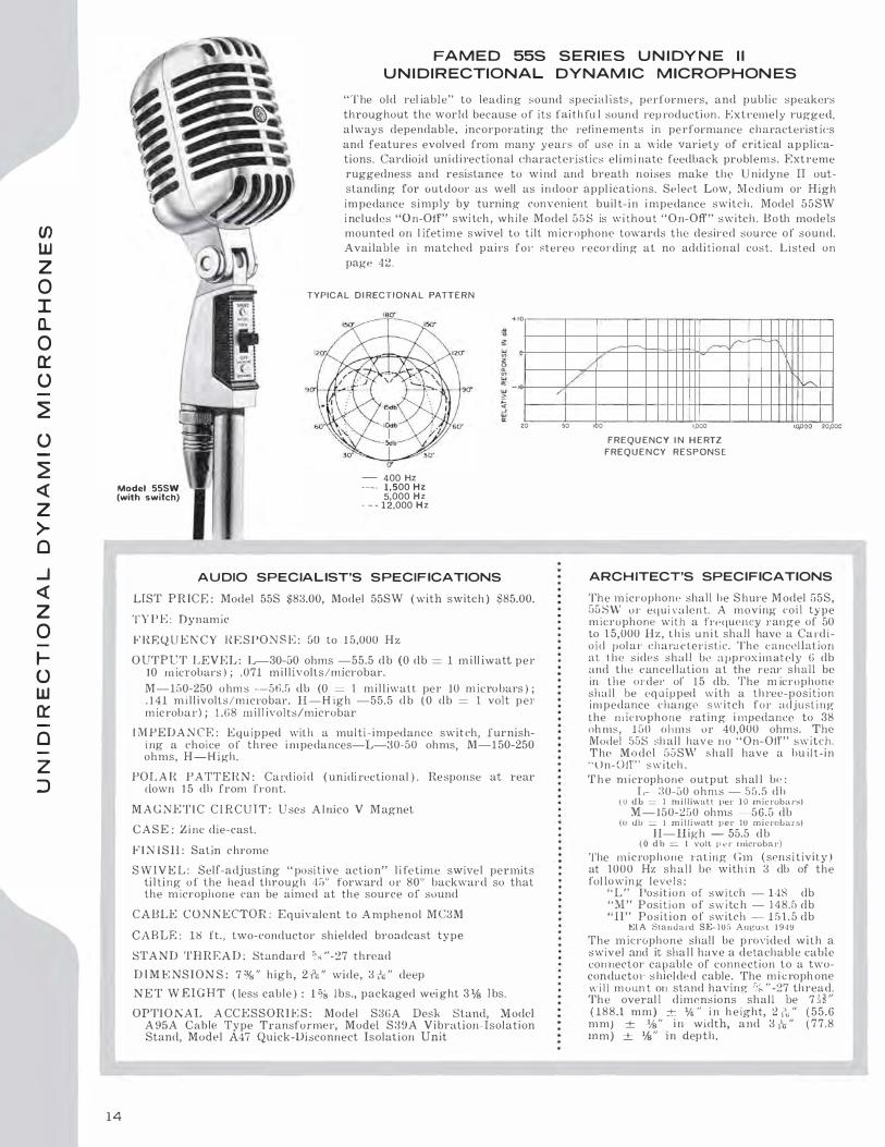
M O D E L 5 4 6 U N I D Y N E I l l
Top-of-line version of smallest prnbe-type, truly cardioid rnic rnphone avail<lble. HemarkaiJly faithrul sound reprndul'tion makes it ideal for brnadcasting, recording, and lop quality puLlic addn'ss applications. Low frequency response makes it a favoi·ite for pickup of drums and bass instl'umentsprevents over-elllphasis of bass. The cardioid 1H·operties are uniform at all frequencies and symmetrical about Lhe axis of the microphone, which provides effective rejection of sound frorn il1e sides and t·eaL This means greater reduction of feedback and "boominess"-as well as imprnv(�d tonal quality of speech and music. Smait black and satin chrome finish and r:ompact modern design make the Unidync III adaptable to every installation. :Model 54G comes complele with live-ruhue1· shock mounting, lifetime swivel, combination impedance-ON-OFF switch, and windscreen fo1· outcloo1· use. Available i n matched pait·s for stereo broadcasting and i·econling at no additional cost. Listed on page 4�.
TYPICAL DIR(CllON.l\L PATTE:AN
� NOTE: Directional patterns show polar response at six frequencies.
a �+IQ w (/) z 0 e; 0 w a: w 2'. '.ii 10 w a:
20
/ 50
--
-� _./ v
/ 100 1,000
FREQU ENCY IN H ERTZ
FREQUENCY RESPONSE
A U D IO SPECIALIST'S SPE C I F ICATIONS
LlST PRICE: $ 13G.OO
TYPE: Dynamic
F'REQUENCY RESPONSR: 50-15,000 Hz OUTPUT LEVEL: 50 ohms: - -56 db (0 db-= 1 mi ll i watt per 10
microbars ); .067 millivolts/rnicroLar 250 ohms : -56 db (0 db= 1 milliwatt per 10 microbars) ; .l 49 mill ivolts/rnicrobar
IMPEDANCE: Dual. Choice of 50 or 150 ohms. (To match all low im pedance inputs, 50 to 250 ohms.)
DTAPHHACM: Shu1·e "Duracoustic"
POLAR PATTERN : Cardioid. ( Uniform with frequency, sym-metrical about axis)
MAGNETIC ClHCUlT: Uses Alnic o V Magnet CASE: Die-cast zinc and "Armo-Dur" FINISH: Satin chrome and black. SWIVEL: Self-adjusting "positive action" lifetime swivel permits
tilting of the head through 180° so that the microphone can be aimed at the so urce of sound.
S H OCK MOUNT: Special vibration-isolation unit of live-rubber construction
SW ITCH : Impedance selection switch with center position "Off" CABLE CONNECTOR: Equi pped with Cannon XL-3-11 connector CABLE: 20', two-conduetor shielded broadcast type STAND THREAD: % "-27 thread DIMENSIONS: (Swivel not i ncluded ) 11;{" diameter, 5,'n" length NET WE IGH T ( Less c able ) : 1 Ys l b., packaged weight 3% lbs. OPTIONAL ACCESSORIES: :Model S33B Desk Stand, Model A95A
Cable-Type Transformer, Model S39A Vibration-Isolatio11 Stand, Model A45 Q uick-Disconnect Isolation Unit, Model A 2WS Windscreen.
L--,_ ,_
I'- h
10,000 20,000
U.S. Patents: 3,1:l2,713 and
D-190,864
ARCHITECT'S SPECI FICATIONS
The microphone shall be Shu re Model 546 or equivalent. A moving coil type microphone with a frequency range of 50 tu 15,000 Hz, this u nit shall have a cardioid pol ar characteristic. Th e cancellation at the sides shall be approximately 6 db and the cancellation at the rear shall be 15 to 20 db. The microphone shall be equipped with a three -position impedance-"Off" s witch for adjusting the microphone rating impedance to 38 ohms-150 ohms.
The microphone output shall be:
50 ohms i mpedance -56 db (0 <lb== 1 milliwatt )JCr 10 microhars)
250 ohms impedance -56 db (0 db== 1 milliwatt per 10 microl.iai·s)
The microphone rating Gm ( sensitivity ) at 1 ,000 Hz shall be within 2: 3 db of the following levels:
Low Impedance -149 db Medium Impedance - 1 48 db ETA Staudai-d SE-105 August 1Y49
The mi crophone shall be provided with ·a swi vel adjustable through 180°. The mi crophone shall be equipped with a vibration-isolation unit in combi nation with the :>tand connector and i t shall have a detachable Cannon cable con nector. The ;nicrophone will mount 011 a stand having % "-27 thread. The overall dimensions shall be 8" in height, and 11;{" in diameter.
7
c z
0
::u m (') -f
0 z )> r
0 -< z )>
s:
(')
s:
(') ::u 0 "U I 0 z m en

(J) UJ z 0 I: n. 0 a:: u -
� u -
� < z > c .J < z 0 tu w a:: -
a z ::>
problem-solving UNIDYNE ill series . . . t he true cardioid microphones
8
. . designed for critical applications where
FA M O U S U N I D Y N E I l l
I .,
1 0.�. :· '
The wo1·ld's fi nest molk rntcly p l'i C'ed d y n a rnic ca1 ·d iu id m i c rnphonP for p u li l i c address systrm US<'. Tlw U n idylle I l l a p p roac ht,s lilt' theoret iea l ideal of the canl i o i d p i ek up pat l<' rn . T h i s means L'Olllpletc l y u 1 1 i fo rn1 p i ck u p a l iou t tlw a x i s at al l frl'qucnciPs- i n a l l p lanes. ( T he advantag('S o f t h i s u n i fo l ' lnity o f p icku p :1 1 '" de 1 11on st rnt ed in t h e l 'h�1 1'l on t h e fa(' i n p: page. ) Hcn1<1 l'k:1 h l y fai t h fu l rep nJduct ion of t lw h u n 1ai1 voice rn;1 kcs tlw U n i dyrw I J I a superiol' choieP fo r p u b l ie-a dd1·css a p p l il'.at ions. Loi\' f r <'< jU( 'ncy l'.haradPri s
I ·. I }1 .. i
M o d e l 5 4 5
(On S 3 3 B Desk stand)
M o a e l 5 4 4
M o d e l 5 4 5 5
AU DIO SPECIAL IST'S SPEC I FICATIONS
LIST PRICE : Model 5458 $89.95 Model 545 $85.00
Model 544 $80.00
Model 544-GG $83.00 Includes 6" flexible goose neck and mounting flange. Model 544-G12 $83.75 Incl udes 1 2" flexible gooseneck and mounting flange. Model 544-Gl8 $85.00 I ncludes 1 8" flexible goose neck and mounting flange.
TYPE : Dynam ic
FREQ U E N C Y R E SPONSE : f>0-15 ,000 Hz
O UTPUT LEVEL: Low : - 57 db (0 d b _ 1 m i l l iwatt pe1· 1 0 rnicrobars ) ; . 14 1 m illivolts/micl'obar. Jl igh : -55 db ( 0 db = 1 volt per microbar ) ; 1 .760 m i l l ivolts/microbar
I M PE DANCE : Dual. Choice of 50-250 ohms or High
D I APH HAG M : Shme Dumcoustic
POLAR PATTE HN : Card ioid. ( Un ifo l'm with frequency, symmetrical about ax i s )
M A G N ETIC CI RCUIT: Uses Alnico V Magnet
CAS E : D ie-cast z inc and "Armo-Dur"
FIN I SH : Satin chrome and black
SWIV E L : Self-adjusting " Posi tive Action" l i fetime swivel perm its t i l t ing of the head through 1 80 ° ( Model 545, �JO " ) so that the m icrnphone can b e a i med a t t h e sou rce o f sound.
CABLE CONNECTO R : Models 545S and 545 : Equivalent to Amphenol M C4 M plug. ( Model 544 has attached cable)
C A B L E : Models 545S and 545 : 18 ft., three-conductor shielded Model 544 : 7 ft., two-conductor sh i el ded .
STAND THREA D : o/s "-27 thread
DIMENSIONS l\fodeJ 545 : H 1 " diameter, 5 li\ " length
NET W E IGHT : Model 545S, 1 4 oz., Model 545, 10 oz., Model G44, 1 3 oz. Packaged weight, Model 545S, 2 1/t lbs., Model 545, 2 'Is I bs.
OPT I O N A L A C C E S S O R J E S : Model A95A Cable-Type Transformer, Model S39A Vibration-Isolation S tand, Model A2WS Windscreen, .Model S3GA Desk S tand for Mode l G4GS, Model S33B Desk Stand for Model G45, Model AA7 Qu ick-Disconnect I solation Unit
t ics of the U n idvne T l I el i m i nate boom i ness , and mal�e i t a favorit< ' fo1· p i c k u p of drums an d hass inst rn rnl'nts. Stl' i k i ng hlark and satin clwunw fi n ish i n compact 1 1 1odr·n1 dPsign rnakPs the· U n i dy1w l T l a sty l i sh addi t ion to any p l a t fol ' ln . M1ide l 545 is s u i talcle for hamllw l d and ·o l' st a nd u s r' w i t h Mod1•l A 2 5 B S w iv<' I A d<1 1 J tor included. Model 5 ·15S i s mounL1·d on l i l'Pti nw s\\' i \'e l and i ncl udes on-oil' S\\' i t r·h . M orie! ;, 44 i s fu r n i sh ed \\' ith <'.able al l a<'lwd ;md i ,; desigm�d fo1· gooseneck mo untings. Ava i la b l e in rnakl1ed pa i 1·s for s te 1·eo reconl ing at no add i t i ona l cost. Listed on page 42 .
A R C H ITECT'S SPECIFICATIONS
The micl'OµhonP sh a l l he Shu re Modd 545, ( G45S ) , ( 54 4 ) or eq u i valent . A rnov ing coil type o f 1 1 1 icl'Ophone with a frequency range of 50 lo 1 5 ,000 H z , this un it shal l ha,·e a Ca rdioid po lar <' h a l'acteristic. The cance l lat io n at the s ides sball be approx i mately G 1 lb and th e cancel lat ion at the rear shal l be lG Lo 20 db. The m icrophone shal l be a dual-impedance m icrophone having a rating impedance of 150 ohms and 40,000 ohms. The microphone output shall be :
Low : -57 db ( 0 db = l mil l iwatt per 10 m icrobars) H i g h : -.55 db ( 0 clb = l volt per micruba r )
The m icrophone rating G m ( se11sit i\'ity ) at 1 000 Hz shall be with i n 3 db of the fo l lowing level s :
Low i m pedance -J49 db H i gh impedance - l fi l clb
ETA Standard SE- 105 August 1 94!J For Model 545:
fhe 1\'lodel 545 Microphone s ha l l be p rn,·i ded with ,a swivel adapter adjustable through 90 ° from ,·ertica l to horizontal and a receptable equ i,·a lcnt to the Amphenol M C·1F capab le of connect ing to a three-conductor shielded cable plug. The micrnphone swivel adapter w il l rnot:nt on a stand having % " -27 th read. The o\'e1·al l dimens ion sha l l be 5 \ � " ( 1 '17.6 m m ) + ,;'., " i n length a nd I V " ( 3 1 .4 mm) + ,,'.,-'' in diameter.
For Model 545S: The Model 545S Microphone shall be prov i ded with a swive l , a built- in on-off swi tch and a 1·eceptaele eq u i valen t tu the Amphf'J1 01 M C 4 F capable of connect i ng tu a 3-conductor shielded cable p lug. The minoph one s h a l l mount on a stand h aving �s "-27 th rea d . The overall dim r,nsion shal l be 7 f.� " ( 200.7 m m ) _+_ "' r " i n l ength, H -f' (. 1 2 . 1 mm) i n depth and l U '' ( 3 1 .4 mm ) ± ,f, " i n d iameter. The Model 544 M i l'. t ·ophone s ha l l be pl'Ov id0d w i t h a fi xed adap te r hav ing a % " -27 thi ·ead. The overn ll dimension sh a l l Le 7 ·; ; '' ( 194.G mm ) ± }2 " in length and U i " ( 3 1 .4 rnrn) ctr " in d iarnetel'.

with pickup symmetrical about axis at all frequencies . . . in all planes
sound system problems seem insurmountable \ i ';-tr
� - J�U��,?i\;o t<1
---- -----�
M o d e l 5 4 5 5 Un i d y n e I l l
The world's finest moderately p1·iccd dynamic cardioid mi<:rophonc for g-eneral lJUrpose and p u blic address system use. In addition to its outstanding- pickup charal'teristics, the U nidyne I I I i s designed throughout for supcrio1· reproduction with utmost convenience and distingu i shed a ppearan<.'e :
Smal lest of the u n i dircdional m ic rophones B u i l t- i n "On-Off" switch I mp roved swivel permits tilting of head through 1 80" so microp hone can be "aimed" at the source of sound
Imagine a perfectly round balloon-now, puke your finger i n to one side of it and push i n hard . . . the resu l tant configuration represents the ideal symmetrical pickup pattern of a card ioid microphone. Ideally, thio pattern should he broad at thP front , u n i form a t all f requencies-with uniform sound quality at any poin t within t h e pattern, off-axis as well as on-axis. Otherwise,
FREQUENCY RESPONSE F R EQ U E N C Y IN H E RTZ
even sl igh t movements of the perfo rmer about the axis tend to disto1· t the sound. And, unless the pattern is symmetrical , i t is p rey to feedback ereati ng floor a n d ceiling reflected sound waves. T h e U n idyne lTJ comes closest of any popu l a r P.A. microphone in reach i ng- the ideal . . . its pattern i s totally symmetric-al ( there i s no hi dden lop or bottom bulge ) . . i n faet, it i s t ruly c a rd ioid at frequenc ies as low as 70 I l z !
W h a t t o L o o k F o r : Study the pickup pattern of the U n i dyne I I I . Note its relative u niformity at ALL frequencies. Compare th i s to the patterns of other m icrophones which become sh arply less d i i·edional as frequency drops unti l at very low frequencies, they becom e omni directional. Note that the U n idyne III on-axis ( sol id line) and offaxis ( dotted l ine ) response is virt u a l l y the same. l'\ute a l so the smoothness of response. The cunlrullcd rol l-off at the low end prevents "boorny" sound.
These common microphone problems can be solved only with the Unidyne III PROBLEMS CAUSED BY INEFFICI ENT REJECTION OF UNWANTED SOUNDS BY THE MICROPHONE
S I T U ATIO N
C O L U M N
LOUDSPEAKERS
REV E R B E R A N T
B O O M
I
P RO B L EM Feedback occurs where a soca l l ed "card io id" m ic rophone is used and the speakers are placed to the rear of the microphone. A common occurrence in churches, aud i tor i ums , and mee t i ng rooms.
Unexplained feedback. Column loudspeakers are used to distribute sound more evenly to the audience in churches and auditoriums.
A disturbing, echoing effect of low frequency sound often found in churches, large auditoriums, and arenas.
C A U S ES Sound bounces oH hard surfaces on the
�a�
l�,u��0�c��re�
e��J·t�� ���,������
used is not ettective in rejecting these sounds at all frequencies, and in all planes about its axis.
Wh i l e col umn speakers d i rect the sound toward the audience, they also have side and rear sound lobes which may reach the microphone. Feedback occurs when the rear and side sound lobes of the speakers coincide with the rear and side lobes of a so-cal led "cardioid" microphone.
The particular "cardioid" microphone used fails to retain its unid irectional characteristics with low frequencies. I n addition, its front response tends to accent low frequencies of tne desired sounds. These factors result in pickup and reinforcement of the low frequency reverberation and boominess characteristic of many hall s.
S O L U T I O N The Unidyne 1 1 1 el iminates this problem because of ettective rejection of sound at the rear of the microphone with unifo rm i ty at a l l f requencies". Sounds bouncing off the floor or other reflective surfaces that reach the rear of the Unidyne I l l are rejected.
b�6bl��idb�6a�� �lv��s
th�6
rear or side lobes. Thus it rejects the side and rear lobes of the sound column speakers.
Using the Unidyne I l l M icrophone wi l t solve the problem because it maintains a uniform pattern of sound rejection in ar1 frequencies. even i1 S low as 7 0 cps. The frequency response also has a controlled roll-OH of the low end. Th i s prevents rei nforcement o f the low frequency reverberation and diminishes the effect of a boomy hal l .
PROBLEMS CAUSED B Y THE MICROPHONE'S I N EFFECTIVENESS IN PICKING UP THE D E S I R E D SOUND
G R O U P COVERAGE
WITH O N E M I C R O P H O N E
VAVAV U S I N G M U LTIPLE
DISTANT P I C K U P
V v
A single microphone does not p rov ide u n i form coverage of a group. This is commonly experienced with choral groups, quartettes, ins t rumenta l combos, and speaker panels.
Variation in the pickup level a nd tona l qua l i t y ex ists throughout the broad area to De covered. This may occur in stage pickup of musical and dramatic productions, panels and audience participation events.
Too much background noise or feedback results when
d'����J d����n�cf������,,t:tJ source.
The oarticular "cardioid" microphone used lacks a uniform pickup pattern, so that persons in different positions with in the general pickup area of the microphone are heard with varying tonal quality and volume.
The pickup pattern ot the microphones used is too narrow, causing "holes" and "hot spots''. The oH-axis frequency response of the microphones also varies.
So-called "cardioid" and particularly long range microphones being used are less di rectional with lower frequencies. In addition, they have lobes or hot spots that pick up sound at the rear, resulting in the background noise or feedback problem.
The Unidyne 1 1 1 affords urnforrn pickup of the group with a resu l t i ng cons i stency i n volume and sound quality among the members of tt1e group.
The Unidyne 1 1 1 permits a smoothness in pickup as the
���d ci������e P�N�r�ni���r��
ity throughout the coverage area. This e l iminates "holes'°. "hot spots". and the var iat ions in sound quality and permits blend ing many microphones with ease.
Use the Unidyne 1 1 1 to gain relatively long range with el· fectivc reJection of sound at al l frequencies '1t the rear of the microphone.
9
c z -0 ::a m 0 -I 0 z )> r
0 -< z )> s 0 s 0 ::a 0 "U :c 0 z m (/)

en w z 0 I 0.. 0 0:: 0 � 0 � <{ z >-0 _J <{ z 0 � 0 w 0:: 0 z :J
1 0
M O D E L 5 4 5 L U N I D Y N E I l l L A V A L I E R M I C R O P H O N E
The n ewest addit ion to t h e " : hU I'<' U n i dyne I l l Li ne of canl ioi rl dynamic micrnphones. SpPcifica l ly des i gned for us.- a s a l a va l ie l ' m i e rophont' to p rovi de tlw u ser with freedom of movement a11d the fu l l use of l!oth h ands.
lt is l!y far the most versat i le m i crophone in the U n i dyne Series bc•eause in adrlition t o i ls a p p l ications as a laval ier 1 1 1 i c rnphone ( w i lh the l a va l i f'r conl a nd cl ip a ssemb l y p ro v ided ) th i s U n i d y rw m i c rn p honc e a 1 1 a l so b e used as :
A Hand-Hel d M i c ro phone.
A Stand-M ounted M i croph one ( when u sed with the opt iona l Shure Mod(' I A25B S w i ve l Stand A d ap ter) .
A G oos<'neck or FixPd Mounl<'d M icrophone. T11 add i tion to lhP vnsat i l i t y i n u s ag-<', tlw pe l ' fon nance in ea ch of these f u nct ion s is su1w rb becau se of the tn1e card i o i d p i c kup patlern that i s c h araderislie of the> U n idy1 1e 111 pe1·foJ'll1ance. T h e u 1 1 if o rn 1 n•jPdion of sou n d at the rear and lo the sides of the m i e ro p h o ne mi n i m i ze pickup of s u r rou nd i n g- sounds f rom ot he r pPrfonn e 1·s. C lot h i ng- a n d eablP 1 10is<' p ickup a t«' a l most non -e x isten t d u e to the m i c rnphonc> ca 1·t1· i dg-P bei n g· sh()(.:k-mou n t<'d .
T h e o\·eral l response of G O to J G,000 Hz i s id P a l f o r h1\·al i e r u s e a n d ot her uses where ex .. e l l e n l repro<l uc t ion o f Yoiee a11d rn usic i s 1·eq u i rc>d.
., T - I I - I I
__l ______,..,,,. � / I I ... /' I
I 1,000 �,,z-f · -r"_
•"'=:.�:::.�·,, " � '
,
v
-
_-
FREQ U E N C Y I N H ERTZ
FREQU ENCY RESPONSE
-
\ -
t0,000 20,00C
TYPICAL
D I R ECTIONAL PATTERN U. S. Patents :l. J :J;> , 7 J :l - :J . ;' 4 0.hS:J " "<l I J l 90.Sti4
A U D I O S P E C I A L I S T S ' S P E C I F I C A T I O N S
L l ST Pl{ I C E : Model 5 4 5 L $ 70.00.
TYPE : Dynam i .. .
F H E Q lJ E N CY RESPO T\ S E : G 0 - 1 5,CIOO Hz.
O U T P U T L E V EL : -57.5 d b ( 0 d h - l m i l l i watt per 1 0 rn i cru lJars ) ; . L OO rn i l l iv o l ts / n 1 i c robar.
I M P E D A NCE : 1 50 ohms ( to match all low imped ance input, 50 to 250 ohms) .
D I A P H R A GM : S hu n• D uraco ustic.
POLA R P A T T E RN : Ca rd i o i d ( un i form with frequency, sym -met rical a l iout axis ) .
M A G N E T I C C I R C U I T : Uses A l n i co V Magnet .
C A SJ<; : A l um in um a n d "A nno- D u r. "
F l N l S H : Sa ti n a noel ized an d black . C A BLE : N ondetachable 20-foot two-conductor shieldl'd.
D I M E )I S l O N S : l % " diameter, 5 Vs " length. NET W E T G I I T : 7 ou nces, pa .. kaged we i gh t : 2 l b s .
F U R NI S H E D A C C E S S OR I E S : Lava l i er a ssembly and bell cl i p .
O PT I ON A L ACCESSOH I E S : Mode l A25D S\\" i\'el A d aptc>r, Model A! 15A Cable-Type Trnnsfonner, Model S39A Vi brat ion-Isolation Stand, M odel S33B Desk Stand, M odel A2WS Windscreen.
ARCH ITECT'S SPECIFICATIONS
The> m i nophon" shal l be S h u re M odel
54 5L 01· cquiva knt. A mov i n g coi l m i c ro
phone w i t h a frequency range of 50 to
l G,000 Hz, th i;.: u n i t shal l have a card i oid
d i rect ional charnd e 1· i s t ic . The cance l la
tion at t h e s ide:; s h a l l be approxi ma tel y
() du, and lhe can .. ellation at t.he reai· shal l
be 1 5 lo 20 db. The l ll i noplione shall be
a s ingle i rnpPdance m i c rophone h a \·ing a
rated i mpedan ce of 1 50 o h m s. The rn ierop h o n e o u t p u t shal l IJe -57.5 d b w he1·e 0 db - J m i l l iwat t with 10 rn icrohars. The
m icrophone 1·ating G rn ( sensitivity ) at
l ,000 Hz sha l l be w i thin , 3 db of 1 5 1 .G
db ( EI A Standard S E - 1 05, A ugust 1 949 ) .
The rn i nophone shal l b e provided w i th a
l aval ier cord a11d d i p assembly fo1· use a s a wc·a rable m i crophone . The m i c rophone
sha l l be pro v ided with a 20-foot t wo-con
d uctor sh i el ded cable. The overall d i men
s ion s h a l l be 5 Y< " ( 1 30.2 mm) i n length
and 1 '4 " (31 .8 m1t1 ) in d i ameter.

MODEL 566 U N I S P H E R E I U N I D I R E CTIONAL DYNAMIC M ICROPHONE
I n troducing a superb unidirectional shock-mounted dynamic microphone with a l l the characteristics of the famed Unidyne m icrophones, plus the following features : A strong, built-in, wire-mesh sph erical front that contains a very effective fi l ter designed to provide excellen t p rotection from wind and " pop" ( explosive breath sounds ) , AND a built-in vibration- isolation shock mount which prevents the p ickup of mechanical vibrations and handling noise. The Unisphere I provides w i de range reproducti o n of voice and m usic, and can be effectively used both indoors and outdoors. In addition, the exceptionall y uniform and effective u nidirectional pickup p a ttern provides an easy solution to feedback problems in reverberant l ocation s ; perm i ts best uti l ization of
space in small studios ; faci l itates orchestral placement ; and provides practical ly complete exclusion of unwanted noises.
I deal for use by professional entertainers in h igh qual i ty theatre-stage sound systems, indoor or outdoor recording,
cathedrals and churches, and critical publ ic-address systems such as those used in political conventions and
legislatures, convention halls, hotels, public auditoriurns, stadiums, etc.
E::lr'\t-+-1... Available i n m atched pairs for stereo broadcasting
TYPICAL DIRECTIONAL PATTERN
TYPICAL DIRECTIONAL PATTE.RN
and recording at no additional cost. Listed on Page 42.
NOTE : A vailable June . HJ67
� NOTE: D I RECT I O N AL PATTERNS SHOW
..,, .. 10 � w � z 0 � 0
POLAR RESPONSE AT S I X FREQ U E N C I ES
1,000 FREQUENCY IN HERTZ
FREQUENCY RESPONSE
10,000 .?0,000
U.S. Patents 3, 1 32 , 7 1 3 and 3 , 240,883
A U D IO SPECIALIST'S SPECIF ICATIONS
LIST P R I C .8 : $ 1 4 0.00
T Y PE : Dynamic.
FR E Q U E N C Y JrnSPO N SE : .50 - 1 5 ,000 Hz.
O U TPUT LE V E L : 50 oh m s : -f>5 db (0 db = l m i l l i waLL per 1 0 microiJars ) ; .075 millivolts/m icrobars. 250 ohm s : -55 db (O db = 1 m i l l i "·att per 10 rnicrobars ) ; . 1 58 mil l i vol ts,'m icro bars.
I M P E D AN C E : Dual . Choice o f ::W-50 ohms " L " or 1 50-250 ohms " H ," selected by impedance switch.
D I A P H R A G M : Shure "Durncoustic."
POLAR PATTJ.;RN : Cardioid. ( U n i form with frequency, symmetri-cal about axis . )
M A G N ETIC C IR C U I T : U ses A l n ico V Magnet.
CA SE : Die cast zinc \\"i t h steel mesh gl'il l .
F I N I S H : Sat i n c h rome a n d black.
S W I V E L : New im proved sel f-adjusting "Positive Action" l i fetime swivel permi ts t i l t i ng o f the head t h rough 1 80 ° so that the microphone can be a imed at the source of sound.
S H OCK MOUNT : Special vibrntion-isolation unit of l ive-rubber construction.
S W ITC H : I m pedance selection switc h w i th center position "OFF."
C A B LE C O N N F.CT O R : Equipped with Cannon XL-3 - 1 1 Connector.
CABLE : 18-foot, ( 5 .5 mm ) two-conductor s h ielded.
ST A N D T H HEAD : �� " -27 t h l'ead.
D I M E N S IO N S : ( Sw iv0! not included ) 2 :i" " diarnetel', 6 % " length.
N E T W E I G H T : ( Less cable ) B'1 pounds, packaged weight 2 % pounds.
OPT I O N A L A C C E S S OR J E S : Model S33B De:ik Stand, Model A95A Cable-Type Transformer, Model S39A V ibration- I solation Stand, Model A45 Quick-Disconnect I solation U n i t.
ARCH ITECT'S SPECIF ICATIONS
The m icrophone shall be Shure Model 566 or equivalent. A m oving coil ( dynami c ) m icrophone with a frequency range of 50 to 1 5,000 H z , this unit shall have a card ioid polar charactel'istic. The cancellation at the sides shall be 1 5 to 20 db. The microphone shall be equ i pped with a three-position i mpedance "Off" switch for adjusting the m icrophone rating impedance lo ::!8 ohms- 1 50 ohms.
The microphone output shal l be : 50 ohms im pedance -55 db ( 0 db = 1 m il l iwatt w i t h 1 0 rn iaobars )
250 ohms impedance -55 db ( 0 db = 1 m i l l iwatt with 1 0 microbal's)
The m icrophone rating Gm ( sensitivi ty ) at 1 ,000 H z shall be within ± ::l db of the following levels.
Low Impedance -148 db Medium I mpedance _ _ -148 db
F.IA Standard S E- 1 0 5 August 1H49
The microphone sha l l L>e p rovided with a swivel adjustable through 1 80 ° . The m icrophone shall Le equ ipped with a vibration-isolation unit in combination with the stand co11necto1·, and it shall have a detachable Cannon cable connector. The m icrophone will mount on a stand having- % "-27 thread.
The overal l d im ensions shall be 5 :/\ " ( 134.1 mm ) i n height, 2 12 " ( 5 1 .5 m m ) i n width, and (jl;'., " ( l'i':�. l m m ) in depth.
1 1
c z
0
;o m (") �
0 z l> r
0 -< z l>
s::
(")
s:: (") ;o 0 "'O I 0 z m CJ)

en w z 0 I Q. 0 0:: u � u � <{ z >-0 ..J <{ z 0 lo w 0:: 0 z :J
1 2
THE MODEL 565 SERIES UNISPHERE I MICROPHONES
Solves major public-address system problems due to feedback boominess . . . " POP."
Now ! You can get all the superb, world-renowned feedback-control and uniform cardioid pickup pattern features that have made the Unidyne family of microphones the industry standard for solving difficult public-address problems - with the added problem-solving abil ity afforded by special filter assemblies that effectively control explosive breath sounds ( " POP") and minimize wind noise in outdoor locations (el iminating the need for windscreens ) .
The Unisphere I provides excellent reproduction o f voice and music - can be effectively used outdoors and indoors, and is ideal for use by professional entertainers, teachers, lecturers, and politicians -wherever reliable microphones are required for use in the highestquality public-address systems.
Model 565 is without "On-Off" switch while Model 565S includes an "On-Off" as a part of the receptacle swivel assembly.
Matched pairs are available for stereo recording. Listed 011 Page 4 2.
5655 565
NOTE : Model 56GS Available June, 1 967 U . S . Patent 3 , 1 32,7 1 3
FREQUENCY IN H ERTZ
FREQUENCY RESPONSE
AUDIO SPECIALIST'S SPECI F ICATIONS
LIST PRICE : Model 565, S95.00 ; Model 5<i5 S , $ 100.00
TYPE : Dynamic
FRE QUEN CY R E SPON S E : 50 to 1 5,000 H z
O UT P U T LEV E L : Low : -57 d b ( 0 d b = 1 m il l i watt per 10 microbars ) ; . 1 4 1 mil l ivolts/microbar. High : - 54.5 db ( 0 db = l volt per rnicrnbar ) ; 1 .88 m i l l ivolts/rnicrobar.
I M PEDANCE : D ual . Choice of 50-250 ohms or H igh.
DIAPHRA G M : Shure "Duracoustic."
POLAR PATTE RN : Cardioid. ( Uniform with frequency, symmetrical about axis ) .
M A GNETlC ClRC U I T : U ses A lnico V Magnet.
CASE : Chrome-plated, die-cast and steel mesh gril le.
F I N I S H : Satin chrnme, black and chrome p lated.
SW I VE L : Self-adjusting "posi tive action" l ifetime swivel permits til ting of th e head through 180 ° ( Mode l 565, 90" ) so that the microphone can be aimed at the source of sound.
C A B L E CONNECTO R : Equivalent to Amphenol MC4M Plug.
CA BLE : 1 8-foot t hree-conductor shielded.
STAND THREA D : % "-27 thread.
D l ME N S l ON S : Model 565 2" diameter, 6Y:i2" length. Model 5G5S 2" d iameter, 611/ta" length.
NET W E I GHT : Model 565 1 0 1/z oz., packaged weight, 2 \I.I lbs. Model 565S 1 lb., packaged weight 2% lbs.
OPTIONAL ACCESSOR J E S : Model A95A Cable-type transformer ; Model S39A Vibration-isolation Stand ; Model S36A Desk Stand for Model 565 8 ; Model S33B Desk Stand for Model 565 ; Model A47 Quick-Disconnect Isolation U nit.
TYPICAL D I RECTIONAL PATTERN
ARCHITECT'S SPECIFICATIONS
The microphone shall be the Shure Model 565 ( 565 S ) or equivalent. The m icrophone shall be a moving-coil type m ic rnph one with a frequency range of 5 0 to 1 5,000 Hz. This unit shall have a "cai·dio id" horizontal polar characteristic. The cancell ation a t the sides shall be approx imately G db, and the can<;el lat ion at the rear shall be 15 to 20 db. The rn icrophone sha l l be a dual-i mpedance m icrnphone h a v i ng rating im pedance of I 50 ohms and 40,000 ohms.
The microphone output shal l be: Low : -57 d b (0 db = 1 mi l l iwatt per 10 micro-
bars ) High : -54.5 db ( 0 d b = 1 volt per micrnbar )
The m icrophone rati ng Gm ( sensit iv ity ) at 1 ,000 Hz shall be w ith in 3 db of the fol lowing leve l s :
L o w I mpedance . . - 148.5 db 11 igh Impedance . . . . . . . . . - 1 50.5 db
EIA Standard SE-105 August 1949 For M odel 565
The M odel 565 mici·ophone shall be provided with a swivel adapter adjustal>le through 90° from vertical to horizontal and a receptacl e equivalent lo the A m phenol 91 -MC4F capable of connecting to a three-cond uctor shielded cable plug. The m icrophone swivel adapter will mounl on a stand h aving % "-27 thread. The overall d imension shal l be 6Y:i�" ( 153.2 mm ) in length and 2 " ( 50.8 m m ) in diameter.
For Model 5658 The Model 565S m icrophone shall be provided with a swivel, a built-i n O N-OFF switch and a receptacle equivalent to the Amphenol 9 1 -M.C4F capable of connecting to a th ree-conductor shielded cable p lug. The microphone shall mount on a stand having % "-27 thread. The overall d imension shall be 6l�i;/' ( 1 56.8 mm ) in depth, 2" ( 50.8 m m ) in diameter ( width ) , and 5 ·A " ( 131.8 m m ) in height.

.0
� ..a w (/) z 0 lJ; 0 w a: w > ;:: :5 - 10 "' a:
M O D E L 5565 U N I D Y N E I I
SHOCK-MOU N T E D M ICROPHONE
The world's most famous mierophonc lwcause o f its wide popula rity a n d u n i versal acceptance. Incorporates a l l lhe refinemPnts in appea rance a n d features d i ctated by many years o f use in a wide variety of appl ications_ The Ca rdioid, un id in•dional cha 1·acter ist ic , achi eved through the patented Shu 1·e "U n iphase"
netwo 1·k, provides efTedive rea 1· n"jedi on to e l i m inate feedback problems. Extremely rugged conslrnction and res i sla 11ee to w ind and breath noises make the Model 5 5GS outstanding for outdoor appl icat ions as well as most indoor broadcasting, recordi ng, and h i gh qual i t y publ ie-address, t heatre-st age sound systems. Tmpedance swi tch penn i t s select ion o f low, medium, o r high impedance. A cl ass i c of rn icroph011e des i gn , fini shed in s at in ch1·ome an d mounted o n l ifet i me swivel and l ive-rubber shock mount . Ava i labl e in matched pairs for stei·eo 1·eco rdi ng at no ad di t ional cost. Listed on page 42.
TYPICAL D I RECT I O NA L PATTE R N
r-...___... '�I"\ ./
/ v ,, �V\
20 50 100 1,000 10,000 20,000 -- 400 Hz
FREQU ENCY IN H E RTZ
FREQ U EN CY RESPON S E
-------- 1,500 H z . . _ . 5,000 H z - . - . - . - 1 2,000 Hz
U . S . Patents: 2 , 237,298, 2.305,596 and 2,305,597
A U D IO SPECIALIST'S SPECIFICATIONS
LI ST PRICE : $ 135.00
TYPE : Dynamic
FREQ UENCY RESPON SE : 40 to 1 5 ,000 Hz
O U T P U T LEVE L : L-30-50 ohm impedance -56.5 db (O db = 1 mil liwatt per 10 m icrnbars ) ; .067 m i l l i volts/ microbar
M-1 50-250 ohm i mpedanee -57.5 db (0 d b = 1 m i l l iwatt per 1 0 microbars ) ; . 13 m i l l ivolts/miaobar
I-I-High -56 d b (0 db = 1 volt per microbar) ; 1.58 m i l livolts/ m i c robar
IMPEDANC E : Equipped with a Multi- impedance switch, furnishing a choice of 3 impedances-L-30-50 ohms, M-150-250 ohms, H-Iligh
POLA R PATTERN : Cardioid ( Un i directiona l ) Response at rear down l 5 db from front
MAGNETIC C I R C U I T : Uses A lnico V Magnet
CASE : Die-cast zinc
F I N I S H : Satin chrome
SWIVE L : Sel f-adjusting " Positive Action" lifetime swivel permits tilti ng of the head through 45° forward and 80° backward so that the microphone can be aimed at the source of sound
SHOCK M O U N T : Special vibration-isolation unit o f l ive-rubber construction
CA BLE CONNECTOR : Equipped with Cannon XL-3- 1 1 type connector
CA B LE : 20 ft . ( G.l m ) , 2-conductor shielded b roadcast type
STA N D THREA D : Standard % "-27 thread
D I M E N SI O N S : 7 %. " h igh, 2 i"i; " w i de, 3 /o" deep
N E T W E IGHT ( less cable ) : 2 l bs., packaged weight 3 1/z l bs.
O PTIONAL ACCESSORIES : M odel S33B Desk Stand, Model A95A Cable-Type Transformer, Model S39A Vibration-Isolation Stand, Model A45 Quick-Disconnect Isolation U nit
ARCH ITECT'S SPECIFICATIONS
The microphone shall be Shure Model 556S or equ ivalent. A moving-coil type microphone with a frequency range of 40 to 1 5 ,000 Hz, this unit shall have a Card i o i d horizontal polar characteristic. The cancellation al the s i des shall be approxi mately 6 db and the cancel lation at the i·ear shall be in the order of 1 5 db. The microphone shall be equipped with a three-position impedance change switch for selecti ng the m i crophone rating impedance to 38 ohms, 150 ohms, or 40,000 ohms.
The m icrophone output shall be : "L"-30-50 ohm impedance - 56.5 db
( 0 db == 1 milliwatt per 1 0 mkrobars)
"M"-150-250 ohm impedanee - 57.5 db ( 0 db = 1 milliwatt per 10 microba rs)
" H "-High - 56 db ( 0 db :....:: l volt pe:r rnicrobar)
The m icrophone rating Gm ( sensitivity) at 1 000 Hz shall be with i n ± 3 <lb of the following levels :
"L" Posit ion of switeh - 149 db "M" Position of switch - 149 db "H" Position of switch - 152 db
EIA Standard SE-105 Aug-ust 1949
The m i c rophone shall be p ro v i ded with a swivel adjustable from 45 ° forward and 80° backward. The m icrophone shall be equi pped with a v i bration-isolation unit in combination with the stand connector, and i i shall have a detachable Cannon type cable connector capable o f connection to a two-conductor shielded cable. The microphone wil l mount on stand having % " -27 thread. T he overall d i mensions shall be 7 % " ( 1 96.8 mm) ::!:: 14, " ( 6.4 mm) in height, 2 -,"c " ( 55.6 mm) ± 1h " (3.2 mm) in width, and 3 ii:- " ( 77.8 mm) ± 'h " ( 3.2 mm) in depth.
1 3
c z
0
;a m 0 -i
0 z )> r 0 -< z )>
�
0
�
0 ;a 0 1J I 0 z m (/)
en UJ z 0 I a. 0 0: ()
�
()
� <( z >-0
...J <( z 0
tu UJ 0:
0
z :J
FA M E D 55S S E R I ES U N I DY N E I I
U N I DI R ECTIONAL DYNAM IC M ICROPHON ES
" T he old rel iable" to leading sound specia l ists , performers, and public speakers
throughout the world because of its fai t h fu l sound rep rod uct ion . Ext t·eme l y rugged,
a lways dependable, incorporating the refin e ments in performance c h a racteristi<.:s
and features evolved from many years of use i n a wide variety of critical a p p li<.:a
tions. Cardioid uni d i rectional <.:haracteristics elimi nate feedback problems. Extreme
ruggedness and resistance to w i nd and breath noises make the U nidyne II out
standing for outdoor as well as i ndoor appl ications. Select Low, Medium or High
im pedance simply by turning" convenient bui l t-in i mpedance switch. Model 55SW
i ncludes "O n-Off" swi tch , whi le Model 5 5 S is w i thout " O n-Off" switc h . B oth models
mounted on l ifet i m e swivel to tilt m icrophone towards the desired sou rce o f sound.
Available i n matched p a i rs fo1· stereo recording at no additional cost. Listed on
page 42.
TYPICAL DI RECT I O N A L PATT E R N
180' +10
!/ -10 7[
20 50
O' - 400 Hz
l
)/
•00
---'-- ,,------,
1,000 FREQU ENCY I N H E RTZ
FREQ U E N CY RESPONSE
� �
1�
10,000 20,00C
Model 55SW (with switch)
---· 1 , 500 H z 5,000 H z
- - - 1 2,000 H z
14
A U DIO SPECIA L IST'S S PECIF ICATIONS
LIST P R IC E : Model 55S $83.00, Model 55SW ( with switc h ) $85.00.
TY P E : Dynamic
F l{EQ U E N C Y R E S PON S E : GO to 1 5,000 Hz
O UTPUT LEVEL : J�30-50 ohms -55.5 d b (0 db = 1 m i ll iwatt p e r 1 0 rn icrobars ) ; .071 m i l l ivolts/microbar.
M-150-250 o hm s --56.G db (0 = 1 m i l l iwatt per 10 m icro bars ) ; . 1 4 1 m i l l ivolts/micrnbar. H-H igh -55.5 d b ( 0 db = 1 volt p e r m ic robar ) ; l .G8 m i l l ivolts/microbar
1 M PEDA N CE : Equ ipped wilh a mu l ti - impedance switch, furnishi ng a choice of t h ree i mpedances-L-30-50 ohms, M-1 50-250 ohms, H-High.
POL A R P A TTE R N : Ca rd io i d ( unidi rectional ) . Response at rear clown 1 5 db from front.
M A G N E T I C C I H C U T T : U ses A l nico V M agnet
C A S E : Z i nc die-cast.
F I N ! S H : Satin c hrome
SWIVE L : Self-adjusting " posi tive action" l i fetime swivel permits ti l t ing o f the head through 45° forward o r 80° backward so that the m icrophone can be aimed at the source of sound
CABLE C O N N ECTOR : Equivalent to A mphenol M C3M
CABLE : 18 ft. , two-conductor shielded broadcast type
STA N D THREAD : Standard �" "-27 thread
D I M E NS I ON S : 7 % " h i g h , 213rr " wide, 3 -tc '' deep
N E T W EI G H T ( less cable ) : 1 % lbs., packaged wei ght 3 1/s l bs.
OPTI O .l\ A L A CCESSORI E S : Model S3GA Desk Stand, Model A 95A Cable Type Transformer, Model S39A V ibration-Isolation Stand, Model A47 Quick-Disconnect Isolation Unit
ARCH ITECT'S SPECIFICATIONS
The m icrophone shall be S hure M odel 55S, 55 SW or eq u i va len t. A moving coil type m icrophone with a frequency range of 50 to 1 5,000 H z , t h is u n i t shall have a Ca rd ioid pol ar characteristic. The e a n cel lation at t he s ides shall be a pprox im atel y G db and the cance l lation a t the rea1· s h a l l be in the 01·de1· o[ L 5 db. The m icrophone sha l l be eq u i p ped with a t h ree-position impedance change S ll' i tch for adjusting the m icrophone rat i n g i rnpedance to 38 oh ms , l GO o h m s or 40,000 ohms. The
Model 55S sh a l l have no " On-Off" switch. T he Model G5SW s h a l l have a bu i l t - i n " O n-Off" sw itch .
T h e m icrop h o ne output shal l be : L- 30-50 o h m s - 55.5 db
( U d b == l m i l liwatt per 1 0 microbar�)
M-150-250 ohms � ·56 .5 db (O t!U =- 1 milliwatt ver 10 microUars)
J I-High -- 55.5 d b ( 0 d b == I volt p e r rnicrobar)
The microp h o n e rating Gm ( sensitivity ) at 1000 Hz s h a l l be within 3 db of the fol lowing leve l s :
" L " Pos i t ion of sw i tch - 1-18 db " M " Posit i on of switc h - 1 48.G db " I I " Position of switch - 1 5 1 . 5 db
EI A StanJanl SE-10:> August 1 949 The m icruphone shall be p rovided with a swivel and it sha l l have a detachable cable con nector capable of connection to a twoconducto1· s hielded cable. The m i c roph one \\' i l l m oun t on stand having ';� " -27 thread. The overal l dimensions shall be 7 H " ( 18 8 . l m m ) ::+::: '4 " i n h e ight, 2 ,'c " ( 55.6 mm) ± %" i n width, a nd 3 /tr " ( 77.8 m m ) ± l/s" in depth.

I
MODELS 580SA and 580SB U N I DY N E A
U N I D I R E CTIONAL DYNA M I C M ICROPHON ES
Now, in the quali ty tradition of the Unidyne fam ily, t he new U n idyne A Seri es offers unidirectional problem-so lv ing features at an omnidirectional price ! W i th the Unidyne A, feedback problems can be solved even i n lowb udget publ ic-add ress systems - making this new m icrophone the ideal
choice where low cost is an importallt factor, yet quality rep!'oduction is essential. The bui l t- in O N -OFF switch has the pi-ovision for l ocking i n ON
position. May be u sed 011 a stand, o t· in the hand, indool's or out. A Model
A25B S w i vel Adapter with s� " sta nd t h read i s furnished. The attractive case is sat i n chrome w i t h bl ack " Armo-Dur" cap and sta in less steel gri l le . Choice
of h i gh - i mpedance Model 58USA, 01· low-impedance :vl odel 580SB. Model
;)80SA is ava i l a bl e in matched p a i 1·s at no add itional cost. Listed on page 42.
w >
' 1 1 �-+ I --
i
a: -<'O L_ __ L___ ___ �_L_--�----��-L�- -' 2<J ,ooo 10,oao 20,oco
F R E Q U E N C Y I N H E RTZ
FREQ U E NCY RESPO N S E
A UDIO SPECIALIST'S SPECIFICATIONS
LIST PR I C E : Model 580SA $59.00, Model 5 80SB $52.00.
TYPE : Dynamic.
F R E Q U E N C Y R E S PONSE : 50 to 1 2,000 Hz.
O U T P U T L E V E L : M odel 580SA . H igh : -56.5 db (0 db = 1 volt per rn ic rnbar) ; 1 .48 m i l l i volts/microbar.
Model 580 S B . Low : -57 d b ( 0 d b = m i l l i watt per 10 m icroba rs) ; . 1 0 5 m i ll ivolts/microbar.
I M PEDA NCE : M odel 580SA, High.
Model 580SB. 1 5 0 to 250 ohms.
P O L A R PATTE R N : Cardioid ( u n i fo rm with frequency, symmetrical about ax i s ) .
MAGNETIC CIRC U I T : Uses A lnico V magnet.
CA S E : Die-cast z i nc and "Arrno-Dur."
F I N I S H : Satin chrome and black.
S W I V E L A DAPTE R : Positive action swivel to fi t % "-27 stand t h1·ead.
CABLE : Model 580SA, non-detachable 15-foot one-conductor shielded.
M odel 580Sl3, non-detachable 1 5-foot two-conductor shielded.
STA N D THRE A D : % "-27 thread.
D IM E N S I O N S : 1 H " d iameter, G 41 /64" length.
N E T WEIGHT : 1 % lbs., packaged weight 2 % lbs.
O PT I O N A L A CC E S S O R IE S : M odel A95A Cable-Type Transformer; Model S3�lA V i bration-Isolation Stand; Model S33B Desk Stand ; M odel A45 Quick-Disconnect I so lation Unit.
- o--
TYPICAL D I R ECTIONAL PATTERN
'•
U . S . Patent 3 , 1 32,7 1 5 Other Patents Pending
ARCHITECT'S SPECIFICATIONS
The microphone sha l l be Shul'e M odel 580SA ( 580SB ) or equivalent. The microphone shall be a moving-coil dynamic type microphone with a s haped frequency range of GO to 12,000 H z . This unit shall have a Cardioid polar characteristic. The cancellation at the sides shall be approximately 6 db, and the cancel lation at the rear shall b e 1 5 to 20 db. Model 580 SA-The microphone has a single high im pedance for connection into a h igh impedance i nput. The microphone output shall be - 56.5 d b where 0 db = 1 volt per m i c robar. The mic ro p hone rating i mpedance is 40,000 ohms and the Gm ( sensitivi ty ) at 1 ,000 Hz shall be within ± 3 db of - 1 52.5 db referenced to EIA Standard SE-105, A ugust J 949. :vlodel 580Sil-Th e rnicrnphone has a single low i mpedance for connection into a 50 to 250 ohm l ine. The m icrophone output shall be - 57.0 db where U db = 1 m i l l i watt with 10 m icrobars. The micro p hone rating impedance is lGO ohm and the G m ( sensitivity ) at 1 ,000 Hz s h a l l be wi thi n ::±: 3 <lb of - 1 5 1 .0 refe r
enced to E I A Standard SE-lOG August 1 949. 1'he M ode! G80SA ( 580SB) shall be provided with a swivel adapter adjustable through 90° from vertical to horizontal. The m icrophone i s equipped with a builti n "ON-O F F " switch and a one conductor ( 580SB, two conductor) , shielded cable,
non-detachable. The m i crop hone swivel adapter w i l l mount on a stand having a �� "-27 th1·ead. The overall d imensions shall be 6 41 /64" ( 168.8 m m ) i n length and 1 til " ( 46.0 m m ) in diameter.
1 5
c z
a
::0 m () -i
0 z )> r a -< z )>
�
()
�
() ::0 0 "U I 0 z m en

en UJ z 0 I Cl. 0 0:: (.)
�
(.)
� <1'. z >-0
_J <( z 0
ru UJ 0::
0
z :J
MODELS 585SA A N D 58558
U N IS P H E R E A
The Mode l G85 Series U n i �.p here A M icrnphones ai·e u n id i1·cct i onal dynamic m i c ro phones featm· ing a bu i l t- in w i re-mesh scree1 1 w ith spel' i a l fi l te rs that prov ide p rotec t i o n from wind and "po p " ( explosive b1·eath soun d s ) .
The Unisph e rcs a re p a r t il' u l a rl y s u i t a b l e for use i n l ocati ons w here om n i d i rectional m i c ro ph ones may not operate p rn p e t· l y Liecause of poor acoustics 0 1· where w i nd l' reates a pro li l e m . The G85's e l i m i nate the an noy i ng loudspeaker "sque a l " caused b y feedbac k and they also p revent echoing ( boom i nes s ) that somet i mes occ u 1·s i 1 1 pa rt i a l l y -fi l led h a l ls . Th ese m ic !'ophones can a l so be used closer to l o udspeake t ·s than usual , without c reat i ng feed back p rob l e ms .
Th is suppression of feedbaek, c o m b i n ed w i t h t he i r smoot h sound , makes th ese m i c ro p hones particularly good for use \\· i t h orchestras, small combos, rock 'n'rol l groups , s i n gers, and t y p_i cal p ub l i c-add ress appl icat i o n s i n v olvi n g speakers, teal'liers, lecl ure1·s, p o l i tic ian s .
The Model 585 Series co mes rnm p l ete w i t h shock - m ou nted cartridge, ON -OFF switch, detachable cabl e , and swivel a d a p te r. Model 5:-ifi S A is h i gh impedance ; Model 585SB i s low i m pedance. M od e l 585SA is a lso ava i l a b l e i n matched p a i rs for ste1·eo i ·ecording. L i sted 0 11 Page 42.
U . S . Patents 3,132,713 and 3,249,883 fYPICAl DIRfCTIONAL PATTERN
FREQ U ENCY IN H ERTZ
FREQU ENCY RESPONSE
1 6
A U DIO SPECIA LIST'S SPEC I F ICATIONS
L I ST PR I C E : :W odel 585SA -$G5.00 ; Model 585SD-$58.00.
TY PE : Dynam i1-.
F REQU ENCY R E S PONS E : 5 0 to 12,000 H z .
O U T PUT L E V E L : Model 585S A . II i gh : 5 G . 5 dl.J ( 0 db = 1 vol t p e r rn icrobar ) ; 1 . 4 S n 1 i l l i vo lt.s/m i crnba r. M o d e l 585Sl:l. Lo w : -57.0 db ( 0 db - 1 m i l l i watt per 10 micl'Oba t·s ) ; . 1 05 m i l l i v o l ts/ m i e r o b a r.
I M P E D A N C E : Mod e l 585 S A , H ig h . M odel 585S B , 1 50 t o 2 50 o h rn s .
POLA R P A T T E R N : Ca nl io i d ( un iform with freq uency, symmetrical about axi s ) .
M A G N E T l C C i H.C U ! T : Uses Al n i co V m agnet.
CASE : D ie-cast zinc and steel mesh gri l le.
F I N I S H : Satin ch rnme.
SW I V E L A DAPTE H : Pos it i ve ac tio ll s w i vel t o fit c.x "-27 st and t h t·ead.
C A RLE C O N NECTOR : M odel 585 SA , cq u i \·a l e nt to A m p henol M C 1 F Type Plug. Model 585 S B , eq ui valent lo A m p he no l MC2M Type Plug.
C A B LE : Model 585SA , 15-foot, one-conductor shi elded. Model 585 S B , 1 5 - foot, two-conductor shielded.
STA N D T H R E A D : % "-27 thread.
D I M E N S I O N S : 2 i'e " d i ameter, G % " length .
N E T W E IG H T : % lb. , packaged we ight 2 ';1 11.Js.
OPT I O N A L A C C E SSORI E S : Model A. 9 5 A Cable-Type Tran s fo rm er ;
Model S39A Vi bration-I solation Stand ; Model S::l::lB Desk Stand ;
Model A45 Q uick-Disconnect Iso l ation U nit.
A R C H ITECT'S SPECIF ICATION S
TlH' rn ic rn ph onc s h a l l b e S hure Model '11-.."i S .-\ ( ;)85 S ll ) 01· eq uiYa l en t . The rn ic rn p ho1w shall lw a m o v i n g -co i l d yn am i c t y p e m i croph o n , • \\' ith a shaped frequ ency ra nge o l' GO t o 1 2 ,000 I J z . Th i s unit shal l have a " l 'a n l i o i d " pol a r c h a racte ristic . T h e catll ' L' l l a l i o 1 1 "l t he s i d e s slwll I x• app 1·0.'-: i m at l' I �· I i d b , :rnd 1 hc c a n c c l l n l i o n at· l h c n-<1 1 · s ha l l J,e 1 5 l o 20 d b .
M o d e l o• i<fi S A-Th l' lll i (' rnp l wne has a s i n g l < ' l t i g h i m p e d :1 1 1 ce fo r c u n ll l'C t i o n i 1 1 tu a h i g·h i lll pcdance i n p u t .
The m i c t '< • [J h c> n c o ut. p u t s l 1 a l l be · - 5l i .5 db when• 0 db = 1 volt. µer m ic rohal'.
Thl' 1 n i c ro p J i , , 1 ie ra t i ng i m ped a n c e t s 40,000 o h m s : rn d t h e G m ( Sensit i Y i t y ) m l ,000 Hz sha l l be w i t h i n 1_ 3 db o f - 1 2 0 . 5
d b rde n-'nn·d t o E: L\ S ta ndard S E- J Oo, A ug u s l J � l-1� 1 . :\lo t le l :J8 G S L :--The 1 1 1 ic rn p h o 1 1 e has a s i ngle i m pedance for c o n 1 1 c d i o 1 1 i n l o a 50 lo z;,o ohm l i ne.
The rn i nophone o u t p ut s h a l l be -- 5 7 db w h e re 0 clb = 1 mi l l i \\'a l t w i t h 10 rnicl'O! Jars. The m ic rop hone 1·at i n g i m pedance is 1 50 o h m s a nd t h e G m ( Sens i l i \· ity ) at 1 ,000 H z s h a l l he w ith i n - J db o f - 1 5 1 dl.J rl'f'erenced t L > I•: I A Standard SE- 1 0 5 , ..\ ugust HJ.HJ. The i\Iodel G 8,) SA ( G S G S B ) shall Lie pro\· idcd \\' i th a S\\' ivel adapte i · adjustable t ll l 'ough 90 from vert i ca l lo horizon tal . T h e m irrnphone i s • 'qu i ppl'd \\ i t h a b u i l t i n " O n -O ff " s w i tch a nd a o ne-CL>ncluct o t · ( 58 G S D t\\'o-co n cl u cto1· ) , shielded cable,
dl'tachable. T h e m ic rnph om• s \\' i vl'I adapt1�1 · \\' i l l mou nt on a st and having a 58 "-27 t h read. The overa l l d imensions sh a l l be G ');; " ( 1 7 1 . 4 mm ) in length and 2 i'c " ( 52 .4 m m ) i n diameter.

MODEL 330 SUPER CAR D IO I D
U N I-RON M ICROPHON E
High -qual ity microphone performance for 011-stage, i·ecor d i ng and broadcast use. Smooth, w ide-range response worthy of top name performers. Super-cardioid unid i rectional pickup p at tern to solve d ifficu lt feedback p roblems. Equal ly at home, i n a concert hal l o r n ight club s tage, i t has become the accepted sta ndard i n the finest theater-restaura nt, hotels and supper cl ubs. Also outstanding for sound reinforcement in theaters of all types i ncluding such diffkult soun d problems as foun d i n tent t heaters " in-the-round." Com pact, distinctive, modern design w i th satin chrome fi n ish and anodized aluminum gril le. A vailable in matched pairs for stereo brnadcasting and record ing at no additional cost. Listed on page 42.
S H U R E R I BBON M ICROPHONES
T h e characteristical ly wide-range response o f t h e ribbon element h a s m a d e it the most widely used type o f microphone f o r broadcasting and p rofessi onal reco rding. Shure engi neers have designed remarkable ruggedness into Slnne r i b bon m icrophones, mak i ng them an excel lent choice for any indoor application where highest quality response i s required. Shure ri bbon m icrophones actually have been used "to pound n ail s" and subjected to severe drop tests - w i thout affect ing t he performance.
D I R ECT I O N A L PATTERN
> 10
'""-I
- >0
,0
I l- �-! ! I ' - T ! I_ -I I -� � I ! I I I 1 1 1 I I i 1 1
100 1poo FREQUENCY IN H ERTZ
FREQUENCY RESPONSE
I �
I
I
v -..../'\
I
I I ' I I
v ,/"\ '
\I 'I
t0,000 20,000
A U DIO SPECIALIST'S SPECIFICATIONS
LIST PR ICE : $ 1 20.00
TYP E : Ribbon
F R E Q U E N C Y R E S P O N S E : 30 to 1 5,000 Hz
O UTPUT L E VE L : 50 ohm i mpeda nce -60 db* ; .0'19 mil livolts/ m icrobar. 1 50 ohm impedance -58.5 db* ; .089 mil l ivolts/micrnbar. 250 ohm im perlance - 58.fi db* ; . 1 1 7 mill ivolts/microbar " ( 0 <l b = l mi l l iwatt per 10 micrnbars )
I M PE DA N CE : Equipped with a M ulti-Impedance Switch, furnish-ing a c ho ice of three impedances-50 ohms, 1 50 ohms, 250 ohms
P O LA R PATTERN : Su per-cardioid ( U n idirectional)
M A G N E T I C CIRCUIT : Use A l nico V Magnet
CASE : Die-cast zinc
F IN I S H : Sati n chrome p late with naturnl anodized aluminum gri l le
SWIV E L : Self-adjust ing "positive act ion" l ifetime swivel. Permits ti lting lhe head 4 5 ° forward and 70° backward, making it si mple to aim the m icropho11e at the source of the sound
SHOCK M O UNT : Special vibration-i solation u ni t of l i ve-rubber construction
C A B LE C O N N ECTO R : Equipped with Cannon XL-3- 1 1 Connector
C A B LE : 20 ft. , t wo-conducLo t· shie lded broadcast type
STAND THRE A D : Standard % "-27 thread
D I M E N S I O N S : 7%/' h igh , 1%2'' wi de, 1 % " deep .
N E T W E I G H T ( less cable ) : 1 112 l b . , packaged weight 8 % lbs.
O PTIONAL ACCE S S O RI E S : M odel S33 Desk Stand, Model A95A Cabl e-Type Transformer, Model S::l9A Viuration-Isolation Stand, Model A45 Q u ick-Disconnect I solation U n it
U.S. Patent
D-1 78, 0 1 8
ARCHITECT'S SPECIFICATIONS
The microphone shall be a Sh ure Morlel ::l30 or equivalen t. A moving ribbon type microphone wit h a l'requency range of 30 to 1 5 ,000 Hz. The unit shal l have a super card i o i d unidi1·ectional polar characterist ic . The micro phone shal l be equipped with a three-posit ion impedance change switch fot· adjusting the m icrophone impedance tu 50 ohms, 150 ohms, or 250 ohms. The m icrophone output shall be :
50 ohm i mpedance - 60 du* 1 50 ohm i m pedance - 58.5 db* 250 ohm impedance - 58.5 db* * ( O db - 1 m illiwatt per 10 microba r·::; )
The mierophone rating Gm ( sensiti\'ity ) a t 1 000 Hz shall be within ±2 db of the J'ol lowing level s :
50 ohm Posit ion o f switch - 1 52.5 db 150 ohm Position of switch - 1 52.5 db 250 ohm Position o f switch - 150.5 db
EJA Standard SE-Ill'> Auv.ust 1949.
The m ic rophone shall be provided with a swivel adj ustable from 4 5 ° forward and 70° backward. The microphone shall be equipped w ith a vib ration-isolation unit in combi nation with the stand connector, and i t shal l have a detachable Cannon cable con nector capable of connecting to a two-conductor shielded cable. The microphone wi l l m ou n t on a st.and having a "}" "-27 thread . The overall d i mensions shal l be 7%/' ( 1 84.9 m m ) ± 14 " i n height, g�/' ( 3 1.0 mm) ± V8 " i n wirlth , a n d 1 % " (47.6 mm ) ± 'Iii " i n depth.
1 7
c z
0
;o m 0 -I
0 z )> r ;o
CD CD 0 z
s::
0 ;o 0 "'O I 0 z m CJ)
u � � a:: I.LI I.LI o z
_J o � I z a.
o o - a:: t- u u I.LI � a::
0
z :J
TYPICAL D I RECT I O NAL
PATTERN
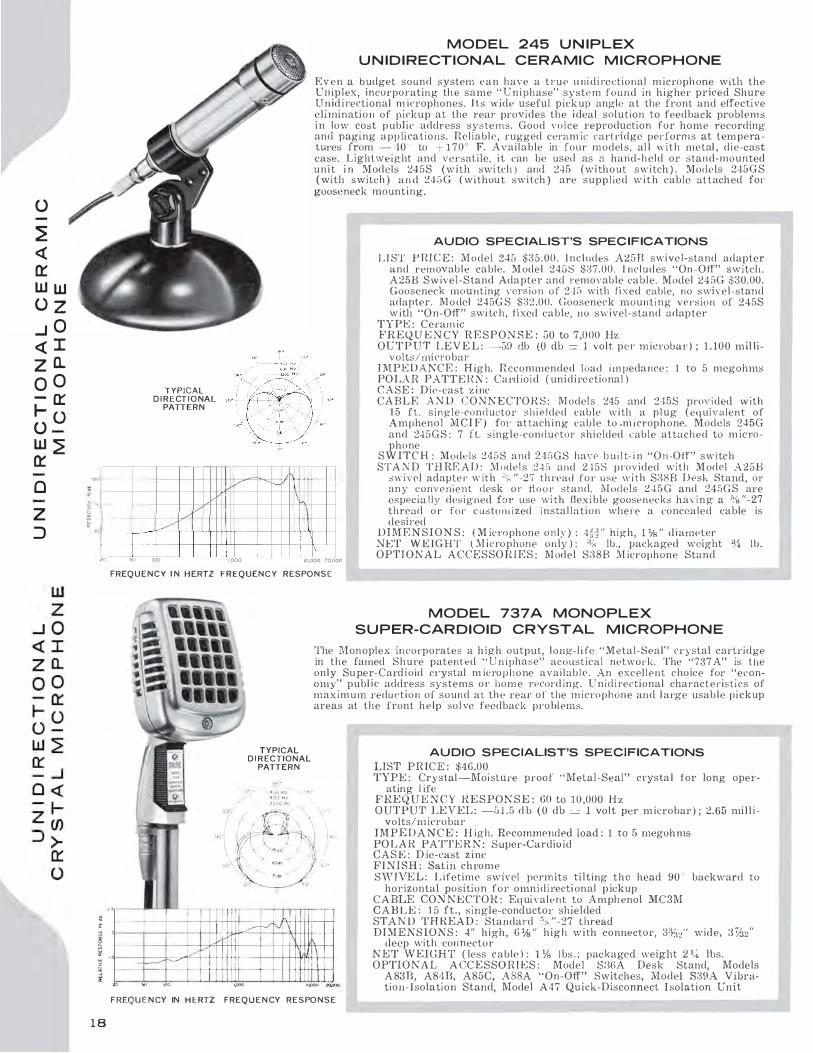
M O D E L 245 U N IPLEX
U N I D I R ECTIONAL CERAMIC M ICROPHONE
E v e n a budget sound system c a n have a t r u e u ni d i rectional m icroph one with the Un ip lex, incorporating th e same " U n iphase" system found in h igher priced Shure Un id i rectional m icrophones. l l s wide useful p ick up angle at the front and effective eliminati o n of pickup at the rear provides the i dea l solution to feedback problems i n low cost p ubl ic address systems. Good voice reproduction for home recording and paging app lications. Reliable, rugged ceram ic cartridge performs at temperatures from - 40 '' to + 170° F. Available in four models, al l "· i t h metal , die-cast case. Lightweight and versatile, it can be used as a hand-held or stand-mounted u n i t i n M odels 245S (with swi tch ) and 245 (without swi tch ) . Models 245G S ( with switch ) a n d 2'15G ( withou t switch ) are supplied w i t h cable at t ached fo1· gooseneck mounting.
AU DIO SPECIALIST'S SPEC IFICATIONS
L I ST P R I C E : Model 245 $35.00. I ncl udes A 2 5 D swivel-stand adapter and removab l e cable. M odel 245S $37.00. I ncludes ' ' On-Off" switch. A25B S w ivel-Stand Adapter and removable cabl e. Model 245G $30.00. Gooseneck mounting version o f 245 with fixed cable, no swivel-stand adapter. M o del 245G S $32 .00. Gooseneck mounting version of 245S with "O n-Off" swi tch, fixed cable, HO swivel-stand adapter
TYPE : Ceram ic FREQ U E N C Y R E S P ON S E : 50 to 7 ,000 Hz OUTPUT L E V E L : -59 db (0 db = 1 volt per microbar ) ; 1 . 100 m il li-
volts/mi crobar I M P E D A NCE : H igh. Recommended load i m peda nce : 1 to 5 megohms PO LAR PATTEHN : Card io id ( unidirectional ) C A S E : Die-cast z i nc CA BLE A N D C O N N E CTOH S : M odel s 245 and 245S prov ided w ith
15 ft. s i n gle-conductor s h i e l ded cable w i th a p l ug ( equivalent of Amphenol M CI F ) fo1· at tach ing cable to .m icrophone. Models 245G and 245 G S : 7 ft. s ingle-conductor shielded cable attached to m icrophone
I - --� /v 1-++-1H+--•-J--+++-'-+++--'----' ;ol -=---� i
S W I TC H : Models 2458 and 2 4 ::>GS han' b u i l t- i n " On-Off" switch STA N D TH RE A D : M odel s 245 and 2-±5S prov ided with M odel A25B
swivel adapte r w ith .-. ;_ " -27 thread for use w i t h S88B D esk Stand, o r an y convenient desk o r ti o o r stand. M odels 2 4 5 G and 245GS are especia l ly designed for use w i t h flex ible goosenecks having a % "-27 thread or for c ustom ized insta l lation where a concealed cable is desired
t �- --- ---=±H- + +++---+-+-+-+++++�I\ D I M E N S I ON S : ( M ic rophone only ) : 4f:I'' high, 1 1/s " d iameter NET WElGHT ( M icrophone only ) : % lb., packaged weight %, lb . OPTI ONAL ACCESSO R I E S : M odel S38B M icrophone Sta nd .::() !'JO 100 1,000 10,000 20,000
1 8
FREQ U E N C Y I N H ERTZ FREQUENCY RESPO N S E
TYPICAL D I R ECTIONAL
PATTERN
MODEL 737 A MONOPLEX
S U P ER-CAR DIOID CRYSTAL M ICROPHON E
The Monoplex in corporates a high output, l ong-l i fe " Metal-Seal" crystal cartridge in the famed Shure patented " U n iphase" acoustical network. The "737 A" is t he onl y Su per-Cardioid ci·ystal m icro p h o ne available. An excellent choice for "economy" publ i c address systems or home record ing. U n i d i rectional charact e r istics of maxim u m reduc t i o n of sound at th e rear of the rnicrophone and l arge usabl e p i ckup areas at the front help sol ve feedback problems.
AU DIO S PECIALIST'S SPECIFICATIONS
LIST PRICE : $46.00 TYPE : Crystal-Moisture proof " Metal-Seal" crysta l for long oper
ating l ife FREQ U E N C Y R E S PON S E : GO to 10 ,000 H z O UTPUT LE VEL: -5 1 .5 d b ( 0 db =-= l vo lt per m icrobar ) ; 2.65 rni l l i -
volts/rn icrobar I M P E D A NC E : H igh. Recommended load : 1 to 5 megoh ms PO L A R PATTE R N : S uper-Cardioid CASE : D ie-cast z i nc FI NISH : Satin chrome SWIVE L : L ifetime swfrel perm its tilting the head 90 ° backward to
horizontal position for omni d i recti onal p ickup C ABLE CON NECTOR : Eq ui valent lo A m ph enol MC3M CABL E : 1 5 ft. , s ingle-conductor shielded STA ND T H REA D : Standard "i.s "-27 thread DI MENSIONS : 4" h igh , 6 Ys " high with connector , 3:%/' wide, 3%2"
deep with connector NET WEIGHT ( less cable ) : l1 /s lbs . ; packaged weight 2 %, lbs. OPTIONAL A CCESSO R I E S : Model S:16A Desk Stand, Models
A 83B, A84B, A85C, A SSA "On-Off" Switches, Model S39A Vibration- Isolation Stand, Model A 4 7 Quick-Disconnect I solation Un it
FREQ U E N CY IN H ERTZ FREQ U E N CY RESPO N S E

MODEL "300" GRADIENT B I D I R ECTIONAL
R I B BON M I CROPHON E
A wide-range, qual i t y ribbon rn icrnp hone w it h bidirectional pickup pattern rn ak ing it i deal for d ial ogs , i ntervi ews, and other appl icat ion s whel'e front and back pickup is desil'able. A lso a problem rnlver where side-located l oudspea kers can cause Jeedback. Comes complete with mul ti -i mpedance s w i t c h , Vo ice-M usic switch to adjust l ow frequency characteristics, sel f-adjusting, "Positi\•e-Action" l i fetime swi ve l and l i ve-rubber shock-mount. Sli m , modem design case is fin ished in non-1·efi ecting " B ronze-Tone" enamel . Available i n ,1iatched pairs fol' stereo brnadcasting and 1·eco1·d i ng at no addi t ional cost. Listed on page 42.
S H U R E R I B BON M ICROPHON ES
The characte risti cally \\· ide-rnngc respouse of the r ibbon element has made it t he most widely used type of m ic ro p h one for broadcasting and professional record i ng. S h u re engineers h ave des igned remarkabl e !'uggedness into Shure 1 · ibbon microphones, making them an excellent choice for any indoor a ppl ication where h i ghest quality response is requ i red . S h u re ribbon m icrophones actually have been used "to po und n a i l s " a nd subjec ted to severe drop t estswithout affecting the perform ance.
TYPICAL DIRECTIONAL PATTERN
..,... __
-IO• f-----"+---+---+-t-"v-'-;";---.,.---.,--.,.-..,.- -rl----+-+-t-+-+-t-t+t-f'...-""'1--t
20 00 100 I/XX) FREQUENCY IN H E RTZ
FREQU ENCY RESPONSE
IOllOO 20,000
A U DIO SPECIALIST'S SPECIFICATIONS
L I ST PR ICE : $ 1 50.00
TY PE : R ibbon
FREQU ENCY RESPON S1: : 40 to 1 5 ,000 Hz
-- 1,000 Hz And Below -------- 3,000 Hz ... . . . . . 10,000 H z
OUT P UT L E V E L : 30-50 ohms -60.5 db ( 0 d b = 1 m i l l i watt per 10 mic roban; ) ; .043 m i l l i volts/microbar. 150-250 ohms - 59 db (0 d b = l m i l l iwa tt per 10 m icrobars ) ; .105 m i l l ivolts/microbar. H igh -57.5 d b (0 db = l volt pe1· m icrobar ) ; 1 .32 m i llivolts/ m i c roba r
I M PE D A NCE : Equi pped with a m ulti-im pedance switch , furnishing a choice of three i mpedances - L-30-50 ohms, M - 1 50-250 oh ms, H igh
POLAR PATTE RN : Bidirec tional. Equally sensitive at front and real'. Response at sides down 15 to 20 db from front and rear responses.
M A G N E T I C CIRC U I T : U ses A l n ico V magnet C A S E : Di e-cast z i nc
FI N T S H : Non - reflecting "Brnnze-Tone" enamel
S W I V E L : Self-adjusting "Positive Action" l i fetime swi vel permits t i l ti ng the head 4 5 ° forwa rd and 90° backward so that the m icrop hone can be aimed at the source of sound
S H OCK M O UN T : Special v ibration-isolation unit of l ive rubber construction
CABLE CONNECTOR : Equipped with Cannon XLH-3- l l C con-nector
C A BLE : 20 ft. 2-conductor shielded broadcast type
STAND T H RE A D : ';8 "-27 thread
STAN D COUPLE R S : Adapters for % " pipe thread or % " -24 thread available upon request at no extra charge
SWITCH : Equipp�d w ith Voice-Music switch to adjust low frequency characteristic for opt i m um pe!'formance ( See Frequency Hesponse Curve )
D I M E NS IO N S : 6 " h igh ; 1 ,'t. " wi de, L i'o " deep
N E T W E IG H T ( less cable ) : 1 lb., p ackaged we ight 4 l bs.
OPTIO NA L ACCE SSORI1: S : Model S33 Desk Stand, Model A95A Cable-Type Transformer, M odel S39A Vibration-Isolation Stand, Model A45 Quick-Disconnect I solation Unit
U.S. Patent
D-1 71.0!)5
ARCHITECT'S SPECIFICATIONS
The m icrophone shall be Shure Model 300 or equivalent. A moving-ribbon type m icrophone with a freq uency range of 4 0 t o 1 5 ,000 Hz, th is unit shall have a bidirectional horizontal polar characteristic. The caneellation at the sides sha l l be H i to 20 db . The micrnphone shall be equipped with a three-position impedance c hange switc h for selecting the m icrophone rating i mpedance to 38 ohms, 1 50 ohms, or 40,000 oh ms.
The microphone output shall be :
30-50 ohms -60.5 db* 1 50-250 ohms -59 db* H igh -57.5 <lb * *
* (0 db == 1 milliwatt per 1 ( 1 microbars) .. "' ( 0 db == l volt per microbar)
The m icrophone rating Gm ( sensitivi ty ) at 1 000 Hz shall be within 3 db of the following leve l s :
" L " Pos i t ion o f switch -1 5:� db " M " Pos ition of switch - 1 5 1 db "H" Posit ion of switch - 1 54 db
EIA Standard SE-1115 August 1 949
The microphone shall be prnvided w i th a swivel adjustable from 45 ° forward and 90° backward. The m icrophone shall be equ i pped with a vibration-isolation unit i n combination w i th the stand connector, and it shall have a detachabl e Cannon cable connector capable of connecting to a two-conductor shielded cable.
The microphone wi ll mount on a stand having % "-27 thread. The overall d imensions shall be 9�112" (234.2 mm) ::±: 1.4 " ( 6. 4 m m ) i n height, 1 /6 " (36.5 mm ) ± 1/g " ( 3.2 m m ) i n w idth , and l'jfo" ( 27.8 mm) ± Vs " (3.2 m m ) in depth.
1 9
CD
0
;o m () _,
0 z )> r
;o
CD CD 0 z
�
() ;o 0 "'O I 0 z m (/)

CJ) UJ z 0 I a.. 0 er u � z 0 CD CD er _J <{ z 0 1-u UJ er 0 CD
20
MODELS 3 1 5 AND 3 1 5S GRADIENT
B I D I R ECTIONAL R I B BON M I CROPHON ES
The " F igure 8" pickup pa t tern of t hi s m iernphone m a kes iL i dea l fo1· d ia l ogues , i n terv i ews. and other group pickup appl icati ons where front a n d back piekup is desirable. lt i s a lso a prnbl em sol vei· i n public-address svstems where l oudspeakers l oc ated at the s ide of the m icrn ph one tend to eause reeclback p robl e ms . Com es c o m p l e te with multi-impedance switch and l i l"et i rn e � w i q� l for L i l ting the m icrophone t oward tlw source of sound.
Model :3 1 5 S inc l udes " On - O ff" switch ; Mod el 3 l ii is w i thom switch. Sl im modern des ign case has smart sa t i n c h ro m e finish. A va i l able in matched pairs for stereo reco1·cling at no addi tional cost. L i sted on pag·e 42.
S H U R E R I B BON M I CROPHON ES
The characteriotica l l y w ide-range response of the ribbon e lement has made i t the most w id e l y used type of 111 inop l 1one for broadcast ing: and profess i o n a l record i ng. S hure e n g i n eers h aYe des igned remarka bl e rugged ness into Sh ure ribbon m i c ro phones, n 1 aking them an excellent c ho ice for any i ndoor a p p l icat ion where h ighest qual i t y response is requ i red. S hure ri bbon micrn11hones aetual ly have been used ' · t o pound na i l s " and su bjected to severe d rop tests - \\' i t h o u t affect i ng t h e performanc('.
D I R E C T I O N A L PATT E RN
� ,, "'
+•O
� 0 z 0
� "' L£J -10 >
� "'
I
/ �
50
-- 1 ,000 Hz And Below
3 , 000 HL
. .. 10,000 Hz
A UDIO SPECIA LIST'S SPEC IFICATIONS
L T ST P R I C E : M odel 3 1 5 $80.50 Model 3 1 5S ( w ith switch ) $9 1 .50
TYPE : Ribbon
FimQUE.'.'ICY l{E SPON SE : 50 to 1 2 ,000 Hz OUTPUT LEVE L : L-30-50 o h m impedance -G2 db (O d b = 1
m i l l iwatt per J O m i c robars ) ; .035 m i l l i vo l ls/m icrobar. M-150-250 ohm impedance -61 db (0 d b = 1 m i l l iwatt per J O rnic robars ) ; .089 rn i l l ivolts/rn ic rnbar. H-High -58.5 d b ( 0 <lb =-= l vol t per m i crnbar) ; 1 . 1 5 m i l l ivolts;m icro b a r
Il\1 PE DAKCE : E q u i p ped w i th a mu l t i - im pedan ce switch, furnishing a choice of : 3 i mpeda nces : L-30-50 ohms, M - 1 50-250 ohms, HHigh
POLA R PATT E R N : B i d i rectional, equal l y sensit ive at front and back. Response at sides down 15 to 20 db Crom fron t and rear responses.
'M A G N ET I C C lRCU J T : U;;es A lnico V Magnet
CA SE : Die-cast zinc F I N I SH : Sati n chrome S W I V E L : Sel f-adjusting swivel perm i ts ti l t i ng t he head th rough
90 ° so that the m icro p hone can be a i med at the source of sou nd.
CABLE co�· N ECTO R : Equivalent t o the A m p h e no l MC3J.Vl Plug
C A BLE : 1 8 ft., two-conductor sh ielded broa dcast t y pe
STAND T H REA D : Standard % "-27 thread DIMEN S I O N S : 6" high , l i7e " wide , Hii2" deep
NET W E I G H T ( less cable ) : 1 l b . , packaged wei g h t 2 1.'2 lbs.
O PT I O NA L ACCESSO R I E S : Model S36A Desk Stand . Model A95A Cabl e-Type Transformer, Model S39A V ibration-Isolation Stand, Model A47 Q u ick-Disconnect Isolation Unit
000
I I I I I .,,--'-" ,..__,
�----�- I \ -I HIGH IMPE �ANCE POSITION -- \ - �\ LOW IMPEDANCE POSJTION - - -- - \ I 1 1 1 I I I I
I ; 1 1 1 ·1 I I I 1.000 10.000 20,000
FREQ U EN C Y I N H ERTZ
F R E Q U E N C Y RESPONSE
ARCH ITECT'S SPECIFICATIONS
The microphone s hall be a Shu re Model 3 1 5 ( 3 1 5 S ) or equi valent, a r i bLon m icrophone with a frequency ra n ge of 50 to l 2 ,000 Hz. This u n i t shall have a bid i rectional polar cha racteristic. The ca ncel l a t i o n at the s i des s ha l l be 15 to 20 db. The m icro ph one shall be equi p ped with a t hree-posit ion i m pedance change switch for adj ust i ng thr.· m icrophone rat i ng i mpedance t o 38 ohms, 1 5 0 ol t m s , or 4 0,000 ohms. The :vl odel 3 1 5 S shall have a builtin · · O n -Off" s w i tc h . The M odel 315 shall ha\·e no s w i tch. The m icrophone output shall be :
L- - 3 0 -50 o h m i m pedance -G2 db'' M-1 5lJ-250 oh m i mpedance -(i l db* I-I-High -58.5 db**
•:-: ( o d b :::: I mil l i watt pe!' 10 microbars) " ( <J ul> = l volt per microbar)
Tlw rn icrnphone rat i ng Gm ( sensit ivity ) al 1 000 Hz sha l l be within ±3 db of the fo l l o w i ng l evels :
" L " Posit ion o f s"· i tc h - 1 55 db " M " Pos i t ion of switch -152.5 db " H " Pos i t ion of sw i t ch - l G G db
1-:IA Sandanl SE- 1 0 5 Aug-usl 1 9 4 9
The m icrophone shal l be provided with a s w i ve l and it s h a l l have a detachable cable connector capable o f connect i on to a two -cond udor sh i e l ded cable. The mic rophone wil l mount on a stand haY ing % "-27 th1·ead. The overnll di mensions shall be 9%/' ( 232.5 m m ) c: 1 4 " in h e igh t, 1 170 " ( 3 G.6 mm ) :::!:: \.i; " in width and 11§/' ( 27 .8 mm ) in depth.

MODEL 576 O M N I D I R ECTIO NAL
DY N A M I C M ICROPHON E
( 3/.l" D I A M ETER PROBE)
A superb, dynamic probe m icrop hone designed f o r lelevis ion a nd radio broadcasting
and super-critical public address a pp l ications . Proved superior for ruggedness and
performance under typical broadcasting conditions i n st renuous field tests. Strik
ingly modern in ultra-slim '% -inch diameter that provides maximum view of per
formers for on-camera use. Featu res smooth , natural, wide-range response for
authentic pickup of voice or music. Dual impedance, 50 and 1 50 ohms : change simply
by moving pin jacks inside case. Comes complete with Model A57S sl i p- in swivel
adapter that perm its ti l ting the microphone 90 ' from vertical to horizontal . The 57G
is an ideal hand-held m i crophone because of i ts unique " feel" and " balance" in the
hand. Rugged steel case provides effective magnetic shi elding as well as good looks.
F i n i shed in non-reflecting grny with stai n less steel grille. A vailable in matched pai rs
for stereo recording. Listed on page 42.
3/4" DIAM ETER
SMALLER
SMA LLER
40% 60%
.0
DIAM . } AREA
THAN OT H E R POPULAR
O M N I D I RECTIONAL
DYN A M I C M ICROPHONES
I I I : ! I 'Q +10
:;; TYPICAL D I R EC T I O N A L PATTERN
w
� a. 0 "' w a: w > � •10 w a:
20
v /
50 !00
I
-
I 1,000
F R E Q U E N C Y I N H E RTZ
F R E Q U E N C Y RESPONSE
� I I I I
A U DIO SPECIALIST'S SPEC I F ICATIONS
L I ST P HI C E : $ 1 75.00
E L E M E N T TYPE : Dynamic
F !U�Q U EN C Y R E S PON S E : 40-20,000 H z
: .....,,_ 1"-
10,000 zo.ooo
-- 1 ,000 H z ........ 4,000 H z
· . - . · . - . 1 0 , 000 Hz
O U T P U T : 50 ohms -60 db (0 db = I mi l l i watt pe1· 1 0 mic roba rs ) ;
.OGO m i l ! iv o l ts/m ic roba r
1 50 ohms -60 db ( 0 db = 1 m i l l i watt per 1 0 microba rs ) ; .094 m i l l i vol ts/microbat·
POLA H PATTE RN : O nm i d i rectional
T M PE DA N C E : D ual - 50 and 1 50 o h m s ( to match all low imped-ance i n puts , 50 to 250 ohms )
D l APll H A C M : Sh ure D u raco u s t i<:
C A S E l•' l N J SH : N o n - reflec t i n g gray
S W I V EL A DA PTER : Furni shed w i t h Model A 5 7 S Swivel A dapter having �" "-27 thread
CA B L E : �5' three-conductor sh ielded brnadcast cable D T M E K S I ON S : % " diamete1·, 8 'Ys " o v e ra l l length
N E T W E I G H T : 7 ou nces ( less cable ) , packaged weight , 2 1/2 lbs.
OPTION A L A CC E S S O R I E S : Model S33B Desk S tand, Model A 9 5 A Tra 1 1 s former, Model S:rnA Vibrat ion - I solation Stand, M odel A47 Qu ick- D i sconnect Iso lat ion U n i t . Model A 2 W S W i ndscreen
90•
o·
ARCHITECT'S SPEC IFICATIONS
The minophone shal l be the Shure M odel 576 or equ i va l ent . The m icro phone sha l l b e a movi ng-co i l t y pe wilh a freq uency range of 40 to 20,000 Hz. The unit sh a l l have an omnid i rcc t i o n a l hori zontal p olar characteri st ic . Th e microphone shall have ava i labl e impedances of GO ohms and 1 50 ohms. T he microphone oulput shall be :
50 ohm i m pedance -60 cib ( 0 db == 1 m i l l lwatt pee 1 0 mil'robars)
150 ohm i m pedance -GO db ( O db = I milli watt per 10 microbars)
The m icrophone rating Cm (se11sit i\·i t y ) at 1 ,000 H z sh a l l br wi th in 2 db of the fol l owing levels :
"Low" I m pedance -15 1 .0 db "'.VI" I mpedance -152.0 db ElA Sta n<larJ SE-105 A ugu�t H149
The m i crnphone shal l be provided with a swivel aclapl e1· adj ustable through 90 ° from vertical lo ho rizo n lal and a 25' ( 7 .G 111 ) three-conducto1· shielded cable . The miCl'op hone sw ivel adapter wil l mounl on a stand having a ';',; " -27 thread . The overa l l d i mem; ions shall be 81 X1�" ( 2 13.Gm m ) i n l e ngth and �%/' ( 19 .8 m m ) i n d i ameter.
2 1
0
� z
CJ
::0 m 0 -f
0 z l> r
CJ -< z l>
�
0
�
0 ::0
0 -u I 0 z m CJ)

en l1J z 0 I D.. 0 a:: u �
u � <{ z >-0
_J <{ z 0
._ u UJ a::
0
z
� 0
M O D E LS 578 A N D 5785 O M N I DY N E
U LTRA-S L I M (3/4" DIAMETER) PROBE
A n outstanding set·ies of public-address microphones combining strikingly modern ultra-slim ( 34 " diameter) design with exceptional performance, proved in severe field testing. Inconspicuous because of slender shape. Smooth, natural response from 50 to 17,000 Hz. Built-in wire mesh "pop" fi l ter reduces breath noises. Extremely rugged construction makes the Omni dyne an excel lent choice for qual ity P.A. use, i ndoors and outdoors. Satin chrome-steel case provides magnetic shielding as well as good looks.
Model 578 has a built-in "ON-OFF" sw itch and a non-detachable cable, making it i dea l for hand-held or hand-to-stand usage. Model 578S features an attached swivel with an " ON -OFF" switch and a detachable cable for use on a floor or desk stand. A locking switch plate is included with both models to lock switch in "ON" position. B oth models are available in matched pairs fo r stereo recording and are listed on Page 42.
D I A M ET E R
SMALLER
SMALLER
3/4" 40% 60%
TYPICAL
D I RECT I O N AL PATTERN
.Q 'O -t-10 � .... (/) z 0 3; 0
.... IC .... > !:i -10 ...J .... IC
20
/
50
DIAM . } THAN OTHER POPULAR
O M N I D I RECTIONAL
A R EA DYNAMIC MICROPHONES
- .... '\ '
100 1,000 10.000 20,000
FREQ U E N C Y I N H ERTZ
FREQUENCY RESPO N S E
ARCHITECT'S SPECIFICATIONS
Patent Pending o•
The microphone shal l be Shure Model 578 ( 5 78S ) or equivalent. The microphone shal l be a moving-coil ( clynam ic ) type microphone with a frequency range of 50 to 1 71000 Hz. The unit sha ll h ave an omnid_ircctional polar characteristic. The microphone shall be a dual im pedance unit-the low impedance fo1· connection into a 50 to �50 ohm l i nt' and t he " high" im pedance for connection into a high impedance i nput.
22
AU DIO SPECIALIST'S SPECIFICATIONS
LI ST P l{lCE : Model 578 $82.50 Model 578S $90.00
TY P E : Dynamic
F R E Q U E N CY R E S PON S E : 50-17,000 Hz
O U T P U T : Low Im pedance - GO db ( 0 du = 1 m i l l i watt per 1 0 microbars ) ; . 1 00 mil l i volt/microba r. H igh I m peda nce -59 db (0 db '- l volt pe 1· microbar) ; 1 . 1 1 m i l l i vol ts/m icro ua r.
IMPE DANCE : Dual. 50 - 250 ohms and H igh.
D l A P H R AG M : Shure Duracoustic
POLA R PATT1': R'.'J : O m n i d i rectional
M AGNETIC CIRC U I T : Uses A ln ico V '.Vf agnet
CA S E : Die-cast zinc
FIN ISH : Sati n chrome with stai nless steel gri lle
S W I V E L : M odel 578, adj ustable sw ivel adapter Model G78S, pos i ti ve action built-in swivel
C A B L E CONNECTO R : Model 578S, Cannon type XL-3-1 1
CABLE : Model 578, non -detachable 1 8-foot three-conductor shiel ded Model 578S, detachable 1 8 -foot two-conductor shi elded
S T A N D T H R EA D : % "-27 th1 ·ead
SWITC H : Suppl ied with "ON-OFF" switch and optional cover plate
D I M E N S I O N S : Model 578, % " diameter, 7 % " overall length Model 578S, 34 " diameter, 9 1"0 " depth, 3 1,4 " height
N E T W E I G H T : Model 578, 7 ozs., packaged weight H � lbs. Model 578S, 13 ozs., packaged weight 2 %. lbs.
O PTIONAL ACCESSORJ E S : Model S33B Desk Stand, Model A95A Transformer, Model S39A Vibratio1I-Jsolation Stand, :Model A47 Q uick-Disconnect I solation U nit, Model A2W S Windscreen.
The microphone output sha l l be : Low : -60 db ( 0 db = l mill iwatt per
10 m ic ro bars ) . H i gh : -59 db (0 db = 1 volt per ·
m icrobar ) .
The m icrophone rating G m ( sensit ivity) at 1 ,000 H z shal l be w ith in ±3 db of the following level s :
Low I mpedance - 1 G l .0 db''' H igh l m pedance -155.0 db"
''' EIA Sta11danl SE-105 August 1 949 For Model 578: The microphon e shall
have a bui l t- in " ON-OFF" switch w ith a locking p late p rovided to lock switch permanently. The m icrophone sha l l be provided with a swivel adapter adjustable through 90 ° from vertical t o horizontal. The swivel adapter w i l l mount on a stand havi ng a % "-27 thread. The m icrophone shall be provided with an 18-foot ( 5.5 meter ) , three-conductor shielded cable. The overall d imen si ons shall be 7 11!13� i nch es ( 1 88.l m m ) in length and 25/32 inc h ( 1 9.8mm ) in diameter.
For Model 578S : · Th e microphone shall be provided with a swivel, a built-in "ON-OFF" switch, and a receptacle for a detachable Cannon type cable connector. The cable is an 1 8-foot ( 5.5 meter) two-conductor shielded, plastic jacketed cable. The microphone shall mount on a stand thread having % "-27 thread. The overal l dimensions sha l l be 9 13., " ( 233.4 m m ) in depth, 3 %. " ( 82.6 m m ) in height, and 2%/' ( 19.8 mm ) in diameter.

MODELS 570 A N D 570S
LAVA L I E R M ICROPHON ES
(3/4" DIAMETER)
The 570 Series a r e m i n iature s i z e , professional-qu a l ity dynamic microphones designed f o r lava l i er u s e b y moderators, panel ists, announcers, singers, instrumentalists, public speakers, l ecturers, instrnctors, and for all appl ications which require a small size, l ightweight, wearable unit of distinctive appearance.
The 570 M icrophones h ave a "shaped" response to provide superior performance-with the special feature of e l i m inating or greatly reducing the pickup of cloth ing and cable noise.
In addi tion , Model 57US features a built-in long-life " ON -OFF" switch.
Can be used o n stand w i th Swivel Adapter. Designed for inconspicuous use with " F l ex-Grip" l avalier assembly - the m ost versatile available. "Flex-G rip" desi gn holds microphone firm l y, yet permits easy and quick remova l . Lavalier c l i p opens righ t o r left or can be removed. Lightweight, flexible 30-ft. microphone cable attached. N on-reflecting gray metal case with stainless steel gril le.
TY P I CAL D I R ECT I O NAL PATTER N
'"" ,, 't) + 10 ;;; w <f> z 0 a. 0 � er
I I
w > � - 10 w a: ¥
I../
50
A UDIO SPECIALIST'S SPECIFICATIONS
L I ST PRICE : M odel 570, $95.00. Model 570S, $105.00.
TYPE : Dynamic.:.
FREQU ENCY RESPO N S E : 50- 1 2,000 Hz shaped for optimum l aval ier performanc.:e, with rising response to G,000 Hz.
O U T P U T : Model 570 a n d Model 570S , --60.5 db ( 0 db = 1 m i ll iwatt per 1 0 m icroba rs ) ; .085 mill ivolts/microbar.
IMPEDANCE : 1 50 o h m s ( to match all l ow i mpedance inputs, 50 to 250 ohms ) .
D I A PHRAGM : Shm·e Duracoustic.
PO LAH PATTERN : Omnidirectional.
MAGNET I C CI RCUIT: Uses Alnico V Magnet .
CASE F l N TSH : Non-reflecting gray.
CA I3LE : 30-foot two-cone! uctor shiclclecl ( non-detachable) .
D IM EN S I ON S : Model 570, % " di ameter, 2 1%"" length. M o del 570S, %. " diameter, 5%/' length.
N E T W E IG H T : Model 570 , 2 oz. ( less cable ) , packaged weight 2 % l bs. Model 570S, 3 'h oz. ( less cable ) , p ackaged weigh t 1 lb .
F U RN I S H E D ACCESSORI E S : M o d e l A57L "Flex-Grip " lavalier eorcl, a n d belt clip for cable.
OPTI ONAL ACCESSORIES : Model A 57 S Swivel Adapter ( for Model 570S ) . Model A 57 R Swivel A d apter ( for Model 570 ) .
Model A 95A Transformer.
oOO
5705 570
I I _ ___J_ I v� I _y---,_..v \
� ..--l- 'h I i
.
. A .
l_ j_b-_ I UL
1,000
FREQUENCY I N H ERTZ
FREQ U ENCY RESPO N S E
\ \ 10,000 20.000
ARCHITECT'S SPECIFICATIONS
The m icrophone shall be the Sh ure M odel 570 ( 57 0 S ) Dynamic Laval ier Microphone or equivalent. The miel'Ophone shal l be a moving coil ( dynam ic ) type microphone with a frequency range of 50 to 1 2,000 Hz. The unit shall have an omn id irectional polar characteristic. The microphone shall b e a single impedance mic rophone having a rating impedance of 1 50 ohms. The m icrophone output sha l l be - 60.5 db (0 db =: 1 m i ll i watt per 10 rnicrob:.u·s ) ; .085 millivolts/rnicrobar. The microphone rating Gm ( sensitivit y ) at l ,OUO Hz shall be within ± 3 db of - 153 d b ( E TA Standard SE-105, August 1 94 9 ) .
Model 570
The m icrophone shall be provi ded with a laval ier conl and clip assembly for use as a wearable m icrophone. The microphone shall be p ro vided with a 80-foot, two-concluctot· shielded table. The overall dimensions shal l be 21%" inches ( 65.9 m m ) i n length and �%:! inches ( 19.8 m m ) in diameter.
Model 5 70S
The microph o n e shal l have a bui lt- i n " O n-Off" switch w ith a locking plate provided to lock switeh permanently, The m icropho ne shall be p rovided with a l avalicr c.:ord and clip assembly for use as a wea rnble microphone. The microphone shall be provided with a 30-foot, 2-conductor shielded cable. The overal l dirnensions shall be 5%/' ( l::l l m m ) in length , "%:!" ( 19.8 m m ) in diameter.
23
0
� z
0
;a m 0 -I
0 z )> r 0 -< z )>
�
0
�
0 ;a
0 "U I 0 z m CJ)

en UJ z 0 I a.. 0 0:: u
�
u
� � z >-0
...J � z 0
1-u UJ 0::
0
z
� 0
24
MODELS 57 1 A N D 572G O M N I DY N E DYNAMIC M ICROPHONES
Model 571 Omnidyne lV! iniatul'e Microphone i s desi gned for hand-held and stand use. S i m i l a r to Model 570 ( p l'ev ious p age ) in size a nd appearance, buL has srno0Ll1 peak-free response from 50 to 1 0.000 Hz for voice applications where a smal l , inconspicuous m i c rophone should be used . Can be used in Jrnnd, 011 stand, hung over a stag0 , or concea led i n studio, motion p icture, theatrical and public-add ress applications.
M odel 572G Ornnidyne Micro phone features same response and size character istics o f Model 5 7 1 , plus the added featu re o f pel'manent mounLing on a new smal l-dia mt•ter, ultra-qui0t gooseneck. Comes complete with 1 2 " gooseneck and mounLing fl ange. Ideal for permanent mounting on lecterns, paging and dispatching stations, i n language laboratories and other appl ications where a permanentl y-mounted qual ity m icrophone is required. The gooseneck is a new ultra-quiet type that redu<'.es noise eaused by adj usting microphone.
-v--. I---,......,. ... � � I'
/""' [\
... " ;;;
>O v / 00 1poo
FREQUENCY I N HERTZ FREQUENCY RESPONSE M O D E L 5 7 1
� ----- I I
\ IQ,000 20.000
,__.... r--.c.-h I\ � w "'
z 0 / I � � -10 "' "' > � -20 _J w "'
20
/
100 t,000
I 1iH\-. j_ -
1� 1 1 \ 10,000 20,000
FREQU E N CY I N H E RTZ FREQU E N CY RESPO N S E M O D E L 572G
A UDIO SPECIALIST'S SPECIF ICATIONS
L I ST P R I C E : Model 57 1-$95.00
TYPE : Dynamic
M odel 572G-$ 1 1 0.00
FREQUENCY R E SP O N S E : 50-1 0,000 Hz.
OUTPUT: -61.0 db (0 db = 1 mil l i watt per 10 m icrobars ) ; .078 m i ll ivolts/micro bar.
IMPEDA NCE : Properly matches any low i mpedance input from 50 to 250 ohms.
POLAR PATTERN : Omnidirectional.
M A G N E T I C CIRCUIT : Uses Aln ico V Magnet.
CASE Fl N lSH : Non -retlecting gray with stainless steel gril le .
SWIVEL A DA PTE R : Model 571, furnished with swivel adapter having % "-27 thread.
M O UNTI N G : Model 572G, furnished w i th 1 2 " llexible gooseneck and mounting flange.
CABLE : Model 5 7 1 , non-detachable 30-foot, two-conductor shielded. Model 572G, non-detachable 5-foot, two-conductor shielded.
D I MENSION S : Model 571, H" diameter, 2 H " overall length. Model 572G , H" diameter, 1 5 %, " overall length.
N E T W EIGHT : Model 5 7 1 , 2 ounces, packaged weight, l 'h lbs. Model 572G, 1 2 ounces, packaged weight, 1 Vs lbs.
OPTIONA L ACCESSORI E S : M odel A95A Cable-type Transformer; Model S 3 3 Il Desk Stand f o r Model 57 1 ; Model A57L " Flex-Grip" Lavalier Assembly for M odel 571 ; M odel A2WS W indscreen for Model 572G.
A RCH ITECT'S SPECIFICATIONS
The m icrophone shall be the Shure Model 571 ( 572G ) Dynamic M icrophone or equivalent. The m icrophone shall be a moving-coil ( dynamic ) type m icrophone with a frequency range of 50 to 1 0 ,000 Hz. The unit shall have an omnidirectional polar characteri stic. The m icrophone shall be a single impedance microphone h aving a rating impedance of 1 50 ohms. The m icrophone rating Gm ( sensitivity) at 1 000 Hz shall be within :±: 3 db of -15:3 .5 db ( E IA Standard S E- 105 , August 1949 ) .
For Model 571 The microphone shal l be provided with an A57R Stand Ada p ter for a convenient. means 01' attaching the microphone to any % " -27 fixture. The m icrophone shall be provided with 30 foot, two-conductor shielded cable. The overall dimensions shall b e 2 �� inche;; ( 65.9 m m ) i n length and H inches ( 19 .8 mm) in d iameter.
For Model 572G
The m icrophone unit shall be mounted on a flexible arm having a mounting flange. The microphone shall have a 5 foot ( 1.5 m ) , two-conductor shielded cable. The over-all d imensions shall be 1 5 '4 " ( 389 mm ) in length and H" ( 19.8 mm) in diameter.

MODELS 533SA A N D 533SB
S P H E R-0-DY N E DYNAMIC
M ICROPHONES
A rugged omnidirectional dynamic microphone unsurpassed for i ts type and qual ity at such a moderate cost. This smal l rugged microphone features flat response for fai t h fu l reproduction of voice and m usic and was designed specifically for use by entertainers, interviewers, singers, and rock 'n' roll groups.
The "bal l"-type head contains a spherical screen to provide protection from "pop" ( explosive breath sounds ) , blast, and wind. Ideal for close-to-mouth operation. Can be used on stand or in the hand. "ON-OFF" Switch can be locked in "ON" position.
Choice of impedances. Model 533SA is high, and Model 533SB is low ( 150 to 250 ohms ) . TYPICAL
D I RECTIONAL PATTERN
t + ro ;i:
20
��
•o
-v-
ooo o_poo
""t\.-..... /11� \ \
1(\000 20,000 O'
FREQU ENCY IN H E RTZ
FREQU E N CY RESPONSE 1000 Hz -----4000 Hz - - - -
1 0,000 Hz - : - · - ·
AUDIO SPECIALIST'S SPECIF ICATIONS
LIST PRIC E : Model 533 SA-$50.00. Model 533SB-$47.50.
TYPE : Dynamic.
FHEQUENCY RESPONSE : 40-11,000 Hz.
OUTPUT: Model 533SA : High I mpedance --55.0 db (0 <lb = 1 vol t per microbar ) 1 .7 6 mil l ivolts/microbar. Model 533 S B : Low i mpedance -55.5 db (0 <lb = 1 milliwatt per 10 microbars ) . 149 mil l ivolts/microbar.
IMPEDANCE : Model 533SA H igh Impedance. Model 533SB-150 to 250 ohms.
POLAR PATTERN : Omnidirectional.
MAGNETIC C I RCUIT : Uses Alnico V Magnet.
CASE FINI S H : Satin chrome with plated steel grille.
SWIVEL ADAPTER : Furnished with swi vel adapter having % inch -27 thread.
CABLE CON N E CTOR: Model 533SA, equivalent to Amphenol M C l F Type Plug. Model 533SB, equivalent to Amphenol M C2 M Type Plug.
CA BLE : Model 533SA, 1 5-foot, one-conductor shielded. Model 533SB, 15-foot, two-conductor shielded.
DIMEN SION S : 2ft inches d iameter, 6 }1 inches length.
N E T W E I G H T : 1 1 ounces, packaged weight 1 % pounds.
OPTIONAL ACCESSO RIE S : M odel A95A Cable Type Transformer: Model A22L Lavalier Assembly; M odel S33B Desk Stand ; Model S38B Desk Stand ; Model S39A Vibration-isolation Stand ; Model A47 Quick-Disconnect isolation Unit.
ARCHITECT'S SPECIFICATIONS
The microphone shall be Shure Model 533SA ( 533SB ) or equivalent. The microphone shall be a moving-coil ( dynamic) type m icrophone with a frequency range of 40 to 11,000 Hz. The unit shall have an omnidirectional polar characteristic.
For Model 533SA The microphone has a single high im
pedance for connection into a high impedance input.
The microphone output shall be -55.0 db when 0 db = 1 volt per m icrobar.
The m icrophone rating impedance is 4 0,000 ohms and the Gm ( Sensitivity) at 1,000 Hz shall be within ± 3 db of -151 db referenced to EIA Standard SE-105, August, 1949.
For Model 533SB The microphone has a single low im
pedance for connection into a 50 to 250 ohm line. The microphone output shall be -55.5 db when 0 db = l milliwatt with 10 microbars.
The microphone rating impedance is 1 50 ohms and the G m ( Sensitivity ) at 1 ,000 H z shall be within ± 3 db of -148 db referenced to EIA Standard SE-1 05, August, 1 949.
The M odel 533SA (533SB) shall be provided with a swivel adapter adjustable through 90° from vertical to horizontal. The m icrophone is equipped with a builti n "ON-OFF" switch and a one conductor ( Model 533SB two conductor) shielded cable, detachable. The m icrophone swivel adapter will mount on a stand having a % " -27 thread. The overall dimensions shall be : 6 ff' ( 1 67.5 millimeters) in length and 2 h" ( 52.4 mill imeters) in diameter.
25
0 s: z 0 ::a m 0 -I 0 z )> r 0 -< z )> s: 0 s: 0 ::a 0 1] I 0 z m CJ)

(/) UJ z 0 I 0. 0 0:: (.)
�
(.)
� <{ z >-0
_J <{ z 0 r (.) UJ 0::
0
z � 0
26
MODEL 5505
PROBE DYNAMIC M ICROPHONE
A rugged, high qual ity Dynamic M icrophone designed for u s e in topqual ity sound rein forcement applications . .Features smooth, w ide-range response which is excellent for p ickup of voice and m usic. Performance and appearance characteristics make the "Probe-Dynamic" a wise choice for use in meeting rooms, auditoriums, for tape recordings, or wherever a qual ity om n idi rectional m icrop hone is required, and moderate cost is an important consicteration. Incluctes on-off switch. Available in matched pairs for stereo recording. L isted on Page 42.
FREQUENCY IN H ERTZ
FREQ U EN CY RESPONSE
TYPICAL D I R ECT I O N A L
PATTERN
180'
-- l,OOO Hz - - - - 5.000 H1 -·--- 10,000 Hz
AU DIO SPECIALIST'S SPECIFICATIONS
LIST PRICE : $69.00
TYPE : Dynam ic.
FREQUENCY R E SPO� S E : 50-15,000 Hz.
OU TPUT LEVE L : 50-250 ohms im pedance : -57.0 db ( 0 � 1 m il liwatt per 10 rnicrobars ) ; . 1 18 mi l l i volts/microbar. H igh impedance : -57.5 db (0 db � 1 volt per microb:otr ; 1 .32 millivolts/ m ic ro bar.
I MP E D A N C E : Dual. Choice of 50-250 ohms or h igh.
POLAR PATTEH)J : Omnidirectional.
CA SE : Die-cast zinc .
F I N I SH : Satin chrome with stainless steel gri l l e.
SWIVE L : Self-adjusting "Positive Action" l i fetime swivel permits tilting of the head through 180° so tha t the m icrophone can be poi nted a t the source of sound. To fit % inch -27 thread.
CA BLE C O N :t\ ECTO R : Equ ivalent Lo Amphenol MC3M Type Plug.
CAB LE : 18 foot two-conductor shielded.
D f M ENSION S : 1 % " d iameter, 6 % " length.
N ET W E IGHT : 15 ounces ; packaged weight, 2 1/t pounds.
O PTIONAL ACCESSORI E S : Model S3GA Desk Stand; Model A95A Cable Type Transformer; Model S 3 9 A Vibration-Isolation Stand ; Model A47 Quick-Disconnect Isolation Un i t.
· · · · · · · · · • · · · · · · · · · · · · · · · · · · · · · · · · · · · · · • • · · · · · · · • · · · • · · · · · · · · · · · · · · · · ·
ARCH ITECT'S SPECIFICATIONS
The microphone shall be Shure Model 550S or equivalent. The microphone s hall be a moving-coil ( dynam i c ) type m i c rophone with a frequency range of 50 to 1 5,000 Hz. The unit shall ha ve an omn idirect iona l polar characteristic. The m icrophone shall be a dual impedance unit-the "low" i m pedance for connection i n to a 50 to 250 ohm line and the "high" impedan t:e for connection i nto a h igh impedance input. The m icrophone rati ng Gm ( sensitivit y ) at 1 ,000 Hz shall be with i n ± 3 db of the following levels :
Low I mpedance _ _ .. . . . . . . . . . . . . . . . . . ... . . . . . . . . ... . . . . . . . . . . . . . . . . .. . . -150.0 db*
High Impedance . . . . . . . . . . . . . . . . - - - · - - - - - - - · · - · · - · · . . · · · - · · . .... . . . _ _ _ -1 53.5 db*
* E I A Sta ndard SE-105, August l 949
The microphone shall be provided with an adjustable swi tch with a bui lti n " On-Off" switch. r t shall have a detachable cable connector of the Amphenol MC3M type and a two conductor, shielded cable. The mierophone shall mount on a stand having % " -27 thread. The overal l dimensions shall be tl H " ( 124.4 m m ) in height, 1 %" ( 38.l m m ) i n diameter, and 6 1/2 " ( 165.1 m m ) in depth.
S LEN DY N E MOD ELS
Choice of two extremely rugged omn id irectional dynam ic m icrophones. Proved in severe use for years of dependable service. A l l units come complete with Model A25 swivel stand adapter and Model 530 also includes Model A22L Lava lier A ssembly. Both models
Model 530
rA£01JlNC1' IN H[ll:TZ J"ll[QIJLNC1' RESPONSE
• • • • • • • • • • • • • • • • • • • • • • • • • • • • • • • • • • • • • • • 4
MODEL 530
L I ST P RI CE : $ 1 1 0.00
T Y PE : Dynamic
FREQ UENCY RESPON SE : 50 to 15 ,000 l lz
O l:TPUT LEV E L : L-50-250 ohms in 1oecla nce : - Gl db (0 d b = l m ill iwatt per 10 m icrobars ) ; .071 m i l l i rnl ts/microbal'. H-H igh Impedance : -GO Lib ( 0 d b = l volt per microbar ) ; . 1 00 mill i volts/ rnic l'obar.
P O L A R PAT T E R N : Omnidirectional
CA B L E CONN E CT O R : Cannon X L-3- 1 1
CABLE : 20 ft., two-conductor shielded
S W I TC H : "On-Off"
lJI M E ).[ S I O N S : 1" d iameter, 7g " length
N E T W E I G HT : 1h lb.
P A C K A G E D W E I G H T : 2% lbs.
F U R N I S H E D A C C E S S O R I E S : A 2 5 B S w ivel Adapter, A22L Laval ier Assembly .
OPT I O NAL ACCE S S O m E S : Model S3ilB Desk Stand, Model A95A T J"ansformer.

530 AND 535
also have impedance switch and "On-Off" switch . Both models can ue used in the hand , on desk or floor stand, or as l aval ier m icrophones. I deal for p u blic address, theater-stage sound systems, and recording.
Model 535
l'REQ!lfNCY IN .. l<lll fREQ\J(NCY RfSl'O,.Sf
MODEL 535
L I ST P R I C E : $72.50
TY P E : Dynam ic
F R E Q U E N C Y R E S P ON S E : 60 to 13,500 Ilz
O UT P U T L E V E L : L-50-250 ohms i mped anee : -6 1 db (0 d b = 1 mil l iwatt per 1 0 m ic robm·s ) ; .071 m i llivolts/microbar. H-H igh Impedance : -60 dL ( 0 db = 1 volt per mic rnbar) ; . 100 mi l l ivolts/ m icrobar.
P O L A R P A T T E R N : Omnidirectional
CABLE CONNECTO R : E qu ivalent to Am phenol M C3M plug
C A B L E : 1 8 f t . , t wo-conducto r sh iel ded
S W I TC H : "On-Off"
D I M E NS I O NS : l" diameter, 7/;' length.
N E T W E I G H T : % lb.
P A C K A G E D W E IGHT : 2% lbs.
F U R N I S H E D A C C E S S O R I E S : A25 S wi ve l Adapter, A 22L Lavalier Assembly.
OPT I O N A L ACCESSORIE S : Model S33B Desk Stand, Model A95A Transformer
MODELS 540 A N D 5405
SONODY N E I I
H as the looks and performance worthy o f twice its price !, Adjustable frequency response a nd dual impedance makes the Sonodyne I T the most versatile microphone ! Normal wide-range response can b e adjusted to provide increased voice i ntel l igibility, and/or reduction of unwanted low frequency no ise below 400 cps, for pagi11g and com munications applications. Full -range response and high output ( particularly with high i mpedance) make the Sonodyne II an outstanding choice for most public address and recording app l ications . The unusual versatility and ruggedness of th is unit also makes it an o utstanding choice for school applications.
MI DDLE. HIGrl HlEQLIUKV Llill"t1A$1S 118 i10�E RE SONATOR!
T LJWlTI ' coo
FREQUENCY I N HERTZ
FREQU ENCY RESPONSE
TYPICAL
D I RECTIONAL
- 400 Hz ---- 1 500 Ht 5.ooo Ht - -·- 12,000 Hl
A UDIO SPECIALIST'S SPECIFICATIONS
, LI ST PRIC E : Model 54US (with switch ) $49.95. Model 540 (without switch) $47.95
TYP E : Dynamic FHEQU E N C Y R E S PON SE : 50 to 13,000 Hz. Provisions for alternate
response : rapid roll-off abo,-e 6,000 Hz and/or below 400 Hz. OUT;:- UT LEVEL : 50-250 ohm i mpedance : -56.0 db ( 0 = 1 mil l iwatt
per 10 m ic robars ) ; .149 mil l ivolls/microbar. High i mpedance : -53.5 db (0 db = 1 vo l t per rnicroba r ) ; 2 . 1 3 mil l ivolts/mierobar
I M PE D ANCE : Dual. Choice of 50-250 ohms or high DIA PH RAGM : Shure Duracoustic POLA R PATTE RN : Omnidirectional CA S E : D ie-east zinc and "A1·mo-Dur" Fl N T S H : Sat i n chrome and black SWIVEL: Self-adjusting "positive action" l ifet ime swivel permits ti l ting
of the head through 180 ° so that the m icrnphone can be pointed at the source of sound.
CA B LE CONN ECTOH : Equ ivalent to Amphenol MC3M CA BLE : 1 5 ft. , two-conductor shielded STA N D T H RE A D : % " -27 thread DIME N S I ON S ( not i ncl ud ing swivel ) : U � " diameter, 3 'i"8 " length N ET W E IG H T ( l ess cable ) : l l b . , packaged weigh t 3 % lbs. F U RN I SHED ACCESSO R I E S : Hesonator plate and set-screw for chang
ing response OPT I O N A L ACCESSO R I E S : Model S36A Desk Stand , Model A95A Cable
Type Transformer, Model S39A Vibration- l :;o l a ti o n Stand, Model A47 Quick-Disconnect I so lation Unit
ARCHITECT'S SPEC IFICATIONS
The m icrophone sh a l l be Sh ure Model 540S ( 54 0 ) or equi valent. A mov ing coi l type microphone with a frequency range of 50 to 1 3,000 Hz. Its response shal l he adjustable to a l l ow l i m i ting the high and low frequency characteristics when desired. The unit shall have an omnidirectional polar characteristic. The microphone shal l be a dual impedance microphone having rating impedances of 1 50 oh ms and 40,000 ohms. The microphone output shall be :
50-250 ohm im pedance : -56.0 db (0 db = 1 milliwatt per 10 microbars)
High impedance; -53.5 db (0 db = 1 volt per microuarl
The. microphone rati ng Gm ( sensitivi ty ) at 1 ,000 Hz shall be within _1_ 3 db of the fol lowing level s :
Low impedance - 148.0 db High impedance - 1 50.0 db
F. I A Standard SE-105, August 1949
The m icrophone shall be provided with an adjustable swivel with a bui lti n "O n-Off" switch to control the microphone cireuit. The Model 540 shall have no swi tch. I t shall have a detachable cable connector capab l e of connection to a two-conductor shielded cable. The m icrophone shall mount on a stand having % " -27 th read. The overall dimensions shal l be 5 '/s " ( 1 30.2 m m ) i n height, HY' ( 42 . 1 m m ) i n diameter, and 3 % " ( 92.1 mm) in depth.
27
0 s: z CJ Al m 0 -t 0 z )> r
CJ -< z )> � 0 s: 0 Al 0 "U I 0 z m en

(/) UJ z 0 I a. 0 er ()
:;?
u
:;? <( z >-0
...J <( z 0
tu UJ er
0
z
:;? 0
28
-"' -· -1
-I
- 400 Hz ---- 1.500 Hz 5,000 Hz - - - 12,000 Hz
TYPICAL OIR(CTIONAL PA1 11:.RN
AUDIO SPECIAL IST'S SPECIFICATIONS
LIST PRICE : Model 51 $49.50 ; Model 5 1 S ( with switch) $ 5 1 . 50 TY P E : Uynamic
FHEQU ENCY RESPONSE : 60 to 10,000 Hz OUTPUT LEV EL : Low, 30-50 ohm impedance 5 1 . 0 db• : . 1 1 8
m i llivolts/rnic1·olia1·. Medium. 150-250 o h m impe<lnnce - 5 l dblf ; . 265 rnillivolts/nlicrobar . Hhd1. -48.5 db"'" jl- : :.L 7 5 m illivolts/microbar
•o db == 1 m i l l iwatt per 10 microbars �· .. 0 db == I volt per microbar IMPEDANC E : Equi pped with a multi-im1)e<lance switch. furnish
ing a choice of three impedances : Low 30-50 ohms ; Medium 1 50-250 ohms : H i gh-·High .
POLAR PATTERN : Omnidirectional M A G N ET CIRCUIT : Uses A l nico V M agnet
CASE : Die-cast zinc FINISH : Satin chrome SWI VE L : Lifetime swivel permits tilting the head S0° backward
to horizontal CABL.E CONNECTOR : F,q uivalenl to Amphenol MC3M CABLE : 1 5 ft., two-conductor shielded
STAND THREA D : Standard %"-27 thread DIMENSIONS : 4 !! " high, 3Y,." wide, 3%" deep NET WEIGHT : 1% lbs .. packaged weight 3 \/8 lbs. OPTION A L ACCESSORIES : Model S36A Desk Stand, Model A95A
Cable Type Transformer, Model S39A V ibration-Isolation Stand. Model A47 Quick-Disconnect Isolation Unit
,.()"
()" -- 400 Hz ········ 1500 Hz
5000 Hz
TYPICAL DrRLC 1 1QNAL PA Tl I RN
AUDIO SPECI ALIST'S SPECIFICATIONS
LIST PH!CE : $42.50
FREQU J::NCY RESPON SE : 4 0 to 1 0,000 Hz OUTPUT LEV E L : Low : - 5 5 . 5 db ( 0 do = l milliwatt per 10
micrnbars) : . 14 9 mi llivollo/microbar. High : - 5 6 . 5 db ( 0 ell> = 1 volt per mic 1·oba1·) ; l .4cl millivolts/ mic:robar.
!MPEUANCE : Uual. Choice o( 1 50 to 250 ohms or High
DIAPHRAGM : Shure Duracoustic
CABLE : Non-detachable 18 ft., two-conductor shielded
CASE : Non-reflecting, black satin finished all-metal case with stain less steel grille
DIMENSIONS : 3�!" long by 1 % " diameter
NET W EIGHT : 5 ounces ; packaged weight : 13 ounces
OPTIONAL ACCESSORIES : Model A25B Swivel Adapte1· ; Model A95A Cable Type Transformer
SONODYN E MODELS 5 1 A N D 5 1 5
A favorite for schools and other public address app l ications where ruggedness and h igh output are desirable features. Excellent for use with tape recorders requiring microphones with high output. Multi-i mpedance switch gives choice of Low, Medium, or High i mpedance. Lifetime positive-lock swivel . Model 5 1 8 comes complete with "On-Off switch ; Model 51 without switch.
FREQUENCY IN HERTZ FREQUENCY RESPONSE
ARCH ITECT'S SPECIFICATIONS
Tb� microphon� !-'hall be the Shure Model fi l S ( S I ) or equivalent. A moving coil type microphone with a freL111ency range of 60 to L 0 ,000 Hz. The m ic1·01Jhone shall have an omn i d i rectional polal' chal'actel'istic. The unit shall have a three-position impedance selection
:-.witch for selecting- the micl'ophoue rating impedanee of ao-i>O ohms , 1 fiu-250 ohms, or �;). 0 0 0 ohms .
The microphone ouL]1ut shall be :
Low 30-50 ohm im peda nce --5 1 . 0 db"' Medium 1 50-250 ohm i m pedance -51 . 0 db .. Hiµ;h Hi>-<h -4�.5 db''"
*O db == 1 m i l l i watt per l U microbars * ':'0 db == 1 volt pe1· m i c roba!'
The Mo<lel 5 1 S :-:hall havt.:' a built-in · 'On-Off" switeh. The MoJel G l shall have no "On-Off" switch. The mic1·ophoue rating Gm ( sensiLiv 1 t y ) at 1 , 000 H z shall be within = 3 db of t ht:o follo ... v ing leveb :
" L' ' Position of Switch 1 44 . 0 db "!'<I" Pooition of Switch - 1 4 3 . 0 db "H" Position of Switc:h l 4 !"i . O db EIA Stand�rd Rati ng Sl'.:- 1 0 5 August 1 �4 V
The microphone shall be p t'ovided w i t h a swivel adju:-;table f 1·om horizontal to S0° backward. It -:hall have a detachable cable connector capable of connecting to a two-conductor shie]ded cable. The m icrophone shall mount on a stantl having ;Y,� "-�7 thread. The overa l l dimensions shall be ·1 1;;'32" ( J J ;) . l mm l high , � 1/h'' 1 7 9.4 m m ) wide, and 3�" ( 9S.4 mm) deep,
MODEL 560 DYN A M I C LA VALI ER M ICROPHON E
A Dual l mpedanc:e, Dynamic Microphone wi th "tai l o1·ed " response specifical l y designed for vi rtual ly every laval ier- application. Compact and l ightweight. Modern black satin al l -metal case w ith stain less steel g1·i l l e . Change from High to Lo w i m pedance by s imply moving p i n jacks. C l ip -grip l aval ie1· asse mbly holds m icrophone securely to wearer. Lightweight 18 foot attached cable perm its max imum freedom o f movement. .,,f___ - , r · --- · .
, - · · LOW l"'l'tD .... "IC:� - .. ICH IMP(0AhC[
f--
f'REOUFNr.Y IN HFRT7 FRFOllFNr.v RFSPONC::.F
ARCH ITECT'S SPECIFICATIONS
The mit:ro1,hone :-;hall be Shure Moc.lei f) 60 or equiv<-1lent. The microphone shall be a movin�; coil type microphone with a frequency 1·ange of 40 to 1 0, U O O Hz. The u n it shall have an omnidi rectional charac:terist i t' . The m i e ro11hone shal l be a dual impe<lance micro� phone having nni n g impedance of l 50 ohms and 40, 000 ohms. The micropho11B rat i n g" Cm ( sensitivity ) at 1000 Hz shall be withio .:::::::: :3 db of the followi111-( levels.
Low lmpedanc:e . . - 1 4 � . 0 db High lm pedance . . . . . . . . - -1 52 . 5 db
EIA Standat"d SE- 1 05 . Au><u't 1 9 4 9
The n1icrovhone shall b e provided w i t h a lavalier cord and c l i p a:o;semhly for u--..e a s :i. wearable mit'rophoue. T h e rnicrophone shall be provided w ith an 18 foot. ( .5 . 5 m ) two conductor shielded cable. The cvecall d i mf'nsions shall be
3�'132" ( �HJ.� mm ) :::t: V16 ( 1 . 6 m m ) inches in length l �'S inche:-; ( 34 . 9 m m ) maximum in Jie:1meter

"VE RSADY N E" MODELS 5755 AND 5755 8 WIDE RANGE, VERSATILE D Y N A M I C M ICROPHONES
AT A LOW PRICE
Smooth response from 4 0 - 1 5 ,000 Hz makes these units a "best-buy" for genet'al publ ic address, home recording of voice and music a nd cal l-system u se where both performance and economy are important. Smart, modern design i ncorporates good looks w i th a rugged, high-performance dynamic cartridge that is unaffected by temperature and humidity variati ons. Choice of H i gh or Low i mpedance model s, each compl ete with loc k i ng, slide-to-talk switch plus stand adapter and laval ier cord. These smal l, , extremel y l ightweight u nits can be easi l y adapted for laval i e r use as wel l as hand-held and stand-mounted applications.
U . S . Patent I % . 9 l Y
A U DIO SPECIALIST'S SPECIFICATIONS
LIST PRI CE : Model 575S $24.00 M odel G75SB $21 .00 TYPE : Dynamic FREQUENCY R E SPONSE : 40 to 1 5 ,000 H z OUTPUT LEV E L : Muriel 5 7 5 S - 5 6 db ( 0 d b = 1 volt per
m icro bar) ; 1 . 58 m i l l ivolts/microbar. Model 575SB -56.0 db ( 0 db = l m i l l iwatt per 1 0 m icrobars ) ; . 1 3 1 m i l l ivolts micro bar
POLAR PATTE RN : O mn i d irectional
�...--. v>- \ -/- \
-
I MPE DA N C E : Model 575S- H ig h ; 100,000 ohms or more ; Model 575SB-150 to 250 ohms
1poo •Q,000 20,000
C A B LE : A tlached 7 ft. singl e-conductor shielded SW ITCH : S l ide-to-talk locking type FIN I S H : Black high- impact " Armo-Dur" body with satin
anodized cap and stainless steel g1· i l l e D I M E N S ION S : 4 % " l o n g , h\r" d i ameter STAN D A DAPTER TH REA D : % "-27 NET WE I G HT : 5 o unces ; package<l weight : 1 pound, 1 ounce FU RN I S H E D A CC E S S O RI E S : Stand Adapter and Lava l ier
Bracket and Cord Assem bly ( Lava l ier B racket becomes wal l bracket when cord i s removed )
O PT I ON A L ACCESSORI E S : S38B Desk Stand ; A 9 5A Cable T ype Transformer ( for use ll' ith .57 5 S )
MODEL 56 1 DYNAMIC M ICROPHON E
Co mpact, h i gh qual ity, tamper-proof d y namic m i crophone with a t tached cable a n d standa1·d �·� " -27 th read f o r d i red mo u n t i ng o n f lexible gooseneck or fixed p i pe t o l'o nceal a n d µro t ect cable. E x tremely rngged, dynamic eart 1·idge ( M odel R50) easily l'eplaced in field. Exce l l e 1 1 t voil'e response for l a 1 1guage lab sys tems, paging appl ications, base-station commu nications and tal k - back a nd cuing from pro fessional con trn l -room i nsta l lations. Low impedance pel'mits un usual l y long cable l engt hs lo be used without affecting response or leve l . Comp lete with A l len wrench 1'01· locking 011 mounting lh 1·ead and removing m icl'ophone head to remove cartridge.
A U DIO SPECIAL IST'S SPEC I F ICATIONS
U ST PRI CE : $32.50
FREQUENCY RE S PONS E : 40 to 1 0,000 H z . R i si ng charactei·istic to 4500 Hz.
OUTPUT L E V E L : -5G.O db (0 d b = l mi l l iwatt pel' 1 0 rn i c robars ) ; 1 .3 1 m i l l ivolts/m icrobar
I M P E D A N C E : 1 50 to 250 ohms
D I A P H RA G M : Shure Duracoustic
C A B L E : Non-detachabl e .J ft., two-cond uctor shiel ded
STA N D TH HEA D : �x " -27
CASE : Black and chrome satin fi n ished a l l -metal case w ith stain l ess steel gri lle
D I M E N S I ONS : 2 � : " long by l � i " diameter
NET W E l G HT : 5 ounces ; packaged weight: 9 o unces
FREQUENCY I N H ERTZ FREQUENCY RESPONSE
FREQUENCY I N HERTZ FREQUENCY RESPONSE
ARCH ITECT'S SPECIFICATIONS
The m i c rophone shall be a S h u re Model GGl or equiva l ent. The microphone sha l l be a m oving coil ( d y namic ) type microphone w i th a frequency range of 40 to 10,000 Hz. The un it shal l have a n omni d i rectional c ha1·actel' istic. The microphone shall be a low impedance m i c l'ophone having a rating impedance of 1 50 ohms. The microphone output shal l be : -56.0 db (0 <lb = 1 m i l l iwatt per 1 0 micl'obars ) .
The microphone rnting G m ( sensitivity ) a t 1000 H z shal l be within ±3 db of -149 db ( EIA Standard S E - 105, A ugust 1949 ) . The m icrophone shall b e p rovided \v i th a % "-27 thread. The microphone shall Lie p rovided with a 4 foot two-conductor shielded cable. The overall dimensions shal l be 2 ;', l i nches ( G7.1 mm) rn length and l H i nches ( 34.5 mm) i n diameter.
29
0
s: z
a
::0 m () -i 0 z l> r a -< z l>
s:
()
s:
() ::0
0 1J I 0 z m en
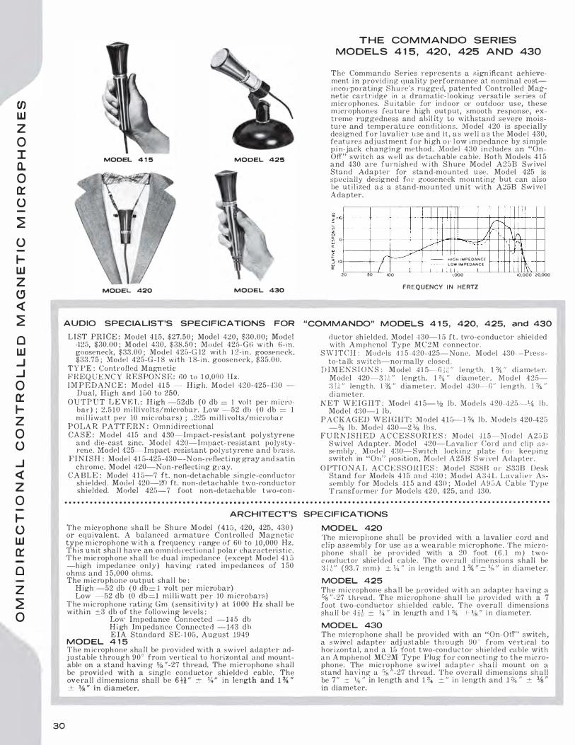
en LU z
0 I a. 0 a:: 0
�
0
JLU z CJ <!
�
0 LU ..J ..J 0 a:: Jz 0 0
..J <! z
0
Jo LU 0::
0
z
� 0
MODEL 4 1 5 MODEL 425
MODEL 420 MODEL 430
AUDIO SPECIA LIST'S SPECIFICATIONS FOR
L I ST PRICE : Model 415, $27.50 ; Model 420, $30.00; Model '125, $30.00 ; Model 430, $38.50 ; Model 425-GG w i th 6-in. goose neck, $33 .00 ; Model 4 25-G 12 w ith 12-in. goose neck, $33.75 ; Model 4 25-G-J 8 with 1 8- in . gooseneck, $35.00.
TYPE : Controlled M agn etic F I{EQUE N C Y RESPON S E : GO to 1 0,000 !I z . I M P E D AN C E : Model 415 - H igh. M o d e l 420-425-430
Dual, High and l iJO to 250. OUTPUT L E V E L : H igh -52db ( 0 db = 1 vo l t per m ic ro
ba r ) ; 2 . 5 10 m i llivolts/micrnbar. Low �52 db ( 0 db = 1 m i l l iwatt per 10 micrnbars ) ; .225 m i l l i volts/m icrnbar
POLA R PATT E R N : O m n i d i rectional CA SE : M odel 415 and 4 30-Impact-resistant polystyrene
and die-cast zinc. Model 420-Impact-resistant polystyJ"ene. Model 425-lmpact-resistant po l yst yrene and b rass.
F I N I S H : Model 4 1 5-425-430-N on-reflecti ng gray and satin chrome. Model 420-Non -reflecting gray.
CABLE : Mode l 4 1 5-7 ft. non-detachable s i ngle-conductO!' sh ielded. Model 420-20 ft. non-detachable t wo-conductor shielded. Model 425-7 foot non-detachable two-con-
T H E CO M M ANDO S E R I ES
MODELS 4 1 5 , 420 , 425 A N D 430
The Commando Series represents a s ign ifican t achievement i n providing q uality performance at nominal costi ncorpornting Shul'e's rugged, p atented Controlled Mag·netic cartridge in a dramatic-looking versati le series of microphones. S u i table for indoor or outdoor use, these microphones feature high output, smooth response, extreme rnggedness and abil ity to withstand severe moistu1·e and temp eratu re condi tions. Model 420 is spec ially designed for l ava! ier u se and ii, as well as the Model 430, featu res adjustment for h igh or low impedance by si mp le p i n-jack changing method. Model 430 i ncludes an "OnOff" switch as well as detachabl e cable. Both Models 4 1 5 and 430 are furn ished w i th S hure Model A25B S w i vel Stand Adapter for stand-mounted u se. Model 425 is specially designed fo r gooseneck mounting but c an also be u t i l ized as a stan d-mounted unit with A25B Swivel Ada pter .
; ••O>----·> --- �-� +---+-+-++++i+---+----j----j-+++t++-t--1 "' f-------,f---+----+---+--++-f-+1-++-----j-- +IC ..... " �U--J.......J ! o+---t--+-----+----j--t--t::..-rrtt"°'""'=:::::b':/-i--t-', r-��llttti ;: VV \ I \ >
r !-----'" ..-� · 10•>---r- --;( 20 50 •00
HIGH IMPEDANCE f--if--++ +++l>-- -+---4 LOW IMPEDANCE
I II II II I •.000 \ 10,000 Z0,000 F R E Q U ENCY I N H E RTZ
"COMMANDO" MODELS 4 1 5 , 420, 425, and 430
ductor shielded. Model 4 30-1 5 ft. two-conductor shi el ded with A m p henol Type MC2M connector.
S W I T C H : Model s 4 l 5-420-425-N one. M ode l 430- --Pressto-talk switch-normally closed .
D I M E N S I O N S : Model 4 1 5-· G l i\ " length. 1 % " diameter . Model 420-3 l ,', " length. 1 % " diameter. M odel 4 :2 5-3 1 ,1, " length. 1 % " diameter. Model 430-- G " l en gth
. l 3/,, "
di ameter. N E T WE I G H T : Model 4 1 5- 112 lb. Models 420-4:25-14 lb .
Model 430-1 lb. PACKAGED WEIGHT: M odel 4 1 5-1 % lb. Models 420-425
-% lb. Model 430-2 % lbs. F U R N I SH E D A C C E S S O R I E S : Model H 5-M odc l A 2 :JB
Swivel Adapter. Model 420-Lavalier Co1 ·d and cl ip assembly . ModPI 430- S wi tch lock i ng p l ate f o 1 · keep i n g switch in "On" position, M odel A 2 5 B S w i ve l Adapter.
O PTIONA L A C C E SS O RI E S : Model S38B or S33B Desk Stand for Models 4 1 5 and 4:) 0 ; M ode l A34L Laval ier Assembly for Models '1 15 and 430 ; Model A �l G A Cable Type T ransformer for Models 420, 425, and '130.
. . . . . . . . . . . . . . . . . . . . . • . . . . • • . • • • • . • • • • • • • • • • • • • • . . . . . . . . . . . . . . . • • • • • • . • • • • • . • . . . . . . . . • • • . • • • • . . . . . . . . . . . . . . . • • • • • • •
30
ARCHITECT'S SPECIF ICATIONS
The m icrophone shall be Shure M odel (415, 420, 425, 430 ) or equ ivalent. A balanced armature Con trolled Magnetic type m icrophone with a frequency range of 60 to 10,000 Hz. Th is u n it sha l l have an omn i di rectional polar characteristic. The m icrophone shall be dual impedance ( except Model 4 1 5 -high impedance onl y ) having rated impedances of 1 50 ohms and 1 5,000 ohms. The m icrophone ou tpu t shal l be :
High -52 db ( 0 db = l volt per microbar) Low -52 db (0 db=l mi l liwatt per 10 m icrobars)
T he m ic rophone rnting Gm ( sensitivi ty ) at 1000 Hz shall be w i th i n ±3 db of the follow ing levels :
Low Impedance Connected -145 db H i gh Im pedance Connected -143 db EIA Standard SE - 1 05 , August 1949
MODEL 4 1 5 T he m ic rophone shal l be p rovided with a swivel adapter adju stable through 9 0 ° from vertical to horizontal and mountable on a stand h avin g % "-27 thread. The microphone shall be provided with a s ingle conductor shi elded cable. The overall dimensions shall be 6 H " ± 14" in length and 1 % " ± % " in di ameter.
MODEL 420
The micrnphone shal l be provi ded with a laval i er cord and cl ip assembl y for use as a wearable m icrophone. The microphone shal l be provided with a 20 foot ( 6 . 1 m ) twoconductor shielded t:able. The overall dimensions shall be 3 l l " ( 93.7 m m ) ± ¥.. " in l ength and 1 % " = % " in diameter.
MODEL 425 The micrnphone shall be prnvided w i t h an adapter having a % "-27 thread. The m i crnphone shal I be provi ded with a 7 foot two-conducto r shiel ded cable. The overall dimensions shall be 4 # :::: % 0 in length and 1 % t:- 1/s " i n diameter.
MODEL 430 The m i crophone shall be pro v i ded with an "On-Off" switch, a swivel adapter adj ust able thro u gh 90 ' from vert ical to horizontal, and a 15 foot two-conductor s h i elded cable with an A mphenol MC2M Type Plug for con nect i ng to the m icrophone. The m ic rophone sw ivel adapte r sha l l mount on a stand hav i ng a % "-27 thread . The overa l l dimensions shall be 7" ± '/,, " in length and 1 '%. ± " in length and 1 % " ± % " in diameter.

M O D E LS 520S L , 520SL B , 520, 5208
M odel s 520SL and 520SLB combine m i c rophone, gri p -to-ta lk , slide-to-lock switch, and desk stand-a complete assembly. A time honored favorite among d i spatchers because of its dependabil i ty. This rugged assembly i s designed fo r base-station u se in police, fi re, u t i l i ty, forestry and transportation serv irns, as well as pagi ng and c a l l systems. Model 520 or 520B known as "Green B u l let," are the microphone h e<ids alone and are exceed ingly rugged utility public add ress microphones. Choice of Low or H igh i m pedm1ce avai l a b l e in boL h series.
FREQUENCY I N H E RTZ FR EQUENCY RESPONSE
5 2 0
5 2 0 8
A U DIO S PECIALIST'S SPEC IFICATIONS
LI ST P HT C E : Model 520SL $45.00 Model 520SLil $4fl.25 Model 520 $22.50 M odel 520B $22.50
T Y P E : Contro l l ed Magnet ic
F R E Q U E N C Y R E S PONS E : 1 00 to 9,000 Hz
O UTPUT LEVE L : Model s 520SL and 520 : -52. 5 db ( 0 db = 1 v o l t per m ic robar 1 2 . 3 8 mil l ivolts / rn ierobar; Models 520SLB and 520B : -5 1 . 0 db { O d b =-= 1 m il l iwatt p e r 1 0 rn i crobars) .28 1 m i l l i vol ts/microbar
TM PED A NCE : :vlodel s 520SL and 520 : H igh . Recom mended load 100 ,000 ohms 0 1 · more. M odels 520SLB and 520B : 150-250 ohms
POLA R PA TTE R N : Omnidirectional
CA S E : Di e-cast zinc
F I N I SH : Meta l lic green w i th satin chrome grille. ( Satin chrome han d l e on Model s 520SL and 520SL R )
C A B LE CONNECTO R : Model S20 S L : Eq uivalent to A mphenol Type M C 3 M Plug. Model 5 20SL B : Equivalent t o Amphenol Type M C 4 M Plug
M O D E LS 5 1 0S L B , 5 1 0C , A N D 5 1 0S
CA B L E : Model 520SL : 7 ft . h i g h qual ity two-conductor shielded. Model 520S L B : 7 ft. high qual ity four-conductor ( two-conductor sh i e l ded ) . Model 5 2 0 : 7 It., single-conductor shielded. Model 520B : 7 ft., two-conductor shielded
S W ITCH : Equipped with grip-to-talk switch, si m i hu· Lo S h u n� ASS A . Model 520SL: S PDT-nonnal l y c losed-normal l y open. Model 520SLB : D PSTnormally open-normal l y open . Model 520 and 520B have no switch
D I M E N ST ON S : Models 520SL and 520SLB : W ith sta nd 9 % " high, 5" wide, 7" deep. M odels 520 and 5 20 8 : Length 3 111 ", diameter 2 % "
NET WE I GH T : M odels 520SL and 520SLB : 2 %. l bs. ; pacbged weight : 5 lbs. Model s 520 and 520 B : % l b . ; packaged weight : 1 1.1' l bs .
OPTIONAL· ACCESSORIES : Model A95A Cable Type Transformer ( for use only with Model 520SLB ) , S34B Desk Stand ( for use w ith 520 and 520B )
Model 5 L O S L B is a com p lete asse m b l y of a Controlled M agnetic M i crophone w i t h a switch and a desk stand. Models 5 1 0C and 5 1 0S are th e m icrophone head a lone ( known as "Hercules " ) , ava i lable with o r without switch . M odel 5 1 0SLB i s espec i a l l y recorn mended for mobile and fi x ed-station use as wel l a s for call systems. Models 5 l O C and 5 1 0S arc desi gned fur hand-held or desk top p l acement making them excel l ent for home-recording, m o b i l e p ubl i c address systems, and intercom systems.
A U DIO SPEC IALIST'S S PECI F ICATIONS
LI ST PR I CE : Model G l OS L B , $29.75 ; M odel 5 10C, $ 17 .00 ; M odel 5 10S ( w ith s w i tc h ) , $ 1 9.00
TYP E : Con tro l l ed Magnetic
F JU .: Q U E N CY R E S PO N S E : 1 00 Lo 7 ,000 Hz
O UTPUT LEVEL : M odel 510 SJ.Il -51 db (O db !. m i l l i watt per 10 m icro bars ) ; .238 m i l livolts/ microbar. Models 5 1 0C and 5 1 0 8 -52.5 db (0 db =
1 volt per rnicrobar ) ; 2 .38 mi l l i v o lts/microbar
IMPEDANCE : 5 1 0S LB- l 50-250 ohms. 5 1 0C and 5 1 0S-H igh. Recommended l oad 1 00,000 o h m s or m o re
POLAR PATTERN : Semid irectional
CASE : Die-cast zinc
F l l\ I S H : Metal l ic green
CABL E : Model 5 1 0SLB : 7 ft., two-conductor shielded. Mode l 5 lOC and 5 10 S : 7 It., single-conductor s hielded
SWITC H : Bui l t-in , normally open, switch to contro l t h e m icro phone c ircuit. The swi tc h is of the pressto-tal k locking o r non - l ocking type
D I M EN S I O N S : Model 5 1 0SLB : W i th stand 8 % " high, 5 " wide, 7" deep. :Y1odels G l OC and 5 1 0 S : 3 Y,, " high , 2 % " wide, l 1h " deep
N ET W E I G H T : Model 5 1 0SLB : 2 l bs . ; packaged weigh t : 2% lbs. M odels 5 1 0C and 5 1 0 S : % lb. ; pack aged weight: 1 1/2 lbs.
O PTIONAL ACCESSO R I E S : Model A95A Cab l e Type Transformer for 5 10SLB only. 8348 Desk Stand (for 510C and 5 1 0 S )
3 1
0
s: z
0
::0 m () -I
0 z )> r
() 0 z -I ::0 0 r r m 0
s: )> G> z m -I
() s:
() ::0 0 "'O I 0 z m en

Cf) w z
0 I a. 0 0:: ()
�
...J <{ IC/) >-0:: ()
...J <{ z 0
lo UJ 0::
0
z
� 0
32
T H E MODEL 777 "S L I M -X" S E R I ES
The "777" S l im -X Microphones are rugged little m icrophones weighing only 6 ounces. They use a " M etal Seal" crystal for operating under adverse conditions of heat and humidity. Designed for good-qual ity voice 1·eproduction, t h e i r versati l ity and " hand-abil ity" make them ideal for use by lecturers, announcers, instructors, and H a m s ; f'or aud i ence participa l i o n show s ; carnivals ; and for use w ith home-recorders. When mounted on e i ther cradle or swivel , the "777" c a n be quickl y removed, making it an i dea l ' 'walk-aro und" hand-held m ic rophone. A l l m odels are furnished w i t h a l ava li er cord .
FREQUENCY IN HERTZ FREQUENCY RESPONSE
7 1 0
REX
MODEL 2755 "VERSAPLEX"
Smart, modern design w i th rugged, l i ghtweight constructio n in a l ow
cost unit. Wide-range response for tape reco rd i ng , budget publ ic address, amateur rad io and many other app l ications. Built-in fi l ter 1·educes voice "pop." Compl ete w i th locking, sl ide-to-talk switc h , plus lavalier assem b l y and stand adapter.
U . S . Pntcnt 1 9 6 , 9 1 9
AU DIO SPECIA LIST'S SPEC I F ICATIONS
LI ST PRICE : Model 777-$25.00 I ncludes Lava l ier Corel and mol ded stand adapter . .YI.ode] 777S-$27.00 I ncludes Lavalier Cord, "On-Off" Switch, and molded stand adapter. M odel 777A-$33.00 Incl udes Laval icr Cord , A25B sw ivel sta nd adapter, S38B Desk Stan d . Model 777SA-$35.00 J nc ludes Laval ier Col'd, A25B Swi vel stand adapter, S:3 8 B lJesk Stand and "On-Off" Switch.
TY PE : Crystal-moisture-proof "Metal Sea l " F H E Q UEKCY R E S PON SE : Smooth from 60 to 1 0,000 Hz
OUTPUT LEVEL : -62 db ( 0 db = 1 vo lt per micro bar) ; .790 mil l i -volts/microbar
I M PE DA N C E : H ig·h-n commended load impedance : 1 to 5 megohms
P O LAH PATTE RN : O m n idirectional
CASE : D ie-cast z i nc with satin chrnme finish
CA BLE CONNECTO R : Equipped with Amphenol MClF Type Plug.
CABLE : Detachable 7 ft. s i ngle-conductor shielded
DI M E N SIONS ( M icrophone onl y ) : 4 % " h igh, 1" diameter
N ET W E J GHT ( Microphone only ) : :Ys l b. ; packaged weight o/.i lb.
OPT l ON A L A CCESSO R lE S : Model S38B Desk Stand for Models 777 and 777S, A25B Type Swivel Adapter for Models 777 and 777S
MODEL 707A
Ideal for l ow-cost publ ic address systems, call systems, amateur phone t ransmitters a nd general purpose use. Features good-quality reprod ucti on at l ow cost. U ses moistu re-proofed B imorp h Rochelle Salt crystal for long-life operation.
MODEL 7 1 0 "REX"
Low price , rugged hand-held microphone, designed for high speech intelligibili ty. A natural for radio amateur rigs, home recording and low-cost p ubl ic address systems. Features broad base, complete with stand adapter fo1· mounti ng on floor stand.
AUDIO SPECIALIST'S SPECIF ICATIONS
LIST PR ICE : $ 15.00 T Y PE : Ceramic F R E Q U ENCY RE SPO NS E : 40 to
1 2,000 Hz O U T P U T LEVF: L : -59.5 db (0 db
= 1 vol t per m icroba r ) ; 1 . 050 m i l l ivolts/ m icl'obar
£MPEDA NCE : H igh-Recom mend ed load impedance : 1 to 5 megohms
P O L A R P A T T E R � : O m nid irect ional
C A SE : Black h ig h impact "AnnoDur" body w ith satin anodized cap and g ri l le
C A BLE : A ttached 7' single - cond ucor sh ielded
SW I TC H : Sl ide-to-talk locking type DJ M E N S l O N S : 4 ff' long, 1 /d- " di
ameter F U R N I S H E D J\ C CE S S O R J E S :
Stand adapter w i th standard % " -27 thread, and la valier assembly. ( J ,avalier bracket becomes wall bracket when cord is removed. )
NET W E I G H T : 4 oz. ; packaged weight : 1 lb.
OPTIONAL A CCESSORIE S : S38B Desk Stan d
L I ST P R l C E : $ 19 .fiO
TY l ' E : Cry stal
F H E Q U E N C Y H ESPONSE : 30 to 7,000 Hz
O U TP U T LEV E L : -50 db ( O db =
l volt per rnicrobar ) ; 3.150 mill i vol ts/m icrobar
I M PEDANCE : Iligh-Recornmended, load impedance : 1 io 5 megohms
P O L A R P A T T E R N : S e m i d i r e c t ional
CASE : Die-cast zinc
F J N ISH : Iridescent gray case, satin chrome gril le
C A l3LE : 7 .ft. , single-conductor shielded
STA N D TH RE AD : Standard % " -27 thread
D I M E N S I O N S : 3 % " high, 2 ff' d i ameter
.;.J J::T W EIGHT: % lb ; p ackaged we ight : 2 lbs.
O PTION AL ACCF. S SORI E S : M odel SMB Desk Stand
' L I ST PR I CE : Model 7 10A, $ 1 2 .00 ; Model 7 10S ( with switch ) , $ 14 .00
TY P1'� : Crystal
FREQUENCY RE SPO N SE : 60 to !:l,000 Hz
• OUTPUT LEVEL: -50 db (0 db = l volt per microbar ) ; 3. 150 m il l i
\'Olts/microbar
I M PEDA NCE : High-Recommended, l oad impedance : 1 to 5 megohms
P O L A R PATT E R N : Sem i d ir e c -tional
C A S E : D ie-cast zinc
F I N I S H : Metall ic burgundy red
C A BLE : 7 ft. fabric covered, s ingle-conductor shielded
SW ITCH : Model 710S has a built in, press-to-talk l ock ing or nonJocki n g switch
D I M EN S I O N S : 3 0'2' high, 2 1/; " wide, 1 ¥.; " deep
NET W E IG H T : % l b . ; packaged weight 1 % lbs.
OPTIONAL ACCESSORI E S : S34B Desk Stand

MODEL 450 "DISPATC H E R " M ICROPHONE
New modern design tits e very decor fo r p:lging use. Integrated case design , made of gray "A rmoDur", features t el escopin g he ight adjust ment for maximum conven ience. H ugged Co11Lrol l ed Ma gnetic element with i mpedance sw itch for l ow or h i gh im pedance. Push-tu-talk switch bar w i t h op t io nal features pro vide every desired switching option.
AU DIO SPECIALIST'S SPECIFICATIONS
LI ST P R I CE : $49.50 ELEMENT TYPR : Cont ro l led Magnetic
FRRQUENCY RE SP ON S P. : 100 to 1 0,000 Hz
O U T P U T LEV E L : H igh impedance -54 .0 d b ( O d b = 1 volt per m icrobar ) ; 2 .00 rn i l l ivo lts/microbar Low i m pedance -53.0 d b (0 db = 1 m i l l iwatt per 10 microbars ) ; .225 rn i l l iYolts/m i croba 1·
I M PED ANCE : Du al . Switch for 50 Lo 250 olirn s or High
C A SE : Two-tone Gray "A rmo-Dur"
C A BLE : 7 ft., fou r-con ductor ( two-cond uc tor shielded )
S W I TCH : P l'ess -lo-Lalk swi tch - l ock ing or n o n - locki ng opel'aiio n. Sw itch actu at es m ic rophone circ u it and an external relay 01· conl 1·o l c i l'cu i L. M ic roph one circ u it is normal l y shorted in high impedaHce and normal ly open in low impedance position.
DIMEN SION S : 4 " w ide, 5 H " deep , l O H " h ig h ( adjustable )
N ET W E I GHT : l �s lbs. ; packaged weight : 2 y, l bs.
FREQ U E N C Y IN H E RTZ
FREQUENCY RESPO N S E
ARCH ITECT'S SPEC I FICATIONS
The m icrophone shall be the Sh u re Model 450 balanced arm atu re Con tro l led Magnetic type microphone or equivalent. The freq uency respon se range sha l l be 100 to 1 0,000 llz. T he m icrophone shal l be equipped wi th a sl i d e switch fo r selecting the m icrophon e rating im peda nce of 200 ohms or 1 4 ,000 ohms. 'The m i c roph one ou tput sha l l be :
H i gh i mpedance -54.0 db ( 0 db · = l volt per m icrobar ) Low i mpedance --5:j .0 db ( 0 db = 1 m i l l i wa tt per 10
micro bars ) The m icrophone rati ng G m ( sen si t iv i t y ) at 1 ,000 Hz shal l be w i th i n _;_ 3 db of the foll owing leve l s :
Low im perl.mwe posit i on - J . J 5.0 d b Jl ig h i m pedance pos i t i on - 1 45.0 db
E J A St andard S E- 1 05 A ugllst 1 94 9 T h e microphone s h a l l have a height adjustment of 2 1;2 " and i t shal l h a\'e " p ress-to-ta l k " switch t o operate the m i crophone c ii·cu i t and t he exte rnal relay c i rc uit. T he m icrophone shal l ha,·c a 7 foot non-detac hable four-conducto r, twoconducto r shie ldetl cable. 'The overa l l d i m ens ions on the m icrophone sha l l b e 4 " ( 1 01 .li m m ) + 1/s " ( 3 .2 111111 ) wide, 5 H " ( 1 4 4 .5 mm ) _±_ 1/g " ( 3 .2 mm ) deep, and l O H " ( 264 .3 m m ) ::+:: % " (9.6 mm) h igh.
MODEL 430SL "CO M MA N DO"
CONTROLLED MAG N ETIC PAG I N G M ICROPHON E
� •IOf-------------- _,--+----+----+-+-+-f++++--t--lv-t....,-t-t-++t+--+---i :;: � J \11 � o� --+--+- ----+--1�/+�--tl..+-ft+--...=:::::l:>"'+-+-1�\�ltt--t-�
10,000 zopoo
Latest a t l d it ion to Lhe famed Shure " Com mando " l ine. Spec ia l " m o m e n t a r y " p ress-to-tal k locki ng or 1 1 0 1 1 - l oc k i ng- S\\ri tch cont 1·ol s both rn ic rn p hone c i rcu i t and ext e rn a l rel ay o r contrnl c i rc uit . S pec i a l ly d0s igned fo 1 · p u b l ic add ress , call systems, backgrotrnd m usic, pag- i 1 1 g syst·erns, and s im i l a r applicatic ns. M ode l 4 :30SL is com p le t e w i th S:38B
Desk Sta nd a11d A 2GH S w ivel Ada pte1·. Can be used i n stand or hand-held.
FREQUENCY I N HERTZ FREQUENCY RESPONSE
AUDIO SPECIALIST'S S PECIFICATIONS
L l ST J ' ]{ ] C l<.: : $49.95
T Y P E : Con tro l l ed M agnetic
FREQ U EN CY RESPON S E : S moot h and u n i form from 60 Lo 1 0 ,000 Hz. Free from u ndesi rab le peaks
POLAR PATTERN : Omnid i rectional
O U TPUT LEVE L : Low impedance -52 db (0 d b = l m i l l iwatt per 10 rn icrobars ) ; .225 m i l l ivol ts/m icroba1· High impedance : - 5� db (0 db = 1 volt per rnicrnba r ) ; 2.5 L O mil l ivolts/m icrobar
1 M PE D A N CE : Dual-Easi l y converted from High to Low CA BLE : N on-detachabl e 1 5 ft. t h ree -conductor, O llc-con
d u <.:tor shielded
S W l TC H : M i l lion cycle, press-lo - La l k lock i ng or 11011- locking type t o control both microphone and external relay or control c irc ui t
F' l N l S H : Sati n chro rne a n d black
D I M E N SI ON S : 6 ii " Jong, l 'f4 " diameter
N E T W E IG H T : 1 llJ . ; packaged weight : 2 1/g l bs.
F U RN I S HED ACCESSO H I E S : A25B Swivel Adapter ; S::l8D Desk Stand
ARCH ITECT'S SPEC IFICATIONS
The rn ic rnpl 1 one shall be t he S h u re Model 430SL Bal anced A rmature Contro l led Mag· 1 1etic type m icropl10ne or equivalent with a frequency rn nge of l iO to J. ( ) ,000 l l z . T h i s un it shal l h a \'e a n o mnic l ircct i o na l l i o rizon ta� polar characteri stic. The m icrop lwne s h a l l be dua l i mpedance having rated impedances of 150 ohms and 1 5,000 oh m s . The mi c rophone o u t p u t sha l l b e :
Low : - 5 2 d b ( 0 d b = 1 rn i l l iwati p e r 10 ni i c robars )
H i gh : -52 db ( 0 db _ 1 vol t per microba r )
The m icrop ho ne rating G m (sensit i vity ) at 1 ,000 l l z sh al l be within ±:3 db of the fol l o \\' i ng levels :
Low i mpedance connected p osit ion - 1 4 5 d b
H igh imped an ce connected posi tion -Ll 3 d b El1\ Stant.lard SE-lO:J August l �H �
The m icrop hone shall be p rov ided with an ' 'On-Off" s w itch to con trol the m i c ro phone cfrc u i t and the re lay circuit, a base and swivel adapte r adjustable th roug h 90" from vertical to hori z o n tal, and a 1 5 [oot th ree-conductor, one-conductor shi elded non-detachal>le cable. The overall d i me11sions of the m ic rophone only shall be G l :'. " ( 1 73.0 m m ) ':: 1A '' ( 6.4 m m ) long, 1 %. " ( .14.5 m m ) ·t- 'is " (3.� m m ) in diameter.
33
"U )> G)
z G)
�
CD )> en m
en -I )> -I
0 z
�
0 :u 0 "U I 0 z m en

CJ) UJ z 0
� o O o 0::: <( 0 0:::
� 0:::
UJ :1 CJ)
UJ 0 ra.. <(
0::: � :1 <(
a.. a:: ...J 0
<( lL
0 UJ a.. CJ)
Model 4 44
FREQUENCY IN HERTZ
FREQUENCY RESPONSE
MODEL 444 ADJUST A B LE H E IG HT "HAM" M ICROPHONE
N o w ' A microphone spec i fical l y designed to meet the needs of the disc rim inating amateur 1·adio enth usiast ! Shure has built into this m od e rn m i c rophone, the u n matched performance characteristics of the famed Model 440SL. Special featu i·es i ncl ude p 1·ess-to-talk switch w i th op tional locking feat u re, providing i deal switch i ng fu nctions for both press-to-talk and VOX operation, and an adjusta ble stand that raises 01· l owers microphone for most rnmfortable ta lking position.
AUDIO S PECIALIST'S S PECIF ICATIONS
LI ST PRICE : $42.50 ELEMENT TYPE : Controlled Magnetic
FHEQUENCY KESPON S !i: : 300 to :3,000 Hz
O U TPUT L E V E L : -53.0 db (0 db = 1 vol t per m i crobal") ; 2.25 mi llivol ts/m ic roba r
J MP E D A NC E : High
C A S E : G ray "Arrno-D ur"
CABLE : 7 ft., two-conductor s h ielded
SWITCH : Press-to -talk switch bar, with opt ional l oc ki ng feature to operate relay control and microphone muting c i rcuits. Separate switch enables user to disable relay con trol c i rcuit for VOX operation.
D I M EN S I ON S : 4 " wide, 5 H'' deep, l O ff' h igh ( adjustabl e )
N E T WEI G HT : 1 % lbs . ; packaged weight : 2 1/s lbs.
. . . . . . . . . . . . . . . . . . . . . . . . . . . . . . . . . . . . . . . . . . . . . . . . . . . . . . . . . . . . . . . . . . . . . . . . . . . . . . . . . . . . . . . . . . . . . . . . . . . . . . . . . . . . . . . . . . . . . .
M odel 440
Model 140SL
FREQUENCY IN HERTZ
FREQUENCY RESPONSE
* A87K
MODIF ICATION KIT
For use w ith Shure Model 410SL Microphone. The Shure A S 7 K Kit will modify the 440SL microphone to obtain optimum fiexiLi l ity between either VOX or push-to-talk operation. LIST PlU C E : $3.25
34
MOD ELS 440-440SL M ICROPHONES
T h e response cha rncteristic of these m icrophon es h a s b e e n tai lored to meet the demands of rad io com m u nications. These microphones are specifical ly designed for si ngle-sideband broadcast, ancl are ideal l y s u ited fo r use w i th all t y pes o f "ham" t ransm itlers. T h e rising response cha racteristic w ith sharp cutoff below 300 and above 3,000 cps insures the highest possible " talk power" level. T he units util ize a rugged, t ime- p rnven , Cont rnl led Magnetic elt·ment, with h igh output equaling that of a crystal unit. Model 440SL i ncludes stand a s i llustrated.
AU DIO SPECIALIST'S SPECIFICATIONS
MODEL 440 and MODEL 440SL M ICROPHONES
L I ST PJUCE : Model 440 $25.00 M odel 440SL $47.50
TYPE : Control led Magnetic
FREQU E N C Y RESPO N S E : 300 to 3 ,000 Ilz O U T P UT LE V E L : -52.5 db ( 0 d b = 1 volt per m i c roba r ) ; 2.:3S
m i llivolts/ m ic robar
I M PEDAN C E : High. Recommended load 1 00,000 ohms or more
POLAR PATTE R N : Omnidirectional
CASE : Die-cast zinc
Fl N l SH : Satin chrome and gray
CABLE C O N N ECTOK Equivalent to Amphenol M C3M p l ug
CABLE : M odel 440-7 ft. , s i ngle-conductor shielded. M odel 440SL -7 ft. , h i gh qual ity , two-conductor shielded
SW ITCH : Model 440SL-Equ ipped w i th grip-to-t a l k switch, similar to Shure ASSA
STAN D THREA D : Model 440-Standard % " -:!.7 t h read
D l ME N S J O N S : Model 440- :!. .H " d iameter, 3 14 " length Model 440SL-9 % " high, 5" w ide, 7" deep ( with stand )
N ET W E I G HT : Model 440-% l b. , paekaged weight 1 % l bs. M odel 440SL-:!. 1 !! lbs., packaged \\"eight 5 lbs.
O PTIONAL ACCE SSORI E S : Model 440-Mode ls S34 I3 or S36A Desk Stands. Model 440SL-A87K Modification Kit*

u new break-throuyh in m icroph o n e design SH U R E MODEL 488
NOISE-CA N C E L L I N G M I CROPHO N E !
Outperforms and ub::;u leles all oth ers . . . confirmed by cxtew; ive laborntv·ry and field eornparisou te::; ts !
Provirl es h ig h l y i n t e l l igib l e speech e o rn 1 1 1 u n i calion in m o b i l e a nd fixedsta tion use wh ere h igh vol u m e backgrnund noise is fou nd, such as airp l anes, h el i copters , motorcycles, truc k s , fire engines, power boats , s por ting events, d rop forges, press-ro o m s , engi nc-1·oom s, factories. The 4 88 incorporates the palented Shure Co ntro l led ]{ el uc tance cartr i dge i nto a d i stance c l iscri m i nate m icrophone that effec li ve l y cancels backgroun d no i se to permit tran s m i:;sion under condit ions that would be i mposs i b l e with any other m ic ro p hone. Correct place m e n t of m icroph one for close-ta l k use is assured by conven ient ru bber l ip-guard . R ugged, i m pact-res istant
"A rn10- D u r " case is l ightweight, easier to hand le i n extremes of lempera ture. Four vers ions of t h e 488 are ava i lable: 4 88A-hi g h impedance ; 488 B - l o w i m pedance ; and -!88C a n d 488T-tran sistorized for d i recl rep lacement of carbon m icrnphones ( 488T F A A Cert ified fo r A i rcraft app l i cation s ) . A l l models equ i p ped w i lh co i led -eo rd and long-l i fe h eavyd u ty p ush-lo-ta l k switches. F ie ld-test i n g l hese blade-type switches confinns their operat ing l i fe rating to bC' i n excess of one m i l l ion cyles.
S H U R E MODEL 488 NOISE-CA NCELLI NG M ICROPHONE
,, 'O z
w Vl 0 z 0 n. Vl w a: w · 10 � !;< -' w a:
� -
---20 50 100
! - -c--r-
�
L I
�� v /
1,000
F R EQ U E N C Y I N H ERTZ
F R EQ U E N C Y RESPONSE
- · -
" �- -
" /I \ -
I -
-f--
--10,000 20,000
AU DIO SPECIALIST'S SPECIF ICATIONS
M O D E L
LT ST PHl C l·:
<188A T; J G H
I MP E DA NCE $57 .50
'188B LOW
I M P E D A N C E
$57.50
488C T R A N S I STO R I Z E D
$62.50
488'1' T l{ A N S I STO H IZ E D
A l l{C H A FT
$n.5o
N O I SE D I SC R f M l N A T I ON F'ar S uper io r to Standa 1·d Com mu n i <:at i on M ic rn p l i o ncs
F'HE Q U E N CY IH� S P O N S E
TY PE ( SPEC I A L L Y TA l LO HE D FO H B E ST I N J N TE L L ! G J B I LTTY ) 200 tu 4000 l l ertz
O U T P U T LEVE L (0 dh= l V O LT PE R M I C IW B A R . H I volls (-17 d b ) F' l ELD )
I M P F: D A NCE
C A B L E
S W ITCH M r e C I R C U I T R I£ L A Y C IRC U J T
H i g h : l{ccomrnended Load 1 00,000 o h m s o r m o re
Three-Cond uctor ( On e-conductor sh iel ded ) cad m iu m coppe1· co i led cord ( 5 % ' ex tended )
Norma l l y c l osed* N o n n a l l y open
Contro l l ed R e l uctance ----------------------·
0.45 volts (-7 du ) 0 . 7 1 volts (-a db ) . 0 1 4 volts ( -37 d b ) using 6 volts DC and u�i ng 1 2 v o l l s and
1 50-250 ohms
Four-Cond uctor ( Two-cond uctor s h i elded ) cadm i u m copper co i led cord ( 5 % ' extended )
N orma l l y open * * )/ on n a l l y open
:300 o h m l oad 500 ohm l oad
l{ecum mended Load 1 0 0 to 500 ohms
F o u r-Conductor cad m i u m copper c o i l ed cord
( 5 1/2 ex lended )
N ormally open N ormal l y open
l{cc·om menr led AC Load 1 00 to 800 ohms
T h ree-Conducto r T inse l coi led cord ( 5 % ' extended ) with PJ 068 -pl u g a ttached
N o rma l l y open Nornia l l y open
C A S E G ILt\ Y H I G H I M PACT " A R M O- D U R" W I T H PK lffO l {ATl: D STE E L G HI LL E A N D 1-w n mm L l P G UARD
U I M EN S I O N S
W F: I GHT
A C C E S SO H.! E S
3 1-t'' h i g h x 2 5s " w i de x 2 1,2 " deep ---------
% l b . , packaged weight 1 % l bs.
M O U N T I N G BRA C KET FOR P F: RM A N J<:N T PLACEM J<:NT
* Pro v i:; ion for sim p le change to 11orrna l l y open * * l'rnvi;;ion for s i mp l e change to norm a l l y c l osed
3 5
z
0
CJ) m
0 )> z 0 m r r z G')
�
0 ;a 0 "U I 0 z m CJ)

(/) LU z 0 I Cl. 0 a: 0
�
CJ z ....J ....J LU 0 z <( 0
LU (/)
0 z
1-LU en 0 z <( I
LU z 0 I Cl. LU ....J LU I-
36
MODELS 4 1 9A AND 4 1 9 8 RANGER II
NOISE CA NCELLING M I CROPHON ES
)I ow, a series of s mall size n o i se-cancel l i n g hand m icrnphones s p ecifically designed lo pro,· ide h ig h l y intel l igible speech c o m m u nicalions in those appl ications req uiring reject ion of un wa 11led noise and where sma l l size is desirable.
The Conlro l lcd Magnetic cart l ' idge i n corporated i n this series perm i ts transmission u11der cond i tions hereto fore thought i mpossible. Significantly superior speech i ntel l i gibil ity <1 1 1d a spec i u l l y t a i lored respo nse ( '.WO to 4 ,000 H z ) all combine to make these m icrophones ideal (or al l t ypes of outdoor- i ndoor communication act iv ity i11 mobi l e and fixed-station use, as in Pol ice, Ffre, Uti l i t y , Forestry and Transportation Serv ices ; Commerc ia l ; I nd ust r i a l ( i nc l uding rad io telephone ) ; Arnati'ur Rad i o ; am! s im ilar appl ic<tlions. The micro phones are excepl io nally s u i t able for out door and i ndoor publ ic-address and c a l l systems in noisy a reas ( facto ries ; forges ; p rint i n g p lants ; etc. ) . Lightweight . . . o n l y 7 ounces less cable.
U . S . Patent. 1 >2 u 3 . b 7
AU DIO SPECIALIST'S SPECIF ICATIONS
LTST PRTCE : Model 4 Hl A , $62.50 ; Model 4 1 9 B , CASE : H igh i mpact "A rmo-Dur."
$62.50.
TYPE : Co nt rol l ed Magnet ic. C A B LE : M odel 4 19 A : Three-cond uctor ( one-conduc
tor shielded ) . Coiled cord ( 5 % feet extended ) .
F R E Q U E N C Y R E S P O N S E : 200 to 4 ,000 Ilz
O C T P U T L E V E L : Model 4 19 A , . 1 2 vol t ( - 1 8.5 db) ,
Mode! 4 1 D B : Four-conductor ( t wo-cund ucto1·s shielded ) . Coi led cord ( 5 % feet extencled ) .
SWITC H : Double-pole, s ingle-th r o w . leaf-type s w i tch to contro l t h e m ic rophone c i rc u i t and to contrnl a n external rel a y on sw itch i ng circ u i t .
( 0 d b = 1 volt pe 1 · 1 00 rn i c roba1·s ) . Model 4 1 9TI, .0 1 4 vol t ( -37 d b ) , ( 0 db = 1 m i l l i watt per l 0 m icrobars ) .
D I M E N S I ON S : 2 � � " h igh, 2 i';; " wide, 2:;°" " deep.
N E T W E TG H T : 7 oz. ; packaged weight % l b.
FURN T S H E D A CC E S SO R Y : Mounting Bracket.
l M P E DA N C E : M odel 4l 9A , H igh : Recomrnended Load 1 00,000 ohm s or m ore. Model 4 1 9 13 , 1 50-250 ohms.
MODEL TH 1 00 PROFESSIONAL
M O B I L E T E L E P H O N E H A N DS ET
The TH l OO Telephone Handset is a C on t rn l l ed Magnetic com111 u 11ica t i ons handset which a l l ows the o perato1· to expand or upgrade his presen t equipment and t o obt a i n a degree o f p rivacy i n his comm u n i rn ti o ns and two-way coHversations.
It fea t u res normal equipment loudspeaker operation witl1 the handset in the hangup c radl e ( w h ich i s designed for panel moun t i ng ) , and autom atic switch ing of l o u dspeaker s ignal to the h a ndset receiver when handset i s l i fted from the c radle.
In add i t io n , the cont r o l of tl1 e transm itter c i t·c u i ls is opera ted by the p ush -lo-talk h a n dset s witch.
The TH lOO is specifically designed for Citizen's Band, A nrnteur, I ndusti·ia l , Commerc i a l , B u si ness, Edu<'at ional , and other rad io commu nication applications such as Safety, M arin e, Foz·estry, etc.
AU DIO SPEC IAL IST'S SPECIFICATION S
LIST PR I C E : $f>8.00.
TYPE : Controlled Magnetic.
FREQUEf\CY R E SPON SE : 200 to 3,000 Hz.
O U T P UT L E V E L : ( 0 d b = l volt per 1 0 0 m ic ro-bars . . 22 volt ( -1 3 . 0 db) .
T M PEDANCE : Transm itter : H igh. Receiver : 1 25 ohms.
C A SE : High i mpact " A nn o-Dur."
CA BLE : Four-conductor, one-conductor s h i el ded , p lastic-jacketed coil curd on handset. Four- fo o t , four-conducto r, olle-c:onductor :;h ielded , p l asticjacketed cable on hangup cradle.
SW I TC H : Double-pole, l c<tf-type switches in both handset and cradle designed t o stand up u nder severe ope rat ing cond i t ions and constant usage.
D I M E N S I O N S : H a n dset : 8 1:-'1 " h i gh , 2 H " wide, 2 ff' deep. Cradle : 3;f," h igh , 3d'i' w ide, 2} � " deep.
NET W E T G H T : 1 1/z lbs. ; packaged weight 2% l bs.
-

MODELS 4048 A N D 404C
CONTROLLED MAG N ETIC M ICROPHONE
The Shure Controlled Magnetic "404" is recommended for those applications where a rugged hand-held microphone is needed. It is ideal for outdoor public-address ( spot-ts arenas, athletic fields, carnivals, etc. ) and for mobile communications. The "404" is designed for high speech intel l i gibil ity. Easy to use, lightweight, it fits snugly i n the palm of the hand and is comfortable to the touch through heat and cold.
The "404" is an unusually strong and practical microphone for ANY mobile application, no matter how severe the use.
AU DIO SPECIALIST'S SPEC IFICATIONS
LIST PRICE : Model 404B, $33.00; Model 404C, $33.00.
TYPE : Controlled Magnetic.
F R E Q U E N CY R E S PO N S E : 400 to 4,000 Hz.
OUTPUT LEVEL: Model 404B : -52 db ( 0 db·= 1
mill iwatt per 10 microbars ) ; .21 mil l ivolts/microbar ;
Model 404 C : -54.0 db ( 0 db. = 1 volt per 100 micrnbars ) ; 0.20 volts.
IMPEDANCE : Model 404B-1 50-250 ohms. Model 404C-High, recommended Load, 1 00,000 ohms or more.
P O L A R PATTE R N : Semidirectional.
MODELS 4 1 4A, 4 1 48 A N D 4 1 4C
RANGER I I M ICROPHONES
C A SE : Hig-h impact gray " A nno-Dur".
CABLE : 5 % foot extended.
Model 404B-Four-conductor ( two-conductor shielded ) Coiled Cord.
Model 404C-Three-conductor (one-conductor shielded ) Coiled Cord.
SW ITCH : Push-to-talk, leaf type.
DIMENSIONS : 3 ti; " h igh, 2 % " wide, l W' deep.
N E T W E IG H T : 12 oz. ; packaged weight, 1 lb.
F U R N I S H E D ACCESSOR Y : Mounting bracket.
OPT I O N AL A C C E S SOR Y : Model A 9 5 A Cable-type Transformer.
� - - I ' ,..--Ideal for miniaturi zed or portable communications systems, the 4 1 4 Series of hand microphones are about half the size and weight of conventional m icrophones, yet perform as well or better.
\ -.
"9 They are rugged units recommended for critical outdoor-indoor communications i n mobile and fixed-station use, as i n Police, Fire, Utility, Forestry, and Transportation Services ; Commercial ; Industrial ; radio telephone; amateur radio ; and similar applications.
�·
Model 411A is h igh impedance ; 4 14B is low im pedance, while Model 4 1 4C is transistorized, and features a transistor amplifier within the case, powered by the current available from a carbon microphone circuit, making the 4 14C directly replaceable for carbon microphones in most carbon circuits.
V.S. Patent 020 3, 1 87
AU DIO SPEC IALIST'S SPECIF ICATIONS
LI ST PHICE : Model 4 14 A , $33.00; Model 4 14B, $33.00 ; M odel 4 1 4C, $'18.50.
TY PE : Controlled Magnetic.
FHEQUENCY RE SPONSE : 400 to 4,000 Hz.
O UTPU T LEV E L : Model 4 1 4 A : -14.5 db. (0 db. == 1 volt pc1· 1 0 0 microbars ) ; 0 . 1 9 volt.
Model 4 1 4B : -52.5 db (0 db = 1 milliwatl per 10 microbars ) ; 0.20 volt.
Model 4 14C : - 1 . 5 db ( 0 db = 1 volt with 100 microbars) or .85 volt using 6 volts cl.c. and 500-ohm load.
I M PEDANCE : Model 4 14A-High, recommended load 100,000 ohms or more.
Model 4 14B-1 50-250 ohms.
Model 414C-Recommended AC l oad, 100 to 1,000 ohms.
POLAR PATTERN : Semidirecti onal .
C A SE : High impact " A nno-Dur"
CA BLE : 5 112 -foot extended. Model 4 1 4A-3-conductor, one shielded neoprene jacketed coil cord.
Model 4 1 '1B-4-conductor, two shielded neoprene jacketed coil cord.
Model 4 14C-4-conductor, neoprene jacketed, coil cord.
SWITC H : Push-to-talk, leaf type.
DIMENSIO::--rS : 2H" high, 2 h " wide, l H " deep.
NET WE IGHT : 8 oz. ; packaged weight, 13 oz.
FU RNISHJ:<.:D ACCESSORY : Mounting bracket.
37
� 0 CD
r m
(') 0 s:
� c z
(') )> -i
0 z en
s:
(') ::0 0 -a I 0 z m en

en LU z 0 I a.. 0 c:: (.) �
en z 0
I<( (.) z :J �
� 0 (.)
LU ....I
m 0 �
38
MODEL 405T
TRANS ISTO R IZED
M ICROPHONE
T h e trans istor amplifier within t h e case of t h i s Controlled Magnetic m icrophone p rovides perfect i m p rovement-replacement for carbon m i crophones now used in mobile communications equipmenl. Powered by the current available from th e carbon m icrophone circuit , i t does not requ ire batteries or extra power supplies. Provides remarkable speech clarity and i s free from the aging common to carbon m icrophones used under conditions of vihration.
MODELS 405 K A N D 4 1 SA
CONTROLLED MAGNETIC
M ICROPHO N E S
Designed for cleai·, c risp, natural voice response of high i ntel l igibil ity. The 405[( and 4 18 A Series Communication Hand M icrophones are pressure-actuate<l units using the Shure developed b a lanced-armature, Con t rolled Magnetic Cartridge.
Model 405K is h i gh i mpedance ( 1 4,000 ohms ) and Model 4 1 8 A is medium i mpedance ( 1,500 ohms ) . Both are especial l y reeommended for all types of outdoor-indoor commun ication acti v i ty i n mobile and fixed-station u se, a s in Pol ice, Fire, Uti l ity, Forestry, and Trnnsportation Service ; Commei·cial ; Industri a l ; rndio telephone ; amateur radio and sim ilar applications.
MODELS 1 04A A N D 1 048
CAR BON M ICROPHON ES
Featuring " A rmo-Dur" high i mpact, corrosion-proof cases. Used throughout the world for police, taxi, bus, t ruck and commerci al appl i cations-more than a l l other m akes combined ! Adopted as the standard m i c rophone for professional two-way radio communications equipment. The "104 Series" m icrophones are provided with a bracket for permanent p lacement in portable or mobile equ ipment. They fit naturally aud com fortably in the palm of the h and. They are l ight, compact aud rugged units -with a reputation for long-l ife performance under "rough and tumble" operating conditions.
I llustration is of models
405T, 405K 4 1 BA, 1 04A and 1 048
I A U DIO SPECIALIST'S SPEC I F ICATIONS
LIST PRIC E : Model 405T, $48.50.
TYPE : Cun trolled Magnetic ( wi th Transistor A m p l ifier ) .
FR EQUE NCY RESPON S E : 200 t u 4 ,000 Hz.
OU TPUT LEVE L : -1 db loaded with 500 ohms ( 0 db = volt pet· 1 00 m icrobars )
POLAR PATTERN : Semidirectional .
CA S E : H igh-impact gray " A rmo-Dur."
C ABLE : 5 ft. extended, four-conductor stranded coi led cord, M odel C 1 5 C .
S W ITCH : Equipped with heavy-duty, push-to-talk switch. Controls external relay.
D I MENSION S : 3 H " h igh, 2 % " wide, l l � " deep.
N E T W E IG H T : %. l b. ; packaged weight 1 l b .
F U RN I SHE D ACC E SSO R Y : Mounting bracket.
A U DIO SPECIALIST'S SPECIF ICATIONS
L TST PRICE : M odel 405K, $37.50 ; M o del 4 18A, $37.50. TYPE : Controlled M agnetic. FREQUENCY RESPONSE : 200 to 4 ,000 IIz .
-
OUTPUT LEVE L : Model 4 05K : - 14 db ( 0 db. = 1 volt per 1 00 m icrobars ) ; M odel 4 1 8A : -22.5 <lb ( O db = l vol t per 1 00 m icrobars ) .
D1 P E D A N C E : Model 4 0 5 K , H igh, 1 4,000 ohms o r more ; Model 4 18A, :.\ied ium, 1 ,500 ohms or more.
P O L A R P A T T E R N : Sem i d i rect ional. C A S E : H igh-impac t gray " Armo-Dur." C A B L E : 5-foot extended. Model 405 K-3-conductor, one
sh ielded coi led cord, with Amphenol MC4M type plug attached. :vl.oclel 4 1 8A-4-cundudor, one shielded, coiled cord, with a Components 6G0 1 - M 6 type p l ug attached.
SWITC H : Single throw, double pole, leaf ty pe. DJ M EN S I ON S : 3 H " high, 2 % " wide, H i " deep. N E T W E I G H T : :Y� l b. ; packaged weight 1 lb . F U RN ISHED ACCESSORY : M o unting bracket.
AU D IO SPECIALIST'S SPECIFICATIONS
L I ST P R J CE : M odel J O-l A , $30.00 ; Model 104 8, $:30.00.
T Y P E : Carbon.
F R E Q U E N C Y R E S l 'O N S E : 300 lo 4,000 H z ( T a ilored voice respon se ) .
OUTPUT LEVEL: G d b below J volt for 1 0 0 rn icrobar speech signa l .
l M PE D A J\' C E : Recom mended load-GO to 100 ohms.
POLAR PATTE R N : Semid i rectiona l .
CA S E : H i gh-impact G my A rmo-Dur."
CA BLE : Cadrniurn copper coi led cord.
S W I TC H : M odel J 04 A - DPST normally open s w i tch to cont rol micro ph one and relay. M odel J 04 B S PST normally open relay switch ( no m ic rophone switc h )
D J M E N S I O >J S : :{ h\ " J1 igh, 2 % " w ide, 1 Ii " deep.
NET W E IG H T : I Vs l b . ; packaged weight 1% l b.
F U RN I SHED ACCESSOH Y : Mounting bracket.

AU DIO SPECIALIST'S SPECIFICATIONS
L I S T P RI C E : Model 20 1 , $ 1 8.00 ; Model 202, $20.00 ; M odel 40 1 A , $22.00 ; M odel 40 1 B , $22.00.
T Y P E : Models 2 0 1 , 202-Ceram i c . M odels 40 1 A , 40 1 B-Cont rol led Magneti c .
F R E Q U E N C Y R E S PO I\ S E : 2 0 0 to 4 ,000 H z. free f r o m undes i rable peaks.
O UTPUT LEVE L : Model 201- -55.G db ( 0 d b ::..: l vol t per microba r ) ; 1 .680 m i l l ivo l t s/m '.croba r ; Model 202- -:>0.5 db (0 d b ::-- 1 vol t per m icrobar ) ; 2.93 m i l l i volls/m ic rol.m r ; M odel ·10 1 A- - -5 1 d b ( 0 db = l vol t per m i e ro ba1· ) ; 2 . 8 1 m i l li vol ts/m ieroba 1 · ; Model 40 1 B-- --1 9 db ( 0 db = 1 m i l l i watt per 10 m i c rnbars ) : .3 1 m i l l i volt s/mic robar.
I M P E DA N CE : Models 201, 202-H igh-Recommended load i m peda nce ; 1 t o 5 megohms. Model 401 A-High-Recommended load impedance : 1 00 ,00() ohms or more. Model 4 0 1 B-LowRecommended load im pedance ; 1 5·0-250 ohms.
P O LA R P A TT E R N : Sem i d i reetiona l . C A S E : fl lue I l i g h - l mpact "A rmo-Dur. " Model 202-G rny. C A B L E : Coi led Cord extends to 5 feet. Models 20 1 , 202, 401 A-
T lnee-cond u e tor, one-co nductor shiel ded . Model 40 l B-Fou r cond ucto r, two-condu ctor shielded.
SW ! T C H : Pu sh-to-ta l k , non-locki ng. D I M E N S I O N : 4" high x 2 ·% " w i de x J % " de('P· N E T W E I G H T : Modeb 20 1 , 202-1 0 oz. ; packaged weight l 1/8
l bs . Models 4 0 1 A , 40 1 B - 1 2 oz. ; pack aged weight 1 l b . f.' U R N f SH E D A C C E S SORY : M ounting bracket.
AU DIO SPECIALIST'S SPECIF ICATIONS
L I ST P!U C E : $ 1 6.50.
T Y PE : Cernm i c . F R I<: Q U E N CY R E S P ON S E : 40 to 1 0 ,000 H z . F ree from u n
d e s i rnble peaks.
O U T P U T L E V E L : 59.5 d b below 1 Volt per M i c:roba r ; 1 .05 rn i l l i -volts/mi c ro l.ia r.
I M P E D A N C E : H igh-recommended load 1/2 to 5 M egoh ms. POLAR l ' A T T B H N : O m n i d i rec tion a l .
C A S E : B l ac k high impact " A rmo-Dur" w ith satin anod ized cap and gri l l e .
C A B L E : Coiled Cord extends to 5 feet. Th ree Conductors, one sh ielded.
SWITCH : Momen tary Sl ide-to-talk, non- locking type.
D I M E N S I ON : 4 '%. " long x Ht" d i am eter. N E T W E I G H T : 6 oz. ; packaged weight 1 1/s lbs.
F U R N I S H J<:D ACCESSOHIE S : Stand adapter w i th standard �s " -27 t hread and l ava l i e r asse m bl y ( l aval ier bracket becomes wal l bracket when cord is removed ) .
O PT I O N A L ACCESSO H Y : S38B Desk Stand
AUDIO SPECIAL IST'S SPECIFICATIONS
L I ST PHJ C E : $ 1 5.00.
T Y P E : Ceramic. FREQUENCY RBSPON S E : 200 to 4 ,000 Hz. O UTPUT· L E V E L : -53 db (0 db = J vol t per microbar ) .
I M PE D A NC :b.: : H i gh-Recommended Load l to 5 megohms.
POLAR PATTE RN : Omnidi rectional.
C A S E : G ray H igh-impact p l a tic.
CABLE : Coiled Cord extends to fi v e feet. Three-conductor ( one-conductor shielded ) .
S W I T C H : Push-to-ta lk ( no n-lock i ng) .
D I M E N S I O N S : 3 ,"6 " high, 2 1/,, '' wide, 1 % " deep.
N ET W E I G HT : 8 oz. ; packag·ed weight 13 oz.
F U RN I S H E D A C C E S S O R Y : Mounting bracket.
MODELS 20 1 , 202 AND 40 1
LOW COST PALM
M ICROPHONES
FOJ\ C B , A M A TE U R, F I X E D STA T I ON O R MO B I L E U S ES
Loaded w i t h features-yet p r iced unusua l l y l ow. " Shaped" voice response is patterned after professional mobile and S S B amateur response curves . . . assures maxim u m i ntel l igibi l i ty. Professional design and const ruction-perform as wel l as they look. Long-l ife s l i de-s wi tc h , guaranteed fur a ful l y e a r. V ir t u a l l y i nd e s t r u c t i b l e "Armo-Dur" case : shock-, shatter-, corrosion-, rust-, and weatherp rnof. Superior c o i led cord won't kink, crack, peel. " L ifetime" hangup bracket for positive snap-in, easy snap out. Choice of ceramic ( rnodel 20 1 ) ; ceramic, noise-canc e l l i ug ( model 202 ) ; or Cont rol led M agnet i c ( 1 1 1odel 401 A and 40 1 B ) elements. 40 1 B is especi a l l y recommended for para l l e l bala nced l i n e opera t i o n such as public address paging or where long cable l engths are required.
U . S. Patent D 1 94,749
MODEL 275SK "VERSAPLEX" C ITIZEN'S
BAND I MPROV E M ENT M ICROPHONE
Citizen's Band broadcasters w i l l fi nd t h i s rcramic m icrophone ideal for repl a c i n g original equipment crystal or ceramic type microphones. Comes complete with stand adapter and laval icr assembly. "Moment ary" push-to- talk switch activates i ·elay circuit. Smooth response from ceramic cartridge that i s l'esista nt t o ex tremes of temperature and humidity. Lightweight impact-resistant "A rmo-Dur" case is h andsomely styl ed with black f inish and anodized sa�i n - finish cap mid gri l l .
U . S . P atent 1 96.9 1 9
MODEL 206
CERAMIC
COM M U N ICATIONS
M ICROPHONE
This l ow-cost cera m i c communications microphone is designed to provide clear, crisp, natural voice reproduction of h igh i ntell igibility. It is a l so relatively immune to adverse temperature and lmm id i ty cond i t i ons. The switching c i rc u itry is designed to make the M odel 206 a u n i versal replacement in all communications equipment ut i l izing ceramic micro p hones.
. , 1 I I ..... ...
39
�
(') ::0 0 1J I 0 z m (/)
i1 0 ::0
(') CD
)> � )> -f m c ::0
� 0 CD r m

UJ UJ z 0 I 0.. 0 Cl:'. u
� UJ Cl:'. ::> I<(
z
�
SOU N D LEVEL M ICROPHON ES
C u s t o m - m a d e n o n - d i re c t i o n a l c t·ystal and ceramic m icrophones designed for scientific and in
d u s t r i a I s o u n d m e a s u reme n t work-and for t hose spec i a l a p pl icat ions that i n vol ve frequency response det e r m i n ations, production testing, ambient noise levels, reve1·be rat ion measu rements, etc. Ceramic model more resistant to extnm1es o f temperature and h u m i d i t y , smoother response. Crystal model protected from hu midity by " H urn i-Sea l " foi l wra p . Both featu re un i form frequency response ; h igh sensitivity ; high
acoust ica l i m pedance ; freedom from electrostat i c and electro
magnetic i nd uction.
AU DIO SPECIAL IST'S SPECIFICATIONS
L I ST P R IC E : Ceramic Model 98A I 08A $ 1 1 6.00. C rystal Model 98B99A $ 1 1 0 .00
T Y P b: : Model 98A 1 08 A - Cera m ic. Model 98B99A - C r ystal
F R B Q U E N C Y R E S PO N S E : M odel 9 S A 1 0SA- -20 to 1 3 ,000 Hz. Model 98B99 A-30 to 15,000 Hz
O UTPUT LEVEL A T 400 H z : Model 98A l08A- -59.5 dh (0 db=- 1 volt per microba l' ) . M odel 98B99A· - -!'>8 db ( 0 d b = l volt per m icroba r )
P O L A R P A T T E R N : O m n i d i rect ional
CA PAC l TA )I C E : M odel 98A 108A-·1GO m m f. Model 98B99A -400 m m f
T E M PE R A T U R E L J M l 'l'A T ! O N : :Yfodel 98A l 08A- -40° F to 1 60 ° F. Model 98B99A - U p to 1 10 ° F .
C A S E : Satin C hrome p l a ted brass
C A B L E CON N E C TOR : Cannon X L-3- 1 1
D I M E N SI ON S : 1 % " d i a meter, 24}(1/' long
N ET W E I GH T : 3 .8 oz .
. . . . . . . . . . . . . . . . . . . . . . . . . . . . . . . . . . . . . . . . . . . . . . . . . . . . . . . . . . . . . . . . . . . . . . . . . . . . . . . . . . . . . . . . . . . . . . . . . . . . . . . . . . . . . . . . . . . . .
S MALL CONTRO L L E D MAGN ETIC M I CROPHON ES
The MC S e l ' ics of small m icro
phones arc special ly desi gned for use in vacuum-tube devices, such as sm a l l , com pact hea r i ng a i d s ,
a m p l i fiers, t ransmitters, dictat-
Model MC 1 1 -J ing eq u i pment - wherever s ize
and wcig·ht a re important factors. They a lso are h ighly recom
mended for use i n sma l l transis-
Model MC20A-J
tor-type devices. The MC Series
are metal cased for hum protec--tion. T hey a re rugged u n i ts, im
mune to mechanical shock and to va ry i ng eondi t ions of heat and h u m i d i ty. The MC Series of mic ro phones have also proven to be extreme l y u seful i n concealed mic ro phone appl ications.
A U DIO SPECIALIST'S SPECIFICATIONS
L I S T PR I C E :
M C l l -J M C20A-J M C30-J
( C i rc u la r ) $ 1 2.50 ( Rectangular ) $ 1 4.00 ( Square ) $20.·00
T Y P B : Control led Magnet i t F l{E Q C ENCY R E S P O :\i S E : M C l l -J-400 to 4 ,000 H z
M C20A-J-400 t o 4 ,500 H z , M C30-J- --400 to 3,500 Hz
O U TPUT LEVE L : MC l l -J- -73 <lb (0 d b = l volt per m ic robar ) M C20A-J- -72 db (0 d b = 1 volt per microbar) MC-30-J- -77.5 db ( 0 db=l volt per m i e robat')
I M PE D A N C E : M C l l -J- 1 ,000 ohms, MC�O A-J-2,000 ohms, M C30-J- 1 ,850 ohms
C A S E : B rass F I N I S H : Ca dmium p l a ted T E R M I N A LS : M C l l -J - Eyelet solder type, M C20A-J-1 % "
flexible lead type, M C30-J - E yelet solder term i nals DI M E N S I O N S : M C l l -J ( c i rcular) n�/' d iameter, �%.1 "
thick, MC20A-J ( rectangular) % " wide, H i " long, ,;" " thick, MC30-J ( square ) % " wide, 1h " long, �� " th ick
NET W E I GH T : M C 1 1 -J-1 2 1h grams, M C20A-J-9.G grams, M30-J-3.7 grams
U LTRA M I N IATU R E CERAMIC M ICROPHONE M O D E L CA5A-J
40
A rugged ultra - miniature ceramic microphone with a l eacl-zirc o n a t e- t i t a n a te c l e me n t . F rn q uency response i s equ i v alent to microphones of much gTeater size. The CA5A-J is ideal for hearing aids, small headpi ece m i <.: rophones, pocket walkie-talkies, d ictating machines, musical i n stru ments, intell igence and seCU l ' ity work.
A U D IO SPEC IALIST'S SPECIF ICATIONS LIST PHI C E : $20.00 T Y P E : Ceramic element F R E Q U E N C Y R A N G E : 50-4500 Hz I M P E D A N CE : E q u i valent to 400 pfd O UT P U T L E V E L : -70 db re 1 volt/ m i c roba r T E M PE RA T U R E R A N G E : -�0 ·0 to �00 ° Fah renh e i t H U M I D I T Y R A NG E : U n a fTected b y humidity S I Z E : 1" x % " x -A; "
( 2 .54 cm x .G35 cm x .254 c m ) W E I GH T : % gram

MODEL V I B RATION
6 1 B PICKUP
Model G I B V i b rat ion Pickup i s a piezoelectr i c illstrnrne n t for t he meas u remen t and anal vsis of v ib rat ions in i ndustrial f ields. T he pi ewe lectric e lement is a g rafo i l b i mol'ph Rochel le sa I t crystal u 11 it with s pecial - p rocess rno istu re-proofing. T he crysta l element is i n e1·t i a actuated, a p r i n c i µle which e l i m i
n a tes t l i e need of a stat ion a ry referem:e body i n v i b rat ion measu 1·ern ents. The isol ated mou n t i ng used in thi s type of actuatlon g i ves a max i mum p rotec t i o n agai nst b1·eakage of the c.: ryst a l . T h e assembly i s enclosed in a cast al u m i num case. A few of t h e many a p p l i cat ion s for the Model 61 R a re as fol l o w s :
Industrial Research a n d D es i gn : Determ ination o f opti m u m shapes and material d i s tr i b u t i o n i n h i gh-speed rotat ing m e m be 1·s, moto r w i n d i ngs, and hydra u l i c e q u i pm e n t. Research i n v i brat i on isola t ion m a te r i a l s , con struction of v i b ration - proof rooms, va ult p rntecti ve systems, etc. >l o i se re du ct ion of auto
m o b i le and a i r p l a m� struc t u res, g·earing, bearings, etc.
M a nufacturing and Inspec t ion : B a lancing uf rntors, adjustment o f g0ars and impact dev i ces, un i fo r m i ty of a i 1·-ga p p u l l , smoot.hn0ss of su rfaces ; v i bration i n mach i nery, bu i l d i ng slru('t.u 1 ·0s, transmission J ines , an tenn a t owe rs, elc. Se r v ic i n g- and S u r veyin g : Locat ion and 0 l i m i natioH uf sou rces nf vi brat. i on , loose pistons and bea r ings ; servic i ng ref ri g·erators and a i r-conditio n i n g systems , i solat ion of machinery, t rnc i ng leaks in wa ter-p i pes, ta n ks , and h yd rau l i c strnclures, geod0 t i c s u rvey i ng for oil a n d m i nera l st rata, etc.
L i st P rice : $9'i . f>0. For com p l ete tec h n i cal i n formation, w rite, req u est ing Tec h nical Data Sheet .:-Jo. �7-El.
MODEL 6 1 CP V I B RATION PICKU P
T h 0 M o d e l t) J C l' V i bra t io11 Pickup i s a p iezoelectric t ra 1 1sd uce1- , d C 's igned for the mea s u rement and ana l ys i s of vi brat ions i n i nd u s trial and res0a rch a p p l ica t ion s . The pi ezoelect r ic l'.]em0nt is a " ben de r sa n d w i c h " of I .. cad Z i rcon ate TitanatC' ( h igh t0m p c ra t u re cernm i c ) w h i ch i s i 1w r t i a l l y act uated. This e l i m i n l! tes t h e need for a sta t io nary rcfrrcncc in v i b rat i on measu rements, and gives max i m um p rotect ion ag-ainst breakage of t lw element. T he assem b l y is e11closecl in a cast a lu m i-n u rn casP.
ThP G l C P is n o r m a l l y u ;;t>d fo r locati ng and nwa suring pel ' iod i c v i b ra t i on s but i t w i l l also res po nd to sudden aper iodic mot ions. s i nce the i n p u t need not l ie pel ' iodic. This means that the G l C P ca 1 1 he used for a w i de v a riety of applications such as :
A n a l ysis of St ress a n d S t rn i 11 , St' lcct i ng- S h ock Moun t i ng;;, l' i ck u p for P rntect i on Syslems, M o n i t ori ng o f A n ima l Act i v ity, Detect. ion of Leaks and Wc·a 1 · l 'o i 1 1is, S u r f"ace S m oo thness Measul'emcnts, T c • l 'l11 i t P I JetP<.:t i o n , and Ba l an l" i 1 1g· lfot at ing Systems
List Price: $ 1 25.00. For comp l ete techn ical i n formation , w l'ite, req u esting Tcc.:h11 i rn l Data Sheet No. 27 A 255.
MODEL 62C P ACCE LERO M ET E R
T h e S h ure Model G 2 C P i s a ceramic accele rnmeter havi ng a Lead Z i rconate T i tanate ( PZ T ) e lemen t . T h i s u n i t fea t u res :
• Very h i g h vol tage sens i ti v i t y • H i g h i n tp rn a l capac i tance • E x t remel y s m a l l 1.'em peraiurc Cocllic ien t o[ Sens itivity
for g-ood stab i l i ty • H i gh resonant frequency • Constr uction unaffected hy h um i d i t y
T h e h i gh o u t p u t a n d h ig}1 capa c it y make the p i c k u p espee iaJJy usP.ful fo 1· measu r ing· l o w accele rat i ons, mPasm·ing w h e rn Pkcti-ical no i se i s high , a n d measu r i n g w i t h rel a t ively l o ng cables. T h0 o u t p u t voltage is p rnportional to acceleration t hou ghout t he l inea r range of the pickup. A s i gnal p ro p o rl 1ona l to velocity may be der ive< l from a s im ple R C i nte�Tator. P u r t h e r i ntegrat ion gives a signal p roportional to d i sp l acement .
Other use.-; i n c l ud e rou t i ne v i b ration measu rements a nd eng ineer i ng v i l.i r a t i o n stud i es of a l l t y pes of mach i nery, veh i c l e� and m o t o t·s, sh ock mo un t i ngs , bu i l d i ng- constrnction and sou 1·cc•s of noise caused by struC'ture-bo 1·np v i b rations.
'
L i st P 1· ice : $250.00. 1"0 1· com p l ete iech11 ical i n formation w ri te, req uesting Tech n ical Data Sheet No. 27 A 32fi.
Model 6 1 B V i bration Pickup and accessories.
(Approxi mately V3 actual size)
Model 6 1 CP Vibration Pickup and Accessories
Model 62CP Accelerometer
4 1
< CD ::0 )> -I
0 z
1J (") " c 1J (J)
)> z 0
)> (") (") m r m ::0 0 s: m -I m ::0

CIJ w z
o O _J I o a. CJ O 0::
u :?
0:: CIJ � w a. Z
0 O I w a. I Q U o:: i- u <( -:? �
w z 0 (1J I w a. CIJ Q <( o:: u u :?
GOLD M ICROPHON ES
Feature Go!J fin ish o n metal cases and gri l le. Specifications are identical to standard models.
Specitications Specificatiorts Model No. De.scriµtion To Be Found On: List Prjce Model No. Descript ion To Be Found On: Lisi Prit.-e
545S Gold U n i d yne I I I Page 8 $ 99.95 580SA Gold U ni dyne A Page 1 5 $69.00 545 Gold U n idyne I I I Page 8 95.00 585SA Gold U n i sphere A Page Hi 75.00 545L Gold U n idyne I I I Page 1 0 80.00 578 Gold Ornn idyne Page 22 92.50 565 Gold Un isphere J Page 1 2 1 05.00 578S Gol d Ornnidyne Page 22 100.00 55S Gold U n idyne I I Page 1'1 93.00 550S Gold Sonodyne lI Page 26 79.00 55SW Gold U n i dyne I I Page 1<1 95.00
M I CROPHON ES WITH ATTACH E D PLUGS
Identical in specifications to standard model s , but with the added feat u re of a special pl'ewil'ed p l ug end connector asse n 1 -
h l y w h ich can b e used as an M C 1 F, an MCJ. M , or a phone p l ug.
Speci fica lions Specifications Model No. Description To Be Found On: List Price Model No. Uescript ion To He Found On: List Price
545SC U n i dyne I I I Page 8 $92.00 53 3 SAC S pher-0-Dyne Page 25 $52.00 545C U n idyne I I I Page 8 87.00 550SC P robe-Dynam ic Page 26 7 1 .00 565C Uni sphere I Page 1 2 97.00 540SC Sonodyne J I Puge 27 52.00 55SWC U n i d yne II Page 1 4 87.00 5 1 S C Sonodyne Page 28 53.50
G80SA C Unidyne A Page 1 5 6 1 .00 5 60C Lava l i e1· Page 28 44.50 58fiSAC Un ispherc A Page 1 6 67.00 575S C Versadyn e Page 29 26 .00 2 4 5 S C U n i plex Pag-e 1 8 39.00 275S C Ve rsaplex Page 32 1 7.00
578C Ornnidyne Page 22 84.50
MATC H E D PAI R M I CROPHO N E S
F o r stereo b l'Oadcusting a n d recoi ·ding, matched p a i , . m i c rop hones an' ava i lable a t no a d d itional cost. These rn i c rnphones
a re ident ical to standard rn i<.: ro phones ex<.:ept they are matched to a p lus O l" rni n u � l d b i n level and l 'h db i n frequency
response.
Specifications Model No. De.->cription To Be _Found Ou:
546M Un idyne III Page 7
545SM U nidyne I I I Page 8
545SM Gold U n idyne I l l Page 8 545M U ni dyne l l l Page 8
f>45M Gold U 11 idyn e I l l Page 8
5 4 4 M U n idyne I I I Page 8
544M-G6 U nidyne III Page 8
544M-Gl2 U n i d y n e III Page 8
G44 M-Gl8 Un i dyne III Page 8
566M Un i sphere I Page 1 1
565M Uni sphere I Page 1 2
565SM U n i sphere I Page 1 2 ri56S Uni dyne I I Page 1 3
55S M Uni dyne I I Page 1 4
'�i 5 S M Gold U n idyne I I Page 1 4
55SWM Uni dyne I I Page 1 4
M ICROPHONE CASES
42
List. Price Specifications I .ist Price Per Pair· Model No. Description To Be Found On: Per Pair
$270.00 5 5 S W M Gold Un i dyne II Page 1 4 $190.00 179.90 580SA-MP U n id y n e A Page 15 1 1 8.00
199.90 580 S R M Un idyne A Page 1 5 1 04.00 1 70.00 585SAM U nisphere A Page 1 6 1 30.00
190.00 330M U ni-Hon Page 1 7 240.00 1 60.00 300M St ud i o Grad ie n t Page 1 9 300.00 1 66.00 3 1 5 M G 1·adient Page 20 1 79.00 1 67.50 3 1 5 S M Gradient Page 20 1 83 .00 1 70.00 576M Omnidi l"ection a l Page 2 1 350.00 280.00 578M Omn i dy ne Page 2 2 1 65.00 190.00 578M Gold Onmidyne Page 22 1 85.00 200.00 578S Onrn idyne Page 22 1 80 .00 270.00 578S Gold Ornnidyne Page 22 200.00 1 66.00 550SM P rnbe-Dynamic Page 26 1 88.00 1 86.00 550SM Gold P rnbe-Dynam ic Page 2() 1 58.00 1 70.00 535M S lendy ne Page 27 1 45.00
These black plastic impact-proof m icrophone carrying cases are ideal for
carryi ng the rn icl'Ophone, cable and accessol"ies from place to place, con
veniently and safely. The foam inserts hold thr, con tents sec u re l y.
Model No. Ue�igned to Fit List Price
A C5 4 Model 545 Type M i crophones $10.00 A C54S M odel 545S Type M icrop ho nes 1 0.00 A C 5 5 M odel 55S, 5 5 S W Type Microphones 1 0.00 A C fi6 Model 565, 585 , 533 Type M icrophones 1 0.00 AC56 S Model 565S Type M i c !'Ophoncs 1 0.00 AC57 Model 576, 578 Type M icrnphones 1 0.00 AC58 M odel 580 T ype Micrnphones 1 0.00

M ICROPHONE SWITCHES
"G R IP-TO-TALK SLIDE-TO-LOCK" SW ITCH
Heavy-D uty Switch M odel A88A , wi thstanJs the most severn field i·equirements of pagi ng and di spatch i ng systems. I de a l for po l ice, taxicab, rn i l rnad, ai rport, bus, t ruck, and al l emerge n<.: y c o m m u ni cations wodc Switch suppl i ed as a momentary sw itch w i t h s i mp le provision fo r s l i de-to-lock. M ino phone n o rm a l l y sho rted, extern a l relay normally open, center blade common. Can be u sed w ith S h u re connector-type C!'ysta l , dynamic and carbon m i c rophones of any i m pedance. F i t s h an d i ly o n Sh ure S 3 6 A Desk Stand. Rich sati n c h rome finish.
L I S T P R I C E : $ 1 2.50
ON-OFF PR ESS-TO-TAL K SWITCHES
Qui c k l y attached to any cabl e-connec tot· t ype Shu re miCl'o phone, these plug- i n u n its 1·equ i re only a screwdrive1 · to insta l l . S u i table fo1· use w i th the fol l o w i ng Shu re m i c rnp hones : M odel s 55S, 5 1 , 3 1 5 , 540 and 737A .
M O D E L A8'3B. Rota ry-type "On-Off" switch, m icrophone sho1t<'d in "Off" position. When "turned on", remains on unti l t u rned off.
L I S T P R I C E : $ 1 1 . 00
M O D E L A84 B . M omen t a ry Press-to-Talk "On-Off" swi tch , m i c rophone sho rted i n " Off" position. P ress-it's o n , re lease-it's off.
L I S T PRI C E : $ 1 1 .00
M O D E L A8GC. · Momenta ry Press-to-T a l k relay contro l switch, normal l y open. M icrop hone circ u i t not switched .
L I S T P R IC E : $ 1 1 . 50
M ICROPHONE R E PLAC E M ENT CARTR I DGES
Model Number
R 4 G
R 5 0
RG4
RG5
R08
R65 R 8 5
R2
R l O 99 A l 4 ! J A
R 7
99 A l 86 A
TI4 :vr R5
RSC
R5D
R 5 E
R 5 F
H5T
R l 4 A
R 1 4 B
R l 4 C R19A R l 9 B
RSSA
R88B
R88T
"f )e�ript ion
JJ Y N A M I C Dynamic for U n idy nP I I I Models 544, 54G, 5 4 5 S , 54 6 . . . . . . . .
D y n a m i c fo1· Models (140 ( se ri es J I ) , 540S ( sP r i cs I I ) 560, fi 6 1 ,
.)75S, 5 7 5 S B . . . . . . . . . . . . . . . . . . . . . . . . . . . . . . . . . . . . . . . . . .
Dy nam ie for M ode ls 540 ( series l ) , 5 4 0 S ( series 1 ) . . . . . . . . . .
Dynamic for l.inidync 1 1 modds !i5 S , G5SW . . . . . . . . . . . . . . . .
l ly n a m i c for M ode l s 580S A , 580SB . . . . . . . . . . . . . . . . . . . . . . . .
Dy namie for Uni sphc1:e T M odels 56G, 5 6 5 S . . . . . . . . . . . . . . . . .
D y n a m i c for U n isphe 1·p A Mod 0 l s 585 S A , 585 S B . . . . . . . . . . . .
C E l� A M l C
C(' J 'a m i c C:u'lr i dgr� fo r �45 se ri"s m o d e l s . . . . . . . . . . . . . . . . . . .
C A ir n O N Carbon for M odels ! Ut! A , 1 0 4 B . . . . . . . . . . . . . . . . . . . . . . . . . . . . Carbon fo r M od P l s C R � O , CB�l , C B5 0 , C B 50 A , 1 1 5 . . . . . . . . . .
C J{ Y S T A L
C ryst a l for M ode ls 707 A , 708A . . . . . . . . . . . . . . . . . . . . . . . . . . . .
C rystal for the S l im- X 7 7 7 snit's . . . . . . . . . . . . . . . . . . . . . . . . . .
C O N T RO L LE D M A G l\' E T I C
Con t rn l l e d Magnetic f o r C o m m a n do Models H 5, 4 2 0 , 4 2 5 , 430
Ct introl led M agne l i c for h i gh i m pedance M o d e l s 4 1 0, 4 1 0 S , 4 4 0, 4 4 0 S L , 505C, S05 K, 5 L O C , GlOM D , 5 1 0 S , 5 2 0 , 520S L
C o n t ro l l t: c l M agnet ic for :vfodds 505 8 , �10 5 K R , 505T, 5 1 0 S LI3, 52 0 B , 520S L B . . . . . . . . . . . . . . . . . . . . . . . . . . . . . . . . .
Contrnl lecl Magn e t i c for Model 1t l8A . . . . . . . . . . . . . . . . . . . .
Contrnlled Magnet i c fo t· M odels 4 05 K , 444 . . . . . . . . . . . . . . . .
Con t rn l l e d Magnet ic fo r Models 4 0 1 8 . 4 0 4 B , 405B, 405 K B, 405T . . . . . . . . . . . . . . . . . . . . . . . . . . . . . . . . . . . . . . . . . · · · · · ·
Contro l l ed M agnetic fo1· Models 40 1 A , 4 0 4 C , 4 0 5 C . . . . . . . . . .
Controlled M agne t i <.: K i t T rn n s isto1·izcd fo 1· Carl.ion Re p l ace-ment . . . . . . . . . . . . . . . . . . . . . . . . . . . . . . . . . . . . . · · · · · · · · · · · ·
Contro l lPd Magnet ic for Model ·I l · I A . _ . . . . . . . . . . . . . _ . . . . . .
Conlrnl led M agnetit: !'01· Mod r l 4 1 4B . . . . . . . . . . . . . . . . . . . . . .
Con trol led M a gnet ic for Model 4 1 4 C . . . . . . . . . . . . . . . . . . . . . .
Control led Magne t i c for Model . J HJA . . . . . . . . . . . . . . . . . . . . . . .
Controlled :\1agnetic for Model 4 1 9 B . • . . . . . . . . . . . . . . . . . . . . .
Contro l l ed Magnetic fo1· Model 488A . . . . . . . . . . . . . . . . . . . . . C o n t ro l led M agnetic for M odels 4 8 8 13 , 4 8 8 C . . . . . . . . . . . . . . . .
Control led M agnet ic fo 1· Model 488T . . . . . . . . . . . . . . . . . . . . . .
Lisl Price
$37.GO
1 5.00
15.00
30.00
22.GO 40 .00 25.00
l G .00
S.50 8.50
8.23 10.00
1 5. 0 0
1 1 . 00
1 1 .Qll 1 1 .00
1 1 . 00
l l .00
l l .UO
2 5.00
1 1 .0 0
1 1 .00
2 5.01)
1 7. 5 0
1 7 .50
1 7. G O
17.50
17.50
A 8 8 A A 8 3 8
A 8 4 B A 8 5 C
R 5 0 R 5 4
., . .
. .
R 2
9 9 A 1 8 6 R l O
R 7 R S
R 4 M
43
s::
C1 ::0 0 '"O I 0 z m
)> C1 C1 m en en 0 ::0 m en
)> z 0
::0 m '"O r )> C1 m s: m z -i
'"O )> ::0 -i en

en UJ
a: 0 en en UJ u u <!
0 z <!
en 0 z <! I-en
UJ z 0 I a. 0 a: u
�
MODEL S39A V I B RATION -ISOLAT ION ST A N D
Ideal for u s e 011 tab le, desk , i n t he foo tl ight a rea of a stage, for re mote liroadcasl ing ( particularly for sp ort i n g e,·ents ) , c o n ference tab les, p a n e l s . and fol' al l applicati o n s where v i brat ion i s a problem. The s:-i9A p rovid es m::i x i m u m iso l at i on from extreme mechanical v i bratio n by its capac ity to abso l'b mech a n i cal shock as a sponge absorbs water. The M odel S::WA Stand i s des i iu1ed fo r a l l S h u:·e m i c roph o n es and Swivel A dapter assembl i es. A n exten s i o 1 1 adapter is fu l'll i s hed to i n crease the h e i g h t o f certa i n m i crophones fo r c a b l e o:on 11ector c l earnnce. M a d e o f durable b lack crackle fi n ish p l astic with heavy duty foa m rubber isolation.
)l'ET WEI G H T : 2'1s lbs., Pac kaged W e igh t, 2% l bs . LIST PRICE : $25.00
DESK STA N DS
S348 TAKE APART STAN D
MODEL S:M B. Handy low-cost gray sta nd fo r des k or hand use. One tw i st of \\'ood handle l ocks it sec ure l y in base for use as a table sta n d , or releases handle for use in ha nd. Metal base. S u itable for use with M odel s 5 10, 520, 707 A and 71 O A .
S388 ROU N D ST A N D
This stand i s a hea v v die-cast base. Metal screw m ach i n e stud con nects m icroph one ada pt er to stand base.
N ET \YE I G H T : "� l b. , Pack aged weight, 1 I b.
N �'J' W E I G H T : % lb . Packaged we i gh t , Ys l b .
l\l O D E L S:�SB. ( Bl ack ) for use w i t h Models 275S. 2 7 5 S K , 4 1 5, !J .10, 575S, 575SB.
L I ST PRICE : $4.50
44
Model A45
[
M O D E L S 3 8 . ( B ronze ) for use w ith 245, 777 Se1·ies m icrophones.
L l ST P R I CE : $4.50
S33B MODERN DESK S36A "TEA R D ROP" STA N D DESK STA N D
M ODE L S:i:m. B l a c k fi n i s h . F o r u s e w i t h M odels :3:{0, :i:io, 5·1 4 , fJ4 G , 5-1 l i , !l!56S, 5G5, Gf ) ( i , G7<> , 578, 580, !i8 5 , tll :) a n d ,1 :10.
M O l l E L S3fi A . S t reani l i n ed gray d 0sk 1 n o u n t fi ts all S h u re co 1 1-ner · t o 1 " - type m i c ro p h o n es i nc l ud · i ng S I , G l S, 55S, 55SW, :; 1 ;; , :n G � . 540S, :"i4 GS , a n d 7:l 7 A . A c · co 1 1 1 nwdates .-\ 2f, B t qJe S\\ i n� I A da p t e r. f\T0lal ha n d l e adapter
M O D E L S:ia. flaked brn nze fi n · i s h . P o r ui;e w i t h Model �{00 a n d f);i;J. p ro v ided for 1 11 0 1 1 1 1 Ling. M odels 4 .J O , 5 1 0 , 520, / L O A , and
7 0 7 A . I d eal fo r use \\" i l h t h e S h u re sw i tc he� l is t ed on p a ge .J ::l .
N P.T W J<: I G l ! T : :2 1 2 l bs . . Pal' k · aged weight, 0 lbs.
U ST PK ! C E : $ 1 5.00 N ET W E I G H T : I lb. , Pac kag·ed \1·e i gh t , l "s l bs. L I ST P R I C E : $R.Oo
SWIVEL ADAPTERS
M O D E L J\25 B. ( B l ack ) To be used w i th M odels 530, 4 1 5, - J :�O , 545, 565, 580 and 585 m icroµhones-For use with sta ndard desk or !loor sta1 1d .
M O D E L A57S S l i p - i n Swivel A dapt e l' f'or Models 57G, S78 a1 1d 570 % " d i a n 1 etcr Dvnamic '.\1 icropho nes-For use
·w i th stand
ard < J I ' f loor s ta nd .
M O D E L A 5 7 R S l i p - i n Swivel A da p ter for Model 57 1 . L I ST P in C E : $5.50
M odel A47
Ll ST P H I C E : $5.50
QU I C K D I SCONN ECT M I CROPHONE ISOLATION U N ITS
Des igned for use w i l h rn icrn ph ones no l 'rna l l y mounted 0 1 1 desk 01· f l o o r st a nds hut whic h rnust be period i c a l l y removed from s tand fo r h a nd held or "any-around u se . I n add i t io n , because of a m o l ded rn bbcr i nsert , L he ad:.i pters effect i v e l y i s o l ate the micrnphones frnrn m echan ical \' i bra t i o n , s h ocks a n d no i ses c a n i e d to t h e m icrophone thrnug-h Lhe desk or floor s tand . Q u i c.:k d i sconnect u p e i·ation is i nstant, easy and s i l e n t . Made o f al u min um and anod i zcu for bea uty and long· wea r des p i te freque nt ha11dli ng.
Model A4G is des i gned fo r n 1 il'rophones i ncorpol'ati n g an isol at i o n assernbly such as t h e Shure M odels 330, 54G, 55G and 5GG. l t also can be used w i th m i.:: roph ones mou n ted o n Sh ure A 25D Sw i Yel Ad apter.
:W odel A47 is desi gned fot· m ic rophones with ( 'Onnecto rs such a s S h u l'c :Vl odel s 5 5 S , 5 1 , 5 4 5 S , GG5S, 540S, 737A O I ' nearly all . m icrophones \\' i t h a s t a n d a n l �, "-27 thread.
SPECIF ICATIO N S FOR MODELS A45-47
DTMP. N S I O N S : M odel A 4 5-3 1,� " h igh x l Ai " d iam . a ssern b l ed . M ode l A --17-5 "'., '' h i g h x 1 i'b " d i a m . assembled .
WE l G HT A DDED TO J I A N D H ELD M I CHOPHO>l B : Model A 4 5-2.3 oz . Model A47-3.G oz.
NET W E I GH T : Mod e l A 4G-3 .3 oz. M odel A47-- LG o z .
LT ST P J{ ! C E : M odel A45-$ 1 2.00. M odel A 47-$ 1 2.00

CA BLE TY PE TRANSFO R M E R
MODEL A95A
A h igh -quality, cable-type tra n s form e r which makes it poss i b l e to co nnect a low im peda n ce m i c rophone { :� 5-50 ohm and 150-250 ohm ) to a h igh i mpeda nce
amp l i f i e r. Tl is housed in a com pact, s t u rdy and magnetica l l y - s h i clde<l case, 2 % " long- x '% " diam eter. U se of t h i!; transformer solves tl1 c prob l e m of excessive h i gh freq uency loss a nd objectionable hum when l ong lengths of m i cro phone ca b l e are necessary. Model A 9S A may also be used in ::;peci a l ized applications requ i r i ng h igh impedance lo l ow i m pedance c i i·cu i t con nections. Altrart i ve gray and black case furn ished w i t h Can non XL-:3- 1 1 i n p u t and A m phenol M C l F output p l ugs insta l led. Frcqurncy respon se : 20 to 2 0 ,000 H z , p l us or minus 1 db.
List Price : $ 1 7.50
W I N DSCREEN
MODEL A2WS
A n i nexpensive accessory designed to effectively m i nimize wind noise i n outdoor l ocations , and also eon t ro l exp l osive breath sounds i n any location. M a y be used with M odels 576 a n d 5 7 8 ( illustrated ) , and Mode l s 544, 545, 545S, 545L and 546.
List P r i c e : $6.00
LAV A L I E R COR D ASSE M B L I ES
MODE L N U M BER D ESCR I PT I O K
LT ST PRICE
A 22L For Models G30, 535, 777, 777S . · · · · · · · . . $ -l .50
1 .63 3.50
5.00
11 .50
A27L
A 34L
A54L
A57L
C l OC
e n c
C l 2C
C 1 4C C l 5 C
c i ne
C 1 7 C
C l 8C C l 9C
C20C
C 2 1 C
C22C
C23C
C24C
C25C C26C
c:nc C28C
For M ode l s 275, 575 . . .
For M o d e l s 11 1 5 , 4 2 0 , 4 8 0 , 5 6 0
F o r Model 5 4 5 L . . .
For M odels 5 70, 576, 578
R EPLACE M E NT CO I L E D CO R DS FOR
COM M U N ICATIONS M ICROPHON ES
Tinse l with Amphenol MC4M Connector ( 3-conductor shiel ded ) fo r G.E. E:Vl l O A and Sh ure 505K, 505 K B
Tinsel with A mp he n o l :\1C4M Plug fo r G . E . E M 10 A2 , E M 1 0 82 , EM2!i A , E M 2 5 E , a n d Shure 405 K , 1 05 K l3
Copper for Mod e l s 4 04 C , 488A
Copper for M odel s 404 B, 4888 . . . . . . . . . . . . . . .
Cop per for M ode l s l O l A , l Ol B , lO l C, 1 02 A , 1 02 R , 1 02C, 1 04A, J 04 B , 405T, 488C, C B l O , C B l O B , C B l OD, C B I OF, C B 12 , C B 1 2A , C l:ll 2C, C B 1 2 D , Cl3l 2M, C B 1 2W, CBl 5, C B J. ii B , C R 1 5 C , C B 1 5D, CB26, T U 34 1 , 'TU : 34 2 , T U852
T i n sel with A m p henol M C4 M Con nector fo r M odel 1 0 1 E , CB l O E , C B G O . . . . . . . . . . . . . . . . . . . . . .
Cop per w i t h Spade Lugs for Models CB I 2 E , C B l 2T, M S 1 2 .
T i nsel w i t h A m phenol MC4 :.Vl Connec l o 1.· fo r Models 1 0:3, C 8 1 5 F. Copper w i th A mphenol :\1C4:\1 Co n nector fo r use 1V i t h
:Vlolorola Equi p m ent . . . . . . . . . .
Copper fo r M odels 2 0 1 , 4 0 1 A
Cop per for Mode l 4 0 1 8 . . . . . . . . . . . . . . . . . . Tinsel w ith PJ 068 P l ug- fo1· Model 1881' . . . . .
Copper fo1· M ode l 275S K
Copper for !l fod e l s 4 1 4A, 4 HJ A .
Copper for M ode l s 4 1 4 13 , 4 19 8
Copper for M od e l -l l 4C
Tinsel for Models 418A, EMlSD . . . . . . . . . . . .
Tinsel for G. I·:. Models E M 1 8 A , E:v£ 1 8 B , EM J 8C
$ 1 2.00
1 2.00
9.75
J O.DO
G.25
9 .50 7 .75
� l .50
f l .50
7 .00
7.7fi
1 5 .00
G.00
!l .7 5
10.00
8.!35
1 8 .00 1 :mo
T K - 1 Solderles!> Term inal K i t f o r attach ing p l u g·s to t i nsel cords. I ncludes special pliers . . . . . . . . . . . . . . . . . . . . . .. . . . . . . . . . . . . . . . . . . . . 1 2 .50
T K - 1 -TW Replacement Terminal K i t ( less p l iers) . . . . . 6 .50
R EACTANCE S L I DE R U LE
T h i s h andy, easy-to-use sl ide r u l e calculato 1· p rov i des quick computation of capacit i ve or inductive reactance, d issi pation factor, " Q " of i n ductances and many other problems. Has fi ve scales with l arge, easy-to-read numerals. List Pric e : $ 1 .00.
45
�
(") ;:u 0 1J I 0 z m
)> (") (") m en en 0 ;:u m en
r )> < )> r m ;:u en
)> z 0
(") 0 r m 0
(") 0 ;:u 0 en
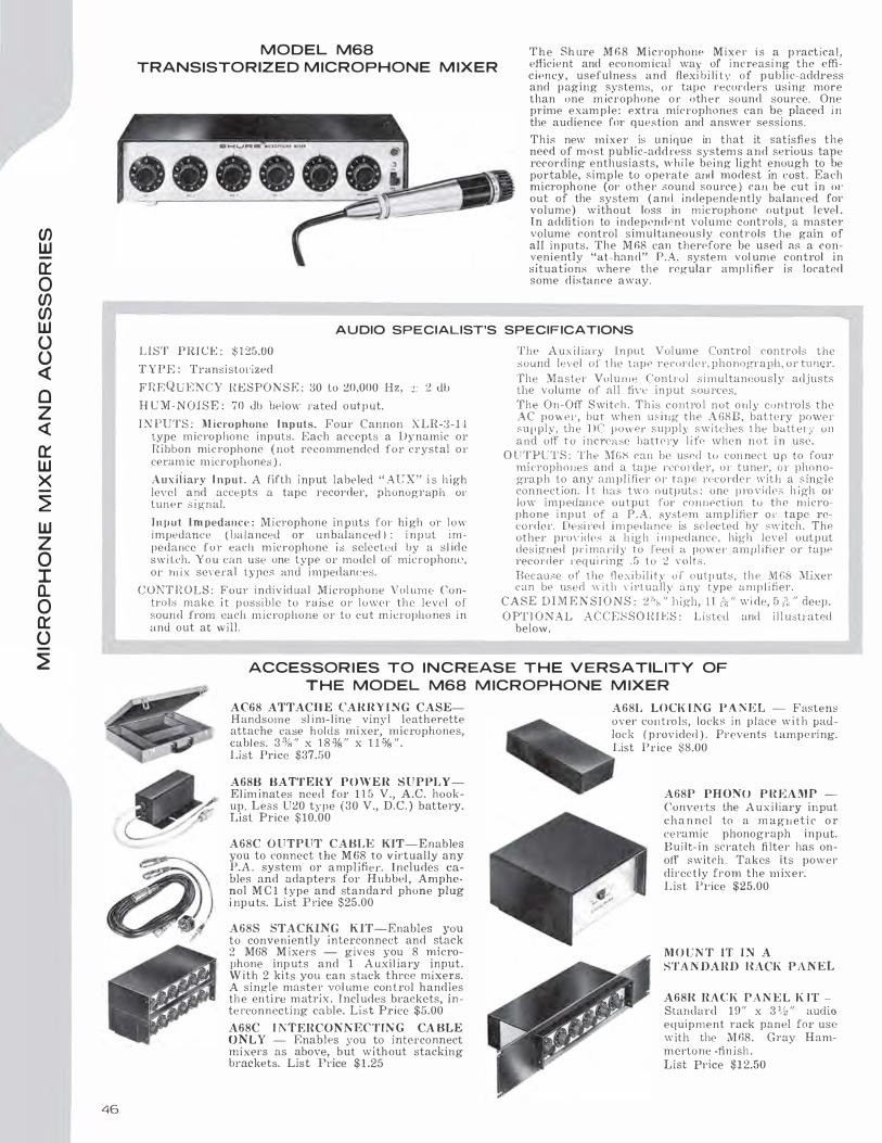
CJ) UJ
a: 0 CJ) CJ) UJ (.) (.) <(
0 z <(
a: UJ x �
UJ z 0 I a. 0 a: (.)
�
46
MODEL M68
TRANSISTO R IZED M ICROPHONE M IXER
T h e Sh ure M68 Mic!'ophone M i x e r i s a p ractica l , efficient and econom ical way of i ncreas i ng the efficiency, usefulness and flex i bi l i ty of publ ic-address and paging systems, or tape recorders us ing more than one m icrophone or oth e r sound source. One prime exam p l e : extra microphones can be place<! i n the audience for question and answer sessions .
This new mixer is u n ique in that it satisfi e s the need of most public-add ress system s and serious tape recording enthusiasts, w h i l e be i ng light enough to be portable, simple to operate and modest in !'.OSt. Each microphone (or o th e r sound source ) can be cut i n oi· out of the system ( and independently balanced for volume) without loss in microphone output l evel . In addi t i on to independent volume controls, a master volume cont rol simultaneou s l y controls t he gain of all inputs . The M 68 can therefore be used as a conveniently "at-hand" P.A. system vol ume control in situations where the regula r amp l i fi er i s located some distance away.
A U DIO SPECIALIST'S SPECIF ICATIONS
L I ST PIUCE : $ 1 25.00
T Y P E : Transistol'ized
F R E Q U E N C Y HESPO N S E : 30 t.o 20,000 Hz, j.: 2 db H U M - N O I S E : 70 db below rated outp ut.
I N PUTS : M icrophone I nputs. Four Cannon XLR-3 - 1 4 type microp hone inputs. Each accepts a Dynamic or Ri bbon microphone ( not recommended for crystal or ceram ic m icrophones ) .
Auxi l iary I npu t. A fifth i nput labeled " AUX" i s h igh leve l and accepts a tape recorder, phonograph or tuner signal.
J n p u t Im peda11c(' : M i crophone inputs for h i gh or lo w impedance ( balanced or unbalan ced ) ; i nput i m pedance f u r each m icrophone i s selected by a s l ide s w i Leh. Y o u can use one type or model of microphom>, or mix several types and i mpedanc:es.
CONTHOLS: Four individual Microphone Vo l ume Controls make i t p oss i u le to raise o r lower th e level of sound from each m i c rophone or to c u t m icrophones in and out at will.
The A ux i l ia ry Input Volume Control controls the sound level of t he tape recorder, pho nograph, o r tu ner.
The :W a s t e r Vol u m e Con Lrol s i multaneously adjusts the volume of al l fi\·e in put s o mTes. The On-Off Switc h . Th is c o n t ro l not only con trols the AC powe1-, but when u s ing the A 6S B , battery power supply, th e DC µower supply s w i k hes t he battery o n and off t o i ncrease hatt ery l i fe when n o t i n use.
O UTPUTS : The MGS can be used to con nec t up to four m i crophones and a tape rceonler , or t uner, o r phonogra p h to any ampl i fiel ' o r tape i·ceorder with a single connection. l t has two o utputs : one p ro vides h i gh OJ' l o w imp edance output for con nPction to th e m i crophone i nput of a P . A . system amp l ifier o t· tape recorder . Desi l'ed i m pedance is selec ted hy switch . The othe1· prO\·idC's a h igh i m ped ance , high Je,·el output desig ned p r i mari l y to feed a power am 1Jl i fi er or tape recorder l'eq u i ring . 5 to :2 volts . Because of t he fl exibi l ity o r outp uts , the l\1 68 Mixer can be used \\' i th ,· i r l u a l l �, a ny type a m p l i fier.
C A S E D IM E N S I O N S : 2 ':s " J1 igh, 11 rt; '' wi de, 5 ?., " deep.
O PT I O N A L A C C E S SO H I ES : Listed and i l l ustrated below.
ACCESSOR I ES TO I N C R EAS E T H E V E RSATIL ITY OF
T H E MODEL M68 M ICROPHONE M IXER
AC68 ATTACII E CAR R Y I N G CASEHandsome sl i m-l ine vinyl leatherette attache case holds mixer, microphones, cabl es. 3 % " x 1 8 % " x 1 1 % " . List Price $37.50
A68B BATTERY POWER S U P PLYE lim inates nee<l for 1 1 5 V., A.C. hookup. Less U20 type ( 3 0 V., D.C. ) battery. List Price $10.00
A68C O UTPUT CABLE KIT-Enables you to connect the M G8 to virtually any P.A . system or a mp l ifier. I ncludes cables and adapters for Hubhel , Amphenol M C l type and standard phone plug i np u ts. L ist P rice $25.00
A68S STACKING K IT-Enables you to conven iently interconnect and stack 2 M68 M ixers - gives you 8 microphone inp uts and 1 A ux i l iary input. With 2 ki ts you can stack three mixers. A single maste1· vol um e control handles th e entire matrix . Incl udes brackets, inte l'connecting cable. List Price $5.00
A68C l i\TERCONKECTIKG CA BLE UNL Y - Enables you to interco nnect mixers as above, but without stacking brackets. List Price $ 1 .25
A68L LOCK I N G P A N E L - Fastens over con t rols, locks in p l ace w i t h padlock ( p ro v ided ) . Prevents tamperi ng. List Price $8 .. 00
A68P PHONO P H EAMP -Converts the A u x i l iary input cha n ne l to a m ag n e t i c o r ceramic phonograph inp ut. B u i l t-in scratch fi lter has on olf switch. Takes its power direc t l y from the m ix e r. List P1·ice $25.00
M O UN T IT I N A
STA N DA R D l{ACK PAN EL
A68R RACK PA N E L K IT -Standard 19" x 3 % " audio equipment rack panel for use w ith the M68. Gray Hammertone -fin ish . List Price $1 2.50

F I RST I N P U B LIC A D D R ESS
SOU N D R E I N FORC E M E NT SYSTEMS

C O N T E N T S
SERVICE AND GUARANTEES
SHURE-FIRST IN PUBLIC ADDRESS SOUND-REINFORCEMENT SYSTEMS . . . . . .
SELECTING THE CORRECT SHURE MICROPHONE FOR THE APPLICATION
SPECIFICATIONS-WHAT THEY MEAN
UNIDIRECTIONAL DYNAMICS .
UNIDIRECTIONAL RIBBONS
UNIDIRECTIONAL CRYSTAL .
UNIDIRECTIONAL CERAMIC
BIDIRECTIONAL RIBBONS .
OMNIDIRECTIONAL DYNAMICS
OMNIDIRECTIONAL CONTROLLED MAGNETIC
OMNIDIRECTIONAL CRYSTAL
OMNIDIRECTIONAL CERAMIC .
PAGING AND BASE-STATION MICROPHONES
AMATEUR RADIO MICROPHONES .
NOISE-CAN CELLING MICROPHONES
MOBILE COMMUNICATIONS MICROPHONES
SOUND LEVEL MICROPHONE
MINIATURE MICROPHONES
VIBRATION PICKUPS AND ACCELEROMETER
GOLD MICROPHONES . . . . . . . .
MICROPHONES WITH ATTACHED PLUGS
MATCHED PAIR MICROPHONES . . .
MICROPHONE STANDS, ACCESSORIES, REPLACEMENT PARTS
MICROPHONE MIXER . . . . . . .
SHURE BROTHERS, INC.
222 Hartrey A venue, Evanston, Illinois 60204, USA
page 2
page 3
pages 4-5
page 6
pages 7-16
page 17
page 1 8
page 18
pages 19-20
pages 21-29
pages 30-31
page 32
page 32
page 33
page 34
pages 35-36
pages 37-39
page 40
page 40
page 41
page 42
page 42
page 42
pages 42-45
page 46
AREA CODE 3 1 2 PHONE 328-9000 CHICAGO PHONE 743-1600
CABLE ADDRESS : Shuremicro
P R I NTED IN U . S .A. FO RM NO. AL64A


![Gohisca [1967] - Internet Archive](https://static.fdokumen.com/doc/165x107/6337f08d1ef10984f505036d/gohisca-1967-internet-archive.jpg)