Space-Time Coding and Signal Processing for High Data Rate Wireless Communications
22
WIRELESS COMMUNICATIONS AND MOBILE COMPUTING Wirel. Commun. Mob. Comput. 2001; 1:13–34 REVIEW Space–time coding and signal processing for high data rate wireless communications Ayman F. Naguib* , † Morphics Technology, Inc. 1550 S. Bascom Av., Suite 200 Campbell CA 95008 U.S.A. R. Calderbank AT&T Labs—Research 180 Park Avenue Florham Park NJ 07932 U.S.A. Summary The information capacity of wireless communication systems can be increased dramatically by employing multiple transmit and receive antennas [Foschini GJ, Gans MJ. On limits of wireless communications in a fading environment when using multiple antennas. Wireless Communications Magazine 1998; 6 311–335. Telatar E. Capacity of Multi-Antenna Gaussian Channels, Technical Memorandum, AT&T Bell Laboratories, 1995.] An effective approach to increasing data rate over wireless channels is to employ coding techniques appropriate to multiple transmit antennas, that is space–time coding. Space–time codes introduce temporal and spatial correlation into signals transmitted from different antennas, in order to provide diversity at the receiver, and coding gain over an uncoded system. The spatial–temporal structure of these codes can be exploited to further increase the capacity of wireless systems with a relatively simple receiver structure. This paper provides an overview of space–time coding techniques and the associated signal processing framework. Copyright 2001 John Wiley & Sons, Ltd. KEY WORDS space–time coding array signal processing interference suppression OFDM wireless communications L Correspondence to: Ayman F. Naguib, Morphics Technology, Inc., 1550 S. Bascom Av., Suite 200, Campbell, CA 95008, U.S.A. ² E-mail: [email protected] Copyright 2001 John Wiley & Sons, Ltd.
-
Upload
independent -
Category
Documents
-
view
0 -
download
0
Transcript of Space-Time Coding and Signal Processing for High Data Rate Wireless Communications
WIRELESS COMMUNICATIONS AND MOBILE COMPUTINGWirel. Commun. Mob. Comput.2001;1:13–34
REVIEW
Space–time coding and signal processing for high data ratewireless communications
Ayman F. Naguib*,†Morphics Technology, Inc.1550 S. Bascom Av., Suite 200CampbellCA 95008U.S.A.
R. CalderbankAT&T Labs—Research180 Park AvenueFlorham ParkNJ 07932U.S.A.
Summary
The information capacity of wireless communicationsystems can be increased dramatically by employingmultiple transmit and receive antennas [Foschini GJ,Gans MJ. On limits of wireless communications in afading environment when using multiple antennas.Wireless Communications Magazine1998; 6311–335. Telatar E. Capacity of Multi-AntennaGaussian Channels, Technical Memorandum, AT&TBell Laboratories, 1995.] An effective approach toincreasing data rate over wireless channels is toemploy coding techniques appropriate to multipletransmit antennas, that is space–time coding.Space–time codes introduce temporal and spatialcorrelation into signals transmitted from differentantennas, in order to provide diversity at thereceiver, and coding gain over an uncoded system.The spatial–temporal structure of these codes can beexploited to further increase the capacity of wirelesssystems with a relatively simple receiver structure.This paper provides an overview of space–timecoding techniques and the associated signalprocessing framework. Copyright 2001 JohnWiley & Sons, Ltd.
KEY WORDSspace–time codingarray signal processinginterference suppressionOFDMwireless communications
ŁCorrespondence to: Ayman F. Naguib, Morphics Technology, Inc., 1550 S. Bascom Av., Suite 200, Campbell, CA 95008,U.S.A.†E-mail: [email protected]
Copyright 2001 John Wiley & Sons, Ltd.
14 A. F. NAGUIB AND R. CALDERBANK
1. Introduction
The goal of high data rate wireless communicationbetween two portable terminals that may be locatedanywhere in the world, and the vision of a singlephone that acts as a traditional cellular phone whenused outdoors, and as a conventional high qualityphone when used indoors [1], are driving recentdevelopments in communications. The great popular-ity of cordless phones, cellular phones, radio paging,portable computing, and other personal communica-tion services (PCS) demonstrates rising demand forthese services. Rapid growth in mobile computingand other wireless data services is inspiring manyproposals for high speed data services in the rangeof 64–144 kbps for micro cellular wide area andhigh mobility applications, and up to 2 Mbps forindoor applications [2]. In addition to mobile appli-cations, fixed wireless access (FWA) technologiesoffer the promise of bringing high quality telephone,high speed internet access, multi-media, and otherbroadband services to the home over wireless links[3, 4]. Research challenges in this area include thedevelopment of efficient coding and modulation, sig-nal processing techniques to improve the quality andspectral efficiency of wireless communications, andbetter techniques for sharing the limited spectrumamong different high capacity users.
The physical limitation of the wireless channelpresents a fundamental technical challenge for reli-able communications. The channel is subject to time-varying impairments such as noise, interference, andmultipath [5–11]. Limitations on the power and sizeof the mobile terminal and of network terminatingdevices (NTD) in an FWA application is a secondmajor design consideration. Most personal commu-nications and wireless services portables are meantto be carried in a briefcase and/or pocket and must,therefore, be small and lightweight, which translatesto a low power requirement since small batteriesmust be used. Although an NTD in FWA applica-tions may have more signal processing power than amobile computing portable, power consumption anddevice and antenna size are still a concern. However,many of the signal processing techniques that can beused for reliable communications and efficient spec-tral utilization demand significant processing power,precluding the use of low power devices. Continuingadvances in VLSI and application-specific integratedcircuit (ASIC) technology for low power applica-tions will provide a partial solution to this problem.Hence, placing more signal processing burden on
fixed locations (base stations) with relatively largerpower resources than the portable makes good engi-neering sense.
2. Diversity Techniques
Several diversity techniques have been employed inwireless communication systems to improve the linkmargin. Diversity techniques that can be used includetime, frequency, and space diversity.
ž Time diversity: channel coding in combination withlimited interleaving is used to provide time diver-sity. However, while channel coding is extremelyeffective in fast fading environments (high mobil-ity), it offers very little protection under slowfading (low mobility and FWA) unless significantinterleaving delays can be tolerated.
ž Frequency diversity: the fact that signals trans-mitted over different frequencies induce differ-ent multipath structure and independent fading isexploited to provide frequency diversity (some-times referred to as path diversity). In TDMA sys-tems, frequency diversity is obtained by the use ofequalizers [12] when the multipath delay spread isa significant fraction of a symbol period. GSM usesfrequency hopping to provide frequency diversity.In DS-CDMA systems, RAKE receivers [13, 14]are used to obtain path diversity. However, whenthe multipath delay spread is small, compared tothe symbol period, frequency or path diversity doesnot exist.
ž Space diversity: the receiver/transmitter uses mul-tiple antennas that are separated and/or differentlypolarized for reception/transmission to create inde-pendent fading channels. Currently, multiple anten-nas at base-stations are used for receive diversity atthe base. However, it is difficult to have more thanone or two antennas at the portable unit owing tothe size limitations and cost of multiple chains ofRF down conversion.
Both receive and polarization diversity have rece-ived a lot of attention [9, 10, 15]. In fact, in cur-rent cellular applications, receive diversity is alreadyused for improving reception from mobiles. In polar-ization diversity, two antennas with different polar-ization are used to receive (or transmit) the sig-nal. Different polarization will ensure that the fadingchannel corresponding to each of the two anten-nas will be independent without having to place
Copyright 2001 John Wiley & Sons, Ltd. Wirel. Commun. Mob. Comput.2001;1:13–34
SPACE–TIME CODING TECHNIQUES 15
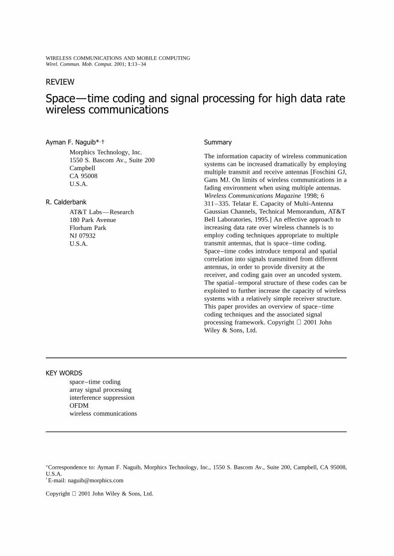
the two antennas far apart. In receive diversity, twoor more antennas that are well separated (again,to ensure independent fading channels) are used togenerate independent looks at the transmitted sig-nal. These different variants of the transmitted sig-nal can be processed in several ways to improvethe overall signal quality. In selection diversity, thebest received signal is used, and this signal can bechosen based on several quality metrics, includingtotal received power, signal-to-noise ratio (SNR), etc.Another form of selection diversity is switched diver-sity in which an alternate antenna is chosen if thereceived signal level falls below a certain threshold.Figure 1 shows a block diagram of selection diversityschemes.
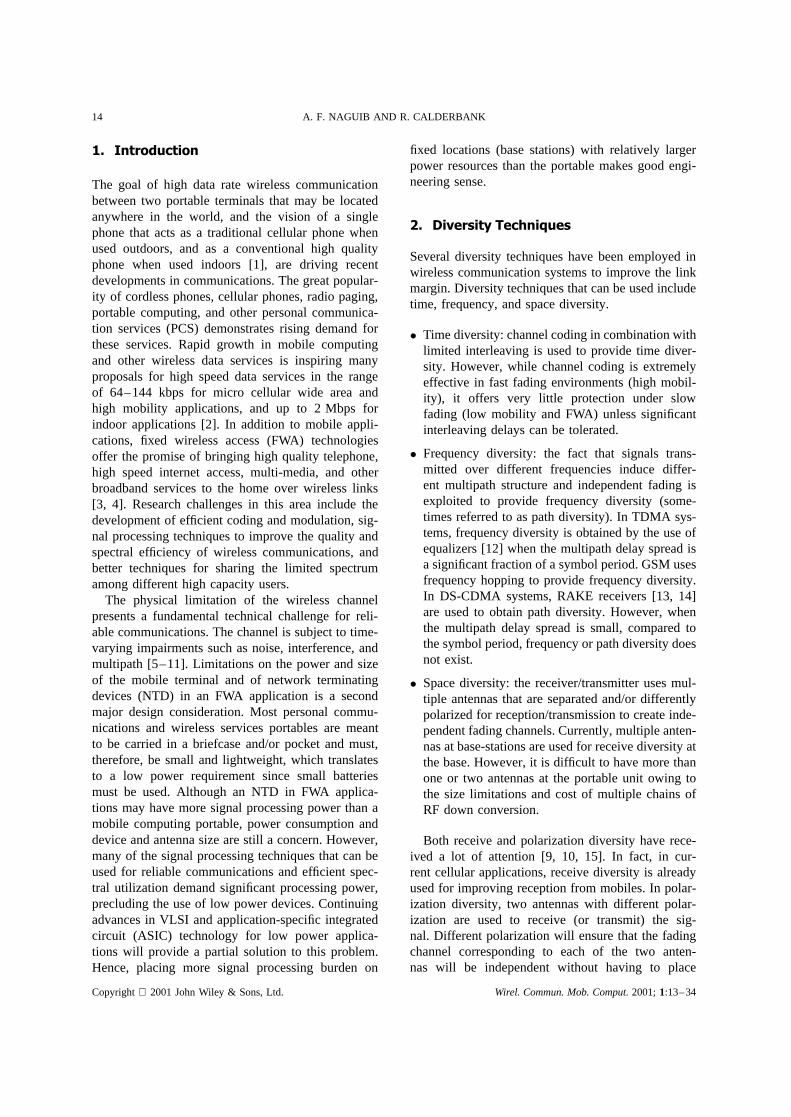
The second form of receive diversity is based onlinear combining. As the name implies, the signalused for detection in linear combining techniques isa linear combination of a weighted replica of allreceived signals. Figure 2 shows a block diagramfor receive diversity with linear combining and tworeceive antennas. In this block diagram, letr1 andr2 be the received signals at antennas 1 and 2,respectively, where
r1 D A1ej�1dC n1 .1/
r2 D A2ej�2dC n2 .2/
where d is the information symbol,n1 and n2 arethe additive white Gaussian noise at antenna 1 and 2respectively, andAi and�i (i D 1, 2) are the corre-sponding amplitude and phase of the fading channel,respectively. The receiver uses the linear combina-tion Qr D ˛1r1C ˛2r2. The weighting coefficients 1,˛2 can be chosen in several ways. Inequal gaincombiningthe weights are chosen as˛1 D e�j�1 and˛2 D e�j�2. In this way the two antenna signals areco-phased and added together. A second approach ismaximal ratio combining, where the two signals arealso weighted with their corresponding amplitudesA1
andA2. In this case 1 D A1e�j�1 and˛2 D A2e�j�2.A third approach isminimum mean squared error(MMSE) combining, where the weighting coefficientsare chosen during a training phase such that
.˛1, ˛2/ D arg min˛1,˛2
j˛1r1C ˛2r2� dj2 .3/
The performance of MMSE linear combining andmaximal ratio combining are essentially the same. Ingeneral, there will be a dramatic improvement in theaverage SNR, even with 2 branch selection diversity.For all the above approaches to receive diversity,the average SNR will increase with the number ofreceive antennas. However, for the selection diversity,the SNR increases very slowly with the number of
Fig. 1. Selection and switched diversity.
Fig. 2. Linear combining diversity.
Copyright 2001 John Wiley & Sons, Ltd. Wirel. Commun. Mob. Comput.2001;1:13–34
16 A. F. NAGUIB AND R. CALDERBANK
receive antennas. For maximal ratio combining, theaverage SNR will increase linearly with the numberof receive antennas. For equal gain combining therate of SNR increase will be slightly less than thatof maximal ratio combining. In fact, the differencebetween the two is only 1.05 dB in the limit of aninfinite number of receive antennas [16].
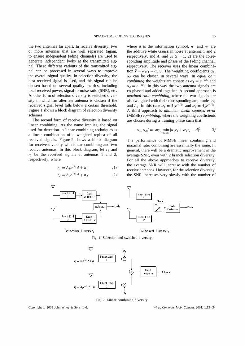
Transmit diversity, on the other hand, has receivedcomparatively little attention. The information theo-retic aspects of transmit diversity were addressed in[17–20]. Previous work on transmit diversity can beclassified into three broad categories: schemes usingfeedback, schemes with feedforward or training infor-mation but no feedback, and blind schemes. The firstcategory uses feedback, either explicitly or implic-itly, from the receiver to the transmitter to train thetransmitter. Figure 3 shows a conceptual block dia-gram for transmit diversity with feedback. A signal isweighted differently and transmitted from two differ-ent antennas. The weightsw1 andw2 are varied suchthat the received signal powerjr.t/j2 is maximized.The weights are adapted based on feedback informa-tion from the receiver. For instance, in time divisionduplex (TDD) systems [21], the same antenna weightsare used for reception and transmission, so feedback
is implicit in the exploitation of channel symmetry.These weights are chosen during reception to max-imize the receive signal-to-noise ratio, and duringtransmission to weight the amplitudes of the trans-mitted signals, and, therefore, will also maximize thesignal-to-noise ratio at the receiver. Explicit feedbackincludes switched diversity systems with feedback[22]. However, in practice, movement by either thetransmitter or the receiver (or the surroundings suchas cars) and interference dynamics causes a mismatchbetween the channel perceived by the transmitter andthat perceived by the receiver.
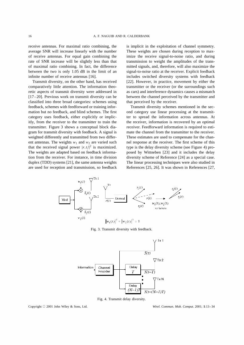
Transmit diversity schemes mentioned in the sec-ond category use linear processing at the transmit-ter to spread the information across antennas. Atthe receiver, information is recovered by an optimalreceiver. Feedforward information is required to esti-mate the channel from the transmitter to the receiver.These estimates are used to compensate for the chan-nel response at the receiver. The first scheme of thistype is the delay diversity scheme (see Figure 4) pro-posed by Wittneben [23] and it includes the delaydiversity scheme of Reference [24] as a special case.The linear processing techniques were also studied inReferences [25, 26]. It was shown in References [27,
Fig. 3. Transmit diversity with feedback.
Fig. 4. Transmit delay diversity.
Copyright 2001 John Wiley & Sons, Ltd. Wirel. Commun. Mob. Comput.2001;1:13–34
SPACE–TIME CODING TECHNIQUES 17
28] that delay diversity schemes are indeed optimalin providing diversity, in the sense that the diversitygain experienced at the receiver (which is assumedto be optimal) is equal to the diversity gain obtainedwith receive diversity. The delay diversity scheme canbe viewed as creating an intentional multipath whichcan be exploited at the receiver by using an equalizer.The linear filtering used (to create delay diversity)at the transmitter can also be viewed as a channelcode that takes binary or integer input and createsreal valued output. The advantage of delay diversityover other transmit diversity schemes is that it willachieve the maximum possible diversity order (i.e.number of transmit antennas) without any sacrifice inthe bandwidth.
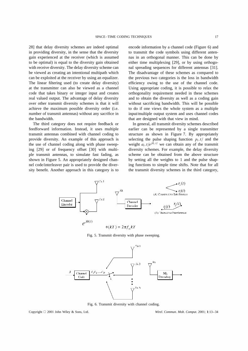
The third category does not require feedback orfeedforward information. Instead, it uses multipletransmit antennas combined with channel coding toprovide diversity. An example of this approach isthe use of channel coding along with phase sweep-ing [29] or of frequency offset [30] with multi-ple transmit antennas, to simulate fast fading, asshown in Figure 5. An appropriately designed chan-nel code/interleaver pair is used to provide the diver-sity benefit. Another approach in this category is to
encode information by a channel code (Figure 6) andto transmit the code symbols using different anten-nas in an orthogonal manner. This can be done byeither time multiplexing [29], or by using orthogo-nal spreading sequences for different antennas [31].The disadvantage of these schemes as compared tothe previous two categories is the loss in bandwidthefficiency owing to the use of the channel code.Using appropriate coding, it is possible to relax theorthogonality requirement needed in these schemesand to obtain the diversity as well as a coding gainwithout sacrificing bandwidth. This will be possibleto do if one views the whole system as a multipleinput/multiple output system and uses channel codesthat are designed with that view in mind.
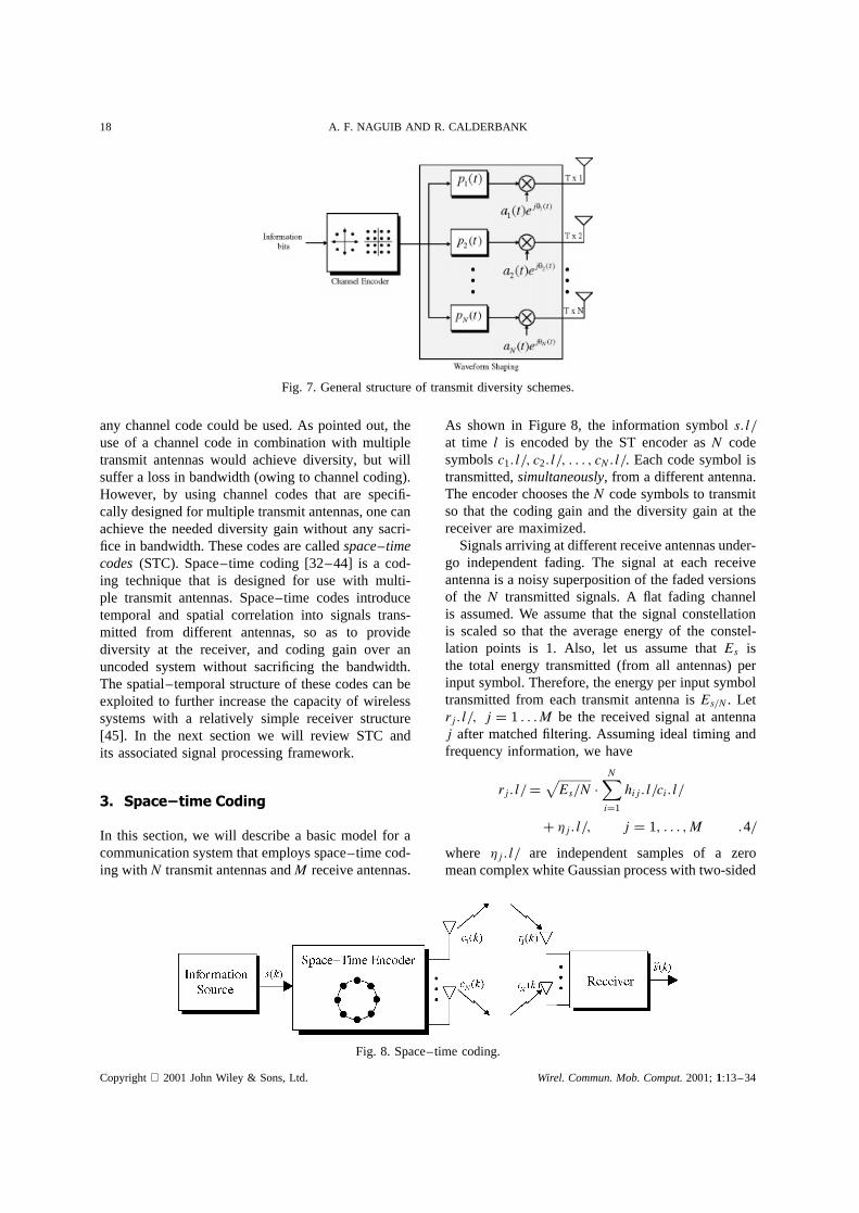
In general, all transmit diversity schemes describedearlier can be represented by a single transmitterstructure as shown in Figure 7. By appropriatelyselecting the pulse shaping functionpi.t/ and theweight ai.t/ej�i.t/ we can obtain any of the transmitdiversity schemes. For example, the delay diversityscheme can be obtained from the above structureby setting all the weights to 1 and the pulse shap-ing functions to simple time shifts. Note that for allthe transmit diversity schemes in the third category,
Fig. 5. Transmit diversity with phase sweeping.
Fig. 6. Transmit diversity with channel coding.
Copyright 2001 John Wiley & Sons, Ltd. Wirel. Commun. Mob. Comput.2001;1:13–34
18 A. F. NAGUIB AND R. CALDERBANK
Fig. 7. General structure of transmit diversity schemes.
any channel code could be used. As pointed out, theuse of a channel code in combination with multipletransmit antennas would achieve diversity, but willsuffer a loss in bandwidth (owing to channel coding).However, by using channel codes that are specifi-cally designed for multiple transmit antennas, one canachieve the needed diversity gain without any sacri-fice in bandwidth. These codes are calledspace–timecodes(STC). Space–time coding [32–44] is a cod-ing technique that is designed for use with multi-ple transmit antennas. Space–time codes introducetemporal and spatial correlation into signals trans-mitted from different antennas, so as to providediversity at the receiver, and coding gain over anuncoded system without sacrificing the bandwidth.The spatial–temporal structure of these codes can beexploited to further increase the capacity of wirelesssystems with a relatively simple receiver structure[45]. In the next section we will review STC andits associated signal processing framework.
3. Space–time Coding
In this section, we will describe a basic model for acommunication system that employs space–time cod-ing withN transmit antennas andM receive antennas.
As shown in Figure 8, the information symbols.l/at time l is encoded by the ST encoder asN codesymbolsc1.l/, c2.l/, . . . , cN.l/. Each code symbol istransmitted,simultaneously, from a different antenna.The encoder chooses theN code symbols to transmitso that the coding gain and the diversity gain at thereceiver are maximized.
Signals arriving at different receive antennas under-go independent fading. The signal at each receiveantenna is a noisy superposition of the faded versionsof the N transmitted signals. A flat fading channelis assumed. We assume that the signal constellationis scaled so that the average energy of the constel-lation points is 1. Also, let us assume thatEs isthe total energy transmitted (from all antennas) perinput symbol. Therefore, the energy per input symboltransmitted from each transmit antenna isEs/N. Letrj.l/, j D 1 . . .M be the received signal at antennaj after matched filtering. Assuming ideal timing andfrequency information, we have
rj.l/ D√Es/N Ð
N∑iD1
hij.l/ci.l/
C �j.l/, j D 1, . . . ,M .4/
where �j.l/ are independent samples of a zeromean complex white Gaussian process with two-sided
Fig. 8. Space–time coding.
Copyright 2001 John Wiley & Sons, Ltd. Wirel. Commun. Mob. Comput.2001;1:13–34
SPACE–TIME CODING TECHNIQUES 19
power spectral densityN0/2 per dimension. It is alsoassumed that�j.l/ and �k.l/ are independent forj 6D k, 1� j, k � M. The gainhij.l/models the com-plex fading channel gain from transmit antennai toreceive antennaj. It is assumed thathij.l/ andhqk.l/are independent fori 6D q or j 6D k, 1� i, q � N,1� j, k �M. This condition is satisfied if the trans-mit antennas arewell separated (by more than�/2)or by using antennas with different polarization.
Let cl D [c1.l/, . . . , cN.l/]T be the Nð 1 codevector transmitted from theN antennas at timel,hj.l/ D [h1j.l/, . . . , hNj.l/]T be the correspondingNð 1 channel vector from theN transmit anten-nas to thejth receive antenna, andr .l/ D [r1.l/, . . . ,rM.l/]T be theMð 1 received signal vector. Also,let h.l/ D [�1.l/, . . . , �M.l/]T be theMð 1 noisevector at the receive antennas. Let us define theMð N channel matrixHl from theN transmit to theM receive antennas asH.l/ D [h1.l/, . . . , hM.l/]T.Equation 4 can be rewritten in a matrix form as
r .l/ D√Es/N ÐH.l/ Ð cl C h.l/ .5/
We can easily see that the SNRper receive antennais given by
SNRD EsNo
.6/
4. Space–Time Trellis Codes
Suppose that the code vector sequence
C D c1, c2, . . . , cL
was transmitted. We consider the probability that thedecoder decides erroneously in favor of the legitimatecode vector sequence
QC D Qc1, Qc2, . . . , QcLConsider a frame or block of data of lengthL anddefine theNðN error matrixA as
A.C, QC/ DL∑lD1
.cl � Qcl/.cl � Qcl/Ł .7/
where (.)Ł denotes the conjugate operation for scalersand the conjugate transpose for matrices and vectors.If ideal channel state information (CSI)H.l/, l D1, . . . , L is available at the receiver, then it is straight-forward to show that the probability of transmittingCand deciding in favor ofQC is upper bounded by [46]
P.C ���! QC/ �(
r∏iD1
�i
)�MÐ .Es/4No/�rM .8/
where r is the rank of the error matrixA and�i, i D 1, . . . , r are the nonzero eigenvalues of theerror matrixA. We can easily see that the probabilityof error bound in Equation (8) is similar to the prob-ability of error bound for trellis coded modulationfor fading channels. The first termgr D
∏riD1 �i rep-
resents the coding gain achieved by the space–timecode and the second term.Es/4No/�rM represents adiversity gain ofrM. It is clear that in designing aspace–time trellis code, the rank of the error matrixrshould be maximized (thereby maximizing the diver-sity gain) and at the same timegr should be alsomaximized (thereby maximizing the coding gain).
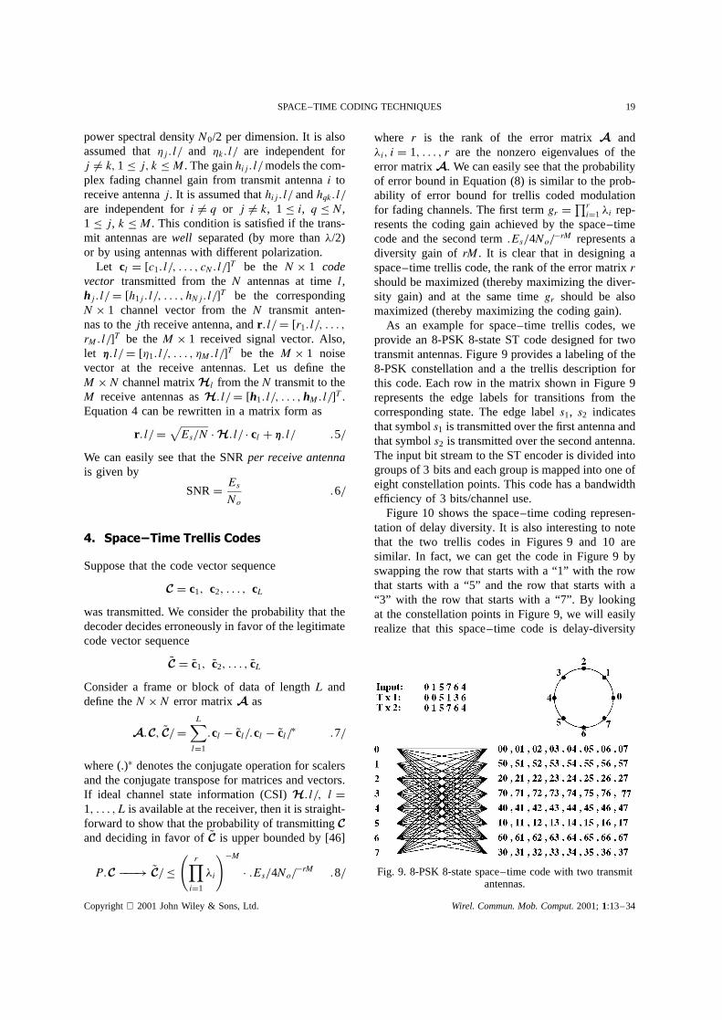
As an example for space–time trellis codes, weprovide an 8-PSK 8-state ST code designed for twotransmit antennas. Figure 9 provides a labeling of the8-PSK constellation and a the trellis description forthis code. Each row in the matrix shown in Figure 9represents the edge labels for transitions from thecorresponding state. The edge labels1, s2 indicatesthat symbols1 is transmitted over the first antenna andthat symbols2 is transmitted over the second antenna.The input bit stream to the ST encoder is divided intogroups of 3 bits and each group is mapped into one ofeight constellation points. This code has a bandwidthefficiency of 3 bits/channel use.
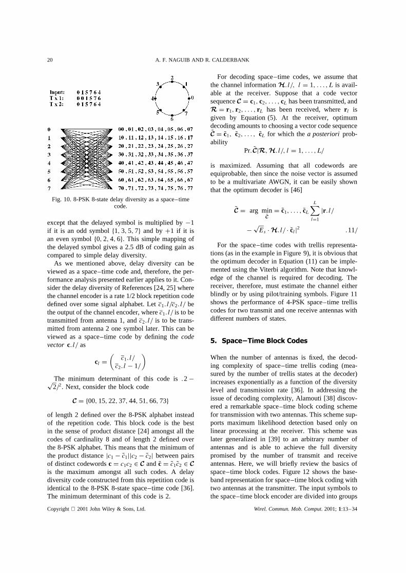
Figure 10 shows the space–time coding represen-tation of delay diversity. It is also interesting to notethat the two trellis codes in Figures 9 and 10 aresimilar. In fact, we can get the code in Figure 9 byswapping the row that starts with a “1” with the rowthat starts with a “5” and the row that starts with a“3” with the row that starts with a “7”. By lookingat the constellation points in Figure 9, we will easilyrealize that this space–time code is delay-diversity
Fig. 9. 8-PSK 8-state space–time code with two transmitantennas.
Copyright 2001 John Wiley & Sons, Ltd. Wirel. Commun. Mob. Comput.2001;1:13–34
20 A. F. NAGUIB AND R. CALDERBANK
Fig. 10. 8-PSK 8-state delay diversity as a space–timecode.
except that the delayed symbol is multiplied by�1if it is an odd symbolf1, 3, 5, 7g and byC1 if it isan even symbolf0, 2, 4, 6g. This simple mapping ofthe delayed symbol gives a 2.5 dB of coding gain ascompared to simple delay diversity.
As we mentioned above, delay diversity can beviewed as a space–time code and, therefore, the per-formance analysis presented earlier applies to it. Con-sider the delay diversity of References [24, 25] wherethe channel encoder is a rate 1/2 block repetition codedefined over some signal alphabet. Letc1.l/c2.l/ bethe output of the channel encoder, wherec1.l/ is to betransmitted from antenna 1, andc2.l/ is to be trans-mitted from antenna 2 one symbol later. This can beviewed as a space–time code by defining thecodevector c.l/ as
cl D(
c1.l/c2.l� 1/
)The minimum determinant of this code is.2�p2/2. Next, consider the block code
C D f00, 15, 22, 37, 44, 51, 66, 73gof length 2 defined over the 8-PSK alphabet insteadof the repetition code. This block code is the bestin the sense of product distance [24] amongst all thecodes of cardinality 8 and of length 2 defined overthe 8-PSK alphabet. This means that the minimum ofthe product distancejc1� Qc1jjc2 � Qc2j between pairsof distinct codewordscD c1c2 2 C and QcD Qc1Qc2 2 Cis the maximum amongst all such codes. A delaydiversity code constructed from this repetition code isidentical to the 8-PSK 8-state space–time code [36].The minimum determinant of this code is 2.
For decoding space–time codes, we assume thatthe channel informationH.l/, l D 1, . . . , L is avail-able at the receiver. Suppose that a code vectorsequenceC D c1, c2, . . . , cL has been transmitted, andR D r1, r2, . . . , rL has been received, wherer l isgiven by Equation (5). At the receiver, optimumdecoding amounts to choosing a vector code sequenceQC D Qc1, Qc2, . . . , QcL for which thea posteriori prob-ability
Pr. QCjR,H.l/, l D 1, . . . , L/
is maximized. Assuming that all codewords areequiprobable, then since the noise vector is assumedto be a multivariate AWGN, it can be easily shownthat the optimum decoder is [46]
QC D arg minQCD Qc1, . . . , QcL
L∑lD1
jr .l/
�pEs ÐH.l/ Ð Qclj2 .11/
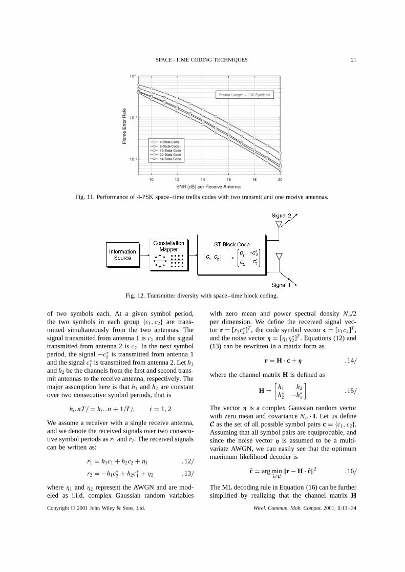
For the space–time codes with trellis representa-tions (as in the example in Figure 9), it is obvious thatthe optimum decoder in Equation (11) can be imple-mented using the Viterbi algorithm. Note that knowl-edge of the channel is required for decoding. Thereceiver, therefore, must estimate the channel eitherblindly or by using pilot/training symbols. Figure 11shows the performance of 4-PSK space–time trelliscodes for two transmit and one receive antennas withdifferent numbers of states.
5. Space–Time Block Codes
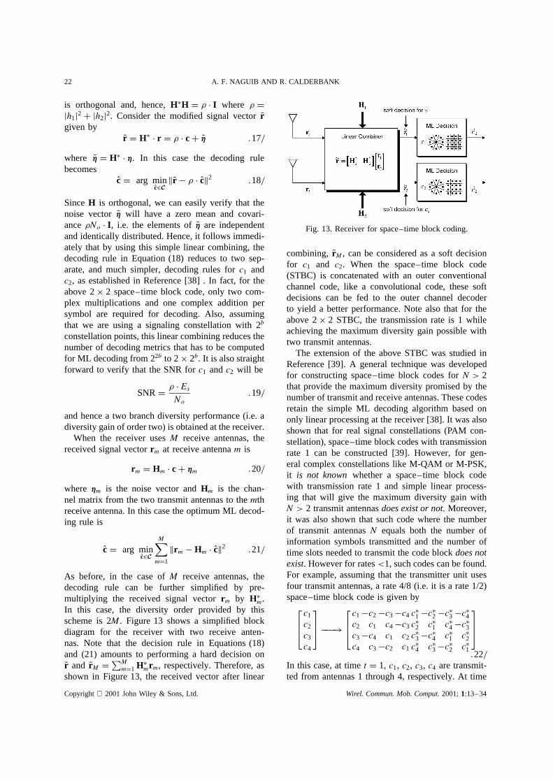
When the number of antennas is fixed, the decod-ing complexity of space–time trellis coding (mea-sured by the number of trellis states at the decoder)increases exponentially as a function of the diversitylevel and transmission rate [36]. In addressing theissue of decoding complexity, Alamouti [38] discov-ered a remarkable space–time block coding schemefor transmission with two antennas. This scheme sup-ports maximum likelihood detection based only onlinear processing at the receiver. This scheme waslater generalized in [39] to an arbitrary number ofantennas and is able to achieve the full diversitypromised by the number of transmit and receiveantennas. Here, we will briefly review the basics ofspace–time block codes. Figure 12 shows the base-band representation for space–time block coding withtwo antennas at the transmitter. The input symbols tothe space–time block encoder are divided into groups
Copyright 2001 John Wiley & Sons, Ltd. Wirel. Commun. Mob. Comput.2001;1:13–34
SPACE–TIME CODING TECHNIQUES 21
Fig. 11. Performance of 4-PSK space–time trellis codes with two transmit and one receive antennas.
Fig. 12. Transmitter diversity with space–time block coding.
of two symbols each. At a given symbol period,the two symbols in each groupfc1, c2g are trans-mitted simultaneously from the two antennas. Thesignal transmitted from antenna 1 isc1 and the signaltransmitted from antenna 2 isc2. In the next symbolperiod, the signal�cŁ2 is transmitted from antenna 1and the signalcŁ1 is transmitted from antenna 2. Leth1
andh2 be the channels from the first and second trans-mit antennas to the receive antenna, respectively. Themajor assumption here is thath1 andh2 are constantover two consecutive symbol periods, that is
hi.nT/ D hi..nC 1/T/, i D 1, 2
We assume a receiver with a single receive antenna,and we denote the received signals over two consecu-tive symbol periods asr1 andr2. The received signalscan be written as:
r1 D h1c1C h2c2C �1 .12/
r2 D �h1cŁ2 C h2c
Ł1 C �2 .13/
where�1 and�2 represent the AWGN and are mod-eled as i.i.d. complex Gaussian random variables
with zero mean and power spectral densityNo/2per dimension. We define the received signal vec-tor r D [r1rŁ2]T, the code symbol vectorcD [c1c2]T,and the noise vectorh D [�1�Ł2]T. Equations (12) and(13) can be rewritten in a matrix form as
r D H Ð cC h .14/
where the channel matrixH is defined as
H D[h1 h2
hŁ2 �hŁ1
].15/
The vectorh is a complex Gaussian random vectorwith zero mean and covarianceNo Ð I . Let us defineC as the set of all possible symbol pairscD fc1, c2g.Assuming that all symbol pairs are equiprobable, andsince the noise vectorh is assumed to be a multi-variate AWGN, we can easily see that the optimummaximum likelihood decoder is
OcD arg minOc2Cjjr � H Ð Ocjj2 .16/
The ML decoding rule in Equation (16) can be furthersimplified by realizing that the channel matrixH
Copyright 2001 John Wiley & Sons, Ltd. Wirel. Commun. Mob. Comput.2001;1:13–34
22 A. F. NAGUIB AND R. CALDERBANK
is orthogonal and, hence,HŁH D � Ð I where � Djh1j2 C jh2j2. Consider the modified signal vectorQrgiven by
Qr D HŁ Ð r D � Ð cC Qh .17/
where Qh D HŁ Ð h. In this case the decoding rulebecomes
OcD arg minOc2CjjQr � � Ð Ocjj2 .18/
SinceH is orthogonal, we can easily verify that thenoise vectorQh will have a zero mean and covari-ance�No Ð I , i.e. the elements ofQh are independentand identically distributed. Hence, it follows immedi-ately that by using this simple linear combining, thedecoding rule in Equation (18) reduces to two sep-arate, and much simpler, decoding rules forc1 andc2, as established in Reference [38] . In fact, for theabove 2ð 2 space–time block code, only two com-plex multiplications and one complex addition persymbol are required for decoding. Also, assumingthat we are using a signaling constellation with 2b
constellation points, this linear combining reduces thenumber of decoding metrics that has to be computedfor ML decoding from 22b to 2ð 2b. It is also straightforward to verify that the SNR forc1 andc2 will be
SNRD � Ð EsNo
.19/
and hence a two branch diversity performance (i.e. adiversity gain of order two) is obtained at the receiver.
When the receiver usesM receive antennas, thereceived signal vectorrm at receive antennam is
rm D Hm Ð cC hm .20/
where hm is the noise vector andHm is the chan-nel matrix from the two transmit antennas to themthreceive antenna. In this case the optimum ML decod-ing rule is
OcD arg minOc2C
M∑mD1
jjrm � Hm Ð Ocjj2 .21/
As before, in the case ofM receive antennas, thedecoding rule can be further simplified by pre-multiplying the received signal vectorrm by HŁm.In this case, the diversity order provided by thisscheme is 2M. Figure 13 shows a simplified blockdiagram for the receiver with two receive anten-nas. Note that the decision rule in Equations (18)and (21) amounts to performing a hard decision onQr and QrM D
∑MmD1 HŁmrm, respectively. Therefore, as
shown in Figure 13, the received vector after linear
Fig. 13. Receiver for space–time block coding.
combining, QrM, can be considered as a soft decisionfor c1 and c2. When the space–time block code(STBC) is concatenated with an outer conventionalchannel code, like a convolutional code, these softdecisions can be fed to the outer channel decoderto yield a better performance. Note also that for theabove 2ð 2 STBC, the transmission rate is 1 whileachieving the maximum diversity gain possible withtwo transmit antennas.
The extension of the above STBC was studied inReference [39]. A general technique was developedfor constructing space–time block codes forN > 2that provide the maximum diversity promised by thenumber of transmit and receive antennas. These codesretain the simple ML decoding algorithm based ononly linear processing at the receiver [38]. It was alsoshown that for real signal constellations (PAM con-stellation), space–time block codes with transmissionrate 1 can be constructed [39]. However, for gen-eral complex constellations like M-QAM or M-PSK,it is not known whether a space–time block codewith transmission rate 1 and simple linear process-ing that will give the maximum diversity gain withN > 2 transmit antennasdoes exist or not. Moreover,it was also shown that such code where the numberof transmit antennasN equals both the number ofinformation symbols transmitted and the number oftime slots needed to transmit the code blockdoes notexist. However for rates<1, such codes can be found.For example, assuming that the transmitter unit usesfour transmit antennas, a rate 4/8 (i.e. it is a rate 1/2)space–time block code is given by
c1
c2
c3
c4
���!c1�c2�c3�c4 cŁ1�cŁ2�cŁ3�cŁ4c2 c1 c4�c3 cŁ2 cŁ1 cŁ4�cŁ3c3�c4 c1 c2 cŁ3�cŁ4 cŁ1 cŁ2c4 c3�c2 c1 cŁ4 cŁ3�cŁ2 cŁ1
.22/
In this case, at timet D 1, c1, c2, c3, c4 are transmit-ted from antennas 1 through 4, respectively. At time
Copyright 2001 John Wiley & Sons, Ltd. Wirel. Commun. Mob. Comput.2001;1:13–34

SPACE–TIME CODING TECHNIQUES 23
t D 2, �c2, c1, �c4, c3 are transmitted from antenna1 through 4, respectively, and so on. For this exam-ple, let r1, r2, . . . , r8 be the received signals at timet D 1, 2, . . . ,8 respectively. Define the new receivedsignal vectorr D [r1, r2, r3, r4, rŁ5, r
Ł6, rŁ7, rŁ8]T. In this
case we can write the received signal vectorr at thereceive antenna as
r D H Ð cC h .23/
whereh is an 8ð 1 AWGN noise vector andH is8ð 4 channel matrix given by
H D
h1 h2 h3 h4
h2 �h1 h4 �h3
h3 �h4 �h1 h2
h4 h3 �h2 �h1
hŁ1 hŁ2 hŁ3 hŁ4hŁ2 �hŁ1 hŁ4 �hŁ3hŁ3 �hŁ4 �hŁ1 hŁ2hŁ4 hŁ3 �hŁ2 �hŁ1
.24/
We can immediately see thatH is orthogonal, that isHŁH D �4 Ð I , where �4 D 2 Ð∑4
iD1 jhij2. Therefore,the same procedure used for decoding the simple2ð 2 STBC can be used for this code too. In thiscase, the SNR forc1, . . . , c4 is �4Es/No, i.e. a four-branch diversity performanceC3 dB coding gain isachieved. The 3 dB coding gain comes from the(intuitive) fact that 8 time slots are used to transmit4 information symbols.
Note that the decoding of ST block codes requiresknowledge of the channel at the receiver. The chan-nel state information can be obtained at the receiverby sending training or pilot symbols or sequencesto estimate the channel from each of the transmitantennas to the receive antenna [47–54]. For onetransmit antenna, there exist differential detectionschemes, such as DPSK, that neither require knowl-edge of the channel nor employ pilot or training sym-bol transmission. These differential decoding schemesare used, for example, in the IS-54 cellular standard(�
4-DPSK
). This motivates the generalization of dif-
ferential detection schemes for the case of multipletransmit antennas. A partial solution to this prob-lem was proposed in Reference [42] for the 2ð 2code, where it was assumed that the channel is notknown at the receiver. In this scheme, the detectedpair of symbols at timet � 1 are used to estimatethe channel at the receiver and these channel esti-mates are used for detecting the pair of symbolsat time t. However, the scheme in Reference [42]requires the transmission of known pilot symbolsat the beginning and hence is not fully differential.
The scheme in Reference [42] can be thought of asa joint data channel estimation approach which canlead to error propagation. In Reference [41], a truedifferential detection scheme for the 2ð 2 code wasconstructed. This scheme shares many of the desir-able properties of DPSK: it can be demodulated withor without CSI at the receiver, achieves full diversitygain in both cases, and there is a simple noncoherentreceiver that performs within 3 dB of the coherentreceiver. However, this scheme has some limitations.First, the encoding scheme expands the signal con-stellation for non-binary signals. Second, it is limitedonly to theN D 2 space–time block code for com-plex constellations and to the caseN � 8 for realconstellations. This is based on the results in Ref-erence [39] that the 2ð 2 STBC is an orthogonaldesign and complex orthogonal designs do not existfor N > 2. In Reference [55], another approach fordifferential modulation with transmit diversity basedon group codes was proposed. This approach can beapplied to any number of antennas and to any con-stellation. The group structure of theses codes greatlysimplifies the analysis of these schemes, and may alsoyield simpler and more transparent modulation anddemodulation procedures. A different no-differentialapproach to transmit diversity when the channel is notknown at the receiver is reported in References [56,57] but this approach requires exponential encodingand decoding complexities.
6. Interference Suppression withSpace–Time Block Codes
The properties of the space–time block codingscheme in Reference [38] and its extension in Refer-ence [39] can be further exploited to develop efficientinterference suppression techniques that can be usedto increase system capacity or increase throughput forindividual users. In general, we consider a multiuserenvironment withK synchronous co-channel userswhere each user is equipped withN transmit antennasand uses an STBC withN transmit antenna. In gen-eral, in this scenario, there will beKðN interferingsignals arriving at the receiver. Therefore, classicalinterference suppression techniques [58] with mul-tiple receive antennas will requireNð .K� 1/C 1antennas at the receiver in order to suppress sig-nals from theK� 1 co-channel space–time users andachieve a diversity order ofN for the desired termi-nal. By exploiting the temporal and spatial structurespace–time block codes, it can be shown [43, 44,59] that onlyK antennas are required to suppress the
Copyright 2001 John Wiley & Sons, Ltd. Wirel. Commun. Mob. Comput.2001;1:13–34
24 A. F. NAGUIB AND R. CALDERBANK
interference from theK� 1 co-channel users whilemaintaining the diversity order ofN provided bythe space–time block code. Given the assumptionthat the receiver is equipped withM ½ K anten-nas, zero forcing (ZF) and minimum mean-squarederror (MMSE) interference suppression techniquesthat exploit the structure of the STBC are devel-oped in References [43, 59]. These techniques willperfectly suppress the interference from theK�1 co-channel users and provide a diversity orderof Nð .M� KC 1/ while maintaining the simplelinear processing feature of the space–time blockcodes.
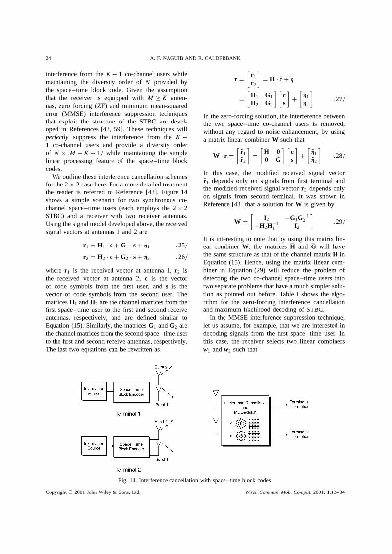
We outline these interference cancellation schemesfor the 2ð 2 case here. For a more detailed treatmentthe reader is referred to Reference [43]. Figure 14shows a simple scenario for two synchronous co-channel space–time users (each employs the 2ð 2STBC) and a receiver with two receiver antennas.Using the signal model developed above, the receivedsignal vectors at antennas 1 and 2 are
r1 D H1 Ð cCG1 Ð sC h1 .25/
r2 D H2 Ð cCG2 Ð sC h2 .26/
where r1 is the received vector at antenna 1,r2 isthe received vector at antenna 2,c is the vectorof code symbols from the first user, ands is thevector of code symbols from the second user. ThematricesH1 andH2 are the channel matrices from thefirst space–time user to the first and second receiveantennas, respectively, and are defined similar toEquation (15). Similarly, the matricesG1 andG2 arethe channel matrices from the second space–time userto the first and second receive antennas, respectively.The last two equations can be rewritten as
r D[
r1
r2
]D H Ð QcC h
D[
H1 G1
H2 G2
] [cs
]C[h1
h2
].27/
In the zero-forcing solution, the interference betweenthe two space–time co-channel users is removed,without any regard to noise enhancement, by usinga matrix linear combinerW such that
W Ð r D[ Qr1
Qr2
]D[ QH 0
0 QG] [
cs
]C[ Qh1
Qh2
].28/
In this case, the modified received signal vectorQr1 depends only on signals from first terminal andthe modified received signal vectorQr2 depends onlyon signals from second terminal. It was shown inReference [43] that a solution forW is given by
W D[
I2 �G1G�12
�H2H�11 I2
].29/
It is interesting to note that by using this matrix lin-ear combinerW, the matrices QH and QG will havethe same structure as that of the channel matrixH inEquation (15). Hence, using the matrix linear com-biner in Equation (29) will reduce the problem ofdetecting the two co-channel space–time users intotwo separate problems that have a much simpler solu-tion as pointed out before. Table I shows the algo-rithm for the zero-forcing interference cancellationand maximum likelihood decoding of STBC.
In the MMSE interference suppression technique,let us assume, for example, that we are interested indecoding signals from the first space–time user. Inthis case, the receiver selects two linear combinersw1 andw2 such that
Fig. 14. Interference cancellation with space–time block codes.
Copyright 2001 John Wiley & Sons, Ltd. Wirel. Commun. Mob. Comput.2001;1:13–34
SPACE–TIME CODING TECHNIQUES 25
Table I. Zero forcing IC and ML decodingalgorithm for space–time block codes.
.c,/ D ZF.DEC.r1, r2,H1,H2,G1,G2/f
Qr D r1 �G1G�12 r2
QH D H1 �G1G�12 H2
�2 D 1C TrfG1GŁ1g/TrfG2GŁ2gOcD arg min
Oc2Cjj��1.Qr � QH РOc/jj2
D jj��1.Qr � QH РOc/jj2
g
J1.w1/ D jjwŁ1 r � c1jj2 and J2.w2/ D jjwŁ2 r � c2jj2.30/
are minimized. It was shown in Reference [43] thatthe optimum solution is given by
w1 D M�1h1 and w2 D M �1h2 .31/
whereM D HH Ł C 1
I , D Es/No is the signal-to-
noise ratio (SNR),h1 D [h11hŁ21h12hŁ22]T is the first
column of H, and h2 D [h21� hŁ11h22� hŁ12]T is the
second column ofH. It was shown in Reference [43]that w1 and w2 are orthogonal and, hence, errors indecodingc1 do not affect decodingc2 and visa versa,thereby maintaining the separate detection feature forSTBC decoding. Note that the MMSE solution willreduce to the ZF solution outlined earlier as!1.Table II outlines the algorithm description for MMSEinterference suppression and decoding of STBC. For
Table II. MMSE IC decoding algorithm for space–timeblock codes.
.c,/ D MMSE.DEC.r1, r2,H1,H2,G1,G2, /f
Qr D [rT1 rT2]T
QH D[H1 G1
H2 G2
]M D HHŁ C 1
I4
h1 D [h11hŁ21h12h
Ł22]
T
D first column ofH
h2 D [h21� hŁ11h22� hŁ12]T
D second column ofH
w1 D M�1h1
w2 D M�1h2
OcD arg minOc2C
{jjwŁ1 r � Oc1jj2 C jjwŁ2 r � Oc2jj2
} D jjwŁ1 r � Oc1jj2 C jjwŁ2 r � Oc2jj2
g
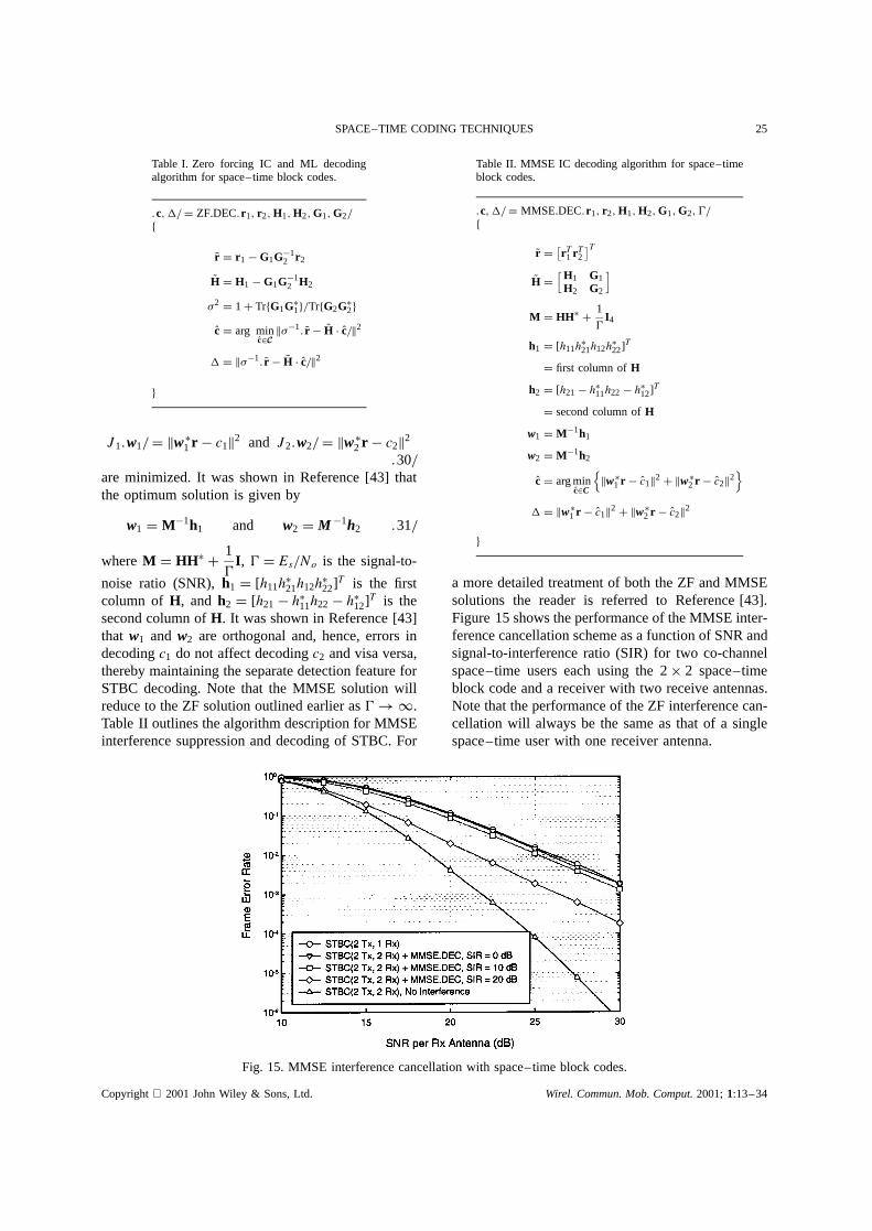
a more detailed treatment of both the ZF and MMSEsolutions the reader is referred to Reference [43].Figure 15 shows the performance of the MMSE inter-ference cancellation scheme as a function of SNR andsignal-to-interference ratio (SIR) for two co-channelspace–time users each using the 2ð 2 space–timeblock code and a receiver with two receive antennas.Note that the performance of the ZF interference can-cellation will always be the same as that of a singlespace–time user with one receiver antenna.
Fig. 15. MMSE interference cancellation with space–time block codes.
Copyright 2001 John Wiley & Sons, Ltd. Wirel. Commun. Mob. Comput.2001;1:13–34
26 A. F. NAGUIB AND R. CALDERBANK
7. Applications of Space–Time Coding toWireless
As pointed out earlier, one of the goals of the thirdand fourth generation wireless systems is to providebroadband access to both mobile and stationary users.Real-time multi-media services (such as video con-ferencing) would require data rates 2–3 orders ofmagnitude larger than what is offered by current wire-less technologies. A higher spectral efficiency can beachieved by using multiple transmit and/or receiveantennas [1, 19, 60]. Space–time coding techniqueswith multiple transmit antennas offer the best possi-ble trade-off between power consumption and spectralefficiency in multipath radio channels. Space–timecoding and signal processing techniques with multi-ple transmit antennas have been recently adopted inthird generation cellular standard (e.g. CDMA-2000[61] and W-CDMA [62]) and also have been proposedfor wireless local loop applications (Lucent’s BLASTproject [6]) and wide-area packet data access (AT&T’sAdvanced Cellular Internet Service [5]). In this sectionwe will outline several examples of application ofspace–time coding to different wireless applications.
7.1. Application to Narrow Band TDMA Cellular
In this section, we will present a general architecturefor a narrow band TDMA modem with space–time
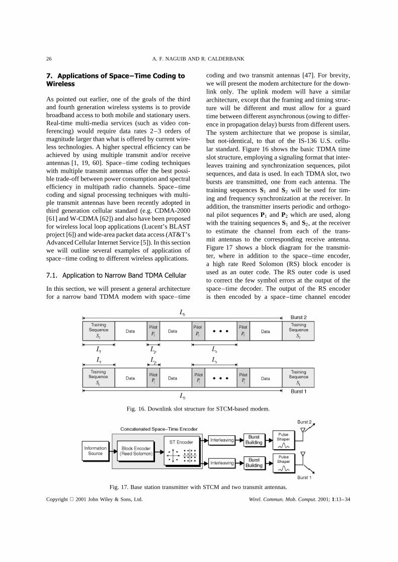
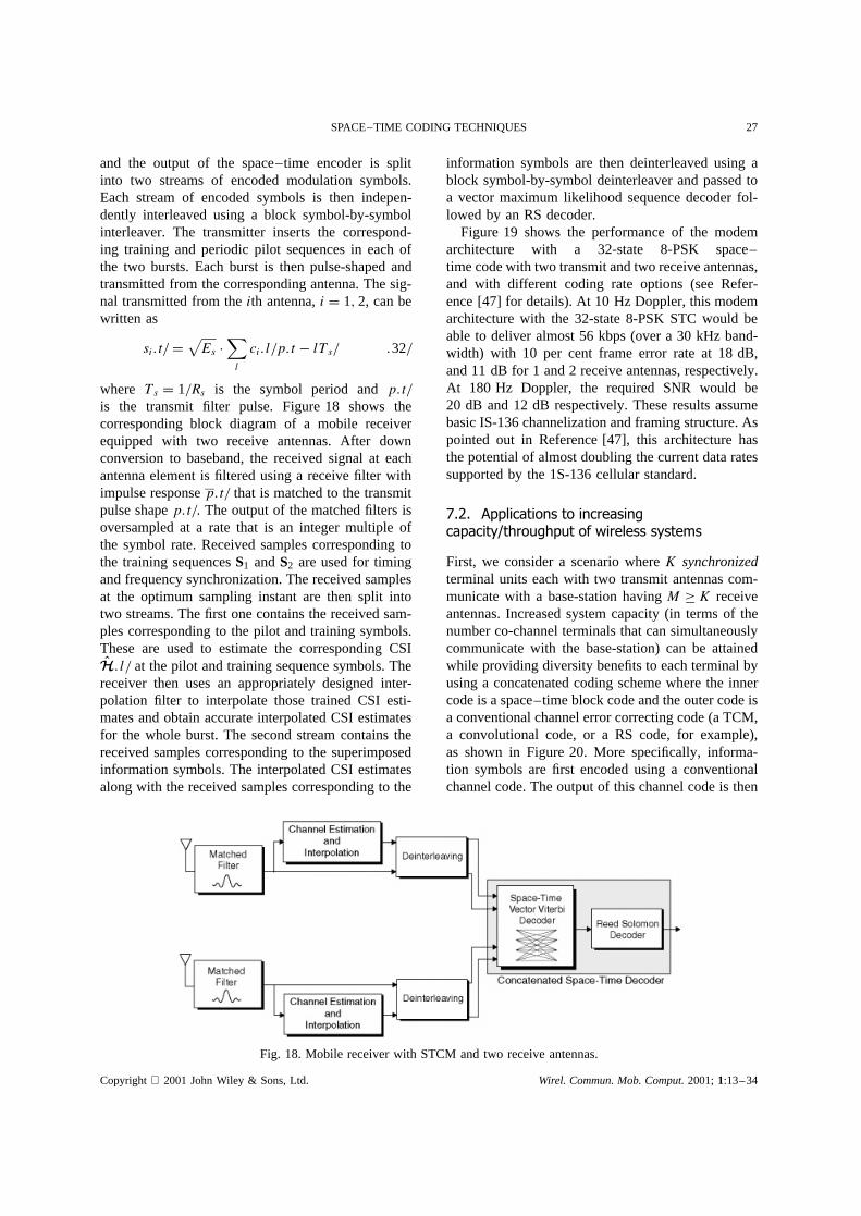
coding and two transmit antennas [47]. For brevity,we will present the modem architecture for the down-link only. The uplink modem will have a similararchitecture, except that the framing and timing struc-ture will be different and must allow for a guardtime between different asynchronous (owing to differ-ence in propagation delay) bursts from different users.The system architecture that we propose is similar,but not-identical, to that of the IS-136 U.S. cellu-lar standard. Figure 16 shows the basic TDMA timeslot structure, employing a signaling format that inter-leaves training and synchronization sequences, pilotsequences, and data is used. In each TDMA slot, twobursts are transmitted, one from each antenna. Thetraining sequencesS1 and S2 will be used for tim-ing and frequency synchronization at the receiver. Inaddition, the transmitter inserts periodic and orthogo-nal pilot sequencesP1 andP2 which are used, alongwith the training sequencesS1 andS2, at the receiverto estimate the channel from each of the trans-mit antennas to the corresponding receive antenna.Figure 17 shows a block diagram for the transmit-ter, where in addition to the space–time encoder,a high rate Reed Solomon (RS) block encoder isused as an outer code. The RS outer code is usedto correct the few symbol errors at the output of thespace–time decoder. The output of the RS encoderis then encoded by a space–time channel encoder
Fig. 16. Downlink slot structure for STCM-based modem.
Fig. 17. Base station transmitter with STCM and two transmit antennas.
Copyright 2001 John Wiley & Sons, Ltd. Wirel. Commun. Mob. Comput.2001;1:13–34
SPACE–TIME CODING TECHNIQUES 27
and the output of the space–time encoder is splitinto two streams of encoded modulation symbols.Each stream of encoded symbols is then indepen-dently interleaved using a block symbol-by-symbolinterleaver. The transmitter inserts the correspond-ing training and periodic pilot sequences in each ofthe two bursts. Each burst is then pulse-shaped andtransmitted from the corresponding antenna. The sig-nal transmitted from theith antenna,i D 1, 2, can bewritten as
si.t/ D√Es Ð
∑l
ci.l/p.t � lTs/ .32/
where Ts D 1/Rs is the symbol period andp.t/is the transmit filter pulse. Figure 18 shows thecorresponding block diagram of a mobile receiverequipped with two receive antennas. After downconversion to baseband, the received signal at eachantenna element is filtered using a receive filter withimpulse responsep.t/ that is matched to the transmitpulse shapep.t/. The output of the matched filters isoversampled at a rate that is an integer multiple ofthe symbol rate. Received samples corresponding tothe training sequencesS1 andS2 are used for timingand frequency synchronization. The received samplesat the optimum sampling instant are then split intotwo streams. The first one contains the received sam-ples corresponding to the pilot and training symbols.These are used to estimate the corresponding CSIOH.l/ at the pilot and training sequence symbols. The
receiver then uses an appropriately designed inter-polation filter to interpolate those trained CSI esti-mates and obtain accurate interpolated CSI estimatesfor the whole burst. The second stream contains thereceived samples corresponding to the superimposedinformation symbols. The interpolated CSI estimatesalong with the received samples corresponding to the
information symbols are then deinterleaved using ablock symbol-by-symbol deinterleaver and passed toa vector maximum likelihood sequence decoder fol-lowed by an RS decoder.
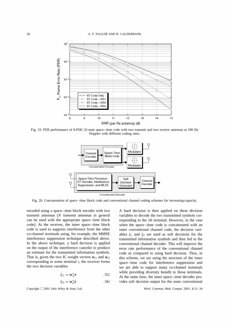
Figure 19 shows the performance of the modemarchitecture with a 32-state 8-PSK space–time code with two transmit and two receive antennas,and with different coding rate options (see Refer-ence [47] for details). At 10 Hz Doppler, this modemarchitecture with the 32-state 8-PSK STC would beable to deliver almost 56 kbps (over a 30 kHz band-width) with 10 per cent frame error rate at 18 dB,and 11 dB for 1 and 2 receive antennas, respectively.At 180 Hz Doppler, the required SNR would be20 dB and 12 dB respectively. These results assumebasic IS-136 channelization and framing structure. Aspointed out in Reference [47], this architecture hasthe potential of almost doubling the current data ratessupported by the 1S-136 cellular standard.
7.2. Applications to increasingcapacity/throughput of wireless systems
First, we consider a scenario whereK synchronizedterminal units each with two transmit antennas com-municate with a base-station havingM ½ K receiveantennas. Increased system capacity (in terms of thenumber co-channel terminals that can simultaneouslycommunicate with the base-station) can be attainedwhile providing diversity benefits to each terminal byusing a concatenated coding scheme where the innercode is a space–time block code and the outer code isa conventional channel error correcting code (a TCM,a convolutional code, or a RS code, for example),as shown in Figure 20. More specifically, informa-tion symbols are first encoded using a conventionalchannel code. The output of this channel code is then
Fig. 18. Mobile receiver with STCM and two receive antennas.
Copyright 2001 John Wiley & Sons, Ltd. Wirel. Commun. Mob. Comput.2001;1:13–34
28 A. F. NAGUIB AND R. CALDERBANK
Fig. 19. FER performance of 8-PSK 32-state space–time code with two transmit and two receive antennas at 180 HzDoppler with different coding rates.
Fig. 20. Concatenation of space–time block code and conventional channel coding schemes for increasing-capacity.
encoded using a space–time block encoder with twotransmit antennas (N transmit antennas in generalcan be used with the appropriate space–time blockcode). At the receiver, the inner space–time blockcode is used to suppress interference from the otherco-channel terminals using, for example, the MMSEinterference suppression technique described above.In the above technique, a hard decision is appliedon the output of the interference canceler to producean estimate for the transmitted information symbols.That is, given the two IC weight vectorswi1 andwi2corresponding to some terminali, the receiver formsthe two decision variables
�i1 D wŁi1r .33/
�i2 D wŁi2r .34/
A hard decision is then applied on these decisionvariables to decode the two transmitted symbols cor-responding to theith terminal. However, in the casewhen the space–time code is concatenated with anouter conventional channel code, the decision vari-ables �1 and �2 are used as soft decisions for thetransmitted information symbols and then fed to theconventional channel decoder. This will improve theerror rate performance of the conventional channelcode as compared to using hard decision. Thus, inthis scheme, we are using the structure of the innerspace–time code for interference suppression andwe are able to support many co-channel terminalswhile providing diversity benefit to those terminals.At the same time, the inner space–time decoder pro-vides soft decision output for the outer conventional
Copyright 2001 John Wiley & Sons, Ltd. Wirel. Commun. Mob. Comput.2001;1:13–34
SPACE–TIME CODING TECHNIQUES 29
channel code which will provide protection againstchannel errors.
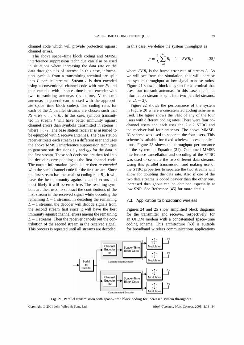
The above space–time block coding and MMSEinterference suppression technique can also be usedin situations where increasing the data rate or thedata throughput is of interest. In this case, informa-tion symbols from a transmitting terminal are splitinto L parallel streams. Streaml is then encodedusing a conventional channel code with rateRl andthen encoded with a space–time block encoder withtwo transmitting antennas (as before,N transmitantennas in general can be used with the appropri-ate space–time block codes). The coding rates foreach of theL parallel streams are chosen such thatR1 < R2 < . . . < RL. In this case, symbols transmit-ted in streaml will have better immunity againstchannel errors than symbols transmitted in streamuwhereu > l. The base station receiver is assumed tobe equipped withL receive antennas. The base stationreceiver treats each stream as a different user and usesthe above MMSE interference suppression techniqueto generate soft decisions�11 and �12 for the data inthe first stream. These soft decisions are then fed intothe decoder corresponding to the first channel code.The output information symbols are thenre-encodedwith the same channel code for the first stream. Sincethe first stream has the smallest coding rateR1, it willhave the best immunity against channel errors andmost likely it will be error free. The resulting sym-bols are then used to subtract the contributions of thefirst stream in the received signal while decoding theremainingL � 1 streams. In decoding the remainingL � 1 streams, the decoder will decode signals fromthe second stream first since it will have the bestimmunity against channel errors among the remainingL � 1 streams. Then the receiver cancels out the con-tribution of the second stream in the received signal.This process is repeated until all streams are decoded.
In this case, we define the system throughput as
� D 1
L
L∑lD1
Rl Ð .1� FERl/ .35/
whereFERl is the frame error rate of streamL. Aswe will see from the simulation, this will increasethe system throughput at low signal-to-noise ratios.Figure 21 shows a block diagram for a terminal thatuses four transmit antennas. In this case, the inputinformation stream is split into two parallel streams,i.e. .L D 2/.
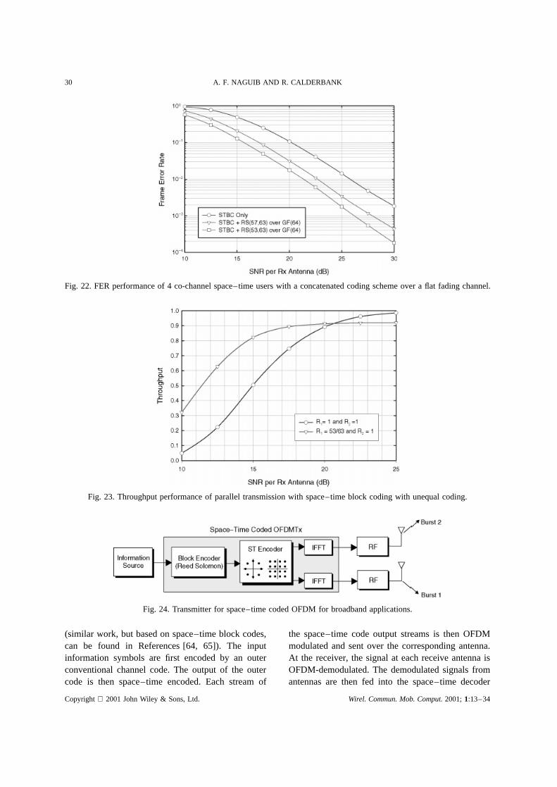
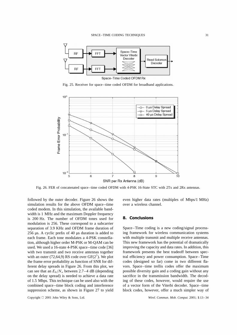
Figure 22 shows the performance of the systemin Figure 20 where a concatenated coding scheme isused. The figure shows the FER of any of the fourusers with different coding rates. There were four co-channel users and each uses the 2ð 2 STBC andthe receiver had four antennas. The above MMSE-IC scheme was used to separate the four users. Thisscheme is suitable for fixed wireless access applica-tions. Figure 23 shows the throughput performanceof the system in Equation (21). Combined MMSEinterference cancellation and decoding of the STBCwas used to separate the two different data streams.Using this parallel transmission and making use ofthe STBC properties to separate the two streams willallow for doubling the data rate. Also if one of thetwo data streams is coded heavier than the other one,increased throughput can be obtained especially atlow SNR. See Reference [45] for more details.
7.3. Application to broadband wireless
Figures 24 and 25 show simplified block diagramsfor the transmitter and receiver, respectively, foran OFDM modem with a concatenated space–timecoding scheme. This architecture [63] is suitablefor broadband wireless communications applications
Fig. 21. Parallel transmission with space–time block coding for increased system throughput.
Copyright 2001 John Wiley & Sons, Ltd. Wirel. Commun. Mob. Comput.2001;1:13–34
30 A. F. NAGUIB AND R. CALDERBANK
Fig. 22. FER performance of 4 co-channel space–time users with a concatenated coding scheme over a flat fading channel.
Fig. 23. Throughput performance of parallel transmission with space–time block coding with unequal coding.
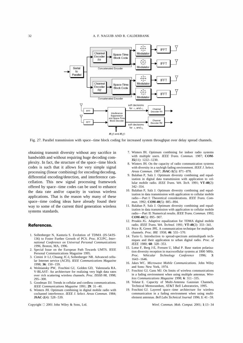
Fig. 24. Transmitter for space–time coded OFDM for broadband applications.
(similar work, but based on space–time block codes,can be found in References [64, 65]). The inputinformation symbols are first encoded by an outerconventional channel code. The output of the outercode is then space–time encoded. Each stream of
the space–time code output streams is then OFDMmodulated and sent over the corresponding antenna.At the receiver, the signal at each receive antenna isOFDM-demodulated. The demodulated signals fromantennas are then fed into the space–time decoder
Copyright 2001 John Wiley & Sons, Ltd. Wirel. Commun. Mob. Comput.2001;1:13–34
SPACE–TIME CODING TECHNIQUES 31
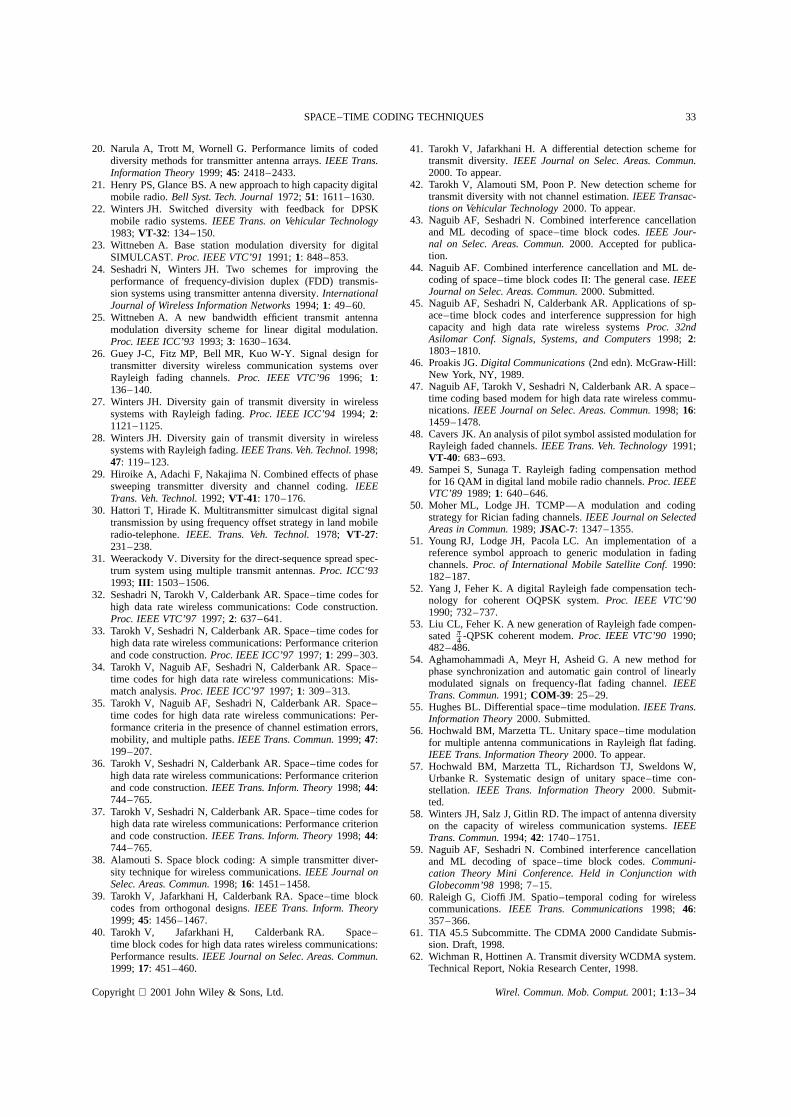
Fig. 25. Receiver for space–time coded OFDM for broadband applications.
Fig. 26. FER of concatenated space–time coded OFDM with 4-PSK 16-State STC with 2Tx and 2Rx antennas.
followed by the outer decoder. Figure 26 shows thesimulation results for the above OFDM space–timecoded modem. In this simulation, the available band-width is 1 MHz and the maximum Doppler frequencyis 200 Hz. The number of OFDM tones used formodulation is 256. These correspond to a subcarrierseparation of 3.9 KHz and OFDM frame duration of256 µs. A cyclic prefix of 40µs duration is added toeach frame. Each tone modulates a 4-PSK constella-tion, although higher order M-PSK or M-QAM can beused. We used a 16-state 4-PSK space–time code [36]with two transmit and two receive antennas togetherwith an outer (72,64,9) RS code over GF(27). We plotthe frame error probability as function of SNR for dif-ferent delay spreads in Figure 26. From this plot, wecan see that anEb/No between 2.7–4 dB (dependingon the delay spread) is needed to achieve a data rateof 1.5 Mbps. This technique can be used also with thecombined space–time block coding and interferencesuppression scheme, as shown in Figure 27 to yield
even higher data rates (multiples of Mbps/1 MHz)over a wireless channel.
8. Conclusions
Space–Time coding is a new coding/signal process-ing framework for wireless communication systemswith multiple transmit and multiple receive antennas.This new framework has the potential of dramaticallyimproving the capacity and data rates. In addition, thisframework presents the best tradeoff between spec-tral efficiency and power consumption. Space–Timecodes (designed so far) come in two different fla-vors. Space–time trellis codes offer the maximumpossible diversity gain and a coding gain without anysacrifice in the transmission bandwidth. The decod-ing of these codes, however, would require the useof a vector form of the Viterbi decoder. Space–timeblock codes, however, offer a much simpler way of
Copyright 2001 John Wiley & Sons, Ltd. Wirel. Commun. Mob. Comput.2001;1:13–34
32 A. F. NAGUIB AND R. CALDERBANK
Fig. 27. Parallel transmission with space–time block coding for increased system throughput over delay spread channels.
obtaining transmit diversity without any sacrifice inbandwidth and without requiring huge decoding com-plexity. In fact, the structure of the space–time blockcodes is such that it allows for very simple signalprocessing (linear combining) for encoding/decoding,differential encoding/detection, and interference can-cellation. This new signal processing frameworkoffered by space–time codes can be used to enhancethe data rate and/or capacity in various wirelessapplications. That is the reason why many of thesespace–time coding ideas have already found theirway to some of the current third generation wirelesssystems standards.
References.
1. Sollenberger N, Kasturia S. Evolution of TDMA (IS-54/IS-136) to Foster Further Growth of PCS.Proc. ICUPC, Inter-national Conference on Universal Personal Communications1996, Boston, MA, 1996.
2. Special Issue on the European Path Towards UMTS. IEEEPersonal Communications Magazine 1995.
3. Cimini Jr LJ, Chuang JC-I, Sollenberger NR. Advanced cellu-lar Internet service (ACIS).IEEE Communications Magazine1998;36: 150–159.
4. Wolniansky PW, Foschini GJ, Golden GD, Valenzuela RA.V-BLAST: An architecture for realizing very high data ratesover rich scattering wireless channels.Proc. ISSSE-98, 1998;295–300.
5. Goodman DJ. Trends in cellular and cordless communications.IEEE Communications Magazine1991;29: 31–40.
6. Winters JH. Optimum combining in digital mobile radio withcochannel interference.IEEE J. Select. Areas Commun.1984;JSAC-2(4): 528–539.
7. Winters JH. Optimum combining for indoor radio systemswith multiple users. IEEE Trans. Commun.1987; COM-35(11): 1222–1230.
8. Winters JH. On the capacity of radio communication systemswith diversity in a rayleigh fading environment.IEEE J. Select.Areas Commun.1987;JSAC-5(5): 871–878.
9. Balaban P, Salz J. Optimum diversity combining and equal-ization in digital data transmission with application to cel-lular mobile radio.IEEE Trans. Veh. Tech.1991; VT-40(2):342–354.
10. Balaban P, Salz J. Optimum diversity combining and equal-ization in data transmission with application to cellular mobileradio—Part I: Theoretical considerations.IEEE Trans. Com-mun.1992;COM-40(5): 885–894.
11. Balaban P, Salz J. Optimum diversity combining and equal-ization in data transmission with application to cellular mobileradio—Part II: Numerical results.IEEE Trans. Commun.1992;COM-40(5): 895–907.
12. Proakis JG. Adaptive equalization for TDMA digital mobileradio. IEEE Trans. Veh. Technol.1991;VT-40(2): 333–341.
13. Price R, Green JPE. A communication technique for multipathchannels.Proc. IRE 1958;46: 555–570.
14. Turin G. Introduction to spread-spectrum antimultipath tech-niques and their application to urban digital radio.Proc. ofIEEE 1980;68: 328–353.
15. Lotse F, Berg J-E, Forssen U, Idhal P. Base station polariza-tion diversity reception in macrocellular systems at 1800 MHz.Proc. Vehicular Technology Conference1996; 3:1643–1646.
16. Jakes WC.Microwave Mobile Communications. John Wileyand Sons: New York, 1974.
17. Foschini GJ, Gans MJ. On limits of wireless communicationsin a fading environment when using multiple antennas.Wire-less Communications Magazine1998;6: 311–335.
18. Telatar E. Capacity of Multi-Antenna Gaussian Channels,Technical Memorandum, AT&T Bell Laboratories, 1995.
19. Foschini GJ. Layered space–time architecture for wirelesscommunication in a fading environment when using multi-element antennas.Bell Labs Technical Journal1996;1: 41–59.
Copyright 2001 John Wiley & Sons, Ltd. Wirel. Commun. Mob. Comput.2001;1:13–34
SPACE–TIME CODING TECHNIQUES 33
20. Narula A, Trott M, Wornell G. Performance limits of codeddiversity methods for transmitter antenna arrays.IEEE Trans.Information Theory1999;45: 2418–2433.
21. Henry PS, Glance BS. A new approach to high capacity digitalmobile radio.Bell Syst. Tech. Journal1972;51: 1611–1630.
22. Winters JH. Switched diversity with feedback for DPSKmobile radio systems.IEEE Trans. on Vehicular Technology1983;VT-32: 134–150.
23. Wittneben A. Base station modulation diversity for digitalSIMULCAST. Proc. IEEE VTC’911991;1: 848–853.
24. Seshadri N, Winters JH. Two schemes for improving theperformance of frequency-division duplex (FDD) transmis-sion systems using transmitter antenna diversity.InternationalJournal of Wireless Information Networks1994;1: 49–60.
25. Wittneben A. A new bandwidth efficient transmit antennamodulation diversity scheme for linear digital modulation.Proc. IEEE ICC’93 1993;3: 1630–1634.
26. Guey J-C, Fitz MP, Bell MR, Kuo W-Y. Signal design fortransmitter diversity wireless communication systems overRayleigh fading channels.Proc. IEEE VTC’96 1996; 1:136–140.
27. Winters JH. Diversity gain of transmit diversity in wirelesssystems with Rayleigh fading.Proc. IEEE ICC’94 1994; 2:1121–1125.
28. Winters JH. Diversity gain of transmit diversity in wirelesssystems with Rayleigh fading.IEEE Trans. Veh. Technol.1998;47: 119–123.
29. Hiroike A, Adachi F, Nakajima N. Combined effects of phasesweeping transmitter diversity and channel coding.IEEETrans. Veh. Technol.1992;VT-41: 170–176.
30. Hattori T, Hirade K. Multitransmitter simulcast digital signaltransmission by using frequency offset strategy in land mobileradio-telephone.IEEE. Trans. Veh. Technol.1978; VT-27:231–238.
31. Weerackody V. Diversity for the direct-sequence spread spec-trum system using multiple transmit antennas.Proc. ICC‘931993; III : 1503–1506.
32. Seshadri N, Tarokh V, Calderbank AR. Space–time codes forhigh data rate wireless communications: Code construction.Proc. IEEE VTC’971997;2: 637–641.
33. Tarokh V, Seshadri N, Calderbank AR. Space–time codes forhigh data rate wireless communications: Performance criterionand code construction.Proc. IEEE ICC’971997;1: 299–303.
34. Tarokh V, Naguib AF, Seshadri N, Calderbank AR. Space–time codes for high data rate wireless communications: Mis-match analysis.Proc. IEEE ICC’97 1997;1: 309–313.
35. Tarokh V, Naguib AF, Seshadri N, Calderbank AR. Space–time codes for high data rate wireless communications: Per-formance criteria in the presence of channel estimation errors,mobility, and multiple paths.IEEE Trans. Commun.1999;47:199–207.
36. Tarokh V, Seshadri N, Calderbank AR. Space–time codes forhigh data rate wireless communications: Performance criterionand code construction.IEEE Trans. Inform. Theory1998;44:744–765.
37. Tarokh V, Seshadri N, Calderbank AR. Space–time codes forhigh data rate wireless communications: Performance criterionand code construction.IEEE Trans. Inform. Theory1998;44:744–765.
38. Alamouti S. Space block coding: A simple transmitter diver-sity technique for wireless communications.IEEE Journal onSelec. Areas. Commun.1998;16: 1451–1458.
39. Tarokh V, Jafarkhani H, Calderbank RA. Space–time blockcodes from orthogonal designs.IEEE Trans. Inform. Theory1999;45: 1456–1467.
40. Tarokh V, Jafarkhani H, Calderbank RA. Space–time block codes for high data rates wireless communications:Performance results.IEEE Journal on Selec. Areas. Commun.1999;17: 451–460.
41. Tarokh V, Jafarkhani H. A differential detection scheme fortransmit diversity.IEEE Journal on Selec. Areas. Commun.2000. To appear.
42. Tarokh V, Alamouti SM, Poon P. New detection scheme fortransmit diversity with not channel estimation.IEEE Transac-tions on Vehicular Technology2000. To appear.
43. Naguib AF, Seshadri N. Combined interference cancellationand ML decoding of space–time block codes.IEEE Jour-nal on Selec. Areas. Commun.2000. Accepted for publica-tion.
44. Naguib AF. Combined interference cancellation and ML de-coding of space–time block codes II: The general case.IEEEJournal on Selec. Areas. Commun.2000. Submitted.
45. Naguib AF, Seshadri N, Calderbank AR. Applications of sp-ace–time block codes and interference suppression for highcapacity and high data rate wireless systemsProc. 32ndAsilomar Conf. Signals, Systems, and Computers1998; 2:1803–1810.
46. Proakis JG.Digital Communications(2nd edn). McGraw-Hill:New York, NY, 1989.
47. Naguib AF, Tarokh V, Seshadri N, Calderbank AR. A space–time coding based modem for high data rate wireless commu-nications.IEEE Journal on Selec. Areas. Commun.1998; 16:1459–1478.
48. Cavers JK. An analysis of pilot symbol assisted modulation forRayleigh faded channels.IEEE Trans. Veh. Technology1991;VT-40: 683–693.
49. Sampei S, Sunaga T. Rayleigh fading compensation methodfor 16 QAM in digital land mobile radio channels.Proc. IEEEVTC’89 1989;1: 640–646.
50. Moher ML, Lodge JH. TCMP—A modulation and codingstrategy for Rician fading channels.IEEE Journal on SelectedAreas in Commun.1989;JSAC-7: 1347–1355.
51. Young RJ, Lodge JH, Pacola LC. An implementation of areference symbol approach to generic modulation in fadingchannels.Proc. of International Mobile Satellite Conf.1990:182–187.
52. Yang J, Feher K. A digital Rayleigh fade compensation tech-nology for coherent OQPSK system.Proc. IEEE VTC’901990; 732–737.
53. Liu CL, Feher K. A new generation of Rayleigh fade compen-sated �
4 -QPSK coherent modem.Proc. IEEE VTC’90 1990;482–486.
54. Aghamohammadi A, Meyr H, Asheid G. A new method forphase synchronization and automatic gain control of linearlymodulated signals on frequency-flat fading channel.IEEETrans. Commun.1991;COM-39: 25–29.
55. Hughes BL. Differential space–time modulation.IEEE Trans.Information Theory2000. Submitted.
56. Hochwald BM, Marzetta TL. Unitary space–time modulationfor multiple antenna communications in Rayleigh flat fading.IEEE Trans. Information Theory2000. To appear.
57. Hochwald BM, Marzetta TL, Richardson TJ, Sweldons W,Urbanke R. Systematic design of unitary space–time con-stellation. IEEE Trans. Information Theory2000. Submit-ted.
58. Winters JH, Salz J, Gitlin RD. The impact of antenna diversityon the capacity of wireless communication systems.IEEETrans. Commun.1994;42: 1740–1751.
59. Naguib AF, Seshadri N. Combined interference cancellationand ML decoding of space–time block codes.Communi-cation Theory Mini Conference. Held in Conjunction withGlobecomm’981998; 7–15.
60. Raleigh G, Cioffi JM. Spatio–temporal coding for wirelesscommunications.IEEE Trans. Communications1998; 46:357–366.
61. TIA 45.5 Subcommitte. The CDMA 2000 Candidate Submis-sion. Draft, 1998.
62. Wichman R, Hottinen A. Transmit diversity WCDMA system.Technical Report, Nokia Research Center, 1998.
Copyright 2001 John Wiley & Sons, Ltd. Wirel. Commun. Mob. Comput.2001;1:13–34
34 A. F. NAGUIB AND R. CALDERBANK
63. Agrawal D, Tarokh V, Naguib A, Seshadri N. Space–timecoded OFDM for high data rate wireless communicationover wideband channels.Proc. of 48th IEEE VTC1998; 3:2232–2236.
64. Liu Z, Giannakis GB, Scaglione A, Barbarossa S. Block pre-coding and transmit-antenna diversity for decoding and equal-ization of unknown multipath channels.Proc. of 33rd Asilo-mar Conf. on Signals, Systems, and Computers1999; 2:1557–1561.
65. Liu Z, Giannakis GB. Space–time coding with transmit ante-nnas for multiple access regardless of frequency-selectivemultipath.Proc. of the 1st Sensor Array and Multichannel SPWorkshop2000.
Authors’ Biographies
Ayman Naguib receivedthe B.Scdegree(with honors)and the M.S.degreein electricalengineeringfromCairo University, Cairo, Egypt, in1987and1990respectively,andtheM.S. degree in statistics and thePh.D. degreein electricalengineer-ing from StanfordUniversity,Stan-ford, CA, in 1993and1996,respec-tively. From 1987to 1989,hespenthis military service at the Signal
ProcessingLaboratory, The Military Technical College,Cairo, Egypt. From 1989 to 1990,he was employedwithCairo University as a researchand teachingassistantinthe CommunicationTheoryGroup,Departmentof Electri-cal Engineering.From 1990 to 1995, he was a researchand teachingassistantin the InformationSystemsLabora-tory, StanfordUniversity,Stanford,CA. In 1996,he joinedAT&T Labs,FlorhamPark,NJ, wherehe is now a princi-pal memberof technicalstaff. His currentresearchinterestsincludeantennaarrays,signalprocessing,modulation,and
coding for high dataratewirelessanddigital communica-tions andmodemdesignfor broadbandsystems.
A. Robert Calderbank receivedtheB.S. degreein 1975 from WarwickUniversity, U.K., the M.S. degreein 1976 from Oxford University,U.K., andthe Ph.D.degreein 1980from CaliforniaInstituteof Technol-ogy, Pasadena,all in Mathematics.He joined AT&T Bell Laboratoriesin 1980, and prior to the split ofAT&T andLucent,hewasaDepart-mentHeadin theMathematicalSci-
encesResearchCenterat Murray Hill. He is now Direc-tor of the InformationSciencesResearchCenterat AT&TLabs—Researchin FlorhamPark,NJ. His researchinter-ests rangefrom algebraiccoding theory to wirelessdatatransmissionto quantumcomputing.At the University ofMichiganandatPrincetonUniversity,hehasdevelopedandtaughtaninnovativecourseon bandwidth-efficient commu-nication.From1986to 1989,Dr. CalderbankwasAssociateEditor for Coding Techniquesfor the IEEE Transactionson Information Theory. From 1996 to 1999, he was theEditor-in-Chiefof theIEEEtransactionsonInformationthe-ory. He was also GuestEditor for the SpecialIssueon ofthe IEEE Transactionson InformationTheorydedicatedtocodingfor storagedevices.He servedon theboardof Gov-ernorsof theIEEEInformationTheorySocietyfrom 1990to1996.Dr. Calderbankreceivedthe1995PrizePaperAwardfrom the Information Theory Society for his work on theZ4 linearity of the Kerdock and Preparatacodes(jointlywith A. R. HammonsJr, P. V. Kumar,N. J. A. SloaneandP. Sole). He also receivedthe 1999 Information TheorySociety Best Paper Award (jointly with V. Tarokh andN. Seshadri).
Copyright 2001JohnWiley & Sons,Ltd. Wirel. Commun.Mob. Comput.2001;1:13–34