Solid/liquid phase welding
48
Solid/liquid phase welding
-
Upload
khangminh22 -
Category
Documents
-
view
1 -
download
0
Transcript of Solid/liquid phase welding
Solid/liquid phase welding

2
Aluminium Brazing of Heat Exchanger, Evaporators and Condensor Coils
3
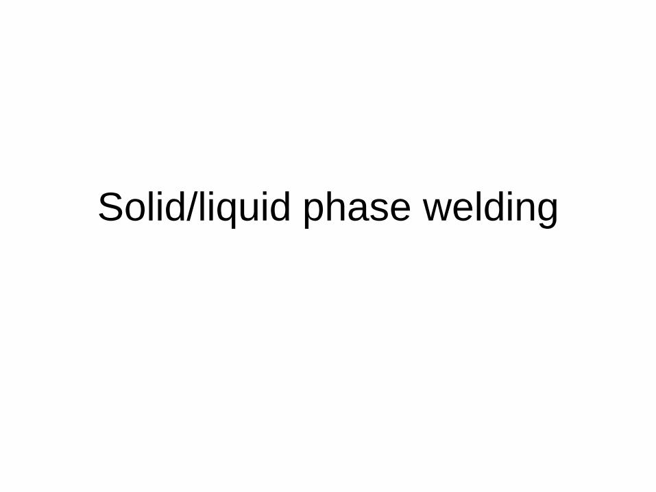
Niagara Thermal Products’ Hudson, Mass facility, isrecognized as one of the best dip brazing/machiningcombinations in North America supporting the defenseand aerospace market sectors.
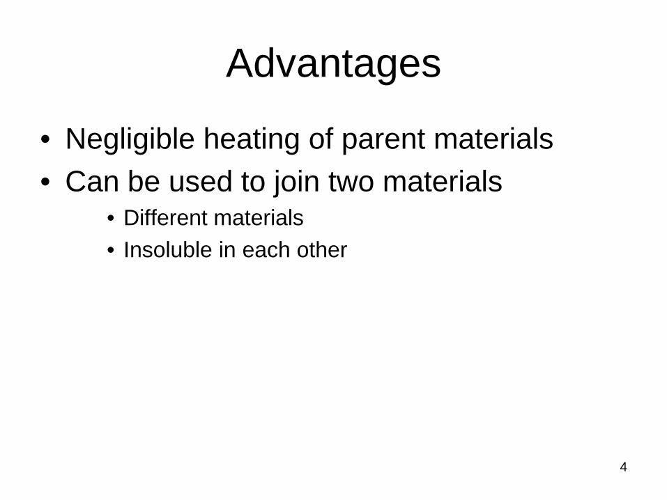
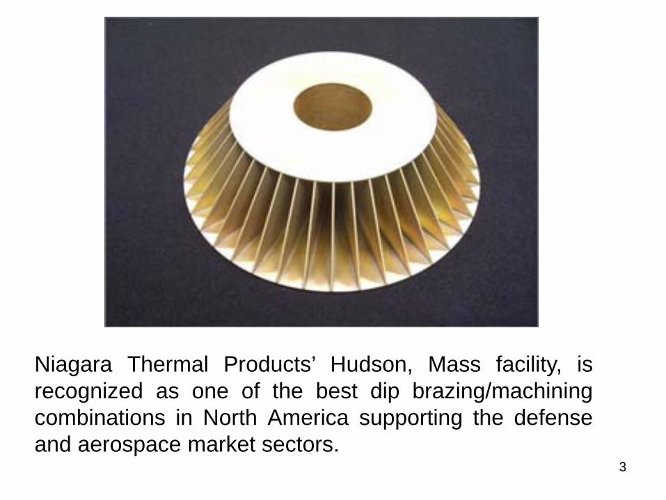
Advantages
• Negligible heating of parent materials• Can be used to join two materials
• Different materials• Insoluble in each other
4

Procedure
• Filler material is melted• Entire gap between the parent bodies is
filled– Through capillary action
• Filler material should have • good spreading capability• Wetting capability
5

Types of solid/liquid phase welding
• Brazing– Temperature rangeAbove 725O KNormally 750oC – 980oC
• Soldering– Temperature range
Below 725O K Normally 160oC – 300oC
• Adhesive bonding– Room temperature
Bulk material is not melted
Molten filler material is used
Heat sourceElectrical resistance
heating
6

Strength of the joint
Thickness of the joint, tt0
σfiller
Stre
ngth
of t
he jo
int, σ j
oint
7
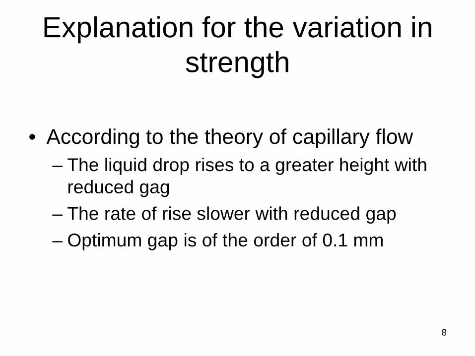
Explanation for the variation in strength
• According to the theory of capillary flow– The liquid drop rises to a greater height with
reduced gag– The rate of rise slower with reduced gap– Optimum gap is of the order of 0.1 mm
8
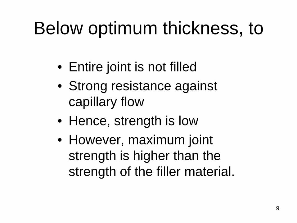
Below optimum thickness, to
• Entire joint is not filled• Strong resistance against
capillary flow• Hence, strength is low• However, maximum joint
strength is higher than the strength of the filler material.
9
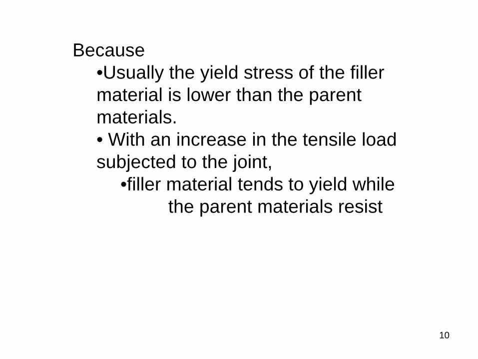
Because•Usually the yield stress of the filler material is lower than the parent materials.• With an increase in the tensile load subjected to the joint,
•filler material tends to yield while the parent materials resist
10

Brazing
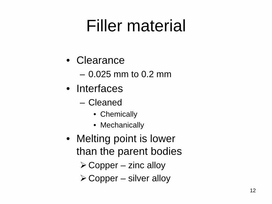
Filler material
• Clearance– 0.025 mm to 0.2 mm
• Interfaces– Cleaned
• Chemically• Mechanically
• Melting point is lower than the parent bodiesCopper – zinc alloy Copper – silver alloy
12
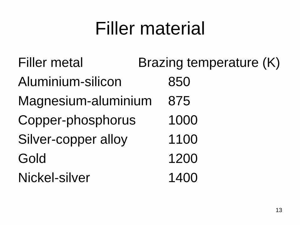
Filler material
Filler metal Brazing temperature (K)Aluminium-silicon 850Magnesium-aluminium 875Copper-phosphorus 1000Silver-copper alloy 1100Gold 1200Nickel-silver 1400
13
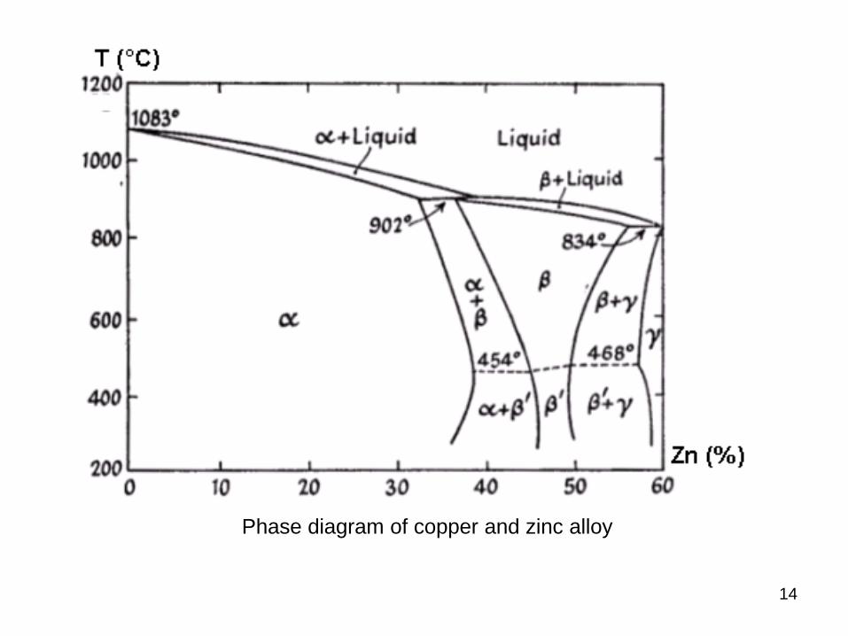
Phase diagram of copper and zinc alloy
14
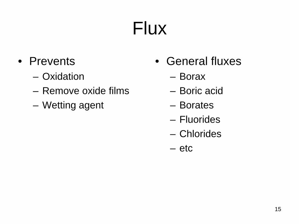
Flux • Prevents
– Oxidation– Remove oxide films– Wetting agent
• General fluxes– Borax– Boric acid– Borates– Fluorides– Chlorides– etc
15
Braze welding
• Prepared as– Fusion welding– Oxyacetylene torch
• Oxidising flame• Filler metal is deposited at the joint• Temperature is lower than fusion welding
– Dissimilar metal can be joined
16
Application of brazed joints
• Carbide drill bits• Carbide inserts on shanks• Strength is 800 MPa (using silver solder)
17
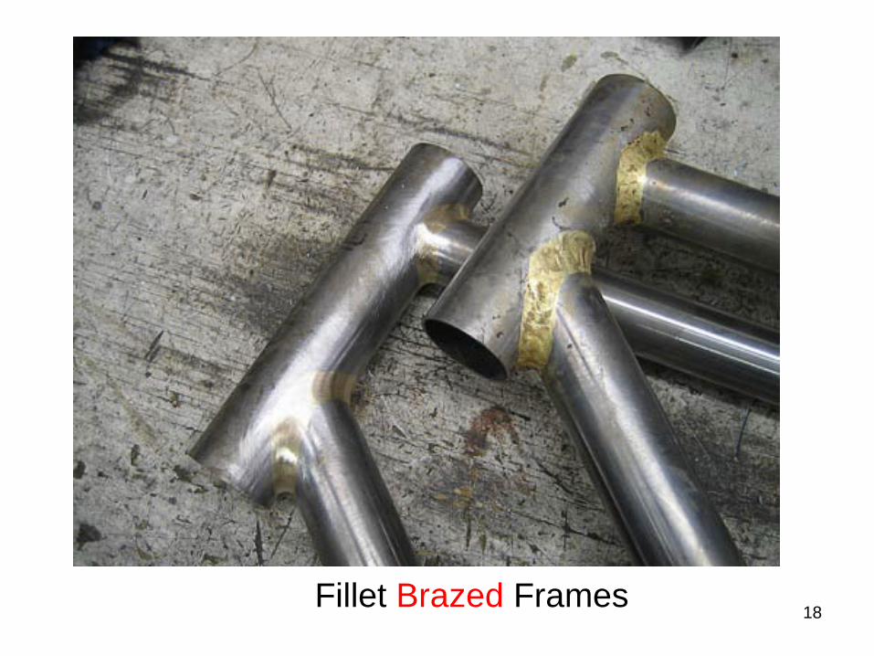
18Fillet Brazed Frames
19
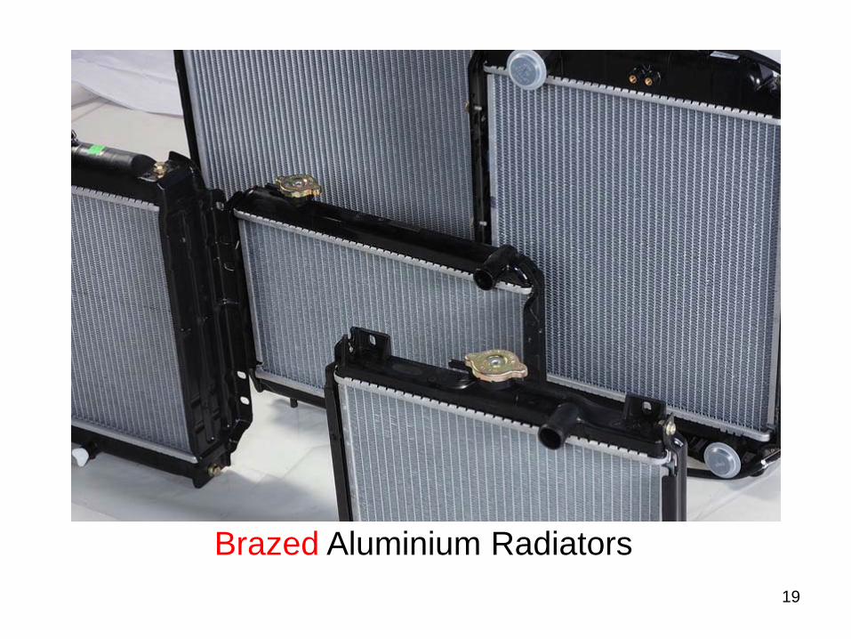
Brazed Aluminium Radiators
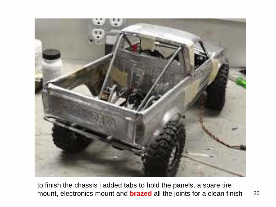
20to finish the chassis i added tabs to hold the panels, a spare tire mount, electronics mount and brazed all the joints for a clean finish
Soldering
Heat sources
• Soldering iron• Torches• Ovens • etc
22
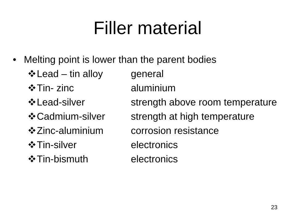
Filler material• Melting point is lower than the parent bodiesLead – tin alloy generalTin- zinc aluminiumLead-silver strength above room temperatureCadmium-silver strength at high temperatureZinc-aluminium corrosion resistanceTin-silver electronicsTin-bismuth electronics
23
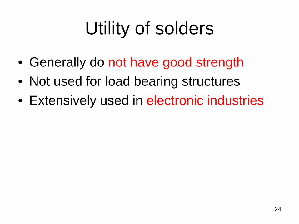
Utility of solders
• Generally do not have good strength• Not used for load bearing structures• Extensively used in electronic industries
24
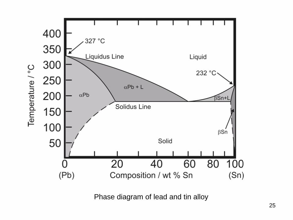
Phase diagram of lead and tin alloy25

Fluxes
• Two types– Inorganic acids or salts
• Zinc ammonium chloride solutions– Non-corrosive resin-based fluxes
• Used in electronic applications
26
27
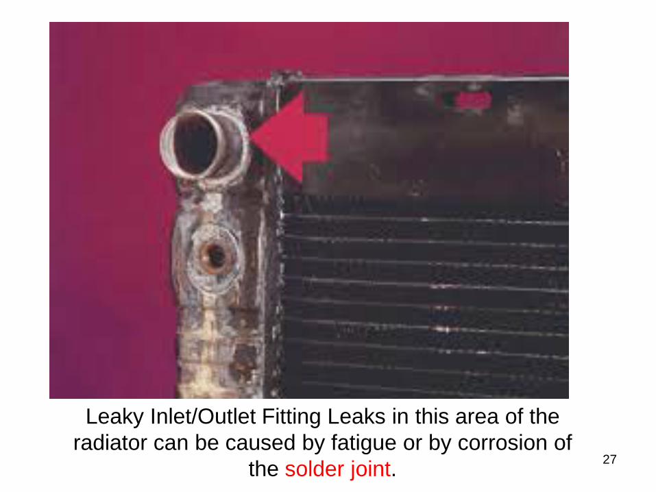
Leaky Inlet/Outlet Fitting Leaks in this area of the radiator can be caused by fatigue or by corrosion of
the solder joint.
28
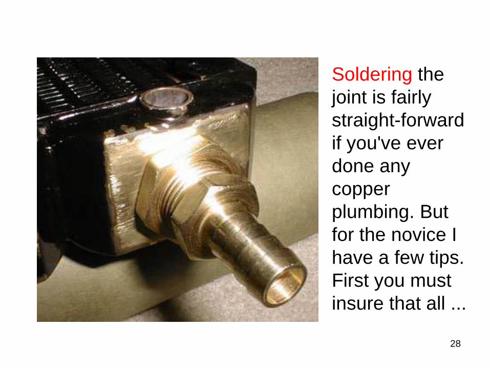
Soldering the joint is fairly straight-forward if you've ever done any copper plumbing. But for the novice I have a few tips. First you must insure that all ...
29
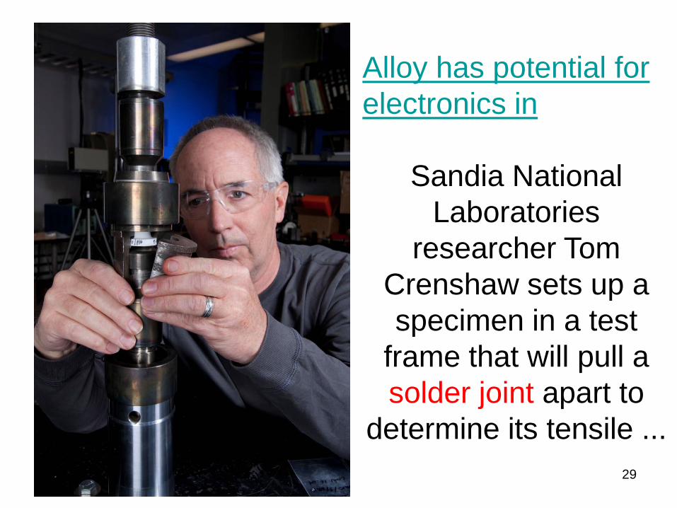
Alloy has potential for electronics in
Sandia National Laboratories
researcher Tom Crenshaw sets up a specimen in a test
frame that will pull a solder joint apart to
determine its tensile ...
30
BGA Process | Indium Corporation From a mechanical perspective, larger solder joints are generally preferred
when assembling package-on-package (PoP) components.
31
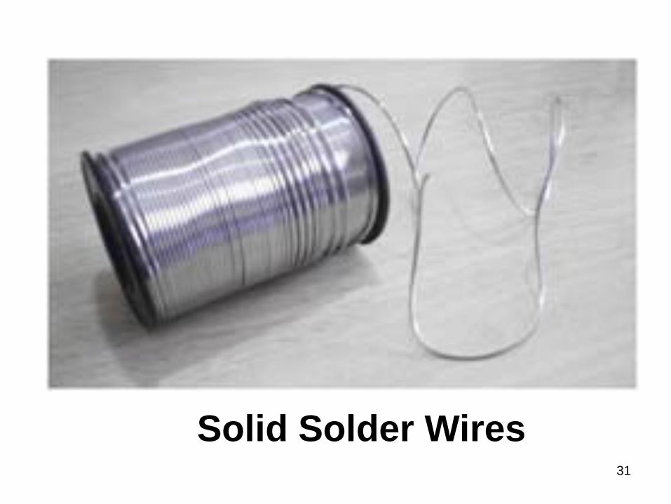
Solid Solder Wires
Adhesive bonding
32
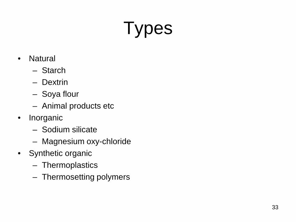
Types • Natural
– Starch– Dextrin– Soya flour– Animal products etc
• Inorganic– Sodium silicate– Magnesium oxy-chloride
• Synthetic organic– Thermoplastics– Thermosetting polymers
33

Synthetic organic adhesives
• Used for load bearing applications
34
Surface preparation• Properly clean from
– Dirt– Dust oil– Other contaminations
• Contaminants affects– Wetting ability– Prevents spreading
• Desirable– Porous surface– Thin surface– Rough surface– Strong oxide film
35
Procedure
• No certainty of the flow of the adhesive in the joint
• Adhesive is applied first on the surfaces to be joined
• Application of– Heat – Pressure
36
Bonding forces
1. Van der WaalsDue to the constant movement of the positive and
negative charges of molecules
2. Polar forceBetween the adhesive and oxide film, due to dipole
adhesive molecules. It is higher than the van der Waals force.
37
Factors affecting the strength• The and dimension of the joint.
• Strength of lap joint increases with the overlapped area
• Reduces with the joint thickness.
• The contact angle at the solid-liquid interface.
• There is also possibility of an air bubble to get entrapped in the cavity.
• The residual stress• Stress concentration.
38
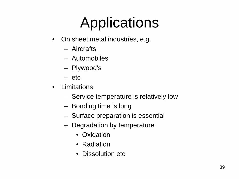
Applications • On sheet metal industries, e.g.
– Aircrafts– Automobiles – Plywood's– etc
• Limitations – Service temperature is relatively low– Bonding time is long– Surface preparation is essential– Degradation by temperature
• Oxidation• Radiation• Dissolution etc
39
40
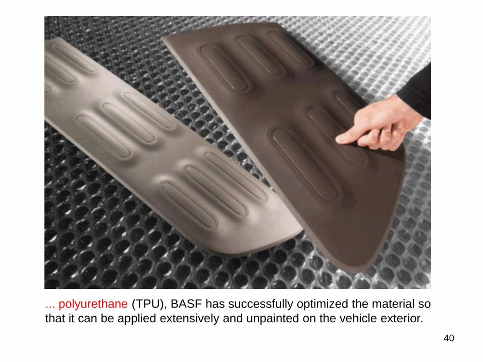
... polyurethane (TPU), BASF has successfully optimized the material so that it can be applied extensively and unpainted on the vehicle exterior.
41
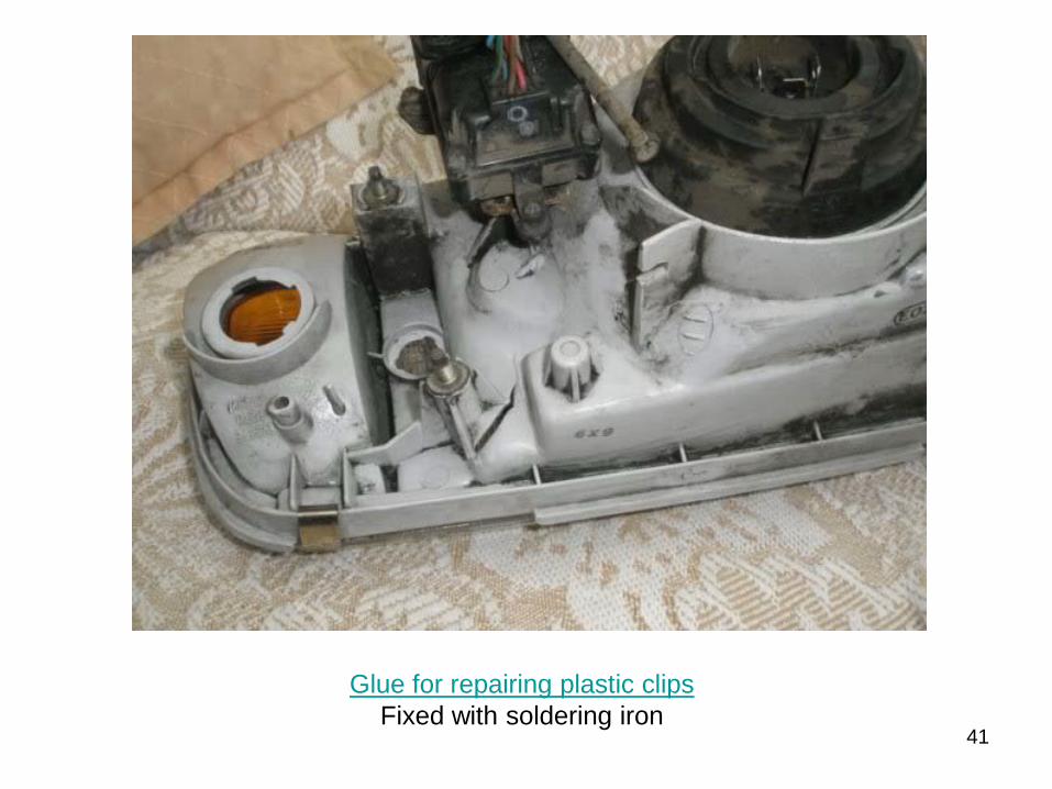
Glue for repairing plastic clips Fixed with soldering iron
42
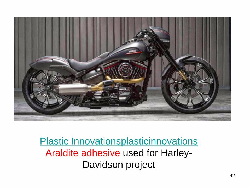
Plastic InnovationsplasticinnovationsAraldite adhesive used for Harley-
Davidson project
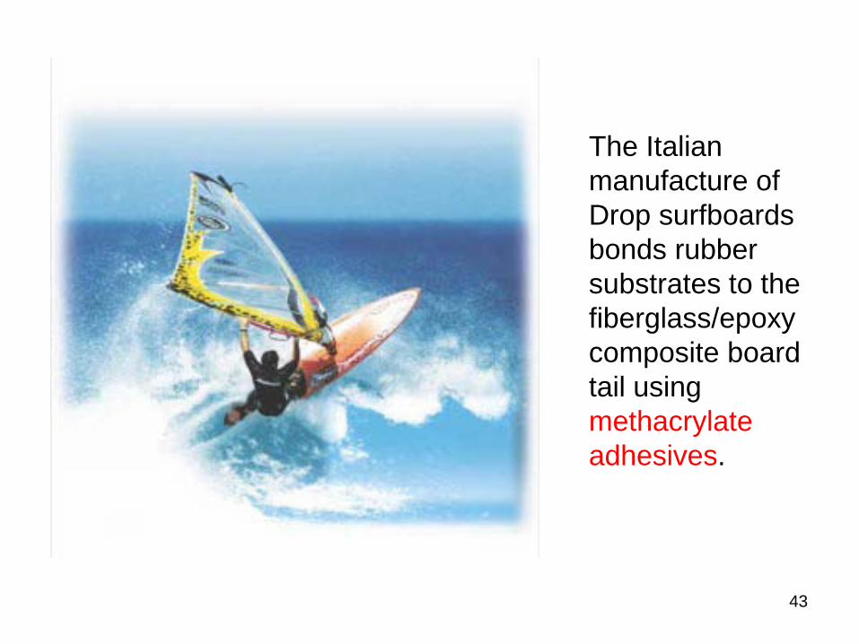
The Italian manufacture of Drop surfboards bonds rubber substrates to the fiberglass/epoxy composite board tail using methacrylate adhesives.
43
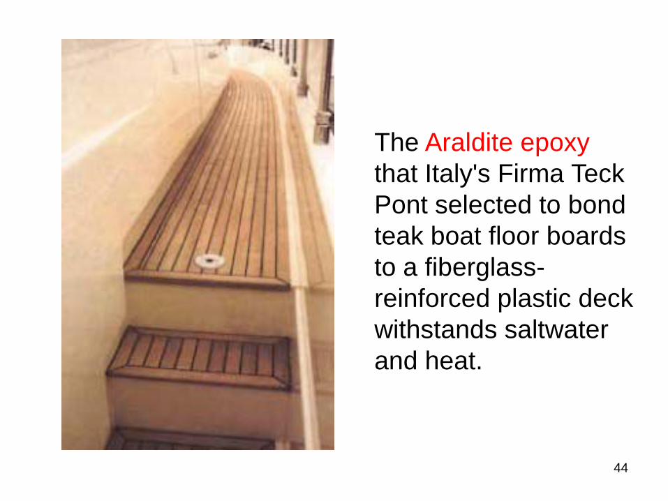
The Araldite epoxy that Italy's Firma TeckPont selected to bond teak boat floor boards to a fiberglass-reinforced plastic deck withstands saltwater and heat.
44
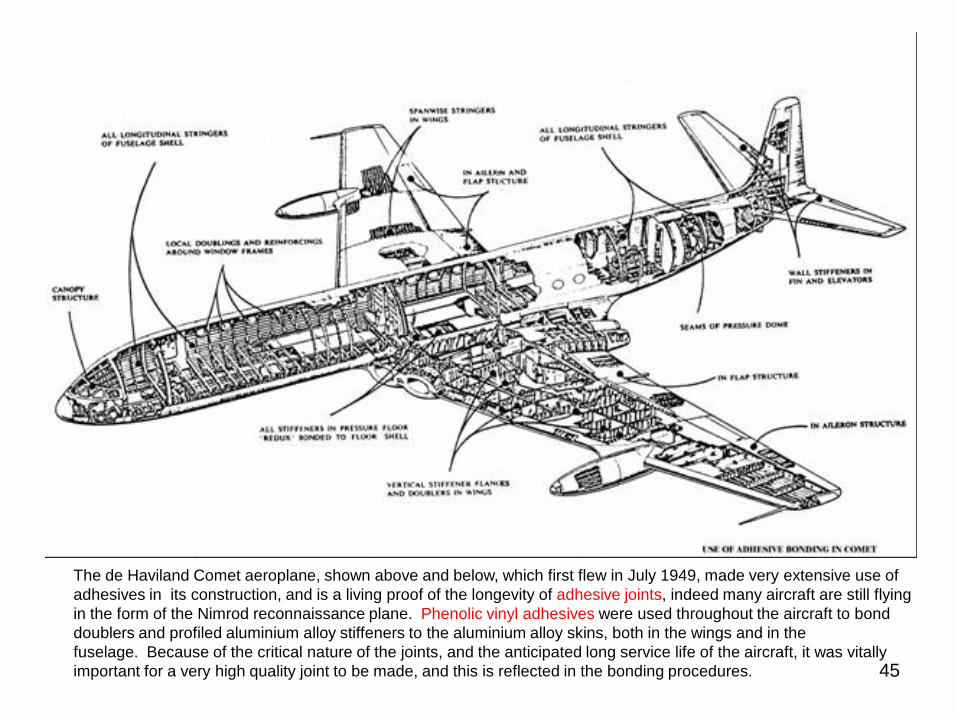
The de Haviland Comet aeroplane, shown above and below, which first flew in July 1949, made very extensive use of adhesives in its construction, and is a living proof of the longevity of adhesive joints, indeed many aircraft are still flying in the form of the Nimrod reconnaissance plane. Phenolic vinyl adhesives were used throughout the aircraft to bond doublers and profiled aluminium alloy stiffeners to the aluminium alloy skins, both in the wings and in the fuselage. Because of the critical nature of the joints, and the anticipated long service life of the aircraft, it was vitally important for a very high quality joint to be made, and this is reflected in the bonding procedures. 45
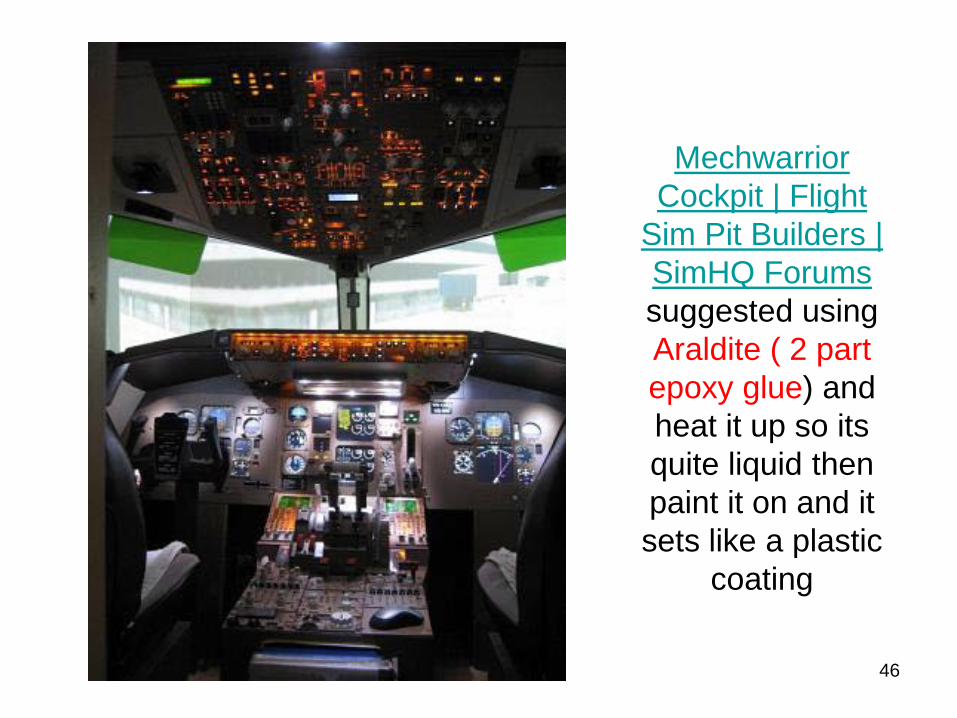
Mechwarrior Cockpit | Flight
Sim Pit Builders | SimHQ Forumssuggested using Araldite ( 2 part epoxy glue) and heat it up so its quite liquid then paint it on and it sets like a plastic
coating
46
4747
Bibliography
• “ Manufacturing processes for Engineering Materials”, by Serope Kalpakjian and Steven R. Schmid.
• “Manufacturing technology metal cutting and machine tools”, volume 1 by P. N. Rao

Thanks
48