Solid Suspension and Liquid Phase Mixing in Solid−Liquid Stirred Tanks
Upload
independentCategory
view
0download
0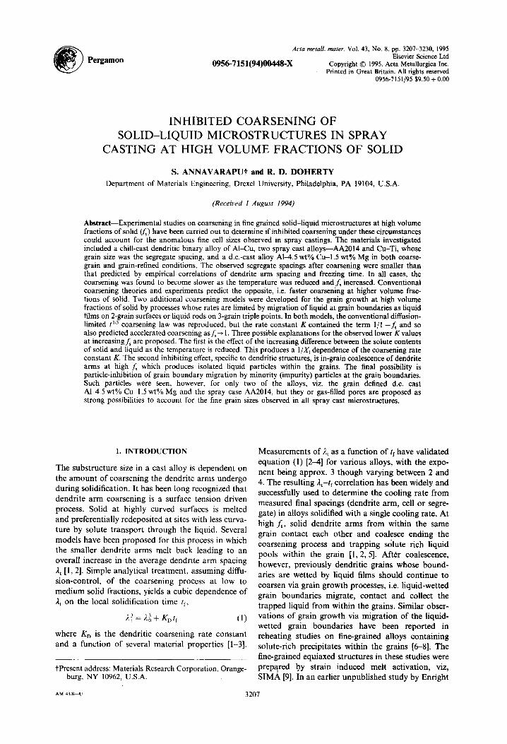
~ Pergamon Acta metall, mater. Vol. 43, No. 8, pp. 3207-3230, 1995
Elsevier Science Ltd 0956-7151(94)00448-X Copyright © 1995. Acta Metallurgica Inc.
Printed in Great Britain. All rights reserved 0956-7151/95 $9.50 + 0.00
I N H I B I T E D C O A R S E N I N G OF
S O L I D - L I Q U I D M I C R O S T R U C T U R E S IN S P R A Y
C A S T I N G AT H I G H V O L U M E F R A C T I O N S OF SOLID
S. ANNAVARAPUt and R. D. DOHERTY Department of Materials Engineering, Drexel University, Philadelphia, PA 19104, U.S.A.
(Received 1 August 1994)
A~tract--Experimental studies on coarsening in fine grained solid-liquid microstructures at high volume fractions of solid Ors) have been carried out to determine if inhibited coarsening under these circumstances could account for the anomalous fine cell sizes observed in spray castings. The materials investigated included a chill-cast dendritic binary alloy of AI~Cu, two spray cast alloys--AA2014 and Cu-Ti, whose grain size was the segregate spacing, and a d.c.-cast alloy A1-4.5 wt% Cu-l.5 wt% Mg in both coarse- grain and grain-refined conditions. The observed segregate spacings after coarsening were smaller than that predicted by empirical correlations of dendrite arm spacing and freezing time. In all cases, the coarsening was found to become slower as the temperature was reduced and f~ increased. Conventional coarsening theories and experiments predict the opposite, i.e. faster coarsening at higher volume frac- tions of solid. Two additional coarsening models were developed for the grain growth at high volume fractions of solid by processes whose rates are limited by migration of liquid at grain boundaries as liquid films on 2-grain surfaces or liquid rods on 3-grain triple points. In both models, the conventional diffusion- limited t '/3 coarsening law was reproduced, but the rate constant K contained the term 1/l -f~ and so also predicted accelerated coarsening as ~--, 1. Three possible explanations for the observed lower K values at increasing fs are proposed. The first is the effect of the increasing difference between the solute contents of solid and liquid as the temperature is reduced. This produces a 1/X 1 dependence of the coarsening rate constant K. The second inhibiting effect, specific to dendritic structures, is in-grain coalescence of dendrite arms at high f~ which produces isolated liquid particles within the grains. The final possibility is particle-inhibition of grain boundary migration by minority (impurity) particles at the grain boundaries. Such particles were seen, however, for only two of the alloys, viz. the grain defined d.c. cast A1~4.5 wt% Cu 1.5 wt% Mg and the spray case AA2014, but they or gas-filled pores are proposed as strong possibilities to account for the fine grain sizes observed in all spray cast microstructures.
l. INTRODUCTION
The substructure size in a cast alloy is dependent on the amount o f coarsening the dendrite arms undergo during solidification. It has been long recognized that dendrite arm coarsening is a surface tension driven process. Solid at highly curved surfaces is melted and preferentially redeposited at sites with less curva- ture by solute transport through the liquid. Several models have been proposed for this process in which the smaller dendrite arms melt back leading to an overall increase in the average dendrite arm spacing 2 t [1, 2]. Simple analytical treatment, assuming diffu- sion-control, of the coarsening process at low to medium solid fractions, yields a cubic dependence of 2t on the local solidification time /f,
,~ = ~0 ~ + tcDtf (1)
where KD is the dendritic coarsening rate constant and a function of several material properties [1-3].
tPresent address: Materials Research Corporation, Orange- burg, NY 10962, U.S.A.
Measurements of 2 t as a function of tf have validated equation (1) [2-4] for various alloys, with the expo- nent being approx. 3 though varying between 2 and 4. The resulting ),t-/f correlation has been widely and successfully used to determine the cooling rate from measured final spacings (dendrite arm, cell or segre- gate) in alloys solidified with a single cooling rate. At high f~, solid dendrite arms from within the same grain contact each other and coalesce ending the coarsening process and trapping solute rich liquid pools within the grain [1, 2, 5]. After coalescence, however, previously dendritic grains whose bound- aries are wetted by liquid films should continue to coarsen via grain growth processes, i.e. liquid-wetted grain boundaries migrate, contact and collect the trapped liquid from within the grains. Similar obser- vations of grain growth via migration of the liquid- wetted grain boundaries have been reported in reheating studies on fine-grained alloys containing solute-rich precipitates within the grains [6-8]. The fine-grained equiaxed structures in these studies were prepared by strain induced melt activation, viz, S IMA [9]. In an earlier unpublished study by Enright
AM 43/8~U 3 2 0 7

3208 ANNAVARAPU and DOHERTY: COARSENING OF SOLID-LIQUID MICROSTRUCTURES
6.0-
5.0-
8 4.0.
g • = ~:
8
2.0
1.0
0.0_
0 Fe.Cu, 1150°C [19,331 (Niemi & Courtney)
0 Fe-Cu, 1150°C[17] (Kang& Yoon)
0 Fe-Cu, 1150°C[33] (Yang& Nash) [] Pb-Sn, 185°C[19] (Hardy& Voorhees)
Sn-Pb, 185°C [19] (Hardy & Voorhees)
Co-Cu, 1290°C [17,33] (Kang & Yoon)
[]D~ ~E3
D@ D 0
T ] F
(9 []
[]
0.0 0.2 0.4 0.6 0.8 1.0
volume f r a c t i o n o f s o l i d (fs)
Fig. 1. Measured dependence of the coarsening rate constant Kp on volume fraction of solid during isothermal liquid phase sintering of various binary alloys [17-20, 33]. For ease of comparison the raw data was normalized to the measured Kp value forf~ ~ 0.6 (Fe-Cu data in Refs [17, 18, 33] normal- ized using Niemi and Courtney's K0. 6 value). In all of the data presented, volume fraction was varied by changing the composition. Intercept length (1) data converted using p3= 0.2391~ as computed in Ref. [19]. S v data in Ref. [18]
converted using p = 3 f JS v.
and Doherty at Sussex University [10], retarded endrite arm coarsening was observed at high f~ in samples reheated to just above the eutectic tempera- ture for extended times, though the reason was not determined.
Despite the general and successful use of the J.t-t correlation, recent studies on spray casting [11-13] have found that the usual correlation appears to overestimate, by 100%, the value of the segregate/cell spacing 2 t . Spray casting [13] consists of atomization of bulk liquid metal into a spray of droplets which consolidate to yield a net-shaped preform with a refined microstructure (equiaxed grains ~< 50/am). In most spray castings the segregate spacing is the grain size. Modeling work supported by measurements [11] suggests that the alloys solidify rapidly within a few milliseconds during droplet flight to an average f~ of 0.54).8 with a fine dendritic structure with an arm spacing of about 1/am. The remaining liquid soli- difies after consolidation in the deposit much more slowly over times of 10-200 s, i.e. over 99% of the solidification time, if, is spent at high f~ in the deposit [13, 14]. Segregate spacings predicted from the appli- cable 2t-t correlation for these local solidification times have been found to be 2-3 times those measured at the corresponding locations [11, 13, 15]. This mismatch indicates either a serious failure of the models for the spray casting process or some unexpected failure of equation (1) for this casting process in which alloys spend a prolonged period at high fs towards the end of solidification. Limited thermal measurements of tf within the deposit [13, 15] support the modeling results on solidification time
and are thus in conflict with the predictions of the standard coarsening theory. Given that one of the important advantages of spray forming is the fine grain size, this conflict needs to be resolved.
The failure of equation (1) may occur because the solidification conditions during spray casting differ from conventional casting processes in at least two ways: solid morphology and solid volume fraction. The dendritic structure of the rapidly but only par- tially frozen droplets arriving at the surface of the deposit is broken-up giving a spherical morphology to the solid. The small spheroidal solid particles derived from broken-up dendrites, as in stir casting [16], rapidly coarsen in the slowly cooled deposits-- with each surviving solid particle having its own orientation so becoming a "grain". Experimental studies, in stir-casting [6, 7, 16] and particle coarsen- ing [17-20], and theoretical modeling by several researchers [21, 22], however, have shown that at high volume fractions of solid coarsening of spherical grains continues to obey equation (1). This result has also been found in a range of experimental and theoretical analysis in solid-state coarsening [23, 24]. Experimental studies in Refs [17-20] present unam- biguous evidence that for spherical solid particles in a liquid matrix, the coarsening rate constant K increases sharply at volume fractions approaching unity, see Fig. 1. Boettinger et al. [25] confirmed this dependence by in si tu observations of the coarsen- ing of equiaxed grains in binary semisolids. Theor- etical and computer modeling of particle coarsening in a liquid-matrix [22, 26, 27] appear to accurately predict the measured variation of K withf~. The same does not hold for the solid-state case--many investi- gations, with the exception of Jayanth-Nash [28], have failed to discern a volume fraction effect in the much studied Ni-Ni3A1 system [29, 30]. A similar
E
i
1.00E- 15
1.00E- 16 "
1.00E-17 A A
o I
1.00E-I9 lid-st
1.00E-20
1.00E-21 . . . . . . . . . 773 1073
• vc.cd, p~] J N~.Ag,[~] (Warren) (Yang, Higgins & Nashj NbC-Fe, [32] • AI-4Cu, [36] (Safian-Weart) (Grant at al)
[ ] NbC-Co, [33] A AA2618, [36] (German) o N707, [36]
[]
9 o
1373 1673 1973 2273
isothermal coarsening temperature, ( °K )
Fig. 2. Reported dependence on Kp on isothermal coarsen- ing temperature during liquid-phase sintering (LPS) of various carbides [31-33]. Superimposed are data from Ref. [34] on Ni-Ag and from Ref. [36] on AI alloys. Eutectic or solidus temperature is 1233K in the Ni-Ag system, 853 K for A1-4 wt% Cu and AA2618 and 1623 K
in the VC~2o system.

ANNAVARAPU and DOHERTY: COARSENING OF SOLID-LIQUID MICROSTRUCTURES 3209
absence of volume fraction effect with a liquid matrix, though at low volume fractions of 0.25-0.45, was noted in a recent paper by Bender and Ratke [31]. Early coarsening studies by Warren [32, 33] and Sarian-Weart [34] on liquid phase sintering of car- bide particles in metallic liquids have clearly shown inhibited coarsening with decreasing temperature (or fs), Fig. 2. Two recent isothermal coarsening stud- ies--one by Yang et al. [35] on Ni-Ag and the other by Grant et al. [36] on spray formed AI alloys lend support to these observations of lower K values at lower temperatures, i.e. higher fractions of solid.
Given the apparently conflicting results from spray casting experiments where there might be some doubt on the actual coarsening times, the objective of the present paper was to study coarsening in isothermal studies. For this purpose various solid-liquid mix- tures were observed at medium to h i g h f , in order to establish the appropriate coarsening kinetics for use in modeling the spray casting process. A study of isothermal coarsening of both dendritic and spray cast microstructures at high f~ in the range 0.6-0,95 was conducted. Rapidly solidified material with a fine dendritic or equiaxed, spray cast, microstructure was reheated into the two-phase regime and isother- mally annealed to coarsen the structure over periods of time comparable to, or larger than, those preva- lent during solidification in spray castings. Compari- son was made, in the same alloys, with the dendrite spacings measured in conventional castings using the observed solidification times. Initial work was conducted using chill-cast dendritic A1-6.7 wt% Cu alloy and lower coarsening rates than in the con- ventional castings were first reported in September 1989 at the First International Conference on Spray Forming at Swansea, Wales [37]. In the current paper, we describe and discuss this coarsening behav- ior, and attempt to find models that might account for the observations. The Al~Su system was selected since it has been extensively studied and dendrite coarsening at low f~ is well characterized. Additional
studies were carried out on spray cast AA2014 (AI-4.5 wt% C u - l . 5 wt% Mg-0.4 wt% Fe) and spray cast Cu-4 wt% Ti and In-625 alloys to compare the coarsening results in spray cast microstructures with those for dendritic structure in the Al~2u alloy. A second comparison of the coarsening behav- ior of equiaxed and dendritic structures was con- ducted using d.c.-cast high purity A1-4.5wt% Cu- l .5 wt% Mg alloy prepared with and without the addition of a grain refiner.
2. E X P E R I M E N T A L M E T H O D S A N D RESULTS
2.1. Chill-Cast AI-Cu
A master alloy of A1-6.7 wt% Cu was remelted under an argon atmosphere and chill cast into a steel wedge mold. The solidification times at various sec- tions was measured by means of thermocouples and a data acquisition system at a sampling interval of 0.1 s. A plot of the observed dendrite arm spacing, ,~t, as a function of tf is shown in Fig. 3 for A1~5.7 wt% Cu. Previously reported data for alloys containing 2-10.2wt% Cu are superimposed [1-4]. These results indicate that the alloy used in this study, A l ~ . 7 w t % Cu, follows the correlation developed in the earlier studies. Samples were cut from the thin end of the wedge; sample mass was 0.10-0.15 g. The starting material at the pre-marked section had a 2 t of about 7 # m as shown in Fig. 4, with an expected initial tf of about 1 s from Fig. 3. The lowering of the coarsening rate with increased Cu content in the dendritic structure in this study should be noted.
The samples were then introduced into a pre- heated lead bath and isothermally aged at 550, 575, 600 and 625 + 2°C corresponding to f~ (the vol- ume fraction of solid) of 0.97, 0.91, 0.81 and 0.58 respectively (Lever Rule values). The sample tem- peratures were monitored by the means of a K-type thermocouple inserted about 2 mm into the sample. Various aging times, up to 8.5 min, were applied after
1000
.=.
'~ ~E • ~ ~t-tfcorrelation for A l - 4 . 5 w t % Cu [1]
• • _ / - • * 4 .5wt% Cu [1-4]
~:7.Ir . . . . . . -O " ~ • 2wt% Cu [2,4]
10 o Current s tudy, 6 .7wt% Cu
.,- O 10.2wt% Cu [21 "~ initial ~'t and t fof = , , • 5 .45wt% Cu [4] .~ c o a r s e m n g spec imens
1 I I n n l l n n l t n i q n ~ n n l i n t l l a U l l n I I h u l l n [ I n I n . . . . J
10 100 1000 10,000 100,000
local solidification time, tf (s)
Fig. 3. Experimental correlation of secondary of secondary dendrite arm, i.e. segregate spacing (2 0 with the local solidification time (tr) for conventionally cast Al~2u alloys [1~,]. Data from current study on
A1~6.7 wt% Cu is superimposed.

3210 ANNAVARAPU and DOHERTY: COARSENING OF SOLID-LIQUID MICROSTRUCTURES
Fig. 4. The initial dendritic structure in the samples of chill-cast A1-6.7 wt% Cu prior to isothermal coarsening.
Average secondary dendrite arm spacing (2t) ~ 7/tm.
which the samples were quenched in water. The samples required about 30 s to heat up from the eutectic temperature to the hold temperature and this time is included in the aging times. The aged samples were cut at a pre-marked section, polished and sub- jected to metallographic analysis after successive etches of picric acid and Keller's reagent.
Figures 5(a) and 5(b) show the observed structures of the quenched samples after hold times of 510 s at two different volume fractions of solid. Figure 5(a) depicts the structure after 510s at the highest temperature of 625°C (f~ = 0.58). The structure has coarsened significantly and comprises of low curva- ture solid interfaces in contact with a matrix of seemingly interconnected (quenched) liquid. A few large but apparently isolated liquid droplets that have curvature similar to the interconnected liquid are seen. We assume that these arise from sectioning through matrix liquid. In addition, a distribution of fine and coarse liquid droplets is present. The density of the small ones arise from a real distribution of fine droplets and not from a sectioning effect as confirmed by serial sectioning. Figure 5(b), material held at 575°C (f~ = 0.91), typifies the observed structure for samples held at 550, 575 and 600°C, and shows that the interdendritic eutectic within the grains seen in Fig. 4 has largely spheroidized, on remelting. It is evident that dendrite arms within grains have fully coalesced trapping the liquid as isolated droplets. The eutectic at the grain boundaries has apparently formed a liquid film with occasional large droplets at triple points, and with a few droplets close to but detached from the boundary film. However, most of the in-grain quenched liquid droplets appear to have coarsened little from the as-cast structure, Fig. 4. In addition, there is some evidence of migration of some of the grain boundary films. The large grains marked A and B have grown larger than their neighbors and a region depleted of fine droplets can be seen, appar- ently swept by the movement of the grain boundaries from left to right (as indicated by the arrows). In
Fig. 6(a), material held for 150 s at 600°C (f~ = 0.81), a large droplet apparently about to detach itself from the boundary is seen above the arrow indicating the direction of apparent grain boundary movement. Other large droplets, both attached and unattached to adjacent grain boundaries can also be seen. In addition, there is also a region of small grains with several large droplets mostly detached from the grain boundaries. At high magnification, some of the grain boundary films and liquid drops revealed the presence of a few fine Fe-rich plates which did not appear to affect the grain boundary film migration. Figure 6(b) shows a larger area of the structure in the same sample at a lower magnification revealing an unusual grain structure in the samples after aging. A layer of coarse grains can be seen near, but not at the sample surface, and these bigger grains contain a distribution of fine droplets seen in more detail in Figs 5(b) and 6(a). We assume that the non-uniform grain structure arose from the solidification structure of the cast wedge.
Fig. 5. Quenched-in microstructure of dendritic AI~.7 wt% Cu after isothermal coarsening for 8.5 min at: (a) 625°C (f~ = 0.57) and (b) 575°C (f~ = 0.92). Note the thicker "frozen liquid" at grain/cell boundaries and pockets of liquid in cell interiors. The "frozen liquid" in the lower f~ sample, (a), appears as a fine "dendritic necklace" because of the quench was not rapid enough to prevent a breakdown of the solid-liquid interface. In (b), grains A and B contain isolated frozen droplets from pinched-off interdendritic liquid and a droplet-depleted zone marking the area swept
by migrating grain boundary liquid film.

ANNAVARAPU and DOHERTY: COARSENING OF SOLID-LIQUID MICROSTRUCTURES
Fig. 6. Observed structures in dendritic A145.7 wt% Cu quenched after isothermal coarsening in solid+liquid regime. (a) Impending release of large droplet behind a migrating grain boundary liquid film; sample was aged for 2.5 min at 600°C (fs = 0.83); (b) Duplex grain struc- ture in samples evident at lower magnifications with fine grains at the surface and center, the coarse grains 100/~m away from the surface; sample was aged for 4.5 min at
600°C (fs = 0.83).
3211
~'- - - convent ional ~,t-tf correlation, [ 1,41 • 625°C (fs = 0.58)
. ~ 1E-13 -- / O 600°C ffs = 0.81)
t • 575°c ~s = 0.91) 8E-14 "-- / 1 8 3 /
~ 6E-14-- KD(10- m Is)=782 ~ 144
° / / ~ 4E-14 -
2E-14 I / A K= 19
0E+00 t -~ 0E+0 2E+2 4E+2 6E+2
time, tf (s)
Fig. 7. The dependence of segregate spacing (2t) on isother- mal coarsening time (tf) for chill cast A1~5.7 wt% Cu show- ing a reduction in the coarsening rate at lower temperatures, i.e. higher fractions of solid (f~). Also shown is the conven- tional correlation of segregate spacing, ~-t, o n solidification time, if. Values of K are marked for each isothermal data-set. Samples initially had a dendritic microstructure
with an average spacing of 7/~m (Fig. 4).
2.2. Spray Cast AA2014
The starting material was an AA2014 spray- deposited preform kindly supplied to us by Osprey Metals Inc. Although Drexel University has a pilot Osprey plant, it is not equipped to deal with the safety problems of fine aluminum powders. Samples were cut from the top 5 mm of the preform, and weighed 0.1ff4).15 g. The starting material exhibited a homo- geneous microstructure of equiaxed grains with precipitates of CuA12 (0 phase) and (Fe, Mn)3SiAI12 (~ phase) at the grain boundaries, as shown in Fig. 8. The interior of the grains was covered with solid-state precipitates of Si and AI4CuMgsSi 4 (Q phase), and
Quanti tat ive measurements of the segregate spac- ing (listed in Table 1) were made by counting the number of intercepts per unit length on an image analyzer, the same method used to determine the spacing in Fig. 4. The results are plotted as 2~ vs tt in Fig. 7 for a total solidification time of the initial 1 s (from Fig. 3) plus the hold time above the eutectic temperature. It is readily seen that the actual coarsening rates at 575°C (f~ = 0.91), 600°C (f~ = 0.81) and 625°C (f~ = 0.58) are below than those seen in the measured arm coarsening rates in conventional solidification, Fig. 3 plotted as the solid line in Fig. 7. The data at 550°C (f~ = 0.97) was not plotted since it showed a wide scatter between the coarse and fine grained regions, the data if plotted lay below that for 575°C (f , = 0.91). Each line in Fig. 7 shows a cubic dependence on t r but with a slope, i.e. a coarsening rate constant K significantly lower than correspond- ing to the 2t- t f correlation [viz. K D in equation (1)] from Refs [1-4]. Experimentally measured values of K (subsequently referred to as Ke~p) decrease by about 2 orders of magnitude as f~ increases from 0.58 to 0.91.
Fig. 8. The starting microstructure in spray cast AA2014 aluminum alloy samples, before isothermal coarsening in solid + liquid regime, showing fine equiaxed grains with an average grain size or segregate spacing (At) of about 17/~m. Grain boundary precipitates are 0 (CuA12) and ((Fe, Mn)3SiAll2) phases, and the disperoid in the grain interiors are Si and Q (Al4CuMgsSi4) particles produced by
a solid-state reaction.

3212 ANNAVARAPU and DOHERTY: COARSENING OF SOLID-LIQUID MICROSTRUCTURES
Table 1. Summary of measurements on various alloys reported in the current study
Time, tf(s)
solidification Segregate spacing, 2--secondary dendrite arm or grain diameter (#m) +
Alloy (processing) coarsening as-cast after isothermal aging in solid-liquid regime
AI-6.7Cu ~hill cast) 575°C 600°C 625°C 1.0 7~ 1.6 8 5.5 13 7.2 15
90 13 20 24 150 14 21 30 270 15 24 37 510 17 25 42
AA2014 (spray cast) 525°C 550°C 575°C 660°C 15# 175 60 25 26 28 90 26 29 31
150 30 32 35 990 34 45 53
Cu-4Ti (chill cast)
Cu-4Ti (spray cast)
In-625 (spray cast)
A I 4 . 5 C u - I . 5 M g (d.c.- cast w/o grain refiner)
A I ~ L 5 C u - I . 5 M g (d.c.- cast w. grain refiner)
2 6
32 48
375 885
14# 49
124 624 924
1824 3624
14,424
lO# 1800 36OO
5 20 33 38 69 98
975°C 13§
18 21 24 27
44
1304°C 15§
60
515°C 160 755 103§
2860 104 14,560 112
515°C 160 755 233§
2860 313 14,560 363
IO00°C
32 40 59 83
1314°C
75 90
1015°C
38 55
625°C
28 29 31 34 37 39 58 73
2 measurmeents for all A1-6,7 Cu data, for as-cast Cu-4Ti and for as-cast AI-4.5 Cu- l .5 Mg correspond to secondary dendrite arm spacing. Rest of 2 data is for grain diameter.
tComputed using preform solidification model by Mathur [11, 13]. :[:Initial secondary dendrite arm spacing size of samples subjected to isothermal coarsening runs. §Initial equiaxed grain size of samples (spray cast and grain refined d.c. cast) subjected to isothermal coarsening runs.
the average grain size was 17#m. The tr was esti- mated to be ~ 15 s using Mathur's preform solidifi- cation model [13] for AI-4.5wt% Cu sprayed at typical process conditions--gas pressure of 0.8 MPa and gas :metal ratio (GMR) of 2.0.
The samples were isothermally aged at 525, 550, 575, 600 and 625 -t- 2°C corresponding to f~ of 0.97, 0.93, 0.89, 0.85 and 0.65 respectively. Aging times, from 1/2 to 16min, were applied after which the samples were quenched in water and subjected to metallographic analysis.
Figures 9(a-c) show the observed structures of the quenched samples after hold times of 16min at various volume fractions of solid. Figure 9(a) is the structure after 16 min at 550°C (f~ = 0.93) and has a
structure that is representative of 525 and 575°C. The precipitates have dissolved on reheating and the eutectic 0 phase at the grain boundaries has melted and is concentrated at the triple points. Fine par- ticles ( < 2 p m ) of insoluble ct are located on the grain boundaries and in the grain interior close to the boundaries. As the hold temperature increased from 525 to 575°C, the fraction of liquid increased yielding similar structures with larger triple points. Figure 9(b) shows the structure after 16 min at 600°C (f~ = 0.85) where it seems that the liquid has pene- trated into many of the grain boundaries. The particles are often near the triple points and have coarsened to ~ 5 pm. The grain boundary ~ particles appear to have undergone coupled-phase coarsening

ANNAVARAPU and DOHERTY: COARSENING OF SOLID LIQUID MICROSTRUCTURES 3213
alloy at 625°C, i.e. low curvature solid interfaces in contact with a matrix of seemingly interconnected (quenched) liquid. Most of the second phase particles lying on grain boundaries have dissolved into the liquid but a few small isolated particles of ~ and 0 remain dispersed within the grains. These are likely to have solidified during cooling and were not expected to have been present during the 625°C hold; 625°C appears to be the above the ~t eutectic temperature in AA2014. In all the cases, the grains and the liquid pockets at triple points coarsened with increasing aging time, while the grain boundary films became thinner and straighter. The same coarsening behavior held true for the grain boundary ct particles at all temperatures except 625°C.
Quantitative measurements of the segregate spac- ing (listed in Table l) are plotted as 2~ vs t r, i.e. the total solidification time in Fig. 10. The total solidifi- cation time comprised the initial solidification time of 17 s and the time the samples were held above the eutectic temperature. The results again clearly show slower coarsening at the higher fractions of solid. The expected rate from conventional casting is plotted as the thick line. The data, within the experimental scatter, can be fitted to a cubic depen- dence on tf. This is questionable at the higher f~ values where the lines do not intersect the origin. However, for cubic kinetics the measured rate con- Stant Kexp decreases by an order of magnitude as J[ increases from 0.65 to 0.93.
Fig. 9. Observed microstructures in an equiaxed spray cast AA2014 aluminum alloy that was quenched after isothermal coarsening for 16 min at: (a) 550°C (f, = 0.93), (b) 600°C (f~ = 0.85), and (c) 625°C (f~ = 0,65). The micro- graphs illustrate different morphological regimes at differ- ent fractions of solid. Note in (a) and (b) the presence of coarse Fe-rich particles and pores on the grain bound- ary liquid films--faces, edges and triple points. Also note decrease in film thickness and grain boundary curvature
with decreasing f,.
as proposed by Higgins et al. [38], i.e. ct particles on grain boundaries were dragged by moving grain boundaries and coalesced with other ct particles at triple points formed by shrinking small grains [as shown by the arrow in Fig. 9(b)]. A dispersion of fine ( < 2 # m) 0 and medium-sized (2-5 lt m) ~t particles is observed in the interior of the grains. These disper- sions within the interior of the grains are believed to have evolved by the same mechanism of release of liquid droplets, possibly containing ct particles, by unstable sections of the moving grain boundary liquid films. Finally, at the highest temperature of 625°C (f~ = 0.65) the structure after 16 min is shown in Fig. 9(c). The structure has coarsened significantly and is similar to that observed for the cast A1-Cu
2.3. Spray Cast C u - 4 w t % Ti
In this case, the samples were taken from the base of a Cu-4 wt% Ti spray deposit made at Drexel in our Osprey facility [12]. The conventional 2 - t r correlation was established from wedge castings
g"
m ~ 4E-13 I
~ 3E-13
• ~ 2E-13
. ~ IE-13
m conventional ~.t-tfcorrelation, [ 1,41 • 550°C (fs = 0.93) O 575°C (fs = 0.89) • 600°C (fs = 0.85)
_ O 625°C (fs = 0 . 6 5 ) / / /
-- ~ " ~ K = 1 8 6 .. . . . .
_
KI= 80 "-"--
'~ 0E+O0 ] 0E+0 2E+2 4E+2 6E+2 8E+2 1E+3
time, tf(S) Fig. 10. The dependence of segregate spacing (20 on isothermal coarsening time (t 0 for spray cast AA2014 alloy showing a reduction in the coarsening rate at lower tempera- tures, i.e. higher fractions of solid (f0. Also shown is the conventional correlation of segregate spacing, )~,, on solidifi- cation time, t r. Values of K are marked for each isothermal data-set. Samples initially had an equiaxed microstructure
with an average grain size 17pm (Fig. 8).
3214 ANNAVARAPU and DOHERTY: COARSENING OF SOLID-LIQUID MICROSTRUCTURES
8E-13
~'~ t~ = 1564.732 + 747.632t! v - =
~ - 6E-13
4E-13
~ 2E-13 ! o
O E + O 0 ~ , , . . . .
250 5O0 750 1000
t ime, tf (s)
Fig. 11. Measured dependence of the dendrite arm spacing (2t) on local solidification time (tr) in conventionally cast
Cu-5 wt% Ti.
with embedded thermocouples to measure the local solidification time; this data is plotted vs 2 in Fig. 11. The starting material from the spray deposit exhib- ited a structure composed of Widmanstatten plates and precipitates of Cu4Ti and Cu3Ti, Fig. 12(a). The solidification structure was recovered by heating the material to 900°C into the single phase field and quenching. The solidification structure is composed of equiaxed grains and a number of twins which may have arisen from the heat treatment. Intercepts on twin boundaries were not counted during image analysis to determine the grain size. The average grain size, excluding twins, of the starting material was 13/lm, as shown in Fig. 12(b); tf was calculated to be 14 s using the Drexel model for spray casting [13]. Use of the experimental data for dendrite arm coarsening in Cu-Ti, Fig. 11, predicts that after 14 s of coarsening the dendrite cell size should be 22 pm which is significantly larger than the 13 #m observed in the spray cast structure. Similar observations of
Fig. 12. Microstructure of Cu-4 wt% Ti (a) in spray cast condition showing coarse Widmanstaten plates which obscure the grain structure, and (b) after solution treat- ment at 900°C for 10 min revealing the spray cast grain
structure; average grain size (2t) was about 13/~m.
inhibited coarsening in spray cast Cu-Ti have been previously reported [37].
The samples were inserted in stainless steel envelopes and isothermally aged in a lead bath at 950, 975 and 1000 + 4°C corresponding to volume
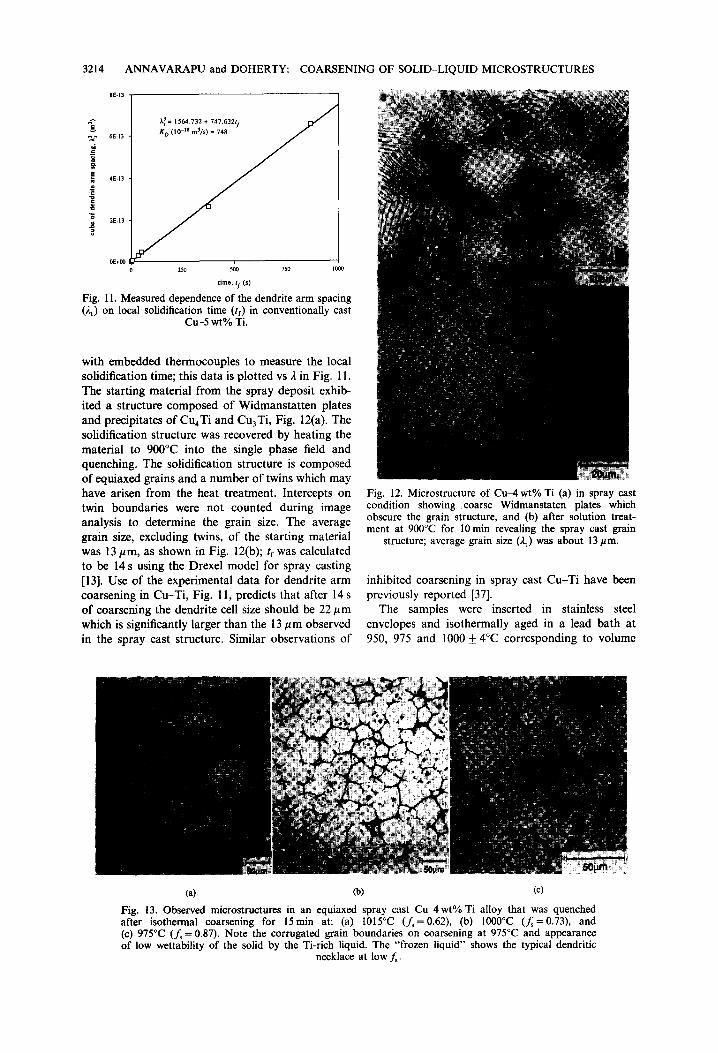
Ca) (b) (c)
Fig. 13. Observed microstructures in an equiaxed spray cast Cu-4wt% Ti alloy that was quenched after isothermal coarsening for 15min at: (a) I015°C (f~=0.62), (b) 1000°C (f~=0.73), and (c) 975°C (f~ = 0.87). Note the corrugated grain boundaries on coarsening at 975°C and appearance of low wettability of the solid by the Ti-rich liquid. The "frozen liquid" shows the typical dendritic
necklace at low f~.

ANNAVARAPU and DOHERTY: 3215
fractions of solid of 0.86, 0.73 and 0.62 respectively (as calculated from Lever Rule using the phase diagram due to Shunk [39]). Aging times up to 4 h were applied after which the samples were quenched in water and subjected to metallographic analysis.
Figures 13(a--c) show the observed structures of the quenched samples after hold times of 15 min at various volume fractions of solid. Figures 13(a, b), the structure after 15 min at 1015°C (f~ = 0.62) and 1000°C (f~ = 0.73), show that the eutectic at the grain boundaries has melted and the liquid was concen- trated at triple points yielding boundaries of rela- tively low curvature. A small number of Cu4Ti precipitates and liquid droplets can be observed inside the grains which appear to coarsen mar- ginally as the temperature increased. After 15 min at 975°C (i.e. f~ --- 0.86), an interesting structure, shown in Fig. 13(c), developed. The liquid was restricted to grain boundary triple points but grain boundaries between these triple points appeared to be highly curved and irregular. In addition, a large number of droplets and precipitates are dispersed inside the grains.
Quantitative measurements of the grain size inter- cepts (listed in Table 1) are plotted as 2~ vs tf in Fig. 14; tf comprised the initial solidification time of 30 s and the hold time above the eutectic tempera- ture. Again, the results show retarded coarsening at high fractions of solid. The expected rate from the measured chill castings is plotted as the thick line with the slope corresponding to KD; K~xp decreases by as much as two orders of magnitude asf~ increases from 0.62 to 0.86.
2.4. Spray Cast In-625
Through thickness samples were taken from a In-625 tubular (12 mm thick, 150 mm i.d.) spray cast
COARSENING OF SOLID-LIQUID MICROSTRUCTURES
7~" 1E-12 =2 ~ 8E-13
o~ 6E-13
4E-13
• ~ 2E-13
0E+00 0
time, tf (S)
m conventional ~,t-tf correlation, [Fig. 1 I ] [] 975°C (fs = 0.86) • 1000°C (fs = 0.73) O 1015°C (fs 0.62)
D(10-18 m3/s) = 750
3.0E+3 6.0E+3 9.0E+3 1.2E+4 1.5E+4
Fig. 14. The dependence of segregate spacing (20 on isothermal coarsening time (tf) for spray cast Cu-4 wt% Ti showing a reduction in the coarsening rate at lower tempera- tures, i.e. higher fractions of solid (f~). Also shown is the conventional correlation of segregate spacing, ).t, on solidifi- cation time, tt. Values of K for each isothermal data-set are noted. Samples initially had an equiaxed microstructure
with an average grain size of 13 pm (Fig. 12).
at the Osprey facility at the Navy's David Taylor Research Center (Annapolis, Md) and kindly pro- vided to Drexel for analysis. The spray cast A-if correlation was established by isothermal coarsening of spray cast samples under argon atmosphere in a glow-bar furnace from 5 min to 1 h at 1304 and 1314°C. The solidus temperature for the alloy is 1288°C and the liquidus 1349°C.
The starting material from the spray deposit exhib- ited a structure composed of equiaxed grains (average size = 15 #m) shown in Fig. 15. Figures 16(a, b) show the observed structures of the quenched samples after hold times of 1/2 h at volume fractions of solid of 0.75 and 0.85. The structure after 30 min at 1304°C (f~=0.85) and 1314°C (f~ --- 0.75), show that the eutectic at the grain boundaries has melted and the
Fig. 15. The starting microstructure in spray cast In-625 samples before isothermal coarsening in solid + liquid regime showing fine equiaxed grains with an average grain size, i.e. segregate spacing (2t)
of about 15 #m.

3216 ANNAVARAPU and DOHERTY: COARSENING OF SOLID-LIQUID MICROSTRUCTURES
Fig. 16. Observed microstructures in an equiaxed spray cast In-625 alloy that was quenched after isothermal coarsening for 30min at: (a) 1304°C (f~=0.85) and (b) 1314°C (fs= 0.75) reproducing
features seen in the other alloys.
liquid was concentrated at grain boundary edges and triple points. Note, however, that in many instances the solid-liquid interface is irregular and unlike the curvature-free boundaries seen in the Al~2u alloy.
Quantitative measurements of the grain size inter- cepts (data listed in Table 1) on isothermally aged spray cast samples are plotted as 3. 3 vs tf in Fig. 17; tr comprised the initial solidification time of approx.
1.6E-12 r - , ~ | - - c o n v e n t i o n a l ~,t-tf correlation
| for In-718 [391 ~ 1.2E-12[-- O 1314°C (fs =0"75) ~a | O 1304°C (fs = 0.85)
l KD(10-18 m3/s) = 400
/ ~ x = 200
"~_ 0.4E-12 K-- 120 ~
.~ OE+O0<~----~"~ I I I I o= OE+0 1E+3 2E+3 3E+3 4E+3
time, tf (s)
Fig. 17. The dependence of segregate spacing (20 on isothermal coarsening time (tf) for spray cast In-625 showing a reduction in the coarsening rate at lower tem- peratures, i.e. higher fractions of solid (f~). Also shown is the measured [39] correlation of segregate spacing, 2t, on solidification time, If for In-718. Values of K are marked for each isothermal data-set. Samples initially had an equiaxed microstructure with an average spacing of 15 #m
(Fig. 15).
10 s and the hold time above the eutectic temperature. As previously the results show retarded coarsening at high fractions of solid. The expected rate for In-718 castings [40] is plotted as the thick line with its slope corresponding to K o in equation (1); Kexo decreases by an order of magnitude as f~ increases from 0.75 to 0.85. The measured 2~-tr correlation for In-718 was used because the same was unavailable for In-625. In-718 has a composition close to that of In-625 and therefore, its solidification response can be assumed representative of In-625.
2.5. Direct Chill Cast A l -4 .5wt% C u - l . 5 w t % Mg
Samples of dendritic and equiaxed d.c.-cast AI-4.5 wt% Cu-l .5 wt% Mg alloys were obtained from a separate research study on hydrogen poros- ity in AI--Cu-Mg alloys involving Drexel Univer- sity and Alcoa Technical Center. Samples of both microstructures were isothermally annealed at 515°C (f~ ~ 0.95) for times of 45 min and 4 h.
The two grain morphologies had been produced by casting with and without grain-refining additions of Ti and B. Measured values of tf, as-cast den- drite arm spacing and as-cast grain size for the two cases were provided by Dr Jie Zou of Drexel Univer- sity. Both the as-cast samples had the same tf and hence the same average secondary arm spacing (2 ~ 75 #m). The grain refined sample was composed of equiaxed grains, average size ~ 103 pm, whereas the unrefined sample consisted of larger dendritic grains, average s ize~253/ tm [41]. The hydrogen content of the grain refined sample (0.27cm3/100 g

ANNAVARAPU and DOHERTY: COARSENING OF
or 0.24 ppm) was higher than that of the unrefined sample (0.06 cm3/100g or 0.05 ppm) yielding a signifi- cantly higher porosity in the former (7% as opposed to 0.13%).
Figures 18(a) and (b) show the observed struc- tures of the samples after hold times of 45 min at 515°C (f~ ~ 0.95) for the two morphologies. Figure 18(a) of the unrefined sample, showed a structure consistent with previous observations by Chien and Kattamis [5], and in the other aluminum alloys of this study viz. trapped solute-rich liquid droplets within non-equiaxed grains whose boundaries are wetted by liquid firms. On the other hand, in the grain-refined sample [Fig. 18(b)], all the liquid was concentrated at the grain boundary triple points yielding boundaries of relatively low curvature. Thus, the grain refined sample after coarsening in semisolid state developed an equiaxed grain structure like that of spray cast- ings. The grain refined samples exhibited coarse pore clusters of ~,20/~m at a few grain corners but these were spaced so much further apart than the grain size that they did not appear to have affected the grain coarsening.
Quantitative measurements of the grain size inter- cepts (data listed in Table 1) are plotted as 2~ vs tf in Fig. 19. Again tf comprised the initial solidification time of 156 s plus the hold time above the eutectic temperature. Note that at short times grain size
SOLID-LIQUID MICROSTRUCTURES 3217
m conventional ~,t-tfcorrelation, [39]
• 515°C Us = 0.95), DC-cast ,'~ [] 515°C (fs = 0.95). DC-cast with grain refiner
5 E - 1 1 - J ~ - • .U []
• 4E-1 1 --
~ ~ ~ 0
~ (10 -18 m3/s)= 1980
az 3E-11 I
~ 2E-l l
o o u 1E_ll I
" ~ 0 / r't [ ] K = 2 1 1
.~ 0 3.0E+3 6.0E+3 9.0E+3 1.2E+4 1.5E+4
time, tf (S)
Fig. 19. The dependence of segregate spacing ()~t) on isothermal coarsening time (tf) for d.c.-cast A1-4.5 wt% Cu-l.5 wt% Mg showing a reduction in the coarsening rate constant K at high f~. Note that the inhibition is significantly stronger in the grain refined samples, The initial segregate spacing was 75#m in both cases. Initial grain size was 253 am in the untreated
sample and 104/am in the grain refined sample [39].
exceeds the secondary dendrite arm spacing, but slower coarsening over time results in smaller grain sizes than secondary arm spacing predicted by the thick line. The thick line corresponds to the 2t-tf equation for conventional casting processes [41]. Once again, the results show retarded coarsening for both morphologies at high f~ compared to the con- ventional dendrite coarsening equation. It should be noted that the rate constant for the grain refined sample decreased by two orders of magnitude while that for the unrefined sample decreased only marginally.
Fig. 18. Observed microstructures in a d.c.-cast [39], high purity A1-4.5 wt% Cu 1.5 wt% Mg alloy after coars- ening for 45rain at 515°C (fs~0.95) showing: (a) coarse grain structure in the un-grain refined (i.e. dendritic) sample and (b) a finer equiaxed structure in the grain
refined sample.
3. DISCUSSION
The results of the entire set of isothermal coarsen- ing experiments described in this paper are summar- ized in Fig. 20 by plotting the measured coarsening rate constant Kexp, normalized by the measured den- dritic coarsening rate constant KD, vs f~. It is clear from Fig. 20 that as f ~ l in all these alloys, /~,p decreased monotonically but at differing rates. Based on the micrographs presented earlier in this paper, we can identify in these experiments four different
0 . 6
~ 0.5
"~ ~1~ 0 .4
~ ~ o ~
m
• AA2014 A / 10 • /
/ - Cu-4Ti
1n625 / , / / / / J
O • /
0.1 - - .~o ~ - ~
o I , ' - ' 1 - - ~ I i I 1 .0 0.9 0.8 0.7 0.6 0.5
fraction of solid (fs)
Fig. 20. Plot summarizing the dependence of the normalized coarsening rate constant (K/Ko) on the. fraction of solid (f~)
observed in this study.

3218 ANNAVARAPU and DOHERTY: COARSENING OF SOLID-LIQUID MICROSTRUCTURES
structural regimes for the coarsening in the mushy zone:
(i) dendrites surrounded by liquid, (ii) spherical grains dispersed in liquid,
(iii) impinged grains/spheroids with liquid films at the grain boundaries, i.e. liquid concentrated at grain boundaries, grain edges and triple points, and
(iv) isolated liquid droplets within dendritic grains following in-grain coalescence.
These different morphologies appear to each require a separate analysis. A large part of the morphology differences arises from the increase of volume fraction of solid for a given alloy compo- sition as the temperature falls. There is, however, a second important variable in the kinetics of coarsen- ing, viz. the composition difference between solid and liquid. This difference usually increases as the temperature falls and its effect must be included in any discussion on the effect of fraction solid for a given alloy, as studied here experimentally. The effect on coarsening of these two aspects derived from the solid-liquid structure are considered below.
3.1. Composition of Solid and Liquid
This effect is much better understood than the morphology effects. It is well established and applies to all coarsening processes, and will, therefore, be briefly discussed first. As is well known, the atomic fraction of solute in liquid changes from the equi- librium (phase diagram) value under a flat inter- face, Xj, to that under a radius of curvature p, Xj(p), which is given by the Gibbs-Thomson (G-T) equation [42]:
Xl(p) = XI ( l 27V ( 1 - Xt "] - pER T (X, -- X3 ] (2)
where p is considered positive for a solid sphere surrounded by liquid. X, is the atomic fraction of solute in the solid (with k = Xs/Xl), V is the molar volume of the liquid, ~ is the solid-liquid interfacial energy, E is the Darken coefficient [21-24, 35,42] which accounts for the non-ideality of the solution and equals (1 +O lng/c~ lnXs). The G - T relation, when applied to the process of Ostwald ripening of spherical solid particles in a liquid matrix, yields the equation derived by the standard LSW analysis [42, 43] for the mean radius after time t of coarsening, Pt, of a dispersed phase which is not a pure element but a solution content As.
P~ p3 o H- t, 9 - - ~ - ) \x , - x , / \ x , - x , /
tf (3)
where b~ is the solute diffusion coefficient in the liquid, V is the molar volume of the solid and X~ < X~ (i.e. k < 1). Note that E is absent from equation (3) since for a liquid with variable activity coefficient, g,
(i.e. E :~ 1), the actual diffusion coefficient, D, is a product of a coefficient determined by atomic mobil- ity and the Darken parameter E.
Equation (3) shows an acceleration of the coars- ening rate with decreasing temperature over the classical LSW rate by two terms which arise from two different sources. The first term given by Xj(I - X I ) / X I - X , , is derived directly from equation (2) and enhances the G - T change of solubility. The second term given by 1/(t"1 - Xs), is a coefficient that reflects the reduction of the amount of solute to be transported from a melting to a growing interface as temperature is reduced. This differs from the factor derived by Chaix et al. [44] which equals 1/(1 - X~) because they considered the F e ~ u system as the model where X~--+I. The solute that must be transported for coarsening decreases from all atoms in the solid for a pure solid to the difference between the two phases (a smaller value) when the solid and/or liquid phases are solutions. This second effect has clearly been illustrated in previous work by Kang-Yoon [17] and Ferrante [45]. However, the data on coarsening from various studies such as Niemi-Courtney [18] and others [17, 19] are for vari- ous volume fractions of solid at constant tempera- tures where the composition of the solid and liquid phases remained unchanged. In the absence of the complicating effect of changing composition as the fraction solid changes, these well-characterized iso- thermal coarsening experiments clearly showed a significantly enhanced coarsening rate (by about 8 times over the range studied) at larger solid frac- tions in the range 0.24).95. Yang et al. [35] show that the inclusion of these two accelerating terms into existing models--LSEM, i.e. Lifshitz-Wagner Encounter Modified [46], BWEM, i.e. Brailsford- Wynblatt Encounter Modified [35] and GV, i.e. Glicksman-Voorhees [26] appears to yield a better match With experimental results in Refs [17-20].
When X, > Xl (i.e. k > 1), equation (3) takes the following form
( ) x - - tf. (3a)
When X ~ I , then ( I - X O - ) I , e ,--) l so that (X I - X , ) 2 ~ 1 and equation (3) reduces to the usually quoted relationship given below
( 8 DI • VXI "] P?=P~'+\ 9RT /tf" (3b)
For solidification coarsening in alloys where the partition coefficient k is a constant, a more useful version of equation (3) is
3__ / 8 D l ' r x ~ ( ]__ - XI p , t - - p 3 + \ 9RT j\X,(l_k)2/tf f o r k < l (3c1
/8Ol];VX~[ e I - - X I "~ p ~ = p ] + ~ - ) i ~ l ( k _ - - i l ) 5 ) t r f o r k > l . (3d)

ANNAVARAPU and DOHERTY: COARSENING OF SOLID-LIQUID MICROSTRUCTURES 3219
For very dilute alloys where (1- ) ( i ) - - -1 , equations (3e), (3f) or (3g) are applicable.
'I/8D'TV'~( X,(1 1_ k) 2) p ~ = p 3 + ~ 9-9-RT-) tf f o r k < l (3e)
. /'8D, yV'~( 1 ) X , ( k - 1) 2 p ~ = p 3 + ~ y ) tf f o r k > l (3f)
p~ = p3 + K,,tf (38)
where
and
K,, = \ ~ - k Y ] for k < l
\ ~ - J X,(k - l) ~ for k > 1.
The reciprocal dependence of coarsening rate on the alloy content, in equations 3(c,e,g), is well established experimentally for alloy systems where k < l, e.g. the data on conventional dendrite coarsening in A l ~ u shown in Fig. 3 in Refs [1-4]. This rate dependence on I/X~ will clearly lead to a steady fall in the expected coarsening rate for a given alloy composition as the temperature falls and the fraction solid, f,,, rises. It may be noted that for alloys in which the partition coefficient k > 1, the contribution from ( k - 1) 2 term will compensate the decrease in X l as the temperature falls and f~ rises. However, there are no exper- imental reports, known to the present authors, of data that would allow this prediction to be tested.
In addition, any impurities in the alloy that can lower the equilibrium partition coefficient k will increase the amount of solute that must be transported across the liquid film for grain growth. Applying this to equation (3c), it is clear that the (1 - k ) 2 term in the denominator will increase and thus decrease K. There is some evidence such behavior in the liquid phase sintering of carbide particles. Warren reported 3- and 2-fold reductions in K upon addition of 5 wt% WC and 3.75 wt% NbB 2 to NbCqSo during LPS at 1420°C; WC is known to reduce the solubility of NbC in liquid Co [47]. He had previously observed similar trends in LPS of WC~Co with additions of NbC, TaC and C [48]. Additional support is avail- able from Lassner and Schreiner [49] who observed a refinement in WC grain size upon LPS in Co with VC impurity of 200 ppm. The same material, however, upon milling prior to sintering, yielded a coarse grain size. Lassner [49] suggested that the impurity concentration in the un-milled sample was sufficient to cover all grain boundaries and inhibited coarsening by reducing surface wettabil- ity and interfacial solute transport. The milled
sample, on the other hand, contained fractured and thus fresh, impurity-free surfaces which per- mitted wetting by Co liquid and did not inhibit interracial solute transport. Fukuhar-a and Mitani's study [50] of TiC-TiN sintering in 30% liquid Ni showed a similar suppression of K with increasing N content; K decreased 5-fold from pure TiC to TiC0.sN0. 2. There are two issues that must be answered: (i) What is the cause/mechanism for this reduction of the partition coefficient k in the pres- ence of a second solute species? and (ii) To what extent can k be reduced? Since a solid-liquid inter- face is not atomically smooth, it appears unlikely that the removal of solute atoms from the solid can be hindered due to the presence of other species even if present as a stable mono-atomic layer, from Sarian-Weart [34], on the solid-side of the solid-liquid interface analogous to a passivating oxide film. Besides, such a suppression cannot be to the extent of zero solid solubility. Consequently, this does not appear a viable reason for the observed dramatic decrease in K as f~--, 1.
One other term in equation (3) that can vary with temperature is solute diffusivity in liquid D~ since D = D o e x p ( - QD/RT); the magnitude of this decrease in D 1 will be determined by the value of QD- As a rule, QD (in cal/mol) is approx. 10 times the melting temperature (in K) of the solute element). Comparison of estimated values shows that D~ increases by a factor of 1.5 as the temperature increases from (that corresponding t o ) ~ = 0.9 to f~= 0.5 in AI~Su, Cu-Ti, In-625 or Fe-Cu. This retardation of coarsening accruing from this decrease in D~ is much less than an order of magnitude and cannot account for the observations in this study. On the other hand, this effect may contribute sig- nificantly to the observed increase in K with coarsen- ing temperature by Kang-Yoon in F e ~ u and Co-Cu [17]. The retardation of coarsening due to the chemical terms in equation (3), as the temperature falls and the fraction solid rises in the alloys studied here, applies to the diffusion-limited coarsening kinetics for all the morphologies discussed in the following section.
3.2. Coarsening in the Different Microstructural Morphologies
3.2.1. Dendrite to sphere comparison
The simplest morphology for modeling coarsen- ing should be the case of spherical solid grains in a medium fraction solid, f~<0.5. Here the simple results of equation (3) should apply, though expressed in terms of the inter-particle spacing, 2, using 23= o~p3/fs where a is a numerical constant of order I, from Mortensen [51]. This substitution yields
2~ = 2~ + \ - f - - / t r . (3h)

3220
By comparison with equation (1) we see that the coarsening rate determined by particle spacing, K D will be given by:
K o \ f , ,] (4)
This is an interesting result that arises from the significant difference between the study of coarsening by measurement of the average particle radius and that by measurement of the inter-particle spacing. The former method is usually adopted for precipitate coarsening [42] while the latter method is the con- ventional method in most solidification studies. It should be noted that the simple analysis, leading to equation (4), ignores at least two important effects. One, the more complex geometry of a dendritic structure where the mean curvature varies continu- ously between the dendrite tip and other locations. Two, the much discussed reduction of the diffusion distances by an increase in the volume fraction of the coarsening phase. In the simple case of spherical particles, this effect leads to a predicted increase of K 0 as f~ increases; For example, Voorhees and Glicksman [26] found that K s rises by a factor of 2 as f~ increased for 0.2 to 0.4 and by a factor 10 as f , increased from 0.2 to 0.95 (Fig. 1), the regime of interest here. As noted previously, this expectation of accelerated coarsening with increasing fraction solid has been clearly demonstrated experimentally for coarsening at constant phase composition on a range of Fe--Cu, Sn-Pb and Co-Cu alloys by Refs [17-20] (see Fig. 1). However, the only partial suc- cess of this prediction for the solid-state coarsening of Ni3A1 in Ni [28-30] should be noted. Examples of
ANNAVARAPU and DOHERTY: COARSENING OF SOLID-LIQUID MICROSTRUCTURES
the reduction of diffusion distances as f~ increases are discussed below for different morphologies.
3.2.2. Free spheres to compacted spheres
As fs increases beyond about 0.74 (the packing factor for close-packed structures of spheres of equal size), the individual solid particles can no longer exist as spheres but they must be compacted into a conventional polycrystalline grain structure subject to normal grain growth. Microstructural examples of this are given in Figs 9, 13, 16 and 18(b). The subject of grain boundary migration and grain growth with liquid film wetted boundaries is outlined here although it was previously discussed in a recent conference on grain growth [8, 37].
Liquid film migration limited grain growth--one- dimensional analys&
The simplest case is that of a liquid film on a grain boundary surface for a spherically curved surface of radius r, Fig. 21. There will be a composition differ- ence AC, in atoms of solute per unit volume across the film, from the negatively to positively curved solid-liquid interface given by:
AC = AX= 2 ( X ~ ( p ) - ) ( i ) V~ V~
47V X~(1-X~) f o r k < l (5) p R T V , (X, - X~)
where Vj is the atomic volume in the liquid. For a liquid film thickness, 6, and a liquid diffusion
direction of film ~ m i g r a t i o n
(mprecifr~:t ing ~N '~N~ ion)
[ I I direction of
p ,,~ ~ ~ diffusive flux of Xl~-p) ~.'~4~ , ~ B atoms across the ~ ] Xl(+p) liquid film
G
2 ~
2~Vm
Q'I ' i i i i i i i p , ,
ic ' I D I x s xL(+p) x L x&~)
X (at. % of B)
(a) (b)
~('9)
~(+p)
Fig. 21. (a) Schematic of a grain boundary liquid film on a grain edge or face with one-dimensional diffusive flow, and (b) free energy of the solid and liquid phases corresponding to (a).

ANNAVARAPU and DOHERTY: COARSENING OF SOLID-LIQUID MICROSTRUCTURES 3221
coefficient, D~, the flux of solute J down this gradient is given by equation (6):
D l AX a - (6)
The velocity of the liquid film wetted grain boundary, vb, towards its center of curvature is given in turn by equation (7):
j r , Vb - - - (7)
(x , - x , )
so that
D, 47 V X~(I - Xj) (7a)
Vb -- b p R T ( X 1 - - Xs) 2
27 - / ~ b (7b)
P
where
grain boundary film thickness 6 remained constant. It is important to note that ~ must be a function of 2, since 6 multiplied by grain boundary area per unit volume corresponds to the volume fraction of liquid f , i.e. 6 • 22t23 ~ f or 6 = 2(1 - f~) . Since the volume fraction of solid essentially remains constant for isothermal coarsening (apart from the small increase due to the G - T equation), we can substitute for 6 by 2 (1 - f~) , in equation (8) thus recovering in equation (10) the cubic dependence of 2 on time t, seen in Figs 3, 7, 10, 14, 17 and 19.
, ~ = ,~0 ~ + K~B~t (10)
where
(12 ,7v) (x,(1-x,)) for k < 1.
(10a)
D~ 2VXj(I - X l ) /~b = (7C)
6 R T (X~ - X,) 2
and is the mobility of the liquid-wetted grain bound- ary film under a capillarity pressure of 27/p. This result is the same as that for curvature-driven liquid film migration in DIGM [52-54]. Using the simplest model for normal grain growth (e.g. [42]) equation (7b) can be used to obtain a model for grain growth, equation (8), yielding a square dependence of grain size or segregate spacing on time. The simple model has:
d~ 2y T t = ~b = m ~ (8)
where a and fl are constants that, for a steady-state grain size or segregate spacing distribution [55], relate the change of the mean grain size or spacing to the mean velocity which, in turn, is determined from the mean grain size or spacing. This, on integration, yields equation (9)
2~ = 2o + K~BFt (9)
where
=(8DITVX~(X,(I - XI)~ K~"F \ ~ f l ~ J \(X~-~--X~J for k < 1 (9a)
KcB ~ is the coarsening rate constant for the migration of a grain boundary liquid film. The 2~-t relationship in equation (9) will, however, only be valid if the
For dilute solutions, with a constant partition coefficient, k, this becomes:
, ) K;BF = \ ~ - ~ - - / / ~ Xj(1 - - k ) 2 for k < 1.
(10b)
Equation (10) nicely illustrates the two effects of coarsening at different temperatures in a given alloy system. As the temperature falls the solute content of the liquid, X l, rises causing the fall of coarsening rates observed in this study. On the other hand, the fraction solid, f~, rises towards 1 giving a very rapid increase in coarsening rate, similar to that predicted by Voorhees~l icksman [26] and Yang-Nash [20], but this type of increase was not seen in the present studies. The predicted acceleration in K'~Bv with increasingf~ from the term in 1/! - f s arises, as in the detailed Glicksman-Voorhees coarsening model [26], from the reduction in diffusion distance which, in this case, is the grain boundary film thickness, ft.
One aspect of the reciprocal relationship between film velocity, Vb, the local boundary thickness, 6, derived in equation (7) was commonly seen in this study. This is the tendency of a migrating grain boundary liquid film to release, as a liquid inclusion, any region with a locally enhanced thickness. A schematic of this feature that has been previously observed in liquid phase sintering [18, 56, 57] is given in Fig. 22. A large liquid inclusion captured and
Fig. 22. Schematic illustrating capture and release of isolated liquid particles by a migrating grain boundary liquid film.

3222 ANNAVARAPU and DOHERTY: COARSENING OF SOLID-LIQUID MICROSTRUCTURES
wetted by a moving grain boundary may not have sufficient time to redistribute the liquid along the boundary as the boundary moves through. Conse- quently, if the boundary is migrating fast enough the inclusion can be released, i.e. left behind if criteria for closure of the neck are satisfied. From Kang et al.
[58], criterion for closure of the neck connecting the liquid droplet to the migrating boundary can be written as
A # = T V ( ~ 1 2 ) < 0 r 2 (11)
where r~ and r2 correspond to the internal and external radii of curvatures of the neck, and Pl is the average radius of curvature of the grain boundary (i.e. one of the two principal radii). Experimental observations, Fig. 6(a), clearly show this process, thus resolving the problem of persistent isolated liquid inclusions, despite extensive grain growth, in regions swept by grain boundaries. As the grain size rises, the average radii of curvature of the boundaries, p in equation (7), and the velocity of boundary migration will both fall. At sufficiently slow rates of boundary migration, this process of releasing liquid inclusions into the growing grains should end since the captured droplet will have time to spread itself along the boundary. Detailed studies of the grain morphology in two phase (solid + liquid) systems [8] have shown that as the grain size increases the frequency of liquid droplets trapped in the grains does fall; this effect is also seen in regions with small grains in Fig. 6(b). Similar observations have been reported in liquid phase sintering of Fe-Cu powder compacts by Kang-Azou [56] and Hwang et al.
[57] who attribute this feature solely to rapid grain growth of strained material during reheating. In the present study, the liquid film was also made thicker in places by the presence of coarse Fe-rich plates and thus destabilized resulting in the release of the ob- served droplets.
A further important microstructure effect seen in the present work and recognized in previous studies
[8, 17, 52, 53] is curvature driven transport of liquid along the grain boundaries in the two-phase solid plus liquid microstructure at high volume of fractions solid. This is illustrated in Fig. 23 showing that even for the usual condition of complete wetting of the grain boundaries by liquid, 2~s~ ~< 7gb, typical in metals [59], at highf~ the local curvature at the 3-grain triple points will be much larger than that arising from grain size differences. The higher curvature, i.e. the smaller radii p, results in solute transport from the liquid films at the boundaries between 2 grains to 3-grain triple lines or edges. A further application of this effect will, at small enough values of the fraction liquid (relative to the grain size), continue the transfer of solute and thus liquid from the 3-grain edges to 4-grain corners. This is universally observed during liquid phase sintering in the various studies cited earlier in this paper, viz. Refs [17-20, 52, 53]. This concentration of liquid at triple points is exacer- bated if the hold temperature is below the wetting transition temperature which, according to Straumal et al. [60], is an inverse function of the grain boundary energy, ~gb. This is illustrated by the structure in Fig. 13(c) corresponding to isothermally coarsened Cu-6wt% Ti at 975°C for 15min. The liquid mor- phology indicates that in Cu-6 wt% Ti below 975°C 2~s~ > )'gb even for high angle boundaries, so that liquid no longer penetrates along the grain bound- aries. As a consequence, the liquid prisms at triple points are larger than expected for good wetting, thus increasing diffusion distance across the liquid film and reducing K. A second consequence of poor wetting is that the liquid film thickness ~ can decrease below a critical value creating a solid-solid grain interface which would, intrinsically, be very mobile since migration of such a boundary only requires atom transport across a disordered interface. In the condition of high grain boundary mobility with liquid pockets at the triple points, grain boundary cur- vatures will be eliminated (see Figs 5 and 9) [38]. However, the observation of corrugated grain bound- aries in Fig. 13(c) suggests some local inhibition of
,"'" ' Os ",XI(~*) " O / \ t .
XI (-O ' II , ', D I ~
xt (-r) > Xt (~) > XI (+R)
Fig. 23. Flow of solute to the triple point at high f~ via solid and liquid diffusion causing the removal of grain boundary curvature and imposition of curvature on the solid-liquid interface at
the triple point.

ANNAVARAPU and DOHERTY: COARSENING OF SOLID-LIQUID MICROSTRUCTURES 3223
grain boundary motion due to pinning, for example, by particles.
Liquid film migration limited grain growth--two- dimensional analysis
Higgins et al. [38] have proposed an analysis for coupled coarsening of a two-phase structure which had all of the minority phases at grain corners. The process of coarsening of the grains and grain corner particles was analyzed as curvature-driven migration of second phase inclusions at grain corners. The principle of this analysis is that in a situation such as that shown in Figs 24(a-c), 3-grain boundaries meeting at an edge or 4-grain edges meeting at a corner, can for a mobile grain boundary meet at angles different from the required values of 120 ° (for edges) or 109 ° (for corners). For non-equil ibrium angles, local force balance will impose a differen- tial curvature on the sides of the inclusion (which, in the present case, is a liquid droplet). The difference in curvature of different faces of such an inclusion then leads to a solute flux across the droplet result- ing in migration or drag of the liquid droplet under the influence of unbalanced grain boundary ten- sion. This methodology is instantly applicable to the present situation of tubes or prisms of liquid at 3-grain edges or tetrahedrons of liquid at 4-grain corners, Figs 24(d, e).
The equilibrium angle of 120 ° for a 3-sided grain in two dimensions can be reduced to 2th = 60 'J by the presence of wetting liquid tubes/prisms at the triple
A
O
P2 IntriangleOAO', Cos~ - P2" Pt
Fig. 25. Construction to derive the dependence of the dihedral angle ~b on the radii of curvature of the growing and receding solid-liquid interfaces at a triple point in a
3-sided grain depicted in Fig. 24.
points if all grain boundary curvature is concen- trated at the solid-liquid interface, Fig. 25. There will be two radii of curvature at the triple points, p~ and P2. In the triangle OAO' the angle O 'OA is q~, so we obtain:
p: cos Pl - 1 - cos~" (12)
When 2~b = 60", P2 is 7.5pt. When 2~b = 120 °, the ratio of the radii has the expected value of 1, while
A
~ .... F j
D
A
(e)
J Fig. 24. The removal of grain boundary curvature by particles (solid/liquid) at the grain boundary triple points in a tetrahedral grain ABCD, (b) section ACF through (a), (c) section ACF through the tetrahedral grain with solid particles at all four corners after Higgins et al. [36], (d) representation of (c) for liquid particles at the triple points, and (e) enlarged view of the liquid film wetting the grain boundary triple
point in (d).
AM 43/8--V

3224 ANNAVARAPU and DOHERTY: COARSENING OF SOLID-LIQUID MICROSTRUCTURES
the ratio of the radii rises rapidly as 2q~ falls to smaller angles. Under this difference in radii there will be a concentration gradient across the liquid droplet determined from the concentration differ- ence obtained from equation (2) across a distance of order a, where aa/8 is the volume of the liquid triple point. Taking 2 as the diameter as of an aver- age 14-sided grain and noting that each such grain shares 6 triple points, the fraction liquid can be written as:
f = 0 ~ (13)
where ~ is a numerical constant approximately equal to 1. A first order model for the migration velocity, Vd, of a triple point droplet is obtained by taking p~ as a and P2 as much larger than pj, assuming liquid diffusion control yields equation (14).
2DlyV/Xl(1 - Xl)'~ Vd = ~ ~,'~ -- X---~,] ' (I 4)
This droplet velocity gives a very approximate value for the rate of grain growth, d2/dt. The argument is that it will take a time ~, where z = 2/va, to cross an average grain diameter 2. During this time interval the mean grain size will approximately double since about 50% of the grains will have vanished. This gives equation (15) which integrates to equation (16).
d). _ 2DtyV (Xl(l --Xj)'~ (15) dt 22f~/3Rr x \(XI_ Xs)2]
~ = ~g + / ~ t (16)
=6DffV ( X l ( l _ - [ X l ) ~ × ( ] 3 2/3 K'rea RT \ (X, - X~) z/ kl - f J for k < 1.
(16a)
For dilute solutions, with a constant partition coefficient, k, this becomes:
Ka-po-6DlTV( 1 "~( 1 "~2/3 f o r k < l R T XI(I -- k)i//k, 1 - - - - ~ J
(16b)
Table 2. Comparison of Kth predicted by equation (16a) with Koxo for various alloys in previous and current studies illustrating the effect of temperature on contributions of different terms to K
Diffusion term Composition Volume
6DlyV m term fraction term Kt h Kexp Alloy Temperature RT XI(I - Xi) 1 [equation (16a)] [17, 20] Kth Kcxp (wt%) (°C) ( x l0 ts m3/s) (-¥1 - Xs) 2 (1 - f s ) 2/3 ( x 10 Is m3/s) ( × l 0 ta mJ/s) Kth I Kexpi
Fe-20Cu 1150 7.13 0.05 3.40 1.21 0.76 1.00 1.00 Fe-20Cu 1200 7.73 0.07 3.47 1.91 1.32 1.58 1.74 Fe-20Cu 1250 8.33 0.09 3.55 2.67 1.88 2.21 2.47 Fe-20Cu 1300 8.93 0.12 3.67 3.91 3.20 3.24 4.21
Fe-30Cu 1150 7.13 0.05 2.33 0.83 0.41 1.00 1.00 Fe-30Cu 1200 7.73 0.07 2.34 1.29 0.71 1.55 1.73 Fe-30Cu 1250 8.33 0.09 2.35 1.77 1.12 2.14 2.73 Fe--30Cu 1300 9.93 0.12 2.37 2.52 1.15 3.05 2.80
Fe-50Cu 1150 7.12 0.05 1.56 0.55 0.25 1.00 1.00 Fe-50Cu 1200 7.73 0.07 1.55 0.85 0.44 1.54 1.76 Fe-50Cu 1250 8.33 0.09 1.54 1.16 0.74 2.09 2.96 Fe-50Cu 1300 8.92 0.12 1.53 1.63 1.10 2.94 4.40
Co-20Cu 1150 3.94 0.10 4.76 1.87 1.21 1.00 1.00 Co-20Cu 1200 4.27 0.15 5.84 3.87 2.75 2.07 2.27 Co-20Cu 1250 4.60 0.22 7.11 7.30 5.20 3.91 4.30 Cty-20Cu 1300 4.93 0.33 8.47 13.62 11.40 7.29 9.42
Co-30Cu 1150 3.97 0.10 2.66 1.05 0.51 1.00 1.00 Co-30Cu 1200 4.30 0.15 2.79 1.86 1.18 1.77 2.31 Co-30Cu 1250 4.64 0.22 2.87 2.97 1.95 2.83 3.82 Co-30Cu 1300 4.97 0.33 2.88 4.66 4.00 4.44 7.84
Co-50Cu 1150 4.02 0.10 1.61 0.64 0.24 1.00 1.00 Co-50Cu 1200 4.36 0.15 1.61 1.09 0.52 1.68 2.17 Co-50Cu 1250 4.70 0.22 1.59 1.67 0.90 2.59 3.75 Cty-50Cu 1300 5.04 0.33 1.55 2.54 2.16 3.94 9.00
Ni-20Ag 1000 4.62 0.008 3.35 0.12 0.02 1.00 1.00 Ni-20Ag 1050 4.99 0.013 3.36 0.22 0.09 1.81 4.23 Ni-20Ag 1100 5.35 0.014 3.39 0.25 0.20 2.11 9.74
AI~6.7Cu 550 17.95 6.56 9.15 1078 1.34 AI~6.7Cu 575 19.26 8.32 5.01 802 6t 1.00 1.00 AI~6.7Cu 600 20.56 11.76 3.02 731 19t 0.91 3.17 AI~6.7Cu 625 21.86 20.45 1.79 799 144? 1.00 24.00
Cu-4Ti 950 24.51 7.28 5.54 988 1.16 Cu~,Ti 975 26.73 8.74 3.65 851 51" 1.00 1.00 Cu-4Ti 1000 29.05 10.46 2.40 730 40~" 0.85 8.00 Cu-4Ti 1015 30.48 12.46 1.90 732 91~" 0.86 18.20
Dl(m2/s) = DI(Cu in liquid Cu)= 1.5 x 10-Texp(--4855/T) [60] = DI(Ag in liquid A g ) = 4.6 × l0 -s exp(--3890/T) [60] = Dl(Cu in liquid AI) ~ 3.8 × 10-Texp(-2799/T) (est.) = D I (Ti in liquid Cu) ~ 4.0 x 10 6 exp( - 6541 / T) (est.)
tCurrent study
Y(s- t)v ~, = 0.04 J/m: [I 7] ~'ts- l)c* c u = 0.234 J/m 2 [I 7] ~,,,_,~,~ N~ = 0.57 J/m ~ [20l h,- ~ T I = 0.3 J/m 2 (est.) Y¢,-,~A~ = 0.163 J/m 2 [58].

ANNAVARAPU and DOHERTY: COARSENING OF SOLID-LIQUID MICROSTRUCTURES 3225
Although this is an approximate model, it yields very similar kinetics to those expected for grain boundary film limited migration, equation (10). This indicates that the expected kinetics of grain bound- ary film limited coarsening should not change when the two-phase material attains the charac- teristic microstructure for a high fraction of solid. The expected decrease in coarsening kinetics due to the increase in liquid concentration X~ will, in the case considered here, be more than offset by the rapid acceleration due to the increase in the volume fraction of solid as f~--*l. Application of equation (16a) reproduces the observed increase of K with increasing temperature in Co-Cu, Fe-Cu and Ni-Ag. Table 2 compares the contributions of diffusion, composition and solid fraction terms for various alloys and gives a computed Kth to be compared with measured Kex p. For the Fe-Cu, Co-Cu and Ni-Ag systems, the simple model for coarsening at high fraction solid at rates limited by the migration of liquid at triple points gives a surprisingly close agreement with the experimental values even at 50% Cu, i.e. f~=0.5. The agree- ment in Ni-Ag though good at the highest tem- perature, II00°C, fails at lower temperatures when the experimental coarsening occurs at much slower rates than expected. In the present samples when data were available for testing AI-Cu and Cu-Ti systems, the model fails completely. The exper- imental results are again much slower than ex- pected, particularly as the temperature falls and the fraction of solid rises--in the condition where the grain boundary/triple line model should be most applicable. A full comparison between the simple theory developed, as equation (16a), for binary alloys cannot be made for the multicompo- nent AA2014, the AI-Cu-Mg ternary or for the nickel-based In-625. However, a comparison of normalized K (i.e. Kexp divided by Ko, the K for dendritic coarsening) for these alloys with that for Al~Su and Cu-Ti where data are avail- able (Table 2), indicates that other systems will also exhibit a strong inhibition of coarsening, though in a less extreme form than that seen for the binary A i n u and Cu-Ti systems. Given that the model works for the non-spray cast high purity Fe-Cu and Co-Cu systems (to within a factor of less than 2), the failure in the other systems indi- cates that at low temperatures there is some other factor involved in Ni-Ag and the systems studied here. As discussed in the following section 3.2.3, the failure for the dendritic A1-Cu and non-grain refined A1-Cu-Mg is readily understood within the current theories of solidification, but for the other systems at least one additional factor is required. As discussed in Section 3.3, we propose that the additional factor appears to be the drag exerted on migrating grain boundaries by a minority second phase of solid particles or (in other spray cast systems) gas pores.
3.2.3. Coarsening of dispersed liquid droplets within solid grains
In the case of a dendritic structure where the dendrite ann spacing is significantly smaller than the grain size yields the one case where strongly inhibited coarsening is actually predicted by theory. This is the situation for the dendritic AI~.7 wt% Cu and non-grain refined AI~I.5 wt% Cu-l.5 wt% Mg cast samples reheated to temperatures just above the eutectic temperature, see Figs 6(a-c) and 18(a). During the last stages of solidification there will be large scale coalescence of adjacent dendrite arms with the same orientation. As the solid regions come in contact, no grain boundary forms. This type of coalescence has long been recognized [5, 61, 62] as leading to the formation of trapped liquid pockets within the grains, thus terminating the rapid coarsen- ing of the segregate spacing, seen in Figs 5(a, b). The liquid droplets are dispered in a solid matrix and the situation is analogous to that of particle coarsen- ing in solid-state. As a consequence, the operative radius of curvature has a sign reverse of that appli- cable for liquid droplets at grain boundaries/corners. This results in the melting at the surface of the largest droplets and freezing at the surface of the smallest with solute transport occurring by solid-state diffu- sion. Since D~ in face-centered-cubic solids close to the melting point is typically four orders of mag- nitude lower than Dj, negligible coarsening of the liquid inclusions within the grains is expected. This was seen experimentally and provided an expla- nation for this effect previously noted by Enright and Doherty [10]. The only signficant changes to be expected for in-grain droplets will be the follow- ing two processes: (i) capture of in-grain droplets by migrating grain boundaries and (ii) occasional release of such captured droplets when the boundary velocity is faster than the processes redistributing the captured liquid along the grain boundaries towards 3-grain triple points [58]. Segregate spacing measurements in the A1-Cu binary samples included intercepts by in-grain droplets. Macroscopic non- uniformity of the initial grain structure from the wedge casting further complicated these measure- ments. Therefore, the coarsening data from the remelted dendritic structures of the binary Al~Su samples was assumed to be irrelevant to the problem of slow grain-scale coarsening observed in the spray cast alloys. This indicates that only the results on AA2014, Cu-Ti and In-625, and the grain-refined d.c. cast AI-4.5 wt% Cu-l.5 wt% Mg systems are of real significance in establishing a much lower than expected coarsening rate at high fs for spray cast (equiaxed) microstructures.
3.3. Role of a Minority Second Solid Phase
In the spray case AA2014 sample, after remelting, small amounts of a second solid phase were observed in the grain boundary liquid films, Figs 9(a, b). This

3226 ANNAVARAPU and DOHERTY: COARSENING OF SOLID LIQUID MICROSTRUCTURES
type of iron-rich "constituent phase" is a common feature of all commercial aluminum structural alloys. In the present case, the solid particles appear, like the matrix grains, to be fully wetted by the liquid. Similar coarse iron-rich second-phase particles were observed in the triple points of grain-refined A1-4.5 wt% Cu-l .5 wt% Mg sample after being remelted, Fig. 26(a). In addition, very fine, poss- ibly Ti-rich, particles derived from grain-refining additions of Ti and B are clearly seen causing cor- rugations on apparently mobile grain boundaries in Fig. 26(b). During grain coarsening by the migration of liquid-wetted grain boundaries, these second-phase particles present on grain boundaries would be dragged along by the liquid-wetted grain boundaries analogous to the solid-state case. In the early stages of coarsening, the particles would be small and distributed equally between grain corners and grain edges. At later stages in the coarsening, as a conse- quence of couple-phase coarsening [35, 38], most of the particles would be coarse and located predomi- nantly at the 4-grain corners. This trend was evident in the case of the spray cast AA2014 [Figs 9(a-c)] and in grain-refined d.c.-cast A1-4.5 wt% Cu-l .5 wt% Mg [Figs 26(a, b)]. The potential influence of such sec- ond-phase particles, forming late in solidification, on the coarsening of fine-grained structures (such as those of spray casting) must be considered in any analysis of grain- or segregation-scale coarsening.
Fig. 26. Ti-rich particles observed on grain boundaries in the grain-refined AI-4.5 wt% Cu 1.5 wt% Mg sample [refer to Fig. 18(b)] after isothermal coarsening at 515°C (~ ~ 0.95). (a) Coarse particles at grain boundary triple points that were wetted by liquid, and (b) fine particles that appear to be pinning a grain face or edge producing corrugations as
shown.
Second phase particle
(so l id o r gas)
I J)
~ _ _ - - ~ - 8 8 c o B d p h a s e
(b)
Fig. 27. Possible mechanisms of impedance of solute diffu- sion in the grain boundary liquid films by second phase particles: (a) drag by the freezing interface of a particle of diameter < liquid film thickness, 6, located at a triple point wetted by liquid; (b) barrier to diffusion in the liquid film between the melting and freezing interfaces by particle of diameter > 6 located either on a grain edge or at a triple
point wetted by liquid.
We propose that particles lying on the grain boundary liquid films inhibit the grain growth pro- cess. These particles can achieve this inhibition by different mechanisms on their propensity to wet the liquid and their size. Particles that wet the liquid will be dragged along but will thicken the liquid film, i.e. increase the diffusion distance [6 in equation (6) or a in equation (12)] over which solute must be trans- ported during coarsening. From this, we can visualize the manner in which the particle size may affect the coarsening process. In one case, particles much smaller than the thickness of the liquid film should provide little barrier to solute transport around them, Fig. 27(a). Their only effect shoud be to create a small region of negative curvature (center of curvature on the liquid side of the solid-liquid interface) on the freezing interface. This negative curvature will gener- ate a low pressure region in the liquid stimulating liquid flow to relieve the pressure and to displace the second-phase solid particle. This type of interface drag of small particles by freezing interfaces was originally identified by Van Vlack [63]. In the second case, particles of sizes comparable to the thickness of the liquid film, Fig. 27(b), are likely to strongly inhibit the free migration of the liquid by becoming a barrier to solute diffusion and fluid flow around them. This would apply to large particles located at triple point liquid droplets seen in Fig. 27(a) and to almost any size particle at the negligibly thin residual grain boundary liquid films seen in Fig. 27(b). On the other hand, previous liquid phase sintering studies

ANNAVARAPU and DOHERTY: COARSENING OF SOLID LIQUID M1CROSTRUCTURES 3227
by Kang et al. [58] on Mo-Ni with 0.6 and l wt%Al203 (mean particle size ~30/~m) have shown that upon coarsening to a certain grain size the migrating liquid films shed these particles even for wettable particles. However, the authors reported a small (10%) decrease in K upon addition of 3 vol.% of AI203 which was proposed to accrue from localized inhibition of grain coarsening by the A1203 particles.
This possibility for inhibition of coarsening, which appears to be an important one, is easily identified in the AA2014 spray cast alloy and the A1~4.5 wt% Cu-l .5 wt% Mg d,c.-cast alloy. How- ever, no particles have been identified so far in the Cu-Ti spray cast alloy which also showed inhibited coarsening a s . / ~ 1. The presence of fine-scale impu- rity particles such as oxides/nitrides or even gas-filled voids from the gas atomization step remains a dis- tinct possibility for all spray cast structures. There is some indirect evidence in the present and previous work supporting this position. First, the sample held at 975C, Fig. 13(c), did exhibit corrugated and irregular grain boundaries despite the presence of liquid at triple points. Since, liquid at triple points should ideally absorb all the curvature and apply sufficient tension on the grain boundaries to flatten them, these corrugations would imply that there are obstacles to grain boundary movement which we hypothesize to be fine titanium nitride particles pin- ning the grain boundaries. These particles can form when the highly reactive Ti species in Cu-Ti reacts with trapped nitrogen. Nitrogen pick-up ranging from 200 to 1000 ppm has been reported for alloys spray cast using nitrogen [64-66]. In addition, results of gas absorption analysis of spray cast copper-based alloys by Ashok et al. [64] point to the presence of compound/s of nitrogen. Pure copper in spray cast condition released nitrogen just above the melting temperature of copper whereas spray cast copper alloys of Zr and Cr released nitrogen at temperatures well above 1084'C (Cu melting point). No direct TEM observations of such sub-micron particles have so far been reported to validate this inference. The hypothesis would suggest that typical grain refine- ment of spray cast alloys should not be observed when spraying with a gas that is inert and does not produce any particles, e.g. nickel-based superalloys spray cast in argon. But results reported by Benz et al. and Dalal [65-67] on In-718 are to the con- trary. This is explained by the fact that In-718 melts containing > 5 ppm of nitrogen contain a dispersion of fine TiN particles which act as nuclei for NbC precipitation during the final stages of solidification [65, 68, 69] (therefore termed "carbonitride" par- ticles). Alternately, pores or voids formed by trapped, insoluble gas may be equally effective in pinning grain boundaries and inhibiting coarsening at high volume fractions of solid. The presence of trapped gas in the form of voids/pores (up to 3 wt%) on grain bound- aries when spray casting with gases inert to the alloys
has clearly been identified by several groups involved in spray casting work [64-68]. However, there was no opportunity to evaluate this possibility in the current study and is not considered significant. Additional support for particle-inhibition is provided by Grant et al.'s [36] observation of inhibited semisolid coarsening in reheated spray casting of aluminum alloys. The alloys used in that study, i.e. A I ~ wt% Cu, Al-10wt% Zn-2 wt% Mg-I wt% Cu-0.2wt% Zr and AA2618 (A1-2.5 wt% Cu-l .5 wt% Mg-l .1 wt% Ni-l .1 wt% Fe) manifest the following insoluble par- ticles respectively--Fe-rich constituents, ZrA13 and A19 FeNi. We believe that such particles, present from the early stages of solidification, inhibit coarsening by pinning liquid-wetted grain boundaries (edges or triple points). The hypothesis put forward here needs to be experimentally confirmed by additional inves- tigations, currently being attempted by the authors. It would be of value if similar tests were to be attempted by other groups studying spray casting on different alloys and using different facilities. This phenomenon which yields a fine equiaxed grain structure appears to be a universal effect in spray casting.
Particles that do not wet the liquid can also produce inhibition until they are released from the liquid film by the same mechanism outlined for the release of liquid droplets in AI -6wt% Cu chill- cast alloy. On the other hand, the Fe-rich par- ticles in the AI-6 wt% Cu, the Ti-rich particles in A1~4.5 wt% Cu-l .5 wt% Mg samples and the TiN particles in Cu-6 wt% Ti [70] are known to be wetted by the parent liquid phase. Therefore, the observed retarded coarsening in the present study cannot be attributed to inhibition by non-wetting particles.
3.4. General Considerations in Coarsening at High Fractions o f Solid
The experimental results in all five systems inves- tigated, chill cast AI~Cu, d.c. cast A l ~ . 5 w t % Cu--l.5 wt% Mg, and spray cast AA2014, Cu-Ti and In-625 showed considerably lower coarsening rates than expected from standard dendrite arm coarsen- ing or Ostwald ripening results, see Figs 1 and 20. This experimental discrepancy in samples subjected to isothermally coarsening over controlled periods of time indicates that the reduced coarsening detected in spray cast deposits is a real result and not caused by errors in thermal modeling of the process. This result is of significance to the utilization of spray casting since it shows that finer grain structures and reduced segregation spacings will be produced in samples made by this process. Spray casting is not a true rapid solidification processing route [8, 11-15, 35,70] in comparison, for example, with plasma spraying or conventional P/M compaction of rapidly solidified powders since solidification in the deposit occurs over extended periods of time (1-100s). However, as a result of slow coarsening

3228 ANNAVARAPU and DOHERTY: COARSENING OF SOLID-LIQUID MICROSTRUCTURES
during solidification and cooling, spray cast deposits yield significantly finer microstructures than expected from conventional wisdom. Incorrect or incomplete solidification theory should not, therefore, be an argument against experimental consideration of this processing route.
However, the reduction of coarsening rates found in the present study remains a considerable theor- etical challenge. Standard coarsening theory for spherical particles in a solid or liquid matrix [21-24, 26, 42-46] clearly predicts an acceleration of coarsening as the fraction solid increases and there are clear experimental confirmations of this effect [17-20]. The opposite result, found in the present study and in those reported in Refs [32-35, 47, 48] is thus a problem. Additional, but approximate, theoretical models for coarsening developed here for the particular grain microstructures seen at high fraction solids confirm the trend observed previously [17-20, 33] in that the rates should vary as 1/1 -f~. These models based on grain growth at rates lim- ited by grain boundary liquid film migration are similar to previous models for DIGM [52-54] and particle coarsening [37]. The increase in the coarsen- ing rate with increasing fraction of solid, in all the theories, arises from a reduction in the required diffusion distance for an individual coarsening event, as previously noted by Yoon-Huppmann [72] and Kang-Yoon [17].
Only two well-understood mechanisms were found that could produce the opposite effect, i.e. the retardation of coarsening at higher fractions of solids. The first of these is the larger amount of solute that must be transported across the solid- liquid interface at lower temperatures (i.e. higher f~) thus reducing the coarsening rate as shown by equation (3) for LSW coarsening. This effect is well known and is derived from the larger difference between the solute content of the liquid and solid (X~- Xs) at lower temperatures in binary eutectic systems with k < 1. However, this effect, as dis- cussed earlier, is more than compensated for by the decrease in diffusion distance, i.e. the liquid film thickness 6, as temperature and f~ are lowered. The second mechanism applies for a dendritic solid, when the dendrite arm spacing is significantly smaller than the grain size. Under such circum- stances, at a high volume fraction of solid dendrite arm coalescence occurs leading to isolated liquid droplets inside grains, and thus an early termination of rapid coarsening at liquid diffusion controlled rates. Such a phenomenon was seen in the chill cast Al~Su binary alloy and has been reported by Ashok and Ogilvy [64, 73] in isolated instances in spray castings where a single grain surrounded the skeleton of a pre-solidified droplet. But this is not applicable to this study's results on the equiaxed structures.
A comprehensive review of literature reveals six other mechanisms that could generate the opposite
effect, viz. the retardation of coarsening at high fractions of solid by reducing the driving force of for liquid film migration due to:
(i) Coherency strain ahead of the solid-liquid interface, as in DIGM, caused by rapid volume diffusion, Song-Yoon [52-54, 68, 74].
(ii) Artificially narrow or skewed particle size and thus curvature distribution [75].
(iii) Interface-diffusion limited grain growth caused by the presence of a solute impurity reaction layer at the solid-liquid interface [32-35].
(iv) Decrease in wettability (i.e. large dihedral angle) due to solute impurities in liquid, [63, 76, 77].
(v) Decrease in D s with decreasing temperature or fraction of solid, Glicksman et al. [26].
(vi) Suppression of solubility of solute in solid and liquid due to the presence of a third component, e.g. NbC in WC-Co, [47-50].
A detailed discussion of each of the above reported mechanisms will not be attempted in this paper due to space limitations. It is sufficient to note, how- ever, that none of the listed possibilities can gener- ate the magnitude of inhibition in binary metallic systems reported in this paper. Consequently, the inhibited coarsening observed in previous and pre- sent studies is hypothesized to accrue from drag on liquid film migration at high fractions of solid by minority second phase particles--solid or gas. In the Yang et al. study [35], the authors sintered the Ni-Ag powder blend in a vacuum-sealed container which was not at a sufficiently low vacuum level (Po2 = 10 ~0 atm) to prevent formation of NiO. These oxide inclusions may have caused the retarded coars- ening observed in that paper. Micrographs of the Ni-Ag study, kindly made available by the authors, do exhibit corrugated boundaries similar to those seen in AI~Cu-Mg and Cu-Ti. On the other hand, no such corrugations were observed in the studies by Warren [32, 47, 48] and Kang and Yoon [17].
Further study is required to verify this hypothesis by conducting new isothermal coarsening studies at high solid fractions on equiaxed microstructures with and without particles. This can be achieved by the following experiments, currently being attempted by the authors. One, repetition of Yang et al.'s Ni-Ag liquid phase sintering [35], however, under reducing atmosphere to prevent oxidation. Two, reproduction of Kang-Yoon's or Niemi-Courtney's liquid phase sintering of Fe-Cu alloys [18, 19] in the presence of oxides introduced either by sintering at < 10 -6 atm vacuum or by blending in fine A1203 powders (0.06 and 1/~m). Comparison of coarsening rate constants in the proposed experiments with data in Refs [17-19, 34] should provide a rigorous test of the present hypothesis. Three, isothermal coarsening studies using equiaxed microstructures, without inclusions,

ANNAVARAPU and DOHERTY: COARSENING OF SOLID-LIQUID MICROSTRUCTURES 3229
prepared by SIMA, i.e. strain-induced-melt-acti- vation [9] of an ingot cast under an argon atmos- phere. We expect that the SIMA material will be devoid of impurity oxide/nitride particles or gas-filled voids. A comparison of the results with those for spray cast samples should show if particle-inhibited grain coarsening is a dominant mechanism. Four, additional isothermal coarsening studies on spray cast samples where variation of the volume fraction of solid in the liquid matrix is set by the alloy composition and not by the temperature so as to eliminate the (X~- Xs) inhibition.
the samples analyzed. In the absence of any other possibility, we hypothesize that these inclusions are inhibiting the coarsening process in the spray cast structures and in other systems studied in this work.
Acknowledgements--The authors are grateful for donations of materials used in this research from Alcoa Technical Center, Osprey Ltd and from the U.S. Navy (NSWC) and for valuable discussions from many people but in particular from Dr John Liu, Dr Pravin Mathur, Dr Jie Zou and Dr Cheng Cai. The research was funded by The Office of Naval Research (code 332). Dr A. K. Vasudevan, the contract monitor for this part of the project, is gratefully acknowl- edged for his helpful scientific guidance and advice
CONCLUSIONS
i. Isothermal coarsening at high f~ in equiaxed structures, both spray cast and grain refined d.c.-cast, occurs by the migration of liquid- wetted grain boundary films via solution and reprecipitation mechanism, Kang-Yoon [17].
ii. Dendritic structures, at high f~, reproduce this grain growth-type behavior after in-grain coalescence of solid dendrite arms. Conse- quently, conventional dendrite arm coarsen- ing theory and correlations may not be valid at high fs.
iii. During coarsening in the semi-solid regime, isolated pockets/droplets of liquid (1-5 #m) were observed in the grain interiors. In the dendritic case, these arise primarily from trapped interdendritic liquid. A second source, proposed for all microstructures, is the occasional release of large liquid droplets behind fast-moving boundaries.
iv. The isothermal coarsening rate in equiaxed-- both cast and spray cast structures--is reduced at temperatures where the fraction of solid exceeds 0.5.
v. Models, derived for this grain growth by migration of films determined by solution- reprecipitation at grain edge and grain corner solid-liquid interfaces, reproduce the classic Ostwald ripening cubic kinetics and predict a rapid increase in the coarsening rate con- stant K with increasing f~ or decreasing temperature.
vi. In non-dilute alloy systems, K is an inverse square function of the amount of solute that must be transported across the liquid film, i.e. (X~-Xs). Therefore, in a simple binary eutectic system with partition coefficient k < 1, as the isothermal aging temperature is decreased the coarsening rate constant K will decrease. This decrease, however, is more than compensated for by the exponential decrease in the distance over which the solute must be transported, essentially given by 1/1 - f s .
vii. Observations reveal the presence of minority insoluble second phase particles in nearly all
REFERENCES
1. A. Mortensen, Metall. Trans. 20A, 247 (1989). 2. K. P. Young and D. H. Kirkwood, Metall. Trans. 6A,
197 (1975). 3. T. Z. Kattamis, J. C. Coughlin and M. C. Flemings,
Trans. Metall. Soc. AIME 239, 1504 (1967). 4. M. C. Flemings, Solidification Processing, p. 150.
McGraw-Hill, New York (1974). 5. K. H. Chien and T. Z. Kattamis, Z. Metallk. 61,
475 (1970). 6. A. Vogel, D. Phil. thesis, Univ. of Sussex, Brighton,
England (1977). 7. J. Liu and R. D. Doherty, unpublished research. Drexel
University, Philadelphia, Pa (1989). 8. S. Annavarapu, J. Liu and R. D. Doherty, in Materials
Science Forum (edited by G. Abbruzzese and P. Brozzo), Vols 94-96, p. 649. TransTech Publications, Amsterdam (1991).
9. M. C. Flemings, Metall. Trans. 22A, 957 (1991). 10. P. G. Enright and R. D. Doherty, unpublished research.
Univ. of Sussex, Brighton, England (1970). 11. P. Mathur, D. Apelian and A. Lawley, Acta metall.
37, 429 (1989). 12. E. Gutierrez-Miravete, E. J. Lavernia, G. M. Trapaga,
J. Szekely and N. J. Grant, Metall. Trans. 20A, 71 (1989).
13. P. Mathur, S. Annavarapu, D. Apelian and A. Lawley, Mater. Sci. Engng A142, 261 (1991).
14. W. G. Watson, Proc. First Int. Conf. Spray Forming, Paper No. 23. Osprey Metals Ltd, Swansea, Wales (1990).
15. S. Annavarapu, D. Apelian and A. Lawley, Metall. Trans. 21A, 3237 (1990).
16. A. Vogel, Metal Sci. 12, 576 (1978). 17. S. S. Kang and D. N. Yoon, Metall. Trans. 13A, 1405
(1982). 18. A. N. Niemi and T. H. Courtney, J. Mater. Sci. 16,
226 (1981). 19. S. C. Hardy and P. W. Voorhees, Metall. Trans. 19A,
2713 (1988). 20. S. C. Yang and P. Nash, Mater. Sci. Technol. 4, 860
(1988). 21. P. W. Voorhees, J. Stat. Phys. 38, 231 (1985). 22. C. S. Jayanth and P. Nash, J. Mater. Sci. 24, 3041
(1989). 23. A. D. Brailsford and P. Wynblatt, Acta metall. 27, 489
(1979). 24. A. J. Ardell, Acta metall. 20, 61 (1972). 25. W. J. Boettinger, P. W. Voorhees, R. C. Dobbyn and
H. E. Burdette, Metall. Trans. lgA, 487 (1987). 26. P. W. Voorhees and M. E. Glicksman, Metall. Trans.
15A, 1081 (1984).
3230 ANNAVARAPU and DOHERTY: COARSENING OF SOLID-LIQUID MICROSTRUCTURES
27. M. E. Glicksman, R. N. Smith, S. P. Marsh and R. Kuklinski, Metall. Trans. 23A, 659 (1992).
28. C. S. Jayanth and P. Nash, Mater. Sci. Technol. 6, 405 (1990).
29. A. J. Ardell, in Phase Transformations '87 (edited by G. W. Lorimer), p. 485. The Institute of Metals, London, England (1988).
30. A. J. Ardell, Scripta metall, mater. 24, 343 (1990). 31. W. Bender and L. Ratke, Scripta metall, mater. 28~
737 (1993). 32. R. Warren, J. Mater. Sci. 7, 1434 (1972). 33. R. M. German, Liquid Phase Sintering, p. 140.
Plenum Press, New York (1985). 34. S. Sarian and H. W. Weart, J. appl. Phys. 37, 1657
(1966). 35. S. C. Yang, G. T. Higgins and P. Nash, Mater. Sci.
Technol. 8, I0 (1992). 36. P. S. Grant, R. P. Underhill, W. T. Kim, K. P.
Mingard and B. Cantor, in Spray Forming 2 (edited by John V. Wood), p. 45. Woodhead, Cambridge, England (1993).
37. S. Annavarapu, P. Mathur, D. Apelian and R. Doherty, ibid. Ref. [14], Paper No. 31.
38. G. T. Higgins, S. Wiryolukito and P. Nash, ibid. Ref. [8], p. 671.
39. F. A. Shunk, Constitution of Binary Alloys, Second Supplement. McGraw-Hill, New York (1969).
40. G. K. Bouse and J. R. Mihalisin, in Superalloys, Supercomposites, and Superceramics (edited by J. K. Tien and T. Caulfield), p. 122. Academic Press, Boston, Mass. (1989).
41. J. Zou and R. D. Doherty, Alcoa Technical Report, p. 3 (1990).
42. J. W. Martin and R. D. Doherty, Stability o f Micro- structure in Metallic Systems, p. 179. Cambridge Univ. Press, Cambridge, England (1976).
43. G. R. Purdy, Metal Sci. J. 5, 81 (1971). 44. J. M. Chaix and N. Eustathopoulos and C. H. Allibert,
Acta metall. 34, 1589 (1986). 45. M. Ferrante and R. D. Doherty, Acta metall. 27,
1603 (1979). 46. C. K. L. Davies, P. Nash and R. N. Stevens,
Acta metall. 28, 179 (1980). 47. R. Warren, J. Mater. Sci. 3, 471 (1968). 48. R. Warren, Plansee. Pulvermetall. 20, 299 (1972). 49. E. Lassner and M. Schreiner, Refractory Hard Mater.
9, 97 (1982). 50. M. Fukuhara and H. Mitani, Powder Metallurgy 25,
62 (1982). 51. A. Mortensen, Metall. Trans. 22A, 569 (1991). 52. Y. Song, S. Ahn and D. N. Yoon, Acta metall. 33,
1907 (1985). 53. S. S. Kim and D. N. Yoon, ibid. 33, 281 (1985).
54. J. C. M. Li and B. B. Rath, Scripta metall. 19, 689 (1985).
55. W. W. Mullins and J. Vinals, Acta metall. 37, 991 (1989).
56. S. L. Kang and P. Azou, Powder Metallurgy 28, 90 (1985).
57. H. Hwang, S. L. Kang and D. N. Yoon, Metall. Trans. 17A, 1429 (1986).
58. S. L. Kang, W. A. Kaysser, G. Petzow and D. N. Yoon, Acta metall. 33, 1919 (1985).
59. M. Gunduz and J. D. Hunt, Acta metall. 33, 1651 (1985).
60. B. Straumal, T. Muschik, W. Gust and B. Predel, Acta metall, mater. 40, 939 (1992).
61. P. C. Dann, L. M. Hogan and J. D. Eady, Metals Forum 2, 212 (1979).
62. R. D. Doherty, E. A. Feest and K. Holm, Metall. Trans. 4, 115 (1973).
63. L. H. Van Vlack and G. I. Madden, Trans. Metall. Soc. AIME 230~ 1200 (1964).
64. S. Ashok, private communication. Metals Research Labs, Olin Corp., New Haven, Conn. (1991).
65. R. Dalai, private communication. Howmet Tech. Center, Howmet Corp., Whitehall, Miss. (1992).
66. M. G. Benz, T. F. Sawyer, W. T. Carter, R. J. Zabala and P. L. Dupree, ibid. Ref. [36], p. 171.
67. M. G. Benz, T. F. Sawyer, F. W. Clark and P. L. Dupree, ibid. Ref No. 14, Paper No. 20.
68. M. G. Benz, R. J. Zabala, P. L. Dupree, B. A. Knudsen, W. T. Carter and T. F. Sawyer, in Super- alloys 718, 625, 706 and Various Derivatives (edited by E. A. Loria), p. 99. T.M.S.-AIME, Warrendale, Pa (1994).
69. A. Mitchell, A. J. Schmalz, C. Schvezov and S. L. Cockroft, ibid. Ref. [68], p. 65.
70. D. H. Kim, S. H. Hwang and S. S. Chun, J. Mater. Sci. 26, 3223 (1991).
71. S. Ashok, Int. J. Rapid Solid. 7, 283 (1992). 72. D. N. Yoon and W. J. Huppmann, Acta metall. 27,
973 (1979). 73. A. J. W. Ogilvy, in Spray Forming: Science, Tech-
nology and Applications (edited by A. Lawley and A. Leatham), p. 33. A.P.M.I., Princeton, N.J. (1992).
74. Y. Song and D. N. Yoon, Metall. Trans. 15A, 1503 (1984).
75. Z. Fang, B. R. Patterson and M. E. Turner, Acta metall, metar. 40, 713 (1992).
76. J. White, in Sintering and Related Phenomena (edited by G. C. Kuczynski), p. 81. Plenum Press, New York (1973).
77. O. K. Riegger, G. I. Madden and L. H. Van Vlack, Trans. Metall. Soc. A1ME 227, 971 (1963).
Copyright © 2022 FDOKUMEN