Solid Edge assembly - Take me to Support Center
899
Solid Edge assembly Publication Number mt01416-s-1050
-
Upload
khangminh22 -
Category
Documents
-
view
3 -
download
0
Transcript of Solid Edge assembly - Take me to Support Center

Solid Edge assembly
Publication Numbermt01416-s-1050


Solid Edge assembly
Publication Numbermt01416-s-1050

Proprietary and restricted rights notice
This software and related documentation are proprietary to Siemens ProductLifecycle Management Software Inc.
© 2012 Siemens Product Lifecycle Management Software Inc. All Rights Reserved.
Siemens and the Siemens logo are registered trademarks of Siemens AG. Solid Edgeis a trademark or registered trademark of Siemens Product Lifecycle ManagementSoftware Inc. or its subsidiaries in the United States and in other countries. Allother trademarks, registered trademarks or service marks belong to their respectiveholders.
2 Solid Edge assembly mt01416-s-1050

Contents
Proprietary and restricted rights notice . . . . . . . . . . . . . . . . . . . . . . . . . 2
Modeling assemblies . . . . . . . . . . . . . . . . . . . . . . . . . . . . . . . . . . . . . . . . 1-1
Solid Edge Assembly . . . . . . . . . . . . . . . . . . . . . . . . . . . . . . . . . . . . . . . . . . 1-1More Assembly Relationships . . . . . . . . . . . . . . . . . . . . . . . . . . . . . . . . . . . 1-69The Assemble command . . . . . . . . . . . . . . . . . . . . . . . . . . . . . . . . . . . . . . . 1-89Designing in the context of an assembly . . . . . . . . . . . . . . . . . . . . . . . . . . . 1-107
Assembly features . . . . . . . . . . . . . . . . . . . . . . . . . . . . . . . . . . . . . . . . . . 2-1
Assembly-based features . . . . . . . . . . . . . . . . . . . . . . . . . . . . . . . . . . . . . . . 2-2Activity: Assembly features . . . . . . . . . . . . . . . . . . . . . . . . . . . . . . . . . . . . . 2-8Lesson review . . . . . . . . . . . . . . . . . . . . . . . . . . . . . . . . . . . . . . . . . . . . . . . 2-23Lesson summary . . . . . . . . . . . . . . . . . . . . . . . . . . . . . . . . . . . . . . . . . . . . 2-24
Assembly patterning . . . . . . . . . . . . . . . . . . . . . . . . . . . . . . . . . . . . . . . . 3-1
Assembly patterning . . . . . . . . . . . . . . . . . . . . . . . . . . . . . . . . . . . . . . . . . . 3-2
Assembly systems libraries . . . . . . . . . . . . . . . . . . . . . . . . . . . . . . . . . . . 4-1
Working with Systems Libraries in assemblies . . . . . . . . . . . . . . . . . . . . . . . 4-2Activity: Systems library . . . . . . . . . . . . . . . . . . . . . . . . . . . . . . . . . . . . . . . 4-8Lesson review . . . . . . . . . . . . . . . . . . . . . . . . . . . . . . . . . . . . . . . . . . . . . . . 4-38Lesson summary . . . . . . . . . . . . . . . . . . . . . . . . . . . . . . . . . . . . . . . . . . . . 4-39
Working with large assemblies . . . . . . . . . . . . . . . . . . . . . . . . . . . . . . . . 5-1
Working with large assemblies . . . . . . . . . . . . . . . . . . . . . . . . . . . . . . . . . . . 5-2
Inspecting assemblies . . . . . . . . . . . . . . . . . . . . . . . . . . . . . . . . . . . . . . . 6-1
Inspecting assemblies . . . . . . . . . . . . . . . . . . . . . . . . . . . . . . . . . . . . . . . . . 6-1Lesson review . . . . . . . . . . . . . . . . . . . . . . . . . . . . . . . . . . . . . . . . . . . . . . . 6-50Lesson summary . . . . . . . . . . . . . . . . . . . . . . . . . . . . . . . . . . . . . . . . . . . . 6-51
Replacing parts in an assembly . . . . . . . . . . . . . . . . . . . . . . . . . . . . . . . 7-1
Replacing parts in an assembly . . . . . . . . . . . . . . . . . . . . . . . . . . . . . . . . . . 7-2
Designing in the context of an assembly . . . . . . . . . . . . . . . . . . . . . . . . . 8-1
Top-Down and Bottom-Up Design in Solid Edge . . . . . . . . . . . . . . . . . . . . . . 8-2Transferring and dispersing assemblies . . . . . . . . . . . . . . . . . . . . . . . . . . . . 8-4Inter-Part . . . . . . . . . . . . . . . . . . . . . . . . . . . . . . . . . . . . . . . . . . . . . . . . . 8-17Assembly layouts . . . . . . . . . . . . . . . . . . . . . . . . . . . . . . . . . . . . . . . . . . . . 8-47
Revising assemblies . . . . . . . . . . . . . . . . . . . . . . . . . . . . . . . . . . . . . . . . . 9-1
mt01416-s-1050 Solid Edge assembly 3

Contents
Revising assemblies . . . . . . . . . . . . . . . . . . . . . . . . . . . . . . . . . . . . . . . . . . 9-1
Assembly reports . . . . . . . . . . . . . . . . . . . . . . . . . . . . . . . . . . . . . . . . . . 10-1
Assembly reports . . . . . . . . . . . . . . . . . . . . . . . . . . . . . . . . . . . . . . . . . . . . 10-2Item numbers in assemblies . . . . . . . . . . . . . . . . . . . . . . . . . . . . . . . . . . . . 10-7Exploded parts lists . . . . . . . . . . . . . . . . . . . . . . . . . . . . . . . . . . . . . . . . . 10-11Activity: Generating a report in an assembly . . . . . . . . . . . . . . . . . . . . . . . 10-12Lesson review . . . . . . . . . . . . . . . . . . . . . . . . . . . . . . . . . . . . . . . . . . . . . . 10-31Lesson summary . . . . . . . . . . . . . . . . . . . . . . . . . . . . . . . . . . . . . . . . . . . 10-32
Virtual components in assemblies . . . . . . . . . . . . . . . . . . . . . . . . . . . . 11-1
Creating and publishing Virtual Components . . . . . . . . . . . . . . . . . . . . . . . . 11-2Activity: Virtual component editor . . . . . . . . . . . . . . . . . . . . . . . . . . . . . . . 11-13Lesson review . . . . . . . . . . . . . . . . . . . . . . . . . . . . . . . . . . . . . . . . . . . . . . 11-51Lesson summary . . . . . . . . . . . . . . . . . . . . . . . . . . . . . . . . . . . . . . . . . . . 11-52
Alternate assemblies . . . . . . . . . . . . . . . . . . . . . . . . . . . . . . . . . . . . . . . 12-1
Define Alternate Component Command . . . . . . . . . . . . . . . . . . . . . . . . . . . . 12-2Activity: Creating an alternate assembly . . . . . . . . . . . . . . . . . . . . . . . . . . . 12-4Lesson review . . . . . . . . . . . . . . . . . . . . . . . . . . . . . . . . . . . . . . . . . . . . . . 12-34Lesson summary . . . . . . . . . . . . . . . . . . . . . . . . . . . . . . . . . . . . . . . . . . . 12-35
Adjustable parts and assemblies . . . . . . . . . . . . . . . . . . . . . . . . . . . . . . 13-1
Creating an adjustable part . . . . . . . . . . . . . . . . . . . . . . . . . . . . . . . . . . . . . 13-1Creating an adjustable assembly . . . . . . . . . . . . . . . . . . . . . . . . . . . . . . . . 13-27
Exploding assemblies . . . . . . . . . . . . . . . . . . . . . . . . . . . . . . . . . . . . . . 14-1
Course overview . . . . . . . . . . . . . . . . . . . . . . . . . . . . . . . . . . . . . . . . . . . . . 14-1Exploding assemblies . . . . . . . . . . . . . . . . . . . . . . . . . . . . . . . . . . . . . . . . . 14-1
Rendering assemblies . . . . . . . . . . . . . . . . . . . . . . . . . . . . . . . . . . . . . . 15-1
Rendering . . . . . . . . . . . . . . . . . . . . . . . . . . . . . . . . . . . . . . . . . . . . . . . . . 15-2Working with advanced rendering . . . . . . . . . . . . . . . . . . . . . . . . . . . . . . . . 15-3Perspective command . . . . . . . . . . . . . . . . . . . . . . . . . . . . . . . . . . . . . . . . 15-23Render Area command . . . . . . . . . . . . . . . . . . . . . . . . . . . . . . . . . . . . . . . 15-24Render Scene command . . . . . . . . . . . . . . . . . . . . . . . . . . . . . . . . . . . . . . 15-25Activity: Rendering an assembly . . . . . . . . . . . . . . . . . . . . . . . . . . . . . . . . 15-26Lesson review . . . . . . . . . . . . . . . . . . . . . . . . . . . . . . . . . . . . . . . . . . . . . . 15-57Lesson summary . . . . . . . . . . . . . . . . . . . . . . . . . . . . . . . . . . . . . . . . . . . 15-58
Animating assemblies . . . . . . . . . . . . . . . . . . . . . . . . . . . . . . . . . . . . . . 16-1
Course Overview . . . . . . . . . . . . . . . . . . . . . . . . . . . . . . . . . . . . . . . . . . . . 16-1Defining motors . . . . . . . . . . . . . . . . . . . . . . . . . . . . . . . . . . . . . . . . . . . . . 16-1Animating an assembly . . . . . . . . . . . . . . . . . . . . . . . . . . . . . . . . . . . . . . . 16-16
XpresRoute (tubing) . . . . . . . . . . . . . . . . . . . . . . . . . . . . . . . . . . . . . . . 17-1
Tube design workflow . . . . . . . . . . . . . . . . . . . . . . . . . . . . . . . . . . . . . . . . . 17-1OrientXpres tool . . . . . . . . . . . . . . . . . . . . . . . . . . . . . . . . . . . . . . . . . . . . 17-15Activity: Placing tubes in assembly with XpresRoute . . . . . . . . . . . . . . . . . . 17-16Lesson review . . . . . . . . . . . . . . . . . . . . . . . . . . . . . . . . . . . . . . . . . . . . . . 17-48
4 Solid Edge assembly mt01416-s-1050

Contents
Lesson summary . . . . . . . . . . . . . . . . . . . . . . . . . . . . . . . . . . . . . . . . . . . 17-49
mt01416-s-1050 Solid Edge assembly 5


Lesson
1 Modeling assemblies
Solid Edge Assembly
Solid Edge Assembly
An assembly is a collection of parts and subassemblies that are positioned in ameaningful way. The parts can be in their final orientation, or have freedom ofmovement in translation and rotation. Solid Edge Assembly provides the toolsneeded to lay out and position the parts relative to each other. Many methodsexist to accomplish this task and these approaches to building assemblies will becovered in this text.
Objectives
This lesson introduces the Solid Edge Assembly interface and discusses the differentworkflows for creating an assembly with the most commonly used part relationships.
Placing parts in assemblies
You can place any of the following types of solid parts in Solid Edge assemblies usingthe Parts Library tab:
• A part constructed in the Solid Edge Part environment.
• A part constructed in the Solid Edge Sheet Metal environment.
• Another assembly constructed in the Solid Edge Assembly environment.
• Any file that is open in Solid Edge other than a draft file.
To place parts that were constructed in other CAD formats, you must first convertthem to Solid Edge part files.
Note When you add an Insight-managed document to an assembly, Solid Edgeuses the SearchScope.txt file to prevent you from creating links to documentswith duplicate IDs. The SearchScope.txt file must list at least one managedworkspace, or you will not be able to place managed parts in assemblies.
mt01416-s-1050 Solid Edge assembly 1-1

Lesson 1 Modeling assemblies
Sharing assemblies
You can place parts in assemblies by selecting them from a local folder path or froma network share. If you use local folder paths, other Solid Edge users who accessthe assembly over a network will not be able to view its parts and subassemblies. Ifyou intend to share an assembly over a network, you should always select the partsthrough a network share, even if they are stored on your computer.
To do this, use the arrow on the right side of the Look In option on the PartsLibrary tab to browse to and select the folder on a network drive where the part orsubassembly is stored.
The network share approach also allows you to build an assembly using parts thatare stored on several computers on your network. For example, your companymay have one or more computers that are used as servers, where commonly usedparts are stored.
Placing the first part in an assembly
To start the part placement process, in the Parts Library tab, select the part youwant, then drag it in the assembly window. You can also start the part placementprocess by double-clicking the part in the Parts Library tab.
The first part you place into an assembly is important. It serves as the foundationupon which the rest of the assembly will be built. Therefore, the first part shouldrepresent a fundamental component of the assembly. Because the first part is placedgrounded, you should pick a part with a known location, such as a frame or base.
Although Solid Edge makes it easy to edit parts during the design cycle, the firstpart you place in the assembly should be as completely modeled as possible. In thesame way, although it is easy to delete parts from assemblies and change assemblyrelationships, the first part you place should remain grounded and not be deleted.
To reposition the first part, you should first delete the ground relationship. You canthen apply assembly relationships between the first part and the assembly referenceplanes or subsequent parts you place in the assembly.
1-2 Solid Edge assembly mt01416-s-1050

Modeling assemblies
Placing additional parts in an assembly
You can use the Assembly tab on the Options dialog box to specify whethersubsequent parts are temporarily placed in the assembly window (A), or displayed ina separate Place Part window (B).
When you set the Do Not Create a New Window During Place Part option, the part istemporarily placed in the assembly window at the location where you dragged anddropped the part. To make the positioning process easier, drop the part in a locationwhere it is easy to select the positioning elements you want to use. If you start thepart placement process by double-clicking the part in the Parts Library tab, thedisplay area of the assembly window is adjusted so you can see the new part.
When you clear the Do Not Create a New Window During Place Part option, the partis displayed in a separate Place Part window. If the active window is maximized,the Place Part window is also maximized, essentially hiding the assembly windowfrom view. Due to this, beginning users should not maximize the active window.Let the windows overlap, and this will make placing parts into the assembly andapplying relationships much easier.
mt01416-s-1050 Solid Edge assembly 1-3

Lesson 1 Modeling assemblies
Positioning parts
You use assembly relationships to position the new part relative to a part alreadyin the assembly. The Relationships Types option on the Assemble command barcontains a wide range of assembly relationships for positioning parts relative toone another.
In addition to traditional assembly relationships, the FlashFit option reducesthe steps required to position a part using the mate, planar align, or axial alignrelationships. This option is recommended in most situations. For example, you canuse FlashFit to mate a face on the placement part (A) with a face on the targetpart (B).
After you apply the first assembly relationship, the new part is repositioned withinthe assembly.
1-4 Solid Edge assembly mt01416-s-1050

Modeling assemblies
As you apply the remaining assembly relationships, the software positions andreorients the part in the assembly.
Additional parts can be positioned relative to any part in the assembly, or evenrelative to more than one part in the assembly. You can also position a part relativeto an assembly sketch.
For more information on positioning parts using assembly relationships, see theAssembly Relationships Help topic.
Note By default, Solid Edge maintains the relationships with which you positionthe part. If you clear the Maintain Relationships command on the Parts Libraryshortcut menu, the relationships will be used only for positioning, and thepart will be grounded. Grounded parts do not update their positions when youmake design changes.
mt01416-s-1050 Solid Edge assembly 1-5

Lesson 1 Modeling assemblies
Placing parts that are not fully positioned
It is a good idea to fully position parts as you place them into assemblies.Fully-positioned parts will update their positions more predictably when changesare made. At times, though, you may want to place a part without fully positioningit. For example, you may be placing another part later that will be used to completethe positioning of both parts.
You can use the Esc key to interrupt the placement sequence at any time. If norelationships have been applied, the part is placed in the assembly at the samerelative position it occupies in the part document. In other words, the part is placedin the assembly such that the base reference planes in the part document (A) arecoincident with the base reference planes in the assembly (B).
If you work with the Do Not Create a New Window During Place Part option set,the part is placed in the assembly at the location you dragged and dropped it intothe assembly.
If you work with the Do Not Create a New Window During Place Part option cleared,the part is placed in the assembly such that the base reference planes in the partdocument (A) are coincident with the base reference planes in the assembly (B).
You can also interrupt the placement process by selecting another command, forexample, the Select tool.
1-6 Solid Edge assembly mt01416-s-1050

Modeling assemblies
Placing the same part more than once
If you want to place the same part in an assembly more than once, you do not have touse the Parts Library tab every time. After you place the part the first time, you canselect it, copy it to the Clipboard, and then paste it into the assembly.
When you select the Paste command, the part is displayed in a separate window,as if you had selected it from the Parts Library tab. You can then apply assemblyrelationships between the new part and the other parts in the assembly.
You can also use PathFinder to place an existing part into an assembly again. Selectthe part in PathFinder, then drag and drop it into the assembly window.
If a part is being placed in the assembly several times using the same relationshipscheme, you can use the Capture Fit command to store the relationships and facesused to position the part the first time. This reduces the number of steps required todefine each relationship when you place the part again. When you place the partlater, you do not need to define which relationship and face you want to use on theplacement part. You only need to select a face on the target part in the assembly foreach relationship.
Positioning a set of parts
You can use the Assemble command to position a set of parts relative to each otherwithout fully constraining each part in an ordered sequence. This type of workflowcan make it easier to position a set of interrelated parts, such as when buildinga mechanism.
First, drag and drop the set of parts into the assembly. Then click the Assemblecommand and apply relationships between one part and the other parts. To positiona different part, click the right mouse button.
Finding parts
If you do not know the name and location of a part or subassembly, you candefine search criteria using Search button on the Parts Library tab. You can thendouble-click the name of the part or subassembly from the list of search results tostart the part placement process.
mt01416-s-1050 Solid Edge assembly 1-7

Lesson 1 Modeling assemblies
Part placement properties
When you place a part or subassembly into an assembly, Solid Edge sets propertiesthat determine the following:
• The placement name of a part or subassembly.
• Whether the part is selectable or not selectable.
• The quantity of the part.
• The x, y, and z location for grounded parts or parts or not positioned usingassembly relationships.
• Whether the part is displayed in a higher level assembly.
• Whether the part is displayed in a drawing of the assembly.
• Whether the part is considered a reference part in a drawing or parts list.
• Whether the part is used in a report, such as a Bill of Material.
• Whether the part is used in mass property calculations of the assembly.
• Whether a part is used in an interference analysis calculation.
You can also change these properties later using the Occurrence Properties button onthe Place Part command bar or the Occurrence Properties command when selectingassembly components.
Placing simplified parts
The Use Simplified Parts command on the Parts Library shortcut menu allows youto specify whether you want to use the simplified or designed version of a part whenplacing it in the assembly. When you have the Use Simplified Parts command set(there is a check mark adjacent to the command), any faces that were deleted whensimplifying the part will not be available for positioning purposes. To make thesefaces available, clear the Use Simplified Parts command.
1-8 Solid Edge assembly mt01416-s-1050

Modeling assemblies
Placing subassemblies
You can place a Solid Edge assembly document into another assembly in much thesame way you place an individual part. When placing an assembly, in the Place Partwindow, you must first select the placement part in the assembly you want to use forpositioning purposes, then the face on the part.
If you are placing a large subassembly, you can save a display configuration inthe subassembly first, then use this configuration to make placement easier. Forexample, you can hide all the parts, except those that will be used to position thesubassembly. Before you place the subassembly, make sure the Use Configurationcommand on the shortcut menu is set. Then, when you place the subassembly,you can select the configuration name from the Configuration list on the UseConfiguration dialog box. Subassemblies also place faster if parts have been hidden.
When placing a subassembly using FlashFit or the Reduced Steps mode, theplacement part step is skipped. You specify the placement part by selecting a face onthe placement part you want.
The placement part must be active before you can select a face. If the placementpart is not already active, you can use the Activate Part button on the Place Partcommand bar to activate the placement part.
Note When placing parts into a subassembly, you can set an option that controlswhether the part is displayed in higher level assemblies. If the Display WhenAssembly Is Attached As Subassembly option on the Properties dialog box iscleared for a part, that part will not be displayed in PathFinder or the graphicswindow in higher level assemblies.
Locating parts
The parts and subassemblies used to build an assembly can be located on differentcomputers on a network. To locate a part or subassembly, you can use the AssemblyStatistics command on the Inspect tab to display the document name and location.When the Assembly Statistics dialog box is displayed, select any document in thelist, then right-click, and then set the Show Document Name and Location option.
Non-graphic parts
Sometimes you need to place parts in assemblies that have no model associated withthem, so they can be documented in a parts list or bill of materials. For example,items such as paint, grease, oil, and so forth require no model, but a part mustexist in the assembly for them to show up in the documentation for the assembly.Solid Edge allows you to create non-graphic parts by adding custom properties toan empty part document. You can then place the part in the assembly withoutpositioning it with assembly relationships, by pressing the Shift key, then draggingthe part into the assembly.
PathFinder in assemblies
The PathFinder tab helps you work with the components that make up yourassembly. It provides alternate ways to view the composition and arrangement of theassembly, besides looking at the graphics in a regular assembly window. You canalso use PathFinder to in-place activate a part or subassembly so you can make editsto individual assembly components while viewing the entire assembly.
mt01416-s-1050 Solid Edge assembly 1-9

Lesson 1 Modeling assemblies
The PathFinder tab is available when you work in an assembly or a subassemblywithin the active assembly.
In the Assembly environment, you can also use PathFinder to view, modify anddelete the assembly relationships used to position the parts and subassemblies,reorder parts in an assembly, and to help you diagnose problems in an assembly.
In the Assembly environment, PathFinder is divided into two panes. The toppane lists the components of the active assembly in a folder tree structure. Listedcomponents can include: parts, subassemblies, assembly reference planes, andassembly sketches.
The bottom pane shows the assembly relationships applied to the part orsubassembly selected in the top pane.
Using the top pane
The top pane of PathFinder allows you to do the following:
• View components in collapsed or expanded form. For example, when you expanda subassembly, you can view all of its parts.
• Highlight, select and clear components for subsequent tasks.
• Determine the current status of the components within the assembly.
• Determine how the assembly was constructed.
• Reorder parts within an assembly.
• Rename reference planes, sketches, and coordinate systems.
1-10 Solid Edge assembly mt01416-s-1050

Modeling assemblies
When you pass your cursor over a component in the top pane of PathFinder, itis displayed in the graphics window using the Highlight color. When you click acomponent it is displayed using the Select color. This allows you to associate thecomponent entry in PathFinder with the corresponding component in the graphicswindow.
Note When you pass your cursor over or click the top-level assembly in PathFinder,it does not display in the highlight or select color. This improves performancewhen working with large assemblies.
Because the highlight and selection of components in large assemblies can impactperformance, options are available on the Assembly tab on the Options dialog boxthat allow you to improve the performance when working with large assemblies. Forexample, options are available that allow you to simplify the display of highlightedand selected components in the graphics window and to disable the highlightof components in the graphics window when you pass your cursor over them inPathFinder.
For more information on improving performance in large assemblies, see theWorking with large assemblies efficiently Help topic.
mt01416-s-1050 Solid Edge assembly 1-11

Lesson 1 Modeling assemblies
Determining the status of a component
The symbols in PathFinder reflect the current status of the components in theassembly. The following table explains the symbols used in the top pane inPathFinder:
LegendActive part
Inactive part
Unloaded part
Part that is not fully positioned
Part that has conflicting relationships
Linked part
Simplified part
Missing component
Alternate components part
Part position is driven by a 2D relationship in anassembly sketchDisplayed assembly
Adjustable Part
Adjustable Assembly
Driven Reference
Fastener System
Pattern group
Pattern item
Reference planes
Reference plane
Sketch
Noncombinable sketch (synchronous only)
Combinable sketch (synchronous only)
Active sketch (synchronous only)WeldmentGroup of parts and subassemblies
Motor
AvailableIn WorkIn ReviewReleasedBaselinedObsolete
1-12 Solid Edge assembly mt01416-s-1050

Modeling assemblies
Note The symbols in PathFinder can also represent combinations of conditions. Forexample, a symbol can show that a part is hidden and not fully positioned:
Determining how the assembly was constructed
The components in the top pane of PathFinder are listed in the order in which theywere placed in the assembly. This can be useful when evaluating design changes.For example, if you delete a single assembly relationship from a part, the symbols forother parts could also change to indicate that the parts are no longer fully positioned.This occurs because the positioning of the other parts depended upon the partfrom which you removed the relationship. In this example, reapplying the singlerelationship should cause the other parts to also become fully positioned again.
Making changes to assembly components
You can use the top pane of PathFinder to open or in-place activate a part orsubassembly so you can make design modifications. For example, you can select apart in PathFinder, then use the Edit command on the shortcut menu to in-placeactivate a part. You can then add, remove, or modify features on the part whileviewing the other assembly components. You can also use geometry on the otherassembly components to help you construct or modify features on the part. Whenyou use the Open command to open an assembly component, you cannot view theother assembly components.
When you in-place activate a subassembly, the display of PathFinder changes tomake it easier to determine your current position within the assembly structure.For example, while in the top-level assembly A1.asm, if you in-place activate intosubassembly S1.asm:1, subassembly S1.asm:1 is displayed using bold text and acontrasting background color is used for the subassembly and its components.
When you in-place activate a part for editing, you do not need to return to theassembly first to in-place activate another part or subassembly in the assembly.
You can select another part or subassembly in PathFinder and use the Edit commandon the shortcut menu to in-place activate the component for editing. When you arefinished making the design changes, you can use the Close and Return command onthe Home tab to return to the original assembly.
mt01416-s-1050 Solid Edge assembly 1-13

Lesson 1 Modeling assemblies
When you in-place activate a part or subassembly for editing, you cannot collapsethe assembly structure to which the part or subassembly belongs within PathFinder.For example, in the following illustration, part P2.par:1 has been in-place activatedand it is in subassembly S1.asm. If you click the minus (-) symbol adjacent to S1.asmto collapse its structure, it will remain expanded.
Changing the display status of assembly components
You can use the top pane of PathFinder to control the display status of assemblycomponents. For example, you can hide parts and subassemblies to make it easierto position a new part you are placing in an assembly. You can use the checkboxesadjacent to the assembly components in PathFinder to control component display orshortcut menu commands when one or more components are selected.
The color of the text in PathFinder also indicates whether a component is displayedor hidden.
Reordering parts within an assembly
PathFinder allows you to drag a part to a different position within an assembly. Asyou drag the part, PathFinder displays a symbol to show where you can repositionthe part in the assembly structure. The part will be positioned below the highlightedpart occurrence in PathFinder.
1-14 Solid Edge assembly mt01416-s-1050

Modeling assemblies
Grouping parts and subassemblies within an assembly
PathFinder allows you to select a set of parts or subassemblies in the activeassembly, then specify that the selected components are a group using the Groupcommand on the shortcut menu. The set of components is then collected into a groupentry in PathFinder. You can then expand, collapse, or rename the group to a morelogical name. Defining a group of parts reduces the space requirements for a set ofparts, and allows you to gather together a set of similar parts into a logical group.This can make it easier to select the parts for other operations, such as displayingand hiding a set of parts.
You cannot select nested parts or nested subassemblies.
Grouping components is also useful when working with large assemblies thatcontain few or no subassemblies. You can select a set of parts, define them as a groupwith the Group command on the Pathfinder shortcut menu, then use the Renamecommand to rename the group to a more logical name.
Note Some assembly commands create a group of components automatically. Forexample, the Move Components command creates a group entry in PathFinderwhen you set the Copy option on the command bar.
You can ungroup a group using the Ungroup command on the shortcut menu when agroup is selected in PathFinder.
The Select Components command , on the shortcut menu when you select a groupentry in PathFinder, activates additional commands and options for manipulatinggroups that would otherwise be disabled. For example, after selecting a group withthe Select Components command, you can then apply a face style to the group ofparts, or transfer the group of parts to another assembly.
Renaming PathFinder entries
You can use PathFinder to rename an entry for an assembly reference plane, sketch,group, or coordinate system. To rename an entry, select it in PathFinder, right-clickand then click Rename. In the name box, type the new name for the entry.
mt01416-s-1050 Solid Edge assembly 1-15

Lesson 1 Modeling assemblies
Finding parts
In a complex or unfamiliar assembly, it can sometimes be difficult to determinewhich subassembly a particular part is contained in. You can use the Scroll ToPart command to quickly find a part in PathFinder. When you select a part in theassembly window, then click the Scroll To Part command on the shortcut menu, thedisplay of PathFinder scrolls to the selected part. If the part is in a subassembly, thelisting for the subassembly is expanded to display the part.
Replacing the file name with the document name formula value
You can use the Document Name Formula dialog box to replace the file namedisplayed in PathFinder with a value composed of document properties. Refer to theReplace a file name with a property value help topic for instructions.
You can combine properties with additional characters to replace the file name.For example, you can separate two properties with dashes, such as DocumentNumber–Revision Number.
If a property does not exist or does not have a value, the property name is displayedin place of the property value, and the file name is displayed in parentheses afterthe value.
Note The Property list displays the properties that you can use to replace the filename. You can add a property that is not in the active document by typing[property name] in the Formula field.
Using the bottom pane
When you select a part or subassembly in the top pane of PathFinder, you can usethe bottom pane to view and modify the assembly relationships between the selectedpart and the other parts in the assembly. The document name is also displayed,as well as a symbol that represents the type of relationship. The following tableexplains the symbols used in the bottom pane in PathFinder:
LegendGround relationship
Mate relationship
Planar align relationship
Axial align relationship
Connect relationship
Angle relationship
Tangent relationship
Gear relationship
Suppressed relationshipFailed relationship
1-16 Solid Edge assembly mt01416-s-1050

Modeling assemblies
When you select a relationship in the bottom pane you can do the following:
• View which elements were used to apply the relationship.
• Edit the fixed offset value of the relationship.
• Change the offset type of the relationship.
• Delete the relationship.
• Suppress the relationship
Viewing assembly relationships
When you select a relationship in the bottom pane, the elements used to apply therelationship are highlighted in the assembly window. For example, if you selecta planar align relationship, the planar faces or reference planes that were usedto apply the relationship highlight in the assembly window. This can help youdetermine how design changes need to be applied.
Modifying assembly relationships
When you select a relationship in the bottom pane, you can use the relationshipcommand bar to edit the fixed offset value or change the offset type. For example,you may want to change a mate relationship from a fixed offset to a floating offset.
Note If you change the offset type from fixed to floating, you may have to make otherrelationship edits to ensure that the part remains fully positioned.
Deleting assembly relationships
If you delete an assembly relationship, the symbol next to the part in the top panechanges to show that the part is no longer fully positioned. The part is also placed onthe Error Assistant dialog box list. It is good practice to apply a new relationship tothe affected parts as soon as possible. If you delete too many relationships withoutapplying new ones, it could become difficult to fully position the affected parts. Ifthis occurs, you may have to delete the affected parts from the assembly and placethem again.
Replacing relationships
After you place a part in an assembly, you can replace any of its relationships. Selectthe part in PathFinder or in the graphics window, then click the Edit Definitionbutton on the command bar. You can then select the relationship you want to replacefrom the Relationship List box on the command bar. Use the Relationship Typesbutton to specify the new relationship you want to apply.
Note You can also delete the current relationship in the bottom pane of PathFinderand apply a new one using the Assemble command bar.
mt01416-s-1050 Solid Edge assembly 1-17

Lesson 1 Modeling assemblies
Conflicting relationships
If you change the design of parts in an assembly, some assembly relationships may nolonger be applicable. When this occurs, the symbol next to the part or subassemblyin the top pane of PathFinder will change to indicate that there are conflictingrelationships and the part will be placed on the Error Assistant dialog box list.
When you select the conflicted part or subassembly, the symbols for the affectedrelationships in the bottom pane of PathFinder are displayed in red. You can thenevaluate the relationship scheme to determine how to repair the assembly. Forexample, you can delete the affected relationships and apply new relationships tofully position the part.
Suppressing assembly relationships
You can use the Suppress command on the shortcut menu to temporarily suppressan assembly relationship for a part. Suppressing an assembly relationship allowsyou to use the Drag Part command to evaluate how the part interacts with otherparts in the assembly. When you suppress an assembly relationship, the symbol forthe part in the top pane of PathFinder changes to indicate that the part is no longerfully positioned. Also, a symbol is added adjacent to the suppressed relationship inthe bottom pane to indicate that the relationship is suppressed.
Note You can use the Unsuppress command on the shortcut menu to unsuppressthe relationship
Displaying document status in PathFinder
You can display the document status for components in PathFinder. For example,in an Insight-managed document, the status can be Available, In Work, In Review,Released, Baseline or Obsolete. The Status®Display Status command on thePathFinder shortcut menu turns on and off the display of symbols adjacent to thedocument names in PathFinder. For more information, see the Displaying andupdating status for documents in assemblies Help topic.
LegendAvailable
In Work
In Review
Released
Baselined
Obsolete
1-18 Solid Edge assembly mt01416-s-1050

Modeling assemblies
Dashed line in the bottom pane
Often a dashed line is displayed between sets of relationships in the bottom pane ofPathFinder. The relationships above the dashed line were applied to parts that areabove the selected part in the top pane of PathFinder. The relationships below thedashed line were applied to parts that are below the selected part in the top paneof PathFinder. You can edit the relationships above the dashed line and below thedashed line. For example, when you select Valve01.asm, the relationships above thedashed line were applied to Body01.par, which is above Valve01.asm in the top paneof PathFinder. The relationships below the dashed line were applied to Handle01.parand NutM15.par , which are below Valve01.asm in the top pane of PathFinder.
Managing relationships in nested assemblies
PathFinder does not display relationships applied outside the active assembly.Before you can view, modify, or delete an assembly relationship from a nestedsubassembly, you must first open or in-place activate the subassembly where therelationship was applied.
You can use the top pane of PathFinder to determine at which level in a multi-levelassembly a particular part was placed. You can then select the subassembly in thetop pane of PathFinder and use the Open or Edit commands on the shortcut menu toopen or in-place activate the subassembly to modify or replace the relationship.
mt01416-s-1050 Solid Edge assembly 1-19

Lesson 1 Modeling assemblies
For example, assembly A1 in the next illustration was built using part P1 andsubassemblies S1 and S2. Subassembly S1 was built using parts P2, P3, P4 andP5. Subassembly S2 was built using parts P6 and P7. If you want to changea relationship used to position part P5, you have to open or in-place activatesubassembly S1.
You can find part P5 by viewing the assembly in the top pane of PathFinder, asshown in the next illustration. Since part P5 is indented under subassembly S1, youwould have to open or in-place activate subassembly S1 in order to view, modify, orremove any relationships that control part P5.
Assembly relationships
When placing a part or subassembly into an assembly, you must define how thepart will be positioned with respect to the other parts in the assembly by applyingassembly relationships. Available relationships include ground, mate, planar align,axial align, parallel, connect, angle, cam, gear, tangent, and center-plane.
In addition to the traditional assembly relationships listed above, the FlashFitoption reduces the steps required to position a part using the mate, planar align, oraxial align relationships.
The relationship options and FlashFit are located on the Relationship Types liston the Assemble command bar.
1-20 Solid Edge assembly mt01416-s-1050

Modeling assemblies
Part positioning workflows
Solid Edge provides several workflows for positioning parts in an assembly:
• FlashFit
• Traditional Workflow
• Reduced Steps
• Capture Fit
Note New users should focus on learning both FlashFit and the Traditional Workflow.As your expertise in building assemblies increases, you can explore the otherworkflows available. All the workflows are discussed in more depth later in thistopic. The Slider tutorial demonstrates FlashFit capabilities.
mt01416-s-1050 Solid Edge assembly 1-21

Lesson 1 Modeling assemblies
Maintaining assembly relationships
By default, Solid Edge maintains the relationships with which you position the part.If the Maintain Relationships command is set on the Parts Library shortcut menuwhen you place a part, the relationships that you apply also control the behavior ofthe part when it is modified. For example:
• If you apply a planar align relationship between two parts, they remain alignedwhen either part is modified.
• If you apply an axial align relationship between two parts, they remain axiallyaligned when either part is modified.
Note You can view, modify, and delete assembly relationships using the AssemblyPathFinder tab.
If the Maintain Relationships command is cleared when you place a part, you muststill use assembly relationships to position the part in the assembly. However,instead of applying these relationships on the part, the software applies a groundrelationship. Grounded parts do not update their positions in the assembly whenother parts are modified.
1-22 Solid Edge assembly mt01416-s-1050

Modeling assemblies
Capturing design intent
To fully control one part in relation to the other parts in an assembly, you mustuse a combination of assembly relationships. There is often more than one way toapply relationships that will position a part correctly. It is important to choose theway that best captures design intent, because this makes your assembly easierto understand and edit.
It may be helpful to keep in mind how the part will react to future modificationswhen positioning a part. Although the part may be positioned correctly using aparticular set of assembly relationships, it may not behave as you expect whenmodifications are made.
As you gain experience placing parts in an assembly, you may find it useful to makeminor design modifications and observe how the parts in your assembly react. Ifthe assembly does not behave as you expect, you can delete the relationships andreapply them using a different approach. As you become more experienced, it willbecome easier to see which set of relationships correctly positions the parts, andgives you the behavior you want when design modifications are made.
Assembly relationships and part movement
When a part is fully positioned in an assembly, it cannot move in any direction inrelation to the assembly. The first assembly relationship you place controls somepart movement, but the part is still free to move in some direction by sliding alongor rotating around the X, Y, or Z axes.
Applying more relationships controls more movement until the part is fullypositioned. The types of relationships you apply and the options you use determinehow the relationships control part movement.
FlashFit
As discussed earlier, the FlashFit option reduces the steps required to positionparts using mate, planar align, and axial align relationships when compared to thetraditional workflow. Because many parts are positioned using these relationships,FlashFit is appropriate in most situations.
When you position a part using FlashFit, you first select a face or edge on theplacement part. You then select a face or edge you want on the target part and letthe inference logic built into Solid Edge determine the most likely relationship,based on the target part element.
For example, if you choose a planar face on the placement and target parts, thesoftware assumes that you want to establish a mate or planar align relationship.When you select the target part element, the placement part is positioned in theassembly using the closest solution.
• If the two faces you select are closer to a mate solution, a mate relationship isapplied.
mt01416-s-1050 Solid Edge assembly 1-23

Lesson 1 Modeling assemblies
• If the two faces you select are closer to a planar align solution, a planar alignrelationship is applied.
1-24 Solid Edge assembly mt01416-s-1050

Modeling assemblies
A Flip button on the command bar allows you to select the alternate solution. Youcan also use the Tab key to select an alternate solution.
When using FlashFit to position a part, it is displayed translucent to make it easierto differentiate from the other parts in the assembly.
When possible, FlashFit moves the first part you select when applying therelationship, and the second part remains stationary. If the first part you select isfully constrained, the second part will move.
You can then use FlashFit to define the additional relationships required to fullyposition the part in the assembly, or select another relationship type.
Note When placing a subassembly using FlashFit or the Reduced Steps mode, theparts in the subassembly must be active before you can select a face. If thesubassembly is not already active, you can use the Activate Part button on theAssemble command bar to activate the placement part in the subassembly whichcontains the face you want to select.
FlashFit also allows more flexibility to use edges, in addition to faces, whenpositioning a part using mate, axial align, and planar align relationships.
This can be especially useful when positioning a fastener, such as a bolt into hole.For example, when positioning a part using an axial align relationship, you cannotuse a circular edge to position a part. With FlashFit, you can use a circular edge onboth the placement part and target part to completely position the part in two steps.
FlashFit options
The Options dialog box on the command bar allows you to set the FlashFit optionsyou want to use. For example, you can specify the element types you want FlashFitto recognize when placing a part. This allows you to tailor the behavior of FlashFitfor the part you are currently placing.
Moving and rotating parts with FlashFit
When using FlashFit, you can also move or rotate the placement part into a moreconvenient location. To move the part, position the cursor over the part and dragthe cursor.
To rotate the part, press the Ctrl key while dragging the cursor. If any relationshipshave been applied to the placement part, the movement or rotation is limited to theavailable degrees of freedom.
mt01416-s-1050 Solid Edge assembly 1-25

Lesson 1 Modeling assemblies
Traditional part positioning workflow
The traditional workflow walks you through every step required to position apart using assembly relationships. For new users, this allows you to gain a fullunderstanding of the part positioning process. A command bar, which is unique toeach relationship, guides you through the positioning process.
The traditional workflow is also preferred when positioning parts using relationshipsthat FlashFit does not recognize, such as angle, cam, parallel, and tangentrelationships.
Reduced steps
The Reduced Steps option eliminates the part selection and accept steps in thetraditional workflow. You can set this option using the Options dialog box onthe Assemble command bar. When the Reduced Steps option is set, you specifythe placement part and target part by selecting a face on each part. This reducesthe number of steps from five to three for a typical mate relationship. There issome trade-off when using this option. Since the part in the assembly is no longerselected as a separate step, surfaces or cylinders on every active part are availablefor selection.
In large assemblies or in assemblies with numerous overlapping parts, positioningone part precisely to another can prove time consuming. In such cases, use QuickPickto filter the selection process.
Note When this option is set, you must specify the offset type and offset value beforeselecting the target face. If you want to use a reference plane on the target partto position the placement part, you must display the reference planes first.
Capture fit
The Capture Fit command captures the assembly relationships and faces used toposition a part or subassembly in the active assembly. When you place the part orsubassembly again, you simply select the faces on a new target part already in theassembly to position the new part or subassembly. This reduces the number of stepsrequired to position the part.
If you used the Insert option to position a part, the Capture Fit command willcapture a mate and an axial align relationship, since these are the relationshipsthat the Insert option actually places.
You can also capture relationships by setting the Automatically Capture Fit WhenPlacing Parts option on the Options dialog box on the Assemble command bar.
Note The Capture Fit command cannot capture Angular relationships.
1-26 Solid Edge assembly mt01416-s-1050

Modeling assemblies
Defining offset values
Some relationships let you define fixed or floating offsets between the parts, suchas the mate and align relationships. To specify an offset type, click one of the twooffset buttons on the command bar. When you specify a fixed offset, you can typea dimensional value for the offset distance. For example, when you define a fixedoffset for a planar align relationship, you can edit the value so that the parts are nolonger co-planar.
A floating offset is useful when you need to control the orientation of a part withrespect to another part, but it is impossible to define a fixed dimensional value.For example, you can use a floating offset to control the rotational orientation of apart. When you apply an axial align relationship using the Unlock Rotation optionbetween a cylindrical shaft and the cylindrical face on another part (A), you can thenuse a planar align relationship, with a floating offset (B), to control the rotationalorientation of the shaft.
If you try to apply a fixed offset for the planar align relationship, a message isdisplayed, saying that the fixed option conflicts with another relationship.
Note The range offset command is not intended to be used to for geometric tolerances.Depending on the relationships used to position the part are defined, this mayresult in an over constrained condition and cause errors.
mt01416-s-1050 Solid Edge assembly 1-27

Lesson 1 Modeling assemblies
Locking and unlocking rotation on axial align relationships
When you apply an axial align relationship, you can use the Lock Rotation andUnlock Rotation buttons on the command bar to specify whether the part is free torotate around the axis of rotation. The Lock Rotation option is useful when therotational orientation of the part is not important, such as placing a bolt into a hole.When you set the Lock Rotation option, the rotational orientation of the part is lockedat a random position, but one less relationship is required to fully position the part.
When you set the Unlock Rotation option, you can define the rotational orientationyou want by applying another relationship. For example, you can apply an anglerelationship.
Assembly relationship dimensions
When positioning parts using assembly relationships, driving or driven dimensionsare created and displayed when appropriate. For example, when you position a partusing a mate relationship with a fixed offset, a driving dimension is created.
1-28 Solid Edge assembly mt01416-s-1050

Modeling assemblies
When you position a part using a mate relationship with a floating offset (the offsetvalue is controlled by another relationship), a driven dimension is created, whichcannot be edited to reposition the part. Zero and negative value dimensions aresupported.
When you apply or edit an assembly relationship, you can select and edit the drivingdimension to change the offset value. You can use the Show All Dimensions optionon the Options dialog box on the command bar to control whether the dimensionsare displayed or hidden. When you set this option, dimensions display when youselect a part and then click the Edit Definition button on the command bar. You canthen select a dimension and edit its value using the command bar. When you clearthis option, no dimensions are displayed, except for when you select a relationshipin the bottom pane of PathFinder. When you select a relationship in the bottompane of PathFinder, the dimension is displayed and selected, which allows you toedit its value using the command bar.
Dimensions are only created when appropriate for the relationship options you areusing. Dimensions are created when using the mate, planar align, connect, angle,tangent, and parallel relationships. Dimensions are not created when using axialalign, ground, or cam relationships.
Assembly Relationship Assistant command
When working with assemblies whose parts are oriented correctly, but do not haveassembly relationships, such as assemblies that were imported into Solid Edge fromanother CAD system, you can use the Assembly Relationship Assistant commandto apply relationships between the parts and subassemblies. The relationships areapplied based on their current geometric orientation. For more information, see theAssembly Relationship Assistant command Help topic.
Differences between assembly relationships and sketch relationships
The relationships that you apply between the parts and subassemblies of anassembly differ from the relationships that you apply while working with partsketches. For example:
• There are no relationship handles added to the assembly to show that arelationship has been applied. Instead, the relationships between parts areshown in PathFinder.
• Except for the ground relationship, all assembly relationships are definedbetween the part or subassembly you are placing and a part or subassemblyalready placed in the assembly.
• You cannot use dimensioning commands to place relationships between partsand subassemblies in an assembly.
mt01416-s-1050 Solid Edge assembly 1-29

Lesson 1 Modeling assemblies
Positioning parts using coordinate systems
You can also position parts in an assembly using coordinate systems. You do this byfirst defining coordinate systems in the part document on both the placement andtarget parts. You can then use the Planar Align relationship, Mate relationship,and Match Coordinate Systems option on the Assemble command bar to positionthe placement part.
For example, with the Match Coordinate Systems option, the placement part ispositioned using planar align relationships that match the three principal axes onthe coordinate system for the placement part and the target part. This allows you toposition the placement part using fewer steps than applying three separate planaralign relationships. This can be useful when working with a common part that isplaced into an assembly multiple times in the same position relative to a target part.
Capture Fit command
Captures the assembly relationships and faces used to position a part or subassemblyalready placed in the assembly. You can then place the part or subassembly againlater using fewer steps. You can use the Capture Fit dialog box to specify whichrelationships you want to capture.
If you used the Insert option to position a part, the Capture Fit command willcapture a mate and an axial align relationship, since these are the relationshipsthat the Insert option actually places.
You can also capture relationships by setting the Automatically Capture Fit WhenPlacing Parts option on the Options dialog box on the Place Part command bar.
Note The Capture Fit command cannot capture angular relationships.
Capture Fit dialog box
Capture the assembly relationships for a part
1. In the assembly window, select a part for which you want to capture relationships.
2. Choose Home tab®Relate group®Capture Fit .
3. In the Capture Fit dialog box, use the Add and Remove buttons to specify whichrelationships you want to capture, and then click OK.
Tip
• You can also select the part you want to use in PathFinder.
• When you use the Capture Fit command, the relationships and faces used toposition the part or subassembly the first time are stored so you can placethe part using fewer steps later.
• If you used the Insert option to position a part, the Capture Fit commandwill capture a mate and an axial align relationship, since these are therelationships that the Insert option actually places.
• The Capture Fit command cannot capture angular, cam or center-planerelationships.
1-30 Solid Edge assembly mt01416-s-1050

Modeling assemblies
• You can also capture relationships by setting the Automatically CaptureFit When Placing Parts option on the Options dialog box on the Place Partcommand bar.
Activity: Placing parts using mate, planar align, and axial align
Positioning parts with mate, axial align, planar align and insert
Overview
This activity shows the process of positioning parts using mate, axial align, planaralign and insert. The parts will be positioned with the reduced steps option turnedoff to better understand the workflow options in the command bar. Then the sameparts will be placed with the reduced steps option turned on to show how the processcan be streamlined.
Note FlashFit is a preferred method of quickly positioning parts in an assembly andwill be covered in another activity. This activity forces you to manually positionparts so that you will understand what is occurring when parts are positionedusing flashfit and how to change a single relationship to reposition a part if anedit is later required.
Objectives
Parts will be added to an assembly using the commands mate, planar align, axialalign and insert
In this activity you will:
• Learn how to position parts using the commands mate, axial align, planar alignand insert without using reduced steps.
• Learn how the command bar reflects the workflow during the positioning of parts.
• Use reduced steps to position parts with mate, planar align, axial align, andinsert.
Activity
In this activity you will learn the procedure for positioning parts in an assemblyusing the mate, planar align and axial align relationships.
Overview
This activity will position a part with reduced steps turned off to show the completesequence of steps involved in positioning a part. The second part will be placed withreduced steps turned on to show a more efficient method of positioning parts.
mt01416-s-1050 Solid Edge assembly 1-31

Lesson 1 Modeling assemblies
Create a new assembly and position the first part
In this step, you will create a new assembly using the Synchronous ISO Assemblytemplate. You will click the Parts Library on pathfinder and browse to the foldercontaining the assembly class files.
▸ Create a new assembly. After the assembly opens, click the Application button.
Choose Solid Edge Options, and then click the assembly tab. Check the boxas shown.
1-32 Solid Edge assembly mt01416-s-1050

Modeling assemblies
▸ From the Parts Library in PathFinder, drag the part dome.par in the assemblywindow.
Note The first part placed in the assembly is placed as a grounded part.
Applying a mate relationship
In this step you will drag the part a1_part.par into the assembly window and apply amate relationship.
▸ Click the Options button on the command bar.
▸ Set the options shown and then click OK. Make sure the reduced steps option isoff and FlashFit as the default placement method is off.
mt01416-s-1050 Solid Edge assembly 1-33

Lesson 1 Modeling assemblies
▸ Select the Mate Relationship.
Note The Locate Steps group on the command bar reflects the current placementstep in the workflow. Notice the step is currently the Placement Part -Element step and you are being prompted to select an element of theplacement part. For this relationship, select a face.
▸ Select the face shown.
Note The command bar shows the Target Part step is active, and you are beingprompted to select the target part. This part has the face you will apply themate relationship to. If you selected the wrong face in the previous step, youcan back up by clicking the button corresponding to that step and then selectthe proper geometry again.
1-34 Solid Edge assembly mt01416-s-1050

Modeling assemblies
▸ Select the target part, dome.par as shown.
Note Notice the Target Part - Element step is active, and you are beingprompted to select the target part element. This element is the face themate relationship will be applied to.
mt01416-s-1050 Solid Edge assembly 1-35

Lesson 1 Modeling assemblies
▸ Select the face shown on dome.par.
▸ Right-click or click the OK button to accept. The mate relationship is applied.
Applying a planar align relationship
Once this relationship is established, the relationship list increments to the nextrelationship. Relationship 2 will be a planar align.
▸ Set the relationship type to Planar Align.
Note The Locate Steps group on the command bar reflects the current placementstep in the workflow. For this relationship, you will select a face.
1-36 Solid Edge assembly mt01416-s-1050

Modeling assemblies
▸ Select the face shown.
Note The Locate Steps group on the command bar reflects the current placementstep in the workflow. This part has the face you will apply the planar alignrelationship to.
mt01416-s-1050 Solid Edge assembly 1-37

Lesson 1 Modeling assemblies
▸ Select the target part shown.
Note The Locate Steps group on the command bar reflects the current placementstep in the workflow. Select the element that is the face you will apply theplanar align relationship to.
1-38 Solid Edge assembly mt01416-s-1050

Modeling assemblies
▸ Select the face shown.
▸ Right-click or click the OK button to accept. The planar align relationship isapplied.
Applying an axial align relationship
The relationship list increments to the next relationship. Relationship 3 will bean axial align.
▸ Set the relationship type to Axial Align
Note The Locate Steps group on the command bar reflects the current placementstep in the workflow. For this relationship, you will select a cylindrical face.
mt01416-s-1050 Solid Edge assembly 1-39

Lesson 1 Modeling assemblies
▸ Select the cylindrical face shown.
Note The Locate Steps group on the command bar reflects the current placementstep in the workflow. This part has the cylindrical face you will apply theaxial align relationship to.
1-40 Solid Edge assembly mt01416-s-1050

Modeling assemblies
▸ Select the target part shown.
Note The Locate Steps group on the command bar reflects the current placementstep in the workflow. This element is the cylindrical face you will apply theaxial align relationship to.
mt01416-s-1050 Solid Edge assembly 1-41

Lesson 1 Modeling assemblies
▸ Select the cylindrical face shown.
▸ Right-click or click OK to accept. The axial align relationship is applied, and thepart is fully positioned.
1-42 Solid Edge assembly mt01416-s-1050

Modeling assemblies
Applying a mate relationship with reduced steps
Another occurrence of the part a1_part.par will be placed. The sequence of steps willbe the same except reduced steps will be used.
Note When the reduced steps option is used, the step for selecting the target partis eliminated. Valid features on every part are available for selection and thetarget part is determined from the part containing the feature. This option ismore efficient in most cases, however in large assemblies where an area can becongested with many parts, it is desirable to have more control by manuallychoosing the target part as was shown in the previous steps.
▸ From the Parts Library, drag the part a1_part.par into the assembly window.You will apply a mate relationship.
▸ Click the Options button on the command bar.
▸ Set the options shown. Make sure the reduced steps option is on and FlashFit asthe default placement method is off.
▸ Select the mate relationship.
Note The command bar reflects the placement step in the workflow. Notice thestep is currently the element step and you are being prompted to select anelement of the placement part. For this relationship, you will select a face.
mt01416-s-1050 Solid Edge assembly 1-43

Lesson 1 Modeling assemblies
▸ Select the face shown.
Note Because the reduced steps option is set, the command bar reflects theplacement step in the workflow. Notice the step is now the target partelement, and you are being prompted to select the target part element. Thiselement is the face the mate relationship will be applied to. The target part isautomatically assigned and is the part on which the target element belongs.
1-44 Solid Edge assembly mt01416-s-1050

Modeling assemblies
▸ Select the face shown.
▸ The mate relationship is applied.
Note Using reduced steps, there is no need to click OK to complete. Once thetarget element is selected, the relationship is established.
Applying a planar align relationship with reduced steps
Once this relationship is established, the relationship list increments to the nextrelationship. Relationship 2 will be a planar align.
▸ Set the relationship type to Planar Align.
Note The command bar reflects the placement step in the workflow. Notice thestep is currently the element step and you are being prompted to select anelement of the placement part. For this relationship, you will select a face.
mt01416-s-1050 Solid Edge assembly 1-45

Lesson 1 Modeling assemblies
▸ Select the face shown.
Note The command bar reflects the placement step in the workflow. Notice thestep is now the target part element, and you are being prompted to selectthe target part element. This element is the face you will apply the planaralign relationship to.
1-46 Solid Edge assembly mt01416-s-1050

Modeling assemblies
▸ Select the target part element shown.
The planar align relationship is applied.
Applying a axial align relationship with reduced steps
Once this relationship is established, the relationship list increments to the nextrelationship. Relationship 3 will be an axial align.
▸ Set the relationship type to Axial Align
Note The command bar reflects the placement step in the workflow. Notice thestep is currently the element step and you are being prompted to selectan element of the placement part. For this relationship, you will select acylindrical face.
mt01416-s-1050 Solid Edge assembly 1-47

Lesson 1 Modeling assemblies
▸ Select the cylindrical face shown.
Note The command bar reflects the placement step in the workflow. Notice thestep is now the target part element, and you are being prompted to select thetarget part element. This element is the cylindrical face you will apply theaxial align relationship to.
1-48 Solid Edge assembly mt01416-s-1050

Modeling assemblies
▸ Select the cylindrical face shown.
The axial align relationship is applied, and the part is fully positioned.
mt01416-s-1050 Solid Edge assembly 1-49

Lesson 1 Modeling assemblies
Placing a fastener with the Insert command
Insert will be used to position a fastener in a hole.
Note Insert requires a mate and an axial align. Once you have established theserelationships, the rotation of the axial align is locked and the part is fullypositioned.
▸ Drag the part 10mm_fastener.par into the assembly window.
▸ Select the Insert Command.
Note The mate relationship will be established first, then the axial align.Because of the number of faces to choose from, Quickpick will be used toaid in the selection.
▸ Fort the mate relationship, select the face shown.
▸ Select the target face for the mate relationship as shown.
1-50 Solid Edge assembly mt01416-s-1050

Modeling assemblies
▸ For the axial align relationship, select the cylindrical face shown.
▸ For the target face of the axial align, select the face shown.
mt01416-s-1050 Solid Edge assembly 1-51

Lesson 1 Modeling assemblies
▸ The fastener is placed and fully positioned, with the rotation locked. Click theSelect tool to exit. Close the assembly document without saving.
Summary
In this activity you learned the workflow for establishing relationships needed toposition parts in an assembly. You also learned that using the reduced steps optionstreamlines the process of positioning parts.
Activity: Placing parts in an assembly with FlashFit
Placing parts in an assembly using FlashFit
Overview
In this activity, FlashFit will be used to position parts in a valve assembly.
Objectives
The objective of this activity is for you to be able to use appropriate relationships toposition parts in an assembly.
1-52 Solid Edge assembly mt01416-s-1050

Modeling assemblies
Activity
In this activity you will learn the procedure for positioning parts in an assemblyusing FlashFit to achieve the relationships of mate, planar align and axial align.
Overview
You will use FlashFit to position parts and subassemblies in completing the valveassembly.
mt01416-s-1050 Solid Edge assembly 1-53

Lesson 1 Modeling assemblies
Place the first part in the assembly.
Create a new assembly and place the first part.
▸ Create a new assembly file.
1-54 Solid Edge assembly mt01416-s-1050

Modeling assemblies
▸ On the assembly PathFinder, click the Parts Library and drag st_v_housing.parinto the assembly window. The first part placed in a new assembly file isgrounded.
Use FlashFit to position the valve parts and subassemblies
Use FlashFit to position the valve parts. Before placing additional parts, set theFlashFit parameters. Once the parameters are set, the part will be positioned.
▸ From the Parts Library, drag the subassembly st_v_handleball.asm into theassembly window.
▸ Click the Options button on the command bar.
mt01416-s-1050 Solid Edge assembly 1-55

Lesson 1 Modeling assemblies
▸ Set the Options shown and then click OK.
▸ Set the relationship type to FlashFit.
▸ On the command bar, click the Activate Part button.
Note When positioning a subassembly using reduced steps, the parts makingup the subassembly come in as inactive. The parts containing the geometryneeded to position the subassembly need to be activated.
1-56 Solid Edge assembly mt01416-s-1050

Modeling assemblies
▸ Select st_v_shaft.par to activate it. Right-click to exit the Activate commandand continue.
mt01416-s-1050 Solid Edge assembly 1-57

Lesson 1 Modeling assemblies
▸ Select the circular edge shown. Use QuickPick for an accurate selection.
Note Matching circular edges with FlashFit is the equivalent of using the Insertcommand. A Mate relationship, and an Axial Align relationship with lockedrotation is created.
▸ Select the inner lip of the center hole of the housing.
1-58 Solid Edge assembly mt01416-s-1050

Modeling assemblies
▸ The subassembly is positioned.
Place the remaining parts
Place additional parts in the assembly until finished.
▸ Drag st_v_endplate.par into the assembly window.
mt01416-s-1050 Solid Edge assembly 1-59

Lesson 1 Modeling assemblies
▸ Use QuickPick to select the face shown.
▸ Select the target face on the housing as shown. A Mate relationship is applied.
1-60 Solid Edge assembly mt01416-s-1050

Modeling assemblies
▸ The next two relationships will be established using alignment of holes in theparts. Select the cylindrical face on the st_v_endplate.par as shown.
▸ For the target, select the cylindrical face shown. An Axial Align relationship isapplied.
mt01416-s-1050 Solid Edge assembly 1-61

Lesson 1 Modeling assemblies
▸ For the last relationship needed to completely position the part, select thecylindrical face shown.
1-62 Solid Edge assembly mt01416-s-1050

Modeling assemblies
▸ For the target, select the cylindrical face shown. An Axial Align relationshipis applied and the part is positioned.
▸ Drag another occurrence of st_v_endplate.par into the assembly window.
mt01416-s-1050 Solid Edge assembly 1-63

Lesson 1 Modeling assemblies
▸ Place st_v_endplate.par on the opposite side of the housing from the one justplace using the same procedure you used to place the previous part.
Note FlashFit will assign either a mate or a planar align to flat faces based onthe closest orientation of the two faces being positioned. In this case, if aplanar align is assigned rather than a mate, use the flip button to change the
relationship type to a mate.
▸ Drag st_v_top.par into the assembly window.
1-64 Solid Edge assembly mt01416-s-1050

Modeling assemblies
▸ Use FlashFit to position st_v_top.par as shown. The procedure is similar to theone used to place the previous two parts.
▸ Drag 10mm_fastener.par into the assembly window.
▸ Using QuickPick, select the circular edge shown.
mt01416-s-1050 Solid Edge assembly 1-65

Lesson 1 Modeling assemblies
▸ For the target, select the circular edge shown on the top cap. The fasteneris placed.
▸ Place additional occurrences of 10mm_fastener.par in the remaining holes onthe valve using the same procedure.
1-66 Solid Edge assembly mt01416-s-1050

Modeling assemblies
Note If FlashFit positions the fasteners incorrectly as shown, follow the stepsoutlined to correct the placement. The reason for the incorrect placement ofthe fastener is that FlashFit determines whether to apply a Planar Align or aMate relationship to the fastener based on the orientation of the face relative tothe placement face. If the part faces are closer to a planar align relationship,then that is what is applied. Prior to selecting the circular edges in FlashFit,the fastener can be rotated into the approximate desired orientation by holdingCtrl while dragging it. This will result in correct placement and is easier thancorrecting the placement using Flip outlined below.
• Click the Select command.
• Select the fastener.
• In the lower pane of PathFinder, right-click the Planar aAlign relationship,and then click Flip.
mt01416-s-1050 Solid Edge assembly 1-67

Lesson 1 Modeling assemblies
▸ This completes the activity. Close the assembly document without saving.
Summary
In this activity you learned how to place parts and subassemblies from a PartsLibrary and position them in an assembly. FlashFit consists of the Mate, PlanarAlign and Axial Align relationships and determines which is appropriate. Whenusing FlashFit and selecting circular edges, fasteners can quickly be positionedbecause the rotation of the fastener is locked and the part becomes fully constrained.
Lesson review
Answer the following questions:
1. What are the steps required to apply a mate relationship without using flashfitor reduced steps?
2. What is the difference between mate and planar align?
3. What is a floating offset?
4. Are linear edges valid for the placement of an axial align relationship?
5. When using reduced steps, which step is eliminating when creating arelationship?
1-68 Solid Edge assembly mt01416-s-1050

Modeling assemblies
Lesson summary
In this lesson you learned the workflow for establishing relationships needed toposition parts in an assembly. You also learned that using the reduced steps optionstreamlines the process of positioning parts.
More Assembly Relationships
More Assembly Relationships
Positions the selected part or subassembly into the active assembly. Parts arepositioned in assemblies using a combination of assembly relationships.
Relationship ListLists the relationships applied to the part. You can replace a previously appliedrelationship by selecting a relationship from the list and then selecting a newrelationship from the Relationship Types list.
Relationship TypesLists the assembly relationship types you can apply. Parts can be positionedusing the following relationship options:
Mate Apply a mate relationship between parts
Modify the fixed offset value for a mate relationship
Mate command
Mate command barPlanarAlign
Apply a Planar Align Relationship Between Parts
Planar Align command
Planar Align command barAxialAlign
Apply an Axial Align Relationship Between Parts
Axial Align command
Axial Align command barInsert Insert a Part in an Assembly
Insert command (Assembly Environment)
Insert command barConnect Apply a Connect Relationship Between Parts
Connect command (Assembly environment)
Connect command barrGround Apply a ground relationship to a part in an assembly
Ground commandAngle Apply an Angle relationship between parts
Angle command
Angle command bar
mt01416-s-1050 Solid Edge assembly 1-69

Lesson 1 Modeling assemblies
Tangent Apply a Tangent Relationship Between Parts
Tangent command (Assembly environment)
Tangent command bar (Assembly Environment)Cam Apply a Cam Relationship Between Two Parts
Cam command
Cam command barParallel Apply a parallel relationship between two parts in an
assembly
Parallel command (Assembly environment)
Parallel command barCenter-PlaneApply a Center-plane relationship
Center-plane command
Center-Plane command barMatchCoordinateSystems
Position a Part in an Assembly By Matching the CoordinateSystems
Match Coordinate Systems command
Match Coordinate Systems command barGear/MotionPlace a gear relationship
Gear command
Gear command barPath Place a path relationship
Path command
Path command barRigid Place a Rigid Set relationship
Rigid Set command
Rigid Set command bar
Note The Insert option applies a mate relationship with a fixed offset value andan axial align relationship with its rotational value fixed.
1-70 Solid Edge assembly mt01416-s-1050

Modeling assemblies
Connect Relationship
Applying a connect relationship
When two parts in an assembly cannot be positioned properly by mate and alignrelationships, you can position them using connect relationships. A connectrelationship positions a keypoint on one part with a keypoint, line, or face on anotherpart. For example, you can apply a connect relationship to position the center of aspherical face on one part with respect to a spherical face on another part.
You can use the following methods to apply connect relationships:
• Point-to-Point: In the following figure, a mate relationship is applied betweenthe mitered corners of the parts. A connect relationship, which ties a point onone part to the appropriate point on another, connects the two corners properly.A floating align relationship between the back surfaces fully positions the part.
• Point-to-Line: In the following example, a mate relationship is applied betweenthe faces of the two parts. Because the sides of each part are drafted, there areno part faces which you can use to apply a planar align relationship. You canapply three connect relationships between the keypoints on the top part andthe linear edges on the bottom part.
mt01416-s-1050 Solid Edge assembly 1-71

Lesson 1 Modeling assemblies
• Point-to-Plane: In the following example, the lower right pin is positioned to adepth that just touches the surface of a reference plane.
• Cone-to-Cone: In the following example, the cone on the fastener is connectedto the cone on the countersunk hole on the plate. When you add a connectrelationship between two conical faces, the keypoint that represents thetheoretical intersection of the individual cones are connected. You can also applyan offset value to a connect relationship between two conical faces.
1-72 Solid Edge assembly mt01416-s-1050

Modeling assemblies
Activity: Positioning assembly parts using the connect relationship
Positioning assembly parts using the connect relationship
Overview
The objective of this activity is to position a part in an assembly using the connectrelationship.
Activity
In this activity you will use the connect relationship to position a part. The faces ofthe parts have draft angles and because of this the connect relationship will needto be used rather than the planar align relationship.
mt01416-s-1050 Solid Edge assembly 1-73

Lesson 1 Modeling assemblies
Overview
This activity shows several options available that are used to position parts withinan assembly using the connect relationship.
Objectives
An assembly with several unconstrained parts will be opened. The Connectrelationship will be used to position the parts.
1-74 Solid Edge assembly mt01416-s-1050

Modeling assemblies
Open the assembly
Open the assembly containing the parts to be positioned, and you will set the desiredparameters.
▸ Open Connect.asm and activate all the parts.
▸ Click the Application button. Click Solid Edge Options, and then click theAssembly tab. Check the box as shown.
Position the lid by connecting 3 points
Use the Connect relationship to position the lid. Position the lid by connecting threeof the corner arc centers together. This will completely position the lid.
Note The connect relationship recognizes key topological features to position parts.Like the axial align option, linear edges can be connected. Endpoints andmidpoints of linear elements are valid for connecting, as well as arc and circlecenters.
▸ Set the display to Visible and Hidden Edges. By exposing the hidden edges,locating desired geometry is more efficient.
mt01416-s-1050 Solid Edge assembly 1-75

Lesson 1 Modeling assemblies
▸ Click the Select command, and then select the lid shown.
▸ To position the part, select the part with the select tool and then click the editdefinition button.
▸ Set the relationship type to Connect.
1-76 Solid Edge assembly mt01416-s-1050

Modeling assemblies
▸ Select the point on the arc center of the lid as shown.
▸ Select the corner of the other lid shown as the target point for the firstrelationship.
mt01416-s-1050 Solid Edge assembly 1-77

Lesson 1 Modeling assemblies
▸ Repeat these steps for any two of the remaining three corners. The lid is thencompletely positioned.
Use spherical faces to define a connect relationship
Position the center of the sphere on the knob to the center of the half spheredepression in the lid. This shows how spherical faces can be positioned using theConnect relationship.
▸ Click the Select tool and select the knob. Then click the Edit DefinitionCommand as shown.
▸ Set the relationship type to Connect.
1-78 Solid Edge assembly mt01416-s-1050

Modeling assemblies
▸ Select the face of the sphere on the knob as shown.
▸ As the target, select the face shown. You may need to use QuickPick to makethe selection more efficient.
Note The center of the sphere on the knob is now connected to the center of thespherical depression on the face. The knob has freedom to pivot about this point.Other relationships, such as Mate with a floating offset can be used to exactlyposition the knob.
mt01416-s-1050 Solid Edge assembly 1-79

Lesson 1 Modeling assemblies
▸ As an optional step in this activity, use the Mate relationship to completelyposition the knob as shown. You may also want to use the parts reference planesto help position the knob. Close the assembly without saving. This completesthe activity.
Summary
In this activity you learned to use the Connect relationship to position a lid usingpoints, and to position a knob by connecting sphere centers together.
This activity is complete.
Activity: Positioning assembly parts using the angle relationship
Positioning assembly parts using the angle relationship
Overview
The objective of this activity is to position a part using the angle relationship.
Activity
In this activity you will position a part using the angle relationship, then modify thevalue of the angle and observe the change in position.
1-80 Solid Edge assembly mt01416-s-1050

Modeling assemblies
Overview
This activity shows several options available that are used to position parts withinan assembly using the Angle relationship.
Objectives
An assembly with unconstrained parts will be opened. The Angle relationship willbe used to position the parts.
mt01416-s-1050 Solid Edge assembly 1-81

Lesson 1 Modeling assemblies
Open the assembly
Open the assembly containing the parts to be positioned, and then set the desiredparameters.
▸ Open Angle.asm with all the parts active.
Create a connect relationship
To position the lid, the first relationship you establish will be the Connectrelationship.
1-82 Solid Edge assembly mt01416-s-1050

Modeling assemblies
▸ Click the Select command and select the part shown. Then click the EditDefinition button as shown.
▸ Select the Connect relationship.
▸ Select the vertex point shown.
Note You may have to rotate the view to better identify the point.
mt01416-s-1050 Solid Edge assembly 1-83

Lesson 1 Modeling assemblies
▸ For the target, select the vertex point shown.
Create an axial align relationship
Use the Axial Align relationship for the second relationship.
▸ Click the Axial Align relationship.
▸ Select the linear edge shown.
1-84 Solid Edge assembly mt01416-s-1050

Modeling assemblies
▸ For the target, select the linear edge shown.
Position the lid using the angle relationship
Use the Angle relationship to position the lid. Once placed, the angular value will beable to be modified to reposition the orientation of the lid.
▸ Select the Angle Relationship.
mt01416-s-1050 Solid Edge assembly 1-85

Lesson 1 Modeling assemblies
▸ Select the face shown as the face to measure to.
▸ Click the face shown as the face to measure from.
1-86 Solid Edge assembly mt01416-s-1050

Modeling assemblies
▸ When prompted to click on a plane in which the angle measurement will lie,click the edge shown.
Note The Angle measurement is established.
▸ Click the Select tool.
Edit the angle
Edit the angle and the position of the lid will change.
▸ Press Ctrl+R on the keyboard to rotate the view to a right view.
▸ In PathFinder, select lid.par:2 and then, in the lower pane, select the Anglerelationship.
Note Variable names and angle values may differ from the picture shown. Thisis not a problem.
mt01416-s-1050 Solid Edge assembly 1-87

Lesson 1 Modeling assemblies
▸ On the Placement command bar, click the Angle Format list, and then move thecursor over the eight options. Notice the difference in how the angle is measuredin each of the different options.
▸ Click the Angle format which gives the measurement shown below. Changethe angle to 90°.
▸ Change the angle to different values and observe the behavior. Change theangle to 190°.
▸ On the ribbon, choose Tools tab®Variables to display the Variable Table. Noticethis angular value is shown here and can be edited from the Variable Table. Alsothe angular value can be driven via a formula to other values within the table.
1-88 Solid Edge assembly mt01416-s-1050

Modeling assemblies
▸ This completes the activity. Close the assembly document without saving.
Summary
In this activity you learned to use the Angle relationship to position a lid, and modifythe value of the angle to change the position of the lid.
This activity is complete.
Lesson review
Answer the following questions:
1. Give an example of why a connect relationship would be used to position a partrather than mate or planar align relationship.
2. Give some examples of valid geometry that can be used to create a connectrelationship.
3. Give some examples of connect relationship combinations.
Lesson summary
In this lesson you learned to use the Connect relationship to position a lid usingpoints, and to position a knob by connecting sphere centers together.
The Assemble command
The Assemble command
The Assemble command is an alternative method of positioning multiple parts in anassembly that have been placed in an assembly, but that are yet to be positioned.Utilizing Flashfit techniques, the Assemble command allows changing parts with aright mouse click.
Assemble command
Positions parts in an assembly. You can use this command to position a single part inan assembly, or you can use this command to position several parts relative to eachother without fully constraining each part in an ordered sequence.
This type of workflow can make it easier to position a set of interrelated parts, suchas when building a mechanism.
mt01416-s-1050 Solid Edge assembly 1-89

Lesson 1 Modeling assemblies
After dragging and dropping a set of parts into an assembly, you can use theAssemble command to apply relationships between one of the parts and one or moretarget parts. To position a different part, click the right mouse button.
To position a series of parts using the Assemble command, you first drag and dropthe set of parts into the assembly using the Parts Library tab.
If it is a new assembly, the first part is automatically grounded. When you drag anddrop the second part into the assembly, the Assemble command bar is displayed, butyou can continue to drag and drop parts into the assembly without positioning them.
After the set of parts is placed in the assembly, you can use the Assemble commandto position the parts.
When you click the Assemble command, the Assemble command bar is displayed.You can use the FlashFit option to apply a mate, planar align, or axial alignrelationship, or choose from the complete set of ordered relationships.
After you apply a relationship between two parts, the first part you select (A)remains selected so you can apply additional relationships to the part.
1-90 Solid Edge assembly mt01416-s-1050

Modeling assemblies
To position a different part, click the right mouse button. You can then select adifferent part (A) and apply the relationships you want.
The Assemble command is tightly integrated with the FlashFit positioning option.When you click the Assemble command, FlashFit is the default option. For moreinformation on FlashFit, see the Assembly Relationships topic.
Assemble command bar
Activity: Assemble command
The Assemble command
Overview
The objective of this activity is to understand how to position parts using theAssemble command.
Activity
In this activity you will learn how to use the Assemble command.
mt01416-s-1050 Solid Edge assembly 1-91

Lesson 1 Modeling assemblies
Overview
When you complete this activity, you will be able to position parts in an assemblyusing the Assemble command. This activity teaches how to use the Assemblecommand to manipulate and fully position parts in an assembly.
Objectives
The activity consists of the following:
• Settings that affect the Assemble Command
• Manipulation and positioning of parts using the Assemble Command
• Editing and error recovery
Note Positioning parts with the Assemble command:
There are many ways to correctly assemble the parts and subassemblyassociated with this activity. You will not be given specific instructions on howto assemble these parts other than the order in which to assemble the parts.How a part is positioned using FlashFit is predictable. With the Assemblecommand however, parts can be positioned incorrectly or over constrained. Thisactivity will purposely position a part incorrectly so that the steps to correctthe positioning will be covered.
The rules on the behavior of the Assemble command are listed next. You willbe instructed to use these rules where appropriate.
1-92 Solid Edge assembly mt01416-s-1050

Modeling assemblies
Note Assemble Command guidelines
The following guidelines are used in positioning the parts in this assembly usingthe Assemble command.
• In the assembly you will be working with valve_housing.par which wasplaced first and is grounded. The other parts will be positioned relativeto this previously positioned part.
• FlashFit is the default assembly relationship creation mode and shouldbe used.
• Once you select a part to position, it will become transparent. Once it is fullypositioned, or another part is selected, it will no longer be transparent.
• If, in the middle of positioning a part, you decide to position another part,right-click to release the current part. It will no longer be transparent. Thenext part you select will then become transparent.
• If you work in wireframe, rather than shaded, you will not have thevisual benefit of the selected part being transparent. For that reason, it issuggested that you use Shaded with Visible Edges display mode while usingthe Assemble command.
• Once a part is selected, it can be dragged to a new position with the leftmouse button. The selected part is the part you are applying relationshipsto. Right-click to release the part.
• To rotate a selected part that is unconstrained, use Ctrl + left mouse button.
• FlashFit will determine whether to use a Mate or Planar Align relationshipbased on the closest orientation of the faces being matched. It is goodpractice to rotate the selected part into the approximate position beforeselecting the faces. After FlashFit, if the faces are 180° out of position, clickthe Flip button on the command bar.
• Matching circular edges will quickly position a part, such as a fastener, in oneoperation. The centerlines are superimposed and the rotation is locked. Youcan unlock the rotation by editing the relationships in Assembly PathFinder.Refer to the section of this activity that addresses editing and error recovery.
mt01416-s-1050 Solid Edge assembly 1-93

Lesson 1 Modeling assemblies
Assemble command setup
Open assemble.asm making all the parts active by using the settings shown in theopen dialog box.
▸ Choose the Home tab->Assemble group->Assemble command..
▸ Click the Options button on the command bar.
1-94 Solid Edge assembly mt01416-s-1050

Modeling assemblies
▸ Set the options shown below, then click OK.
Note The behavior of positioning faces with FlashFit will first be shown. Forother parts, edges will be used.
▸ Click Shaded with Visible Edges.
Assemble the parts beginning with the top cap
Move the parts to their approximate final position. Select a part to move. The partwill become transparent. With the left mouse button, drag the part to the positionshown. Right-click to release the part and left-click to select a different part to drag.
mt01416-s-1050 Solid Edge assembly 1-95

Lesson 1 Modeling assemblies
▸ Position all the parts approximately as shown.
▸ Right-click to release the last part selected. Select the top cap. Zoom in on thetop face of the valve housing. Using FlashFit, mate the bottom face of the topcap to the top face of the valve housing as shown.
1-96 Solid Edge assembly mt01416-s-1050

Modeling assemblies
▸ Select the cylindrical face of a hole on the top cap, and then select the cylindricalface of a hole in the top of the valve housing, as shown.
▸ To completely position the part, repeat the previous step beginning with adifferent cylindrical face in the top cap, and a corresponding cylindrical face inthe valve housing. Once the part is completely positioned, it will become shadedand no longer be transparent.
Position the first fasteners on the top cap
Position the first fastener on the top cap.
mt01416-s-1050 Solid Edge assembly 1-97

Lesson 1 Modeling assemblies
▸ To begin positioning the next part, select the face shown of one of the fasteners.
▸ Select the face of the top cap as shown.
1-98 Solid Edge assembly mt01416-s-1050

Modeling assemblies
▸ FlashFit determines whether to apply a mate or planar align relationship basedon the orientation of each of the faces. If the fastener is placed reversed, asshown, click Flip on the command bar to correct.
mt01416-s-1050 Solid Edge assembly 1-99

Lesson 1 Modeling assemblies
▸ Select the cylindrical shaft of the fastener and the cylindrical face of thecorresponding hole. The fastener is positioned in the hole, but is transparentbecause there is freedom in the axis defined by the center of the shaft.
1-100 Solid Edge assembly mt01416-s-1050

Modeling assemblies
▸ Select the flat face on the head of the fastener as shown, and then select the faceon the top cap as shown. The bolt rotates such that the planes become paralleland a floating offset is applied which locks the rotation of the bolt.
mt01416-s-1050 Solid Edge assembly 1-101

Lesson 1 Modeling assemblies
Position the other fasteners using edge selection
You will now position other fasteners by using FlashFit and selecting circular edges.
▸ Click the options button on the command bar and set the options as shown.
1-102 Solid Edge assembly mt01416-s-1050

Modeling assemblies
▸ Position the fastener using the edges shown below.
Note Positioning by matching circular edges completely constrains the part byfixing the rotation. This is the preferred method.
mt01416-s-1050 Solid Edge assembly 1-103

Lesson 1 Modeling assemblies
▸ If the fastener becomes oriented as shown, it is because the original orientationof the faces of the fastener was closer to a planar align relationship rather than amate relationship.
Note Because the part is completely constrained, the Assemble command hasreleased this fastener and is ready to position another part. The fastenerhas become shaded indicating it is fully positioned. To position this fastenercorrectly, you will need to temporarily exit the Assemble command byclicking the Select tool. Once the fastener is positioned correctly, click theAssemble command to continue positioning parts.
▸ If the fastener was placed upside down, select the fastener. It will becometransparent. Select the mate relationship, click Flip, then click OK to correctlyposition the fastener.
▸ To position the remaining two fasteners, use these steps. Click the Assemblecommand and select one of the remaining fasteners. To rotate the fastener intothe approximate vertical position, click and hold Ctrl while you left-click andthen drag.
1-104 Solid Edge assembly mt01416-s-1050

Modeling assemblies
▸ Position the fastener by selecting the same circular edges as the previous part.The fastener will be oriented correctly because the orientation was close to thefinal position. Right-click to clear the selection when done.
Position the handle subassembly
You will now position the handle subassembly by using FlashFit and selectingcircular edges.
▸ Position the subassembly handle and ball.asm by selecting the circular edgesas shown.
mt01416-s-1050 Solid Edge assembly 1-105

Lesson 1 Modeling assemblies
▸ Use the Assemble command and the techniques learned from the previous stepsto position each endcap into the correct position on the valve housing. Thiscompletes this activity. Close the assembly document.
Summary
In this activity you learned how to use the Assemble command to quickly assemble agroup of parts into an assembly. If all the parts making up an assembly are placed inan assembly window, the Assemble command can be used to complete the positioningof the parts into the final assembly.
This completes the activity.
Lesson review
Answer the following questions:
1. How do you move an unconstrained assembly component when using theassemble command?
2. How do you rotate an unconstrained assembly component when using theassemble command?
3. How do you select a different assembly component to position without exitingthe assembly command?
1-106 Solid Edge assembly mt01416-s-1050

Modeling assemblies
Lesson summary
In this lesson you learned how to use the Assemble command to quickly assemble agroup of parts into an assembly. If all the parts making up an assembly are placed inan assembly window, the Assemble command can be used to complete the positioningof the parts into the final assembly.
Designing in the context of an assembly
Designing in the context of an assembly
When designing in the context of an assembly, you can construct the parts witheither ordered or synchronous geometry based on which is appropriate for thedesired outcome.
In the activity, you will experience designing parts in context of a top level assemblyusing the tools provided.
Activity: Designing in the context of a synchronous assembly
Designing in the context of a synchronous assembly
Overview
The objective of this activity is to explore designing in the context of an assemblywith Solid Edge synchronous technology. You will open an existing assembly and useadjacent parts to refine the sizing and spacing of the faces and parts in the assembly.You will also used geometry from one part to create a cavity in an adjacent part.
Activity
In this activity you will learn how synchronous technology can be of benefit whendesigning in the context of an assembly.
mt01416-s-1050 Solid Edge assembly 1-107

Lesson 1 Modeling assemblies
Overview
In this activity, you will modify parts in the context of the assembly using Solid Edge.
1-108 Solid Edge assembly mt01416-s-1050

Modeling assemblies
mt01416-s-1050 Solid Edge assembly 1-109

Lesson 1 Modeling assemblies
Open the assembly
Open spindle_cover.asm with all the parts activated.
Note Click the Select command and click on each part in PathFinder. Eachrelationship that has been used to position the assembly can be viewed bymoving the cursor over the relationships in the lower pane of PathFinder.These existing assembly relationships as well as Live Rules are honored whenmanipulating geometry with Solid Edge.
▸ Open spindle_cover.asm. Activate all the parts.
Modify the plastic part to make the brackets fit
The brackets holding the axle do not fit correctly on the plastic cylindrical part,and the face of the plastic part that the brackets attach to is not wide enough toaccommodate the brackets. You will modify the parts in the context of the assemblyto correct these problems.
▸ Set the Selection Priority to Face.
1-110 Solid Edge assembly mt01416-s-1050

Modeling assemblies
▸ Select the face shown with the steering wheel in the position shown.
▸ Select the additional faces shown. You should have a total of 4 faces selected.
mt01416-s-1050 Solid Edge assembly 1-111

Lesson 1 Modeling assemblies
▸ Select the axis of the steering wheel as shown.
▸ On the QuickBar, select the circle center key point.
1-112 Solid Edge assembly mt01416-s-1050

Modeling assemblies
▸ Click the circular center of the end face of the axle. The 4 faces will move.
Note Because symmetry about the base reference planes is set in live rules, theparts are modified on the opposite side as well.
▸ Clear the Selection.
Shorten the brackets
Because the brackets are too tall, the axle is too far out from the plastic housing.You will shorten the bracket.
mt01416-s-1050 Solid Edge assembly 1-113

Lesson 1 Modeling assemblies
▸ Select the face and the cylinder shown. Move the origin of the steering wheelto the face shown.
Note The steering wheel can be relocated by dragging the origin knob which isthe large sphere at the center.
1-114 Solid Edge assembly mt01416-s-1050

Modeling assemblies
▸ Drag the primary axis on the steering wheel so that the bracket becomes shorter.Enter 30.00 mm. The axial alignment between the bracket and the axle forcethe axle to stay aligned with the hole in the bracket.
mt01416-s-1050 Solid Edge assembly 1-115

Lesson 1 Modeling assemblies
Note The axle moves with the bracket because of the axial align relationshipused to place the axle.
▸ Clear the Selection.
Create clearance between the bracket and plastic housing
The face of the plastic part is too close to the bracket. You will move the face inward.
1-116 Solid Edge assembly mt01416-s-1050

Modeling assemblies
▸ Select the face shown.
▸ Rotate the view to a right view and move the face somewhere between thebracket face and the next face on the shaft. Exact placement is not important.Because the part is symmetrical about the base, Live Rules are controlling thebehavior such that the opposite face is also positioned correctly.
In-place activate the plastic part and create inter-part geometry for cutting the part
After in-place activating the plastic part, inter-part faces and an inter-part body willbe created from other parts in the assembly.
mt01416-s-1050 Solid Edge assembly 1-117

Lesson 1 Modeling assemblies
▸ Clear the select set.
▸ Set the selection criteria to Part.
▸ Double-click the plastic part to in-place activate the part. You are now in thepart environment but can still see the other parts in the assembly.
Note Using Inter-Part Copy, you will copy needed geometry from the assembly.You need two planar faces to create bolt holes in the plastic part to attachthe brackets. You will also need the body of beltdrive.par.
1-118 Solid Edge assembly mt01416-s-1050

Modeling assemblies
▸ Click the Inter-Part Copy command.
Note Linked Inter-Part copies of surfaces can only be created in the orderedenvironment. The Inter-Part surface created for this exercise does not need tobe linked and we will stay in the synchronous environment for this operation.
▸ Select the bracket.
mt01416-s-1050 Solid Edge assembly 1-119

Lesson 1 Modeling assemblies
▸ In the Select Faces step in the command bar, select Face. Select the face shown.
▸ Accept and then click Finish. Repeat for the opposite side.
1-120 Solid Edge assembly mt01416-s-1050

Modeling assemblies
▸ Click the Inter-Part Copy command and select the part shown.
mt01416-s-1050 Solid Edge assembly 1-121

Lesson 1 Modeling assemblies
▸ In the Select Faces step in the command bar, select Body. Select the wholebody shown.
▸ Accept the body, then click finish. The body is created.
Cut the plastic part using the inter-part faces
The two inter-part faces and the inter-part body, and a cutout will be used to cut theplastic part.
▸ Click the View tab and in the Show group, click Hide Previous Level. This willturn off the display of the other parts in the assembly
1-122 Solid Edge assembly mt01416-s-1050

Modeling assemblies
▸ Click the Sketching tab. Lock the sketch plane to the face containing theinter-part copies. Click Project to Sketch and select each of the 4 holes on thetwo Inter-Part faces.
▸ Hide the Inter-Part Copy faces, used to create the holes, in PathFinder. Click theExtrude command. Create cutouts from each of the holes.
mt01416-s-1050 Solid Edge assembly 1-123

Lesson 1 Modeling assemblies
▸ Now you will draw a sketch for the first cutout in the housing. Select the sketchplane shown.
1-124 Solid Edge assembly mt01416-s-1050

Modeling assemblies
▸ Draw the sketch below and create an open cutout that extends the full length ofthe part.
Note In the Relate group on the ribbon, use the Equal relationship to makethe lines the same length. The angle between the lines is 120o. Use theHorizontal/Vertical relationship to line up the ends of the lines vertically.Intellisketch may put a perpendicular relationship at the intersection ofthe two lines. You will need to delete that relationship in order to get the120o driving dimension placed.
mt01416-s-1050 Solid Edge assembly 1-125

Lesson 1 Modeling assemblies
The part is shown.
▸ Click the Surfacing tab. In the Surfaces group, click the Offset command.
1-126 Solid Edge assembly mt01416-s-1050

Modeling assemblies
▸ In the Select step in the command bar, set Select to Body. Select the Inter-PartCopy shown and accept.
mt01416-s-1050 Solid Edge assembly 1-127

Lesson 1 Modeling assemblies
▸ Enter 3.00 mm for the offset distance. For the direction, click as shown. Thenclick Finish.
1-128 Solid Edge assembly mt01416-s-1050

Modeling assemblies
▸ The offset surface is shown. Notice it is bigger than the Inter-Part Copy.
Note If the offset is smaller than the original part, you have chosen the wrongdirection and will need to repeat the operation.
▸ Turn off the Inter-Part Copy of the body in PathFinder.
▸ Click the Surfacing tab. In the Surfaces group, click the Boolean command.
▸ In the command bar in the Tool Step, set the select to Body and click Subtract.
▸ Select the offset surface and accept. Then click Finish.
mt01416-s-1050 Solid Edge assembly 1-129

Lesson 1 Modeling assemblies
▸ Hide the offset surface in PathFinder.
The part is as shown.
1-130 Solid Edge assembly mt01416-s-1050

Modeling assemblies
▸ Click the Home tab and then click Close and Return to return to the assembly.The assembly is as shown.
Modify the angle of the opening in the plastic part
Now you will modify the angle of the angular cut in the plastic face.
▸ Set the Selection Priority to Face.
mt01416-s-1050 Solid Edge assembly 1-131

Lesson 1 Modeling assemblies
▸ Select the face shown and move the steering wheel so that the primary axisaligns with the axis of the axle as shown.
1-132 Solid Edge assembly mt01416-s-1050

Modeling assemblies
▸ Select the steering wheel torus as shown and rotate with the mouse. Notice theangle of the cut in the plastic part changes.
Note Make sure the 120o dimension is unlocked so the face can move
This completes the activity.
Summary
In this activity you learned how to modify parts in the context of an assemblyusing Solid Edge.
Lesson review
Answer the following questions:
1. What is one advantage to modeling assemblies using synchronous components?
2. Can synchronous components in an assembly be copied using the steering wheel?
3. When using the steering wheel to move or copy an assembly component, whencan live rules be used?
Lesson summary
In this lesson you learned how to modify parts in the context of an assembly usingSolid Edge.
mt01416-s-1050 Solid Edge assembly 1-133


Lesson
2 Assembly features
mt01416-s-1050 Solid Edge assembly 2-1

Lesson 2 Assembly features
Assembly-based featuresIn some assemblies, you may want to construct a single feature that modifies morethan one part. For example, a pattern of cutouts may extend through several parts.
In other cases, you may want to construct a feature within the context of theassembly, rather than in the Part or Sheet Metal document.
You can use the feature commands in the Assembly environment to constructfeatures such as cutouts, revolved cutouts, holes, chamfers, and threads. You canalso mirror and pattern these features.
In Solid Edge, you can construct two types of assembly-based features:
• Assembly Features
• Assembly-Driven Part Features
• Part Features
You use the Feature Options dialog box to specify whether the assembly-basedfeature you are constructing affects only the selected parts (Assembly Feature),or affects all parts with the same document names as the selected parts(Assembly-Driven Part Feature). Part features are the same as features createdusing in-place activation and reside in the part document.
Note The Feature Options dialog box is not available until you set theAssembly-Driven Part Feature option on the Inter-Part tab of the Options dialogbox. When this option is disabled, you can only construct assembly features.
2-2 Solid Edge assembly mt01416-s-1050

Assembly features
Assembly Features
When you set the Create Assembly Features option, the feature affects only theparts you select.
For profile-based features, the reference plane, profile, extent definition, and surfacegeometry resides in and can only be viewed from the assembly document where thefeature was constructed.
This option is useful when you want to modify one or more commonly-used parts,but do not want to affect other instances of the same parts in the active assembly orother assemblies that reference those parts.
You do not need write access to the affected part files to construct an assemblyfeature.
Assembly-Driven Part Features
When you set the Create Assembly-Driven Part Features option, the feature affectsall parts with the same document name as the selected parts.
The reference plane, profile, and extent definition, resides in and can only be viewedfrom the assembly document where the feature was constructed. The surfacegeometry resides in the part documents. The surface geometry can be viewed in thepart documents, and any other assemblies that reference the part documents.
This option is useful when you want to globally modify one or more parts whileworking in the assembly.
You need write access to the affected part files to construct an assembly-drivenpart feature.
A part document that contains an assembly-driven part feature is associativelylinked to the assembly document where the feature definition (reference plane,profile, and extent definition) resides.
You can break the links that control an assembly-driven part feature by in-placeactivating the part document, selecting the feature in PathFinder, and clicking theBreak Links command on the shortcut menu. After the link is broken, it is likelythat some aspects of the feature will become undefined. For example, the referenceplane may no longer be associated to its parent face. You can repair the broken linksby selecting the feature, and using the Edit Definition option on the command bar toredefine the reference plane, feature extents, and so forth.
Note When you set the Assembly-Driven Part Feature option on the FeatureOptions dialog box, any existing assembly features are temporarily hidden whileconstructing the assembly-driven part feature. This prevents you from usingedges on assembly-driven part features to construct the assembly feature.
When you finish constructing the assembly-driven part feature, the assemblyfeatures are redisplayed.
mt01416-s-1050 Solid Edge assembly 2-3

Lesson 2 Assembly features
Part Features
When you set the Create Part Features option, the feature affects all parts with thesame document name as the selected parts.
Part features are the same as features created using in-place activation and residein the part document, and becomes an ordered feature. The feature is not linkedand is not associative.
This option is useful when you want to globally modify one or more parts whileworking in the assembly.
You need write access to the affected part files to construct an part feature.
Drawing the Profile
When constructing a profile-based assembly feature, you can draw the profile on oneof the default assembly reference planes or use a part face to define a profile plane.
You can use the draw commands to draw the profile, or if you have created anassembly sketch, you can use the Select From Sketch option available whenconstructing a cutout or revolved cutout. The Text Profile command is not availablewhen creating assembly features or assembly-driven part features.
Dimensioning the Profile
You place dimensions to the profile elements in the same way as you would aprofile-based features for a part. Before you can place dimensions or geometricrelationships to part edges, you must set the Peer Edge Locate command on the Toolstab. You can then place dimensions or relationships between the assembly featureprofile elements and the edges of other parts in the assembly.
Defining the Extent
You can specify that the feature extends through all the parts, extends by a finitedistance value, or define a from/to extent. When defining a from/to extent, youcan select an assembly reference plane or a part face to define the feature extent.Associative links are created when you select a reference plane or part face to definethe extent, and the links are displayed in the bottom pane of PathFinder whenthe feature is selected.
2-4 Solid Edge assembly mt01416-s-1050

Assembly features
Selecting the Parts
You do not have to apply the feature to every part that the profile geometry passesthrough. The Select Parts step allows you to specify which parts you want to modify.Parts that lie within the range of the profile and the feature extent are automaticallyselected. You can add parts to the select set by clicking on the part you want toadd, and you can deselect parts by holding the SHIFT key and selecting parts thatare highlighted.
You can select a subassembly as the select set of parts to modify, and all parts thatintersect the feature are modified. If parts are added to the subassembly later,the new parts are not added to the feature scope. If you want the new parts toparticipate in the feature, you must edit the feature and return to the Select Partsstep and select the new parts to which you want to apply the feature.
Creating assembly features in multi-body parts
When creating an assembly feature in a part or sheet metal files containingmulti-bodies, the assembly feature can act on the designated body defined as theactive assembly body within that part or sheet metal document. See the help topicActivate Assembly Body command.
Assembly-based Features in PathFinder
Separate lists are maintained for assembly features (A) and assembly-driven partfeatures (B) in PathFinder. When constructing assembly-driven part features,the symbols for the affected parts (C) are changed to show they have links to theassembly.
mt01416-s-1050 Solid Edge assembly 2-5

Lesson 2 Assembly features
When you select an assembly-based feature in the top pane of PathFinder, theparents that control the feature are displayed in the bottom pane of PathFinder. Forexample, when you select Cutout3 (A) in the top pane, in the bottom pane it showsthat C.PAR is the parent part for the coincident reference plane on which the profilewas constructed. Also listed are the parts (C) that were modified by the feature.
Editing Assembly-based Features
To edit an assembly-based feature, select the feature entry in PathFinder and clickthe Edit Definition button on the command bar. Thecommand bar for the featureis displayed, so you can select the step you want to modify. For example, you canreturn to the Select Parts step and select additional parts to which you want toapply the feature.
The Select Feature Components command on the Pathfinder shortcut menu can beused to select the parent components for an assembly feature. This can be useful indetermining the parent components for the feature, and for managing the componentdisplay. For example, after you select the parent components, you can use theShow, Show Only, and Hide commands to display or hide the parent components forediting purposes.
Note Assembly features and assembly-driven part features are not included in theundo list.
Opening Part Documents with Assembly-Driven Part Features
When you open a part document that contains an assembly-driven part feature, adialog box reminds you that the part document has links to the assembly where thefeature was constructed. The dialog box allows you to specify whether you want toopen the assembly document or the part document.
2-6 Solid Edge assembly mt01416-s-1050

Assembly features
Mirroring and Patterning Assembly Features
You can mirror and pattern only assembly features that were constructed in thecurrent assembly. You cannot mirror or pattern assembly-driven part features. Youcan specify which parts are included in the mirror or pattern feature. If you add partsto the mirror or pattern feature which were not in the parent feature, a message isdisplayed to instruct you the parts must also be added to the parent feature.
Suppressing Assembly-based Features
You can use the Suppress and Unsuppress commands on both types ofassembly-based features, but the behavior differs somewhat.
When you suppress an assembly feature, a symbol is added adjacent to the featurein PathFinder to indicate that the feature is suppressed. When you suppressan assembly feature, the feature is suppressed for all the parts affected by theassembly feature. You cannot suppress an assembly feature for individual partsin an assembly feature.
When you suppress an assembly-driven part feature, no symbol is added to thefeature in PathFinder to indicate that the feature is suppressed. Because the surfacegeometry for an assembly-driven part feature resides in the part document, thesuppress symbol is added to the part documents in PathFinder.
You can also suppress an assembly-driven part feature on an individual part byin-place activating the part, and suppressing the feature on that part in PathFinder.When you return to the assembly where the feature was defined, no indication of thesuppress operation is displayed in PathFinder, but the graphic display is updated tofor the part that had the feature suppressed. You can redisplay the feature using theUnsuppress command in the assembly document or the part document.
Placing an Assembly that contains Assembly-based Features as aSubassembly
Both assembly features and assembly-driven part features are viewable and can beused for positioning purposes when the assembly is placed as a subassembly inanother assembly.
Assembly-based Features and Draft Documents
When constructing drawings of an assembly that contain assembly features, you canspecify whether the assembly features are displayed in a drawing view using theDrawing View Properties dialog box. This applies only to assembly features, notassembly-driven part features. Because assembly-driven part features physicallymodify the part document, they are always displayed in a drawing view.
mt01416-s-1050 Solid Edge assembly 2-7

Lesson 2 Assembly features
Creating Stand-alone Documents for Components with Assembly FeaturesYou can save an individual part in a assembly to a new document using the SaveSelected Model command. This is useful when you have used assembly featuresto modify a part.
Because assembly features are visible only within the context of the assembly, savinga part with assembly feature modifications to a new document allows you to create adrawing for that part, prior to creating an assembly drawing. You can also use thestand-alone document for manufacturing or analysis purposes.
The documents you create using the Save Selected Model command contain anassociative part copy of the part in the assembly. Associative part copies do notcontain a feature tree.
You can use the Save Selected Model dialog box to specify the new file type youwant. You can save the component as aSolid Edge Part document (.PAR) or a SheetMetal document (.PSM).
Assembly-based Features and Alternate AssembliesAssembly features, but not assembly-driven part features, are allowed when workingwith a family of assemblies, but certain restrictions apply. Inter-part links are notallowed when working with an alternate assembly, and both types of assembly-basedfeatures allow you to create inter-part links. When converting an assembly to afamily of assemblies that contains inter-part links, a dialog box is displayed to warnyou that the inter-part links will be deleted.
If you anticipate creating a family of assemblies that will contain assembly-basedfeatures, you should consider using only assembly features and not place dimensionsor geometric relationships to part edges. This approach does not create inter-partlinks. For example, you can use an assembly sketch to define the profile for anassembly feature, and use assembly reference planes for positioning dimensions andgeometric relationships.
Assembly Features and Simplified PartsWhen you create an assembly feature (assembly-based feature or assembly-drivenpart feature), any simplified parts that are displayed in simplified mode in theassembly are redisplayed in design mode when you select them to be included in anassembly feature.
Any parts that were selected for an assembly feature cannot be displayed insimplified mode, whether the parts were modified by the assembly feature, or notmodified. The simplified mode is also not available if you suppress the assemblyfeature.
Activity: Assembly features
Assembly features
An assembly cutout allows you to cut multiple parts within the assemblyenvironment. The resultant cutout can be applied only in the assembly (assemblyfeature) or it can be associatively linked back to the part or sheet metal files(assembly-driven part feature). This capability reduces the chance of error through
2-8 Solid Edge assembly mt01416-s-1050

Assembly features
misalignment that could happen when through holes spanning multiple parts arecut independently.
Objectives
Learn to use the Assembly Cutout command. Assembly Cutout places a cutout inmultiple parts from within the Assembly environment. To do this, draw a sketchon one of the assembly reference planes, and then select the parts to cut. For thisactivity, construct an assembly feature cutout in the assembly as shown in thefollowing illustration.
mt01416-s-1050 Solid Edge assembly 2-9

Lesson 2 Assembly features
Open the assembly with inactive parts
▸ Open assembly_cut.asm. In the Open File dialog box, select the Inactivate alloption. Turn shading on or off as preferred.
▸
2-10 Solid Edge assembly mt01416-s-1050

Assembly features
Set the Inter-Part options
▸ On the Application menu, click Solid Edge Options. In the Solid Edge Optionsdialog box, click the Inter-Part tab. Check all the boxes and then click OK.
mt01416-s-1050 Solid Edge assembly 2-11

Lesson 2 Assembly features
Activate parts in the assembly in order to select them for modification
▸ Activate the files baseplate.psm, motormount.psm, and motor.par. Select thethree parts by holding down the Ctrl key. Right-click to display the shortcutmenu, and then click Activate.
2-12 Solid Edge assembly mt01416-s-1050

Assembly features
Turn on the display of one of the reference planes
▸ Turn on the display of the x-z plane. In PathFinder, click the check boxes for thex-z plane and the Reference Planes.
mt01416-s-1050 Solid Edge assembly 2-13

Lesson 2 Assembly features
Construct an assembly cutout through parts baseplate.psm andmotormount.psm
▸ On the Features tab, in the Assembly Features group, choose the Cut command
.
▸ In the Feature Options dialog box, select the Create Assembly features optionand click OK.
▸ Select the assembly reference plane as shown.
2-14 Solid Edge assembly mt01416-s-1050

Assembly features
▸ On the Home tab, in the Draw group, choose the Include command. In theInclude Options dialog box, select the options shown and click OK.
▸ Select the circle on the motor.
▸ Click the Accept button.
mt01416-s-1050 Solid Edge assembly 2-15

Lesson 2 Assembly features
▸ Type 15 for the offset distance and then click to the outside direction of theselected circle. Choose Close Sketch.
2-16 Solid Edge assembly mt01416-s-1050

Assembly features
▸ On the command bar, click the Through All extent option. Position the cursor sothe arrow points in the direction as shown, and click to accept.
▸ Click the Deselect button to deselect the parts highlighted in PathFinder. Theseare all the parts that the cutout affects.
mt01416-s-1050 Solid Edge assembly 2-17

Lesson 2 Assembly features
▸ In PathFinder, select the files baseplate.psm (A) and motormount.psm (B) for theparts to cut. Click the Accept button, and then click Finish. Both cutouts, drivenby the circle, are placed in the assembly only.
2-18 Solid Edge assembly mt01416-s-1050

Assembly features
Turn off the reference plane display
▸ Click the Select tool. Right-click in the working window to display the shortcutmenu, and then choose the Show/Hide All Components command. In the ShowAll/Hide All dialog box, check the Hide All box for Reference Planes.
mt01416-s-1050 Solid Edge assembly 2-19

Lesson 2 Assembly features
Observe the changes in PathFinder
▸ Observe the changes in PathFinder. Since the Create Assembly features optionwas selected, the cutout is shown as an Assembly Feature.
▸ If the Create Assembly-Driven Part features option was selected, thenPathFinder would show the following.
baseplate.psm and motormount.psm are now shown as associatively linked tothe assembly sketch. The baseplate.psm and motormount.psm files are actuallymodified by the cutouts. Investigate this by saving and closing this file. Thenopen either baseplate.psm or motormount.psm to verify the modification.
If the create part features option was selected, the cutout would reside in thepart file as if it was created there rather than in the assembly.
2-20 Solid Edge assembly mt01416-s-1050

Assembly features
The activity is complete
Save and close the assembly. This activity is complete.
mt01416-s-1050 Solid Edge assembly 2-21

Lesson 2 Assembly features
Activity summary
An Assembly Cutout can be applied in the assembly only (assembly feature) or thecutout can be applied directly to the part or sheet metal files (assembly-driven partfeature). This activity only covered the assembly feature cutout option. You can goback later and use the assembly-driven part feature cutout option to observe how thepart files have cutouts applied directly to them.
2-22 Solid Edge assembly mt01416-s-1050

Assembly features
Lesson reviewAnswer the following questions:
1. What is the difference between an assembly feature and an assembly drivenpart feature?
2. Can an assembly feature, such as a cutout, operate on more than one assemblycomponent?
3. How are assembly features displayed in a draft document?
4. Are assembly features valid when the assembly is placed as a subassembly?
mt01416-s-1050 Solid Edge assembly 2-23

Lesson 2 Assembly features
Lesson summaryAn Assembly Cutout can be applied in the assembly only (assembly feature) orthe cutout can be applied directly to the part or sheet metal files (assembly-drivenpart feature).
2-24 Solid Edge assembly mt01416-s-1050

Lesson
3 Assembly patterning
mt01416-s-1050 Solid Edge assembly 3-1

Lesson 3 Assembly patterning
Assembly patterningThere are several ways to create a pattern in an assembly. The activity will showhow to pattern using some of these options.
3-2 Solid Edge assembly mt01416-s-1050

Assembly patterning
Patterning and mirroring components in assemblies
When building assemblies, you often need to place parts and subassemblies multipletimes in a pattern or mirror arrangement. For example, nuts, bolts, and otherfasteners are placed in a rectangular or circular pattern on the parts they arefastening together.
Patterning parts
You can use the Pattern Parts command to quickly copy one or more parts andsubassemblies into a pattern arrangement. You can also add an existing part patternto a new part pattern.
The patterned parts are not positioned using assembly relationships, but accordingto a pattern feature on a part or assembly sketch.
Mirroring parts
You can use the Mirror Components command to quickly copy one or more parts andsubassemblies into a mirror arrangement around a reference plane you select.
mt01416-s-1050 Solid Edge assembly 3-3

Lesson 3 Assembly patterning
3-4 Solid Edge assembly mt01416-s-1050

Assembly patterning
Pattern Parts command
Copies one or more assembly components into a pattern.
You can select the following types of components to define a pattern of parts:
• Parts in the active assembly.
• Subassemblies in the active assembly.
• Patterns of parts in the active assembly.
The parts are not positioned using assembly relationships. They are positioned usinga pattern feature in a selected part or in an assembly sketch.
mt01416-s-1050 Solid Edge assembly 3-5

Lesson 3 Assembly patterning
Positioning the components to be patterned
Before creating a pattern of parts, you should properly position one copy of thecomponents you want to pattern. For example, to pattern a bolt, use the Place Partcommand to place the bolt into one of the bolt holes in the part.
Note If the pattern feature on the part was constructed using the Fast Patternoption, you should position the first bolt in the parent feature of the pattern. Forexample, if you used a hole feature to create the part pattern, position the firstbolt in the hole feature, not one of the holes in the pattern feature.
Selecting the components to be patterned
After you have positioned the components you want to pattern, use the Pattern Partscommand to select them. The Select Parts step on the Pattern Parts command barallows you to select the components you want to pattern. You can pattern multiplecomponents in one operation. You can select parts in the active assembly, entiresubassemblies, and existing patterns of parts.
3-6 Solid Edge assembly mt01416-s-1050

Assembly patterning
Defining the pattern
After you have selected the components you want to pattern, the Define Pattern stepon the command bar allows you to select the part that contains the pattern featureyou want to use. You can also select an assembly sketch if the assembly sketchcontains a 2D pattern profile.
Next, you must select the pattern feature on the part or assembly sketch. The partyou use as a pattern reference does not have to be the part in which you positionedthe original components. You can select pattern features that were constructedwith the following commands:
• Rectangular Pattern
• Circular Pattern
• Pattern Along Curve
• Hole
mt01416-s-1050 Solid Edge assembly 3-7

Lesson 3 Assembly patterning
When the pattern feature highlights in the assembly window, select a referenceposition on the pattern feature. In most cases you should select the feature intowhich you placed the original copy of the part to be patterned.
When you click the Finish button on the command bar, the original part is copiedto each position in the pattern.
Modifying the feature pattern
If you change the design of the part containing the feature pattern, the part patternin the assembly updates. For example, if you increase the number of holes in thefeature pattern, additional bolts are added to the part pattern in the assembly.
3-8 Solid Edge assembly mt01416-s-1050

Assembly patterning
Deleting and suppressing patterned parts
When you delete the original part in a pattern, all the patterned parts are alsodeleted. You cannot delete the individual Pattern Items in a pattern of parts, but youcan suppress them. For example, you may have a pattern of 24 bolts where designconsiderations require one bolt to be shorter than the rest.
After you have placed the pattern of bolts, you can suppress the Pattern Item forthat bolt in PathFinder. You can then use the Assemble command to place a shorterbolt in that location.
When you suppress a Pattern Item, the quantity value in an assembly report or aparts list in a drawing is adjusted accordingly. For example, if you suppress onePattern Item in pattern of 24 bolts, the quantity value in the parts list would be23 bolts.
Controlling occurrence properties of patterned parts
You can control the occurrence properties of the individual parts in a pattern ofparts. When creating a pattern of parts, the parent part’s occurrence propertiesare applied to all of the patterned parts when you set the Patterned Parts InheritParent Part Occurrence Properties By Default option on the Assembly Tab on theOptions dialog box.
After you create a pattern of parts, you can change the occurrence properties ofindividual parts in the pattern. For example, you may want to hide one of thepatterned parts in the drawing, but still display it in the assembly. You can selectthe part in PathFinder or the graphics window, then use the Occurrence Propertiescommand on the shortcut menu to set the occurrence property Display in DrawingViews to No for that part.
The part will be displayed in the assembly and counted in an assembly report, butwill be hidden in the drawing and not counted in a parts list in the drawing.
Replacing patterned parts
You can use the Replace Part command to replace the original part, but not thepatterned parts. When you replace the original part, all the patterned parts arealso replaced.
mt01416-s-1050 Solid Edge assembly 3-9

Lesson 3 Assembly patterning
Patterned parts and assembly relationships
Although the parts in a pattern are not positioned using assembly relationships,they do change position if a relationship controlling the original part is modified.For example, if you edit the offset value of the original part, all the patterned partsalso update.
Defining patterns productively
You can create patterns of parts that contain part patterns you defined earlier. Forexample, you can create a part pattern of socket head screws, then use that partpattern to construct another pattern.
Assembly patterns and alternate assemblies
The Pattern Parts command is available when the Apply Edits to All Membersoption on the Alternate Assemblies tab is set (you are working globally) or cleared(you are working locally).
You can only modify the inputs for a pattern of parts when the Apply Edits to AllMembers option is set (you are working globally). For example, if an assemblypattern of parts originally included a bolt and nut, you cannot modify the pattern toadd a washer to the pattern unless you are working globally.
3-10 Solid Edge assembly mt01416-s-1050

Assembly patterning
For more information, see the Alternate Assemblies Impact on Solid EdgeFunctionality Help topic.
Activity: Generating a pattern in an assembly
Assembly patterning
The objective of this activity is to show how to create a pattern of parts within anassembly.
In this activity you will use different options to assembly patterns.
Pattern a hole feature in a part
A pattern will be created in a part that will later be used to position fasteners inan assembly.
▸ Open the part cylinder_01.par in the folder that contains the activities.
▸ In PathFinder, select the cutout shown.
Note This feature is the reference feature of the pattern about to be created.
▸ On the home tab in the pattern group, click the rectangular pattern command.
mt01416-s-1050 Solid Edge assembly 3-11

Lesson 3 Assembly patterning
▸ When prompted to select a face or reference plane, select the lock icon on theface shown.
3-12 Solid Edge assembly mt01416-s-1050

Assembly patterning
▸ Orient the steering wheel as shown and set the parameters to:
• Pattern Type: Fit
• X Count: 2
• Y Count: 2
• X Distance: 285.00
• Y Distance: 170.00
Note If the pattern is oriented differently after setting the parameters, use thesteering wheel to change the orientation of the pattern.
▸ Accept the selection to complete the pattern.
▸ Save and close the cylinder_01.par.
mt01416-s-1050 Solid Edge assembly 3-13

Lesson 3 Assembly patterning
Note It is important that the part be saved. The pattern created is used in theupcoming steps of the activity.
Place a pattern of fasteners in an assembly
The fastener will be placed in using the reference feature of the pattern that residesin the part.
▸ Open the assembly rotary_engine.asm with all the parts active.
3-14 Solid Edge assembly mt01416-s-1050

Assembly patterning
▸ Drag the fastener 25mm_fastner.par and place the fastener in the referencefeature of the part pattern as shown.
▸ On the Home tab in the Pattern group, click the Pattern command .
▸ When prompted to select the parts to be included in the pattern, select thefastener shown and accept.
mt01416-s-1050 Solid Edge assembly 3-15

Lesson 3 Assembly patterning
▸ When prompted to click on the part or sketch that contains the pattern, click thepart cylinder_01.par as shown.
▸ When prompted to click on the pattern, select the whole pattern as shown.
▸ When prompted to click on the reference feature of the pattern, click thereference feature as shown.
3-16 Solid Edge assembly mt01416-s-1050

Assembly patterning
▸ Click Finish. The pattern is placed.
Create an assembly pattern from an assembly layout sketch
▸ On the Home tab in the Sketch group, click the Sketch command .
▸ Select the front reference plane to place the sketch.
▸ On the Home tab in the Features group, click the Circular Pattern command
.
▸ Ensure that the full circle option is set.
▸ Set the count to 4.
mt01416-s-1050 Solid Edge assembly 3-17

Lesson 3 Assembly patterning
▸ Place a 450 mm radius circle centered on the origin of the reference planesoriented as shown.
▸ When prompted to click on the arc direction, click above the part as shown.
3-18 Solid Edge assembly mt01416-s-1050

Assembly patterning
▸ The pattern circle is created.
▸ Click Close Sketch , and then click Finish.
▸ On the Home tab in the Pattern group, click the Pattern command .
▸ When prompted to select the parts in the pattern, click on the parts inPathFinder as shown and accept.
▸ When prompted to select the part or sketch that contains the pattern, selectthe sketch as shown.
mt01416-s-1050 Solid Edge assembly 3-19

Lesson 3 Assembly patterning
▸ When prompted to click on the pattern, click on the circle as shown.
▸ Click Finish to create the pattern.
Modify the pattern
▸ Select the sketch and then click Edit Profile .
3-20 Solid Edge assembly mt01416-s-1050

Assembly patterning
▸ Select the pattern circle as shown.
mt01416-s-1050 Solid Edge assembly 3-21

Lesson 3 Assembly patterning
▸ Set the count to 6. Close the sketch and then click Finish.
▸ Select the pattern in PathFinder. Click Edit Definition, and then click Finish torecalculate the pattern.
Suppress a pattern occurrence
▸ In pathfinder, right click item_3 in the pattern and then click supress.
3-22 Solid Edge assembly mt01416-s-1050

Assembly patterning
mt01416-s-1050 Solid Edge assembly 3-23

Lesson 3 Assembly patterning
▸ Item_3 is supressed as shown.
The occurrence is supressed.
Excluding a pattern occurrence from reports
▸ In pathfinder, right click 25mm_fastener.par in item_2 in the pattern and thenclick occurrence properties.
3-24 Solid Edge assembly mt01416-s-1050

Assembly patterning
▸ Set No in the assembly reports column.
The item will be removed from assembly reports and draft parts list.
Summary
In this activity you learned some of the options available for generating assemblypatterns.
mt01416-s-1050 Solid Edge assembly 3-25

Lesson 3 Assembly patterning
Lesson review
Answer the following questions:
1. Name two entities that control the placement of a pattern of components inan assembly.
2. How do you suppress one of the occurrences of an assembly pattern?
3. How can a component that is part of an assembly pattern be excluded fromassembly and draft reports?
3-26 Solid Edge assembly mt01416-s-1050

Assembly patterning
Lesson summary
In this lesson you learned some of the options available for generating assemblypatterns.
mt01416-s-1050 Solid Edge assembly 3-27


Lesson
4 Assembly systems libraries
mt01416-s-1050 Solid Edge assembly 4-1

Lesson 4 Assembly systems libraries
Working with Systems Libraries in assembliesWhen building assemblies, you often need to use the same group of parts more thanonce. This group of parts may also need the same feature modification made to amating part in the assembly to facilitate placement of the group of parts.
For example, you may need to place a bracket (A) and its mounting bolts and washers(B) in many different assemblies, or many times in one assembly. The bolts may alsoneed mounting holes in the part (C) to which they are fastened.
You can use the systems library functionality in Solid Edge to define the group ofparts, features, and assembly relationships so you can reuse them easily later.
The parts, features, and relationships for a systems library member are stored in anassembly document you define.
A systems library document can consist of the following:
• Complete subassembly documents
• Part documents
• Features that are associative children of one of the part documents
Creating Systems Library members
When creating a new systems library member, you must adhere to the followingrules:
• You can only select parts and entire subassemblies that are in the top levelassembly.
• You cannot create a systems library member when working in an alternateassembly. You can use the Save Member As command to save a copy of thealternate assembly as a normal assembly to use this functionality.
• You cannot create a systems library member when you are in-place activatedin a subassembly.
4-2 Solid Edge assembly mt01416-s-1050

Assembly systems libraries
Creating a new Systems Library member
You create a new systems library member using the Create Systems Librarycommand on the Home tab in the Systems group. When you click the Create SystemsLibrary button, a command bar guides you through the steps required to createthe systems library member:
• Selecting the assembly components you want
• Selecting the features you want to capture (optional)
• Viewing the captured relationships
• Defining the new assembly document name, template, and location
Selecting components
Any parts and subassemblies that are in the active assembly can be added to asystems library document. When adding a subassembly, the entire subassemblymust be added. You cannot select individual parts in the subassembly. You canselect the parts you want to capture in the assembly window or in PathFinder. Ifyou select an assembly pattern, the parts that were used to define the pattern areautomatically captured.
The parts and subassemblies you select are listed in the Selected Componentsdialog box. When you have selected all the parts and subassemblies you want inthe new systems library member, click the Accept button on the command bar toproceed to Captures Features Step. The relationships used to position the parts andsubassemblies are automatically captured.
mt01416-s-1050 Solid Edge assembly 4-3

Lesson 4 Assembly systems libraries
Capturing features
You can only capture features that were created using inter-part associativitytechniques. If one of the parts you selected in the Select Components Step was usedas a parent to create an associative feature on another part, the associative childfeature on that other part is available for use in the systems library member. Forexample, if the hole feature (A) in the mounting plate was constructed using theInclude command to associatively include edges (B) (C) from the bracket part, thehole feature (A) can be part of the systems library document.
Note For more information on inter-part associativity, see the Inter-Part AssociativityHelp topic.
In the previous example, the system library member will then consist of the bracketpart (A), the bolts and washers (B) (C), and the hole feature (D). When you place thesystems library document later, the plate part itself is not placed.
When you select parts that have been used as parents in an associative inter-partfeature, the child features that are available for including in the new systems librarydocument are listed in the Captured Features dialog box and are highlighted in theassembly window so you can select only the features you want to capture.
4-4 Solid Edge assembly mt01416-s-1050

Assembly systems libraries
You can also capture any treatment features that modified the associative inter-partfeature. For example, if you added chamfers to the holes described earlier, youcan add them to the captured features list by selecting the chamfer feature in theassembly window.
After you have selected the features you want to capture, click the Accept button onthe command bar. If you do not want to capture features for the new systems librarydocument, you can click the Next button on the command bar to bypass this step.
Capturing relationships
When you finish defining the parts and features you want to capture, the CaptureRelationships dialog box is displayed so you can review the parts, features, andpositioning relationships you captured. You can click the relationships listed onthe Capture Relationships dialog box to highlight the faces used to define therelationship you selected, or you can click the OK button on the dialog box to dismissit.
Defining the Systems Library container document
When you click the Create Group button on the command bar, the Create SystemsLibrary dialog box is displayed so you can define the systems library document nameand location, the assembly template you want to use, and rename any featuresyou captured.
If you are going to share systems library documents with other users at yourcompany, you should define file naming and location conventions to make it easier touse systems library documents.
Placing a Systems Library member document
You place a systems library member document by dragging the assembly documentfor the systems library member from the Parts Library page in PathFinder, anddropping it into the assembly window. When you drop the systems document in theassembly window, a command bar and the Input dialog box are displayed to guideyou through the steps required to place the systems document:
• Positioning the parts
• Positioning the features
The parts that comprise the systems library document are also temporarilypositioned in the assembly window.
The Input dialog box lists the assembly relationships required to position thesystems library components. When placing the component parts and capturedfeatures, options are provided on the command bar to skip captured relationshipsor features. As you complete the steps required to define a relationship, the Inputdialog box is updated to indicate the steps you have completed.
mt01416-s-1050 Solid Edge assembly 4-5

Lesson 4 Assembly systems libraries
Positioning parts
You position the parts similarly to the way you would normally position a part in anassembly, by selecting a part already in the assembly, and a face or element on thatpart to define the relationship. If the Use Reduced Steps When Positioning Partsoption is set, then you will only need to select a face or element on an assemblypart to define the relationship.
When you drop the systems library member into the assembly, the face on theplacement part for the first positioning relationship is highlighted (A). You can thenselect the target face in the assembly to satisfy the first relationship (B). The Inputdialog box displays the relationship type and default value for each relationship. Youcan also use the command bar to define a new offset value for the first relationship,or skip defining the relationship entirely.
After you select the target face for the first relationship, the set of parts isrepositioned, and the face on the placement part for the second positioningrelationship is highlighted (A). You can then select the target face in the assemblyto satisfy the second relationship (B).
4-6 Solid Edge assembly mt01416-s-1050

Assembly systems libraries
You continue in this fashion until all the positioning relationships have been definedor skipped.
Positioning features
After you define the assembly relationships, you specify the part that you want tomodify with the captured features. For example, if the feature you are placing is ahole feature, you would select a planar face on the assembly part (A) on which youwant to apply the hole feature. The hole feature is associatively linked as a child ofthe parent part used to define the feature. In this example, the parent part is thebracket part (B).
After placement, the parts behave exactly the same as any part in an assembly.The systems library document itself is not placed into the assembly. It is used as acontainer that defines the systems components.
Reviewing inter-part relationships
The inter-part relationships that you use when creating a systems library member,and when you placing a systems library member are indicated in PathFinder, andcan be further reviewed using the Inter-Part Manager dialog box.
For example, a symbol is added to the child part (A) in PathFinder to indicate that itis associatively linked to another part in the assembly.
mt01416-s-1050 Solid Edge assembly 4-7

Lesson 4 Assembly systems libraries
Activity: Systems library
Systems library
The objective of this activity is to teach the fundamentals of creating a systemslibrary and then placing the library into an assembly so that the parts and featuresassociated with that library are correctly positioned.
When you complete this activity, you will know how to use systems librariesto quickly create components and features, which can be used in many otherassemblies. You will learn procedures used during systems library creation thatmake placement of system libraries easy and consistent.
4-8 Solid Edge assembly mt01416-s-1050

Assembly systems libraries
Place the motor on the plate
The motor is first placed on the plate. Parts and features that need to accompany themotor in a systems library are created on this plate.
The systems library consists of a group of parts and features that are meant to beplaced many times. First, you assemble the components of the systems library inthe manner you later wish them to be placed. Once the components are correctlypositioned, then you define them as a systems library.
Note In creating a systems library, it is important to establish as many relationshipsas possible between components that are going to be a part of the systemslibrary. Relationships to other parts need to be reestablished upon placement,so whenever possible establish relationships with components within the groupto speed placement. Establish as many relationships as you can to the firstpart that is placed.
▸ Open Create_Sys_Lib.asm with all the parts activated.
▸ The right (y-z) plane of the part base_plate.par will be used to position the motoron the plate. The assembly reference planes can be turned off.
Hide the assembly reference planes.
▸ Show the reference planes for the part file base_plate.par. Later, these will beused to position the motor. In PathFinder, right-click base_plate.par and thenclick Show/Hide Component and select the On check box for Reference Planes.
mt01416-s-1050 Solid Edge assembly 4-9

Lesson 4 Assembly systems libraries
▸ From the Parts Library, drag motor.par into the assembly. Position the partusing the following steps.
▸ Click Options on the command bar and set the options as shown.
Note Even though the FlashFit option is set, choose the appropriate relationshipand leave the default as FlashFit.
4-10 Solid Edge assembly mt01416-s-1050

Assembly systems libraries
▸ On the command bar, select the Mate relationship, and mate the plane of thefoot of motor.par to the top plane of base_plate.par.
▸ Select the Planar Align relationship, and align the front face of the motorbracket on motor.par with the vertical face of base_plate.par. Set the fixedoffset to 15 mm.
mt01416-s-1050 Solid Edge assembly 4-11

Lesson 4 Assembly systems libraries
▸ Use the Planar Align relationship to create a relationship between the referenceplane of motor.par to the reference plane of base_plate.par. Access the referenceplanes for the motor by turning on the construction display for reference planesas shown.
4-12 Solid Edge assembly mt01416-s-1050

Assembly systems libraries
The motor is now centered on the base plate.
mt01416-s-1050 Solid Edge assembly 4-13

Lesson 4 Assembly systems libraries
Use Inter-Part Copy to associate the holes in the motor to the holesin the plate
Next, add holes to the base plate. Use the Inter-Part Copy command to associate theholes with the corresponding geometry on the motor.
▸ Click the Application button.
▸ Click Solid Edge Options.
▸ Click the Inter-Part tab and set the options as shown. Then click OK.
▸ In Assembly PathFinder, right-click base_plate.par, and then click Edit.
Note When editing a part in the context of an assembly, you can turn off the viewof the rest of the assembly. The command that does this is View tab®Showgroup®Hide Previous Level. For the upcoming steps, however, do not hide theassembly.
▸ If you cannot see the motor, select View tab®Show group®Hide Previous Level.
▸ Choose the Home tab®Clipboard group®Inter-Part Copy command .
4-14 Solid Edge assembly mt01416-s-1050

Assembly systems libraries
▸ Select motor.par as the assembly part to copy from. Select the bottom plane ofeach foot as the faces to copy.
▸ Click the Accept button, and then click Finish to place the inter-part copy.
mt01416-s-1050 Solid Edge assembly 4-15

Lesson 4 Assembly systems libraries
Create holes in the plate from the Inter-Part copy
Place features on the plate. These features become part of the systems library andwill be placed as features in the target part at the time of placement.
▸ Choose View tab®Show group®Hide Previous Level to turn off the displayof motor.par.
▸ Choose Home tab®Solids group®Hole command .
4-16 Solid Edge assembly mt01416-s-1050

Assembly systems libraries
▸ Click Hole Options and set the values as shown, and then click OK.
▸ Select the reference plane shown in the image. Use the N key on the keyboard toorient the reference plane as shown.
Note When creating features for a systems library, it is good practice to orientthe reference plane consistently for all the features.
mt01416-s-1050 Solid Edge assembly 4-17

Lesson 4 Assembly systems libraries
▸ Place four Through All holes using the center of the inter-part surfaces to placethe holes.
▸ Choose Home tab®Close group®Close Sketch.
▸ Click with the arrow in the direction shown to define the direction of the holeextent.
▸ On the command bar, click Finish.
4-18 Solid Edge assembly mt01416-s-1050

Assembly systems libraries
Create the pocket on the plate
▸ Click the Cut command.
▸ The reference plane is created from the top face of the plate. Use the N key toorient the reference plane as shown.
▸ Click the Include command and set the options as shown, and then click OK.
mt01416-s-1050 Solid Edge assembly 4-19

Lesson 4 Assembly systems libraries
▸ As shown below, offset the bold lines a distance of 5 mm from the inter-partconstruction surfaces.
▸ Click Trim, and trim the 4 offset lines as shown.
▸ Click Close Sketch and on the command bar, enter 7.5 mm for the extent ofthe cutout.
4-20 Solid Edge assembly mt01416-s-1050

Assembly systems libraries
▸ Click to define the direction of the cutout as into the part. Click Finish tocomplete the cutout.
▸ Click the Round command. Select the top edges of the cutout, and enter a radiusof 2.5 mm. Preview and finish the round.
▸ Click Close and Return to return to the assembly.
mt01416-s-1050 Solid Edge assembly 4-21

Lesson 4 Assembly systems libraries
Place the first fastener
▸ Drag 10mm_cs_screw.par into the assembly.
▸ Using FlashFit, select the circular edge of the screw, and then select the circularedge of the hole in the foot of the motor as shown.
▸ The screw is placed.
▸ Drag 10mm_nut.par into the assembly.
Note It is good design practice when creating a systems library to positionsubsequent parts relative to a single part that will be included in thesystems library. In this case, the plate will not be a part of the systemslibrary, but the features on the plate will be. Because all the features needto be placed relative to the motor, the motor will be used to establish asmany relationships to as possible.
▸ To establish relationship 1, axial align the cylindrical face of 10mm_nut.par withthe cylindrical face of the hole in motor.par.
4-22 Solid Edge assembly mt01416-s-1050

Assembly systems libraries
▸ Mate the top face of the hex face of 10mm_nut.par to the bottom face ofbase_plate.par.
▸ Click the Select tool to exit the Place Part command. Select 10mm_nut.par inAssembly PathFinder, and in the lower plane, click the axial align relationship.
▸ Lock the rotation.
The nut is positioned.
mt01416-s-1050 Solid Edge assembly 4-23

Lesson 4 Assembly systems libraries
Pattern the fasteners
The pattern in motor.par will be used to pattern the fasteners.
▸ Click the Pattern command .
▸ In Assembly PathFinder, select 10mm_cs_screw.par and 10mm_nut.par to beincluded in the pattern, and then click the Accept button.
▸ When prompted to select the part that contains the pattern, select the motor.
▸ Select the pattern shown.
4-24 Solid Edge assembly mt01416-s-1050

Assembly systems libraries
▸ Select the reference feature shown, and then click Finish to place the pattern.
mt01416-s-1050 Solid Edge assembly 4-25

Lesson 4 Assembly systems libraries
Create the systems library
All the components of the systems library are in place and can now be stored. Createthe systems library.
▸ Choose the Home tab®Assemble group®create Systems Library command .
▸ In the Assembly PathFinder, select all parts except base_plate.par.
▸ The dialog box showing the set of parts to be added to the systems library isdisplayed.
▸ Click Next on the command bar.
▸ The dialog box showing which features are to be included in the systems libraryis displayed.
4-26 Solid Edge assembly mt01416-s-1050

Assembly systems libraries
▸ Add the round feature to the selection set, by clicking on the feature in theassembly window.
▸ Click Next on the command bar.
▸ The dialog box showing the Captured Relationships is displayed. Click OK.
▸ Click Create on the command bar.
mt01416-s-1050 Solid Edge assembly 4-27

Lesson 4 Assembly systems libraries
▸ Name the new systems library motor_assembly.asm. Fill in the appropriateboxes in the dialog box. Make sure the new file location is the folder containingthe lab files for this activity.
▸ Click OK.
▸ The systems library is now created. Save and close the assembly.
4-28 Solid Edge assembly mt01416-s-1050

Assembly systems libraries
Place the systems library into an assembly
To place the systems library, you will create a new assembly with a plate. You willplace four occurrences of the systems library on the plate.
Note During creation of the systems library, care and consideration was givenin orienting the reference planes consistently for each feature, and as manyrelationships as possible were established to motor.par. This makes accurateplacement easier.
▸ Create a new assembly file. Save the assembly file as newplate.asm.
▸ Drag newplate.par into the assembly window.
▸ Hide the assembly reference planes.
▸ Right-click newplate.par and click Show/Hide Component, and then select thecheck box for Reference planes. These will be used to position the systemslibrary on the plate.
▸ Drag motor_assembly.asm into the assembly window.
▸ The first relationship to be established is the mate between the foot of the motorand the top face of the plate. Select the top face of newplate.par
mt01416-s-1050 Solid Edge assembly 4-29

Lesson 4 Assembly systems libraries
▸ Establish the planar align relationship with the 15 mm offset. Click the frontface of newplate.par.
4-30 Solid Edge assembly mt01416-s-1050

Assembly systems libraries
▸ Now the Mate relationship between the reference plane of the motor and thereference plane of the plate is to be established. Click the reference plane shown.
mt01416-s-1050 Solid Edge assembly 4-31

Lesson 4 Assembly systems libraries
▸ Place the 10mm_nut.par. Establish the Mate relationship with the bottom planeof the plate.
Note Notice that no action is required to place the screws. This is because allthe relationships needed to position the screws were established relativeto the motor.
▸ Click the bottom face of newplate.par.
4-32 Solid Edge assembly mt01416-s-1050

Assembly systems libraries
▸ Place the Cutout feature and the Round on the plate.
Note The orientation of the reference plane selected to place the features will beconsistent with the orientation at the time of their creation.
▸ Position the mouse so that the reference plane associated with the top face ofnewplate.par highlights. If needed, use the N key to orient the reference planeas shown, then click.
mt01416-s-1050 Solid Edge assembly 4-33

Lesson 4 Assembly systems libraries
▸ The systems library has been placed.
▸ In Assembly PathFinder, right click newplate.par and then click Show Only. Youwill see the systems library placed holes for the screws as well as the cutoutand rounds under the motor.
▸ Save, but do not close, this assembly as newplate.asm.
4-34 Solid Edge assembly mt01416-s-1050

Assembly systems libraries
▸ In Assembly PathFinder, right-click the newplate.asm and then click Show All.
mt01416-s-1050 Solid Edge assembly 4-35

Lesson 4 Assembly systems libraries
Place more occurrences of the system library
▸ Repeat the placement ofmotor_assembly.asm on the other 3 sides of newplate.paras shown. Remember to orient the reference plane correctly when placing thefeatures.
▸ This completes the activity.
4-36 Solid Edge assembly mt01416-s-1050

Assembly systems libraries
Activity summary
In this activity you learned how to place components into an assembly and definethem as a systems library. Relationships were, when possible, established to thefirst part in the features library. Care was taken in creating profile based featuressuch that the reference plane was oriented consistently for each feature. Whenthe systems library was placed, the reference plane orientation for placement wasconsistent with the orientation used to create the feature.
mt01416-s-1050 Solid Edge assembly 4-37

Lesson 4 Assembly systems libraries
Lesson reviewAnswer the following questions:
1. What is the definition of a systems library?
2. How are features, such as holes and cutouts linked to the system library?
3. When placing assembly components in an assembly to be used in a systemslibrary, is it good practice to define as many relationships as possible to a singlecomponent that is part of the systems library?
4. When creating features that will be placed on target components of systemslibrary, is it good practice to keep the reference plane orientation the same foreach feature?
4-38 Solid Edge assembly mt01416-s-1050

Assembly systems libraries
Lesson summaryIn this lesson you learned how to place components into an assembly and definethem as a systems library. Relationships were, when possible, established to thefirst part in the features library. Care was taken in creating profile based featuressuch that the reference plane was oriented consistently for each feature. Whenthe systems library was placed, the reference plane orientation for placement wasconsistent with the orientation used to create the feature.
mt01416-s-1050 Solid Edge assembly 4-39


Lesson
5 Working with large assemblies
mt01416-s-1050 Solid Edge assembly 5-1

Lesson 5 Working with large assemblies
Working with large assembliesWhen working with large assemblies, there are tools available to speed up theprocess and make work more efficient. This activity will explore those techniques.
5-2 Solid Edge assembly mt01416-s-1050

Working with large assemblies
Working with large assemblies efficiently
There are many ways you can improve interactive performance when working withlarge assemblies in Solid Edge. This Help topic describes actions you can take toimprove performance when working with large assemblies.
How available memory affects performance
The amount of physical memory available on your computer affects the performanceof all your Windows applications, not just Solid Edge. When the physical memoryis completely allocated, some operations are swapped to virtual memory. Virtualmemory is disk space on your hard drive allocated for use when physical memoryresources are not available.
Virtual memory is much slower than physical memory. When any application hasto swap information between virtual memory and physical memory to complete atask, system performance slows down considerably. You can improve performance byincreasing available physical memory in the following ways:
• Reduce the demand for physical memory
• Install additional physical memory in your computer
Note See the readme.htm file in the Solid Edge folder for additional information onmemory recommendations for Solid Edge.
Reducing the demand for physical memory
The easiest way to reduce the demand for physical memory is to close anyapplications you are not using. Doing this can speed up any application, not justSolid Edge.
Note You can use the Windows Task Manager to evaluate both physical and virtualmemory usage.
mt01416-s-1050 Solid Edge assembly 5-3

Lesson 5 Working with large assemblies
Improving display performance
Display performance in Solid Edge is improved if your computer is equipped witha graphics board that supports OpenGL acceleration. The shaded display data inSolid Edge is manipulated directly by OpenGL during dynamic view operations. Theamount of physical memory on the graphics board also affects display performance.
The hidden line display mode in Solid Edge supports multiple processors. If yourcomputer contains multiple processors, hidden line performance is improved.
The Process Hidden Edge During View Manipulations option in the View tabin the Options dialog box affects interactive performance during dynamic viewmanipulations, such as when dynamically rotating a view. Processing edges duringdynamic view manipulations can negatively impact interactive performance whenworking with complex parts or large assemblies. When this option is set, the displaystatus of edges (whether they are visible, hidden, or silhouette) is continuouslycalculated during dynamic view manipulations. When you clear this option, thedisplay status of edges is suspended during a dynamic view manipulation. Whenthe dynamic view manipulation is completed, the edges are processed. This cansignificantly improve performance.
You can also improve display performance from within Solid Edge Assembly bycontrolling which parts in the assembly use physical memory resources. Hidingand unloading parts frees up physical memory and improves display performance.Hidden and unloaded parts place the least demand on computer resources.
Using display configurations to hide, unload, and inactive assemblycomponents
When you are building or modifying a large assembly, you often work in a localizedarea, or on a limited number of parts for a period of time. You can use the displayconfiguration control commands in Solid Edge to make it easier to work and toimprove performance in large assemblies.
For example, you can use the Display Configurations command to capture thecurrent display status of the assembly components to a name you define. After youdefine a display configuration, you can use the Assembly Configuration list on theSelect tool command bar to apply a display configuration. This allows you to quicklydisplay, hide, inactivate, and unload specific parts and subassemblies.
Each of these display states places a different demand on physical or graphicmemory. Additional configuration control commands are located in several places inSolid Edge. For example, they are available on the PathFinder shortcut menu andthe Home tab in the Configurations group.
You can determine the current display status for parts and subassemblies usingPathFinder. Unique symbols indicate whether an assembly component is displayed,hidden, inactive, or unloaded. For a list of these and other symbols used inPathFinder, see the PathFinder in assemblies Help topic.
Note If the inactive part or subassembly contains construction surfaces, theconstruction surfaces will be automatically hidden. You can redisplay theconstruction surfaces by activating the part or subassembly.
Hiding components
You can hide parts and subassemblies to make it easier to visualize the area youare working on. This makes your display less cluttered and helps you work
5-4 Solid Edge assembly mt01416-s-1050

Working with large assemblies
more efficiently because you can locate and select the proper parts quickly.Hiding components also reduces physical memory demands, which improvesperformance.
Unloading components
Once the unneeded parts and subassemblies are hidden, you can also unloadthem from physical memory with the Unload Hidden Parts command on theTools menu. Unloading hidden parts from memory frees up memory for otheroperations, which speeds up Solid Edge Assembly functions.
It also allows you to work with assemblies with higher component counts andmore unique components. In some cases, unloading hidden parts from memoryallows you to open and work with an assembly that would otherwise exceedthe memory limits on your computer.
If you hide and then unload all the parts in a subassembly, the componentstructure within the subassembly listing in PathFinder is collapsed. You can usethe plus symbol (+) in PathFinder, the Expand, and the Expand All commands toredisplay the assembly structure within PathFinder.
Inactivating components
You also can improve performance without hiding parts and subassembliesby inactivating them. When you inactivate components with the Inactivatecommand, they remain displayed but use less physical memory.
Inactivating parts unloads all the feature history and mathematical partdefinition and leaves only the graphical representation of the part loaded intomemory. This significantly reduces physical memory requirements, which canbe useful when working with large assemblies.
An inactive part is automatically activated when you use it to position anotherpart, or when you use the Edit or Open commands to open it in the Partenvironment.
You also can inactivate components automatically by setting the InactivateHidden and Unused Components Every XXX Minutes option, which is on theAssembly tab on the Options dialog box.
Expanding assemblies
The Expand command expands only next level of references for a selectedsubassembly. If the subassembly also contains nested subassemblies, thestructure for the nested subassemblies is not expanded.
The Expand All command expands the entire structure for a selectedsubassembly, including any nested subassemblies.
You can also use the plus (+) and minus (-) symbols in PathFinder to expand orcollapse subassembly listings in PathFinder.
mt01416-s-1050 Solid Edge assembly 5-5

Lesson 5 Working with large assemblies
Using simplified assemblies
When working with a large assemblies, you can create and use simplified assemblyrepresentations using the commands in the Simplify group on the Tools tab in theAssembly environment.
A simplified representation of assembly only contains the external shell faces of theparts in the assembly, which can significantly reduce the memory requirementsrequired when working with a large, nested assembly. You can then specify thatthe simplified representation is used in higher level assemblies, in drawings, andwhen opening assemblies.
When working with large, nested assemblies that contain simplified subassemblies,you should work with the simplified subassemblies inactive whenever possible. Thiscan significantly reduce memory requirements.
For more information, see the Simplifying assemblies Help topic.
Using zones
You can use the Zone command on the Select Tools tab on PathFinder to definea named rectangular volume of space. You can then display, hide, and select theassembly components which are contained within the zone. For example, you canselect a zone in the Select Tools tab, then use the Hide command on the shortcutmenu to hide the assembly components within the zone.
When you add new components to the assembly, they are automatically added to thezone(s) they fall within.
For more information on zones, see the Using zones in assemblies Help topic.
5-6 Solid Edge assembly mt01416-s-1050

Working with large assemblies
Improving performance when opening assemblies
You can use the options on the Open File dialog box to improve performance whenopening a specific assembly. You can also use the Save As Default option on theOpen File dialog box to specify that assemblies you open using Windows Explorerare opened with the options you set.
• You can open the assembly as read-only, then edit only the portion of thedocument where you have responsibility.
• You can open an assembly with parameters defined in the Assembly Open Astab in Options dialog box. Here, open behavior can be defined for small, mediumand large assemblies. The behavior defines part activation, part simplification,subassembly simplification on open, based on the number of components or theparameters used on the last save. The number of components defining small,medium and large assemblies can be defined in Solid Edge Options, and the canbe opened using these values with auto-select.
• You can select a display configuration from the Configuration list when openingan assembly. This can improve performance when the display configurationspecifies that only a subset of the assembly components are displayed.
• You can select a zone from the Zones list when opening an assembly. This canimprove performance when the zone definition specifies that only a subset of theassembly components are displayed.
When you open an assembly with all parts hidden, only the assembly document youare opening is loaded into physical memory.
When working with an assembly with thousands of parts and dozens ofsubassemblies, this can dramatically reduce the time required to open the assembly.Because these types of large assemblies are typically shared by many users who onlywork on specific subassemblies within the top-level assembly, hiding all parts whenopening the assembly allows you to work efficiently with a very large assembly.
When you open an assembly with all components hidden, the subassembly listingsin PathFinder are collapsed. You can open the next level of documents using the "+"symbol, or you can expand the subassembly listings using the Expand and ExpandAll commands on the shortcut menu.
You can expand the listings for only those subassemblies you need, then display oractivate only the parts and subassemblies you need.
When a simplified representation of an assembly exists, using these optionsimproves file open times.
mt01416-s-1050 Solid Edge assembly 5-7

Lesson 5 Working with large assemblies
Highlighting parts
You can improve large assembly performance by setting the Fast Locate Using BoxDisplay option on the Assembly tab on the Options dialog box. When you pause yourcursor over a part in the assembly, it will highlight using a rectangular range box,instead of all of the graphic display elements of the part.
Setting the Fast Locate When Over PathFinder option on the Assembly tab onthe Options dialog box also allows you to improve performance. When you setthis option, the name of the assembly component is displayed in the message fieldwhen you pass the cursor over the component name in PathFinder, but it doesnot highlight in the graphics window. When you clear this option, the assemblycomponent highlights in the graphics window when you pass the cursor over thecomponent name in PathFinder.
Selecting parts
Solid Edge provides different options for selecting parts in the Assembly environmentusing the Select Tool command. Following are short descriptions of the selectionmethods and related forms.
Selecting parts with the mouse
The mouse click is the fastest method for selecting single parts. Parts can beselected either in the graphics window or from PathFinder. To select a part withthe mouse, simply click the part in the graphics window or the part name inPathFinder. To create a select set of parts, hold down the Shift key and selectmultiple parts with the mouse.
Selection Box
This command lets you select a group of parts by drawing a dynamic 3D boxin the graphics window. This button is available only when a single part isselected. This command is used to quickly select parts that are in the proximityof another selected part. After creating select sets, you can manipulate themas a group. For example, the Show Only command on the PathFinder shortcutmenu can be used to hide all parts not selected, leaving on the select set in theimmediate display.
Select All Identical Parts
Selects all the parts in the assembly which are identical to the selected part.
Select Subassembly Parts
Selects all the parts in multiple occurrences of the same subassembly as theselected part.
Select Small Parts
This command selects parts uses a spin box to select parts dynamically by theirrespective size as a percentage of the entire assembly size. Use the up and downarrows on the box to increase or decrease the size criteria.
Select Visible Parts
This option selects only those parts that are fully or partially visible in thegraphic window.
5-8 Solid Edge assembly mt01416-s-1050

Working with large assemblies
Select Parts Constrained To
Selects parts that are constrained to one or more previously selected parts. Thisoption is available after you select one or more parts. This can make it easierto perform operations on a related set of parts. For example, you can select aset of parts constrained to a part, then use the Show Only option to hide theremaining parts in the assembly.
Simplifying parts
When working with an assembly, it can be useful to work with a simplified versionof a complex part. For example, a part that contains numerous rounds, chamfers,and holes will process more slowly than a part from which these features have beenremoved.
The commands in the Simplify Model environment allow you to reduce thecomplexity of a part so that it processes more quickly when used in an assembly.The ultimate goal of part simplification is to reduce the total number of surfacesthat make up the part.
You can also control whether the simplified version or the designed version of thepart is displayed in the assembly.
mt01416-s-1050 Solid Edge assembly 5-9

Lesson 5 Working with large assemblies
Simplifying parts
You access the commands for simplifying a part using the Simplify command on theTools tab in the Part and Sheet Metal environments. When you set the Simplifycommand, commands that can be used for simplifying a part are activated, andcommands that are not appropriate for simplifying a part are disabled. For example,the commands on the Delete list on the Home tab in the Modify group are availablefor deleting faces, regions, and so forth.
After you have simplified a part, you can return to the Part or Sheet Metalenvironment with the Design command on the Tools tab.
You can also simplify a part by adding extruded and revolved protrusions, andextruded and revolved cutouts. Feature construction commands are included inthe Simplify Model environment because sometimes it can be easier to simplify apart by adding one new feature than deleting many features. For example, you canconstruct one protrusion that obstructs several features, which then eliminatesdozens of surfaces in one operation.
The features you create in the Simplify Model environment are added to theSimplify section of the PathFinder tab in the part document. You can also use thecommands on the shortcut menu within PathFinder to manipulate the simplifiedfeatures you construct.
Direct editing and simplifying compared
Many of the commands available when directly editing a part are also available whensimplifying a part in the Simplify Model environment. Deciding whether to directlyedit the model or simplify the model is determined by whether you want to haveaccess to a simplified version of the part in an assembly or when creating a drawing.
If you want to use a simplified version of the part in an assembly or a drawing,you must set the Simplify command. No simplified version of the model is createdwhen you directly edit a model.
5-10 Solid Edge assembly mt01416-s-1050

Working with large assemblies
Saving simplified parts to a separate file
You can save the simplified representation of the part out to a separate file usingthe Save Model As command on the Application menu. The Save Model As dialogbox allows you to specify a file name, folder location and file format. You can savethe new document as a Solid Edge document or as a Parasolid body, and it is notassociative to the original model.
Simplified parts in assemblies
When placing a part in an assembly, you can place it using the simplified version ofthe part, or the designed version of the part. When you set the Use Simplified Partscommand on the Parts Library shortcut menu, the simplified version of the part isdisplayed when placing the part in an assembly. Any faces that you deleted whensimplifying the part will not be available for positioning the part in the assembly. Tomake these faces available for positioning, clear the Use Simplified Part commandbefore placing the part.
When working with simplified parts in an assembly, you can control whether thesimplified version or as-designed version of the part is displayed. If you place thesame part in an assembly more than once, you can control the display for eachinstance of the part individually. When you select a part in the assembly, you canuse the Use Designed Part and Use Simplified Part commands on the shortcut menuto control which version of a selected part is displayed.
Note The Use Simplified Part command is not available for parts that were selectedfor an assembly feature, whether the parts were modified by the assemblyfeature, or not modified.
Simplified parts in PathFinder
The symbols adjacent to each part in the PathFinder tab in an assembly change toindicate whether the simplified version or designed version of the part is currentlydisplayed.
mt01416-s-1050 Solid Edge assembly 5-11

Lesson 5 Working with large assemblies
Locating edges in simplified models
In some cases there may be edges in a simplified part that are not locatable. Thisoccurs when the simplified version of the part creates edges that do not havecorresponding design edges.
When this occurs you will not be able to locate an edge on a simplified part whenplacing a dimension or relationship, or when including an edge.
Location of these edges is purposely prevented to ensure stability of the model indownstream operations.
Simplifying assemblies
When working with a large, complex assembly, it can be useful to work with asimplified version of the assembly. For example, a large assembly with manysubassemblies can process slowly.
The commands in the Simplify group on the Tools tab in the Assembly environmentallow you to create an exterior shell of faces that represents the assembly envelope,and exclude selected parts.
A simplified assembly processes more quickly when used in a higher level assemblyor a drawing. You can also control whether the as designed or simplified assemblyrepresentation is used in other documents and when opening an assembly. Thisallows you to work with larger data sets more efficiently.
You can also save the simplified representation of the assembly to a new documentname. This can make it easier to share or protect proprietary information whenexchanging data with other companies that need access to your data.
5-12 Solid Edge assembly mt01416-s-1050

Working with large assemblies
Simplified assemblies and memory usage
When you create a simplified representation of an assembly, the data storagerequirements for the assembly document increase because the surface data for thesimplified representation is stored in the assembly document.
The size increase required to support the simplified representation is small whencompared to the size requirements of all the documents that make up the assembly.
When you place a simplified assembly document as a subassembly into anotherassembly, the memory requirements required to display the higher level assemblydrop dramatically. This improves performance and also allows you to work withlarger data sets more effectively.
This performance improvement also applies when creating a drawing of a simplifiedassembly. Because less memory is required to support the simplified data set, thedrawing views will process quicker.
For more information on working with simplified assemblies in Solid Edge, see theSimplified assemblies best practices Help topic.
Simplifying an assembly
You access the commands for simplifying an assembly using the Simplify Assemblycommand on the tools tab in the Model group. The Simplify commands allowyou to create and update the simplified representation and save the simplifiedrepresentation as a separate document. After you have simplified the assembly, youcan return to the Assembly environment using the Design Assembly command onthe Tools tab in the Model group.
When you create a simplified representation of an assembly, an entry is added toPathFinder to indicate that a simplified representation of the assembly exists.
Creating the simplified representation
The Create Simplified Assembly command allows you to process the assembly toshow only the exterior envelope of faces and to exclude parts, such as small parts,which reduces the total number surfaces that make up the assembly. The simplifiedassembly representation is associative to the components in the assembly.
Updating simplified assemblies
When you make design changes to assembly components, you must use the UpdateSimplified Assembly command to update the simplified representation before thedesign changes are displayed in a higher level assembly or drawing that uses thesimplified representation.
Saving the simplified representation as a document
You can use the Save Model As command on the Application menu to save thesimplified representation of the assembly as a new Solid Edge Part document(*.PAR) or as a Parasolid document.
This can be useful when another company uses your assembly as a part in theirassemblies. This reduces the data-management and transfer requirements to asingle document, and it can also protect any proprietary information that a completeassembly might reveal.
mt01416-s-1050 Solid Edge assembly 5-13

Lesson 5 Working with large assemblies
Using simplified assemblies
You can specify whether the as designed version or the simplified representation ofthe assembly is used in many down-stream operations. In some cases, other SolidEdge functionality requires that the as designed version is used. For example, youcannot create a simplified assembly representation of an alternate assembly.
If you have already created a simplified assembly representation, then try to convertthe assembly to an alternate assembly, a message is displayed to warn you that thesimplified representation will be deleted.
Placing simplified assemblies in other assemblies
When you place an assembly as a subassembly in another assembly, you can specifywhether the assembly is placed using the as designed or simplified version. The UseSimplified Assemblies command on the Parts Library shortcut menu allows you tospecify how the assembly is placed. When you place the simplified version of theassembly, only the faces that comprise the simplified representation of the assemblyare available for positioning the assembly using assembly relationships.
You can use the commands on the PathFinder shortcut menu to specify whether theas designed or simplified version of a subassembly is used. You can control eachsubassembly in an assembly individually. This allows you to display the as designedversion of a subassembly when needed, and then switch to the simplified version ofthe subassembly later to improve performance.
Inactivating Simplified Subassemblies
When working with large, nested assemblies that contain simplified subassemblies,you should work with the simplified subassemblies inactive whenever possible. Thiscan significantly reduce memory requirements.
You can use the Inactivate and Activate commands on the PathFinder shortcutmenu to inactivate and activate a simplified subassembly. When placing or editingrelationships, you can use the Activate button on the Assemble command bar toactivate a simplified subassembly.
Creating drawings of simplified assemblies
When creating or modifying drawing views of an assembly, options on the DrawingView Wizard and Drawing View Properties dialog box allow you to control howsimplified assembly representations are applied.
Opening simplified assemblies
When opening an assembly, options on the Open File dialog box allow you to controlhow simplified assembly representations are applied.
Moving simplified assemblies
Because the simplified representation is considered a construction body, collisiondetection is not available using the simplified representation.
5-14 Solid Edge assembly mt01416-s-1050

Working with large assemblies
Checking interference on simplified assemblies
Because the simplified representation is considered a construction body, interferencedetection is not available using the simplified representation.
Simplified assemblies best practices
When considering whether to simplify an assembly, there are several factors that candetermine whether you receive the maximum benefit from assembly simplification.This Help topic discusses these factors.
Simplify both parts and assemblies
Using simplified parts in conjunction with a simplified assembly improves simplifiedassembly performance in the following ways:
• Faster creation of the simplified assembly representation because there arefewer total surfaces to evaluate.
• Reduced assembly document size, which reduces memory demand.
When you simplify parts before simplifying the assembly, you are reducing the totalnumber of surfaces which must be evaluated during assembly simplification. Thisallows the assembly simplification process to complete faster.
The wide range of commands available for part simplification also allow you bettercontrol over which part surfaces are removed prior to assembly simplification. Forexample, there may be holes and cutouts on an exterior part that are not necessaryin the simplified assembly. If these holes and cutouts expose interior faces, theinterior faces will be included in the simplified assembly.
By simplifying the exterior part to remove the holes and cutouts, the simplifiedassembly representation will contain fewer surfaces, which reduces file size andmemory demands.
mt01416-s-1050 Solid Edge assembly 5-15

Lesson 5 Working with large assemblies
Simplify assemblies that contain enclosures
Some assemblies are better suited to assembly simplification than others. In general,assemblies that have many interior components are better candidates for assemblysimplification. This is because assembly simplification processes the assembly toshow only the exterior envelope of faces and by excluding small parts.
For example, assembly (A) is an ideal candidate for assembly simplification becausethere are many complex components enclosed by the exterior housing. The exteriorhousing itself also contains many interior surfaces that would be excluded byassembly simplification.
Assembly (B) is a poor candidate for assembly simplification because there are fewinterior surfaces and no interior components to exclude. If assembly (B) is alsoused in a higher level assembly, where assembly (B) is enclosed, that higher levelassembly may be a better candidate for simplification.
Open assemblies with simplified subassemblies
When you open an assembly that contains simplified subassemblies, you can specifywhether the assembly is opened with the subassemblies simplified or as designed.When you open an assembly with the subassemblies simplified, file open timesare improved.
Simplify deeply nested assemblies
The more subassemblies and parts an assembly has, the more likely the assemblyis a good candidate for simplification. When you open a large assembly with manysubassemblies that have been simplified, file open performance is improved.
Inactivate simplified subassemblies
When working with large, nested assemblies that contain simplified subassemblies,you should work with the simplified subassemblies inactive whenever possible. Thiscan significantly reduce memory requirements.
5-16 Solid Edge assembly mt01416-s-1050

Working with large assemblies
Avoid simplifying top-level assemblies
The simplified assembly representation is stored in the assembly document in whichit was created, which increases the file size. An assembly that has been simplifiedwill open slower than an identical assembly which has not been simplified.
This means that the top-level assembly itself does not benefit from assemblysimplification.
Although performance is improved when creating drawing views of a top-levelassembly that has been simplified, in most cases this performance improvement doesnot offset the performance impact when opening the top-level assembly.
Activity: Creating a simplified assembly
Using Simplified Assemblies
The objective of this activity is to show how a large assembly can be simplified.
In this activity you will create a simplified assembly.
Open an existing assembly
The clock assembly has many internal parts that do not need to be represented in ahigher level assembly.
▸ From the Solid Edge start screen, click Open Existing Document. Browse forclock.asm in the folder where the activity files are located.
▸ Click Tools tab®Model group®Simplify command.
▸ Click Tools tab®Simplify group®Create command .
mt01416-s-1050 Solid Edge assembly 5-17

Lesson 5 Working with large assemblies
▸ On the Create Simplified Assembly command bar, select the Options button
and review the colors that are assigned to the simplified assembly.
▸ Click the Analyze Assembly button , and then click Process.
▸ Click Preview.
Note Faces can be defined as interior or exterior, or parts be included or excludedby size based on percentage of the largest distance across the assembly.
▸ Click Finish. The simplified assembly is created and ready to be used.
▸ Click Tools tab®Model group®Design command .
This restores the assembly to the design state.
Note Notice that a simplified assembly now exists in assembly pathfinder.
▸ Save and close the assembly. This completes this activity.
Summary
In this activity you learned how to simplify an assembly. The simplified version canbe used in a higher level large assembly, and is more efficient because the interiordetails do not have to be shown.
5-18 Solid Edge assembly mt01416-s-1050

Working with large assemblies
Lesson review
Answer the following questions:
1. What is a simplified assembly?
2. Why is a simplified assembly desirable?
3. Can a simplified assembly be saved as a Solid Edge Part Document? Why isthis desirable?
4. Generally, what type of assembly is better suited as a candidate forsimplification?
mt01416-s-1050 Solid Edge assembly 5-19

Lesson 5 Working with large assemblies
Lesson summary
In this lesson you learned how to simplify an assembly. The simplified version canbe used in a higher level large assembly, and is more efficient because the interiordetails do not have to be shown.
5-20 Solid Edge assembly mt01416-s-1050

Working with large assemblies
Using zones in assemblies
It can be useful to define a set of components in an assembly based on the volumeof space the parts occupy. The Zones functionality on the Select Tools page in SolidEdge allows you to define a rectangular volume of space based on one or moreassembly components you select. You can then use that named zone to select,display, or hide all the assembly components that are contained within the boundaryof the zone. For example, you can select a named zone on the Select Tools page, thenclick the Hide Components command on the shortcut menu to hide all the assemblycomponents in the zone.
Note You can use a zone to show, hide, and select parts, assemblies, assemblysketches, weld beads, coordinate systems, and reference planes in an assembly.Defining and using zones is especially useful when working with large assemblydata sets. For more information on working with large assemblies, see theWorking with large assemblies efficiently Help topic.
Defining zones
You define a zone using the Create Zone command on the Select Tools page. Whenyou click the Create Zone button, a command bar is displayed, with the Origin andSize Step active, which allows you to define the initial volume of the zone by selectingone or more assembly components. The range box of the design body of each selectedcomponent is used to calculate the zone box volume.
Note Construction bodies and simplified bodies are ignored when calculating zonebox volume.
mt01416-s-1050 Solid Edge assembly 5-21

Lesson 5 Working with large assemblies
You can select the components in the PathFinder page or the graphics window. Forexample, you can select a subassembly (A) using PathFinder. When you click theAccept button, a zone boundary box is displayed in the graphics window (B). Thecommand bar then advances to the Modify Size Step, which allows you to furtherrefine the size of the zone.
To change the size of the zone during the Modify Size Step, you can select a face onthe zone box, and then select a keypoint on an adjacent part or a point in free space.
To control which components are included in the zone, you can specify whether thezone definition is inside or overlapping using the options on the command bar.
When you finish defining a zone, a zone boundary box is displayed in the graphicswindow (B), and a zone name is added to the Select Tools page. You can also editthe size of a zone later.
The zone boundary box volume is not associative to the parts used to define thezone. If you move, edit, or delete the parts used to define the zone, the size of thezone boundary box remains the same.
Note When you create the first zone in an assembly, the assembly structure mustbe updated. A message is displayed to warn you that updating the assemblystructure may take several minutes, depending on the size of the assembly.For more information, see the Updating the assembly structure section of thisHelp topic.
Modifying zones later
You can edit the size of a zone later using the Edit Definition command on theshortcut menu when you select a zone entry in the Select Tools page, or a zone box inthe graphics window. If you click the Origin and Size Step on the command bar, youcan select new parts to redefine the zone boundary. If you click the Modify Size Step,you can edit the size of the zone boundary as described earlier.
Displaying zone boundary boxes
The zone box can be displayed or hidden in the graphics window.
5-22 Solid Edge assembly mt01416-s-1050

Working with large assemblies
• You can use the zone shortcut menu commands to show and hide a zoneboundary box display when you select a zone entry on the Select Tools tab or inthe graphics window.
• You can show or hide all the zone boundary boxes using the View tab®Showgroup®Zones command.
Using zones
Shortcut menu commands in the Select Tools page allow you to show only, show,hide, and select the components in a zone. You can also show all the parts in a zoneby double-clicking a zone box in the graphic window.
A part can belong to one or more zones. As you add new components to an assembly,the components are automatically added to the zone(s) they fall within.
Drawing views of assembly zones
You can use the Drawing View Wizard to select an assembly zone volume to beshown in a drawing view. The assembly zone captures any part components thatexist within the predefined volume.
You can choose an assembly zone from the .cfg, PMI model view, or Zone list on theDrawing View Options page of the Drawing View Wizard.
Zones and display configurations
The functionality of zones and display configurations differ in a number of ways. Formore information, see the Comparing display configuration and zones section of theDisplaying parts in assemblies Help topic.
Updating the assembly structure
When working with zones, assembly components that are considered to be insideor outside a zone is accurate as long as the assembly structure is up to date. Theassembly structure can become out of date when multiple people are working ondifferent subassemblies, and you then open a higher level assembly with some ofthose changed subassemblies hidden. For example, on the Open File dialog box,there are options that allow you to open an assembly using a display configuration,a zone, or with all components hidden.
You update the assembly structure using the Update Assembly Structure buttonon the Select Tools page. When you click the Update Assembly Structure button,the entire assembly structure is loaded into memory to ensure that the assemblystructure is up to date.
Note Updating the assembly structure can take several minutes, depending onthe size of the assembly.
Activity: Working with zones
Working with zones
The objective of this activity is to demonstrate how to use zones to make movingaround in assemblies more efficient.
mt01416-s-1050 Solid Edge assembly 5-23

Lesson 5 Working with large assemblies
In this activity you will open an assembly with a zone, modify a zone and create anew zone.
Open an existing assembly using zones
The assembly you will open has two zones defined. You will open the assemblyusing a zone, and then add a new zone.
▸ From the Solid Edge start screen, click Open Existing Document. Browse forframe.asm in the folder where the activity files are located. In the Open Filedialog box, set the zone to right_front_tire as shown.
5-24 Solid Edge assembly mt01416-s-1050

Working with large assemblies
▸ Observe the assembly showing the zone right_front_tire.
▸ In the PathFinder tab set, on the Select Tools tab, right-click the zoneright_front_tire, and then click Show Zone Box.
Note If PathFinder does not contain the tab you are looking for, such as SelectTools, Parts Library, or Alternate Assemblies, you can display it by doing eitherof the following:
• Choose View tab®Show group®Panes , and then select the tab namefrom the menu.
• In any of the other open docking windows, such as the Layers tab or the
Sensors tab, click the Display Docking Window Menu button , and thenselect the tab name.
mt01416-s-1050 Solid Edge assembly 5-25

Lesson 5 Working with large assemblies
▸ Select the zone box and then click Edit Definition as shown.
▸ On the command bar, change the Zone Filter from Overlapping to Inside, andthen click Show Components. Observe the results. The parts that are not fullycontained in the zone are not shown.
▸ Click Finish to complete the editing of the zone.
Modifying the extent of a zone
The extent of an existing zone will be modified.
5-26 Solid Edge assembly mt01416-s-1050

Working with large assemblies
▸ On the Select Tools tab, right-click the zone right_rear_tire and then click ShowComponents.
mt01416-s-1050 Solid Edge assembly 5-27

Lesson 5 Working with large assemblies
▸ On the Select Tools tab, right-click the zone right_rear_tire and then click ShowZone Box.
5-28 Solid Edge assembly mt01416-s-1050

Working with large assemblies
▸ Edit the definition of the zone right_rear_tire just as you did for theright_front_tire zone. Set the Zone Filter to Overlapping and click ShowComponents.
▸ On the Edit Definition command bar, click Modify Size Step .
mt01416-s-1050 Solid Edge assembly 5-29

Lesson 5 Working with large assemblies
▸ Select the face shown.
5-30 Solid Edge assembly mt01416-s-1050

Working with large assemblies
▸ Drag the face to the approximate position shown.
Note To precisely position the face, use a keypoint on some existing geometry.The part has to be active for the keypoint to be available to use.
mt01416-s-1050 Solid Edge assembly 5-31

Lesson 5 Working with large assemblies
▸ Click Next.
▸ Set the zone filter to Overlapping and then click Show Components. Click Finish.
5-32 Solid Edge assembly mt01416-s-1050

Working with large assemblies
▸ On the Select Tools tab, select both zones. Right-click and select Hide Zone Box.
mt01416-s-1050 Solid Edge assembly 5-33

Lesson 5 Working with large assemblies
▸ In Assembly PathFinder, right-click frame.asm, and then click Show.
Create a new zone
Create a new zone for the left rear tire assembly.
5-34 Solid Edge assembly mt01416-s-1050

Working with large assemblies
▸ In PathFinder, right-click the subassembly rear_wheel_assembly_left.asm, andthen click Activate.
▸ In Pathfinder, right-click the subassembly rear_wheel_assembly_left.asm, andthen Show Only.
▸ On the Select Tools tab, click the Create Zone command .
mt01416-s-1050 Solid Edge assembly 5-35

Lesson 5 Working with large assemblies
▸ In the Select Parts Step, select rear_wheel_assembly_left.asm in Pathfinder,and then click Accept.
▸ Click Next. Name the zone rear_wheel_assembly, and then click Finish. Thenew zone is created.
▸ Save and close the assembly. This completes the activity.
5-36 Solid Edge assembly mt01416-s-1050

Working with large assemblies
Summary
In this activity you learned how to use zones to narrow down a specific volume of anassembly to focus your work on.
mt01416-s-1050 Solid Edge assembly 5-37

Lesson 5 Working with large assemblies
Lesson review
Answer the following questions:
1. What is a zone?
2. Where are the zone commands located?
3. Can the extent of a zone be modified?
4. What options determine which components are displayed within the volume ofa zone?
5. Is there an option to direct an assembly to be open using a zone?
6. Can zones be used to display components using the display configuration dialogbox?
5-38 Solid Edge assembly mt01416-s-1050

Working with large assemblies
Lesson summary
In this lesson you learned how to use zones to narrow down a specific volume of anassembly to focus your work on.
mt01416-s-1050 Solid Edge assembly 5-39

Lesson 5 Working with large assemblies
Using display configurations
You can save display configurations of an assembly and exploded views of anassembly. When you save a display configuration with the Display Configurationscommand, the current display status is stored so you can use it later.
Note Display configurations store both the show/hide and the simplified/designedstatus of the parts in the assembly.
For example, if you hide several parts in an assembly, you can save the displayconfiguration to a name you define. Later, if you want to quickly hide the sameparts, you can apply the display configuration using the Configuration drop list onthe Home tab in the Configurations group. You can also save, apply, edit, and deletedisplay configurations using the Display Configurations dialog box.
You can also apply a saved display configuration when doing the following:
• Opening an assembly document
• Placing a subassembly in another assembly
• Creating a drawing of an assembly
• Creating a drawing of an exploded assembly
Display configurations are stored in a document that has the same name as theassembly document, but with a (.CFG) extension. The configuration document isstored in the same folder as the assembly document.
Note To support concurrent design, the configuration file allows multiple users tosimultaneously add, delete, and edit display configurations.
Using display configurations effectively
Both assembly configurations and exploded view configurations are saved to thesame configuration file. To use display configurations effectively, your companyshould define a naming convention so all users can easily distinguish between typesof configurations.
Note You should avoid using special characters in configuration names. For example,special characters such as \ / : ! are not allowed.
You can apply an assembly configuration to an exploded view to control theshow/hide status of the parts and subassemblies. You cannot apply an exploded viewconfiguration to a regular assembly window. For this reason, configuration names ofexploded views are not displayed in the Configuration list on the Home tab when youare working in a regular assembly window.
Using a display configuration to open a document
When working with large assemblies, you can open the document faster if you use adisplay configuration where some parts and subassemblies were hidden or wheresimplified versions of the parts were defined. To apply a display configuration whenyou open an assembly, use the Configuration list on the Open File dialog box.
5-40 Solid Edge assembly mt01416-s-1050

Working with large assemblies
Using a display configuration to place a subassembly
You can select an assembly configuration name in the Use Configurations dialog boxwhen placing a subassembly into an assembly. Subassemblies will place faster andcan be easier to visualize if you apply a configuration where parts not necessary forplacement are hidden. Exploded view configuration names are not displayed in theconfiguration list on the Use Configurations dialog box.
To use a display configuration when placing a subassembly, you must first setthe Use Configurations command on the Parts Library shortcut menu. When youset this option and then drag and drop a subassembly into the assembly, the UseConfiguration dialog box is displayed so you can select the configuration name youwant to use.
Using display configurations in the Draft environment
There are many ways you can use display configurations in the Draft environment.
• You can use both assembly and exploded view configurations when creatingdrawings in the Draft environment. When you use the Drawing View Wizardcommand and choose an assembly document from the Select Model dialog box,you also can select an assembly configuration or an exploded view configuration.When you select either configuration type, the drawing view is placed with theparts displayed or hidden as they were when the configuration was saved.
• You can control the display of weld beads and material addition features in anassembly drawing view. For example, you can hide the display of weld beadsand material addition features, and then save a display configuration. You canthen use the display configuration to place a drawing view of the assembly withthese features hidden.
• You can reduce complexity in a drawing view. For example, you can display tube,pipe, or frame centerlines without displaying the solid bodies of the tubes, pipes,or frames. Use the Show/Hide All Components command to Show All of thecenterlines and Hide All of the design bodies in the assembly model before youcreate the display configuration file.
In the Draft document, you can then use the Include reference, sketch, andconstruction items check box in either of the following locations:
o On the General tab (Solid Edge Options dialog box), you can define adocument level preference.
o On the Display tab (Drawing View Properties dialog box), you can overrideindividual show and hide settings for design bodies and centerlines.
mt01416-s-1050 Solid Edge assembly 5-41

Lesson 5 Working with large assemblies
Using display configurations in alternate assemblies
Display configurations are available when working with alternate assemblies. Thebehavior of display configurations based on whether you specify that the alternateassembly is a family of assemblies or an alternate position assembly.
Family of assemblies
For a family of assemblies, a display configuration is member-specific. In otherwords, the family of assembly member which is active when you create thedisplay configuration is the only member in which you can use the displayconfiguration later. The Configuration list on the Home tab filters the availabledisplay configurations automatically.
Alternate position assemblies
For alternate position assemblies, display configurations are not member-specific.In other words, you can use any display configuration for any active member.The Configuration list on the Home tab displays all the display configurations.
Zones and display configurations
The functionality of zones and display configurations differ in a number of ways. Formore information, see the Comparing display configuration and zones section of theDisplaying parts in assemblies Help topic.
5-42 Solid Edge assembly mt01416-s-1050

Working with large assemblies
Displaying parts in assemblies
When you work with complex or unfamiliar assemblies, it is often useful to changethe display of the parts and subassemblies. Solid Edge makes it easy to hide anddisplay the components in your assembly so you can work more efficiently.
Displaying and hiding assembly components
The display commands in the Assembly environment are especially useful when youwork with large assemblies. For example, you may want to hide most of the parts inan assembly to make it easier to place a new part. You can select the parts to displayusing the PathFinder tab, then use the Show Only command to hide all other parts.
For more information, see the Working with large assemblies efficiently Help topic.
Note When you hide parts or subassemblies in the active assembly, the symbols inPathFinder change to indicate that the components are hidden.
Saving and applying display configurations
After you hide parts or subassemblies, you can save the display configuration withthe Display Configuration command. You can quickly apply a saved configurationto a view using the Configuration list on the Home tab in the Configurationsgroup. Avoid using special characters in configuration names. For example, specialcharacters such as \ / : ! are not allowed.
For more information, see the Using display configurations Help topic.
Using zones
You can also use zones to show, hide, and select assembly components, such as parts,assemblies, layouts, weld beads, and reference planes.
For more information, see the Using zones in assemblies Help topic.
Comparing display configurations and zones
Both display configurations and zones are useful tools to manage componentdisplay in assemblies. The following information compares and contrasts displayconfigurations and zones.
Display configurations
A display configuration allows you to control the display status of assemblycomponents regardless of the components physical location in the design space.
If you add components to the assembly, they are not added to an existing displayconfiguration. You must apply the configuration, display the components youwant to add to the configuration, then resave the configuration. When workingin large, nested assemblies, shared by multiple users, it can sometimes bedifficult to keep track of efficiently.
When working with a family of assemblies, you can create member-specificdisplay configurations.
mt01416-s-1050 Solid Edge assembly 5-43

Lesson 5 Working with large assemblies
Zones
A zone allows you to show, hide, and select assembly components based on arectangular volume of space you define when you create the zone. As you addnew components to the assembly, they are automatically added to any existingzones they fall within.
You can edit the physical size of a zone later to include or exclude components.
When working with a family of assemblies, the zones functionality is notavailable.
Part display and system performance
When you work with large assemblies, you can improve system performance byhiding parts and subassemblies you are not using. For example, display commandssuch as Zoom, Zoom Area, and Pan work faster if you hide parts. Assemblydocuments also open faster if parts have been hidden.
Note You can improve performance by using the Unload Hidden Parts command tounload the hidden parts from memory.
Displaying and hiding parts during editing
When you in-place activate a part or subassembly to make changes, the remainingparts and subassemblies are still displayed, but they change color to make it easierto focus on the part you are editing. You can use the Hide Previous Level commandon the View tab to hide other parts and subassemblies while you edit the part.
For example, suppose you are working in assembly A1 and need to make changes insubassembly S2.
You can select subassembly S2 in PathFinder, then click the Edit command on theshortcut menu to in-place activate subassembly S2. In subassembly S2, you can stillsee all the parts and subassemblies, but the parts and subassemblies that are not insubassembly S2 are dimmed.
5-44 Solid Edge assembly mt01416-s-1050

Working with large assemblies
You can use the Hide Previous Level command on the View tab to hide the otherparts and subassemblies as shown below.
If you then in-place activate part P3 in subassembly S2, you also can hide theremaining parts in subassembly S2 using the Hide Previous Level command. Theresult would be similar to the following illustration.
To redisplay the hidden parts, select the Hide Previous Level command again.
Displaying and hiding specific geometry for assembly componentsYou can also control the display of a selected part or subassembly’s reference planes,sketches, coordinate systems, reference axes, construction surfaces, and constructioncurves. You can use the Show/Hide Component commands on the shortcut menu todisplay and hide these element types for one or more selected parts. For example,you can select a part, then on the shortcut menu, point to Show/Hide Component,then click Construction Surfaces to display or hide all the construction surfaces for apart. A checkmark is displayed adjacent to the command name when a component isdisplayed. You can also display an assembly component based on how it was savedusing the As Last Saved command on the Show/Hide Component shortcut menu.
Similarly, when nothing is selected you can also hide the reference planes, sketches,reference axes, construction surfaces, or construction curves for all the parts in anassembly using the commands on the Hide All shortcut menu. For example, tohide the sketches for all parts in the assembly, on the shortcut menu point to HideAll, then click Sketches.
Note When you display or hide reference planes, sketches, coordinate systems,reference axes, construction surfaces, and construction curves for a part orsubassembly, the current display status for these element types is not capturedin a saved display configuration.
You can also control the display of part geometry while you place a part or edit itsposition in the assembly. The Construction Display option on the Assemble commandbar allows you to display and hide reference planes, coordinate systems, and so forthfor the placement part or the target part.
mt01416-s-1050 Solid Edge assembly 5-45

Lesson 5 Working with large assemblies
Configuration Manager command
Configuration Manager is used to manage changes in configurations. With theConfiguration Manager command, when parts are added to or deleted fromsubassemblies, the configurations in the top level assembly can easily find thechanges in the subassemblies and allow the current configurations to incorporatethese changes.
Configuration Manager is useful when using large assemblies, nested assemblies, orassemblies being shared by several designers.
For more information, see the Using display configurations and Working with largeassemblies efficiently Help topics.
Note Exploded configurations can only be edited in the ERA environment.
5-46 Solid Edge assembly mt01416-s-1050

Working with large assemblies
Configuration Manager dialog box
Edits a display configuration in the active assembly and searches for changes insubassemblies. A column exists for each display configuration.
Using the columnsNew ComponentsThe New Component column designates components that have not been definedin any Display Configuration. Undefined items are shaded.
Adding New ComponentsTo add a component, remove the check in the New column and add to DisplayConfigurations where appropriate.
Dialog Box OptionsConfiguration fileDisplays the name of the current configuration file, which contains configurationnames and display information. You can type a name or use the Browse buttonto find another configuration file.
Find Previous New ComponentMoves the selection up the list of components and stops at a new component notcurrently listed in the display configuration. Use the check box to include orexclude the component into the display configuration.
Find Next New ComponentMoves the selection down the list of components and stops at a new componentnot currently listed in the display configuration. Use the check box to include orexclude the component into the display configuration.
Clean Up Deleted ComponentsFinds Components that were deleted and removes them from the displayconfiguration.
• The components in the configuration list are not removed when they adeleted from your assembly or subassembly.
• When a Display Configuration is activated that contains components that nolonger exist in the assembly, warning is issued.
• The Clean up Deleted Components button re-indexes the list removingcomponents that are no longer in the assembly.
BrowseAccesses a dialog box that allows you to search for an existing configuration.
SaveSaves the configuration to the current configuration file.
CancelCancels changes made before saving.
Note Right-click a component in Configuration Manager to set show/hide settingsand simplify/design settings.
mt01416-s-1050 Solid Edge assembly 5-47

Lesson 5 Working with large assemblies
Activity: Using configurations in assembly
Using configurations in assembly
The objective of this activity show how configurations can be used to make workingin an assembly more efficient.
In this activity you will open an assembly with predefined configurations. You willuse these to change the display and assembly parameters of the assembly.
Open an existing assembly using configurations
The assembly has several display configurations defined for it. You will open theassembly using one configuration, and then add a new configuration.
5-48 Solid Edge assembly mt01416-s-1050

Working with large assemblies
▸ On the Solid Edge start screen, click Open Existing Document. Browse forframe.asm in the folder where the activity files are located. In the Open Filedialog box, from the Configuration list, select all_parts_shown.
mt01416-s-1050 Solid Edge assembly 5-49

Lesson 5 Working with large assemblies
▸ Observe in Assembly PathFinder that all the subassemblies and parts aredisplayed. Not all the parts are active.
Changing configurations
There are several existing configurations in the assembly. You will change theconfiguration and observe the result.
▸ Click Home tab®Configurations group®Configuration Options .
5-50 Solid Edge assembly mt01416-s-1050

Working with large assemblies
▸ In the Display Configuration Options dialog box, select Apply activation overrideand Activate all parts. This activates all the parts when selecting a configuration.
▸ Click Home tab®Configurations group®Display Configuration .
▸ In the Display Configurations dialog box, select deck_assembly, click Apply,and then click Close. Observe PathFinder and notice just the assembly makingup the deck is shown. Because of the activation override, all the parts in theassembly are active.
mt01416-s-1050 Solid Edge assembly 5-51

Lesson 5 Working with large assemblies
Change the configuration
Add a few more parts to the current configuration.
▸ In PathFinder, expand the subassembly rear_wheel_assembly_right.asm and allthe subassemblies contained within it. Display all the parts in the subassembly.
▸ Click Home tab®Configurations group®Display Configuration .
5-52 Solid Edge assembly mt01416-s-1050

Working with large assemblies
▸ In the Display Configurations dialog box, select deck_assembly, click Update,and then click Close. The configuration now has the display of the subassemblyrear_wheel_assembly_right.asm.
Note The update can quickly be applied using the Save Display Configurationbutton.
mt01416-s-1050 Solid Edge assembly 5-53

Lesson 5 Working with large assemblies
▸ On the Home tab in the Configurations group, click the arrow beside the CurrentConfiguration list to see a menu of all the available display configurations.Select the two shown.
Note Using the Current Configuration list, you can combine displayconfigurations, and you can select zones.
▸ Practice turning on and off configurations using this menu. Also, display someparts in PathFinder, and update a configuration to include those parts.
Configurations in the Explode-Render-Animate environment.
Configurations used to explode a part are not visible until you display theExplode-Render-Animate environment.
▸ Choose the Tools tab®Environs group®ERA command.
▸ Click Home tab®Configurations group®Current Configuration list, notice thatnow the explode configurations are available. Select the one shown.
Note Notice the exploded view stored in the configuration is displayed.
▸ Click Close ERA to exit the ERA environment.
More tips for working with large assemblies
There are more tools available to speed up working in large assemblies. Someof these are there to enhance performance. Others are there to prevent you fromloading in more information that you really need to perform certain tasks. Here wewill look at these tools.
5-54 Solid Edge assembly mt01416-s-1050

Working with large assemblies
▸ Click the Application button, and then click Solid Edge Options. On the Generaltab, review the items, which can be used to improve performance.
▸ On the Assembly tab, the items shown are options that can speed upperformance.
mt01416-s-1050 Solid Edge assembly 5-55

Lesson 5 Working with large assemblies
▸ On the Assembly Open as Tab, behavior can be defined for opening assembliesbased on the number of components.
▸ On the Home tab, in the Configurations group, notice the Unload command. Usethis command to inactivate any hidden parts.
▸ Save and close the assembly.
5-56 Solid Edge assembly mt01416-s-1050

Working with large assemblies
▸ On the Solid Edge startup screen, on the Open File menu, there are severaloptions available for speeding up the opening of large assemblies. These optionsare defined in the Solid Edge Options on the Assembly Open As tab. These canbe set as the default so that this happens each time an assembly is opened.
▸ This completes the activity.
Summary
In this activity you learned the following:
• How to use configurations to narrow down a specific volume of an assemblyto focus your work on.
• Options available to enhance performance when opening large assemblies, orworking in them.
mt01416-s-1050 Solid Edge assembly 5-57

Lesson 5 Working with large assemblies
Lesson review
Answer the following questions:
1. What is a display configuration in an assembly?
2. Where are display configurations stored?
3. Are new parts added to an assembly automatically added to a displayconfiguration?
4. If a subassembly has parts removed from it, how can a display configurationbe updated to reflect these changes?
5. When creating an exploded view to place on a drawing sheet, where is theinformation about how to display the exploded view stored?
5-58 Solid Edge assembly mt01416-s-1050

Working with large assemblies
Lesson summary
In this lesson you learned the following:
• How to use configurations to narrow down a specific volume of an assemblyto focus your work on.
• Options available to enhance performance when opening large assemblies, orworking in them.
mt01416-s-1050 Solid Edge assembly 5-59


Lesson
6 Inspecting assemblies
Inspecting assemblies
Introduction
Solid Edge supports a variety of tools to inspect and analyze assemblies. Coveredhere are:
• Motion
• Collision detection
• Sensors
• Mass properties
mt01416-s-1050 Solid Edge assembly 6-1

Lesson 6 Inspecting assemblies
Objectives
After completing this lesson, you should be able to:
• Assign material densities to different parts and calculate a center of mass andweight of an assembly.
• Use motion to analyze and detect collisions in unconstrained parts.
• Establish sensors to warn if an unconstrained part is violating a set parameteras it moves.
6-2 Solid Edge assembly mt01416-s-1050

Inspecting assemblies
Physical properties of parts and assemblies
You can calculate the following physical properties of parts and assemblies:
• Volume
• Mass
• Center of volume
• Center of mass
• Surface area
• Orientation of the principal axis
• Mass moments of inertia
• Radii of gyration
Note You can calculate surface area only for parts.
Center of mass, center of volume, mass moment of inertia, and principal axiscoordinates are output with respect to the global coordinate system. Principalmoments of inertia and radii of gyration are output with respect to the principal axes.
Physical property symbols
The Physical Properties command places symbols on the part or assembly to showthe center of mass location, center of volume location, and principal axis orientation.You can display and hide the symbols individually, or display them all at once usingthe Physical Properties dialog box.
Calculating and storing physical properties
When you calculate physical properties for a part, the Physical Properties commandcalculates and stores the properties for the individual part. In the Assemblyenvironment, the Physical Properties command calculates and stores the propertiesfor the entire assembly.
mt01416-s-1050 Solid Edge assembly 6-3

Lesson 6 Inspecting assemblies
If you want to calculate the properties for a portion of an assembly, you can select theindividual parts in the assembly before selecting the command. The software placesproperty symbols indicating the center of mass, center of volume, and principaldirections for the selection set.
Physical properties for a selection set are not stored with the assembly. When youclose the Physical Properties dialog box, the property data for the entire assemblyis restored. To store physical properties of a selection set, click the Save As buttonbefore dismissing the Physical Properties dialog box.
Using coordinate systems
You can calculate physical properties relative to a user-defined coordinate system.A list of all user-defined coordinate systems plus an entry for the Model Spacecoordinate system, which is the default, is available on the Physical Propertiesdialog box. Calculating physical properties relative to a user-defined coordinatesystem will affect all properties other than Mass, Volume, and Surface Area.
Defining the density
Before calculating the physical properties for a part or the weld beads in a weldmentassembly you must specify the density of the part or weld bead.
For a part, you can define the density on the Material tab of the Solid Edge MaterialTable dialog box, the Physical Properties dialog box, or the Variable Table. TheChange button on the Physical Properties dialog box displays the Solid Edge MaterialTable dialog box so you can edit the material type and/or the density for the part.
For weldment assemblies, you can define the weld bead material density using theWeldment Assembly command, or the Variable Table.
When you have defined the density, click the Update button. You must provide apositive density value. If you do not specify a density, Solid Edge uses a density ofzero and produces the error message: Density Must Be A Positive Numeric Value.
Note You can create material-specific template files by defining the material anddensity in the files you use as templates.
In the Assembly environment, the software checks each part in the assemblyto determine if a density was defined for each part in the Part or Sheet Metalenvironments. If you have not specified a density for a particular part, you cansupply a density value for calculating the part’s physical properties.
When you save an assembly, part, or sheet metal document, you can also save thedensity information with the document. The information can be used later to updatethe physical properties.
User-defined properties
You can override physical properties calculated by the software by setting the UserDefined Properties option on the Physical Properties dialog box in the Part andSheet Metal environments. For example, if you know the mass for a particular part,you can supply the value, and it will be treated as computed data. However, if youthen update values, the software will recalculate and override any user-definedvalues. The physical properties will not update using a mix of user-defined andsystem calculated properties.
6-4 Solid Edge assembly mt01416-s-1050

Inspecting assemblies
Note Density, Mass, and Volume cannot be zero.
Failed parts or assemblies
Physical properties cannot be calculated for parts with features that have notrecalculated correctly. In the Part and Sheet Metal environments, you can use theError Assistant dialog box to determine which parts have features that have notrecalculated correctly and why.
Updating physical properties
If you change a part or assembly so that its physical properties change, the colorsof the physical properties symbols change to show that the last calculated physicalproperties are out-of-date and should be updated. For example, if you change thematerial density for a part, the physical properties symbols can go out of date.
A part can also become out-of-date if you add, delete, or modify a feature. Anassembly can become out-of-date if you add or delete a part from the assembly, or ifyou add or remove assembly features.
In the Part and Sheet Metal environments, you can set or clear the Update on FileSave option to specify whether the physical properties are automatically updatedwhen you save the document. You can also update the physical properties of a partor assembly by selecting the Update button on the Physical Properties dialog box.A message is displayed at the bottom of the dialog box that indicates whether thephysical properties are up-to-date or out-of-date.
Physical properties manager
In the Assembly environment, you can use the Physical Properties Managercommand to view, edit, and manage the physical properties for all the parts in theactive assembly. This can be useful because you can view and edit the physicalproperties for all the parts at once, rather opening each part document to view andedit its physical properties.
Mapping physical properties for synchronization with Teamcenter
By using mapping definition files, physical properties such as density, mass, andvolume can be stored in the Teamcenter database and displayed and modifiedin both Solid Edge and Teamcenter. This synchronization allows an attribute inone application to be updated automatically when a modification is made to thecorresponding attribute in another application. Refer to the Sold Edge EmbeddedClient Administrator’s Guide, for attribute mapping syntax and examples.
mt01416-s-1050 Solid Edge assembly 6-5

Lesson 6 Inspecting assemblies
Activity: Computing mass properties of an assembly
Computing mass properties of an assembly
When you complete this activity, you will be able to change material types in parts,and then compute the center of mass in an assembly.
The activity consists of the following:
• Editing a part in the context of an assembly.
• Changing the materials for each part.
• Computing the mass properties for the assembly.
6-6 Solid Edge assembly mt01416-s-1050

Inspecting assemblies
Open the assembly and change the material
▸ Open and activate all the parts in the assembly mass.asm located in the folderwhere the activity files are located.
Note The assembly consists of five parts: the base and the four posts with spheres. Ifthe posts were identical, the assembly could have been made with just two parts,and the post placed four times. In this activity, the posts are different becausethe material and density will be altered for each post.
▸ Choose the Inspect tab®Physical Properties group®Properties Manager
command .
mt01416-s-1050 Solid Edge assembly 6-7

Lesson 6 Inspecting assemblies
▸ In the dialog box, set the material for all the parts to be copper, and then clickUpdate All.
Note Another way to change the material for each of the posts is to in-place activateand change the material through File Properties®Material Table. With thePhysical Properties Manager, this task is much simpler.
▸ Notice the color of the parts have changed to match the material. Click OK todismiss the dialog box.
Examine the physical properties
Since the whole assembly is symmetric about the front and right planes, you wouldexpect the center of gravity to be centered in the top view.
6-8 Solid Edge assembly mt01416-s-1050

Inspecting assemblies
▸ Choose the Inspect tab®Physical Properties group®Properties command
.
▸ Turn on the Display Symbol for the center of mass and the center of volume.Notice that the mass is 1.74 kilograms. Click Update, and then click Close.
Note Rotate the view and notice that the center of mass and the center of volumeare located in the same position. The center of volume should not changefor this assembly for the remainder of the activity. The center of mass willchange.
mt01416-s-1050 Solid Edge assembly 6-9

Lesson 6 Inspecting assemblies
▸ Choose the Inspect tab®Physical Properties group®Properties command
.
▸ Click the Principal tab to calculate the principal axes. Turn on the DisplaySymbol for the principal axes. Click Update, and then click Close.
6-10 Solid Edge assembly mt01416-s-1050

Inspecting assemblies
Change the material
▸ Choose the Inspect tab®Physical Properties group®Properties Manager
command .
▸ In the dialog box, set the material for all the parts as shown, and then clickUpdate All. Click OK to dismiss the dialog box.
Note Notice that Polycarbonate is much less dense than copper. This means thecenter of gravity will be closer to the two copper posts.
▸ Choose the Inspect tab®Physical Properties group®Properties
command .
mt01416-s-1050 Solid Edge assembly 6-11

Lesson 6 Inspecting assemblies
▸ Click the Principal tab to calculate the principal axes. Turn off the displaysymbol for the principal axes. Click Update, and then click Close.
6-12 Solid Edge assembly mt01416-s-1050

Inspecting assemblies
▸ Rotate the view to the top and observe the location of the center of mass.
▸ Continue using the Physical Properties Manager. Change the material values ofthe parts in the assembly and observe how the mass and center of gravity change.
▸ Save and close the assembly. This completes this activity.
Activity Summary
In this activity you learned out to change the material of a part using the PhysicalProperty Manager, and how to calculate the mass properties for an assembly.
Lesson review
Answer the following questions:
1. In a part or sheet metal document, how is the density of the material defined?
2. In an assembly document, how is the density of the material defined?
3. Where is the radii of gyration calculated and the values displayed in an assemblydocument?
Lesson summary
In this lesson you learned out to change the material of a part using the PhysicalProperty Manager, and how to calculate the mass properties for an assembly.
mt01416-s-1050 Solid Edge assembly 6-13

Lesson 6 Inspecting assemblies
Analyzing movement and detecting collisions in assemblies
You can use the Drag Component command in the Assembly environment to analyzephysical motion and detect collisions between parts in an assembly.
The Options button on the Drag Component command bar displays the AnalyzeOptions dialog box so you can define the analysis options you want to use. To reducethe performance impact when working with large assemblies, you should limit theanalysis to as few parts as possible.
The Analyze (Shown Parts Only) options allow you to specify whether only activeparts or both active and inactive parts are analyzed. With large assemblies, you canactivate only the parts you want to analyze, which can improve performance. Youcan also hide the parts you do not want to analyze. These options are used when youset the Physical Motion option on the command bar.
The Collision Options settings allow you to specify whether only the parts thatcontact the selected part are analyzed or that all parts that move in tandem withthe selected part are analyzed. These options are used when you set the DetectCollisions option on the command bar.
Analyzing motion
The Physical Motion option on the command bar allows you to simulate motionin an assembly. This option detects contact between parts and applies temporaryconstraints between the contacting parts to simulate motion. When you set thisoption, you must select a part and define a movement type and value. Also withthis option, the Distance and Angle values you specify are applied incrementally,rather than all at once. This makes it possible to analyze motion in mechanisms thatcontain gears and other forms of sliding or intermittent contact.
6-14 Solid Edge assembly mt01416-s-1050

Inspecting assemblies
Collision detection
The Detect Collisions option on the command bar allows you to detect collisionsbetween parts. You perform collision detection by dragging a part to simulate itsmovement in the assembly. The part you are dragging must be free to move in theassembly or be grounded. You can only select grounded parts and subassemblieswhen the Locate Grounded Components option on the Analysis Options dialog boxis set.
If the part is not free to move, you can use the Suppress command on the shortcutmenu to temporarily suppress one or more of its assembly relationships. Whencollisions are detected, the display changes to temporarily highlight the faces thatare involved in the collision. You can also specify that the part you are draggingstops temporarily at the point of collision or that an audible warning is given.
If you are working in a shaded view, and a hidden face is involved in a collision, youwill not be able to see the hidden face highlight. To see these faces highlight, setthe view to Vector Hidden Line.
Note The current zoom level impacts the accuracy of collision detection. For moreaccurate results, zoom in closer to the area where collisions are suspected.
Distance and area measurement
You can measure distances or areas, even when you are in the middle of anothertask. To set the units for measuring distances or areas, use the Properties commandon the Application menu.
Measuring distances in 2D
In the Draft environment, you can measure distance using the Measure Distancecommand. These commands measure linear distances or measure the cumulativelinear distance along a series of points. The first point you click establishes the originof the measurement (A). After that, you can select any keypoint to see the distancebetween it and the origin, as well as the delta distance along each principal axis (B).
mt01416-s-1050 Solid Edge assembly 6-15

Lesson 6 Inspecting assemblies
Clicking the keypoint adds it to a series of measurement points. Then you can selectanother point to see the new linear distance and deltas (C), or click it to see thedistance between the last two points and the total cumulative distance from theorigin to the last point (D). Click the right button to reset the command.
Measuring distances and angles in 3D
In the Part, Sheet Metal, and Assembly environments, the Measure Distancecommand measures linear distances. The first point you click establishes the originof the measurement (A). After that, you can select any keypoint (B) to display theMeasure Distance dialog box which displays the keypoint select type, the truedistance, the apparent screen view distance, and the delta distance along eachprincipal axis.
6-16 Solid Edge assembly mt01416-s-1050

Inspecting assemblies
In the Part, Sheet Metal, and Assembly environments, the Measure Angle commandmeasures angles. You can measure between any two faces or between any threepoints.
Measuring minimum distances
In the Part, Sheet Metal, and Assembly environments, you can use the MeasureMinimum Distance command to measure the minimum distance between any twoelements or keypoints. You can use the Select Type option on the Minimum Distancecommand bar to filter which type of elements you want to select. When working inthe context of an assembly, you can also use the Activate Part option to activatethe parts you want to measure.
Measuring normal distances
In the Part, Sheet Metal, and Assembly environments, the Measure NormalDistance command measures normal distances between a planar element or line anda keypoint. You can use the Element Types option on the Measure Normal Distancecommand bar to filter which type of elements you want to select. You can use theKey Point option to specify the type of keypoint you want to identify when measuringthe distance. You can use the Coordinate System option to select a user-definedcoordinate system to define one of the points. If you use a coordinate system, thereturned values will be relative to the specified coordinate system. When workingin the context of an assembly, you can also use the Activate Part option to activatethe parts you want to measure.
mt01416-s-1050 Solid Edge assembly 6-17

Lesson 6 Inspecting assemblies
Measuring areas
The Measure Area command, available only in the Draft environment and in 2Dprofiles and sketches, measures the area inside a closed boundary (A). You can alsomeasure the cumulative area inside more than one closed boundary by holding theShift key as you click elements (B). Each time you click, the area of the last elementis displayed, along with the total area. Click another element without holding theShift key to reset the command.
Measuring lengths
The Measure Total Length command measures the cumulative length of a selectset of 2D geometry.
Measuring automatically
In addition to the individual distance, area, length, and angle commands, youcan use the Smart Measure command in 2D and 3D environments to measureautomatically based on what you select:
• Select a single 2D element or 3D object to measure its length or its angle orradius.
• Select two or more 2D elements or 3D objects to measure the distance or anglebetween them.
The Smart Measure command works like the Smart Dimension command, exceptthat it does not place a dimension as a result.
Copying measurement values
You can copy the highlighted measurement value to the Clipboard by pressingCtrl+C. You can then use the copied value as input for another command. Forexample, you can paste the copied value into the Line command bar to define thelength of a line. Use the Tab key if you want to highlight a different value.
6-18 Solid Edge assembly mt01416-s-1050

Inspecting assemblies
Measuring drawing view geometry
When you measure model geometry within a drawing view, or when you measuredistances between model edges in two drawing views, you can select the UseDrawing View Scale check box on the command bar to specify that the measuredvalue is displayed using the equivalent of the model distance.
Alternatively, you can apply a user-defined scale value by selecting it from the Scalelist on the command bar.
When measuring between drawing views, they must be views of the same modeland they must use the same view rotation and orientation. For example, you canmeasure between an edge in a front view and an edge in a detail view with the samefront orientation, but not between a front view and a side view.
Note
• You can show the scale of a drawing view using the General page (DrawingView Properties dialog box).
• User-defined scale values are defined in the Drawing View Scales section ofthe Custom.xml file, in the Solid Edge Program folder. See the Help topic,Add custom drawing view scales to Solid Edge.
Drag Component command
Translates or rotates parts in an assembly. The part being moved must be groundedor not fully positioned. You can use this command to do the following:
• Reposition parts dynamically along the x, y, or z axis.
• Analyze physical motion in mechanisms.
• Detect collisions between parts.
Any relationships applied to the part will prevent movement along the axiswhose position is controlled by a relationship. A part will move only in anunder-constrained direction. You can use the Suppress command on the shortcutmenu to temporarily suppress one or more assembly relationships to allow the partto move.
You can only select grounded parts and subassemblies when the Locate GroundedComponents option on the Analysis Options dialog box is set.
After you select the part you want to move, you can use the options on the commandbar to specify the type of movement you want. For example, you can click the Movebutton, then position the cursor over one of the principal axes and drag the partto a new position.
mt01416-s-1050 Solid Edge assembly 6-19

Lesson 6 Inspecting assemblies
You can restart the command by clicking the right mouse button.
Note Patterned parts do not participate in collision detection or motion analysis.
When you use the Drag Component command to move an adjustable part, theassembly relationships positioning the adjustable part are temporarily suppressed.When you complete a move cycle, the relationships are reapplied. If the movementyou define conflicts with the adjustable part’s relationship structure, the adjustablepart is returned to its original position or a position that is consistent with therelationship structure.
Activity: Analyzing motion
Analyzing motion
Overview
This activity shows how to use the Motion command to analyze collisions inmoving parts.
You will use the Motion command to analyze the motion of a simple bar linkage.
Open the assembly
Open the assembly and activate all the parts in the assembly.
6-20 Solid Edge assembly mt01416-s-1050

Inspecting assemblies
▸ Open and activate all the parts in the assembly slider_linkage.asm located in thefolder where the activity files are located.
▸ In Assembly PathFinder, select slider_block.par. Right-click the materelationship, and click Delete Relationship.
Motion environment
Start the Motion application.
▸ Choose the Tools tab®Environs group®Motion command .
mt01416-s-1050 Solid Edge assembly 6-21

Lesson 6 Inspecting assemblies
▸ When prompted to automatically add the parts, click No in the dialog box.
▸ In the Motion environment, in the Settings group, select the Display Motion
Builder command .
▸ In the Motion Builder wizard, click the Gravity tab. Verify the Gravity On box isselected, and then click Next.
6-22 Solid Edge assembly mt01416-s-1050

Inspecting assemblies
▸ On the Parts tab, drag base block.par;1, rod_a.par;1, and pin.par:1 to GroundParts.
▸ Drag the remaining parts to Moving Parts. Dismiss the Simply Motion Messagesdialog box.
▸ Click Next to proceed to the Joints tab.
mt01416-s-1050 Solid Edge assembly 6-23

Lesson 6 Inspecting assemblies
▸ Click the Joints plus sign to expand the joints list.
Note Because you deleted the mate relationship before activating the motioncommand, Solid Edge did not recognize or create a joint from the materelationship.
Find the initial collision
Simulate motion of the linkage and find the initial collision of the parts.
▸ In the Motion Builder wizard, click the Simulation tab.
▸ Click Simulate to set the parts in motion, and watch the motion display.
▸ Click the Interferences tab.
6-24 Solid Edge assembly mt01416-s-1050

Inspecting assemblies
▸ If the wizard blocks the view of the assembly, drag the wizard window to theright of the assembly window. Click Check Interferences.
mt01416-s-1050 Solid Edge assembly 6-25

Lesson 6 Inspecting assemblies
▸ In the assembly graphics window, click brace.par and slide_lever.par to add themto the list of parts to test in the Find Interferences Over Time dialog box.
▸ Click the Options tab. Click Find First Contact, and then click Find Now.
6-26 Solid Edge assembly mt01416-s-1050

Inspecting assemblies
▸ Watch the assembly move and then stop when the first interference between thetwo parts is detected.
Note Part interference begins at frame 5.45257.
▸ Close the Find First Contact dialog box.
▸ On the Inspect tab, click Measure Distance. Set the element type to All elements.
▸ For the points to measure between, select the lower-right corner of the base andthe upper-right corner of the slider block.
mt01416-s-1050 Solid Edge assembly 6-27

Lesson 6 Inspecting assemblies
▸ Notice that the distance in delta Z is -110.14 mm. These parts interfere if thedistance between the base block and the slider block is 110.14 mm or greater.
▸ On the Measure command bar, click Close.
▸ Close any open dialog boxes. Click Close and Return to return to the assembly.
▸ Save and close the file. This completes the activity.
Activity Summary
In this activity you learned how to use the Motion command to analyze themovement of a simple linkage. Parts that did not move were grounded and partsthat did move had no constraints in the their direction of travel. When motion wasapplied, interference was detected and measured.
Lesson review
Answer the following questions:
1. What is Simply motion?
2. How can you detect the initial point of a collision between moving parts?
3. Once an interference is detected how can the range of motion be limited so thatinterference does not occur?
Lesson summary
In this lesson you learned how to use the Motion command to analyze the movementof a simple linkage. Parts that did not move were grounded and parts that didmove had no constraints in the their direction of travel. When motion was applied,interference was detected and measured.
6-28 Solid Edge assembly mt01416-s-1050

Inspecting assemblies
Sensors
When constructing parts and assemblies, you often need to keep track of criticaldesign parameters. For example, when designing a shield or shroud that encloses arotating part, you must maintain enough clearance for maintenance and operational
purposes. You can use the Sensors tab on PathFinder to define and keep trackof design parameters for your parts and assemblies.
You can define the following types of sensors:
• Minimum distance sensors
• General variable sensors
• Sheet metal sensors
• Surface area sensors
• Custom sensors
Creating a sensorAlthough there are several types of sensors, you follow the same basic steps whencreating any sensor:
1. From the Sensors tab on PathFinder, select the sensor type you want.
2. Define what you want to track in the design.
3. Define the operating limits for the sensor.
Every sensor you define in the document is displayed and managed on the Sensorstab on PathFinder.
Minimum distance sensorsMinimum distance sensors are used to track the minimum distance between any twoelements. For example, you can track the minimum distance between two part facesin an assembly. You define a minimum distance sensor similar to how you measurethe minimum distance between two elements with the Minimum Distance command.
When you click the Minimum Distance Sensor button on the Sensors tab, theMinimum Distance command bar is displayed so you can select the two elementsyou want to measure between. After you select the two measurement elements, theMeasure Distance box displays the current minimum distance value. When you clickthe Close button on the command bar, the Minimum Distance Sensor Parametersdialog box is displayed so you can define the sensor parameters you want, such asthe sensor name, display type, threshold value, sensor range, and so forth. Whenyou click OK, the new sensor is displayed on the Sensors tab.
General variable sensorsYou can use a general variable sensor to track variables, such as driving and drivendimensions. To create a general variable sensor, select the Variable Sensor buttonon the Sensors tab, then select the variable you want in the variable table. When
mt01416-s-1050 Solid Edge assembly 6-29

Lesson 6 Inspecting assemblies
you click the Add Variable button on the Variable Sensor Parameters dialog box, thevariable value is added to the Current Value box. You can then define the remainingsensor parameters.
Sheet metal sensors
You can use sheet metal sensors to track design parameters, such as the minimumdistance between particular types of sheet metal features and part edges. You cancreate your own sheet metal sensors from scratch, or you can select from a list ofpredefined examples.
Sheet metal sensors are available only in sheet metal documents.
To create a sheet metal sensor, select the Sheet Metal Sensor button on the Sensorstab, then use the Sheet Metal Sensor command bar to define the faces and edgesets you want to track. When you click the Finish button, the Sheet Metal SensorParameters dialog box displays so you can define the remaining sensor parameters.
Note Sheet metal sensors are not available in 64-bit systems.
Surface area sensors
You can use a surface area sensor to monitor a surface or a set of surfaces. You canmonitor both positive and negative surface area. A negative surface area sensormonitors the "holes" or internal boundaries in a surface. For example, you may needto track the total area for a series of ventilation holes and cutouts in a surface.
The Surface Area Sensor command bar is where you define the faces you want totrack as a sensor. When you click the Accept (checkmark) button on the commandbar, the Surface Area Sensor Parameters dialog box displays so you can define theremaining sensor parameters. This sensor type is available only for part and sheetmetal documents.
Custom sensors
You can use a custom sensor to monitor any numeric result that is calculated from acustom program. For example, you could create a custom program that assigns amanufacturing cost to each feature type used for creating sheet metal parts. Theprogram would then monitor the part features and give you the part cost of thecompleted model.
When you click the Custom Sensor button, it displays the Custom Sensor DLL dialogbox so you can define the DLL and user function you want. After you define the DLLand user function, and click OK, the Custom Sensor Parameters dialog box displaysso you can define the sensor parameters.
Note For more in-depth information on how to use custom sensors, see thereadme.doc file delivered to the Solid Edge\Custom\CustomSensor folder.
Sensor alarms
When a change to the model exceeds the defined sensor threshold limit, the Sensorstab displays a special notification symbol and a sensor violation alarm is displayedin the upper-right corner of the graphic window.
6-30 Solid Edge assembly mt01416-s-1050

Inspecting assemblies
Violation alarms
On the Sensors tab:
In the graphics window:
When one of the elements a sensor tracks is deleted, a warning notification symbol isdisplayed to call attention to it.
Warning alarms
On the Sensors tab:
In the graphics window:
When you see an alarm symbol in the upper-right corner of the graphics window,you can click it to respond to the alarm. This displays the Sensor Assistant, whichcontains hyperlinks to all the sensor violations and warnings in the document.
You can activate or deactivate the Sensor Assistant and alarm notification in thegraphics window using the Show Sensor Indicator option on the Helpers page of theSolid Edge Options dialog box. This does not affect the operation of the sensorsthemselves.
To learn how to use the Sensor Assistant, see Responding to sensor alarms.
Activity: Creating a sensor
Creating a sensor
Overview
When you complete this activity, you will be able to create a distance sensor totrack the motion of a simple bar linkage.
Open the assembly with all parts active
Open the assembly and activate all the parts in the assembly.
mt01416-s-1050 Solid Edge assembly 6-31

Lesson 6 Inspecting assemblies
▸ Open and activate all the parts in the assembly slider_linkage.asm located in thefolder where the activity files are located.
Reestablish the mate relationship
Reestablish the previously deleted mate relationship.
▸ In Assembly PathFinder, select slider_block.par and then click Edit Definition
.
▸ For the next relationship, edit the mate relationship to have an 80 mm offsetvalue between the top of the slider block and the bottom of the base block.
6-32 Solid Edge assembly mt01416-s-1050

Inspecting assemblies
Create sensor
Create sensors.
▸ In PathFinder, click the Sensors tab .
▸ Click the Minimum Distance Sensor .
▸ From the Element Types list, select Surfaces.
▸ To measure between the top of the slider block and the bottom of the base block,select the two faces.
▸ Close the Minimum Distance dialog box.
mt01416-s-1050 Solid Edge assembly 6-33

Lesson 6 Inspecting assemblies
▸ In the Sensor Parameters dialog box, enter the information as shown, and clickOK. In the previous activity, when interference was found using the Motioncommand, the software determined a threshold value of 110.14. Click OK.
Note Notice that the sensor is added to PathFinder.
Test the sensor
▸ In Assembly PathFinder, click slider block.par, and then click the materelationship with the 80 mm offset in the lower pane of Assembly PathFinder.
6-34 Solid Edge assembly mt01416-s-1050

Inspecting assemblies
▸ Edit the slider block offset value to 118 mm.
▸ In PathFinder, click the Sensors tab.
Note Notice that the sensor shows the range is no longer valid.
Note When a sensor is violated, an icon appears on the upper right corner of thescreen.
mt01416-s-1050 Solid Edge assembly 6-35

Lesson 6 Inspecting assemblies
▸ Click the icon in the corner. Information is displayed. Click for more information.The sensors document in PathFinder is displayed.
▸ Set the offset value of the slider block back to 50.00 mm. Notice that the sensorreturns to a valid state.
Activity Summary
In this activity you learned how to create a distance sensor and establish a validrange of travel. Parameters on the distance sensor were set so that when the travelof the mechanism passed the valid range, alerts were triggered.
Lesson review
Answer the following questions:
1. Name three types of sensors.
2. Is the interface for sensors a tab in pathfinder?
3. How can you tell when a sensor has been violated?
Lesson summary
In this lesson you learned how to create a distance sensor and establish a valid rangeof travel. Parameters on the distance sensor were set so that when the travel of themechanism passed the valid range, alerts were triggered.
6-36 Solid Edge assembly mt01416-s-1050

Inspecting assemblies
Checking interference on parts
Solid Edge allows you to check for interference between parts in assemblies usingthe Check Interference command on the Inspect tab.
Creating sets of parts
To run an interference analysis, you must create one or two sets of parts. A set ofparts typically contains many parts; however, each set can contain any number ofparts. If a set of parts will include all the parts in a subassembly, you can selectthe subassembly using the PathFinder.
Note You can also use the Select Tools tab on PathFinder to define a select set usinga query.
Checking sets of parts for interference
You can check parts in the following ways during the interference analysis:
• All parts of set one against all parts of set two.
• All parts of set one against all other parts in the active assembly.
• All parts of set one against all currently displayed parts.
• All parts of set one against themselves.
Unless you indicate otherwise, the software uses the first option, checking all theparts of set one against all the parts of set two.
mt01416-s-1050 Solid Edge assembly 6-37

Lesson 6 Inspecting assemblies
Interference and threaded features
You can use the settings on the Options Tab (Interference Options dialog box) tocontrol how threaded fastener interference is checked.
Check interference can report or ignore interferences when the threaded portionof a bolt interferes with a non-threaded hole in a mating part. For example, youwould typically want to ignore interferences when using a self-tapping bolt in anon-threaded hole, but would want to report interferences when a standard boltextends past the thread depth in a threaded mating part.
The Ignore Threaded Fasteners Interfering With Non-threaded Holes option allowsyou to control whether interference is detected in these situations.
Check interference also can report or ignore interferences between a threadedcylinder and a threaded hole whose nominal diameters match. When you set theIgnore Interferences of the Same Nominal Diameter option, if the thread pitch doesnot match between a bolt and a threaded hole with the same nominal diameters, nointerference is detected.
Analyzing results
Before running the interference analysis, you can set options for analyzing results.The following methods are available:
• Output a report to a text file.
• Display the interfering volumes.
• Save the interfering volumes as parts.
• Highlight the interfering parts.
• Dim the display of parts that do not interfere.
• Hide parts not selected for an interference check.
If no interferences were detected during the interference analysis, the softwaredisplays a message box telling you that no interferences were detected.
Activity: Interference checking
Interference checking
Overview
In this activity, you learn how to:
6-38 Solid Edge assembly mt01416-s-1050

Inspecting assemblies
• Use the interference checking and measure tools to determine where partsinterfere with each other.
• Edit the part shape to correct the offending part.
• Edit part relationships.
Open the assembly and analyze the interference
Open an assembly and check for interference between adjacent parts. Once theinterference is found, the volume representing the interference is created as surfacefeatures.
▸ Open and activate all the parts in the assembly ball_valve.asm located in thefolder where the activity files are located.
▸ Choose the Inspect tab®Evaluate group®Interference command .
▸ Click Interference Options.
mt01416-s-1050 Solid Edge assembly 6-39

Lesson 6 Inspecting assemblies
▸ On the Options tab, set the options as shown and click OK.
▸ For select set 1, select the subassembly handle and ball.asm in PathFinder.Accept the selection.
▸ Click Process.
Note A new part is placed at the bottom of the list in PathFinder. This partrepresents the volume of the interference. The interference is representedas a construction surface. Using the select tool on the Home tab, right-clickthe new part and ensure that the construction surfaces are displayed byselecting Show/Hide component construction surfaces.
6-40 Solid Edge assembly mt01416-s-1050

Inspecting assemblies
▸ Click the Select tool, and then select the interference part to highlight theinterference volume in the assembly window.
Find the interference
The highlighted interference is between the ball and the end caps. Modify the endcap to remove the interference.
▸ Shade the assembly using the Visible and Hidden Edges command .
▸ Press Ctrl+R on the keyboard to rotate the assembly to a right view. Use theZoom Area command for a better view of the interference.
mt01416-s-1050 Solid Edge assembly 6-41

Lesson 6 Inspecting assemblies
Measure the interference
Measure the elements to help decide how to modify one of the parts.
▸ Right-click Interference1.par in PathFinder and choose Show Only.
▸ Choose the Inspect tab®3D Measure group®Inquire Element command .
▸ Select the outside radius of the ball.
▸ Notice the radius is 30 mm. Remember this value when the end cap is modified.Close the Inquire Element dialog box.
▸ Right-click valve_endcap.par:2 in PathFinder and choose Show.
▸ Choose the Inspect tab®3D Measure group®Measure Distance command.Using keypoints, measure from the radius of the ball to the midpoint on themating surface of the end cap. To select the center of the sphere, select thecircular edge shown, then select the face of the end cap shown.
6-42 Solid Edge assembly mt01416-s-1050

Inspecting assemblies
▸ Notice the distance value is 35 mm. Remember this value when editing the endcap. Close the Measure Distance dialog box.
▸ Click the Select tool command, right-click the right end cap namedvalve_endcap.par:2 in PathFinder, and then click Edit.
▸ Press CTRL+I on the keyboard to return to the isometric view.
▸ Choose the View tab®Show group®hide Previous Level command .
▸ At the bottom of the list in feature PathFinder, click the revolved protrusion.
▸ On the command bar, click the Dynamic Edit button .
mt01416-s-1050 Solid Edge assembly 6-43

Lesson 6 Inspecting assemblies
▸ Select the 40 mm dimension on the profile, and change it to 35 mm.
▸ On the Home tab, click Close and Return .
▸ Display all the parts in the assembly.
▸ Click the Select tool command, and in Assembly PathFinder highlight theinterference part. Press the Delete key.
▸ Run the interference checking against the handle subassembly and all otherparts. No interference should be found.
▸ Save the file.
Unlock the handle and reposition
Now that there is no interference between the ball and the housing, rotate thehandle to a new position. Unlock the axial relationship locking the rotation, andthen reposition the handle.
▸ In Assembly PathFinder, select the handle and ball.asm subassembly.
6-44 Solid Edge assembly mt01416-s-1050

Inspecting assemblies
▸ In the bottom pane of Assembly PathFinder, click the axial align relationship.
▸ On the command bar, click Unlock Rotation , and then click OK.Notice that the fixed offset used by the original insert relationship is gone.
▸ Click Edit Definition .
▸ On the command bar, set the relationship type to the Angle relationship .
▸ Click the Options button .
Note Make sure the reduced steps option is cleared.
mt01416-s-1050 Solid Edge assembly 6-45

Lesson 6 Inspecting assemblies
▸ Using QuickPick, select valve_shaft.par:1.
Note If you have trouble picking valve_shaft.par:1 it may not be active in thesubassembly. Use the Activate button on the command bar.
6-46 Solid Edge assembly mt01416-s-1050

Inspecting assemblies
▸ Select the left planar side of the shaft.
▸ Select the main housing.
mt01416-s-1050 Solid Edge assembly 6-47

Lesson 6 Inspecting assemblies
▸ Select the left side of the housing.
▸ Type 45° for the rotation angle.
▸ Change the angle value and watch the handle and ball subassembly rotate.
▸ Save and close the file. This completes the activity.
6-48 Solid Edge assembly mt01416-s-1050

Inspecting assemblies
Activity Summary
In this activity you learned how to check for interference between parts andsubassemblies. You learned how to determine the extent of the interference andmake the modifications necessary to correct the interference.
Lesson review
Answer the following questions:
1. After selecting a set of assembly components to check for interference, whatoptions are available to perform the interference detection?
2. After the interference is detected, what options exist for analyzing theinterference?
Lesson summary
In this lesson you learned how to check for interference between parts andsubassemblies. You learned how to determine the extent of the interference andmake the modifications necessary to correct the interference.
mt01416-s-1050 Solid Edge assembly 6-49

Lesson 6 Inspecting assemblies
Lesson review1. What do the check interference options control?
2. Where are motion tools located in Solid Edge assembly?
3. When setting up the assembly for motion, which command steps you through themotion process?
4. What are the two types of sensors available in the assembly ?
5. Describe the difference between true/false range and horizontal range sensors.
6-50 Solid Edge assembly mt01416-s-1050

Inspecting assemblies
Lesson summary• When creating an assembly, at some point you must test the design to see if it isvalid. Solid Edge provides tools to calculate physical properties, analyze partmotion, and check for minimum distance. Using these tools, you can quicklyidentify potential problem areas and correct your design.
• The physical properties dialog box, located under the inspect tab, activatesgraphics in the assembly view to illustrate physical properties.
• The motion commands in Solid Edge assembly set parts in motion so you cananalyze the motion and check for part interference. Motion is found under thetools tab.
• Sensors help monitor critical design elements in assembly design applicationswhere parts must maintain a minimal clearance from others. Sensors canmonitor required conditions and warn when a condition is not met. The sensorstab is located on PathFinder.
• Interference can be checked against a subset of parts or the whole of theassembly. A part file representing the common volume defining the interferencecan be produced to see the shape of the interference, and to measure overlappingvolumes in order to fix the problem.
mt01416-s-1050 Solid Edge assembly 6-51


Lesson
7 Replacing parts in an assembly
mt01416-s-1050 Solid Edge assembly 7-1

Lesson 7 Replacing parts in an assembly
Replacing parts in an assemblyIt is possible to quickly replace a part in an assembly with another part orsubassembly that has similar geometry.
7-2 Solid Edge assembly mt01416-s-1050

Replacing parts in an assembly
Replacing parts in assemblies
At times you may need to replace a part or subassembly in an assembly with a newpart or subassembly. For example, a part may be placed in multiple assemblies,and at a later time, the part needs to be redesigned for one assembly only. Aftercreating a new version of the part, you can replace the existing part using theReplace command.
Tip In the Teamcenter-managed environment, you should use the Revisionscommand to replace an item with a different revision of the same item.
Replacing Parts commands
The table below contains different replace part commands which are designed forspecific functions.
Replace Part Used to replace a part.
Replace Part with Standard Part Used to replace an existing part with astandard part.
Replace Part with New Part
Used to replace an existing part with apart created in the context of an assembly.The Create in Place command is used toconstruct the new part.
Replace Part with Copy Copies the part by doing a Save As whichallows the new part to be renamed.
mt01416-s-1050 Solid Edge assembly 7-3

Lesson 7 Replacing parts in an assembly
Replacing similar parts
When you replace a part with a new version of the same part, Solid Edge attemptsto use the existing assembly relationships to position the new version. However, ifany faces used to position the old part were consumed when the part was modified;assembly relationships can fail. If this occurs, you can delete the affected assemblyrelationships using PathFinder, and then apply new relationships to completelyposition the new part.
You can also use a member of a family of parts as a replacement part. If the currentpart is not a family of parts member, and you want to replace it with a family of partsmember, use the Replacement Part dialog box to select a family of parts member asthe replacement part.
If the current part is a member of a family of parts, the Family of Parts Memberdialog box is automatically displayed when you select the part you want to replace.You can then specify another family member you want to use as the replacementpart. If you want to replace the family of parts member with any other part, click theBrowse button on the Family of Parts Member dialog box to display the ReplacementPart dialog box. This allows you to select any part as the replacement part.
Replacing dissimilar parts
When you replace a part with a different part, one that was created independently ofthe part being replaced, Solid Edge compares the geometry of the two parts. If thegeometry matches sufficiently, the replacement part is positioned properly.
When replacing dissimilar parts, the original part and the replacement part arerequired to be in the same relative orientation in their respective part files.
Replacing one occurrence of a part
If the part you are replacing has been placed more than once in the active assembly,you can specify whether to replace all occurrences of the part, or only the selected one.
Replacing parts in subassemblies
The Replace command can be used to replace parts in a subassembly.
Replacing subassemblies
When you replace a subassembly, you can replace it with another subassembly oryou can replace it with a part. If the current or replacement subassembly is also afamily of assemblies, you can use the Assembly Member dialog box to specify whichfamily member you want to use as the replacement.
Note For more information on working with families of assemblies, see the Family ofAssemblies and Alternate Position Assemblies topic in online Help.
7-4 Solid Edge assembly mt01416-s-1050

Replacing parts in an assembly
Failed relationships during part replacement
Assembly relationships can fail when you are replacing parts. Normally, thishappens because the assembly cannot locate the faces in the new part that it wasconnected to in the old part. When this occurs, a symbol displays to the left of thefailed relationship in the lower pane of the PathFinder.
Replacing renamed occurrences
When you replace an assembly occurrence whose default name in PathFinder hasbeen overridden using the Rename or Occurrence Properties commands on thePathFinder shortcut menu, you can control whether the replacement occurrence usesthe new document name or the overridden name in PathFinder.
When you set the Use Default Placement Name During Replace Part option on theAssembly tab on the Options dialog box, the document name of the replacementoccurrence is used. When you clear this option, the overridden name is maintained.
When you override the name of an assembly occurrence, the actual document nameis not changed.
Define Alternate Components
Alternate components are a predefined list of components that aid in placement ofreplacing parts. The list consists of alternate candidates which can be added orremoved from the list. These lists can originate from related family documents,searched documents, and browsed documents.
Activity: Replacing parts in an assembly
Replacing parts in an assembly
Overview
The objective of this activity is to show how to replace a part or subassembly inan assembly.
Activity
In this activity you will replace a subassembly with a similar subassembly insideof the top level assembly.
mt01416-s-1050 Solid Edge assembly 7-5

Lesson 7 Replacing parts in an assembly
Open an existing assembly with all the parts active
The assembly you will open has a small pulley subassembly that you will replacewith a large pulley subassembly.
▸ From the Solid Edge start screen, click Open Existing Document. Browse forEngine.asm in the folder where the activity files are located.
Replacing the subassembly
The subassembly small.asm will be replaced with large.asm.
▸ In the Home tab, in the Modify group, choose the Replace Part command .
▸ In Pathfinder, select small.asm as the subassembly to replace.
7-6 Solid Edge assembly mt01416-s-1050

Replacing parts in an assembly
▸ In the replacement part dialog box, browse for the assembly large.asm in thefolder where the activity files are located, and then click open.
The subassembly has been replaced.
▸ Save and close the assembly. This completes the activity.
Summary
In this activity you learned how to replace a subassembly within a top level assembly.
mt01416-s-1050 Solid Edge assembly 7-7

Lesson 7 Replacing parts in an assembly
Lesson review
Answer the following questions:
1. Can you replace subassemblies within an assembly?
2. Can parts with dissimilar geometry be replaced?
3. Can you replace parts in a subassembly, and if so, how?
4. Can you replace members when creating a family of assemblies?
7-8 Solid Edge assembly mt01416-s-1050

Replacing parts in an assembly
Lesson summary
In this lesson you learned how to replace a subassembly within a top level assembly.
mt01416-s-1050 Solid Edge assembly 7-9


Lesson
8 Designing in the context ofan assembly
mt01416-s-1050 Solid Edge assembly 8-1

Lesson 8 Designing in the context of an assembly
Top-Down and Bottom-Up Design in Solid EdgeMechanical design and engineering requires careful planning and an analyticalapproach to developing new products. The purpose of CAD/CAE/CAM is to reducethe design cycle length, and eliminate fit errors by taking better advantage ofcommon part geometry. When designing assemblies using computer-aided designtools, there are two basic ways of categorizing assembly design: top-down designand bottom-up design.
Top-Down assembly modeling
Top-down assembly modeling is an assembly-centric modeling method where theassembly design is started at the highest level possible, and individual parts andsubassemblies are defined within the context of the overall assembly. With thisapproach, an assembly layout is typically created first, and this assembly layout isused to define individual part geometry and position.
This approach is often used at companies where the product being designed is largeenough that it requires many people to complete the design. A senior-level designermight create the initial assembly layout, then divide the assembly layout into logicalsubassemblies and parts for the remainder of the organization to complete.
Bottom-Up assembly modeling
Bottom-up assembly modeling is a part-centric modeling method where the assemblydesign is started with a principal structural or functional element, and individualparts are designed in relative isolation from the overall assembly. Componentparts and subassemblies are defined as the process moves up towards the top-levelassembly. With this approach, as the design of a key component is completed, itsgeometry may or may not be used to aid the design of related mating components.
This approach is often used at companies where the product being designed is smallenough that one or only a few people are needed to complete the design.
Combining both approaches
Solid Edge provides tools that allow you to take advantage of the benefits of bothapproaches as needed. Many organizations use a combination of both methods,using the method which best suits the immediate requirements. For example, youcan use the top-down approach to create the initial assembly layout and to definethe document structure needed. You can then copy the assembly layout geometry tosubassembly and part documents to divide the work among the organization.
You can shift to the bottom-up approach in areas of the design that use purchasedparts, existing parts from an earlier project, or where you are modeling standardparts in 3D that were created on an earlier 2D CAD system.
The suite of commands and tools in Solid Edge also allow you to use either approachassociatively or non-associatively, as you see fit.
8-2 Solid Edge assembly mt01416-s-1050

Designing in the context of an assembly
Top-Down tools
The primary top-down assembly design tool within Solid Edge is virtual componentmodeling, available in the Assembly environment. The Creating and PublishingVirtual Components Help topic discusses this functionality in depth.
If you choose not to use virtual component modeling, you can use the Copy Sketchcommand to copy layout graphics to parts and subassemblies, either associatively ornon-associatively.
The Create In-Place option on the Parts Library tab of PathFinder allows youto create new parts associatively or non-associatively within the context of theassembly. The Constructing New Parts within an Assembly Help topic discussesthis functionality.
You can control whether the new parts are associative to existing parts using thesuite of Inter-Part Associativity tools available. The options on the Inter-Part tab onthe Options dialog box allow you to control what types of associatively you want touse.
The Include command also allows you to associatively or non-associatively copygeometry between documents when working in the context of an assembly.
Many feature commands allow you to define the extent of the feature associativelyby selecting a keypoint on another part in the assembly.
Bottom-Up tools
With the bottom-up approach, you can create new 3D models in relative isolationfrom the assembly by referencing existing paper or electronic drawings, or bydesigning entirely new components.
A variation of the bottom-up approach involves using the Part Copy command on theInsert menu to associatively or non-associatively copy surface geometry from one3D model to another 3D model outside the context of an assembly. This approach isespecially useful when working with tightly related components that share commoncharacteristics, such as parts that make up an weldment assembly.
When used associatively, the Part Copy command allows you to control commongeometry on several child parts from one or more parent parts. You can edit theparent document, then open and update the child documents without creating orreferencing an assembly document.
When used non-associatively, part copies allow you to quickly reuse existinggeometry in another document.
mt01416-s-1050 Solid Edge assembly 8-3

Lesson 8 Designing in the context of an assembly
Bringing it together
With either approach, you usually will want to view the components within one ormore assemblies. You can use assembly relationships to position the componentsin the assembly, or you can use coordinate systems to define the position of eachcomponent in the assembly structure.
Transferring and dispersing assemblies
Transferring and dispersing assemblies
The ability to transfer and create subassemblies within the tree structure of anassembly or to push the parts out of a subassembly into a higher level assembly is apowerful tool when managing and manipulating large assemblies.
8-4 Solid Edge assembly mt01416-s-1050

Designing in the context of an assembly
Restructuring assemblies
Solid Edge contains commands that allow you to change the structure of an existingassembly.
The Transfer command transfers parts and subassemblies from one assemblyto another. You can transfer these parts and subassemblies to any level of theassembly that can be seen from the top level assembly that is open. You can alsouse the Create New Subassembly dialog box to create a new subassembly for thetransferred files. To access the Create New Subassembly dialog box, on the Transferto Assembly Level dialog box, click the New Subassembly button.
The Disperse command transfers the parts in a subassembly to the next highestsubassembly and deletes the reference to the subassembly. The command dispersesonly the top-level occurrence of a subassembly. For example, if a subassembly existsas an occurrence within the assembly being dispersed, the subassembly remainsunchanged, but is moved up to the next higher assembly level.
To change the order of the files within an assembly, you can drag and drop partsin the PathFinder.
Transferring parts between assemblies
You can use the Transfer command to transfer assembly files, parts containinginter-part relationships, tube parts, and pattern parts. It is important that youunderstand how Solid Edge handles these transfers so you can avoid possibleproblems.
When transferring parts, it is very important that you have write access to all ofthe part and assembly files involved in the transfer.
Solid Edge handles relationships during transfers just like it would if you deleted apart from one subassembly and added it to another. It attempts to re-establish eachpositioning relationship exactly like it was before the transfer, with reference to thesame reference part. If the reference part remains in the assembly tree below itsnew location, the relationship should be successfully re-established. If the referencepart is not below the transferred part’s new location, it will not be converted into anon-positioning relationship and the relationship is removed. You will not receivewarnings for affected relationships during transfers, so you should be very carefulwhen transferring parts with relationships. You might choose to add positioningrelationships to any occurrence that becomes underconstrained after its transfer.
If you transfer a part that is a parent of an inter-part relationship, the link is broken,but not deleted. Inter-part Manager will show the inter-part link as broken, just as ifthe parent part was deleted from the assembly. You will not receive a warning whenthe parent part is deleted. You must understand the relationship dependencieswithin your assembly so that you can avoid breaking links when you transfer parts.You will be warned if you transfer a part that is inter-part child. If you continuewith the transfer, the link will be broken and automatically deleted by the command.
Pasted variable links will remain intact during transfer as long as both the parentand child remain anywhere in the assembly.
If you transfer a tube part containing the port that defines a path, the link will bedeleted and you will not receive a warning message. If you transfer a part containinga port to a level above the assembly containing the tube path, the tube path becomesnon-associative to the part and you will not receive a warning message.
mt01416-s-1050 Solid Edge assembly 8-5

Lesson 8 Designing in the context of an assembly
If you transfer a part containing a feature pattern that drives the assembly pattern,the pattern disappears and you not receive a warning message.
Transferring parts to a new subassembly
Solid Edge allows you to create a new subassembly for parts you want to transfer.The New Subassembly button on the Transfer to Assembly Level dialog box accessesthe Create New Subassembly dialog box. You can use this dialog box to specify atemplate, file name and location for the new database. You can also use the dialogbox to define the position of the transferred parts in the new subassembly.
You have two options when defining the part position.
• Position First Selected Part at Origin and Others Relative to It
• Maintain Current Offsets From Assembly Origin
The first option specifies that if the new subassembly is opened outside of the parentassembly, the parts will be positioned relative to the global reference planes so thatwhen you fit the view, the parts will not be remote from the reference planes. Thisoptions provides results similar to creating a new assembly with existing parts. Forexample, when you create a new assembly and drag the first part in from PartsLibrary, it is grounded at the origin of the assembly file. The subassembly is thenpositioned as a whole within the upper level assembly.
The second option specifies that you want to position everything relative to a singleglobal origin. After the new subassembly is created, if you open the subassemblyoutside of the parent assembly and the fit the view, the parts might be remotelylocated from the global reference planes.
Transferring part occurrences between subassemblies
If you transfer a part from one subassembly to another and there are multipleoccurrences of one or both of the subassemblies within the assembly structure, it isvery likely that the instances of the transferred occurrence will change. For example,if a part in subassembly A, which occurs only once, is transferred into subassembly Bthat occurs five times, the effect is that four instances of the transferred occurrence isadded. Likewise, if there are more occurrences of the source subassembly than thereare of the target subassembly, the number of occurrences instead could be reduced.
Things to consider when transferring parts
There are several things you need to consider when transferring parts. It isimportant that you understand how Solid Edge handles these situations so you getthe desired results from your transfer.
Occurrence numbers
The occurrence number of a occurrence after its transfer into the target assemblyis the next consecutive number available for the file name that is transferred.If you transfer more than one of the same file name occurrences at the sametime, the number that is assigned to each occurrence in the target assembly isdetermined by the order in which they are numbered in the source assembly.
Display configurations
8-6 Solid Edge assembly mt01416-s-1050

Designing in the context of an assembly
Existing display configurations become invalid as parts are removed or addedduring part transfer.
Face styles of transferred parts
If you transfer a part into a target assembly that contains a style that is assignedto the part in the source assembly, you must reapply the style after the transfer.If the target assembly does not contain the style assigned to the part in thesource assembly, the part is assigned the Aluminum style.
Explode configurations
Explode configurations become invalid as parts are removed or added duringpart transfer. In the Draft environment, drawing views will go out-of-date whenparts are removed or added from the configuration.
Groups
Groups are not maintained during part transfer. Solid Edge handles the transferof groups the same as if the part was manually deleted from or added to thesource assembly.
3D section views
Since 3D section views contain a list of parts that are cut, they are affectedduring transfer. Solid Edge handles the transfer of 3D section views the same asif the part was manually deleted from or added to the source assembly.
Sensors
Sensors are not maintained during part transfer. Solid Edge handles thetransfer of sensors the same as if the part was manually deleted from or addedto the source assembly.
Motion joints
Motion joints are not maintained during part transfer. Solid Edge handles thetransfer of motion joints the same as if the part was manually deleted from oradded to the source assembly.
Physical properties
Physical Properties are not maintained during part transfer. Solid Edge handlesthe transfer of physical properties the same as if the part was manually deletedfrom or added to the source assembly.
Dispersing subassemblies
You can use the Disperse command to disperse a subassembly by reassigningthe parts to the next highest subassembly and removing the reference to theexisting subassembly. The command will disperse only the top-level occurrence ofa subassembly. For example, if a subassembly exists as an occurrence within theassembly being dispersed, the subassembly remains unchanged, but is moved up tothe next higher assembly level.
The command does not modify the dispersed subassembly on the disk. The partoccurrences are copied to the next higher level and the reference to the subassembly
mt01416-s-1050 Solid Edge assembly 8-7

Lesson 8 Designing in the context of an assembly
is deleted. When you save the top-level assembly, since it is no longer in the assemblystructure, the dispersed subassembly occurrence is not saved.
If the subassembly being dispersed contains a pattern, the parts of the pattern areplaced at the proper location in the next higher level and a ground constraint isplaced on each of the parts. The parts will not be grouped in the PathFinder under apattern node, but will be ordered the same in the next higher assembly.
If you disperse a subassembly containing a tube part, the tube part and other partsare transferred to the next higher level, but the dispersed subassembly on the diskis not affected. Therefore, the tube part is still associative to the path when youopen the subassembly stored on the disk.
Activity: Transferring and dispersing in assembly
Transferring and dispersing assemblies
The objective of this activity is to demonstrate how the assembly structure can bealtered without having to delete and replace parts and subassemblies manually.
In this activity you used the disperse and transfer commands to change theorganizational structure of an assembly.
Open the assembly
▸ Open the assembly Wheel_Base.asm with all the parts active.
8-8 Solid Edge assembly mt01416-s-1050

Designing in the context of an assembly
Examine the assembly structure
▸ In PathFinder, expand the subassemblies right_rear_wheel_assembly.asm andleft_rear_wheel_assembly.asm as shown.
Note Notice an occurrence of the subassembly tire_assmbly.asm is present in bothright_rear_wheel_assembly.asm and left_rear_wheel_assembly.asm
mt01416-s-1050 Solid Edge assembly 8-9

Lesson 8 Designing in the context of an assembly
Disperse one of the subassemblies
▸ In the subassembly right_rear_wheel_assembly.asm select tire_assembly.asmas shown.
8-10 Solid Edge assembly mt01416-s-1050

Designing in the context of an assembly
▸ Click the Home tab®Modify group®Disperse command.
▸ When prompted: Transfer the parts in the selected assembly to the next higherlevel, and delete the selected assembly occurrence? Click Yes.
▸ When prompted: The assembly that you are dispersing contains interpartrelationships. If you continue, the interpart relationships could be broken.Continue? Click Yes.
Note When using Inter-part relationships, the changes in one part can controlthe size and shape of geometry in another part. When changes are made tothe parent part. If this type of behavior is still desired in the assembly afterexecuting the disperse command, check to see if the links were broken. If theywere, you will need to reestablish them.
mt01416-s-1050 Solid Edge assembly 8-11

Lesson 8 Designing in the context of an assembly
Examine the results of the disperse command
▸ Compare the differences between right_rear_wheel_assembly.asm andleft_rear_wheel_assembly.asm. Notice:
• That tire_assembly.asm only exists in left_rear_wheel_assembly.asm now.
• That the parts that once existed in tire_assembly.asm have been placed inthe right_rear_wheel_assembly.asm.
• The pattern that had four occurrences of ASM_01_00601.asm is nolonger a pattern, and those four occurrences have been placed inright_rear_wheel_assembly.asm.
Transfer parts into a subassembly
▸ Select the parts hub.par and shaft.par in Assembly PathFinder.
▸ Right-click on the selection in pathfinder, and then click Show Only to hidethe rest of the assembly.
▸ Click Fit to fit the view.
▸ Select the parts hub.par and shaft.par in Assembly Pathfinder.
8-12 Solid Edge assembly mt01416-s-1050

Designing in the context of an assembly
▸ Click the Home tab®Modify group®Transfer command.
Note The Transfer command either moves the selected parts to a new location inthe assembly structure, or combines the selected parts into a subassembly.
▸ Select the top level assembly, Wheel_Base.asm, as the destination for thesubassembly being created, then click New Subassembly.
mt01416-s-1050 Solid Edge assembly 8-13

Lesson 8 Designing in the context of an assembly
▸ Name the new subassembly hub_shaft_assembly.asm. Direct the subassembly tothe folder where the remainder of the assembly resides as shown. Then click OK.
▸ View the destination of the new subassembly. If satisfactory, as shown, thenclick OK.
8-14 Solid Edge assembly mt01416-s-1050

Designing in the context of an assembly
▸ Notice the new subassembly consisting of the two selected parts in the assemblypathfinder.
▸ Right-click on Wheel_Base.asm in PathFinder and then click show to display thecomplete assembly, then fit the view.
▸ Save and close the assembly. This completes the activity.
Summary
In this activity you learned the following
• How to move parts in a subassembly into a new location in the assemblystructure with the disperse command.
• How to create a new subassembly from parts within an assembly using thetransfer command, and how to locate the position in the assembly structure forthe new subassembly to reside.
mt01416-s-1050 Solid Edge assembly 8-15

Lesson 8 Designing in the context of an assembly
Lesson review
Answer the following questions:
1. What does the transfer command do in an assembly document?
2. What does the disperse command do in an assembly document?
3. Can you disperse a subassembly?
8-16 Solid Edge assembly mt01416-s-1050

Designing in the context of an assembly
Lesson summary
In this lesson you learned the following
• How to move parts in a subassembly into a new location in the assemblystructure with the disperse command.
• How to create a new subassembly from parts within an assembly using thetransfer command, and how to locate the position in the assembly structure forthe new subassembly to reside.
Inter-Part
Inter-Part
Overview
Creating parts in an assembly whose size and shape can be controlled based on thesize and shape of geometry in another part in the assembly is accomplished throughInter-part links. When the geometry of the parent part changes, the Inter-part linksin the linked part alter the geometry accordingly.
mt01416-s-1050 Solid Edge assembly 8-17

Lesson 8 Designing in the context of an assembly
Inter-Part associativity
When constructing the parts and assemblies for a design project, you can usethe geometry on other parts in the assembly to help you construct a new part orsubassembly. For example, you can use the Include command to create 2D geometryfor the base feature of a new part by copying edges on an existing part.
Depending on the approach you use, the included geometry can be associative ornon-associative to the original edges.
When you create new geometry associatively, then modify the original, or parentgeometry; the child geometry also updates. If you change the size of the parent part,the included child geometry for the base feature also updates.
Note An Inter-Part Associativity tutorial is available that demonstrates how tocreate associative inter-part features.
Note When designing in the context of an assembly, only ordered features can belinked using Inter-part relationships. In the synchronous environment faces canbe copied, but they are not linked to geometry contained in the part that theface was copied from.
8-18 Solid Edge assembly mt01416-s-1050

Designing in the context of an assembly
The following commands and functions in Solid Edge allow you to use existinggeometry associatively:
• Include command
• Inter-Part Copy command
• Assembly-Driven Part Features
• Reference Plane Definition
• Feature Extent Definition
• Variable Table
Note Many of these options are available only when you set the proper inter-partassociativity option on the Inter-Part tab on the Options dialog box.
When one part is associatively linked to another part in Solid Edge, special symbolsare used to indicate the associative link. For example, when you include an edgefrom another part in the assembly to define the profile for cutout feature in theactive part, a link symbol is displayed adjacent to the part feature in PathFinder andadjacent to the part entry in PathFinder.
These associative links between parts are called inter-part links to indicate that onepart is dependent on another part for the definition of some of its geometry. Thelink information is added to the highest level assembly that is common to bothparts, based on the assembly you opened.
For more information about managing inter-part links, see the Managing Inter-PartsLinks section of this Help topic.
Including elements
You can use the Include command to include edges from the active part, an assemblysketch, or the other parts in the assembly. When including edges from an assemblysketch or another part in the assembly, you can control whether the included edgesare associative to the parent element using the Inter-Part Locate options on theInclude dialog box.
You can only include elements from an assembly sketch or the other parts in anassembly when you are editing a part in the context of an assembly (you havein-place activated a part or you are creating a part in place).
When the Allow Locate of Peer Assembly Parts and Assembly Sketches option is set,you can locate and select elements in other parts and assembly sketches. To copy theelements associatively, you must also set the Maintain Associativity When IncludingGeometry From Other Parts in the Assembly option. When this option is cleared youcan copy elements from other parts and assembly sketches non-associatively.
Note To include elements associatively between documents, set the Allow Inter-PartLinks Using: Include Command in Part and Assembly Sketches option on theInter-Part tab on the Options dialog box.
mt01416-s-1050 Solid Edge assembly 8-19

Lesson 8 Designing in the context of an assembly
Inter-Part copies
You can use the Inter-Part Copy command in the Part and Sheet Metal environmentsto associatively copy faces, features, and entire parts into another part document asconstruction geometry. You can then use the Include command to associatively copyedges from the construction geometry into a profile for a feature. To ensure that theInclude command only copies edges from the associative construction geometry, turnoff the assembly display using the Hide Previous Level command on the View tab.
The Inter-Part Copy command is only available when you are editing a part in thecontext of an assembly (you have in-place activated a part or you are creating apart in place).
Note To copy elements associatively between documents, set the Allow Inter-PartLinks Using: Inter-Part Copy Command option on the Inter-Part tab on theOptions dialog box.
Assembly-Driven part features
You can use the assembly feature commands such as Cutout, Hole, and RevolvedCutout in the Assembly environment to construct assembly-driven part featuresin an assembly. You can specify which parts in the assembly you want to cut.Assembly-driven part features are added as a linked feature to each part document.
For more information on assembly-driven part features, see the Assembly-basedFeatures Help topic.
Note To construct assembly-driven part features in an assembly, set the AllowInter-Part Links Using: Assembly-Driven Part Features option on the Inter-Parttab on the Options dialog box.
Reference planes
When constructing a feature for a part, you can use an assembly reference planeto define the new feature. If the assembly reference plane is modified, the featureassociatively updates. To select an assembly reference plane, press the SHIFT key,then select the assembly reference plane.
You can only use an assembly reference plane when you are editing a part in thecontext of an assembly (you have in-place activated a part or you are creating apart in place).
Note To use an assembly reference plane while constructing a part feature, set theAllow Inter-Part Links Using: Assembly Reference Planes In Feature option onthe Inter-Part tab on the Options dialog box.
8-20 Solid Edge assembly mt01416-s-1050

Designing in the context of an assembly
Feature extents
When working within the context of an assembly, many feature commands allowyou to select a keypoint on another part in the assembly to define the extent for afeature. For example, when constructing a protrusion in the Part environment, youcan select a keypoint (A) on another part in the assembly during the Extent Step.
The extent for the feature is associative to the keypoint on the part you select. Ifthe other part is modified (B) such that the keypoint location changes, the extent forthe linked feature also updates.
You can also use an assembly sketch to define the extent for a feature.
Variables
You can use the Variable Table in Solid Edge to associatively paste an assemblyvariable into a part or subassembly. This allows you to control several parts at oncewith one variable. For example, you can create an assembly variable to control thesize of a hole in several parts in the assembly.
For more information on pasting variables between documents, see the LinkingVariables Between Parts in an Assembly section of the Variables Help topic.
Note To associatively paste variables between documents, set the Allow Inter-PartLinks Using: Paste Link To Variable Table option on the Inter-Part tab on theOptions dialog box.
mt01416-s-1050 Solid Edge assembly 8-21

Lesson 8 Designing in the context of an assembly
Managing Inter-Part Links
You can use the Inter-Part Links dialog box to view and manage the inter-part linksyou create between the parts and assemblies for a design project. You display theInter-Parts Links dialog box using the Inter-Part Manager command on the Tools tab.
LegendPart
Assembly
Inter-part copyVariable
Reference plane
Sketch or Profile
Feature Extent
Link is intactLink status cannot be determined because parent is inactiveParent is not foundLink to parent is brokenLink has multiple solutions
Link is out-of-context with its container assembly
8-22 Solid Edge assembly mt01416-s-1050

Designing in the context of an assembly
The Inter-Part Links dialog box allows you to sort the inter-part links by parentsor by children. When set to Children, each part or assembly that is a child in aninter-part relationship is displayed. Below each child is a description of the type ofinter-part relationship and the name of the parent document. When set to Parents,each part or assembly that is a parent in an inter-part relationship is listed. Beloweach parent is the name of each of its children.
In the Inter-Part Links dialog box, special symbols are used to indicate the statusof the associative links:
The link is intact and if design changes are made, the link should update properly.
The status of the link cannot be determined because the parent document iscurrently inactive. You can resolve this with the Activate All command on theshortcut menu to activate all the parts in the assembly with associative links.
Parent is not found. This can occur if, for example, you rename the parent fileoutside of Revision Manager. This can be fixed by renaming the file back to itsoriginal name.
Link to parent is broken. This can occur if a feature that another part isdependent on is deleted. For example, a cutout feature in Part P1 is used to createan inter-part copy in Part P2. If you then delete the parent cutout feature in Part P1,a broken link symbol would be displayed adjacent to the inter-part copy listing forPart P2.
Link has multiple solutions. The current assembly relationship or inter-partlink contains multiple solutions. To correct the problem, you can adjust the assemblyrelationships or use Inter-Part Manager to determine which links are affected anddelete those links.
Linked document is out-of-context with its container assembly. When you createinter-part links between documents, the link information is contained in the highestlevel assembly that is common to both the child and parent documents, based onthe assembly you opened. When you open a child document out-of-context with itscontainer assembly, this symbol is displayed. See the Understanding In-ContextContainer Assembly section for more details.
This symbol does not indicate a problem, only that inter-part links in the childdocument may not update properly if the parent document is modified outside thecontext of the container assembly. You can do one of the following:
• Open the assembly listed in the Tooltip, then in-place activate the childdocument.
• Ignore the symbol.
• Break the link between the child document and parent document.
Understanding the In-Context Container Assembly
When you create the first inter-part link for a part, the link information is storedin the highest level assembly possible that is common to both parts, based on theassembly you opened (using the Open dialog box or from Windows Explorer). Adocument can have only one in-context container assembly.
mt01416-s-1050 Solid Edge assembly 8-23

Lesson 8 Designing in the context of an assembly
For example, you start a design session by opening assembly A2. You then in-placeactivate part P4. You then create a cutout feature using included geometry from partP5, which is in assembly A5. An inter-part link is created, with part P5 being theparent part, and part P4 being the child part.
Because the assembly you opened at the start of the design session was A2, A2becomes the in-context container assembly for part P4. To create inter-part links forpart P4 in the future, you must open assembly A2, then in-place activate part P4.
In a future design session, if you were to open assembly A1, the inter-partassociativity options would be disabled. For example, on the Include Options dialogbox, the Maintain Associativity When Including Geometry From Other Parts in theAssembly option would not be available.
You can determine the in-context container assembly for a part using the Inter-PartManager dialog box. When you position the cursor over the inter-part link entry inthe Inter-Part Manager dialog box, a Tooltip is displayed which lists the in-contextcontainer assembly for the part.
8-24 Solid Edge assembly mt01416-s-1050

Designing in the context of an assembly
Links Collection
The links collection in pathfinder can be expanded to show the links in the currentopen document.
Right-clicking occurrences in pathfinder gives the following options:
• Expand All
• Collapse All
• Activate All
• Update All
• Freeze All
• Unfreeze All
• Break All
• Inter-part Manager
All links can be broken or froze from the top level in the links collector, orindividually by right-clicking on the expanded items in the collection.
Inter-Part Associativity and Inactive Parts
Before you make a design change to a part or assembly that is involved in aninter-part relationship, you should first use the Activate All command on theshortcut menu in the Inter-Part Links dialog box to activate the parts that containinter-part relationships. The Activate All command only activates those parts thatcontain inter-parts links in the assembly.
mt01416-s-1050 Solid Edge assembly 8-25

Lesson 8 Designing in the context of an assembly
Breaking Inter-Part Links
If you want to delete any associative links between a child element and its parent,you can select the child element in the Inter-Part Links dialog box, then use theBreak Links command on the shortcut menu. For example, you may want to breakthe associative links to a part that used to be unique to the assembly, but now willbe used in other unrelated assemblies.
When you break the associative links to a part, you can still make design changesto the individual parts, but you may need to add dimensions or edit the feature toredefine the inputs for the feature. For example, if you define the extent for a featureusing a keypoint on another part, then break the link later, you can still edit theextent for the feature.
After you break the associative link, you can select the feature, then use the EditDefinition option to access the Extent Step for the feature, then type a dimensionvalue on the command bar to define a new extent for the feature.
Note When you define the extent for a feature associatively using a keypoint onanother part, no driving dimension for the feature extent is created.
If you break the link and then edit the feature extent by typing an extent value,a driving dimension for the extent is created.
8-26 Solid Edge assembly mt01416-s-1050

Designing in the context of an assembly
Updating Assembly Documents with Inter-Part Relationships
The methodology by which inter-part relationships (inter-part copies, associativeinclude from assembly sketch, associative reference planes, and multi-part cutouts)are managed has been enhanced in version 14. The new methodology is morereliable and flexible. Because of this enhancement, pre-version 14 assemblies withinter-part relationships should be opened in-context and saved before new designwork is performed.
To do this, you must open the in-context assembly with write access to all affecteddocuments (the child documents with inter-part relationships and the assembly) andthen save the assembly.
Determining the In-Context Assembly
In many situations, it can be difficult to determine which assembly is the properin-context assembly. To make the update process easier, an Update dialog box isdisplayed when all the inter-part documents within an assembly cannot be updated.The Update dialog box explains the actions you need to take to successfully updateall inter-part relationships.
There are three situations that can cause an inter-part occurrence to not be updatedto the new compute methodology when you save the assembly:
• The inter-part child document is out of context with the assembly that controlsthe inter-part relationship.
• Either the child document or the in-context assembly is write-protected.
• Another unknown reason. This is usually due to a problem that existed in theprevious version of the file (version 12 or earlier). One possibility is that thechild part was replaced in the assembly and became out of context in V12. Toresolve this particular problem, you can open the assembly and use Inter-partManager to break any unresolved links.
If any of the three situations occurs when you open the assembly, an Update dialogbox is displayed. If the Update dialog box is not displayed, the assembly and allinter-part occurrences within the assembly were updated successfully.
The inter-part relationships in an assembly are updated on an occurrence byoccurrence basis. This means that, in some cases, only some of the inter-part childdocuments in the current assembly are updated, while others are not updated.
If the Update dialog box is displayed, this indicates there were some child documentsin the current assembly that could not be updated. When this occurs, you shouldstill save the current assembly. The Update dialog box will display messages thatexplain the actions you need to take to correct the situation.
Any child documents and related assemblies that were not updated will need tobe addressed separately. This is usually done by opening the correct in-contextassembly with write access to the child documents, and then saving that assembly.
mt01416-s-1050 Solid Edge assembly 8-27

Lesson 8 Designing in the context of an assembly
Note It is very important that you update all inter-part relationships beforeproceeding with further design work on the assembly and the inter-partoccurrences. Any inter-part relationships that are not updated will not functionproperly, which can result in incorrect part positions and incorrect geometry onnew design work.
The in-context assembly might be in a higher-level assembly than the open assemblyin which the message is seen, or it could be a different assembly that is unrelatedto the open assembly except for the presence of the out-of-context occurrence inboth assemblies.
If a single inter-part relationship in an occurrence cannot be updated, no otherinter-part relationships in that occurrence will be updated. A child document mustbe in-context of all of its inter-part relationships before the child document can beupdated. This does not prevent other child documents in the assembly from beingupdated.
Examples
The following examples assume write access to all affected documents. Consider theassembly represented in the following illustration. When an update is attempted,the in-context assembly is the lowest assembly that is common to both the childand parent. (A = assembly, P = Part, the arrow points from child document toparent document)
If A4 is opened, no inter-part documents can be updated. In this example, twomessages are displayed in the dialog box:
• File. P1 / Reason. The in-context assembly is A2
• File. P2 / Reason. The in-context assembly is A1
If A2 is opened, P1 will be updated, but there will be a message for P2:
• File: P2 / Reason. The in-context assembly is A1
If A1 is opened, all inter-part documents are updated, as this is the lowest levelassembly that is common to all child and parent documents.
8-28 Solid Edge assembly mt01416-s-1050

Designing in the context of an assembly
Activity: Inter-part assembly modeling
Inter-part assembly modeling
When you complete this activity, you will be able to use inter-part modelingtechniques to create new parts in an assembly.
For this activity, you will model a mating cover for the sheet metal chassis shown inthe following illustration. The activity emphasizes the use of inter-part modeling inSolid Edge Assembly. Inter-part enables the modeling and mating of parts withinan assembly to maintain like design characteristics between the parts. In otherwords, when one part is changed, the mating parts change accordingly. This is atop-down assembly modeling method.
Activity guides you through the process of associatively linking parts with Inter-partcopies, so that changes in one part will be reflected in another part.
Create a new assembly file and set the parameters for inter-part
▸ Create a new metric assembly file.
▸ Hide all the assembly reference planes if they are shown.
mt01416-s-1050 Solid Edge assembly 8-29

Lesson 8 Designing in the context of an assembly
▸ To allow inter-part links using inter-part copy, set the option in the Solid EdgeOptions dialog box. Click the Application button. Click Solid Edge Options.Click the Inter-Part tab, and select the options as shown. Click OK.
▸ Insert a part into the assembly. This part will be used as a reference part toconstruct the mating cover. In Parts Library tab, drag Chassis.psm into themain assembly window.
▸ Save the file as interpartassy.asm in the folder being used for the activity.
8-30 Solid Edge assembly mt01416-s-1050

Designing in the context of an assembly
Create a new part in-place
▸ Click the Home®Assemble®Create Part In-Place command. Fill out the CreateNew Part In-Place dialog box as shown, and then click Create and Edit. Makesure the template option is set to the sheet metal template, iso sheet metal.psm.The name of the new part will be cover.psm. The Coincident with assembly originoption assures proper orientation of the new part. Make sure the folder for theNew file location is the folder containing the activity files.
mt01416-s-1050 Solid Edge assembly 8-31

Lesson 8 Designing in the context of an assembly
▸ On the Application menu, choose Properties®Material Table. Set the gage to20, then click Apply to Model.
Insert an inter-part copy that will be used as a construction surface to create asheet metal cover
▸ Right-click in PathFinder and then click Transition to Ordered.
▸ Click Home®Clipboard®Inter-part Copy.
8-32 Solid Edge assembly mt01416-s-1050

Designing in the context of an assembly
▸ Click Chassis.psm as the assembly part to copy from, and then select thethickness face as shown.
▸ Click the Accept button and then click Finish. This face serves as a constructionsurface within the sheet metal part file.
▸ To turn off the display of Chassis.psm, click View®Show®Hide Previous Level.Ensure the base reference planes are shown.
Note When you select a part for modification (in-place activation) through theedit command within an assembly, hide previous level turns off the displayof the remaining parts within the assembly for the sake of clarity.
▸ Ensure the base reference planes are shown.
Use the Contour Flange command to construct the sheet metal cover
Note The modeling strategy for this activity is to use the construction surface tocontrol the size and shape of the cover. PathFinder shows the thickness face as aconstruction surface. Constructions will need to be displayed in PathFinder tosee the linked inter-part copy.
mt01416-s-1050 Solid Edge assembly 8-33

Lesson 8 Designing in the context of an assembly
▸ Click the Contour Flange command. Select the reference plane as shown.
8-34 Solid Edge assembly mt01416-s-1050

Designing in the context of an assembly
▸ Draw the profile as shown. Dimension and constrain the left side the sameas shown for the right side. Apply a horizontal/vertical relationship as shown(A). Click Close Sketch.
▸ Click outside the profile to accept the side step as shown.
mt01416-s-1050 Solid Edge assembly 8-35

Lesson 8 Designing in the context of an assembly
▸ Click the Symmetric Extent button, and then select any key point on theconstruction surface for the cover extent. Click Finish to complete the cover.
Note The new cover is now in place. If an edit is made to Chassis.psm (from whichthe construction surface was copied), the new cover will update when the updatelinks button is clicked, and then the construction surface will update. You willdo this later in the activity.
▸ Click View® Show® Hide Previous Level. This turns on the display ofChassis.psm.
▸ Hide the reference planes.
▸ Save, but do not exit the file. Click Yes if you see the dialog box shown.
8-36 Solid Edge assembly mt01416-s-1050

Designing in the context of an assembly
Place a cutout and four holes on the top face of the cover linked via Inter-part
▸ Click Home®Clipboard®Inter-part Copy. Copy the four top faces of the tabsas shown.
▸ Click View® Show® Hide Previous Level to turn off the display of Chassis.psm.The cover and the four copied faces display.
Place four holes on the cover using the inter-part copied faces as reference
▸ Click the Home®Sheet Metal® Hole command.
mt01416-s-1050 Solid Edge assembly 8-37

Lesson 8 Designing in the context of an assembly
▸ Highlight the top face of the sheet metal cover for the reference plane and orientthe plane as shown. Press N to toggle reference plane orientations, then click toselect this orientation.
▸ Click the Hole Options button.
8-38 Solid Edge assembly mt01416-s-1050

Designing in the context of an assembly
▸ Set the options as shown.
mt01416-s-1050 Solid Edge assembly 8-39

Lesson 8 Designing in the context of an assembly
▸ Place four 6.35 mm Simple holes centered on the circles of each inter-part copiedface as shown.
▸ Close the sketch and select the direction as shown, then click Finish.
▸ In PathFinder, turn off the surfaces created by inter-part copy.
8-40 Solid Edge assembly mt01416-s-1050

Designing in the context of an assembly
▸ Save the file. The result is shown.
Add a cutout to the cover
▸ Click the Home®Sheet Metal® Hole®Cut.
▸ Select the top face of the sheet metal cover for the reference plane and orientas shown.
mt01416-s-1050 Solid Edge assembly 8-41

Lesson 8 Designing in the context of an assembly
▸ Draw the profile for the cutout as shown.
▸ Click Close Sketch.
▸ Click Through Next and position the arrow as shown.
8-42 Solid Edge assembly mt01416-s-1050

Designing in the context of an assembly
▸ Click Finish.
▸ Save the file, and click Yes in the Save Top Level Assembly dialog box.
Turn on the display of Chassis.psm and then return to the assembly file
▸ Click Hide Previous Level to turn on the display of Chassis.psm. The two-partassembly displays.
▸ Click Close and Return. This returns you to the assembly.
Make an edit and update the links to update the new sheet metal cover
▸ On Assembly PathFinder, right-click Chassis.psm, and then click Edit on theshortcut menu. This opens the Chassis.psm file for editing.
▸ Right-click the first contour flange feature listed in PathFinder and then clickEdit Definition. This is the base feature for the model.
mt01416-s-1050 Solid Edge assembly 8-43

Lesson 8 Designing in the context of an assembly
▸ Select the following dimensions and edit their values:
200 mm (part length) to 250 mm
50 mm (part height) to 75 mm
▸ After Chassis.psm recomputes, click Close and Return to return to the assemblyfile. If the cover has not updated at this time, click Tools®Links®Update AllLinks to force the update.
▸ Repeat the editing procedure, and change dimensions on Chassis.psm back totheir original values:
250 mm (part length) to 200 mm
75 mm (part height) to 50 mm
▸ Save the file. This completes the activity.
8-44 Solid Edge assembly mt01416-s-1050

Designing in the context of an assembly
Activity Summary
In this activity you learned how to use the create in place command to create a newsheet metal file in the context of an existing assembly. Inter-part functionality wasused to link geometry in the new sheet metal file to geometry in other files in theassembly. You learned that because the faces used to create the new sheet metalfile were linked to the other parts of the assembly, changes made to those otherparts result in a change of size and shape of the new part, which responds to thechanges made via the inter-part link.
mt01416-s-1050 Solid Edge assembly 8-45

Lesson 8 Designing in the context of an assembly
Lesson review
Answer the following questions:
1. Name the two methods of building an assembly in Solid Edge.
2. Describe the bottom up approach to assembly modeling.
3. Describe the top down approach to assembly modeling.
4. Is it possible to combine top down and bottom up assembly modeling?
5. Describe the use of the include command when using the top down assemblymodeling approach.
8-46 Solid Edge assembly mt01416-s-1050

Designing in the context of an assembly
Lesson summary
In this lesson you learned how to use the create in place command to create a newsheet metal file in the context of an existing assembly. Inter-part functionality wasused to link geometry in the new sheet metal file to geometry in other files in theassembly. You learned that because the faces used to create the new sheet metalfile were linked to the other parts of the assembly, changes made to those otherparts result in a change of size and shape of the new part, which responds to thechanges made via the inter-part link.
Assembly layouts
Assembly layouts
As you develop the design concepts for a new assembly, it is useful to create a layoutof the preliminary design. The Sketch command in the Assembly environment allowsyou to draw 2D sketch geometry on part or assembly reference planes.
You can draw assembly sketches on the three default assembly reference planes oryou can create new assembly reference planes to draw sketches on.
You can use assembly sketches to do the following:
• Create 3D ordered geometry within parts.
• Create assembly features.
• Position 3D parts relative to the sketch geometry.
• Position an assembly sketch relative to a 3D part.
Note For more information about 2D drawing in Solid Edge, see the Drawing inSolid Edge and Drawing Profiles topics.
mt01416-s-1050 Solid Edge assembly 8-47

Lesson 8 Designing in the context of an assembly
Drawing an assembly sketch
Drawing an assembly sketch is similar to drawing a sketch in the Part environment.When you click the Sketch button and then select or define a reference plane, a sketchview is displayed. You can position the new reference plane relative to an assemblyreference plane or relative to a face or reference plane on a part in the assembly.
You can use the 2D element creation commands to draw sketches that represent thebasic shapes of the parts. You can set style, color, type, and width options for the 2Delements to make it easier to interpret the assembly sketch.
The 2D elements you draw are assigned to the active layer. For example, whenworking with a complex assembly sketch that will be used to construct several parts,you may want to arrange the elements on multiple layers.
You can add dimensions and relationships to control the position and size of thesketches. You can also define functional relationships using the Variables command.You can use the PathFinder shortcut menu commands to control the display of thesketch elements.
You can also control the display of elements in an assembly sketch by assigning theelements to a logical set of layers, and then display or hide the layers to control thedisplay of the elements.
You can use the Save and Save All commands to save an assembly sketch. Whenyou have finished drawing, close the sketch view using the Close Sketch commandon the Home tab.
Copying sketches
Your assembly layout might contain representations of many parts andsubassemblies, and during the course of design you might choose to copy sketchesbetween documents. You can use the Copy Sketch command to copy assembly andpart sketches between documents when working in the context of an assembly.When copying sketches, you use the Copy Sketch To Target dialog box to specifythe target document, and whether the copied sketch is associatively linked to theoriginal sketch.
8-48 Solid Edge assembly mt01416-s-1050

Designing in the context of an assembly
Tearing-off sketches
You can use the Tear-Off Sketch command to move or copy elements in an assemblysketch to new reference plane you define.
When you copy sketch elements, you can use the options on the Tear-Off SketchOptions dialog box to specify whether the copied elements are associative to theexisting elements.
Using an assembly sketch to construct parts and subassemblies
Note Assembly sketch geometry can be associatively linked to drive the creation ofordered part geometry only.
When you create or modify a part or subassembly in the context of the assembly, youcan use your assembly sketches to construct part profiles and subassembly sketches.You can also use the sketch elements to construct assembly features. For example,you can use the Include command to include an element from an assembly sketch toa part profile or to include an edge from a part to the assembly sketch.
To associatively include an assembly sketch element, you must first set an optionon the Inter-Part tab on the Options dialog box: Allow Inter-Part Links Using:Include Command In Part and Assembly Sketches. Then, on the Include Optionsdialog box, set the Allow Locate of Peer Assembly Parts and Assembly Sketchesoption and the Maintain Associativity When Including Geometry From Other Partsin the Assembly option.
Note For more information about working with associative links between parts andassemblies in Solid Edge, see the Inter-Part Associativity topic.
Link relationship handle
A special relationship handle is added to any linked profile element (A) to indicatethat it is linked to an element in another document. You can break a link by deletingthe relationship handle for that link.
mt01416-s-1050 Solid Edge assembly 8-49

Lesson 8 Designing in the context of an assembly
Positioning 3D components using assembly sketches
You can position parts and subassemblies with respect to a part or assembly sketch.You can position 3D components using assembly relationships, such as mate andplanar align; or using 2D dimensions and relationships, such as distance betweenand connect.
While editing an assembly sketch, you can use the Parts Library tab to add newcomponents to the assembly.
Positioning 3D components using assembly relationships
You can use assembly relationships, such as mate, planar align, connect andaxial align, to position a part to a keypoint or a line on a part, subassembly,or top-level assembly sketch.
For example, it can be difficult to position a bolt in a slot using faces. In thisexample, a bolt part is positioned to a point element on a part sketch.
An inferred axis that is perpendicular to the reference plane of the sketch onwhich the point lies defines the axis for the axial align relationship. The arc andpoint were drawn such that if the size or position of the slot changes, the arcand point will also update properly.
Positioning 3D components using 2D dimensions and relationships
While you are editing an assembly sketch, you can use 2D dimensions andrelationships to position a 3D component relative to elements in the sketch.For example, you can use connect relationships (A) to position roller parts (B)relative to an assembly sketch. When you edit the assembly sketch, the positionof the roller parts update. This can be useful when creating a new assemblythat uses existing components.
8-50 Solid Edge assembly mt01416-s-1050

Designing in the context of an assembly
In this example, the value of the 60 millimeter dimension was edited in theassembly sketch to 75 millimeters. Because the roller part was constrained tothe assembly sketch using a 2D connect relationship, the position of the rollerupdated when the sketch dimension was edited.
When a sketch window is active, you can use the Select tool and options on thePosition 3D Component command bar to specify whether the sketch drives theposition of the 3D component or the 3D component drives the position of thesketch. In the previous example, the Sketch Driving option was set for the rollerparts to specify that the sketch drives the position of the 3D components.
Note When you set the Sketch Driving option, the component symbol inPathFinder indicates that the component is driven by the assembly sketch.
You can use the Select tool to select the 3D component in PathFinder or you canuse the Component Select Tool command to select the 3D component in thegraphics window. In either case, when you select the 3D component, the Position3D Component command bar is displayed.
As you choose which relationships and techniques to use when you positioncomponents in assemblies, keep in mind the following:
• That you cannot use 2D dimensions and relationships to position 3Dcomponents that conflict with existing 3D relationships.
• When you set the Sketch Driving option for a part, it is with respect to thecurrent sketch. If relationships are available, the part can be driven by ordrive another sketch.
• You can set the Sketch Driving option for a part in more than one sketch andapply 2D relationships in each sketch until the part is fully positioned. Thiscan make it easy to fully position a part using two or more sketches.
• When you set the Lock Alignment option on the Position 3D Componentcommand bar, the part is locked parallel with respect to the sketch plane andthe part face you selected. The part can still move and rotate. This can makeit easy to fully position a part using one sketch.
mt01416-s-1050 Solid Edge assembly 8-51

Lesson 8 Designing in the context of an assembly
Positioning assembly sketches using 3D components
You can also constrain elements on an assembly sketch to a 3D assembly componentsuch that if the size, shape or position of the 3D component changes, the assemblysketch updates. When you are editing an assembly sketch, you can select a 3Dcomponent and set the Component Driving option on the Position 3D Componentcommand bar to specify that the 3D component drives the size, shape, and positionof the assembly sketch.
Assembly sketches and alternate assemblies
The Sketch and Copy Sketch commands are available only when the Apply Edits toAll Members option on the Alternate Assemblies tab is set (you are working globally).
For more information, see the Alternate Assemblies Impact on Solid EdgeFunctionality Help topic.
8-52 Solid Edge assembly mt01416-s-1050

Designing in the context of an assembly
Assembly layouts
Overview
Creating parts in an assembly whose size and shape can be controlled based on thesize and shape of geometry in a sketch in the assembly is accomplished throughInter-part links. When the geometry of the sketch changes, the Inter-part links inthe linked part alter the geometry accordingly.
Activity: Creating parts from assembly sketches
Layout sketches in assembly
When you complete this activity, you will be able to use inter-part modelingtechniques to create new parts in an assembly using sketch geometry in the toplevel assembly.
For this activity, you will use sketch geometry to control the size and shape of twohalves of a radio housing.
Activity guides you through the process of associatively linking parts with Inter-partlinks to sketch geometry, so that changes in the sketch will be reflected in theparts in the assembly.
mt01416-s-1050 Solid Edge assembly 8-53

Lesson 8 Designing in the context of an assembly
Set associativity parameters
Set the parameters needed to have the sketch control the geometry of the partscreated in the assembly.
▸ Open radio.asm located in the folder where you placed your activity files.
▸ Click the Application button, then click Solid Edge Options. In the Solid EdgeOptions dialog box, click the inter-part tab. Select the options as shown andclick OK.
Note For this activity, an assembly sketch is provided. This sketch will be usedto drive the creation of two parts that make up the front and back of a radiohousing.
Create a part that is the front half of the radio housing
Create a part that is the front-half of the radio housing.
▸ Click Home®Assemble®Create Part In-Place.
8-54 Solid Edge assembly mt01416-s-1050

Designing in the context of an assembly
▸ Type the new part file name as front. The new file location will be the samelocation as the current assembly. Click Create and Edit. Solid Edge opens thenew part file and displays the sketch contained in the assembly file radio.asm.
Construct an extrusion
Construct an extrusion using the assembly sketch.
▸ If you are in the Synchronous environment, right-click in PathFinder and thenclick Transition to Ordered.
▸ In PathFinder, display the base reference planes.
▸ Click the Extrude command.
mt01416-s-1050 Solid Edge assembly 8-55

Lesson 8 Designing in the context of an assembly
▸ Select the reference plane shown.
▸ Click the Include command.
▸ In the Include Options dialog box, make the selections as shown. Any elementsyou select to include will link to the assembly sketch for associative edits. ClickOK.
▸ In the command bar, set the select box to Wireframe chain.
8-56 Solid Edge assembly mt01416-s-1050

Designing in the context of an assembly
▸ Select the sketch chain shown.
▸ Click the Accept button and then Close Sketch.
▸ Type 15 for the finite extent distance and select the extent direction shown.
▸ Click Finish.
▸ In Feature PathFinder, turn off all reference planes in the current part file. Thereference planes and sketch from the assembly file continue to display.
mt01416-s-1050 Solid Edge assembly 8-57

Lesson 8 Designing in the context of an assembly
▸ Click View®Show®Hide Previous Level. This turns off the display of thereference planes and the sketch.
Add a round
Add a round to an edge of the part.
▸ Click the Round command.
▸ Select the edge shown.
▸ Type 3 for the radius and click the Accept button.
8-58 Solid Edge assembly mt01416-s-1050

Designing in the context of an assembly
▸ Click Preview and then Finish.
Apply a thickness to the part
Apply a thickness to the part using the thin wall command.
▸ Click the Thin Wall command.
▸ Type 3 for the common thickness. Select the face shown to be the open face.
mt01416-s-1050 Solid Edge assembly 8-59

Lesson 8 Designing in the context of an assembly
▸ Click Preview and then Finish. In the image below, the part was rotated 180°to show the thin wall feature.
Add cutouts
Add several cutout features to the part in one step.
▸ Click the Cut command.
▸ Click View®Show®Hide Previous Level. This turns the display of the referenceplanes and the sketch back on again.
8-60 Solid Edge assembly mt01416-s-1050

Designing in the context of an assembly
▸ Select the front face as the profile plane as shown.
▸ Click the Include command. Set the options as shown and click OK.
▸ Set the select field to Wireframe Chain.
mt01416-s-1050 Solid Edge assembly 8-61

Lesson 8 Designing in the context of an assembly
▸ Select the five chain sets shown and click the Accept button. Click Close Sketch.
▸ Select the Through Next option for the extent. Set the direction as shown andclick Finish.
8-62 Solid Edge assembly mt01416-s-1050

Designing in the context of an assembly
The front part is now complete.
▸ Click the Home tab. Click Close and Return to return to the assembly fileradio.asm.
▸ Click the Assembly PathFinder tab and notice that the part just created is now apart of the assembly.
Create the back half of the radio housing
Create the back-half of the radio housing.
▸ Click Home®Assemble®Create Part In-Place.
mt01416-s-1050 Solid Edge assembly 8-63

Lesson 8 Designing in the context of an assembly
▸ Type the new part file name as back. The new file location will be the samelocation as the current assembly. Click Create and Edit. Solid Edge opens thenew part file and displays the sketch contained in the assembly file radio.asm.
Construct a protrusion using the assembly sketch
Construct a protrusion using the assembly sketch.
▸ If you are in the Synchronous environment, right-click in PathFinder and thenclick Transition to Ordered.
▸ In PathFinder, display the base reference planes.
▸ Click the Extrude command.
8-64 Solid Edge assembly mt01416-s-1050

Designing in the context of an assembly
▸ Select the reference plane shown.
▸ Click the Include command. In the Include Options dialog box, make theselections as shown. Any elements you select to include will link to the assemblysketch for associative edits. Click OK.
▸ Set the select field to Wireframe Chain.
mt01416-s-1050 Solid Edge assembly 8-65

Lesson 8 Designing in the context of an assembly
▸ Select the outside wireframe chain as shown. Click the Accept button and thenclick Close Sketch.
▸ Use the Finite Extent and type 12 for the distance. Set the direction as shownand click Finish.
8-66 Solid Edge assembly mt01416-s-1050

Designing in the context of an assembly
▸ Click View®Show®Hide Previous Level.
Add a cutout to the part
Add a cutout to the part.
▸ Click the Cut command.
▸ Select the face shown for the profile plane.
mt01416-s-1050 Solid Edge assembly 8-67

Lesson 8 Designing in the context of an assembly
▸ Draw and dimension the profile as shown. Click Close Sketch.
▸ Position the arrow as shown and click for direction of material removal.
8-68 Solid Edge assembly mt01416-s-1050

Designing in the context of an assembly
▸ Select the Through All Extent option and set the direction arrow to bothdirections as shown and click.
▸ Click Finish.
Note The view was rotated 180o for the image below.
Thin wall the part
Apply thickness to the part using the thin wall command.
▸ Click the Thin Wall command.
▸ On the command bar, type 3 for the common thickness.
mt01416-s-1050 Solid Edge assembly 8-69

Lesson 8 Designing in the context of an assembly
▸ Select the face shown as the open face. Click Preview and then Finish.
Add another cutout
Add another cutout using elements from the assembly sketch.
▸ Click the Cut command.
▸ Click View®Show®Hide Previous Level.
8-70 Solid Edge assembly mt01416-s-1050

Designing in the context of an assembly
▸ Select the face shown for the profile plane.
▸ Click the Include command. Click OK in the dialog box.
▸ On the command bar, set the Select field to Wireframe Chain.
▸ Select the wireframe chain as shown and click the Accept button. Click CloseSketch.
mt01416-s-1050 Solid Edge assembly 8-71

Lesson 8 Designing in the context of an assembly
▸ Click the Through Next Extent option. Set the extent direction as shown andclick.
▸ Click Finish.
8-72 Solid Edge assembly mt01416-s-1050

Designing in the context of an assembly
The back part is now complete.
▸ Click Close and Return to return to the assembly file radio.asm.
▸ Click the Assembly PathFinder tab and notice that the part just created is now apart of the assembly.
Edit the assembly sketch and observe changes
Now that two parts are created that are driven by the assembly sketch, edit theassembly sketch to observe how the two parts update to the sketch changes.
▸ Click the Select tool.
▸ In Assembly PathFinder, click the assembly sketch named Sketch_1.
▸ Click the Edit Definition button.
▸ Click the Draw Profile step in the command bar.
mt01416-s-1050 Solid Edge assembly 8-73

Lesson 8 Designing in the context of an assembly
▸ Edit the dimensions as shown.
A=80
B=140
C=30
D=30
▸ Click Close Sketch. Click Finish, and notice how the assembly parts update tothe changes made to the assembly sketch dimensions.
8-74 Solid Edge assembly mt01416-s-1050

Designing in the context of an assembly
Repeat the previous step
Repeat the previous step to make the following changes to the assembly sketch.
▸ Edit the dimensions as shown.
A=90
B=60
C=25
▸ Click Close. Click Finish to update the assembly parts.
mt01416-s-1050 Solid Edge assembly 8-75

Lesson 8 Designing in the context of an assembly
Link the wall thickness to the two parts
The final step in the activity is to link the wall thickness variables of the two parts.This will ensure that if a change is made to the wall thickness that both parts willupdate simultaneously. Use peer variables to accomplish this.
▸ Click Tools®Variables®Peer Variables.
▸ Click front.par in the assembly window. A variable table for the selected partdisplays. To display the dimensions and variables, click the Filter button. Clickdimensions and user variables in the type: field and select the radio buttonfor both as shown. Click OK.
8-76 Solid Edge assembly mt01416-s-1050

Designing in the context of an assembly
▸ Click the left-most button on the Thinwall_1_Thickness variable and thenright-click (the variable name may differ slightly). Select Copy Link as shown.
▸ Click back.par in the assembly window. A variable table for the selected partdisplays.
▸ Click the left-most button on Thinwall_3_Thickness variable and then right-click(the variable name may differ slightly). Select Paste Link.
▸ Notice the link placed in the formula field for the wall thickness variablefor back.par. If the wall thickness is edited in front.par, back.par updatesautomatically to same wall thickness value.
mt01416-s-1050 Solid Edge assembly 8-77

Lesson 8 Designing in the context of an assembly
▸ Click Close to dismiss the variable table.
▸ This completes this activity.
Activity summary
In this activity, you learned how to use assembly sketches to create and control thesize and shape of parts created in a top down design. Inter-part links between theassembly geometry and the part features were used to control the part features fromthe assembly sketch. Variables from the assembly can be linked to variables in partfiles to link dimensions and control geometric behavior as the dimensions change.
8-78 Solid Edge assembly mt01416-s-1050

Designing in the context of an assembly
Lesson review
Answer the following questions:
1. What is an assembly layout sketch?
2. What command is used to create a new part or sheet metal document fromwithin the context of an assembly?
3. When will changing the size and shape of geometry in a layout sketch change thesize and shape of part or sheet metal components within an assembly?
mt01416-s-1050 Solid Edge assembly 8-79

Lesson 8 Designing in the context of an assembly
Lesson summary
In this lesson, you learned how to use assembly sketches to create and control thesize and shape of parts created in a top down design. Inter-part links between theassembly geometry and the part features were used to control the part features fromthe assembly sketch. Variables from the assembly can be linked to variables in partfiles to link dimensions and control geometric behavior as the dimensions change.
8-80 Solid Edge assembly mt01416-s-1050

Lesson
9 Revising assemblies
Revising assemblies
Objectives
After completing this lesson, you should be able to:
• Use the Edit and Open In Solid Edge Part commands to make modifications toparts in an assembly.
• Use the Edit Links dialog box to review and modify documents linked to anassembly.
• Use the Update Links command to manage linked documents in an assembly.
• Use View and Markup: Revision Manager to create revisions for an assembly.
• Use the Properties command to review and enter document properties.
• Set the document status and understand the effect of status on the accessibilityof documents to different users.
• Generate bill of material reports, and preview parts and assemblies withouthaving to run Solid Edge.
mt01416-s-1050 Solid Edge assembly 9-1

Lesson 9 Revising assemblies
Introduction
Solid Edge supports assembly management, including the process of revisingassemblies. View and Markup: Revision Manager lets you copy an assembly, replaceparts in it, and create new revisions of the assembly and its parts. Documentmanagement tools in Solid Edge enable efficient management of Solid Edgedocuments and related information. Use these tools to save descriptive informationabout a document, control access to files, and track the progress of a file throughthe work cycle. Searching for and retrieving documents is easy with user-definedsearch criteria. Documents can be routed to a group of users for review, approval, orrejection.
Windows Explorer can access many document management tasks. A shortcut menudisplays Solid Edge-related commands when you right-click a Solid Edge file inWindows Explorer.
9-2 Solid Edge assembly mt01416-s-1050

Revising assemblies
Document properties
A document’s properties are an important part of managing documents. Usingdocument properties, you can store document information with the documentitself, instead of in a separate database. This makes it easy to find documentsand information about them. Using the File Properties command available fromApplication menu®Properties, you can view, edit, and store properties for adocument.
Propseed.txt File
Propseed.txt is an ASCII text file that is used to populate values on the Propertiesdialog box. You can use a text editor, such as Notepad, to add values to the file.
By default, the file is located in the Solid Edge Program folder. For example, ifyou loaded Solid Edge to drive C, the path would be C:\Program Files\Solid EdgeST5\Program\propseed.txt.
You can instruct Solid Edge to look for propseed.txt in a different folder, includinga folder on another machine in the network. To do this, on the Application menu,click Solid Edge Options. On the File Locations tab of the Solid Edge Options dialogbox, select Property Seed File and click Modify. On the Browse dialog box, specifythe drive and folder containing the propseed.txt file. After specifying the location,click Update.
mt01416-s-1050 Solid Edge assembly 9-3

Lesson 9 Revising assemblies
General and summary properties
Some properties are updated automatically by the software; they can include thetitle, the author, and keywords that identify important information. These propertiesalso can include document statistics, such as document size and the date that adocument was created and last modified.
Units of measure
The unit of measure settings for a document are stored as a property. When you setthe units of measure on the Units tab on the File Properties dialog box, the unitsof measure for various types of measurements in a document are displayed in theunits you specified. For example, when you set the length unit of measure to inches,then the output values for the measurement commands on the Inspect menu thatmeasure elements lengths are displayed in inches.
You can set units of measure for values such as length, area, or angles. You canchange the unit of measure at any time in a document.
The precision readout options set the number of significant figures to display. It setsthe accuracy of the unit readout value. The precision setting does not alter thenumbers that you type, only the display of the numbers in the box. Values ending in5 are rounded up. For example, if the precision readout is .123 and you draw a linethat is 2.1056 inches long, then the line value length is rounded. The length valueappears as 2.106 inches long. If you are using mm as your drawing sheet units, youcan have the values display as 3.5 mm or 3.50 mm.
Note The units of measure settings for a document do not affect the units used fordimensions you place with the dimensioning commands.
You specify the dimensional value units you want with the Style option on theDimension command bar. You can modify the delivered dimension styles andcreate new dimension styles using the Style command on the Format menu.To make it easy to reuse the unit settings you want, you should define anduse document templates. You can also set the units used for an individualdimension using the Properties command on the shortcut menu when you selecta dimension.
Document status
You can track or change the status of a document (for example, Available, In Work,Released, Baselined) in the Status page of the File Properties dialog box.
Note The Status page is not available in Insight XT which uses custom propertiesto display status information.
You can determine the status of a document within its life cycle or browse parts of thedocument tree. A document tree consists of a top-level document and subdocuments.The status of a document can be updated using the Update Status Info command,available from the shortcut menu in PathFinder while no item is highlighted.
9-4 Solid Edge assembly mt01416-s-1050

Revising assemblies
Changing Document status
The software tracks the status of a document with a status property. When you createa document, the default status property is set to Available. If you want to work witha document for an extended time, you can use Property Manager to change the statusto In Work. The software then stores your user name with the document. If you wantto review information in a document, you can change the status to In Review.
When a document’s status is set to In Work, the document cannot be opened foredit by another user. However, a read-only copy of the document is available forreview. Anyone attempting to access the document can choose to be notified whenthe document becomes available. When you have completed work on a document,you can make it available to other users by using the Property Manager to changethe document status to Available.
Note Document status available to document in Insight XT are: Working, In Review,In Approval, Released, and Obsolete.
Preview
You can save a bitmap picture of a document’s graphic content and save it as aproperty. The bitmap picture can be used in the Open dialog box and in WindowsWindows Explorer to display a preview of the document.
You can also create a custom large icon to easily view the contents of the document.The custom large icon is displayed in the Solid Edge Find Files window when youselect the Large Icon View option in Solid Edge Find Files.
Custom properties
You can define custom properties to store information regarding your documents.The custom property information is stored within the document and viewable onthe Custom tab of the Properties dialog box. For example, Density and Accuracyare custom properties.
In Insight XT, custom properties store status information. Custom properties createdas a result of saving or opening a Insight XT managed document are:
PDM_Status_IDContains the value associated with the status.
PDM_StatusDisplays the current status of the document (Working, In Review). This propertyis owned by Insight XT (/master=iman).
PDM _Status_UserDisplays the user of the document. This property is owned by Insight XT(/master=iman).
PDM _Status_DateDisplays the date the document is accessed.
mt01416-s-1050 Solid Edge assembly 9-5

Lesson 9 Revising assemblies
Concurrent design
Concurrent design allows multiple users to access an assembly documentsimultaneously. To assist in controlling concurrent access, you can define the statusof parts and assemblies with the Properties dialog box. You can provide read-onlyaccess to the top-level assembly and write-access to the parts and sub-assemblies.This allows multiple users to actually work in the context of the same assembly atthe same time, but on different parts.
Another advantage of concurrent design is the ability to update the display to seethe changes made to the assembly by other users. In the following example, user Acan open a part in an assembly. At the same time, user B can display a read-onlyversion of the entire assembly.
9-6 Solid Edge assembly mt01416-s-1050

Revising assemblies
As user A places two additional holes in the part, user B can update the display ofthe assembly to view any changes made to the assembly.
Baselining documents
You can use the Property Manager command to baseline a document, freezing it andpreventing further modification. Documents linked to a baselined document are notfrozen. You must either baseline or release any linked documents that you want tofreeze from modifications.
The baselined document can then be used as a point of reference if changes are madedownstream. Baselining a document also forces later modifications to be made in anew version of the document, instead of the current version.
When you baseline a base document, the individual documents are not automaticallyset to baselined. You have to manually set the documents that you want to baseline.You can also set the status of the individual documents to released.
Releasing documents
Base documents contain all the links for individual documents. Individualdocuments can contain parts, floorplans, drawings, and so forth. You can usethe Property Manager command to release a base document and its individualdocuments at the same time, or you can release individual documents.
Routing documents
Routing slips can be used to send documents to one or more users for review. Arouting slip allows you to list the users that should receive mail containing theattached document. Documents can be routed to (A) all users at one time or (B)users one after another.
mt01416-s-1050 Solid Edge assembly 9-7

Lesson 9 Revising assemblies
When you route a document to users one after another, and one user completes areview, the document is routed to the next user in the list. When you receive routeddocuments, you can double-click the attached document in the mail message toactivate the appropriate application for viewing the document.
The routing slip can contain a sign-off request for approval or rejection of thecontents. The software records all sign-off results. When all the users in the listhave approved the document, you can use the Properties command to change thedocument status to released to freeze the document and prevent further modification.
Note Routing is disabled for managed documents.
Managing document properties
You can use the Property Manager command to modify existing properties or createnew properties for a document in Solid Edge or Insight Connect. The commanddisplays the Property Manager Select dialog box that allows you to select folders andfiles that contain properties that you want to edit. The dialog box reacts differentlydepending on whether or not you have an active document.
If you have an active document in Solid Edge, the Property Manager Select dialogbox is not displayed. The Property Manager dialog box is displayed to allow you toedit the properties of the active document. You can use the No Levels and BOM Viewoptions on the Property Manager dialog box to display the document in a list viewwith no levels or a BOM view with levels. By default, the view is a list view.
If you have an active document in Insight Connect, the Property Manager Selectdialog box is displayed with both the BOM View For and User View options enabled.This allows you to edit the properties based on the BOM structure of the activedocument or based on a selected list of folders and documents.
If you have no documents open in Solid Edge or Insight Connect, the PropertyManager Select dialog box is displayed with User View option disabled and the BOMView For option enabled. You can click the folders and files that contain propertiesyou want to edit and click the Add button to add them to the Edit Properties box.You can select the OK button to display the Property Manager dialog box and editthe properties for selected documents.
9-8 Solid Edge assembly mt01416-s-1050

Revising assemblies
Editing document properties
Once you make selections on the Property Manager Select dialog box and clickthe OK button, the Property Manager dialog box is displayed to allow you to editproperty values. Any properties that you cannot edit are disabled and appear in gray.
To edit a value, click on the appropriate property cell and type in the new value.When you edit a property, the document containing the property is checked out toprevent others from making changes. After you edit a property value, the propertycell is underlined to indicate that it has been changed. The cell remains underlineduntil you click the Save button to save the changes or click the Restore button toset the value back to the previous value. You can use the Copy, Cut, and Pastebuttons to edit information between cells.
Note The Save button is disabled when you use the Property Manager commandwithin Solid Edge. To save your changes, use the Save command on the Filemenu to maintain assembly integrity.
You can use the Show Properties dialog box to specify the properties you want todisplay on the Property Manager dialog box. To display the dialog box, in the list ofdisplayed documents and folders in the Property Manager dialog box, click the rightmouse button on any row containing information, and then click Show Propertieson the shortcut menu.
You can add properties to the list that is displayed on the Property Manager dialogbox. To add a property to the displayed list, on the Show Properties dialog box, selectthe property in the Available Properties box and click the Add button to add theproperty to the Show These Properties in This Order Box. You can use the SelectAvailable Properties From pulldown menu to control the list of available properties.
You can remove properties from the list that is displayed on the Property Managerdialog box. To remove a property from the displayed list, on the Show Propertiesdialog box, select the property in the Show These Properties in This Order box,and click the Remove button.
You can use the Move Up and Move Down buttons to change the display order for theproperties. Use the Move Up button to move the property further to the left in thelist and the Move Down button to move the property further to the right.
Note You can select a column heading in the Property Manager dialog box, then usedrag and drop to change the order of the columns.
To create new document properties, click the New button to display the NewProperty dialog box. After you add the information for the new property and clickthe OK button, the property appears in the Show These Properties in This Orderbox. When you click the OK button on the Show Properties dialog box, the newproperty is displayed in the list.
You can use the Files of Type option to control the types of documents that appearin the list of documents. You can edit the properties for non-Solid Edge documents.However, for non-Solid Edge documents, you can only edit profile properties formanaged documents.
Note The Files of Type option is disabled in the BOM view.
mt01416-s-1050 Solid Edge assembly 9-9

Lesson 9 Revising assemblies
You can edit the properties for both managed and non-managed documents.However, you cannot edit both types at the same time. You determine the type ofdocuments you want to edit when you select the first folder or document on theProperty Manager Select dialog box. You must be able to check out a manageddocument to edit the document properties. If you edit a property for a manageddocument that is not checked out, the document is checked out when you make thechange, but the cache is not updated with linked documents. You can change thedocument profile for a managed document if you have the Profile property displayedon the Property Manager dialog box.
If a property for a managed document belongs to the workspace, but does not belongto a profile, then the property is assigned a String data type. For example, supposea property, Color, belongs to a workspace named //servername/workspace. Theworkspace contains a profile, SampleProfile, that does not contain the propertyColor. Therefore none of the documents associated with SampleProfile contain theproperty. If you use the Property Manager command and select a managed documentthat is associated with SampleProfile, the data type of the selected property for thedocument is String or Text. If you edit the property, the Color property is added tothe document with a data type or Text.
You can copy and paste SharePoint property values between parts. You shouldunderstand that the copy and paste procedure uses the what you see is what you getmethod. For example, suppose you have a SharePoint property that is defined todisplay three decimal places. Part A in Assembly 1 has a value of 5.12493 for anumeric property. If you open the assembly in Property Manager, the propertyfor Part A displays 5.125. If you copy and paste this numeric value into Part B ofAssembly 1, the defined property value is the displayed value of 5.125 instead of theactual value of 5.12493.
Property display
The display of property values in the list depends on whether or not the propertybelongs to the profile. If the property belongs to the profile, the list displays theproperty value for managed document. If the property does not belong to the profile,the property is either a standard or custom property for the document and the listdisplays the displays the property value from the unmanaged document.
For example, suppose you use the Property Manager command to change the valueof a profile property named Width from 20 to 25. Then, you save the document, butdo not close it in Solid Edge. If you re-run the Property Manager command, thevalue displayed in the list is still 20. Since you have not checked in the documentthat contains the changes to the Width property, the value for the property in thelibrary is still 20.
9-10 Solid Edge assembly mt01416-s-1050

Revising assemblies
Property synchronization during upload and download
Each time you upload documents to a workspace or use the Create Unmanaged Copycommand to create an unmanaged copy of a document, Solid Edge synchronizesthe profile and document properties. Solid Edge creates custom properties in thedocument for the profile properties that don’t exist in the document and thenpopulates the custom property with the profile property value.
Only properties for documents that support standard property storage aresynchronized. If the document does not support standard property storage, it isskipped and no error is reported.
When uploading a file, if the profile and document contain different values for thesame property, the document property becomes the default value.
When using the Create Unmanaged Copy command, if a custom property alreadyexists, Solid Edge checks to make sure the values for the profile property and customproperty match. If the values are different, profile property becomes the defaultvalue.
When downloading a file or using the Create Unmanaged Copy command, if there isa custom property that matches a Solid Edge system property, such as documentnumber, Solid Edge copies the value of the custom property to the system property,and then removes the custom property. This only applies to Solid Edge documents. Ifthere is a Solid Edge system property defined as a custom property in a non-nativedocument, the property is not removed from the non-native document.
SharePoint Version 2003 properties
The Property Manager command, Edit Profile command, Create UnmanagedCopy command, Add Library command, report generation, and advanced searchresults support the lookup table, currency, and calculated properties delivered withSharePoint 2003.
Lookup properties
When working with lookup properties, administrators can specify a SharePoint listand a specific property used to generate the lookup list. Insight uses the list ofvalues to create a list from which you can choose.
If you modify a lookup property with the Solid Edge Custom Property tab andenter a value that is not valid according to the lookup, Property Manager or EditProfile displays the last valid value for the property that is stored by SharePoint.For example, you can define a lookup property named supplier with three values:SupplierA, SupplierB, and SupplierC. Suppose you create a new file and check thefile in, selecting SupplierA for the supplier on the Edit Profile dialog box. You thenre-open the part and, on the Custom tab of the Properties dialog box, change thevalue for supplier to SupplierD. When you attempt to close and save the file, EditProfile displays SupplierA as the supplier, since SupplierD is not a valid value.
Currency properties
Solid Edge supports all of the currencies and countries supported by SharePoint2003. Currency properties are stored as numeric custom properties on the CustomProperties tab of the Properties dialog box.
mt01416-s-1050 Solid Edge assembly 9-11

Lesson 9 Revising assemblies
Calculated properties
Calculated properties are added as custom properties during propertysynchronization with the appropriate data type, such as numeric, string, or date,based on the SharePoint data type used to display the calculation. If you manuallyedit a custom property that is synchronized with a calculated property, your editsare overwritten with the value from the document library.
Note Calculated property values are not updated until the document is checked backinto the workspace, even if the properties changed during a Solid Edge session.
Formatting SharePoint properties
Solid Edge allows you to format information for the minimum/maximum value,number of decimal places, and show as percentage properties.
The minimum and maximum values for numeric properties are displayed as partof the tool tip in error messages. For example, the text in the error message for avalue that exceeded the maximum value displays The value <value entered> is abovethe maximum value of <property maximum value> for <property name>. Edit theproperty and enter a valid value.
You can set the number of places for decimal properties to display between 0 and 5decimal places. Property values of 0 - 4 are rounded down to the nearest decimalplace and values of 5 - 9 are rounded up to the nearest decimal value. For example, ifdecimal places is set to 3 for .1234, the value is displayed as .123.
The value you enter for a Show as Percentage property is multiplied by 100 whenit is displayed. When you enter a value, it is divided by 100 when is stored in thedocument.
9-12 Solid Edge assembly mt01416-s-1050

Revising assemblies
Standard and Custom properties
The properties used to define the document name formula are available tounmanaged and managed documents.
Note Properties shown in italics are custom properties.
Part Assembly or Draft Sheet MetalFilename Filename FilenameMaterial Material MaterialOccurrence Occurrence Occurrence
Title Title TitleSubject Subject SubjectAuthor Author AuthorManager Manager ManagerCompany Company CompanyCategory Category CategoryKeywords Keywords KeywordsDocument Number Document Number Document NumberRevision Number Revision Number Revision NumberProject Name Project Name Project NameDensity DensityAccuracy Accuracy
Material ThicknessBend RadiusRelief WidthRelief LengthNeutral FactorMinimum Arc LengthDeviational Tolerance
Many of these properties are accessible through the Summary and Project tabs onthe File Properties dialog box.
Note Solid Edge Embedded Client displays properties in addition to what is listedhere due to the properties available in Teamcenter.
Activity: Revision manager release and revise
Revision Manager (release and revise)
Overview
In this activity, you learn how to change the status of a part and draft documentto released and how to make a revision to a released part and draft and movefiles to a new location. You also learn how Revision Manager can be used to copyand rename whole or parts of and assembly and preserve the links to the parts.
mt01416-s-1050 Solid Edge assembly 9-13

Lesson 9 Revising assemblies
Open the part
▸ Open part_a1.par.
Create a drawing
▸ Click the Application button. Choose New®Create Drawing.
▸ Click OK in the Create Drawing dialog box.
▸ On the Drawing View Creation Wizard, click Next.
▸ Under Named Views, select front and then click Next.
▸ Click Finish.
▸ Place the view in the center of the drawing sheet and then click Fit.
▸ Use the Smart Dimension command to place the dimensions. On the commandbar, set the dimension style to ISO and the text scale to be 5.0.
▸ Close and save the draft file as part_a1.dft. The design is approved.
▸ Close and save the part file as part_a1.par.
9-14 Solid Edge assembly mt01416-s-1050

Revising assemblies
Change the status of the draft and part files to Released
▸ In Windows Explorer, browse for part_a1.dft in the folder containing the wherethe activity files are located. Right-click the file, and then click Properties.
▸ In the Properties dialog box, click the Status tab.
▸ Click Select All.
Note This applies the status change to both the draft and part files.
▸ Click Released, and then click OK.
▸ Both part_a1.dft and part_a1.par are read only because the status has beenset to released.
Note If you attempt to open the released file part_a1.par, you see the followingmessage box.
mt01416-s-1050 Solid Edge assembly 9-15

Lesson 9 Revising assemblies
Create a revision of the released part and draft file
▸ Start View And Markup. Click Start®Programs®Solid Edge ST5®View andMarkup.
▸ To start Revision Manager, click Open®Revision Manager.
▸ In the Open a File dialog box, click part_a1.dft and then click Open.
Use Revision Manager Assistant
▸ On the Tools tab, click the Revision Manager Assistant.
▸ In the Select an action list, click Copy a file, and then click Next.
Note The Revise a file option only refers to managed documents. For unmanageddocuments, choose the action to Copy a file.
9-16 Solid Edge assembly mt01416-s-1050

Revising assemblies
▸ When prompted to Select a file, click Browse to locate part_a1.dft. Browse to theworking folder for this document. Make sure that the other options are checkedas shown, and then click Next.
▸ Browse to C:/Temp as the new location for the copied files, and then click Next.
▸ In the Where Used dialog box, click Next.
▸ Click Finish, and then click OK In the Revision Manager information box.
▸ In the New Filename column, rename the files. Copy the file part_a1.dft and inthe New filename field, enter the name parta1–1.dft, and the new filename forpart_a1.par is parta1–1.par.
mt01416-s-1050 Solid Edge assembly 9-17

Lesson 9 Revising assemblies
▸ On the Home tab in the Perform group, click Perform Actions to create the copy.
Note These new files can now be revised.
▸ On the ribbon, click File®Close.
This completes the activity of learning the process for creating file revisions.
Summary
In this activity, you learned how to change the status of a part and draft documentto released and how to make a revision to a released part and draft and move filesto a new location.
9-18 Solid Edge assembly mt01416-s-1050

Revising assemblies
Revision Manager
Document relationship management is a complex information management problemfacing businesses and industries. As more information is being shared and reusedbetween documents, tracking revisions of documents and the links they containbecomes increasingly difficult.
Making a new revision of an existing document while maintaining the originalversion is a part of every document’s life cycle. When you select a document forrevision, Revision Manager displays a hierarchy of the related documents that mayor may not need to be revised as well. Revision Manager lets you do such tasks as:
• Copy and rename documents selected for revision to locations you specify.
• Update the revision and document numbers you specify.
• Update or maintain references in the document hierarchy.
• Show the size of documents.
• Copy a row or rows of data to the clipboard for printing.
• Save previous query paths.
• Preview a document.
Revising managed documents
When you add a document to a managed library on a server, it becomes a manageddocument. The Set Action To Revise command, on the Manage menu in RevisionManager, revises managed documents. When you select the command, the existingpath and an incremented version of the existing document name are placed in theNew Filename column on the Contents window. You must have a managed libraryfolder as part of the new document path. If you set the Get Latest Version WhenOpening Document option on the Manage page of the Options dialog box, the latestversion of the document is downloaded to the local cache before it is revised.
You can revise a single document or multiple documents. When updating multipledocuments, all of the selected documents must be managed. Since the originaldocument does not change when you revise it, it is not checked out of the library.
If you use the Set Action to Revise command to revise a document in the context ofan assembly, the link in the assembly updates to point to the new revision. However,you need to run the Where Used command to find where the document is used andmanually update any other documents you want linked to the new revision.
If you use the Set Action to Revise command to revise a 3D document, a WhereUsed search is performed for associated draft documents and you can choose torevise them as well. Draft documents with a status of Obsolete are ignored in theWhere Used search.
The Cache Assistant dialog box contains two commands that work together with theSet Action to Revise command to provide information for revised documents. TheRevised From command, on the shortcut menu in Cache Assistant, displays thename and folder path of the document that was used as a template to create theselected document. The Show Revisions command, on the shortcut menu in Cache
mt01416-s-1050 Solid Edge assembly 9-19

Lesson 9 Revising assemblies
Assistant, displays the name and folder path of any documents that are revisions ofthe selected document.
Revision Manager AssistantThe Revision Manager Assistant helps you perform a variety of basic documentrevision tasks. The assistant presents a list of common operations to you. You canselect from the list of operations and create a streamlined set of subsequent stepsto be completed. To use the Revision Manager Assistant command, on the Maintoolbar, click the Revision Manager Assistant button.
Disabling Revision ManagerIf you work strictly with viewing and marking up Solid Edge data, you may notbe concerned with the management of the data. Therefore, your needs may belimited to those commands need to view and mark up the data. You can use SolidEdge Administrator to disable Revision Manager and limit user access to RevisionManager commands and other Insight utilities. To disable the option, start SolidEdge Administrator and set the Allow Override field to Yes. Set the Value field toYes. Once disabled, an error message is displayed if you select Revision Managerfrom the Start menu. If you disable Revision Manager and start Insight Connect,the default environment will be View and Markup.
Redefining links
When you move documents from one location to another, sometimes the links tothese documents break. The Redefine Links command, located on the Tools menu,allows you to redefine the links on a selected set of files. The command does notactually copy or move files, but instead allows you redefine links in assemblies afterthe files have already been moved.
The Redefine Links command presents a series of dialog boxes that allows you todefine information needed to redefine the links.
The first dialog box allows you to select the folders or documents containing thelinks that you want to define. You can choose from several filters to specify thelocation and type of files you want to process. You can specify any type of SolidEdge file or you can choose to process files listed in an ASCII text file. When youhave determined the location of the files, you can process a selected list of files, allfiles within a selected folder, or all files within a selected folder and any subfolders.Once you have selected the files you want to process, click the OK button to proceedto the next dialog box.
The second dialog box allows you specify the link path redefinition. First, youspecify the current link path and then specify the path to which you want to redefinethe link. The dialog box provides an example of these link path definitions work.Once you have specified the link path redefinition, click the OK button to proceedto the next dialog box.
Note Redefine Links only searches and replaces the first occurrence of the CurrentLink Path . It will not search the BOM tree and replace other occurrences thatyou may not be aware of.
The third dialog box confirms the information you entered in the previous dialog box.It lists the number of files you have selected and the path redefinition information.The dialog box also contains a very important option, Do not Save Files When Links
9-20 Solid Edge assembly mt01416-s-1050

Revising assemblies
Point to Non-existent Files. If you do not select this option and attempt to process alink that points to a non-existent file, the system will open the parent assembly andsave the redefined link path string in the parent assembly. An error is written tothe log file stating that the non-existent files could not be found. If you select theoption, the system does not open and save the redefined link path string in theparent assembly, but does write an error message to the log file stating that thenon-existent files could not be found. Once you have confirmed this information,click the OK button to proceed to the final dialog box.
The final dialog box tracks the processing of the selected files. It specifies thenumber of the number of documents processed and the number of links repaired.You can click the Stop button to stop the processing. You can also click the Viewbutton to view the ReDefLinksLog.txt file, which contains information about thelinks you redefined. Once you have completed redefining the links, you can clickthe Finish button.
Redefined Links Log FilesTwo log files are created when you redefine links. These files are located in the samedirectory that contains the files being processed.
ReDefLinksLog.txt is an ASCII text file that contains information about the filesbeing processed. It contains general information, such time, date, login name, andnodename. It also contains a list of all results, both successful replacements andproblems encountered.
ReDefLinksErr.txt contains the same information as ReDefLinksLog.txt except forthe successful replacements. This is very useful when you are processing a largenumber of files, most of which are successful. You can check to the errors log toquickly see the files that need correcting. To view these files, on Redefine Links Step3 of 4 dialog box, select the log file you want to view and click the View button.
Activity: Revision manager (revise and release an assembly draft)
Revision Manager (revise and release an assembly draft)
Overview
In this activity, you learn how to release a draft of an assembly. You will revisethe draft, assembly and a single part to a new location. You will edit a part,update the assembly and draft. When complete, you will re-release the draft.
Open the draft file
Open module.dft in Solid Edge.
Release the draft file
Release the draft file module.dft.
Note A draft cannot be released unless its children (assembly, parts) have beenreleased.
▸ Click the Application button .
mt01416-s-1050 Solid Edge assembly 9-21

Lesson 9 Revising assemblies
▸ Choose Properties®file Properties.
▸ In the Properties dialog box, click the Status tab.
Notice that the Released option is unavailable.
▸ Click the + to expand the display of the files associated with module.dft.
9-22 Solid Edge assembly mt01416-s-1050

Revising assemblies
▸ Click Select All, and then click the Released button. Click OK.
▸ Close and save module.dft. At this point, the draft, assembly and part files arereleased.
▸ Exit Solid Edge.
Create a revision
A design change is needed to one part in the assembly. Create a revision of the draft,assembly and the part that requires a design change.
▸ Start View and Markup. Click Start®Programs®Solid Edge ST5®View andMarkup.
mt01416-s-1050 Solid Edge assembly 9-23

Lesson 9 Revising assemblies
▸ Start Revision Manager.
Click Open®Revision Manager.
▸ Open module.asm.
▸ Start the Revision Manager Wizard by clicking the Revision Manager Assistant
on the Tools tab.
▸ Select the action Copy a file, and then click Next.
Note The Revise a file option only refers to managed documents. For unmanageddocuments, choose the action to Copy a file.
9-24 Solid Edge assembly mt01416-s-1050

Revising assemblies
▸ Browse for module.dft in the folder where your activity files reside. Set theoptions as shown and click Next.
▸ For the new location, browse to C:\Temp and click Next.
▸ Click Next, and then click Finish in the Where Used dialog box.
▸ Click OK in the Revision Manager information box.
Clear action
Clear files that do not need a revision. Clear action on parts block.par, F100a.par,F200a.par and F500a.par.
▸ Right-click the filename and click Clear Action.
▸ In the New Filename field, rename the files to the names shown.
mt01416-s-1050 Solid Edge assembly 9-25

Lesson 9 Revising assemblies
▸ Click Perform Actions to apply the revisions.
▸ Exit Revision Manager.
Make a design change to the revision part
Make a design change to the revision part cover-1.par. Add a handle to the cover.
▸ Open C:\Temp\cover-1.par.
9-26 Solid Edge assembly mt01416-s-1050

Revising assemblies
▸ Create a sketch on the Right (yz) reference plane and centered on the top ofthe cover.
mt01416-s-1050 Solid Edge assembly 9-27

Lesson 9 Revising assemblies
▸ Create a protrusion from the sketch. Use a 5 mm symmetric extent.
▸ Close and save the file.
Update the assembly and drawing
Update the assembly and draft file due to the design change.
▸ Open C:\Temp\module-1.asm.
▸ If you see the following dialog box, click Yes.
▸ Close and save the file.
▸ Open C:\Temp\module-1.dft.
9-28 Solid Edge assembly mt01416-s-1050

Revising assemblies
▸ Click OK in the Drawing Views information box.
The box around the drawing lets you know that the view is out-of-date.
mt01416-s-1050 Solid Edge assembly 9-29

Lesson 9 Revising assemblies
▸ Click the Update Views command .
▸ Save the draft file.
Re-release the draft file
The revisions have been made. Re-release the draft file.
▸ Click the Application button, and then choose Properties®File Properties.
9-30 Solid Edge assembly mt01416-s-1050

Revising assemblies
▸ Click cover-1.par and set the status to Released. Click OK.
▸ Click the Application button, and then choose Properties®File Properties.
▸ Click module-1.dft and module-1.asm and set the status to Released.
▸ Exit and save the file. This completes the activity on the process for revising adraft of an assembly.
Activity Summary
In this activity, you learned how to release a draft of an assembly. You revised thedraft, assembly and a single part to a new location. You edited a part, updated theassembly and draft. When complete, you re-released the draft.
Activity: Editing a part in context of the assembly
Editing a part in context of the assembly
In this activity you will edit a part in the context of an assembly. You create anewrevision of a part in the assembly.
In this activity you will:
• Use the Edit command to modify a part in an assembly.
• Set document properties.
mt01416-s-1050 Solid Edge assembly 9-31

Lesson 9 Revising assemblies
Open the assembly with all parts active
Open carrier.asm. Activate all the parts in the assembly.
Edit a part in the assembly
Begin the activity by editing a part in the assembly.
▸ On the Assembly PathFinder tab, right-click the left side plate Splate.par:2, andon the shortcut menu, click Edit. The part Splate.par is displayed in the Partenvironment. Use the Hide Previous Level command on the View tab to turn onand off the display of the other parts in the assembly as needed.
Edit the part
Splate.par is now open in the part environment. Edit the part.
▸ Click the Cut command , and select the front face of the plate as shown.
9-32 Solid Edge assembly mt01416-s-1050

Revising assemblies
▸ Click the Include button . Set the Include Options as shown, and then clickOK. Offset four edges from the side plate one edge at a time.
▸ Select the first edge to offset, and then on the command bar, click the Acceptbutton.
▸ In the distance box, type 20 mm and press the Enter key. Click toward the insideof the part to specify the side to offset.
mt01416-s-1050 Solid Edge assembly 9-33

Lesson 9 Revising assemblies
▸ Repeat the steps for the remaining two lines and the circle as shown. Offset allthe lines a distance of 20 mm, and offset the circle a distance of 12 mm.
▸ Click the Trim command , and then trim the geometry to create the profileas shown.
9-34 Solid Edge assembly mt01416-s-1050

Revising assemblies
▸ Use the Fillet command to add four 5 mm fillets, one at each corner, asshown.
▸ Click Close Sketch .
▸ For the extent of the cutout, click the Through Next button , and then clickwhen the extent arrow points toward the part.
▸ Click Finish.
mt01416-s-1050 Solid Edge assembly 9-35

Lesson 9 Revising assemblies
Hide the other parts
▸ On the View tab, click the Hide Previous Level command to hide the otherparts in the assembly.
Save the file with a new name
Save the file with a new name.
▸ Click the Application button. Click Save As®Save Copy As.
▸ In the Save As dialog box, save this part as splate02.par in the folder that theactivities are in. Overwrite any existing files, if necessary.
Return to the assembly file
Return to the assembly file.
▸ Click the Application button. Click Close. Do not save changes to the assembly.
Replace parts in the assembly
Replace parts in the assembly with a new part created in the previous steps.
▸ Open carrier.asm located in the in the folder that the activities are in, with allthe parts active.
▸ Click the Replace Part command .
9-36 Solid Edge assembly mt01416-s-1050

Revising assemblies
▸ Select Splate.par:1 and Splate.par:2 as shown as the parts to be replaced.
▸ Select Splate02.par in the Replacement Part dialog box and click Open.
The parts are replaced.
Save the assembly
Save the assembly as carrier2.asm in the folder where your activities are located andthen close the file. This completes this activity.
Activity Summary
In this activity you edited a part in the context of an assembly and made a newrevision of a part in the assembly.
mt01416-s-1050 Solid Edge assembly 9-37

Lesson 9 Revising assemblies
Lesson review
Answer the following questions:
1. Describe the main difference between the Edit and the Open In Solid Edge Partcommands that are used to modify parts while working in an assembly.
2. Where is Revision Manager located?
3. What purpose does the Revision Manager Assistant serve?
4. What happens when a document is opened with a status of In-Work?
5. How can properties be automatically loaded into newly created documents?
9-38 Solid Edge assembly mt01416-s-1050

Revising assemblies
Lesson summary
In the Assembly, you can use the Edit command to in-place activate a part to makedesign modifications to the part while viewing the remainder of the assembly. A partdoes not have to be activated in the assembly to edit it. When you select the Editcommand, the part is automatically activated.
Solid Edge supports assembly management, including the process of revisingassemblies. Revision Manager lets you copy an assembly, replace parts in it, andcreate new revisions of an assembly and its parts.
The Application button®Manage®Edit Links command is used to manage linkeddocuments such as an assembly. All Solid Edge parts placed in an assembly arelinked objects.
Document properties store information about a Solid Edge document. All OLEcompatible applications, such as Microsoft Word and Excel, use document propertiesto manage document information. To access document properties, use the Propertiescommand.
The Search button located in the Open File dialog box is used to start an advancedsearch for files. The file name, file type, and date last modified boxes allow you tosearch for documents using known information.
The document management tools within Solid Edge let you generate reports on fileswithout actually opening those files in Solid Edge.
mt01416-s-1050 Solid Edge assembly 9-39


Lesson
10 Assembly reports
mt01416-s-1050 Solid Edge assembly 10-1

Lesson 10 Assembly reports
Assembly reports
Types of assembly reports
Solid Edge creates reports that provide information about the components thatmake up an assembly. You can create:
• Assembly reports—For assembly and structural frame models, assembly reportslist the parts and subassemblies in the model. You can generate these types ofreports:
o Bill of Materials—This report supports item number levels that match theassembly structure.
o Exploded Bill of Materials
o Summary of Atomic Reports
o Parts List—This report is a flat list that shows the quantity of each element.
• Pipe reports—For pipe and tubing models, lists the pipes and fittings in anassembly.
• Harness reports—For wire harness models, lists the harness components andconnections in an assembly. You can create the following types of wire reports:
o Top Level
o Expanded
You can create assembly reports for managed documents and unmanaged documents.
• For unmanaged documents, the report information is collected from the local fileproperties of the referenced part or assembly documents.
• For managed documents, the property information is collected from the list ofproperties defined in the SharePoint managed document profile, not the localfile properties.
Producing assembly bill of material reports
To produce an assembly bill of materials, you can run the Reports command fromthe Solid Edge Assembly environment, from Revision Manager, or from WindowsExplorer. In Explorer, the Reports command is available on the shortcut menu ofan assembly document (.asm).
Note The Reports command is not available in Windows Explorer for assembliesthat are in a managed library. To create a report for a managed assembly, youmust open the assembly in Solid Edge or Revision Manager. Also, the Reportscommand is not available if you have standalone Insight Connect loaded. Tocreate a report in standalone Insight Connect, you must open the assembly inView and Markup or Revision Manager.
10-2 Solid Edge assembly mt01416-s-1050

Assembly reports
Producing pipe reports
For pipe parts, you can use the Pipe Report command in XpresRoute to create areport for the pipes and fittings in an assembly. This displays the Piping Reportdialog box for you to specify report type and content:
• Report all the pipes in the assembly.
• Report only the currently selected pipes.
• Include pipe fittings.
• Create a total length or cut length report.
The Pipe Report command is not available if there are no pipes in the file.
Producing harness reports
For wire harness parts, you can run the Harness Reports command from HarnessDesign to create a report for the components and connections in an assembly.
When you run the Harness Reports command in Harness Design, you can specifywhich harness elements to include in the report:
• All the harness components (or connections) in the assembly
• Only the currently selected components (or connections)
• Only the currently displayed components (or connections)
Note
• To create a report on selected parts, select the parts before selecting theReports command.
• You can use the Show and Hide commands to control which harness elementsare displayed.
Weldment assembly reports
You can use the Reports dialog box to specify whether a weldment assembly istreated as a single component, similar to a part; or as an assembly, where all itscomponent parts are included in the report.
When you set the Expand Weldment Assemblies option, the component parts in theassembly are included in the report. When you clear this option, the weldmentassembly is treated as a single part, and the component parts are excluded fromthe report.
Alternate assembly reports
If the assembly has been converted to an alternate assembly, in Solid Edge the reportis created for the active member. In Windows Explorer and Revision Manager youcan use the FOA Member Names dialog box to specify which member you want tocreate a report for.
mt01416-s-1050 Solid Edge assembly 10-3

Lesson 10 Assembly reports
Virtual components
If the assembly for which you are creating a report contains virtual components, usethe Reports command on the Tools menu in the Assembly environment to generatethe report. Teamcenter-managed virtual components are included in the report.
Caution If you run the Reports command from Windows Explorer on an assemblythat has virtual components, the virtual components will not be contained inthe report. In a case where the assembly contains only virtual components, amessage may be displayed that states that no parts are in the file.
Showing assembly item numbers in reports
You can show assembly item numbers in assembly and structural frame reports,and in pipe reports. Assembly item numbers are saved with the assembly and areavailable for downstream use, for example, in balloons placed on a model and inballooned parts lists placed on an assembly drawing. This ensures consistent partnumbering is propagated across all applications of the model.
• To create item numbers in the assembly, select the Maintain item numbers checkbox in the Item Numbers page (Solid Edge Options dialog box).
• To use these item numbers in assembly reports, select the Use assemblygenerated item numbers check box, which is available in the Report dialog box.
Alternatively, you can leave this option unchecked and have the assembly Reportcommand generate item numbers on the fly.
Formatting a report
You can format the report using the Format option on the Reports dialog box. Usingthe Format Report dialog box, you can set the following:
• Font
• Column headings (based on available properties)
• Sorting method
Each property you include in the report will be a new report column. Standardproperties you can choose from include Quantity, Document Number, Revision, andAuthor. You can also include custom file properties that you have recorded in thepart and subassembly documents.
After you have formatted the report, you can preview the report output by selectingthe OK button on the Format Report dialog box.
10-4 Solid Edge assembly mt01416-s-1050

Assembly reports
Report Column Source
Many of the values shown in a report are stored in File Properties for individualparts and subassemblies that make up the assembly. Other values, such as mass,are calculated or added by choosing a material from the material table.
You can control some of the report values from the File Properties dialog box. Thefollowing shows the tab in the File Properties dialog box where these columnheadings reside:
• Document Number (Project Tab)
• Revision Number (Project Tab)
• Title (Summary Tab)
• Author (Summary Tab)
• Subject (Summary Tab)
• Keywords (Summary Tab)
• Comments (Summary Tab)
• Category (Summary Tab)
• Manager (Summary Tab)
• Company (Summary Tab)
• Project Name (Project Tab)
• Custom (Custom Tab)
More information on the File Properties dialog box is found in the Property Textsource list help topic.
Outputting the report
After previewing the report, you have the following options:
• Save the current report.
• Print the current report.
• Copy the current report to the Clipboard.
• Create another report.
Saving a report
The Save As option allows you to define a storage location, document name, andoutput type. You can output the report as a text file (.txt) or rich text file (.rtf).
mt01416-s-1050 Solid Edge assembly 10-5

Lesson 10 Assembly reports
Adding properties to managed documents
If you add new custom properties to managed Solid Edge documents, you mustalso add these properties to the managed document profile on the SharePointserver to make them available in an assembly report. Managed document profilesare stored in the Document Profiles folder on the SharePoint server. To properlysynchronize the Solid Edge file properties and the SharePoint managed documentprofile properties, the property names must match exactly.
10-6 Solid Edge assembly mt01416-s-1050

Assembly reports
Item numbers in assembliesItem numbers for parts and subassemblies can be created and maintainedautomatically in an assembly model. Item numbers are based on the assemblystructure, that is, the order in which parts, subassemblies, and assemblies aredisplayed in Assembly PathFinder.
Once created, you can use assembly item numbers in assembly reports, includingpipe and tubing reports produced in XpresRoute, and structural frame designreports. The item numbers are saved with the assembly and are available fordownstream use, for example, in PMI balloons placed on the model and in balloonedparts lists on an assembly drawing. This ensures consistent part numbering ispropagated across all applications of the model.
Creating item numbers in assemblies
You can create item numbers in an assembly model by selecting the Maintain itemnumbers check box in the Item Numbers page (Solid Edge Options dialog box). Asnew items are added to the assembly, new item numbers are created. If items areremoved from the assembly, their item numbers are not available for reuse.
You can remove item numbers from the assembly by deselecting the Maintain itemnumbers check box.
Item number creation can be enabled and disabled at any time.
• Item numbers can be generated as the assembly is built by enabling itemnumber creation before items are added to the assembly.
• In some cases, it may be better to enable item numbers after most of theassembly structure has been created.
Editing item numbers
You can edit item numbers in the model by selecting the top level assemblyoccurrence in PathFinder and choosing the Occurrence Properties command. TheItem Number column in the Occurrences Properties dialog box shows the assemblyitem numbers. You can:
• Change existing item numbers.
• Add missing item numbers using the Next Available Number command on theshortcut menu.
• Use the Reset Item Numbers command on the shortcut menu to cancel your editsand restore the item numbers generated by the assembly structure.
Using assembly item numbers in reports
You can use the assembly-generated item numbers in assembly reports when youselect the Use assembly generated items number check box in the assembly Reportdialog box. The item numbers are shown when you select the Format button to openthe Format Report dialog box or in the Report Output dialog box.
See the help topic, Create a report.
mt01416-s-1050 Solid Edge assembly 10-7

Lesson 10 Assembly reports
Using assembly item numbers in PMI balloons
You can display assembly item numbers in PMI balloons placed on the model.
When you select the PMI tab®Annotation group®Balloon command, you can usethese options on the Balloon command bar to retrieve the item numbers from theassembly and display them in the balloon:
• Item Number button
• Item Count button
Using assembly item numbers on a drawing
On an assembly drawing, you can:
• Review the assembly generated item numbers on the Item Number page (PartsList Properties dialog box). The numbers shown in the first column correspondto the assembly structure.
• Show the assembly generated item numbers in a ballooned parts list by selectingthe Use assembly generated items number check box on the Options page (PartsList Properties dialog box).
10-8 Solid Edge assembly mt01416-s-1050

Assembly reports
Item numbering schema
Use the Item Numbers page (Solid Edge Options dialog box) to select an itemnumbering schema for the parts and subassemblies in the assembly model. Refer tothe following table for a comparison of item numbering options.
Example The gray shaded cells below indicate the assembly structure, where A1 andA2 are subassemblies, and P1, P2, P3, P4, and P5 are parts.
The unshaded cells show how flat list item numbering is applied to the assemblystructure.
The last column shows the level based item number option, which is availableonly for Exploded - Top down item numbers.
Level 1 Level 2 Level 3 Top levelonly
Atomic-Topdown
Exploded- Topdown
Use levelbasednumbers
Topassembly
A1 1 1 1P1 1 2 1.1P2 2 3 1.2A2 4 1.3
P3 3 5 1.3.1P4 4 6 1.3.2
P6 5 7 1.4P7 6 8 1.5
P2 2 2 3 2P4 3 4 6 3A2 4 4 4
P3 3 5 4.1P4 4 6 4.2
P5 5 7 9 5
Formatting item numbers
You can format the item numbers shown in the assembly model by selecting thefollowing options on the Item Numbers page (Solid Edge Options dialog box):
• Use level based numbers
• Start number
• Increment by
mt01416-s-1050 Solid Edge assembly 10-9

Lesson 10 Assembly reports
Synchronizing Item Numbers with Teamcenter Find Numbers
In the Teamcenter-managed environment, the integration of Solid Edge ItemNumbers with Teamcenter Find Numbers is governed by the Teamcenter preferenceSEEC_Synchronize_ItemNumbers. This site preference, delivered by SEECAdministrator, provides a single point for enabling and configuring Item Numberoptions. When you enable SEEC_Synchronize_ItemNumbers the Solid Edge Options,Item Numbers page is available for viewing only. Definitions are based on the valuesspecified by the preference.
By enabling SEEC_Synchronize_ItemNumbers, you can construct a view inStructure Manager that is consistent with a draft’s parts list. Synchronizationis bi-directional. Existing structures that contain non-modeled items (virtualcomponents) and associated occurrences cannot be reset. The item numbers arelocked. However, when an Item Number is assigned either through reset or whenplacing a new occurrence, the numbers assigned do not conflict with numbers lockedby virtual components.
There are a few important governing rules to be aware of:
• Item Numbers are supported at the top level only.
• Any change to the Item Number options results in a reset.
• Item Numbers assigned to non-medeled Item Revisions are considered locked orfixed. These BOM lines are not included in Solid Edge Save.
• Solid Edge will not assign an Item Number that is currently assigned tonon-modeled Item Revisions.
• The reset command will not impact an Item Number that is currently assignedto a non-modeled revision.
• Item Numbers must be unique by document reference. If they are not unique,Solid Edge keeps the lowest Item Number and assigns it to all occurrences ofthat reference.
The Teamcenter Preferences section of the Solid Edge Administrator’s Guide providesdetails regarding preference options.
10-10 Solid Edge assembly mt01416-s-1050

Assembly reports
Exploded parts listsYou can use the Parts List command and options in the Parts List Properties dialogbox to define and place an exploded parts list on an assembly drawing.
Use the General page (or the Parts List command bar) to:
• Select the default Solid Edge Exploded parts list style from the Saved Settingslist.
• Define a custom exploded parts list style.
Use the Options page to:
• Show the item numbers that were created in the assembly.
Using item numbers from the model ensures the parts list item numbers do notchange unless the model does. Otherwise, item numbers are generated on-the-flyby the Parts List command.
Note You can use the assembly model item numbers when the Maintain itemnumbers check box is selected in the assembly document on the ItemNumbers page, Solid Edge Options dialog box. To learn more, see Help topicItem numbers in assemblies.
Use the List Control page to:
• Display subassemblies and subassembly parts in an exploded parts list.
• Choose the item numbering format:
o Level based item numbers, which indicate the hierarchy of an exploded partslist.
o Flat list item numbers.
• Show the top level assembly in a row by itself.
Use the Columns page to:
• Select and format the Item Number data column.
• Select additional data columns—Mass (Item), Mass (Quantity), Miter Cut 1,and Miter Cut 2—when generating parts lists for assembly models containingframes, pipes, or tubes.
• Indent the item numbers or the content of any column.
Use the Sorting page to:
• Sort the item numbers in the same order that they are shown in AssemblyPathFinder.
Note Unless the assembly has been saved in V17 or later, the parts list ordermay not match the Assembly PathFinder order.
mt01416-s-1050 Solid Edge assembly 10-11

Lesson 10 Assembly reports
Activity: Generating a report in an assembly
Assembly reports
There are many options for getting reports from an assembly. The activity willshow how to utilize some of these options.
Overview
The objective of this activity is to demonstrate some of the options whengenerating an assembly report.
Activity
In this activity you will use different options to create assembly reports.
10-12 Solid Edge assembly mt01416-s-1050

Assembly reports
Open an existing assembly with all parts active
The assembly you open has assemblies and subassemblies with parts at all levels.
▸ From the Solid Edge start screen, click Open Existing Document. Browse fortop.asm in the folder where the activity files are located.
mt01416-s-1050 Solid Edge assembly 10-13

Lesson 10 Assembly reports
Generate a bill of materials report
▸ Expand PathFinder to show all the parts and subassemblies.
▸ Choose the Tools tab®Assistants group®Reports command .
10-14 Solid Edge assembly mt01416-s-1050

Assembly reports
▸ Select the options shown, and then click Format.
▸ In the Bill of Materials Format dialog box, click Options.
▸ Use the Add and Remove buttons to set the options as shown and click OK.
▸ Click OK. The report is generated. Observe the results. Save the report as richtext format as bom.rtf in the folder where the activity files are located.
mt01416-s-1050 Solid Edge assembly 10-15

Lesson 10 Assembly reports
Generate an exploded bill of materials report
▸ Click New Report to generate an exploded bill of materials report.
▸ Select the options shown, and then click Format.
▸ In the Exploded Bill of Materials Format dialog box, click Options.
▸ Use the Add and Remove buttons set the options as shown and click OK.
▸ Click OK. The report is generated. Observe the results. Save the report as richtext format as exploded_bom.rtf in the folder where the activity files are located.
10-16 Solid Edge assembly mt01416-s-1050

Assembly reports
Generate a summary of atomic parts report
▸ Click New Report to generate a summary of atomic parts report.
▸ Select the options shown, and then click Format.
▸ In the Summary of atomic parts dialog box, click Options.
▸ Use the Add and Remove buttons to set the options as shown and click OK.
▸ Click OK. The report is generated. Observe the results. Save the report as richtext format as atomic.rtf in the folder where the activity files are located.
mt01416-s-1050 Solid Edge assembly 10-17

Lesson 10 Assembly reports
Generate a parts list report
▸ Click New Report to generate a parts list report.
▸ Select the options shown, and then click Format.
▸ In the Parts List Format dialog box, click Options.
▸ Use the Add and Remove buttons to set the options as shown and click OK.
▸ Click OK. The report is generated. Observe the results. Save the report as richtext format as parts_list.rtf in the folder where the activity files are located.
▸ Click Close
10-18 Solid Edge assembly mt01416-s-1050

Assembly reports
Assigning top level item numbers in an assembly
Item numbers can be assigned at the assembly level and used downstream in reportsand on a drawing sheet.
▸ Click the Application button .
▸ Click Solid Edge Options, and then click the item numbers tab.
▸ Set the options as shown.
Note Item numbers are determined by the Assembly PathFinder order. Itemnumbers can be controlled by editing the occurrence properties in PathFinder.
▸ Click Apply, and then click OK to dismiss the Solid Edge Options dialog box.
▸ To view the occurrence properties for the top level of the assembly, right-clicktop.asm in PathFinder, and then choose Occurrence Properties.
mt01416-s-1050 Solid Edge assembly 10-19

Lesson 10 Assembly reports
▸ Click OK.
▸ Choose the PMI tab®Annotation group®Balloon command .
▸ Set the balloon shape to Circle .
▸ Ensure that the Item Number and Item Count buttons are selected as shown.
▸ Click Lock Dimension Plane .
▸ Select the Front reference plane as shown.
10-20 Solid Edge assembly mt01416-s-1050

Assembly reports
▸ Annotate the parts as shown. Placement is approximate.
▸ Click Save to save the assembly.
mt01416-s-1050 Solid Edge assembly 10-21

Lesson 10 Assembly reports
Placing PMI dimensions on a drawing sheet
▸ Click the Application button .
▸ Click New®ISO Draft.
▸ Choose Home tab®Drawing Views group®View Wizard command .
▸ Select the assembly top.asm and then click Open.
▸ Click Next.
▸ Select the front view, click Next and then click Finish.
▸ Place the view on the drawing sheet as shown.
▸ Choose Home tab®Dimension group®Retrieve Dimensions command .
10-22 Solid Edge assembly mt01416-s-1050

Assembly reports
▸ Select the view. The balloons created in the assembly are placed on the drawingsheet with the corresponding item numbers.
▸ Save the draft document as top_level.dft.
▸ Close the draft file. The assembly document is displayed..
▸ Close the assembly.
mt01416-s-1050 Solid Edge assembly 10-23

Lesson 10 Assembly reports
Assigning atomic top down item numbers in an assembly
▸ Open the assembly top_atomic.asm with all the parts active.
▸ Click the Application button .
▸ Click Solid Edge Options, and then click the Item Numbers tab.
▸ Set the options as shown.
▸ Click Apply, and then click OK to dismiss the Solid Edge Options dialog box.
▸ Choose the PMI tab®Annotation group®Balloon command .
▸ Set the balloon shape to Circle .
▸ Ensure that the Item Number and Item Count buttons are selected as shown.
▸ Click Lock Dimension Plane .
10-24 Solid Edge assembly mt01416-s-1050

Assembly reports
▸ Select the Front reference plane as shown.
mt01416-s-1050 Solid Edge assembly 10-25

Lesson 10 Assembly reports
▸ Annotate the parts as shown. Placement is approximate.
▸ Click Save to save the assembly.
▸ An optional step is to create a drawing sheet as you did for the top level itemnumbers, and place the front view and the balloons on the drawing sheet.
▸ Close the assembly.
10-26 Solid Edge assembly mt01416-s-1050

Assembly reports
Assigning atomic top down item numbers in an assembly
▸ Open the assembly top_explode.asm with all the parts active.
▸ Click the Solid Edge application button .
▸ Click Solid Edge Options, and then click the Item Numbers tab.
▸ Set the options as shown.
▸ Click Apply, and then click OK to dismiss the Solid Edge Options dialog box.
▸ Choose the PMI tab®Annotation group®Balloon command .
▸ Set the balloon shape to Circle .
▸ Ensure that the Item Number and Item Count buttons are selected as shown.
▸ Click Lock Dimension Plane .
mt01416-s-1050 Solid Edge assembly 10-27

Lesson 10 Assembly reports
▸ Select the front reference plane as shown.
10-28 Solid Edge assembly mt01416-s-1050

Assembly reports
▸ Annotate the parts as shown. Placement is approximate.
▸ Click Save to save the assembly.
▸ An optional step is to create a drawing sheet as you did for the top level itemnumbers, and place the front view and the balloons on the drawing sheet.
▸ Save and close the assembly. This completes the activity.
mt01416-s-1050 Solid Edge assembly 10-29

Lesson 10 Assembly reports
Summary
In this activity you learned some of the options available for generating assemblyreports.
10-30 Solid Edge assembly mt01416-s-1050

Assembly reports
Lesson reviewAnswer the following questions:
1. When item numbers are maintained, what is the difference between top levelonly, Atomic — top down, and exploded — top down?
2. What are level based item numbers?
3. If item number PMI balloons are placed in an assembly document, are you ableto see these in a draft document, and if so, how?
4. Can the user define item numbers and if so how?
mt01416-s-1050 Solid Edge assembly 10-31

Lesson 10 Assembly reports
Lesson summaryIn this lesson you learned some of the options available for generating assemblyreports.
10-32 Solid Edge assembly mt01416-s-1050

Lesson
11 Virtual components in assemblies
mt01416-s-1050 Solid Edge assembly 11-1

Lesson 11 Virtual components in assemblies
Creating and publishing Virtual ComponentsWhen you start a new design project, you may want to define the overall productstructure for the project before creating new Solid Edge documents, or beforepositioning 3D geometry for existing Solid Edge documents in the top-level assembly.In effect, you use a top-down design approach to define the assembly structure usingvirtual components as place holders until real components are defined.
You can use the Virtual Component functionality in Solid Edge or in Teamcenter todefine the assembly structure for a new design project.
When you have finished defining the assembly structure, you can publish theassembly. Publishing the assembly creates the new Solid Edge documents required,copies assembly sketch geometry to the new documents, and adds the 3D geometryfor existing Solid Edge documents to the assembly.
Virtual components in Solid EdgeThe basic workflow for creating and publishing a virtual assembly in the unmanagedSolid Edge environment is:
• Define the virtual components you need.
• Add existing documents to the virtual assembly structure.
• Assign 2D geometry to individual virtual components.
• Position virtual components.
• Publish virtual components.
Virtual components in a Teamcenter-managed Solid Edge environmentWhile you can use the virtual component functionality in Solid Edge to developunmanaged assembly structures, most often in a managed environment, yourproduct structure is created and modified in another Teamcenter PDM client suchas Teamcenter Structure Manager. Then the empty items that are created in thePDM client are opened for further development along with the remaining structurein either Solid Edge or Structure Editor.
Note As a best practice, you should choose between using Solid Edge VirtualComponents and a workflow where Teamcenter empty items are created in aPDM client. Using both in the same structure is not recommended.
11-2 Solid Edge assembly mt01416-s-1050

Virtual components in assemblies
Once you have finished defining the assembly structure, you can publish the virtualcomponents, converting non-modeled objects into physical documents containingSolid Edge 3D datasets. Publishing the components assigns the Solid Edge template(part, assembly, sheet metal or weldment), and Teamcenter attributes to the realdocument.
The basic workflow for working with Teamcenter-managed virtual assembly is:
• Create the virtual components you need using a Teamcenter PDM client.
• Open the structure in Solid Edge where you can view the structure in PathFinder.
• Add existing documents to the virtual assembly structure.
Note If you are working in Solid Edge in the Teamcenter mode, you cannot placeunmanaged parts into a Teamcenter-managed virtual component structure.
• Publish virtual components.
• Upload the real document into the Teamcenter database.
Defining the assembly structure
The Virtual Component Structure Editor command defines the assembly structurefor a new design project in an unmanaged environment. When you click the VirtualComponent Structure Editor command, the Virtual Component Structure Editordialog box is displayed.
The Virtual Component Structure Editor defines the name and document type fornew virtual components, and allows you to drag any existing Solid Edge documentsinto the virtual assembly structure.
Defining new virtual components
You use the right pane on the Virtual Component Structure Editor to definevirtual components and organize the assembly structure. The Component Typeoptions on the right pane of the Virtual Component Structure Editor define thedocument type for new virtual components:
• Assembly components
• Part components
• Sheet metal components
The Name option assigns a name to the virtual component you are creating.You can select a default name from the list, or type the name you want in theName box.
You can customize the Names list by editing VCNames.txt in the Solid EdgeProgram folder. Separate sections in VCNames.txt define unique virtualcomponent names for part, sheet metal, and assembly components.
After you define the component type and name, you can click the Add VirtualComponent button on the Virtual Component Structure Editor dialog box toadd the virtual component to the tree structure list. You can also add a virtualcomponent to the tree structure list by pressing Enter after typing the virtualcomponent name.
mt01416-s-1050 Solid Edge assembly 11-3

Lesson 11 Virtual components in assemblies
Note When you create a virtual component, it has no physical position and noassociated graphics. Later, you can position the virtual component and/orassign graphics to it.
You can use the Promote Component and Demote Component buttons to furtherdefine the assembly structure. For example, if you want to move a componentfrom a virtual subassembly into the next higher level assembly, you can selectthe component and click the Promote Component button.
You can also drag virtual components within the Virtual Component StructureEditor dialog box to rearrange the assembly structure. For example, you candrag a virtual part from one virtual subassembly to another virtual subassembly.
11-4 Solid Edge assembly mt01416-s-1050

Virtual components in assemblies
Adding existing documents to the virtual structure
You can also place existing Solid Edge documents into the assembly structureusing the Virtual Component Structure Editor dialog box.
The left pane on the Virtual Component Structure Editor dialog box browsesto and selects existing documents on your computer or another computer onyour network. If you are working in Teamcenter mode, you can select existingdocuments from your Teamcenter database.
You can place an existing document into the virtual assembly structure in one oftwo ways: as a pre-defined component or as a real component.
Pre-defined components
Pre-defined components are virtual components that are based on an existingdocument. You cannot place 3D geometry using a pre-defined component, butyou can create 2D geometry in the parent document (A), then position the 2Dgeometry in the assembly sketch (B). You can reuse existing documents innew design projects without the overhead of 3D geometry.
When you clear the Add As Real Component option on the Virtual ComponentStructure Editor, then drag an existing component into the right pane of thestructure editor, the component is placed as a pre-defined component. If youwant to add the document to a virtual subassembly, position the cursor overthe virtual subassembly when dropping the pre-defined component.
Pre-defined components are typically purchased or released parts that arenot subject to significant changes.
Adding real components
When you set the Add As Real Component option on the Virtual ComponentStructure Editor before you drag an existing document into the virtualassembly structure, the 3D geometry associated with the component is addedto the assembly. When this option is set you can only place the component inthe top-level assembly.
The component is placed in the assembly hidden, with no relationshipsapplied, and is oriented in the assembly by aligning the base referenceplanes of the component with the base reference planes in the assembly.
You can position the real component within the assembly sketch usingassembly relationships such as mate and align, or 2D relationships anddimensions such as Connect and Distance Between.
mt01416-s-1050 Solid Edge assembly 11-5

Lesson 11 Virtual components in assemblies
Copying virtual and pre-defined components
You can specify that the same part or subassembly occurs more than onceusing the Virtual Component Structure Editor dialog box. To specify that acomponent occurs more than once, you can select an existing virtual componentor pre-defined component, then click the Copy Definition command on theshortcut menu.
This copies the component name and component type to the Name box andComponent Type list. You can then press Enter or click Add Virtual Componentto add the component to the tree structure list. You can also add the samecomponent multiple times by pressing Enter repeatedly.
Saving the tree structure
When you click the OK button on the Virtual Component Structure Editor dialogbox, the virtual assembly structure you defined is added to the PathFinder tab.You can make changes to the virtual assembly structure later using the VirtualComponent Structure Editor dialog box.
You can dismiss the Virtual Component Structure Editor dialog box withoutsaving changes by clicking the Cancel button.
Assigning sketch geometry to Virtual Components
You can assign 2D sketch geometry from the assembly layout to a virtual component.You can create the 2D geometry before or after you define the assembly structure.
Assigning geometry to a virtual component defines its size and position in theassembly sketch. You can only assign geometry to one occurrence of a particularvirtual component.
When you assign 2D geometry to a virtual component, it becomes the master, orsource component. You can edit the sketch geometry associated with the sourcecomponent directly. If there are additional occurrences of a particular virtualcomponent, they become slave or instance components.
The sketch geometry for an instance component is an associative copy of thesketch geometry of the source component. When you update the sketch geometryfor a source component, the sketch geometry for the instance components updatesautomatically. You cannot modify the sketch graphics for an instance componentdirectly.
You assign geometry to a virtual component using the Edit Definition command onthe Assembly PathFinder shortcut menu. This command is available only when anassembly sketch window is open.
When you click the Edit Definition command, a command bar is displayed so youcan select the geometry and define an origin. You can select the 2D sketch geometryusing the cursor or by dragging a fence. When you finish selecting geometry, clickAccept or right-click to proceed to the Orientation Step.
11-6 Solid Edge assembly mt01416-s-1050

Virtual components in assemblies
The Orientation Step defines the origin location for the virtual component and thereference plane that the 2D sketch graphics are placed on when you publish thevirtual component. You can specify that the graphics are placed on one of the threebase reference planes.
When defining the origin you can specify that the origin is based on a keypoint or afree space point. With either method you must also define the x-axis direction. Whenyou click the Finish button, a symbol is displayed that represents the origin (A) andx-axis direction (B) for the virtual component geometry.
You can constrain to the origin point on a virtual component to position it withinthe assembly.
Creating sketch geometry for pre-defined Virtual Components
You create the sketch geometry for a pre-defined virtual component by openingthe parent document, then using the Component Sketch command to create acomponent sketch.
There are two types of graphics you can create in a component sketch: componentimage graphics, and wireframe graphics. Component image graphics are createdusing the Component Image command. This command creates a 2D representationof the visible edges on a part.
Component image graphics are not individually selectable in the assembly sketch,but provide a reference envelope.
You supplement the component image graphics with wireframe graphics youcreate using the Include command or drawing wireframe graphics manually. Thewireframe graphics can be selected and used for constraining the component sketchin the assembly sketch.
You typically would create both types of graphics for a component sketch. Insome cases, you may only create component image graphics, then use the virtualcomponent symbol origin to constrain the predefined component in the assemblysketch.
Using too many wireframe graphic elements can impact performance when placingthe component sketch in the assembly sketch.
mt01416-s-1050 Solid Edge assembly 11-7

Lesson 11 Virtual components in assemblies
Updating sketch geometry for pre-defined Virtual Components
As discussed earlier, pre-defined components are typically purchased or releasedparts. If the parent 3D geometry for a pre-defined component sketch changes, youmust delete the component image graphics and create new graphics using theComponent Image command.
You can then open the assembly sketch and select the pre-defined component withinPathFinder. Click the Update Component command on the shortcut menu to updatethe pre-defined component graphics in the assembly.
Replacing pre-defined components
You can use the Replace command on the shortcut menu when a sketch is active toreplace a pre-defined component with another Solid Edge document you specify. youcan select the pre-defined component in Assembly PathFinder or the sketch window.
Displaying Virtual Component sketch geometry
Before you assign assembly sketch graphics to a virtual component, you use theShow and Hide commands on the Layers tab shortcut menu to display and hide theassembly sketch graphics. An effective layer management scheme can make workingwith complex assembly sketches more productive.
After you assign assembly sketch graphics to a virtual component, you can use theShow and Hide commands on the PathFinder shortcut menu to display and hidethe virtual component sketch graphics. For example, you can select the virtualcomponent in PathFinder, or in the graphics widow, then click the Show and Hidecommands on the shortcut menu.
You control the display of dimensions you apply to the sketch geometry by showingand hiding the layers on which the dimensions were created, both before and afteryou assign graphics to a virtual component.
Because geometric relationship handles do not reside on a layer, you always controltheir display using the Relationship Handles command on the Tools menu whenin the assembly sketch.
Positioning Virtual Components
You use the Position Virtual Component command on the PathFinder shortcut menuto position virtual components. This command is only available when you areediting an assembly sketch. You can position an empty virtual component (a virtualcomponent that has no geometry assigned), an instance virtual component, or apre-defined component.
You can position a virtual component by dragging it from the PathFinder tab anddropping it into the sketch window.
As discussed earlier, source virtual components are positioned as part of the processof assigning geometry.
Positioning empty Virtual Components
If you have not assigned geometry to any occurrences of a particular virtualcomponent, you can select the virtual component in PathFinder, then clickthe Position Virtual Component command on the shortcut menu. The virtual
11-8 Solid Edge assembly mt01416-s-1050

Virtual components in assemblies
component symbol is attached to the cursor so you can position the virtualcomponent on the assembly sketch.
The symbol represents the approximate position for the empty virtual componentin the assembly. Later, you can select the empty virtual component entryin PathFinder and use the Edit Definition command to assign geometry toone occurrence of the empty virtual component. This instance of the virtualcomponent becomes the source virtual component.
The other occurrences of the virtual component update with the graphics youassigned to the source component, and they become instance components.
You can then add relationships and dimensions to the sketch geometry toprecisely locate the virtual component in the assembly sketch.
Positioning instance Virtual Components
After you assign sketch geometry to a virtual component, it becomes the sourcecomponent for additional occurrences of that virtual component. You can selectanother occurrence of the virtual component in PathFinder and use the PositionVirtual Component command on the shortcut menu to position the virtualcomponent on the active assembly sketch.
A copy of the sketch graphics that were assigned to the source component isattached to the cursor. As discussed earlier, the sketch geometry for an instancecomponent is an associative copy of the sketch geometry of the source component.You can apply relationships and dimensions to the sketch graphics or to thevirtual component symbol to precisely position the instance component on theassembly sketch.
mt01416-s-1050 Solid Edge assembly 11-9

Lesson 11 Virtual components in assemblies
Determining the status of a Virtual ComponentThe symbols in PathFinder and the Virtual Component Structure Editor dialog boxreflect the current status of the virtual components in the assembly.
Teamcenter-managed non-modeled nodes can either be assembly or leaf nodes.Assembly nodes contain references or children, while leaf nodes do not containreferences or children. The symbols in PathFinder, Assembly Reports, and theProperty Manager dialog box reflect the state of the virtual components in theassembly. The following table explains the symbols used:
Teamcenter Solid Edge
ASM PAR PSM Leaf ASM PAR PSM
Source partInstancevirtual partthat has beenpositionedPosition-lessvirtual partwhose sourcevirtualcomponenthas graphicsassignedPositionedEmptyvirtual part(no graphicsassigned)Position-lesspre-definedcomponentPositionedpre-definedcomponent
Note The Teamcenter Status and Checked Out By information displayed inPathFinder is not available for an object until it is published.
11-10 Solid Edge assembly mt01416-s-1050

Virtual components in assemblies
Publishing Virtual Components
When you are ready to create the document set for the new design project, youcan click the Publish Virtual Components command. You can then use the PublishVirtual Components dialog box to specify the target folder and template you want touse to create the document set.
In an unmanaged Solid Edge environment, when you click Publish, all virtualcomponents are published at one time. The unmanaged Solid Edge documents arecreated using the names, folder path, and templates you specified.
If you have associated 2D assembly sketch graphics with source virtual components,the sketch graphics, including dimensions and relationships, are copied to the properdocument as sketches. The sketch graphics are positioned in the new documentusing the Publish On option you specified on the Edit Definition command bar whenyou assigned the sketch geometry to the source component.
There is no associative link between the sketch graphics in the original assemblyand the sketch graphics copied to the new documents.
The sketch graphics associated with instance virtual components are deleted fromthe source assembly.
You cannot publish a virtual component to the same folder as a real component of thesame name. For example, if you add both a pre-defined component named bolt.parand a virtual component named bolt to the virtual component structure, they are notallowed to reside in the same folder when you publish the virtual components.
Conflicts such as these are indicated in the Publish Virtual Components dialog boxusing red text and an exclamation mark (!). In this example, you can resolve theconflict by renaming the virtual component or by specifying a different folder forthe virtual component.
If you do not rename the virtual component or specify a different folder, the existingdocument will be used and the new document for the virtual component will not becreated. The existing part is positioned as defined by the virtual component sketch,but the sketch geometry is not added to the existing document.
Publishing pre-defined components using the simplified representation
If a simplified representation of a part or subassembly exists, you can specify thatthe simplified representation is used for pre-defined components. When you setthe Publish Pre-defined Components Using Simplified Representations option onthe Publish Virtual Components dialog box, the simplified representation is used.
This can improve processing time and reduce document size. When you publisha simplified representation of a subassembly, the subassembly is published as asingle unit and the assembly structure is not loaded into memory. The assemblystructure is also not displayed within PathFinder.
You can use commands on the PathFinder shortcut menu to specify whether thesimplified or as designed version of the parts and subassemblies are displayed.For more information on working with simplified parts and assemblies, see theSimplifying Parts and Simplifying Assemblies Help topics.
Publishing documents in the Teamcenter-managed environment
When you are ready to create the document set for the new design project, you havethree options. You can perform an ad hoc publish on a single object by selecting
mt01416-s-1050 Solid Edge assembly 11-11

Lesson 11 Virtual components in assemblies
the virtual component in PathFinder and dragging it into the Solid Edge graphicwindow. You are then prompted to choose the template for the object to give it aSolid Edge dataset, and then the New Document dialog box displays so you cancheck in the real document.
Another option is to use the Publish Virtual Components command. You can thenuse the Publish Virtual Components dialog box to select components for either apartial or full publish, and to determine the template you want to use to createthe document.
During a partial publish, you select a component of an assembly for publishing byselecting the associated check box. Then you are given the opportunity to assign atemplate. The New Document common property dialog box assigns Teamcenterattributes, and the physical document is created with a Solid Edge dataset.
A full publish involves selecting all components of a structure. The entire virtualstructure is published at the same time. You use the New Document commonproperty dialog box to assign Teamcenter attributes, and the documents are createdwith Solid Edge datasets.
In all three cases, if a virtual component is denoted as an assembly, only SolidEdge assembly templates are displayed during template selection. If the virtualcomponent is a leaf node (one that has no references or children), then you canchoose from the 3D Solid Edge templates during template selection.
Virtual Components and assembly reportsIf the assembly for which you are creating a report contains virtual components, youshould always use the Reports command in the Assembly environment.
When you run the Reports command from Windows Explorer on an assembly thathas virtual components, the virtual components will not be contained in the report.If the assembly contains only virtual components, a message may be displayed thatstates that no parts are in the file.
When you run the Reports command from Windows Explorer on an assembly thathas virtual components, the Assembly Report shows Teamcenter virtual componentsand uses the same symbols for identification that you see in PathFinder.
Assigning properties to Virtual ComponentsWhen an active document contains a virtual component, you can use the PropertyManager command to modify existing properties or create new properties for thevirtual component in Solid Edge.
Note Virtual components created in Teamcenter are shown, but are read-only andcannot be edited.
When you select the Property Manager command, the Property Manager dialogbox is displayed for editing property values. Any properties that you cannot editare disabled and appear in gray.
To edit a value, click the appropriate property cell and type in the new value. Whenyou edit a property, if the document containing the property is a managed document,it is checked out to prevent others from making changes. After you edit a propertyvalue, the property cell is underlined to indicate that it has been changed. The cellremains underlined until you click the Save button to save the changes or click theRestore button to set the value back to the previous value. You can use the Copy,
11-12 Solid Edge assembly mt01416-s-1050

Virtual components in assemblies
Cut, and Paste buttons to edit information between cells. When you click OK, theproperty changes are written back to the document in memory. The changes are notwritten until you save the document.
When you publish the virtual components, the properties you assigned to the virtualcomponents are added to the new documents.
For more information on editing document properties, see Document Properties.
Activity: Virtual component editor
Virtual component editor
Activity guides you through the process of laying out an assembly using the virtualcomponent structure editor and then publishing the assembly to create the basicdesign which is further refined.
Objectives
The virtual component editor allows a designer to use Solid Edge assembly sketchesas a component layout for a new assembly. The orientation and positioning of futureparts and subassemblies can be defined in the new assembly as well as existing partsand subassemblies. In this activity, you will use a Solid Edge assembly sketch todefine geometric positions of parts that will be created in a top down method. Whenthe virtual components are published, the files needed to complete the assembly willexist and the sketches will be used to create the new geometry.
mt01416-s-1050 Solid Edge assembly 11-13

Lesson 11 Virtual components in assemblies
Define the virtual assembly structure
▸ Open vc.asm located in the folder where you put the activity documents.
▸ Click the Home tab, in the Assemble group, click Component Structure Editor.
▸ Click the Virtual assembly option to set the type. Type Frame in the Namebox and press the Enter key.
▸ Click the Frame assembly, and then click the Virtual part option. Enter Supportin the Name box.
11-14 Solid Edge assembly mt01416-s-1050

Virtual components in assemblies
▸ Click the Frame assembly, and add the virtual parts Front Axle and Rear Axle.
▸ Click the Virtual assembly button and enter Wheel in the Name box. EnterWheel again to create a second assembly of the same name.
mt01416-s-1050 Solid Edge assembly 11-15

Lesson 11 Virtual components in assemblies
▸ Select the Wheel assembly and click the Virtual part option. Enter Hub, andthen enter Tire in the Name box.
▸ Select vc.asm. Click the Virtual sheet metal option and add the sheet metal partDeck, then click OK to exit the Virtual Component Structure Editor.
11-16 Solid Edge assembly mt01416-s-1050

Virtual components in assemblies
Assign geometry to parts
Assign geometry from an existing sketch in vc.asm to parts in the virtual componentstructure.
Note Layers are used on the sketch so that geometry can easily be chosen andassigned to the proper virtual component. Once assigned, a graphic sketchelement cannot be selected, preventing geometry being assigned to multiplevirtual components.
▸ On the Assembly PathFinder, expand the assembly structure as shown byclicking the + symbol. Right-click Sketch_1 and select Edit Profile.
▸ Click the Layers tab on PathFinder.
mt01416-s-1050 Solid Edge assembly 11-17

Lesson 11 Virtual components in assemblies
▸ Right-click the Support layer and click Make Active.
▸ On the Assembly PathFinder, right-click the virtual part Support and click EditDefinition.
11-18 Solid Edge assembly mt01416-s-1050

Virtual components in assemblies
▸ Using the left mouse button, drag a box around the sketch to select everythingon the layer. Click the Accept button.
▸ After clicking Accept in the previous step, the origin of the orientation axis isready to be defined. To select the origin of the axis, click the midpoint of the leftmost vertical line (point 1) as shown. To orient the x axis, click the midpoint ofthe right most vertical line (point 2) as shown.
▸ Click Finish.
mt01416-s-1050 Solid Edge assembly 11-19

Lesson 11 Virtual components in assemblies
▸ In PathFinder select the Layers tab and right-click the layer Front Axle andmake it active as shown.
Note Displayed geometry that has been assigned to a virtual component is notselectable when editing the definition of another virtual component.
▸ On the Assembly PathFinder, right-click the virtual component, Front Axle, andclick Edit Definition.
11-20 Solid Edge assembly mt01416-s-1050

Virtual components in assemblies
▸ Select the Front axle as shown and click Accept.
▸ Position the front axle by selecting the origin point of the axis to be the midpointof the line as shown (point 1) and to orient the axis, select the midpoint of theright-most vertical line as shown (point 2), then click Finish.
mt01416-s-1050 Solid Edge assembly 11-21

Lesson 11 Virtual components in assemblies
▸ In PathFinder, click the Layers tab and make Rear Axle the active layer. Clickthe Assembly PathFinder tab, then right-click the virtual component Rear Axleand then choose Edit Definition. Select the rear axle and accept. Orient the axisusing the midpoints of the lines shown below, and click Finish.
▸ Click the Layers tab. Right-click the layer Hub and make it active.
11-22 Solid Edge assembly mt01416-s-1050

Virtual components in assemblies
▸ Right-click Layers and click Hide All Layers.
Note Geometry that has been previously added to virtual components cannotbe hidden by sketch layers and is not available to be added to additionalvirtual components.
▸ On the Layers tab, show the layer Rear Axle.
▸ On the Assembly PathFinder tab, right-click the virtual component Hub andclick Edit Definition. Use a fence to select all the geometry on the layer Huband click Accept.
▸ Orient the axis using the points shown below, and click Finish.
▸ On the Layers tab, make the layer Tire active and hide the layer Hub.
▸ On the Assembly PathFinder tab, right-click the virtual component Tire andclick Edit Definition. Use a fence to select all the geometry on the layer Tireand click Accept.
mt01416-s-1050 Solid Edge assembly 11-23

Lesson 11 Virtual components in assemblies
▸ Orient the axis using the points shown below, and click Finish.
▸ On the Layers tab, show the layer Front Axle.
▸ On the Assembly PathFinder tab, right-click the second occurrence of theassembly Wheel and click Position Virtual Component.
▸ Click the top of the vertical line that represents the front axle.
▸ On the Layers tab, make the layer Deck the active layer and hide all the otherlayers.
11-24 Solid Edge assembly mt01416-s-1050

Virtual components in assemblies
▸ On the Assembly PathFinder tab, right-click the virtual component Deck, andclick Edit Definition. Use a fence to select all the geometry on the layer Deck,and accept. Orient the axis using the two points shown, and then click Finish.
▸ On the Layers tab, show all the layers.
▸ Click Close Sketch to exit the sketch, then click Finish.
mt01416-s-1050 Solid Edge assembly 11-25

Lesson 11 Virtual components in assemblies
Create component sketches
Create component sketches in three existing parts to position the parts in thevirtual assembly.
▸ In the Parts Library tab of PathFinder, right-click small_motor.par and clickOpen in Solid Edge. Browse to the location where the activity files are located.
▸ On the Home tab, click the command Component Sketch.
▸ Create the sketch on a plane parallel to the top reference plane. Use the keypointshown to position the parallel plane.
11-26 Solid Edge assembly mt01416-s-1050

Virtual components in assemblies
▸ Click the Tools tab. In the Virtual group, click the Component Image command.
▸ Click Accept to add the highlighted geometry to the sketch.
mt01416-s-1050 Solid Edge assembly 11-27

Lesson 11 Virtual components in assemblies
▸ On the Home tab, in the Draw group, click the Include command and includethe edges shown. The Include command is needed to add precise geometry tothe sketch in order to accurately position the part.
▸ Click Close Sketch, then click Finish. Save and close the file.
▸ In the Parts Library tab of PathFinder, right-click wide_seat.par and click Openin Solid Edge.
11-28 Solid Edge assembly mt01416-s-1050

Virtual components in assemblies
▸ Create a component sketch on a plane parallel to the top reference plane. Usea keypoint on the bottom face of the mount as shown to position the sketch’sreference plane.
mt01416-s-1050 Solid Edge assembly 11-29

Lesson 11 Virtual components in assemblies
▸ Click the Component Image command. Accept the highlighted geometry, andthen select the Include command and include the cutouts and edges shown.Click Close Sketch, then Finish to complete the component sketch. Save andclose the file.
11-30 Solid Edge assembly mt01416-s-1050

Virtual components in assemblies
▸ In the Parts Library, right click steering.asm and click Open in Solid Edge.Activate all the parts in the assembly. Create a component sketch on a planeparallel with the top reference plane. Use the keypoint shown to position thereference plane.
▸ Click the Application button. Click Solid Edge Options and then click theInter-Part tab. Make sure the Include command in part and assembly sketchesbox is checked.
mt01416-s-1050 Solid Edge assembly 11-31

Lesson 11 Virtual components in assemblies
▸ Drag a box to Include all the geometry shown in the sketch. Set the includeoptions as shown.
▸ Click Close Sketch to exit the sketch, then click Finish.
▸ Save and close the file. This returns you to the assembly.
11-32 Solid Edge assembly mt01416-s-1050

Virtual components in assemblies
Position the component sketches in the existing parts as part of thevirtual component structure
▸ Open the Component Structure Editor and drag the three Solid Edge files whereyou created component sketches into the assembly, then click OK.
mt01416-s-1050 Solid Edge assembly 11-33
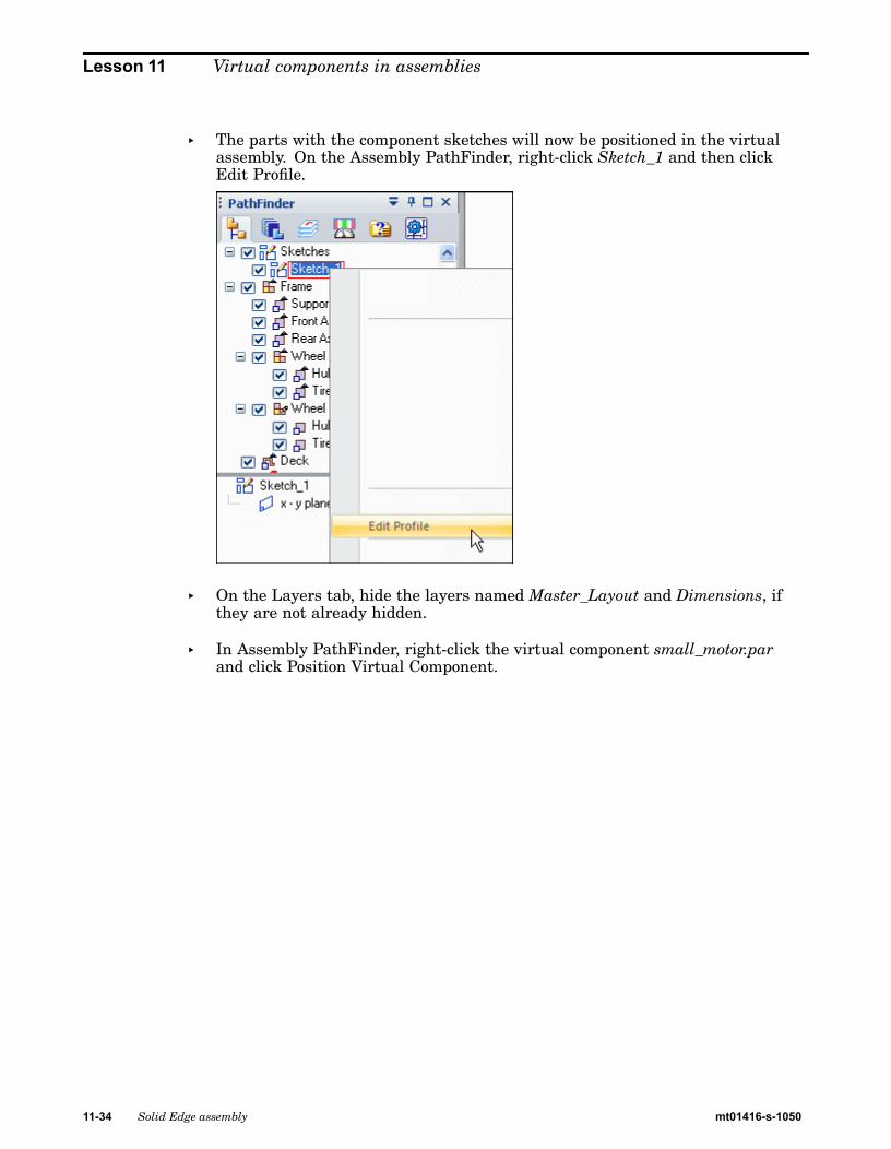
Lesson 11 Virtual components in assemblies
▸ The parts with the component sketches will now be positioned in the virtualassembly. On the Assembly PathFinder, right-click Sketch_1 and then clickEdit Profile.
▸ On the Layers tab, hide the layers named Master_Layout and Dimensions, ifthey are not already hidden.
▸ In Assembly PathFinder, right-click the virtual component small_motor.parand click Position Virtual Component.
11-34 Solid Edge assembly mt01416-s-1050

Virtual components in assemblies
▸ Select the plane shown. The component sketch will show in the preview area.Click OK.
Note You will know you have selected the correct plane when the preview showsyour component sketch.
▸ Observe the prompts. On the keyboard, press A to rotate the motor intothe position shown. Click to the left of the sketch and place the componentapproximately where shown.
▸ Click the Home tab. In the Relate group, turn off Relationship Handles.
mt01416-s-1050 Solid Edge assembly 11-35

Lesson 11 Virtual components in assemblies
▸ In the Relate group, click the Connect command, and connect the center of thecircles shown below.
▸ Click the select tool. In Assembly PathFinder, right-click the virtual componentwide_seat.par and click Position Virtual Component.
11-36 Solid Edge assembly mt01416-s-1050

Virtual components in assemblies
▸ Click the Select tool. Use the same procedure to position the seat as you usedto position the component motor. Use the Connect command to position theseat using the circles shown.
▸ Click the Select tool.
▸ In Assembly PathFinder, right-click the virtual component steering.asm and clickPosition Virtual Component.
▸ Use the same procedure used to position the seat to position the steering wheel.Use the Connect command to position the steering wheel using the circles shown.
▸ Click Close Sketch to exit the sketch. Then click Finish. Save the assembly.
mt01416-s-1050 Solid Edge assembly 11-37

Lesson 11 Virtual components in assemblies
Publish the virtual assembly
▸ On the Home tab, in the Assemble group, click the command Publish VirtualComponents. This will create real components from the virtual components.
▸ Set the path to correspond to the directory structure you have been using forthis activity and click Publish.
11-38 Solid Edge assembly mt01416-s-1050

Virtual components in assemblies
▸ Notice that now there are real parts Assembly PathFinder. Activate all the parts.
mt01416-s-1050 Solid Edge assembly 11-39

Lesson 11 Virtual components in assemblies
Create the frame from the sketch geometry
▸ In Assembly PathFinder, right-click support.par and then click Edit.
▸ Choose the Home tab®Draw group®Symmetric Offset command, and enterthe values shown.
▸ Set the type to chain.
▸ Select the rectangular perimeter of the sketch as shown below.
11-40 Solid Edge assembly mt01416-s-1050

Virtual components in assemblies
▸ Accept the selection.
▸ Click the Select tool and use QuickPick to select the region shown. Extrudethe selection 8 mm in the +Z direction.
▸ Click the Symmetric Offset command. Using the same values as before, selectthe 5 lines shown below. Accept the selection.
mt01416-s-1050 Solid Edge assembly 11-41

Lesson 11 Virtual components in assemblies
▸ Click the Select tool. Select the region shown below.
▸ Set the Selection mode to add mode as shown below.
11-42 Solid Edge assembly mt01416-s-1050

Virtual components in assemblies
▸ Continue selecting the additional regions required to extrude the remainder ofthe frame and extrude them 8 mm in the +Z direction.
Note Use QuickPick to select the regions easily.
▸ Save and close the file to return to the assembly.
mt01416-s-1050 Solid Edge assembly 11-43

Lesson 11 Virtual components in assemblies
Model the front axle
▸ On Assembly PathFinder, select frame.asm and then choose Home tab®Relategroup®Ground relationship. This will ground the top level of the frame suchthat additional relationships can be added to the remaining parts withoutmoving the frame.
▸ Assembly PathFinder, right-click the part Front Axle.par and then click Edit.
▸ Use the Coincident Plane command to create a plane parallel to, and 5 mmbelow, the x-y plane. Use the Include command or the Project to Sketch commandto project the line of the front axle onto the plane.
▸ Draw a rectangle with a short side that is 5 mm wide and as long as the frontaxle sketch element. Lock the sketch onto the plane you created.
▸ Use the Revolve command to create an axle with radius of 5 mm by selecting therectangle you created. Use the included line in the front axle sketch to representthe center-line of the 3D axle. Sweep the revolution 360o to create the axle.
▸ After creating the revolved protrusion, click Close and Return.
11-44 Solid Edge assembly mt01416-s-1050

Virtual components in assemblies
Model the rear axle
▸ On the Assembly PathFinder, right-click the part Rear Axle.par and then clickEdit. Create a revolved protrusion on a parallel plane 5 mm below the x-y plane,as you did with the Front Axle in previous steps. The radius of the protrusionis 5 mm.
Click Close and Return to return to the assembly.
mt01416-s-1050 Solid Edge assembly 11-45

Lesson 11 Virtual components in assemblies
Model the wheel hub
▸ On the Assembly PathFinder, right-click the part Hub.par and click Edit.
▸ Create a 360° revolved protrusion on a parallel plane 5 mm below the x-y plane.Define the axis of revolution using the dashed line as shown. Use the includecommand with the wireframe chain option. Click Finish to complete the revolvedprotrusion, then click Save and close to return to the assembly.
11-46 Solid Edge assembly mt01416-s-1050

Virtual components in assemblies
Model the tire
▸ On the Assembly PathFinder, right-click the part Tire.par and click Edit.
▸ Create a 360° revolved protrusion on a parallel plane 5 mm below the x-y plane.Define the axis of revolution using the dashed line as shown. Click finish tocomplete the revolved protrusion, then click close and return.
mt01416-s-1050 Solid Edge assembly 11-47

Lesson 11 Virtual components in assemblies
Model the sheet metal deck
▸ On the Assembly PathFinder, right-click the sheet metal part Deck.psm andclick edit.
▸ Select the region shown and create the deck. The circles will be the cutout inthe deck. The extent of the tab will be below the profile plane and the sheetmetal thickness will be 3.00 mm.
▸ Click close and return.
11-48 Solid Edge assembly mt01416-s-1050

Virtual components in assemblies
Mirror the wheels
▸ In the Assembly PathFinder, right-click the assembly named Frame.asm, andclick Edit.
▸ On the Assembly PathFinder show the reference planes.
▸ On the Home tab in the Pattern group, click the mirror command.
▸ In PathFinder, select each occurrence of Wheel.asm and accept.
▸ Select the Front (XZ) reference plane as the plane to mirror about.
Note If a mirrored component is symmetrical about the mirror plane, the componentis rotated rather than mirrored. The rotation occurs about an axis residing onthe specified plane. The plane of rotation is perpendicular to the specified plane.
▸ Set the options shown and then click ok, then click finish.
▸ Click Close and Return to return to the top level assembly.
▸ Assembly relationships can be edited to further position and constrain the parts.Save and close this file. This concludes this activity.
mt01416-s-1050 Solid Edge assembly 11-49

Lesson 11 Virtual components in assemblies
Activity summary
In this activity you learned how to create a virtual assembly structure using virtualcomponents. Sketch geometry in the assembly file was assigned to virtual partfiles and once published, the sketch geometry was moved into those files and usedto create parts. Existing parts were placed in the virtual structure and positionedusing component sketches. This is a top down approach to laying out and modelingcomplex assemblies.
11-50 Solid Edge assembly mt01416-s-1050

Virtual components in assemblies
Lesson reviewAnswer the following questions:
1. How is assembly sketch geometry assigned to a virtual component?
2. What is the purpose of a component sketch?
3. What is created when virtual components are published?
mt01416-s-1050 Solid Edge assembly 11-51

Lesson 11 Virtual components in assemblies
Lesson summaryIn this lesson you learned how to create a virtual assembly structure using virtualcomponents. Sketch geometry in the assembly file was assigned to virtual partfiles and once published, the sketch geometry was moved into those files and usedto create parts. Existing parts were placed in the virtual structure and positionedusing component sketches. This is a top down approach to laying out and modelingcomplex assemblies.
11-52 Solid Edge assembly mt01416-s-1050

Lesson
12 Alternate assemblies
mt01416-s-1050 Solid Edge assembly 12-1

Lesson 12 Alternate assemblies
Define Alternate Component CommandDefines a list of documents which are related to the selected part or subassembly.Alternate components are typically similar in nature, and can be based on documentsthat were created independently. Defining a list of alternate components makes iteasier to find and select valid components when replacing parts in an assembly.
A simple example of an application for an alternate component group is where thereare several versions of a part that have different finishing details. The parts can beindependently created or members of a family of parts.
In an assembly where one of the parts is used, you can use the Define AlternateComponents command to specify that all three parts are members of the samealternate component group.
Note Note: A special symbol is used in Assembly PathFinder to indicate that anassembly component is part of a alternate component group.
You can then use the Replace command to replace the part with one of the alternatecomponent members. When you select a part to replace that is a member of aalternate component group, the Alternate Member dialog box is displayed so you canselect another alternate component member as the replacement part.
Defining an Alternate Component Group
You can select any part or subassembly in the active assembly to define an alternatecomponent group. When working with a nested assembly, you cannot selectindividual components that are in a subassembly.
Although an alternate component group would typically contain similar parts, youcan define an alternate component group that contains different document typesthan the original component. For example, you can define an alternate component
12-2 Solid Edge assembly mt01416-s-1050

Alternate assemblies
group that consists of a Part document, a Sheet Metal document, and an Assemblydocument.
When you select a component in an assembly, then click the Define AlternateComponents command, the Define Alternate Components dialog box is displayedso you can browse or search for the documents you want define as alternates forthe selected component.
Defining documents as alternate components is a two step process. First, you browseor search for documents that you want to add to the Alternate Candidates list inthe left pane of the Define Alternate Components dialog box. Then you can selectdocuments in the Alternate Candidates list and click the Add button to add them tothe Alternates List in the right pane of the dialog box.
If the component you select to define the alternate components group is a memberof a family of parts or a family of assemblies, all related members from the samemaster document are added to the Alternate Candidates list automatically.
The assembly document in which you define the alternate components group storesthe group member data.
Using Alternate Component GroupsAs described earlier, a alternate components group makes it easier to find andselect valid components when replacing parts in an assembly. When you select acomponent to replace in an assembly, and the component is a member of a alternatecomponents group, the Alternate Member dialog box is displayed so you can selectanother group member as the replacement part.
Note When you replace an assembly component with an alternate component that isa different document type than the original component, assembly relationshipscan fail to recompute properly.
If you want to replace the component with a component that is not an alternatecomponents member, you can click the Browse button to display the ReplacementPart dialog box to select another component.
If you create alternate component groups that are used frequently in manyassemblies, you should consider creating an assembly that contains only the masteralternate component and define the alternate components group in this document.This assembly document then becomes the master document for the alternatecomponents group definition.
To place one of the group members in an assembly later, you can place the assemblydocument instead. If you also set the Disperse This Assembly During Place Partoption on the Assembly tab of the Options dialog box for this assembly, when youplace the assembly into another assembly, it will be placed as a part that containsthe alternate components group data.
This workflow can be useful when you know a part will be replaced later by anotherpart. For example, you may create a prototype version of a part that you knowwill later be replaced by a production version of the part that will be createdindependently in a separate document.
Alternate Components and Alternate AssembliesYou can use an alternate component to replace a component in an alternate assemblythat is a family of assemblies, but not an alternate position assembly. For example,
mt01416-s-1050 Solid Edge assembly 12-3

Lesson 12 Alternate assemblies
you can use the Replace command to replace a part in a family of assembly memberwith an alternate component, rather than use the Exclude Occurrence functionalityon the Alternate Assembly tab. Although this approach can be quicker than usingthe Exclude Occurrence functionality, when you use Revision Manager to copyor move the assembly data set to a new location, any members of the alternatecomponents group that are not used in a family of assembly member will not beincluded in the data set.
For more information on working with alternate assemblies, see the AlternateAssemblies Help topic.
Comparing Alternate Components and Family of Parts
Alternate Component groups are similar to a family of parts, but provideadditional flexibility because you can define an alternate components group usingindependently created documents and different document types.
Activity: Creating an alternate assembly
Creating an alternate assembly
This activity guides you through the process creating alternate versions of anassembly.
When you complete this activity, you will be able to:
• Convert a normal assembly into an alternate assembly.
• Add members to an alternate assembly.
• Define unique variable values for individual members.
• Replace occurrences for a member.
• Exclude occurrences for a member.
• Exclude and reapply assembly relationships for a member.
12-4 Solid Edge assembly mt01416-s-1050

Alternate assemblies
mt01416-s-1050 Solid Edge assembly 12-5

Lesson 12 Alternate assemblies
Create an alternate assembly for a valve
Create an alternate assembly for a valve. The valve in the existing assembly is open.Create an alternate assembly with the valve closed.
▸ Open Alternate.asm located in the folder where you loaded the parts files neededfor this activity. Open the assembly with all the parts active.
▸ On the View tab, click Color Manager, and ensure the following options are set.
▸ Set the use individual part styles option.
▸ Set the show and allow assembly style overrides option.
▸ Clear the Show part face colors option.
▸ Click OK.
Note You create a family of assemblies by converting a normal assemblydocument into an alternate assemblies document. You can only convertthe assembly document once, and you must specify whether you want toconvert it into a family of assemblies or an alternate position assembly. Inthis activity, you convert the assembly into a family of assemblies.
▸ In PathFinder, click the Alternate Assemblies tab.
▸ On the Alternate Assemblies tab, click the New button.
▸ In the Alternate Assemblies dialog box, do the following:
▸ Ensure that the Create a Family of Assemblies option is selected.
▸ In the Name current member box, type Default Type 1 Open and press the Tabkey.
12-6 Solid Edge assembly mt01416-s-1050

Alternate assemblies
▸ In the Name new member* box, type Type 1 Closed.
▸ Click OK.
Note On the Alternate Assemblies tab, notice that the Type 1 Closed member isthe active member. When you create a new family of assemblies, the nameyou type in the Name new member box becomes the active member.
mt01416-s-1050 Solid Edge assembly 12-7

Lesson 12 Alternate assemblies
Modify the Type 1 Closed family member
Modify the Type 1 Closed family member by overriding the value of the angularrelationship that controls the position of the valve subassembly and handle. First,add the variable to the member variables list.
▸ On the Alternate Assemblies tab, select the Member Variables option.
▸ On the Tools tab, click Variables to display the Variable Table. Click the Filterbutton and set the values as shown, and then click OK.
12-8 Solid Edge assembly mt01416-s-1050

Alternate assemblies
▸ Click the ValveAngle variable, as shown.
▸ On the Alternate Assemblies tab, click the Add Variables button.
Note The variable is added to the Member Variables list. When you addvariables to the Member Variables list, you can no longer edit them withinthe Variable Table. You must edit them in the member variables list onthe Alternate Assemblies tab.
▸ Close the Variable Table.
▸ In the Member Variables list, position the cursor over the variable as shown, butdo not click yet.
▸ In the graphics window, notice the faces used to define the angle relationshiphighlight as shown in the following illustration.
mt01416-s-1050 Solid Edge assembly 12-9

Lesson 12 Alternate assemblies
▸ Position the cursor over the variable value as shown, and then double click theleft mouse button.
▸ Type 90, and then press the Enter key.
▸ In the graphics window, notice that the handle rotated 90° clockwise. In additionto the handle, the valve subassembly also rotated.
12-10 Solid Edge assembly mt01416-s-1050

Alternate assemblies
▸ On the Alternate Assemblies tab, select the Default Type 1 Open member asshown.
Note For the Default Type 1 Open member, the ValveAngle variable was alsoadded to the Member Variables list, but the valve handle is still in the openposition. The variable value you changed only affected the Type 1 Closedfamily member.
When you add a variable to the Member Variables list for one member,the variable is added to the Member Variables list for all members thatcontain the variable, but each member can have a different value assignedto the variable.
mt01416-s-1050 Solid Edge assembly 12-11

Lesson 12 Alternate assemblies
Create the member Type 2 Open
Create another family member, as shown. For this family member, delete theoriginal handle and place a new handle. Use the replace part command to replacethe TopFlange01.asm subassembly with a different subassembly.
▸ On the Alternate Assemblies tab, click the New button.
▸ In the New Member dialog box, type Type 2 Open, and then click OK.
Note The new family member has the same characteristics as Default Type 1Open. When you create a new family member, it has the same characteristicsas the family member that is active when you create the new member. Inthis case, the active member was Default Type 1 Open.
▸ On the Alternate Assemblies tab, do the following as shown.
▸ Select the Excluded Occurrences option.
12-12 Solid Edge assembly mt01416-s-1050

Alternate assemblies
▸ Ensure that the Apply edits to all members check box is cleared.
Note When you exclude occurrences, you can exclude them for all family membersor for only the active member. In this case, you want to exclude the handle foronly the active member.
When you exclude an occurrence for all family members, the occurrence isphysically deleted from the assembly file, and it is not added to the excludedoccurrences list.
▸ Click the Assembly PathFinder tab.
▸ In Assembly PathFinder, select Handle01.par and delete it.
▸ A dialog box displays to confirm that you want to exclude the part for the activefamily member.
▸ In the Confirm Delete dialog box, click Yes.
mt01416-s-1050 Solid Edge assembly 12-13

Lesson 12 Alternate assemblies
▸ To make it easier to position the new handle, hide the nut part.
▸ In PathFinder, click the Parts Library tab.
▸ On the Parts Library tab, click the arrow on the right side of the Look In list.Browse to the folder where the activity files are located.
▸ Drag Handle02.par into the assembly window.
▸ Position the handle using FlashFit as directed in the following steps.
12-14 Solid Edge assembly mt01416-s-1050

Alternate assemblies
▸ Mate the two planar faces shown.
▸ Axial align the curved faces shown.
mt01416-s-1050 Solid Edge assembly 12-15

Lesson 12 Alternate assemblies
▸ Mate the two planar faces shown.
The handle is fully positioned in the assembly.
12-16 Solid Edge assembly mt01416-s-1050

Alternate assemblies
▸ Save the assembly.
mt01416-s-1050 Solid Edge assembly 12-17

Lesson 12 Alternate assemblies
Observe results
Make some observations of the alternate assemblies created so far.
▸ In PathFinder, click the Alternate Assemblies tab.
▸ In the Excluded Occurrences list for the Type 2 Open family member, notice thatHandle01.par has been added to the list.
▸ On the Alternate Assemblies tab, activate the member named Default Type1 Open.
Note For this family member, Handle02.par is in the excluded occurrences list.Also notice that the assembly display updated when you activated thisfamily member.
12-18 Solid Edge assembly mt01416-s-1050

Alternate assemblies
Finish defining the Type 2 Open member
Finish defining the characteristics for member Type 2 Open by replacing asubassembly.
▸ On the Alternate Assemblies tab, activate the member named Type 2 Open.
▸ Click the Assembly PathFinder tab.
▸ In Assembly PathFinder, select the entry TopFlange01.asm.
▸ Click the Home tab. In the Modify group, click the Replace Part command.
Note You can use the replace Part command to replace a part or subassemblywithin the assembly. When replacing a subassembly, you must select itwithin Assembly PathFinder.
▸ In the Replacement Part dialog box, do the following:
▸ Set the Look In location to the folder where the activity files are located.
▸ Set the Files of type option to Assembly Files (*.asm).
▸ Select the assembly file TopFlange02.asm.
mt01416-s-1050 Solid Edge assembly 12-19

Lesson 12 Alternate assemblies
▸ Click the Open button.
Note Since the replacement subassembly is also a family of assemblies, you mustspecify which family member you want to use as the replacement.
▸ In the Assembly Member dialog box, select the member named 3 screws withstud, and then click OK.
Note In the assembly window, notice the replacement subassembly does not havefour Phillips-head screws. In place of one of the screws is a stud that servesto limit the rotation of the new handle. Also notice in Assembly PathFinder,the member name is appended to the filename.
12-20 Solid Edge assembly mt01416-s-1050

Alternate assemblies
▸ In PathFinder, click the alternate assemblies tab.
▸ On the Alternate Assemblies tab, select the Occurrence Overrides option.
Note Notice for this member that TopFlange01.asm was overridden byTopFlange02.asm!3 screws with stud.
When you replace a part or subassembly, the original occurrence is addedto the left column in the occurrence overrides list, and the replacementoccurrence is added to the right column in the occurrence overrides list.
mt01416-s-1050 Solid Edge assembly 12-21

Lesson 12 Alternate assemblies
Create a new family member
Create another family member as shown. For this family member, change theposition of Handle02.par. This family member illustrates how you can excluderelationships for a part. Excluding relationships for a part allows you to add newrelationships that change the position of the part.
▸ On the Alternate Assemblies tab, click the New button.
▸ In the New Member dialog box, type Type 3 Open Reverse Handle, and thenclick OK.
Note The new member you created is active, and it has the characteristics of theType 2 Open member.
▸ On the Alternate Assemblies tab, do the following as shown.
▸ Select the Excluded Relationships option.
12-22 Solid Edge assembly mt01416-s-1050

Alternate assemblies
▸ Ensure that the Apply edits to all members check box is cleared.
Note When you exclude relationships, you can exclude them for all familymembers or for only the active member. In this case, you want to exclude therelationships for only the active member.
▸ Click the Assembly PathFinder tab.
▸ In the top pane of Assembly PathFinder, select Handle02.par as shown.
mt01416-s-1050 Solid Edge assembly 12-23

Lesson 12 Alternate assemblies
▸ In the bottom pane of Assembly PathFinder, delete the two relationships shown.
Note Notice that the symbol adjacent to Handle02.par changes to indicate it isno longer fully positioned.
▸ In PathFinder, click the Alternate Assemblies tab.
Note Notice that the relationships you excluded were added to the ExcludedRelationships list for the family member named Type 3 Open ReverseHandle.
▸ Click the Assembly PathFinder tab.
▸ In the top pane of Assembly PathFinder, select Handle02.par.
▸ On the command bar, click the Edit Definition button.
12-24 Solid Edge assembly mt01416-s-1050

Alternate assemblies
▸ Establish a Mate relationship between the faces shown.
▸ The handle is mated to the shaft as shown.
mt01416-s-1050 Solid Edge assembly 12-25

Lesson 12 Alternate assemblies
▸ Continue using FlashFit to mate the faces shown.
▸ Click the Offset Type button, and then click Floating Offset.
Note This setting allows the faces to take on whatever offset value is appropriateto satisfy the other relationships that position the two parts.
The handle is fully positioned in the assembly.
12-26 Solid Edge assembly mt01416-s-1050

Alternate assemblies
▸ Fit the assembly and then save the assembly.
▸ In Assembly PathFinder, show NutM15.par.
mt01416-s-1050 Solid Edge assembly 12-27

Lesson 12 Alternate assemblies
Observe results
Make some observations of the alternate assemblies created so far.
▸ In PathFinder, click the Alternate Assemblies tab.
▸ On the Alternate Assemblies tab, activate the member named Type 2 Open.
Note There are two relationships on the excluded relationships list for thisfamily member. These relationships were added to the list automaticallywhen you repositioned the handle for the member named Type 3 OpenReverse Handle. When the Apply edits to all members option is cleared, therelationships you add to position a part for one member are automaticallyexcluded from the other members that contain the same part.
Also notice that for this member, NutM15.par is still hidden. When youchange the display of a part for one family member, the display of the samepart in other family members is not changed.
12-28 Solid Edge assembly mt01416-s-1050

Alternate assemblies
Create family member named Type 3 Open Reverse Handle.
Create a new assembly document for the family member named Type 3 OpenReverse Handle.
▸ On the Alternate Assemblies tab, activate the member named Type 3 OpenReverse Handle.
▸ On the Alternate Assemblies tab, click the save member as button.
▸ In the Save Member dialog box, save the active member (using the default name)to the folder where the activity files are located.
If a dialog box displays and asks if you want to save the current assembly first,click the Yes button.
Note Remember the name and location, because you will be opening thisdocument in the next step.
▸ Click the Application button. Click the Open button.
mt01416-s-1050 Solid Edge assembly 12-29
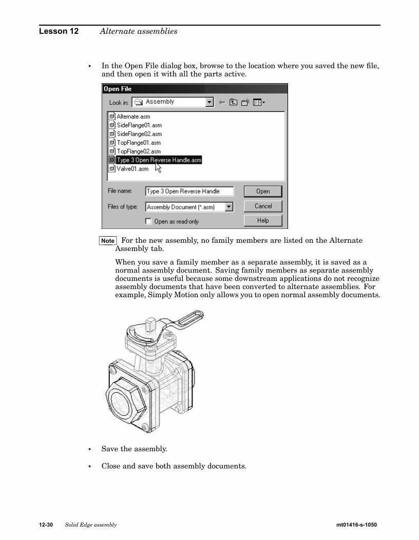
Lesson 12 Alternate assemblies
▸ In the Open File dialog box, browse to the location where you saved the new file,and then open it with all the parts active.
Note For the new assembly, no family members are listed on the AlternateAssembly tab.
When you save a family member as a separate assembly, it is saved as anormal assembly document. Saving family members as separate assemblydocuments is useful because some downstream applications do not recognizeassembly documents that have been converted to alternate assemblies. Forexample, Simply Motion only allows you to open normal assembly documents.
▸ Save the assembly.
▸ Close and save both assembly documents.
12-30 Solid Edge assembly mt01416-s-1050

Alternate assemblies
Draft family of assembly members
Create a new draft document and place a drawing view of one of the family ofassembly members.
▸ Click the Application button. Click the New button.
▸ In the New dialog box, click iso draft.dft, and then click OK.
▸ Choose the Home tab®Drawing Views group®View Wizard command .
▸ In the Select Model dialog box, select Alternate.asm, and then click Open.
▸ The Family of Assembly Member page of the Drawing View Wizard displays, soyou can specify which family member you want. From the Family member list,select the Type 3 Open Reverse Handle option, and then click the Next button.
▸ On the Assembly Drawing View Options page, click the Next button.
mt01416-s-1050 Solid Edge assembly 12-31

Lesson 12 Alternate assemblies
▸ On the Drawing View Orientation page, select the iso option, and then clickFinish.
▸ Position the drawing view on the drawing sheet, and then click to place thedrawing view.
▸ Save and close the draft document. This completes the activity.
12-32 Solid Edge assembly mt01416-s-1050

Alternate assemblies
Activity summary
In this activity you learned how to create an alternate assembly. In the alternateassembly, you learned how to add new members, define unique variablesfor individual members, exclude member occurrences and reapply assemblyrelationships for a member.
mt01416-s-1050 Solid Edge assembly 12-33

Lesson 12 Alternate assemblies
Lesson reviewAnswer the following questions:
1. In the Alternate Assemblies tab in PathFinder, what two types of assembliescan you create?
2. In a family of assemblies, which substitutions, modifications or exclusions areallowed?
3. Can an assembly family member be saved as a unique assembly?
4. How do you place an assembly family member on a drawing sheet?
12-34 Solid Edge assembly mt01416-s-1050

Alternate assemblies
Lesson summaryIn this lesson you learned how to create an alternate assembly. In the alternateassembly, you learned how to add new members, define unique variablesfor individual members, exclude member occurrences and reapply assemblyrelationships for a member.
mt01416-s-1050 Solid Edge assembly 12-35


Lesson
13 Adjustable parts and assemblies
Creating an adjustable part
Creating an adjustable part
Adjustable parts will change relationship values to fit when placed in an assembly.
mt01416-s-1050 Solid Edge assembly 13-1

Lesson 13 Adjustable parts and assemblies
Adjustable parts in assemblies
In some designs, there are parts that must react to changing conditions in theassembly. For example, a spring that is compressed or uncompressed based on theposition of other parts in the assembly.
The Adjustable Parts functionality in Solid Edge allows you to define parametersin a part model that will adjust with respect to corresponding parameters withinthe assembly. This allows you to control the size and shape of the part based onparameters you define in the assembly.
When you specify that a part is adjustable, the design body in the part model doesnot change when the assembly parameters change. An associative copy of the designbody in the assembly changes. The associative copy of the design body is placed inthe assembly automatically and is managed by Solid Edge when you specify that apart is adjustable within the context of the assembly.
This allows you to place several occurrences of an adjustable part into an assembly,and each occurrence of the adjustable part will conform to the current parametervalues for that occurrence of the part. For example, one occurrence of a springcan be shown compressed while another occurrence of the spring can be shownuncompressed.
Note Only the design body for an adjustable part is associatively copied to theassembly. If the adjustable part contains construction bodies, they are notassociatively copied to the assembly.
13-2 Solid Edge assembly mt01416-s-1050

Adjustable parts and assemblies
Making a part adjustable
To make a part adjustable within the context of an assembly, you first must definethe parameters you want to adjust in the part document. You can then definecorresponding parameters in the Assembly environment.
You can use driving dimensions and variables that control a feature, reference plane,or construction element as the parameters to define an adjustable part.
When you specify that a part is adjustable, you cannot in-place activate the partusing the Edit command. You can use the Open command to open the part.
Defining the part parameters
The Adjustable Part command on the Tools tab in the Part or Sheet Metalenvironments displays the Adjustable Part dialog box so you can define or edit theadjustable parameters.
When the Adjustable Part dialog box is displayed, you can select features to displaytheir dimensions, or you can click the Variable Table button on the Adjustable Partdialog box to display the variable table.
For example, to make the length of the spring shown adjustable, you can add thevariable which controls spring length: SprLngPrt, to the adjustable parameters listby selecting the variable in the Variable Table.
When you add a variable or dimension to the Adjustable Part dialog box, theparameter name is added to the Variable Name column (A). You can also add textto the Notes column (B) to make it easier to remember later what aspect of thepart the adjustable parameter controls.
Placing adjustable parts in an assembly
When adding an adjustable part to an assembly, you should place and position theparts which interact with the adjustable part first. This allows you to use thesurrounding parts to define the assembly parameters required to complete the
mt01416-s-1050 Solid Edge assembly 13-3

Lesson 13 Adjustable parts and assemblies
process. You can specify whether an adjustable part is adjustable or rigid in theassembly when placing the part or after you position the part in the assembly.
When you drag and drop an adjustable part into an assembly, a dialog box isdisplayed that allows you to specify whether the part is rigid or adjustable.
When you set the Place Rigid option, the part placement process proceeds as itwould for a typical part. You can then define assembly relationships to position thepart in the assembly. An adjustable part placed as rigid in an assembly behaves thesame as any other part in an assembly.
When you set the Place Adjustable option, the part placement process is temporarilysuspended so you can define the adjustable parameters in the assembly using theAdjustable Part dialog box.
Note When positioning an adjustable part, the option to use a separate Place Partwindow is not available. The part is placed in the assembly window so you candefine the adjustable parameters and the assembly relationships in one window.
Defining the assembly parameters
In addition to the options for selecting driving dimensions and variables, theAdjustable Part dialog box in the Assembly environment contains options that allowyou to define a measurement variable. This allows you to use geometry on otherparts in the assembly to define variables which will control the size and shape of theadjustable part in the assembly.
The measurement variable options activate one of the Measurement commands thatare also available on Inspect®Measure. For example, you can use the MeasureMinimum Distance option to specify that the minimum distance between the twofaces shown controls the height parameter of the part.
After you select the elements in the assembly that define the distance you want tomeasure, an assembly variable is created automatically and added to the AssemblyVariable cell in the Adjustable Part dialog box for the adjustable part you are placingor editing.
There are three columns in the Adjustable Part dialog box in the Assemblyenvironment: Part Variable (A) Notes (B), and Assembly Variable (C). In thisexample, the part variable SprLngPrt is controlled by the measurement variableSprLngAsm in the assembly.
13-4 Solid Edge assembly mt01416-s-1050

Adjustable parts and assemblies
In addition to defining measurement variables, you can also use assemblyrelationship variables for an adjustable part. For example, you can use the offsetvalue for a mate or planar align relationship as an assembly variable by selectingthe variable value for the relationship in the Variable Table.
The place like a spring option will use the variable created by measuring a distanceto adjust the length of the corresponding variable in the part or sheet metaldocument. The position of the parts attached to the adjustable part determines thelength of the variable defining the distance.
The adjust to fit and allow assembly relationships option will use the variablecreated by the measurement to change the length of the adjustable part, andreposition parts within the assembly that are not constrained. The length of thevariable defining the adjustable part length is used to position the unconstrainedparts connected to the adjustable part.
After you have defined all the parameters in the assembly to control the adjustablepart, click the OK button on the Adjustable Part dialog box to resume the partplacement process. In this example, a mate relationship (A) and an axial alignrelationship (B) fully position the part in the assembly (C).
You can also specify that a part is adjustable after it has been positioned in theassembly. First, you must define the adjustable parameters for the part in the Partor Sheet Metal environment. Then, in the assembly, you can use the Adjustable Partcommand on the shortcut menu when a part is selected to specify that the part isadjustable and then define the adjustable parameters.
Note When you specify that a part is adjustable, you cannot in-place activate thepart using the Edit command. You can use the Open command to open the part.
Updating adjustable parts
When you edit the assembly such that the adjustable part must change, the size andshape of the adjustable part updates automatically when the Automatic Updateoption is set. For example, in this assembly, if you edit the offset value for the planaralign relationship between the valve and body parts, the valve opens.
mt01416-s-1050 Solid Edge assembly 13-5

Lesson 13 Adjustable parts and assemblies
This causes the size and shape of the adjustable part to update automatically.
Adjustable parts in adjustable subassemblies
You can place a subassembly that contains an adjustable part into an assembly, thenmake the subassembly adjustable. For example, you may need to place two instancesof a cylinder subassembly, with each subassembly in different positions.
Each cylinder assembly contains a spring that is an adjustable part, which allowsthe spring to change length as the cylinder subassemblies change positions.
When you make a subassembly adjustable that contains adjustable parts, theadjustable part variables are promoted to the current assembly.
For more information on creating and using adjustable assemblies, see theAdjustable assemblies Help topic.
13-6 Solid Edge assembly mt01416-s-1050

Adjustable parts and assemblies
Using reference geometry to constrain adjustable parts
You can use part reference planes or construction geometry to define positioningrelationships for an adjustable part in an assembly, but in some cases this canprevent the adjustable part from reacting properly to assembly changes.
If this occurs, you can edit the positioning relationship to use geometry on the designbody on the adjustable part instead.
Adjustable parts and Parts Lists
When you place the same adjustable part several times in an assembly in differentstates of adjustment, all occurrences have a single part number. If you useseveral family of parts members to simulate adjustable parts in different states ofadjustment, you can have more than one part number, because different family ofparts members have unique part numbers. Typically, a single part number is thepreferable result.
Adjustable parts and alternate assemblies
You can use adjustable parts in a family of assemblies and alternate positionassemblies. You can edit the assembly variable used to control an adjustable part ona per member basis by clearing the Apply Edits to All Members option.
Activity: Creating an adjustable part
Creating an adjustable part
Overview
The objective of this activity is to show how to create an adjustable part to beused in an assembly.
In this activity you will create a spring that adjusts its length when placed inan assembly.
Creating the variable defining the adjustable distance
Sketches created in a part document will be used to define the adjustable variable.
mt01416-s-1050 Solid Edge assembly 13-7

Lesson 13 Adjustable parts and assemblies
▸ From the Solid Edge start screen, click Open Existing Document. Browse forspring.par in the folder where the activity files are located.
▸ Select Sketch1 in pathfinder and then select Edit Profile to edit the sketch.
Note This sketch will be used to create a helix defining the spring. To make thelength adjustable, a dimension controlling the length will be defined.
▸ Dimension the horizontal line in the sketch. The length is 2000 mm.
▸ Click Tools, then click Variables to show the variable table.
▸ Find the variable with the length equal to 2000 and change the name of thevariable name to spring_length.
▸ Dismiss the variable table.
▸ Click the home tab, then click Close Sketch.
▸ Click finish.
▸ Select Sketch2 in pathfinder and then select Edit Profile to edit the sketch.
13-8 Solid Edge assembly mt01416-s-1050

Adjustable parts and assemblies
▸ Place a horizontal dimension between the two rectangles.
Note The rectangles will be used to create a cutout and shave off the ends of thespring creating a planar face on each end. The spacing will be controlled by aformula in the variable table equating the spacing between the rectangles to thespring_length variable previously defined.
▸ Click Tools, then click variables to show the variable table.
▸ Find the variable with the length equal to the horizontal dimension just created.In the formula field, set the value equal to the variable spring_length.
▸ Dismiss the variable table.
▸ Click the home tab, then click Close Sketch.
▸ Click finish.
Create the spring from the sketches
Create the helix from the sketch1.
▸ Hide Sketch2.
mt01416-s-1050 Solid Edge assembly 13-9

Lesson 13 Adjustable parts and assemblies
▸ On the home tab, in the solids group, click add helix.
▸ Set the create from option to: Select from Sketch.
▸ Select the circle as the sketch chain and then click accept.
▸ Select the horizontal line as the axis.
▸ Select the left side of the line as the origin of the axis.
▸ Set the method to Axis length and turns and the number of turns to 15.
13-10 Solid Edge assembly mt01416-s-1050

Adjustable parts and assemblies
▸ Click Next.
▸ Click Preview.
▸ Click Finish.
▸ Hide Sketch1 and show Sketch2.
▸ On the Home tab, in the Solids group, click the Cut command.
▸ Set the create from option to: Select from Sketch.
▸ Select each of the rectangles in the sketch, then click the accept button.
▸ Select the through all option for the extent of the cut.
mt01416-s-1050 Solid Edge assembly 13-11

Lesson 13 Adjustable parts and assemblies
▸ Select both directions to define the extent of the cut.
▸ Click Finish to complete the cut.
Define the adjustable variable
The variable defining the axis length of the spring will be defined as the adjustablevariable.
▸ Click the Tools Tab. In the Assistants group, click Adjustable part.
▸ Click the variable table button.
▸ Select spring_length as the adjustable variable.
13-12 Solid Edge assembly mt01416-s-1050

Adjustable parts and assemblies
▸ Dismiss the variable table. Spring_length will be defined as the adjustablevariable.
▸ Click OK.
▸ The spring is complete. Save and close the document.
Place and define the adjustable part as a spring
The spring will be placed and positioned in the assembly as an adjustable part.
▸ Open the assembly shock_absorber.asm.
▸ In pathfinder, right click shock_absorber.asm and then click Activate to activateall the parts.
In the subassembly, shock_top.asm, examine the relationships used to position thesubassembly relative to shock_bottom.asm.
mt01416-s-1050 Solid Edge assembly 13-13

Lesson 13 Adjustable parts and assemblies
▸ In pathfinder, click shock_top.asm. In the lower pane notice that there is an axialalign relationship and a floating planar align.
Note These relationships keep the cylindrical parts aligned and keep the holescontaining the bushing and sleeve parallel. There is still freedom to movealong the axis of the cylinders.
The reference planes will be used to position the spring. The next steps will turn onthe planes needed to position the spring.
▸ Click the Select tool. Right mouse click in the assembly window. Click Show/HideAll Component.
▸ Hide all the reference planes.
▸ Click Apply, then click OK to dismiss the dialog box.
▸ In pathfinder, right click shock_bottom.asm and then click Show/HideComponent.
▸ Turn on the Reference planes for shock_bottom.asm. Then click Apply, then clickOK to dismiss the dialog box.
▸ On the Home tab in the Select group, click Clear Selection.
13-14 Solid Edge assembly mt01416-s-1050

Adjustable parts and assemblies
▸ From the parts library, drag spring.par into the assembly.
▸ Set the placement choice as Place Adjustable, then click OK.
Note The adjustable variable in the spring will be controlled by the measureddistance between two faces defined in the next steps.
mt01416-s-1050 Solid Edge assembly 13-15

Lesson 13 Adjustable parts and assemblies
▸ Click Adjust like a spring and then click the measure button.
▸ Select the circular face shown for the point to measure from. The measurementtool will lock to the radial point of the circle when selected.
13-16 Solid Edge assembly mt01416-s-1050

Adjustable parts and assemblies
▸ Select the circular face shown for the point to measure to. The measurement toolwill lock to the radial point of the circle when selected.
Note The adjustable distance has been set and the spring length adjusts to thedistance defined.
▸ Click OK to dismiss the dialog box.
▸ Using the mate relationship, select the face shown.
mt01416-s-1050 Solid Edge assembly 13-17

Lesson 13 Adjustable parts and assemblies
▸ For the target face, click the face shown.
▸ Using the mate relationship, select the face
shown.
▸ For the target face, click the face shown.
13-18 Solid Edge assembly mt01416-s-1050

Adjustable parts and assemblies
▸ Click the construction display to turn on the reference planes for spring.par.
▸ Using the mate relationship, select the reference plane shown.
mt01416-s-1050 Solid Edge assembly 13-19

Lesson 13 Adjustable parts and assemblies
▸ Select the reference plane shown as the target.
▸ Using the mate relationship, select the reference plane shown.
13-20 Solid Edge assembly mt01416-s-1050

Adjustable parts and assemblies
▸ Select the reference plane shown as the target.
▸ The Spring is placed.
mt01416-s-1050 Solid Edge assembly 13-21

Lesson 13 Adjustable parts and assemblies
▸ Turn off the display of the reference planes.
shock_top.asm is still free to move along the axis of the cylinders. You will move thispart and the spring will adjust size based on the position of this subassembly.
▸ Click the home tab. In the modify group, click the drag command.
13-22 Solid Edge assembly mt01416-s-1050

Adjustable parts and assemblies
▸ Drag shock_top.asm to increase the separation distance between thesubassemblies.
▸ The spring will adjust to the spacing between the faces.
mt01416-s-1050 Solid Edge assembly 13-23

Lesson 13 Adjustable parts and assemblies
▸ Use the drag command to change the spacing and observe how the spring reacts.
Define the adjustable part as a rigid part
Previously, the spring was set to adjust as a spring. The length of the spring wasdetermined by the spacing between two faces on different parts. The adjustable partalso be used to determine the spacing between the faces which removes the freedomto move and makes the assembly rigid. This will be demonstrated in the next steps.
▸ Notice the icon in pathfinder for the subassembly shock_top.asm shows it asunder constrained.
▸ Click the select tool. In pathfinder, right click spring.par. ClickSimplified/Adjustable. Click Rigid Part.
13-24 Solid Edge assembly mt01416-s-1050

Adjustable parts and assemblies
Note Now the spread distance is defined by the spring_length variable in spring.par.You will use peer variables to edit the value of this variable.
▸ On the Tools tab in the variable group, click Peer variables. Select the springand change the value of spring_length to 1540.
▸ Close the variable table. Notice that shock_top.asm is now constrained and thevariable defining spring length determines the offset value.
▸ Save and close the document. This completes the activity.
Summary
In this activity you learned how to create and adjustable part and place it in anassembly as a spring, or to adjust the fit to allow assembly relationships.
mt01416-s-1050 Solid Edge assembly 13-25

Lesson 13 Adjustable parts and assemblies
Lesson review
Answer the following questions:
1. Is the following statement true or false? When an adjustable part is placed in anassembly and adjusts to fit, the part document containing the part also adjuststo a specific size, as well as every occurrence of that part in the assembly andother assemblies that it may reside.
2. Fill in the blank in the following statement. When defining a part as adjustable,the adjustable value is defined by a ________.
3. Is the following statement true or false? After defining a part as adjustable, it isimpossible to place the part as a rigid part.
4. What is the difference between the following placement options of an adjustablepart?
• Adjust like a spring
• Adjust to fit and allow assembly relationships
13-26 Solid Edge assembly mt01416-s-1050

Adjustable parts and assemblies
Lesson summary
In this lesson you learned how to create and adjustable part and place it in anassembly as a spring, or to adjust the fit to allow assembly relationships.
Creating an adjustable assembly
Creating an adjustable assembly
Adjustable assemblies will change relationship values to fit when placed in a higherlevel assembly.
mt01416-s-1050 Solid Edge assembly 13-27

Lesson 13 Adjustable parts and assemblies
Adjustable and rigid assemblies
When working with assemblies, it is sometimes necessary to allow movement withina subassembly while working in a higher-level assembly. In other instances, it can benecessary to show identical subassemblies in different positions. For example, youcan have two identical hydraulic cylinder subassemblies in an assembly, but needto show the hydraulic cylinders in different positions.
The Adjustable Assembly functionality allows you to address both of these issues.
Comparing rigid and adjustable subassemblies
Specifying that a subassembly is adjustable allows you to place positioningrelationships between parts in the subassembly while in the higher-level assembly.This is not possible with a rigid subassembly.
When you specify that a subassembly is adjustable, you are prevented from in-placeactivating the subassembly. For example, when you try to in-place activate thesubassembly using the Edit command, a dialog box is displayed that informs youthat the subassembly is adjustable and to use the Open command to open thesubassembly.
Displaying identical subassemblies in different positions
There are several approaches to solving this problem:
You can create uniquely-named subassemblies for each of the otherwise identicalsubassemblies. This allows you to assign unique offset values to the affectedrelationships, but creates extra files and complicates data management.
You can create a single-level assembly where the subassembly components areplaced as discrete parts, instead of as a subassembly. This also allows you to assignunique offset values to the affected relationships, but makes it more difficult to reusethe hydraulic cylinder components later in another assembly. Another disadvantageof this method is that the parts are listed individually, rather than as a subassembly.
13-28 Solid Edge assembly mt01416-s-1050

Adjustable parts and assemblies
Alternately, you can use the Adjustable Assembly functionality within Solid Edge.This approach eliminates the need to create multiple copies of the hydraulic cylindersubassembly data set or to create single-level assemblies.
Preparing the subassembly
To use the Adjustable Assembly functionality, the subassembly should be leftunder-constrained in the range of motion in which you want to adjust. This allowsyou to apply the relationship(s) that you want to adjust in the higher level assembly,not in the subassembly.
Placing the subassembly into the higher-level assembly
You place the subassembly into the higher-level assembly in the same manner asyou would any subassembly. There are several methods available to specify that youwant the subassembly to be considered an adjustable assembly.
To specify that the subassembly is considered adjustable while you are placing thesubassembly, set the Place As Adjustable option on the Options dialog box on theAssemble command bar.
To specify that the subassembly is considered adjustable after you have completedpositioning the subassembly, select the subassembly in PathFinder, then click theAdjustable Assembly command on the shortcut menu.
Note Only subassemblies that contain parts that are not fully positioned can bemarked as adjustable.
You can also specify that a subassembly is adjustable by setting the Place asAdjustable when this Assembly is Placed into Another Assembly option on theAssembly tab on the Options dialog box.
Regardless of the method used, a special symbol is used in PathFinder (A) to indicatethe subassembly is adjustable.
mt01416-s-1050 Solid Edge assembly 13-29

Lesson 13 Adjustable parts and assemblies
Working with adjustable assemblies
When a subassembly is set to adjustable, all assembly relationships existing withinthe subassembly are solved at the level of the active assembly. In other words, therelationships in the subassembly are promoted to the higher-level assembly forsolve purposes.
The relationships used to position the parts within the subassembly can be viewedin the bottom pane of PathFinder when you select a part in the subassembly. Theserelationships are read-only and the text label is gray to indicate that the relationshipcannot be edited. Displaying the read-only relationships makes it easier to evaluatethe existing relationships and apply the remaining relationships.
For example, when you select cylinder.par:1 in the adjustable assembly namedActuator.asm:1, three relationships are displayed. The axial align relationshipto base.par (A) was placed in the current assembly. It was used to position thesubassembly in the current assembly, and is editable.
The Mate relationship to piston.par:1 (B) was placed in the current assembly afterthe subassembly was made adjustable. Its purpose is to adjust the length of thehydraulic cylinder subassembly and the relationship is editable.
Notice that no visual distinction is made between relationships (A) and (B), althoughone of the relationships was used to position the subassembly in the currentassembly (A), and the other was used to position the two parts in the subassembly.
The remaining axial align relationship to piston.par:1 (C) was placed in thesubassembly, is read-only and not editable within the current assembly. Notice thatthe text label is gray, indicating that the relationship is read-only.
If you specify that a subassembly is flexible, add positioning relationships, and thenspecify that the subassembly is rigid, conflicting relationships can occur. You candelete or suppress relationships to correct this situation.
13-30 Solid Edge assembly mt01416-s-1050

Adjustable parts and assemblies
Adjustable assemblies and adjustable parts
You can create assemblies that contain adjustable parts within an adjustablesubassembly. For example, you may need to place two instances of a cylindersubassembly, with each subassembly in different positions.
Each cylinder assembly contains a spring that is an adjustable part, which allowsthe spring to change length as the cylinder subassemblies change positions.
When you make a subassembly adjustable that contains adjustable parts, theadjustable part variables are promoted to the current assembly.
If you define an assembly variable in the variable table for a subassembly thatcontrols a part variable, the subassembly variable is promoted to the currentassembly. The promoted variable is a linked variable.
For more information on creating and using adjustable parts in assemblies, see theAdjustable parts in assemblies Help topic.
Adjustable assemblies and the Drag Part command
If you specify that a subassembly is adjustable, and the combination of relationshipsat the active level and the promoted relationships allow movement, you can usethe Drag Part command to reposition the parts. Adjustable assemblies work withall modes of the Drag Part command.
Because an adjustable subassembly is typically used to drive movement in anassembly, you may need to provide for that movement by suppressing or deletingrelationships in the related parts and subassemblies.
Activity: Creating an adjustable assembly
Creating an adjustable assembly
Overview
The objective of this activity is to show how to create an adjustable assemblyto be used in a higher level assembly.
In this activity you will create and place an adjustable assembly.
mt01416-s-1050 Solid Edge assembly 13-31

Lesson 13 Adjustable parts and assemblies
Place an assembly containing an adjustable part into a higher level assembly
The assembly you will place will later be defined as adjustable.
▸ Open the assembly arms.asm. Activate all the parts in the assembly.
13-32 Solid Edge assembly mt01416-s-1050

Adjustable parts and assemblies
▸ From the parts library, drag shock_absorber1.asm into the assembly window.
▸ Using quickpick, activate the part sleeve.par. If you cannot select it, it mayneed to be activated by clicking the activate button on the assemble command
toolbar.
mt01416-s-1050 Solid Edge assembly 13-33

Lesson 13 Adjustable parts and assemblies
▸ Using Flashfit, select the cylinder insleeve.par.
▸ Select the cylindrical shaft in arm.par as shown.
13-34 Solid Edge assembly mt01416-s-1050

Adjustable parts and assemblies
▸ For the next relationship select the cylinder in sleeve.par as shown.
▸ Select the cylindrical shaft in arm.par as
shown.
mt01416-s-1050 Solid Edge assembly 13-35

Lesson 13 Adjustable parts and assemblies
▸ Click the construction display to turn on the reference planes forshock_absorber1.asm.
▸ Select the reference plane shown.
13-36 Solid Edge assembly mt01416-s-1050

Adjustable parts and assemblies
▸ Select the face shown in arm.par.
Note The subassembly is placed and is fully constrained.
▸ Observe in pathfinder that all the parts of the assembly are fully positioned.
mt01416-s-1050 Solid Edge assembly 13-37

Lesson 13 Adjustable parts and assemblies
Make the assembly adjustable.
The assembly you will place will be defined as adjustable.
▸ Click the Select tool. In pathfinder, right click the subassemblyshock_absorber1.asm. Click Simplified/Adjustable then click AdjustableAssembly.
▸ Click OK to accept the warning message shown.
▸ Observe in pathfinder that all the parts of the assembly are not fully positioned.Because the assembly is adjustable, the arm has freedom to move.
13-38 Solid Edge assembly mt01416-s-1050

Adjustable parts and assemblies
▸ Click the home tab. In the modify group, click the drag command.
▸ Drag arm.par as shown into different positions. Observe how the spacingbetween the cylinders adjusts and that the spring adjusts to the spacing definedby the new location of the arm.
▸ Drag the arm to several different positions and observe how the assemblyadjusts.
mt01416-s-1050 Solid Edge assembly 13-39

Lesson 13 Adjustable parts and assemblies
Note The assembly shock_absorber1.asm has a mate relationship defined with arange offset. This limits the range of travel for the shock absorber. You can alsouse a linear element as a path to achieve this.
▸ Save and close the assembly. This completes this activity.
Note Motors defined in the top level of an assembly will move under constrainedparts. If an subassembly contains a motor, the motor will not move theunconstrained parts unless the subassembly is made adjustable.
Summary
In this activity you placed an assembly with an adjustable part and defined theassembly as adjustable.
13-40 Solid Edge assembly mt01416-s-1050

Adjustable parts and assemblies
Lesson review
Answer the following questions:
1. What are the characteristics of an adjustable assembly?
2. How do you prepare an assembly to be adjustable?
3. If a motor exists in a subassembly and you would like to have that motor controlthe position of under constrained parts, how could you do it?
4. When a subassembly contains an under constrained part and the subassembly ismade adjustable, constraints to the under constrained part can be made in thehigher level assembly. Where can you view and edit the relationships used toposition the part?
mt01416-s-1050 Solid Edge assembly 13-41

Lesson 13 Adjustable parts and assemblies
Lesson summary
In this lesson you placed an assembly with an adjustable part and defined theassembly as adjustable.
13-42 Solid Edge assembly mt01416-s-1050

Lesson
14 Exploding assemblies
Course overview
Course overview
Course overview
The Explode-Render-Animate application within the Solid Edge assemblyenvironment is a tool for creating different types of presentations of Solid Edgeassemblies. Exploding an assembly allows you to control the movement, sequence,and grouping of parts and subassemblies. Rendering a view allows you to definetextures, lighting, shadows, backgrounds, and other properties to create presentationstyle images. Motors apply movement to under constrained parts in an assemblythat can be animated. Using Animation, you can combine previously createdexploding sequences and custom camera movement to create animation. Each frameof the animation can be rendered to create presentation quality animations.
Once you complete the activities in this course, you will be able to control thesequence and direction of explode events.
Exploding assemblies
Exploding assemblies
Solid Edge enables you to easily create exploded views of your assemblies. Youcan use the exploded views you define in the Assembly environment to createexploded assembly drawings in the Draft environment. You can also createpresentation-quality renderings and animations of exploded assemblies.
mt01416-s-1050 Solid Edge assembly 14-1

Lesson 14 Exploding assemblies
14-2 Solid Edge assembly mt01416-s-1050

Exploding assemblies
Creating Exploded Views of Assemblies
Solid Edge enables you to easily create exploded views of your assemblies. Youcan use the exploded views you define in the Assembly environment to createexploded assembly drawings in the Draft environment. You can also createpresentation-quality renderings and animations of exploded assemblies.
To access the commands for creating assembly explosions, clickExplode-Render-Animate on the Tools tab in the Assembly environment. A setof commands specifically tailored for working with explosions, renderings, andanimations is displayed. You can use the menu commands and the ExplodePathFinder tab shortcut menu to create, view, and edit exploded views of anassembly.
The operations you perform while creating an exploded view are captured as eventsand displayed in the Explode PathFinder tab on PathFinder. You can edit theseevents later.
When you have finished defining an exploded view, you can save the exploded viewdisplay configuration to a name you define.
mt01416-s-1050 Solid Edge assembly 14-3

Lesson 14 Exploding assemblies
Exploding Assemblies Automatically
Many assemblies can be quickly exploded using the Automatic Explode command.You can use this command to explode all the parts in an assembly; or to explode onlythe parts in subassemblies you select.
When you explode selected subassemblies, you can select the subassemblies in thegraphic window or the PathFinder.
The Automatic Explode command explodes assemblies based on the relationshipsapplied between parts. In assemblies where the parts are positioned using mate oraxial align relationships, the Automatic Explode command will quickly give youexcellent results.
The Automatic Explode command cannot explode parts that are grounded. Forexample, when you create a new part within the context of the assembly using theCreate In-Place option, the part is positioned using a ground relationship. You canuse the Explode command to manually explode a grounded part, or you can deletethe ground relationship, then position the part using assembly relationships, suchas mate and align.
Exploding Assemblies Manually
The Explode command gives you more control over assembly explosions than theAutomatic Explode command. You should use Explode for assemblies where many ofthe parts were positioned without using mate or axial align relationships or whenyou want to explode the parts in a different direction than the Automatic Explodecommand uses.
The Explode command allows you to define an explode direction for one or moreselected parts. You can select the parts in the graphic window or PathFinder.
When exploding parts manually, you first define the parts you want to explode, thenselect a base part and a face on the base part to define the explode direction.
You can also use the Explode command to edit explosions created with the AutomaticExplode command.
Exploding Subassemblies
If you want all the parts in a subassembly to remain a single unit (no offset distanceis applied between the parts), there are two approaches you can use. If you want allthe subassemblies in the assembly to remain a single unit, you can set the Bind AllSubassemblies option available with the Automatic Explode command.
If you only want some of the subassemblies in the assembly to remain a single unit,you can use the Bind Subassembly command on the Home tab to specify that aselected subassembly remains a single unit. A symbol is added to PathFinder toindicate the subassembly is bound.
If you want to explode the subassembly later, you can use the Unbind Subassemblycommand to unbind the subassembly.
Modifying an Exploded Assembly
You can use the other commands to modify the position and display of parts in yourexplosions.
14-4 Solid Edge assembly mt01416-s-1050

Exploding assemblies
Moving and Offsetting Parts
The Move Exploded Part command allows you to move or rotate one or moreparts along the original explode vector, or along another vector you define. Youcan use the buttons on the command bar to move only the parts you select (A), orthe selected part and its dependent parts (B).
Note The Move Exploded Part command cannot reorder parts in an explodedview by moving a part past any adjacent parts.
mt01416-s-1050 Solid Edge assembly 14-5

Lesson 14 Exploding assemblies
When you select a part to move, an orientation triad is displayed with theoriginal explode vector axis highlighted. To offset the parts in a new direction,select one of the other axes, or use the options on the command bar to reorientthe triad to define the vector you want.
When you offset the part in a new direction, a joggle is added to the part and anew explode event is added to the Explode PathFinder tab.
14-6 Solid Edge assembly mt01416-s-1050

Exploding assemblies
Repositioning Parts
The Reposition command allows you to change the order of a part in an explodedview. To reposition a part, select the part you want to reposition (A), thenhighlight a reference part (B) in the explosion. An arrow is displayed to indicatewhere the part will be repositioned. If that is not the correct position, highlighta different reference part. You can reposition a part by placing it into a newposition in its original explode vector or into the explode vector of another groupof parts.
When you reposition a part, the spacing of adjacent parts is adjusted. You canalso reposition all the parts in a bound subassembly.
Collapsing Parts
The Collapse command allows you to quickly return a part to its originalassembly position relative to its parent part, but still show it in the explodedview.
mt01416-s-1050 Solid Edge assembly 14-7

Lesson 14 Exploding assemblies
Removing Parts
The Remove command allows you to hide a part in the exploded view. Whenyou remove a part, it is returned to its original, unexploded assembly position.You can re-display it using PathFinder.
14-8 Solid Edge assembly mt01416-s-1050

Exploding assemblies
Flow Lines
Flow lines are used between the parts in an exploded view to represent how theparts are related to one another. You control the display of flow lines and flow lineterminators in an exploded view using the Flow Lines and Flow Line Terminatorscommands on the Home tab.
There are two types of flow lines, event flow lines and annotation flow lines. Eventflow lines and annotation flow lines. Event flow lines are created using the explodecommands and show the path the assembly components follow during an explodeevent in an animation.
Annotation flow lines are used to create exploded views for draft documents. TheEvent flow lines can be dropped, which converts them into annotation flow lines, andcreates an individual entry in the explode pathfinder for each flow line. Annotationflow lines can be added or modified to create the desired exploded view.
Once you have completed placing annotation flow lines on an exploded view, a displayconfiguration must be saved in order to place the exploded view on a drawing sheet.
mt01416-s-1050 Solid Edge assembly 14-9

Lesson 14 Exploding assemblies
Editing Event Flow Lines
You can edit the length of an end segment of a flow line (A), or the position of ajoggle segment (B) of a flow line using the Modify command, or by using the dragcomponent command.
14-10 Solid Edge assembly mt01416-s-1050

Exploding assemblies
Editing Annotation Flow Lines
Annotation flow lines can also be edited with the Modify command. Annotationflow lines can be modified by dragging the handles and using key points ondestination geometry to determine the length of the flow line.
Displaying and Hiding Individual Flow Lines
You can also display or hide the flow line between two parts using the explodepathfinder to show or hide the flow lines. The flow line command will turn on oroff the display of flow lines. The flow line terminator command will turn on or offthe display of the arrowheads at the end of each flow line.
Note You can only select individual flow lines in the graphic window with the EditFlow Lines command or in the Explode Pathfinder tab with the Select Tool.
Deleting Flow Line Segments
For event flow lines, you cannot delete the first or last segments of a flow line, butyou can delete the joggle segment of a flow line using the Explode PathFindertab. For annotation flow lines, you can delete segments or complete flow linesusing the modify command.
mt01416-s-1050 Solid Edge assembly 14-11

Lesson 14 Exploding assemblies
Explode PathFinder Tab
The Explode PathFinder tab on PathFinder displays the structure for the currentexploded view configuration in a hierarchal list. As discussed previously, theoperations you perform while creating an exploded view are captured as events anddisplayed in the Explode PathFinder tab.
You can use the Explode PathFinder tab to review and modify explode operations.For example, you can move an explode Group to another position in the explodestructure, add and remove parts from Event Groups, edit the linear or rotationaloffset values of an explode event and so forth.
Editing Explosion Offset Distance and Angle
You can use the Select Tool to edit the offset distance or rotation angle for one ormore explode events. You can select a single event in the Explode PathFinder tab, ormultiple events by selecting one or more parts in the graphic window.
Editing Single Events
When you select an explode event entry in the Explode PathFinder tab, thecurrent offset distance or rotational angle is displayed on the command bar. Youcan type a new value to change the distance or angle.
Editing Multiple Events for a Single Part
When a single part has multiple linear offset events, such as for a part with ajoggled flow line, you can change all the linear distance values to a common valuein one operation. Select the part in the graphic window, then type a value in theDistance box on the command bar. The Distance box on the command bar will beblank the first time you do this. Only linear distance events are recognized.
Editing Multiple Events for Multiple Parts
You can also define a common linear offset value for multiple parts in oneoperation. Drag a box around the parts with the Select Tool, then type a value inthe Distance box. Again, only linear distance events are recognized.
14-12 Solid Edge assembly mt01416-s-1050

Exploding assemblies
Saving Exploded Display Configurations
You can use the Display Configurations command on the Home tab to save thedisplay configuration of an exploded view so you can recall it later. When yousave an exploded view configuration, the set of explode operations used to createthe exploded view is captured and saved. When you activate an exploded viewconfiguration, the Explode PathFinder tab updates to list the captured operationsfor the current configuration.
You can also use exploded display configurations when creating drawings andtechnical documents of exploded assemblies, and when creating animations ofexploded assemblies using the Animation Editor command on the Home tab.
Creating Multiple Exploded Views
If you need to create several drawings or animations of the same assembly, but withdifferent parts displayed or the parts displayed in different positions, you can saveadditional exploded display configurations. After you have saved an exploded displayconfiguration, you can use the Unexplode command on the Edit menu to reassemblethe parts so you can start a new exploded view.
Using Assembly Display Configurations
You can use display configurations of regular assembly windows to control thedisplay status of parts in an exploded view. For example, when you apply anassembly display configuration which has a hidden subassembly, the subassembly isalso hidden in the exploded view. The exploded positions of the parts are not changed.
Animating Exploded Views
You can use the Animation Editor command to create an animation of an explodedview. The Animation Editor tool has options that allow you to specify the explodeconfiguration, initial state, speed, and animation order. For more information, seethe Creating Assembly Animations Help topic.
Creating Drawings of Exploded Views
When creating a drawing of an assembly in the Draft environment, you can specifyan exploded view configuration name on the Drawing View Wizard to create adrawing view of an assembly explosion. You can also use the Create Drawingcommand on the Application menu under the New command in the main Assemblyenvironment to create a drawing of an assembly explosion.
Note The Create Drawing command is not available when working in theExplode-Render-Animate application.
Flow Lines in Exploded Assembly Drawings
When you create drawings of assembly explosions, the flow lines are automaticallydisplayed in the drawing views. You can specify whether flow lines are displayed in adrawing view using the Annotation tab on the Drawing View Properties dialog box.You can also modify the display of the flow lines using the Draw in View commandon the shortcut menu.
mt01416-s-1050 Solid Edge assembly 14-13

Lesson 14 Exploding assemblies
Automatic Explode command
Explodes the active assembly by applying a spread distance between parts.
The Automatic Explode command explodes assemblies based on the relationshipsapplied between parts. In assemblies where the components are positioned usingmate or axial align relationships, the Automatic Explode command quickly gives youexcellent results.
Note You cannot use this command to explode grounded parts or pipe components.
Steps
The basic steps for automatically exploding an assembly are:
• Specifying the components to explode.
• Defining the explode settings.
Specifying the components
You can use the Select option on the command bar to specify whether all theparts and subassemblies in the assembly are exploded or only the subassembliesyou select are exploded. When you explode selected subassemblies, you can selectthe subassemblies in the graphics window or the Assembly PathFinder tab.
Defining the explode settings
You can use the options on the command bar and the Automatic Explode Optionsdialog box to specify how the components are exploded. For example, you canspecify whether the spread distance between parts is calculated automatically,or you can specify the spread distance yourself.
14-14 Solid Edge assembly mt01416-s-1050

Exploding assemblies
When exploding an assembly that contains subassemblies, you can specifyhow the parts in the subassemblies are exploded using the Automatic ExplodeOptions dialog box.
Calculating spread distance
The Automatic Spread Distance button on the command bar allows you to specifywhether the spread distance between parts is calculated automatically by theAutomatic Explode command, or that you want to specify the spread distanceyourself.
• To have the spread distance calculated automatically, set the Automatic SpreadDistance option.
• To specify the spread distance yourself, clear the Automatic Spread Distanceoption, then type the value you want in the Distance box.
When defining the spread distance yourself, you can type the value you want, thenclick the Explode button to see the result. To try another spread distance, type a newvalue, then click the Explode button again.
Binding subassemblies
When using the Automatic Explode command on an assembly that containssubassemblies, you can specify whether the parts in subassemblies are exploded (A)or the parts in subassemblies are grouped together as a single unit (B). To keep theparts in the subassemblies grouped together, set the Bind All Subassemblies optionon the Automatic Explode Options dialog box.
If you want to explode the parts in some subassemblies (A), but not others (B), youcan use the Bind Subassembly command to select the subassemblies you want toremain a single unit when exploded.
mt01416-s-1050 Solid Edge assembly 14-15

Lesson 14 Exploding assemblies
First, select the subassemblies in Assembly PathFinder, then click the BindSubassembly command. A symbol is added adjacent to the subassembly entry inAssembly PathFinder to indicate that the subassembly is bound.
You can then clear the Bind All Subassemblies option on the Automatic ExplodeOptions dialog box, and only the bound subassemblies you selected remain a singleunit when you complete the command.
If you want to explode the subassembly later, you can use the Unbind Subassemblycommand to unbind the subassembly.
Explode technique
The Explode Technique option on the Automatic Explode Options dialog box allowsyou to specify whether the subassembly is considered or ignored when creatingthe explosion.
The By Subassembly Level option specifies that each subassembly is considered as aunique explosion. This keeps the parts in a subassembly adjacent to one another asthey are exploded (A).
The By Individual Part option specifies that the subassembly structure is ignoredwhen the parts are exploded. The parts are exploded based on their proximity toone another. This can result in parts in separate subassemblies being intermingledwith one another. (B) This option duplicates the behavior used prior to version19 of Solid Edge.
14-16 Solid Edge assembly mt01416-s-1050

Exploding assemblies
Explode PathFinder tab
The Explode PathFinder tab on PathFinder lists the explode operations in theorder you perform them. You can use the Explode PathFinder tab to review andmodify explode operations. When you save explode configurations, each explodeconfiguration captures a separate set of explode operations. When you activate anexplode configuration, the Explode PathFinder tab updates to list the operationscaptured for that configuration.
Grounded parts
The Automatic Explode command cannot explode parts that are grounded. Forexample, when you create a new part within the context of the assembly using theCreate In-Place option, the part is positioned using a ground relationship. You canuse the Explode command to manually explode a grounded part, or you can deletethe ground relationship, then position the part using assembly relationships, suchas mate and align.
mt01416-s-1050 Solid Edge assembly 14-17

Lesson 14 Exploding assemblies
Bind Subassembly command
Groups the parts in a subassembly so they will explode as a single unit when usingthe Automatic Explode or Explode commands. To bind a subassembly, you mustfirst select it using PathFinder.
A symbol is added adjacent to the subassembly entry in PathFinder to indicatethat the subassembly is bound. You can use the Unbind Subassembly command tounbind a subassembly.
14-18 Solid Edge assembly mt01416-s-1050

Exploding assemblies
Unbind Subassembly command
Ungroups a subassembly that was grouped using the Bind Subassembly command.
mt01416-s-1050 Solid Edge assembly 14-19

Lesson 14 Exploding assemblies
Explode command
Explodes one or more parts in a specified direction. The parts (A) selected forexplosion are offset along an explode vector you define by selecting a face or referenceplane on a base or reference part (B).
You can manually explode a single part, multiple parts, and bound subassemblies.You define the offset distance using the Distance box on the command bar.
Note Parts that were exploded with the Automatic Explode command can bere-exploded along a different explode vector using this command.
StepsThe basic steps for manually exploding parts are:
• Select the parts to explode.
• Select the base part.
• Select a face or reference plane on the base part.
• Specify the explode direction.
Exploding Multiple PartsWhen you select multiple parts to explode in one operation, you can use the ManualExplode Options dialog box to specify whether the parts are spread out evenly, orthat the parts are moved as a single unit.
Spreading Components Evenly
When you set the Spread Components Evenly option, you can use the ManualExplode Options dialog box to define the explode order you want. You can selectone or more parts in the Explode Order list, then use the Move Up and Move
14-20 Solid Edge assembly mt01416-s-1050

Exploding assemblies
Down buttons on the dialog box to define the explode order you want. When youselect a part in the list, it highlights in the graphic window. This allows you toreorder the parts as you explode them.
Moving as a Single Unit
When you set the Move Components as a Single Unit option, the current relativeposition of the set of parts is maintained, and they are relocated along theexplode vector you defined.
Exploding Bound Subassemblies
When you select a bound subassembly to explode, it is exploded as a single unit. Inother words, the components within the subassembly are not spread out.
mt01416-s-1050 Solid Edge assembly 14-21

Lesson 14 Exploding assemblies
Collapse command
Returns an exploded part to its original assembly position relative to its parent part.
You can collapse several parts in one operation by holding the Shift key and selectingthe parts you want to collapse. If you select a part that is a component in a boundsubassembly, the entire subassembly is collapsed.
When you collapse a part, the flow line for the part is deleted.
14-22 Solid Edge assembly mt01416-s-1050

Exploding assemblies
Explode PathFinder tab
Provides alternate ways of viewing and editing an exploded assembly. The ExplodePathFinder tab displays the structure for the current exploded view configuration ina hierarchical list. The Explode PathFinder tab helps you work with the componentsthat make up an exploded view.
This allows you to view the structure and perform edit operations on the currentexploded view configuration. Some of the operations you can perform include:
• You can select an explode event, then edit the offset or rotational value usingthe command bar.
• You can use the commands on the shortcut menu to show and hide parts, collapseparts, show and hide flow lines, and so forth.
• You can add and remove parts from explode Groups and Event Groups. This isuseful when working with animations.
The following table explains the symbols used in Explode PathFinder:
LegendPart
Assembly
Group
Event Group
Linear Event
Rotational Event
Moved Parts
Unexploded Parts
mt01416-s-1050 Solid Edge assembly 14-23

Lesson 14 Exploding assemblies
Explode groups and event groups
The way the parts and subassemblies are arranged in the Explode PathFindertab is based on the operations you performed to create the exploded view. Theseoperations, or events, are collected into one or more explode operation collectionsin Explode PathFinder.
There are two types of explode operation collections: Groups and Event Groups. Thegroups and event groups are created automatically as part of the explosion creationprocess, but you can edit them later.
Groups
A Group collects all the parts and subassemblies that participate in a commonexplode vector. It is possible for a group collector to have additional groups nestedwithin it. For example, if one part in the explode vector has parts branching offinto a different explode vector, the branched parts will be in a group nestedwithin the main group. The components within a group animate sequentially.
Event Groups
An Event Group collects all the components that will move simultaneously in ananimation. For example, a pattern of fasteners would typically be in an EventGroup. You can add parts to and remove parts from an event group.
Explode PathFinder and the graphics window
Similar to the PathFinder tab in an assembly, when you select an entry in ExplodePathFinder, the associated parts highlight in the graphics window. For example, ifyou select a Group entry in Explode PathFinder, the parts associated with thatentry highlight in the graphic window.
14-24 Solid Edge assembly mt01416-s-1050

Exploding assemblies
If you select a part in the graphics window, a box is displayed in Explode PathFinderto indicate where in the exploded view tree structure the selected part is located.
Explode configurations and explode events
When you save an exploded view configuration, each explode configuration capturesa separate set of explode events. When you activate an exploded view configuration,the Explode PathFinder tab updates to list the events captured for the currentconfiguration.
Adding and removing parts from event groups
You can add and remove parts from an Event Group to control which parts movesimultaneously during an assembly animation. The Add To Event Group andRemove From Event Group shortcut menu commands in the Explode PathFindertab allow you to make these types of changes. For example, you may want all thefasteners in an assembly to animate at one time, even though the results of theAutomatic Explode command placed them in different explode event groups.
Note The Add To Event Group and Remove From Event Group commands are notavailable when the Animation Editor is displayed.
For more information on assembly animations, see the Creating AssemblyAnimations Help topic.
Reordering groups
You can change the order of an explode Group, but not an Event Group using theExplode PathFinder tab. This allows you to change the sequential order in which theparts move in an assembly animation.
mt01416-s-1050 Solid Edge assembly 14-25

Lesson 14 Exploding assemblies
Use the Select Tool to drag and drop an explode Group to a different location.Explode PathFinder displays a symbol to show where you can reposition the Groupin the explode structure. The symbol changes if you drag the Group to an invalidlocation in the explode structure.
14-26 Solid Edge assembly mt01416-s-1050

Exploding assemblies
Display Configurations command
Saves, applies, or deletes a display configuration of an assembly. A displayconfiguration captures the display status of the parts, assemblies, assembly sketches,weld beads, and reference planes in an assembly.
Using display configurations can be useful when working with large assemblies.
To apply a saved configuration, you can also use the Configuration drop list on theHome tab®Configurations group.
You can apply display configurations that were defined in the current assembly,or display configurations that were defined in a subassembly. To apply a displayconfiguration defined in a subassembly, you must select the subassembly first.
For more information, see the Using display configurations and Working with largeassemblies efficiently Help topics.
mt01416-s-1050 Solid Edge assembly 14-27

Lesson 14 Exploding assemblies
Move Part command
Moves or rotates parts in an exploded view in an assembly. You can use thiscommand to do the following:
• Move one or more parts along the original explode vector or a new vector youdefine.
• Rotate one or more parts along the original explode vector or a new vector youdefine.
• Move one or more parts within a plane you define.
You can move or rotate a single part, a set of parts, or a part and all its dependentparts. The same basic steps apply whether you are moving, rotating, or movingwithin a plane.
Moving parts along the original explode vector
• To move a single part: select the part, then drag it to the new location.
• To move a set of parts: select the parts, then click the Accept (check mark)button on the command bar.
14-28 Solid Edge assembly mt01416-s-1050

Exploding assemblies
When you click the Accept button, an orientation triad is displayed, with theX-axis oriented to the explode vector. By default, the original explode vector axisis selected. Drag the cursor to move the set of parts to the new location.
• To move a part and all its dependent parts: set the Move Dependent Parts optionon the command bar, then select the part you want to move. The part and allits dependent parts highlight. When you click the Accept button, an orientationtriad is displayed. By default, the original explode vector axis is selected. Dragthe cursor to move the set of parts to the new location.
mt01416-s-1050 Solid Edge assembly 14-29

Lesson 14 Exploding assemblies
Moving parts along a different explode vector
To move one or more parts along a different explode vector, first define the selectset of parts. For example, you can use the command bar to specify that you want tomove a part and all its dependent parts. After you click the Accept button, positionthe cursor over the triad axis you want to move along, then drag the cursor. A joggleis added to the flow line automatically. When you offset the part in a new direction, anew explode event is added to the Explode PathFinder tab.
14-30 Solid Edge assembly mt01416-s-1050

Exploding assemblies
When parts have been moved outside of their original explode vector, you can alsomove them back into their original explode vector. Select the parts you want to move,select the proper axis, then drag the parts back to the original explode vector. Whenyou get close to the original explode vector, the parts will automatically lock into theoriginal vector. The joggle segment will be automatically removed.
Rotating parts
To rotate one more parts, first set the Rotate option on the command bar. Define theselect set of parts, then position the cursor over the axis you want to rotate about,and then drag the cursor to the new location.
Moving parts within a plane
To move one or more parts within a plane, first set the Move Planar option on thecommand bar. Define the parts you want to move (A), then define the plane you wantto move the parts within. The movement plane is defined by the X axis (B) andanother axis you select. For example, you can move a part within the plane definedby the X axis and Z axis (C). Then drag the cursor to the new location (D).
mt01416-s-1050 Solid Edge assembly 14-31

Lesson 14 Exploding assemblies
With the Move Planar option, parts are typically moved outside of the originalexplode vector axis. If so, a joggle is added to the flow line.
For additional information on working with exploded views, see the CreatingExploded Views of Assemblies and Explode PathFinder tab Help topics.
14-32 Solid Edge assembly mt01416-s-1050

Exploding assemblies
Remove command (Explode application)
Hides the selected part in the exploded view and returns the part to its unexplodedassembly position.
You can remove several parts in one operation by holding the Shift key and selectingthe parts you want to remove. If you select a part that is a component in a boundsubassembly, the entire subassembly is removed.
You can use the PathFinder tab to re-display the parts later.
mt01416-s-1050 Solid Edge assembly 14-33

Lesson 14 Exploding assemblies
Reposition command
Repositions a part with respect to another reference part in an exploded view.This can be useful when you want to change the position of a part after using theAutomatic Explode command.
To reposition a part, select the part you want to reposition (A), then position thecursor over the reference part (B). The reference part highlights, and an arrowis displayed on the reference part to indicate which side of the reference part theselected part will be repositioned to.
If the arrow does not point in the direction you want, highlight a different referencepart. If the reference part is the last part in an explode vector sequence, a dynamicarrow is displayed to indicate that you can choose the side of reference part whereyou want to reposition the selected part.
If the part you select is within a bound subassembly (A), all the parts in thesubassembly will be repositioned (B).
14-34 Solid Edge assembly mt01416-s-1050

Exploding assemblies
You use this command to change the order in which the parts are exploded. Torelocate a part without changing its order, you can use the Move Exploded Partcommand.
Activity: Exploding an assembly
Explode
Activity objectives
In this activity, you will use the Explode-Render-Animate application to explode anassembly. In this activity, you will accomplish the following:
• Use the Manual Explode command to order and sequence the events of anexplosion.
• Define the distances and directions of exploding parts along a time line.
• Group parts and subassemblies and control how they behave during andexplosion and when they explode.
• Creating an animation time line to be used in an animation sequence.
• Use the Automatic Explode command to begin an exploding sequence.
mt01416-s-1050 Solid Edge assembly 14-35

Lesson 14 Exploding assemblies
Step 1
In this activity you open an assembly and enter the Explode-Render-Animateapplication. You use the automatic explode command to create an exploding timeline used to animate the explosion. Once the initial explosions are created, you usethe manual explode command to group parts and subassemblies, and to sequence theexplosion and define the behavior of the parts as they explode.
You enter the Explode-Render-Animate application and explode the assembly usingthe Auto Explode command. You explode the assembly with the bind subassembliesoption set. After the command is finished, you examine the results, and then use theUnexplode command to reset the assembly.
Note When using the Auto Explode command, the results are dependent on severalfactors. Relationships used in building the assembly determine how the AutoExplode command behaves. Parts positioned with an axial align will explodeaway from the adjacent part in the direction of the axis. The same parts thatcan be positioned with an axial align, can also be positioned with mate, andplanar align, however how these parts explode using the auto explode commandmay not be as desired.
The behavior of subassemblies using the Auto Explode command can be defined.Subassembly parts can be bound together as a group causing it behave as if it isa single part, or the subassembly can be exploded into its constituent parts.
For the Auto Explode command to give desirable and predictable results, youmust consider which relationships to use during the process of positioning partsin the assembly.
▸ Open the assembly explode.asm with all the parts active.
▸ In PathFinder, observe the relationships and grouping of parts in subassembliesthat were used to create the assembly. These relationships and subassemblieswill be used in the auto explode command.
14-36 Solid Edge assembly mt01416-s-1050

Exploding assemblies
▸ On the ribbon, choose Tools tab®Environs group®ERA .
▸ On the ribbon, choose Home tab®Explode group®Auto Explode .
▸ On the Auto Explode command bar, select Top level assembly, and then clickthe Accept button.
mt01416-s-1050 Solid Edge assembly 14-37

Lesson 14 Exploding assemblies
▸ Click Automatic Explode Options.
▸ In the Automatic Explode Options dialog box, select Bind all subassemblies. Setthe Explode Technique to By subassembly level and click OK.
▸ On the command bar, click Explode, click Finish and then click Cancel. Theresults are shown.
Examine the results. The parts that were in the top level of the assemblyexploded, and the subassemblies stayed intact.
14-38 Solid Edge assembly mt01416-s-1050

Exploding assemblies
▸ Click the Explode PathFinder tab and observe the grouping. The display showsthat the subassemblies are bound and behave as if they were a single part.
Note If PathFinder does not contain the tab you are looking for, such as ExplodePathFinder, Parts Library, or Alternate Assemblies, you can display it bydoing either of the following:
• Choose View tab®Show group®Panes , and then select the tab namefrom the menu.
• In any of the other open docking windows, such as the Layers tab or the
Sensors tab, click the Display Docking Window Menu button , andthen select the tab name.
mt01416-s-1050 Solid Edge assembly 14-39

Lesson 14 Exploding assemblies
▸ Expand some of the parts and observe the offset values. The Explode PathFinderallows you to modify events and parameters that define the explosion.
14-40 Solid Edge assembly mt01416-s-1050

Exploding assemblies
▸ Select Group 2 in the Explode PathFinder, and in the command bar enter 15mm for the explode Distance, and then press Enter. This will set a uniformexplosion distance.
Note If you exit the Explode-Render-Animate application, or use the Unexplodecommand to collapse the explosion without saving a display configuration, anyinformation about the explosion is lost.
▸ Choose the Home tab®Configurations group®Display Configurations command
.
▸ Click New to create a new configuration, type exp01, and then click OK. ClickClose.
▸ Choose the Home tab®Modify group®Unexplode command to restore theassembly to the unexploded state. When asked to delete the current explosion,click Yes.
mt01416-s-1050 Solid Edge assembly 14-41

Lesson 14 Exploding assemblies
Step 2
Explode the assembly with the bind subassemblies option turned off.
▸ Click the Auto Explode command.
▸ Select Top-level assembly and click the Accept button.
▸ Click the Automatic Explode Options button.
▸ Deselect Bind all subassemblies and click OK.
14-42 Solid Edge assembly mt01416-s-1050

Exploding assemblies
▸ On the command bar, click Explode, click Finish and then click Cancel Theresults are shown.
Examine the results. All the parts exploded as if they were in the top levelassembly.
▸ Click the Display Configurations command .
▸ Click New to create a new configuration, and enter exp02, and then click OK.Click Close.
▸ Choose the Home tab®Modify group®Unexplode command to restore theassembly to the unexploded state. When asked to delete the current explosion,click Yes.
mt01416-s-1050 Solid Edge assembly 14-43

Lesson 14 Exploding assemblies
Step 3
Bind the clock hand subassemblies so that they do not explode, and repeat the AutoExplode command.
▸ In PathFinder, select the subassemblies defining the clock hands.
▸ Choose the Home tab®Modify group®Bind command .
▸ Notice the display in PathFinder has changed to indicate the subassembliesare bound.
Note If you need to unbind a subassembly, select the subassembly and click
the Unbind command .
▸ Repeat the Auto Explode command with Bind all subassemblies turned off.
14-44 Solid Edge assembly mt01416-s-1050

Exploding assemblies
▸ Click Explode, click Finish and then click Cancel. The results are shown.
Examine the results. All the parts exploded as if they were in the top levelassembly except the clock hands.
mt01416-s-1050 Solid Edge assembly 14-45

Lesson 14 Exploding assemblies
▸ You will reposition the parts e_glass.par and e_SE_face.par in the explosion.
Choose the Home tab®Modify group®Reposition command .
▸ Select e_glass as the part to reposition.
14-46 Solid Edge assembly mt01416-s-1050

Exploding assemblies
▸ Select G07_60_15.par as the part to place the part next to.
mt01416-s-1050 Solid Edge assembly 14-47

Lesson 14 Exploding assemblies
▸ Select the side away from the clock housing to place the part.
Note The flow line retains its length and may be longer than desired.
14-48 Solid Edge assembly mt01416-s-1050

Exploding assemblies
▸ Reposition the part e_SE_face.par by repeating the steps above. The part toplace the part next to will be e_glass.par. The direction is towards the clock body.This positions the face between the glass and the rest of the clock.
mt01416-s-1050 Solid Edge assembly 14-49

Lesson 14 Exploding assemblies
▸ Click the Select command and in the Explode PathFinder, find e_glass.par ande_SE_face.par and set the offset distance to 30 mm.
▸ Click the Display Configurations command .
▸ Click New, enter exp03, and then click Save. Click Close.
▸ Choose the Home tab®Modify group®Unexplode command to restore theassembly to the unexploded state. When asked to delete the current explosion,click Yes.
Step 4
Use the Auto Explode command with the Subassembly option set. This is the firststep in creating the final explosion. After the automatic explosion, use the manualExplode command to further control the events in the explosion.
▸ Click the Auto Explode command.
▸ On the Auto Explode command bar, select Subassembly. Select e_housing.asm,and then click the Accept button.
▸ Click the Automatic Explode Options button .
14-50 Solid Edge assembly mt01416-s-1050

Exploding assemblies
▸ Select Bind all subassemblies. Set the Explode Technique to By subassemblylevel and click OK.
▸ Click the Automatic Spread Distance button and enter a value of 15 mm.
▸ Click Explode, click Finish and then click Cancel. The results are shown.
Examine the results. Only the subassembly chosen exploded.
mt01416-s-1050 Solid Edge assembly 14-51

Lesson 14 Exploding assemblies
Step 5
Now use the manual Explode command to refine the explosion events.
▸ Choose Home tab®Explode group®Explode .
▸ In PathFinder, in the subassembly e_housing.asm, select e_feltpad.par, and thenclick Accept. This part is on the bottom of the housing and is positioned using aground relationship. You will explode it in the same direction as the foot pads.
14-52 Solid Edge assembly mt01416-s-1050

Exploding assemblies
▸ Select the e_case.par as the stationary part.
mt01416-s-1050 Solid Edge assembly 14-53

Lesson 14 Exploding assemblies
▸ Select the bottom face of e_case.par as the stationary part face to explode from.
14-54 Solid Edge assembly mt01416-s-1050

Exploding assemblies
▸ Select down as the direction to explode.
mt01416-s-1050 Solid Edge assembly 14-55

Lesson 14 Exploding assemblies
▸ Set the offset distance to 35 mm and then click Explode. Click Finish, thenclick Cancel.
Step 6
Using the manual Explode command, move the gears as a group. Gears will beplaced between the clock housing and the circular back plane that is used to positionthe gears in the clock. You first need to correct the spread distance between thehousing and the back to make room for the gears.
▸ In the Explode PathFinder, select the Event 1 in e_back.par and change thedistance to 60.00 mm.
▸ Click the Explode command .
14-56 Solid Edge assembly mt01416-s-1050

Exploding assemblies
▸ In PathFinder, select all the gears and the subassemblies that define the clockhands, and then click Accept.
▸ Select e_back.par as the part to remain stationary.
mt01416-s-1050 Solid Edge assembly 14-57

Lesson 14 Exploding assemblies
▸ Select the circular face shown as the stationary face from which to explode.
14-58 Solid Edge assembly mt01416-s-1050

Exploding assemblies
▸ Select the direction shown as the explosion direction.
mt01416-s-1050 Solid Edge assembly 14-59

Lesson 14 Exploding assemblies
▸ Set the parameters shown, then click OK.
14-60 Solid Edge assembly mt01416-s-1050

Exploding assemblies
▸ Enter a distance of 25 mm and then click Explode, click Finish, then click Cancel.
▸ Click the Display Configurations command .
▸ Click New, and enter exp04. Then click OK. Click Close.
Note You will overwrite this configuration at a later time. It is good practice toincrementally save the exploded views in case you need to revert back tothe point at which you saved.
Step 7
Use the Move Exploded Part command to reposition a portion of the explosion.
▸ Choose Home tab®Modify group®Drag Component .
mt01416-s-1050 Solid Edge assembly 14-61

Lesson 14 Exploding assemblies
▸ From the Explode PathFinder, select e_back.par, and then click Accept on theDrag Component command bar.
▸ On the command bar, select Move .
14-62 Solid Edge assembly mt01416-s-1050

Exploding assemblies
▸ Drag the Z axis vertically.
mt01416-s-1050 Solid Edge assembly 14-63

Lesson 14 Exploding assemblies
▸ Position the parts as shown.
14-64 Solid Edge assembly mt01416-s-1050

Exploding assemblies
▸ The result is shown.
▸ Choose the Select command, and in the Explode PathFinder, select the event youjust created. The vertical flow line will highlight. Set the distance to 50 mm,and then click OK.
▸ Click the Drag Component command .
mt01416-s-1050 Solid Edge assembly 14-65

Lesson 14 Exploding assemblies
▸ Select e_backplate.par, and then click Accept.
▸ On the command bar, select Rotate .
14-66 Solid Edge assembly mt01416-s-1050

Exploding assemblies
▸ Enter 45o as the angle to rotate about the Y axis. The results are shown.
▸ In the Configuration group on the ribbon, click Save Display Configuration.
Note The Save Display Configuration command saves the changes to theconfiguration name that is currently displayed on the ribbon. This is a quickway to save a configuration.
Step 8
Animate the explosion.
Note Creating an animation of an exploded view is the only portion of the animatecommand covered in this activity.
▸ Choose Home tab®Animate group®Animation Editor .
mt01416-s-1050 Solid Edge assembly 14-67

Lesson 14 Exploding assemblies
▸ Examine the Animation Editor.
The right pane is the time line for each of the animation events. A motor waspreviously defined in this assembly. Controls for playing the animation aredisplayed.
The left pane displays the animation events, and the right pane displays theevent duration bars. These can be used to define and sequence the events ofthe animation.
▸ Click Animation Properties.
▸ Set the values as shown, and then click OK.
14-68 Solid Edge assembly mt01416-s-1050

Exploding assemblies
▸ Right-click the Explosion event, and then click Edit Definition.
▸ Set the parameters as shown.
• Initial State: Exploded.
• Speed: Explosion duration 5 seconds per event.
• Animation Order: Innermost first.
Click OK.
▸ The explosion events are populated in the left pane.
Note During an animation, you can zoom and pan. It is good practice to arrangethe display window before the animation to fit the animation in the view. Todo this, choose the View tab®Window group®Arrange, and then chooseHorizontal.
▸ Click Play on the animation controls and observe the explosion.
mt01416-s-1050 Solid Edge assembly 14-69

Lesson 14 Exploding assemblies
▸ When the explosion is complete, click Stop on the animation controls.
▸ Click Go to Start on the animation controls.
▸ Now change the sequence of the explosion. Right-click the explosion event, andthen click Edit Definition.
▸ Set the parameters as shown.
• Initial state: Collapsed.
• Animation order: Innermost first.
Click OK.
14-70 Solid Edge assembly mt01416-s-1050

Exploding assemblies
▸ Click Play on the animation controls and observe the explosion.
▸ When the explosion is complete, click Stop on the animation controls.
▸ Click Go to Start on the animation controls.
▸ Now change the sequence of the explosion. Right-click the explosion event, andthen click Edit Definition.
mt01416-s-1050 Solid Edge assembly 14-71

Lesson 14 Exploding assemblies
▸ Set the parameters as shown.
• Initial state: Collapsed.
• Animation order: Outermost first.
Click OK.
▸ Click Play on the animation controls and observe the explosion.
▸ When the explosion is complete, click Stop on the animation controls.
▸ Click Go to Start on the animation controls.
▸ To exit the Animation Editor, click the Animation Editor command again. ClickYes to save the changes to the current animation.
14-72 Solid Edge assembly mt01416-s-1050

Exploding assemblies
Step 9
To get all the fasteners to explode at the same time, move all the fasteners into thesame event group for animation purposes.
▸ In the Explode PathFinder, select the fasteners connecting the footpadsto the bottom of the case. Right-click and select Remove from Event
Group.
Note The event group that contained these fasteners was dissolved because it nolonger contains any events.
▸ Right-click the fasteners and select Add to Event Group.
▸ Either from Explode PathFinder or in the graphics window, select a fastener inthe group you are adding these fasteners to.
mt01416-s-1050 Solid Edge assembly 14-73

Lesson 14 Exploding assemblies
▸ The fasteners now all belong to the same event group.
▸ Click Save Display Configuration.
Step 10
Replay the animation and observe the behavior of the fasteners now that they are allin the same event group.
▸ Click the Animation Editor command.
▸ Update the animation with the configuration changes.
▸ Click Play on the animation controls and observe the explosion.
▸ When the explosion is complete, click Stop on the animation controls.
Note Notice the fasteners exploded simultaneously.
14-74 Solid Edge assembly mt01416-s-1050

Exploding assemblies
▸ Click Go to End on the animation controls.
Step 11
Add a motion path to the explosion to control movement of the bottom fasteners.
▸ Click the Motion Path command on the animation controls.
▸ Select the bottom fasteners as the components that follow the motion path,and then click Accept.
▸ Press X on the keyboard as many times as it takes to lock the XY plane as shown.
mt01416-s-1050 Solid Edge assembly 14-75

Lesson 14 Exploding assemblies
▸ On the command bar, enter 35 as the frame count.
▸ Enter the curve approximately as shown and Accept. Click Finish.
Note This curve is a free-form 3D space curve locked into the XY plane. Yourresults may vary slightly.
▸ Play the animation. Notice the fasteners follow the motion path at the beginningof the animation.
▸ In the animation time line, drag the motion path event bar to the right as faras it can go.
▸ Right-click the event bar and check the Properties. These can be modified ifnecessary.
▸ Run the animation from the beginning. Notice the fasteners follow the motionpath at the end of the animation rather than the beginning.
▸ Stop the animation and reset to the beginning. Save the changes by clickingthe Save Animation command.
▸ To exit the Animation Editor, click the Animation Editor command.
14-76 Solid Edge assembly mt01416-s-1050

Exploding assemblies
▸ This completes the activity. Click Close ERA to exit the Explode-Render-Animateapplication. Save the assembly.
Activity summary
In this activity, you used the Explode-Render-Animate application to explode anassembly. You accomplished the following:
• Used the Auto Explode command to begin an exploding sequence.
• Defined the distances and directions of exploding parts along a time line.
• Used the manual Explode command to order and sequence the events of anexplosion.
• Grouped parts and subassemblies and controlled how they behave during andexplosion and when they explode.
• Created an animation time line to be used in an animation sequence.
mt01416-s-1050 Solid Edge assembly 14-77

Lesson 14 Exploding assemblies
Lesson review
Answer the following questions:
1. Where are exploded views stored?
2. Name two methods of binding a subassembly during an explosion?
3. How can explode events be moved to other explode groups?
4. Why would you use manual explode rather than auto explode?
5. What type of flow lines are created with the auto explode command?
14-78 Solid Edge assembly mt01416-s-1050

Exploding assemblies
Lesson summary
In this lesson, you used the Explode-Render-Animate application to explode anassembly. You accomplished the following:
• Used the Auto Explode command to begin an exploding sequence.
• Defined the distances and directions of exploding parts along a time line.
• Used the manual Explode command to order and sequence the events of anexplosion.
• Grouped parts and subassemblies and controlled how they behave during andexplosion and when they explode.
• Created an animation time line to be used in an animation sequence.
mt01416-s-1050 Solid Edge assembly 14-79

Lesson 14 Exploding assemblies
Flow Lines command
Displays or hides all the flow lines between exploded parts.
14-80 Solid Edge assembly mt01416-s-1050

Exploding assemblies
Modify command
Edits a flow line between two exploded parts. You can make the following types ofchanges to a flow line:
• You can change the length of a flow line by editing the end point position ofeither end of the flow line.
• You can change the location of a joggle segment on a flow line.
• You change the location of the entire flow line.
Changing Flow Line Length
You change the length of the flow line by selecting it at the end you want to edit (A),then drag the cursor to the new position you want (B).
Changing Joggle Segment Position
If the Move Exploded Part command is used to move the part outside of the originalexplode vector, a joggle is added to the flow line. You can use the Edit Flow Linescommand to drag the joggle segment (A) to a new position (B).
mt01416-s-1050 Solid Edge assembly 14-81

Lesson 14 Exploding assemblies
Flow Line Handles
An event flow line mid-segment, or joggle, can be modified by dragging the handle(A). An annotation flow line can be modified by dragging either of the handles shown(B), and can be split (C) if needed.
14-82 Solid Edge assembly mt01416-s-1050

Exploding assemblies
Changing Flow Line Location
The location and length of a flow line is determined automatically by using the rangebox of the parent and child parts. The flow line terminator end originates at thecenter of the range box on the parent part. (A) The range box is the theoretical 3Denvelope that the solid body is contained within. For some parts, you may want tochange the flow line location.
To relocate an entire flow line, click near one end of the flow line (A), then click anedge or face that you want to connect that end of the flow line to (B).
mt01416-s-1050 Solid Edge assembly 14-83

Lesson 14 Exploding assemblies
The flow line position is updated (A). You may also want to change the flow line lengthso you can better view the flow line terminator (B) in the current view orientation.
Other Flow Line Operations
You can also perform the following actions on flow lines:
• To display or hide flow line terminators, set or clear the Flow Line Terminatorscommand on the View menu.
• To display or hide all flow lines, set or clear the Flow Lines command on theView menu.
• To display or hide an individual flow line, select the part in the graphic windowor PathFinder, then click the Show Flow Lines or Hide Flow Lines commandson the shortcut menu.
• To delete a joggle segment on a flow line, select the proper event in the ExplodePathFinder tab, then click the Delete command on the shortcut menu. This hasthe same effect as using the Move Exploded Part command to move the partback within an earlier explode vector.
• When you collapse a part with the Collapse command, the flow line is deleted.
14-84 Solid Edge assembly mt01416-s-1050

Exploding assemblies
The Show Flow Lines and Hide Flow Lines commands are also available on theshortcut menu when you select an explode event in the Explode PathFinder tab.
Note You can only select flow lines in the graphics window with the Edit Flow Linescommand, or in the Explode Pathfinder tab with the Select Tool.
Activity: Manipulating flow lines in an exploded assembly
Manipulating flow lines in an exploded assembly
In this activity, you will accomplish the following:
• Modify event flow lines.
• Create and modify annotation flow lines.
• Delete annotation flow lines.
• Split annotation flow lines and then modify them.
• Place an exploded view on a drawing sheet.
Step 1
In this activity you open an assembly that has an exploded view that was previouslycreated. The event flow lines will be modified, then converted to annotation flowlines with the drop command. During this activity, assembly components will berepositioned along with the flow lines associated with each component.
▸ Open the assembly computer_speaker.asm with all the parts active.
▸ On the tools tab in the environs group, click ERA.
▸ On the home tab in the configurations group, click the display configurationscommand.
mt01416-s-1050 Solid Edge assembly 14-85

Lesson 14 Exploding assemblies
▸ Select the configuration named explode. Click apply and then click close.
Note The flow lines in this display configuration are event flow lines.
Step 2
The drag component command will be used modify an event flow line.
▸ Click the drag component command.
14-86 Solid Edge assembly mt01416-s-1050

Exploding assemblies
▸ Select the assembly component woofer_tube1.par as shown and accept.
▸ Select the Z axis and enter the distance value of 50 mm.
mt01416-s-1050 Solid Edge assembly 14-87

Lesson 14 Exploding assemblies
▸ Click the select tool to exit the drag command. The flow line has been modifiedas shown.
Step 3
An event flow line will be repositioned.
▸ Click the modify command.
14-88 Solid Edge assembly mt01416-s-1050

Exploding assemblies
▸ Select the flow line shown.
▸ Click the handle shown.
mt01416-s-1050 Solid Edge assembly 14-89

Lesson 14 Exploding assemblies
▸ Select the end point of the line segment shown.
▸ The flow line is moved as shown.
14-90 Solid Edge assembly mt01416-s-1050

Exploding assemblies
▸ Save the display configuration.
Step 4
Event flow lines will be converted to annotation flow lines.
▸ Observe the explode pathfinder. Event flow lines are not displayed in explodepathfinder.
▸ Click the drop command.
▸ Observe the explode pathfinder. The event flows lines have been converted toannotation flow lines.
Note The event flow lines have not been lost. The event flow lines are stored andsaved in the display configuration that was saved prior to dropping the flowlines. A display configuration with the annotation flow lines should be savedwith a different display configuration name.
mt01416-s-1050 Solid Edge assembly 14-91

Lesson 14 Exploding assemblies
▸ Click the display configurations command.
▸ Click New. Enter annotation then click OK. Click Close
Note The display configuration containing the annotation flow lines has beensaved.
Step 5
An annotation flow line will be deleted and replaced by a new annotation flow line.
▸ In the explode pathfinder, select flow line 3.
14-92 Solid Edge assembly mt01416-s-1050

Exploding assemblies
▸ Delete flow line 3.
Note The deleted flow line was connected to the part grate2_1.par.
▸ Click the drag component command.
▸ Select grate2_1.par and accept.
mt01416-s-1050 Solid Edge assembly 14-93

Lesson 14 Exploding assemblies
▸ Move the grate2_1.par –300 mm in the Y direction, —100 in the X direction,and 200 mm in the Z direction.
▸ A new annotation flow line will be created. Click the draw command.
14-94 Solid Edge assembly mt01416-s-1050

Exploding assemblies
▸ For the point of the flow line, click the circle shown.
▸ For the end of the flow line, click the circle shown.
mt01416-s-1050 Solid Edge assembly 14-95

Lesson 14 Exploding assemblies
▸ Click the draw previous and draw next buttons to get the result shown. ClickFinish and then click Cancel.
14-96 Solid Edge assembly mt01416-s-1050

Exploding assemblies
An annotation flow line is created.
Step 6
An annotation flow line will be repositioned.
▸ Click the modify command.
mt01416-s-1050 Solid Edge assembly 14-97

Lesson 14 Exploding assemblies
▸ Select the segment handle as shown.
14-98 Solid Edge assembly mt01416-s-1050

Exploding assemblies
▸ Drag the segment to the approximate position shown.
▸ Click the split flow line command.
mt01416-s-1050 Solid Edge assembly 14-99

Lesson 14 Exploding assemblies
▸ Select the flow line shown in the approximate position shown.
▸ Click the modify command.
14-100 Solid Edge assembly mt01416-s-1050

Exploding assemblies
▸ Select the segment handle as shown.
▸ Drag the segment to the approximate position shown.
mt01416-s-1050 Solid Edge assembly 14-101

Lesson 14 Exploding assemblies
▸ Save the display configuration.
▸ Close ERA and save the assembly.
Step 7
Create a drawing sheet of the exploded view.
▸ Click the Solid Edge Application button. Then click New>Create Drawing. ClickOK when prompted for the default template.
▸ Select the display configuration named annotation in the drawing view wizard.
14-102 Solid Edge assembly mt01416-s-1050

Exploding assemblies
▸ Place the exploded view on the drawing sheet.
▸ Save and close all files. This completes this activity.
Activity summary
In this activity, you used the Explode-Render-Animate application to accomplishthe following:
• Modify event flow lines.
• Create and modify annotation flow lines.
• Delete annotation flow lines.
• Split annotation flow lines and then modify them.
• Place an exploded view on a drawing sheet.
mt01416-s-1050 Solid Edge assembly 14-103

Lesson 14 Exploding assemblies
Lesson review
Answer the following questions:
1. What is the difference between an event flow line and an annotation flow line?
2. Can annotation flow lines be stored in a display configuration?
3. Can annotation flow be split and segments modified?
14-104 Solid Edge assembly mt01416-s-1050

Exploding assemblies
Lesson summary
In this lesson you learned that event flow lines, which control animation events canbe changed into annotation flow lines for better assembly annotation of explodedviews. As an annotation flow line, they are easily modified to produce high qualityexploded views of an assembly.
mt01416-s-1050 Solid Edge assembly 14-105


Lesson
15 Rendering assemblies
mt01416-s-1050 Solid Edge assembly 15-1

Lesson 15 Rendering assemblies
RenderingLimited rendering is available in Solid Edge assembly using the settings in the Viewcommand. Advanced rendering in assembly is covered here and is contained in theExplode-Render-Animate environment.
15-2 Solid Edge assembly mt01416-s-1050

Rendering assemblies
Working with advanced rendering
The advanced rendering capabilities in Solid Edge are an extension of theExplode-Render-Animate application. This functionality can enhance the qualityof images used in documents such as customer presentations or marketing andsales literature.
With the advanced rendering capability, you have a single view style calledpresentation view style that contains all of your rendering settings.
A library of predefined entities such as materials, backgrounds, render modes, andlight studios is available. You can customize the library with user-defined settings,but you cannot edit, delete, or modify the contents of the original library. Thisensures protection for the original data stored in the library. Any custom settingsyou add to the library are stored in a separate file. You can have multiple libraries.
The advanced rendering capability uses the Solid Edge display for viewmanipulations. It supports part visibility and will only render what is on the screen.The Sharpen command is available when working with advanced rendering to allowyou to make your graphics crisp and clear. Sharpening the display of the model willincrease the quality of the rendering.
Supported advanced rendering entities
Advanced rendering provides rendering support for these entities:
• Backgrounds
• Foregrounds
• Materials
mt01416-s-1050 Solid Edge assembly 15-3

Lesson 15 Rendering assemblies
• Environments
• Lighting Studios
• Render Mode
• Scenery
• Schemes
Activating advanced renderingAdvanced rendering is activated automatically when you click the Render Scene andRender Area buttons when you have a Solid Edge Classic license. When you clickthese commands, two new tabs are added to PathFinder automatically.
• The Session Entities tab displays the name of the active assembly, alongwith a tree structure that shows you the entities that are applied to the assembly.You can right-click an entity to display a shortcut menu to:
o Edit the properties of an entity as the basis for creating a new entity.
o Detach (remove) a material that you have applied to the model.
o Cut, copy, and paste an entity.
o Rename an entity you created.
• The Predefined Archives tab displays a list of folders that contain predefinedentities, such as backgrounds, foregrounds, and materials. You can right-click anentity to display a shortcut menu to:
o Create a new archive folder or advanced rendering entity.
o Apply an entity to the model.
o Cut, copy, and paste an entity.
o Rename an entity you created.
o A toolbar on the Predefined Archives page containscommands used to create, save, open, close, and import customized entitiesin user-defined archive folders.
Any material, color, background, light, or scene that you want to customize needs tobe applied to the assembly first, and then modified within the Session Entities tab tolook the way you want it to. When you have adjusted the parameters of an entity sothat it looks good on the model, you then copy the entity from the Session Entitiespage to a user-defined entity archive on the Predefined Archives page on PathFinder.
Editing advanced rendering entitiesYou can use the <Entity> Editor dialog box to edit the advanced rendering entitysettings. To display the dialog box, click the Sessions Entity tab on PathFinder.
15-4 Solid Edge assembly mt01416-s-1050

Rendering assemblies
Right-click the entity you want to edit. For example, if you want to change thematerial settings for the rendering, right click Materials. On the shortcut menu,click Edit Definition.
The options on the dialog box change based on the shader you select. A shader isdesigned to imitate a real-world look for things such as material, light, and renderingmode. Every component in advanced rendering is based on a shader, and each shaderhas multiple options that allow you to control the look and feel of the renderings.
Applying advanced rendering entities
There are two ways to apply an advanced rendering entity.
• You can select the entity from the library in the Predefined Archives tab anddrag it onto the model in the graphics window.
• You can first select a model part in the graphics window, then right-click anentity in the Predefined Archives tab and choose Apply To Selected on itsshortcut menu.
After applying the entity, you can use the Render Scene or Render Area command tosee what the change looks like in the model.
Saving an advanced rendered image
You can use the Save As command to save a rendered image.
Guidelines for saving advanced rendered images
When saving images, you should follow these guidelines.
• To calculate the memory requirements for the image, multiply the image size (inpixels) * 4 (true color). For example, for an image 500 x 500 pixels, the memoryrequirements are 10 MB (500 x 500 x 4).
• To calculate the file size for the image, multiply the image size * 3 (true color).
• On the Image Options form, set the Alternate View Style to Presentation ViewStyle.
Backgrounds
Backgrounds are a simple way of enhancing the screen area behind a model. Theyappear in reflective surfaces so they can impact a model’s appearance and addcontext to the model’s image.
mt01416-s-1050 Solid Edge assembly 15-5

Lesson 15 Rendering assemblies
Note Backgrounds in advanced rendering inherit the background in Assembly.
Advanced rendering supports the following background shaders.
• Graduated
A smooth linear transition from one color to another. In other words, there is agradual change in background colors as you go from the top to the bottom.
• Image
• Plain
• None
15-6 Solid Edge assembly mt01416-s-1050

Rendering assemblies
To learn how to stretch a background image so that it fills the window, see the Helptopic, Set a Background Image in Explode-Render-Animate.
Foregrounds
Foregrounds allow you to add additional view effects that help simulate variousatmospheric effects such as fog. You can add foregrounds from the library or you canedit the view settings directly.
Note Foregrounds in advanced rendering do not inherit any assembly settings.
Advanced rendering supports the following foreground shaders.
• Depth Cue
Depth Cue fades an image to a particular color to portray a sense of depth inthe image.
mt01416-s-1050 Solid Edge assembly 15-7

Lesson 15 Rendering assemblies
• Fog
• None
Materials
Advanced rendering includes a wide range of materials to simulate such thingsas wood, plastic, marble, and metal. It also supports advanced surface effects fortexture maps and bump maps.
The material definition is inherited from the style definition in the assembly. Forexample, a part with a green style in the Assembly environment will initiallybe green material in advanced rendering. The materials applied to a model inadvanced rendering are available only when using the Render Scene and RenderArea commands in the Explode-Render-Animate application. For example, if youapply a red material to a green part, the part will still be green when you are notusing these commands.
You can apply a material to a single or multiple occurrences of parts. For example,suppose you have several parts with a material definition of blue. If you change thematerial definition to dark blue, all parts with blue material are affected.
Advanced rendering supports several properties and allows you to set the followingsettings:
• Color
• Reflectance
• Transparency
• Displacement
• Texture space
15-8 Solid Edge assembly mt01416-s-1050

Rendering assemblies
When working in Explode-Render-Animate, you can modify the existing materialsto create different colors and properties. Once that is done, you can create a newarchive (.lwa file) for the modified entities, so you can apply them to differentprojects whenever you want.
Color support
You can define colors as plain colors, patterns such as wood, granite, and marble,or a textured map based on a bitmap image. The color settings support shaderssuch as plain, woods, marble, and wrapped images.
Reflectance support
Reflectance properties affect the way light interacts with the materials. You canuse these properties to apply such effects as:
• Mirror reflectance
• Plastic reflectance
• Glass reflectance
mt01416-s-1050 Solid Edge assembly 15-9

Lesson 15 Rendering assemblies
• Metal reflectance
The reflectance settings support shaders such as chrome 2D, conductor,glass, matte, metal, and mirror. Some of the most common options for theseshaders include:
o Specular factor
The specular factor is the amount of highlight or light reflected from atriangle where its normal matches the light vector.
With a low specular factor, the appearance of the blue plastic seems tobe dull,
15-10 Solid Edge assembly mt01416-s-1050

Rendering assemblies
compared to a high specular factor that produces a shiner, almostmirror-like effect.
o Diffuse factor
The diffuse factor is the amount of light reflected from triangles wherethe light is approximately 45 degrees from the light ray.
A low diffuse factor produces a dark image,
compared to a high diffuse factor.
mt01416-s-1050 Solid Edge assembly 15-11

Lesson 15 Rendering assemblies
o Mirror factor
Transparency support
Transparency is the amount of coverage by a color filter to simulate glass orsome plastic materials. The values range from 0 for transparent to 1 for opaque.The transparency settings support shaders such as none, glow, plain, andwrapped image.
You can apply simple transparency to a model,
or combine it with properties such as reflectance, you can produce a moreaccurate looking image.
Displacement support
Surface displacement defines surface deformations by applying such effects assimple surface roughness, patterns such as leather and dimples, or tread plates.The displacement settings support such shaders as none, casting, leather, rough,wrapped displacements.
15-12 Solid Edge assembly mt01416-s-1050

Rendering assemblies
Wrapped displacement shaders simulate materials with an imprinted pattern.Some of the common wrapped displacement shaders include:
• Wrapped tread plate
Wrapped tread plates imitates slip resistant shaped tread pattern. Alsoknown as diamond plate, this material is commonly used for outdoor steps.
• Wrapped knurl
Wrapped knurl imitates handgrips and is a common finish for barbellhandgrips.
• Wrapped dimple
Wrapped dimple simulates a slip resistant bubble-shaped pattern. Alsoknown as diamond plate, this material is commonly used for outdoor steps.
mt01416-s-1050 Solid Edge assembly 15-13

Lesson 15 Rendering assemblies
• Wrapped leather
Wrapped leather imitates leather and is commonly used for camera bodies,chairs, and desk ground.
You can use the displacement settings to define a bump map based on bitmapimages. The direction of the light source determines the surface texture of therendering. Lighter areas are rendered as raised portions of the surface anddarker areas are rendered as depressions in the surface. A gradient render isdone between the light and dark areas.
15-14 Solid Edge assembly mt01416-s-1050

Rendering assemblies
You can use texture mapping to define how a texture is wrapped onto the surface.
Light studios
A light studio is the top-level container for all lights used in a model. It providesa fast and simple way to change the entire light scheme. You can change suchthings as:
• Shadows
• Intensity
• Shadow type
Shadows can be soft or hard. Soft shadows are gradually diffused to create amore realistic lighting effect. Hard shadows can be colored and are useful forsuch effects as stained glass.
• Shadow resolution
mt01416-s-1050 Solid Edge assembly 15-15

Lesson 15 Rendering assemblies
Each light in the light studio has its own set of attributes, such as light type andcolor. These attributes are defined by a light shader.
You can quickly turn light sources on and off by setting or clearing the check boxdisplayed adjacent to each light in the Light Studio branch of the Session Entitytree on the EdgeBar tool.
Lighting is very important to rendering because it gives a sense of depth to the sceneand highlights the shiny surfaces. Lighting supports the following shaders:
• Ambient light
• Point light
• Spot light
• Distant light
• Sun
• Sky
• More
These shaders contain options that affect the light. Some of the most commonoptions include color, intensity, and location.
Ambient light illuminates all surfaces regardless of orientation. This is useful forilluminating the scene that is not illuminated by other light sources.
Point light emits light equally in all directions from a point specified by an X, Y, andZ definition. This type of light is useful when lighting enclosed spaces or simulatingthe effect of a light bulb.
15-16 Solid Edge assembly mt01416-s-1050

Rendering assemblies
Spot light emits light from a single point and is contained by a cone. The startingand ending positions of a light are specified by X, Y, and Z definitions. This type oflight is useful for focusing attention on the model or part of the model.
Distant light emits light parallel to a specific point as if is from a very distant source.Solid Edge uses distant lights, which are used for general lighting.
mt01416-s-1050 Solid Edge assembly 15-17

Lesson 15 Rendering assemblies
To learn how to use the lighting controls, see the Help topic, Edit Light EntityProperties for Advanced Rendering.
Render mode
Advanced rendering provides rendering settings that allow you to control suchthings as reflections and the amount of light that bounces between objects. Advancedrendering does not inherit any rendering settings from the Assembly environment.Any changes you make to the rendering settings in advanced rendering do notchange in Assembly.
Advanced rendering supports two classes of rendering:
• Photorealistic
• Artistic
Each render mode uses a shader to produce special effects and each shader includesa variety of options. The available options differ depending on the shader you select.
Photorealistic rendering supports ray tracing to show reflections and refractions.Photorealistic rendering supports such shader options as anti-aliasing, transparency,and reflections.
• Ray tracing—plots a path of imaginary rays from the observer’s eye through eachpixel on the screen, back to the 3D environment. These rays are tracked as theybounce from one object to another to the light source.
• Anti-aliasing—a method of displaying elements on a low resolution device tomake the object appear smoother. You can control the level of anti-aliasing. Themore anti-aliasing you apply, the smoother the display will be, but it will alsotake longer to process.
You can choose from a variety of artistic rendering modes to make a 3D model lookas if it was hand-drawn, painted, a mosaic, among others.
15-18 Solid Edge assembly mt01416-s-1050

Rendering assemblies
Scenery
Scenery allows you to enhance your renderings by adding such affects as tiled floorsor water.
Advanced rendering supports the following types of scenes.
• Circular bases
• Panoramas
• Rooms
• Square bases
• None
mt01416-s-1050 Solid Edge assembly 15-19

Lesson 15 Rendering assemblies
Schemes
Schemes allow you to enhance your renderings by adding background images andlighting settings listed below:
• 2D Schemes (HDR) with 2d backgrounds and lighting.
• 3D Schemes (HDR) with 360 backgrounds and lighting. The 3D schemes rotaterelative to the view.
Note These 3D scenes are not displayed during real time rotations. The scenewill need to be rendered again to see the scene.
• Four levels of quality are provided. These are:
o High Quality HDR
o Medium Quality HDR
o Draft HDR
o Ambient Occlusion (AO)
• Schemes:
o Interior Schemes
o Exterior Schemes
o Studios
o 2D Abstract Backgrounds and Reflections
o 2D Exterior Back plates
o 2D Interior Back plates
Examples:
15-20 Solid Edge assembly mt01416-s-1050

Rendering assemblies
mt01416-s-1050 Solid Edge assembly 15-21

Lesson 15 Rendering assemblies
Note Digital background images can be substituted by editing the definition of ascheme in the session entities tab of pathfinder.
15-22 Solid Edge assembly mt01416-s-1050

Rendering assemblies
Perspective commandApplies perspective to (A) or removes perspective from (B) the view for the activewindow.
You can quickly add or remove a perspective override using this command, butcannot change the perspective angle with this command.
mt01416-s-1050 Solid Edge assembly 15-23

Lesson 15 Rendering assemblies
Render Area commandRenders a fenced area.
Depending on the type of Solid Edge license you have, you may have advancedrendering capabilities available to you in the Explode-Render-Animate applicationin the Assembly environment. For example, if you have a Solid Edge Classic license,advanced rendering is available. If you have a Foundation license, advancedrendering is not available.
15-24 Solid Edge assembly mt01416-s-1050

Rendering assemblies
Render Scene commandRenders the active window.
Depending on the type of Solid Edge license you have, you may have advancedrendering capabilities available to you in the Explode-Render-Animate applicationin the Assembly environment. For example, if you have a Solid Edge Classic license,advanced rendering is available. If you have a Foundation licence, advancedrendering is not available.
mt01416-s-1050 Solid Edge assembly 15-25

Lesson 15 Rendering assemblies
Activity: Rendering an assembly
Rendering
You will be working in the context of an assembly named render.asm. In this activityyou will:
• Set parameters for changing backgrounds, foregrounds, light sources, andperspectives to control the display of a Solid Edge assembly.
• Enter the assembly application Explode-Render-Animate and assign materialsand rendering properties to a Solid Edge assembly.
15-26 Solid Edge assembly mt01416-s-1050

Rendering assemblies
• Edit parameters assigned from the predefined archive and better control theimage display of rendered scene.
• Generate presentation quality images of a Solid Edge assembly using therendering tools in the Explode-Render-Animate application.
mt01416-s-1050 Solid Edge assembly 15-27

Lesson 15 Rendering assemblies
Step 1
In the following steps, you will be working in the context of an assembly documentrender.asm. Before entering the Explode-Render-Animate application, you willassign properties to some parts and change some viewing parameters withinthe Solid Edge Assembly environment. These settings will carry over into theExplode-Render-Animate application and will be available there unless they areoverridden by another parameter in that application.
You will make the glass face clear by setting the face style.
▸ Open the assembly render.asm and activate all the parts in the assembly.
15-28 Solid Edge assembly mt01416-s-1050

Rendering assemblies
▸ In PathFinder, right-click housing.asm, and then click Edit.
▸ In PathFinder, right-click glass.par, and then click Edit.
▸ On the ribbon, choose View tab®Style group®Part Painter.
▸ On the Part Painter command bar, set the Style to White (glass) and the Selectmethod to Any.
▸ In the graphics window, select the revolved protrusion to set the face style.
▸ On the command bar, click the Close button.
▸ On the ribbon, click the Close and Return button to return to housing.asm.
▸ On the ribbon, click the Close and Return button to return to render.asm.
mt01416-s-1050 Solid Edge assembly 15-29

Lesson 15 Rendering assemblies
Step 2
The numbers for the clock face have been created and stored in a TIFF formatimage. You will now assign this image to the clock face as a texture. To do this,you will create a new face style based on the properties of an existing face style.You will then modify the face style by assigning the TIFF image as a texture andthen orienting it appropriately.
▸ On the ribbon, choose View tab®Style group®Color Manager.
Ensure that individual part styles are used and that part face colors areshown. Textures assigned to faces will not display if these are not
set.
▸ In PathFinder, right-click SE_face.par, and then click Edit.
▸ On the ribbon, choose View tab®Show group®Hide Previous Level to turnoff the display of the assembly (if it is visible).
▸ Choose View tab®Style group®View Overrides .
▸ Set the Render mode to Smooth with VHL Overlay.
▸ Turn on Textures and Reflections, then click OK.
▸ Choose View tab®Style group®Styles .
15-30 Solid Edge assembly mt01416-s-1050

Rendering assemblies
▸ Set the Style type to Faces Styles.
▸ From the Styles list, select White (glass).
▸ Click New.
▸ In the Name field, type Clockface, but do not press Enter.
Note When you press Enter, the new style Clockface is created and you return tothe Faces Style menu. To make further changes to the style Clockface, youneed to select Clockface, and then click Modify.
▸ Click the Texture tab.
▸ Browse for the texture file clockface.tif, and click Open.
▸ Click the Appearance tab. Set the values as shown. Click OK, and then clickApply.
• Shininess: 0.25
• Reflectivity: 0.20
• Opacity: 1.0
Note Create the face style in the template and it will be available for future geometrycreated with that template.
▸ On the ribbon, choose View tab®Style group®Part Painter .
▸ Set the Style to Clockface and the Select method to Face.
▸ Select the front face of the clock, and then click the Close button on the commandbar.
mt01416-s-1050 Solid Edge assembly 15-31

Lesson 15 Rendering assemblies
15-32 Solid Edge assembly mt01416-s-1050

Rendering assemblies
Note You will edit the style Clockface to correct the problems with the texture.
▸ Choose View tab®Style group®Styles .
▸ Select Faces Style.
▸ Select Clockface, and then click Modify.
▸ Click the Texture tab, and modify the Rotation angleto 270, such that the orientation of the clock face is
correct.
▸ Click Apply, then click OK. Click Close to close the style dialog box.
mt01416-s-1050 Solid Edge assembly 15-33

Lesson 15 Rendering assemblies
▸ Choose View tab®Show group®Hide Previous Level to display theassembly again.
15-34 Solid Edge assembly mt01416-s-1050

Rendering assemblies
▸ On the ribbon, click Close and Return to return to render.asm. Save the assembly.
mt01416-s-1050 Solid Edge assembly 15-35

Lesson 15 Rendering assemblies
Step 3
You will now enter the Explode-Render-Animate application and apply settings tocreate your desired rendered images.
▸ Choose Tools tab®Environs group®ERA .
▸ Choose Home tab®Render group®Render Setup .
▸ In the Render Setup dialog box, select all of the Automatic Render Options andUse Progressive Rendering, and then click OK.
▸ In PathFinder, click the Session Entities tab .
Note The Session Entities tab in PathFinder contains rendering settingsand parameters that have been defined up to this point in time. Theseparameters can be edited and the values modified. You will be adding newvalues from the Predefined Archives. Values in Predefined Archives cannotbe changed, but once used, the entry in the Session Entities tab can berenamed and modified.
▸ In PathFinder, click the Predefined Archives tab .
Note To use a setting in the Predefined Archives, you will drag the setting intothe rendered scene. To set geometry-specific settings, such as materialtextures, you will drag the material onto the desired part. For view-specificsettings, such as backgrounds and lighting, you will drag the settinganywhere into the rendered scene.
▸ Drag Backgrounds®Graduated®Green into the rendered scene.
Note Because you set the rendering options to automatically render upona background change, the scene is automatically rendered. When thisparameter is turned off, you need to manually render the scene by clickingthe Scene command.
▸ To modify the parameter you just set, in PathFinder, click the Session Entities
tab .
15-36 Solid Edge assembly mt01416-s-1050

Rendering assemblies
▸ In PathFinder, right-click Background, and then click Edit Definition.
▸ In the Background Editor, set the Bottom Color to be the color shown, and clickOK. Click OK to exit the Background Editor.
▸ In PathFinder, click the Predefined Archives tab.
▸ Drag Render Modes®Photorealistic®Photorealistic, high quality into therendered scene.
mt01416-s-1050 Solid Edge assembly 15-37

Lesson 15 Rendering assemblies
▸ Drag Light Studios®High-Contrast®Left spot with back into the renderedscene.
15-38 Solid Edge assembly mt01416-s-1050

Rendering assemblies
▸ Now modify the parameter you just set. In PathFinder, click the Session Entitiestab.
▸ To see the effect of the left spot on the rendered scene, turn off the Left Spot, andthen click the Home tab®Render group®Scene command.
mt01416-s-1050 Solid Edge assembly 15-39

Lesson 15 Rendering assemblies
▸ Turn on the Left Spot again, and then click the Scene command.
▸ Modify the Left Spot definition. Right-click Left Spot, and then click EditDefinition.
▸ In the Light Editor dialog box, set the cone angle to 40o.
▸ Click the Placement tab. Click the Front View button, and drag the handles sothat the front looks approximately like the view below.
15-40 Solid Edge assembly mt01416-s-1050

Rendering assemblies
▸ Now select the Top View button and drag the handles of the cone to theapproximate position shown.
mt01416-s-1050 Solid Edge assembly 15-41

Lesson 15 Rendering assemblies
▸ Select the Right View button and drag the handles of the cone to the approximateposition shown. Check the top, front and right views. Changes made in one viewcould move the viewing cone in another. It may take you several iterations toachieve the desired results.
15-42 Solid Edge assembly mt01416-s-1050

Rendering assemblies
▸ Click OK to exit the Light Editor dialog box, and return to the rendered scene.
▸ Add a new light source. In PathFinder on the session entities tab, right-clickLighting Studio and click Add.
▸ Right-click New Spot Light, and then click Edit Definition.
mt01416-s-1050 Solid Edge assembly 15-43

Lesson 15 Rendering assemblies
▸ On the Placement tab, set the viewing cone as shown for the top, front and rightbuttons.
15-44 Solid Edge assembly mt01416-s-1050

Rendering assemblies
▸ Click OK to exit the Light Editor dialog box and return to the rendered scene.
mt01416-s-1050 Solid Edge assembly 15-45

Lesson 15 Rendering assemblies
Step 4
You will now create presentation quality images.
▸ On the view tab, in the style group, click the perspective command.
▸ On the view tab, in the style group, click the view overrides command.
▸ On the view overrides dialog box, set the perspective to Wide (35mm).
▸ In PathFinder, click the Predefined Archives tab.
15-46 Solid Edge assembly mt01416-s-1050

Rendering assemblies
▸ Drag Scenery®3D backgrounds®Interior — Lobby into the rendered scene.
Note The scene is now in the session entities. By editing the session entity, differentdigital images can be substituted for the current images.
▸ In PathFinder, click the Predefined Archives tab .
mt01416-s-1050 Solid Edge assembly 15-47

Lesson 15 Rendering assemblies
▸ Drag Materials®Wood®Mahogany®Polished mahogany onto the part case.par.
15-48 Solid Edge assembly mt01416-s-1050

Rendering assemblies
▸ Drag Polished mahogany onto the part backplate.par.
▸ Now assign a different wood to the same two parts. DragMaterials®Wood®Japanese Oak®Polished Japanese oak onto thepart case.par.
mt01416-s-1050 Solid Edge assembly 15-49

Lesson 15 Rendering assemblies
▸ Drag Polished Japanese oak onto the part backplate.par.
15-50 Solid Edge assembly mt01416-s-1050

Rendering assemblies
▸ Drag Materials®Glass®Clear (glass) onto the part glass.par.
▸ Now modify the parameters you just set. In PathFinder, click the SessionEntities tab.
▸ Modify the properties on Polished Japanese oak and reapply it to the parts.Right-click the material Polished Japanese oak and click Edit Definition.
▸ Change the trunk direction to 0, 1, 0.
▸ Now modify the glass parameters to allow more light to pass through. On theSessions Entities tab, right-click the material Clear (Glass), and then click EditDefinition.
mt01416-s-1050 Solid Edge assembly 15-51

Lesson 15 Rendering assemblies
▸ In the Material Editor dialog box, click the Reflectance tab and set thetransmission factor to 1.30. Click OK to dismiss the dialog box.
15-52 Solid Edge assembly mt01416-s-1050

Rendering assemblies
Step 5
You will now replace the scenary with textures created in the Draft Environment.The textures are JPEG format images that have been assigned to faces of parts inthe same manner as the numbers you previously placed on the clock. Since youknow how to do this, there is no need to for you to do those steps. To see the textures,you will turn off the scenery and show the textured parts and then render and savethe final image.
▸ On the view tab, in the style group, click the perspective command. This turnsthe perspective display off.
▸ In PathFinder, click the Predefined Archives tab .
▸ Drag Scenery®No Scenery into the rendered scene.
▸ Drag Backgrounds®No Backgrounds into the rendered scene.
▸ The parts wall1.par, wall2.par and wall3.par are hidden. Find them in AssemblyPathFinder and show them.
mt01416-s-1050 Solid Edge assembly 15-53

Lesson 15 Rendering assemblies
▸ Render the scene.
▸ Now save the rendered view as a presentation quality image. Click theApplication button and then choose Save As®Save As Image. Set the filetype to JPEG and then click the Options button. Set the alternate view styleto Presentation View Style. Set the resolution to 300 DPI. Set the units toPixels. Click OK and then save the file as Japanese Oak Clock.jpg in the foldercontaining the documents for this activity.
Note From the Predefined Archives, you have taken rendering parameters andmaterials and applied them to a rendered scene. There are many combinationsand modifications that can be made to enhance the rendered scene that werenot covered. The workflow for using the predefined parameters and thenmodifying them is the same as covered in this activity. You may want to continueexperimenting with the Predefined Archives by using other backgrounds,environments, foregrounds, light studios, materials, render modes and scenerynot covered in this activity.15-54 Solid Edge assembly mt01416-s-1050

Rendering assemblies
▸ Click the Application button, and then click Save.
▸ Click Close ERA to exit the Explode-Render-Animate application.
▸ Save and close the assembly. This completes this activity.
mt01416-s-1050 Solid Edge assembly 15-55

Lesson 15 Rendering assemblies
Activity summary
In this activity you learned how to generate presentation quality images of a SolidEdge assembly. In the activity, the following topics were covered:
• Creating and editing backgrounds for rendered scenes.
• Creating and editing light sources for rendered scenes.
• Assigning predefined material textures to parts within an assembly.
• Editing the material properties to give the desired result in the rendered scene.
• Placing and then editing predefined scenery to enhance the rendered scene.
• Saving presentation quality JPEG images once the desired rendering optionshave been finalized.
15-56 Solid Edge assembly mt01416-s-1050

Rendering assemblies
Lesson reviewAnswer the following questions:
1. What makes the session entities tab appear in pathfinder?
2. How do you apply a texture to a face?
3. What is the difference between the session entities tab and the predefinedarchives tab?
4. How do you create a high quality rendered image?
mt01416-s-1050 Solid Edge assembly 15-57

Lesson 15 Rendering assemblies
Lesson summaryIn this lesson you learned how to generate presentation quality images of a SolidEdge assembly. In the activity, the following topics were covered:
• Creating and editing backgrounds for rendered scenes.
• Creating and editing light sources for rendered scenes.
• Assigning predefined material textures to parts within an assembly.
• Editing the material properties to give the desired result in the rendered scene.
• Placing and then editing predefined scenery to enhance the rendered scene.
• Saving presentation quality JPEG images once the desired rendering optionshave been finalized.
15-58 Solid Edge assembly mt01416-s-1050

Lesson
16 Animating assemblies
Course Overview
Course Overview
Course overview
The Explode-Render-Animate application within the Solid Edge assemblyenvironment is a tool for creating different types of presentations of Solid Edgeassemblies. Exploding an assembly allows you to control the movement, sequenceand grouping of parts and subassemblies. Rendering a view allows you to definetextures, lighting, shadows, backgrounds and other properties to create presentationstyle images. Motors apply movement to under constrained parts in an assemblywhich can be animated. Using animation, you can combine previously createdexploding sequences and custom camera movement to create animation. Each frameof the animation can be rendered to create presentation quality animations.
Once you complete the activities in this course, you will be able to:
• Add a motor to a unconstrained part of an assembly to create movement foran animation.
• Manipulate animation events and explode events to create an animation of anassembly.
Defining motors
Defining motors
There are two types of motors that can be defined in Solid Edge: rotational and linear.
You use motor features to help you observe how a set of under-constrained partswill move relative to the part you define as a motor. This allows you to design andsimulate complex mechanisms where the movement of a set of interrelated partsneeds to be simulated.
mt01416-s-1050 Solid Edge assembly 16-1

Lesson 16 Animating assemblies
Motor command
Defines a rotational or linear motor using an element on a selected part. You canthen use the Simulate Motor command to display a kinematic simulation of themotion in an assembly.
You use motor features to help you observe how a set of under-constrained partswill move relative to the part you define as a motor. This allows you to design andsimulate complex mechanisms where the movement of a set of interrelated partsneeds to be simulated.
This is useful when working with assemblies that contain moving parts such asgears, pulleys, crankshafts, parts that travel in grooves or slots, and hydraulic orpneumatic actuators. For example, you can specify that a crankshaft part (A) in amechanism rotates around an axis you specify (B).
You can then use the Motor Simulation command to playback a kinematic simulationof how the under-constrained parts in the assembly move.
Press F5 to replay the animation.
16-2 Solid Edge assembly mt01416-s-1050

Animating assemblies
You can define properties for the motor, such as the type of motor, the motor rate orspeed, motor direction, and any limits you may want to place on the motor.
When you define a motor feature using the Motor command, an entry is added forthe motor feature to PathFinder. You can select the motor entry in PathFinderto edit the motor feature later.
Types
You can define the following types of motors:
• Rotation
• Linear
Steps
The basic steps for defining a motor are:
• Specify the type of motor you want, Rotation or Linear.
• Select the part you want to act as a motor.
• Define the movement axis.
• Specify the motor rate and limits.
Specifying Motor Type
mt01416-s-1050 Solid Edge assembly 16-3

Lesson 16 Animating assemblies
The Motor Type list on the command bar allows you to define the type of motoryou want. You can specify whether you want the motor type to be Rotation orLinear.
Selecting the Part
You can only select a part that is under-constrained, or has relationshipssuppressed. The assembly should also be under-constrained such that themechanism is free to move in the proper axes.
Defining the Movement Axis
Depending on the motor type you specify, you can select faces, edges, orcylindrical axes to define the motor axis. For example, to define a Rotary motor,you can select cylindrical faces, cylindrical edges, or cylindrical axes.
Specifying the Motor Rate and Limits
The Motor Value and Limits options on the command bar allow you to specify thespeed or rate you want the motor operate at, and any limits on the travel youwant to impose. For example, you may want to specify that a rotational motorrotates at 1750 revolutions per minute, and makes two complete revolutions(720 degrees).
You can set the working units you want to use for the angular and linearvelocity of a motor using the Advanced Units button on the Units tab of the FileProperties dialog box, on the File menu.
Motor Definition and Simulation Guidelines
You can define as many motors as you want in an assembly. When you definemultiple motors in an assembly, use the Motor Group Properties dialog box, availablewith the Simulate Motor command and the Animation Editor tool to specify whichmotors you want to use, whether you want to detect collisions during the simulation,and so forth.
When working with more than one motor, use the Animation Editor tool to specifywhen the motors start time, duration time and stop time for each motor. This allowsyou to design and simulate complex mechanisms where the timing and positioning ofthe parts is critical to understanding the behavior of the mechanism.
Note Only motors in the active assembly participate in a motor simulation. If youwant subassembly parts to move in response to a motor simulation, you need tomake the subassembly adjustable, using the Adjustable Assembly command onthe PathFinder shortcut menu.
16-4 Solid Edge assembly mt01416-s-1050

Animating assemblies
Simulate Motor command
Display a kinematic simulation of motion in an assembly. You use motor features todefine how a set of interrelated parts will move. This is useful when working withassemblies that contain crankshafts, gears, pulleys, and hydraulic or pneumaticactuators.
Press F5 to replay the animation.
When you click the Simulate Motor button, the Motor Group Properties dialogbox is displayed, so you can specify which motors you want to use, whether youwant to detect collisions during the simulation, and so forth. When you click OK,the Animation Editor tool is displayed so you can run the simulation. To run thesimulation, click the Play button.
Note The Simulate Motor command contains a subset of the Animation Editorfunctionality. To access the full functionality of the Animation Editor tool,you must use the Animation Editor command in the Explode-Render-Animateapplication. To access the Explode-Render-Animate application, on the Toolstab, click Explode-Render-Animate.
mt01416-s-1050 Solid Edge assembly 16-5

Lesson 16 Animating assemblies
Motor Group Properties dialog box
No AnalysisAllows you to move under-constrained parts and observe the results.
Detect CollisionsAllows you to detect collisions during motor animation.
Physical MotionAllows you to simulate physical motion between parts. This option detectscontact between unconstrained surfaces and applies temporary constraintsbetween the contacting surfaces. This makes it possible to analyze motion inmechanisms that contain gears and other forms of sliding contact.
Motor DurationSpecifies how the motor duration is defined.
Use Motor Limits as Duration if DefinedSpecifies that the motor limits define the duration.
Default Motor DurationSpecifies the motor duration in seconds. You can type a value.
Available MotorsLists the available motors. You can use the Add and Remove buttons to addmotors to and remove motors from the Motors in Animation list.
AddAdds a motor to the Motors in Animation list.
RemoveRemoves a motor from the Motors in Animation list.
Motors in AnimationLists the motors that will be used in the animation.
Activity: Creating a motor
Motor
In this activity, you assign a motor to a part in an assembly. The motor type isrotational, and it is applied to a gear in a clock. The speed of the motor is defined sothat the second hand of the clock moves at the operating speed of 1 rpm. The gearrelationships are predefined, and by assigning the motor to the appropriate gear, youcan show motion through motor simulation. This motor simulation is used in a lateractivity to create an animation of the clock.
Step 1
You will open an assembly, then inspect and change the rotation units for theassembly and assign a motor to a part in the assembly. Once the motor is defined, amotor simulation will be generated to be used later in an animation.
16-6 Solid Edge assembly mt01416-s-1050

Animating assemblies
Note A motor can only be assigned to a part that is under constrained in an assembly.If the under constrained part used to define the motor exists in a subassembly,then the subassembly will have to be made into an adjustable assembly ratherthan a rigid assembly. By making a subassembly adjustable, the relationshipsused to position the parts in the subassembly are promoted into the higher levelassembly and solved at that level.
You will set the Angular Velocity units to revolutions per minute.
▸ Open the assembly motor.asm with all the parts active.
▸ Click the Application button , and then choose Properties®FileProperties.
▸ Click the Units tab, and on the Units tab, click Advanced Units. Set the AngularVelocity to rpm, and then click OK to dismiss the Advanced Units dialog box.Click OK to return to the assembly.
mt01416-s-1050 Solid Edge assembly 16-7

Lesson 16 Animating assemblies
Step 2
Create the motor and define the motor parameters.
▸ In PathFinder, right-click the part G05_62.par and then click Show Only. ClickFit to see the gear.
Note As an option, to better understand how the predefined gear relationships inthis assembly, you can review the spreadsheet named clock_gears.xls, whichis located in the same folder as the assembly. This spreadsheet shows therelationships and gear ratios used to create the clock mechanism.
▸ Choose Home tab®Assemble group®Motor .
▸ Set the motor type to Rotation.
▸ Set the rotation rate in rpm by entering 1/60.
16-8 Solid Edge assembly mt01416-s-1050

Animating assemblies
▸ Select the gear as the under-constrained part.
▸ Select the interior cylindrical face to define the rotation axis.
mt01416-s-1050 Solid Edge assembly 16-9

Lesson 16 Animating assemblies
▸ The rotation is defined as counterclockwise as shown. You can change thedirection by clicking the Flip direction button.
▸ Click Finish to complete the motor definition.
Step 3
Once you have defined a motor, you can change a parameter by editing the motor.Even though the motor is defined correctly, this step shows how you can edit it. Youwill ensure that the direction of rotation for this motor is counter clockwise. If not,you can reverse the rotation.
▸ On the ribbon, click the Select command and select Motor 1 in PathFinder.
16-10 Solid Edge assembly mt01416-s-1050

Animating assemblies
▸ The rotation is displayed. If the rotation is counter clockwise as shown, skipthe next step.
▸ To change the direction of rotation, click Edit Definition. Click the Flip Directionbutton, then click Finish.
Step 4
Display the motor. For best visibility, all the parts of the assembly will be shown,and then some will be hidden.
▸ Click the Select command and right-click motor.asm in PathFinder. Click ShowAll.
mt01416-s-1050 Solid Edge assembly 16-11

Lesson 16 Animating assemblies
▸ Using the same procedure as in the previous step, hide m_housing.asm, andthen fit the assembly.
16-12 Solid Edge assembly mt01416-s-1050

Animating assemblies
Step 5
Create a motor simulation.
▸ Choose Home tab®Assemble group®Simulate Motor .
▸ In the Motor Group Properties dialog box, set the Motor Duration to 180 seconds(3 minutes) and the other values as shown, and then click OK.
Note If you need to change any of these values at a later time, right-click Motorsin the time line and then click Edit Definition. You can define multiplemotors in a simulation but for this activity, you define a single motor.
mt01416-s-1050 Solid Edge assembly 16-13

Lesson 16 Animating assemblies
▸ The controls for playing the animation are shown below.
▸ Click Play to start the animation.
▸ As the animation is playing, increase the Speed to 4x.
Note Changing the speed to 4x is for animation display purposes only. The motoris still spinning at the assigned rpm.
▸ Click the Stop button to halt the motor simulation.
▸ Click Go to Start, to reset the animation to the initial point.
▸ Set the Speed back to 1x.
▸ Click the Application button.
▸ Click Save. When prompted to save changes to the animation editor, click yes.
▸ In PathFinder, right-click motor.asm and click Show All.
▸ Save and close this assembly. This completes this activity.
Activity summary
In this activity, you learned how to create and simulate a motor. The motoranimation created will be used later during the explode sequence. In the activity, thefollowing topics were covered:
• The speed and direction of a rotational motor was defined.
• Parameters used to define the motor were changed by an editing process.
• The motor simulation was created and run.
• Animation controls and time line were introduced.
• A motor time line was created to be used in exploding and an animation.
16-14 Solid Edge assembly mt01416-s-1050

Animating assemblies
Lesson review
Answer the following questions:
1. Name two types of motors.
2. How do you change the rotational units from degrees per second to revolutionsper minute?
3. Can a motor that exists in a subassembly be used to apply motion tounconstrained parts in a higher level assembly? If so, explain how.
4. Once a motor is defined, how do you get it to drive unconstrained parts andsee the movement?
5. Can the movement created by a motor be seen during an animation, along withexplosion events?
mt01416-s-1050 Solid Edge assembly 16-15

Lesson 16 Animating assemblies
Lesson summary
In this lesson, you learned how to create and simulate a motor. The motor animationcreated will be used later during the explode sequence. In the activity, the followingtopics were covered:
• The speed and direction of a rotational motor was defined.
• Parameters used to define the motor were changed by an editing process.
• The motor simulation was created and run.
• Animation controls and time line were introduced.
• A motor time line was created to be used in exploding and an animation.
Animating an assembly
Animating an assembly
Solid Edge enables you to easily create animated presentations of your assemblies.Assembly animations can be useful for motion studies of mechanisms, visualizinghow parts are assembled into a completed assembly, and for vendor or customerpresentations.
16-16 Solid Edge assembly mt01416-s-1050

Animating assemblies
Animation Editor command
Displays the Animation Editor Tool so you can create, display, and edit animations ofan assembly.
You can define the following types of animation events:
• Camera
• Motor
• Explosion
• Appearance
• Motion Path
You can use the controls on the Animation Editor tool to play, stop, pause, andrewind the animation in the graphic window.
You can also save an assembly animation in AVI format with the Save As Moviebutton on the Animation Editor tool.
Note When you are working in Solid Edge Embedded Client, AVI files are saved tounmanaged locations.
For more detailed information on creating assembly animations, see the CreatingAssembly Animations Help topic.
mt01416-s-1050 Solid Edge assembly 16-17

Lesson 16 Animating assemblies
Animation Editor Tool
Animation ListLists the existing animations. You can select an animation entry from the list forplayback and editing purposes.
New AnimationDisplays the Animation Properties dialog box so you can define the propertiesfor a new animation.
Save AnimationSaves the current animation.
Delete AnimationDeletes the current animation.
Animation PropertiesDisplays the Animation Properties dialog box so you can edit the properties foran existing animation.
Save as MovieDisplays the Save as Movie dialog box so you can save the current animationas an AVI file.
Camera PathDisplays the Camera Path Wizard so you define the camera path you want.
Display Camera PathDisplays the camera path as a curve in the graphic window. This can be useful invisualizing the path the camera will take during the animation.
Animation Events List (Left Pane)Lists the event types available in the current animation. Depending on thecurrent animation, you can define events or select existing events for thecamera, motor, explosion, appearance, and path you want to use for the currentanimation. You can expand, collapse, and select items in the list. Shortcut menucommands are available that allow you to define the event you want to use forthe animation, delete the current event, and so forth.
SpeedSpecifies the speed you want to use for playback purposes. The speed settingdoes not affect the speed of an AVI recording, or the relative speed of theanimation entries.
Go to StartMoves the current frame indicator to the start of the animation.
Previous FrameMoves the indicator to the previous frame.
16-18 Solid Edge assembly mt01416-s-1050

Animating assemblies
Play/PausePlays or pauses the current animation.
StopStops the playback of the animation.
Next FrameMoves the indicator to the next frame.
Go To EndMoves the current frame indicator to the end of the animation.
TimeDisplays the current time in the animation.
FrameDisplays the current frame in the animation.
Toggle ScaleToggles the timeline scale between frames and seconds.
Zoom OutReduces the scale of the animation timeline.
Zoom InIncreases the scale of the animation timeline.
MinimizeMinimizes the Animation Editor.
Motion PathDisplays the Motion Path command bar so you can select components and drawa curve path to guide component movement.
AppearanceDisplays the Appearance command bar so you can create an appearance event.For example, you may want a part to fade in or fade out in your animation.
Event Timeline and Duration List (Right Pane)Displays event duration bars, which represent the start and stop times, andelapsed time for each event in the current animation timeline. You can edit eventduration bars by dragging with the cursor or using shortcut menu commands.This allows you to customize the animation.
mt01416-s-1050 Solid Edge assembly 16-19

Lesson 16 Animating assemblies
Basic user-interface elements in the right pane include:
(A) Frame Scale. You can use the Toggle Scale button to change the scale displaybetween Frames and Seconds.
(B) Current Frame Indicator. The current frame is the frame which is displayedin the graphic window. You can use the cursor to drag the Current FrameIndicator to another location to view individual frames in the animation.
(C) Event Duration Bars. Notice that a different color is used at the start andend locations.
(D) Selected Event Duration Bar. Notice that a scale is displayed when aduration bar is selected. This can make it easier to precisely relocate a durationbar with respect to Frame Scale.
(E) Event Duration Bar Key Frame Indicator.
(F) Vertical Scroll Bar. Allows you to scroll the timeline up and down.
(G) Horizontal Scroll Bar. Allows you to scroll the timeline left and right.
Shortcut Menu Commands
The following shortcut menu commands are available. The shortcut menu commandsare context-sensitive. In other words, the commands which are available changebased on what is selected.
Left Pane Shortcut Menu CommandsDeleteDeletes the selected event.
RenameRenames the selected event.
16-20 Solid Edge assembly mt01416-s-1050

Animating assemblies
Edit DefinitionAllows you to define a new event or edit an existing event. The action youcan perform depends on the event type and whether you are defining a newevent or editing an existing event.
CameraThe Edit Definition command displays the Camera Path Wizard whenyou click the Camera category entry, and displays the Path command barwhen you select an existing camera event.
MotorThe Edit Definition command displays the Motor Group Propertiesdialog box when you select the Motor category entry.
ExplosionThe Edit Definition command displays the Explosion Properties dialogbox when you select the Explosion category entry.
AppearanceThe Edit Definition command displays the Appearance command barwhen you select an existing Appearance event.
PathsThe Edit Definition command displays the Path command bar whenyou select an existing Path event.
Expand AllExpands all the event collections.
Right Pane Shortcut Menu CommandsCutCuts the selected event from the animation and places it on the Clipboard.
CopyCopies the selected event from the animation and places it on the Clipboard.
PastePastes an event onto the animation timeline.
Delete DurationDeletes the selected event duration.
Insert Key FrameInserts a keyframe at the current cursor position. This option is availablewhen the cursor is over a camera or motion path event duration bar.
Delete Key FrameDeletes a keyframe at the current cursor position. This option is availablewhen the cursor is over a camera or motion path event duration bar.
Insert Camera LocationInserts a camera location at the current cursor position. This option isavailable when the cursor is over a camera event duration bar.
mt01416-s-1050 Solid Edge assembly 16-21

Lesson 16 Animating assemblies
Add FramesDisplays the Add Frames dialog box so you can add frames or time to ananimation event.
Remove FramesDisplays the Remove Frames dialog box so you can remove frames or time toan animation event.
PropertiesDisplays the Duration Properties dialog box so you can redefine the starttime, end time, or elapsed time for an animation event.
16-22 Solid Edge assembly mt01416-s-1050

Animating assemblies
event duration bar
A user-interface element on the timeline (right) pane of the Animation Editor tool.
Event duration bars allow you to visualize and control the timing of events in anassembly animation.
Event duration bars represent the start time, elapsed time, and end time for ananimation event. There are two basic types of event duration bars:
• Duration bars for explode, appearance, and motor events.
• Duration bars for camera and motion path events. Duration bars for theseevent types also support key frames (A).
You can move and modify duration bars using the cursor and shortcut menucommands.
mt01416-s-1050 Solid Edge assembly 16-23

Lesson 16 Animating assemblies
Camera Path Wizard command
Runs the Camera Path Wizard, which guides you through the process of creatinga camera path for an assembly animation. The Camera Path Wizard allows youdefine the camera path name, camera direction, and so forth. You can use camerapaths as part of an assembly animation.
16-24 Solid Edge assembly mt01416-s-1050

Animating assemblies
Animation Properties dialog box
Animation NameDisplays the name of the animation.
Frames Per SecondSpecifies how many frames per second are used to build your animation. You canspecify a standard frame rate, such as NTSC or PAL, or a custom frame rate.
NTSCSpecifies that the NTSC standard frame rate is used to build the animation.
PALSpecifies that the PAL standard frame rate is used to build the animation.
CustomAllows you to define a custom frame rate. Type the number of frames per secondyou want.
Animation LengthSpecifies the duration of the animation in seconds.
mt01416-s-1050 Solid Edge assembly 16-25

Lesson 16 Animating assemblies
Duration Properties dialog box
Start FrameLists the current start frame. You can type a new value to change the startingtime for the event duration.
End FrameLists the current end frame. You can type a new value to change the endingtime for the event duration.
Entry DurationLists the current duration of the event entry. When you change this value, theEnd Frame value also updates.
16-26 Solid Edge assembly mt01416-s-1050

Animating assemblies
Path command bar (Animation Editor Tool)
This command bar is displayed when you are creating or editing Motion Path orCamera Path events.
Select Parts StepSpecifies the parts you want to follow the motion path. Select the parts you wantin the graphic window. This step is only available when creating or editing amotion path.
Draw Path StepDraws a path to guide component or camera motion. You can draw a curve thatdefines the path in the graphic window.
Finish/CancelThis button changes function as you move through the motion path definitionprocess. The Finish button applies the motion path properties you defined. TheCancel button discards any input and exits the command.
Select Parts Step OptionsDeselect (x)Clears the selection.
Accept (check mark)Accepts the selection.
Draw Path Step OptionsActivate PartActivates the selected part.
KeypointsSets the type of keypoint you can select to define the motion path curve. Theavailable keypoint options may be different than displayed below.
Allows you to select any keypoint.
Allows you to select an end point.
Allows you to select a midpoint.
Allows you to select the center point of a circle or arc.
Allows you to select a tangency point on an analytic curved face suchas a cylinder, sphere, torus, or cone.Allows you to select a silhouette point.
Allows you to select an edit point on a curve.
Open PathSets the path curve type to open.
ClosedSets the path curve type to closed. The start and end points of a closedpath curve are coincident. If the start and end points you selected are not
mt01416-s-1050 Solid Edge assembly 16-27

Lesson 16 Animating assemblies
coincident, and you set the Closed option, a keypoint that is coincident withthe start point is automatically added to the curve.
When you set this option, the Start and End options are automatically setto Periodic. Periodic curves are closed, connected, and tangent at the firstand last points on the curve.
Frame CountSpecifies the total frame count for the path.
Straight PathCreates the path with straight segments.
Blend PathCreates the path with curved or blended segments.
HoldHolds the component position until the next key frame.
Deselect (x)Clears the selection.
Accept (check mark)Accepts the selection.
Activity: Animating an assembly
Animating an assembly
In this activity, you will use the animation portion of the Explode-Render-Animateapplication to produce a presentation quality animation. The animation will becreated and then different effects will be used to edit the animation and give thedesired results. The animation time line you create will consist of a motor drivingunder-constrained parts, explosion events, camera events, and appearance events.The end result will be an .avi movie.
Step 1
In this activity you will open an assembly that contains a motor and an explodedconfiguration. You will use the Animation Editor to manipulate the events thatoccur during the animation. You will create an animation that consists of cameramovement, changes in part appearance, part motion paths, exploded views andmotion from motors.
You will define a camera path for a predefined animation.
Note The description of the animation controls is also covered in the activityexploding an assembly.
▸ Open the assembly animate.asm with all the parts active.
▸ Choose Tools tab®Environs group®ERA .
16-28 Solid Edge assembly mt01416-s-1050

Animating assemblies
▸ Choose Home tab®Animation group®Animation Editor .
▸ Examine the Animation Editor.
The right pane is the time line for each of the animation events. A motor wasdefined previously in this assembly. Controls for playing the animation aredisplayed.
The left pane displays the animation events, and the right pane displays theevent duration bars. These can be used to define and sequence the events ofthe animation.
▸ Click Animation Properties.
mt01416-s-1050 Solid Edge assembly 16-29

Lesson 16 Animating assemblies
▸ Set the values as shown, and then click OK.
▸ Right-click the Explosion event and then click Edit Definition. Examine theparameters previously defined for this explosion. Click OK when finished.
▸ Click the Camera Path command to open the Camera Path Wizard.
16-30 Solid Edge assembly mt01416-s-1050

Animating assemblies
▸ Set the values as shown, and then click Next.
▸ Click Preview. Observe the animation preview, and then click Finish. Thecamera path is created.
mt01416-s-1050 Solid Edge assembly 16-31

Lesson 16 Animating assemblies
Step 2
You will view the camera path and then edit the path.
▸ Click the Show Camera Path command. The path is displayed.
▸ Right-click the Camera Path in the event time line, and then click Edit Definition.
16-32 Solid Edge assembly mt01416-s-1050

Animating assemblies
▸ On the command bar, click the Draw Path Step group button and observe thecontrols.
▸ The camera path can be either open or closed. For this path click Closed.
▸ The key points of the camera path are graphically displayed as points on thecurve. The X-Y-Z axis displays at the location of the key point which is currentlybeing edited and a preview of what the camera sees at that frame is shown. Theframe count showing the duration of the camera movement is displayed.
mt01416-s-1050 Solid Edge assembly 16-33

Lesson 16 Animating assemblies
▸ Camera movement and direction can be edited at each key point. The bluenavigation arrows move to the next or previous point for making changes tothose points. Click the Next Point button, which is the right blue arrow.
Notice the camera preview and X-Y-Z axis move to the next point.
16-34 Solid Edge assembly mt01416-s-1050

Animating assemblies
▸ Click the Straight Path button. This changes the curvature of the previouspoint from a curve to a straight path.
mt01416-s-1050 Solid Edge assembly 16-35

Lesson 16 Animating assemblies
▸ Click the Next Point button twice to move the camera.
▸ Click Hold. This freezes the animation until the next key frame is reached inthe time line.
16-36 Solid Edge assembly mt01416-s-1050

Animating assemblies
▸ Click the Next Point button once. Drag the tangency control handle of the keypoint.
▸ Drag the handle so that the curve is approximately positioned as shown.
mt01416-s-1050 Solid Edge assembly 16-37

Lesson 16 Animating assemblies
▸ Click Next Point. Select the X axis of the triad and enter a rotation angle of 5o.
▸ Select the origin of the triad. The curvature tangency handles are availableat the key point.
16-38 Solid Edge assembly mt01416-s-1050

Animating assemblies
▸ Drag one of the handles so that the curve is approximately modified as shown.
▸ Click Finish. Play the animation and observe how the edits to the camerapath affected the animation. After the animation plays, reset the animation bystopping the animation and then clicking the Go to Start button.
▸ On the camera path event bar, notice the key points are displayed as greengraduation marks. Click and drag any of the key points to a different position.This changes the time at which a key point occurs, and increases the speed of thetransition from that key point to the key point in the direction you moved thepoint. Likewise, the duration of the transition of the camera path is increasedfrom the key point moved and the point you moved away from.
▸ Play the animation and observe how the edits to the camera path affected theanimation. After the animation plays, reset the animation by stopping theanimation and then clicking the Go to Start command.
Step 3
Add an appearance event to the time line.
▸ Click the Appearance command .
mt01416-s-1050 Solid Edge assembly 16-39

Lesson 16 Animating assemblies
▸ Select a_case.par and a_backplate.par as the parts for the appearance change,and then click Accept.
▸ Set the Start style to Use Part Style and the Finish style to Chrome. Set theFrames duration to 50, and then click Accept. Click Finish.
▸ Find the appearance and play the animation from the beginning through thefirst 50 frames. Observe the change to chrome for the parts selected.
▸ Play the animation and observe how the selected parts transition to chrome.After the animation plays, reset the animation by stopping the animation andthen clicking the Go to Start command.
Step 4
Edit the event bars along the time line.
Note An event group consists of events occurring either simultaneously orsequentially. The duration of an event group is defined by the extent of all theevents within that group. Actions such as mirroring and copying of events mustincorporate all the events making up a group.
▸ Right-click the Appearance_1 event bar, and then click Properties. Examinethe values, and then click OK.
Note The values can be edited in the Duration Properties dialog box if desired.
▸ Click and drag the right side of the Appearance_1 event bar to frame 100.
16-40 Solid Edge assembly mt01416-s-1050

Animating assemblies
▸ Right-click the Appearance_1 event bar, and then click Properties as you didpreviously. Notice the changed values.
▸ Right-click the Appearance_1 event bar and choose Copy.
▸ Right-click on the time line after the Appearance_1 event and choose Mirror.
mt01416-s-1050 Solid Edge assembly 16-41

Lesson 16 Animating assemblies
▸ Observe the new event bar on the Appearance_1 event.
Note Copying and mirroring an event reverses the effect caused by that event.By copying and mirroring the appearance event, as the animation plays,the selected parts transition into chrome and return to their original partstyles. Mirroring is also valid for explosion events. Mirrored event bars canbe moved, or shortened to make the transition happen faster, or lengthenedto make the event happen slower.
▸ Play the animation to observe the changes you made. After stopping theanimation, click Go to Start to reset the animation.
▸ Click Save Animation to save your edits.
Step 5
In the following steps, you will use what you learned in the previous steps tocontinue editing the animation. You will not be directed to edit specific events,however you will edit events you choose based on the general directions given.
▸ Lengthen an explode event by dragging the end of the event bar for that event.
▸ Copy and mirror the explosion event.
▸ Reposition an explosion event that has a sequence of cascading events. Shortensome of the events and lengthen others.
▸ Generate a new camera path based on saved views.
Step 6
Save an animation.
Note Animations are saved as .avi formatted movies. There are many differentplayers available from many different sources. A video codec is a device orsoftware that enables video compression and or decompression for digital video.The list of codecs that are available to be used for creating an animation maydiffer from one computer to the next. To choose the codec which best works for theanimations you are trying to create needs to be determined by experimentation.
▸ Animation views can be generated from previously generated 3D view styles. Tosee the current 3D view styles available, choose View tab®Style group®Styles
.
16-42 Solid Edge assembly mt01416-s-1050

Animating assemblies
▸ Set the Style type to 3D View Styles.
Note Existing 3D view styles can be modified or new 3D view styles can becreated to suit your needs.
▸ Click Apply to close the Style dialog box.
▸ Reopen the Animation Editor in Explode-Render-Animate.
▸ Reset the animation to the beginning. Click the Save as Movie command
.
mt01416-s-1050 Solid Edge assembly 16-43

Lesson 16 Animating assemblies
▸ In the Save As Movie dialog box, click Options.
16-44 Solid Edge assembly mt01416-s-1050

Animating assemblies
▸ Examine the options for creating an animation.
Note Creating an animation can take considerable system resources dependingon the options chosen. It is good practice to run a small number of framesrather than the complete animation to preview the results. Once the settingsare satisfactory, then you can run the complete animation.
Notice the view style selection set is the same as the 3D view styles shown inthe previous steps.
Set the quality to 100, and click OK.
▸ Save an animation to a folder of your choice and give it a name of your choice.
Note To create a rendered animation, render the view just prior to saving theanimation and the animation will use the rendering settings. Renderedanimations typically take more processing time to create.
mt01416-s-1050 Solid Edge assembly 16-45

Lesson 16 Animating assemblies
▸ To exit the Animation Editor, click the Animation Editor command .
▸ This completes the activity. Click Close ERA to exit the Explode-Render-Animateapplication. Save the assembly.
Note To create a rendered animation, render the view just prior to saving theanimation and the animation will use the rendering settings. Renderedanimations typically take more processing time to create.
This completes this activity. Save and exit the assembly.
Activity summary
In this activity, you learned how to create and edit an animation. The animationconsisted of events defined by exploded views, camera movement, appearanceevents, and rendering. Using editing commands, the time line for each event wasable to be edited to produce the desired effect. You created an .avi movie showingthe animation.
16-46 Solid Edge assembly mt01416-s-1050

Animating assemblies
Lesson review
Answer the following questions:
1. How is a camera path represented in an animation?
2. How is an appearance event used in an animation?
3. The frame scale can be displayed in what two types of units?
4. Can explosion or appearance event duration bars be copied and mirrored?
5. What are the different types of event duration bars that appear in the animationeditor time line?
6. What command creates an .avi movie file?
mt01416-s-1050 Solid Edge assembly 16-47

Lesson 16 Animating assemblies
Lesson summary
In this lesson, you learned how to create and edit an animation. The animationconsisted of events defined by exploded views, camera movement, appearanceevents, and rendering. Using editing commands, the time line for each event wasable to be edited to produce the desired effect. You created an .avi movie showingthe animation.
16-48 Solid Edge assembly mt01416-s-1050

Lesson
17 XpresRoute (tubing)
Tube design workflow
Tube design workflow
Tube design overviewYou can use XpresRoute to create path segments and tubes in an assembly. To accessthe commands for tubing, while in Assembly, choose Tools® Enviro s® XpresRoute.
Tube parts are designed in the context of an assembly, so you can directly modelthem within an assembly, using existing part and assembly geometry to ensureaccurate fit and function. Tube parts are fully associative and update with the partsto which they are connected. Tube wire parts are directed parts. They conform tothe path segment and the options you use to construct the part. When you makechanges to the assembly that cause the path to change, the part will also change.
Tube design workflow1. Create a path
Use the PathXpres command to automatically create a 3D path for the tube.
To learn how, see Create a tube path with PathXpres.
Use the Line Segment or Arc Segment command to manually draw the pathfor the tube.
To learn how, see Create a tube path.
mt01416-s-1050 Solid Edge assembly 17-1

Lesson 17 XpresRoute (tubing)
2. Create the tube
Use the Tube command to assign pipe attributes and fittings to a path segmentthat defines the route the pipe should follow.
To learn how, see Create a tube.
Note Tube center lines can be displayed and used for dimensioning using theShow/Hide Component Center Line command. Center lines can also be shown ondrawing sheets in the draft environment.
Creating path segments
Tubes and Pipes are created along a path segment. You can use the PathXprescommand in XpresRoute to create the path without manually drawing the individuallines of the path or you can use the Line Segment command or Arc Segmentcommand to manually draw the path.
Note In addition to drawing the path segment, you can use the sketch geometry ofan assembly layout to define the path.
Creating the path with PathXpres
Use the PathXpres command to create a 3D path for a tube or pipe without havingto manually draw the individual lines of the path. PathXpres generates a pathbetween two points that is orthogonal to the default reference planes. These pointsmust be circular or elliptical element, the endpoint of a segment, or the endpoint ofa sketch element.
17-2 Solid Edge assembly mt01416-s-1050

XpresRoute (tubing)
In cases where more than one way for the path exists, you can use the Next andPrevious button on the PathXpres command bar to display alternative paths. Theorder of the paths goes from the simplest path, with the least number of segments, tothe most complex path. The maximum number of segments in a path that PathXpresgenerates is five.
Drawing a Path Manually
You can use the Line Segment command , Arc Segment command , or Path commandin XpresRoute to manually draw the path for the tube or pipe. You can connect arcsegments to line segments or other arc segments.
Note The part must be activated before you can attach a line segment to the part. Ifthe part is not active, you can use the Activate Part button on the Line Segmentcommand bar to activate the part.
OrientXpres
You use the OrientXpres tool to assist you in drawing lines and arcs in 3Dspace when drawing a path manually. As you draw the line or arc segments, useOrientXpres to lock the orientation of the element parallel to an axis or plane as youdraw it. For example, after you define the start point for a line segment, you canuse OrientXpres to lock the orientation to the y axis.
mt01416-s-1050 Solid Edge assembly 17-3

Lesson 17 XpresRoute (tubing)
When you click to define the second point for the line, you can then use OrientXpresto lock the orientation to the z axis.
You can continue to lock the axis or plane to assist you in defining the path (A),(B), (C).
If you make an error when you draw a path segment, you can click the Undo buttonto undo the unwanted action. You can then continue drawing the path segment.
If you mistakenly undo the wrong action, you can click the Redo button to restorethe action.
17-4 Solid Edge assembly mt01416-s-1050

XpresRoute (tubing)
Creating paths with assembly layouts
In addition to drawing the path, you can use sketch geometry that exists in anassembly layout as input for the path segment.
Applying relationships and dimensions to path segments
As you add segments to the tube path, relationship handles are displayed on thesegments (A) to indicate the relationships that you are creating. You can display orhide the relationship handles with the Relationship Handles command.
There are four types of geometric relationships for tube parts:
• Connect relationships
• Coaxial relationships
• Parallel relationships
• Tangent relationship
The PathFinder tab displays the tube path segment relationships.
You can delete any relationship by deleting its handle in the graphic window ordeleting the relationship in PathFinder.
mt01416-s-1050 Solid Edge assembly 17-5

Lesson 17 XpresRoute (tubing)
Notice the dashed line separating cylinder4.par and tube1.par. This dashed lineindicates that parts below the line are directed parts.
Creating linear dimensions on paths
You can use the Axis Dimension command to create a dimension along a principalaxis between a path segment and a reference element. The reference element can beanother path segment, a principal plane, or a part edge.
17-6 Solid Edge assembly mt01416-s-1050

XpresRoute (tubing)
Creating angular dimensions on paths
You can use the Angle command to place a dimension that measures the anglebetween two endpoint-connected tube path segments.
Dimensioning path segments
You can use the SmartDimension command to dimension the length of a linear pathsegment or the radius of an arc path segment.
Modifying path segments
You can modify path segments by:
• Moving the path segment
• Splitting the path segment
• Creating a 3D curve from the path segment
mt01416-s-1050 Solid Edge assembly 17-7

Lesson 17 XpresRoute (tubing)
Moving path segments
You can use the Move Segment command to move a path segment along the planeto which it is attached. With the command, you simply click the segment you wantto move, drag it to a new position, then release the mouse button. This commandmaintains any existing relationships on the path segment and any of the adjacenttube segments.
Suppose you place a dimension on a segment and later decide you want to changethe dimension value. All you have to do is click the dimension you want to change,and type the new value in the Dimension Value on the XpresRoute command bar.
Splitting path segments
You can use the Split Segment command to split a path segment into two separatesegments. With the command, you click the segment at the point you want to split.
Relationships and split segments
When you use the Split Segment command, the relationships on the split segmentare maintained on the new segment. In addition, a connect relationship is appliedto the split point of the new segments. The following cases describe how the SplitSegment command works with relationships.
Segment coaxial relationship with a port
When you split a segment that is coaxially aligned with a port, the new segmentattached to the port retains the coaxial relationship. The segment that is notdirectly attached to the port has no additional relationships other than theconnect relationships.
Segment with an axis dimension
17-8 Solid Edge assembly mt01416-s-1050

XpresRoute (tubing)
When you split a segment containing an axis dimension relationship, the originalaxis dimension is maintained between the endpoints of the segment.
Segment with a planar relationship
When you split a segment containing a planar relationship, both new segmentsretain the planar relationship.
Segment with a parallel relationship
When you split a segment containing a parallel relationship, the new segmentmaintains the parallel relationship.
Creating curve segments
You can use the Curve Segment command to create a 3D curve based on a set ofendpoint-connected path segments. The curve is always tangent to the first and lastsegments in the select set and it passes through the first and last points of the path.There is an option on the Curve Segment command bar that allows you to define thepoints for the curve. You can specify that the curve pass through the
• midpoints of the line segments,
mt01416-s-1050 Solid Edge assembly 17-9

Lesson 17 XpresRoute (tubing)
• the endpoints of the line segments,
• or all points of the input segments.
Note You can use the Hide Input Path and Show Input Path commands on theshortcut menu to control the display on the path used to create the curvesegment.
Creating the tube
Once you have drawn a tube path, use the Tube command to create a tube alongthe path segment. With the Tube command you can select a single segment or achain of segments as the tube path. You can also define tube extents to both endsof the tube path.
When creating a tube part, you can use the Tube Options dialog box to defineparameters such as material, outside diameter, bend radius, and wall thickness forthe part. To access the Tube Options dialog box, click the Tube Options button onthe Tube command bar.
17-10 Solid Edge assembly mt01416-s-1050

XpresRoute (tubing)
Defining the tube material
You can use the Material option on the Tube Options dialog box to specify thematerial for the tube part. The list of materials is populated from the Material table.
Note Prior to ST4, specifying the material simply applied an assembly-level styleoverride to the tube part and did not apply physical properties such as density.
If a material is specified in the template you use to create the tube, it is the defaultmaterial for the tube. If no material exists in the template, the default material isthe material used when the last tube was created. If there was no last used material,the default material is Copper, if Copper exists in the Material Table. If Copper doesnot exist in the Material table, the default material is None.
Note If you click OK on the Tube Options dialog box with Material set to None, awarning dialog box indicates that the tube file has no density, which causes thephysical property calculations for the assembly to be inaccurate. To correctthe problem, you can select a material with a defined density or you can leavethe material without a defined density.
Editing the tube material
You can edit the tube material:
• With the Material Table command while in the tube part file.
• With the Tube Options dialog box while editing the tube definition in XpresRoute.
• With the Tube Properties command while editing the tube definition inXpresRoute.
Defining end treatments
You can use the End Treatment Options dialog box to apply treatment types tothe end of the tube.
The list of available end treatments include: None, Expand, Reduce, Close, andFlange. To display the End Treatment Options dialog box, on the Tube commandbar, click the End Treatment Options button. You cannot apply end treatment toa curve segment.
Opening and editing tube parts
The Edit Definition button on the Select Tool command bar displays the XpresRoutecommand bar so you can edit the tube part. You can use the Tube Options dialogbox to make changes to such parameters as the material, bend radius, and wall
mt01416-s-1050 Solid Edge assembly 17-11

Lesson 17 XpresRoute (tubing)
thickness. You can also make changes to path segments and edit the extents for theends of the tube.
The Open command on the shortcut menu activates the tube part in the Partenvironment so you can add features to the tube To save your changes, you can usethe Close command to change the part and return to the XpresRoute environment.
Managing path display
When working with tube parts, it is often useful to manage the path display. SolidEdge makes it easy to hide and display the part paths so you can work moreefficiently. To hide a tube path, right-click the tube part containing the path andclick Hide Path on the shortcut menu.
To display a hidden path, right-click the part containing the path and click ShowPath on the shortcut menu.
Displaying tube center lines
When you place tube parts in a draft document, you can display the tube center linesin the drawing view. To display the center lines, on the Annotation tab of the ViewProperties dialog box, select Show Centerlines.
Generating tube information
You can use tube properties to extract information to create such reports as bendtables, tube reports, and parts lists.
Outputting bend information
You can use the Bend Table command to create an ASCII text file that containsinformation about how to manufacture the tube. You can output the tubes as a select
17-12 Solid Edge assembly mt01416-s-1050

XpresRoute (tubing)
set or output them all at once. The information consists of columns of data such asfeed length, rotation angle, bend radius, and bend angle.
Creating tube reports and parts listYou can include tube properties defined on the Tube Options dialog box in reportsor parts lists. When you create a tube file, these tube properties are automaticallystored in the tube file and are exposed so that they can be included in reports andparts lists.
For tube parts created in version 12 and earlier, the tube properties areadded to the tube file when the tube is recomputed. You can use theWriteTubeFilePropertiesForReportsAndPartsList method on the Tube object ina Visual Basic program to automatically populate the tube files with the tubeproperties.
Transferring tubes to another assembly
You can use the Transfer command to transfer a tube to a new or existing assembly.When you transfer a tube, the system copies the path for the tube into the targetassembly and creates an associative link between the tube and the copied path. Thepath in the target assembly is not associative to the path in the source assembly, soyou can edit the new path without affecting the path in the source assembly.
All of the parameters of the tube are copied to the new assembly.
Any relationships applied to the path segments in the source assembly arereestablished in the target assembly. If the part that contains the port remainsbelow the target assembly, the relationships are reestablished. If the part thatcontains the port is transferred to an assembly that is not below the target assemblyno warning is displayed and the associativity of the port is broken. You can use theHide Previous Level command to make sure the part containing the port is below thetarget assembly. To do this, in-place activate into a subassembly and select the HidePrevious Level command. If you can see the part in the graphics window, it is at thecurrent level or below in the tree structure. If the part disappears when you selectthe Hide Previous Level command, the part is above the active assembly level. Ifyou want to move the tube down the tree structure, make sure that the port partwill remain at or below the target level. If the target assembly is below the currentlevel of the port part, you should transfer the port part to the level of the targetassembly before transferring the tube.
If the tube being transferred refers to sketch elements, a new sketch is created inthe target assembly. The sketch will contain only the 2D elements referenced by thetube being transferred.
XpresRoute and alternate assemblies
There are restrictions on the operations you can perform with respect to XpresRouteand alternate assemblies.
For more information, see the Alternate Assemblies Impact on Solid EdgeFunctionality Help topic.
Apply an angular dimension between tube path segments
1. Choose Home tab®Dimension group®Angle Between .
mt01416-s-1050 Solid Edge assembly 17-13

Lesson 17 XpresRoute (tubing)
2. Click on the tube segment you want to dimension from.
3. Click on the connected tube segment you want to dimension to.
Tip
• If you cannot locate elements on one of the parts in the assembly, makesure the part is active. To activate the part, click the Activate button on thecommand bar, and then click the part.
Angle Between command (XpresRoute)
Places a dimension that measures the angle between two connected tube pathsegments.
Note To access XpresRoute, choose Tools tab®Environs group®XpresRoute
Angle command bar
Displays information about the angular dimensions placed on a tube path segment.
AngleSpecifies the value for the angular dimension. You can enter any angle between 0and 360, but the angle reported will be the smallest angle between the two lines.
Activate PartActivates the selected part.
17-14 Solid Edge assembly mt01416-s-1050

XpresRoute (tubing)
OrientXpres toolThe OrientXpres tool is an interactive design aid for drawing lines, arcs, and curvesin 3D space, and for editing the position of BlueDots in 3D space. OrientXpresappears automatically when creating or editing elements which require itscapabilities. For example, OrientXpres appears when drawing line segments inthe XpresRoute and Frame applications, and when editing BlueDots in the Partand Sheet Metal environments.
Note BlueDots are only available in the ordered modeling environment.
When working in 3D space, you often need to restrict the placement or movement ofelements to a particular plane or in an axial direction. The OrientXpres tool providesthat capability. You can do the following using OrientXpres:
• To restrict movement in an axial direction, select one of the three axes (X, Y, orZ). You can also cycle through the axes by pressing the Z key.
• To restrict movement to a particular plane, select one of the three planes (XY,YZ, or XZ). You can also cycle through the planes by pressing the X key.
• To move the OrientXpres tool to a more convenient location, select the origin,and drag it to a new location.
mt01416-s-1050 Solid Edge assembly 17-15

Lesson 17 XpresRoute (tubing)
• You can press the C key to clear any locks to a plane or axis.
Activity: Placing tubes in assembly with XpresRoute
Placing tubes in assembly with XpresRoute
When you complete this activity, you will be able to:
• Add tubes to the design using PathXpres.
• Add tubes by manually creating tube paths.
• Add end treatments to tubes.
• Modify tube paths and update the tube part.
• Edit the tube part after the tube is created.
• Output a Bend Table of the tube parts for manufacturing.
17-16 Solid Edge assembly mt01416-s-1050

XpresRoute (tubing)
Use PathXpres to automatically route the first tube path
▸ Open Xpres.asm with all the parts active.
▸ Click the Tools tab. In the Evirons group, click XpresRoute.
▸ Click the Application button. Click Solid Edge Options, and then click the TubeProperties tab. Set the tube properties values as shown, and click OK.
▸ Click the PathXpres command.
mt01416-s-1050 Solid Edge assembly 17-17

Lesson 17 XpresRoute (tubing)
▸ For the first port, on the part wall.psm, click the front edge of the far right hole.
Note The front edge is selected so the tube will extend toward the front of theassembly. If you select the rear edge of the hole, the tube path tries to projecttoward the rear of the assembly.
17-18 Solid Edge assembly mt01416-s-1050

XpresRoute (tubing)
▸ For the second port, select the rear inlet on the blue part reg1.par as shown.After you click the rear port, the tube path should highlight.
mt01416-s-1050 Solid Edge assembly 17-19

Lesson 17 XpresRoute (tubing)
▸ Accept the tube path by clicking Finish. The tube path changes to the profilecolor and displays the relationships applied along the path.
17-20 Solid Edge assembly mt01416-s-1050

XpresRoute (tubing)
Place the tube on the tube path
▸ On the Home tab, in the Tubing group, click the Tube button. If the TubeOptions dialog is not displayed automatically, click the Tube Options button.
Note The Tube Options dialog box should display as shown. Check the valuesagainst the values in the image below and make any necessary adjustments.
▸ To select the folder where the part file for this tube will be stored, click thebrowse button and select the folder location where the activity files are located.
▸ On the dialog box, clear the show this dialog when the command begins option.To see this box in the future, click the tube options button on the command bar.
▸ Type tube001 as the new file name and click OK.
▸ Select the tube path just created.
▸ In the Name box, tube001 is displayed. Click the Accept button to accept thepath.
mt01416-s-1050 Solid Edge assembly 17-21

Lesson 17 XpresRoute (tubing)
▸ The result should look like the following illustration.
▸ To accept this result, click Finish.
▸ If the tube options dialog box is shown, click cancel.
17-22 Solid Edge assembly mt01416-s-1050

XpresRoute (tubing)
Create a new path and a new tube
▸ To construct a second path, click PathXpres.
▸ For the first port of this new path, click the hole to the left of the first holeselected on wall.psm.
▸ For the second port, click the bottom port on the valve body pvalve.par.
mt01416-s-1050 Solid Edge assembly 17-23

Lesson 17 XpresRoute (tubing)
▸ To accept this tube path, click Finish on the command bar.
▸ To place a tube using this path, click the Tube command.
▸ Select the path just created.
▸ In the name box, type the name tube002.
17-24 Solid Edge assembly mt01416-s-1050

XpresRoute (tubing)
▸ Click Preview.
Note In the 3D window, it looks like the two tubes intersect each other. Bychecking the window with the right view of the assembly, you can see thatthe two tubes do not interfere with each other.
▸ Click Finish to complete the placement of the tube part.
▸ If the tube options dialog box is shown, click cancel.
mt01416-s-1050 Solid Edge assembly 17-25

Lesson 17 XpresRoute (tubing)
Create another new path and tube
▸ Click PathXpres.
▸ Select the far right port on pvalve.par as shown.
▸ Select the top port on the blue reg1.par as shown.
17-26 Solid Edge assembly mt01416-s-1050

XpresRoute (tubing)
▸ The resulting path should look like the following illustration.
▸ To see another path option, on the command bar, click the right blue arrowonce. Keep clicking the blue arrow until the path looks like the illustrationbelow. If you click too many times, use the left blue arrow to cycle back throughthe options.
▸ Click Finish to accept this path.
mt01416-s-1050 Solid Edge assembly 17-27

Lesson 17 XpresRoute (tubing)
▸ To construct a tube part from this path, click the Tube command.
▸ Select the path just created, type tube003 for the tube part name, and clickPreview to view the part. The result should look like the following illustration.
▸ Click Finish.
▸ If the tube options dialog box is shown, click cancel.
17-28 Solid Edge assembly mt01416-s-1050

XpresRoute (tubing)
Create a new path, then move a segment to maintain a clearance
▸ The fourth path will be created in the middle of the assembly. Adjust the viewas shown.
▸ Click PathXpres and construct a tube path from the bottom right port of thetank2.par to the rear port of the green reg1.par. Do not click finish.
mt01416-s-1050 Solid Edge assembly 17-29

Lesson 17 XpresRoute (tubing)
▸ Cycle through the tube path solution options to get a tube path as shown byclicking the right blue arrow on the command bar.
▸ Click Finish.
▸ Zoom the area on the top portion of the tube path as shown.
▸ On the Home tab, in the Segments group, click the Move Segment command.
17-30 Solid Edge assembly mt01416-s-1050

XpresRoute (tubing)
▸ Hold down the left mouse button over the second segment in the path, and dragthe path segment to the right. Use additional windows to make sure you do notcause an interference with the other parts in the assembly.
▸ Using this modified path, construct a tube part named tube004. Click the Tubecommand, and select this path.
Note Depending on the new segment position, the software may display awarning dialog box stating that one of the segments has violated either theminimum flat length or the bend radius as specified in the options settings.This is not an error message but a notification that this tube does not meetthe requirements as specified in the Tube Options dialog box. Take thetime to study whether or not the tube path is still valid, and modify thetube path accordingly. The tube part will not be placed into the assemblyif you click OK.
▸ If this warning is displayed, click OK to dismiss the dialog box.
▸ Click the Move Segment button.
mt01416-s-1050 Solid Edge assembly 17-31

Lesson 17 XpresRoute (tubing)
▸ Select the tall vertical segment, and drag it towards the rear of the assembly.
17-32 Solid Edge assembly mt01416-s-1050

XpresRoute (tubing)
▸ To force the tube part to reflect the new tube path, click the Tools tab and then inthe Links group, click Update Relationships. Notice that the tube recalculatesand now resides on the newly modified path.
▸ To construct and modify another tube path, click PathXpres.
mt01416-s-1050 Solid Edge assembly 17-33

Lesson 17 XpresRoute (tubing)
▸ For the first port, select the remaining bottom tube port on tank2.par.
▸ For the second port, select the bottom port on cylinder1.par.
17-34 Solid Edge assembly mt01416-s-1050

XpresRoute (tubing)
▸ Cycle through the path options until a path is found that resembles the pathas shown.
▸ Click Finish.
mt01416-s-1050 Solid Edge assembly 17-35

Lesson 17 XpresRoute (tubing)
Modify the tube path and add end treatments
▸ Click the Select tool.
▸ As shown, select the parallel relationship on the line segment.
▸ Press the Delete key to delete it.
▸ Click the Move Segment button.
▸ Select the endpoint of this line segment closest to the rear of the part, and dragit to the left to make it longer.
17-36 Solid Edge assembly mt01416-s-1050

XpresRoute (tubing)
▸ Click the Tube button and construct a tube part named tube005 from thismodified path.
▸ If the tube options dialog box is shown, click cancel.
▸ Once tube005 has been placed, click the Select tool and select tube005.par.Double-click tube005.par in PathFinder to edit the definition, and then edit thetube by clicking the End Treatment step.
▸ Increase the extent of End 1 by typing 9.92 mm.
▸ Click End Treatment Options for end 1, and edit as shown in the illustration.Then click OK on the End Treatment Options dialog box.
mt01416-s-1050 Solid Edge assembly 17-37

Lesson 17 XpresRoute (tubing)
▸ Click Preview, and then click Finish. The end of tube005 is shown.
▸ If the tube options dialog box is shown, click cancel.
17-38 Solid Edge assembly mt01416-s-1050

XpresRoute (tubing)
Use OrientXpres to manually route a tube path and place a tube
▸ On the Home tab, in the Segments group, click the Line Segment button. Youmay see the Line Segment Tips box shown.
▸ As the starting point for the new path, select the middle port on pvalve.par.Adjust the view angle to get a better view.
mt01416-s-1050 Solid Edge assembly 17-39

Lesson 17 XpresRoute (tubing)
▸ To lock this line segment to this axis, select the vertical axis on OrientXpres.
Note To move the OrientXpres triad to another screen location, click and dragthe triad by the origin.
▸ Extend this vertical line 40 mm and then click.
▸ Click the axis as shown, and extend the line 40 mm toward the rear of the partand then click.
17-40 Solid Edge assembly mt01416-s-1050

XpresRoute (tubing)
▸ Extend the next line segment the distance to the center of the hole in wall.par.Do this by selecting the axis shown and then positioning the cursor over the holefeature. When the center of the hole feature highlights, left-click. The line willextend to that distance horizontally.
▸ Select the axis and extend the line down to the hole’s center as in the previousstep. Highlight the center, and accept this as the distance.
mt01416-s-1050 Solid Edge assembly 17-41

Lesson 17 XpresRoute (tubing)
▸ Select the axis shown in the illustration, and extend the line to the center ofthe top port on green reg1.par.
▸ Select the axis as shown, and extend the line to the port center.
17-42 Solid Edge assembly mt01416-s-1050

XpresRoute (tubing)
▸ Select the axis as shown, and extend the line to the port center.
▸ To end the line segment command, right-click. The path is now complete.
▸ From this path, construct a tube part named tube006.
▸ If the tube options dialog box is shown, click cancel.
mt01416-s-1050 Solid Edge assembly 17-43

Lesson 17 XpresRoute (tubing)
Place a tube path manually
▸ To construct a second path manually, on the XpresRoute toolbar click the linesegment button.
▸ Select the remaining port on pvalve.par as the starting port. Lock theOrientXpres into the vertical axis as shown.
▸ Extend this line segment by 50 mm and click.
▸ Lock the next line segment to the plane as shown (click the plane with the mousewhen it highlights), and extend the line 100 mm towards tank2.par. Use theother views to determine a reasonable height for the line segment. Right-clickto restart the line command.
Note Locking to the plane allows construction of an angled tube segment.
17-44 Solid Edge assembly mt01416-s-1050

XpresRoute (tubing)
▸ Start the next line segment at the end of the previous line segment. Lock thenext segment as shown, and extend it to one of the port centers on tank2.par.
▸ Extend the final line segment to the port center by locking the line to the verticalaxis.
▸ Right-click to exit the line segment command.
▸ From this tube path, construct a tube part named tube007.
▸ If the tube options dialog box is shown, click cancel.
mt01416-s-1050 Solid Edge assembly 17-45

Lesson 17 XpresRoute (tubing)
▸ Click the select tool. In the assembly window, right-click. On the shortcutmenu, click show/hide all component. Turn on the display of center lines.
Note The center lines shown can shown on for individual tubes, rather thanall, can be dimensioned too, and can be placed on a drawing sheets in thedraft environment.
▸ On the Tools tab, in the Assistants group, click Bend Table.
▸ Click the Select All Tubes button and accept. All the tubes in the assemblyshould highlight.
▸ The bend information for the highlight tube part displays in the right portion ofthe dialog box. To view other tube part information, highlight the tube part fileon the left portion of the dialog box.
▸ Click Save. Solid Edge will construct .txt files for each tube part in the folderspecified in the Bend Table dialog box.
17-46 Solid Edge assembly mt01416-s-1050

XpresRoute (tubing)
▸ Save and close this file. This completes the activity. However, if time permits, usethe remaining ports to practice constructing additional tubes in the assembly.
mt01416-s-1050 Solid Edge assembly 17-47

Lesson 17 XpresRoute (tubing)
Lesson reviewAnswer the following questions:
1. What is the difference between PathXpres and OrientXpres?
2. What defines a tube?
3. If a path segment is moved, does the tube change to reflect the new positionof the path segment?
4. After deleting a tube part, can the tube name be reused?
5. What information is contained in a bend table?
17-48 Solid Edge assembly mt01416-s-1050

XpresRoute (tubing)
Lesson summaryIn this lesson you learned how create tube paths both automatically and manuallyusing OrientXpres. Once created, the tube paths were edited and tubes placed onthe different paths. A bend table was created for the tube paths created.
• The XpresRoute provides the basic tools for creating tubes for fluid and airtransfer. Other tube part features can be modeled by in-place activating to thepart environment.
• XpresRoute provides editing, modification, and output tools for creating andmanufacturing these types of tube parts.
• PathXpres is an automated method of generating a 3D tube path between twoports. Solid Edge calculates as many solutions as possible for connecting the twoports, where the solution solves a maximum of five (5) segments.
• OrientXpres activates automatically when you click the line segment command.This tool allows PathXpres to lock the line segment direction or planarorientation along a specific vector regardless of the mouse position on the screen.OrientXpres is activated by default, but its options are not active.
• The Tube command is used to construct a tube part file from a tube path. Thetube path must exist before the tube part can be constructed. When the tubecommand is clicked, the command bar updates to show the options and stepsrequired for tube part creation.
• The Bend Table command is accessed on the Tools tab. Bend table allows theextraction of tube information to an ASCII text file for use on the shop floor.
mt01416-s-1050 Solid Edge assembly 17-49