Sol−Gel Poly(ethylene glycol) Stationary Phase for High-Resolution Capillary Gas Chromatography
13
Sol-Gel Poly(ethylene glycol) Stationary Phase for High-Resolution Capillary Gas Chromatography Chetan Shende, Abuzar Kabir, Eric Townsend, and Abdul Malik* Department of Chemistry, University of South Florida, 4202 East Fowler Avenue, Tampa, Florida 33620-5250 A sol-gel chemistry-based method was developed for the preparation of highly stable capillary gas chromatography (GC) columns with surface-bonded poly(ethylene glycol) (PEG) stationary phase. Through a single-step procedure, it concurrently provided column deactivation, stationary- phase coating, and chemical immobilization of the coated film. Sol-gel reactions were carried out within fused-silica capillaries that were filled with properly designed sol solutions containing two sol-gel precursors, two different triethoxysilyl-derivatized poly(ethylene glycol)s, two sol- gel catalysts, and a deactivation reagent. Hydrolytic poly- condensation reactions led to the formation of a sol-gel coating chemically bonded to the inner walls of the capillary. A number of sol-gel coated fused-silica capillary columns were prepared using sol-gel-active PEG deriva- tives. These columns demonstrated many inherent ad- vantages, the main being the strong anchoring of the coating to the capillary wall resulting from chemical bonding with the silanol groups on the fused-silica capil- lary inner surface. This chemical bonding yielded strongly immobilized PEG coatings with outstanding thermal stability (up to 320 °C). To our knowledge, such a high thermal stability has not been achieved so far on conven- tionally prepared PEG GC columns. Sol-gel PEG columns provided excellent chromatographic perfor- mances: high number of theoretical plates, excellent run- to-run and column-to-column reproducibility, and pro- nounced selectivity for a wide range of test solutes. Using n-octadecane as a test solute (k ) 7.14), an efficiency value of 3200 theoretical plates/m was obtained on a 10 m × 0.25 mm i.d. fused-silica capillary column. Five sol- gel PEG columns provided RSD values of 1.09% for column efficiency (solute, n-octadecane), 1.37% for reten- tion factor (solute, n-octadecane), and 0.9% for separation factor (for solute pair o- and p-xylene). In five replicate measurements using the same column, RSD values of less than 0.50% for the retention time and 1.36% for retention factor (k) were obtained. Poly(ethylene glycol)s (PEGs) have long been one of the most popular polar GC stationary phases. 1-4 PEG stationary phases are very suitable for the GC analysis of oxygenated compounds and alcohols. 5,6 Their unique selectivity makes them an excellent choice for separating polar compounds with similar boiling points that are otherwise difficult to separate on silicone-based stationary phases. 7 Despite such advantages, PEG phases are not as widely used in GC practice 8 as the polysiloxane phases. The deficiencies of conventional column technology 9-12 with respect to stationary- phase immobilization especially for polar stationary phases such as PEGs 13,14 coupled with unfavorable phase characteristics such as low oxidation stability, 15 low thermal stability, 15 phase degrada- tion at low column temperatures, 16,17 and high minimum working temperature for certain PEGs 15 (e.g., ∼70 °C for Carbowax 20M) appear to be the major shortcomings in using PEGs as stationary phases. Most of these drawbacks can be eliminated by developing effective methods for the immobilization of PEG stationary phases, and many methods have been put forward to accomplish this. 18-23 A majority of these methods employ free radical cross-linking reactions for the immobilization of the stationary phases. Such immobilization methods have inherent drawbacks. In many cases, only partial immobilization is achieved. 24 Apart from this, free * Corresponding author. Phone: 813-974-9688. Fax: 813-974-3203. E-mail: [email protected]. (1) Yancey, J. A. J. Chromatogr. 1985, 23, 161-167. (2) Rohrschneider, L. In Advances in Chromatography; Giddings, J. C., Keller, R. A., Eds.; Marcel Dekker: New York, New York, 1967; Vol. 4, pp 333- 363. (3) Supina, W. R.; Rose, L. R. J. Chromatogr. Sci. 1970, 8, 214-217. (4) Sandra, P.; David, F.; Proot, M.; Diricks, G.; Verstappe, M.; Verzele, M. J. High Resolut. Chromatogr. Chromatogr. Commun. 1985, 8, 782-798. (5) Castello, G.; D’Amato, G. J. Chromatogr. 1974, 90, 291-301. (6) Evans, M. B.; Smith, J. F. J. Chromatogr. 1968, 36, 489-503. (7) Yancey, J. A. J. Chromatogr. Sci. 1985, 23, 370-377. (8) Persinger, H. E.; Shank, J. T. J. Chromatogr. Sci. 1973, 11, 190-191. (9) Poole, C.; Poole, S. In Chromatography, 5th ed.; Part A: Fundamentals and Techniques; Heftman., E., Ed.; Journal of Chromatography Library 51A.; Elsevier: Amsterdam, 1992; Chapter 9, pp A393-A447. (10) Woolley, C.; Kong, R.; Ritcher, B.; Lee, M. L. J. High. Resolut. Chromatogr./ Chromatogr. Commun. 1984, 7, 329-332. (11) Bouche, J.; Verzele, M. J. Gas Chromatogr. 1968, 6, 501-505. (12) Blomberg, L. J. Microcolumn Sep. 1990, 2, 62-67. (13) Yakabe, Y.; Sudoh, Y.; Takahata, Y. J. Chromatogr. 1991, 558, 323-327. (14) Tatar, V.; Popl, M.; Matucha, M.; Pesek, M. J. Chromatogr. 1985, 328, 337- 341. (15) Ciganek, M.; Dressler, M.; Teply, J. J. Chromatogr. 1991, 588, 225-230. (16) Keller, R. A.; Bate, R.; Costa, B.; Forman, P. J. Chromatogr. 1962, 8, 157. (17) Conder, J.; Fruitwala, N.; Shingari, K. J. Chromatogr. 1983, 269, 171-178. (18) Martinez de la Gandara, V.; Sanz, J.; Martinez-Castro, I. J. High. Resolut. Chromatogr. Chromatogr. Commun. 1984, 7, 44-46. (19) Buijten, J.; Blomberg, L.; Markides, K.; Wannman, T. J. Chromatogr. 1983, 268, 387-394. (20) Russo, M. V.; Goretti, G. C.; Liberti, A. J. High. Resolut. Chromatogr. Chromatogr. Commun. 1985, 8, 535-538. (21) Traitler, H.; Kolarovic, L.; Sorio, A. J. Chromatogr. 1983, 279, 69-73. (22) Horka, M.; Kahle, V.; Janak, K.; Tesarik, K. J. High. Resolut. Chromatogr. Chromatogr. Commun. 1985, 8, 259-263. (23) Horka, M.; Kahle, V.; Janak, K.; Tesarik, K. Chromatographia 1986, 21, 454-460. (24) Bystricky, L. J. High. Resolut. Chromatogr. Chromatogr. Commun. 1986, 9, 240-241. Anal. Chem. 2003, 75, 3518-3530 3518 Analytical Chemistry, Vol. 75, No. 14, July 15, 2003 10.1021/ac0207224 CCC: $25.00 © 2003 American Chemical Society Published on Web 05/22/2003
Transcript of Sol−Gel Poly(ethylene glycol) Stationary Phase for High-Resolution Capillary Gas Chromatography

Sol-Gel Poly(ethylene glycol) Stationary Phase forHigh-Resolution Capillary Gas Chromatography
Chetan Shende, Abuzar Kabir, Eric Townsend, and Abdul Malik*
Department of Chemistry, University of South Florida, 4202 East Fowler Avenue, Tampa, Florida 33620-5250
A sol-gel chemistry-based method was developed for thepreparation of highly stable capillary gas chromatography(GC) columns with surface-bonded poly(ethylene glycol)(PEG) stationary phase. Through a single-step procedure,it concurrently provided column deactivation, stationary-phase coating, and chemical immobilization of the coatedfilm. Sol-gel reactions were carried out within fused-silicacapillaries that were filled with properly designed solsolutions containing two sol-gel precursors, two differenttriethoxysilyl-derivatized poly(ethylene glycol)s, two sol-gel catalysts, and a deactivation reagent. Hydrolytic poly-condensation reactions led to the formation of a sol-gelcoating chemically bonded to the inner walls of thecapillary. A number of sol-gel coated fused-silica capillarycolumns were prepared using sol-gel-active PEG deriva-tives. These columns demonstrated many inherent ad-vantages, the main being the strong anchoring of thecoating to the capillary wall resulting from chemicalbonding with the silanol groups on the fused-silica capil-lary inner surface. This chemical bonding yielded stronglyimmobilized PEG coatings with outstanding thermalstability (up to 320 °C). To our knowledge, such a highthermal stability has not been achieved so far on conven-tionally prepared PEG GC columns. Sol-gel PEGcolumns provided excellent chromatographic perfor-mances: high number of theoretical plates, excellent run-to-run and column-to-column reproducibility, and pro-nounced selectivity for a wide range of test solutes. Usingn-octadecane as a test solute (k ) 7.14), an efficiencyvalue of 3200 theoretical plates/m was obtained on a 10m × 0.25 mm i.d. fused-silica capillary column. Five sol-gel PEG columns provided RSD values of 1.09% forcolumn efficiency (solute, n-octadecane), 1.37% for reten-tion factor (solute, n-octadecane), and 0.9% for separationfactor (for solute pair o- and p-xylene). In five replicatemeasurements using the same column, RSD values of lessthan 0.50% for the retention time and 1.36% for retentionfactor (k) were obtained.
Poly(ethylene glycol)s (PEGs) have long been one of the mostpopular polar GC stationary phases.1-4 PEG stationary phases arevery suitable for the GC analysis of oxygenated compounds andalcohols.5,6 Their unique selectivity makes them an excellent
choice for separating polar compounds with similar boiling pointsthat are otherwise difficult to separate on silicone-based stationaryphases.7 Despite such advantages, PEG phases are not as widelyused in GC practice8 as the polysiloxane phases. The deficienciesof conventional column technology9-12 with respect to stationary-phase immobilization especially for polar stationary phases suchas PEGs13,14 coupled with unfavorable phase characteristics suchas low oxidation stability,15 low thermal stability,15 phase degrada-tion at low column temperatures,16,17 and high minimum workingtemperature for certain PEGs 15 (e.g., ∼70 °C for Carbowax 20M)appear to be the major shortcomings in using PEGs as stationaryphases. Most of these drawbacks can be eliminated by developingeffective methods for the immobilization of PEG stationary phases,and many methods have been put forward to accomplish this.18-23
A majority of these methods employ free radical cross-linkingreactions for the immobilization of the stationary phases. Suchimmobilization methods have inherent drawbacks. In many cases,only partial immobilization is achieved.24 Apart from this, free
* Corresponding author. Phone: 813-974-9688. Fax: 813-974-3203. E-mail:[email protected].(1) Yancey, J. A. J. Chromatogr. 1985, 23, 161-167.
(2) Rohrschneider, L. In Advances in Chromatography; Giddings, J. C., Keller,R. A., Eds.; Marcel Dekker: New York, New York, 1967; Vol. 4, pp 333-363.
(3) Supina, W. R.; Rose, L. R. J. Chromatogr. Sci. 1970, 8, 214-217.(4) Sandra, P.; David, F.; Proot, M.; Diricks, G.; Verstappe, M.; Verzele, M. J.
High Resolut. Chromatogr. Chromatogr. Commun. 1985, 8, 782-798.(5) Castello, G.; D’Amato, G. J. Chromatogr. 1974, 90, 291-301.(6) Evans, M. B.; Smith, J. F. J. Chromatogr. 1968, 36, 489-503.(7) Yancey, J. A. J. Chromatogr. Sci. 1985, 23, 370-377.(8) Persinger, H. E.; Shank, J. T. J. Chromatogr. Sci. 1973, 11, 190-191.(9) Poole, C.; Poole, S. In Chromatography, 5th ed.; Part A: Fundamentals and
Techniques; Heftman., E., Ed.; Journal of Chromatography Library 51A.;Elsevier: Amsterdam, 1992; Chapter 9, pp A393-A447.
(10) Woolley, C.; Kong, R.; Ritcher, B.; Lee, M. L. J. High. Resolut. Chromatogr./Chromatogr. Commun. 1984, 7, 329-332.
(11) Bouche, J.; Verzele, M. J. Gas Chromatogr. 1968, 6, 501-505.(12) Blomberg, L. J. Microcolumn Sep. 1990, 2, 62-67.(13) Yakabe, Y.; Sudoh, Y.; Takahata, Y. J. Chromatogr. 1991, 558, 323-327.(14) Tatar, V.; Popl, M.; Matucha, M.; Pesek, M. J. Chromatogr. 1985, 328, 337-
341.(15) Ciganek, M.; Dressler, M.; Teply, J. J. Chromatogr. 1991, 588, 225-230.(16) Keller, R. A.; Bate, R.; Costa, B.; Forman, P. J. Chromatogr. 1962, 8, 157.(17) Conder, J.; Fruitwala, N.; Shingari, K. J. Chromatogr. 1983, 269, 171-178.(18) Martinez de la Gandara, V.; Sanz, J.; Martinez-Castro, I. J. High. Resolut.
Chromatogr. Chromatogr. Commun. 1984, 7, 44-46.(19) Buijten, J.; Blomberg, L.; Markides, K.; Wannman, T. J. Chromatogr. 1983,
268, 387-394.(20) Russo, M. V.; Goretti, G. C.; Liberti, A. J. High. Resolut. Chromatogr.
Chromatogr. Commun. 1985, 8, 535-538.(21) Traitler, H.; Kolarovic, L.; Sorio, A. J. Chromatogr. 1983, 279, 69-73.(22) Horka, M.; Kahle, V.; Janak, K.; Tesarik, K. J. High. Resolut. Chromatogr.
Chromatogr. Commun. 1985, 8, 259-263.(23) Horka, M.; Kahle, V.; Janak, K.; Tesarik, K. Chromatographia 1986, 21,
454-460.(24) Bystricky, L. J. High. Resolut. Chromatogr. Chromatogr. Commun. 1986, 9,
240-241.
Anal. Chem. 2003, 75, 3518-3530
3518 Analytical Chemistry, Vol. 75, No. 14, July 15, 2003 10.1021/ac0207224 CCC: $25.00 © 2003 American Chemical SocietyPublished on Web 05/22/2003

radical reactions tend to yield varying degrees of cross-linking incolumns prepared by using the same stationary phase, making itdifficult to achieve good column-to-column reproducibility.
Considering the above-mentioned problems and drawbacks ofcurrent GC column technology for PEG stationary phases, the
goal of this research was to develop an effective method for thepreparation of immobilized PEG columns free from the above-mentioned drawbacks. The new method would provide enhancedthermal stability, efficiency, and chromatographic selectivity.These objectives were successfully accomplished by using sol-
Table 1. Ingredients Used in the Sol Solution
Scheme 1. Hydrolysis of the Alkoxysilane-Containing, Sol-Gel-Active Ingredients of the Sol Solution
Analytical Chemistry, Vol. 75, No. 14, July 15, 2003 3519
gel technology to chemically immobilize PEG stationary phases.Sol-gel coating technology described in this paper was specificallydesigned for PEG stationary phases that were efficiently incor-porated into a sol-gel network. During the course of sol-gelreactions, a portion of the created organic-inorganic hybrid sol-gel PEG polymer became chemically bonded to the fused-silicacapillary inner walls producing a surface-bonded stationary-phasecoating, with inherently effective chemical immobilization, out-standing thermal and solvent stability, and excellent gas chro-matographic performance.
EXPERIMENTAL SECTIONMaterials and Chemicals. Fused-silica capillary (250-µm i.d.)
was obtained from Polymicro Technologies Inc. (Phoenix, AZ).Polypropylene microcentrifuge tubes (1.5 mL) and HPLC grademethylene chloride were purchased from Fisher Scientific (Pitts-burgh, PA). Methyltrimethoxysilane (MTMOS, 98%), 1,1,1,3,3,3-hexamethyldisalazane (HMDS, 99.9%), trifluoroacetic acid (TFA,99%), and ammonium fluoride (99.99+%) were purchased fromAldrich (Milwaukee, WI). Bis(trimethoxysilylethyl)benzene waspurchased from Gelest Inc. (Tullytown, PA). Methoxypoly(ethyl-ene glycol)-silane (PEG1) and poly(ethylene glycol)-bissilane(PEG2) were purchased from Shearwater Polymers, Inc. (Hunts-ville, AL).
Equipment. Chromatographic experiments were carried outon a Shimadzu model 17A capillary GC system. A homemadecapillary filling/purging device25 was used for filling the capillarywith the coating sol solution under helium pressure. A ScientificProducts model S8223 Vortex Genie system was used for thorough
mixing of various solution ingredients. A Microcentaur model APO5760 centrifuge was used to separate the sol solution from theprecipitate (if any). A Barnstead model 04741 Nanopure deionizedwater system was used to obtain 17.8 MΩ water.
Hydrothermal Treatment. Before coating, the fused-silicacapillary was hydrothermally treated. For this, first the fused-silicacapillary was sequentially rinsed with methylene chloride, metha-nol, and deionized water followed by a brief helium purge for 5min. Both ends of the capillary were then sealed using anoxyacetylene torch, and the column was further conditioned in aGC oven by programming the temperature from 40 to 250 °C ata rate of 4 °C min-1 with a final temperature hold time of 120min. After this thermal treatment, the column was cooled to roomtemperature and the sealed ends were cut open using an aluminawafer. Following this, the column was installed in a GC oven andagain thermally conditioned under helium purge using the sametemperature program as described above. At this point, thecapillary was ready to be coated with the sol-gel stationary phase.
Column Preparation. In the present work, our previouslyreported general procedure for preparing open tubular sol-gelcolumns26 was carefully modified to meet the special requirementsfor the preparation of sol-gel PEG GC columns. The sol solutioningredients used to prepare sol-gel PEG columns are listed inTable 1.
The sol-gel coating solution was prepared as follows: 35 mgof PEG 1 and 15 mg of PEG2 (sol-gel active organic ligands)were dissolved in 600 µL of methylene chloride (solvent) contained
(25) Hayes, J. D.; Malik, A. J. Chromatogr., B 1997, 695, 3-13.(26) Wang, D.; Chong, S. L.; Malik, A. Anal. Chem. 1997, 69, 4566-4576.
Scheme 2. Formation of Sol-Gel PEG Polymer Network Due to Polycondensation of theSilanol-Containing Moieties Formed as a Result of Hydrolysis of the Sol-Gel-Active Ingredients in theSol Solution
3520 Analytical Chemistry, Vol. 75, No. 14, July 15, 2003
in a polypropylene microcentrifuge vial. A Scientific Productsmodel S8223 Vortex shaker aided the dissolution process (5 min).Then 5 µL of MTMOS (precursor), 10 µL of bis(trimethoxysilyl-ethyl)benzene (precursor), and 5 µL of HMDS (deactivatingreagent) were sequentially added to the microcentrifuge vial andthoroughly mixed for 5 min to obtain a homogeneous solution.After this, 50 µL of 95% TFA (acid catalyst containing 5% water)was added to the solution and thoroughly mixed. After 10 min, a20-µL volume of NH4F solution (20 mg/mL in methanol) wasintroduced into the vial. The volume of the solution was made upto 1000 µL by adding the required amount of methylene chloride,and the mixture was thoroughly vortexed. The resulting solutionwas centrifuged at 13 000 rpm (15682g) for 5 min. The precipitateat the bottom of the vial, if any, was discarded, and the top clearsol solution was used to fill the hydrothermally treated fused-silicacapillary using a helium pressure of 50 psi. After a set period ofin-capillary residence time (10-20 min), the solution was expelledfrom the capillary under the same helium pressure and thecapillary was subsequently purged with helium at 50 psi for anadditional 60 min. This was followed by temperature-programmedheating in a GC oven from 40 to 150 °C at 2 °C min-1 with a holdtime of 300 min at 150 °C and then from 150 to 280 °C at 6 °Cmin-1, holding it at 280 °C for 120 min. Keeping the temperatureprogramming rate at 6 °C min-1, the column was furtherconditioned in small steps, holding the column for 120 min at eachof the following final temperatures: 300, 320, and 340 °C. Thecolumn was then rinsed with 2 mL of methylene chloride andconditioned again from 40 to 320 °C at 6 °C min-1. Whileconditioning, the column was purged with helium at 1 mL min-1.
RESULTS AND DISCUSSIONChemical Reactions in Sol-Gel PEG Column Technology.
An understanding of the basic chemical reactions that take placeinside the capillary column will provide a clear picture of howthe stationary phase is chemically immobilized through sol-gelchemistry. The sol-gel process starts with the catalytic hydrolysis(Scheme 1) of the sol-gel precursors and other sol-gel-activeingredients in the coating solution, followed by polycondensationof the hydrolyzed products into a sol-gel network.27a,b Scheme 1illustrates the hydrolysis of the sol-gel precursors (MTMOS andBIS) and the two triethoxysilyl-derivatized poly(ethylene glycol)s(PEG1 and PEG2).
In the sol solution, these hydrolyzed products then canundergo polycondensation reactions illustrated in Scheme 2.
It should be noted that the hydrolysis and polycondensationreactions can take place concurrently, and the reaction sequencesin Schemes 1 and 2 are being used only for a vivid illustration ofchemical reactions involved in the sol-gel process. Also, poly-condensation reactions may take place in an order different fromthat presented in Scheme 2 (e.g., between PEG1 and PEG2, PEG1and the precursor, PEG2 and the precursor, PEG1 and BIS, orPEG2 and BIS, and so on). The above reactions take place in arandom fashion and result in a growing three-dimensional PEG-based sol-gel polymer network. Since both PEG2 and BIS have
(27) (a) Brinker, C. J.; Scherer, G. W. Sol-Gel Science. The Physics and Chemistryof Sol-Gel Processing; Academic Press: San Diego, 1990. (b) Rodriguez, S.A.; Colon, L. A. Anal. Chim. Acta 1999, 397, 207-215. (c) Tanaka, N.;Kobayashi, H.; Ishizuka, N.; Minakuchi, H.; Nakanishi, K.; Hosoya, K.;Ikegami, T. J. Chromatogr., A 2000, 965, 35-49. (d) Prakash, S.; Brinker,C.; Hurd, A.; Rao, S. Nature 1995, 374, 439-443.
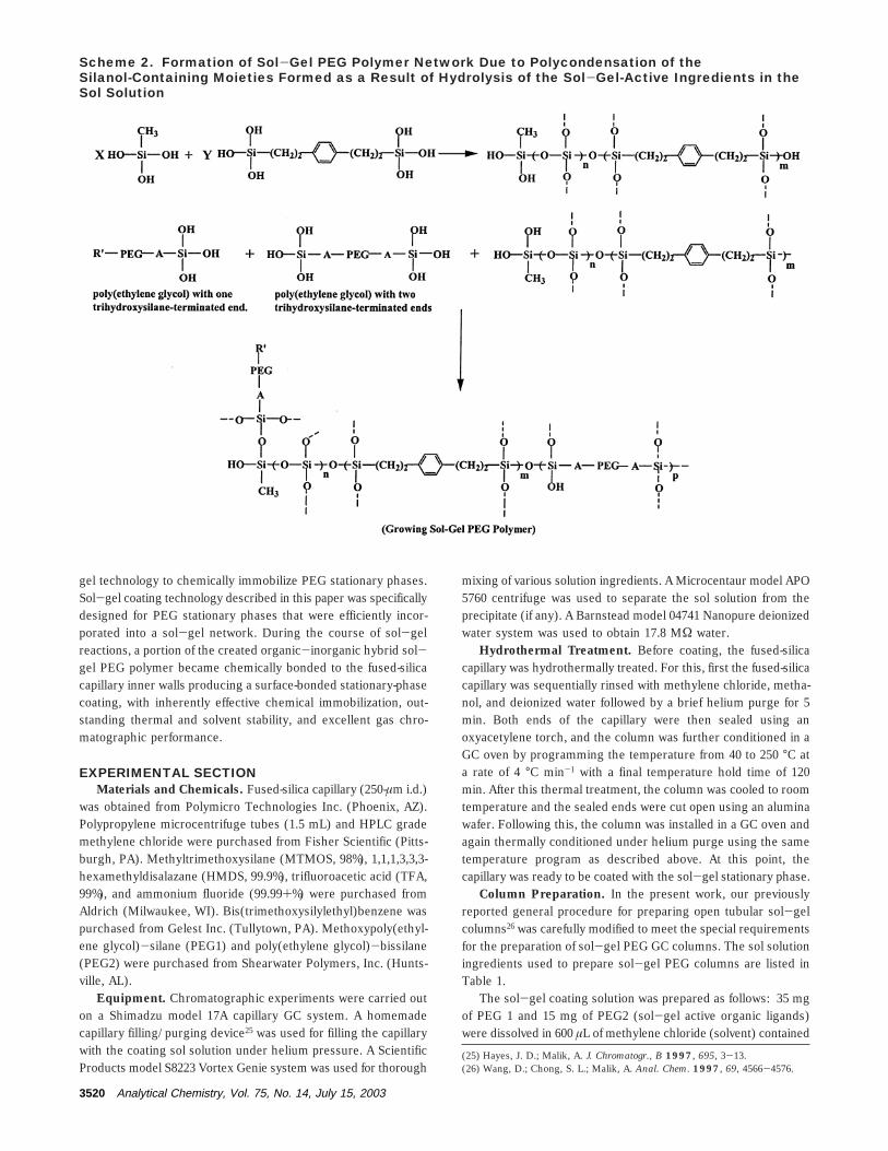
Scheme 3. Chemical Bonding of the Growing Sol-Gel PEG Polymer to the Inner Walls of theFused-Silica Capillary
Analytical Chemistry, Vol. 75, No. 14, July 15, 2003 3521

sol-gel active functional groups at both ends of their molecularstructures, they are likely to get incorporated in the polymernetwork structure. PEG1, on the other hand, having only one sol-gel active end, is likely to form a pendant side chain in thestationary-phase structure as shown in Scheme 3.
Portions of the sol-gel PEG polymer network growing in thevicinity of the fused-silica capillary inner walls got bonded to itdue to condensation with the silanol groups residing on thecapillary inner surface. After an appropriate length of in-capillaryresidence time (typically 10-30 min), the nonbonded bulk portionof the sol solution is expelled from the capillary, leaving behinda surface-bonded sol-gel PEG stationary-phase film on the innerwalls of the fused-silica capillary (Scheme 3). This chemicalbonding provides strong immobilization of the stationary phase,which in turn increases its thermal and solvent stability. Thethickness of this coating can be varied by manipulating the in-capillary residence time of the sol solution or by adjusting theconcentrations of various ingredients in the sol-gel coatingsolution.
In the presented sol-gel approach, the PEG1 and PEG2 playeddual roles. First, they served as the organic components for thesol-gel organic-inorganic hybrid stationary phase. Second, theirchemical bonding to silanol groups resulted in column deactiva-tion. HMDS in the sol solution served not only as a reagent forchemical derivatization of the residual silanol groups (Scheme 4)in the sol-gel columns to ensure added column inertness but
also as a precursor for in situ generation of ammonia, which isknown to play a significant role in determining the pore andsurface characteristics of sol-gel materials.27c
The use of MTMOS as a precursor aimed at eliminating theproblems inherently associated with the widely used tetraalkox-ysilane precursors. Sol-gel coatings prepared with the use oftetraalkoxysilane precursors show a tendency to crack during thethermal-conditioning step,27d which may serve as a major hin-drance to providing a uniform and highly homogeneous surfacecoating. The use of an alkyl or aryl derivative of a tetraalkoxysilaneprecursor can effectively overcome this problem. This is due tothe relatively open structure and greater flexibility of sol-gelpolymeric network resulting from the alkyl- or aryl-derivatizedprecursors.28 When subjected to thermal conditioning, stationaryphases consisting of such sol-gel polymeric networks canefficiently release the capillary thrust generated on the pore wallsduring evaporation of the solvent residing in the stationary-phasepores.
The purpose of using a second sol-gel precursor (BIS) wasto provide chemical incorporation of a phenyl ring into thestationary-phase structure during the sol-gel process. Due to thepresence of a phenyl ring in the polymeric backbone, the createdstationary phase can be expected to possess added thermalstability29 since the steric hindrance offered by the phenyl groups
(28) Mackenzie, J. Hybrid Organic-Inorganic Composites; ACS Symposium Series585; American Chemical Society: Washington, DC, 1995; pp 227-236.
Scheme 4. Derivatization of the Residual Silanol Groups in the Sol-Gel PEG Coating with HMDSduring Postcoating Thermal Treatment Resulting in Column Deactivation
3522 Analytical Chemistry, Vol. 75, No. 14, July 15, 2003
serves as an impediment to undesirable rearrangement reactionsthat could lead to stationary-phase degradation through formationof volatile cyclic compounds responsible for column bleeding.However, these phenyl groups could also potentially increase therigidity of the stationary phase. Chromatographic properties (e.g.,separation efficiency, mass transfer properties, etc.) of the station-ary phase might get negatively affected, if the structure is toorigid. Therefore, it is important to maintain a delicate balancebetween structural rigidity of the stationary phase and its
chromatographic performance. To avoid the sol-gel stationaryphase becoming too rigid, we selected BIS in which a spacerconsisting of two methylene groups is attached to the phenylgroup on each side, providing a reasonable degree of flexibilityto the sol-gel polymer.
(29) Bernhard, M.; Zollner, P.; Walfried, R.; Hanspeter, K. J. Chromatogr., A2001, 917, 219-226.
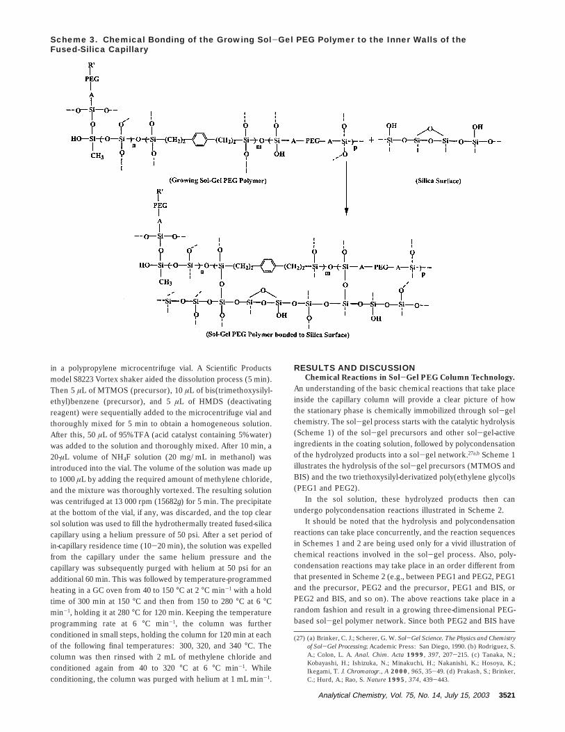
Figure 1. Scanning electron microscopic images of a sol-gel PEGcoated 250-µm-i.d. fused-silica capillary. (A) Cross-sectional view,magnification 5000×; (B) surface view of the fine structures on thesol-gel PEG coating, magnification, 20000×.
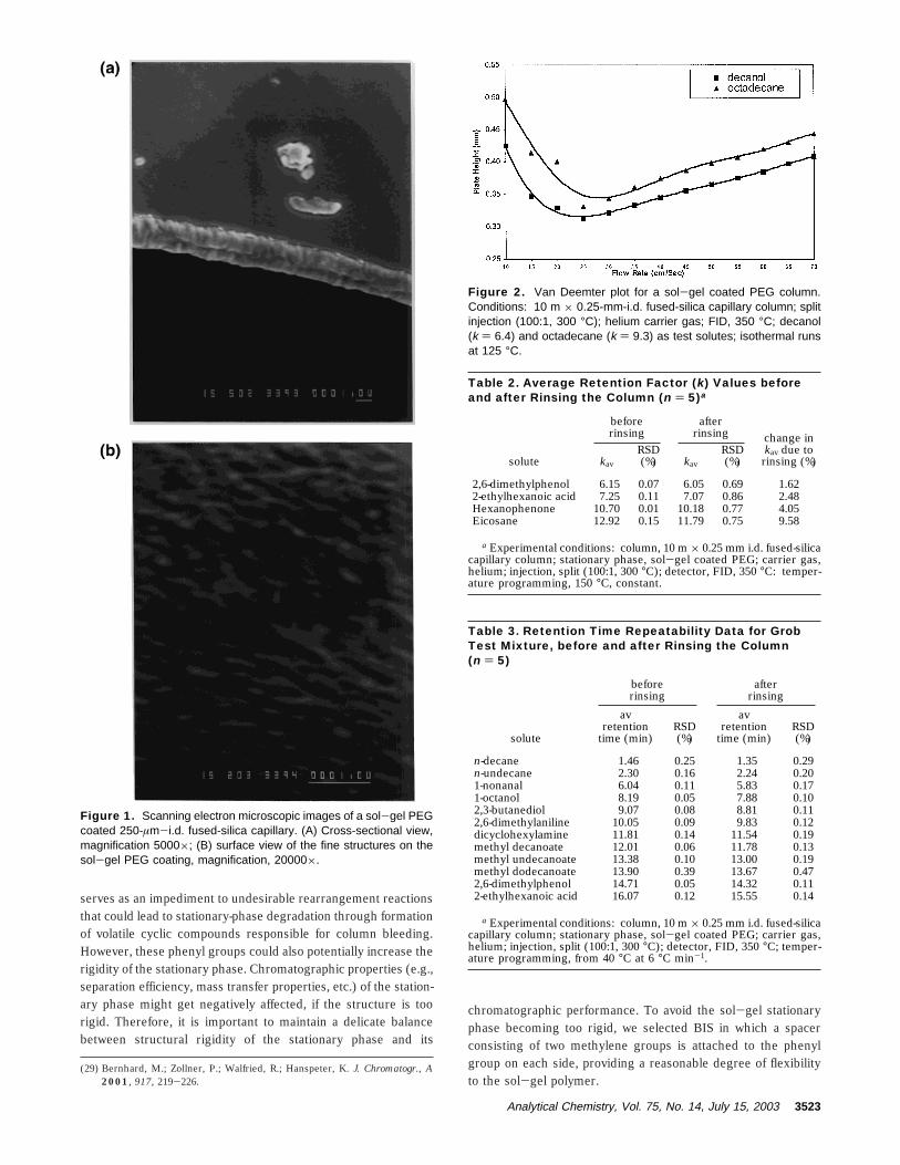
Figure 2. Van Deemter plot for a sol-gel coated PEG column.Conditions: 10 m × 0.25-mm-i.d. fused-silica capillary column; splitinjection (100:1, 300 °C); helium carrier gas; FID, 350 °C; decanol(k ) 6.4) and octadecane (k ) 9.3) as test solutes; isothermal runsat 125 °C.
Table 2. Average Retention Factor (k) Values beforeand after Rinsing the Column (n ) 5)a
beforerinsing
afterrinsing
solute kav
RSD(%) kav
RSD(%)
change inkav due to
rinsing (%)
2,6-dimethylphenol 6.15 0.07 6.05 0.69 1.622-ethylhexanoic acid 7.25 0.11 7.07 0.86 2.48Hexanophenone 10.70 0.01 10.18 0.77 4.05Eicosane 12.92 0.15 11.79 0.75 9.58
a Experimental conditions: column, 10 m × 0.25 mm i.d. fused-silicacapillary column; stationary phase, sol-gel coated PEG; carrier gas,helium; injection, split (100:1, 300 °C); detector, FID, 350 °C: temper-ature programming, 150 °C, constant.
Table 3. Retention Time Repeatability Data for GrobTest Mixture, before and after Rinsing the Column(n ) 5)
beforerinsing
afterrinsing
solute
avretention
time (min)RSD(%)
avretention
time (min)RSD(%)
n-decane 1.46 0.25 1.35 0.29n-undecane 2.30 0.16 2.24 0.201-nonanal 6.04 0.11 5.83 0.171-octanol 8.19 0.05 7.88 0.102,3-butanediol 9.07 0.08 8.81 0.112,6-dimethylaniline 10.05 0.09 9.83 0.12dicyclohexylamine 11.81 0.14 11.54 0.19methyl decanoate 12.01 0.06 11.78 0.13methyl undecanoate 13.38 0.10 13.00 0.19methyl dodecanoate 13.90 0.39 13.67 0.472,6-dimethylphenol 14.71 0.05 14.32 0.112-ethylhexanoic acid 16.07 0.12 15.55 0.14
a Experimental conditions: column, 10 m × 0.25 mm i.d. fused-silicacapillary column; stationary phase, sol-gel coated PEG; carrier gas,helium; injection, split (100:1, 300 °C); detector, FID, 350 °C; temper-ature programming, from 40 °C at 6 °C min-1.
Analytical Chemistry, Vol. 75, No. 14, July 15, 2003 3523
It is known that sol-gel-active organic polymers by themselvesmay act as deactivating agents.30 PEG1 and PEG2 not only servedas the sol-gel-active organic ligands but also took part in thecolumn deactivation through their condensation with silanol
groups responsible for undesirable adsorption activity of GCcolumns. Such a deactivation mechanism was complementary tothe deactivation obtained through the use of HMDS.
TFA (containing 5% water) was used as a sol-gel catalyst, inplace of the more conventional catalysts such as strong inorganicacids or strong bases. The selection of TFA as a sol-gel catalystwas based on the findings by Sharp31 that carboxylic acids withpKa values less than 4 were able to provide significantly higherreaction rates than strong inorganic acids or organic acids with apKa value greater than 4. Thus, the use of TFA, with a pKa valueof 0.3,32 provided enhanced gelation speed resulting in a decreasedcolumn fabrication time.
The surface characteristics of the created sol-gel PEGcoatings were studied by scanning electron microscopy (SEM)and are presented in Figure 1.
Figure 1a gives a vivid illustration of the sol-gel stationary-phase film created on the fused-silica capillary inner surface. Here,the SEM image (magnification of 5000×) shows that the createdsol-gel PEG coating is highly uniform, having a thickness of ∼1.0µm. The SEM image in Figure 1b (magnification 20000×),illustrates the fine structures of the sol-gel coated surface. Ascan be seen in Figure 1b, sol-gel PEG coating possessesenhanced surface area due to microroughening created by these
(30) Blomberg, L.; Wannman, T. J. Chromatogr. 1978, 148, 379-387.(31) Sharp, K. J. Sol-Gel Sci. Technol. 1994, 2, 35-41.(32) The Merck Index, 12th ed.; Merck: Rahway, NJ, 1996; p 9812.
Table 4. Column-to-Column Reproducibility Data forEfficiency (N), Retention Factor (k), and SeparationFactor (r) Obtained on Five Sol-Gel PEG Columnsa
columnefficiency
retentionfactor
separationfactor
column N RSD (%) k RSD (%) Rb RSD (%)
1 3117 7.23 1.332 3163 7.14 1.343 3091 1.09 7.29 1.37 1.32 0.94 3179 7.43 1.305 3104 7.36 1.32
a Conditions for column efficiency (N) and retention factor (k):column, 10 m × 0.25 mm i.d. fused-silica capillary column; stationaryphase, sol-gel PEG; injection, split (100:1, 300 °C); detector, FID, 350°C; temperature programming, 150 °C constant. Solute for measuringN and k was n-octadecane. Conditions for separation factor (R):column, 10 m × 0.25 mm i.d. fused-silica capillary column; stationaryphase, sol-gel PEG; injection, split (100:1, 300 °C); detector: FID,350 °C; temperature programming, 40 °C constant. b *For solute pairo- and p-xylene.
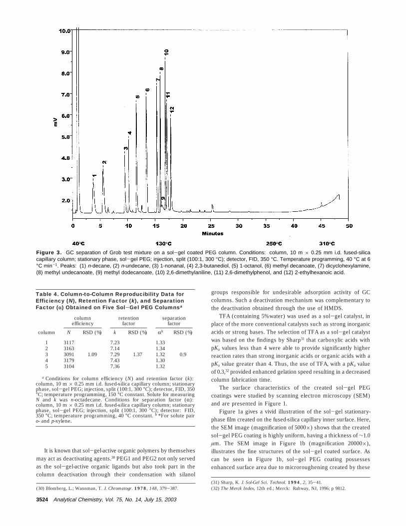
Figure 3. GC separation of Grob test mixture on a sol-gel coated PEG column. Conditions: column, 10 m × 0.25 mm i.d. fused-silicacapillary column; stationary phase, sol-gel PEG; injection, split (100:1, 300 °C); detector, FID, 350 °C. Temperature programming, 40 °C at 6°C min-1. Peaks: (1) n-decane, (2) n-undecane, (3) 1-nonanal, (4) 2,3-butanediol, (5) 1-octanol, (6) methyl decanoate, (7) dicyclohexylamine,(8) methyl undecanoate, (9) methyl dodecanoate, (10) 2,6-dimethylaniline, (11) 2,6-dimethylphenol, and (12) 2-ethylhexanoic acid.
3524 Analytical Chemistry, Vol. 75, No. 14, July 15, 2003
fine structures. Thus, sol-gel PEG stationary-phase coatings,having a porous structure and enhanced surface area, possessfavorable structural characteristics needed for enhanced samplecapacity and fast mass transfer.
Figure 2 represents a Van Deemter plot for a 10 m × 0.25mm i.d. sol-gel PEG column.
The curves were obtained at 125 °C using decanol (k ) 6.4)and octadecane (k ) 9.3) as test solutes. As can be seen fromthese plots, the minimum plate height (Hmin) was 0.31 mm for
decanol and 0.33 mm for octadecane. This corresponded to 3200and 3000 theoretical plates/m for decanol and octadecane,respectively. The right-hand side of the Van Deemter plotcharacterizes the mass-transfer process in the column and isrepresented by the coefficient C in the Van Deemter-Golayequation. This C value can be calculated from the ascending right-hand part of the plot. The slope on this part of the plot is quitesmall and has a value of ∼5.0 × 10⁻⁴ s. This value comparesfavorably with the values commonly obtained for open-tubularcolumns34 and indicates the rapid transfer of the solute moleculesbetween the two phases in sol-gel PEG columns. This efficientmass transfer points to the flexibility of the sol-gel surfacecoating. It should be mentioned that sol-gel column technologydoes not involve free radical cross-linking reactions, which arenormally employed in conventional column technology for im-mobilizing the stationary phase. Free radical cross-linking reac-tions often lead to reduced stationary-phase flexibility which, inmany cases, negatively affects the mass-transfer characteristicsof the column. A small C value indicates that the column efficiencywill not be greatly effected even if high carrier gas flow rates areused. This makes sol-gel PEG columns well suited for fastanalysis.
Chromatographic Characteristics of Sol-Gel PEG Sta-tionary Phases in GC. The prepared sol-gel PEG columnsshowed excellent solvent stability. They were rinsed with meth-ylene chloride after sol-gel coating and conditioning steps werecompleted. The solvent stability was then tested by comparingretention factor (k) values of four different solutes determined intriplicate before and after rinsing the column with the solvent(Table 2).
For all polar solutes the average (k) values differed by lessthan 5% before and after rinsing the column operated under thesame experimental conditions. For the nonpolar solute, eicosane,this difference was 9.58%, which is significantly higher than thosefor the polar solutes. This may be explained by the removal ofphysically incorporated nonpolar materials from the coating duringrinsing and by poor solubility of the nonpolar solute like eicosanein PEG. The outstanding solvent stability of sol-gel PEG columnsis due to the fact that the sol-gel approach to column technologyprovides chemical bonding of the stationary phase with the silicasurface. Strong chemical immobilization of the stationary phase
(33) Bigham, S.; Medlar, J.; Kabir, A.; Shende, C.; Alli, A.; Malik, A. Anal. Chem.2002, 74, 752-761.
(34) Ettre, L. S.; Hinshaw, J. V. Basic Relationship in Gas Chromatography;Advanstar: Cleveland, OH, 1993; p 127.
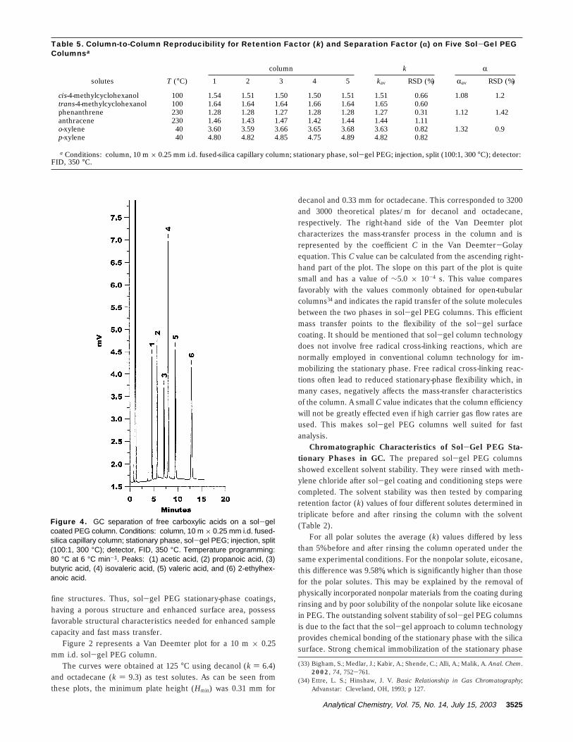
Figure 4. GC separation of free carboxylic acids on a sol-gelcoated PEG column. Conditions: column, 10 m × 0.25 mm i.d. fused-silica capillary column; stationary phase, sol-gel PEG; injection, split(100:1, 300 °C); detector, FID, 350 °C. Temperature programming:80 °C at 6 °C min-1. Peaks: (1) acetic acid, (2) propanoic acid, (3)butyric acid, (4) isovaleric acid, (5) valeric acid, and (6) 2-ethylhex-anoic acid.
Table 5. Column-to-Column Reproducibility for Retention Factor (k) and Separation Factor (r) on Five Sol-Gel PEGColumnsa
column k R
solutes T (°C) 1 2 3 4 5 kav RSD (%) Rav RSD (%)
cis-4-methylcyclohexanol 100 1.54 1.51 1.50 1.50 1.51 1.51 0.66 1.08 1.2trans-4-methylcyclohexanol 100 1.64 1.64 1.64 1.66 1.64 1.65 0.60phenanthrene 230 1.28 1.28 1.27 1.28 1.28 1.27 0.31 1.12 1.42anthracene 230 1.46 1.43 1.47 1.42 1.44 1.44 1.11o-xylene 40 3.60 3.59 3.66 3.65 3.68 3.63 0.82 1.32 0.9p-xylene 40 4.80 4.82 4.85 4.75 4.89 4.82 0.82
a Conditions: column, 10 m × 0.25 mm i.d. fused-silica capillary column; stationary phase, sol-gel PEG; injection, split (100:1, 300 °C); detector:FID, 350 °C.
Analytical Chemistry, Vol. 75, No. 14, July 15, 2003 3525

to the silica surface is also evident from comparison of pre-andpostrinsing retention times for Grob35 test mixture solutes belong-ing to a wide range of chemical classes (Table 3).
Data presented in Table 3 suggest that the solute retentiontimes do not change appreciably (if the manual injections are takeninto consideration). Strong chemical immobilization and structuralintegrity are important attributes of the prepared sol-gel PEGstationary phase that contributed to this excellent retention timereproducibility.
Strong chemical immobilization is also responsible for en-hanced thermal stability of the prepared sol-gel PEG columnsthat can be operated at elevated temperatures up to 320 °C andhigher. This operating temperature clearly surpasses the maxi-mum operating temperatures recommended for conventionallycoated PEG phases (200-275 °C).15,36 Figure 3 represents onesuch chromatogram illustrating separation of the Grob testmixture on a sol-gel PEG column.
The baseline of the chromatogram showed very low bleedingeven at a temperature of 320 °C. To our knowledge, such a highthermal stability has not been achieved so far for PEG columns.Thus, sol-gel column technology provided an effective solutionto a difficult problem related to the immobilization of PEG-basedstationary phases and offered outstanding thermal stability.
Reproducibility Characteristics of Sol-Gel Coated PEGColumns. An important feature of any newly developed techniqueis its reproducibility. The reproducibility characteristics greatlyinfluence the reliability and hence the viability of the developedmethod. In column technology, an important reproducibilitycriterion is the column-to-column reproducibility. To evaluate this,five sol-gel PEG columns were prepared under identical condi-tions. Table 4 gives the column efficiency (N), retention factor(k), and separation factor (R) data for selected test solutes andRSD values associated with them.
The RSD values were 1.09% for N, 1.37% for k, and 0.9% for R,respectively. These low RSD values bear testimony to the fact thatthe developed sol-gel method for the preparation of PEG GCcolumns is indeed reliable and highly reproducible. Column-to-column repeatability was further examined by injecting isomerssuch as cis- and trans-4-methylcyclohexanol, phenanthrene andanthracene, and o-xylene and p-xylene on the five sol-gel PEGcoated columns. These isomeric solutes were run isothermallyat column temperatures appropriate for each pair of solutes. TheR value for each solute pair was calculated from the experimentallydetermined k values of the two solutes in the pair. For the fivecolumns, the calculated RSD values for k and R are presented inTable 5.
The RSD values for retention and separation factors on thesefive sol-gel PEG columns were less than1.2 and 1.5%, respectively.
(35) Grob, K., Jr.; Grob, G.; Grob, K. J. Chromatogr. 1978, 156, 1-20.(36) de Zeeuw, J.; Luong, J. Trends Anal. Chem. 2002, 21, 594-607.
Figure 5. GC separation of amines and amino alcohols on a sol-gel coated PEG column. Conditions: column, 10 m × 0.25 mm i.d. fused-silica capillary column; stationary phase, sol-gel PEG; injection, split (100:1, 300 °C); detector, FID, 350 °C. (A) aliphatic/aromatic amines andamino alcohols: temperature programming, from 75 °C at 6 °C min-1. Peaks: (1) propylamine, (2) ethanolamine, (3) N-methylaniline, (4)triethanolamine, and (5) 2-ethylaniline. (B) aromatic amines: temperature programming, from 65 °C at 6 °C min-1. Peaks: (1) N,N-dimethylaniline,(2) N-methylaniline, (3) N-ethylaniline, (4) 2-ethylaniline, (5) 4-ethylaniline, and (6) 3-ethylaniline.
3526 Analytical Chemistry, Vol. 75, No. 14, July 15, 2003
Such low RSD values are indicative of excellent column-to-columnreproducibility in terms of both column fabrication procedure andstationary-phase selectivity.
Another important reproducibility parameter is the run-to-runrepeatability, which reflects upon the robustness of the stationary-phase coatings to preserve the retention, selectivity, efficiency,and other chromatographic parameters that might be monitoredover the runs to gauge the column performance. To evaluate therun-to-run repeatability, Grob mixture was injected in five replicateGC runs. RSD values of less than 0.50% in retention times wereobtained for the Grob mixture. These low RSDs can again beattributed to the structural and functional integrity of the sol-gelPEG stationary phases in GC operations.
Deactivation in Sol-Gel Coated PEG GC Columns. Properdeactivation of the polar adsorption sites in the column is acritically important task in GC column technology that greatlyinfluences the separation efficiency and column performance ingeneral. Inadequate column deactivation often results in undesir-able effects in chromatographic separations such as peak tailing,reduced peak height, and irreversible solute adsorption, especiallyfor polar analytes. The principle reason for the above undesirableeffects is the presence of surface silanol groups, which stronglyinteract (through hydrogen-bonding, dipole-dipole, and dipole-induced dipole interactions) with the polar analytes and ultimately
lead to the detrimental effects mentioned above. The deactivationquality of the sol-gel coated PEG columns was evaluated by usingfree carboxylic acids, amines, and amino alcohols as test solutes.It is well known that separation of free carboxylic acids37 oraliphatic amines is a challenging task in gas chromatography,more so if they are to be separated on the same column, withoutadding any stationary-phase modifier. Thus, these two classes ofanalytes provide a very stringent test of column deactivation.Carboxylic acids are very polar and tend to interact with theresidual silanol and other adsorptive sites, resulting in broad andtailing peaks. Similarly, acid-base interactions of the basicanalytes with the silanol groups cause them to tail, and in somecases, such analytes may even be irreversibly sorbed by thestationary phase in a poorly deactivated column. Figure 4represents the gas chromatographic separation of free carboxylicacids, and Figure 5 represents the gas chromatographic separationof aliphatic/aromatic amines and amino alcohols (Figure 5A) andaromatic amines (Figure 5B).
Symmetrical peaks for free carboxylic acids, aliphatic andaromatic amines, and amino alcohols obtained on the prepared
(37) Ballesteros, E.; Cardenas, S.; Gallego, M.; Valcarcel, M. Anal. Chem. 1994,21, 628-634.
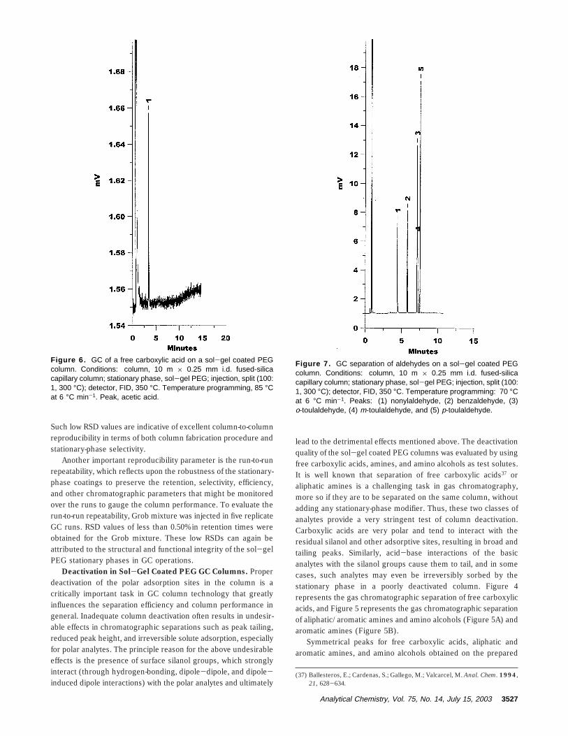
Figure 6. GC of a free carboxylic acid on a sol-gel coated PEGcolumn. Conditions: column, 10 m × 0.25 mm i.d. fused-silicacapillary column; stationary phase, sol-gel PEG; injection, split (100:1, 300 °C); detector, FID, 350 °C. Temperature programming, 85 °Cat 6 °C min-1. Peak, acetic acid.
Figure 7. GC separation of aldehydes on a sol-gel coated PEGcolumn. Conditions: column, 10 m × 0.25 mm i.d. fused-silicacapillary column; stationary phase, sol-gel PEG; injection, split (100:1, 300 °C); detector, FID, 350 °C. Temperature programming: 70 °Cat 6 °C min-1. Peaks: (1) nonylaldehyde, (2) benzaldehyde, (3)o-toulaldehyde, (4) m-toulaldehyde, and (5) p-toulaldehyde.
Analytical Chemistry, Vol. 75, No. 14, July 15, 2003 3527
sol-gel PEG column are indicative of high quality of columndeactivation. Mention should be made of the fact that no specialdeactivation steps were employed, nor was any surface/phasemodification carried out on the sol-gel PEG columns used toperform these separations. This high quality of deactivationachieved in sol-gel column technology can be attributed to anumber of factors inherent in the sol-gel process itself. First,during the sol-gel process, some of the surface silanol groupsare derivatized by the growing sol-gel network and others areburied under it. Second, during the coating process, HMDS (aningredient of the coating solution) becomes physically includedin the sol-gel PEG stationary phase and deactivates the columnby reacting with the silanol groups mainly during thermalconditioning that follows the column coating process. Third, inthe sol-gel approach, deactivation of the column begins with thesol-gel process used to in situ create the stationary-phase film.Here the sol-gel-active organic ingredients (PEG 1, PEG 2, BIS)can also take part in the column deactivation. It should beemphasized that, in the sol-gel approach, column deactivationtakes place not only on the capillary inner surface but alsothroughout the entire volume of the stationary-phase film. It is athree-dimensional deactivation process rather than a two-dimen-sional process inherent in conventional column technology.
In probing the column deactivation quality, it is very importantto consider the individual concentration of the analytes in the testmixture. If the analyte concentration is too high, then theadsorptive sites may become saturated with the analytes and onemay get good looking peak shapes even for highly polar com-pounds. Concentration as low as 2 µg/mL of a free carboxylicacid (acetic acid), corresponding to an injected amount of 2 ng,was introduced into a sol-gel coated Carbowax column andperfect peak shape was obtained (Figure 6).
Sol-gel coated PEG columns showed excellent chromato-graphic performances for a wide range of analytes, evidenced bythe following examples of GC separations. Figure 7 representsGC separation of a mixture of aldehydes that often produce broadand tailing peaks on PEG phases.35 The sharp and symmetricalpeaks obtained for aldehydes on the sol-gel PEG columns onceagain point to the excellent quality of deactivation inherent in thesol-gel column technology (Figure 7).
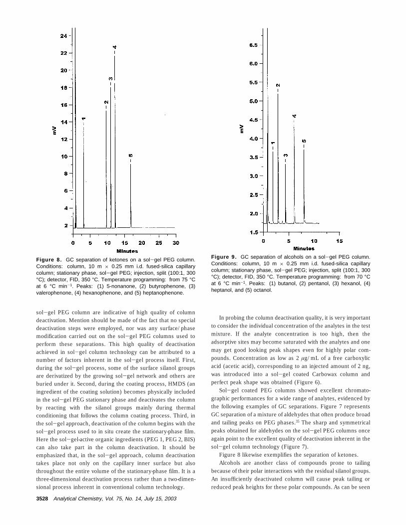
Figure 8 likewise exemplifies the separation of ketones.Alcohols are another class of compounds prone to tailing
because of their polar interactions with the residual silanol groups.An insufficiently deactivated column will cause peak tailing orreduced peak heights for these polar compounds. As can be seen
Figure 8. GC separation of ketones on a sol-gel PEG column.Conditions: column, 10 m × 0.25 mm i.d. fused-silica capillarycolumn; stationary phase, sol-gel PEG; injection, split (100:1, 300°C); detector, FID, 350 °C. Temperature programming: from 75 °Cat 6 °C min-1. Peaks: (1) 5-nonanone, (2) butyrophenone, (3)valerophenone, (4) hexanophenone, and (5) heptanophenone.
Figure 9. GC separation of alcohols on a sol-gel PEG column.Conditions: column, 10 m × 0.25 mm i.d. fused-silica capillarycolumn; stationary phase, sol-gel PEG; injection, split (100:1, 300°C); detector, FID, 350 °C. Temperature programming: from 70 °Cat 6 °C min-1. Peaks: (1) butanol, (2) pentanol, (3) hexanol, (4)heptanol, and (5) octanol.
3528 Analytical Chemistry, Vol. 75, No. 14, July 15, 2003

from Figure 9, sol-gel PEG columns produced good peak shapesfor alcohols, minimizing the above-mentioned adverse effects.
Phenols represent an environmentally important class ofcompounds that are acidic in nature. Figure 10 gives the high-efficiency separation of dimethylphenol isomers. Baseline resolu-tion of dimethylphenol isomers demonstrates high selectivity ofthe newly developed sol-gel PEG stationary phase toward theseisomeric polar compounds.
Figure 11 A is the separation of anthracene and phenanthrene,which are baseline resolved on a 10-m-long sol-gel PEG column.This indicates the ability of the PEG stationary phases to recognizestructural differences in molecules. Figure 11B represents the GCseparation of o- and p-xylene. The o- and p-xylene pair was morethan baseline resolved with an RS value of 2.80.
Polarity Of Sol-Gel Coated PEG Columns. Polarity of sol-gel coated PEG columns was evaluated by calculating theMcReynolds constants.38,39 The calculated values in Table 6 showthat PEG coated columns have an overall polarity value of 1917,as compared to a value of 2353 for static coated PEG columns.39
This difference in polarity can be attributed to the presence ofnonpolar moieties in the chemical structure of the used sol-gel
precursors that ultimately become incorporated in the coatingstructure. A higher polarity could be obtained if the precursorsin the sol solution are decreased or precursors containing nononpolar moieties were used.
CONCLUSIONA sol-gel chemistry-based novel approach to prepare high-
efficiency columns with immobilized poly(ethylene glycol) station-ary phases is presented for capillary gas chromatography. Thesol-gel approach successfully addresses and eliminates many ofthe drawbacks associated with conventional column technologyfor PEG stationary phases. Such shortcomings include difficultiesassociated with the immobilization of these polar stationaryphases, their low thermal stability, and low reproducibility incolumn preparation and performance. Sol-gel technology facili-tates effective chemical bonding between the sol-gel PEG
(38) Rotzsche, H. Stationary Phases in Gas Chromatography; Elsevier ScienceB.V.: Amsterdam, 1991; pp 81-94.
(39) McReynolds, W. O. J. Chromatogr. Sci. 1970, 8, 685-691.
Figure 10. GC separation of dimethylphenol isomers on a sol-gelPEG column. Conditions: column, 10 m × 0.25 mm i.d. fused-silicacapillary column; stationary phase, sol-gel PEG; injection, split (100:1, 300 °C); detector, FID, 350 °C. Temperature programming: from65 °C at 6 °C min-1. Peaks: (1) 2,6-dimethyphenol, (2) 2,5-dimethyphenol, (3) 3,5-dimethyphenol, and (4) 3,4-dimethyphenol.
Figure 11. GC separation of isomeric compounds on a sol-gelPEG column. Conditions: column, 10 m × 0.25 mm i.d. fused-silicacapillary column; stationary phase, sol-gel PEG; injection, split (100:1, 300 °C); detector, FID, 350 °C. (A) Temperature, 230 °C. Peaks:(1) phenanthrene and (2) anthracene; (B) Temperature, 40 °C.Peaks: (1) p-xylene and (2) o-xylene.
Table 6. McReynolds Constants for Sol-Gel PEGColumna
probe benzene 1-butanol 2-pentanone 1-nitropropane pyridine
I for sol-gelPEG
848.29 1050.79 945.34 1148.89 1144.91
I for squalane 653 590 627 652 699∆ I 195 (X) 460 (Y) 318 (Z) 496 (U) 445 (S)
a General polarity: X + Y + Z + U + S ) 1917.
Analytical Chemistry, Vol. 75, No. 14, July 15, 2003 3529

stationary phase film and the fused-silica capillary inner surface,leading to excellent stationary-phase immobilization and thermalstability up to 320 °C. Column efficiencies on the order of 3200theoretical plates/m can be routinely obtained on 250-µm-i.d. sol-gel PEG capillary columns in GC. Sol-gel PEG stationary phasecan be used for efficient separation of difficult-to-chromatographanalytes such as free carboxylic acids and aliphatic amines on
the same column. The presented results bear strong evidence thatsol-gel PEG columns have the potential to offer a new level ofperformance in GC separation of polar analytes.
Received for review November 20, 2002. Accepted April 9,2003.
AC0207224
3530 Analytical Chemistry, Vol. 75, No. 14, July 15, 2003