Software layer for FPGA-based TESLA cavity control system
12
EU contract number RII3-CT-2003-506395 CARE Conf-04-047-SRF SRF Software layer for FPGA-based TESLA cavity control system (part I) Waldemar Koprek, Paweł Kaleta, Jarosław Szewiński, Krzysztof T. Poźniak, Tomasz Czarski, Ryszard S.Romaniuk Institute of Electronic Systems, WUT, Nowowiejska 15/19, 00-665 Warsaw, Poland Abstract The paper describes design and practical realization of software for laboratory purposes to control FPGA-based photonic and electronic equipment. There is presented a universal solution for all relevant devices with FPGA chips and gigabit optical links. The paper describes architecture of the software layers and program solutions of hardware communication based on Internal Interface (II) technology. Such a solution was used for superconducting Cavity Controller and Simulator (SIMCON) for the TESLA experiment in DESY (Hamburg). A number of practical examples of the software solutions for the SIMCON system were given in this paper. Keywords: accelerator, superconducting cavity, cavity simulator, cavity controller, Matlab, FPGA, VHDL, multi-gigabit optical links Contribution to the XVIth IEEE-SPIE Wilga Symposium on Electronics and Photonics for HEP Experiments, May 04, Wilga, Poland Work supported by the European Community-Research Infrastructure Activity under the FP6 “Structuring the European Research Area” programme (CARE, contract number RII3-CT- 2003-506395).
-
Upload
independent -
Category
Documents
-
view
6 -
download
0
Transcript of Software layer for FPGA-based TESLA cavity control system
EU contract number RII3-CT-2003-506395 CARE Conf-04-047-SRF
SRF
Software layer for FPGA-based TESLA cavity control system (part I) Waldemar Koprek, Paweł Kaleta, Jarosław Szewiński, Krzysztof T. Poźniak,
Tomasz Czarski, Ryszard S.Romaniuk Institute of Electronic Systems, WUT, Nowowiejska 15/19, 00-665 Warsaw, Poland
Abstract
The paper describes design and practical realization of software for laboratory purposes to control FPGA-based photonic and electronic equipment. There is presented a universal solution for all relevant devices with FPGA chips and gigabit optical links. The paper describes architecture of the software layers and program solutions of hardware communication based on Internal Interface (II) technology. Such a solution was used for superconducting Cavity Controller and Simulator (SIMCON) for the TESLA experiment in DESY (Hamburg). A number of practical examples of the software solutions for the SIMCON system were given in this paper. Keywords: accelerator, superconducting cavity, cavity simulator, cavity controller, Matlab, FPGA, VHDL, multi-gigabit optical links
Contribution to the XVIth IEEE-SPIE Wilga Symposium on Electronics and Photonics for HEP Experiments, May 04, Wilga, Poland
Work supported by the European Community-Research Infrastructure Activity under the FP6 “Structuring the European Research Area” programme (CARE, contract number RII3-CT-2003-506395).
TESLA Report 2004-10
Software layer for FPGA-based TESLA cavity control system (part I)
Waldemar Koprek, Paweł Kaleta, Jarosław Szewiński, Krzysztof T. Poźniak, Tomasz Czarski, Ryszard S.Romaniuk
Institute of Electronic Systems, WUT, Nowowiejska 15/19, 00-665 Warsaw, Poland
ABSTRACT
The paper describes design and practical realization of software for laboratory purposes to control FPGA-based photonic and electronic equipment. There is presented a universal solution for all relevant devices with FPGA chips and gigabit optical links. The paper describes architecture of the software layers and program solutions of hardware communication based on Internal Interface (II) technology. Such a solution was used for superconducting Cavity Controller and Simulator (SIMCON) for the TESLA experiment in DESY (Hamburg). A number of practical examples of the software solutions for the SIMCON system were given in this paper.
Keywords: accelerator, superconducting cavity, cavity simulator, cavity controller, Matlab, FPGA, VHDL, multi-gigabit optical links
1. INTRODUCTION
The photonic and electronic systems which are used to control the cavities in the TESLA experiment [2,3,4,5] base on the newest FPGA chips [1,9]. This system requires not only the development and implementation of complex photonic/electronic modules but also application of efficient and dedicated layer of the software. This layer is an essential element during the stages of testing, activating and diagnostics of any device functionality. The software also supports the reliable work on the system development, which in turn leads to final and optimized version of the devices under design. Because of the above aspects, the electronic systems basing on the FPGA chips are classified as „hard-soft” ones. Such HS systems have coherent, very closely coupled, layers of the software and the hardware.
A significant feature of the FPGA-based systems is the possibility of easy modification of the functional layer of devices. These changes can be done exclusively with reprogramming. Such technological facilities allow easy, fast and repeated way of implementing the changes, corrections and improvements. According to these facilities the software layer must keep up with these changes and must co-operate with the hardware to provide the ability to check the proper work of the software after all the changes have been introduced. Therefore, such software has to be flexible and allow for applying all modifications in an easy way. In such a manner, the time of software modifications can be minimized. Due to these advantages of the software, the developer can concentrate on the functional layer of the devices. In many cases, the testing of the devices is an iterative process. According to this, the time spent on software modifications should be as short as possible. In this paper, there were described the results of the work on a dedicated software layer for the cavity controller and simulator in the TESLA experiment in DESY (Hamburg) [8].
All of the devices of the cavity controller system, which base on the FPGA, have a specified internal structure. The device operation and form of the dedicated software depends on the FPGA structure. To minimize the influence of the hardware structure on the software there were created special system solutions which could be used to describe the FPGA-based systems. Such a standard of the FPGA description was implemented as a proprietary solution under the name of the Internal Interface (II). The II description of the FPGA-based electronic systems allows for creating the universal software which can be used in laboratory and in experiment
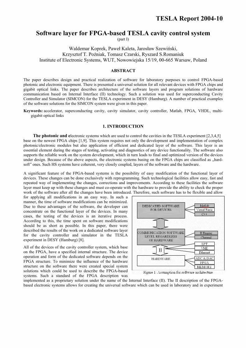
conditions. On the base of such solutions a capability of developing software which can be used to dedicated purposes for particular devices was achieved. Various graphical user interfaces may be built, such as control panels, measurements panels or panels for hardware debugging. Implementation of such solutions can be found in further parts of this paper. A general structure of the software layer under development is presented in fig. 1.
2. SOFTWARE LAYER STRUCTURE FOR FPGA BASED SYSTEM
The photonic and electronic cavity control system bases on the FPGA technology. The FPGA chips make realization of the number of special functionalities possible, such as logic systems, DSP processes, data acquisition, etc. All of the functional blocks with FPGA chips are connected to the II. This connection exchanges data between the FPGA and the software.
F P G A
TCP/IP
Other Application
Channel libraries
Other Application
VM
Ehternet
Ohter
LP
Intern
al Interface
TCP Server
IID
II Engine
The photonic and electronic devices also possess external interface to communicate with other devices. Such interfaces allow for communication with computer or other devices to II, which is connected to electronic subsystems and FPGA chips. The external interfaces can be made in different ways. In actual systems there are used: serial port with EPP protocol, VME interface of 6HE in size, Ethernet link with TPC/IP protocol implemented. There is a possibility to apply other and new interface standard which have implemented II from one side and from the other side it has implemented any other communication protocol (e.g. RS-232, USB, etc.). For the laboratory development, the easiest and most effective is connection over LPT port using EPP protocol, but for the industrial usage, the access over the VME bus, or the Ethernet connection is required. In this case, there is a need for a single uniform method of accessing the hardware, which will be transparent for the higher levels of the software system. To achieve such flexibility, the channels used in the project are implemented as a plugging. This solution will be described in chapter 3.1.
Figure 2. Block diagram of laboratory software
The II was developed to automate the local communication interface. It works at the hardware side (VHDL) and the software side (C++) [1,6]. The basis of that project is describing the FPGA I/O area (bits, registers, etc.) using well-known syntax in description file (IID). This file is included and processed in VHDL and C++ as a header file. It is provided to enhance the compatibility and flexibility between the hardware and the software version.
The system is divided into layers. On the top, there is the User Application Layer. This layer has access only to the middle layer, where there is located the Internal Interface Engine (II Engine). The II Engine is implemented as a Dynamic Link Library (DLL). This library exports a set of functions which create an interface of the II Engine (II
Engine API). Any application that uses this API may become a client of this system and may have access to these FPGA devices.
Such elaborated set of libraries allows for connection of devices with various user applications. The user applications can be created in the Matlab or in other programming environments, which make graphics user interface creation possible. In laboratory conditions, the Matlab is a very useful programming tool. Matlab can be used to create mathematical model of the devices (especially the FPGA systems), to upload work parameters of devices and next to read and analyze the response from them in the Matlab. The functions from communication libraries are called from the Matlab using MEX-files.
The architecture of software, which was described above, allows preparing a work station with a single PC computer. But there is a necessity to work on the second computer which can communicate with device via the local network. According to this necessity, there were elaborated and created libraries and applications which can work in the client-server architecture using the TPC/IP protocol. These applications communicate via the Ethernet. Thanks to this device, the client computer can be placed in different locations. This advantage is very useful in distributed experiment conditions. The detailed description of realization and implementation all programming layers and examples of using them can be found in the next chapters.
3. REALIZATION OF SOFTWARE LAYERS
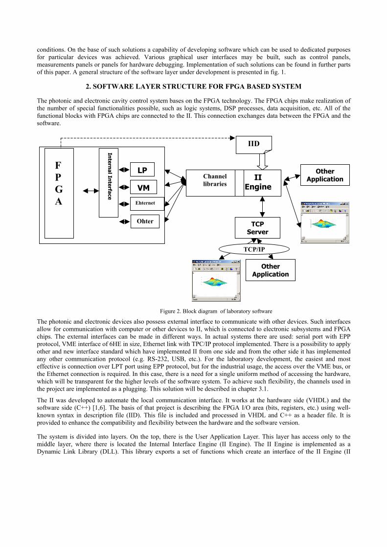
3.1. Communication with hardware using channels The channel is a general method of communication with the device. Since a single board may contain many FPGA chips, the device is a one address space which can span over one or more FPGA chips.
All channels have the same uniform interface, which is a set of methods that does not dependent on the channel architecture, but describes operations on the higher level of abstraction. For example, there are primitive functions “read” and “write” which let us operate on the address space.
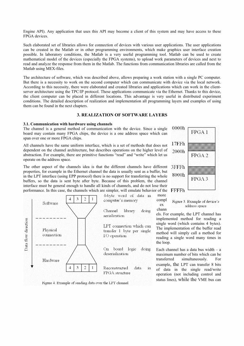
The other aspect of the channels idea is that the different channels have different properties, for example in the Ethernet channel the data is usually sent as a buffer, but in the LPT interface (using EPP protocol) there is no support for transferring the whole buffers, so the data is sent byte after byte. Because of this problem, the channel interface must be general enough to handle all kinds of channels, and do not lose their performance. In this case, the channels which are simpler, will emulate behavior of the
more compl
ex channels. For example, the LPT channel has implemented method for reading a single word (which contains 4 bytes). The implementation of the buffer read method will simply call a method for reading a single word many times in the loop.
Each channel has a data bus width – a maximum number of bits which can be transferred simultaneously. For example, the LPT can transfer 8 bits of data in the single read/write operation (not including control and status lines), while the VME bus can
transfer 32 bits of data at once.
Unfortunately, each device may have different widths of address and data busses, the size of these busses is not determined a priori (it may even not be multiplicity of 8).
In the case of data sending, each channel must cut the data stream into some parts that can fit into the channel bus width. When receiving the data, the channel is doing the reverse operations to reconstruct the data from device’s address space in the computer memory. Also, the hardware must have a functional logic which will reconstruct the transferred data in the FPGA address space, or will prepare the data for sending from the FPGA to the PC. Example of such solution can be found in [7].
The simplest solutions use a single medium (like the LPT), which connects the PC with one device. In more complex cases, one machine can control many devices (multiple address spaces), for example using one Ethernet connection for accessing multiple hardware. Because of that, it was necessary to enable access to hardware for multiple client applications, where each client operates on a different device, but on the other hand, each client must have exclusive access to a single device. To enable exclusivity, there are used platform depended methods of inter-process synchronization (semaphores, mutexes, critical sections, etc.).
To achieve a flexible uniform interface for all channels, we have implemented them as a plugging. Every channel module is a dynamic link library (DLL on MS Windows platform, but in the future we plan to port it to the Linux and Solaris environments). This solution gives a possibility to change the way of communication, by simply changing the channel file, without recompiling other parts of the system. The higher levels of the system will not even notify this change, because channels are transparent for them.
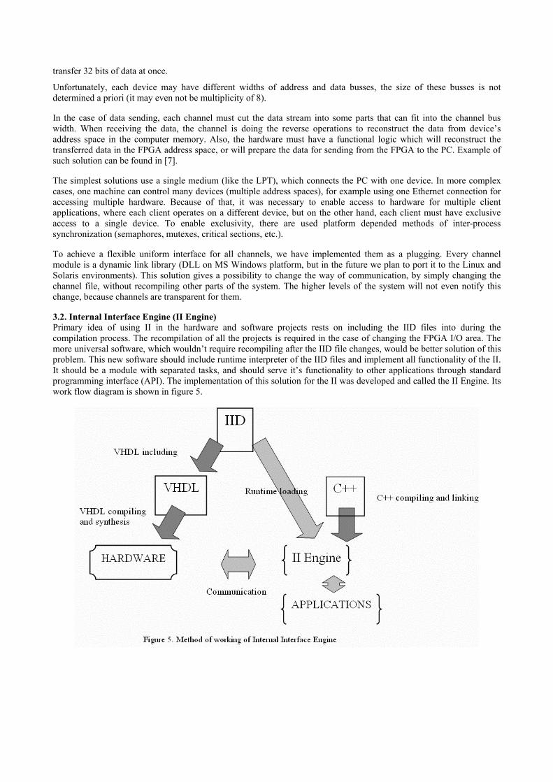
3.2. Internal Interface Engine (II Engine) Primary idea of using II in the hardware and software projects rests on including the IID files into during the compilation process. The recompilation of all the projects is required in the case of changing the FPGA I/O area. The more universal software, which wouldn’t require recompiling after the IID file changes, would be better solution of this problem. This new software should include runtime interpreter of the IID files and implement all functionality of the II. It should be a module with separated tasks, and should serve it’s functionality to other applications through standard programming interface (API). The implementation of this solution for the II was developed and called the II Engine. Its work flow diagram is shown in figure 5.
Modifying the FPGA I/O area is equivalent to modifying the IID file, so it is reasonable. As distinct from the hardware project, the software project is completely independent from the IID changes and it needn’t be recompiled. It is the biggest advantage of this solution. It should be noticed, that the new idea of using the II makes the hardware testing process simpler. In this solution the II Engine module has two primary tasks, both of which are described in next paragraphs:
1. extracting and serving information about hardware from the IID file,
2. enable communication between the hardware and external application.
Dynamic loading of the IID files. The absolute independence between the software and the IID files changes is only possible in the case of runtime interpreting of the IID. To make this possible, the IID should be treated not only as some macros for the preprocessor, but as the hardware description language. In this case, the II Engine has to contain the IID interpreter.
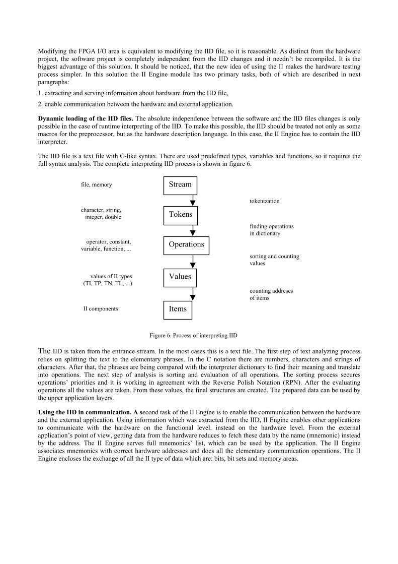
The IID file is a text file with C-like syntax. There are used predefined types, variables and functions, so it requires the full syntax analysis. The complete interpreting IID process is shown in figure 6.
Figure 6. Process of interpreting IID
counting addreses of items
sorting and counting values
finding operations in dictionary
tokenization
II components
values of II types(TI, TP, TN, TL, ...)
operator, constant,variable, function, ...
character, string,integer, double
file, memory
Items
Values
Operations
Tokens
Stream
The IID is taken from the entrance stream. In the most cases this is a text file. The first step of text analyzing process relies on splitting the text to the elementary phrases. In the C notation there are numbers, characters and strings of characters. After that, the phrases are being compared with the interpreter dictionary to find their meaning and translate into operations. The next step of analysis is sorting and evaluation of all operations. The sorting process secures operations’ priorities and it is working in agreement with the Reverse Polish Notation (RPN). After the evaluating operations all the values are taken. From these values, the final structures are created. The prepared data can be used by the upper application layers.
Using the IID in communication. A second task of the II Engine is to enable the communication between the hardware and the external application. Using information which was extracted from the IID, II Engine enables other applications to communicate with the hardware on the functional level, instead on the hardware level. From the external application’s point of view, getting data from the hardware reduces to fetch these data by the name (mnemonic) instead by the address. The II Engine serves full mnemonics’ list, which can be used by the application. The II Engine associates mnemonics with correct hardware addresses and does all the elementary communication operations. The II Engine encloses the exchange of all the II type of data which are: bits, bit sets and memory areas.
3.3. Client Applications - Matlab Connection to the II Engine In the laboratory work, for the processing of measurement data, the Matlab is commonly used. The obvious need is to transfer this data to the Matlab environment. To enable the direct access from Matlab to the hardware (though the II Engine) there has been created a set of extensions for the Matlab written in the C language as a “Matlab Executables” - MEX-files, they appear for Matlab as functions (like M-files).
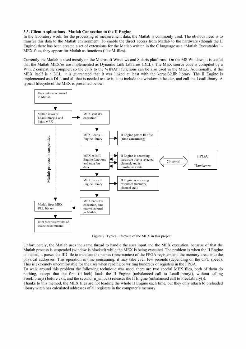
Currently the Matlab is used mostly on the Microsoft Windows and Solaris platforms. On the MS Windows it is useful that the Matlab MEX’es are implemented as Dynamic Link Libraries (DLL). The MEX source code is compiled by a Win32 compatible compiler, so the calls to the WINAPI functions can be also used in the MEX. Additionally, if the MEX itself is a DLL, it is guaranteed that it was linked at least with the kernel32.lib library. The II Engine is implemented as a DLL and all that is needed to use it, is to include the windows.h header, and call the LoadLibrary. A typical lifecycle of the MEX is presented below.
Unfortunately, the Matlab uses the same thread to handle the user input and the MEX execution, because of that the Matlab process is suspended (window is blocked) while the MEX is being executed. The problem is when the II Engine is loaded, it parses the IID file to translate the names (mnemonics) of the FPGA registers and the memory areas into the physical addresses. This operation is time consuming; it may take even few seconds (depending on the CPU speed). This is extremely uncomfortable for the user when reading or writing hundreds of registers in the FPGA.
Matlab invokes LoadLibrary(), and loads MEX
MEX Loads II Engine library
II Engine parses IID file (time consuming)
MEX calls II Engine functions and transfers data
II Engine is accessing hardware over a selected channel, and is transferring data
MEX Frees II Engine library
II Engine is releasing resources (memory, channel etc.)
MEX ends it’s execution, and returns control to Matlab
FPGA
HardwareChannel
Matlab frees MEX DLL library
Figure 7. Typical lifecycle of the MEX in this project
User receives results of executed command
MEX start it’s execution
User enters command in Matlab
Mat
lab
proc
ess i
s sus
pend
ed
To walk around this problem the following technique was used, there are two special MEX files, both of them do nothing, except that the first (ii_lock) loads the II Engine (unbalanced call to LoadLibrary(), without calling FreeLibrary() before exit, and the second (ii_unlock) releases the II Engine (unbalanced call to FreeLibrary()). Thanks to this method, the MEX files are not loading the whole II Engine each time, but they only attach to preloaded library witch has calculated addresses of all registers in the computer’s memory.
The technique described above is possible, because the calls to LoadLibrary() and FreeLibrary() are cumulative; FreeLibrary must be called as many times as the LoadLibrary was, other way the system will keep the library in memory as long as the number of calls to the FreeLibrary() is less than the number of call to the LoadLibrary().
Local Remote
The DLL libraries are mapped into the address space of the calling process, the DLL_PROCESS_ATTACH event is notified only during the first call of the LoadLibrary for the calling process, and the DLL_PROCESS_DETACH event is notified only during the last call of the FreeLibrary for the calling process.
II E
ng. A
PI
II Engine
TCP/
IP
TCP Client
Cha
nne
lII
Eng
. API
Matlab
TCP Server
FPGA
Cha
nne
lII
Eng
. API
Matlab
II Engine
FPGA
In this case it is not a problem if the II Engine is loaded by the Matlab process using the ii_lock, and then loaded again and released by each executed MEX file. Because all the libraries are loaded in the address space of Matlab process, it works with the full speed of the available communication channel and the CPU.
4. REMOTE ACCESS TO HARDWARE OVER TCP/IP NETWORK
Direct connection between the Matlab and the hardware is very fast and it is good for the laboratory setup. But there are situations when it is impossible to do everything on the computer which has the hardware connected directly. For example in physical experiments, when the operator is in the control room, and computer is close to the measurement systems in the hall - far away from the operator. In this case, it is necessary to enable the remote access to the hardware. Using solutions like a “desktop sharing” (VNC) are not optimal, because transferring a whole screen of pixels over the network is too slow for the online measurement.
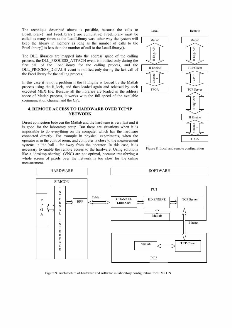
Figure 8. Local and remote configuration
Matlab
Matlab
TCP Client
PC2
PC1
TCP Server IID ENGINE CHANNEL LIBRARY
SOFTWARE HARDWARE
EPP
I N T E R N A L I N T E R F A C E
F P G A
SIMCON
Ethenet
Cable
Figure 9. Architecture of hardware and software in laboratory configuration for SIMCON
As it was mentioned, any application that uses the II Engine API may have access to the hardware, especially to a TCP server which serves access to the hardware over the TCP/IP network. On the “other side of network” there must be a TCP Client, which emulates the II Engine – this is a library which has the same interface as the II Engine. It does not communicate with the hardware, but it is sending the requests over the network.
The advantage of this solution is that we can operate on the hardware which is located far away from the laboratory, but it has also a disadvantage, which is slow data flow on the TCP/IP network. The TCP Server must provide an exclusive access to the FPGA device – only one client may work on one device a time. In the simplest situation with only one device, it may be an iterative server – this type of server automatically provides mutual exclusions of clients. If there is more than one device, then it should be concurrent server (multithreaded), which uses inter-process synchronization techniques to provide the exclusions.
5. APPLICATION– GRAPHIC USER INTERFACE FOR SIMCON
The solution which is presented below consists of control-measurement software for cavity controller and simulator for the TESLA experiment [1,7]. Such an implemented solution is represented by figure 9.
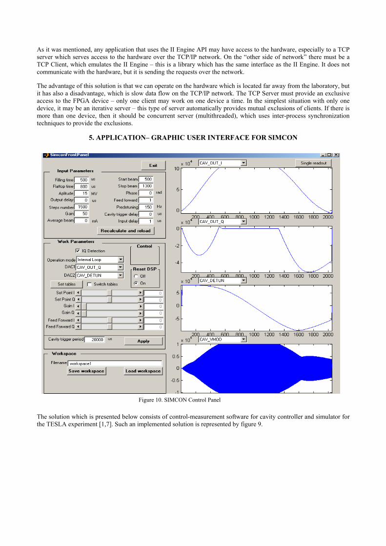
Figure 10. SIMCON Control Panel
At this time the SIMCON system has the EPP interface, which allows for communication with others devices. It is connected to a computer. On that computer, there works software which makes the communication with the SIMCON possible via the serial port. On the same computer, there works the II Engine, which translates the requests from the user application to the SIMCON.
In this configuration from figure 9, the Matlab works on a computer signed by the PC1 which uses the MEX-files to call with the II Engine. On the PC1 computer there also a TCP server can work, which listens to the requests from the client applications. Thanks to that, it is possible to connect from the computer signed by PC2. On the PC2 also works the Matlab. To communicate with the TCP server placed on the PC1 the PC2 computer and Matlab uses the MEX-files based on special, implemented Dynamic Link Libaries (dll). Such solution makes the graphic user interface possible. The Matlab 6.5 version has tools to create graphic interfaces which can be applied with the SIMCON. The following part describes three panels which are used to work with the SIMCON.
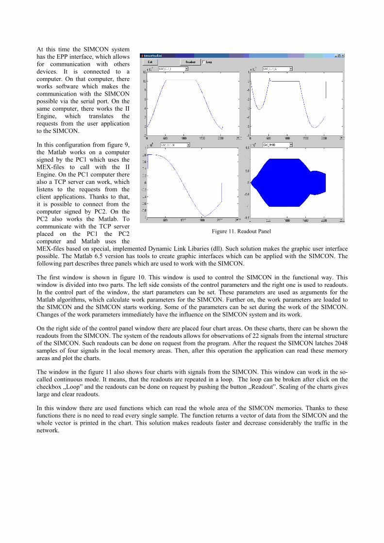
Figure 11. Readout Panel
The first window is shown in figure 10. This window is used to control the SIMCON in the functional way. This window is divided into two parts. The left side consists of the control parameters and the right one is used to readouts. In the control part of the window, the start parameters can be set. These parameters are used as arguments for the Matlab algorithms, which calculate work parameters for the SIMCON. Further on, the work parameters are loaded to the SIMCON and the SIMCON starts working. Some of the parameters can be set during the work of the SIMCON. Changes of the work parameters immediately have the influence on the SIMCON system and its work.
On the right side of the control panel window there are placed four chart areas. On these charts, there can be shown the readouts from the SIMCON. The system of the readouts allows for observations of 22 signals from the internal structure of the SIMCON. Such readouts can be done on request from the program. After the request the SIMCON latches 2048 samples of four signals in the local memory areas. Then, after this operation the application can read these memory areas and plot the charts.
The window in the figure 11 also shows four charts with signals from the SIMCON. This window can work in the so-called continuous mode. It means, that the readouts are repeated in a loop. The loop can be broken after click on the checkbox „Loop” and the readouts can be done on request by pushing the button „Readout”. Scaling of the charts gives large and clear readouts.
In this window there are used functions which can read the whole area of the SIMCON memories. Thanks to these functions there is no need to read every single sample. The function returns a vector of data from the SIMCON and the whole vector is printed in the chart. This solution makes readouts faster and decrease considerably the traffic in the network.
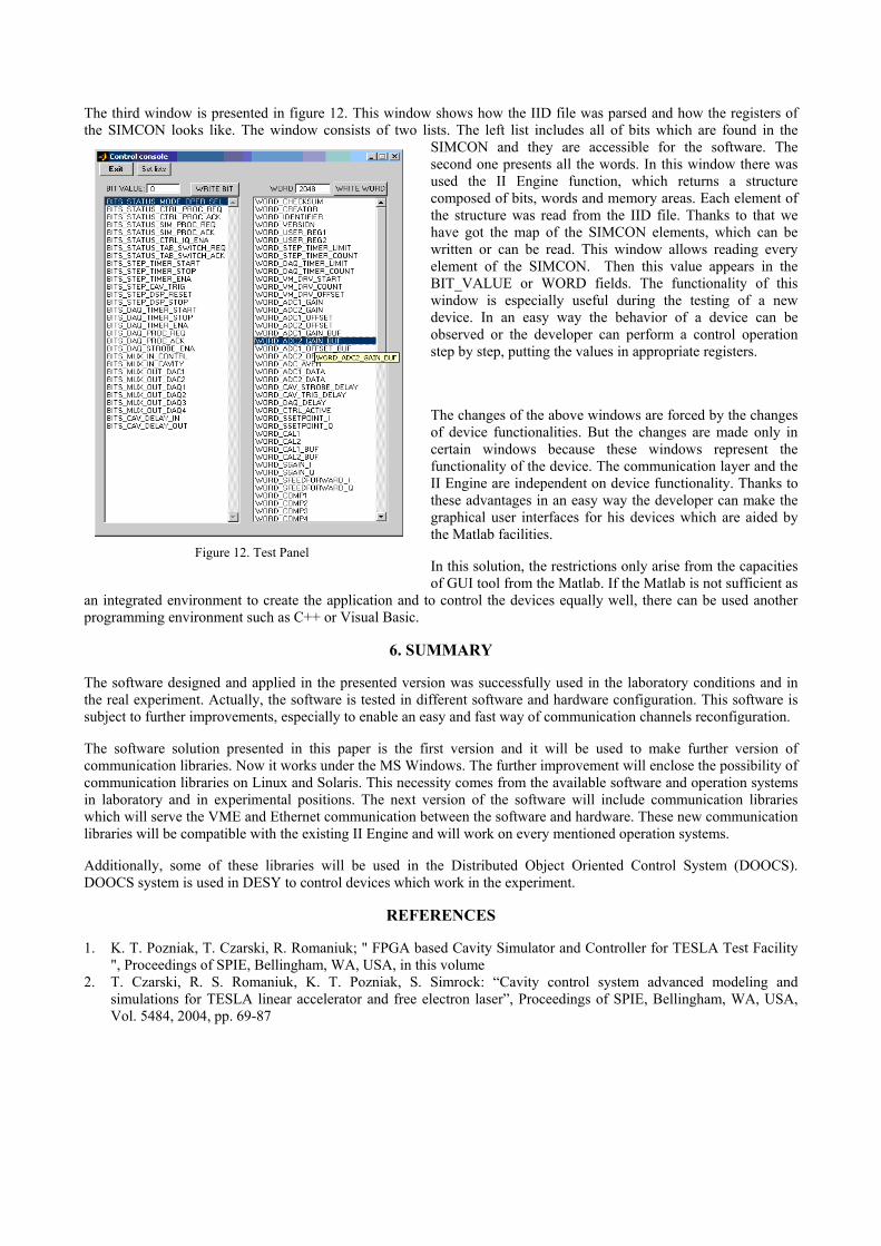
The third window is presented in figure 12. This window shows how the IID file was parsed and how the registers of the SIMCON looks like. The window consists of two lists. The left list includes all of bits which are found in the
SIMCON and they are accessible for the software. The second one presents all the words. In this window there was used the II Engine function, which returns a structure composed of bits, words and memory areas. Each element of the structure was read from the IID file. Thanks to that we have got the map of the SIMCON elements, which can be written or can be read. This window allows reading every element of the SIMCON. Then this value appears in the BIT_VALUE or WORD fields. The functionality of this window is especially useful during the testing of a new device. In an easy way the behavior of a device can be observed or the developer can perform a control operation step by step, putting the values in appropriate registers.
The changes of the above windows are forced by the changes of device functionalities. But the changes are made only in certain windows because these windows represent the functionality of the device. The communication layer and the II Engine are independent on device functionality. Thanks to these advantages in an easy way the developer can make the graphical user interfaces for his devices which are aided by the Matlab facilities.
Figure 12. Test Panel In this solution, the restrictions only arise from the capacities of GUI tool from the Matlab. If the Matlab is not sufficient as
an integrated environment to create the application and to control the devices equally well, there can be used another programming environment such as C++ or Visual Basic.
6. SUMMARY
The software designed and applied in the presented version was successfully used in the laboratory conditions and in the real experiment. Actually, the software is tested in different software and hardware configuration. This software is subject to further improvements, especially to enable an easy and fast way of communication channels reconfiguration.
The software solution presented in this paper is the first version and it will be used to make further version of communication libraries. Now it works under the MS Windows. The further improvement will enclose the possibility of communication libraries on Linux and Solaris. This necessity comes from the available software and operation systems in laboratory and in experimental positions. The next version of the software will include communication libraries which will serve the VME and Ethernet communication between the software and hardware. These new communication libraries will be compatible with the existing II Engine and will work on every mentioned operation systems.
Additionally, some of these libraries will be used in the Distributed Object Oriented Control System (DOOCS). DOOCS system is used in DESY to control devices which work in the experiment.
REFERENCES
1. K. T. Pozniak, T. Czarski, R. Romaniuk; " FPGA based Cavity Simulator and Controller for TESLA Test Facility ", Proceedings of SPIE, Bellingham, WA, USA, in this volume
2. T. Czarski, R. S. Romaniuk, K. T. Pozniak, S. Simrock: “Cavity control system advanced modeling and simulations for TESLA linear accelerator and free electron laser”, Proceedings of SPIE, Bellingham, WA, USA, Vol. 5484, 2004, pp. 69-87
3. T. Czarski, R. S. Romaniuk, K. T. Pozniak, S. Simrock: “Cavity digital control testing system by Simulink step operation method for TESLA linear accelerator and free electron laser”, Proceedings of SPIE, Bellingham, WA, USA, Vol. 5484, 2004, pp. 88-98
4. T. Czarski, R. S. Romaniuk, K. T. Pozniak, S. Simrock: “Cavity control system: optimization methods for single cavity driving and envelope detection”, Proceedings of SPIE, Bellingham, WA, USA, Vol. 5484, 2004, pp. 99-110
5. T. Czarski, R. S. Romaniuk, K. T. Pozniak, S. Simrock: “TESLA cavity modeling and digital implementation with FPGA technology solution for control system development, Proceedings of SPIE, Bellingham, WA, USA, Vol. 5484, 2004, pp. 111-129
6. P. Z. Rutkowski, R. S. Romaniuk, K. T. Pozniak, T. Jezynski, P. D. Pucyk, M. Pietrusinski, S. Simrock: “FPGA-based TESLA cavity SIMCON DOOCS server design, implementation, and application”, Proceedings of SPIE, Bellingham, WA, USA, Vol. 5484, 2004, pp. 153-170
7. K. T. Pozniak, M. Bartoszek, M. Pietrusinski, “Internal interface for RPC muon trigger electronics at CMS experiment”, Proceedings of SPIE, Bellingham, WA, USA, Vol. 5484, 2004, pp. 269-282
8. http://www.desy.de/ [DESY Deutsches Elektronen Synchrotron Homepage] 9. http://www.XILINX.com/ [XILINX Homepage] Paper presented during XVIth IEEE-SPIE WILGA Symposium on Electronics and Photonics for HEP Experiments, 26-30 May, 2004, http://nms.ise.pw.edu.pl Published in Proc. SPIE, 2005;