Soft Error Mitigation Techniques For Future Chip ...
295
ADVERTIMENT. La consulta d’aquesta tesi queda condicionada a l’acceptació de les següents condicions d'ús: La difusió d’aquesta tesi per mitjà del servei TDX (www.tesisenxarxa.net ) ha estat autoritzada pels titulars dels drets de propietat intel·lectual únicament per a usos privats emmarcats en activitats d’investigació i docència. No s’autoritza la seva reproducció amb finalitats de lucre ni la seva difusió i posada a disposició des d’un lloc aliè al servei TDX. No s’autoritza la presentació del seu contingut en una finestra o marc aliè a TDX (framing). Aquesta reserva de drets afecta tant al resum de presentació de la tesi com als seus continguts. En la utilització o cita de parts de la tesi és obligat indicar el nom de la persona autora. ADVERTENCIA. La consulta de esta tesis queda condicionada a la aceptación de las siguientes condiciones de uso: La difusión de esta tesis por medio del servicio TDR (www.tesisenred.net ) ha sido autorizada por los titulares de los derechos de propiedad intelectual únicamente para usos privados enmarcados en actividades de investigación y docencia. No se autoriza su reproducción con finalidades de lucro ni su difusión y puesta a disposición desde un sitio ajeno al servicio TDR. No se autoriza la presentación de su contenido en una ventana o marco ajeno a TDR (framing). Esta reserva de derechos afecta tanto al resumen de presentación de la tesis como a sus contenidos. En la utilización o cita de partes de la tesis es obligado indicar el nombre de la persona autora. WARNING. On having consulted this thesis you’re accepting the following use conditions: Spreading this thesis by the TDX (www.tesisenxarxa.net ) service has been authorized by the titular of the intellectual property rights only for private uses placed in investigation and teaching activities. Reproduction with lucrative aims is not authorized neither its spreading and availability from a site foreign to the TDX service. Introducing its content in a window or frame foreign to the TDX service is not authorized (framing). This rights affect to the presentation summary of the thesis as well as to its contents. In the using or citation of parts of the thesis it’s obliged to indicate the name of the author
-
Upload
khangminh22 -
Category
Documents
-
view
0 -
download
0
Transcript of Soft Error Mitigation Techniques For Future Chip ...
ADVERTIMENT. La consulta d’aquesta tesi queda condicionada a l’acceptació de les següents condicions d'ús: La difusió d’aquesta tesi per mitjà del servei TDX (www.tesisenxarxa.net) ha estat autoritzada pels titulars dels drets de propietat intel·lectual únicament per a usos privats emmarcats en activitats d’investigació i docència. No s’autoritza la seva reproducció amb finalitats de lucre ni la seva difusió i posada a disposició des d’un lloc aliè al servei TDX. No s’autoritza la presentació del seu contingut en una finestra o marc aliè a TDX (framing). Aquesta reserva de drets afecta tant al resum de presentació de la tesi com als seus continguts. En la utilització o cita de parts de la tesi és obligat indicar el nom de la persona autora. ADVERTENCIA. La consulta de esta tesis queda condicionada a la aceptación de las siguientes condiciones de uso: La difusión de esta tesis por medio del servicio TDR (www.tesisenred.net) ha sido autorizada por los titulares de los derechos de propiedad intelectual únicamente para usos privados enmarcados en actividades de investigación y docencia. No se autoriza su reproducción con finalidades de lucro ni su difusión y puesta a disposición desde un sitio ajeno al servicio TDR. No se autoriza la presentación de su contenido en una ventana o marco ajeno a TDR (framing). Esta reserva de derechos afecta tanto al resumen de presentación de la tesis como a sus contenidos. En la utilización o cita de partes de la tesis es obligado indicar el nombre de la persona autora. WARNING. On having consulted this thesis you’re accepting the following use conditions: Spreading this thesis by the TDX (www.tesisenxarxa.net) service has been authorized by the titular of the intellectual property rights only for private uses placed in investigation and teaching activities. Reproduction with lucrative aims is not authorized neither its spreading and availability from a site foreign to the TDX service. Introducing its content in a window or frame foreign to the TDX service is not authorized (framing). This rights affect to the presentation summary of the thesis as well as to its contents. In the using or citation of parts of the thesis it’s obliged to indicate the name of the author

UNIVERSITAT POLITECNICA DE CATALUNYA
Soft Error Mitigation Techniques
For Future Chip Multiprocessors
by
Gaurang Upasani
A thesis submitted in partial fulfillment for the
degree of Doctor of Philosophy
in the
Department of Computer Architecture
September 2015

Declaration of Authorship
I, Gaurang Upasani, declare that this thesis titled, ‘Soft error mitigation techniques
for future chip multiprocessors’ and the work presented in it are my own. I confirm
that:
■ This work was done wholly or mainly while in candidature for a research
degree at this University.
■ Where any part of this thesis has previously been submitted for a degree or
any other qualification at this University or any other institution, this has
been clearly stated.
■ Where I have consulted the published work of others, this is always clearly
attributed.
■ Where I have quoted from the work of others, the source is always given.
With the exception of such quotations, this thesis is entirely my own work.
■ I have acknowledged all main sources of help.
■ Where the thesis is based on work done by myself jointly with others, I have
made clear exactly what was done by others and what I have contributed
myself.
Signed:
Date:
ii


‘Here’s to the crazy ones. The misfits. The rebels. The troublemakers. The round
pegs in the square holes.
The ones who see things differently. They’re not fond of rules. And they have no
respect for the status quo. You can quote them, disagree with them, glorify or vilify
them.
But the only thing you can’t do is ignore them. Because they change things. They
invent. They imagine. They heal. They explore. They create. They inspire. They
push the human race forward. Maybe they have to be crazy.
How else can you stare at an empty canvas and see a work of art? Or sit in
silence and hear a song thats never been written? Or gaze at a red planet and see
a laboratory on wheels?
We make tools for these kinds of people.
While some see them as the crazy ones, we see genius. Because the people who are
crazy enough to think they can change the world, are the ones who do!’
Apple Computer, Inc. (Written by Rob Siltanen & Lee Clow)


Dedicated to my wife and family . . .
vi


Abstract
The sustained drive to downsize the transistors has reached a point where device
sensitivity against transient faults due to neutron and alpha particle strikes a.k.a
soft errors has moved to the forefront of concerns for next-generation designs.
Following Moore’s law, the exponential growth in the number of transistors per
chip has brought tremendous progress in the performance and functionality of
processors. However, incorporating billions of transistors into a chip makes it
more likely to encounter a soft soft errors. Moreover, aggressive voltage scaling
and process variations make the processors even more vulnerable to soft errors.
Also, the number of cores on chip is growing exponentially fueling the multicore
revolution. With increased core counts and larger memory arrays, the total failure-
in-time (FIT) per chip (or package) increases. Our studies concluded that the
shrinking technology required to match the power and performance demands for
servers and future exa- and tera-scale systems impacts the FIT budget. New soft
error mitigation techniques that allow meeting the failure rate target are important
to keep harnessing the benefits of Moore’s law.
Traditionally, reliability research has focused on providing circuit, microarchitec-
ture and architectural solutions, which include device hardening, redundant exe-
cution, lock–step, error correcting codes, modular redundancy etc. In general, all
these techniques are very effective in handling soft errors but expensive in terms
of performance, power, and area overheads. Traditional solutions fail to scale in
providing the required degree of reliability with increasing failure rates while main-
taining low area, power and performance cost. Moreover, this family of solutions
has hit the point of diminishing return, and simply achieving 2× improvement in
the soft error rate may be impractical.
Instead of relying on some kind of redundancy, a new direction that is growing in
interest by the research community is detecting the actual particle strike rather
than its consequence. The proposed idea consists of deploying a set of detectors on
silicon that would be in charge of perceiving the particle strikes that can potentially
create a soft error. Upon detection, a hardware or software mechanism would
trigger the appropriate recovery action.
This work proposes a lightweight and scalable soft error mitigation solution. As
a part of our soft error mitigation technique, we show how to use acoustic wave

detectors for detecting and locating particle strikes. We use them to protect both
the logic and the memory arrays, acting as unified error detection mechanism.
We architect an error containment mechanism and a unique recovery mechanism
based on checkpointing that works with acoustic wave detectors to effectively
recover from soft errors.
Our results show that the proposed mechanism protects the whole processor (logic,
flip-flop, latches and memory arrays) incurring minimum overheads.

Acknowledgements
My sincere thanks to:
Xavier Vera for his direct supervision and guidance throughout this work. Xavi
is extremely approachable. Hes one of the smartest people I know. I hope that I
could be as lively, enthusiastic, and energetic as him;
Antonio Gonzalez for reviewing and providing his insights and experience in im-
provising my papers, tutoring this thesis work, providing the financial support
during initial phase and for providing me with the required logistical support;
My parents for enrolling me into my first computer course at the age of 9 and
buying the first computer (A BBC Micro with 32kB RAM by Acron Comput-
ers™ ) when I was a kid; and supporting me to take up the research in computer
architecture. My wonderful sister for making me feel home even though I was
away.
My beautiful and loving wife for her constant support and infinite patience...
My good friends, Rakesh Kumar, Amrit Kumar Panda and lab mates for numerous
discussions on random topics of research in microarchitecture.
A special mention to Javier Carretero, Nicholas Axelos and Enric Herrero who
generously gave of their time and assisted me with the part of research of this
thesis and setting up the required infrastructure;
Lastly, thanks to everyone at ARCO, Intel Barcelona Research Center and DAC-
UPC. Thanks to badminton group Manoj, Gaurav and Prashanth. Thanks to the
Generalitat of Catalunya for awarding me the FI-AGAUR fellowship and funding
my research and the DAC administration for arranging the numerous trips to the
conferences and solving countless administrative problems.
Barcelona, April 2015
x


Contents
Declaration of Authorship ii
Abstract viii
Acknowledgements x
List of Figures xviii
List of Tables xxiii
Publications xxv
Glossary xxvi
Physical Constants xxx
1 Introduction 1
1.1 Motivation . . . . . . . . . . . . . . . . . . . . . . . . . . . . . . . . 2
1.1.1 Soft Error Trends . . . . . . . . . . . . . . . . . . . . . . . . 4
1.1.2 Current Solutions and Challenges . . . . . . . . . . . . . . . 5
1.2 Problem Statement . . . . . . . . . . . . . . . . . . . . . . . . . . . 6
1.2.1 Soft Error Rate Limits the Core Count . . . . . . . . . . . . 7
1.2.2 Soft Errors in the age of Dark Silicon . . . . . . . . . . . . . 8
1.2.3 Soft Errors in Large Memories . . . . . . . . . . . . . . . . . 9
1.2.4 Handling SDC & DUE . . . . . . . . . . . . . . . . . . . . . 10
1.2.5 Protecting all Computing Segments . . . . . . . . . . . . . . 11
1.3 Thesis Scope and Contributions . . . . . . . . . . . . . . . . . . . . 12
1.4 Organization . . . . . . . . . . . . . . . . . . . . . . . . . . . . . . 14
2 Soft Errors: Background and Overview 16
2.1 Soft Error Terminologies . . . . . . . . . . . . . . . . . . . . . . . . 16
2.1.1 Faults, Errors and Failures . . . . . . . . . . . . . . . . . . . 17
2.1.2 Metrics . . . . . . . . . . . . . . . . . . . . . . . . . . . . . 18
xii

Contents xiii
2.1.3 SDC and DUE . . . . . . . . . . . . . . . . . . . . . . . . . 19
2.2 Realizing Reliable Solution . . . . . . . . . . . . . . . . . . . . . . . 20
2.3 Soft Error Sources . . . . . . . . . . . . . . . . . . . . . . . . . . . 22
2.3.1 Alpha particles . . . . . . . . . . . . . . . . . . . . . . . . . 22
2.3.2 Neutron particles . . . . . . . . . . . . . . . . . . . . . . . . 23
2.3.3 Neutron induced boron fission . . . . . . . . . . . . . . . . . 23
2.4 Interaction of Particles with Silicon . . . . . . . . . . . . . . . . . . 24
2.4.1 Generation of Light, Sound and Heat! . . . . . . . . . . . . . 25
2.5 Computing Soft Error Rate . . . . . . . . . . . . . . . . . . . . . . 26
2.6 Soft Error Manifestation in Electronics . . . . . . . . . . . . . . . . 28
2.6.1 Soft Errors in SRAM . . . . . . . . . . . . . . . . . . . . . . 28
2.6.2 Soft Errors in DRAM . . . . . . . . . . . . . . . . . . . . . . 29
2.6.3 Soft Errors in Logic . . . . . . . . . . . . . . . . . . . . . . . 29
2.6.4 Evidence of Soft Errors . . . . . . . . . . . . . . . . . . . . . 31
2.7 Parameters Affecting Soft Error Rate . . . . . . . . . . . . . . . . . 32
2.8 Soft Errors and Future Processors . . . . . . . . . . . . . . . . . . . 35
2.8.1 Impact of Technology Scaling . . . . . . . . . . . . . . . . . 35
2.8.1.1 SRAM . . . . . . . . . . . . . . . . . . . . . . . . . 35
2.8.1.2 DRAM . . . . . . . . . . . . . . . . . . . . . . . . 35
2.8.1.3 Logic Components . . . . . . . . . . . . . . . . . . 36
2.8.2 Impact of New Technologies . . . . . . . . . . . . . . . . . . 37
2.8.2.1 Silicon on Insulator (SOI) . . . . . . . . . . . . . . 37
2.8.2.2 Multigate-FET Devices . . . . . . . . . . . . . . . 38
2.8.2.3 Non-Volatile Memories . . . . . . . . . . . . . . . . 38
2.9 Calculating SER to Make Architectural Decisions . . . . . . . . . . 39
2.9.1 Fault Injection: . . . . . . . . . . . . . . . . . . . . . . . . . 40
2.9.2 Architecture Vulnerability Factor (AVF) Analysis: . . . . . . 40
3 Error Detection using Acoustic Wave Detectors 42
3.1 Particle Strike Detectors . . . . . . . . . . . . . . . . . . . . . . . . 42
3.2 The Microelectromechanical Ears: Acoustic Wave Detectors . . . . 46
3.2.1 Structure and Properties of Device . . . . . . . . . . . . . . 47
3.2.2 Calibrating the Detector . . . . . . . . . . . . . . . . . . . . 48
3.2.2.1 False Positives . . . . . . . . . . . . . . . . . . . . 48
3.3 Soft Error Detection via Detecting Particle Strikes . . . . . . . . . . 49
3.4 Location Estimation of a Particle Strike . . . . . . . . . . . . . . . 51
3.4.1 Example . . . . . . . . . . . . . . . . . . . . . . . . . . . . . 53
3.4.2 Obtaining TDOA . . . . . . . . . . . . . . . . . . . . . . . . 54
3.4.3 Generating TDOA Equations . . . . . . . . . . . . . . . . . 55
3.4.4 Solving TDOA Equations . . . . . . . . . . . . . . . . . . . 56
3.5 Algorithms for TDOA Equations . . . . . . . . . . . . . . . . . . . 57
3.5.1 Deterministic Method . . . . . . . . . . . . . . . . . . . . . 57
3.5.2 Non-deterministic Method . . . . . . . . . . . . . . . . . . . 58
3.5.2.1 Non-iterative Algorithms . . . . . . . . . . . . . . . 58

Contents xiv
3.5.2.2 Iterative Algorithm . . . . . . . . . . . . . . . . . . 60
3.5.3 Metrics for Evaluating Algorithms . . . . . . . . . . . . . . . 61
3.5.3.1 Runtime . . . . . . . . . . . . . . . . . . . . . . . . 61
3.5.3.2 Complexity . . . . . . . . . . . . . . . . . . . . . . 61
3.5.3.3 Location Estimation Coverage . . . . . . . . . . . . 62
3.5.3.4 Accuracy . . . . . . . . . . . . . . . . . . . . . . . 62
3.6 Assessing the Algorithms . . . . . . . . . . . . . . . . . . . . . . . . 63
3.6.1 Placement of Detectors . . . . . . . . . . . . . . . . . . . . . 63
3.6.1.1 Accuracy . . . . . . . . . . . . . . . . . . . . . . . 64
3.6.1.2 Location Estimation Coverage . . . . . . . . . . . . 65
3.6.2 Choosing Detectors for TDOA Equations . . . . . . . . . . . 69
3.6.2.1 Accuracy . . . . . . . . . . . . . . . . . . . . . . . 69
3.6.2.2 Location Estimation Coverage . . . . . . . . . . . . 69
3.6.3 Effect of Solving More TDOA Equations . . . . . . . . . . . 69
3.6.3.1 Accuracy . . . . . . . . . . . . . . . . . . . . . . . 70
3.6.3.2 Runtime . . . . . . . . . . . . . . . . . . . . . . . . 72
3.6.3.3 Complexity . . . . . . . . . . . . . . . . . . . . . . 74
3.6.4 Effect of Sampling Frequency on Accuracy . . . . . . . . . . 74
3.6.5 Detection Latency . . . . . . . . . . . . . . . . . . . . . . . 77
3.6.6 Summary of Chosen Configuration . . . . . . . . . . . . . . 77
3.6.7 Summary of Results . . . . . . . . . . . . . . . . . . . . . . 79
3.7 Related Work . . . . . . . . . . . . . . . . . . . . . . . . . . . . . . 79
3.7.1 Current Glitch Detectors . . . . . . . . . . . . . . . . . . . . 80
3.7.1.1 Built-In Current Sensors (BICS) . . . . . . . . . . 80
3.7.1.2 Switching Current Detector . . . . . . . . . . . . . 81
3.7.2 Voltage Glitch Detectors . . . . . . . . . . . . . . . . . . . . 81
3.7.3 Metastability Detectors . . . . . . . . . . . . . . . . . . . . . 82
3.7.4 Deposited Charge Detectors . . . . . . . . . . . . . . . . . . 83
3.7.4.1 Thin film silicon detectors . . . . . . . . . . . . . . 83
3.7.4.2 Heavy-ion Sensing . . . . . . . . . . . . . . . . . . 83
3.7.5 Comparison of Detectors . . . . . . . . . . . . . . . . . . . . 83
3.7.5.1 Hardware cost/Area overhead . . . . . . . . . . . . 84
3.7.5.2 Power overhead and detection latency . . . . . . . 85
3.7.5.3 False alarms . . . . . . . . . . . . . . . . . . . . . . 86
3.7.5.4 Detected particles/Fault types . . . . . . . . . . . . 87
3.7.5.5 Intrusiveness of the design . . . . . . . . . . . . . . 87
3.7.5.6 Fault coverage vs. Cost . . . . . . . . . . . . . . . 88
3.8 Chapter Summary . . . . . . . . . . . . . . . . . . . . . . . . . . . 89
4 Protecting Caches with Acoustic Wave Detectors 91
4.1 Error Detection and Localization in Cache . . . . . . . . . . . . . . 91
4.2 Providing Error Correction in Caches . . . . . . . . . . . . . . . . . 93
4.2.1 Reaction upon a Particle Strike . . . . . . . . . . . . . . . . 94
4.2.2 Standalone Acoustic Wave Detectors . . . . . . . . . . . . . 94

Contents xv
4.2.2.1 Error Area Granularity: Cache Lines . . . . . . . . 95
4.2.2.2 Error Area Granularity: Exact bit . . . . . . . . . 95
4.3 Acoustic Wave Detectors with Error Codes . . . . . . . . . . . . . . 97
4.3.1 Error Area Granularity: Cache Lines . . . . . . . . . . . . . 97
4.3.2 Error Area Granularity: Exact bit . . . . . . . . . . . . . . . 100
4.3.2.1 Acoustic Wave Detectors + Parity per Block . . . . 102
4.3.2.2 Acoustic Wave Detectors + Parity per Byte . . . . 105
4.3.2.3 Acoustic Wave Detectors with Physical Interleaving 107
4.4 Handling Multi-bit Upsets in Caches . . . . . . . . . . . . . . . . . 109
4.5 Cost of Protection . . . . . . . . . . . . . . . . . . . . . . . . . . . 112
4.6 Related Work . . . . . . . . . . . . . . . . . . . . . . . . . . . . . . 112
4.6.1 Particle Strike Detection for Soft Errors . . . . . . . . . . . 113
4.6.2 Soft Error Detection . . . . . . . . . . . . . . . . . . . . . . 113
4.6.2.1 Error Codes . . . . . . . . . . . . . . . . . . . . . . 113
4.6.3 Soft Error Mitigation . . . . . . . . . . . . . . . . . . . . . . 115
4.6.3.1 Physical Interleaving . . . . . . . . . . . . . . . . . 116
4.6.3.2 Cache Scrubbing . . . . . . . . . . . . . . . . . . . 116
4.6.3.3 Cache Flush . . . . . . . . . . . . . . . . . . . . . . 117
4.6.3.4 Early Writeback . . . . . . . . . . . . . . . . . . . 117
4.6.4 Comparison of Techniques . . . . . . . . . . . . . . . . . . . 117
4.7 Chapter Summary . . . . . . . . . . . . . . . . . . . . . . . . . . . 122
5 Protecting Entire Core with Acoustic Wave Detectors 124
5.1 ”SDC & DUE 0” Architecture . . . . . . . . . . . . . . . . . . . . . 124
5.1.1 Effect of Detection Latency on SDC & DUE . . . . . . . . . 125
5.1.2 Achieving SDC-& DUE 0 per Core . . . . . . . . . . . . . . 127
5.1.3 Divide and Conquer for SDC and DUE 0 . . . . . . . . . . . 129
5.1.4 Containment in Core: Recap . . . . . . . . . . . . . . . . . . 131
5.1.5 Proposed Architecture . . . . . . . . . . . . . . . . . . . . . 131
5.2 Implementation of Proposed Architecture: Unicore Processor . . . . 133
5.2.1 Error Containment Mechanism . . . . . . . . . . . . . . . . 133
5.2.1.1 Dealing with Verified Cache. . . . . . . . . . . . . . 134
5.2.1.2 Dealing with Not-Verified Cache. . . . . . . . . . . 134
5.2.2 Creating Checkpoints . . . . . . . . . . . . . . . . . . . . . . 136
5.2.2.1 Validating the Checkpoint. . . . . . . . . . . . . . 138
5.2.3 Recovering from Error . . . . . . . . . . . . . . . . . . . . . 139
5.2.4 Intrusiveness of Design . . . . . . . . . . . . . . . . . . . . . 139
5.3 Implementation of Proposed Architecture: Multicore Processor . . . 140
5.3.1 Shared Memory Architecture . . . . . . . . . . . . . . . . . 140
5.3.1.1 MOESI Protocol for Error Containment. . . . . . . 140
5.3.1.2 MOESI Protocol for Checkpointing. . . . . . . . . 142
5.3.1.3 Recovering from Error. . . . . . . . . . . . . . . . . 142
5.4 Managing System Calls, Interrupts and Exceptions . . . . . . . . . 142
5.4.1 Handling Interrupts. . . . . . . . . . . . . . . . . . . . . . . 142

Contents xvi
5.4.2 Dealing with Exceptions. . . . . . . . . . . . . . . . . . . . 143
5.4.3 Context switching and Multi-programming. . . . . . . . . . 144
5.5 Performance Evaluation of ”SDC- & DUE 0” Architecture . . . . . 144
5.5.1 Experimental Setup . . . . . . . . . . . . . . . . . . . . . . . 144
5.5.1.1 Single core system. . . . . . . . . . . . . . . . . . . 144
5.5.1.2 Multicore system. . . . . . . . . . . . . . . . . . . . 146
5.5.2 Error Detection Latency vs Containment Area . . . . . . . . 146
5.5.3 Checkpoint Length vs Checkpoint Area . . . . . . . . . . . . 147
5.5.4 Uniprocessor Performance . . . . . . . . . . . . . . . . . . . 150
5.5.5 Performance of Multicore for Data Non-Sharing Applications 150
5.5.6 Multicore Shared Memory Performance . . . . . . . . . . . . 152
5.6 Related Work . . . . . . . . . . . . . . . . . . . . . . . . . . . . . . 152
5.6.1 Error Detection and Recovery in Core . . . . . . . . . . . . 152
5.6.1.1 Dual Modular Redundancy with Recovery . . . . . 152
5.6.1.2 Lockstepping with Recovery . . . . . . . . . . . . . 154
5.6.1.3 Redundant Multithreading (RMT) with Recovery . 156
5.6.1.4 Error Detection and Recovery using Checker Core . 158
5.7 Chapter Summary . . . . . . . . . . . . . . . . . . . . . . . . . . . 159
6 Protecting Embedded Core with Acoustic Wave Detectors 161
6.1 Experimental Setup . . . . . . . . . . . . . . . . . . . . . . . . . . . 161
6.2 Handling SDC & DUE in Embedded Core . . . . . . . . . . . . . . 163
6.2.1 Acoustic Wave Detectors and Error Detection Latency . . . 163
6.2.2 Error Containment Granularity . . . . . . . . . . . . . . . . 164
6.2.2.1 Error Containment Granularity: Core . . . . . . . 165
6.2.2.2 Error Containment Granularity: Cache . . . . . . . 166
6.2.3 Putting everything together . . . . . . . . . . . . . . . . . . 168
6.3 Selective Error Containment . . . . . . . . . . . . . . . . . . . . . . 168
6.3.1 Protecting Individual Data Paths & Latency Guard Bands . 168
6.3.1.1 Traversal of Instructions in Pipeline . . . . . . . . 169
6.3.1.2 Cost of Error Containment . . . . . . . . . . . . . 170
6.4 Error Containment Coverage vs. Vulnerability . . . . . . . . . . . . 172
6.4.1 ACE Analysis . . . . . . . . . . . . . . . . . . . . . . . . . . 173
6.4.2 Reducing AVF using Acoustic Wave Detectors . . . . . . . . 175
6.5 Related Work . . . . . . . . . . . . . . . . . . . . . . . . . . . . . . 176
6.5.1 Soft Error Sensitivity Analysis . . . . . . . . . . . . . . . . . 177
6.5.2 Soft Error Protection . . . . . . . . . . . . . . . . . . . . . . 178
6.5.2.1 Hardware Only Approach . . . . . . . . . . . . . . 178
6.5.2.2 Software Only Approach . . . . . . . . . . . . . . . 179
6.5.2.3 Hybrid Approach . . . . . . . . . . . . . . . . . . . 180
6.6 Chapter Summary . . . . . . . . . . . . . . . . . . . . . . . . . . . 180
7 Related Work 182
7.1 Soft Error Protection Schemes . . . . . . . . . . . . . . . . . . . . . 182

Contents xvii
7.1.1 Device Enhancements . . . . . . . . . . . . . . . . . . . . . 182
7.1.1.1 Triple-well technology . . . . . . . . . . . . . . . . 183
7.1.1.2 Silicon-on-insulator . . . . . . . . . . . . . . . . . . 183
7.1.1.3 Process techniques . . . . . . . . . . . . . . . . . . 184
7.1.2 Circuit Enhancements . . . . . . . . . . . . . . . . . . . . . 184
7.1.2.1 Increasing nodal capacitance in the circuit . . . . . 185
7.1.2.2 Radiation hardened cells . . . . . . . . . . . . . . . 186
7.2 Soft Error Detection Schemes . . . . . . . . . . . . . . . . . . . . . 186
7.2.1 Spatial Redundancy . . . . . . . . . . . . . . . . . . . . . . 187
7.2.1.1 Detectors for Error Detection . . . . . . . . . . . . 187
7.2.1.2 Error Detection via Monitoring Invariants . . . . . 188
7.2.1.3 Error Detection via Dynamic Control/Data FlowChecks . . . . . . . . . . . . . . . . . . . . . . . . . 190
7.2.1.4 Error Detection via Hardware Assertion . . . . . . 191
7.2.1.5 Error Detection via Symptom Checks . . . . . . . . 192
7.2.1.6 Error Detection via Selective Protection . . . . . . 193
7.2.2 Information Redundancy . . . . . . . . . . . . . . . . . . . . 194
7.2.2.1 Error Codes for Combinational Logic . . . . . . . . 194
7.2.2.2 Signature Based Approach . . . . . . . . . . . . . . 199
7.2.3 Temporal Redundancy . . . . . . . . . . . . . . . . . . . . . 199
7.2.3.1 Various Flavors of RMT . . . . . . . . . . . . . . . 200
7.2.3.2 Error Detection via Detecting Anomalies . . . . . . 206
7.2.3.3 Using shifting operations . . . . . . . . . . . . . . . 207
7.3 Error Recovery . . . . . . . . . . . . . . . . . . . . . . . . . . . . . 208
7.3.1 Forward Error Recovery . . . . . . . . . . . . . . . . . . . . 209
7.3.1.1 Triple Modular Redundancy (TMR) . . . . . . . . 209
7.3.2 Backward Error Recovery . . . . . . . . . . . . . . . . . . . 210
7.3.2.1 Checkpointing Techniques for Recovery . . . . . . . 211
7.3.3 Other Recovery Schemes . . . . . . . . . . . . . . . . . . . . 215
7.4 Error Detection and Recovery using Software . . . . . . . . . . . . . 216
8 Conclusions 220
8.1 Summary of Research . . . . . . . . . . . . . . . . . . . . . . . . . . 220
8.1.1 Detecting Particle Strikes for Soft Error Detection . . . . . . 221
8.1.2 Unified Error Detection for Logic & Memory . . . . . . . . . 221
8.1.3 Precisely Locating the Errors . . . . . . . . . . . . . . . . . 221
8.1.4 Reducing Reliability Cost for Caches and Memory . . . . . . 222
8.1.5 Protecting Entire Processor . . . . . . . . . . . . . . . . . . 223
8.1.6 One Solution for All Computing Segments . . . . . . . . . . 223
8.2 Discussions . . . . . . . . . . . . . . . . . . . . . . . . . . . . . . . 224
8.2.1 Future Work . . . . . . . . . . . . . . . . . . . . . . . . . . . 224
Bibliography 226

List of Figures
1.1 SRAM bit and SRAM system (e.g., cache) soft error rate for differ-ent technology nodes [17]. The soft error rate of a bit is predictedto remain roughly constant. However, the soft error rate of a cacheis predicted to increase. . . . . . . . . . . . . . . . . . . . . . . . . . 3
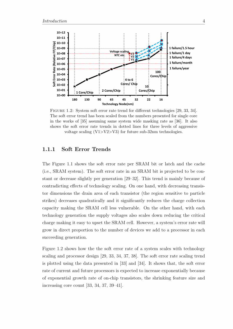
1.2 System soft error rate trend for different technologies [29, 33, 34].The soft error trend has been scaled from the numbers presented forsingle core in the works of [35] assuming same system wide maskingrate as [36]. It also shows the soft error rate trends in dotted linesfor three levels of aggressive voltage scaling (V1>V2>V3) for futuresub-32nm technologies. . . . . . . . . . . . . . . . . . . . . . . . . . 4
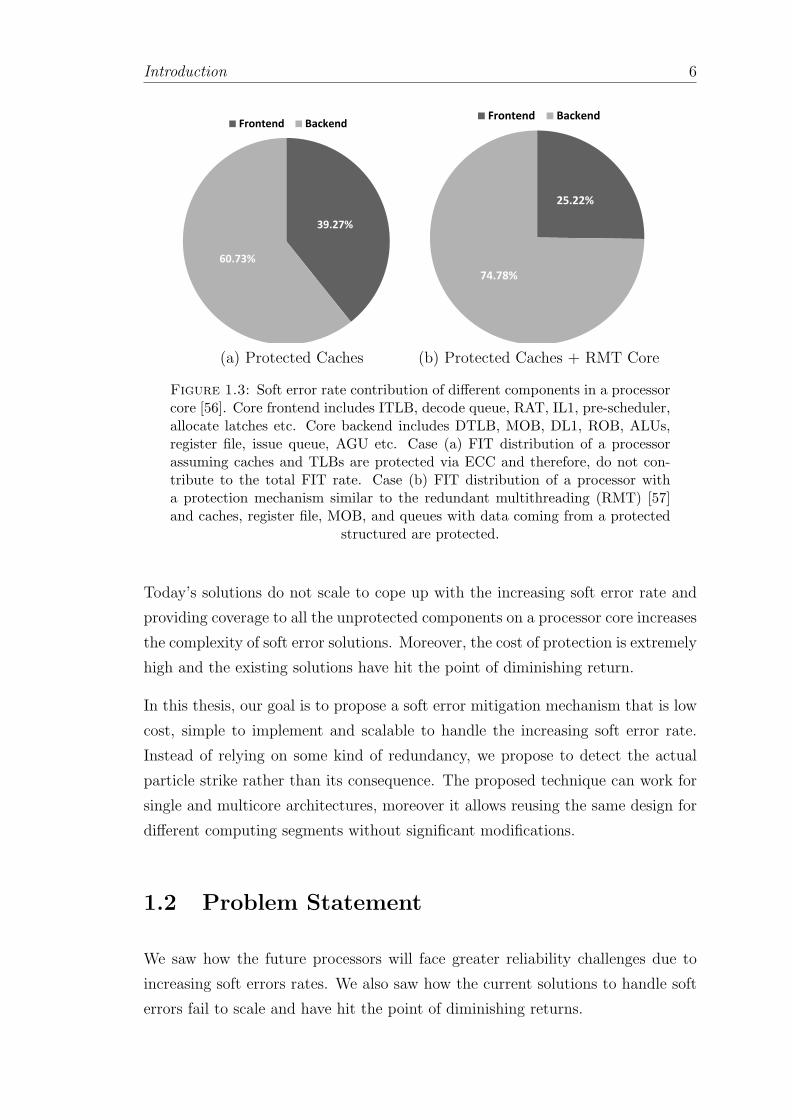
1.3 Soft error rate contribution of different components in a processorcore [56]. Core frontend includes ITLB, decode queue, RAT, IL1,pre-scheduler, allocate latches etc. Core backend includes DTLB,MOB, DL1, ROB, ALUs, register file, issue queue, AGU etc. Case(a) FIT distribution of a processor assuming caches and TLBs areprotected via ECC and therefore, do not contribute to the total FITrate. Case (b) FIT distribution of a processor with a protectionmechanism similar to the redundant multithreading (RMT) [57]and caches, register file, MOB, and queues with data coming froma protected structured are protected. . . . . . . . . . . . . . . . . . 6
1.4 Scaling of FIT/Core to accommodate more cores per chip whilemaintaining the FIT/Chip constant . . . . . . . . . . . . . . . . . . 7
1.5 TDP modes in modern multicore processor. TDP1 operates at 0.7VDD and hence there are 4 active cores. In TDP2 the supply volt-age is scaled down to 0.45 VDD to activate 64 cores. The relativeFIT in TDP2 is increased by 16× compared to TDP1 due to in-creased active silicon area. However, due to effects of the supplyvoltage scaling the relative impact on soft error rate is as high as30× [77] . . . . . . . . . . . . . . . . . . . . . . . . . . . . . . . . . 8
2.1 Reliability metrics: Mean time to repair (MTTR), Mean time tofailure (MTTF) and Mean time between failures (MTBF) . . . . . . 18
2.2 Classification of soft errors: silent data corruption (SDC) and de-tected unrecoverable error (DUE) . . . . . . . . . . . . . . . . . . . 20
2.3 Realizing reliability pipeline for soft errors: error detection, errorcontainment and error recovery . . . . . . . . . . . . . . . . . . . . 21
xviii

List of Figures xix
2.4 Alpha particles generate electron-hole pairs in silicon by direct ion-ization. Inelastic collision of neutrons with a silicon atom generateelectron-hole pairs via indirect ionization by creating a silicon recoil.Elastic collisions of neutron particles are harmless. . . . . . . . . . . 24
2.5 Particle strike on a critical node Q on a 6T-SRAM cell . . . . . . . 28
2.6 Structure of a DRAM memory cell . . . . . . . . . . . . . . . . . . 29
2.7 Masking effect in combinational logic circuits. . . . . . . . . . . . . 30
2.8 Impact of frequency on soft error rate . . . . . . . . . . . . . . . . . 34
2.9 DRAM bit soft error rate for different technology nodes [180]. Thesoft error rate of a DRAM bit is predicted to decrease. The softerror rate of a DRAM memory system has traditionally remainedconstant over technology generations moreover, it is predicted to bedominated by the soft errors in the DRAM peripheral logic. . . . . 36
3.1 Transformation of the energy of particle strike upon its impact onsilicon surface into acoustic shock wave . . . . . . . . . . . . . . . . 46
3.2 Cantilever beam like structure of acoustic wave detectors [214]. Aparticle strike is detected by sensing the deflection of cantilever beam. 47
3.3 A comparison of relative slowdown due to false positive recovery fordifferent recovery techniques: Seqoia [226], Swich [227], Carer [228],SPARC64 [229], IBM Z series [59], IBM G5 [58], Encore [230], Re-Store [231], ReVive [102], SafetyNet [107], IBM Blue Gene [232],BLCR [233] . . . . . . . . . . . . . . . . . . . . . . . . . . . . . . . 49
3.4 TDOA hyperbolas in a system and location of source. Dashed hy-perbola is formed using only two detectors S1 and S2. Including athird detector S3 can successfully locate the source via intersectinghyperbolas. . . . . . . . . . . . . . . . . . . . . . . . . . . . . . . . 52
3.5 Strike detection and localization via triangulation using TDOAmeasurements of acoustic wave detectors . . . . . . . . . . . . . . . 53
3.6 Timeline of the events following the particle strike . . . . . . . . . . 53
3.7 Strike detection algorithm (firmware) and a hardware control mech-anism . . . . . . . . . . . . . . . . . . . . . . . . . . . . . . . . . . 54
3.8 Sampling errors in the measurements of the time difference of thearrival at the acoustic wave detectors . . . . . . . . . . . . . . . . . 55
3.9 Placement of detectors in a mesh formation . . . . . . . . . . . . . 64
3.10 Impact of placement of detectors (while solving 4 TDOA equations)on accuracy (area unit is the area of 1 bit SRAM cell) . . . . . . . . 65
3.11 Impact of placement of detectors (while solving 4 TDOA equations)on location estimation coverage . . . . . . . . . . . . . . . . . . . . 65
3.12 Impact of initial guess on coverage (while solving 4 TDOA equa-tions) on location estimation coverage . . . . . . . . . . . . . . . . . 66
3.13 Worst-case error area with the selection of different set of detectors(4 to 10) from a given [4× 5] mesh . . . . . . . . . . . . . . . . . . 68
3.14 Error area with closest detectors for [4× 5] mesh . . . . . . . . . . 70
3.15 Comparing accuracy of all algorithms and for the mesh configura-tions discussed in Table 3.2 . . . . . . . . . . . . . . . . . . . . . . 72

List of Figures xx
3.16 Comparing runtime and complexity of all algorithms and for themesh configurations discussed in Table 3.2 . . . . . . . . . . . . . . 73
3.17 Impact of sampling frequency on error area for configurations ofTable 3.2 Iterative Algorithm 4 . . . . . . . . . . . . . . . . . . . . 74
3.18 Impact of sampling frequency on error area for configurations ofTable 3.2 for all algorithms . . . . . . . . . . . . . . . . . . . . . . . 75
3.19 Worst-case detection latency for mesh configurations of Table 3.2in a processor running at 2 GHz . . . . . . . . . . . . . . . . . . . . 76
3.20 Adding more detectors to reduce worst-case detection latency in aprocessor running at 2 GHz . . . . . . . . . . . . . . . . . . . . . . 76
3.21 Built-in current sensor (BICS) . . . . . . . . . . . . . . . . . . . . . 80
3.22 Switching current detector . . . . . . . . . . . . . . . . . . . . . . . 81
3.23 Voltage glitch detector . . . . . . . . . . . . . . . . . . . . . . . . . 82
3.24 Metastability detector (BISS) . . . . . . . . . . . . . . . . . . . . . 82
4.1 Mapping of the estimated worst-case error area at the granularityof affected (a) bits (b) bytes and (c) lines. These affected bits, bytesor cache lines contain the actual erroneous bit, byte or cache line. . 92
4.2 Breakdown of the obtained worst-case error area granularity for1048 particle strikes at random location and instance for differentmesh configurations in L1 data cache at the sampling frequency of4 GHz . . . . . . . . . . . . . . . . . . . . . . . . . . . . . . . . . . 96
4.3 Quantification of error area granularity for 5× 5 mesh for L1 datacache . . . . . . . . . . . . . . . . . . . . . . . . . . . . . . . . . . . 101
4.4 3*CEP error area mapping to bits to bits of the L1 cache: (a) 1-bit,(b) 2-bits, (c) 3-bits (d) 4-bits and (e) 5-bits . . . . . . . . . . . . . 102
4.5 Possibilities of 3*CEP error area granularity patterns : (a) 2-bits,(b) 3-bits, (c) 4-bits and (d) 5-bits . . . . . . . . . . . . . . . . . . 102
4.6 Probability of pin-pointing the erroneous bit using acoustic wavedetectors + parity per block for 3*CEP error area granularity pat-terns of (a) 2-bit, (b) 3-bit, (c) 4-bit and (d,e) 5-bit . . . . . . . . . 103
4.7 Probability of pin-pointing the erroneous bit using acoustic wavedetectors + parity per byte for 3*CEP error area granularity pat-terns of (a,b) 2-bit, (c-f) 3-bit, (g) 4-bit and (h-m) 5-bit . . . . . . . 105
4.8 Probability of pin-pointing the erroneous bit using acoustic wavedetectors + parity per byte and assuming the bits are physicallyinterleaved with degree of interleaving: 4 . . . . . . . . . . . . . . . 107
4.9 Probability of pin-pointing the erroneous bit and correcting it (i.e.,DUE improvement) using acoustic wave detectors and combiningacoustic wave detectors with parity at byte and block level andassuming physically interleaved parity protected bits in L1 data cache108
4.10 Extending the 3*CEP error area granularity of 1-bit and 5-bits forhandling spatial multi-bit upsets using acoustic wave detectors tolocate (a) 2 bit MBU and (b) 3 bit MBU . . . . . . . . . . . . . . 110

List of Figures xxi
4.11 Probability of locating the 2 bit MBU using acoustic wave detectorsconfiguration providing 3*CEP error area granularity of 1 bit andparity per byte . . . . . . . . . . . . . . . . . . . . . . . . . . . . . 111
4.12 Basic functionality of encoding and decoding of data bits in errorcodes . . . . . . . . . . . . . . . . . . . . . . . . . . . . . . . . . . . 114
5.1 Number of detectors vs. detection latency at 2 GHz . . . . . . . . . 128
5.2 Pipeline of a state of the art processor and the latency of stages . . 129
5.3 Error Containment Architecture . . . . . . . . . . . . . . . . . . . . 132
5.4 Time-line of the events in cache. D indicates the dirty bit and EDLstands for error detection latency. Once the cache line has been writ-ten the cache line enters in quarantine state. After ErrorDetectionLatencycycles the cache line is now in verified state and also error free. . . . 134
5.5 Error containment in cache for evictions caused by read and writeoperations. D indicates the dirty bit. . . . . . . . . . . . . . . . . . 135
5.6 Checkpointing in the caches due to the evictions caused by readand write operations. D indicates the dirty bit and CH stands forthe checkpoint bit. . . . . . . . . . . . . . . . . . . . . . . . . . . . 137
5.7 A scenario indicating the importance of validating the checkpoint.CH indicates the checkpoint bit and EDL stands for error detec-tion latency. Notice the CheckpointValid counter that indicates thevalidity of the checkpoint. . . . . . . . . . . . . . . . . . . . . . . . 138
5.8 Handling error containment in a shared memory accesses for multi-core architecture. EDL stands for error detection latency. . . . . . . 141
5.9 MOESI protocol: Transitions are shown in the trigger 7→action for-mat. Underlined transition triggers and actions are the same asuniprocessor architecture. The transition triggers in gray boxes areextensions for multicore shared memory architecture. ”Wr” standsfor write and ”Rd” stands for read operation. ”Stall” 7→ErrorDetectionLatencycycles. . . . . . . . . . . . . . . . . . . . . . . . . . . . . . . . . . . 141
5.10 Extending the architecture to handle interrupts and I/O traffic. . . 143
5.11 Checkpoint events in LLC checkpoint boundary . . . . . . . . . . . 145
5.12 Average dirty lines to be written back from L1 to LLC . . . . . . . 149
5.13 Average wait-cycles until LLC is verified . . . . . . . . . . . . . . . 149
5.14 Performance impact of containment and checkpointing LLC cachein single core architecture . . . . . . . . . . . . . . . . . . . . . . . 150
5.15 Slowdown due to containment and checkpointing LLC cache in the16-core system for private memory applications . . . . . . . . . . . 151
5.16 Slowdown due to containment and checkpointing LLC cache in the16-core system for shared memory applications . . . . . . . . . . . . 151
5.17 Implementation of dual modular redundancy scheme for error de-tection and recovery. . . . . . . . . . . . . . . . . . . . . . . . . . . 153
5.18 Lockstep error detection and recovery via retry . . . . . . . . . . . 155
5.19 Implementation of dynamic implementation verification architec-ture (DIVA) and the functioning of the checker core . . . . . . . . . 158

List of Figures xxii
6.1 Error detection latency for acoustic wave detectors on embeddedcore for different mesh configurations . . . . . . . . . . . . . . . . . 164
6.2 Error containment granularities in embedded processor . . . . . . . 165
6.3 Performance overhead of error containment in cache for a checkpointperiod of 1 million cycles . . . . . . . . . . . . . . . . . . . . . . . . 167
6.4 Distribution of residency cycles in a state of the art embedded corepipeline . . . . . . . . . . . . . . . . . . . . . . . . . . . . . . . . . 169
6.5 Arrangement of FUBs and placement of acoustic wave detectors onembedded core [313] . . . . . . . . . . . . . . . . . . . . . . . . . . 172
6.6 Error containment granularities in embedded processor . . . . . . . 173
6.7 Reducing AVF by adapting acoustic wave detectors . . . . . . . . . 175
6.8 AVF of issue queue by protecting them with acoustic wave detectorsfor different detection latency . . . . . . . . . . . . . . . . . . . . . 176
7.1 Triple well technology and the creation of deep n-well which trapsthe charge generated upon a particle strike. . . . . . . . . . . . . . . 183
7.2 The suspended body in partially depleted SOI transistor . . . . . . 184
7.3 Reduction of soft errors by introducing capacitance on the criticalnodes in an SRAM cell . . . . . . . . . . . . . . . . . . . . . . . . . 185
7.4 The C-Element circuit forming the core logic of BISER detectionscheme [322] . . . . . . . . . . . . . . . . . . . . . . . . . . . . . . . 188
7.5 The control flow checker: A high level program, compiler generatedinstructions and the corresponding CFG . . . . . . . . . . . . . . . 191
7.6 The hardware assertion and the timestamps . . . . . . . . . . . . . 192
7.7 Residue code generation logic for an adder . . . . . . . . . . . . . . 197
7.8 Functional block diagram of parity prediction circuit in an adder . . 198
7.9 Sphere of replication is shown in shaded part. Both the processorcores are part of the sphere of replication . . . . . . . . . . . . . . . 202
7.10 Functional implementation of RMT scheme on a processor with twocores (P0 and P1). The cross coupled cores with a few dedicatedhardware queues can work in unison for error detection. . . . . . . . 205
7.11 Using temporal redundancy for error detection via re-execution withshifted operands . . . . . . . . . . . . . . . . . . . . . . . . . . . . . 207
7.12 Classification of error recovery schemes . . . . . . . . . . . . . . . . 208
7.13 Triple modular redundancy . . . . . . . . . . . . . . . . . . . . . . 210
List of Tables
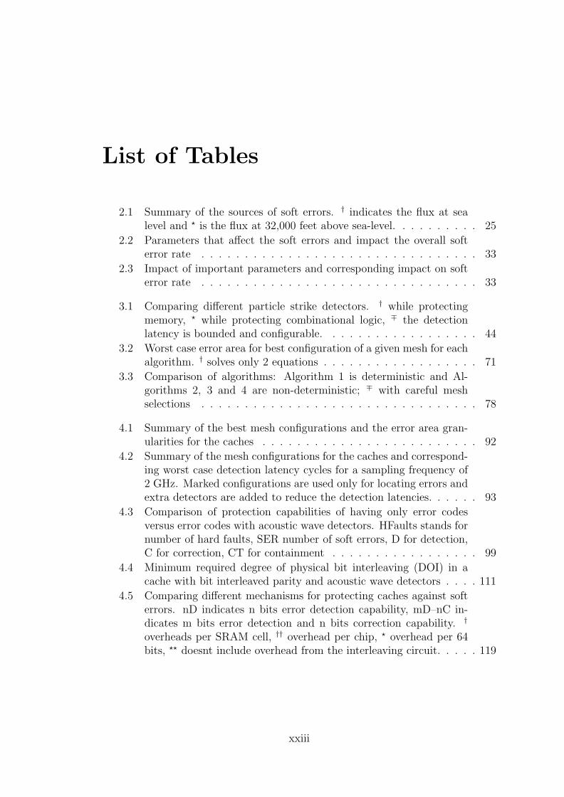
2.1 Summary of the sources of soft errors. † indicates the flux at sealevel and ⋆ is the flux at 32,000 feet above sea-level. . . . . . . . . . 25
2.2 Parameters that affect the soft errors and impact the overall softerror rate . . . . . . . . . . . . . . . . . . . . . . . . . . . . . . . . 33
2.3 Impact of important parameters and corresponding impact on softerror rate . . . . . . . . . . . . . . . . . . . . . . . . . . . . . . . . 33
3.1 Comparing different particle strike detectors. † while protectingmemory, ⋆ while protecting combinational logic, ∓ the detectionlatency is bounded and configurable. . . . . . . . . . . . . . . . . . 44
3.2 Worst case error area for best configuration of a given mesh for eachalgorithm. † solves only 2 equations . . . . . . . . . . . . . . . . . . 71
3.3 Comparison of algorithms: Algorithm 1 is deterministic and Al-gorithms 2, 3 and 4 are non-deterministic; ∓ with careful meshselections . . . . . . . . . . . . . . . . . . . . . . . . . . . . . . . . 78
4.1 Summary of the best mesh configurations and the error area gran-ularities for the caches . . . . . . . . . . . . . . . . . . . . . . . . . 92
4.2 Summary of the mesh configurations for the caches and correspond-ing worst case detection latency cycles for a sampling frequency of2 GHz. Marked configurations are used only for locating errors andextra detectors are added to reduce the detection latencies. . . . . . 93
4.3 Comparison of protection capabilities of having only error codesversus error codes with acoustic wave detectors. HFaults stands fornumber of hard faults, SER number of soft errors, D for detection,C for correction, CT for containment . . . . . . . . . . . . . . . . . 99
4.4 Minimum required degree of physical bit interleaving (DOI) in acache with bit interleaved parity and acoustic wave detectors . . . . 111
4.5 Comparing different mechanisms for protecting caches against softerrors. nD indicates n bits error detection capability, mD–nC in-dicates m bits error detection and n bits correction capability. †
overheads per SRAM cell, †† overhead per chip, ⋆ overhead per 64bits, ⋆⋆ doesnt include overhead from the interleaving circuit. . . . . 119
xxiii

List of Tables xxiv
5.1 Comparison of different error detection schemes († vulnerabilityholes in LSQ logic (i.e., MOB logic), ∗ cannot detect errors in stores,†† does not detect but prevents error, ⋆ only for simple in-order cores,⋆⋆ cannot detect if fault does not manifest a symptom, ∓ latencyfrom actual strike instance) . . . . . . . . . . . . . . . . . . . . . . 126
5.2 Required number of detectors for containment in core . . . . . . . . 130
5.3 Configuration Parameters . . . . . . . . . . . . . . . . . . . . . . . 146
5.4 Containment cost (i.e., #Stalls and wait cycles for each stall) forcontainment boundary limited to L1 . . . . . . . . . . . . . . . . . 147
6.1 Configuration Parameters . . . . . . . . . . . . . . . . . . . . . . . 162
6.2 Required acoustic wave detectors for full error containment cov-erage. L1 cache is protected separately using an architecture aspresented in Chapter 4. . . . . . . . . . . . . . . . . . . . . . . . . . 171
7.1 AN codes and the functions for which they are invariant . . . . . . 195
7.2 Residue codes and the functions for which they are invariant. Divi-sion is not directly encodable however division holds D - R = Q ×I relation where D is dividend, R is remainder, Q is quotient and Iis divisor . . . . . . . . . . . . . . . . . . . . . . . . . . . . . . . . . 196
Publications
The following is a list of all publications subject to peer review that are part of
this thesis.
Published papers:
Conferences
• “Framework for Economical Error Recovery in Embedded Cores”, Gaurang
Upasani, Xavier Vera and Antonio Gonzalez. In the proceedings of 20th
International On-Line Testing Symposium (IOLTS) 2014.
• “Avoiding Core’s DUE & SDC via Acoustic Wave Detectors and Tailored
Error Containment and Recovery”, Gaurang Upasani, Xavier Vera and An-
tonio Gonzalez. In the proceedings of 41st International Symposium on
Computer Architectures (ISCA) 2014.
• “Reducing DUE-FIT of Caches by Exploiting Acoustic Wave Detectors for
Error Recovery”, Gaurang Upasani, Xavier Vera and Antonio Gonzalez. In
the proceedings of 19th International On-Line Testing Symposium (IOLTS)
2013.
• “Setting an Error Detection Infrastructure with Low Cost Acoustic Wave
Detectors”, Gaurang Upasani, Xavier Vera and Antonio Gonzalez. In the
proceedings of 39th International Symposium on Computer Architectures
(ISCA) 2012.
Journals
• “ A Case for Acoustic Wave Detectors for Soft-Errors”, Gaurang Upasani,
Xavier Vera and Antonio Gonzalez. IEEE Transactions on Computers (ToC).
(preprint available)
• “Particle Strike Detectors for Soft Errors”, Gaurang Upasani, Xavier Vera
and Antonio Gonzalez. IEEE Computer. (under review)
xxv

Glossary
ACE Architecturally Correct Execution.
ALU Arithmetic and Logic Unit.
APS Active Pixel Sensor.
AR-SMT Active and Redundant Simultaneous Multi Threading.
AVF Architecture Vulnerability Factor.
BER Backward Error Recovery.
BICS Built- In Current Sensor.
BISS Built- In Single-event upset Sensor.
BIST Built- In Self Test.
CEP Circular Error Probable.
CFG Control Flow Graph.
CMOS Complementary Metal- Oxide Semiconductor.
CMP Chip- Multi-processor.
CRC Cyclic Redundancy Code.
DEC-TED Double Error Correction Triple Error Detection.
DFG Data Flow Graph.
DICE Dual Interlocked CElls.
DIVA Dynamic Implementation Verification Architecture.
xxvi

Glossary of Terms xxvii
DMR Dual Modular Redundacy.
DOI Degree Of Interleaving.
DRAM Dynamic Random-access Memory.
DUE Detected Unrecoverable Error.
DVFS Dynamic Voltage and Frequency Scaling.
ECC Error Correcting Code.
EDL Error Detection Latency.
FER Forward Error Recovery.
FIFO First In First Out.
FIT Failure In Time.
FRAM Ferroelectric Random-access Memory.
GPS Global Positioning System.
HCI Hot Carrier Injection.
IC Integrated Circuit.
IQ Issue Queue.
ISA Instruction Set Architecture.
LET Linear Energy Transfer.
LLC Last Level Cache.
LRU Least Recently Used.
LSQR Least Square Roots.
MBU Multiple Bit Upset.
MCA Machine Check Architecture.
MOB Memory Order Buffer.

Glossary of Terms xxviii
MRAM Magnetoresistive Random-access Memory.
MTBF Mean Time Between Failures.
MTTF Mean Time To Failure.
MTTR Mean Time To Repair.
MUX Multiplexer.
NBTI Negative Bias Temperature Instability.
NMOS N-type Metal Oxide Semiconductor.
NOP Null Operation instruction.
NTC Near Threshold Computing.
PBTI Positive Bias Temperature Instability.
PC Program Counter.
PCM Phase Change Memory.
RAT Register Alias Table.
RF Register File.
RMT Redundant Multi Threading.
RNA Register Name Authentication.
ROB Re- Order Buffer.
RTL Register- Transfer Level.
RUU Register Update Unit.
SBU Single Bit Upset.
SDC Silent Data Corruption.
SEC-DED Single Error Correction Double Error Detection.
SER Soft Error Rate.

Glossary of Terms xxix
SES Soft Error Sensitivity.
SET Single Event Transient.
SEU Single Event Upset.
SMT Simultaneous Multi Threading.
SOI Silicon On Insulator.
SRAM Static Random-access Memory.
SRT Simultaneous and Redundant Threading.
SRTR Simultaneously and Redundantly Threaded with Recovery.
SSD Silicon Strip Detector.
STT-RAM Spin-Transfer Torque Random-access Memory.
TAC Timestamp-based assertion checking.
TDDB Time Dependent Dielectric Breakdown.
TDOA Time Difference Of Arrival.
TDP Thermal Design Power.
TLB Translation Lookaside Buffer.
TMR Triple Modular Redundancy.
TTF Time To Failure.
TVF Time Vulnerability Factor.

Physical Constants
Electron Volt eV = 1.60217657× 10⁻¹⁹ joules
Speed of Light c = 2.99792458× 10⁸ ms−s
Speed of Sound in Silicon Cp = 10kms−1
xxx
Chapter 1
Introduction
For several decades, the semiconductor devices have seen tremendous progress in
performance and functionality due to the exponential growth in the number of
transistors per chip. In 1971, the Intel 4004® processor held 2,300 transistors. In
early 2014 Intel released Xeon Ivy Bridge-Ex® with than 4.3 billion transistors [1].
This exponential growth in number of transistors is popularly known as Moore’s
law [2].
Each succeeding technology generation has introduced new obstacles in fulfilling
the on chip transistor count. First, the rate of improvement in microprocessor
speed exceeds the rate of improvement in off chip memory (DRAM) speed [3].
This resulted into the memory wall problem that drives the innovation in having
low latency caches and other higher-level techniques such as prefetching [4, 5] and
multithreading [6] that either reduce the memory latency, or keep the processor
occupied for the longer latency memory operations.
Later, the power dissipation of the microprocessors started reaching sky high and
semiconductor industry hit the power wall, where the performance improvements
of microprocessor were limited by power constraints [7]. It motivated the research
in low power computing techniques such as dynamic voltage and frequency scaling
(DVFS), near threshold computing (NTC) and subthreshold operations. According
to Dennard scaling [8], as transistors get smaller their power density stays constant,
so that the power used stays in proportion with area (i.e., both voltage and current
scale down with length). The breakdown of Dennard scaling and the failure of
Moore’s law to yield dividends in improved performance [9, 10] prompted a switch
among some chip manufacturers to a greater focus on multicore processors [11].
1
Introduction 2
Since the number of cores on chip is growing exponentially fueling the multicore
revolution, operating all cores simultaneously requires exponentially more energy
per chip. However, whereas the energy requirements grow, chip power delivery
and cooling limitations remain largely unchanged across technologies imposing the
power wall [12]. As a result we will soon be incapable of operating all transistors
simultaneously, pushing multicore scaling to an end [13, 14]. This trend is leading
us into an era of dark silicon where we will be able to build denser devices but we
will not be able to power them up.
In this series of challenges, the reliability issues are next in line. Shrinking tran-
sistor dimensions and aggressive voltage scaling increase the sensitivity against
intrinsic and extrinsic noise sources and a corresponding increase in static and
dynamic variations. They lead to higher probability of parametric and wear-out
failures, manufacturing defects and particle strike induced soft errors. This has
elevated reliability into a prime design constraint for current and future processor
design [15, 16]. Among all the failure mechanisms, transient faults from alpha and
neutron particle strikes can induce a higher failure rate than the failure rate of all
other failure mechanisms combined [17]. As the benefits of fault tolerance solu-
tions come at the cost of area, energy and performance overheads, it may prevent
achieving scalable performance leading us to the soft error wall.
1.1 Motivation
Charged particles coming from the atmosphere generate electron-hole pairs as they
pass through a transistor. Transistor nodes can collect these charges. A particle
strike can deposit enough charge to corrupt a data bit stored in the memory (i.e.,
SRAM), or it can create a glitch in any gate in combinational logic. Such faults
in the circuit’s operation may cause a failure by corrupting the data leading to
a system crash. Since these transient errors occur due to an incorrect charge or
discharge of an intermediate capacitive node, they do not cause permanent failure
in the hardware and hence are termed soft errors in the literature.
The soft error rate (SER) is the rate at which a device or system encounters or
is predicted to encounter soft errors per unit of time, and is typically expressed
as Failures-In-Time (FIT). Chip designers have specific FIT targets for different
computing segments similar to power or performance budget [18].

Introduction 3
Figure 1.1: SRAM bit and SRAM system (e.g., cache) soft error rate fordifferent technology nodes [17]. The soft error rate of a bit is predicted toremain roughly constant. However, the soft error rate of a cache is predicted to
increase.
Although soft errors do not permanently damage the device, they are the pri-
mary limit on digital circuit reliability [19]. According to the current trends, soft
errors are more important than all other causes of computing reliability put to-
gether [20]. Typically, the soft error rate can be 250-1000× higher than the hard
failure rates [17].
The existence of this problem in space applications was reported in the early
1950s. Later, researchers found three potential radiation mechanisms that can
also cause soft errors at ground level. In late 70’s alpha particles emitting from
the radioactive impurities in the packaging materials were the dominating source
of soft errors. High energy neutrons (more than 1 MeV) were the dominating
cause of errors in 90’s. Currently, low energy neutrons are also responsible for
causing soft errors in sub-65nm technology nodes [19, 21, 22]. From then on, soft
errors have been consistently reported to be primary cause of failures in many
commercial and academic studies [23–28].
Introduction 4
0.0
0.2
0.4
0.6
0.8
1.0
1.2
1E+00
1E+01
1E+02
1E+03
1E+04
1E+05
1E+06
1E+07
1E+08
1E+09
1E+10
1E+11
1E+12
180 130 90 65 45 32 22 16
Soft
Err
or
Ra
te (
Re
lati
ve F
IT/C
hip
)
Technology Node(nm)
1 Core/Chip2 Cores/Chip
10
Cores/Chip
100
Cores/Chip4 to 6
Cores/ Chip
Voltage scaling,
NTC etc.
V1V2V3
1 failure/year
1 failure/month
1 failure/4 days
1 failure/1 day
1 failure/1.5 hour
Figure 1.2: System soft error rate trend for different technologies [29, 33, 34].The soft error trend has been scaled from the numbers presented for single corein the works of [35] assuming same system wide masking rate as [36]. It alsoshows the soft error rate trends in dotted lines for three levels of aggressive
voltage scaling (V1>V2>V3) for future sub-32nm technologies.
1.1.1 Soft Error Trends
The Figure 1.1 shows the soft error rate per SRAM bit or latch and the cache
(i.e., SRAM system). The soft error rate in an SRAM bit is projected to be con-
stant or decrease slightly per generation [29–32]. This trend is mainly because of
contradicting effects of technology scaling. On one hand, with decreasing transis-
tor dimensions the drain area of each transistor (the region sensitive to particle
strikes) decreases quadratically and it significantly reduces the charge collection
capacity making the SRAM cell less vulnerable. On the other hand, with each
technology generation the supply voltages also scales down reducing the critical
charge making it easy to upset the SRAM cell. However, a system’s error rate will
grow in direct proportion to the number of devices we add to a processor in each
succeeding generation.
Figure 1.2 shows how the the soft error rate of a system scales with technology
scaling and processor design [29, 33, 34, 37, 38]. The soft error rate scaling trend
is plotted using the data presented in [33] and [34]. It shows that, the soft error
rate of current and future processors is expected to increase exponentially because
of exponential growth rate of on-chip transistors, the shrinking feature size and
increasing core count [33, 34, 37, 39–41].

Introduction 5
A chip with 4 cores is expected to encounter roughly 1 failure every month for a
45 nm technology node. This might not be alarming yet and can be efficiently
handled with existing error handling solutions. However, servers with 100 cores
and huge memory capacity may encounter 1 failure everyday due to soft errors.
On top of that, process variations will be more pronounced with every new tech-
nology generation which may worsen soft error rate [33, 42]. Moreover, for future
processors aggressive voltage scaling and NTC will be common for meeting the
power/thermal caps escalating the soft error rate. This dramatic increase in the
soft error rate requires specific soft error tolerance mechanisms for current and
future processors.
Next, we will discuss how the existing solutions to handle soft errors do not scale
to cope up with this increase in soft error rate.
1.1.2 Current Solutions and Challenges
Current solutions for protecting processors with caches and large memory arrays
against soft errors rely on redundancy techniques. Today’s caches and mem-
ory components are protected by parity or error codes [43–49] and hardened
latches [50–54]. Unfortunately, the FIT rate of the other parts of the micro-
processor system have started reaching concerning levels [29, 30, 34, 55].
Figure 1.3 shows the contribution of different elements to the total soft error rate
for a modern processor with state-of-the-art technology [56]. Figure 1.3 (a) shows
the FIT rate contribution from unprotected parts of the processor. It shows that
FIT rate of processor is mainly due to several unprotected components such as
IQ, register files (RF), MOB, ROB, RAT and unprotected latches [56].
Figure 1.3 (b) shows the FIT distribution when the caches and TLBs are protected
with ECC and the register files, queues and MOB are protected with a redundant
multithreading (RMT) approach [57]. Overall, it brings down the FIT of the
processor compared to the case of Figure 1.3 (a). Even in this case the majority
of the FIT rate comes from unprotected latches and structures such as ROB, IQ,
RAT and free–list. These latches and structures are extremely difficult to protect
and the cost of protection in terms of area, power and performance overhead is
extremely high.
Introduction 6
39.27%
60.73%
Frontend Backend
25.22%
74.78%
Frontend Backend
(a) Protected Caches (b) Protected Caches + RMT Core
Figure 1.3: Soft error rate contribution of different components in a processorcore [56]. Core frontend includes ITLB, decode queue, RAT, IL1, pre-scheduler,allocate latches etc. Core backend includes DTLB, MOB, DL1, ROB, ALUs,register file, issue queue, AGU etc. Case (a) FIT distribution of a processorassuming caches and TLBs are protected via ECC and therefore, do not con-tribute to the total FIT rate. Case (b) FIT distribution of a processor witha protection mechanism similar to the redundant multithreading (RMT) [57]and caches, register file, MOB, and queues with data coming from a protected
structured are protected.
Today’s solutions do not scale to cope up with the increasing soft error rate and
providing coverage to all the unprotected components on a processor core increases
the complexity of soft error solutions. Moreover, the cost of protection is extremely
high and the existing solutions have hit the point of diminishing return.
In this thesis, our goal is to propose a soft error mitigation mechanism that is low
cost, simple to implement and scalable to handle the increasing soft error rate.
Instead of relying on some kind of redundancy, we propose to detect the actual
particle strike rather than its consequence. The proposed technique can work for
single and multicore architectures, moreover it allows reusing the same design for
different computing segments without significant modifications.
1.2 Problem Statement
We saw how the future processors will face greater reliability challenges due to
increasing soft errors rates. We also saw how the current solutions to handle soft
errors fail to scale and have hit the point of diminishing returns.

Introduction 7
In particular, the work of this thesis addresses the following problems:
1.2.1 Soft Error Rate Limits the Core Count
FIT/ChipTo
tal
FIT
time
Figure 1.4: Scaling of FIT/Core to accommodate more cores per chip whilemaintaining the FIT/Chip constant
With increased core counts per chip and larger memory arrays, the total FIT per
chip (or package) increases. The current soft error handling mechanisms have two
exacerbating challenges to meet FIT rate target in the presence of unprecedented
transistor densities and higher core count per chip: (i) They have to keep the total
FIT of a chip constant and (ii) they have to scale to cope up with the increased
soft error rate to accommodate more cores as shown in Figure 1.4. For example, if
you want to have 100 cores in a chip, and now you have 4 cores, you need 25× FIT
reduction per core to accommodate 100 cores. FIT rate is limiting the number of
cores on a chip just like the power/thermal budget.
To reduce the FIT rate and accommodate more cores and larger caches several ma-
jor vendors have announced aggressive reliability and protection counter measures
for current and future processors [54, 58–64].
Time and space redundancy techniques are very effective and provide very good
coverage but cause 1.5–2× slowdown [56, 57, 65–76]. The caches and larger mem-
ory arrays are equipped with more parity and stronger ECC. While protecting the
caches, the extra delay imposed by ECC computation may increase cache hit and
miss times. Moreover, smaller caches and memory arrays cannot be protected with

Introduction 8
ECC without incurring huge performance penalty. Unprotected latches and flip-
flops are replaced with hardened latches. Replacing the latches in critical paths
with hardened latches increase the length of the critical path severely impacting
performance.
To overcome the performance overhead of the conventional solutions in providing
the necessary reliability and keep increasing the core count, in this thesis we pro-
pose a novel soft error mitigation technique that uses acoustic wave detectors for
detecting particle strikes that may cause soft errors. Upon detection, a hardware
or software mechanism would trigger the appropriate recovery action. Our results
show that the proposed mechanism protects the whole processor (logic, flip-flop,
latches and memory arrays) incurring minimum overheads.
1.2.2 Soft Errors in the age of Dark Silicon
Following the multicore trend, researchers have started designing 100-core and
1000-core chips. These 100-core and 1000-core chips create dark silicon. It im-
poses a limit in terms of the number of active cores per chip leaving some cores
underutilized.
Re
lati
ve
FIT
/Ch
ip
#A
ctiv
e C
ore
s
TDP1
Vdd = 0.7
4
64
TDP2
Vdd = 0.45
1x
16x
30x
3.5x
Figure 1.5: TDP modes in modern multicore processor. TDP1 operates at 0.7VDD and hence there are 4 active cores. In TDP2 the supply voltage is scaleddown to 0.45 VDD to activate 64 cores. The relative FIT in TDP2 is increasedby 16× compared to TDP1 due to increased active silicon area. However, dueto effects of the supply voltage scaling the relative impact on soft error rate is
as high as 30× [77]

Introduction 9
In a conventional multicore processor, there is only one thermal design power
(TDP) mode. It implies that at peak voltage and frequency all cores are powered
on. In contrast, in the age of dark silicon, multicore processors have different TDP
modes with different operating voltages. Each TDP mode have starkly different
and inconsistent impact on soft error rates as well. TDP mode with lower operating
voltage, increases number of active cores on the chip as shown in Figure 1.5. This
results in higher FIT rate of chip due to two reasons: (i) lower voltages decrease the
minimum charge required to cause the soft error and, (ii) due to reduced supply
voltages the applications will take longer to execute prolonging the vulnerability
window of critical structures. To handle dark silicon, powering on 16×more silicon
area can increase the soft error rates by 3.5–30× [77].
We propose a solution that is extremely low cost in terms of area, power and
performance overhead which is crucial in dark silicon era where the chips are
already suffering the performance due to the power limitations.
1.2.3 Soft Errors in Large Memories
Cache memory is a fundamental component used to enhance the performance
of microprocessors. Current high performance processors employ multilevel on-
chip caches. The sizes are in the range of several megabytes and are expected to
increase [58, 64, 78]. On-chip caches occupy roughly 50% of chip real estate [79].
The combination of growing cache size, voltage scaling, shrinking SRAM cell di-
mensions, and increased impact of process variations is causing rapid increase in
the soft error rate. Caches benefit from the positive impact of smaller cell sizes.
However, this benefit is offset by the negative impact of storing less charge per bit
and reduced critical charge to create a soft error; as a result the cache error rate
increases linearly with cache size [30, 31, 38, 80].
To protect the caches designers adapt to error detecting codes such as parity
codes or ECC such as Single Error Correction–Double Error Detection (SEC-
DED) [43, 44]. Every read and write operation requires the encoding or decoding
of the data bits for error detection or correction. Usually, L1 caches are not
protected at all or have only error detection [81]. Large caches (L2 or L3) are
usually protected via ECC [82, 83].
Introduction 10
Most soft errors are single bit upsets and can be detected by parity codes. To
correct single bit errors single error correction can be used. However, larger caches
frequently switch to drowsy mode [84] or subthreshold operating modes [85] to
save energy. Such optimizations in future processors will be very common and
they increase the likelihood of soft errors by 9-10× [86]. Moreover, due to reduced
operating voltages, a single neutron strike can upset more than one bit of memory
in close proximity, causing spatial multibit errors. To handle spatial multibit errors,
designers usually physically interleave the ECC protected bits [87, 88]. Also, in a
cache the error handling policy (e.g., SEC-DED) has to access the erroneous data
to correct it. If not accessed, the first single bit errors may not be corrected by it,
leading to accumulation of such single bit errors over a long time which are called
temporal multibit errors. To detect and correct temporal multibit errors more
complex codes Double Error Correction–Triple Error Detection (DEC-TED) [45,
89] or RS codes [90] are required. Alternatively, there have been proposals to
use cache scrubbing that periodically scans the cache for single bit errors avoiding
their accumulation [91, 92].
Error codes combined with scrubbing is very widely used in commercial proces-
sors. To handle increasing soft error rates complex codes are required. Complex
codes need longer time for encoding and decoding data and may not be able to
provide inline error detection and correction. They may also increase the critical
path severely impacting performance [48]. Scrubbing techniques may cause large
overheads for protecting on-chip caches [93, 94]. Solutions to protect caches in
drowsy mode sacrifice the cache capacity [95, 96].
TIn this work, we propose an error detection and correction architecture that
reduces the failure rate of caches due to soft errors at minimal overheads. As a
result of which larger caches with less complex and economical error protection
techniques can also provide higher degree of reliability.
1.2.4 Handling SDC & DUE
Soft errors can be classified as silent data corruption (SDC) or detected unrecover-
able error (DUE). Corrupted data may go unnoticed by the user and is harmless.
However, corrupted data that ends up as a visible error counts as SDC event. A
DUE event occurs when a system detects the soft error but cannot recover from
it. An SDC event or a DUE event can cause a system crash. However, unlike an

Introduction 11
SDC event, a DUE event prevents data corruption. Once the error is detected the
system contains the error by stopping the error propagation beyond the point of
detection. The system can then reboot itself or it can resume the normal execution
by reverting back to the last known error free state (i.e., checkpoint).
Designers have fixed SDC and DUE FIT rates. Adding error detection can reduce
the SDC FIT rate by orders of magnitude. However, in the absence of any recov-
ery mechanism this reduction in SDC FIT transforms into DUE FIT [97]. This
interesting effect has been observed in parity protected (write–back) L1 caches
and partially protected caches (L2 with parity protected tags). Increasing cache
size causes a super linear increase in DUE FIT [98, 99].
DUE events directly impact the server availability. Increase in DUE FIT rate
causes frequent recovery actions or system reboots and may result into increased
unplanned downtime of the server system [100, 101]. To handle the increased
DUE FIT rate most of the servers today rely on checkpoint based error recovery.
Taking system wide checkpoints for error recovery can be very complex and ex-
pensive [36, 66, 102–112]. Triple modular redundancy (TMR) can eliminate DUE
without halting the system. However, TMR incurs more than 300% area and
power overhead [58, 113–115] and it is only affordable in high availability mission
critical systems.
This thesis proposes to detect and accurately locate all the particle strikes that
may cause soft errors, eliminating SDC. Moreover, proposed solution can signifi-
cantly reduce DUE FIT of entire core in a multicore processor by implementing
an extremely lightweight and scalable checkpoint based recovery mechanism.
1.2.5 Protecting all Computing Segments
Reliability research has focused largely on the high performance server market.
High availability systems rely on redundancy to provide fault tolerance. Area,
power and performance overheads associated with existing solutions for handling
soft errors may be affordable in high performance servers. Unlike high performance
servers, area and power are primary constraints in the embedded design space.
Embedded processors typically have smaller components, longer clock cycle times
and larger logic depths between latches. Due to increased logic depths the relative
area occupied by the combinational logic increases [116]. The combinational logic

Introduction 12
elements are mostly unprotected making them the largest contributors towards
total FIT of the processor. Moreover, in pipelines with larger logic depth the
number of target latches per stage increases due to wider fan-out, which increases
the probability of a fault to propagate and cause a soft error.
In general, error detection and correction codes are effective but very costly for
embedded processors with smaller caches [117–119]. Execution redundancy is
not suitable for embedded processors with limited resources. Also, checkpoint
based error recovery techniques may be complex. Moreover, the area, power and
performance overheads of taking a system wide checkpoint is unacceptable. Other
fault tolerant techniques such as radiation hardened latches require 20-30% extra
logic [50–54].
In this work, we show that the proposed solution can also effectively protect em-
bedded systems against soft errors minimizing area, power and performance over-
heads.
1.3 Thesis Scope and Contributions
To tackle the challenges described in Section 1.2, this work focuses on cost effective
soft error mitigation in microprocessors. In this work, we primarily target the
particle strike induced soft errors since these are the most prevalent soft errors in
chips. We aim to protect: (i) the unstructured, inherently complex and irregular
processor cores (i.e., combinational logic, latches and other unprotected elements
in the pipeline) and (ii) the on-chip caches which occupy large portions of the chip
area and are regular in design and behavior.
Many solutions exist to provide error detection and recovery from soft errors in
logic and memory components. However, providing robustness minimizing area,
power and performance is extremely crucial. The goal of this work is to detect
and recover from all soft errors in a processor core minimizing the overheads.
This thesis proposes a soft error mitigation architecture using acoustic wave de-
tectors. Acoustic wave detectors detect particle strikes that may cause soft errors.
In this work, we also propose a novel, economical and acoustic wave detector

Introduction 13
specific checkpointing technique for error recovery. Proposed architecture is ex-
tremely simple, scalable and it can protect different computing segments without
significant design changes.
The proposed architecture, besides providing a highly reliable core, is able to
recover a significant part of the overheads associated with current reliability tech-
niques by potentially eliminating error codes and radiation hardened latches for
soft errors. It also significantly reduces the design complexity compared to other
mainstream reliability solutions. The benefits of adapting acoustic wave detectors
are numerous and will be detailed throughout this thesis.
Several contributions of this thesis include:
• Detecting Particle Strikes to Detect Soft Errors: We propose to use a low-
cost dynamic particle strike detection mechanism based on acoustic wave
detectors. Instead of relying on error correcting codes or some kind of re-
dundancy, we deploy a set of detectors on silicon for error detection. The
benefits of this solution are twofold: (i) it can detect errors on the entire
chip, including currently unprotected logic at a very low cost, and (ii) it can
decrease the growing costs of protecting large memory arrays.
• Unified Error Detection for Logic & Memory: We develop an architecture
that detects and locates particle strikes on a processor based on acoustic
wave detectors. We first introduce the structure of such detectors, and later
propose the architecture to deploy them. Moreover, the proposed mechanism
can function stand alone or it can be integrated smoothly with other end-
to-end error detection techniques.
• Locating the Particle Strikes: We propose a new methodology that uses
the acoustic wave detectors to precisely locate particle strikes. To provide
successful error correction and recovery, the system must know the precise
location of the error. Once the accurate location is found the system can take
an available recovery action. Our solution is based on measuring the time
difference of arrival across different detectors, generate a set of hyperbolic
equations, and solve them. We implement various algorithms for solving the
hyperbolic equations and we discuss the different trade-offs in terms of cost
versus accuracy.

Introduction 14
• Protecting Caches in a Processor Core: We apply the architecture based on
acoustic wave detectors to detect and correct soft errors in caches. Addi-
tionally, we propose a new solution that combines acoustic wave detectors
with error correcting codes in such a way that we decrease the total cost of
the protection mechanism while providing the same reliability levels.
• Eliminating SDC & DUE of Core: We propose an architectural framework
to completely eliminate the SDC and DUE related to soft errors in single
and multicore processors. We propose a novel recovery solution tailored for
acoustic wave detectors. It relies on an extremely light-weight and scalable
checkpointing mechanism. We discuss different design parameters and eval-
uate the cost of checkpointing & recovery. We evaluate the impact of error
detection latency on the cost and complexity of the required recovery tech-
nique. We present different trade-offs related with complexity of detectors
deployment, detection latency and complexity of recovery mechanism. We
also show that the proposed architecture can provide cost effective recovery
in low cost embedded cores.
1.4 Organization
The rest of the thesis is organized as follows: Chapter 2 discusses in thorough
details about the soft errors, their sources and some details about the historical
background related to them. We discuss how the soft errors are manifested in logic
and memory. We also discuss some important terminologies related to soft errors
which are important to understand the rest of the thesis.
Chapter 3 begins with the physics involved behind the soft errors. We show how
particle strike detectors can be used to detect soft errors. We introduce the acoustic
wave detectors. We discuss several structural aspects of the device and some
important properties. Once we have detected the soft error we discuss how we can
accurately locate the particle strike and hence the error. Using a basic example
we discuss how we can generate the hyperbolic equations based on the relative
time difference of arrival (TDOA) of the acoustic wave generated by the strike
among different detectors. We discuss the implementation of different algorithms
to solve hyperbolic equations for location estimation. Finally, we evaluate the

Introduction 15
error detection and localization architecture taking an example of the core of a
Core™i7 like processor.
In Chapter 4 we show how we can detect and locate errors in caches using acoustic
wave detectors. We compare the trade offs in protecting the caches using stand
alone acoustic wave detectors and combination of error codes (i.e., parity and
ECC) with acoustic wave detectors for error recovery.
Chapter 5 describes the architecture using acoustic wave detectors can be used
for protecting an entire core. We discuss the architecture for eliminating SDC- &
DUE-FIT in a core. We discuss various aspects of error containment and recovery.
We evaluate the architecture on real life workloads and we discuss different design
parameters and evaluate cost of checkpointing & recovery.
Chapter 6 explains how we can use the proposed architecture for protecting an
embedded core against soft-errors. First, we discuss specific aspects of reliability
requirements for an embedded core and tradeoffs involving parameters such as
area and performance overhead against cost of recovery.
Chapter 7 reviews some relevant related work in the field of reliability.
Finally, a summary of conclusions and discussion regarding future work is pre-
sented in Chapter 8.

Chapter 2
Soft Errors: Background and
Overview
In this chapter, we provide a background of soft errors. First, we describe some
terminologies and metrics related to reliability in general to which we will adhere
to for the remainder of the thesis. Next, we discuss the sources and the physics
behind the manifestation of soft error caused by a particle strike, followed by the
discussions of the methods to measure the soft error rate. After that we list the
parameters that play a role in soft error manifestation and show how the soft
errors affect the memory components and logic. Next, we review how the design
of future processors will affect the soft error rate. Finally, we will discuss the
essentials building blocks for a soft error handling solution.
2.1 Soft Error Terminologies
Precisely modeling soft errors and their impact on electronics, predicting soft
error rates and deploying adequate reliability mechanism is challenging and an
interesting field of research. The work of this thesis is focused on handling soft
errors. Before indulging into the specifics of soft errors, we discuss some metrics
and terminologies which are widely used in the field of reliability.
16

Soft Errors: Background and Overview 17
2.1.1 Faults, Errors and Failures
A fault in a computer system is an undesirable event and usually a result of
defects, imperfections or interaction of external environment. Typically faults can
be classified in three types:
• Permanent or hard fault: As the name suggests permanent faults or hard
faults remain in existence for a long period until the faulty part is replaced.
Permanent faults or hard faults can be further categorized as extrinsic or
intrinsic faults. Extrinsic faults are caused due to manufacturing defects or
due to contamination of the device. Intrinsic faults are caused by wearout
of the material over time. Intrinsic faults include faults due to electromigra-
tion [120–122], stress voiding, gate oxide wearout [123], hot carrier injection
(HCI), negative bias temperature instability (NBTI) [124, 125], positive bias
temperature instability (PBTI) [126], errors due to scaled voltages (i.e., low
Vccmin errors [127]), high heat flux or thermal cycling across the silicon
die [128] and time dependent dielectric breakdown (TDDB) [129].
• Intermittent fault: An intermittent fault is a fault that appears under specific
situation (e.g., elevated temperature), and it is usually an early indicator of
an impending permanent fault. A partial oxide wearout may cause intermit-
tent faults.
• Transient fault: Transient faults occur only once and are non–repeatable.
Transient faults in semiconductor devices are caused by noise and erratic
voltage fluctuations [130] within the chip or by external factors such as ra-
diation induced soft errors. Soft errors are transient errors which do not
permanently damage the processor and do not recur.
Handling both permanent and transient faults are important for reliability. Unlike
soft errors, the permanent faults and the transient faults due to noise can be iden-
tified during validation and are fixed before the silicon chip is shipped. However,
soft errors must be handled in the field.
An error is a manifestation of an underlying fault in a computer system. Just like
faults, errors can be permanent, intermittent or transient. A hard fault may cause
a hard error, an intermittent fault may cause an intermittent error, and a transient
fault may cause a transient error. Particle strike induced bit flips are transient in

Soft Errors: Background and Overview 18
nature and do not cause any permanent damage hence they are termed soft errors.
It is important to note that faults are necessary to cause errors, however, not all
faults cause errors.
All those faults that do not cause errors are masked. The masking rate indicates
the percentage of masked faults. Most of the faults get masked or corrected before
they can cause an error. For instance, a fault in a branch predictor will not affect
the correctness of the end result and hence it will not cause an error. We will
discuss about masking effects of combinational logic in a processor in detail in
Section 2.6.3.
A failure is a special case of error, in which the error deviates the system from
the expected action. It is important to note that not all errors cause failures. For
instance, an error in the unmodified L1 cache line will not cause a system failure.
2.1.2 Metrics
System
working
System
working
System
down
Failure Failure
MTTR MTTF
MTBF
Figure 2.1: Reliability metrics: Mean time to repair (MTTR), Mean time tofailure (MTTF) and Mean time between failures (MTBF)
Failure rates can be given by Time to Failure (TTF). It is the time until the
first fault or error occurs. Similarly, Mean time Between Failures (MTBF) indi-
cates the mean time that has elapsed between two faults or errors as shown in
Figure 2.1. Besides MTBF, Mean Time to Repair (MTTR) and Mean Time to
Failure (MTTF) are also commonly used. MTTR indicates the mean time re-
quired to repair an error after it is detected. And MTTF is the time until the
system encounters a failure once it is repaired.
Although MTTF is easy to understand, its computation can be complex for larger
circuits with millions of components. Hence, to express the failure rate an additive
metric Failure in Time (FIT) is more convenient. One FIT is equal to one failure

Soft Errors: Background and Overview 19
in a billion run-time hours. FIT rate of a system is the summation of individual
FIT rates of all the components. For example, if a 6T-SRAM cell with the failure
rate of 0.001 FIT/bit is used to design a 1 MB cache, then the total failure rate
of the cache is 8389 FIT and the cache has an MTTF of about 4900 days.
FIT rate =109
MTTF in years× 24 hours× 365 days(2.1)
MTTF and FIT are inversely related to each other as shown in Equation 2.1.
MTTF of 1000 years is equivalent to 114 FIT. Chip designers have fixed FIT (or
MTTF) target just like power budget.
2.1.3 SDC and DUE
As we discussed in Section 1.2.4 of Chapter 1 errors are classified into two cate-
gories: silent data corruption (SDC) and detected unrecoverable errors (DUE).
Correctable errors are errors from which recovery to normal system operation
is possible, either by hardware or software. Detected unrecoverable errors are
errors that are discovered and reported, but from which recovery is not possible.
A failed ECC correction is an example of DUE event. These errors typically
cause a program or system to crash. A silent data corruption, also known as
an undetected error, alters the data without being detected, thus permanently
corrupting program state or user data.
To better understand, we illustrate the possible outcomes once a faulty bit is
accessed as shown in Figure 2.2. If the faulty bit is not protected and an error in
that bit affects the program outcome then such an undetected error is classified
as SDC. Adapting an error detection scheme (e.g., parity codes) can avoid SDC.
However, with only error detection capability once the error is detected it is not
possible to recover. Such detected but uncorrectable errors are classified as DUE.
Usually, SDC event is more harmful than a DUE event. SDC causes data cor-
ruption (or loss) and it goes undetected. Upon a DUE event, once the error is
detected it is possible to handle it by rebooting the system. By rebooting system
it is possible to avoid any meaningful effect of the error on the system. However,
frequent DUE events are responsible for system downtime.

Soft Errors: Background and Overview 20
Is faulty Bit
Read?
Bit has error
protection?
Error
is only detected
(e.g., parity)
yes no
Does bit
matter?
yes
yes
no
yes no
benign fault
no error
Detected, but
unrecoverable error
(DUE) no error
benign fault
no error
Error can be
corrected
(e.g., ECC)
Silent Data
Corruption
(SDC)
Figure 2.2: Classification of soft errors: silent data corruption (SDC) anddetected unrecoverable error (DUE)
Usually, SDC design target is more stringent than DUE since error is undetected
and cannot be trace back and identify its origin. Designers may deploy simple
error detection schemes (i.e., parity or RMT) to handle SDC [18, 131].
DUE target is relatively relaxed since error will be detected and sometimes con-
tained. Once the error is detected the system should be able to stop the propaga-
tion of the error and be able to restore the normal state of operation. For instance,
error correction codes are used to provide recovery in memory which can reduce
the DUE rate.
The acceptable rate of SDC and DUE events also differ for different market seg-
ments. For instance, a database system is expected to maintain data integrity and
can tolerate very low SDC. A web application server with extremely low system
downtime should rarely have any DUE events. On the other hand, a desktop
computer can tolerate relatively higher SDC and DUE events.
2.2 Realizing Reliable Solution
We will now discuss the major components required for an end to end reliability
solution. We show the basic components in Figure 2.3.

Soft Errors: Background and Overview 21
Detection Containment Recovery
Data InReliable
Output
Figure 2.3: Realizing reliability pipeline for soft errors: error detection, errorcontainment and error recovery
Error detection is the first requirement of reliable solutions and it usually involves
an error detection mechanism. It may be specific to the structure it is protecting.
Error detection is usually done via detection of the symptom (i.e., the error itself).
For example, to detect errors in memories one may use parity codes while for error
detection in logic a dual modular redundancy can be used. New direction that is
growing in interest among researchers is to detect the actual particle strike rather
than its consequence [132–135]. Such particle strike detectors detect errors via
detection of currents or voltage glitches, shockwave of sound, a flash of light or a
small amount of heat and will be discussed in Section 2.4.1.
It is possible that the erroneous data is consumed before the error is detected. To
avoid the consumption of the erroneous data and prevent SDC, the detected error
must be contained to the affected part. Error containment restricts the spread of
the error by isolating it. Error detecting codes contain the data by checking the
data every time it is read.
Once the system has detected the error it is desirable to restore the error free
state. This is called error recovery. Error recovery is usually done with some kind
of checkpointing mechanism. Upon error detection, system can revert back in time
to an appropriate checkpoint and restore the correct processor state and resume
execution.
We discuss the traditional solutions for error detection, containment and recovery
in Chapter 7. Error diagnosis and repair can also be included in the reliability
pipeline however, they are specifically used for handling hard errors. This thesis
specifically targets the soft error problem and proposes novel error detection, con-
tainment and recovery technique which will be discussed in the coming chapters.
Next, we will discuss the sources of soft errors and how they interact with semi-
conductor devices.

Soft Errors: Background and Overview 22
2.3 Soft Error Sources
The sources of soft errors include various extra-terrestrial (i.e., solar flares) and
terrestrial (i.e., radioactive decay) phenomena. Terrestrial sources include the
particles generated due to decay of radioactive impurities in the material used in
packaging of the chip. While in extra-terrestrial phenomena, the primary cosmic
rays react with the earth’s atmosphere via strong nuclear interactions, producing
various particles which can induce soft errors [17].
The main sources are as follows:
• Alpha particles
• High-energy neutrons
• Neutron induced boron fission
2.3.1 Alpha particles
The silicon wafer, the packaging material or the contamination in soldering ma-
terial are typical sources of alpha particles and they contribute to the ionizing
radiation in semiconductors. Basically an alpha particle is composed of two pro-
tons and two neutrons.
Primarily, alpha particles come from residual radioactive impurities (e.g., Uranium
(U238), Thorium (Th232), and Lead (Pb210)) in the packaging material of a chip [17,
136, 137]. Traces have been found in the mold compound and underfill, and most
predominantly in solder balls. Packages, which use solder balls for the power
supply and I/Os, are particularly vulnerable to soft errors.
In order to reduce the alpha induced soft errors highly refined materials can be
employed for packaging materials. Strict design rules can also be adapted to sepa-
rate the sensitive circuit areas from alpha emitting hot zones. It is also possible to
shield the chip using thin films coat to prevent the alpha contamination [17]. Alpha
emitting materials have an emission rate of 0.0003-0.0017 alphas/cm2–hr [17, 137].
Soft Errors: Background and Overview 23
2.3.2 Neutron particles
The second significant source of soft errors are high-energy neutrons coming from
cosmic rays. Cosmic rays react with the Earth’s atmosphere and produce complex
cascades of secondary particles. Most of the particles are short-lived while protons
and electrons are attenuated by Coulombic interactions with the atmosphere and
render harmless [17]. Neutrons survive because they carry neutral charge and
relatively high flux. Neutrons have the highest charge generation capacity and are
the dominant among all other particles in producing soft errors.
The cosmic neutron flux is a function of neutron energy and altitude [117, 138].
Neutron flux decreases with increasing neutron energy and increases with increas-
ing altitude. For example, at flying altitude (32,000 feet above the sea level), the
neutron flux increases by 228× compared to sea level neutron flux [139]. Due to
varying neutron flux, cosmic neutron-induced soft error rate for the same device
will be different in different cities and different altitudes.
Although only 1% of the neutrons created by cosmic rays reach the surface of the
Earth, they are still the dominant source of the soft errors in circuits. Both neutron
flux and energy determine the soft error rate experienced by circuits. Neutrons
with energies of 10 MeV or higher are capable of causing soft errors [17, 20, 32, 137,
140–143]. The exact threshold depends on the properties of the silicon device. At
sea-level the flux of neutrons with energies above 10 MeV is approximately 14–20
neutrons/cm2–hr [37, 137, 138, 144, 145].
Unlike alpha particles, reducing the cosmic neutron flux at the chip level is very
difficult and requires mitigation techniques within the chip, such as improving the
robustness of the circuit, using error correction techniques or modular redundancy
techniques (described in Chapter 7).
2.3.3 Neutron induced boron fission
The interaction of low energy cosmic neutrons with boron nuclei is a third source
of ionizing particles in semiconductor devices. Boron is used extensively as a p-
type dopant. Its exposure to neutron results into generation of charges in silicon
and cause soft errors. Using specific device processing techniques soft errors due
to boron fission can be completely eliminated [17, 137].

Soft Errors: Background and Overview 24
2.4 Interaction of Particles with Silicon
STI
NMOS
N+ N+STI
Substrate
-
--
--
+
+
++
+++
+
--
Light charged
particles: α, p, e etc.
Neutrons
Inelastic collision
Si atom
α
p
Si recoil
-
+
+
--
-
-+
+ +
+
++
-
---
-
-
+
+
+
- +
Neutrons
Elastic collision
Figure 2.4: Alpha particles generate electron-hole pairs in silicon by directionization. Inelastic collision of neutrons with a silicon atom generate electron-hole pairs via indirect ionization by creating a silicon recoil. Elastic collisions
of neutron particles are harmless.
For each incoming cosmic ray particle, the collision of the particle with the nucleus
in the semiconductor medium can be classified into two categories: elastic and
inelastic scattering (see Figure 2.4) [17].
In most elastic events, the cosmic ray particle is deflected slightly from its origi-
nal trajectory (small-angle scattering) without changing its intrinsic energy state.
Elastic collisions of alpha or neutron particles are harmless. Inelastic collisions
are responsible for soft errors. During inelastic collisions, large scale of energies
are exchanged. In the initial stage, secondary protons, neutrons, and pions are
produced, and an excited intermediate nucleus (i.e., recoil) is formed. This nucleus
de-excites by the emission of other secondary particles, and it is finally transformed
into a stable and lighter residual nucleus.
During the impact of energetic particles on silicon atom large amount of energies
are exchanged in a very short duration of time. The amount of energy or charge
generated upon the impact depends on the stopping power or linear energy transfer
(LET). The LET is the amount of energy deposited per unit of length travelled
in silicon. Typically, the lost energy is converted into charge at the rate of 3.6 eV
per electron-hole pair in silicon [146, 147].

Soft Errors: Background and Overview 25
Particle Deposited Charge Flux
Alpha 16 fC/µm 0.0003-0.0017 alphas/cm2–hr
Neutron 25-150 fC/µm14–20 neutrons/cm2–hr†
∼3000 neutrons/cm2–hr⋆
Table 2.1: Summary of the sources of soft errors. † indicates the flux at sealevel and ⋆ is the flux at 32,000 feet above sea-level.
Alpha particles. In an inelastic collision involving an alpha particle, electron-
hole pairs are generated through direct ionization in silicon as it is shown in Fig-
ure 2.4. The total energy deposited from such an event is in the range of several
MeV [17, 37, 148]. Roughly, an alpha particle with 10 MeV of energy has a
stopping power of 100 KeV/µm and can generate approximately 4.5 fC/µm of
charge [17, 30].
Neutrons. Unlike alpha particles, when the neutrons are involved in inelastic
collisions, first silicon recoil (or Li recoil in the case of interaction with boron
nuclei) and secondary particles are generated which finally result into generation
of electron-hole pairs as shown in Figure 2.4. Impact of a higher energy neutron
results into higher energy recoils. However, the probability of 1 MeV recoil is
100-3000 times higher than the probability of a 15 MeV recoil [17, 143, 149]. Each
neutron can generate about 10× more electron-hole pairs compared to an alpha
particle [17]. The charge density per distance traveled for silicon recoils (25-150
fC/µm) is significantly higher than that for alpha particles (16 fC/µm) and hence,
neutron strikes have higher potential to upset a circuit [30]. Typically, a neutron
with 200 MeV energy, generates a recoil that has stopping power of 1.25 MeV/µm
and maximum penetration range of 3 µm [30]. One such particle strike can deposit
total charge of 55.7 fC [150].
Table 2.1 gives a summary of the soft errors induced due to alpha or neutron
particle strikes.
2.4.1 Generation of Light, Sound and Heat!
When a high-energy particle collides with a silicon nucleus, it causes an ionization
process that creates a large number of electron-hole pairs (shown in Figure 2.4).

Soft Errors: Background and Overview 26
In a few picoseconds the released energy may be in the range of several MeVs.
The spurious electron-hole pairs subsequently produce unstable quasiparticles (i.e.,
phonons or photons).
Generation of phonons and photons indicate that a particle strike results into a
shockwave of sound, a flash of light or a small amount of heat for a very small
period of time. Therefore, it is possible to detect particle strikes by detecting the
sound, light or heat.
The unstable quasi-particles gradually result into a cascade of carriers resulting
into drift current (i.e., transient funneling current) or diffuse current generated due
to diffusion of electron-hole pairs. The generation of electron-hole pairs also result
into a voltage glitch. Therefore, particle strikes may also be detected by detecting
currents or voltage glitches.
In this work, we detect the particle strike that may cause soft errors. We construct
an architecture to detect the acoustic shockwave generated by particle strikes upon
impact on silicon surface.
2.5 Computing Soft Error Rate
Measuring the soft error rate is very challenging mainly because of extremely
low soft error rates. For instance a circuit element with a failure rate of 0.001
FIT will have an MTTF of 1012 hours. It is a very long wait to encounter one
error. Moreover, several errors must be observed to predict the FIT rate of the
component with sufficient statistical confidence. One can measure the soft error
rate by exposing the silicon to the radiation in the field and collect real-time
data [26, 144, 151–155] or in an environment with accelerated particle flux [128,
137, 138].
Alternatively, to evaluate whether chip’s soft error rate meets the desired target
or not before fabricating it, microprocessor designers use sophisticated computer
models to compute the FIT rate for every component (i.e., SRAM cells, latches,
and logic gates) on the chip. Using simulations soft error rate can be modeled
at circuit, microarchitecture or architecture level. We have seen how particle
strikes generate electron-hole pairs. Linear energy transfer can explain how many
electron-hole pairs or charge will be generated upon an alpha particle or a neutron

Soft Errors: Background and Overview 27
strike. However, it does not explain whether the strike will cause a soft error
or not! In fact, most of the electron-hole pairs either recombine or are collected
on reverse-biased p–n junctions that are shorted to a power supply rail without
disturbing the normal operation of the circuit. For the strike to cause a soft error,
it has to generate enough charge and the device has to accumulate enough charge
to cause a malfunction.
The minimum accumulated charge that is necessary to cause a circuit malfunction
is called the critical charge (Qcrit) of the circuit. For memory circuits (e.g., SRAM
cell) the Qcrit is the minimum charge required to flip the value stored in that
memory cell. In a logic circuit, Qcrit is defined as the minimum amount of induced
charge required at a circuit node to cause a voltage pulse to propagate from that
node to the output and be of sufficient duration and magnitude to be latched.
Since a logic circuit contains many nodes that may encounter a particle strike,
and each node may be of unique capacitance and distance from output, Qcrit is
typically characterized on a per–node basis.
Once the Qcrit is determined it can be mapped to the FIT rate. The Qcrit of
a circuit is not a single valued quantity but is a function of the shape of the
transient pulse generated by the particle strike, the position of the circuit on
the chip, the supply voltage, and parametric variations. An accurate calculation
of the critical charge requires a circuit model with detailed process, device, and
operating parameters. Qcrit is estimated by inserting different current pulses in the
circuit model till the circuit malfunctions. Several methods have been proposed
to compute Qcrit for a given circuit [156–158].
Once we have the Qcrit from the circuit simulations, there are several models that
relate soft error rate with Qcrit [21, 25, 156, 159]. One such model is proposed
in [156],
Soft Error Rate = Constant× Flux× Area× e−Qcrit
Qcoll (2.2)
In equation 2.2, constant is a technology dependent constant, Flux is the neutron
flux at a specific location, Area is the area of circuit that is sensitive to particle
strikes and Qcoll is the collected charge. The critical charge is Qcrit.
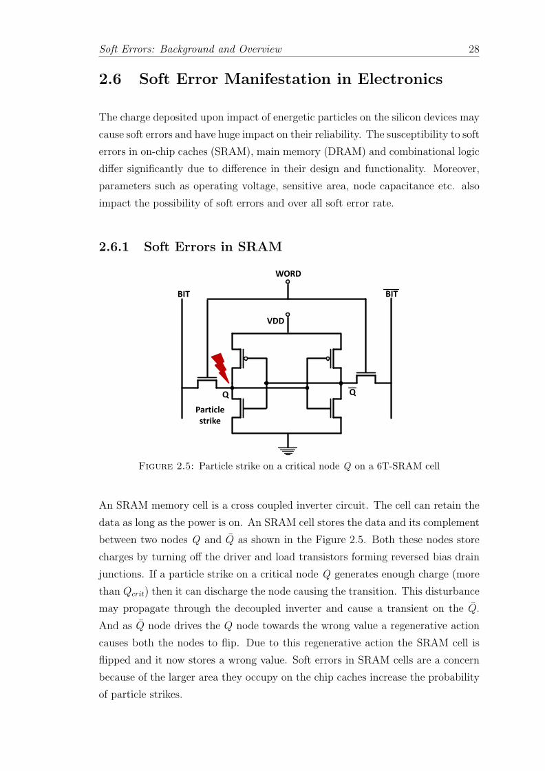
Soft Errors: Background and Overview 28
2.6 Soft Error Manifestation in Electronics
The charge deposited upon impact of energetic particles on the silicon devices may
cause soft errors and have huge impact on their reliability. The susceptibility to soft
errors in on-chip caches (SRAM), main memory (DRAM) and combinational logic
differ significantly due to difference in their design and functionality. Moreover,
parameters such as operating voltage, sensitive area, node capacitance etc. also
impact the possibility of soft errors and over all soft error rate.
2.6.1 Soft Errors in SRAM
BIT BIT
WORD
VDD
Q Q
Particle
strike
Figure 2.5: Particle strike on a critical node Q on a 6T-SRAM cell
An SRAM memory cell is a cross coupled inverter circuit. The cell can retain the
data as long as the power is on. An SRAM cell stores the data and its complement
between two nodes Q and Q as shown in the Figure 2.5. Both these nodes store
charges by turning off the driver and load transistors forming reversed bias drain
junctions. If a particle strike on a critical node Q generates enough charge (more
than Qcrit) then it can discharge the node causing the transition. This disturbance
may propagate through the decoupled inverter and cause a transient on the Q.
And as Q node drives the Q node towards the wrong value a regenerative action
causes both the nodes to flip. Due to this regenerative action the SRAM cell is
flipped and it now stores a wrong value. Soft errors in SRAM cells are a concern
because of the larger area they occupy on the chip caches increase the probability
of particle strikes.

Soft Errors: Background and Overview 29
2.6.2 Soft Errors in DRAM
BIT
WORD
Figure 2.6: Structure of a DRAM memory cell
Figure 2.6 shows a DRAM memory cell. DRAM cell consists of a capacitor to store
the bit, with a transistor to access the stored data in the capacitor. A particle
strike on the capacitor may impart a large amount of charge (more than Qcrit) and
may alter the stored data causing a bit flip. Initially, the DRAM cells used planar
capacitors with large junction area. In a cell with larger cell area it was easier to
cause the soft error. However, by adapting to 3D capacitors (e.g., stack, trench
etc.) designers could successfully reduce the sensitive volume without decreasing
the nodal capacitance making a DRAM cell one of the more robust electronic
devices. By adapting to 3D capacitors the soft error rate reduced and it was
possible to fit in more memory cells in the same area. The amount of DRAM in
computer systems continues to increase every year, and is predicted to increase
50× over 2009 levels by 2024 [160]. In this situation, The contribution of soft
errors in total DRAM errors (including hard errors) can be as high as 30% [161].
2.6.3 Soft Errors in Logic
The phenomenon that explains bit inversions remains the same for both memories
and logic elements. However, the soft error rate of logic elements and its impact
on the system are much harder to quantify because of their non-regular design
and their period of vulnerability (when they are active rather than idle) which
varies widely depending on the functionality of the design, frequency, and the
workload [32, 34, 117, 162, 163].
Sequential Logic: Logic elements include latches and flip-flops that hold system
event signals and buffer the data before it goes in or out of the microprocessor.

Soft Errors: Background and Overview 30
They provide the interface to other combinational logic (i.e., ALUs) that perform
logical operations based on multiple inputs. Flip-flops and latches are fundamen-
tally similar to the DRAM cell and they use cross-coupled inverters to store the
data state. However, compared to an DRAM cell, the sequential logic is usually
less susceptible to soft errors due to the use of larger transistors (hence larger
capacitance and driving strength) in latches and associated logic gates [34].
1 DFF
CLK
D Q
(a) Electrical masking
DFF
CLK
D Q
1
DFF
CLK
D Q
(b) Logical masking
Error
Latched
(c) Latch-window masking
Figure 2.7: Masking effect in combinational logic circuits.
Combinational Logic: Unlike caches or memories, a transient pulse (glitch) that
is generated in combinational logic can only cause an error at a critical point in
the circuit if the following conditions are fulfilled: (i) The glitch has to be strong
enough to generate a signal on one of the nodes in the circuit and the signal
has to be strong enough to propagate through the combinational logic in the
circuit i.e., electrical masking, (ii) The path that is traveled by the pulse has to be
logically enabled i.e. logical masking and (iii) The fault has to be latched i.e. latch-
window masking. Due to these inherent masking characteristics combinational
Soft Errors: Background and Overview 31
logic components are relatively less sensitive towards particle strikes compared to
memory. Figure 2.7 shows all the three masking possibilities. Figure 2.7(a) shows
the electrical masking where the generated pulse is weak and will not propagate
to the latch. Figure 2.7(b) shows that if the one of the inputs of the or gate is set
high in that case the patch of the fault is not logically enabled and hence it will
not cause an error. The case of latch-window masking is shown in Figure 2.7(c).
Although the glitch generated by particle strike is strong enough if it is not latched
(in this case the rising clock pulse in edge trigger flip flop), it will not cause soft
error.
2.6.4 Evidence of Soft Errors
Soft errors due to cosmic rays have already had an impact on the microelectronics
industry. The existence of this problem in space applications was reported in the
early 1950s [28]. Due to high solar activity in 2003, 28 satellites were damaged,
out of which 2 were unrecoverable [23]. More recently, on October 7th, 2008, an
Airbus A330-303 operated by Qantas Airways, en route from Perth to Singapore,
suffered a failure. When incorrect data entered the flight control systems, the
plane suddenly and severely pitched downwards, injuring 110 passengers and nine
crew members [24]. And now the potential havoc caused by this invisible threat
is growing as more airborne microchip-based devices are used in drones, aircrafts,
spacecrafts and satellites every year.
The threat on the ground is growing too, a number of commercial computer manu-
facturers have reported that cosmic rays have become a major cause of disruptions
at customer sites [25, 26].
In early 2000, Sun Microsystems’s Ultra SPARC II workstations were crashing
at an alarming rate. The root cause of the problem was traced back to IBM
supplied SRAMs that were experiencing upsets due to soft errors. As a result, Sun
had to switch memory vendors and also designed error detection and correction
mechanisms for their caches [27]. In 2003, due to increased solar activity, the
Q cluster located at Los Alamos, recorded highest ever 26.1 errors a week [23].
Soft errors have been blamed for 4096 extra votes being counted by an electronic
voting machine in the county of Schaerbeek, Belgium, in 2003 [164, 165], and for
repeatedly bringing the $1 billion Cypress Semiconductor Corporation factory to
a halt [28].
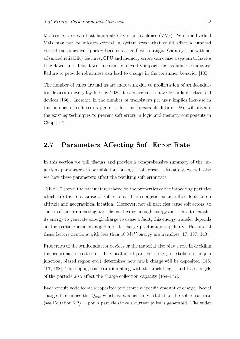
Soft Errors: Background and Overview 32
Modern servers can host hundreds of virtual machines (VMs). While individual
VMs may not be mission critical, a system crash that could affect a hundred
virtual machines can quickly become a significant outage. On a system without
advanced reliability features, CPU and memory errors can cause a system to have a
long downtime. This downtime can significantly impact the e-commerce industry.
Failure to provide robustness can lead to change in the consumer behavior [100].
The number of chips around us are increasing due to proliferation of semiconduc-
tor devices in everyday life, by 2020 it is expected to have 50 billion networked
devices [166]. Increase in the number of transistors per user implies increase in
the number of soft errors per user for the foreseeable future. We will discuss
the existing techniques to prevent soft errors in logic and memory components in
Chapter 7.
2.7 Parameters Affecting Soft Error Rate
In this section we will discuss and provide a comprehensive summary of the im-
portant parameters responsible for causing a soft error. Ultimately, we will also
see how these parameters affect the resulting soft error rate.
Table 2.2 shows the parameters related to the properties of the impacting particles
which are the root cause of soft errors. The energetic particle flux depends on
altitude and geographical location. Moreover, not all particles cause soft errors, to
cause soft error impacting particle must carry enough energy and it has to transfer
its energy to generate enough charge to cause a fault, this energy transfer depends
on the particle incident angle and its charge production capability. Because of
these factors neutrons with less than 10 MeV energy are harmless [17, 137, 140].
Properties of the semiconductor devices or the material also play a role in deciding
the occurrence of soft error. The location of particle strike (i.e., strike on the p–n
junction, biased region etc.) determines how much charge will be deposited [146,
167, 168]. The doping concentration along with the track length and track angels
of the particle also affect the charge collection capacity [169–172].
Each circuit node forms a capacitor and stores a specific amount of charge. Nodal
charge determines the Qcrit which is exponentially related to the soft error rate
(see Equation 2.2). Upon a particle strike a current pulse is generated. The wider

Soft Errors: Background and Overview 33
Domain Parameters
EnergeticParticle
Properties
• Particle sources and type, Atomic weight, Number ofsimultaneously produced secondary particles
• Particle energy, Particle flux, Incident angle and energy,Charge production capability
Device orMaterial
• Position of impact, Track lengths, Track angles• Stopping power or LET• Doping Concentration, Charge collection capacity
Circuit
• Nodal Capacitance, Sensitive area, Critical charge(Qcrit), Resulting shape of the current pulse
• Operating voltage, Frequency, Temperature, Parametricvariations
• Masking rate (Electrical, Logical and Timing masking)
Microarchitecture
• Operating voltage and frequency, Thermal profile, Para-metric variations
• Microarchitectural masking rate (e.g., Dead instruc-tions, Unused structures etc.)
Chip Packaging material, Process technology
Environmental Altitude, Geographical location
Table 2.2: Parameters that affect the soft errors and impact the overall softerror rate
current pulse with higher magnitude are more likely to cause a soft error. Apart
from that in circuit or microarchitecture domain the operating voltage, frequency,
temperature and parametric variations also affect the soft error rate.
Parameter Trend Parameter Soft Error Rate
IncreaseParticle flux Linear increase
Temperature Exponential increase
Frequency Linear increase
DecreaseQcrit Exponential increase
Sensitive Area Linear decrease
Voltage Exponential increase
Table 2.3: Impact of important parameters and corresponding impact on softerror rate
Table 2.3 enlists the parameters that have the most significant impact on the
soft error rate. According to the equation 2.2, the soft error rate is related to
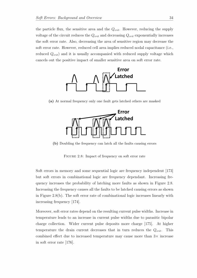
Soft Errors: Background and Overview 34
the particle flux, the sensitive area and the Qcrit. However, reducing the supply
voltage of the circuit reduces the Qcrit and decreasing Qcrit exponentially increases
the soft error rate. Also, decreasing the area of sensitive region may decrease the
soft error rate. However, reduced cell area implies reduced nodal capacitance (i.e.,
reduced Qcrit) and it is usually accompanied with reduced supply voltage which
cancels out the positive impact of smaller sensitive area on soft error rate.
Error
Latched
(a) At normal frequency only one fault gets latched others are masked
Error
Latched
(b) Doubling the frequency can latch all the faults causing errors
Figure 2.8: Impact of frequency on soft error rate
Soft errors in memory and some sequential logic are frequency independent [173]
but soft errors in combinational logic are frequency dependant. Increasing fre-
quency increases the probability of latching more faults as shown in Figure 2.8.
Increasing the frequency causes all the faults to be latched causing errors as shown
in Figure 2.8(b). The soft error rate of combinational logic increases linearly with
increasing frequency [174].
Moreover, soft error rates depend on the resulting current pulse widths. Increase in
temperature leads to an increase in current pulse widths due to parasitic bipolar
charge collection. Wider current pulse deposits more charge [175]. At higher
temperature the drain current decreases that in turn reduces the Qcrit. This
combined effect due to increased temperature may cause more than 3× increase
in soft error rate [176].

Soft Errors: Background and Overview 35
2.8 Soft Errors and Future Processors
Apart from the parameters of Table 2.2 in Section 2.7, the way future processors
are going to be designed have a significant impact on the soft error rate.
2.8.1 Impact of Technology Scaling
We will see how the technology scaling affects the soft error rate in future proces-
sors.
2.8.1.1 SRAM
Recall the Figure 1.1 from Chapter 1, which shows the effect of technology scaling
on the soft error rate of an SRAM cell and an SRAM system (e.g., cache). The
soft error rate of an SRAM cell is almost constant. The SRAM system soft error
rate which roughly doubles every technology generation. This increasing trend is
because of the increase in the number of transistors following Moore’s law [29, 33,
34].
A particle strike may cause single bit upset (SBU) if it affects only one memory
cell. Although, SBU is the most common failure scenario for memories, with
reduced device dimensions now particles can simultaneously cause multiple bit
upsets (MBU) [48, 87, 88]. The phenomenon that explains bit inversions remains
the same for both cases [117]. However, the literature indicates that two adjacent
bits being upset by a single particle strike is ten times less probable than a single
cell upset, and the probability of three bits being upset is one hundred times less
likely than a single bit upset [32, 80, 87, 88, 177–179]. Although the probability
of MBU is low it is predicted to increasing with technology scaling. MBUs rate
have increased by a factor of four when scaling from 90 nm to 65 nm [87, 88].
2.8.1.2 DRAM
Figure 2.9 shows how the soft error rate of a DRAM cell and the logic scale for
different technology generations [17, 180]. DRAM cell soft error rate is trending
downwards (a reduction of 4 to 5× per generation). It is mainly because of the
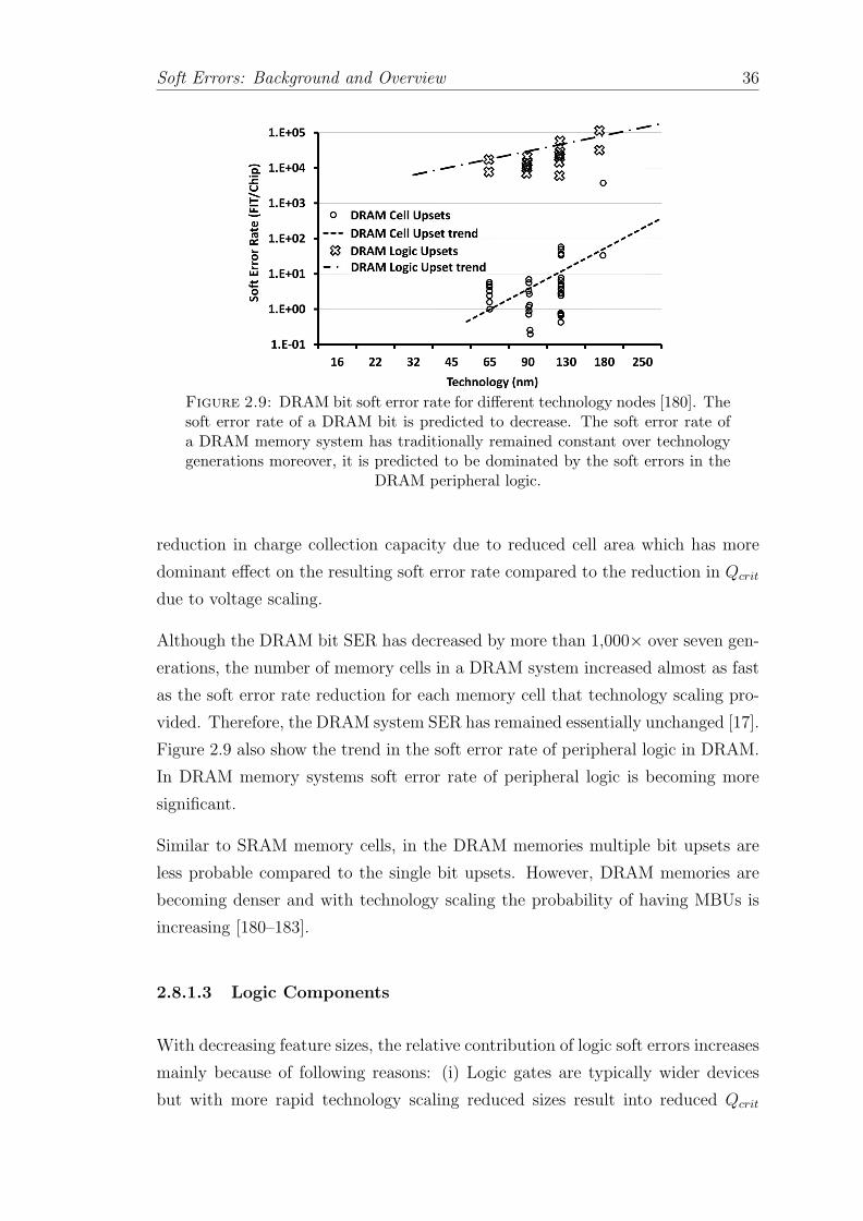
Soft Errors: Background and Overview 36
Figure 2.9: DRAM bit soft error rate for different technology nodes [180]. Thesoft error rate of a DRAM bit is predicted to decrease. The soft error rate ofa DRAM memory system has traditionally remained constant over technologygenerations moreover, it is predicted to be dominated by the soft errors in the
DRAM peripheral logic.
reduction in charge collection capacity due to reduced cell area which has more
dominant effect on the resulting soft error rate compared to the reduction in Qcrit
due to voltage scaling.
Although the DRAM bit SER has decreased by more than 1,000× over seven gen-
erations, the number of memory cells in a DRAM system increased almost as fast
as the soft error rate reduction for each memory cell that technology scaling pro-
vided. Therefore, the DRAM system SER has remained essentially unchanged [17].
Figure 2.9 also show the trend in the soft error rate of peripheral logic in DRAM.
In DRAM memory systems soft error rate of peripheral logic is becoming more
significant.
Similar to SRAM memory cells, in the DRAM memories multiple bit upsets are
less probable compared to the single bit upsets. However, DRAM memories are
becoming denser and with technology scaling the probability of having MBUs is
increasing [180–183].
2.8.1.3 Logic Components
With decreasing feature sizes, the relative contribution of logic soft errors increases
mainly because of following reasons: (i) Logic gates are typically wider devices
but with more rapid technology scaling reduced sizes result into reduced Qcrit
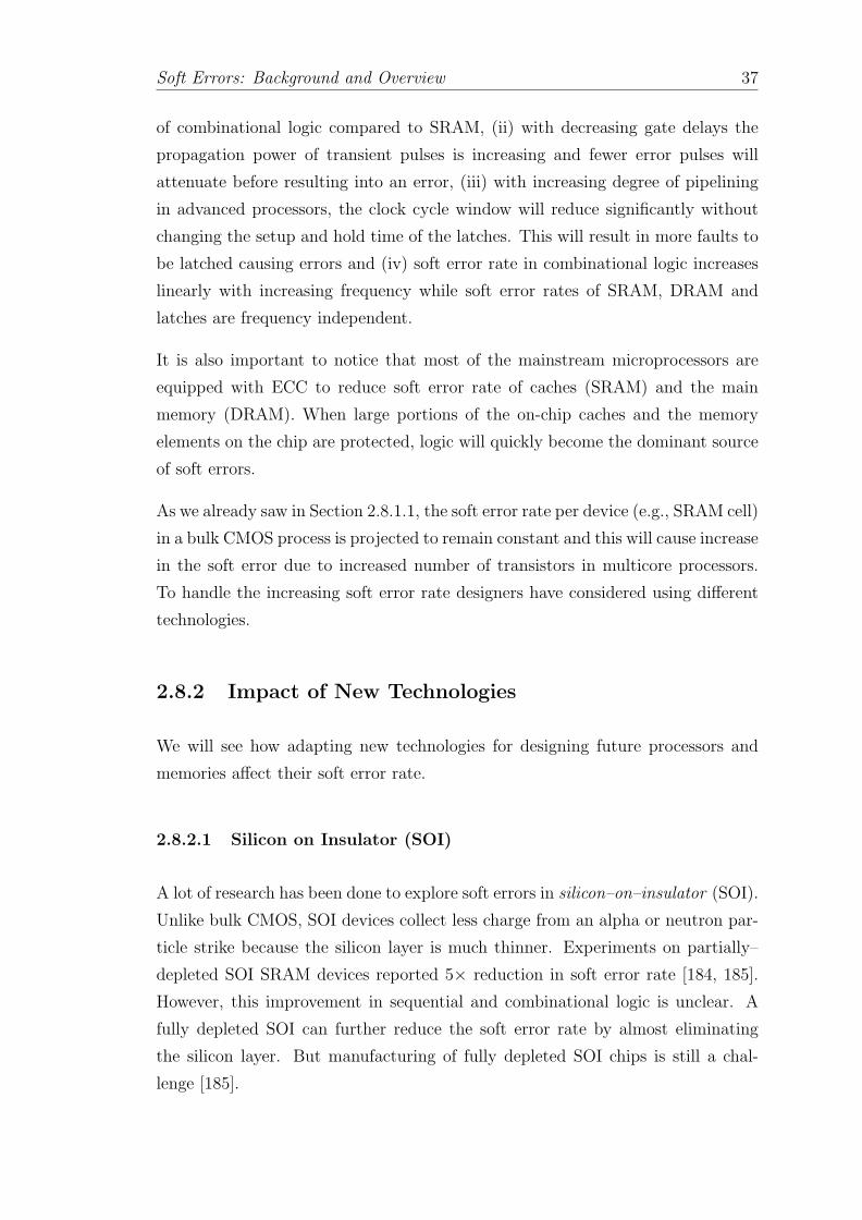
Soft Errors: Background and Overview 37
of combinational logic compared to SRAM, (ii) with decreasing gate delays the
propagation power of transient pulses is increasing and fewer error pulses will
attenuate before resulting into an error, (iii) with increasing degree of pipelining
in advanced processors, the clock cycle window will reduce significantly without
changing the setup and hold time of the latches. This will result in more faults to
be latched causing errors and (iv) soft error rate in combinational logic increases
linearly with increasing frequency while soft error rates of SRAM, DRAM and
latches are frequency independent.
It is also important to notice that most of the mainstream microprocessors are
equipped with ECC to reduce soft error rate of caches (SRAM) and the main
memory (DRAM). When large portions of the on-chip caches and the memory
elements on the chip are protected, logic will quickly become the dominant source
of soft errors.
As we already saw in Section 2.8.1.1, the soft error rate per device (e.g., SRAM cell)
in a bulk CMOS process is projected to remain constant and this will cause increase
in the soft error due to increased number of transistors in multicore processors.
To handle the increasing soft error rate designers have considered using different
technologies.
2.8.2 Impact of New Technologies
We will see how adapting new technologies for designing future processors and
memories affect their soft error rate.
2.8.2.1 Silicon on Insulator (SOI)
A lot of research has been done to explore soft errors in silicon–on–insulator (SOI).
Unlike bulk CMOS, SOI devices collect less charge from an alpha or neutron par-
ticle strike because the silicon layer is much thinner. Experiments on partially–
depleted SOI SRAM devices reported 5× reduction in soft error rate [184, 185].
However, this improvement in sequential and combinational logic is unclear. A
fully depleted SOI can further reduce the soft error rate by almost eliminating
the silicon layer. But manufacturing of fully depleted SOI chips is still a chal-
lenge [185].

Soft Errors: Background and Overview 38
2.8.2.2 Multigate-FET Devices
As the bulk CMOS is reaching its scaling limits, FinFETs and multigate-FETs
(e.g., Tri-Gate FET) devices have been popularized as promising candidates to
keep harnessing the benefits of Moore’s law. Due to their many superior attributes,
especially in the areas of performance, leakage power, intra-die variability, low
voltage operation (translates to lower dynamic power), and significantly lower
retention voltage for SRAMs, FinFETs are replacing planar CMOS as the device
of choice especially in sub–32 nm technologies [186–189].
Upon a particle strike on a planar bulk CMOS device, a lot of generated charge can
reach the drain of the device and collect there, causing enough current to upset the
storage node. In FinFET devices, the conduction is mainly in the channel and,
hence most of the charge dissipates in the substrate and will not collect at the
drain. It is worth noticing that for the same technology node, the Qcrit of FinFET
SRAM and planner CMOS SRAM are same. However, due to reduced charge
collection, compared to planned CMOS device, 15× reduction in soft error rate of
Tri-gate FinFet devices has been reported using device simulations at terrestrial
flux [190].
The soft error rate of FinFET devices depend on their manufacturing process
and the measurement technique. Laser and heavy-ion testing of Tri-Gate devices
manufactured at IMEC indicated that the sensitive area for charge collection in
bulk FinFETs is significantly larger than the actual fin’s structure, increasing the
probability of single event upsets in the cell [191]. On the contrary, proton beam
testing of the 22 nm Tri-Gate SRAM and sequential logic devices observed 1.5–4×reduction in soft error rate compared to 32 nm planner bulk CMOS [192]. Study
also shows that in Tri-Gate technology a modest increase in combinational soft
error rate relative to sequential soft error rate. Overall, even with Tri-Gate devices
unprotected logic will continue to dominate the soft error rate [192].
2.8.2.3 Non-Volatile Memories
Many memory cell technologies are being considered as possible replacements for
DRAM mainly because they are nearing their scaling limits. DRAM scaling is
especially challenging for sub–30 nm [193, 194].

Soft Errors: Background and Overview 39
Phase change memory (PCM), spin-transfer torque (STT-RAM), ferroelectric RAM
(FeRAM or FRAM), magnetoresistive RAM (MRAM) etc. promise high density,
better scaling, and non-volatility, however, they introduce several new challenges.
DRAM uses a capacitor to store charge and can be upset by an energetic parti-
cle strike causing soft error. Resistive memories (PCM, STT-RAM, FRAM and
MRAM), which arrange atoms within a cell and then measure the resistive drop
through the atomic arrangement, are promising as a potentially more scalable
replacement for DRAM.
Because the FRAM cell stores the state as a piezoelectric polarization, an alpha
hit is very unlikely to cause the polarization to change cell’s state and the MRAM
terrestrial soft error rate needs more measurements. PCM cell arrays may not be
vulnerable to soft error due to particle strikes but they experience soft errors caused
by resistance drift and spontaneous crystallization resulting from gradual atomic
motion at high temperatures [195]. A recent study [196] predicted the failure rate
of PCM to be 109–1011 times higher compared to DRAM. Moreover, soft error
specific studies for resistive memory technologies do not consider the possibility of
soft errors in peripheral circuits which will still use the CMOS transistors [197].
The future solutions for handling soft errors will have to adapt to these new
technologies and should be able to protect the peripheral circuits as well [198].
2.9 Calculating SER to Make Architectural De-
cisions
We discussed how we can compute the soft error rate by computer simulations
in Section 2.5. We also quantified the soft error rate in equation 2.2. However,
not all the particle strikes can cause soft errors. As we have seen in Section 2.6.3,
most of the faults induced by particle strikes are masked. In this situation the
equation 2.2, which does not take the masking effects into consideration, gives a
very pessimistic estimation of soft error rate. Overly pessimistic estimate of soft
error rate may lead to overdesign for reliability and incur huge area, power and
performance overheads. For this reason it is important to derate the soft error
rate.

Soft Errors: Background and Overview 40
To obtain the soft error rate under the masking effects, two main methodologies
are used: statistical fault injection and architecture vulnerability factor (AVF)
analysis.
2.9.1 Fault Injection:
Fault injection is a way to quantify the reliability of a microarchitecture by inject-
ing faults in each state and examining the outcome. In this brute force approach
the number of possible faults to be injected can be astronomical depending on the
number of states. Moreover, identifying all the combinations of the possible fault
locations and the instances at which the fault can occur in a given set of workload
is challenging and complex. Also, to observe the effect a fault has on the final
outcome it is necessary to run a complete simulation and observe any abnormal
behavior due to the injected fault.
One way to optimize the method is by using a subset of faults to observe the
possible outcomes and provide enough statistical confidence in the estimated soft
error rate. In sampled fault injection the accuracy is traded off for simulation
time [199]. More number of simulations are required if a higher degree of confi-
dence is necessary. Moreover, depending on the design if many corner cases are
to be observed then each corner case requires its own set of injected faults for the
required confidence.
2.9.2 Architecture Vulnerability Factor (AVF) Analysis:
Architectural vulnerability factor (AVF) is a probability that a user visible error
will occur given a bit flip in a storage cell or a glitch in combinational logic. The
underlying concept in AVF computation is knowing if a particle strike on a bit
matters or not. The fraction of the bit flips that affect the program outcome is
captured by AVF. The AVF has a significant impact on the effective soft error
rate. The higher the AVF of a structure implies a higher probability of having soft
error in that structure.
AVF analysis is performed via architectural simulations. Architectural simulations
of a processor is fast and abstract. Moreover, the reliability analysis can be done at
design time and hence a detailed RTL or a test chip is not required. By performing

Soft Errors: Background and Overview 41
AVF analysis designers can rank the structures based on their vulnerability in a
very early stage of design.
The AVF of a processor is related with the FIT rate in the following manner:
FIT = FITRaw × TV F × Sizestructure × AV F (2.3)
The raw soft error rate (FITRaw) depends on the circuit characteristics and it can
be obtained by accelerated soft error rate measurements. Time vulnerability factor
(TVF) is the fraction of cycle during the circuit is vulnerable. For an example,
TVF of an SRAM memory cell is 1, however if a latch is accepting data rather than
holding data, a strike on its stored bit may not result into an error, because the
erroneous data that was stored will be overwritten by the correct new input data.
If the latch is accepting data 50% of the time, the latch is vulnerable only for the
50% of the time it is operational. TVF is dependent on the circuit and frequency.
Once we have determined raw FIT rate it has to be derated by TVF. Finally, the
effective FIT rate of a circuit is shown in Equation 2.3. It is the product of its
raw FIT rate, TVF and AVF.
AVF analysis vastly relies on identifying masked faults and it provides a conser-
vative estimate of processor’s reliability. Although it is not accurate, it can help
reliability designers. Substantial amount of research has been done in efficiently
modeling the AVF of different microarchitectural structures [39, 98, 117, 162, 200–
205].
In this work, we implement the AVF model similar to [97]. In Chapters 5 and 6,
we use AVF to identify the vulnerable structures for providing protection. Notice
in Equation 2.3 that AVF and FIT rate are directly related. If the structure is
more vulnerable its AVF increases and it results into increased FIT rate and vise
versa. We show how the proposed architecture can significantly reduce the AVF
and in turn improves the overall reliability.
Chapter 3
Error Detection using Acoustic
Wave Detectors
In this chapter we first study and compare several particle strike detectors. A
detailed discussion of the structures, design issues related to several particle strike
detectors and their comparison of area, power and performance overhead is given
in Section 3.7. We then propose to adopt acoustic wave detectors as a method
to detect such particle strikes by detecting the shockwave they generate upon an
impact on silicon. We present the structure of the acoustic wave detector and
discuss its properties in detail. Next, we will show how to use the acoustic wave
detectors in order to precisely locate the particle strike. We will describe different
algorithms to precisely locate the particle strikes. Finally, we will present a case
study to evaluate how the architecture with acoustic wave detectors performs in
detecting and locating particle strikes on a state of the art processor core.
3.1 Particle Strike Detectors
Several particle strike detector based techniques have been proposed. These detec-
tors detect particle strikes via detection of voltage or current glitches [132–134, 206]
or via detection of the sound [135].
We studied the challenges in adapting the detector based techniques for soft error
detection. We compared them based on following parameters,
42
Error Detection using Acoustic Wave Detectors 43
• Hardware cost, area and power overheads
• Detection latency
• False alarms : False positive is an event when detector triggers indicating an
error without any actual error.
• Fault coverage in a processor
• Design cost
Error detection using particle strike detectors involves adding physical redundancy
to the protected circuit. Depending on the number of required detectors used to
detect particle strikes the overall area overhead varies. Moreover, the detectors are
required to be connected to a controller circuit and interconnecting the detectors
further increases the area overhead. Due to added hardware the power overhead
is also increased.
Detection latency can be defined as the time between a particle strike and when the
first detector triggers. Detection latency is important for providing error contain-
ment. Efficient error containment restricts the spread of error to a specific region.
By containing the error we prevent the error to be visible to the user before its
detection and avoid SDC. Error detection with lower detection latency is desir-
able to avoid SDC. Once the error is detected, a hardware or software mechanism
would trigger the appropriate recovery action for correction (e.g., checkpointing).
False alarms include the false positive events for the given detector type. Fault cov-
erage metric indicates the structures a given particle strike detector can cover. In
other words some detectors can only detect particle strikes in only SRAM memory
cells while some detectors can detect particle strikes in both memory components
as well as logic. The detectors that protects memory and logic has higher coverage
than the detectors that can protect only memory or only logic. And finally design
cost which represents the intrusiveness of the design for including the detectors. It
covers the necessary changes required in the process technology, layout, placement
and routing etc.
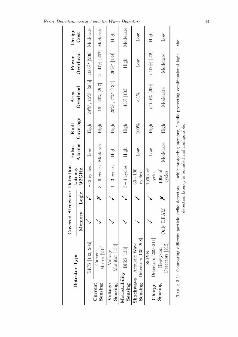
Error Detection using Acoustic Wave Detectors 44
DetectorType
CoveredStructure
Detection
False
Fault
Area
Power
Design
Latency
Alarm
sCovera
ge
Overh
ead
Overh
ead
Cost
Memory
Logic
@2GHz
Current
Sensing
BIC
S[132,206]
!!
∼3cycles
Low
High
29%
† ,15%
⋆[206]
100%
⋆[206]
Moderate
Current
Mirror[207]
!%
3−6cycles
Moderate
High
16−20%
[207]
2−47%
[207]Moderate
Voltage
Sensing
Voltage
Mon
itor
[134]
!!
1−3cycles
High
High
20%
† ,7%
⋆[134]
20%
⋆[134]
High
Metastability
Sensing
BISS[133]
!!
3−4cycles
High
High
45%
[133]
High
Moderate
Shock
wave
Sensing
Acoustic
Wave
Detectors
[135,208]
!!
30−100
cycles
∓Low
100%
<1%
Low
Low
Charg
eSensing
Si-PIN
Detectors
[209–211]
!!
1000sof
cycles
Low
High
>100%
[209]
>100%
[209]
High
Heavy-ion
Detectors
[212]
Only
DRAM
%100s
ofcycles
Moderate
High
Moderate
Moderate
Low
Table
3.1:Com
paringdifferentparticlestrikedetectors.
†whileprotectingmem
ory,
⋆whileprotectingcombinationallogic,∓
the
detection
latency
isbou
nded
andconfigu
rable.
Error Detection using Acoustic Wave Detectors 45
Considering all these parameters mentioned above, an ideal solution would be the
one that has minimum area & power overheads and the least detection latency.
It would have minimum false negative rates so it can guarantee detection of all
strikes. It should cover all the possible sources of particle strikes (i.e., alpha, neu-
trons, etc.). It can detect particle strikes in both logic and memory components.
Finally, the solution should pose no major challenges in the implementation pro-
cess, placement and routing etc. to minimize design cost. We summarize our
study in Table 3.1.
As can be seen in Table 3.1, schemes for particle strike detection via the detection
of voltage or current glitches [132–134, 206, 207] provide short detection latency
and provide good coverage. However, their area and power penalties are high.
They also pose design challenges in terms of selective insertion while providing
maximum fault coverage at minimum area penalty.
Charge sensing techniques [209–212] for detecting particle strikes via the detection
of deposited charges are very effective but cost more than 100% in area and power
overhead.
The overheads in terms of area and power penalty while using acoustic wave detec-
tors are low. Moreover, acoustic wave detectors provide bounded and configurable
detection latency. The error is detected within a fixed number of cycles that is
known a-priori or can be set by the designer. Acoustic wave detectors act as unified
error detection mechanism and can detect particle strikes in both logic and mem-
ory components. Based on this survey, we conclude that acoustic wave detectors
based on cantilever structures are the most attractive solution [135].
Detecting the right particle: At 45 nm technology, any particle strike that will
result into a silicon recoil energy less than 10 MeV will not induct enough charge
to create an upset in the memory [20, 141, 149]. Therefore, we need to size the
cantilever accordingly, in such a way that it only detects particle strikes that result
into a silicon recoil energy larger than 10 MeV and therefore avoiding false positive
detection [137]. By calibrating the acoustic wave detectors it is possible to detect
only those particle strikes that are capable of generating single event transient
(SET) in logic or a single event upset (SEU) in memory. The same detectors can
be used for memories as well as logic components [20, 32].

Error Detection using Acoustic Wave Detectors 46
3.2 The Microelectromechanical Ears: Acoustic
Wave Detectors
Figure 3.1: Transformation of the energy of particle strike upon its impact onsilicon surface into acoustic shock wave
Recall from Section 2.3.2 in Chapter 2 that particles with recoil energies of 10 MeV
or higher are capable of causing upsets in the circuits. When a cosmic ray collides
with a silicon nucleus this energy is released in a very short span of time (≤1ps).
This rapid recombination process results into a cloud of phonons spreading out of
the impact site. Hence the cosmic ray is transformed into an intense shock wave
as shown in the Figure 3.1. Such a shockwave travels at the speed of 10km/s on
the silicon surface [213].
We propose to use cantilever like structures [214, 215] as an acoustic wave detector
to detect particle strikes through the sound they generate. To be able to detect
the impact of the cosmic particle, the cantilevers must perform two contradictory
tasks:
1. For detecting all potent particle strikes that may cause soft errors the can-
tilever based detector must absorb as much energy as possible resulting due
to the collision. This implies a thick pliable structure composed of a high
density, high-impedance material, such as gold.
2. For efficient detection at a distance and to avoid thermal noise, the pliable
structure must maximally deflect for the given energy deposition. Thus, the
levers should be light in weight and highly flexible.
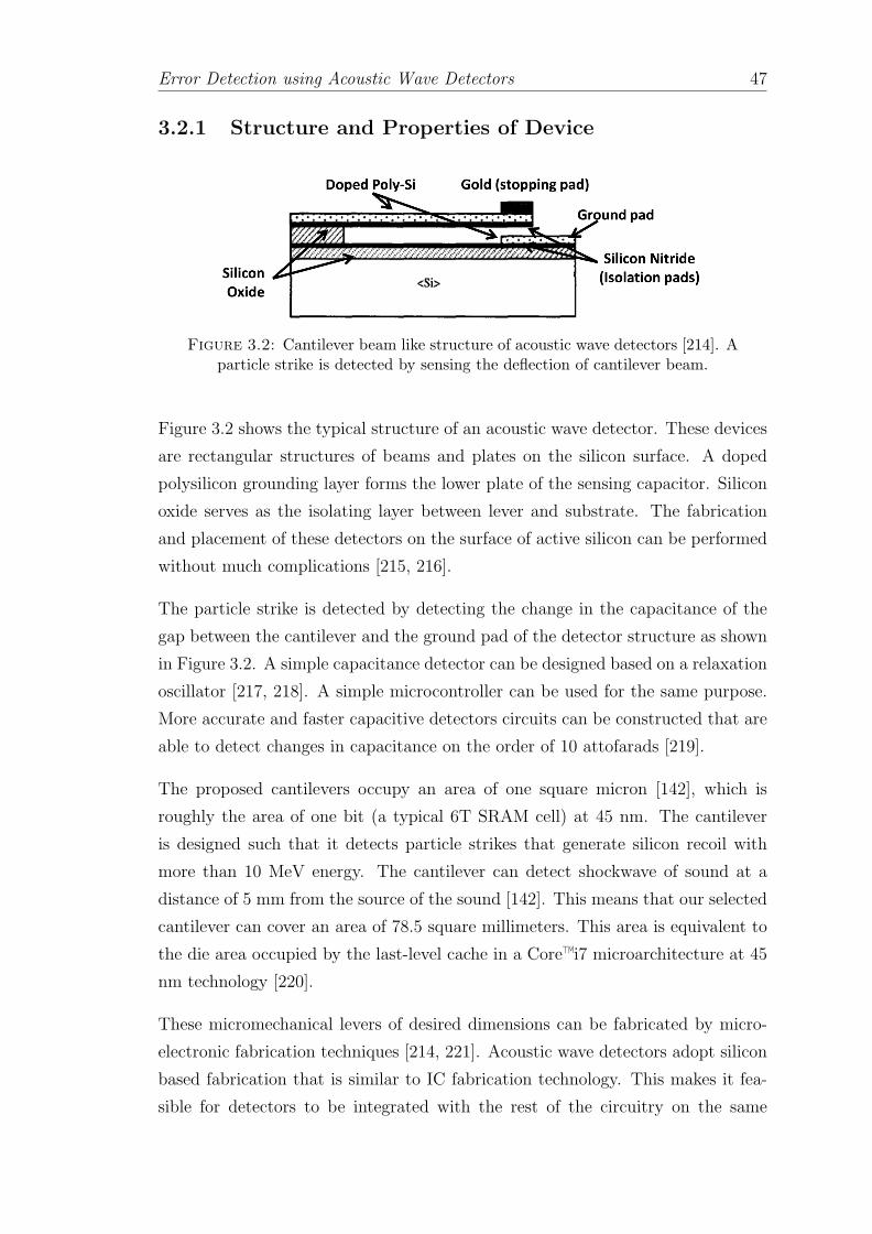
Error Detection using Acoustic Wave Detectors 47
3.2.1 Structure and Properties of Device
Figure 3.2: Cantilever beam like structure of acoustic wave detectors [214]. Aparticle strike is detected by sensing the deflection of cantilever beam.
Figure 3.2 shows the typical structure of an acoustic wave detector. These devices
are rectangular structures of beams and plates on the silicon surface. A doped
polysilicon grounding layer forms the lower plate of the sensing capacitor. Silicon
oxide serves as the isolating layer between lever and substrate. The fabrication
and placement of these detectors on the surface of active silicon can be performed
without much complications [215, 216].
The particle strike is detected by detecting the change in the capacitance of the
gap between the cantilever and the ground pad of the detector structure as shown
in Figure 3.2. A simple capacitance detector can be designed based on a relaxation
oscillator [217, 218]. A simple microcontroller can be used for the same purpose.
More accurate and faster capacitive detectors circuits can be constructed that are
able to detect changes in capacitance on the order of 10 attofarads [219].
The proposed cantilevers occupy an area of one square micron [142], which is
roughly the area of one bit (a typical 6T SRAM cell) at 45 nm. The cantilever
is designed such that it detects particle strikes that generate silicon recoil with
more than 10 MeV energy. The cantilever can detect shockwave of sound at a
distance of 5 mm from the source of the sound [142]. This means that our selected
cantilever can cover an area of 78.5 square millimeters. This area is equivalent to
the die area occupied by the last-level cache in a Core™i7 microarchitecture at 45
nm technology [220].
These micromechanical levers of desired dimensions can be fabricated by micro-
electronic fabrication techniques [214, 221]. Acoustic wave detectors adopt silicon
based fabrication that is similar to IC fabrication technology. This makes it fea-
sible for detectors to be integrated with the rest of the circuitry on the same

Error Detection using Acoustic Wave Detectors 48
chip [222, 223]. Cantilever based devices of varying lengths have been developed
and used extensively to study bio-interactions at atomic level [216, 224, 225].
3.2.2 Calibrating the Detector
The length of the cantilever beam is very important in detecting the cosmic particle
strike. Too long or very small lever dimensions would not be efficient in detecting
the desired particle strikes. Moreover, failing to calibrate the cantilever device
may cause false positives.
3.2.2.1 False Positives
Precise calibration of acoustic wave detectors will lead to zero false positives.
Failing to properly calibrate the detectors would result into false positives (i.e.,
detectors’ trigger for the particles that do not carry enough charge to create a soft
error). Also, the analysis of false positives due to process variations, temperature
variations, aging and distance between strikes and cantilevers is beyond the scope
of the thesis readers may refer to [214, 221].
Also recall from Chapter 2, that many of the faults induced due to energetic
particle strikes will not cause an error because of several masking effects. If a
circuit has zero fault masking, all the faults will cause soft errors.
However, in a scenario where 100% faults are masked the solution with acoustic
wave detectors will have false positives. The flux of energetic particles at sea
level is approximately 14 neutrons/(cm2-hr), an improbable scenario of detectors
triggering for every harmless particle strike (which also gets masked not causing
an error) would imply detecting 1 false positive every 1.3 minutes for a modern
general-purpose multi-core processor.
Increased false positives cause high performance penalty due to frequent error
recovery actions. Figure 3.3 shows the performance impact of recovery due to
false positive error detection for checkpointing techniques in different granulari-
ties. As you can see in the figure saving the checkpoints in the cache has very
similar cost as recovering only registers (i.e., microarchitecture checkpoint/recov-
ery) [226–229, 234]. As you include more structures in the checkpoint the cost

Error Detection using Acoustic Wave Detectors 49
Re
lati
ve
Slo
wd
ow
n
Cost of “False Positive” (ns)
1x
100
100x
10x
101 102 103
Proposed
Sequoia
IBM G5
IBM Z series
Carer
Swich
SPARC64
Cache assisted recoveryMicroarchitecture recovery
Architecture recoveryPartial architecture recovery
Enterprise recovery
108 109 1010 1011
>1000x
ReViveSafetyNet
ReStore
IBM Blue Gene
1000x
BLCR
Encore
Figure 3.3: A comparison of relative slowdown due to false positive recov-ery for different recovery techniques: Seqoia [226], Swich [227], Carer [228],SPARC64 [229], IBM Z series [59], IBM G5 [58], Encore [230], ReStore [231],
ReVive [102], SafetyNet [107], IBM Blue Gene [232], BLCR [233]
of recovery increases as in the case of techniques proposed in [230, 231]. Re-
covery techniques at architecture level or at system level incur approx 1000×slowdown compared to microarchitecture or cache assisted checkpointing/recov-
ery [102, 107]. The recovery in petascale systems can take significantly long time
before a normal operation can resume severely impacting their performance and
availability [58, 232, 233, 235].
Now that we are familiar with the structure of the acoustic wave detector we will
next discuss how we can use them for error detection.
3.3 Soft Error Detection via Detecting Particle
Strikes
In this work, the fundamental idea is to detect the particle strikes via mechanical
deflection of acoustic wave detectors. From functionality point of view one such

Error Detection using Acoustic Wave Detectors 50
acoustic wave detector is analogous to one parity bit. The potential of the detectors
will be exploited by:
1. Detecting errors in the unprotected logic and memory components and there-
fore, reduce the SDC FIT rate.
2. Deploying less number of detectors than the required parity/ECC bits in
already protected memories and accurately localizing the particle strikes/bit
flips in memory arrays.
We discussed that the cantilevers can be used for detecting the existence of particle
strikes on the silicon surface. The acoustic wave detectors can be placed on or off
the chip but on the same silicon surface.
Traditional processor cores have surface are of a few square millimeters. Recall
that acoustic wave detectors have a detection range of 5 mm. It means that just
one acoustic wave detector is enough for error detection on an entire processor
core or a last level cache of Core™i7 microarchitecture.
Acoustic wave detectors detect all soft errors due to alpha and neutron strikes.
However, not only the detection of the error but how soon the error is detected is
also very important. Recall from Section 3.2, that the sound wave traverses the
silicon lattice at 10 km/sec. This means that if only one acoustic wave detector
was used, in the worst-case a particle strike occurring at 5 mm away would be
detected in 500 ns (or 1000 cycles in a processor running at 2 GHz). By putting
more acoustic wave detectors on the surface of silicon, it is possible to reduce the
worst case detection latency.
So far, we discussed the use of acoustic wave detectors for detecting the particle
strikes on the silicon surface. Now, let’s see how to use the acoustic wave detectors
in order to precisely locate the particle strike.
Why Locate Particle Strikes? Using the acoustic wave detectors, we can only
detect all the particle strikes and hence avoid possible data corruption. However,
locating the particle strikes are equally important. Once the error has been de-
tected, a hardware or software mechanism would trigger the appropriate recovery
action for error correction. To provide successful error correction or recovery, the
system must know the precise location of the error. This can be done by exploit-
ing the localization accuracy of acoustic wave detectors to detect and correct the

Error Detection using Acoustic Wave Detectors 51
errors. Once the accurate location is found the system can take available recovery
action. For instance, if the error has occurred in one of the bits in the cache we
may correct the error by flipping the bit.
Next, we present an architecture to precisely locate the particle strikes using acous-
tic wave detectors.
3.4 Location Estimation of a Particle Strike
The estimation location of the particle strike and latency of detection depends on
the following parameters:
1. How many acoustic wave detectors are required to be able to locate the
particle strike?
2. Where the acoustic wave detectors should be placed?
3. What is the accuracy of the found location?
4. What is the latency in detecting the particle strike?
Unlike GPS, any apriori knowledge of the spatio-temporal information about the
impacting particle strike is unavailable. This means that we do not know the
actual time span between the particle strikes and when the detectors trigger. The
only information we have is the relative time difference of arrival (TDOA) [236]
of the acoustic wave generated by the strike among different detectors.
TDOA technique estimates the difference in the arrival times of the signal from
the particle strike at multiple receivers. A particular value of the time difference
estimate defines a hyperbola between the two receivers on which the particle strike
may exist, assuming that the source and the receivers are co-planar as shown in
Figure 3.4. If we have another receiver in combination with any of the previously
used receivers, another hyperbola can be defined and the intersection of the two
hyperbolas results in the position location estimate of the particle strike. This
method is also sometimes called a hyperbolic position location method [236, 237].
TDOA method offers many advantages. It does not require complex receivers, we
use simple acoustic wave detectors as receivers. It does not require any special type

Error Detection using Acoustic Wave Detectors 52
R1
R2
S2
S3
S1
R1-R3
R1-R2
Source
R2-R3
Figure 3.4: TDOA hyperbolas in a system and location of source. Dashedhyperbola is formed using only two detectors S1 and S2. Including a third
detector S3 can successfully locate the source via intersecting hyperbolas.
of antennas, hence it is cheaper to use it in existing processors. Moreover, multiple
TDOA readings can also provide immunity against timing errors and noise as we
will see later in this chapter.
Let us assume that a particle strikes at location (Xa, Ya). Therefore, a system of
two equations is required to solve both unknowns. Hence, a minimum of three
detectors are needed: with three detectors we obtain two TDOA measurements,
which allows us to derive the required equations.
Hyperbolic position location estimation. The estimation of the location is
carried out as follows:
• The acoustic wave detectors can be placed on or off the protected area but
on the same silicon surface. Notice that the coordinates of the acoustic wave
detectors are known.
• Once the strike is detected, we measure the TDOAs of the sound between
pairs of detectors through the use of time delay estimation.

Error Detection using Acoustic Wave Detectors 53
• Using the TDOA measurements we construct the system of hyperbolic equa-
tions.
• Once the equations are formed, efficient algorithms are applied to obtain a
solution to these hyperbolic equations, which represent the estimated posi-
tion of the particle strike.
3.4.1 Example
To illustrate the particle strike detection and localization problem, a simple case
of particle strike localization using 3 acoustic wave detectors is discussed.
S2(X2,Y2,t2)
S1(X1,Y1,t1)
S3(X3,Y3,t3)
(Xa,Ya,T) d1
d2d3
Figure 3.5: Strike detection and localization via triangulation using TDOAmeasurements of acoustic wave detectors
T t1t2 t3
∆T1 ∆T2
time
Detection Latency
Figure 3.6: Timeline of the events following the particle strike
Figure 3.5 displays three acoustic wave detectors (S1, S2 and S3) placed at known
coordinates (X1,Y1), (X2,Y2) and (X3,Y3) respectively on the surface of the chip.
Let’s assume that a particle strike occurs at an unknown time T at unknown
location (Xa,Ya). As shown in Figure 3.5, d1, d2 and d3 are unknown absolute
distances from the detectors S1, S2 and S3. Once the strike has occurred, the
ripples of phonons will traverse outward in a circular manner and the closest
detector from the strike will trigger first. In this case S1 will trigger at instance t1.

Error Detection using Acoustic Wave Detectors 54
After that, as the phonons traverse further, other detectors S2 and S3 will trigger
at instances t2 and t3 respectively. A timeline of the events is shown in Figure 3.6.
3.4.2 Obtaining TDOA
yes
No
Get “timer0” value at
event t1
If event
t(i+1) is high?
i=1,2
Get “timer0” value
∆T1 = t2-t1
∆ T2 = t3-t2
∆ D1 = Cp * ∆ T1
∆ D2 = Cp * ∆ T2
Stop
Start
Speed of phonon in Si lattice = Cp
∆ D1 = d2-d1
∆ D2 = d3-d2
Counter
Asynchronous
Control
t1
Sampling
Frequency
Enablet2
t3
Figure 3.7: Strike detection algorithm (firmware) and a hardware controlmechanism
Figure 3.7 shows a simple system which can measure the timing differences of the
acoustic waves’ arrival. The hardware consists of an asynchronous control (e.g.,
multiple logic OR gates or a multiplexer circuit) which generates an output Enable
signal.
Enable is high whenever one of the triggered detector raises a flag, and activates the
sequential counter that counts the number of clock pulses between two consecutive
triggering detectors. The counter runs at the sampling frequency, which is a design
parameter.
As the speed Cp at which acoustic waves traverse on the silicon surface is known
(recall Section 3.2 of this chapter), using the measured timing differences of the
arrival of the acoustic waves, we can compute the distance differences ∆Di.
Errors in measurements. The effect of errors in the measurements of timing
differences due to the sampling frequency cannot be ignored. We use the example

Error Detection using Acoustic Wave Detectors 55
t1A t2A
e1 e2 e3
t1R t2R t3Rt3A
tp
Figure 3.8: Sampling errors in the measurements of the time difference of thearrival at the acoustic wave detectors
depicted in Figure 3.8 to illustrate such case: the three detectors S1, S2 and S3
are in synch with each other and are being sampled at the rising edge of the clock
with sampling period tp. The actual arrival times of the acoustic wave generated
due to particle strike at detectors S1, S2 and S3 are t1A, t2A and t3A respectively.
However, the signal will be read only at the rising edge of the clock pulse (i.e.,
at the instances t1R, t2R and t3R) by the detectors. This introduces error in the
measurements of the time differences.
Assume a particle strike occurring at an unknown instance T , sampling period tp
and the actual arrival time of the acoustic wave generated due to particle strike
at detector Si is tiA. The sampling error es at the acoustic wave detector S can
be expressed as:
es = tp − [(T + tiA)mod(tp)] (3.1)
Notice that es ∈ [0, tp). Hence, the error in the time difference of arrival of the
acoustic wave between detectors Si and Si+1 is esi∈(−tp, tp).
3.4.3 Generating TDOA Equations
In order to generate the equations that describe the localization of the particle
strike. We sort detectors based on their proximity to the source of the signal (i.e.,
the order in which they trigger), S1 being the closest detector and Sn the furthest
one. (Xa, Ya) denotes the unknown location of strike and (Xi, Yi) indicates the
known location of the ith detector.

Error Detection using Acoustic Wave Detectors 56
A general model for the two dimensional (2-D) location estimation of a source
using N detectors is adapted, where the mathematical problem is to estimate the
actual location of a strike (Xa, Ya), utilizing the detector positions and the TDOA
readings. First, we define the squared euclidean distance between the source and
the ith detector:
Dia =√(Xi −Xa)2 + (Yi − Ya)2 (3.2)
Next we derive the range difference ∆Dia between detectors Si and Si+1,
∆Dia = Dia−D(i+1)a
=√(Xi−Xa)2+(Yi−Ya)2
−√
(Xi+1−Xa)2+(Yi+1−Ya)2 (3.3)
Now, we can set up our set of equations based on the TDOA measurements ∆Tia
between detectors Si and Si+1,
∆Dia = Cp ∗∆Tia + esi , i = 1 . . . N − 1 (3.4)
Where, Cp is the speed of the sound wave on the silicon surface. Notice that if
N>3, we will have a non-determined system (i.e., more equations than unknowns).
Next, we will see how we can solve these hyperbolic TDOA equations to obtain
the estimation of location.
3.4.4 Solving TDOA Equations
Solving a set of hyperbolic equations for accurate location estimation is non-trivial.
The simplest way to estimate the location of particle strike, is to generate a de-
terministic system of TDOA equations. The deterministic algorithms can be used
when the number of hyperbolic equations equals the number of unknown coordi-
nates of the source. In this work we implement an algorithm to solve a determin-
istic system of two hyperbolic equations [238].
A particle strike will be detected by all the detectors within the detection range
of 5 mm. Hence, usually we have more than two TDOA measurements. By using
the redundant TDOA measurements we can improve the accuracy of the position
location estimation. To take advantage of these redundant TDOA measurements,
whenever the number of triggered detectors is larger than three we construct a

Error Detection using Acoustic Wave Detectors 57
non-deterministic system of equations (i.e., ≥ 3 hyperbolic TDOA equations).
A non-deterministic system of equations is more difficult to solve as a unique
solution does not exist. We implement and examine both iterative [237] and non-
iterative [239, 240] algorithms to solve non-deterministic system of equations.
The algorithm to solve TDOA equations is stored in firmware (along with the po-
sition of all detectors) and is transparently run in any of the cores of the processor.
The preferred option is to run the algorithm in a core that is not triggering the
error to facilitate the error recovery if necessary, but it could also be done in the
same core with some checkpointing. Next, we will discuss the implementation and
compare different algorithms for solving TDOA equations.
3.5 Algorithms for TDOA Equations
In this section we implement algorithms to solve deterministic and non-deterministic
system of equations and discuss their computational complexity, runtime, their
ability to provide exact solutions and the risk of not reaching a valid solution.
Later in this chapter, we will discuss in detail how design parameters like number
of detector and their location impact all these metrics, and especially, the quality
of the location estimate.
3.5.1 Deterministic Method
A high-level description of the algorithm to compute an exact solution when the
number of TDOA measurements are equal to the number of unknowns ((X,Y)
coordinates) is shown in Algorithm 1.
Algorithm 1 Deterministic location estimation
1: INPUT: Locations of 3 detectors 7→ (Xi, Yi), i = 1, 2, 3.2: INPUT: Range difference between receivers 7→ ∆Dia, i = 1, 2.3: INPUT: Error in TDOA esi ∈ (−tp, tp).4: Generate hyperbolic equations5: Linearization 7→ D2
i = (∆Di,1 +D1)2
6: Quadratic equation in the form of d∗x2+e∗x+f=0
7: X=−e−√
e2−4df
2d, Y substitute X into line 6.
8: OUTPUT: Location (X,Y ), CEP.

Error Detection using Acoustic Wave Detectors 58
Lines 1-3 define the inputs for generating the equations: the location of detectors,
as well as the statistical distribution of the error in TDOA measurements, which
is known at design time. The TDOA measurements are calculated online as ex-
plained in Section 3.4.2. First step of the algorithm is generating the equations
and linearizing them by squaring (lines 4-5). Notice that in this implementation
we use only the first 3 detectors that trigger to build the hyperbolic equations.
Then we apply a hyperboloid transformation to obtain a single variable quadratic
equation (lines 6-7). Finally, solving the quadratic equation yields the value of
one of the coordinates and we can obtain the other by substitution in the line 6.
This solution does not utilize the extra TDOA measurements, available when three
or more triggered detectors are available [238].
3.5.2 Non-deterministic Method
Next, we implement iterative and non-iterative algorithms to solve non-deterministic
systems of equations.
3.5.2.1 Non-iterative Algorithms
We describe a non-iterative algorithm to solve a non-deterministic system of equa-
tions similar to [239]. It provides an unambiguous solution when the number of
TDOA measurements are ≥3.
A high-level description is shown in Algorithm 2. Lines 1-8 are basically the same
as lines 1-6 of Algorithm 1. By introducing an intermediate variable, the nonlinear
equations relating TDOA estimates and source position can be transformed into
a set of equations which are linear and function of the unknown parameters (i.e.,
the X and Y co-ordinates) and the intermediate variable. A least square (i.e.,
LSQR [241]) yields a solution (line 9). By exploiting the known relation between
the intermediate variable and the position coordinates, a second weighted LSQR
gives the final solution (lines 10-11).
Algorithm 2 is further extended as shown in Algorithm 3. It derives a bias of
the source location estimate using Algorithm 2. Two methods, called BiasSub
and BiasRed, are developed to reduce the bias. The BiasSub method subtracts
the expected bias from the solution of Algorithm 2, where the expected bias is
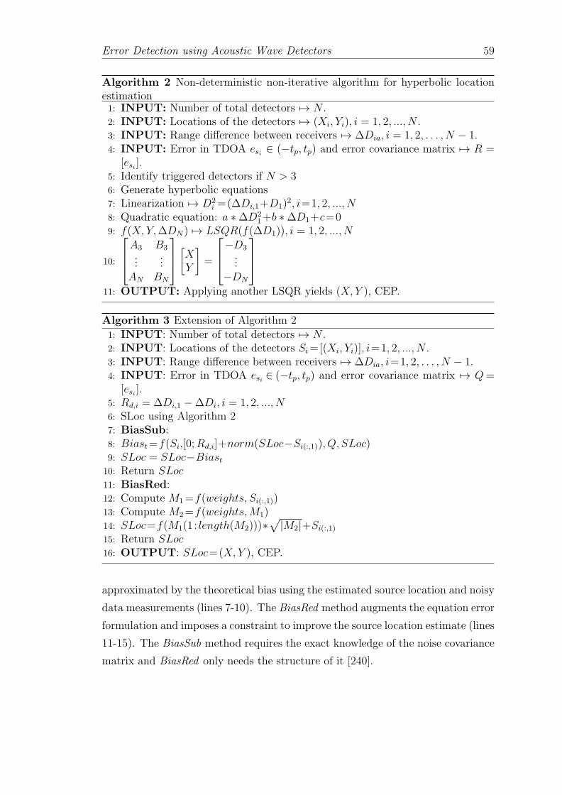
Error Detection using Acoustic Wave Detectors 59
Algorithm 2 Non-deterministic non-iterative algorithm for hyperbolic locationestimation1: INPUT: Number of total detectors 7→ N .2: INPUT: Locations of the detectors 7→ (Xi, Yi), i = 1, 2, ..., N .3: INPUT: Range difference between receivers 7→ ∆Dia, i = 1, 2, . . . , N − 1.4: INPUT: Error in TDOA esi ∈ (−tp, tp) and error covariance matrix 7→ R =
[esi ].5: Identify triggered detectors if N > 36: Generate hyperbolic equations7: Linearization 7→ D2
i =(∆Di,1+D1)2, i=1, 2, ..., N
8: Quadratic equation: a ∗∆D21+b ∗∆D1+c=0
9: f(X,Y,∆DN) 7→ LSQR(f(∆D1)), i = 1, 2, ..., N
10:
A3 B3...
...AN BN
[XY
]=
−D3...−DN
11: OUTPUT: Applying another LSQR yields (X,Y ), CEP.
Algorithm 3 Extension of Algorithm 2
1: INPUT: Number of total detectors 7→ N .2: INPUT: Locations of the detectors Si=[(Xi, Yi)], i=1, 2, ..., N .3: INPUT: Range difference between receivers 7→ ∆Dia, i=1, 2, . . . , N − 1.4: INPUT: Error in TDOA esi ∈ (−tp, tp) and error covariance matrix 7→ Q=
[esi ].5: Rd,i = ∆Di,1 −∆Di, i = 1, 2, ..., N6: SLoc using Algorithm 27: BiasSub:8: Biast=f(Si,[0;Rd,i]+norm(SLoc−Si(:,1)), Q, SLoc)9: SLoc = SLoc−Biast10: Return SLoc11: BiasRed:12: Compute M1=f(weights, Si(:,1))13: Compute M2=f(weights,M1)14: SLoc=f(M1(1 : length(M2)))∗
√|M2|+Si(:,1)
15: Return SLoc16: OUTPUT: SLoc=(X, Y ), CEP.
approximated by the theoretical bias using the estimated source location and noisy
data measurements (lines 7-10). The BiasRed method augments the equation error
formulation and imposes a constraint to improve the source location estimate (lines
11-15). The BiasSub method requires the exact knowledge of the noise covariance
matrix and BiasRed only needs the structure of it [240].

Error Detection using Acoustic Wave Detectors 60
3.5.2.2 Iterative Algorithm
A high-level iterative algorithm is shown in Algorithm 4. Iterative Gauss-Newton
interpolation uses the Taylor-series expansion method [237].
Algorithm 4 Iterative algorithm
1: INPUT: Number of total detectors 7→ N .2: INPUT: Locations of the detectors 7→ (Xi, Yi), i = 1, 2, ..., N .3: INPUT: Range difference between receivers 7→ ∆Dia, i = 1, 2, . . . , N − 1.4: INPUT: Error in TDOA esi ∈ (−tp, tp) and error covariance matrix 7→ R =
[esi ].5: Identify triggered detectors6: Generate hyperbolic equations7: Linearization (Tylor series) 7→ Aδ ∼= Z + E8: Gauss-Newton-Interpolation [(Xv, Yv), N, (Xi, Yi), A, δ, Z]9: while (δx = 0, δy = 0) do10: [δx, δy] 7→ LSQR((A), (Z))11: Xv ← Xv + δx, Yv ← Yv + δy12: end while13: Compute Q = [ATR−1A]−1, CEP14: OUTPUT: Area of Error Distribution, Radius of the circle(CEP), center
(Xv, Yv)
Lines 1-4 show the required inputs for solving the equations. First step of the
algorithm is generating the equations (lines 5-7). Equation 3.3 (and therefore, the
set of equations 3.4) is nonlinear in nature. Unlike Algorithms 1, 2 and 3, we opt
to linearize these equations through Taylor-series expansion and retain the terms
below second order [237].
We also provide an initial guess (Xv, Yv) as shown in Equation 3.5.
(Xv, Yv) =n∑
i=1
[(max(Xi),min(Xi))
2,(max(Yi),min(Yi))
2
](3.5)
The system of equations is solved by computing LSQR iteratively (lines 8-12). In
order to estimate the solution, we keep iterating until δx 7→ 0 and δy 7→ 0. In
each new iteration, the provisional solution is updated through Xv ← Xv + δx and
Yv ← Yv + δy, yielding the estimated location (Xv, Yv) as shown in (line 14) at the
end of the iterative process.

Error Detection using Acoustic Wave Detectors 61
3.5.3 Metrics for Evaluating Algorithms
The algorithms described in Section 3.5, have very different behavior in terms of
runtime, complexity, accuracy and location estimation coverage. To evaluate them
we will first describe the important metrics.
3.5.3.1 Runtime
Runtime of algorithm is the time it takes to obtain the estimated location of strike
after the TDOA equations are generated. Once the first detector triggers, we stall
the processor and obtain all TDOAs. Once all TDOAs are ready, we can execute
any algorithm to generate and solve the equations. It is worth noticing that the
more TDOA equation are generated the longer it takes to solve them.
3.5.3.2 Complexity
Algorithm 1 is computationally the least intensive as it is non-iterative and deter-
ministic (i.e., solves just 2 hyperbolic equations to obtain the location). It does
not use redundant TDOA measurements.
Algorithms 2, 3 and 4 are more complex as they solve more than two hyperbolic
equations to estimate the location. Algorithm 4 is computationally intensive since
an LSQR computation is required in each iteration. Simulations show that at
least three iterations are required for convergence. It demands computing LSQR
at least 3 times. Algorithm 2 and Algorithm 3 also require LSQR computations.
However, they are computationally less intensive than the Algorithm 4, mainly
because of their non-iterative nature. Note that solving more hyperbolic equations
to estimate the location increases the overall complexity.
The runtime memory footprint increases when increasing the number of hyperbolic
equations. Since, Algorithms 2, 3 and 4 utilize redundant TDOA measurements,
they are more memory consuming than Algorithm 1. Most of the memory goes
into storing the data matrices. The LSQR operation itself is less memory inten-
sive [241]. The overall runtime memory footprint of all the algorithms discussed
above is not significant.

Error Detection using Acoustic Wave Detectors 62
3.5.3.3 Location Estimation Coverage
Location estimation coverage is the ability to produce a valid estimation of loca-
tion. Location estimation coverage depends on the placement of detectors. For
example, Algorithms 1, 2 and 3 fail to produce an estimation of location when
all the TDOA equations are formed consisting detectors having either the same X
co-ordinates or Y co-ordinates (i.e., collinear detectors).
Algorithm 4 is an iterative method and requires an initial guess of the location. If
the initial guess is not properly provided, convergence may be compromised and
that reduces the location estimation coverage. Non-iterative algorithms do not
face any convergence problem.
We show a detailed evaluation regarding location estimation coverage in Sec-
tion 3.6.
3.5.3.4 Accuracy
To quantify the accuracy of the estimated location we calculate the error in the
obtained position estimate for all the algorithms mentioned above. Apart from
the sampling errors in TDOA measurements as explained in Section 3.4.2, lin-
earizing the hyperbolic equations (i.e., by squaring operation as in Algorithm 1,
Algorithm 2 and Algorithm 3 or by using Taylor series and eliminating the second
order terms as shown in Algorithm 4) can introduce errors in the final location
estimation.
Estimation of Error: Because of errors in measurements, we cannot exactly
pinpoint the particle strike; instead, we obtain an error distribution area that
contains the actual location of the particle strike. We use circular error probability
(CEP) to express the area of the error with a given probability. CEP is the
measure of the area of the error distribution of the final estimation of the position.
Moreover, the location estimation accuracy depends on various design parameters
such as, (i) the placement of detectors, (ii) choice of triggered detectors, (iii)
number of TDOA equations used for estimating the location and (iv) sampling
frequency. Note that these design parameters also affect runtime, complexity,
location estimation coverage of the algorithms.
Error Detection using Acoustic Wave Detectors 63
Error Area Granularity: The location of the particle strike is given as estimated
(X, Y ) coordinates and an estimation of the error area covered by (3*CEP) radius.
Using Rayleigh’s method for approximating the CEP [242], we guarantee that
the actual strike location will always fall within a circle with the center at the
obtained estimated location and the radius equal to the 3*CEP. We analyze the
3*CEP error area for all the algorithms discussed above in Section 3.6. The most
accurate algorithm has the minimum 3*CEP error area.
For simplicity, we will describe the error area in terms of bits. However, the error
area can be easily mapped to relevant functional blocks in the processor pipeline
or to specific lines in caches [135].
3.6 Assessing the Algorithms
In this section we assess how the placement of the detectors, and how the number
of detectors impact the error in the estimation of location (accuracy), runtime,
complexity and coverage for all algorithms discussed in Section 3.5. We demon-
strate the utility of the cantilever detectors for detecting and locating particle
strikes in the core of a Core™i7-like processor. The core has a rectangular shape
with an area of 28 mm2.
3.6.1 Placement of Detectors
After trying different configurations, we have opted to place the detectors in a
mesh as shown in Figure 3.9. Each node in the mesh represents an acoustic wave
detector. For a m × n mesh the area of the core is split into m − 1 equal parts
along the X-axis and n− 1 equal parts along Y-axis.
We have evaluated different mesh configurations. For this experiment, we have
opted for a system of 4 hyperbolic equations. Therefore, we need to construct
a mesh that guarantees that for all possible particle strikes, at least 5 detectors
trigger (recall that only the detectors that are placed within 5 mm of the particle
strike will be able to detect the strike). We inject 1048 particle strike at random
locations at random instances. We chose the sample set to be 1048 because we
wanted to be as accurate as possible in locating the exact erroneous bits while

Error Detection using Acoustic Wave Detectors 64
Figure 3.9: Placement of detectors in a mesh formation
using location estimation algorithms with 95% confidence. It is also backed up by
confidence interval theory. Our studies show that the minimum configuration is a
3×3 mesh with 9 detectors. In those configurations where more than 5 detectors
trigger, we take the first five detectors that trigger and observe the impact of
placement of detectors on accuracy and the location estimation coverage. Note
that the runtime and computational complexity are independent of the placement
of detectors.
3.6.1.1 Accuracy
Figure 3.10 shows how the number and placement of detectors impact the error
area (i.e., accuracy). As one can see, for the iterative Algorithm 4, using only 9
detectors yields an error area of 40 bits, which is a 3*CEP radius of 3.5 bits. It is
also interesting to note that increasing the number of detectors does not increase
the quality of the solution, since the solution is more affected by the location of the
detectors. For instance, using 12 detectors (i.e., a 2×6 mesh) the 3*CEP radius
increases to 9 bits. However, when we change to a 3×5 mesh, area is significantly
reduced to a radius of 3 bits. Algorithm 2 and Algorithm 3 follow a similar pattern.
Algorithm 1 does not produce a valid estimation for some mesh configurations. It
is worth noticing that for the given analysis the iterative algorithm outperforms
all the other algorithms by a factor of about three in terms of area.
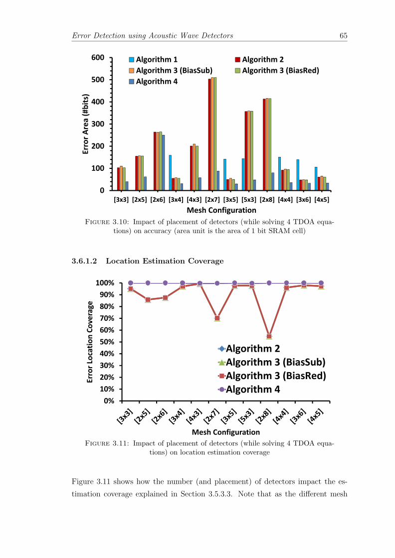
Error Detection using Acoustic Wave Detectors 65
0
100
200
300
400
500
600
[3x3] [2x5] [2x6] [3x4] [4x3] [2x7] [3x5] [5x3] [2x8] [4x4] [3x6] [4x5]
Err
or
Are
a (
#b
its)
Mesh Configuration
Algorithm 1 Algorithm 2
Algorithm 3 (BiasSub) Algorithm 3 (BiasRed)
Algorithm 4
Figure 3.10: Impact of placement of detectors (while solving 4 TDOA equa-tions) on accuracy (area unit is the area of 1 bit SRAM cell)
3.6.1.2 Location Estimation Coverage
0%
10%
20%
30%
40%
50%
60%
70%
80%
90%
100%
Err
or
Loca
tio
n C
ov
era
ge
Mesh Configuration
Algorithm 2
Algorithm 3 (BiasSub)
Algorithm 3 (BiasRed)
Algorithm 4
Figure 3.11: Impact of placement of detectors (while solving 4 TDOA equa-tions) on location estimation coverage
Figure 3.11 shows how the number (and placement) of detectors impact the es-
timation coverage explained in Section 3.5.3.3. Note that as the different mesh
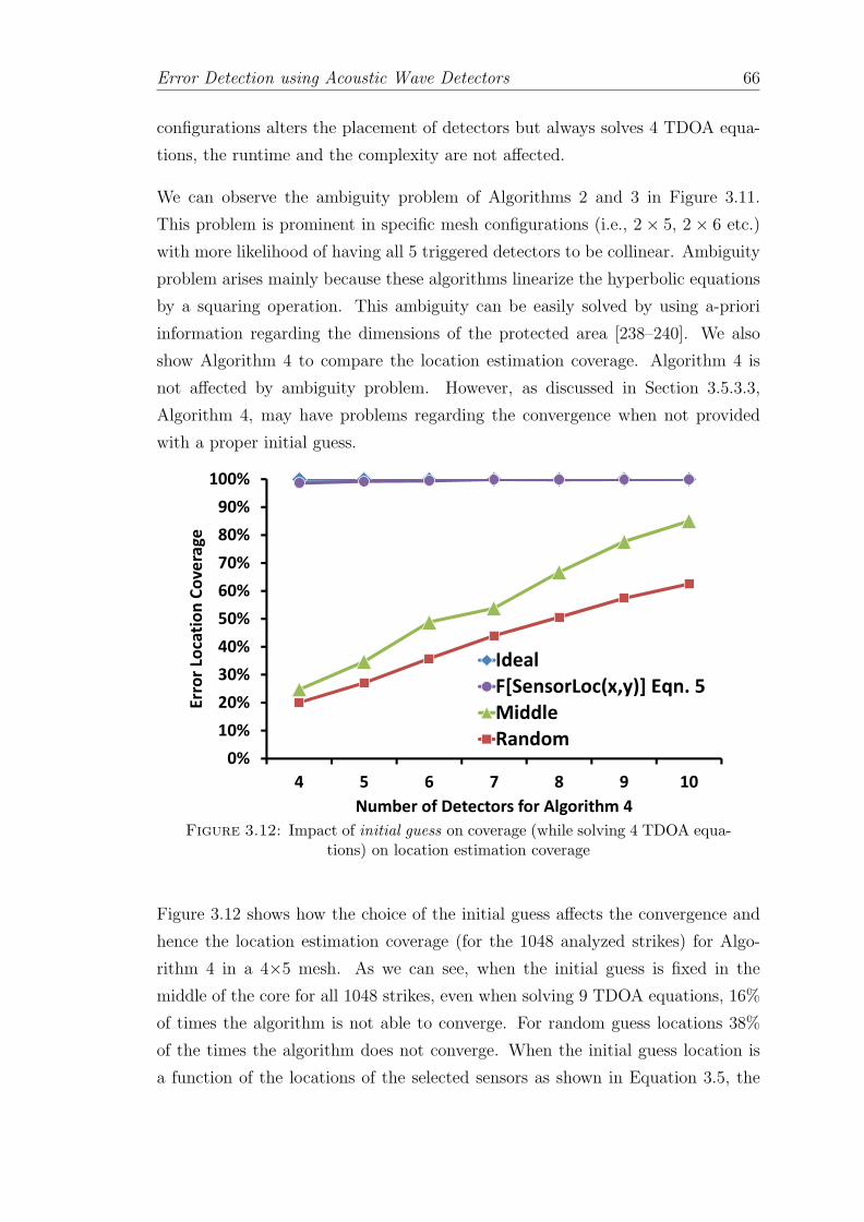
Error Detection using Acoustic Wave Detectors 66
configurations alters the placement of detectors but always solves 4 TDOA equa-
tions, the runtime and the complexity are not affected.
We can observe the ambiguity problem of Algorithms 2 and 3 in Figure 3.11.
This problem is prominent in specific mesh configurations (i.e., 2× 5, 2 × 6 etc.)
with more likelihood of having all 5 triggered detectors to be collinear. Ambiguity
problem arises mainly because these algorithms linearize the hyperbolic equations
by a squaring operation. This ambiguity can be easily solved by using a-priori
information regarding the dimensions of the protected area [238–240]. We also
show Algorithm 4 to compare the location estimation coverage. Algorithm 4 is
not affected by ambiguity problem. However, as discussed in Section 3.5.3.3,
Algorithm 4, may have problems regarding the convergence when not provided
with a proper initial guess.
0%
10%
20%
30%
40%
50%
60%
70%
80%
90%
100%
4 5 6 7 8 9 10
Err
or
Loca
tio
n C
ov
era
ge
Number of Detectors for Algorithm 4
Ideal
F[SensorLoc(x,y)] Eqn. 5
Middle
Random
Figure 3.12: Impact of initial guess on coverage (while solving 4 TDOA equa-tions) on location estimation coverage
Figure 3.12 shows how the choice of the initial guess affects the convergence and
hence the location estimation coverage (for the 1048 analyzed strikes) for Algo-
rithm 4 in a 4×5 mesh. As we can see, when the initial guess is fixed in the
middle of the core for all 1048 strikes, even when solving 9 TDOA equations, 16%
of times the algorithm is not able to converge. For random guess locations 38%
of the times the algorithm does not converge. When the initial guess location is
a function of the locations of the selected sensors as shown in Equation 3.5, the

Error Detection using Acoustic Wave Detectors 67
algorithm converges all the times within 3 iterations providing 100% error local-
ization. To compare the effectiveness of the choice of the initial guess we also
show the ideal case where initial guess is the actual location of the particle strike.
Note that when the algorithm does not converge, the system cannot identify the
location of the strike, but the strike is still detected.

Error Detection using Acoustic Wave Detectors 68
Figure3.13:Worst-caseerrorarea
withtheselectionof
differentsetof
detectors
(4to
10)from
agiven
[4×
5]mesh

Error Detection using Acoustic Wave Detectors 69
3.6.2 Choosing Detectors for TDOA Equations
In this section, we assess the impact of the choice of the TDOA equations on the
accuracy (i.e. 3*CEP error area) and error estimation coverage. For that purpose,
we choose a 4×5 mesh because it guarantees that at least, 10 detectors detect
the particle strike. We also assume a 2 GHz sampling frequency. Note that the
runtime and computational complexity are unaffected by the choice of the TDOA
equations.
3.6.2.1 Accuracy
Figure 3.13 shows the obtained error area for the 4×5 mesh for all algorithms.
We show results for three different methods that select the detectors when more
detectors than necessary are triggered by: (i) choosing the closest, (ii) the farthest
or (iii) choosing randomly. For all the algorithms discussed in Section 3.5, selecting
the closest set of detectors is the most accurate option. This is because the nearest
detectors are placed at locations where it was possible to generate better TDOA
measurements between two detectors. It helps in reducing the error involved in
linearizing hyperbolic equations as discussed in Section 3.5.3.4 and yielding more
accurate solutions.
3.6.2.2 Location Estimation Coverage
The choice of triggered detectors does not affect the complexity or runtime of the
algorithms as same number of equations are solved. However, choosing the closest
set of detectors guarantees 100% error coverage for Algorithm 4 and >97.7% error
coverage for Algorithms 2 and 3 as shown in Figure 3.11.
3.6.3 Effect of Solving More TDOA Equations
Once we select the closest set of detectors, we can observe that solving a higher
number of TDOA equations has a very important impact on the accuracy. More-
over, solving more number of TDOA equations can worsen the runtime and in-
crease the computational complexity.

Error Detection using Acoustic Wave Detectors 70
3.6.3.1 Accuracy
10
20
30
40
50
60
70
80
90
4 5 6 7 8 9 10
Err
or
Are
a(#
bit
s)
Number of used detectors
Algorithm 2
Algorithm 3 (BiasSub)
Algorithm 3 (BiasRed)
Algorithm 4
Figure 3.14: Error area with closest detectors for [4× 5] mesh
Figure 3.14 shows that by increasing the selected detectors from 4 to 10, the error
area reduces by a factor of 2 for Algorithm 2, Algorithm 3 and Algorithm 4.
Table 3.2 shows the best configurations observed for each algorithm; we consider
different mesh configurations and number of equations for Algorithms 2, 3 and 4.
Algorithm 1 is deterministic and solves only 2 equations for the given mesh. Second
column of the table shows the minimum number of detectors that trigger upon the
particle strike. Third column shows the number of detectors used to set up the
TDOA equations. Last column shows the worst-case error observed for the 1048
particle strikes for the different algorithms discussed in Section 3.5. It is worth
noticing that the improvement in the error area of Algorithm 1 when increasing
the number of detectors is mainly due to the improved quality of the 2 equations
with a denser mesh (as explained in Section 3.6.1). For all the algorithms the best
error area is obtained by setting a 4×5 mesh and using 10 detectors. However,
the complexity of setting and solving the equations makes it too expensive as
explained in Section 3.5.3.2.

Error Detection using Acoustic Wave Detectors 71
Mesh
Minim
um
#Detectors
#TDOA
3*CEP
ErrorArea(#
bits)
Configura
tion
#Detectors
usedfor
EquationsAlgorith
m1†Algorith
m2
Algorith
m3
Algorith
m4
[Mesh
,#Detectors]
triggered
TDOA
solved
BiasS
ub
BiasR
ed
[3×4,12]
44
3159
5860
5737
[3×5,15]
95
4142
5050
5130
[3×6,18]
106
5140
3737
4029
[3×6,18]
107
6140
3333
3524
[3×6,18]
108
7140
3131
3323
[4×5,20]
129
8106
2929
3021
[4×5,20]
1210
9106
2828
2919
Table3.2:Worst
case
errorarea
forbestconfigu
ration
ofagiven
meshforeach
algorithm.†solves
only
2equations

Error Detection using Acoustic Wave Detectors 72
Figure 3.15: Comparing accuracy of all algorithms and for the mesh configu-rations discussed in Table 3.2
The average improvement in the accuracy for the iterative Algorithm 4 is 1.4×,1.55× and 5.2× compared to Algorithms 2, 3 and 1 respectively as shown in
Figure 5.11c.
Figure 3.16 shows how increasing the number of equations (for the configurations
of Table 3.2) impacts the runtime and complexity. As per Figure 3.16(a) and Fig-
ure 3.16(b), for the same mesh configuration, with increasing number of equations
the runtime and complexity of Algorithms 2 and 3 increases linearly relative to the
runtime and complexity of Algorithm 1. Algorithms 2 and 3 are non-iterative and
the increase in complexity and runtime is mainly because of the increased size of
working data set (e.g., more equations). In the case of Algorithm 4, for the same
mesh, the runtime and complexity increase exponentially relative to the runtime
and complexity of Algorithm 1. This exponential trend is because more number
of iterations (and the number of LSQR computations) are required to solve higher
number of TDOA equations.
3.6.3.2 Runtime
Generating and solving the TDOA equations has negligible impact on the per-
formance of active tasks and user experience. As per Figure 3.16(a) the iterative

Error Detection using Acoustic Wave Detectors 73
(a) Runtime
(b) Complexity
Figure 3.16: Comparing runtime and complexity of all algorithms and for themesh configurations discussed in Table 3.2
Algorithm 4 takes 3.2×, 2.6× and 6.8× longer runtime to produce location esti-
mation compared to Algorithms 2, 3 and 1 respectively.
In a Core™i7 processor, Algorithm 1 is the fastest and takes 0.011 ms. Algo-
rithm 2 and Algorithm 3 take around 0.02–0.03 ms. Algorithm 4, being an iterative
method, has the longest worst-case runtime of 0.07 ms.

Error Detection using Acoustic Wave Detectors 74
3.6.3.3 Complexity
According to Figure 3.16(b) the iterative Algorithm 4 is 2.1×, 1.8× and 6× more
complex compared to Algorithms 2, 3 and 1 respectively.
The ideal algorithm for location estimation would be the one that is the least
complex, with the least runtime and the most accurate. Choosing the best algo-
rithm is balancing a 3-way trade-off involving complexity, runtime and accuracy.
Non-deterministic algorithms are complex but best for accuracy. Deterministic al-
gorithms are least accurate and severely affected by sampling noise and ambiguity
problem. For maximum accuracy Algorithm 4 is the best choice. Algorithms 2
and 3 are almost half as accurate as Algorithm 4 but they are faster and less
complex. We want to precisely locate the error and hence we opt for Algorithm 4
which provides maximum accuracy.
3.6.4 Effect of Sampling Frequency on Accuracy
0
5
10
15
20
25
30
35
40
[3x4,4] [3x5,5] [3x6,6] [3x6,7] [3x6,8] [4x5,9] [4x5,10]
Err
or
Are
a (
# b
its)
Configurations [Mesh, Detectors used]
2 GHz
2.5 GHz
3 GHz
3.5 GHz
4 GHz
Figure 3.17: Impact of sampling frequency on error area for configurations ofTable 3.2 Iterative Algorithm 4

Error Detection using Acoustic Wave Detectors 75
The effect of altering the sampling frequency over the final error area is studied
in this section. Figure 3.17 shows the impact of sampling frequency on the worst-
case error area for all best configurations described in Table 3.2 for the iterative
Algorithm 4. The results indicate that doubling the frequency from 2 GHz to 4
GHz reduces the error area by 4×. Our experiments show a similar improvement
while doubling the frequency from 2 GHz up to 4 GHz for all the other algorithms
discussed in Section 3.5.
0
5
10
15
20
25
30
35
2 GHz 2.5 GHz 3 GHz 3.5 GHz 4 GHz
Err
or
Are
a (
#b
its)
Sampling Frequency
Algorithm 2
Algorithm 3 (BiasSub)
Algorithm 3 (BiasRed)
Algorithm 4
Figure 3.18: Impact of sampling frequency on error area for configurations ofTable 3.2 for all algorithms
In Figure 3.18, we depict the effect of varying the frequency for the best config-
uration described in Section 3.6.3 (i.e., a 3×6 mesh employing 8 detectors) for
all algorithms. We can see that increasing the sampling frequency reduces the
error area; doubling the frequency from 2 GHz to 4 GHz reduces the worst-case
error area from 23 bits down to 5 bits (i.e., a radius of 2.7 bits down to 1.3 bits)
for iterative Algorithm 4, from 31 bits down to 8 bits for Algorithms 2 and for
BiasSub method of Algorithm 3. In the case of BiasRed method of Algorithm 3
the improvement is from 33 bits down to 8 bits.
Notice that varying the sampling frequency has no impact on the complexity,
runtime or location estimation coverage.

Error Detection using Acoustic Wave Detectors 76
230
190199 196
185179
167
153
0
50
100
150
200
250
3x3 3x4 4x3 2x6 3x5 4x4 3x6 4x5
Wo
rst-
Ca
se D
ete
ctio
n L
ate
ncy
(#C
ycl
es)
Mesh Configuration
Figure 3.19: Worst-case detection latency for mesh configurations of Table 3.2in a processor running at 2 GHz
0
100
200
300
400
500
600
700
800
900
1000
Wp
rst-
Ca
se D
ete
ctio
n L
ate
ncy
(#C
ycl
es)
Number of Detectors on the Core
Detection latency(#Cycles) @ 2GHz
Figure 3.20: Adding more detectors to reduce worst-case detection latency ina processor running at 2 GHz

Error Detection using Acoustic Wave Detectors 77
3.6.5 Detection Latency
Figure 3.19 shows the worst-case latency observed for the different mesh config-
urations of Table 3.2. As one can observe, adding more acoustic wave detectors
significantly helps in reducing the detection latency. Figure 3.20 shows that in-
creasing the number of detectors in the mesh reduces the worst-case detection
latency exponentially. Small detection latencies allow simple hardware checkpoint
and recovery.
We have considered the option of adding, on top of the detectors deployed for
precise estimation of location, a set of detectors to minimize the detection latency.
According to Figure 3.20, a detection latency of 1 cycle will require > 68K de-
tectors. A mesh consisting of 30-300 detectors can provide detection latency of
30-100 cycles for a processor running at 2 GHz.
3.6.6 Summary of Chosen Configuration
The proposed solution uses of two different meshes. The 3×6 mesh is used to
obtain the TDOA. In that case, the hardware mechanism explained in Section 3.4.2
consists of 18 detectors (i.e., roughly 18 bits area), and a 2-level OR tree (7 3-input
OR gates and 3 2-input OR gates) to generate the Enable signal. Besides, a 10-bit
counter is required for the counting TDOA pulses.
We also use a separate mesh to minimize the detection latency. It consists of 30-
300 detectors achieving 30-100 cycles of latency at 2 GHz (i.e., an area overhead
of 30-300 bits). Depending on the number of detectors in the second mesh we may
need an additional controller circuit (i.e., a MUX or a logic-OR tree structure)
to generate the detection signal. Note that for latency minimization we do not
require a counter since we only want to signal the presence of the strike.
For the given mesh configuration to obtain maximum accuracy in the location
estimation we use Algorithm 4.

Error Detection using Acoustic Wave Detectors 78
Algorith
ms
Runtime
Complexity
Covera
ge
Acc
ura
cyLim
itations
Algorithm
11×
1×90%
1וCan
not
benefitfrom
redundan
tmeasure-
ments
•Lessaccurate
Non- ite
rativ
e
Algorithm
22.1×
2.8×
100%
∓3.6×
•Failswhen
detectors
arecollinear
•Ambiguityproblem
•Requires
a-prioriknow
ledge
ofcore
di-
mension
s
Algorithm
3(B
iasSub)
2.3×
3.2×
100%
∓3.6×
Algorithm
3(B
iasR
ed)
2.65×
3.2×
100%
∓3.3×
Itera
tive
Algorithm
46.4×
6.1×
100%
5.2×
•Con
vergence
issues
•Requires
initialgu
ess
Table3.3:Com
parison
ofalgorithms:
Algorithm
1is
deterministican
dAlgorithms2,3and4are
non-deterministic;
∓withcareful
meshselections

Error Detection using Acoustic Wave Detectors 79
3.6.7 Summary of Results
Nondetermined system of equations (i.e., when using more than 3 detectors and
setting more than 2 equations) reduces the worst-case error area by a huge margin
compared to determined system of equations. We have also shown the impact of
detectors placement and higher number of equations on the accuracy, runtime and
complexity. Using an iterative algorithm (Algorithm 4) is the best option if highest
accuracy is desired. It also guarantees convergence independently of the type of
the mesh. Algorithms 2 and 3 are almost half as accurate as Algorithm 4 but they
are faster and less complex. Error estimation coverage can be an issue if collinear
detectors form TDOA equations. Deterministic algorithms are the least accurate
and severely affected by sampling noise and ambiguity problem. A comparative
summary of all the trade-offs is described in Table 3.3.
We also studied the effect of sampling frequency on accuracy. Increasing sampling
frequency reduces the sampling error in the measured TDOA. Raising sampling
frequency from 2 GHz to 4 GHz reduces the worst-case error area by 4×. Overall,
our results confirm that increasing the sampling frequency is more effective than
increasing the number of equations. For instance, a system that uses 3 equations
(e.g., 3×4 mesh) sampling at 4 GHz is a better option than a system using 9
equations (e.g., 4×5 mesh) with the sampling frequency of 2 GHz.
Finally, we have also discussed the impact of the number of detectors on the
detection latency. We have concluded that the most effective design is the one that
uses two independent meshes: a small mesh for precise location of the strike, and a
somewhat larger mesh for reducing detection latency. The optimum configuration
for maximum accuracy is to use Algorithm 4 on the studied core with a 3×6 mesh
and construct a nondetermined system of 7 equations, which gives a worst-case
error area of 23 bits (i.e., 23 µm2). We add another mesh (i.e., 30-300 detectors)
for reducing the detection latency, resulting in a latency of 30-100 cycles for a
processor running at 2 GHz.
3.7 Related Work
In this section, we review detectors that detect the particle strikes via detection
of current glitches, voltage glitches, metastability issues or deposited charge. A

Error Detection using Acoustic Wave Detectors 80
detailed discussion of other existing techniques for error detection is given in Chap-
ter 7. We will compare all the particle strike detectors for the parameters discussed
in Section 3.2 against acoustic wave detectors that detect particle strikes by detec-
tion of the sound they generate upon impact on silicon surface. A brief summary
is also given in the form of Table 3.1.
3.7.1 Current Glitch Detectors
3.7.1.1 Built-In Current Sensors (BICS)
Figure 3.21: Built-in current sensor (BICS)
Built-in current sensors (BICSs) detect particle strikes by sensing abnormal current
dissipation in the memory cells. BICS is a high-speed current-mode comparator
which detects transient current pulses and provides logic level output to set the
asynchronous latch. A BICS is composed of two current comparators and an
asynchronous latch as shown in Figure 3.21. The fundamental operation of the
BICS is based on the current controlled current switches. The two comparators
generate logical output pulses which set an asynchronous error latch. They are
placed between the memory cells and the power lines as shown in Figure 3.21,
where one BICS is used for entire memory column [206].

Error Detection using Acoustic Wave Detectors 81
3.7.1.2 Switching Current Detector
Figure 3.22: Switching current detector
This technique detects soft errors in SRAM memories [207]. Any bit flip due to
soft error results in a transient switching current. It detects any soft error by
monitoring the supply current of SRAM in the standby mode. A current pulse
sensing circuit is shown in Figure 3.22. It uses a current mirror circuit to convert
a fast current pulse into a transient voltage pulse. Finally, by using a Schmitt
trigger it is possible to sense this transient voltage pulse and generate an error
signal.
3.7.2 Voltage Glitch Detectors
These detectors monitor the supply rail disturbance caused by a particle strike [134].
A hierarchical soft error detection circuitry which monitors the ground voltage to
detect the pulses as a result of particle strike-induced switching is shown in Fig-
ure 3.23. The detection circuitry has two levels of voltage comparators (differential
amplifier). The first level compares the ground voltages of the functional blocks,
while the second comparator amplifies the error signal. In the design, only the
ground voltage is monitored to detect error. A single NMOS is connected between
the ground bus line and ground terminal of the functional block. The addition of
this transistor helps to separate the ground bus from the functional block ground
terminal, thus creating a virtual ground (GND’) at the ground terminal of the
functional block.

Error Detection using Acoustic Wave Detectors 82
Figure 3.23: Voltage glitch detector
3.7.3 Metastability Detectors
Figure 3.24: Metastability detector (BISS)
Unlike BICS, a Built-in single-event upset sensor (BISS), implements a metastabil-
ity monitor circuit to detect particle strikes. BISS detects the setup and hold time
violations in flip-flops that occur due to several reasons (i.e., clock skew, particle
strikes etc.) [133]. Designers can insert the BISS to detect SEUs at the output of
a flip-flop.
As shown in Figure 3.24, it has three major components: (i) a positive pulse
generator, (ii) a footed dynamic inverter and (iii) a keeper latch. The positive

Error Detection using Acoustic Wave Detectors 83
pulse generator transforms SEU-induced positive/negative pulse to positive pulse.
The footed dynamic inverter is used to widen the pulse generated by the positive
pulse generator, so that it can be easily detected.
3.7.4 Deposited Charge Detectors
3.7.4.1 Thin film silicon detectors
These silicon detectors are constructed as thin planner p-on-n diodes. This planner
diode covers the entire target processor to detect any particle strikes. In principle,
a silicon detector is a solid state ionization chamber [209, 210]. They detect particle
strikes based on the changes in the depletion region of the p-n junction diodes due
to ionization.
Most popular ones are listed below:
• Silicon strip detector (SSD) detects collected charge
• Active pixel sensors (APS) detects collected charge
• Scintillator coupled silicon photodiodes: detects flash of light
3.7.4.2 Heavy-ion Sensing
Heavy-ions deposit a huge amount of charge upon impact on the silicon surface.
Heavy-ion sensors detect the particle strikes by detecting the deposited charge.
The work of [212] proposes to use the DRAM memory cell to collect the charge
upon a heavy-ion strike. When the storage node is discharged to a second voltage,
a sense amplifier coupled to the storage node generates an output signal indicating
that an SEU event has occurred. Also by tweaking the reference voltage to the
sense amplifier the DRAM arrays can be tuned to detect heavy-ion particles with
different energies.
3.7.5 Comparison of Detectors
In this section, we compare all the particle strike detectors for the parameters
described in Section 3.2.
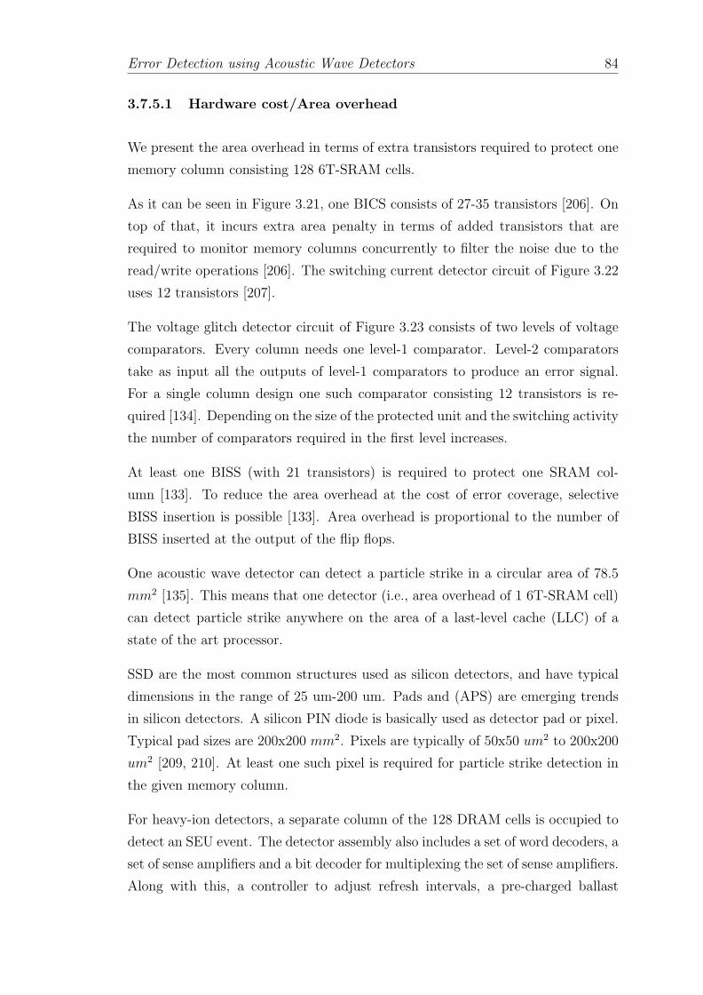
Error Detection using Acoustic Wave Detectors 84
3.7.5.1 Hardware cost/Area overhead
We present the area overhead in terms of extra transistors required to protect one
memory column consisting 128 6T-SRAM cells.
As it can be seen in Figure 3.21, one BICS consists of 27-35 transistors [206]. On
top of that, it incurs extra area penalty in terms of added transistors that are
required to monitor memory columns concurrently to filter the noise due to the
read/write operations [206]. The switching current detector circuit of Figure 3.22
uses 12 transistors [207].
The voltage glitch detector circuit of Figure 3.23 consists of two levels of voltage
comparators. Every column needs one level-1 comparator. Level-2 comparators
take as input all the outputs of level-1 comparators to produce an error signal.
For a single column design one such comparator consisting 12 transistors is re-
quired [134]. Depending on the size of the protected unit and the switching activity
the number of comparators required in the first level increases.
At least one BISS (with 21 transistors) is required to protect one SRAM col-
umn [133]. To reduce the area overhead at the cost of error coverage, selective
BISS insertion is possible [133]. Area overhead is proportional to the number of
BISS inserted at the output of the flip flops.
One acoustic wave detector can detect a particle strike in a circular area of 78.5
mm2 [135]. This means that one detector (i.e., area overhead of 1 6T-SRAM cell)
can detect particle strike anywhere on the area of a last-level cache (LLC) of a
state of the art processor.
SSD are the most common structures used as silicon detectors, and have typical
dimensions in the range of 25 um-200 um. Pads and (APS) are emerging trends
in silicon detectors. A silicon PIN diode is basically used as detector pad or pixel.
Typical pad sizes are 200x200 mm2. Pixels are typically of 50x50 um2 to 200x200
um2 [209, 210]. At least one such pixel is required for particle strike detection in
the given memory column.
For heavy-ion detectors, a separate column of the 128 DRAM cells is occupied to
detect an SEU event. The detector assembly also includes a set of word decoders, a
set of sense amplifiers and a bit decoder for multiplexing the set of sense amplifiers.
Along with this, a controller to adjust refresh intervals, a pre-charged ballast

Error Detection using Acoustic Wave Detectors 85
capacitor to store charges and a reference voltage generator of the sense amplifier
is required to change the sensitivity of the detection [212].
It is important to note that the current/voltage glitch detectors and metastability
detectors will have a detection granularity at the column level. To exactly pin-
point the location of error they will have to be combined with error detection
codes (i.e. parity) [133, 134, 206, 207]. A single parity bit per memory word is
used along with one of the detectors for every memory column. The area cost of
the parity checker/generator providing parity bit per word is significant.
The area overhead of acoustic wave detectors is very less compared to other par-
ticle strike detectors. Moreover, their accuracy can be improved by deploying
more detectors to pin-point errors at word/byte level. Even after deploying more
acoustic wave detectors they significantly reduce the area overhead compared to
ECC [135]. Silicon detectors [209, 210] and heavy-ion detectors are effective but
incur >100% area overhead.
3.7.5.2 Power overhead and detection latency
Particle strike detector that is faster and consumes minimum power is desirable.
Worst case power dissipation of one BICS varies from 4.43 to 24.95 uW for 100
nm technology [206]. And, the worst case detection latency ranges from 650 ps-
1.1 ns [206]. Inserting the BICS may increase the resistance of the critical path
and hence degrades the read-write speed of the memory severely reducing the
performance. The leakage power for a The switching current detector is 12.9uw-
18.9uW [207]. And the detection latency is in the range of 0.92 ns-1.14 ns. In the
low power mode it is even slower and in the range of 2.41 ns-3.0 ns.
The voltage glitch detector [134] consumes less power compared to current glitch
detector and per unit power overhead is in the range of 0.8 uW to 5 uW. However,
this power savings makes it slower and its detection latency varies from 220 ps-1.4
ns.
In the case of BISS the power overhead is more than 10 uW due to increased
number of transistors. To reduce the power overhead, only a selective flip flops
are covered using BISS [133]. Detection latency is in a range of 1.5 ns-2 ns.
The acoustic wave detectors are passive and do not consume power. Power over-
head of the controller circuit is insignificant [135]. The detection latency for the

Error Detection using Acoustic Wave Detectors 86
particle strike occurring anywhere on the LLC is around 30-100 cycles (1200-161
detectors) and can be further reduced by putting more detectors [135].
Silicon detectors typically operate between 10 Volts and 100 Volts [209, 210]. The
power consumption depends on the resistivity of the material used and it normally
consumes >10 Watts. The detection latency of a silicon detector alone is around
25 ns. The delay added by the pre-amplifier and other controlling mechanism will
further increase the overall detection latency [209, 210].
Heavy-ion detector uses flexible supply voltages and consume a few mW of power.
The detection latency is similar to the memory access time.
3.7.5.3 False alarms
BICS, switching current detector and BISS are susceptible to noise. Common
sources of noise are power supply lines, higher switching activities and miss-match
in the inputs of the dynamic logic gates. Presence of noise increases the chances
of false positives. The voltage glitch detector, receives the fluctuations in the
voltage due to transient switching noise from the protected block as well as due to
the particle strikes. The comparator filters switching noises and amplifies spikes
generated by SEU. Tuning the threshold of the comparator is very difficult and if
not set properly, the chances of false alarms increase. In the work of [134], while
protecting memory, 27% and 7% false positives are reported for 1 7→ 0 flips and
for 0 7→ 1 flip respectively.
The acoustic wave detectors are fairly accurate and can be calibrated to detect all
particle strikes in the targeted energy spectrum for the given technology. Further-
more, some studies [17, 117, 142] support that the rate of particle strikes (with
recoil energy > 10 MeV) is not very high. The false positive rate is practically
zero, or in the worst case scenario it is one false positive per 1.3 minutes [135].
The presence of noise in the high voltage supply lines for silicon detectors increases
the possibility of false positives [209, 210]. For heavy-ion detectors, imperfect
calibration of any of the programmable parameters (i.e., VDD, refresh rate or
reference voltage to the sense amplifier) may result into unwanted noise due to
read/write operation and trigger false positives [212].

Error Detection using Acoustic Wave Detectors 87
3.7.5.4 Detected particles/Fault types
Alpha and neutron particle strikes induce soft errors are more frequent [17, 117].
Current and voltage glitch detectors, BISS and acoustic wave detectors can detect
particle strikes due to alpha and neutron particles. Silicon detectors can detect
alpha and neutron strikes and other heavy elements with the energies in the range
of 10 to 100 MeV. Heavy-ion detectors are able to detect particle strikes only
due to heavy-ions such as proton, alpha or any other ions whose atom has been
stripped off its electrons.
3.7.5.5 Intrusiveness of the design
Insertion of particle strike detectors in the design can have significant implications.
Insertion of current glitch detectors involve splitting of the power lines of each
column into smaller parts. The voltage glitch detectors require generating a virtual
ground by partitioning the ground line. These modifications require changes in the
physical layouts and routing. Moreover, to reduce huge area overhead, selective
insertion is desirable for current/voltage glitch detectors and BISS. Identifying
the correct flip-flops for selective insertion of the detector is challenging and can
increase complexity.
The fabrication and placement of acoustic wave detectors on the surface of active
silicon can be performed without complications [135, 142]. The control circuit is
also simple and poses no major challenge to the RTL design or placement and
routing [135].
The assembly of the silicon detector is very complex especially to provide reliability
in processors. It consists of pre-amplifiers and might need to be pipelined requiring
a complex control circuit [209, 210]. Heavy-ion detectors of [212] proposes to use
part of the DRAM memory cell and pose no significant design challenge. However,
providing adjustable sensitivity to detecting particle strikes can have implications
in design cost.

Error Detection using Acoustic Wave Detectors 88
3.7.5.6 Fault coverage vs. Cost
BICS, voltage glitch detectors, BISS, acoustic wave detectors and silicon detectors
can detect particle strikes in both memory cells and combinational logic [133–
135, 206, 209, 210]. While switching current detector can detect particle strikes
only in SRAM memory cells [207]. Heavy-ion detectors can detect particle strikes
only in DRAM memories [212].
To understand the cost vs. coverage trade-off lets compute the cost of protection
for a level-one data cache of 32 KB with 512 columns and 512 rows. In the simplest
arrangement of one BICS per column, it requires 512 BICS. The switching current
detector of Figure 3.22 uses only 12 transistors per detector, and hence the area
and power overheads will be relatively less compared to BICS. However, as the
cache size increases the overhead increases exponentially. To protect a last level
cache (8 MB, 16 way, 8K sets, each way with 8192 columns, 512 rows) >1.3 million
BICS are required. If voltage glitch detector are used to provide the protection to
the last-level cache, the required number of level-1 detectors to protect all caches
would be >1.3 million and apart from that it will require 16 level-2 comparators.
Also the transistor sizes should be increase to drive larger portions of the circuit.
For combinational logic, even when selective insertion is used (only some latches
are protected), protecting a typical 4-bit multiplier with 504 transistors would
require 70 BICS. The BICS area overhead for protecting such a multiplier is
29% [206]. For the same multiplier design, the overhead of protecting using hier-
archical voltage detectors accounts for 18% of the area of the multiplier [134]. The
area overhead of inserting BISS in the design would be 20%-30%.
Because of their large error detection range, acoustic wave detectors and silicon
detectors can potentially guard the entire chip against particle strikes [135, 209].
Only 4 acoustic wave detectors are required, to provide detection capability in
an entire state of the art chipmulti processor with surface area of 245mm2 [135].
However, to accurately locate the strike, 30-40 detectors are required, and to
minimize the detection latency the required detectors are in the range of 450-500.
This means the total area overhead in protecting entire chip is equivalent to 540
6T SRAM cells. SSD can provide detection coverage to the entire core, chip or
system level. If APS are used to detect particle strikes on a chip, they are placed
in the form of an array. One such array with 9x9 pixels covers a surface area of

Error Detection using Acoustic Wave Detectors 89
1 cm2 over the target processor. This area overhead also includes the connectors
for the read out channels to deliver the signal to the outside world [209].
If the error rate in DRAM chips due to heavy-ions is a concern, the DRAMs chips
can be effectively protected using heavy-ion detectors [212]. Depending upon the
size of the DRAM, one or multiple arrays in the same or different DRAMs are
dedicated for particle strike detection.
Protecting larger designs using current/voltage glitch or metastability detectors
require more detectors. Adding more transistors will increase the power con-
sumption. Applying selective insertion on a full processor core can be extremely
challenging. Techniques such as AVF, or fault injection can be used to identify
the vulnerable latches and selectively protect them [117]. Moreover, protecting
the latches on the critical paths can severely degrade performance. Silicon detec-
tors are very effective and provide excellent coverage but they are not economical.
Acoustic wave detectors provide very high levels of reliability at very little area
and power overheads.
3.8 Chapter Summary
In this chapter, we saw how acoustic wave detectors are used for soft error detec-
tion. They detect particle strikes via detection of the shockwave of sound they
generate upon impact on the silicon surface. We first studied several particles
trike detectors that detect voltage/current glitches, metastability, sound or de-
posited charge to detect the soft errors. We compared all the detectors for various
parameters such as area, power, performance overheads.
We provided details regarding the structure and important properties of the can-
tilever based acoustic wave detectors. Due to its detection range it is possible
that just one detector can detect a potent particle strike (and hence soft error)
any where on the surface of a modern processor core or cache. Error detection
using acoustic wave detectors is extremely simple and incurs negligible overheads
compared to other detectors.
Once the error is detected, to provide error correction or recovery, the system
should be able to accurately locate the error. The architecture based on acoustic
wave detectors can be further exploited to precisely locate the particle strikes.
Error Detection using Acoustic Wave Detectors 90
We presented a firmware/hardware approach in which the hardware takes respon-
sibility for TDOA measurements and generating hyperbolic equations while the
firmware is responsible for solving the equations using several algorithms.
Lastly, we presented a case study which helps understanding various trade-offs be-
tween design parameters (e.g., sampling frequency, location of detectors etc.) and
the algorithmic properties (i.e., runtime, accuracy, complexity etc.). We concluded
that for the maximum accuracy and coverage Algorithm 4 is the best option.
In the next chapter, we will discusses how we can use the proposed error detection
and location scheme for protecting caches.

Chapter 4
Protecting Caches with Acoustic
Wave Detectors
In the previous chapter, we understood how we can detect and locate soft errors
via locating potent particle strikes. In doing so we observed how to construct the
hyperbolic equations based on TDOA measurements. We also identified the best
algorithm for accuracy by observing various trade-offs. Now we will proceed to
take advantage of this information by demonstrating the utility of the cantilever
detectors in detecting and locating particle strikes in the caches of a Core™i7-likeprocessor. Next, we will show how we can leverage the location information in cor-
recting the error using acoustic wave detectors alone. Finally, we will discuss how
we can combine the acoustic wave detectors with error detecting and correcting
codes and reduce the overall cost of protection.
4.1 Error Detection and Localization in Cache
The underlying architecture for detecting and locating errors in caches is similar to
described in previous Chapter 3. The impact of different design parameters on the
accuracy of the obtained location in caches is similar to the study of Section 3.4
of Chapter 3.
The location of the particle strike is given as estimated (X, Y) coordinates and the
worst-case error area (3*CEP) that contains the actual location of particle strike.
91

Protecting Caches with Acoustic Wave Detectors 92
However, this error area can be easily mapped to affected bits, bytes or cache lines
that may contain the erroneous byte or cache line.
Unaffected Region Estimated Location of Strike
Actual Location of Strike Error Area (3*CEP)
(a) (b)
(c)
Figure 4.1: Mapping of the estimated worst-case error area at the granularityof affected (a) bits (b) bytes and (c) lines. These affected bits, bytes or cache
lines contain the actual erroneous bit, byte or cache line.
We show in Figure 4.1 how the error area maps into bits, bytes and cache lines.
From the discussions in Chapter 3, we know that accuracy of the location can be
improved either by increasing the sampling frequency or by solving more than 2
TDOA equations.
CacheMesh #Detectors #Detectors
Frequency3*CEP Radius Error
Configuration in Mesh used for TDOA (#bits) Area (#bits)
L1 5× 5 25 25 4 GHz 1.5 7
L2 3× 3 9 92 GHz 2.9 26
4 GHz 1.7 10
LLC 5× 3 15 52 GHz 3.4 38
4 GHz 1.8 11
Table 4.1: Summary of the best mesh configurations and the error area gran-ularities for the caches
Table 4.1 summarizes the estimated worst-case 3*CEP error area and the 3*CEP
radius for all the caches for the best configurations. The error area of L1 and L2
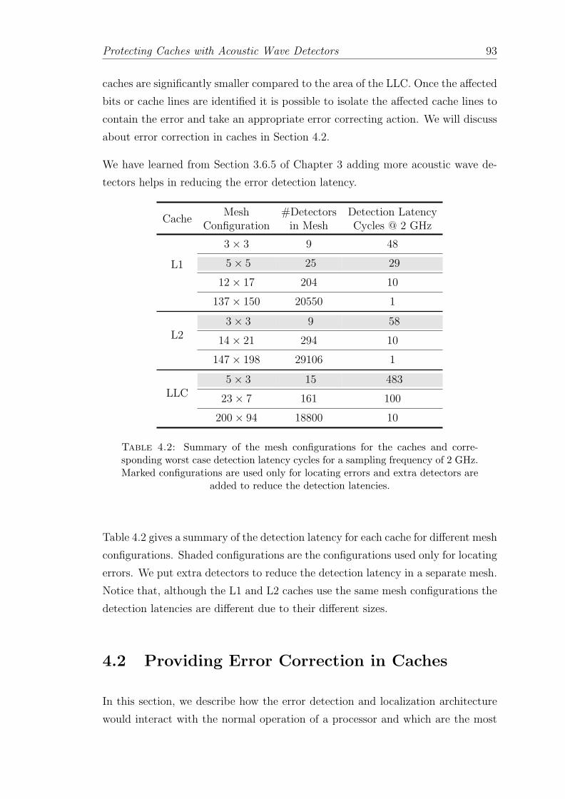
Protecting Caches with Acoustic Wave Detectors 93
caches are significantly smaller compared to the area of the LLC. Once the affected
bits or cache lines are identified it is possible to isolate the affected cache lines to
contain the error and take an appropriate error correcting action. We will discuss
about error correction in caches in Section 4.2.
We have learned from Section 3.6.5 of Chapter 3 adding more acoustic wave de-
tectors helps in reducing the error detection latency.
CacheMesh #Detectors Detection Latency
Configuration in Mesh Cycles @ 2 GHz
L1
3× 3 9 48
5× 5 25 29
12× 17 204 10
137× 150 20550 1
L23× 3 9 58
14× 21 294 10
147× 198 29106 1
LLC5× 3 15 483
23× 7 161 100
200× 94 18800 10
Table 4.2: Summary of the mesh configurations for the caches and corre-sponding worst case detection latency cycles for a sampling frequency of 2 GHz.Marked configurations are used only for locating errors and extra detectors are
added to reduce the detection latencies.
Table 4.2 gives a summary of the detection latency for each cache for different mesh
configurations. Shaded configurations are the configurations used only for locating
errors. We put extra detectors to reduce the detection latency in a separate mesh.
Notice that, although the L1 and L2 caches use the same mesh configurations the
detection latencies are different due to their different sizes.
4.2 Providing Error Correction in Caches
In this section, we describe how the error detection and localization architecture
would interact with the normal operation of a processor and which are the most
Protecting Caches with Acoustic Wave Detectors 94
important challenges for achieving high levels of error protection and error contain-
ment. Later, we will consider the case when the caches are protected only with
acoustic wave detectors, and the more reasonable case when they are deployed
with protection codes.
4.2.1 Reaction upon a Particle Strike
Once we know the estimate of the localization of the particle strike and the error
area, it is time to take the appropriate actions to provide, when possible, fine-grain
error correction. The challenges are:
1. We need to provide error containment. For instance, if a read to a cache line
or eviction of a dirty cache line happens before the error is detected (i.e., the
worst-case 100 cycles detection latency in the case of LLC) the error may
propagate through the architectural state and cause SDC.
2. We need to provide recovery capabilities. If we can accurately pin-point the
erroneous bit then one possible way to correct it is by flipping it. By recov-
ering from the error it is possible to reduce DUE FIT of cache. Whenever
it is not possible to pin-point the erroneous bit and the particle strike has
occurred on a dirty cache line it is not possible to recover the error using the
detectors alone.
With faster error detection and proper error containment using acoustic wave
detectors it is possible to avoid SDC but we also want to provide error correction
to reduce the DUE.
4.2.2 Standalone Acoustic Wave Detectors
We discuss the application of acoustic wave detectors for error recovery in caches
considering these two scenarios: (i) when the error area granularity is spread over
a few cache lines which is more general case and (ii) specific case where we will
try to pinpoint the exact erroneous bit.
Protecting Caches with Acoustic Wave Detectors 95
4.2.2.1 Error Area Granularity: Cache Lines
As discussed in Section 4.1, once the particle strike has been localized the error
area would be spanned on several cache-lines. For example, in LLC the worst-
case the error area spans over 7 cache lines. This means that we would have 7
potential cache lines where the particle could have hit. Employing 4 GHz sampling
frequency for LLC reduces the error area granularity to 4 lines from 7 lines (shown
in Table 4.1). Once we have the affected lines, we propose to invalidate the cache
lines within the error area provided by the localization algorithm. If any of the
cache lines is dirty, no recovery would be possible and we would need to throw
a machine check architecture (MCA) exception. Techniques such as early write
back may help in providing recovery by minimizing the number of dirty cache
lines [243].
4.2.2.2 Error Area Granularity: Exact bit
From the discussions in Chapter 3, we know that accuracy of the location can be
improved by either increasing the sampling frequency or by solving more than 2
TDOA equations. We are now interested in finding out for how many strikes out
of 1048, it is possible to have the 3*CEP error area at the granularity of one bit.
Once the erroneous bit has been located we can correct the erroneous bit is by
flipping it.
The area of L1 data cache is 1 mm2 and the detection range of one detectors is 5
mm. Hence, for L1 data cache, in a mesh with N detectors all N detectors trigger
upon a particle strike. Therefore, we can built N − 1 TDOA equations. We tried
different mesh configurations starting from the most basic overdetermined system
(3 TDOA equations) with 4 detectors in 2×2 mesh upto 99 TDOA equations (i.e.
100 detectors in a 10× 10 mesh).
Figure 4.2, shows the best choices for the given number of TDOA equations that
we solve, out of all the mesh configurations that can be used to construct those
many TDOA equations. It summarizes the break-down and the improvement
in the precision for the obtained 3*CEP error area. We collect the information
regarding how many times out of 1048, we can locate the actual strikes within the
area granularity of 1 bit. Figure 4.2 indicates that by increasing number of TDOA
equations in solving the localization algorithm we significantly improve percentage

Protecting Caches with Acoustic Wave Detectors 96
0
10
20
30
40
50
60
70
80
90
100
[2x
2,3
]
[2x
3,4
]
[2x
3,5
]
[3x
5,6
]
[4x
4,7
]
[3x
3,8
]
[5x
5,9
]
[3x
5,1
0]
[4x
4,1
1]
[4x
4,1
2]
[4x
4,1
3]
[5x
5,1
4]
[5x
5,1
5]
[5x
5,1
6]
[5x
5,1
7]
[5x
5,1
8]
[5x
5,1
9]
[5x
5,2
4]
[5x
6,2
9]
[5x
8,3
9]
[5x
10
,49
]
[6x
10
,59
]
[7x
10
,69
]
[8x
10
,79
]
[9x
10
,89
]
[10
x1
0,9
9]
% o
f S
trik
es
Configurations [Mesh, Equations]
>=10 bits 6 to 9 bits 2 to 5 bits 1 bit
Figure 4.2: Breakdown of the obtained worst-case error area granularity for1048 particle strikes at random location and instance for different mesh config-
urations in L1 data cache at the sampling frequency of 4 GHz
of 1 bit error area granularity at sampling frequency of 4 GHz. For example, in the
case of solving 10 TDOA equations, out of 1048 strikes 50% of the strikes result
in estimated area of ≤1 bit. Hence,we improve the DUE by 50%. It is noteworthy
that for 50% DUE improvement with 10 equations, we will need a 3×5 mesh with
15 detectors.
As we keep solving more TDOA equations, the improvement curve soon starts
to saturate. Using more detectors increases the over all cost and complexity in
solving the TDOA equations. Observing the cost of solution in terms of number
of detectors against the error area granularity improvement achieved, we conclude
that the best trade-off for L1 data cache is obtained by configuring a 5× 5 mesh
with 25 detectors and solving for 24 TDOA equations with sampling frequency of
4 GHz. This configuration can pin point the exact erroneous bit 71.85% of the
times. It also implies that out of 1048 strikes, 71.85% of the times we can correct
the erroneous bit by flipping it. And whenever this is not possible, to prevent the
corruption of the architectural state, the solution takes advantages of the error

Protecting Caches with Acoustic Wave Detectors 97
codes already deployed for error detection of hard errors (will be discussed in
Section 4.3.2).
Whether it is possible to locate the error at the granularity of several cache lines
or a single bit, providing error containment is somewhat more involved using only
acoustic wave detectors mainly because of their higher error detection latencies.
The error detection latency is summarized in Table 4.2 in Section 4.1. In the
case of LLC, detectors would trigger 100 cycles after the particle has hit the LLC.
This means that any data (assuming the cache does not have error codes) leaving
the LLC may have a bit flip. For cache lines being evicted, this can be easily
solved using a victim buffer that delays write to main memory for 100 cycles. On
the other hand, data being served to the processor would reach the head of the
reorder buffer much earlier than those 100 cycles. A good option to contain the
error would be stalling the commit of the load instruction (with its corresponding
impact on performance) or enabling checkpointing mechanisms (will be discussed
in detail in Chapter 5). Next, we will explore the possibility of combining error
codes with acoustic wave detectors.
4.3 Acoustic Wave Detectors with Error Codes
In this section we present the possibility of combining error codes with acoustic
wave detectors. Similar to the previous section we will consider two cases: (i)
when it is not possible to pinpoint the exact erroneous bit and (ii) the case where
we can pinpoint the exact erroneous bit.
4.3.1 Error Area Granularity: Cache Lines
For the case when the obtained error area spans over few cache lines, the baseline
implementation is the same as explained in the previous section: once the error is
localized, we would go line by line within the error area provided by the localization
algorithm and clear them. Unlike the previous case, now we have the option
of using the error detecting and correcting codes along with the acoustic wave
detectors. If the code offers the correction, we would correct the error (the benefits
would be similar to those of cache scrubbing [92, 93]). If code only offers detection,
we would still need to invalidate the affected cache line.

Protecting Caches with Acoustic Wave Detectors 98
Combining detectors with error codes offers two other benefits: (i) error codes
allow us to contain the error when the cache line is evicted or read before the
detectors trigger, and (ii) they allow us to identify if an error is caused by a hard
fault or particle strike. If a cache line is read or evicted and the code triggers, we
will wait up to the error detection latency cycles (i.e., 100 cycles in the case of
LLC). If the error is caused by a particle strike, a detector will trigger. Otherwise,
it is a hard fault. In either case, correction will be provided by the code when
possible.
Columns Error Codes+Detectors in Table 4.3 summarize the error detection, cor-
rection and containment capabilities of the combined approach. As one can see,
using Error Codes+Detectors we can detect all particle strikes, since detectors
trigger timely and therefore, latent particle strikes do not accumulate. In general,
error containment is achieved when the number of hard faults in the cache line is
strictly less than the error code detection capability (1 for double error detection,
2 for triple error detection). Error correction (of dirty lines) is achieved when the
number of hard faults in the cache line is strictly less than the error code correction
capability (0 for single error correction, 1 for double error correction).
Columns Error Codes in Table 4.3 show the error detection, correction and con-
tainment of the codes without the acoustic wave detectors. If we compare both
approaches (left and right of the table), one can see that the approach of Er-
ror Codes+Detectors is able to detect all temporal particle strikes that cause
bit upsets (i.e., with recoil energy ≥ 10MeV ), whereas in the case of only Er-
ror Codes the detection is limited by their detection capability. Moreover, Error
Codes+Detectors provides better error containment. Interestingly, in a scenario
where there is presence of 1 hard fault, SEC-DED codes with detectors provide
the same detection level as DEC-TED, at a much cheaper cost in area and latency
(see light shadowed cells).
Usually, designers use error detection and correction codes to provide detection as
well as correction (i.e., SEC-DED). L2 and L3 caches are often protected by error
detection and correction codes (i.e., SEC-DED) [64, 244–246]. SEC-DED codes are
less attractive for L1 caches because they take a long time to decode [46, 119, 247–
249] and may add some extra cycles to executing the load instruction in high-speed
microprocessors.
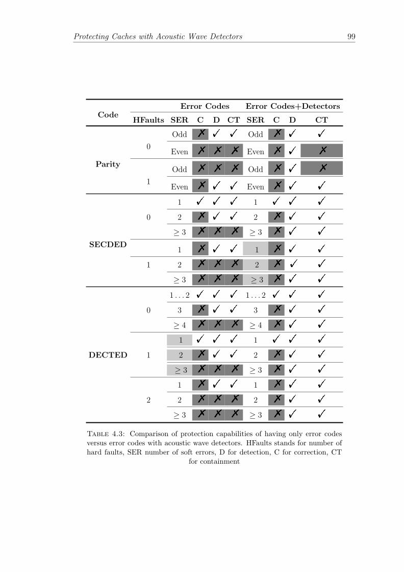
Protecting Caches with Acoustic Wave Detectors 99
Error Codes Error Codes+DetectorsCode
HFaults SER C D CT SER C D CT
Odd % ! ! Odd % ! !
0Even % % % Even % ! %
ParityOdd % % % Odd % ! %
1Even % ! ! Even % ! !
1 ! ! ! 1 ! ! !
0 2 % ! ! 2 % ! !
≥ 3 % % % ≥ 3 % ! !
SECDED1 % ! ! 1 % ! !
1 2 % % % 2 % ! !
≥ 3 % % % ≥ 3 % ! !
1 . . . 2 ! ! ! 1 . . . 2 ! ! !
0 3 % ! ! 3 % ! !
≥ 4 % % % ≥ 4 % ! !
1 ! ! ! 1 ! ! !
DECTED 1 2 % ! ! 2 % ! !
≥ 3 % % % ≥ 3 % ! !
1 % ! ! 1 % ! !
2 2 % % % 2 % ! !
≥ 3 % % % ≥ 3 % ! !
Table 4.3: Comparison of protection capabilities of having only error codesversus error codes with acoustic wave detectors. HFaults stands for number ofhard faults, SER number of soft errors, D for detection, C for correction, CT
for containment

Protecting Caches with Acoustic Wave Detectors 100
L1 caches are usually protected only with parity codes. Parity codes can be im-
plemented at byte level [250] at word level [251] or at cache block level [64]. Due
to incapability of correcting errors using parity, parity protected write-back cache
is the largest contributor towards the total DUE-FIT of the processor due to soft
errors. This forces designers to provide error correction in L1 cache. However, to
have correction capability, each byte should be protected with ECC. Implementing
ECC for every byte is complex and expensive. Hence, instead of providing ECC
for each byte in a cache block, to reduce the cost of protection designers opt to
protect cache block with ECC. But caches closer to the core have a lot of partial
write operations. Having ECC at cache block level will result into an increase in
read-modifies-writes operations. This incurs huge performance and energy penalty.
Without any error correction mechanism handling DUE-FIT of L1 cache is a big
challenge. Moreover, processors can experience a superlinear increase in DUE-FIT
when the size of the write-back cache is doubled [93]. By combining acoustic wave
detectors with parity codes it is possible to handle the DUE problem in L1 cache.
4.3.2 Error Area Granularity: Exact bit
To provide error correction, the system should be able to accurately locate the
error. To reduce the DUE-FIT, the architecture should be able to recover from
all the errors that are detected. This can be done by exploiting the localization
accuracy of acoustic wave detectors to detect and correct the errors. As discussed
in Section 4.2 using only 25 detectors it is possible to pinpoint and correct the
error in L1 cache for 71.85% of the times. By correcting the erroneous bit we can
improve the DUE-FIT rate of L1 cache by 71.85%.
If an L1 data cache is protected with only acoustic wave detectors in 5× 5 mesh,
71.85% of the times we can exactly locate the upset bit, we call this P1bitAWD. A
further quantification of error area obtained by 5× 5 mesh is shown in Figure 4.3.
It reveals that for 14.59%, 7.53%, 2.88% and 1.33% of the times we can locate the
error at the granularity of 2 bits, 3 bits, 4 bits and 5 bits respectively. We call
them P2bitAWD, P3bitAWD
, P4bitAWDand P5bitAWD
respectively.
DUE(AWD) = P1bitAWD= 71.85% (4.1)

Protecting Caches with Acoustic Wave Detectors 101
1bit, 71.85%
2 bits, 14.59%
3 bits, 7.53%
4 bits, 2.88%
5 bits, 1.33% >= 6 bits, 1.82%
Distribution of Estimated Error Area in Bits (for 5x5 mesh)
Figure 4.3: Quantification of error area granularity for 5×5 mesh for L1 datacache
By using only acoustic wave detectors in L1 data cache we can improve the DUE
by 71.85% as shown in Equation 4.1.
Interestingly, we noted that the granularities of error area (i.e. circular area with
CEP radius) obtained by acoustic wave detectors are mapped to bits in specific
patterns as shown in Figure 4.4. The circle in the Figures 4.4(a-e) show the esti-
mated error area obtained by localization algorithm. The bits that are overlapped
or intersected by this circle are also shown in Figure 4.4. For single bit upsets,
one of the bits covered by this circular area is erroneous. Using this mapping, we
show all the possible error area patterns (not to be confused with multi-bit upset
patterns) for bit granularities of 2 to 5 bits in Figure 4.5.
Because of this characteristic, we can further improve the DUE if we can exactly
isolate the erroneous bit out of the error area granularities of 2-5 bits by combining
acoustic wave detectors with error codes. To detect hard errors already parity codes
can be deployed for each block or for every byte in a block. Now we will see how
we can take advantage of combining acoustic wave detectors with parity codes.
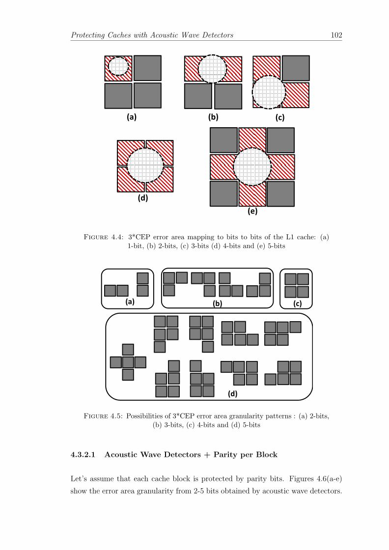
Protecting Caches with Acoustic Wave Detectors 102�
�
�
�
�
�
�
�
�
�
�
�
�
��� ��� ���
���
���
Figure 4.4: 3*CEP error area mapping to bits to bits of the L1 cache: (a)1-bit, (b) 2-bits, (c) 3-bits (d) 4-bits and (e) 5-bits
�
�
�
�
�
�
�
�
�
�
�
�
�
��� ��� ���
���
Figure 4.5: Possibilities of 3*CEP error area granularity patterns : (a) 2-bits,(b) 3-bits, (c) 4-bits and (d) 5-bits
4.3.2.1 Acoustic Wave Detectors + Parity per Block
Let’s assume that each cache block is protected by parity bits. Figures 4.6(a-e)
show the error area granularity from 2-5 bits obtained by acoustic wave detectors.
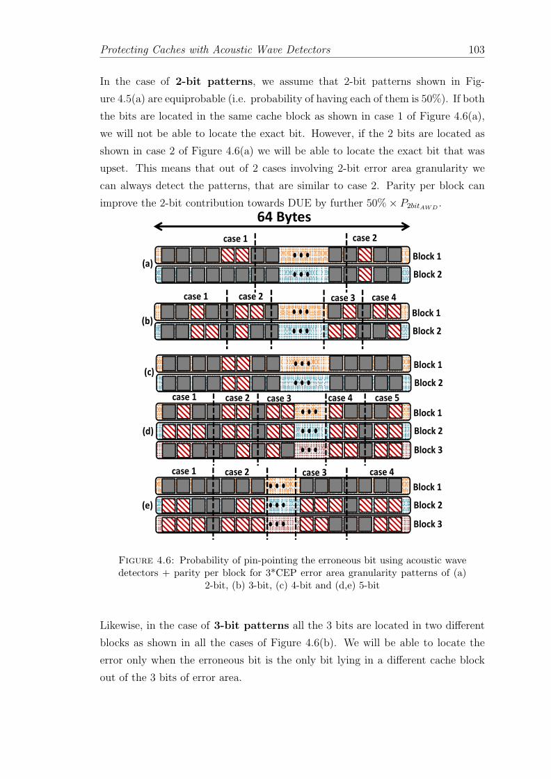
Protecting Caches with Acoustic Wave Detectors 103
In the case of 2-bit patterns, we assume that 2-bit patterns shown in Fig-
ure 4.5(a) are equiprobable (i.e. probability of having each of them is 50%). If both
the bits are located in the same cache block as shown in case 1 of Figure 4.6(a),
we will not be able to locate the exact bit. However, if the 2 bits are located as
shown in case 2 of Figure 4.6(a) we will be able to locate the exact bit that was
upset. This means that out of 2 cases involving 2-bit error area granularity we
can always detect the patterns, that are similar to case 2. Parity per block can
improve the 2-bit contribution towards DUE by further 50%× P2bitAWD.
�
�
�
�
�
�
�
�
�
�
��������
������
�� � �� �� �� �� �� ��
��������
������
�����
���������
�� � �� ��
�������
��������
�������
� ���� � ���� � ���� � ���� � ����
�������
���������
�������
� ���� � ���� � ���� � ����
��������
Figure 4.6: Probability of pin-pointing the erroneous bit using acoustic wavedetectors + parity per block for 3*CEP error area granularity patterns of (a)
2-bit, (b) 3-bit, (c) 4-bit and (d,e) 5-bit
Likewise, in the case of 3-bit patterns all the 3 bits are located in two different
blocks as shown in all the cases of Figure 4.6(b). We will be able to locate the
error only when the erroneous bit is the only bit lying in a different cache block
out of the 3 bits of error area.

Protecting Caches with Acoustic Wave Detectors 104
Again we consider all the 4 cases shown in Figure 4.5(b) are equiprobable(i.e.
probability of having each case is 25%). Furthermore, we can detect the exact
location of the error only when the error is in specific 1 bit out of 3 bits in each
case. This means that we can improve DUE for each case of Figure 4.6(b) by
(1/3)×25%. This yields an overall improvement for the 3-bit contribution towards
DUE by 34%× P3bitAWD.
In the case of 4-bit pattern as shown in Figure 4.6(c) it is not possible to locate
the exact erroneous bit.
Figures 4.6(d) and (e) show the 5-bit patterns. Here also we consider that all
the patterns shown in Figure 4.5(d) are equiprobable. Hence, each can occur with
a probability of 11.12%.
Similar calculation in the case of 5-bit pattern, shows that for the case 1 of Fig-
ure 4.6(d) when the strike is either in the bit that is in block 1 or block 3, it is
possible to locate the exact error. This means we can correct the error if it is only
in either of the two bits out of the 5 possible bits. The probability of locating
exact error in case 1 of Figure 4.6(d) like patterns is (2/5)× 11.12%.
And as shown in other cases of Figure 4.6(d), it is possible to locate the exact
error only when the erroneous bit is in a different block and it is the only bit of
the 5 bits. This means we can correct the error if it is in only one specific bit out
of the 5 possible bits. The probability of locating exact error bit in case 2, 3, 4
and 5 of Figure 4.6(d) is (1/5) × 11.12% each. As they are all equiprobable the
improvement is (4/5)× 11.12%.
Also in the occurrence of patterns shown in all the cases of Figure 4.6(e) it is not
possible to locate the exact bit that was upset. As each block contains two or
more bits that can be erroneous.
Putting it all together, for 5-bit pattern, parity per block on top of acoustic wave
detectors can increase the DUE improvement by (2/5)× 11.12%+ (4/5)× 11.12%
giving overall DUE improvement of 14%× P5bitAWD.
DUE(AWD+Parityblock) =P1bitAWD+ 50%× P2bitAWD
+
34%× P3bitAWD+
14%× P5bitAWD
=81.89%
(4.2)

Protecting Caches with Acoustic Wave Detectors 105
�
������
������
�
������
������
���� ����
������
������
��
������
������
������
������
�
������
������
���� ����
������
������
��
������
������
���� ����
������
������
��
������
������
���� ����
������
������
��
������
������
���� ����
������
������
�
������
������
����� �����
������
������
�
������
������
�����
������
������������
������
������
��
������
������
�����
������
������������
������
������
��
������
������
�����
������
������ ������
������
������
�
������
������
�����
������
������ ������
������
������
��
������
������
�����
������
������ ������
������
������
��
������
������
�����
������
������������
������
������
Figure 4.7: Probability of pin-pointing the erroneous bit using acoustic wavedetectors + parity per byte for 3*CEP error area granularity patterns of (a,b)
2-bit, (c-f) 3-bit, (g) 4-bit and (h-m) 5-bit
Hence, deploying parity per block + acoustic wave detectors in L1 data cache will
improve the DUE by 81.89% as calculated in Equation 4.2.
4.3.2.2 Acoustic Wave Detectors + Parity per Byte
Now, we will see the case when each byte in a cache block is protected by parity
bits along with acoustic wave detectors. A cache block in L1 data cache of a
Core™i7-like processor has 64 Bytes. Figures 4.7(a-m) show all the possible cases
for locating the erroneous bit for 2-bit, 3-bit, 4-bit patterns and 5-bit patterns.
As it is obvious that if all the estimated error bits are in the same byte, we will
not be able to locate the exact bit with upset. But if the bits are in different bytes
it is possible to locate the exact erroneous bit.
All 2-bit patterns are shown in Figures 4.7(a) and (b). For the patterns as in
the case 1 of Figure 4.7(a), as both the error area bits are in the same byte we
cannot locate the upset bit. But for the patterns similar to case 2 of Figure 4.7(a)

Protecting Caches with Acoustic Wave Detectors 106
or patterns similar to Figure 4.7(b) both the bits are into two different bytes and
as we have parity at byte level, we can exactly pin-point the upset bit out of the
two bit error area.
For a 64 byte block the probability of having 2-bit pairs, in which both bits are
in different bytes as shown in case 2 of Figure 4.7(a) is 12.3% (i.e. 63 pairs out of
511 total possible combinations). Which also yields probability of having patterns
like case 1 of Figure 4.7(a) to 87.7%. We know that the 2-bit patterns shown
in Figure 4.5(a) are equiprobable (i.e., each of them have probability of 50%).
This concludes that the probabilities of having patterns like case 1 and case 2 of
Figure 4.7(a) are 43.85% and 6.15% respectively and the probability of having
patterns similar to Figure 4.7(b) is 50%. This implies that 56.15% of the times we
can exactly pin-point the upset bit for 2-bit error area granularity. Hence, parity
per byte helps improving the 2-bit DUE rate by 56.15%× P2bitAWD.
Figures 4.7(c-f) show the 3-bit patterns. For each 3-bit pattern there are two
possibilities, either these 3 bits are spread over 2 different bytes (i.e., case 1 of
Figure 4.7(c)) or all the 3 bits are in 3 different bytes (i.e., case 2 of Figure 4.7(c)).
Probability of having patterns similar to case 1 and case 2 of Figure 4.7(c) is 87.7%
and 12.3% respectively. Moreover, all the 4 possibilities of 3-bit granularities,
shown in Figure 4.5(b) are equiprobable each with the probability of 25%.
For patterns similar to case 1 of Figure 4.7(c) we will be able to locate the ex-
act upset bit if the upset is in the one bit that is in a different byte from the
other two. This means that we can improve DUE for case 1 of Figure 4.7(c) by
(1/3) × (87.7%) × 25%. However, We can exactly pin-point the erroneous bit
in the patterns similar to case 2 of Figure 4.7(c) and this can improve DUE by
(12.3%)× 25%. Summing it up for all 4 possibilities shown in Figures 4.7(c-f) we
conclude, parity per byte helps improving the 3-bit DUE rate by 41.5%×P3bitAWD.
For 4-bit pattern, as can be seen in Figure 4.7(g) there are two possibilities. If
the pattern bits are spread as shown in the case 2 over 4 different bytes in 2 rows
it is possible to correct the upset. Or if they are spread as shown in the case 1 it
is not possible to find the upset bit with the help of parity per byte. Parity per
byte helps improving the 4-bit DUE rate by 12.3%× P4bitAWD.
Similar observation for 5-bit patterns of Figures 4.7(h-m) reveal that for 5-bit
patterns shown in Figure 4.7(h) we can locate the upset for case 1 only in only 2
bits out of 5 and the probability of having 3 bits in the same byte in a 64 byte

Protecting Caches with Acoustic Wave Detectors 107
block is 75.3% (i.e., 384 out of 510 total combination of triplets in a block). This
results into the probability to locate the upset for case 1 as (2/5)×(75.3%) and for
case 2 as we can locate 3 bits out of 5, the probability is (3/5)×(24.7%). Again all
the 9 possibilities of 5-bit granularities as shown in Figure 4.5(d) are equiprobable
each with the probability of 11.12%. This yields the joint probability for 5-bit
patterns shown in case 1 and case 2 of Figure 4.7(h) as ((2/5)× (75.3%)+ (3/5)×(24.7%))× 11.12%.
Similarly, we can correct all the upsets in all case 2 like patterns of Figures 4.7(i-
l), but we can correct only 1 upset out of 5 possible locations in all possibilities
similar to case 1 like patterns in Figures 4.7(i-l). This results into a probability of
(4× (12.3%) + (4/5)× (87.7%))× 11.12%. Also for Figure 4.7(m) the probability
of locating the upset is ((4/5)× (24.7%))× 11.12%. Parity per byte improves the
5-bit DUE rate by 20.5%× P5bitAWD.
DUE(AWD+Paritybyte) =P1bitAWD+ 56.15%× P2bitAWD
+
41.5%× P3bitAWD+
12.3%× P4bitAWD+
20.5%× P5bitAWD
=83.8%
(4.3)
Summing up, Parity per byte + acoustic wave detectors for L1 data cache will
result into 83.8% improvement in DUE as shown in Equation 4.3.
4.3.2.3 Acoustic Wave Detectors with Physical Interleaving
Block 1
Block 1
Interleaved
P1
P2
P3
P4
Figure 4.8: Probability of pin-pointing the erroneous bit using acoustic wavedetectors + parity per byte and assuming the bits are physically interleaved
with degree of interleaving: 4
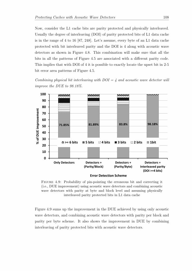
Protecting Caches with Acoustic Wave Detectors 108
Now, consider the L1 cache bits are parity protected and physically interleaved.
Usually the degree of interleaving (DOI) of parity protected bits of L1 data cache
is in the range of 4 to 16 [87, 248]. Let’s assume, every byte of an L1 data cache
protected with bit interleaved parity and the DOI is 4 along with acoustic wave
detectors as shown in Figure 4.8. This combination will make sure that all the
bits in all the patterns of Figure 4.5 are associated with a different parity code.
This implies that with DOI of 4 it is possible to exactly locate the upset bit in 2-5
bit error area patterns of Figure 4.5.
Combining physical bit interleaving with DOI = 4 and acoustic wave detector will
improve the DUE to 98.18%.
71.85% 81.89% 83.8% 98.18%
0
10
20
30
40
50
60
70
80
90
100
Only Detectors Detectors +
(Parity/Block)
Detectors +
(Parity/Byte)
Detectors +
Interleaved parity
(DOI >=4 bits)
% o
f D
UE
im
pro
ve
me
nt
Error Detection Scheme
>= 6 bits 5 bits 4 bits 3 bits 2 bits 1bit
Figure 4.9: Probability of pin-pointing the erroneous bit and correcting it(i.e., DUE improvement) using acoustic wave detectors and combining acousticwave detectors with parity at byte and block level and assuming physically
interleaved parity protected bits in L1 data cache
Figure 4.9 sums up the improvement in the DUE achieved by using only acoustic
wave detectors, and combining acoustic wave detectors with parity per block and
parity per byte scheme. It also shows the improvement in DUE by combining
interleaving of parity protected bits with acoustic wave detectors.

Protecting Caches with Acoustic Wave Detectors 109
4.4 Handling Multi-bit Upsets in Caches
A single neutron strike can upset more than one bits of memory in close proximity,
causing spatial multibit errors. Bit interleaving [87, 248] can be used to demote the
spatial multi-bit fault to several single-bit faults, then simple coding techniques
can correct the several single bit faults separately [252–254]. Temporal multi-bit
fault is the cumulative effect of several single-bit faults in a period of time. For
temporal multi-bit errors, cache scrubbing [91, 92] techniques are more effective.
As explained in Section 4.3, in a system that employs error codes without scrub-
bing, particle strikes may linger and increase the chance of a multiple bit error if lo-
cations go a long time without being read. The approach of Error Codes+Detectors
presented in Table 4.3 of Section 4.3 can detect all temporal particle strikes and
do not let them accumulate eliminating temporal multi-bit errors.
Our scheme takes the spatial multi-bit upsets into account in a very easy manner.
We assume that a set of templates for the shape of the multi-bit upsets caused by
a particle strike are available. Then, we only need to map on top of the perimeter
of the 3*CEP circle the MBU templates of [87], and therefore, extend the area of
affected bits. In the case of L2 and LLC as we studied in Section 4.3 usually a
stronger ECC code (i.e., SEC-DED or DEC-TED) is present and can take care of
multi-bit upsets. We will see how acoustic wave detectors with parity codes can
handle spatial multi-bit upsets with an example of L1 cache.
We consider the spatial multi-bit upset patterns studied in [87]. Figure 4.10(a)
shows the 2-bit upset patterns and Figure 4.10(b) shows 3-bit upset patterns. As
we have already seen in Section 4.3.2, according to Figure 4.3 for the case of single
bit upsets the acoustic wave detector can locate the bit at the granularity of 1 bit
(best case) or 5 bits (worst case).
Now in the case of 2-bit MBUs, as shown in Figure 4.10(a) to be able to cover all
2-bit upsets the single bit error area mask will be transformed into an area mask
of 9 bits. Similarly, the 5-bit error mask will now be transformed into an area of
21 bits. The same scenario for 3-bit MBUs, as shown in Figure 4.10(b) will require
the area masks of 25 bits and 45 bits for the error area accuracy of 1 bit and 5
bits respectively.
This implies that using only acoustic wave detectors to point out the exact lo-
cations of upsets in 2 and 3 bit MBUs is not possible. Also the combination of

Protecting Caches with Acoustic Wave Detectors 110
Figure 4.10: Extending the 3*CEP error area granularity of 1-bit and 5-bitsfor handling spatial multi-bit upsets using acoustic wave detectors to locate (a)
2 bit MBU and (b) 3 bit MBU
acoustic wave detectors + parity per block cannot locate the exact locations of the
upset bits.
Figure 4.11 shows the scenario for the combination of acoustic wave detectors +
parity per byte. Undertaking similar exercise as done in the case of single bit upsets
earns, a DUE improvement for 2-bit MBUs by of (3/8) × 24.7% when the error
area granularity of acoustic wave detector is 1 bit. It is worth mentioning here that
acoustic wave detectors + parity per byte cannot detect any 2-bit MBU when the

Protecting Caches with Acoustic Wave Detectors 111
�
�
�
�
������
������
������
�����
�����������
� ���� � ����
Figure 4.11: Probability of locating the 2 bit MBU using acoustic wave de-tectors configuration providing 3*CEP error area granularity of 1 bit and parity
per byte
MBU Area gran. MBU area Min. requiredtype bits (#bits) mask(#bits) DOI
1 9 42 bits
5 21 6
1 25 63 bits
5 45 8
Table 4.4: Minimum required degree of physical bit interleaving (DOI) in acache with bit interleaved parity and acoustic wave detectors
error area granularity of acoustic wave detector is 5-bits. Also, this combination
is ineffective against 3-bit MBUs.
Acoustic wave detectors + bit interleaving is very effective in improving DUE by
locating both bits in 2-bit MBU and all 3 bits in 3-bit MBU. This can achieve
98.18% DUE improvement for 2-bit and 3-bit MBUs. However, in adapting Acous-
tic wave detectors + bit interleaving, the minimum required degree of interleaving
to be able to locate all bits in the given MBU pattern of Figure 4.10 increases
with the increase in the number of bits required to be located. Increasing degree
of interleaving increases the cost and the complexity of the solution.
Table 4.4 summarizes the minimum required degree of interleaving for adapting
acoustic wave detectors + bit interleaving. In the L1 data cache, to be able to
correct 98.18% 2-bit and 3-bit MBUs the optimum solution is to have acoustic
wave detector with bit interleaved parity with DOI = 8.

Protecting Caches with Acoustic Wave Detectors 112
4.5 Cost of Protection
The proposed solution will make use of two independent meshes: a small mesh for
precise location of the strike (summarized in Table 4.1), and a somewhat larger
mesh for detection latency given in Table 4.2.
In LLC the 5×3 mesh will be used to obtain the TDOA. In that case, the hardware
mechanism will consist of 15 detectors (i.e., roughly 15 bits area), and a 2-level
OR tree to generate the Enable signal. The tree will use 6 3-input OR gates and
2 2-input OR gates. To count the worst-case TDOA clock pulses a 10-bit counter
is necessary. We will also use a 23×7 mesh to minimize the detection latency.
One one hand, it requires 161 detectors (i.e., roughly 161 bits area). On the other
hand, we will need a 4-level OR tree to generate the detection signal. Such tree
is composed of 66 3-input OR gates and 28 2-input OR gates. Notice that in the
second mesh we do not require a counter since we only want to signal the presence
of the strike.
In the case of L1 cache, the area overhead includes 25 detectors (area of 25 memory
bits) and a control circuit (consists of a counter and a few logic gates). Because of
smaller dimensions of L1 data cache and denser mesh, the detection latency is 14.5
ns for 5× 5 mesh with 25 detectors. The latency in solving 24 equations is small
compared to the error detection latency. Moreover, once the error is detected
we stall the processor so the delay in locating error is harmless. The detectors
are passive and do not consume power and the control circuit is trivial and adds
minimal power overhead.
Overhead in combined approach, such as parity per block, parity per byte and bit
interleaving adds to the overall cost of protecting the caches.
4.6 Related Work
A variety of mitigation techniques have been reported to handle the SDC- and
DUE-FIT related to soft errors in caches. In this section we review the basic
works on soft error protection for memory arrays and peripheral logic. Many of
these methods were first proposed for main memory systems. However, due to
cache size increases, these methods have now been adapted to caches.

Protecting Caches with Acoustic Wave Detectors 113
The reliability techniques can be classified into three broader categories: (i) par-
ticle strike detection for soft error detection, (ii) soft error detection and (iii) soft
error mitigation.
4.6.1 Particle Strike Detection for Soft Errors
Several particle strike detector based techniques have been studied in Section 3.7.1
of Chapter 3. These techniques can also be used to detect soft errors in the caches.
These particle strike detectors detect voltage or current glitches [132–134, 206] or
sound [135] generated upon a particle strike. A detailed comparison is provided
in the previous chapter in Section 3.7 and a summary of comparison of particle
strike detectors is given in Table 3.1.
4.6.2 Soft Error Detection
Error detection techniques work by alerting the system when the system is exposed
to erroneous data. For instance, in caches data usually spend a long time before
being read by the processor. In a cache with error detection mechanism the data is
checked for errors on every read and if found corrupted it is marked invalid. Many
error detection techniques are also accompanied by error correction or recovery
methods. Once the error is detected usually an error correction mechanism is
invoked to correct the data.
4.6.2.1 Error Codes
The most popular method of dealing with soft errors in caches is to use error codes
for error detection and correction. Error codes such as parity are often employed to
detect the error and ECC is employed for simultaneously detecting and correcting
errors in caches.
Figure 4.12 shows the basic process of implementing error codes. Error codes have
to encode the data bits for every store operation in the cache and decode data bits
upon every load operation. Every encode operation generates code word using
the check bits. Upon every access to the protected data a decoding operation is
performed and, the code word is re-computed and compared with the original code

Protecting Caches with Acoustic Wave Detectors 114
Data bits
Encoder Data bitsCheck
bits
Data Buffer
Co
de
wo
rd
Co
de
wo
rd
Decoder
Error Signal!
Data bits
No error
Figure 4.12: Basic functionality of encoding and decoding of data bits in errorcodes
word to protect against errors in original data. The check bits require separate
storage which incurs area overhead; moreover, if the encoding and decoding of the
data bits is on the critical path it may increase the cache read/write time.
Parity:
Parity is the most common technique for error detection. Parity is a simple form
of information redundancy where one extra bit added for every protected group of
data bits. Parity bit can be encoded based on the number of 1s in the protected
bits. If there are odd number of 1s in the data bits the parity bit is set to zero and
is termed as odd parity. In even parity, the parity bit is set to one if the number
of 1s in the protected data bits is even. Due to this encoding, parity code cannot
detect even number of errors in the protected data bits as two errors will generate
the same parity bit as in the case of error free data bits.
In caches parity is computed whenever the protected cache line is modified. Upon
a read to the cache line parity bit is re-computed. A parity bit match indicate the
error free data. If the parity bits do not match an error is detected and the cache
line can be mark invalid.
Parity can be implemented at byte level [250] at word level [251] or at cache block
level [64]. Parity at byte can allow the architecture to avoid computing the parity
for entire word or block for read/write operations on a byte in a cache block.
Usually, L1 caches are protected with parity codes [81, 255–257] combined with
error mitigation technique.
ECC:
Error correcting codes (ECC) encodes more information redundancy for providing
error detection as well as correction. Similar to parity codes ECC generates a code
word for every protected data word. This code word is computed upon every write

Protecting Caches with Acoustic Wave Detectors 115
and re-computed and compared upon every read to the cache. ECC encoding is
based on the concept of Hamming distance [43]. Hamming distance between two
same length data words is defined as the number of bits by the two data words
differ. For instance, the Hamming distance between data words 0011 and 0001 is
one since they differ only in position two. In order to protect a data word against
a one bit error, Hamming-distance-based ECC assigns code words such that any
two data words having a Hamming distance of less than two will never share the
same code word. By providing code words with Hamming distances greater than
the minimum required for protection, ECC can also provide for error correction.
To correct an n bit error requires a code word of size (2×n + 2). In addition to
correcting n bit errors, this will also detect (n+1) bit errors.
Single error correction double error detection (SEC-DED) can correct one bit error
as well as detect double bit errors. By adding more code bits a DEC-TED can
correct double bit errors and detect triple bit errors. Most common ECC codes
used in today’s processors to protect caches are SEC-DED [43, 44] and DEC-
TED [89]. L2 and L3 caches are protected by SEC-DED or DEC-TED [64, 244–
246, 258]. Error codes are effective way of handling single-bit as well as multi-bit
errors (as explained in Table 4.3 of Section 4.3 and Section 4.4).
4.6.3 Soft Error Mitigation
Unlike error detection techniques, error mitigation techniques can avoid the soft
errors altogether by employing some process or device hardening schemes. At ar-
chitecture level soft error mitigation techniques may employ means to overwrite the
erroneous data and hence architecturally masking the error before it is consumed.
At process level several techniques can be used to reduce the charge collection
capacity of the sensitive nodes in an SRAM memory cell [259]. Using multi-
ple well structures have been proposed to show improved robustness by limiting
charge collection [260]. Another effective process technique for reducing the charge
collections is to use the SOI substrates. Other process techniques include wafer
thinning, mechanisms to dope implants under the most sensitive nodes etc. Pro-
cess level techniques are effective and significantly reduce the soft error rate of the
memories. However these techniques require modifications in the standard CMOS
fabrication process and therefore are less attractive.

Protecting Caches with Acoustic Wave Detectors 116
Another way of protecting the caches at circuit level is by making the memory cell
physically robust. One way of implementing robust SRAM cell is by increasing
the Qcrit of the SRAM cells used in caches. Radiation hardening is another circuit
level approach for handling soft error rates in caches. We talk about soft error
mitigation techniques at process and device level in Chapter 7.
4.6.3.1 Physical Interleaving
Physical interleaving is a technique to arrange physically adjacent bits into dif-
ferent logical code words. Bit interleaving [87] can be used to demote the spatial
multi-bit fault to several single-bit faults, then simple encoding techniques can
correct the several single-bit faults separately [252–254]. Error codes accompany-
ing with bit interleaving can detect and correct several spatial multi-bit errors.
An example of physically interleaved parity code is shown in Figure 4.8. If two
adjacent bits are affected by a single particle strike and as the adjacent bits are
physically interleaved the affected two bits will be detected as two single bit errors.
Degree of interleaving (DOI) is defined as the number of adjacent bit errors the
interleaving scheme can detect. Figure 4.8 shows a scheme with DOI=4. As the
degree of interleaving increases the capacity of error codes to detect or correct
spatial multi-bit errors increases. However, with increased degree of interleaving
the depth of XOR logic tree for computing the parity increases and will require
longer encoding and decoding time which may impact the overall performance.
4.6.3.2 Cache Scrubbing
Temporal multi-bit faults are the cumulative effect of several single-bit faults in a
period of time. When the probability of having temporal multi-bit error is high
cache scrubbing [92, 93] technique is often combined with ECC. Temporal multi-
bit errors can be seen more frequently in large memories (e.g., LLC) where the data
stays without being accessed for a very long time. Because the data is not accessed
the error due to first particle strike goes undetected and upon a second particle
strike it is transformed into double bit error and the SEC-DED will not be able
to correct it. Cache scrubbing avoids the accumulation of errors by periodically
accessing all the cache blocks and hence invoking the error codes for possible single
bit error detection and correction. Typical scrubbers step through cache lines at
fixed times, guaranteeing that all words will be scrubbed at least once during some

Protecting Caches with Acoustic Wave Detectors 117
larger interval. Usually, the scrubbing frequency is set such that each cache line
will be scrubbed on average more often than a bit flip occurs. Determining the
cache scrubbing period can be challenging and also as every cache block is accessed
periodically to check for errors the overall power consumption increases.
4.6.3.3 Cache Flush
As a part of error mitigation in cache flushing techniques a hardware of software
controller mechanism is employed to periodically flush the entire contents of the
cache [203, 226, 261]. By removing all the data from the cache the erroneous data
is also removed improving the overall reliability. However, frequent cache flushing
techniques can incur huge performance overhead due to increased cache miss rate.
4.6.3.4 Early Writeback
Usually, a cache line remains in the cache until it is replaced by another cache line
according to an appropriate replacement policy (i.e., least recently used (LRU)).
The early writeback scheme is motivated by the observation that the dirty cache
lines that have not been accessed recently are unlikely to be read again. Several
proposals have been made in the direction to replace the dirty cache lines in
the cache after a fixed time period, earlier than they would be replaced by the
usual LRU policy [243, 262, 263]. Early writeback schemes enhance reliability of
writeback cache by reducing the exposure of dirty cache lines to the soft errors.
4.6.4 Comparison of Techniques
In this section, we summarize the area, power and performance overheads as-
sociated with techniques discussed above for protecting caches. Table 4.5 gives
compares the process, circuit and architecture level solutions for their area, power
and performance overheads. Process level techniques can be effective in terms of
the reduction in the soft error rate they can achieve. However these techniques re-
quire modifications in the standard CMOS fabrication process and hence difficult
to adapt in existing technology.
Circuit level solutions either employ larger transistors or include redundant tran-
sistors in the SRAM cell. For instance, the DICE cell employs 2× more transistors

Protecting Caches with Acoustic Wave Detectors 118
than a normal SRAM cell it can incur 1.5-2× higher area overhead [264, 265]. Be-
cause of the large number of transistors per cell, these designs consume more area
(and consequently more power) than six transistor cells. Employing larger cells
or increasing the node capacitance can impact performance in other ways (usually
degrades the read/write time of cache). Including redundant transistors may also
increase the overall energy consumption.

Protecting Caches with Acoustic Wave Detectors 119
Mech
anism
Detection
False
Chip
SER
Are
aPower
Perform
ance
Design
Latency
Alarm
sReduction
Overh
ead
Overh
ead
Overh
ead
Cost
Pro
cess
Level
Multi-well[260
],SOI[184
,18
5]
–%
5×[184
]Low
Low
Low
High
Circuit
level
(V-I)sensing[132
–134
]3-6cycles
!Moderate
20-45%
[206
]upto
100%
[206
]1-10
%[206
]Moderate
Decou
pling
capacitor
[28,26
6,267
]-
%25
-32%
[268
]Moderate
3%††
[268
]High
High
Hardened
cell[54,26
4,26
5,26
9]0-2cycles
%10×
[265
]1.5-2×
†[264
]40
-50%
†[265
]6-8%
[270
]Moderate
Architectu
relevel
Parity
0cycles
%1D
1.5%
⋆Low
Low
Low
SEC-D
ED
0cycles
%2D
-1C
13%
⋆Moderate
Moderate
Low
DEC-T
ED
0cycles
%3D
-2C
23%
⋆High
High
Moderate
Interleaving
(DOI=
8)+
Parity
0cycles
%8D
1.5%
⋆⋆
High
High
Moderate
Scrubbing+
SEC-D
ED
100
0sof
cycles
%42
%[203
]13
%⋆
High
High
Moderate
CacheFlush
1000
sof
cycles
%10
-25×
[261
]Low
High
10%
[261
]Low
Early
Writeback
1000
sof
cycles
%High
5%[263
]High
<1%
[243
]Low
Table4.5:Com
paringdifferentmechan
ismsforprotectingcaches
against
soft
errors.nD
indicatesnbitserrordetectioncapability,
mD–n
Cindicates
mbitserrordetection
andnbitscorrection
capab
ility.
†overheadsper
SRAM
cell,††
overheadper
chip,⋆overhead
per
64bits,
⋆⋆doesntincludeoverheadfrom
theinterleavingcircuit.

Protecting Caches with Acoustic Wave Detectors 120
At architecture level, while employing error detection and correction codes, the
generated check bits adds to the original data bits and they are required to be
stored causing area overhead; however, the relative overhead diminishes as the
width of protected data word increases.
Generation and checking of parity and ECC occurs during data reads and writes
and adds energy overhead. ECC encoding is done using complex bit-wise XOR
logic gates across portions of a cache block and generating check bits which are
stored along with the original data in the cache. Employing ECC for protecting
caches can cause area and power overheads [270, 271]. Due to encoding and
decoding delay of code words the ECC may add extra cycles to the cache access
time incurring significant performance penalty [119, 243].
Moreover, as the complexity of code increases the overheads increase exponentially.
Compared to parity the SEC-DED and DEC-TED can increase the energy over-
head by 25% and 50% respectively [254]. In addition, reading and computing the
ECC bits for error checking can be a performance bottleneck parity and ECC are
best applied to data that is not manipulated often. Caches closer to the core have
a lot of partial store operations (i.e., store instructions operating on a few bytes
in a cache block). Having ECC at cache block level will result in computations
of check bits for the entire cache block, incurring huge performance and energy
penalty. The extra area and energy overhead to implement multi-bit error detec-
tion and correction grows quickly as the code strength is increased. Employing
complex codes may also require pipelined encoding and decoding schemes which
may increase the length of the critical path. Thus, parity and ECC protection
of data is difficult to efficiently integrate into modern processor cores that are
performance, power, and complexity constrained.
Cache scrubbing techniques can avoid the ECC latency by periodically scanning
the cache, checking the data integrity. Scrubbing period may vary from 80 ns
to 1000 s of ns [91–93]. Because scrubbing avoids the inline error correction of
traditional ECC; it has lower error coverage than checking ECC on every read [92].
Physical bit interleaving can handle spatial multi-bit errors at the cost of additional
power due to the unnecessary read access of the undesired words in the row as
all cells in a row share common word-line [64, 87, 179, 244]. Additional area and
performance penalty incurs due to the long word-line and column MUX circuits.
The overheads grow significantly as the interleaving factor increases depending on
the memory design [248, 254, 272].

Protecting Caches with Acoustic Wave Detectors 121
The benefits of the early writeback cache against the incurred performance penalty
largely depends on the behavior of the workload. If in a given workload there is
only a portion of the cache that is dirty the benefits achieved will be small.
Plenty of research has been done in inventing schemes to reduce the overheads
associated with error codes [46, 47, 248, 254, 273–276]. We highlight the major
features for reducing the overheads related to error codes for protecting caches:
1. Existing error codes mostly protect a cache block (64 bytes) in caches. How-
ever, by protecting more bits the protection coverage can be increased at
minute increase in area, power and performance overheads. Method pro-
posed in [249, 273] protects multiple cache block or entire cache and signifi-
cantly reduce the area overhead.
2. Another way of reducing the overheads is by decoupling the correction capa-
bility of ECC from the critical path. As we have seen in Table 4.5 the cost
of error detection is significantly smaller than the cost of error correction.
Decoupling the error detection and correction mechanisms can be beneficial
especially where the soft error rate is low. One way of implementing it is to
detect error on every read operation and invoke error correction only when
needed [87, 248, 249, 253, 275]. Using such two-tired schemes it is possible
to off load the error correction codes to DRAM to further reduce the area
overhead [248].
3. Decouple the multi bit correction capability and single bit correction capa-
bility of ECC. A variable length ECC proposed in [258] that protects the
common case of large number (about 96%) of cache lines with zero or one
failures using a simple and fast ECC and the smaller portion of cache lines
with multi-bit failures use a strong multi-bit ECC that requires some addi-
tional area and latency.
4. An alternative approach includes the mechanisms that protect only dirty
cache lines in the cache. The idea is based on the observation that most
of the time a majority of cache contains clean data and as this data is
unmodified, another copy of correct data already exists in the lower levels of
caches. Any error in the clean data can be recovered by restoring the clean
data from the lower level of cache. Therefore, clean data does not require
complex and expensive error correction mechanism. Work of [277] protects

Protecting Caches with Acoustic Wave Detectors 122
the dirty cache lines in L2 and LLC via SEC-DED and the clean lines with
parity code. In [86] authors proposed to protect dirty cache blocks using
ECC and once the dirty cache block turns clean the correction capacity of
ECC is disabled by gating some bits and converting ECC into parity code.
Another variant [274] proposed to use a small cache for saving check bits for
ECC or replicated cache lines. Techniques protecting the dirty cache lines in
a cache can be further benefited by employing policies such as eager write-
back to reduce the number of dirty cache lines in the cache [243, 262, 263].
5. Similar to the idea of protecting only dirty cache lines, cache replication
technique [278] proposes to protect only subset of cache lines using ECC. The
cache lines are selected based upon the access frequency. The mechanism
proposes to store the replicas of frequently accessed cache lines in place of
cache lines that are no longer required. It reduces the ECC overheads by
not protecting the selected cache lines by employing redundancy in terms of
replication. Not all cache lines are replicated leading to a potentially higher
uncorrectable error rate than with the baseline uniform ECC. The work has
been further extended that utilizes replicating dirty cache lines or parts of
dirty cache lines for providing error protection [279].
4.7 Chapter Summary
In this chapter, we saw how acoustic wave detectors are used for soft error detection
and localization in the caches. We first studied the implications of error detection
and localization architecture on the design parameters, detection latency and er-
ror area granularity. Based on the obtained error area granularity, we explored
the possibility of correcting errors. We observed that acoustic wave detectors can
correct the error whenever the exact location of the error is identified. Our ex-
periments concluded that using only 25 acoustic wave detectors it is possible to
correct 71.85% errors in L1 cache.
We then explored the possibility of combining acoustic wave detectors with error
codes. We discussed the architectural modifications for integrating error codes
with acoustic wave detectors. We then studied the DUE problem in caches closer
the the core (i.e., L1 cache). Because of the higher cost of error correction L1
caches only have error detection capability. We showed how by accommodating

Protecting Caches with Acoustic Wave Detectors 123
acoustic wave detectors with bit interleaved parity codes, we can correct 98% of
single bit errors in the L1 cache.
Lastly, we presented a mechanism to handle the multi-bit errors in caches. We
observed how SEC-DED codes with acoustic wave detectors provide the same de-
tection level as standalone DEC-TED, at significantly low overheads. We also
studied how adapting acoustic wave detectors and parity protected physically in-
terleaved bits can provide protection against 2-bit and 3-bit MBUs at very low
cost.
In the next chapter, we will discusses how we can use the proposed error detection
and location scheme for protecting entire processor core.

Chapter 5
Protecting Entire Core with
Acoustic Wave Detectors
In the previous chapter, we understood how we can protect caches against soft
errors using acoustic wave detectors. In Chapter 3 we developed an architecture
that detects and locates the errors in processor core. Now we will proceed to
take advantage of error detection architecture based on acoustic wave detectors
in providing efficient error containment and recovery in the core of a Core™i7-likeprocessor. By providing error containment and recovery the proposed architecture
can potentially eliminate the SDC and DUE of a processor core. The architecture
uses acoustic wave detectors for dynamic particle strike detection. Moreover, the
architecture does not allow errors to escape to user (i.e., updating main memory or
i/o devices) before detection, eliminating SDC. Eliminating DUE of core is more
involved and our proposal relies on a novel and cantilever-specific checkpointing for
recovery. Next, we will show how the proposed architecture scales to protect multi-
core systems. Finally, we will evaluate the performance impact of the proposed
architecture using real life workloads.
5.1 ”SDC & DUE 0” Architecture
The main objective of the proposed architecture is to achieve 0 SDC- and DUE-
FIT per core. SDC occurs when errors escape and become visible to the user. And
DUE occurs in the absence of an error recovery mechanism. Error correction is
handled by either moving the system to a state that does not contain the error
124

Protecting Entire Core with Acoustic Wave Detectors 125
(e.g., using checkpointing) or by an on-the-fly error correction method, which is
possible only when the error is detected before the erroneous data is consumed.
Next, we will see how error detection latency plays an important role in deciding
the overall cost of SDC and DUE.
5.1.1 Effect of Detection Latency on SDC & DUE
Acoustic wave detectors detect all soft errors due to alpha and neutron strikes.
However, not only detection of error but how soon the error is detected is also
very important. Detection latency defines the degree of error containment. De-
pending on the detection latency, errors can be contained at various granularities
in a processor (i.e., within pipeline or caches etc.). Efficient error containment is
essential for avoiding SDC (e.g., error is visible to user before its detection) and it
also has an impact on the recovery process.

Protecting Entire Core with Acoustic Wave Detectors 126
Dete
ction
Mechanism
Post
Consu
mption
Conta
inm
ent
Sizeof
Prote
cts
Dete
ction
Area
Perform
ance
Dete
ction
Late
ncy
Cost
Checkpoint
Coverage
Overhead
Overhead
Redundant
execution
Lock
step
[58,115],
DMR
[280],DCC
[281]
Cycle-by-cycle
detection
Low
Small
Core
100%
100%
[58,115,
280],1%
[281]
>1.5-2×
RMT
[72],CRT
[57],
AR-SMT
[68]
Hundredsofcy
cles
&unbounded
High
Large
Core
<100%
†Low
>2×
Instruction
duplication
EDDI[282],
SW
IFT
[283],
CRAFT
[284]
Low
&unbounded
Low
Small
Core
&Main
mem
ory
[282]
<100%
∗[283]
Low
>150%
[282]
Sym
pto
mchecks
ErrorCodes
[117],
Hard
ened
latches
††[54,264,
265,269]
0cy
cles
&bounded
Low
–Main
mem
ory
[117],
Logic
[54]
100%
[117]
12.5%
[117],
∼55%
[54]
Low
BIST
[285],
Bulletproof[286]
Periodic
&bounded
High
Large
Core
Only
hard
errors
90%
[286]
5%-6%
5%-25%
⋆
SWAT
[287],
Shoestring[35],
Restore
[36],
Pertu
rbation[288]
Millionsof
cycles
&unbounded
High
Large
Core
<100%
⋆⋆[35]
Low
5-16%
Monitorin
ginvariants
DIV
A[67],Argus[289]
Low
&bounded
Low
Small
Core
Backen
d[67],
Core
[289]
100%
[67],
∼100%
[289]
6%
[67],
17%
[289]
5-15%
Senso
rbase
d
Aco
ustic
detectors
[135]
100cy
cles
∓
(configurable)&
bounded
Low
–Cach
e100%
detection
<1%
Low
(V-I)detectors
[132–134]
3-6
cycles
&bounded
Low
–Main
mem
ory
&Logic
Moderate
20-45%
[206]
1-10%
[206]
Propose
dArchitectu
re
30-100cy
cles
∓
(configurable)&
bounded
Low
Small
Core
100%
detection
&recovery
<1%
0.6%
Table5.1:Com
parison
ofdifferenterrordetection
schem
es(†
vulnerab
ilityholes
inLSQ
logic
(i.e.,MOB
logic),
∗cannotdetecterrors
instores,††
does
not
detectbutprevents
error,
⋆on
lyforsimple
in-order
cores,
⋆⋆cannotdetectiffaultdoes
notmanifestasymptom,
∓latency
from
actual
strikeinstan
ce)

Protecting Entire Core with Acoustic Wave Detectors 127
Table 5.1 reviews the detection latencies for different error detection techniques
once the error is consumed. Bounded latency means the error is detected within a
fixed number of cycles, that is known a-priori or can be set by the designer (e.g.,
periodic BIST). Longer detection latency enforces the error containment to be
done at higher degree of abstraction in a processors, and results in more complex
hardware and/or software checkpointing/recovery mechanisms. Excessively long
detection latencies may not be even recoverable. Long detection latencies can
also prevent the fault diagnosis due to weak correlation between the fault and its
symptoms or due to the limited on-chip tracing storage (i.e., log sizes).
Error detection mechanisms with lower detection latency provide the best tradeoff.
Therefore, to achieve SDC-& DUE 0 core at minimum cost we next explore error
containment and recovery for minimum latency (i.e., containment before error
updates architectural state).
5.1.2 Achieving SDC-& DUE 0 per Core
In order to achieve 0 SDC, we can equip a processor core with acoustic wave
detectors so it detects all particle strikes that may cause an error. To have DUE
0 per core, the architecture must be able to recover from all the errors and restore
correct processor state; this includes architectural register file, RAT, PC etc.
Previous work [135] proposed using acoustic wave detectors in combination with
error correction codes to detect and locate errors in memories. In this section, we
extend it and assess its detection latency and capabilities to address challenges in
achieving SDC-& DUE 0 for an entire core.
Achieving SDC 0 per core: The first option that we explored is protecting the
core for the minimum error detection latency. It requires that the error is captured
before the wrong value is committed.
Given the dimensions of current core designs, a single detector would suffice to
detect all errors. Recall from Section 3.2, using just 1 detector implies the worst-
case detection latency of 1000 cycles at 2 GHz, which may give time for erroneous
instructions to commit before being detected.

Protecting Entire Core with Acoustic Wave Detectors 128
0
200
400
600
800
1000
1200
1400
1600
0
100
200
300
400
500
600
700
800
900
1000 Ov
erh
ea
d o
f Inte
rcon
ne
cts (#W
ires)
De
tect
ion
La
ten
cy (
#C
ycl
es)
Number of Detectors on the Core [Mesh configuration]
Detection latency(#Cycles) @ 2GHzRelative Increase in Interconnects (#Wires)
Latency: 100 Cycles
<1 Metal layer
Latency: 30 Cycles
~1 Metal layer
Figure 5.1: Number of detectors vs. detection latency at 2 GHz
Obviously, in order to reduce the detection latency, we can deploy more detectors,
for instance in a mesh formation. Figure 5.1 shows the detection latency and com-
plexity for various mesh configurations. Complexity in terms of increased number
of wires is calculated. It is clear that the detection latency varies exponentially
with number of detectors. Also complexity increases with number of detectors.
According to Figure 5.1, we will need >68,000 detectors to guarantee that no
instruction will be committed before it is checked for errors (error detection latency
of 1 cycle).
Achieving DUE 0 per core: With 68K detectors we contain the errors before
they are committed. If the strike happened in speculative state, a nuke and retry
will suffice to recover. However, if the strike is in the architectural state, recovery is
somewhat more involved. One option is using error correcting codes; nevertheless,
majority of the structures that hold the architectural state (i.e., architectural
register file) do not have error correcting codes. Therefore, we opt to periodically
take checkpoints (that include shadow copies of the architectural state).
In a nutshell, for SDC- & DUE 0 core we will need 68K detectors. This implies

Protecting Entire Core with Acoustic Wave Detectors 129
an area overhead equivalent to having 68K bits of SRAM (∼7KB cache). More-
over, as shown in Figure 5.1 the interconnects to the micro-controller from 68K
detectors increases the complexity and require >5 metal layers and pose significant
challenges in place and route [290, 291].
Next, we will explore an optimized architecture that reduces the number of detec-
tors without compromising the reliability coverage.
5.1.3 Divide and Conquer for SDC and DUE 0
We made the observation that errors in different stages of pipeline take different
time until they propagate outside the containment area (i.e., before they com-
mit). We know from previous section that providing detectors to all the functional
blocks for the same detection latency is expensive in terms of area overhead and it
is complex. To reduce the number of detectors for containment before erroneous
Figure 5.2: Pipeline of a state of the art processor and the latency of stages
instruction is committed, we study pipeline structures and analyze the time each

Protecting Entire Core with Acoustic Wave Detectors 130
instruction spends in traversing through the pipeline. We collect the latency re-
quirements for all structures to provide coverage to all instructions. This gives us
an insight of the required detection latency for each structure in the core.
Figure 5.2 shows the pipeline of our base core running at 2 GHz. It shows the
latency for different stages of the pipeline up to commit. We identified four differ-
ent paths with different latency: (i) fetch/decode until commit takes 20 cycles, (ii)
rename/scheduler to commit takes 15 cycles, (iii) execute to commit takes 8-10
cycles, and (iv) write-back/retire to commit is 4-6 cycles.
For example of fetch stage, once fetched, all instructions will take minimum 20
cycles (considering best case) to reach the commit stage. Providing single cycle
detection latency for structures in fetch stage (i.e., prefetch, branch-predictor etc.)
would be unnecessary.
Pipeline stage #Detectors
Fetch + Decode (including I-Cache, D-Cache, TLBs) 1787Rename + Schedule 170
Execute 461Writeback + Commit 139
Total 2561
Table 5.2: Required number of detectors for containment in core
From this initial observation, we identified that some data-flow paths are more
critical (i.e., writeback to commit) and will need stricter detection latency require-
ments for error containment. So, instead of protecting all the functional units in
pipeline for a common detection latency we propose to put detectors for individ-
ual functional units. By protecting each functional units for respective allowable
detection latencies we can reduce the number of detectors and still achieve 0 SDC.
And for 0 DUE we keep low cost shadow copies of architecture state as described
in Section 5.1.2.
Now we contain errors before they commit and as shown in Table 5.2, it requires
2.5K detectors for functional blocks in pipeline for their allowable detection latency
requirements.
Overheads. 2.5K detectors cause an area overhead equivalent to 2.5K bit SRAM.
Complexity for accommodating 2500 (low latency) interconnects occupy ∼4 metal
Protecting Entire Core with Acoustic Wave Detectors 131
layers causing an unacceptable area overhead as shown in Figure 5.1. Moreover,
control circuit for handling 2500 logic inputs is complex and requires a 2500×1MUX (∼22K extra CMOS cells).
5.1.4 Containment in Core: Recap
We realized that achieving DUE 0 by recovering within the core demands 68K
detectors. To reduce the area overhead, we explore a modification that protects
each pipeline stage based on its allowable detection latencies. By relaxing error
detection latency requirement, the required number of detectors for efficient error
containment goes down to 2.5K. However, the resulting design is complex and the
area overhead of 2.5K interconnects is still unacceptable.
Hence, we propose to extend the error containment area beyond the commit stage
to the cache hierarchy.
5.1.5 Proposed Architecture
There are several advantages of containing and recovering from errors within cache
hierarchy [228, 234, 292], such as (i) cache assisted containment and recovery
techniques are not intrusive on the architecture and require little modifications,
(ii) they accommodate larger checkpoint periods reducing the need of frequent
checkpointing and (iii) the cost of recovery in terms of the amount of work to be
undone is little.
Including caches in the error containment boundary implies that we can further re-
lax the detection latency requirement which in turn reduces the required detectors.
According to Figure 5.1 relaxing detection latency constraint by 10× (i.e., from
10 cycles to 100 cycles) reduces the number of required detectors by 90× and this
reflects in 100× decrease in complexity and interconnects overhead. We believe
that a good trade-off between detection latency, area overhead and complexity lies
within 30-300 detectors, which means 30-100 cycles latency at 2 GHz.
Our proposed architecture to provide DUE 0 cores consists of the following steps:
Error detection. We use acoustic wave detectors to detect particle strikes in the
core. We opt for a simple configuration with a number of detectors in the range of

Protecting Entire Core with Acoustic Wave Detectors 132
Log
ic
L1 L2 Main
Memory
Containment Boundary
Off chip
LLC
Private/
Shared
Core
Includes logic, RF, L1
Includes logic, RF, L1 and L2
Includes logic, RF, L1, L2 and LLC (shared)
Figure 5.3: Error Containment Architecture
30-300, which provides a detection latency in the range of 30-100 cycles running
at 2 GHz.
Data error containment. We choose our containment area to be the cache
hierarchy. Figure 5.3 shows the different error containment boundaries for an
architecture with a single core and three levels of cache. Notice that the boundary
of the containment area can be configured to be at any cache level. We assume
that the caches themselves are protected by some mechanism. A datum will be
correct once it has spent more time than the worst-case error detection latency
in the cache (this way, we guarantee that the datum was produced correctly). In
order to guarantee containment, we do not allow any data to go out of containment
region before making sure that data is error free.
Data checkpointing. Containment boundary helps deciding the checkpoint
boundary. By definition, containment boundary lies within the checkpoint bound-
ary. If not, then there is a possibility of corrupting the checkpoints. Every con-
ceptual checkpoint will consist of the architectural state (e.g., RF, PC, etc) and
the memory data. Process of checkpointing would include saving register values
and flushing cache block values within the checkpoint boundaries that have been
modified since the last checkpoint.
Data recovery. Upon an error, data recovery consists of invalidating all tem-
poral data within the checkpoint boundary, and resume execution from the latest
checkpoint. Notice that this checkpoint will consume the data from outside the
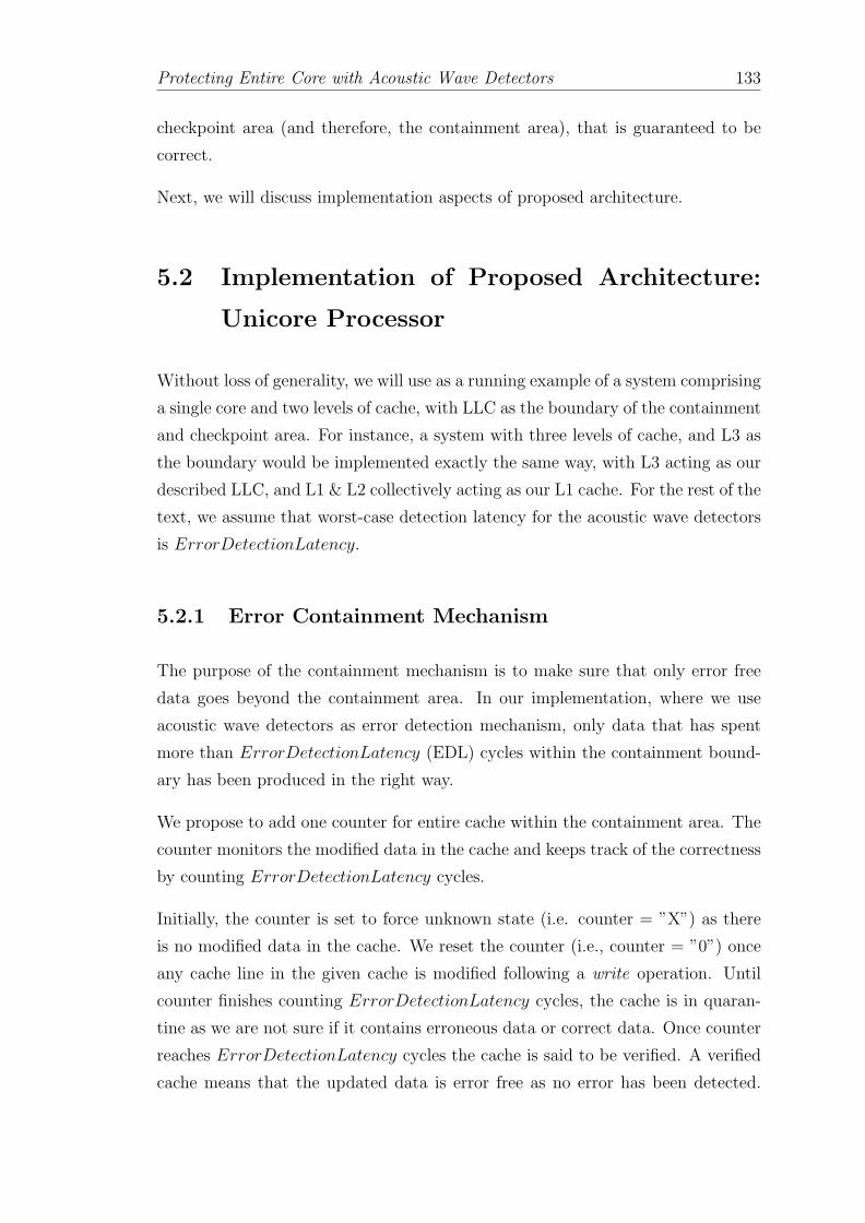
Protecting Entire Core with Acoustic Wave Detectors 133
checkpoint area (and therefore, the containment area), that is guaranteed to be
correct.
Next, we will discuss implementation aspects of proposed architecture.
5.2 Implementation of Proposed Architecture:
Unicore Processor
Without loss of generality, we will use as a running example of a system comprising
a single core and two levels of cache, with LLC as the boundary of the containment
and checkpoint area. For instance, a system with three levels of cache, and L3 as
the boundary would be implemented exactly the same way, with L3 acting as our
described LLC, and L1 & L2 collectively acting as our L1 cache. For the rest of the
text, we assume that worst-case detection latency for the acoustic wave detectors
is ErrorDetectionLatency.
5.2.1 Error Containment Mechanism
The purpose of the containment mechanism is to make sure that only error free
data goes beyond the containment area. In our implementation, where we use
acoustic wave detectors as error detection mechanism, only data that has spent
more than ErrorDetectionLatency (EDL) cycles within the containment bound-
ary has been produced in the right way.
We propose to add one counter for entire cache within the containment area. The
counter monitors the modified data in the cache and keeps track of the correctness
by counting ErrorDetectionLatency cycles.
Initially, the counter is set to force unknown state (i.e. counter = ”X”) as there
is no modified data in the cache. We reset the counter (i.e., counter = ”0”) once
any cache line in the given cache is modified following a write operation. Until
counter finishes counting ErrorDetectionLatency cycles, the cache is in quaran-
tine as we are not sure if it contains erroneous data or correct data. Once counter
reaches ErrorDetectionLatency cycles the cache is said to be verified. A verified
cache means that the updated data is error free as no error has been detected.

Protecting Entire Core with Acoustic Wave Detectors 134
“Verified”
Time (#cycles)
D = 0
Counter = X
D = 1
Counter = 0
WRITE
D = 1
Counter = EDL
EDL cycles
t t + EDL
“Don’t care” Quarantine (“Not Verified”)
Figure 5.4: Time-line of the events in cache. D indicates the dirty bit andEDL stands for error detection latency. Once the cache line has been writtenthe cache line enters in quarantine state. After ErrorDetectionLatency cycles
the cache line is now in verified state and also error free.
Remember, counter is reset (i.e., counter = ”0”) upon every write operation from
the core. Read operations do not affect the state of counter.
Example. Figure 5.4 shows the basic events for a cache line in the cache. Before
the write operation the line is clean (i.e., dirty bit, D = ”0”) and counter = ”X”.
Following a write operation at time t, D = ”1” and counter is reset (i.e., counter =
”0”). After ErrorDetectionLatency cycles entire cache is verified. Now, we will
discuss how the normal cache operation is carried out in proposed architecture.
For that purpose we will be using Figure 5.5, which shows different events that
may happen to cache lines within the cache of containment area.
5.2.1.1 Dealing with Verified Cache.
Figure 5.5(ii) shows the case of evictions of dirty cache lines in a verified cache, we
allow them to make forward progress and leave the containment boundary. Later,
they can be part of the new checkpoint.
5.2.1.2 Dealing with Not-Verified Cache.
Not-verified cache is in quarantine. Read operations from the core do not alter the
state of counter, since potentially erroneous data will not leave the containment
area.
Evictions from L1 cache. Figure 5.5(i) shows the actions to be taken upon an
eviction of a dirty cache line when the L1 cache is not verified. First, we will evict

Protecting Entire Core with Acoustic Wave Detectors 135
Dirty (D=“1”)
“Not Verified” Cache
L1 LLC
Read/Write
Miss Eviction of the line to LLC
Dirty (D=“1”)
“Verified” Cache
Read/Write
Miss Eviction of the line to LLC
(i)
(ii)
L1LLC
Dirty (D=“1”)
“Not Verified” Cache
LLC
MemoryRead/Write
Miss Stall until verified
Force checkpoint then
Eviction of the line to memory
(iii)
Figure 5.5: Error containment in cache for evictions caused by read and writeoperations. D indicates the dirty bit.
the cache line to LLC. The counter could be inherited or pessimistically reset at
LLC. Alternatively, we could stall until the L1 cache is verified before evicting
modified cache line to LLC.
Evictions from LLC. Evictions of dirty cache lines from LLC (i.e., containment
boundary) when LLC is not verified are not allowed as is the case of Figure 5.5(iii).
In such event we will stall until LLC is verified.
In Section 3.6 we analyze all the cases discussed above for their impact on perfor-
mance and observe tradeoff between error containment area and cost of contain-
ment using real life workloads.

Protecting Entire Core with Acoustic Wave Detectors 136
5.2.2 Creating Checkpoints
The checkpointing process should include:
• Copying the architectural state.
• Saving the program counter.
• Wait for all caches to be verified.
• Writeback all dirty data in lower (verified) caches to main memory.
For checkpointing architectural state we suggest to use shadow structures as pro-
posed in [293]. The copy of program counter is stored in a special register. All
these structures are assumed to have error recovery capabilities (e.g., ECC).
We anticipate that writing all dirty data present in all caches to memory may be
expensive. Similar to previous works [228, 292], we adopt an incremental check-
pointing where only dirty lines from the caches closest to the core (L1 in our
running example) are written back to the cache in the boundary of the checkpoint
area (LLC in our running example). Dirty lines in the LLC are now part of the
checkpoint. In this configuration, the data part of the checkpoint will be split
between the LLC and main memory.
In order to implement such optimization, we add a checkpoint bit (CH) in every
cache line of the cache in checkpoint boundary (i.e., every cache line of LLC).
Initially the checkpoint bit is set to ”0”, which means that the line is not part of
the checkpoint.
Periodicity. In this proposal we take periodic incremental checkpoints. The
frequency of checkpoints and its implications are further discussed in Section 5.5.
Next, we discuss how we handle events to cache lines of cache in the checkpoint
boundary (LLC in our running example).
Figure 5.6(i) shows the the case of a dirty cache line in LLC that is part of
checkpoint. In that case we allow any eviction since the cache lines are already
part of the checkpoint and do not affect the recovery of the correct architectural
state. Moreover, write hits to a cache line that is part of the checkpoint will result
into an eviction as the cache line cannot be modified without having a safe copy in
main memory. Therefore, we evict the cache line to memory, reset the checkpoint

Protecting Entire Core with Acoustic Wave Detectors 137
Dirty (D=“1”)
Checkpointed (CH = “1”)
Cache line
LLC
MemoryRead/Write
Miss Eviction of the line to memory
(i)
Dirty (D=“1”)
Checkpointed (CH = “1”)
Cache line
LLC
MemoryWrite Hit
Eviction of the line to memory
Dirty (D=“1”)
Not Checkpointed (CH = “0”)
Cache line
LLC
MemoryRead/Write
Miss Force checkpoint then
Eviction of the line to memory
(ii)
(iii)
Figure 5.6: Checkpointing in the caches due to the evictions caused by readand write operations. D indicates the dirty bit and CH stands for the checkpoint
bit.
bit and then serve the write as shown in Figure 5.6(ii). Finally, in the case of
Figure 5.6(iii) an eviction of dirty line that is not part of a checkpoint in LLC will
force a checkpoint before being evicted to memory.
Waiting for verified data. It is important to note that in order to take a
checkpoint, we need to stall until the caches (L1 and LLC) are verified. Once they
are verified, we can start writing back all cache lines to checkpoint boundary to
take checkpoint.

Protecting Entire Core with Acoustic Wave Detectors 138
5.2.2.1 Validating the Checkpoint.
Checkpointing process is not free from suffering particle strikes. Therefore, we
need to pay careful attention to guarantee that the checkpoint is valid.
WRITE Verified
Time (#cycles)
t t + EDL
Checkpoint Valid = “EDL”
tstrike tstrike + EDL
Error Detected
Tc + EDL
Checkpoint Valid = “0”CH = “1” CH = “1”
Tc
EDL cycles
Figure 5.7: A scenario indicating the importance of validating the checkpoint.CH indicates the checkpoint bit and EDL stands for error detection latency.Notice the CheckpointValid counter that indicates the validity of the checkpoint.
Consider a scenario as shown in Figure 5.7. It shows a cache line in LLC. The cache
line is part of checkpoint at instance Tc. Assume a situation where the cache line is
hit by a particle at instance tstrike, where tstrike ∈ [t, t+ ErrorDetectionLatency].
In this case if Tc < (tstrike + ErrorDetectionLatency) the strike will be detected
after taking checkpoint, resulting in incorrect checkpoint.
To avoid creation of corrupted checkpoints, we also add one global counter Check-
pointValid to LLC (i.e., cache in the checkpoint boundary). As soon as the check-
point process is finished the checkpoint bit is set, at the same time the counter
CheckpointValid is set to ErrorDetectionLatency, and we let it decrement. After
ErrorDetectionLatency cycles, When CheckpointValid reaches 0, it asserts valid
signal indicating a valid checkpoint as no error was detected.
CheckpointValid counter guarantees the correctness of the checkpoint in the LLC.
However, in order to be able to recover we must keep two copies of the state (one
for the yet-to-be-valid checkpoint, and the other of previous valid checkpoint) of
RAT, RF and PC. If an error was detected before the CheckpointValid reaches 0,
we would just rollback to last valid checkpoint, ignoring the checkpoint bit of all
cache lines in LLC.

Protecting Entire Core with Acoustic Wave Detectors 139
5.2.3 Recovering from Error
Upon a particle strike, one of the detectors would trigger detecting the error.
Recovering from an error requires a few steps:
1. Once we know the checkpoint is valid (CheckpointValid = ”0”) the recovery
may begin. If not, we have to discard current checkpoint as explained earlier,
and apply the recovery algorithm.
2. Restore architectural state from shadow copy.
3. Invalidate all the dirty lines and set the counter of L1 cache to force unknown
state (i.e. counter = ”X”).
4. Invalidate all the dirty lines of LLC that are not part of the checkpoint.
5. Set the counter of LLC to force unknown state (i.e. counter = ”X”).
5.2.4 Intrusiveness of Design
The proposed architecture is extremely simple. It achieves SDC- & DUE 0 core
using just one counter for caches within the containment area (i.e., L1 and LLC).
It also requires one checkpoint bit for every cache lines in the cache that is the
checkpoint boundary (i.e., LLC). To validate the checkpoint we have one global
counter CheckpointValid for LLC.
Regarding the checkpoint itself, we maintain 2 of the most recent copies of RAT,
RF and PC, encoded using ECC. Having a shadow register file for checkpointing
register files and keeping the log of RAT incurs little area and power overhead [293].
Besides their impact on performance is minimal as retrieving and saving the data
can be done simultaneously and in 1 cycle.
Also during the recovery process, invalidation of cache lines and clearing the check-
point bits and counters can be done in one cycle as proposed in [294].

Protecting Entire Core with Acoustic Wave Detectors 140
5.3 Implementation of Proposed Architecture:
Multicore Processor
In this section, we discuss the scalability of the proposed architecture in multicore
systems and describe the interaction with the processor during normal operation.
We also define the most important challenges for achieving high levels of error
protection and error containment.
5.3.1 Shared Memory Architecture
In a shared memory architecture, the LLC is physically distributed in multiple
banks but logically unified among all cores. As data are shared among different
cores, the allocated blocks and all cache accesses are controlled via a coherency
protocol. For our baseline core, we have chosen a MOESI protocol [7].
5.3.1.1 MOESI Protocol for Error Containment.
The MOESI protocol allows several copies of cache lines across multiple processors
to be different from the copy in shared LLC. Owned (O) cache lines are responsible
to share data among the requesting processors. Owned state also writes back the
data in the case of replacement. All other cache line copies remains in Shared (S)
state. Moreover, cache lines in Modified (M) and Owned (O) states hold dirty
data.
The most important issue in a shared memory architecture is that a dirty block can
be directly read by another processor without writing back to the shared memory.
Let us show the potential issue through an example. We consider 2 cores with
shared memory. Figure 5.8 shows a scenario in which “core 0” has taken a check-
point at time Tc. At instance t1 “core 0” writes in cache. At time t2 “core 1”
requests a read from the cache in “core 0” following a cache miss in local cache.
Now, if there is an error at time tstrike in “core 0”, detectors from “core 0” trigger
after ErrorDetectionLatency cycles at time t3. Now, as soon as “core 0” recovers
using the local checkpoint taken at time Tc, “core 1” will have invalid data. To

Protecting Entire Core with Acoustic Wave Detectors 141
t1 t2tstriket3 = tstrike + EDL
Error Detected
EDL cycles
Tc
Checkpoint
Core 0
WRITE
Core 1
READ
Figure 5.8: Handling error containment in a shared memory accesses for multi-core architecture. EDL stands for error detection latency.
avoid such cases we propose to stall all the read requests coming from other cores
and once the cache is verified, it can service read requests from other cores.
Invalid Exclusive
SharedOwned
Modified
Rd Hit
Bus Rd
Rd Hit
Wr Hit ->Reset Verify bit
Bus RdX
Rd Miss
Reset
Rd Hit
Rd Miss
(From memory)
Wr Hit-> Reset Verify bit
Figure 5.9: MOESI protocol: Transitions are shown in the trigger 7→actionformat. Underlined transition triggers and actions are the same as uniprocessorarchitecture. The transition triggers in gray boxes are extensions for multicoreshared memory architecture. ”Wr” stands for write and ”Rd” stands for read
operation. ”Stall”7→ErrorDetectionLatency cycles.

Protecting Entire Core with Acoustic Wave Detectors 142
5.3.1.2 MOESI Protocol for Checkpointing.
We adopt an incremental checkpointing, similar to the case of uniprocessor archi-
tecture explained in Section 5.2.
Compared to uniprocessor system, shared memory introduces a new situation that
needs to be handled to properly create checkpoints: when one processor invalidates
dirty data from another processor that is not part of the checkpoint. If it turns
out that the requestor processor suffers an error, and triggers a recovery, it has to
trigger another recovery in the owner processor in such a way that invalidated data
can be recovered. In order to deal with this case, we employ previously proposed
solutions that keep track of the sharing history [295, 296]. We summarize the
adapted MOESI protocol in Figure 5.9.
5.3.1.3 Recovering from Error.
If a core triggers an error, data recovery takes place in the same way as described
for uniprocessor. The only caveat is that we will have to check the sharing history
in order to initiate the recovery process in other processors cores [295].
5.4 Managing System Calls, Interrupts and Ex-
ceptions
In this section we will discuss how we can handle I/O requests and exceptions.
5.4.1 Handling Interrupts.
Interrupts are asynchronous events coming from the core and external devices
(i.e., disk controller). Interrupts are crucial, as the requestor is outside the error
containment area.
Similar to [297], we allow only error free stores to propagate to memory. We pro-
pose to buffer the requests in local memory, protected with ECC for ErrorDetectionLatency
cycles. This assures the correctness of each outgoing store and all its preceding
instructions. The size of the buffer should be large enough to hold the I/O requests

Protecting Entire Core with Acoustic Wave Detectors 143
Figure 5.10: Extending the architecture to handle interrupts and I/O traffic.
for ErrorDetectionLatency cycles. Also, in order to facilitate successful recovery,
as we allow all the error free stores to commit to memory after the last checkpoint,
we must keep the load values issued so far in the buffer. Upon recovery we replay
the loads so all the committed stores are correctly reproduced.
We propose to have one buffer for each I/O device to facilitate successful recov-
ery, with an expected interrupt response time penalty of 30 to 1000 ns, which is
acceptable for typical asynchronous interrupts.
5.4.2 Dealing with Exceptions.
Exceptions are synchronous events such as a ”div 0” instruction or a page fault on
instruction fetch. When the exception occurs, the corresponding entry of ROB is
marked. Since in modern processors exceptions are rare events [7], we propose to
delay the exception service by ErrorDetectionLatency cycles until all potential

Protecting Entire Core with Acoustic Wave Detectors 144
errors have been detected. In case of no error detection, we assume the exception
to be genuine and invoke the respective handler and handle it precisely.
5.4.3 Context switching and Multi-programming.
In order to handle context-switching, we allow the preempted thread to swap out
and we propose to stall for ErrorDetectionLatency to make sure the preempted
thread is error-free. After the context switch we take a checkpoint of the incoming
thread. This is to make sure that in an event of error due to particle strike the
thread can recover its state from the instance after the context switch.
5.5 Performance Evaluation of ”SDC- & DUE
0” Architecture
In this section, we analyze how error detection latency impacts the choice of error
containment boundary. Next, we study the trade-off between checkpoint period
and the checkpoint boundary. Finally, we evaluate the performance impact of the
selected configuration for uniprocessor and multicore system with data sharing
and non-sharing applications.
5.5.1 Experimental Setup
To evaluate the proposed architecture, we use a full-system execution-driven sim-
ulator extended with OPAL and GEMS tool-set [298]. We modified the memory
hierarchy model to adapt it to the proposed architecture. Table 5.3 enlists the
important configuration parameters.
We simulate two different configurations as follows:
5.5.1.1 Single core system.
All caches are private to the processor. All the LLC misses will be served by the
main memory. We evaluate the performance of single core system using SPEC
CPU2006 benchmark set with the reference input set.
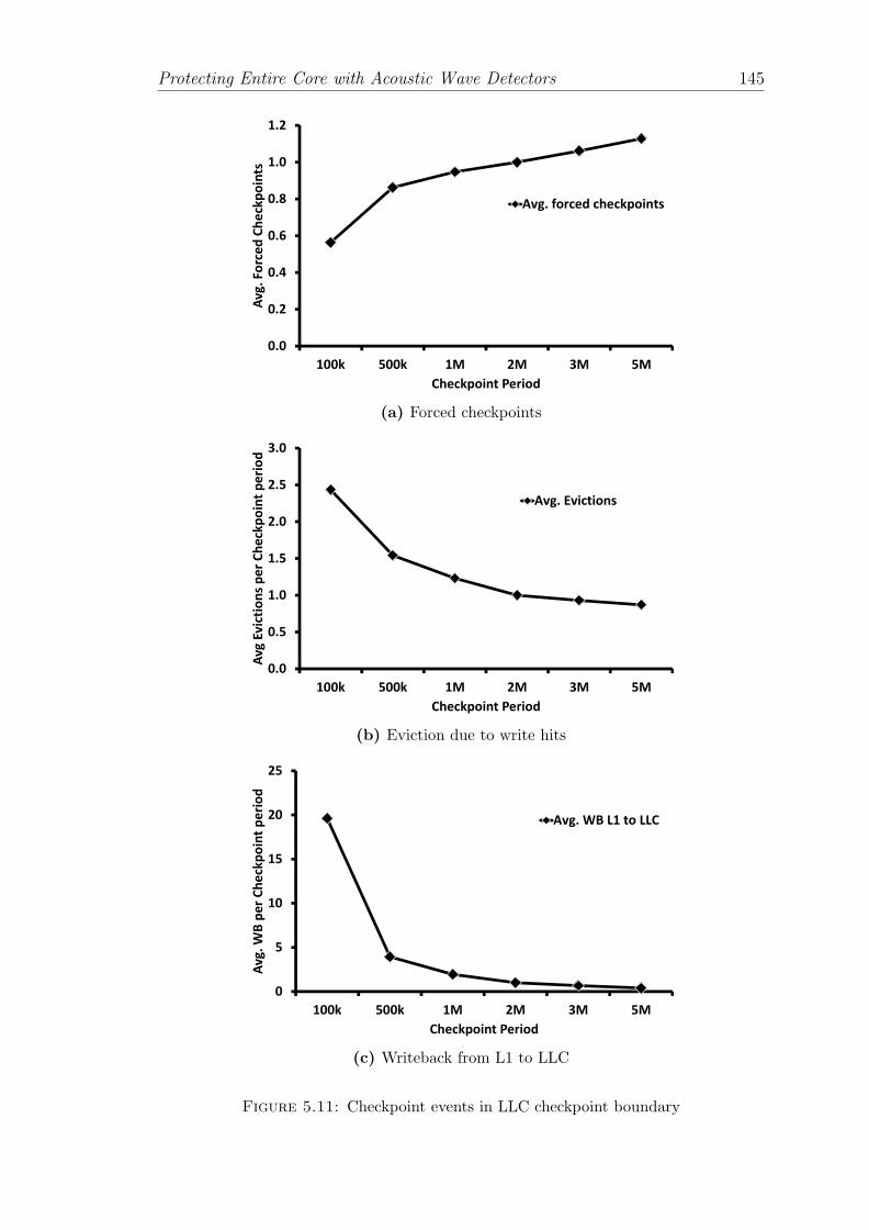
Protecting Entire Core with Acoustic Wave Detectors 145
0.0
0.2
0.4
0.6
0.8
1.0
1.2
100k 500k 1M 2M 3M 5M
Av
g.
Fo
rce
d C
he
ckp
oin
ts
Checkpoint Period
Avg. forced checkpoints
(a) Forced checkpoints
0.0
0.5
1.0
1.5
2.0
2.5
3.0
100k 500k 1M 2M 3M 5M
Av
g E
vic
tio
ns
pe
r C
he
ckp
oin
t p
eri
od
Checkpoint Period
Avg. Evictions
(b) Eviction due to write hits
0
5
10
15
20
25
100k 500k 1M 2M 3M 5M
Av
g.
WB
pe
r C
he
ckp
oin
t p
eri
od
Checkpoint Period
Avg. WB L1 to LLC
(c) Writeback from L1 to LLC
Figure 5.11: Checkpoint events in LLC checkpoint boundary

Protecting Entire Core with Acoustic Wave Detectors 146
Parameter Value
Number of Processors 1-16Instr Window / ROB 16/48 entriesFrequency 2GHz
L1 I/D Cache per Core 16 KB, 4-way, 64BLLC Cache per bank 256 KB, 4-way, 64B (distributed 1-16 banks)L1 access Latency 2 cyclesLLC access Latency 6 cycles
Table 5.3: Configuration Parameters
5.5.1.2 Multicore system.
Multi-core system consists of 16 cores. We present analysis of multicore systems
with following categories of applications, where each trace runs for 20 million
cycles.
• Data non-sharing applications: To obtain various trade-off details for
data non-sharing applications we replicate the same application for all 16
cores (i.e., all 16 cores running the same application independently). We
evaluate performance of this configuration using SPEC CPU2006 benchmark
set with reference input set.
• Shared Memory Applications: For this 16 core system we use SPEC
OMP2001 benchmark set with appropriate input set to observe various trade-
offs.
5.5.2 Error Detection Latency vs Containment Area
We first analyze the trade-off between the error detection latency and the size of
the error containment area. As we mentioned in Section 5.2.1, non-verified data
is not allowed to leave the error containment and we need to stall until data is
guaranteed to be correct, which degrades performance. We evaluate the range of
detection latency 30 to 100 cycles as proposed in Section 5.1.5.
Table 5.4 shows result for having one counter for entire L1 cache. It shows total
number of evictions that create stalls when L1 is not verified. With detection
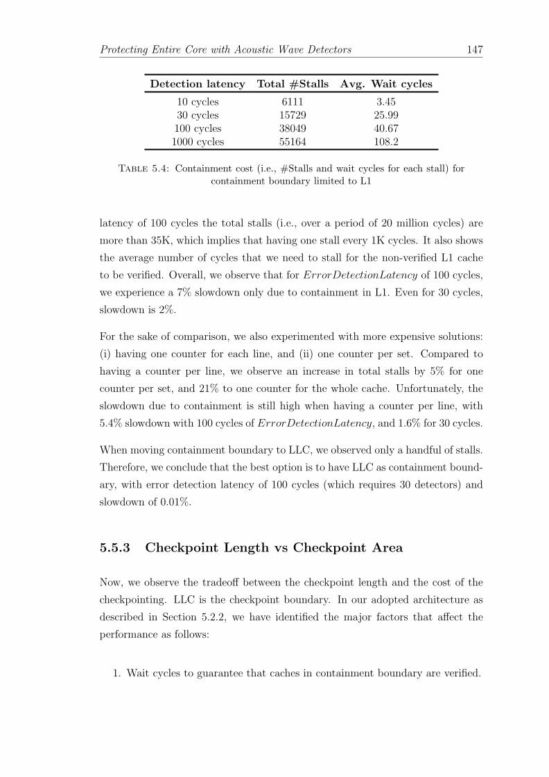
Protecting Entire Core with Acoustic Wave Detectors 147
Detection latency Total #Stalls Avg. Wait cycles
10 cycles 6111 3.4530 cycles 15729 25.99100 cycles 38049 40.671000 cycles 55164 108.2
Table 5.4: Containment cost (i.e., #Stalls and wait cycles for each stall) forcontainment boundary limited to L1
latency of 100 cycles the total stalls (i.e., over a period of 20 million cycles) are
more than 35K, which implies that having one stall every 1K cycles. It also shows
the average number of cycles that we need to stall for the non-verified L1 cache
to be verified. Overall, we observe that for ErrorDetectionLatency of 100 cycles,
we experience a 7% slowdown only due to containment in L1. Even for 30 cycles,
slowdown is 2%.
For the sake of comparison, we also experimented with more expensive solutions:
(i) having one counter for each line, and (ii) one counter per set. Compared to
having a counter per line, we observe an increase in total stalls by 5% for one
counter per set, and 21% to one counter for the whole cache. Unfortunately, the
slowdown due to containment is still high when having a counter per line, with
5.4% slowdown with 100 cycles of ErrorDetectionLatency, and 1.6% for 30 cycles.
When moving containment boundary to LLC, we observed only a handful of stalls.
Therefore, we conclude that the best option is to have LLC as containment bound-
ary, with error detection latency of 100 cycles (which requires 30 detectors) and
slowdown of 0.01%.
5.5.3 Checkpoint Length vs Checkpoint Area
Now, we observe the tradeoff between the checkpoint length and the cost of the
checkpointing. LLC is the checkpoint boundary. In our adopted architecture as
described in Section 5.2.2, we have identified the major factors that affect the
performance as follows:
1. Wait cycles to guarantee that caches in containment boundary are verified.

Protecting Entire Core with Acoustic Wave Detectors 148
2. The write-back of dirty cache lines to the checkpoint boundary upon check-
point creation.
3. Forced checkpoint events due to evictions of dirty lines that are not part of
checkpoint.
4. Evictions to memory due to write hits on dirty and checkpointed lines.
Notice that factors 3-4 are runtime factors, and will largely depend on the footprint
of the application (and therefore, the size of the selected checkpoint boundary and
the checkpoint period). On the other hand, factors 1-2 are the overhead that is
paid at checkpoint creation.
Figure 5.11(a) shows the number of forced checkpoints, per checkpoint length, for
different checkpoint periods. As one can see, the number of extra checkpoints is
negligible, and therefore we can opt for long checkpoints in the order of millions
of cycles. Figure 5.11(b) shows the number of extra evictions to main memory
caused by write hits on checkpointed lines. Numbers are relative to the length of
the checkpoint period. Regarding the cost of creating a checkpoint, we show in
Figure 5.11(c) the extra write-backs we have to perform when taking a checkpoint.
As shown in the figure, increasing the checkpoint period from 100K cycles to 2
million cycles brings down the write-back traffic by more than 10×, and after that
benefits flatten. Therefore, we opt for 2 million cycles checkpoint length.
We detail the results for a checkpoint period of 2 million cycles for our workloads
in Figure 5.12. The results indicate that, for every 2 million cycles we will have
to write-back 97 dirty cache lines from verified L1 cache to LLC.
Finally, we assess how much time we need to wait until we can create the check-
point. Figure 5.13 shows the average wait cycles for the LLC to be verified before
taking a checkpoint for a checkpoint period of 2 million cycles. For detection la-
tency of 100 cycles, every 2 million cycles we will have to wait 50 cycles to take a
checkpoint in LLC.
Next, we will see how the performance is impacted in the proposed architecture.
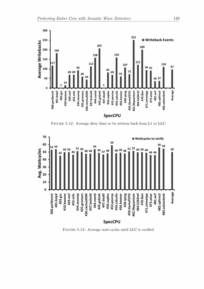
Protecting Entire Core with Acoustic Wave Detectors 149
117
182
114
69 69
92
6044
112
158
207
1
8169
159
61
107
72
251
121
200
94 91
36 37
11097
0
50
100
150
200
250
300
40
0.p
erl
be
nch
40
1.b
zip
2
40
3.g
cc
41
0.b
wa
ve
s
42
9.m
cf
43
3.m
ilc
43
4.z
eu
smp
43
5.g
rom
acs
43
6.c
act
usA
DM
43
7.l
esl
ie3
d
44
4.n
am
d
44
5.g
ob
mk
44
7.d
ea
lII
45
0.s
op
lex
45
3.p
ov
ray
45
4.c
alc
uli
x
45
6.h
mm
er
45
8.s
jen
g
45
9.G
em
sFD
TD
46
2.l
ibq
ua
ntu
m
46
4.h
26
4re
f
47
0.l
bm
47
1.o
mn
etp
p
47
3.a
sta
r
48
1.w
rf
48
2.s
ph
inx
3
48
3.x
ala
ncb
mk
Av
era
ge
Av
era
ge
Wri
teb
ack
s
SpecCPU
Writeback Events
Figure 5.12: Average dirty lines to be written back from L1 to LLC
53 54
45
50 5046
51 5048 48
54
4947 48
59
48 49 4851 52
50 50 4946 46
56 54
50
0
10
20
30
40
50
60
70
4
00
.pe
rlb
en
ch
4
01
.bzi
p2
4
03
.gcc
4
10
.bw
av
es
4
29
.mcf
4
33
.mil
c
4
34
.ze
usm
p
4
35
.gro
ma
cs
4
36
.ca
ctu
sAD
M
4
37
.le
slie
3d
4
44
.na
md
4
45
.go
bm
k
4
47
.de
alI
I
4
50
.so
ple
x
4
53
.po
vra
y
4
54
.ca
lcu
lix
4
56
.hm
me
r
4
58
.sje
ng
4
59
.Ge
msF
DT
D
4
62
.lib
qu
an
tum
4
64
.h2
64
ref
4
70
.lb
m
4
71
.om
ne
tpp
4
73
.ast
ar
4
81
.wrf
4
82
.sp
hin
x3
4
83
.xa
lan
cbm
k
Av
era
ge
Av
g.
Wa
itcy
cle
s
SpecCPU
Waitcycles to verify
Figure 5.13: Average wait-cycles until LLC is verified

Protecting Entire Core with Acoustic Wave Detectors 150
5.5.4 Uniprocessor Performance
Figure 5.14 evaluates the proposed single core architecture in terms of performance
vs. cost of containment and recovery. The experimentation shows that the average
performance slowdown is 0.1% and the worst case performance degradation is
0.42%. We notice that the average performance degradation due to containment
is almost 0, since there are no eviction of dirty lines from non-verified LLC. The
performance degradation comes from writing back dirty data from L1 to LLC
during periodic and forced checkpoints.
0.00%
0.05%
0.10%
0.15%
0.20%
0.25%
0.30%
0.35%
0.40%
0.45%
0.50%
40
0.p
erl
be
nch
40
1.b
zip
2
40
3.g
cc
41
0.b
wa
ve
s
42
9.m
cf
43
3.m
ilc
43
4.z
eu
smp
43
5.g
rom
acs
43
6.c
act
usA
DM
43
7.l
esl
ie3
d
44
4.n
am
d
44
7.d
ea
lII
45
0.s
op
lex
45
3.p
ov
ray
45
4.c
alc
uli
x
45
6.h
mm
er
45
8.s
jen
g
45
9.G
em
sFD
TD
46
2.l
ibq
ua
ntu
m
46
4.h
26
4re
f
47
0.l
bm
47
3.a
sta
r
48
1.w
rf
48
2.s
ph
inx
3
48
3.x
ala
ncb
mk
Av
era
ge
Slo
wd
ow
n
SpecCPU
WB Cycles: Periodic Checkpoints
WB Cycles: Force Checkpoints
Containment Cycles
Figure 5.14: Performance impact of containment and checkpointing LLCcache in single core architecture
5.5.5 Performance of Multicore for Data Non-Sharing Ap-
plications
We observe similar results for 16 core system for data non-sharing workloads in
Figure 5.15. Notice, that we depict the results for the slowest core of the 16 running
cores. The average total degradation in performance is 0.1% and the worst case
degradation is 0.45%.

Protecting Entire Core with Acoustic Wave Detectors 151
0.00%
0.05%
0.10%
0.15%
0.20%
0.25%
0.30%
0.35%
0.40%
0.45%
0.50%
40
0.p
erl
be
nch
40
1.b
zip
2
40
3.g
cc
41
0.b
wa
ve
s
42
9.m
cf
43
3.m
ilc
43
4.z
eu
smp
43
5.g
rom
acs
43
6.c
act
usA
DM
43
7.l
esl
ie3
d
44
4.n
am
d
44
7.d
ea
lII
45
0.s
op
lex
45
3.p
ov
ray
45
4.c
alc
uli
x
45
6.h
mm
er
45
8.s
jen
g
45
9.G
em
sFD
TD
46
2.l
ibq
ua
ntu
m
46
4.h
26
4re
f
47
0.l
bm
47
3.a
sta
r
48
1.w
rf
48
2.s
ph
inx
3
48
3.x
ala
ncb
mk
Av
era
ge
Slo
wd
ow
n
SpecCPU
WB Cycles: Periodic Checkpoints
WB Cycles: Force Checkpoints
Containment Cycles
Figure 5.15: Slowdown due to containment and checkpointing LLC cache inthe 16-core system for private memory applications
0.00%
0.10%
0.20%
0.30%
0.40%
0.50%
0.60%
0.70%
0.80%
0.90%
Slo
wd
ow
n
SpecOMP
WB Cycles: Periodic Checkpoints
WB Cycles: Force Checkpoints
Containment Cycles
Figure 5.16: Slowdown due to containment and checkpointing LLC cache inthe 16-core system for shared memory applications

Protecting Entire Core with Acoustic Wave Detectors 152
5.5.6 Multicore Shared Memory Performance
Figure 5.16 shows the impact on performance for 16 cores shared memory ar-
chitecture. Again, we collect data for the slowest core to reach the 20 million
executed cycles. As one can see, the average slowdown is 0.4%. Again even in the
case of shared memory we do not have any dirty evictions from LLC before LLC
is verified. Hence, the slowdown due to containment is zero. In shared memory
architecture we have more cache lines evicting after the LLC is verified. This
results into increased forced checkpoints. Forced checkpoints attribute to about
0.3% average slowdown.
5.6 Related Work
In this section, we will describe some techniques used for protecting the entire core.
We will discuss techniques for detecting and recovering from errors. Usually, an
error detection scheme (i.e., DMR) is combined with error recovery scheme (i.e.,
Checkpointing) for providing recovery. Several popular error detection mechanisms
have been compared and summarized in Table 5.1.
5.6.1 Error Detection and Recovery in Core
Unlike error codes, the execution redundancy techniques resort to fault detection
via comparing outputs from redundant stream of instructions. Execution redun-
dancy is a widely used technique to detect errors in entire core, either using the
multithreading capabilities [57, 68] or hardware redundancy [58, 115]. Execution
redundancy techniques can provide higher error coverage across the processor chip
compared to other error detection techniques (i.e., error codes). However, execu-
tion redundancy can cost a lot in terms of area, power and performance overheads
compared to error codes as detailed in Table 5.1.
5.6.1.1 Dual Modular Redundancy with Recovery
Modular redundancy can be applied to provide error detection for entire modules
of both data storage and combinational logic. DMR is the simplest form of mod-
ular redundancy with a comparator as shown in Figure 5.17(a). DMR provides
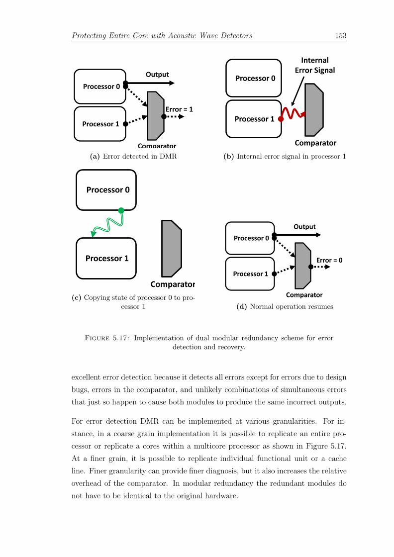
Protecting Entire Core with Acoustic Wave Detectors 153
Processor 0
Processor 1
Comparator
Error = 1
Output
(a) Error detected in DMR
Processor 0
Processor 1
Comparator
Internal
Error Signal
(b) Internal error signal in processor 1
Processor 0
Processor 1
Comparator
(c) Copying state of processor 0 to pro-cessor 1
Processor 0
Processor 1
Comparator
Error = 0
Output
(d) Normal operation resumes
Figure 5.17: Implementation of dual modular redundancy scheme for errordetection and recovery.
excellent error detection because it detects all errors except for errors due to design
bugs, errors in the comparator, and unlikely combinations of simultaneous errors
that just so happen to cause both modules to produce the same incorrect outputs.
For error detection DMR can be implemented at various granularities. For in-
stance, in a coarse grain implementation it is possible to replicate an entire pro-
cessor or replicate a cores within a multicore processor as shown in Figure 5.17.
At a finer grain, it is possible to replicate individual functional unit or a cache
line. Finer granularity can provide finer diagnosis, but it also increases the relative
overhead of the comparator. In modular redundancy the redundant modules do
not have to be identical to the original hardware.

Protecting Entire Core with Acoustic Wave Detectors 154
Once the output mismatch is detected as shown in Figure 5.17(a). The system
triggers an error and stalls until the error is located and an internal error signal is
generated which is shown in Figure 5.17(b). For instance, in processor 0 and pro-
cessor 1 the caches are parity protected and any bit flip will be detected via parity
which is responsible to generate the internal error signal. Without this information
it is not possible to identify location of the error. Once the erroneous processor
is identified the clean processor state from processor 0 is copied to processor 1
(Figure 5.17(c)). Once both the processor states are identical normal operation
can resume. Such a system’s recovery depends on its ability to generate the in-
ternal error signal and the internal error detection mechanisms. Alternatively, a
DMR system can also recover using checkpoints. Checkpointing mechanisms will
be discussed in Chapter 7.
A system with DMR uses more than two times as much hardware (one redun-
dant module and a voter) compared to an unprotected system. Adding redundant
hardware also increases corresponding energy consumption. These overheads are
unavoidable while designing systems in which the reliability requirements are ex-
tremely high. However, these overheads are not acceptable for commodity pro-
cessors where extracting maximum performance in a given power envelope is a
primary concern.
5.6.1.2 Lockstepping with Recovery
Lockstepping detects the error by executing the same instructions in redundant
threads and comparing them. Figure 5.18 shows one such implementation of lock-
stepped architecture where thread–0 and thread–1 both execute same instructions.
In lockstepping, both the redundant copies are cycle synchronized. A hardware
comparator compares the state of redundant computations every cycle as shown
in Figure 5.18. As a result, any error in one of the copies will produce different
output and will be detected in the same cycle. Lockstepped architectures are very
popular and provide great degree of coverage because of which they are part of
several commercial architectures [54, 113, 299, 300]. A lockstepped architecture
can reduce the SDC of system. However, for reducing the DUE it still requires a
separate error recovery mechanism. As the lockstepped architectures have detec-
tion latency of 1 cycle, usually the recovery can be done via maintaining copies of

Protecting Entire Core with Acoustic Wave Detectors 155
Thread 0
Thread 1
Copying clean state
State mismatch
Error = 1
Figure 5.18: Lockstep error detection and recovery via retry
architecture states (i.e., shadow copies of register file etc. per thread). As the in-
structions commit the speculative state is written to a temporary state from where
subsequent instructions can read and execute. Once the threads are checked for
errors (after one cycle) the temporary state can be copied to architecture state.
Upon an error the architecture state is loaded back to both the redundant threads
and execution can restart from the instruction after the last correctly retired in-
struction.
Lockstepping can be implemented purely in hardware which makes it easy to
implement. It can detect almost all soft errors and permanent errors as long as
the two redundant copies are fed the exact same inputs. The errors it cannot
detect are the ones which affect both the redundant threads in exactly the same
way.
Lockstepping has significant disadvantages. Due to redundantly executing threads
it incurs huge area and power overheads. Moreover because of redundantly execut-
ing threads the performance impact is more than 1.5–2×. Cycle synchronization
in shared memory architectures can pose additional challenges. Validating lock-
stepped architectures are also considerably challenging. Lockstepping requires
both the redundant copies to execute deterministically to produce the same out-
put. This can be a problem in the floating point computations where modern
processors assume random values due to the circuit properties. This will not
cause incorrect execution, however, it can cause a lockstep failure. Lockstepping
on its own can only provide error detection and hence additional mechanisms are
essential for providing error recovery.

Protecting Entire Core with Acoustic Wave Detectors 156
5.6.1.3 Redundant Multithreading (RMT) with Recovery
Redundant Multithreading (RMT) is an error detection mechanism, that like lock-
stepping, runs redundant copies of the same instruction set and compares the
output to detect the error [113, 301, 302]. Unlike lock-stepping in RMT solu-
tion compares the outputs of only committed instructions. Because of this the
internal states of redundant threads can be significantly different in RMT. By re-
laxing the constraint of cycle by cycle comparison RMT is more flexible compared
to lockstepping. For the same reason RMT is also known as loose lockstepping.
RMT can be implemented on any mutlithreaded architecture (i.e., Simultaneous
Multithreading (SMT) [68]) or a multicore architecture [281].
An SMT core with N thread contexts can simultaneously execute N threads of the
given application [303, 304]. The fundamental idea is to use the unutilized threads
for error detection by executing redundant threads, whenever an SMT core has
fewer than N useful threads to run. RMT, depending on its implementation, may
require little additional hardware beyond a comparator to determine whether the
redundant threads are behaving identically. Implementing RMT on an SMT core
impacts on performance mainly because of the extra contention for core resources
due to the redundant threads [69]. The reason for using multiple cores, rather
than a single SMT core, is to avoid having the threads compete for resources on
the SMT core.
A large amount of work has been done in implementing redundant multithreading
for both SMT cores and multicore processors. Usually, RMT is also accompanied
by a recovery mechanism for providing error recovery. Most of the research is in
the direction of enhancing the RMT to provide recovery and reduce the associated
power and performance overheads [56–58, 65, 68–72, 75, 111, 115, 280, 281, 305,
305–307].
Now, we will discuss one such RMT implementation simultaneous and redundant
threaded processor (SRT) that protects the core in which the error is detected be-
fore the instruction commits as proposed in [65]. The SRT architecture utilizes an
underlying SMT core [6]. In the SRT implementation one of the two redundant
threads is designed to run ahead of the other thread. The outputs of the leading
and trailing threads are compared to detect the error. Here, we will discuss the
SRT implementation that compares the outputs before the register value is com-
mitted to the architecture state. The register value comparison from the leading
Protecting Entire Core with Acoustic Wave Detectors 157
and the trailing threads can be done in the register update unit (RUU) as the in-
struction retires. However, this implementation will have significant performance
overhead due to limited RUU entries. Alternatively a buffer can be employed to
hold the values of retiring instruction of the leading thread. Once the same in-
struction of the trailing thread retires the values can be compared with the values
stored in the buffer and if there is a match then only the architecture state is
updated. To avoid complex issues such as forwarding values to the subsequent
instructions in the same thread it is possible to employ separate register file per
thread [308]. These separate register files will hold the unverified register values.
Once the register values are compared and are verified to be error free they can
be written back to another register file that is protected (i.e., via ECC) and holds
the architectural state. Having separate register file to hold verified and protected
copy of architecture state also facilitates simpler recovery as upon a mismatch in
the outputs of leading and trailing thread the processor can revert back to the
clean architecture state.
The replication of the register values for leading and trailing thread is trivial in
SRT implementation. However, replicating the cached data is more involved and
require special hardware modifications [65].
In the proposed SRT technique, the trailing thread can benefit from the a-priori
information of the leading thread’s cache and branch prediction behavior to reduce
the performance impact. However, due to the comparisons of outputs the average
performance degradation is 32% compared to the SMT processor running a single
thread. The leading cause of this performance overhead is the comparison of store
instructions. Increasing the size of store queue can improve the performance by 5%.
Another disadvantage of the proposed SRT technique is in a multicore processor
with SMT cores, enabling the SRT mechanism will reduce the throughput by 100%
since half of the threads are occupied with redundant threads.
Several implementations of Core and Chip level RMT have been proposed. These
techniques try to achieve locakstepping architecture’s error coverage and reduce
the power, performance and area overheads of SRT technique. Notice that RMT
techniques have unbounded and large detection latencies (refer to Table 5.1). To
handle large detection latency some RMT proposals include checkpointing the
caches and main memory for successful error recovery. The cost of taking system
wide checkpoint is very high and we will discuss in detail various implementation
in along with other RMT enhancements in Chapter 7.

Protecting Entire Core with Acoustic Wave Detectors 158
5.6.1.4 Error Detection and Recovery using Checker Core
Main Core
Co
mm
it
Co
mp
are
Exe
cute
Ch
eck
Op
era
nd
Re
ad
Bypass
Checker Core
Match?
[Inst, Result]
Figure 5.19: Implementation of dynamic implementation verification archi-tecture (DIVA) and the functioning of the checker core
Similar to RMT where the outputs of leading and trailing threads are compared
to detect errors. Dynamic implementation verification architecture (DIVA) [67]
uses a simple in-order core that is paired with an out-of-order core as a checker
as shown in Figure 5.19. As processor designs grow in complexity, they become
increasingly difficult to fully verify and debug. DIVA proposes to implement a
relatively simple and fully verified backend processor to perform dynamic (while
the processor is in use) verification of a processor. While the main purpose of
DIVA is to ease the challenge of verification and debugging complex processor
cores, DIVA also serves to detect soft error events. Assuming that a fault affects
only the complex processor core or the backend checker, DIVA will detect the fault
and can be configured to attempt recovery.
As can be seen in Figure 5.19, DIVA ensures the error free state by making sure
that for each instruction the operation has executed correctly and also the operand
values of the given instruction flows correctly through register, memory or bypass
logic. DIVA implements simpler checker core to perform the verification. The
checker core recomputes all the operations based on the source operands and
compares it with the value that the main processor has generated. If the values
match it verifies the error free operation. However, in the event of an error it
triggers an error flag. To verify that the instructions executed in the main processor

Protecting Entire Core with Acoustic Wave Detectors 159
received the correct operands the checker core also reads the operands from its own
register file (or bypass network) and it verifies the correctness of the operands.
DIVA can detect permanent, transient as well as design errors in the main core.
The main disadvantage of DIVA is that it assumes the checker is always correct
and upon a mismatch in the result it commits the output of the checker core.
This can lead to reliability issues in the cases of executing uncached load/store
operations which cannot be executed twice. Due to added hardware DIVA causes
an average slowdown by 3–15%.
5.7 Chapter Summary
This proposed architecture potentially eliminates particle strike induced SDC &
DUE-FIT in a processor core. The architecture uses acoustic wave detectors to
detect errors. It is extremely light-weight and uses 30 detectors (i.e., area is
30 SRAM memory cells) for error detection, and provides a worst-case detection
latency of 100 cycles. The area overhead of 30 interconnects is also minimum.
Controller circuit to signal error detection is extremely simple and requires 6 3-
input and 2 2-input logic-OR gates.
Next, we proposed an error containment mechanism within the cache hierarchy to
manage the detection latency. We implement the containment boundary at the
LLC. By containing all the errors we eliminate SDC. The containment architecture
consists of L1 and LLC with one counter each, to count 100 cycles. Additionally,
we will need one counter for LLC to check the checkpoint validity. All 3 counters
are 7-bit, non-repeating word counters.
Finally, we eliminate DUE-FIT by enabling a low cost checkpointing mechanism.
Checkpointing requires a physical Checkpoint bit for every cache line in LLC. We
propose to use 2 million cycles as checkpoint length, which guarantees a good trade-
off between checkpoint overhead and recovery time. For recovery of architecture
state it requires 2 shadow copies of the architectural state (register files, RAT and
PC). We also make use of a trivial control circuit for clearing Checkpoint bit and
counters in one cycle.

Protecting Entire Core with Acoustic Wave Detectors 160
Proposed architecture eliminates particle strike induced SDC & DUE-FIT, for
systems ranging from one core to 16-core with shared memory with the worst-case
performance overhead is 0.8% for shared memory systems.
Chapter 6
Protecting Embedded Core with
Acoustic Wave Detectors
In the previous chapter, we understood how we can protect an entire processor
core against soft errors using acoustic wave detectors in a unicore and multicore
processor chip. Now we in this chapter we will take advantage of error detection
architecture based on acoustic wave detectors in providing efficient error contain-
ment and recovery in the core of an embedded processor. We target embedded
processors which are used to provide moderate performance. The architecture pro-
posed in Chapter 3 can detect and locate the errors. The architecture uses acoustic
wave detectors for dynamic particle strike detection. To provide error containment
and recovery in the embedded core first we will utilize the architecture proposed
in Chapter 5. However, our experiments conclude that in an embedded core ar-
chitecture proposed in Chapter 5 is not economical. Therefore in this chapter
we will show the modification required in the architecture to provide economical
error containment and recover in embedded domain. Finally, we will evaluate the
performance impact of the proposed architecture using embedded applications.
6.1 Experimental Setup
First, we describe the evaluation method and experimental set-up of the proposed
architecture. We evaluate the performance impact of the selected configuration
for single core embedded system.
161

Protecting Embedded Core with Acoustic Wave Detectors 162
Parameter Value
Number of Cores 1Issue Queue (Int/FP) 15 entriesROB 8 entriesFrequency 333 MHzIssue Width 2Commit Width 2Load Queue 8 entriesStore Queue 8 entries
L1 Inst./Data Cache 16 KB, 2-way, 32B
Memory Bus Latency 100 cycles
Table 6.1: Configuration Parameters
Table 6.1 enlists the important configuration parameters and their respective
values. Notice that the embedded core is extremely simple and has just L1
cache. Such architectures have been used in many applications including smart-
phones [309]. To evaluate the proposed architecture for embedded core we use
SimpleScalar [310]. A new version of SimpleScalar has been adapted to the ARM
instruction set and is used to evaluate the performance of architectures of current
and next generation of embedded processor. It is a cycle accurate microarchi-
tecture simulator that is modified to necessitate the changes required to simulate
a state of the art embedded processor [309]. Using this experimental set up we
evaluate the error containment architecture presented in this chapter.
In this work we evaluate the performance of proposed architecture on real-life
workload for embedded systems using the Mibench benchmark set [311]. It consists
of six categories including: Automotive and Industrial Control, Network, Security,
Consumer Devices, Office Automation, and Telecommunications. These categories
offer different program characteristics that enable us to examine the architecture
more effectively.
The small data set represents a light-weight, useful embedded application of the
benchmark, while the large data set provides a more stressful, real-world appli-
cation. We run each trace for complete execution with the reference large input
set.

Protecting Embedded Core with Acoustic Wave Detectors 163
6.2 Handling SDC & DUE in Embedded Core
As we have seen in Section 1.2.5 of Chapter 1, unlike high performance servers,
embedded processors typically have smaller components, longer clock cycle times
and larger logic depths between latches. Since the design constraints for the em-
bedded systems differ from those in the high-performance domain, it implies that
the robustness techniques also differ dramatically.
Now we will explain how we can contain the soft-errors in embedded cores us-
ing acoustic wave detectors. First, we briefly discuss the placement of acoustic
wave detectors and corresponding detection latency for the studied embedded
core. Later, we detail various error containment granularities and tradeoffs involv-
ing error containment boundary and its impact on cost of recovery for embedded
core.
6.2.1 Acoustic Wave Detectors and Error Detection La-
tency
As proposed in Chapter 3 we use acoustic wave detectors to detect errors on the
core of an embedded processor. Recall from Chapter 2, the speed of acoustic waves
on silicon surface is 10 km/s and the detection range of acoustic wave detectors is
5 mm. Given the dimensions of current embedded core designs, the surface area
of an embedded core is about 4− 6mm2 including caches [309]. A single detector
would be sufficient to detect all errors occurring anywhere on the entire core area.
However, with just 1 detector the worst-case detection latency (i.e., latency to
detect a strike that is 3.5 mm away from the detector) is 350 ns (117 cycles at
333 MHz). By deploying more detectors we can reduce the detection latency.
We propose to deploy detectors in a mesh formation as discussed previously in
Chapter 3, Chapter 4 and Chapter 5.
Figure 6.1 shows the error detection latency for various mesh configurations cov-
ering an entire core area. It shows that with 18 detectors we can detect an error
on the entire core (including cache, register files etc.) within 10 cycles. To de-
crease the detection latency by 10×, the required number of detectors in the mesh
formation increases by 140×. As we can see in from the figure, 2.5K detectors are
required to obtain single cycle detection latency.

Protecting Embedded Core with Acoustic Wave Detectors 164
10
9
8
7
6
5
4
3
2
1
0
2
4
6
8
10
12
18
[6
x3
]
24
[8
x3
]
32
[8
x 4
]
44
[1
1 x
4]
55
[1
1 x
5]
84
[1
4 x
6]
12
6 [
18
x 7
]
22
0 [
22
x 1
0]
49
5 [
33
x 1
5]
25
00
[5
0x
50
]
De
tect
ion
La
ten
cy (
#C
ycl
es)
#Detectors [Mesh]
Detection latency (#Cycles)
Detection latency(#Cycles) @ 333 MHz
Figure 6.1: Error detection latency for acoustic wave detectors on embeddedcore for different mesh configurations
Since, we want to eliminate SDC and DUE of the embedded core we must pro-
vide error containment and recovery. As discussed in detail in the Chapter 5, the
detection latency of acoustic wave detectors is important in deciding error contain-
ment boundary. Smaller detection latencies are desirable. Next, we will analyze
different error detection latency for different error containment granularities and
its impact on cost of containment.
6.2.2 Error Containment Granularity
The main objective of the proposed architecture is to provide error containment
for economical recovery in an embedded core. This means that we need to detect
all errors, and once an error is detected, we must contain it in order to avoid the
penetration of error into a state that is free from errors. Choosing the correct error
containment boundary is very important. It impacts the complexity and cost of
containment and recovery.
Different granularities of error containment in an embedded processor is shown
in Figure 6.2. If error is contained within the core, it implies that we guarantee

Protecting Embedded Core with Acoustic Wave Detectors 165
Figure 6.2: Error containment granularities in embedded processor
that every instruction that is being committed is error free. At this granularity, a
simple nuke & restart mechanism [312] can act as checkpointing and recovery.
Another option, similar to the proposal of previous chapter, is to contain the error
in cache hierarchy (i.e., the L1 cache). Containing errors in L1 cache implies that
we allow the erroneous data from core to go to the L1 cache but not beyond that.
In other words, the dirty data in the L1 cache can be erroneous. Containing errors
in L1 cache means that nuke & restart will not be enough to recover from errors,
and a more expensive checkpoint that includes the modified data in L1 cache will
be necessary.
The selection of the error containment boundary is deciding factor to determine
size and frequency of costly checkpointing for recovery. The closer we are to the
core, the fewer components are required to be included in checkpoint.
6.2.2.1 Error Containment Granularity: Core
The first option that we have is to contain the error within the core. The core holds
the speculative architectural state until the instruction is committed. The error
containment in core requires that every instruction is checked for error at every
cycle before it commits to the architectural state. Summarizing from Chapter 5,
the advantages of containing error in core are: (i) Error is confined to such a small

Protecting Embedded Core with Acoustic Wave Detectors 166
boundary that avoids system-wide recovery, (ii) A simple nuke & restart can be
used for recovery that will have little or no performance impact.
Error containment within core is lucrative especially for embedded cores due to
above mentioned advantages. The only caveat is it demands an error detection
latency of <1 cycle. Latency of 1 cycle will not be enough since in 1 cycle instruc-
tion is committed and if the error is in the commit stage it will end up outside
the containment boundary. So to contain the error in the commit itself we have
to have detection latency of <1 cycle. To eliminate SDC one option is to stall the
instructions by 1 cycle but that will have huge performance penalty. Alternatively,
hardened latches can be used to protect the ”commit” stage (i.e., ROB, RF etc.).
According to Figure 6.1, it will need more than 2.5K detectors to achieve er-
ror detection latency of <1 cycle for entire embedded core. This causes an area
overhead equivalent to a 2.5Kbit cache without counting for the overhead of in-
terconnects and controller circuit. This area overhead is unreasonable especially
for an embedded core where silicon estate is scarce.
6.2.2.2 Error Containment Granularity: Cache
Having minimum error detection latency is best-case scenario for having cost ef-
fective and trivial error containment. Figure 6.1 shows that for error detection
latency of 1 cycle for the entire embedded processor we will need 2.5K detectors.
This area overhead is unacceptable. However, for detection latency of 10 cycles we
will need just 18 detectors in the mesh covering embedded processor. This reduces
the area overhead by a huge margin. But now we have to contain the error for
10 cycles. One option is to stall the commit for 10 cycles until we make sure that
there is no error. But this will have huge performance impact. So we go for the
other option and allow the error to commit and go outside the core into L1 cache.
Now, we include the core and the L1 cache in the error containment boundary
as shown in Figure 6.2. By extending error containment boundary to L1 cache
we can afford to have longer detection latency and minimize number of required
detectors. The advantages are similar to the ones discussed in Chapter 5.
In our implementation we assume that the L1 cache itself has an error detection
and recovery mechanism via ECC or a technique based on acoustic wave detectors
as discussed in Chapter 4 to detect & correct the errors occurring on the L1 cache.

Protecting Embedded Core with Acoustic Wave Detectors 167
The error containment in L1 cache can be implemented in similar manner as
discussed in Chapter 5. To contain the error in L1 cache, we have to include one
counter that counts 10 detection latency cycles. This is to make sure that any data
in the cache is error free before it goes out of the cache. We need one counter for
entire cache. This counter is reset on every write operation to the cache to keep
track of all modified data. With the help of single counter, we can identify error
free cache lines which are modified. We can also know ”dirty and unverified” cache
lines, lines which are modified and in the process of being verified. Evictions of
the dirty unverified cache lines causes a stall impacting performance due to error
containment.
0%
5%
10%
15%
20%
25%
Pe
rce
nta
ge
ov
erh
ea
d
Overheads for Extra Writebacks
Forced Chkpt WB
Normal Chkpt WB
STALLS
Figure 6.3: Performance overhead of error containment in cache for a check-point period of 1 million cycles
Now that we can contain the errors, we want to provide error recovery eliminate
the DUE. To provide error recovery we will need a checkpointing mechanism that
includes L1 cache. We implemented a simple checkpointing mechanism similar to
the one described in previous chapter.
We evaluate the architecture to analyze the cost of recovery for containing errors in
L1 cache. Our analysis shows that a checkpoint period of 1 million cycles is enough
to balance the cost of containment, checkpointing and performance. Figure 6.3
shows the impact on performance due to the write-back of updated cache lines
to memory for both periodic checkpoints and forced checkpoints (eviction of dirty

Protecting Embedded Core with Acoustic Wave Detectors 168
lines that are not part of checkpoint from L1 cache causes a forced checkpoint).
It also shows the cost due to stalls to make sure evicting dirty lines are free from
error. Our results show that stalls have little impact on the average performance.
The worst case slowdown (in the case of patricia) due to stalls is 1.4%. The
average slowdown due to checkpointing is 3.8% and worst case is 22.3% due to
high memory footprint of rijndael. The performance overhead of error containment
in L1 cache is not affordable.
6.2.3 Putting everything together
Overall, we saw that error containment in the core will benefit from cheap recov-
ery (i.e., nuke & restart) but requires detection latency to be less than one cycle
and that is expensive in terms of the number of required detectors. On the other
hand error containment in L1 cache, relaxes the required number of detectors but it
requires little modification in microarchitecture. However, it will require an expen-
sive checkpointing mechanism for recovery and results in an average performance
penalty of 3.8% and for worst case 22.3% which is unaffordable. Extending error
containment boundary to main memory invites non-trivial challenges associated
with checkpointing entire main memory.
This demands the necessity of a more refined error containment in the core that
reduces the overall cost of containment and recovery.
6.3 Selective Error Containment
Now, we will see how acoustic wave detectors can help in providing selective er-
ror containment within core, reducing the overall area, power and performance
overheads.
6.3.1 Protecting Individual Data Paths & Latency Guard
Bands
As we have seen from the Section 6.2.2.2, to reduce the impact of error contain-
ment on performance, we want to contain the error in the core. At the same time,
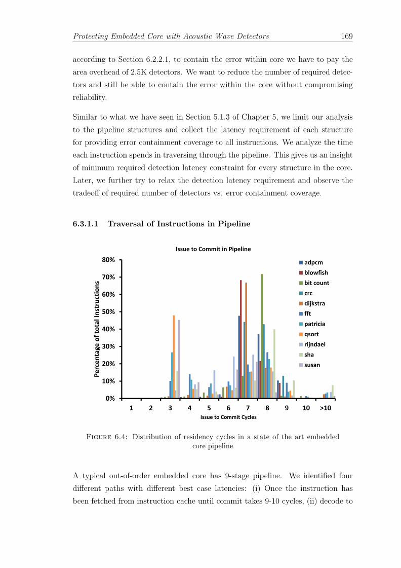
Protecting Embedded Core with Acoustic Wave Detectors 169
according to Section 6.2.2.1, to contain the error within core we have to pay the
area overhead of 2.5K detectors. We want to reduce the number of required detec-
tors and still be able to contain the error within the core without compromising
reliability.
Similar to what we have seen in Section 5.1.3 of Chapter 5, we limit our analysis
to the pipeline structures and collect the latency requirement of each structure
for providing error containment coverage to all instructions. We analyze the time
each instruction spends in traversing through the pipeline. This gives us an insight
of minimum required detection latency constraint for every structure in the core.
Later, we further try to relax the detection latency requirement and observe the
tradeoff of required number of detectors vs. error containment coverage.
6.3.1.1 Traversal of Instructions in Pipeline
0%
10%
20%
30%
40%
50%
60%
70%
80%
1 2 3 4 5 6 7 8 9 10 >10
Pe
rce
nta
ge
of
tota
l In
stru
ctio
ns
Issue to Commit Cycles
Issue to Commit in Pipeline
adpcm
blowfish
bit count
crc
dijkstra
fft
patricia
qsort
rijndael
sha
susan
Figure 6.4: Distribution of residency cycles in a state of the art embeddedcore pipeline
A typical out-of-order embedded core has 9-stage pipeline. We identified four
different paths with different best case latencies: (i) Once the instruction has
been fetched from instruction cache until commit takes 9-10 cycles, (ii) decode to

Protecting Embedded Core with Acoustic Wave Detectors 170
commit 7-8 cycles (ii) rename/issue to commit takes 3-5 cycles, (iii) execute to
commit takes 2-3 cycles, and (iv) writeback to commit is 1-2 cycles [309].
Consider an example of fetch stage: from our observation we noticed that all
instructions that are fetched will take minimum 9 cycles (considering best case) to
reach the commit stage. Providing single cycle detection latency for structures in
fetch stage (i.e., prefetch, branch-predictor etc.) would be unnecessary. The same
holds true for structures in decode stage.
From this initial observation, we identified that paths from issue to commit, exe-
cute to commit and writeback to commit are critical and will need stricter detec-
tion latency requirement for error containment. To have a better understanding
of the error detection latency constraints of issue, execution unit and writeback
we have to know how much time each instruction spends to reach commit from
issue, execution units and writeback.
Figure 6.4 shows the distribution of number of cycles it takes for each instruction
since they are issued until commit (including the wait cycles in ROB). Histogram
of Figure 6.4 shows that 100% of instructions are committed in ≥3 cycles. Similar
experiments indicate that from write-back stage 100% of instructions reach commit
in ≥1 cycle and 100% of instructions reach commit in ≥2 cycle from execution
units. Once in ROB, instructions wait until it is their turn to commit.
6.3.1.2 Cost of Error Containment
Now we know that to provide error containment coverage for 100% instructions
before they commit, the issue queue requires error detection latency of 3 cycles,
for ALUs detection latency should be 2 cycles and structures of writeback stage
(i.e., register file, ROB) must have error detection latency of 1 cycle.
However, error containment in the ROB is little more involved. It is also responsi-
ble for instruction commit. If the detection latency of error in commit (i.e., ROB)
is 1 cycle, implies that an error in the commit itself cannot be contained within
core (i.e., before the commit is over). So to have full error containment coverage
(i.e., including errors in commit), detection latency for ROB must be less than 1
cycle.
Table 6.2 summarizes the required number of detectors to provide selective error
containment before the instruction is committed. It shows the number of detectors

Protecting Embedded Core with Acoustic Wave Detectors 171
Structure Detection Latency #Detectors(#Cycles)
Fetch 9 3Decode 7 4Issue queue 3 4ALU (3 in total) 2 4ROB and Commit 0.15 2Load Queue 1 1Store Queue 1 1
Total 19
Table 6.2: Required acoustic wave detectors for full error containment cov-erage. L1 cache is protected separately using an architecture as presented in
Chapter 4.
required for given detection latency constraints. It shows that to provide selective
error containment we will need 19 detectors for 100% error containment coverage.
It is worth mentioning that with 2 detectors ROB achieves error detection latency
of 0.15 cycle. This implies that a glitch generated by a particle strike in commit
needs to propagate within 0.15 cycles to cause SDC, this increases the possibility
of masking the error before it will be committed. Alternatively, hardened latches
can be used to protect ROB [117].
Figure 6.5 shows the structural map of an embedded core and also the placement
of acoustic wave detectors. Majority of the area is occupied by caches, TLBs and
register files. To contain the error in these structures, we propose to use ECC, or
adapt a low cost acoustic wave detector based solution similar to the one that is
described in Chapter 4.
Overheads. The area overhead for selective error containment for full coverage
is equivalent to 19 6T-SRAM bit cells at 45 nm. The controller circuit is also very
cheap and will require (roughly 10 logic-OR gates). As the number of detectors are
less the intrusiveness of solution on placement and routing is minimum. Acoustic
wave detectors are passive and hence they do not consume power, so the power
overhead comes only from control circuit and interconnects, which is negligible.
Protecting caches alone for 1 cycle detection latency costs 1680 detectors. Using
the architecture for protecting caches as presented in Chapter 4, it is possible to
reduce detection latency to 10 cycles for L1 cache with just 15 detectors.

Protecting Embedded Core with Acoustic Wave Detectors 172
Figure 6.5: Arrangement of FUBs and placement of acoustic wave detectorson embedded core [313]
6.4 Error Containment Coverage vs. Vulnera-
bility
Now, we want to see if we can further relax the detection latency constraint to
reduce the required number of detectors for reducing area overhead even further
compared to what we saw in previous section. Reducing the number of detectors
may result into some instruction escaping the error containment boundary reduc-
ing the error containment coverage. To observe the tradeoff of relaxing detection
latency requirement and its impact on reliability, we perform an estimation of
structure’s AVF. The concept of AVF is discussed in great detail in Section 2.9 of
Chapter 2.

Protecting Embedded Core with Acoustic Wave Detectors 173
6.4.1 ACE Analysis
To estimate a structure’s AVF we track the state bits required for architecturally
correct execution (ACE) for all committed instructions. Let’s understand the
concept of ACE bit via one example in a program that runs for 10 billion cycles
in a processor. Out of these 10 billion cycles a particular bit in the processor core
is required to be correct just for 1 billion of cycles. The state of the bit during the
rest of the 9 billion cycle does not affect the correctness of the program. In this
case, the AVF of the bit is 10%. This concludes that the bit is ACE for 1 billion
cycles and un-ACE for 9 billion cycles.
Similar to the notion of an ACE bit at architecture level instructions can be ACE
or un-ACE. In ACE instructions all the bits are ACE bits. However, in un-ACE
instructions only some of the bits are ACE. It is possible to compute the ACE and
un-ACE bits for an instruction through out its journey in a processor pipeline.
If the error is in one of the ACE bits, it will cause the silent data corruption if
it is not contained. ACE analysis of the entire execution is difficult and hence
conservatively we assume every bit is ACE unless we can prove it to be un-ACE.
Once we classify ACE and un-ACE bits for a structure, AVF of a structure is
simply the fraction of time that it holds ACE bits. AVF analysis gives us better
insight into a structure’s vulnerability because depending upon the application, a
structure holds ACE bits at some times and un-ACE bits at other times.
0
0.1
0.2
0.3
0.4
0.5
0.6
0.7
0.8
0.9
1
Prefetching ACE NOP Unknown Dynamic Dead
Figure 6.6: Error containment granularities in embedded processor

Protecting Embedded Core with Acoustic Wave Detectors 174
Using cycle accurate simulation, we track average ACE bits through structures
holding both microarchitecture and architecture states and we collect the res-
idency cycles of ACE bits and structure usage cycles. We identify sources of
un-ACE instructions (i.e., NOP instructions, Performance enhancing instructions
etc.) similar to [117]. Figure 6.6 shows the distribution of instructions in the
analyzed benchmark suit.
As suggested in [97], we classify the instructions into 5 clusters. The Unknown
category includes the instructions whose destination registers’s lifetimes can not be
determined within the instruction analysis window. Dynamically dead instructions
include instructions whose computation results are simply not utilized by any other
instructions. NOP instructions and perfecting instructions are easily identified.
Once we have obtained the information of ACE and un-ACE bits it is possible to
compute the AVF of a given hardware structure. As discussed in Section 2.9 of
Chapter 2 the AVF of a storage cell is the fraction of time (i.e., ACE cycles) an
upset in that cell can cause a user visible error. AVF of a hardware structure (i.e.,
issue queue) is the average of the AVF of all storage bits in the structure.
AV Fstructure =
N∑i=0
ACE cyclesi
Total cycles× Size of the structure (N bits)(6.1)
The AVF of a hardware structure can be given as shown in Equation 6.1. ACE cyclesi
denotes the ACE state of ith bit and the Total cycles are the cycles over which the
state of the ith bit is observed. N represents the total number of storage cells in
the observed structure.
The equation can be further simplified to,
AV Fstructure =Average number of ACE bits in a structure in a cycle
Size of the structure (i.e., total number of bits)(6.2)
Now, that we are familiar with how to obtain AVF of a structure, next we will
analyze the AVF undertaking an example structure. Moreover, we will also explore
the possibility to reduce the AVF of a structure in an architecture protected via
acoustic wave detectors.

Protecting Embedded Core with Acoustic Wave Detectors 175
6.4.2 Reducing AVF using Acoustic Wave Detectors
Residency cycles Saved cycles
Clk
Without
Detectors
With
Detectors
ErrorDetectionLatency = 3 cycles
Residency cycles = 5
Figure 6.7: Reducing AVF by adapting acoustic wave detectors
Figure 6.7 shows how the vulnerability of a structure protected by acoustic wave
detectors can be reduced. Consider an example as shown in Figure 6.7(a) where
the residency time of ACE bits of an instruction in a structure is 5 cycles. So the
ACE bits are vulnerable for all the 5 cycles they spend in the structure, and all 5
cycles contributes towards AVF.
Now, imagine the structure is protected with acoustic wave detectors as in the case
of Figure 6.7(b). The error detection latency is 3 cycles. Instruction still stays for
5 cycles in the structure but now the ACE bits are vulnerable only for 2 cycles as
we will detect the error within 3 cycles. Only 2 cycles will contribute towards AVF.
This implies that if the detection latency of the acoustic wave detectors protecting
a structure is less than the residency cycles of ACE bits in that structure then the
AVF of given structure can be reduced substantially.
We leverage this observation to evaluate vulnerability factor of issue queue pro-
tected with detectors. We collect the ACE bits and the amount of time they
spend in issue queue for different detection latency cycles. And we show how
the architecture with different detection latency cycles impacts the AVF of issue
queue.
Figure 6.8 shows the AVF of issue queue (relative to the AVF of unprotected IQ
= 100%) for containing errors using acoustic wave detectors for different error
detection latency. Figure 6.8 shows that for error detection latency of 6 cycles,
the average AVF of IQ is 45%. And if provided with enough detectors to achieve
detection latency of 4 cycles the AVF of IQ goes down to 2.2%.

Protecting Embedded Core with Acoustic Wave Detectors 176
0%
10%
20%
30%
40%
50%
60%
70%
80%
90%
100%
IQ AVF for DetectionLatency
6 Cycles 5 Cycles 4 Cycles 3 Cycles
Figure 6.8: AVF of issue queue by protecting them with acoustic wave detec-tors for different detection latency
Summarizing, containing the error with acoustic wave detectors for error detection
latency of 3 cycles will provide 100% error containment coverage and in this case
the AVF of IQ is 0. Now, if we provide error containment for just 4 cycles to IQ, the
AVF is 2.2%. This means that the error detection latency of 4 cycles reduces the
error containment coverage of IQ reducing the reliability of IQ by 2.2.%. Similarly,
providing error containment for 5 cycles reduces the error containment coverage
of IQ to reduce its reliability by 31%. It is worth mentioning that this reduction
in reliability is computed considering that there is zero error masking. In reality,
error masking can mask many errors that we are allowing to escape and hence, it
may not have any impact on the overall correctness of the architectural state and
reliability.
6.5 Related Work
Several fault tolerant methods exists that detects and recovers from soft errors.
Thus, the techniques discussed in Section 5.6 of Chapter 5 and Chapter 7 can be
used with any design including embedded processors. However, other techniques

Protecting Embedded Core with Acoustic Wave Detectors 177
exist that are specific to embedded processors. These techniques depend on the
architecture and functionality of microprocessors. The most well known of those
techniques are briefly explained in this section.
6.5.1 Soft Error Sensitivity Analysis
In this section we will see the proposals that characterize the soft errors and soft
error rate specifically embedded processors. The presented work suggests that
soft errors in embedded processors are important and require specific techniques
to handle them.
The work of [314] conducted fault injection on an RTL model of the PicoJava-II
microprocessor to characterize the soft error sensitivity of logic blocks within the
embedded processor. Similar to the AVF, they derive a soft error sensitivity (SES)
metric. And SES represents the probability that a soft error within a given logic
block will cause the processor to enter an incorrect architectural state. Similar
to the AVF, the SES information is used in devising an integrity checking scheme
for the picoJava-II, and evaluate how well the existing robustness techniques of
current microprocessors reflect the soft error behavior.
The main outtakes of their analysis are as follow: (i) Most of the faults are masked
and do not cause soft errors. Similar to AVF, few structures with a very high SES
are more vulnerable to soft errors. The SES of a structure is a function of its
architectural properties; logical situation, its behavior in collaboration with other
structures; and the operating frequency, (ii) Variations in the tested workloads do
not significantly vary the SES of a structure, (iii) Based on the SES analysis primer
concern of soft errors are the memory components and should be protected. Soft
errors in control logic generally have a shorter lifetime than those in the memory
arrays and can be easily masked, and (iv) The sensitivities of many structures in
the pipeline are easily predictable from processor architecture and organization.
A similar soft error sensitivity analysis is presented in [315]. It performs the soft
error injection in both sequential state elements and combinational logic on a DLX
microprocessor model. It collects the soft error sensitivity data to assess (i) the
soft error sensitivity of control and speculation logic compared to that of other
functional blocks, (ii) how vulnerable the combinational circuits are compared
to flip-flops, and (iii) how many errors get masked while propagating from one

Protecting Embedded Core with Acoustic Wave Detectors 178
functional unit to the other. Their analysis indicates that sensitivity of control
and speculation blocks in an embedded core to soft errors is comparable to the soft
error sensitivity of ALUs. Moreover they conclude that the combinational logic,
though less sensitive than flip-flops, could potentially lead to increased soft error
rate in future technologies.
6.5.2 Soft Error Protection
Now, we will see some hardware, software and hardware/software hybrid tech-
niques for handling soft errors in embedded domain.
6.5.2.1 Hardware Only Approach
The proposal of [118] focused on circuits for detecting delay faults caused by
electrical noise, particle strikes and inadequate voltage levels. The fundamental
idea relies on strategic placement of transient fault detectors. The work exploits
the circuit-level characteristics of embedded microprocessors in order to efficiently
place the detectors on the given chip. For mitigating soft errors, two complemen-
tary techniques are proposed. The first technique, uses a register value cache. It
is an architectural solution that provides twice the fault coverage compared to
ECC when applied to the register file and costs less to implement in terms of both
area and power. The register value cache maintains duplicate copies of only the
most recently used register data in order to provide high fault coverage. Unlike
traditional mechanisms, such as ECC, the register value cache can handle faults in
both the combinational logic and the memory buffers. By storing redundant val-
ues it can yield more than double fault coverage compared to ECC. The coverage
provided by the register value cache may be increased by adding more redundant
entries to the cache.
The second technique uses time delayed shadow latches for fault detection. In
this technique all high fan-in nodes in the processor pipeline are covered with
shadow latches. These shadow latches stores the redundant data and compares it
to detect the transient errors. Moreover, once error is detected it is possible to use
these detectors to flush speculative state and correct transient errors occurring in
microarchitectural state. The process of determining the most effective location
for these pulse detectors and inserting them into the design can be challenging.

Protecting Embedded Core with Acoustic Wave Detectors 179
The two proposed fault tolerance techniques can be used in conjunction and they
collectively provide approximately 84% fault coverage while incurring less than
5.5% area overhead and about 14% power overhead.
6.5.2.2 Software Only Approach
A software only approach for detecting soft errors in embedded processors was
proposed in [316]. It is based on two well known areas of prior research in the
field of soft error detection: symptom-based fault detection and software-based
instruction duplication (will be discussed in Chapter 7).
This work uses use edge profiling, memory profiling and value profiling in the
context of code duplication for protection against soft errors. With profiling infor-
mation we can exploit the common case behavior of a program to duplicate only
those critical instructions. Different types of profiling information enables us to
ignore unnecessary duplication of instructions that are unlikely to cause program
output corruption in the presence of a transient fault.
1. Edge profiling is based on the intuition that frequently executed instructions
should not be duplicated to protect an infrequently executed instruction.
The probability of a soft error affecting an infrequently executed instruction
is relatively low and so to protect such a instruction, unnecessary duplication
of frequently executed instructions should not be performed.
2. Memory profiling is used to obtain information about load/store dependency,
aliasing between loads and stores and information about silent stores (i.e.,
stores that update the same value to a memory location that is already
present at that location).
3. Value profiling is used to observe the values generated by an instruction
during the execution. If an instruction generates the same value almost
100% of the time, it is possible to use that value and compare it to the value
generated by the same instruction at runtime for error detection. If the value
generated at runtime differs from the one that the instruction generates very
frequently an error is detected and appropriate recovery action is triggered.
The solution also uses of symptom-based detection, which relies on anomalous
microarchitectural behavior to detect soft errors. And it can achieve 92% fault

Protecting Embedded Core with Acoustic Wave Detectors 180
coverage. However, this technique requires redundant instruction to be added for
fault detection and causes upto 20% instruction overhead. These extra instructions
may cause average 51% performance overhead.
6.5.2.3 Hybrid Approach
A hardware/software approach for detecting and recovering from errors is proposed
in [317]. The fundamental idea of this approach is to re-engineer the instruction
set. The proposal decomposes the application into multiple instructions for a spe-
cific processor. These instructions typically are composed of micro-ops. Several
micro-ops are added to the native instruction set of the embedded processor to
enable checkpointing. The checkpoint based error recovery mechanism is imple-
mented using three custom instructions. These custom instructions can recover
from (i) the changes in the general purpose registers, (ii) the data memory values
which were modified and (iii) the changes in the architecture special registers (PC,
status registers etc.).
At run-time, instructions execute the native functionalities (e.g., adding two operands
of the ADD instruction) as well as the additional functionality which is to generate
checkpoint data of destination register for the given instruction. The checkpointing
storage varies for each executing application. Results show that the hardware/-
software approach degrades performance by 1.45% under fault free conditions. In
the event of an error the recovery takes 62 clock cycles (worst case). Due to added
storage for checkpointing and recovery it incurs area overhead of 45% on average
and 79% in the worst case. Due to the added functionality to each instruction
the power overhead of this approach is upto 75%. The main disadvantage of this
approach is that the the processor’s architecture needs to be modified to support
the additional custom instructions.
6.6 Chapter Summary
In this chapter we presented an architecture that uses acoustic wave detectors to
detect and contains the error with minimal hardware overhead incurring zero per-
formance cost. We have shown how the choice of error containment granularity can
affect the cost of recovery and performance for embedded core. Containing error in
Protecting Embedded Core with Acoustic Wave Detectors 181
the cache can cause 22% performance overhead in the studied embedded core. For
error containment in the core, we show that providing selective error containment
can reduce the required number of detectors by 130×. The solution proposed in
Chapter 5 may be useful for some complex embedded multicore processors.
Next, we explained how we can obtain AVF of a structure using performance
simulator. We presented the sources of un-ACE and ACE instructions for embed-
ded core while simulating real world embedded applications. Moreover, we also
explored the possibility to reduce the AVF of a structure in an architecture pro-
tected via acoustic wave detectors. We also showed that by trading off the error
containment coverage by as little as 2.2% the required detectors can be further
reduced to 17.

Chapter 7
Related Work
Along with power, performance and temperature, reliability is now considered as
a key design parameter. Typically, silicon chip vendors have market specific SDC
and DUE FIT budgets that they require their chips to meet [18, 318]. Keeping the
consumer needs in mind chip vendors decide a certain FIT budget. FIT budget
is typically kept constant across years. In other words, designers are motivated to
incorporate various techniques to satisfy the FIT budget, by making the system
more robust. This section will describe such techniques at device and circuit level,
this section will also discuss techniques to improve reliability by adding redundancy
at circuit, micro-architecture and system level.
7.1 Soft Error Protection Schemes
Soft error protection schemes can protect the device against soft errors by making
the device inherently robust by deploying various device and circuit enhancement
techniques.
7.1.1 Device Enhancements
The most famous and effective device enhancement schemes to reduce the avoid
soft errors are triple well and SOI technology. We have already introduced these
techniques in Section 4.6.3 of Chapter 4.
182
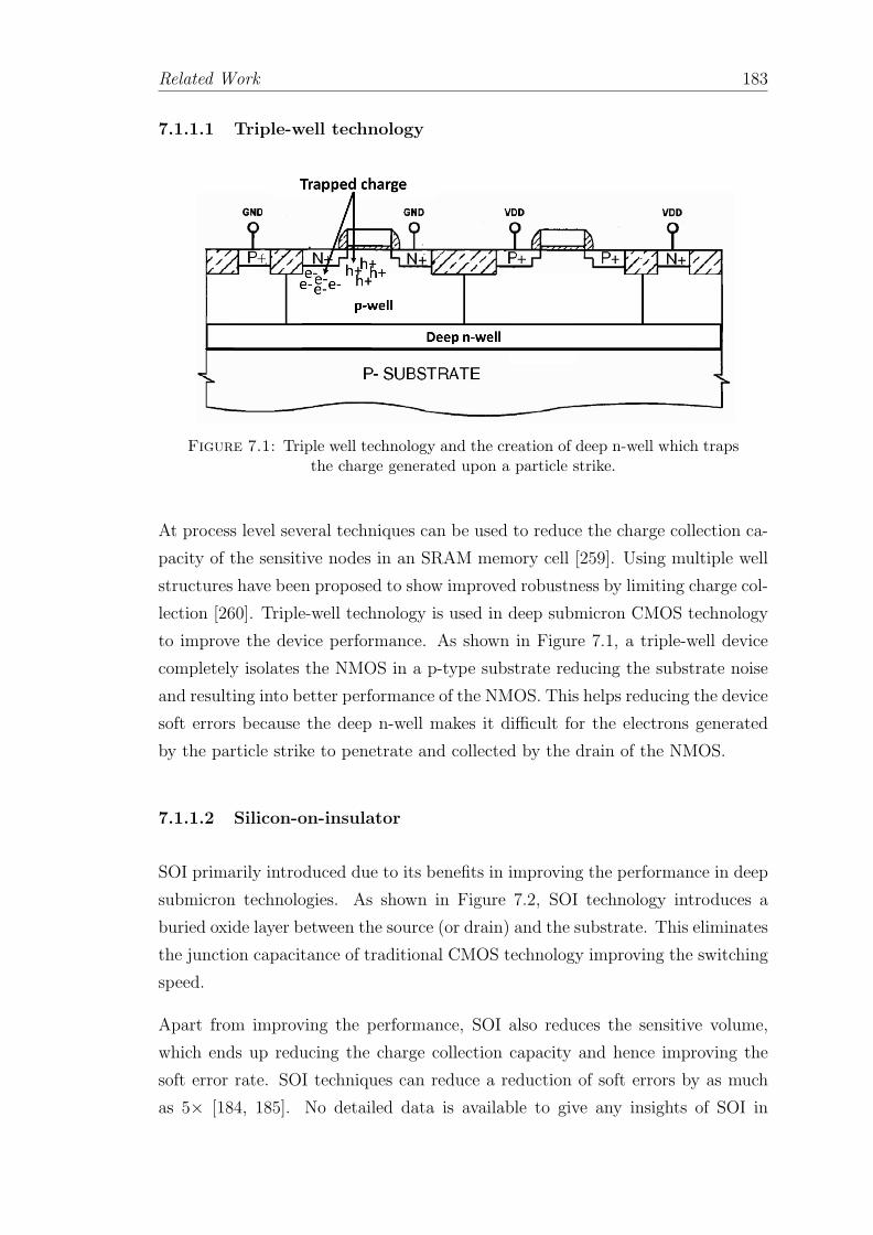
Related Work 183
7.1.1.1 Triple-well technology
Figure 7.1: Triple well technology and the creation of deep n-well which trapsthe charge generated upon a particle strike.
At process level several techniques can be used to reduce the charge collection ca-
pacity of the sensitive nodes in an SRAM memory cell [259]. Using multiple well
structures have been proposed to show improved robustness by limiting charge col-
lection [260]. Triple-well technology is used in deep submicron CMOS technology
to improve the device performance. As shown in Figure 7.1, a triple-well device
completely isolates the NMOS in a p-type substrate reducing the substrate noise
and resulting into better performance of the NMOS. This helps reducing the device
soft errors because the deep n-well makes it difficult for the electrons generated
by the particle strike to penetrate and collected by the drain of the NMOS.
7.1.1.2 Silicon-on-insulator
SOI primarily introduced due to its benefits in improving the performance in deep
submicron technologies. As shown in Figure 7.2, SOI technology introduces a
buried oxide layer between the source (or drain) and the substrate. This eliminates
the junction capacitance of traditional CMOS technology improving the switching
speed.
Apart from improving the performance, SOI also reduces the sensitive volume,
which ends up reducing the charge collection capacity and hence improving the
soft error rate. SOI techniques can reduce a reduction of soft errors by as much
as 5× [184, 185]. No detailed data is available to give any insights of SOI in
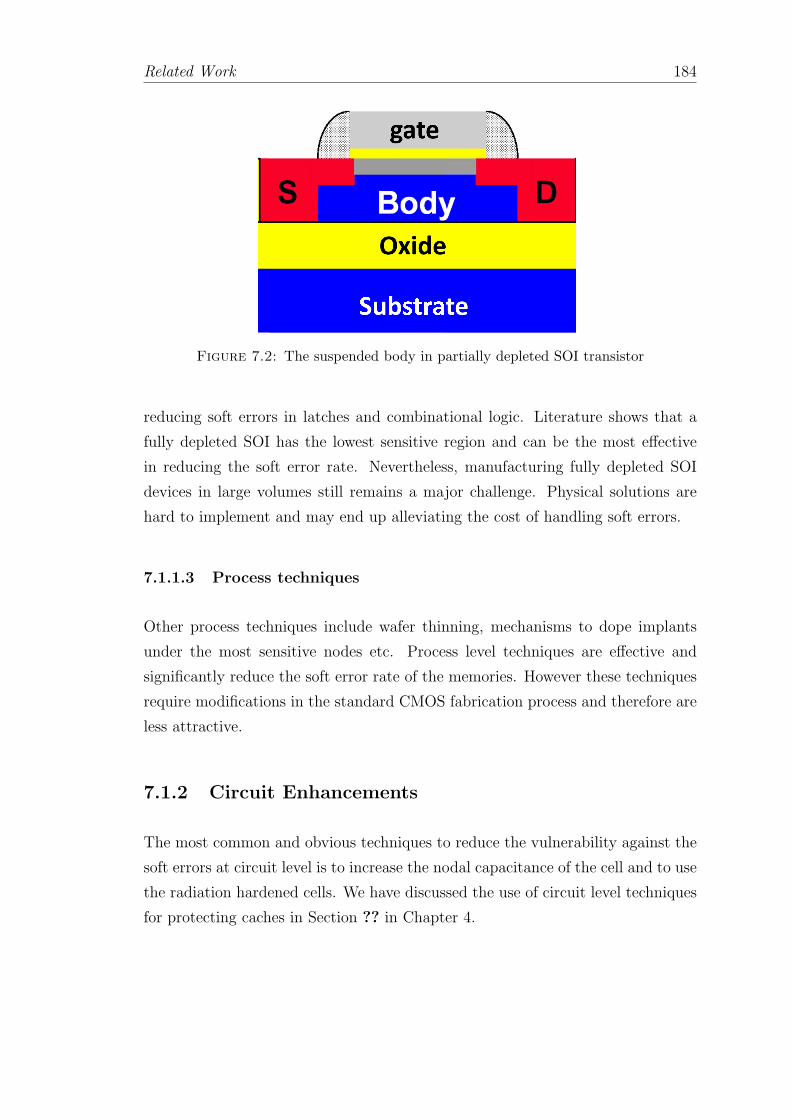
Related Work 184
Figure 7.2: The suspended body in partially depleted SOI transistor
reducing soft errors in latches and combinational logic. Literature shows that a
fully depleted SOI has the lowest sensitive region and can be the most effective
in reducing the soft error rate. Nevertheless, manufacturing fully depleted SOI
devices in large volumes still remains a major challenge. Physical solutions are
hard to implement and may end up alleviating the cost of handling soft errors.
7.1.1.3 Process techniques
Other process techniques include wafer thinning, mechanisms to dope implants
under the most sensitive nodes etc. Process level techniques are effective and
significantly reduce the soft error rate of the memories. However these techniques
require modifications in the standard CMOS fabrication process and therefore are
less attractive.
7.1.2 Circuit Enhancements
The most common and obvious techniques to reduce the vulnerability against the
soft errors at circuit level is to increase the nodal capacitance of the cell and to use
the radiation hardened cells. We have discussed the use of circuit level techniques
for protecting caches in Section ?? in Chapter 4.
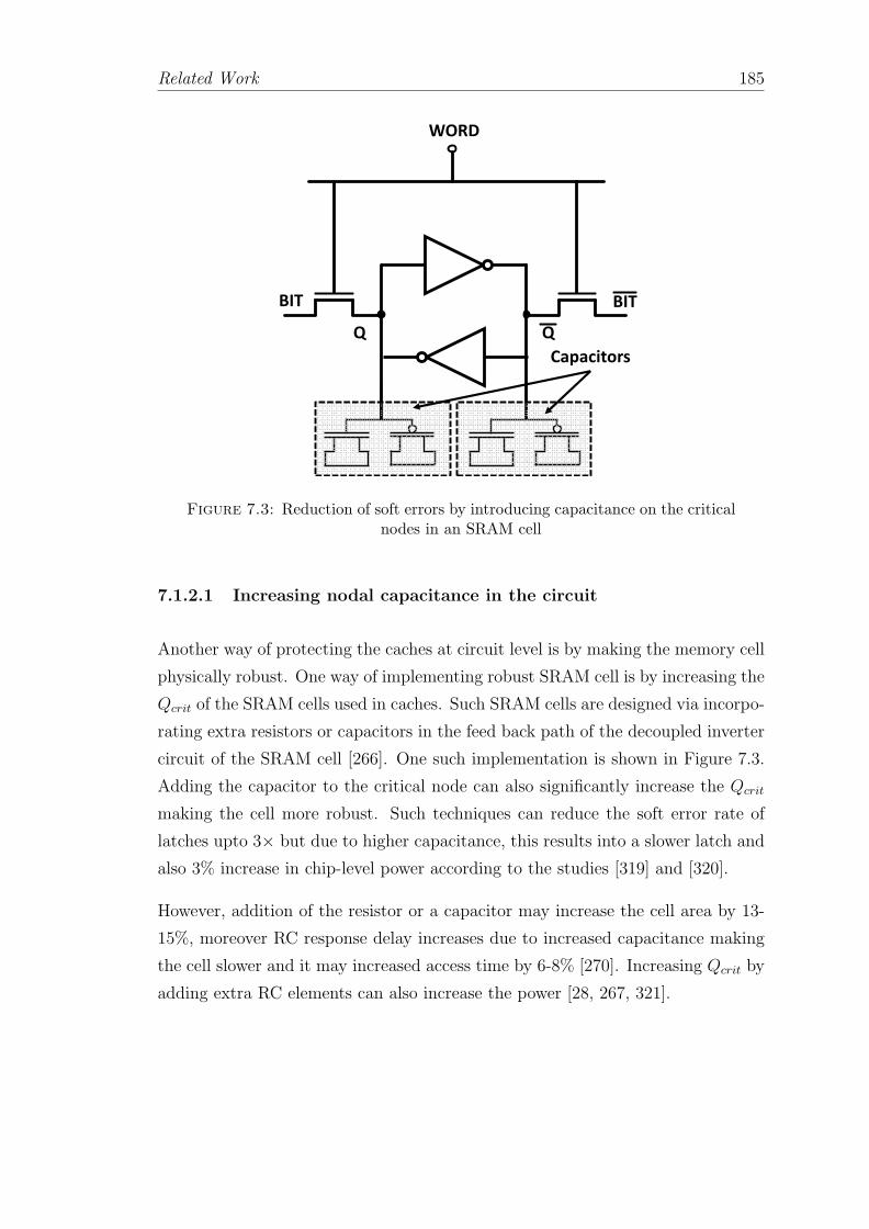
Related Work 185
WORD
BIT BIT
Capacitors
Q Q
Figure 7.3: Reduction of soft errors by introducing capacitance on the criticalnodes in an SRAM cell
7.1.2.1 Increasing nodal capacitance in the circuit
Another way of protecting the caches at circuit level is by making the memory cell
physically robust. One way of implementing robust SRAM cell is by increasing the
Qcrit of the SRAM cells used in caches. Such SRAM cells are designed via incorpo-
rating extra resistors or capacitors in the feed back path of the decoupled inverter
circuit of the SRAM cell [266]. One such implementation is shown in Figure 7.3.
Adding the capacitor to the critical node can also significantly increase the Qcrit
making the cell more robust. Such techniques can reduce the soft error rate of
latches upto 3× but due to higher capacitance, this results into a slower latch and
also 3% increase in chip-level power according to the studies [319] and [320].
However, addition of the resistor or a capacitor may increase the cell area by 13-
15%, moreover RC response delay increases due to increased capacitance making
the cell slower and it may increased access time by 6-8% [270]. Increasing Qcrit by
adding extra RC elements can also increase the power [28, 267, 321].
Related Work 186
7.1.2.2 Radiation hardened cells
Radiation hardening is another circuit level approach for handling soft error rates.
In radiation hardening the SRAM cell is made stronger by increasing its overall
size or by adding more transistors. Increasing the size of an SRAM cell may
make it slower impacting performance. By adding more transistors to the original
SRAM cell to make it more robust the underlying idea is to maintain a redundant
copy of the data which can provide the correct data upon a particle strike and also
recover from the error [264, 269]. Such DICE can reduce the soft error rate upto
10× [265]. Another set of circuit level solutions include, a high speed scan logic
circuit in which the transient fault is detected by quickly by comparing the outputs
of the redundant SRAM cells [85, 322, 323]. However, such high speed scan logic
adds extra hardware increasing the area overhead. Moreover, the scan logic must
be maintained at the same speed as the protected cache all the time increasing the
power overhead [117]. However, it is worth noticing that this robustness comes at
the cost of 1.7× to 2× increased area and almost doubled energy penalty.
All the circuit level soft error protection techniques are attractive at first because
they guarantee higher levels of robustness but on the other hand this robustness
comes at huge penalties in terms of area and energy. Also they increase the
complexity of post silicon validation.
7.2 Soft Error Detection Schemes
Detecting faults is the most crucial problem for any fault tolerance system. A
system cannot recover from a problem of which it is not aware of. Fault detection
provides the minimum measure of safety and efficient fault detection helps to
reduce the SDC to almost zero. Error detection can be implemented in three
ways: (i) physical or spatial redundancy, (ii) information redundancy and (iii)
temporal redundancy. In this section we will see each one of them in greater detail
with examples.

Related Work 187
7.2.1 Spatial Redundancy
Spatial redundancy is very common and simplest techniques to detect transient
and permanent errors. Basically these techniques add extra hardware (redundant
hardware) to detect the errors. Spatial redundancy can be implemented via exe-
cuting the same task on two different components as is the case of the most basic
implementation of the DMR technique. A DMR system comprises of a comparator
as explained in Section 5.6 of Chapter 5.
Modular redundancy is a widely used technique in the industry as it can detect and
recover from both transient and permanent faults in microprocessors by using non
homogeneous replicas which provides design diversity. It is possible to implement
physical redundancy at various granularities. Replicating the entire system or a
core within multi-core processors are also possible and replicating parts of the core
has also been explored depending upon the required level of robustness and amount
of overheads. The IBM G3 [58] employs lockstepped pipeline implementation and
to reduce the performance penalty, instruction fetch and execution units were
replicated and the error checking was performed at the end of the pipeline. This
however, led to area penalty of 35%.
These techniques provide excellent error detection for all kinds of failures provided
that the redundant copies are non-homogeneous but they have huge impact in area,
power and delay, as the output of each replicated component has to be compared.
7.2.1.1 Detectors for Error Detection
Implementing physical redundancy for error detection also includes adding de-
tectors. The detectors that detect the particle strikes via detection of current
glitches, voltage glitches, metastability issues or deposited charge are discussed in
great detail in Section 3.7 in Chapter 3.
Several other detector based techniques have been proposed. One such famous
circuit level technique is Razor [85, 323]. It mainly deals with the voltage drop
induced errors (caused by transient and intermittent errors) in combinatorial logic.
The fundamental idea behind this mechanism is to use double-sampling of values
at certain pipeline stages, to guarantee robustness but at the cost of huge area
overheads. Razor works via pairing each flip-flop within the data path with a

Related Work 188
shadow latch that is controlled by a delayed clock. After the data propagates
through the shadow latch, the output of both of the blocks is compared. If the
combinational logic meets the setup time of the flip-flop, the correct data is latched
in both the data path flip-flop and the shadow latch and no error signal is set. Upon
a mismatch between the outputs of the flip-flop and shadow latch an error signal is
triggered and hence an error is detected. Razor uses extra circuitry to determine
if the flip-flop is metastable. If so, it is treated as an error and appropriately
corrected. An important property of Razor flip-flops is that the shadow latch is
designed to pick up the correct result upon the delayed clock. Using Razor it is
possible to correct the value via stalling the result from the latch by one cycle.
Input A
Input A’
Output
VDD
Latch A
Shadow
Latch A
Figure 7.4: The C-Element circuit forming the core logic of BISER detectionscheme [322]
Another circuit level technique is proposed in [322]. It relies on a at-speed scan
logic based on a C-Element circuit as shown in Figure 7.4. It can be used to detect
the error by comparing the stored values in the storage elements. It acts as an
inverter when both inputs A and A’ are same. However, it does not let any input
to propagate when the inputs are different.
7.2.1.2 Error Detection via Monitoring Invariants
Rather than replicate a piece of hardware, another approach to error detection is
dynamic verification. Added hardware checks whether certain invariants are being
satisfied at runtime. These invariants are true for all error-free executions and

Related Work 189
thus dynamically verifying them detects errors. The key to dynamic verification
is identifying the invariants to check. As the invariants become more end-to-
end, checking them provides better error detection. Ideally, if we identify a set
of invariants that completely defines correct behavior, then dynamically verifying
them provides comprehensive error detection. That is, no error can occur that will
not lead to a violation of at least one invariant, and thus, checking these invariants
enables the detection of all possible errors. We present work in dynamic verification
in an order that is based on a logical progression of invariants checked rather than
in chronological order of publication.
DIVA as discussed in Section 5.6 of Chapter 5 uses heterogeneous physical redun-
dancy. It detects errors in a complex, speculative, superscalar core by checking
it with a core that is architecturally identical but microarchitecturally far simpler
and smaller.
DIVA [67] uses a simple in-order core as a checker for an out-of-order core. As
processor designs grow in complexity, they become increasingly difficult to fully
verify and debug. DIVA proposes to implement a relatively simple and fully ver-
ified back-end processor to perform dynamic (while the processor is in use) veri-
fication of a processor. While the main purpose of DIVA is to ease the challenge
of verification and debugging complex processor cores, DIVA also serves to detect
soft error events. Assuming that a fault affects only the complex processor core or
the backend checker, DIVA will detect the fault and can be configured to attempt
recovery.
Argus framework consists of checkers for each control flow, data flow, computation,
and interacting with memory [289]. It achieves near-complete error detection,
including errors due to design bugs, because its checkers are not the same as
the hardware being checked. However, it cannot detect errors that occur during
interrupts and I/O. Moreover, checkers use DFG signatures (will be discussed in
Section refDFG). Signatures represent a large amount of data by hashing it to
a fixed length quantity. Because of the lossy nature of hashing, there is some
probability of aliasing, that is, an incorrect history happens to hash to the same
value as the correct history. It cannot detect the errors whenever the checker is
using lossy signatures.
Similar to DIVA implementation, a watchdog processor can be employed to observe
the invariants and detect an error. A watchdog processor is a simple co-processor

Related Work 190
that watches the behavior of the main processor and detects violations of invari-
ants [324].
7.2.1.3 Error Detection via Dynamic Control/Data Flow Checks
Detecting errors in control logic is generally more difficult than detecting errors in
data flow. Data errors can be easily detected via parity codes. Checking errors in
control flow involves monitoring errors in control logic as well as control flow.
Efficient control checking is based on the observation that for a given instruction
a subset of the control signals are always the same as proposed in [325]. Special
hardware is added that compute a fixed-length signature of these control signals,
and the these signature that is generated runtime is compared with a signature that
is stored a-priori for that instruction. If the comparison results into a mismatch
of signatures an error is detected.
In another approach as proposed in [326] specific microarchitectural checkers are
added to check a set of control invariants. These added hardware also compute
signatures for control signals. However, instead of computing signatures for ev-
ery instruction, microarchitectural checkers generate a signature over a cluster of
instructions. Instead of comparing signatures for every instruction, now the run-
time comparison is done between the runtime signature with the signature that
is generated when the last time that cluster of instructions was encountered. A
mismatch indicates an error.
In high-level control flow checker a program’s expected control flow graph (CFG)
can be generated and compared to detect errors. A control flow checker [324, 327–
331] compares the statically known CFG generated by the compiler and embedded
in the program to the CFG that the core follows at runtime. If they differ, an error
has been detected. In an example as shown in Figure 7.5, the CFG represents the
sequence of instructions executed by the core. Now the control flow of instruction
can be stored a-priori and any deviation from the desired flow can be due to an
error. The most challenging aspect of the control flow checker is the complex-
ity of the compiler. Due to conditional branches, indirect jumps, and returns it
impossible for the compiler to know the entire CFG of a program in advance.
Similar to control flow checking, checkers that can check for error by comparing
the data flow graph (DFG) of a program have also been explored. A data flow

Related Work 191
Inst:1
Inst:2
Inst:3
Inst:4
Inst:5
Inst:6
R3 = R2 + R1
if (R3 == 0)
goto A
else
goto B
end
A :
R3 = R3-R4
R5 = R3*R3
B :
R5 = R3+R3
R6 = R5 and R3
Inst1: add R3, R2, R1
Inst2: beqz R3, A(Inst3), B(Inst5)
Inst3: sub R3, R3, R4
Inst4: mult R5, R3, R3
Inst5: add R5, R3, R3
Inst6: and R6, R5, R3
Figure 7.5: The control flow checker: A high level program, compiler gener-ated instructions and the corresponding CFG
checker [332] generates a cluster of instructions called basic block. A DFG of each
basic block in the program is stored. At runtime the comparison between the DFG
of currently executing basic block and the statically generated DFG of the same
basic block is used to indicate an error.
A data flow checker can detect any error that manifests itself as a deviation in data
flow and can thus detect errors in many core components, including the reorder
buffer, reservation stations, register file, and operand bypass network. A data flow
checker must also check for the generated values and not only the flow. Data flow
checking faces similar challenges as control flow checking. Additionally data flow
checkers face a non trivial challenge which is the size of the generated DFG. To
handle the unbounded size of the DFG it is possible to generate a fixed-length
hash entry for each DFG.
7.2.1.4 Error Detection via Hardware Assertion
Similar to invariant monitors hardware assertions are used to detect errors [333].
We will discuss assertions that require architecture specific knowledge. Hardware
assertions are specific to each hardware structure and cannot be generalized. For
example, one such hardware assertion can be used to monitor the coherence engine
in the caches. Assuming a MOESI cache coherence protocol is implemented. The

Related Work 192
finite state machine should have five states for each cache block namely: Modified,
Owned, Exclusive, Shared and Invalid. A specific implementation of the protocol
requires the cache block to follow the transition in specific order Invalid 7→ Exclu-
sive 7→ Modified. Now if a block undergoes Invalid 7→ Modified transition skipping
the Exclusive state a hardware assertion can trigger an error.
Timestamps
InstA: mul R2, R1, R1 0x01
InstB: add R1, R2, R3 0x02
InstC: add R3, R1, R4 0x03
Figure 7.6: The hardware assertion and the timestamps
The work of [333] proposed two such assertion techniques: (i) Timestamp-based
assertion checking (TAC) and (ii) Register name authentication (RNA). TAC im-
plementation specifically targets the instruction issue logic. To detect errors it
timestamps the instructions as they are issued to the execution units. For in-
stance, as shown in Figure 7.6 each instruction waiting in the issue buffer has
been assigned a timestamp. Notice that the instruction A updates the R2 with
a multiplication. It has a timestamp associated with it. The the instruction B
utilizes the R2. The latency of the instruction A is L. The assertion holds if
Timestamp(B) ≥ Timestamp(A) + L. In the event that condition doesn’t hold
(i.e., multiplication operation of instruction A takes longer than one cycle) an
error signal is asserted.
In an another approach towards hardware assertions the work of [334] implements
a separate checker engine which takes care of asserting error signals upon failure
to meet the assertion condition for number of hardware structures.
7.2.1.5 Error Detection via Symptom Checks
Detecting errors by symptom checks include error detection via detecting anoma-
lous behavior of generated data. Symptom checks can be implemented via using
some sort of information redundancy (i.e., error detecting codes). Using spatial
redundancy for symptom checks relies on checker core or watchdog core which can
trigger an error signal.

Related Work 193
The idea of symptom checks is based on the observation that the value of generated
data remains constant for a given window of execution time. Any deviation from
this constant value within the execution window may be used to indicate the
presence of an error. The expected range of values within the execution time
window can be obtained either by statically profiling the program’s behavior or
by dynamically profiling it at runtime [335]. However, if the value of datum goes
beyond the known profiled range of values it may result into false positive.
The work of [288] proposes hardware fault screener that employs several anomaly
detectors that check data value ranges (i.e., history based approach), data bit
invariants (i.e., generating bit-masks for each static instruction), and whether a
data value matches with the one of a set of recent values (i.e., bloom filter based
approach). A fault screener operates by examining program state for internal
inconsistencies with past behavior. Consider an example of a static instruction
that generates a result value between 0 and 16 the first thousand times it is
executed, then generates a value of 50. Since the new value of 50 does not fall
within the profiled range of values for that static instruction, the new value is an
example of a perturbation. Other works in the same direction that detects the
anomalous.
7.2.1.6 Error Detection via Selective Protection
Another scheme to detect the errors is by providing selective protection. One
way of implementing it is by duplicating a subset of values in the shadow latches
and comparing them with the generated values. For instance, a core’s register
file holds a significant amount of architectural state that must be kept error-free.
A simplest approach for protecting the registers would be to protect them using
error codes. However, associating error codes can cause huge area, power and
performance overhead at this granularity.
Alternatively, proposals have been made to selectively protect the most vulnerable
registers by copying their values in the shadow register files [336]. The register
file that includes a primary storage portion configured to store a first value, and
a secondary storage portion that is coupled to the primary storage portion. The
secondary storage portion is configured to act as a shadow register buffer and holds
replicas of live register values. The mechanism also includes an error detection
scheme that is coupled to the primary register file and the secondary storage

Related Work 194
portion (i.e., shadow register file) and is configured to indicate a difference between
the first value and the second value, caused by a soft error. Every read to the
register file is also done twice on both the original register file and the shadow
register file. Then the two values are compared. If they are unequal, an error has
been detected.
Similarly, the work [337, 338] realized that protecting all registers is unnecessary.
Intuitively, not all registers hold live values, and protecting dead values is unnec-
essary. They proposed maintaining error codes only for those registers predicted
to be most vulnerable to soft errors.
7.2.2 Information Redundancy
The fundamental idea behind information redundancy for error detection is to add
some extra bits to a set of data bits to detect an error. Error coding techniques
incur two kinds of area overheads : (i) number of added redundant bits and (ii)
logic to encode and decode. However, the penalty due to added logic is negligible
compared to the area penalty due to added redundant bits.
The most common technique for detecting errors in the cache and memory com-
ponents is to use parity codes and are discussed in detail in Section 4.6.2.1 in
Chapter 4. Now we will see the error detection codes for protecting execution
units in a processor core.
7.2.2.1 Error Codes for Combinational Logic
The most effective method of dealing with soft errors in memory components (i.e.,
caches, main memory, register file etc.) is to use codes like parity, or ECC [117].
Unlike memory components the data in functional units in the processor pipeline
is less vulnerable to soft errors mainly due to masking properties discussed in
Section 2.6.3 of Chapter 2. Another important factor that affects the overall
vulnerability of the functional unit is the period of time the instruction stays in
the functional unit. For instance, instruction queue holds the issue until they
can be issued and hence the period of time instructions spend in issue queue is
much higher compared to the execution units. Vulnerable functional units can be

Related Work 195
protected with error codes such as arithmetic codes (i.e., AN codes and residue
codes) and parity prediction codes [76].
Arithmetic error codes are those codes that are preserved under a set of arithmetic
operations. This property allows us to detect errors which may occur during
the execution of an arithmetic operation in the defined set. Such concurrent
error detection can always be attained by duplicating the arithmetic unit, but
duplication is often too costly to be practical.
We expect arithmetic codes to be able to detect all single-bit faults. Note, however,
that a single-bit error in an operand or an intermediate result may well cause
a multiple-bit error in the final result. For example, when adding two binary
numbers, if stage i of the adder is faulty, all the remaining (n i) higher order
digits may become erroneous.
AN codes:
The simplest arithmetic codes are the AN codes, formed by multiplying the data
word N by a constant A. The encoded data word Nc is given as: Nc = A × n
where A > 1. Only multiples of A are valid code words and every operation
processing AN-encoded data has to preserve this property. Code checking is done
by computing the modulus with A. For a valid code word it is zero: Nc mod A =
0. The data value N is retrieved by an integer division N = Nc/A.
Function Residue Relation
Addition N1c + N2c = A(N1) + A(N2) = A(N1 + N2)Subtraction N1c - N2c = A(N1) - A(N2) = A(N1 - N2)Multiplication N1c × N2c = (A(N1) × A(N2))/A = A(N1 × N2)Division ⌊ N1c / N2c ⌋ = ⌊ (A × A(N1))/A(N2) ⌋ = A| N1
N2|
Table 7.1: AN codes and the functions for which they are invariant
The arithmetic operations valid for AN codes are given in Table 7.1. For example,
two bit strings N1 and N2 then the AN code would hold A(N1 Θ N2) = A(N1)
Θ A(N2), where Θ can be addition, subtraction, multiplication or division. The
choice of A determines the number of extra bits require to encode N. For example,
if A = 3, we multiply each operand by 3 (obtained as 2N + N which can be
obtained by a left shift operation on N followed by an addition). It is possible to
check the result of an add or subtract operation to see whether it is an integer
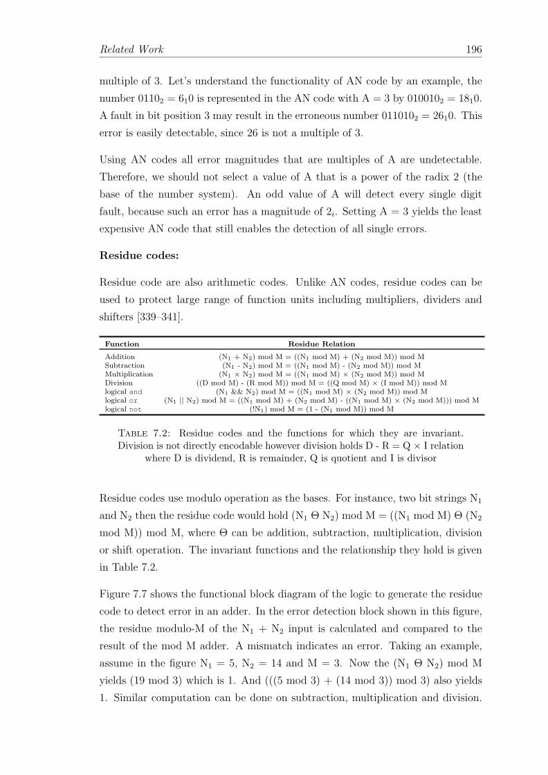
Related Work 196
multiple of 3. Let’s understand the functionality of AN code by an example, the
number 01102 = 610 is represented in the AN code with A = 3 by 0100102 = 1810.
A fault in bit position 3 may result in the erroneous number 0110102 = 2610. This
error is easily detectable, since 26 is not a multiple of 3.
Using AN codes all error magnitudes that are multiples of A are undetectable.
Therefore, we should not select a value of A that is a power of the radix 2 (the
base of the number system). An odd value of A will detect every single digit
fault, because such an error has a magnitude of 2i. Setting A = 3 yields the least
expensive AN code that still enables the detection of all single errors.
Residue codes:
Residue code are also arithmetic codes. Unlike AN codes, residue codes can be
used to protect large range of function units including multipliers, dividers and
shifters [339–341].
Function Residue Relation
Addition (N1 + N2) mod M = ((N1 mod M) + (N2 mod M)) mod MSubtraction (N1 - N2) mod M = ((N1 mod M) - (N2 mod M)) mod MMultiplication (N1 × N2) mod M = ((N1 mod M) × (N2 mod M)) mod MDivision ((D mod M) - (R mod M)) mod M = ((Q mod M) × (I mod M)) mod Mlogical and (N1 && N2) mod M = ((N1 mod M) × (N2 mod M)) mod Mlogical or (N1 || N2) mod M = ((N1 mod M) + (N2 mod M) - ((N1 mod M) × (N2 mod M))) mod Mlogical not (!N1) mod M = (1 - (N1 mod M)) mod M
Table 7.2: Residue codes and the functions for which they are invariant.Division is not directly encodable however division holds D - R = Q × I relation
where D is dividend, R is remainder, Q is quotient and I is divisor
Residue codes use modulo operation as the bases. For instance, two bit strings N1
and N2 then the residue code would hold (N1 Θ N2) mod M = ((N1 mod M) Θ (N2
mod M)) mod M, where Θ can be addition, subtraction, multiplication, division
or shift operation. The invariant functions and the relationship they hold is given
in Table 7.2.
Figure 7.7 shows the functional block diagram of the logic to generate the residue
code to detect error in an adder. In the error detection block shown in this figure,
the residue modulo-M of the N1 + N2 input is calculated and compared to the
result of the mod M adder. A mismatch indicates an error. Taking an example,
assume in the figure N1 = 5, N2 = 14 and M = 3. Now the (N1 Θ N2) mod M
yields (19 mod 3) which is 1. And (((5 mod 3) + (14 mod 3)) mod 3) also yields
1. Similar computation can be done on subtraction, multiplication and division.
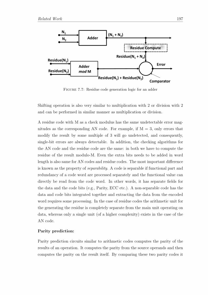
Related Work 197
Adder
Adder
mod M
Residue Compute
ComparatorResidue(N1) + Residue(N2)
(N1 + N2)
Error
N1
N2
Residue(N1)
Residue(N2)
Residue(N1 + N2)
Figure 7.7: Residue code generation logic for an adder
Shifting operation is also very similar to multiplication with 2 or division with 2
and can be performed in similar manner as multiplication or division.
A residue code with M as a check modulus has the same undetectable error mag-
nitudes as the corresponding AN code. For example, if M = 3, only errors that
modify the result by some multiple of 3 will go undetected, and consequently,
single-bit errors are always detectable. In addition, the checking algorithms for
the AN code and the residue code are the same: in both we have to compute the
residue of the result modulo-M. Even the extra bits needs to be added in word
length is also same for AN codes and residue codes. The most important difference
is known as the property of separability. A code is separable if functional part and
redundancy of a code word are processed separately and the functional value can
directly be read from the code word. In other words, it has separate fields for
the data and the code bits (e.g., Parity, ECC etc.). A non-separable code has the
data and code bits integrated together and extracting the data from the encoded
word requires some processing. In the case of residue codes the arithmetic unit for
the generating the residue is completely separate from the main unit operating on
data, whereas only a single unit (of a higher complexity) exists in the case of the
AN code.
Parity prediction:
Parity prediction circuits similar to arithmetic codes computes the parity of the
results of an operation. It computes the parity from the source operands and then
computes the parity on the result itself. By comparing these two parity codes it

Related Work 198
Adder
Parity Generator
Comparator(Ac XOR Bc XOR Carry)
Error
A
Ac
Bc
Sc
B
Carry “C”
S = A+B
Figure 7.8: Functional block diagram of parity prediction circuit in an adder
can detect an error upon a mismatch. Parity prediction circuits have been used
in commercial processors [229].
A functional block diagram of parity prediction is given in Figure 7.8. In the figure
a parity prediction is implemented for the addition: S = A + B. A, B and S are
bit strings. In the figure Ac, Bc and Sc are the parity coded bits for A, B and S
respectively. Sc can be obtained byn−1XORi=0
Si. Sc can also be computed by Ac XOR
Bc XOR Carry. Where Ccarry =n−1XORi=0
Ci. Comparing Sc by two independent ways
it is possible to compare them for a mismatch and detect an error. For example,
assume A = 010102 = 1010, B = 010012 = 910 then S = A + B = 100112 = 1910.
Obtaining the parity on A, B and S yields Ac = 0, Bc = 0 and Sc = 1. Now the
summation of A + B also gives the carry C = 010002. Computing Sc from Ac XOR
Bc XOR C yields 1.
Parity prediction circuits have been successfully implemented for adders [342–
344] and multipliers [345, 346]. It is worth mentioning here that the circuit must
ensure an error is not triggered due to an error or particle strike in the comparator.
Moreover, if the error is in the carry itself which feeds to both the modules that
are computing Sc. If the same error propagates to both the data that computes
Sc the error will not be detected.
Arithmetic codes and parity prediction circuits both are effective in protecting
functional blocks. Parity prediction circuits incur less in terms of area overhead for
smaller adders and multipliers. Arithmetic codes are better option while protecting
larger functional units. Both these techniques incur little performance degradation

Related Work 199
as they strive for near-instantaneous error detection putting detection to be on the
critical path.
7.2.2.2 Signature Based Approach
Another mechanism was proposed in [347], where a Π bit is used to identify pos-
sible errors in each instruction and only for the instructions that are needed for
architecturally correct execution signals an error before they leave the pipeline.
Also, they propose to stall the fetch (and therefore reduce the AVF) on long la-
tency stalls.
Signatures have been used to protect the control flow [324]. A signature is calcu-
lated at compile time and inserted in the code. Later, a new signature is generated
at runtime and compared to the one generated at compile time. This approach
implies a non negligible design cost, due to the required modifications to the ISA,
as well as power consumption increase and impact on performance, because of the
required signature calculation during runtime.
The work of [348] proposes an end-to-end protection scheme based on signatures
which is a token associated to a chunk of information. The concept of end-to-
end protection is based on identifying a path either for data or instructions where
there is a source from which data or instructions originate, and a consumption site
where they are finally consumed. The end-to-end scheme involves generating a
protection code at the source, sending the data or instructions with the protection
code along the path, and checking for errors only at the end of the path, where
data or instructions are consumed. Any error found at the consumption site can be
caused by any logic gates, storage elements, or buses along the path. Other works
have focused on using signature based mechanisms to protect the microprocessor
pipeline against errors caused by defects and degradation [349].
7.2.3 Temporal Redundancy
There are several ways to incorporate temporal redundancy for error detection.
The most common idea is to be able to detect faults from redundant streams of
instructions within a single core or multiple cores. Once executed the outcome of
the instructions on redundant threads are compared to detect possible faults.

Related Work 200
Redundant execution techniques are widely accepted by the industries in the forms
of lockstepping and redundant multithreading as discussed in detail in Section 5.6
of Chapter 5. The Stratus ftServer [299], HP Himalaya [350] and IBM-Z [300] series
are all lockstepped in which the redundant streams are run on two separate but
identical cores and they must have exact the same state at each cycle, which is very
costly and incur huge performance penalty. More recent server architectures such
as Marathon Endurance and HP’s NonStop Advanced Architecture implement
RMT [350].
These techniques can provide greater fault coverage across a processor chip com-
pares to error coding techniques. It is important to note that these methods cannot
detect hard faults and design bugs. The main reason for this is, as both threads
use the same hardware it is impossible to find permanent errors, and due to ho-
mogeneous nature of the chip design errors can not be found due to lack of design
diversity among the cores. Moreover, due to redundant execution these class of
techniques cause huge power and performance overheads (almost 2×). The area
overhead can be as much as 100% since the multithreading capability is used for
error detection. A lot of modifications to the classical RMT technique has been
attempted to reduce the performance penalty, by using only the idle resources for
error checking [73, 74] and by replicating instructions only when the processor has
available resources [71].
7.2.3.1 Various Flavors of RMT
Implementing RMT on an SMT core was first proposed in the work of AR-
SMT [68]. The redundant threads are called active (A) and redundant (R) thread.
The A-thread runs ahead of the R-thread and saves the results of each committed
instruction in a FIFO. The R-thread compares the result of each instruction it
completes with the corresponding result of A-thread in the FIFO. Whenever the
results of instructions match they are committed. The R-thread commits instruc-
tions that have been successfully compared. By checking for error before commit
they establish an error free recovery state. Since RMT can only detect error, this
error free recovery state can be later used for recovery upon an error.
If the instructions have to be compared before commit huge performance overhead
may occur due to the limited size of the FIFO. When the FIFO is full the A-
thread must stall and it cannot complete more instructions. When the FIFO is

Related Work 201
empty the lagging R-thread has no value to compare its result with. R-thread
cannot commit more instructions. The slowdown can be even worse if RMT is
implemented on multiple cores (instead of an SMT processor) due to longer latency
in communicating the results between threads. To avoid the performance overhead
AR-SMT allows the A-thread to commit instructions before the comparison [111].
To consistently detect errors due to hard faults AR-SMT suggests to bound the
A-thread and R-thread to use specific and different resources in the pipeline. For
instance in a core with multiple ALUs, the two threads can be enforced such that
they always use different ALUs.
Three main causes of the performance overheads have been identified while em-
ploying RMT schemes for error detection. We go through them one by one and
briefly discuss the enhancements in each category.
Choice of Sphere of replication:
It was observed that the majority of the performance overhead comes from where
and when to the redundant threads are compared. The work [65] concludes that by
carefully managing core resources and by more efficiently comparing the behaviors
of the two threads it is possible to reduce the performance impact of traditional
RMT core. The authors introduced the notion of sphere of replication. Sphere
of replication includes the logical domain that is protected by the RMT scheme.
It also implies that any error within the sphere of replication will be detected by
RMT. Sphere of replication clearly defines the components that must be protected
by RMT scheme. It provides necessary freedom for deciding what needs to be
replicated. For example, should the thread be replicated before or after each
instruction is fetched? Moreover, sphere of replication clearly sets a boundary and
decides when comparisons need to be performed. For example, the threads can be
compared at every store or at every I/O event.
Figure 7.9 shows the concept of sphere of replication. It shows that the sphere of
replication includes both the processor cores and one of them is redundant. The
sphere of replication does not include the main memory, storage disks and any
I/O devices. Moreover, specific hardware takes care of replicating all the inputs
coming from the components out of the sphere of replication. Similarly, all the
outputs from the main and the redundant cores leaving the sphere of replication
are compared via hardware comparator.
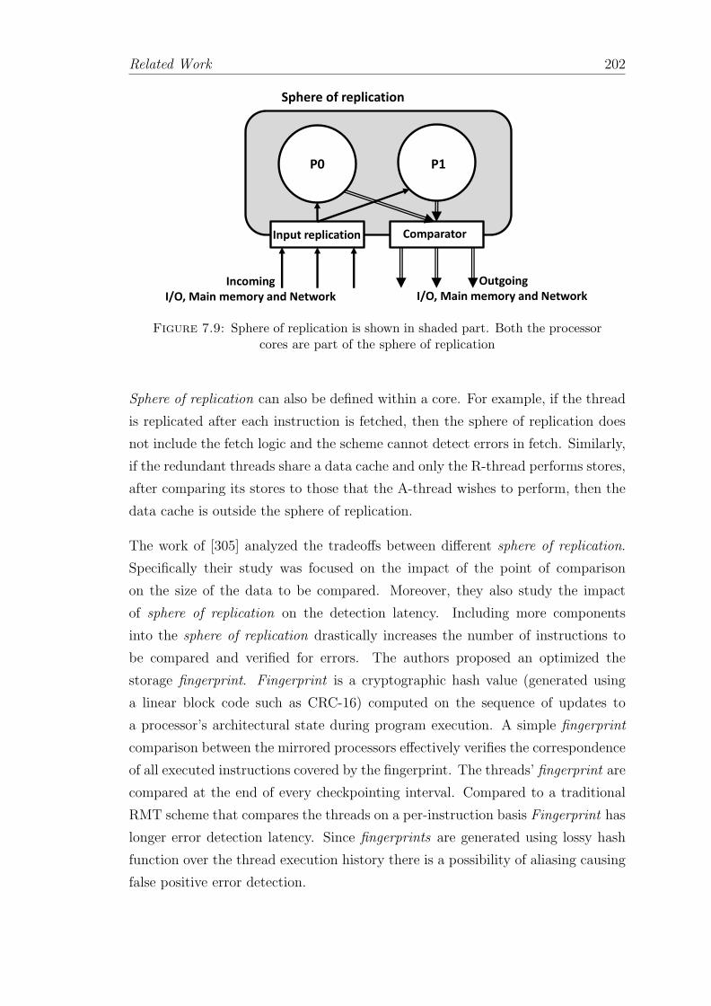
Related Work 202
P0 P1
Sphere of replication
Input replication Comparator
Incoming
I/O, Main memory and Network
Outgoing
I/O, Main memory and Network
Figure 7.9: Sphere of replication is shown in shaded part. Both the processorcores are part of the sphere of replication
Sphere of replication can also be defined within a core. For example, if the thread
is replicated after each instruction is fetched, then the sphere of replication does
not include the fetch logic and the scheme cannot detect errors in fetch. Similarly,
if the redundant threads share a data cache and only the R-thread performs stores,
after comparing its stores to those that the A-thread wishes to perform, then the
data cache is outside the sphere of replication.
The work of [305] analyzed the tradeoffs between different sphere of replication.
Specifically their study was focused on the impact of the point of comparison
on the size of the data to be compared. Moreover, they also study the impact
of sphere of replication on the detection latency. Including more components
into the sphere of replication drastically increases the number of instructions to
be compared and verified for errors. The authors proposed an optimized the
storage fingerprint. Fingerprint is a cryptographic hash value (generated using
a linear block code such as CRC-16) computed on the sequence of updates to
a processor’s architectural state during program execution. A simple fingerprint
comparison between the mirrored processors effectively verifies the correspondence
of all executed instructions covered by the fingerprint. The threads’ fingerprint are
compared at the end of every checkpointing interval. Compared to a traditional
RMT scheme that compares the threads on a per-instruction basis Fingerprint has
longer error detection latency. Since fingerprints are generated using lossy hash
function over the thread execution history there is a possibility of aliasing causing
false positive error detection.

Related Work 203
Partial/Selective Thread Replication:
Alternative research explores the possibility to replicate only selective instructions
or a subset of instructions from the active thread.
Slipstream core [115] provides some degree of the error detection of classical re-
dundant multithreading. However, it provides a performance that is greater than
a single thread operating alone on the core. The contribution is based on the
intuition that the partially redundant A-thread can run ahead of the original R-
thread. By doing so the lagging thread can benefit from various performance
enhancing decisions already made by the leading thread. For instance, the lag-
ging thread can utilize the branch predictor decisions and prefetcher decisions
to speed up the execution of the trailing thread. A compiler takes care of par-
tially replicating instructions in leading thread by using heuristics that effectively
guess which instructions are most helpful for generating predictions for the trail-
ing thread. Retaining more instructions in the leading thread enables it to predict
more instructions and provides better error detection because more instructions
are executed redundantly. However, due to more redundancy the leading thread
takes longer to execute and may not run ahead enough to help the trailing thread
in improving performance.
An extension to this work has been proposed in [307]. It assumes a mixture of
partial duplication and confident predictions in the context of slipstream processors
to approximate full coverage. A similar approach [70] adapts the register renaming
to issue instructions from a single thread redundantly in the dynamic execution
path. As a result, the effective dispatch bandwidth, entries in the ROB, and size
of the register file are reduced by the factor of 2 which is the total amount of
redundancy.
Proposal of [75] suggests to partially replicate the leading thread. Further, it
views RMT scheme as a leading thread generating outputs stores that emanate
from the processor, and a redundant thread verifying the integrity of these outputs.
The redundant thread can be further envisioned as intertwined dependency chains
of instructions that ultimately lead up to these stores. They suggest to choose a
partial set of instructions for redundant execution from these chains. For instance,
for each store instruction, if either the address or the store value predictor produces
a misprediction, the mechanism considers that an indication of a possible error that

Related Work 204
should be checked. In this situation, the proposal replicates the backward slice of
instructions that led to this store instruction.
Furthermore the work of [71] proposed to keep the leading thread unchanged. And
observe the impact of selectively replicating the trailing thread and its impact
on performance and error detection coverage. They observed that the amount
of redundancy can be tuned at runtime and that there are often times when
redundancy can be achieved at minimal performance loss. For example, when
the leading thread misses in the L2 cache, the core would otherwise be partially
or mostly idle without trailing thread instructions to keep it busy. They further
claim that instead of replicating each instruction in the leading thread, they can
store the value produced by an instruction and, when that instruction is executed
again, compare it to the stored value.
The work of [56] proposes Selective replication. Their selective replication scheme
is guided by the vulnerability of the instructions to protect the back-end. They
opt for an inexpensive way of estimating the AVF that allows re-execution as
soon as possible. To selectively reissue and re-execute those instructions that are
above the selected vulnerability threshold in order to achieve maximum coverage
by replicating a minimum number of instructions. Instructions that are placed in
the IQ are also inserted into the Selective Queue (SQ). They use the time that
an instruction spends in the IQ as an indicator of the AVF. Whenever there is
an empty port for execution, an instruction in the SQ (whose counterpart in the
IQ has already been issued) is issued and executed. Once instructions finish their
execution, they keep the result in the widened ROB. When the replica execution
finishes, it compares its result against the one stored for validation purposes.
A dependence based checking scheme was proposed in [66] and extended in [111].
They selectively try to reduce the number of instructions required to be compared
for detecting errors. The proposal is based on the intuition that as instruction ex-
ecute, the fault propagates through instructions via control or data flow creating a
chain. The proposed scheme builds short chains of instructions which are required
to be checked for errors.
Redundant Threads in Multicore System:
There have been attempts to implement the RMT on a chip multiprocessor. The
basic idea of implementing RMT in a CMP is to generate logically redundant
threads similar to SRT scheme [65]. The difference however comes from the fact

Related Work 205
that the leading and the trailing threads execute on different cores. The redundant
threads can run on different cores within a multicore processor or on different cores
that are on different chips. The reason for using multiple cores, rather than a single
SMT core, is to avoid having the threads compete for resources on the SMT core.
P0 P1
Leading
Thread A
Trailing
Thread R
Trailing
Thread A
Leading
Thread R
Thread A
Load Q
Store Q
Branch Outcome Q
Thread R
Load Q
Store Q
Branch Outcome Q
Figure 7.10: Functional implementation of RMT scheme on a processor withtwo cores (P0 and P1). The cross coupled cores with a few dedicated hardware
queues can work in unison for error detection.
The proposal [57] performed a detailed simulation study of redundant multithread-
ing. We show this implementation in Figure 7.10. Trailing thread’s load value
queue and branch outcomes now receive inputs from the leading threads execut-
ing on another core [301]. The same holds true for store instructions. It may also
possible that the cores executing the two threads are very far from each other
increasing the latency to forward data back and forth. However, the advantage
is that the queues implemented to store the values of load, stores and branch
outcomes decouple the execution of the redundant threads and now they are not
on the critical path. This design point differs from lockstepped redundant cores
in that the redundant threads are not restricted to operating in lockstep. They

Related Work 206
show that this design point outperforms lockstepped redundant cores, by avoiding
certain performance penalties inherent in lockstepping.
The DCC technique proposed in [281] uses redundant threads on multiple cores,
but it removes the need for dedicated hardware queues for the leading thread to
communicate its results to the trailing thread. DCC uses the existing intercon-
nection network to carry this traffic.
While implementing RMT on multicore the biggest challenge is in handling the
interaction between the threads and the memory system. The threads perform
loads and stores, and these loads and stores must be the same for the threads
in normal conditions. If the threads share the same address space then a load
instruction in the leading thread may return a different value than the same load
instruction in the trailing thread. For instance, if both threads load from address
X. If the leading thread loads X before the trailing thread loads X it may possible
that the leading thread also try to modify the content following a store to address
X causing an invalidation. In this event the trailing thread may read a different
value from X. A solution was proposed in [351], which is to let the trailing thread
perform reads and detect those violations when the trailing thread’s load reads
different value from that of the leading thread and recover to a checkpoint from
which forward progress is guaranteed.
7.2.3.2 Error Detection via Detecting Anomalies
Error detection via data and control value anomalies have been discussed in Sec-
tion 7.2.1.3. Restore [36] architecture detects transient errors by detecting a higher
level microarchitectural anomalies.
Errors are detected through temporal redundancy on demand. The symptom de-
tectors trigger in situations that are likely to occur in the presence of an error.
These behaviors include exceptions, page faults, and branch mispredictions that
occur despite the branch confidence predictor having high confidence in the predic-
tions. Their intuition is that these anomalous behavior are possible in an error-free
execution but they are rare enough to be suspicious. If ReStore observes any of
these behaviors, it recovers to a pre-error checkpoint and replays execution. If the
anomalous behavior does not recur during replay, then it was most likely due to a
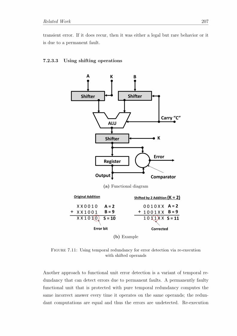
Related Work 207
transient error. If it does recur, then it was either a legal but rare behavior or it
is due to a permanent fault.
7.2.3.3 Using shifting operations
Shifter Shifter
ALU
Shifter
Register
Comparator
Error
Carry “C”
A BK
K
Output
(a) Functional diagram
Original Addition
X X 0 0 1 0
X X 1 0 0 1
X X 1 0 1 0
+
A = 2
B = 9
S = 10
Error bit
0 0 1 0 X X
1 0 0 1 X X
1 0 1 1 X X
+
A = 2
B = 9
S = 11
Corrected
Shifted by 2 Addition (K = 2)
(b) Example
Figure 7.11: Using temporal redundancy for error detection via re-executionwith shifted operands
Another approach to functional unit error detection is a variant of temporal re-
dundancy that can detect errors due to permanent faults. A permanently faulty
functional unit that is protected with pure temporal redundancy computes the
same incorrect answer every time it operates on the same operands; the redun-
dant computations are equal and thus the errors are undetected. Re-execution
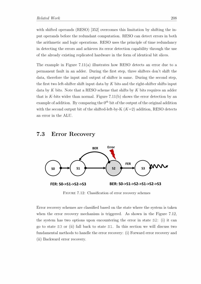
Related Work 208
with shifted operands (RESO) [352] overcomes this limitation by shifting the in-
put operands before the redundant computation. RESO can detect errors in both
the arithmetic and logic operations. RESO uses the principle of time redundancy
in detecting the errors and achieves its error detection capability through the use
of the already existing replicated hardware in the form of identical bit slices.
The example in Figure 7.11(a) illustrates how RESO detects an error due to a
permanent fault in an adder. During the first step, three shifters don’t shift the
data, therefore the input and output of shifter is same. During the second step,
the first two left-shifter shift input data by K bits and the right-shifter shifts input
data by K bits. Note that a RESO scheme that shifts by K bits requires an adder
that is K -bits wider than normal. Figure 7.11(b) shows the error detection by an
example of addition. By comparing the 0th bit of the output of the original addition
with the second output bit of the shifted-left-by-K (K=2) addition, RESO detects
an error in the ALU.
7.3 Error Recovery
S0 S3S2S1
BER
FER
Error
FER: S0->S1->S2->S3 BER: S0->S1->S2->S1->S2->S3
Figure 7.12: Classification of error recovery schemes
Error recovery schemes are classified based on the state where the system is taken
when the error recovery mechanism is triggered. As shown in the Figure 7.12,
the system has two options upon encountering the error in state S2: (i) it can
go to state S3 or (ii) fall back to state S1. In this section we will discuss two
fundamental methods to handle the error recovery: (i) Forward error recovery and
(ii) Backward error recovery.

Related Work 209
7.3.1 Forward Error Recovery
Forward error recovery (FER) techniques can correct the errors on the fly. In other
words the system is allowed to make forward progress under the event of an error.
According to Figure 7.12 in FER the system goes to state S3 from S2. FER sys-
tems are required to maintain redundancy that allows the system to reconstruct
the most recent error free state. FER can be implemented by incorporating phys-
ical, temporal or information redundancy in the system. Error correcting codes
can also provide forward error correction by incorporating information redundancy
as explained in the Section 4.6.2.1 in Chapter 4. The most common example of
forward error recovery technique is to employ modular redundancy (i.e., a TMR).
Implementing FER via modular redundancy in full computing systems (i.e., repli-
cating all the memory, registers, ALUs etc.) can be very hardware intensive and
can cause huge power overhead.
7.3.1.1 Triple Modular Redundancy (TMR)
We have seen the use of DMR system for error detection in Section 5.6.1.1 in Chap-
ter 5. It detects the error by comparing the outcomes of two replicas. Adding one
more replica of the modules gives the TMR, that is triple modular redundancy
system [353] as shown in Figure 7.13. The TMR system consists of three identical
replicas of the execution system and the state and a comparator. The fault detec-
tion can be similar to the lockstepping (i.e., cycle by cycle comparison) or similar
to the RMT techniques (i.e., comparing before the output goes out of the sphere
of replication). So long as a majority (2 or 3) of the modules produce correct
results, the system will be functional. Usually, after detecting and identifying the
erroneous module the TMR system isolates the faulty module and keeps running
in a degraded DMR system. To bring back the faulty module the DMR system
copies the new system state from the error free modules to the faulty module
and resumes the execution. The advantage of TMR is that it can provide error
correction. It can also help to isolate the erroneous module and assist in system
diagnosis. TMR can significantly improve the system downtime and can eliminate
DUE without requiring to roll-back.
The first use of TMR in a computer was the Czechoslovak computer SAPO, in
the 1950s [354]. Today triple redundancy systems are used in several commercial

Related Work 210
Processor 0
Processor 1
Processor 2Comparator
Error
Figure 7.13: Triple modular redundancy
processors (i.e., HP NonStop architecture [113]) and ”Pair & spare” systems [114].
Many variations of the traditional TMR have been proposed and implemented.
The Boeing 777 [355] uses heterogeneous triple-triple modular redundancy [76].
7.3.2 Backward Error Recovery
Unlike forward error recovery schemes, backward error recovery (BER) restores
the system to the last known error free state and resumes the execution from that
state. As shown in Figure 7.12 the system state is traced back to S1 once the
error has been detected in S2. To be able to trace back the system to S1 the
exact system state must be saved in a checkpoint. Moreover, the backward error
recovery mechanisms should also make sure that any output which the system
cannot recover from is error free before exiting the recovery boundary. Thus,
errors must be contained within the sphere of recoverability so that the error

Related Work 211
does not propagate to a component that cannot be recovered. If an error escapes
the sphere of recoverability, then the error is unrecoverable and the system fails.
For instance a backward error recovery scheme that does not save the I/O state
cannot recover from any erroneous outputs that has propagated and modified the
I/O state. Similarly, a backward error recovery mechanism should make sure that
once the system reverts back to the checkpoint all the inputs including the ones
that have arrived from outside of the recovery boundary are replayed.
Basically a checkpoint can comprise any or all of the following: (i) architecture
register files, (ii) caches and memory and (iii) I/O state of the processor. What
comprises the checkpoint directly depends on the fault detection mechanism and
the detection latency. There are several options for choosing the sphere of recover-
ability [356] and the options are discussed at length in Chapter 5. If checkpointing
is implemented just on the core, then errors cannot be allowed to propagate to
the caches or memory or beyond. If checkpointing includes the memory hierarchy,
then errors can be allowed to propagate into the memory system but not to I/O
devices. A backward error recovery scheme recover the system to a precise, con-
sistent and error free state from which it can resume execution. For a processor to
resume execution, it requires all of the architectural state, including the program
counter, architectural registers, status registers, and the memory state.
Checkpoints can be taken at regular periodic intervals or in response to certain
events. Taking checkpoints more frequently is likely to increase the performance
penalty of checkpointing, but it reduces the amount of error-free work that must be
replayed after a recovery. Logging, like checkpointing, is useful in contexts other
than architectural BER. Many programs, such as word processors and spread-
sheets, log changes to data structures so that they can provide recovery. Because
checkpointing and logging have different costs for different types of state, many
BER systems use a hybrid of both [107].
7.3.2.1 Checkpointing Techniques for Recovery
Now, we will discuss the most relevant checkpoint based hardware error recovery
techniques in which the system maintains snapshots of the architectural state of
the system to which it can revert back to in the event of an error.

Related Work 212
1. Error recovery before register commit: Backward error recovery within
core has been adapted in many commercial cores as a mainstream solution
for error recovery [58, 62, 229]. Checkpoint/recovery hardware is used for
recovering from the effects of misprediction instead of being used for error
recovery. The proposal modifies the speculative recovery mechanism to meet
two important criteria: (i) guaranteeing creation of error free checkpoints and
(ii) by performing the error detection before the instruction is committed [66,
357]. These recovery technique can be used only when the error detection
happens before the register values are committed to the architecture register
file. For recovery the processor just have to flush the speculative register
values as the architecture register files holds the most recent and error free
state.
Now, we will discuss one such implementation simultaneously and redun-
dantly threaded processor with recovery (SRTR) which was proposed in [66].
SRTR is an enhancement of redundant multithreading on an SMT core which
provides in core error recovery. To avoid stalling leading instructions at com-
mit while waiting for their trailing counterparts, SRTR exploits the time be-
tween the completion and commit of leading instructions. SRTR compares
the leading and trailing values as soon as the trailing instruction completes,
typically before the leading instruction reaches the commit point. SRTR
relies on the register value queue (RVQ) to hold register values for checking.
Upon a mismatch all the instructions are squashed. The leading thread waits
until the trailing thread also encounters the offending instruction and then
resumes the normal execution.
2. Error recovery after register commit: These techniques allow the regis-
ter values to be committed to the architecture register file but not to caches
or memory and hence they must keep checkpoints of the consistent and error
free architecture state. Checkpoints can be taken periodically or whenever
new values are generated or updated (i.e., incremental checkpointing).
Incremental checkpointing used history buffer to keep a record of all the
register values whenever they are generated [308, 358]. A history buffer
consists of several entries containing information about program counter,
old destination register value and the mapped physical register for every
retired instruction. When an instruction retires but it is still waiting in
the ROB for its turn to commit an entry is allocated in the history buffer.

Related Work 213
Once the retired instruction is verified to be error free the corresponding
entry from the history buffer is deallocated. Whenever a fault is detected
all the speculative instructions which are not retired are flushed. And the
correct architecture state is reconstructed from the existing register file and
the history buffer. The architecture register file holds the state up to the last
retired instruction prior to the erroneous instruction. The values must be
obtained via a roll back to the state prior to the erroneous instruction which
is done by finding the latest update from history buffer to the architecture
register file. The system has to iterate through all the entries in the history
buffer. Once found the architecture state can be restored and the history
buffer is flushed.
Periodic checkpointing takes the snapshot of the processor state periodi-
cally. Unlike incremental checkpointing periodic checkpoints can accommo-
date longer checkpoint periods and reduces the constraint of detecting errors
on every instruction for generation of clear checkpoint. However, the amount
of state has to be copied to create the checkpoint [102, 103, 107, 359–361].
Fingerprinting as proposed in [305] and discussed in Section ?? of this chap-
ter, contains the summary of the outputs of any new register values, memory
values or addresses generated by executing instructions.
3. Cache assisted Checkpointing: More recently checkpointing schemes
have been used for enabling error recovery using caches and memory. In-
cluding caches in the checkpoint can support longer checkpointing periods.
One of the landmark papers on backward error recovery Cache-Aided Roll-
back Error Recovery (CARER) explores how to use the cache to hold check-
point [228]. CARER permits committed stores to write into the cache, but
it does not allow them to be written back to memory until they have been
validated as being error-free. Thus, the memory and the clean lines in the
cache represent the checkpoint. Dirty lines in the cache represent state that
could be recovered if an error is detected. During a recovery, all dirty lines
in the cache are invalidated. If the address of one of these lines is accessed
after recovery, it will miss in the cache and obtain the checkpoint value for
that data from memory. Any cache or memory state, including TLB entries,
that is not part of the recovery point, should be flushed. Otherwise, we may
use incorrect values. CARER also observes that the memory state does not

Related Work 214
need to be restored to the same place where it had been. For example, as-
sume that data block X had been in the data cache with the value 21 when
the checkpoint was taken. The recovery process could restore block X to the
value 21 in either the data cache or the memory.
While extending CARER architecture to provide backward error recovery in
a multiprocessor requires a little modification and apart from the state of
the cores, caches, and memories, we need to maintain the history of shared
data. Consider the following example for a two-core processor that uses its
caches to save part of its checkpoint state (like CARER [228]). When the
checkpoint is saved, core 1 has block A in a modified coherence state, and
core 2’s cached copy of block A is invalid. Upon recovery, if the shared
history is not maintained then both core 1 and core 2 may end up having
block A in the modified state and thus both might believe they can write
to block A. Cherry(-MP) [292] & others [112, 234, 281, 286, 295, 296] are
popular techniques that saves the checkpoints within the cache hierarchy.
4. Checkpointing memory and I/O: Now we will discuss the checkpointing
schemes that allow the processor to commit values in the main memory and
hence these schemes along with the architecture state and caches take snap-
shot of the entire main memory for successful error recovery. By including
the main memory in the checkpoint these checkpointing schemes can allow
very long checkpointing periods. The main challenge in generating system
wide checkpoint is to maintain a consistent recovery point such that in a
multiprocessor system upon encountering an error all the computing nodes
can be restored to a consistent error free state. SafetyNet [107] and Re-
Vive [102] famous examples that maintain system wide checkpoints and can
recover from soft errors, hard errors and system errors.
ReVive [102] creates a system wide checkpoint by halting all the nodes and
coordinating the individual checkpoint generation. It relies on distributed
parity to detect faults in memory and also to guarantee the generation of
error free checkpoints. ReVive incorporates a log based scheme to keep track
of the order of memory writes once the checkpoint is created. It augments
all the memory blocks with an additional log bit and this bit is set on the
first write after the creation of the checkpoint. This log bit helps it identify
modifies writes after the checkpoint which must be undone upon recovery.
ReVive implements a state machine to maintain the global coordination

Related Work 215
while creating checkpoints. The process involves flushing and writing back
all the modified data in the caches to main memory.
SafetyNet [107] generates local checkpoints such that it can create a global
consistent state. This global consistent state can act as the point of recovery
whenever a recovery is required. A combination of local checkpoints together
constitute a global consistent state. To maintain the global consistent state
SafetyNet relies on the fact that coherence transactions are atomic once they
are completed. In other words, the global consistent state is not created until
all the outstanding transactions are completed and are error free.
Including I/O devices in the checkpoint is non trivial and can be very com-
plex. Moreover, it is difficult to recover from some I/O operations. For
instance an erroneous print command to the printer cannot be undone. A
known approach to handle I/O in checkpointing systems is to delay the com-
mit of output until the next checkpoint (output commit problem). To ac-
complish this, adding a ”virtual” device driver layer between the kernel and
the device drivers has been proposed [106, 362]. ReViveIO [103] discusses
about recovering disc operations. Disk output requests are redirected to the
”virtual” device driver rather than the device driver. The ”virtual” device
driver blocks any output-requesting process until the next checkpoint, after
which the output is performed. The ”virtual” device driver can be considered
an extremely thin virtual machine layer for I/O checkpointing.
7.3.3 Other Recovery Schemes
Referring to Figure 7.12 once the error is detected in S2 it is always possible
to revert back to the very initial S0 state. Reverting back to S0 requires the
system to be rebooted. For transient errors rebooting can be economical if the
latency of re-execution and the amount of work lost is non-critical. Rebooting
is not a valid recovery option for hard errors because the system will most likely
encounter the error again. Other recovery schemes include throwing MCA which
throws an exception upon encountering an error and invokes a specific system
handler for recovery [363]. Another technique is popularized as Nuke and Restart
that involves flushing the pipeline to clear the processor state (i.e., Nuke) and
restarting the execution [312].

Related Work 216
7.4 Error Detection and Recovery using Soft-
ware
Software based techniques to improve the system reliability are gaining momentum
due to the higher level of customization and the possibility to deploy it even in the
already established systems. The primary appeal of software redundancy is that
it has no hardware costs and requires no invasive design modifications. It also
provides good coverage of possible errors, although it has some small coverage
holes that are fundamental to all-software schemes. However, the costs of software
redundancy are significant. They degrade performance more than the hardware
techniques due to the overheads incur in the implementation. The dynamic energy
overhead is more than 100%.
Software based checkers for error detection have been studied in [324]. Assertion
based and signature based checkers have been studied and thoroughly. Assertion
based checkers work by asserting or defining rules such as memory bound violation
or coherence violations that can happen due to an error. These assertions can
be inserted by the programmers or by a compiler or through binary translation.
Signature based checkers are popular to detect faults in control flow. One such
implementation is based on Signatured Instruction Streams (SIS). SIS performs
error detection by comparing signatures that are generated statically at compile
time with the ones generated dynamically at run-time [329].
There have been extensive efforts to implement RMT system entirely in software.
Unlike hardware RMT the software RMT instantiation can implement redundant
version of threads within the same hardware context. Software RMT techniques
can provide higher error coverage than software checkers but incur huge perfor-
mance degradation compared to their hardware implementations. Error detec-
tion by duplicated instructions (EDDI) [282], Software implemented fault tolerance
(SWIFT) [283] and Spot [364] are popular software RMT implementations.
EDDI takes advantage of compiler to insert redundant instructions in a single
thread to create two redundant execution streams. Both the streams share the
existing architecture register file and memory address space. Compiler also inserts
specific instructions to compare the outcomes of the redundant streams for fault
detection. EDDI causes performance degradation upto 111%.
Related Work 217
SWIFT combines the approach of achieving fault tolerance by replicating instruc-
tions at compiler level and implementing signature based physical error detec-
tors [283]. SWIFT is very similar to EDDI in its implementation. SWIFT du-
plicates the instruction streams and compare the inputs to both the load/store
instructions to make sure they receive the correct inputs. However, unlike EDDI,
SWIFT does not protect the store instructions. For instance, store instruction can
be corrupted in the store buffer even after receiving correct inputs. The SWIFT
assumes that the memory is protected via ECC. Note that by reducing the num-
ber of duplications and comparisons SWIFT can optimize the performance over
EDDI.
Unlike EDDI or SWIFT Spot does not require the source code since it operates
directly on binary [364]. Spot can dynamically trade off the reliability for perfor-
mance.
Compiler assisted fault tolerance (CRAFT) [365] improves the fault coverage and
reduces the overhead by undertaking hybrid approach instead of pure software
RMT like SWIFT. Unlike SWIFT, CRAFT introduces redundant store instruc-
tions. Moreover, CRAFT implements hardware buffers for checking load/store
instructions for errors and can provide higher coverage by protecting the entire
data path.
SWAT [287] observes the software anomalies induced by hardware errors to achieve
low-cost error detection for cores. SWAT scans for the suspicious software anoma-
lies such as fatal exceptions, program crashes, an unusually high amount of op-
erating system activity, and system hangs. Such behavior can occur due to a
hardware error or a software bug. SWAT focuses on the hardware errors and with
the help of embedded hardware detectors all of these anomalous behaviors are eas-
ily detectable. SWAT benefits from low additional hardware and software costs,
little performance overhead and no false positives. The limitation of SWAT is that
not all hardware errors manifest themselves in software anomalies. For instance
a hardware error in computing floating point values may not necessarily cause a
software error.
Shoestring [35] uses of minimally invasive software solution to provide just enough
resilience to transient faults. The key insight that Shoestring exploits is that the
majority of transient faults do not ultimately propagate to user-visible corruptions

Related Work 218
at the application level or are easily covered by light-weight symptom-based detec-
tion. Shoestring relies on symptom based error detection to supply the bulk of the
fault coverage at little to no cost. Shoestring characterizes all instructions in the
program and identifies symptom generating instructions such as: (i) ISA defined
exceptions: these are exceptions defined by the ISA and must already be detected
by any hardware implementing the ISA (e.g., page fault or overflow), (ii) Fatal
exceptions: these are the subset of the ISA defined exceptions that never occur un-
der normal user program execution (e.g., segment fault or illegal opcode) and (iii)
Anomalous behavior: these events occur during normal program execution but
can also be symptomatic of a fault (e.g., branch mispredict or cache miss) etc. To
address the remaining faults, compiler analysis is utilized to identify hot regions of
the application code that are susceptible to soft errors and causes the corruption.
These hot portions of the code are then protected with instruction duplication.
In essence, Shoestring intelligently selects between relying on symptoms and judi-
ciously applying instruction duplication to optimize the coverage and performance
trade-off. Shoestring transparently provides a low-cost, high-coverage solution for
soft errors in processors targeted for the consumer electronics market. Shoestring
provides limited opportunistic coverage.
EverRun [366] by Marathon technologies has given a full software based solution
for fault tolerance, it uses redundant virtual machines like structure to implement
fault detection in software. It also allows recovery in the case of one of the virtual
machines crashes. It copies the entire state of one virtual machine to another and
transparently restart the entire server.
SWIFT-R as proposed in [367] can also provide forward error recovery purely via
implemented software RMT. SWIFT-R uses triple redundant instructions streams
and a voter similar to hardware TMR. SWIFT-R also combines AN codes for error
detection. Due to triplication of instructions SWIFT-R degrades the performance
by ≥200%.
Major disadvantages of software based solutions are as following: (i) many faults
are missed (i.e., transient errors) in scenarios that are worse than the real (i.e.,
overclocking the processor), (ii) detecting a high-level error like a program crash
provides little diagnostic information which is very important for handling hard
errors, (iii) relying only on high-level error detection has a longer and unbounded
error detection latency. This implies that a bit flip may not result in a program
crash for a very long time. To recover from a crash requires the processor to

Related Work 219
recover to a state from before the error’s occurrence. Longer detection latencies
thus require the processor to keep saved recovery points from further in the past.
Unbounded detection latencies imply that certain detected errors will be unrecov-
erable because of unavailability of a recovery point of the state prior to the error.
Longer detection latency also implies that the effects of an error may propagate
farther, (iv) Software based error detection complicates the recovery process and
to recover from the errors these techniques requires extensive amount of check-
pointing or logging. Recovering the state of a small component is often easier
than recovering a larger component or an entire chip-multiprocessor system.

Chapter 8
Conclusions
The work of this thesis introduces, develops, and analyzes a novel method to detect
and recover from soft errors and improve the reliability of a state of the art micro-
processor. The goal of the thesis was to provide a soft error mitigation mechanism
that is low cost, simple to implement and scalable to handle the increasing soft
error rate. Instead of relying on some kind of redundancy, the proposed method
detects the actual particle strike rather than its consequence.
Many solutions exists to provide error detection and recovery from soft errors
in logic and memory components. However, providing robustness minimizing
area, power and performance is extremely challenging. As Chip Multi-Processors
(CMPs) become ubiquitous, it is imperative to have a robust error handling mech-
anism that is low cost, less complex, scalable and capable of analyzing the complex
behaviors and interactions that result. Existing solutions do not scale to cope up
with the increasing soft error rate and providing coverage to all the unprotected
components on a processor core increases the complexity of soft error solutions.
Moreover, the cost of protection is extremely high and the existing solutions have
hit the point of diminishing return.
8.1 Summary of Research
In this section we will provide a brief summary of the research carried out in this
dissertation:
220

Conclusions 221
8.1.1 Detecting Particle Strikes for Soft Error Detection
The major novel contribution of this dissertation is using the acoustic wave detec-
tors for detecting soft errors via detecting particle strikes and use their information
to locate particle strikes within processor and to protect and recover.
The impact of a high-energy particle with a silicon nucleus can be detected by
detecting the sound, light or heat generated upon impact due to various quantum
physical phenomenons. By detecting particle strikes we are detecting the cause of
soft errors and not wait for the symptom (i.e., an actual error) like other redun-
dancy based solutions. We detect only those particle strikes that may cause soft
errors.
We observed how acoustic wave detectors are used for soft error detection. We
also studied several particles strike detectors that detect voltage/current glitches,
metastability, sound or deposited charge to detect the soft errors. We compared
all the detectors for various trade-offs such as area, power, performance overheads.
8.1.2 Unified Error Detection for Logic & Memory
The proposed architecture uses acoustic wave detectors to detect soft errors.
Acoustic wave detectors can detect the soft errors by detecting the sound the
energetic particle makes upon impact on silicon. And hence, the proposed error
detection architecture is not dependent on the functional or behavioral properties
of the underlying component that is being protected. This eliminates the necessity
of having different schemes for detecting errors in memory and logic components in
a processor and hence, the proposed architecture acts as a unified error detection
mechanism protecting the entire processor.
8.1.3 Precisely Locating the Errors
Using the acoustic wave detectors, we can only detect the particle strikes and hence
avoid possible data corruption. To provide successful error correction or recovery,
the system must know the precise location of the error. Once the error has been
detected, a hardware or software mechanism would trigger an appropriate recovery
action for error correction.
Conclusions 222
We presented an architecture to precisely locate the particle strikes using acous-
tic wave detectors. We demonstrated a solution based on measuring the TDOA
across different detectors, generating a set of hyperbolic equations, and solving
them to obtain the location of particle strike. We presented a firmware/hardware
approach in which the hardware takes responsibility for TDOA measurements and
generating hyperbolic equations while the firmware is responsible for solving the
equations using several algorithms. We implemented algorithms to solve determin-
istic and non-deterministic system of equations and discuss their computational
complexity, runtime, their ability to provide exact solutions and the risk of not
reaching a valid solution. We also discussed in detail how design parameters like
number of detectors and their location impact complexity, runtime and especially,
the accuracy. Lastly, we presented a detailed case study which helped us under-
standing various trade-offs between design parameters (e.g., sampling frequency,
location of detectors etc.) and the algorithmic properties (i.e., runtime, accuracy,
complexity etc.). We concluded that for the maximum accuracy and coverage
non-deterministic iterative algorithm is the best option.
8.1.4 Reducing Reliability Cost for Caches and Memory
We proposed a new solution that combines acoustic wave detectors with error
correcting codes in such a way that we decrease the total cost of the protection
mechanism while providing the same reliability levels. Our analysis concluded that
SEC-DED combined with acoustic wave detectors can provide the same degree
of protection as stand-alone DEC-TED, at a significantly low overheads. We
discussed the architectural modifications for integrating error codes with acoustic
wave detectors.
We specifically focused on caches closer to the core (i.e., L1 cache) that have only
error detection capability. Because of higher costs of error correction designers
cannot afford to provide error correction in L1 cache. Lack of error correction
makes them the highest contributors to the over all DUE FIT budget. We showed
that by accommodating acoustic wave detectors with bit interleaved parity codes,
we can correct 98% of single bit errors in L1 cache. We then presented a mechanism
to detect and correct multi-bit errors in L1 caches. We showed how adapting
acoustic wave detectors and parity protected physically interleaved bits can provide
error correction against 2-bit and 3-bit MBUs at very low cost.

Conclusions 223
8.1.5 Protecting Entire Processor
We proposed an architectural framework to completely eliminate the SDC and
DUE related with soft errors in single and multicore processors. The architec-
ture uses acoustic wave detectors for error detection. We tailored a novel error
recovery mechanism that is less intrusive on design and highly scalable. The er-
ror recovery scheme relies on an extremely light-weight checkpointing mechanism.
The proposed architecture stores checkpoints in caches. We discussed different de-
sign parameters and evaluated cost of checkpointing & recovery. We also observed
the impact of error detection latency on the cost and complexity of the required
amount of checkpointing. We discussed in detail different trade-offs related with
complexity of detectors deployment, detection latency and complexity of recovery
mechanism. The proposed error detection and recovery mechanism can eliminate
SDC and DUE related with soft errors at a negligible 0.8% of performance penalty.
8.1.6 One Solution for All Computing Segments
In general, most of the reliability techniques that are applicable to high perfor-
mance computing are render useless for protecting embedded processors due to the
area, power and performance overheads and complexity. The design constraints
for the embedded systems are different from those in the high-performance domain
and hence robustness techniques specific to the embedded processors are required.
As a part of this dissertation we presented an architecture to provide reliability
in high-performance multicore processors and we showed that the same architec-
ture can be configured to provide reliability in embedded processors with little
design modification. In this thesis we presented an architecture that uses acoustic
wave detectors to detect and contains the error with minimal hardware overhead
incurring negligible area, power and performance cost. The presented architec-
ture provides the flexibility to configure various design parameters such as error
detection latency and error containment boundary which significantly affect the
cost of recovery and performance overhead. This flexibility is very important for
providing robustness in an embedded processor.
We also showed that the proposed architecture can optimize the trade-off between
degree of reliability and performance for non-mission critical embedded applica-
tions. We explained how we can quantify the vulnerability of processor structures

Conclusions 224
and explored the possibility to reduce the vulnerability of a structure in an archi-
tecture by protecting it using acoustic wave detectors.
8.2 Discussions
In this section, we discuss the limitation of the work as presented so far as well as
the potential future applications and uses that are enabled by the use of acoustic
wave detectors.
8.2.1 Future Work
The main goals of this dissertation work were as follow: (i) we wanted to analyze
the possibility of detecting soft errors via particle strike detection using acoustic
wave detectors, (ii) once the error detection mechanism is in place explore the
mechanism to precisely locate the particle strikes and hence soft errors, (iii) once
we have identified the location of the error build architecture to protect the caches
and the explore the feasibility of combining acoustic wave detectors with existing
solutions for protecting caches and memory and (iv) build an extremely simple,
scalable and cost effective architecture that can detect, contain and recover from
soft errors while protecting entire chip-multiprocessor system.
In this work, various properties such as error detection latency, sensitivity to
detect only particle strikes etc. of acoustic wave detectors are entirely based
on simulations. Perhaps an implementation of an actual micro-electromechanical
acoustic wave detector prototype would provide the first hand insight towards these
properties. By fabricating such device the experimental results would benefit from
a more summarized view of the questions such as if the acoustic detector is able
to determine whether the particle strikes has really caused an upset, or if it can
only determine the strike? Moreover, an experimental prototype can also help to
determine if it is feasible to fabricate and calibrate the acoustic wave detectors for
detecting only potent particle strikes and accurately characterizing and eventually
eliminating false positives.
Another aspect of the future work is to focus on the optimization of the firmware
to precisely locate the particle strikes. It may be possible to always pinpoint the

Conclusions 225
exact location of error. By identifying the exact erroneous bit can simplify the
error correction mechanism.
The applicability of this architecture can be shown by extending it to protect
off-chip components such as DRAM, memory controller, buses, interconnects and
switching fabric etc. It will be interesting to explore the architecture based on
acoustic wave detectors to provide reliability to these off-chip components and
studying its impact on the area, power and performance overheads while comparing
with the improved system reliability and availability.
Bibliography
[1] AnandTech Ian Cutress. Intel readying 15-core xeon e7 v2. Online, February
2014. http://www.anandtech.com/show/7753/intel-readying-15core-xeon-
e7-v2.
[2] Gordon E Moore et al. Cramming more components onto integrated circuits.
Proceedings of the IEEE, 86(1):82–85, 1998.
[3] Wm A Wulf and Sally A McKee. Hitting the memory wall: implications
of the obvious. ACM SIGARCH computer architecture news, 23(1):20–24,
1995.
[4] Shlomit S Pinter and Adi Yoaz. Tango: a hardware-based data prefetch-
ing technique for superscalar processors. In Proceedings of the 29th annual
ACM/IEEE international symposium on Microarchitecture, pages 214–225.
IEEE Computer Society, 1996.
[5] Glenn Reinman, Brad Calder, and Todd Austin. Fetch directed instruc-
tion prefetching. In Microarchitecture, 1999. MICRO-32. Proceedings. 32nd
Annual International Symposium on, pages 16–27. IEEE, 1999.
[6] Dean M Tullsen, Susan J Eggers, and Henry M Levy. Simultaneous multi-
threading: Maximizing on-chip parallelism. In ACM SIGARCH Computer
Architecture News, volume 23, pages 392–403. ACM, 1995.
[7] John L. Hennessy and David A. Patterson. Computer Architecture: A Quan-
titative Approach, 4th Edition. Elsevier Science Publishers B. V., 2007.
[8] Robert H Dennard, Fritz H Gaensslen, V Leo Rideout, Ernest Bassous, and
Andre R LeBlanc. Design of ion-implanted mosfet’s with very small physical
dimensions. Solid-State Circuits, IEEE Journal of, 9(5):256–268, 1974.
226
Bibliography 227
[9] Kate Greene. A new and improved moore’s law. MIT Technology Re-
view, September 2011. http://www.technologyreview.com/news/425398/a-
new-and-improved-moores-law/.
[10] Mark Bohr. A 30 year retrospective on dennard’s mosfet scaling paper.
Solid-State Circuits Society Newsletter, IEEE, 12(1):11–13, 2007.
[11] Stefanos Kaxiras and Margaret Martonosi. Computer architecture tech-
niques for power-efficiency. Synthesis Lectures on Computer Architecture, 3
(1):1–207, 2008.
[12] Semiconductor Industry Association et al. International technology roadmap
for semiconductors (itrs), 2003 edition. Hsinchu, Taiwan, Dec, 2003.
[13] Hadi Esmaeilzadeh, Emily Blem, Renee St Amant, Karthikeyan Sankar-
alingam, and Doug Burger. Dark silicon and the end of multicore scaling. In
Computer Architecture (ISCA), 2011 38th Annual International Symposium
on, pages 365–376. IEEE, 2011.
[14] Nikos Hardavellas, Michael Ferdman, Babak Falsafi, and Anastasia Aila-
maki. Toward dark silicon in servers. IEEE Micro, 31(4):6–15, 2011.
[15] Sani R Nassif, Nikil Mehta, and Yu Cao. A resilience roadmap. In Proceed-
ings of the Conference on Design, Automation and Test in Europe, pages
1011–1016. European Design and Automation Association, 2010.
[16] T. Karnik, J. Tschanz, N. Borkar, J. Howard, S. Vangal, V. De, and
S. Borkar. Resiliency for many-core system on a chip. In Design Automation
Conference (ASP-DAC), 2014 19th Asia and South Pacific, pages 388–389,
Jan 2014.
[17] Robert Baumann. Soft errors in advanced computer systems. In Proceedings
of IEEE Design and Test of Computers, pages 258–266, Los Alamitos, CA,
USA, 2005. IEEE Computer Society.
[18] Douglas Bossen. Cmos soft errors and server design. IEEE 2002 Reliability
Physics Tutorial Notes, Reliability Fundamentals, 121:07–1, 2002.
[19] James F Ziegler, Huntington W Curtis, Hans P Muhlfeld, Charles J Mon-
trose, and B Chin. Ibm experiments in soft fails in computer electronics
(1978–1994). IBM journal of research and development, 40(1):3–18, 1996.
Bibliography 228
[20] R. Baumann. Soft errors in advanced semiconductor devices-part i: the three
radiation sources. IEEE Transactions on Device and Materials Reliability,
1(1):17–22, 2001. ISSN 7045-483.
[21] JF Ziegler and WA Lanford. Effect of cosmic rays on computer memories.
Science, 206(4420):776–788, 1979.
[22] JF Ziegler and WA Lanford. The effect of sea level cosmic rays on electronic
devices. Journal of applied physics, 52(6):4305–4312, 1981.
[23] H. Quinn and P. Graham. Terrestrial-based radiation upsets: A cautionary
tale. Technical Report LA-UR-08-1643, Los Alamos National Laboratory,
2008.
[24] Australian Transport Safty Bureau. In-
flight upset-airbus a330-303 vh-qpa. online.
http://www.atsb.gov.au/publications/investigation reports/2008/aair/ao-
2008-070.aspx.
[25] Eugene Normand. Single-event effects in avionics. Nuclear Science, IEEE
Transactions on, 43(2):461–474, 1996.
[26] Bianca Schroeder, Eduardo Pinheiro, and Wolf-Dietrich Weber. Dram errors
in the wild: a large-scale field study. In ACM SIGMETRICS Performance
Evaluation Review, volume 37, pages 193–204. ACM, 2009.
[27] Actel. Understanding soft and firm errors in semiconductor devices. White
paper, Actel. http://www.microsemi.com.
[28] James F Ziegler and Helmut Puchner. SER–history, Trends and Challenges:
A Guide for Designing with Memory ICs. Cypress, 2004.
[29] Robert Baumann. The impact of technology scaling on soft error rate perfor-
mance and limits to the efficacy of error correction. In IEDm: international
electron devices meeting, pages 329–332, 2002.
[30] Tanay Karnik and Peter Hazucha. Characterization of soft errors caused by
single event upsets in cmos processes. Dependable and Secure Computing,
IEEE Transactions on, 1(2):128–143, 2004.
[31] Scott Hareland, Jose Maiz, Mohsen Alavi, Kaizad Mistry, Steve Walsta,
and Changhong Dai. Impact of cmos process scaling and soi on the soft

Bibliography 229
error rates of logic processes. In VLSI Technology, 2001. Digest of Technical
Papers. 2001 Symposium on, pages 73–74. IEEE, 2001.
[32] Anand Dixit and Alan Wood. The impact of new technology on soft error
rates. In Proceedings of the International Reliability Physics Symposium
(IRPS), 2011.
[33] Shekhar Borkar. Designing reliable systems from unreliable components:
the challenges of transistor variability and degradation. Micro, IEEE, 25(6):
10–16, 2005.
[34] Premkishore Shivakumar, Michael Kistler, Stephen W Keckler, Doug
Burger, and Lorenzo Alvisi. Modeling the effect of technology trends on
the soft error rate of combinational logic. In Dependable Systems and Net-
works, 2002. DSN 2002. Proceedings. International Conference on, pages
389–398. IEEE, 2002.
[35] Shuguang Feng, Shantanu Gupta, Amin Ansari, and Scott Mahlke.
Shoestring: probabilistic soft error reliability on the cheap. In ACM
SIGARCH Computer Architecture News, volume 38, pages 385–396. ACM,
2010.
[36] Nicholas J Wang and Sanjay J Patel. Restore: Symptom-based soft error
detection in microprocessors. IEEE Transactions on Dependable and Secure
Computing,, 3(3):188–201, 2006.
[37] Tanay Karnik, Bradley Bloechel, K Soumyanath, Vivek De, and Shekhar
Borkar. Scaling trends of cosmic ray induced soft errors in static latches
beyond 0.18 u. In Symposium on VLSI circuits digest of technical papers,
pages 61–62, 2001.
[38] Subhashish Mitra, Norbert Seifert, and Pia Sanda. Soft errors: Trends,
system effects, and protection techniques. IOLTS-Tutorial Slides, December
2007.
[39] Niranjan Soundararajan, Anand Sivasubramaniam, and Vijay Narayanan.
Characterizing the soft error vulnerability of multicores running multi-
threaded applications. In ACM SIGMETRICS Performance Evaluation Re-
view, volume 38, pages 379–380. ACM, 2010.

Bibliography 230
[40] Cristian Constantinescu. Trends and challenges in vlsi circuit reliability.
IEEE micro, 23(4):14–19, 2003.
[41] Hang T Nguyen, Yoad Yagil, Norbert Seifert, and Mike Reitsma. Chip-level
soft error estimation method. IEEE Transactions on Device and Materials
Reliability, 5(3):365–381, 2005.
[42] Ethan H Cannon, A KleinOsowski, Rouwaida Kanj, Daniel D Reinhardt,
and Rajiv V Joshi. The impact of aging effects and manufacturing variation
on sram soft-error rate. Device and Materials Reliability, IEEE Transactions
on, 8(1):145–152, 2008.
[43] Richard W Hamming. Error detecting and error correcting codes. Bell
System technical journal, 29(2):147–160, 1950.
[44] Mu-Yue Hsiao. A class of optimal minimum odd-weight-column sec-ded
codes. IBM Journal of Research and Development, 14(4):395–401, 1970.
[45] Chin-Long Chen and MY Hsiao. Error-correcting codes for semiconductor
memory applications: A state-of-the-art review. IBM Journal of Research
and Development, 28(2):124–134, 1984.
[46] Timothy J Dell. A white paper on the benefits of chipkill-correct ecc for pc
server main memory. IBM Microelectronics Division, pages 1–23, 1997.
[47] Weldon E J. Peterson W W. Error-Correcting Codes. MIT Press, 2003.
[48] C W Slayman. Cache and memory error detection, correction, and reduction
techniques for terrestrial servers and workstations. IEEE Transactions on
Device and Materials Reliability, 5(3):397–404, 2005.
[49] Jangwoo Kim, Nikos Hardavellas, Ken Mai, Babak Falsafi, and James Hoe.
Multi-bit error tolerant caches using two-dimensional error coding. In Pro-
ceedings of International Symposium on Microarchitecture (MICRO), pages
197–209. Ieee, 2007.
[50] Jiri Gaisler. A portable and fault-tolerant microprocessor based on the sparc
v8 architecture. In Proceedings of International Conference on Dependable
Systems and Networks, 2002. DSN 2002., pages 409–415, 2002.
Bibliography 231
[51] Ken Yano, Takanori Hayashida, and Toshinori Sato. Analysis of ser improve-
ment by radiation hardened latches. In IEEE 18th Pacific Rim International
Symposium on Dependable Computing (PRDC), 2012, pages 89–95, 2012.
[52] Liang Wang, Yuhong Li, Suge Yue, Yuanfu Zhao, Long Fan, and Liquan
Liu. Single event effects on hard-by-design latches. In Radiation and Its
Effects on Components and Systems, 2007. RADECS 2007. 9th European
Conference on, pages 1–4, 2007.
[53] Sheng Lin, Yong-Bin Kim, and Fabrizio Lombardi. Design and performance
evaluation of radiation hardened latches for nanoscale cmos. Very Large
Scale Integration (VLSI) Systems, IEEE Transactions on, 19(7):1315–1319,
2011.
[54] Timothy J Slegel, Robert M Averill III, Mark A Check, Bruce C Giamei,
Barry W Krumm, Christopher A Krygowski, Wen H Li, John S Liptay,
John D MacDougall, Thomas J McPherson, et al. Ibm’s s/390 g5 micropro-
cessor design. IEEE Micro, 19(2):12–23, 1999.
[55] Subhasish Mitra, Norbert Seifert, Ming Zhang, Quan Shi, and Kee Sup Kim.
Robust system design with built-in soft-error resilience. Computer, 38(2):
43–52, 2005.
[56] Xavier Vera, Jaume Abella, Javier Carretero, and Antonio Gonzalez. Selec-
tive replication: A lightweight technique for soft errors. ACM Transactions
on Computer Systems (TOCS), 27:8:1–8:30, January 2010.
[57] Shubhendu S Mukherjee, Michael Kontz, and Steven K Reinhardt. Detailed
design and evaluation of redundant multithreading alternatives. In Proceed-
ings of International Symposium on Computer Architecture (ISCA), 2002.
[58] Lisa Spainhower and Thomas A Gregg. IBM S/390 parallel enterprise server
G5 fault tolerance: a historical perspective. IBM Journal of Research and
Development, 43(5/6):863–873, 1999.
[59] Patrick J Meaney, Scott B Swaney, Pia N Sanda, and Lisa Spainhower. Ibm
z990 soft error detection and recovery. Device and Materials Reliability,
IEEE Transactions on, 5(3):419–427, 2005.
[60] Blaine Stackhouse, Sal Bhimji, Chris Bostak, Dave Bradley, Brian
Cherkauer, Jayen Desai, Erin Francom, Mike Gowan, Paul Gronowski, Dan

Bibliography 232
Krueger, et al. A 65 nm 2-billion transistor quad-core itanium processor.
Solid-State Circuits, IEEE Journal of, 44(1):18–31, 2009.
[61] Reid Riedlinger, Ron Arnold, Larry Biro, Bill Bowhill, Jason Crop, Kevin
Duda, Eric S Fetzer, Olivier Franza, Tom Grutkowski, Casey Little, et al. A
32 nm, 3.1 billion transistor, 12 wide issue itanium® processor for mission-
critical servers. Solid-State Circuits, IEEE Journal of, 47(1):177–193, 2012.
[62] Myron L Fair, Christopher R Conklin, Scott B Swaney, Patrick J Meaney,
William J Clarke, Luiz C Alves, Indravadan N Modi, Fritz Freier, Wolfgang
Fischer, and Norman E Weber. Reliability, availability, and serviceability
(ras) of the ibm eserver z990. IBM Journal of Research and Development,
48(3.4):519–534, 2004.
[63] Alan Wood, Robert Jardine, and Wendy Bartlett. Data integrity in hp
nonstop servers. In Workshop on SELSE, 2006.
[64] Nhon Quach. High availability and reliability in the itanium processor. IEEE
Micro, 20(5):61–69, 2000.
[65] S.K. Reinhardt and S.S. Mukherjee. Transient fault detection via simulta-
neous multithreading. In Proceedings of the 27th International Symposium
on Computer Architecture (ISCA), New York, NY, USA, 2000. ACM Press.
[66] T.N. Vijaykumar, I. Pomeranz, and K. Cheng. Transient-fault recovery
using simultaneous multithreading. In Proceedings of the 29th International
Symposium on Computer Architecture (ISCA), 2002.
[67] Todd M Austin. DIVA: a reliable substrate for deep submicron microarchi-
tecture design. In Proceedings of International Symposium on Microarchi-
tecture (MICRO), 1999.
[68] Eric Rotenberg. AR-SMT: A microarchitectural approach to fault tolerance
in microprocessors. In Proceedings of International Symposium on Fault-
Tolerant Computing (FTC), page 84, 1999. ISBN 0-7695-0213-X.
[69] J.C. Smolens, J. Kim, J.C. Hoe, and B. Falsafi. Efficient resource sharing in
concurrent error detecting superscalar microarchitectures. In Proceedings of
the 37th International Symposium on Microarchitecture (MICRO), 2004.
Bibliography 233
[70] Joydeep Ray, James C Hoe, and Babak Falsafi. Dual use of superscalar dat-
apath for transient-fault detection and recovery. In Proceedings of the 34th
annual ACM/IEEE international symposium on Microarchitecture, pages
214–224. IEEE Computer Society, 2001.
[71] M.A. Gomaa and T.N. Vijaykumar. Opportunistic transient-fault detec-
tion. In Proceedings of International Symposium on Computer Architecture
(ISCA), 2005.
[72] Mohamed Gomaa, Chad Scarbrough, TN Vijaykumar, and Irith Pomeranz.
Transient-fault recovery for chip multiprocessors. In Proceedings of 30th
Annual International Symposium on Computer Architecture, 2003, pages
98–109. IEEE, 2003.
[73] S. Kumar and A. Aggarwal. Reducing resource redundancy for concurrent
error detection techniques in high performance microprocessors. In Pro-
ceedings of the International Symposium on High-Performance Computer
Architecture (HPCA), 2006.
[74] M.K. Qureshi, O. Mutlu, and Y.N. Patt. Microarchitectural-based inspec-
tion: a technique for transient-fault tolerance in microprocessors. In Pro-
ceedings of International Conference on Dependable Systems and Networks
(DSN), 2005.
[75] Angshuman Parashar, Anand Sivasubramaniam, and Sudhanva Gurumurthi.
SlicK: slice-based locality exploitation for efficient redundant multithreading,
volume 40. ACM, 2006.
[76] D.K. Pradhan. Fault-tolerant computer system design. Computer Science
Press, 2003.
[77] Muhammad Shafique, Siddharth Garg, Jorg Henkel, and Diana Marculescu.
The eda challenges in the dark silicon era: Temperature, reliability, and
variability perspectives. In Proceedings of the The 51st Annual Design Au-
tomation Conference on Design Automation Conference, pages 1–6. ACM,
2014.
[78] Douglas Bossen, Joel M Tendler, and Kevin Reick. Power4 system design
for high reliability. Micro, IEEE, 22(2):16–24, 2002.

Bibliography 234
[79] Naveen Muralimanohar. Wire Aware Cache Architecture. PhD thesis, Cite-
seer, 2009.
[80] Eishi Ibe, Hitoshi Taniguchi, Yasuo Yahagi, Ken-ichi Shimbo, and Tadanobu
Toba. Impact of scaling on neutron-induced soft error in srams from a 250
nm to a 22 nm design rule. Electron Devices, IEEE Transactions on, 57(7):
1527–1538, 2010.
[81] Joel M Tendler, J Steve Dodson, JS Fields, Hung Le, and Balaram Sinharoy.
Power4 system microarchitecture. IBM Journal of Research and Develop-
ment, 46(1):5–25, 2002.
[82] John Wuu, Don Weiss, Charles Morganti, and Michael Dreesen. The asyn-
chronous 24mb on-chip level-3 cache for a dual-core itanium®-family proces-
sor. In IEEE International Solid-State Circuits Conference Digest of Tech-
nical Papers, 2005.
[83] Chetana N Keltcher, Kevin J McGrath, Ardsher Ahmed, and Pat Conway.
The amd opteron processor for multiprocessor servers. IEEE Micro, 23(2):
66–76, 2003.
[84] Krisztian Flautner, Nam Sung Kim, Steve Martin, David Blaauw, and
Trevor Mudge. Drowsy caches: simple techniques for reducing leakage
power. In Computer Architecture, 2002. Proceedings. 29th Annual Inter-
national Symposium on, pages 148–157. IEEE, 2002.
[85] Dan Ernst, Nam Sung Kim, Shidhartha Das, Sanjay Pant, Rajeev Rao,
Toan Pham, Conrad Ziesler, David Blaauw, Todd Austin, Krisztian Flaut-
ner, et al. Razor: A low-power pipeline based on circuit-level timing spec-
ulation. In Microarchitecture, 2003. MICRO-36. Proceedings. 36th Annual
IEEE/ACM International Symposium on, pages 7–18. IEEE, 2003.
[86] Lin Li, Vijay Degalahal, Narayanan Vijaykrishnan, Mahmut Kandemir, and
Mary Jane Irwin. Soft error and energy consumption interactions: a data
cache perspective. In Low Power Electronics and Design, 2004. ISLPED’04.
Proceedings of the 2004 International Symposium on, pages 132–137. IEEE,
2004.
[87] Zhang K Maiz J, Hareland S. Characterization of multi-bit soft error events
in advanced srams. In IEEE International Electron Devices Meeting, 2003.

Bibliography 235
IEDM’03 Technical Digest, pages 21–24, Los Alamitos, CA, USA, March
2003. IEEE Computer Society.
[88] N. Seifert, P. Slankard, M. Kirsch, B. Narasimham, V. Zia, B C. Brookreso-
nand A. Voand S. Mitraand B. Gill, and J. Maiz. Radiation-induced soft er-
ror rates of advanced cmos bulk devices. In Proceedings of International Re-
liability Physics Symposium, pages 217–225, Los Alamitos, CA, USA, March
2006. IEEE Computer Society.
[89] D Costello and Shu Lin. Error control coding. Pearson Higher Education,
2004.
[90] Irving S Reed and Gustave Solomon. Polynomial codes over certain finite
fields. Journal of the Society for Industrial & Applied Mathematics, 8(2):
300–304, 1960.
[91] AMD Bios. kernel developers guide for amd athlon 64 and amd opteron
processors. Technical report, Technical Report Pub. 26094, AMD, 2006.
[92] A.M. Saleh, J.J. Serrano, and J.H. Patel. Reliability of scrubbing recovery
techniques for memory systems. IEEE Transactions on Reliability, 39(1):
114–122, 1990.
[93] S.S. Mukherjee, J. Emer, T. Fossum, and S.K. Reinhardt. Cache scrubbing
in microprocessor. In Proceedings of International Symposium on Pacific
Rim Dependable Computing (PRDC), 2004.
[94] Shuai Wang, Jie Hu, and Sotirios G Ziavras. On the characterization and
optimization of on-chip cache reliability against soft errors. Computers,
IEEE Transactions on, 58(9):1171–1184, 2009.
[95] Kazunari Ishimaru. 45nm/32nm cmos–challenge and perspective. Solid-State
Electronics, 52(9):1266–1273, 2008.
[96] Vijay Degalahal, Lin Li, Vijaykrishnan Narayanan, Mahmut Kandemir, and
Mary Jane Irwin. Soft errors issues in low-power caches. Very Large Scale
Integration (VLSI) Systems, IEEE Transactions on, 13(10):1157–1166, 2005.
[97] S.S. Mukherjee, C. Weaver, J. Emer, S.K. Reinhardt, and T. Austin. A
systematic methodology to compute the architectural vulnerability factors

Bibliography 236
for a high-performance microprocessor. In Proceedings of the 36th Inter-
national Symposium on Microarchitecture (MICRO), New York, NY, USA,
2003. ACM Press.
[98] Arijit Biswas, Charles Recchia, Shubhendu S Mukherjee, Vinod Ambrose,
Leo Chan, Aamer Jaleel, Athanasios E Papathanasiou, Mike Plaster, and
Norbert Seifert. Explaining cache ser anomaly using due avf measurement.
In High Performance Computer Architecture (HPCA), 2010 IEEE 16th In-
ternational Symposium on, pages 1–12. IEEE, 2010.
[99] Jinho Suh, Mehrtash Manoochehri, Murali Annavaram, and Michel Dubois.
Soft error benchmarking of l2 caches with parma. ACM SIGMETRICS
Performance Evaluation Review, 39(1):85–96, 2011.
[100] Ishwar Parulkar. Impact of soft errors on reliability and
availability of servers in the internet computing era. online.
http://www.slideshare.net/ishwardutt/vts2006softerrorimpactservers2.
[101] Vision Solutions. Assessing the financial impact of downtime. white paper,
2008.
[102] Milos Prvulovic, Zheng Zhang, and Josep Torrellas. Revive: cost-effective
architectural support for rollback recovery in shared-memory multiproces-
sors. In Computer Architecture, 2002. Proceedings. 29th Annual Interna-
tional Symposium on, pages 111–122. IEEE, 2002.
[103] Jun Nakano, Pablo Montesinos, Kourosh Gharachorloo, and Josep Torrel-
las. Revivei/o: Efficient handling of i/o in highly-available rollback-recovery
servers. In High-Performance Computer Architecture, 2006. The Twelfth
International Symposium on, pages 200–211. IEEE, 2006.
[104] Michel Banatre, Alain Gefflaut, Philippe Joubert, Christine Morin, and
Peter A Lee. An architecture for tolerating processor failures in shared-
memory multiprocessors. Computers, IEEE Transactions on, 45(10):1101–
1115, 1996.
[105] Elmootazbellah N Elnozahy and Willy Zwaenepoel. Manetho: Transpar-
ent roll back-recovery with low overhead, limited rollback, and fast output
commit. IEEE Transactions on Computers, 41(5):526–531, 1992.

Bibliography 237
[106] Elmootazbellah Nabil Elnozahy, Lorenzo Alvisi, Yi-Min Wang, and David B
Johnson. A survey of rollback-recovery protocols in message-passing systems.
ACM Computing Surveys (CSUR), 34(3):375–408, 2002.
[107] Daniel J Sorin, Milo MK Martin, Mark D Hill, and David A Wood. Safe-
tynet: improving the availability of shared memory multiprocessors with
global checkpoint/recovery. In Computer Architecture, 2002. Proceedings.
29th Annual International Symposium on, pages 123–134. IEEE, 2002.
[108] Brian T Gold, Jangwoo Kim, Jared C Smolens, Eric S Chung, Vasileios
Liaskovitis, Eriko Nurvitadhi, Babak Falsafi, James C Hoe, and Andreas G
Nowatzyk. Truss: a reliable, scalable server architecture. Micro, IEEE, 25
(6):51–59, 2005.
[109] Daniel J Sorin, Milo MK Martin, Mark D Hill, and David A Wood. Fast
checkpoint/recovery to support kilo-instruction speculation and hardware
fault tolerance. Dept. of Computer Sciences Technical Report CS-TR-2000-
1420, University of Wisconsin-Madison, 2000.
[110] James S Plank, Yuqun Chen, Kai Li, Micah Beck, and Gerry Kingsley.
Memory exclusion: Optimizing the performance of checkpointing systems.
Software-Practice and Experience, 29(2):125–142, 1999.
[111] M. Gomaa, C. Scarbrough, T.N. Vijaykumar, and I. Pomeranz. Transient-
fault recovery for chip multiprocessors. In Proceedings of the 30th Interna-
tional Symposium on Computer Architecture (ISCA), 2003.
[112] K-L Wu, W. Kent Fuchs, and Janak H. Patel. Error recovery in shared
memory multiprocessors using private caches. IEEE Transactions on Parallel
and Distributed Systems,, 1(2):231–240, 1990.
[113] David Bernick, Bill Bruckert, Paul Del Vigna, David Garcia, Robert Jardine,
Jim Klecka, and Jim Smullen. Nonstop® advanced architecture. In Proceed-
ings. International Conference on Dependable Systems and Networks, 2005.
DSN 2005., pages 12–21. IEEE, 2005.
[114] Wendy Bartlett and Lisa Spainhower. Commercial fault tolerance: A tale
of two systems. IEEE Transactions on Dependable and Secure Computing,,
1(1):87–96, 2004.
Bibliography 238
[115] Karthik Sundaramoorthy, Zach Purser, and Eric Rotenberg. Slipstream pro-
cessors: improving both performance and fault tolerance. In Proceedings of
the 33th International Symposium on Microarchitecture (MICRO), 2000.
[116] ARM. Arm926ej-s™technical reference manual. Online, February 2014.
http://infocenter.arm.com/help/index.jsp?topic=/com.arm.doc.ddi0198e/index.html.
[117] Shubhendu S Mukherjee. Architecture Design for Soft Errors. 1st edition,
2009.
[118] Jason Blome, Scott Mahlke, Daryl Bradley, and Krisztian Flautner. A mi-
croarchitectural analysis of soft error propagation in a production-level em-
bedded microprocessor. In Proceedings of the 1st Workshop on Architectural
Reliability, 38th International Symposium on Microarchitecture, Barcelona,
Spain, 2005.
[119] L.G. Szafaryn, B.H. Meyer, and K. Skadron. Evaluating overheads of multi-
bit soft-error protection in the processor core. Micro, IEEE, 33(4):56–65,
July 2013.
[120] James R Black. Electromigrationa brief survey and some recent results.
Electron Devices, IEEE Transactions on, 16(4):338–347, 1969.
[121] JEDEC Solid State Technology Association et al. Failure mechanisms and
models for semiconductor devices. JEDEC Publication JEP122-B, 2003.
[122] C-K Hu, R Rosenberg, HS Rathore, DB Nguyen, and B Agarwala. Scaling
effect on electromigration in on-chip cu wiring. In Interconnect Technology,
1999. IEEE International Conference, pages 267–269. IEEE, 1999.
[123] E Wu, J Sune, W Lai, E Nowak, J McKenna, A Vayshenker, and D Harmon.
Interplay of voltage and temperature acceleration of oxide breakdown for
ultra-thin gate oxides. Solid-State Electronics, 46(11):1787–1798, 2002.
[124] Jaume Abella, Xavier Vera, and Antonio Gonzalez. Penelope: The nbti-
aware processor. In Microarchitecture, 2007. MICRO 2007. 40th Annual
IEEE/ACM International Symposium on, pages 85–96. IEEE, 2007.
[125] Taniya Siddiqua and Sudhanva Gurumurthi. Recovery boosting: A tech-
nique to enhance nbti recovery in sram arrays. In VLSI (ISVLSI), 2010
IEEE Computer Society Annual Symposium on, pages 393–398. IEEE, 2010.

Bibliography 239
[126] Rakesh Vattikonda, Wenping Wang, and Yu Cao. Modeling and minimiza-
tion of pmos nbti effect for robust nanometer design. In Proceedings of the
43rd annual Design Automation Conference, pages 1047–1052. ACM, 2006.
[127] Jaume Abella, Javier Carretero, Pedro Chaparro, Xavier Vera, and An-
tonio Gonzalez. Low vccmin fault-tolerant cache with highly predictable
performance. In Proceedings of the 42nd Annual IEEE/ACM International
Symposium on Microarchitecture, pages 111–121. ACM, 2009.
[128] Cristian Constantinescu. Neutron ser characterization of microprocessors.
In Dependable Systems and Networks, 2005. DSN 2005. Proceedings. Inter-
national Conference on, pages 754–759. IEEE, 2005.
[129] Ennis T Ogawa, Jinyoung Kim, Gad S Haase, Homi C Mogul, and Joe W
McPherson. Leakage, breakdown, and tddb characteristics of porous low-k
silica-based interconnect dielectrics. In Reliability Physics Symposium Pro-
ceedings, 2003. 41st Annual. 2003 IEEE International, pages 166–172. IEEE,
2003.
[130] Marty Agostinelli, J Hicks, J Xu, B Woolery, K Mistry, K Zhang, S Jacobs,
J Jopling, W Yang, B Lee, et al. Erratic fluctuations of sram cache vmin
at the 90nm process technology node. In Electron Devices Meeting, 2005.
IEDM Technical Digest. IEEE International, pages 655–658. IEEE, 2005.
[131] Shubhendu S Mukherjee, Joel Emer, and Steven K Reinhardt. The soft
error problem: An architectural perspective. In High-Performance Computer
Architecture, 2005. HPCA-11. 11th International Symposium on, pages 243–
247. IEEE, 2005.
[132] Balkaran Gill, Michael Nicolaidis, Francis Wolff, Chris Papachristou, and
Steven Garverick. An efficient bics design for seus detection and correction
in semiconductor memories. In Proceedings of the conference on Design,
Automation and Test in Europe-Volume 1, pages 592–597. IEEE Computer
Society, 2005.
[133] Zheng Feng Huang and Mao Xiang Yi. Biss: A built-in seu sensor for soft
error mitigation. Applied Mechanics and Materials, 130:4228–4231, 2012.
[134] Ashay Narsale and Michael C Huang. Variation-tolerant hierarchical voltage
monitoring circuit for soft error detection. IEEE, 2009.

Bibliography 240
[135] Gaurang Upasani, Xavier Vera, and Antonio Gonzalez. Setting an error
detection infrastructure with low cost acoustic wave detectors. In Proceed-
ings of the 39th International Symposium on Computer Architecture (ISCA),
2012.
[136] Timothy C May and Murray H Woods. Alpha-particle-induced soft errors
in dynamic memories. Electron Devices, IEEE Transactions on, 26(1):2–9,
1979.
[137] Tino Heijmen. Radiation-induced soft errors in digital circuits–a literature
survey. 2002.
[138] JEDEC SOLID STATE TECHNOLOGY ASSOCIATION. Measurement
and reporting of alpha particle and terrestrial cosmic ray-induced soft errors
in semiconductor devices. Technical Report JDEC89A, Electronic Industries
Alliance, 2006.
[139] www.seutest.com. Soft error testing resources. online, September 2006.
URL http://www.seutest.com/cgi-bin/FluxCalculator.cgi.
Available online.
[140] Hajime Kobayashi, Nobutaka Kawamoto, Jun Kase, and Ken Shiraish. Al-
pha particle and neutron-induced soft error rates and scaling trends in sram.
In Reliability Physics Symposium, 2009 IEEE International, pages 206–211.
IEEE, 2009.
[141] Robert Baumann. Silicon amnesia: a tutorial on radiation induced soft
errors. In International Reliability Physics Symposium (IRPS), 2001.
[142] Eric Hannah. Cosmic ray detectors for integrated circuit chips. United States
Patent Number 7309866B2, December 2007. Available online (17 pages).
[143] J.R. Letaw and E. Normand. Guidelines for predicting single-event upsets in
neutron environments [ram devices]. IEEE Transactions on Nuclear Science,
38(6):1500–1506, 1991. ISSN 4108617.
[144] MS Gordon, P Goldhagen, KP Rodbell, TH Zabel, HHK Tang, JM Clem,
and P Bailey. Measurement of the flux and energy spectrum of cosmic-ray
induced neutrons on the ground. Nuclear Science, IEEE Transactions on,
51(6):3427–3434, 2004.
Bibliography 241
[145] James F Ziegler. Terrestrial cosmic rays. IBM journal of research and de-
velopment, 40(1):19–39, 1996.
[146] Chang-Ming Hsieh, Philip C Murley, and Redmond R O’Brien. Collection of
charge from alpha-particle tracks in silicon devices. Electron Devices, IEEE
Transactions on, 30(6):686–693, 1983.
[147] Eric Dupont, Michael Nicolaidis, and Peter Rohr. Embedded robustness ips
for transient-error-free ics. IEEE Design & Test of Computers, 19(3):56–70,
2002.
[148] R. Silberberg, H. Tsao Chen, and J.R. Letaw. Neutron generated single-
event upsets in the atmosphere. IEEE Transactions on Nuclear Science, 31
(6):1183–1185, 1984. ISSN 0018-9499.
[149] H. Tsao Chen ans R. Silberberg and J.R. Letaw. A comparison of neutron
induced soft error rate in si and gaas devices. IEEE Transactions on Nuclear
Science, 35(6):1634–1637, 1988. ISSN 0018-9499.
[150] Henry HK Tang. Nuclear physics of cosmic ray interaction with semicon-
ductor materials: particle-induced soft errors from a physicist’s perspective.
IBM journal of research and development, 40(1):91–108, 1996.
[151] Xin Li, Kai Shen, Michael C Huang, and Lingkun Chu. A memory soft
error measurement on production systems. In USENIX Annual Technical
Conference, pages 275–280, 2007.
[152] Xin Li, Michael C Huang, Kai Shen, and Lingkun Chu. A realistic evaluation
of memory hardware errors and software system susceptibility. In USENIX
Annual Technical Conference, 2010.
[153] Vilas Sridharan and Dean Liberty. A study of dram failures in the field.
In High Performance Computing, Networking, Storage and Analysis (SC),
2012 International Conference for, pages 1–11. IEEE, 2012.
[154] Andy A Hwang, Ioan A Stefanovici, and Bianca Schroeder. Cosmic rays
don’t strike twice: understanding the nature of dram errors and the impli-
cations for system design. ACM SIGPLAN Notices, 47(4):111–122, 2012.
[155] Timothy J Dell. System ras implications of dram soft errors. IBM Journal
of Research and Development, 52(3):307–314, 2008.
Bibliography 242
[156] Peter Hazucha and Christer Svensson. Impact of cmos technology scaling on
the atmospheric neutron soft error rate. Nuclear Science, IEEE Transactions
on, 47(6):2586–2594, 2000.
[157] Peter Hazucha, Christer Svensson, and Stephen A Wender. Cosmic-ray soft
error rate characterization of a standard 0.6-/spl mu/m cmos process. Solid-
State Circuits, IEEE Journal of, 35(10):1422–1429, 2000.
[158] C Detcheverry, C Dachs, E Lorfevre, C Sudre, G Bruguier, JM Palau,
J Gasiot, and R Ecoffet. Seu critical charge and sensitive area in a sub-
micron cmos technology. 1997.
[159] Philip C Murley and GR Srinivasan. Soft-error monte carlo modeling pro-
gram, semm. IBM Journal of Research and Development, 40(1):109–118,
1996.
[160] ITRS. International technology roadmap for semiconductors. 2010.
[161] Vilas Sridharan and Dean Liberty. A field study of dram errors. studies, 3
(5):10, 2012.
[162] N. Seifert and N. Tam. Timing vulnerability factors of sequentials. IEEE
Transactions on Device and Materials Reliability, 4(3):516–522, 2004.
[163] Premkishore Shivakumar, Michael Kistler, Stephen W Keckler, Doug
Burger, and Lorenzo Alvisi. Modeling the effect of technology trends on
the soft error rate of combinational logic. In Proceedings of International
Conference on Dependable Systems and Networks (DSN), volume 00, page
389, Los Alamitos, CA, USA, 2002. IEEE Computer Society. ISBN 0-7695-
1597-5.
[164] Jordi Barrat i Esteve, Ben Goldsmith, and John Turner. International ex-
perience with e-voting. 2012.
[165] Belgian Goverment Report. Bevoting study
of electronic voting systems. online.
http://www.ibz.rrn.fgov.be/fileadmin/user upload/Elections2011/fr/presentation/bevoting-
1 gb.pdf.
[166] Ciscos Internet Business Solutions Group (IBSG). The internet of things.
online. http://share.cisco.com/internet-of-things.html.

Bibliography 243
[167] Larry D Edmonds. Electric currents through ion tracks in silicon devices.
Nuclear Science, IEEE Transactions on, 45(6):3153–3164, 1998.
[168] Larry D Edmonds. A time-dependent charge-collection efficiency for diffu-
sion. Nuclear Science, IEEE Transactions on, 48(5):1609–1622, 2001.
[169] Paul E Dodd. Device simulation of charge collection and single-event upset.
Nuclear Science, IEEE Transactions on, 43(2):561–575, 1996.
[170] PE Dodd and FW Sexton. Critical charge concepts for cmos srams. Nuclear
Science, IEEE Transactions on, 42(6):1764–1771, 1995.
[171] PE Dodd, FW Sexton, GL Hash, MR Shaneyfelt, BL Draper, AJ Farino,
and RS Flores. Impact of technology trends on seu in cmos srams. Nuclear
Science, IEEE Transactions on, 43(6):2797–2804, 1996.
[172] PE Dodd, MR Shaneyfelt, E Fuller, JC Pickel, FW Sexton, and PSWinokur.
Impact of substrate thickness on single-event effects in integrated circuits.
Nuclear Science, IEEE Transactions on, 48(6):1865–1871, 2001.
[173] Norbet Seifert, David Moyer, Norman Leland, and Ray Hokinson. Historical
trend in alpha-particle induced soft error rates of the alpha tm micropro-
cessor. In Reliability Physics Symposium, 2001. Proceedings. 39th Annual.
2001 IEEE International, pages 259–265. IEEE, 2001.
[174] Norbert Seifert, Xiaowei Zhu, D Moyer, R Mueller, R Hokinson, N Leland,
M Shade, and L Massengill. Frequency dependence of soft error rates for
sub-micron cmos technologies. In Electron Devices Meeting, 2001. IEDM’01.
Technical Digest. International, pages 14–4. IEEE, 2001.
[175] Matthew J Gadlage, Jonathan R Ahlbin, Vishwanath Ramachandran,
Pascale Gouker, Cody A Dinkins, Bharat L Bhuva, Balaji Narasimham,
Ronald D Schrimpf, Michael W McCurdy, Michael L Alles, et al. Tempera-
ture dependence of digital single-event transients in bulk and fully-depleted
soi technologies. Institute of Electrical and Electronics Engineers, 2009.
[176] S Jagannathan, Z Diggins, N Mahatme, TD Loveless, BL Bhuva, S-J Wen,
R Wong, and LW Massengill. Temperature dependence of soft error rate
in flip-flop designs. In Reliability Physics Symposium (IRPS), 2012 IEEE
International, pages SE–2. IEEE, 2012.

Bibliography 244
[177] Guillaume Hubert, Nadine Buard, Cecile Weulersse, Thierry Carriere,
Marie-Catherine Palau, Jean-Marie Palau, Damien Lambert, Jacques Bag-
gio, Frederic Wrobel, Frederic Saigne, et al. A review of dasie code family:
Contribution to seu/mbu understanding. In IOLTS, pages 87–94, 2005.
[178] Yukiya Kawakami, Masami Hane, Hideyuki Nakamura, Takashi Yamada,
and Kouichi Kumagai. Investigation of soft error rate including multi-bit
upsets in advanced sram using neutron irradiation test and 3d mixed-mode
device simulation. In International Electron Devices Meeting, pages 945–948,
2004.
[179] Kenichi Osada, Ken Yamaguchi, Yoshikazu Saitoh, and Takayuki Kawahara.
Sram immunity to cosmic-ray-induced multierrors based on analysis of an
induced parasitic bipolar effect. Solid-State Circuits, IEEE Journal of, 39
(5):827–833, 2004.
[180] Ludger Borucki, Guenter Schindlbeck, and Charles Slayman. Comparison of
accelerated dram soft error rates measured at component and system level.
In Reliability Physics Symposium, 2008. IRPS 2008. IEEE International,
pages 482–487. IEEE, 2008.
[181] Charles Slayman. Soft error trends and mitigation techniques in mem-
ory devices. In Reliability and Maintainability Symposium (RAMS), 2011
Proceedings-Annual, pages 1–5. IEEE, 2011.
[182] S Satoh, Y Tosaka, and SA Wender. Geometric effect of multiple-bit soft
errors induced by cosmic ray neutrons on dram’s. Electron Device Letters,
IEEE, 21(6):310–312, 2000.
[183] Timothy J O’Gorman. The effect of cosmic rays on the soft error rate of
a dram at ground level. Electron Devices, IEEE Transactions on, 41(4):
553–557, 1994.
[184] Ethan H Cannon, Daniel D Reinhardt, Michael S Gordon, and Paul S
Makowenskyj. Sram ser in 90, 130 and 180 nm bulk and soi technologies. In
IEEE international reliability physics symposium, pages 300–304, 2004.
[185] P Oldiges, K Bernstein, D Heidel, B Klaasen, E Cannon, R Dennard,
H Tang, M Ieong, and H-SP Wong. Soft error rate scaling for emerging
soi technology options. In VLSI Technology, 2002. Digest of Technical Pa-
pers. 2002 Symposium on, pages 46–47. IEEE, 2002.

Bibliography 245
[186] Eric Karl, Yih Wang, Yong-Gee Ng, Zheng Guo, Fatih Hamzaoglu, Uddalak
Bhattacharya, Kevin Zhang, Kaizad Mistry, and Mark Bohr. A 4.6 ghz
162mb sram design in 22nm tri-gate cmos technology with integrated active
v min-enhancing assist circuitry. In Solid-State Circuits Conference Digest of
Technical Papers (ISSCC), 2012 IEEE International, pages 230–232. IEEE,
2012.
[187] ITRS. International technology roadmap for semiconductors. Online, 2006.
http://www.itrs.net/Links/2006Update/FinalToPost/04 PIDS2006Update.pdf.
[188] Jon Cartwright. Intel enters the third dimension. nature news, 2011.
[189] Matthew Murray. Intel’s new tri-gate ivy bridge transistors: 9 things you
need to know. Retrieved March, 13:2012, 2011.
[190] Y-P Fang and Anthony S Oates. Neutron-induced charge collection simula-
tion of bulk finfet srams compared with conventional planar srams. Device
and Materials Reliability, IEEE Transactions on, 11(4):551–554, 2011.
[191] F El-Mamouni, EX Zhang, ND Pate, N Hooten, RD Schrimpf, RA Reed,
KF Galloway, D McMorrow, J Warner, E Simoen, et al. Laser-and heavy
ion-induced charge collection in bulk finfets. Nuclear Science, IEEE Trans-
actions on, 58(6):2563–2569, 2011.
[192] Norbert Seifert, Balkaran Gill, Shah Jahinuzzaman, Joseph Basile, Vinod
Ambrose, Quan Shi, Randy Allmon, and Arkady Bramnik. Soft error sus-
ceptibilities of 22 nm tri-gate devices. Nuclear Science, IEEE Transactions
on, 59(6):2666–2673, 2012.
[193] Kinam Kim. Technology for sub-50nm dram and nand flash manufacturing.
In Electron Devices Meeting, 2005. IEDM Technical Digest. IEEE Interna-
tional, pages 323–326. IEEE, 2005.
[194] Tokyo Electron TEL. Emerging research devices. Special Focus, page 29.
[195] Nak Hee Seong, Sungkap Yeo, and Hsien-Hsin S Lee. Tri-level-cell phase
change memory: Toward an efficient and reliable memory system. In Pro-
ceedings of the 40th Annual International Symposium on Computer Archi-
tecture, pages 440–451. ACM, 2013.
Bibliography 246
[196] Sungkap Yeo, Nak Hee Seong, and Hsien-Hsin S Lee. Can multi-level cell pcm
be reliable and usable? analyzing the impact of resistance drift. In the 10th
Ann. Workshop on Duplicating, Deconstructing and Debunking (WDDD),
2012.
[197] Doe Hyun Yoon, Naveen Muralimanohar, Jichuan Chang, Parthasarathy
Ranganathan, Norman P Jouppi, and Mattan Erez. Free-p: Protecting non-
volatile memory against both hard and soft errors. In High Performance
Computer Architecture (HPCA), 2011 IEEE 17th International Symposium
on, pages 466–477. IEEE, 2011.
[198] Stuart Schechter, Gabriel H Loh, Karin Straus, and Doug Burger. Use ecp,
not ecc, for hard failures in resistive memories. In ACM SIGARCH Computer
Architecture News, volume 38, pages 141–152. ACM, 2010.
[199] N. Wang, A. Mahesri, and S.J. Patel. Examining ace analysis reliability
estimates using fault-injection. In Proceedings of International Symposium
on Computer Architecture (ISCA), 2007.
[200] Shubhendu S Mukherjee, Christopher Weaver, Joel Emer, Steven K Rein-
hardt, and Todd Austin. A systematic methodology to compute the ar-
chitectural vulnerability factors for a high-performance microprocessor. In
Proceedings of the 36th annual IEEE/ACM International Symposium on Mi-
croarchitecture, page 29. IEEE Computer Society, 2003.
[201] K. Walcott, G. Humphreysand, and S. Gurumurthi. Dynamic prediction of
architectural vulnerability from microarchitectural state. In Proceedings of
34th International Symposium on Computer Architecture (ISCA), 2007.
[202] A. Biswas, N. Soundararajan, S. Mukherjee, and S. Gurumurthi. Quantized
avf: A means of capturing vulnerability variations over small windows of
time. In Proceedings of Workshop on Silicon Errors in Logic -System Effects
(SELSE), 2009.
[203] A. Biswas, P. Racunas, R. Cheveresan, J. Emer, S.S. Mukherjee, and R. Ran-
gan. Computing architectural vulnerability factors for address-based struc-
tures. In Proceedings of the 32nd International Symposium on Computer
Architecture (ISCA), 2005.
[204] L. Duan, B. Li, and L. Peng. Versatile prediction and fast estimation of
architectural vulnerability factor from processor performance metrics. In

Bibliography 247
Proceedings of International Symposium on High Performance Computer Ar-
chitecture (HPCA), 2009.
[205] X. Fu, J. Poe, T. Li, and J. Fortes. Characterizing microarchitecture soft er-
ror vulnerability phase behavior. In Proceedings of International Symposium
on Modeling, Analysis, and Simulation of Computer and Telecommunication
Systems (MASCOTS), 2006.
[206] Egas Henes Neto, Ivandro Ribeiro, Michele Vieira, Gilson Wirth, and Fer-
nanda Lima Kastensmidt. Using bulk built-in current sensors to detect soft
errors. Micro, IEEE, 26(5):10–18, 2006.
[207] Patrick Ndai, Amit Agarwal, Qikai Chen, and Kaushik Roy. A soft error
monitor using switching current detection. In Computer Design: VLSI in
Computers and Processors, 2005. ICCD 2005. Proceedings. 2005 IEEE In-
ternational Conference on, pages 185–190. IEEE, 2005.
[208] Gaurang Upasani, Xavier Vera, and Antonio Gonzalez. Reducing due-fit of
caches by exploiting acoustic wave detectors for error recovery. In IOLTS,
pages 85–91, 2013.
[209] I Abt. Silicon detectors: Technology and applications. Max Planck Institut
for Physics, Munich.
[210] Nicolas Wyrsch, S Dunand, C Miazza, A Shah, G Anelli, M Despeisse,
A Garrigos, P Jarron, J Kaplon, D Moraes, et al. Thin-film silicon detectors
for particle detection. physica status solidi (c), 1(5):1284–1291, 2004.
[211] P S. Marrocchesi, O Adriani, C Avanzini, M G. Bagliesi, A Basti, K Batkov,
G Bigongiari, L Bonechi, R Cecchi, M Y. Kim, et al. A silicon array for
cosmic-ray composition measurements in calet. Journal of the Physical So-
ciety of Japan, 78(Suppl. A):181–183, 2009.
[212] Howard H Chen, John A Fifield, Louis L Hsu, and Henry HK Tang. Pro-
grammable heavy-ion sensing device for accelerated dram soft error detec-
tion, 2009. US Patent 7,499,308.
[213] B. C. Daly, T. B. Norris, J. Chen, and J. B. Khurgin. Picosecond acoustic
phonon pulse propagation in silicon. Phys. Rev. B, 70:214307, Dec 2004.

Bibliography 248
[214] M. Hammig. The design and construction of a mechanical radiation detector.
In Proceedings of IEEE Nuclear Science Symposium, pages 803–805, Dept.
of Nucl. Eng., Michigan Univ., Ann Arbor, MI, 1998. IEEE.
[215] M. Hammig. Nuclear radiation detection via the detection of pliable mi-
crostructures. In Proceedings of Nuclear Instruments and Methods in Physics
Research, pages 278–281, Los Alamitos, CA, USA, 1999. Elsevier Science.
[216] Robert W Keyes. Semiconductor surface acoustic wave device, November
1982. US Patent 4,358,745.
[217] Larry K. Baxter. Capacitive Sensors: Design and Applications. John Wiley
and Sons, 1996.
[218] Scott Whitney. Vibrations of cantilever beams: Deflection, frequency, and
research uses. Website: Apr, 23:10, 1999.
[219] M. William, O. Roger, and M. Daniel. Capacitance bar sensor. United States
Patent US4947131, August 1990.
[220] Intel Corporation. Intel’s Nehalem data sheet. Intel Corporation‘.
[221] Mark D Hammig, David K Wehe, and John A Nees. The measurement of
sub-brownian lever deflections. Nuclear Science, IEEE Transactions on, 52
(6):3005–3011, 2005.
[222] N Blanc, J Brugger, NF De Rooij, and U Durig. Scanning force microscopy
in the dynamic mode using microfabricated capacitive sensors. Journal of
Vacuum Science & Technology B: Microelectronics and Nanometer Struc-
tures, 14(2):901–905, 1996.
[223] Moussa Hoummady, Andrew Campitelli, and Wojtek Wlodarski. Acoustic
wave sensors: design, sensing mechanisms and applications. Smart materials
and structures, 6(6):647, 1997.
[224] Sandia National Laboratories. Microsensors
and sensor microsystems. Online, June 2013.
http://www.sandia.gov/mstc/MsensorSensorMsystems/technical-
information/SH-SAW-biosensors.html.

Bibliography 249
[225] Roberto Raiteri, Massimo Grattarola, Hans-Jurgen Butt, and Petr Skladal.
Micromechanical cantilever-based biosensors. Sensors and Actuators B:
Chemical, 79(2):115–126, 2001.
[226] Philip A. Bernstein. Sequoia: A fault-tolerant tightly coupled multiprocessor
for transaction processing. Computer, 21(2):37–45, 1988.
[227] Radu Teodorescu, Jun Nakano, and Josep Torrellas. Swich: A prototype for
efficient cache-level checkpointing and rollback. IEEE Micro, 26(5):28–40,
2006.
[228] Douglas B Hunt and Peter N Marinos. A general purpose cache-aided roll-
back error recovery (carer) technique. In Proceedings of the 17th Inter-
national Symposium on Fault-Tolerant Computing Systems, pages 170–175,
1987.
[229] Hisashige Ando, Yuuji Yoshida, Aiichiro Inoue, Itsumi Sugiyama, Takeo
Asakawa, Kuniki Morita, Toshiyuki Muta, Tsuyoshi Motokurumada, Seishi
Okada, Hideo Yamashita, et al. A 1.3-ghz fifth-generation sparc64 micro-
processor. Solid-State Circuits, IEEE Journal of, 38(11):1896–1905, 2003.
[230] Shuguang Feng, Shantanu Gupta, Amin Ansari, Scott A Mahlke, and David I
August. Encore: low-cost, fine-grained transient fault recovery. In Proceed-
ings of the 44th Annual IEEE/ACM International Symposium on Microar-
chitecture, pages 398–409. ACM, 2011.
[231] N.J. Wang and S.J. Patel. Restore: Symptom based soft error detection in
microprocessors. In Proceedings of International Conference on Dependable
Systems and Networks (DSN), 2005.
[232] Harish Naik, Rinku Gupta, and Pete Beckman. Analyzing checkpointing
trends for applications on the ibm blue gene/p system. In Parallel Processing
Workshops, 2009. ICPPW’09. International Conference on, pages 81–88.
IEEE, 2009.
[233] Jason Duell. The design and implementation of berkeley lab’s linux check-
point/restart. Lawrence Berkeley National Laboratory, 2005.

Bibliography 250
[234] Rana E Ahmed, Robert C Frazier, and Peter N Marinos. Cache-aided roll-
back error recovery (carer) algorithm for shared-memory multiprocessor sys-
tems. In Digest of Papers., 20th International Symposium Fault-Tolerant
Computing, 1990. FTCS-20., pages 82–88. IEEE, 1990.
[235] Xiangyu Dong, Yuan Xie, Naveen Muralimanohar, and Norman P Jouppi. A
case study of incremental and background hybrid in-memory checkpointing.
In Proc. of the 2010 Exascale Evaluation and Research Techniques Workshop,
volume 115, pages 119–147, 2010.
[236] G. Shen, R. Zetik, and R.S. Thoma. Performance comparison of toa and
tdoa based location estimation algorithms in los environment. Proceedings of
Workshop on Positioning, Navigation and Communication(WPNC), pages
71–78, 2008. ISSN 1001-3454.
[237] W. Foy. Position-Location Solutions by Taylor-Series Estimation. IEEE
Transactions on Aerospace Electronic Systems, 12:187–194, March 1976.
[238] B. T. Fang. Simple solutions for hyperbolic and related position fixes. IEEE
Transactions on Aerospace Electronic Systems, 26:748–753, September 1990.
[239] YT Chan and KC Ho. A simple and efficient estimator for hyperbolic loca-
tion. Signal Processing, IEEE Transactions on, 42(8):1905–1915, 1994.
[240] KC Ho. Bias reduction for an explicit solution of source localization using
tdoa. Signal Processing, IEEE Transactions on, 60(5):2101–2114, 2012.
[241] Christopher C. Paige and Michael A. Saunders. Lsqr: An algorithm for
sparse linear equations and sparse least squares. ACM Trans. Math. Softw.,
8:43–71, March 1982. ISSN 0098-3500.
[242] C. McMillan and P. McMillan. Characterizing rifle performance using cir-
cular error probable measured via a flatbed scanner. Creative Commons
Attribution-Noncommercial-No Derivative Works, December 2008.
[243] L. Li, V. Degalahal, N. Vijaykrishnan, M. Kandemir, and M.J. Irwin. Soft
error and energy consumption interactions: a data cache perspective. In
Proceedings of the International Symposium on Low Power Electronics and
Design (ISLPED), 2004.

Bibliography 251
[244] Hisashige Ando, Ken Seki, Satoru Sakashita, Masatosh Aihara, Ryuji Kan,
Kenji Imada, Masaru Itoh, Masamichi Nagai, Yoshiharu Tosaka, Keiji
Takahisa, et al. Accelerated testing of a 90nm sparc64 v microprocessor
for neutron ser. In The Third Workshop on System Effects on Logic Soft
Errors, 2007.
[245] COMPAQ. Alpha 21264 microprocessor hardware reference manual. July
1999.
[246] Poonacha Kongetira, Kathirgamar Aingaran, and Kunle Olukotun. Niagara:
A 32-way multithreaded sparc processor. Micro, IEEE, 25(2):21–29, 2005.
[247] Davide Bertozzi, Luca Benini, and Giovanni De Micheli. Error control
schemes for on-chip communication links: the energy-reliability tradeoff.
Computer-Aided Design of Integrated Circuits and Systems, IEEE Transac-
tions on, 24(6):818–831, 2005.
[248] Doe Hyun Yoon and Mattan Erez. Memory mapped ecc: low-cost error pro-
tection for last level caches. In Proceedings of the 36th annual international
symposium on Computer architecture(ISCA), 2009.
[249] Mehrtash Manoochehri, Murali Annavaram, and Michel Dubois. Cppc: cor-
rectable parity protected cache. In Proceedings of the 38th annual interna-
tional symposium on Computer architecture(ISCA), 2011.
[250] ARM ARM. Cortex-a15 mpcore processor technical reference manual, 2013.
[251] Paul Genua and Freescale Semiconductor. Error correction and error han-
dling on powerquicc iii processors. DOI= http://www. freescale. com/-
files/32bit/doc/app note/AN3532. pdf, 2004.
[252] Sakai S. Hung L D, Goshima M. Zigzag-hvp: A cost-effective technique
to mitigate soft errors in caches with word-based access. In IPSJ Digital
Courier, Washington, DC, USA, 2006. IEEE Computer Society.
[253] Mai K Kim J, Hardavellas N. Multi-bit error tolerant caches using two-
dimensional error coding. In Proceedings of International Symposium on
Microarchitecture (MICRO), Washington, DC, USA, 2007. IEEE Computer
Society.

Bibliography 252
[254] Calingaert P. Two-dimensional parity checking. In Proceedings of Interna-
tional Symposium on Microarchitecture (MICRO), Washington, DC, USA,
1961. IEEE Computer Society.
[255] Jack Huynh. The amd athlon xp processor with 512kb l2 cache. AMD White
Paper (Feb.), 2003.
[256] Stefan Rusu, Harry Muljono, and Brian Cherkauer. Itanium 2 processor 6m:
higher frequency and larger l3 cache. Micro, IEEE, 24(2):10–18, 2004.
[257] Harry Muljono, Stefan Rusu, Brian Cherkauer, and Jason Stinson. New
130nm itanium 2 processors for 2003. In Hot Chips, pages 1–22, 2003.
[258] Alaa R Alameldeen, Ilya Wagner, Zeshan Chishti, Wei Wu, Chris Wilker-
son, and Shih-Lien Lu. Energy-efficient cache design using variable-strength
error-correcting codes. In Computer Architecture (ISCA), 2011 38th Annual
International Symposium on, pages 461–471. IEEE, 2011.
[259] Sai-Wai Fu, Amr M Mohsen, and Tim C May. Alpha-particle-induced charge
collection measurements and the effectiveness of a novel p-well protection
barrier on vlsi memories. Electron Devices, IEEE Transactions on, 32(1):
49–54, 1985.
[260] D Lage Burnett and A C Bormann. Soft-error-rate improvement in ad-
vanced bicmos srams. Reliability Physics Symposium, 1993. 31st Annual
Proceedings., International, 1993.
[261] G-H Asadi, Vilas Sridharan, Mehdi Baradaran Tahoori, and David Kaeli.
Balancing performance and reliability in the memory hierarchy. In Perfor-
mance Analysis of Systems and Software, 2005. ISPASS 2005. IEEE Inter-
national Symposium on, pages 269–279. IEEE, 2005.
[262] H-H.S. Lee, G.S. Tyson, and M.K. Farrens. Improving bandwidth utilization
using eager writeback. Journal of Instruction Level Parallelism, 3:1–22, 2001.
[263] S. Kaxiras, Z. Hu, and M. Martonosi. Cache decay: exploiting generational
behavior to reduce cache leakage power. In Proceedings of 28th International
Symposium on Computer Architecture (ISCA), 2001.
[264] T Calin, M Nicolaidis, and R Velazco. Upset hardened memory design for
submicron cmos technology. IEEE Transactions on Nuclear Science, 43,
1996.

Bibliography 253
[265] Peter Hazucha, Tanay Karnik, Steven Walstra, Bradley A Bloechel,
James W Tschanz, Jose Maiz, Krishnamurthy Soumyanath, Gregory E Der-
mer, Siva Narendra, Vivek De, et al. Measurements and analysis of ser-
tolerant latch in a 90-nm dual-v t cmos process. Solid-State Circuits, IEEE
Journal of, 39(9):1536–1543, 2004.
[266] F Ootsuka, M Nakamura, T Miyake, S Iwahashi, Y Ohira, T Tamaru,
K Kikushima, and K Yamaguchi. A novel 0.20/spl mu/m full cmos sram cell
using stacked cross couple with enhanced soft error immunity. In Electron
Devices Meeting, 1998. IEDM’98. Technical Digest., International, pages
205–208. IEEE, 1998.
[267] Philippe Roche, Francois Jacquet, Christian Caillat, and J-P Schoellkopf.
An alpha immune and ultra low neutron ser high density sram. In Re-
liability Physics Symposium Proceedings, 2004. 42nd Annual. 2004 IEEE
International, pages 671–672. IEEE, 2004.
[268] Tanay Karnik, Sriram Vangal, V Veeramachaneni, Peter Hazucha, Vasantha
Erraguntla, and Shekhar Borkar. Selective node engineering for chip-level
soft error rate improvement [in cmos]. In VLSI Circuits Digest of Technical
Papers, 2002. Symposium on, pages 204–205. IEEE, 2002.
[269] Leonard R Rockett Jr. An seu-hardened cmos data latch design. IEEE
Transactions on Nuclear Science, 35:1682–1687, 1988.
[270] N Derhacobian, Valery A Vardanian, and Yervant Zorian. Embedded mem-
ory reliability: The ser challenge. In Memory Technology, Design and Test-
ing, 2004. Records of the 2004 International Workshop on, pages 104–110.
IEEE, 2004.
[271] Hossein Asadi, Vilas Sridharan, Mehdi B Tahoori, and David Kaeli. Reliabil-
ity tradeoffs in design of cache memories. In 1st Workshop on Architectural
Reliability (WAR-1), 2005.
[272] Bharadwaj S Amrutur and Mark A Horowitz. Speed and power scaling of
sram’s. Solid-State Circuits, IEEE Journal of, 35(2):175–185, 2000.
[273] Soontae Kim. Reducing area overhead for error-protecting large l2/l3 caches.
Computers, IEEE Transactions on, 58(3):300–310, 2009.
Bibliography 254
[274] Arun K. Somani Seongwoo Kim. Area efficient architectures for informa-
tion integrity in cache memories. International Symposium on Computer
Architecure, 1999.
[275] Koustav Bhattacharya, Nagarajan Ranganathan, and Soontae Kim. A
framework for correction of multi-bit soft errors in l2 caches based on redun-
dancy. Very Large Scale Integration (VLSI) Systems, IEEE Transactions
on, 17(2):194–206, 2009.
[276] Zeshan Chishti, Alaa R Alameldeen, Chris Wilkerson, Wei Wu, and Shih-
Lien Lu. Improving cache lifetime reliability at ultra-low voltages. In Pro-
ceedings of the 42nd Annual IEEE/ACM International Symposium on Mi-
croarchitecture, pages 89–99. ACM, 2009.
[277] Soontae Kim. Area-efficient error protection for caches. In Proceedings of
the conference on Design, automation and test in Europe: Proceedings, pages
1282–1287. European Design and Automation Association, 2006.
[278] Wei Zhang, Sudhanva Gurumurthi, Mahmut T Kandemir, and Anand Siva-
subramaniam. Icr: In-cache replication for enhancing data cache reliability.
In DSN, pages 291–300, 2003.
[279] Wei Zhang. Replication cache: a small fully associative cache to improve
data cache reliability. Computers, IEEE Transactions on, 54(12):1547–1555,
2005.
[280] Nidhi Aggarwal, Parthasarathy Ranganathan, Norman P Jouppi, and
James E Smith. Configurable isolation: building high availability systems
with commodity multi-core processors. ACM SIGARCH Computer Archi-
tecture News, 35(2):470–481, 2007.
[281] Christopher LaFrieda, Engin Ipek, Jose F Martinez, and Rajit Manohar.
Utilizing dynamically coupled cores to form a resilient chip multiprocessor.
In 37th Annual IEEE/IFIP International Conference on Dependable Systems
and Networks, 2007. DSN’07., pages 317–326. IEEE, 2007.
[282] Nahmsuk Oh, Philip P Shirvani, and Edward J McCluskey. Error detec-
tion by duplicated instructions in super-scalar processors. Reliability, IEEE
Transactions on, 51(1):63–75, 2002.

Bibliography 255
[283] George A Reis, Jonathan Chang, Neil Vachharajani, Ram Rangan, and
David I August. Swift: Software implemented fault tolerance. In Proceed-
ings of the International Symposium on Code Generation and Optimization,
pages 243–254. IEEE Computer Society, 2005.
[284] George A Reis, Jonathan Chang, Neil Vachharajani, Shubhendu S Mukher-
jee, R Rangan, and DI August. Design and evaluation of hybrid fault-
detection systems. In Proceedings of 32nd International Symposium on Com-
puter Architecture, 2005. ISCA’05., pages 148–159. IEEE, 2005.
[285] K Constantinides, S Shyam, S Phadke, V Bertacco, and T Austin. Ultra
low-cost defect protection for microprocessor pipelines. In Proc. of ASPLOS,
2006.
[286] Kypros Constantinides, Stephen Plaza, Jason Blome, Bin Zhang, Valeria
Bertacco, Scott Mahlke, Todd Austin, and Michael Orshansky. Bulletproof:
A defect-tolerant cmp switch architecture. In The Twelfth International
Symposium on High-Performance Computer Architecture, 2006., pages 5–
16. IEEE, 2006.
[287] Man-Lap Li, Pradeep Ramachandran, Swarup Kumar Sahoo, Sarita V Adve,
Vikram S Adve, and Yuanyuan Zhou. Understanding the propagation of
hard errors to software and implications for resilient system design. ACM
Sigplan Notices, 43(3):265–276, 2008.
[288] Paul Racunas, Kypros Constantinides, Srilatha Manne, and Shubhendu S
Mukherjee. Perturbation-based fault screening. In IEEE 13th International
Symposium on High Performance Computer Architecture, 2007. HPCA
2007., pages 169–180. IEEE, 2007.
[289] Albert Meixner, Michael E Bauer, and Daniel J Sorin. Argus: Low-cost,
comprehensive error detection in simple cores. In 40th Annual IEEE/ACM
International Symposium on Microarchitecture, 2007. MICRO 2007., pages
210–222. IEEE, 2007.
[290] Rajeev Balasubramonian, Naveen Muralimanohar, Karthik Ramani, and
Venkatanand Venkatachalapathy. Microarchitectural wire management for
performance and power in partitioned architectures. In 11th International
Symposium on High-Performance Computer Architecture, 2005. HPCA-11.,
pages 28–39. IEEE, 2005.

Bibliography 256
[291] Naveen Muralimanohar, Rajeev Balasubramonian, and Norman P Jouppi.
Architecting efficient interconnects for large caches with cacti 6.0. IEEE
Micro,, 28(1):69–79, 2008.
[292] Jose F Martınez, Jose Renau, Michael C Huang, and Milos Prvulovic.
Cherry: Checkpointed early resource recycling in out-of-order microproces-
sors. In Proceedings. 35th Annual IEEE/ACM International Symposium on
Microarchitecture, 2002.(MICRO-35)., pages 3–14. IEEE, 2002.
[293] Oguz Ergin, Deniz Balkan, Dmitry Ponomarev, and Kanad Ghose. Early
register deallocation mechanisms using checkpointed register files. IEEE
Transactions on Computers,, 55(9):1153–1166, 2006.
[294] Edson Borin, Youfeng Wu, Mauricio Breternitz, and Cheng Wang. Lar-cc:
Large atomic regions with conditional commits. In Proceedings of the 2011
9th Annual IEEE/ACM International Symposium on Code Generation and
Optimization, pages 54–63. IEEE Computer Society, 2011.
[295] Meyrem Kyrman, Nevin Kyrman, and Jose F Martynez. Cherry-mp: Cor-
rectly integrating checkpointed early resource recycling in chip multiproces-
sors. In Proceedings of the 38th annual IEEE/ACM International Symposium
on Microarchitecture, pages 245–256. IEEE Computer Society, 2005.
[296] M Wasiur Rashid and Michael C Huang. Supporting highly-decoupled
thread-level redundancy for parallel programs. In IEEE 14th International
Symposium on High Performance Computer Architecture, 2008. HPCA
2008., pages 393–404. IEEE, 2008.
[297] Steven K Reinhardt, Shubhendu S Mukherjee, Joel S Emer, et al. Periodic
checkpointing in a redundantly multi-threaded architecture, December 11
2007. US Patent 7,308,607.
[298] Milo MK Martin, Daniel J Sorin, Bradford M Beckmann, Michael R
Marty, Min Xu, Alaa R Alameldeen, Kevin E Moore, Mark D Hill, and
David A Wood. Multifacet’s general execution-driven multiprocessor simu-
lator (gems) toolset. ACM SIGARCH Computer Architecture News, 33(4):
92–99, 2005.
[299] J. Somers. Stratus ftServer - Intel Fault Tolerant Platform. Intel Corpora-
tion.

Bibliography 257
[300] C. Webb. z6 - The Next-generation Mainframe Microprocessor. Hot Chips.
[301] Ravi Nair and James E Smith. Method and apparatus for fault-tolerance
via dual thread crosschecking, March 21 2006. US Patent 7,017,073.
[302] Thomas D Bissett, Paul A Leveille, Erik Muench, and Glenn A Trem-
blay. Loosely-coupled, synchronized execution, April 20 1999. US Patent
5,896,523.
[303] D.M. Tullsen, S.J. Eggers, J.S. Emer, H.M. Levy, J.L. Lo, and R.L. Stamm.
Exploiting choice: instruction fetch and issue on an implementable simul-
taneous multithreading processor. In Proceedings of the 23rd International
Symposium on Computer Architecture (ISCA), pages 191–202, New York,
NY, USA, 1996. ACM Press.
[304] Darrell Boggs, Aravindh Baktha, Jason Hawkins, Deborah T Marr, J Alan
Miller, Patrice Roussel, Ronak Singhal, Bret Toll, and KS Venkatraman.
The microarchitecture of the intel pentium 4 processor on 90nm technology.
Intel Technology Journal, 8(1), 2004.
[305] Jared C Smolens, Brian T Gold, Jangwoo Kim, Babak Falsafi, James C Hoe,
and Andreas G Nowatzyk. Fingerprinting: bounding soft-error detection
latency and bandwidth. In ACM SIGPLAN Notices, volume 39, pages 224–
234. ACM, 2004.
[306] Javier Carretero, Xavier Vera, Jaume Abella, Tanausu Ramirez, Matteo
Monchiero, and Antonio Gonzalez. Hardware/software-based diagnosis of
load-store queues using expandable activity logs. In High Performance Com-
puter Architecture (HPCA), 2011 IEEE 17th International Symposium on,
pages 321–331. IEEE, 2011.
[307] Vimal K Reddy, Eric Rotenberg, and Sailashri Parthasarathy. Understand-
ing prediction-based partial redundant threading for low-overhead, high-
coverage fault tolerance. In ACM SIGARCH Computer Architecture News,
volume 34, pages 83–94. ACM, 2006.
[308] James E. Smith and Andrew R. Pleszkun. Implementing precise interrupts
in pipelined processors. Computers, IEEE Transactions on, 37(5):562–573,
1988.

Bibliography 258
[309] ARM. ARM11 Technical Reference Manual. ARM, . http:
//infocenter.arm.com/help/topic/com.arm.doc.ddi0360e/
DDI0360E_arm11_mpcore_r1p0_trm.pdf.
[310] Doug Burger and Todd M Austin. The simplescalar tool set, version 2.0.
ACM SIGARCH Computer Architecture News, 25(3):13–25, 1997.
[311] Matthew R Guthaus, Jeffrey S Ringenberg, Dan Ernst, Todd M Austin,
Trevor Mudge, and Richard B Brown. Mibench: A free, commercially repre-
sentative embedded benchmark suite. In Workload Characterization, 2001.
WWC-4. 2001 IEEE International Workshop on, pages 3–14. IEEE, 2001.
[312] S Dion Rodgers and Lawrence O Smith. Method and apparatus for pro-
cessing events in a multithreaded processor, February 15 2005. US Patent
6,857,064.
[313] ARM. ARM Cortex A5 Technical Reference Manual. ARM, .
http://infocenter.arm.com/help/topic/com.arm.doc.
ddi0433b/DDI0433B_cortex_a5_r0p1_trm.pdf.
[314] Seongwoo Kim and Arun K Somani. Soft error sensitivity characterization
for microprocessor dependability enhancement strategy. In Dependable Sys-
tems and Networks, 2002. DSN 2002. Proceedings. International Conference
on, pages 416–425. IEEE, 2002.
[315] Giacinto Paolo Saggese, Anoop Vetteth, Zbigniew Kalbarczyk, and Ravis-
hankar Iyer. Microprocessor sensitivity to failures: control vs. execution and
combinational vs. sequential logic. In Dependable Systems and Networks,
2005. DSN 2005. Proceedings. International Conference on, pages 760–769.
IEEE, 2005.
[316] Daya Shanker Khudia, Griffin Wright, and Scott Mahlke. Efficient soft error
protection for commodity embedded microprocessors using profile informa-
tion. In ACM SIGPLAN Notices, volume 47, pages 99–108. ACM, 2012.
[317] Tuo Li, Roshan Ragel, and Sri Parameswaran. Reli: Hardware/software
checkpoint and recovery scheme for embedded processors. In Design, Au-
tomation & Test in Europe Conference & Exhibition (DATE), 2012, pages
875–880. IEEE, 2012.
Bibliography 259
[318] E.S. Fetzer, D. Dahle, C. Little, and K. Safford. The parity protected,
multithreaded register files on the 90-nm Itanium microprocessors. IEEE
Journal of Solid-State Circuits, 41(1), January 2006.
[319] Ruchir Puri, Tanay Karnik, and Rajiv Joshi. Technology impacts on sub-
90nm cmos circuit design & design methodologies. In VLSI Design, 2006.
Held jointly with 5th International Conference on Embedded Systems and
Design., 19th International Conference on, pages 3–pp. IEEE, 2006.
[320] Kartik Mohanram and Nur A Touba. Cost-effective approach for reducing
soft error failure rate in logic circuits. In 2013 IEEE International Test
Conference (ITC), pages 893–893. IEEE Computer Society, 2003.
[321] Chuanjun Zhang, Frank Vahid, and Walid Najjar. A highly configurable
cache architecture for embedded systems. In Computer Architecture, 2003.
Proceedings. 30th Annual International Symposium on, pages 136–146.
IEEE, 2003.
[322] Subhasish Mitra, Ming Zhang, Norbert Seifert, TM Mak, and Kee Sup Kim.
Built-in soft error resilience for robust system design. In Integrated Circuit
Design and Technology, 2007. ICICDT’07. IEEE International Conference
on, pages 1–6. IEEE, 2007.
[323] Shidhartha Das, Carlos Tokunaga, Sanjay Pant, Wei-Hsiang Ma, Sudherssen
Kalaiselvan, Kevin Lai, David M Bull, and David T Blaauw. Razorii: In situ
error detection and correction for pvt and ser tolerance. Solid-State Circuits,
IEEE Journal of, 44(1):32–48, 2009.
[324] Aamer Mahmood and Edward J McCluskey. Concurrent error detection
using watchdog processors-a survey. Computers, IEEE Transactions on, 37
(2):160–174, 1988.
[325] Seongwoo Kim and Arun K Somani. On-line integrity monitoring of micro-
processor control logic. Microelectronics journal, 32(12):999–1007, 2001.
[326] Vimal Reddy and Eric Rotenberg. Coverage of a microarchitecture-level
fault check regimen in a superscalar processor. In Dependable Systems and
Networks With FTCS and DCC, 2008. DSN 2008. IEEE International Con-
ference on, pages 1–10. IEEE, 2008.

Bibliography 260
[327] X Delord and Gabriele Saucier. Formalizing signature analysis for control
flow checking of pipelined risc microprocessors. In Test Conference, 1991,
Proceedings., International, page 936. IEEE, 1991.
[328] Nirmal R Saxena and Edward J McCluskey. Control-flow checking us-
ing watchdog assists and extended-precision checksums. Computers, IEEE
Transactions on, 39(4):554–559, 1990.
[329] Michael A. Schuette and John Paul Shen. Processor control flow monitoring
using signatured instruction streams. Computers, IEEE Transactions on,
100(3):264–276, 1987.
[330] Nancy J Warter and W-MW Hwu. A software based approach to achieving
optimal performance for signature control flow checking. In Fault-Tolerant
Computing, 1990. FTCS-20. Digest of Papers., 20th International Sympo-
sium, pages 442–449. IEEE, 1990.
[331] Kent Wilken and John Paul Shen. Continuous signature monitoring: low-
cost concurrent detection of processor control errors. Computer-Aided Design
of Integrated Circuits and Systems, IEEE Transactions on, 9(6):629–641,
1990.
[332] Albert Meixner and Daniel J Sorin. Error detection using dynamic dataflow
verification. In Parallel Architecture and Compilation Techniques, 2007.
PACT 2007. 16th International Conference on, pages 104–118. IEEE, 2007.
[333] V.K. Reddy, A.S. Al-Zawawi, and E. Rotenberg. Assertion-based microarchi-
tecture design for improved fault tolerance. In Proceedings of International
Conference on Computer Design (ICCD), pages 362–369, 2007.
[334] Nithin Nakka, Zbigniew Kalbarczyk, Ravishankar K Iyer, and Jun Xu. An
architectural framework for providing reliability and security support. In
Dependable Systems and Networks, 2004 International Conference on, pages
585–594. IEEE, 2004.
[335] Karthik Pattabiraman, Giacinto Paolo Saggese, Daniel Chen, Zbigniew
Kalbarczyk, and Ravishankar K Iyer. Dynamic derivation of application-
specific error detectors and their implementation in hardware. In Depend-
able Computing Conference, 2006. EDCC’06. Sixth European, pages 97–108.
IEEE, 2006.
Bibliography 261
[336] Sam Gat-Shang Chu, Daniel R Knebel, and Stephen V Kosonocky. Register
file cell with soft error detection and circuits and methods using the cell,
July 14 2009. US Patent 7,562,273.
[337] Pablo Montesinos, Wei Liu, and Josep Torrellas. Using register lifetime
predictions to protect register files against soft errors. In Dependable Sys-
tems and Networks, 2007. DSN’07. 37th Annual IEEE/IFIP International
Conference on, pages 286–296. IEEE, 2007.
[338] Pablo Montesinos, Wei Liu, and Josep Torrellas. Shield: Cost-effective soft-
error protection for register files. In Third IBM TJ Watson Conference on
Interaction between Architecture, Circuits and Compilers (PAC206), 2006.
[339] Sorin Iacobovici. Residue-based error detection for a shift operation, June 2
2009. US Patent 7,543,007.
[340] J-C Lo. Reliable floating-point arithmetic algorithms for error-coded
operands. Computers, IEEE Transactions on, 43(4):400–412, 1994.
[341] C Webb. z6-the next-generation mainframe micropro cessor. In Hot Chips,
pages 19–21, 2007.
[342] Michael Nicolaidis. Carry checking/parity prediction adders and alus. Very
Large Scale Integration (VLSI) Systems, IEEE Transactions on, 11(1):121–
128, 2003.
[343] Michael Nicolaidis. Efficient implementations of self-checking adders and
alus. In Fault-Tolerant Computing, 1993. FTCS-23. Digest of Papers., The
Twenty-Third International Symposium on, pages 586–595. IEEE, 1993.
[344] I Alzaher Noufal and Michael Nicolaidis. A cad framework for generating self-
checking multipliers based on residue codes. In Proceedings of the conference
on Design, automation and test in Europe, page 29. ACM, 1999.
[345] Michael Nicolaidis and Ricardo O Duarte. Fault-secure parity prediction
booth multipliers. IEEE design & test of computers, 16(3):90–101, 1999.
[346] Michael Nicolaidis, Ricardo O Duarte, Salvador Manich, and Joan Figueras.
Fault-secure parity prediction arithmetic operators. IEEE Design & Test of
computers, 14(2):60–71, 1997.

Bibliography 262
[347] C. Weaver, J. Emer, S.S. Mukherjee, and S.K. Reinhardt. Techniques to
reduce the soft error rate of a high-performance microprocessor. In Proceed-
ings of the 31st International Symposium on Computer Architecture (ISCA),
Washington, DC, USA, 2004. IEEE Computer Society.
[348] Javier Carretero, Pedro Chaparro, Xavier Vera, Jaume Abella, and Anto-
nio Gonzalez. End-to-end register data-flow continuous self-test. In ACM
SIGARCH Computer Architecture News, volume 37, pages 105–115. ACM,
2009.
[349] Smitha Shyam, Kypros Constantinides, Sujay Phadke, Valeria Bertacco, and
Todd Austin. Ultra low-cost defect protection for microprocessor pipelines.
In ACM Sigplan Notices, volume 41, pages 73–82. ACM, 2006.
[350] W.Bartlett A.Wood, R.Jardine. Data integrity in hp nonstop servers. In In
the Proceedings of the IEEE workshop on Silicon Errors in Logic and System
Effects (SELSE), Los Alamitos, CA, USA, 2006.
[351] Jared C Smolens, Brian T Gold, Babak Falsafi, and James C Hoe. Reunion:
Complexity-effective multicore redundancy. In Proceedings of the 39th An-
nual IEEE/ACM International Symposium on Microarchitecture, pages 223–
234. IEEE Computer Society, 2006.
[352] Janak H. Patel and Leona Y. Fung. Concurrent error detection in alu’s by
recomputing with shifted operands. Computers, IEEE Transactions on, 100
(7):589–595, 1982.
[353] John Von Neumann. Probabilistic logics and the synthesis of reliable organ-
isms from unreliable components. Automata studies, 34:43–98, 1956.
[354] Antonin Svoboda. From mechanical linkages to electronic computers: Rec-
ollections from czechoslovakia. Metropolis, N., J. Howlett, and Gian-Carlo
Rota, A History of Computing in the Twentieth Century, Academic Press,
New York, pages 579–586, 1980.
[355] YC Yeh. Triple-triple redundant 777 primary flight computer. In Aerospace
Applications Conference, 1996. Proceedings., 1996 IEEE, volume 1, pages
293–307. IEEE, 1996.
[356] Brian T Gold, Jared C Smolens, Babak Falsafi, and James C Hoe. The
granularity of soft-error containment in shared memory multiprocessors.

Bibliography 263
In Proceedings of The Workshop on Silicon Errors in Logic-System Effects
(SELSE), 2006.
[357] Michael J Mack, WM Sauer, Scott B Swaney, and Bruce G Mealey. Ibm
power6 reliability. IBM Journal of Research and Development, 51(6):763–
774, 2007.
[358] Joel S Emer, Shubhendu S Mukherjee, and Steven K Reinhardt. Incremental
checkpointing in a multi-threaded architecture, July 10 2007. US Patent
7,243,262.
[359] Haitham Akkary, Ravi Rajwar, and Srikanth T Srinivasan. Checkpoint
processing and recovery: Towards scalable large instruction window pro-
cessors. In Microarchitecture, 2003. MICRO-36. Proceedings. 36th Annual
IEEE/ACM International Symposium on, pages 423–434. IEEE, 2003.
[360] Chris Gniady and Babak Falsafi. Speculative sequential consistency with
little custom storage. In Parallel Architectures and Compilation Techniques,
2002. Proceedings. 2002 International Conference on, pages 179–188. IEEE,
2002.
[361] Avinash C Palaniswamy and Philip A Wilsey. An analytical comparison
of periodic checkpointing and incremental state saving. In ACM SIGSIM
Simulation Digest, volume 23, pages 127–134. ACM, 1993.
[362] Yoshio Masubuchi, Satoshi Hoshina, Tomofumi Shimada, B Hirayama,
and Nobuhiro Kato. Fault recovery mechanism for multiprocessor servers.
In Fault-Tolerant Computing, 1997. FTCS-27. Digest of Papers., Twenty-
Seventh Annual International Symposium on, pages 184–193. IEEE, 1997.
[363] Douglas C Bossen, Alongkorn Kitamorn, Kevin F Reick, and Michael S
Floyd. Fault-tolerant design of the ibm pseries 690 system using power4
processor technology. IBM Journal of Research and Development, 46(1):
77–86, 2002.
[364] Steven K Reinhardt and Shubhendu S Mukherjee. Transient fault detection
via simultaneous multithreading, volume 28. ACM, 2000.
[365] G.A. Reis, J. Chang, N. Vachharajani, R. Rangan, D.I. August, and S.S.
Mukherjee. Design and evaluation of hybrid fault-detection systems. In

Bibliography 264
Proceedings of the 32nd International Symposium on Computer Architecture
(ISCA), 2005.
[366] D.P. Siewiorek and R.S. Swarz. Reliable Computer Systems: Design and
Evaluation. A. K. Peters, Ltd., Natick, MA, USA, 1998. ISBN 1-56881-092-
X.
[367] George A Reis, Jonathan Chang, and David I August. Automatic
instruction-level software-only recovery. IEEE micro, 27(1):36–47, 2007.