smart EQ forfour Owner's Manual - Daimler AG
220
>> Owner's Manual smart EQ forfour
-
Upload
khangminh22 -
Category
Documents
-
view
0 -
download
0
Transcript of smart EQ forfour Owner's Manual - Daimler AG

>> Owner's Manualsmart EQ forfour
É4535846814*ËÍ
4535
8468
14
Ord
er n
o. 6
522
0286
02
Part
no.
453
584
68
14Ed
itio
n Ä
J201
7-1c
www.smart.com smart - A Daimler brand
É999109020R*ËÍ9 9 9 1 0 9 0 2 0 R
VC
smar
t EQ
for
fou
r O
wn
er's
Man
ual

Publication details
Internet
Further information about smart vehiclesand about Daimler AG can be found on thefollowing websites:http://www.smart.comhttp://www.daimler.com
Editorial office
You are welcome to forward any queries orsuggestions you may have regarding thisOwner's Manual to the technical documen-tation team at the following address:Daimler AG, HPC: CAC, Customer Service,70546 Stuttgart, Germany©Daimler AG: not to be reprinted, translatedor otherwise reproduced, in whole or in part,without written permission from Daimler AG.
Vehicle manufacturer
Daimler AGMercedesstraße 13770327 StuttgartGermany
Symbols in the Owner's ManualThe following symbols are used in this Own-er's Manual:
G WARNING
Warning notes make you aware of dangerswhich could pose a threat to your health orlife, or to the health and life of others.
H Environmental note
Environmental notes provide you withinformation on environmentally awareactions or disposal.
! Notes on material damage alert you todangers that could lead to damage to yourvehicle.
i These symbols indicate useful instruc-tions or further information that could behelpful to you.
X Instructions that must be followed.
X Several consecutive symbols indicate aninstruction with several consecutive steps.
(Y page) Further information on a topic
YY A warning or an instruction that is con-tinued on the next page.Display text: Display text in the instru-ment cluster display, the smart Audio-Sys-tem or the smart Media-System.
As at 04.09.2017

About this Owner's ManualBefore you first drive off, read this Owner'sManual carefully and familiarise yourselfwith your vehicle. For your own safety and alonger vehicle life, follow the instructionsand warning notices in this manual. Disre-garding them may lead to damage to thevehicle or personal injury.This Owner's Manual provides informationon the most important functions of yourvehicle.The equipment or model designation of yourvehicle may vary according to:
RModelROrderRCountry variantRAvailabilityThe illustrations in this manual show a left-hand-drive vehicle. On right-hand-drivevehicles, the layout of components and con-trols differs accordingly.smart is constantly updating its vehicles tothe state of the art.smart therefore reserves the right to intro-duce changes in the following areas:
RDesignREquipmentRTechnical featuresTherefore, the description may differ fromyour vehicle in some cases.Integral parts of the vehicle include:
ROwner's ManualRService BookletREquipment-dependent SupplementsThese documents should be kept in the vehi-cle at all times. If you sell the vehicle, alwayspass all documents on to the new owner.Your Owner's Manuals:
Digital on the InternetThe Owner's Manual on the Internetprovides you with convenient access toall the information relevant to yourvehicle and multimedia system. It alsooffers helpful animations, excitingbackground information and a widevariety of search options.Digital as an appUsing the smart guides app, you can callup all of the information relevant to
your vehicle and multimedia systemonline on your phone or as a downloadregardless of the status of your networkconnection. Available for smartphonesor tablets.
QR codes for the smart guides app.
Apple® iOS
Android™
Please note that the smart guides app maynot currently be available in your country.
4535846814 É4535846814*ËÍ

Index ......................................................... 5
Introduction ........................................... 21Protecting the environment ................. 21smart genuine parts .............................. 21Warranty for the smart Audio-Sys-tem and smart Media-System .............. 22Vehicle equipment ................................. 22Operating safety .................................... 22QR codes for rescue card ....................... 27Data stored in the vehicle .................... 27Copyright information .......................... 29
At a glance .............................................. 30Cockpit .................................................... 30Multifunction steering wheel .............. 31Centre console with drawer .................. 32Overhead control panel ......................... 33Door control panel ................................. 34Displays shown in the instrumentcluster and the display ......................... 35
Safety ...................................................... 36Occupant safety ..................................... 36Travelling safely with children inthe vehicle .............................................. 42Pets in the vehicle ................................. 56Driving safely ........................................ 56
Entering and setting up ........................ 60Understanding functions of the key ... 60Opening the door ................................... 60Correct driver's seat position ............... 60Adjusting the seats ............................... 61Adjusting the steering wheel ............... 62Adjusting the mirrors ............................ 63Adjusting head restraints in therear compartment .................................. 64Using the armrest .................................. 65
Driving ..................................................... 66Starting the engine ............................... 66Pulling away .......................................... 66Automatic transmission ........................ 68
Using the turn signals .......................... 69Acoustic presence indicator ................. 69Radar-based recuperation ................... 69Driving economically ............................ 70Braking correctly ................................... 73Driving on wet roads ............................. 74Winter driving ........................................ 74Lane Keeping Assist .............................. 74Cruise control and limiter .................... 75Charging the high-voltage battery ..... 76
Ensuring good visibility ........................ 86Switching on the lighting ..................... 86Adjusting the lighting .......................... 87Using the interior lighting ................... 88Using the windscreen wipers ............... 88Folding the sun visor to the side ......... 90
Feeling comfortable in the vehicleinterior .................................................... 91Locking and unlocking the doorsfrom the inside ....................................... 91Understanding the reversing fea-ture .......................................................... 92Opening and closing the windows ....... 92Opening and closing the folding top ... 93Operating the climate control sys-tem ........................................................... 94Activating/deactivating the seatheating and steering wheel heating ... 96Using the accessories ........................... 97
Parking and getting out ...................... 102Parking .................................................. 102Using the parking aid ......................... 102Using the reversing camera ............... 103Locking the vehicle ............................. 105Priming and deactivating the anti-theft alarm system .............................. 105
Operating the on-board computer ..... 106Overview of the on-board computer .. 106Calling up displays .............................. 107Setting values ...................................... 109
2 Contents

Using the smart Audio-System ........... 112Operating and setting the smartAudio-System ....................................... 112Listening to the radio .......................... 114Using a mobile phone .......................... 116Operating external data storagemedia ..................................................... 118
Using the smart Media-System .......... 120Operating and setting up the smartMedia-System ...................................... 120Listening to the radio .......................... 125Displaying energy consumption ........ 126Using a mobile phone .......................... 127Connecting and operating externaldata storage media .............................. 131Viewing images .................................... 133Video playback ..................................... 134Using TomTom Services ...................... 134Using the navigation system ............. 136
Using online offerings ......................... 146Online access to the vehicle ............... 146Using smart "ready to" services ........ 146
Loading and stowing ............................ 148Stowing small objects ......................... 148Removing and fitting the rear shelf .. 149Stowing luggage and large objects ... 149Using lashing eyelets ......................... 150Enlarging the load compartment ....... 151Removing/fitting the chargingcable bag ............................................... 153
Maintenance and care .......................... 154Useful information ............................... 154Removing/fitting the subwoofer ........ 154Opening and closing the servicecover ...................................................... 154Checking service products and top-ping up .................................................. 156Checking wheels and tyres ................. 157Changing a wheel ................................ 158Using the tyre pressure monitor ....... 161Checking the tyre pressures .............. 162
Using winter tyres ............................... 163Using snow chains ............................... 164Changing the window wiper blades .. 164Cleaning the vehicle ............................ 165Observing service due dates .............. 169Parking up the vehicle ........................ 169
Dealing with accidents and break-downs .................................................... 170Securing the vehicle in the event ofan accident or a breakdown ............... 170Removing the first-aid kit .................. 173Removing the fire extinguisher ......... 173Removing the vehicle tool tray .......... 174Sealing tyres using the TIREFIT kit .. 174Towing the vehicle .............................. 177Manually releasing the selectorlever lock .............................................. 178Replacing the bulbs ............................ 179Changing fuses ..................................... 181Replacing the key battery .................. 183Opening a door with the emergencyrelease ................................................... 183Locking the doors in an emergency .. 184Unlocking the tailgate with theemergency release ............................... 184
Practical advice .................................... 186Notes on display messages ................ 186Locking and unlocking ........................ 186Vision, vehicle occupants, airbag ...... 188Engine, brakes, transmission ............. 190Charging process ................................. 192Driving safety systems ....................... 195Driver assistance systems .................. 200Battery, lights, heating ....................... 203smart Audio-System and smartMedia-System ...................................... 205
Technical data ...................................... 207Obtaining technical data .................... 207Reading vehicle data ........................... 207Service products .................................. 209Bulb types ............................................. 209Fuse allocation ..................................... 210
Contents 3

Radio type approvals for the tyrepressure monitors ................................ 212Installing two-way radios andmobile phones ...................................... 213
4 Contents

1, 2, 3 ...
12 V batteryImportant safety notes ................... 25
12 V socketsee Socket (12 V)
A
ABS (Anti-lock Braking System)Display message ............................ 195Function/notes ................................. 56Warning lamp (yellow) .................. 195
Accelerationsee Kickdown
Acoustic presence indicatorDeactivating/activating ................. 69Function/notes ................................. 69
Active Brake AssistActivating or deactivating ............. 58Display message ............................ 200Forward collision warningfunction ............................................ 58Function/notes ................................. 57Important safety notes ................... 57Switching off/on (on-boardcomputer with colour display) ..... 110Switching on/off (on-boardcomputer with monochromedisplay) ........................................... 109
Adaptive brake lights ............................ 58Adjusting the headlamp range ............. 87Air conditioning
General notes ................................... 94Air distribution
Setting (automatic climate con-trol) .................................................... 94
Air pressuresee Tyre pressure
Air ventsImportant safety notes ................... 96Setting ............................................... 96
Air ventssee Air vents
Air-recirculation modeSwitching on/off (automaticclimate control) ................................ 95
AirbagEnabling and disabling thepassenger airbag* ........................... 51Installation locations ...................... 40Limited protection ........................... 41Overview ........................................... 40PASSENGER AIR BAG indicatorlamps ................................................. 41
AirbagsFront airbag (driver, frontpassenger) ........................................ 40Kneebag ............................................ 40Protection provided ......................... 40Sidebag ............................................. 40Triggering ........................................ 37Windowbag ....................................... 40
AlarmAnti-theft alarm system ............... 105Switching off .................................. 105
AlertsSetting (Audio-System) ................ 115
Ambient lightingSetting the brightness .................. 111Switching on/off ............................ 110
Android Auto™Using ............................................... 130
Animalssee Pets in the vehicle
Anti-entrapment featuresee Reversing feature
Anti-lock Braking Systemsee ABS (Anti-lock Braking System)
Anti-skid chainssee Snow chains
Anti-theft alarm systemPriming/deactivating .................... 105Switching off the alarm ................ 105
Aquaplaning ........................................... 74Ashtray .................................................... 97Audio-System
Connecting a mobile phone .......... 116Connecting Bluetooth® audiodevices ............................................ 119Connecting external audioequipment (AUX) ............................ 119Operating ........................................ 112Operating the radio ....................... 114Operating via the mobile phone .. 113
Index 5

Overview ......................................... 112Setting interruption for news ...... 115Setting the time ............................. 114Smartphone bracket ...................... 112System settings ............................. 113Troubleshooting ............................. 205Using external devices .................. 112Volume/sound settings ................. 114Warranty ........................................... 22
Authorised workshopsee Qualified specialist workshop
Automatic climate controlActivating/deactivating air-recirculation mode .......................... 95Cooling with air dehumidifica-tion .................................................... 95Demisting the rear window ............ 95Demisting the windscreen .............. 95Increasing/decreasing theblower speed .................................... 94Setting air distribution .................. 94Setting the temperature ................. 94Switching on/off .............................. 94Windows misted up ......................... 95
Automatic headlamp mode .................... 86Automatic transmission
Display message ............................ 191Engaging neutral ............................. 68Engaging reverse gear .................... 68Engaging the park position ............ 68Important safety notes ................... 68Kickdown .......................................... 68Manually releasing the selectorlever lock ........................................ 178Pulling away .................................... 66Starting the engine ......................... 66Transmission positions .................. 68
AUX jackAudio-System ................................. 112Media-System ................................ 120
B
BatteryDisplay message ............................ 203
Batterysee High-voltage battery
Battery (key)Important safety notes ................. 183Replacing ........................................ 183
Battery (vehicle)see High-voltage battery
Beltsee Seat belt
Belt tensionerActivation ......................................... 37
Belt warning ........................................... 39Blower speed
Increasing or decreasing (auto-matic climate control) ..................... 94
Bluetooth®
Activating mobile phone(Audio-System) .............................. 116Activating the mobile phone(Media-System) .............................. 127Authorising function for mobilephone (Audio-System) .................. 116Connecting a device (Media-System) ........................................... 132Operating (Audio-System) ............ 119Switching on/off (Media-Sys-tem) ................................................. 127
Bonnet (front)see Service cover
BrakeEBD ..................................................... 59
Brake Assistsee Active Brake Assist
Brake fluidDisplay message ............................ 191
Brake force distributionsee EBD (electronic brake forcedistribution)
Brake lampReplacing bulbs ............................. 180
Brake lampsAdaptive ............................................ 58Display message ............................ 203
BrakesABS ..................................................... 56Driving tips ...................................... 73Important safety notes ................... 73Parking brake ................................... 67Warning lamp ................................. 191
6 Index

BrakingBraking on steep downhill gra-dients ................................................ 73Braking on wet road surfaces ........ 73Limited braking performanceon salt-treated roads ...................... 73
BreakdownTowing away .................................. 177see Flat tyre
C
Carsee Vehicle
Car keysee Key
Car washsee Care
Car wash (care) ..................................... 165Care
Automatic car wash ....................... 165Carpets ............................................ 169Cleaning the interior ..................... 168Display ............................................ 168Exterior ........................................... 165Exterior lighting ............................ 167High-pressure cleaner .................. 166High-voltage battery ...................... 79Interior ............................................ 168Notes ............................................... 165Paint ................................................ 167Plastic trim ..................................... 168Reversing camera .......................... 166Roof lining .............................. 167, 169Seat belt .......................................... 168Seat cover ....................................... 168Selector lever ................................. 168Sensors ............................................ 166Steering wheel ............................... 168Trim pieces ..................................... 169Washing by hand ........................... 166Wheels ............................................. 166Windows .......................................... 167Wiper blades ................................... 167
Cargo boxRemoving (rear seats) ................... 153
Central lockingAutomatic locking ............................ 91
Locking/unlocking (key) ............... 105Centre console
Overview ........................................... 32Changing the route
Navigation ...................................... 140Charge cable
Display message ............................ 192Charge level display .............................. 71Charging
see Charging the high-voltagebattery
Charging cableConnection ........................................ 85Control panel .................................... 82Disconnecting .................................. 85Heating up ........................................ 79Storing .............................................. 85Version 1 (mode 2) ........................... 83Version 2 (mode 2) ........................... 83
Charging cable bagRemoving/fitting ........................... 153
Charging currentDisplay messages .......................... 192
Child seatApproval categories ........................ 46Basic instructions ........................... 42Disabling or enabling the frontpassenger front airbag ................... 51Front passenger seat (notes) .......... 55ISOFIX/i-Size (fitting) ..................... 49Notes on risks and dangers ............ 43Recommendations for childrestraint systems ............................ 45Seats suitable for belt-securedchild restraint systems .................. 53Seats suitable for ISOFIX childrestraint systems ............................ 48Securing (notes) ............................... 46Securing on the front passengerseat .................................................... 55Securing on the rear seat ............... 54Suitability of the seats for i-Size child restraint systems .......... 49Top Tether ........................................ 51
ChildrenAvoiding dangers in the vehicle .... 43Basic instructions ........................... 42
Cigarette lighter ..................................... 97
Index 7

Cleaningsee Care
Climate controlAutomatic air conditioning ............ 94Setting the air vents ....................... 96
ClockSetting the time (Media-Sys-tem) ................................................. 123
CockpitOverview ........................................... 30
Collision warningWarning lamp ................................. 200
COMAND displayCleaning .......................................... 168
Connectivity manager .......................... 135Constant headlamp mode
see Daytime driving lightsConsumption details
Calling up (Media-System) ........... 127Controlling speed
see Cruise controlCoolant
Checking coolant level and top-ping up ............................................ 156Important safety notes ................. 156
Coolingsee Climate control
Cooling with air dehumidificationAutomatic climate control .............. 95
Copyright ................................................ 29Cornering light function ........................ 87Cover (front)
see Service coverCrosswind Assist ..................................... 58Cruise control
Activating ......................................... 76Buttons .............................................. 76Calling up the speed last stored .... 76Cancelling cruise control ................ 76Deactivating ..................................... 76Display message (colour dis-play) ................................................ 202Display message (monochromedisplay) ........................................... 202Function/notes ................................. 75General notes ................................... 75Important safety notes ................... 75
Increasing/decreasing thespeed ................................................. 76Storing and maintaining cur-rent speed ......................................... 76
Cup holderCentre console ................................ 148Important safety notes ................. 148Rear compartment ......................... 149
Cup holdersee Cup holder
D
DAB radiosee Digital radio
Dashboardsee Cockpit
Datasee Technical data
Data sharingManaging ........................................ 136
Data storage mediasee External data storage media
Daytime driving lights ........................... 86Dealership
see Qualified specialist workshopDeclarations of conformity .................... 23Diagnostics connection .......................... 25Digital radio
Audio-System ................................. 115Displaying services (Media-System) ........................................... 126EPG (Electronic ProgrammeGuide) (Media-System) ................. 126Frequency range (Audio-Sys-tem) ................................................. 115Intellitext™ (Media-System) ........ 126Introducing (Audio-System) ........ 115Media-System ................................ 125Setting interruption for news(Audio-System) .............................. 115Slide show (Media-System) .......... 126
Digital speedometerDisplaying ...................................... 110
Dipped-beam headlampsDriving abroad ................................. 88Replacing bulbs ............................. 179Switching on/off .............................. 86
8 Index

DisplayColour .............................................. 106Monochrome ................................... 106
Display messageColour display ................................ 109
Display messagesGeneral information ...................... 186
Disposal of old devices .......................... 80Distance recorder
Monochrome display ..................... 107Distance recorder
see Trip meterDoor
Automatic locking (switch) ............ 91Central locking/unlocking (key) .. 105Control panel .................................... 34Display message ............................ 187Emergency locking ........................ 184Emergency unlocking ................... 183Opening (from the inside) ............... 91Unlocking (key) ................................ 60
Double lock function .............................. 91Driver's door
see DoorDriver's seat
see SeatDriving abroad
Symmetrical dipped beam .............. 88Driving noise
see Acoustic presence indicatorDriving safety system
Active Brake Assist .......................... 57Crosswind Assist .............................. 58Driving safety system limita-tions .................................................. 56EBD (electronic brake force dis-tribution) .......................................... 59
Driving safety systemsABS (Anti-lock Braking System) .... 56Adaptive brake lights ..................... 58ESP® (Electronic Stability Pro-gram) ................................................. 58ETS (Electronic Traction Sys-tem) ................................................... 58
Driving systemsCruise control ................................... 75Lane Keeping Assist ........................ 74Speed limiter .................................... 75
Driving tipsAquaplaning ..................................... 74Brakes ................................................ 73Downhill gradient ............................ 73Driving in winter ............................. 74Driving on flooded roads ................ 74Driving on wet roads ....................... 74Icy road surfaces ............................. 74Limited braking efficiency onsalted roads ...................................... 73Pulling away .................................... 66Symmetrical dipped beam .............. 88see Economical driving
Dynamic handling control systemsee ESP® (Electronic StabilityProgram)
E
EBD (electronic brake force distri-bution)
Function/notes ................................. 59Indicator lamp ................................ 195
ECO modeSwitching on/off .............................. 70
eco scoreCalling up ......................................... 72Comparing the trip .......................... 72Display (colour display) ................. 72Display (monochrome display) ...... 72Evaluating the current trip ............ 72Function/notes ................................. 71Resetting data .................................. 73Saving the trip ................................. 72
Economical drivingeco score display ............................. 71General information ........................ 70
Electrical fusessee Fuses
Electromagnetic compatibilityDeclaration of conformity ............... 23
Electronic Brake-force Distributionsee EBD (electronic brake forcedistribution)
Electronic Stability Programsee ESP® (Electronic StabilityProgram)
Index 9

Electronic Traction Systemsee ETS (Electronic Traction System)
Emergency assistance systemAutomatic emergency call ............ 171Button in the overhead controlpanel ............................................... 170Manual emergency call ................. 171Overview ......................................... 170Requirements ................................. 170Transmitted data ........................... 170
Emergency releaseDriver's door ................................... 183
Emergency unlockingTailgate ........................................... 184Vehicle ............................................ 183
EnergyDisplaying the current con-sumption (colour display) ............ 108
Energy consumptionHigh-voltage battery ...................... 79
Energy flow displayCalling up (Media-System) ........... 126Colour display ................................ 108
EngineStarting problems .......................... 190Starting the engine with the key .. 66
Engine electronicsNotes ................................................. 22
Entering a destinationNavigation ...................................... 137
Environmental protectionHigh-voltage battery ...................... 21Returning an end-of-life vehi-cle ...................................................... 21
EPG (Electronic Program Guide)Displaying (Audio-System) .......... 116
EPG (Electronic Programme Guide)Displaying (Media-System) .......... 126
ESP® (Electronic Stability Program)Crosswind Assist .............................. 58Display message ............................ 196General notes ................................... 58Important safety guidelines .......... 58Warning and indicator lamps ...... 196
ETS (Electronic Traction System) ......... 58Exterior lighting
Cleaning .......................................... 167see Lights
Exterior mirrorsAdjusting .......................................... 64Out of position (troubleshoot-ing) .................................................. 188
External audio equipment (AUX)Connecting (Audio-System) ......... 119
External data carriersConnection (Media-System) ......... 132Operation (Media-System) ........... 132
External data storage mediaConnecting (Audio-System) ......... 112Operating (Audio-System) ............ 118
F
Factory settingsResetting (Media-System) ............ 123
FavouritesCreating (Media-System) .............. 124Managing (Media-System) ........... 124
Fire extinguisher .................................. 173First-aid kit .......................................... 173Fitting a wheel
Fitting a wheel ............................... 160Preparing the vehicle .................... 159Raising the vehicle ........................ 159Removing a wheel .......................... 159Securing the vehicle againstrolling away ................................... 172
Fitting/removingfront wheel arch cover .................. 180
Flat tyrePreparing the vehicle .................... 170TIREFIT kit ...................................... 174
Floormat .................................................. 98Foglamps
Switching on/off .............................. 87Folding top
Important safety notes ................... 93Operating .......................................... 93Problem (malfunction) .................. 187
FordingOn flooded roads .............................. 74
Forward collision warning functionFunction/notes ................................. 58
FrequenciesMobile phone .................................. 213Two-way radio ............................... 213
10 Index

Front airbag ............................................ 40Front cover
see Service coverFront wheel arch
Fitting/removing the cover .......... 180Front-passenger front airbag deac-tivation system
PASSENGER AIR BAG indicatorlamps ................................................. 41Status indicator ............................... 41
Front-passenger seatsee Seat
Frontal area coversee Service cover
FusesAllocation chart ............................. 210Before changing ............................. 182Dashboard fuse box ....................... 182Important safety notes ................. 181Opening the fuse box ..................... 182
G
Glove compartment .............................. 149
H
Hand brakesee Parking brake
Hands-free systemsee Mobile phone
Hazard warning lampsSwitching on/off ............................ 170
Head restraintsAdjusting (rear) ............................... 64
Headlamp flasher ................................... 87Headlamps
see Automatic headlamp modeHeating
see Climate controlHigh-voltage battery
Battery care ...................................... 79Charge level ...................................... 71Charge level display ........................ 71Charging (charging station) ........... 81Charging (mains socket) ................. 85Charging (wallbox) .......................... 81Charging cable heating up ............. 79Discharged battery .......................... 78
Display message ............................ 203Energy consumption ....................... 79Important safety notes ................... 76Indicator lamp (vehicle socket) ..... 80Method of operation ........................ 78Outside temperatures ...................... 79Problems during charging ............ 192Protective equipment ...................... 79Range ................................................ 79READY indicator ............................. 203Terms of use ..................................... 79Vehicle socket .................................. 80Warning and indicator lamps ...... 203
High-voltage electrical systemAutomatic switch-off ...................... 26Danger of electric shock ................. 26Operating safety .............................. 26Vehicle fire ....................................... 26
Hinged windowsOpening/closing ............................... 93
Home addressEntering and saving ...................... 138
Home address (navigation)see Home address
I
i-Size child seat securing systemFitting ............................................... 49Suitable seats for securing ............ 49
i-TrafficTraffic announcements ................. 126
Ice warningWarning lamp (colour display) .... 202Warning lamp (monochromedisplay) ........................................... 202
Ignition locksee Key positions
ImagePlayback (Media-System) ............. 133
Immobiliser ........................................... 105Indicator and warning lamp
Restraint system ............................ 189Indicator and warning lamps
Battery ............................................ 203Indicator lamps
see Warning and indicator lamps
Index 11

Instrument clusterOverview ........................................... 35Warning and indicator lamps ........ 35
Instrument cluster lightingSetting ............................................. 110
Instrument lightingsee Instrument cluster lighting
Intellitext™Setting (Media-System) ................ 126Switching on (Audio-System) ...... 116
Interior lighting ..................................... 88Adjusting the ambient lighting(colour display) ................................ 88Changing bulbs .............................. 181Setting the ambient lighting ....... 110Switching on/off .............................. 88
Intermittent wipe ................................... 89ISOFIX child seat securing system
Fitting ............................................... 49Suitable seats for securing ............ 48
J
JackUsing ............................................... 159
K
KeyChanging the battery .................... 183Loss .................................................. 186Position in the ignition lock .......... 66Problem (malfunction) .................. 186Starting the engine ......................... 66
Key positions (ignition lock) ................. 66Keyboard
Adjusting (Media-System) ............ 122Kickdown ................................................. 68Kneebag ................................................... 40
L
Lampssee Warning and indicator lamps
Lane Keeping AssistActivating/deactivating ................. 75Function/information ...................... 74Warning lamp (colour display) .... 202
Warning lamp (monochromedisplay) ........................................... 202
Lane recognition system (auto-matic)
see Lane Keeping AssistLanguage
Selecting (Media-System) ............ 122Language (on-board computer) .......... 111Lashing eyelets .................................... 150Licence plate lighting
Changing bulbs .............................. 181Light
see Replacing bulbsLighting
see LightsLights
Automatic headlamp mode ............. 86Cornering light function ................. 87Dipped-beam headlamps ................ 86Display message ............................ 204Driving abroad ................................. 88Foglamps .......................................... 87Hazard warning lamps .................. 170Headlamp flasher ............................ 87Headlamp range ............................... 87Light switch ..................................... 86Main-beam headlamps ................... 86Rear foglamp .................................... 87Setting the ambient lighting ....... 110Side lamps ........................................ 87Turn signals ..................................... 69see Interior lighting
LimiterCalling up the stored limitspeed ................................................. 76Cancelling ......................................... 76Deactivating ..................................... 76Display message (colour dis-play) ................................................ 202Exceeding the stored limitspeed ................................................. 75General notes ................................... 75Increasing or reducing thestored limit speed ............................ 76
Limiting the speedsee Speed limiter
Loading guidelines ............................... 149
12 Index

Lockingsee Central locking
Locking (doors)Automatic ......................................... 91Emergency locking ........................ 184From inside (central lockingbutton) .............................................. 91
Loudspeakersee Subwoofer
Luggage compartment enlargement .. 151
M
M+S tyres (winter tyres) ...................... 163Main-beam headlamps
Replacing bulbs ............................. 179Switching on/off .............................. 86
Making a callMedia-System ................................ 128
Malfunction messagesee Display message
Manually releasing the selectorlever lock (automatic transmission) ... 178Media-System
Adjusting the on-screen key-board ............................................... 122Buttons on the multifunctionsteering wheel ............................... 120Calling up Applications man-ager ................................................. 135Calling up menus ........................... 122Connectivity manager ................... 135Consumption details ...................... 127Controls ........................................... 120Creating favourites ........................ 124Data connectivity .......................... 134Display settings ............................. 122Downloading updates and POIs ... 135eco score ........................................... 72Enabling data sharing .................. 136Energy flow display ...................... 126Home screen ................................... 121Image playback .............................. 133Navigation menu ........................... 136Navigation system ......................... 136Operating the radio ....................... 125Overview ......................................... 120Problem solving ............................. 205
Reversing camera .......................... 103Selecting the home screen dis-play ................................................. 123Selecting the language ................. 122Setting the time ............................. 123Setting warning tones ................... 124Status and information ................. 123Switching on/off ............................ 121System menu .................................. 122System settings ............................. 122Video playback ............................... 134Volume/tone settings .................... 123Warranty ........................................... 22
Message memory (colour display) ...... 109MirrorLink™
Using ............................................... 129Mirrors
see Exterior mirrorssee Rear-view mirror
Mobile phoneConnecting (Audio-System) ......... 116Connecting (Media-System) ......... 127Downloading data automati-cally (Media-System) .................... 128Frequencies .................................... 213Installation ..................................... 213Loading and updating the tele-phone book (Audio-System) ......... 116Making a call (Media-System) ..... 128Setting the sound (Audio-Sys-tem) ................................................. 117Transmission output (maxi-mum) ................................................ 213Using Android Auto™ .................... 130Using MirrorLink™ ........................ 129Using voice control (Audio-System) ........................................... 118Using voice control (Media-System) ........................................... 131
Model seriessee Vehicle identification plate
Multi-functional seatsee Seat
Multifunction steering wheelOverview ........................................... 31
Index 13

N
NavigationAlternative route ........................... 140Changing the route ........................ 140Current location ............................. 143Destination memory ...................... 138Displaying the reachabilitymap .................................................. 143Entering a charging station as adestination ..................................... 138Entering a destination .................. 137Entering a destination byaddress ............................................ 137Entering a destination usinggeo-coordinates ............................. 137Entering a destination usingthe map ........................................... 137Entering a POI ................................ 138Entering/saving your homeaddress ............................................ 138Reading map data .......................... 136Route details .................................. 140Selecting a destination from thelist of last destinations ................. 137Setting route planning .................. 141Setting the voice ............................ 144Starting ........................................... 136Starting route calculation ............ 139Switching announcementson/off ............................................... 141System settings ............................. 144TomTom Services ........................... 134Traffic information ........................ 142Troubleshooting ............................. 205Way points ...................................... 140
O
Occupant safetyAirbags .............................................. 40Belt warning ..................................... 39Children in the vehicle ................... 42PASSENGER AIRBAG indicatorlamp ................................................... 41Pets in the vehicle ........................... 56Restraint system ............................. 36Restraint system warning lamp .... 36Seat belts .......................................... 38
On-board computerCalling up displays (colour dis-play) ................................................ 107Calling up displays (mono-chrome display) ............................. 107Important safety notes ................. 106Operation ........................................ 106Overview ......................................... 106Selecting the language ................. 111Setting and resetting values(colour display) .............................. 109Setting and resetting values(monochrome display) .................. 109
On-board diagnostics interfacesee Diagnostics connection
On-screen keyboardAdjusting (Media-System) ............ 122
Online access ........................................ 146Operating instructions
Vehicle equipment ........................... 22Operating safety
Declaration of conformity ............... 23High-voltage electrical system ..... 26
Operating systemsee On-board computer
Original parts ......................................... 21Outside temperature display
Colour display ................................ 106Monochrome display ..................... 106Setting the units ............................ 110
Outside temperaturesHigh-voltage battery ...................... 79
Overhead control panel ......................... 33Overvoltage protection
High-voltage battery ...................... 79
P
Paint code ............................................. 207Paintwork (cleaning instructions) ...... 167Panorama roof
Cleaning .......................................... 167Park brake
see Parking brakeParking .................................................. 102
Engaging park position .................. 68Important safety notes ................. 102Parking aid ..................................... 102
14 Index

Parking brake ................................... 67Reversing camera .......................... 103
Parking brakeDisplay message ............................ 191General information ........................ 67Warning lamp ................................. 191
PASSENGER AIR BAGDisabling/activating ....................... 51Indicator lamps ................................ 41
Passenger airbagEnabling and disabling* ................. 51Problem (malfunction)* ................. 189
Passenger seatFolding down .................................. 151
Pets in the vehicle ................................. 56Power display ......................................... 71Power windows
see Side windowsPre-entry climate control andcharging
Colour display ................................ 109Pre-entry climate control at depar-ture time
Smart-Charging ............................... 95Pre-entry climate control at time ofdeparture
Setting departure time .................... 95Protection against theft
Anti-theft alarm system ............... 105Protection of the environment
General notes ................................... 21Pulling away
General notes ................................... 66Hill start assist ................................ 68
Q
QR codeRescue card ...................................... 27
Qualified specialist workshop ............... 25
R
Radar-based recuperationFunction/notes ................................. 69Switching off/on (on-boardcomputer with colour display) ..... 110
RadioDisplay mode .................................. 125
Displaying programme infor-mation (EPG) (Audio-System) ....... 116i-Traffic (Traffic announce-ments) ............................................. 126Operating (Audio-System) ............ 114Operation (Media-System) ........... 125
Radio textDisplaying (Audio-System) .......... 115Displaying (Media-System) .......... 126
Radio type approvalsTyre pressure monitors ................. 212
Radio-based vehicle componentsDeclaration of conformity ............... 23
Rain sensor ............................................. 89Rain/light sensor (display message) .. 203Range
High-voltage battery ...................... 79RBS
see Radar-based recuperationReading lamp .......................................... 88Readyspace seats ................................. 152Rear bench seat
Folding the backrest forwards/back ................................................. 151
Rear foglampReplacing bulbs ............................. 180Switching on/off .............................. 87
Rear lampReplacing bulbs ............................. 180
Rear parking aidActivating/deactivating ............... 102Function/notes ............................... 102
Rear seatAdjusting the angle of thebackrests ........................................ 152Rear seat heating ............................. 96
Rear seatsee Rear bench seat
Rear seatsreadyspace seats ........................... 152Removing the cargo box ................ 153Rotating the seat cushions ........... 152
Rear shelf .............................................. 149Rear window heating
Demisting the rear window(automatic climate control) ............ 95
Index 15

Rear window wiperAutomatic rear window wiperwhen in reverse gear ....................... 89Replacing the wiper blade ............ 165Switching on/off .............................. 89
Rear-compartment seat belt statusindicator .................................................. 40Rear-view mirror .................................... 63
Anti-dazzle mode (automatic) ....... 63Dipping (manual) ............................. 63
Recharging cableIndicator lamp ................................. 82
Recuperation (radar based)Function/notes ................................. 69
Recuperation (radar-based)Switching on and off (colourdisplay) ........................................... 110
Recyclingsee Protection of the environment
Reflective safety jacket ....................... 173Remote configuration
smart control .................................. 146Remote query functions
smart control .................................. 146Replacing bulbs
Brake lamp ...................................... 180Dipped-beam headlamps .............. 179Fitting/removing the cover(front wheel arch) .......................... 180Important safety notes ................. 179LED ................................................... 180Licence plate lighting ................... 181Main-beam headlamps ................. 179Overview of bulb types ................. 209Rear foglamp .................................. 180Rear lamp ........................................ 180Reversing lamp .............................. 180Turn signal lamp (rear) ................. 180see Changing bulbs
Replacing lampssee Changing bulbs
Replacing the bulbTurn signal lamp (front) ............... 180
Replacing the bulbsInterior lighting ............................ 181
Rescue card ............................................. 27Restraint system
Basic instructions ........................... 42
Display message ............................ 189Function during an accident .......... 37Limited protection ........................... 36Malfunction ...................................... 36Operational readiness ..................... 36Protection provided ......................... 36System self-test .............................. 36Warning lamp ................................. 189Warning lamp (function) ................ 36
Reverse gearEngaging (automatic transmis-sion) ................................................... 68
Reversing cameraCleaning instructions ................... 166Function/notes ............................... 103Guide lines in the display ............ 104Settings ........................................... 104Switching on/off ............................ 104
Reversing featureSide windows .................................... 92
Reversing lampReplacing bulbs ............................. 180
Roof lining and carpets (cleaninginstructions) ......................................... 169
S
SafetyChildren in the vehicle ................... 42see Occupant safetysee Operating safety
Safety systemsee Driving safety system
SD cardConnecting (Media-System) ......... 132Reading map data .......................... 136SD card slot ..................................... 120
SeatAdjusting rear head restraint ........ 64Correct driver's seat position ......... 60Folding passenger seat down ....... 151Folding the backrest (rear com-partment) forwards/back .............. 151
Seat beltLimited protection ........................... 38Protection provided ......................... 38
Seat beltsAdjusting the height ....................... 39
16 Index

Cleaning .......................................... 168Fastening .......................................... 39Rear seat belt status indicator ...... 40Releasing .......................................... 39Warning lamp ................................. 188Warning lamp (function) ................ 39
Seat cushionsRotating (rear seats) ..................... 152
Seat heating ............................................ 96Seats
Adjusting (manually) ...................... 61Cleaning the cover ......................... 168Important safety notes ................... 61Switching seat heating on/off ........ 96
Selector leverCleaning .......................................... 168
Selector leversee Automatic transmission
Sensors (cleaning instructions) .......... 166Service Centre
see Qualified specialist workshopService cover ........................................ 154Service display
Calling up (colour display) ........... 109Calling up (monochrome dis-play) ................................................ 107
Service due dateDisplay message ............................ 192
Service productsBrake fluid ...................................... 209Coolant (engine) ............................. 156Important safety notes ................. 156Washer fluid ................................... 209
Services menu settingsTomTom Services ........................... 134
Setting the charge currentCharging cable version 2 ................ 84
Side lampsSwitching on/off .............................. 87
Side windowsImportant safety notes ................... 92Opening/closing ............................... 93Opening/closing the hingedwindow .............................................. 93Problem (malfunction) .................. 187Resetting ......................................... 187Reversing feature ............................ 92
Sidebag .................................................... 40
smart Centresee Qualified specialist workshop
smart controlInternet ........................................... 146
smart ServicesRegistering ..................................... 146Using ............................................... 146
Smart-ChargingFunction/notes ................................. 95
SmartphoneFitting the bracket ........................ 113Inserting/removing ....................... 113Operating the Audio-Systemvia the mobile phone ..................... 113
Smartphone ScreenSetting (Media -System) ............... 129
Snow chains .......................................... 164Socket (12 V)
Centre console .................................. 98Socket (high-voltage battery)
see Vehicle socketSound
Setting (Audio-System) ................ 114Setting (Media-System) ................ 123
Sound generatorsee Acoustic presence indicator
Speakerssee Subwoofer
Special destinationEntry ............................................... 138
Specialist workshop ............................... 25Speed limiter
Activating ......................................... 76Functions and conditions foractivation ......................................... 75Setting limit speed .......................... 76
SpeedometerDigital ............................................. 106Displaying (digital speedome-ter) ................................................... 110General notes (digital speed-ometer) ............................................ 109see Instrument cluster
Starting (engine) .................................... 66Starting the engine
see Starting (engine)
Index 17

StationSelecting a stored station(Audio-System) .............................. 115Setting (Media-System) ................ 125
Station listSetting a station from the sta-tion list (Audio-System) ............... 115Updating (Media-System) ............ 126
Station searchAudio-System ................................. 115
StationsSetting (Audio-System) ................ 114Storing (Audio-System) ................ 115
SteeringDisplay message (colour dis-play) ................................................ 200Warning lamps ............................... 200
Steering wheelAdjusting (manually) ...................... 62Button overview ............................... 31Cleaning .......................................... 168Important safety notes ................... 62
Steering wheel heatingSwitching on/off .............................. 96
Stowage compartmentsCentre console ................................ 148Cup holder ....................................... 148Door ................................................. 148Glove compartment ........................ 148Important safety information ...... 148Rear ................................................. 149
SubwooferFitting/removing ........................... 154
Sun visor ................................................. 90
T
Tablet bracketAffixing protective film .................. 99Dismantling .................................... 101Important safety notes ................... 98Mounting .......................................... 99Using ................................................. 98
TailgateEmergency unlocking ................... 184Opening dimensions ...................... 207Opening/closing ............................. 150Warning lamp ................................. 187
Technical dataInformation .................................... 207Vehicle data .................................... 207
Telephone bookLoading (Audio-System) ............... 116
Telephone operationAudio-System ................................. 117
TemperatureSetting (automatic climate con-trol) .................................................... 94
TimeSetting (Audio-System) ................ 114Setting (colour display) ................ 110Setting (monochrome display) ..... 109Setting the time format (colourdisplay) ........................................... 110
TIREFIT kit ............................................ 174TomTom Services
Activating ....................................... 135Introduction ................................... 134My Services menu .......................... 135Starting ........................................... 135Subscription status ....................... 135Traffic information menu ............. 143
Toolsee Vehicle tool kit
Top Tether .............................................. 51Total distance recorder
Colour display ................................ 108Monochrome display ..................... 106Setting the display unit ................ 110
TouchscreenConfirming settings with Done .... 122Operating the touchscreen ........... 121
TowingImportant safety notes ................. 177
Towing awayFitting the towing eye .................. 178Removing the towing eye ............. 178With both axles on the ground ..... 178
Traction systemsee ETS (Electronic Traction System)
Traffic reportsSwitching on/off ............................ 115
Transmissionsee Automatic transmission
Transporting the vehicle ..................... 178
18 Index

Trip computerDisplaying ...................................... 108
Trip meterColour display ................................ 108Displaying (colour display) .......... 108Displaying (monochrome dis-play) ................................................ 107
Trip metersee Trip meter
Turn signal lamp (front)Replacing the bulb ........................ 180
Turn signal lamp (rear)Replacing bulbs ............................. 180
Turn signalsReplacing the bulb ........................ 180Switching on/off .............................. 69
Turn signalssee Turn signals
Two-way radioFrequencies .................................... 213Installation ..................................... 213Transmission output (maxi-mum) ................................................ 213
Type identification platesee Vehicle identification plate
Tyre pressureChecking/correcting ...................... 163Display message ............................ 197Important safety notes ................. 162Not reached (TIREFIT) ................... 176Reached (TIREFIT) .......................... 176Recommended ................................ 162
Tyre pressure monitorFunction/notes ............................... 161Radio type approval for the tyrepressure monitor ........................... 212Restarting ....................................... 161Starting ........................................... 110Warning lamp ................................. 197
TyresChanging a wheel .......................... 158Checking ......................................... 157Direction of rotation ...................... 160Important safety notes ................. 157M+S tyres (winter tyres) ............... 163Rules for new tyres ........................ 158Service life ...................................... 158Snow chains .................................... 164
Storing ............................................ 161Tyre tread ....................................... 157see Flat tyre
U
Unit of measurement for distanceSetting ............................................. 110
UnitsSetting (on-board computer) ....... 110
UnlockingFrom inside the vehicle (centralunlocking button) ............................ 91With emergency key element ....... 183
USB deviceConnecting (Audio-System) ......... 118Connection (Media-System) ......... 132Operating (Audio-System) ............ 118
USB portAudio-System ................................. 112Media-System ................................ 120
V
ValuesSetting (colour display) ................ 109Setting (monochrome display) ..... 109
VehicleCorrect use ........................................ 27Data acquisition .............................. 27Electronics ........................................ 22Equipment ........................................ 22Implied warranty ............................. 27Locking (in an emergency) ........... 184Locking (key) .................................. 105Operating safety .............................. 22Parking ............................................ 102Parking up ...................................... 169Raising ............................................ 159Registration ...................................... 26Remote configuration .................... 146Remote query functions ................ 146Securing from rolling away .......... 172Towing away .................................. 177Transporting .................................. 178Unlocking (in an emergency) ....... 183Unlocking (key) ................................ 60Vehicle data .................................... 207
Vehicle data .......................................... 207
Index 19

Vehicle dimensions .............................. 207Vehicle emergency locking ................. 184Vehicle identification number
see VINVehicle identification plate ................. 207Vehicle key
see KeyVehicle socket
High-voltage battery ...................... 80Indicator lamp ................................. 80Problems during the chargingprocess ............................................ 192
Vehicle tool kit ..................................... 174Ventilation
see Air conditioningVideo
Playback (Media-System) ............. 134VIN ......................................................... 207Voice control system
Entering a destination in thenavigation system ......................... 137Problems with the voice controlsystem ............................................. 206Starting an application ................. 120
Voltage rangeHigh-voltage battery ...................... 78
VolumeAdjusting automatically ............... 114Setting (Audio-System) ................ 114Setting (Media-System) ................ 123
W
Warning and indicator lampsABS ................................................... 195Active Brake Assist ........................ 200Brakes .............................................. 191Collision warning (red) ................. 200EBD ................................................... 195ESP® (yellow) .................................. 196High-voltage battery .................... 203Lane Keeping Assist ...................... 201Overview ........................................... 35Parking brake ................................. 191PASSENGER AIR BAG ........................ 41PASSENGER AIRBAG OFF ................ 189Seat belt .......................................... 188Steering ........................................... 200
Tyre pressure monitor .................. 197Warning triangle .................................. 172Wheel bolt tightening torque .............. 160Wheels
Changing a wheel .......................... 158Checking ......................................... 157Cleaning .......................................... 166Fitting a new wheel ....................... 160Important safety notes ................. 157Removing a wheel .......................... 159Snow chains .................................... 164Storing ............................................ 161Tightening torque ......................... 160
Windowbag .............................................. 40Windows
Cleaning .......................................... 167see Side windows
WindscreenDemisting (automatic climatecontrol) ............................................. 95
Windscreen washer fluidsee Windscreen washer system
Windscreen washer systemImportant safety notes ................. 157Topping up ..................................... 157
Windscreen wipersIntermittent wipe ............................ 89Problem (malfunction) .................. 188Rain sensor ....................................... 89Rear window wiper .......................... 89Replacing the wiper blades .......... 164Switching on/off .............................. 88Wiping with washer fluid ............... 89
Wingsee Front wheel arch
Winter drivingGeneral notes ................................... 74
Winter operationSlippery road surfaces .................... 74Snow chains .................................... 164
Winter tyresM+S tyres ........................................ 163
Wiper bladesCleaning .......................................... 167Replacing (on the rear window) ... 165Replacing (windscreen) ................ 164
Workshopsee Qualified specialist workshop
20 Index

Protecting the environment
General notes
H Environmental note
Daimler's declared policy is one of com-prehensive environmental protection.
Our objectives are to use the naturalresources which form the basis of our exis-tence on this planet sparingly and in amanner which takes the requirements ofboth nature and humanity into consider-ation.
You too can help to protect the environ-ment by operating your vehicle in an envi-ronmentally-responsible manner.
Energy consumption and the rate ofengine, transmission, brake and tyre weardepend on the following factors:
Roperating conditions of your vehicle
Ryour personal driving style
You can influence both factors. Therefore,please bear the following in mind:
Operating conditions:
Robserve the correct tyre pressure.
Rdo not carry any unnecessary weight inthe vehicle
Rremove the roof rack once you no longerneed it.
Ra regularly serviced vehicle will con-tribute to environmental protection. Youshould therefore adhere to the serviceintervals.
Rall maintenance work should be carriedout at a qualified specialist workshop.
Personal driving style:
Rdrive carefully and maintain a safe dis-tance from the vehicle in front.
Ravoid frequent, sudden acceleration andbraking.
Rmonitor the vehicle's energy consump-tion.
High-voltage battery
H Environmental note
Have a defective high-voltage battery dis-posed of in an environmentally-responsi-ble manner. Contact a specialist workshop,which is qualified for smart EQ fortwo,smart EQ fortwo cabrio or smart EQ forfour,and has the necessary special skills andtools to carry out the work required. smartrecommends a smart centre for this.
Returning an end-of-life vehicle
EU countries only:smart will take back your end-of-life vehiclefor environment-friendly disposal inaccordance with the European Union (EU)End-Of-Life Vehicles Directive.This makes an important contribution toclosing the recycling circle and conservingresources. A network of vehicle take-backpoints and dismantlers has been establishedfor you to return your vehicle. Returningvehicles to these facilities is free of charge.For further information about the recyclingand disposal of end-of-life vehicles, and thetake-back conditions, please visit thenational smart website for your country.
smart genuine parts
H Environmental note
Daimler AG also supplies reconditionedassemblies and parts which are of the samequality as new parts. For these, the samewarranty applies as for new parts.
! Airbags and seat belt tensioners, as wellas control units and sensors for theserestraint systems, may be installed in thefollowing areas of your vehicle:
RdoorsRdoor pillarsRdoor sillsRseatsRdashboard
>> Introduction. 21
Z

Rinstrument clusterRcentre consoleDo not install accessories such as audiosystems in these areas. Do not carry outrepairs or welding. You could impair theoperating efficiency of the restraint sys-tems.Have accessories retrofitted at a qualifiedspecialist workshop.
Only smart genuine parts or parts of the samequality may be used. Additionally, onlytyres, wheels and accessories approved forthe specific type of vehicle may be used.Always specify the vehicle identificationnumber (VIN) when ordering smart genuineparts.Using parts, tyres, wheels or safety-relevantequipment not approved by smart couldendanger the operating safety of the vehicle.Safety-relevant systems, e.g. the brake sys-tem, could malfunction.smart tests genuine parts and conversionparts and accessories that have been specif-ically approved for your vehicle for theirreliability, safety and suitability. Despiteongoing market research, smart is unable toassess other parts. smart therefore acceptsno responsibility for the use of such parts insmart vehicles, even if they have been offi-cially approved or independently approvedby a testing centre.In Germany, certain parts are only officiallyapproved for installation or modification ifthey comply with legal requirements. Thisalso applies to some other countries. All gen-uine smart parts meet the approval require-ments. The use of non-approved parts mayinvalidate the vehicle's general operatingpermit.The following situations will invalidate theoperating permit:
RThe vehicle type changes from that statedin the vehicle's operating permit, due tomodifications.ROther road users are likely to be endan-
gered.REmissions or noise characteristics deteri-
orate.
Warranty for the smart Audio-Systemand smart Media-System
The smart sales organisation provides a war-ranty for a period of 24 months without a kil-ometre limit for the smart Audio-System andthe smart Media-System.The warranty issuer is the respective salesorganisation in the country in which theaccessory or replacement part was pur-chased (see list in the service booklet).
Vehicle equipment
This Owner's Manual describes all modelsand all standard and optional equipmentavailable for the vehicle at the time of pub-lication of this Owner's Manual. Country-specific differences are possible. Please notethat the vehicle equipment may differ fromcertain descriptions and illustrations provi-ded in this manual. This is also the case forsystems and functions relevant to safety.The vehicle's original purchase contractdocumentation contains a list of all the sys-tems in your vehicle. Please contact anysmart centre to help clarify any questionsrelated to the vehicle equipment and opera-tion.
Operating safety
Important safety notes
G WARNING
If you do not have the prescribed service/maintenance work or necessary repairscarried out, this could result in malfunc-tions or system failures. There is a risk ofan accident.
Always have the prescribed service/main-tenance work as well as necessary repairscarried out at a qualified specialist work-shop.
G WARNING
If you operate information and communi-cation equipment integrated in the vehicle
22 >> Introduction.

when driving, you could be distracted fromthe traffic situation. This could also causeyou to lose control of the vehicle. There is arisk of an accident.
Only operate this equipment when thetraffic situation permits. If you cannot besure of this, stop the vehicle paying atten-tion to road and traffic conditions andoperate the equipment with the vehiclestationary.
G WARNING
Modifications to electronic components,their software as well as wiring couldaffect their function and/or the operationof other networked components. This couldin particular also be the case for systemsrelevant to safety. They might not functionproperly anymore and/or jeopardise theoperational safety of the vehicle. There isan increased risk of an accident and injury.
Do not attempt to modify the wiring as wellas electronic components or their software.Always have work on electrical and elec-tronic components carried out at a quali-fied specialist workshop.
If you fail to adapt your driving style or if youare inattentive, the driving safety systemscan neither reduce the risk of accident noroverride the laws of physics. Driving safetysystems are merely aids designed to assistdriving. The driver is responsible for keepinga safe distance from the vehicle in front, forvehicle speed, for braking in good time andfor staying in lane. The driving style shouldalways be adjusted to the current street andweather conditions. An adequate safe dis-tance must be maintained at all times.You must observe the legal requirements forthe country in which you are currently driv-ing when operating information systems andcommunication devices integrated into thevehicle.If you make any changes to the vehicle elec-tronics, the general operating permit is ren-dered invalid.
! There is a risk of damage to the vehicle if:
Rthe vehicle becomes stuck, e.g. on a highkerb or an unpaved roadRyou drive too fast over an obstacle, e.g. a
kerb, a speed bump or a pothole in theroadRa heavy object strikes the underbody or
parts of the chassisIn situations like this, the body, the under-body, chassis parts, wheels or tyres couldbe damaged without the damage beingvisible. Components damaged in this waycan unexpectedly fail or, in the case of anaccident, no longer withstand the strainthey are designed to.In such situations, have the vehiclechecked and repaired immediately at aqualified specialist workshop. If on con-tinuing your journey you notice that driv-ing safety is impaired, pull over and stopthe vehicle immediately, paying attentionto road and traffic conditions. In suchcases, consult a qualified specialist work-shop.
The multimedia device is equipped withtechnical provisions to protect it againsttheft. Further information is available fromany smart centre.The functionality of a roof aerial (radio, DAB)may be impaired if roof carriers are used.Metallised retrofit film on windows may alsoaffect radio and GPS reception and have anegative impact on all other aerial functionsin the vehicle interior.
Declarations of conformity
Electromagnetic compatibility
The electromagnetic compatibility of thevehicle components has been checked andcertified according to the currently validversion of UNECE standard UN-R10.
Declaration of conformity for two-wayradio systems according to Directive2014/53/EU
The components of the vehicle that receiveand/or transmit radio waves are compliantwith the basic requirements and all other
>> Introduction. 23
Z

relevant regulations stipulated by Directive2014/53/EU.You can obtain further information from anyMercedes-Benz Service Centre.In the following, you will find the addressesof radio component manufacturers which,due to their size or nature, do not allow thisinformation to be indicated on the equip-ment.Tyre pressure monitor sensors: SchraderElectronics Ltd., 11 Technology Park, BelfastRoad, Antrim BT41 1QS, Northern IrelandTransponder ring:Visteon Electronics, 04 Rue Nelson Mandela,Zone Industrielle Borj Cedria, 2055 Bir El Bey,TunisiaRemote keyless entry:Visteon Electronics, 04 Rue Nelson Mandela,Zone Industrielle Borj Cedria, 2055 Bir El Bey,TunisiaAlps Electric Europe GmbH, Ohmstraße 4,D-85716 Unterschleißheim, GermanyRadio:Visteon Electronics, 04 Rue Nelson Mandela,Zone Industrielle Borj Cedria, 2055 Bir El Bey,TunisiaContinental Automotive, 1 Rue de Clairefon-taine, 78120 Rambouillet, FranceMobile communication and telemetry:Ficosa Internationnal, Gran Via de Carles III98, 08028 Barcelona, SpainRadar:Robert Bosch GmbH, Daimlerstraße 6, 71229Leonberg, GermanyWindscreen unit:car2go Group GmbH, Fasanenweg 15-17,70771 Leinfelden-Echterdingen, Germany
TIREFIT kit
Copy of the original declaration of conform-ity:VERIFICATION OF EMC COMPLIANCEVerificationNo.:
GZEM161000740001V
Applicant: ITW Global Tire Repair EuropeGmbH
Address ofManufac-turer:
No. 11 Kuiqing Road, QingxiTown, Dongguan City, China.
Factory: The same as manufacturerAddress ofFactory:
The same as manufacturer
ProductDescription:
Air compressor
Model No: AEROB-DP
Sufficient samples of the product have beentested and found to be in conformity withTest Standards: EN 50498:2010
As shown in theTest ReportNumber(s):
GZEM161000740001
This verification of EMC Compliance has beengranted to the applicant based on the resultsof the tests, performed by laboratory of SGS-CSTC Standards Technical Services Co., Ltd.on the sample of the above-mentioned prod-uct in accordance with the provisions of therelevant specific standards under Directive2014/30/EU. The CE mark as shown below canbe used, under the responsibility of the man-ufacturer, after completion of an EU Decla-ration of Conformity and compliance with allrelevant EU Directives.Date: 2016-11-10Signature: Kobe Jian
Type of radio device in the vehicle
Frequencyrange
Technology Transmis-sion output/magneticfieldstrength
125 kHz(119 kHz -135 kHz)
Trans-ponder ring
≤ 42 dBμA/mat 10 m
13.553 MHz -13.567 MHz
Windscreenunit (vehicleaccess sys-tem forCar2Go)
≤ 42 dBμA/mat 10 m
433 MHz(433.05 MHz-434.79 MHz)
Remote key-less entryTyre pres-sure monitor
≤ 10 mWe.r.p.
24 >> Introduction.

Frequencyrange
Technology Transmis-sion output/magneticfieldstrength
2.4 GHz ISMwaveband(2400 MHz -2483.5 MHz)
Bluetooth® ≤ 100 mWe.i.r.p.
76 GHz -77 GHz
76 GHzRadar ≤ 55 dBmpeak e.i.r.p.
Diagnostics connection
The diagnostics connection is only intendedfor the connection of diagnostic equipmentat a qualified specialist workshop.
G WARNING
If you connect equipment to a diagnosticsconnection in the vehicle, it may affect theoperation of vehicle systems. As a result,the operating safety of the vehicle could beaffected. There is a risk of an accident.
Only connect equipment to a diagnosticsconnection in the vehicle, which isapproved for your vehicle by Mercedes-Benz.
G WARNING
Objects in the driver's footwell mayrestrict the clearance around the pedals orblock a depressed pedal. This jeopardisesthe operating and road safety of the vehi-cle. There is a risk of an accident.
Stow all objects securely in the vehicle sothat they do not get into the driver's foot-well. Always fit the floormats securely andas prescribed in order to ensure that thereis always sufficient room for the pedals. Donot use loose floormats and do not placeseveral floormats on top of one another.
! If the engine is switched off and a deviceis connected to a diagnostic connection,the battery may become discharged.
Qualified specialist workshop
A qualified specialist workshop has the nec-essary special skills, tools and qualificationsto correctly carry out any necessary work onyour vehicle. This particularly applies towork relevant to safety.Observe the information contained in theService Booklet.Always have the following work carried outon your vehicle at a smart centre:
Rwork relevant to safetyRservice and maintenance workRrepair workRmodifications, installations and conver-
sionsRwork on electronic componentsRreplacing the 12 V battery within the pre-
scribed interval, at the latest every threeyears
You can obtain current information concern-ing the servicing of your vehicle at any timefrom a qualified specialist workshop, e.g. asmart centre.
Replacing the 12 V battery
Observe the notes on the 12 V battery.smart recommends that you have the 12 Vbattery replaced at a qualified specialistworkshop, e.g. at a smart centre.If you intend to replace the battery yourself,please observe the following points:
Ralways replace a defective battery with abattery which fulfils the specific vehiclerequirementsThe vehicle is equipped with either an AGM(Absorbent Glass Mat) technology batteryor a lithium-ion battery. Full vehicle func-tionality is only guaranteed with a batteryof the same technology. smart recommendsthat you only use batteries of the sametechnology which have been tested andapproved for your vehicle.Rcarry over detachable parts, e.g. the
breather hose, angled connecting piece orterminal cover from the battery which isbeing replacedRmake sure that the breather hose is always
connected to the original opening on thebattery side
>> Introduction. 25
Z

Fit current or newly delivered cell caps.Otherwise, gases or battery acid may leak.Rmake sure that the detachable parts are
reconnected in the same way
Vehicle registration
smart may ask its smart centres to carry outtechnical inspections on certain vehicles.The quality or safety of the vehicle isimproved as a result of the inspection.smart is only able to notify the vehicle ownerabout vehicle inspections if smart has thevehicle registration data.In the following cases, it is possible that avehicle has not yet been registered in theowner's name:
Rthe vehicle was not purchased at anauthorised specialist dealerRthe vehicle has not yet been examined at a
smart centresmart recommends registering the vehicle ina smart centre.Notify smart as soon as possible if there is achange of address or if ownership of thevehicles changes. This can be done at a smartcentre, for example.
High-voltage electrical system
Danger of electric shock
G DANGER
The vehicle's high voltage electrical sys-tem is under high voltage. If you modifycomponents in the vehicle's high-voltageelectrical system or touch damaged com-ponents, you may be electrocuted. Thecomponents in the vehicle's high-voltageelectrical system may be damaged in anaccident, although the damage is not visi-ble. There is a risk of fatal injury.
Do not touch any high-voltage componentsafter an accident and never modify thevehicle's high-voltage electrical system.Have the vehicle towed away after an acci-dent and the vehicle's high-voltage elec-
trical system checked by a qualified spe-cialist workshop.
All of the vehicle's high-voltage electricalsystem components are marked with yellowwarning stickers which warn you of the dan-gers of high voltages. The cables of the vehi-cle's high-voltage electrical system areorange in colour.Observe the following before carrying outgeneral work such as changing a bulb orchecking the coolant level:
Rthe ignition is switched offRthe charging cable for charging the high-
voltage battery is disconnected
Automatically switching off the vehicle'shigh-voltage electrical system
In order to prevent anyone coming into con-tact with high voltage, the high-voltageelectrical system is generally switched offautomatically in the following cases:
Rthe restraint systems are activated in theevent of an accidentRan electrical short circuit is detected in the
vehicle's high-voltage electrical systemRan electrical connection in the vehicle's
high-voltage electrical system is discon-nected
High-voltage battery
G WARNING
In the event of a vehicle fire, the internalpressure of the high-voltage battery couldexceed a critical value. In this case, flam-mable gas escapes through a vent valve in
26 >> Introduction.

the vehicle's underbody. The gas couldignite. There is a risk of injury.
In cases of unusual smells developing,smoke or burn marks, stop the chargingprocess immediately.
Leave the danger area immediately. Securethe danger area at a suitable distance.
Contact a qualified specialist workshop.
G WARNING
If the housing of the high-voltage batteryhas been damaged, electrolyte and gasesmay leak out. These are poisonous andcaustic. There is a risk of injury.
Avoid contact with the skin, eyes or cloth-ing. Immediately rinse electrolytesplashes off with water and seek medicalattention straight away.
Correct use
If warning stickers are removed, you may failto recognise certain dangers. Leave warningstickers in place.The following are important sources of infor-mation in regard to vehicle use:
Rsafety notes in this Owner's ManualRtechnical data in this Owner's ManualRtraffic rules and regulationsRlaws and safety standards pertaining to
motor vehicles
Implied warranty
! Follow the instructions in this manualabout the proper operation of your vehicleas well as about possible vehicle damage.Damage to your vehicle that arises fromculpable contraventions against theseinstructions is not covered either by thesmart implied warranty or by the New orUsed-Vehicle Warranty.
QR codes for rescue card
The QR code is affixed on the charge socketflap and on the door pillar (B-pillar), on theopposite side. In the event of an accident,rescue services can use the QR code toquickly determine the corresponding rescuecard for a vehicle. The current rescue cardcontains the most important informationabout the vehicle in compact form, such asthe routing of the electric cables. Furtherinformation: www.mercedes-benz.de/qr-code
Data stored in the vehicle
Electronic control units
Your vehicle is equipped with electroniccontrol units. Some of them are necessary foryour vehicle to function safely, some providesupport when driving (driver assistancesystems). In addition, your vehicle offerscomfort or entertainment functions whichare also made possible with electronic con-trol units.Electronic control units contain data memo-ries which can permanently or temporarilystore technical information on vehicle con-dition, component stress, service require-ments as well as technical incidents andfaults.This information generally documents thecondition of a component, a module, a systemor of the environment such as:
Roperating states of system components(e.g. fluid levels, battery status, tyre pres-sure)Rstatus messages of the vehicle or its indi-
vidual components (e.g. wheel revolu-tions/speed, deceleration in movement,lateral acceleration, display of seat beltsfastened)Rmalfunctions and defects in key system
components (e.g. the lights and brakes)Rinformation on incidents in which the
vehicle is damagedRreactions of the systems in specific driv-
ing situations (e.g. deployment of an air-bag, use of stability control systems)Rambient conditions (e.g. temperature, rain
sensor)
>> Introduction. 27
Z

In addition to the provision of control unitfunctions, this data serves to detect and rec-tify faults as well as to optimise vehiclefunctions by the manufacturer. Most of thisdata is volatile and is only processed in thevehicle itself. Only a small proportion of thedata is stored in event or error memories.When service work is carried out on yourvehicle, the technical data from the vehiclecan be read out by service network staff (e.g.workshops, manufacturers) or third parties(e.g. breakdown services). Service work is, forexample, repair work, maintenance, war-ranty claims and quality assurance meas-ures. The data is read out via the legally pre-scribed connection for the diagnostics con-nection in the vehicle. The respective work-shop of service network or third parties col-lect, process and use the data. The data docu-ments technical states of the vehicle, help infinding errors and in improving quality andare transferred to the manufacturer if nec-essary. In addition, the manufacturer is sub-ject to product liability. For this purpose, themanufacturer requires technical data fromvehicles.Error memories in the vehicle can be reset bya service outlet during repairs or servicework.Depending on the equipment selected, youcan enter data in comfort and infotainmentfunctions of the vehicle.This includes, for example:
Rmultimedia data, such as music, films orphotos for playback in an integrated mul-timedia systemRaddress book data for use in an integrated
hands-free system or an integrated navi-gation systemRnavigation destinations enteredRdata on the use of Internet servicesThis data can be saved locally in the vehicleor it is located on a device which you haveconnected to the vehicle (e.g. smartphone,USB memory stick or MP3 player). If this datais saved in the vehicle, you can delete it atany time. Transfer of this data to third par-ties only occurs at your request, especiallyas part of online services according to thesettings you have selected.You can save comfort settings/individuali-sation in the vehicle and change them at anytime.
Depending on the equipment, these include,for example:
Rsettings for seat and steering wheel posi-tionsRsuspension and air-conditioning settingsRindividualisation such as interior lightingIf your vehicle is suitably equipped, you canconnect your mobile phone or another mobileend device with the vehicle. You can operatethese devices via the control elements inte-grated in the vehicle. Images and sound fromthe mobile phone can played back via themultimedia system. At the same time, certaininformation is transferred to your mobilephone.This includes, depending on the type of inte-gration, for example:
Rgeneral vehicle statusRposition dataThis allows the use of selected mobile phoneapps, e.g. navigation or music playback.There is no further interaction betweenmobile phone and vehicle; in particular thereis no active access to vehicle data. The pro-vider of the app being used determines howthe data may be further processed. Whichsettings you can adjust, if any, depends onthe specific app and the operating system ofyour mobile phone.
Online services
Wireless network connection
If your vehicle has a wireless network con-nection, this will permit the exchange of databetween your vehicle and further systems.The wireless network connection is enabledby a transmission and reception devicebelonging to the vehicle or via mobile enddevices (e.g. mobile phones) you bring intothe vehicle. Online functions can be used viathis wireless network connection. Theseinclude online services and applications/apps, which are provided by the manufac-turer or by other providers.
Manufacturer's own services
Regarding online services of the manufac-turer, the individual functions are describedby the manufacturer in a suitable place (e.g.
28 >> Introduction.

Owner's Manual, the manufacturer's website)along with the relevant data protectioninformation. Personal identification datamay be used to provide online services. Thedata exchange for this takes place via asecure connection, e.g. with the manufactur-er's IT systems intended for the purpose. Thecollecting, processing, and use of personalidentification data beyond the provision ofservices occurs exclusively on the basis of alegal permit or after due consent.Generally, you can enable or disable theservices and functions (which sometimeshave associated costs). In some cases, thisalso applies to the whole data connection ofthe vehicle. Excluded from this are speciallegally prescribed functions and services.
Services of third parties
If it is possible to use online services fromother providers, these services are theresponsibility of the provider in questionand subject to that provider's data protectionconditions and terms of use. The manufac-turer has no influence on the contentsexchanged whilst using these services.Please ask the respective service provider fordetails on the type, extent and purpose of thecollection and use of personal data in thecontext of third party services.
Copyright information
Information on licenses of Free and Open-Source software used in the vehicle and theelectronic components:http://www.mercedes-benz.com/opensource
>> Introduction. 29
Z

Cockpit
Function Page
: Charge level display 71Power display 71
; Instrument cluster 35
= Horn
? Instrument cluster multi-function lever 107Windscreen wipers combi-nation switch 88
A Automatic locking feature 91Hazard warning lamps 170
B Overhead control panel 33
C smart Audio-System 112smart Media-System 120
Function Page
D Climate control systemcontrol panel 94
E Ignition lock 66
F Control panel for:Lane Keeping Assist 74Parking aid 102Acoustic presence indica-tor 69Headlamp range adjust-ment 87
G Lights combination switch 86
30 Cockpit>>
At
a gl
ance
.

Multifunction steering wheel
Function Page
: Colour display of theinstrument cluster 106Monochrome display of theinstrument cluster 106
; smart Audio-System 112smart Media-System 120
= Only for instrument cluster with colour display:WX Adjusts the vol-ume 120
Switches voice-oper-ated control on or off andaccepts or ends a call 120
? ® Increases or storesthe current speed 76g Decreases current speed 76
Function Page
A ° Calls up the last speedstored 76
B ± Interrupts cruisecontrol or the limiter 76
C ¯ Activates cruise con-trol 76^ Deactivates cruisecontrol or the limiter 76È Activates limiter 76
D Only for instrument cluster with colour display:9: Scrolls throughmenus 107a Confirms the selec-tion 109
Multifunction steering wheel 31
>> A
t a
glan
ce.

Centre console with drawer
Function Page
: Cup holders 148Ashtray 97
; Drawer 148
= Coin holderOpens and closes the fold-ing roof 93
? Selector lever 68
A Parking brake 67
Function Page
B Cigarette lighter 9712 V socket 98
C smart Media-System: AUXport, USB port and SD cardslot 120
D Cup holders 148
E Selector lever indicator 68
F ECO mode 70
32 Centre console with drawer>>
At
a gl
ance
.

Overhead control panel
Function Page
: Left-hand reading lamp 88
; Interior lighting 88
= Right-hand reading lamp 88
Function Page
? PASSENGER AIRBAG indica-tor lamps 41Rear seat belt status indi-cator 40
A Rear-view mirror 63
Overhead control panel 33
>> A
t a
glan
ce.

Door control panel
Function Page
: Opens the door 91
; Adjusts the exterior mir-rors 64
Function Page
= Opens and closes the sidewindows 93
34 Door control panel>>
At
a gl
ance
.

Displays shown in the instrument cluster and the display
Function Page
: Speedometer
; Display
= Warning and indicatorlamps
C Doors or tailgate 187
7 Seat belts 188
6 Restraint system 189
þ Drive diagnostics 192
J Brakes 191
! ABS 195
÷ ESP® 58
h Tyre pressure monitor 197
D Power steering 200
· Collision warning 200
^ Active Brake Assist 57
Function Page
à Lane Keeping Assist 201
# 12 V battery 203
R Rear foglamp 87
O Foglamps 87
K Main-beam headlamps 86
L Dipped-beam headlamps 86
T Side lamps 87
è Charging cable 192
¯ Cruise control 202
È Limiter 202
b Brake lights, rain or lightsensors 203
¯
°
Next service due date
192
õ READY indicator 203
Displays shown in the instrument cluster and the display 35
>> A
t a
glan
ce.

Occupant safety
Restraint system
Protection provided by the restraint sys-tem
The restraint system comprises:
RSeat belt systemRAirbagsRChild restraint systemRChild seat securing systemsIn the event of an accident, the restraint sys-tem can:
Rreduce the risk of vehicle occupants com-ing into contact with parts of the vehicleinterior.Rreduce the forces to which vehicle occu-
pants are subjectedOnly a seat belt which is worn correctly canprovide the intended level of protection. Thebelt tensioners and/or airbags can comple-ment a correctly worn seat belt depending onthe detected accident situation. Belt ten-sioners and airbags are not necessarilydeployed in every accident.For the restraint system to provide its fullprotection, each occupant has to:
Rhave the seat belt fastened correctlyRbe in an almost upright position with their
back against the seat backrestRsit with their feet resting on the floor, if
possibleRif below 1.50 m in height, be secured using
an additional restraint system suitable foryour vehicle
However, no system available today cancompletely eliminate injuries and fatalitiesin every accident situation. In particular,seat belts and airbags generally do not pro-tect against objects penetrating the vehiclefrom the outside. The risk of an injury result-ing from airbag deployment cannot be ruledout entirely either.
Limited protection from restraint system
G WARNING
If the restraint system is modified, it mayno longer work as intended. The restraintsystem may then not perform its intended
protective function by failing in an acci-dent or triggering unexpectedly, for exam-ple. There is an increased risk of injury,possibly even fatal.
Never modify parts of the restraint system.Do not attempt to modify the wiring as wellas electronic components or their software.
If it is necessary to adjust the vehicle toaccommodate a person with disabilities,contact a qualified specialist workshop.smart recommends that you use driving aidswhich have been approved specifically foryour vehicle by smart.
Preparing the restraint system for oper-ation
When the ignition is switched on, the 6restraint system warning lamp lights upduring the self-check. It goes out no laterthan a few seconds after the vehicle is star-ted. The components of the restraint systemare then ready for operation.
Restraint system malfunctions
RThe restraint system warning lamp 6does not light up when the ignition isswitched on.RThe restraint system warning lamp 6 is
constantly lit or lights up repeatedly whendriving.
In the event of an accident, the vehicle'shigh-voltage electrical system may not bedeactivated as intended if there is a mal-function in the restraint system.
G DANGER
If the restraint system is malfunctioning,restraint system components may be trig-gered unintentionally or may not deployas intended during an accident. This mayaffect the seat belt tensioner or airbag, forexample. Furthermore, in the event of anaccident, the vehicle's high-voltage elec-trical system may not be deactivated asintended. You may be electrocuted if youtouch the damaged components of thevehicle's high-voltage electrical system.
36 Occupant safety>>
Saf
ety
.

This poses an increased risk of injury oreven fatal injury.
Have the restraint system checked andrepaired immediately at a qualified spe-cialist workshop. After an accident, switchoff the ignition immediately and removethe key from the ignition lock.
Restraint system response during anaccident
How the restraint system works depends onthe severity of the impact detected and theapparent type of accident:
Rhead-on collisionRrear collisionRside impactRoverturn1
The activation threshold for the restraintsystem components is determined based onthe analysis of the sensor values measured atvarious points in the vehicle. This process ispre-emptive in nature. The triggering proc-ess of the restraint system componentsshould take place in good time at the start ofthe collision.Factors which can only be seen and meas-ured after a collision has occurred do notplay a decisive role in the deployment of anairbag, nor do they provide an indication ofairbag deployment.The vehicle may be deformed significantlywithout an airbag being deployed. This is thecase if only parts which are relatively easilydeformed are affected and the rate of vehicledeceleration is not high. Conversely, an air-bag may be deployed even though the vehiclesuffers only minor deformation. If, forinstance, very rigid car parts such as longi-tudinal body members are hit, the rate ofvehicle deceleration may be sufficient.
The restraint system components can beactivated or triggered independently of eachother:
Components Detected trigger sit-uation
Belt tensioners Frontal collision,rear collision, sideimpact, overturn1
Driver's airbag,front passengerfront airbag andknee airbag
Head-on collision
Sidebag Side impact
Windowbag Side impact, over-turn1, frontal colli-sion
G WARNING
After the airbag deploys, the airbag partsare hot. There is a risk of injury.
Do not touch the airbag parts. Have adeployed airbag replaced at a qualifiedspecialist workshop as soon as possible.
i smart recommends that you have thevehicle towed to a qualified specialistworkshop after an accident. Take this intoaccount, particularly if a belt tensionerwas triggered or an airbag was deployed.
If the belt tensioners are triggered or an air-bag is deployed, you will hear a bang, and asmall amount of powder may also bereleased:
Rthe bang will not usually affect your hear-ing.Rin general, the powder released is not haz-
ardous to health but may cause short-termbreathing difficulties to persons sufferingfrom asthma or other pulmonary condi-tions.Provided it is safe to do so, leave the vehi-cle immediately or open the window inorder to prevent breathing difficulties.
1 Only for certain countries.
Occupant safety 37
>> S
afet
y.
Z

Seat belts
Protection provided by seat belts
Always fasten seat belts correctly beforecommencing your journey. A seat belt canonly provide maximum protection when worncorrectly.
G WARNING
If the seat belt is worn incorrectly, it can-not perform its intended protective func-tion. Furthermore, an incorrectly worn seatbelt can cause additional injuries, e.g. inthe event of an accident, heavy braking orsudden changes of direction. There is anincreased risk of injury, possibly evenfatal.
Always ensure that all vehicle occupantshave their seat belts fastened correctlyand are sitting properly.
Always observe the notes on correct driver'sseat position (Y page 60) and seat adjust-ment (Y page 61).Every car occupant must observe the follow-ing notes to ensure a properly worn seat beltcan provide full protection.RThe seat belt must:
- not be twisted and must be tight and fitsnugly across your body
- be routed across the centre of the shoul-der and as low down across your hips aspossible
Rthe shoulder section of the belt should nottouch your neck nor be routed under yourarm or behind your back.Ravoid wearing bulky clothing, e.g. a winter
coat.Rpress the lap belt down into your hip joints
and pull taut by the shoulder section of thebelt. The lap belt must never be routedacross your stomach or abdomen.Rnever route the seat belt across sharp,
pointed, abrasive or fragile objects.Ronly one person per seat belt. Infants and
children must never travel sitting on thelap of a vehicle occupant.Rnever secure objects with a seat belt if the
seat belt is also being used by one of thevehicle's occupants. Always observe the
notes on "Loading the vehicle" for securingobjects, luggage or loads (Y page 149).Also make sure that objects are neverplaced between an occupant and the seat,e.g. a cushion.
If children are travelling in the vehicle, besure to observe the instructions and safetynotes on "Children in the vehicle"(Y page 42).
Limited protection from seat belts
G WARNING
The seat belt does not offer the intendedlevel of protection if you have not movedthe backrest to an almost vertical position.When braking or in the event of an acci-dent, you could slide underneath the seatbelt and sustain abdomen or neck injuries,for example. This poses an increased risk ofinjury or even fatal injury.
Adjust the seat properly before beginningyour journey. Always ensure that thebackrest is in an almost vertical positionand that the shoulder section of your seat-belt is routed across the centre of yourshoulder.
G WARNING
Persons under 1.50 m tall cannot wear theseat belts correctly without an additionalsuitable restraint system. If the seat belt isworn incorrectly, it cannot perform itsintended protective function. Further-more, an incorrectly worn seat belt cancause additional injuries, e.g. in the eventof an accident, heavy braking or suddenchanges of direction. There is an increasedrisk of injury, possibly even fatal.
Always secure persons less than 1.50 m tallin additional suitable restraint systems.
38 Occupant safety>>
Saf
ety
.

G WARNING
Seat belts cannot protect as intended, if:
Rthey are damaged, have been modified,are extremely dirty, bleached or dyed
Rthe seat belt buckle is damaged orextremely dirty
Rmodifications have been made to the belttensioners, belt anchorages or inertiareels
Seat belts may sustain non-visible dam-age in an accident, e.g. due to glass splint-ers. Modified or damaged seat belts cantear or fail, for example in the event of anaccident. Modified seat belt tensionersmay be deployed unintentionally or notfunction as intended. There is an increasedrisk of injury, possibly even fatal.
Never modify seat belts, seat belt tension-ers, seat belt anchorages and inertia reels.Ensure that seat belts are not damaged orworn and are clean. After an accident, havethe seat belts checked immediately at aqualified specialist workshop.
smart recommends that you only use seatbelts that have been approved specificallyfor your vehicle by smart.
G WARNING
Pyrotechnical belt tensioners which havebeen triggered are no longer operationaland therefore cannot protect as intended.There is an increased risk of injury, pos-sibly even fatal.
Have pyrotechnic belt tensioners whichhave been triggered replaced at a qualifiedspecialist workshop immediately.
smart recommends that you have the vehicletowed to a qualified specialist workshopafter an accident.
! Make sure that the seat belt is fully rolledup. Otherwise, the seat belt or belt tonguewill be trapped in the door or in the seatmechanism. This could damage the door,the door trim panel and the seat belt. Dam-aged seat belts can no longer fulfil their
protective function and must be replaced.Visit a qualified specialist workshop.
Fastening and adjusting the seat belts
If the seat belt is pulled quickly or suddenly,the inertia reel locks. The belt strap cannotbe pulled out further.
! If the co-driver's seat is not occupied, donot engage the seat belt tongue in thebuckle on the co-driver's seat. Otherwise,in the event of an accident the belt ten-sioner could be triggered in addition toother systems and would need to bereplaced.
X Always insert seat belt tongue ; into beltbuckle : that belongs to the seat.
X Slide the belt sash guide into the requiredposition. To raise: slide upwards at the ring.To lower: press the belt guide release andslide downwards at the ring.
X Make sure that the belt sash guide isengaged.
Releasing the seat belts
X Press the release button in the belt buckleand guide the seat belt back by the belttongue.
Belt warning for the driver and frontpassenger
The 7 seat belt warning lamp in theinstrument cluster reminds you that allvehicle occupants must fasten their seatbelts correctly.A warning tone may also sound.
Occupant safety 39
>> S
afet
y.
Z

As soon as the driver and co-driver fastentheir seat belts, the seat belt warning goesout.
Rear seat belt status indicator
: Seat belt warning lamp; Rear left-hand seat belt status indicator= Rear right-hand seat belt status indica-
tor
The rear seat belt status indicator informsyou which rear seat belt is not fastened.You will recognise the status of the rear seatbelt from the following colour:
RRed – seat belt not fastenedRGreen – seat belt fastenedWhen you drive off and have reached a speedof approximately 10 km/h the lamps go outafter approximately 30 seconds.
Airbags
Overview of airbags
The installation location of an airbag isidentified by the AIRBAG symbol.
When deployed, an airbag may increase pro-tection for the corresponding vehicle occu-pant.
AIRBAG Possible protectionfor:
: Driver'skneebag
Thigh, knee, lower leg
; Driver's air-bag
Head and thorax
= Frontpassengerfront airbag
Head and thorax
? Windowbag Head
A Sidebag Thorax and pelvis
The front passenger front airbag can bedeployed in an accident only if thePASSENGER AIR BAG ON indicator lamp is lit.If the front passenger seat is occupied, makesure both before and during the journey thatthe status of the front passenger front airbagis correct (Y page 41).
Protection provided by the airbags
Depending on the accident situation, an air-bag supplements a correctly worn seat beltand can increase protection.
G WARNING
If you deviate from the correct seat posi-tion, the airbag cannot perform its inten-ded protective function and can even causeadditional injuries when deployed. Thereis an increased risk of serious or even fatalinjuries.
In order to avoid such risks, always ensurethat all vehicle occupants:
Rfasten their seatbelts correctly, includ-ing pregnant women
Rare seated correctly and maintain thefurthest possible distance from the air-bags
Robserve the following notes
Always ensure that there are no objectslocated between the airbag and the vehicleoccupant.
40 Occupant safety>>
Saf
ety
.

To avoid risks resulting from a deployed air-bag:
Radjust the seats properly before beginningyour journey. Move the driver's and co-driver's seats as far back as possibleAlways observe the information on thecorrect driver's seat position (Y page 60).Rhold the steering wheel by the rim only.
This allows the airbag to deploy fullyRalways lean against the backrest while
driving. Do not lean forwards or againstthe door or side window. Otherwise, you arein the airbags' deployment areaRfeet should always be placed on the
ground. Do not place your feet on the dash-board, for example. Otherwise, your feetare in the airbag's deployment areaRwhen travelling with children in the vehi-
cle, observe the additional notes(Y page 42)Ralways stow objects correctly and securelyObjects in the vehicle interior may preventthe airbag from functioning correctly.Therefore, always make sure that:
Rthere are no people, animals or objectsbetween the vehicle occupants and theairbagRthere are no objects between the seat, door
and B-pillarRthere are no hard objects, e.g. coat hang-
ers, hanging on the grab handles or coathooksRthere are no accessories, such as drinks
can holders, attached in the airbag'sdeployment area, e.g. on doors, side win-dows or side trim panelsRthere are no heavy, sharp-edged or fragile
objects in the pockets of your clothing.Stow such objects in a suitable place
Limited protection from airbags
G WARNING
If you modify an airbag cover or affixobjects such as stickers to it, the airbagcan no longer function correctly. There isan increased risk of injury.
Never modify an airbag cover or affixobjects to it.
G WARNING
Unsuitable seat covers may obstruct oreven prevent deployment of the airbagsintegrated into the seats. The airbags maythen fail to protect the vehicle occupantsas intended. There is an increased risk ofinjury, possibly even fatal.
Use only seat covers which have been spe-cifically approved for the respective seatby smart.
G WARNING
Sensors to control the airbags are locatedin the doors. Modifications or work not per-formed correctly to the doors or door pan-elling, as well as damaged doors, can leadto the function of the sensors beingimpaired. The airbags might therefore notfunction properly any more. Consequently,the airbags cannot protect vehicle occu-pants as they are designed to do. Thisposes an increased risk of injury.
Never modify the doors or parts of thedoors. Always have work on the doors ordoor panelling carried out at a qualifiedspecialist workshop.
G WARNING
An airbag that has been deployed oncecannot provide any further protection and,in the event of an accident, can no longerperform its intended protective function.There is an increased risk of injury.
Have the vehicle towed to a qualified spe-cialist workshop to have the deployed air-bag replaced.
Have deployed airbags replaced immedi-ately.
Status of the front passenger front airbag
PASSENGER AIR BAG indicator lampsThe front passenger front airbag can be ena-bled or disabled using the airbag-off switchin the instrument panel on the frontpassenger side (Y page 51).
Occupant safety 41
>> S
afet
y.
Z

The PASSENGER AIR BAG OFF and PASSENGERAIR BAG ON indicator lamps are part of thefront passenger front airbag deactivationsystem.The indicator lamps display the status of thefront passenger front airbag:
RPASSENGER AIR BAG OFF lights up: thefront passenger front airbag is deactiva-ted. It will then not be deployed in theevent of an accident.RPASSENGER AIR BAG ON lights up: the front
passenger front airbag is activated. Thefront passenger front airbag may deployduring an accident.
If the front passenger seat is occupied, makesure that the status of the front passengerfront airbag is correct depending on the sit-uation both before and during the journey:
RChildren in a child restraint system:whether the front passenger front airbagshould be enabled or disabled depends onthe child restraint system fitted and theage and size of the child. Be sure to observethe notes on "Children in the vehicle"(Y page 42). There, you will also findinformation on rearward- or forward-facing child restraint systems on the frontpassenger seat.RAll other persons: the PASSENGER AIR BAG
ON indicator lamp must be lit. The frontpassenger front airbag is activated. Besure to read the notes on "Seat belts"(Y page 38) and "Airbags" (Y page 40).There, you can also find information on thecorrect seat position.
Observe the information on the airbag deac-tivation system of the front passenger frontairbag (Y page 51).
Travelling safely with children in thevehicle
Observe carefully when children trav-elling in the vehicle
Being consistent
i Be sure to observe the safety notes rele-vant to the situation. In doing so, you willbe able to identify possible risks and avoiddangers when children are travelling inthe vehicle (Y page 43).
Bear in mind that negligence when securingthe child in the child restraint system mayhave serious consequences. Always be con-sistent and secure a child carefully beforeeach journey.To improve protection for children youngerthan twelve years old and under 1.50 m inheight, smart recommends you alwaysobserve the following notes:
RAlways secure the child in a child restraintsystem suitable for your smart vehicle.RThe child restraint system must be appro-
priate to the age, weight and size of thechild.RThe vehicle seat must be suitable for the
child restraint system to be fitted(Y page 46).
Accident statistics show that childrensecured on the rear seats are safer than chil-dren secured on the front seats. For this rea-son, smart strongly advises that you fit achild restraint system on a rear seat.
The generic term child restraint system
The generic term child restraint system isused in this Owner's Manual. A childrestraint system is, for example:
Ra baby car seatRa rearward-facing child seatRa forward-facing child seatRa child booster seat with a backrest and
seat belt guidesThe child restraint system must be appro-priate to the age, weight and size of the child.
42 Travelling safely with children in the vehicle>>
Saf
ety
.

Observing laws and regulations
Be sure to observe the legal requirementswhen using a child restraint system in thevehicle.Ensure that the child restraint system isapproved in accordance with the valid testspecifications and guidelines. Further infor-mation can be obtained at a qualified spe-cialist workshop. smart recommends thatyou use a smart Centre.
Use only approved child restraint sys-tems
Only child restraint systems that meet thefollowing UNECE standards are permitted foruse in the vehicle:
RUN-R44RUN-R129 (i‑Size child restraint systems)Information about the approval categoriesfor child restraint systems and details on theapproval label on the child restraint system(Y page 46).
Detecting risks, avoiding danger
Securing systems for child restraint sys-tems in the vehicle
Only use the following securing systems forchild restraint systems:
Rthe ISOFIX or i-Size securing ringsRthe vehicle's seat belt systemRTop Tether anchoragesPreferably, fit an ISOFIX or i‑Size childrestraint system.The risk of incorrectly fitting the childrestraint system can be reduced by simplyfitting it on the securing rings of the vehicle.When the child is secured using the safetybelt integrated in the ISOFIX or i-Size childrestraint system, be sure to observe the max-imum permissible weight of the child andchild restraint system together (Y page 49).
The advantage of a rearward-facingchild restraint system
Babies or infants should preferably travel ina suitable rearward-facing child restraintsystem. In this case, the child is seated in the
opposite direction to the direction of traveland is facing backwards.Babies and infants have comparativelypoorly developed neck muscles in relation tothe size and weight of their head. A rear-ward-facing child restraint system canreduce the risk of injury to the cervical spinein an accident.
Secure the child restraint system cor-rectly at all times
G WARNING
If the child restraint system is incorrectlyfitted on the seat position suitable for thispurpose, it cannot perform its intendedprotective function. In the event of anaccident, sharp braking or a suddenchange in direction, the child may not beheld securely. There is an increased risk ofserious or even fatal injuries.
Observe the manufacturer's installationinstructions and the correct use for thechild restraint system. Make sure that theentire surface of the child restraint systemis resting on the seat surface. Never placeobjects under or behind the child restraintsystem, e.g. cushions. Only use childrestraint systems with the original coverdesigned for them. Only replace damagedcovers with genuine covers.
G WARNING
If the child restraint system is fitted incor-rectly or is not secured, it can come loose inthe event of an accident, heavy braking ora sudden change in direction. The childrestraint system could be thrown about,striking vehicle occupants. There is anincreased risk of injury, possibly evenfatal.
Always fit child restraint systems prop-erly, even if they are not being used. Makesure that you observe the child restraintsystem manufacturer's installationinstructions.
RBe sure to observe the installation andoperating instructions provided by the
Travelling safely with children in the vehicle 43
>> S
afet
y.
Z

manufacturer for the child restraint sys-tem being used as well as the vehicle-spe-cific notes at all times:- Fitting an ISOFIX or i-Size child
restraint system to the rear seat(Y page 49).
- Securing the child restraint system withthe seat belt on the rear seat(Y page 54).
- Securing the child restraint system withthe seat belt on the front passenger seat(Y page 55). Observe the specific noteson rearward-facing and forward-facingchild restraint systems.If the front passenger seat is occupied,make sure that the status of the frontpassenger front airbag is correctdepending on the situation both beforeand during the journey.
RObserve the warning labels in the vehicleinterior and on the child restraint system.RAlso secure Top Tether, if available.
Do not modify the child restraint system
G WARNING
If you modify a child restraint system oraffix objects to it, e.g. toys or unsuitableaccessories, the child restraint systemmay no longer function properly. Thisposes an increased risk of injury.
Never modify a child restraint system.Only affix accessories which have beenspecially approved for this child restraintsystem by the child restraint system'smanufacturer.
smart recommends you use smart care prod-ucts to clean child restraint systems recom-mended by smart.
Only use child restraint systems whichare not damaged
G WARNING
Child restraint systems or their securingsystems that have been damaged or sub-jected to a load in an accident cannot per-form their intended protective function. Inthe event of an accident, sharp braking or a
sudden change in direction, the child maynot be held securely. There is an increasedrisk of serious or even fatal injuries.
Immediately replace child restraint sys-tems that have been damaged or subjectedto a load in an accident. Have the childrestraint securing systems checked in aqualified specialist workshop before fit-ting a child restraint system again.
Avoiding direct sunlight
G WARNING
If the child restraint system is placed indirect sunlight, the parts could becomevery hot. Children could be suffer burns bytouching these parts, in particular on themetallic parts of the child restraint sys-tem. There is a risk of injury.
If you and your child leave the vehicle,always make sure that the child restraintsystem is not in direct sunlight. Cover itwith a blanket, for example. If the childrestraint system has been exposed todirect sunlight, leave it to cool down beforesecuring the child in it. Never leave chil-dren unattended in the vehicle.
Observe the following when stopping orparking
G WARNING
If you leave children unattended in thevehicle, they may be able to set the vehiclein motion if, for example, they:
Rrelease the parking brake
Rshift the automatic transmission out ofpark position P
Rstart the engine
In addition, they may operate vehicleequipment and become trapped. There is arisk of an accident and injury.
When leaving the vehicle, always take thekey with you and lock the vehicle. Neverleave children unattended in the vehicle.
44 Travelling safely with children in the vehicle>>
Saf
ety
.

G WARNING
If persons (particularly children) areexposed to heat or cold for a prolongedperiod, there is a risk of serious or even
fatal injuries. Never leave persons (par-ticularly children) unattended in the vehi-cle.
Overview of recommended child restraint systems
The smart forfour is equipped with a manual front passenger front airbag deactivation sys-tem.
X Before using a rearward-facing child restraint system on the front passenger seat, disablethe front passenger front airbag (Y page 51).
i You can obtain further information about the correct child restraint system from a quali-fied specialist workshop. smart recommends that you use a smart Centre.
Securing with ISOFIX
Weight groupSize class
Model2
Approval numberOrder number3
Group 0+:up to 13 kg and up to approx-imately 15 monthsSize category E
BABY SAFE plusE1 04 301 146
B6 6 86 8224
Group I:9–18 kgSize category B1
DUO plusE1 04 301 133
A 000 970 17 02
Securing with the vehicle seat belt
Weight group Type2
Approval numberOrder number3
Group 0:up to 10 kg and up to approx-imately 6 months
BABY SAFE plus IIE1 04 301 146
A 000 970 13 02
Group 0+:up to 13 kg and up to approx-imately 15 months
BABY SAFE plus IIE1 04 301 146
A 000 970 13 02
Group I:9–18 kg and from approx-imately 9 months to 4 years
DUO plusE1 04 301 133
A 000 970 17 02
2 Manufacturer: Britax Römer.3 With colour code 9H95.
Travelling safely with children in the vehicle 45
>> S
afet
y.
Z

Weight group Type2
Approval numberOrder number3
Group II/III:15–36 kg and from approx-imately 4–12 years
KIDFIXE1 04 301 198
A 000 970 20 02
Group II/III:15–36 kg and from approx-imately 4–12 years
KIDFIX XPE1 04 301 304
A 000 970 23 02
Suitable seats in the vehicle for installing a child restraint system
Securing systems for child restraint systems
Vehicle seat
Left/right rear seat Preferred securing system:
ISOFIX child seat securingsystem (Y page 48)ori‑Size child seat securingsystem (Y page 49)
Also secure Top Tether ifavailable (Y page 51)
Alternative securing sys-tem:
RVehicle seat belt(Y page 53)
Front passenger seat Securing system:
RVehicle seat belt (Y page 53)
Be sure to observe:
RIf the front passengerseat is occupied, makesure that the status ofthe front passengerfront airbag is correctdepending on the situa-tion both before andduring the journey.
Permitted categories for child restraintsystems
Use only approved child restraint sys-tems
Only child restraint systems that meet thefollowing UNECE standards are permitted foruse in the vehicle:
RUN-R44RUN-R129 (i‑Size child restraint systems)
Identification on the child restraint sys-tem
Information about the approval category,weight category and approval number, forexample, is on the approval label on the childrestraint system.Depending on the approval category of thechild restraint system, there may be furtherinformation, e.g. the ISOFIX size category.
2 Manufacturer: Britax Römer.3 With colour code 9H95.
46 Travelling safely with children in the vehicle>>
Saf
ety
.

Approval categories in accordance withUN-R44
Example of an approval label
RUniversal: child restraint systems in the"Universal" category are approved forinstallation in vehicles. They can be used,in accordance with overviews of the suit-ability of seats for securing child restraintsystems, on seats labelled U, UF or IUF.The designation IUF refers to an ISOFIXchild restraint system in the "Universal"category. These child restraint systemsmust also be secured using Top Tether or asupporting bracket.RSemi-Universal: child restraint systems in
the "semi-universal" category may only beused if the vehicle and the seat are listed inthe child restraint system manufacturer'svehicle model list.RVehicle-specific: child restraint systems
in the "vehicle-specific" category mayonly be used if the vehicle and the seat arelisted in the child restraint system man-ufacturer's vehicle model list.
Approval categories in accordance withUN-R129
Example of an approval label
Ri‑Size: child restraint systems in the"i‑Size" category are approved for instal-lation in vehicles with i‑Size securingrings. They can be used, in accordancewith overviews of the suitability of seatsfor securing child restraint systems, onseats labelled i-U.The designation i-U refers to an i-Sizechild restraint system in the "Universal"category. These child restraint systemsmust also be secured using Top Tether or asupporting bracket.
Observe the suitability of vehicle seats
Depending on the approval category, thereare forward-facing and/or rearward-facingchild restraint systems. Usage may be limi-ted for certain vehicle seats.
RSuitability of seats for securing ISOFIXchild restraint systems (Y page 48)RSuitability of seats for securing i-Size
child restraint systems (Y page 49)RSuitability of seats for securing a belt-
secured child restraint system(Y page 53)
Travelling safely with children in the vehicle 47
>> S
afet
y.
Z

Securing the ISOFIX or i-Size child restraint system
Suitability of the seats for attaching ISOFIX child restraint systems
ISOFIX identification
ISOFIX is a standardised securing system for special restraint systems.
RThis symbol indicates which seats are suitable for securing an ISOFIXchild restraint system in accordance with UN-R44.ROnly secure child restraint systems approved by UN-R44 in accordance
with the following ISOFIX tables.
Carry cot
Size class Equipment Left/right rear seat
F ISO/L1 X
G ISO/L2 X
X Not suitable for an ISOFIX child restraint system in this weight category and/or size
category.
Weight category 0 (up to 10 kg and up to approximately 6 months)
Size class Equipment Left/right rear seat
E ISO/R1 IL
IL Suitable for ISOFIX child restraint systems in accordance with the table in "Over-
view of recommended child restraint systems", or if the vehicle and the seat are listed
in the child restraint system manufacturer's vehicle model list.
Weight category 0+ (up to 13 kg and up to approximately 15 months)
Size class Equipment Left/right rear seat
E ISO/R1 IL
D ISO/R2 IL
C ISO/R3 X
IL Suitable for ISOFIX child restraint systems in accordance with the table in "Over-
view of recommended child restraint systems", or if the vehicle and the seat are listed
in the child restraint system manufacturer's vehicle model list.
X Not suitable for an ISOFIX child restraint system in this weight category and/or size
category.
48 Travelling safely with children in the vehicle>>
Saf
ety
.

Weight category I (9‑18 kg and approximately 9 months to 4 years)
Size class Equipment Left/right rear seat
D ISO/R2 IL
C ISO/R3 X
B ISO/F2 IUF
B1 ISO/F2X IUF
A ISO/F3 IUF
IL Suitable for ISOFIX child restraint systems in accordance with the table in "Over-
view of recommended child restraint systems", or if the vehicle and the seat are listed
in the child restraint system manufacturer's vehicle model list.
X Not suitable for an ISOFIX child restraint system in this weight category and/or size
category.
IUF Suitable for forward-facing ISOFIX child restraint systems in the "Universal"
category in this weight category.
Suitability of the seats for attaching i‑Size child restraint systems
i‑Size identification
i‑Size is a standardised securing system for special restraint systems.
RThis symbol indicates which seats are suitable for securing an i‑Sizechild restraint system in accordance with UN-R129.RChild restraint systems which have been approved in accordance with the
following may be secured:- UN-R44 in accordance with the ISOFIX tables (Y page 48)- UN-R129 in accordance with the following i‑Size table
Front passenger seat Left/right rear seat
i‑Size child restraint system X i‑U
X Not suitable for an ISOFIX child
restraint system in this weight category
and/or size category.
i-U Suitable for forward-facing and
rearward-facing i‑Size child restraint
systems in the "Universal" category.
Installing an ISOFIX or i-Size childrestraint system on the rear seat
G WARNING
For ISOFIX or i‑Size child restraint sys-tems, where the child is secured using theintegrated seat belt of the child restraintsystem, the permissible gross weight ofthe child and the child restraint system is33 kg.
If the child together with the childrestraint system weighs more than 33 kg,ISOFIX or i‑Size child restraint systemswith integrated seat belt no longer offersufficient protection. ISOFIX or i‑Size childseat securing systems may be overloadedand will not be able to restrain the child,for example, in the event of an accident.This poses an increased risk of injury oreven fatal injury.
Travelling safely with children in the vehicle 49
>> S
afet
y.
Z

If the child together with the childrestraint system weighs more than 33 kg ,only use ISOFIX or i-Size child restraintsystems with which the child is securedwith the vehicle seat belt. Also secure thechild restraint system with the Top Tetherbelt, if available.
Always observe the information on theweight of the child restraint system:
Rin the installation and operating instruc-tions provided by the manufacturer for thechild restraint system being usedRon the label of the child restraint system, if
presentRegularly check that the maximum permis-sible weight of the child and child restraintsystem together is still complied with.When fitting a child restraint system, be sureto observe the following:
O Be sure to observe the correct use andthe suitability of seats for securing achild restraint system.ISOFIX child seat securing system(Y page 48)i‑Size child seat securing system(Y page 49)
O Be sure to observe the installation andoperating instructions provided by themanufacturer for the child restraintsystem being used.
O Make sure that the child's feet do nottouch the front seat. If necessary, movethe front seat forwards slightly.
When fitting an ISOFIX child restraintsystem, also observe the following:
O When using a category 0/0+ baby car seat and a category I, rearward-facing child restraint system on a rear seat: adjustthe front seat so that the seat does nottouch the child restraint system.
O For certain child restraint systems inweight category II or III, there may berestrictions on the maximum size set-ting, e.g. due to possible contact with theroof.
O The child restraint system must not beput under strain between the roof and
the seat cushion and/or be fitted facingthe wrong direction.
O The child restraint system must not beput under strain by the head restraint.Adjust the head restraints as appropri-ate.
When fitting an i-Size child restraintsystem, also observe the following:
O When using a rearward-facing child restraint system: adjust the front seat sothat it does not touch the child restraintsystem.
O When using a forward-facing child restraint system: remove the headrestraint from the respective seat, ifpossible. In addition, the seat backrestof the child restraint system must, as faras possible, lie flat against the backrestof the vehicle seat.
: ISOFIX securing rings; i-Size securing rings
Before every trip, make sure that the ISOFIXchild restraint system or the i-Size childrestraint system is engaged correctly in bothISOFIX or i-Size securing rings.
50 Travelling safely with children in the vehicle>>
Saf
ety
.

X Fit the ISOFIX or i-Size child restraint sys-tem on both securing rings of the vehicle.
Securing Top Tether
G WARNING
If the rear seat backrests are not locked,they could fold forwards in the event of anaccident, heavy braking or suddenchanges of direction. As a result, childrestraint systems cannot perform theirintended protective function. Rear seatbackrests that are not locked can alsocause additional injuries, e.g. in the eventof an accident. This poses an increased riskof injury or even fatal injury.
Always lock rear seat backrests after fit-ting a Top Tether belt. Observe the lockverification indicator. Adjust the rear seatbackrests so that they are in an uprightposition.
Ensure that the red lock verification indica-tor on the loop at the top of the rear benchseat is no longer visible.
If the child restraint system is equip-ped with a Top Tether belt:Top Tether can reduce the risk of injury. TheTop Tether belt provides an additional con-nection between the child restraint systemsecured with ISOFIX or i-Size and the vehicle.
Top Tether anchorage : is fitted to the lug-gage compartment floor behind each rearseat.
X Fit the ISOFIX or i-Size child restraint sys-tem with Top Tether. Be sure to comply
with the child restraint system manufac-turer's installation instructions whendoing so.
X Move the head restraint upwards.
X Guide Top Tether belt = under the headrestraint between the two head restraintbars.
X Guide Top Tether belt = between thebackrest and parcel shelf into the luggagecompartment.Remove the parcel shelf if necessary(Y page 149).
X Hook Top Tether hook ; of Top Tether belt= into Top Tether anchorage :.Lift up the carpet a little if necessary.Ensure that:
RTop Tether hook ; is hooked into TopTether anchorage : as shownRTop Tether belt = is not twistedRTop Tether belt = is routed between the
backrest and the parcel shelf if the par-cel shelf is fitted
X Tension Top Tether belt =. Be sure to com-ply with the child restraint system man-ufacturer's installation instructions whendoing so.
X If necessary, move the head restraint backdown again slightly.Make sure that you do not interfere withthe correct routing of Top Tether belt =.
Disabling or enabling the frontpassenger front airbag
G WARNING
If the PASSENGER AIRBAG OFF indicatorlamp is lit, the front-passenger front air-
Travelling safely with children in the vehicle 51
>> S
afet
y.
Z

bag is disabled. It will not be deployed inthe event of an accident and cannot per-form its intended protective function. Aperson in the front-passenger seat couldthen, for example, come into contact withthe vehicle's interior, especially if the per-son is sitting too close to the dashboard.This poses an increased risk of injury oreven fatal injury.
In this case the front-passenger seat maynot be used. You may only transport a childon the front-passenger seat if they areseated in a suitable rearward or forward-facing child restraint system. Alwaysobserve the information about suitablepositioning of the child restraint system inthis Owner's Manual as well as the childrestraint system manufacturer's installa-tion instructions.
G WARNING
If you secure a child in a rearward-facingchild restraint system on the front-passenger seat and the PASSENGER AIRBAG ON indicator lamp is lit, the front-passenger front airbag can deploy in theevent of an accident. The child could bestruck by the airbag. This poses anincreased risk of injury or even fatalinjury.
Make sure that the front-passenger frontairbag has been disabled. The PASSENGERAIR BAG OFF indicator lamp must be lit.
NEVER use a rearward-facing childrestraint on a seat protected by an ACTIVEAIRBAG in front of it; DEATH or SERIOUSINJURY to the child can occur.
If the PASSENGER AIR BAG OFF indicator lampremains off and/or the PASSENGER AIR BAGON indicator lamp lights up, do not fit a rear-ward-facing child restraint system on thefront passenger seat. Further informationcan be found under "Problems with the frontpassenger front airbag shutoff" (Y page 189).
G WARNING
If you secure a child in a forward-facingchild restraint system on the front-passenger seat and you position the front-passenger seat too close to the dashboard,in the event of an accident, the child could:
Rcome into contact with the vehicle'sinterior if the PASSENGER AIR BAG OFFindicator lamp is lit, for example
Rbe struck by the airbag if the PASSENGERAIR BAG ON is lit up
This poses an increased risk of injury oreven fatal injury.
Move the front-passenger seat as far backas possible. Always make sure that theshoulder belt strap is correctly routed fromthe vehicle belt outlet to the shoulder beltguide on the child restraint system. Theshoulder belt strap must be routed for-wards and downwards from the vehiclebelt outlet. If necessary, adjust the vehiclebelt outlet and the front-passenger seataccordingly. Always observe the informa-tion in this Owner's Manual on suitablepositioning of the child restraint system inaddition to the child restraint systemmanufacturer's installation instructions.
Symbol for a rearward-facing child restraintsystem
If you use a rearward-facing child restraintsystem on the front passenger seat, you mustdisable the front passenger front airbag.
52 Travelling safely with children in the vehicle>>
Saf
ety
.

Airbag-off switch :, to enable and disablethe front passenger front airbag manually, isin the dashboard on the front passenger side.
X Press front passenger front airbag-offswitch : in beyond the point of resist-ance.
X To disable the front passenger front airbag:turn airbag-off switch : anti-clockwise.The 4 PASSENGER AIR BAG OFF indica-tor lamp on the overhead control panel
lights up and remains lit up continuouslywhen the ignition is switched on(Y page 41).
X To enable the front passenger front airbag:turn airbag-off switch : clockwise.The × PASSENGER AIR BAG ON indicatorlamp on the overhead control panel lightsup and remains lit up continuously whenthe ignition is switched on (Y page 41).
The front passenger front airbag is generallyenabled when the ignition is switched on,except when the front passenger front airbaghas been disabled manually. When the frontpassenger front airbag is disabled, the 4PASSENGER AIR BAG OFF indicator lamp onthe overhead control panel (Y page 41) lightsup continuously when the ignition isswitched on.
Attaching a child restraint system with the seat belt
Notes on the suitability of the seats for attaching belt-secured child restraint sys-tems
Rear seats
Weight group Left/right rear seat
Group 0: up to 10 kg U, L
Group 0+: up to 13 kg U, L
Group I: 9 to 18 kg U, L
Group II: 15 to 25 kg U, L
Group III: 22 to 36 kg U, L
U Suitable for child restraint systems in the "Universal" category in this weight
category.
L Suitable for semi-universal child restraint systems in accordance with the table in
"Recommended child restraint systems", or if the vehicle and the seat are listed in the
child restraint system manufacturer's vehicle model list.
Travelling safely with children in the vehicle 53
>> S
afet
y.
Z

Front passenger seat – notes
Notes on child restraint systems on the front passenger seat
RIf circumstances require you to fit a child restraint system to the front passenger seat, besure to observe the notes on child restraint systems on the front passenger seat(Y page 55).Observe the specific notes on rearward-facing and forward-facing child restraint sys-tems. If the front passenger seat is occupied, make sure that the status of the frontpassenger front airbag is correct depending on the situation both before and during thejourney.
Weight group Front passenger front airbagis enabled
Front passenger front airbagis disabled1
1 The vehicle is equipped with a front
passenger front airbag deactivation sys-
tem. The PASSENGER AIR BAG OFF indi-
cator lamp must be lit.
Group 0: up to 10 kg X U, L
Group 0+: up to 13 kg X U, L
Group I: 9 to 18 kg UF, L U, L
Group II: 15 to 25 kg UF, L U, L
Group III: 22 to 36 kg U, L U, L
X Not suitable for an ISOFIX child
restraint system in this weight category
and/or size category.
UF Suitable for forward-facing child
restraint systems in the "Universal" cat-
egory in this weight category.
U Suitable for child restraint systems in
the "Universal" category in this weight
category.
L Suitable for semi-universal child
restraint systems in accordance with the
table in "Recommended child restraint
systems", or if the vehicle and the seat
are listed in the child restraint system
manufacturer's vehicle model list.
Attaching a child restraint system withthe seat belt to the rear seat
When fitting a belt-secured child restraintsystem, observe the following:
O Be sure to observe the installation andoperating instructions provided by themanufacturer for the child restraintsystem being used.
O When using a "Universal" or "Semi-Uni-versal" category child restraint system,ensure that it is approved for the vehicleseat.
Observe the notes under "Suitability ofseats for securing belt-secured childrestraint systems" (Y page 53).
O When using a category 0/0+ baby car seat and a category I, rearward-facing child restraint system on a rear seat: adjustthe front seat so that the seat does nottouch the child restraint system.
O The backrest of a forward-facing childrestraint system must, as far as possible,rest flat against the backrest of the rearseat.
O For certain child restraint systems inweight category II or III, there may be
54 Travelling safely with children in the vehicle>>
Saf
ety
.

restrictions on the maximum size set-ting, e.g. due to possible contact with theroof.
O The child restraint system must not beput under strain between the roof andthe seat cushion and/or be fitted facingthe wrong direction. If possible, adjustthe seat cushion angle as appropriate.
O The child restraint system must not beput under strain by the head restraint.Adjust the head restraints as appropri-ate.
O Make sure that the child's feet do nottouch the front seat. If necessary, movethe front seat forwards slightly.
X Fit the child restraint system.The base of the child restraint system mustlie fully on the front passenger seat cush-ion.
X Always make sure that the shoulder beltstrap is correctly routed from the seat beltoutlet of the vehicle to the shoulder beltguide on the child restraint system.The shoulder belt strap must be routedforwards and downwards from the seat beltoutlet.
Notes on rearward and forward facingchild restraint systems on the frontpassenger seat
G WARNING
If you secure a child in a rearward-facingchild restraint system on the front-passenger seat and the PASSENGER AIRBAG OFF indicator lamp is off, the front-passenger front airbag can deploy in theevent of an accident. The child could bestruck by the airbag. This poses anincreased risk of injury or even fatalinjury.
Make sure that the front-passenger frontairbag has been disabled. The PASSENGERAIR BAG OFF indicator lamp must be lit.
NEVER use a rearward-facing childrestraint on a seat protected by an ACTIVEAIRBAG in front of it; DEATH or SERIOUSINJURY to the child can occur.
Observe the specific notes on rearward-facing and forward-facing child restraintsystems.
Warning notice on the front passenger sun visor
PASSENGER AIR BAG OFF indicator lamp:always pay attention to the status of thefront passenger front airbag.
RIf circumstances require you to fit a childrestraint system on the front passengerseat, be sure to observe the notes on disa-bling the front passenger front airbag.RWhen using a rearward-facing child
restraint system on the front passengerseat, the front passenger front airbag mustalways be deactivated. This is only thecase if the PASSENGER AIR BAG OFF indi-cator lamp is lit continuously.RIf the PASSENGER AIR BAG OFF indicator
lamp goes out, the front passenger frontairbag is activated. The front passengerfront airbag may deploy during an acci-dent.
Attaching a child restraint system withthe seat belt to the front passenger seat
When fitting a belt-secured child restraintsystem on the front passenger seat, alwaysobserve the following:
O Be sure to observe the installation andoperating instructions provided by themanufacturer for the child restraintsystem being used.
O When using a "Universal" or "Semi-Uni-versal" category child restraint system,ensure that it is approved for the vehicleseat.Observe the notes under "Suitability ofseats for securing belt-secured childrestraint systems" (Y page 53).
Travelling safely with children in the vehicle 55
>> S
afet
y.
Z

O The backrest of a forward-facing childrestraint system must, as far as possible,rest flat against the backrest of the frontpassenger seat.
O For certain child restraint systems inweight category II or III, there may berestrictions on the maximum size set-ting, e.g. due to possible contact with theroof.
O The child restraint system must not beput under strain between the roof andthe seat cushion and/or be fitted facingthe wrong direction.
O The child restraint system must not beput under strain by the head restraint.
O Never place objects, such as cushions,under or behind the child restraint sys-tem.
X Set the front passenger seat as far back aspossible.
X Adjust the seat backrest to an almost ver-tical position.
X Fit the child restraint system.The entire base of the child restraint sys-tem must always rest on the seat cushionof the front passenger seat.
X Always make sure that the shoulder beltstrap is correctly routed from the seat beltoutlet of the vehicle to the shoulder beltguide on the child restraint system.The shoulder belt strap must be routedforwards and downwards from the seat beltoutlet.
X If necessary, adjust the seat belt outlet andthe front passenger seat as appropriate.
Pets in the vehicle
G WARNING
If you leave animals unsupervised orunsecured in the vehicle, they may pressbuttons or switches, for instance.
In this way, animals may:
Ractivate vehicle equipment and becometrapped, for example
Rswitch systems on or off and therebyendanger other road users
Furthermore, unsecured animals may beflung around inside the vehicle in theevent of an accident or abrupt steering orbraking manoeuvre, and thereby injurevehicle occupants. There is a risk of acci-dent and injury.
Never leave animals unattended in thevehicle.
Always secure animals properly whendriving, for instance with a suitable petcarrier.
Driving safely
Driving safety system limitations
! Make sure you have suitable tyres, sothat assistance systems and drivingsafety systems can work as effectively aspossible.
If you fail to adapt your driving style or if youare inattentive, the driving safety systemscan neither reduce the risk of accident noroverride the laws of physics. Driving safetysystems are merely aids designed to assistdriving. You are responsible for the distanceto the vehicle in front, for vehicle speed andfor braking in good time. Always adapt yourdriving style to suit the prevailing road,weather and traffic conditions and maintaina safe distance from the vehicle in front.Drive carefully.For safety reasons, smart recommends thatyou only use snow chains that have beenspecially approved for your vehicle by smart.Further information can be obtained at asmart centre or a qualified specialist work-shop.
Braking with ABS (Anti-lock BrakingSystem)
ABS regulates brake pressure in such a waythat the wheels do not lock when you brake.This allows you to continue steering thevehicle when braking.When you switch on the ignition, the !warning lamp in the instrument clusterlights up. It goes out after the engine is star-ted.
56 Driving safely>>
Saf
ety
.

ABS works from a speed of about 6 km/h,regardless of road-surface conditions. ABSintervenes in the case of slippery road sur-faces, even when you only brake gently.
X To brake while ABS intervenes: continue todepress the brake pedal with force untilthe braking situation is over.
X To make a full brake application: depressthe brake pedal with full force.
G WARNING
If ABS is faulty, the wheels could lock whenbraking. The steerability and brakingcharacteristics may be severely impaired.Additionally, further driving safety sys-tems are deactivated. There is an increaseddanger of skidding and accidents.
Drive on carefully. Have ABS checkedimmediately at a qualified specialistworkshop.
Using Active Brake Assist
Useful information
With the help of the radar sensor system,Active Brake Assist can calculate the dis-tance of your vehicle to the vehicle travellingin front.If for several seconds, the distance to thevehicle ahead is insufficient for the speedyou are driving at, Active Brake Assist alertsthe driver visually.If a risk of collision is detected, Active BrakeAssist alerts the driver both visually andacoustically. In addition, Active Brake Assistprepares the vehicle for a possible emer-gency braking manoeuvre.In particularly critical situations ActiveBrake Assist may brake autonomously. Inthis case, Active Brake Assist continues toalert the driver both visually and acousti-cally.
Please note
G WARNING
Active Brake Assist cannot always clearlyidentify objects and complex traffic situa-tions.
In these cases, Active Brake Assist may:
Rwarn or brake for no reason
Rnot issue a warning
Rnot brake
There is a risk of an accident.
Always pay careful attention to the trafficsituation and do not rely on Active BrakeAssist alone. Be prepared to brake ormanoeuvre if necessary.
G WARNING
Active Brake Assist does not react:
Rto persons, bicycles, motorcycles or ani-mals
Rto approaching vehicles
Rto cross traffic
Ron bends
As a result, Active Brake Assist cannotintervene in all critical situations. There isa risk of an accident.
Always pay careful attention to the trafficsituation and be prepared to brake.
G WARNING
Severe jolting, for example in the case of acollision, may cause the radar sensors tobe misaligned. The function of Active BrakeAssist is then impaired.
There is a risk of an accident.
Deactivate Active Brake Assist. Have ActiveBrake Assist checked at a qualified spe-cialist workshop.
The following requirements must also be ful-filled:
Rthe selector lever is in position h.Rthe parking brake is released.Rthe driving speed is within the suitable
speed range.Detection can be restricted under the follow-ing conditions:
Rthe vehicle is new or service work has beencarried out on the system. In this case,
Driving safely 57
>> S
afet
y.
Z

observe the information on running-in thevehicle.Rthe radio sensors are dirty or covered
(Y page 166)Rin heavy rain or snowRthere is interference from other radar
sources, e.g. in multi-storey car parksRthe vehicle travelling in front is narrow,
e.g. a motorcycleRthe vehicle travelling in front is travelling
on a different lineAutonomous braking can be cancelled bybriefly depressing the accelerator pedal.If the brake lamps are inoperative, deacti-vate Active Brake Assist.
i Observe the notes on "Limitations of thedriving safety systems" (Y page 56).
Distance warning and forward collisionwarning with autonomous braking func-tion
Method of operationIf the distance maintained to the vehicleahead is insufficient for the speed you aredriving at, the · warning lamp lights up.If Active Brake Assist detects a risk of colli-sion while driving, the · warning lamplights up and a warning tone sounds. If thedriver depresses the brake pedal fast, thebraking pressure may be increased to a fullbrake application.The autonomous braking function may inter-vene if the driver does not react to theforward collision warning.When driving at speeds of more than 30 km/h,the forward collision warning may issue awarning in the following situations:
Situation Speed you are trav-elling
Vehicles travellingahead
30 - 140 km/h
Vehicles coming to astandstill
30 - 140 km/h
Stationary vehicles 30 - 80 km/h
Other objects orcrossing vehicles
No warning possible
When driving at speeds of more than 30 km/h,the autonomous braking function may inter-vene in the following situations:
Situation Speed you are trav-elling
Vehicles travellingahead
30 - 140 km/h
Vehicles coming to astandstill
30 - 140 km/h
Stationary vehicles No interventionpossible
Other objects orcrossing vehicles
No interventionpossible
Activating or deactivating Active BrakeAssist
Active Brake Assist is automatically activa-ted when you start the engine.Monochrome display: activating/deactivat-ing Active Brake Assist using the on-boardcomputer (Y page 109).Colour display: activating/deactivatingActive Brake Assist using the on-board com-puter (Y page 110).
Adaptive brake lamps
The adaptive brake lights warn followingtraffic in an emergency situation:If you brake the vehicle sharply from a speedof more than 50 km/h the brake lamps flashrapidly.If the vehicle is sharply braked to a standstillat a speed of over 70 km/h, the hazard warn-ing lamps are also switched on automati-cally. The hazard warning lamps switch offautomatically if you subsequently drivefaster than 10 km/h.
Driving with ESP®
If ESP® detects that the vehicle is deviatingfrom the direction desired by the driver, oneor more wheels are braked to stabilise thevehicle.
ESP® supports the driver when pulling awayon wet or slippery roads. ESP® can also sta-
58 Driving safely>>
Saf
ety
.

bilise the vehicle during braking. ESP® com-prises ETS (Electronic Traction System) andCrosswind Assist.ETS brakes the drive wheels individually ifthey spin. This enables you to pull away oraccelerate on slippery surfaces, for exampleif the road surface is slippery on one side.Strong crosswind gusts can impair the road-holding of your vehicle when drivingstraight ahead.Crosswind Assist reduces these impairments.Crosswind assist is active at vehicle speedsabove 70 km/h when driving straight aheador cornering gently.
If ESP® intervenes, pull away carefully andadapt your driving style to the prevailingroad and weather conditions.If the ÷ warning lamp goes out beforebeginning the journey, ESP® is active. If ESP®
intervenes, the ÷ warning lamp flashes inthe instrument cluster.
G WARNING
If ESP® is malfunctioning, ESP® is unable tostabilise the vehicle. In addition, otherdriving safety systems are switched off.This increases the risk of skidding and anaccident.
Drive on carefully. Have ESP® checked at aqualified specialist workshop.
Information on EBD (Electronic Brake-force Distribution)
EBD monitors and controls the brake pres-sure on the rear wheels to improve drivingstability while braking.
G WARNING
If EBD is malfunctioning, the rear wheelscan lock, e.g. under full braking. Thisincreases the risk of skidding and an acci-dent.
You should therefore adapt your drivingstyle to the different handling character-istics. Have the brake system checked at aqualified specialist workshop.
Driving safely 59
>> S
afet
y.
Z

Understanding functions of the key
: % Unlocks the vehicle;º Opens the tailgate (press and hold)= & Locks the vehicle
: % Unlocks the vehicle; & Locks the vehicle=é Opens the tailgate (press and hold)
X To unlock centrally: press the % button.The turn signals flash once.
i After unlocking, open the vehicle withinapproximately two minutes to prevent itfrom locking itself and priming the anti-theft alarm system again.
X To unlock and open the tailgate: press andhold the º or é button.
X To lock centrally: press the & button.The turn signals flash twice.
X To activate the double-lock function (for United Kingdom only): press the & but-ton twice.The turn signals flash twice slowly andthree times quickly.
Opening the door
X Press the # button on the key.X Open the door.
i After unlocking, open the vehicle withinapproximately two minutes to prevent itfrom locking itself and priming the anti-theft alarm system again.
Correct driver's seat position
G WARNING
You could lose control of the vehicle whiledriving if you:
Radjust the driver's seat, steering wheelor mirror
Rfasten the seat belt.
There is a risk of an accident.
Adjust the driver's seat, steering wheel ormirror and fasten the seat belt beforestarting the engine.
Observe the following rules on the correctdriver's seat position:
Rthe driver must be as far away from thedriver's airbag as possible (Y page 40).Rthe driver must be wearing seat belt =
properly.Rthe driver must be able to depress the ped-
als properly.Rthe driver must be able to move their legs
freely.Rthe driver must be able to reach steering
wheel : with their arms slightly bent.
60 Correct driver's seat position>>
En
teri
ng
and
set
tin
g u
p.

Rthe driver must be able to see all the dis-plays in the instrument cluster clearly.Rmove seat backrest ; to an almost vertical
position.Rsit in a normal upright position.Rthe seat belt must fit snugly across your
body.Rthe seat belt must be routed across the
middle of your shoulder.Rthe seat belt must be routed in your pelvic
area across the hip joints.Radjust the rear-view and exterior mirrors
so that the driver has a good view of theroad and traffic.
Adjusting the seats
Please note
G WARNING
If children adjust the seats, they couldbecome trapped, especially if they areunattended. There is a risk of injury.
When leaving the vehicle, always take thekey with you and lock the vehicle. Neverleave children unattended in the vehicle.
G WARNING
If the driver's seat is not correctlyengaged, it could unexpectedly move whiledriving. This could cause you to lose con-trol of the vehicle. There is a risk of anaccident.
Always ensure that the driver's seat isengaged before starting the vehicle.
G WARNING
When adjusting a seat, you or anothervehicle occupant could become trapped bythe guide rail of the seat, for instance.There is a risk of injury.
Make sure that no one has any part of theirbody within the sweep of the seat whenadjusting it.
G WARNING
The seat belt does not offer the intendedlevel of protection if you have not movedthe backrest to an almost vertical position.When braking or in the event of an acci-dent, you could slide underneath the seatbelt and sustain abdomen or neck injuries,for example. This poses an increased risk ofinjury or even fatal injury.
Adjust the seat properly before beginningyour journey. Always ensure that thebackrest is in an almost vertical positionand that the shoulder section of your seat-belt is routed across the centre of yourshoulder.
G WARNING
The steering wheel may move unexpect-edly if you adjust it while driving. Thiscould cause you to lose control of the vehi-cle. There is a risk of an accident.
Make sure that the steering wheel is lockedbefore driving off. Never unlock the steer-ing wheel when the vehicle is in motion.
G WARNING
You could lose control of the vehicle whiledriving if you:
Radjust the driver's seat, steering wheelor mirror
Rfasten the seat belt.
There is a risk of an accident.
Adjust the driver's seat, steering wheel ormirror and fasten the seat belt beforestarting the engine.
! Make sure that there are no objects in thefootwell under or behind the seats whenmoving the seats back. There is a risk thatthe seats and/or the objects could be dam-aged.
Observe the safety notes on "Airbags"(Y page 40) and "Children in the vehicle"(Y page 42).
Adjusting the seats 61
>> E
nte
rin
g an
d s
etti
ng
up
.
Z

Adjusting the seat fore-and-aft posi-tion
Seat with a lever
Seat with a handwheel
To adjust the seat fore-and-aft position, theseat belt must not be fastened.
X Lift lever =.X Slide the seat forwards or backwards.
The seat engages audibly.
Adjusting the seat hight (seat with alever only)
X Pull handle ; up or push it down severaltimes.
Adjusting the seat backrest (seat with alever)
X Pull lever : upwards.X At the same time, move the backrest for-
wards or backwards.
Adjusting the seat backrest (seat with ahandwheel)
X Turn handwheel ? forwards or back-wards.
Adjusting the steering wheel
G WARNING
The steering wheel may move unexpect-edly if you adjust it while driving. Thiscould cause you to lose control of the vehi-cle. There is a risk of an accident.
Make sure that the steering wheel is lockedbefore driving off. Never unlock the steer-ing wheel when the vehicle is in motion.
G WARNING
You could lose control of the vehicle whiledriving if you:
Radjust the driver's seat, steering wheelor mirror
Rfasten the seat belt.
There is a risk of an accident.
Adjust the driver's seat, steering wheel ormirror and fasten the seat belt beforestarting the engine.
G WARNING
Children could become trapped by thesteering wheel if they adjust it. There is arisk of injury.
When leaving the vehicle, always take thekey with you and lock the vehicle. Neverleave children unattended in the vehicle.
62 Adjusting the steering wheel>>
En
teri
ng
and
set
tin
g u
p.

X Fold down lever :.X Set desired steering wheel height 2.X Fold up lever :.X Check that the steering column is locked.
Adjusting the mirrors
Adjusting the interior mirror
X Move the interior mirror up, down, left orright.
Manually setting the interior mirror toanti-dazzle mode
X Fold lever : forwards.
Understanding automatic anti-dazzlemode of interior mirror
Please note
G WARNING
Electrolyte may escape if the glass in anautomatic anti-dazzle mirror breaks. Theelectrolyte is harmful and causes irrita-tion. It must not come into contact withyour skin, eyes, respiratory organs orclothing or be swallowed. There is a risk ofinjury.
If you come into contact with the electro-lyte, observe the following:
RRinse off the electrolyte from your skinimmediately with water.
RImmediately rinse the electrolyte out ofyour eyes thoroughly with clean water.
RIf the electrolyte is swallowed, immedi-ately rinse your mouth out thoroughly.Do not induce vomiting.
RIf electrolyte comes into contact withyour skin or hair or is swallowed, seekmedical attention immediately.
RImmediately change out of clothingwhich has come into contact with elec-trolyte.
RIf an allergic reaction occurs, seek med-ical attention immediately.
Useful information
The interior mirror automatically goes intoanti-dazzle mode if simultaneously:
Rthe ignition is switched onRincident light from headlamps hits the
sensor in the interior mirrorThe interior mirror does not go into anti-dazzle mode if reverse gear is engaged or ifthe interior lighting is switched on.
Adjusting the mirrors 63
>> E
nte
rin
g an
d s
etti
ng
up
.
Z

Adjusting the exterior mirrors man-ually
G WARNING
You could lose control of the vehicle whiledriving if you:
Radjust the driver's seat, steering wheelor mirror
Rfasten the seat belt.
There is a risk of an accident.
Adjust the driver's seat, steering wheel ormirror and fasten the seat belt beforestarting the engine.
G WARNING
The exterior mirrors reduce the size of theimage. Objects visible in the mirrors arecloser than they appear. You could mis-judge the distance from road users drivingbehind you when changing lanes, forinstance. There is a risk of an accident.
You should therefore always look over yourshoulder to determine the actual distancefrom road users driving behind you.
X Move lever : up, down, left or right.
Adjusting the exterior mirrors electri-cally
In order to adjust the exterior mirrors elec-trically, the ignition must be switched on.
X To select the left or right exterior mirror:turn control = left 1 or right 2.
X To adjust the exterior mirrors: move con-trol = up, down, left or right.
Adjusting head restraints in the rearcompartment
Please note
G WARNING
The head restraints cannot provide theintended protection unless they are fittedand adjusted correctly. There is anincreased risk of injury to the head andneck in the event of an accident or suddenbraking, for example.
Always drive with the head restraints fit-ted. Ensure that the centre of the headrestraints support the back of each vehicleoccupant's head at eye level before drivingoff.
Do not interchange the head restraints of thefront and rear seats. Otherwise, you cannotadjust the height and angle of the headrestraints to the correct position.
Raising the head restraints in the rear
X Pull the head restraint up until it engages.
64 Adjusting head restraints in the rear compartment>>
En
teri
ng
and
set
tin
g u
p.

Lowering the head restraints in therear
X Press release button :.X Push the head restraint down.
Using the armrest
Please note
! Do not lean on the armrest with full forceor it could become damaged.
Using the armrest 65
>> E
nte
rin
g an
d s
etti
ng
up
.
Z

Starting the engine
Please note
G WARNING
If children are left unsupervised in thevehicle, they can:
Ropen doors and endanger other personsor road users
Rclimb out and be injured by the traffic
Roperate vehicle equipment and, forexample, trap themselves.
Children could also set the vehicle inmotion, for example by:
Rreleasing the parking brake
Rshifting the automatic transmission outof park position P
Rstarting the engine.
There is a risk of an accident and injury.
When leaving the vehicle, always take thekey with you and lock the vehicle. Neverleave children unattended in the vehicle.Always keep the key out of reach of chil-dren.
G WARNING
If you attach heavy or large objects to thekey, the key could be unintentionallyturned in the ignition lock. This couldcause the engine to be switched off. Thereis a risk of an accident.
Do not attach any heavy or large objects tothe key. Remove any bulky keyrings beforeinserting the key into the ignition lock.
u To insert the key into the ignition lock1 To switch on the power supply2 To switch on the ignition3 To start the engine
Automatic transmission
X Turn the key to position 3.The READY indicator appears in the instru-ment cluster. A tone sounds.
X Shift out of transmission position j or i.
Pulling away
Please note
G WARNING
Objects in the driver's footwell can impedepedal travel or block a pedal which isdepressed. This jeopardises safe operationof the vehicle. There is a risk of an accident.
Stow all objects in the vehicle safely, sothat they cannot reach the driver's foot-well. Make sure the floormats and carpetsare properly secured so that they cannotslip and obstruct the pedals. Do not layseveral floormats or carpets on top of oneanother.
G WARNING
Unsuitable footwear can hinder correctusage of the pedals, e.g.:
Rshoes with thick soles
Rshoes with high heels
Rslippers
66 Pulling away>>
Dri
vin
g.

There is a risk of an accident.
Wear suitable footwear to ensure correctusage of the pedals.
G WARNING
If you switch off the ignition while driving,safety-relevant functions are only avail-able with limitations, or not at all. Thiscould affect, for example, the power steer-ing and the brake boosting effect. You willrequire considerably more effort to steerand brake. There is a risk of an accident.
Do not switch off the ignition while driv-ing.
Note the following when pulling away:
RDo not drive with the parking brakeapplied.RUse caution when pulling away on slippery
surfaces.RDo not allow tyres to spin.RDepress the brake pedal and keep it
depressed.RPress the release button on the selector
lever.RShift the gear selector lever to position h
or k.
Using the parking brake
Please note
G WARNING
If the parking brake has not been fullyreleased when driving, the parking brakecan:
Roverheat and cause a fire
Rlose its hold function.
There is a risk of fire and an accident.Release the parking brake fully beforedriving off.
G WARNING
If you must brake the vehicle with theparking brake, the braking distance isconsiderably longer and the wheels could
lock. This increases the risk of skiddingand an accident.
Only use the parking brake to brake thevehicle when the service brake is faulty. Donot apply the parking brake too firmly. Ifthe wheels lock, release the parking brakeuntil the wheels begin turning again.
G WARNING
If you leave children unattended in thevehicle, they may be able to set the vehiclein motion if, for example, they:
Rrelease the parking brake
Rshift the automatic transmission out ofpark position P
Rstart the engine
In addition, they may operate vehicleequipment and become trapped. There is arisk of an accident and injury.
When leaving the vehicle, always take thekey with you and lock the vehicle. Neverleave children unattended in the vehicle.
Applying the parking brake
X Pull parking brake ; upwards.
The brake lights do not light up when youbrake the vehicle with the parking brake.
Releasing the parking brake
X depress the brake pedal and keep itdepressed.
X Press release button : on parkingbrake ; and move the parking brake downto the stop.
Pulling away 67
>> D
rivi
ng.
Z

Hill start assist
G WARNING
After a while, hill start assist no longerholds the vehicle and it may roll away.There is a risk of an accident and injury.
Therefore, quickly move your foot from thebrake pedal to the accelerator pedal. Neverleave the vehicle when it is held by hillstart assist.
Hill start assist keeps the vehicle in placewhen driving uphill as soon as the brakepedal is released.Hill start assist is only active in the follow-ing situations:
Rwhen pulling away on an uphill slopeRwhen the parking brake is releasedRthe transmission is not in position iRESP® is functioning correctly.
X Release the brake pedal.The vehicle is then held for about one sec-ond.
X Pull away.
Automatic transmission
Please note
G WARNING
When the engine is switched off, the auto-matic transmission shifts into neutralposition N. The vehicle may roll away.There is a risk of an accident.
Always shift to parking position P beforeswitching off the engine. Secure the parkedvehicle against rolling away by applyingthe parking brake.
Transmission position display
! Only shift into transmission positionsB, C or A when the vehicle isstationary. Otherwise, you may damagethe transmission.
The following transmission positions areavailable:
Rj Park positionPosition j should not be used to brake thevehicle when parking. To secure the vehi-cle, apply the parking brake in addition toshifting to transmission position j.Rk Reverse gearRi Neutral
No power is transmitted from the engine tothe drive wheels.Rh Drive
Changing the transmission position
j Park position with parking lockk Reverse geari Neutralh Drive
The ignition must be switched on in order toshift the transmission to positions j, i ork. To shift the transmission from positionj, you must also depress the brake pedal.
X Press release knob :.X Shift the selector lever to the desired
transmission position.
Maximum acceleration (kickdown)
To reach maximum acceleration, use kick-down:
X Depress the accelerator pedal beyond thepressure point.
X Ease off the accelerator pedal once thedesired speed is reached.
68 Automatic transmission>>
Dri
vin
g.

Using the turn signals
The ignition must be switched on in order touse the turn signals.
X To indicate: press the combination switchin the direction of arrow 1 (right) or 2(left) past the point of resistance.
X To indicate briefly: press the combinationswitch briefly to the point of resistance.The turn signal flashes three times.
Acoustic presence indicator
Useful information
Vehicles with an electric motor generatemuch less driving noise than vehicles withinternal combustion engines. As a result, thevehicle may not be heard by other road usersin certain situations.In order to allow your vehicle to be heardwhen it is moving at slow speeds, a soundgenerator installed in the vehicle produces aspecific noise at speeds between 0 and30 km/h. This function is called the acousticpresence indicator. This helps other roadusers, particularly pedestrians and cyclists,to hear your vehicle better. The acousticpresence indicator can also be heard in thevehicle interior.The volume of the acoustic presence indica-tor depends on the engine speed. The fasteryou accelerate, the louder the sound is. Atspeeds of over 30 km/h, the sound is switchedoff. Above this speed, the driving noise nat-urally created by the vehicle is typicallysufficient for the vehicle to be heard in goodtime by other road users.
Deactivating/activating the acousticpresence indicator
The acoustic presence indicator is automat-ically activated each time the ignition isstarted.
X Press the switch.If the acoustic presence indicator is deac-
tivated, the LED on the switch lightsup.
Radar-based recuperation
Only for instrument cluster with colour dis-play:The "Radar-based recuperation" functionadapts the vehicle's rate of recuperation tocurrent traffic conditions. It activates itselfautomatically as soon as the acceleratorpedal is released. There are five levels up tothe maximum value for optimum recupera-tion and distance to the vehicle ahead. Themaximum value can vary depending on thecharge status of the battery and the batterytemperature.Radar sensors measure the distance to andthe speed of a vehicle ahead. The shorter thedistance to the vehicle ahead, the greater therecuperation. When recuperation is high, thebrake lamps also light up. The current levelof recuperation is not shown in the powerdisplay (Y page 71).Radar-based recuperation is not active inthe following cases:
Rthe radar sensor system is malfunctioningRthe connection to the radar is interruptedRActive Brake Assist is deactivatedRECO mode is switched on
Radar-based recuperation 69
>> D
rivi
ng.
Z

Rthe vehicle speed is too lowRthe transmission is in position k or iRadar-based recuperation is switched offwhen ECO mode is activated.On-board computer with colour display: the
symbol in the display indicates thestatus of radar-based recuperation:
R lights up white: switched on, notactiveR lights up green: switched on, activeR is not displayed: Active Brake Assist
is deactivated or the radar sensor is mal-functioning
On-board computer with colour display:radar-based recuperation is switched on andoff in the on-board computer (Y page 110).Observe the notes on safe driving(Y page 56).
Driving economically
Notes on economical driving
In order to save energy, a part of the kineticenergy is recuperated and stored in thehigh-voltage battery. When the driver relea-ses the accelerator pedal, the vehicle decel-erates.In the following cases, the vehicle does notdecelerate, or only decelerates to a limitedextent, when the accelerator pedal isreleased:
Rthe gear lever is in position h and thevehicle is rolling backwardsRthe gear lever is in position k and the
vehicle is rolling forwardsOn steep slopes, the vehicle may not be heldat all or only be held to a limited degree.In the following cases recuperation isrestricted:
Rthe high-voltage battery is full or too coldRthe power electronics or engine has over-
heatedRecommendations for driving economically:
Raccelerate moderatelyRobserve the power availability display
(Y page 71)Rdrive with care
Ruse the air conditioning and the electricalconsumers sparinglyRhave maintenance work carried out at the
specified service intervalsYou can use ECO mode in order to save moreenergy.ECO mode has the following characteristics:
Rreduced torque and significantly reducedpower. This supports a particularly effi-cient, steady driving style. The speed isreduced to approx. 110 km/h.Rthe performance of the air-conditioning
and heating systems is reduced.Rthe maximum available recuperation is
activated.Rthe vehicle accelerates more slowly.Rthe "radar-based recuperation" function
is switched off.To increase acceleration when in ECO mode,depress the accelerator pedal beyond thepressure point.
Switching ECO mode on and off
X Press button :.If the energy-saving function is activated,the ECO display is shown in the on-boardcomputer.The energy-saving function is switchedoff when the ignition is restarted.
70 Driving economically>>
Dri
vin
g.

Power and charge level display
Useful information
: Power display; Charge level display
Power display : and charge level display ;can be adjusted to the left or right. Thecharge level display lights up when thevehicle is unlocked.
Power display
! Do not hang any objects on the powerdisplay.This could cause the dashboard clock to betorn out of its anchorage point and beseverely damaged.
Power display : contains two areas:
RArea to the right of 0The current power that the high-voltagebattery provides is shown here. 100% cor-responds to the peak performance of thehigh-voltage battery.RArea to the left of 0
The vehicle's level of recuperation in over-run mode and when braking is shown here.
The LED ring in power display : shows thepower output available.If the needle for power display : is in the"OFF" position, the vehicle is not ready todrive because:
Rthe ignition is switched offRthe gear lever has not been moved to posi-
tion i or j to start the drive systemRthe charging cable is still connected to the
vehicle socket
Rthere is insufficient power available fromthe high-voltage batteryRthere is a malfunction in the vehicle's
high-voltage electrical systemIf the drive system has been started, the nee-dle of power display : is in position "0". TheREADY indicator appears in the instrumentcluster. A tone sounds. The vehicle is readyfor driving.
Charge level display
! Do not hang any objects on the chargelevel gauge.This could cause the charge level gauge tobe torn out of its anchorage point and bedamaged.
Charge level display ; displays the chargestatus of the high-voltage battery as a per-centage.The high-voltage battery has reached thereserve level in the following cases:
Rthe Battery Reserve Level messageappears in the displayRcharge level display ; is in the red area
i Charge the high-voltage battery whenthe charge falls below 20%.
Understanding the eco score display inthe on-board computer
Useful information
The eco score display provides informationon how to drive economically.A higher percentage indicates a more eco-nomical driving style.The percentage of the eco score display isonly calculated after a short distance. If theignition remains switched off for longer thanfour hours, the eco score display will be reset.
Driving economically 71
>> D
rivi
ng.
Z

Monochrome display
The percentage of the eco score displayincreases when you:
Raccelerate with moderationRavoid unnecessary acceleration and
deceleration
Colour display
The percentage in the eco score display iscalculated using the following categories:
RSpeed: the value increases when driving atlow speeds.RAnticipation: the value increases when
unnecessary acceleration and decelera-tion is avoided.
Using the eco score display in the smartMedia-System
Calling up the eco score menu
X Select Vehicle > eco score.
Evaluating the current trip
X Select Current trip .Evaluation information and values are cal-culated.
The following rating information and val-ues appear:
RBar graphs for accelerate, anticipa‐tory and shiftRBar graphs for Speed and AnticipationRDistance coveredRTotal eco score as a percentage
Saving the current trip
X Select Current trip > Save.X Select the category under which you want
to save the trip.The values for the current trip will beadded to the category selected and thecurrent trip will be reset. In the instrumentcluster, the trip computer values will bereturned to "From reset".The values for the current trip will beadded to the category selected and thecurrent trip will be reset. In the instrumentcluster, the values for the "From start" tripcomputer and eco score display will bereset.
Comparing the current trip with thesaved trips from a category
: Last trip saved in this category; Average value for the category= Best trip in the category
X Select Current trip > W > Compare.X Select a category.
A comparison of the values for the currenttrip with the values of the selected cate-gory appears.
X Select the comparison value :, ; or =.The current trip is compared to the respec-tive comparison value from the category.
72 Driving economically>>
Dri
vin
g.

Resetting the current trip data
X Select Current trip > Reset.X Select Yes.
In the instrument cluster, the trip com-puter values will be returned to "Fromreset".In the instrument cluster, the values forthe "From start" trip computer and ecoscore display will be reset.
Activating/deactivating eco score after atrip
X To activate: select Current trip > W >Show eco score after trip.
X To deactivate: select Current trip > W >Hide eco score after trip.
Displaying eco score for saved trips in acategory
X Select Vehicle > eco score > My prefer‐red trips.
X Select a category.eco score displays the comparison values.eco score contains the following compari-son values for each category:
RSummaryRLast valueRAverage valueRBest valueFor the category Last trip saved you canchoose from various types of evaluations.Types of evaluations:
RSummaryRDetailed report
Renaming a category
At least one trip must be stored in the respec-tive category.
X Select Vehicle > eco score > My prefer‐red trips > W > Rename this category.
Resetting the eco score of a category
At least one trip must be stored in the respec-tive category.
X Select Vehicle > eco score > My prefer‐red trips > W > Reset this category.
Braking correctly
Please note
G WARNING
The braking system can overheat if youleave your foot on the brake pedal whiledriving. This increases the braking dis-tance and could even cause the brakingsystem to fail. There is a risk of an acci-dent.
Never use the brake pedal as a footrest. Donot simultaneously depress both the brakepedal and the accelerator pedal whiledriving.
The vehicle decelerates as soon as yourelease the accelerator pedal. This aids recu-peration as the motor is used as a generatorand charges the high-voltage battery.
Braking on steep downhill gradients
Observe the following rules when driving ondownhill gradients:
Rdo not move the selector lever to positioniRif recuperation is restricted, also brake at
intervals
Braking on wet road surfaces
There may be a delayed brake response whendriving on wet roads, after driving through acar wash or after driving through deep water.
X Maintain a greater distance to the vehiclein front.
X Brake more firmly.
Braking on salt-treated roads
When driving on salt-treated roads, a layerof salt may form on the brake discs and pads.
Braking correctly 73
>> D
rivi
ng.
Z

This increases the vehicle's braking dis-tance.
X In order to prevent any salt build-up,apply the brakes occasionally while pay-ing attention to the traffic conditions.
X Brake carefully at the end of the journeyand when starting the next journey.
X Maintain a greater distance to the vehiclein front.
Driving on wet roads
Aquaplaning
Depending on driving style and tyre treaddepths, aquaplaning can occur on the road.Adapt your driving style as follows:
X Reduce the speed.X Brake carefully.X Avoid sudden steering movements.X Avoid tyre ruts.
Fording
! Bear in mind that vehicles travelling infront or in the opposite direction createwaves. This may cause the maximum per-missible water depth to be exceeded.These notes must be observed under allcircumstances. You could otherwise dam-age the engine, the electronics or thetransmission.
Observe the following when driving throughstanding water:
X Do not drive through water that is higherthan the lower edge of the vehicle body.
X Drive at walking pace.
Winter driving
X Before the start of winter, have the vehiclechecked at a qualified specialist work-shop.
X Use winter tyres and, if applicable, snowchains.
X Drive carefully and avoid sudden acceler-ation, turning and braking on slipperyroad surfaces.
X Do not use cruise control.X If the vehicle skids, take corrective steer-
ing actions to counteract the movement.X If the vehicle skids, shift the transmission
to position i.X Do not use the outside temperature display
as a way to determine if conditions are icy.X Observe the road surface.
Lane Keeping Assist
Please note
G WARNING
Lane Keeping Assist cannot always clearlydetect lane markings.
In such cases, Lane Keeping Assist can:
Rissue an unnecessary warning
Rnot issue a warning
There is a risk of an accident.
Always pay particular attention to thetraffic situation and keep within the lane,especially if Lane Keeping Assist alertsyou.
G WARNING
The Lane Keeping Assist warning does notreturn the vehicle to the original lane.There is a risk of an accident.
Always steer, apply the brakes or acceler-ate the vehicle yourself, especially if LaneKeeping Assist alerts you.
Lane Keeping Assist issues an acoustic andvisual warning when a vehicle unintention-ally leaves the lane.Lane Keeping Assist uses a camera which islocated on the windscreen behind the rear-view mirror.Lane Keeping Assist does not keep your vehi-cle in its lane. The driver is responsible fordriving the vehicle in a safe manner andstaying within the lane.
74 Lane Keeping Assist>>
Dri
vin
g.

Lane Keeping Assist could be impaired or failto respond under the following conditions:
Rpoor visibilityRstrong glaring lightRdirty windscreen in the camera areaRunclear or broken lane markingsRvery narrow and winding roadsRhighly variable shade conditions on the
roadWhen the turn signal is set, warnings aresuppressed for a certain period of time.No warning is given in the following situa-tions:
Rwhen crossing a lane marking quicklyRat speeds below 70 km/hOn-board computer with monochrome dis-play: the ¸ and ¤ symbols in the dis-play indicate the status of Lane KeepingAssist:
R¸: speed is below 70 km/h or lanes arenot detected due to external causes. Nowarning is given when the vehicle leavesthe lane.R¤: speed is above 70 km/h and the sys-
tem is able to detect lane markings. Awarning is given if the vehicle uninten-tionally leaves the detected lane.
On-board computer with colour display: The¸ symbol in the display indicates thestatus of Lane Keeping Assist:
R¸ lights up white: speed is below70 km/h or lanes are not detected due toexternal causes. No warning is given whenthe vehicle leaves the lane.R¸ lights up green: speed is above
70 km/h and the system is able to detectlane markings. A warning is given if thevehicle unintentionally leaves the detec-ted lane.
Activating and deactivating LaneKeeping Assist
X Press the switch.When Lane Keeping Assist is deactivated,
the LED on the switch lights up.On-board computer with colour display:the display also shows a message.
When the ignition is restarted, the last set-ting of Lane Keeping Assist is retained.
Cruise control and limiter
Please note
G WARNING
If you call up the stored speed and thisdiffers from your current speed, the vehi-cle will accelerate. If you do not know thestored speed, the vehicle can accelerateunexpectedly. There is a risk of an acci-dent.
Before you call up the stored speed, payattention to traffic conditions. If you do notknow the stored speed, store the desiredspeed again.
Cruise control is used in order to drive at aconstant speed for a prolonged period. Thelimiter helps to avoid exceeding a storedspeed.The driver is responsible for driving thevehicle in a safe manner, controlling thevehicle speed and braking in good time.If there is a change of drivers, inform the newdriver of the speed stored.
Cruise control and limiter 75
>> D
rivi
ng.
Z

The two driver assist systems require thefollowing:
Rfavourable weather and good visibilityRgood road and traffic conditionsThe cruise control and limiter systems do notbrake automatically.
Rreduce the vehicle speed by applying thebrakes
Speed regulation is cancelled when the fol-lowing occur:
Rbraking (including the parking brake)RESP® interventionOn downhill gradients or when acceleratingbriefly, cruise control may interrupt speedregulation. Afterwards, the set speed isapplied again.On downhill slopes, the limiter can exceedthe set speed. In this case, the stored speedflashes in the display and a warning tonesounds.Cruise control is ready for use at speedsabove 30 km/h. With the limiter, speeds of30 km/h and over can be set as the maximumspeed.Cruise control and limiter cannot be activa-ted at the same time.
Activating cruise control or the limiter
X Press top (cruise control) or bottom (lim-iter) of button :.The ¯ (cruise control) or È (limiter)button appears in the instrument clusterdisplay.
Storing the current speed
X Press ® button ;.Limiter: the stored speed appears next tothe È symbol in the instrument clusterdisplay.Cruise control: the stored speed appearsnext to the ¯ symbol in the instrumentcluster display.
Adjusting the stored speed
X Press ® button ; or g until thedesired speed is reached.
Interrupting cruise control and thelimiter
X Press ± button ?.The stored speed can be accessed againlater.
The stored speed is deleted when the engineis switched off.
Calling up the stored speed
X Press ° button =.X Cruise control: release the accelerator
pedal.
Deactivating cruise control or the lim-iter
X Press button : to the OFF centre position.The ̄ or È symbol in the instrumentcluster display goes out. The stored speedis deleted.
The stored speed is deleted when the engineis switched off.
Charging the high-voltage battery
Please note
G DANGER
The vehicle's high voltage electrical sys-tem is under high voltage. If you modify
76 Charging the high-voltage battery>>
Dri
vin
g.

components in the vehicle's high-voltageelectrical system or touch damaged com-ponents, you may be electrocuted. Thecomponents in the vehicle's high-voltageelectrical system may be damaged in anaccident, although the damage is not visi-ble. There is a risk of fatal injury.
Do not touch any high-voltage componentsafter an accident and never modify thevehicle's high-voltage electrical system.Have the vehicle towed away after an acci-dent and the vehicle's high-voltage elec-trical system checked by a qualified spe-cialist workshop.
G WARNING
In the event of a vehicle fire, the internalpressure of the high-voltage battery couldexceed a critical value. In this case, flam-mable gas escapes through a vent valve inthe vehicle's underbody. The gas couldignite. There is a risk of injury.
In cases of unusual smells developing,smoke or burn marks, stop the chargingprocess immediately.
Leave the danger area immediately. Securethe danger area at a suitable distance.
Contact a qualified specialist workshop.
G WARNING
If the housing of the high-voltage batteryhas been damaged, electrolyte and gasesmay leak out. These are poisonous andcaustic. There is a risk of injury.
Avoid contact with the skin, eyes or cloth-ing. Immediately rinse electrolytesplashes off with water and seek medicalattention straight away.
G DANGER
The vehicle's high-voltage electrical sys-tem is under high voltage. If you carry outwork on high-voltage components, youmay suffer an electric shock. There is a riskof fatal injury.
To avoid such risks, observe the following:
Rdo not tamper with high-voltage com-ponents or the orange cables of the vehi-cle's high-voltage electrical system
Rnever touch the high-voltage compo-nents or the orange cables of the high-voltage electrical system in a vehiclewhich has been involved in an accident
Rnever touch any damaged components orthe damaged orange cables of the vehi-cle's high-voltage electrical system
Rdo not remove the covers of the high-voltage electrical system componentsthat are marked with a yellow warningsticker
Rdo not insert any objects which conductelectricity into the charging cable con-nector or the charging cable socket
G DANGER
The vehicle's high-voltage electrical sys-tem is under high voltage. If the chargingprocess is not performed properly, it couldcause a fire or an electric shock. There is arisk of fatal injury.
Do not perform the charging process in thefollowing situations:
Rat temperatures of over 50 † and below-40 †Rin storms
Rif the charging cable is damaged, rustedor corroded
Rif there is moisture on the charging cableconnector or charging cable socket, oryour hands are wet
Rwhen cleaning the vehicle
To avoid hazardous situations, always han-dle the charging cable correctly before andafter using it:
Rbefore using the charging cable for thefirst time, remove the adhesive tape whichholds the cable togetherRunwind the charging cable fully before
every charging process
Charging the high-voltage battery 77
>> D
rivi
ng.
Z

Rthere must be no foreign objects in thecharging cable connector or on the charg-ing cable socketRkeep the charging cable out of the reach of
children and animals. Always store thecharging cable in a safe place, e.g. in thecharging cable bag
The high-voltage battery must not becharged with a damaged charging cable.Therefore, always make sure that:
Ryou do not damage the charging cable, e.g.by driving over it, pulling too hard or as aresult of heavy impactsRthe charging cable is not twisted, as oth-
erwise the charging cable may overheatand the cable covering may be damagedRthe charging cable is not placed in water,
fluids or snowThe charging cable must always be used inthe correct manner. In order to ensure thecharging cable is handled correctly, observethe following:
Rdo not make any changes or modificationsto the charging cableRonly use the charging cable to charge the
high-voltage batteryRdo not pull out the charging cable connec-
tor or the charging cable socket during thecharging process
For safety reasons, only use the chargingcable which is supplied with the vehicle orhas been approved by smart for this vehicle.
Useful information
Method of operation
The vehicle is equipped with a high-voltagebattery for driving. The high-voltage bat-tery stores the energy needed to operate theelectric motor and releases it again.The electric motor uses energy stored in thehigh-voltage battery for pulling away andaccelerating.In overrun mode, kinetic energy is convertedinto electrical energy by recuperation andstored in the high-voltage battery.
In addition to recuperation, the high-voltagebattery can be charged as follows:
Rwith the suitable charging cable at a mainssocket while the vehicle is stationaryRwith the suitable charging cable at a wall-
box while the vehicle is stationaryRwith the suitable charging cable at a
charging station while the vehicle is sta-tionary
: Charging cable for charging at a chargingstation or wallbox
; Charging cable for charging at a mainssocket
Charging cables may differ from the versionsshown depending on the country.The different versions of charging cables aredistinguished by their charging cable con-nectors. Charging cables which are chargedat a mains socket also have controls.The options listed for charging a high-volt-age battery are not available in all countries.The high-voltage battery can be charged at acharging station or wallbox in a nominalvoltage range from 100 V to 400 V.Vehicles with 22 kW on-board charger: thehigh-voltage battery can be charged in anominal voltage range from 220 V to 400 V.
i If possible only charge the high-voltagebattery when the charge is below 80%.Charge the high-voltage battery at thelatest when the charge falls below 20%.
Discharged high-voltage battery
The high-voltage electrical system switchesoff if the high-voltage battery is completelydischarged. This protects the high-voltagebattery from exhaustive discharge.
78 Charging the high-voltage battery>>
Dri
vin
g.

i Switching the ignition on and then offcan reactivate the high-voltage electricalsystem temporarily. The vehicle can thenbe parked safely.
Do not leave the vehicle with a discharged oralmost fully discharged high-voltage bat-tery for longer than 14 days. You can checkthe charge status in the charge level display(Y page 71).
Extreme outside temperatures
The efficiency of the high-voltage battery istemperature-dependent and is significantlyreduced at low or high temperatures. In addi-tion, the electrolytes used may freeze at verylow temperatures.The LED ring in the power output displayshows the power output available(Y page 71).
Energy consumption and range
The available energy in the high-voltagebattery is basically reduced by the followingfactors:
Rlow outside temperaturesRoperating the air-conditioning system or
heatingRuse of electrical consumersLeaving the vehicle parked for an extendedperiod at low outdoor temperatures withoutcharging it can lead to the following:
Rhigh-voltage battery output is signifi-cantly reducedRcharge times can be longerRrange can be significantly reducedIn extreme cases, it may not be possible tostart the vehicle as a result. You shouldtherefore always ensure that the high-volt-age battery is fully charged or that thecharging cable is connected when parkingthe vehicle for an extended period of time atlow outside temperatures.As the high-voltage battery ages, the capa-city of the high-voltage battery will dimin-ish over the battery's lifetime. This meansthat the maximum range and the maximumacceleration are reduced.
Battery care
Observe the following notes on battery care:
Ravoid storing or transporting the vehiclein high temperatures over a long period(e.g. container transport).Rconnect the vehicle to a power supply
when parking it for an extended period oftime.RTemperatures below Ò25 † for more than
seven days can cause irreversible damageto the vehicle due to frost damage.
Terms of use
Observe the information on exceptions andlimitations in the warranty documentationand in the Service Booklet.
Voltage surge protector
! Overvoltage in the mains supply candamage the vehicle. The vehicle is there-fore equipped with a device which protectsit from overvoltage in the mains supply.This device may be triggered duringsevere thunderstorms, for example, andmay lead to the building's circuit breakerbeing tripped and an interruption in thepower supply. These functions protect thevehicle. After the building's circuitbreaker is switched on again, the chargingprocess resumes automatically. Followingan interruption in the power supply with-out the building's circuit breaker beingtripped, it may take up to ten minutes forcharging to resume automatically.
After the device has triggered, switch thebuilding's fuse unit on again. Otherwise, thecharging process will not resume.
Heat generated by the charging cableand charging cable connector
Charging cables and charging cable connec-tors may heat up during the charging proc-ess at a power socket.
Charging the high-voltage battery 79
>> D
rivi
ng.
Z

In the following cases, the degree of heatingis within the permissible limits:
Rthe mains supply and charging cableinfrastructure are intactRthe instructions for handling the charging
cable and control panel of the chargingcable are observed
If heating up beyond the permissible limitsoccurs, have the mains supply infrastructurechecked.
Disposing of a charging cable
Do not dispose of a charging cable withhousehold rubbish, give it to a suitable recy-cling service. Abide by the potential legalrequirements for recycling.
Understanding the vehicle socket
Vehicle socket overview
G DANGER
Connecting the charging cable to themains supply via incorrectly installedmains sockets or by means of adapters,extension cables or similar could cause afire or an electric shock. There is a risk offatal injury.
To avoid hazardous situations, observe thefollowing:
ROnly connect the charging cable tomains sockets:
- which have been properly installedand
- which have been inspected by a quali-fied electrician
RFor safety reasons, only use the charg-ing cables supplied with the vehicle, orcharging cables which have beenapproved for use with this vehicle.
RNever use a damaged charging cable.
RDo not use:
- extension cables
- extension reels
- multiple sockets
RNever use socket adapters to connect thecharging cable to the mains socket. Theonly exception being if the adapter hasbeen tested and approved by the manu-facturer for charging the high-voltagebattery of an electric vehicle.
RObserve the safety notes in the operat-ing instructions for the socket adapter.
: Charge socket flap; Socket cap= Locking mechanism? Indicator lampA Vehicle socket
Indicator lamp on the vehicle socket
When the indicator lamp on the vehiclesocket lights up, this means the following:
Indicator lamp
Flashesgreen slowly
High-voltage battery ischarging.
Lights upgreen
High-voltage battery isfully charged.
Flashesorangeslowly
Vehicle waiting for charg-ing to start.
80 Charging the high-voltage battery>>
Dri
vin
g.

Indicator lamp
Flashesorange
Vehicle is paused fromcharging.
Flashes redquickly
A malfunction occurredduring charging.
Charging the battery at a charging sta-tion or wall box
Charging stations without communica-tions functionality
Charging stations without communicationsfunctionality must be activated beforecharging, e.g. by using an RFID card. Observethe notes provided by the charging stationoperator.
Charging stations with communicationcapabilities (Plug&Charge)
The "Plug&Charge" function is not availablein all countries.A suitable electricity contract is required inorder to use "Plug&Charge". To arrange this,contact the charging station operator.If the vehicle is connected to a charging sta-tion with communication capabilities, infor-mation and technical parameters areexchanged so that the charging process canbe started without additional activation.This function is called "Plug&Charge".Due to the data transfer, it may take up to30 seconds after the charging cable is con-nected before charging begins.
i International Standard ISO 15118 is usedfor the communication between the vehicleand the intelligent charging station.
Connecting a charging cable
G DANGER
Connecting the charging cable to the wall-box via an incorrectly installed wallbox orby means of adapters, extension cables orsimilar could cause a fire or an electricshock. There is a risk of fatal injury.
To avoid such risks, observe the following:
ROnly connect the charging cable to awallbox:
- which has been properly installed and
- has been inspected by a qualifiedelectrician
RFor safety reasons, only use chargingcables which have been tested andapproved for charging the high-voltagebattery of an electric vehicle.
RNever use damaged charging cables.
RDo not connect the charging cable to anamplifier.
RDo not extend the charging cable.
RNever use an adapter.
RObserve the safety notes in the operat-ing instructions for the wallbox.
: Charge socket flap; Socket cap= Locking mechanism? Indicator lampA Vehicle socket
X Wallbox without a pre-installed cable or charging station: before using the charg-ing cable for the first time, remove theadhesive tape, which holds the cabletogether.
X Fully unwind the charging cable beforecharging.
Charging the high-voltage battery 81
>> D
rivi
ng.
Z

X Engage transmission position j.X Turn the key to position u in the ignition
lock and remove it.X Open socket flap : (Y page 80).X Release locking mechanism = on socket
cap ;.Socket cap ; opens.
X Wallbox without a preinstalled cable:insert the charging cable connector intothe wallbox socket to the stop.
X Insert the charging cable connector intovehicle socket A to the stop.The vehicle socket locks audibly.The high-voltage battery is charged andindicator lamp ? on the vehicle socketslowly flashes green.
i The high-voltage battery is fullycharged when indicator lamp ? on thevehicle socket lights up green.
i The vehicle must not be moved duringcharging. The gear lever cannot be shiftedfrom position j.
i Depending on the temperature, theengine cooling system and battery coolingsystem may audibly switch on during thecharging process.
Removing the charging cable
The charging cable may be removed when thecharging process has completed or has beencancelled.
! Always disconnect the charging cablefrom the vehicle socket first. Disconnect-ing the charging cable from the stationarysocket first could damage the chargingcable connector.
X Press the % button on the key.Indicator lamp ? above vehicle socket Agoes out.Vehicle socket A unlocks audibly.
X Disconnect the charging cable within60 seconds from vehicle socket A. Other-wise, the vehicle will relock the vehiclesocket.The connector locking mechanism on thecharging station is opened.
X Close socket cap ;.
X Close charge socket flap :.X Wallbox without a pre-mounted cable or
charging station: if necessary, disconnectthe charging cable from the wallbox andstow it in the charging cable bag(Y page 85).
Understanding the charging cable formains sockets
Useful information
! Only use the charging cable to charge thehigh-voltage battery. Do not use thecharging cable for other purposes. It mayotherwise be damaged.
Depending on the vehicle version, the vehicleis equipped with different charging cableversions. Charging cable versions differ intheir controls.
i If you use the mains socket to charge thehigh-voltage battery, the charging time islonger and the electricity consumption ishigher. If possible, charge the high-volt-age battery at a wallbox or a charging sta-tion.
Only use a charging cable which is approvedby smart for this vehicle.Do not leave the charging cable control panelhanging loose from a mains socket. Other-wise, this could lead to a bad contact with themains socket and to malfunctions whencharging the vehicle.Never lift or carry the control panel by thecharging cable connector or the mains plug.Only for charging cable version 1: beforecharging at a mains socket, check the maxi-mum permissible charge current for the cor-responding mains socket or building. Themaximum value of the charge current is set tothe country-specific setting for the suppliedcharging cable. When charging abroad, themaximum value may exceed that of the coun-try you are in. Observe the regulations spe-cific to the country you are in if chargingabroad. Consult a qualified specialist work-shop if you have questions about charge cur-rent settings or a malfunction.
82 Charging the high-voltage battery>>
Dri
vin
g.

Controls of charging cable version one
: Voltage indicator lamp; Charging process indicator lamp= Indicator lamp temperature monitor? Electrical fuse and control system indi-
cator lamp
The indicator lamps on the charging cableindicate the following:
Indicator lamp :
Lights upwhite
Voltage is switched on. Thehigh-voltage battery canbe charged.
Indicator lamp ;
Flashesgreen
High-voltage battery ischarging.
Indicator lamp =
Lights upred
With flashing green indica-tor lamp ;: the charge out-put is reduced due to over-temperature.Without flashing greenindicator lamp ;: charg-ing was terminated due toovertemperature on thecharging cable.
Flashes red Charging was terminateddue to overtemperature onthe mains socket.
Indicator lamp ?
Flashes redquickly
An internal malfunctionhas occurred. The high-voltage battery cannot becharged.The infrastructure has amalfunction. The high-voltage battery cannot becharged.
If the control element detects a fault currentor a malfunction, the charging process isinterrupted. The charging process will beresumed automatically when the malfunc-tion has been rectified.
Controls of charging cable version two
: Indicator lamp for charge current setting; Voltage indicator lamp= Charging process indicator lamp? Electrical fuse and control system indi-
cator lampA Button for setting the charge current
The indicator lamps on the charging cableindicate the following:
Indicator lamp :
Lights upgreen
Value is set as the desiredcharging current.
Flashesorange
Depending on the mainssocket, the value cannot beset as the desired chargingcurrent.
Charging the high-voltage battery 83
>> D
rivi
ng.
Z

Indicator lamp ;
Lights upgreen
Voltage is switched on. Thehigh-voltage battery canbe charged.
Indicator lamp =
Lights upgreen
High-voltage battery ischarging.
Flashesorange
Connection to vehicle hasbeen made.
Indicator lamp ?
Lights upred
The current at the controlpanel is not correct. Thehigh-voltage battery can-not be charged.
For transportation, wrap the charging cablearound the control panel or secure it to thecontrol panel housing.
Setting the charging current (onlycharging cable version two)
G WARNING
If the charge current draw via a mainssocket is too high during the chargingprocess, the external mains supply mayoverheat. There is a risk of fire.
Before charging, check the maximum per-missible charge current available at thelocation. If necessary, contact a qualifiedspecialist company for assistance.
Adjust your vehicle's settings, if neces-sary.
! If the charge current is too high, the fusecould be tripped or the external mainssupply could overheat. Check if the exter-nal mains supply is equipped to handle theprogrammed charge current. If necessary,reduce the programmed charge current oruse a different mains socket.
You can only limit the charging current forcharging the high-voltage battery with
charging cable version 2. This may protectthe mains supply from overloads.The maximum setting value and the adjust-ment values may vary from country to coun-try.The preset default value is the minimum set-ting. This is the minimum charge currentavailable from the mains supply.If the charging cable is left connected to themains socket, the currently selected valueswill be used for the next charging process. Ifthe charging cable is removed from themains socket, the values will be reset to theminimum setting for the next charging proc-ess.
X Check the maximum permissible chargecurrent for the relevant mains socket.
X Insert the mains plug into the mainssocket.You have one minute to set the charge cur-rent.
X Press button A repeatedly until the indi-cator lamp in the desired setting lights upgreen.The desired value has been set.
i After one minute, the charge current canonly be set by restarting. To do so, removethe charging cable from the mains supplyand reinsert it into the mains socket.
84 Charging the high-voltage battery>>
Dri
vin
g.

Charging the battery using a mainssocket
Connecting a charging cable
: Charge socket flap; Socket cap= Locking mechanism? Indicator lampA Vehicle socket
X Fully unwind the charging cable beforecharging.
X Engage transmission position j.X Turn the key to position u in the ignition
lock and remove it.X Open socket flap : (Y page 80).X Release locking mechanism = on socket
cap ;.Socket cap ; opens.
X Insert the mains plug into the mains socketto the stop.
X Only for charging cable version 2: set thedesired charge current.
X Insert the charging cable connector intovehicle socket A to the stop.The vehicle socket locks audibly.The high-voltage battery is charged andindicator lamp ? on the vehicle socketslowly flashes green.
i The high-voltage battery is fullycharged when indicator lamp ? on thevehicle socket lights up green perma-nently.
i The vehicle must not be moved duringcharging. The gear lever cannot be shiftedfrom position j.
i Depending on the temperature, theengine cooling system and battery coolingsystem may audibly switch on during thecharging process.
i Only for charging cable version 2: ifcharging the vehicle's high-voltage bat-tery is taking longer than usual, check themaximum charge current settings.
Removing the charging cable
! Always disconnect the charging cablefrom the vehicle socket first. Disconnect-ing the charging cable from the stationarysocket first could damage the chargingcable connector.
The charging cable can be removed when thehigh-voltage battery is completely chargedor charging has to be interrupted.
X Press the % button on the key.Indicator lamp ? above vehicle socket Agoes out. Vehicle socket A unlocks audi-bly.
X Disconnect the charging cable within60 seconds from vehicle socket A. Other-wise, the vehicle will relock the vehiclesocket.
X Close socket cap ;.X Close charge socket flap :.X Remove the charging cable from the mains
socket.X Stow the charging cable safely in the
charging cable bag (Y page 85).
Storing the charging cable
! The charging cable must be stowed in thecharging cable bag only to prevent it frombeing thrown around inside the vehicle.
X Stow the charging cable in the chargingcable bag.
The charging cable bag is located in the boot(Y page 153).
Charging the high-voltage battery 85
>> D
rivi
ng.
Z

Switching on the lighting
Useful information
The driver must ensure that the light set-tings match the current weather, light andtraffic conditions.For reasons of safety, smart recommends thatyou drive with the daytime driving lights ordipped-beam headlamps switched on evenduring the daytime.A warning tone sounds if the lights are stillon when you leave the vehicle.In some countries, operation of the head-lamps varies due to legal requirements andself-imposed obligations.
: Combination switch control; Marking
Activating automatic headlamp mode
G WARNING
When the light switch is set to Ã, thedipped-beam headlamps may not beswitched on automatically if there is fog,snow or other causes of poor visibility dueto the weather conditions such as spray.There is a risk of an accident.
In such situations, turn the light switch toL.
While the engine is running, the light settingis selected automatically according to thebrightness of the ambient light. Ã con-trols the daytime driving lights, side lampsand dipped-beam headlamps. The automaticheadlamp feature is only an aid. The driver isresponsible for the vehicle's lighting at alltimes.
X Turn combination switch control : to theà position.
When one or more of the following occurs, thelights are switched off automatically:
RThe engine is switched off.RThe driver's door is opened.RThe vehicle is locked.RThe main-beam headlamps are not
switched on when the vehicle is station-ary.
Switching on the dipped-beam head-lamps
X Turn combination switch control : to theL position.The L indicator lamp lights up in theinstrument cluster.
Switching the main-beam headlampson or off
The engine must be running.
X Turn the combination switch control to theà or K position.
X To switch on: press the combination switchin the direction of arrow 1.
X To switch off: move the combination switchback to its original position.
The K indicator lamp in the instrumentcluster lights up when the main-beam head-lamps are switched on.
86 Switching on the lighting>>
En
suri
ng
good
vis
ibil
ity
.

Using the headlamp flasher
X Pull the combination switch in the direc-tion of arrow 2.
Switching on the side lamps
X Turn combination switch control : to theT position.
Switching the foglamps and rear fog-lamp on and off
Only vehicles with front foglamps have the"Foglamps" function.
: Combination switch middle ring; Marking
Switch on the ignition and either the sidelamps or the dipped beam headlamps in orderto switch on the fog lamps.Start the engine and switch on either the sidelamps or dipped beam headlamps in order toswitch on the rear foglamp.
X To switch on or off manually: turn combi-nation switch middle ring : to the desiredmarking:RO FoglampsRR Rear foglamp
After releasing, the combination switch mid-dle ring returns automatically to the neutralposition.The foglamps and rear foglamp also switchoff automatically in the following situations:
Rthe lights are switched off.Rthe engine is switched off and the control
is in the à position.
Using the cornering light function
Only vehicles with the LED & Sensor packageare equipped with the cornering light func-tion.The cornering light function uses the frontfoglamps to improve the illumination of theroad in the direction in which you are turn-ing, enabling better visibility in tight bends,for example.The following conditions must be fulfilled forthe cornering light function to switch onautomatically:Rthe dipped-beam headlamps are switched
onRthe vehicle is moving at less than
40 km/hRthe turn signal is switched on or the steer-
ing wheel is turned
Adjusting the lighting
Adjusting the headlamp range
The vehicle load can affect the headlamprange. This can impair visibility, and theheadlamps can dazzle oncoming traffic.
The ignition must be switched on in order toset the headlamp range.
X Turn headlamp range adjuster : to theposition which corresponds to the load inyour vehicle.
Positions for the vehicle load:
Rg: Driver's seat occupied or driver's seatand front-passenger seat occupiedR1: All seats occupied
Adjusting the lighting 87
>> E
nsu
rin
g go
od v
isib
ilit
y.
Z

R2: All seats occupied and luggage com-partment ladenR3: Driver's seat occupied and luggage
compartment laden
Adjusting the dipped-beam headlampsto left-hand or right-hand traffic
The symmetrical dipped-beam headlampsare required when travelling in countrieswhere vehicles are driven on the oppositeside of the road to that in which the vehicle isregistered. Unlike the asymmetrical dipped-beam headlamps, these headlamps do notdazzle oncoming traffic. Symmetricaldipped-beam headlamps provide less illu-mination to the edge of the carriageway.
X Open the service cover.X For symmetrical dipped beam: turn the
screws of both headlamps as far as theywill go to position ±.For asymmetrical dipped beam: turn thescrews of both headlamps as far as theywill go to position q.
X Have the dipped-beam headlamp settingchecked at a qualified specialist work-shop.
Using the interior lighting
Switching the interior lighting on andoff
The interior lights go on when you unlock thedoors.
The interior lights switch off in the followingsituations:
RA door is opened and 15 minutes havepassed.RAll doors are closed, the vehicle has been
locked and 15 seconds have passed.RAll doors are closed, the vehicle has not
been locked and 4 minutes have passed.RThe engine has been started.The interior lighting can be activated when adoor is open. After closing the doors, theinterior lighting goes out.
X Press switch : to switch the left-handreading lamp on and off.
X Move switch ; to the desired position:RInterior lighting switched on.RInterior lighting controlled automati-
cally.RInterior lighting switched off.
X Press switch = to switch the right-handreading lamp on and off.
Adjusting the ambient lighting (colourdisplay)
On-board computer with colour display: theambient lighting is set in the on-board com-puter (Y page 110).
Using the windscreen wipers
Switching on the windscreen wipers
Please note
! Do not operate the windscreen wiperswhen the windscreen is dry, as this could
88 Using the windscreen wipers>>
En
suri
ng
good
vis
ibil
ity
.

damage the wiper blades. Moreover, dustthat has collected on the windscreen canscratch the glass if wiping takes placewhen the windscreen is dry.If it is necessary to switch on the wind-screen wipers in dry weather conditions,always operate them using washer fluid.
! Vehicles with a rain sensor: if the wind-screen becomes dirty in dry weather con-ditions, the windscreen wipers may beactivated inadvertently. This could dam-age the windscreen wiper blades orscratch the windscreen.For this reason, you should always switchoff the windscreen wipers in dry weather.
! Make sure that the windscreen wipers arefree of ice. Otherwise the wiper motor mayoverheat.
Wiper blades are subject to wear and tear.smart recommends replacing the wiperblades twice a year. Worn or damaged wiperblades cause smearing on the windscreen. Onvehicles with a rain sensor, malfunctions arethen possible.
Switching continuous wipe on and off
: Control for wipe frequencyg Continuous wipe, off© Automatic wipe1 Continuous wipe, slow2 Continuous wipe, fastî Wiping with washer fluid
The ignition must be switched on in order tooperate the windscreen wipers.
X Press the combination switch down or upto the desired position.
Automatic wipe (vehicles with rain sen-sor)
The rain sensor is only an aid. The driver isresponsible for ensuring good visibility atall times.
X Press the combination switch to the ©position. In automatic wipe mode, theappropriate wiping frequency is setaccording to the intensity of the rain.
X Use control : to set the wipe frequency.
Switching on intermittent wiping
X Press the combination switch to the ©position.
X Use control : to set the wipe frequency.
Wiping with washer fluid
X Pull the combination switch in the direc-tion of arrow î.
Switching the rear window wiper on/off
To operate the rear window wiper, the igni-tion must be switched on.
X Turn the outer control on the combinationswitch to the desired position:Rg Rear window wiper offRè Rear window wiper onRî Wiper with washer fluid
Activating/deactivating the rear win-dow wiper when reversing
You can switch the "Automatic rear windowwiper when reversing" setting on or off in the
Using the windscreen wipers 89
>> E
nsu
rin
g go
od v
isib
ilit
y.
Z

smart Media-System. The rear window wiperis automatically activated for a short whilewhen the ignition is switched on, the windowwipers are switched on and reverse gear isengaged.
X In the smart Media-System, select Vehicle> Settings > Auto rear wipe with reverse gear.The selected setting is highlighted.
X Confirm the setting with Done.
Folding the sun visor to the side
: Mirror cover; Bracket= Retaining strap? Vanity mirror
X Fold the sun visor down.X Pull the sun visor out of retainer ;.X Fold the sun visor to one side
90 Folding the sun visor to the side>>
En
suri
ng
good
vis
ibil
ity
.

Locking and unlocking the doors fromthe inside
Using the door handle to unlock thedoor
X Pull door handle :.
If the vehicle has previously been lockedwith the key, opening a door from the insidewill trigger the anti-theft alarm system. Todisable the alarm, switch on the ignition.
Centrally locking and unlocking thevehicle from the inside
G WARNING
If children are left unsupervised in thevehicle, they can:
Ropen doors and endanger other personsor road users
Rclimb out and be injured by the traffic
Roperate vehicle equipment and, forexample, trap themselves.
Children could also set the vehicle inmotion, for example by:
Rreleasing the parking brake
Rshifting the automatic transmission outof park position P
Rstarting the engine.
There is a risk of an accident and injury.
When leaving the vehicle, always take thekey with you and lock the vehicle. Neverleave children unattended in the vehicle.Always keep the key out of reach of chil-dren.
X To lock: press button :.When the doors are locked, indicatorlamp ; lights up.
X To unlock: press button :.
Activating and deactivating the auto-matic locking feature
The activated automatic locking featurelocks the vehicle automatically when theignition is switched on and the vehicle ismoving.
X When the engine is running, press andhold button : for 5 seconds until a tonesounds.Repeat the procedure to deactivate theautomatic locking feature.When the automatic locking function isactivated, the locking mechanism engagesaudibly when you pull away. When theautomatic locking function is deactivated,no sound occurs.
Activating the double-lock function
For United Kingdom only: the double-lockfunction prevents the doors from beingopened from the inside.
G WARNING
When the double locks are activated, thedoors can no longer be opened from theinside. People in the vehicle can no longerget out, e.g. in hazardous situations. Thereis a risk of injury.
Therefore, do not leave any people unsu-pervised in the vehicle, particularly chil-
Locking and unlocking the doors from the inside 91
>> F
eeli
ng
com
fort
able
in t
he
veh
icle
inte
rior
.
Z

dren, elderly people or people in need ofspecial assistance. Do not activate thedouble lock when people are in the vehicle.
G WARNING
If persons (particularly children) areexposed to heat or cold for a prolongedperiod, there is a risk of serious or evenfatal injuries. Never leave persons (par-ticularly children) unattended in the vehi-cle.
X Press button : twice.The double-lock function is enabled.
Understanding the reversing feature
The side windows are equipped with an auto-matic reversing feature. If a solid objectblocks or restricts a side window from clos-ing during automatic operation, the sidewindow opens again automatically. Duringthe manual closing process, the side windowonly opens again automatically after thecorresponding switch is released. The auto-matic reversing feature is only an aid. Thedriver is responsible for operating the sidewindows safely.
G WARNING
The reversing feature does not react:
Rto soft, light and thin objects, e.g. smallfingers
Rwhile adjusting
This means that the reversing feature can-not prevent someone being trapped inthese situations. There is a risk of injury.
When closing, make sure that no bodyparts are in the closing area. If someonebecomes trapped, press the W button toopen the side window again.
Opening and closing the windows
Please note
G WARNING
While closing the side windows, body partsin the closing area could become trapped.There is a risk of injury.
When closing make sure that no parts ofthe body are in the closing area. If some-body becomes trapped, release the switchor press the switch to open the side windowagain.
G WARNING
Children could become trapped if theyoperate the side windows, particularlywhen unattended. There is a risk of injury.
When leaving the vehicle, always take thekey with you and lock the vehicle. Neverleave children unattended in the vehicle.
G WARNING
If you close a side window again immedi-ately after it has been blocked or reset, theside window closes with increased or max-imum force. The reversing function is thennot active. Parts of the body could be trap-ped in the closing area in the process. Thisposes an increased risk of injury or evenfatal injury.
Make sure that no parts of the body are inthe closing area. To stop the closing proc-ess, release the switch or push the switchagain to reopen the side window.
The switches for both side windows are loca-ted on the driver's door. There is also a switchfor the front-passenger window on the front-passenger door. The switch on the driver’sdoor takes precedence.
92 Opening and closing the windows>>
Fee
lin
g co
mfo
rtab
le in
th
e ve
hic
le in
teri
or.

Opening and closing the windows
: Left side window; Right side window
X To open: press the switch.X To close: pull the switch.
Opening and closing windows fully inautomatic mode
X To open the windows fully, press theswitch beyond the point of resistance andrelease it.
X To close the windows fully, pull the switchbeyond the point of resistance and releaseit.
X To stop automatic operation, press theswitch again.
Opening and closing the hinged win-dows of rear doors
Opening the hinged windows
X Fold the lever forwards.X Use the lever to push the hinged window
out to the stop.X Push the lever back until as far as it will go.
Closing the hinged windows
X Fold the lever forwards.X Use the lever to pull in the hinged window.X Push the lever back until as far as it will go.
Opening and closing the folding top
G WARNING
During opening and closing, body parts inthe sweep of the folding top can get trap-ped. There is a risk of injury.
When opening and closing make sure thatno parts of the body are in the sweep.
Release the switch immediately if some-body becomes trapped.
The opening or closing will stop.
G WARNING
Children could become trapped if theyoperate the folding top, particularly whenunattended. There is a risk of injury.
When leaving the vehicle, always take thekey with you and lock the vehicle. Neverleave children unattended in the vehicle.
! Only open the folding top if it is free ofsnow and ice. Otherwise, malfunctionsmay occur.Do not allow anything to protrude from thefolding top. Otherwise, the seals could bedamaged.
Opening and closing the folding top 93
>> F
eeli
ng
com
fort
able
in t
he
veh
icle
inte
rior
.
Z

To open or close the folding top, the ignitionmust be switched on.
X To open: press the switch to position :until the folding top is in the desired posi-tion.
X To close: press the switch to position ;until the folding top is in the desired posi-tion.
i It is possible to open or close the foldingtop while driving at speeds of up to100 km/h.
Operating the climate control system
Useful information
The climate control system is only availablewhen the ignition is switched on.If the climate control system is deactivated,the air supply and circulation are switchedoff. The windows could mist up. You shouldtherefore switch off the climate control sys-tem for brief periods only.In air-recirculation mode, only the air insidethe vehicle is recirculated and no fresh air isintroduced. This is useful in a tunnel or whenthere are unpleasant odours outside thevehicle. In air-recirculation mode, the win-dows may mist up more quickly, particularlywhen the outside temperature is low. There-fore, switch on air-recirculation mode onlybriefly.The integrated filter in the climate controlsystem keeps out most particles of dust aswell as pollen. The filter reduces the amountof air supplied to the vehicle interior. For thisreason, always observe the interval forreplacing the filter.
Operating the automatic climate con-trol system
Switching the automatic climate controlsystem on and off
The ignition must be switched on in order tooperate the blower. The engine must be run-ning in order to operate all the functions ofthe automatic climate control system.
X To switch on: press the à button.The indicator lamps below à and¿ light up.
X To switch off: press the ^ button.The indicator lamp below ^ lights up.
Setting the temperature
X Move the slider in small increments to theleft or right.
In automatic mode, the set temperature ismaintained at a constant level. The air dis-tribution and blower speed are regulatedautomatically.
Setting and switching the air distribu-tion off
X Press one or more of the ¯, P, Obuttons.R¯ Demister ventsRP Centre and side air ventsRO Footwell vents
Increasing the blower speed
X Press the K button.
94 Operating the climate control system>>
Fee
lin
g co
mfo
rtab
le in
th
e ve
hic
le in
teri
or.

Decreasing the blower speed
X Press the I button.
Activating/deactivating air-recircula-tion mode
X Press the À button.The indicator lamp above À lights upwhen air-recirculation mode is activated.
Switching "Cooling with air dehumidifi-cation" on or off
The "Cooling with air dehumidification"function cools and dehumidifies the airinside the vehicle during warm weather.The engine must be running in order to use"Cooling with air dehumidification".
X To switch on: press the K and¿ button.The indicator lamp below ¿ lights upwhen the function is activated.
In damp weather, only switch off the "Coolingwith air dehumidification" function briefly.Otherwise the windows can mist up morequickly.
Demisting the windscreen
X Press the ¬ button.The indicator lamp above ¬ lights upwhen the windscreen is being demisted.
Use this setting only until the windscreen isclear again.
Demisting the rear window
When the rear window heating is activated,the exterior mirrors are also heated.
X Press the ¤ button.The indicator lamp above ¤ lights upwhen the rear window heating is activated.
Use this setting only until the rear window isclear again.
Drying windows that are misted up on theinside
X Press the ¿ button.X Press the à button.X If the windows are still misted up, press
the ¬ button.
Use this setting only until the windows areclear again.
Drying windows that are misted up on theoutside
X Switch on the windscreen wipers.X Press the ¬ button.
Use this setting only until the windows areclear again.
Setting the pre-entry climate control atdeparture time using the on-board com-puter
Only for instrument cluster with colour dis-play:The "Pre-entry climate control at departuretime" function heats or cools the vehicleinterior before the scheduled departure time.The climate control runs until approx. 10minutes after the set departure time.The vehicle must be connected to the chargerin order to activate pre-entry climate con-trol. The battery charge and the charge out-put of the high-voltage battery must be suf-ficient.If pre-entry climate control cannot be oper-ated, a display message is shown in the on-board computer.
X Call up Pre-heat/cool and charge in theon-board computer.
X Press a.X Select one of the following settings:Rno pre-selection
The pre-entry climate control is deacti-vated.RTwo stored departure times
X Departure time > select Activate to acti-vate the stored departure time. If Smart-Charging was selected before, this settingis also activated.
Operating the climate control system 95
>> F
eeli
ng
com
fort
able
in t
he
veh
icle
inte
rior
.
Z

X Departure time > select Change to changethe settings of a stored departure time.
X Set the value.X Select Smart-Charging or instant charg‐ing.A display message is shown with the selec-ted settings.If Smart-Charging is selected, the high-voltage battery charges at minimum costwhile also conserving battery life.Depending on the set departure time,charging of the high-voltage battery maynot start immediately or may be interrup-ted during the charging process.
i The charging station must support thetransmission of tariff information in orderfor the optimised charging process withSmart-Charging to be possible. If thecharging station does not provide tariffinformation, set the preferred chargingtimes on the "smart control" website.
i If instant charging is selected, thehigh-voltage battery is charged regard-less of the cost information. A part of thecharging may not be conducted untilone to two hours before the departure time,in order for temperature control of thehigh-voltage battery to be carried out forthe intended departure time.
Adjusting the air vents
Please note
G WARNING
Very hot or very cold air can flow from theair vents. This could result in burns orfrostbite in the immediate vicinity of theair vents. There is a risk of injury.
Make sure that all vehicle occupantsalways maintain a sufficient distance tothe air outlets. If necessary, redirect theairflow to another area of the vehicle inte-rior.
G WARNING
If you pour cleaning fluid or disinfectantinto the vehicle's ventilation system, itmay ignite. There is a risk of fire.
Never spray these or other agents into theventilation system. Always have work onthe ventilation system carried out at aqualified specialist workshop.
Keep the following rules in mind for optimalclimate control:
RKeep the air slots between the servicecover and windscreen clear of blockages.RDo not cover the vents or ventilation grilles
in the vehicle interior.ROpen the air vents fully.
Opening and closing the air vents
X To open 1: turn the vent outwards.X To close 2: turn the vent inwards.
Directing the air vents
X Turn the air vents upwards, downwards, tothe left or to the right as desired.
Activating/deactivating the seat heat-ing and steering wheel heating
G WARNING
Repeatedly switching on the seat heatingcan cause the seat cushion, the backrestpad and parts of the steering wheel tobecome very hot. The health of personswith limited temperature sensitivity or a
96 Activating/deactivating the seat heating and steering wheel heating>>
Fee
lin
g co
mfo
rtab
le in
th
e ve
hic
le in
teri
or.

limited ability to react to higher tempera-tures may be affected or they may evensuffer burn-like injuries. There is a risk ofinjury.
Therefore, do not switch the seat heatingon repeatedly.
! When the seat heating is switched on, theseat surface can be damaged as a result ofobjects being placed on the seats, forexample, seat cushions, child seats andprotective covers not approved byMercedes-Benz.Ensure that there are no objects on the seatsurface when the seat heating is switchedon.
The seat heating only works when the igni-tion is switched on. Vehicles with the Winterpackage are additionally equipped with"Steering wheel heating" function : and the"Rear seat heating" function. The rear seatheating buttons are located on the surface ofthe rear seat armrests.
X Press button =.Indicator lamp ; lights up when seatheating is activated.Vehicles with the Winter package: steeringwheel heating : is also switched on whenthe driver's seat heating is activated.
Using the accessories
Using the cigarette lighter
G WARNING
You can burn yourself if you touch the hotheating element or the socket of the ciga-rette lighter.
In addition, flammable materials canignite if:
Rthe hot cigarette lighter falls
Ra child holds the hot cigarette lighter toobjects, for example
There is a risk of fire and injury.
Always hold the cigarette lighter by theknob. Always make sure that the cigarettelighter is out of reach of children. Neverleave children unattended in the vehicle.
The cigarette lighter only works when theignition is switched on.
X Press cigarette lighter :.When cigarette lighter : is hot, it pops upautomatically.
Using the ash tray
! The cup holder in the centre console isnot heat resistant. Before placing lit ciga-rettes in the ashtray, make sure that theashtray is fully inserted in the cup holder.Make sure that lit cigarettes do not fall intothe cup holder.Otherwise, the cup holder could be dam-aged.
Using the accessories 97
>> F
eeli
ng
com
fort
able
in t
he
veh
icle
inte
rior
.
Z

X To open: lift up cover :.X To close: push down cover :.X To remove: pull the ashtray up and out.X To insert: insert the ashtray into the cup
holder.
Using the 12 V socket
X Turn the key to position 1 in the ignitionlock.
X Lift up the cover of socket :.X Connect the device.
The socket can be used for accessories up to amaximum draw of 120 W (15 A).If you use the socket for very long periodswhen the engine is switched off, the 12 Vbattery may discharge.
Fitting and removing the floormats
G WARNING
Objects in the driver's footwell mayrestrict the clearance around the pedals orblock a depressed pedal. This jeopardises
the operating and road safety of the vehi-cle. There is a risk of an accident.
Stow all objects securely in the vehicle sothat they do not get into the driver's foot-well. Always fit the floormats securely andas prescribed in order to ensure that thereis always sufficient room for the pedals. Donot use loose floormats and do not placeseveral floormats on top of one another.
X Slide the driver's seat backwards.X To install: press securing knobs : onto
retainers ;.X To remove: release securing knobs : from
retainers ;.
Tablet bracket for iPad Air®
Useful information
iPad Air® tablets can be attached to the backof the front seats using the tablet bracket inthe rear.The tablet bracket offers the following func-tions:
RThe attachment can be rotated 180° allow-ing the iPad® to be used in portrait or land-scape mode.RThe attachment can be gently tilted allow-
ing individual setting.
Please note
G WARNING
The iPad® distracts the driver from thetraffic situation. This could cause thedriver to lose control of the vehicle.
98 Using the accessories>>
Fee
lin
g co
mfo
rtab
le in
th
e ve
hic
le in
teri
or.

There is a risk of an accident.
The driver must never use the iPad® whiledriving.
Always keep the iPad® away from the driv-er's field of vision.
G WARNING
A bracket fitted in the vehicle without anattachment could be thrown around andthereby hit vehicle occupants, for examplein the event of an accident, braking or asudden change in direction.
There is a risk of injury.
Make sure that the entire tablet bracket issecurely mounted in the fitting.
When removing the iPad® or the attach-ment, remove the entire tablet bracket.
! When adjusting and folding the seatswith the tablet bracket mounted, contactwith adjacent components may occur. If acharging cable is connected to the tabletbracket, the charging cable or the USB portmay be damaged.In order to avoid damage adjust the seatswith the appropriate caution.When folding down the rear bench seat,ensure that the rear bench seat does notcollide with the tablet bracket.
You must observe the legal requirements forthe country in which you are currently driv-ing when operating the tablet bracket foriPad Air®.Further information on the tablet bracket isavailable from any smart centre.
Mounting the tablet bracket
i Before mounting, ensure that no objects,e.g. coat hangers, are on the headrests.
X Mount bracket : on the back of attach-ment ; until the bracket : audiblyengages.
X Insert tablet bracket ? with the bracketforwards into fitting = until the tabletbracket audibly engages.
Affixing protective film
G WARNING
The display of the iPad® may shatter in anaccident. If there is no protective film onthe display, you or other passengers mayreceive eye injuries, for example, causedby fragments.
There is a risk of injury.
Ensure that the protective film is affixed tothe display.
Using the accessories 99
>> F
eeli
ng
com
fort
able
in t
he
veh
icle
inte
rior
.
Z

i To avoid air bubbles or dirt getting underthe surface, observe the following tips:
RDo not bend the protective film.RDo not touch the adhesive surface of the
protective film.RUse disposable gloves to affix the pro-
tective film.
X Carefully clean the display of the iPad®.X The adhesive surface of the protective film
is protected by a thin transparent backingfilm. Peel off half the backing film from theprotective film.
X Affix the upper edge of the protective filmto the edge of the display by applying gen-tle pressure.
X Slowly peel off the backing film from theprotective film. At the same time, carefullyapply pressure to the protective film witha suitable implement or plastic card suchas a credit card and smooth over the sur-face.
If air bubbles or dirt particles are presentafter attaching the protective film, proceedas follows:
X Carefully remove the protective film fromthe display.
X Remove dust and impurities.X Attach the protective film once again.
Inserting an iPad Air®
X Turn attachment : so that the openingfaces the vehicle interior.
X Insert iPad® with Lightning connection ;first into the attachment until the attach-ment audibly locks.
X Move the attachment to the desired posi-tion.
Charging the iPad Air® via the USB port
The iPad Air® can be charged via the USB porton the tablet bracket.
This additionally requires:
Ra suitable USB adapter for the 12 V socketRa suitable USB data cable for the USB
adapter and USB port on the tablet bracketX Insert the USB adapter into the 12 V socketX Connect the USB data cable to the USB
adapter and the USB port on the tabletbracket
Removing an iPad Air®
i The iPad® is not designed for the extremetemperatures which can be reached in avehicle and may be damaged. For this rea-son, it is not recommended to leave theiPad® in a parked vehicle.
X Turn the attachment so that the openingfaces the vehicle interior.
X Press button ; on the back of the tabletbracket.The attachment unlocks and the iPad® ispushed a little out of the bracket.
X Remove iPad® :.
100 Using the accessories>>
Fee
lin
g co
mfo
rtab
le in
th
e ve
hic
le in
teri
or.

Dismantling the tablet bracket
X Press button ; on the bracket.X Pull the tablet bracket out of the fitting.X To remove the bracket from the attach-
ment, press release button : on theattachment.
Using the accessories 101
>> F
eeli
ng
com
fort
able
in t
he
veh
icle
inte
rior
.
Z

Parking
Please note
G WARNING
When the engine is switched off, the auto-matic transmission shifts into neutralposition N. The vehicle may roll away.There is a risk of an accident.
Always shift to parking position P beforeswitching off the engine. Secure the parkedvehicle against rolling away by applyingthe parking brake.
! Always secure the vehicle correctlyagainst rolling away. Otherwise, the vehi-cle or its drivetrain could be damaged.
Parking the vehicle
X Apply the parking brake.X Shift the transmission to position j.X Turn the key to position u in the ignition
lock and remove it.X On steep uphill or downhill gradients, turn
the front wheels towards the kerb.X Lock the vehicle.
Using the parking aid
Useful information
! Pay attention to people and obstacleswhen manoeuvring or parking the car. Thedriver is responsible in these situations.
The electronic parking aid gives an acousticindication of the distance between the vehi-cle and an obstacle behind it.
The parking aid uses three sensors : in therear bumper to monitor the area around thevehicle.The parking aid measures the distancebetween the vehicle and an obstacle. If theproximity to the object behind the vehicle isless than 1.20 m, a short signal is issued. Ifthe object is less than 30 cm away, a contin-uous warning tone is issued.The parking aid might not function correctlyunder the following circumstances:
Rthe vehicle is on uneven terrainRif there are obstacles below or above the
sensor detection rangeRthe vehicle is on snow or near objects that
absorb ultrasonic wavesRthe vehicle is near strong ultrasonic sour-
ces, such as pneumatic hammersIf you engage reverse gear while the engineis running, the parking aid is activated.
Activating and deactivating parkingaid
The parking aid is automatically activatedwhen you start the engine.
102 Using the parking aid>>
Par
kin
g an
d g
etti
ng
out.

X Press the switch.When the parking aid is deactivated, the
LED on the switch lights up.
Using the reversing camera
Please note
The reversing camera is only an aid. It is nota substitute for your attention to the imme-diate surroundings. The responsibility forsafe manoeuvring and parking remains withyou. Make sure that there are no persons,animals or objects etc., in the manoeuvringarea while manoeuvring or parking.
! If the rear of your vehicle is damaged,consult a qualified specialist workshopand have the reversing camera checked.
! Objects that are not at ground levelappear further away than they actuallyare, for example:
Rthe bumper of the vehicle parked behindRthe drawbar of a trailerRthe ball coupling of a trailer tow hitchRthe tail-end of a lorryRslanted postsOnly use the image from the reversingcamera as a guide. You may otherwisedamage your vehicle and/or the object.
Understanding the reverse camerafunctions
! Pay attention to people and obstacleswhen manoeuvring or parking the car. Thedriver is responsible in these situations.
! If the rear of your vehicle is damaged,consult a qualified specialist workshopand have the reversing camera checked.
The reversing camera is a visual parking andmanoeuvring aid. It shows the area behindyour vehicle with guide lines in the smartMedia-System display.
Reversing camera : is located in the smartlogo in the tailgate.The area behind the vehicle is displayed as amirror image in the smart Media-System dis-play.The reversing camera may show a distortedview of obstacles or show them incorrectly ornot at all if:
Rthe obstacle is very close to the rearbumperRthe obstacle is underneath the rear
bumperRthe obstacle is close to the tailgate handleRthe reversing camera is covered by addi-
tional accessories, e.g. a bicycle rackRthe reversing camera function is impaired
due to pixel errorsThe function of the reversing camera is limi-ted:
Rif the tailgate is openRif there is heavy rain, snowfall or fogRif the light conditions are too dark or too
brightRif there is fluorescent light shining, e.g.
under fluorescent lamps or LED lightingRif the outside temperature changes
quicklyRif the camera lens is dirty, obstructed or
misted up(Y page 166)Rif the camera or the rear of your vehicle is
damaged
i The display contrast may be impaireddue to incident sunlight or other lightsources, e.g. if the vehicle is being drivenout of a garage. In this case, pay specialattention.
i The use of the display can be considera-bly restricted due to pixel errors, for exam-
Using the reversing camera 103
>> P
arki
ng
and
get
tin
g ou
t.
Z

ple. In this case have the display repairedor replaced.
Guide lines in the display
Useful information
! Objects that are not at ground levelappear further away than they actuallyare, for example:
Rthe bumper of the vehicle parked behindRthe drawbar of a trailerRthe ball coupling of a trailer tow hitchRthe tail-end of a lorryRslanted postsOnly use the image from the reversingcamera as a guide. You may otherwisedamage your vehicle and/or the object.
Guide lines in different colours show the dis-tance of obstacles from the rear of the vehi-cle. Static guide lines do not change when thesteering wheel is turned. Dynamic guidelines change depending on the position ofthe steering wheel.
: Static: vehicle width including exteriormirrors
; Green, static: approx. 1.50 m= Yellow, static: approx. 0.7 m? Red, static: approx. 0.3 mA Blue, dynamic: vehicle width including
exterior mirrors
The distance specifications only apply toobjects that are at ground level.
Switching on the reversing camera
The ignition must be switched on to use thereversing camera.
X In the smart Media-System, select Vehicle> Settings > Rear camera > Rear camera view settings > Rear camera view.
X Confirm with Done.X Engage reverse gear.
The area behind the vehicle is shown withguide lines in the smart Media-Systemdisplay.
Switching off the reversing camera
After driving forwards briefly, the reversingcamera will switch itself off.
Adjusting the reversing camera set-tings
X In the smart Media-System, select Vehicle> Settings > Rear camera > Rear camera view settings.
The following settings can be selected:
RSwitch Rear camera view on or off.RSwitch Static guidelines on or off.RSwitch Dynamic guidelines on or off.X Select the desired settings.X Confirm with Done.
Adjusting reversing camera displaysettings
X In the smart Media-System, select Vehicle> Settings > Rear camera > Image settings.
X Adjust the values for Brightness, Satura‐tion and Contrast.
X Confirm the display settings with Done.
104 Using the reversing camera>>
Par
kin
g an
d g
etti
ng
out.

Locking the vehicle
G WARNING
If children are left unsupervised in thevehicle, they could:
Ropen doors, thereby endangering otherpersons or road users
Rget out and be struck by oncoming traffic
Roperate vehicle equipment and becometrapped, for example
In addition, the children could also set thevehicle in motion by, for example:
Rreleasing the parking brake
Rshifting the transmission out of parkposition P
Rstarting the vehicle's drive system
There is a risk of an accident and injury.
When leaving the vehicle, always take thekey with you and lock the vehicle. Neverleave children and animals unattended inthe vehicle. Keep the keys out of the reachof children.
X Press the & button on the key.The turn signals flash twice.
Priming and deactivating the anti-theft alarm system
Useful information
The immobiliser prevents the vehicle frombeing started without the correct key. It isswitched on and off automatically.The anti-theft alarm system triggers a visualand audible alarm if a door, the tailgate or theservice cover is opened.The alarm is not switched off, even if, forexample, you close the open door that hastriggered it.
Priming
X Close the doors.X Close the tailgate.
X Close the service cover.X Press the & button on the key. The
alarm system is primed after approx-imately 30 seconds.
Deactivating and switching off thealarm
X Press the % button on the key.
Priming and deactivating the anti-theft alarm system 105
>> P
arki
ng
and
get
tin
g ou
t.
Z

Overview of the on-board computer
Please note
G WARNING
If you operate information and communi-cation equipment integrated in the vehiclewhen driving, you could be distracted fromthe traffic situation. This could also causeyou to lose control of the vehicle. There is arisk of an accident.
Only operate this equipment when thetraffic situation permits. If you cannot besure of this, stop the vehicle paying atten-tion to road and traffic conditions andoperate the equipment with the vehiclestationary.
G WARNING
If the instrument cluster has failed or mal-functioned, you may not recognise func-tion restrictions relevant to safety. Theoperating safety of your vehicle may beimpaired. There is a risk of an accident.
Drive on carefully. Have the vehiclechecked at a qualified specialist workshopimmediately.
If the operating safety of your vehicle isimpaired, you must park the vehicle safely assoon as possible. Consult a qualified spe-cialist workshop.Display messages and displays in theinstrument cluster are only shown for cer-tain systems. Vehicle owners and drivers areresponsible for ensuring that the vehicle isoperating safely. A vehicle which is not oper-ating safely can cause an accident.The display shows the outside temperatureon the far right in the header. Drivers mustpay special attention to road conditionswhen temperatures are around freezingpoint. Changes in the outside temperatureare displayed after a short delay.After opening the door, the on-board com-puter is activated for approximately15 minutes. To permanently activate the on-board computer, the ignition must beswitched on.
Monochrome display overview
: Time; Transmission display= Lane Keeping Assist indicator lamp? Outside temperature display and black
ice warning ÒA Trip meter, remaining range, service dis-
playB Tyre pressure monitorC eco score displayD Brake lamp failure warning lampE Total distance recorderF Cruise control, limiter
Colour display overview
: Time; Lane Keeping Assist indicator lamp= Digital speedometer? Outside temperature display with black
ice warning ÒA Display field for display messages,
menus and listsB Remaining rangeC ECO mode, radar-based recuperation
106 Overview of the on-board computer>>
Op
erat
ing
the
on-b
oard
com
pu
ter.

D Transmission displayE Cruise control, limiter
Calling up displays
Calling up displays (monochrome dis-play)
: Monochrome display; Buttons on the multifunction lever
X To scroll forward at menu level, brieflypress the ´ button on multifunctionlever.
X To directly call up the trip meter, press andhold the ´ button on multifunctionlever.
X Press and hold a on the multifunctionlever to reset the values.
The following displays can be called up oneafter another:
Rtrip meterRremaining rangeRservice due dateRsetting the timeRactivating/deactivating Active Brake
AssistRrestarting the tyre pressure monitor
Calling up displays (colour display)
Calling up displays
: Colour display; Left control panel
X Briefly press 9 or : on left controlpanel ;, to scroll forwards or backwards.
X Press and hold 9 or : on left controlpanel ;, to directly call up the Distancedisplay.
The following displays can be called up oneafter another:
RDistanceRTrip computer from startRTrip computer from resetReco score from startRFuel consumption bar chartREnergy flowRPre-heat/cool and chargeRMessages and serviceRSettingsRDigital speedometer
Calling up displays 107
>> O
per
atin
g th
e on
-boa
rd c
omp
ute
r.
Z

Distance display
: Trip meter; Total distance recorder
Trip computer display
: Elapsed time; Distance= Average speed? Average energy consumption
The data in the from start menu refers to thestart of the journey, whilst the data in thefrom reset menu refers to the last time thesubmenu was reset.If the ignition remains switched off for lon-ger than four hours, the from start values inthe instrument cluster are reset. The ecoscore display is also reset automatically.
eco score display
The eco score display provides feedback onhow economical the driver's driving behav-iour is (Y page 71).If the ignition remains switched off for lon-ger than four hours, the eco score display willbe automatically reset.
When the eco score display is reset, the from start trip computer in the smart Media-Sys-tem and the eco score display are also resetin the smart Media-System.
Fuel consumption bar chart display
: Energy consumption; Recuperation
The display shows the average energy con-sumption and recuperation over the previous15 minutes.
Energy flow display
: Total output; Output for electrical consumers
The total output shows the driver the sum ofthe energy currently flowing from the bat-tery. The colour of the battery shows whetherenergy is being consumed or recuperated:RBattery symbol is orange: energy is being
consumed.RBattery symbol is green: energy is being
recuperated.RBattery symbol is grey: energy consump-
tion and recuperation are equal or both at0 kW.
The output for electrical consumers showsthe driver what output is needed to operateelectrical consumers, e.g. climate controlsystems or the radio. If the value is kept aslow as possible, a greater range is achieved.
108 Calling up displays>>
Op
erat
ing
the
on-b
oard
com
pu
ter.

Pre-entry climate control and chargingdisplay
: Time of the full charge; Charge status of the battery= Departure time? Smart-ChargingA Charge current and charge output
An arrow underneath the battery indicatesthe charge status of the battery at the depar-ture time. The charge status and the time ofcomplete charge are only predicted approx-imately. The time of complete charge cannotbe displayed when Smart-Charging is acti-vated.Information on the "Pre-entry climate con-trol at departure time" function (Y page 95).
Messages and service display
: Message memory; Next service due date
The display shows the number of displaymessages in the message memory and thenext service due date.¯ indicates a minor service. ° indi-cates a major service.To show the display messages, the ignitionmust be switched on.
X Press a to scroll through the displaymessages.
Current information on the type of servicecan be obtained at a smart centre or a quali-fied specialist workshop.
Digital speedometer display
The display shows the digital speedometer.The digital speedometer in the header is hid-den.United Kingdom only: the digital speedome-ter in the header continues to be displayed.
Setting values
Setting values (monochrome display)
Setting the time
X Press ́ repeatedly until ° is shownnext to the time.
X Press a until the hour display flashes.X Set values.
Deactivating or activating Active BrakeAssist
X Press ´ several times until Ä and° are displayed.
X Press a until on or OFF appears belowÄ.The ^ indicator lamp lights up whenActive Brake Assist is deactivated.
Resetting values
The trip meter display and eco score displaycan be reset.
X Scroll to the desired display.X Press a for three seconds.
Setting values (colour display)
Setting values
X Press 9 or : to scroll to Settings.X Press 9 or : to scroll to the desired
menu.
Setting values 109
>> O
per
atin
g th
e on
-boa
rd c
omp
ute
r.
Z

X Press 9 or : to set the desired data.X Press a to confirm.
Resetting values
X Press a.X Select yes and press a to confirm.
Setting the time
X Select Settings > Time > Set the time.X Set values.
Vehicles with smart Media-System: thetime and time format are set in the smartMedia-System.
Setting the time format
X Select Settings > Time > 12/24 Time for‐mat.
X Set the value.
Adjusting the instrument cluster light-ing
X Select Settings > Display > Display/switch brightness.
X Set the value.
Displaying the digital speedometer in theheader
X Select Settings > Display > Digital speedometer.
X Select the Disp. addit. dig. speedo.function.The digital speedometer is displayed inthe header.
England only: the digital speedometer in theheader cannot be hidden.
Setting the unit for speed in the digitalspeedometer
X Select Settings > Display > Digital speedometer > Unit.
X Set the value.The following values are set:RDigital speedometer displayRDigital speedometer in the header
England only: only the display unit of thedigital speedometer is set.
Setting the unit of measurement for dis-tance
X Select Settings > Display > Units of distance.
X Set the value.
Setting the temperature unit
X Select Settings > Display > Units of temperature.
X Set the value.
Switching radar-based recuperation offand on
To switch on radar-based recuperation, theconditions for activation must be fulfilledand the ignition must be switched on.
X Select Settings > Radar assist.recuper‐ation > on or off.
Information on radar-based recuperation(Y page 69).
Deactivating or activating Active BrakeAssist
The ignition must be switched on in order toset Active Brake Assist.
X Select Settings > Active Brake Assist >on or off.
Information on Active Brake Assist(Y page 57).
Starting the tyre pressure monitor
X Select Settings > Tyre pressure monitor.
Information on the tyre pressure monitor(Y page 161).
Switching ambient lighting on/off
X Select Settings > Ambient lighting > On.
110 Setting values>>
Op
erat
ing
the
on-b
oard
com
pu
ter.

Setting the brightness of the ambientlighting
X Select Settings > Ambient lighting >Brightness.
X Set the value.
Setting the language
X Select Settings > Language (Language).X Set the value.
Setting values 111
>> O
per
atin
g th
e on
-boa
rd c
omp
ute
r.
Z

Operating and setting the smart Audio-System
smart Audio-System overview
G WARNING
If you operate information and communi-cation equipment integrated in the vehiclewhen driving, you could be distracted fromthe traffic situation. This could also causeyou to lose control of the vehicle. There is arisk of an accident.
Only operate this equipment when thetraffic situation permits. If you cannot besure of this, stop the vehicle paying atten-tion to road and traffic conditions andoperate the equipment with the vehiclestationary.
You must observe the legal requirements forthe country in which you are currently driv-ing when operating the smart Audio-System.
: Number keys 1 - 6; C Previous station or track= USB1 port and bracket connection for
mobile phone with smart cross connectapp
? D Next station or trackA % Goes back one menu level higherB Control for menu selection and station
list, 9 buttonC USB2 portDÃ Telephone menu to accept or reject
callsEª System settingsF 8 MuteG Õ Plays back media from external data
carriers
H $ Switches on the radio and selectsthe waveband
I External audio equipment (AUX connec-tion)
J Volume control, Ü buttonK F Sets the radio text
Operating and setting the smart Audio-System
X To switch on or off: press Ü.X To scroll through menus: turn control B.X To select menu options: turn control B
and press the 9 button.X To navigate to the next-highest folder:
press the % button.X To set values: turn control B and press the
9 button.X To increase or decrease the volume: turn
control J.
Using external devices
Useful information
You can connect the following external devi-ces:
RUSB devices, iPods® and MP3 players (USBport)RExternal audio equipment (AUX connec-
tion)RBluetooth® devices, such as mobile phonesExternal devices can be charged at USB ports= and C when the ignition is switched on. Itis better to use USB port = for charging as itsupplies a higher charge current. To chargean external device remove the cover on USBport =.
Using the smartphone bracket
Useful information
i Operating smartphones in the smart-phone bracket is permitted exclusively inconnection with the smart cross connectapp.
112 Operating and setting the smart Audio-System>>
Usi
ng
the
smar
t A
ud
io-S
yst
em.

The smartphone bracket keeps your mobilephone secured in the vehicle. In order to usethe smart cross connect app, rotate themobile phone to landscape mode.You can use the USB port behind the smart-phone bracket on the left to charge yourmobile phone during the journey with a suit-able charging cable. Mobile phones and otherUSB devices can be charged when the igni-tion is switched on.The smartphone bracket is suitable formobile phones with the following dimen-sions:
Rthickness: 6 – 10 mmRwidth: 55 – 82 mmRlength: 120 – 162 mmFurther information is available from anysmart centre.
Removing and fastening the cover of theUSB1 port
X To remove: turn the cover anti-clockwiseusing handle :.
X Press on marking ;.X Remove the cover.X To secure: place the cover in position ;.X Turn the cover clockwise using handle :.
Fitting the smartphone bracket
X Remove the cover from the USB1 port.X Connect the smartphone bracket to USB1
and turn the locking mechanism clock-wise.
Inserting and removing the mobile phone
X To insert: press the right-hand raised but-ton on the bottom edge of the smartphonebracket.The upper tensioning arm opens.
X If necessary, press the left-hand button onthe bottom edge of the smartphonebracket.The tensioning arms on the side open.
X Set the mobile phone in the smartphonebracket.
X If necessary, press the tensioning arms onthe side together to set them to the size ofthe mobile phone.
X Press down the upper tensioning arms tosecure the mobile phone.
X To remove: press the right-hand raisedbutton on the bottom edge of the smart-phone bracket.The upper tensioning arm opens.
X Remove the mobile phone from the smart-phone bracket.
Operating the smart Audio-System viathe mobile phone
You can use the smart cross connect app foriOS and Android™ to operate the smartAudio-System via a mobile phone.
X Download the smart cross connect appfrom the App Store® (iOS) or Google Play™(Android™) and install it on the mobilephone.
X Connect the mobile phone with the smartAudio-System via Bluetooth®.
X Insert the mobile phone into the bracket.
Further information about operating thesmart Audio-System via mobile phone can befound in the smart cross connect app user'sguide.
Adjusting the system settings
Setting the system language
X Press the ª button.X Select Language.
The list of languages appears.X Select the language.
Operating and setting the smart Audio-System 113
>> U
sin
g th
e sm
art
Au
dio
-Sy
stem
.
Z

Switching the time on or off
X Press the ª button.X Select Clock.X Select ON or OFF.
Setting the time
X Press the ª button.X Select Clock.X Select Set Time.X Set the time.
Setting the time format
X Press the ª button.X Select Clock.X Select Format.X Choose one of the following time formats:RAm/PmR24hr
Adjusting the audio settings
Adjusting the sound
X Press the ª button.X Select Audio.X Select Sound.X Select the desired sound settings:RBass: adjusts the bass.RTreble: adjusts the treble.RBal.: adjusts the surround sound (bal-
ance) to left or right.RFade: adjusts the surround sound (bal-
ance) to the front or back.
Switching the bass boost on or off (vehi-cles without JBL sound system)
X Press the ª button.X Select Audio.X Select Bass Boost.X Select ON or OFF.
Resetting audio settings
X Press the ª button.X Select Audio.X Select Audio Default.X Select Yes .
Adjusting the volume to the vehiclespeed (vehicles without JBL sound sys-tem)
X Press the ª button.X Select Audio.X Select Speed Vol..X Select the desired level.
The higher the level, the higher the volumewill be at increasing road speeds.
Listening to the radio
Switching on the radio
X Press the Ü button.X Press the $ button.
The smart Audio-System receives datatransmitted via the Radio Data System (RDS).
Selecting a waveband
X Press the $ button repeatedly until thedesired waveband appears.
If available, you can switch between the fol-lowing wavebands:
RFM1RFM2RDR1 (digital radio)RDR2 (digital radio)RAM
Selecting stations manually
FM and AM waveband
X Press the D or C button to set thedesired frequency.
114 Listening to the radio>>
Usi
ng
the
smar
t A
ud
io-S
yst
em.

Digital radio frequency range
X To select the desired station, press theD or C button.
Setting a station from the station list
X Press a in radio mode.The station list appears.
X Select a station.X Press a to confirm.
Updating the station list
X Press the $ button until you hear atone.
Storing a station
X Select a waveband.X Set the station.X Press a number key 1 to 6 until you hear
a tone.The station set for this waveband will besaved at the button you have pressed.
Selecting a stored station
X Select a waveband.X Press a number key for the stored station.
Switching traffic announcementson/off
X Press the ª button.X Select Radio.X Select TA.X Select ON or OFF.
Interrupting a traffic announcement
X During a traffic announcement, brieflypress %.
Displaying radio text in FM radio
X Press the F button.If radio text is available, it will be dis-played.
Digital radio (if available)
Information on DAB
i Any electronic devices taken into thevehicle may seriously impair radio andDAB radio reception.
Digital radio or DAB (Digital Audio Broad-casting) is a digital transmission standardoptimally designed for the mobile receptionof radio transmissions. Several programmesare combined into so-called ensembles andtransmitted on a single frequency. Some sta-tions only transmit programmes at certaintimes. If you have selected a programme thathas subsequently been removed from theensemble, it will no longer be received. Youwill continue to receive the other pro-grammes in the ensemble. Select either a dif-ferent programme or a different ensemble.
i DAB cannot be received everywhere inEurope.
Displaying radio text
This function provides additional datatransmitted in the DAB waveband (DR1 andDR2). Besides displaying the artist and tracknames, information on the current pro-gramme may also be available.
X Press the F button.X Select Radio text.
The î dot shows that radio text is acti-vated.
Setting alerts
If this function is activated, certain pro-gramme categories allow another broadcastto interrupt the current audio playback.Numerous categories can be selected, such asnews, business news, sports news etc.A prerequisite for the reception is thatbroadcasters process the relevant informa-tion. This function is only available in cer-tain countries.
Listening to the radio 115
>> U
sin
g th
e sm
art
Au
dio
-Sy
stem
.
Z

X Call up the setup menu (Y page 113).X Radio > DR Interrupt > Select the desired
category.The î dot shows the active settings.
i Several categories can be selected.Repeat the procedure if necessary.
Displaying the EPG
EPG (Electronic Program Guide) is availablein the DAB waveband (DR1 and DR2).If the station supports EPG, you can use theEPG (Electronic Programme Guide) to displaythe current and the following two radio pro-grammes. At the very least, the programmeoverview contains the name, time and lengthof each programme.
X Press the F button.X Select EPG.X Select the desired station.
Switching on Intellitext™
If the station supports Intellitext™, you canhave additional information displayed, suchas news, headlines, business news, sportsnews etc. A prerequisite for the reception isthat broadcasters process the relevant infor-mation. Intellitext™ is only available in cer-tain countries.
X Press the F button.X Select Intellitext.
Using a mobile phone
Connecting a mobile phone
Useful information
The Bluetooth®-capable mobile phone mustbe compatible with the smart Audio-System.Overview of compatible mobile phones:http://www.smart.com/connect.
To make a call, Bluetooth® must be activatedon the mobile phone and the smart Audio-System.
Once outside the Bluetooth® reception range,the connection is terminated automatically.
To clearly identify a mobile phone, changethe device name (see the manufacturer'soperating instructions).
Activating Bluetooth® on a mobile phone
X Activate Bluetooth® on the mobile phone(see the manufacturer's operating instruc-tions).
X Search for devices.
Switching on the Bluetooth® function ofthe smart Audio-System
X Press the à button.X Turn control B to Bluetooth and confirm
with 9.X Turn control B to ON and confirm with 9.
The î dot shows the active setting.
Authorising a mobile phone on the smartAudio-System
X Press the à button.X Select Scan devices.
The system searches for available mobilephones and displays them in a list.
X Select the mobile phone and confirm with9.
X Do one of the following:Rif a code appears in the smart Audio-
System display and on the mobile phone,confirm it on the mobile phoneRif the code 0000 appears in the smart
Audio-System display, enter it and con-firm it on the mobile phone
A maximum of five mobile phones can beauthorised. However, only one authorisedmobile phone can be connected with Blue-tooth® at a time.
Loading and updating the phone book
X Press the à button.X Select Settings > PB download.X If necessary, accept the access confirma-
tion on the mobile phone.
If the mobile phone supports the Bluetooth®
PBAP (Phone Book Access Profile) profile, thephone book and call lists will be transferredafter you connect.
116 Using a mobile phone>>
Usi
ng
the
smar
t A
ud
io-S
yst
em.

Removing a mobile phone from the list(de-authorising)
X Press the à button.X Select Del. device.
Authorised mobile phones are displayed.X Select the mobile phone to be removed.X Select YES.
After de-authorisation, the Bluetooth® con-nection to the mobile phone is no longerestablished automatically.
Connecting another authorised mobilephone
X Activating Bluetooth® on a mobile phoneX Press the à button.X Select Sel. device.
All authorised mobile phones are dis-played. The currently connected mobilephone is indicated by a dot.
X Select the desired mobile phone from thelist.
Setting the sound
Adjusting the call volume
X Press the à button.X Select Settings > Volume > Call.X Select the setting.
Switching the smart Audio-System ring-tone on and off
X Press the à button.X Select Settings > Ringtone.X To switch on: select Car.X To switch off: select Phone.
Adjusting the ringtone volume
X Press the à button.X Select Settings > Volume > Ring.X Select the setting.
Telephone operation
Calling a contact from the phone book
To call a contact in the phone book, themobile phone telephone book first has to beimported into the smart Audio-System.
X Press the à button.X Select Telephone book.X Select the contact.
The details for the contact are displayed.X Dial the selected phone number.X Press the 9 button.
Dialling a number
X Press the à button.X Select Dial a number.
An input screen appears.X Enter the number.X Press the 9 button.X Select ;.
Using call lists to call contacts
To call a contact in a call list, the mobilephone telephone book first has to be impor-ted into the smart Audio-System.
X Press the à button.X Select Call lists.X Select Dialed, Received or Missed.X Select an entry from the list.
Calling the last number dialled
X Press and hold the à button until thecall is established.
Accepting a call
X Press the à button.
Rejecting a call
X Press and hold the à button until thecall is rejected.
Using a mobile phone 117
>> U
sin
g th
e sm
art
Au
dio
-Sy
stem
.
Z

Holding and continuing a call
X To place a call on hold: select Â.X To continue the call: press the 9 button.
Transferring a call to the mobile phone
X Select z.X To transfer the call back to the smart
Audio-System: press 9.
Entering numbers or characters during acall
X Select #123.X Enter numbers or characters.
Ending a call
X Press the 9 button.
Using voice control of the mobile phone
Useful information
Voice control of the connected mobile phonecan be used (see manufacturer's operatinginstructions). Not all voice control servicesare supported by the smart Audio-System.Voice control must be activated in the set-tings menu of the mobile phone.
Starting voice control of the mobilephone
X Connect the mobile phone with the smartAudio-System via Bluetooth®.
X Press the button on the steeringwheel.A message appears in the display of thesmart Audio-System and a tone sounds.Voice control of the mobile phone is active.
X Say a command.
Ending voice control of the mobile phone
X Press the button on the steeringwheel.
orX Press the 9 button.
Voice control of the mobile phone is ended.
Operating external data storage media
Useful information
You can switch between the following mediasources, depending on the type of externaldata carrier connected:
RUSB 1 or iPod 1RUSB 2 or iPod 2RAUX (external audio equipment)RBT Audio (with Bluetooth® connected
device, such as a mobile phone)
Selecting external data carriers
X Press the Õ button repeatedly until thedesired media source appears in the dis-play.
Operating a USB device or iPod®
Connecting a device
X Connect the device to the USB port.The device is activated automatically andthe first track is played.
Selecting a track
X In USB mode, press the 9 button.Available tracks or folders are displayed.
X Turn control B.X Press 9 to confirm.
Rapid search
X Press the 9 button.An entry field appears.
X To enter characters, turn control B andpress the 9 button.
118 Operating external data storage media>>
Usi
ng
the
smar
t A
ud
io-S
yst
em.

Skipping to the next or previous track
X Press the D or C button briefly toskip to the next track or press longer forrapid scrolling.
Switching random track sequence on/off
X Press the C button.
Switching the repeat function on/off
X Press the number key.
Selecting a track from a category with aniPod® connected
X Press the 9 button.X Select the category from a list.
Different categories, such as playlists,artists or albums, can be selected, depend-ing on the connected device.
Displaying metadata
X Press the F button repeatedly until thedesired metadata is displayed.
Operating external audio equipment(AUX)
Connecting a device
X Connect the device to the AUX jack.Use the Õ button to access the media ona connected AUX device.
Adjusting the volume of external audioequipment
X Press the ª button.X Select Audio.X Select AUX In.X Select one of the following options for the
volume:RLowRMediumRHigh
Bluetooth® device operation
Connecting a device
X Connect a Bluetooth® audio device thesame way you connect a mobile phone withBluetooth®.
Skipping to the next or previous track
X Press the D or C button briefly toskip to the next track or press longer forrapid scrolling.
Displaying metadata
X Press the F button repeatedly until thedesired metadata is displayed.
Operating external data storage media 119
>> U
sin
g th
e sm
art
Au
dio
-Sy
stem
.
Z

Operating and setting up the smartMedia-System
Operating the smart Media-System
Please note
Some functions are restricted while driving.
Controls
: Switches voice control system onand off, accepts and ends a phone call
; W Increases the volume= X Reduces the volume? smart Media-System display
Voice control system
The following functions are possible usingthe voice control system of the smart Media-System:
Renter a destination for navigationRmake a callRstart an application
Controls on the smart Media-System
: Previous station or track and fast rewind; Mute= Next station or track and fast forward? Switches to the home screenA Ü On/off button and volume controlB Touchscreen
Ports on the centre console
: Port for external audio equipment (AUX); USB port= SD card slot
Some devices, for example mobile phones orUSB drives, connect with the smart Media-System via USB port ;. External deviceswith 5 V (1 A) can be charged on USB port ;when the ignition is switched on.
120 Operating and setting up the smart Media-System>>
Usi
ng
the
smar
t M
edia
-Sy
stem
.

Overview of home screen
: Radio station, media track; Number of messages in the message
memory= Status of the mobile phone and field
strength of the mobile phone network? Outside temperatureA TimeB MapC Next navigation manoeuvreD Context menuE Distance to the destination and estima-
ted time of arrivalF Favourites menuG Main menuH Telephone menu, status of the mobile
phone and field strength of the mobilephone network
X To call up a function, tap on an area on thehome page or on a symbol.
The following functions can be selected:
R:: to switch to radio or media applicationR;: to call up message memoryR=: to switch to telephone applicationR?: to call up the weather forecast for the
current locationRA: to display time and temperature in full
screen or to call up time settingsRB: to switch to full screen navigation viewRD: to change language, change home
page, remove an SD card or switch off thedisplayRF: to view, call up or change favouritesRG: to call up the main menuRH: to switch to telephone application
i The home screen can be set to display theenergy flow.
If the home page is set so as to display the ecoscore, you can switch to the eco score appli-cation by tapping on the area.
When Android Auto™ or MirrorLink® is active,another symbol is displayed on the homepage. You can switch to the relevant smart-phone screen application by tapping on thesymbol.
Switching the smart Media-System onand off
Switching on automaticallyX Start the engine.
Switching off automaticallyX Switch off the ignition and open the door.
Switching on and off manuallyX Press the Ü button.
RestartingX Press the Ü button.
The smart Media-System shuts down andrestarts.
i The restart can take several minutes.During the restart, the audio volume can-not be adjusted.
Scrolling through a menu or list on thetouchscreen
X Touch the touchscreen with your finger.X Swipe up, down, left or right.
The selection on the display will then movein the respective direction.
Selecting items on the touchscreen
X Tap on a menu, an option or an applicationwith one finger.The menu, the option or the application islaunched.
Operating and setting up the smart Media-System 121
>> U
sin
g th
e sm
art
Med
ia-S
yst
em.

Controlling media playback on thetouchscreen
X Swipe to the left.The next media item is played or dis-played, e.g. the next track or station.
X Swipe to the right.Playback is restarted or the previousmedia item is played or displayed, e.g. theprevious track.
Media playback can be controlled in the fol-lowing playback modes:
RRadio modeRMusic and audio playbackRImage playbackRVideo playback
Calling up menus
X Select Menu on the home screen.X Select one of the following submenus.Submenus:
RMultimediaRadio and media playbackRNavigation
Navigation systemRTelephone
Mobile phone functionsRVehicle
Reversing camera, eco score, energy flowand consumption detailsRServices
TomTom ServicesRSystem
General system settings
Confirming settings
X Select Done.Settings are accepted.
Switching off the display
X Select home page > W > Switch off screen.
Adjusting the system settings
Adjusting the display
Setting the daytime brightnessX Select System > Display .X Move the Daytime brightness control to
the left or right.
Setting the night time brightnessX Select System > Display .X Move the Nighttime brightness control
to the left or right.
Activating automatic switching betweenday and night modeX Select System > Display > Automatic day/night mode.
Displaying day mode constantlyX Select System > Display.X Remove the tick for Automatic day/night mode and Force night mode.
Displaying night mode constantlyX Select System > Display > Force night mode.
Setting the system language
X Select System > Language.A list of available languages is displayed.
X Select the desired language.
i The language of the spoken navigationannouncement can be selected independ-ently of the system language.
Changing the on-screen keyboard
X Select System > Keyboards.X Select the keyboard layout.
The following keyboard layouts can beselected:
RLatinRGreekRCyrillic
For the Latin keyboard layout, it is possibleto choose between the ABCD, QWERTY, AZERTYand QWERTZ layouts.
122 Operating and setting up the smart Media-System>>
Usi
ng
the
smar
t M
edia
-Sy
stem
.

Selecting the home screen display
Different displays are available for the homepage which display up-to-date informationabout the applications in the smart Media-System.
X Select System > Home page .A selection of home screen displaysappears.
X Select the desired display.
Resetting to factory settings
X Select System > Restore factory set‐tings.
X Confirm with Yes.All settings changed in the system returnto the default values. All destinations,routes and favourites will be deleted.
Setting the time manually
X Select System > Clock > Set time.X Change the minutes and hours of the time
shown.
Activating automatic time adjustment
X Select System > Clock > Set time > Auto‐matic time adjustment.
Setting the time format
X Select System > Clock > Time format.X Select the time format.
The following time formats can be selec-ted:
R18:00R6:00 PMR6:00
Displaying status and information
X Select System > Status & Information.X Select the information.
The following information can be selected:
RVersion informationSoftware and hardware of the Media-SystemRGPS status
Current GPS signal strengthRNetwork status
Signal strength of the data connectionRLicences
For free and open-source software usedRCopyright
For text in the TomTom software used.
Adjusting the audio settings
Setting the volume
X Select System > Sound > Sound levels.X Select the volume setting.
The following volume settings can beselected:
RMain volumeFor the whole systemRHands-free
For the hands-free systemRRingtone
Ring tone volumeRNavigation
Volume for the whole navigation systemRComputer voice
Volume of the computer-generated voiceRApp events
Volume of events triggered by appsX Set the desired volume.
Adjusting the volume to the vehiclespeed (vehicles without JBL sound sys-tem)
The speed-dependent volume adjustmentfunction adapts the volume to the currentvehicle speed.
X Select System > Sound > Speed sensitiv‐ity volume.
X Move the Speed dependency control to theleft or right.The higher the value, the more the volumeincreases with the speed of the vehicle.
Volume adjustment is not set using the con-trol but automatically.
Operating and setting up the smart Media-System 123
>> U
sin
g th
e sm
art
Med
ia-S
yst
em.

Adjusting surround sound (balance)
X Select Multimedia > Settings > Sound >Balance > Manual.
X Move the control to the desired position.X Fade: adjusts the surround sound (bal-
ance) to the front or back.X Confirm with Done.
Adjusting the bass and treble
X Select Multimedia > Settings > Sound >Bass/Treble > Manual.
X Use the control to adjust the bass and tre-ble separately.
Setting a neutral sound for the bass andtreble
X Select Multimedia > Settings > Sound >Bass/Treble > Neutral.Audio is played without increasing thebass or treble.
Activating and deactivating arkamys®
bass boost (vehicles without JBL soundsystem)
The arkamys® bass boost setting emphasisesthe bass during playback.
X Select Multimedia > Settings > Bass boost Arkamys.
Manual activation of arkamys® bass boost onmodels with a JBL sound system is not pos-sible. Activation functions automatically.
Setting the volume for warning tones
X Select System > Sound > Alerts.X Move the control to the left or right.
Enabling warning tones when the displayis switched off
X Select System > Sound > Alerts > Keep audio alerts when screen turned off.
Creating and deleting favourites
Creating favourites
: Preset; Navigation= Radio? TelephoneA ServicesB Context menu
Frequently used settings such as phone con-tacts and radio stations can be stored asfavourites. Six favourites can be stored foreach of the following categories:
RNavigationRRadioRTelephoneRServicesX Select Favourites on the home screen.X Select a category.X Select the next empty memory position.
A list of possible favourites appears.X Select favourites.
Deleting favourites
X Select Favourites on the home screen.X Select W > Remove a Favourite.X Delete a favourite.
The following options can be selected:
RSelect the favourite you wish to deleteand confirm with Delete.RTo delete all favourites, select Remove all Favourites.
124 Operating and setting up the smart Media-System>>
Usi
ng
the
smar
t M
edia
-Sy
stem
.

Listening to the radio
Switching on the radio
X Select Multimedia > Radio.
Display modes
Useful information
In radio mode there are three different dis-play modes, in which various settings can bemade:
R"List" display mode (FM and digital radio)R"Frequency" display mode (AM and FM
radio)R"Presets" display mode
"List" display mode (FM and digitalradio)
: Selects the waveband (AM/FM/DAB radio)and preset group (FM/DAB)
; Selects the previous station= Selects the next station? Context menuA "Frequency" display modeB "List" display modeC "Presets" display modeD Station currently playing
"Frequency" display mode (AM and FMradio)
: Selects the waveband (AM/FM radio) andpreset group (FM)
; Increases or decreases the frequency insmall increments
= Station search, forwards or backwards? Context menuA Adjusts the frequency manuallyB Station currently playing
"Presets" display mode
: Selects the waveband (AM/FM/DAB radio)and preset group (FM/DAB)
; Stored station= Context menu? Station currently playing
Selecting a station
"List" display mode
X Swipe up or down in the station list.X Tap on the desired station.
Listening to the radio 125
>> U
sin
g th
e sm
art
Med
ia-S
yst
em.

"Frequency" display mode (AM and FMradio)
X Slide control on the waveband left or right.
Starting a station search
X Select C or D in the "Frequency"display mode.
Storing a station
X Set the station.X Select W > Save as preset.
Up to six stations can be stored for eachwaveband.
Displaying radio text
Radio text contains information such as cur-rent track or latest news.
X Select W > Show radio text.
Displaying digital radio services
X Select W > DR services.X Select one of the following digital radio
services:REPG (Electronic Programme Guide)
Programme schedule for the station cur-rently playingRIntellitext
Programme information and programmeschedule for the station currently play-ingRSlide show
Displays images to accompany the cur-rent broadcast
Other radio settings
Searching for alternative frequencieswith the best possible reception quality
X Select Multimedia > Settings > Radio > AF (Alternative frequency).
Receiving traffic reports (i-Traffic)
X Select Multimedia > Settings > Radio > i-Traffic (Traffic program).
Displaying the programme type (e.g.classical)
X Select Multimedia > Settings > Radio >PTY (Program type).
Switching to the corresponding FM sta-tion when digital radio reception is poor
X Select Multimedia > Settings > Radio >Simulcast.
Displaying information on certain cate-gories (i-Announcement, digital radioonly)
X Select Multimedia > Settings > Radio > i-Announcement.
X Select an i-Announcements category.
Updating the station list
X Select Multimedia > Settings > Radio >Update radio list.
Displaying energy consumption
Calling up the energy flow display
X Select Menu > Vehicle > Energy consump‐tion > Energy flow.
The Energy flow display shows the flow ofenergy in the vehicle.The colour of the energy flow indicates thefollowing:
RGreen colouring: energy is being recuper-atedROrange colouring: the drive is consuming
energyRYellow colouring and an illustration of the
consumers: electrical consumers are con-suming energyRGrey colouring: no energy is being recu-
perated or consumed
126 Displaying energy consumption>>
Usi
ng
the
smar
t M
edia
-Sy
stem
.

Calling up the detailed consumptiondisplay
X Select Menu > Vehicle > Energy consump‐tion > Consumption details.
The Consumption details display shows theenergy consumption of the drive and elec-trical consumers as well as the energy recu-perated during the previous 15 minutes. Thedisplay also shows the total consumption ofthe drive and electrical consumers as well asthe total amount of energy recuperated dur-ing the current journey.The Consumption details display is reseteach time the engine is switched on.
Using a mobile phone
Connecting a mobile phone
Please note
G WARNING
The electromagnetic radiation from two-way radios can interfere with the vehicleelectronics if they are manipulated or ret-rofitted incorrectly. This could jeopardisethe operating safety of the vehicle. There isa risk of an accident.
You should have all work on electrical andelectronic components carried out at aqualified specialist workshop.
G WARNING
If you operate two-way radios incorrectlyin the vehicle, their electromagnetic radi-ation can interfere with the vehicle elec-tronics, for example if:
Rthe two-way radio is not connected to anexterior aerial
Rthe exterior aerial is not correctly moun-ted or is not low-reflection
This could jeopardise the operating safetyof the vehicle. There is a risk of an accident.
Have the low-reflection exterior aerial fit-ted at a qualified specialist workshop.When operating two-way radios in the
vehicle, always connect them to the low-reflection exterior aerial.
Bluetooth® must be enabled both on themobile phone and on the smart Media-Sys-tem.
Enabling and disabling Bluetooth®
The mobile phone must be compatible withthe smart Media-System.Overview of compatible mobile phones:https://www.smart.com/connect.
X Select Settings > Turn Bluetooth on.The setting is marked. Bluetooth® is ena-bled or disabled on the smart Media-Sys-tem.
Authorising a mobile phone
Authorising a mobile phone for the firsttime
Bluetooth® must be enabled on the smartMedia-System.
X Select Phone menu.X Confirm the display message with Yes.X Enter the security code on the mobile
phone or accept access confirmation (seemanufacturer's operating instructions).The Enabling Bluetooth messageappears.
Authorising another mobile phone
Bluetooth® must be enabled on the smartMedia-System.
X Select Settings > Manage devices.The list of visible mobile phones appears.
X Select the mobile phone from the list.X Enter the security code on the mobile
phone or accept access confirmation (seemanufacturer's operating instructions).The Bluetooth® connection is established.The Bluetooth® connection will be estab-lished automatically in future.
Using a mobile phone 127
>> U
sin
g th
e sm
art
Med
ia-S
yst
em.
Z

Downloading telephone data automati-cally
X Select Settings > Automatically down‐load phone data.
X If necessary, accept the access confirma-tion on the mobile phone.During connection, up to 1,000 contacts areautomatically transferred to the smartMedia-System.
Connecting another authorised mobilephone
X Select Settings > Manage devices.X Select the mobile phone.
The current Bluetooth® connection is ter-minated. The desired mobile phone is con-nected to the smart Media-System instead.
Removing a mobile phone from the list
X Select Settings > Manage devices.X Select W > Delete device(s).X Select the mobile phone.X Select Delete.
Terminating a Bluetooth® connection
X Select Settings > Manage devices.X Select W > Disconnect all devices.X Select the mobile phone.
If the mobile phone leaves the Bluetooth®
receiver range, the connection is automati-cally terminated.
Telephone operation
Useful information
The following conditions must be fulfilled inorder to make a 999 or 112 emergency call:
Ra valid and operational SIM card is inser-ted in the mobile phoneRa mobile phone network is available
Calling a contact from the phone book
X Select Phonebook.X Select the contact.X Select the contact's telephone number.
If the phone book contains multiple contacts,they can be called up using Find.
Dialling a phone number
X Select Dial a number.X Enter a number on the keypad.X Select Call.
Calling a contact from the call log
X Select Call logs.X Select an entry from the list.
The call log can be sorted according to callsmade, calls received and missed calls usingthe corresponding receiver icon.
Accepting and rejecting an incoming call
If a call is incoming, the following informa-tion will appear on the display:
Rname of caller, if already in the phone bookRnumber of caller, if name of caller is not
already in the phone bookRPrivate number, if the caller has the "Hide
caller ID" function switched onX To accept the call, select Pick up.X To reject the call, select Refuse.
The call will be forwarded to voicemail.
Holding and continuing a call
X Select W > Put on hold.X To continue the call, select Resume.
Transferring a call to the mobile phone
X Select W > Handset.
Ending a call
X Select End call.
128 Using a mobile phone>>
Usi
ng
the
smar
t M
edia
-Sy
stem
.

Using the smartphone screen applica-tion
Selecting settings for the smartphonescreen
Selecting the preferred smartphone screenapplicationIf mobile phones support Android Auto™ aswell as MirrorLink®, the preferred applica-tion can be selected when a mobile phone isconnected.
X Select System > Smartphone Screen >Smartphone Screen application pref‐erence.
X Select Android Auto™ or MirrorLink®.
Selecting settings to start Android Auto™and MirrorLink®
X Select System > Smartphone Screen >Android Auto™ Settings.or
X Select System > Smartphone Screen > Mir‐rorLink™ Settings.
X Select one of the following settings:RAsk me at each launch
If the smartphone has been connectedwith the smart Media-System, you willbe asked whether the preferred smart-phone screen application should bestarted.RYes
If the smartphone has been connectedwith the smart Media-System, the pre-ferred smartphone screen applicationwill be started automatically.RNo
If the smartphone has been connectedwith the smart Media-System, a smart-phone screen application will not bestarted.
Using MirrorLink®
Useful information
MirrorLink® is a standard for the connectionbetween the smart Media-System and amobile phone. With MirrorLink®, the contentof the display on your mobile phone can bedisplayed in the smart Media-System.
MirrorLink® is available for mobile phoneswith the Android™ operating system.Further information: http://www.smart.com/connect.
To use MirrorLink®, observe the followingrequirements:
Rthe mobile phone must support Mirror-Link® version 1.1 and aboveRthe mobile phone is switched onRa MirrorLink® certified app must be instal-
led on the mobile phoneRthe GPS connection must be activated on
the mobile phoneRthe time is set on the smart Media-System
Setting up a connectionX Activate MirrorLink® on your mobile phone
(see the manufacturer's operating instruc-tions).
X Connect a mobile phone with a connectingcable to the USB socket in the centre con-sole.
X Select Yes.Apps which have been certified for Mir-rorLink® will be shown in the smart Media-System display.
Calling up MirrorLink® appsX Tap on the home page of the smart
Media-System.MirrorLink® starts in the smart Media-System display.
X Select the desired app.The display switches to full screen mode.
X To leave full screen display: press and holdthe ò button on the smart Media-Sys-tem until the lower bar is shown.
X To leave the display: select 2.
MirrorLink® audio playbackIf your mobile phone supports this function,you can control audio playback via the but-tons on the smart Media-System.
X To select the previous track: press the 9button.
X To rewind: press and hold the 9 button.X To select the next track: press the :
button.
Using a mobile phone 129
>> U
sin
g th
e sm
art
Med
ia-S
yst
em.
Z

X To fast forward: press and hold the :button.
X To mute: press the 8 button.
Terminating a MirrorLink® connectionX Select W > Disconnect.
Using Android Auto™
Useful informationAndroid Auto™ is an application for the con-nection between the smart Media-Systemand a mobile phone. Certain mobile phonefunctions and apps can be controlled via thesmart Media-System with Android Auto™.Functions such as telephony, navigation andthe audio playback of Android Auto™ are dis-played on the home page of the smart Media-System.Android Auto™ is available for mobile phoneswith the Android™ operating system.Further information: http://www.smart.com/connect.In order to use Android Auto™, the followingconditions must be met:
Rthe mobile phone supports Android Auto™starting from Android™ 5.0Rthe mobile phone is switched onRthe mobile phone has an Internet connec-
tionRthe Android Auto™ app is installed on the
mobile phoneRdata sharing must be approved
Transmitted vehicle data when usingAndroid Auto™When using Android Auto™, specific vehicledata is transmitted to the mobile phone. Thismakes it possible to use selected mobilephone services efficiently. The mobile phonedoes not have active access to vehicle data.The following system information is trans-mitted:
Rsmart Media-System software statusRsystem ID (anonymous)This data is transmitted in order to optimisecommunication between the vehicle andmobile phone.A random vehicle code is generated for thispurpose and in order to assign multiple vehi-
cles to the mobile phone. This code is notrelated to the vehicle identification number(VIN) and is deleted if the smart Media-Sys-tem is reset.The following driving status data is trans-mitted:
Rgear position engagedRinstrument cluster day/night modeThis data is transmitted in order to adapt thecontent displayed to the driving situation.GPS data such as coordinates, speed andcompass direction is transmitted. This datais transmitted only when navigation isactive in order to improve navigation (e.g.when driving through a tunnel).
Setting up a connectionX Activate Android Auto™ on the mobile
phone (see manufacturer's operatinginstructions).
X Connect a mobile phone with a connectingcable to the USB socket in the centre con-sole.
X Select Yes.Android Auto™ starts in the smart Media-System display.
Calling up Android Auto™X Tap on the home page of the smart
Media-System.Android Auto™ starts in the smart Media-System display.
Activating Android Auto™ voice-operatedcontrolWhen Android Auto™ is activated, the systemcan be operated with voice control.
X Press and hold the button on the mul-tifunction steering wheel for approx-imately three seconds.A tone sounds.
Disconnecting Android Auto™X Disconnect the USB connection between
the mobile phone and the smart Media-System.
130 Using a mobile phone>>
Usi
ng
the
smar
t M
edia
-Sy
stem
.

Using voice control for the mobilephone
Useful information
The voice control of the connected mobilephone can be used (see manufacturer's oper-ating instructions). Not all voice controlservices are supported by the smart Media-System.The requirement for voice control of themobile phone is that Android Auto™ or Mir-rorLink® are not active.
Activating voice control for the mobilephone
X Connect the mobile phone with the smartMedia-System via Bluetooth®.
X Press and hold the button on thesteering wheel.
The symbol appears in the display.Voice control for the mobile phone isactive.
Further settings
Setting the volume
X Select Settings > Sound levels.X Set the volume of the hands-free system
and the ringtone.
Activating voicemail
X Select Voice mail.X Enter the voicemail phone number on the
keypad.X Select Done.
Voicemail is activated and the voicemailnumber is dialled.
Configuring voicemail
X Select Settings > Voice mail configura‐tion.
Updating the phone book
A Bluetooth® connection must be present.
X Select Phone book > W > Update phone data.
Updating the call log
X Select Call logs > W > Update phone data.
Adding a contact to favourites
X Select Phone > Phonebook.X Select the contact from the list.X Select W > Add to Favourites.X Dial a phone number.
Connecting and operating externaldata storage media
Useful information
The following external data storage mediacan be connected:
RUSB memory stick (USB 2.0 or 3.0 with max.64 GB) or iPod™RSD or SDHC card (max. 64 GB)RExternal audio equipment (AUX connec-
tion)RBluetooth® devices such as mobile phonesThe following formats are supported:
RMP3 filesRWMA filesRACC formats
(.AAC, .M4A, .M4B, .M4P, .M4V, .M4R, .MP4and .3GP)ROGG Vorbis (.OGG, .OGA)RPCM 16 bit (.WAV, .PCM)A data storage medium may contain no morethan eight directory levels.The smart Media-System only recognises thefirst partition of a data storage medium. Thepartition must be formatted as FAT or FAT32.
Connecting and operating external data storage media 131
>> U
sin
g th
e sm
art
Med
ia-S
yst
em.
Z

Connecting external data storagemedia
Connecting a USB memory stick
X Insert a USB memory stick in the port onthe centre console.Playback starts automatically.
Connecting an SD card
X Insert an SD card into the SD card slot inthe centre console.Playback starts automatically.
Connecting a Bluetooth® device
X Authorise and connect a Bluetooth® device,such as a Bluetooth®-capable mobilephone.
Operating external data storage media
Selecting connected external data stor-age media
X Select Menu > Multimedia > Media .X Select connected medium.
Controlling playback from a USB memorystick or SD card
: Selects the previous track; Selects the next track= Stops and continues playback? Switches track repeat onA Switches random playback onB Calls up the context menuC Displays the playlist
D Selects a new track based on categories,e.g. album, genre, folder
E Resumes playback at any point in thetrack
Controlling playback from a Bluetooth®
device
: Selects a new track; Selects the previous track= Stops playback? Selects the next trackA Displays the playlistB Calls up the context menu
Selecting a different device
X Select W > Change source.
Connecting another authorised Blue-tooth® device
X Select W > Find new device.
Enabling and disabling random playback
X To enable: select W > Enable shuffle.X To disable: select W > Disable shuffle.
Displaying details of tracks on a USBmemory stick or SD card
X Select W > Song details.
132 Connecting and operating external data storage media>>
Usi
ng
the
smar
t M
edia
-Sy
stem
.

Selecting a track from current playlist
X Select New selection > Folders.The current playlist is displayed.
X Select Find.A keyboard is shown.
X Enter the name or part of the name of thetrack you are looking for.
Selecting a track from categories
X Select New selection.X Select a category for playback.
Switching album cover display on and off
The album cover must be saved in the audiofile.
X Select Multimedia > Settings > Media >Display album cover.
Viewing images
Useful information
Images that have been saved to an SD card orUSB memory stick can be viewed in the smartMedia-System.The following file formats can be displayed:
R.JPGR.GIFR.PNGR.BMP
Image playback
Starting image playback
X Insert an SD card or USB memory stick intothe corresponding port.
X Select Multimedia > Pictures.X Select USB or SD as the media source.X Select a folder.X Select an image.
Switching between images
X Swipe left or right.
Specifying a new selection of images
X Select New selection.
Setting image playback
Switching from normal to thumbnail view
X Select Thumbnails.
Switching from thumbnail to normal view
X Select an image.
Displaying in full screen mode
X Select W > Full screen.
Activating the controls in full screenmode
X Tap the touchscreen.
Switching from full screen mode to nor-mal view
X Select W > Normal view.
Enlarging the image
X Select W > Zoom in.
Showing images as a slide show
X Select W > Slide show.
Setting the display duration
X Select W > Picture settings > Slide show delay.
X Set the desired time using the controls.
Setting default view for image playback
X Select W > Image settings > Default view.
X Select Normal view or Full screen.
Viewing images 133
>> U
sin
g th
e sm
art
Med
ia-S
yst
em.
Z

Video playback
Video playback
Starting video playback
X Insert an SD card or connect a USB stick.X Select Multimedia > Video.X Select USB or SD.X Select a folder or video.
All videos in a folder are played one afterthe other.
i The size of the video file may have animpact on the performance of the system.Therefore, only playback videos with alength of up to five minutes.
Selecting the next or previous video
X Select D or C.
Stopping and continuing playback
X Select Ë.
Playing a new video
X Select New selection.X Select a new video.
Setting the video view
Playing videos in full screen mode
X Select Full screen.
Setting the default view for video play-back
X Select W > Video settings.X Select Normal view or Full screen.
Using TomTom Services
Please note
The smart Media-System uses a mobilephone connection for data connection.
Please take note of the following informationwhen using data services:
RThe mobile connectivity and built-in SIMcard for this vehicle can only be used fordata services. These are offered by certainthird parties as well as Daimler AG. Usageoccurs via the smart Media-System in thevehicle. The use of data services requiresthe conclusion of separate agreementsbetween the vehicle user and the respec-tive provider. Voice service usage is notpermitted. As such, the SIM card must bepermanently installed in the condition inwhich it was delivered.RThe mobile communications connectivity
and the SIM card may only be used respon-sibly in accordance with the applicablelaws and other legal requirements of thecorresponding countries. Provided thatthis is within the power of the vehicle user.RUpgrading, reproduction, reverse assem-
bly and disassembly of the SIM card arenot permitted. Statutory authorityremains unaffected.
Failure to follow the above instructions can,in some cases, lead to temporary or perma-nent deactivation of the mobile connectionand the SIM card. This depends on theseverity of non-observance. The measuredescribed here contributes in particular tothe protection of Daimler AG and its contrac-tual partners from negative legal conse-quences due to non-observance. The availa-bility of mobile connectivity in individualcountries depends on the existence of corre-sponding mobile service agreements withlocal mobile network providers. Availabilitycan therefore change from time to time. Themaximum period of validity for the mobileconnectivity is 15 years from the time ofinstallation in the vehicle.
Useful information
In the TomTom Services menu, traffic infor-mation and other TomTom Services can becalled up and managed.
134 Using TomTom Services>>
Usi
ng
the
smar
t M
edia
-Sy
stem
.

TomTom Live Services are available for asubscription fee. The following TomTomServices come pre-installed and, followingactivation, can be used free of charge for aperiod of three years:
RHD TrafficRRadar cameras (not available in all coun-
tries)RWeatherRTomTom PlacesMore information on serviceshttp://www.tomtom.com/services.More information on availability in specificcountries: http://smart.com/connectTomTom Services can also be called up andmanaged in the Services menu. In the mainmenu, select Services > TomTom Services.
i If you have subscribed to the "TomTomTraffic" service and this is available, the"Traffic info" menu will be called "TomTomTraffic".
Activating TomTom Services
TomTom Services must be activated in thesmart Media-System before using them forthe first time. If TomTom Services are not yetactivated, a corresponding button will bedisplayed in the main menu and in the Serv‐ices menu.To activate TomTom Services for the firsttime, observe the following requirements:
Ran SD card with map data is inserted intothe SD card slotRa valid vehicle position is available on the
mapRa mobile phone network is available
X Select Services > Activate My Services.X Confirm the display messages with Yes.
After a short while, TomTom Services areavailable.
X Select Services > TomTom Services.The TomTom Services installed on thedevice are displayed.
X Select the desired TomTom service.A display message appears. TomTom Serv-ices are activated.
Starting TomTom Services
X Select Navigation > TomTom Services.
Checking subscription status for Tom-Tom Services
The services available on the device andtheir subscription status may be checked atany time.
X Select Services > TomTom Services > My services.The services available on the device andtheir subscription status will be shown.
Subscription to a service can be extended viahttp://www.tomtom.com, subject to a fee.This requires registration at http://tomtom.com/forsmart.
X Remove the SD card from the vehicle andinsert it into a computer.
Further information: http://tomtom.com/forsmart.
Downloading updates and POIs
If available, map and software updates aswell as points of interest may be downloadedvia http://www.tomtom.com. This requiresregistration at http://tomtom.com/forsmart.
X Remove the SD card from the vehicle andinsert it into a computer.
Further information: http://tomtom.com/forsmart.
Calling up Applications manager
Information on smartphone screen applica-tions and smartphone voice-operated con-trol can be called up with the Applicationsmanager.
X Select Services > Settings > Applica‐tions manager.
Calling up the connectivity manager
The connectivity manager allows you tomanage the devices connected to the smartMedia-System.
Using TomTom Services 135
>> U
sin
g th
e sm
art
Med
ia-S
yst
em.
Z

X Select Services > Settings > Connectiv‐ity manager.
Managing data sharing
Please note
If data sharing is approved, smartphonescreen applications, for example AndroidAuto™, smartphone voice-operated controland the online charging station search areactivated alongside TomTom Services.
Enabling or disabling data sharing
If data sharing has not been enabled before-hand, a corresponding message is shownwhen the smart Media-System is started up.Data sharing can be enabled or disabled atany time.
X Select Services > Settings > Data shar‐ing.
X Select one of the following settings:RYes
Enable data sharingRNo
Disable data sharing.
Displaying additional information
X Select Services > Settings > Data sharing> About.
Displaying text in another language
X Select Services > Settings > Data sharing> Language.
Using the navigation system
Starting the navigation system
Please note
G WARNING
If you operate information and communi-cation equipment integrated in the vehiclewhen driving, you could be distracted fromthe traffic situation. This could also cause
you to lose control of the vehicle. There is arisk of an accident.
Only operate this equipment when thetraffic situation permits. If you cannot besure of this, stop the vehicle paying atten-tion to road and traffic conditions andoperate the equipment with the vehiclestationary.
The navigation system does not provideinformation on stop signs, right of way signs,traffic regulations or road safety regula-tions.The traffic regulations always take prece-dence over navigation announcements.Observe the legal stipulations and trafficregulations of the country you are driving inwhen in navigation mode.
Selecting the navigation system
X Select Menu > Navigation.The following functions can be carried out:Rsearching for a destinationRplanning a routeRdisplaying a mapRcalling up TomTom ServicesRchanging navigation settings
Installing map data
G WARNING
SD cards are small parts. They can be swal-lowed and cause choking. This poses anincreased risk of injury or even fatalinjury.
Keep the SD card out of the reach of chil-dren. If a SD card is swallowed, seek med-ical attention immediately.
! To prevent damage to data, only use theSD card provided for the data in the Media-System or for updating map and systemsfiles.
X Insert an SD card into the SD card slot inthe centre console.
X Switch on the device.The map data is read by the navigationsystem.
136 Using the navigation system>>
Usi
ng
the
smar
t M
edia
-Sy
stem
.

Removing an SD card
X Select Menu > System > Remove SD-card.X Confirm the display message with Yes.X Press the SD card.X Remove the SD card from the slot.
Updating map data
Regular updates will be offered for the mapdata. The first update can be downloaded forfree in the web portal within 90 days of vehi-cle activation. This requires registration athttp://tomtom.com/forsmart. Further infor-mation is available from any smart centre.
X Remove the SD card from the vehicle andinsert it into a computer.
X Install update software on the computer.X Run the map update assistant.
i As well as updates, the latest software forthe Media-System can be downloaded andPremium Voices by TomTom can be pur-chased.
Entering and managing destinations
Entering a destination by address
X When using the navigation system for thefirst time, enter the country.
X Select Navigation > Drive to... >Address.
X If desired, change the country using theflag symbol.
X Enter the town or postcode.X Select the destination from the list.X Select the street.X Select the house number.X Confirm with Done.
Searching for a car park near the desti-nation address
This function can be called up when enteringthe destination.
X Select W > Nearby car park.A list of car parks near the current desti-nation appears.
Displaying information about the desti-nation address
This function can be called up when enteringthe destination.
X Select W > Show info.
Entering a destination using the map
A location on the map can be selected as thedestination.
X Select Navigation > Drive to... > Point on map.
X Align the map view with the destination.X Tap the destination point on the display.
The symbol selected is highlighted in blue.X Tap on the symbol to confirm.
Entering a destination using the voicecontrol system
X Press the button on the multifunctionsteering wheel.A tone sounds.
X Say the command "Enter address".X When prompted by the voice control sys-
tem, say the destination address, includ-ing street name, house number and city.
X Say the voice command "Yes" or, if severalpossible destinations are displayed, saythe number.
Selecting a destination from the list ofprevious destinations
X Select Navigation > Drive to... > Recent destinations.
X Select the destination.
Entering a destination using geo-coor-dinates
X Select Navigation > Drive to... > Lati‐tude Longitude.
X Enter the longitude and latitude.
Using the navigation system 137
>> U
sin
g th
e sm
art
Med
ia-S
yst
em.
Z

Setting a home location
X Select Navigation > Settings > Set home location.
X Enter a home address.
Setting home as a destination
X Select Navigation > Drive to... > Home.
Selecting a saved location as a destina-tion
At least one destination must be stored forthis function.
X Select Navigation > Drive to... > Saved locations.
X Select the destination.
Managing saved locations
X Select Navigation > Settings > Manage saved locations.
Entering a charging station as a desti-nation
X Select Navigation > Drive to... > Charg‐ing stations.The following list of locations appears inwhich a charging station can be searchedfor:RNear my locationRAlong routeRNear destinationRNear HomeRIn city
X Select the location for the charging stationsearch.A list of the corresponding charging sta-tions appears. There is an automatic checkwhether a charging point is free on thesecharging stations. The check may takeseveral minutes. When the check is fin-ished, a message appears. If a chargingstation has a charging point which is notbeing used, it will be marked green. If nocharging point is free, or no information isavailable, the charging station is markedgrey. Charging stations from the map datawhich cannot be checked are not marked. A
maximum of 24 charging stations can bechecked.
i Five minutes after the check, the markingautomatically changes from green to grey.
X Select a charging station.
Entering a point of interest
POIs such as museums, restaurants or carparks near a location are displayed on themap.
X Select Navigation > Drive to... > Point of interest.The following list of surrounding areasappears. A POI can be searched for in theseareas:RNear my locationRAlong routeRNear destinationRNear HomeRIn city
X Select the surrounding area in which tosearch for a POI.The following list of categories for POIsappears:Rlist of categories for POIs: e.g. charging
station or restaurantRPOI name searchRPOI search within a category
X Select the category for the search.X Select a POI.
i If the charging station category is selec-ted, only charging stations from the mapdata are searched. Charging stations thatcan be checked for charging point availa-bility are not taken into account.
Managing POIs
Adding a POI categoryX Select Navigation > Settings > Manage POIs > Add POI category.
X Enter the name and symbol for the new POIcategory.
Deleting a POI categoryX Delete Navigation > Settings > Manage POIs > Delete POI category.
X Select the category to be deleted.
138 Using the navigation system>>
Usi
ng
the
smar
t M
edia
-Sy
stem
.

Adding POIsX Select Navigation > Settings > Manage POIs > Add POI.If no POI categories have been defined yet,a prompt appears to enter a POI category.
X Select the category for the POI.X Enter your POI.
Having POIs displayed on mapThis function enables the display of person-alised POIs on the map.
X Select Navigation > Settings > Show POI on map.
Deleting POIsX Select Navigation > Settings > Manage POIs > Delete POI.
X Select a POI category.X Select the POI to be deleted.
Editing POIsX Select Navigation > Settings > Manage POIs > Edit POI.
X Select a POI category.X Customise the POI properties.
Setting alerts for a nearby POIX Select Navigation > Settings > Manage POIs > Warning when near POI.
X Select a POI category.X Set the distance at which the message
should appear.X Set the type of alert issued.
Entering a destination via the TomTomLIVE service "TomTom Places"
POIs from the "TomTom Places" online data-base are available using the "TomTom Pla-ces" function.
X Select Navigation > Drive to... > TomTom Places.A list of search criteria appears which canbe used to search for a POI.
X Select the search criterion.X Enter a search term.
If a large number of search results areavailable, 20 additional search results canbe downloaded.
Changing the route
Useful information
Once the destination has been selected, thenavigation system calculates the route to thedestination. The following options are avail-able for adjusting route guidance:
Rcalculate alternative routesRadjust routes calculated by the navigation
systemRplan routes in advance and travel via spe-
cific way pointsRadjust settings for calculating routesOnce the route is calculated, a route sum-mary is shown. By default, the quickest routewill be calculated for route planning, takinginto account IQ Routes™. Traffic informationis taken into account when calculating theroute.Depending on the remaining range, sectionsof the route receive the following colours:
Rgreen: remaining range is expected to besufficient for the route.Rorange: this route may or may not be able
to be completed depending on the drivingstyle and the influence of external factors.Rred: remaining range is not expected to be
sufficient for the route.The "route overview" function allows you toset whether the summary of a calculatedroute is automatically faded out from thedisplay after ten seconds.If the route is not confirmed with Done, theview switches after approximately ten sec-onds automatically to the map view.
Displaying a planned route
Calculating the routeX Enter a destination.X Select Done.
The route is displayed. If the remainingrange is not expected to be sufficient toreach the destination, a prompt willappear asking whether a charging stationshould be added to the route.
Using the navigation system 139
>> U
sin
g th
e sm
art
Med
ia-S
yst
em.
Z

Displaying the route detailsX Select W > Route details.X Select one of the following functions:RShow instructions
An overview of the route with directionsappears.RShow map of route
The route appears on a map.RShow destination
The destination for the route appears.By pressing W, it is possible to searchfor a car park near the destination or addthe location to the saved locations.RShow traffic on route
Traffic disruptions along the route areshown.RSummary
A summary of the route details appears.
Saving a planned route
X Select W > Save Itinerary .
Changing the route
Cancelling the routeX Select Navigation > Change route > Can‐cel route.When a new destination is entered, routeguidance can be resumed again.
Calculating an alternative routeX Select Navigation > Change route > Cal‐culate alternative.A new route is calculated and displayedthat takes you on different roads.
X Select the alternative route or a previousone.
Route guidance via way pointThe route can be adjusted by entering up tofour way points.
X Select Navigation > Change route >Travel via.If a way point has already been entered, alist of the saved way points will be dis-played.
X Select Add.X Select a new way point from Address,Recent destinations, Saved locations,TomTom Places or Point of interest.The new way point is added.
Avoiding road blocksThe route can be changed if a section of roadalong the route is blocked or there is a trafficjam.
X Select Navigation > Change route > Avoid roadblock.
X Select the length of the route that needs tobe avoided.
Avoiding specific roadsThe route is calculated to avoid specificroads.
X Select Navigation > Change route > Avoid part of route.A list of the roads on the route is displayed.
X Select the street that you wish to avoid.
Taking traffic disruptions into accountThe route is recalculated based on currenttraffic information.Traffic information is not available in allcountries and regions.
X Select Navigation > Change route > Mini‐mise delays.An overview of the traffic disruptionsalong the route will be shown.
X Select the traffic disruption you wish toavoid.
Planning a route in advance
Adding a routeX Select Navigation > Itineraries.X Select Add.X Select the starting point of the route.X Enter the route destination.X Enter at least one way point for the route.
140 Using the navigation system>>
Usi
ng
the
smar
t M
edia
-Sy
stem
.

X Enter the route name.X Confirm with Done.
Starting navigation using a saved routeX Select Navigation > Itineraries.X Select the desired route.X Select W > Start.
Setting route planning
Selecting route typesX Select Navigation > Settings > Route planning > Route types.
X Select one of the following settings:RAsk for every routeRAlways plan the fastest routeRAlways plan eco routesRAlways avoid motorwaysRAlways plan the shortest route
Selecting the setting for toll roadsX Select Navigation > Settings > Route planning > Toll roads.
X Select one of the following settings:RAsk for toll roads on routeRAlways avoid toll roadsRDo not avoid toll roads
Selecting the setting for ferry connectionsX Select Navigation > Settings > Route planning > Ferry connections.
X Select one of the following settings:RAsk for ferries on my routeRAlways avoid ferriesRDo not avoid ferries
i Route planning treats the Eurotunnel asa ferry connection.
Selecting the setting for unpaved roadsX Select Navigation > Settings > Route planning > Unpaved roads.
X Select one of the following settings:RAsk for unpaved roads on my routeRAlways avoid unpaved roads
Selecting the setting for carpool lanesCarpool lanes are lanes which can only beused by vehicles with at least two occupants.
X Select Navigation > Settings > Route planning > Carpool lane settings.
X Select one of the following settings:RAsk for carpool lanes on my routeRAlways avoid carpool lanesRNever avoid carpool lanes
Using information during route guid-ance
Useful information
Navigation announcements provide guid-ance during the journey without distractingyou from traffic conditions. In addition, thedisplay shows information about the route.
Switching navigation announcements onand off
X Tap on the area of the next navigationmanoeuvre during route guidance.
X Select Turn on voice guidance or Turn off voice guidance.
Information such as traffic reports andwarnings will be played even if the naviga-tion announcements have been deactivated.During route guidance, traffic informationcan be shown for the route ahead. The fol-lowing traffic information can be received:
RTraffic announcements (RDS/TMC)RHD Traffic (a TomTom Live service)
i HD Traffic Information takes precedence.
Live services are not available in all coun-tries and regions. Further information:http://tomtom.com/services
Using the navigation system 141
>> U
sin
g th
e sm
art
Med
ia-S
yst
em.
Z

Tracking navigation on the display
: Zoom in and out of the map view; Maximum permitted speed= Name of the next main road or informa-
tion about the next street sign? Traffic informationA Route information
Warning for remaining range to destina-tion
B Compass and symbol for two or three-dimensional map display
C Context menuD Next navigation manoeuvre with dis-
tance and symbol for volume adjustmentE Information about current radio or audio
equipment
X Tap on an area or on a symbol in the mapdisplay:RMap: to switch to the overview mapR:: to zoom in and out of the map viewR?: to show traffic reports on the routeRA: to display the route detailsRB: to switch between two or three-dimen-
sional map displayRC: to open the context menuRD: to repeat the navigation message,
change the volume of navigationannouncements or switch offRE: to switch to the corresponding radio,
multimedia or telephone menuThe navigation system zooms in on the mapview as the vehicle approaches a junction.This makes it possible to follow turningmanoeuvres more accurately.Shortly before navigating a motorway junc-tion or exit, the display will show a three-dimensional representation of the lanes and
the exit. Lane Keeping Assist is not availablefor all junctions in all countries.
Traffic information details
: Overall delay on route; Traffic disruption (packed snow)= Traffic disruption (rain)? Traffic disruption (traffic jam)A Current location and distance to next
traffic disruption
During route guidance, traffic information isshown for the route ahead. When there are anumber of traffic disruptions in quick suc-cession, only the very next disruption on theroute will be displayed.Traffic information is not available in allcountries and regions.
Colour Meaning
Grey Unknown or unexplained situa-tion
Orange Slow-moving traffic
Red Traffic jam
Darkred
Standstill or road blocked
Calling up more detailed informationabout the traffic problems
X Tap on the display for traffic informationduring route guidance.
Scrolling through the traffic reports
X Tap on the message on the touchscreen andswipe left or right.
142 Using the navigation system>>
Usi
ng
the
smar
t M
edia
-Sy
stem
.

Displaying the overview map
Useful information
With the "View map" function, the displayshows a slidable, two-dimensional overviewmap. The map shows your current position,as well as a number of other elements, suchas favourites.
Displaying a map
X Select Navigation > View map.A map of the surrounding area will beshown.
X To search: select W > Find.
Controlling the map view
Moving the mapX Tap on the centre of the touchscreen.X Swipe in the desired direction. The map
will then move in the respective direction.
Zooming in on the mapX Place two fingers slightly apart in the
middle of the touchscreen.X Move your fingers away from each other.
Reducing the scale of the mapX Place two fingers at a greater distance
apart on the screen. Do not place your fin-gers at the very top area or very bottomarea of the display.
X Pull your fingers towards each other.
Displaying the reachability map
If no route is planned, a reachability map canbe displayed in order to roughly gauge therange with the current charge status.
X Select Navigation > View map.X Select W > View reachability map.
Showing and hiding additional informa-tion on the map
X Select Navigation > View map.X Select W > Change map information.X Select one of the following pieces of infor-
mation:
RTraffic informationRNamesRPoints of interest (POIs)RSatellite imagesRCoordinates
Using TomTom Services with the navi-gation system
Displaying traffic information along theroute
X Tap on the area of traffic information dur-ing route guidance.
X Swipe left or right to switch between traf-fic information.
Adjusting the route according to trafficdisruptions
X Select Navigation > TomTom Services >Traffic > Minimise delays.A faster route that had been previouslyrejected or route which may not have beentaken into account due to the Never change my route setting for the trafficinformation is selected.
Displaying traffic disruptions on theoverview map
X Select W > View map during route guid-ance.Traffic disruptions are displayed as sym-bols on the overview map. Large area traf-fic disruptions such as rain, fog or snoware displayed with several symbols.
X To view detailed information, tap on a traf-fic disruption symbol.
The following symbols are used:
Symbol Meaning
Traffic jam
Road blocked
Traffic disruption
Construction site
Using the navigation system 143
>> U
sin
g th
e sm
art
Med
ia-S
yst
em.
Z

Symbol Meaning
One or more lanes blocked
Accident
Traffic disruption avoidedusing the traffic information
Fog
Wind
Snow
Black ice
Rain
i Large area traffic disruptions such asrain, fog or snow are displayed on theoverview map with several symbols.
Viewing traffic information for the routeto work
X Select Navigation > TomTom Services >Traffic > Traffic info. for route to work.
X Select one of the following settings:RHome to workRWork to homeRChange the home to work route
Selecting the settings for traffic infor-mation
X Select Navigation > TomTom Services >Traffic > Traffic info. settings.
X Select one of the following settings:RAlways change to this route
If a faster route has been calculated dueto a traffic report, the navigation systemautomatically changes the route.RRequest confirmation for route
If a faster route has been calculated dueto a traffic report, the navigation systemwill ask which route should be used.RNever change my route
The navigation system will not changethe route, even if a traffic announcementhas been made.
Setting the navigation system
Setting the voice
The voice used for navigation messages canbe changed. It is possible to choose betweencomputer-generated voices or voices recor-ded by professionals. For voices that havebeen recorded by professionals, only basicnavigation messages will be spoken.
X Select System > Sound > Voice.X Select the voice for playback.X To listen to the voice, select Test.
Setting the voice output
The read-aloud function is only available ina computer-generated voice.
X Select System > Sound > Voice output settings.
X Select one of the following settings:RRead early warning instructionsRRead aloud motorway lane instruc‐tionsRRead aloud traffic info when navi‐gatingRRead aloud foreign street namesRRead aloud road numbersRRead aloud street namesRRead aloud weather informationRRead aloud POI warningsRRead aloud warningsRRead aloud signposts
Changing the map
X Select Navigation > Settings > Switch map.
X Select the desired map.
144 Using the navigation system>>
Usi
ng
the
smar
t M
edia
-Sy
stem
.

Changing the map colours
X Select Navigation > Settings > Change map colours.
X Press , or . to select the desireddisplay.
Changing the E-vehicle settings
X Select Navigation > Settings > E-vehicle settings.The following functions can be called up:Rdeactivating or activating the battery
warningWhen the charge status of the high-voltage battery has reached 20% and thebattery warning is activated, a displaymessage appears.Rshowing or hiding charging stations on
the mapRmanaging charging stationsRselecting the charging cable
The settings for both the type of chargingand charging cable are used by the naviga-tion system to refine the selection of avail-able charging stations. During navigation,the following options can be selected via theW context menu:Rsearch for type of chargingRsearch for electricity providerRdisplay all charging stationsA display message appears if there is someincompatibility between the defined set-tings and a selected charging station.
Setting safety warnings
X Select System > Safety warnings.X Select the desired settings:RSuggest driving breaksRWarn when driving near schoolsRWarn when driving faster than allowedRWarn when driving faster than a set speed
X Select Resume.X Select a warning tone for the respective
safety warning.
For the "Warn when driving faster than a setspeed" function, the speed above which thewarning tone should sound must be entered.
Setting the units of measurement for dis-tance
All units of measurement for distance in thenavigation system can be changed. The unitsof measurement for distance of other dis-plays are not changed, such as distance dis-plays for the eco score or the on-board com-puter.
X Select System > Set units > Distance units.
X Select one of the following settings:RKilometresRMiles
Setting the units for GPS coordinates
X Select System > Set units > GPS coordi‐nate display.
X Select one of the following settings:RDegrees (d°)RDegrees, Minutes (d° m.m')RDegrees, Minutes, Seconds (d° m' s'')
Using the navigation system 145
>> U
sin
g th
e sm
art
Med
ia-S
yst
em.
Z

Online access to the vehicle
G WARNING
If you operate information and communi-cation equipment integrated in the vehiclewhen driving, you could be distracted fromthe traffic situation. This could also causeyou to lose control of the vehicle. There is arisk of an accident.
Only operate this equipment when thetraffic situation permits. If you cannot besure of this, stop the vehicle paying atten-tion to road and traffic conditions andoperate the equipment with the vehiclestationary.
G WARNING
If you use mobile information systems andcommunications devices while driving,you will be distracted from traffic condi-tions. You could then lose control of thevehicle. There is a risk of an accident.
Only operate these devices when the vehi-cle is stationary.
Observe the legal requirements for the coun-try in which you are currently driving.You can use "smart control" to access remotequery and to configure your vehicleremotely. It can be accessed from computersand smartphones. The Internet address isavailable from any smart centre. It is alsopossible to call up "smart control" via thesmart website.Access to "smart control" is free of charge forthe first three years commencing from hand-over of the new vehicle, subject to the avail-ability of the service. Thereafter you cancontinue to subscribe to use the "smart con-trol" service.The availability and features of "smart con-trol" may vary from country to country.Requirements for the use of "smart control":
RRegistration on the "smart portal" Internetpage via smart.com/portal.
A valid e-mail address or mobile phonenumber is necessary for registration andthe terms of use must be accepted.RThe vehicle must be linked with a personal
"smart portal" account at a smart centre.Verification and presentation of the vehi-cle registration document are required tolink the vehicle. The vehicle identificationnumber (VIN) is also required.RThe desired functions must be activated
after linking the vehicle.For activation, the "smart control" terms ofuse for both the remote query and remoteconfiguration must be accepted via the"smart portal". The portal address is sup-plied by the smart centre.RThe vehicle must be connected to the
Internet.Connection is made possible via the mobilecommunications module integrated in thevehicle.
Once these requirements are fulfilled, thefollowing functions, for example, may beused:
RCalling up the current locking status of thevehicle.RCalling up information on the distance
before the next recommended service or ifa service is already due.RCalling up the current vehicle position in
the range of approx. 1.5 km around thevehicle.
During the charging process, additional dis-plays can be called up such as the predictedtime until charging is completed or thecharging capacity.If there is a delay in the synchronisation ofdata via the mobile phone network, the dis-plays in the vehicle and at "smart control"may temporarily differ from each other.Further information on "smart control" isavailable at any smart centre and viawww.smart.com/smartcontrol.
Using smart "ready to" services
Useful information
smart "ready to" services are only availablein certain countries.
146 Using smart "ready to" services>>
Usi
ng
onli
ne
offe
rin
gs.

The functions are enabled via a communica-tion module and the smart "ready to" app.Information as well as the Internet addressesfor the smart "ready to" services are availa-ble at any smart centre.
i If you are already using a smart "readyto" service, additional services can beactivated with your user details in theusual web portal or via the app.
The communication module and activationare required in order to use the smart "readyto" services:RRegister on the "ready to" web portal.
A valid e-mail address and the vehicleidentification number (VIN) are necessaryfor registration, and the conditions of usemust be accepted.RInstall the "ready to" app on your smart-
phone and create a user account.
Using the Key Card Holder
Key Card Holder : is fitted in the glove com-partment and is intended for the storage andinventory of the vehicle key and up to twocards (e.g. fuel card, parking card or car washcard).The inventory is available within certainsmart "ready to" services.For an inventory, the key and/or the cardsmust be equipped with an RFID tag.
Using smart "ready to" services 147
>> U
sin
g on
lin
e of
feri
ngs
.
Z

Stowing small objects
Please note
G WARNING
If you stow objects in the vehicle interior inan unsuitable way, they could slip or bethrown around and thus hit vehicle occu-pants. Additionally, the cup holders, openstowage spaces and mobile phone bracketscannot restrain the objects placed in themin the event of an accident. There is a riskof injury, especially in the event of brakingor sudden changes in direction.
RAlways stow objects so they cannot bethrown around in these or similar situa-tions.
RAlways ensure that objects do not pro-trude over the top of stowage compart-ments or ruffled pockets.
RAll closable stowage compartmentsshould be closed before beginning yourjourney.
RAlways stow and secure heavy, hard,pointed, sharp-edged, fragile objects orobjects which are too large behind thelast bench seat or under the passengerseats.
G WARNING
The cup holder cannot secure a drinks con-tainer in place during a journey. If you usea cup holder during a journey, the drinkscontainer could be flung around and liquidcould be spilt. Vehicle occupants couldcome into contact with the liquid and, inparticular, be scalded by hot liquid. Youcould be distracted from the traffic situa-tion and lose control of the vehicle. There isa risk of an accident and injury.
Only use the cup holder when the vehicle isstationary. Only place containers of a suit-able size in the cup holder. Seal the con-tainer, in particular when it contains hotliquid.
! Only use the cup holders for containers ofthe right size and which have lids. Thedrinks could otherwise spill.
Using the compartments
X To stow objects, use suitable stowagespaces.The following stowage spaces are availa-ble:
R: Stowage compartments in the doorsR; Cup holder in the front centre consoleR= Glove compartmentR? Stowage net in the front-passenger
footwellRA Sliding drawer in the centre consoleRBracket on the seat for a tabletRVelcro strip on the front passenger seat
for stowing a handbagRCup holder in the rear centre console
with a recess for storing a mobile phoneRreadyspace seats: cargo box with cup
holders in the rear compartmentRParcel shelf
148 Stowing small objects>>
Loa
din
g an
d s
tow
ing.

Locking/unlocking the glove compart-ment
X Insert the key into the lock.X To lock: turn the key to position 2.X To unlock: turn the key to position 1.
Using the rear cup holders (readyspaceseats)
In conjunction with readyspace seats, twocup holders : and ; are available for use inthe rear.
X Open the stowage compartment in order touse cup holder ;.Cup holder ; can be removed. The maxi-mum load for the stowage compartment is1 kg.
Removing and fitting the rear shelf
Removing the rear shelf
! The maximum load which may be placedon the parcel shelf is 3 kg.
: Straps; Rear shelf
X Detach the straps from the tailgate.X Fold down the rear shelf.X Pull the rear shelf out to the rear.
Fitting the rear shelf
X Place the rear shelf on the guide rails onthe left and right.
X Push the rear shelf forwards until itengages.
X Fold the rear shelf upwards.X Attach straps to the tailgate.
Stowing luggage and large objects
Please note
G WARNING
If you stow objects in the vehicle interior inan unsuitable way, they could slip or bethrown around and thus hit vehicle occu-pants. Additionally, the cup holders, openstowage spaces and mobile phone bracketscannot restrain the objects placed in themin the event of an accident. There is a riskof injury, especially in the event of brakingor sudden changes in direction.
RAlways stow objects so they cannot bethrown around in these or similar situa-tions.
RAlways ensure that objects do not pro-trude over the top of stowage compart-ments or ruffled pockets.
Stowing luggage and large objects 149
>> L
oad
ing
and
sto
win
g.
Z

RAll closable stowage compartmentsshould be closed before beginning yourjourney.
RAlways stow and secure heavy, hard,pointed, sharp-edged, fragile objects orobjects which are too large behind thelast bench seat or under the passengerseats.
The handling characteristics of a laden vehi-cle are dependent on the distribution of theload within the vehicle.Observe the following loading guidelineswhen loading and transporting luggage andloads:
Rdo not exceed the maximum permissiblegross vehicle weight or the permissibleaxle loads for the vehicle (including occu-pants)Rthe load compartment is the preferred
place to stow objectsRstow heavy loads as far forwards and as
low down in the load compartment as pos-sibleRthe load must not protrude above the upper
edge of the seat backrestsRalways place the load against the rear or
front seat backrests. Make sure that theseat backrests are securely locked inplace.Ralways transport the load behind unoccu-
pied seats if possibleRsecure the load and luggage suitably
Opening the boot
! The tailgate swings upwards and to therear when opened. Therefore, make surethat there is sufficient clearance aboveand behind the tailgate.
X Press the % button on the key.X Press button :.X Fold the tailgate up.
Closing the boot
X Pull the tailgate down and close.X Press the & button on the key.
The vehicle is locked.
Using lashing eyelets
To prevent damage, observe the following:
RSecure the load using lashing eyelets :.RDistribute the load on the lashing eyelets
evenly.RDo not use elastic straps or nets.RPad any sharp edges.
150 Using lashing eyelets>>
Loa
din
g an
d s
tow
ing.

Enlarging the load compartment
Folding the rear seat backrest forward
G WARNING
If the rear bench seat/rear seat and seatbackrest are not engaged they could foldforwards, e.g. when braking suddenly or inthe event of an accident.
RThe vehicle occupant would thereby bepushed into the seat belt by the rearbench seat/rear seat or by the seat back-rest. The seat belt cannot protect asintended and could result in additionalinjury.
RObjects or loads in the boot/luggagecompartment cannot be restrained bythe seat backrest.
This poses an increased risk of injury.
Before every trip, make sure that the seatbackrests and the rear bench seat/rearseat are engaged before every trip.
X Push the head restraints all the way in.X Pull right or left loop : on the seat back-
rest in the direction of the arrow.X Fold down the seat backrest fully.
Folding back the rear seat backrests
! Make sure that the seat belt does notbecome trapped when folding the rear seatbackrest back. Otherwise, it could be dam-aged.
X Fold back the left or right seat backrestuntil it engages.Red lock status indicator : on the loopmust no longer be visible.
Folding the front-passenger seatbackrest forwards
Folding down the front-passenger seatbackrest (using the lever)
Seat with a lever
X Lift lever ; and slide the front passengerseat to its rearmost position.
X Pull lever : forwards.X Fold the seat backrest forwards at the same
time.
Enlarging the load compartment 151
>> L
oad
ing
and
sto
win
g.
Z

Folding down the front-passenger seatbackrest (using the handwheel)
Seat with a handwheel
X Turn handwheel : forward.
Folding back the front-passenger seatbackrest
Please note
G WARNING
If the seat backrest is not engaged, it mayfold forwards, e.g. during braking or in theevent of an accident.
RAs a result, a backrest which is notengaged would press you into the seatbelt. The seat belt cannot perform itsintended protective function and couldadditionally cause injury.
RThe backrest cannot restrain objects orloads in the boot.
This poses an increased risk of injury.
Before every journey, make sure that thebackrest is engaged as described.
Folding back the front-passenger seatbackrest (using the lever)
X Pull lever :.X Push the seat backrest back at the same
time until it engages.
Folding back the front-passenger seatbackrest (using the handwheel)
X Turn handwheel : backwards.
Adjusting the angle of the rear seatbackrests (cargo position)
X Release right-hand or left-hand seatbackrest ;.
X Fold right-hand or left-hand seat back-rest ; slightly forwards.
X Fold seat backrest catch : forwards.X Fold right-hand or left-hand seat back-
rest ; back to seat backrest catch : untilit engages.
Folding seat cushions forwards (ready-space seats)
G WARNING
If you rotate the rear seat cushion when thecargo box is removed, you or other vehicleoccupants could be caught in the seatmechanism. There is a risk of injury.
Only rotate the seat cushion if the cargobox is fitted. Ensure that no parts of thebody are in the immediate vicinity of mov-ing parts.
! Do not fold the rear seat backrests for-wards if the rear seat cushions have beenrotated. Otherwise, the rear seat backrestsmay be damaged.
152 Enlarging the load compartment>>
Loa
din
g an
d s
tow
ing.

X Pull loop : and fold the seat cushion for-wards.
Removing the cargo box (readyspaceseats)
X Release the cargo box using handle :.X Using both hands, reach into the handle
recesses at the front and behind and pushthe cargo box forwards and up at a slightangle.
X Remove the cargo box.
Removing/fitting the charging cablebag
Removing the charging cable bag
X Turn both buttons : to the left.The buttons are released from the anchor-age.
X Fold the charging cable bag to the left.The Velcro fasteners under the chargingcable bag are detached.
X Remove snap hook ;.
Installing the charging cable bag
X Place the charging cable bag with its sideresting on the engine compartment coverand then position it on the side trim.
X Position the charging cable bag in a ver-tical position.Take hold of the Velcro fasteners beneaththe charging cable bag.
X Push both buttons : into the anchorageand turn them to the right.
X Secure snap hook ;.
Removing/fitting the charging cable bag 153
>> L
oad
ing
and
sto
win
g.
Z

Useful information
The engine compartment in the smart islocated at the rear, below the boot. Servicefluid reservoirs are located under the servicecover at the front.When working on the vehicle, always complywith all safety regulations. Always havework in the engine compartment carried outat a qualified specialist workshop.
Removing/fitting the subwoofer
Removing the subwoofer
X Release quick-release fastener : in thedirection of the arrow.
X Reach into the recess on the quick-releasefastener.
X Detach, tilt and pull the subwoofer to theright.
X Pull out the connector.
Fitting the subwoofer
X Insert the connector.X Place the subwoofer at the base of the side
trim.X Turn quick-release fastener : upwards.X Press the bracket into the recess in side
trim ;.X Turn quick-release fastener : to the
right.
Opening and closing the service cover
Please note
G WARNING
If the service cover is not locked, it maycome loose during driving and block yourview or endanger other road users. There isa risk of an accident and injury.
Therefore, make sure that the service coveris locked before driving off.
G WARNING
If the windscreen wipers start to movewhen the service cover is open, you couldbecome caught up in the wiper rods. Thereis a risk of injury.
Always switch off the windscreen wipersand the ignition before you open the ser-vice cover.
! To ensure unhindered air intake, com-pletely remove any dirt or snow from theventilation slots above the service cover.
The vehicle must be secured against rollingaway.On vehicles with a lockable service cover, theservice cover must be unlocked before it isopened.
154 Opening and closing the service cover>>
Mai
nte
nan
ce a
nd
car
e.

Unlocking the service cover
X Insert the tip of the key into the opening oflock cover :.
X Press the key to the right ; to lever up thelock cover.
X Remove the lock cover.X Insert the key into the lock and turn it 90°
clockwise.
Opening the service cover
X Pull both levers ; in the direction of thearrow.
X Lift service cover = at the front.X Pull service cover = slightly forwards and
lift upwards.X Put down service cover =.
Closing the service cover
X Unhook service cover =.X Slide bars A on the left and right of the
service cover under the bars on wing ?.
X Press service cover = downwards.X Press both levers ; backwards in the
direction of the arrow.
Locking the service cover
X Insert the key into the lock and turn it toposition 1.
X Insert lock cover : on the driver's sideand snap it into place.
Opening and closing the service cover 155
>> M
ain
ten
ance
an
d c
are.
Z

Checking service products and toppingup
Please note
G WARNING
Service product can be poisonous and haz-ardous to health. There is a risk of injury.
Observe the instructions on the respectiveoriginal container when using, storing anddisposing off service products. Alwaysstore service products in the sealed origi-nal container. Always keep service prod-ucts out of the reach of children.
H Environmental note
Dispose of service products in an environ-mentally-responsible manner.
Also observe the information in the "Serviceproducts" section (Y page 209).Service products include the following:
RCoolantRBrake fluidRWindscreen washer fluidRClimate control system refrigerantService products approved for smart:http://bevo.mercedes-benz.com
Checking the coolant and topping up
Checking the coolant level
X Stop the vehicle on a level surface.X Let the coolant cool down for at least
30 minutes.
X Open the service cover.X Check reservoir ; visually.
The fluid level must be between the MINmark and the MAX mark.
Topping up the coolant
G WARNING
The cooling system is pressurised whenthe drive system is at normal operatingtemperature. When you open the cap, youcould be scalded by hot coolant sprayingout. There is a risk of injury.
Let the drive system cool down before youopen the cap. Wear protective gloves andeye protection when opening. Open the capslowly to relieve pressure.
! Only add coolant that has been premixedwith the desired antifreeze protection. Youcould otherwise damage the engine.Further information on coolants can befound in the Mercedes-Benz Specificationsfor Service Products, MB BeVo 310.1, e.g. onthe Internet athttp://bevo.mercedes-benz.com. Or con-tact a qualified specialist workshop.
If antifreeze/corrosion inhibitor is present inthe correct concentration, the boiling pointof the coolant during operation is approx-imately 130 †.The antifreeze/corrosion inhibitor concen-tration in the engine cooling system shouldbe between 40% and 50% (antifreeze protec-tion down to -37 †). This will protect theengine cooling system against freezing downto approximately -25 †.
X Cover cap : of coolant expansion tank ;with a cloth.
X Turn the cap slowly one half turn. If nec-essary, allow excess pressure to escape.
X Turn the cap further and remove it.X Top up the coolant to the MAX level.X Replace the cap and tighten it as far as it
will go.X Close the service cover.
i See "Technical data" for information onrecommended coolants.
156 Checking service products and topping up>>
Mai
nte
nan
ce a
nd
car
e.

Topping up the washer fluid
G WARNING
Windscreen washer concentrate is highlyflammable. If it comes into contact with hotcomponents in the front compartment, itmay ignite. There is a risk of fire andinjury.
Make sure that windscreen washer con-centrate is not spilled next to the fillerneck.
X Open the service cover.X Pull cap : upwards at the tab.X If available, pull the removable nozzle up
as far as the stop.X Top up with washer fluid.X If available, push the removable nozzle
down and push it inside.X Replace and tightly screw on cap :.X Close the service cover.
i See "Technical data" for information onwindscreen washer fluid and antifreeze.
Checking wheels and tyres
G Warning
A flat tyre severely impairs the driving,steering and braking characteristics of thevehicle. There is a risk of an accident.
Do not drive with a flat tyre. Immediatelyreplace the flat tyre with your spare wheel,or consult a qualified specialist workshop.
G WARNING
Damaged tyres can cause tyre inflationpressure loss. As a result, you could losecontrol of your vehicle. There is a risk ofaccident.
Check the tyres regularly for signs of dam-age and replace any damaged tyres imme-diately.
G WARNING
Insufficient tyre tread will reduce tyretraction. The tyre is no longer able to dis-sipate water. This means that on wet roadsurfaces, the risk of aquaplaning increa-ses, in particular where speed is not adap-ted to suit the driving conditions. There isa risk of accident.
If the tyre pressure is too high or too low,tyres may exhibit different levels of wearat different locations on the tyre tread.Thus, you should regularly check the treaddepth and the condition of the tread acrossthe entire width of all tyres.
Minimum tyre tread depth for:
Rsummer tyres: 3 mm
RM+S tyres: 4 mm
For safety reasons, replace the tyres beforethe legally prescribed limit for the mini-mum tyre tread depth is reached.
! If you cannot avoid driving over obsta-cles, e.g. kerbs, do so slowly and at anobtuse angle only. You could otherwisedamage the wheel rims and tyres.
Modification work on the brake system andwheels is not permitted. The use of spacers orbrake dust shields is not permitted. Thisinvalidates the general operating permit forthe vehicle.Check the wheels and tyres for damage atleast once a month, as well as after drivingoff-road or on poorly surfaced roads.Run-in new tyres at moderate speeds for thefirst 100 km. The tyres only attain their max-imum performance after this distance.Vibrations, audible noises and unusual han-dling characteristics, e.g. pulling to one side,can indicate damage to wheels or tyres.
Checking wheels and tyres 157
>> M
ain
ten
ance
an
d c
are.
Z

If you suspect a tyre defect:
X Reduce vehicle speed.X Stop the vehicle as soon as possible.X Check the wheels and tyres for damage.
If you find no signs of damage, have thewheels and tyres checked at a specialistworkshop.
Changing a wheel
Please note
G WARNING
Interchanging the front and rear wheelsmay severely impair the driving charac-teristics if the wheels or tyres have differ-ent dimensions. The wheel brakes or sus-pension components may also be damaged.There is a risk of accident.
Interchange front and rear wheels only ifthe wheels and tyres are of the samedimensions.
G WARNING
Exceeding the stated tyre load-bearingcapacity and the approved maximumspeed could lead to tyre damage or the tyrebursting. There is a risk of accident.
Therefore, only use tyre types and sizesapproved for your vehicle model. Observethe tyre load rating and speed ratingrequired for your vehicle.
G WARNING
If wheels and tyres of the wrong size areused, the wheel brakes or suspension com-ponents may be damaged. There is a risk ofan accident.
Always replace wheels and tyres withthose that fulfil the specifications of theoriginal part.
When replacing wheels, make sure to fitthe correct:
Rdesignation
Rtype
When replacing tyres, make sure to fit thecorrect:
Rdesignation
Rmanufacturer
Rtype
! On vehicles fitted with a tyre pressuremonitor, electronic components are loca-ted in the wheel.Tyre-fitting tools should not be applied inthe area of the valve, since this could dam-age the electronic components.Only have tyres changed at a qualifiedspecialist workshop.
! Position a suitable jack only on the jack-ing points intended for this purpose. Raisethe vehicle for a short time only to changethe wheel. Make sure the vehicle is on asuitable surface and that no-one is in thevehicle. Secure the vehicle using chocksand apply the parking brake.
Interchanging front and rear wheels or tiresof differing dimensions can render the gen-eral operating permit invalid.
Rules for selecting new tyres
! For safety reasons, smart recommendsthat you only use tyres and wheels whichhave been specifically approved by smartfor your vehicle. These are specially adap-ted to the control systems, such as ABS orESP®.Only use tyres and wheels specificallytested and approved by smart. Certaincharacteristics, e.g. handling, vehiclenoise emissions or fuel consumption, mayotherwise be adversely affected. In addi-tion, when driving with a load, dimen-sional variations and different tyre defor-mation characteristics could cause thetyres to make contact with the bodyworkand axle components. This could result indamage to the tyres or the vehicle.smart accepts no liability for damageresulting from the use of tyres or wheelsother than those tested and approved.Information on wheels and tyres can beobtained at a qualified specialist work-shop, e.g. a smart centre.
158 Changing a wheel>>
Mai
nte
nan
ce a
nd
car
e.
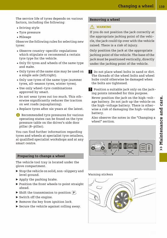
The service life of tyres depends on variousfactors, including the following:
RDriving styleRTyre pressureRMileageObserve the following rules for selecting newtyres:
RObserve country-specific regulationswhich stipulate or recommend a certaintyre type for the vehicle.ROnly fit tyres and wheels of the same type
and make.ROnly tyres of the same size may be used on
a single axle (left/right).ROnly use tyres of the same type (summer
tyres, all-season tyres, winter tyres).RUse only wheel-tyre combinations
approved by smart.RDo not wear tyres out too much. This oth-
erwise significantly reduces the tractionon wet roads (aquaplaning).RReplace tyres after six years at the latest.
i Recommended tyre pressures for variousoperating states can be found on the tyrepressure table on the driver's side doorpillar (B-pillar).
You can find further information regardingtyres and wheels at specialist tyre retailers,at qualified specialist workshops and at anysmart centre.
Preparing to change a wheel
The vehicle tool tray is located under theglove compartment.
X Stop the vehicle on solid, non-slippery andlevel ground.
X Apply the parking brake.X Position the front wheels to point straight
ahead.X Shift the transmission to position j.X Switch off the engine.X Remove the key from ignition lock.X Secure the vehicle against rolling away.
Removing a wheel
G WARNING
If you do not position the jack correctly atthe appropriate jacking point of the vehi-cle, the jack could tip over with the vehicleraised. There is a risk of injury.
Only position the jack at the appropriatejacking point of the vehicle. The base of thejack must be positioned vertically, directlyunder the jacking point of the vehicle.
! Do not place wheel bolts in sand or dirt.The threads of the wheel bolts and wheelhubs could otherwise be damaged whenthe bolts are tightened.
! Position a suitable jack only on the jack-ing points intended for this purpose.Never position the jack on the high-volt-age battery. Do not jack up the vehicle onthe high-voltage battery. There is other-wise a risk of damaging the high-voltagebattery.Also observe the notes in the "Changing awheel" section.
Warning stickers
Changing a wheel 159
>> M
ain
ten
ance
an
d c
are.
Z

Vehicles with steel wheels and hub caps:
X Using both hands, grasp two hub capopenings and remove the hub cap.
Vehicles with steel wheels and hub cap cover:
X Remove the hub cap cover.
X Using wheel wrench : loosen the wheelbolts by about one turn. Do not unscrew thewheel bolts completely.
The vehicle may only be raised at the desig-nated jacking points. These points ; arelocated in the front and the rear directly nextto the wheels. Do not position jack = on theedge of sill :. Otherwise, damage to thevehicle could occur.
X Position jack ; behind the triangularindentations for jacking point :.
X Set the foot of the jack up vertically withrespect to the jacking point on the vehicle.
X Raise the vehicle using the jack until thetyre is a maximum of 3 cm off the ground.
X Unscrew and remove the wheel bolts.X Remove the wheel.
Fitting a wheel
G WARNING
The wheels could work loose if the wheelnuts and bolts are not tightened to thespecified tightening torque. There is a riskof accident.
Have the tightening torque immediatelychecked at a qualified specialist workshopafter a wheel is changed.
G WARNING
If you tighten the wheel bolts or wheel nutswhen the vehicle is raised, the jack couldtip over. There is a risk of injury.
160 Changing a wheel>>
Mai
nte
nan
ce a
nd
car
e.

Only tighten the wheel bolts or wheel nutswhen the vehicle is on the ground.
! When changing a wheel, use only wheelbolts that have been approved for thewheel rim and vehicle.
Always pay attention to the instructions andsafety notices in "Changing a wheel"(Y page 158).
Fit tyres with a specified direction of rota-tion only according to their direction of rota-tion. An arrow on the sidewall of the tyreindicates its correct direction of rotation.
X Clean the wheel and wheel hub contactsurfaces.
X Push the wheel onto the wheel hub andpress it on.
X Screw in the wheel bolts and tighten themslightly.
X Lower the vehicle all the way.X Remove the jack.X Tighten the wheel bolts evenly in a cross-
wise pattern in sequence indicated :
to ?. The tightening torque must be105 Nm.
X Check the recommended tyre pressure andadjust if necessary.
i Vehicles with tyre pressure control sys-tem: all fitted wheels must be equippedwith functioning sensors.
Vehicles with steel wheels and hub caps:
X Fit hub cap A such that valve B does notbecome trapped.
X Press the hub cap evenly onto the wheelwith both hands until you hear the hub capengage.
X Check to make sure the hub cap is seatedsecurely on the wheel.
Vehicle with steel wheels and wheel hub cov-ers:
X Fit the hub cap cover.
Storing wheels
X Store wheels in a cool, dry and dark placewhen not in use.
X Protect against oil, grease and fuel.
Using the tyre pressure monitor
Useful information
It is the driver's responsibility to set the tyrepressure to the recommended cold tyre pres-sure suitable for the operating situation.The tyre pressure monitor issues a warningwhen the pressure drops in one or more of thetyres.The tyre pressure monitor works properlyonly if sensors are present in all four tyres,
Using the tyre pressure monitor 161
>> M
ain
ten
ance
an
d c
are.
Z

and after the monitor has learned the correcttyre pressure for the current operating sit-uation. This occurs automatically in mostsituations, but may also be specified afterrestarting the tyre pressure monitor. Beforerestarting, check the tyres for the recom-mended tyre pressure.The tyre pressure monitor does not provide awarning in the following cases:
REven loss of pressure on multiple tyresRSudden loss of tyre pressure, e.g. due to
penetration by a foreign bodyRIncorrectly set tyre pressureThe tyre pressure monitor has a yellowwarning lamp in the instrument cluster forindicating a pressure loss or malfunction.
Restarting the tyre pressure monitor(on-board computer with a mono-chrome display)
X Set the tyre pressure of all tyres to therecommended value.
X On the multifunction lever press the ´button repeatedly until the ° and hsymbols are displayed in the instrumentcluster display.
X Press and hold the a button on the mul-tifunction lever.The ° and h symbols flash in theinstrument cluster display for approx-imately five seconds. The two symbolsthen light up.
The tyre pressure monitor is restarted.
Restarting the tyre pressure monitor(on-board computer with colour dis-play)
X Set the tyre pressure of all tyres to therecommended value.
X Select Settings > Tyre pressure monitorin the on-board computer.The Tyre pressure monitor Adopt cur‐rent pressures as new reference val‐ues? message appears in the display.
X Select yes and press a to confirm.The display shows the Tyre pressure monitor restarted message.
If the Tyre pressure monitor restartedmessage does not appear after five seconds,restart the tyre pressure monitor again.
Checking the tyre pressures
Please note
G WARNING
Underinflated or overinflated tyres posethe following risks:
Rthe tyres may burst, especially as theload and vehicle speed increase.
Rthe tyres may wear excessively and/orunevenly, which may greatly impairtyre traction.
Rthe driving characteristics, as well assteering and braking, may be greatlyimpaired.
There is a risk of an accident.
Observe the recommended tyre pressureand check the tyre pressure of all the tyres:
Rat least every two weeks
Rwhen the load changes
Rbefore embarking on a longer journey
Rfor changed operating conditions, e.g.off-road driving
If necessary, correct the tyre pressure.
G WARNING
If you mount unsuitable accessories ontotyre valves, the tyre valves may be over-loaded and malfunction, which can causetyre pressure loss. Aftermarket tyre pres-sure monitoring systems will cause thetyre valve to remain open. This can alsoresult in tyre pressure loss. There is a riskof an accident.
Only screw standard valve caps or valvecaps specifically approved by smart foryour vehicle onto the tyre valve.
G WARNING
If the tyre pressure drops repeatedly, thewheel, valve or tyre may be damaged. Tyre
162 Checking the tyre pressures>>
Mai
nte
nan
ce a
nd
car
e.

pressure that is too low may result in a tyreblow-out. There is a risk of accident.
RCheck the tyre for foreign objects.
RCheck whether the wheel is losing air orthe valve is leaking.
If you are unable to rectify the damage,contact a qualified specialist workshop.
H Environmental note
Check the tyre pressure regularly, at leastevery 14 days.
The table with the recommended tyre pres-sure for various operating conditions can befound on the driver's side door pillar(B-pillar).The tyre pressure table may also state airpressures for different load conditions.These are defined in the table as differentnumbers of passengers and amounts of lug-gage. The actual number of seats may differfrom this.If a tyre size precedes a tyre pressure, thetyre pressure information following is onlyvalid for that tyre size. If tyre sizes are notspecified, the tyre pressures stated on thetyre pressure table apply for all approvedtyres.
Checking and correcting the tyre pres-sure manually
Only check the tyre pressure once the tyreshave cooled down.
X Drive the vehicle less than 2 km.X Park the vehicle away from direct sunlight
for at least three hours.
X Check the tyre pressure with a suitabletyre pressure gauge.
X If necessary, adjust the tyre pressure.X Restart tyre pressure monitor.
Using winter tyres
G WARNING
M+S tyres with a tyre tread depth of lessthan 4 mm are not suitable for use in winteras they do not provide sufficient traction.There is a risk of accident.
M+S tyres with a tread depth of less than4 mm must be replaced.
At temperatures below +7 †, summer tyreslose elasticity and therefore traction andbraking power. Change the tyres on yourvehicle therefore to winter tyres or all-sea-son tyres marked with M+S. Using summertyres at very cold temperatures could causetears to form, thereby damaging the tyrespermanently. smart cannot accept responsi-bility for this type of damage.Have the vehicle winterproofed at a qualifiedspecialist workshop at the onset of winter.
X At low temperatures, use only winter tyresmarked with M+S.
X When road conditions are wintry, useM+S tyres with the additional i snow-flake symbol.These tyres allow driving safety systems,e.g. ABS, to function optimally in the win-ter.
X Use M+S tyres of the same make and treadon all wheels.
X When driving with M+S tyres, observe thespecified maximum permissible speed.
X Use only tyre types and sizes approved forsmart.
X When using tyres with a specified direc-tion of rotation, observe the arrow on thesidewall indicating the tyre's direction ofrotation.
Using winter tyres 163
>> M
ain
ten
ance
an
d c
are.
Z

After fitting M+S tyres:
X Check tyre pressure.X Restart tyre pressure monitor.X If M+S tyres with a lower maximum per-
missible speed than that of the vehicle arefitted, affix an appropriate warning labelin the driver's field of vision. Using thelimiter, restrict the speed to the maximumpermissible speed for M+S tyres.
Using snow chains
G WARNING
If you have fitted snow chains to the frontwheels, they may scrape against the vehi-cle body or chassis components. This couldcause damage to the vehicle or the tyres.There is a risk of an accident.
To avoid hazardous situations:
Rnever fit snow chains on the front wheels
Rfit snow chains to the rear wheels inpairs.
! Vehicles with steel wheels: if you fit snowchains on steel wheels, you may damagethe hub caps. Remove the hub caps fromthe relevant wheels before fitting the snowchains.
For safety reasons, smart recommends thatyou only use snow chains that have beenspecially approved for your vehicle by smart.Further information can be obtained at asmart centre or a qualified specialist work-shop.
X Observe country-specific regulations.X Use only snow chains approved for smart.X Fit snow chains on both rear wheels.X Use snow chains only on snow-covered
roads.X When driving with snow chains fitted, do
not exceed the maximum permissiblespeed of 50 km/h.
Changing the window wiper blades
Please note
G WARNING
If the windscreen wipers begin to movewhile you are changing the wiper blades,you can be trapped by the wiper arm. Thereis a risk of injury.
Always switch off the windscreen wipersand ignition before changing the wiperblades.
! Never open the service cover or tailgate ifa wiper arm has been folded away from thewindscreen or rear window. Never fold awiper arm without a wiper blade back ontothe windscreen or rear window. Hold thewiper arm firmly when you change thewiper blade. If you release the wiper armwithout a wiper blade and it falls onto thewindow, the window may be damaged bythe force of the impact.
Changing the window wiper blades onthe windscreen
X Fold the wiper arm away from the wind-screen.
X Press release clips ; on mounting ? inthe direction of windscreen 3. The catchtab is released from the mounting and thewindow wiper blades can be removed fromthe wiper arm.
X Slide window wiper blade : in the direc-tion of arrow 5 until the securing hook forthe window wiper blade is revealed.
X Remove the window wiper blade.
164 Changing the window wiper blades>>
Mai
nte
nan
ce a
nd
car
e.

X Slide new window wiper blade : in thedirection of arrow 4 onto mounting = ofwiper arm ;.The window wiper blade snaps into place.
X Check that the window wiper blade is posi-tioned correctly.
X Carefully fold wiper arm ; onto the wind-screen.
Changing the rear window wiper blade
X Remove key from ignition lock.X Fold wiper arm : away from the rear win-
dow until you hear it engage.X Pull window wiper blade ; in the direc-
tion of the arrow until it is released fromthe retainer on the wiper arm.
X Remove window wiper blade ;.X Slide new window wiper blade ; onto
wiper arm : until it engages.X Turn window wiper blade ; parallel to
wiper arm :.X Check that window wiper blade ; is posi-
tioned correctly.X Fold wiper arm : back onto the rear win-
dow.
Cleaning the vehicle
Useful information
Regular care maintains the appearance andquality of the vehicle over time.Observe the following when cleaning andcaring for the vehicle:
X Do not clean the engine.X Do not clean the vehicle whilst charging.X Use soft, moist cloths.X Use care products and cleaning agents
recommended and approved for smart.X Do not use acidic cleaning agents.X In winter, carefully remove road salt as
soon as possible.
Cleaning the vehicle exterior
Washing in an automatic car wash orwashing by hand
Preparing the vehicle for cleaning
G WARNING
Braking efficiency is reduced after thevehicle has been washed. There is a risk ofan accident.
After washing the vehicle, brake carefullywhile paying attention to the traffic con-ditions in order to restore full braking effi-ciency.
X Close the side windows completely.X Switch off the climate control blower.X Turn the windscreen wipers to position 0.
Washing in an automatic car washX Prepare the vehicle for cleaning.X Remove excess dirt.X Drive through the automatic car wash.X Remove wax from the front windscreen and
the wiper blades.
i If the windscreen wipers leave smearsafter the vehicle has passed through thecar wash, this may be caused by wax orother residue. This residue can be removedwith washer fluid.
Cleaning the vehicle 165
>> M
ain
ten
ance
an
d c
are.
Z

Washing by handX Locate a washing bay equipped for hand-
washing.X Prepare the vehicle for cleaning.X Apply mild cleaning agent with a soft
vehicle sponge.X Thoroughly hose the vehicle with a gentle
jet of water; do not point the water jetdirectly towards the air inlet grille.
X Dry the vehicle off with a chamois.
Cleaning with a high-pressure cleaner
G WARNING
The water jet of circular-jet nozzles (dirtgrinders) can cause damage not visiblefrom the outside to tyres or chassis com-ponents. Components damaged in this waycan unexpectedly fail. There is a risk of anaccident.
Do not use high-pressure cleaners withcircular-jet nozzles to clean the vehicle.Have damaged tyres or chassis compo-nents replaced immediately.
! Always maintain a distance of at least30 cm between the vehicle and the high-pressure cleaner nozzle. Informationabout the correct distance is availablefrom the equipment manufacturer.Move the high-pressure cleaner nozzlearound when cleaning your vehicle.Do not aim directly at any of the following:
RtyresRdoor gaps, roof gaps, joints etc.Relectrical componentsRbatteryRconnectorsRlightsRsealsRventilation slotsDamaged seals or electrical componentscan lead to leaks or failures.
X Prepare the vehicle for cleaning.X Maintain a distance of at least 30 cm
between the high-pressure cleaner nozzleand the vehicle.
X Keep moving the nozzle whilst cleaning.
Cleaning the reversing camera
X Clean camera lens : with water and a softcloth.
Cleaning the sensors
: Active Brake Assist sensor; Parking aid sensors
X Clean sensors with water, car shampoo anda soft cloth.
Cleaning the wheels
G WARNING
The water jet of circular-jet nozzles (dirtgrinders) can cause damage not visiblefrom the outside to tyres or chassis com-ponents. Components damaged in this waycan unexpectedly fail. There is a risk of anaccident.
166 Cleaning the vehicle>>
Mai
nte
nan
ce a
nd
car
e.

Do not use high-pressure cleaners withcircular-jet nozzles to clean the vehicle.Have damaged tyres or chassis compo-nents replaced immediately.
! Do not use acidic wheel cleaning prod-ucts to remove brake dust. This could dam-age wheel bolts and brake components.
! Do not park up your vehicle for a longperiod of time immediately after cleaning,particularly after cleaning the wheel rimwith wheel cleaner. Wheel cleaner maylead to increased corrosion of the brakediscs and pads. You should therefore drivefor a few minutes after cleaning. By heat-ing up the brakes, the brake discs and padsdry. The vehicle can then be parked up fora long period of time.
X Clean the wheels with an acid-free clean-ing agent.
Cleaning the windows and windscreenwipers
Cleaning the windows
G WARNING
If the windscreen wipers are set in motionwhen cleaning the windscreen or wiperblades, you could become trapped. There isa danger of injury.
Always switch off the windscreen wipersand the ignition before cleaning the wind-screen or wiper blades.
X Place the wiper arms in the vertical posi-tion and fold them away from the window.
X Clean the inside and outside of the win-dows with a damp cloth and a cleaningagent recommended for smart.
X Clear deposits regularly from the wind-screen and rear window to ensure thatwater can drain unhindered.
Cleaning the window wiper bladesX Place the wiper arms in the vertical posi-
tion and fold them away from the window.X Clean the window wiper blades with a soft
cloth.X Fold the wiper arms back into place.
Cleaning the panoramic roof
! Only use cleaning agents or cleaningcloths that are suitable for plastic lenses.Unsuitable cleaning agents or cleaningcloths could scratch or damage the plasticpanes of the panorama roof. Do not usecleaning agents containing solvents
X Apply mild cleaning agent for plastic win-dows and wipe off with a moist sponge.
Cleaning the roof
Dry cleaningX Brush from the front to the back using a
soft brush.
Wet cleaningX Dry clean first.X Wash down with a soft brush or sponge and
lukewarm water.X Rinse with clean water.
Cleaning the exterior lighting
X Apply mild cleaning agent for plastic len-ses and wipe off with a wet sponge.
Cleaning and caring for paintwork
! Do not affix stickers to the painted sur-face. Adhesive residue could damage thepaintwork.
X Remove impurities immediately by rub-bing carefully.
X Soak insect remains with insect removerand rinse off.
X Soak bird droppings with water and rinseoff.
X Use tar remover to remove tar stains.X Use silicone remover to remove wax.X Remove coolant, brake fluid, tree resin,
oils, fuels and greases by rubbing care-fully with a cloth soaked in petroleumether or lighter fluid.
Cleaning the vehicle 167
>> M
ain
ten
ance
an
d c
are.
Z

Cleaning the vehicle interior
Cleaning the displays
! For cleaning, do not use any of the fol-lowing:
Ralcohol-based thinner or petrolRabrasive cleaning agentsRcommercially-available household
cleaning agentsThese may damage the display surface. Donot put pressure on the display surfacewhen cleaning. This could lead to irrepar-able damage to the display.
X Switch off the display and let it cool down.X Clean the display surface with a microfibre
cloth and cleaner for TFT or LCD displays.X Dry the display surface using a dry micro-
fibre cloth.
Cleaning the steering wheel and theselector lever
X Wipe off with a moist cloth, or use a leathercare agent recommended for smart.
Cleaning the seat belts
G WARNING
Seat belts may be severely weakened ifbleached or coloured. This may lead to theseat belts, for example, tearing or failing inan accident. There is an increased risk ofinjury, possibly even fatal.
Never bleach or colour seat belts.
! Do not clean the seat belts using chemi-cal cleaning agents. Do not dry the seatbelts at temperatures above 80 † or indirect sunlight.
X Clean the seat belts using only lukewarmsoapy water.
Cleaning and caring for seats
Please note
! Do not use microfibre cloths to clean gen-uine leather or artificial leather covers, asthese are too aggressive and, if used often,may damage the cover.
Regular care maintains the appearance andfeel of the seats over time.
Cleaning and caring for genuine leatherseat coversX Wet a cloth with water and clean the seat
covers. Do not allow the leather to becomesoaked.
X Wipe off with a dry cloth.X Apply a leather care agent recommended
for smart.
Cleaning synthetic leather seat coversX Wet a cloth with detergent water and clean
the seat covers.
Cleaning cloth seat coversX Wet a microfibre cloth with detergent
water.X Rub cloth covers with care, cleaning entire
sections of the cover.X Allow the seat to dry.
Cleaning DINAMICA seat coversX Wet a cloth with water.X Clean entire sections of the cover.
Cleaning the trim
Cleaning the plastic trim
G WARNING
Care products and cleaning agents con-taining solvents can cause surfaces in thecockpit to become porous. This could resultin plastic parts breaking away when theairbags are deployed. There is a danger ofinjury.
Do not use care products and cleaningagents containing solvents to clean thecockpit.
! Never attach the following to plastic sur-faces:
RstickersRfilmsRperfume oil container or similarYou could otherwise damage the plastic.
168 Cleaning the vehicle>>
Mai
nte
nan
ce a
nd
car
e.

To maintain the appearance of high-qualityplastic surfaces, do not allow surfaces tocome into contact with cosmetics, insectrepellents or sun creams.
X Clean the plastic trim with a damp cloth.X Use care products and cleaning agents
recommended for smart to remove heavysoiling.
Cleaning the roof liningX Remove heavy soiling using a soft brush or
a cleaning agent recommended for smart.
Cleaning the carpetsX Use carpet and textile cleaning agents rec-
ommended for smart.
Cleaning the trim elements
! Do not use solvent-based cleaningagents such as tar remover, wheel clean-ers, polishes or waxes. There is otherwise arisk of damaging the surface.
X Clean the trim elements with a moistmicrofibre cloth.
X Use care products and cleaning agentsrecommended for smart to remove heavysoiling.
Observing service due dates
The ¯ and ° indicator lamps in theinstrument cluster display are reminders ofupcoming service due dates:
R¯: minor service.R°: major service.Monochrome display: the indicator lampflashes for a few seconds after the engine isstarted. Depending on the operating condi-tions of the vehicle, the time or distanceremaining until the service is due, is alsodisplayed.The service interval is based on normal oper-ation of the vehicle. Observe the following ifthe vehicle is operated under arduous con-ditions or increased loads, e.g. regular citydriving with frequent intermediate stops:
X Carry out service work more often thanspecified by the service interval.
X Check the tyres more frequently.
Current information on the type of servicecan be obtained at a smart centre or a quali-fied specialist workshop.
Parking up the vehicle
! Please note that if the vehicle is not usedfor prolonged periods, vehicle damage mayoccur and the battery may discharge orbecome damaged.
X Visit a qualified specialist workshop for aconsultation.
Parking up the vehicle 169
>> M
ain
ten
ance
an
d c
are.
Z

Securing the vehicle in the event of anaccident or a breakdown
Securing the vehicle
! When a tyre is damaged, the danger areamust be kept clear of all persons.
X Stop the vehicle away from traffic on solid,non-slippery ground.
X Switch on the hazard warning lights.X Turn the front wheels to the straight-
ahead position.X Switch off the engine.X Passengers should leave the vehicle.X Secure the vehicle against rolling away.X Set up the warning triangle.
In the event of a flat tyre, without TIREFIT thevehicle cannot be made roadworthy againusing the on-board equipment. No emer-gency call can be made via the smart Audio-System. The vehicle owner and the driver ofthe vehicle are responsible for equipping thevehicle with an appropriate breakdown kitand seeking assistance in the event of abreakdown.
Switching the hazard warning lamps onand off
When the hazard warning lamps areswitched on, all the turn signal lamps flash.The hazard warning lamps automaticallyswitch on in the following cases:
Ran airbag is deployed.Rthe vehicle decelerates rapidly from a
speed of above 70 km/h and comes to astandstill.
The hazard warning lamps switch off auto-matically if a speed of 10 km/h is exceededagain after full brake application.
X To switch on the hazard warning lampsmanually: press button :.
Operating the emergency assistancesystem
Useful information
For Russia only:The emergency assistance system is there torescue you and others in an emergency.Should the driver arrive at the scene of anaccident, or feel unwell, an emergency callcan be initiated. The emergency call must notbe deployed in the case of a breakdown or asimilar, non-dangerous situation.The emergency assistance system can helpto radically reduce the time between an acci-dent and the arrival of the emergency serv-ices. The requirement is a stable mobilephone connection; network coverage candepend on the region.If there is no safety risk, in the event of anaccident the vehicle occupants shouldremain in the vehicle after initiating anemergency call.The emergency assistance system has a sep-arate battery. The battery only functionswithin a temperature range of -20 † to 85 †.The battery must be replaced every fouryears. Always have work on the battery car-ried out at a qualified specialist workshop.
Method of operation
After an emergency call has been initiated,the emergency call centre will ascertain ifassistance is required on location.
170 Securing the vehicle in the event of an accident or a breakdown>>
Dea
lin
g w
ith
acc
iden
ts a
nd
bre
akd
own
s.

In the event of an emergency, accident datais forwarded to a public emergency callcentre.The data transferred includes:
RGPS/GLONASS position dataRDirection of travelRTime of initiationThis allows measures for rescue, recovery ortowing away to be initiated quickly.The emergency assistance system consists ofa loudspeaker, the control panel and the tel-ecommunication system. The control panel islocated in the overhead control panel.
: Automatic emergency call indicator lamp; Microphone= SOS button? Call and reception status indicator lamp
Using test mode
In test mode, the driver can check if theemergency assistance system is working. Todo this, a voice message from the driver isrecorded and the test result is transmitted tothe emergency call centre.
X Briefly press SOS button = several timeswithin five seconds.
X Wait for 25 seconds.X Briefly press SOS button = three times
within ten seconds.A tone sounds. Microphone ; records forten seconds.
X Speak any message.A signal sounds after 25 seconds. Therecorded message is played back via theloudspeaker.
X If the voice message is correctly playedback, press and hold SOS button = for fiveseconds.Indicator lamp ? flashes green slowly.
orX If the voice message is incorrectly played
back or not played back at all, press SOSbutton = three times within three sec-onds.Indicator lamp ? flashes red slowly forfive seconds.
Automatic emergency call
Indicator lamp : shows if an automaticemergency call can be initiated.If airbags are deployed, the emergencyassistance system automatically notifies anemergency centre.
i The automatic emergency call is opera-tional as standard.
Triggering an emergency call manually
Manually initiating an emergency call as aperson involved in an accident:
X Press and hold SOS button = for three sec-onds.An emergency call is made.
Manually initiating an emergency call afterwitnessing an accident:
X Press SOS button = five times within tenseconds.The emergency call centre is informed ofthe accident.
Securing the vehicle in the event of an accident or a breakdown 171
>> D
eali
ng
wit
h a
ccid
ents
an
d b
reak
dow
ns.

Securing the vehicle against rollingaway
Securing on level ground
X When changing a wheel, place chocks orother suitable items under the front andrear of the wheel that is diagonally oppo-site the wheel you wish to change.
Securing on a downhill gradient
X Place wheel chocks or other suitable itemsin front of the wheels of the front and rearaxle.
Using the warning triangle
Removing the warning triangle
Warning triangle : is located in the bootbehind the seat backrest, secured to the car-pet with a Velcro fastener. Return it to thislocation after use.
X Remove warning triangle : from the boot.
Setting up the warning triangle
X Fold feet 3 out to the side.X Pull side reflectors 2 upwards to form a
triangle.X Connect the reflectors using upper stud1.
X Place the warning triangle at a suitabledistance.
172 Securing the vehicle in the event of an accident or a breakdown>>
Dea
lin
g w
ith
acc
iden
ts a
nd
bre
akd
own
s.

Using a reflective safety jacket
Notes on reflective safety jackets
: Maximum number of washes; Maximum wash temperature= Do not bleach? Do not ironA Do not use a tumble dryerB Do not dry-cleanC This is a class 2 jacket
The reflective safety jacket only meets therequirements defined by the legal standardif it is the right size and fully closed when inuse.Replace the reflective safety jacket:
Rif it is damaged or there is irremovable dirton the reflective stripesRif you exceed the maximum number of
washesRif the fluorescence has faded
Removing the reflective safety jacket
The reflective safety jacket is located instowage compartment : of the front-passenger door. Reflective safety jackets can
also be stored in the rear door stowage com-partments.
X To remove: take out the safety jacket bagcontaining the reflective safety jacket.
X Open the safety jacket bag and take out thereflective safety jacket.
X To stow: fold the reflective safety jacket,roll it up and stow it in the safety jacketbag.
X Replace the safety jacket bag in stowagecompartment :.
Removing the first-aid kit
i Check the expiry date on the first-aid kitat least once a year. Replace the contents ifnecessary, and replace any missing parts.
First-aid kit ; is located in the boot behindthe seat backrest, secured to the carpet witha Velcro fastener. Return it to this locationafter use.
X Remove first-aid kit ; from the boot.
Removing the fire extinguisher
The fire extinguisher is located underneaththe front passenger seat.
Removing the fire extinguisher 173
>> D
eali
ng
wit
h a
ccid
ents
an
d b
reak
dow
ns.

Removing the vehicle tool tray
The towing eye and the TIREFIT kit are loca-ted in the vehicle tool tray under the glovecompartment.
X Remove bolts in the front-passenger foot-well.
X Remove the vehicle tool tray.
Sealing tyres using the TIREFIT kit
Useful information
The tyre sealant is pumped into the tyre.TIREFIT is a tyre sealant. TIREFIT is used toseal punctures of up to 4 mm, particularlythose in the tyre tread, at outside tempera-tures down to Ò20 †.
i The tyre inflation compressor weighsapproximately 0.7 kg.
At a distance of approximately 60 cm from thetyre inflation compressor, the followingsound pressure level applies:
RX-axis: 82.9 dB (A)RY-axis: 84.3 dB (A)RZ-axis: 84.1 dB (A)The tyre inflation compressor is mainte-nance-free. If there is a malfunction, contacta qualified specialist workshop.
Please note
G WARNING
In the following situations, the tyre seal-ant is unable to provide sufficient break-down assistance, as it is unable to seal thetyre properly:
Rthere are cuts or punctures in the tyrelarger than those mentioned above.
Rthe wheel rim is damaged.
Ryou have driven at very low tyre pres-sures or on a flat tyre.
There is a risk of an accident.
Do not drive any further. Contact a quali-fied specialist workshop.
G WARNING
The tyre sealant is harmful and causesirritation. It must not come into contactwith your skin, eyes or clothing or be swal-lowed. Do not inhale TIREFIT fumes. Keeptyre sealant away from children. There is arisk of injury.
If you come into contact with the tyre seal-ant, observe the following:
RRinse off the tyre sealant from your skinimmediately with water.
RIf the tyre sealant comes into contactwith your eyes, immediately rinse themthoroughly with clean water.
RIf tyre sealant is swallowed, immedi-ately rinse your mouth out thoroughlyand drink plenty of water. Do not inducevomiting, and seek medical attentionimmediately.
RImmediately change out of clothingwhich has come into contact with tyresealant.
RIf an allergic reaction occurs, seek med-ical attention immediately.
G WARNING
A tyre temporarily sealed with tyre sealantimpairs the driving characteristics and is
174 Sealing tyres using the TIREFIT kit>>
Dea
lin
g w
ith
acc
iden
ts a
nd
bre
akd
own
s.

not suitable for higher speeds. There is arisk of accident.
You should therefore adapt your drivingstyle accordingly and drive carefully. Donot exceed the specified maximum speedwith a tyre that has been repaired usingtyre sealant.
The maximum permissible speed for a tyresealed with tyre sealant is 80 km/h.
! After use, excess tyre sealant may run outof the filler hose. This could cause stains.Therefore, place the filler hose in the plas-tic bag that contained the TIREFIT kit.
H Environmental note
Have the used tyre sealant bottle disposedof professionally, e.g. at a qualified spe-cialist workshop.
Comply with the manufacturer's safetyinstructions on the sticker on the tyre infla-tion compressor.
Filling with tyre sealant
X Leave foreign bodies which have penetra-ted the tyre in the tyre.
X Remove the vehicle tool tray.X Remove the TIREFIT kit, consisting of a
tyre sealant bottle and a tyre inflationcompressor, from the vehicle tool kit.
X Affix the 80 km/h maximum speed sticker tothe instrument cluster within the driver'sfield of vision.
X Unwind plug : with the cable from tyreinflation compressor ;.
X Remove hose A from the bottom section oftyre inflation compressor ;.
X Unscrew the cap from tyre sealant bot-tle ?.
X Connect hose A.
X Remove the valve flap from valve E on thefaulty tyre.
X Unscrew the cap from filler hose =.X Screw filler hose = onto valve E.X Insert connector : into the cigarette
lighter socket or the 12 V socket.X Turn the key to position 1 in the ignition
lock.X Press on/off switch B on tyre inflation
compressor ; to position 1.The tyre sealant is pumped into the tyre.The pressure may briefly rise to approx-imately 600 kPa (6.0 bar/86 psi) in pressuregauge C.
i Preventing damage to the tyre inflationcompressorDo not switch off the tyre inflation com-pressor during this phase.
X Let the tyre inflation compressor run for amaximum of 15 minutes, then allow it tocool down.
The tyre pressure must be at least 180 kPa(1.8 bar/26 psi) in pressure gauge C.Allow any leaking tyre sealant to dry. It canthen be removed like a layer of film.Have any clothing stained with tyre sealantcleaned as soon as possible with perchloro-ethylene.
Sealing tyres using the TIREFIT kit 175
>> D
eali
ng
wit
h a
ccid
ents
an
d b
reak
dow
ns.
Z

Further procedure if the pressure of thesealed tyre is below 180 kPa
G WARNING
If the specified tyre pressure still cannotbe reached, the tyre is too badly damaged.The tyre sealant cannot repair the tyre inthis instance. Damaged tyres and low tyrepressures can significantly impair thevehicle's braking and driving character-istics. There is a risk of an accident.
Do not drive any further. Contact a quali-fied specialist workshop.
X Switch off the tyre inflation compressor.X Unscrew the filler hose from the valve of
the defective tyre.Please note that tyre sealant may escapewhen unscrewing.
X Slowly move the vehicle approximately10 m forwards or backwards.
X Pump up the tyre again.After a maximum of 15 minutes, the tyrepressure must be at least 180 kPa (1.8 bar,26 psi).
Further procedure if the pressure of thesealed tyre is at least 180 kPa
X Switch off the tyre inflation compressor.X Unscrew the hose from the valve of the
defective tyre.Please note that tyre sealant may escapewhen unscrewing.
X Stow the tyre sealant bottle and the tyreinflation compressor.
X Perform a test drive.The maximum permissible speed for a tyresealed with tyre sealant is 80 km/h.
X Stop after driving for approximately 3 kmand check the tyre pressure with the tyreinflation compressor.The tyre pressure must now be at least130 kPa (1.3 bar/19 psi). The precise valuesare located on the door pillar (B-pillar) onthe driver's side.
X If necessary, adjust the tyre pressure.X Unscrew the filler hose from the valve on
the sealed tyre.
Please note that tyre sealant may escapewhen unscrewing.
X Screw the valve cap onto the valve of thesealed tyre.
X Pull the tyre sealant bottle out of the tyreinflation compressor. The filler hose stayson the tyre sealant bottle.
X Drive to the nearest qualified specialistworkshop and have the tyre changed there.
X Have the tyre sealant bottle and filler hosereplaced as soon as possible at a qualifiedspecialist workshop.
Adjusting the tyre pressure
Increasing the tyre pressure
X Switch on the tyre inflation compressor.X Observe the display.
Reducing the tyre pressure
X Press button : next to pressure gauge ;.
i Even unused tyre sealant loses its effec-tiveness over time.Have the tyre sealant bottle replaced everyfour years at a qualified specialist work-shop.
176 Sealing tyres using the TIREFIT kit>>
Dea
lin
g w
ith
acc
iden
ts a
nd
bre
akd
own
s.

Towing the vehicle
Please note
G WARNING
Safety relevant functions are restricted orno longer available if:
Rthe ignition is switched off
Rthe brake system or power steering ismalfunctioning
Rthere is a malfunction in the voltagesupply or the vehicle's electrical system.
When your vehicle is towed, you mayrequire considerably more effort to steerand brake. There is a risk of an accident.
In such cases use a rigid towing bar. Beforetowing away, make sure the steeringmoves freely.
G WARNING
If the steering wheel lock is engaged, thevehicle can no longer be steered. There is arisk of an accident.
Always switch on the ignition when towingwith a tow rope or a towing bar.
G WARNING
When towing or tow-starting anothervehicle and its weight is greater than thepermissible gross weight of your vehicle,the:
Rtowing eye may be torn off
Rcar/trailer combination may swerve oreven overturn
There is a risk of an accident.
When towing or tow-starting anothervehicle, its weight should not be greaterthan the permissible gross weight of yourvehicle.
Information on the vehicle's permissiblegross weight can be found on the vehicleidentification plate (Y page 207).
! Observe the following points when tow-ing with a tow rope:
Rsecure the tow rope on the same side onboth vehicles.Rmake sure that the tow rope is not longer
than legally permitted. Mark the towrope in the middle, e.g. with a white cloth(30 x 30 cm). This makes other road usersaware that a vehicle is being towed.Ronly secure the tow rope to the towing
eye.Robserve the brake lamps of the towing
vehicle while driving. Always maintaina distance so that the tow rope does notsag.Rdo not use steel cables or chains to tow
your vehicle. You could otherwise dam-age the vehicle.
! Do not use the towing eyes for recoverypurposes as this could damage the vehicle.If in doubt, recover the vehicle with acrane.
! When towing, pull away slowly andsmoothly. If the tractive power is too high,the vehicles could be damaged.
! You may tow the vehicle for a maximum of50 km. A towing speed of 50 km/h must notbe exceeded.For towing distances over 50 km, the entirevehicle must be lifted up and transported.
Observe the legal requirements for the rele-vant countries when towing.Always have the vehicle transported in thefollowing cases:
RThe warning lamp lights up and Do not tow vehicle with wheels on groundappears in the display of the instrumentcluster.RThe multifunction display is not working.ROne or more of the following warning
lamps is lit up:- þ drive diagnostics (red)- # 12 V batteryRThe brake pedal begins to pulsate as soon
as the towing procedure commences.RThe vehicle must be moved over a long dis-
tance.The transmission must be in position iwhen the vehicle is being towed.
Towing the vehicle 177
>> D
eali
ng
wit
h a
ccid
ents
an
d b
reak
dow
ns.
Z

i Before the vehicle is towed, switch off theautomatic locking feature. The drivercould otherwise be locked out when push-ing or having the vehicle towed.
i Vehicles with the basic carrier fitted:Do not tow the vehicle with the basic car-rier fitted.Do not secure the tow rope or tow bar to thebasic carrier.
Observe the notes on the selector lever whentowing the vehicle.
Fitting the towing eye
The towing eye can be attached to the front orrear of the vehicle.
X Remove the towing eye from the vehicletool tray.
X Carefully prise off cover : on the vehicle.X Screw in the towing eye to the stop.
Towing the vehicle with both axles onthe ground
X Turn the key to position 2 in the ignitionlock.
X Depress the brake pedal and keep itdepressed.
X Shift the automatic transmission to posi-tion i.The selector lever lock can be manuallyreleased in the event of an electrical mal-function.
X Release the brake pedal.X Release the parking brake.X Switch on the hazard warning lights.
Transporting the vehicle
! Only secure the vehicle by the wheels orrims, not by parts of the vehicle such as theaxle or steering components. Otherwisethe vehicle could be damaged.
X Turn the key to position 2 in the ignitionlock. Shift the transmission to position i.
As soon as the vehicle is loaded:
X Apply the parking brake.X Shift the transmission to position j.X Remove the key.X Lash down the vehicle.
Removing the towing eye
X Loosen the towing eye and unscrew it.X Attach the cover to the recess at the top
and engage it at the bottom.X Stow the towing eye in the vehicle tool
tray.
Manually releasing the selector leverlock
In cases of an electrical fault the selectorlever lock can be manually deactivated, e.g.if the parking lock has been deactivated fortowing and should subsequently be re-applied.
178 Manually releasing the selector lever lock>>
Dea
lin
g w
ith
acc
iden
ts a
nd
bre
akd
own
s.

! Do not use any sharp-edged objects toprise out the cover from the centre console.Otherwise, the cover or the centre consolecould be damaged.
X Apply the parking brake.X Open the drawer on the front-passenger
side.X Prise out cover : on the centre console
from bottom edge ; using with a flat,blunt object.
X Pull cover : in the direction of the arrow.
X Pull yellow release = behind the trim upand simultaneously press release but-ton ? on the selector lever.
X Shift the gear selector lever to position ior j.
Replacing the bulbs
Please note
G WARNING
Bulbs, lamps and plug connectors canbecome very hot during use. When replac-
ing a bulb, you could burn yourself onthese components. There is a risk of injury.
Allow these components to cool downbefore replacing the bulb.
Observe the following rules when replacingbulbs:
ROnly replace bulbs when the engine isswitched off.RDo not use bulbs that have been dropped or
show signs of visible damage, e.g.scratches.RDo not touch the glass bulb with your bare
hands.ROnly use bulbs in enclosed lamps designed
for that purpose.ROnly fit spare bulbs of the same type and
with a specified voltage.RDo not allow bulbs to come into contact
with moisture.RHave LEDs changed at qualified specialist
workshops only.Change only the bulbs described below your-self in accordance with the specified bulbtypes.
Replacing front bulbs
Changing dipped-beam and main-beamheadlamps
X Switch off the lights.X Open the service cover.X Remove cover :.X Pull out the connector.X Press retainer ; inwards and to the left.X Pull the bulb out.
Replacing the bulbs 179
>> D
eali
ng
wit
h a
ccid
ents
an
d b
reak
dow
ns.
Z

X Insert the new bulb.X Lock retainer ;.X Insert the connector.X Replace and engage cap :.
Replacing the front turn signal lamps
X Switch off the lights.X Turn the respective front wheel inwards.X Push clamp : downwards.X Remove cover ; upwards.X Turn the bulb holder anti-clockwise and
remove it.X Remove the bulb from the bulb holder.X Insert the new bulb.X Insert the bulb holder and turn it clock-
wise until it engages.X Insert and engage cover ;.
Replacing the side turn signal lamps
X Carefully insert a flat tool into recess :.X Prise out side turn signal ;.X Turn bulb holder in side turn signal ; 90°
anti-clockwise and remove it.
X Remove the bulb from the bulb holder.X Insert the new bulb into the bulb holder.X Insert the bulb holder into side turn sig-
nal ; and turn it 90° clockwise.X Refit side turn signal ;.
Replacing rear bulbs
Replacing the tail lamp bulbs
Tail lamps without partial LEDs
: Rear/brake lamp; Rear fog lamp= Reversing lamp? Turn signals
Tail lamps with partial LEDs
: Turn signals; Reversing lamp
180 Replacing the bulbs>>
Dea
lin
g w
ith
acc
iden
ts a
nd
bre
akd
own
s.

Removing the tail lamp cover
X Switch off the lights.X Open the tailgate.X Loosen screws :.X Remove the tail lamp.X Carefully insert a flat tool under the plas-
tic hanger on the tail lamp.X Lift the connector and remove it.
Replacing a faulty tail lamp bulb
: Rear lamp/brake lamp (vehicles withoutpartial LEDs)
; Turn signals= Reversing lamp? Rear fog lamp (vehicles without partial
LEDs)
X Release four tabs A on the bulb holder.X Remove the bulb holder.X Pull the faulty bulb out.X Insert the new bulb.X Refit the bulb holder.X Insert the connector.X Insert the tail lamp until you hear it
engage.X Tighten the screws on the tail lamp.
Replacing the licence plate lighting
X Insert a flat tool into recess :.X Remove the cover from the licence plate
lamp.X Remove the bulb from the holder.X Insert the new bulb into the holder.X Insert the lamp lens into the licence plate
lamp.
Replacing the interior lighting
X Insert a flat tool into the recess.X Prise out lamp lens :.X Remove the bulb from the holder.X Insert the new bulb into the holder.X Refit the lamp lens.
Changing fuses
Please note
G WARNING
If you manipulate, bridge or replace afaulty fuse with a fuse of a higher amper-
Changing fuses 181
>> D
eali
ng
wit
h a
ccid
ents
an
d b
reak
dow
ns.
Z

age, the electric cables could be overloa-ded. This may result in a fire. There is a riskof an accident and injury.
Always replace faulty fuses with specifiednew fuses of the correct amperage.
! Only use fuses that have been approvedfor smart vehicles and which have the cor-rect fuse rating for the system concerned.Components or systems could otherwise bedamaged.
! Make sure that no moisture can enter thefuse box when the cover is open.
The electrical fuses disconnect defective cir-cuits. If a fuse blows, all the connected com-ponents and their functions will fail.Blown fuses must be replaced with fuses ofthe same rating, which you can recognise bythe colour and fuse rating. The fuse ratingsare listed in the fuse allocation chart(Y page 210).If new fuses blow, the cause for this must bediagnosed and rectified at a qualified spe-cialist workshop.
Preparing the vehicle to change a fuse
X Apply the parking brake.X Switch off all electrical consumers.X Turn the key to position u in the ignition
lock and remove it.X Check whether all indicator lamps in the
instrument cluster are off.
Replacing a fuse (left-hand drive vehi-cle)
! Do not use a pointed object such as ascrewdriver to open the cover in the dash-board. You could damage the dashboard orthe cover.
X Open the front-passenger door.X Open the glove compartment.X To open: open cover : in the direction of
the arrow.X Replace the faulty fuse.X To close: insert and fold in cover : until it
engages.X Close the glove compartment.
Replacing a fuse (right-hand drivevehicle)
X Open the driver’s door.X To open: turn quick-release fastener ; by
90° using a suitable object.X Fold down cover :.X Replace the faulty fuse.X To close: close cover :.X Close quick-release fastener ;.
182 Changing fuses>>
Dea
lin
g w
ith
acc
iden
ts a
nd
bre
akd
own
s.

Replacing the key battery
G WARNING
Batteries contain toxic and corrosive sub-stances. If batteries are swallowed, it canresult in severe health problems. There is arisk of fatal injury.
Keep batteries out of the reach of children.If a battery is swallowed, seek medicalattention immediately.
H Environmental note
Batteries contain pollu-tants. It is illegal to dis-pose of them with thehousehold rubbish. Theymust be collected sepa-rately and disposed of inan environmentallyresponsible recycling sys-tem.
Dispose of batteries in anenvironmentally respon-sible manner. Take dis-charged batteries to aqualified specialist work-shop or to a collectionpoint for used batteries.
X Fixed keys: unscrew screw :.
X Insert a flat tool, e.g. a coin, into the recess.X Turn the tool until the cover of the battery
tray opens.
X Replace battery ; with the positive ter-minal facing upwards.
X Replace the cover on the battery tray andpush it closed.
X Fixed keys: screw in screw :.X Check the function of all key buttons.
Opening a door with the emergencyrelease
Opening a door with the emergency release 183
>> D
eali
ng
wit
h a
ccid
ents
an
d b
reak
dow
ns.
Z

If the vehicle cannot be opened using theremote control key, the vehicle can be openedusing the emergency release.If the driver's door is unlocked and openedwith the key in the emergency release, theanti-theft alarm system will issue an alarm.To disable the alarm, switch on the ignition.
X Insert the key into the emergency releaseon the driver's door.
X Turn the key anti-clockwise.X Remove the key from the lock.X Open the door.X To disable the alarm from the anti-theft
alarm system: switch on the ignition.
On right-hand-drive vehicles, the emer-gency release is located on the front-passenger door.
Locking the doors in an emergency
Locking the doors with the locking but-ton
X Open the driver’s door.X Close the other doors and the tailgate.X Press and hold button :. An audible lock-
ing and unlocking sound can be heard.Wait until the third (locking) sound, beforereleasing button :.
X Leave the vehicle and close the driver'sdoor.The doors, tailgate and socket cap arelocked. The anti-theft alarm system isprimed.
X From the outside, check that the doors,tailgate and socket cap are locked.
Locking the doors with the emergencylocking
X Insert the key into slot : on the left door.X Turn the key towards the bonnet as far as it
will go to position 2.X Close the left door.X Repeat the procedure described above on
the right door.X Check that the doors are locked.
i If you lock the vehicle using emergencylocking, the tailgate and socket cap are notlocked. The anti-theft alarm system is notprimed.
Unlocking the tailgate with the emer-gency release
! The tailgates swing to the rear, bothupwards and downwards, when opened.Therefore, make sure that there is suffi-cient clearance above, behind and belowthe tailgates.
If the tailgate can no longer be opened fromoutside the vehicle, it can be opened from theinside using the emergency release.
184 Unlocking the tailgate with the emergency release>>
Dea
lin
g w
ith
acc
iden
ts a
nd
bre
akd
own
s.

X Fold the rear seat backrest forward.X Slide lever : on the tailgate to the left
until the tailgate is unlocked.
Unlocking the tailgate with the emergency release 185
>> D
eali
ng
wit
h a
ccid
ents
an
d b
reak
dow
ns.
Z

Notes on display messages
The display shows warnings, malfunctionsor additional information. A warning tonealso sounds with some display messages.Messages from all categories can containimportant information that must beobserved. Have error messages checked at aMercedes-Benz Service Centre as soon aspossible. If an error message is not followedup with a repair, this can lead to damage thatis not covered by the Mercedes-Benz LimitedWarranty including injuries or materialdamage.
Display messages with graphic symbols aresimplified in the Owner's Manual and maydiffer from the symbols in the display.Colour display: low-priority display mes-sages can be hidden by pressing a on thesteering wheel. High-priority messages areshown in red. The display messages are thenstored in the message memory and can becalled up for as long as the ignition remainsswitched on. Switching off the ignition clearsthe message memory.
Locking and unlocking
Problem Possible causes/consequences and M Solutions
Key will not lock orunlock the vehicle.
A strong source of radio waves is interfering with the signal.
X Stand closer to the door lock and try to lock/unlock the vehicleagain.
Key battery is low or discharged.
X Unlock the vehicle with the key in the emergency release or lockthe vehicle with emergency locking.
X Replace the key battery.
Key is faulty.To lock:
X Press the locking button and close the door within five seconds.
The vehicle still will not lock.
X Lock driver's door using emergency locking.X Consult a qualified specialist workshop.
To unlock:
X Unlock vehicle with the key in the emergency release.X Consult a qualified specialist workshop.
Key is lost. X Have the key deactivated or replaced at a qualified specialistworkshop.
X Report loss of the key to vehicle insurer.
Warning tone sounds. Driver's door is opened while the engine is running.
Switch off the engine before leaving the vehicle:
X Apply the parking brake.X Select transmission position j.X Turn the key to position u in the ignition lock and remove it.
186 Locking and unlocking>>
Pra
ctic
al a
dvi
ce.

Problem Possible causes/consequences and M Solutions
Side window will notclose or will not open orclose fully.
Objects are obstructing the window guide.
X Remove objects.
Side window is not reset.
G WARNING
While closing the side windows, body parts in the closing areacould become trapped. There is a risk of injury.
When closing make sure that no parts of the body are in theclosing area. If somebody becomes trapped, release the switchor press the switch to open the side window again.
X Close all doors.X Turn the key to position 2 in the ignition lock.X Pull the switch for closing the window until the window is
closed, and then push the switch for one second.
The side window opens again a little way.
X Repeat previous step until the window remains closed afterreleasing the switch.
Folding top will notclose.
Folding top is obstructed during closing and reopens againslightly.
X Immediately after it is obstructed, press the top part of thefolding top switch again until the folding roof is fully closed.Folding top is closed with increased force.
C Red warning lampis lit.If the speed exceeds20 km/h, a warningtone also sounds.Colour display: the dis-play shows an opendoor/tailgate.
Door or tailgate is open.
X Pull over and stop the vehicle, paying attention to road andtraffic conditions.
X Close all doors and the tailgate.
Locking and unlocking 187
>> P
ract
ical
ad
vice
.
Z

Vision, vehicle occupants, airbag
Problem Possible causes/consequences and M Solutions
The exterior mirror isnot engaged.
The exterior mirror has been moved forwards or backwards byforce.
X Carefully move the exterior mirror to the correct position.
The windscreen wipershave malfunctioned.
The windscreen wipers are obstructed, e.g. by snow.
X Pull over and stop the vehicle, paying attention to road andtraffic conditions.
X Remove the key from ignition lock.X Remove the cause of the obstruction.X Switch the windscreen wipers on again after 30 seconds.
The windscreen wiper drive is malfunctioning.
X Select another wiper speed on the combination switch.X Consult a qualified specialist workshop.
The windscreen wiperswill not stop or alwayswipe at the same speed.
The combination switch or rain sensor is malfunctioning.
X Pull over and stop the vehicle, paying attention to road andtraffic conditions.
X Remove the key from ignition lock.
X Insert the key into the ignition lock, turn to position 1 andstart the engine.
X Consult a qualified specialist workshop.
The red 7 warninglamp lights up for 6seconds after startingthe engine (certaincountries only).A warning tone sounds.
The warning lamp prompts the driver and front passenger to fas-ten their seat belts.
X Fasten the seat belts.
The red 7 warninglamp lights up afterstarting the engine.
The driver or front passenger has not fastened their seat belt.
X Fasten the seat belts.
The red 7 warninglamp flashes.A warning tone sounds.
The driver or front passenger has not fastened their seat belt andthe vehicle is travelling faster than 20 km/h.
X Fasten the seat belts.
188 Vision, vehicle occupants, airbag>>
Pra
ctic
al a
dvi
ce.

Problem Possible causes/consequences and M Solutions
The red 6 warninglamp lights up whilethe engine is running.Colour display: Mal‐function Visit work‐shop appears.
The restraint system is malfunctioning.
G WARNING
If the restraint system is malfunctioning, restraint systemcomponents may be triggered unintentionally or may notdeploy as intended during an accident. This may affect the seatbelt tensioner or airbag, for example. This poses an increasedrisk of injury or even fatal injury.
Have the restraint system checked and repaired immediately ata qualified specialist workshop.
The 4 indicatorlamp on the overheadcontrol panel lights up.
The front-passenger front airbag has been disabled (Y page 41).
X Enable the front-passenger front airbag.
The front-passenger front airbag has not been disabled and ismalfunctioning.
X Do not use a rearward-facing child restraint system on thefront-passenger seat.
X Do not allow passengers to travel on the front-passenger seat.X Consult a qualified specialist workshop.
The × indicatorlamp on the overheadcontrol panel lights up.
Front-passenger front airbag is enabled (Y page 41). The airbagsystem is operating correctly.
X Do not use a rearward-facing child restraint system on thefront-passenger seat.
The × indicatorlamp on the overheadcontrol panel does notlight up if the front-passenger front airbaghas been enabled man-ually.
There is a malfunction in the airbag system.
X Do not allow passengers to travel on the front-passenger seat.X Consult a qualified specialist workshop.
Vision, vehicle occupants, airbag 189
>> P
ract
ical
ad
vice
.
Z

Engine, brakes, transmission
Problem Possible causes/consequences and M Solutions
The engine will notstart using the key.
The steering lock is manually locked.
X Remove the key from the ignition lock and then reinsert it intothe ignition lock.
X Turn the key.X Turn the steering wheel left and right.
The red þ warninglamp lights up.A warning tone sounds.Without starting motor again, visit workshop appears.
There is a serious malfunction in the high-voltage electrical sys-tem.The engine can no longer be started.
X Do not restart the engine.X Consult a qualified specialist workshop.
The red þ warninglamp lights up.Stop Switch off motor appears.
The high-voltage electrical system, engine or high-voltage bat-tery is malfunctioning.
X Switch off the engine.X Do not drive on.X Consult a qualified specialist workshop.X Do not tow away the vehicle on its own wheels.
The red þ warninglamp lights up.A warning tone sounds.Stop appears.
Communication with the engine's control unit is malfunctioning.
X Switch off the engine.X Do not drive on.X Consult a qualified specialist workshop.X Do not tow away the vehicle on its own wheels.
The yellow þ warn-ing lamp lights up.A warning tone sounds.Malfunction Visit workshop appears.
There is a malfunction in the high-voltage electrical system. Thevehicle's high-voltage electrical system may become damaged ifyou continue running the engine.
X Switch off the engine.X Do not drive on.X Consult a qualified specialist workshop.X Do not tow away the vehicle on its own wheels.
The red þ warninglamp lights up.A warning tone sounds.Reduce speed appears.
The speed of the vehicle is above 135 km/h.
X Reduce the speed to below 135 km/h.
lights up.Do not tow vehicle with wheels on ground appears.
The drive system or high-voltage electrical system is faulty.
X Have the vehicle transported by a qualified specialist work-shop.
X Do not tow away the vehicle on its own wheels.
190 Engine, brakes, transmission>>
Pra
ctic
al a
dvi
ce.

Problem Possible causes/consequences and M Solutions
The red J warninglamp lights up whilethe engine is running.A warning tone sounds.Colour display: Check brake fluid levelappears.
Brake fluid level is too low.
G WARNING
If the brake fluid level is too low the brake system may fail.There is a risk of an accident.
Stop the vehicle in accordance with the traffic conditions.Secure the vehicle by applying the parking brake. Do not driveany further. Consult a qualified specialist workshop immedi-ately and have the brake system repaired.
Do not top up the brake fluid, as this will not rectify the fault.
X Consult a qualified specialist workshop.
The red J warninglamp lights up whiledriving.A warning tone sounds.Colour display:Release parking brake appears.
The parking brake is applied.
X Release the parking brake.
The red J warninglamp lights up whilethe engine is running.A warning tone sounds.Colour display: Brake system malfunction Stop appears.
There is a serious malfunction in the brake system.
X Consult a qualified specialist workshop.
The yellow J warn-ing lamp lights up.Colour display: Mal‐function Visit work‐shop appears.
There is a malfunction in the vacuum supply of the brake system.
X Consult a qualified specialist workshop.
Monochrome display:i or j flash alter-nately in the middle ofthe display.Colour display: To start engine: shift to P or N appears.
An attempt was made to start the engine with the transmission inposition h or k.
X Shift to j or i to start.
Engine, brakes, transmission 191
>> P
ract
ical
ad
vice
.
Z

Problem Possible causes/consequences and M Solutions
Monochrome display:j or h/k, i flashalternately.A warning tone sounds.Colour display: Risk of vehicle rolling away Transmission not in P appears.A warning tone sounds.
The driver's door is open and the selector lever is in position k,i or h.
G WARNING
The vehicle may roll away.There is a risk of an accident.
X Shift to position j.X Switch off the engine.X Close the driver's door completely.
¯ or ° warninglamp flashes for a fewseconds after startingthe engine.Colour display: Next service due in … kmor Service due … days ago appears.
A service due date is approaching or has already passed:
R¯ indicates a minor service.R° indicates a full service.
X Consult a qualified specialist workshop.
Charging process
Problem Possible causes/consequences and M Solutions
The charge socket flapcannot be opened.
The charge socket flap is not unlocked.
X Press the # button on the key.
The key batteries are discharged.
X Opening a door with the emergency release
The charging cablecannot be plugged intothe vehicle socket.
The vehicle socket is locked.
X Make sure that the selector lever is in position j.
The indicator lamp onthe vehicle socketflashes red. The high-voltage battery is notbeing charged.
A fault occurred while initializing the charging process.
X Make sure that the charging cable is plugged into the mainssocket.
X Disconnect the charging cable connector from the vehiclesocket and plug it back into the vehicle socket after 30 seconds.
X If the malfunction should persist, inform a qualified specialistworkshop.
192 Charging process>>
Pra
ctic
al a
dvi
ce.

Problem Possible causes/consequences and M Solutions
The indicator lamp onthe vehicle socketremains off after thecharging cable con-nector has been con-nected to the vehiclesocket. When chargingusing a mains socket,the high-voltage bat-tery is not charged.
There is a malfunction at the mains socket.
X Have the mains socket checked to ensure that it is workingcorrectly.
orX Use a different mains socket.
è lights up.Warning tone sounds.Charger cable con‐nected appears.
The charging cable is plugged into the vehicle socket. The enginecannot be started.
X Before driving off, disconnect the charging cable from thevehicle socket and stow it away in the vehicle.
è flashes.Charging cable not inserted correctlyappears.
The charge cable is connected to the vehicle socket. The battery isnot being charged.
X Make sure that the charging cable is correctly plugged into thesockets on the vehicle and power connection. If necessary, dis-connect the charging cable from the sockets and then reconnectit.
If the message continues to be displayed:
X Consult a qualified specialist workshop.
The charging cableconnector cannot beremoved from the vehi-cle socket.
The charging cable connector is not unlocked.
X Press the # button on the key.This unlocks the charging cable connector in the vehiclesocket.
X Remove charging cable connector from the vehicle socket.
Charging not possi‐ble Power supply interrupted appears.
The high-voltage battery cannot be charged. The charge currentwas interrupted during the charging process.
X Make sure that the charging cable is plugged into the mainssocket.
X Disconnect the charging cable connector from the vehiclesocket and plug it back into the vehicle socket after 30 seconds.
If the message continues to be displayed:
X Consult a qualified specialist workshop.
Charging process 193
>> P
ract
ical
ad
vice
.
Z

Problem Possible causes/consequences and M Solutions
Charging not possi‐ble s. Owner's Man‐ual appears.
Communication with the charging point infrastructure is notfunctioning correctly.
X Make sure that the charging cable is correctly plugged into thesockets on the vehicle and power connection. If necessary, dis-connect the charging cable from the sockets and then reconnectit.
If the message continues to be displayed:
X Use a different charging station.
If the message continues to be displayed:
X Consult a qualified specialist workshop.
þ Yellow warninglamp lights up.Charging not possi‐ble Visit workshopappears.
The vehicle electronics are malfunctioning. The high-voltagebattery cannot be charged.
X Consult a qualified specialist workshop.
þ Yellow warninglamp lights up.Charging not possi‐ble s. Owner's Man‐ual appears.
The high-voltage battery cannot be charged. The charging cableconnector is overheated.
X Remove the charging cable connector from the vehicle socket.X Allow the charging cable connector to cool off for several
minutes.X Plug the charging cable back into the vehicle socket.
If the message continues to be displayed:
X Consult a qualified specialist workshop.
The indicator lamp onthe vehicle socket doesnot light up. The high-voltage battery is notbeing charged.
The vehicle is inactive.
X Activate the vehicle by pressing the # button on the key andlock it again.
The charging cablecannot be removed.
The vehicle is in charging mode or has completed active charging.
X Unlock the charging lock by pressing the # button on the key.
194 Charging process>>
Pra
ctic
al a
dvi
ce.

Driving safety systems
Problem Possible causes/consequences and M Solutions
! Yellow warninglamp lights up.Colour display: System inoperative appears.
ABS is malfunctioning. Other driving systems may be deactiva-ted.If ABS is faulty, there is also a possibility that other driving sys-tems may be unavailable.Observe the information on the ABS warning lamp and displaymessages which may be shown in the instrument cluster.
G WARNING
If ABS is faulty, the wheels could lock when braking. The steer-ability and braking characteristics may be severely impaired.Additionally, further driving safety systems are deactivated.There is an increased danger of skidding and accidents.
Drive on carefully. Have ABS checked immediately at a qualifiedspecialist workshop.
When ABS is malfunctioning, other systems, including drivingsafety systems, will also become inoperative. Observe the infor-mation on the ABS warning lamp and display messages whichmay be shown in the instrument cluster.
X Pull over and stop the vehicle, paying attention to road andtraffic conditions.
X Secure the vehicle against rolling away.X Consult a qualified specialist workshop.
J Red warning lamplights up while theengine is running.Warning tone sounds.Colour display: Brake force distribution inoperative. Stop See Owner's Manualappears.
EBD is malfunctioning. This means that ABS, ESP®, CrosswindAssist and Hill start assist are also unavailable.Other driving systems may be deactivated.
G WARNING
The brake system continues to function normally, but without thefunctions listed above. The wheels could therefore lock early ifyou brake hard, for example.The steerability and braking characteristics may be severelyaffected. The braking distance may increase in emergency brak-ing situations.
If ESP® is not operational, the vehicle will not be stabilised byESP®.The danger of skidding and having an accident increases.
X Pull over and stop the vehicle, paying attention to road andtraffic conditions.
X Secure the vehicle against rolling away.X Consult a qualified specialist workshop.
Driving safety systems 195
>> P
ract
ical
ad
vice
.
Z

Problem Possible causes/consequences and M Solutions
÷ Monochrome dis-play: yellow warninglamp lights up whilethe engine is running.÷ Colour display:yellow warning lamplights up.System inoperativeappears.
ESP® is not available due to a malfunction. Other driving systemsmay be deactivated.
G WARNING
If ESP® is malfunctioning, ESP® is unable to stabilise the vehi-cle. In addition, other driving safety systems are switched off.This increases the risk of skidding and an accident.
Drive on carefully. Have ESP® checked at a qualified specialistworkshop.
Brake lamps may be inoperative and thus no longer working whenbraking.
X Pull over and stop the vehicle, paying attention to road andtraffic conditions. Do not drive on.
X Check that the brake lamps are working.
The brake lamps are not working.
X Consult a qualified specialist workshop.
Brake lamps are working.
X Drive on carefully.X Consult a qualified specialist workshop.
÷ Colour display:yellow warning lamplights up.Brake Assist System (BAS) inoperativeappears.
The Brake Assist System (BAS) is inoperative.
X Consult a qualified specialist workshop.
÷ Yellow warninglamp flashes whiledriving.
ESP® is intervening because there is a risk of skidding or at leastone of the wheels is spinning.
X Pull away carefully.X Accelerate carefully whilst driving.X Adapt your driving style to suit the road and weather condi-
tions.
÷ and C andother warning lampsare lit.Colour display: Elec‐tronics malfunction Visit workshopappears.
Central vehicle electronics system is malfunctioning.After switching off the engine, it is no longer possible to lock orunlock the doors using the remote control on the key or to start theengine.
X Pull over and stop the vehicle, paying attention to road andtraffic conditions.
X Consult a qualified specialist workshop.
196 Driving safety systems>>
Pra
ctic
al a
dvi
ce.

Problem Possible causes/consequences and M Solutions
Colour display: ÷Hill start assist inoperative appears.
Hill start assist is malfunctioning. Vehicle will not be held auto-matically when pulling away uphill and may start rolling imme-diately.
G WARNING
If ESP® is malfunctioning, ESP® is unable to stabilise the vehi-cle. In addition, other driving safety systems are switched off.This increases the risk of skidding and an accident.
Drive on carefully. Have ESP® checked at a qualified specialistworkshop.
Other driving systems may be deactivated.
The brake system functions normally, but without hill startassist.
X Drive on carefully.X Consult a qualified specialist workshop.
h Yellow warninglamp lights up whiledriving.Colour display: Cor‐rect tyre pressureappears.
The tyre pressure is too low in at least one of the tyres, or the tyrepressure difference between the wheels is too great.
X Check tyre pressure.X Correct the tyre pressure.X Restart tyre pressure monitor.
Driving safety systems 197
>> P
ract
ical
ad
vice
.
Z

Problem Possible causes/consequences and M Solutions
h Yellow warninglamp lights up whiledriving.Colour display: Tyre pressure Caution tyre malfunctionappears.
The tyre pressure monitor has detected a significant loss of pres-sure in at least one of the tyres.
G WARNING
Underinflated or overinflated tyres pose the following risks:
Rthe tyres may burst, especially as the load and vehicle speedincrease.
Rthe tyres may wear excessively and/or unevenly, which maygreatly impair tyre traction.
Rthe driving characteristics, as well as steering and braking,may be greatly impaired.
There is a risk of an accident.
Observe the recommended tyre pressure and check the tyrepressure of all the tyres:
Rat least every two weeks
Rwhen the load changes
Rbefore embarking on a longer journey
Rfor changed operating conditions, e.g. off-road driving
If necessary, correct the tyre pressure.
X Secure the vehicle against rolling away.X Check tyres visually and, if necessary, follow the instructions
for flat tyres.X Check the tyre pressure and correct it if necessary.
h Yellow warninglamp flashes forapproximately oneminute and then stayslit.Colour display: Tyre pressure monitor inoperative appears.
The tyre pressure monitor is malfunctioning or was not restartedafter a wheel change.
G WARNING
If you correct the tyre pressure without recalibrating the RunFlat Indicator, the system cannot issue a warning about adefective tyre in time. In the event of tyre pressure loss, thedriving characteristics and the steering and braking may begreatly impaired. There is a risk of an accident.
If you correct the tyre pressure, you must recalibrate the RunFlat Indicator.
X Restart tyre pressure monitor.
The display message continues to be displayed.
X Drive on carefully.X Consult a qualified specialist workshop.
198 Driving safety systems>>
Pra
ctic
al a
dvi
ce.

Problem Possible causes/consequences and M Solutions
h Yellow warninglamp flashes forapproximately60 seconds and thenremains lit.Colour display: Tyre pressure monitor inoperative wheel sensors missingappears.
There is no signal from the tyre pressure sensor of one or morewheels.
G WARNING
Risk of accident due to undetected tyre pressure losses. The sys-tem is possibly unable to recognise or register low tyre pressure.
X Consult a qualified specialist workshop.
Wheels have unsuitable tyre pressure sensors.
X Fit wheels with suitable tyre pressure sensors.
J Red warning lampis lit.÷, ! yellowwarning lamps light upwhile the engine isrunning.Warning tone sounds.Colour display: Elec‐tronics malfunction Stop See Owner's Manual appears.
The following systems are malfunctioning:
RABS (anti-lock braking system)RESP® (Electronic Stability Program)RCrosswind AssistRHill start assistFurther driving systems could be switched off automatically.
G WARNING
The risk of skidding and having an accident increases due tomalfunctioning driving safety systems.The brake system functions normally, but without the systemslisted. The wheels could therefore lock if you brake hard,for example.This will greatly impair the ability to steer and brake. The brak-ing distance may increase in emergency braking situations.
X Pull over and stop the vehicle, paying attention to road andtraffic conditions.
X Consult a qualified specialist workshop.
Driving safety systems 199
>> P
ract
ical
ad
vice
.
Z

Problem Possible causes/consequences and M Solutions
Monochrome display:D yellow warninglamp lights up whilethe engine is running.
Power assistance may be malfunctioning, making steering diffi-cult.
G WARNING
You will need to use more force to steer.There is a risk of an accident.
X Check whether you are able to apply the extra force required.
If you are able to steer safely:
X Drive on carefully.X Visit a qualified specialist workshop immediately.
If you are unable to steer safely:
X Do not drive on.X Consult a qualified specialist workshop.
D Yellow warninglamp lights up whilethe engine is running.Colour display: Steer‐ing malfunction See Owner's ManualorElectronics mal‐function See Own‐er's Manual appears.
Power assistance may be malfunctioning, making steering diffi-cult.
G WARNING
You will need to use more force to steer.There is a risk of an accident.
X Check whether you are able to apply the extra force required.
If you are able to steer safely:
X Drive on carefully.X Visit a qualified specialist workshop immediately.
If you are unable to steer safely:
X Do not drive on.X Consult a qualified specialist workshop.
Driver assistance systems
Problem Possible causes/consequences and M Solutions
· Red warning lampis lit.Warning tone sounds.
Collision warning detects an obstacle on the road.
X Pay careful attention to the road and traffic conditions and beready to brake.
· Red warning lampis lit.
Distance to the vehicle in front is too short for the current speed.
X Increase the distance.
^ Yellow warninglamp lights up whiledriving.Colour display: Active Brake Assist inoper‐
The sensors in the radiator trim are dirty.
X Clean the sensors.
200 Driver assistance systems>>
Pra
ctic
al a
dvi
ce.

Problem Possible causes/consequences and M Solutions
ative or Electronics malfunction Visit workshop appears.
Environmental influences or error sources outside the system aretemporarily interfering with Active Brake Assist and radar-assisted recuperation. Possible causes:
Rheavy rain or snowRoperating temperature is too highRon-board voltage is too lowActive Brake Assist is automatically operational again when thecauses listed no longer apply.
Warning lamp remains lit:
X Pull over and stop the vehicle, paying attention to road andtraffic conditions.
X Clean the sensors.X Restart the engine.
Warning lamp still remains lit:
X Consult a qualified specialist workshop.
^ and C as wellas other warning lampsare lit.
Central vehicle electronics system is malfunctioning.After switching off the engine, it is no longer possible to lock orunlock the doors using the remote control on the key or to start theengine.
X Pull over and stop the vehicle, paying attention to road andtraffic conditions.
X Consult a qualified specialist workshop.
à flashes forapproximately threeseconds.Warning tone sounds.Colour display: Lane Keeping Assist inop‐erative appears.
Windscreen is dirty in the camera's field of vision.
X Pull over and stop the vehicle, paying attention to road andtraffic conditions.
X Clean the windscreen.
Environmental influences are interfering with Lane KeepingAssist. Possible causes:
Rheavy rain or snow or thick fog is impairing visibilityRthe sun is low in the sky and shining directly onto the sensorRlane markings cannot be detectedLane Keeping Assist is automatically operational again when thecauses listed no longer apply.If the windscreen is clean and the causes listed do not apply, thenthe electronics are malfunctioning.
System electronics are faulty.
X Consult a qualified specialist workshop.
Driver assistance systems 201
>> P
ract
ical
ad
vice
.
Z

Problem Possible causes/consequences and M Solutions
¤ flashes for a max-imum of five seconds.Colour display: thegreen à warninglamp flashes for a max-imum of five seconds.Warning tone sounds.
A lane boundary marking was crossed without using the turnsignal.
X Stay inside the lane boundary markings.X Use indicator before changing lanes.
¯ flashes forapproximately ten sec-onds.Warning tone sounds.Colour display: ¯Cruise control inop‐erative appears.
Cruise control is malfunctioning and deactivates automatically.
X Consult a qualified specialist workshop.
¯ flashes forapproximately ten sec-onds. C and otherwarning lamps are alsolit.Warning tone sounds.Colour display: Elec‐tronics malfunction Visit workshopappears.
Central vehicle electronics system and cruise control are mal-functioning. After switching off the engine, it is no longer pos-sible to lock or unlock the doors using the remote control on thekey or to start the engine.
X Pull over and stop the vehicle immediately, paying attention toroad and traffic conditions.
X Consult a qualified specialist workshop.
È lights up.Speed display flashes.Warning tone sounds.
Vehicle is exceeding the set limit speed.
X Brake the vehicle, paying attention to road and traffic condi-tions.
È flashes forapproximately ten sec-onds.Warning tone sounds.Colour display: Lim‐iter inoperativeappears.
Speed limiter is malfunctioning and deactivates automatically.
X Consult a qualified specialist workshop.
Ò warning lampflashes for a minute orlights up continuously.Colour display: Black ice warning appears.
The outside temperature has fallen to or below 3 °C. There is a riskof black ice.
X Adapt your driving style and speed to suit the weather condi-tions.
202 Driver assistance systems>>
Pra
ctic
al a
dvi
ce.

Battery, lights, heating
Problem Possible causes/consequences and M Solutions
Rear window heatingor seat heatingswitches off automati-cally or cannot beswitched on.
Battery is not sufficiently charged.
X Switch off electrical consumers that are not required.
Ý Yellow warninglamp lights up.Battery reserve level appears.
The charge status of the high-voltage battery has dropped intothe reserve range.
X Charge the high-voltage battery.
Monochrome display:Ý Yellow warninglamp flashes.Colour display: ÝYellow warning lamplights up. Battery reserve levelappears.
Charge status of the high-voltage battery is below 10 %.
X Charge the high-voltage battery.
õ Display flashes.The vehicle hasswitched itself off.Battery charge too low Charge HV bat‐tery now appears.
The vehicle has switched itself off because the charge status ofthe high-voltage battery is too low. After restarting the vehicle,depending on the charge status of the high-voltage battery, thevehicle can only drive on a maximum of 1 km.
X Park the vehicle paying attention to road and traffic condi-tions.
X Charge the high-voltage battery.
# Red warning lamplights up when drivingor when the vehicle isready to start.Warning tone sounds.Colour display: Stop See Owner's Manualappears.
12 V battery is not being charged or the high-voltage battery ismalfunctioning.
X Do not drive on.The engine may switch itself off after a short while.
X Pull over and stop the vehicle, paying attention to road andtraffic conditions.
X Switch off the engine.X Consult a qualified specialist workshop.
It may not be possible to drive the vehicle further and it maynot be possible to restart the engine.
Colour display: #Warning lamp lightsup.Malfunction Visit workshop appears.
Battery monitoring is malfunctioning.
X Consult a qualified specialist workshop.
Monochrome display: b Warning lamplights up.
Dipped beam is on continuously. Main beam cannot be activated.
X Switch off the engine.X Start the engine.
Battery, lights, heating 203
>> P
ract
ical
ad
vice
.
Z

Problem Possible causes/consequences and M Solutions
Warning lamp remains lit.Brake lamps are inoperative. The bulb or LED is faulty.
G WARNING
Risk of accident due to faulty brake lamps.The brake lamps are faulty and no longer alert other road userswhen braking.
X Pull over and stop the vehicle, paying attention to road andtraffic conditions.
X Consult a qualified specialist workshop.
Warning lamp still remains lit.Rain/light sensor is malfunctioning.
X Manually adjust exterior lighting.X Manually adjust windscreen wipers.X Consult a qualified specialist workshop.
Colour display: bWarning lamp lightsup.Malfunction See Own‐er's Manual appears.
Dipped beam is on continuously. Main beam cannot be activated.
X Switch off the engine.X Restart the engine.
Warning lamp remains lit.Rain/light sensor is malfunctioning.
X Manually adjust exterior lighting.X Manually adjust windscreen wipers.X Consult a qualified specialist workshop.
Colour display: bWarning lamp lightsup.Brake lamps inoper‐ative appears.
Brake lamps are inoperative. The bulb or LED is faulty.
G WARNING
Risk of accident due to faulty brake lamps.The brake lamps are faulty and no longer alert other road userswhen braking.
X Pull over and stop the vehicle, paying attention to road andtraffic conditions.
X Consult a qualified specialist workshop.
Colour display: Switch off lights appears.Warning tone sounds.
Lights are still switched on when you leave the vehicle.
X Turn control knob for the lights to à or u.
204 Battery, lights, heating>>
Pra
ctic
al a
dvi
ce.

smart Audio-System and smart Media-System
Bluetooth® connection
Problem Possible causes/consequences and M Solutions
Bluetooth® connectioncannot be establishedbetween the smartAudio-System or smartMedia-System andmobile phone.
X Ascertain whether the mobile phone is compatible with thesystem. Information about compatible mobile phones:www.smart.com/connect
X Check the security settings on your mobile phone.X Check that the Bluetooth® function is enabled on the smart
Audio-System or smart Media-system and on your mobilephone.
X Start the device search on the smart Audio-System or smartMedia-System and on the mobile phone.
Navigation system in the smart Media-System
Problem Possible causes/consequences and M Solutions
No map is displayed inthe navigation system.
The SD card with the map data is missing or damaged.
X Check to see that the SD card is inserted.
Position of the vehiclein the navigation sys-tem does not match thevehicle's actual posi-tion.GPS symbol on the dis-play is grey or yellow.
GPS reception is poor.
X Drive the vehicle to another position where GPS reception isbetter.
The road's course in thenavigation system nolonger coincides withthe actual road.
The map data is out of date.
X Update the map data.
Navigation systemdoes not display anytraffic information.
Route guidance has not been started.
X Select a destination and start navigation.
HD Traffic is not available or the subscription for HD Traffic hasexpired.
X Check whether HD Traffic is available for the country you are inor upgrade the subscription for HD Traffic.
There are no naviga-tion messages duringroute guidance.
The road's course is not detected. The map data may be out of date.
X Check if route guidance has started.X If not, select a destination and start navigation.
Navigation messages are switched off.
X Switch on navigation messages.
smart Audio-System and smart Media-System 205
>> P
ract
ical
ad
vice
.
Z

Voice control system in the smart Media-System
Problem Possible causes/consequences and M Solutions
The voice control sys-tem does not under-stand voice commands.
The interval for entering voice commands has been exceeded.
X Press the button on the multifunction steering wheel.
Voice commands have not been given from the driver's seat.
X Issue voice commands from the driver's seat.
Noise from the blower or wind noise are interfering with voicecommands.
X Avoid interfering noises.
Voice commands have not been given clearly.
X Speak clearly when giving voice commands.
A voice command is unknown.
X Enter voice command "Help".A list of possible voice commands appears.
206 smart Audio-System and smart Media-System>>
Pra
ctic
al a
dvi
ce.

Obtaining technical data
Information on technical data:www.smart.deThe technical data was determined inaccordance with EC Directives. All dataapplies to the vehicle's standard equipment.Differences will be present in the case ofvehicles with optional equipment. Furtherinformation is available from any smartCentre.
Reading vehicle data
Useful information
Deviations from specified data:
RThe heights and lengths specified vary asa result of:- tyres- load- condition of the suspension- optional equipmentRItems of optional equipment reduce the
maximum payloadRVehicle-specific weight information can
be found on the vehicle identificationplateROnly for certain countries: you can find
vehicle-specific vehicle data in the COCdocuments (EU CERTIFICATE OF CONFORM-ITY). These documents are delivered withyour vehicle.
Vehicle identification plate
: Vehicle identification plate position
: Vehicle identification plate; Vehicle manufacturer= EU type approval number? Vehicle identification number (VIN)A Maximum permissible gross weightB Maximum permissible gross weight of the
vehicle combinationC Maximum permissible front axle loadD Maximum permissible rear axle loadE Paint code
i The data shown on the vehicle identifi-cation plate is example data. This data isdifferent for every vehicle and can deviatefrom the data shown here. The data appli-cable to the vehicle is found on the vehi-cle's identification plate.
Vehicle identification number (VIN)
X Slide the right-hand front seat to its rear-most position.
X Fold floor covering : upwards.VIN ; is located there.
The VIN can also be found on the vehicleidentification plate.
Reading vehicle data 207
>> T
ech
nic
al d
ata.

Dimensions and weights
Missing technical data was not available atthe time of going to print.
smart EQ forfour Dimensions andweights
Opening height : 2012 mm
Vehicle length 3495 mm
Vehicle width includingexterior mirrors
1875 mm
Vehicle width excludingexterior mirrors
1665 mm
Vehicle width excludingexterior mirrors forvehicles equipped withwheel trims
Vehicle height 1554 mm
Wheelbase 2494 mm
Maximum ground clear-ance
108 mm
Permissible roof load 0 kg
smart forfour crosstownedition
Dimensions,weights andvolumes
Opening height : 2012 mm
Vehicle length 3512 mm
Vehicle width includingexterior mirrors
1875 mm
Vehicle width excludingexterior mirrors
1665 mm
smart forfour crosstownedition
Dimensions,weights andvolumes
Vehicle width excludingexterior mirrors forvehicles equipped withwheel trims
Vehicle height 1554 mm
Wheelbase 2494 mm
Maximum ground clear-ance
108 mm
Permissible roof load
Charging time
i The options listed for charging a high-voltage battery are not available in allcountries.
High-voltage battery
Type Lithium-ion
Vehicles with a 7 kW / 4.6 kW on-board charger
Charging time(from 0% to 80%)at 32 A / 230 V
Approx. 2 h30 min
Charging time(from 0% to 80%)at 20 A / 230 V
Approx. 3 h30 min
Charging time(from 0% to 80%)at 10 A / 230 V
Approx. 7 h30 min
Charging time(from 0% to 80%)at 8 A / 230 V
Approx. 9 h30 min
Vehicles with a 22 kW on-board chargerCharging time(from 0% to 80%)at 3x32 A / 230 V
Approx. 45 min
208 Reading vehicle data>>
Tec
hn
ical
dat
a.

Charging cable
Charging the battery at a charging stationor wall box
Nominal voltage max. 400 V AC,max. 3-phase
Nominal frequency 50 Hz / 60 Hz
Nominal current max. 32 A
Charge output from 4.6 kW to22 kW
System of protection IP44 (inserted),IP24 (not inser-ted)
Outside temperatureObserve the notes onmaintaining the high-voltage bat-tery(Y page 79)
-40 † to +50 †
Standards IEC 61851-1,IEC 62196-1,IEC 62186-2
Interface Type 2 to Type2
Also observe the identification plate on thecharging cable connector.
Service products
Please note
Also observe the information in the section"Checking and refilling service products"(Y page 156).Vehicle components and their respectiveservice products must match. Therefore, onlyuse products tested and approved byMercedes-Benz.
Information on service products
The following table lists all technical datafor the service products of the vehicle. Fur-ther information on service products: http://
bevo.mercedes-benz.com and in any smartcentre.
Service prod-ucts
Specifications
Corrosioninhibitor/antifreeze(Y page 156)
Recommended: G40
Windscreenwasher fluid(Y page 157)
Temperatures abovefreezing point: mixingratio of 1:100MB SummerFit to water.Temperatures belowfreezing point: for the cor-rect mixing ratio ofMB WinterFit and water,please observe the infor-mation on the antifreezecontainer.
Bulb types
The following table lists the correct bulbtypes of the vehicle:
Bulb Type
Dipped-beam/main-beamheadlamps
H4 60/55 W
Front foglamps H 16
Turn signals PY 21 W
Side turn signal lamps WY 5 W
Licence plate lighting W 5 W
Interior lighting W 5 W
Tail lamps
Bulb Type
Tail lamp and brake lamp P21 5 W
Rear foglamp P21 W
Reversing lamp W 16 W
Turn signals PY 21 W
Bulb types 209
>> T
ech
nic
al d
ata.

Fuse allocation
No. Consumer Current Colour cod-ing
1 Starter motor 5 A Brown
2 Power steering control unit 5 A Brown
3 Multifunction lever 5 A Brown
4 Airbag 5 A Brown
5 ‑ ‑ ‑
6 Instrument cluster 10 A Red
7 Horn, alarm system 15 A Blue
8 Power supply control unit 10 A Red
9 Power supply control unit 10 A Red
10 Central control unit 20 A Yellow
11 Central control unit 15 A Blue
12 Central control unit 10 A Red
13 Central control unit 15 A Blue
14 Power window switch (without reversing func-tion)
30 A Green
15 ESP®, transmission control unit 5 A Brown
16 Interior lighting 10 A Red
17 Immobiliser 3 A Violet
18 Electrical exterior mirror 5 A Brown
210 Fuse allocation>>
Tec
hn
ical
dat
a.

No. Consumer Current Colour cod-ing
19 Brake lamps 10 A Red
20 Cruise control, radio, belt warning 15 A Blue
21 Not for smart EQ fortwo, smart EQ fortwo cabrio,smart EQ forfour: central control unit, fuel pump,ignition system
15 A Blue
22 Rear window wiper 15 A Blue
23 Starter motorsmart EQ fortwo, smart EQ fortwo cabrio, smart EQforfour only: power supply control unit
40 A Orange
24 ‑ ‑ ‑
25 Power supply control unit 30 A Green
26 Radio 20 A Yellow
27 Daytime driving lamps 5 A Brown
28 12 V socket, cigarette lighter 15 A Blue
29 Power supply control unit 5 A Brown
30 Forward collision warning 15 A Blue
31 ‑ ‑ ‑
32 Radio, central control unit 15 A Blue
33 Tail lamps, front foglamps, hazard warning lampbutton, locking button, headlamp range control,power windows, licence plate lighting, radio,control unit for heating or climate control system,cruise control, limiter, parking aid button, pro-gram selector button, tailgate release, Lane Keep-ing Assist camera, automatic start/stop systembutton
25 A Cyan
34 Power supply control unit 25 A Cyan
35 Headlamps, daytime driving lamps 25 A Cyan
36 - 40 ‑ ‑ ‑
41 smart EQ forfour only: seat heating in the rear 15 A Blue
42 smart EQ fortwo, smart EQ fortwo cabrio, smart EQforfour only: seat heating in the front
25 A Cyan
43 Mirror heating 5 A Brown
44 Power windows (automatic reversing feature) 25 A Cyan
Fuse allocation 211
>> T
ech
nic
al d
ata.

No. Consumer Current Colour cod-ing
45 Transmission control unitsmart EQ fortwo, smart EQ fortwo cabrio, smart EQforfour only: EQ control unit
5 A Brown
46 Radio amplifier 20 A Yellow
47 ‑ ‑ ‑
48 smart EQ fortwo, smart EQ fortwo cabrio, smart EQforfour only: vacuum pump
10 A Red
49 smart EQ fortwo, smart EQ fortwo cabrio, smart EQforfour only: heating control unit, air-condition-ing
10 A Red
Radio type approvals for the tyre pres-sure monitors
Country Radio type approval number
Argen-tina
MW2433AH-12337GG4H-12338
Brazil 2770-12-8001Model: MW2433A0381-13-8001Model: GG4
AbuDhabiDubai
TRA, Registered-NOER0092100/12TRA, Registered-NOER0099792/12TRA, Registered-NOER0076990/11Dealer-NO: DA0047074/10
Country Radio type approval number
Jordan Model: Gen Alpha Wal 2 TPMStransmitterType Approval Number:TRC/LPD/2012/114Model: Gen Gamma Gen4 433.92 MHz.Type Approval Number:TRC/LPD/2012/190Model: Corax 3 MRXMC34MA4Type Approval Number:TRC/LPD/2011/158Type Number: LPD
Morocco MR7319 ANRT 2012/ 11/07/2012MR7672 ANRT 2012/ 23/11/2012MR6706 ANRT 2011
Moldova 1024
Philip-pines
No: ESD-1206394CNo: ESD-1306871C
Serbia И 011 12
Singa-pore
Compliance with IDA StandardDA- 103365
SouthAfrica
TA-2012/719TA-2012/1540TA-2011/1370
212 Radio type approvals for the tyre pressure monitors>>
Tec
hn
ical
dat
a.

Installing two-way radios and mobilephones
G WARNING
The electromagnetic radiation from two-way radios can interfere with the vehicleelectronics if they are manipulated or ret-rofitted incorrectly. This could jeopardisethe operating safety of the vehicle. There isa risk of an accident.
You should have all work on electrical andelectronic components carried out at aqualified specialist workshop.
G WARNING
If you operate two-way radios incorrectlyin the vehicle, their electromagnetic radi-ation can interfere with the vehicle elec-tronics, for example if:
Rthe two-way radio is not connected to anexterior aerial
Rthe exterior aerial is not correctly moun-ted or is not low-reflection
This could jeopardise the operating safetyof the vehicle. There is a risk of an accident.
Have the low-reflection exterior aerial fit-ted at a qualified specialist workshop.When operating two-way radios in thevehicle, always connect them to the low-reflection exterior aerial.
! Have the engine electronics and partsbelonging to it such as control units, sen-sors, actuating components or electriccables maintained only at a qualified spe-cialist workshop. Otherwise, vehicle com-ponents may wear more quickly and thevehicle's operating permit may be invali-dated.
! The operating permit may be invalidatedif the instructions for installation and useof two-way radios are not observed.
In particular, the following conditionsmust be complied with:
Ronly approved wavebands may be usedRobserve the maximum permissible out-
put in these wavebandsRonly approved aerial positions may be
used
Excessive levels of electromagnetic radia-tion can cause damage to health. The use ofan exterior aerial takes into considerationthe scientific discussion surrounding thepossible health risk posed by electromag-netic fields.The following aerial positions may be usedfor the correct installation of two-wayradios:
: Front roof area; Rear roof area
i On vehicles with a folding top, fitting anaerial to the front roof area is not permit-ted.
Use Technical Specification ISO/TS 21609(Road Vehicles – "EMC guidelines for instal-lation of aftermarket radio frequency trans-mitting equipment") when retrofitting two-way radios. Comply with the legal require-ments for add-on parts.If your vehicle has fittings for two-way radioequipment, use the power supply and aerialconnections intended for use in the basicwiring. Be sure to observe the manufacturer'sadditional instructions during installation.Deviations with respect to wavebands, max-imum transmission outputs or aerial posi-tions must be approved by smart.
Installing two-way radios and mobile phones 213
>> T
ech
nic
al d
ata.
Z

The maximum transmission output (PEAK) atthe base of the aerial must not exceed thefollowing values:
Waveband Maximum transmission
output
Tetra380 - 410 MHz
20 W
Mobile communicationsgeneration 2G/3G/4G
6 W
The following can be used in the vehiclewithout restrictions:
Rtwo-way radios with a maximum trans-mission output of up to 100 mWRmobile phones (2G/3G/4G)There are no restrictions when positioningthe aerial on the outside of the vehicle for thefollowing wavebands:
RtetraRmobile communications (2G/3G/4G)
214 Installing two-way radios and mobile phones>>
Tec
hn
ical
dat
a.

215

216

Publication details
Internet
Further information about smart vehiclesand about Daimler AG can be found on thefollowing websites:http://www.smart.comhttp://www.daimler.com
Editorial office
You are welcome to forward any queries orsuggestions you may have regarding thisOwner's Manual to the technical documen-tation team at the following address:Daimler AG, HPC: CAC, Customer Service,70546 Stuttgart, Germany©Daimler AG: not to be reprinted, translatedor otherwise reproduced, in whole or in part,without written permission from Daimler AG.
Vehicle manufacturer
Daimler AGMercedesstraße 13770327 StuttgartGermany
Symbols in the Owner's ManualThe following symbols are used in this Own-er's Manual:
G WARNING
Warning notes make you aware of dangerswhich could pose a threat to your health orlife, or to the health and life of others.
H Environmental note
Environmental notes provide you withinformation on environmentally awareactions or disposal.
! Notes on material damage alert you todangers that could lead to damage to yourvehicle.
i These symbols indicate useful instruc-tions or further information that could behelpful to you.
X Instructions that must be followed.
X Several consecutive symbols indicate aninstruction with several consecutive steps.
(Y page) Further information on a topic
YY A warning or an instruction that is con-tinued on the next page.Display text: Display text in the instru-ment cluster display, the smart Audio-Sys-tem or the smart Media-System.
As at 04.09.2017

>> Owner's Manualsmart EQ forfour
É4535846814*ËÍ
4535
8468
14
Ord
er n
o. 6
522
0286
02
Part
no.
453
584
68
14Ed
itio
n Ä
J201
7-1c
www.smart.com smart - A Daimler brand
É999109020R*ËÍ9 9 9 1 0 9 0 2 0 R
VC
smar
t EQ
for
fou
r O
wn
er's
Man
ual