Owner's Manual - Daimler AG
224
>> Owner's Manual smart EQ fortwo and smart EQ fortwo cabrio
-
Upload
khangminh22 -
Category
Documents
-
view
3 -
download
0
Transcript of Owner's Manual - Daimler AG

>> Owner's Manualsmart EQ fortwo and smart EQ fortwo cabrio
É45358448160ËÍ
4535
8448
16
Ord
er n
o. 6
522
0312
02
Part
no.
453
5844
816
Edit
ion
ÄJ2
018-
1b
www.smart.com smart - A Daimler brand smar
t EQ
for
two
and
sm
art
EQ f
ortw
o ca
bri
o O
wn
er's
Man
ual

Publication details
Internet
Further information about smart vehiclesand about Daimler AG can be found on thefollowing websites:http://www.smart.comhttp://www.daimler.com
Editorial office
You are welcome to forward any queries orsuggestions you may have regarding thisOwner's Manual to the technical documen-tation team at the following address:Daimler AG, HPC: CAC, Customer Service,70546 Stuttgart, Germany©Daimler AG: not to be reprinted, translatedor otherwise reproduced, in whole or inpart, without written permission fromDaimler AG.
Vehicle manufacturer
Daimler AGMercedesstraße 13770327 StuttgartGermany
Symbols in the Owner's ManualThe following symbols are used in thisOwner's Manual:
G WARNING
Warning notes draw your attention tohazards that may endanger your healthor life, or the health or life of others.
Observe the warning notes.
H Environmental note
Environmental notes provide you withinformation on environmentally awareactions or disposal.
! Notes on material damage alert you todangers that could lead to damage toyour vehicle.
i These symbols indicate useful instruc-tions or further information that could behelpful to you.
X Instructions that must be followed.
X Several consecutive symbols indicate aninstruction with several consecutive steps.
(Y page) Further information on a topic
YY A warning or an instruction that iscontinued on the next page.Display text: Display text in the instru-ment cluster display, the smart Audio-Sys-tem or the smart Media-System.
G WARNING
If the front passenger airbag has beenactivated, a child on the front passengerseat may be hit by the front passengerairbag in the event of an accident. Thereis a risk of injury or fatal injury.
NEVER use a rearward-facing childrestraint system on a seat protected by
an ACTIVE FRONT AIRBAG; DEATH or SERI-OUS INJURY to the CHILD can occur.
Observe the "Children in the vehicle" sec-tion .
As at 27.06.2018

About this Owner's ManualBefore you first drive off, read this Owner'sManual carefully and familiarise yourselfwith your vehicle. For your own safety anda longer vehicle life, follow the instructionsand warning notices in this Owner's Man-ual. Disregarding them may lead to damageto the vehicle or personal injury.This Owner's Manual provides informationon the most important functions of yourvehicle.The equipment or model designation ofyour vehicle may vary according to:
RModelROrderRCountry variantRAvailabilityThe illustrations in this Owner's Manualshow a left-hand-drive vehicle. On right-hand-drive vehicles, the layout of compo-nents and controls differs accordingly.smart is constantly updating its vehicles tothe state of the art.smart therefore reserves the right to intro-duce changes in the following areas:
RDesignREquipmentRTechnical featuresTherefore, the description may differ fromyour vehicle in some cases.Integral parts of the vehicle include:
ROwner's ManualRService BookletREquipment-dependent SupplementsThese documents should be kept in thevehicle at all times. If you sell the vehicle,always pass all documents on to the newowner.Your Owner's Manuals:
Digital – on the InternetThe Owner's Manual on the Internetprovides you with convenient accessto all the information relevant to yourvehicle and multimedia system. It alsooffers helpful animations, excitingbackground information and a widevariety of search options.Digital – as an App
Using the smart guides App, you cancall up all of the information relevantto your vehicle and multimedia systemonline on your phone or as a downloadregardless of the status of your net-work connection. Available for smart-phones or tablets.
QR codes for the smart guides App.
Apple® iOS
Android™
Please note that the smart guides App maynot currently be available in your country.
4535844816 É45358448160ËÍ

Index ......................................................... 5
Introduction ........................................... 22Protecting the environment ................. 22smart genuine parts .............................. 22Warranty for the smart Audio-System and smart Media-System ........ 23Vehicle equipment ................................. 23Declarations of conformity ................... 23Operating safety .................................... 25Information on the REACH Regula-tion .......................................................... 28QR codes for rescue card ....................... 29Data stored in the vehicle .................... 29Copyright information .......................... 30
At a glance .............................................. 31Cockpit .................................................... 31Multifunction steering wheel .............. 32Centre console with drawer .................. 33Overhead control panel ......................... 34Door control panel ................................. 35Displays shown in the instrumentcluster and the display ......................... 36
Safety ...................................................... 37Occupant safety ..................................... 37Travelling safely with children inthe vehicle .............................................. 43Pets in the vehicle ................................. 57Driving safely ........................................ 57
Entering and setting up ........................ 61Understanding functions of thekey ........................................................... 61Opening the door ................................... 61Correct driver's seat position ............... 61Adjusting the seats ............................... 62Adjusting the steering wheel ............... 63Adjusting the mirrors ............................ 64Using the armrest .................................. 65
Driving ..................................................... 66Starting the engine ............................... 66
Pulling away .......................................... 66Automatic transmission ........................ 68Using the turn signals .......................... 69Acoustic presence indicator ................. 69Radar-based recuperation ................... 69Driving economically ............................ 70Braking correctly ................................... 73Driving on wet roads ............................. 74Winter driving ........................................ 74Lane Keeping Assist .............................. 75Cruise control and limiter .................... 76Charging the high-voltage bat-tery .......................................................... 77
Ensuring good visibility ........................ 86Switching on the lighting ..................... 86Adjusting the lighting .......................... 87Using the interior lighting ................... 88Using the windscreen wipers ............... 88Folding the sun visor to the side ......... 90
Feeling comfortable in the vehicleinterior .................................................... 91Locking and unlocking the vehiclefrom the inside ....................................... 91Understanding the reversingfunction .................................................. 92Opening and closing the windows ....... 92Using the soft top (smart EQ for-two cabrio) .............................................. 93Fitting and removing the draughtstop (smart EQ fortwo cabrio) .............. 96Operating the climate control sys-tem ........................................................... 96Activating/deactivating the seatheating and steering wheel heat-ing ........................................................... 99Using the accessories .......................... 100
Parking and getting out ...................... 102Parking .................................................. 102Using the parking aid ......................... 102Using the reversing camera ............... 103Locking the vehicle ............................. 105Priming and deactivating theanti-theft alarm system ..................... 105
2 Contents

Operating the on-board computer ..... 106Overview of the on-board com-puter ...................................................... 106Calling up displays .............................. 107Setting values ...................................... 109
Using the smart Audio-System ........... 112Operating and setting the smartAudio-System ....................................... 112Listening to the radio .......................... 114Using a mobile phone .......................... 115Operating external data storagemedia ..................................................... 118
Using the smart Media-System .......... 120Operating and setting up thesmart Media-System ........................... 120Listening to the radio .......................... 125Displaying energy consumption ........ 126Using a mobile phone .......................... 127Connecting and operating externaldata storage media .............................. 132Viewing images .................................... 133Video playback ..................................... 134Using TomTom Services ...................... 135Using the navigation system ............. 137
Using online offerings ......................... 147Online access to the vehicle ............... 147Using smart "ready to" services ........ 148
Loading and stowing ............................ 149Stowing small objects ......................... 149Stowing luggage and large objects ... 150Using the boot separator .................... 152Removing/fitting the chargingcable bag ............................................... 153
Maintenance and care .......................... 155Useful information ............................... 155Removing/fitting the subwoofer ........ 155Opening and closing the servicecover ...................................................... 155
Checking service products andtopping up ............................................ 157Checking wheels and tyres ................. 158Changing a wheel ................................ 159Using the tyre pressure monitor ....... 163Checking the tyre pressures .............. 164Using winter tyres ............................... 165Using snow chains ............................... 165Changing the window wiperblades .................................................... 166Cleaning the vehicle ............................ 167Observing service due dates .............. 172Parking up the vehicle ........................ 172
Dealing with accidents and break-downs .................................................... 173Securing the vehicle in the eventof an accident or a breakdown ........... 173Removing the first-aid kit .................. 176Removing the fire extinguisher ......... 176Removing the vehicle tool tray .......... 177Sealing tyres using the TIREFITkit ........................................................... 177Towing the vehicle .............................. 180Manually releasing the selectorlever lock .............................................. 181Replacing the bulbs ............................ 182Replacing fuses .................................... 185Replacing the key battery .................. 186Open a door with the emergencyrelease. .................................................. 186Locking the doors in an emer-gency ..................................................... 187
Practical advice .................................... 188Notes on display messages ................ 188Locking and unlocking ........................ 188Vision, vehicle occupants, airbag ...... 190Engine, brakes, transmission ............. 192Charging process ................................. 194Driving safety systems ....................... 197Driver assistance systems .................. 202Battery, lights, heating ....................... 205smart Audio-System and smartMedia-System ...................................... 207
Contents 3

Technical data ...................................... 210Obtaining technical data .................... 210Reading vehicle data ........................... 210Service products .................................. 212Bulb types ............................................. 212Fuse allocation ..................................... 213Radio type approvals for the tyrepressure monitors ................................ 215Installing two-way radios andmobile phones ...................................... 216
4 Contents

1, 2, 3 ...
12 V batteryImportant safety notes ................... 27
12 V socketsee Socket (12 V)
A
ABS (Anti-lock Braking System)Display message ............................ 197Function/notes ................................. 57Warning lamp (yellow) .................. 197
Accelerationsee Kickdown
Acoustic presence indicatorDeactivating/activating ................. 69Function/notes ................................. 69
Activating voicemail ............................ 131Active Brake Assist
Activating or deactivating ............. 59Display message ............................ 202Forward collision warningfunction ............................................ 59Function/notes ................................. 58Important safety notes ................... 58Switching off/on (on-boardcomputer with colour display) ..... 110Switching on/off (on-boardcomputer with monochromedisplay) ........................................... 109
Adding a contact to favourites ........... 131Adjusting the headlamp range ............. 87Air conditioning
General notes ................................... 96Air distribution
Setting (automatic climatecontrol) ............................................. 97
Air pressuresee Tyre pressure
Air ventsImportant safety notes ................... 99Setting ............................................... 99
Air ventssee Air vents
Air-recirculation modeSwitching on/off (automaticclimate control) ................................ 97
AirbagEnabling and disabling thepassenger airbag* ........................... 53Headbag ............................................ 41Installation locations ...................... 41Limited protection ........................... 42Overview ........................................... 41PASSENGER AIR BAG indicatorlamps ................................................. 43
AirbagsFront airbag (driver, frontpassenger) ........................................ 41Kneebag ............................................ 41Protection provided ......................... 41Sidebag ............................................. 41Triggering ........................................ 38Windowbag ....................................... 41
AlarmAnti-theft alarm system ............... 105Switching off .................................. 105
AlertsSetting (Audio-System) ................ 115
Ambient lightingSetting the brightness .................. 111Switching on/off ............................ 111
Android Auto™Using ............................................... 130
Animalssee Pets in the vehicle
Anti-entrapment featuresee Reversing feature
Anti-lock Braking Systemsee ABS (Anti-lock Braking System)
Anti-skid chainssee Snow chains
Anti-theft alarm systemPriming/deactivating .................... 105Switching off the alarm ................ 105
Aquaplaning ........................................... 74Ashtray .................................................. 100Audio-System
Connecting a mobile phone .......... 115Connecting Bluetooth® audiodevices ............................................ 119Connecting external audioequipment (AUX) ............................ 118Operating ........................................ 112Operating the radio ....................... 114
Index 5

Overview ......................................... 112Setting interruption for news ...... 115Setting the time ............................. 113System settings ............................. 113Troubleshooting ............................. 207Using external devices .................. 112Volume/sound settings ................. 113Warranty ........................................... 23
Authorised workshopsee Qualified specialist workshop
Automatic climate controlActivating/deactivating air-recirculation mode .......................... 97Cooling with air dehumidifica-tion .................................................... 97Demisting the rear window ............ 98Demisting the windscreen .............. 98Increasing/decreasing theblower speed .................................... 97Setting air distribution .................. 97Setting the temperature ................. 97Switching on/off .............................. 97Windows misted up ......................... 98
Automatic headlamp mode .................... 86Automatic transmission
Display message ............................ 194Engaging neutral ............................. 68Engaging reverse gear .................... 68Engaging the park position ............ 68Important safety notes ................... 68Kickdown .......................................... 69Manually releasing the selec-tor lever lock .................................. 181Pulling away .................................... 66Starting the engine ......................... 66Transmission positions .................. 68
AUX jackAudio-System ................................. 112Media-System ................................ 120
B
BatteryDisplay message ............................ 205
Batterysee High-voltage battery
Battery (key)Important safety notes ................. 186
Replacing ........................................ 186Battery (vehicle)
see High-voltage batteryBelt
see Seat beltBelt tensioner
Activation ......................................... 38Belt warning ........................................... 41Blower speed
Increasing or decreasing(automatic climate control) ............ 97
Bluetooth®
Activating mobile phone(Audio-System) ...................... 115, 116Activating the mobile phone(Media-System) .............................. 127Authorising function formobile phone (Audio-System) ...... 116Connecting a device (Media-System) ........................................... 132Connecting a different mobilephone ....................................... 116, 128Operating (Audio-System) ............ 119Switching on/off (Media-Sys-tem) ................................................. 127
Bonnet (front)see Service cover
Bootsee Tailgate
Boot separatorFitting ............................................. 152Removing ........................................ 153
BrakeEBD ..................................................... 60
Brake Assistsee Active Brake Assist
Brake fluidDisplay message ............................ 193
Brake force distributionsee EBD (electronic brake forcedistribution)
Brake lampReplacing bulbs ............................. 183
Brake lampsDisplay message ............................ 206
BrakesABS ..................................................... 57Driving tips ...................................... 73
6 Index

Important safety notes ................... 73Parking brake ................................... 67Warning lamp ................................. 193
BrakingBraking on steep downhill gra-dients ................................................ 74Braking on wet road surfaces ........ 74Limited braking performanceon salt-treated roads ...................... 74
BreakdownTowing away .................................. 180see Flat tyre
C
CallEnding ............................................. 129
Carsee Vehicle
Car keysee Key
Car parkDestination entry .......................... 138
Car washsee Care
Car wash (care) ..................................... 168Care
Automatic car wash ....................... 168Carpets ............................................ 171Cleaning the interior ..................... 170Cleaning the roof lining (smartfortwo coupé) .................................. 171Display ............................................ 170Exterior ........................................... 167Exterior lighting ............................ 170High-pressure cleaner .................. 168High-voltage battery ...................... 80Interior ............................................ 170Matt paintwork .............................. 167Notes ............................................... 167Paint ................................................ 170Plastic trim ..................................... 171Reversing camera .......................... 168Roof lining ...................................... 170Seat belt .......................................... 170Seat cover ....................................... 171Selector lever ................................. 170Sensors ............................................ 169
Soft-top system ............................. 170Steering wheel ............................... 170Trim pieces ..................................... 171Vehicle ............................................ 167Washing by hand ........................... 168Wheels ............................................. 169Windows .......................................... 169Wiper blades ................................... 169
Central lockingAutomatic locking ............................ 91Locking/unlocking (key) ............... 105
Centre consoleOverview ........................................... 33
Changing the routeNavigation ...................................... 140
Charge cableDisplay message ............................ 194
Charge level display .............................. 71Charging
see Charging the high-voltagebattery
Charging cableConnection ........................................ 84Control panel .................................... 83Disconnecting .................................. 84Heating up ........................................ 80Storing .............................................. 85
Charging cable bagRemoving/fitting ........................... 153
Charging currentDisplay messages .......................... 194
Child seatApproval categories ........................ 48Basic instructions ........................... 43Disabling or enabling the frontpassenger front airbag ................... 53Front passenger seat (notes) .......... 56ISOFIX/i-Size (fitting) ..................... 51Notes on risks and dangers ............ 44Recommendations for childrestraint systems ............................ 46Seats suitable for belt-securedchild restraint systems .................. 55Seats suitable for ISOFIX childrestraint systems ............................ 49Securing (notes) ............................... 48Securing on the frontpassenger seat ................................. 56
Index 7

Suitability of the seats for i-Size child restraint systems .......... 51Top Tether ........................................ 52
ChildrenAvoiding dangers in the vehi-cle ...................................................... 44Basic instructions ........................... 43
Cigarette lighter ................................... 100Cleaning
see CareClimate control
Automatic air conditioning ............ 97Setting the air vents ....................... 99
ClockSetting the time (Media-Sys-tem) ................................................. 123
CockpitOverview ........................................... 31
Collision warningWarning lamp ................................. 202
COMAND displayCleaning .......................................... 170
Connecting a telephoneDeleting a mobile phone ............... 128
Connectivity manager .......................... 136Constant headlamp mode
see Daytime driving lightsConsumption details
Calling up (Media-System) ........... 127Continuous wipe ..................................... 89
Switching on/off .............................. 89Controlling speed
see Cruise controlCoolant
Checking coolant level andtopping up ...................................... 157Important safety notes ................. 157
Coolingsee Climate control
Cooling with air dehumidificationAutomatic climate control .............. 97
Copyright ................................................ 30Cornering light function ........................ 87Cover (front)
see Service coverCrosswind Assist ..................................... 59Cruise control
Activating ......................................... 76
Buttons .............................................. 76Calling up the speed laststored ................................................ 77Cancelling cruise control ................ 76Deactivating ..................................... 77Display message (colour dis-play) ................................................ 204Display message (monochromedisplay) ........................................... 204Function/notes ................................. 76General notes ................................... 76Important safety notes ................... 76Increasing/decreasing thespeed ................................................. 76Storing and maintaining cur-rent speed ......................................... 76
Cup holderCentre console ................................ 149Important safety notes ................. 149
Cup holdersee Cup holder
D
DAB radiosee Digital radio
Dashboardsee Cockpit
Datasee Technical data
Data sharingManaging ........................................ 136
Data storage mediasee External data storage media
Daytime driving lights ........................... 86Dealership
see Qualified specialist workshopDeclarations of conformity .................... 23Diagnostics connection .......................... 26Digital radio
Audio-System ................................. 114Displaying services (Media-System) ........................................... 126EPG (Electronic ProgrammeGuide) (Media-System) ................. 126Frequency range (Audio-Sys-tem) ................................................. 114Intellitext™ (Media-System) ........ 126
8 Index

Introducing (Audio-System) ........ 114Media-System ................................ 125Setting interruption for news(Audio-System) .............................. 115Slide show (Media-System) .......... 126
Digital speedometerDisplaying ...................................... 110
Dipped-beam headlampsDriving abroad ................................. 88Replacing bulbs ............................. 182Switching on/off .............................. 86
Disconnecting ....................................... 128Display
Colour .............................................. 106Monochrome ................................... 106
Display messageColour display ................................ 109
Display messagesGeneral information ...................... 188
Display modeFrequency display mode ....... 125, 126List display mode .......................... 125Preset display mode ...................... 125
Disposal of old devices .......................... 80Distance recorder
Monochrome display ..................... 107Distance recorder
see Trip meterDoor
Automatic locking (switch) ............ 91Central locking/unlocking(key) ................................................ 105Control panel .................................... 35Display message ............................ 189Emergency locking ........................ 187Emergency unlocking ................... 186Opening (from the inside) ............... 91Unlocking (key) ................................ 61
Double lock function .............................. 91Draught stop
Inserting and removing .................. 96Driver's door
see DoorDriver's seat
see SeatDriving abroad
Symmetrical dipped beam .............. 88
Driving noisesee Acoustic presence indicator
Driving safety systemActive Brake Assist .......................... 58Crosswind Assist .............................. 59Driving safety system limita-tions .................................................. 57EBD (electronic brake forcedistribution) ..................................... 60
Driving safety systemsABS (Anti-lock Braking Sys-tem) ................................................... 57ESP® (Electronic Stability Pro-gram) ................................................. 59ETS (Electronic Traction Sys-tem) ................................................... 59
Driving systemsCruise control ................................... 76Lane Keeping Assist ........................ 75Speed limiter .................................... 76
Driving tipsAquaplaning ..................................... 74Brakes ................................................ 73Downhill gradient ............................ 74Driving in winter ............................. 74Driving on flooded roads ................ 74Driving on wet roads ....................... 74Icy road surfaces ............................. 74Limited braking efficiency onsalted roads ...................................... 74Pulling away .................................... 66Symmetrical dipped beam .............. 88see Economical driving
Dynamic handling control systemsee ESP® (Electronic StabilityProgram)
E
EBD (electronic brake force distri-bution)
Function/notes ................................. 60Indicator lamp ................................ 197
ECO modeSwitching on/off .............................. 71
eco scoreCalling up ......................................... 72Comparing the trip .......................... 73
Index 9

Display (colour display) ................. 72Display (monochrome display) ...... 72Evaluating the current trip ............ 72Function/notes ................................. 72Preferred trips ................................. 73Renaming a category ...................... 73Resetting a category ....................... 73Resetting data .................................. 73Saving the trip ................................. 72
Economical drivingeco score display ............................. 72General information ........................ 70
Electrical fusessee Fuses
Electromagnetic compatibilityDeclaration of conformity ............... 23
Electronic Brake-force Distribu-tion
see EBD (electronic brake forcedistribution)
Electronic Stability Programsee ESP® (Electronic StabilityProgram)
Electronic Traction Systemsee ETS (Electronic Traction System)
Emergency assistance systemAutomatic emergency call ............ 174Button in the overhead controlpanel ............................................... 173Manual emergency call ................. 174Overview ......................................... 173Requirements ................................. 173Transmitted data ........................... 173
Emergency releaseDriver's door ................................... 186
Emergency unlockingVehicle ............................................ 186
EnergyDisplaying the current con-sumption (colour display) ............ 108
Energy consumptionHigh-voltage battery ...................... 79
Energy flow displayCalling up (Media-System) ........... 126Colour display ................................ 108
EngineStarting problems .......................... 192
Starting the engine with thekey ..................................................... 66
Engine compartment ............................ 155Engine electronics
Notes ................................................. 25Entering a destination
Entering a destination viaTomTom Places ............................... 140Navigation ...................................... 137
Entering the destinationSelecting your home town asthe destination ............................... 138
Environmental protectionHigh-voltage battery ...................... 22Returning an end-of-life vehi-cle ...................................................... 22
EPG (Electronic Program Guide)Displaying (Audio-System) .......... 115
EPG (Electronic Programme Guide)Displaying (Media-System) .......... 126
ESP® (Electronic Stability Program)Crosswind Assist .............................. 59Display message ............................ 198General notes ................................... 59Important safety guidelines .......... 59Warning and indicator lamps ...... 198
ETS (Electronic Traction System) ......... 59Exterior lighting
Cleaning .......................................... 170see Lights
Exterior mirrorsAdjusting .......................................... 65Adjusting (electrically) ................... 65Out of position (troubleshoot-ing) .................................................. 190
External audio equipment (AUX)Connecting (Audio-System) ......... 118
External data carriersConnection (Media-System) ......... 132Operation (Media-System) ........... 132
External data storage mediaConnecting (Audio-System) ......... 112Operating (Audio-System) ............ 118
F
Factory settingsResetting (Media-System) ............ 123
10 Index

FavouritesCreating (Media-System) .............. 124Managing (Media-System) ........... 124
Fire extinguisher .................................. 176First-aid kit .......................................... 176Fitting a wheel
Fitting a wheel ............................... 162Preparing the vehicle .................... 160Raising the vehicle ........................ 160Removing a wheel .......................... 160Securing the vehicle againstrolling away ................................... 175
Fitting/removingfront wheel arch cover .................. 183
Flat tyrePreparing the vehicle .................... 173TIREFIT kit ...................................... 177
Floormat ................................................ 101Foglamps
Switching on/off .............................. 87Fording
On flooded roads .............................. 74Forward collision warning function
Function/notes ................................. 59Frequencies
Mobile phone .................................. 216Two-way radio ............................... 216
Front airbag ............................................ 41Front cover
see Service coverFront wheel arch
Fitting/removing the cover .......... 183Front-passenger front airbagdeactivation system
PASSENGER AIR BAG indicatorlamps ................................................. 43Status indicator ............................... 43
Front-passenger seatsee Seat
Frontal area coversee Service cover
Functions of the keyUnderstanding ................................. 61
Further settings ................................... 131Fuses
Allocation chart ............................. 213Before changing ............................. 185Dashboard fuse box ....................... 185
Important safety notes ................. 185Opening the fuse box ..................... 185
G
Glove compartment .............................. 150
H
Hand brakesee Parking brake
Hands-free systemsee Mobile phone
Hazard warning lampsSwitching on/off ............................ 173
Headbag .................................................. 41Headlamp flasher ................................... 87Headlamps
see Automatic headlamp modeHeating
see Climate controlHigh-voltage battery
Battery care ...................................... 80Charge level ...................................... 71Charge level display ........................ 71Charging (charging station) ........... 81Charging (mains socket) ................. 84Charging (wallbox) .......................... 81Charging cable heating up ............. 80Discharged battery .......................... 79Display message ............................ 205Energy consumption ....................... 79Important safety notes ................... 77Indicator lamp (vehicle socket) ..... 81Method of operation ........................ 78Outside temperatures ...................... 79Problems during charging ............ 194Protective equipment ...................... 80Range ................................................ 79READY indicator ............................. 205Terms of use ..................................... 80Vehicle socket .................................. 80Warning and indicator lamps ...... 205
High-voltage electrical systemAutomatic switch-off ...................... 28Danger of electric shock ................. 27Operating safety .............................. 27Vehicle fire ....................................... 28
Index 11

Home addressEntering and saving ...................... 138
Home address (navigation)see Home address
I
i-Announcements (DAB) ...................... 126i-Size child seat securing system
Fitting ............................................... 51Suitable seats for securing ............ 51
i-TrafficTraffic announcements ................. 126
Ice warningWarning lamp (colour display) .... 205Warning lamp (monochromedisplay) ........................................... 205
Ignition locksee Key positions
ImagePlayback (Media-System) ............. 133
Immobiliser ........................................... 105Indicator and warning lamp
Restraint system ............................ 191Indicator and warning lamps
Battery ............................................ 205Indicator lamps
see Warning and indicator lampsInstrument cluster
Overview ........................................... 36Warning and indicator lamps ........ 36
Instrument cluster lightingSetting ............................................. 110
Instrument lightingsee Instrument cluster lighting
Intellitext™Setting (Media-System) ................ 126Switching on (Audio-System) ...... 115
Interior lighting ..................................... 88Adjusting the ambient lighting(colour display) ................................ 88Changing bulbs .............................. 184Setting the ambient lighting ....... 111Switching on/off .............................. 88
Intermittent wipe ................................... 89ISOFIX child seat securing system
Fitting ............................................... 51Suitable seats for securing ............ 49
J
JackUsing ............................................... 160
K
KeyChanging the battery .................... 186Loss .................................................. 188Opening the soft top ........................ 94Position in the ignition lock .......... 66Problem (malfunction) .................. 188Starting the engine ......................... 66
Key positions (ignition lock) ................. 66Keyboard
Adjusting (Media-System) ............ 122Kickdown ................................................. 69Kneebag ................................................... 41
L
Lampssee Warning and indicator lamps
Lane Keeping AssistActivating/deactivating ................. 75Function/information ...................... 75Warning lamp (colour display) .... 204Warning lamp (monochromedisplay) ........................................... 204
Lane recognition system (auto-matic)
see Lane Keeping AssistLanguage
Selecting (Media-System) ............ 122Language (on-board computer) .......... 111Licence plate lighting
Changing bulbs .............................. 184Light
see Replacing bulbsLighting
see LightsLights
Automatic headlamp mode ............. 86Cornering light function ................. 87Dipped-beam headlamps ................ 86Display message ............................ 207Driving abroad ................................. 88Foglamps .......................................... 87
12 Index

Hazard warning lamps .................. 173Headlamp flasher ............................ 87Headlamp range ............................... 87Light switch ..................................... 86Main-beam headlamps ................... 86Rear foglamp .................................... 87Setting the ambient lighting ....... 111Side lamps ........................................ 87Turn signals ..................................... 69see Interior lighting
LimiterCalling up the stored limitspeed ................................................. 77Cancelling ......................................... 76Deactivating ..................................... 77Display message (colour dis-play) ................................................ 204Exceeding the stored limitspeed ................................................. 76General notes ................................... 76Increasing or reducing thestored limit speed ............................ 76
Limiting the speedsee Speed limiter
Loading guidelines ............................... 150Locking
see Central lockingLocking (doors)
Automatic ......................................... 91Emergency locking ........................ 187From inside (central lockingbutton) .............................................. 91
Loudspeakersee Subwoofer
M
M+S tyres (winter tyres) ...................... 165Main-beam headlamps
Replacing bulbs ............................. 182Switching on/off .............................. 86
Making a callMedia-System ................................ 128
Malfunction messagesee Display message
Manually releasing the selectorlever lock (automatic transmis-sion) ....................................................... 181
Matt finish (cleaning instructions) .... 167Media-System
Adjusting the on-screen key-board ............................................... 122Buttons on the multifunctionsteering wheel ............................... 120Calling up Applications man-ager ................................................. 136Calling up menus ........................... 122Connectivity manager ................... 136Consumption details ...................... 127Controls ........................................... 120Creating favourites ........................ 124Data connectivity .......................... 135Display settings ............................. 122Downloading updates and POIs ... 136eco score ........................................... 72Enabling data sharing .................. 136Energy flow display ...................... 126Home screen ................................... 121Image playback .............................. 133Navigation menu ........................... 137Navigation system ......................... 137Operating the radio ....................... 125Overview ......................................... 120Problem solving ............................. 207Reversing camera .......................... 103Selecting the home screen dis-play ................................................. 122Selecting the language ................. 122Setting the time ............................. 123Setting warning tones ................... 124Status and information ................. 123Switching on/off ............................ 121System menu .................................. 122System settings ............................. 122Video playback ............................... 134Volume/tone settings .................... 123Warranty ........................................... 23
Message memory (colour display) ...... 109MirrorLink™
Using ............................................... 129Mirrors
Adjustment ....................................... 64see Exterior mirrorssee Rear-view mirror
Mobile phoneConnecting (Audio-System) ......... 115
Index 13

Connecting (Media-System) ......... 127De-authorising .............................. 116Downloading data automati-cally (Media-System) .................... 128Frequencies .................................... 216Installation ..................................... 216Loading and updating thetelephone book (Audio-System) ... 116Making a call (Media-System) ..... 128Setting the sound (Audio-Sys-tem) ................................................. 116Transmission output (maxi-mum) ................................................ 216Using Android Auto™ .................... 130Using MirrorLink™ ........................ 129Using voice control (Audio-System) ........................................... 117Using voice control (Media-System) ........................................... 131
Model seriessee Vehicle identification plate
Multi-functional seatsee Seat
Multifunction steering wheelOverview ........................................... 32
Multimedia menu settingsRadio settings ................................ 126
N
NavigationAlternative route ........................... 141Changing the route ........................ 140Current location ............................. 143Destination memory ...................... 138Displaying the reachabilitymap .................................................. 144Entering a charging station asa destination .................................. 138Entering a destination .................. 137Entering a destination byaddress ............................................ 137Entering a destination usinggeo-coordinates ............................. 138Entering a destination usingthe map ........................................... 138Entering a POI ................................ 139
Entering/saving your homeaddress ............................................ 138Reading map data .......................... 137Route details .................................. 140Selecting a destination fromthe list of last destinations .......... 138Setting route planning .................. 141Setting the voice ............................ 145Starting ........................................... 137Starting route calculation ............ 140Switching announcementson/off ............................................... 142System settings ............................. 145TomTom Services .................... 135, 144Traffic information ........................ 143Troubleshooting ............................. 208Using information duringroute guidance ............................... 142Way points ...................................... 141
Navigation menu settingsChanging the map .......................... 145Changing the map colours ............ 145Managing POIs ............................... 139Managing saved locations ............ 138
O
Occupant safetyAirbags .............................................. 41Belt warning ..................................... 41Children in the vehicle ................... 43PASSENGER AIRBAG indicatorlamp ................................................... 43Pets in the vehicle ........................... 57Restraint system ............................. 37Restraint system warninglamp ................................................... 37Seat belts .......................................... 39
On-board computerCalling up displays (colourdisplay) ........................................... 107Calling up displays (mono-chrome display) ............................. 107Important safety notes ................. 106Operation ........................................ 106Overview ......................................... 106Selecting the language ................. 111
14 Index

Setting and resetting values(colour display) ...................... 109, 110Setting and resetting values(monochrome display) .................. 109
On-board diagnostics interfacesee Diagnostics connection
On-screen keyboardAdjusting (Media-System) ............ 122
Online access ........................................ 147Operating instructions
Vehicle equipment ........................... 23Operating safety
Declaration of conformity ............... 23High-voltage electrical system ..... 27
Operating systemsee On-board computer
Original parts ......................................... 22Outside temperature display
Colour display ................................ 106Monochrome display ..................... 106Setting the units ............................ 110
Outside temperaturesHigh-voltage battery ...................... 79
Overhead control panel ......................... 34Overvoltage protection
High-voltage battery ...................... 80
P
Paint code ............................................. 210Paintwork (cleaning instructions) ...... 170Panorama roof
Cleaning .......................................... 169Park brake
see Parking brakeParking .................................................. 102
Engaging park position .................. 68Important safety notes ................. 102Parking aid ..................................... 102Parking brake ................................... 67Reversing camera .......................... 103
Parking brakeDisplay message ............................ 193General information ........................ 67Warning lamp ................................. 193
PASSENGER AIR BAGDisabling/activating ....................... 53Indicator lamps ................................ 43
Passenger airbagEnabling and disabling* ................. 53Problem (malfunction)* ................. 191
Passenger seatFolding down .................................. 152
Pets in the vehicle ................................. 57Phone book
Calling a contact ............................ 128Updating the phone book ............. 131
Phone menu settingsVoicemail configuration ............... 131
Power display ......................................... 71Power windows
see Side windowsPre-entry climate control andcharging
Colour display ................................ 109Pre-entry climate control atdeparture time
Smart-Charging ............................... 98Pre-entry climate control at timeof departure
Setting departure time .................... 98Programme type list (PTY) .................. 126Protection against theft
Anti-theft alarm system ............... 105Protection of the environment
General notes ................................... 22Pulling away
General notes ................................... 66Hill start assist ................................ 68
Q
QR codeRescue card ...................................... 29
Qualified specialist workshop ............... 26
R
Radar-based recuperationFunction/notes ................................. 69Switching off/on (on-boardcomputer with colour display) ..... 110
RadioChanging a station (on-boardcomputer) ........................................ 126Display mode .................................. 125
Index 15

Displaying programme infor-mation (EPG) (Audio-System) ....... 115i-Traffic (Traffic announce-ments) ............................................. 126Operating (Audio-System) ............ 114Operation (Media-System) ........... 125Switching on ........................... 114, 125
Radio stationStoring ............................................ 126
Radio textDisplaying (Audio-System) .. 114, 115Displaying (Media-System) .......... 126
Radio type approvalsTyre pressure monitors ................. 215
Radio-based vehicle componentsDeclaration of conformity ............... 23
Rain sensor ............................................. 89Rain/light sensor (display mes-sage) ...................................................... 206Range
High-voltage battery ...................... 79RBS
see Radar-based recuperationRDS (Radio Data System) ...................... 114REACH Regulation ................................... 28Reading lamp .......................................... 88Rear foglamp
Replacing bulbs ............................. 183Switching on/off .............................. 87
Rear lampReplacing bulbs ............................. 183
Rear parking aidActivating/deactivating ............... 102Function/notes ............................... 102
Rear soft topClosing ............................................ 151Opening ........................................... 151
Rear window heatingDemisting the rear window(automatic climate control) ............ 98
Rear window wiperAutomatic rear window wiperwhen in reverse gear ....................... 90Replacing the wiper blade ............ 167Switching on/off .............................. 89
Rear-view mirrorAdjusting .......................................... 64Anti-dazzle mode (automatic) ....... 64
Dipping (manual) ............................. 64Recharging cable
Indicator lamp ................................. 83Recuperation (radar based)
Function/notes ................................. 69Recuperation (radar-based)
Switching on and off (colourdisplay) ........................................... 110
Recyclingsee Protection of the environment
Reflective safety jacket ....................... 176Remote configuration
smart control .................................. 147Remote query functions
smart control .................................. 147Replacing bulbs
Brake lamp ...................................... 183Dipped-beam headlamps .............. 182Fitting/removing the cover(front wheel arch) .......................... 183Important safety notes ................. 182LED ................................................... 183Licence plate lighting ................... 184Main-beam headlamps ................. 182Overview of bulb types ................. 212Rear foglamp .................................. 183Rear lamp ........................................ 183Reversing lamp .............................. 183Turn signal lamp (rear) ................. 183see Changing bulbs
Replacing lampssee Changing bulbs
Replacing the bulbTurn signal lamp (front) ............... 183
Replacing the bulbsInterior lighting ............................ 184
Rescue card ............................................. 29Restraint system
Basic instructions ........................... 43Display message ............................ 191Function during an accident .......... 38Limited protection ........................... 37Malfunction ...................................... 37Operational readiness ..................... 37Protection provided ......................... 37Self-check ......................................... 37Warning lamp ................................. 191Warning lamp (function) ................ 37
16 Index

Reverse gearEngaging (automatic trans-mission) ............................................ 68
Reversing cameraCleaning instructions ................... 168Function/notes ............................... 103Guide lines in the display ............ 104Settings ........................................... 104Switching on/off ............................ 104
Reversing featureSide windows .................................... 92
Reversing lampReplacing bulbs ............................. 183
Roof lining and carpets (cleaninginstructions) ......................................... 171Route
Editing ............................................ 140Route planning
Planning a route in advance ........ 141
S
SafetyChildren in the vehicle ................... 43see Occupant safetysee Operating safety
Safety systemsee Driving safety system
SD cardConnecting (Media-System) ......... 132Reading map data .......................... 137SD card slot ..................................... 120
SeatCorrect driver's seat position ......... 61Folding passenger seat down ....... 152
Seat beltLimited protection ........................... 39Protection provided ......................... 39
Seat beltsCleaning .......................................... 170Fastening .......................................... 40Releasing .......................................... 40Warning lamp ................................. 190Warning lamp (function) ................ 41
Seat heating ............................................ 99Seats
Adjusting (manually) ...................... 62Cleaning the cover ......................... 171
Important safety notes ................... 62Switching seat heating on/off ........ 99
Selecting unitsDisplaying GPS coordinates ......... 146
Selector leverCleaning .......................................... 170
Selector leversee Automatic transmission
Sensors (cleaning instructions) .......... 169Service Centre
see Qualified specialist workshopService cover ........................................ 155Service display
Calling up (colour display) ........... 109Calling up (monochrome dis-play) ................................................ 107
Service due dateDisplay message ............................ 194
Service productsBrake fluid ...................................... 212Checking ......................................... 157Coolant (engine) ............................. 157Important safety notes ................. 157Topping up ..................................... 157Washer fluid ................................... 212
Services menu settingsTomTom Services ........................... 135
Setting the waveband .......................... 114Settings
Time format .................................... 123Side bars
Closing the stowage space .............. 96Stowing ............................................. 94
Side lampsSwitching on/off .............................. 87
Side sparsFitting ............................................... 95Removing .......................................... 94
Side windowsImportant safety notes ................... 92Opening/closing ............................... 93Problem (malfunction) .................. 189Resetting ......................................... 189Reversing feature ............................ 92
Sidebag .................................................... 41smart Centre
see Qualified specialist workshop
Index 17

smart controlInternet ........................................... 147
smart ServicesRegistering ..................................... 148Using ............................................... 148
Smart-ChargingFunction/notes ................................. 98
Smartphone ScreenSetting (Media -System) ............... 129
Snow chains .......................................... 165Socket (12 V)
Centre console ................................ 101Socket (high-voltage battery)
see Vehicle socketSoft top
Cleaning .......................................... 170Closing .............................................. 94Closing the rear soft top ............... 151Closing the stowage spacewithout the side bars ...................... 96Important safety notes ................... 93Opening ............................................. 94Opening the rear soft top .............. 151Removing the side bars .................. 94Stowing the side bars ...................... 94
SoundSetting (Audio-System) ................ 113Setting (Media-System) ................ 123
Sound generatorsee Acoustic presence indicator
Speakerssee Subwoofer
Special destinationEntry ............................................... 139
Specialist workshop ............................... 26Speed limiter
Activating ......................................... 76Functions and conditions foractivation ......................................... 76Setting limit speed .......................... 76
SpeedometerDigital ............................................. 106Displaying (digital speedome-ter) ................................................... 110General notes (digital speed-ometer) ............................................ 109see Instrument cluster
Starting (engine) .................................... 66
Starting the enginesee Starting (engine)
StationSelecting a stored station(Audio-System) .............................. 114Setting (Media-System) ................ 125Storing ............................................ 126
Station listSetting a station from the sta-tion list (Audio-System) ............... 114Updating (Media-System) ............ 126
Station search ....................................... 126Audio-System ................................. 114
StationsSetting (Audio-System) ................ 114Storing (Audio-System) ................ 114
SteeringDisplay message (colour dis-play) ................................................ 202Warning lamps ............................... 202
Steering wheelAdjusting (manually) ...................... 63Button overview ............................... 32Cleaning .......................................... 170Important safety notes ................... 63
Steering wheel heatingSwitching on/off .............................. 99
Stowage areas ....................................... 149Stowage compartment in the tail-gate ........................................................ 150Stowage compartments
Centre console ................................ 149Cup holder ....................................... 149Door ................................................. 149Glove compartment ........................ 149Important safety information ...... 149Spectacles compartment ............... 149
SubwooferFitting/removing ........................... 155
Sun visor ................................................. 90SVHC (Substances of Very HighConcern) .................................................. 28System menu
Safety warnings ............................. 145System menu settings
Voice output settings .................... 145
18 Index
T
TailgateOpening dimensions ...................... 210Opening/closing ............................. 151Warning lamp ................................. 189
Tailgate (smart fortwo cabrio)Opening/closing ............................. 151
Technical dataInformation .................................... 210Vehicle data .................................... 210
TelephoneVoice control .................................. 131
Telephone (on-board computer)Accepting an incoming call .......... 128Rejecting or ending a call ............. 128
Telephone bookLoading (Audio-System) ............... 116
Telephone operationAudio-System ................................. 116
TemperatureSetting (automatic climatecontrol) ............................................. 97
TimeSetting (Audio-System) ................ 113Setting (colour display) ................ 110Setting (monochrome display) ..... 109Setting the time format (colourdisplay) ........................................... 110
TIREFIT kit ............................................ 177TomTom Services
Activating ....................................... 135Introduction ................................... 135My Services menu .......................... 136Starting ........................................... 136Subscription status ....................... 136Traffic information menu ............. 144
Toolsee Vehicle tool kit
Top Tether .............................................. 52Total distance recorder
Colour display ................................ 108Monochrome display ..................... 106Setting the display unit ................ 110
TouchscreenConfirming settings with Done .... 122Operating the touchscreen ........... 121
TowingImportant safety notes ................. 180
Towing awayFitting the towing eye .................. 181Removing the towing eye ............. 181With both axles on the ground ..... 181
Traction systemsee ETS (Electronic Traction System)
Traffic announcementsCalling up ....................................... 143
Traffic reportsSwitching on/off ............................ 114
Transmissionsee Automatic transmission
Transporting the vehicle ..................... 181Trip computer
Displaying ...................................... 108Trip meter
Colour display ................................ 108Displaying (colour display) .......... 108Displaying (monochrome dis-play) ................................................ 107
Trip metersee Trip meter
Turn signal lamp (front)Replacing the bulb ........................ 183
Turn signal lamp (rear)Replacing bulbs ............................. 183
Turn signalsReplacing the bulb ........................ 183Switching on/off .............................. 69
Turn signalssee Turn signals
Two-way radioFrequencies .................................... 216Installation ..................................... 216Transmission output (maxi-mum) ................................................ 216
Type identification platesee Vehicle identification plate
Tyre pressureAdjusting ........................................ 179Checking/correcting ...................... 165Display message ............................ 199Important safety notes ................. 164Not reached (TIREFIT) ................... 179Reached (TIREFIT) .......................... 179Recommended ................................ 164
Index 19

Tyre pressure monitorFunction/notes ............................... 163Radio type approval for thetyre pressure monitor ................... 215Restarting ....................................... 163Restarting (on-board computerwith colour display) ...................... 164Restarting (on-board computerwith monochrome display) ........... 163Starting ........................................... 111Using ............................................... 163Warning lamp ................................. 199
Tyre sealantUsing ............................................... 178
TyresChanging a wheel .......................... 159Checking ......................................... 158Direction of rotation ...................... 162Important safety notes ................. 158M+S tyres (winter tyres) ............... 165Rules for new tyres ........................ 159Service life ...................................... 159Snow chains .................................... 165Storing ............................................ 163Tyre tread ....................................... 158see Flat tyre
U
Unit of measurement for distanceSetting ..................................... 110, 146
UnitsSetting (on-board computer) ....... 110
UnlockingFrom inside the vehicle (cen-tral unlocking button) .................... 91With emergency key element ....... 186
Updating the call log ........................... 131USB device
Connecting (Audio-System) ......... 118Connection (Media-System) ......... 132Operating (Audio-System) ............ 118
USB portAudio-System ................................. 112Media-System ................................ 120
Using a mobile phone ................... 115, 127
V
ValuesSetting (colour display) ................ 109Setting (monochrome display) ..... 109
VehicleCorrect use ........................................ 28Data acquisition .............................. 29Electronics ........................................ 25Equipment ........................................ 23Implied warranty ............................. 28Locking (in an emergency) ........... 187Locking (key) .................................. 105Operating safety .............................. 25Parking ............................................ 102Parking up ...................................... 172Raising ............................................ 160REACH Regulation ............................ 28Registration ...................................... 27Remote configuration .................... 147Remote query functions ................ 147Securing from rolling away .......... 175Towing away .................................. 180Transporting .................................. 181Unlocking (in an emergency) ....... 186Unlocking (key) ................................ 61Vehicle data .................................... 210
Vehicle data .......................................... 210Charging cable ............................... 212Charging time ................................. 211Dimensions and weights ............... 211
Vehicle dimensions .............................. 210Vehicle emergency locking ................. 187Vehicle identification number
see VINVehicle identification plate ................. 210Vehicle key
see KeyVehicle menu settings
Activating/deactivating ecoscore after a trip .............................. 73
Vehicle socketHigh-voltage battery ...................... 80Indicator lamp ................................. 81Problems during the chargingprocess ............................................ 194
Vehicle tool kit ..................................... 177
20 Index

Ventilationsee Air conditioning
VideoPlayback (Media-System) ............. 134
VIN ......................................................... 210Voice control system
Entering a destination in thenavigation system ......................... 138Problems with the voice con-trol system ...................................... 208Starting an application ................. 120
Voltage rangeHigh-voltage battery ...................... 78
VolumeAdjusting ........................................ 131Adjusting automatically ............... 113Setting (Audio-System) ................ 113Setting (Media-System) ................ 123
W
Warning and indicator lampsABS ................................................... 197Active Brake Assist ........................ 202Brakes .............................................. 193Collision warning (red) ................. 202EBD ................................................... 197ESP® (yellow) .................................. 198High-voltage battery .................... 205Lane Keeping Assist ...................... 203Overview ........................................... 36Parking brake ................................. 193PASSENGER AIR BAG ........................ 43PASSENGER AIRBAG OFF ................ 191Seat belt .......................................... 190Steering ........................................... 202Tyre pressure monitor .................. 199
Warning triangle .................................. 175Wheel bolt tightening torque .............. 162Wheels
Changing a wheel .......................... 159Checking ......................................... 158Cleaning .......................................... 169Fitting a new wheel ....................... 162Important safety notes ................. 158Removing a wheel .......................... 160Snow chains .................................... 165Storing ............................................ 163
Tightening torque ......................... 162Windowbag .............................................. 41Windows
Cleaning .......................................... 169see Side windows
WindscreenDemisting (automatic climatecontrol) ............................................. 98
Windscreen washer fluidsee Windscreen washer system
Windscreen washer systemImportant safety notes ................. 158Topping up ..................................... 158
Windscreen wipersIntermittent wipe ............................ 89Problem (malfunction) .................. 190Rain sensor ....................................... 89Rear window wiper .......................... 89Replacing the wiper blades .......... 166Switching on/off .............................. 88Wiping with washer fluid ............... 89
Wingsee Front wheel arch
Winter drivingGeneral notes ................................... 74
Winter operationSlippery road surfaces .................... 74Snow chains .................................... 165
Winter tyresM+S tyres ........................................ 165
Wiper bladesCleaning .......................................... 169Replacing (on the rear window) ... 167Replacing (windscreen) ................ 166
Workshopsee Qualified specialist workshop
Index 21

Protecting the environment
General notes
H Environmental note
Daimler's declared policy is one of com-prehensive environmental protection.
Our objectives are to use the naturalresources which form the basis of ourexistence on this planet sparingly and ina manner which takes the requirementsof both nature and humanity into consid-eration.
You too can help to protect the environ-ment by operating your vehicle in anenvironmentally-responsible manner.
Energy consumption and the rate ofengine, transmission, brake and tyrewear depend on the following factors:
Roperating conditions of your vehicle
Ryour personal driving style
You can influence both factors. Therefore,please bear the following in mind:
Operating conditions:
Robserve the correct tyre pressure.
Rdo not carry any unnecessary weightin the vehicle
Rremove the roof rack once you no lon-ger need it.
Ra regularly serviced vehicle will con-tribute to environmental protection.You should therefore adhere to the ser-vice intervals.
Rall maintenance work should be carriedout at a qualified specialist workshop.
Personal driving style:
Rdrive carefully and maintain a safedistance from the vehicle in front.
Ravoid frequent, sudden accelerationand braking.
Rmonitor the vehicle's energy consump-tion.
High-voltage battery
H Environmental note
Have a defective high-voltage batterydisposed of in an environmentally-responsible manner. Contact a specialistworkshop, which is qualified for smart EQfortwo, smart EQ fortwo cabrio or smartEQ forfour, and has the necessary specialskills and tools to carry out the workrequired. smart recommends a smartcentre for this.
Returning an end-of-life vehicle
EU countries only:smart will take back your end-of-life vehi-cle for environment-friendly disposal inaccordance with the European Union (EU)End-Of-Life Vehicles Directive.A network of vehicle take-back points anddismantlers has been established for you toreturn your vehicle. This makes an impor-tant contribution to closing the recyclingcircle and conserving resources. You canleave it any of these points free of charge.For further information about the recyclingand disposal of end-of-life vehicles, andthe take-back conditions, please visit thenational smart website for your country.
smart genuine parts
H Environmental note
Daimler AG also supplies reconditionedassemblies and parts which are of thesame quality as new parts. For these, thesame warranty applies as for new parts.
! Airbags and seat belt tensioners, aswell as control units and sensors forthese restraint systems, may be installedin the following areas of your vehicle:
RdoorsRdoor pillarsRdoor sillsRseats
22 >> Introduction.

RdashboardRinstrument clusterRcentre consoleDo not install accessories such as audiosystems in these areas. Do not carry outrepairs or welding. You could impair theoperating efficiency of the restraint sys-tems.Have accessories retrofitted at a quali-fied specialist workshop.
Only smart genuine parts or parts of thesame quality may be used. Additionally,only tyres, wheels and accessoriesapproved for the specific type of vehiclemay be used.Always specify the vehicle identificationnumber (VIN) when ordering smart genuineparts.Using parts, tyres, wheels or safety-rele-vant equipment not approved by smartcould endanger the operating safety of thevehicle. Safety-relevant systems, e.g. thebrake system, could malfunction.smart tests genuine parts and conversionparts and accessories that have been spe-cifically approved for your vehicle for theirreliability, safety and suitability. Despiteongoing market research, smart is unable toassess other parts. smart therefore acceptsno responsibility for the use of such partsin smart vehicles, even if they have beenofficially approved or independentlyapproved by a testing centre.In Germany, certain parts are only offi-cially approved for installation or modifi-cation if they comply with legal require-ments. This also applies to some othercountries. All genuine smart parts meet theapproval requirements. The use of non-approved parts may invalidate the vehicle'sgeneral operating permit.The following situations will invalidate theoperating permit:
RThe vehicle type changes from that sta-ted in the vehicle's operating permit, dueto modifications.ROther road users are likely to be endan-
gered.REmissions or noise characteristics deteri-
orate.
Warranty for the smart Audio-Systemand smart Media-System
The smart sales organisation provides awarranty for a period of 24 months withouta kilometre limit for the smart Audio-Sys-tem and the smart Media-System.The warranty issuer is the respective salesorganisation in the country in which theaccessory or replacement part was pur-chased (see list in the service booklet).
Vehicle equipment
This Owner's Manual describes all modelsand all standard and optional equipmentavailable for the vehicle at the time of pub-lication of this Owner's Manual. Country-specific differences are possible. Pleasenote that the vehicle equipment may differfrom certain descriptions and illustrationsprovided in this manual. This is also thecase for systems and functions relevant tosafety.The vehicle's original purchase contractdocumentation contains a list of all thesystems in your vehicle. Please contact anysmart Centre to help clarify any questionsrelated to the vehicle equipment and oper-ation.
Declarations of conformity
Electromagnetic compatibility
The electromagnetic compatibility of thevehicle components has been checked andcertified according to the currently validversion of UNECE standard UN-R10.
Declaration of conformity for two-wayradio systems according to Directive2014/53/EU
The components of the vehicle that receiveand/or transmit radio waves are compliantwith the basic requirements and all otherrelevant regulations stipulated by Directive2014/53/EU.
>> Introduction. 23
Z

You can obtain further information fromany Mercedes-Benz Service Centre.In the following, you will find the addressesof radio component manufacturers which,due to their size or nature, do not allow thisinformation to be indicated on the equip-ment.Tyre pressure monitor sensors: SchraderElectronics Ltd., 11 Technology Park, BelfastRoad, Antrim BT41 1QS, Northern IrelandTransponder ring:Visteon Electronics, 04 Rue Nelson Mandela,Zone Industrielle Borj Cedria, 2055 Bir ElBey, TunisiaRemote Keyless Entry:Visteon Electronics, 04 Rue Nelson Mandela,Zone Industrielle Borj Cedria, 2055 Bir ElBey, TunisiaAlps Electric Europe GmbH, Ohmstraße 4,D-85716 Unterschleißheim, GermanyRadio:Visteon Electronics, 04 Rue Nelson Mandela,Zone Industrielle Borj Cedria, 2055 Bir ElBey, TunisiaContinental Automotive, 1 Rue de Clairefon-taine, 78120 Rambouillet, FranceMobile communication and telemetry:Ficosa Internationnal, Gran Via de Carles III98, 08028 Barcelona, SpainRadar:Robert Bosch GmbH, Daimlerstraße 6, 71229Leonberg, GermanyWindscreen unit:car2go Group GmbH, Fasanenweg 15-17,70771 Leinfelden-Echterdingen, Germany
Wireless vehicle components (Mexico)
The following information applies to allcomponents of the vehicle and the informa-tion systems and communication devicesintegrated into the vehicle which receiveand/or transmit radio waves:Operation of this device is dependent onthe following two conditions: (1) this deviceor this equipment must not cause anyinterference, and (2) this device must toler-ate the reception of interference, includinginterference that may cause undesiredoperating behaviour.
TIREFIT kit
Copy of the original declaration of conform-ity:VERIFICATION OF EMC COMPLIANCEVerificationNo.:
GZEM161000740001V
Applicant: ITW Global Tire Repair EuropeGmbH
Address ofManufac-turer:
No. 11 Kuiqing Road, QingxiTown, Dongguan City, China.
Factory: The same as manufacturerAddress ofFactory:
The same as manufacturer
ProductDescription:
Air compressor
Model No: AEROB-DP
Sufficient samples of the product have beentested and found to be in conformity withTest Standards: EN 50498:2010
As shown in theTest ReportNumber(s):
GZEM161000740001
This verification of EMC Compliance hasbeen granted to the applicant based on theresults of the tests, performed by labora-tory of SGS-CSTC Standards Technical Serv-ices Co., Ltd. on the sample of the above-mentioned product in accordance with theprovisions of the relevant specific stand-ards under Directive 2014/30/EU. The CEmark as shown below can be used, underthe responsibility of the manufacturer,after completion of an EU Declaration ofConformity and compliance with all rele-vant EU Directives.Date: 2016-11-10Signature: Kobe Jian
24 >> Introduction.

Type of radio device in the vehicle
Frequencyrange
Technology Transmis-sion output/magneticfieldstrength
125 kHz(119 kHz -135 kHz)
Trans-ponder ring
≤ 42 dBμA/mat 10 m
13.553 MHz -13.567 MHz
Windscreenunit (vehi-cle accesssystem forCar2Go)
≤ 42 dBμA/mat 10 m
433 MHz(433.05 MHz-434.79 MHz)
RemoteKeylessEntryTyre pres-sure moni-tor
≤ 10 mWe.r.p.
2.4 GHz ISMwaveband(2400 MHz -2483.5 MHz)
Bluetooth® ≤ 100 mWe.i.r.p.
76 GHz -77 GHz
76 GHzRadar ≤ 55 dBmpeak e.i.r.p.
Operating safety
Important safety notes
G WARNING
If you do not have the prescribed service/maintenance work or necessary repairscarried out, this could result in malfunc-tions or system failures. There is a risk ofan accident.
Always have the prescribed service/maintenance work as well as necessaryrepairs carried out at a qualified special-ist workshop.
G WARNING
If you operate information and communi-cation equipment integrated in the vehi-
cle when driving, you could be distractedfrom the traffic situation. This could alsocause you to lose control of the vehicle.There is a risk of an accident.
Only operate this equipment when thetraffic situation permits. If you cannot besure of this, stop the vehicle payingattention to road and traffic conditionsand operate the equipment with the vehi-cle stationary.
G WARNING
Modification to electronic components,their software or wiring could impairtheir function and/or the function ofother networked components. In particu-lar, systems relevant to safety could alsobe affected. As a result, these may no lon-ger function properly and/or jeopardisethe operating safety of the vehicle. Thereis an increased risk of accident andinjury.
You must not tamper with wiring, elec-tronic components, or their software. Youshould have all work on electrical andelectronic components carried out at aqualified specialist workshop.
If you fail to adapt your driving style or ifyou are inattentive, the driving safety sys-tems can neither reduce the risk of accidentnor override the laws of physics. Drivingsafety systems are merely aids designed toassist driving. The driver is responsible forkeeping a safe distance from the vehicle infront, for vehicle speed, for braking in goodtime and for staying in lane. The drivingstyle should always be adjusted to the cur-rent street and weather conditions. An ade-quate safe distance must be maintained atall times.You must observe the legal requirementsfor the country in which you are currentlydriving when operating information sys-tems and communication devices integra-ted into the vehicle.If you make any changes to the vehicleelectronics, the general operating permit isrendered invalid.
>> Introduction. 25
Z

! There is a risk of damage to the vehicleif:
Rthe vehicle becomes stuck, e.g. on ahigh kerb or an unpaved roadRyou drive too fast over an obstacle, e.g.
a kerb, speed bumps or a pothole in theroadRa solid object impacts with the vehicle
underside or chassis componentIn situations like this, the body, theunderbody, chassis parts, wheels or tyrescould be damaged without the damagebeing visible. Components damaged inthis way can unexpectedly fail or, in thecase of an accident, no longer withstandthe strain they are designed to.In such situations, have the vehiclechecked and repaired immediately at aqualified specialist workshop. If on con-tinuing your journey you notice thatdriving safety is impaired, pull over andstop the vehicle immediately, payingattention to road and traffic conditions.In such cases, consult a qualified spe-cialist workshop.
The multimedia device is equipped withtechnical provisions to protect it againsttheft. Further information is available fromany smart Centre.The functionality of a roof aerial (radio,DAB) may be impaired if roof carriers areused. Metallised retrofit film on windowsmay also affect radio and GPS reception andhave a negative impact on all other aerialfunctions in the vehicle interior.
Diagnostics connection
The diagnostics connection is only inten-ded for the connection of diagnostic equip-ment at a qualified specialist workshop.
G WARNING
If you connect equipment to a diagnosticsconnection in the vehicle, it may affectthe operation of vehicle systems. As aresult, the operating safety of the vehiclecould be affected. There is a risk of anaccident.
Only connect equipment to a diagnosticsconnection in the vehicle, which is
approved for your vehicle by Mercedes-Benz.
G WARNING
Objects in the driver's footwell mayrestrict the clearance around the pedalsor block a depressed pedal. This jeopard-ises the operating and road safety of thevehicle. There is a risk of an accident.
Stow all objects securely in the vehicle sothat they do not get into the driver'sfootwell. Always fit the floormatssecurely and as prescribed in order toensure that there is always sufficientroom for the pedals. Do not use loosefloormats and do not place several floor-mats on top of one another.
! If the engine is switched off and adevice is connected to a diagnostic con-nection, the battery may become dis-charged.
Qualified specialist workshop
A qualified specialist workshop has thenecessary special skills, tools and qualifi-cations to correctly carry out any neces-sary work on your vehicle. This particularlyapplies to work relevant to safety.Observe the information contained in theService Booklet.Always have the following work carried outon your vehicle at a smart Centre:
Rwork relevant to safetyRservice and maintenance workRrepair workRmodifications, installations and conver-
sionsRwork on electronic componentsRreplacing the 12 V battery within the
prescribed interval, at the latest everythree years
You can obtain current information con-cerning the servicing of your vehicle at anytime from a qualified specialist workshop,e.g. a smart Centre.
26 >> Introduction.

Replacing the 12 V battery
Observe the notes on the 12 V battery.smart recommends that you have the 12 Vbattery replaced at a qualified specialistworkshop, e.g. at a smart Centre.If you intend to replace the battery your-self, please observe the following points:
Ralways replace a defective battery with abattery which fulfils the specific vehiclerequirementsThe vehicle is equipped with either anAGM (Absorbent Glass Mat) technologybattery or a lithium-ion battery. Fullvehicle functionality is only guaranteedwith a battery of the same technology.smart recommends that you only use bat-teries of the same technology which havebeen tested and approved for your vehi-cle.Rcarry over detachable parts, e.g. the
breather hose, angled connecting piece orterminal cover from the battery which isbeing replacedRmake sure that the breather hose is
always connected to the original openingon the battery sideFit any existing or supplied cell caps.Otherwise, gases or battery acid mayleak.Rmake sure that the detachable parts are
reconnected in the same way
Vehicle registration
smart may ask its smart Centres to carryout technical inspections on certain vehi-cles. The quality or safety of the vehicle isimproved as a result of the inspection.smart is only able to notify the vehicleowner about vehicle inspections if smarthas the vehicle registration data.In the following cases, it is possible that avehicle has not yet been registered in theowner's name:
Rthe vehicle was not purchased at anauthorised specialist dealerRthe vehicle has not yet been examined at
a smart Centresmart recommends registering the vehiclein a smart Centre.
Notify smart as soon as possible if there isa change of address or if ownership of thevehicles changes. This can be done at asmart Centre, for example.
High-voltage electrical system
Danger of electric shock
G DANGER
The vehicle's high-voltage electrical sys-tem is under high voltage. If you modifycomponents in the vehicle's high-voltageelectrical system or touch damaged com-ponents, you may suffer an electricshock. The components in the vehicle'shigh-voltage electrical system may bedamaged in an accident, although thedamage is not visible. There is a risk offatal injury.
Never carry out modifications to thehigh-voltage electrical system.
Never touch damaged components of thehigh-voltage electrical system.
Do not touch high-voltage componentsafter an accident.
Have the vehicle transported away afteran accident.
Have the high-voltage electrical systemchecked at a qualified specialist work-shop.
All of the vehicle's high-voltage electricalsystem components are marked with yellowwarning stickers which warn you of thedangers of high voltages. The cables of the
>> Introduction. 27
Z

vehicle's high-voltage electrical system areorange in colour.Observe the following before carrying outgeneral work such as replacing a bulb orchecking the coolant level:
Rthe ignition must be switched offRthe charging cable for charging the high-
voltage battery must not be connected
Automatically switching off the vehi-cle's high-voltage electrical system
In order to prevent anyone coming intocontact with high voltage, the high-voltageelectrical system is generally switched offautomatically in the following cases:
Rthe restraint systems are activated in theevent of an accidentRan electrical short circuit is detected in
the vehicle's high-voltage electrical sys-temRan electrical connection in the vehicle's
high-voltage electrical system is discon-nected
High-voltage battery
G WARNING
In the event of a vehicle fire, the internalpressure of the high-voltage batterycould exceed a critical value. In this case,flammable gas escapes through a ventvalve in the vehicle's underbody. The gascould ignite. There is a risk of injury.
If there is an unusual odour, smoke orburn marks, stop charging immediately.
Leave the danger area immediately.Secure the danger area at a suitable dis-tance.
Call the fire service.
G WARNING
If the housing of the high-voltage bat-tery has been damaged, electrolyte andgases may leak out. These are poisonousand caustic. There is a risk of injury.
Avoid contact with the skin, eyes orclothing. Immediately rinse electrolyte
splashes off with water and seek medicalattention straight away.
Correct use
If warning stickers are removed, you mayfail to recognise certain dangers. Leavewarning stickers in place.The following are important sources ofinformation in regard to vehicle use:
Rsafety notes in this Owner's ManualRtechnical data in this Owner's ManualRtraffic rules and regulationsRlaws and safety standards pertaining to
motor vehicles
Implied warranty
! Follow the instructions in this manualabout the proper operation of your vehi-cle as well as about possible vehicledamage. Damage to your vehicle that ari-ses from culpable contraventions againstthese instructions is not covered eitherby the smart implied warranty or by theNew or Used-Vehicle Warranty.
Information on the REACH Regulation
EU and EFTA countries only:The REACH Regulation (Regulation (EU) no.1907/2006, Article 33) provides for an obli-gation to inform for Substances of VeryHigh Concern (SVHCs).Daimler AG acts to the best of its knowledgeto prevent the use of SVHCs, and to enablethe customer to handle these substancessafely. There are SVHCs known to DaimlerAG, according to supplier information andinternal product information, found inindividual components of this vehicle inquantities of over 0.1 percent by weight.You can obtain further information at thefollowing addresses:
Rhttp://www.daimler.com/reach (Germanversion)Rhttp://www.daimler.com/reach/en (Eng-
lish version)
28 >> Introduction.

QR codes for rescue card
The QR code is affixed on the charge socketflap and on the door pillar (B-pillar), on theopposite side. In the event of an accident,rescue services can use the QR code toquickly determine the corresponding res-cue card for a vehicle. The current rescuecard contains the most important informa-tion about the vehicle in compact form,such as the routing of the electric cables.Further information: http://www.mercedes-benz.de/qr-code
Data stored in the vehicle
Electronic control units
Your vehicle is equipped with electroniccontrol units. Some of them are necessaryfor your vehicle to function safely, someprovide support when driving (driver assis-tance systems). In addition, your vehicleoffers comfort or entertainment functionswhich are also made possible with elec-tronic control units.Electronic control units contain data mem-ories which can permanently or tempora-rily store technical information on vehiclecondition, component stress, servicerequirements as well as technical incidentsand faults.This information generally documents thecondition of a component, a module, a sys-tem or of the environment such as:
Roperating states of system components(e.g. fluid levels, battery status, tyrepressure)Rstatus messages of the vehicle or its
individual components (e.g. wheel revo-lutions/speed, deceleration in movement,lateral acceleration, display of seat beltsfastened)Rmalfunctions and defects in important
system components (e.g. the lights andbrakes)Rinformation on incidents in which the
vehicle is damaged
Rreactions of the systems in specific driv-ing situations (e.g. deployment of an air-bag, use of stability control systems)Rambient conditions (e.g. temperature,
rain sensor)In addition to the provision of control unitfunctions, this data serves to detect andrectify faults as well as to optimise vehiclefunctions by the manufacturer. Most of thisdata is volatile and is only processed in thevehicle itself. Only a small proportion ofthe data is stored in event or error memo-ries.When service work is carried out on yourvehicle, the technical data from the vehiclecan be read out by service network staff(e.g. workshops, manufacturers) or thirdparties (e.g. breakdown services). Servicework is, for example, repair work, mainte-nance, warranty claims and quality assur-ance measures. The data is read out via thelegally prescribed connection for the diag-nostics connection in the vehicle. Therespective workshop of service network orthird parties collect, process and use thedata. The data documents technical statesof the vehicle, help in finding errors and inimproving quality and are transferred tothe manufacturer if necessary. In addition,the manufacturer is subject to product lia-bility. For this purpose, the manufacturerrequires technical data from vehicles.Error memories in the vehicle can be resetby a service outlet during repairs or servicework.Depending on the equipment selected, youcan enter data in comfort and infotainmentfunctions of the vehicle.This includes, for example:
Rmultimedia data, such as music, films orphotos for playback in an integratedmultimedia systemRaddress book data for use in an integra-
ted hands-free system or an integratednavigation systemRnavigation destinations enteredRdata on the use of Internet servicesThis data can be saved locally in the vehi-cle or it is located on a device which youhave connected to the vehicle (e.g. smart-phone, USB memory stick or MP3 player). Ifthis data is saved in the vehicle, you candelete it at any time. Transfer of this data
>> Introduction. 29
Z

to third parties only occurs at your request,especially as part of online servicesaccording to the settings you have selected.You can save comfort settings/individuali-sation in the vehicle and change them atany time.Depending on the equipment, these include,for example:
Rsettings for seat and steering wheel posi-tionsRsuspension and air-conditioning settingsRindividualisation such as interior light-
ingIf your vehicle is suitably equipped, youcan connect your mobile phone or anothermobile end device with the vehicle. You canoperate these devices via the control ele-ments integrated in the vehicle. Images andsound from the mobile phone can playedback via the multimedia system. At thesame time, certain information is transfer-red to your mobile phone.Depending on the type of integration, thiscan include:
Rgeneral vehicle statusRposition dataThis allows the use of selected mobilephone apps, e.g. navigation or music play-back. There is no further interactionbetween mobile phone and vehicle; in par-ticular there is no active access to vehicledata. The provider of the app being useddetermines how the data may be furtherprocessed. Which settings you can adjust, ifany, depends on the specific app and theoperating system of your mobile phone.
Online services
Wireless network connection
If your vehicle has a wireless network con-nection, this will permit the exchange ofdata between your vehicle and further sys-tems. The wireless network connection isenabled by a transmission and receptiondevice belonging to the vehicle or viamobile end devices (e.g. mobile phones) youbring into the vehicle. Online functions canbe used via this wireless network connec-tion. These include online services and
applications/apps, which are provided bythe manufacturer or by other providers.
Manufacturer's own services
Regarding online services of the manufac-turer, the individual functions are descri-bed by the manufacturer in a suitable place(e.g. Owner's Manual, the manufacturer'swebsite) along with the relevant data pro-tection information. Personal identificationdata may be used to provide online serv-ices. The data exchange for this takes placevia a secure connection, e.g. with the man-ufacturer's IT systems intended for thepurpose. The collecting, processing, anduse of personal identification data beyondthe provision of services occurs exclusivelyon the basis of a legal permit or after dueconsent.Generally, you can enable or disable theservices and functions (which sometimeshave associated costs). In some cases, thisalso applies to the whole data connection ofthe vehicle. Excluded from this are speciallegally prescribed functions and services.
Services of third parties
If it is possible to use online services fromother providers, these services are theresponsibility of the provider in questionand subject to that provider's data protec-tion conditions and terms of use. The man-ufacturer has no influence on the contentsexchanged whilst using these services.Please ask the respective service providerfor details on the type, extent and purposeof the collection and use of personal data inthe context of third party services.
Copyright information
Information on licences for Free and Open-Source software used in the vehicle and itselectronic components is available at:http://www.mercedes-benz.com/opensourceand on the CD provided.
30 >> Introduction.

Cockpit
Function Page
: Charge level display 71Power display 71
; Instrument cluster 36
= Horn
? Instrument cluster multi-function lever 107Windscreen wipers combi-nation switch 88
A Automatic locking feature 91Hazard warning lamps 173
B Overhead control panel 34
C smart Audio-System 112smart Media-System 120
Function Page
D Climate control systemcontrol panel 96
E Ignition lock 66
F Control panel for:Lane Keeping Assist 75Parking aid 102Acoustic presence indica-tor 69Headlamp range control 87
G Light combination switch 86
Cockpit 31
>> A
t a
glan
ce.

Multifunction steering wheel
Function Page
: Colour display of theinstrument cluster 106Monochrome display ofthe instrument cluster 106
; smart Audio-System 112smart Media-System 120
= Only for instrument clus-ter with colour display:WX Adjusts the vol-ume 120
Switches voice-oper-ated control on or off andaccepts or ends a call 120
? ® Increases or storesthe current speed 76g Decreases currentspeed 76
Function Page
A ° Calls up the lastspeed stored 77
B ± Interrupts cruisecontrol or the limiter 76
C ¯ Activates cruise con-trol 76^ Deactivates cruisecontrol or the limiter 77È Activates limiter 76
D Only for instrument clus-ter with colour display:9: Scrolls throughmenus 107a Confirms the selec-tion 109
32 Multifunction steering wheel>>
At
a gl
ance
.

Centre console with drawer
Function Page
: Cup holders 149Ashtray 100
; Drawer 149
= smart EQ fortwo: coinholder
= smart EQ fortwo cabrio:opens and closes the softtop 93
? Selector lever 68
A Parking brake 67
Function Page
B Cigarette lighter 10012 V socket 101
C smart Media-System: AUXport, USB port and SD cardslot 120
D Cup holders 149
E Selector lever indicator 68
F ECO mode 71
Centre console with drawer 33
>> A
t a
glan
ce.

Overhead control panel
Function Page
: Left-hand reading lamp 88
; Interior lighting 88
= Right-hand reading lamp 88
Function Page
? PASSENGER AIRBAG indi-cator lamps 43
A Rear-view mirror 64
34 Overhead control panel>>
At
a gl
ance
.
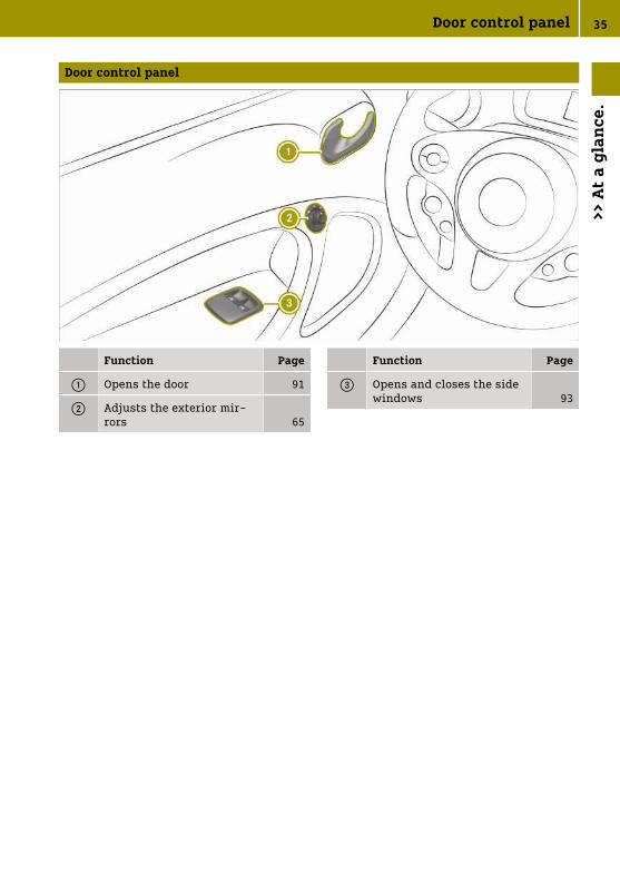
Door control panel
Function Page
: Opens the door 91
; Adjusts the exterior mir-rors 65
Function Page
= Opens and closes the sidewindows 93
Door control panel 35
>> A
t a
glan
ce.

Displays shown in the instrument cluster and the display
Function Page
: Speedometer
; Display
= Warning and indicatorlamps
C Doors or tailgate 189
7 Seat belts 190
6 Restraint system 191
þ Drive diagnostics 194
J Brakes 193
! ABS 197
÷ ESP® 59
h Tyre pressure monitor 199
D Power steering 202
· Distance warning signal
^ Forward collision warning
Function Page
à Lane Keeping Assist 203
# 12 V battery 205
R Rear foglamp 87
O Foglamps 87
K Main-beam headlamps 86
L Dipped-beam headlamps 86
T Side lamps 87
è Charging cable 194
¯ Cruise control 204
È Limiter 204
b Brake lights, rain or lightsensors 206
¯
°
Next service due date
194
õ READY indicator 205
36 Displays shown in the instrument cluster and the display>>
At
a gl
ance
.

Occupant safety
Restraint system
Protection provided by the restraintsystem
The restraint system includes the followingcomponents:
RSeat belt systemRAirbagsRChild restraint systemRChild seat securing systemThe restraint system can reduce the risk ofvehicle occupants coming into contact withparts of the vehicle's interior in the eventof an accident. In the event of an accident,the restraint system can also reduce theforces to which the vehicle occupants aresubjected.A seat belt can only provide maximum pro-tection when worn correctly. Depending onthe type of accident detected, seat belt ten-sioners and/or airbags may supplement acorrectly worn seat belt. Not every accidentwill trigger the seat belt tensioners and/ordeploy the airbags.In order for the restraint system to providethe intended level of protection, each vehi-cle occupant must observe the followinginformation:
Rfasten the seat belt correctly.Rbe in an almost upright position with the
back against the backrest.Rsit with feet resting on the floor, if possi-
ble.Ralways secure persons under 1.50 m tall
in an additional restraint system suita-ble for this vehicle.
However, no system available today cancompletely eliminate injuries and fatalitiesin every accident. In particular, the seatbelt and airbag generally do not protectagainst objects penetrating the vehiclefrom the outside. The risk of injuries due toa deployed airbag also cannot be com-pletely eliminated.
Limited protection from restraint sys-tem
G WARNING
If the restraint system is modified, it mayno longer work as intended. The restraintsystem may then not perform its inten-ded protective function by failing in anaccident or triggering unexpectedly, forexample. There is an increased risk ofinjury, possibly even fatal.
Never modify parts of the restraint sys-tem. Do not attempt to modify the wiringas well as electronic components or theirsoftware.
If it is necessary to adjust the vehicle toaccommodate a person with disabilities,contact a qualified specialist workshop.smart recommends that you use drivingaids which have been approved specificallyfor your vehicle by smart.
Preparing the restraint system foroperation
When the ignition is switched on, therestraint system warning lamp lights up6 during the self-check. It goes out nolater than a few seconds after the vehicle isstarted. The components of the restraintsystem are then in operational readiness.
Malfunctioning restraint system
A malfunction has occurred in the restraintsystem if:
RWhen the ignition is switched on, the6 restraint system warning lamp doesnot light up.RWhile driving, the 6 restraint system
warning lamp remains lit or lights uprepeatedly.
If the restraint warning system is faulty,the vehicle's high-voltage electrical systemmay not be deactivated as intended in theevent of an accident.
G DANGER
If the restraint system is malfunctioning,restraint system components may be
Occupant safety 37
>> S
afet
y.
Z

triggered unintentionally or may notdeploy as intended during an accident.This may affect the seat belt tensioner orairbag, for example. Furthermore, in theevent of an accident, the vehicle's high-voltage electrical system may not bedeactivated as intended. You may beelectrocuted if you touch the damagedcomponents of the vehicle's high-voltageelectrical system. This poses anincreased risk of injury or even fatalinjury.
Have the restraint system checked andrepaired immediately at a qualified spe-cialist workshop. After an accident,switch off the ignition immediately andremove the key from the ignition lock.
Restraint system function during anaccident
The way the restraint system respondsdepends on the severity of the impactdetected and the apparent type of accident:
RHead-on collisionRRear impactRSide impactROverturn1
The activation threshold for the restraintsystem components is determined based onthe analysis of the sensor values measuredat various points in the vehicle. This proc-ess is pre-emptive in nature. The trigger-ing process of the restraint system compo-nents should take place in good time at thestart of the collision.Factors which can only be seen and meas-ured after a collision has occurred do notplay a decisive role in the deployment of anairbag, nor do they provide an indication ofairbag deployment.The vehicle may be deformed significantlywithout an airbag being deployed. This isthe case if only parts which are relativelyeasily deformed are affected and the rate ofvehicle deceleration is not high. Con-
versely, an airbag may be deployed eventhough the vehicle suffers only minordeformation. If, for instance, very rigidvehicle parts such as longitudinal bodymembers are hit, the rate of vehicle decel-eration may be sufficient.The restraint system components can beactivated or triggered independently ofeach other:
Component Detected triggersituation
Belt tensioners Head-on collision,rear impact, sideimpact, overturn1
Driver's airbag,front-passengerfront airbag andkneebag
Head-on collision
Sidebag Side impact
Windowbag2 orheadbag3
Side impact, over-turn1, head-on col-lision
G WARNING
After the airbag deploys, the airbag partsare hot. There is a risk of injury.
Do not touch the airbag parts. Have adeployed airbag replaced at a qualifiedspecialist workshop as soon as possible.
i smart recommends that you have thevehicle towed to a qualified specialistworkshop after an accident. Take thisinto account, particularly if a seat belttensioner was triggered or an airbag wasdeployed.
If the belt tensioners are triggered or anairbag is deployed, you will hear a bang,and a small amount of powder may also bereleased:
RThe bang will not usually affect yourhearing.RIn general, the powder released is not
hazardous to health but may cause short-
1 Only for certain countries.2 smart EQ fortwo.3 smart EQ fortwo cabrio.
38 Occupant safety>>
Saf
ety
.
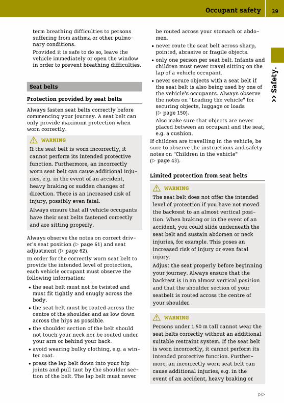
term breathing difficulties to personssuffering from asthma or other pulmo-nary conditions.Provided it is safe to do so, leave thevehicle immediately or open the windowin order to prevent breathing difficulties.
Seat belts
Protection provided by seat belts
Always fasten seat belts correctly beforecommencing your journey. A seat belt canonly provide maximum protection whenworn correctly.
G WARNING
If the seat belt is worn incorrectly, itcannot perform its intended protectivefunction. Furthermore, an incorrectlyworn seat belt can cause additional inju-ries, e.g. in the event of an accident,heavy braking or sudden changes ofdirection. There is an increased risk ofinjury, possibly even fatal.
Always ensure that all vehicle occupantshave their seat belts fastened correctlyand are sitting properly.
Always observe the notes on correct driv-er's seat position (Y page 61) and seatadjustment (Y page 62).In order for the correctly worn seat belt toprovide the intended level of protection,each vehicle occupant must observe thefollowing information:
Rthe seat belt must not be twisted andmust fit tightly and snugly across thebody.Rthe seat belt must be routed across the
centre of the shoulder and as low downacross the hips as possible.Rthe shoulder section of the belt should
not touch your neck nor be routed underyour arm or behind your back.Ravoid wearing bulky clothing, e.g. a win-
ter coat.Rpress the lap belt down into your hip
joints and pull taut by the shoulder sec-tion of the belt. The lap belt must never
be routed across your stomach or abdo-men.Rnever route the seat belt across sharp,
pointed, abrasive or fragile objects.Ronly one person per seat belt. Infants and
children must never travel sitting on thelap of a vehicle occupant.Rnever secure objects with a seat belt if
the seat belt is also being used by one ofthe vehicle's occupants. Always observethe notes on "Loading the vehicle" forsecuring objects, luggage or loads(Y page 150).Also make sure that objects are neverplaced between an occupant and the seat,e.g. a cushion.
If children are travelling in the vehicle, besure to observe the instructions and safetynotes on "Children in the vehicle"(Y page 43).
Limited protection from seat belts
G WARNING
The seat belt does not offer the intendedlevel of protection if you have not movedthe backrest to an almost vertical posi-tion. When braking or in the event of anaccident, you could slide underneath theseat belt and sustain abdomen or neckinjuries, for example. This poses anincreased risk of injury or even fatalinjury.
Adjust the seat properly before beginningyour journey. Always ensure that thebackrest is in an almost vertical positionand that the shoulder section of yourseatbelt is routed across the centre ofyour shoulder.
G WARNING
Persons under 1.50 m tall cannot wear theseat belts correctly without an additionalsuitable restraint system. If the seat beltis worn incorrectly, it cannot perform itsintended protective function. Further-more, an incorrectly worn seat belt cancause additional injuries, e.g. in theevent of an accident, heavy braking or
Occupant safety 39
>> S
afet
y.
Z

sudden changes of direction. There is anincreased risk of injury, possibly evenfatal.
Always secure persons less than 1.50 mtall in additional suitable restraint sys-tems.
G WARNING
Seat belts may not be used in the follow-ing situations in particular:
Rthe seat belt is damaged, has beenmodified, is very dirty, bleached ordyed.
Rthe seat belt buckle is damaged or verydirty.
Rmodifications have been made to theseat belt tensioner, seat belt anchorageor seat belt retractor.
Seat belts may sustain non-visible dam-age in an accident, e.g. due to glasssplinters. Modified or damaged seat beltscan tear or fail, for example in the eventof an accident. Modified seat belt ten-sioners may be triggered unintentionallyor may not function as intended. There isan increased risk of injury, possibly evenfatal.
Never modify seat belts, seat belt ten-sioners, seat belt anchorages and inertiareels. Ensure that seat belts are not dam-aged or worn and are clean. After an acci-dent, have the seat belts checked imme-diately at a qualified specialist work-shop.
smart recommends that you only use seatbelts which have been approved specifi-cally for your vehicle by smart.
G WARNING
Pyrotechnical belt tensioners which havebeen triggered are no longer operationaland therefore cannot protect as intended.There is an increased risk of injury, pos-sibly even fatal.
Have pyrotechnic belt tensioners whichhave been triggered replaced at a quali-fied specialist workshop immediately.
smart recommends that you have the vehi-cle towed to a qualified specialist workshopafter an accident.
! Make sure that the seat belt is fully rol-led up. Otherwise, the seat belt or belttongue will be trapped in the door or inthe seat mechanism. This could damagethe door, the door trim panel and the seatbelt. Damaged seat belts can no longerfulfil their protective function and mustbe replaced. Visit a qualified specialistworkshop.
Fastening and releasing the seat belt
If the seat belt is pulled out quickly orsharply, the inertia reel locks. The beltstrap cannot be pulled out any further.
! If the co-driver's seat is not occupied,do not engage the seat belt tongue in thebuckle on the co-driver's seat. Otherwise,in the event of an accident the belt ten-sioner could be triggered in addition toother systems and would need to bereplaced.
For easy fastening, the seat belt is routedthrough the seat belt guide on the side ofthe seat, if available.
X To fasten: always engage seat belttongue ; into belt buckle : of the cor-responding seat.
X To release: press the release button inbelt buckle : and guide the seat beltback by belt tongue ;.
40 Occupant safety>>
Saf
ety
.

Function of seat belt warning for thedriver and front passenger
The 7 seat belt warning lamp in theinstrument display is a reminder that allvehicle occupants must wear their seatbelts correctly.In addition, a warning tone may sound.The belt warning goes out as soon as thedriver and front-passenger fasten theirseat belts.
i If you are using an ISOFIX or an i-Sizechild restraint system on the front-passenger seat and the child is notsecured using the seat belt of the front-passenger seat, the belt warning may beactivated. In this case, you can insert thebelt tongue of the seat belt into the beltbuckle belonging to the front-passengerseat. To do this, guide the seat beltbetween the ISOFIX child restraint sys-tem or i-Size child restraint system andthe backrest of the front-passenger seat.
Airbags
Overview of airbags
The installation location of an airbag isidentified by the AIRBAG symbol.A deployed airbag can increase the level ofprotection provided to the vehicle occu-pant.
AIRBAG Possible protectionfor:
: Headbag4 Head
; Driver'skneebag
Thigh, knee andlower leg
= Driver's air-bag
Head and thorax
? Front-passengerfront airbag
Head and thorax
A Windowbag5 Head
B Sidebag Thorax and pelvis
The front-passenger front airbag can bedeployed in an accident only if thePASSENGER AIR BAG ON indicator lamp islit. If the front-passenger seat is occupied,make sure both before and during the jour-ney that the status of the front-passengerfront airbag is correct (Y page 43).
Protection provided by the airbags
Depending on the type of accident, an air-bag can supplement a correctly worn seatbelt and provide added protection.
G WARNING
If you deviate from the correct seat posi-tion, the airbag cannot carry out itsintended function and may even causeadditional injuries if it is deployed. Thereis an increased risk of injury, possiblyeven fatal.
To avoid risks, vehicle occupants mustensure the following points are followed:
Rfasten the seat belt correctly. in par-ticular, make sure that the lap belt
4 smart EQ fortwo cabrio.5 smart EQ fortwo.
Occupant safety 41
>> S
afet
y.
Z

never runs over the stomach or abdo-men of pregnant women..
Rtake the correct seating position andkeep as far away from the airbags aspossible.
Robserve the following information:
Always make sure that there are noobjects between the airbag and vehicleoccupant.
To avoid the risks resulting from thedeployment of an airbag, each vehicleoccupant must observe the following notes:
RAdjust seats correctly before startingyour journey and move the driver's andfront passenger seat as far back as possi-ble.Always observe the information on thecorrect driver's seat position(Y page 61).ROnly hold onto the outside of the steering
wheel rim. This allows the airbag to befully deployed.RAlways lean against the backrest while
driving. Do not lean forwards or againstthe door or side window. You may other-wise be in the deployment area of theairbags.RAlways keep your feet on the floor. Do not
put your feet on the dashboard, for exam-ple. Your feet may otherwise be in thedeployment area of the airbag.RWhen children are travelling in the vehi-
cle, follow the related additional notes(Y page 43).RAlways properly stow and secure objects.Objects in the vehicle interior may limit anairbag's ability to function correctly. Eachvehicle occupant must always make sure ofthe following:
RThere are no people, animals or objectsbetween the vehicle occupants and anairbag.RThere are no objects between the seat,
the door and the door pillar (B-pillar).RNo hard objects, e.g. coat hangers, are
hanging on the grab handles or coathooks.RThere are no accessory parts, such as
mobile navigation devices, mobile phones
or cup holders, attached to the vehiclewithin the deployment area of an airbag,e.g. on the cockpit, on doors, side win-dows or side panelling.In addition, no connection cable, tension-ing strap or retainer belt may be routedor secured in the deployment area of anairbag. Always observe the accessorymanufacturer's installation instructions,in particular the notes on a suitableplace to fit the accessory.RNo heavy, sharp-edged or fragile objects
are kept in the pockets of clothing. Storesuch objects in a suitable place.
Limited protection from airbags
G WARNING
If you modify the cover of an airbag oraffix objects such as stickers to it, theairbag can no longer perform its intendedfunction. This poses an increased risk ofinjury.
Never modify the cover of an airbag oraffix objects to it.
The installation location of an airbag isindicated by the AIRBAG symbol(Y page 41).
G WARNING
Unsuitable seat covers may obstruct oreven prevent deployment of the airbagsintegrated into the seats. The airbagsmay then fail to protect the vehicle occu-pants as intended. There is an increasedrisk of injury, possibly even fatal.
Use only seat covers which have beenspecifically approved for the respectiveseat by smart.
G WARNING
Sensors to control the airbags are locatedin the doors. Modifications or work notperformed correctly to the doors or doorpanelling, as well as damaged doors, canlead to the function of the sensors beingimpaired. The airbags might therefore notfunction properly any more. Conse-
42 Occupant safety>>
Saf
ety
.

quently, the airbags cannot protect vehi-cle occupants as they are designed to do.This poses an increased risk of injury.
Never modify the doors or parts of thedoors. Always have work on the doors ordoor panelling carried out at a qualifiedspecialist workshop.
G WARNING
An airbag that has been deployed oncecannot provide any further protectionand, in the event of an accident, can nolonger perform its intended protectivefunction. There is an increased risk ofinjury.
Have the vehicle towed to a qualifiedspecialist workshop to have the deployedairbag replaced.
Have deployed airbags replaced immedi-ately.
Status of the front passenger front air-bag
Function of the PASSENGER AIR BAG indi-cator lampsThe front-passenger front airbag can beenabled or disabled using the airbag-offswitch in the instrument panel on thefront-passenger side (Y page 53).
The PASSENGER AIR BAG OFF andPASSENGER AIR BAG ON indicator lamps arepart of the front-passenger front airbagdeactivation system.
The indicator lamps display the status ofthe front-passenger front airbag:
RPASSENGER AIR BAG OFF lights up: thefront-passenger front airbag is disabled.It will then not be deployed in the eventof an accident.RPASSENGER AIR BAG ON lights up: the
front-passenger front airbag is enabled.The front-passenger front airbag maydeploy during an accident.
If the front-passenger seat is occupied,make sure that the status of the front-passenger front airbag is correct dependingon the situation both before and during thejourney:
RChildren in a child restraint system:whether the front-passenger front airbagshould be enabled or disabled depends onthe child restraint system fitted and theage and size of the child. Make sure thatyou observe the notes on "Children in thevehicle" (Y page 43). There you will alsofind instructions on backwards and for-wards-facing child restraint systems onthe front-passenger seat.RAll other persons: the PASSENGER AIR BAG
ON indicator lamp must be lit. The front-passenger front airbag is enabled. Besure to observe the notes on "Seat belts"(Y page 39) and "Airbags" (Y page 41).There you can also find information onthe correct seat position.
Observe the information on the airbagdeactivation system of the front-passengerfront airbag (Y page 53).
Travelling safely with children in thevehicle
Observe carefully when children aretravelling in the vehicle
Be diligent
i Be sure to observe the safety notes rele-vant to the situation. In doing so, youwill be able to identify possible risks andavoid dangers when children are travel-ling in the vehicle (Y page 44).
Bear in mind that negligence when secur-ing the child in the child restraint systemmay have serious consequences. Always be
Travelling safely with children in the vehicle 43
>> S
afet
y.
Z

diligent and secure a child carefully beforeeach journey.To improve protection for children youngerthan twelve years old and under 1.50 m inheight, smart recommends you alwaysobserve the following notes:
RAlways secure the child in a childrestraint system suitable for your smartvehicle.RThe child restraint system must be
appropriate to the age, weight and size ofthe child.RThe vehicle seat must be suitable for the
child restraint system to be fitted(Y page 48).
The generic term child restraint system
The generic term child restraint system isused in this Owner's Manual. A childrestraint system is, for example:
Ra baby car seatRa rearward-facing child seatRa forward-facing child seatRa child booster seat with a backrest and
seat belt guidesThe child restraint system must be appro-priate to the age, weight and size of thechild.
Observing laws and regulations
Always observe the legal requirements forusing a child restraint system in the vehi-cle.Ensure that the child restraint system isapproved in accordance with the valid testspecifications and guidelines. Furtherinformation can be obtained at a qualifiedspecialist workshop. smart recommendsthat you use a smart Centre.
Use only approved child restraint sys-tems
Only child restraint systems that meet thefollowing UNECE standards are permittedfor use in the vehicle:
RUN-R44RUN-R129 (i‑Size child restraint systems)Information about the approval categoriesfor child restraint systems and details on
the approval label on the child restraintsystem (Y page 48).
Detecting risks, avoiding danger
Securing systems for child restraintsystems in the vehicle
Only use the following securing systems forchild restraint systems:
Rthe ISOFIX or i‑Size securing ringsRthe vehicle's seat belt systemRthe Top Tether anchoragesPreferably, fit an ISOFIX or i‑Size childrestraint system.The risk of incorrectly fitting the childrestraint system can be reduced by simplyfitting it on the securing rings of the vehi-cle.When the child is secured using the seatbelt integrated in the ISOFIX or i-Size childrestraint system, be sure to observe themaximum permissible weight of the childand child restraint system together(Y page 51).
The advantage of a rearward-facingchild restraint system
Babies or infants should preferably travelin a suitable rearward-facing childrestraint system. In this case, the child isseated in the opposite direction to thedirection of travel and is facing backwards.Babies and infants have comparativelypoorly developed neck muscles in relationto the size and weight of their head. A rear-ward-facing child restraint system canreduce the risk of injury to the cervicalspine in an accident.
Secure the child restraint system cor-rectly at all times
G WARNING
If the child restraint system is incor-rectly fitted on the seat position suitablefor this purpose, it cannot perform itsintended protective function. In the eventof an accident, sharp braking or a sudden
44 Travelling safely with children in the vehicle>>
Saf
ety
.

change in direction, the child may not beheld securely. There is an increased riskof serious or even fatal injuries.
Observe the manufacturer's installationinstructions and the correct use for thechild restraint system. Make sure thatthe entire surface of the child restraintsystem is resting on the seat surface.Never place objects under or behind thechild restraint system, e.g. cushions.Only use child restraint systems with theoriginal cover designed for them. Onlyreplace damaged covers with genuinecovers.
Where possible, use child restraint systemsrecommended for Mercedes-Benz(Y page 46).
G WARNING
If the child restraint system is fittedincorrectly or is not secured, it can comeloose in the event of an accident, heavybraking or a sudden change in direction.The child restraint system could bethrown about, striking vehicle occupants.There is an increased risk of injury, pos-sibly even fatal.
Always fit child restraint systems prop-erly, even if they are not being used.Make sure that you observe the childrestraint system manufacturer's installa-tion instructions.
RBe sure to observe the installation andoperating instructions provided by themanufacturer for the child restraint sys-tem being used as well as the vehicle-specific notes at all times:- Fitting an ISOFIX or i-Size child
restraint system to the front-passenger seat (Y page 51).
- Securing the child restraint systemwith the seat belt on the front-passenger seat (Y page 56). Observethe specific notes on rearward-facingand forward-facing child restraintsystems (Y page 56).If the front-passenger seat is occupied,make sure that the status of the front-
passenger front airbag is correctdepending on the situation both beforeand during the journey (Y page 43).
RObserve the warning labels in the vehicleinterior and on the child restraint sys-tem.RAlso secure Top Tether, if available.
Do not modify the child restraint sys-tem
G WARNING
If you modify a child restraint system oraffix objects to it, e.g. toys or unsuitableaccessories, the child restraint systemmay no longer function properly. Thisposes an increased risk of injury.
Never modify a child restraint system.Only affix accessories which have beenspecially approved for this childrestraint system by the child restraintsystem's manufacturer.
smart recommends you use smart careproducts to clean child restraint systemsrecommended by smart.
Only use child restraint systems whichare not damaged
G WARNING
Child restraint systems or their securingsystems that have been damaged or sub-jected to a load in an accident cannotperform their intended protective func-tion. In the event of an accident, sharpbraking or a sudden change in direction,the child may not be held securely. Thereis an increased risk of serious or evenfatal injuries.
Immediately replace child restraint sys-tems that have been damaged or subjec-ted to a load in an accident. Have thechild restraint securing systems checkedin a qualified specialist workshop beforefitting a child restraint system again.
Travelling safely with children in the vehicle 45
>> S
afet
y.
Z

Avoiding direct sunlight
G WARNING
If the child restraint system is placed indirect sunlight, the parts could becomevery hot. Children could be suffer burnsby touching these parts, in particular onthe metallic parts of the child restraintsystem. There is a risk of injury.
If you and your child leave the vehicle,always make sure that the child restraintsystem is not in direct sunlight. Cover itwith a blanket, for example. If the childrestraint system has been exposed todirect sunlight, leave it to cool downbefore securing the child in it. Neverleave children unattended in the vehicle.
Observe the following when stopping orparking
G WARNING
If children are left unattended in thevehicle, they could in particular:
Ropen doors, thereby endangering otherpersons or road users.
Rget out and be struck by oncomingtraffic.
Roperate vehicle equipment and becometrapped, for example.
In addition, the children could also setthe vehicle in motion, for example by:
Rreleasing the parking brake.
Rchanging the transmission position.
Ryou start the vehicle.
There is a risk of accident and injury.
Never leave children unattended in thevehicle.
When leaving the vehicle, always takethe key with you and lock the vehicle.
Keep the key out of the reach of children.
G WARNING
If persons (particularly children) areexposed to heat or cold for a prolongedperiod, there is a risk of serious or evenfatal injuries. Never leave persons (par-ticularly children) unattended in thevehicle.
Overview of recommended child restraint systems
The smart EQ fortwo is equipped with a manual front-passenger front airbag deactivationsystem.
X Before using a rearward-facing child restraint system on the front-passenger seat, dis-able the front-passenger front airbag (Y page 53).
i You can obtain further information about the correct child restraint system from aqualified specialist workshop. smart recommends that you use a smart Centre.
46 Travelling safely with children in the vehicle>>
Saf
ety
.

Securing with ISOFIX
Weight categorySize category
Type6
Type approval numberOrder number7
Category 0+:up to 13 kg and up toapproximately 15 monthsSize category E
BABY SAFE PLUSE1 04 301 146
B6 6 86 8224
Category I:9–18 kgSize category B1
DUO PLUSE1 04 301 133
A 000 970 17 02
Securing with the vehicle seat belt
Weight category Type6
Type approval numberOrder number7
Category 0:up to 10 kg and up toapproximately 6 months
BABY SAFE plus IIE1 04 301 146
A 000 970 13 02
Category 0+:up to 13 kg and up toapproximately 15 months
BABY SAFE plus IIE1 04 301 146
A 000 970 13 02
Category I:9–18 kg and from approx-imately 9 months to 4 years
DUO PLUSE1 04 301 133
A 000 970 17 02
Category II/III:15–36 kg and from approx-imately 4–12 years
KIDFIXE1 04 301 198
A 000 970 20 02
Category II/III:15–36 kg and from approx-imately 4–12 years
KIDFIX XPE1 04 301 304
A 000 970 23 02
6 Manufacturer: Britax Römer.7 With colour code 9H95.
Travelling safely with children in the vehicle 47
>> S
afet
y.
Z

Suitable seats in the vehicle for fitting a child restraint system
Securing systems for child restraint systems
Vehicle seat
Front-passenger seat Preferred securing system:
ISOFIX child seatsecuring system(Y page 49)ori‑Size child seatsecuring system(Y page 51)Also secure TopTether if available(Y page 52)
Other securing system:
RVehicle seat belt(Y page 55)
Be sure to observe:
RIf the front-passengerseat is occupied, makesure that the status of thefront-passenger frontairbag is correct depend-ing on the situation bothbefore and during thejourney (Y page 43).
Permitted categories for childrestraint systems
Use only approved child restraint sys-tems
Only child restraint systems that meet thefollowing UNECE standards are permittedfor use in the vehicle:
RUN-R44RUN-R129 (i‑Size child restraint systems)
Identification on the child restraintsystem
Information about the approval category,weight category and approval number, forexample, is on the approval label on thechild restraint system.Depending on the approval category of thechild restraint system, there may be fur-ther information, e.g. the ISOFIX size cate-gory.
Approval categories in accordance withUN-R44
Example of an approval label
RUniversal: child restraint systems in the"Universal" category are approved forinstallation in vehicles. They can beused, in accordance with overviews of thesuitability of seats for securing childrestraint systems, on seats labelled U, UFor IUF.The designation IUF refers to ISOFIX childrestraint systems in the "Universal" cat-egory. These child restraint systemsmust also be secured using Top Tether ora supporting bracket.RSemi-Universal: child restraint systems
in the "semi-universal" category mayonly be used if the vehicle and the seat
48 Travelling safely with children in the vehicle>>
Saf
ety
.

are listed in the child restraint systemmanufacturer's vehicle model list.RVehicle-specific: child restraint systems
in the "vehicle-specific" category mayonly be used if the vehicle and the seatare listed in the child restraint systemmanufacturer's vehicle model list.
Approval categories in accordance withUN-R129
Example of an approval label
Ri‑Size: child restraint systems in the"i‑Size" category are approved for instal-
lation in vehicles with i‑Size securingrings. They can be used, in accordancewith overviews of the suitability of seatsfor securing child restraint systems, onseats labelled i-U.The designation i-U refers to i-Size childrestraint systems in the "Universal" cat-egory. These child restraint systemsmust also be secured using Top Tether ora supporting bracket.
Observe the suitability of vehicle seats
Depending on the approval category, thereare forward-facing and/or rearward-facingchild restraint systems. Usage may be limi-ted for certain vehicle seats.
RSuitability of the seats for attaching ISO-FIX child restraint systems (Y page 49)RSuitability of the seats for attaching
i‑Size child restraint systems(Y page 51)RSuitability of the seats for attaching
belt-secured child restraint systems(Y page 55)
Securing the ISOFIX or i-Size child restraint system
Suitability of the seats for attaching ISOFIX child restraint systems
ISOFIX identification
ISOFIX is a standardised securing system for special restraint systems.
RThis symbol indicates which seats are suitable for securing an ISOFIXchild restraint system in accordance with UN-R44 (Y page 48).ROnly secure child restraint systems approved by UN-R44 in accordance
with the following ISOFIX tables.
Carry cot
Size class Equipment Front-passenger front air-bag enabled
Front-passenger front air-bag disabled1
F ISO/L1 X X
G ISO/L2 X X
X Not suitable for an ISOFIX child
restraint system in this weight cate-
gory and/or size category.
1 The vehicle is equipped with a front-
passenger front airbag deactivation
system. The PASSENGER AIR BAG OFF
indicator lamp must be lit.
Travelling safely with children in the vehicle 49
>> S
afet
y.
Z

Weight category 0 (up to 10 kg and up to approximately 6 months)
Size class Equipment Front-passenger front air-bag enabled
Front-passenger front air-bag disabled1
E ISO/R1 X IL
X Not suitable for an ISOFIX child
restraint system in this weight cate-
gory and/or size category.
1 The vehicle is equipped with a front-
passenger front airbag deactivation
system. The PASSENGER AIR BAG OFF
indicator lamp must be lit.
IL Suitable for ISOFIX child restraint
systems in accordance with the table in
"Overview of recommended child
restraint systems", or if the vehicle and
the seat are listed in the child restraint
system manufacturer's vehicle model
list.
Weight category 0+ (up to 13 kg and up to approximately 15 months)
Size class Equipment Front-passenger front air-bag enabled
Front-passenger front air-bag disabled1
E ISO/R1 X IL
D ISO/R2 X IL
C ISO/R3 X IL
X Not suitable for an ISOFIX child
restraint system in this weight cate-
gory and/or size category.
1 The vehicle is equipped with a front-
passenger front airbag deactivation
system. The PASSENGER AIR BAG OFF
indicator lamp must be lit.
IL Suitable for ISOFIX child restraint
systems in accordance with the table in
"Overview of recommended child
restraint systems", or if the vehicle and
the seat are listed in the child restraint
system manufacturer's vehicle model
list.
Weight category I (9‑18 kg and approximately 9 months to 4 years)
Size class Equipment Front-passenger front air-bag enabled
Front-passenger front air-bag disabled1
D ISO/R2 X IL
C ISO/R3 X IL
B ISO/F2 IUF IUF
B1 ISO/F2X IUF IUF
50 Travelling safely with children in the vehicle>>
Saf
ety
.

Size class Equipment Front-passenger front air-bag enabled
Front-passenger front air-bag disabled1
A ISO/F3 IUF IUF
X Not suitable for an ISOFIX child
restraint system in this weight cate-
gory and/or size category.
IUF Suitable for forward-facing ISOFIX
child restraint systems in the "Univer-
sal" category in this weight category.
1 The vehicle is equipped with a front-
passenger front airbag deactivation
system. The PASSENGER AIR BAG OFF
indicator lamp must be lit.
IL Suitable for ISOFIX child restraint
systems in accordance with the table in
"Overview of recommended child
restraint systems", or if the vehicle and
the seat are listed in the child restraint
system manufacturer's vehicle model
list.
Suitability of the seats for attaching i‑Size child restraint systems
i‑Size identification
i‑Size is a standardised securing system for special restraint systems.
RThis symbol indicates which seats are suitable for securing an i‑Sizechild restraint system in accordance with UN-R129 (Y page 48).RChild restraint systems which have been approved in accordance with
the following may be secured:- UN-R44 in accordance with the ISOFIX tables (Y page 49)- UN-R129 in accordance with the following i‑Size table
Front-passenger front air-bag enabled
Front-passenger front air-bag disabled1
i‑Size child restraint sys-tem
i-UF i‑U
i-UF Suitable for a forward-facing
i‑Size child restraint system in the
"Universal" category.
1 The vehicle is equipped with a front-
passenger front airbag deactivation
system. The PASSENGER AIR BAG OFF
indicator lamp must be lit.
i-U Suitable for forward-facing and
rearward-facing i‑Size child restraint
systems in the "Universal" category.
Installing an ISOFIX or i-Size childrestraint system on the front passengerseat
G WARNING
For ISOFIX or i‑Size child restraint sys-tems, where the child is secured using
the integrated seat belt of the childrestraint system, the permissible grossweight of the child and the childrestraint system is 33 kg.
If the child together with the childrestraint system weighs more than 33 kg,
Travelling safely with children in the vehicle 51
>> S
afet
y.
Z

ISOFIX or i‑Size child restraint systemswith integrated seat belt no longer offersufficient protection. ISOFIX or i‑Sizechild seat securing systems may be over-loaded and will not be able to restrain thechild, for example, in the event of anaccident. This poses an increased risk ofinjury or even fatal injury.
If the child together with the childrestraint system weighs more than 33 kg ,only use ISOFIX or i-Size child restraintsystems with which the child is securedwith the vehicle seat belt. Also secure thechild restraint system with the TopTether belt, if available.
Always observe the information on theweight of the child restraint system:
Rin the installation and operating instruc-tions provided by the manufacturer forthe child restraint system being usedRon the label of the child restraint system,
if presentRegularly check that the maximum permis-sible weight of the child and child restraintsystem together is still complied with.When fitting a child restraint system, besure to observe the following:
O be sure to observe the correct use andthe suitability of seats for securing achild restraint system.ISOFIX child seat securing system(Y page 49)i‑Size child seat securing system(Y page 51)
O be sure to observe the installation andoperating instructions provided by themanufacturer for the child restraintsystem being used.
When fitting an ISOFIX childrestraint system, also observe the follow-ing:
O For certain child restraint systems inweight category II or III, there may berestrictions on the maximum size set-ting, e.g. due to possible contact withthe roof.
O The child restraint system must not beput under strain between the roof and
the seat cushion and/or be fitted facingthe wrong direction.
: ISOFIX securing rings; i-Size securing rings
Before every trip, make sure that the ISOFIXchild restraint system or the i-Size childrestraint system is engaged correctly inboth ISOFIX or i-Size securing rings.
X Fit the ISOFIX or i-Size child restraintsystem on both securing rings of thevehicle.
Securing Top Tether
If the child restraint system isequipped with a Top Tether belt:Top Tether can reduce the risk of injury.The Top Tether belt provides an additionalconnection between the child restraint sys-tem secured with ISOFIX or i-Size and thevehicle.
52 Travelling safely with children in the vehicle>>
Saf
ety
.

Top Tether anchorage ; is fitted to theluggage compartment floor.
X Fit the ISOFIX or i-Size child restraintsystem with Top Tether. Always complywith the child restraint system manufac-turer's installation instructions whendoing so.
X Route Top Tether belt ? back over thehead restraint, keeping it as central aspossible, into the luggage compartmentthrough loop :.
X Hook Top Tether hook = of Top Tetherbelt ? into Top Tether anchorage ;.Lift up the carpet a little if necessary.Ensure that:
RTop Tether hook = is hooked into TopTether anchorage ; as shown.RTop Tether belt ? is not twisted.
X Tension Top Tether belt ?. Always com-ply with the child restraint system man-ufacturer's installation instructionswhen doing so.
Disabling or enabling the frontpassenger front airbag
G WARNING
If the PASSENGER AIRBAG OFF indicatorlamp is lit, the front-passenger front air-bag is disabled. It will not be deployed inthe event of an accident and cannot per-form its intended protective function. Aperson in the front-passenger seat couldthen, for example, come into contact withthe vehicle's interior, especially if theperson is sitting too close to the dash-board. This poses an increased risk ofinjury or even fatal injury.
In this case the front-passenger seat maynot be used. You may only transport achild on the front-passenger seat if theyare seated in a suitable rearward orforward-facing child restraint system.Always observe the information aboutsuitable positioning of the child restraintsystem in this Owner's Manual as well asthe child restraint system manufacturer'sinstallation instructions.
G WARNING
If you secure a child in a rearward-facingchild restraint system on the front-passenger seat and the PASSENGER AIRBAG ON indicator lamp is lit, the front-passenger front airbag can deploy in theevent of an accident. The child could bestruck by the airbag. This poses anincreased risk of injury or even fatalinjury.
Make sure that the front-passenger frontairbag has been disabled. The PASSENGERAIR BAG OFF indicator lamp must be lit.
NEVER use a rearward-facing childrestraint on a seat protected by anACTIVE AIRBAG in front of it; DEATH orSERIOUS INJURY to the child can occur.
If the PASSENGER AIR BAG OFF indicatorlamp remains off and/or the PASSENGER AIRBAG ON indicator lamp is lit, do not fit arearward-facing child restraint system to
Travelling safely with children in the vehicle 53
>> S
afet
y.
Z

the front-passenger seat. Further informa-tion can be found under "Problems with thefront-passenger front airbag deactivationsystem" (Y page 191).
G WARNING
If you secure a child in a forward-facingchild restraint system on the front-passenger seat and you position thefront-passenger seat too close to thedashboard, in the event of an accident,the child could:
Rcome into contact with the vehicle'sinterior if the PASSENGER AIR BAG OFFindicator lamp is lit, for example
Rbe struck by the airbag if thePASSENGER AIR BAG ON indicator lampis on.
This poses an increased risk of injury oreven fatal injury.
Move the front-passenger seat as farback as possible. Always make sure thatthe shoulder belt strap is correctly routedfrom the vehicle belt outlet to the shoul-der belt guide on the child restraint sys-tem. The shoulder belt strap must berouted forwards and downwards from thevehicle belt outlet. If necessary, adjustthe front-passenger seat accordingly.Additionally, always observe the infor-mation on suitable positioning of thechild restraint system in this Owner'sManual in addition to the child restraintsystem manufacturer's installationinstructions.
Symbol for a rearward-facing child restraintsystem
If you use a rearward-facing child restraintsystem on the front-passenger seat, youmust disable the front-passenger front air-bag.
Airbag-off switch : for enabling and disa-bling the front-passenger front airbagmanually is in the dashboard on the front-passenger side.
X Push in airbag-off switch : of the front-passenger front airbag beyond the pointof resistance.
X To disable the front-passenger front air-bag: turn airbag-off switch : anti-clockwise.The PASSENGER AIR BAG OFF 4 indica-tor lamp on the overhead control panellights up and stays on when the ignitionis switched on (Y page 43).
X To enable the front-passenger front air-bag: turn airbag-off switch : clockwise.The PASSENGER AIR BAG ON × indica-tor lamp on the overhead control panellights up and stays on when the ignitionis switched on (Y page 43).
The front-passenger front airbag is gener-ally enabled when the ignition is switched
54 Travelling safely with children in the vehicle>>
Saf
ety
.

on, except when the front-passenger frontairbag has been disabled manually. Whenthe front-passenger front airbag is disa-
bled, the 4 PASSENGER AIR BAG OFFindicator lamp on the overhead controlpanel (Y page 43) lights up continuouslywhen the ignition is switched on.
Attaching a child restraint system with the seat belt
Notes on the suitability of the seats for attaching belt-secured child restraint sys-tems
Front-passenger seat – notes
Notes on child restraint systems on the front-passenger seat
RObserve the specific notes on rearward-facing and forward-facing child restraint sys-tems. If the front-passenger seat is occupied, make sure that the status of the front-passenger front airbag is correct depending on the situation both before and duringthe journey (Y page 43).
Weight category Front-passenger front air-bag is enabled
Front-passenger front air-bag is disabled1
1 The vehicle is equipped with a front-
passenger front airbag deactivation
system. The PASSENGER AIR BAG OFF
indicator lamp must be lit.
Category 0: up to 10 kg X U, L
Category 0+: up to 13 kg X U, L
Category I: 9 to 18 kg UF, L U, L
Category II: 15 to 25 kg UF, L U, L
Category III: 22 to 36 kg U, L U, L
X Not suitable for an ISOFIX child
restraint system in this weight cate-
gory and/or size category.
UF Suitable for forward-facing child
restraint systems in the "Universal"
category in this weight category.
U Suitable for child restraint systems
in the "Universal" category in this
weight category.
L Suitable for semi-universal child
restraint systems in accordance with
the table in "Recommended child
restraint systems", or if the vehicle and
the seat are listed in the child restraint
system manufacturer's vehicle model
list.
Travelling safely with children in the vehicle 55
>> S
afet
y.
Z

Notes on rearward-facing and forward-facing child restraint systems on thefront passenger seat
G WARNING
If you secure a child in a rearward-facingchild restraint system on the front-passenger seat and the PASSENGER AIRBAG OFF indicator lamp is off, the front-passenger front airbag can deploy in theevent of an accident. The child could bestruck by the airbag. This poses anincreased risk of injury or even fatalinjury.
Make sure that the front-passenger frontairbag has been disabled. The PASSENGERAIR BAG OFF indicator lamp must be lit.
NEVER use a rearward-facing childrestraint on a seat protected by anACTIVE AIRBAG in front of it; DEATH orSERIOUS INJURY to the child can occur.
Observe the specific notes on rearward-facing and forward-facing child restraintsystems.
Warning notice on the front-passenger sunvisor
Always pay attention to the status of thefront-passenger front airbag with thePASSENGER AIR BAG OFF indicator lamp:
RIf you fit a child restraint system to thefront-passenger seat, be sure to observethe notes on disabling the front-passenger front airbag (Y page 53).RWhen using a rearward-facing child
restraint system on the front-passengerseat, the front-passenger front airbagmust always be disabled. This is only the
case if the PASSENGER AIR BAG OFF indi-cator lamp is permanently lit (Y page 43).RIf the PASSENGER AIR BAG OFF indicator
lamp goes out, the front-passenger frontairbag is enabled. The front-passengerfront airbag may deploy during an acci-dent.
Attaching a child restraint system withthe seat belt to the front passenger seat
When fitting a belt-secured child restraintsystem on the front-passenger seat, alwaysobserve the following:
O Be sure to observe the installation andoperating instructions provided by themanufacturer for the child restraintsystem being used.
O When using a "Universal" or "Semi-Universal" category child restraintsystem, ensure that it is approved forthe vehicle seat.Observe the notes under "Suitability ofseats for attaching belt-secured childrestraint systems" (Y page 55).
O The backrest of a forward-facing childrestraint system must, as far as possi-ble, rest flat against the backrest of thefront-passenger seat.
O For certain child restraint systems inweight categories II or III, the maxi-mum size setting may be restricted, forinstance due to possible contact withthe roof.
O The child restraint system must not beput under strain between the roof andthe seat cushion and/or be fitted facingthe wrong direction.
O The child restraint system must not beput under strain by the head restraint.
O Never place objects, such as a cushion,under or behind the child restraintsystem.
X Set the front-passenger seat as far backas possible.
X Adjust the seat backrest to an almostvertical position.
X Fit the child restraint system.The base of the child restraint systemmust lie fully against the seat cushion ofthe front-passenger seat.
56 Travelling safely with children in the vehicle>>
Saf
ety
.

X Always make sure that the shoulder beltstrap is correctly routed from the vehiclebelt outlet to the shoulder belt guide onthe child restraint system.The shoulder belt strap must be routedforwards and downwards from the beltoutlet.
X If necessary, adjust the belt outlet andthe front-passenger seat as appropriate.
Pets in the vehicle
G WARNING
If you leave animals unsupervised orunsecured in the vehicle, they may pressbuttons or switches, for instance.
In this way, animals may:
Ractivate vehicle equipment and becometrapped, for example
Rswitch systems on or off and therebyendanger other road users
Furthermore, unsecured animals may beflung around inside the vehicle in theevent of an accident or abrupt steering orbraking manoeuvre, and thereby injurevehicle occupants. There is a risk of acci-dent and injury.
Never leave animals unattended in thevehicle.
Always secure animals properly whendriving, for instance with a suitable petcarrier.
Driving safely
Driving safety system limitations
! Make sure you have suitable tyres, sothat assistance systems and drivingsafety systems can work as effectively aspossible.
If you fail to adapt your driving style or ifyou are inattentive, the driving safety sys-tems can neither reduce the risk of accidentnor override the laws of physics. Drivingsafety systems are merely aids designed toassist driving. You are responsible for the
distance to the vehicle in front, for vehiclespeed and for braking in good time. Alwaysadapt your driving style to suit the pre-vailing road, weather and traffic conditionsand maintain a safe distance from the vehi-cle in front. Drive carefully.For safety reasons, smart recommends thatyou only use snow chains that have beenspecially approved for your vehicle bysmart. Further information can be obtainedat a smart Centre or a qualified specialistworkshop.
Braking with ABS (Anti-lock BrakingSystem)
ABS controls brake pressure in such a waythat the wheels do not lock when you brake.This allows you to continue steering thevehicle when braking.When you switch on the ignition, the !warning lamp in the instrument clusterlights up. It goes out after the engine isstarted.ABS works from a speed of about 6 km/h,regardless of road surface conditions. ABSintervenes in the case of slippery road sur-faces, even if you only brake gently.
X To brake while ABS intervenes: continueto depress the brake pedal with forceuntil the braking situation is over.
X To make a full brake application: depressthe brake pedal with full force.
G WARNING
If ABS is faulty, the wheels could lockwhen braking. The steerability and brak-ing characteristics may be severelyimpaired. Additionally, further drivingsafety systems are deactivated. There isan increased danger of skidding andaccidents.
Drive on carefully. Have ABS checkedimmediately at a qualified specialistworkshop.
Driving safely 57
>> S
afet
y.
Z

Using Active Brake Assist
Useful information
With the help of the radar sensor system,Active Brake Assist can calculate the dis-tance of your vehicle to the vehicle in front.If for several seconds, the distance to thevehicle in front is insufficient for the speedyou are driving at, Active Brake Assistalerts the driver visually.If a risk of collision is detected, ActiveBrake Assist alerts the driver both visuallyand acoustically. In addition, Active BrakeAssist prepares the vehicle for a possibleemergency braking manoeuvre.In particularly critical situations ActiveBrake Assist may brake autonomously. Inthis case, Active Brake Assist continues toalert the driver both visually and acousti-cally.
Please note
G WARNING
Active Brake Assist cannot always clearlyidentify objects and complex traffic sit-uations.
In these cases, Active Brake Assist may:
Rwarn or brake for no reason
Rnot issue a warning
Rnot brake
There is a risk of an accident.
Always pay careful attention to the traf-fic situation and do not rely on ActiveBrake Assist alone. Be prepared to brakeor manoeuvre if necessary.
G WARNING
Active Brake Assist does not react:
Rto persons, bicycles, motorcycles oranimals
Rto approaching vehicles
Rto cross traffic
Ron bends
As a result, Active Brake Assist cannotintervene in all critical situations. Thereis a risk of an accident.
Always pay careful attention to the traf-fic situation and be prepared to brake.
G WARNING
Severe jolting, for example in the case ofa collision, may cause the radar sensorsto be misaligned. The function of ActiveBrake Assist is then impaired.
There is a risk of an accident.
Deactivate Active Brake Assist. HaveActive Brake Assist checked at a qualifiedspecialist workshop.
The following requirements must also befulfilled:
Rthe selector lever is in position h.Rthe parking brake is released.Rthe driving speed is within the suitable
speed range.Detection can be restricted under the fol-lowing conditions:
Rthe vehicle is new or service work hasbeen carried out on the system. In thiscase, observe the information on run-ning-in the vehicle.Rthe radio sensors are dirty or covered
(Y page 169).Rin heavy rain or snow.Rthere is interference from other radar
sources, e.g. in multi-storey car parks.Rthe vehicle travelling in front is narrow,
e.g. a motorcycle.Rthe vehicle travelling in front is travel-
ling on a different line.Autonomous braking can be cancelled bybriefly depressing the accelerator pedal.If the brake lamps are inoperative, deacti-vate Active Brake Assist.
i Observe the notes on "Limitations of thedriving safety systems" (Y page 57).
58 Driving safely>>
Saf
ety
.

Distance warning and forward collisionwarning with autonomous brakingfunction
Method of operationIf the distance maintained to the vehicleahead is insufficient for the speed you aredriving at, the · warning lamp lightsup.If Active Brake Assist detects a risk of colli-sion while driving, the · warning lamplights up and a warning tone sounds. If thedriver depresses the brake pedal fast, thebraking pressure may be increased to a fullbrake application.The autonomous braking function mayintervene if the driver does not react to theforward collision warning.When driving at speeds of more than30 km/h, the collision warning may issue awarning in the following situations:
Situation Speed you are trav-elling
Vehicles in front 30 - 140 km/h
Vehicles coming toa standstill
30 - 140 km/h
Stationary vehicles 30 - 80 km/h
Other objects orcrossing vehicles
No warning possi-ble
When driving at speeds of more than30 km/h, the autonomous braking functionmay intervene in the following situations:
Situation Speed you are trav-elling
Vehicles in front 30 - 140 km/h
Vehicles coming toa standstill
30 - 140 km/h
Stationary vehicles No interventionpossible
Other objects orcrossing vehicles
No interventionpossible
Activating/deactivating Active BrakeAssist
Active Brake Assist is automatically activa-ted when you start the engine.Monochrome display: activating/deactivat-ing Active Brake Assist using the on-boardcomputer (Y page 109).Colour display: activating/deactivatingActive Brake Assist using the on-boardcomputer (Y page 110).
Driving with ESP®
G WARNING
If ESP® is malfunctioning, ESP® is unableto stabilise the vehicle. In addition, otherdriving safety systems are switched off.This increases the risk of skidding and anaccident.
Drive on carefully. Have ESP® checked ata qualified specialist workshop.
Within physical limits, ESP® can monitorand improve the driving stability and trac-tion in the following situations:
Rwhen pulling away on wet or slipperyroad surfacesRwhen brakingRin case of strong crosswindsIf the vehicle deviates from the directiondesired by the driver, ESP® can stabilise thevehicle by intervening in the followingways:
Rbraking one or more wheels accordinglyRadjusting the engine output according to
the situation
ESP® comprises ETS (Electronic TractionSystem) and Crosswind Assist.ETS brakes the drive wheels individually ifthey spin. This enables you to pull away oraccelerate on slippery surfaces, for exampleif the road surface is slippery on one side.If the ÷ warning lamp goes out beforebeginning the journey, ESP® is active.If the ÷ warning lamp flashes in theinstrument cluster, ESP® is intervening.
Driving safely 59
>> S
afet
y.
Z

If ESP® intervenes, observe the followingpoints:
Rpull away carefully: only depress theaccelerator pedal as far as necessaryRadapt your driving style to the prevailing
road and weather conditions
If the ÷ ESP® warning lamp lights upcontinuously, ESP® is not available due to amalfunction. Crosswind Assist is then alsono longer active.Observe the additional information on indi-cator and warning lamps and display mes-sages.Crosswind Assist recognises suddenlyoccurring crosswinds and helps the driverto keep the vehicle in the correct lane. Thevehicle is stabilised using a targeted andone-sided application of the brakes.Crosswind Assist is active at vehicle speedsabove 70 km/h when driving straight aheador cornering gently.
Information on EBD (Electronic Brake-force Distribution)
EBD monitors and controls the brake pres-sure on the rear wheels to improve drivingstability while braking.
G WARNING
If EBD is malfunctioning, the rear wheelscan lock, e.g. under full braking. Thisincreases the risk of skidding and anaccident.
You should therefore adapt your drivingstyle to the different handling character-istics. Have the brake system checked ata qualified specialist workshop.
60 Driving safely>>
Saf
ety
.

Understanding functions of the key
The following keys are available:
Rfolding keyRreplacement key with fixed bit
: % Unlocks the vehicle;º smart EQ fortwo: opens the upper
tailgate (press and hold);º smart EQ fortwo cabrio: opens the
soft top (press and hold)= & Locks the vehicle
: % Unlocks the vehicle; & Locks the vehicle=é smart EQ fortwo: opens the upper
tailgate (press and hold)=é smart EQ fortwo cabrio: opens the
soft top (press and hold)
X To unlock centrally: press the % but-ton.The turn signals flash once.
i After unlocking, open the vehicle withinapproximately two minutes to prevent itfrom locking itself and priming the anti-theft alarm system again.
X To unlock and open the upper tailgate (smart EQ fortwo): press and hold theº or é button.
X To open the soft top to the B-pillar (smart EQ fortwo cabrio): press and hold theº or é button.
X To lock centrally: press the & button.The turn signals flash twice.
X To activate the double-lock function (for United Kingdom only): press the &button twice.The turn signals flash twice slowly andthree times quickly.
Opening the door
X Press the # button on the key.X Open the door.
i After unlocking, open the vehicle withinapproximately two minutes to prevent itfrom locking itself and priming the anti-theft alarm system again.
Correct driver's seat position
G WARNING
You could lose control of the vehiclewhile driving if you:
Radjust the driver's seat, steering wheelor mirror
Rfasten the seat belt.
There is a risk of an accident.
Adjust the driver's seat, steering wheel ormirror and fasten the seat belt beforestarting the engine.
Correct driver's seat position 61
>> E
nte
rin
g an
d s
etti
ng
up
.
Z

Observe the following rules on the correctdriver's seat position:
Rthe driver must be as far away from thedriver's airbag as possible (Y page 41).Rthe driver must be wearing seat belt =
properly.Rthe driver must be able to depress the
pedals properly.Rthe driver must be able to move their legs
freely.Rthe driver must be able to reach steering
wheel : with their arms slightly bent.Rthe driver must be able to see all the dis-
plays in the instrument cluster clearly.Rmove seat backrest ; to an almost verti-
cal position.Rsit in a normal upright position.Rthe seat belt must fit snugly across your
body.Rthe seat belt must be routed across the
middle of your shoulder.Rthe seat belt must be routed in your pel-
vic area across the hip joints.Radjust the rear-view and exterior mirrors
so that the driver has a good view of theroad and traffic.
Adjusting the seats
Please note
G WARNING
If children adjust the seats, they couldbecome trapped, especially if they areunattended. There is a risk of injury.
When leaving the vehicle, always takethe key with you and lock the vehicle.
Never leave children unattended in thevehicle.
G WARNING
If the driver's seat is not correctlyengaged, it could unexpectedly movewhile driving. This could cause you tolose control of the vehicle. There is a riskof an accident.
Always ensure that the driver's seat isengaged before starting the vehicle.
G WARNING
When adjusting a seat, you or anothervehicle occupant could become trappedby the guide rail of the seat, for instance.There is a risk of injury.
Make sure that no one has any part oftheir body within the area of movement ofthe seat when adjusting it.
G WARNING
The seat belt does not offer the intendedlevel of protection if you have not movedthe backrest to an almost vertical posi-tion. When braking or in the event of anaccident, you could slide underneath theseat belt and sustain abdomen or neckinjuries, for example. This poses anincreased risk of injury or even fatalinjury.
Adjust the seat properly before beginningyour journey. Always ensure that thebackrest is in an almost vertical positionand that the shoulder section of yourseatbelt is routed across the centre ofyour shoulder.
G WARNING
The steering wheel may move unexpect-edly if you adjust it while driving. Thiscould cause you to lose control of thevehicle. There is a risk of an accident.
Make sure that the steering wheel islocked before driving off. Never unlock
62 Adjusting the seats>>
En
teri
ng
and
set
tin
g u
p.

the steering wheel when the vehicle is inmotion.
G WARNING
You could lose control of the vehiclewhile driving if you:
Radjust the driver's seat, steering wheelor mirror
Rfasten the seat belt.
There is a risk of an accident.
Adjust the driver's seat, steering wheel ormirror and fasten the seat belt beforestarting the engine.
! Make sure that there are no objects inthe footwell under or behind the seatswhen moving the seats back. There is arisk that the seats and/or the objectscould be damaged.
Observe the safety notes on "Airbags"(Y page 41) and "Children in the vehicle"(Y page 43).
Adjusting the seat fore-and-aft posi-tion
Seat with a lever
Seat with a handwheel
To adjust the seat fore-and-aft position,the seat belt must not be fastened.
X Lift lever =.X Slide the seat forwards or backwards.
The seat engages audibly.
Adjusting the seat height (seat with alever only)
X Pull handle ; up or push it down severaltimes.
Adjusting the seat backrest (seat witha lever)
X Pull lever : upwards.X At the same time, move the backrest for-
wards or backwards.
Adjusting the seat backrest (seat witha handwheel)
X Turn handwheel ? forwards or back-wards.
Adjusting the steering wheel
G WARNING
The steering wheel may move unexpect-edly if you adjust it while driving. Thiscould cause you to lose control of thevehicle. There is a risk of an accident.
Adjusting the steering wheel 63
>> E
nte
rin
g an
d s
etti
ng
up
.
Z

Make sure that the steering wheel islocked before driving off. Never unlockthe steering wheel when the vehicle is inmotion.
G WARNING
You could lose control of the vehiclewhile driving if you:
Radjust the driver's seat, steering wheelor mirror
Rfasten the seat belt.
There is a risk of an accident.
Adjust the driver's seat, steering wheel ormirror and fasten the seat belt beforestarting the engine.
G WARNING
Children could become trapped by thesteering wheel if they adjust it. There is arisk of injury.
When leaving the vehicle, always takethe key with you and lock the vehicle.Never leave children unattended in thevehicle.
X Fold down lever :.X Set desired steering wheel height 2.X Fold up lever :.X Check that the steering column is locked.
Adjusting the mirrors
Adjusting the rear-view mirror
X Move the rear-view mirror up, down, leftor right.
Manually setting the rear-view mirrorto anti-dazzle mode
X Fold lever : forwards.
Understanding automatic anti-dazzlemode of rear-view mirror
Please note
G WARNING
Electrolyte may escape if the glass in anautomatic anti-dazzle mirror breaks. Theelectrolyte is harmful and causes irrita-tion. It must not come into contact withyour skin, eyes, respiratory organs orclothing or be swallowed. There is a riskof injury.
If you come into contact with the electro-lyte, observe the following:
RRinse off the electrolyte from your skinimmediately with water.
RImmediately rinse the electrolyte out ofyour eyes thoroughly with clean water.
RIf the electrolyte is swallowed, immedi-ately rinse your mouth out thoroughly.Do not induce vomiting.
64 Adjusting the mirrors>>
En
teri
ng
and
set
tin
g u
p.

RIf electrolyte comes into contact withyour skin or hair or is swallowed, seekmedical attention immediately.
RImmediately change out of clothingwhich has come into contact with elec-trolyte.
RIf an allergic reaction occurs, seekmedical attention immediately.
Useful information
The rear-view mirror automatically goesinto anti-dazzle mode if simultaneously:
Rthe ignition is switched onRincident light from headlamps hits the
sensor in the rear-view mirrorThe rear-view mirror does not go into anti-dazzle mode if reverse gear is engaged or ifthe interior lighting is switched on.
Adjusting the exterior mirrors man-ually
G WARNING
You could lose control of the vehiclewhile driving if you:
Radjust the driver's seat, steering wheelor mirror
Rfasten the seat belt.
There is a risk of an accident.
Adjust the driver's seat, steering wheel ormirror and fasten the seat belt beforestarting the engine.
G WARNING
The exterior mirrors reduce the size of theimage. Objects visible in the mirrors arecloser than they appear. You could mis-judge the distance from road users driv-ing behind you when changing lanes, forinstance. There is a risk of an accident.
You should therefore always look overyour shoulder to determine the actualdistance from road users driving behindyou.
X Move lever : up, down, left or right.
Adjusting the exterior mirrors electri-cally
In order to adjust the exterior mirrors elec-trically, the ignition must be switched on.
X To select the left or right exterior mirror:turn control = left 1 or right 2.
X To adjust the exterior mirrors: move con-trol = up, down, left or right.
Using the armrest
Please note
! Do not lean on the armrest with fullforce or it could become damaged.
Using the armrest 65
>> E
nte
rin
g an
d s
etti
ng
up
.
Z

Starting the engine
Please note
G WARNING
If children are left unsupervised in thevehicle, they can:
Ropen doors and endanger other personsor road users
Rclimb out and be injured by the traffic
Roperate vehicle equipment and, forexample, trap themselves.
Children could also set the vehicle inmotion, for example by:
Rreleasing the parking brake
Rshifting the automatic transmissionout of park position P
Rstarting the engine.
There is a risk of an accident and injury.
When leaving the vehicle, always takethe key with you and lock the vehicle.Never leave children unattended in thevehicle. Always keep the key out of reachof children.
G WARNING
If you attach heavy or large objects to thekey, the key could be unintentionallyturned in the ignition lock. This couldcause the engine to be switched off. Thereis a risk of an accident.
Do not attach any heavy or large objectsto the key. Remove any bulky keyringsbefore inserting the key into the ignitionlock.
u To insert the key into the ignition lock1 To switch on the power supply2 To switch on the ignition3 To start the engine
Automatic transmission
X Turn the key to position 3 until theREADY indicator appears in the instru-ment cluster and a warning tone sounds.
X Shift out of transmission position j ori.
i Hold the key in position 3 until theengine starts.
Pulling away
Please note
G WARNING
Objects in the driver's footwell canimpede pedal travel or block a pedalwhich is depressed. This jeopardises safeoperation of the vehicle. There is a risk ofan accident.
Stow all objects in the vehicle safely, sothat they cannot reach the driver's foot-well. Make sure the floormats and carpetsare properly secured so that they cannotslip and obstruct the pedals. Do not layseveral floormats or carpets on top of oneanother.
66 Pulling away>>
Dri
vin
g.

G WARNING
Unsuitable footwear can hinder correctusage of the pedals, e.g.:
Rshoes with thick soles
Rshoes with high heels
Rslippers
There is a risk of an accident.
Wear suitable footwear to ensure correctusage of the pedals.
G WARNING
If you switch off the ignition while driv-ing, safety-relevant functions are onlyavailable with limitations, or not at all.This could affect, for example, the powersteering and the brake boosting effect.You will require considerably more effortto steer and brake. There is a risk of anaccident.
Do not switch off the ignition while driv-ing.
Note the following when pulling away:
RDo not drive with the parking brakeapplied.RUse caution when pulling away on slip-
pery surfaces.RDo not allow tyres to spin.RDepress the brake pedal and keep it
depressed.RPress the release button on the selector
lever.RShift the gear selector lever to positionh or k.
Using the parking brake
Please note
G WARNING
If the parking brake has not been fullyreleased when driving, the parking brakecan:
Roverheat and cause a fire
Rlose its hold function.
There is a risk of fire and an accident.Release the parking brake fully beforedriving off.
G WARNING
If you must brake the vehicle with theparking brake, the braking distance isconsiderably longer and the wheels couldlock. This increases the risk of skiddingand an accident.
Only use the parking brake to brake thevehicle when the service brake is faulty.Do not apply the parking brake toofirmly. If the wheels lock, release theparking brake until the wheels beginturning again.
G WARNING
If you leave children unattended in thevehicle, they may be able to set the vehi-cle in motion if, for example, they:
Rrelease the parking brake
Rshift the automatic transmission out ofpark position P
Rstart the engine
In addition, they may operate vehicleequipment and become trapped. There isa risk of an accident and injury.
When leaving the vehicle, always takethe key with you and lock the vehicle.Never leave children unattended in thevehicle.
Applying the parking brake
Pulling away 67
>> D
rivi
ng.
Z

X Pull parking brake ; upwards.
The brake lights do not light up when youbrake the vehicle with the parking brake.
Releasing the parking brake
X Depress the brake pedal and keep itdepressed.
X Press release button : on parkingbrake ; and move the parking brakedown to the stop.
Hill start assist
G WARNING
After a while, hill start assist no longerholds the vehicle and it may roll away.There is a risk of an accident and injury.
Therefore, quickly move your foot fromthe brake pedal to the accelerator pedal.Never leave the vehicle when it is held byhill start assist.
Hill start assist keeps the vehicle in placewhen driving uphill as soon as the brakepedal is released.Hill start assist is only active in the follow-ing situations:
Rwhen pulling away on an uphill slopeRwhen the parking brake is releasedRthe transmission is not in position iRESP® is functioning correctly.
X Release the brake pedal.The vehicle is then held for about onesecond.
X Pull away.
Automatic transmission
Please note
G WARNING
When the engine is switched off, theautomatic transmission shifts into neu-tral position N. The vehicle may rollaway. There is a risk of an accident.
Always shift to parking position P beforeswitching off the engine. Secure theparked vehicle against rolling away byapplying the parking brake.
Transmission position display
! Only shift into transmission positionsB, C or A when the vehicle isstationary. Otherwise, you may damagethe transmission.
The following transmission positions areavailable:
Rj Park positionPosition j should not be used to brakethe vehicle when parking. To secure thevehicle, apply the parking brake in addi-tion to shifting to transmission positionj.Rk Reverse gearRi Neutral
No power is transmitted from the engineto the drive wheels.Rh Drive
Changing the transmission position
j Park position with parking lockk Reverse geari Neutralh Drive
The ignition must be switched on in orderto shift the transmission to positions j,i or k. To shift the transmission fromposition j, you must also depress thebrake pedal.
68 Automatic transmission>>
Dri
vin
g.

X Press release knob :.X Shift the selector lever to the desired
transmission position.
Maximum acceleration (kickdown)
To reach maximum acceleration, use kick-down:
X Depress the accelerator pedal beyond thepressure point.
X Ease off the accelerator pedal once thedesired speed is reached.
Using the turn signals
The ignition must be switched on in orderto use the turn signals.
X To indicate: press the combination switchin the direction of arrow 1 (right) or 2(left) past the point of resistance.
X To indicate briefly: press the combina-tion switch briefly to the point of resist-ance.The turn signal flashes three times.
Acoustic presence indicator
Useful information
Vehicles with an electric motor generatemuch less driving noise than vehicles withinternal combustion engines. As a result,the vehicle may not be heard by other roadusers in certain situations.In order to allow your vehicle to be heardwhen it is moving at slow speeds, a soundgenerator installed in the vehicle produces
a specific noise at speeds between 0 and30 km/h. This function is called the acousticpresence indicator. This helps other roadusers, particularly pedestrians andcyclists, to hear your vehicle better. Theacoustic presence indicator can also beheard in the vehicle interior.The volume of the acoustic presence indi-cator depends on the engine speed. Thefaster you accelerate, the louder the soundis. At speeds of over 30 km/h, the sound isswitched off. Above this speed, the drivingnoise naturally created by the vehicle istypically sufficient for the vehicle to beheard in good time by other road users.
Deactivating/activating the acousticpresence indicator
The acoustic presence indicator is automat-ically activated each time the ignition isstarted.
X Press the switch.If the acoustic presence indicator is
deactivated, the LED on the switchlights up.
Radar-based recuperation
Only for instrument cluster with colour dis-play:The "Radar-based recuperation" functionadapts the vehicle's rate of recuperation tocurrent traffic conditions. It activates itselfautomatically as soon as the acceleratorpedal is released. There are five levels up tothe maximum value for optimum recupera-tion and distance to the vehicle ahead. The
Radar-based recuperation 69
>> D
rivi
ng.
Z

maximum value can vary depending on thecharge status of the battery and the batterytemperature.Radar sensors measure the distance to andthe speed of a vehicle ahead. The shorterthe distance to the vehicle ahead, thegreater the recuperation. When recupera-tion is high, the brake lamps also light up.The current level of recuperation is notshown in the power display (Y page 71).Radar-based recuperation is not active inthe following cases:
Rthe radar sensor system is malfunction-ingRthe connection to the radar is interruptedRActive Brake Assist is deactivatedRECO mode is activated.Rthe vehicle speed is too lowRthe transmission is in position k or iRadar-based recuperation is deactivatedwhen ECO mode is activated.On-board computer with colour display: the
symbol in the display indicates thestatus of radar-based recuperation:
R lights up white: switched on, notactiveR lights up green: switched on, activeR is not displayed: Active Brake Assist
is deactivated or the radar sensor is mal-functioning
On-board computer with colour display:radar-based recuperation is switched onand off in the on-board computer(Y page 110).Observe the notes on safe driving(Y page 57).
Driving economically
Notes on economical driving
In order to save energy, a part of the kineticenergy is recuperated and stored in thehigh-voltage battery. When the driverreleases the accelerator pedal, the vehicledecelerates.
In the following cases, the vehicle does notdecelerate, or only decelerates to a limitedextent, when the accelerator pedal isreleased:
Rthe gear lever is in position h and thevehicle is rolling backwardsRthe gear lever is in position k and the
vehicle is rolling forwardsOn steep slopes, the vehicle may not beheld at all or only be held to a limiteddegree.In the following cases recuperation isrestricted:
Rthe high-voltage battery is full or toocoldRthe power electronics or engine has over-
heatedRecommendations for driving economically:
Raccelerate moderatelyRobserve the power availability dis-
play(Y page 71)Rdrive with careRuse the air conditioning and the electri-
cal consumers sparinglyRhave maintenance work carried out at the
specified service intervalsYou can use ECO mode in order to save moreenergy.ECO mode has the following characteristics:
Rreduced torque and significantly reducedpower. This supports a particularly effi-cient, steady driving style. The speed isreduced to approx. 110 km/h.Rthe performance of the air-conditioning
and heating systems is reduced.Rthe maximum available recuperation is
activated.Rthe vehicle accelerates more slowly.Rthe "radar-based recuperation" function
is switched off.To increase acceleration when in ECO mode,depress the accelerator pedal beyond thepressure point.
70 Driving economically>>
Dri
vin
g.

Switching ECO mode on/off
X Press button :.If the energy-saving function is activa-ted, the ECO display is shown in the on-board computer.The energy-saving function is switchedoff when the ignition is restarted.
Power and charge level display
Useful information
: Power display; Charge level display
Power display : and charge level dis-play ; can be adjusted to the left or right.The charge level display lights up when thevehicle is unlocked.
Power display
! Do not hang any objects on the powerdisplay.This could cause the dashboard clock tobe torn out of its anchorage point and beseverely damaged.
Power display : contains two areas:
RArea to the right of 0The current power that the high-voltagebattery provides is shown here. 100% cor-responds to the peak performance of thehigh-voltage battery.RArea to the left of 0
The vehicle's level of recuperation inoverrun mode and when braking is shownhere.
The LED ring in power display : shows thepower output available.If the needle for power display : is in the"OFF" position, the vehicle is not ready todrive because:
Rthe ignition is switched offRthe gear lever has not been moved to
position i or j to start the drive sys-temRthe charging cable is still connected to
the vehicle socketRthere is insufficient power available from
the high-voltage batteryRthere is a malfunction in the vehicle's
high-voltage electrical systemIf the drive system has been started, theneedle of power display : is in position"0". The READY indicator appears in theinstrument cluster. A tone sounds. Thevehicle is ready for driving.
Charge level display
! Do not hang any objects on the chargelevel gauge.This could cause the charge level gaugeto be torn out of its anchorage point andbe damaged.
Charge level display ; displays the chargestatus of the high-voltage battery as a per-centage.The high-voltage battery has reached thereserve level in the following cases:
Rthe Battery Reserve Level messageappears in the displayRcharge level display ; is in the red area
i Charge the high-voltage battery whenthe charge falls below 20%.
Driving economically 71
>> D
rivi
ng.
Z

Understanding the eco score displayin the on-board computer
Useful information
The eco score display provides informationon how to drive economically.A higher percentage indicates a more eco-nomical driving style.The percentage of the eco score displayonly appears after covering a short dis-tance. If the ignition remains switched offfor longer than four hours, the eco scoredisplay will be reset.
Monochrome display
The percentage of the eco score displayincreases when you:
Raccelerate with moderationRavoid unnecessary acceleration and
deceleration
Colour display
The percentage in the eco score display iscalculated using the following categories:
RSpeed: the value increases when drivingat low speeds.RAnticipation: the value increases when
unnecessary acceleration and decelera-tion is avoided.
Using the eco score display in thesmart Media-System
Calling up the eco score menu
X Select Vehicle > eco score.
Evaluating the current trip
X Select Current trip.Evaluation information and values arecalculated.The following rating information andvalues appear:
RBar graphs for accelerate, anticipa‐tory and shiftRBar graphs for Speed and AnticipationRDistance coveredRTotal eco score as a percentage
Saving the current trip
X Select Current trip > Save.X Select the category under which you
want to save the trip.The values for the current trip will beadded to the category selected and thecurrent trip will be reset. In the instru-ment cluster, the trip computer valueswill be returned to "From reset".The values for the current trip will beadded to the category selected and thecurrent trip will be reset. In the instru-ment cluster, the values for the "Fromstart" trip computer and eco score dis-play will be reset.
72 Driving economically>>
Dri
vin
g.

Comparing the current trip with thesaved trips from a category
: Last trip saved in this category; Average value for the category= Best trip in the category
X Select Current trip > W > Compare.X Select a category.
A comparison of the values for the cur-rent trip with the values of the selectedcategory appears.
X Select comparison value :, ; or =.The current trip is compared to therespective comparison value from thecategory.
Resetting the current trip data
X Select Current trip > Reset.X Select Yes.
In the instrument cluster, the trip com-puter values will be returned to "Fromreset".In the instrument cluster, the values forthe "From start" trip computer and ecoscore display will be reset.
Activating/deactivating eco score aftera trip
X To activate: select Current trip > W >Show eco score after trip.
X To deactivate: select Current trip >W > Hide eco score after trip.
Displaying eco score for saved trips in acategory
X Select Vehicle > eco score > My prefer‐red trips.
X Select a category.eco score displays the comparison values.eco score contains the following compari-son values for each category:
RSummaryRLast valueRAverage valueRBest valueFor the category Last trip saved youcan choose from various types of evalua-tions.Types of evaluations:
RSummaryRDetailed report
Renaming an eco score category
At least one trip must be stored in therespective category.
X Select Vehicle > eco score > My prefer‐red trips > W > Rename this cate‐gory.
Resetting the eco score of a category
At least one trip must be stored in therespective category.
X Select Vehicle > eco score > My prefer‐red trips > W > Reset this cate‐gory.
Braking correctly
Please note
G WARNING
The braking system can overheat if youleave your foot on the brake pedal whiledriving. This increases the braking dis-tance and could even cause the brakingsystem to fail. There is a risk of an acci-dent.
Braking correctly 73
>> D
rivi
ng.
Z

Never use the brake pedal as a footrest.Do not simultaneously depress both thebrake pedal and the accelerator pedalwhile driving.
The vehicle decelerates as soon as yourelease the accelerator pedal. This aidsrecuperation as the motor is used as a gen-erator and charges the high-voltage bat-tery.
Braking on steep downhill gradients
Observe the following rules when drivingon downhill gradients:
Rdo not move the selector lever to positioniRif recuperation is restricted, also brake at
intervals
Braking on wet road surfaces
There may be a delayed brake responsewhen driving on wet roads, after drivingthrough a car wash or after driving throughdeep water.
X Maintain a greater distance to the vehiclein front.
X Brake more firmly.
Braking on salt-treated roads
When driving on salt-treated roads, a layerof salt may form on the brake discs andpads. This increases the vehicle's brakingdistance.
X In order to prevent any salt build-up,apply the brakes occasionally while pay-ing attention to the traffic conditions.
X Brake carefully at the end of the journeyand when starting the next journey.
X Maintain a greater distance to the vehiclein front.
Driving on wet roads
Aquaplaning
Depending on driving style and tyre treaddepths, aquaplaning can occur on the road.Adapt your driving style as follows:
X Reduce the speed.X Brake carefully.X Avoid sudden steering movements.X Avoid tyre ruts.
Fording
! Bear in mind that vehicles travelling infront or in the opposite direction createwaves. This may cause the maximum per-missible water depth to be exceeded.These notes must be observed under allcircumstances. You could otherwise dam-age the engine, the electronics or thetransmission.
Observe the following when drivingthrough standing water:
X Do not drive through water that is higherthan the lower edge of the vehicle body.
X Drive at walking pace.
Winter driving
X Before the start of winter, have the vehi-cle checked at a qualified specialistworkshop.
X Use winter tyres and, if applicable, snowchains.
X Drive carefully and avoid sudden accel-eration, turning and braking on slipperyroad surfaces.
X Do not use cruise control.X If the vehicle skids, take corrective steer-
ing actions to counteract the movement.X If the vehicle skids, shift the transmis-
sion to position i.X Do not use the outside temperature dis-
play as a way to determine if conditionsare icy.
X Observe the road surface.
74 Winter driving>>
Dri
vin
g.

Lane Keeping Assist
Please note
G WARNING
Lane Keeping Assist cannot alwaysclearly detect lane markings.
In such cases, Lane Keeping Assist can:
Rissue an unnecessary warning
Rnot issue a warning
There is a risk of an accident.
Always pay particular attention to thetraffic situation and keep within the lane,especially if Lane Keeping Assist alertsyou.
G WARNING
The Lane Keeping Assist warning doesnot return the vehicle to the originallane. There is a risk of an accident.
Always steer, apply the brakes or accel-erate the vehicle yourself, especially ifLane Keeping Assist alerts you.
Lane Keeping Assist issues an acoustic andvisual warning when a vehicle uninten-tionally leaves the lane.Lane Keeping Assist uses a camera which islocated on the windscreen behind the rear-view mirror.Lane Keeping Assist does not keep yourvehicle in its lane. The driver is responsiblefor driving the vehicle in a safe manner andstaying within the lane.Lane Keeping Assist could be impaired orfail to respond under the following condi-tions:
Rpoor visibilityRstrong glaring lightRdirty windscreen in the camera areaRunclear or broken lane markingsRvery narrow and winding roadsRhighly variable shade conditions on the
roadWhen the turn signal is set, warnings aresuppressed for a certain period of time.
No warning is given in the following situa-tions:
Rwhen crossing a lane marking quicklyRat speeds below 70 km/hOn-board computer with monochrome dis-play: the ¸ and ¤ symbols in the dis-play indicate the status of Lane KeepingAssist:
R¸: speed is below 70 km/h or lanes arenot detected due to external causes. Nowarning is given when the vehicle leavesthe lane.R¤: speed is above 70 km/h and the
system is able to detect lane markings. Awarning is given if the vehicle uninten-tionally leaves the detected lane.
On-board computer with colour display: The¸ symbol in the display indicates thestatus of Lane Keeping Assist:
R¸ lights up white: speed is below70 km/h or lanes are not detected due toexternal causes. No warning is givenwhen the vehicle leaves the lane.R¸ lights up green: speed is above
70 km/h and the system is able to detectlane markings. A warning is given if thevehicle unintentionally leaves the detec-ted lane.
Activating and deactivating LaneKeeping Assist
X Press the switch.When Lane Keeping Assist is deactivated,
the LED on the switch lights up.On-board computer with colour display:the display also shows a message.
Lane Keeping Assist 75
>> D
rivi
ng.
Z

When the ignition is restarted, the last set-ting of Lane Keeping Assist is retained.
Cruise control and limiter
Please note
G WARNING
If you call up the stored speed and thisdiffers from your current speed, the vehi-cle will accelerate. If you do not know thestored speed, the vehicle can accelerateunexpectedly. There is a risk of an acci-dent.
Before you call up the stored speed, payattention to traffic conditions. If you donot know the stored speed, store thedesired speed again.
Cruise control is used in order to drive at aconstant speed for a prolonged period. Thelimiter helps to avoid exceeding a storedspeed.The driver is responsible for driving thevehicle in a safe manner, controlling thevehicle speed and braking in good time.If there is a change of drivers, inform thenew driver of the speed stored.The two driver assist systems require thefollowing:
Rfavourable weather and good visibilityRgood road and traffic conditionsThe cruise control and limiter systems donot brake automatically.
Rreduce the vehicle speed by applying thebrakes
Speed regulation is cancelled when the fol-lowing occur:
Rbraking (including the parking brake)RESP® interventionOn downhill gradients or when acceleratingbriefly, cruise control may interrupt speedregulation. Afterwards, the set speed isapplied again.On downhill slopes, the limiter can exceedthe set speed. In this case, the stored speedflashes in the display and a warning tonesounds.
Cruise control is ready for use at speedsabove 30 km/h. With the limiter, speeds of30 km/h and over can be set as the maxi-mum speed.Cruise control and limiter cannot be activa-ted at the same time.
Activating cruise control or the lim-iter
X Press top (cruise control) or bottom (lim-iter) of button :.The ¯ (cruise control) or È (lim-iter) button appears in the instrumentcluster display.
Storing the current speed
X Press the ® button ;.Limiter: the stored speed appears next tothe È symbol in the instrument clus-ter display.Cruise control: the stored speed appearsnext to the ¯ symbol in the instru-ment cluster display.
Adjusting the stored speed
X Press the ® button ; or the g buttonuntil the desired speed is reached.
Interrupting cruise control and thelimiter
X Press the ± button ?.The stored speed can be accessed againlater.
76 Cruise control and limiter>>
Dri
vin
g.

The stored speed is deleted when theengine is switched off.
Calling up the stored speed
X Press the ° button =.X Cruise control: release the accelerator
pedal.
Deactivating cruise control or thelimiter
X Press button : to the OFF centre posi-tion.The ¯ or È symbol in the instru-ment cluster display goes out. The storedspeed is deleted.
The stored speed is deleted when theengine is switched off.
Charging the high-voltage battery
Please note
G DANGER
The vehicle's high-voltage electrical sys-tem is under high voltage. If you modifycomponents in the vehicle's high-voltageelectrical system or touch damaged com-ponents, you may suffer an electricshock. The components in the vehicle'shigh-voltage electrical system may bedamaged in an accident, although thedamage is not visible. There is a risk offatal injury.
Never carry out modifications to thehigh-voltage electrical system.
Never touch damaged components of thehigh-voltage electrical system.
Do not touch high-voltage componentsafter an accident.
Have the vehicle transported away afteran accident.
Have the high-voltage electrical systemchecked at a qualified specialist work-shop.
G WARNING
In the event of a vehicle fire, the internalpressure of the high-voltage batterycould exceed a critical value. In this case,flammable gas escapes through a ventvalve in the vehicle's underbody. The gascould ignite. There is a risk of injury.
In cases of unusual smells developing,smoke or burn marks, stop the chargingprocess immediately.
Leave the danger area immediately.Secure the danger area at a suitable dis-tance.
Contact a qualified specialist workshop.
G WARNING
If the housing of the high-voltage bat-tery has been damaged, electrolyte andgases may leak out. These are poisonousand caustic. There is a risk of injury.
Avoid contact with the skin, eyes orclothing. Immediately rinse electrolytesplashes off with water and seek medicalattention straight away.
G DANGER
The vehicle's high-voltage electrical sys-tem is under high voltage. If you carryout work on high-voltage components,you may suffer an electric shock. There isa risk of fatal injury.
To avoid such risks, observe the follow-ing:
Rdo not tamper with high-voltage com-ponents or the orange cables of thevehicle's high-voltage electrical sys-tem
Rnever touch the high-voltage compo-nents or the orange cables of the high-voltage electrical system in a vehiclewhich has been involved in an accident
Rnever touch any damaged componentsor the damaged orange cables of thevehicle's high-voltage electrical sys-tem
Charging the high-voltage battery 77
>> D
rivi
ng.
Z

Rdo not remove the covers of the high-voltage electrical system componentsthat are marked with a yellow warningsticker
Rdo not insert any objects which con-duct electricity into the charging cableconnector or the charging cable socket
G DANGER
The vehicle's high-voltage electrical sys-tem is under high voltage. If the chargingprocess is not performed properly, itcould cause a fire or an electric shock.There is a risk of fatal injury.
Do not perform the charging process inthe following situations:
Rat temperatures of over 50 † and below-40 †Rin storms
Rif the charging cable is damaged, rus-ted or corroded
Rif there is moisture on the chargingcable connector or charging cablesocket, or your hands are wet
Rwhen cleaning the vehicle
To avoid hazardous situations, always han-dle the charging cable correctly before andafter using it:
Rbefore using the charging cable for thefirst time, remove the adhesive tapewhich holds the cable togetherRunwind the charging cable fully before
every charging processRthere must be no foreign objects in the
charging cable connector or on thecharging cable socketRkeep the charging cable out of the reach
of children and animals. Always store thecharging cable in a safe place, e.g. in thecharging cable bag
The high-voltage battery must not becharged with a damaged charging cable.Therefore, always make sure that:
Ryou do not damage the charging cable,e.g. by driving over it, pulling too hard oras a result of heavy impactsRthe charging cable is not twisted, as oth-
erwise the charging cable may overheatand the cable covering may be damagedRthe charging cable is not placed in water,
fluids or snowThe charging cable must always be used inthe correct manner. In order to ensure thecharging cable is handled correctly,observe the following:
Rdo not make any changes or modifica-tions to the charging cableRonly use the charging cable to charge the
high-voltage batteryRdo not pull out the charging cable con-
nector or the charging cable socket dur-ing the charging process
For safety reasons, only use the chargingcable which is supplied with the vehicle orhas been approved by smart for this vehi-cle.
Useful information
Method of operation
The vehicle is equipped with a high-volt-age battery for driving. The high-voltagebattery stores the energy needed to operatethe electric motor and releases it again.The electric motor uses energy stored in thehigh-voltage battery for pulling away andaccelerating.In overrun mode, kinetic energy is conver-ted into electrical energy by recuperationand stored in the high-voltage battery.In addition to recuperation, the high-volt-age battery can be charged as follows:
Rwith the suitable charging cable at amains socket while the vehicle is station-aryRwith the suitable charging cable at a
wallbox while the vehicle is stationaryRwith the suitable charging cable at a
charging station while the vehicle is sta-tionary
78 Charging the high-voltage battery>>
Dri
vin
g.

: Charging cable for charging at a charg-ing station or wallbox
; Charging cable for charging at a mainssocket
Charging cables may differ from the ver-sions shown depending on the country.The different versions of charging cablesare distinguished by their charging cableconnectors. The charging cable which ischarged at a mains socket also has controls.The options listed for charging a high-volt-age battery are not available in all coun-tries.The high-voltage battery can be charged ata charging station or wallbox in a nominalvoltage range from 100 V to 400 V.Vehicles with 22 kW on-board charger: thehigh-voltage battery can be charged in anominal voltage range from 220 V to 400 V.
i If possible, only charge the high-volt-age battery when the charge is below80%. Charge the high-voltage battery atthe latest when the charge falls below20%.
Discharged high-voltage battery
The high-voltage electrical systemswitches off if the high-voltage battery iscompletely discharged. This protects thehigh-voltage battery from exhaustive dis-charge.
i Switching the ignition on and then offcan reactivate the high-voltage electricalsystem temporarily. The vehicle can thenbe parked safely.
Do not leave the vehicle with a dischargedor almost fully discharged high-voltagebattery for longer than 14 days. You can
check the charge status in the charge leveldisplay (Y page 71).
Extreme outside temperatures
The efficiency of the high-voltage batteryis temperature-dependent and is signifi-cantly reduced at low or high temperatures.In addition, the electrolytes used mayfreeze at very low temperatures.The LED ring in the power output displayshows the power output available(Y page 71).
Energy consumption and range
The available energy in the high-voltagebattery is basically reduced by the follow-ing factors:
Rlow outside temperaturesRoperating the air-conditioning system or
heatingRuse of electrical consumersLeaving the vehicle parked for an extendedperiod at low outdoor temperatures withoutcharging it can lead to the following:
Rhigh-voltage battery output is signifi-cantly reducedRcharge times can be longerRrange can be significantly reducedIn extreme cases, it may not be possible tostart the vehicle as a result. You shouldtherefore always ensure that the high-volt-age battery is fully charged or that thecharging cable is connected when parkingthe vehicle for an extended period of timeat low outside temperatures.As the high-voltage battery ages, the capa-city of the high-voltage battery will dimin-ish over the battery's lifetime. This meansthat the maximum range and the maximumacceleration are reduced.
Charging the high-voltage battery 79
>> D
rivi
ng.
Z

Battery care
Observe the following notes on batterycare:
Ravoid storing or transporting the vehiclein high temperatures over a long period(e.g. container transport).Rconnect the vehicle to a power supply
when parking it for an extended period oftime.Rtemperatures below Ò25 † for more than
seven days can cause irreversible dam-age to the vehicle due to frost damage.
Terms of use
Observe the information on exceptions andlimitations in the warranty documentationand in the Service Booklet.
Voltage surge protector
! Overvoltage in the mains supply candamage the vehicle. The vehicle is there-fore equipped with a device which pro-tects it from overvoltage in the mainssupply. This device may be triggeredduring severe thunderstorms, for exam-ple, and may lead to the building's circuitbreaker being tripped and an interrup-tion in the power supply. These functionsprotect the vehicle. After the building'scircuit breaker is switched on again, thecharging process resumes automatically.Following an interruption in the powersupply without the building's circuitbreaker being tripped, it may take up toten minutes for charging to resume auto-matically.
After the device has triggered, switch thebuilding's fuse unit on again. Otherwise,the charging process will not resume.
Heat generated by the charging cableand charging cable connector
Charging cables and charging cable con-nectors may heat up during the chargingprocess at a power socket.
In the following cases, the degree of heat-ing is within the permissible limits:
Rthe mains supply and charging cableinfrastructure are intactRthe instructions for handling the charg-
ing cable and control panel of the charg-ing cable are observed
If heating up beyond the permissible limitsoccurs, have the mains supply infrastruc-ture checked.
Disposing of a charging cable
Do not dispose of a charging cable withhousehold rubbish, give it to a suitablerecycling service. Abide by the potentiallegal requirements for recycling.
Understanding the vehicle socket
Vehicle socket overview
G DANGER
Connecting the charging cable to themains supply via incorrectly installedmains sockets or by means of adapters,extension cables or similar could cause afire or an electric shock. There is a risk offatal injury.
To avoid hazardous situations, observethe following:
ROnly connect the charging cable tomains sockets:
- which have been properly installedand
- which have been inspected by aqualified electrician
RFor safety reasons, only use the charg-ing cables supplied with the vehicle, orcharging cables which have beenapproved for use with this vehicle.
RNever use a damaged charging cable.
RDo not use:
- extension cables
- extension reels
- multiple sockets
80 Charging the high-voltage battery>>
Dri
vin
g.

RNever use socket adapters to connectthe charging cable to the mains socket.The only exception being if the adapterhas been tested and approved by themanufacturer for charging the high-voltage battery of an electric vehicle.
RObserve the safety notes in the operat-ing instructions for the socket adapter.
: Charge socket flap; Socket cap= Locking mechanism? Indicator lampA Vehicle socket
Indicator lamp on the vehicle socket
When the indicator lamp on the vehiclesocket lights up, this means the following:
Indicator lamp
Flashesgreenslowly
High-voltage battery ischarging.
Lights upgreen
High-voltage battery isfully charged.
Flashesorangeslowly
Vehicle waiting for charg-ing to start.
Indicator lamp
Flashesorange
Vehicle is paused fromcharging.
Flashes redquickly
A malfunction occurredduring charging.
Charging the battery at a chargingstation or wall box
Charging stations without communica-tions functionality
Charging stations without communicationsfunctionality must be activated beforecharging, e.g. by using an RFID card.Observe the notes provided by the chargingstation operator.
Charging stations with communicationcapabilities (Plug&Charge)
The "Plug&Charge" function is not availablein all countries.A suitable electricity contract is requiredin order to use "Plug&Charge". To arrangethis, contact the charging station operator.If the vehicle is connected to a chargingstation with communication capabilities,information and technical parameters areexchanged so that the charging process canbe started without additional activation.This function is called "Plug&Charge".Due to the data transfer, it may take up to30 seconds after the charging cable is con-nected before charging begins.
i International Standard ISO 15118 isused for the communication between thevehicle and the intelligent charging sta-tion.
Connecting a charging cable
G DANGER
Connecting the charging cable to thewallbox via an incorrectly installed wall-box or by means of adapters, extensioncables or similar could cause a fire or anelectric shock. There is a risk of fatalinjury.
Charging the high-voltage battery 81
>> D
rivi
ng.
Z

To avoid such risks, observe the follow-ing:
ROnly connect the charging cable to awallbox:
- which has been properly installedand
- has been inspected by a qualifiedelectrician
RFor safety reasons, only use chargingcables which have been tested andapproved for charging the high-volt-age battery of an electric vehicle.
RNever use damaged charging cables.
RDo not connect the charging cable to anamplifier.
RDo not extend the charging cable.
RNever use an adapter.
RObserve the safety notes in the operat-ing instructions for the wallbox.
: Charge socket flap; Socket cap= Locking mechanism? Indicator lampA Vehicle socket
X Wallbox without a pre-installed cable or charging station: before using the charg-ing cable for the first time, remove the
adhesive tape which holds the cabletogether.
X Fully unwind the charging cable beforecharging.
X Engage transmission position j.X Turn the key to position u in the igni-
tion lock and remove it.X Open socket flap : (Y page 80).X Release locking mechanism = on socket
cap ;.Socket cap ; opens.
X Wallbox without a preinstalled cable:insert the charging cable connector intothe wallbox socket to the stop.
X Insert the charging cable connector intovehicle socket A to the stop.The vehicle socket locks audibly.The high-voltage battery is charged andindicator lamp ? on the vehicle socketslowly flashes green.
i The high-voltage battery is fullycharged when indicator lamp ? on thevehicle socket lights up green.
i The vehicle must not be moved duringcharging. The gear lever cannot be shif-ted from position j.
i Depending on the temperature, theengine cooling system and battery cool-ing system may audibly switch on duringthe charging process.
Removing the charging cable
The charging cable may be removed whenthe charging process has completed or hasbeen cancelled.
! Always disconnect the charging cablefrom the vehicle socket first. Disconnect-ing the charging cable from the station-ary socket first could damage the charg-ing cable connector.
X Press the % button on the key.Indicator lamp ? above vehicle socketA goes out.Vehicle socket A unlocks audibly.
X Disconnect the charging cable within60 seconds from vehicle socket A. Other-
82 Charging the high-voltage battery>>
Dri
vin
g.

wise, the vehicle will relock the vehiclesocket.The connector locking mechanism on thecharging station is opened.
X Close socket cap ;.X Close charge socket flap :.X Wallbox without a pre-mounted cable or
charging station: if necessary, disconnectthe charging cable from the wallbox andstow it in the charging cable bag(Y page 85).
Understanding the charging cable formains sockets
Useful information
! Only use the charging cable to chargethe high-voltage battery. Do not use thecharging cable for other purposes. It mayotherwise be damaged.
i If you use the mains socket to chargethe high-voltage battery, the chargingtime is longer and the electricity con-sumption is higher. If possible, chargethe high-voltage battery at a wallbox ora charging station.
Only use a charging cable which isapproved by smart for this vehicle.Do not leave the charging cable controlpanel hanging loose from a mains socket.Otherwise, this could lead to a bad contactwith the mains socket and to malfunctionswhen charging the vehicle.Never lift or carry the control panel by thecharging cable connector or the mains plug.Before charging the high-voltage battery ata mains socket, check the maximum per-missible charge current for the relevantmains socket or the building. The maximumvalue of the charge current is set to thecountry-specific setting for the suppliedcharging cable. When charging abroad, themaximum value may exceed that of thecountry you are in. Observe the regulationsspecific to the country you are in if charg-ing abroad. Consult a qualified specialistworkshop if you have questions aboutcharge current settings or a malfunction.
Control panel on charging cable
: Voltage indicator lamp; Charging process indicator lamp= Indicator lamp temperature monitor? Electrical fuse and control system indi-
cator lamp
The indicator lamps on the charging cableindicate the following:
Indicator lamp :
Lights upwhite
Voltage is switched on. Thehigh-voltage battery canbe charged.
Indicator lamp ;
Flashesgreen
High-voltage battery ischarging.
Indicator lamp =
Lights upred
With flashing green indi-cator lamp ;: the charg-ing capacity is reduced asa result of overheating.Without flashing greenindicator lamp ;: charg-ing has stopped as a resultof the charging cable over-heating.
Flashes red Charging has stopped as aresult of the mains plugoverheating.
Charging the high-voltage battery 83
>> D
rivi
ng.
Z

Indicator lamp ?
Flashes redquickly
An internal malfunctionhas occurred. The high-voltage battery cannot becharged.The infrastructure has amalfunction. The high-voltage battery cannot becharged.
If the control element detects a fault cur-rent or a malfunction, the charging processis interrupted. The charging process will beresumed automatically when the malfunc-tion has been rectified.
Charging the battery using a mainssocket
Connecting a charging cable
: Charge socket flap; Socket cap= Locking mechanism? Indicator lampA Vehicle socket
X Fully unwind the charging cable beforecharging.
X Engage transmission position j.X Turn the key to position u in the igni-
tion lock and remove it.X Open socket flap : (Y page 80).
X Release locking mechanism = on socketcap ;.Socket cap ; opens.
X Insert the mains plug into the mainssocket to the stop.
X Insert the charging cable connector intovehicle socket A to the stop.The vehicle socket locks audibly.The high-voltage battery is charged andindicator lamp ? on the vehicle socketslowly flashes green.
i The high-voltage battery is fullycharged when indicator lamp ? on thevehicle socket lights up green perma-nently.
i The vehicle must not be moved duringcharging. The gear lever cannot be shif-ted from position j.
i Depending on the temperature, theengine cooling system and battery cool-ing system may audibly switch on duringthe charging process.
Removing the charging cable
! Always disconnect the charging cablefrom the vehicle socket first. Disconnect-ing the charging cable from the station-ary socket first could damage the charg-ing cable connector.
The charging cable may be removed whenthe charging process has completed or hasbeen cancelled.
X Press the % button on the key.Indicator lamp ? above vehicle socketA goes out. Vehicle socket A unlocksaudibly.
X Disconnect the charging cable within60 seconds from vehicle socket A. Other-wise, the vehicle will relock the vehiclesocket.
X Close socket cap ;.X Close charge socket flap :.X Remove the charging cable from the
mains socket.X Stow the charging cable safely in the
charging cable bag (Y page 85).
84 Charging the high-voltage battery>>
Dri
vin
g.

Storing the charging cable
! The charging cable must be stowed inthe charging cable bag only to prevent itfrom being thrown around inside thevehicle.
X Stow the charging cable in the chargingcable bag.
The charging cable bag is located in theboot (Y page 153).
Charging the high-voltage battery 85
>> D
rivi
ng.
Z

Switching on the lighting
Useful information
The driver must ensure that the light set-tings match the current weather, light andtraffic conditions.For reasons of safety, smart recommendsthat you drive with the daytime drivinglights or dipped-beam headlamps switchedon even during the daytime.A warning tone sounds if the lights are stillon when you leave the vehicle.In some countries, operation of the head-lamps varies due to legal requirements andnon-compulsory stipulations.
: Combination switch control; Marking
Activating automatic headlamp mode
G WARNING
When the light switch is set to Ã, thedipped-beam headlamps may not beswitched on automatically if there is fog,snow or other causes of poor visibilitydue to the weather conditions such asspray. There is a risk of an accident.
In such situations, turn the light switchto L.
While the engine is running, the light set-ting is selected automatically according tothe brightness of the ambient light. Ãcontrols the daytime driving lights, sidelamps and dipped-beam headlamps. Theautomatic headlamp feature is only an aid.The driver is responsible for the vehicle'slighting at all times.
X Turn combination switch control : tothe à position.
When one or more of the following occurs,the lights are switched off automatically:
Rthe engine is switched offRthe driver's door is openedRthe vehicle is lockedRthe main-beam headlamps are not
switched on when the vehicle is station-ary
Switching on the dipped-beam head-lamps
X Turn combination switch control : tothe L position.The L indicator lamp lights up in theinstrument cluster.
Switching the main-beam headlampson or off
The engine must be running.
X Turn the combination switch control tothe à or K position.
X To switch on: press the combinationswitch in the direction of arrow 1.
X To switch off: move the combinationswitch back to its normal position.
The K indicator lamp in the instrumentcluster lights up when the main-beamheadlamps are switched on.
86 Switching on the lighting>>
En
suri
ng
good
vis
ibil
ity
.

Using the headlamp flasher
X Pull the combination switch in the direc-tion of arrow 2.
Switching on the side lamps
X Turn combination switch control : tothe T position.
Switching the foglamps and rear fog-lamp on and off
Only vehicles with front foglamps have the"Foglamps" function.
: Combination switch middle ring; Marking
Switch on the ignition and either the sidelamps or the dipped-beam headlamps inorder to switch on the foglamps.Start the engine and switch on either theside lamps or dipped-beam headlamps inorder to switch on the rear foglamps.
X To switch on or off manually: turn combi-nation switch middle ring : to thedesired marking:RO FoglampsRR Rear foglamps
After releasing, the combination switchmiddle ring returns automatically to theneutral position.The foglamps and rear foglamps also switchoff automatically in the following situa-tions:
Rthe lights are switched offRthe engine is switched off and the control
is in the à position
Using the cornering light function
Only vehicles with the LED & Sensor pack-age are equipped with the "Cornering lightfunction".The cornering light function uses the frontfoglamps to improve the illumination of theroad in the direction in which you are turn-ing, enabling better visibility in tightbends, for example.The following conditions must be fulfilledfor the cornering light function to switchon automatically:Rthe dipped-beam headlamps are
switched onRthe vehicle is moving at less than
40 km/hRthe turn signal indicator is switched on
or the steering wheel is turned
Adjusting the lighting
Adjusting the headlamp range
The vehicle load can affect the headlamprange. This can impair visibility, and theheadlamps can dazzle oncoming traffic.
The ignition must be switched on in orderto set the headlamp range.
X Turn headlamp range adjuster : to theposition which corresponds to the load inyour vehicle.
Positions for the vehicle load:
Rg: Driver's seat occupied or driver's seatand front-passenger seat occupiedR1: Other loading
Adjusting the lighting 87
>> E
nsu
rin
g go
od v
isib
ilit
y.
Z

Adjusting the dipped-beam head-lamps to left-hand or right-handtraffic
The symmetrical dipped-beam headlampsare required when travelling in countrieswhere vehicles are driven on the oppositeside of the road to that in which the vehicleis registered. Unlike the asymmetricaldipped-beam headlamps, these headlampsdo not dazzle oncoming traffic. Symmetricaldipped-beam headlamps provide less illu-mination to the edge of the carriageway.
X Open the service cover.X For symmetrical dipped beam: turn the
screws of both headlamps as far as theywill go to position ±.For asymmetrical dipped beam: turn thescrews of both headlamps as far as theywill go to position q.
X Have the dipped-beam headlamp settingchecked at a qualified specialist work-shop.
Using the interior lighting
Switching the interior lighting on andoff
The interior lighting goes on when youunlock the doors.The interior lighting switches off in the fol-lowing situations:
RA door is opened and 15 minutes havepassed.RAll doors are closed, the vehicle has been
locked and 15 seconds have passed.
RAll doors are closed, the vehicle has notbeen locked and 4 minutes have passed.RThe engine has been started.The interior lighting can be activated whena door is open. After closing the doors, theinterior lighting goes out.
X Press switch : to switch the left-handreading lamp on and off.
X Move switch ; to the desired position.The following settings can be selected:
RInterior lighting is switched on.RInterior lighting controlled automati-
cally.RInterior lighting is switched off.
X Press switch = to switch the right-handreading lamp on and off.
Adjusting the ambient lighting (colourdisplay)
On-board computer with colour display: theambient lighting is set in the on-boardcomputer (Y page 111).
Using the windscreen wipers
Switching on the windscreen wipers
Please note
! Do not operate the windscreen wiperswhen the windscreen is dry, as this coulddamage the wiper blades. Moreover, dustthat has collected on the windscreen canscratch the glass if wiping takes placewhen the windscreen is dry.
88 Using the windscreen wipers>>
En
suri
ng
good
vis
ibil
ity
.

If it is necessary to switch on the wind-screen wipers in dry weather conditions,always operate them using washer fluid.
! Vehicles with a rain sensor: if the wind-screen becomes dirty in dry weather con-ditions, the windscreen wipers may beactivated inadvertently. This could dam-age the windscreen wiper blades orscratch the windscreen.For this reason, you should alwaysswitch off the windscreen wipers in dryweather.
! Make sure that the windscreen wipersare free of ice. Otherwise the wiper motormay overheat.
Wiper blades are subject to wear and tear.smart recommends replacing the wiperblades twice a year. Worn or damagedwindscreen wiper blades cause smearing onthe windscreen. On vehicles with a rainsensor, malfunctions may occur as a resultof this.
Switching continuous wipe on and off
: Control for wipe frequencyg Continuous wipe, offà Automatic wipe1 Continuous wipe, slow2 Continuous wipe, fastî Wiping with washer fluid
To operate the windscreen wipers, the igni-tion must be switched on.
X Press the combination switch down or upto the desired position.
Automatic wiping (vehicles with rainsensor)
The rain sensor is only an aid. The driver isresponsible for ensuring unimpaired vision.
X Press the combination switch to the Ãposition. In automatic wiping mode, theappropriate wipe frequency is setaccording to the intensity of the rain.
X Use control : to set the wipe frequency.
Switching on intermittent wiping
X Press the combination switch to the Ãposition.
X Use control : to set the wipe frequency.
Wiping with washer fluid
X Pull the combination switch in the direc-tion of arrow î.
Switching the rear window wiperon/off (smart EQ fortwo)
To operate the rear window wiper, the igni-tion must be switched on.
X Turn the outer control on the combina-tion switch to the desired position:The following settings can be selected:
Rg Rear window wiper, offRè Rear window wiper, onRî Wipes with washer fluid
Using the windscreen wipers 89
>> E
nsu
rin
g go
od v
isib
ilit
y.
Z

Switching the rear window wiperon/off when in reverse gear (smart EQfortwo)
You can switch the "Automatic rear windowwiper when reversing" setting on or off inthe smart Media-System. The rear windowwiper is automatically activated for a shortwhile when the ignition is switched on, thewindow wipers are switched on and reversegear is engaged.
X In the smart Media-System, select Vehi‐cle > Settings > Auto rear wipe with reverse gear.The selected setting is highlighted.
X Confirm the setting with Done.
Folding the sun visor to the side
: Mirror cover; Bracket= Retaining strap? Vanity mirror
X Fold the sun visor down.X Pull the sun visor out of retainer ;.X Fold the sun visor to one side
90 Folding the sun visor to the side>>
En
suri
ng
good
vis
ibil
ity
.

Locking and unlocking the vehiclefrom the inside
Using the door handle to unlock thedoor
X Pull door handle :.
If the vehicle has previously been lockedwith the key, opening a door from theinside will trigger the anti-theft alarmsystem. To disable the alarm, switch on theignition.
Centrally locking and unlocking thevehicle from the inside
G WARNING
If children are left unsupervised in thevehicle, they can:
Ropen doors and endanger other personsor road users
Rclimb out and be injured by the traffic
Roperate vehicle equipment and, forexample, trap themselves.
Children could also set the vehicle inmotion, for example by:
Rreleasing the parking brake
Rshifting the automatic transmissionout of park position P
Rstarting the engine.
There is a risk of an accident and injury.
When leaving the vehicle, always takethe key with you and lock the vehicle.Never leave children unattended in the
vehicle. Always keep the key out of reachof children.
X To lock: press button :.When the doors are locked, indicatorlamp ; lights up.
X To unlock: press button :.
Activating/deactivating the automaticlocking feature
The activated automatic locking featurelocks the vehicle automatically when theignition is switched on and the vehicle ismoving.
X When the engine is running, press andhold button : for 5 seconds until a tonesounds.Repeat the procedure to deactivate theautomatic locking feature.When the automatic locking feature isactivated, the locking mechanismengages audibly when you pull away.When the automatic locking feature isdeactivated, no sound occurs.
Activating the double-lock function
For United Kingdom only: the double-lockfunction prevents the doors from beingopened from the inside.
G WARNING
When the double locks are activated, thedoors can no longer be opened from theinside. People in the vehicle can no lon-ger get out, e.g. in hazardous situations.There is a risk of injury.
Locking and unlocking the vehicle from the inside 91
>> F
eeli
ng
com
fort
able
in t
he
veh
icle
inte
rior
.
Z

Therefore, do not leave any people unsu-pervised in the vehicle, particularly chil-dren, elderly people or people in need ofspecial assistance. Do not activate thedouble lock when people are in the vehi-cle.
G WARNING
If persons (particularly children) areexposed to heat or cold for a prolongedperiod, there is a risk of serious or evenfatal injuries. Never leave persons (par-ticularly children) unattended in thevehicle.
X Press button : twice.The double-lock function is enabled.
Understanding the reversing function
Vehicles with automatic operation: the sidewindows are equipped with an automaticreversing function. If a solid object blocksor restricts a side window from closing dur-ing automatic operation, the side windowopens again automatically. During themanual closing process, the side windowonly opens again automatically after thecorresponding switch is released. The auto-matic reversing function is only an aid. Thedriver is responsible for operating the sidewindows safely.
G WARNING
The reversing feature does not react:
Rto soft, light and thin objects, e.g. fin-gers
Rwhile adjusting
This means that the reversing featurecannot prevent someone being trapped inthese situations. There is a risk of injury.
When closing, make sure that no bodyparts are in the closing area. If someonebecomes trapped, press the W buttonto open the side window again.
Opening and closing the windows
Please note
G WARNING
While closing the side windows, bodyparts in the closing area could becometrapped. There is a risk of injury.
When closing make sure that no parts ofthe body are in the closing area. If some-body becomes trapped, release the switchor press the switch to open the side win-dow again.
G WARNING
Children could become trapped if theyoperate the side windows, particularlywhen unattended. There is a risk ofinjury.
When leaving the vehicle, always takethe key with you and lock the vehicle.Never leave children unattended in thevehicle.
G WARNING
If you close a side window again immedi-ately after it has been blocked or reset,the side window closes with increased ormaximum force. The reversing function isthen not active. Parts of the body couldbe trapped in the closing area in theprocess. This poses an increased risk ofinjury or even fatal injury.
Make sure that no parts of the body are inthe closing area. To stop the closingprocess, release the switch or push theswitch again to reopen the side window.
Vehicles with automatic operation: theswitches for both side windows are locatedon the driver's door. There is also a switchfor the front-passenger window on thefront-passenger door. The switch on thedriver’s door takes precedence.
92 Opening and closing the windows>>
Fee
lin
g co
mfo
rtab
le in
th
e ve
hic
le in
teri
or.

Opening and closing the windows
Vehicles with automatic operation: Left side window; Right side window
Vehicles without automatic operation
X To open: press the switch.X To close: pull the switch.
Opening and closing windows fully inautomatic mode
Vehicles with automatic operation:
X To open the windows fully, press theswitch beyond the point of resistanceand release it.
X To close the windows fully, pull theswitch beyond the point of resistanceand release it.
X To stop automatic operation, press theswitch again.
Using the soft top (smart EQ fortwocabrio)
Please note
G WARNING
During opening and closing of the foldingtop or rear soft top, body parts maybecome trapped for example, by the roofmechanical system. There is a risk ofinjury.
Ensure that no parts of the body are inthe immediate vicinity of moving partsduring the closing or opening process.Release the switch immediately if some-body becomes trapped.
! If you are transporting long objects inthe vehicle interior, you must make surethat the objects do not press against thefolding top when the folding top isclosed.When transporting objects which pro-trude at the rear, make sure that they donot lie on the rear soft top fasteners(brackets). When loading the vehicle,make sure that no sharp-edged partscome into contact with the soft top or therear window.Do not place any flat loads weighing over75 kg on the rear soft top when it hasbeen lowered.Make sure that the additional brake lightis not covered.
! Make sure that the lock openings of thesoft-top system are not blocked. Stow theside spars only in the intended stowagecompartment in the tailgate.
! Make sure that objects in the luggagecompartment are not stacked too high.They could otherwise be damaged whenthe rear soft top is opened or closed.
The procedure for removing, fitting andstowing the side bars is described below.The QR code is a link to a video clip thatdemonstrates the procedure.
Using the soft top (smart EQ fortwo cabrio) 93
>> F
eeli
ng
com
fort
able
in t
he
veh
icle
inte
rior
.
Z

Opening and closing the soft top
To open or close the soft top, the ignitionmust be switched on.
X To open: press the switch to position ;until the soft top is in the desired posi-tion.Press switch ; again to fully open thesoft top.
X To close: press the switch to position :until the soft top is in the desired posi-tion.
It is possible to open or close the soft topwhile driving up to the maximum designspeed. In poor weather and at high speeds,it is possible that electric locking whenclosing is not reliable. If this is the caseyou must reduce the speed and, if neces-sary, press the switch again to close thesoft top.
Opening the soft top (using the key)
X Press and hold the é button on thekey.
Removing the side bars
X Open the soft top.X Open the doors and tailgate.
X To release: slide lever : back.The side bar is unlocked.
X Push lever : back again and remove sidebars ;.
Stowing the side bars
G WARNING
If you transport the side bars withoutsecuring them, they may be thrownaround in the event of an accident, brak-ing or sudden changes in direction. Thereis a risk of injury.
Always stow the side bars in the designa-ted stowage well and close the stowagewell lid.
! When the rear soft top is lowered, theside support beams could be stolen.Therefore, remove the side support beamsand stow them in the luggage compart-ment or close the soft top.
! If you load the stowage space it couldbe damaged.Never stow heavy objects on the stowagespace or sit on it.
Please note:
Ronly use the stowage space to store theside barsRalways place both side bars in the stow-
age space
94 Using the soft top (smart EQ fortwo cabrio)>>
Fee
lin
g co
mfo
rtab
le in
th
e ve
hic
le in
teri
or.

Observe the notice on the stowage space.
X Release fastening straps : on the stow-age space and guide the locking mecha-nism with your hand until the fasteningstraps are released.
X Open cover ;.X Store the side bars as shown.
Observe markings l and k on the sidebars and the stowage compartment forthe left and right side bars.
: Side bar, front left; Side bar, rear left= Side bar, front right? Side bar, rear right
X Close the cover.The cover must audibly engage.
X Secure both fastening straps with ten-sioner : on rear detent ;.The red surfaces at the side must no lon-ger be visible. An audible click can beheard upon engaging.
X Close the tailgate.X If the tailgate does not close properly,
check if the side bars have been stored asspecified.
Fitting the side bars
G WARNING
If the side bars are incorrectly mountedthey may become loose during the jour-ney and endanger other road users. Thereis a risk of accident and injury.
Mount the side bars as described.
X Open the doors and tailgate.X Release the fastening straps on the stow-
age space and guide the locking mecha-nism with your hand until the fasteningstraps are released.
X Open the cover.X Remove the side bars.
Using the soft top (smart EQ fortwo cabrio) 95
>> F
eeli
ng
com
fort
able
in t
he
veh
icle
inte
rior
.
Z

X Insert the side bar from the stowage com-partment marked L on the left side at thefront end :.
X Press down rear end of side bar ; untilit engages twice.
X Fit the side bar from the stowage com-partment marked R on the right-handside.
Closing the stowage space without theside bars
X Move folding mechanism : in the direc-tion of the arrow.
X Close cover ;.
X Secure both fastening straps with ten-sioner : on front detent ;.The red surfaces at the side must no lon-ger be visible. An audible click can beheard upon engaging.
X Close the tailgate.
Fitting and removing the draught stop(smart EQ fortwo cabrio)
Fitting the draught stop
X Open the soft top completely.X Attach recesses : of draught stop = on
to hooks ; on the roll bar.X Attach loops A on to hooks ? in the side
panelling.
Removing the draught stop
X Unhook loops A from hooks ? in theside panelling.
X Unhook recesses : from hooks ; on theroll bar.
Operating the climate control system
Useful information
The climate control system is only availa-ble when the ignition is switched on.
96 Operating the climate control system>>
Fee
lin
g co
mfo
rtab
le in
th
e ve
hic
le in
teri
or.

If the climate control system is deactivated,the air supply and circulation are switchedoff. The windows could mist up. You shouldtherefore switch off the climate controlsystem for brief periods only.In air-recirculation mode, only the airinside the vehicle is recirculated and nofresh air is introduced. This is useful in atunnel or when there are unpleasant odoursoutside the vehicle. In air-recirculationmode, the windows may mist up morequickly, particularly when the outside tem-perature is low. Therefore, switch on air-recirculation mode only briefly.smart EQ fortwo cabrio: when the soft top isopen, the climate control system is alwaysdeactivated. When the temperature is set tomaximum cooling, the climate control sys-tem remains activated.The integrated filter in the climate controlsystem keeps out most particles of dust aswell as pollen. The filter reduces theamount of air supplied to the vehicle inte-rior. For this reason, always observe theinterval for replacing the filter.
Operating the automatic climate con-trol system
Switching the automatic climate controlsystem on/off
The ignition must be switched on in orderto operate the blower. The engine must berunning in order to operate all the func-tions of the automatic climate control sys-tem.
X To switch on: press the à button.The indicator lamps below à and¿ light up.
X To switch off: press the ^ button.The indicator lamp below ^ lights up.
Setting the temperature
X Move the slider in small increments tothe left or right.
In automatic mode, the set temperature ismaintained at a constant level. The air dis-tribution and blower speed are regulatedautomatically.
Setting and switching the air distribu-tion off
X Press one or more of the buttons.The following options can be selected:
R¯ Demister ventsRP Centre and side air ventsRO Footwell vents
Increasing the blower speed
X Press the K button.
Decreasing the blower speed
X Press the I button.
Switching air-recirculation mode on/off
X Press the À button.The indicator lamp above À lights upwhen air-recirculation mode is activated.
Switching "Cooling with air dehumidifi-cation" on or off
The "Cooling with air dehumidification"function cools and dehumidifies the airinside the vehicle during warm weather.The engine must be running in order to use"Cooling with air dehumidification".
X To switch on: press the K and¿ button.The indicator lamp below ¿ lights upwhen the function is activated.
Operating the climate control system 97
>> F
eeli
ng
com
fort
able
in t
he
veh
icle
inte
rior
.
Z

In damp weather, only switch off the "Cool-ing with air dehumidification" functionbriefly. Otherwise the windows can mist upmore quickly.
Demisting the windscreen
X Press the ¬ button.The indicator lamp above ¬ lights upwhen the windscreen is being demisted.
Use this setting only until the windscreenis clear again.
Demisting the rear window
When the rear window heating is activated,the exterior mirrors are also heated.
X Press the ¤ button.The indicator lamp above ¤ lights upwhen the rear window heating is activa-ted.
Use this setting only until the rear windowis clear again.
Drying windows that are misted up onthe inside
X Press the ¿ button.X Press the à button.X If the windows are still misted up, press
the ¬ button.
Use this setting only until the windows areclear again.
Drying windows that are misted up onthe outside
X Switch on the windscreen wipers.X Press the ¬ button.
Use this setting only until the windows areclear again.
Setting the pre-entry climate control atdeparture time using the on-boardcomputer
Only for instrument cluster with colour dis-play:The "Pre-entry climate control at departuretime" function heats or cools the vehicleinterior before the scheduled departure
time. The climate control runs until approx.10 minutes after the set departure time.The vehicle must be connected to thecharger in order to activate pre-entry cli-mate control. The battery charge status andthe charge output of the high-voltage bat-tery must be sufficient.If pre-entry climate control cannot beoperated, a display message is shown in theon-board computer.
X Call up Pre-heat/cool and charge inthe on-board computer.
X Press a.X Select the setting.
The following settings can be selected:
RNo pre-selectionThe pre-entry climate control is deac-tivated.RTwo stored departure times
X Select Departure time > Activate to acti-vate the stored departure time. If Smart-Charging was selected before, this set-ting is also activated.
X Select Departure time > Change to changethe settings of a stored departure time.
X Set the value.X Select Smart-Charging or instant charging.A display message is shown with theselected settings.If Smart-Charging is selected, the high-voltage battery charges at minimum costwhile also conserving battery life.Depending on the set departure time,charging of the high-voltage battery maynot start immediately or may be inter-rupted during the charging process.
i The charging station must support thetransmission of tariff information inorder for the optimised charging processwith Smart-Charging to be possible. Ifthe charging station does not providetariff information, set the preferredcharging times on the "smart control"website.
i If instant charging is selected, thehigh-voltage battery is charged regard-less of the cost information. A part of thecharging may not be conducted until oneto two hours before the departure time in
98 Operating the climate control system>>
Fee
lin
g co
mfo
rtab
le in
th
e ve
hic
le in
teri
or.

order for temperature control of thehigh-voltage battery to be carried out forthe intended departure time.
Activating immediate pre-entry climatecontrol using the smart control app
Pre-entry climate control can be activatedimmediately using the smart control app.The vehicle's charge status must be at least30%.Climate control is started immediately andlimited to five minutes.The procedure cannot be cancelled, but maybe carried out several times.
Adjusting the air vents
Please note
G WARNING
Very hot or very cold air can flow fromthe air vents. This could result in burnsor frostbite in the immediate vicinity ofthe air vents. There is a risk of injury.
Make sure that all vehicle occupantsalways maintain a sufficient distance tothe air outlets. If necessary, redirect theairflow to another area of the vehicleinterior.
G WARNING
If you pour cleaning fluid or disinfectantinto the vehicle's ventilation system, itmay ignite. There is a risk of fire.
Never spray these or other agents intothe ventilation system. Always have workon the ventilation system carried out at aqualified specialist workshop.
Keep the following rules in mind for optimalclimate control:
RKeep the air slots between the servicecover and windscreen clear of blockages.RDo not cover the vents or ventilation
grilles in the vehicle interior.ROpen the air vents fully.
Opening and closing the air vents
X To open 1: turn the vent outwards.X To close 2: turn the vent inwards.
Directing the air vents
X Turn the air vents upwards, downwards,to the left or to the right as desired.
Activating/deactivating the seatheating and steering wheel heating
G WARNING
Repeatedly switching on the seat heatingcan cause the seat cushion, the backrestpad and parts of the steering wheel tobecome very hot. The health of personswith limited temperature sensitivity or alimited ability to react to higher temper-atures may be affected or they may evensuffer burn-like injuries. There is a riskof injury.
Therefore, do not switch the seat heatingon repeatedly.
! When the seat heating is switched on,the seat surface can be damaged as aresult of objects being placed on theseats, for example, seat cushions, childseats and protective covers not approvedby Mercedes-Benz.Ensure that there are no objects on theseat surface when the seat heating isswitched on.
Activating/deactivating the seat heating and steering wheel heating 99
>> F
eeli
ng
com
fort
able
in t
he
veh
icle
inte
rior
.
Z

The seat heating only works when the igni-tion is switched on. Vehicles with the Win-ter package are additionally equipped with"Steering wheel heating" function :.
X Press button =.Indicator lamp ; lights up when seatheating is activated.Vehicles with the Winter package: steer-ing wheel heating : is also switched onwhen the driver's seat heating is activa-ted.
Using the accessories
Using the cigarette lighter
G WARNING
You can burn yourself if you touch thehot heating element or the socket of thecigarette lighter.
In addition, flammable materials canignite if:
Rthe hot cigarette lighter falls
Ra child holds the hot cigarette lighterto objects, for example
There is a risk of fire and injury.
Always hold the cigarette lighter by theknob. Always make sure that the ciga-rette lighter is out of reach of children.Never leave children unattended in thevehicle.
The cigarette lighter only works when theignition is switched on.
X Press cigarette lighter :.When cigarette lighter : is hot, it popsup automatically.
Using the ashtray
! The cup holder in the centre console isnot heat resistant. Before placing lit cig-arettes in the ashtray, make sure that theashtray is fully inserted in the cupholder. Make sure that lit cigarettes donot fall into the cup holder.Otherwise, the cup holder could be dam-aged.
X To open: lift up cover :.X To close: push down cover :.X To remove: pull the ashtray up and out.X To insert: insert the ashtray into the cup
holder.
100 Using the accessories>>
Fee
lin
g co
mfo
rtab
le in
th
e ve
hic
le in
teri
or.

Using the 12 V socket
X Turn the key to position 1 in the igni-tion lock.
X Lift up the cover of socket :.X Connect the device.
The socket can be used for accessories up toa maximum draw of 120 W (15 A).If you use the socket for very long periodswhen the engine is switched off, the 12 Vbattery may discharge.
Fitting and removing the floor mats
G WARNING
Objects in the driver's footwell mayrestrict the clearance around the pedalsor block a depressed pedal. This jeopard-ises the operating and road safety of thevehicle. There is a risk of an accident.
Stow all objects securely in the vehicle sothat they do not get into the driver'sfootwell. Always fit the floormatssecurely and as prescribed in order toensure that there is always sufficientroom for the pedals. Do not use loosefloormats and do not place several floor-mats on top of one another.
X Slide the driver's seat backwards.X To install: press securing knobs : onto
retainers ;.X To remove: release securing knobs :
from retainers ;.
Using the accessories 101
>> F
eeli
ng
com
fort
able
in t
he
veh
icle
inte
rior
.
Z

Parking
Please note
G WARNING
When the engine is switched off, theautomatic transmission shifts into neu-tral position N. The vehicle may rollaway. There is a risk of an accident.
Always shift to parking position P beforeswitching off the engine. Secure theparked vehicle against rolling away byapplying the parking brake.
! Always secure the vehicle correctlyagainst rolling away. Otherwise, thevehicle or its drivetrain could be dam-aged.
Parking the vehicle
X Apply the parking brake.X Shift the transmission to position j.X Turn the key to position u in the igni-
tion lock and remove it.X On steep uphill or downhill gradients,
turn the front wheels towards the kerb.X Lock the vehicle.
Using the parking aid
Useful information
! Pay attention to people and obstacleswhen manoeuvring or parking the car.The driver is responsible in these situa-tions.
The electronic parking aid gives an acous-tic indication of the distance between thevehicle and an obstacle behind it.
The parking aid uses three sensors : inthe rear bumper to monitor the area aroundthe vehicle.The parking aid measures the distancebetween the vehicle and an obstacle. If theproximity to the object behind the vehicleis less than 1.20 m, a short signal is issued.If the object is less than 30 cm away, a con-tinuous warning tone is issued.The parking aid might not function cor-rectly under the following circumstances:
Rthe vehicle is on uneven terrainRif there are obstacles below or above the
sensor detection rangeRthe vehicle is on snow or near objects
that absorb ultrasonic wavesRthe vehicle is near strong ultrasonic
sources, such as pneumatic hammersIf you engage reverse gear while the engineis running, the parking aid is activated.
Activating and deactivating the park-ing aid
The parking aid is automatically activatedwhen you start the engine.
102 Using the parking aid>>
Par
kin
g an
d g
etti
ng
out.

X Press the c switch.When the parking aid is deactivated, theLED on the c switch lights up.
Using the reversing camera
Please note
The reversing camera is only an aid. It isnot a substitute for your attention to theimmediate surroundings. The responsibil-ity for safe manoeuvring and parkingremains with you. Make sure that there areno persons, animals or objects etc., in themanoeuvring area while manoeuvring orparking.
! If the rear of your vehicle is damaged,consult a qualified specialist workshopand have the reversing camera checked.
! Objects that are not at ground levelappear further away than they actuallyare, for example:
Rthe bumper of the vehicle parkedbehindRthe drawbar of a trailerRthe ball coupling of a trailer tow hitchRthe tail-end of a lorryRslanted postsOnly use the image from the reversingcamera as a guide. You may otherwisedamage your vehicle and/or the object.
Understanding the reversing camerafunctions
! Pay attention to people and obstacleswhen manoeuvring or parking the car.The driver is responsible in these situa-tions.
! If the rear of your vehicle is damaged,consult a qualified specialist workshopand have the reversing camera checked.
The reversing camera is a visual parkingand manoeuvring aid. It shows the areabehind your vehicle with guide lines in thesmart Media-System display.
Reversing camera : is located above thelicence plate in the tailgate.The area behind the vehicle is displayed asa mirror image in the smart Media-Systemdisplay.The reversing camera may show a distortedview of obstacles or show them incorrectlyor not at all if:
Rthe obstacle is very close to the rearbumperRthe obstacle is underneath the rear
bumperRthe obstacle is close to the tailgate han-
dleRthe reversing camera is covered by addi-
tional accessories, e.g. a bicycle rackRthe reversing camera function is
impaired due to pixel errorsThe function of the reversing camera islimited:
Rif the tailgate is openRif there is heavy rain, snowfall or fogRif the light conditions are too dark or too
brightRif there is fluorescent light shining, e.g.
under fluorescent lamps or LED lightingRif the outside temperature changes
quicklyRif the camera lens is dirty, obstructed or
misted up(Y page 168)Rif the camera or the rear of your vehicle
is damaged
i The display contrast may be impaireddue to incident sunlight or other lightsources, e.g. if the vehicle is being drivenout of a garage. In this case, pay specialattention.
Using the reversing camera 103
>> P
arki
ng
and
get
tin
g ou
t.
Z

i The use of the display can be consider-ably restricted due to pixel errors, forexample. In this case have the displayrepaired or replaced.
Guide lines in the display
Useful information
! Objects that are not at ground levelappear further away than they actuallyare, for example:
Rthe bumper of the vehicle parkedbehindRthe drawbar of a trailerRthe ball coupling of a trailer tow hitchRthe tail-end of a lorryRslanted postsOnly use the image from the reversingcamera as a guide. You may otherwisedamage your vehicle and/or the object.
Guide lines in different colours show thedistance of obstacles from the rear of thevehicle. Static guide lines do not changewhen the steering wheel is turned. Dynamicguide lines change depending on the posi-tion of the steering wheel.
: Static: vehicle width including exteriormirrors
; Green, static: approx. 1.50 m= Yellow, static: approx. 0.7 m? Red, static: approx. 0.3 mA Blue, dynamic: vehicle width including
exterior mirrors
The distance specifications only apply toobjects that are at ground level.
Switching on the reversing camera
The ignition must be switched on to use thereversing camera.
X In the smart Media-System, select Vehi‐cle > Settings > Rear view camera >Rear camera view settings > Rear cam‐era view.
X Confirm with Done.X Engage reverse gear.
The area behind the vehicle is shownwith guide lines in the smart Media-Sys-tem display.
Switching off the reversing camera
The reversing camera switches off afterdriving forwards briefly.
Adjusting the reversing camera set-tings
X In the smart Media-System, select Vehi‐cle > Settings > Rear view camera >Rear camera view settings.
The following settings can be selected:
RSwitch Rear camera view on or off.RSwitch Static guidelines on or off.RSwitch Dynamic guidelines on or off.X Select desired settings.X Confirm with Done.
Adjusting reversing camera displaysettings
X In the smart Media-System, select Vehi‐cle > Settings > Rear view camera >Image settings.
X Adjust the values for Brightness, Satu‐ration and Contrast.
X Confirm the display settings with Done.
104 Using the reversing camera>>
Par
kin
g an
d g
etti
ng
out.

Locking the vehicle
G WARNING
If children are left unsupervised in thevehicle, they could:
Ropen doors, thereby endangering otherpersons or road users
Rget out and be struck by oncomingtraffic
Roperate vehicle equipment and becometrapped, for example
In addition, the children could also setthe vehicle in motion by, for example:
Rreleasing the parking brake
Rshifting the transmission out of parkposition P
Rstarting the vehicle's drive system
There is a risk of an accident and injury.
When leaving the vehicle, always takethe key with you and lock the vehicle.Never leave children and animals unat-tended in the vehicle. Keep the keys outof the reach of children.
X Press the & button on the key.The turn signals flash twice.
Priming and deactivating the anti-theft alarm system
Useful information
The immobiliser prevents the vehicle frombeing started without the correct key. It isswitched on and off automatically.The anti-theft alarm system triggers a vis-ual and audible alarm if a door, the tailgateor the service cover is opened.The alarm is not switched off, even if, forexample, you close the open door that hastriggered it.
Priming
X Close the doors.X Close the tailgate.
X Close the service cover.X Press the & button on the key. The
alarm system is primed after approx-imately 30 seconds.
Deactivating and switching off thealarm
X Press the % button on the key.
Priming and deactivating the anti-theft alarm system 105
>> P
arki
ng
and
get
tin
g ou
t.
Z

Overview of the on-board computer
Please note
G WARNING
If you operate information and communi-cation equipment integrated in the vehi-cle when driving, you could be distractedfrom the traffic situation. This could alsocause you to lose control of the vehicle.There is a risk of an accident.
Only operate this equipment when thetraffic situation permits. If you cannot besure of this, stop the vehicle payingattention to road and traffic conditionsand operate the equipment with the vehi-cle stationary.
G WARNING
If the instrument cluster has failed ormalfunctioned, you may not recognisefunction restrictions relevant to safety.The operating safety of your vehicle maybe impaired. There is a risk of an acci-dent.
Drive on carefully. Have the vehiclechecked at a qualified specialist work-shop immediately.
If the operating safety of your vehicle isimpaired, you must park the vehicle safelyas soon as possible. Consult a qualifiedspecialist workshop.Display messages and displays in theinstrument cluster are only shown for cer-tain systems. Vehicle owners and driversare responsible for ensuring that the vehi-cle is operating safely. A vehicle which isnot operating safely can cause an accident.The display shows the outside temperatureon the far right in the header. Drivers mustpay special attention to road conditionswhen temperatures are around freezingpoint. Changes in the outside temperatureare displayed after a short delay.After opening the door, the on-board com-puter is activated for approximately15 minutes. To permanently activate theon-board computer, the ignition must beswitched on.
Monochrome display overview
: Time; Transmission display= Lane Keeping Assist indicator lamp? Outside temperature display and black
ice warning ÒA Trip meter, remaining range, service
displayB Tyre pressure monitorC eco score displayD Brake light failure warning lampE Total distance recorderF Cruise control, limiter
Colour display overview
: Time; Lane Keeping Assist indicator lamp= Digital speedometer? Outside temperature display with black
ice warning ÒA Display field for display messages,
menus and listsB Remaining rangeC ECO mode, radar-based recuperation
106 Overview of the on-board computer>>
Op
erat
ing
the
on-b
oard
com
pu
ter.

D Transmission displayE Cruise control, limiter
Calling up displays
Calling up displays (monochrome dis-play)
: Monochrome display; Buttons on the multifunction lever
X To scroll forward at menu level, brieflypress the ´ button on multifunctionlever.
X To directly call up the trip meter, pressand hold the ´ button on multifunc-tion lever.
X Press and hold a on the multifunctionlever to reset the values.
The following displays can be called up oneafter another:
Rtrip meterRremaining rangeRservice due dateRsetting the timeRactivating/deactivating Active Brake
AssistRrestarting the tyre pressure monitor
Calling up displays (colour display)
Calling up displays
: Colour display; Left control panel
X Briefly press 9 or : on left controlpanel ;, to scroll forwards or backwards.
X Press and hold 9 or : on left con-trol panel ;, to directly call up the Dis‐tance display.
The following displays can be called up oneafter another:
RDistanceRTrip computer from startRTrip computer from resetReco score from startREnergy consumption bar chartREnergy flowRPre-heat/cool and chargeRMessages and serviceRSettingsRDigital speedometer
Calling up displays 107
>> O
per
atin
g th
e on
-boa
rd c
omp
ute
r.
Z

Distance display
: Trip meter; Total distance recorder
Trip computer display
: Elapsed time; Distance= Average speed? Average energy consumption
The data in the from start menu refers tothe start of the journey, whilst the data inthe from reset menu refers to the last timethe submenu was reset.If the ignition remains switched off for lon-ger than four hours, the from start valuesin the instrument cluster are reset. The ecoscore display is also reset automatically.
eco score display
The eco score display provides feedback onhow economical the driver's driving behav-iour is (Y page 72).If the ignition remains switched off for lon-ger than four hours, the eco score displaywill be automatically reset.
When the eco score display is reset, thefrom start trip computer in the smartMedia-System and the eco score display arealso reset in the smart Media-System.
Energy consumption bar chart display
: Energy consumption; Recuperation
The display shows the average energy con-sumption and recuperation over the previ-ous 15 minutes.
Energy flow display
: Total output; Output for electrical consumers
The total output shows the driver the sumof the energy currently flowing from thebattery. The colour of the battery showswhether energy is being consumed or recu-perated:RBattery symbol is orange: energy is being
consumed.RBattery symbol is green: energy is being
recuperated.RBattery symbol is grey: energy consump-
tion and recuperation are equal or bothat 0 kW.
The output for electrical consumers showsthe driver what output is needed to operateelectrical consumers, e.g. climate controlsystems or the radio. If the value is kept aslow as possible, a greater range is achieved.
108 Calling up displays>>
Op
erat
ing
the
on-b
oard
com
pu
ter.

Pre-entry climate control and chargingdisplay
: Time of the full charge; Charge status of the battery= Departure time? Smart-ChargingA Charge current and charge output
An arrow underneath the battery indicatesthe charge status of the battery at thedeparture time. The charge status and thetime of complete charge are only predictedapproximately. The time of complete chargecannot be displayed when Smart-Charginghas been activated.Information on the "Pre-entry climate con-trol at departure time" function (Y page 98).
Messages and service display
: Message memory; Next service due date
The display shows the number of displaymessages in the message memory and thenext service due date.¯ indicates a minor service. ° indi-cates a major service.To show the display messages, the ignitionmust be switched on.
X Press a to scroll through the displaymessages.
Current information on the type of servicecan be obtained at a smart centre or aqualified specialist workshop.
Digital speedometer display
The display shows the digital speedometer.The digital speedometer in the header ishidden.United Kingdom only: the digital speedom-eter in the header continues to be dis-played.
Setting values
Setting values (monochrome display)
Setting the time
X Press ´ repeatedly until ° isshown next to the time.
X Press a until the hour display flashes.X Set the values.
Activating/deactivating Active BrakeAssist
X Press ´ several times until Ä and° are displayed.
X Press a until ON or OFF appears belowÄ.The ^ indicator lamp lights up whenActive Brake Assist is deactivated.
Resetting values
The trip meter display and eco score dis-play can be reset.
X Scroll to the desired display.X Press a for three seconds.
Setting values (colour display)
Setting values
Setting values 109
>> O
per
atin
g th
e on
-boa
rd c
omp
ute
r.
Z

X Press 9 or : to scroll to Settings.X Press 9 or : to scroll to the
desired menu.X Press 9 or : to set the desired
value.X Press a to confirm.
Resetting values
To reset the values in the respective dis-plays, select the following:
X Press a.X Select yes and press a to confirm.
Setting the time
X Select Settings > Time > Set the time.X Set the values.
Vehicles with smart Media-System: ifavailable, the time and time format areset in the smart Media-System.
Setting the time format
X Select Settings > Time > Time format (12/24 h).
X Set the value.
Adjusting the instrument lighting
X Select Settings > Display > Display/switch brightness.
X Set the value.
Displaying the digital speedometer inthe header
X Select Settings > Display > Digital speedometer.
X Select the Disp. addit. dig. speedo.function.The digital speedometer is displayed inthe header.
UK only: the digital speedometer in theheader cannot be hidden.
Setting the unit for speed in the digitalspeedometer
X Select Settings > Display > Digital speedometer > Unit.
X Set the value.The following values are set:
RDigital speedometer displayRDigital speedometer in the headerUK only: only the display unit of the digitalspeedometer is set.
Setting the unit of measurement fordistance
X Select Settings > Display > Units of distance.
X Set the value.
Setting the temperature unit of meas-urement
X Select Settings > Display > Units of temperature.
X Set the value.
Switching radar-based recuperation offand on
To switch on radar-based recuperation, theconditions for activation must be fulfilledand the ignition must be switched on.
X Select Settings > Radar assist. recu‐peration > on or off.
Information on radar-based recuperation(Y page 69).
Activating/deactivating Active BrakeAssist
The ignition must be switched on in orderto set Active Brake Assist.
X Select Settings > Active Brake Assist >on or off.
Information on Active Brake Assist(Y page 58).
110 Setting values>>
Op
erat
ing
the
on-b
oard
com
pu
ter.

Starting the tyre pressure monitor
X Select Settings > Tyre pressure moni‐tor.
Information on the tyre pressure monitor(Y page 163).
Switching ambient lighting on/off
X Select Settings > Ambient lighting > On.
Setting the brightness of the ambientlighting
X Select Settings > Ambient lighting >Brightness.
X Set the value.
Setting the language
X Select Settings > Language (Language).X Set the value.
Setting values 111
>> O
per
atin
g th
e on
-boa
rd c
omp
ute
r.
Z

Operating and setting the smartAudio-System
smart Audio-System overview
G WARNING
If you operate information and communi-cation equipment integrated in the vehi-cle when driving, you could be distractedfrom the traffic situation. This could alsocause you to lose control of the vehicle.There is a risk of an accident.
Only operate this equipment when thetraffic situation permits. If you cannot besure of this, stop the vehicle payingattention to road and traffic conditionsand operate the equipment with the vehi-cle stationary.
You must observe the legal requirementsfor the country in which you are currentlydriving when operating the smart Audio-System.
: Number keys 1 - 6; C Previous station or track= USB1 connection? D Next station or trackA % Goes back one menu level higherB Control for menu selection and station
list, 9 buttonC USB2 portDÃ Telephone menu to accept or reject
callsEª System settingsF 8 MuteG Õ Plays back media from external
data storage media
H $ Switches on the radio and selectsthe waveband
I External audio equipment (AUX connec-tion)
J Volume control, Ü buttonK F Sets the radio text
Operating and setting the smartAudio-System
X To switch on or off: press Ü.X To scroll through menus: turn control B.X To select menu options: turn control B
and press the 9 button.X To navigate to the next-highest folder:
press the % button.X To set values: turn control B and press
the 9 button.X To increase or decrease the volume: turn
control J.
Using external devices
Useful information
You can connect the following externaldevices:
RUSB devices, iPods® and MP3 players (USBport)RExternal audio equipment (AUX connec-
tion)RBluetooth® devices, such as mobile
phonesExternal devices can be charged at USBports = and C when the ignition isswitched on. It is better to use USB port =for charging as it supplies a higher chargecurrent. To charge an external deviceremove the cover on USB port =.
112 Operating and setting the smart Audio-System>>
Usi
ng
the
smar
t A
ud
io-S
yst
em.

Removing and fastening the cover ofthe USB1 port
X To remove: turn the cover anti-clockwiseusing handle :.
X Move the cover into position ;.X Remove the cover.X To secure: place the cover in position ;.X Turn the cover clockwise using han-
dle :.
Adjusting the system settings
Setting the system language
X Press the ª button.X Select Language.
The list of languages appears.X Select the language.
Switching the time on/off
X Press the ª button.X Select Clock.X Select ON or OFF.
Setting the time
X Press the ª button.X Select Clock.X Select Set Time.X Set the time.
Setting the time format
X Press the ª button.X Select Clock.X Select Format.Select one of the following time formats:
RAm/PmR24hr
Adjusting the audio settings
Adjusting the sound
X Press the ª button.X Select Audio.X Select Sound.Select the desired sound setting:
RBass: adjusts the bass.RTreble: adjusts the treble.RBal.: adjusts the surround sound (bal-
ance) to left or right.
Switching the bass boost on/off (vehi-cles without JBL sound system)
X Press the ª button.X Select Audio.X Select Bass Boost.X Select ON or OFF.
Resetting audio settings
X Press the ª button.X Select Audio.X Select Audio Default.X Select Yes.
Adjusting the volume to the vehiclespeed (vehicles without JBL sound sys-tem)
X Press the ª button.X Select Audio.X Select Speed Vol..X Select the desired level.
The higher the level, the higher the vol-ume will be at increasing road speeds.
Operating and setting the smart Audio-System 113
>> U
sin
g th
e sm
art
Au
dio
-Sy
stem
.
Z

Listening to the radio
Switching on the radio
X Press the Ü button.X Press the $ button.
The smart Audio-System receives datatransmitted via the Radio Data System(RDS).
Setting the waveband
X Press the $ button repeatedly untilthe desired waveband appears.
If available, you can switch between thefollowing wavebands:
RFM1RFM2RDR1 (digital radio)RDR2 (digital radio)RAM
Selecting stations manually
FM and AM waveband
X Press the D or C button to set thedesired frequency.
Digital radio frequency range
X To select the desired station, press theD or C button.
Setting a station from the station list
X Press a in radio mode.The station list appears.
X Select a station.X Press a to confirm.
Updating the station list
X Press the $ button until you hear atone.
Storing a station
X Select the waveband.X Set the station.X Press a number key 1 to 6 until you
hear a tone.The station set for this waveband will bestored on the button you have pressed.
Selecting a stored station
X Select a waveband.X Press a number key for the stored station.
Switching traffic announcementson/off
X Press the ª button.X Select Radio.X Select TA.X Select ON or OFF.
Interrupting a traffic announcement
X During a traffic announcement, brieflypress %.
Displaying radio text in FM radio
X Press the F button.If radio text is available, it will be dis-played.
Digital radio (if available)
Information on DAB
i Any electronic devices taken into thevehicle may seriously impair radio andDAB radio reception.
Digital radio or DAB (Digital Audio Broad-casting) is a digital transmission standardoptimally designed for the mobile receptionof radio transmissions. Several programmesare combined into so-called ensembles andtransmitted on a single frequency. Somestations only transmit programmes at cer-
114 Listening to the radio>>
Usi
ng
the
smar
t A
ud
io-S
yst
em.

tain times. If you have selected a pro-gramme that has subsequently beenremoved from the ensemble, it will no lon-ger be received. You will continue toreceive the other programmes in theensemble. Select either a different pro-gramme or a different ensemble.
i DAB cannot be received everywhere inEurope.
Displaying radio text
This function provides additional datatransmitted in the DAB waveband (DR1 andDR2). Besides displaying the artist andtrack names, information on the currentprogramme may also be available.
X Press the F button.X Select Radio text.
The î dot shows that radio text is acti-vated.
Setting alerts
If this function is activated, certain pro-gramme categories allow another broadcastto interrupt the current audio playback.Numerous categories can be selected, suchas news, business news, sports news etc.A prerequisite for the reception is thatbroadcasters process the relevant informa-tion. This function is only available in cer-tain countries.
X Call up the setup menu (Y page 113).X Select Radio > DR Interrupt… > Desired
category.The î dot shows the active settings.
i Several categories can be selected.Repeat the procedure if necessary.
Displaying the EPG
EPG (Electronic Program Guide) is availablein the DAB waveband (DR1 and DR2).If the station supports EPG, you can use theEPG (Electronic Programme Guide) to dis-play the current and the following tworadio programmes. At the very least, theprogramme overview contains the name,time and length of each programme.
X Press the F button.X Select EPG.X Select the desired station.
Switching on Intellitext™
If the station supports Intellitext™, you canhave additional information displayed,such as news, headlines, business news,sports news etc. A prerequisite for thereception is that broadcasters process therelevant information. Intellitext™ is onlyavailable in certain countries.
X Press the F button.X Select Intellitext.
Using a mobile phone
Connecting a mobile phone
Useful information
The Bluetooth®-capable mobile phone mustbe compatible with the smart Audio-Sys-tem. Overview of compatible mobile phones:http://www.smart.com/connect.
To make a call, Bluetooth® must be activa-ted on the mobile phone and the smartAudio-System.
Once outside the Bluetooth® receptionrange, the connection is terminated auto-matically.To clearly identify a mobile phone, changethe device name (see the manufacturer'soperating instructions).
Activating Bluetooth® on a mobilephone
X Activate Bluetooth® on the mobile phone(see the manufacturer's operatinginstructions).
X Search for devices.
Using a mobile phone 115
>> U
sin
g th
e sm
art
Au
dio
-Sy
stem
.
Z

Switching on the Bluetooth® function ofthe smart Audio-System
X Press the à button.X Turn control B to Bluetooth and confirm
with 9.X Turn control B to ON and confirm with
9.The î dot shows the active setting.
Authorising a mobile phone on thesmart Audio-System
X Press the à button.X Select Scan devices.
The system searches for available mobilephones and displays them in a list.
X Select a mobile phone confirm with 9.X Authorise the mobile phone with the
smart Audio-System.The following options are available:
Rif a code appears in the smart Audio-Sys-tem display and on the mobile phone,confirm it on the mobile phoneRif the code 0000 appears in the smart
Audio-System display, enter it and con-firm it on the mobile phone
A maximum of five mobile phones can beauthorised. However, only one authorisedmobile phone can be connected with Blue-tooth® at a time.
Loading and updating the phone book
X Press the à button.X Select Settings > PB download.X If necessary, accept the access confirma-
tion on the mobile phone.
If the mobile phone supports the Bluetooth®
PBAP (Phone Book Access Profile) profile,the phone book and call lists will be trans-ferred after you connect.
Removing a mobile phone from the list(de-authorising)
X Press the à button.X Select Del. device.
Authorised mobile phones are displayed.
X Select the mobile phone to be deleted.X Select Yes.
After de-authorisation, the Bluetooth® con-nection to the mobile phone is no longerestablished automatically.
Connecting another authorised mobilephone
X Activating Bluetooth® on a mobile phoneX Press the à button.X Select Sel. device.
All authorised mobile phones are dis-played. The currently connected mobilephone is indicated by a dot.
X Select the desired mobile phone from thelist.
Setting the sound
Adjusting the call volume
X Press the à button.X Select Settings > Volume > Call.X Select the value.
Switching the smart Audio-Systemringtone on and off
X Press the à button.X Select Settings > Ringtone.X To switch on: select Car.X To switch off: select Phone.
Adjusting the ringtone volume
X Press the à button.X Select Settings > Volume > Ring.X Select the value.
Telephone operation
Calling a contact from the phone book
To call a contact in the phone book, themobile phone telephone book first has to beimported into the smart Audio-System.
116 Using a mobile phone>>
Usi
ng
the
smar
t A
ud
io-S
yst
em.

X Press the à button.X Select Phonebook.X Select the contact.
The details for the contact are displayed.X Select the desired phone number.X Press the 9 button.
Dialling a phone number
X Press the à button.X Select Dial a number.
An input screen appears.X Enter the number.X Press the 9 button.X Select ;.
Using call lists to call contacts
To call a contact in a call list, the mobilephone telephone book first has to be impor-ted into the smart Audio-System.
X Press the à button.X Select Call List.X Select Dialled, Received or Missed.X Select an entry from the list.
Calling the last number dialled
X Press and hold the à button until thecall is established.
Accepting a call
X Press the à button.orX Briefly press the button on the
steering wheel.
Rejecting a call
X Press and hold the à button.orX Press and hold the button on the
steering wheel until the call is rejected.
Holding and continuing a call
X To hold: select Â.X To continue the call: press the 9 button.
Transferring a call to the mobile phone
X Select z.X To transfer the call back to the smart
Audio-System: press the 9 button.
Entering numbers or characters duringa call
X Select #123.X Enter numbers or characters.
Ending a call
X Press the 9 button.orX Press the button on the steering
wheel.
Using voice control for the mobilephone
Useful information
The voice control of the connected mobilephone can be used (see manufacturer'soperating instructions). Not all voice con-trol services are supported by the smartAudio-System.Voice control must be activated in the set-tings menu of the mobile phone.
Starting voice control of the mobilephone
X Connect the mobile phone with the smartAudio-System via Bluetooth®.
X Press the button on the steeringwheel.A message appears in the display of thesmart Audio-System and a tone sounds.Voice control for the mobile phone isactive.
X Say a command.
Using a mobile phone 117
>> U
sin
g th
e sm
art
Au
dio
-Sy
stem
.
Z

Ending voice control of the mobilephone
X Press the button on the steeringwheel.or
X Press the 9 button.Voice control of the mobile phone isended.
Operating external data storage media
Useful information
You can switch between the followingmedia sources, depending on the type ofexternal data storage media connected:
RUSB 1 or iPod® 1RUSB 2 or iPod® 2RAUX (external audio equipment)RBT Audio (with Bluetooth® connected
device, such as a mobile phone)
Selecting external data storage media
X Press the Õ button repeatedly untilthe desired media source appears in thedisplay.
Operating a USB device or iPod®
Connecting a device
X Connect the device to the USB port.The device is activated automatically andthe first track is played.
Selecting a track
X In USB mode, press the 9 button.Available tracks or folders are displayed.
X Turn control B.X Press 9 to confirm.
Rapid search
X Press the 9 button.An entry field appears.
X To enter characters, turn control B andpress the 9 button.
Skipping to the next or previous track
X Press the D or C button briefly toskip to the next track or press longer forrapid scrolling.
Switching random track sequence on/off
X Press the C button.
Switching the repeat function on/off
X Press the number key.
Selecting a track from a category withan iPod® connected
X Press the 9 button.X Select a category from the list.
Different categories, such as playlists,artists or albums, can be selected,depending on the connected device.
Displaying metadata
X Press the F button repeatedly untilthe desired metadata is displayed.
Operating external audio equipment(AUX)
Connecting a device
X Connect the device to the AUX jack.Use the Õ button to access the mediaon a connected AUX device.
Adjusting the volume of external audioequipment
X Press the ª button.X Select Audio.X Select AUX In.
118 Operating external data storage media>>
Usi
ng
the
smar
t A
ud
io-S
yst
em.

Select one of the following options for thevolume:
RLowRMediumRHigh
Bluetooth® device operation
Connecting a device
X Connect a Bluetooth® audio device thesame way you connect a mobile phonewith Bluetooth®.
Skipping to the next or previous track
X Press the D or C button briefly toskip to the next track or press longer forrapid scrolling.
Displaying metadata
X Press the F button repeatedly untilthe desired metadata is displayed.
Operating external data storage media 119
>> U
sin
g th
e sm
art
Au
dio
-Sy
stem
.
Z

Operating and setting up the smartMedia-System
Operating the smart Media-System
Please note
Some functions are restricted while driving.
Controls
: Switches voice control system on/off, accepts and ends a phone call
; W Increases the volume= X Reduces the volume? smart Media-System display
Voice control system
The following functions are possible usingthe voice control system of the smartMedia-System:
Renter a destination for navigationRmake a callRstart an application
Controls on the smart Media-System
: Previous station or track and fastrewind
; Mute= Next station or track and fast forward? Switches to the home screenA Ü On/off button and volume controlB Touchscreen
Ports on the centre console
: Port for external audio equipment (AUX); USB port= SD card slot
Some devices, for example mobile phones orUSB drives, connect with the smart Media-System via USB port ;. External deviceswith 5 V (1 A) can be charged on USB port ;when the ignition is switched on.
120 Operating and setting up the smart Media-System>>
Usi
ng
the
smar
t M
edia
-Sy
stem
.

Overview of home screen
X To call up a function, tap on an area onthe home page or on a symbol.
The following functions can be selected:
R:: to switch to radio or media applica-tionR;: to call up message memoryR=: to switch to telephone applicationR?: to call up the weather forecast for the
current locationRA: to display time and temperature in
full screen or to call up time settingsRB: to switch to full screen navigation
viewRC: next navigation manoeuvre is dis-
playedRD: to change language, change home
page, remove an SD card or switch off thedisplayRE: distance to the destination and esti-
mated time of arrival are displayedRF: to view, call up or change favouritesRG: to call up the main menuRH: to switch to telephone application
i The home screen can be set to displaythe energy flow.
If the home page is set so as to display theeco score, you can switch to the eco scoreapplication by tapping on the area.
When Android Auto™ or MirrorLink® isactive, another symbol is displayed on thehome page. You can switch to the relevantsmartphone screen application by tappingon the symbol.
Switching the smart Media-Systemon/off
Switching on automaticallyX Start the engine.
Switching off automaticallyX Switch off the ignition and open the door.
Switching on/off manuallyX Press the Ü button.
RestartingX Press the Ü button five times.
The smart Media-System shuts down andrestarts.
i The restart can take several minutes.During the restart, the audio volume can-not be adjusted.
Scrolling through a menu or list on thetouchscreen
X Touch the touchscreen with your finger.X Swipe up, down, left or right.
The selection on the display will thenmove in the respective direction.
Selecting items on the touchscreen
X Tap on a menu, an option or an applica-tion with one finger.The menu, the option or the application islaunched.
Controlling media playback on thetouchscreen
X Swipe to the left.The next media item is played or dis-played, e.g. the next track or station.
X Swipe to the right.Playback is restarted or the previousmedia item is played or displayed, e.g.the previous track.
Media playback can be controlled in thefollowing playback modes:
RRadio modeRMusic and audio playback
Operating and setting up the smart Media-System 121
>> U
sin
g th
e sm
art
Med
ia-S
yst
em.

RImage playbackRVideo playback
Calling up menus
X Select Menu on the home screen.X Select one of the following submenus.Submenus:
RMultimediaRadio and media playbackRNavigation
Navigation systemRTelephone
Mobile phone functionsRVehicle
Reversing camera, eco score, energy flowand consumption detailsRServices
TomTom ServicesRSystem
General system settings
Confirming settings
X Select Done.Settings are accepted.
Switching off the display
X Select home page > W > Switch off screen.
Adjusting the system settings
Adjusting the display
Setting the daytime brightnessX Select System > Display.X Move the Daytime brightness control to
the left or right.
Setting the night-time brightnessX Select System > Display.X Move the Nighttime brightness control
to the left or right.
Activating automatic switching betweenday and night modeX Select System > Display > Automatic day/night mode.
Displaying day mode constantlyX Select System > Display.X Remove the tick for Automatic day/night mode and Force night mode.
Displaying night mode constantlyX Select System > Display > Force night mode.
Setting the system language
X Select System > Language.A list of available languages is displayed.
X Select the desired language.
i The language of the spoken navigationannouncement can be selected independ-ently of the system language.
Changing the on-screen keyboard
X Select System > Keyboards.X Select the keyboard layout.
The following keyboard layouts can beselected:
RLatinRGreekRCyrillic
For the Latin keyboard layout, it is possi-ble to choose between the ABCD, QWERTY,AZERTY and QWERTZ layouts.
Selecting the home screen display
Different displays are available for thehome page which display up-to-date infor-mation about the applications in the smartMedia-System.
X Select System > Home page.A selection of home screen displaysappears.
X Select the desired display.
122 Operating and setting up the smart Media-System>>
Usi
ng
the
smar
t M
edia
-Sy
stem
.

Resetting to factory settings
X Select System > Restore factory set‐tings.
X Confirm with Yes.All settings changed in the system returnto the default values. All destinations,routes and favourites will be deleted.
Setting the time manually
X Select System > Clock > Set time.X Change the minutes and hours of the time
shown.
Activating automatic time adjustment
X Select System > Clock > Set time > Auto‐matic time adjustment.
Setting the time format
X Select System > Clock > Time format.X Select the time format.
The following time formats can be selec-ted:
R18:00R6:00 PMR6:00
Displaying status and information
X Select System > Status & Information.X Select the information.
The following information can be selec-ted:
RVersion informationSoftware and hardware of the Media-SystemRGPS status
Current GPS signal strengthRNetwork status
Signal strength of the data connectionRLicences
For free and open-source software usedRCopyright
For text in the TomTom software used.
Adjusting the audio settings
Setting the volume
X Select System > Sound > Sound levels.X Select the volume setting.
The following volume settings can beselected:
RMain volumeFor the whole systemRHands-free
For the hands-free systemRRingtone
Ring tone volumeRNavigation
Volume for the whole navigation sys-temRComputer voice
Volume of the computer-generatedvoiceRApp events
Volume of events triggered by appsX Set the desired volume.
Adjusting the volume to the vehiclespeed (vehicles without JBL sound sys-tem)
The speed-dependent volume adjustmentfunction adapts the volume to the currentvehicle speed.
X Select System > Sound > Speed sensitiv‐ity volume.
X Move the Speed sensitivity volumecontrol to the left or right.The higher the value, the more the vol-ume increases with the speed of the vehi-cle.
Volume adjustment is not set using thecontrol but automatically.
Adjusting surround sound (balance)
X Select Multimedia > Settings > Sound >Balance > Manual.
X Move the control to the desired position.X Confirm with Done.
Operating and setting up the smart Media-System 123
>> U
sin
g th
e sm
art
Med
ia-S
yst
em.

Adjusting the bass and treble
X Select Multimedia > Settings > Sound >Bass/Treble > Manual.
X Use the control to adjust the bass andtreble separately.
Setting a neutral sound for the bass andtreble
X Select Multimedia > Settings > Sound >Bass/Treble > Neutral.Audio is played without increasing thebass or treble.
Activating/deactivating arkamys® bassboost (vehicles without JBL sound sys-tem)
The arkamys® bass boost setting emphasi-ses the bass during playback.
X Select Multimedia > Settings > Bass boost Arkamys.
Manual activation of arkamys® bass booston models with a JBL sound system is notpossible. Activation functions automati-cally.
Setting the volume for warning tones
X Select System > Sound > Alerts.X Move the control to the left or right.
Enabling warning tones when the dis-play is switched off
X Select System > Sound > Alerts > Keep audio alerts when screen turned off.
Creating and deleting favourites
Creating favourites
: Preset; Navigation= Radio? TelephoneA ServicesB Context menu
Frequently used settings such as phonecontacts and radio stations can be stored asfavourites. Six favourites can be stored foreach of the following categories:
RNavigationRRadioRTelephoneRServicesX Select Favourites on the home screen.X Select a category.X Select the next empty memory position.
A list of possible favourites appears.X Select favourites.
Deleting favourites
X Select Favourites on the home screen.X Select W > Remove a Favourite.X Delete a favourite.
The following options can be selected:
RSelect the favourite you wish to deleteand confirm with Delete.RTo delete all favourites, select Remove all Favourites.
124 Operating and setting up the smart Media-System>>
Usi
ng
the
smar
t M
edia
-Sy
stem
.

Listening to the radio
Switching on the radio
X Select Multimedia > Radio.
Display modes
Useful information
In radio mode there are three different dis-play modes, in which various settings canbe made:
R"List" display mode (FM and digital radio)R"Frequency" display mode (AM and FM
radio)R"Presets" display mode
"List" display mode (FM and digitalradio)
: Selects the waveband (AM/FM/DABradio) and preset group (FM/DAB)
; Selects the previous station= Selects the next station? Context menuA "Frequency" display modeB "List" display modeC "Presets" display modeD Station currently playing
"Frequency" display mode (AM and FMradio)
: Selects the waveband (AM/FM radio) andpreset group (FM)
; Increases or decreases the frequency insmall increments
= Station search, forwards or backwards? Context menuA Adjusts the frequency manuallyB Station currently playing
"Presets" display mode
: Selects the waveband (AM/FM/DABradio) and preset group (FM/DAB)
; Stored station= Context menu? Station currently playing
Selecting a station
"List" display mode
X Swipe up or down in the station list.X Tap on the desired station.
Listening to the radio 125
>> U
sin
g th
e sm
art
Med
ia-S
yst
em.

"Frequency" display mode (AM and FMradio)
X Slide control on the waveband left orright.
Starting a station search
X Select C or D in the "Frequency"display mode.
Storing a station
X Set the station.X Select W > Save as preset.
Up to six stations can be stored for eachwaveband.
Displaying radio text
Radio text contains information such ascurrent track or latest news.
X Select W > Show radio text.
Displaying digital radio services
X Select W > DR services.X Select one of the following digital radio
services:Digital radio services:
REPGProgramme schedule for the stationcurrently playingRIntellitext
Programme information and pro-gramme schedule for the station cur-rently playingRSlide show
Displays images to accompany the cur-rent broadcast
Other radio settings
Searching for alternative frequencieswith the best possible reception quality
X Select Multimedia > Settings > Radio >AF (Alternative frequency).
Receiving traffic reports (i-Traffic)
X Select Multimedia > Settings > Radio > i-Traffic (Traffic program).
Displaying the programme type (e.g.classical)
X Select Multimedia > Settings > Radio >PTY (Program type).
Switching to the corresponding FM sta-tion when digital radio reception is poor
X Select Multimedia > Settings > Radio >Simulcast.
Displaying information on certain cate-gories (i-Announcement, digital radioonly)
X Select Multimedia > Settings > Radio > i-Announcement.
X Select an i-Announcements category.
Updating the station list
X Select Multimedia > Settings > Radio >Update radio list.
Displaying energy consumption
Calling up the energy flow display
X Select Menu > Vehicle > Energy consump‐tion > Energy flow.
The Energy flow display shows the flow ofenergy in the vehicle.
126 Displaying energy consumption>>
Usi
ng
the
smar
t M
edia
-Sy
stem
.

The colour of the energy flow indicates thefollowing:
RGreen colouring: energy is being recu-peratedROrange colouring: the drive is consuming
energyRYellow colouring and an illustration of
the consumers: electrical consumers areconsuming energyRGrey colouring: no energy is being recu-
perated or consumed
Calling up the detailed consumptiondisplay
X Select Menu > Vehicle > Energy consump‐tion > Consumption details.
The Consumption details display showsthe energy consumption of the drive andelectrical consumers as well as the energyrecuperated over the previous 15 minutes.The display also shows the total consump-tion of the drive and electrical consumersas well as the total amount of energy recu-perated during the current journey.The Consumption details display is reseteach time the engine is switched on.
Using a mobile phone
Connecting a mobile phone
Please note
G WARNING
The electromagnetic radiation from two-way radios can interfere with the vehicleelectronics if they are manipulated orretrofitted incorrectly. This could jeop-ardise the operating safety of the vehicle.There is a risk of an accident.
You should have all work on electricaland electronic components carried out ata qualified specialist workshop.
G WARNING
If you operate two-way radios incorrectlyin the vehicle, their electromagneticradiation can interfere with the vehicleelectronics, for example if:
Rthe two-way radio is not connected toan exterior aerial
Rthe exterior aerial is not correctlymounted or is not low-reflection
This could jeopardise the operatingsafety of the vehicle. There is a risk of anaccident.
Have the low-reflection exterior aerialfitted at a qualified specialist workshop.When operating two-way radios in thevehicle, always connect them to the low-reflection exterior aerial.
Bluetooth® must be enabled both on themobile phone and on the smart Media-Sys-tem.
Enabling and disabling Bluetooth®
The mobile phone must be compatible withthe smart Media-System.Overview of compatible mobile phones:http://www.smart.com/connect.
X Select Settings > Turn Bluetooth on.The setting is marked. Bluetooth® is ena-bled or disabled on the smart Media-Sys-tem.
Authorising a mobile phone
Authorising a mobile phone for the firsttime
Bluetooth® must be enabled on the smartMedia-System.
X Select Phone menu.X Confirm the display message with Yes.X Enter the security code on the mobile
phone or accept access confirmation (seemanufacturer's operating instructions).The Enabling Bluetooth messageappears.
Using a mobile phone 127
>> U
sin
g th
e sm
art
Med
ia-S
yst
em.
Z

Authorising another mobile phone
Bluetooth® must be enabled on the smartMedia-System.
X Select Settings > Manage devices.The list of visible mobile phones appears.
X Select the mobile phone from the list.X Enter the security code on the mobile
phone or accept access confirmation (seemanufacturer's operating instructions).The Bluetooth® connection is established.The Bluetooth® connection will be estab-lished automatically in future.
Downloading telephone data automati-cally
X Select Settings > Automatically down‐load phone data.
X If necessary, accept the access confirma-tion on the mobile phone.During connection, up to 1,000 contactsare automatically transferred to thesmart Media-System.
Connecting another authorised mobilephone
X Select Settings > Manage devices.X Select the mobile phone.
The current Bluetooth® connection is ter-minated. The desired mobile phone isconnected to the smart Media-Systeminstead.
Removing a mobile phone from the list
X Select Settings > Manage devices.X Select W > Delete device(s).X Select the mobile phone.X Select Delete.
Terminating a Bluetooth® connection
X Select Settings > Manage devices.X Select W > Disconnect all devices.X Select the mobile phone.
If the mobile phone leaves the Bluetooth®
receiver range, the connection is automati-cally terminated.
Telephone operation
Useful information
The following conditions must be fulfilledin order to make a 999 or 112 emergencycall:
Ra valid and operational SIM card is inser-ted in the mobile phoneRa mobile phone network is available
Calling a contact from the phone book
X Select Phonebook.X Select the contact.X Select the contact's telephone number.
If the phone book contains multiple con-tacts, they can be called up using Find.
Dialling a phone number
X Select Dial a number.X Enter a number on the keypad.X Select Call.
Calling a contact from the call log
X Select Call logs.X Select an entry from the list.
The call log can be sorted according to callsmade, calls received and missed calls usingthe corresponding receiver icon.
Accepting and rejecting an incomingcall
If a call is incoming, the following informa-tion will appear on the display:
Rname of caller, if already in the phonebookRnumber of caller, if name of caller is not
already in the phone bookRPrivate number, if the caller has the
"Hide caller ID" function switched onX To accept the call, select Pick up.X To reject the call, select Refuse.
The call will be forwarded to voicemail.
128 Using a mobile phone>>
Usi
ng
the
smar
t M
edia
-Sy
stem
.

Holding and continuing a call
X Select W > Put on hold.X To continue the call, select Resume.
Transferring a call to the mobile phone
X Select W > Handset.
Ending a call
X Select End call.
Using the smartphone screen applica-tion
Selecting settings for the smartphonescreen
Selecting the preferred smartphonescreen applicationIf mobile phones support Android Auto™ aswell as MirrorLink®, the preferred applica-tion can be selected when a mobile phone isconnected.
X Select System > Smartphone Screen >Smartphone Screen application pref‐erence.
X Select Android Auto™ or MirrorLink®.
Selecting settings to start Android Auto™and MirrorLink®
X Select System > Smartphone Screen >Android Auto™ Settings.
orX Select System > Smartphone Screen >MirrorLink™ Settings.
X Start smartphone screen applicationSelect one of the following settings:
RAsk me at each launchIf the smartphone has been connectedwith the smart Media-System, you willbe asked whether the preferred smart-phone screen application should bestarted.RYes
If the smartphone has been connectedwith the smart Media-System, the pre-
ferred smartphone screen applicationwill be started automatically.RNo
If the smartphone has been connectedwith the smart Media-System, a smart-phone screen application will not bestarted.
Using MirrorLink®
Useful information
MirrorLink® is a standard for the connec-tion between the smart Media-System and amobile phone. With MirrorLink®, the con-tent of the display on your mobile phonecan be displayed in the smart Media-Sys-tem.
MirrorLink® is available for mobile phoneswith the Android™ operating system.Further information: http://www.smart.com/connect.
To use MirrorLink®, observe the followingrequirements:
Rthe mobile phone must support Mirror-Link® version 1.1 and aboveRthe mobile phone is switched onRa MirrorLink® certified app must be
installed on the mobile phoneRthe GPS connection must be activated on
the mobile phoneRthe time is set on the smart Media-Sys-
tem
Setting up a connectionX Activate MirrorLink® on your mobile
phone (see the manufacturer's operatinginstructions).
X Connect a mobile phone with a connect-ing cable to the USB socket in the centreconsole.
X Select Yes.Apps which have been certified for Mir-rorLink® will be shown in the smartMedia-System display.
Using a mobile phone 129
>> U
sin
g th
e sm
art
Med
ia-S
yst
em.
Z

Calling up MirrorLink® appsX Tap 0 on the home page of the smart
Media-System.MirrorLink® starts in the smart Media-System display.
X Select the desired app.The display switches to full screen mode.
X To leave full screen display: press andhold the ò button on the smart Media-System until the lower bar is shown.
X To leave the display: select 2.
MirrorLink® audio playbackIf your mobile phone supports this func-tion, you can control audio playback via thebuttons on the smart Media-System.
X To select the previous track: press the9 button.
X To rewind: press and hold the 9 but-ton.
X To select the next track: press the :button.
X To fast forward: press and hold the :button.
X To mute: press the 8 button.
Terminating a MirrorLink® connectionX Select W > Disconnect.
Using Android Auto™
Useful informationAndroid Auto™ is an application for theconnection between the smart Media-Sys-tem and a mobile phone. Certain mobilephone functions and apps can be controlledvia the smart Media-System with AndroidAuto™.Functions such as telephony, navigationand the audio playback of Android Auto™are displayed on the home page of thesmart Media-System.Android Auto™ is available for mobilephones with the Android™ operating sys-tem.Further information: http://www.smart.com/connect.
In order to use Android Auto™, the follow-ing conditions must be met:
Rthe mobile phone supports AndroidAuto™ starting from Android™ 5.0Rthe mobile phone is switched onRthe mobile phone has an Internet con-
nectionRthe Android Auto™ app is installed on the
mobile phoneRdata sharing must be approved
Transmitted vehicle data when usingAndroid Auto™When using Android Auto™, specific vehicledata is transmitted to the mobile phone.This makes it possible to use selectedmobile phone services efficiently. Themobile phone does not have active access tovehicle data. The following system infor-mation is transmitted:
Rsmart Media-System software statusRsystem ID (anonymous)This data is transmitted in order to opti-mise communication between the vehicleand mobile phone.A random vehicle code is generated for thispurpose and in order to assign multiplevehicles to the mobile phone. This code isnot related to the vehicle identificationnumber (VIN) and is deleted if the smartMedia-System is reset. The following driv-ing status data is transmitted:
Rgear position engagedRinstrument cluster day/night modeThis data is transmitted in order to adaptthe content displayed to the driving situa-tion.GPS data such as coordinates, speed andcompass direction is transmitted. This datais transmitted only when navigation isactive in order to improve navigation (e.g.when driving through a tunnel).
130 Using a mobile phone>>
Usi
ng
the
smar
t M
edia
-Sy
stem
.

Setting up a connectionX Activate Android Auto™ on the mobile
phone (see manufacturer's operatinginstructions).
X Connect a mobile phone with a connect-ing cable to the USB socket in the centreconsole.
X Select Yes.Android Auto™ starts in the smart Media-System display.
Calling up Android Auto™X Tap / on the home page of the smart
Media-System.Android Auto™ starts in the smart Media-System display.
Activating Android Auto™ voice-operatedcontrolWhen Android Auto™ is activated, the sys-tem can be operated with voice control.
X Press and hold the button on themultifunction steering wheel for approx-imately three seconds.A tone sounds.
Disconnecting Android Auto™X Disconnect the USB connection between
the mobile phone and the smart Media-System.
Using voice control for the mobilephone
Useful information
The voice control of the connected mobilephone can be used (see manufacturer'soperating instructions). Not all voice con-trol services are supported by the smartMedia-System.The requirement for voice control of themobile phone is that Android Auto™ or Mir-rorLink® are not active.
Activating voice control for the mobilephone
X Connect the mobile phone with the smartMedia-System via Bluetooth®.
X Press and hold the button on thesteering wheel.The o symbol appears in the display.Voice control for the mobile phone isactive.
X Say a command.
Further settings
Setting the volume
X Select Settings > Sound levels.X Set the volume of the hands-free system
and the ringtone.
Activating voicemail
X Select Voice mail.X Enter the voicemail phone number on the
keypad.X Select Done.
Voicemail is activated and the voicemailnumber is dialled.
Configuring voicemail
X Select Settings > Voice mail configu‐ration.
Updating the phone book
A Bluetooth® connection must be present.
X Select Phone book > W > Update phone data.
Updating the call log
X Select Call logs > W > Update phone data.
Adding a contact to favourites
X Select Phone > Phonebook.X Select the contact from the list.
Using a mobile phone 131
>> U
sin
g th
e sm
art
Med
ia-S
yst
em.
Z

X Select W > Add to Favourites.X Dial a phone number.
Connecting and operating externaldata storage media
Useful information
The following external data storage mediacan be connected:
RUSB memory stick (USB 2.0 or 3.0 withmax. 64 GB) or iPod®
RSD or SDHC card (max. 64 GB)RExternal audio equipment (AUX connec-
tion)RBluetooth® devices such as mobile phonesThe following formats are supported:
RMP3 filesRWMA filesRACC formats
(.AAC, .M4A, .M4B, .M4P, .M4V, .M4Rand .MP4)ROGG Vorbis (.OGG, .OGA)RPCM 16 bit (.WAV, .PCM)A data storage medium may contain nomore than eight directory levels.The smart Media-System only recognisesthe first partition of a data storage medium.The partition must be formatted as FAT orFAT32.
Connecting external data storagemedia
Connecting a USB memory stick
X Insert a USB memory stick in the port onthe centre console.Playback starts automatically.
Connecting an SD card
X Insert an SD card into the SD card slot inthe centre console.Playback starts automatically.
Connecting a Bluetooth® device
X Authorise and connect a Bluetooth®
device, such as a Bluetooth®-capablemobile phone.
Operating external data storage media
Selecting connected external data stor-age media
X Select Menu > Multimedia > Media .X Select connected medium.
Controlling playback from a USB mem-ory stick or SD card
: Selects the previous track; Selects the next track= Stops and continues playback? Switches track repeat onA Switches random playback onB Calls up the context menuC Displays the playlistD Selects a new track based on categories,
e.g. album, genre, folderE Resumes playback at any point in the
track
132 Connecting and operating external data storage media>>
Usi
ng
the
smar
t M
edia
-Sy
stem
.

Controlling playback from a Bluetooth®
device
: Selects a new track; Selects the previous track= Stops playback? Selects the next trackA Displays the playlistB Calls up the context menu
Selecting a different device
X Select W > Change source.
Connecting another authorised Blue-tooth® device
X Select W > Find new device.
Enabling and disabling random play-back
X To enable: select W > Enable shuffle.X To disable: select W > Disable shuf‐fle.
Displaying details of tracks on a USBmemory stick or SD card
X Select W > Song details.
Selecting a track from current playlist
X Select New selection > Folders.The current playlist is displayed.
X Select Find.A keyboard is shown.
X Enter the name or part of the name of thetrack you are looking for.
Selecting a track from categories
X Select New selection.X Select a category for playback.
Switching album cover display on/off
The album cover must be saved in the audiofile.
X Select Multimedia > Settings > Media >Display album cover.
Viewing images
Useful information
Images that have been saved to an SD cardor USB memory stick can be viewed in thesmart Media-System.The following file formats can be displayed:
R.JPGR.GIFR.PNGR.BMP
Image playback
Starting image playback
X Insert an SD card or USB memory stickinto the corresponding port.
X Select Multimedia > Pictures.X Select USB or SD as the media source.X Select a folder.X Select an image.
Switching between images
X Swipe left or right.
Specifying a new selection of images
X Select New selection.
Viewing images 133
>> U
sin
g th
e sm
art
Med
ia-S
yst
em.
Z

Setting image playback
Switching from normal to thumbnailview
X Select Thumbnails.
Switching from thumbnail to normalview
X Select an image.
Displaying in full screen mode
X Select W > Full screen.
Activating the controls in full screenmode
X Tap the touchscreen.
Switching from full screen mode to nor-mal view
X Select W > Normal view.
Enlarging the image
X Select W > Zoom in.
Showing images as a slide show
X Select W > Slide show.
Setting the display duration
X Select W > Picture settings > Slide show delay.
X Set the desired time using the controls.
Setting default view for image playback
X Select W > Image settings > Default view.
X Select Normal view or Full screen.
Video playback
Video playback
Starting video playback
X Insert an SD card or connect a USB stick.X Select Multimedia > Video.X Select USB or SD.X Select a folder or video.
All videos in a folder are played one afterthe other.
i The size of the video file may have animpact on the performance of the system.Therefore, only playback videos with alength of up to five minutes.
Selecting the next or previous video
X Select D or C.
Stopping and continuing playback
X Select Ë.
Playing a new video
X Select New selection.X Select a new video.
Setting the video view
Playing videos in full screen mode
X Select Full screen.
Setting the default view for video play-back
X Select W > Video settings.X Select Normal view or Full screen.
134 Video playback>>
Usi
ng
the
smar
t M
edia
-Sy
stem
.

Using TomTom Services
Please note
The smart Media-System uses a mobilephone connection for data connection.Please take note of the following informa-tion when using data services:
RThe mobile connectivity and built-in SIMcard for this vehicle can only be used forcertain data services. These are offeredby certain third parties as well asDaimler AG. Usage occurs via the smartMedia-System in the vehicle. The use ofdata services requires the conclusion ofseparate agreements between the vehicleuser and the respective provider. Voiceservice usage is not permitted. As such,the SIM card must be permanentlyinstalled in the condition in which it wasdelivered.RThe mobile communications connectivity
and the SIM card may only be usedresponsibly in accordance with theapplicable laws and other legal require-ments of the corresponding countries.Provided that this is within the power ofthe vehicle user.RUpgrading, reproduction, reverse assem-
bly and disassembly of the SIM card arenot permitted. Statutory authorityremains unaffected.
Failure to follow the above instructions can,in some cases, lead to temporary or perma-nent deactivation of the mobile connectionand the SIM card. This depends on theseverity of non-observance. The measuredescribed here contributes in particular tothe protection of Daimler AG and its con-tractual partners from negative legal con-sequences due to non-observance. Theavailability of mobile connectivity in indi-vidual countries depends on the existenceof corresponding mobile service agree-ments with local mobile network providers.Availability can therefore change from timeto time. The maximum period of validity forthe mobile connectivity is 15 years from thetime of installation in the vehicle.
Useful information
In the TomTom Services menu, traffic infor-mation and other TomTom Services can becalled up and managed.TomTom Live Services are available for asubscription fee. The following TomTomServices come pre-installed and, followingactivation, can be used free of charge for aperiod of three years:
RHD TrafficRRadar cameras (not available in all coun-
tries)RWeatherRTomTom PlacesMore information on services http://www.tomtom.com/services.More information on availability in specificcountries: http://www.smart.com/connectTomTom Services can also be called up andmanaged in the Services menu. In the mainmenu, select Services > TomTom Services.
i If you have subscribed to the "TomTomTraffic" service and this is available, the"Traffic info" menu will be called "Tom-Tom Traffic".
Activating TomTom Services
TomTom Services must be activated in thesmart Media-System before using them forthe first time. If TomTom Services are notyet activated, a corresponding button willbe displayed in the main menu and in theServices menu.To activate TomTom Services for the firsttime, observe the following requirements:
Ran SD card with map data is inserted intothe SD card slotRa valid vehicle position is available on
the mapRa mobile phone network is available
X Select Services > Activate My Services.X Confirm the display messages with Yes.
After a short while, TomTom Services areavailable.
Using TomTom Services 135
>> U
sin
g th
e sm
art
Med
ia-S
yst
em.
Z

X Select Services > TomTom Services.The TomTom Services installed on thedevice are displayed.
X Select the desired TomTom service.A display message appears. TomTomServices are activated.
Starting TomTom Services
X Select Navigation > TomTom Services.
Checking subscription status for Tom-Tom Services
The services available on the device andtheir subscription status may be checked atany time.
X Select Services > TomTom Services > My services.The services available on the device andtheir subscription status will be shown.
Subscription to a service can be extendedvia http://www.tomtom.com, subject to afee. This requires registration at http://www.tomtom.com/forsmart.
X Remove the SD card from the vehicle andinsert it into a computer.
Further information: http://www.tomtom.com/forsmart.
Downloading updates and POIs
If available, map and software updates aswell as points of interest may be downloa-ded via http://www.tomtom.com. Thisrequires registration at http://www.tomtom.com/forsmart.
X Remove the SD card from the vehicle andinsert it into a computer.
Further information: http://www.tomtom.com/forsmart.
Calling up the applications manager
Information on smartphone screen applica-tions and smartphone voice-operated con-trol can be called up with the applicationsmanager.
X Select Services > Settings > Applica‐tions manager.
Calling up the connectivity manager
The connectivity manager allows you tomanage the devices connected to the smartMedia-System.
X Select Services > Settings > Connectiv‐ity manager.
Managing data sharing
Please note
If data sharing is approved, smartphonescreen applications, for example AndroidAuto™, smartphone voice-operated controland the online charging station search areactivated alongside TomTom Services.
Enabling or disabling data sharing
If data sharing has not been enabledbeforehand, a corresponding message isshown when the smart Media-System isstarted up. Data sharing can be enabled ordisabled at any time.
X Select Services > Settings > Data shar‐ing.
X Select the setting.The following settings can be selected:
RYesEnable data sharingRNo
Disable data sharing.
Displaying additional information
X Select Services > Settings > Data shar‐ing > About.
Displaying text in another language
X Select Services > Settings > Data shar‐ing > Language.
136 Using TomTom Services>>
Usi
ng
the
smar
t M
edia
-Sy
stem
.

Using the navigation system
Starting the navigation system
Please note
G WARNING
If you operate information and communi-cation equipment integrated in the vehi-cle when driving, you could be distractedfrom the traffic situation. This could alsocause you to lose control of the vehicle.There is a risk of an accident.
Only operate this equipment when thetraffic situation permits. If you cannot besure of this, stop the vehicle payingattention to road and traffic conditionsand operate the equipment with the vehi-cle stationary.
The navigation system does not provideinformation on stop signs, right of waysigns, traffic regulations or road safetyregulations.The traffic regulations always take prece-dence over navigation announcements.Observe the legal stipulations and trafficregulations of the country you are drivingin when in navigation mode.
Selecting the navigation system
X Select Menu > Navigation.The following navigation settings can beselected:
Rsearching for a destinationRplanning a routeRdisplaying a mapRcalling up TomTom ServicesRchanging navigation settings
Installing map data
G WARNING
SD cards are small parts. They can beswallowed and cause choking. This posesan increased risk of injury or even fatalinjury.
Keep the SD card out of the reach of chil-dren. If a SD card is swallowed, seek med-ical attention immediately.
! To prevent damaging data, only use thesupplied SD card for Media-System dataor to update map and system files.
X Insert an SD card into the SD card slot inthe centre console.
X Switch on the device.The map data is read by the navigationsystem.
Removing an SD card
X Select Menu > System > Remove SD card.X Confirm the display message with Yes.X Press the SD card.X Remove the SD card from the slot.
Updating map data
Regular updates will be offered for the mapdata. The first update can be downloadedfor free in the web portal within 90 days ofvehicle activation. This requires registra-tion at http://tomtom.com/forsmart. Furtherinformation is available from any smartCentre.
X Remove the SD card from the vehicle andinsert it into a computer.
X Install update software on the computer.X Run the map update assistant.
i As well as updates, the latest softwarefor the Media-System can be downloadedand Premium Voices by TomTom can bepurchased.
Entering and managing destinations
Entering a destination by address
X When using the navigation system forthe first time, enter the country.
X Select Navigation > Drive to... >Address.
X If desired, change the country using theflag symbol.
X Enter the town or postcode.
Using the navigation system 137
>> U
sin
g th
e sm
art
Med
ia-S
yst
em.
Z

X Select the destination from the list.X Select the street.X Select the house number.X Confirm with Done.
Searching for a car park near the desti-nation address
This function can be called up when enter-ing the destination.
X Select W > Nearby car park.A list of car parks near the current desti-nation appears.
Displaying information about the desti-nation address
This function can be called up when enter-ing the destination.
X Select W > Show info.
Entering a destination using the map
A location on the map can be selected as thedestination.
X Select Navigation > Drive to... >Point on map.
X Align the map view with the destination.X Tap the destination point on the display.
The symbol selected is highlighted inblue.
X Tap on the symbol to confirm.
Entering a destination using the voicecontrol system
X Press the button on the multifunc-tion steering wheel.A tone sounds.
X Say the command "Enter address".X When prompted by the voice control sys-
tem, say the destination address, includ-ing street name, house number and city.
X Say the voice command "Yes" or, if sev-eral possible destinations are displayed,say the number.
Selecting a destination from the list ofprevious destinations
X Select Navigation > Drive to... >Recent destinations.
X Select the destination.
Entering a destination using geo-coor-dinates
X Select Navigation > Drive to... > Lati‐tude Longitude.
X Enter the longitude and latitude.
Setting a home location
X Select Navigation > Settings > Set home location.
X Enter a home address.
Setting home as a destination
X Select Navigation > Drive to... > Home.
Selecting a saved location as a destina-tion
At least one destination must be stored forthis function.
X Select Navigation > Drive to... >Saved locations.
X Select the destination.
Managing saved locations
X Select Navigation > Settings > Manage saved locations.
Entering a charging station as a desti-nation
X Select Navigation > Drive to... >Charging stations.
The following search settings for chargingstations can be selected:
RNear my locationRAlong routeRNear destinationRNear HomeRIn city
138 Using the navigation system>>
Usi
ng
the
smar
t M
edia
-Sy
stem
.

X Select the location for the charging sta-tion search.A list of the corresponding charging sta-tions appears. An automatic check is per-formed to determine whether a chargingstation is free. The check may take sev-eral minutes. When the check is finished,a message appears. If a charging stationis free, it will be marked green. If nocharging station is free, or no informa-tion is available, the charging station ismarked grey. Charging stations from themap data which cannot be checked arenot marked. A maximum of 24 chargingstations can be checked.
i Five minutes after the check, the mark-ing automatically changes from green togrey.
X Select a charging station.
Entering a point of interest
POIs such as museums, restaurants or carparks near a location are displayed on themap.
X Select Navigation > Drive to... >Point of interest.
The following POI settings can be selectedto select surrounding areas:
RNear my locationRAlong routeRNear destinationRNear HomeRIn cityX Select the surrounding area in which to
search for a POI.The following category settings for POIscan be selected:
Rlist of categories for POIs: e.g. chargingstation or restaurantRPOI name searchRPOI search within a categoryX Select the category for the search.X Select a POI.
i If the charging station category isselected, only charging stations from themap data are searched.
Managing POIs
Adding a POI categoryX Select Navigation > Settings > Manage POIs > Add POI category.
X Enter the name and symbol for the newPOI category.
Deleting a POI categoryX Delete Navigation > Settings > Manage POIs > Delete POI category.
X Select the category to be deleted.
Adding POIsX Select Navigation > Settings > Manage POIs > Add POI.If no POI categories have been definedyet, a prompt appears to enter a POI cate-gory.
X Select the category for the POI.X Enter your POI.
Having POIs displayed on mapThis function enables the display of per-sonalised POIs on the map.
X Select Navigation > Settings > Show POI on map.
Deleting POIsX Select Navigation > Settings > Manage POIs > Delete POI.
X Select a POI category.X Select the POI to be deleted.
Editing POIsX Select Navigation > Settings > Manage POIs > Edit POI.
X Select a POI category.X Customise the POI properties.
Setting alerts for a nearby POIX Select Navigation > Settings > Manage POIs > Warning when near POI.
X Select a POI category.X Set the distance at which the message
should appear.X Set the type of alert issued.
Using the navigation system 139
>> U
sin
g th
e sm
art
Med
ia-S
yst
em.
Z

Entering a destination via the TomTomLIVE service "TomTom Places"
POIs from the "TomTom Places" online data-base are available using the "TomTom Pla-ces" function.
X Select Navigation > Drive to... > Tom‐Tom Places.A list of search criteria appears whichcan be used to search for a POI.
X Select the search criterion.X Enter a search term.
If a large number of search results areavailable, 20 additional search resultscan be downloaded.
Changing the route
Useful information
Once the destination has been selected, thenavigation system calculates the route tothe destination. The following options areavailable for adjusting route guidance:
Rcalculate alternative routesRadjust routes calculated by the naviga-
tion systemRplan routes in advance and travel via
specific way pointsRadjust settings for calculating routesOnce the route is calculated, a route sum-mary is shown. By default, the quickestroute will be calculated for route planning,taking into account IQ Routes™. Trafficinformation is taken into account when cal-culating the route.Depending on the remaining range, sec-tions of the route receive the following col-ours:
Rgreen: remaining range is expected to besufficient for the route.Rorange: this route may or may not be able
to be completed depending on the drivingstyle and the influence of external fac-tors.Rred: remaining range is not expected to
be sufficient for the route.The "route overview" function allows you toset whether the summary of a calculatedroute is automatically faded out from thedisplay after ten seconds.
If the route is not confirmed with Done, theview switches after approximately ten sec-onds automatically to the map view.
Displaying a planned route
Calculating the routeX Enter a destination.X Select Done.
The route is displayed. If the remainingrange is not expected to be sufficient toreach the destination, a prompt willappear asking whether a charging sta-tion should be added to the route.
Displaying the route detailsX Select W > Route details.The following settings can be selected:
RShow instructionsAn overview of the route with directionsappears.RShow map of route
The route appears on a map.RShow destination
The destination for the route appears.By pressing W, it is possible to searchfor a car park near the destination or addthe location to the saved locations.RShow traffic on route
Traffic disruptions along the route areshown.RSummary
A summary of the route details appears.
Saving a planned route
X Select W > Save Itinerary .
Changing the route
Cancelling the routeX Select Navigation > Change route > Can‐cel route.When a new destination is entered, routeguidance can be resumed again.
140 Using the navigation system>>
Usi
ng
the
smar
t M
edia
-Sy
stem
.

Calculating an alternative routeX Select Navigation > Change route > Cal‐culate alternative.A new route is calculated and displayedthat takes you on different roads.
X Select the alternative route or a previousone.
Route guidance via way pointThe route can be adjusted by entering up tofour way points.
X Select Navigation > Change route >Travel via.If a way point has already been entered,a list of the saved way points will be dis-played.
X Select Add.X Select a new way point from Address,Recent destinations, Saved locations,TomTom Places or Point of interest.The new way point is added.
Avoiding road blocksThe route can be changed if a section ofroad along the route is blocked or there is atraffic jam.
X Select Navigation > Change route >Avoid roadblock.
X Select the length of the route that needsto be avoided.
Avoiding specific roadsThe route is calculated to avoid specificroads.
X Select Navigation > Change route >Avoid part of route.A list of the roads on the route is dis-played.
X Select the road that you wish to avoid.
Taking traffic disruptions into accountThe route is recalculated based on currenttraffic information.Traffic information is not available in allcountries and regions.
X Select Navigation > Change route > Min‐imise delays.An overview of the traffic disruptionsalong the route will be shown.
X Select the traffic disruption you wish toavoid.
Planning a route in advance
Adding a routeX Select Navigation > Itineraries.X Select Add.X Select the starting point of the route.X Enter the route destination.X Enter at least one way point for the route.X Enter the route name.X Confirm with Done.
Starting navigation using a saved routeX Select Navigation > Itineraries.X Select the desired route.X Select W > Start.
Setting route planning
Selecting route typesX Select Navigation > Settings > Route planning > Route types.
Select one of the following settings:
RAsk for every routeRAlways plan the fastest routeRAlways plan eco routesRAlways avoid motorwaysRAlways plan the shortest routeSelecting the setting for toll roadsX Select Navigation > Settings > Route planning > Toll roads.
Select one of the following settings:
RAsk for toll roads on routeRAlways avoid toll roadsRDo not avoid toll roads
Using the navigation system 141
>> U
sin
g th
e sm
art
Med
ia-S
yst
em.
Z

Selecting the setting for ferry connectionsX Select Navigation > Settings > Route planning > Ferry connections.
Select one of the following settings:
RAsk for ferries on my routeRAlways avoid ferriesRDo not avoid ferriesi Route planning treats the Eurotunnel as
a ferry connection.
Selecting the setting for unpaved roadsX Select Navigation > Settings > Route planning > Unpaved roads.
Select one of the following settings:
RAsk for unpaved roads on my routeRAlways avoid unpaved roadsSelecting the setting for carpool lanesCarpool lanes are lanes which can only beused by vehicles with at least two occu-pants.
X Select Navigation > Settings > Route planning > Carpool lane settings.
Select one of the following settings:
RAsk for carpool lanes on my routeRAlways avoid carpool lanesRNever avoid carpool lanes
Using information during route guid-ance
Useful information
Navigation announcements provide guid-ance during the journey without distract-ing you from traffic conditions. In addition,the display shows information about theroute.
Switching navigation announcementson/off
X Tap on the area of the next navigationmanoeuvre during route guidance.
X Select Turn on voice guidance or Turn off voice guidance.
Information such as traffic reports andwarnings will be played even if the naviga-tion announcements have been deactivated.
During route guidance, traffic informationcan be shown for the route ahead. The fol-lowing traffic information can be received:
RTraffic announcements (RDS/TMC)RHD Traffic (a TomTom Live service)
i HD Traffic Information takes prece-dence.
Live services are not available in all coun-tries and regions. Further information:http://tomtom.com/services
Tracking navigation on the display
X To call up a function, tap on an area onthe map display or on a symbol.
X Tap directly on the map to switch to theoverview map.
The following functions can be selected:
R:: to zoom in and out of the map viewR;: maximum permissible speed is dis-
playedR=: name of the next main road or infor-
mation about the next street sign is dis-playedR?: to have traffic reports on the route
displayedRA: to have the route details displayed
Warning for remaining range to destina-tion appears.RB: compass display and to switch
between two or three-dimensional mapdisplayRC: to open the context menuRD: next navigation manoeuvre with dis-
tance is displayed and to repeat the nav-igation announcement, change the vol-
142 Using the navigation system>>
Usi
ng
the
smar
t M
edia
-Sy
stem
.
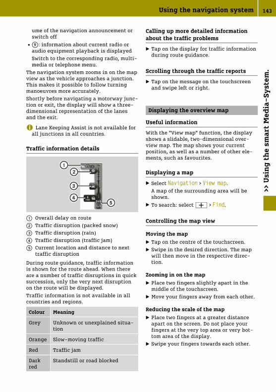
ume of the navigation announcement orswitch offRE: information about current radio or
audio equipment playback is displayedSwitch to the corresponding radio, multi-media or telephone menu.
The navigation system zooms in on the mapview as the vehicle approaches a junction.This makes it possible to follow turningmanoeuvres more accurately.Shortly before navigating a motorway junc-tion or exit, the display will show a three-dimensional representation of the lanesand the exit.
i Lane Keeping Assist is not available forall junctions in all countries.
Traffic information details
: Overall delay on route; Traffic disruption (packed snow)= Traffic disruption (rain)? Traffic disruption (traffic jam)A Current location and distance to next
traffic disruption
During route guidance, traffic informationis shown for the route ahead. When thereare a number of traffic disruptions in quicksuccession, only the very next disruptionon the route will be displayed.Traffic information is not available in allcountries and regions.
Colour Meaning
Grey Unknown or unexplained situa-tion
Orange Slow-moving traffic
Red Traffic jam
Darkred
Standstill or road blocked
Calling up more detailed informationabout the traffic problems
X Tap on the display for traffic informationduring route guidance.
Scrolling through the traffic reports
X Tap on the message on the touchscreenand swipe left or right.
Displaying the overview map
Useful information
With the "View map" function, the displayshows a slidable, two-dimensional over-view map. The map shows your currentposition, as well as a number of other ele-ments, such as favourites.
Displaying a map
X Select Navigation > View map.A map of the surrounding area will beshown.
X To search: select W > Find.
Controlling the map view
Moving the mapX Tap on the centre of the touchscreen.X Swipe in the desired direction. The map
will then move in the respective direc-tion.
Zooming in on the mapX Place two fingers slightly apart in the
middle of the touchscreen.X Move your fingers away from each other.
Reducing the scale of the mapX Place two fingers at a greater distance
apart on the screen. Do not place yourfingers at the very top area or very bot-tom area of the display.
X Swipe your fingers towards each other.
Using the navigation system 143
>> U
sin
g th
e sm
art
Med
ia-S
yst
em.
Z

Displaying the reachability map
If no route is planned, a reachability mapcan be displayed in order to roughly gaugethe range with the current charge status.
X Select Navigation > View map.X Select W > View reachability map.
Showing and hiding additional informa-tion on the map
X Select Navigation > View map.X Select W > Change map information.Select one of the following pieces of infor-mation:
RTraffic informationRNamesRPoints of interest (POIs)RSatellite imagesRCoordinates
Using TomTom Services with the nav-igation system
Displaying traffic information along theroute
X Tap on the area of traffic informationduring route guidance.
X Swipe left or right to switch betweentraffic information.
Adjusting the route according to trafficdisruptions
X Select Navigation > TomTom Services >Traffic > Minimise delays.A faster route that had been previouslyrejected or route which may not havebeen taken into account due to theNever change my route setting for thetraffic information is selected.
Displaying traffic disruptions on theoverview map
X Select W > View map during routeguidance.Traffic disruptions are displayed as sym-bols on the overview map.
X To view detailed information, tap on atraffic disruption symbol.
The following symbols are used:± Traffic jam´ Road blockedµ Traffic disruption· Construction site¸ One or more lanes blocked¹ Accidentº Traffic disruption avoided using the
traffic information¿ FogÀ WindÁ Snow Black iceà Rain
i Large area traffic disruptions such asrain, fog or snow are displayed on theoverview map with several symbols.
Viewing traffic information for the routeto work
X Select Navigation > TomTom Services >Traffic > Traffic info. for route to work.
Select one of the following settings:
RHome to workRWork to homeRChange the home to work route
Selecting the settings for traffic infor-mation
X Select Navigation > TomTom Services >Traffic > Traffic info. settings.
Select one of the following settings:
RAlways change to this routeIf a faster route has been calculated dueto a traffic report, the navigation systemautomatically changes the route.RRequest confirmation for route
144 Using the navigation system>>
Usi
ng
the
smar
t M
edia
-Sy
stem
.

If a faster route has been calculated dueto a traffic report, the navigation systemwill ask which route should be used.RNever change my route
The navigation system will not changethe route, even if a traffic announcementhas been made.
Setting the navigation system
Setting the voice
The voice used for navigation messages canbe changed. It is possible to choosebetween computer-generated voices or voi-ces recorded by professionals. For voicesthat have been recorded by professionals,only basic navigation messages will bespoken.
X Select System > Sound > Voice.X Select the voice for playback.X To listen to the voice, select Test.
Setting the voice output
The read-aloud function is only availablein a computer-generated voice.
X Select System > Sound > Voice output settings.
Select one of the following settings:
RRead early warning instructionsRRead aloud motorway lane instruc‐tionsRRead aloud traffic info when navi‐gatingRRead aloud foreign street namesRRead aloud road numbersRRead aloud street namesRRead aloud weather informationRRead aloud POI warningsRRead aloud warningsRRead aloud signposts
Changing the map
X Select Navigation > Settings > Switch map.
X Select the desired map.
Changing the map colours
X Select Navigation > Settings > Change map colours.
X Press , or . to select the desireddisplay.
Changing the E-vehicle settings
X Select Navigation > Settings > E-vehi‐cle settings.
The following functions can be called up:
Rdeactivating or activating the batterywarningWhen the charge status of the high-volt-age battery has reached 20% and the bat-tery warning is activated, a display mes-sage appears.Rshowing or hiding charging stations on
the mapRmanaging charging stationsRselecting the charging cableThe settings for both the type of chargingand charging cable are used by the naviga-tion system to refine the selection of avail-able charging stations. During navigation,different options can be selected via theW context menu:Select one of the following options:
Rsearch for type of chargingRsearch for electricity providerRdisplay all charging stationsA display message appears if there is someincompatibility between the defined set-tings and a selected charging station.
Setting safety warnings
X Select System > Safety warnings.Select the desired settings:
RSuggest driving breaksRWarn when driving near schoolsRWarn when driving faster than allowedRWarn when driving faster than a set speed
X Select Resume.X Select a warning tone for the respective
safety warning.
Using the navigation system 145
>> U
sin
g th
e sm
art
Med
ia-S
yst
em.
Z

For the "Warn when driving faster than aset speed" function, the speed above whichthe warning tone should sound must beentered.
Setting the units of measurement fordistance
All units of measurement for distance in thenavigation system can be changed. Theunits of measurement for distance of otherdisplays are not changed, such as distancedisplays for the eco score or the on-boardcomputer.
X Select System > Set units > Distance units.
Select one of the following settings:
RKilometresRMiles
Setting the units for GPS coordinates
X Select System > Set units > GPS coordi‐nate display.
Select one of the following settings:
RDegrees (d°)RDegrees, Minutes (d° m.m')RDegrees, Minutes, Seconds (d° m' s'')
146 Using the navigation system>>
Usi
ng
the
smar
t M
edia
-Sy
stem
.

Online access to the vehicle
G WARNING
If you operate information and communi-cation equipment integrated in the vehi-cle when driving, you could be distractedfrom the traffic situation. This could alsocause you to lose control of the vehicle.There is a risk of an accident.
Only operate this equipment when thetraffic situation permits. If you cannot besure of this, stop the vehicle payingattention to road and traffic conditionsand operate the equipment with the vehi-cle stationary.
G WARNING
If you use mobile information systemsand communications devices while driv-ing, you will be distracted from trafficconditions. You could then lose control ofthe vehicle. There is a risk of an accident.
Only operate these devices when thevehicle is stationary.
Observe the legal requirements for thecountry in which you are currently driving.You can use "smart control" services toaccess remote query and to configure yourvehicle remotely. It can be accessed fromcomputers and smartphones. The Internetaddress is available from any smart Centre.It is also possible to call up "smart control"services via the smart website.Access to "smart control" services is free ofcharge for the first three years commencingfrom handover of the new vehicle, subjectto the availability of the service. Thereafteryou can continue to subscribe to use "smartcontrol" services.The availability and functions of "smartcontrol" services may vary from country tocountry.Requirements for the use of "smart control"services:
RRegistration on the "smart portal" Inter-net page via http://www.smart.com/portal.
A valid e-mail address or mobile phonenumber is necessary for registration andthe terms of use must be accepted.RThe vehicle must be linked with a per-
sonal "smart portal" account at a smartCentre.Verification and presentation of thevehicle registration document arerequired to link the vehicle. The vehicleidentification number (VIN) is alsorequired.RThe desired functions must be activated
after linking the vehicle.For activation, "smart control" services'terms of use for both remote query andremote configuration must be acceptedvia the "smart portal". The portal addressis supplied by the smart Centre.RThe vehicle must be connected to the
Internet.Connection is made possible via themobile communications module integra-ted in the vehicle.
Once these requirements are fulfilled, thefollowing functions, for example, may beused:
RActivating the pre-entry climate controlfor the vehicle interior.RCalling up information on the distance
before the next recommended service or ifa service is already due.RConvenient charging with automatic
authentication and cashless payment.During the charging process, additionaldisplays can be called up such as the pre-dicted time until charging is completed orthe charging capacity.If there is a delay in the synchronisation ofdata via the mobile phone network, the dis-plays in the vehicle and for "smart control"services may temporarily differ from eachother.Further information on "smart control"services is available at any smart Centreand via http://www.smart.com/portal.
Online access to the vehicle 147
>> U
sin
g on
lin
e of
feri
ngs
.
Z

Using smart "ready to" services
Useful information
smart "ready to" services are only availablein certain countries.The functions are enabled via a communi-cation module and the smart "ready to" app.Information and the Internet addresses forthe smart "ready to" services are availableat any smart Centre.
i If you are already using a smart "readyto" service, additional services can beactivated with your user details in theusual web portal or via the app.
The communication module and activationare required in order to use the smart"ready to" services:
RRegister on the "ready to" web portal.A valid e-mail address and the vehicleidentification number (VIN) are neces-sary for registration, and the terms of usemust be accepted.RInstall the "ready to" app on your smart-
phone and create a user account.
Using the Key Card Holder
Key Card Holder : is located in the glovecompartment and is intended for the stor-age and inventory of the vehicle key and upto two cards (e.g. fuel card, parking card orcar wash card).The inventory is available within certainsmart "ready to" services.For an inventory, the key and/or the cardsmust be equipped with an RFID tag.Further information about RFID tags isavailable from any smart Centre.
148 Using smart "ready to" services>>
Usi
ng
onli
ne
offe
rin
gs.

Stowing small objects
Please note
G WARNING
If you stow objects in the vehicle interiorin an unsuitable way, they could slip orbe thrown around and thus hit vehicleoccupants. Additionally, the cup holders,open stowage spaces and mobile phonebrackets cannot restrain the objectsplaced in them in the event of an acci-dent. There is a risk of injury, especiallyin the event of braking or suddenchanges in direction.
RAlways stow objects so they cannot bethrown around in these or similar sit-uations.
RAlways ensure that objects do not pro-trude over the top of stowage compart-ments or stowage nets.
RAll closable stowage compartmentsshould be closed before beginning yourjourney.
RAlways stow and secure heavy, hard,pointed, sharp-edged, fragile objects orobjects which are too large behind thelast bench seat or under the passengerseats.
G WARNING
The cup holder cannot secure a drinkscontainer in place during a journey. Ifyou use a cup holder during a journey,the drinks container could be flungaround and liquid could be spilt. Vehicleoccupants could come into contact withthe liquid and, in particular, be scaldedby hot liquid. You could be distractedfrom the traffic situation and lose controlof the vehicle. There is a risk of an acci-dent and injury.
Only use the cup holder when the vehicleis stationary. Only place containers of asuitable size in the cup holder. Seal thecontainer, in particular when it containshot liquid.
! Only use the cup holders for containersof the right size and which have lids. Thedrinks could otherwise spill.
Using the compartments
X To stow objects, use suitable stowagespaces.The following stowage spaces are availa-ble:
R: Stowage compartments in the doorsR; Cup holder in the front centre con-
soleR= Glove compartmentR? Stowage net in the front passenger
footwellRA Sliding drawer in the centre consoleRB smart EQ fortwo: spectacles com-
partment above the driver's seat andabove the front passenger seatRVelcro strip on the front passenger seat
for stowing a handbagRCup holder in the rear centre console
with a recess for storing a mobilephoneRsmart EQ fortwo: stowage compartment
in the lower tailgateRStowage net with two separate com-
partments on the back of the boot sep-arator
Stowing small objects 149
>> L
oad
ing
and
sto
win
g.
Z

Locking/unlocking the glove compart-ment
X Insert the key into the lock.X To lock: turn the key to position 2.X To unlock: turn the key to position 1.
Opening the stowage compartment inthe tailgate (smart EQ fortwo)
! Do not exceed the lower tailgate maxi-mum load of 100 kg. It may otherwisebecome damaged.
X Open the tailgate.X Pull handle : on the inside of the lower
tailgate upwards.X Lift up the cover in the direction of the
arrow.
Stowing luggage and large objects
Please note
G WARNING
If you stow objects in the vehicle interiorin an unsuitable way, they could slip orbe thrown around and thus hit vehicleoccupants. Additionally, the cup holders,open stowage spaces and mobile phonebrackets cannot restrain the objectsplaced in them in the event of an acci-dent. There is a risk of injury, especiallyin the event of braking or suddenchanges in direction.
RAlways stow objects so they cannot bethrown around in these or similar sit-uations.
RAlways ensure that objects do not pro-trude over the top of stowage compart-ments or ruffled pockets.
RAll closable stowage compartmentsshould be closed before beginning yourjourney.
RAlways stow and secure heavy, hard,pointed, sharp-edged, fragile objects orobjects which are too large behind thelast bench seat or under the passengerseats.
The handling characteristics of a ladenvehicle are dependent on the distribution ofthe load within the vehicle.Observe the following loading guidelineswhen loading and transporting luggage andloads:
Rdo not exceed the maximum permissiblegross vehicle weight or the permissibleaxle loads for the vehicle (includingoccupants)Rthe load must not protrude above the
upper edge of the head restraintsRensure that no items of luggage can enter
the vehicle interior above or between theseatsRensure that loaded objects are stowed
safely and are securedRload heavy objects at the bottom and
light objects at the top
150 Stowing luggage and large objects>>
Loa
din
g an
d s
tow
ing.

Rthe load compartment is the preferredplace to stow objectsRstow heavy loads as far forwards and as
low down in the load compartment aspossible
Opening the load compartment (smartEQ fortwo)
! The tailgates swing to the rear, bothupwards and downwards, when opened.Therefore, make sure that there is suffi-cient clearance above, behind and belowthe tailgates.
X Press the é button on the key.X Fold the upper tailgate upwards.
X Pull lever : upwards.X Fold the lower tailgate down.
Closing the boot (smart EQ fortwo)
X Fold the lower tailgate upwards andengage on both sides.
X Pull the upper tailgate down and press itclosed.
X Press the & button on the key.The vehicle is locked.
Opening the boot (smart EQ fortwocabrio)
Opening the tailgate
X Press the % button on the key.X Press button : in the handle recess.X Fold down the tailgate.
Opening the rear soft top
X Open the tailgate.X Press both latch levers :.X Swing the rear soft top up.
Closing the boot (smart EQ fortwocabrio)
Closing the rear soft top
! When closing the tailgate, you mustfirst lock the tail cover. Otherwise, youcould break the catch lever.
X Pull the rear soft top down until itengages.
X Lock the rear soft top with both latch lev-ers.
Stowing luggage and large objects 151
>> L
oad
ing
and
sto
win
g.
Z

Closing the tailgate
X Pull the tailgate up until it engages.X Press the & button on the key.
The vehicle is locked.
Enlarging the boot: folding the seatbackrest forwards
Folding the seat backrest forwards(using the lever)
Seat with a lever
X Lift lever ; and slide the frontpassenger seat to its rearmost position.
X Pull lever : forwards.X Fold the seat backrest forwards at the
same time.
Folding the seat backrest forwards(using the handwheel)
Seat with a handwheel
X Turn handwheel : forward.
Folding back the seat backrest
Please note
G WARNING
If the seat backrest is not engaged, it mayfold forwards, e.g. during braking or inthe event of an accident.
RAs a result, a backrest which is notengaged would press you into the seatbelt. The seat belt cannot perform itsintended protective function and couldadditionally cause injury.
RThe backrest cannot restrain objects orloads in the boot.
This poses an increased risk of injury.
Before every journey, make sure that thebackrest is engaged as described.
Folding back the seat backrest (usingthe lever)
X Pull lever :.X Push the seat backrest back at the same
time until it engages.
Folding back the seat backrest (usingthe handwheel)
X Turn handwheel : backwards.
Using the boot separator
Fitting the boot separator
G WARNING
On its own, the boot cover cannot secureor restrain heavy objects, items of lug-gage and heavy loads. You could be hit byan unsecured load during suddenchanges in direction, braking or in theevent of an accident. There is anincreased risk of injury or even fatalinjury.
Always store objects so that they cannotbe flung around. Secure objects, luggageor loads against slipping or tipping over,
152 Using the boot separator>>
Loa
din
g an
d s
tow
ing.

e.g. by using lashing material, even ifyou are using the boot cover.
For easier fitting, fold the front passengerseat backrest forwards.
X smart EQ fortwo: open the upper andlower tailgate.
X smart EQ fortwo cabrio: open the lowertailgate.
X smart EQ fortwo cabrio: fold the rear softtop up.
X Hold boot separator : with the luggagenet bag in the direction of the vehicleinterior in the boot.
X Insert boot separator : into bracket ;on the right side.
X Slide handle ? to the right and hold.X Insert boot separator : into bracket ;
on the left side.X Release handle ?.
Boot separator : snaps into place.X Secure the luggage net bag with the Vel-
cro fasteners.
If boot separator : is not required and nosubwoofer is installed, it can be attached tobrackets =.
Hooking and unhooking the boot sep-arator
X Grip boot separator : in the middle andpull it back.
X Hook the boot separator into left andright rear brackets A.
Removing/fitting the charging cablebag
Removing the charging cable bag
X Turn both buttons : to the left.The buttons are released from theanchorage.
X Fold the charging cable bag to the left.The Velcro fasteners under the chargingcable bag are detached.
X Remove snap hook ;.
Removing/fitting the charging cable bag 153
>> L
oad
ing
and
sto
win
g.
Z

Installing the charging cable bag
X Place the charging cable bag with its sideresting on the engine compartment coverand then position it on the side trim.
X Position the charging cable bag in a ver-tical position.Take hold of the Velcro fasteners beneaththe charging cable bag.
X Push both buttons : into the anchorageand turn them to the right.
X Secure snap hook ;.
154 Removing/fitting the charging cable bag>>
Loa
din
g an
d s
tow
ing.

Useful information
The engine compartment in the smart islocated at the rear, below the boot. Servicefluid reservoirs are located under the ser-vice cover at the front.When working on the vehicle, always com-ply with all safety regulations. Alwayshave work in the engine compartment car-ried out at a qualified specialist workshop.
Removing/fitting the subwoofer
Removing the subwoofer
X Release quick-release fastener : in thedirection of the arrow.
X Reach into the recess on the quick-release fastener.
X Detach, tilt and pull the subwoofer to theright.
X Pull out the connector.
Fitting the subwoofer
X Insert the connector.X Place the subwoofer at the base of the
side trim.X Turn quick-release fastener : upwards.X Press the bracket into the recess in side
trim ;.X Turn quick-release fastener : clock-
wise.
Opening and closing the service cover
Please note
G WARNING
If the service cover is not locked, it maycome loose during driving and block yourview or endanger other road users. Thereis a risk of an accident and injury.
Therefore, make sure that the servicecover is locked before driving off.
G WARNING
If the windscreen wipers start to movewhen the service cover is open, you couldbecome caught up in the wiper rods.There is a risk of injury.
Always switch off the windscreen wipersand the ignition before you open the ser-vice cover.
! To ensure unhindered air intake, com-pletely remove any dirt or snow from theventilation slots above the service cover.
The vehicle must be secured against rollingaway.On vehicles with a lockable service cover,the service cover must be unlocked before itis opened.
Opening and closing the service cover 155
>> M
ain
ten
ance
an
d c
are.
Z

Unlocking the service cover
X Insert the tip of the key into the openingof lock cover :.
X Press the key to the right ; to lever upthe lock cover.
X Remove the lock cover.X Insert the key into the lock and turn it
90° clockwise.
Opening the service cover
X Pull both levers ; in the direction of thearrow.
X Lift service cover = at the front.X Pull service cover = slightly forwards
and lift upwards.X Carefully rest service cover =, still
attached to the straps, against the frontof the vehicle.
Closing the service cover
X Lift service cover =.X Slide bars A on the left and right of the
service cover under the bars on wing ?.
X Press service cover = downwards.X Press both levers ; backwards in the
direction of the arrow.
Locking the service cover
X Insert the key into the lock and turn it toposition 1.
X Insert lock cover : on the driver's sideand snap it into place.
156 Opening and closing the service cover>>
Mai
nte
nan
ce a
nd
car
e.

Checking service products and top-ping up
Please note
G WARNING
Service product can be poisonous andhazardous to health. There is a risk ofinjury.
Observe the instructions on the respec-tive original container when using, stor-ing and disposing off service products.Always store service products in thesealed original container. Always keepservice products out of the reach of chil-dren.
H Environmental note
Dispose of service products in an envi-ronmentally-responsible manner.
Also observe the information in the "Serviceproducts" section (Y page 212).Service products include the following:
RcoolantRbrake fluidRwindscreen washer fluidRclimate control system refrigerantService products approved for smart:http://bevo.mercedes-benz.com
Checking the coolant and topping up
Checking the coolant level
X Stop the vehicle on a level surface.X Let the coolant cool down for at least
30 minutes.X Open the service cover. (Y page 155)X Check reservoir ; visually.
The fluid level must be between the MINmark and the MAX mark.
Topping up the coolant
G WARNING
The cooling system is pressurised whenthe drive system is at normal operatingtemperature. When you open the cap, youcould be scalded by hot coolant sprayingout. There is a risk of injury.
Let the drive system cool down before youopen the cap. Wear protective gloves andeye protection when opening. Open thecap slowly to relieve pressure.
! Add only coolant that has been pre-mixed with the desired antifreeze protec-tion. You could otherwise damage theengine.You can find additional notes on thecoolant in the following places:
Rin the Mercedes-Benz Specificationsfor Service Products, MB BeVo 310.1- on the internet at
http://bevo.mercedes-benz.com- on the Mercedes-Benz BeVo appRat a qualified specialist workshop
If antifreeze/corrosion inhibitor is presentin the correct concentration, the boilingpoint of the coolant during operation isapproximately 130 †.The antifreeze/corrosion inhibitor concen-tration in the engine cooling system shouldbe 50% (antifreeze protection down to-37 †). This will protect the engine coolingsystem against freezing down to approx-imately -25 †.
X Cover cap : of coolant expansiontank ; with a cloth.
X Turn the cap slowly one half turn. If nec-essary, allow excess pressure to escape.
X Turn the cap further and remove it.X Top up the coolant to the MAX level.
Checking service products and topping up 157
>> M
ain
ten
ance
an
d c
are.
Z

X Replace the cap and tighten it as far as itwill go.
X Close the service cover. (Y page 155)
i See "Technical data" for information onrecommended coolants.
Topping up the washer fluid
G WARNING
Windscreen washer concentrate is highlyflammable. If it comes into contact withhot components in the front compart-ment, it may ignite. There is a risk of fireand injury.
Make sure that windscreen washer con-centrate is not spilled next to the fillerneck.
X Open the service cover. (Y page 155)X Pull cap : upwards at the tab.X If available, pull the removable nozzle up
as far as the stop.X Top up with washer fluid.X If available, push the removable nozzle
down and push it inside.X Replace and tightly screw on cap :.X Close the service cover. (Y page 155)
i See "Technical data" for information onwindscreen washer fluid and antifreeze.
Checking wheels and tyres
G Warning
A flat tyre severely impairs the driving,steering and braking characteristics ofthe vehicle. There is a risk of an accident.
Do not drive with a flat tyre. Immediatelyreplace the flat tyre with your sparewheel, or consult a qualified specialistworkshop.
G WARNING
Damaged tyres can cause tyre inflationpressure loss. As a result, you could losecontrol of your vehicle. There is a risk ofaccident.
Check the tyres regularly for signs ofdamage and replace any damaged tyresimmediately.
G WARNING
If there is insufficient tyre tread, the tyretraction will decrease. The tyre tread canno longer dissipate water. This increasesthe risk of aquaplaning on a wet roadsurface, especially when the vehicle'sspeed is not adapted to the road condi-tions. There is a risk of an accident.
If the tyre pressure is too high or too low,tyres may wear differently at differentpoints of the tyre tread. Regularly checkthe tyre tread depth and the condition ofthe tread across the whole width of alltyres, therefore.
Minimum tyre tread depth on:
RSummer tyres: 3 mm
RM+S tyres: 4 mm
For safety reasons, have the tyresreplaced before the legally specifiedminimum tread depth is reached.
! If you cannot avoid driving over obsta-cles, e.g. kerbs, do so slowly and at anobtuse angle only. You could otherwisedamage the wheel rims and tyres.
158 Checking wheels and tyres>>
Mai
nte
nan
ce a
nd
car
e.

Modification work on the brake system andwheels is not permitted. The use of spacersor brake dust shields is not permitted. Thisinvalidates the general operating permitfor the vehicle.Check the wheels and tyres for damage atleast once a month, as well as after drivingoff-road or on poorly surfaced roads.Run-in new tyres at moderate speeds forthe first 100 km. The tyres only attain theirmaximum performance after this distance.Vibrations, audible noises and unusualhandling characteristics, e.g. pulling to oneside, can indicate damage to wheels ortyres.
If you suspect a tyre defect:
X Reduce vehicle speed.X Stop the vehicle as soon as possible.X Check the wheels and tyres for damage.
If you find no signs of damage, have thewheels and tyres checked at a specialistworkshop.
Changing a wheel
Please note
G WARNING
Interchanging the front and rear wheelsif the wheels or tyres have differentdimensions may severely impair thedriving characteristics. The service brakeor wheel suspension components mayalso be damaged. There is a risk of anaccident.
Rotate front and rear wheels only if thewheels and tyres are of the same dimen-sions.
G WARNING
Exceeding the stated tyre load-bearingcapacity and the approved maximumspeed could lead to tyre damage or thetyre bursting. There is a risk of accident.
Therefore, only use tyre types and sizesapproved for your vehicle model. Observethe tyre load rating and speed ratingrequired for your vehicle.
G WARNING
If you fit wheels and tyres with incorrectdimensions, the service brake or wheelsuspension components may be damaged.There is a risk of an accident.
Always replace wheels and tyres withones that comply with the specificationsof the original part.
When replacing wheels, pay attention tothe:
Rdesignation
Rtype
When replacing tyres, pay attention tothe:
Rdesignation
Rmanufacturer
Rtype
! To prevent damage, smart recommendshaving the wheel changed at a qualifiedspecialist workshop.
! On vehicles fitted with a tyre pressuremonitor, electronic components are loca-ted in the wheel.Tyre-fitting tools should not be appliedin the area of the valve, since this coulddamage the electronic components.Only have tyres changed at a qualifiedspecialist workshop.
! Only position a suitable jack on thejacking point intended for the purpose.Only raise the vehicle briefly to changethe wheel. Make sure that there are nopersons in the vehicle and that it is on asuitable surface. Secure the vehicle withwheel chocks and apply the parkingbrake.
Interchanging front and rear wheels ortyres of differing dimensions can renderthe general operating permit invalid.
Rules for selecting new tyres
! For safety reasons, smart recommendsthat you only use wheels and tyres whichsmart has specifically approved for your
Changing a wheel 159
>> M
ain
ten
ance
an
d c
are.
Z

vehicle. These are specially adapted tothe systems, such as ABS or ESP®.Only use tyres and wheels tested andrecommended by smart. Certain charac-teristics, such as handling, vehicle noiseemissions, fuel consumption, etc. mayotherwise be adversely affected. Dimen-sional variations and altered tyre defor-mation when driving under load may alsocause the tyres to come into contact withthe vehicle body and axle components.This may result in damage to the tyre orthe vehicle.smart is not responsible for any damagecaused by using tyres and wheels otherthan those which have been tested andrecommended.You can obtain information about tyresand wheels from any qualified specialistworkshop, e.g. a smart Centre.
The service life of tyres depends on variousfactors, including the following:
Rdriving styleRtyre pressureRmileageObserve the following rules for selectingnew tyres:
Robserve country-specific regulationswhich stipulate or recommend a certaintyre type for the vehicle.Ronly fit tyres and wheels of the same
type and make.Ronly tyres of the same size may be used
on a single axle (left/right).Ronly use tyres of the same type (summer
tyres, all-season tyres, winter tyres).Ronly use wheel-tyre combinations
approved by smart.Rdo not wear tyres out too much. This oth-
erwise significantly reduces the tractionon wet roads (aquaplaning).Rreplace tyres after six years at the latest.Rthe use of a specific tyre type in certain
regions and areas of operation can behighly beneficial.
i Recommended tyre pressures for vari-ous operating states can be found on thetyre pressure table on the driver's sidedoor pillar (B-pillar).
You can find further information regardingtyres and wheels at specialist tyre retail-ers, at qualified specialist workshops andat any smart Centre.
Preparing to change a wheel
The vehicle tool tray is located under theglove compartment.
X Stop the vehicle on solid, non-slipperyand level ground.
X Apply the parking brake.X Position the front wheels to point
straight ahead.X Shift the transmission to position j.X Switch off the engine.X Remove the key from the ignition lock.X Secure the vehicle against rolling away.
Removing a wheel
G WARNING
If you do not position the jack correctlyat the appropriate jacking point of thevehicle, the jack could tip over with thevehicle raised. There is a risk of injury.
Only position the jack at the appropriatejacking point of the vehicle. The base ofthe jack must be positioned vertically,directly under the jacking point of thevehicle.
! Do not place wheel bolts in sand or dirt.The threads of the wheel bolts and wheelhubs could otherwise be damaged whenthe bolts are tightened.
! Position a suitable jack only on thejacking points intended for this purpose.Never position the jack on the high-volt-age battery. Do not jack up the vehicle onthe high-voltage battery. There is other-wise a risk of damaging the high-voltagebattery.Also observe the notes in the "Changing awheel" section.
160 Changing a wheel>>
Mai
nte
nan
ce a
nd
car
e.

Warning stickers
Always pay attention to the instructionsand safety notes on "Changing a wheel"(Y page 159).
Vehicles with steel wheels and hub caps:
X Using both hands, grasp two hub capopenings and remove the hub cap.
Vehicles with steel wheels and hub cap cover:
X Remove the hub cap cover.
: Wheel wrench
X Using wheel wrench : loosen the wheelbolts by about one turn. Do not unscrewthe wheel bolts completely.
; Jack= Reinforced area for the jacking points
Jack ; may only be positioned on thereinforced area intended for this purposefor jacking points =.The vehicle may be damaged if jack ; ispositioned at another point on the sill.
= Reinforced area for the jacking points? Triangular indentationA Outer covering of the sill
Changing a wheel 161
>> M
ain
ten
ance
an
d c
are.
Z

! To prevent damage, smart recommendshaving the wheel changed at a qualifiedspecialist workshop.
The reinforced areas for jacking points =are located behind the front wheels and infront of the rear wheels. They can be recog-nised by triangular indentations ? on thevehicle.Jack ; may only be positioned on thereinforced areas for jacking points = onthe sill and not on the outer covering of sillA.
X Search for the reinforced area for jackingpoints = which is found approx. 7 cmbehind the sill at triangular indenta-tions ?.
X Position jack ; under the correspondingreinforced area for jacking points =.
X Set the foot of the jack up vertically withrespect to the reinforced area for thejacking points on the vehicle.
X Make sure that the jack is correctly posi-tioned so that the vehicle cannot slip.
X Raise the vehicle using the jack until thetyre is a maximum of 3 cm off the ground.
X Unscrew and remove the wheel bolts.X Remove the wheel.
Fitting a wheel
G WARNING
The wheels could come loose if the wheelbolts or wheel nuts are not tightened tothe prescribed tightening torque. Thereis a risk of an accident.
Ensure that the wheel bolts or wheel nutsare tightened to the prescribed tighten-ing torque.
If you are not sure, do not move the vehi-cle. Contact a qualified specialist work-shop and have the tightening torquechecked immediately.
The tightening torque must be 105 Nm.After travelling approx. 500 km, check thetightening torque and retighten if neces-sary.
G WARNING
If you tighten the wheel bolts or wheelnuts when the vehicle is raised, the jackcould tip over. There is a risk of injury.
Only tighten the wheel bolts or wheelnuts when the vehicle is on the ground.
! When changing a wheel, only use wheelbolts which have been approved forwheel rims and the vehicle.
Always pay attention to the instructionsand safety notes on "Changing a wheel"(Y page 159).
Fit tyres with a specified direction of rota-tion only according to their direction ofrotation. An arrow on the sidewall of thetyre indicates its correct direction of rota-tion.
X Clean the wheel and wheel hub contactsurfaces.
X Push the wheel onto the wheel hub andpress it on.
X Screw in the wheel bolts up to the cone.X Make sure that they sit securely on the
cone.
162 Changing a wheel>>
Mai
nte
nan
ce a
nd
car
e.

X Lower the vehicle all the way.X Remove the jack.X Tighten the wheel bolts evenly in a
crosswise pattern in sequence indica-ted : to ?. The tightening torque mustbe 105 Nm.
X Check the recommended tyre pressureand adjust if necessary.After travelling approx. 500 km, check thetightening torque and retighten if neces-sary.
i Vehicles with tyre pressure control sys-tem: all fitted wheels must be equippedwith functioning sensors.
Vehicles with steel wheels and hub caps:
X Fit hub cap A such that valve B doesnot become trapped.
X Press the hub cap evenly onto the wheelwith both hands until you hear the hubcap engage.
X Check to make sure the hub cap is seatedsecurely on the wheel.
Vehicle with steel wheels and wheel hub covers:
X Fit the hub cap cover.
Storing wheels
X Store wheels in a cool, dry and dark placewhen not in use.
X Protect against oil and grease.
Using the tyre pressure monitor
Useful information
It is the driver's responsibility to set thetyre pressure to the recommended cold tyrepressure suitable for the operating situa-tion.The tyre pressure monitor issues a warningwhen the pressure drops in one or more ofthe tyres.The tyre pressure monitor works properlyonly if sensors are present in all four tyres,and after the monitor has learned the cor-rect tyre pressure for the current operatingsituation. This occurs automatically inmost situations, but may also be specifiedafter restarting the tyre pressure monitor.Before restarting, check the tyres for therecommended tyre pressure.The tyre pressure monitor does not providea warning in the following cases:
Reven loss of pressure on multiple tyresRsudden loss of tyre pressure, e.g. due to
penetration by a foreign bodyRincorrectly set tyre pressureThe tyre pressure monitor has a yellowwarning lamp in the instrument cluster forindicating a pressure loss or malfunction.
Restarting the tyre pressure monitor(on-board computer with a mono-chrome display)
X Set the tyre pressure of all tyres to therecommended value.
X On the multifunction lever, press the´ button repeatedly until the °and h symbols are displayed in theinstrument cluster display.
X Press and hold the a button on themultifunction lever.The ° and h symbols flash in theinstrument cluster display for approx-
Using the tyre pressure monitor 163
>> M
ain
ten
ance
an
d c
are.
Z

imately five seconds. The two symbolsthen light up.
The tyre pressure monitor is restarted.
Restarting the tyre pressure monitor(on-board computer with colour dis-play)
X Set the tyre pressure of all tyres to therecommended value.
X Select Settings > Tyre pressure moni‐tor in the on-board computer.The Tyre pressure monitor Adopt cur‐rent pressures as new reference values? message appears in the display.
X Select Yes and press a to confirm.The display shows the Tyre pressure monitor restarted message.
If the Tyre pressure monitor restartedmessage does not appear after five seconds,restart the tyre pressure monitor again.
Checking the tyre pressures
Please note
G WARNING
Underinflated or overinflated tyres posethe following risks:
Rthe tyres may burst, especially as theload and vehicle speed increase.
Rthe tyres may wear excessively and/orunevenly, which may greatly impairtyre traction.
Rthe driving characteristics, as well assteering and braking, may be greatlyimpaired.
There is a risk of an accident.
Observe the recommended tyre pressureand check the tyre pressure of all thetyres:
Rat least every two weeks
Rwhen the load changes
Rbefore embarking on a longer journey
Rfor changed operating conditions, e.g.off-road driving
If necessary, correct the tyre pressure.
G WARNING
If you mount unsuitable accessories ontotyre valves, the tyre valves may be over-loaded and malfunction, which can causetyre pressure loss. Aftermarket tyre pres-sure monitoring systems will cause thetyre valve to remain open. This can alsoresult in tyre pressure loss. There is arisk of an accident.
Only screw standard valve caps or valvecaps specifically approved by smart foryour vehicle onto the tyre valve.
G WARNING
If the tyre pressure drops repeatedly, thewheel, valve or tyre may be damaged.Tyre pressure that is too low may resultin a tyre blow-out. There is a risk of acci-dent.
RCheck the tyre for foreign objects.
RCheck whether the wheel is losing airor the valve is leaking.
If you are unable to rectify the damage,contact a qualified specialist workshop.
H Environmental note
Check the tyre pressure regularly, atleast every 14 days.
164 Checking the tyre pressures>>
Mai
nte
nan
ce a
nd
car
e.

The table with the recommended tyre pres-sure for various operating conditions canbe found on the driver's side door pillar(B-pillar).The tyre pressure table may also state airpressures for different load conditions.These are defined in the table as differentnumbers of passengers and amounts of lug-gage. The actual number of seats may differfrom this.If a tyre size precedes a tyre pressure, thetyre pressure information following is onlyvalid for that tyre size. If tyre sizes are notspecified, the tyre pressures stated on thetyre pressure table apply for all approvedtyres.
Checking and correcting the tyrepressure manually
Only check the tyre pressure once the tyreshave cooled down.
X Drive the vehicle less than 2 km.X Park the vehicle away from direct sun-
light for at least three hours.X Check the tyre pressure with a suitable
tyre pressure gauge.X If necessary, adjust the tyre pressure.X Restart the tyre pressure monitor.
Using winter tyres
G WARNING
M+S tyres with a tyre tread depth of lessthan 4 mm are not suitable for use inwinter as they do not provide sufficienttraction. There is a risk of accident.
M+S tyres with a tread depth of less than4 mm must be replaced.
At temperatures below +7 †, summer tyreslose elasticity and therefore traction andbraking power. Change the tyres on yourvehicle therefore to winter tyres or all-sea-son tyres marked with M+S. Using summertyres at very cold temperatures could causetears to form, thereby damaging the tyrespermanently. smart cannot accept respon-sibility for this type of damage.
Have the vehicle winterproofed at a quali-fied specialist workshop at the onset ofwinter.
X At low temperatures, use only wintertyres marked with M+S.
X When road conditions are wintry, useM+S tyres with the additional i snow-flake symbol.These tyres allow driving safety systems,e.g. ABS, to function optimally in thewinter.
X Use M+S tyres of the same make and treadon all wheels.
X When driving with M+S tyres, observe thespecified maximum permissible speed.
X Use only tyre types and sizes approvedfor smart.
X When using tyres with a specified direc-tion of rotation, observe the arrow on thesidewall indicating the tyre's direction ofrotation.
After fitting M+S tyres:
X Check the tyre pressure.X Restart the tyre pressure monitor.X If M+S tyres with a lower maximum per-
missible speed than that of the vehicleare fitted, affix an appropriate warninglabel in the driver's field of vision. Usingthe limiter, restrict the speed to the max-imum permissible speed for M+S tyres.
Using snow chains
G WARNING
If you have fitted snow chains to thefront wheels, they may scrape against thevehicle body or chassis components. Thiscould cause damage to the vehicle or thetyres. There is a risk of an accident.
To avoid hazardous situations:
Rnever fit snow chains on the frontwheels
Rfit snow chains to the rear wheels inpairs.
! Vehicles with steel wheels: if you fitsnow chains on steel wheels, you maydamage the hub caps. Remove the hub
Using snow chains 165
>> M
ain
ten
ance
an
d c
are.
Z

caps from the relevant wheels before fit-ting the snow chains.
For safety reasons, smart recommends thatyou only use snow chains that have beenspecially approved for your vehicle bysmart. Further information can be obtainedat a smart Centre or a qualified specialistworkshop.
X Observe country-specific regulations.X Use only snow chains approved for smart.X Fit snow chains on both rear wheels.X Use snow chains only on snow-covered
roads.X When driving with snow chains fitted, do
not exceed the maximum permissiblespeed of 50 km/h.
Changing the window wiper blades
Please note
G WARNING
If the windscreen wipers begin to movewhile you are changing the wiper blades,you can be trapped by the wiper arm.There is a risk of injury.
Always switch off the windscreen wipersand ignition before changing the wiperblades.
! Never open the service cover or tailgateif a wiper arm has been folded away fromthe windscreen or rear window. Neverfold a wiper arm without a wiper bladeback onto the windscreen or rear window.Hold the wiper arm firmly when youchange the wiper blade. If you release thewiper arm without a wiper blade and itfalls onto the window, the window may bedamaged by the force of the impact.
Changing the window wiper blades onthe windscreen
X Fold the wiper arm away from the wind-screen.
X Release tab ; of bracket ? must bepressed towards windscreen 3. Thecatch tab is released from the bracketand the wiper blade can be pulled awayfrom the wiper arm.
X Slide window wiper blade : in the direc-tion of arrow 5 until the securing hookfor the window wiper blade is revealed.
X Remove the window wiper blade.
X Slide new window wiper blade : in thedirection of arrow 4 onto mounting =of wiper arm ;.The window wiper blade snaps into place.
X Check that the window wiper blade ispositioned correctly.
X Carefully fold wiper arm ; onto thewindscreen.
166 Changing the window wiper blades>>
Mai
nte
nan
ce a
nd
car
e.

Changing the rear window wiper blade(smart EQ fortwo)
X Remove the key from the ignition lock.X Fold wiper arm : away from the rear
window until you hear it engage.X Unscrew window wiper blade ; in the
direction of the arrow until it is releasedfrom the retainer on the wiper arm.
X Pull out window wiper blade ;.X Press new window wiper blade ; onto
wiper arm : until it engages.X Check that window wiper blade ; is
positioned correctly.X Fold wiper arm : back onto the rear
window.
Cleaning the vehicle
Useful information
Regular care maintains the appearance andquality of the vehicle over time.Observe the following when cleaning andcaring for the vehicle:
X Do not clean the engine.X Do not clean the vehicle whilst charging.X Use soft, moist cloths.X Use care products and cleaning agents
recommended and approved for smart.X Do not use acidic cleaning agents.X In winter, carefully remove road salt as
soon as possible.
Cleaning the vehicle exterior
Washing in an automatic car wash orwashing by hand
Preparing the vehicle for cleaning
G WARNING
Braking efficiency is reduced after thevehicle has been washed. There is a riskof an accident.
After washing the vehicle, brake carefullywhile paying attention to the traffic con-ditions in order to restore full brakingefficiency.
X Close the side windows completely.X Switch off the climate control blower.X Turn the windscreen wipers to positiong.
Notes on care of matt paintwork
! The following can give the paint aglossy appearance and thus reduce thematt effect:
RRubbing hard with unsuitable agentsRWashing the vehicle in direct sunlight
! Only use automatic car washes whichcorrespond to the latest technologicalstandards. Never use wash programswhich finish by treating the vehicle withhot wax.
! Never use paint cleaner, buffing or pol-ishing products, or gloss preserver, e.g.wax, for the purpose of paintwork care.These products are only suitable forhigh-gloss surfaces. Their use on vehi-cles with matt paintwork leads to consid-erable surface damage or, more specifi-cally, to shiny, spotted areas.Always have paintwork repairs carriedout at a qualified specialist workshop.
! Never polish the vehicle or the lightalloy wheels. Polishing makes the paint-work shiny.
If your vehicle has a clear matt finish,observe these notes. By doing so, you canavoid paintwork damage due to incorrecthandling.
Cleaning the vehicle 167
>> M
ain
ten
ance
an
d c
are.
Z

Washing in an automatic car washX Prepare the vehicle for cleaning.X Remove excess dirt.X Drive through the automatic car wash.X Remove wax from the front windscreen
and the wiper blades.
i If the windscreen wipers leave smearsafter the vehicle has passed through thecar wash, this may be caused by wax orother residue. This residue can beremoved with washer fluid.
Washing by handX Locate a washing bay equipped for hand-
washing.X Prepare the vehicle for cleaning.X Apply mild cleaning agent with a soft
vehicle sponge.X Thoroughly hose the vehicle with a gen-
tle jet of water; do not point the water jetdirectly towards the air inlet grille.
X Dry the vehicle off with a chamois.
Cleaning with a high-pressure cleaner
G WARNING
The water jet of circular-jet nozzles (dirtgrinders) can cause damage not visiblefrom the outside to tyres or chassis com-ponents. Components damaged in thisway can unexpectedly fail. There is a riskof an accident.
Do not use high-pressure cleaners withcircular-jet nozzles to clean the vehicle.Have damaged tyres or chassis compo-nents replaced immediately.
! Always maintain a distance of at least30 cm between the vehicle and the high-pressure cleaner nozzle. Informationabout the correct distance is availablefrom the equipment manufacturer.Move the high-pressure cleaner nozzlearound when cleaning your vehicle.Do not aim directly at any of the follow-ing:
RtyresRdoor gaps, roof gaps, joints etc.Relectrical components
RbatteryRplug-type couplingsRlight bulbsRsealsRtrim elementsRventilation slotsDamaged seals or electrical componentscan lead to leaks or failures.
X Prepare the vehicle for cleaning.X Maintain a distance of at least 30 cm
between the high-pressure cleaner noz-zle and the vehicle.
X Keep moving the nozzle whilst cleaning.
Cleaning the reversing camera
X Clean camera lens : with water and asoft cloth.
168 Cleaning the vehicle>>
Mai
nte
nan
ce a
nd
car
e.

Cleaning the sensors
: Active Brake Assist sensor; Parking aid sensors
X Clean sensors with water, car shampooand a soft cloth.
Cleaning the wheels
G WARNING
The water jet of circular-jet nozzles (dirtgrinders) can cause damage not visiblefrom the outside to tyres or chassis com-ponents. Components damaged in thisway can unexpectedly fail. There is a riskof an accident.
Do not use high-pressure cleaners withcircular-jet nozzles to clean the vehicle.Have damaged tyres or chassis compo-nents replaced immediately.
! Do not use acidic wheel cleaning prod-ucts to remove brake dust. This coulddamage wheel bolts and brake compo-nents.
! Do not park up your vehicle for a longperiod of time immediately after clean-ing, particularly after cleaning the wheelrim with wheel cleaner. Wheel cleanermay lead to increased corrosion of thebrake discs and pads. You should there-fore drive for a few minutes after clean-ing. By heating up the brakes, the brake
discs and pads dry. The vehicle can thenbe parked up for a long period of time.
X Clean the wheels with an acid-free clean-ing agent.
Cleaning the windows and windscreenwipers
Cleaning the windows
G WARNING
If the windscreen wipers are set inmotion when cleaning the windscreen orwiper blades, you could become trapped.There is a danger of injury.
Always switch off the windscreen wipersand the ignition before cleaning thewindscreen or wiper blades.
X Place the wiper arms in the vertical posi-tion and fold them away from the win-dow.
X Clean the inside and outside of the win-dows with a damp cloth and a cleaningagent recommended for smart.
X Clear deposits regularly from the wind-screen and rear window to ensure thatwater can drain unhindered.
Cleaning the window wiper bladesX Place the wiper arms in the vertical posi-
tion and fold them away from the win-dow.
X Clean the window wiper blades with asoft cloth.
X Fold the wiper arms back into place.
Cleaning the panoramic roof (smart EQfortwo)
! Only use cleaning agents or cleaningcloths that are suitable for plastic lenses.Unsuitable cleaning agents or cleaningcloths could scratch or damage the plas-tic panes of the panorama roof. Do not usecleaning agents containing solvents
X Apply mild cleaning agent for plasticwindows and wipe off with a moistsponge.
Cleaning the vehicle 169
>> M
ain
ten
ance
an
d c
are.
Z

Cleaning the roof
Dry cleaningX Brush from the front to the back using a
soft brush.
Wet cleaningX Dry clean first.X Wash down with a soft brush or sponge
and lukewarm water.X Rinse with clean water.
Cleaning the soft top (smart EQ fortwocabrio)
Useful information
! Never clean the soft top using a high-pressure cleaner as water could other-wise enter the vehicle interior.
! Only clean the folding roof and the rearsoft top when they are closed.
Dry cleaningX Brush from the front to the back using a
soft brush.
Wet cleaningX Dry clean first.X Wash down with a soft brush or sponge
and lukewarm water.X Rinse with clean water.
Cleaning the exterior lighting
X Apply mild cleaning agent for plasticlenses and wipe off with a wet sponge.
Cleaning and caring for paintwork
! Do not affix stickers to the painted sur-face. Adhesive residue could damage thepaintwork.
X Remove impurities immediately by rub-bing carefully.
X Soak insect remains with insect removerand rinse off.
X Soak bird droppings with water and rinseoff.
X Use tar remover to remove tar stains.
X Use silicone remover to remove wax.X Remove coolant, brake fluid, tree resin,
oils, fuels and greases by rubbing care-fully with a cloth soaked in petroleumether or lighter fluid.
Cleaning the vehicle interior
Cleaning the displays
! For cleaning, do not use any of the fol-lowing:
Ralcohol-based thinner or petrolRabrasive cleaning agentsRcommercially-available household
cleaning agentsThese may damage the display surface.Do not put pressure on the display sur-face when cleaning. This could lead toirreparable damage to the display.
X Switch off the display and let it cooldown.
X Clean the display surface with a microfi-bre cloth and cleaner for TFT or LCD dis-plays.
X Dry the display surface using a drymicrofibre cloth.
Cleaning the steering wheel and theselector lever
X Wipe off with a moist cloth, or use aleather care agent recommended forsmart.
Cleaning the seat belts
G WARNING
Seat belts may be severely weakened ifbleached or coloured. This may lead tothe seat belts, for example, tearing orfailing in an accident. There is anincreased risk of injury, possibly evenfatal.
Never bleach or colour seat belts.
! Do not clean the seat belts using chemi-cal cleaning agents. Do not dry the seat
170 Cleaning the vehicle>>
Mai
nte
nan
ce a
nd
car
e.

belts at temperatures above 80 † or indirect sunlight.
X Clean the seat belts using only lukewarmsoapy water.
Cleaning and caring for seats
Please note
! Do not use a microfibre cloth to cleancovers made of genuine leather or artifi-cial leather. A microfibre cloth is tooaggressive and can damage the coverwhen used frequently.
Regular care maintains the appearance andfeel of the seats over time.
Cleaning and caring for genuine leatherseat coversX Wet a cloth with water and clean the seat
covers. Do not allow the leather to becomesoaked.
X Wipe off with a dry cloth.X Apply a leather care agent recommended
for smart.
Cleaning synthetic leather seat coversX Wet a cloth with detergent water and
clean the seat covers.
Cleaning cloth seat coversX Wet a microfibre cloth with detergent
water.X Rub cloth covers with care, cleaning
entire sections of the cover.X Allow the seat to dry.
Cleaning DINAMICA seat coversX Wet a cloth with water.X Clean entire sections of the cover.
Cleaning the trim
Cleaning the plastic trim
G WARNING
Care products and cleaning agents con-taining solvents can cause surfaces inthe cockpit to become porous. This couldresult in plastic parts breaking away
when the airbags are deployed. There is adanger of injury.
Do not use care products and cleaningagents containing solvents to clean thecockpit.
! Never attach the following to plasticsurfaces:
RstickersRfilmsRperfume oil container or similarYou could otherwise damage the plastic.
To maintain the appearance of high-qualityplastic surfaces, do not allow surfaces tocome into contact with cosmetics, insectrepellents or sun creams.
X Clean the plastic trim with a damp cloth.X Use care products and cleaning agents
recommended for smart to remove heavysoiling.
Cleaning the roof lining (smart EQ fortwo)X Remove heavy soiling using a soft brush
or a cleaning agent recommended forsmart.
Cleaning the carpetsX Use carpet and textile cleaning agents
recommended for smart.
Cleaning the trim elements
! Do not use solvent-based cleaningagents such as tar remover, wheel clean-ers, polishes or waxes. There is otherwisea risk of damaging the surface.
X Clean the trim elements with a moistmicrofibre cloth.
X Use care products and cleaning agentsrecommended for smart to remove heavysoiling.
Cleaning the vehicle 171
>> M
ain
ten
ance
an
d c
are.
Z

Observing service due dates
The ¯ and ° indicator lamps in theinstrument cluster display are reminders ofupcoming service due dates:
R¯: minor service.R°: major service.Monochrome display: the indicator lampflashes for a few seconds after the engine isstarted. Depending on the operating condi-tions of the vehicle, the time or distanceremaining until the service is due, is alsodisplayed.The service interval is based on normaloperation of the vehicle. Observe the fol-lowing if the vehicle is operated underarduous conditions or increased loads, e.g.regular city driving with frequent inter-mediate stops:
X Carry out service work more often thanspecified by the service interval.
X Check the tyres more frequently.
Current information on the type of servicecan be obtained at a smart centre or aqualified specialist workshop.
Parking up the vehicle
! Please note that if the vehicle is notused for prolonged periods, vehicle dam-age may occur and the battery may dis-charge or become damaged.
X Visit a qualified specialist workshop for aconsultation.
172 Parking up the vehicle>>
Mai
nte
nan
ce a
nd
car
e.

Securing the vehicle in the event ofan accident or a breakdown
Securing the vehicle
! When a tyre is damaged, the dangerarea must be kept clear of all persons.
X Stop the vehicle away from traffic onsolid, non-slippery ground.
X Switch on the hazard warning lights.X Turn the front wheels to the straight-
ahead position.X Switch off the engine.X Passengers should leave the vehicle.X Secure the vehicle against rolling away.X Set up the warning triangle.
In the event of a flat tyre, without TIREFITthe vehicle cannot be made roadworthyagain using the on-board equipment. Noemergency call can be made via the smartAudio-System. The vehicle owner and thedriver of the vehicle are responsible forequipping the vehicle with an appropriatebreakdown kit and seeking assistance inthe event of a breakdown.
Switching the hazard warning lampson and off
When the hazard warning lamps areswitched on, all the turn signal lamps flash.The hazard warning lamps automaticallyswitch on in the following cases:
Ran airbag is deployed.Rthe vehicle decelerates rapidly from a
speed of above 70 km/h and comes to astandstill.
The hazard warning lamps switch off auto-matically if the vehicle reaches a speed ofabove 10 km/h again after a full brakeapplication.
X To switch on the hazard warning lampsmanually: press button :.
Operating the emergency assistancesystem
Useful information
For Russia only:The emergency assistance system is thereto rescue you and others in an emergency.Should the driver arrive at the scene of anaccident, or feel unwell, an emergency callcan be initiated. The emergency call mustnot be deployed in the case of a breakdownor a similar, non-dangerous situation.The emergency assistance system can helpto radically reduce the time between anaccident and the arrival of the emergencyservices. The requirement is a stable mobilephone connection; network coverage candepend on the region.If there is no safety risk, in the event of anaccident the vehicle occupants shouldremain in the vehicle after initiating anemergency call.The emergency assistance system has aseparate battery. The battery only func-tions within a temperature range of -20 †to 85 †. The battery must be replaced everyfour years. Always have work on the bat-tery carried out at a qualified specialistworkshop.
Method of operation
After an emergency call has been initiated,the emergency call centre will ascertain ifassistance is required on location.
Securing the vehicle in the event of an accident or a breakdown 173
>> D
eali
ng
wit
h a
ccid
ents
an
d b
reak
dow
ns.

In the event of an emergency, accident datais forwarded to a public emergency callcentre.The data transferred includes:
RGPS/GLONASS position dataRDirection of travelRTime of initiationThis allows measures for rescue, recoveryor towing away to be initiated quickly.The emergency assistance system consistsof a loudspeaker, the control panel and thetelecommunication system. The controlpanel is located in the overhead controlpanel.
: Automatic emergency call indicatorlamp
; Microphone= SOS button? Call and reception status indicator lamp
Using test mode
In test mode, the driver can check if theemergency assistance system is working.To do this, a voice message from the driveris recorded and the test result is transmit-ted to the emergency call centre.
X Briefly press SOS button = several timeswithin five seconds.
X Wait for 25 seconds.X Briefly press SOS button = three times
within ten seconds.A tone sounds. Microphone ; records forten seconds.
X Speak any message.A signal sounds after 25 seconds. Therecorded message is played back via theloudspeaker.
X If the voice message is correctly playedback, press and hold SOS button = forfive seconds.Indicator lamp ? flashes green slowly.
orX If the voice message is incorrectly played
back or not played back at all, press SOSbutton = three times within three sec-onds.Indicator lamp ? flashes red slowly forfive seconds.
Automatic emergency call
Indicator lamp : shows if an automaticemergency call can be initiated.If airbags are deployed, the emergencyassistance system automatically notifies anemergency centre.
i The automatic emergency call is opera-tional as standard.
Triggering an emergency call manually
Manually initiating an emergency call as aperson involved in an accident:
X Press and hold SOS button = for threeseconds.An emergency call is made.
Manually initiating an emergency call afterwitnessing an accident:
X Press SOS button = five times within tenseconds.The emergency call centre is informed ofthe accident.
174 Securing the vehicle in the event of an accident or a breakdown>>
Dea
lin
g w
ith
acc
iden
ts a
nd
bre
akd
own
s.

Securing the vehicle against rollingaway
Securing on level ground
X When changing a wheel, place chocks orother suitable items under the front andrear of the wheel that is diagonally oppo-site the wheel you wish to change.
Securing on a downhill gradient
X Place wheel chocks or other suitableitems in front of the wheels of the frontand rear axle.
Using the warning triangle
Removing the warning triangle
Warning triangle : is secured behind thedriver's seat backrest with a Velcro fas-tener.
X Fold the driver's seat forwards.X Remove warning triangle :.
Setting up the warning triangle
X Fold feet 3 out to the side.X Pull side reflectors 2 upwards to form a
triangle.X Connect the reflectors using upper stud1.
X Place the warning triangle at a suitabledistance.
Securing the vehicle in the event of an accident or a breakdown 175
>> D
eali
ng
wit
h a
ccid
ents
an
d b
reak
dow
ns.

Using a reflective safety jacket
Notes on reflective safety jackets
: Maximum number of washes; Maximum wash temperature= Do not bleach? Do not ironA Do not use a tumble dryerB Do not dry-cleanC This is a class 2 jacket
The reflective safety jacket only meets therequirements defined by the legal standardif it is the right size and fully closed whenin use.Replace the reflective safety jacket:
Rif it is damaged or there is irremovabledirt on the reflective stripesRif you exceed the maximum number of
washesRif the fluorescence has faded
Removing the reflective safety jacket
The reflective safety jacket is located instowage compartment : of the front-passenger door. Reflective safety jackets
can also be stored in the rear door stowagecompartments.
X To remove: take out the safety jacket bagcontaining the reflective safety jacket.
X Open the safety jacket bag and take outthe reflective safety jacket.
X To stow: fold the reflective safety jacket,roll it up and stow it in the safety jacketbag.
X Replace the safety jacket bag in stowagecompartment :.
Removing the first-aid kit
i Check the expiry date on the first-aidkit at least once a year. Replace the con-tents if necessary, and replace any miss-ing parts.
First-aid kit : is secured behind the driv-er's seat backrest with a Velcro fastener.Return it to this location after use.
X Fold the driver's seat forwards.X Remove first-aid kit :.
Removing the fire extinguisher
The fire extinguisher is located underneaththe front passenger seat.
176 Removing the fire extinguisher>>
Dea
lin
g w
ith
acc
iden
ts a
nd
bre
akd
own
s.

Removing the vehicle tool tray
The towing eye and the TIREFIT kit arelocated in the vehicle tool tray under theglove compartment.
X Remove bolts in the front-passengerfootwell.
X Remove the vehicle tool tray.
Sealing tyres using the TIREFIT kit
Useful information
The tyre sealant is pumped into the tyre.TIREFIT is a tyre sealant. TIREFIT is used toseal punctures of up to 4 mm, particularlythose in the tyre tread, at outside tempera-tures down to -20 †.
i The tyre inflation compressor weighsapproximately 0.7 kg.
At a distance of approximately 60 cm fromthe tyre inflation compressor, the followingsound pressure level applies:
RX-axis: 82.9 dB (A)RY-axis: 84.3 dB (A)RZ-axis: 84.1 dB (A)The tyre inflation compressor is mainte-nance-free. If there is a malfunction, con-tact a qualified specialist workshop.
Please note
G WARNING
In the following situations, the tyre seal-ant is unable to provide sufficient break-down assistance, as it is unable to sealthe tyre properly:
Rthere are cuts or punctures in the tyrelarger than those mentioned above.
Rthe wheel rim is damaged.
Ryou have driven at very low tyre pres-sures or on a flat tyre.
There is a risk of an accident.
Do not drive any further. Contact a quali-fied specialist workshop.
G WARNING
The tyre sealant is harmful and causesirritation. It must not come into contactwith your skin, eyes or clothing or beswallowed. Do not inhale TIREFIT fumes.Keep tyre sealant away from children.There is a risk of injury.
If you come into contact with the tyresealant, observe the following:
RRinse off the tyre sealant from yourskin immediately with water.
RIf the tyre sealant comes into contactwith your eyes, immediately rinse themthoroughly with clean water.
RIf tyre sealant is swallowed, immedi-ately rinse your mouth out thoroughlyand drink plenty of water. Do notinduce vomiting, and seek medicalattention immediately.
RImmediately change out of clothingwhich has come into contact with tyresealant.
RIf an allergic reaction occurs, seekmedical attention immediately.
G WARNING
A tyre temporarily sealed with tyre seal-ant impairs the vehicle's driving charac-teristics and is not suitable for driving at
Sealing tyres using the TIREFIT kit 177
>> D
eali
ng
wit
h a
ccid
ents
an
d b
reak
dow
ns.
Z

higher speeds. There is a risk of an acci-dent.
Adapt your driving style accordingly anddrive carefully. Do not exceed the maxi-mum permissible speed for a tyre sealedwith tyre sealant.
The maximum permissible speed for a tyresealed with tyre sealant is 80 km/h.
! After use, excess tyre sealant may runout of the filler hose. This could causestains.Therefore, place the filler hose in theplastic bag that contained the TIREFITkit.
H Environmental note
Have the used tyre sealant bottle dis-posed of professionally, e.g. at a qualifiedspecialist workshop.
Comply with the manufacturer's safetyinstructions on the sticker on the tyreinflation compressor.
Using tyre sealant
X Leave foreign bodies which have pene-trated the tyre in the tyre.
X Remove the vehicle tool tray.X Remove the TIREFIT kit, consisting of a
tyre sealant bottle and a tyre inflationcompressor, from the vehicle tool kit.
X Affix the 80 km/h maximum speed stickerto the instrument cluster within the driv-er's field of vision.
X Unwind plug : with the cable from tyreinflation compressor ;.
X Remove hose A from the bottom sectionof tyre inflation compressor ;.
X Unscrew the cap from tyre sealant bot-tle ?.
X Connect hose A.
X Remove the valve flap from valve E onthe faulty tyre.
X Unscrew the cap from filler hose =.X Screw filler hose = onto valve E.X Insert connector : into the cigarette
lighter socket or the 12 V socket.X Turn the key to position 1 in the igni-
tion lock.X Press on/off switch B on tyre inflation
compressor ; to position 1.The tyre sealant is pumped into the tyre.The pressure may briefly rise to approx-imately 600 kPa (6.0 bar/87 psi) in pres-sure gauge C.
i Preventing damage to the tyre inflationcompressorDo not switch off the tyre inflation com-pressor during this phase.
X Let the tyre inflation compressor run fora maximum of 15 minutes, then allow it tocool down.
The tyre pressure must be at least 180 kPa(1.8 bar/26 psi) in pressure gauge C.Allow any leaking tyre sealant to dry. It canthen be removed like a layer of film.Have any clothing stained with tyre sealantcleaned as soon as possible with perchloro-ethylene.
178 Sealing tyres using the TIREFIT kit>>
Dea
lin
g w
ith
acc
iden
ts a
nd
bre
akd
own
s.

Further procedure if the pressure ofthe sealed tyre is below 180 kPa
G WARNING
If the specified tyre pressure still cannotbe reached, the tyre is too badly dam-aged. The tyre sealant cannot repair thetyre in this instance. Damaged tyres andlow tyre pressures can significantlyimpair the vehicle's braking and drivingcharacteristics. There is a risk of an acci-dent.
Do not drive any further. Contact a quali-fied specialist workshop.
X Switch off the tyre inflation compressor.X Unscrew the filler hose from the valve of
the defective tyre.Please note that tyre sealant may escapewhen unscrewing.
X Slowly move the vehicle approximately10 m forwards or backwards.
X Pump up the tyre again.After a maximum of 15 minutes, the tyrepressure must be at least 180 kPa(1.8 bar/26 psi).
Further procedure if the pressure ofthe sealed tyre is at least 180 kPa
X Switch off the tyre inflation compressor.X Unscrew the hose from the valve of the
defective tyre.Please note that tyre sealant may escapewhen unscrewing.
X Stow the tyre sealant bottle and the tyreinflation compressor.
X Perform a test drive.The maximum permissible speed for atyre sealed with tyre sealant is 80 km/h.
X Stop after driving for approximately 3 kmand check the tyre pressure with the tyreinflation compressor.The tyre pressure must now be at least130 kPa (1.3 bar/19 psi). The precise val-ues are located on the door pillar (B-pil-lar) on the driver's side.
X If necessary, adjust the tyre pressure.
X Unscrew the filler hose from the valve onthe sealed tyre.Please note that tyre sealant may escapewhen unscrewing.
X Screw the valve cap onto the valve of thesealed tyre.
X Pull the tyre sealant bottle out of the tyreinflation compressor. The filler hosestays on the tyre sealant bottle.
X Drive to the nearest qualified specialistworkshop and have the tyre changedthere.
X Have the tyre sealant bottle and fillerhose replaced as soon as possible at aqualified specialist workshop.
Adjusting the tyre pressure
Increasing the tyre pressure
X Switch on the tyre inflation compressor.X Observe the display.
Reducing the tyre pressure
X Press button : next to pressuregauge ;.
i Even unused tyre sealant loses itseffectiveness over time.Have the tyre sealant bottle replacedevery four years at a qualified specialistworkshop.
Sealing tyres using the TIREFIT kit 179
>> D
eali
ng
wit
h a
ccid
ents
an
d b
reak
dow
ns.
Z

Towing the vehicle
Please note
G WARNING
Safety relevant functions are restrictedor no longer available if:
Rthe ignition is switched off
Rthe brake system or power steering ismalfunctioning
Rthere is a malfunction in the voltagesupply or the vehicle's electrical sys-tem.
When your vehicle is towed, you mayrequire considerably more effort to steerand brake. There is a risk of an accident.
In such cases use a rigid towing bar.Before towing away, make sure the steer-ing moves freely.
G WARNING
If the steering wheel lock is engaged, thevehicle can no longer be steered. There isa risk of an accident.
Always switch on the ignition when tow-ing with a tow rope or a towing bar.
G WARNING
When towing or tow-starting anothervehicle and its weight is greater than thepermissible gross weight of your vehicle,the:
Rtowing eye may be torn off
Rcar/trailer combination may swerve oreven overturn
There is a risk of an accident.
When towing or tow-starting anothervehicle, its weight should not be greaterthan the permissible gross weight of yourvehicle.
Information on the vehicle's permissiblegross weight can be found on the vehicleidentification plate (Y page 210).
! Observe the following points when tow-ing with a tow rope:
Rsecure the tow rope on the same side onboth vehicles.Rmake sure that the tow rope is not lon-
ger than legally permitted. Mark thetow rope in the middle, e.g. with awhite cloth (30 x 30 cm). This makesother road users aware that a vehicle isbeing towed.Ronly secure the tow rope to the towing
eye.Robserve the brake lamps of the towing
vehicle while driving. Always maintaina distance so that the tow rope does notsag.Rdo not use steel cables or chains to tow
your vehicle. You could otherwise dam-age the vehicle.
! Do not use the towing eyes for recoverypurposes as this could damage the vehi-cle. If in doubt, recover the vehicle with acrane.
! When towing, pull away slowly andsmoothly. If the tractive power is toohigh, the vehicles could be damaged.
! You may tow the vehicle for a maximumof 50 km. A towing speed of 50 km/h mustnot be exceeded.For towing distances over 50 km, theentire vehicle must be lifted up andtransported.
Observe the legal requirements for the rel-evant countries when towing.Always have the vehicle transported in thefollowing cases:
RThe warning lamp lights up and Do not tow vehicle with wheels on ground appears in the display of theinstrument cluster.RThe multifunction display is not working.ROne or more of the following warning
lamps is lit up:- þ drive diagnostics (red)- # 12 V batteryRThe brake pedal begins to pulsate as soon
as the towing procedure commences.RThe vehicle must be moved over a long
distance.
180 Towing the vehicle>>
Dea
lin
g w
ith
acc
iden
ts a
nd
bre
akd
own
s.

The transmission must be in position iwhen the vehicle is being towed.
i Before the vehicle is towed, switch offthe automatic locking feature. The drivercould otherwise be locked out whenpushing or having the vehicle towed.
i Vehicles with the basic carrier fitted:Do not tow the vehicle with the basic car-rier fitted.Do not secure the tow rope or tow bar tothe basic carrier.
Observe the notes on the selector leverwhen towing the vehicle.
Fitting the towing eye
The towing eye can be attached to the frontor rear of the vehicle.
X Remove the towing eye from the vehicletool tray.
X Carefully prise off cover : on the vehi-cle.
X Screw in the towing eye to the stop.
Towing the vehicle with both axles onthe ground
X Turn the key to position 2 in the igni-tion lock.
X Depress the brake pedal and keep itdepressed.
X Shift the automatic transmission to posi-tion i.The selector lever lock can be manuallyreleased in the event of an electricalmalfunction.
X Release the brake pedal.X Release the parking brake.X Switch on the hazard warning lights.
Transporting the vehicle
! Only secure the vehicle by the wheelsor rims, not by parts of the vehicle suchas the axle or steering components. Oth-erwise the vehicle could be damaged.
X Turn the key to position 2 in the igni-tion lock. Shift the transmission to posi-tion i.
As soon as the vehicle is loaded:
X Apply the parking brake.X Shift the transmission to position j.X Remove the key.X Lash down the vehicle.
Removing the towing eye
X Loosen the towing eye and unscrew it.X Attach the cover to the recess at the top
and engage it at the bottom.X Stow the towing eye in the vehicle tool
tray.
Manually releasing the selector leverlock
In cases of an electrical fault the selectorlever lock can be manually deactivated, e.g.if the parking lock has been deactivated fortowing and should subsequently be re-applied.
Manually releasing the selector lever lock 181
>> D
eali
ng
wit
h a
ccid
ents
an
d b
reak
dow
ns.
Z

! Do not use any sharp-edged objects toprise out the cover from the centre con-sole. Otherwise, the cover or the centreconsole could be damaged.
X Apply the parking brake.X Open the drawer on the front-passenger
side.X Prise out cover : on the centre console
from bottom edge ; using with a flat,blunt object.
X Pull cover : in the direction of thearrow.
X Pull yellow release = behind the trim upand simultaneously press release but-ton ? on the selector lever.
X Shift the gear selector lever to positioni or j.
Replacing the bulbs
Please note
G WARNING
Bulbs, lamps and plug connectors canbecome very hot during use. When
replacing a bulb, you could burn yourselfon these components. There is a risk ofinjury.
Allow these components to cool downbefore replacing the bulb.
Observe the following rules when replacingbulbs:
ROnly replace bulbs when the engine isswitched off.RDo not use bulbs that have been dropped
or show signs of visible damage, e.g.scratches.RDo not touch the glass bulb with your
bare hands.ROnly use bulbs in enclosed lamps
designed for that purpose.ROnly fit spare bulbs of the same type and
with a specified voltage.RDo not allow bulbs to come into contact
with moisture.RHave LEDs changed at qualified specialist
workshops only.Change only the bulbs described belowyourself in accordance with the specifiedbulb types.
Replacing front bulbs
Changing dipped-beam and main-beamheadlamps
X Switch off the lights.X Open the service cover.X Remove cover :.X Pull out the connector.X Press retainer ; inwards and to the left.
182 Replacing the bulbs>>
Dea
lin
g w
ith
acc
iden
ts a
nd
bre
akd
own
s.

X Pull the bulb out.X Insert the new bulb.X Lock retainer ;.X Insert the connector.X Replace and engage cap :.
Replacing the front turn signal lamps
X Switch off the lights.X Turn the respective front wheel inwards.X Push clamp : downwards.X Remove cover ; upwards.X Turn the bulb holder anti-clockwise and
remove it.X Remove the bulb from the bulb holder.X Insert the new bulb.X Insert the bulb holder and turn it clock-
wise until it engages.X Insert and engage cover ;.
Replacing the side turn signal lamps
X Carefully insert a flat tool into recess :.X Prise out side turn signal ;.X Unscrew the bulb from the bulb holder.
X Insert the new bulb into the bulb holder.X Refit side turn signal ;.
Replacing rear bulbs
Replacing the tail lamp bulbs
Tail lamps without partial LEDs
: Rear/brake lamp; Rear fog lamp= Reversing lamp? Turn signals
Tail lamps with partial LEDs
: Turn signals; Reversing lamp
Replacing the bulbs 183
>> D
eali
ng
wit
h a
ccid
ents
an
d b
reak
dow
ns.
Z
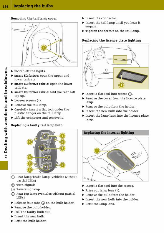
Removing the tail lamp cover
X Switch off the lights.X smart EQ fortwo: open the upper and
lower tailgate.X smart EQ fortwo cabrio: open the lower
tailgate.X smart EQ fortwo cabrio: fold the rear soft
top up.X Loosen screws :.X Remove the tail lamp.X Carefully insert a flat tool under the
plastic hanger on the tail lamp.X Lift the connector and remove it.
Replacing a faulty tail lamp bulb
: Rear lamp/brake lamp (vehicles withoutpartial LEDs)
; Turn signals= Reversing lamp? Rear fog lamp (vehicles without partial
LEDs)
X Release four tabs A on the bulb holder.X Remove the bulb holder.X Pull the faulty bulb out.X Insert the new bulb.X Refit the bulb holder.
X Insert the connector.X Insert the tail lamp until you hear it
engage.X Tighten the screws on the tail lamp.
Replacing the licence plate lighting
X Insert a flat tool into recess :.X Remove the cover from the licence plate
lamp.X Remove the bulb from the holder.X Insert the new bulb into the holder.X Insert the lamp lens into the licence plate
lamp.
Replacing the interior lighting
X Insert a flat tool into the recess.X Prise out lamp lens :.X Remove the bulb from the holder.X Insert the new bulb into the holder.X Refit the lamp lens.
184 Replacing the bulbs>>
Dea
lin
g w
ith
acc
iden
ts a
nd
bre
akd
own
s.

Replacing fuses
Please note
G WARNING
If you manipulate, bridge or replace afaulty fuse with a fuse of a higher amper-age, the electric cables could be overloa-ded. This may result in a fire. There is arisk of an accident and injury.
Always replace faulty fuses with speci-fied new fuses of the correct amperage.
! Only use fuses that have been approvedfor smart vehicles and which have thecorrect fuse rating for the system con-cerned. Components or systems couldotherwise be damaged.
! Make sure that no moisture can enterthe fuse box when the cover is open.
The electrical fuses disconnect defectivecircuits. If a fuse blows, all the connectedcomponents and their functions will fail.Blown fuses must be replaced with fuses ofthe same rating, which you can recogniseby the colour and fuse rating. The fuse rat-ings are listed in the fuse allocation chart(Y page 213).If new fuses blow, the cause for this mustbe diagnosed and rectified at a qualifiedspecialist workshop.
Preparing the vehicle to replace afuse
X Apply the parking brake.X Switch off all electrical consumers.X Turn the key to position u in the igni-
tion lock and remove it.X Check whether all indicator lamps in the
instrument cluster are off.
Replacing a fuse (left-hand drivevehicle)
! Do not use a pointed object such as ascrewdriver to open the cover in thedashboard. You could damage the dash-board or the cover.
X Open the front-passenger door.X Open the glove compartment.X To open: open cover : in the direction of
the arrow.X Replace the faulty fuse.X To close: insert and fold in cover : until
it engages.X Close the glove compartment.
Replacing a fuse (right-hand drivevehicle)
X Open the driver's door.X To open: turn quick-release fastener ;
by 90° using a suitable object.X Fold down cover :.X Replace the faulty fuse.X To close: close cover :.X Close quick-release fastener ;.
Replacing fuses 185
>> D
eali
ng
wit
h a
ccid
ents
an
d b
reak
dow
ns.
Z

Replacing the key battery
G WARNING
Batteries contain toxic and corrosivesubstances. If batteries are swallowed, itcan result in severe health problems.There is a risk of fatal injury.
Keep batteries out of the reach of chil-dren. If a battery is swallowed, seek med-ical attention immediately.
H Environmental note
Batteries contain pollu-tants. It is illegal to dis-pose of them with thehousehold rubbish. Theymust be collected sepa-rately and disposed of inan environmentallyresponsible recyclingsystem.
Dispose of batteries in anenvironmentally respon-sible manner. Take dis-charged batteries to aqualified specialist work-shop or to a collectionpoint for used batteries.
X Fixed keys: unscrew screw :.
X Insert a flat tool, e.g. a coin, into therecess.
X Turn the tool until the cover of the bat-tery tray opens.
X Replace battery ; with the positive ter-minal facing upwards.
X Replace the cover on the battery tray andpush it closed.
X Fixed keys: screw in screw :.X Check the function of all key buttons.
Open a door with the emergencyrelease.
186 Open a door with the emergency release.>>
Dea
lin
g w
ith
acc
iden
ts a
nd
bre
akd
own
s.
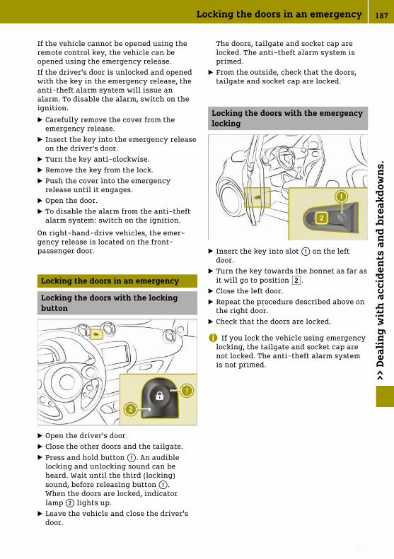
If the vehicle cannot be opened using theremote control key, the vehicle can beopened using the emergency release.If the driver's door is unlocked and openedwith the key in the emergency release, theanti-theft alarm system will issue analarm. To disable the alarm, switch on theignition.
X Carefully remove the cover from theemergency release.
X Insert the key into the emergency releaseon the driver's door.
X Turn the key anti-clockwise.X Remove the key from the lock.X Push the cover into the emergency
release until it engages.X Open the door.X To disable the alarm from the anti-theft
alarm system: switch on the ignition.
On right-hand-drive vehicles, the emer-gency release is located on the front-passenger door.
Locking the doors in an emergency
Locking the doors with the lockingbutton
X Open the driver's door.X Close the other doors and the tailgate.X Press and hold button :. An audible
locking and unlocking sound can beheard. Wait until the third (locking)sound, before releasing button :.When the doors are locked, indicatorlamp ; lights up.
X Leave the vehicle and close the driver'sdoor.
The doors, tailgate and socket cap arelocked. The anti-theft alarm system isprimed.
X From the outside, check that the doors,tailgate and socket cap are locked.
Locking the doors with the emergencylocking
X Insert the key into slot : on the leftdoor.
X Turn the key towards the bonnet as far asit will go to position 2.
X Close the left door.X Repeat the procedure described above on
the right door.X Check that the doors are locked.
i If you lock the vehicle using emergencylocking, the tailgate and socket cap arenot locked. The anti-theft alarm systemis not primed.
Locking the doors in an emergency 187
>> D
eali
ng
wit
h a
ccid
ents
an
d b
reak
dow
ns.
Z

Notes on display messages
The display shows warnings, malfunctionsor additional information. A warning tonealso sounds with some display messages.Messages from all categories can containimportant information that must beobserved. Have error messages checked at aMercedes-Benz Service Centre as soon aspossible. If an error message is not followedup with a repair, this can lead to damagethat is not covered by the Mercedes-BenzLimited Warranty including injuries ormaterial damage.
Display messages with graphic symbols aresimplified in the Owner's Manual and maydiffer from the symbols in the display.Colour display: low-priority display mes-sages can be hidden by pressing a onthe steering wheel. High-priority messagesare shown in red. The display messages arethen stored in the message memory and canbe called up for as long as the ignitionremains switched on. Switching off theignition clears the message memory.
Locking and unlocking
Problem Possible causes/consequences and M Solutions
The key does not lockor unlock the vehicle.
A strong source of radio waves is interfering with the signal.
X Stand closer to the door lock and try to lock/unlock the vehi-cle again.
Key battery is low or discharged.
X Unlock the vehicle with the key in the emergency release orlock the vehicle with emergency locking.
X Replace the key battery.
Key is faulty.To lock:
X Press the locking button and close the door withinfive seconds.
The vehicle still will not lock.
X Lock driver's door using emergency locking.X Consult a qualified specialist workshop.
To unlock:
X Unlock vehicle with the key in the emergency release.X Consult a qualified specialist workshop.
Key is lost. X Have the key deactivated or replaced at a qualified specialistworkshop.
X Report loss of the key to vehicle insurer.
188 Locking and unlocking>>
Pra
ctic
al a
dvi
ce.

Problem Possible causes/consequences and M Solutions
A warning tonesounds.
Driver's door is opened while the engine is running.
Switch off the engine before leaving the vehicle:
X Apply the parking brake.X Select transmission position j.X Turn the key to position u in the ignition lock and remove
it.
Side window will notclose or will not openor close fully.
Objects are obstructing the window guide.
X Remove objects.
Side window is not reset.
G WARNING
While closing the side windows, body parts in the closingarea could become trapped. There is a risk of injury.
When closing make sure that no parts of the body are in theclosing area. If somebody becomes trapped, release theswitch or press the switch to open the side window again.
X Close all doors.X Turn the key to position 2 in the ignition lock.X Pull the switch for closing the window until the window is
closed, and then push the switch for one second.
The side window opens again a little way.
X Repeat previous step until the window remains closed afterreleasing the switch.
C Red warninglamp lights up.If the speed exceeds20 km/h, a warningtone also sounds.Colour display: thedisplay shows an opendoor/tailgate.
A door or the tailgate is open.
X Pull over and stop the vehicle, paying attention to road andtraffic conditions.
X Close all doors and the tailgate.
Locking and unlocking 189
>> P
ract
ical
ad
vice
.
Z

Vision, vehicle occupants, airbag
Problem Possible causes/consequences and M Solutions
The exterior mirror isnot engaged.
The exterior mirror has been moved forwards or backwards byforce.
X Carefully move the exterior mirror to the correct position.
The windscreen wip-ers do not function.
The windscreen wipers are obstructed, e.g. by snow.
X Pull over and stop the vehicle, paying attention to road andtraffic conditions.
X Remove the key from ignition lock.X Remove the cause of the obstruction.X Switch the windscreen wipers on again after 30 seconds.
The windscreen wiper drive is malfunctioning.
X Select another wiper speed on the combination switch.X Consult a qualified specialist workshop.
The windscreen wip-ers will not stop oralways wipe at thesame speed.
The combination switch or rain sensor is malfunctioning.
X Pull over and stop the vehicle, paying attention to road andtraffic conditions.
X Remove the key from ignition lock.
X Insert the key into the ignition lock, turn to position 1 andstart the engine.
X Consult a qualified specialist workshop.
The red 7 warninglamp lights up for 6seconds after startingthe engine (certaincountries only).A warning tonesounds.
The warning lamp prompts the driver and front passenger tofasten their seat belts.
X Fasten the seat belts.
The red 7 warninglamp lights up afterstarting the engine.
The driver or front passenger has not fastened their seat belt.
X Fasten the seat belts.
The red 7 warninglamp flashes.A warning tonesounds.
The driver or front passenger has not fastened their seat beltand the vehicle is travelling faster than 20 km/h.
X Fasten the seat belts.
190 Vision, vehicle occupants, airbag>>
Pra
ctic
al a
dvi
ce.

Problem Possible causes/consequences and M Solutions
The red 6 warninglamp lights up whilethe engine is running.Colour display: Mal‐function Visit workshop appears.
The restraint system is malfunctioning.
G WARNING
If the restraint system is malfunctioning, restraint systemcomponents may be triggered unintentionally or might not betriggered as intended in the event of an accident. This mayapply to belt tensioners or airbags, for example. There is arisk of injury.
Have the restraint system checked and repaired immediatelyat a qualified specialist workshop.
The 4 indicatorlamp on the overheadcontrol panel lightsup.
The front-passenger front airbag has been disabled(Y page 43).
X Enable the front-passenger front airbag.
The front-passenger front airbag has not been disabled and ismalfunctioning.
X Do not use a rearward-facing child restraint system on thefront-passenger seat.
X Do not allow passengers to travel on the front-passengerseat.
X Consult a qualified specialist workshop.
The × indicatorlamp on the overheadcontrol panel lightsup.
The front-passenger front airbag is enabled (Y page 43). Theairbag system is operating correctly.
X Do not use a rearward-facing child restraint system on thefront-passenger seat.
The × indicatorlamp on the overheadcontrol panel does notlight up if the front-passenger front airbaghas been enabledmanually.
There is a malfunction in the airbag system.
X Do not allow passengers to travel on the front-passengerseat.
X Consult a qualified specialist workshop.
Vision, vehicle occupants, airbag 191
>> P
ract
ical
ad
vice
.
Z

Engine, brakes, transmission
Problem Possible causes/consequences and M Solutions
The engine will notstart using the key.
The steering lock is manually locked.
X Remove the key from the ignition lock and then reinsert itinto the ignition lock.
X Turn the key.X Turn the steering wheel left and right.
The engine will notstart.
The ignition is not being actuated long enough.
X Hold the key for longer in position 3 (Y page 66).
The red þ warninglamp lights up.A warning tonesounds.Without starting motor again, visit workshop appears.
There is a serious malfunction in the high-voltage electricalsystem.The engine can no longer be started.
X Do not restart the engine.X Consult a qualified specialist workshop.
The red þ warninglamp lights up.Stop Switch off motor appears.
The high-voltage electrical system, engine or high-voltagebattery is malfunctioning.
X Switch off the engine.X Do not drive on.X Consult a qualified specialist workshop.X Do not tow away the vehicle on its own wheels.
The red þ warninglamp lights up.A warning tonesounds.Stop appears.
Communication with the engine's control unit is malfunction-ing.
X Switch off the engine.X Do not drive on.X Consult a qualified specialist workshop.X Do not tow away the vehicle on its own wheels.
The yellow þwarning lamp lightsup.A warning tonesounds.Malfunction Visit workshop appears.
There is a malfunction in the high-voltage electrical system.The vehicle's high-voltage electrical system may become dam-aged if you continue running the engine.
X Switch off the engine.X Do not drive on.X Consult a qualified specialist workshop.X Do not tow away the vehicle on its own wheels.
The red þ warninglamp lights up.A warning tonesounds.Reduce speedappears.
The speed of the vehicle is above 135 km/h.
X Reduce the speed to below 135 km/h.
192 Engine, brakes, transmission>>
Pra
ctic
al a
dvi
ce.

Problem Possible causes/consequences and M Solutions
lights up.Do not tow vehicle with wheels on ground appears.
The drive system or high-voltage electrical system is faulty.
X Have the vehicle transported by a qualified specialist work-shop.
X Do not tow away the vehicle on its own wheels.
The red J warninglamp lights up whilethe engine is running.A warning tonesounds.Colour display: Check brake fluid levelappears.
Brake fluid level is too low.
G WARNING
If the brake fluid level is too low the brake system may fail.There is a risk of an accident.
Stop the vehicle in accordance with the traffic conditions.Secure the vehicle by applying the parking brake. Do notdrive any further. Consult a qualified specialist workshopimmediately and have the brake system repaired.
Do not top up the brake fluid, as this will not rectify the fault.
X Consult a qualified specialist workshop.
The red J warninglamp lights up whiledriving.A warning tonesounds.Colour display:Release parking brake appears.
The parking brake is applied.
X Release the parking brake.
The red J warninglamp lights up whilethe engine is running.A warning tonesounds.Colour display: Brake system malfunction Stop appears.
There is a serious malfunction in the brake system.
X Consult a qualified specialist workshop.
The yellow Jwarning lamp lightsup.Colour display: Mal‐function Visit workshop appears.
There is a malfunction in the vacuum supply of the brake sys-tem.
X Consult a qualified specialist workshop.
Engine, brakes, transmission 193
>> P
ract
ical
ad
vice
.
Z

Problem Possible causes/consequences and M Solutions
Monochrome display:i or j flash alter-nately in the middle ofthe display.Colour display: To start engine: shift to P or Nappears.
An attempt was made to start the engine with the transmissionin position h or k.
X Shift to j or i to start.
Monochrome display:j or h/k, i flashalternately.A warning tonesounds.Colour display: Risk of vehicle rolling away Transmission not in P appears.A warning tonesounds.
The driver's door is open and the selector lever is in positionk, i or h.
G WARNING
The vehicle may roll away.There is a risk of an accident.
X Shift to position j.X Switch off the engine.X Close the driver's door completely.
¯ or ° warninglamp flashes for a fewseconds after startingthe engine.Colour display: Next service due in … kmor Service due … days ago appears.
A service due date is approaching or has already passed:
R¯ indicates a minor service.R° indicates a full service.
X Consult a qualified specialist workshop.
Charging process
Problem Possible causes/consequences and M Solutions
The charge socket flapcannot be opened.
The charge socket flap is not unlocked.
X Press the # button on the key.
The key batteries are discharged.
X Open a door with the emergency release.
The charging cablecannot be pluggedinto the vehiclesocket.
The vehicle socket is locked.
X Make sure that the selector lever is in position j.
194 Charging process>>
Pra
ctic
al a
dvi
ce.

Problem Possible causes/consequences and M Solutions
The indicator lamp onthe vehicle socketflashes red. The high-voltage battery is notbeing charged.
A fault occurred while initialising the charging process.
X Make sure that the charging cable is plugged into the mainssocket.
X Disconnect the charging cable connector from the vehiclesocket and plug it back into the vehicle socket after30 seconds.
X If the malfunction should persist, inform a qualified special-ist workshop.
The indicator lamp onthe vehicle socketremains off after thecharging cable con-nector has been con-nected to the vehiclesocket. When chargingusing a mains socket,the high-voltage bat-tery is not charged.
There is a malfunction at the mains socket.
X Have the mains socket checked to ensure that it is workingcorrectly.
orX Use a different mains socket.
è lights up.A warning tonesounds.Charger cable con‐nected appears.
The charging cable is plugged into the vehicle socket. Theengine cannot be started.
X Before driving off, disconnect the charging cable from thevehicle socket and stow it away in the vehicle.
è flashes.Charging cable not inserted correctlyappears.
The charging cable is connected to the vehicle socket. The bat-tery is not being charged.
X Make sure that the charging cable is correctly plugged intothe sockets on the vehicle and power connection. If neces-sary, disconnect the charging cable from the sockets andthen reconnect it.
If the message continues to be displayed:
X Consult a qualified specialist workshop.
The charging cableconnector cannot beremoved from thevehicle socket.
The charging cable connector is not unlocked.
X Press the # button on the key.This unlocks the charging cable connector in the vehiclesocket.
X Remove the charging cable connector from the vehicle socket.
Charging process 195
>> P
ract
ical
ad
vice
.
Z

Problem Possible causes/consequences and M Solutions
Charging not possi‐ble Power supply interrupted appears.
The high-voltage battery cannot be charged. The charge cur-rent was interrupted during the charging process.
X Make sure that the charging cable is plugged into the mainssocket.
X Disconnect the charging cable connector from the vehiclesocket and plug it back into the vehicle socket after30 seconds.
If the message continues to be displayed:
X Consult a qualified specialist workshop.
Charging not possi‐ble s. Owner's Man‐ual appears.
Communication with the charging point infrastructure is notfunctioning correctly.
X Make sure that the charging cable is correctly plugged intothe sockets on the vehicle and power connection. If neces-sary, disconnect the charging cable from the sockets andthen reconnect it.
If the message continues to be displayed:
X Use a different charging station.
If the message continues to be displayed:
X Consult a qualified specialist workshop.
The yellow þwarning lamp lightsup.Charging not possi‐ble Visit workshopappears.
The vehicle electronics are malfunctioning. The high-voltagebattery cannot be charged.
X Consult a qualified specialist workshop.
The yellow þwarning lamp lightsup.Charging not possi‐ble s. Owner's Man‐ual appears.
The high-voltage battery cannot be charged. The chargingcable connector is overheated.
X Remove the charging cable connector from the vehicle socket.X Allow the charging cable connector to cool off for several
minutes.X Plug the charging cable back into the vehicle socket.
If the message continues to be displayed:
X Consult a qualified specialist workshop.
The indicator lamp onthe vehicle socketdoes not light up. Thehigh-voltage batteryis not being charged.
The vehicle is inactive.
X Activate the vehicle by pressing the # button on the key andlock it again.
The charging cablecannot be removed.
The vehicle is in charging mode or has completed active charg-ing.
X Unlock the charging lock by pressing the # button on thekey.
196 Charging process>>
Pra
ctic
al a
dvi
ce.

Driving safety systems
Problem Possible causes/consequences and M Solutions
! Yellow warninglamp lights up.Colour display: Sys‐tem inoperativeappears.
ABS is malfunctioning. Other driving systems may be deactiva-ted.If ABS is faulty, there is also a possibility that other drivingsystems may be unavailable.Observe the information on the ABS warning lamp and displaymessages which may be shown in the instrument cluster.
G WARNING
If ABS is faulty, the wheels could lock when braking. Thesteerability and braking characteristics may be severelyimpaired. Additionally, further driving safety systems aredeactivated. There is an increased danger of skidding andaccidents.
Drive on carefully. Have ABS checked immediately at a quali-fied specialist workshop.
When ABS is malfunctioning, other systems, including drivingsafety systems, will also become inoperative. Observe theinformation on the ABS warning lamp and display messageswhich may be shown in the instrument cluster.
X Pull over and stop the vehicle, paying attention to road andtraffic conditions.
X Secure the vehicle against rolling away.X Consult a qualified specialist workshop.
J Red warninglamp lights up whilethe engine is running.A warning tonesounds.Colour display: Brake force distribution inoperative Stop See Owner's Manualappears.
EBD is malfunctioning. This means that ABS, ESP®, CrosswindAssist and Hill Start Assist are also unavailable.Other driving systems may be deactivated.
G WARNING
The brake system continues to function normally, but withoutthe functions listed above. The wheels could therefore lockearly if you brake hard, for example.The steerability and braking characteristics may be severelyaffected. The braking distance may increase in emergencybraking situations.
If ESP® is not operational, the vehicle will not be stabilised byESP®.The danger of skidding and having an accident increases.
X Pull over and stop the vehicle, paying attention to road andtraffic conditions.
X Secure the vehicle against rolling away.X Consult a qualified specialist workshop.
Driving safety systems 197
>> P
ract
ical
ad
vice
.
Z

Problem Possible causes/consequences and M Solutions
÷ Monochrome dis-play: yellow warninglamp lights up whilethe engine is running.÷ Colour display:yellow warning lamplights up.System inoperativeappears.
ESP® is not available due to a malfunction. Other driving sys-tems may be deactivated.
G WARNING
If ESP® is malfunctioning, ESP® is unable to stabilise thevehicle. In addition, other driving safety systems areswitched off. This increases the risk of skidding and an acci-dent.
Drive on carefully. Have ESP® checked at a qualified special-ist workshop.
Brake lamps may be inoperative and thus no longer workingwhen braking.
X Pull over and stop the vehicle, paying attention to road andtraffic conditions. Do not drive on.
X Check that the brake lamps are working.
The brake lamps are not working.
X Consult a qualified specialist workshop.
The brake lamps are working.
X Drive on carefully.X Consult a qualified specialist workshop.
÷ Colour display:yellow warning lamplights up.Brake Assist Sys‐tem (BAS) inopera‐tive appears.
The Brake Assist System (BAS) is inoperative.
X Consult a qualified specialist workshop.
÷ Yellow warninglamp flashes whiledriving.
ESP® is intervening because there is a risk of skidding or atleast one of the wheels is spinning.
X Pull away carefully.X Accelerate carefully whilst driving.X Adapt your driving style to suit the road and weather condi-
tions.
÷ and C andother warning lampsare lit.Colour display: Elec‐tronics malfunc‐tion Visit workshopappears.
The central vehicle electronics system is malfunctioning.After switching off the engine, it is no longer possible to lock orunlock the doors using the remote control on the key or to startthe engine.
X Pull over and stop the vehicle, paying attention to road andtraffic conditions.
X Consult a qualified specialist workshop.
198 Driving safety systems>>
Pra
ctic
al a
dvi
ce.

Problem Possible causes/consequences and M Solutions
Colour display: ÷Hill start assist inoperative appears.
Hill start assist is malfunctioning. Vehicle will not be heldautomatically when pulling away uphill and may start rollingimmediately.
G WARNING
If ESP® is malfunctioning, ESP® is unable to stabilise thevehicle. In addition, other driving safety systems areswitched off. This increases the risk of skidding and an acci-dent.
Drive on carefully. Have ESP® checked at a qualified special-ist workshop.
Other driving systems may be deactivated.
The brake system functions normally, but without hill startassist.
X Drive on carefully.X Consult a qualified specialist workshop.
h Yellow warninglamp lights up whiledriving.Colour display: Cor‐rect tyre pressureappears.
The tyre pressure is too low in at least one of the tyres, or thetyre pressure difference between the wheels is too great.
X Check tyre pressure.X Correct the tyre pressure.X Restart tyre pressure monitor.
Driving safety systems 199
>> P
ract
ical
ad
vice
.
Z

Problem Possible causes/consequences and M Solutions
h Yellow warninglamp lights up whiledriving.Colour display: Tyre pressure Caution tyre malfunctionappears.
The tyre pressure monitor has detected a significant loss ofpressure in at least one of the tyres.
G WARNING
Underinflated or overinflated tyres pose the following risks:
Rthe tyres may burst, especially as the load and vehiclespeed increase.
Rthe tyres may wear excessively and/or unevenly, whichmay greatly impair tyre traction.
Rthe driving characteristics, as well as steering and brak-ing, may be greatly impaired.
There is a risk of an accident.
Observe the recommended tyre pressure and check the tyrepressure of all the tyres:
Rat least every two weeks
Rwhen the load changes
Rbefore embarking on a longer journey
Rfor changed operating conditions, e.g. off-road driving
If necessary, correct the tyre pressure.
X Secure the vehicle against rolling away.X Check tyres visually and, if necessary, follow the instructions
for flat tyres.X Check the tyre pressure and correct it if necessary.
h Yellow warninglamp flashes forapproximately oneminute and then stayslit.Colour display: Tyre pressure monitor inoperative appears.
The tyre pressure monitor is malfunctioning or was not restar-ted after a wheel change.
G WARNING
If you correct the tyre pressure without recalibrating the RunFlat Indicator, the system cannot issue a warning about adefective tyre in time. In the event of tyre pressure loss, thedriving characteristics and the steering and braking may begreatly impaired. There is a risk of an accident.
If you correct the tyre pressure, you must recalibrate the RunFlat Indicator.
X Restart tyre pressure monitor.
The display message continues to be displayed.
X Drive on carefully.X Consult a qualified specialist workshop.
200 Driving safety systems>>
Pra
ctic
al a
dvi
ce.

Problem Possible causes/consequences and M Solutions
h Yellow warninglamp flashes forapproximately60 seconds and thenremains lit.Colour display: Tyre pressure monitor inoperative wheel sensors missingappears.
There is no signal from the tyre pressure sensor of one or morewheels.
G WARNING
Risk of accident due to undetected tyre pressure losses. Thesystem is possibly unable to recognise or register low tyrepressure.
X Consult a qualified specialist workshop.
Wheels have unsuitable tyre pressure sensors.
X Fit wheels with suitable tyre pressure sensors.
J Red warninglamp lights up.÷, ! yellowwarning lamps lightup while the engine isrunning.A warning tonesounds.Colour display: Elec‐tronics malfunc‐tion Stop See Own‐er's Manual appears.
The following systems are malfunctioning:
RABS (anti-lock braking system)RESP® (Electronic Stability Program)RCrosswind AssistRHill start assistFurther driving systems could be switched off automatically.
G WARNING
The risk of skidding and having an accident increases due tomalfunctioning driving safety systems.The brake system functions normally, but without the systemslisted. The wheels could therefore lock if you brake hard,for example.This will greatly impair the ability to steer and brake. Thebraking distance may increase in emergency braking situa-tions.
X Pull over and stop the vehicle, paying attention to road andtraffic conditions.
X Consult a qualified specialist workshop.
Driving safety systems 201
>> P
ract
ical
ad
vice
.
Z

Problem Possible causes/consequences and M Solutions
Monochrome display:D yellow warninglamp lights up whilethe engine is running.
Power assistance may be malfunctioning, making steering dif-ficult.
G WARNING
You will need to use more force to steer.There is a risk of an accident.
X Check whether you are able to apply the extra force required.
If you are able to steer safely:
X Drive on carefully.X Visit a qualified specialist workshop immediately.
If you are unable to steer safely:
X Do not drive on.X Consult a qualified specialist workshop.
D Yellow warninglamp lights up whilethe engine is running.Colour display: Steer‐ing malfunction See Owner's ManualorElectronics mal‐function See Own‐er's Manual appears.
Power assistance may be malfunctioning, making steering dif-ficult.
G WARNING
You will need to use more force to steer.There is a risk of an accident.
X Check whether you are able to apply the extra force required.
If you are able to steer safely:
X Drive on carefully.X Visit a qualified specialist workshop immediately.
If you are unable to steer safely:
X Do not drive on.X Consult a qualified specialist workshop.
Driver assistance systems
Problem Possible causes/consequences and M Solutions
The red · warninglamp is lit.A warning tonesounds.
The collision warning detects obstacles on the road.
X Pay careful attention to the road and traffic conditions andbe ready to brake.
The red · warninglamp is lit.
The distance to the vehicle in front is too short for the currentspeed.
X Increase the distance.
The yellow ^warning lamp lightsup while driving.
The sensors in the radiator trim are dirty.
X Clean the sensors.
202 Driver assistance systems>>
Pra
ctic
al a
dvi
ce.

Problem Possible causes/consequences and M Solutions
Colour display:Active Brake Assist inoperativeor Electronics mal‐function Visit workshop appears.
Environmental influences or error sources outside the systemare temporarily interfering with Active Brake Assist and radar-assisted recuperation. Possible causes:
Rheavy rain or snowRoperating temperature is too highRon-board voltage is too lowActive Brake Assist is automatically operational again when thecauses listed no longer apply.
Warning lamp remains lit:
X Pull over and stop the vehicle, paying attention to road andtraffic conditions.
X Clean the sensors.X Restart the engine.
Warning lamp still remains lit:
X Consult a qualified specialist workshop.
^ and C as wellas other warninglamps are lit.
The central vehicle electronics system is malfunctioning.After switching off the engine, it is no longer possible to lock orunlock the doors using the remote control on the key or to startthe engine.
X Pull over and stop the vehicle, paying attention to road andtraffic conditions.
X Consult a qualified specialist workshop.
à flashes forapproximately threeseconds.A warning tonesounds.Colour display: Lane Keeping Assist inoperative appears.
The windscreen is dirty in the camera's field of vision.
X Pull over and stop the vehicle, paying attention to road andtraffic conditions.
X Clean the windscreen.
Environmental influences are interfering with Lane KeepingAssist. Possible causes:
Rheavy rain or snow or thick fog is impairing visibilityRthe sun is low in the sky and shining directly onto the sensorRlane markings cannot be detectedLane Keeping Assist is automatically operational again whenthe causes listed no longer apply.If the windscreen is clean and the causes listed do not apply,then the electronics are malfunctioning.
The system electronics are faulty.
X Consult a qualified specialist workshop.
Driver assistance systems 203
>> P
ract
ical
ad
vice
.
Z

Problem Possible causes/consequences and M Solutions
¤ flashes for amaximum of five sec-onds.Colour display: thegreen à warninglamp flashes for amaximum of five sec-onds.A warning tonesounds.
A lane boundary marking was crossed without using the turnsignal.
X Stay inside the lane boundary markings.X Use the turn signal before changing lanes.
¯ flashes forapproximately tenseconds.A warning tonesounds.Colour display: ¯Cruise control inoperative appears.
Cruise control is malfunctioning and deactivates automatically.
X Consult a qualified specialist workshop.
¯ flashes forapproximately tenseconds. C andother warning lampsare also lit.A warning tonesounds.Colour display: Elec‐tronics malfunc‐tion Visit workshopappears.
The central vehicle electronics system and cruise control aremalfunctioning. After switching off the engine, it is no longerpossible to lock or unlock the doors using the remote control onthe key or to start the engine.
X Pull over and stop the vehicle immediately, paying attentionto road and traffic conditions.
X Consult a qualified specialist workshop.
È lights up.The speed displayflashes.A warning tonesounds.
The vehicle is exceeding the set limit speed.
X Brake the vehicle, paying attention to road and traffic condi-tions.
204 Driver assistance systems>>
Pra
ctic
al a
dvi
ce.

Problem Possible causes/consequences and M Solutions
È flashes forapproximately tenseconds.A warning tonesounds.Colour display: Lim‐iter inoperativeappears.
The speed limiter is malfunctioning and deactivates automati-cally.
X Consult a qualified specialist workshop.
The Ò warninglamp flashes for aminute or lights upcontinuously.Colour display: Black ice warning appears.
The outside temperature has fallen to or below 3 °C. There is arisk of black ice.
X Adapt your driving style and speed to suit the weather con-ditions.
Battery, lights, heating
Problem Possible causes/consequences and M Solutions
Rear window heatingor seat heatingswitches off automati-cally or cannot beswitched on.
Battery is not sufficiently charged.
X Switch off electrical consumers that are not required.
Ý Yellow warninglamp lights up.Battery reserve level appears.
The charge status of the high-voltage battery has dropped intothe reserve range.
X Charge the high-voltage battery.
Monochrome display:Ý Yellow warninglamp flashes.Colour display: ÝYellow warning lamplights up. Battery reserve levelappears.
The charge status of the high-voltage battery is below 10%.
X Charge the high-voltage battery.
õ Display flashes.The vehicle hasswitched itself off.Battery charge too low Charge HV bat‐tery now appears.
The vehicle has switched itself off because the charge status ofthe high-voltage battery is too low. After restarting the vehicle,depending on the charge status of the high-voltage battery, thevehicle can only drive on a maximum of 1 km.
X Park the vehicle paying attention to road and traffic condi-tions.
X Charge the high-voltage battery.
Battery, lights, heating 205
>> P
ract
ical
ad
vice
.
Z

Problem Possible causes/consequences and M Solutions
# Red warninglamp lights up whendriving or when thevehicle is ready tostart.A warning tonesounds.Colour display: Stop See Owner's Manualappears.
12 V battery is not being charged or the high-voltage battery ismalfunctioning.
X Do not drive on.The engine may switch itself off after a short while.
X Pull over and stop the vehicle, paying attention to road andtraffic conditions.
X Switch off the engine.X Consult a qualified specialist workshop.
It may not be possible to drive the vehicle further and it maynot be possible to restart the engine.
Colour display: #Warning lamp lightsup.Malfunction Visit workshop appears.
Battery monitoring is malfunctioning.
X Consult a qualified specialist workshop.
Monochrome display: b Warning lamplights up.
Dipped beam is on continuously. Main beam cannot be activa-ted.
X Switch off the engine.X Start the engine.
Warning lamp remains lit:Brake lamps are inoperative. The bulb or LED is faulty.
G WARNING
Risk of accident due to faulty brake lamps.The brake lamps are faulty and no longer alert other road userswhen braking.
X Pull over and stop the vehicle, paying attention to road andtraffic conditions.
X Consult a qualified specialist workshop.
Warning lamp still remains lit:Rain/light sensor is malfunctioning.
X Manually adjust exterior lighting.X Manually adjust windscreen wipers.X Consult a qualified specialist workshop.
Colour display: bWarning lamp lightsup.Malfunction See Owner's Manualappears.
Dipped beam is on continuously. Main beam cannot be activa-ted.
X Switch off the engine.X Restart the engine.
206 Battery, lights, heating>>
Pra
ctic
al a
dvi
ce.

Problem Possible causes/consequences and M Solutions
Warning lamp remains lit:Rain/light sensor is malfunctioning.
X Manually adjust exterior lighting.X Manually adjust windscreen wipers.X Consult a qualified specialist workshop.
Colour display: bWarning lamp lightsup.Brake lamps inoper‐ative appears.
Brake lamps are inoperative. The bulb or LED is faulty.
G WARNING
Risk of accident due to faulty brake lamps.The brake lamps are faulty and no longer alert other road userswhen braking.
X Pull over and stop the vehicle, paying attention to road andtraffic conditions.
X Consult a qualified specialist workshop.
Colour display:Switch off lightsappears.A warning tonesounds.
Lights are still switched on when you leave the vehicle.
X Turn control knob for the lights to à or u.
smart Audio-System and smart Media-System
Bluetooth® connection
Problem Possible causes/consequences and M Solutions
A Bluetooth® connec-tion cannot be estab-lished between thesmart Audio-Systemor smart Media-Sys-tem and mobile phone.
X Ascertain whether the mobile phone is compatible with thesystem. Information about compatible mobile phones: http://www.smart.com/connect
X Check the security settings on your mobile phone.X Check that the Bluetooth® function is enabled on the smart
Audio-System or smart Media-system and on your mobilephone.
X Start the device search on the smart Audio-System or smartMedia-System and on the mobile phone.
smart Audio-System and smart Media-System 207
>> P
ract
ical
ad
vice
.
Z

Navigation system in the smart Media-System
Problem Possible causes/consequences and M Solutions
No map is displayed inthe navigation sys-tem.
The SD card with the map data is missing or damaged.
X Check to see that the SD card is inserted.
The position of thevehicle in the naviga-tion system does notmatch the vehicle'sactual position.The GPS symbol on thedisplay is grey or yel-low.
GPS reception is poor.
X Drive the vehicle to another position where GPS reception isbetter.
The road's course inthe navigation systemno longer coincideswith the actual road.
The map data is out of date.
X Update the map data.
The navigation systemdoes not display anytraffic information.
Route guidance has not been started.
X Select a destination and start navigation.
HD Traffic is not available or the subscription for HD Traffic hasexpired.
X Check whether HD Traffic is available for the country you arein or upgrade the subscription for HD Traffic.
There are no naviga-tion messages duringroute guidance.
The road's course is not detected. The map data may be out ofdate.
X Check if route guidance has started.X If not, select a destination and start navigation.
Navigation messages are switched off.
X Switch on navigation messages.
Voice control system in the smart Media-System
Problem Possible causes/consequences and M Solutions
The voice control sys-tem does not under-stand voice com-mands.
The interval for entering voice commands has been exceeded.
X Press the button on the multifunction steering wheel.
Voice commands have not been given from the driver's seat.
X Issue voice commands from the driver's seat.
Noise from the blower or wind noise are interfering with voicecommands.
X Avoid interfering noises.
208 smart Audio-System and smart Media-System>>
Pra
ctic
al a
dvi
ce.

Problem Possible causes/consequences and M Solutions
Voice commands have not been given clearly.
X Speak clearly when giving voice commands.
A voice command is unknown.
X Enter voice command "Help".A list of possible voice commands appears.
smart Audio-System and smart Media-System 209
>> P
ract
ical
ad
vice
.
Z

Obtaining technical data
Information on technical data: http://www.smart.deThe technical data was determined inaccordance with EU Directives. All dataapplies to the vehicle's standard equip-ment. Differences will be present in thecase of vehicles with optional equipment.Further information is available from anysmart Centre.
Reading vehicle data
Useful information
Please observe the following notes for thespecified vehicle data:
RItems of optional equipment reduce themaximum payloadRVehicle-specific weight information can
be found on the vehicle identificationplate.RFor certain countries only: you can find
vehicle-specific vehicle data in the COC(CERTIFICATE OF CONFORMITY) docu-ments. These documents are deliveredwith your vehicle.
Vehicle identification plate
: Vehicle identification plate position
: Vehicle identification plate; Vehicle manufacturer= EU type approval number? Vehicle identification number (VIN)A Maximum permissible gross weightB Maximum permissible front axle loadC Maximum permissible rear axle loadD Paint code
i The data shown on the vehicle identifi-cation plate is example data. This data isdifferent for every vehicle and can devi-ate from the data shown here. The dataapplicable to the vehicle is found on thevehicle's identification plate.
Vehicle identification number (VIN)
X Slide the right-hand front seat to itsrearmost position.
X Fold floor covering : upwards.VIN ; is located there.
The VIN can also be found on the vehicleidentification plate.
210 Reading vehicle data>>
Tec
hn
ical
dat
a.

Dimensions and weights
The heights specified may vary as a resultof the following factors:
RtyresRloadRcondition of the suspensionRoptional equipment
smart EQ fortwo Dimensionsand weights
Opening height : 1855 mm
Vehicle length 2695 mm
Vehicle width includingexterior mirrors
1893 mm
Vehicle width excludingexterior mirrors
1663 mm
Vehicle width excludingexterior mirrors forvehicles equipped withwheel trims
1671.8 mm
Vehicle height 1555 mm
Wheelbase 1873 mm
Maximum ground clear-ance
113 mm
Maximum tailgate load 100 kg
Permissible roof load 0 kg
smart EQ fortwo cabrio Dimensionsand weights
Vehicle length 2695 mm
Vehicle width includingexterior mirrors
1893 mm
Vehicle width excludingexterior mirrors
1663 mm
Vehicle width excludingexterior mirrors forvehicles equipped withwheel trims
1671.8 mm
Vehicle height 1553 mm
Wheelbase 1873 mm
Maximum ground clear-ance
112 mm
Maximum tailgate loadwithout side bars
100 kg
Maximum tailgate loadwith sidebars stowed
0 kg
Permissible roof load 0 kg
Charging time
i The options listed for charging a high-voltage battery are not available in allcountries.
High-voltage battery
Type Lithium-ion
Vehicles with a 7 kW/4.6 kW on-board charger
Charging time(from 10% to 80%)at 32 A/230 V
Approx. 2 h
Charging time(from 10% to 80%)at 20 A/230 V
Approx. 3 h30 min
Charging time(from 10% to 80%)at 10 A/230 V
Approx. 6 h
Reading vehicle data 211
>> T
ech
nic
al d
ata.

High-voltage battery
Charging time(from 10% to 80%)at 8 A/230 V
Approx. 9 h30 min
Vehicles with a 22 kW on-board chargerCharging time(from 10% to 80%)at 3x32 A/230 V
Approx. 40 min
Charging cable
Charging the battery at a charging stationor wall box
Nominal voltage max. 400 V AC,max. 3-phase
Nominal frequency 50 Hz/60 Hz
Nominal current max. 32 A
Charge output from 4.6 kW to22 kW
System of protection IP44 (inserted),IP24 (notinserted)
Outside temperatureObserve the notes onmaintaining the high-voltage bat-tery(Y page 80)
-40 † to +50 †
Standards IEC 61851-1,IEC 62196-1,IEC 62186-2
Interface Type 2 to Type2
Also observe the identification plate on thecharging cable connector.
Service products
Please note
Also observe the information in the section"Checking and refilling service products"(Y page 157).
Vehicle components and their respectiveservice products must match. Therefore,only use products tested and approved byMercedes-Benz.
Information on service products
The following table lists all technical datafor the service products of the vehicle. Fur-ther information on service products:http://bevo.mercedes-benz.com and in anysmart Centre.
Service prod-ucts
Specifications
Corrosioninhibitor/antifreeze(Y page 157)
325.6, 326.6MB-Freigabe or MB-Approval is stated on thecorrosion inhibitor/anti-freeze containers.
Windscreenwasher fluid(Y page 158)
Temperatures abovefreezing point: mixingratio of 1:100MB SummerFit to water.Temperatures belowfreezing point: for thecorrect mixing ratio ofMB WinterFit and water,please observe the infor-mation on the antifreezecontainer.
Bulb types
The following table lists the correct bulbtypes of the vehicle:
Bulb Type
Dipped-beam/main-beamheadlamps
H4 60/55W
Front foglamps H 16
Turn signals PY 21 W
Side turn signal lamps WY 5 W
Licence plate lighting W 5 W
Interior lighting W 5 W
212 Bulb types>>
Tec
hn
ical
dat
a.

Tail lamps
Bulb Type
Tail lamp and brake lamp P21 5 W
Rear foglamp P21 W
Bulb Type
Reversing lamp W 16 W
Turn signals PY 21 W
Fuse allocation
No. Consumer Current Colour cod-ing
1 Starter motor 5 A Brown
2 Power steering control unit 5 A Brown
3 Multifunction lever 5 A Brown
4 Airbag 5 A Brown
5 ‑ ‑ ‑
6 Instrument cluster 10 A Red
7 Horn, alarm system 15 A Blue
8 Power supply control unit 10 A Red
9 Power supply control unit 10 A Red
10 Central control unit 20 A Yellow
11 Central control unit 15 A Blue
12 Central control unit 10 A Red
13 Central control unit 15 A Blue
Fuse allocation 213
>> T
ech
nic
al d
ata.

No. Consumer Current Colour cod-ing
14 Power window switch (without reversing func-tion)
30 A Green
15 ESP®, transmission control unit 5 A Brown
16 Interior lighting 10 A Red
17 Immobiliser 3 A Violet
18 Electrical exterior mirror 5 A Brown
19 Brake lamps 10 A Red
20 Cruise control, radio, belt warning 15 A Blue
21 Not for smart EQ fortwo, smart EQ fortwo cabrio,smart EQ forfour: central control unit, fuelpump, ignition system
15 A Blue
22 Rear window wiper 15 A Blue
23 Starter motorsmart EQ fortwo, smart EQ fortwo cabrio, smartEQ forfour only: power supply control unit
40 A Orange
24 ‑ ‑ ‑
25 Power supply control unit 30 A Green
26 Radio 20 A Yellow
27 Daytime driving lamps 5 A Brown
28 12 V socket, cigarette lighter 15 A Blue
29 Power supply control unit 5 A Brown
30 Forward collision warning 15 A Blue
31 ‑ ‑ ‑
32 Radio, central control unit 15 A Blue
33 Tail lamps, front foglamps, hazard warninglamp button, locking button, headlamp rangecontrol, power windows, licence plate lighting,radio, control unit for heating or climate controlsystem, cruise control, limiter, parking aid but-ton, program selector button, tailgate release,Lane Keeping Assist camera, automatic start/stop system button
25 A Cyan
34 Power supply control unit 25 A Cyan
35 Headlamps, daytime driving lamps 25 A Cyan
36 - 40 ‑ ‑ ‑
41 smart EQ forfour only: seat heating in the rear 15 A Blue
214 Fuse allocation>>
Tec
hn
ical
dat
a.

No. Consumer Current Colour cod-ing
42 smart EQ fortwo, smart EQ fortwo cabrio, smartEQ forfour only: seat heating in the front
25 A Cyan
43 Mirror heating 5 A Brown
44 Power windows (automatic reversing feature) 25 A Cyan
45 Transmission control unitsmart EQ fortwo, smart EQ fortwo cabrio, smartEQ forfour only: EV control unit
5 A Brown
46 Radio amplifier 20 A Yellow
47 ‑ ‑ ‑
48 smart EQ fortwo, smart EQ fortwo cabrio, smartEQ forfour only: vacuum pump
10 A Red
49 smart EQ fortwo, smart EQ fortwo cabrio, smartEQ forfour only: heating control unit, air-condi-tioning
10 A Red
Radio type approvals for the tyrepressure monitors
Country Radio type approval number
Argen-tina
MW2433AH-12337GG4H-12338
Brazil 2770-12-8001Model: MW2433A0381-13-8001Model: GG4
AbuDhabiDubai
TRA, Registered-NOER0092100/12TRA, Registered-NOER0099792/12TRA, Registered-NOER0076990/11Dealer-NO: DA0047074/10
Country Radio type approval number
Jordan Model: Gen Alpha Wal 2 TPMStransmitterType Approval Number:TRC/LPD/2012/114Model: Gen Gamma Gen 4433.92 MHz.Type Approval Number:TRC/LPD/2012/190Model: Corax 3 MRXMC34MA4Type Approval Number:TRC/LPD/2011/158Type Number: LPD
Morocco MR7319 ANRT 2012/ 11/07/2012MR7672 ANRT 2012/ 23/11/2012MR6706 ANRT 2011
Moldova 1024
Philip-pines
No: ESD-1206394CNo: ESD-1306871C
Serbia И 011 12
Radio type approvals for the tyre pressure monitors 215
>> T
ech
nic
al d
ata.

Country Radio type approval number
Singa-pore
Compliance with IDA StandardDA- 103365
SouthAfrica
TA-2012/719TA-2012/1540TA-2011/1370
Installing two-way radios and mobilephones
G WARNING
The electromagnetic radiation from two-way radios can interfere with the vehicleelectronics if they are manipulated orretrofitted incorrectly. This could jeop-ardise the operating safety of the vehicle.There is a risk of an accident.
You should have all work on electricaland electronic components carried out ata qualified specialist workshop.
G WARNING
If you operate two-way radios incorrectlyin the vehicle, their electromagneticradiation can interfere with the vehicleelectronics, for example if:
Rthe two-way radio is not connected toan exterior aerial
Rthe exterior aerial is not correctlymounted or is not low-reflection
This could jeopardise the operatingsafety of the vehicle. There is a risk of anaccident.
Have the low-reflection exterior aerialfitted at a qualified specialist workshop.When operating two-way radios in thevehicle, always connect them to the low-reflection exterior aerial.
! Have the engine electronics and associ-ated parts, such as control units, sensors,actuating components or electric cablesserviced only at a qualified specialistworkshop. Vehicle components may oth-erwise wear more quickly and the vehi-
cle's operating permit may be invalida-ted.
! The operating permit may be invalida-ted if the instructions for installationand use of two-way radios are notobserved.In particular, the following requirementsmust be complied with:
Ronly approved wavebands may be usedRobserve the maximum permissible out-
put in these wavebandsRonly approved aerial positions may be
used
Excessive levels of electromagnetic radia-tion can cause damage to health. The use ofan exterior aerial takes into considerationthe scientific discussion surrounding thepossible health risk posed by electromag-netic fields.The following aerial positions may be usedfor the correct installation of two-wayradios:
: Front roof area; Rear roof area
Use Technical Specification ISO/TS 21609(Road Vehicles – "EMC guidelines forinstallation of aftermarket radio frequencytransmitting equipment") when retrofittingtwo-way radios. Comply with the legalrequirements for add-on parts.If your vehicle has fittings for two-wayradio equipment, use the power supply andaerial connections intended for use in thebasic wiring. Be sure to observe the manu-facturer's additional instructions duringinstallation.Deviations with respect to wavebands,maximum transmission outputs or aerialpositions must be approved by smart.
216 Installing two-way radios and mobile phones>>
Tec
hn
ical
dat
a.

The maximum transmission output (PEAK)at the base of the aerial must not exceedthe following values:
Waveband Maximum transmission
output
Tetra380 - 410 MHz
20 W
Mobile communicationsgeneration 2G/3G/4G
6 W
The following can be used in the vehiclewithout restrictions:
Rtwo-way radios with a maximum trans-mission output of up to 100 mWRmobile phones (2G/3G/4G)There are no restrictions when positioningthe aerial on the outside of the vehicle forthe following wavebands:
RtetraRmobile communications (2G/3G/4G)
Installing two-way radios and mobile phones 217
>> T
ech
nic
al d
ata.
Z

218

219

220

Publication details
Internet
Further information about smart vehiclesand about Daimler AG can be found on thefollowing websites:http://www.smart.comhttp://www.daimler.com
Editorial office
You are welcome to forward any queries orsuggestions you may have regarding thisOwner's Manual to the technical documen-tation team at the following address:Daimler AG, HPC: CAC, Customer Service,70546 Stuttgart, Germany©Daimler AG: not to be reprinted, translatedor otherwise reproduced, in whole or inpart, without written permission fromDaimler AG.
Vehicle manufacturer
Daimler AGMercedesstraße 13770327 StuttgartGermany
Symbols in the Owner's ManualThe following symbols are used in thisOwner's Manual:
G WARNING
Warning notes draw your attention tohazards that may endanger your healthor life, or the health or life of others.
Observe the warning notes.
H Environmental note
Environmental notes provide you withinformation on environmentally awareactions or disposal.
! Notes on material damage alert you todangers that could lead to damage toyour vehicle.
i These symbols indicate useful instruc-tions or further information that could behelpful to you.
X Instructions that must be followed.
X Several consecutive symbols indicate aninstruction with several consecutive steps.
(Y page) Further information on a topic
YY A warning or an instruction that iscontinued on the next page.Display text: Display text in the instru-ment cluster display, the smart Audio-Sys-tem or the smart Media-System.
G WARNING
If the front passenger airbag has beenactivated, a child on the front passengerseat may be hit by the front passengerairbag in the event of an accident. Thereis a risk of injury or fatal injury.
NEVER use a rearward-facing childrestraint system on a seat protected by
an ACTIVE FRONT AIRBAG; DEATH or SERI-OUS INJURY to the CHILD can occur.
Observe the "Children in the vehicle" sec-tion .
As at 27.06.2018

>> Owner's Manualsmart EQ fortwo and smart EQ fortwo cabrio
É45358448160ËÍ
4535
8448
16
Ord
er n
o. 6
522
0312
02
Part
no.
453
5844
816
Edit
ion
ÄJ2
018-
1b
www.smart.com smart - A Daimler brand smar
t EQ
for
two
and
sm
art
EQ f
ortw
o ca
bri
o O
wn
er's
Man
ual