SIZE REDUCTION OF YAGI-UDA ANTENNA BY ALTERING SPACING AND DIAMETER BETWEEN THE ELEMENTS
12
International Journal of Applied Engineering Research ISSN 0973-4562 Volume 9, Number 22 (2014) pp. 12011-12022 © Research India Publications http://www.ripublication.com Paper Code: 26786 - IJAER Size Reduction of Yagi-Uda Antenna by Altering the Diameter and Spacing between the Elements S. Daya Murali 1 , K. Ch. Sri Kavya 2 , Sarat K Kotamraju 3 , R. Sai Divya 1 , Y. Satish 1 , K. Pradeep Chandra 1 , N. Sri Keerthi 1 , G. Jaya Sree 1 1 Department of ECE, K L University (Koneru Lakshmaiah Education Foundation), AP, India 2 Women Scientist, Department of ECE, K L University (Koneru Lakshmaiah Education Foundation), AP, India 2 [email protected] 3 Associate Dean (P&D) & Professor, Department of ECE, K L University (Koneru Lakshmaiah Education Foundation), AP, India Abstract: Miniaturization of antennas helps in civilian, military and satellite applications for present trends in many means such as their installation, mobility etc. Yagi- Uda antenna with reduced lengths has been proposed used for such applications. In this work investigation of Radiation Characteristics, Return loss, Directivity are simulated and practically examined. A five-element Yagi antenna fed with co-axial feed and made of aluminum is developed in this work. About 40% of size reduction is obtained by rearranging the directors and by decreasing the diameter of the elements. Keywords: Yagi-Uda, Directors, Spacing, Diameter, Co-axial Feed, Directivity. Introduction: An Antenna is a transducer which is used to transmit and receive the electromagnetic waves, converting them into electric currents and vice versa. A typical antenna finds its usage in every domain location of life whether it is broadcasting or space exploration. Point to point communication, wireless LAN are other important fields which cannot be imagined without an antenna [18]. Antenna can be developed in any medium whether it is air, space, soil or water [11]. Several critical parameters affecting on antenna performance are directivity, gain, electric field intensity, resonant frequency, impedance, gain and band width [8], [17].
-
Upload
kluniversity -
Category
Documents
-
view
1 -
download
0
Transcript of SIZE REDUCTION OF YAGI-UDA ANTENNA BY ALTERING SPACING AND DIAMETER BETWEEN THE ELEMENTS

International Journal of Applied Engineering Research ISSN 0973-4562 Volume 9, Number 22 (2014) pp. 12011-12022 © Research India Publications http://www.ripublication.com
Paper Code: 26786 - IJAER
Size Reduction of Yagi-Uda Antenna by Altering the Diameter and Spacing between the Elements
S. Daya Murali1, K. Ch. Sri Kavya2, Sarat K Kotamraju3, R. Sai Divya1, Y. Satish1, K. Pradeep Chandra1, N. Sri Keerthi1, G. Jaya Sree1
1Department of ECE, K L University (Koneru Lakshmaiah Education Foundation), AP, India 2Women Scientist, Department of ECE, K L University
(Koneru Lakshmaiah Education Foundation), AP, India [email protected]
3Associate Dean (P&D) & Professor, Department of ECE, K L University (Koneru Lakshmaiah Education Foundation), AP, India
Abstract:
Miniaturization of antennas helps in civilian, military and satellite applications for present trends in many means such as their installation, mobility etc. Yagi-Uda antenna with reduced lengths has been proposed used for such applications. In this work investigation of Radiation Characteristics, Return loss, Directivity are simulated and practically examined. A five-element Yagi antenna fed with co-axial feed and made of aluminum is developed in this work. About 40% of size reduction is obtained by rearranging the directors and by decreasing the diameter of the elements. Keywords: Yagi-Uda, Directors, Spacing, Diameter, Co-axial Feed, Directivity.
Introduction: An Antenna is a transducer which is used to transmit and receive the electromagnetic waves, converting them into electric currents and vice versa. A typical antenna finds its usage in every domain location of life whether it is broadcasting or space exploration. Point to point communication, wireless LAN are other important fields which cannot be imagined without an antenna [18]. Antenna can be developed in any medium whether it is air, space, soil or water [11]. Several critical parameters affecting on antenna performance are directivity, gain, electric field intensity, resonant frequency, impedance, gain and band width [8], [17].

12012 S. Daya Murali et al
Yagi-Uda antenna is famous as a Yagi antenna. It is a directional antenna consisting of an array of dipole and additionally closely coupled parasitic elements. Its design is exclusively based on dipoles. The design of a Yagi-Uda antenna requires proper understanding of how the components are structured and by varying the diameter and position of these parasitic elements (reflector and directors) changes the radiation characteristics of the antenna. This Yagi antenna is used as T.V receivers in olden days because of low cost and easy to construction [9], [16], [20]. A Yagi antenna, as shown in Fig.1, typically has one driven element (dipole), one reflector which is slightly 5% longer than the driven element and several directors which are slightly 5% shorter than the driven element. Here driven element is active element; reflector and directors are passive elements. The length of the reflector should be greater than the driven element such that its impedance will be more and hence it can be acts as a inductive element. Similarly the length of the director is less than the driven element such that its impedance will be less and hence they acts as a capacitive elements [1-3]. Now-a-days, instead of using a normal rod as reflector, these are replaced by rectangular plate as reflectors or parallel rods in series arrangement simulating a reflecting plate. The reflector just acts as mirror and reflects the EM waves. So position of placing reflector changes the radiation pattern [21]. Normally a reflector will possess a gain of 4-5 dB in the forward direction but more than one reflector has little benefit [6].
Fig.1: Geometry of proposed 5-element Yagi-Uda antenna

Size Reduction of Yagi-Uda Antenna 12013
Generally every director will provide a 1dB of gain in the forward direction. The function of these directors is to enhance the radiation in particular direction. The number of elements will depend on the gain and the limits of the antenna structure [8], [12]. The length, spacing and diameters of these elements have a large effect on radiation parameters like forward gain, backward gain ratio and input impedance [4]. Half wave dipole is used as a driven element in our proposed Yagi antenna. The resonance of driven element will be occurred when its electrical length is half of the wavelength of the frequency applied to its feeding point [5], [7]. The dipole is fed with a co-axial cable. Therefore there must be proper impedance match with the cable input and the antenna feed [13-14]. In order to have appropriate gain it is better to place these elements with equal spacing and to achieve good antenna beam in desired direction. To improve input impedance it is better to use folded dipole instead of ordinary dipole [24]. For real life applications of these types of antennas the SWR should be in the range of 0 to 1. For Omni-directional antenna noise was added from all directions but where as in case of Yagi-Uda antenna since it is a Uni-directional antenna noise was added only from one direction which is better suits for the communications [10], [19], [22], [25]. Design Specifications: Typical Yagi-Uda antenna designed for 600 MHz.
Table 1: Design Specifications
Elements General specifications Proposed specifications Length of reflector 0.55 λ=16.5cm 16.5cm Length of driven 0.5λ=15cm 15cm Length of director 1 0.45 λ=13.5cm 13.5cm Length of director 2 0.40 λ=12cm 12cm Length of director 3 0.35 λ=10.5cm 10.5cm Spacing between the Directors 0.2 λ=6cm 5cm Diameter of the elements 10mm 6mm
Working principle: The working of yagi uda antenna is mainly depends on the working of the normal ordinary dipole which is working as a driven element. The input is given to the driven element through the co-axial cable or transmission line. The driven elements radiates in all directions i.e. forward and backward. As Yagi-Uda antenna is a forward radiating antenna we have to place a reflector at the back end. The length of the reflector is larger than the driven element and therefore the current leads the voltage and hence no radiation will be there at the back end. While in the forward desired direction we have to place a parasitic element whose length is smaller than the driven element thus current lags the voltage and hence it acts as a director. The phase and amplitude of the currents depends on length of the elements and spacing between the

12014 S. Daya Murali et al
elements. Hence proper spacing and length of parasitic elements causes constructive addition of E-field in forward direction and destructive addition in backward direction [23].
Fig.2: Geometry of 5-element Yagi in HFSS
Fig.3: Hardware setup of Proposed Yagi-Uda Antenna Radiation pattern The radiation fashion of the antenna enhances how the relative strength of the field that is radiated in multiple directions from the antenna. The radiation pattern is nothing but a "reception pattern", since it also narrates the receiving and acceptance properties of the antenna. The proposed Yagi antenna has radiation view displayed in fig 4 has maximum radiation of 20.33 at an angle of 90 degrees. It is clear from the

Size Reduction of Yagi-Uda Antenna 12015
Fig.4 & Fig.5 that the radiation pattern of proposed Yagi shows an end-fire radiation.
Fig.4: Radiation Pattern of Proposed Antenna
Fig.5: Radiation Pattern of Proposed Antenna
Directivity: As number of director’s increases the directivity also increases in the forward direction. But this leads to affect the input impedance of the antenna and also
12016 S. Daya Murali et al
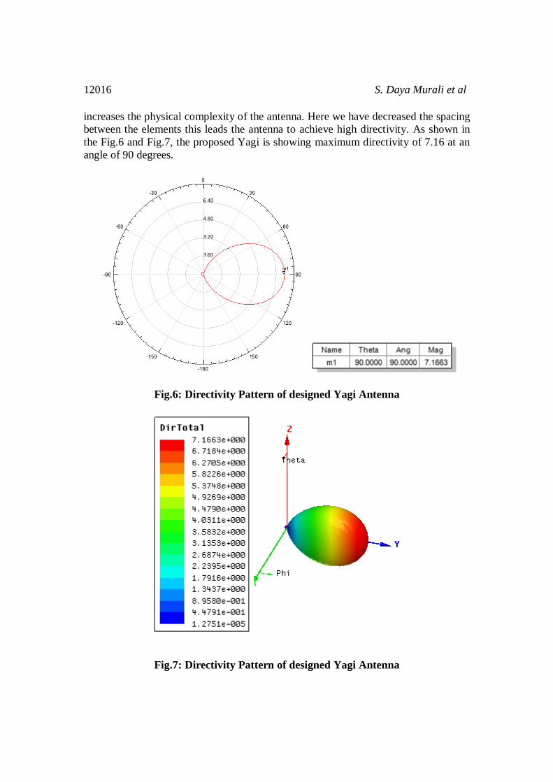
increases the physical complexity of the antenna. Here we have decreased the spacing between the elements this leads the antenna to achieve high directivity. As shown in the Fig.6 and Fig.7, the proposed Yagi is showing maximum directivity of 7.16 at an angle of 90 degrees.
Fig.6: Directivity Pattern of designed Yagi Antenna
Fig.7: Directivity Pattern of designed Yagi Antenna

Size Reduction of Yagi-Uda Antenna 12017
Practical Results:
Fig.8: Experimentation of proposed Yagi-Uda Antenna using Network Analyzer (Facility available in RF&MW Research Centre, KL University) Return loss: Return loss defines the wastage of signal power resulting from the reflection caused at discontinuities in a transmission line or optical fiber. These discontinuities may be either a mismatch with the load that is terminated or a device inserted in the Transmission line. It is usually expressed in decibels (dB). Two lines or devices are said to be well matched if the return loss is more. An antenna is said to be perfectly matched if the return loss is of about-10dB.The return loss obtained for our design is-17.653db which can be shown in the Fig.8. VSWR: The Voltage Standing Wave Ratio describes how better the impedance matching is. VSWR is frequently called as SWR. A high VSWR indicates that how much signal is reflected rather than being radiated by the antenna. VSWR and reflected power express the same in different ways of measuring [15]. Generally the vswr is calculated at the desired operating frequency. The Proposed antenna has obtained SWR of 1.4 as shown in the Fig.9.

12018 S. Daya Murali et al
Fig.9: Return loss of Yagi using Network Analyzer Field characteristics:
Fig.10: SWR Measurement of Yagi using Network Analyzer

Size Reduction of Yagi-Uda Antenna 12019
Fig.11: E-Field distributions of proposed yagi-uda Antenna
Fig.12: H-Field characteristics of proposed Yagi-Uda Antenna

12020 S. Daya Murali et al
Discussions For designing of Yagi-Uda antenna to operate at 6 MHz we required spacing between the elements is 10 cms. But in this work we have designed for 1 MHz where the spacing should be 6 cms. But by reducing the spacing between the elements to 5 cms and diameter of the elements to 6mm we made the antenna to operate at 6 MHz. Hence optimization of geometrical length has been achieved. The proposed Yagi–Uda antenna has been modeled using a software HFSS. HFSS is a commercial finite element method solver for EM structures. The software includes a linear circuit simulator with integrated optometric for input and matching network design. The radiation characteristics are investigated using network analyzer. Network analyzer is an instrument that measures the electrical parameters of networks. Conclusions In this work, simple, light weight and optimized antenna based on a modification of the classic Yagi–Uda antenna has been developed and implemented practically. Further impedance and radiation characteristics can be improved by using folded-dipole as driven element and gain can be improved by using more number of directors. Acknowledgments The authors especially thank the support given from Department of Science and technology DST, Government of India through the WOS–A scheme with file number: SR/WOS–A/ET-33/2011 and also with SR/FST/ETI-316/2012 FIST program. The authors are also highly thankful to the management of K L University for supporting and encouraging this work. References [1] C.A.Balanis, “Antenna Theory, Analysis and Design,”Johnwiely &sons, New
York, 1997. [2] K.D. Prasad “Antenna and Wave Propagation”2007. [3] John D. Kraus, “Yagi-uda Antennas” in Antennas second edition1997, page-
621. [4] B.T.P.Madhav,”Design and analysis of 3-element yagi-uda antenna for wind
profile radar”, International journal of computer science & communication networks, Vol 1(3), 242-246.
[5] Deepak Patidar, P.K Singhal, Hemant Kumar Gupta, Rajkumar Prjapati,”Design & Investigation of Five Element Liquid Yagi Uda Antenna a L-Band(1Ghz) Applications”, International Journal of Engineering and Technology, 1(3) (2012).

Size Reduction of Yagi-Uda Antenna 12021
[6] G.Sharma, V.Sharma and P. K. Singhal,”Performance Investigation of Yagi-Uda Antenna using Different Shapes of Antenna Element at 2 ghz”, IJECCT 2013, Vol. 3(2).
[7] G.Sharma,Anand N. Sharma, Ashish Duvey,P.K Singhal,”Yagi-Uda Antenna for L-Band Frequency Range”,IJET, 1(4) (2012) 315-320.
[8] Ankit Agnihotri, Akshay Prabhu, Dheerendra Mishra,”Improvement in Radiation Pattern of Yagi-Uda Antenna”, IJES, Vol.2 Issue 12(May 2013), Pp 26-35.
[9] B.I. Neelgar and G.S.N. Raju,”Impedance Characteristics of Yagi-Uda Antenna”, IJECE, Vol.4, Number 1(2011), Pp.115-130.
[10] M. Bemani and S. Nikmehr,”A Novel Wide-Band Microstrip Yagi-Uda Array Antenna for WLAN Applications”, Progress In Electromagnetics Research B, Vol. 16, 389-406, 2009.
[11] Mirishkar Sai Ganesh,”Optimization of Radiation Pattern of Yagi-Uda Antenna”, EDUBEAM Multidisciplinary-Online Research Journal, Vol-XI, Issue-1, January-2014.
[12] Pristin k Mathew,”A Three Element Yagi-Uda Antenna for RFID Systems”, IJEDER, Vol. 2, Issue 1, 2014.
[13] Paraminder Singh, Ankita Sharma, Neha Uniyal, Richa Kala,”Half-Wave Dipole Antenna for GSM Applications”, International Journal of Advanced Computer Research, Vol.2, Nmber-4, December-2012.
[14] Mohammad Tareq, Dewan Ashraful Alam, Mazidul Islam, Razin Ahmed,”Simple Half-Wave Dipole Antenna Analysis for Wireless Applications by CST Microwave Studio”, IJCA, Vol. 94, N. 7, May 2014.
[15] Jason D. Lohn, William F. Kraus Derek S. Linden and Silvano P. Colombano,”Evolutionary Optimization of Yagi-Uda Antennas”, International Conference on Evolvable Systems, Tokyo, October 3-5, 2001, pp. 236-243.
[16] Satyandra Singh Lodhi, P. K. Singhal,”Microstip Yagi-Uda antenna at 2.45 GHz for ISM Band Application”, International Journal of Research in Engineering & Technology (IJRET),Vol. 1, Issue 2, July 2013, 151-154.
[17] Y. Chen and C. F. Wang, “Electrically Loaded Yagi-Uda Antenna Optimizations Using Characteristics Modes And Differential Evolution”, Journal of Electromagnetic Waves and Applications, Vol. 26, 1018-1028, 2012.
[18] E. Krasnok, A. E. Miroshnichenki, P. A. Belov and Yu. S. Kivshar,” Huygens Optical Elements and Yagi-Uda Nanoantennas Based on Dielectric Nanoparticles”, JETP Letters, 2011, Vol. 94, No.8 pp. 593-598.
[19] Richard A. Formato,” Improving Bandwidth of Yagi-Uda Arrays”, Wireless Engineering and Technology, Vol. 3 No.1 (2012), DOI:10.4236/wet.2012.31003.
[20] Mahesh Kumar Aghwariya, P. K. Singhal,” Dual Director Microstrip Planar Yagi-Uda Antenna for X-Band”, IJECCT 2013, Vol. 3(2).
[21] Sreethivya M, Dhanya.M.G, Nimisha.C, Gandhiraj.R, Soman.K.P,” Radiation Pattern of Yagi-Uda Antenna Using USRP on GNU Radio Platform”, IJERT, eISSN: 2319-1163|pISSN: 2321-7308.

12022 S. Daya Murali et al
[22] Satyandra Singh Lodhi, Mahesh Kumar Aghwariya, Ragini Sharma,” Microstrip Branch Structure Yagi-Uda Antenna with Proper Impedance Matching”, IJAIM, Vol 1, Issue 5, ISSN 2320-5121.
[23] G. Sharma, Vijay Sharma, and P.K. Singhal,” Design and Characterization of Multiband Yagi-Uda Radiator”, IJOAR, Vol 1, Issue 3, March 2013.
[24] Zedong Wang, Xianglong liu, Yingzeng Yin, Junhui Wang, and Zhaoxing Li,” A Novel Design of Folded Dipole for Broadband Printed Yagi-Uda Antenna”, Progress In Electromagnetics Research c, Vol. 46, 23-30, 2014.
[25] S. S. Khade, Suvarna Talatule, S. L. Dadjate,”Compact Planar Directive YagiAntenna for WLAN Application”, International Journal of Electrical, Electronics and Data Communication, Vol. 1, Issue. 2, April-2013.