Site/SunNet/Domain Manager Administration Guide - Oracle ...
598
Solstice Site/SunNet/Domain Manager Administration Guide 2550 Garcia Avenue Mountain View, CA 94043 U.S.A. A Sun Microsystems, Inc. Business
-
Upload
khangminh22 -
Category
Documents
-
view
2 -
download
0
Transcript of Site/SunNet/Domain Manager Administration Guide - Oracle ...

Solstice Site/SunNet/Domain ManagerAdministration Guide
2550 Garcia AvenueMountain View, CA 94043U.S.A.
A Sun Microsystems, Inc. Business

PleaseRecycle
Copyright 1996 Sun Microsystems, Inc., 2550 Garcia Avenue, Mountain View, California 94043-1100 U.S.A. All rights reserved.
This product or document is protected by copyright and distributed under licenses restricting its use, copying, distribution, anddecompilation. No part of this product or document may be reproduced in any form by any means without prior writtenauthorization of Sun and its licensors, if any.
Portions of this product may be derived from the UNIX® system, licensed from Novell, Inc., and from the Berkeley 4.3 BSDsystem, licensed from the University of California. UNIX is a registered trademark in the United States and other countries and isexclusively licensed by X/Open Company Ltd. Third-party software, including font technology in this product, is protected bycopyright and licensed from Sun’s suppliers.
RESTRICTED RIGHTS LEGEND: Use, duplication, or disclosure by the government is subject to restrictions as set forth insubparagraph (c)(1)(ii) of the Rights in Technical Data and Computer Software clause at DFARS 252.227-7013 and FAR 52.227-19.
Sun, Sun Microsystems, the Sun logo, Solaris, Solstice, Solstice Site Manager, Solstice SunNet Manager, Solstice DomainManager, and Cooperative Consoles are trademarks or registered trademarks of Sun Microsystems, Inc. in the United States andother countries. All SPARC trademarks are used under license and are trademarks or registered trademarks of SPARCInternational, Inc. in the United States and other countries. Products bearing SPARC trademarks are based upon an architecturedeveloped by Sun Microsystems, Inc.
The OPEN LOOK® and Sun™ Graphical User Interfaces were developed by Sun Microsystems, Inc. for its users and licensees.Sun acknowledges the pioneering efforts of Xerox in researching and developing the concept of visual or graphical userinterfaces for the computer industry. Sun holds a non-exclusive license from Xerox to the Xerox Graphical User Interface, whichlicense also covers Sun’s licensees who implement OPEN LOOK GUIs and otherwise comply with Sun’s written licenseagreements.
X Window System is a trademark of X Consortium, Inc.
THIS PUBLICATION IS PROVIDED “AS IS” WITHOUT WARRANTY OF ANY KIND, EITHER EXPRESS OR IMPLIED,INCLUDING, BUT NOT LIMITED TO, THE IMPLIED WARRANTIES OF MERCHANTABILITY, FITNESS FOR APARTICULAR PURPOSE, OR NON-INFRINGEMENT.

iii
Contents
1. Overview and Concepts . . . . . . . . . . . . . . . . . . . . . . . . . . . . . . . . 1-1
1.1 Licensing . . . . . . . . . . . . . . . . . . . . . . . . . . . . . . . . . . . . . . . . 1-1
1.2 Site and Domain Differences. . . . . . . . . . . . . . . . . . . . . . . . 1-1
1.3 Management Applications and Agents . . . . . . . . . . . . . . . 1-2
1.4 SunNet Manager Console . . . . . . . . . . . . . . . . . . . . . . . . . . 1-5
1.5 Management Database. . . . . . . . . . . . . . . . . . . . . . . . . . . . . 1-6
1.6 Configuration . . . . . . . . . . . . . . . . . . . . . . . . . . . . . . . . . . . . 1-8
2. Planning for Network Management . . . . . . . . . . . . . . . . . . . . . 2-1
2.1 Planning for Network Management . . . . . . . . . . . . . . . . . 2-1
3. Creating and Modifying the Management Database . . . . . . . 3-1
3.1 Adding SunNet Manager to Your PATH Variable . . . . . . 3-1
3.2 Starting the Console . . . . . . . . . . . . . . . . . . . . . . . . . . . . . . . 3-2
3.3 Using IP Discover and IPX Discover . . . . . . . . . . . . . . . . . 3-8
3.4 Using IPX Discover . . . . . . . . . . . . . . . . . . . . . . . . . . . . . . . 3-11
3.5 Netware Management System Export/Import Agent . . . 3-12

iv Solstice Site/SunNet/Domain Manager Administration Guide
3.6 Invoking IPX Discover . . . . . . . . . . . . . . . . . . . . . . . . . . . . . 3-12
3.7 Traversing the View Hierarchy . . . . . . . . . . . . . . . . . . . . . . 3-16
3.8 Creating Elements Using the Editor. . . . . . . . . . . . . . . . . . 3-18
3.9 Creating Aliases . . . . . . . . . . . . . . . . . . . . . . . . . . . . . . . . . . 3-24
3.10 Finding Elements . . . . . . . . . . . . . . . . . . . . . . . . . . . . . . . . . 3-26
3.11 Modifying Element Properties . . . . . . . . . . . . . . . . . . . . . . 3-27
3.12 Changing Element Types. . . . . . . . . . . . . . . . . . . . . . . . . . . 3-29
3.13 Moving Elements within a View. . . . . . . . . . . . . . . . . . . . . 3-31
3.14 Moving Elements from One View to Another . . . . . . . . . 3-31
3.15 Connecting Elements . . . . . . . . . . . . . . . . . . . . . . . . . . . . . . 3-32
3.16 Copying Elements . . . . . . . . . . . . . . . . . . . . . . . . . . . . . . . . 3-34
3.17 Deleting Elements. . . . . . . . . . . . . . . . . . . . . . . . . . . . . . . . . 3-36
3.18 Saving the Management Database . . . . . . . . . . . . . . . . . . . 3-37
3.19 Quitting the Console . . . . . . . . . . . . . . . . . . . . . . . . . . . . . . 3-39
4. Requesting Data . . . . . . . . . . . . . . . . . . . . . . . . . . . . . . . . . . . . . . 4-1
4.1 Making a One-Time Request for Data . . . . . . . . . . . . . . . . 4-2
4.2 Making a Request for Periodic Data . . . . . . . . . . . . . . . . . 4-5
4.3 Prioritizing Requests . . . . . . . . . . . . . . . . . . . . . . . . . . . . . . 4-5
4.4 Copying Requests. . . . . . . . . . . . . . . . . . . . . . . . . . . . . . . . . 4-14
4.5 Viewing Incoming Data . . . . . . . . . . . . . . . . . . . . . . . . . . . . 4-15
4.6 Analyzing Stored Data. . . . . . . . . . . . . . . . . . . . . . . . . . . . . 4-22
4.7 Printing a Graph . . . . . . . . . . . . . . . . . . . . . . . . . . . . . . . . . . 4-31
4.8 Viewing and Managing Requests . . . . . . . . . . . . . . . . . . . . 4-32
4.9 Request States . . . . . . . . . . . . . . . . . . . . . . . . . . . . . . . . . . . . 4-34

Contents v
4.10 Viewing and Modifying Properties of a Request . . . . . . . 4-35
5. Specifying Event Requests . . . . . . . . . . . . . . . . . . . . . . . . . . . . . 5-1
5.1 Specifying an Event . . . . . . . . . . . . . . . . . . . . . . . . . . . . . . . 5-2
5.2 Scheduling Requests Based on Events . . . . . . . . . . . . . . . . 5-2
5.3 Retrieving Single Attributes . . . . . . . . . . . . . . . . . . . . . . . . 5-3
5.4 Detecting the Presence of an Event . . . . . . . . . . . . . . . . . . 5-24
5.5 Checking the Cause of an Event . . . . . . . . . . . . . . . . . . . . . 5-25
5.6 Changing a Glyph State Back to Normal. . . . . . . . . . . . . . 5-27
5.7 Glyph Pending State . . . . . . . . . . . . . . . . . . . . . . . . . . . . . . 5-27
5.8 Propagation of Glyph States . . . . . . . . . . . . . . . . . . . . . . . . 5-29
5.9 Changing the Propagation of Glyph State Changes. . . . . 5-30
6. Viewing Reports . . . . . . . . . . . . . . . . . . . . . . . . . . . . . . . . . . . . . . 6-1
6.1 Viewing Error Messages and Error Reports . . . . . . . . . . . 6-11
6.2 Viewing Traps . . . . . . . . . . . . . . . . . . . . . . . . . . . . . . . . . . . . 6-15
7. Managing Printers . . . . . . . . . . . . . . . . . . . . . . . . . . . . . . . . . . . . 7-1
8. Managing SNMP Devices . . . . . . . . . . . . . . . . . . . . . . . . . . . . . . 8-1
8.1 Adding SNMP Devices . . . . . . . . . . . . . . . . . . . . . . . . . . . . 8-2
8.2 Creating an SNMP Element in the Database. . . . . . . . . . . 8-5
8.3 Setting Up SNM to Receive Traps from a Device . . . . . . . 8-8
8.4 Using the Set Tool to Retrieve SNMP Attribute Values . . 8-13
8.5 Using the Set Tool to Change SNMP Attribute Values . . 8-18
9. Creating and Managing a Link. . . . . . . . . . . . . . . . . . . . . . . . . . 9-1
9.1 Using the Console’s Edit Function . . . . . . . . . . . . . . . . . . . 9-1
9.2 Using IP Discover to Create Manageable Links . . . . . . . . 9-10
vi Solstice Site/SunNet/Domain Manager Administration Guide
10. Customizing SunNet Manager . . . . . . . . . . . . . . . . . . . . . . . . . . 10-1
10.1 Adding Background Image to Current View . . . . . . . . . . 10-1
10.2 Creating Types of Elements . . . . . . . . . . . . . . . . . . . . . . . . 10-6
10.3 Creating a New Glyph for an Element Type . . . . . . . . . . 10-9
10.4 Modifying the Console Tools Menu . . . . . . . . . . . . . . . . . 10-10
10.5 Modifying the Tools Menu for an Element Type . . . . . . . 10-12
10.6 Adding Agents and Glyphs . . . . . . . . . . . . . . . . . . . . . . . . 10-12
11. Network Management Security . . . . . . . . . . . . . . . . . . . . . . . . . 11-1
11.1 Authentication . . . . . . . . . . . . . . . . . . . . . . . . . . . . . . . . . . . 11-2
11.2 Access Control . . . . . . . . . . . . . . . . . . . . . . . . . . . . . . . . . . . 11-2
11.3 The Security Algorithm . . . . . . . . . . . . . . . . . . . . . . . . . . . . 11-3
11.4 Conferring Right-of-Access . . . . . . . . . . . . . . . . . . . . . . . . . 11-4
12. NetWork Layout Assistant. . . . . . . . . . . . . . . . . . . . . . . . . . . . . . 12-1
12.1 Who Should Use NLA? . . . . . . . . . . . . . . . . . . . . . . . . . . . . 12-1
12.2 What Does NLA Do? . . . . . . . . . . . . . . . . . . . . . . . . . . . . . . 12-1
12.3 What the Network Layout Assistant Does Not Do . . . . . 12-2
12.4 Starting the SunNet Manager Console. . . . . . . . . . . . . . . . 12-2
12.5 Creating the SunNet Manager Console Database . . . . . . 12-4
12.6 Using the Layout... Option . . . . . . . . . . . . . . . . . . . . . . . . . 12-6
12.7 Using the Overview... Option . . . . . . . . . . . . . . . . . . . . . . . 12-10
12.8 Using the Print... Option . . . . . . . . . . . . . . . . . . . . . . . . . . . 12-14
12.9 The Print Window . . . . . . . . . . . . . . . . . . . . . . . . . . . . . . . . 12-15
12.10 Tailoring Your Layouts . . . . . . . . . . . . . . . . . . . . . . . . . . . . 12-20
12.11 Hierarchical Layout Style . . . . . . . . . . . . . . . . . . . . . . . . . . 12-20
Contents vii
12.12 Tailoring Your Layout . . . . . . . . . . . . . . . . . . . . . . . . . . . . . 12-22
12.13 Hierarchical Layout Style . . . . . . . . . . . . . . . . . . . . . . . . . . 12-22
12.14 Circular Layout Style . . . . . . . . . . . . . . . . . . . . . . . . . . . . . . 12-32
12.15 Symmetric Layout Style. . . . . . . . . . . . . . . . . . . . . . . . . . . . 12-41
12.16 Network Layout Assistant Restrictions . . . . . . . . . . . . . . . 12-45
13. Reference Overview . . . . . . . . . . . . . . . . . . . . . . . . . . . . . . . . . . . 13-1
13.1 Overview . . . . . . . . . . . . . . . . . . . . . . . . . . . . . . . . . . . . . . . . 13-1
13.2 Agents and Proxies. . . . . . . . . . . . . . . . . . . . . . . . . . . . . . . . 13-2
13.3 SunNet Manager Directories and Files . . . . . . . . . . . . . . . 13-5
13.4 Environment Variables Used with SunNet Manager . . . . 13-9
13.5 Extending SunNet Manager . . . . . . . . . . . . . . . . . . . . . . . . 13-12
14. Console . . . . . . . . . . . . . . . . . . . . . . . . . . . . . . . . . . . . . . . . . . . . . . 14-1
14.1 SunNet Manager Console . . . . . . . . . . . . . . . . . . . . . . . . . . 14-1
14.2 Freezing the Console (Read-Only Mode) . . . . . . . . . . . . . 14-4
14.3 Control Panel Buttons and Menus . . . . . . . . . . . . . . . . . . . 14-5
14.4 View Button . . . . . . . . . . . . . . . . . . . . . . . . . . . . . . . . . . . . . 14-10
14.5 Edit Button . . . . . . . . . . . . . . . . . . . . . . . . . . . . . . . . . . . . . . 14-11
14.6 Props Button . . . . . . . . . . . . . . . . . . . . . . . . . . . . . . . . . . . . . 14-17
14.7 Requests Button . . . . . . . . . . . . . . . . . . . . . . . . . . . . . . . . . . 14-17
14.8 Tools Button . . . . . . . . . . . . . . . . . . . . . . . . . . . . . . . . . . . . . 14-18
14.9 Goto Button . . . . . . . . . . . . . . . . . . . . . . . . . . . . . . . . . . . . . . 14-19
14.10 Element Glyph Menu . . . . . . . . . . . . . . . . . . . . . . . . . . . . . . 14-20
15. Requests Management . . . . . . . . . . . . . . . . . . . . . . . . . . . . . . . . . 15-1
15.1 Send Request . . . . . . . . . . . . . . . . . . . . . . . . . . . . . . . . . . . . . 15-4

viii Solstice Site/SunNet/Domain Manager Administration Guide
15.2 Create Predefined . . . . . . . . . . . . . . . . . . . . . . . . . . . . . . . . . 15-20
15.3 Requests Summary. . . . . . . . . . . . . . . . . . . . . . . . . . . . . . . . 15-40
15.4 Request Glyph Popup Menu. . . . . . . . . . . . . . . . . . . . . . . . 15-45
16. View Reports . . . . . . . . . . . . . . . . . . . . . . . . . . . . . . . . . . . . . . . . . 16-1
16.1 Alarm Reports. . . . . . . . . . . . . . . . . . . . . . . . . . . . . . . . . . . . 16-2
16.2 Data Reports . . . . . . . . . . . . . . . . . . . . . . . . . . . . . . . . . . . . . 16-9
16.3 Event/Trap Reports . . . . . . . . . . . . . . . . . . . . . . . . . . . . . . . 16-14
16.4 Error Reports. . . . . . . . . . . . . . . . . . . . . . . . . . . . . . . . . . . . . 16-16
16.5 Events Summary. . . . . . . . . . . . . . . . . . . . . . . . . . . . . . . . . . 16-17
16.6 Add Background . . . . . . . . . . . . . . . . . . . . . . . . . . . . . . . . . 16-18
16.7 Remove Background . . . . . . . . . . . . . . . . . . . . . . . . . . . . . . 16-18
16.8 Find . . . . . . . . . . . . . . . . . . . . . . . . . . . . . . . . . . . . . . . . . . . . 16-18
16.9 Clipboard. . . . . . . . . . . . . . . . . . . . . . . . . . . . . . . . . . . . . . . . 16-19
17. Props Menu . . . . . . . . . . . . . . . . . . . . . . . . . . . . . . . . . . . . . . . . . . 17-1
17.1 Global Properties . . . . . . . . . . . . . . . . . . . . . . . . . . . . . . . . . 17-2
17.2 Windows . . . . . . . . . . . . . . . . . . . . . . . . . . . . . . . . . . . . . . . . 17-5
17.3 Requests. . . . . . . . . . . . . . . . . . . . . . . . . . . . . . . . . . . . . . . . . 17-6
17.4 Automatic Management . . . . . . . . . . . . . . . . . . . . . . . . . . . 17-7
17.5 Events and Traps . . . . . . . . . . . . . . . . . . . . . . . . . . . . . . . . . 17-16
17.6 Errors . . . . . . . . . . . . . . . . . . . . . . . . . . . . . . . . . . . . . . . . . . . 17-22
17.7 Locations . . . . . . . . . . . . . . . . . . . . . . . . . . . . . . . . . . . . . . . . 17-25
17.8 Miscellaneous . . . . . . . . . . . . . . . . . . . . . . . . . . . . . . . . . . . . 17-26
17.9 Custom Colors . . . . . . . . . . . . . . . . . . . . . . . . . . . . . . . . . . . 17-29
17.10 Other Configuration. . . . . . . . . . . . . . . . . . . . . . . . . . . . . . . 17-29

Contents ix
17.11 Custom Colors . . . . . . . . . . . . . . . . . . . . . . . . . . . . . . . . . . . 17-33
18. Management Database. . . . . . . . . . . . . . . . . . . . . . . . . . . . . . . . . 18-1
18.1 Element Type Definition . . . . . . . . . . . . . . . . . . . . . . . . . . . 18-3
18.2 Element Instance Definition . . . . . . . . . . . . . . . . . . . . . . . . 18-9
18.3 Connection Definition . . . . . . . . . . . . . . . . . . . . . . . . . . . . . 18-11
18.4 Background Definition. . . . . . . . . . . . . . . . . . . . . . . . . . . . . 18-12
18.5 Tools Menu Definition . . . . . . . . . . . . . . . . . . . . . . . . . . . . . 18-13
18.6 Definition of Requests . . . . . . . . . . . . . . . . . . . . . . . . . . . . . 18-14
18.7 Duplicate Databases . . . . . . . . . . . . . . . . . . . . . . . . . . . . . . . 18-23
19. SNMP Support . . . . . . . . . . . . . . . . . . . . . . . . . . . . . . . . . . . . . . . 19-1
19.1 SNMP Proxy Agent Operation . . . . . . . . . . . . . . . . . . . . . . 19-2
19.2 Schema Files . . . . . . . . . . . . . . . . . . . . . . . . . . . . . . . . . . . . . 19-8
19.3 SNMP Host Files. . . . . . . . . . . . . . . . . . . . . . . . . . . . . . . . . . 19-10
19.4 Asynchronous Event Reports (Traps) . . . . . . . . . . . . . . . . 19-12
19.5 SNMP Version 2 Support . . . . . . . . . . . . . . . . . . . . . . . . . . . 19-27
20. Browser . . . . . . . . . . . . . . . . . . . . . . . . . . . . . . . . . . . . . . . . . . . . . . 20-1
20.1 Starting the Browser. . . . . . . . . . . . . . . . . . . . . . . . . . . . . . . 20-2
20.2 Loading Files . . . . . . . . . . . . . . . . . . . . . . . . . . . . . . . . . . . . . 20-3
20.3 Report Streams . . . . . . . . . . . . . . . . . . . . . . . . . . . . . . . . . . . 20-5
20.4 Streams Menu . . . . . . . . . . . . . . . . . . . . . . . . . . . . . . . . . . . . 20-10
20.5 Selecting Streams . . . . . . . . . . . . . . . . . . . . . . . . . . . . . . . . . 20-11
20.6 Folders . . . . . . . . . . . . . . . . . . . . . . . . . . . . . . . . . . . . . . . . . . 20-13
20.7 Customizing the Browser . . . . . . . . . . . . . . . . . . . . . . . . . . 20-15
21. Results Grapher. . . . . . . . . . . . . . . . . . . . . . . . . . . . . . . . . . . . . . . 21-1
x Solstice Site/SunNet/Domain Manager Administration Guide
21.1 Results Grapher Window . . . . . . . . . . . . . . . . . . . . . . . . . . 21-3
21.2 Graph Properties Window. . . . . . . . . . . . . . . . . . . . . . . . . . 21-4
21.3 Displaying Graphs . . . . . . . . . . . . . . . . . . . . . . . . . . . . . . . . 21-8
21.4 Merging Graphs . . . . . . . . . . . . . . . . . . . . . . . . . . . . . . . . . . 21-11
22. IP Discover . . . . . . . . . . . . . . . . . . . . . . . . . . . . . . . . . . . . . . . . . . . 22-1
22.1 Invoking IP Discover . . . . . . . . . . . . . . . . . . . . . . . . . . . . . . 22-2
22.2 Discover Tool Configuration . . . . . . . . . . . . . . . . . . . . . . . . 22-5
22.3 Updating the Management Database. . . . . . . . . . . . . . . . . 22-19
22.4 snm_discover Command . . . . . . . . . . . . . . . . . . . . . . . . . . 22-20
22.5 The discover.conf File . . . . . . . . . . . . . . . . . . . . . . . . . . 22-25
23. IPX Discover . . . . . . . . . . . . . . . . . . . . . . . . . . . . . . . . . . . . . . . . . 23-1
23.1 Function Overview. . . . . . . . . . . . . . . . . . . . . . . . . . . . . . . . 23-1
23.2 Forwarding Novell’s NMS Alarms to SunNet Manager . 23-4
24. Set Tool . . . . . . . . . . . . . . . . . . . . . . . . . . . . . . . . . . . . . . . . . . . . . . 24-1
24.1 Set Tool Window. . . . . . . . . . . . . . . . . . . . . . . . . . . . . . . . . . 24-3
24.2 Set Information List . . . . . . . . . . . . . . . . . . . . . . . . . . . . . . . 24-5
24.3 Invoking Set Tool from the Command Line . . . . . . . . . . . 24-7
Glossary. . . . . . . . . . . . . . . . . . . . . . . . . . . . . . . . . . . . . . . . Glossary-1
Index . . . . . . . . . . . . . . . . . . . . . . . . . . . . . . . . . . . . . . . . . . . Index-1

xi
Figures
Figure 1-1 Agent and Proxy Agent Communications Protocol. . . . . . . . . 1-3
Figure 1-2 Using Proxy Agents Across Networks. . . . . . . . . . . . . . . . . . . . 1-4
Figure 1-3 Using the Console to Initiate Management Tasks and Display Data1-5
Figure 2-1 Example of a LAN Configuration . . . . . . . . . . . . . . . . . . . . . . . . 2-3
Figure 2-2 Critical Nodes in Home View . . . . . . . . . . . . . . . . . . . . . . . . . . . 2-4
Figure 2-3 SunNet Manager Console Views. . . . . . . . . . . . . . . . . . . . . . . . . 2-5
Figure 2-4 Elements Within Console Views . . . . . . . . . . . . . . . . . . . . . . . . . 2-6
Figure 3-1 Quick Start Window . . . . . . . . . . . . . . . . . . . . . . . . . . . . . . . . . . . 3-3
Figure 3-2 Console Window . . . . . . . . . . . . . . . . . . . . . . . . . . . . . . . . . . . . . . 3-4
Figure 3-3 IP Discover Home Screen . . . . . . . . . . . . . . . . . . . . . . . . . . . . . . . 3-9
Figure 3-4 IP Discover Properties Sheet . . . . . . . . . . . . . . . . . . . . . . . . . . . . 3-11
Figure 3-5 IPX Discover Home Screen . . . . . . . . . . . . . . . . . . . . . . . . . . . . . 3-12
Figure 3-6 IPX Discover Properties Sheet . . . . . . . . . . . . . . . . . . . . . . . . . . . 3-13
Figure 3-7 Selecting a View Name in the Goto Menu. . . . . . . . . . . . . . . . . 3-17
Figure 3-8 Create Object Window . . . . . . . . . . . . . . . . . . . . . . . . . . . . . . . . . 3-18
Figure 3-9 Object Properties Window (Component). . . . . . . . . . . . . . . . . . 3-19
xii Solstice Site/SunNet/Domain Manager Administration Guide
Figure 3-10 Top Portions of Object Properties Windows . . . . . . . . . . . . . . . 3-21
Figure 3-11 Object Properties Window . . . . . . . . . . . . . . . . . . . . . . . . . . . . . . 3-23
Figure 3-12 Alias Window. . . . . . . . . . . . . . . . . . . . . . . . . . . . . . . . . . . . . . . . . 3-25
Figure 3-13 Properties Window for Router . . . . . . . . . . . . . . . . . . . . . . . . . . 3-26
Figure 3-14 Selecting the View—Find Menu Item. . . . . . . . . . . . . . . . . . . . . 3-27
Figure 3-15 Selecting the Glyph—Properties Menu Item. . . . . . . . . . . . . . . 3-28
Figure 3-16 Element categories for Create Object . . . . . . . . . . . . . . . . . . . . . 3-29
Figure 3-17 Change Type Window . . . . . . . . . . . . . . . . . . . . . . . . . . . . . . . . . 3-30
Figure 3-18 Moving a Glyph to a New Location . . . . . . . . . . . . . . . . . . . . . . 3-31
Figure 3-19 Glyph—Connect Example . . . . . . . . . . . . . . . . . . . . . . . . . . . . . . 3-33
Figure 3-20 Selecting the Edit—Copy Menu Item . . . . . . . . . . . . . . . . . . . . . 3-35
Figure 3-21 Selecting the Edit—Delete Menu Item . . . . . . . . . . . . . . . . . . . . 3-37
Figure 3-22 Selecting the File➤Save➤Management Database Menu Item 3-38
Figure 3-23 Console Quit Window . . . . . . . . . . . . . . . . . . . . . . . . . . . . . . . . . 3-39
Figure 4-1 Requests Menu—Quick Dump Request . . . . . . . . . . . . . . . . . . 4-2
Figure 4-2 Glyph Menu—Quick Dump Request . . . . . . . . . . . . . . . . . . . . . 4-3
Figure 4-3 Quick Dump Report Window . . . . . . . . . . . . . . . . . . . . . . . . . . . 4-4
Figure 4-4 Request Schedule Menu . . . . . . . . . . . . . . . . . . . . . . . . . . . . . . . . 4-6
Figure 4-5 Sample Request Builder Window . . . . . . . . . . . . . . . . . . . . . . . . 4-7
Figure 4-6 Request Name Menu. . . . . . . . . . . . . . . . . . . . . . . . . . . . . . . . . . . 4-8
Figure 4-7 Sample Data Request Properties Sheet. . . . . . . . . . . . . . . . . . . . 4-10
Figure 4-8 Predefined Data Request . . . . . . . . . . . . . . . . . . . . . . . . . . . . . . . 4-12
Figure 4-9 View—Data Reports Option . . . . . . . . . . . . . . . . . . . . . . . . . . . . 4-16
Figure 4-10 Sample Data Reports Window . . . . . . . . . . . . . . . . . . . . . . . . . . 4-17
Figure 4-11 Graph Tool Menu . . . . . . . . . . . . . . . . . . . . . . . . . . . . . . . . . . . . . 4-18

Figures xiii
Figure 4-12 Strip Chart and Indicator Samples . . . . . . . . . . . . . . . . . . . . . . . 4-19
Figure 4-13 Data Request Properties Template . . . . . . . . . . . . . . . . . . . . . . . 4-20
Figure 4-14 Strip Chart Menu . . . . . . . . . . . . . . . . . . . . . . . . . . . . . . . . . . . . . . 4-21
Figure 4-15 Results Browser Window . . . . . . . . . . . . . . . . . . . . . . . . . . . . . . . 4-23
Figure 4-16 Results Browser File Menu. . . . . . . . . . . . . . . . . . . . . . . . . . . . . . 4-23
Figure 4-17 Results Browser with Reports Loaded . . . . . . . . . . . . . . . . . . . . 4-25
Figure 4-18 Browser Edit Menu . . . . . . . . . . . . . . . . . . . . . . . . . . . . . . . . . . . . 4-27
Figure 4-19 Browser Tool Edit Menu. . . . . . . . . . . . . . . . . . . . . . . . . . . . . . . . 4-28
Figure 4-20 Browser Properties Window . . . . . . . . . . . . . . . . . . . . . . . . . . . . 4-28
Figure 4-21 Results Grapher Window. . . . . . . . . . . . . . . . . . . . . . . . . . . . . . . 4-30
Figure 4-22 Tools—Snapshot Window . . . . . . . . . . . . . . . . . . . . . . . . . . . . . . 4-31
Figure 4-23 Sample Requests—Summary Window . . . . . . . . . . . . . . . . . . . 4-33
Figure 4-24 Requests—Summary Window . . . . . . . . . . . . . . . . . . . . . . . . . . 4-35
Figure 4-25 Request Glyph Menu . . . . . . . . . . . . . . . . . . . . . . . . . . . . . . . . . . 4-36
Figure 4-26 Predefined Data Request Using hostperf Agent . . . . . . . . . . . . 4-38
Figure 4-27 Graph from Predefined Request . . . . . . . . . . . . . . . . . . . . . . . . . 4-38
Figure 4-28 Data Request Properties Sheet with Log File Specified . . . . . . 4-40
Figure 4-29 Copying a Request from an Element’s Subview. . . . . . . . . . . . 4-41
Figure 4-30 Data Report Files in Browser . . . . . . . . . . . . . . . . . . . . . . . . . . . . 4-42
Figure 4-31 Streams➤Graph Grapher Menu Data Report Files . . . . . . . . . 4-43
Figure 4-32 Merged Graphs . . . . . . . . . . . . . . . . . . . . . . . . . . . . . . . . . . . . . . . 4-43
Figure 5-1 Event Request Properties Sheet . . . . . . . . . . . . . . . . . . . . . . . . . . 5-3
Figure 5-2 Sample Request Builder Window . . . . . . . . . . . . . . . . . . . . . . . . 5-5
Figure 5-3 Request Name Menu. . . . . . . . . . . . . . . . . . . . . . . . . . . . . . . . . . . 5-6
Figure 5-4 Sample Event Request. . . . . . . . . . . . . . . . . . . . . . . . . . . . . . . . . . 5-7

xiv Solstice Site/SunNet/Domain Manager Administration Guide
Figure 5-5 Sending Predefined Event Request. . . . . . . . . . . . . . . . . . . . . . . 5-9
Figure 5-6 Sample Event Request Properties Sheet w/Blink Glyph Effect 5-10
Figure 5-7 Predefined Event Request Builder . . . . . . . . . . . . . . . . . . . . . . . 5-11
Figure 5-8 Event Request Properties Sheet w/Color by Priority Glyph Effect5-12
Figure 5-9 Accessing snmp system Group for Event Request . . . . . . . . . . 5-13
Figure 5-10 SysUpTime Event Request Properties Sheet . . . . . . . . . . . . . . . 5-14
Figure 5-11 Accessing snmp ifStatus Group for Event Request . . . . . . . . . 5-15
Figure 5-12 Event Request Properties Sheet for ifOperStatus Request . . . 5-16
Figure 5-13 Event Request with traffic agent . . . . . . . . . . . . . . . . . . . . . . . . . 5-18
Figure 5-14 Example of traffic Event Request . . . . . . . . . . . . . . . . . . . . . . . . 5-19
Figure 5-15 Managing Log Files: Request Builder Selection . . . . . . . . . . . . 5-21
Figure 5-16 Managing SunNet Manager Log Files: Defining the Event Request5-22
Figure 5-17 View—Event/Traps Window . . . . . . . . . . . . . . . . . . . . . . . . . . . 5-26
Figure 5-18 Glyph—Glyph State Menu. . . . . . . . . . . . . . . . . . . . . . . . . . . . . . 5-29
Figure 5-19 Properties Window for a View . . . . . . . . . . . . . . . . . . . . . . . . . . 5-30
Figure 5-20 Console—Properties—Category Menu . . . . . . . . . . . . . . . . . . . 5-31
Figure 5-21 Properties—Event/Trap Window . . . . . . . . . . . . . . . . . . . . . . . 5-32
Figure 6-1 Alarm Reports Summary Window . . . . . . . . . . . . . . . . . . . . . . . 6-2
Figure 6-2 Alarm Reports Find Window . . . . . . . . . . . . . . . . . . . . . . . . . . . 6-3
Figure 6-3 Alarm Reports: Show View Window . . . . . . . . . . . . . . . . . . . . . 6-4
Figure 6-4 Device-specific Alarm Reports Window . . . . . . . . . . . . . . . . . . 6-6
Figure 6-5 Device-specific Alarm Reports View Menu. . . . . . . . . . . . . . . . 6-7
Figure 6-6 Device-specific Alarm Reports Filter Window . . . . . . . . . . . . . 6-8
Figure 6-7 Device-specific Alarm Reports Sort Menu. . . . . . . . . . . . . . . . . 6-9

Figures xv
Figure 6-8 Device-specific Alarm Reports Find Window. . . . . . . . . . . . . . 6-10
Figure 6-9 Save to Logfile Window . . . . . . . . . . . . . . . . . . . . . . . . . . . . . . . . 6-11
Figure 6-10 Console Window Footer Display . . . . . . . . . . . . . . . . . . . . . . . . 6-12
Figure 6-11 Console Pop-up or Tool Window Footer Display . . . . . . . . . . 6-12
Figure 6-12 Sample Error Reports Window . . . . . . . . . . . . . . . . . . . . . . . . . . 6-13
Figure 6-13 View—Event/Trap Reports Window . . . . . . . . . . . . . . . . . . . . 6-16
Figure 7-1 Creating a Printer . . . . . . . . . . . . . . . . . . . . . . . . . . . . . . . . . . . . . 7-2
Figure 7-2 Properties for New Printer . . . . . . . . . . . . . . . . . . . . . . . . . . . . . . 7-3
Figure 7-3 Sending Predefined Request to Printer . . . . . . . . . . . . . . . . . . . 7-4
Figure 8-1 Edit—Create Window. . . . . . . . . . . . . . . . . . . . . . . . . . . . . . . . . . 8-5
Figure 8-2 Properties Window for a New Component. . . . . . . . . . . . . . . . 8-7
Figure 8-3 Glyph—Set Request Menus . . . . . . . . . . . . . . . . . . . . . . . . . . . . . 8-14
Figure 8-4 Set Tool Window . . . . . . . . . . . . . . . . . . . . . . . . . . . . . . . . . . . . . . 8-15
Figure 8-5 Attribute Information Screen. . . . . . . . . . . . . . . . . . . . . . . . . . . . 8-16
Figure 8-6 Set Tool—Agent Menu . . . . . . . . . . . . . . . . . . . . . . . . . . . . . . . . . 8-17
Figure 8-7 Set Tool—Group Menu. . . . . . . . . . . . . . . . . . . . . . . . . . . . . . . . . 8-18
Figure 9-1 Creating a Connection Object . . . . . . . . . . . . . . . . . . . . . . . . . . . 9-2
Figure 9-2 Properties for New Connection. . . . . . . . . . . . . . . . . . . . . . . . . . 9-3
Figure 9-3 New Link in Console. . . . . . . . . . . . . . . . . . . . . . . . . . . . . . . . . . . 9-4
Figure 9-4 Link in View with Connected Objects . . . . . . . . . . . . . . . . . . . . 9-5
Figure 9-5 Invoking Send Request to a Link . . . . . . . . . . . . . . . . . . . . . . . . 9-7
Figure 9-6 Request Builder Window . . . . . . . . . . . . . . . . . . . . . . . . . . . . . . . 9-8
Figure 9-7 Event Request Properties . . . . . . . . . . . . . . . . . . . . . . . . . . . . . . . 9-9
Figure 9-8 Discover Configuration Window . . . . . . . . . . . . . . . . . . . . . . . . 9-10
Figure 9-9 Network Icon for View “Routers” . . . . . . . . . . . . . . . . . . . . . . . 9-11

xvi Solstice Site/SunNet/Domain Manager Administration Guide
Figure 9-10 View Created by Discover . . . . . . . . . . . . . . . . . . . . . . . . . . . . . . 9-12
Figure 9-11 Link Name as Created by IP Discover . . . . . . . . . . . . . . . . . . . . 9-13
Figure 9-12 Properties of Discovered Link . . . . . . . . . . . . . . . . . . . . . . . . . . . 9-14
Figure 10-1 Add Background File Menu. . . . . . . . . . . . . . . . . . . . . . . . . . . . . 10-2
Figure 10-2 Console with New Background . . . . . . . . . . . . . . . . . . . . . . . . . 10-3
Figure 10-3 Selecting the File—Save—Management Database Menu Item 10-4
Figure 10-4 File—Save—Management Database Menu . . . . . . . . . . . . . . . . 10-5
Figure 10-5 Selecting the File—Load—Management Database Menu Item 10-7
Figure 10-6 File—Load—Management Database Window . . . . . . . . . . . . . 10-8
Figure 10-7 Tools—Customize Window. . . . . . . . . . . . . . . . . . . . . . . . . . . . . 10-11
Figure 10-8 Properties/Locations Window . . . . . . . . . . . . . . . . . . . . . . . . . . 10-13
Figure 12-1 Console Window . . . . . . . . . . . . . . . . . . . . . . . . . . . . . . . . . . . . . . 12-3
Figure 12-2 Overview Window . . . . . . . . . . . . . . . . . . . . . . . . . . . . . . . . . . . . 12-11
Figure 12-3 Print window with default settings . . . . . . . . . . . . . . . . . . . . . . 12-15
Figure 12-4 Print window with Secondary Option Panel Displayed. . . . . 12-19
Figure 12-5 Main Window - Hierarchical Layout Style Default Settings. . 12-21
Figure 12-6 Main Window - Hierarchical Layout Style Default Settings. . 12-22
Figure 12-7 Hierarchical Layout, Horizontal Level Orientation (default) . 12-23
Figure 12-8 Hierarchical Layout, Vertical Level Orientation. . . . . . . . . . . . 12-24
Figure 12-9 Hierarchical Layout, 60 Percent Level Frame Spacing (default)12-25
Figure 12-10 Hierarchical Layout, 120 Percent Level Frame Spacing. . . . . . 12-26
Figure 12-11 Hierarchical Layout, 60 Percent Node Frame Spacing (default)12-27
Figure 12-12 Hierarchical Layout, 120 Percent Node Frame Spacing . . . . . 12-28
Figure 12-13 Hierarchical Layout, 0.20 Minimum Slope (default) . . . . . . . . 12-29

Figures xvii
Figure 12-14 Hierarchical Layout, 0.50 Minimum Slope . . . . . . . . . . . . . . . . 12-29
Figure 12-15 Hierarchical Layout, Wide Buses . . . . . . . . . . . . . . . . . . . . . . . . 12-30
Figure 12-16 Hierarchical Layout, Narrow Buses (default) . . . . . . . . . . . . . . 12-31
Figure 12-17 Hierarchical Layout, “As Is” Buses. . . . . . . . . . . . . . . . . . . . . . . 12-31
Figure 12-18 Main Window Showing Circular Layout Style Selected . . . . . 12-32
Figure 12-19 Circular Layout, 60 Percent Node Frame Spacing (Default). . 12-33
Figure 12-20 Circular Layout, 120 Percent Node Frame Spacing . . . . . . . . . 12-34
Figure 12-21 Internetwork Before Circular Layout Grouping. . . . . . . . . . . . 12-35
Figure 12-22 Internet After Circular Layout Grouping . . . . . . . . . . . . . . . . . 12-35
Figure 12-23 Main Window Showing Symmetric Layout Style Selected. . . 12-41
Figure 12-24 Symmetric Layout, 60 Percent Node Frame Spacing (Default) 12-42
Figure 12-25 Symmetric Layout, 120 Percent Node Frame Spacing . . . . . . . 12-43
Figure 12-26 Symmetric Layout, Start Seed of 1 (default) . . . . . . . . . . . . . . . 12-44
Figure 12-27 Symmetric Layout, Start Seed of 2 . . . . . . . . . . . . . . . . . . . . . . . 12-45
Figure 14-1 Console Read-Only Mode . . . . . . . . . . . . . . . . . . . . . . . . . . . . . . 14-5
Figure 14-2 File Menu . . . . . . . . . . . . . . . . . . . . . . . . . . . . . . . . . . . . . . . . . . . . 14-7
Figure 14-3 Load/Save Management Database Window . . . . . . . . . . . . . . 14-8
Figure 14-4 Edit Button Menu . . . . . . . . . . . . . . . . . . . . . . . . . . . . . . . . . . . . . 14-11
Figure 14-5 Edit>Create Menu . . . . . . . . . . . . . . . . . . . . . . . . . . . . . . . . . . . . . 14-14
Figure 14-6 Edit>Create >Element Properties Window . . . . . . . . . . . . . . . . 14-15
Figure 14-7 Tools Menu. . . . . . . . . . . . . . . . . . . . . . . . . . . . . . . . . . . . . . . . . . . 14-18
Figure 14-8 Sample Goto Menu . . . . . . . . . . . . . . . . . . . . . . . . . . . . . . . . . . . . 14-20
Figure 14-9 Glyph Menu . . . . . . . . . . . . . . . . . . . . . . . . . . . . . . . . . . . . . . . . . . 14-21
Figure 14-10 Glyph Menu—Tools . . . . . . . . . . . . . . . . . . . . . . . . . . . . . . . . . . . 14-23
Figure 14-11 Glyph Menu—Glyph States . . . . . . . . . . . . . . . . . . . . . . . . . . . . . 14-25
xviii Solstice Site/SunNet/Domain Manager Administration Guide
Figure 14-12 Sample Show Subview Window . . . . . . . . . . . . . . . . . . . . . . . . . 14-26
Figure 14-13 Glyph Menu—Properties—Alias Window . . . . . . . . . . . . . . . . 14-30
Figure 14-14 Connection Created Between two Elements . . . . . . . . . . . . . . . 14-31
Figure 14-15 Glyph Menu—Change Type Window . . . . . . . . . . . . . . . . . . . . 14-32
Figure 14-16 Glyph Menu—Auto Manage Off . . . . . . . . . . . . . . . . . . . . . . . . 14-33
Figure 15-1 Requests Menu. . . . . . . . . . . . . . . . . . . . . . . . . . . . . . . . . . . . . . . . 15-2
Figure 15-2 Quick Dump Request . . . . . . . . . . . . . . . . . . . . . . . . . . . . . . . . . . 15-3
Figure 15-3 Send Requests Window . . . . . . . . . . . . . . . . . . . . . . . . . . . . . . . . 15-4
Figure 15-4 Data Request Template. . . . . . . . . . . . . . . . . . . . . . . . . . . . . . . . . 15-5
Figure 15-5 Event Request Template . . . . . . . . . . . . . . . . . . . . . . . . . . . . . . . . 15-12
Figure 15-6 Sample Predefined Data Request Template . . . . . . . . . . . . . . . 15-24
Figure 15-7 Sample Predefined Event Request Template . . . . . . . . . . . . . . 15-31
Figure 15-8 Requests Menu—Requests Summary Window . . . . . . . . . . . . 15-41
Figure 15-9 Selecting Requests . . . . . . . . . . . . . . . . . . . . . . . . . . . . . . . . . . . . . 15-43
Figure 15-10 Request Glyph Menu . . . . . . . . . . . . . . . . . . . . . . . . . . . . . . . . . . 15-45
Figure 15-11 Sample Request Properties Window . . . . . . . . . . . . . . . . . . . . . 15-46
Figure 16-1 View Button Menu . . . . . . . . . . . . . . . . . . . . . . . . . . . . . . . . . . . . 16-2
Figure 16-2 Alarm Reports Summary Window . . . . . . . . . . . . . . . . . . . . . . . 16-3
Figure 16-3 Device-specific Alarm Reports Sort Menu. . . . . . . . . . . . . . . . . 16-4
Figure 16-4 Device-specific Alarm Reports Filter Window . . . . . . . . . . . . . 16-6
Figure 16-5 Save to Logfile Window . . . . . . . . . . . . . . . . . . . . . . . . . . . . . . . . 16-7
Figure 16-6 Alarm Reports Show View Window . . . . . . . . . . . . . . . . . . . . . 16-8
Figure 16-7 Alarm Reports Find Window . . . . . . . . . . . . . . . . . . . . . . . . . . . 16-9
Figure 16-8 View -- Data Reports Window. . . . . . . . . . . . . . . . . . . . . . . . . . . 16-10
Figure 16-9 Strip Chart. . . . . . . . . . . . . . . . . . . . . . . . . . . . . . . . . . . . . . . . . . . . 16-12

Figures xix
Figure 16-10 Strip Chart Properties . . . . . . . . . . . . . . . . . . . . . . . . . . . . . . . . . . 16-13
Figure 16-11 View — Event/Trap Reports . . . . . . . . . . . . . . . . . . . . . . . . . . . . 16-15
Figure 16-12 Drop All Option Popup Menu. . . . . . . . . . . . . . . . . . . . . . . . . . . 16-17
Figure 16-13 View—Find Window . . . . . . . . . . . . . . . . . . . . . . . . . . . . . . . . . . 16-19
Figure 17-1 Selecting Props Button . . . . . . . . . . . . . . . . . . . . . . . . . . . . . . . . . 17-2
Figure 17-2 Console Properties Window . . . . . . . . . . . . . . . . . . . . . . . . . . . . 17-3
Figure 17-3 Console Properties Window Categories . . . . . . . . . . . . . . . . . . 17-4
Figure 17-4 Console Properties Requests Category. . . . . . . . . . . . . . . . . . . . 17-6
Figure 17-5 Console Properties Automatic Management Category . . . . . . 17-8
Figure 17-6 Automatic Management Customize Window . . . . . . . . . . . . . 17-13
Figure 17-7 Customizing Auto Management. . . . . . . . . . . . . . . . . . . . . . . . . 17-14
Figure 17-8 Console Properties Events and Traps Category . . . . . . . . . . . . 17-16
Figure 17-9 Events and Traps—Upon Opening Menu . . . . . . . . . . . . . . . . . 17-17
Figure 17-10 Custom Colors Category of Console Props Menu . . . . . . . . . . 17-19
Figure 17-11 Custom Color Window. . . . . . . . . . . . . . . . . . . . . . . . . . . . . . . . . 17-20
Figure 17-12 Console Properties Errors Category . . . . . . . . . . . . . . . . . . . . . . 17-23
Figure 17-13 Console Properties Locations Category . . . . . . . . . . . . . . . . . . . 17-25
Figure 17-14 Console Properties Miscellaneous Category . . . . . . . . . . . . . . . 17-26
Figure 17-15 Custom Colors Window . . . . . . . . . . . . . . . . . . . . . . . . . . . . . . . . 17-29
Figure 17-16 Custom Colors Configuration Window. . . . . . . . . . . . . . . . . . . 17-33
Figure 19-1 SNMP Proxy Agent . . . . . . . . . . . . . . . . . . . . . . . . . . . . . . . . . . . . 19-2
Figure 19-2 MIB and Schema Definition . . . . . . . . . . . . . . . . . . . . . . . . . . . . . 19-3
Figure 19-3 Sample Properties Sheet for Pseudo-Devices . . . . . . . . . . . . . . 19-21
Figure 19-4 Trap Report. . . . . . . . . . . . . . . . . . . . . . . . . . . . . . . . . . . . . . . . . . . 19-23
Figure 20-1 Results Browser Window . . . . . . . . . . . . . . . . . . . . . . . . . . . . . . . 20-3

xx Solstice Site/SunNet/Domain Manager Administration Guide
Figure 20-2 Load Window. . . . . . . . . . . . . . . . . . . . . . . . . . . . . . . . . . . . . . . . . 20-4
Figure 20-3 Results Browser Report Streams . . . . . . . . . . . . . . . . . . . . . . . . . 20-5
Figure 20-4 Agent Reports from Selected Stream. . . . . . . . . . . . . . . . . . . . . 20-7
Figure 20-5 Report Menu. . . . . . . . . . . . . . . . . . . . . . . . . . . . . . . . . . . . . . . . . . 20-8
Figure 20-6 Results Browser Streams Menu. . . . . . . . . . . . . . . . . . . . . . . . . . 20-10
Figure 20-7 Streams Selection by System . . . . . . . . . . . . . . . . . . . . . . . . . . . . 20-11
Figure 20-8 Sending Data to the Grapher . . . . . . . . . . . . . . . . . . . . . . . . . . . . 20-12
Figure 20-9 Copying Streams to a Folder . . . . . . . . . . . . . . . . . . . . . . . . . . . . 20-14
Figure 20-10 Tool Properties Window. . . . . . . . . . . . . . . . . . . . . . . . . . . . . . . . 20-16
Figure 21-1 Invoking the Grapher from the Console . . . . . . . . . . . . . . . . . . 21-2
Figure 21-2 Results Grapher Window. . . . . . . . . . . . . . . . . . . . . . . . . . . . . . . 21-4
Figure 21-3 Graph Properties . . . . . . . . . . . . . . . . . . . . . . . . . . . . . . . . . . . . . . 21-5
Figure 21-4 Graph. . . . . . . . . . . . . . . . . . . . . . . . . . . . . . . . . . . . . . . . . . . . . . . . 21-9
Figure 21-5 Controlling Grapher Rotation Angles . . . . . . . . . . . . . . . . . . . . 21-10
Figure 22-1 IP Discover Tool Base Window . . . . . . . . . . . . . . . . . . . . . . . . . . 22-3
Figure 22-2 Discover Configuration Window: . . . . . . . . . . . . . . . . . . . . . . . . 22-5
Figure 22-3 Subview Created without Coordinates . . . . . . . . . . . . . . . . . . . 22-12
Figure 22-4 Example of Routers-Only IP Discover Configuration . . . . . . . 22-14
Figure 22-5 Subview in Routers-only Hierarchy . . . . . . . . . . . . . . . . . . . . . . 22-15
Figure 22-6 IP Discover Configuration: Monitor Window. . . . . . . . . . . . . . 22-16
Figure 22-7 Example of Monitor Configuration . . . . . . . . . . . . . . . . . . . . . . 22-20
Figure 23-1 IPX Discover Home Screen . . . . . . . . . . . . . . . . . . . . . . . . . . . . . 23-3
Figure 23-2 IPX Discover Configuration Screen . . . . . . . . . . . . . . . . . . . . . . 23-4
Figure 24-1 Invoking Set Tool. . . . . . . . . . . . . . . . . . . . . . . . . . . . . . . . . . . . . . 24-2
Figure 24-2 Set Tool Window . . . . . . . . . . . . . . . . . . . . . . . . . . . . . . . . . . . . . . 24-3

Figures xxi
Figure 24-3 Set Tool Attributes Window . . . . . . . . . . . . . . . . . . . . . . . . . . . . 24-5

xxii Solstice Site/SunNet/Domain Manager Administration Guide

xxiii
Tables
Table 2-1 Summary of Shipped Agents and Proxies . . . . . . . . . . . . . . . . . 2-8
Table 3-1 Glyphs Used for Multiple Element Types . . . . . . . . . . . . . . . . . 3-22
Table 4-1 SNM Supplied Predefined Data Requests . . . . . . . . . . . . . . . . . 4-37
Table 5-1 Predefined Event Requests Supplied with SunNet Manager . 5-8
Table 13-1 Agents Specific to Solaris 2.x . . . . . . . . . . . . . . . . . . . . . . . . . . . . 13-3
Table 13-2 Summary of Default SNM File Locations . . . . . . . . . . . . . . . . . 13-10
Table 14-1 Glyphs Used for Multiple Element Types . . . . . . . . . . . . . . . . . 14-16
Table 14-2 Summary of Edit Operations . . . . . . . . . . . . . . . . . . . . . . . . . . . . 14-17
Table 15-1 SNM Supplied Predefined Data Requests . . . . . . . . . . . . . . . . . 15-22
Table 15-2 SNM Supplied Predefined Event Requests . . . . . . . . . . . . . . . . 15-23
Table 18-1 Data Request — dataRequest Record. . . . . . . . . . . . . . . . . . . 18-15
Table 18-2 Data Request—dataAttribute Record . . . . . . . . . . . . . . . . . . 18-17
Table 18-3 Data Request — rqstState Record . . . . . . . . . . . . . . . . . . . . . 18-18
Table 18-4 Data Request — membership Record . . . . . . . . . . . . . . . . . . . . 18-18
Table 18-5 Event Request — eventRequest Record . . . . . . . . . . . . . . . . 18-19
Table 18-6 Event Request — eventAttribute Record . . . . . . . . . . . . . . 18-21

xxiv Solstice Site/SunNet/Domain Manager Administration Guide
Table 18-7 Event Request — rqstState Record . . . . . . . . . . . . . . . . . . . . 18-22
Table 18-8 Event Request — membership Record . . . . . . . . . . . . . . . . . . . 18-22
Table 19-1 Supported SNMP and Schema Types. . . . . . . . . . . . . . . . . . . . . 19-22
Table 19-2 Supported SNMP and Schema Types. . . . . . . . . . . . . . . . . . . . . 19-25
Table 22-1 Sun Machine Types . . . . . . . . . . . . . . . . . . . . . . . . . . . . . . . . . . . . 22-28

xxv
Preface
This Administration Guide provides Task and Reference information for thecurrent Solstice Site/SunNet/Domain Manager product (hereafter referred toas SunNet Manager or SNM). This Guide is intended to help you perform basicnetwork management tasks. Part 1, “Tasks,” provides steps for performingmany common network management tasks. Part 2, “Reference,” providesdetail on SunNet Manager features, functions and tools.
Like other OpenWindows applications, the SunNet Manager Console uses theOPEN LOOK(tm) graphical user interface. The OPEN LOOK interface allowsyou to perform a variety of operations through direct manipulation ofwindows, icons, glyphs and menus on your workstation screen. This Guideassumes you already know how to use the OPEN LOOK screen objects, such asbuttons, scroll bars, and the like. If you are new to the Open Windows userinterface, you may wish to consult the following SunSoft Press books:
• Solaris Open Windows User’s Guide• John A. Pew, Guide to Solaris
At the end of this chapter is an explanation of conventions followed in thisGuide when describing use of the mouse.
Who Should Use This BookThe document is intended both for first-time and more experienced SunNetManager users.

xxvi Solstice Site/SunNet/Domain Manager Administration Guide
Reorganization of Information
Combines User and Reference GuidesThis book is new for version 2.3 of SunNet Manager. It combines informationthat was in the previous User’s Guide and Reference Manual. This neworganization is designed to help you access information more easily andefficiently.
Man Pages The Man Pages are now in a new book titled, Solstice/Site/SunNet/DomainManager Reference Guide.
Error MessagesThe Error Messages are now in a new book, titled, Solstice/Site/SunNet/DomainManager Troubleshooting Guide.
Administration Guide OrganizationThis Administration Guide has two Parts. Part 1: Tasks describes how to performvarious SunNet Manager tasks. Part 2: Reference presents referenceinformation on SunNet Manager features and functions.
Part 1: Tasks, is organized as follows:
Chapter 1, “Overview and Concepts,” provides a high-level description ofSunNet Manager and its underlying architecture.
Chapter 2, “Planning for Network Management,” describes the planning youshould do before installing SunNet Manager.
Chapter 3, “Creating and Modifying the Management Database,” describeshow to start and quit the Console, and how to create andmodify the runtimedatabase.
Chapter 4, “Requesting Data,” describes how to create and send data requests.
Chapter 5, “Specifying Event Requests,” describes how to specify conditionsthat will trigger an event, check for the presence and cause of an event, andchange the state of a Glyph.

Preface xxvii
Chapter 6, “Viewing Reports,” describes how to view event, data, trap, anderror reports.
Chapter 7, “Managing Printers,” describes how to manage remote printers.
Chapter 8, “Managing SNMP Devices,” describes how to add SNMP devicesand perform other related tasks.
Chapter 9, “Creating and Managing a Link,” describes how to use theConsole’s Edit function and how to use IP-Discover to create links.
Chapter 10, “Customizing SunNet Manager,” describes the ways you canmodify SunNet Manager to perform tasks beyond sending requests andgathering data.
Chapter 11, “Network Management Security,” describes how to restrict accessto agent services.
Chapter 12, “NetWork Layout Assistant,” describes NLA functions and how touse them.
Part 2: Reference, is organized as follows:
Chapter 13, “Reference Overview,” gives an overview of the functions andfeatures discussed in the Reference Part.
Chapter 14, “Console,” describes the Control Panel features and functions.
Chapter 15, “Requests Management,” identifies predefined requests sent withSunNet Manager and gives details on the options available when sending dataand event requests.
Chapter 16, “View Reports,” describes the features of the View button.
Chapter 17, “Props Menu,” describes the features of the Console Props button.
Chapter 18, “Management Database,” describes the files that comprise yourmanagement database.
Chapter 19, “SNMP Support,” discusses SunNet Manager SNMP support.
Chapter 20, “Browser,” describes the Browser tool.
Chapter 21, “Results Grapher,” describes the Grapher tool.
Chapter 22, “IP Discover,” describes how to use the IP Discover tool.

xxviii Solstice Site/SunNet/Domain Manager Administration Guide
Chapter 23, “IPX Discover,” describes how to use the IPX Discover tool.
Chapter 24, “Set Tool,” describes how to change attribute values.
“Glossary” provides a glossary of terms used throughout the SunNet Managerdocuments.
CompatibilitySee the SunNet Manager 2.3 Important Product Information (IPI) for compatibilityinformation.
Conventions Used in This Book
Command Line Examples
All command line examples in this guide use the C-shell environment. If youuse either the Bourne or Korn shells, refer to sh (1) and ksh (1) man pages forcommand equivalents to the C-shell.
What Typographic Changes and Symbols Mean
The following table describes the type changes and symbols used in this book.
Table P-1 Typographic Conventions
Typeface orSymbol Meaning Example
AaBbCc123 The names of commands, files,and directories; on-screencomputer output
Edit your .login file.Use ls -a to list all files.system% You have mail.
AaBbCc123 What you type, contrasted withon-screen computer output
system% suPassword:
<AaBbCc123> Command-line placeholder:replace with a real name orvalue
To delete a file, type rm<filename>.

Preface xxix
AaBbCc123 Book titles, new words orterms, or words to beemphasized
These are called class options.You must be root to do this.
Code samples are included in boxes and may display the following:
% UNIX C shell prompt system%
$ UNIX Bourne and Korn shellprompt
system$
# Superuser prompt, all shells system#
Table P-1 Typographic Conventions
Typeface orSymbol Meaning Example

xxx Solstice Site/SunNet/Domain Manager Administration Guide

Part 1 — Network Management Tasks

1-1
Overview and Concepts 1
Solstice Site/SunNet/Domain Manager (hereafter referred to as SunNetManager or SNM) is a comprehensive set of tools and services to help youperform basic network management tasks. SunNet Manager is also anextensible platform that allows you to develop your own network managementapplications. This chapter introduces basic concepts underlying the use ofSunNet Manager.
1.1 LicensingSunNet Manger is a licensed product. You need a password for each machineon which it is installed. You can obtain a license password from the licensedistribution center for your region or country. See your Installation Guide forthe addresses and phone numbers of license distribution centers.
1.2 Site and Domain DifferencesSolstice Site Manager has a license restriction of 100 nodes and includes thesender portion of Cooperative Consoles. The sender portion allowsmanagement data (topology, events, and traps) to be forwarded to DomainManager. All other features of the current release are included in Site Manager.The SNM proxy agent does remote polling and sends the data back to theconsole using RPC.

1-2 Solstice Site/SunNet/Domain Manager Administration Guide
1
Solstice Domain Manager is typically used to manage large site or multi-sitenetworks. Up to 10,000 nodes can be managed, and the sender and receiverportions of Cooperative Consoles are included. In addition to the full suite ofSunNet Manager tools, including remote polling by the SNMP proxy agent,Domain Manager can use more than 300 partner applications to augmentnetwork management and data analysis.
1.3 Management Applications and AgentsThe SunNet Manager product provides both management applications andagent software. You install the SunNet Manager software on the system fromwhich you will manage the network—this system is known as the managementstation. Management applications are the processes that allow you to initiatemanagement tasks and collect management information. Agents are processesthat access the device or element being managed at the request of amanagement application.
Most agents that are provided with SunNet Manager return information aboutentities on the Sun workstation on which the agent software is installed. Asecond type of agent, a proxy agent, provides information about entities on othersystems or other vendors’ devices. Each agent returns a certain set ofinformation or attributes to the management application. For example, thehostmem agent returns information about memory usage on the system onwhich the agent is installed. The Simple Network Management Protocol(SNMP) proxy agent returns information about SNMP objects on any devicethat supports the SNMP standard.
Proxy agents provide two main advantages:
• They allow the management application to manage objects using virtuallyany protocol. SunNet Manager agents and proxy agents communicate withthe management applications through the Remote Procedure Call (RPC)protocol. Proxy agents translate the RPC protocol into the protocol that themanaged objects understand. This is illustrated in Figure 1-1.

Overview and Concepts 1-3
1
Figure 1-1 Agent and Proxy Agent Communications Protocol
• A single proxy agent can provide management access to multiple devices.The management application only needs to communicate with one proxyagent to manage many devices. The real advantage of this becomes apparentwhen the proxy agent is installed in a different subnet or domain from themanagement application. The proxy agent handles the low-level gatheringof data from the managed objects. Only minimal network traffic containingthe relevant management information passes between the proxy agent andthe management application. This is illustrated in Figure 1-2.
Management application onmanagement station
Agent
Proxy agentRPC protocol
RPC protocol
Managed objectprotocol

1-4 Solstice Site/SunNet/Domain Manager Administration Guide
1
Figure 1-2 Using Proxy Agents Across Networks
The SunNet Manager package includes a collection of agents and proxy agents.For a list of SunNet Manager agents and brief descriptions of the data theyreturn, see “Part 2: Reference.”
SunNet Manager console
Data gathering
Data gathering
Management data
SUBNET A SUBNET B
Management data
SNMP proxy SNMP device hostperf proxyPolling
Polling
Router
RouterRouter

Overview and Concepts 1-5
1
1.4 SunNet Manager ConsoleThe SunNet Manager Console is the central management application in theSunNet Manager package. The Console is a graphically-oriented interface thatallows you to create a representation of your network. You can use the Consoleto initiate management tasks and display management information. Figure 1-3shows some examples of Console functions.
Figure 1-3 Using the Console to Initiate Management Tasks and Display Data
The Console provides mechanisms to initiate requests to agents for datareporting and for specifying events.

1-6 Solstice Site/SunNet/Domain Manager Administration Guide
1
Data reporting allows you to direct agents to send reports of management dataon a periodic basis. For example, you can direct the hostperf agent to returnat one-hour intervals the percentage of CPU being used on a particular system.You can choose to have the reported data displayed in a log, in a chart orgraph, or stored in a disk file.
SunNet Manager provides additional tools for viewing and analyzing thereturned data: the Results Browser allows you to analyze data that has beenstored to a disk file, while the Results Grapher allows you to see a graphicalrepresentation of either incoming data or stored data.
Event reporting allows you to direct agents to send reports of managementdata when an event takes place in the network. An event is an occurrence ofcertain user-defined conditions. For example, you can direct the hostperfagent to send a report whenever the CPU percentage on a system exceeds a setnumber. You can choose to have the Console reflect the report of an event byvisual or audible indicators, or have the report of an event automaticallylaunch a predefined program.
1.5 Management DatabaseThe Console and other management applications rely on a management database(MDB) that contains definitions of the elements being managed, the agents thatare available, and the requests that have been made to agents. Themanagement database contains:
• Definitions of each type of element that can be represented in the SNMConsole. This element type definition specifies the name of the element type(for example, ss10 for a SPARCstation 10) and the glyph (or icon) associatedwith it. The elements.schema file provided with SunNet Manager definesmany general element types.
The elements.schema file is located in the struct directory. (The defaultpath for this directory is /usr/snm/struct for the Solaris 1.1.1 version ofSNM, or /opt/SUNWconn/snm/struct for the Solaris 2.x version.) Inaddition, you can create your own element schema file that defines one ormore element types.
• Definitions of instances of element types. The element instance definitionrepresents a particular element in your network—usually the name of adevice. An element instance also defines those agents that can be used tomanage the element. In the Console, glyphs represent the instance definition

Overview and Concepts 1-7
1
of each element. Element instance definitions can be created automaticallyby a management application such as the Discover Tool, or created“manually” using the Console’s Edit➤Create function.
• Definitions of the agents that the management application can use tomanage elements. Each agent can return different sets of information orattributes. The set of attributes that can be returned by each agent is definedin an agent schema file. At least one agent schema file should be installed onthe management station for each agent that a management application willdirect. (The SNMP proxy agent can be used with many agent schema filesfor different SNMP devices. Three SNMP schema files are included withSNM: snmp.schema , snmp-mibII.schema , and sun-snmp.schema .)
Note that while technically all agents and schema files are available for anyelement instance, some agents are more appropriate for certain elementtypes than others. A set of agent schema files are provided with SunNetManager. The default location for these agent schema files is:• /usr/snm/agents , if you’ve installed the Solaris 1.1.1 version of SNM• /opt/SUNWconn/snm/agents , if you’ve installed the Solaris 2.x version
of SNM
The contents of the agent schema files are described in the man page foreach agent.
• Definitions of predefined requests that you can invoke for a managedobject in the Console. SNM has a set of predefined requests that cover awide range of your information-gathering needs. These save you the troubleof building requests for individual elements. These requests are stored in$HOME/.SNMpredefined .
The management database present while you are running theConsole—referred to as the runtime database—can be saved to an ASCII file andlater reloaded into the Console. This feature allows you to save or backup yourdatabase—with any customizations you might have made—across systemreboots. It also allows you the advantage of a portable database file. Forexample, you can manage multiple databases from the same Console or, withinthe same network, manage the elements in the same database from differentmachines.

1-8 Solstice Site/SunNet/Domain Manager Administration Guide
1
1.6 Configuration The two basic types of SunNet Manager configuration are:
• Configuration of the operation of the Console and SunNet Manager tools.You change values associated with these programs through the Props(Properties) button in the Console window. An example of this type ofconfiguration is changing the way a glyph responds to an event fromblinking (the default) to changing color. See Chapter 17, “Props Menu” in“Part 2: Reference” for a description of configurable properties.
• Configuration of certain operating characteristics of SunNet Manageragents and daemons on the system on which the agents and daemons areinstalled. Most network administrators do not need to perform this type ofconfiguration.
The characteristics of SNM agents and daemons are defined in thesnm.conf file. For example, you can specify the locations of the log filesgenerated by the SunNet Manager daemons. (The snm.conf file is locatedin the /etc directory if you’ve installed this product on a SunOS 4.xmachine; if you’ve installed the Solaris 2.x version of this product, this file islocated in /etc/opt/SUNWconn/snm .)
Additionally, you can specify information relevant to the operation of theSNMP proxy agent, such as the location of SNMP schema files and themaximum number of requests that an SNMP proxy agent subprocess willhandle. You can also specify security access for agents on the system wherethe snm.conf file resides. See the snm.conf (5) man page and the manpages for individual agents for more information. There is list of all theagents shipped with the current product in Table 2-1 in the next chapter.

2-1
Planning for Network Management 2
This chapter offers ideas on how to set up and use SunNet Manager to meetyour network management goals. The methods described here are not the onlyway these goals can be met. Your approach will depend upon your particularnetwork configuration, your network management priorities, and the networkmanagement applications you have.
2.1 Planning for Network ManagementBefore installing the agent software and starting the management Console, youneed to plan for the installation. Ask yourself this question: How will we useSunNet Manager to manage our network?
The following steps indicate the types of specific questions you will need toanswer:
1. What are our critical nodes?Identify devices that have impact on the greatest number of network users--devices such as gateways, hubs, print servers, and software servers. If youonly want to monitor these devices, you can reduce the number of elementsto create and monitor.
2. What views of the network are most important?On a small network, you might place all critical nodes into a single view.For example, Figure 2-1 shows a network consisting of two subnets, A andB, which are connected by a gateway.

2-2 Solstice Site/SunNet/Domain Manager Administration Guide
2
You could create a separate view for each subnet as well as separate views bytype of device — routers, software servers, and print servers. You could createthese views one-at-a-time using the Console Edit➤Create function, asdescribed in Section 3.8, “Creating Elements Using the Editor.” Usually, it ismore convenient to let the Discover Tool build a hierarchy of views torepresent your network topology, as described in the Tools section of thismanual. (You should use IPX Discover, if you have Novell Netware IPX nodesin your network.) For the example in Figure 2-1, you could create views in theHome view which would group elements by function (software servers,routers, etc.) and subnetwork.
SPARCstations and diskless workstations mount software from servers. Onesoftware server in each subnet doubles as a print server. An IPX.25 routerprovides a connection to a public switching network.
Assuming the servers and gateways are critical nodes, they could be placedinto a single view. You could create these elements one-at-a-time, using theConsole’s Edit➤Create function, as described in Section 3.8, “CreatingElements Using the Editor.” With only one view required, the elements couldbe placed in the Home view, as shown in Figure 2-2.
For most situations, however, you will want multiple views to representfunctional groupings of network devices and to represent the networktopology — the various networks and subnetworks, types of connections used,and locations of routers and gateways. For example, you might want views todepict devices in particular buildings, or a view that consists of only routers.

Planning for Network Management 2-3
2
.
Figure 2-1 Example of a LAN Configuration
[router] [router]
[server]
[server]
[server]
[server]
X.25 connection topacket-switchednetwork
SNM Console
SUBNET A SUBNET B

2-4 Solstice Site/SunNet/Domain Manager Administration Guide
2
Figure 2-2 Critical Nodes in Home View
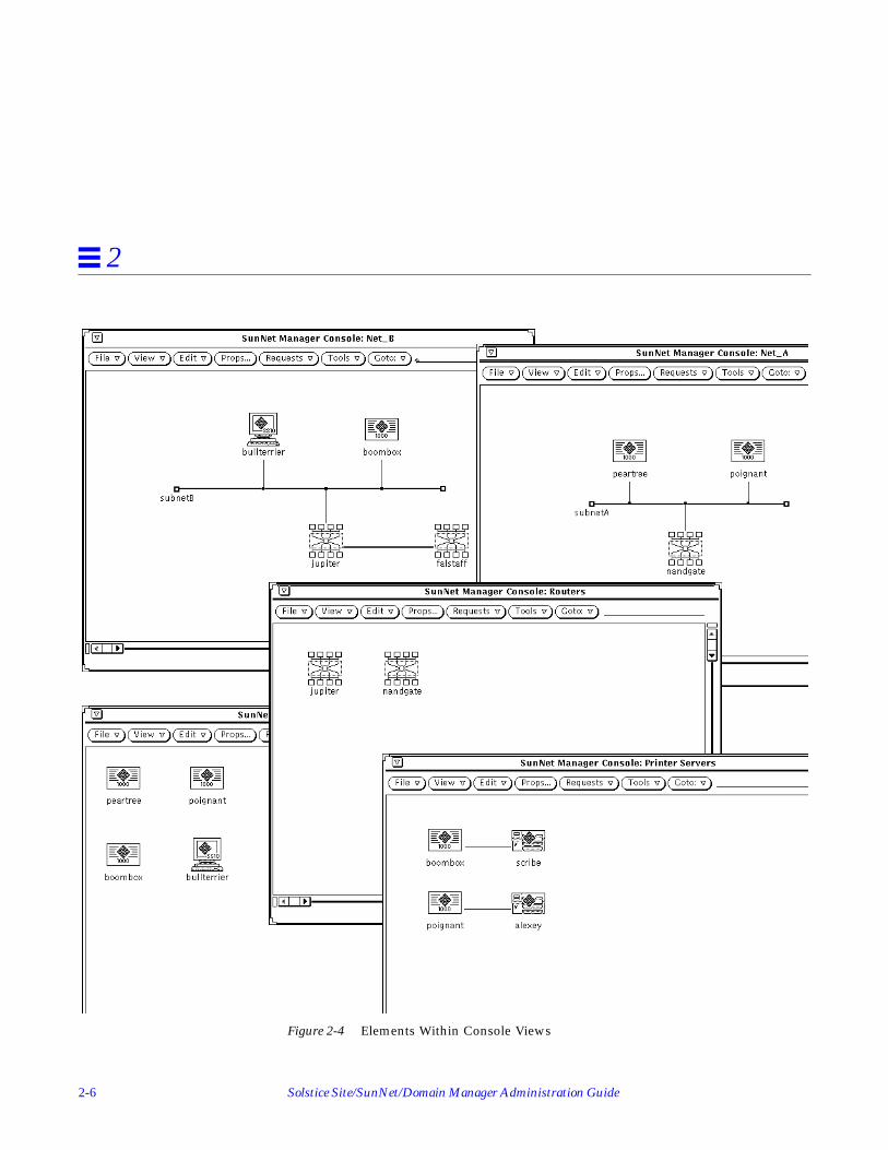
The cloud glyphs in Figure 2-3 represent the separate views into the LANand its subnetworks. Figure 2-4 shows the elements within these clouds. Thesame element can occur within multiple views. A software server, such aspoignant , can occur both in the Servers view and in the Net_B view, whichshows all nodes in a subnetwork.

Planning for Network Management 2-5
2
Figure 2-3 SunNet Manager Console Views
2-6 Solstice Site/SunNet/Domain Manager Administration Guide
2
Figure 2-4 Elements Within Console Views

Planning for Network Management 2-7
2
3. What type of information do we need to use this product effectively? SunNet Manager provides three types of information:
a. Event notificationYou want to be notified of critical events. The event request mechanismallows you to define conditions that generate an event notification. Afterit is specified, the event request is sent to the agent. The agent generatesan event whenever the specified condition becomes true.
If one of your critical nodes becomes unavailable to users, you will wantto know this immediately. This means you must specify frequent pollingintervals, such as every five minutes, in the appropriate event requests.
If you want to know the status of a certain device, for example, whethera router is currently down and whether it has been down at any timesince you last cleared an event, you want to choose Color By Priority asthe method for notifying you. You can then take advantage of the“decay” feature. When the specified event occurs, its glyph changes tothe priority color you have selected, then changes to blue, or the coloryou select, if the condition (e.g., unavailability) is no longer true.
Starting with this release of SunNet Manager, you are not limited toyellow, orange, red, and blue as the colors representing low, medium,high priority, and the decay state. You can customize colors to create onesthat you prefer. See Chapter 5, “Specifying Event Requests” or Chapter 4,“Requesting Data” for more information.
Also starting with the current release, you can put a glyph in pendingstate to avoid logging repeated events or traps against the device itrepresents. This is useful when a device has been down for an extendedtime. When pending state is turned off, the current status of the device isdisplayed. See Chapter 5, “Specifying Event Requests,” for moreinformation.
In addition to events generated by agents in response to event requests,there are also unsolicited events — called “traps” — generated by SimpleNetwork Management Protocol (SNMP) devices, such as routers. Forinformation on how to set up SunNet Manager to receive traps, refer toChapter 8, “Managing SNMP Devices.”
2-8 Solstice Site/SunNet/Domain Manager Administration Guide
2
b. Data reportingOver a period of time, statistical information can help you compare theperformance of your critical nodes, such as servers and gateways. Datareporting provides this information in addition to statistics on networktraffic levels at various times. Collecting data on resource utilization ratescan help you determine whether particular network resources are beingoverburdened.
In most cases, you will probably not want continual polling for data, asthis can add an additional burden to the network. If you periodicallyactivate data-gathering periodically, you can develop a historical recordto help you spot trends and determine “normal” load levels.
c. Topology informationYou also want information on changes to the network’s topology, such asthe addition of new devices and connections. IP Discover tool’s Monitorfunction searches the network to provide this information. You mightwant to limit these to weekly searches, since network configurationtypically changes slowly.
Starting with this release, you can use IPX Discover to search yournetwork for Novell Netware IPX nodes. See Chapter 23, “IPX Discover,”for more information.
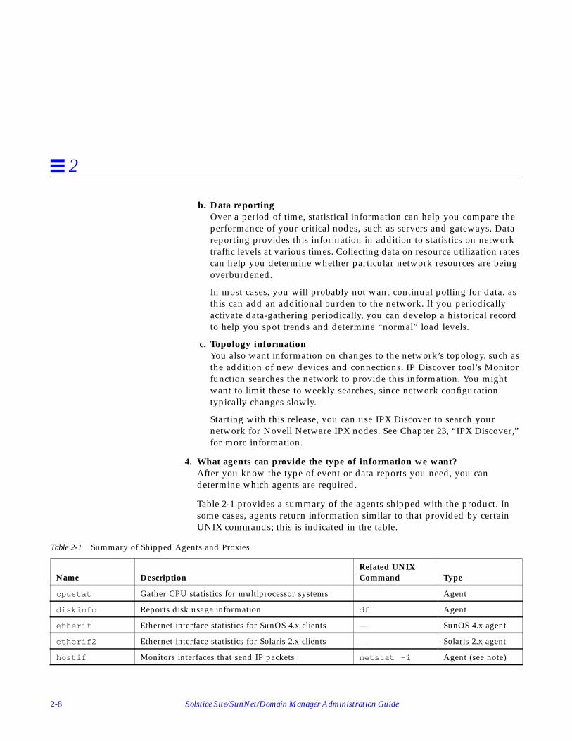
4. What agents can provide the type of information we want?After you know the type of event or data reports you need, you candetermine which agents are required.
Table 2-1 provides a summary of the agents shipped with the product. Insome cases, agents return information similar to that provided by certainUNIX commands; this is indicated in the table.
Table 2-1 Summary of Shipped Agents and Proxies
Name DescriptionRelated UNIXCommand Type
cpustat Gather CPU statistics for multiprocessor systems Agent
diskinfo Reports disk usage information df Agent
etherif Ethernet interface statistics for SunOS 4.x clients — SunOS 4.x agent
etherif2 Ethernet interface statistics for Solaris 2.x clients — Solaris 2.x agent
hostif Monitors interfaces that send IP packets netstat -i Agent (see note)

Planning for Network Management 2-9
2
After you have installed SunNet Manager, you can get specific informationabout each agent by consulting the man page for na. <agent-name>. Forexample:
hostmem Memory utilization information for SunOS 4.x clients netstat -m SunOS 4.x agent
hostmem2 Memory utilization information for Solaris 2.x clients netstat -m Solaris 2.x agent
hostperf Host system performance data rup andperfmeter
Proxy agent
iostat Input/output statistics for SunOS 4.x clients iostat SunOS 4.x agent
iostat2 Input/output statistics for Solaris 2.x clients iostat Solaris 2.x agent
ippath IP packet trace information — Proxy agent
iproutes IP route table and statistics netstat -r Agent
layers Protocol layer statistics for SunOS 4.x clients netstat -rsnetstat -s
SunOS 4.x agent
layers2 Protocol layer statistics for Solaris 2.x clients netstat -rs,netstat -s
Solaris 2.x agent
lpstat Printer status lpq and lpstat Proxy agent
ping IP connectivity information ping Proxy agent
rpcnfs Remote Procedure Call and Network File Systemstatistics
nfsstat Agent
snmp Information from MIB I-compliant SNMP devices. — Proxy agent
snmpv2 For managing SNMP Version 1 and Version 2 devices — Proxy agent
snmp-mibII Information from MIB II-compliant SNMP devices. — Proxy agent
sun-snmp MIB I-compliant and Sun-specific information fromSun workstations.
— Proxy agent
sync Synchronous serial lines monitoring syncstat Agent
traffic Ethernet traffic analyzer — Proxy Agent
hostname% man na.ping
Table 2-1 Summary of Shipped Agents and Proxies
Name DescriptionRelated UNIXCommand Type

2-10 Solstice Site/SunNet/Domain Manager Administration Guide
2
To have access to the man pages, make sure you have set your MANPATHenvironment variable, as described in your installation manual.
In the case of the na.snmp proxy agent, there are three schema files shippedwith SunNet Manager that can be used with it (snmp, snmp-mibII , andsun-snmp ). You can get information on the snmp and snmp-mibII schemafiles in the man pages for <agent-name>.schema . For example:
The sun-snmp.schema file supports the features of the Sun enterprise-specific SNMP agent, snmpd, for Sun workstations and servers. To accessinformation on this agent, enter the following command:
An efficient arrangement for proxy agents is to distribute them to collectinformation within separate domains or subnetworks. This reduces networktraffic between the management station and managed devices.
For example, to find out if a router is down in a remote subnet, themanagement station can send an event request to a ping proxy agent in thetarget subnet. The proxy agent responds if it detects that a router is notavailable. Regular polling of routers is limited to the subnet where the proxysystem is located.
For information on installing the SunNet Manager agents, refer to yourinstallation manual.
hostname% man snmp-mibII.schema
hostname% man snmpd

3-1
Creating and Modifying theManagement Database 3
This chapter discusses the following topics:
• Starting and quitting the Console
• Creating the initial runtime database
• Modifying the database when elements and agents are added, deleted, orchanged.
Use the Console to create a graphic representation of elements in a glyph. Thisgraphic representation of your network is reflected in the runtime managementdatabase, which holds all your network elements, possible element types, andpredefined requests.
Note – All command line examples in this Guide use the C-shell environment.If you use the Bourne or Korn shells, refer to the sh (1) or ksh (1) man pages,respectively, for compatibility information.
3.1 Adding SunNet Manager to Your PATH VariableUse the command line to start SunNet Manager. To do this, you could type thefull path name.

3-2 Solstice Site/SunNet/Domain Manager Administration Guide
3
For example, if SunNet Manager was installed on a Solaris 2.x machine in thedefault location, you could enter:
However, to avoid typing the complete path each time you start the Console,set the PATH environment variable in your.cshrc file (or .profile file ifyou use a Bourne or Korn shell) to point to the location of the executable files(the SunNet Manager Console, and tools). For a C-shell, enter the following inyour .cshrc file:
For Solaris 1.x:
For Solaris 2.x:
For a Bourne or Korn shell, consult the examples in your installation guide.Examples in the rest of this chapter assume that your PATH environmentvariable points to the appropriate location.
Note – If you installed SunNet Manager in a location other than the default(/usr/snm on Solaris 1.x machines, /opt/SUNWconn/snm on Solaris 2.x), youmust set the environment variable SNMHOME to the installation directory beforeinvoking the command to start SunNet Manager. See your installation guidefor instructions for setting this variable.
3.2 Starting the ConsoleIf no management database exists when you start the Console — which is thecase for first-time users—you receive a Quick Start window show in Figure 3-1.
host% /opt/SUNWconn/bin/snm &
setenv PATH ${PATH}:/usr/snm/bin
setenv PATH ${PATH}:/opt/SUNWconn/bin

Creating and Modifying the Management Database 3-3
3
Figure 3-1 Quick Start Window
If a database exists, you go directly to the SunNet Manager Console windowshown in Figure 3-2.

3-4 Solstice Site/SunNet/Domain Manager Administration Guide
3
Figure 3-2 Console Window
Note – You can use the -q option to suppress the Quick Start window.
3.2.1 Startup Commands• To start the Console when there is no database or to restart the Console with
the runtime management database from the last Console session (assumingno intervening reboot), enter
Appending an ampersand (&) to the command line puts the command in thebackground.
host% snm &

Creating and Modifying the Management Database 3-5
3
• To start the Console and initialize (in effect clearing) the runtime database,enter the command below. You receive the Quick Start window.
Caution – Use the -i option with care. If you have created a runtimemanagement database in a prior Console session, the -i option deletes thisdatabase.
• You can use the -i option in conjunction with the file name of an ASCIIdatabase file. For example:
This command deletes a runtime database, and loads the specified ASCIIdatabase file into the runtime database. The Quick Start window does notappear.
• A variation of the preceding command example is to specify an ASCIIdatabase, but not the -i option. The specified ASCII database file is mergedinto the runtime database. For example:
• The snm command has two additional command-line options, v1 and v2 .Use the v1 option if you are loading database files used with SNM 1.x. Usethe v2 option only if you are loading multiple database files, one or more,but not all, of which are for SunNet Manager version 1.x. The v2 optionallows you to distinguish those files that are not from version 1.x. Forexample:
host% snm -i &
host% snm -i /home/alex/snm/osaka.dbase &
host% snm /home/alex/snm/osaka.dbase &
host% snm -v1 /home/alex/snm/west.dbase -v2 /home/alex/snm/osaka.dbase
!

3-6 Solstice Site/SunNet/Domain Manager Administration Guide
3
3.2.2 Managing Duplicate Databases
Starting with version 2.3, if a database you specify has elements in commonwith a runtime database already present, you can either abort the database youare loading, ignore the duplicates and proceed with the load, or replace the olddatabase with the new one from the ASCII database. See Chapter 18,“Management Database,” for more information.
3.2.3 Disk Space Requirements
A minimum of 10-15 Mbytes of disk space should be available in the directorythat stores the runtime database. You can check the available disk space withthe following command:
• df -a (if you’re running Solaris 1.x)• df -k (if you’re running Solaris 2.x)

Creating and Modifying the Management Database 3-7
3
You specify the database location during installation of SunNet Manager or byusing the environment variable SNMDBDIR. If you have not specifiedSNMDBDIR, then the following directory is assumed:
• /var/adm/snm for Solaris 1.1.1• /var/opt/SUNWconn/snm for Solaris 2.4
The disk space required may vary according to the size of the network beingdiscovered. For example, a database that contains 647 components, 9 buses,and 11 views takes approximately 3.2 Mbytes of disk space. If your runtimedatabase grows very large, your file system can run out of space. This can be aproblem if the /var directory is in the root partition, which generally does nothave a large amount of free disk space. In this case, you can change thedirectory specified by the SNMDBDIR environment variable to point to anotherpartition with more free disk space.
Note – When the database directory is changed, the files under the current$SNMDBDIR should be moved to the new location to ensure smooth operation.
The new directory should be created with mode 777 so that the database filescan be written to the directory. When you run the IP Discover Tool, both you(as user) and root must be able to write to this directory—therefore, you shouldlocate the database on a local file system rather than an NFS-mounted filesystem. (NFS servers usually do not allow root users on remote machines tohave write permission.)
3.2.4 Quick Start Window
After invoking SunNet Manager with the -i option or with no command-linearguments when there is no database present, you receive a Quick Startwindow.
You can suppress the Quick Start window by using the -q option. This optionworks when you invoke snm with no other options or with the -i option.
The Quick Start window has the HeadStart and BasicStart options. TheProgress bar is dimmed. If you are a first-time user, HeadStart isrecommended.
Clicking SELECT on the buttons has the following effects:

3-8 Solstice Site/SunNet/Domain Manager Administration Guide
3
• The HeadStart button launches the SunNet Manager Console and discoversa few nodes (up to a maximum of ten) on the local subnetwork, so that youcan begin using SunNet Manager immediately.
• The BasicStart button skips the discovery of local nodes and directly invokesthe SunNet Manager Console window.
3.2.5 Console Window Characteristics
You can configure a number of Console window characteristics. For example,you can change text that appears in the title bar. For more information onchanges you can make, see “Part 2: Reference.”
You initiate most SunNet Manager activities through pull-down menusaccessed in the abbreviated menu buttons in the Console’s control area. Theeffect of a menu selection differs depending on whether or not you select aglyph in the Console window. In general, if you select a glyph, your menuchoice affects only the highlighted element. If no glyph is selected, your menuchoice either affects all elements or has no consequences for any singleelement.
3.3 Using IP Discover and IPX DiscoverThis section discusses the discover function of the IP Discover and IPXDiscover tools. You use these functions normally when you first bring up theConsole. More details on these tools is in Chapter 22, “IP Discover” andChapter 23, “IPX Discover.”
3.3.1 Using IP Discover
The IP Discover tool, invoked from the Tools menu in the Console window orfrom a command line, finds networks, subnetworks, routers, and hosts. Bydefault, IP Discover limits search to the local subnetwork to which yourSunNet Manager machine’s Console is attached.
The IP Discover tool has two functions:
• IP Discover, which finds hosts, routers, networks, subnetworks, and SimpleNetwork Management Protocol (SNMP) devices reachable from the Consolemachine. IP Discover stores a record in the runtime database for eachelement it finds.
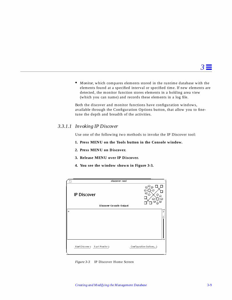
Creating and Modifying the Management Database 3-9
3
• Monitor, which compares elements stored in the runtime database with theelements found at a specified interval or specified time. If new elements aredetected, the monitor function stores elements in a holding area view(which you can name) and records these elements in a log file.
Both the discover and monitor functions have configuration windows,available through the Configuration Options button, that allow you to fine-tune the depth and breadth of the activities.
3.3.1.1 Invoking IP Discover
Use one of the following two methods to invoke the IP Discover tool:
1. Press MENU on the Tools button in the Console window.
2. Press MENU on Discover.
3. Release MENU over IP Discover.
4. You see the window shown in Figure 3-3.
Figure 3-3 IP Discover Home Screen

3-10 Solstice Site/SunNet/Domain Manager Administration Guide
3
5. Click SELECT on Start Discover to start the IP Discover function.The Start IP Discover button changes to Stop IP Discover. The IP Discoverfunction continues to run, within the boundaries you have configured inyour local subnetwork until it finds all elements within the subnetwork
6. Click SELECT on Stop Discover.From the SunOS command line, if you have the path to the SunNet Managerexecutables in your PATH variable, invoke snm_discover. For example, torun IP Discover and invoke the user interface, enter:
The path to snm_discover is:
• /usr/snm/bin on SunOS 4.x• /opt/SUNWconn/snm/bin on Solaris 2.x
You can start IP Discover directly, bypassing the initial Home window if youuse the snm_discover command without the -T option.
3.3.1.2 IP Discover Views Beyond the Local Subnetwork
IP Discover reports progress in the IP Discover Console Output window andadds elements to the current view in the SunNet Manager Console window.Simultaneously, it adds these elements to the runtime database.
Running IP Discover with the Default option will find network elements in thesubnetwork to which the Console system is attached. If you enable IP Discoverto reach beyond your local subnetwork, it constructs a hierarchy of views. SeeChapter 22, “IP Discover,” for more information. The Home view is the toplevel in the hierarchy of your management domain views.
1. Double-click the SELECT button on each network/subnetwork glyph todisplay the elements, usually hosts and routers, contained in each of theseviews.The console output section of the IP Discover window displays informationabout the program’s progress.
You can display logical groupings of elements, such as routers in yourmanagement domain, or all the SNMP devices in a particular subnet.
hostname# snm_discover -T

Creating and Modifying the Management Database 3-11
3
2. Click SELECT on the Configuration Options button to display theProperties sheet.
Figure 3-4 shows the Properties sheet. For a description of fields, seeChapter 22, “IP Discover.”
Figure 3-4 IP Discover Properties Sheet
3.4 Using IPX DiscoverStarting with version 2.3 of SunNet Manager, you can use IPX Discover todiscover IPX Netware nodes and networks. See “Part 2: Reference” for detailedinformation on IPX Discover functionality.

3-12 Solstice Site/SunNet/Domain Manager Administration Guide
3
3.5 Netware Management System Export/Import AgentIPX Discovers and models IPX networks by communicating with a topologyexport/import agent (NXIS) located on the Novell Management platform(Managewise). NXIS exports topology data discovered by Managewise;Managewise need not be running during this process.
IPX Discover has scheduling capability and can be configured to periodicallypoll the NXIS agent for changes to the network.
Refer to the IPX Discover man page for command syntax.
3.6 Invoking IPX DiscoverTo invoke IPX Discover, follow the steps below
1. Click SELECT on the Tools Menu➤Discover➤IPX Discover to see thescreen in Figure 3-5.
Figure 3-5 IPX Discover Home Screen

Creating and Modifying the Management Database 3-13
3
2. Click SELECT on Configuration to see the Properties sheet in Figure 3-6.
Figure 3-6 IPX Discover Properties Sheet
3.6.1 IPX Discover Options
From this point, you can use IPX Discover any of the following four ways:
A. Perform a load to export a database from the Export Services Agent withoutusing the scheduler.
B. Perform a load using the scheduler without specifying time period to exportthe database.
3-14 Solstice Site/SunNet/Domain Manager Administration Guide
3
C. Perform an update using the scheduler and specifying how often to reportchanges that have occurred on the Novell network.
D. Perform multiple loads and updates from multiple Export Services Agents.
Steps for each of these options are provided below.
A. Load without using the scheduler:
1. On the IPX Discover Properties sheet, enter the Server Name of theNovell export agent.
2. Enter the password for the Novell export agent.
3. Enter the IP address of the console on which the export agent resides.
4. Click SELECT on Add➤Apply.
5. On the IPX Discover Home screen, click SELECT on Discover.
B. Load using the scheduler without specifying period time:
1. On the IPX Discover Properties sheet, enter the Server Name of theNovell export agent.
2. Enter the password for the Novell export agent.
3. Enter the IP address of the console on which the export agent resides.
4. Click SELECT on Add.
5. Click SELECT on Schedule Discover.
6. Enter Start and Stop Dates in the appropriate date format.
7. Click SELECT on Start Time and Stop Time, and choose the desired times.
8. Click SELECT on am or pm button.
9. Click SELECT on Add➤Apply.
10. On the IPX Discover Home screen, click SELECT on Discover.
C. Update using the scheduler and specifying period time:
1. On the IPX Discover Properties sheet, enter the Server Name of theNovell export agent.

Creating and Modifying the Management Database 3-15
3
2. Enter the password for the Novell export agent.
3. Enter the IP address of the console on which the export agent resides.
4. Click SELECT on Add.
5. Click SELECT on Schedule Discover.
6. Enter Start and Stop Dates in the appropriate date format.
7. Click SELECT on Start Time and Stop Time, and click on the desiredtimes.
8. Click SELECT on am or pm button.
9. Click SELECT on Period Time button, and click on the desired time.
10. Click SELECT on am or pm button.
11. Click SELECT on Add➤Apply.
12. On the IPX Discover Home screen, click SELECT on Discover.
D. Perform multiple loads and updates with multiple export agents:
1. On the IPX Discover Properties sheet, enter the Server Name of the firstNovell export agent.
2. Enter the password for the Novell export agent.
3. Enter the IP address of the console on which the export agent resides.
4. Click SELECT on Add.
5. For each additional export agent, follow steps 1 - 3.
6. Click SELECT on Schedule Discover.
7. Enter Start and Stop Dates in the appropriate date format.
8. Click SELECT on Start Time and Stop Time, and click on the desiredtimes.
9. Click SELECT on am or pm button.
10. Click SELECT on Period Time button, and click on the desired time.
11. Click SELECT on am or pm button.
3-16 Solstice Site/SunNet/Domain Manager Administration Guide
3
12. Click SELECT on Add➤Apply.
13. On the IPX Discover Home screen, click SELECT on Discover.
3.6.2 Change, Remove, and Reset Options
To change the configuration of an IPX Discover, enter new information in theappropriate fields and click SELECT on Change➤Apply➤Start Discover.
To remove a configuration from the Export Agent Services list, use the mouseto highlight you choice, then click SELECT on the Remove button.
To reset your configuration if you have not clicked on the Add button, clickSELECT on the Reset button. All fields become blank. If you have clicked on theAdd button, click SELECT on the Change button.
3.7 Traversing the View HierarchyWhenever you start the Console, the Home view is displayed. Elements thatare views can contain other elements, including other views. Other types ofelements, such as components, can also contain other elements. The Consolekeeps track of up to 16 different views or elements as they are displayed. Youcan traverse through the Console view hierarchy in several ways.
1. If the element is a view, double-click SELECT over the glyph thatrepresents the element to display the elements contained in the view.
2. To return to any of the views that have already been displayed, pressMENU on the Goto button and release MENU over the name of the viewyou want to display, as indicated in Figure 3-7.

Creating and Modifying the Management Database 3-17
3
Figure 3-7 Selecting a View Name in the Goto Menu
3. To return to the last view that was displayed, click SELECT on the Gotobutton. The default is the first item on the menu, Home, in this case
3.7.0.1 Selecting an Element or View by Name• If you know the name of an element in a view, you can use the Find option
in the View menu to display the view(s) that contain the particular element.See the Section on “Finding Elements” later in this Chapter.
• If you know the name of the view you want to see, type in the view nameon the line next to the Goto button and press Return. If the view name youspecify is not part of the runtime database, the Console displays a message“View name <view_name> does not exist” in the Console window footer areaand leaves you in the current view.
3.7.1 Returning to the Home View
1. Press MENU on the Goto button; choose the Home option.
a. Or, type “Home” in the Goto line and click SELECT on the Gotobutton.
You can enter a name here
You can enter a name here

3-18 Solstice Site/SunNet/Domain Manager Administration Guide
3
If you often find it necessary to return to the Home view, you could have theHome view displayed whenever you click SELECT on the Goto button. Thischange is made in the Console Properties window Miscellaneous category.Refer to “Part 2: Reference” for more information.
3.8 Creating Elements Using the EditorThis section describes the Console’s graphical editor function, accessiblethrough the Edit➤Create button. This function limits you to creating elementsone-at-a-time. Use IP Discover as a more convenient way to create elements inlarge networks.
You can create new elements of different types to represent particular views,networks, devices, and other components in your network. Elements arerepresented by glyphs, a type of icon, which appear in one or more views. Tocreate new elements follow the steps below:
1. In the Console’s control area, press MENU on the Edit button.
2. Release MENU over the Create item. (Alternatively, you can press MENUover an empty space in the view to obtain a floating popup menu. Youreceive the window shown in Figure 3-8.
Figure 3-8 Create Object Window
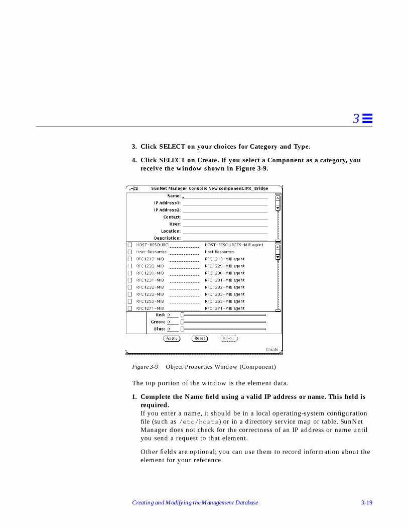
Creating and Modifying the Management Database 3-19
3
3. Click SELECT on your choices for Category and Type.
4. Click SELECT on Create. If you select a Component as a category, youreceive the window shown in Figure 3-9.
Figure 3-9 Object Properties Window (Component)
The top portion of the window is the element data.
1. Complete the Name field using a valid IP address or name. This field isrequired.If you enter a name, it should be in a local operating-system configurationfile (such as /etc/hosts ) or in a directory service map or table. SunNetManager does not check for the correctness of an IP address or name untilyou send a request to that element.
Other fields are optional; you can use them to record information about theelement for your reference.

3-20 Solstice Site/SunNet/Domain Manager Administration Guide
3
The middle portion of the new-element window is the list of agent schema filesthat the Console knows about. This and the bottom portion are the same forall categories of elements as shown in Figure 3-9.
In the middle portion, click SELECT on the box to the left of a listed schema totoggle a check mark—this specifies that the element can be managed with thisschema. Check all schemas that apply to the element. The line to the right ofsome schema names indicates that a proxy system can be defined. If you do notdefine a proxy system, the default proxy system will be the system on whichyou are running the Console.
Note – Checking a schema does not make the element manageable from theConsole; the appropriate agent software must be installed and running on thetarget system. See your installation guide for instructions on running thegetagents script to install agents. The exceptions to this are the hostperfand ping proxy agents. On most Sun and those of many other vendors on aTCP/IP network, you can check off the hostperf and ping agents and usethe Console machine (localhost) as the proxy.
The bottom portion of the Properties window allows you to specify a color forthe glyph associated with the element.
When you finish entering data and making selections in the new-elementwindow, click SELECT on Apply. A glyph for the element you just definedappears in the current view with the name you specified.
Figure 3-10 shows the data portion of the Object Properties windows for theremaining element categories: view, connection, and bus.
!

Creating and Modifying the Management Database 3-21
3
Figure 3-10 Top Portions of Object Properties Windows
3.8.0.1 Glyphs for Multiple Element Types
The glyphs in Table 3-1 are used for more than one type of element.
Data portion of ObjectProperties Window for anew view
Data portion of ObjectProperties window for anew connection
Data portion ofObject PropertiesWindow for a newbus

3-22 Solstice Site/SunNet/Domain Manager Administration Guide
3
Table 3-1 Glyphs Used for Multiple Element Types
Glyph Element Category Element Type
Component ss330ss370sun-deskside
Component sun-serversun470
Connection linkrs232
Component IPX-Latern DeviceIPX-PCUnixware
Component IPX-BridgeIPX-RouterNetware Router
Component IPX Print ServerIPX Printer
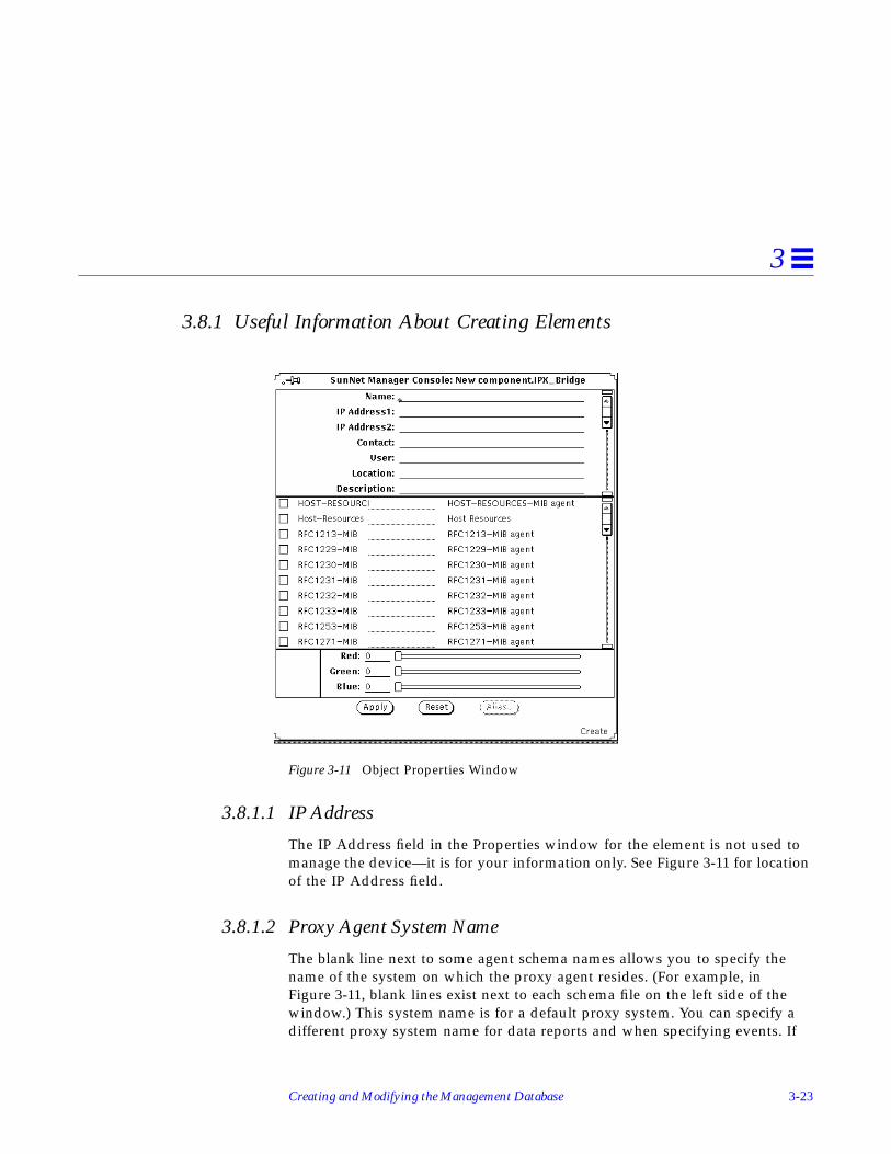
Creating and Modifying the Management Database 3-23
3
3.8.1 Useful Information About Creating Elements
Figure 3-11 Object Properties Window
3.8.1.1 IP Address
The IP Address field in the Properties window for the element is not used tomanage the device—it is for your information only. See Figure 3-11 for locationof the IP Address field.
3.8.1.2 Proxy Agent System Name
The blank line next to some agent schema names allows you to specify thename of the system on which the proxy agent resides. (For example, inFigure 3-11, blank lines exist next to each schema file on the left side of thewindow.) This system name is for a default proxy system. You can specify adifferent proxy system name for data reports and when specifying events. If

3-24 Solstice Site/SunNet/Domain Manager Administration Guide
3
you do not specify a proxy system in the Properties window or in the reportrequest, the system on which the Console is running is assumed to be wherethe proxy agent resides.
3.8.1.3 Creating Elements Within Elements
You can create an element that logically contains other elements. For example,if managing all the file servers in your management domain is important, youmight want to create a view called File Servers. To do so, perform the followingsteps:
1. Create an element of category View, as described previously.
2. Double-click SELECT on the new glyph.
3. In the empty view, create the element instance for each device. If theelement instance definition already exists, copy the glyph into the view.(See the Section on “Copying Elements” later in this chapter.)
3.8.1.4 Changing Label Fonts
You can change the font used for the labels under element glyphs. This is donein the Console Properties window. (If you change the font, you must restart theConsole for the change to take effect.) See the description of the Icon Fontsetting in “Part 2: Reference.”
3.9 Creating AliasesSunNet Manager has an alias feature that allows you assign multiple names toan element. This feature is useful with machines that have multiple networkinterfaces (usually routers). You can use an alias in the same way that you useelement names. That is, you can search on an alias or send requests that specifyan alias.
If you use unique names for each interface, the Discover tool fills in aliasesautomatically when it creates a router. The first name it finds is the one filled inas the name of the element and the names of subsequently-found networkinterfaces as aliases.
To add one or more aliases for an element, do the following:

Creating and Modifying the Management Database 3-25
3
1. Press MENU over the glyph to which you want to add aliases.You can also click SELECT on the glyph to highlight it, then press MENUover the glyph. You receive the Properties window for that element.
2. In the Properties window, click SELECT on the Alias button.You receive the window shown in Figure 3-12.
Figure 3-12 Alias Window
3. Enter a name and click SELECT on Add.The name you entered appears in the Aliases List.
To change or delete an alias:
1. Click SELECT on the alias in the Aliases List
2. Click SELECT on Change or Delete.
The same rules apply to aliases as to element names, as specified in thesubsection on “Creating Elements” later in this chapter. You can use an IPaddress or a name.
The Properties window for a router has two IP address fields as shown inFigure 3-13.

3-26 Solstice Site/SunNet/Domain Manager Administration Guide
3
Figure 3-13 Properties Window for Router
You are not, however, limited to managing the two interfaces identified in theIP Address fields. The alias feature allows you to add a name for each interfaceon a machine. Note that the IP Discover tool does this automatically.
3.10 Finding ElementsThe Find option of the View menu displays the view(s) in which a specifiedelement is located.
1. In the Console window, invoke View➤Find.
First two IPInterfaces

Creating and Modifying the Management Database 3-27
3
Figure 3-14 Selecting the View—Find Menu Item
2. In the Find window, enter the name of the element you want to find.
3. Click SELECT on the Find button in the window or press Return.The element is highlighted when found.
4. Click SELECT on the Next button to see the next view (if any) in whichthe element is located.
Use the Find function key on the left side of your keyboard to search on any ofthe names (aliases) associated with an element.
3.11 Modifying Element PropertiesYou can modify the following properties of an element instance in theelement’s Properties sheet:
• Agent schemas that apply to the element• Element color• Optional fields information

3-28 Solstice Site/SunNet/Domain Manager Administration Guide
3
“Part 2: Reference” describes the fields in the Properties window. Note thatyou cannot modify the name of an element instance once it has been created.
To rename an element instance, you must delete and re-create it with the newname using the following steps:
1. Over the glyph that represents the element, press MENU. Or, clickSELECT on the glyph and press the Props button on the left side of yourkeyboard.
2. Release MENU over Properties to open the Properties window for theelement.
Figure 3-15 Selecting the Glyph—Properties Menu Item
3. Modify the fields within the Properties window for the element. ClickSELECT on the Apply button to incorporate the changes to the element.
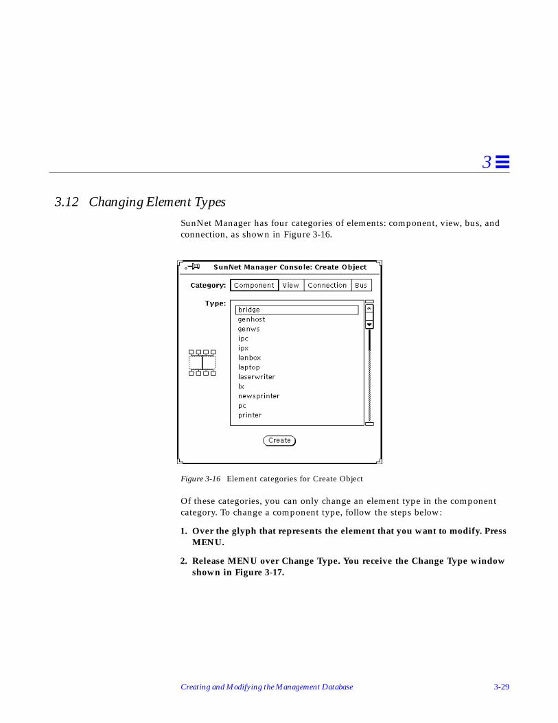
Creating and Modifying the Management Database 3-29
3
3.12 Changing Element TypesSunNet Manager has four categories of elements: component, view, bus, andconnection, as shown in Figure 3-16.
Figure 3-16 Element categories for Create Object
Of these categories, you can only change an element type in the componentcategory. To change a component type, follow the steps below:
1. Over the glyph that represents the element that you want to modify. PressMENU.
2. Release MENU over Change Type. You receive the Change Type windowshown in Figure 3-17.

3-30 Solstice Site/SunNet/Domain Manager Administration Guide
3
Figure 3-17 Change Type Window
3. Click SELECT on the new element type; click SELECT on Change.The Change Type window disappears and the changed element appears inthe Console window represented by a new glyph.
3.12.1 Restrictions on Changing Element Types
You can change element types for components, such as workstations, servers,printers. These types are displayed in the Type menu in the Change Typewindow, such as the one shown in Figure 3-17. You cannot change elements ofcategory view, bus, or connection.

Creating and Modifying the Management Database 3-31
3
3.12.1.1 Elements on Different Machines
As the Discover tool finds network elements, it distinguishes among machinesrunning SunNet Manager agents, SNMP devices, routers, and networks andsubnetworks. (You can restrict the search to one or any combination of thesetypes of objects.) The first three object types are in the component category ofelements. The last, networks and subnetworks, are in the view category andcannot be changed.
3.13 Moving Elements within a ViewYou can move elements within a view as described in the following steps:
1. Over the glyph that represents the element to be moved, press SELECT. Ifyou wish to move multiple elements at the same time, click ADJUST onsubsequent glyphs.
2. Drag the mouse pointer to the desired new location and release.Figure 3-18 shows moving a glyph.
Figure 3-18 Moving a Glyph to a New Location
3.14 Moving Elements from One View to AnotherYou can move elements between views using the steps below:

3-32 Solstice Site/SunNet/Domain Manager Administration Guide
3
1. Over the glyph that represents the element to be moved, click SELECT.To move multiple elements at the same time, click ADJUST on subsequentglyphs.
2. In the control area of the Console window, invoke Edit➤Cut.Or, press MENU over an empty space in the view to open the Edit menuas a floating popup menu.
3. Release MENU over Cut.
4. Use the Goto button in the Console’s control area to switch to the viewwhere the glyph(s) will be moved.See “Traversing the View Hierarchy” earlier in this Chapter for moreinformation.
5. In the Console’s control area, invoke Edit➤Paste.
3.14.1 Useful Tips
1. You can use the Cut and Paste function keys on the left side of yourkeyboard instead of Edit menu functions.
2. When you cut or copy an element or set of elements, the element(s) is storedin the clipboard. To view the contents of the clipboard in the Consolewindow, press MENU on View➤Clipboard and release MENU.
3. You cannot cut an element with an associated request, nor delete an elementthat contains another element in its subview.
3.15 Connecting ElementsYou can draw a connection from a selected (highlighted) element to theelement glyph where the mouse pointer is located.
1. Click SELECT over one of the elements (the element to connect from).
2. Press MENU over the other element (the element to connect to).
3. Release MENU over Connect.Figure 3-19 shows a connect example.
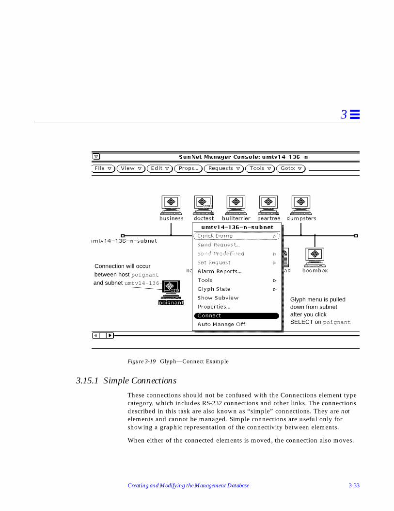
Creating and Modifying the Management Database 3-33
3
Figure 3-19 Glyph—Connect Example
3.15.1 Simple Connections
These connections should not be confused with the Connections element typecategory, which includes RS-232 connections and other links. The connectionsdescribed in this task are also known as “simple” connections. They are notelements and cannot be managed. Simple connections are useful only forshowing a graphic representation of the connectivity between elements.
When either of the connected elements is moved, the connection also moves.
Connection will occur
Glyph menu is pulleddown from subnetafter you clickSELECT on poignant
and subnet umtv14-136-n
between host poignant

3-34 Solstice Site/SunNet/Domain Manager Administration Guide
3
The color of the connection is based on the color of the second, “connected to”element. Whenever you select (highlight) this element, the connection is alsohighlighted.
3.16 Copying ElementsAfter you have created an element, you can create many instances of thatelement in various views in your database. To do this, copy the element fromone view to another as explained below.
1. Click SELECT on the glyph that represents the element to be copied tohighlight it.If you wish to copy multiple elements in a view at the same time, clickADJUST on subsequent glyphs.
2. In the control area of the Console window, invoke Edit➤Copy. Or, pressMENU over an empty space in the view

Creating and Modifying the Management Database 3-35
3
Figure 3-20 Selecting the Edit—Copy Menu Item
3. Use the Goto menu to move to the view to which the element will becopied.
4. Invoke Edit➤Paste (from the Edit button or from a floating popup menuin an empty space in the new view).
When you cut or copy an element or set of elements, the element(s) is stored inthe clipboard. To view the contents of the clipboard in the Console window,press MENU on View➤Clipboard and release MENU.
Edit menu is also available by pressing MENUin Console background area

3-36 Solstice Site/SunNet/Domain Manager Administration Guide
3
3.16.0.1 Using Function Keys for Copy and Paste
You can use the Copy and Paste function keys on the left side of your keyboardinstead of the Edit menu functions. The Copy function copies the element intothe Console clipboard. After an element has been copied into the clipboard, itcan be pasted into as many views as needed.
3.16.0.2 Drag and Drop
If an element and the view into which it will be copied are both displayed inthe same view, you can use the Console’s “drag and drop” function:
1. Press SELECT over the glyph that represents the element to be copied.
2. While still pressing the SELECT mouse button, drag the mouse pointer tothe glyph that represents the view to which the element will be copied.Release the mouse button.
3.17 Deleting ElementsYou can delete an element instance from a view using the steps below:
1. Click SELECT over the glyph to be deleted. If you wish to delete multipleelements at the same time, click ADJUST on subsequent glyphs.
2. In the Console’s control area, invoke Edit➤Delete.Or, press MENU overan empty space in the view.

Creating and Modifying the Management Database 3-37
3
Figure 3-21 Selecting the Edit—Delete Menu Item
3.17.1 Useful Notes About Delete
You cannot delete an element that has a request associated with it. You alsocannot delete an element that contains another element in its subview.
Delete removes the element from the view and from the database. The elementis not placed in the clipboard, so you cannot paste a deleted element.
3.18 Saving the Management DatabaseThe runtime database contains element and request instances that you havecreated. You can save the database to an ASCII file, allowing you to reinvokethe Console with the same database. Follow the steps below:
1. In the Console window, press MENU on File➤Save➤ManagementDatabase and release MENU.

3-38 Solstice Site/SunNet/Domain Manager Administration Guide
3
Figure 3-22 Selecting the File➤Save➤Management Database Menu Item
2. In the Save pop-up window, enter the directory and file name for thedatabase.
3. Click SELECT on the Save button to store the database.
After you invoke File➤Save➤Management Database, SunNet Manager takes asnapshot of the current database and stores it in a single ASCII file. Thestructure of this stored database—a single file—is entirely different from thestructure of the runtime database. The runtime database consists of a set ofspecial database files under a directory name having the following form:
• /var/adm/snm (or $SNM_HOME)/db. <login> (or db. <$SNM_NAME>) forSolaris 1.1.1
• /var/opt/SUNWconn/snm (or $SNM_HOME)/db. <login> (ordb. <$SNM_NAME>) for Solaris 2.x
3.18.0.1 Don’t Store Under /Var
It is recommended that you not store the ASCII files under /var because/var is for files that grow and because a saved ASCII database is static andpossibly large.
When restarting the Console, you can specify whether to continue to use theruntime database from the previous run of the Console, or to reinitialize thedatabase from ASCII structure and instance files. See the section “Starting theConsole” in this Chapter for instructions for reinitializing the database.

Creating and Modifying the Management Database 3-39
3
3.19 Quitting the ConsoleYou quit a Console session by using the Quit option of the Console’s windowmenu.
1. In the title bar of the Console window, press MENU and release MENUover Quit.
2. If there are any active requests, you see the pop-up verification window inFigure 3-23.
Figure 3-23 Console Quit Window
Click SELECT on one of the following:
• Quit, to have the Console kill all active requests before stopping.• View Requests, to display the Request Viewer window.• Resume, to continue running the Console.
When you quit a Console session, the verification window is displayed bydefault if there are any active requests. You can choose to have the verificationwindow always displayed or never displayed—this is specified in the ConsoleProperties window, under the Miscellaneous category. See the description ofthe Verify Quit setting in “Part 2: Reference.”
3-40 Solstice Site/SunNet/Domain Manager Administration Guide
3

4-1
Requesting Data 4
This chapter discusses the following topics:
• Making a one-time request for data
• Requesting periodic data
• Copying requests
• Viewing incoming data
• Analyzing stored data
• Modifying the display of a graph
• Printing a graph
You can request that an agent return values for some or all attributes in a singleagent group. Your request can either be for a single, quick snapshot of all thevalues in the agent group, or it can be a request for periodic reporting of one ormore attribute values. For the latter type of requests, you can specify reportcharacteristics such as:
• Number of reports from the agent
• Interval between reports
• Whether the reports should be stored in a file
• Whether the attribute values reported should be displayed graphically
This chapter describes how to request data reports from agents and how toview or analyze the returned data.

4-2 Solstice Site/SunNet/Domain Manager Administration Guide
4
4.1 Making a One-Time Request for DataA Quick Dump retrieves all the values in an attribute group for a targetsystem. You can initiate a Quick Dump request in one of two ways.
4.1.1 Quick Dump using the Console Requests Menu
1. Click SELECT over the glyph that represents the target element.
2. Press MENU on the Requests button in the SNM Console.
3. Release MENU over Quick Dump to receive a Request Builder windowsuch as the one shown in Figure 4-1.
Figure 4-1 Requests Menu—Quick Dump Request

Requesting Data 4-3
4
4. In the Request Builder window, click SELECT on the Agent Schema, thenon the Group you want for that schema. Click SELECT on Apply to sendthe request. You receive a Quick Dump Report window, as shown inFigure 4-3.
4.1.2 Quick Dump Through the Glyph Menu
1. Press MENU over the glyph that represents the target element.
2. Press MENU over Quick Dump and drag to the right over the desiredagent name and attribute group name as shown in Figure 4-2.
Figure 4-2 Glyph Menu—Quick Dump Request
Releasing MENU on the attribute group name starts the Quick Dumprequest. You receive a Quick Dump Report window, as shown in Figure 4-3.

4-4 Solstice Site/SunNet/Domain Manager Administration Guide
4
Figure 4-3 Quick Dump Report Window
4.1.3 Useful Notes About the Quick Dump Window
Starting with version 2.3, a popup window is displayed and filled withinformation as it is gathered from the appropriate managed devices.
Table attributes are displayed in tabular form when possible and the QuickDump window is automatically stretched if necessary.
Data returned in the Quick Dump window is not stored and is not displayed inthe Data Reports window.
Starting with the current product, the pop-up window appears as soon as thequick dump request is submitted. Results of the request display when they arereturned from the agent. If an error occurs, the message “cannot start request<request name> displays in the pop-up window. The text of the error can bedisplayed through the View➤Error Reports window.

Requesting Data 4-5
4
4.1.3.1 Quick Dump Information from Set Tool
The Get operation of the Set Tool returns the same information for SNMPdevices as the Quick Dump. The Set Tool is described in “Part 2: Reference.”
4.2 Making a Request for Periodic DataA data request causes an agent to automatically report the values of specifiedattributes for a target system at specified intervals. You can compose your ownrequest, targeting a specific machine for a specific set of information. Moreconveniently, you can use one of the predefined requests. These requests saveyou the trouble of composing requests for individual machines.
4.3 Prioritizing RequestsStarting with the current version of SunNet Manager, you can prioritize datarequests by specifying:
• Start time• Start date• Stop time• Stop date
This is useful, for example, if you want a request to begin when no one will beavailable to initiate it, or when network traffic is at a minimum. The default isto start immediately and run indefinitely. If you enter a Stop time, it takesprecedence over any count value that has been specified. A count value of 0means “run indefinitely.” If a count value is reached before Stop time, therequest would stop. To initiate the prioritizing process:

4-6 Solstice Site/SunNet/Domain Manager Administration Guide
4
1. Define your request in the Request Builder window, then click SELECTon Apply. You receive the screen shown in Figure 4-4.
Figure 4-4 Request Schedule Menu
2. Follow the prompts on the Request Builder Menu to specify start and stopfor date and time.
4.3.1 Sending a Data Request Through the Console Requests Menu
1. Move the mouse pointer over the glyph that represents the target element,and click SELECT.
2. Press MENU on the Requests button, and release MENU over SendRequest.You will receive the window in Figure 4-5. The Request Action field isautomatically set to Send Request.

Requesting Data 4-7
4
Figure 4-5 Sample Request Builder Window
3. Click SELECT on the Request Type you want to send (Data, in thisexample).
4. Press MENU on the Request Name abbreviated menu button. You receivethe menu shown in Figure 4-6.

4-8 Solstice Site/SunNet/Domain Manager Administration Guide
4
Figure 4-6 Request Name Menu
5. Choose a request from the Request Name menu.
6. After choosing either NEW_REQUEST or a predefined request name fromthe Request Name menu, click SELECT on the Apply button. You receivea Data Request Properties window as shown in Figure 4-7.

Requesting Data 4-9
4
4.3.2 Creating Your Own Request
There can be times when you want to create your own request. You canaccomplish this using the following steps:
1. Click SELECT on an agent in the Agent Schema scrolling list.
2. Click SELECT on a group name in the Group scrolling list.
b. Choose NEW_REQUEST from the Request Name pull-down menu.
3. After choosing either NEW_REQUEST or a predefined request name fromthe Request Name menu, click SELECT on the Apply button. You receivea Data Request Properties window as shown in Figure 4-7.
4. Examine the Request Properties window and make any changes you want.Many predefined requests will require little or no modification.

4-10 Solstice Site/SunNet/Domain Manager Administration Guide
4
Figure 4-7 Sample Data Request Properties Sheet
The example above shows the predefined data request “Graph HostPerformance.”
5. On the left side of the request window, modify or fill in the reportcharacteristics fields.
See the Section below on “Scheduling Requests” for more information.
6. On the right side of the request window, select (or accept) the attributeson which you want the agent to send data, and how you want to view thedata.
7. Press MENU on the Attribute menu button and release MENU over theattribute you want.

Requesting Data 4-11
4
8. Click SELECT on Apply to add the attribute to your request. For adescription of the fields in the Data Request template, refer to “Part 2:Reference.”
9. Click SELECT on the Start button to send the data request to the agent.
4.3.3 Sending a Data Request Using the Glyph Menu
1. Move the mouse cursor over the glyph and pull down the Glyph menu.
2. In the Glyph menu, release MENU over Send Request. You then receive aRequest Builder window, from which you can use a predefined request orcreate your own request.
4.3.4 Sending a Predefined Data Request Through the Glyph Menu
SunNet Manager is shipped with a number of predefined data requests. Usethese as a convenient way to request routine data reports. To send such arequest using the Glyph menu, follow the steps below:
1. Move the mouse pointer over the glyph for the element to which youwant to send the request.
2. Press MENU at Send Predefined.
3. Move the mouse pointer to the right over Data Request and continue topull right to obtain the menu of predefined data requests shown inFigure 4-8.

4-12 Solstice Site/SunNet/Domain Manager Administration Guide
4
Figure 4-8 Predefined Data Request
4. Release MENU over the predefined request you want.You receive no Properties window for the request; the request is sentimmediately following your menu selection.
To view the properties associated with a predefined request:
1. Click SELECT on the glyph to which you are sending a request.
2. Invoke Requests➤Send Request.
3. In the Request Builder window, choose the name of the predefinedrequest you want from the Request Name menu.
This list will vary depending on theagents installed on target machine

Requesting Data 4-13
4
4. Click SELECT on Apply. You receive the Properties window for thatpredefined request.
Alternative ways to view the properties of a request:
• Double-click on the glyph for the target of your request.
• Click SELECT on the glyph for the request.
• Click SELECT on the Props button in the Console’s control area.
• Invoke Requests➤Requests Summary.
• Find and click SELECT on your request.
• Click SELECT on the Props button in the Requests Summary window.
• Use the Select and Sort menus to find your request.
See “Viewing and Modifying Properties of a Request” on page 4-35 for moreinformation.
For further background on predefined requests, see “Part 2: Reference.”
4.3.5 Predefined Requests Depend on Agents Present
Predefined requests (and the agents listed in the Agent Schema list in aRequest Builder window) for a given machine depend on the agents that havebeen checked off as present in the properties window for that machine.
A machine the Discover tool adds to your database which does not haveSunNet Manager agents on it, has the hostperf and ping agents checked off.Information is available from a machine without agents through the proxyfeature, just as if the hostperf and ping agents were on that machine. Amachine with agents installed that the Discover tool adds to your database, hasthe agents checked off that are actually present.
4.3.6 Notes About Console Window Features
Messages indicating that the request has been started are displayed in thelower left footer of the Console window.

4-14 Solstice Site/SunNet/Domain Manager Administration Guide
4
The default value of the Restart field in the Request Properties window isspecified in the Requests category of the Console’s Properties window. Youaccess the Console’s Properties window by clicking SELECT in the Propsbutton in the Console’s control area. For more information, see “Part 2:Reference.”
4.4 Copying RequestsCopying requests allows you to quickly start the same Data Request formultiple elements. Each request is represented by a glyph that appears in thesubview of an element. Because requests are represented by glyphs, copyingrequests is similar to copying elements.
1. Move the mouse pointer over the source element. Double-click SELECT todisplay the subview of the element.
2. Move the mouse pointer over the request glyph you want to copy, andclick SELECT.
3. Press MENU over the Edit button to open the Edit menu.
4. Drag the mouse pointer down to the Copy option and release.
5. Move the mouse pointer over the target element (in either the same viewor a different view). Double-click SELECT to display the subview of theelement.
6. In the element’s subview, press MENU to open the Edit menu. Drag themouse pointer down to the Paste option and release.
4.4.1 Using Function Keys for Copy and Paste
You can use the keyboard function keys that correspond to Copy and Pasteinstead of the Console Edit menu.
The Copy function copies the request into the clipboard. Once a request hasbeen copied into the clipboard, it can be pasted into as many views as needed.In the Console window, invoke View➤Clipboard to view the contents of theclipboard.

Requesting Data 4-15
4
Pasting a request into the view of an element launches the request for thatelement. If you specified a name for the original request, the same name isused for the copied request. If you did not specify a name for the originalrequest, the request name assigned to the copied request is incremented by 1.For example, if the original request uses the name hostperf.data.0 , then acopied request becomes hostperf.data.1 .
As an alternative to copying a request, you can use the predefined requestfeature, described in this chapter under “Sending a Predefined Data Requestthrough the Glyph Menu.”
4.5 Viewing Incoming DataYou can view Data Request results as they are received by the Console in oneof the following ways:
Data ReportsThe Data Reports option of the View menu displays data reports in a simpletext format. The values of attributes specified in a single Data Request aredisplayed.
Results GrapherThe Results Grapher displays the values of a specified attribute on a graph.The Grapher is intended to aid in the visual analysis of collected attributeinformation. You can modify the display of graphs, including specifyinggraph colors and two-dimensional or three-dimensional displays. Graphscan be merged for comparison of data.
Strip ChartA Strip Chart can also display the values of a specified attribute in a simplegraph. A Strip Chart is a simple graph of a single attribute for a singlesystem. Although Strip Charts can be copied and pasted into differentviews, you cannot merge multiple Strip Charts. Because each Strip Chart isautomatically scaled, it is not very practical to try to compare data amongmultiple Strip Charts.
An Indicator displays the last reported value of an attribute for a particularrequest. If many different Data Requests are active, an Indicator can be aconvenient way of seeing the latest reported value of an attribute.

4-16 Solstice Site/SunNet/Domain Manager Administration Guide
4
4.5.1 Viewing Incoming Data for All Systems: Data Reports Window
To see attribute values sent by the agent in response to a Data Request, followthe steps below:
1. In the Console window, press MENU in the View menu and releaseMENU over Data Reports as shown in Figure 4-9. (Or, click SELECT overthe target glyph, and invoke View and Data Reports.)
Figure 4-9 View—Data Reports Option
You receive the window shown in Figure 4-10.
2. To examine data reports for a particular system, type in the device nameafter the Device prompt and press Return.
3. To see entries for all elements again, press Ctrl-U to clear the Device lineand press Return.

Requesting Data 4-17
4
Figure 4-10 Sample Data Reports Window
4. To save the data reports to a file, click SELECT on the Save button.A pop-up Save window appears, where you can enter the path and filename where the data reports are to be stored.
5. To browse through entries in the window:• Press SELECT on the slider and drag the slider to the left or right.• Click SELECT to the left or right of the slider.• Click SELECT on either end of the slider bar.• Enter the number of a report on the Report line and press Return.
The Data Reports window contains the most recently received data reports forall systems. The currently displayed entry and the total number of entries areidentified in the slider bar. When Device is set for a particular element, theslider bar reflects the current and total number of entries for the element.
By default, the maximum number of data reports displayed in the DataReports window is 1000. When the maximum limit is exceeded, the oldest datareport is deleted.
4.5.2 Viewing Incoming Data: Grapher
The Graph tool (also known as the Grapher) displays reported attribute valuesin a graph that you can modify.
Enter device name here

4-18 Solstice Site/SunNet/Domain Manager Administration Guide
4
1. Open the Data Request Properties window for the target element byeither defining a new Data Request or modifying an existing request.The Data Request Properties window as shown in Figure 4-7 on page 4-10will be displayed.
2. Move the mouse pointer over the Graph Tool abbreviated menu buttonand press MENU. Drag and release on either Absolute Values or DeltaValues.
Figure 4-11 Graph Tool Menu
Choose Absolute Values to graph the values as they are reported. In graphsthat use absolute values, the graphs use actual numbers, such as packetcounts or collisions.
Choose Delta Values to graph the delta (or difference) between a previouslyreported value and the current reported value. In graphs that use deltavalues, the graph starts at zero or an arbitrary number and increments byhowever much it needs to accommodate changes.
Note – The predefined requests shipped with SunNet Manager have AbsoluteValues selected in the Graph Tool field.
4.5.3 Viewing Incoming Data: Strip Charts and Indicators
You can choose the Strip Chart or Indicator options in the Data RequestProperties window. These options allow you to monitor the value of a singleattribute from the Console view. An Indicator shows the last reported value ofan attribute. A Strip Chart is an auto-scaled chart of reported values for asingle attribute. See Figure 4-12.

Requesting Data 4-19
4
Figure 4-12 Strip Chart and Indicator Samples
1. Open the Data Request Properties window for the target element byeither defining a new Data Request or modifying an existing request. SeeFigure 4-13.
Indicator
Strip chart
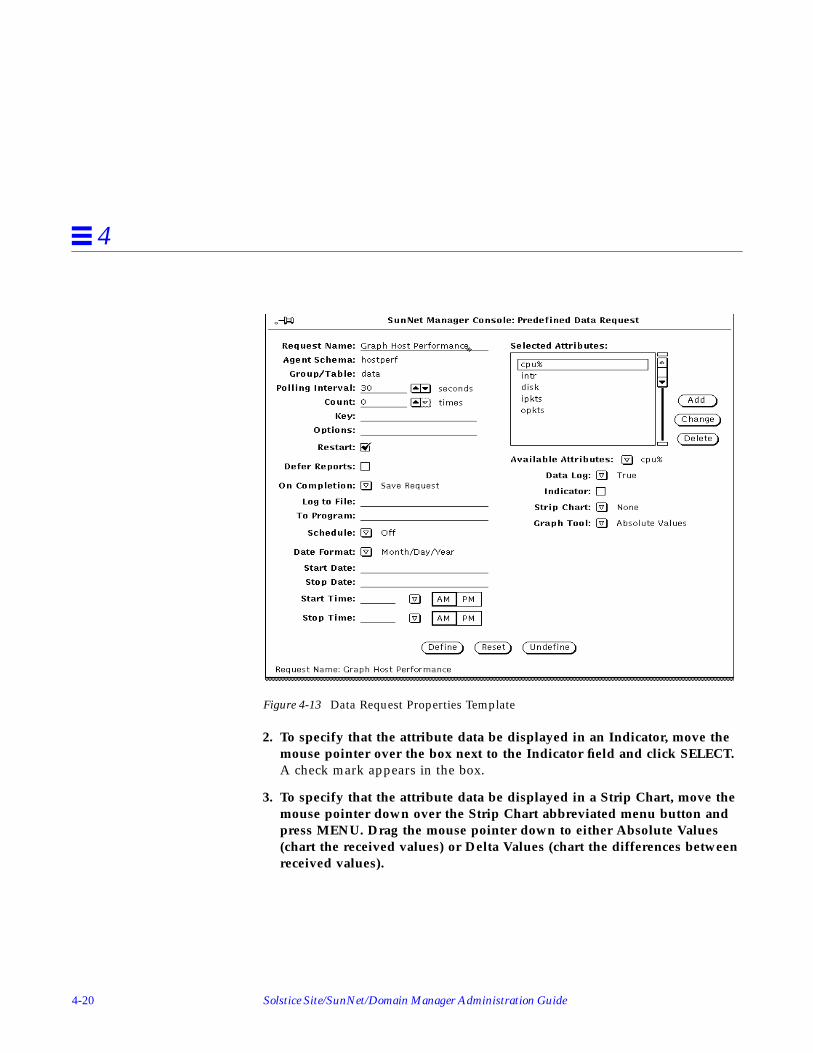
4-20 Solstice Site/SunNet/Domain Manager Administration Guide
4
Figure 4-13 Data Request Properties Template
2. To specify that the attribute data be displayed in an Indicator, move themouse pointer over the box next to the Indicator field and click SELECT.A check mark appears in the box.
3. To specify that the attribute data be displayed in a Strip Chart, move themouse pointer down over the Strip Chart abbreviated menu button andpress MENU. Drag the mouse pointer down to either Absolute Values(chart the received values) or Delta Values (chart the differences betweenreceived values).

Requesting Data 4-21
4
Figure 4-14 Strip Chart Menu
4.5.4 Useful Notes About Indicators and Strip Charts
Indicators and Strip Charts are automatically positioned in the view fromwhich the request is launched. You can move Indicators or Strip Charts withina view, or cut, paste, or copy them into other views.
A maximum of 64 Indicators or 128 Strip Charts can be displayed in the viewwhere the associated request is started.
You can modify certain properties of Strip Charts with their Propertieswindow. For example, you can specify the maximum height and width of aStrip Chart. To modify the properties of a Strip Chart:
1. Move the mouse pointer over the Strip Chart you want to modify andpress MENU to open its Glyph menu.
2. Drag the mouse pointer down to Properties and release to open theProperties window.
3. Modify the Properties window, as necessary.Note that the Properties window for Strip Charts is similar to an ElementProperties window. The middle portion of the window, for selecting agentschemas, and the bottom portion, for color selection, do not apply to StripCharts.
4. Click SELECT on the Apply button to modify the Indicator or Strip Chart.

4-22 Solstice Site/SunNet/Domain Manager Administration Guide
4
4.6 Analyzing Stored DataYou can analyze data that has been stored into a disk file by using thefollowing tools:
• Results Browser
• Results Grapher
The following types of data files can be analyzed:
• Event/Trap Reports file. Unless a different log directory was specifiedduring installation, this file is located at:• /var/adm/snm/event.log for Solaris 1.x installations.• /var/opt/SUNWconn/snm/event.log for Solaris 2.x installations.The log file is defined by the event-log keyword in the /etc/snm.conffile for Solaris 1.x installations and in the /etc/opt/SUNWconn/snm.conffile for Solaris 2.x installations.
• Data report entries that have been saved to a disk file (see the section“Viewing Incoming Data for All Systems: Data Reports Window,” in thischapter).
• Data report files specified with the Log to File field in the Data Requestwindow.
• Any other files that use the data format specified by snm.logfile (5).
4.6.1 Analyzing Stored Data: Results Browser
Use the Results Browser to retrieve and organize stored data.
1. Move the mouse pointer over the Tools button on the Console Menu andpress MENU to open the Tools menu. Or, invoke the Browser from thecommand line:
host% snm_br.
2. Drag the mouse pointer down to Browser and release to open the ResultsBrowser. You receive the window in Figure 4-15

Requesting Data 4-23
4
Figure 4-15 Results Browser Window
3. In the Results Browser file menu, move the mouse pointer over the Filebutton and press MENU to open the File menu. Drag the mouse pointerdown to Load. You receive the window in Figure 4-16.
Figure 4-16 Results Browser File Menu

4-24 Solstice Site/SunNet/Domain Manager Administration Guide
4
4. Enter the directory and file name of the file to be loaded and clickSELECT on the Load button. You receive the window shown inFigure 4-17.Data loaded into the Browser is automatically organized into report streamsand grouped by request and type of data. A stream is the set of requestsassociated with a specific pairing of hostname or IP address and agentname. For example, all of the data reports from the hostmem2 agent forpoignant would make up a single stream. The reports from the layers2agent for the same machine make up a different stream, as do the layers2reports for a different machine.

Requesting Data 4-25
4
Figure 4-17 Results Browser with Reports Loaded
5. To view individual reports in a report stream, double-click SELECT on theline that represents the stream.
129.144.31.77
129.144.31.68

4-26 Solstice Site/SunNet/Domain Manager Administration Guide
4
The Browser runs as a separate process from the Console and remains runningwhen you quit or close the Console.
The first column in the Browser scrolling list of streams can contain a hostnameor an IP address.
4.6.1.1 Printing Browser Reports
You can invoke the Browser from a command line by entering snm_br . Whenyou invoke the Browser from the command line, you can also specify the pathand name of one or more data files to be loaded automatically when theBrowser’s main window is displayed. You can print Browser report streams toa specified printer. To do so:
1. Select the report streams you wish to print.
a. Move the mouse pointer into the top portion of the Browser windowwhere the names of the report streams are displayed.
b. Press MENU to open the Streams menu.
c. Drag the mouse pointer down to Select, then continue to drag right toBy System, By Agent and Group, or By Report Type.
d. Continue to drag right on the appropriate system name, agent groupname, or report type.
e. Repeat steps a through d until all desired streams are selected.
2. Move the mouse pointer over the report streams and press MENU to openthe Streams menu.
3. Drag the mouse pointer down to Print. (See Figure 4-18.)The default printer is lp . To change the printer, modify the BrowserProperties window as explained in the following summary.

Requesting Data 4-27
4
Figure 4-18 Browser Edit Menu
You can modify certain characteristics of the Browser display and the defaultprinter. To do so:
1. Move the mouse pointer to the Edit button of the Browser window andpress MENU to open the Edit menu.
2. Drag the mouse pointer down to the Tool Properties option and release.(See Figure 4-19.)

4-28 Solstice Site/SunNet/Domain Manager Administration Guide
4
Figure 4-19 Browser Tool Edit Menu
3. Modify Browser display or print options. (See Figure 4-20.)
Figure 4-20 Browser Properties Window

Requesting Data 4-29
4
For a complete description of Results Browser features, see “Part 2: Reference.”
4.6.2 Analyzing Stored Data: Results Grapher
The Results Grapher displays reported attribute values in a graph that can bemanipulated.
You can invoke the Grapher directly, by selecting Tools➤Grapher in theConsole window or by invoking snm_gr on a command line.
However, it is often more useful to invoke the Grapher from the Browser, then,enter the attribute name you want. The procedure for this is specified below.
1. Move the mouse pointer over the Tools button and press MENU to openthe Tools menu. Drag the mouse pointer down to Browser and release. Or,invoke the Browser from the command line:
host% snm_br
2. Load the file into the Results Browser.
a. Move the mouse pointer over the File button and press MENU to openthe File menu. Drag the mouse pointer down to Load.
b. Enter the directory and path name of the file to be loaded and clickSELECT on the load button.
3. In the Browser window, send the stream(s) that contain the data to begraphed to the Grapher.
a. Select the stream that contains the data to be graphed.
b. Move the mouse pointer into the scrolling list in the upper portion ofthe Browser window and press MENU to open the Streams menu.
c. Drag the mouse pointer down to Graph and drag right over the desiredattribute name.
4.6.2.1 Changing a Graph Display
Follow the steps below to change the display of the graph:
1. Move the mouse pointer over the displayed graph.
2. Press MENU and drag the mouse pointer down to Properties and release.
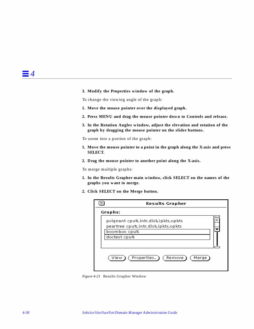
4-30 Solstice Site/SunNet/Domain Manager Administration Guide
4
3. Modify the Properties window of the graph.
To change the viewing angle of the graph:
1. Move the mouse pointer over the displayed graph.
2. Press MENU and drag the mouse pointer down to Controls and release.
3. In the Rotation Angles window, adjust the elevation and rotation of thegraph by dragging the mouse pointer on the slider buttons.
To zoom into a portion of the graph:
1. Move the mouse pointer to a point in the graph along the X-axis and pressSELECT.
2. Drag the mouse pointer to another point along the X-axis.
To merge multiple graphs:
1. In the Results Grapher main window, click SELECT on the names of thegraphs you want to merge.
2. Click SELECT on the Merge button.
Figure 4-21 Results Grapher Window

Requesting Data 4-31
4
4.7 Printing a GraphYou can print graphs (or strip charts) using the OpenWindows Snapshot utility.Snapshot is available from the Tools menu of the Console.
1. Start the Snapshot utility from the Console Tools menu or from theOpenWindows Programs menu.• In the Console, move the mouse pointer to the Tools button and press
MENU to open the Tools menu. Drag the mouse pointer down toSnapshot and release.
• In an open area of your workstation display, press MENU to open theWorkspace menu. Drag the mouse pointer right on Programs, then dragdown to the Snapshot option and release.
• For more information on the Snapshot utility, refer to the SunOS 4.xDeskSet Environment Reference Guide.
2. In the Snapshot window, click SELECT on Window in the Snap Typefield, then click SELECT on the Snap button. (See Figure 4-22.)
Figure 4-22 Tools—Snapshot Window
3. Move the mouse pointer to the graph to be printed and click SELECT.Within a few seconds you should see the message “Snap succeeded” at thebottom of the Snapshot window.

4-32 Solstice Site/SunNet/Domain Manager Administration Guide
4
4. In the Snapshot window, press MENU on the Print abbreviated menubutton.
5. Drag the mouse pointer down to Print Snap to print the snapshot. Dragthe mouse pointer down to Options to set up printer options.
4.7.0.1 Useful Notes About Displaying and Printing Graphs
The Results Browser and Grapher run as separate processes and remainrunning when you quit or close the Console.
By default, graphs are displayed on a black background. To display graphs ona white background, invoke the Grapher from the command line with the-b option. You can also modify the Tools menu to add the -b option wheninvoking the Grapher. See Chapter 10, “Customizing SunNet Manager” formore information.
Graphs can be printed by using the OpenWindows Snapshot utility. Snapshotis available from the Tools menu of the Console. See “Printing a Graph” later inthis Section for more information.
If the Grapher displays the graphs on a black background, the graphs willprint on a black background. To print graphs on a white background, invokethe Grapher with the -b option. You can also modify the Tools menu to addthe -b option when invoking the Grapher. See Chapter 10, “CustomizingSunNet Manager” for more information.
4.8 Viewing and Managing RequestsThe SunNet Manager Console Requests➤Summary window allows you toview the status of all requests that have been started from the Console session.From the Requests➤Summary window you can stop, kill, or restart multiplerequests at a time or modify the properties of a request.
Each request is associated with a request glyph that resides in the subview ofthe target element. From the Glyph menu for the request you can modify, stop,or kill the request.
This section describes how to view, modify, stop, and kill requests from theRequests Summary window and from the Glyph menu for the request.
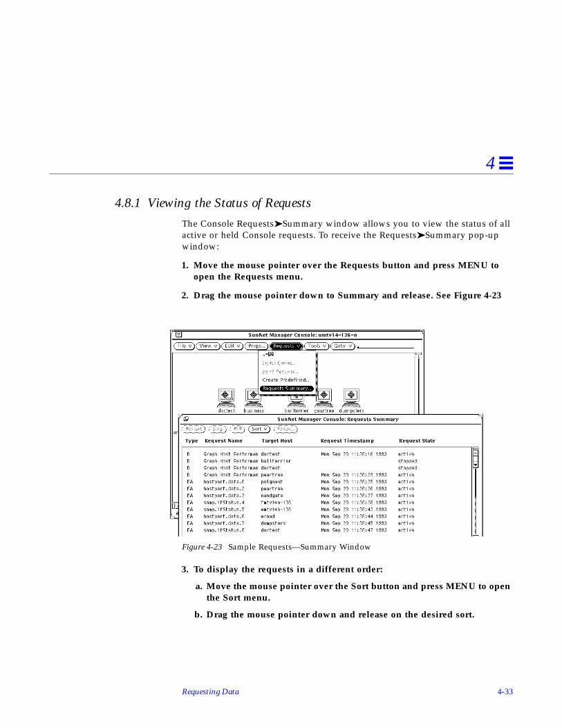
Requesting Data 4-33
4
4.8.1 Viewing the Status of Requests
The Console Requests➤Summary window allows you to view the status of allactive or held Console requests. To receive the Requests➤Summary pop-upwindow:
1. Move the mouse pointer over the Requests button and press MENU toopen the Requests menu.
2. Drag the mouse pointer down to Summary and release. See Figure 4-23
Figure 4-23 Sample Requests—Summary Window
3. To display the requests in a different order:
a. Move the mouse pointer over the Sort button and press MENU to openthe Sort menu.
b. Drag the mouse pointer down and release on the desired sort.

4-34 Solstice Site/SunNet/Domain Manager Administration Guide
4
4.9 Request StatesEvery active or held Console request is shown in one of several states:• Not defined• Idle• Retrying Failed Start• Being Started• Active• Retrying Failed Stop• Stopping• Scheduled
• When you start a request (you click SELECT on the Start button on theProperties window for the request), the request state is initially awaitingactivation. Normally, the request state quickly changes to being activated,followed by active.
• If an agent error occurs while a request is being activated, the request statechanges to stopped.
• An active request that is stopped or killed passes through the states awaitingstop, being stopped, and stopped.
• A held request (you click SELECT on the Hold button on the Propertieswindow for the request) is shown in stopped state.
• If you specified Delete Request in the Upon Completion field in theProperties window of a request, the request disappears from theRequests➤Summary window when the request is completed. If youspecified Save Request in the Upon Completion field in the Propertieswindow of a request, the state of the request becomes stopped when therequest is completed.
• Note that the states awaiting activation, being activated, awaiting stop, andbeing stopped are normally temporary. If you notice that a request seems tobe in one of these states for a long time without changing, you should makesure that the target element is reachable by using the ping agent to do aQuick Dump request.
• A request that is Scheduled for later is sent to the appropriate agent at thescheduled time.

Requesting Data 4-35
4
4.10 Viewing and Modifying Properties of a RequestYou can modify a data or event request from the Requests➤Summary windowor from the request glyph.
To view the properties of a request from the Requests➤Summary window:
1. Click SELECT on the request whose properties you want to view ormodify.
2. Click SELECT on the Props button at the top of the window. SeeFigure 4-24
Figure 4-24 Requests—Summary Window
To view the properties of a request from the request glyph:
1. Move the mouse pointer over the glyph that represents the target elementfor which you have specified an Event or Data report, and double-clickSELECT.Data requests are represented by a meter glyph, while event requests arerepresented by an alarm clock glyph. When a request is active, its glyphappears black or solid. When a request is stopped or held, its glyph isdimmed.
2. Move the mouse pointer over the glyph that corresponds to the requestand press MENU to open the Glyph menu for that request.
3. Drag the mouse pointer down to Properties and release. See Figure 4-25.

4-36 Solstice Site/SunNet/Domain Manager Administration Guide
4
Figure 4-25 Request Glyph Menu
4.10.1 Modifying Report Characteristics or Specifications
Once the Properties window for the request is displayed, you can modifyrequest reporting characteristics or the attribute or event specifications.
To change how an attribute is logged or displayed, select the attribute in theAttribute values scrolling list by pointing the mouse at the entry and clickingSELECT. This causes the current values of the event definition to appear in thefields on the right side of the window. If you modify any of these fields, clickthe Apply button at the bottom of the window. To delete an attribute from adata request, select the attribute from the Attribute values scrolling list andclick the Delete button at the bottom of the window.
4.10.2 Using Data Requests to Monitor Performance
Use data requests to gather comparative data in such areas as network trafficlevels or the performance of critical nodes, such as servers and routers. A datarequest causes an agent to report the values of specified attributes for a targetdevice. You can request a one-time report of current data (a Quick Dump), orreporting of data at periodic intervals. You can see data reports in a real-timegraph or log them to a file for later viewing.
Continual data polling can generate significant additional network traffic. Youmay prefer to collect data only at periodic intervals, to establish an historicalrecord, to help you gauge trends, and to determine normal levels of activity.
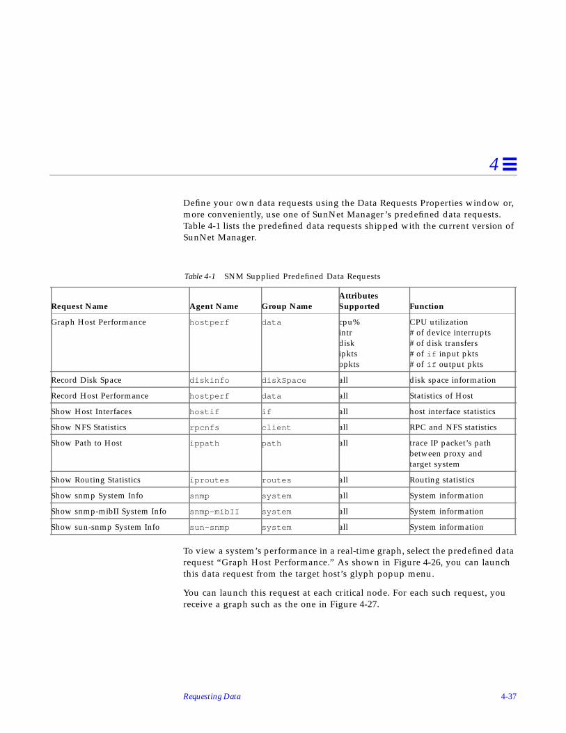
Requesting Data 4-37
4
Define your own data requests using the Data Requests Properties window or,more conveniently, use one of SunNet Manager’s predefined data requests.Table 4-1 lists the predefined data requests shipped with the current version ofSunNet Manager.
To view a system’s performance in a real-time graph, select the predefined datarequest “Graph Host Performance.” As shown in Figure 4-26, you can launchthis data request from the target host’s glyph popup menu.
You can launch this request at each critical node. For each such request, youreceive a graph such as the one in Figure 4-27.
Table 4-1 SNM Supplied Predefined Data Requests
Request Name Agent Name Group NameAttributesSupported Function
Graph Host Performance hostperf data cpu%intrdiskipktsopkts
CPU utilization# of device interrupts# of disk transfers# of if input pkts# of if output pkts
Record Disk Space diskinfo diskSpace all disk space information
Record Host Performance hostperf data all Statistics of Host
Show Host Interfaces hostif if all host interface statistics
Show NFS Statistics rpcnfs client all RPC and NFS statistics
Show Path to Host ippath path all trace IP packet’s pathbetween proxy andtarget system
Show Routing Statistics iproutes routes all Routing statistics
Show snmp System Info snmp system all System information
Show snmp-mibII System Info snmp-mibII system all System information
Show sun-snmp System Info sun-snmp system all System information

4-38 Solstice Site/SunNet/Domain Manager Administration Guide
4
Figure 4-26 Predefined Data Request Using hostperf Agent
Figure 4-27 Graph from Predefined Request

Requesting Data 4-39
4
Example:
You can also use the hostperf agent to log data reports to a file. SeeFigure 4-28. To build such a request for a target device:
1. Select the device.
2. Invoke the Request Builder window through the Console’sRequests➤Send Request option.
3. Select the Data Request type and the hostperf agent
4. Click on the Apply button to invoke the Data Request Properties sheet.
5. To launch the request, click SELECT on the Start button.
The subview for each device shows the active requests targeted at that device.To access the subview for a device:
6. Double-click SELECT on the glyph for that device.The active requests for that device are represented by glyphs.

4-40 Solstice Site/SunNet/Domain Manager Administration Guide
4
Figure 4-28 Data Request Properties Sheet with Log File Specified
4.10.2.1 Copying and Pasting Requests to Track Additional Devices
After a request is launched for one device, you can copy and paste it from thesubview of the initial device to the subview of each additional device you wantto track. As shown in Figure 4-29, you can use the Console Edit➤Copyfunction to copy requests from the subview of one element to the clipboard.You can then paste this request into the subview of each of multiple elements.This launches a clone of the initial data request for each additional devicewhere you paste the request.

Requesting Data 4-41
4
Figure 4-29 Copying a Request from an Element’s Subview
To view the data reports from these requests:
1. Invoke the Results Browser from the Console Tools menu
2. Load the log file where the data is stored into the Results Browser throughthe Browser’s File➤Load option
Figure 4-30 shows the Results Browser loaded with the log file specified in theLog to File field of a Data Request Properties Sheet.

4-42 Solstice Site/SunNet/Domain Manager Administration Guide
4
Figure 4-30 Data Report Files in Browser
4.10.3 Example: Assessing Overall Operation of the Network
To quickly assess individual performance characteristics of each critical node,and determine potential problem areas for overall operation of the network.graph the attributes available from the Streams➤Graph Grapher menu shownin Figure 4-31. Features such as “zooming” and merging help you refinecomparisons of the data you have logged. A detailed discussion of Grapherfeatures is presented in the “Grapher” chapter in “Part 2: Reference.”
To compare data from different streams over a particular attribute, such ascpu%, merge the data from the various files into a single graph:
• Invoke the Grapher tool from the Browser.
You receive the window shown inFigure 4-32. The merged graph allows you toquickly compare the CPU utilization of multiple nodes.

Requesting Data 4-43
4
Figure 4-31 Streams➤Graph Grapher Menu Data Report Files
Figure 4-32 Merged Graphs

4-44 Solstice Site/SunNet/Domain Manager Administration Guide
4

5-1
Specifying Event Requests 5
This chapter discusses the following topics:
• Specifying an event
• Detecting the presence of an event
• Checking the cause of an event
• Changing the state of a glyph
• Changing the propagation of glyph state changes
An event occurs when specified conditions are met. The Console provides amechanism that allows you to specify the following characteristics pertainingto an event:
• Condition(s) that define a particular event;
• Visual or audible indications of an event or the action that is to take placewhen the event occurs;
• Whether or not the visual indications of an event are propagated throughthe view hierarchy of the Console
• Starting with version 2.3, start time and stop time of the request
• Starting with version 2.3, new requests as part of the event action
When you specify an event, a request is made to the appropriate agent. Whenan event occurs, the agent sends an event report back to the Console. You canspecify various actions for the Console to perform when it receives an event

5-2 Solstice Site/SunNet/Domain Manager Administration Guide
5
report. For example, you can have the Console display a visual alarm, play anaudio file, send a mail message, send the event report to a program, or anycombination of these actions.
Starting with version 2.3, you can stop the request or start another request orperform a combination of both actions.
5.1 Specifying an EventYou specify the event conditions, event notification, and actions for individualelements by using the Event Request Properties window.
You can compose your own event request, targeting a specific machine for aspecific set of information. More conveniently, you can use a predefinedrequest. These requests save you the trouble of composing requests forindividual machines.
The product is shipped with a number of predefined event requests that canaccommodate many of your network management needs. You can choose oneof these requests, modify it for a specific need, or build your own request.
5.2 Scheduling Requests Based on EventsStarting with version 2.3, you can start or stop requests as the result of anevent. For example, a ping request may send ICMP packets to a device atregular intervals and generate an event if there is no response. If a device goesdown for an extended time and the request continues to launch at the sameintervals, a significant number of reports would be generated if no action istaken.
Under such conditions, it would be helpful to stop the event request and putthe device in a pending state. This would reduce unnecessary management ofnetwork traffic.
With event-based requests, you can:
• Stop the current request
• Start another event request
• Carry out the event request on a different proxy agent using the alternateproxy field

Specifying Event Requests 5-3
5
You can combine these options or use them independently.
Use the Properties sheet for an event request to define a schedule (seeFigure 5-1).
Figure 5-1 Event Request Properties Sheet
Use this screen together with the Request Builder (as demonstrated inexamples that follow) to specify details of how SunNet Manager should handleyour request.
5.3 Retrieving Single AttributesStarting with version 2.3 of the product, you can use an event request toretrieve a single attribute or a subset of attributes. Previously, an event wouldgenerate a report containing information about non-requested, as well asrequested, attributes in a group.

5-4 Solstice Site/SunNet/Domain Manager Administration Guide
5
Here is an example of the type of new report you can generate:
Event ReportMon March 4 16:58:00 1996 [yercaud]: Event: snmp-mibII.systemsysUpTime=26:14:24:68 (Greater Than 00:00:00:00 Priority Low)
The report shows the requested attribute, sysUpTime. Previously it would alsohave included non-requested information such as sysDescr, sysObjectID,sysContact, sysName, sysLocation, and sysServices. You can see the type ofreport previously generated by specifying false on the keyword get-
requested-attributes-only in the snm.conf file.
5.3.1 Sending an Event Request Through the Console Requests Menu
1. Click SELECT on the glyph that represents the target element.
2. Press MENU on the Requests button in the control area of the Consoleand release MENU over Send Request.The window shown in Figure 5-2 appears. The Request Action field isautomatically set to Send Request.

Specifying Event Requests 5-5
5
Figure 5-2 Sample Request Builder Window
3. Click SELECT on the Request Type you want to send (event, in thisexample). Press MENU on the Request Name abbreviated menu button.You receive the menu shown in Figure 5-3.
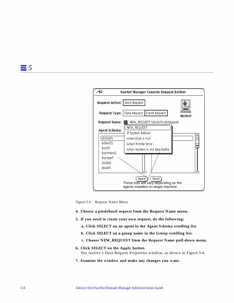
5-6 Solstice Site/SunNet/Domain Manager Administration Guide
5
Figure 5-3 Request Name Menu
4. Choose a predefined request from the Request Name menu.
5. If you need to create your own request, do the following:
a. Click SELECT on an agent in the Agent Schema scrolling list
b. Click SELECT on a group name in the Group scrolling list.
c. Choose NEW_REQUEST from the Request Name pull-down menu.
6. Click SELECT on the Apply button.You receive a Data Request Properties window, as shown in Figure 5-4.
7. Examine the window and make any changes you want.
These lists will vary depending on theagents installed on target machine

Specifying Event Requests 5-7
5
Figure 5-4 Sample Event Request
1. On the left side of the request window, modify or fill in the reportcharacteristics fields.
2. On the right side of the request window, select the attributes on whichyou want the agent to send data, and how you want to view the data.
3. Press MENU on the Attribute menu button and release MENU over theattribute you want.
4. Click SELECT on Apply to add the attribute to your request.After selecting and applying attributes and their viewing options, clickSELECT on the Start button on the lower left side of the window to sendthe event request to the agent.
For a description of the fields in the Event Request template, refer to “Part2:Reference.”

5-8 Solstice Site/SunNet/Domain Manager Administration Guide
5
5.3.1.1 Using Event Requests to Monitor Critical Nodes
Use the Event Request Properties window to specify conditions that define anevent and the type of notification you want to receive. You can compose yourown event request or, more conveniently, use a predefined request. Predefinedrequests included with the current product are summarized in Table 5-1.
The examples that follow show how to send event requests.
5.3.2 Sending Predefined Event Requests through the Glyph Menu
5.3.2.1 Example: Monitoring Node Availability with Ping
To be informed immediately if any of your critical nodes goes down, use anevent request with the ping agent. For convenience, you can use thepredefined event request “when System is not Reachable” and specify thedefault (blinking glyph).
Here are the steps:
1. Display the glyph menu by pressing the MENU button over the glyphrepresenting the target device.
Table 5-1 Predefined Event Requests Supplied with SunNet Manager
Request Name Agent Name Group NameAttributesSupported Event to be Reported
when Disk is Full diskinfo diskSpace capacity disk file system is full
If System Reboot hostperf data uptime if system reboots
when Printer Error lpstat status statusCode line printer error
when System is not Reachable ping reach reachable system not reachable

Specifying Event Requests 5-9
5
2. Select the predefined event request from this menu as shown inFigure 5-5.
Figure 5-5 Sending Predefined Event Request
Using this method, the predefined request, “when System is not Reachable,”does not take advantage of the “decay” feature. The default is for the glyphto blink when an event occurs, as indicated on the Properties sheet inFigure 5-6.

5-10 Solstice Site/SunNet/Domain Manager Administration Guide
5
Figure 5-6 Sample Event Request Properties Sheet w/Blink Glyph Effect
To change the default, use the Request Builder, as explained below.

Specifying Event Requests 5-11
5
Using Request BuilderUse the “decay” feature to cause the device glyph to turn blue (the defaultcolor) or to the color you have customized, to alert you when a device hasbeen unreachable at any time since you last cleared an event for it.
Here are the steps:
1. Select the target router and access Request Builder by pulling down theConsole Requests menu, as shown in Figure 5-7.
Figure 5-7 Predefined Event Request Builder
2. Select the agent (ping ), attribute group (reach ), request type (EventRequest), and then “when System is not Reachable” — the name of thepredefined event request to use as a starting point for specifying the newevent request.
3. Click SELECT on the Apply button to display the Properties sheet.
4. Create a new event request to take advantage of the “decay” feature by:

5-12 Solstice Site/SunNet/Domain Manager Administration Guide
5
a. pressing MENU on the Glyph Effect button and releasing MENU overthe Color By Priority option. See Figure 5-8
Figure 5-8 Event Request Properties Sheet w/Color by Priority Glyph Effect
b. clicking SELECT on Apply to add the attribute to your request
c. clicking SELECT on the Start button to send the event request to theagent.

Specifying Event Requests 5-13
5
5.3.2.2 Example: Using sysUpTime to Monitor SNMP Device
The Ping agent can only determine if a device is available when it polls thedevice. However, between polls, you may want to be notified if routers havegone down momentarily and then become available again. Use the SNMPsysUpTime attribute to check for this on devices that support Simple NetworkManagement Protocol (SNMP).
1. Build an event request by pressing MENU over the target element
2. Select Send Request to invoke the Request Builder window, as shown inFigure 5-9.
3. Select Event Request, the snmp-mibII agent, and the system group.
Figure 5-9 Accessing snmp system Group for Event Request
4. Click SELECT on the Apply button to access the Event Request Propertiessheet, Figure 5-10.

5-14 Solstice Site/SunNet/Domain Manager Administration Guide
5
Figure 5-10 SysUpTime Event Request Properties Sheet
In Figure 5-10, the following values have been set in the event request fields.
• Attribute: sysUpTime• Relation: Decreased by More Than• Threshold1: 1. An event is generated when the value of sysUpTime
decreases by more than.001 seconds. If the system is up less time than on theprevious poll, the system went down between polls. sysUpTime measurestime, in hundredths of a second, since the last system restart.
• Interval: 600 seconds (ten minutes)• Count: 0 (to continue indefinitely)• On Completion: Save Request (to prevent the request from being deleted if
you stop it).• Priority: High• Glyph Effect. Glyph will blink to indicate a new event.

Specifying Event Requests 5-15
5
5. To implement these selections, click SELECT on the Apply button. Theattribute name will then appear in the window at the upper right.
6. Click SELECT on the Start button to launch the request.
5.3.2.3 Example: Using ifOperStatus to Monitor Router Interfaces
Use the SNMP ifOperStatus attribute to monitor the availability of routerinterfaces.
1. Select the target router,
2. To access the Request Builder, select Send Request from the glyph popupmenu or the Console Requests pulldown menu.
3. Select Event Request, the snmp agent, and the ifStatus group, as shownin Figure 5-11.
Figure 5-11 Accessing snmp ifStatus Group for Event Request
4. Click SELECT on the Apply button to access the Event Request Propertiessheet shown in Figure 5-12.
5. Click SELECT on Start to send the request.

5-16 Solstice Site/SunNet/Domain Manager Administration Guide
5
Figure 5-12 Event Request Properties Sheet for ifOperStatus Request
A partial list of values entered in the Event Request Fields are shown below:
Attribute: IfOperStatus
Relation: Not Equal to
Threshold1: 1. The condition that defines a critical event is when the interfaceis not up. The interface is not up if ifOperStatus has a value other than 1.
Key: If this field is blank, an event is generated if any of the router’s interfacesare not up. To test for a particular interface, enter the ifIndex number for thatrouter in the Key field.
5.3.2.4 Generating a Report on Router Interface Status
To generate a one-time report to check the status of all interfaces on a router:
1. Click MENU on the target glyph.

Specifying Event Requests 5-17
5
2. Click SELECT on Quick Dump➤snmp➤ifStatus.
This Quick Dump returns the status of all interfaces.
5.3.3 Example: Monitoring Network Traffic Load Using Request Builder
Periodic data reporting can help you determine thresholds in capacityutilization rates or traffic levels where problems occur. You can use thesethreshold levels to define event requests that tell you when these conditionsoccur.
In the example below, the traffic agent is used to generate an event reportwhen there is an unusually high level of activity between any two nodes on thenetwork. In this case, the particular threshold may have been determined byprevious sampling of traffic levels on this network.
This event request is targeted at the Ethernet bus in each of the network’ssubnets. To generate the request:
1. Select the Ethernet bus glyph in a subnet view.
2. Invoke the Request Builder by selecting the Console’s Requests➤SendRequest option.

5-18 Solstice Site/SunNet/Domain Manager Administration Guide
5
3. Select Event Request type, the traffic agent, and the BetweenIP group,as shown in Figure 5-13.
Figure 5-13 Event Request with traffic agent

Specifying Event Requests 5-19
5
4. Click SELECT on the Apply button to invoke the Event RequestProperties window as shown in Figure 5-14.
Figure 5-14 Example of traffic Event Request
5. Click SELECT on the Start button to launch this request.
All fields in the Event Request Properties sheet are described in Chapter 15,“Requests Management.”
The fields in this example have been completed as follows:
• Attribute: Set to “pkts”.• Relation1: Set to Greater Than.• Threshold1: Set to 400.
In observing the network, you may have noticed that if more than 400packets are sent between two nodes, it creates an abnormally high rate ofnetwork activity. “Greater Than 400,” then, defines the condition forgenerating an event notification.

5-20 Solstice Site/SunNet/Domain Manager Administration Guide
5
• Glyph Effect: Set to Color by Priority. This allows you to take advantage ofthe “decay” feature, to indicate that this condition has occurred at sometime since you last cleared an event. You can customize the color of theglyph. You need not use blue.
• Mail To: You can specify your e-mail address in this field. Any e-mailmessage generated by this event would contain the IP addresses of the twonodes whose packet activity exceeded 400.
• Interval: This value is set to 60 so the agent polls every minute to comparethe result with the specified threshold value.
• Count: This value is left at 0 (the default) so that the event request willcontinue indefinitely.
After launching this request for the gateway node in one subnet, you can copyit from the subview of that node and paste it into the subview of a gatewaynode on each additional Ethernet subnet you want to monitor. Copying therequest to the subview of an element launches a clone of that event requesttargeted at the node where the request has been copied.
5.3.3.1 Alternative Ways to View the Properties Sheet for Event Requests
1. Double-click on the target glyph.
2. Click SELECT on the glyph for the request
3. Click SELECT on the Props button in the Console’s control area.
4. Invoke Requests➤Requests Summary from the Console’s control area.
5. In the Requests Summary window, find and click SELECT on yourrequest,
6. Click SELECT on the Props button in the Requests Summary window.In that window, the Select and Sort menus can be very useful in findingyour request.

Specifying Event Requests 5-21
5
5.3.3.2 Example: Managing Log Files Using Predefined Request
You can use event requests to help you manage the management station, itself.In this example, an event request is defined to generate an alarm when the filesystem where the Console log files are mounted (/var), is more than 90% full,.
1. Click SELECT the glyph representing your management station.
2. invoke the Request Builder through the Requests➤Send Request option.
3. As shown in Figure 5-15, select the diskinfo agent and Event Request inthe Request Builder.
Figure 5-15 Managing Log Files: Request Builder Selection
4. Click SELECT the “Apply” button, to get the Event Request Propertiessheet in Figure 5-16.

5-22 Solstice Site/SunNet/Domain Manager Administration Guide
5
Figure 5-16 Managing SunNet Manager Log Files: Defining the Event Request
5. Enter the appropriate data in each field.
6. Click SELECT on Define to launch the request.
Each field on the Properties sheet is described in Chapter 15, “RequestsManagement.”
Selected fields in the example above are defined as follows:
Interval: specifies a polling interval of 15 minutes.
Count: 0. The request will continue until an operator stops it.
For event reports, the Interval and Count fields simply specify when theagent is to send a report. A report is forwarded to the Console system onlyif it has been determined that an event has occurred. For agents that areshipped with SunNet Manager, the value reported for an attribute is thevalue noted at the reporting interval. Thus, it is possible for eventconditions to occur between reporting intervals which will not generate anevent report.

Specifying Event Requests 5-23
5
If a count is specified and a stop date and time are specified, the earlier ofthe two takes precedence. For example, if a count of 100 is specified and astop date of 9/13 is specified and a stop time of 12:30 am is specified, therequest will stop if 100 occurs before the stop date and time. If the stop dateand time occur before the count is reached, the request will stop at thespecified stop date and time.
Send Once: If the Send Once field is off (no check mark appears in theaccompanying box), an event report will be sent for every event occurrence. Ifthe Send Once field is on (a check mark appears in the accompanying box), itmeans that after the first event report is received by the Console, the request iskilled. To specify Send Once, click SELECT on the box to display a check mark.
Key: /var--in this example. For the diskinfo agent, Key specifies the relevantdisk partition -- for example, the file system that would be indicated in the“Mounted On” column in a df command output. In this example, the log filesare situated in a separate partition.
On Completion: Save Request. The request will not be deleted if we stop it.
Attribute: in this example “capacity” designates the percentage of totalcapacity used. The condition defining the event is capacity Greater Than 90.
Glyph Effect: Color by Priority. If the event condition is met, the glyph, willturn red (or, starting in version 2.3, to a color you select).
By default, an event’s glyph effect options remain in effect for 10 secondsbeyond the reporting interval. If another event does not occur within thistime, the Console cancels the glyph effect. You can increase the 10-secondglyph effect overlap time in the Console Properties window. See thedescription of the Event Effect Overlap Time setting in “Part 2: Reference.”
Start Date: 06/30/96. Start the request on this date.
Stop Date: 06/30/96. Do not run the request beyond this date.
Start time: 3:00 p.m. Start the request at this time.
Stop time: 3:15 p.m. Do not run the request beyond this time.
When you specify a start date and time and click Start, the request status islisted as “scheduled” in the request summary window.

5-24 Solstice Site/SunNet/Domain Manager Administration Guide
5
5.3.3.3 Available Predefined Requests
Predefined requests available (and the agents listed in the Agent Schema list ina Request Builder window) for a given machine depend on the agents thathave been checked off as present in the Properties window for that machine. Amachine which does not have SunNet Manager on it, that the IP Discover tooladds to your database, has the hostperf and ping agents checked off.Information is available from a machine without agents through SunNetManage’s proxy feature, just as if the hostperf and ping agents were on thatmachine. A machine with agents installed that the IP Discover tool adds toyour database, has the agents checked off that are actually present.
5.3.3.4 Automatically Opening an Icon
You can choose to have a Console window that is closed to an icon openautomatically when an event or trap is received. You specify this in theConsole’s Properties window, available by clicking SELECT in the Propsbutton in the Console’s control area. See the description of the Open on Eventor Trap setting in “Part2: Reference.”
5.4 Detecting the Presence of an EventThis section describes how you can use the Alarm Reports or Event/TrapReports windows to monitor events. You obtain these from the View menu inthe Console’s control area (View➤Alarm Reports or View➤Event/TrapReports). You can use either of these windows for all elements in a view or fora specific element. An alternative, and perhaps easier, way to detect an eventfor a specific element is to observe the visual effect of an event as it shows in aglyph.
If an event occurs, a glyph can blink, dim, change color, or remain unchanged.You choose the effect you want in the Properties window at the time you makean event request. SunNet Manager has a “decay” feature that allows you todetect that a condition that caused an event report occurred and that thecondition no longer exists. For example, a file server might exceed a thresholdyou have set for a certain number of NFS transactions, then fall below thatthreshold. To take advantage of the “decay” feature, you must specify Color byPriority as your Glyph Effect.

Specifying Event Requests 5-25
5
See the example, “Sending Predefined Event Requests through the GlyphMenu” on page 5-8 for instructions on specifying a request to take advantageof the “decay” feature.
5.5 Checking the Cause of an EventWhen an event occurs, a report is returned to the Console that indicates thecause of the event. The Console gives you two ways to view an event report:
• The Event/Traps Reports window, described in this section.
• The Alarms Summary window (available in the View➤Alarm Reportswindow). This window displays error, event, and trap reports and isdescribed in the Section on “Viewing Alarm Reports” later in this Manual.
To check the cause of an event in the Event/Trap Reports window, perform thefollowing steps:
1. Press MENU over the View button, and Release MENU over Event/TrapReports. (See Figure 5-17.)

5-26 Solstice Site/SunNet/Domain Manager Administration Guide
5
Figure 5-17 View—Event/Traps Window
2. To examine event and trap reports for a particular system, type in thedevice name after the Device prompt and press Return.To see entries for all elements again, press Ctrl-U to clear the Device lineand press Return.
An alternative way to obtain an element-specific event or trap report is toclick SELECT on the glyph in the Console window, then invokeView➤Event/Trap Reports.
3. To save the event reports to a file, click SELECT on the Save button.A pop-up Save window appears, where you can enter the path and filename where the Event/Trap Reports are to be stored.

Specifying Event Requests 5-27
5
4. To browse through entries in the log:• Press SELECT on the slider and drag the slider to the left or right.• Click SELECT to the left or right of the slider.• Click SELECT on either end of the slider bar.• Enter the number of a report on the Report line and press Return.
5.5.1 Event/Trap Reports Window
Event/Trap Reports entries are time-stamped and show values for allattributes in the specified agent group. The attribute and value that caused theevent are flagged with the relational operator and threshold values shown inparentheses to the right.
By default, a maximum of 1000 event reports are displayed in the Event/TrapReports window. You can change the maximum number in the ConsoleProperties window. To view or change this setting (or any other event- or trap-related setting), click SELECT on Props in the Console’s control area, thenselect Miscellaneous in the Category pulldown menu. See the description ofthe Maximum Event Reports setting in “Part 2: Reference.”
5.6 Changing a Glyph State Back to NormalA glyph may change its state when an event or a trap is received for theelement that is represented by the glyph. For example, if you have specified anevent for an element and the notification is “Blink Glyph”, the element’s glyphstate changes from “normal” to “blinking” when the event occurs. Once youhave been alerted to the event, you may want to change the state of a glyphback to “normal.” This is done using the Glyph State option of the Glyph menufor the element.
5.7 Glyph Pending StateStarting with version 2.3 of SunNet Manager, you can also put a glyph topending state. You might want to use pending state when a device has beendown for an extended period and events continue to be logged against it, orwhen you know that someone is repairing the device and you do not want newevents or traps against the device to have any effect.

5-28 Solstice Site/SunNet/Domain Manager Administration Guide
5
When you click Pending On, the glyph goes to pending state, and the color ofthe object is dimmed. All outstanding events and traps on the device arecleared and the object is “frozen.” New events and traps will not change theappearance of the glyph state or propagate the effect of a trap or event to theparent object. If a parent object is in pending state, a change in the state of thechildren will not affect the parent.
When you click Pending Off, pending state is turned off, and the object is anend node or device, its glyph state is recalculated based on any outstandingalarms. If there are none, the glyph state is set to normal. If the glyph object isa parent inheriting from its children, its state is recalculated appropriately.
When a pending device is moved to normal state, all outstanding alarms arecleared. If the glyph object is a parent, the state of the children are set tonormal, also.
To change the state of a glyph, follow the steps below:
1. Press MENU over the glyph whose state you want to change.
2. Release MENU over Glyph State and drag right to the desired glyph state.See Figure 5-18.

Specifying Event Requests 5-29
5
Figure 5-18 Glyph—Glyph State Menu
5.8 Propagation of Glyph StatesWhenever a glyph state is changed as a result of an event or a trap, the glyphstate is propagated through the view hierarchy. If a glyph is contained in morethan one view, its state is propagated through its multiple view hierarchies.When the Console is closed to an icon, glyph state changes reflected in theHome view cause the Console icon to display question marks. These effects arenot true for pending state.
When you change the state of a glyph, the new glyph state is propagated asthough an event had occurred to change the glyph state. For example, if youchange the glyph state of an element from “normal” to “blinking,” the glyphstate “blinking” propagates as if an event had occurred.
If you have multiple glyph states propagating into a single view and youchange the glyph state for the view to “normal,” the glyph states of theelements contained in the view are also reset to “normal.” For example, if you

5-30 Solstice Site/SunNet/Domain Manager Administration Guide
5
change the glyph state of a view from “blinking” to “normal,” this clears theeffects of the event that caused the glyph state to change to “blinking.” Thisallows you to clear multiple events by resetting the glyph state of a view.
You can also choose to have errors that are received from agents cause achange in the glyph state of an element. By default, this is not enabled. See thedescription of the Errors category of the Console Properties window in “Part 2:Reference.”
5.9 Changing the Propagation of Glyph State ChangesBy default, glyph state changes caused by events or traps are propagatedthrough the view hierarchy, except for glyphs in pending state. You can disableglyph state propagation in several ways.
To disable glyph state propagation for a particular view:
1. Press MENU over the glyph that represents the view.
2. Release MENU over Properties to open the Properties window for theview. (SeeFigure 5-19.)
Figure 5-19 Properties Window for a View
3. In the Properties window, press MENU over the Glyph State abbreviatedmenu button in the top portion of the window.
4. Release MENU over the Not Inherited option.
To disable glyph statepropagation

Specifying Event Requests 5-31
5
5. Click SELECT on the Apply button.To disable glyph state propagation forall views in the database:
1. Click SELECT on the Props button in the Console window.
2. In the Console Properties window, press MENU over the Categoryabbreviated menu button to open the categories menu.
3. Release MENU over Events and Traps. (See Figure 5-20.)
Figure 5-20 Console—Properties—Category Menu
4. In the Events and Traps categories window, click SELECT in the box nextto the Propagate Event Effect setting to toggle the check mark off. (See theFigure below.)

5-32 Solstice Site/SunNet/Domain Manager Administration Guide
5
Figure 5-21 Properties—Event/Trap Window
5. Click SELECT on the Apply button.
To disable propagation of glyph states caused by traps:
1. Open the Events and Traps category settings in the Console Propertieswindow, as described in the previous steps.
2. Click SELECT in the box next to the Traps Propagate Effect setting totoggle the check mark off.
3. Click SELECT on the Apply button.

6-1
Viewing Reports 6
This chapter discusses:
• Viewing alarm reports
• Viewing error messages and error reports
• Viewing traps
• Viewing event reports
SunNet Manager returns four types of reports:• Data report• Event report• Error report• Trap report
The Console groups the last three under the heading of “alarms.” You can viewa summary of alarm reports for all elements within a given view. To do this,follow these steps:
1. Make sure there are no glyphs selected in the Console window.
2. Press MENU on the View button in the Console window and releaseMENU over Alarms.You receive a window such as the one shown in Figure 6-1.
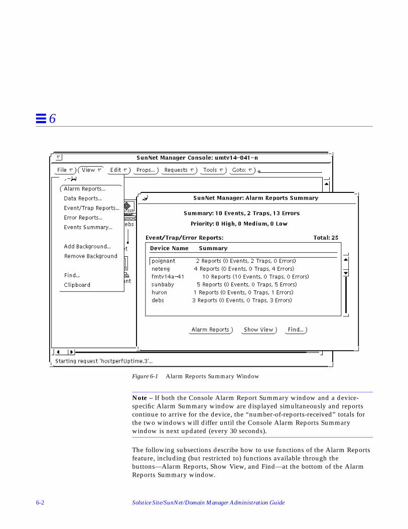
6-2 Solstice Site/SunNet/Domain Manager Administration Guide
6
Figure 6-1 Alarm Reports Summary Window
Note – If both the Console Alarm Report Summary window and a device-specific Alarm Summary window are displayed simultaneously and reportscontinue to arrive for the device, the “number-of-reports-received” totals forthe two windows will differ until the Console Alarm Reports Summarywindow is next updated (every 30 seconds).
The following subsections describe how to use functions of the Alarm Reportsfeature, including (but restricted to) functions available through thebuttons—Alarm Reports, Show View, and Find—at the bottom of the AlarmReports Summary window.
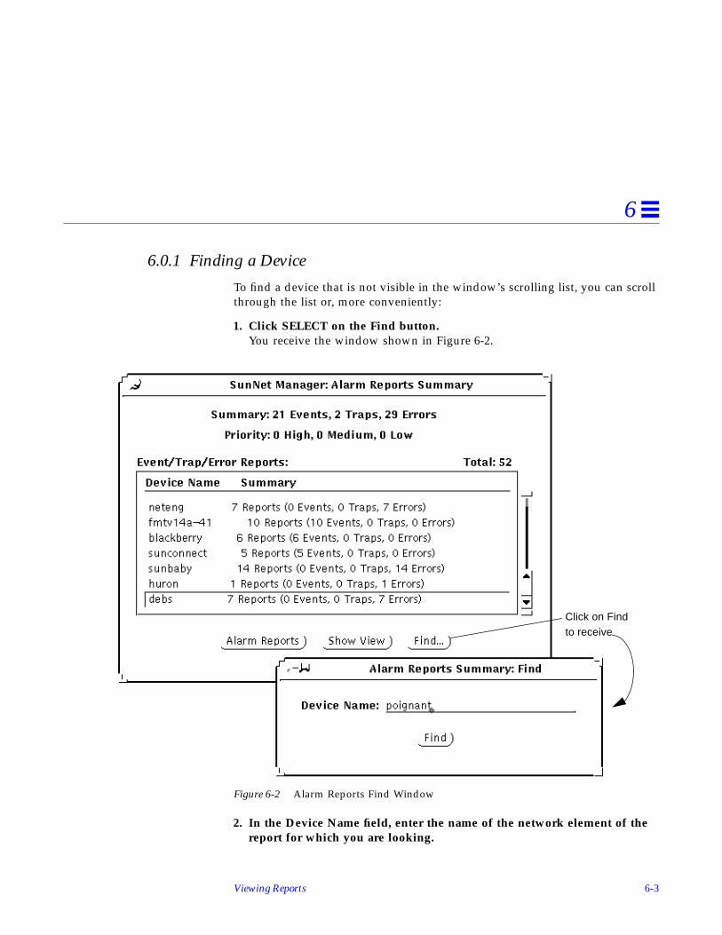
Viewing Reports 6-3
6
6.0.1 Finding a Device
To find a device that is not visible in the window’s scrolling list, you can scrollthrough the list or, more conveniently:
1. Click SELECT on the Find button.You receive the window shown in Figure 6-2.
Figure 6-2 Alarm Reports Find Window
2. In the Device Name field, enter the name of the network element of thereport for which you are looking.
Click on Findto receive

6-4 Solstice Site/SunNet/Domain Manager Administration Guide
6
3. Click SELECT on Find.
If a line for a device is present, that line is displayed and highlighted in theAlarm Reports window’s scrolling list. If a line for a device is not present, youreceive the message “Device name not found” in a popup window.
6.0.2 Switching Views
Through the Alarm Reports Summary window, you can switch views for aspecific device. (This function is also available through the View➤Find optionin the Console window.) To show the current view for a device and to be ableto switch views, do the following:
1. Select the specific device in the Alarm Reports Summary window’sscrolling list.
2. Click SELECT on the Show View button.You receive a window such as the one shown below.
Figure 6-3 Alarm Reports: Show View Window
If a device is in only one view, the Next button in the window above is greyed-out.
3. If a device is in multiple views, click SELECT on Next to switch from thecurrent view (as displayed in the Console window) to the next view inwhich the specified device appears.In this context, “next” means the next view on the list of views as displayedby the Console’s Goto menu.
Device name is alreadyfilled in

Viewing Reports 6-5
6
6.0.3 Obtaining Device-specific Alarm Reports
You can view further detail for a specific device. To obtain a device-specificreport, use any of the following methods:
• Double click on the line for a device in the scrolling list in the AlarmReports Summary window.
• Click SELECT on the line for a device in the scrolling list in the AlarmReports window, then click SELECT on the Alarm Reports button at thebottom of the window.
• Click SELECT on the glyph for a device and invoke View➤Alarm Reports inthe Console menu
• Invoke Alarm Reports from an element’s glyph menu.
Using any of the preceding methods, you then receive an Alarm Reportswindow for the specified device, as shown in Figure 6-4.

6-6 Solstice Site/SunNet/Domain Manager Administration Guide
6
Figure 6-4 Device-specific Alarm Reports Window
device to receive AlarmDouble-click on line for
Reports window for thatdevice.

Viewing Reports 6-7
6
6.0.4 Device-specific Alarm Reports Window
A device-specific Alarm Reports window allows you to:
• Sort alarm reports
• Filter reports
• Find reports associated with a specific agent
• Save reports to a file
• Print reports
These functions are available through the View, Save, and Print buttons at thebottom of the Alarm Reports window. The functions are described in detail in“Part 2: Reference.”
6.0.4.1 Filtering Alarm Reports
1. Press MENU in the View button, to receive the following menu;
Figure 6-5 Device-specific Alarm Reports View Menu
2. Release MENU over Filter to receive the following window:

6-8 Solstice Site/SunNet/Domain Manager Administration Guide
6
Figure 6-6 Device-specific Alarm Reports Filter Window
Your selections in the Filter window determine which types of reports aredisplayed in the device-specific Alarm Reports window. The default is that allalarm reports are displayed. Priority choices apply only to Event Reports.
• Click on Apply, your choices take effect immediately.
• Click on Reset to restore the choices to the way they were when you openedthe Filter window.
Note – If you plan to both sort (described below) and filter your device-specificalarm reports, you must sort before filtering. If you want to sort again, afterfiltering, you must click SELECT on Reset, then Apply, in the Filter window,sort again, as described below, then reinvoke Filter.
6.0.4.2 Sorting Alarm Reports
1. In a device-specific Alarm Reports window, press MENU on View➤SortBy. You receive the following menu:

Viewing Reports 6-9
6
Figure 6-7 Device-specific Alarm Reports Sort Menu
2. Release MENU over the sorting method you want. Your selection takeseffect immediately. The choices are mutually exclusive.
The sorting choices are:
Time Stamp: The default. Reports are sorted in chronological order with themost recent appearing last on the list.
Priority: high priority reports are listed first. Use this option if you are filteringout trap and error reports. If you are not filtering out reports and you specifysorting by priority, event reports are listed first, followed by error reports, thentrap reports.
Type: Reports are sorted by type, in the order: event, error, trap. Note thatalarm reports received after you specify sorting by type, are appended to theappropriate list of reports, depending on the type of the new reports.
Note – When sorting alarm reports, only the reports currently displayed in theAlarm Reports window are sorted. All new reports received during the sortingoperation are appended to the end of the sorted list.

6-10 Solstice Site/SunNet/Domain Manager Administration Guide
6
6.0.4.3 Finding Agent-specific Alarm Reports
You can search on an agent name to find instance(s) of event reportsoriginating with that agent. To do this, in the device-specific Alarm Reportswindow, press MENU on View➤Find and release MENU to receive thewindow shown in the Figure below.
Figure 6-8 Device-specific Alarm Reports Find Window
In the Agent Name field, enter the agent and group name—not just the agentname. For example, specify hostperf.data , not just hostperf . When youclick SELECT on Find, the window displays the contents of the first (oldest)report originating with the agent you specified. If there is no report originatingwith the agent you specify, you receive the message, “Agent name not found.”
6.0.4.4 Saving Device-specific Alarm Reports
SunNet Manager allows you to save device-specific alarm reports to a file. Todo this, in the device-specific Alarm Reports window, click SELECT on Save.You receive a window such as the one in Figure 6-9.

Viewing Reports 6-11
6
Figure 6-9 Save to Logfile Window
If the directory first displayed is not the directory you want, change directoriesby clicking SELECT on folder icons or the. (level above) symbol. Alternatively,you can enter a pathname in the Name field and click SELECT on Save. If thepath you enter ends in a valid directory, you are switched to that directory.
When you reach the directory you want, enter the name of the file to which thereport will be written.
6.0.4.5 Printing Device-specific Alarm Reports
SunNet Manager allows you to print device-specific alarm reports. ClickSELECT on the Print button on the bottom of the device-specific Alarm Reportswindow, or press MENU on Print➤Report and release MENU. SunNetManager sends the currently displayed alarm report to your default printer.
6.1 Viewing Error Messages and Error Reports The Console displays error messages in several locations:

6-12 Solstice Site/SunNet/Domain Manager Administration Guide
6
• Footer of the Console window.These are generally brief messages about the status of an operation and aretemporary. They are overwritten by subsequent status messages. Because ofthe brevity of these messages, you are usually directed to the Error Reportswindow for more information.
Figure 6-10 Console Window Footer Display
• Footer of the Console pop-up windows or a tool (Results Browser, Grapher,Set Tool) window.These messages are described in the Site/SunNet/Domain ManagerTroubleshooting Guide.
Figure 6-11 Console Pop-up or Tool Window Footer Display
• Error Reports window.Errors detected by the Console and errors returned by agents are displayedin this window. These messages are described in Site/SunNet/DomainManager Troubleshooting Guide and in the man page for the agent.
To view the Error Reports window:
Pop-up window footer message.

Viewing Reports 6-13
6
1. Move the mouse pointer over the View button and press MENU to openthe View menu.
2. Drag the mouse pointer down to Error Reports and release MENU.You receive a sample error reports window similar to the one below:
Figure 6-12 Sample Error Reports Window
3. To examine error reports for a particular system, type in the device nameafter the Device prompt and press Return.To see entries for all elements again, press Ctrl-U to clear the Device lineand press Return.
4. To save the error reports to a file, press MENU in the output portion of theError Reports window and release MENU over File➤Save or File➤Storeas New File. In the window you then receive, select or enter a directoryand enter a file name. Click SELECT on the Save button.
5. To browse through entries in the log:

6-14 Solstice Site/SunNet/Domain Manager Administration Guide
6
• Press SELECT on the slider and drag the slider to the left or right.• Click SELECT to the left or right of the slider.• Click SELECT on either end of the slider bar.• Enter the number of a report on the Report line and press Return.
6.1.1 Useful Notes about Types of Errors
Two types of agent errors are returned to the Console. Agent-specific errors areerrors defined in the agent schema file—these error messages are described inthe man pages for each agent. There are also “generic” errors, such as“unknown host” or “no threshold value”—these errors are described in theSite/SunNet/Domain Manager Troubleshooting Guide.
Agent errors can also be classified as “fatal” or “warning.” All generic errorsare fatal errors. Agent-specific errors can be either fatal or warning. Fatal errorscause the agent to stop servicing the request. Warnings are for yourinformation only; the agent will continue to return reports.
The Errors category of the Console Properties window allows you to specifysignal options and any operations to be started when the Console receives anerror from an agent. The default Errors category settings cause the glyph forthe target element to be dimmed only if a fatal error is reported for theelement. The glyph effect is not propagated. You can change the Errorscategory settings—for more information, refer to “Part 2: Reference.”
Fatal errors reported by agents, whether agent-specific or generic, areconsidered in the Console as high-priority errors. The Console treats warningsas low-priority errors. Thus, if you specify Color by Priority in the Glyph Effectsetting for the Errors category in the Console Properties window, fatal errorswill change an element glyph to red, and warnings will change an elementglyph to yellow, or to colors you have customized.
By default, a maximum of 100 error reports are displayed in the Error Reportswindow. You can change the maximum number in the Console Propertieswindow. See the description of the Maximum Error Reports setting in “Part 2:Reference.”

Viewing Reports 6-15
6
6.2 Viewing TrapsA trap is an unsolicited report sent from an agent that usually signifies someunexpected error condition. Trap reports are displayed in the Event/TrapReports window.
When a trap is generated, a trap report stating the cause of the trap is returnedto the Console. The report is stored in the event.log file and may be viewedusing the following steps.
1. In the Console window, press MENU in View➤Event/Trap Reports andrelease MENU.You receive an Event/Traps Reports window similar to the one below.

6-16 Solstice Site/SunNet/Domain Manager Administration Guide
6
Figure 6-13 View—Event/Trap Reports Window
2. To examine trap reports for a particular system, type in the device nameafter the Device prompt and press Return.To see entries for all elements again, press Ctrl-U to clear the Device lineand press Return.
An alternative way to obtain an element-specific trap reports is to clickSELECT on the glyph in the Console window, then invokeView➤Event/Trap Reports.
Menu selection invokes Event/Trap Reports window

Viewing Reports 6-17
6
3. To save the Event/Trap Reports to a file, click SELECT on the Save button.A pop-up Save window appears, where you can enter the path and filename where the event/trap reports are to be stored.
4. To browse through entries in the log:
• Press SELECT on the slider and drag the slider to the left or right.• Click SELECT to the left or right of the slider.• Click SELECT on either end of the slider bar.• Enter the number of a report on the Report line and press Return.
6.2.1 Useful Notes about Report Settings and Display
The Trap Information settings in the Events and Traps category of the ConsoleProperties window allow you to specify signal options and any operations tobe started when the Console receives a trap. The default Events and Trapscategory settings cause the glyph for the target element to blink only if a trap isreported for the element. By default, the glyph effect is propagated. If theConsole window is closed to an icon, you can specify that it be openedautomatically if an event or trap is received. To view or change event- andtrap-related settings, click SELECT on Props in the Console’s control area, thenselect Events and Traps in the Category pulldown menu. For more informationon changing Trap Information settings, refer on the Console’s Propertieswindow in “Part 2: Reference.”
Trap reports are generated when elements are added, changed, or deleted inthe runtime database. By default, these traps are ignored by the Console. If youwant to have these traps displayed, toggle the check mark off in the IgnoreDatabase Traps setting for the Events and Traps category. If a glyph effect isspecified for traps, the glyph representing the system on which the runtimedatabase is located is affected.
Note – When you create an element with the Ignore-Database-Traps optionturned off in the Console’s Props➤Events and Traps window, the trap reportfor that element says that the element was “created.” An analogous operationusing the database API returns the word “added” rather than “created.”

6-18 Solstice Site/SunNet/Domain Manager Administration Guide
6
6.2.2 Priority Settings for Traps
Traps can be high, medium, or low priority. Starting with version 2.3 of SunNetManager, you can determine priority level for any SNMP trap (low, medium orhigh). Enter your choice into the trap configuration file, snmp.traps after thetrap description field. See Chapter 8, “Managing SNMP Devices” forinformation on how to set SNMP trap priorities. Traps generated by changes tothe runtime database are considered low-priority.
If you specify Color by Priority in the Glyph Effect setting for the Events andTraps category in the Console Properties window, SNMP traps will change anelement glyph to the default color of red, or to the color you have customized.Database traps will change an element glyph to the default color of yellow orto the color you have customized. For more information about customizingColor by Priority, see “Part 2: Reference.”
By default, a maximum of 1000 trap reports are displayed in the Event/TrapReports window. You can change this maximum number in the ConsoleProperties window. See the description of the Maximum Trap Reports settingin “Part 2: Reference.”

7-1
Managing Printers 7
This chapter discusses the following topics:
• Checking the queue of a remote printer
• Checking the status of a remote printer
Through the lpstat agent, SunNet Manager allows you to check the queueand check the status of remote printers. A printer can be connected to amachine running SunOS 4.x or Solaris 2.x.
Perform the following steps to manage a remote printer:
1. Install agents on the machine to which the printer is connected (theprinter server).If the machine is running Solaris 2.x, use pkgadd ; if it is running SunOS 4.x,use getagents . See your installation guide for instructions on installingagents.
2. In the Console window, create an element of category component andtype laserwriter , newsprinter , or printer , as appropriate.See the chapter on “Creating and Modifying the Management Database” forinstructions on creating an element. Figure 7-1 shows an example CreateObject window.

7-2 Solstice Site/SunNet/Domain Manager Administration Guide
7
Figure 7-1 Creating a Printer
3. After clicking SELECT in the window above, you receive an ElementProperties window. In this window, do the following:
a. Enter the name of the printer (print queue name)—not the name of theprinter server.
b. Check off the lpstat agent.
c. Enter the name of the connected machine as the proxy.
d. Click SELECT on Apply.
Do not check off any agents other than lpstat . See Figure 7-2 for anexample Element Properties window.
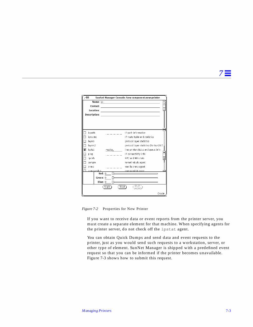
Managing Printers 7-3
7
Figure 7-2 Properties for New Printer
If you want to receive data or event reports from the printer server, youmust create a separate element for that machine. When specifying agents forthe printer server, do not check off the lpstat agent.
You can obtain Quick Dumps and send data and event requests to theprinter, just as you would send such requests to a workstation, server, orother type of element. SunNet Manager is shipped with a predefined eventrequest so that you can be informed if the printer becomes unavailable.Figure 7-3 shows how to submit this request.

7-4 Solstice Site/SunNet/Domain Manager Administration Guide
7
Figure 7-3 Sending Predefined Request to Printer
Through the Quick Dump mechanism (in the printer’s glyph menu pressMENU on Quick Dump➤lpstat➤queue or ➤status), you can view the currentjob queue for a printer or obtain the current status. Status is reported as one ofthe following codes:
• 0 idle
• 1 waiting
• 2 printing
• 3 error
Through the lpstat agent, you can obtain a variety of information about printqueue and printer status. There are some differences between informationreturned from printers connected to SunOS 4.x printer servers and thatreturned from Solaris 2.x print servers. See the na.lpstat (8) man page fordetails.

8-1
Managing SNMP Devices 8
This chapter discusses the following topics:
• Adding SNMP devices
• Creating an SNMP element in the database
• Setting up SNM to receive traps from a device
• Using the Set Tool to retrieve SNMP attribute values
• Using the Set Tool to change SNMP attribute values
SunNet Manager provides a proxy agent that supports the Simple NetworkManagement Protocol (SNMP). The SNMP proxy agent allows you to get dataand event information from, and set attribute values for, devices that aremanageable through SNMP. The proxy agent can handle requests from theConsole for multiple SNMP devices on a network.
The SNMP trap daemon receives traps from SNMP devices, filters the traps, andtranslates the traps into SunNet Manager traps. The trap daemon thenforwards the traps to one or more management stations.
Management of SNMP devices is similar to management of non-SNMPdevices, with the following exceptions:
• Multiple schemas can be associated with an SNMP device (however, onlyone schema can be specified in a request).

8-2 Solstice Site/SunNet/Domain Manager Administration Guide
8
• While SunNet Manager uses schema files to describe the attributes of amanaged object, the SNMP protocol uses a mib to describe the attributes ofa managed object.
This chapter describes how to integrate SNMP devices into your SunNetManager environment in order to use SNMP to manage those devices. Youshould have some familiarity with SNMP concepts to proceed with these tasks.Refer to “Part 2: Reference” for a detailed description of how the SNMP proxyagent works.
8.1 Adding SNMP DevicesThe following is an overview of how to add non-Sun SNMP devices to yourmanagement database.
If you are using SNMP to manage Sun workstations that contain the SNM-supplied SNMP agent (snmpd), you can skip this task and proceed to thesection on “Creating an SNMP Element in the Database.”
1. Install the device on the network.
2. Obtain the schema file for the device.
3. Configure the SNMP proxy agent.The schema file should reside in a directory specified by na.snmp.schemasin the snm.conf file, for example:
4. On the Console system, load the schema file.Skip this step if you are using the SNMP schema files provided with SNM(snmp.schema for MIB I devices, or snmp-mibII.schema for MIB IIdevices). The schema file should reside in a directory specified in the SNMConsole Properties window.
# @(#)snm.conf2.36 6/30/96 - SunNet Manager configuration file# Copyright (c) 1990,1993,1996 by Sun Microsystems Inc.
# Site-specific configuration information
### Keywords for the SNMP proxy agent:# Directory list for SNMP schema files. Separate each directory# with a colon.na.snmp.schemas /opt/SUNWconn/snm/agents

Managing SNMP Devices 8-3
8
5. Create the device in the Console.See “Creating an SNMP Element in the Database” for information about thisstep.
The following is a detailed explanation of each step:
1. Install the device on the network.Refer to the device documentation for installation information. If the devicesends SNMP traps that you want forwarded to the SNM Console, you willalso want to set up the SNMP trap daemon and Console for trap handling.See “Setting Up SNM to Receive Traps from a Device” for more information.
2. Obtain the schema file for the device.SunNet Manager uses schema files to manage objects. You can obtain aschema file in one of several ways:
• The vendor of the SNMP device may provide a SunNet Manager schemafile. If the SNMP device sends enterprise-specific traps, the vendor may alsosupply a file that describes these traps—see “Setting Up SNM to ReceiveTraps from a Device” for more information about setting up SNM to handleenterprise-specific traps.
• The [email protected] electronic mail server maintains a collection ofschema files for various SNMP devices. For information on accessing themail server, see “SunNet Manager Electronic Mail Distribution Service” inthe Preface of this book.
• If the SNMP device adheres to MIB I or MIB II specifications, you can useone of the schemas supplied with SNM—either snmp.schema (for MIB I) orsnmp-mibII.schema (for MIB II). If you installed the SNMP proxy agentwith getagents , the Sun-supplied SNMP schemas are automaticallycopied onto the host system with other schemas.
• Starting with version 2.3, SunNet Manager schemas for several RFC MIBsare bundled.
• If you do not have a schema file for the device that you want to manage,you can create a schema file from the MIB for the device with themib2schema utility. Refer to “Part2: Reference” for more information.
Change the name of the schema, if necessary. The schema name is not theschema file name. The schema name is specified by the keyword proxy inthe schema file. If mib2schema was used to generate the schema file, thisname is derived from the name of the MIB (not the MIB file name). This is

8-4 Solstice Site/SunNet/Domain Manager Administration Guide
8
the name that will appear in the list of agent schemas for each element.Therefore, you may want to edit this name to ensure that it is meaningful toyou.
3. Configure the SNMP proxy agent.
a. A single proxy agent can handle management requests for many devices.You can allow the SNMP proxy agent on the manager station to handleall SNMP requests. However, you may want to distribute the proxy agentto minimize network traffic—see “Management Applications andAgents” for more information.
b. On the proxy system, make sure that the schema file is available to theSNMP proxy agent. The schema file should reside in a directory specifiedby the na.snmp.schemas keyword in the snm.conf file on the proxysystem. By default, the snm.conf file is located in the following directory:•/etc for the Solaris 1.1.1 version of the current SunNet Manager
product•/etc/opt/SUNWconn/snm for the Solaris 2.x version of the current
SunNet Manager product
Note – If you modify the snm.conf file while the SNMP proxy agent isrunning, you need to kill the proxy agent (na.snmp ) for the changes to takeeffect. Refer to the Solstice Site/SunNet/Domain Manager Troubleshooting Guide forinformation on how to kill the agent.
4. On the Console system, load the schema file.Skip this step if you are using the SNMP schema files provided with SNM(snmp.schema for MIB I devices, or snmp-mibII.schema for MIB IIdevices).
To load the schema file into the Console:
a. Start the Console.
b. Use the Load➤Management Database option in the File menu to load theschema file.
c. Make sure that the schema file is located in a directory that is specifiedby the Schema Directories setting in the Console Properties window.

Managing SNMP Devices 8-5
8
8.2 Creating an SNMP Element in the DatabaseThe IP Discover Tool automatically creates SNMP elements. You can specify anoption in IP Discover that allows you to discover only SNMP elements orSNMP elements in combination with other types of elements. See “Part 2:Reference” for a description of the IP Discover Tool.
To create SNMP elements one-at-a-time, use the Console’s graphical editor.Using this method, creating an element that will be managed with the SNMPproxy agent is essentially the same as creating any element in your database.To define an SNMP element instance in a Console view, you specify SNMP-specific information about that element in the Properties window.
1. Move the mouse pointer to the Edit button and press MENU to open theEdit menu. Release MENU over the Create option. You receive the CreateObject window:
Figure 8-1 Edit—Create Window
2. Click SELECT on the category of element and type of element you want.Then click SELECT on Create.
3. Fill in the Properties window for the element.The top portion of the Properties window is the element data. You must fillin the Name field; other fields are optional. Specify the SNMP ReadCommunity and SNMP Write Community fields for the element. Although
8-6 Solstice Site/SunNet/Domain Manager Administration Guide
8
filling in the SNMP fields (including SNMP Vendor Proxy and SNMPTimeout) is optional, you should understand how the proxy agent uses thisinformation—see the discussion below.
The middle portion of the Properties window is the list of agent schemasthat the Console knows about. Check the schemas that apply to the device.There are three SNMP schemas supplied with SunNet Manager: snmpdescribes the MIB I, snmp-mibII describes MIB II, and sun-snmp is theschema file for the SNMP agent (snmpd) for Sun workstations. If you loadedany additional schemas into the Console, the names of these schemasappear in the schemas list. Note that the schema name is not the schema filename. The schema name is specified by the keyword proxy in the schemafile. See “Adding SNMP Devices” for more information about setting theschema name.
4. Click SELECT on the Apply button in the properties window.A glyph for the element you just defined appears with the name youspecified.
Figure 8-2 shows a properties window for a new component that has theSNMP schemas checked.

Managing SNMP Devices 8-7
8
Figure 8-2 Properties Window for a New Component
Field ValuesThe values in the fields SNMP Read Community, SNMP Write Community,SNMP Vendor Proxy, and SNMP Timeout are sent with the request to theSNMP proxy agent. If you do not specify values in the SNMP ReadCommunity, SNMP Write Community, and SNMP Timeout fields, the SNMPproxy agent uses the following values:
• Read community is “public.”
• Write community is “public.”

8-8 Solstice Site/SunNet/Domain Manager Administration Guide
8
• Timeout will be the value (in seconds) specified by the keywordna.snmp.request_timeout in the snm.conf file on the system wherethe SNMP proxy agent resides. The keyword’s supplied value is 5 (seconds).
Vendor Proxy FieldSNMP Vendor Proxy is an optional field that specifies the name of a proxysystem with which the SNMP proxy agent will communicate. Normally, youdo not need to specify a value for this field. If this field is used, the SNMPrequest is passed through the element to a secondary proxy. This field shouldonly be specified when a vendor has supplied an SNMP proxy agent to managea particular device or set of devices that do not support IP connectivity. Thevendor‘s SNMP proxy agent communicates with the SunNet Manager SNMPproxy agent through SNMP, but communicates with the element using eitherSNMP or a different protocol.
Agent Schema FilesYou can select multiple SNMP agent schema files for an element. However,only one schema is associated with each request. Merely checking an SNMPagent schema on the Properties window does not make the elementmanageable through the SNMP proxy agent. SNMP agent software must beinstalled and running on the SNMP device. The MIB for the device mustcontain the same data definitions as the schema file used by the Console andthe SNMP proxy agent.
The blank lines next to the SNMP agent schema names allow you to specify thename of the system on which the SNMP proxy agent resides. This system nameis for a default proxy system. You can specify a different proxy system namefor each request. If you do not specify a proxy system in the Propertieswindow or in the report request, the system on which the Console is running isassumed to be where the proxy agent resides.
8.3 Setting Up SNM to Receive Traps from a DeviceMany SNMP devices send out unsolicited or unexpected reports called traps.For example, a trap may be sent when a device is restarted. When the SNMPtrap daemon receives traps, it will forward all or only selected traps to one ormore SNM Consoles.

Managing SNMP Devices 8-9
8
1. Determine the location of the SNMP trap daemon.See the discussion later in this section.
2. If you want to define the priority of traps or discard traps based onenterprise-specific traps of host-specific traps, create file entries for thesetraps.For example:
Setting Enterprise-Specific Trap PrioritiesStarting with version 2.3 of SunNet Manager, you can assign low, medium, orhigh priority to an enterprise-specific SNMP trap. Enter the priority into thetrap configuration file (snmp.traps) after the trap description field. Forexample:
If you choose to discard all traps from an enterprise or assign a priority to alltraps for an enterprise, you can specify this on the keyword values next to theObject Identifier following the enterprise keyword. For example:
## Example trapsenterprise 1.3.6.1.4.1.42
1 CPU_Failure high2 Power_Supply_Failure medium3 Network_Connection_Failure low4 Over_Heating discard5 RealTimeClock_Failure discard
## Sample trapshost shanghai
1 CPU_Failure high2 Power_Supply_Failure medium3 Network_Connection_Failure low4 Over_Heating discard5 RealTimeClock_Failure discard

8-10 Solstice Site/SunNet/Domain Manager Administration Guide
8
The snm.conf file includes the following priority keyword:
na.snmp.trap.default-priorit y
The default value is low; however, any of the three values can be used. If youchange the value, stop and restart the trap daemon, na.snmp-trap . Anenterprise specific trap priority overrides the priority specified byna.snmp.default-priority in the snm.conf file.
Setting Host Specific Trap FiltersStarting with version 2.3, you can specify filters based on certain hosts. Whatyou specify overrides any enterprise-specific filter. The keyword, <host>, canbe used in the snm.conf file followed by the ip_address or host name and apriority keyword. Each line beginning with the keyword <host> can befollowed by subsequent lines describing the action, description, or priority foreach trap. For example:
<host> 139.146.75.165 discard
<host> 149.136.75.200 medium
6 TEMP_HIGH high
10 PORT_TEST_FAIL discard
Precedence ValuesThe snm.conf file specifies general priority for all traps. The trap daemonwill compare oid entries with specific settings specified in snmp.traps when itreceives a trap. If a particular trap has an oid entry in snmp.traps , thena.snmp-trap daemon will take the priority of the enterprise trap. Thena.snmp-trap daemon searches for the hostname of the target trap. If the name ispresent, the daemon will use it as this trap’s priority.
3. Specify where the trap daemon should forward the traps.
## Sample traps
1 snmp.traps enterprise 1.3.6.1.5.1.75 discard

Managing SNMP Devices 8-11
8
Forwarding TrapsStarting with version 2.3 of SunNet Manager, you can forward all raw trapPDU packets to other workstations or to a different port on the same machineusing the keyword na.snmp-trap.forward . You can specify a maximum oftwo hosts and the appropriate UDP ports to which the trap PDUs are to beforwarded.
Add the keyword na.snmp-trap.forward.snmp-traps : <hostname>,<port> :
<hostname>,<port> in the snm.conf file. You can specify more than one hostname—separate each host name with a colon (:).
Use the keyword na.snmp-trap.rendez to forward a SunNet Manager formatSNMP trap to one or more consoles. Add the keyword to the snm.conf file.
If you modify the snm.conf file while the SNMP trap daemon is running, youmust kill the trap daemon (na.snmp-trap ) for the changes to take effect. Forexample:
(Refer to the Solstice Site/SunNet/Domain Manager Troubleshooting Guide forinformation on how to kill the daemon.)
4. On the SNMP device, specify that traps be sent to the host where the trapdaemon resides.See the discussion below. Typically, you would specify the IP address of thehost system. However, this is very device-specific. Refer to the devicedocumentation to find out how to do this.
Warning – Use SNMP trap forwarding to forward SNMP traps with caution. Ifyou forward traps within the SunNet Manager environment, and infinite loop(machine A->machine B->machine A) may occur, exhausting machineresources in the process and increasing the burden on network traffic. If aninfinite loop should occur, see the Solstice Site/SunNet/Domain ManagerTroubleshooting Guide for resolution.
### Keywords for the SNMP trap proxy on wordstwo:# default file name of per-enterprise trapsna.snmp-trap.default-trapfile /var/adm/snm/snmp.traps#na.snmp-trap.rendez rubicon

8-12 Solstice Site/SunNet/Domain Manager Administration Guide
8
Trap MessagesA single trap daemon can accept trap messages from many devices. The trapdaemon does not need to reside on the SNMP proxy agent system or theConsole system. Like proxy agents, the SNMP trap daemon can be distributedin a network to reduce network traffic and distribute the processing loadbetween systems. See Chapter 1, “Overview and Concepts” for moreinformation. For example, you might want to have traps from all of the SNMPdevices on a subnet sent to one host system. The trap daemon on this systemcan then forward some or all of these traps to selected Console system(s).
Types of TrapsThe SNMP protocol defines six generic types of traps. In addition to returninggeneric traps, an SNMP device may return enterprise-specific traps, which aredefined by the device vendor. (See the device documentation for informationon enterprise-specific traps.) Enterprise-specific traps are usually defined in thedevice MIB. If the MIB for the device contains enterprise-specific traps and youused the mib2schema utility to generate a schema file, a trap file, such assnmp.traps , is automatically generated. This file may be copied into place orits contents can be appended to the existing trap file. (See the mib2schema (1)man page for more information.) Otherwise, create an snmp.trap file asdescribed in “Part 2: Reference.”
Discarding TrapsYou may determine that certain generic or enterprise-specific traps do not needto be forwarded to the Console. For example, you may decide that a trap doesnot need to be sent to the Console every time a device is warm-started. You canadd the optional keyword “discard” to trap definition entries in the trapfile—see the trap file syntax in “Part 2: Reference.” The default trap filecontains trap definitions according to enterprise ID. If multiple devices on thenetwork use the same enterprise ID and all the trap file entries apply to eachdevice, add the trap entries to the default trap file. The default trap file isspecified by the keyword na.snmp-trap.default-trapfile in thesnm.conf file on the system on which the trap daemon resides. Normally, thedefault trap file name is:
• /var/adm/snm/snmp.traps for the Solaris 1.x version of the currentproduct.
• /var/opt/SUNWconn/snm/snmp.traps for the Solaris 2.x version of thecurrent product.

Managing SNMP Devices 8-13
8
Trap Priorities and FiltersSee “Setting Trap Priorities” and “Setting Trap Filters” earlier in this chapterfor information about these features.
If multiple devices on the network use the same enterprise ID, but the trap fileentries apply to only specific device names, define an entry for each device inthe SNMP host file. Refer to “Part 2: Reference.”
8.4 Using the Set Tool to Retrieve SNMP Attribute ValuesYou can use the Console to obtain Quick Dumps and data, event, and trapreports on SNMP devices, just as with any other type of device. See thefollowing chapters for steps to get this information: Chapter 4, “RequestingData,” Chapter 5, “Specifying Event Requests” and Chapter 6, “ViewingReports.”
For SNMP devices you can also use the Set Tool to retrieve SNMP attributevalues. Retrieving attribute values with the Set Tool allows you to examine anattribute’s current value before you change it—see Section 8.5, “Using the SetTool to Change SNMP Attribute Values,” on page 8-18 for information onchanging attribute values.
1. Move the mouse pointer over the glyph that represents the target SNMPdevice and press MENU to open the Glyph menu.
2. Drag the mouse pointer down to Set Request. Drag right over the desiredagent schema name and continue to drag right over the desired group ortable name. For example:

8-14 Solstice Site/SunNet/Domain Manager Administration Guide
8
Figure 8-3 Glyph—Set Request Menus
In your response to your menu selection, you receive a window such as theone shown in Figure 8-4.

Managing SNMP Devices 8-15
8
Figure 8-4 Set Tool Window
3. In the Set Tool window, specify the key or options for the request.If the group is a table and you know the key of the row you want, type inthe key value in the Key field. If you do not specify a key value, when youSELECT the Get button (in the next step) the first row of the table will be

8-16 Solstice Site/SunNet/Domain Manager Administration Guide
8
displayed by default and the Key menu generated. You can then choose avalue from the Key menu by pressing MENU on the abbreviated menubutton.
You can specify an SNMP read-community name in the Options field if it isdifferent from the read-community you have previously specified in theProperties window for the element.
4. Click SELECT on the Get button. The attribute values are displayed in theattribute list.You can see detail on an attribute by clicking SELECT on the Details button.Figure 8-5 is an example of information available.
Name: is the name of the attribute
Type: is the type of the attribute. If the attribute is an enumeration, the validvalues will be displayed.
Access: indicates what access categories are assigned to the attribute
Description: gives the meaning of the attribute
Figure 8-5 Attribute Information Screen
8.4.0.1 Retrieving Other Attribute Values
In the control panel at the top of the Set Tool window, you can change theattribute group or agent schema name (or both) to retrieve attribute values forother attribute groups or for other agent schemas used by the target device.
• To change the agent schema:

Managing SNMP Devices 8-17
8
a. Move the mouse pointer over the Agent abbreviated menu button.
b. Press MENU to open the list of agent schemas available for the targetelement.
c. Drag the mouse pointer to the desired agent schema and release.
Figure 8-6 Set Tool—Agent Menu
• To change the attribute group:
a. Move the mouse pointer over the Group abbreviated menu button.
b. Press MENU to open the list of attribute groups specified in the agentschema.
c. Drag the mouse pointer to the desired group and release.
d. If the group is a table and you know the key of the row you want, typein the key value in the Key field.

8-18 Solstice Site/SunNet/Domain Manager Administration Guide
8
Figure 8-7 Set Tool—Group Menu
8.5 Using the Set Tool to Change SNMP Attribute ValuesA set request is used to request an agent to change the value of a particularattribute. With one Set Tool operation, you can send set requests to differentagents for multiple attributes with one Set Tool operation.
1. Move the mouse pointer over the glyph that represents the target SNMPdevice and press MENU to open the Glyph menu.
2. Drag the mouse pointer down to Set Request. Drag right over the desiredagent schema name and continue to drag right over the desired group ortable name. You receive a Set Tool such as the one shown in Figure 8-4 onpage 8-15.
Managing SNMP Devices 8-19
8
3. In the Set Tool window, specify the key or options for the request.If the group is a table, type in the key value in the Key field. If you do notknow the key, retrieve the available key values by clicking SELECT on theGet button.
4. Enter the new value on the line provided in the New Value column andpress Return. The new value is shown in the lower portion of the window.
5. To change another attribute in a different attribute group or agent schema,use the Group and Agent abbreviated menu buttons.All the attributes in the selected group appear in the attribute list. If youwant to change the value of an attribute of a row in a table, you mustsupply the key for that row. You can also click the Get button to display thecurrent values of the attributes.
You can specify an SNMP write-community name in the Options field if it isdifferent from the write-community you have previously specified in theProperties window for the element.
6. Repeat the previous three steps until you have entered all the attributechanges you want to make for the target element.Note that the new attribute values are collected in the Set Information list.This allows you to view your changes and edit them, if necessary, before theactual set request is made.
7. To send the set request with the new value(s), SELECT the Set button atthe top of the control panel.When the Set request has been successfully completed, the Set Informationlist is cleared.
8.5.1 Setting Attributes
If you are allowed to set an attribute, a line is provided in the New Valuecolumn to the right of the Current Value in the attribute list. (Current Value isalso provided for attributes that cannot be set; however, no lines are providedin the New Value column.) Attributes of enumeration data types that you canset have an abbreviated menu button displayed in the New Value column;press MENU on the menu button to choose the desired new value.

8-20 Solstice Site/SunNet/Domain Manager Administration Guide
8

9-1
Creating and Managing a Link 9
This chapter discusses the following topics:
• Using the Console’s Edit function
• Using IP Discover to create manageable links
“Manage,” in this context, means sending data and event requests to andreceiving event and trap reports from. A link is an SNM object in the category“connection.”
The easiest way to create a connection is through the IP Discover Tool, the useof which is described in “Part 2: Reference.” If you need to create only a fewmanageable links, you should use the Console’s graphical editor function,described in the following section. The use of IP Discover hides the details oflink creation; the use of the Edit function requires more intervention on yourpart.
9.1 Using the Console’s Edit FunctionYou create a link in the same you way you create elements of other categories.Invoke the Console’s graphical editor function (press Edit➤Create in theConsole’s control area) and click SELECT in the Connection category. SeeFigure 9-1.

9-2 Solstice Site/SunNet/Domain Manager Administration Guide
9
Figure 9-1 Creating a Connection Object
You can manage a connection of any type—types link or rs232 , the typessupplied with SNM, or connection types that you add. You can create a linkbetween any two elements. However, realistically, the most useful links arebetween two components, such as two routers, or a router and a subnet.
After you click SELECT in the Create button in the window shown inFigure 9-1, you receive a properties window for a new connection as shown inFigure 9-2.

Creating and Managing a Link 9-3
9
Figure 9-2 Properties for New Connection
Referring to Figure 9-2, Object1 and Object2 are the names of objects in theruntime database. SNM manages the link based on the data returned fromObject1. The name of the link (in the Name field) is for your use and cannot bean existing object in the database. For a link, you should have the ping and, ifone or both objects support it, the snmp agents checked off.
After you click SELECT on apply your link object is created and is displayed inthe Console as shown in Figure 9-3.

9-4 Solstice Site/SunNet/Domain Manager Administration Guide
9
Figure 9-3 New Link in Console
This example shows the link in the view for the machine,fmtv14a-136 , a router that is the first object (Object1) listed in the linkproperties. This choice of where to locate the object is arbitrary. You mightlocate the link in its own view, in your Home view, or the view that displaysglyphs for both the router and the subnet to which it connects. In the example,we copy the link object to the view displaying the objects connected by thelink. See Figure 9-4.

Creating and Managing a Link 9-5
9
Figure 9-4 Link in View with Connected Objects
In Figure 9-4, note that the link lies between the two objects specified asObject1 and Object2 in Figure 9-2. That is, it connects the router fmtv14a-136to the subnet umtv-eng-fddi-bb-routers.
Independent of creating the object link_to_fddi_net in the Console, if youare creating the link object “by hand”, you must add an entry to the linkmapfile to identify the new link. The linkmap file, described in a man pagesupplied with SNM, is stored by default in the following directory:
• /var/adm/snm for Solaris 1.x• /var/opt/SUNWconn/snm for Solaris 2.x
For the link object link_to_fddi_net we create the following entry in thelinkmap file:
fmtv14a-136 2 link_to_fddi_net
Link (connection) object link_to_fddi_net

9-6 Solstice Site/SunNet/Domain Manager Administration Guide
9
The first field in this entry (fmtv14a-136 ) corresponds to Object1 in the linkproperties sheet. As with Object1 in the properties sheet, SNM manages thelink based on data returned by the element in this first field. The third field(link_to_fddi_net ) corresponds to the Name field in the properties sheet.The second field (2) is the interface on the machine specified in the first field.This is the interface over which the connection exists to the object at the remoteend of the link. We obtained this number from the IP Discover Tool, so strictlyspeaking, we have “cheated” in this example. However, we later describe howto use IP Discover to perform the same tasks that are described here.
At this point, the link is fully manageable. That is, you can send event requeststo it and, if the machine identified in the linkmap file is running an SNMPagent, can receive traps from it.
Sending an Event Request to a link is the same as sending such a request to acomponent. Figure 9-5 is an example of invoking a Send Request to a link.

Creating and Managing a Link 9-7
9
Figure 9-5 Invoking Send Request to a Link
After invoking Send Request, you receive the Request Builder window inFigure 9-6.
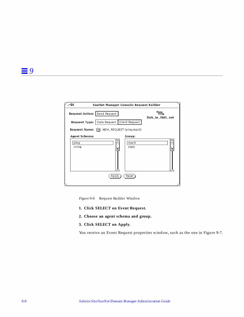
9-8 Solstice Site/SunNet/Domain Manager Administration Guide
9
Figure 9-6 Request Builder Window
1. Click SELECT on Event Request.
2. Choose an agent schema and group.
3. Click SELECT on Apply.
You receive an Event Request properties window, such as the one in Figure 9-7.

Creating and Managing a Link 9-9
9
Figure 9-7 Event Request Properties
The Key field in the properties sheet is derived from the interface-number fieldin the linkmap file. The fact that this number displays correctly is oneindication of a valid linkmap entry for link_to_fddi_net .
You can use the decay feature to alert you if your link goes down, then comesup again. If the link goes down (with a resultant change of glyph color to red,orange, yellow, or a color you customize) then comes back up, the glyph colorchanges to blue (or a color you customize) and remains that color until reset oruntil the link goes down again.
If the link goes down (or decays), you observe the glyph effect in the Console,just as you do for an event occurring for any element. The difference with thelink management feature is that the link itself displays your specified glypheffect. When a link changes color, blinks, or dims, it indicates that one or bothof the machines at either end of the link is down, or that the link medium itselfis disrupted.

9-10 Solstice Site/SunNet/Domain Manager Administration Guide
9
9.2 Using IP Discover to Create Manageable LinksThe IP Discover Tool automates the process of creating manageable links andadding required entries to the linkmap file. In this example, we “discover” thesame link we created by hand in the previous section.
Invoke IP Discover by selecting Tools➤Discover in the Console’s control area.In the IP Discover Tool’s base window, click SELECT on ConfigurationOptions. In the IP Discover Configuration window, to find manageable links,click SELECT on Yes in Add Object Connections. The window shown inFigure 9-8 has Add Object Connections selected.
Figure 9-8 Discover Configuration Window
In addition to the Add Object Connections selection, the non-default selectionsin the window shown in Figure 9-8 are: Maximum Hops (changed from 0 to 1),Add To All Views (changed from Yes to No), Routers (only) for Objects toDiscover. A Viewname of “routers” is specified.

Creating and Managing a Link 9-11
9
Starting with version 2.3, you can choose the ARP or Ping search method inaddition to the default method. The default method is a combination of ARPand Ping. See “Part 2: Reference” for descriptions of these methods.
The effect of the selections shown in Figure 9-8 is to tell IP Discover, “Find onlyrouters 0 or 1 hops away and find all links between those routers. Add alldiscovered elements to a view named ‘routers’.”
After clicking SELECT on Apply and starting the IP Discover function, youreceive a view similar to the one in Figure 9-9.
Figure 9-9 Network Icon for View “Routers”
Double-click on the network icon in Figure 9-9 to receive the sub-view shownFigure 9-10.

9-12 Solstice Site/SunNet/Domain Manager Administration Guide
9
Figure 9-10 View Created by Discover
A difference between the link you created yourself in the previous section andthe link created by IP Discover is the name. The IP Discover Tool creates aname by combining the names of the two linked objects and appending thestring link . You can illustrate this by pulling down the glyph menu for thelink glyph, as shown Figure 9-11.
Link that you plan to manage

Creating and Managing a Link 9-13
9
Figure 9-11 Link Name as Created by IP Discover
Figure 9-12 shows the properties of the “discovered” link. Note that, except forthe name, these properties are identical to the properties for the hand-createdlink, shown in Figure 9-2 on page 9-3.
Link name as created by Discover
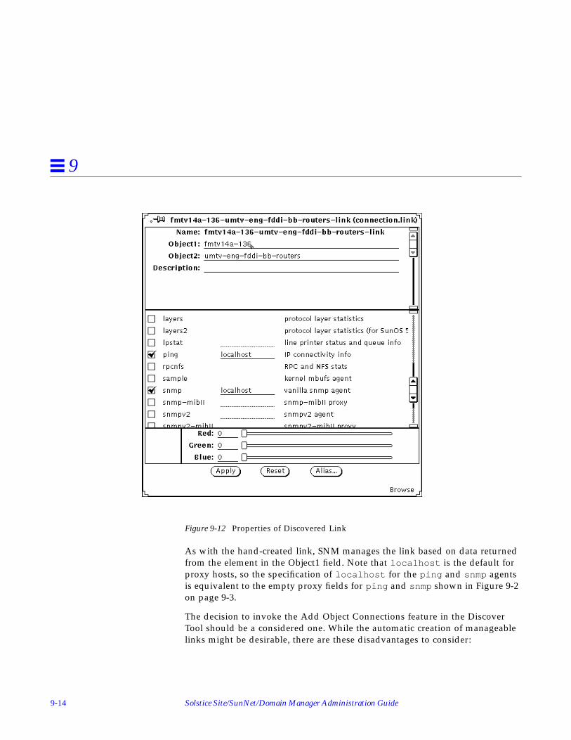
9-14 Solstice Site/SunNet/Domain Manager Administration Guide
9
Figure 9-12 Properties of Discovered Link
As with the hand-created link, SNM manages the link based on data returnedfrom the element in the Object1 field. Note that localhost is the default forproxy hosts, so the specification of localhost for the ping and snmp agentsis equivalent to the empty proxy fields for ping and snmp shown in Figure 9-2on page 9-3.
The decision to invoke the Add Object Connections feature in the DiscoverTool should be a considered one. While the automatic creation of manageablelinks might be desirable, there are these disadvantages to consider:

Creating and Managing a Link 9-15
9
• You lengthen the amount of time IP Discover takes to find elements andbuild your database. The time required by the monitor function to detectchanges in your database is also lengthened proportionately.
• If your network consists of a set of LANs, you create many links that havelittle or no value from a network management point of view. With AddObject Connections turned on, the IP Discover Tool creates links betweeneach machine on a subnet and that subnet. In effect, you have a link thatmaps to the machine’s network interface and its transceiver cable (in thecase of Ethernet). This is of no more value than having an element for themachine (or interface) itself.
• Following from the preceding item, you end up with a much larger databasethan you would otherwise.
Depending on the number of links you want to manage, it might be better foryou to use the Console’s graphical editor function, as described in the previoussection, than to use IP Discover Tool’s Add Object Connections feature.

9-16 Solstice Site/SunNet/Domain Manager Administration Guide
9

10-1
Customizing SunNet Manager 10
This chapter discusses the following topics:
• Adding background image to current view
• Creating types of elements
• Creating a new glyph for an element type
• Modifying the tools menu for an element type
• Adding agents and glyphs
• Forwarding Novell’s NMS Alarms to SunNet Manager
10.1 Adding Background Image to Current ViewYou may find it helpful to place elements in views relative to their physicallocations to each other. A Console view may be superimposed upon abackground image, such as that of a region map or the layout of a building.
1. Create the background with your favorite graphics tools (for example,Island Paint).
The background canvas can be any size. A size no larger than 1120 x 800 isrecommended for standard resolution displays. The image should be inraster file format. Icon format is supported if the file ends with the extension.icon . Large backgrounds in icon format load much more slowly thanraster format files.

10-2 Solstice Site/SunNet/Domain Manager Administration Guide
10
2. In the Console window, invoke the View➤Add Background option.
You receive an Add Background file menu, as shown in Figure 10-1.
Figure 10-1 Add Background File Menu
3. Double-click SELECT on the file of your choice in the Add Backgroundfile menu.The background contained in the selected file is displayed in the SunNetManager Console, as shown in Figure 10-2.

Customizing SunNet Manager 10-3
10
Figure 10-2 Console with New Background
After you save the runtime database to a file, the background you add to agiven view is displayed each time you select that view.
To save the runtime database to an ASCII file, do the following:
1. In the Console’s File button, press MENU on Save➤ManagementDatabase and release MENU.

10-4 Solstice Site/SunNet/Domain Manager Administration Guide
10
Figure 10-3 Selecting the File—Save—Management Database Menu Item
You receive the file menu shown in Figure 10-4.

Customizing SunNet Manager 10-5
10
Figure 10-4 File—Save—Management Database Menu
In the file menu, enter or select the directory and file name of the file you wantto save. Click SELECT on the Save button.
When you restart the Console with a command such as the one below, youreceive the view with the background that you added.
Note that the pathname specified as an argument to snm, above, is an example.
10.1.1 Background Images
You can have up to 1024 icon or raster files defined in the runtime database;this includes background images as well as element glyphs.
In addition to changing the background image with the Console optiondescribed in this section, you can also edit the ASCII file that contains theruntime database to achieve the same effect. With a text editor, open this ASCIIfile. Define a viewBackground instance record that specifies the name of theview and the path name of the background image.
hostname% snm -i $HOME/snm/databases/japan.dbase

10-6 Solstice Site/SunNet/Domain Manager Administration Guide
10
Database definitions for background images are described in “Part 2:Reference.”
By editing the ASCII file containing a database, you can add a background to aview other than the current view. However, it is generally easier to use theConsole menu item to add or remove a background than it is to edit a file andload the modified database. Also, the Console option is far less prone to errorthan the file-editing option.
10.2 Creating Types of ElementsThe elements.schema file defines many general types of elements, such asSPARCstations and SPARCservers. If necessary, you can create additionalelement types for your database.
1. With a text editor, create a file with the extension .schema in a directoryspecified by the Schema Directories category of the Console Properties➤
Locations window. The default locations for these directories are:
• /opt/SUNWconn/snm/agents or /opt/SUNWconn/snm/struct forSolaris 2.x
• /usr/snm/agents or /usr/snm/struct for Solaris 1.xIf you create a schema file in another directory, you should specify thedirectory in the Console Properties➤Locations window. The steps foradding a path to this window are described in “Adding Agents and Glyphs”later in this Chapter.
2. Create a record that defines the element type and the fields that are storedin the database for the element type.Database definitions for element types are described in “Part 2: Reference.”Define a glyph to be used to represent the element type. You can also definethe tools that will be available for this element type.
See “Creating a New Glyph for an Element Type” later in this Chapter forinformation on creating an icon for the element type. See “Modifying theConsole Tools Menu” later in this Chapter for information on defining toolsfor the element type.
3. Load the new element type definition into the runtime database:

Customizing SunNet Manager 10-7
10
In the Console’s File button, press MENU on Load➤Management Databaseand release MENU as shown in Figure 10-5.
An alternative to loading the file into the runtime database is to exit theConsole (you may want to save the runtime database), then reinvoke theConsole (snm -i). The new schema file will be automatically loaded in the newConsole session.
Figure 10-5 Selecting the File—Load—Management Database Menu Item
e. In the file menu you receive (shown i n Figure 10-6), enter or select thedirectory and file name for the schema file where the new element typeis stored and click SELECT on Load.

10-8 Solstice Site/SunNet/Domain Manager Administration Guide
10
Figure 10-6 File—Load—Management Database Window
4. Create element instances of the newly loaded element type with thegraphical editor.
Starting with version 2.3 a new file, network_elements.schema, is availablewhich contains the Novell IPX component definition.
10.2.1 Element Categories
There are four categories of elements. You cannot create new elementcategories. The element categories are:
• Component. Includes elements such as workstations, printers, and routers.
• View. Includes elements such as subnets and buildings. Views can containother views or components.

Customizing SunNet Manager 10-9
10
• Bus. Includes an Ethernet LAN segment. A bus appears as a line withmovable endpoints.
• Connection. Includes links and RS-232 lines. A connection connects twoother elements and appears as a line between the two elements.
Element types are defined in a record that specifies the element category andthe name of the element type. Refer to “Part 2: Reference” for more informationabout the element type record definition.
10.3 Creating a New Glyph for an Element TypeEach element type defined in the elements.schema file is represented by aglyph. The elements.schema file is normally located in the followingdirectory:
• /opt/SUNWconn/snm/struct for Solaris 2.x• /usr/snm/struct for Solaris 1.x
You can create your own glyphs to represent an element type.
1. Save the runtime database to an ASCII file.
a. In the Console’s File button, press MENU on Save➤ManagementDatabase and release MENU. (See Figure 10-5.)
b. In the file menu, enter or select the directory and file name of the fileyou want to save. (See Figure 10-6.)
c. Click SELECT on the Save button.
2. Create an icon using the OpenWindows Icon Editor or your favoriteutility. The icon file name should be <iconname>.icon .Icons shipped with SunNet Manager are 32 by 32 pixels in size. Icons to beused with the Console can be 32, 48, or 64 pixels wide and any reasonableheight.
3. You can also define a second icon—the icon mask—to be used as a stencilwhen coloring or inverting the icon.This step is optional. The icon mask should be black for bits that you wishcolored or inverted. The icon mask should have the path nameiconname.iconmask . If you do not define an icon mask, a rectangular iconis assumed.

10-10 Solstice Site/SunNet/Domain Manager Administration Guide
10
4. In the element’s schema file, define an elementGlyph instance specifyingthe component or view and its icon path name.If the icon path name begins with a slash (/), it is treated as an absolutepath. Otherwise, the path name is relative to the directories specified in theConsole Properties window. Refer to “Part 2: Reference” for moreinformation.
5. Restart the Console with the -i option and specify the ASCII file inwhich the runtime database was saved.
Note – You can have up to 1024 icon or raster files defined in the runtimedatabase; this includes background images as well as element glyphs.
10.4 Modifying the Console Tools MenuStarting with version 2.3, in addition to being able to add new tools to theTools Menu, you can create cascaded submenus and associate commands withdifferent menu items.
1. In the Console window, press MENU in Tools➤Customize and releaseMENU. You receive the window in Figure 10-7.
2. Click SELECT on the Menu check box.
3. Enter the name of the Menu or Tool you are adding.
1. In the Console window press MENU in Tools➤Customize and releaseMENU. You receive the window in Figure 10-7.

Customizing SunNet Manager 10-11
10
Figure 10-7 Tools—Customize Window
2. Add a new entry or modify an entry.
a. To add an entry enter the tool name in the Tool Name line, as you wantit to appear in the Console Tools menu.
b. Enter the tool’s complete pathname in the Command line.
c. Click SELECT on the Add button to add your entry to the Tools List.
d. Click SELECT on Apply for your change to take effect.
3. To modify an entry in the Tools List, click SELECT on the entry.The tool’s name appears in the Tool Name line as it is displayed in theConsole Tools menu. The tool’s full pathname appears in the commandline.
a. Make any edits you want and click SELECT on Change.
b. Click SELECT on Apply to make the change take effect.
c. Click SELECT on Reset to restore the menu to the state it was in whenyou first invoked the Customize option.
Any changes you make to the Console’s Tool menu remain in effect until thenext time you invoke snm with the -i argument. The contents of the Toolmenu are part of the runtime database. As such, they are saved when youinvoke File➤Save➤Management Database to save the database to an ASCIIfile.

10-12 Solstice Site/SunNet/Domain Manager Administration Guide
10
10.5 Modifying the Tools Menu for an Element TypeA SunOS command can be defined to appear in the Tools menu of an elementtype.
1. Save the runtime database to an ASCII file.
a. In the Console’s File button, press MENU on Save➤ManagementDatabase and release MENU. (See Figure 10-3.)
b. In the file menu, enter or select the directory and file name of the fileyou want to save. (See Figure 10-4.)
c. Click SELECT on the Save button.
2. Using a text editor, open the .schema file that contains the element typefor which you are adding or modifying a user command.If you are adding or modifying Tools menu options for an element type thatis supplied with SunNet Manager, open the elements.schema file. Theelements.schema file is normally located in the following directory:
• /opt/SUNWconn/snm/struct for Solaris 2.x• /usr/snm/struct for Solaris 1.xIf you are adding or modifying Tools menu options for an element type thatyou have created previously, open the appropriate .schema file.
3. Restart the Console with the -i option and specify the ASCII file inwhich the runtime database was saved.
10.6 Adding Agents and GlyphsSee the Section, “Creating a New Glyph for an Element Type” in this Chapterfor instructions on creating new glyphs.
You add agents and glyphs by appending the paths to the directories thatcontain them to the Schema Directories and Icon Directories items in theConsole’s Properties➤Locations window. These might be agents and glyphsshipped with another Sun product, such as SunLink X.25, or agents and glyphsprovided by a party other than Sun.
1. In the Console window, click SELECT on Props.
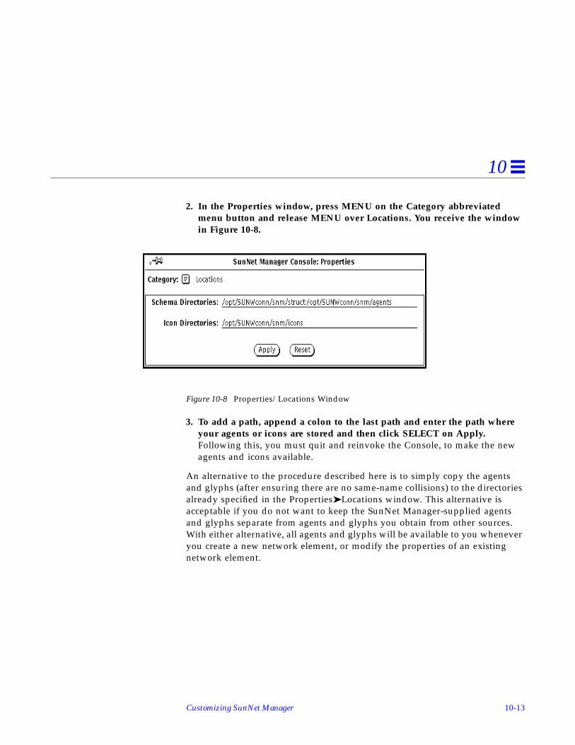
Customizing SunNet Manager 10-13
10
2. In the Properties window, press MENU on the Category abbreviatedmenu button and release MENU over Locations. You receive the windowin Figure 10-8.
Figure 10-8 Properties/Locations Window
3. To add a path, append a colon to the last path and enter the path whereyour agents or icons are stored and then click SELECT on Apply.Following this, you must quit and reinvoke the Console, to make the newagents and icons available.
An alternative to the procedure described here is to simply copy the agentsand glyphs (after ensuring there are no same-name collisions) to the directoriesalready specified in the Properties➤Locations window. This alternative isacceptable if you do not want to keep the SunNet Manager-supplied agentsand glyphs separate from agents and glyphs you obtain from other sources.With either alternative, all agents and glyphs will be available to you wheneveryou create a new network element, or modify the properties of an existingnetwork element.

10-14 Solstice Site/SunNet/Domain Manager Administration Guide
10

11-1
Network Management Security 11
This chapter covers the following topics:
• Authentication
• Access Control
• The Security Algorithm
• Conferring Right-of-Access
SunNet Manager provides an optional security mechanism for restrictingaccess to agent services. As delivered, any manager may request data and/orevent reporting from any SunNet Manager agent. For each agent, you canspecify read-security for data and event report requests and write security forSet requests. This section describes how to customize security for your SunNetManager environment.
SunNet Manager security uses and builds upon the “secure networkingfeatures” introduced in SunOS 4.x. These security features are based on DESencryption and public key cryptography. If you are installing this product onSolaris 1.x, we recommend that you first read the “Secure Networking” chapterin the Security Features Guide before reading the rest of this chapter. If you areinstalling for Solaris 2.x, you should first read SunOS 5.2 Administering Security,Performance, and Accounting before continuing with this chapter.
SunNet Manager implements security by giving an agent the option toauthenticate each network management request before acting on it. The twoelements of security are:

11-2 Solstice Site/SunNet/Domain Manager Administration Guide
11
• Authentication—is the requestor really who he claims to be?
• Access control—does the requestor have sufficient right-of-access to makethis request?
11.1 AuthenticationSunNet Manager uses the RPC protocol DES authentication feature to provethe identity of the user making the request. This guarantees that the request iscoming from a genuine source and makes it computationally infeasible foranyone to impersonate that source.
11.2 Access ControlOnce the requestor’s identity is authenticated, SunNet Manager verifies thatthe requestor has the required right-of-access. SunNet Manager confers right-of-access based on the “netgroups” feature of Sun OS 4.x, which was carriedforward to SunOS 5.x (Solaris 2.x). Consult the following:
• The SunOS 5.2 manual Administering TCP/IP and UUCP (for Solaris 2.xinstallations),
• The netgroup(5) man page, and
• “Setting up Network Software” in the System and Network AdministrationGuide (for Solaris 1.1 installations).
Access rights are administered by granting membership in one of the fivenetwork security groups. These groups are named:
• netmgt_security_one• netmgt_security_two• netmgt_security_three• netmgt_security_four• netmgt_security_five
Access control for members of this group works as follows:
The Agent Library has a global variable, Network Management Security Level,that can have a value between 0 and 5. The value 5 is the most secure and willallow only members of the network group netmgt_security_five access tonetwork management functions served by this agent library. All otherrequestors will be refused. The value 4 will allow access to members of groups

Network Management Security 11-3
11
netmgt_security_four and netmgt_security_five and so on. Lowervalues of the Network Management Security Level variable allow access tomembers of more and more network groups and the value 0 provides no accesscontrol at all.
For the security scheme to work, both the manager’s and the agent’s machine(and their respective NIS/NIS+ master server machines) must be runningunder SunOS 4.0 or later, and the keyserv daemon must have been started atboot–time in one of the following ways:
• By the /etc/rc2.d/S71rpc script, if the installation is in a Solaris 2.xenvironment
• From the /etc/rc.local file, if installed in a SunOS 4.x environment.
11.3 The Security AlgorithmThe following algorithm is used by the agent library to verify the authenticityand the access rights associated with every incoming request.
1. Since all security and authentication depends upon NIS/NIS+, first check ifNIS/NIS+ is up and running. If NIS/NIS+ is down, reject the requestindicating that NIS/NIS+ is not running.
2. Check Network Management Security Level to ascertain the level of securitybeing requested. If this value is zero, bypass the following checks and allowthis request through without authentication.
Note – UNIX-style authentication is not supported.
3. Verify that the request has a DES style authenticator. If not, the request isrefused, indicating too weak an authentication.
4. Verify that a domain specific user-id and password table entry exists for thenetwork name supplied in the DES authenticator contained in the request. Ifnot, the request is refused.
5. Finally, confirm membership of the appropriate network groups based onthe value of Network Management Security Level (for a value of 1, checkgroups 1 through 5; for a value of 2, check groups 2 through 5; etc). Denythe request if membership is not confirmed.

11-4 Solstice Site/SunNet/Domain Manager Administration Guide
11
If the request passes the above tests, it is considered successfully authenticated,and processing of the request proceeds as normal.
11.4 Conferring Right-of-AccessNow that you understand how security works, let’s look at how to conferright-of-access for your agent.
1. Create up to five network groups for the network namednetmgt_security_one , netmgt_security_two ,netmgt_security_three , netmgt_security_four , andnetmgt_security_five .
2. Include in these groups the user–names of the system administrators whohave permission to run SunNet Manager. This grouping defines a hierarchyof abilities for the administrators. Those administrators who are members ofthe netmgt_security_five group have maximum privilege and can sendrequests to any agent. Members of the netmgt_security_four group cansend requests to agents with security level 4, 3, 2, 1 or 0. Members of the lastgroup, netmgt_security_one , can send requests to agents with securitylevel 1 or 0.
3. For each administrator, create a new public key for the administrator’s user–name using newkey(8) .
4. For each host on which you have agents installed, create a new public keyfor the super–user at the host using newkey(8) .
5. Decide the level of read–security and write–security you wish to assign toyour agents and set the security levels associated with the agent name in theSunNet Manager configuration file snm.conf to values between 0 (nosecurity) and 5 (maximum security) on each system where agents areinstalled.
An example entry is shown below:
na.snmp 2 4

Network Management Security 11-5
11
This sets the SNMP proxy agent read–security level to 2 and write–securitylevel to 4. A user must be in at least the netmgt_security_two networkgroup to request SNMP data or event reports and in at least thenetmgt_security_four group to invoke SNMP Set requests.
If the snm.conf file does not contain an entry for an agent, the agent’s readand write security levels default to 0—no security checking. If the entry for anagent contains only one number, the agent’s read and write security levels areset to that number.

11-6 Solstice Site/SunNet/Domain Manager Administration Guide
11

12-1
NetWork Layout Assistant 12
The Network Layout Assistant (NLA) provides you with clear, readable viewsof your networks and helpful tools for documenting and navigating throughthem.
12.1 Who Should Use NLA?• Anyone whose network grows beyond a few devices; it is far easier to
manage your maps with automated layout
• Anyone who has network topologies that change often.
• Anyone who needs high quality network maps — for example, forpresentations, reports, and demonstrations
12.2 What Does NLA Do?• NLA reads the network information in your SunNet Manager database, and
automatically places devices and connections in a meaningful arrangementin the Console window. There is no need to hand-position each device asyou build a logical view of your internetwork.
• NLA shows you where you are. It is often difficult to see an entire view ofyour network with the Console since there is no “zooming” feature. TheNLA overview window provides a high-level view of the Console and amarquee indicating the portion of the network you are currently viewing inthe Console window. The marquee mirrors your moves as you scrollthrough the Console, thereby helping you navigate your network.
12-2 Solstice Site/SunNet/Domain Manager Administration Guide
12
• It provides you with choices. Since internets can be comprised of a varietyof topologies, NLA provides three unique layout styles: Hierarchical,Circular and Symmetric. Experiment with each style to find the best one foryou.
• It lets you customize your layouts. Although each layout style has presetdefaults, you can tailor the effect through OpenWindows controls.
• It lets you print your networks. Using the Print option, you can generatecolor PostScript files of your network views and include them in pagecomposition programs or send them directly to a PostScript printer/plotter.
12.3 What the Network Layout Assistant Does Not Do• The Network Layout Assistant is not a Discover tool. NLA cannot discover
your network devices. Specifically, NLA does not populate the SunNetManager database with connection information. However, NLA willaccurately lay out the device and connection information stored in theSunNet Manager database.
• The Network Layout Assistant does not provide a physical map orgeographical layout of your network. It provides logical arrangement ofyour devices based on their connectivity and does not represent the actualdistance between devices or physical location of devices.
• The Network Layout Assistant does not troubleshoot network errors.However, it can help you resolve and avoid problems through its clearpresentation of complicated network maps.
12.3.1 Available with Domain Manager
The Network Layout Assistant is available only with the Domain Managerproduct, not with Site/SunNet Manager.
12.4 Starting the SunNet Manager ConsoleAccess NLA through three new menu items under the submenu NLA in theSunNet Manager Console Tools menu: Layout..., Overview..., and Print...
If this is the first time you are using NLA tools but you have previously runSunNet Manager, you must first clear the current Console run-time database:

NetWork Layout Assistant 12-3
12
• To save the current runtime database, start the Console and use the File:Save menu to save it to a named file; then quit the Console.
• To clear the runtime database, start the Console with the -i option:
If you have never used the Network Layout Assistant, or have never run theSunNet Manager Console, you can start the Console by entering:
More information on starting the SunNet Manager Console can be found under“Starting the Console” in the “Creating and Modifying the ManagementDatabase” chapter. Issuing the snm command causes an empty Consolewindow to appear as shown in Figure 12-1
Figure 12-1 Console Window
% /usr/snm/bin/snm -i &
% /usr/snm/bin/snm &

12-4 Solstice Site/SunNet/Domain Manager Administration Guide
12
12.5 Creating the SunNet Manager Console DatabaseYou can populate the SunNet Manager Console runtime database with yournetwork information in a number of ways as described in other chapters. Theseare summarized as follows:
1. If you have previously built your network using the Console and havesaved the database to a file using File➤Save , you can populate theSunNet Manager Console by selecting the File➤Load menu item. Thenreload the database using the pop-up window:
2. If you do not have a saved database to reload, you can use the Tools➤ IPDiscover menu option to find all the devices in your network andpopulate the Console database:

NetWork Layout Assistant 12-5
12
3. Instead of using the IP Discover tool, you can use the ConsoleEdit➤Create menu to create new views and devices as described in thesection entitled “Creating Elements” in the “Creating and Modifying theManagement Database” chapter.

12-6 Solstice Site/SunNet/Domain Manager Administration Guide
12
4. After adding the elements to the Console, add connections between theglyphs as necessary as shown in the “Connecting Elements” section in the“Creating and Modifying the Management Database” chapter.If you used IP Discover to populate your database, you might want to usethe Edit➤Copy and Edit➤Paste options to copy elements from multiple“discovered” views into one logical view. This new logical view will helpyou understand the logical interconnection of your networks.
12.6 Using the Layout... OptionTo bring up the Network Layout Assistant main window, select theTools➤NLA➤Layout menu option on the SunNet Manager Console:
The first time you start the Network Layout Assistant, the pop up window willshow the default settings:

NetWork Layout Assistant 12-7
12
To lay out your network using the default values, click the Apply button. NLAwill position the elements in the view considering their connections. Thedefaults lay out the current view using the Hierarchical style. To lay out allviews of your network at once, Layout All Views➤Apply. To use a differenttype of layout, use the Layout Style menu as described in the section on“Choosing a Layout Style.”
12.6.1 Main Window Controls
Use the NLA main window to choose your layout style, determine whichviews it will affect, and apply it to the Console contents. Depending on thestyle, style-specific panels offer various options that further affect the overallglyph positioning.
These controls are present on all the layout style windows:
• Layout Style menu offers a choice of three layout styles: Hierarchical,Circular or Symmetric.
• Layout All Views check box determines whether the Network LayoutAssistant lays out all views of your network at once, or just the current view.

12-8 Solstice Site/SunNet/Domain Manager Administration Guide
12
• Apply button causes the settings in the Network Layout Assistant mainwindow to take effect and a layout to be executed.
• Reset button returns the current style’s settings to those before you lastpressed Apply.
• Defaults button resets the current style’s settings.
• Undo button returns the network elements to where they were locatedbefore you pressed Apply.
12.6.1.1 Choosing a Layout Style
You choose a layout style by pulling down the Layout Style menu andselecting one from the list:

NetWork Layout Assistant 12-9
12
Selecting from the Layout Style menu will display one of three panels fromwhich you can set the layout style specific tailoring options:
Layout style is primarily a matter of personal preference, and your preferencemay change as your network changes. Experiment with the different layoutstyles and settings to see which work best for you.
The layout style-specific tailoring options are described in the section,“Tailoring Your Layouts.” All three layout styles have sophisticated real-timelayout capability and support the following features:
• Variable spacing between and around elements.
• Line crossing minimization.
• Separate placement of independent internetworks to help you isolateproblems.
• Name-sorted tiling of independent elements.

12-10 Solstice Site/SunNet/Domain Manager Administration Guide
12
If there are no connections between your glyphs, each layout style will lookvirtually the same. When there are no connections, the Network LayoutAssistant provides a sort-by-name tiling of glyphs similar to the SunNetManager IP Discover tool’s automatic positioning feature.
12.6.2 Troubleshooting• Executing a layout buries the buses underneath the connections.
Explanation: The SunNet Manager Console draws bus elements underneaththe connections. Click on a bus to bring it to the front.
12.7 Using the Overview... OptionThe Network Layout Assistant overview window displays a high-level view ofthe network contained in the Console window. The overview window helpsyou maintain your perspective as you scroll around the SunNet ManagerConsole. A marquee in the overview window outlines the portion of thenetwork visible in the Console.
To familiarize yourself with the overview window’s capabilities, follow thesesteps:

NetWork Layout Assistant 12-11
12
1. In the Console window, select the Tools➤Overview menu item, and theoverview window will pop up. Depending on the size of your network, itcan sometimes take up to thirty seconds for the overview window toinitialize itself from the SunNet Manager database.
Figure 12-2 Overview Window
2. The overview window is read-only. To move its marquee, use the scrollbars in the Console. The overview window’s marquee will automaticallyupdate itself to reflect the Console map’s visible area.
3. As you resize the Console or scroll around it, the overview windowautomatically adjusted to show your current view of the network.
Note – An error message will appear when you open a view that you have notyet laid out. This message reminds you that the glyphs in that view won’t bevisible in the overview window until their positions are initialized eitherthrough hand positioning or Network Layout Assistant positioning.

12-12 Solstice Site/SunNet/Domain Manager Administration Guide
12
12.7.1 Overview Window Controls
12.7.1.1 Refresh Contents Button
The overview window's network representation can sometime appear out ofsync with the Console window view. This can happen, for instance, when youload a new database file using the Console’s File➤Load menu option. Tosynchronize the overview, click the Refresh Contents button to update it.
12.7.1.2 Process All Traps Check Box
To temporarily turn off the overview updates, uncheck the Auto-update checkbox. When unchecked, changes made to the Console will not be reflected in theoverview window. To synchronize the overview window with the Console,simply reselect the check box.
12.7.1.3 Process Change Traps Check Box
The Overview window receives traps from the SunNet Manager database foractions such as cut, paste, drag, and color changes whether these actions wereexecuted by the user or by SNM applications. Some SNM applications cangenerate a high frequency of database traps, causing the Overview window touse a larger portion of the CPU as it processes these traps. If you uncheck theProcess Change Traps check box, the Overview window will ignore certainchange traps, significantly reducing the processing requirements. whether thissetting is on or off, most users will not notice a performance difference; if youexperience reduced window manager performance caused by a high frequencyof redraws in the Overview window, try turning this option off.
12.7.2 Shapes
The overview window emulates the SunNet Manager Console:
• Routers are represented by diamonds.
• Subnets are represented by ovals.
• Buses are represented by knob terminated lines.
• All other components and views are represented by rectangles sizedproportionally to the glyph representing the component or view.

NetWork Layout Assistant 12-13
12
12.7.3 Color
The overview window uses the color of the network element as defined in theSunNet Manager Console.
To set the color of a Console element, use the Red/Green/Blue sliders in theelement’s properties sheet. Colors for window decorations such as borders andscroll bars are controlled by OpenWindows. To change them, choose theOpenWindows Desktop➤Properties... pop-up menu item.
12.7.3.1 For More Information on Setting the Color
On setting the color when creating an element:
See the section entitled “Creating Elements” in the “Creating and Modifyingthe Management Database” chapter.
On setting the color for an existing element:
See the section entitled “Modifying Element Properties” in the “Creatingand Modifying the Management Database” chapter.
On setting a color for window decorations:
See the OpenWindows on-line tutorial or the OpenWindows User’s Guide.
12.7.4 Troubleshooting
The glyphs and/or connections in the Console do not show up in the overviewwindow, or do not appear to be in the correct position.
Explanation: If you have dragged elements, they may not appear in theirnew location because dragging does not update the position in the database.Likewise, if you have added connections between glyphs that do not haveset positions, the connections may not show up in the overview window.
You can use any of the following approaches to remedy the situation:• If you drag elements and would like the overview window to reflect your
changes, switch from the current view to a different view and back again.You can switch between views by either using the Goto menu or bydouble-clicking on the displayed view.

12-14 Solstice Site/SunNet/Domain Manager Administration Guide
12
• Set positions for all elements by applying a layout with the Tools➤Layoutmenu item.
• Cutting and pasting also sets the glyph positions. Position each elementmanually by cutting then pasting instead of dragging.
12.7.4.1 For More Information:
On the difference between explicit and automatic positioning for elements:
See the section titled “Moving Elements” in Chapter 3, “Creating andModifying the Management Database.”
On visiting a view with the Goto menu or by double-clicking an view:
See the section titled “Traversing the View Hierarchy” in Chapter 3,“Creating and Modifying the Management Database.”
12.8 Using the Print... OptionThis section describes how to use the options on the Print window to createPostScript files of your SunNet Manager views. You can generate wall-sizediagrams to improve network documentation capabilities, or generate smallimages to include in other documents. The printing features include:
• Single-page and multi-page output by specifying number of row andcolumn pages. Images will be scaled to fill the number of specified pages.
• User specified page width and height settings provide arbitrary PostScriptplotter size support.
• With EPSF support, network drawings may be easily embedded intodocuments generated by page composition applications such asFrameMaker and PageMaker.
• Gray scale and color support
• Crop marks for paper cutting
• Page labeling and numbering
• Image rotation
• DSC 3.0 support

NetWork Layout Assistant 12-15
12
12.9 The Print WindowTo bring up the NLA print window, select the Tools➤NLA➤Print menu optionon the SunNet Manager Console.
To print the current view using the default settings, check the printer name andclick the Print button. The Network Layout Assistant will send a one-pageimage to the printer specified.
Figure 12-3 Print window with default settings
When the print button is pressed, the Network Layout Assistant will readthrough the current view and generate a PostScript file showing the devicesand links.
Note – Unpositioned elements will not be processed by the print program. Usethe layout option or hand position your devices before printing.
Note – Strip-charts in the current view will be displayed as shaded boxes

12-16 Solstice Site/SunNet/Domain Manager Administration Guide
12
12.9.1 Primary Print Options
This section describes the options on the primary print window.
12.9.1.1 Destination
The generated PostScript can be sent directly to a printer, saved as a file, orpassed to a user supplied PostScript previewer program:
• Printer
To send the output directly to a printer, select “Print” as the destination andenter your printer name in the “Printer” text field. The current view will beprocessed and the output routed directly to that device using lpr (Solaris1.x) or lp (Solaris 2.x).
• File
To save the output into a file, select “File” as the destination and enter thedirectory and file name in the supplied text fields. In the directory field youcan use the shell home directory symbol ’~’. In the filename field you canuse $VIEW to represent the current SunNet Manager view name. Forexample, to save the current view “MyNet” into PostScript file MyNet.ps inyour home directory, specify a directory of “~” and a filename of“$VIEW.ps .”
• Previewer
To open the file in a PostScript previewer, select “Previewer” as thedestination and enter the preview command line in the text field. Thepreviewer will be launched in the background using the Unix “system”command. To represent the name of the PostScript file in the previewercommand you can use the $FILE variable.
If no $FILE variable is specified in the previewer command, the filename ofthe temporary PostScript file will be appended to the end of the command.For example, to start page view at 72 dots per inch scaling level you wouldspecify “pageview -dpi 72 $FILE ” in the Command field. Note that inthis case since $FILE is specified at the end of the command line, the sameeffect can be realized without including $FILE in the command line at all,i.e. “pageview -dpi 72 ” would be sufficient.

NetWork Layout Assistant 12-17
12
12.9.1.2 Format
The Format choice determines whether a standard single/multi-page printerready PostScript (PS) file or an encapsulated PostScript (EPS) file is created.The EPS file can be imported into most composition programs such asFrameMaker and Illustrator, while the standard PS file can be sent directly to aprinter/plotter.
12.9.1.3 PS Output
When generating standard printer-ready PostScript files, a number of furtheroptions are available which determine the page size and number of pages forthe output file.
First you should specify the page size and page border using the Page Width,Page Height, and Page Border fields. The number of pages of this size that willbe generated is determined by the “Scale To” setting:
• Scale to pages
When you select “Scale To: Pages”, entry fields are displayed where you canspecify the number of page rows and page columns. To generate a singlepage of output enter a “1” in both fields. To split the output onto four pages(two pages by two pages), enter a “2” in both fields.
• Scale to percent
You can allow the Network Layout Assistant to set the number of pagesbased on the size of the current view using the “Scale To: Percent” choice. Asetting of 100 percent will produce an overall image of the same size as thecurrent view assuming there are 72 pixels per inch (1 pixel will be equal to 1point). This overall image size is divided by the specified Page Width andPage Height to determine the actual number of page rows and pagecolumns.

12-18 Solstice Site/SunNet/Domain Manager Administration Guide
12
12.9.1.4 EPS Output
When generating an EPS image, the size of the image is determined by the“Image Width,” “Image Height,” “Image Border,” and the “Scale To” options.
To specify an exact image width and height, choose “Scale To: Both” and enterthe width and height value in inches. To just set one dimension and let theNetwork Layout Assistant determine the other dimension based on the aspectratio of the current view, choose “Scale To: Width” or “Scale To: Height” andenter either the “Image Width” or “Image Height”, respectively. For example, ifyou want an image 4.5 inches wide but want the height based on the currentview proportions, select “Scale To: Width” and enter “4.5” in the “ImageWidth” field.
You can also let the Network Layout Assistant set both the width and height ofthe image using the “Scale To: Actual Size” option. This will generate a singleEPS image of the same size as the current view assuming there are 72 pixelsper inch.
The “Image Border” option allows you to specify extra white space or todisplay a image border/label within the specified image height/width.

NetWork Layout Assistant 12-19
12
12.9.2 Additional Print Options
Secondary output options can be accessed by pressing the “+” button in thelower right hand corner of the Print dialog. The Print window will open up todisplay a secondary panel with additional options:
Figure 12-4 Print window with Secondary Option Panel Displayed.
These options are:
• Show element icons
If you turn this option off, the devices in the output will be represented withshaded boxes instead of including the actual bitmap. This option may beuseful for producing draft output on plotters where bitmap rendering istime consuming.
• Show element names
This option determines whether the device labels will be shown on theoutput. The accompanying text fields are where you describe the PostScriptfont and point size with which to draw the device labels.

12-20 Solstice Site/SunNet/Domain Manager Administration Guide
12
• Show page label
This option determines whether the page labels, including userid and timestamp, will be shown on the output. The accompanying text fields are whereyou describe the PostScript font and point size with which to draw the pagelabel.
• Show pageborder
This option determines whether a black rectangle will be drawnencompassing the overall image.
• Show page numbers
This option determines whether the page numbers will be shown on theoutput. The accompanying text fields are where you describe the PostScriptfont and point size with which to draw the page numbers.
• Show crop marks
This option determines whether crop marks describing where to cut thepaper are included on multi-page output.
Note – If Page Border/Image Border is 0.0, the page border, page label, andpage numbers will not be displayed regardless of the checkbox settings in thesecondary panel.
12.10 Tailoring Your LayoutsThis section explains how to make adjustments to your network layoutthrough the style specific controls in the Network Layout Assistant mainwindow. The three layout styles – Hierarchical, Circular, and Symmetric – areeach covered in their own section.
12.11 Hierarchical Layout Style• Organizes the elements in your network into a hierarchy.
• Emphasizes tree-like subnetworks in your network.
• Is excellent for maps containing buses, because the Network LayoutAssistant can stretch the bus glyphs to accommodate all of the elementsdirectly attached to them.

NetWork Layout Assistant 12-21
12
Figure 12-5 shows the Network Layout Assistant main window with theHierarchical layout style default settings.
Figure 12-5 Main Window - Hierarchical Layout Style Default Settings
12.11.1 What is a Level?
A level is a grouping of nodes placed on a line. Usually a horizontal or verticalline can be drawn through the nodes that belong to a particular level. If agraph has a horizontal level orientation, each level occupies a row in the graph.If a graph has a vertical orientation, each level occupies a column in the graph.
12.11.2 Hierarchical Layout: Level Orientation
The Level Orientation panel option changes the orientation of the levels in agraph between horizontal and vertical. When the orientation is horizontal, allthe nodes will line up on horizontal levels. Horizontal levels imply a top-to-bottom organization of your network in the Console. When the orientation isvertical, all the nodes will line up on vertical levels. Vertical levels cause a left-to-right organization of your network in the Console.

12-22 Solstice Site/SunNet/Domain Manager Administration Guide
12
12.12 Tailoring Your LayoutThis chapter explains how to make adjustments to your network layoutthrough the style specific controls in the Network Layout Assistant mainwindow. The three layout styles – Hierarchical, Circular, and Symmetric – areeach covered in their own section.
12.13 Hierarchical Layout Style• Organizes the elements in your network into a hierarchy.
• Emphasizes tree-like subnetworks in your network.
• Is excellent for maps containing buses, because the Network LayoutAssistant can stretch the bus glyphs to accommodate all of the elementsdirectly attached to them.
Figure 12-6 shows the Network Layout Assistant main window with theHierarchical layout style default settings.
Figure 12-6 Main Window - Hierarchical Layout Style Default Settings

NetWork Layout Assistant 12-23
12
12.13.1 What is a Level?
A level is a grouping of nodes placed on a line. Usually a horizontal or verticalline can be drawn through the nodes that belong to a particular level. If agraph has a horizontal level orientation, each level occupies a row in the graph.If a graph has a vertical orientation, each level occupies a column in the graph.
12.13.2 Hierarchical Layout: Level Orientation
The Level Orientation panel option changes the orientation of the levels in agraph between horizontal and vertical. When the orientation is horizontal, allthe nodes will line up on horizontal levels. Horizontal levels imply a top-to-bottom organization of your network in the Console. When the orientation isvertical, all the nodes will line up on vertical levels. Vertical levels cause a left-to-right organization of your network in the Console.
Figure 12-7 and Figure 12-8 illustrate the difference between horizontal andvertical orientation.
Figure 12-7 Hierarchical Layout, Horizontal Level Orientation (default)

12-24 Solstice Site/SunNet/Domain Manager Administration Guide
12
Figure 12-8 Hierarchical Layout, Vertical Level Orientation
12.13.3 Hierarchical Layout: Level Alignment
The Network Layout Assistant employs the familiar “word processing model”to specify the alignment of nodes within a level. The concept is similar to howusers set the alignment of text within paragraphs in word processing software.If the levels are oriented horizontally, the Network Layout Assistant allowsyou to set the alignment of nodes as either top, center, or bottom-alignedwithin a level. If the levels are oriented vertically, the Network LayoutAssistant allows you to set the alignment of nodes as either left, center, orright-aligned within a level.
This setting will only make a difference if the icons are of different sizes. WithSunNet Manager 2.2 and newer versions, the supplied icons are all the sameheight and width and this option will have no effect.
12.13.4 Hierarchical Layout: Level Frame Percent
The Level Frame Percent control allows you to set the spacing above andbelow each level of glyphs in the map. This control is called “level framepercent” because the Network Layout Assistant maintains an internal “frame

NetWork Layout Assistant 12-25
12
level-bounding rectangle” that is a percentage larger than the smallestrectangle that can bound all of the nodes in a level. Increasing the level framepercent has the effect of spreading the levels further apart, decreasing the levelframe percent has the effect of pulling the levels closer together.
Note that the glyphs in Figure 12-9 are closer together along the y axis than theglyphs in Figure 12-10 due to the smaller level frame percent.
Figure 12-9 Hierarchical Layout, 60 Percent Level Frame Spacing (default)
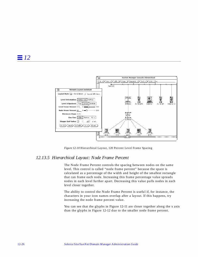
12-26 Solstice Site/SunNet/Domain Manager Administration Guide
12
Figure 12-10 Hierarchical Layout, 120 Percent Level Frame Spacing
12.13.5 Hierarchical Layout: Node Frame Percent
The Node Frame Percent controls the spacing between nodes on the samelevel. This control is called “node frame percent” because the space iscalculated as a percentage of the width and height of the smallest rectanglethat can frame each node. Increasing this frame percentage value spreadsnodes in each level further apart. Decreasing this value pulls nodes in eachlevel closer together.
The ability to control the Node Frame Percent is useful if, for instance, thecharacters in your icon names overlap after a layout. If this happens, tryincreasing the node frame percent value.
You can see that the glyphs in Figure 12-11 are closer together along the x axisthan the glyphs in Figure 12-12 due to the smaller node frame percent.

NetWork Layout Assistant 12-27
12
Figure 12-11 Hierarchical Layout, 60 Percent Node Frame Spacing (default)
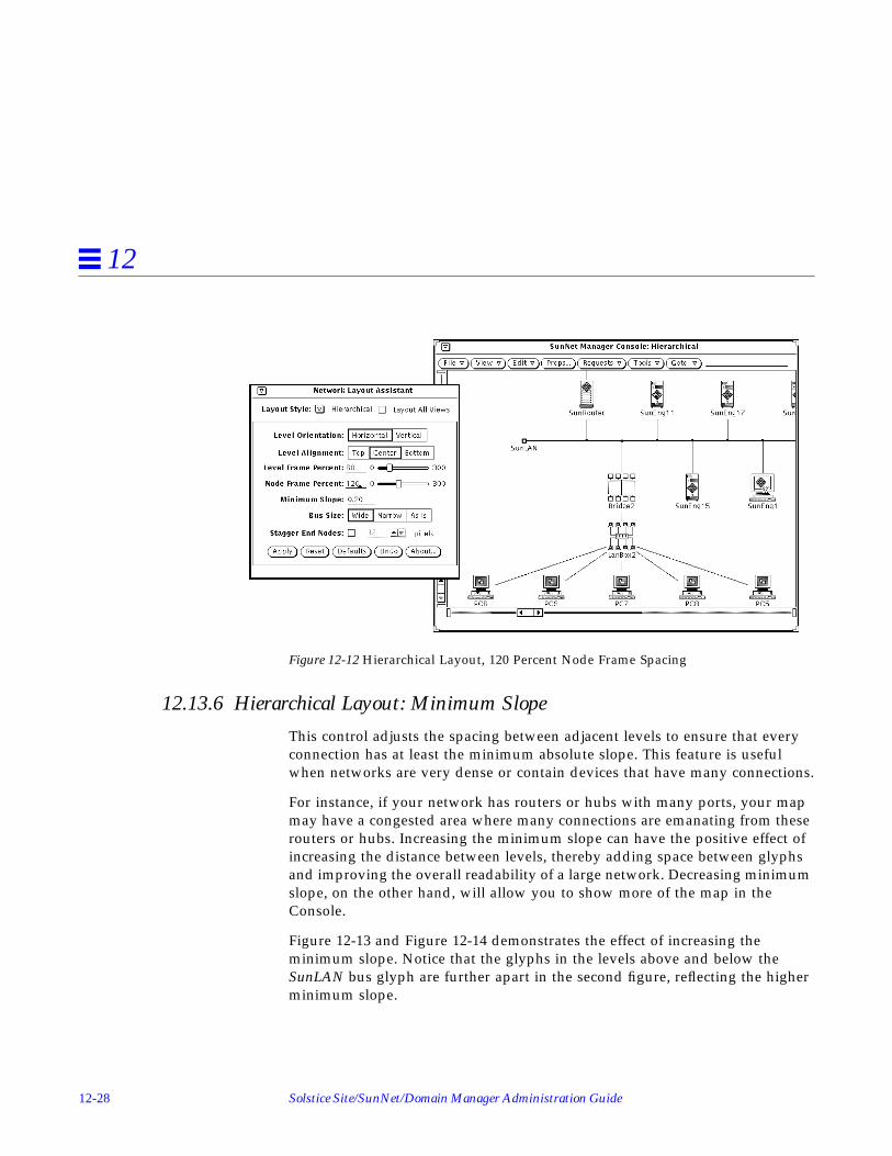
12-28 Solstice Site/SunNet/Domain Manager Administration Guide
12
Figure 12-12 Hierarchical Layout, 120 Percent Node Frame Spacing
12.13.6 Hierarchical Layout: Minimum Slope
This control adjusts the spacing between adjacent levels to ensure that everyconnection has at least the minimum absolute slope. This feature is usefulwhen networks are very dense or contain devices that have many connections.
For instance, if your network has routers or hubs with many ports, your mapmay have a congested area where many connections are emanating from theserouters or hubs. Increasing the minimum slope can have the positive effect ofincreasing the distance between levels, thereby adding space between glyphsand improving the overall readability of a large network. Decreasing minimumslope, on the other hand, will allow you to show more of the map in theConsole.
Figure 12-13 and Figure 12-14 demonstrates the effect of increasing theminimum slope. Notice that the glyphs in the levels above and below theSunLAN bus glyph are further apart in the second figure, reflecting the higherminimum slope.

NetWork Layout Assistant 12-29
12
Figure 12-13 Hierarchical Layout, 0.20 Minimum Slope (default)
Figure 12-14 Hierarchical Layout, 0.50 Minimum Slope

12-30 Solstice Site/SunNet/Domain Manager Administration Guide
12
12.13.7 Hierarchical Layout: Bus Size
The Bus Size option allows you to automatically resize your bus elementswhen you apply a layout. The choices have the following effect:
• Wide (Horizontal orientation), Tall (Vertical orientation): Your buses will bestretched to accommodate the elements directly connected to them.
• Narrow (Horizontal orientation), Short (Vertical orientation): All the busesin the view will be shrunk down to the size of an average-sized glyph.
• As Is: The buses will stay the same size as they were before the layout wasapplied.
Figure 12-15, Figure 12-16, and Figure 12-17 show how the different bus sizesettings affect the layout. You can see in the third figure that the “As Is” settingallows you to have different size buses in the same view.
Figure 12-15 Hierarchical Layout, Wide Buses

NetWork Layout Assistant 12-31
12
Figure 12-16 Hierarchical Layout, Narrow Buses (default)
Figure 12-17 Hierarchical Layout, “As Is” Buses

12-32 Solstice Site/SunNet/Domain Manager Administration Guide
12
12.13.8 Hierarchical Layout: Stagger End Nodes
The Stagger End Nodes control determines whether devices attached to busesare alternately staggered along a level. Specify the number of pixels to adjustthe devices in the entry field provided.
12.14 Circular Layout Style• Supports sophisticated element grouping using IP networking standards.
• Supports administrative element grouping features.
• Performs radiated placement of those groups.
• Highlights the difference between prominent backbone main sites in yournetwork and peripheral sub-sites in your network.
• Highlights the networks within your internet by grouping nodes accordingto the network or subnetwork to which they belong.
Figure 12-18 shows the Network Layout Assistant main window with theCircular layout style default settings.
Figure 12-18 Main Window Showing Circular Layout Style Selected

NetWork Layout Assistant 12-33
12
12.14.1 Circular Layout: Node Frame Percent
The Node Frame Percent slider controls the spacing between each node in acluster (circular grouping of elements). Increasing the frame percentage valuespreads the elements further apart. Decreasing this value pulls the elementscloser together. The ability to control the Node Frame Percent is useful if, forinstance, the characters in your icon names overlap after a layout. If thishappens, try increasing the node frame percent value.
In Figure 12-19 and Figure 12-20, note how the spacing between the nodesincreases as the node frame percent is increased.
Figure 12-19 Circular Layout, 60 Percent Node Frame Spacing (Default)

12-34 Solstice Site/SunNet/Domain Manager Administration Guide
12
Figure 12-20 Circular Layout, 120 Percent Node Frame Spacing
12.14.2 Circular Layout: Grouping Options
The Circular layout operates by gathering elements into groups, or clusters,and arranging the elements in each group into a circle. The circles are thenplaced considering inter-group connection information.
Figure 12-21 and Figure 12-22 illustrate how Circular layout grouping can helpyou localize devices on a particular subnet.

NetWork Layout Assistant 12-35
12
Figure 12-21 Internetwork Before Circular Layout Grouping
Figure 12-22 Internet After Circular Layout Grouping

12-36 Solstice Site/SunNet/Domain Manager Administration Guide
12
The Network Layout Assistant provides three clustering mechanisms thatdetermine which group an element is assigned to. These are:
• Edge Degree grouping: The default method generates groups based ontopology.
• IP Address grouping: The IP Address of the element is used to set thegroup.
• Group ID: You explicitly set the group of a particular element.
These grouping mechanisms operate in sequence (series). If the Group IDcheck box is selected and a group ID exists for an element, the Network LayoutAssistant organizes elements into circles based on these group ID settings.Next, if the IP Address check box is selected and an IP Address exists for anelement, the element will be clustered based on the subnet mask for itsnetwork. Finally, the Edge Degree facility is used if there are any elements thathave not yet been grouped by the other two methods.
The end result is that each element in the network is assigned to a group afterall three grouping operations are performed.
12.14.3 Circular Layout: Edge Degree
This default clustering method uses information based on the connectivity ofthe network. The edge degree of an element is the number of connections theelement has to other elements. If an element has an edge degree greater than orequal to a specified edge degree value, these elements will form the initialclusters.
For example, highly connected buses and routers should form the center ofinitial clusters in your network. Elements that are adjacent to the new clustersare assigned to these new clusters. Then, remaining unclustered elements withlower edge degree begin to form new clusters and attract adjacent nodes intothe clusters. This operation continues until each element is assigned to acluster.
If too many clusters appear when using the default, increase the Edge Degreenumber; if too few clusters appear, decrease the Edge Degree number.
The Edge Degree grouping can be overridden using the IP Address and GroupID methods described next.

NetWork Layout Assistant 12-37
12
12.14.4 Circular Layout: Cluster by IP Address
Most UNIX-based networks use the Internet Protocol (IP) for their networkprotocol. The Network Layout Assistant can make use of the elements’ IPaddresses when assigning groups; simply select the IP Address checkbox tocluster elements belonging to the same IP network.
Network grouping: The Network Layout Assistant analyzes the IP addressof each network element (if it has one) and gathers elements on the sameClass A, Class B or Class C network into groups.
Subnet grouping: The Network Layout Assistant supports furtherorganization of your network maps through support for IP subnetting. TheNetmask window, described below, allows you to set the subnet mask foreach network in your internet.
The IP Address grouping overrides the groups determined by edge degreeclustering. You can further tailor the groups by using the Group ID facilitydescribed in Section 12.14.7, “Grouping Window.”

12-38 Solstice Site/SunNet/Domain Manager Administration Guide
12
12.14.5 Netmask Window
The Netmask dialog permits you to fine-tune how the elements in eachnetwork are grouped by setting a subnet mask. Subnetting is commonly usedto partition IP networks into manageable groups. The netmask window allowsthe system administrator to apply a subnet mask value other than the defaultfor each network. Click the “Netmask” button to pop up the netmask dialog:
You change the mask for a network by selecting a record in the list box,entering the new mask into the entry fields and clicking Apply. Then clickApply in the Circular Layout panel to layout your internet based on the newsubnet mask(s).
12.14.6 Circular Layout: Cluster by Group ID
After you apply a Circular layout using the above clustering methods, youmight want to adjust the groups of a few particular elements. You canexplicitly set the group of an element with the grouping window describedbelow. If a group ID exists for an element, it will override the group set byEdge Degree clustering or IP Address clustering.

NetWork Layout Assistant 12-39
12
To use this grouping feature, first run a layout using Edge Degree or IPAddress clustering. Then check the Group ID check box and click the “Groups”button to bring up the grouping dialog:
12.14.7 Grouping Window
The Circular Layout Grouping dialog provides fine control of element groupsettings. The dialog box provides a list box that displays the element name, thegroup to which the element belongs and the IP address of the element. You canselect one or more elements in the list box and set their group.
12.14.7.1 Selecting Elements to be Grouped
You use the mouse to select items that you wish to group together (i.e. toappear on one circle). Scroll through the list box and select each element thatyou would like to set a group for. After selecting the items, enter a groupnumber in the Group ID field and click the Apply button to update the group.To run the layout with the new group settings, click the Apply button on theNetwork Layout Assistant main window.

12-40 Solstice Site/SunNet/Domain Manager Administration Guide
12
Note – If you use the grouping window to set an element’s group ID and lateruncheck the IP Address check box, the group ID(s) will be reset on the nextlayout.
A number of controls are provided which make using the grouping windoweasier:
12.14.7.2 Sort By:
The list box elements may be sorted by name, group or by IP address:
• Sort By Name: Alphabetizes the list of elements within the list box by name.
• Sort By Group: Sorts the list of elements by their group identifier.
• Sort By IP Address: Sorts the list by the IP Address of each element.Elements without IP addresses are placed at the end of the list.
12.14.7.3 Group Filter:
The Group Filter drop down list box provides a convenient mechanism to limitthe number of items that are viewed in the list box at any time so that you canfocus on the task at hand. The drop down list box provides you the followingchoices:
• All: Shows all elements that are displayed within the view.
• Ungrouped: Shows those elements that do not yet have groups assigned tothem (group 0).
• Group 1-N: From this list, you select the group from which you would liketo see elements listed in the list box.
12.14.7.4 Refresh List:
This button causes the element list box to be refreshed from the SunNetManager database. If, for instance, you load a new database file into theConsole, you will need to click the Refresh List button to see the new elementsin the list.

NetWork Layout Assistant 12-41
12
12.14.7.5 Ungroup All:
This button causes all the elements to be reset to group 0 (ungrouped).
12.15 Symmetric Layout StyleThis style is:
• Ideal for organizing wide area meshed networks.
• Highlights the symmetries inherent in the topology of the network.
• Lays out any network regardless of routing protocol(s) employed ordiscovery mechanism.
• Provides uniform distribution of glyphs on the display.
Figure 12-23 shows the Network Layout Assistant main window with theSymmetric layout style default settings.
Figure 12-23 Main Window Showing Symmetric Layout Style Selected

12-42 Solstice Site/SunNet/Domain Manager Administration Guide
12
12.15.1 Symmetric Layout: Node Frame Percent
The Node Frame Percent controls the spacing around each glyph. A highernode frame percent value increases the cushion of space around the elementsand lengthens the connections between glyphs. Smaller values result in morecondensed layouts with shorter connections.
Notice how the glyphs in Figure 12-24 are closer together than the glyphs inFigure 12-25 due to the smaller node frame percent.
Figure 12-24 Symmetric Layout, 60 Percent Node Frame Spacing (Default)

NetWork Layout Assistant 12-43
12
Figure 12-25 Symmetric Layout, 120 Percent Node Frame Spacing
12.15.2 Symmetric Layout: Granularity
The Granularity option controls the size of the underlying coordinate gridupon which the network is laid out. At the default of 0, the Symmetric styleuses a relatively fine grid. A value of 100 specifies a very coarse grid. Thedifference in granularity is reflected in a trade-off between the final layoutquality and computation time. A fine grid generally produces a better layoutbut takes longer to compute. A coarse grid generally produces a rougherlayout, but runs much faster.
If speed is a consideration, set a higher granularity to produce draft layouts,and then reduce the granularity when you want to produce a presentation-quality layout.
12.15.3 Symmetric Layout: Threshold
The threshold determines the point at which Symmetric layout processingstops and outputs a final layout. Lower threshold values generally producebetter layouts but usually take more time to compute.

12-44 Solstice Site/SunNet/Domain Manager Administration Guide
12
The default threshold value of four is adequate for most networks. Loweringthe value to two or one can produce better results while taking longer tocompute. Increasing the value will produce slightly lower quality layouts butwill be faster to compute.
12.15.4 Symmetric Layout: Start Seed
The Start Seed affects the starting configuration of the map before the layoutprocess begins. Each different seed value produces a unique final layout. Whilethe result of changing the start seed is admittedly random, this control canhelp you generate an better layout.
Figure 12-26 and Figure 12-27 show the same topology with different startseeds.
Figure 12-26 Symmetric Layout, Start Seed of 1 (default)

NetWork Layout Assistant 12-45
12
Figure 12-27 Symmetric Layout, Start Seed of 2
12.15.5 Symmetric Layout: Incremental
If this check box is selected, the Symmetric layout style will use the currentpositions of the nodes as a starting point when determining the new layout.The incremental setting helps you maintain correlation between layouts, andwill sometimes improve the layout quality if you run multiple layouts.
12.16 Network Layout Assistant RestrictionsIf you start multiple SunNet Manager Consoles on the same desktop, you needto set the “Display user name in Title” checkbox in the Console’s “Props...”window.
You cannot create view names that contain a colon followed by a space (“:”).
The Program name used to start the SunNet Manager Console must be namedsnm.

12-46 Solstice Site/SunNet/Domain Manager Administration Guide
12

Part 2 — Reference


13-1
Reference Overview 13
13.1 OverviewThis Reference Part describes the features and functions of SunNet Manager inmore detail, including the following:
• Agents and proxy agents
• Ancillary daemons (activity daemon and event dispatcher)
• The details of sending data and event requests
• The details of viewing data and event requests
• Console properties
• The management database
• SNMP support
• Results Browser
• Results Grapher
• IP Discover
• IPX Discover
• Set Tool

13-2 Solstice Site/SunNet/Domain Manager Administration Guide
13
13.2 Agents and ProxiesThere are two types of SunNet Manager agents: those that directly accessmanaged objects and those that indirectly access managed objects. Most of theagents provided with this release manage objects on the Sun workstationswhere they are installed. For example, the hostmem agent uses the samemechanism as netstat -m to get memory utilization data.
The second type of agent provides the ability to manage objects that reside inother Sun workstations or in other vendors’ devices. Such agents are calledproxy agents. Proxy agents run on Sun workstations, called proxy systems, anduse protocol translation mechanisms to provide the necessary access to themanaged objects. The proxy system may be the workstation on which theSunNet Manager Console is running or another workstation on the network.The proxy system can also be a workstation in a different subnet or domainfrom where the Console is running. This allows SunNet Manager to extendinto virtually any domain.
13.2.1 Agents Included with SunNet Manager
A Console can manage both SunOS 5.x, and SunOS 4.x clients. All SNM agentsthat run on SunOS 4.x clients are also available for the Solaris 2.x environment.Note however, that certain of the agents that run on Solaris 2.x clients supportdifferent attributes than their SunOS 4.x counterparts. The Solaris 2.x versionsof these agents have been renamed to <agentname>2. For example,na.iostat2 is the Solaris 2.x version of the (SunOS 4.x) agent na.iostat .See Chapter 2, “Planning for Network Management,” for a list of agents andproxy agents shipped with the current release.
Note – snmp, snmp-mibII , and sun-snmp and several RFC schema files canbe used with the SNMP proxy agent na.snmp . For each of the other agentsshipped with the current product, there is only one corresponding schema file.
Note – na.hostif is the same for SunOS 4.x and Solaris 2.x except that themetric table is inaccessible for Solaris 2.x.

Reference Overview 13-3
13
Table 13-1 lists the agents that have substantial differences between theirSunOS 4.x and Solaris 2.x versions. Table 13-1 shows the attributes that wereadded to the Solaris 2.x agents; it also shows attributes from the SunOS 4.xversion that were deleted for the Solaris 2.x version of these agents.
Table 13-1 Agents Specific to Solaris 2.x
AgentSunOS 4.x attributesremoved
New attributes added forSolaris 2.x
na.etherif2 input group: ibufs ibufdesc idiscard iframedescoutput group: ojams odrops watchdog obufdesc copies nocfs obufs oframedesc obuferr
input group: imissed inocanputoutput group: oinits
na.hostmem2 mbuf groupmbuf_uses groupstreams group:
mblkused mblkfree mblk% mblkcom mblkfaildblks tabl e
streams group: msgused msgfree msg% msgcum msgfail linkblkused linkblkfree linkblk% linkblkcum linkblkfail streveused strevefree streve% strevecum strevefail

13-4 Solstice Site/SunNet/Domain Manager Administration Guide
13
These agents represent examples of the data you can gather using SunNetManager, and are not meant to be an exhaustive set. To write your own agent,refer to your Site/SunNet/Domain Manager Application and Agent DevelopmentGuide.
Many Sun products include agents that can be used with SunNet Manager.Refer to your product documentation or call your local Sun representative formore information.
13.2.2 Ancillary Daemons
SunNet Manager includes two ancillary daemons: the activity daemon(na.activity ) and the event dispatcher (na.event ). The activity daemon isa process that uses the Manager/Agent Services to ensure ongoing requests(activities) continue to be serviced. The activity daemon uses the activity log, arecord of active requests started from the Console.
The event dispatcher is a process that uses the Manager/Agent Services todirect reports of events to the proper destinations (rendezvous process), such asthe SunNet Manager Console. Any other management application can use theevent dispatcher, registering to receive some or all event reports based on avariety of selection criteria. The Event Dispatcher also logs all event reports inthe Event/Trap Log. The Event/Trap Log is in ASCII format, so you canexamine and modify it using standard UNIX tools.
na.iostat2 disk table: mbytes xfers seeks activeT xferT seekT %xferT avgxferT kbps
disk table: kreads kwrites svcwait acttrans svctime %wait %busy
na.layers2 no changes no changes
na.cupstat available only on Solarix 2.x
Table 13-1 Agents Specific to Solaris 2.x
AgentSunOS 4.x attributesremoved
New attributes added forSolaris 2.x

Reference Overview 13-5
13
Four processes of the event dispatcher are started when you invoke theConsole. When you make the first request to any agent, two processes of theactivity daemon are started. When you exit the Console, two processes ofna.activity and one copy of na.event remain.
13.3 SunNet Manager Directories and FilesThis section discusses the files and directories that are created during SunNetManager installation. The Solaris 1.x and Solaris 2.x versions of SunNetManager differ in the default locations assigned to these files and directoriesby the installation scripts. The default locations for these files are summarizedin Table 13-2.
The snm.conf file is the configuration file used by SNM agents and daemons.(For Solaris 1.x installations of SNM, snm.conf is located in /etc ; for Solaris2.x installations snm.conf is located in /etc/opt/SUNWconn/snm .) See thesnm.conf(5) man page for more information about changing keywordvalues.
The SunNet Manager installation script prompts you for the followinglocations:
• The directory where the SNM software will be installed. This normally is/usr/snm for Solaris 1.x installations; for Solaris 2.x installations thedefault location is /opt/SUNWconn/snm.
If you install SNM into a directory other than the default, you must set theenvironment variable SNMHOME to the directory where SNM is installedbefore you can use the software.
• The directory where the SNM database will be written. (If you do notspecify otherwise, this is /var/adm/snm for Solaris 1.x installations; thedefault location for Solaris 2.x installations is /var/opt/SUNWconn/snm .)
Caution – You should have at least 10 Mbytes of space for the initial databasedirectory. You can change the location of the database directory afterinstallation by setting the environment variable SNMDBDIR to a writabledirectory.
• The directory where SNM log files will be written. (If you do not specifyotherwise, this is /var/adm/snm for Solaris 1.x installations; the defaultlocation for Solaris 2.x installations is /var/opt/SUNWconn/snm .)

13-6 Solstice Site/SunNet/Domain Manager Administration Guide
13
The log files grow during Console operation. This could cause a disk spaceproblem if the /var directory is part of the root file system. You can changethe location of the log files after installation by specifying fully-qualifiedpath names for the keywords activity-log , event-log , monitor-log ,and request-log in the snm.conf file. Make sure that the new directoriesare writable by root or mode 777 so that the Console can write to the logfiles.
13.3.1 Installation Directory Files
If you install the SNM software in the default path (/usr/snm for Solaris 1.xinstallations, /opt/SUNWconn/snm for Solaris 2.x installations), theinstallation script will create the following directories and files under thedefault directory:
• agents directory, which contains SNM agents and their correspondingschema files. You can add your own agent and schemas to this directory.This directory also contains the files enterprises.oid , which containsmappings for enterprise identifiers, and snmp.oid , which containsmappings for SNMP MIB I object identifiers.
• bin directory, which contains binaries used by SNM. One of the binaries,snm_asroot , is undocumented.
• icons directory, which contains SNM icon files. You can add your ownicons to this directory.
• include directory, which contains header files for building agents.
• lib directory, which contains SNM libraries.
• man directory, which contains SNM man pages.
• 5.x , which contains the Solaris 2.x version of the SunNet Manager agents,for managing SunOS 5.x machines.
• src , which contains sample source code for selected agents and managerapplications.
• struct directory, which contains the following files:• elements.schema defines the element types. If you need to add site-
specific elements, create your own file with the .schema extension (forexample, myelements.schema ).

Reference Overview 13-7
13
• netware_elements.schema contains Novell specific elementdefinitions.
• snm.schema contains NLA specific information.• example.db is an example database that you can load into the Console.• snm.glue is a file that contains a starting set of definitions for the
Console. Do not modify this file.
13.3.2 Database Files
A database directory is created in the path specified by the environmentvariable SNMDBDIR. If SNMDBDIR is not specified, then the database pathspecified during installation is used. The database directory isdb. <user_name>, where <user_name> is the value of the environment variableSNM_NAME, or the environment variables LOGNAME or USER, if SNM_NAME isnot set. The following database files are created for SNM:
• snm+lock is the Console lock file; this prevents more than one user fromaccessing the same runtime database.
• snmdb+lock is the database API lock file; this file enables the database tobe locked when entries are changed programmatically.
• The files events.ind , events.rec , nc.ind , and nc.rec make up theruntime database used by the Console.
• The following data files, whch are used by IPX Discover, reside in yourdatabase directory: dumpfile, snm_index.dat, x.x.x.x.dat, nc.ind, and nc.rec,where x.x.x.x.dat is an ipaddress.dat file. An example would be129.9.119.5.dat
13.3.3 Log Files
Log files are created in the directory specified during installation. You can alsochange the location of individual log files after installation by modifying theappropriate log file entry in the snm.conf file. The following log files arecreated for SNM:
• activity.log is a log of active requests started from the SNM Consolehost; this file is used by the activity daemon.
• event.log is the log file written by event dispatcher.

13-8 Solstice Site/SunNet/Domain Manager Administration Guide
13
• monitor.log is written by the na.logger agent. This agent logs datareports launched by the snm_cmd command.
• request.log is a record of requests that are to be restarted by theappropriate agent; this file is used by the agents.
13.3.4 Miscellaneous Files• The snmp.hosts file contains information about SNMP hosts. (The default
location of the snmp.hosts file for Solaris 1.x installations is/var/adm/snm ; for Solaris 2.x installations the default location is/var/opt/SUNWconn/snm .) You can add entries into this file to specifyenterprise-specific host information.
• The snmp.traps file contains information about enterprise-specific traps.(For Solaris 1.x installations the default location is /var/adm/snm ; forSolaris 2.x installations, the default directory is /var/opt/SUNWconn/snm .)You can add entries into this file to specify enterprise-specific trapinformation.
• The $HOME/.SNMdefaults file contains information pertaining to SNMConsole properties. For example, when the icon size is set to a new value(i.e., 32X32), or the schema path changed, these values and other propertiesare written to your $HOME/.SNMdefaults file. If you subsequently removeSNM, then reinstall it (e.g., migrating from a previous version to the currentversion), the old .SNMdefaults values will continue to be used. You canmodify the values by using the SNM Console Props button, or by editingyour .SNMdefaults file. You can ensure that the Console property defaultsare used by moving a preexisting .SNMdefaults file from your homedirectory or deleting your $HOME/.SNMdefaults file.
• The .SNMpredefined file contains predefined data and event requestrecords provided with the current product. (The default location of this filefor Solaris 1.x installations is /usr/snm/struct ; for Solaris 2.xinstallations, the default path is /opt/SUNWconn/snm/struct .) Forinformation about creating and sending predefined data and event requests,refer to Chapter 18, “Management Database.” When you modify or createpredefined data and event requests, they are stored in your$HOME/.SNMpre-defined file along with the predefined requestsprovided with this product.

Reference Overview 13-9
13
• The linkmap file is an ASCII file that contains information used by theSNM Console to provide link management capabilities. (The default locationof the linkmap file is /var/adm/snm for Solaris 1.x installations and/var/opt/SUNWconn/snm for Solaris 2.x installations.) It is either createdby the network manager or the IP Discover tool; the IP Discover tool willpopulate this file with discovered links (if 2 or more hops are specified asthe scope of a network discovery operation). Refer to the linkmap (5)manual page for information about the format and use of the linkmap file.
• The .snmautomanagement file contains information about custom autorequests.
13.4 Environment Variables Used with SunNet ManagerYou can use the following environment variables with SunNet Manager:
• The PATH environment variable should include<installation_path>/snm/bin where:• <installation_path> will be /usr if SNM is installed in the default location
for SunOS 4.x installations.• <installation_path> will be /opt/SUNWconn if SNM is installed in the
default location for the Solaris 2.x version.
• If the software for the current product is installed in a directory other thanthe default location (/usr/snm for Solaris 1.x, /opt/SUNWconn/snm forSolaris 2.x), you must set the SNMHOME environment variable to theinstallation directory.
• The HELPPATH environment variable should include<installation_path>/snm/help where:• <installation_path> will be /usr if the default location is used for a Solaris
1.x installation.• <installation_path> will be /opt/SUNWconn if the default location is used
for a Solaris 2.x installation.
This enables you to get SunNet Manager on-line help.
• The MANPATH environment variable should include<installation_path>/snm/man where:• <installation_path> will be /usr if the default location is used for a Solaris
1.x installation.

13-10 Solstice Site/SunNet/Domain Manager Administration Guide
13
• <installation_path> will be /opt/SUNWconn if the default location is usedfor a Solaris 2.x installation.
This enables use of the SunNet Manager man pages.
• The SNM_NAME environment variable can be used to allow multipleinstances of the Console and database to be run from a single user ID. Oneor more names can be specified with SNM_NAME. Each instance of theConsole is associated with its own runtime database, located in thedb .<snm_name> directory, where <snm_name> is a name specified by theenvironment variable SNM_NAME. Each instance of the Console will use theuser’s $HOME/.SNMdefaults and $HOME/.SNMpre-defined.snmautomanagement files.
• The SNMDBDIR environment variable is used to specify the directory wherethe predefined data and event request ASCII data record file resides./var/adm/snm is the default directory for the Solaris 1.x version of thecurrent product; the default location for Solaris 2.x is/var/opt/SUNWconn/snm .
• The SNMLINKMAP environment variable is used to specify the directorywhere the linkmap file used by the link management feature is located. Ifthis environment variable is undefined, the default location is:• /var/adm/snm for the Solaris 1.x version• /var/opt/SUNWconn/snm for the Solaris 2.x version.
• The SNMDISCOVERMAP environment variable is used to specify the directorywhere the discover.conf file, used by the IP Discover Tool, is located./var/adm/snm is the default directory for Solaris 1.x installations;/var/opt/SUNWconn/snm is the default location for Solaris 2.xinstallations.
Table 13-2 Summary of Default SNM File Locations
FilesDefault Locationin Solaris 1.x Version
Default Locationin Solaris 2.x Version
Agents and schema files /usr/snm/agents /opt/SUNWconn/snm/agents
Agents for Solaris 2.xmachines
/usr/snm/5.x /opt/SUNWconn/snm/5.x
discover.conf file /var/adm/snm /var/opt/SUNWconn/snm
elements.schema file /usr/snm/struct /opt/SUNWconn/snm/struct

Reference Overview 13-11
13
Example database /usr/snm/struct /opt/SUNWconn/snm/struct
Header files /usr/snm/include /opt/SUNWconn/include
Icon files /usr/snm/icons /opt/SUNWconn/snm/icons
linkmap file /var/adm/snm /var/opt/SUNWconn/snm
Log files /var/adm/snm /var/opt/SUNWconn/snm
/var/adm/snm /var/opt/SUNWconn/snm
Manager Services libraries /usr/snm/lib /opt/SUNWconn/snm/lib
man pages /usr/snm/man /opt/SUNWconn/snm/man
messages file /var/adm/snm /var/opt/SUNWconn/snm
Predefined data/ eventrequest file
/var/adm/snm /var/opt/SUNWconn/snm
On-line help files /usr/snm/help /opt/SUNWconn/snm/help
Sample agent andapplication source code files
/usr/snm/src /opt/SUNWconn/src
snm.conf file andsnmpd.conf file
/etc /etc/opt/SUNWconn/snm
.SNMdefaults file $HOME $HOME
SNM executables /usr/snm/bin /opt/SUNWconn/snm/bin
snm.glue file /usr/snm/struct /opt/SUNWconn/snm/struct
.SNMpredefined file /usr/snm/struct /opt/SUNWconn/snm/struct
snmp.hosts file /var/adm/snm /var/opt/SUNWconn/snm
snmp.traps file /var/adm/snm /var/opt/SUNWconn/snm
.snmautomanagement $HOME $HOME
Table 13-2 Summary of Default SNM File Locations
FilesDefault Locationin Solaris 1.x Version
Default Locationin Solaris 2.x Version

13-12 Solstice Site/SunNet/Domain Manager Administration Guide
13
13.5 Extending SunNet ManagerThe SunNet Manager infrastructure provides a platform extensible to anyapplication. The SunNet Manager Console user interface is an application thatuses the underlying services. SunNet Manager also includes a command-linemechanism for initiating data and event reporting called snm_cmd(1) .
You will probably want to extend the capabilities of SunNet Manager. Some ofthe mechanisms to support this are discussed later in this document. Refer toyour Site/SunNet/Domain Manager Application and Agent Development Guide toimplement the extensions you need.

14-1
Console 14
This section discusses the following topics:
• Freezing the Console
• Control panel buttons and menus
• Element Glyph menu
• Data request Properties window
• Event request Properties window
• Viewing and modifying request results
14.1 SunNet Manager ConsoleThe SunNet Manager Console is the central management application in theSunNet Manager package—the place where you initiate management tasks andmanagement information is returned.
14.1.1 Management Database
The Console relies on the definitions and information contained in amanagement database (MDB). Emerging open management standards (forexample, OSI and SNMP) specify that agents abstract the properties (orattributes) of managed objects into data items (for example, “how busy a CPUis” may become a value between 0 and 100). In SunNet Manager, the attributes

14-2 Solstice Site/SunNet/Domain Manager Administration Guide
14
of a managed object are described in a portion of the MDB called the agentschema. The agent is able to respond to the manager’s request because bothuse the same data definitions for the managed object.
Each instance of the Console requires a separate, runtime database. In otherwords, multiple Console instances cannot share a single runtime database.
The MDB data and any updates made using the graphical editing capabilitiesconstitute a dynamic runtime database, which may be saved to an ASCIIdatabase file at any time. The ASCII format supports easy modification andportability to other systems. See Chapter 18, “Management Database,” formore on MDB files and how to modify them.
SNM provides an application programming interface (API) that allows anapplication program to query or modify the runtime database. The APIfunctions are described in your Site/SunNet/Domain Manager Application andAgent Development Guide.
14.1.2 Graphical Interface
The SunNet Manager Console presents an object-oriented interface which maybe tailored to depict a particular management domain. The Console uses theOPEN LOOK Graphical User Interface running under OpenWindows™ 3.0 orlater, Motif, or Window Manager. OpenWindows supports the X11 protocol,which allows the Console and other application windows to be displayed on anetwork display that is managed by an X11 server. X terminals must be fullycompatible with the MIT X11 release 4 server and use an OPEN LOOK-compliant window manager.
The SNM Console supports X terminals by allowing multiple instances of theConsole, using separate runtime databases, to run on a single machine at thesame time. Each instance of the Console is mapped to the name of the userwho invokes it. Each instance of the Console will only work with other SNMtools that use the same user name.

Console 14-3
14
14.1.3 Data and Event Reporting
The Console provides mechanisms for initiating requests for data reporting andevent reporting. Data reporting allows you to direct agents to send reports ofraw management data on a periodic basis. Event reporting allows you to directagents to report only when specified conditions are met (that is, when an eventoccurs).
You direct an agent by making a request in which you specify the parametersfor a desired management task. The request contains information on the objectto be managed and how often the agent is to report.
When requesting data reports, you can elect to gather data in groups orindividually, have data reported immediately or on a deferred basis, and storereturned data in files. For event reports, you have many options for setting thecondition(s) of the event.
The Console also supports the display of reported data and event indications(including audible, visual, and programmatic mechanisms). Visual changesresulting from predefined event conditions are propagated through theConsole so that you can see at a glance if an event has occurred. From theConsole, you can also use the Set Tool, a window interface that allows you tochange attribute values. Currently, only the Simple Network ManagementProtocol (SNMP) proxy agent supports Set Tool operations. With the Set Tool,you can request to change (set) the value of one or more attributes in a groupor among different groups. The Console can also be extended to support userspecified commands as well.
Context sensitive help is available on-line for Console screens through popupHelp windows.
14.1.4 Console Tools
SunNet Manager includes several tools that you can invoke from the Console:
• The IP Discover tool seeks out network elements and automatically creates agraphical representation of your network. As it finds elements, Discoveradds them to the runtime database. Refer to Chapter 22, “IP Discover,” for adescription of the Discover functions.
14-4 Solstice Site/SunNet/Domain Manager Administration Guide
14
• The IPX Discover tool seeks out IPX network elements and topology,discovers services these nodes provide, and automatically creates agraphical representation of the network. As it finds elements, IPX Discoveradds them to the runtime database.
• The Results Browser allows you to examine and organize log files. SeeChapter 20, “Browser,” for Browser functions.
• The Results Grapher allows you to visualize data reports and log fileinformation. You can send data directly from data reports to the Grapher, oryou can send log file data from the Browser to the Grapher. See Chapter 21,“Results Grapher,” for Grapher functions.
• The Set Tool allows you to change SNMP attribute values. Refer toChapter 24, “Set Tool,” for more information about Set Tool.
Context-sensitive help is available on-line for these tools through popup Helpwindows. See your installation guide for information about the environmentvariable required for SNM on-line help.
14.2 Freezing the Console (Read-Only Mode)Starting with version 2.3, you can place the console in read-only mode so thatobject additions, deletions, and updates will not be allowed through theconsole or through any management application.
Consistent with previous versions of SunNet Manager, read-only state allowsonly one instance of the console to be active for a given runtime database.
In read-only mode, you can run your applications and manage requests.However, the following menu items are dimmed: Edit, Create PredefinedRequests, and Change Type.
To enable read-only mode:
1. Open Properties in the Console menu.
2. Click SELECT on Miscellaneous from the Category pulldown item.
3. Click SELECT on the read-only mode button.
4. Click SELECT on Apply.

Console 14-5
14
14.2.1 Topology
When the Console is in Read-Only mode, see Figure 14-1, you cannot move ordelete topology objects. No new objects can be added or updated, nor will yoube able to create new predefined requests. The type of object cannot bechanged, and appropriate menu items are dimmed. You can still send data andevent requests and configure devices.
Figure 14-1 Console Read-Only Mode
Note – When operating in this mode, applications such as IP/IPX Discover andCC Receive will not be able to add, modify, or delete topology objects from theruntime database.
14.3 Control Panel Buttons and MenusThe Console base menu contains the following control panel buttons:

14-6 Solstice Site/SunNet/Domain Manager Administration Guide
14
• File
• View
• Edit
• Props
• Requests
• Tools
• Goto
They are discussed in the following sections.
14.3.1 File Button
Use the File button menu to load (read) management database (MDB) orschema files, and predefined request records. You can also use this menu tosave predefined requests, or instances in the runtime database to a file.

Console 14-7
14
Figure 14-2 File Menu
14.3.1.1 Load Option
Use the Load option to:
• Specify an ASCIII-format database file to load into the runtime database.
• Load a predefined data and/or event request file into the runtime database.
14.3.1.2 Save Option
Use the Save option to:
• Save the runtime database version of the predefined data and event requestfile into an ASCII-format file.

14-8 Solstice Site/SunNet/Domain Manager Administration Guide
14
• Save the runtime database into an ASCII-format file.
14.3.1.3 About Option
Use the About option to:
• Find out information about the current release of the product, includingversion number, licensing requirements, software packages, anddocumentation titles.
14.3.1.4 Load/Save Management Database Options
The Load and Save options’ Management Database window is shown inFigure 14-3.
Figure 14-3 Load/Save Management Database Window
The directory from which you started the Console is supplied as the defaultdirectory in the Directory field, and its contents are displayed in the scrollinglist. To load a file from the list, double-click SELECT on the file name or clickSELECT on the file name. Then click SELECT on the Load button. In the Namefield, specify a file name in the default directory, a fully-qualified file name, or

Console 14-9
14
an alternate directory path. If you specify a directory path, the directorybecomes the default directory, and its contents are displayed in the scrollinglist.
If the parser detects an error (for example, incorrect syntax) while loading anMDB file, it displays error messages in the Load/Save window footer andbacks out all changes made to the runtime database for the particular file. Youmust fix and reload the entire file.
Files Must be ASCIIFiles must be ASCII-format (for example, a runtime database saved using theFile➤Save➤Management Database option). If you attempt to load a non-ASCIIfile, an error message is displayed in the Console window footer: <file name>:Not Readable by SunNet Manager...
Saving the Current Runtime DatabaseYou can use the File➤Save➤Management Database option to save the currentversion of the Console’s runtime database to a file. This is especially useful ifyou have made modifications to the Console and you wish to save themodified Console’s runtime database for future use. If, for instance, themachine on which the Console is running goes down and you have saved theruntime database to a file using the File➤Save➤Management Database option,you can reinvoke SunNet Manager and either specify the saved runtimedatabase file using the -i option, or you can use the File➤Load➤ManagementDatabase option to load the modified version you saved earlier.
Unloading the Runtime DatabaseThere is no way to unload the runtime database. To use another database, youmust quit the Console session, then restart the Console with the -i option.
14.3.1.5 Load Predefined Requests Option
Select the File➤Load➤Predefined Requests menu option to load a filecontaining predefined data and/or event request records into the runtimedatabase. This option is intended for use by knowledgeable users who have afile containing their own predefined data and event requests records whichthey prefer to use instead of, or in conjunction with, the predefined data andevent requests provided with the current product. Refer to the Section below,

14-10 Solstice Site/SunNet/Domain Manager Administration Guide
14
“Predefined Requests Supplied with SunNet Manager” for more detailedinformation about the predefined data and event requests provided with thecurrent product. Refer to the Section below, “Creating, Modifying, or DeletingPredefined Requests” for a complete description on how to build, modify, ordelete predefined data and event requests.
Requests Must be ASCII FilesTo load files containing predefined event or data requests, these files must beASCII-format files. For example, predefined requests that are saved using theFile➤Save➤Predefined Requests menu option are saved in ASCII format. Ifyou attempt to load a non-ASCII file, an error message is displayed in thefooter of the Console window:<file name>: Not Readable by SunNet Manager...
Warning – Attempting to load a file containing predefined data and/or eventrequest records that have duplicate names of records already existing in theruntime database will cause the “Load of <filename> failed -- see error reportfor detailed error message. You can view the error report using theView➤menu option. If this problem occurs, use your favorite text editor toremove or rename the duplicate predefined data and/or event record name(s)from the file being loaded. Then, use the File➤Load➤Predefined Requestsmenu option
14.3.1.6 Save Predefined Requests Option
Select the File➤Save➤Predefined Requests menu option to save the runtimedatabase version of the predefined data and event requests records to theASCII file you specify. Refer to the Section below, “Predefined RequestsSupplied with SunNet Manager” for a complete description of predefined dataand event requests.
14.4 View ButtonUse the View button menu to:
• Display a list of the alarm reports received.
• Display a log of the data reports received.
• Display a log of the event/trap reports received.

Console 14-11
14
• Display a log of the error reports received.
• Display a list of machines that have had an event occur on them.
• Specify a background image to be displayed for the current view.
• Remove a background image from the current view.
• Find a particular element.
• Look at the contents of the clipboard.
The View Console button is described in detail in Chapter 16, “View Reports.”
14.5 Edit ButtonThe Edit button menu provides a graphical editing capability forcreating/deleting, and cutting/copying/pasting glyphs. To access the Editmenu, move the mouse pointer to either the Edit button, or to any open area(where there is no glyph) in the view, and press MENU.
Figure 14-4 Edit Button Menu

14-12 Solstice Site/SunNet/Domain Manager Administration Guide
14
Edit operations make use of a clipboard. The clipboard holds elements editedvia the SunNet Manager Console graphical editor. The clipboard is read-only— you cannot modify clipboard elements.
14.5.1 Select All
Select All selects all elements in the current view for copying, cutting, ordeleting.
14.5.2 Cut
Cut removes the selected elements from the view and places them in theclipboard. As an alternative, you can press the Cut function key. You can onlycut an element if it has a non-empty subview.
14.5.3 Copy
Copy copies the selected element(s)—element or request instances—to theclipboard. As an alternative, you can press the Copy function key.
Caution – Perform only one Copy operation at a time. You cannot append tothe clipboard—the latest Copy overwrites the clipboard’s previous contents.
14.5.4 Paste
Paste inserts the clipboard contents at the current mouse location.Alternatively, you can press the Paste (also known as Get) function key.
You cannot paste an element (a component, view, connection, or bus) in a viewwhere it already is displayed. Duplicate element names are not allowed in asingle view.
You can copy and paste a request in a different element’s subview. (SeeSection 14.10.8, “Show Subview,” on page 14-25 for a discussion of how tonavigate to different views using the Glyph➤Show Subview menu entry.)Pasting a request into the subview of a particular element inserts the requestinto that subview and also launches the request targeted at that element. Youcan use this method to launch the same requests for multiple elements.

Console 14-13
14
To copy elements into a view, you can do one of the following:• Select one or more elements, Copy them, then go to the target view and
Paste.• Select one or more elements, Copy them, then point at the glyph for the
target view and press the Paste function key.• Move the mouse pointer to the desired element and press SELECT. To
copy additional elements, move the mouse pointer to them and pressADJUST. Drag the mouse pointer to the target view. For a single element,release SELECT to place it in the target view. For multiple elements,release ADJUST.
Caution – Perform only one Cut operation at a time. You cannot append to theclipboard—the latest Cut overwrites the clipboard’s previous contents.
14.5.5 Delete
Delete removes the selected element from the view but does not place it in theclipboard. Deleting an element causes the record for that element to beremoved from the runtime database. You cannot Delete an element that has anactive data or event request associated with it. You also cannot Delete anelement that has a non-empty subview.
14.5.6 Create
Create displays a window that allows you to create a new element (acomponent, view, connection, or bus). See Figure 14-5.

14-14 Solstice Site/SunNet/Domain Manager Administration Guide
14
Figure 14-5 Edit>Create Menu
You specify the Category and Type. The glyph image will be displayed for youto preview. When you are satisfied with your selections, click on the Createbutton. A Properties window for the selected element type appears, as shownin Figure 14-6.

Console 14-15
14
Figure 14-6 Edit>Create >Element Properties Window
See Section 14.6, “Props Button,” for a description of the Element Propertieswindow. The Alias button at the bottom of the Properties window is dimmedwhen using Edit>Create to create the new element.

14-16 Solstice Site/SunNet/Domain Manager Administration Guide
14
The glyphs in Table 14-1, “Glyphs Used for Multiple Element Types,” are usedfor more than one type of element.
If you use the Edit button to create an element, the glyph is positioned afterany explicitly positioned glyphs. Otherwise, the glyph is positioned as near aspossible to the upper left-hand corner of the view window. You may also
Table 14-1 Glyphs Used for Multiple Element Types
Glyph Element Category Element Type
Component ss330ss370sun-deskside
Component sun-serversun470
Connection linkrs232
Component IPX-Latern DeviceIPX-PCUnixware
Component IPX-BridgeIPX-RouterNetware Router
Component IPX Print ServerIPX Printer

Console 14-17
14
access the Edit functions by pressing MENU while pointing at any blank spacein a view. Creating a new element in this manner positions the glyph at thepointer location. (This is an explicitly positioned glyph.)
Table 14-2 shows a summary of whether an operation can (yes) or cannot (no)be done on the various elements.
Note that “simple” connects have not yet been described; see Section 14.10.10,“Connect,” for more information.
14.6 Props ButtonThe Props button allows you to view, modify, and configure specific element orConsole properties. See Chapter 17, “Props Menu,” for a description of thefunctions of the Console Properties window.
14.7 Requests Button
The Requests button menu allows you to send a Quick Dump request, send dataand event requests, build predefined data and event requests, or get a summary of
Table 14-2 Summary of Edit Operations
OperationComponent/Bus/View Connection
SimpleConnect Request
Simple Connect yes no no no
Copy yes yes no yes
Create yes yes no no
Cut yes yes yes yes
Delete yes yes yes yes
Double Click ye yes no no
Drag yes yes no yes
Drop into yes yes no no
Paste yes yes no yes
Properties yes yes no yes

14-18 Solstice Site/SunNet/Domain Manager Administration Guide
14
requests you are sending. See Chapter 15, “Requests Management,” for detailedinformation about sending requests.
14.8 Tools ButtonThe Tools button menu allows you to invoke SunNet Manager utilities fromthe Console. When you click MENU on the Tools button, the menu shown inFigure 14-7, is displayed. Features of this button are discussed in detail inChapter 24, “Set Tool.”
Figure 14-7 Tools Menu
The following options are available through the Tools menu:
• Browser allows you to examine and organize log files. Chapter 20,“Browser,” describes the Browser Tool functions.
• Grapher allows you to visualize data reports and log file information. SeeChapter 21, “Results Grapher,” for a description of the Grapher Toolfunctions.

Console 14-19
14
• Snapshot enables you to capture and print Console screens. For moreinformation about using the OpenWindows Snapshot utility, refer to theSunOS 4.x DeskSet Environment Reference Guide.
• IP Discover automatically creates a graphical representation of yournetwork. See Chapter 22, “IP Discover,” for a description of the DiscoverTool.
• IPX Discover automatically discovers IPX nodes such as NetWare clientsand servers and displays their logical topology. It also discovers NetWareservices regardless of protocols used. See Chapter 23, “IPX Discover,” formore information.
• NLA allows you to use the Network Layout Assistant to read the databaseand automatically place devices and connections. See Chapter 12, “NetWorkLayout Assistant,” for more information.
• Cooperative Consoles Config allows you to configure relationships betweenmultiple Site/SunNet/Domain Manager consoles. See the CooperativeConsoles Administrative Guide for more information.
• Cooperative Consoles Receive allows you to start the exchange ofinformation between multiple Site/SunNet/Domain Manager consoles. Seethe Cooperative Consoles Administrative Guide for more information.
• Customize allows you to create a customized Tools menu. The customizedTool menu remains in the runtime database, and as such, will carry over toany subsequent invocations of SunNet Manager as long as the -i parameteris not specified with the snm command.
14.9 Goto ButtonThe Goto button menu allows you to navigate through views defined in yourmanagement database. The Home option displays the home or top-level view.The other options in the Goto menu are the most recently-displayed views. Upto 16 view names in addition to Home can appear in the menu. An examplemenu is shown in Figure 14-8.

14-20 Solstice Site/SunNet/Domain Manager Administration Guide
14
Figure 14-8 Sample Goto Menu
Clicking SELECT on the Goto button causes the last-visited view to bedisplayed. You can optionally change this operation so that clicking SELECTon the Goto button causes the Home view to be displayed. This is specified inthe Miscellaneous category of the Console Properties window. (See Chapter 17,“Props Menu,” for more information.) If you know the name of the view youwant to see, you can enter the view name on the line next to the Goto buttonand press Return.
14.10 Element Glyph MenuThe element Glyph menu allows you to:
• Launch a Quick Dump request for an element.
• Launch standard and predefined data and event requests.
• Start a user-defined command on an element.
• Analyze event/trap and error reports.
• Invoke SunNet Manager tools.
• Change the glyph state of an element.
• Display the subview of an element.

Console 14-21
14
• Display and modify the properties of an element.
• Connect an element to another element.
• Change the element type of a component.
• Turn off automatic node management for a subview, if automatic nodemanagement is enabled in the Console Properties window. See “AutomaticManagement” in Chapter 17, “Props Menu,” for more information.
Press MENU on the target glyph to display the Glyph menu as shown inFigure 14-9.
Figure 14-9 Glyph Menu
Following is a description of each item in the glyph menu.
14.10.1 Quick Dump
Quick Dump launches a request for a one-time data report of all the attributesin an agent group. Refer to “Using Quick Dump to Send a Data Report” inChapter 15, “Requests Management,” for information about using the QuickDump option.

14-22 Solstice Site/SunNet/Domain Manager Administration Guide
14
14.10.2 Send Request
Send Request allows you to send a data or event request. Refer to “SendingData and Event Requests” in Chapter 15, “Requests Management,” forinformation about using the Send Request option.
14.10.3 Send Predefined
Send Predefined allows you to send a previously created predefined data orevent request. Predefined data and event requests are built by using the SNMConsole Requests➤Create Predefined option and assigning a Request Name tothe request being built. Refer to “Sending Predefined Data and EventRequests” in Chapter 15, “Requests Management,” for information about usingthe Send Predefined option.
14.10.4 Set Request
Set Request allows you to set attribute values. The Set Request selection isdimmed if there are no writable attributes for any agent on the target system.Refer to Chapter 24, “Set Tool,” for a detailed discussion.
14.10.5 Alarm Reports
Alarm Reports allows you to analyze event/trap and error reports for aspecific element. For a detailed description of the Alarm Reports option, seethe discussion under “Viewing Alarm Reports” in Chapter 16, “View Reports.”

Console 14-23
14
14.10.6 Tools
The Tools submenu allows you to execute user-designated commands. SeeFigure 14-10.
Figure 14-10 Glyph Menu—Tools
The commands in this menu are defined in the elements.schema file. (Referto Chapter 18, “Management Database,” for more information.) The followingtools are defined by default:
• Rlogin—allows you to log in to the selected machine. This command isdefined for workstations only.
• Telnet—allows you to communicate with the selected machine, using theTELNET protocol. This command is defined for all devices. However, it maynot be valid for devices such as bridges and LAN boxes.

14-24 Solstice Site/SunNet/Domain Manager Administration Guide
14
14.10.7 Glyph State
14.10.7.1 Blinking and Dimming
Glyph State allows you to turn blinking or dimming on/off for a glyph or turna glyph that has changed color back to its normal color (see Figure 14-11). Forexample, you can turn blinking off or turn a glyph back to its normal coloronce you have recognized that an event has been reported for a particularelement. By default, glyph state changes are propagated through the Console’sview hierarchy. Refer to the Section on “Events and Traps” in Chapter 17,“Props Menu,” for more information about glyph state propagation. Refer toyour SunNet Manager User’s Guide for Solaris 2.x/x86 for information on how tohave your link(s) blink and turn a different color when an event has occurred.
14.10.7.2 Pending State
Starting with version 2.3 of SunNet Manager, a glyph can be put into pendingstate. In pending state, the request action is cleared and the object is put into a“frozen” state so that no new event or trap for the device will change the stateof the glyph. Figure 14-11 shows the “pending state” option. For moreinformation, refer to the Section on “Events and Traps” in Chapter 17, “PropsMenu.”

Console 14-25
14
Figure 14-11 Glyph Menu—Glyph States
14.10.8 Show Subview
Show Subview changes views to the next lower level view in the containmenthierarchy. The particular subview depends on the context of the current view.The Show Subview option for a subnet shows the element instances that aremembers of that view. Show Subview for a particular element instance showsall requests targeted at that element.

14-26 Solstice Site/SunNet/Domain Manager Administration Guide
14
You can also display an element’s view by double-clicking SELECT on theelement’s glyph. Figure 14-12 shows a sample Show Subview window.
Figure 14-12 Sample Show Subview Window
14.10.9 Properties
The Properties item of the Glyph Menu displays the properties of a particularelement glyph.
The Properties pop-up window is divided into four sections: element data,agent/proxy list, color, and a control panel.
• The element data consists of panel text items representing the fields in theelement type data record as defined in the elements.schema file. Thesefields are displayed in a scrollable panel.
The values in the fields SNMP RdCommunity (read), SNMP WrCommunity(write), SNMP Vendor Proxy, and SNMP Timeout are parameters that areused only for requests to the SNMP proxy agent. (Refer to Chapter 19,“SNMP Support,” for more information about the SNMP proxy agent.) Ifyou do not specify values in the SNMP RdCommunity, SNMPWrCommunity, and SNMP Timeout fields, the SNMP proxy agent uses thefollowing values:

Console 14-27
14
• Read community is “public”• Write community is “public”• Timeout is the value (in seconds) specified by the keyword
na.snmp.request_timeout in the snm.conf file on the system wherethe SNMP proxy agent resides. The keyword’s supplied value is 5(seconds).
SNMP Vendor Proxy is an optional field that specifies the name of a proxysystem with which the SNMP proxy agent will communicate. If this field isspecified, the SNMP request is passed through the element to the secondaryproxy. This field should only be specified when a vendor has supplied anSNMP proxy agent to manage a particular device or set of devices. Thevendor‘s SNMP proxy agent communicates with the SunNet ManagerSNMP proxy agent via SNMP, but communicates with the element usingeither SNMP or a different protocol.
Glyph State is a field that appears for an element of types ‘view’ or ‘bus’.This field allows you to specify whether the glyph states of elements in thesubview are propagated to the element.
Default Proxy is a field that appears in subnets that correspond to theelement category ‘bus’ and element type ‘ethernet’. This field specifies thedefault proxy system for any elements that are discovered in the subnet.When the Discover Tool is run for the subnet, the name specified in this fieldappears in the proxy system fields in the Properties window for eachelement in the subnet. The name you specify for Default Proxy should bethe host name of a system on the subnet. This would confine polling anddata gathering to the subnet and only relevant management informationwould pass from the proxy to the Console.
Starting with version 2.3, two attributes have been added:Physical_Address and SNMP_SysObjectID .
Physical_Address is the MAC address of the device, represented in hexnotation. SNMP_SysObjectID is a SNMP unique system identifier,represented as an object identifier string. These are read-only fields updatedby IP_discovery.
For multiport and multi-interface devices, the MAC address of the first twointerfaces would be stored. The following components contain two physicaladdress entries (Physical_Address1, Physical_Address2) :• component.bridge

14-28 Solstice Site/SunNet/Domain Manager Administration Guide
14
• component.router
• component.hub
• The agent schema list—agent schema file name, proxy system (ifapplicable), and brief description—shows all the agent schemas the SunNetManager Console knows about.
Note – Most of the agents supplied with SunNet Manager have only one agentschema file. The SNMP proxy agent can use Sun-supplied SNMP schema filesand/or device-specific schema files created from a MIB file.
The “check” box to the left of the agent schema list provides a convenientmethod of indicating that this element can be managed using a particularschema. To toggle the check box state between checked and not checked,click SELECT on the check box.
Note – Merely checking an agent schema box does not make the elementmanageable through the particular agent. The appropriate agent software mustbe installed and running on the system.
In the case of a proxy agent, the SunNet Manager Console allows you tospecify the name of the Sun workstation or server where the proxy agent isrunning. This proxy system is used as the default in Quick Dump, data, andevent reporting requests. If you used the Discover tool to create yourmanagement database, each discovered SunNet Manager host is the defaultproxy system for agents that are installed on the host. For discoveredsystems that are not SunNet Manager hosts, localhost —the Consolesystem—is the default proxy system.
The agent schema list is generated from files in the directories specified bythe Schema Locations setting in the Console Properties Locations category(For more information, refer to “Locations” in Chapter 17, “Props Menu.”) Ifyou don’t want an agent schema to appear in the list, remove thecorresponding file from the directory. (Before you remove an agent schemafile, make sure that the schema is not defined for any elements in an existinginstance file. Otherwise, you will not be able to load the instance file.)

Console 14-29
14
• The color section of the Properties window provides three fields--red, greenand blue--that specify the hue of the glyph associated with a particularmachine. To change a hue, press SELECT on the color slider and drag themouse pointer to the right or the left. Or, enter in numeric values. Theintensity for each of the three colors falls in the range of 0 through 255. Allzeros makes the glyph transparent; the glyph appears the same color as thebackground of the Console window. White is all 255s. The box to the left ofthe color fields displays the currently-defined color.
If you are running the SunNet Manager Console on a monochrome monitor,modifying the color palette has no effect on the glyphs displayed on yourmachine. However, these modifications are kept in the runtime database. Ifyou save your runtime database to an instance file and use this instance filewhen running the Console on a color workstation, the color palette valueswould be used.
• The control panel has the following buttons: Apply, Reset, and Alias. Usethe Apply button to put into effect changes made to the properties. Use theReset button to set the data to its initial state or to the state of the mostrecent Apply. Use the Alias button to apply one or more alternate names fora machine that has multiple network interfaces, such as a router, for usingwith SunNet Manager. Figure 14-13 shows the Alias window for the elementnamed boombox .
Note – The Alias button will be dimmed if the Edit➤Create option was used tocreate the new element. Refer to Section 14.5, “Edit Button,” for informationregarding the Edit➤Create option.

14-30 Solstice Site/SunNet/Domain Manager Administration Guide
14
Figure 14-13 Glyph Menu—Properties—Alias Window
Enter a name at the Alias Name prompt and click SELECT on Add to addthe name to the Aliases List. To change a name, click SELECT on the namein the Aliases List, make your change to the name as it subsequentlyappears on the Alias Name line, and click SELECT on Change. To delete aname, click SELECT on the name in the Aliases List, then click SELECT onDelete. At any time, you can click SELECT on the pushpin in the upper rightcorner of the aliases window to unpin and thereby dismiss the window.
The control panel at the bottom right corner of the element Propertieswindow, indicates if you are in Browse mode (reviewing the properties of anexisting element) or Create mode (creating a new element).
Note – Instead of using the Glyph➤Properties pull-down menu, you canaccess the properties of a particular element by moving the mouse pointer overthe element glyph and pressing the Props function key.
14.10.10 Connect
Connect draws connections from selected (highlighted) elements to theelement glyph on which the mouse arrow is currently pointing. This type ofconnection is “simple,” in contrast to the connections created through the Edit

Console 14-31
14
menu’s Create function. Simple connections are not true elements but areuseful for graphically representing connectivity. They can be selected anddeleted, but cannot be copied, pasted, or managed. Simple connections inheritthe color of the element to which they belong (that is, the connected-toelement). Selecting an element also highlights its simple connections; however,connections cannot be moved.
To connect two glyphs, click SELECT on one of them. Move the mouse pointerover the other glyph and choose the Glyph➤Connect option. As an example,using two elements called doctest and blackberry136, the connection will bedrawn as shown in Figure 14-14 on page 14-31. To delete the connectioncreated by using this feature, click SELECT on the connection, then clickSELECT the Edit➤Delete option.
Figure 14-14 Connection Created Between two Elements
14.10.11 Change Type
Change Type allows you to change the element type of a component. ChangeType displays a submenu that allows you to select a new component elementtype. Pull right to the desired element type and release the menu button. The

14-32 Solstice Site/SunNet/Domain Manager Administration Guide
14
glyph changes to reflect the glyph that is associated with the new element type.Figure 14-15 shows the Change Type pop-up window that allows you tochange an element type.
Figure 14-15 Glyph Menu—Change Type Window
When an element type is changed, in some cases not all of the element datafields for the previous element type can be copied over to the new elementtype. In this case, appropriate warnings are logged in the Error Reportswindow.
14.10.12 Auto Manage Off
Note – This menu option appears if you enable automatic node management inthe Console Properties window. Refer to “Automatic Management” inChapter 17, “Props Menu,” for more information on this feature.

Console 14-33
14
If automatic node management is enabled, automatic requests are launched forall elements that support at least one of the agents associated with automaticrequests. Selecting the Auto Manage Off option, shown in Figure 14-16,specifies that no automatic requests are launched for the element or view. Anyactive automatic requests for the element or view are killed. Once you choosethe Auto Manage Off option, the menu option changes to Auto Manage On.You can use the Auto Manage On option to toggle automatic nodemanagement back on for the element or view.
Figure 14-16 Glyph Menu—Auto Manage Off
If the element is a bus or a view, the Auto Manage Off option prevents andkills automatic requests for elements contained in the bus or view. You cantoggle automatic management on for individual elements in the view bychoosing the Auto Manage On option in the Glyph menu for the element.
Starting with version 2.3 of SunNet Manager, you can use automaticmanagement to launch a predefined event request or chain of requests forspecific components. See Chapter 17, “Props Menu,” for more information.

14-34 Solstice Site/SunNet/Domain Manager Administration Guide
14

15-1
Requests Management 15
This chapter discusses the following topics:
• Quick Dumps through the Request Menu and the Element Glyph Menu
• Send Request option
• Create Predefined Requests
• Request Summary indicator
Use the Request Menu to send a Quick Dump request, send data and eventrequests, build predefined data and event requests, or get a summary/modify ofrequests that are being sent. When you press MENU on the Requests button andno elements have been selected, the Requests menu is displayed with the Requests
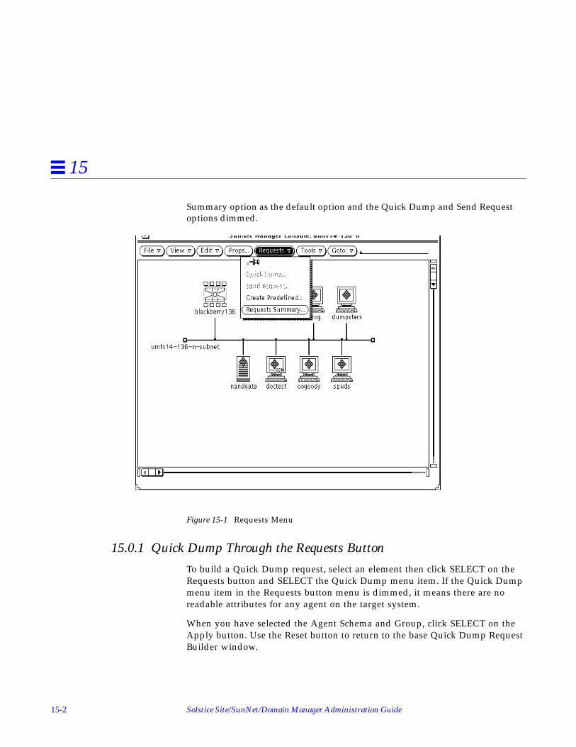
15-2 Solstice Site/SunNet/Domain Manager Administration Guide
15
Summary option as the default option and the Quick Dump and Send Requestoptions dimmed.
Figure 15-1 Requests Menu
15.0.1 Quick Dump Through the Requests Button
To build a Quick Dump request, select an element then click SELECT on theRequests button and SELECT the Quick Dump menu item. If the Quick Dumpmenu item in the Requests button menu is dimmed, it means there are noreadable attributes for any agent on the target system.
When you have selected the Agent Schema and Group, click SELECT on theApply button. Use the Reset button to return to the base Quick Dump RequestBuilder window.

Requests Management 15-3
15
Starting with version 2.3, when you launch a Quick Dump request, you receivea dialog box that tracks the status of the request. For requests with no visibledata stream, a timer lets you know the request is processing.
15.0.2 Quick Dump Through the Glyph Menu
Use the Quick Dump option of the element Glyph menu to send a QuickDump Request for a one-time data report of all attributes in an agent group. Ifthere are no readable attributes for any agent on the target system, the QuickDump item is dimmed. Figure Figure 15-2is an example of launching a QuickDump request from the element flower Glyph menu for the Agent Schemanamed diskinfo of Group type diskSpace.
Figure 15-2 Quick Dump Request

15-4 Solstice Site/SunNet/Domain Manager Administration Guide
15
15.1 Send RequestThe Send Request option is used to send a data or event request from theselected element. The Send Request option is dimmed if an element was notselected prior to selecting the Requests button or if the selected element has noagents specified.
Figure 15-3 Send Requests Window
Data and event requests send information such as the number of reports andreporting intervals to the specified agents on the target machine. The agentsautomatically generate reports at specified intervals without intervention(polling) from the Console. The activity daemon running on the Consoleworkstation periodically verifies that the specified agent is running on thetarget machine. In the case of proxy agents, the proxy agent polls the targetsystem at the intervals specified in the data or event request.
See the Tasks section of this Manual for examples of sending data and eventrequests.

Requests Management 15-5
15
15.1.0.1 Data Request Template
Figure 15-4 is an example of a data request named DataReachable . Adescription of the fields in the template are provided in Figure 15-4.
Figure 15-4 Data Request Template
The description of the agent group for the request is displayed in the lower leftcorner of the window. The properties fields for this data request need to bespecified at this time. Each field is described below.
Reporting CharacteristicsThe fields on the left side of the Data Request window specify reportingcharacteristics. Each field is described below.
Name:The optional name you wish to assign to the request. This allows you toassign a recognizable name to a request. The request manager assigns arequest name, if one is not specified, using the following format:

15-6 Solstice Site/SunNet/Domain Manager Administration Guide
15
<agent>.<group>.<number> (for example, hostperf.data.0 )
Proxy System:The name of the system the data request is to be sent to.
Interval:Specifies the interval (in seconds) for the agent on the target system to sendreports. An Interval value of 0 indicates that the agent should use its defaultinterval. See the agent’s man page for its default interval.
Count:Specifies the number of times for the agent on the target system is to sendreports. A count of 0 specifies that the agent is to send reports until therequest is stopped or killed. If a count is specified, and a Stop Date/Timeis/are specified, the request stops if the specified number of reports aregenerated before the Stop Date/Time are reached. If the Stop Date/Timeis/are reached before the specified number of reports are generated, therequest stops at the specified time.
Key:Identifies a particular row in a table (for example, ie0 or le0 in an Ethernetinterface table). The use of a key is agent-specific and is indicated in thebottom left corner of the Data Request Properties window. See the man pagefor the particular agent for information regarding keys. If no key isspecified, the entire table is returned.
Restart:Specifies whether the agent should attempt to restart the request if thesystem on which the agent is running reboots, the agent terminatesunexpectedly, or the Console itself is restarted. If Restart is off (no checkmark appears in the accompanying box), the request is discarded if theagent fails or if you quit the Console. If Restart is on (a check mark appearsin the accompanying box), the request is restarted. The default setting of thisfield is determined by the Restart Request upon Agent Failure setting in theConsole Properties Requests category. Click SELECT on the box next to thisfield to toggle the check mark on or off.
Defer Reports:Specifies whether or not the agent should cache reports and send them tothe Console only when asked to. If Defer Reports is on (a check markappears in the accompanying box), the agent is directed to collect thestatistics, but send them to the Console only when directed. Defer Reports

Requests Management 15-7
15
tells the agent to cache the last 32 reports. If 32 reports are cached, or if theagent runs out of memory, the oldest report is deleted when a new report iscached. You should not specify Defer Reports for agents that return a largeamount of data (for example, a routing table).
In many cases an agent collects information useful for debugging problems.This information might not be of interest in your normal daily operation.Furthermore, if a request were started before the error occurred, data reportswill continually stream back to the Console causing unnecessary networktraffic and increased CPU load. If, on the other hand, the request was startedafter the error happened, the debugging information would not have beencollected. By setting Deferred Sending on, reports are held in the agent’ssystem until you need to ask for them.
The data request must be active for Defer Reports to work properly; that is,issue the request with a long Interval and high Count. Refer to the “Viewingand Modifying Requests” section for more information on how to obtaindeferred reports.
On Completion:Specifies whether the request should be deleted or saved upon completion.To specify that the request be saved, drag MENU over the On Completionabbreviated menu button—release MENU over Save Request. If you chooseto save the request, the request glyph is dimmed after the request has beencompleted but remains in the view of the target element. You can examine,modify, or restart the saved request.
If you choose Delete Request on Completion, stopping the request is thesame as killing it. (Refer to the “Viewing and Modifying Requests” sectionfor more information.)
Options:Specifies any options (such as arguments) that the agent expects. To specifyOptions, type in an option string. For example, with SNMP requests you canspecify an SNMP read-community name. The information that you canspecify in the Options field is agent-specific—not all agents accept options.See the man page for the particular agent for information regarding options.
Note – Starting with version 2.3, there is a new flag called get-requested-attribute-only. By default it is set to true. Only the requested attributes will beretrieved. When this flag is set to false, all attributes are retrieved.

15-8 Solstice Site/SunNet/Domain Manager Administration Guide
15
Log to File:Specifies the file name where reports are to be stored. If you specify a filename with no path, the Console uses the current directory. If you fullyqualify the file name and the left-most characters scroll left, they are not lost.
To Program:A shell command line specifying a program or shell script to be run. Includethe directory path, if necessary. Data reports are passed to the standardinput of the program or shell script. Every active program to which datareports are sent keeps a file descriptor open. The default maximum numberof file descriptors allowed for a single process is 64. You can increase thisnumber up to 256 by using the limit command in the C-shell.
Schedule:Set this field to “On” in order to activate the scheduling options below.
Date Format:Select one of the four formats in which you will enter the start and stopdates.
Start Date:When you enter a date here, and click the Start button, the request will starton the specified date.
Stop Date:When you enter a date here, the request will stop on the specified date.
Start Time:When you enter a time here, and click the Start button, the request will startat the specified time.
Stop Time:When you enter a time here, the request will stop at the specified time.
Selecting AttributesThe fields in the right portion of the Data Request window are used to specifyattributes.

Requests Management 15-9
15
Attributes:A scrolling list that contains those attributes for which you are requestingdata. You choose an attribute and how you want the attribute datadisplayed with the fields beneath the Attributes scrolling list (describedbelow). When you click SELECT on the Apply button at the bottom right ofthe window, the attribute is added to the Attributes scrolling list.
Following is a description of the Attribute and attribute display fields:
Attribute:Specifies the attribute you want the agent to return data on. When the DataRequest window is first displayed, the Attribute field displays the name ofthe first attribute in the group/table from the agent schema file. To specify aparticular Attribute, press MENU on the Attribute abbreviated menu buttonand release MENU on the desired entry. When an attribute is selected, adescription is displayed in the lower-right footer.
Note – If no attribute is specified, all attributes for the selected group or tableare written to the Data Reports log. For tables, the values of the keys are alsoreturned. However, if you specify a particular table attribute, the key valuesare not returned.
Data Log:Specifies whether or not the attribute data should be written in the DataReports Log. To specify that the data not be written in the Data Reports log,drag MENU over the Data Log abbreviated menu button—release MENUover False.
Indicator:Specifies whether or not the attribute data should be displayed in anIndicator. An Indicator shows the last reported value for a particularattribute. Refer to the “Indicators” section for more information.
To specify the Indicator display option, click SELECT on the Indicator box.

15-10 Solstice Site/SunNet/Domain Manager Administration Guide
15
Strip Chart:Specifies whether or not the attribute data should be displayed in a StripChart. A Strip Chart contains an auto-scaled strip chart of values for anattribute. Refer to the “Strip Charts” section for more information.
To specify the Strip Chart display option, drag MENU over the Strip Chartabbreviated menu button—release MENU over either Absolute Values(chart the received values) or Delta Values (chart the differences betweenreceived values).
Graph Tool:Specifies whether or not the attribute data should be displayed by theGrapher. The Graph Tool, also known as the Results Grapher, is anapplication that allows the display of data received by the Console. Onlydata of types integer, float, counter, gauge, timestamp, or UNIX time can beplotted. Refer to Chapter 21, “Results Grapher,” for more information aboutthe Graph Tool. To specify the Graph Tool display option, drag MENU overthe Graph Tool abbreviated menu button—release MENU over eitherAbsolute Values (graph the received values) or Delta Values (graph thedifferences between received values).
Adding AttributesThe buttons below the Attributes fields in the Data Request window allow youto add, change, and delete attribute selections in the Attributes scrolling list.The buttons are described below:
• Apply tells the request manager to add the Attribute selected to theAttributes scrolling list.
• Reset tells the request manager to reset the Attributes scrolling list back toits default value.
• Delete tells the request manager to remove the Attribute selected from theAttributes scrolling list.
An entry in the scrolling list may be selected at any time by pointing the mousepointer at the entry and clicking the SELECT button. This updates the windowto the settings for the selected attribute. An entry may be deleted by selectingit and clicking on the Delete button.

Requests Management 15-11
15
Sending the Data/Event RequestThe buttons at the bottom left of the Data/Event Request window allow you tosend, hold, and reset the data/event request. The buttons are described below:
• Start tells the request manager to send the data/event request.
• Hold tells the request manager to hold the data/event request.
• Reset tells the request manager to set the data/event request to its defaultvalues.
Once you have specified the options that you desire in the Request Buildertemplate, click SELECT on the Apply button. Refer to “Data RequestTemplate,” above for a description of the template that will be displayed next.Again, specify the desired options and then click on the Start button to sendthe data request to the desired agent.
15.1.0.2 Event Request Template
Figure 15-5 is an example of an event request named if System Reboot .

15-12 Solstice Site/SunNet/Domain Manager Administration Guide
15
Figure 15-5 Event Request Template
Reporting CharacteristicsThe fields on the left side of the Event Request window specify reportingcharacteristics. Each field is described below.
Name:The optional name you wish to assign to the request. This allows you toassign a recognizable name to a request. The request manager assigns arequest name, if one is not specified, using the following format:
<agent>.<group>.<number> (for example, hostperf.data.0 )
Proxy System:The name of the system the data request is to be sent to.

Requests Management 15-13
15
Interval:Specifies the interval (in seconds) for the agent on the target system to sendreports. An Interval value of 0 indicates that the agent should use its defaultinterval. See the agent’s man page for its default interval.
Count:Specifies the number of times for the agent on the target system is to sendreports. A count of 0 specifies that the agent is to send reports until therequest is stopped or killed. If a count is specified, and a Stop Date/Timeis/are specified, the request stops if the specified number of reports aregenerated before the Stop Date/Time are reached. If the Stop Date/Timeis/are reached before the specified number of reports are generated, therequest stops at the specified time.
Key:Identifies a particular row in a table (for example, ie0 or le0 in an Ethernetinterface table). The use of a key is agent-specific and is indicated in thebottom left corner of the Data Request Properties window. See the man pagefor the particular agent for information regarding keys. If no key isspecified, the entire table is returned.
Restart:Specifies whether the agent should attempt to restart the request if thesystem on which the agent is running reboots, the agent terminatesunexpectedly, or the Console itself is restarted. If Restart is off (no checkmark appears in the accompanying box), the request is discarded if theagent fails or if you quit the Console. If Restart is on (a check mark appearsin the accompanying box), the request is restarted. The default setting of thisfield is determined by the Restart Request upon Agent Failure setting in theConsole Properties Requests category. Click SELECT on the box next to thisfield to toggle the check mark on or off.
Send Once:If you check this box, the event request is killed after the console receivesthe event. If the box is not checked, an event report is sent for every eventoccurrence.
Defer Reports:Specifies whether or not the agent should cache reports and send them tothe Console only when asked to. If Defer Reports is on (a check markappears in the accompanying box), the agent is directed to collect thestatistics, but send them to the Console only when directed. Defer Reports

15-14 Solstice Site/SunNet/Domain Manager Administration Guide
15
tells the agent to cache the last 32 reports. If 32 reports are cached, or if theagent runs out of memory, the oldest report is deleted when a new report iscached. You should not specify Defer Reports for agents that return a largeamount of data (for example, a routing table).
In many cases an agent collects information useful for debugging problems.This information might not be of interest in your normal daily operation.Furthermore, if a request were started before the error occurred, data reportswill continually stream back to the Console causing unnecessary networktraffic and increased CPU load. If, on the other hand, the request was startedafter the error happened, the debugging information would not have beencollected. By setting Deferred Sending on, reports are held in the agent’ssystem until you need to ask for them.
The data request must be active for Defer Reports to work properly; that is,issue the request with a long Interval and high Count. Refer to the “Viewingand Modifying Requests” section for more information on how to obtaindeferred reports.
On Completion:Specifies whether the request should be deleted or saved upon completion.To specify that the request be saved, drag MENU over the On Completionabbreviated menu button—release MENU over Save Request. If you chooseto save the request, the request glyph is dimmed after the request has beencompleted but remains in the view of the target element. You can examine,modify, or restart the saved request.
If you choose Delete Request on Completion, stopping the request is thesame as killing it. (Refer to the “Viewing and Modifying Requests” sectionfor more information.)
Options:Specifies any options (such as arguments) that the agent expects. To specifyOptions, type in an option string. For example, with SNMP requests you canspecify an SNMP read-community name. The information that you canspecify in the Options field is agent-specific—not all agents accept options.See the man page for the particular agent for information regarding options.
Note – Starting with version 2.3, there is a new flag called get-requested-attribute-only. By default it is set to true. Only the requested attributes will beretrieved. When this flag is set to false, all attributes are retrieved.

Requests Management 15-15
15
Alternate ProxyUse this field to specify an alternate proxy you wish to use to launch arequest that has previously been launched with a different proxy agent. See“Alternate Proxy” for more information on this feature.
Schedule:Set this field to “On” in order to activate the scheduling options below.
Date Format:Select one of the four formats in which you will enter the start and stopdates.
Start Date:When you enter a date here, and click the Start button, the request will starton the specified date.
Stop Date:When you enter a date here, the request will stop on the specified date.
Start Time:When you enter a time here, and click the Start button, the request will startat the specified time.
Stop Time:When you enter a time here, the request will stop at the specified time.
Important Information About Interval and Count fieldsFor event requests, interval and count fields simply specify when the agent isto send a report. A report is forwarded to the Console system only if it hasbeen determined that an event has occurred. For agents that are shipped withthe product, the value reported for an attribute is the value noted at thereporting interval. Thus, it is possible for event conditions to occur betweenreporting intervals and not cause an event report.
If Send Once has been selected (a check mark appears in the accompanyingbox), the request is terminated after the Console receives the first event report.Click SELECT on the Send Once box to toggle the check mark on or off.
Alternate ProxyStarting with version 2.3, you can use an alternate proxy to create an eventrequest against a device. When an event is generated against a device and avalue name is specified in the alternate proxy field, the request is started on

15-16 Solstice Site/SunNet/Domain Manager Administration Guide
15
this proxy agent on the specified host. This become useful in a troubleshootinga situation such as the following: You are pinging a device in a remote location,and it responds by indicating that the device is down. To verify that it is thedevice and not, for example, an intermediate router, you can send the samerequest using an alternate proxy agent. You might then want to try an alternateroute through another proxy agent on an alternate network. This way, you canverify the router is down, not the device. The alternate proxy feature enablesyou to do this verification automatically.
The alternate proxy field is enabled only when you send requests against proxyagents.
Descriptions of the Attribute fields are provided below:
Attributes:A scrolling list that contains attributes for which you want eventinformation.
Attribute:Specifies the attributes that you want to use to specify an event. ClickSELECT on the button to see the list of available attributes. After you setattribute threshold(s), click SELECT on Apply to add the attribute to theAttributes list.
Relation1, Relation2:Specify threshold conditions for reporting an event. You can specify up totwo threshold relational operators; the event is reported if either of the twothreshold conditions are met. To set the threshold relational operator(s) for

Requests Management 15-17
15
Relation1 or Relation2, drag MENU over the Relation abbreviated menubutton to display the following list of relational operators in a pop-upmenu—release MENU over the desired relational operator.
Threshold Not Set means you have not set a threshold for this attribute.This is the default choice.
Equal To tells the agent to report an event if the attribute value equals“Thresholdn”.
Not Equal To tells the agent to report an event if the attribute value doesnot equal “Thresholdn”.
Less Than tells the agent to report an event if the attribute value is lessthan “Thresholdn.”
Less Than Or Equal To tells the agent to report an event if the attributevalue is less than or equal to “Thresholdn.”
Greater Than tells the agent to report an event if the attribute value isgreater than “Thresholdn.”
Greater Than Or Equal To tells the agent to report an event if theattribute value is greater than or equal to “Thresholdn.”
Changed tells the agent to report an event if the attribute value differsfrom the last sampled value.
Increased By tells the agent to report an event if the attribute value hasincreased by “Thresholdn” compared to the last sampled value.
Decreased By tells the agent to report an event if the attribute value hasdecreased by “Thresholdn” compared to the last sampled value.
Increased By More Than tells the agent to report an event if the attributevalue has increased by more than “Thresholdn” compared to the lastsampled value.
Increased By Less Than tells the agent to report an event if the attributevalue has increased by less than “Thresholdn” compared to the lastsampled value.
Decreased By More Than tells the agent to report an event if the attributevalue has decreased by more than “Thresholdn” compared to the lastsampled value.
Decreased By Less Than tells the agent to report an event if the attribute

15-18 Solstice Site/SunNet/Domain Manager Administration Guide
15
value has decreased by less than “Thresholdn” compared to the lastsampled value.
Note – For the Changed, Increased By, Decreased By, Increased By More Than,Increased By Less Than, Decreased By More Than, and Decreased By LessThan operators, the Count field of the report characteristics must not be ‘1.’ AKey must be supplied if a table of attributes is selected.
Threshold1, Threshold2:Specify the threshold value if the selected operator is other than ThresholdNot Set, or Changed.
Priority:Specifies the priority of the request. Click SELECT on the desired prioritybutton (Low, Medium, or High) for the request.
Glyph Effect:Specifies a visible indicator when the specified event is reported. PressMENU on the Glyph Effect abbreviated menu button to display a signaloptions pop-up menu. Release MENU on the signal option you want. Youcan choose only one visual signal option. In order to have the “decay”feature in effect, you must select the Priority by Color option.
The following options are available:Blink Glyph
Blinks the glyph of the element for which an event has been reported.
Dim Glyph
Dims the glyph of the element for which an event has been reported.
Priority by Color
Causes the glyph to change color, based on the priority of the reportedevent. The defaults are:
• red = high priority• orange = medium priority• yellow = low priority• blue = decay

Requests Management 15-19
15
Starting with version 2.3, you can customize colors, including the “decay”color. See Chapter 4, “Requesting Data,” or Chapter 5, “Specifying EventRequests,” for procedures to customize Color by Priority.
If multiple reports are received for a system, the highest priority is used. Inassociation with the Priority by Color option is the “decay” feature. Thisfeature pertains to events and traps that have reached a threshold and thenfallen below it, or that have had an event or trap stop being reported. Inresponse to these conditions, the glyph for the affected element turns blue,which is the default color, or to the color you have customized. Once a glyphhas decayed to blue, the event must be acknowledged in order for the glyph toreturn to its original color. To get a glyph to return to its original color, you caneither:
• Select the Console’s View➤Event Summary option• Highlight the name of the glyph• Press the Drop from List button.
Or
• From the Glyph Menu for the specific element, pull right over the GlyphState➤Normal option.
Audio Effect:Specifies an audible indicator when the specified event is reported. PressMENU on the Audio Effect abbreviated menu button to display a signaloptions pop-up menu—drag and release MENU on the desired signaloption. Only one audio signal option can be chosen. The following optionsare available:
Ring Bell sounds an audible bell on the Console workstation.
Play Audio File causes the file specified in the Audio File field to beplayed.
Audio File:Defines the audio file to be played when the specified event is reported.Type in the file name of the audio file. The option Play Audio File must bespecified in the Audio Effect field. You can use the volume function of theAudio Tool in OpenWindows 3.2 to control the sound level.

15-20 Solstice Site/SunNet/Domain Manager Administration Guide
15
Note – The Console must be running (not merely displaying) on a machinewith an audio port. If you are running the Console on a server but displayingthe Console windows on a local workstation, the Console will attempt to playthe audio file on the server.
Mail To:Defines one or more mail recipients to send the event report to when thespecified event is reported. Type in a list of mail recipients. If there is morethan one recipient, use a space between each entry.
To Program:A shell command line specifying a program or shell script to be run. Includethe directory path, if necessary. A new copy of the program or shell script isforked for each event report. The event report is passed to the standardinput of the program or shell script. Every active program that receives anevent report keeps a file descriptor open. The default maximum number offile descriptors allowed for a single process is 64. You can increase thisnumber up to 256 by using the limit command in the C-shell.
Stop Request:This field is new starting with version 2.3. If this field is checked, the requestwill be stopped when a specific event is received. This feature enables youto specify a stop request at the attribute level. You can set thresholds againstdifferent attributes in an event request and also specify that the request stoponly when a specific attribute exceeds a threshold’s level.
Start Request:This field is new starting with version 2.3. A new request name (includingpredefined requests) can be specified in this field. A different request namecan be specified for each event atrtribute. Whenever an event is generatedagainst the given event request, the reqeust specified in this field islaunched automatically upon receipt of the event. This can be used inconjunction with the other event based options such as stopping the requestor trying an alternate proxy.
15.2 Create Predefined
The Create Predefined option is used to build a predefined data or event request.This is a global operation, not element based. Therefore, this menu item will bedimmed if an element has been selected prior to clicking the Requests button. Refer

Requests Management 15-21
15
to the “Creating, Modifying, or Deleting Predefined Requests” section forinformation about using the Create Predefined option.
Note – The predefined data and event record names are not case sensitive, as istrue with most of the Console related name fields. Since the predefined dataand event records reside in the runtime database with all of the elements, it isstrongly recommended that the names assigned to newly created predefinedrequests consist of at least two words, as is the case with the predefined dataand event requests provided with this product. Otherwise, a conflict may arisebetween the names of hosts and the names of the predefined data and eventrequest records, as they all must be unique.
15.2.1 Supplied Predefined Requests
A number of predefined data and event requests are supplied and recorded inthe .SNMpredefined file in the struct directory. Upon invoking theConsole, a check is made to see if the $HOME/.SNMpredefined file exists. If itdoes, the file is loaded into the runtime database for use by the Console. If itdoes not exist, the .SNMpredefined file is loaded into the runtime database.The first time the Console is invoked, the .SNMpredefined file will be loadedinto the runtime database. The records in this file, along with any predefineddata and event requests you modify or create after the Console is started, arestored in your $HOME/.SNMpredefined file upon exiting from the Console.You can also save the runtime database version of the predefined data andevent requests records by using the File➤Save➤Predefined Requests option.Using this option, you can save these records to your$HOME/.SNMpredefined file or to any other file you desire. For informationabout creating, modifying, deleting, and sending predefined data and eventrequests, refer to the sections that follow.

15-22 Solstice Site/SunNet/Domain Manager Administration Guide
15
15.2.2 Predefined Data Request Records
The following table lists the predefined data requests that are provided withthis product, their Agent, Group, and Attribute settings, as well as adescription of their intended function(s).
Table 15-1 SNM Supplied Predefined Data Requests
Request Name Agent Name Group NameAttributesSupported Function
Graph Host Performance hostperf data cpu%intrdiskipktsopkts
CPU utilization# of device interrupts# of disk transfers# of if input pkts# of if output pkts
Record Disk Space diskinfo diskSpace all disk space information
Record Host Performance hostperf data all Statistics of Host
Show Host Interfaces hostif if all host interface statistics
Show NFS Statistics rpcnfs client all RPC and NFS statistics
Show Path to Host ippath path all trace IP packet’s pathbetween proxy andtarget system
Show Routing Statistics iproutes routes all Routing statistics
Show snmp System Info snmp system all System information
Show snmp-mibII System Info snmp-mibII system all System information
Show sun-snmp System Info sun-snmp system all System information

Requests Management 15-23
15
15.2.3 Predefined Event Request Records
The following table lists the predefined event requests that are provided withthis product, their Agent, Group, and Attribute settings, as well as adescription of their intended function(s).
15.2.4 Predefined Requests Management
A Predefined Data Request Template similar to the one in Figure 15-6 appearsafter you select the Request Type, Request Name, Agent Schema, and GroupName.
Table 15-2 SNM Supplied Predefined Event Requests
Request Name Agent Name Group NameAttributesSupported Event to be Reported
When Disk is Full diskinfo diskSpace capacity Disk file system is full
If System Reboot hostperf data uptime If system reboots
When Printer Error lpstat status statusCode Line printer error
When System is not Reachable ping reach reachable System not reachable

15-24 Solstice Site/SunNet/Domain Manager Administration Guide
15
Figure 15-6 Sample Predefined Data Request Template
15.2.4.1 Reporting Characteristics
The fields on the left side of the Predefined Data/Event Request windowspecify reporting characteristics. Each of the fields isdescribed below.
Request Name:The name you are assigning to the predefined request. You must specify aname for this request. Request Names are limited to a maximum of 64characters. If you selected a predefined data or event request, the RequestName field will contain the name of the predefined data or event requestyou selected.
Requests Management 15-25
15
Case SensitivityThe predefined data and event record names are case insensitive. Since thepredefined data and event records reside in the runtime database with all ofthe elements, it is strongly recommended that the names assigned to newlycreated predefined requests consist of at least two words, as is the case withthe predefined data and event requests provided with this product. Otherwise,a conflict may arise between the name of an element and the name of thepredefined data and/or event request record being created, as they must beunique. When an attempt to create a predefined data or event request with aduplicate name of an element or an existing predefined request is made, anerror message will be placed in the error reports log and the predefined requestwill not be created.
Agent Schema:The name of the agent schema with which the predefined data request isassociated.
Group/Table:The name of the group or table associated with the agent schema withwhich the predefined data request is associated.
Polling Interval:Specifies the interval (in seconds) for the agent on the target system to sendreports. An Interval value of 0 indicates that the agent should use its defaultinterval. See the specific agent’s man page for its default interval value.
Count:Specifies the number of times for the agent on the target system to sendreports. A count of 0 specifies that the agent is to send reports until therequest is stopped or killed. If a count is specified, and a Stop Date/Timeis/are specified, the request stops if the specified number of reports aregenerated before the Stop Date/Time are reached. If the Stop Date/Timeis/are reached before the specified number of reports are generated, therequest stops at the specified time.
Key:Identifies a particular row in a table (for example, ie0 or le0 in an Ethernetinterface table). The use of a key is agent-specific and is indicated in thebottom left corner of the Data Request Properties window. See the man pagefor the particular agent for information regarding keys. If no key isspecified, the entire table is returned.

15-26 Solstice Site/SunNet/Domain Manager Administration Guide
15
Options:Specifies any options (such as arguments) that the agent expects. To specifyOptions, type in an option string. For example, with SNMP requests you canspecify an SNMP read-community name. The information that you canspecify in the Options field is agent-specific—not all agents accept options.See the man page for the particular agent for information regarding options.
Restart:Specifies whether the agent should attempt to restart the request if thesystem on which the agent is running reboots, the agent terminatesunexpectedly, or the Console itself is restarted. If Restart is off (no checkmark appears in the accompanying box), the request is discarded if theagent fails or if you quit the Console. If Restart is on (a check mark appearsin the accompanying box), the request is restarted. The default setting of thisfield is determined by the Restart Request upon Agent Failure setting in theConsole Properties Requests category. (Refer to Chapter 17, “Props Menu,”under “Requests” for more information.) Click SELECT on the box next tothis field to toggle the check mark on or off.
Defer Reports:Specifies whether or not the agent should cache reports and send them tothe Console only when asked to. If Defer Reports is on (a check markappears in the accompanying box), the agent is directed to collect thestatistics, but send them to the Console only when directed. Defer Reportstells the agent to cache the last 32 reports. If 32 reports are cached, or if theagent runs out of memory, the oldest report is deleted when a new report iscached. You should not specify Defer Reports for agents that return a largeamount of data (for example, a routing table).
In many cases an agent collects information useful for debugging problems.This information might not be of interest in your normal daily operation.Furthermore, if a request were started before the error occurred, data reportswill continually stream back to the Console causing unnecessary networktraffic and increased CPU load. If, on the other hand, the request was startedafter the error happened, the debugging information would not have beencollected. By setting Deferred Sending on, reports are held in the agent’ssystem until you need to ask for them.
The data request must be active for Defer Reports to work properly; that is,issue the request with a long Interval and high Count. Refer to Chapter 14,“Console,” under “Viewing and Modifying Requests” for information onhow to obtain deferred reports.

Requests Management 15-27
15
On Completion:Specifies whether the request should be deleted or saved upon completion.To specify that the request be saved, drag MENU over the On Completionabbreviated menu button—release MENU over Save Request. If you chooseto save the request, the request glyph is dimmed after the request has beencompleted but remains in the view of the target element. You can examine,modify, or restart the saved request.
If you select Delete Request On Completion, then stopping the request is thesame as killing it. (Refer to Chapter 14, “Console,” under “Viewing andModifying Requests” for more information.)
Log to File:Specifies the file name where reports are to be stored. If you specify a filename with no path, the SunNet Manager Console uses the current directory.If you fully qualify the file name and the left-most characters scroll left, theyare not lost.
Note – Starting with version 2.3, there is a new flag called get-requested-attribute-only. By default it is set to true. Only the requested attributes will beretrieved. When this flag is set to false, all attributes are retrieved.
To Program:A shell command line specifying a program or shell script to be run. Includethe directory path, if necessary. Data reports are passed to the standardinput of the program or shell script. Every active program to which datareports are sent keeps a file descriptor open. The default maximum numberof file descriptors allowed for a single process is 64. You can increase thisnumber up to 256 by using the limit command in the C-shell.
Schedule:Set this field to “On” in order to activate the scheduling options below.
Date Format:Select one of the four formats in which you will enter the start and stopdates.
Start Date:When you enter a date here, and click the Start button, the request will starton the specified date.

15-28 Solstice Site/SunNet/Domain Manager Administration Guide
15
Stop Date:When you enter a date here, the request will stop on the specified date.
Start Time:When you enter a time here, and click the Start button, the request will startat the specified time.
Stop Time:When you enter a time here, the request will stop at the specified time.
15.2.4.2 Selecting Attributes
The fields in the right portion of the Predefined Data Request window are usedto specify attributes.
Selected Attributes:A scrolling list that contains those attributes for which you are requestingdata. You choose an attribute and how you want the attribute datadisplayed with the fields beneath the Available Attribute values scrolling list(described below). When you click SELECT on the Add button at the rightof the window, the attribute is added to the Selected Attributes valuesscrolling list.
Following is a description of the Available Attributes and attribute displayfields:
Available Attributes:Specifies the attribute you want the agent to return data on. When thePredefined Data Request window is first displayed, the Available Attributesfield displays the name of the first attribute in the group/table from theagent schema file. To specify a particular Available Attribute, press MENUover the Available Attributes abbreviated menu button and release MENUon the desired entry. When an attribute is selected, a description isdisplayed in the lower-right footer.
Note – If no attribute is specified, all attributes for the selected group or tableare written to the Data Reports log. For tables, the values of the keys are alsoreturned. However, if you specify a particular table attribute, the key valuesare not returned.

Requests Management 15-29
15
Data Log:Specifies whether or not the attribute data should be written in the DataReports Log. To specify that the data not be written in the Data Reports log,drag MENU over the Data Log abbreviated menu button—release MENUover False.
Indicator:Specifies whether or not the attribute data should be displayed in anIndicator. An Indicator shows the last reported value for a particularattribute. Refer to Chapter 16, “View Reports,” under “Indicators” for moreinformation.
To specify the Indicator display option, click SELECT on the Indicator box.
Strip Chart:Specifies whether or not the attribute data should be displayed in a StripChart. A Strip Chart contains an auto-scaled strip chart of values for anattribute. Refer to the section on “Strip Charts” for more information.
To specify the Strip Chart display option, drag MENU over the Strip Chartabbreviated menu button—release MENU over either Absolute Values(chart the received values) or Delta Values (chart the differences betweenreceived values).
Graph Tool:Specifies whether or not the attribute data should be displayed by theGrapher. The Graph Tool, also known as the Results Grapher, is anapplication that allows the display of data received by the Console. Onlydata of types integer, float, counter, gauge, timestamp, or UNIX time can beplotted. Refer to Chapter 21, “Results Grapher,” for more information aboutthe Graph Tool. To specify the Graph Tool display option, drag MENU overthe Graph Tool abbreviated menu button—release MENU over eitherAbsolute Values (graph the received values) or Delta Values (graph thedifferences between received values).
15.2.4.3 Adding Attributes
The buttons to the right of the Selected Attributes field in the Predefined DataRequest window allow you to add, change, and delete attribute selections inthe Selected Attributes values scrolling list. The buttons are described below:

15-30 Solstice Site/SunNet/Domain Manager Administration Guide
15
• Add tells the request manager to add the Available Attribute selected to theSelected Attributes scrolling list.
• Change tells the request manager to apply the changes made to the attributesetting(s).
• Delete tells the request manager to remove the Available Attribute selectedfrom the Selected Attributes scrolling list.
An entry in the scrolling list may be selected at any time by pointing the mousepointer at the entry and clicking the SELECT button. This updates the windowto the settings for the selected attribute. An entry may be deleted by selectingit and clicking on the Delete button.
15.2.5 Define and Reset Data Record Fields
Use the buttons at the bottom of the Predefined Data Request window todefine and reset all the data record fields for the predefined data request, aswell as to delete the record from the runtime database. The buttons aredescribed below:
• Define creates or updates the predefined data request runtime databaserecord to the values specified in the Predefined Data Request Window.
• Reset returns the request specifications back to the originally appliedselections.
• Undefine deletes the selected predefined data request from the runtimedatabase record.
15.2.6 Predefined Event Request Management
When you specify a predefined Event Request, the window in Figure 15-7appears after you select the Request Type, Request Name, Agent Schema, andGroup Name in the Request Builder window.

Requests Management 15-31
15
Figure 15-7 Sample Predefined Event Request Template
Descriptions of the reporting characteristics fields are provided below:
Request Name:The optional name you wish to assign to the request. This allows you toassign a recognizable name to a request. The request manager assigns arequest name, if one is not specified, using the following format:
<agent>.<group>.<number> (for example, hostperf.data.0 )
Agent Schema:The file containing the attribute group/table.
Group/Table:the set of attribute values for which you are requesting data.

15-32 Solstice Site/SunNet/Domain Manager Administration Guide
15
Polling Interval:Specifies the interval (in seconds) for the agent on the target system to sendreports. An Interval value of 0 indicates that the agent should use its defaultinterval. See the agent’s man page for its default interval.
Count:Specifies the number of times for the agent on the target system is to sendreports. A count of 0 specifies that the agent is to send reports until therequest is stopped or killed. If a count is specified, and a Stop Date/Timeis/are specified, the request stops if the specified number of reports aregenerated before the Stop Date/Time are reached. If the Stop Date/Timeis/are reached before the specified number of reports are generated, therequest stops at the specified time.
Key:Identifies a particular row in a table (for example, ie0 or le0 in an Ethernetinterface table). The use of a key is agent-specific and is indicated in thebottom left corner of the Data Request Properties window. See the man pagefor the particular agent for information regarding keys. If no key isspecified, the entire table is returned.
Options:Specifies any options (such as arguments) that the agent expects. To specifyOptions, type in an option string. For example, with SNMP requests you canspecify an SNMP read-community name. The information that you canspecify in the Options field is agent-specific—not all agents accept options.See the man page for the particular agent for information regarding options.
Restart:Specifies whether the agent should attempt to restart the request if thesystem on which the agent is running reboots, the agent terminatesunexpectedly, or the Console itself is restarted. If Restart is off (no checkmark appears in the accompanying box), the request is discarded if theagent fails or if you quit the Console. If Restart is on (a check mark appearsin the accompanying box), the request is restarted. The default setting of thisfield is determined by the Restart Request upon Agent Failure setting in theConsole Properties Requests category. Click SELECT on the box next to thisfield to toggle the check mark on or off.

Requests Management 15-33
15
Send OnceIf Send Once has been selected (a check mark appears in the accompanyingbox), the request is terminated after the Console receives the first eventreport. Click SELECT on the Send Once box to toggle the check mark on oroff.
Defer Reports:Specifies whether or not the agent should cache reports and send them tothe Console only when asked to. If Defer Reports is on (a check markappears in the accompanying box), the agent is directed to collect thestatistics, but send them to the Console only when directed. Defer Reportstells the agent to cache the last 32 reports. If 32 reports are cached, or if theagent runs out of memory, the oldest report is deleted when a new report iscached. You should not specify Defer Reports for agents that return a largeamount of data (for example, a routing table).
In many cases an agent collects information useful for debugging problems.This information might not be of interest in your normal daily operation.Furthermore, if a request were started before the error occurred, data reportswill continually stream back to the Console causing unnecessary networktraffic and increased CPU load. If, on the other hand, the request was startedafter the error happened, the debugging information would not have beencollected. By setting Deferred Sending on, reports are held in the agent’ssystem until you need to ask for them.
The data request must be active for Defer Reports to work properly; that is,issue the request with a long Interval and high Count. Refer to the “Viewingand Modifying Requests” section for more information on how to obtaindeferred reports.
On Completion:Specifies whether the request should be deleted or saved upon completion.To specify that the request be saved, drag MENU over the On Completionabbreviated menu button—release MENU over Save Request. If you chooseto save the request, the request glyph is dimmed after the request has beencompleted but remains in the view of the target element. You can examine,modify, or restart the saved request.
If you choose Delete Request on Completion, stopping the request is thesame as killing it. (Refer to the “Viewing and Modifying Requests” sectionfor more information.)

15-34 Solstice Site/SunNet/Domain Manager Administration Guide
15
Schedule:Set this field to “On” in order to activate the scheduling options below.
Date Format:Select one of the four formats in which you will enter the start and stopdates.
Start Date:When you enter a date here, and click the Start button, the request will starton the specified date.
Stop Date:When you enter a date here, the request will stop on the specified date.
Start Time:When you enter a time here, and click the Start button, the request will startat the specified time.
Stop Time:When you enter a time here, the request will stop at the specified time.
Important Information About Polling Interval and Count FieldsFor predefined event requests, these fields specify when the agent is to send areport. A report is forwarded to the Console system only if it has beendetermined that an event has occurred. For agents that are shipped with theproduct, the value reported for an attribute is the value noted at the reportinginterval. Thus, it is possible for event conditions to occur between reportingintervals and not cause an event report.
If a count is specified, and a Stop Date/Time is/are specified, the request stopsif the specified number of reports are generated before the Stop Date/Time arereached. If the Stop Date/Time is/are reached before the specified number ofreports are generated, the request stops at the specified time.
15.2.6.1 Selecting Attributes
Use the fields in the right portion of the Predefine Event Request propertieswindow to specify attributes.

Requests Management 15-35
15
Selected Attributes:A scrolling list that contains those attributes for which you are requestingevent information. You specify attributes, event thresholds, and how youwant the event signalled with the fields under the Selected Attributes valuesscrolling list. When you click SELECT on the Add button to the right of theSelected Attributes window, the attribute is added to the Selected Attributesvalues scrolling list.
Following is a description of the available attributes, event threshold, signaloptions, receiver, and priority fields:
Available Attributes:Specifies the attributes that you want to use to specify an event. When thewindow is first displayed, the Available Attributes field displays the nameof the first attribute in the group/table from the agent schema file. Tospecify an attribute, press MENU on the Available Attributes field andrelease the mouse button on the desired entry. When an attribute is selected,a description is displayed in the lower-right footer of the window.
Relation1, Relation2:Specify threshold conditions for reporting an event. You can specify up totwo threshold relational operators; the event is reported if either of the twothreshold conditions are met. To set the threshold relational operator(s) for

15-36 Solstice Site/SunNet/Domain Manager Administration Guide
15
Relation1 or Relation2, drag MENU over the Relation abbreviated menubutton to display the following list of relational operators in a pop-upmenu—release MENU over the desired relational operator.
Threshold Not Set means you have not set a threshold for this attribute.This is the default choice.
Equal To tells the agent to report an event if the attribute value equals“Thresholdn.”
Not Equal To tells the agent to report an event if the attribute value doesnot equal “Thresholdn.”
Less Than tells the agent to report an event if the attribute value is lessthan “Thresholdn.”
Less Than Or Equal To tells the agent to report an event if the attributevalue is less than or equal to “Thresholdn.”
Greater Than tells the agent to report an event if the attribute value isgreater than “Thresholdn.”
Greater Than Or Equal To tells the agent to report an event if theattribute value is greater than or equal to “Thresholdn.”
Changed tells the agent to report an event if the attribute value differsfrom the last sampled value.
Increased By tells the agent to report an event if the attribute value hasincreased by “Thresholdn” compared to the last sampled value.
Decreased By tells the agent to report an event if the attribute value hasdecreased by “Thresholdn” compared to the last sampled value.
Increased By More Than tells the agent to report an event if the attributevalue has increased by more than “Thresholdn” compared to the lastsampled value.
Increased By Less Than tells the agent to report an event if the attributevalue has increased by less than “Thresholdn” compared to the lastsampled value.
Decreased By More Than tells the agent to report an event if the attributevalue has decreased by more than “Thresholdn” compared to the lastsampled value.
Decreased By Less Than tells the agent to report an event if the attribute

Requests Management 15-37
15
value has decreased by less than “Thresholdn” compared to the lastsampled value.
Note – For the Changed, Increased By, Decreased By, Increased By More Than,Increased By Less Than, Decreased By More Than, and Decreased By LessThan operators, the Count field of the report characteristics must not be ‘1.’ AKey must be supplied if a table of attributes is selected.
Threshold1, Threshold2:Specify the threshold value if the selected operator is other than ThresholdNot Set, or Changed.
Priority:Specifies the priority of the request. Click SELECT on the desired prioritybutton (Low, Medium, or High) for the request.
Glyph Effect:Specifies a visible indicator when the specified event is reported. PressMENU on the Glyph Effect abbreviated menu button to display a signaloptions pop-up menu. Release MENU on the signal option you want. Youcan choose only one visual signal option. In order to have the “decay”feature in effect, you must select the Priority by Color option.
The following options are available:Blink Glyph
Blinks the glyph of the element for which an event has been reported.
Dim Glyph
Dims the glyph of the element for which an event has been reported.
Priority by Color
Causes the glyph to change color, based on the priority of the reportedevent. The defaults are:
• Red = high priority• Orange = medium priority• Yellow = low priority• Blue = decay

15-38 Solstice Site/SunNet/Domain Manager Administration Guide
15
Starting with version 2.3, you can customize colors, including the “decay”color. See Chapter 4, “Requesting Data,” or Chapter 5, “Specifying EventRequests,” for procedures to customize Color by Priority.
If multiple reports are received for a system, the highest priority is used. Inassociation with the Priority by Color option is the “decay” feature. Thisfeature pertains to events and traps that have reached a threshold and thenfallen below it, or that have had an event or trap stop being reported. Inresponse to these conditions, the glyph for the affected element turns blue,which is the default color, or to the color you have customized. Once a glyphhas decayed to blue, the event must be acknowledged in order for the glyph toreturn to its original color. To return a glyph to its original color, you caneither:
• Select the Console’s View➤Event Summary option• Highlight the name of the glyph• Press the Drop from List button.
Or
• From the Glyph Menu for the specific element, pull right over the GlyphState➤Normal option.
Pending StateStarting with version 2.3, you can place an object in pending state. In thisstate, the color of the glyph is dimmed, and all outstanding events arecleared. New events/traps do not change the color of the glyph nor do theypropagate the effect of the trap/event to the parent object. A parent object inpending state is not affected by a change in state on any children.
Audio Effect:Specifies an audible indicator when the specified event is reported. PressMENU on the Audio Effect abbreviated menu button to display a signaloptions pop-up menu—drag and release MENU on the desired signaloption. Only one audio signal option can be chosen. The following optionsare available:
Ring Bell sounds an audible bell on the Console workstation.
Play Audio File causes the file specified in the Audio File field to beplayed.

Requests Management 15-39
15
Audio File:Defines the audio file to be played when the specified event is reported.Type in the file name of the audio file. The option Play Audio File must bespecified in the Audio Effect field. You can use the volume function of theAudio Tool in OpenWindows 3.2 to control the sound level.
Note – The Console must be running (not merely displaying) on a machinewith an audio port. If you are running the Console on a server but displayingthe Console windows on a local workstation, the Console will attempt to playthe audio file on the server.
Mail To:Defines one or more mail recipients to send the event report to when thespecified event is reported. Type in a list of mail recipients. If there is morethan one recipient, use a space between each entry.
To Program:A shell command line specifying a program or shell script to be run. Includethe directory path, if necessary. A new copy of the program or shell script isforked for each event report. The event report is passed to the standardinput of the program or shell script. Every active program that receives anevent report keeps a file descriptor open. The default maximum number offile descriptors allowed for a single process is 64. You can increase thisnumber up to 256 by using the limit command in the C-shell.
Stop Request:This field is new starting with version 2.3. If this field is checked, the requestwill be launched one time. If this field is checked, it will override anynumber specified in the Count field.
Start Request:This field is new starting with version 2.3. This field defines a child requestthat is to be launched when the parent request in the Request Name fieldis launched. When this sequence is launched, the child request becomes aparent request enabling you to specify another child request, and so forth. Inthis way, you can launch as many requests as you choose.

15-40 Solstice Site/SunNet/Domain Manager Administration Guide
15
15.2.6.2 Adding Attributes
The buttons to the right of the Selected Attributes field in the Predefined EventRequest window allow you to add, change, and delete attribute selections inthe Selected Attributes values scrolling list. The buttons are described below:
• Add tells the request manager to add the Available Attribute selected to theSelected Attributes scrolling list.
• Change tells the request manager to apply the changes made to the attributesetting(s).
• Delete tells the request manager to remove the selected attribute from theSelected Attributes scrolling list.
An entry in the scrolling list may be selected at any time by pointing the mousepointer at the entry and clicking the SELECT button. This updates the windowto the settings for the selected attribute. An entry may be deleted by selectingit and clicking on the Delete button.
15.2.6.3 Define and Reset Event Record Fields
The buttons at the bottom of the Predefined Event Request window allow youto define and reset all of the event record fields for the predefined eventrequest, as well as delete the record from the runtime database. The buttons aredescribed below:
• Define creates or updates the predefined event request runtime databaserecord to the values specified in the Predefined Event Request window.
• Reset returns the request specifications back to the originally appliedselections.
• Undefine deletes the selected predefined event request from the runtimedatabase record.
15.3 Requests SummaryTo get a summary of the data and event requests, click SELECT on theRequests Summary button. The window shown in Figure 15-8 on page 15-41appears. For a description of the fields in the Requests Summary Window, referto Chapter 16, “View Reports.”

Requests Management 15-41
15
To display the Requests Summary window, press MENU over the ConsoleRequests➤Requests Summary option and release.
Figure 15-8 Requests Menu—Requests Summary Window
The following information is displayed in the Requests Summary window:
• Type defines the request as one of the following:• D: data request• E: event request

15-42 Solstice Site/SunNet/Domain Manager Administration Guide
15
• EA: event request launched by the Automatic Node Management featureof the Console
• Request Name lists the name you have assigned to the request or, if youhave not assigned a name, a name of the format <agent>.<group>.<number>,for example, ping.reach.4 .
• Target Host is the name of the target element for the request.
• Request Timestamp is the date that the request was started or restarted.Dates are only displayed for requests that have been started at least once.
• Request State is one of the following:• Active• Stopped• Awaiting stop• Stopping• Awaiting activation• Being activated• Scheduled for later
The footer of the window indicates the total number of requests (whetheractive or stopped) and the number of active requests.
Using the buttons at the top of the window, you can restart, stop, sort, or killrequests. The operation applies to all requests that you have selected(highlighted). To select requests, press MENU in the scrolling list area of thewindow to bring up the Select menu. The Select menu is shown in Figure 15-9.
If the On Completion field in the properties of a request is set to DeleteRequest (rather than the default Save Request), then stopping that request isthe same as killing the request. A description of the fields in requests can befound in Section 15.1.0.1, “Data Request Template.’

Requests Management 15-43
15
Figure 15-9 Selecting Requests
If you choose Select By Request Name, Select By Target Host, Select by RequestType, or Select By View, a pop-up window is displayed where you can specifythe request name, target element, request type, or view name. Wild cardcharacters (* and ?) may be used when specifying the request name, targetelement, or request type. View name cannot be specified with wild cardcharacters.
Note – If an element is selected (highlighted) in a Console view, the elementname appears in the target element or view name pop-up window.

15-44 Solstice Site/SunNet/Domain Manager Administration Guide
15
Use the Sort button menu to sort the displayed requests by request name,target host, request timestamp, request type, or request state. Sorting bytimestamp displays the requests from earliest to latest start times. Sorting byrequest state displays requests according to the following order of requeststates:
1. Stopped
2. Awaiting activation
3. Being activated
4. Active
5. Awaiting stop
6. Stopping
7. Scheduled for later
All other sorting is done in alphabetical order.
Use the Props button to display the Request Properties window. You can thenmodify any of the properties of the request. If more than one request is selectedwhen you click SELECT on the Props button, only the Properties window forthe first selected request is displayed.

Requests Management 15-45
15
15.4 Request Glyph Popup MenuRequests are represented by glyphs in the subview of the target element. Todisplay the request glyph view, you can either double-click SELECT on thetarget element or choose the element Glyph➤Show Subview menu option.
Note – Held requests or requests that are completed and saved are displayedas dimmed.
There is a pop-up menu associated with each request glyph. To display therequest glyph’s menu, move the mouse pointer over a the request glyph andpress MENU. This is shown in Figure 15-10.
Figure 15-10 Request Glyph Menu
Following is a description of the options in the Request Glyph Menu:
• Properties shows the properties of a particular request. Figure 15-11 is anexample.

15-46 Solstice Site/SunNet/Domain Manager Administration Guide
15
Figure 15-11 Sample Request Properties Window
You can modify the request in several ways. For example, you can choose adifferent attribute, change the report frequency, stop an active request, orstart a request that was placed on hold. When you modify a request, you areactually changing the specifications for that request, not launching a newone. The request manager stops the original request and restarts it with thenew specifications.
Clicking the Stop button stops the request and saves it only if you havepreviously specified that the request be saved upon completion. Otherwise,the Stop button effectively kills the request. Use the Restart button to launchheld or saved requests. If the request has already been started, Restartrestarts the modified request with the new attribute specification and reportcharacteristics.
• Kill allows you to kill a request that you no longer wish to run. Kill deletesa request even if you have previously set the Upon Completion requestproperties field to Save Request.

Requests Management 15-47
15
Note – Quitting the Console causes any active requests to be discarded unlessthe Restart field is on (a check mark appears in the accompanying box) or theOn Completion field is set to Save Request.
• Send Deferred indicates you are now ready to receive deferred reports. Theagent system now sends the deferred reports (up to 32) to the Console. Referto the Defer Reports discussion in the ”Reporting Characteristics” section ofChapter 20, “Browser,” for a description of deferred reports.

15-48 Solstice Site/SunNet/Domain Manager Administration Guide
15

16-1
View Reports 16
This chapter discusses the following topics:
• The View button for alarm reports
• The View button for data reports
• The View button for event reports
Use the View button to:• Display a list of the alarm reports received.• Display a log of the data reports received.• Display a log of the event/trap reports received.• Display a log of the error reports received.• Display a list of machines that have had an event occur on them.• Specify a background image to be displayed for the current view.• Remove a background image from the current view.• Find a particular element.• Look at the contents of the clipboard.
See Figure 16-1 for a sample of the View Button Menu.

16-2 Solstice Site/SunNet/Domain Manager Administration Guide
16
Figure 16-1 View Button Menu
16.1 Alarm ReportsAlarm Reports facilitates alarm/fault management. It displays the number andpriority (high/medium/low) of events, traps, and errors to have occurred. Thereports can pertain to a specific element or to an entire view.
SNM allows you to view a summary of alarm reports for all elements within agiven view. Event, trap, and error reports can be summarized in Figure 16-2.

View Reports 16-3
16
Figure 16-2 Alarm Reports Summary Window
The Alarm Reports Summary window is updated every 30 seconds. You mightfind it useful to leave the window pinned up while the Console is running. TheAlarms Reports Summary displays reports only for the current view. If thereare no reports pertaining to the current view, the Alarms Reports Summarywindow is blank. Upon switching to another view, the Alarms ReportsSummary window is updated with the switched-to view’s alarm reportssummary, if such reports exist.
Note – If both the Console Alarm Report Summary window and a devicespecific Alarm Summary window are being displayed simultaneously andreports continue to arrive for the device, the number of reports received totalsfor the two windows will differ until the Console Alarm Reports Summarywindow is next updated (every 30 seconds.)

16-4 Solstice Site/SunNet/Domain Manager Administration Guide
16
The Alarm Reports Summary window has three buttons at the bottom,described in the following sections.
16.1.1 Alarm Reports
Allows you to view a device-specific alarm report for a device selected in theAlarm Reports Summary window’s scrolling list.
A device-specific Alarm Reports window allows you to:
• Sort alarm reports
• Filter reports
• Find reports associated with a specific agent
• Save reports to a file (which can be viewed using the Results Browser)
• Print reports
These functions are available through the View, Save, and Print buttons at thebottom of the Alarm Reports window.
Sort ReportsIn a device-specific Alarm Reports window, press MENU on View➤Sort By.You receive the following menu:
Figure 16-3 Device-specific Alarm Reports Sort Menu

View Reports 16-5
16
These choices are mutually exclusive. Release MENU over the sorting methodyou want. Your selection takes effect immediately.
The sorting choices are explained as follows:
Time StampThe default choice. Reports are sorted in chronological order with the mostrecent being last on the list.
PriorityEvent reports are sorted according to priority—high, medium, or low—withhigh priority reports listed first on the list. This option makes most sense ifyou are filtering out trap and error reports. If you are not filtering outreports and specify sorting by priority, event reports come first, followed byerror reports, then trap reports.
TypeReports are sorted by type, in the order: event, error, trap. Note that alarmreports that are received after you specify sorting by type are appended tothe appropriate list of reports, depending on the new reports’ type.
Note – When sorting alarm reports, only the reports currently displayed in theAlarm Reports window will be sorted. All new reports received during thesorting operation are appended to the end of the sorted list.
Filter ReportsPress MENU in the View button. Release MENU over Filter to receive thefollowing window:

16-6 Solstice Site/SunNet/Domain Manager Administration Guide
16
Figure 16-4 Device-specific Alarm Reports Filter Window
Your selections in the Filter window determine which types of reports aredisplayed in the device-specific Alarm Reports window. The default is that allalarm reports are displayed. Note that priority choices apply only to EventReports. If you click on Apply, your choices take effect immediately. Click onReset to restore the choices to the way they were when you brought up theFilter window.
Note – If you plan to both sort (described in “Sort Reports” on page 16-4”) andfilter your device-specific alarm reports, you must sort before filtering. If youwant to sort again, after filtering, you must click SELECT on Reset, then Apply,in the Filter window, sort again, then reinvoke Filter.
Find Agent-specific ReportsSNM allows you to search on an agent name to find instance(s) of event reportsoriginating with that agent. To do this, in the device-specific Alarm Reportswindow, press MENU on View➤Find and release MENU. In the Agent Namefield, enter the agent and group name—not just the agent name. For example,specify hostperf.data , not just hostperf . When you click SELECT on Find,the window displays the contents of the first (oldest) report originating withthe agent you specified. If there is no report originating with the agent youspecify, you receive the message, “Agent name not found.”

View Reports 16-7
16
Save Device-specific ReportsSNM allows you to save device-specific alarm reports to a file. To do this, inthe device-specific Alarm Reports window, click SELECT on Save. You receivea window such as the one in Section Figure 16-5, “Save to Logfile Window.”
Figure 16-5 Save to Logfile Window
If the directory that is first displayed is not the directory you want, changedirectories by clicking SELECT on folder icons or the .. (level above) symbol.Alternatively, you can enter a path name in the Name field and click SELECTon Save. If the path you enter ends in a valid directory, you are switched tothat directory.
When you reach the directory you want, enter the name of the file to which thereport will be written.
Print Device-specific ReportsSNM allows you to print device-specific alarm reports. Click SELECT on thePrint button on the bottom of the device-specific Alarm Reports window, orpress MENU on Print➤Report and release MENU. SNM sends the currentlydisplayed alarm report to your default printer.

16-8 Solstice Site/SunNet/Domain Manager Administration Guide
16
16.1.2 Show View
After having selected a specific device from the scrolling list, clicking SELECTon the Show View button selects the specified device and brings it into view inthe Console window and tells you whether the device resides under one ormultiple views. You receive a window such as the one shown in Figure 16-6.
Figure 16-6 Alarm Reports Show View Window
If a device resides under multiple views, clicking the Next button allows youto switch to the next view under which this device resides.
If a device resides under multiple views, clicking the Next button allows youto switch to the next view under which this device resides.
If a device is in only one view, the Next button in the window above is grayed-out. If a device is in multiple views, click SELECT on Next to switch from thecurrent view (as displayed in the Console window) to the next view in whichthe specified device appears. In this context, “next” means the next view on thelist of views as displayed by the Console’s Goto menu.

View Reports 16-9
16
16.1.3 Find
Allows you to find an element entry not visible in the Alarm Reports Summarywindow’s scrolling list.
Figure 16-7 Alarm Reports Find Window
To find a device that is not visible in the window’s scrolling list, you can scrollthrough the list or, more conveniently, click SELECT on the Find button at thebottom of the window
If a line for a device is present, that line is displayed and highlighted in theAlarm Reports Summary window’s scrolling list. If a line for a device is notpresent, you receive the message “Device name not found” in the AlarmReports Summary Find pop-up window.
This section describes several ways of viewing output from data and eventrequests. Additionally, you can view data reports or event/trap reports withthe SunNet Manager Results Browser and Results Grapher. (See Chapter 20,“Browser,” and Chapter 21, “Results Grapher,” for more information.)
16.2 Data ReportsFor data requests, you specify how you want the attribute data displayed (datareports log, Strip Chart, or Indicator) in the Data Request window. You viewthe Data Reports log through the SNM Console View menu, while Strip Chartsand Indicators are displayed in the view from which the data request waslaunched. The following subsections discuss each of these types of displays.

16-10 Solstice Site/SunNet/Domain Manager Administration Guide
16
16.2.1 Data Reports Log
The Data Reports log contains data reports, in ASCII, for all elements managedby the SunNet Manager Console. You display the Data Reports log by selectingthe SNM Console View➤Data Reports menu item.
Figure 16-8 View -- Data Reports Window
Data report entries have the following format:
<timestamp> [ <element_name> ] : <report type>: ’<request_name>’
Table attributes are displayed in tabular form when possible. Attributes thatare not tables are displayed in the format:
<attribute_name> = <attribute_value>
To view data reports, drag the slider to the right or the left. To look at all datareports for all elements, leave the Device field blank. To examine data reportsfor a particular element instance, type in the element name after the Deviceprompt and press Return. If you wish to look at Data Report log entries for allthe elements again, press ctrl-u to clear the Device field and press Return.

View Reports 16-11
16
The Data Reports log contains the most recently-received data reports for allsystems. The currently displayed report is indicated on the Report line, whilethe total number of entries is displayed at the right of the slider. If you specifyan element name in the Device field, the number of entries reflects the totalnumber of entries for that element.
Data reports are allocated a maximum number of entries in the Data Reportslog. By default, the maximum number of data reports is 1000. When theallocation limit is reached for either data reports, the oldest data report or errormessage is deleted. You can change the maximum number of entries bymodifying the Maximum Data Reports setting in the Console PropertiesMiscellaneous category.
Save writes the contents of the Data Reports log to disk. Selecting this buttondisplays a pop-up window in which you can specify the file name and path ofthe disk file. You can use Save after specifying a Device name to save a subsetof the Data Reports log to disk.
Use the scroll elevator to scroll through an entry that spans multiple panes ofthe Data Report window. Any number of Data Report log windows can bedisplayed simultaneously, allowing you to view the log entries for individualsystems side-by-side.
Note – The contents of the Data Report log window are subject to configuredXView limitations. This may cause data requests for very large tables to not bedisplayed in the Data Reports log window. If this happens, increase the valueof the text.maxDocumentSize parameter in your .Xdefaults file, reloadthe resource into the X resource manager, and restart the Console.
16.2.2 Indicators
An Indicator shows the last reported value for a particular attribute. Indicatorsare displayed in the format of <label>:<value>, where the <label> consists of theelement name, agent name, and attribute. For example:poignant.etherif.ipkts: 6892892
The SunNet Manager Console displays a maximum of 64 indicators in theView where the data request selection process is begun. Indicators arepositioned in the View using the same algorithm applied to newly createdelements.

16-12 Solstice Site/SunNet/Domain Manager Administration Guide
16
Indicators may be edited (cut, copied, or pasted) in the same manner as otherelements. For example, you can position an Indicator adjacent to the glyph forthe element being monitored.
As with any other element in the SunNet Manager Console, an Indicator hasproperties that may be modified using the Properties option. The IndicatorProperties window is similar to the Properties window for an element. Themiddle portion of the window for selecting agents does not apply, nor do thecolor slide bars in the lower portion of the window. The scrollable top portionof the window displays the Name, Label, and Data fields.
If an Indicator is associated with a request that is loaded from an ASCII fileand the request’s Restart field is set to True, the Indicator is displayed in theview from which the request is launched. This is the case even if you havemoved the Indicator into a different view before saving the ASCII file.
16.2.3 Strip Charts
A Strip Chart contains an auto-scaled strip chart of values for a single attributereported from a particular element.
Figure 16-9 Strip Chart
The SunNet Manager Console displays up to 128 Strip Charts in the viewwhere the data request selection process is begun. Strip Charts are positionedin the view using the same positioning algorithm applied to newly createdelements.
Strip Charts may be edited (cut, copied, pasted) in the same manner as otherelements. For example, all Strip Charts can be collected in a separate view.

View Reports 16-13
16
If a Strip Chart is associated with a request that is loaded from an ASCII fileand the request’s Restart field is set to True, the Strip Chart is displayed in theview from which the request is launched. This is the case even if you havemoved the Strip Chart into a different view before saving the ASCII file.
As with any other SunNet Manager Console element, the Strip Chart hasproperties that can be modified. Click MENU on the appropriate strip chart,and click SELECT on the Properties option. The window shown in thefollowing figure will be displayed.
Figure 16-10 Strip Chart Properties
Note that the Strip Chart Properties window is similar to the Propertieswindow for an element. However, the middle portion of the window forselecting agents does not apply and the strip chart color cannot be changed.The scrollable top portion of the window displays the following fields:
Name: is an internal element identifier and may not be changed.
16-14 Solstice Site/SunNet/Domain Manager Administration Guide
16
Label: sets the label displayed underneath the chart.
Data: is the latest attribute value displayed in the chart and may not be changed.
Width: is the displayed width of the chart in pixels.
Height: is the displayed height of the chart in pixels.
Fixed Range: determines whether the chart is auto-ranging (no check mark in box) orfixed-range (check mark in box).
Max Y Value: is the maximum value to use in a fixed range chart.
Min Y Value: is the minimum value to use in a fixed range chart.
16.2.4 Graph Tool
The Graph Tool, also known as the Results Grapher, is an application thatallows the display of real-time data. See Chapter 21, “Results Grapher,”formore information about displaying information with the Grapher.
16.3 Event/Trap ReportsEvent/Trap Reports displays event reports as well as trap reports. Theinformation in the reports consists of timestamp, element name, request name,and attribute name/value pairs. The reports can pertain to a specific elementor to an entire view.
The Event/Trap Reports log displays reported values for selected attributes, aswell as asynchronous (trap) reports. You display the Event/Trap Reports logby selecting the SNM Console View➤Event/Trap Reports menu item.

View Reports 16-15
16
16.3.1 Event/Trap Reports Log
The Event/Trap Reports log contains event and trap reports, in ASCII, for allelements managed by the SunNet Manager Console. Event/trap reports entriesare time-stamped and show attribute values for the entire agent group. Theattribute and value that caused the event are flagged with the relational operatorand threshold value shown to the right in parentheses. See Figure 16-11.
Figure 16-11 View — Event/Trap Reports
To view event/trap reports, drag the slider to the right or the left. To look at allEvent/Trap log entries for all elements, leave the Device field blank. Toexamine event/trap reports for a particular element instance, type in the

16-16 Solstice Site/SunNet/Domain Manager Administration Guide
16
element name after the Device prompt and press Return. If you wish to look atEvent/Trap log entries for all the elements again, press ctrl-u to clear theDevice field and press Return.
The Event/Trap log contains the most recently received event reports and trapreports for all systems. The currently displayed report is indicated on theReport line, while the total number of entries is displayed at the right of theslider. If you specify an element name in the Device field, the number of entriesreflects the total number of entries for that element.
Event reports and trap reports are each allocated a maximum number ofentries in the Event/Trap log. By default, the maximum number of reports foreither events or traps is 1000. When the allocation limit is reached for eitherevent reports or trap reports, the oldest event report or trap report is deleted.You can change the maximum number of entries by modifying the MaximumEvent Reports or Maximum Trap Reports settings in the Console PropertiesMiscellaneous category.
Save writes the contents of the Event/Trap Reports log to disk. Selecting thisbutton displays a pop-up window in which you can specify the file name andpath of the disk file. You can use Save after specifying a Device name to save asubset of the Event/Trap Reports log to disk.
Use the scroll elevator to scroll through the entry that spans multiple panes ofthe Event/Trap log window. Any number of Event/Trap log windows can bedisplayed simultaneously, allowing you to view log entries from individualsystems side-by-side.
16.4 Error ReportsError Reports displays messages that are sent when a request is notsuccessfully launched and when other miscellaneous errors occur. The reportscan pertain to a specific element or to an entire view.
16.4.1 Errors Log
The Errors log contains a list of machines, in ASCII, that have had at least oneerror occur on them, for all elements managed by the SunNet Manager Console.You display the Error Reports log by selecting the SNM Console View➤ErrorReports menu item. You are then able to use the View➤Event/Trap Reports

View Reports 16-17
16
menu item to specify a specific device name in the Event/Trap Reportswindow to see the event(s) that have occurred on the machine(s) of yourchoice.
16.5 Events SummaryEvents Summary displays a list of machines that have had at least one event ortrap occur on them. You can use the Event/Trap Reports option to see theevent(s) and trap(s) that have occurred for a specific device.
16.5.1 Events Summary Log
The Events Summary log contains a list of machines, in ASCII, that have had atleast one event occur on them, for all elements managed by the SunNetManager Console. You display the Events Summary log by selecting the SNMConsole View➤Events Summary menu item. You are then able to use theView➤Event/Trap Reports menu item to specify a specific device name in theEvent/Trap Reports window to see the event(s) that have occurred on themachine(s) of your choice. If you press the MENU button over the EventsSummary, the Drop All popup menu appears, as shown in Figure 16-12.Selecting Drop All clears all outstanding events.
Figure 16-12 Drop All Option Popup Menu
You can select multiple devices and drop all events against them.

16-18 Solstice Site/SunNet/Domain Manager Administration Guide
16
16.6 Add BackgroundAdd Background allows you to specify the background image to be used forthe current view. The background image is a Raster file.
16.7 Remove BackgroundRemove Background allows you to remove the background image from thecurrent view.
16.8 FindFind displays a window which allows you to specify an element to find (seeFigure 16-13). It then displays the view containing the glyph for the elementspecified. The message at the bottom of the Find window tells you the numberof views that the particular glyph appears in. If the glyph appears in only oneview, the Next button is dimmed. Otherwise, the Console displays the nextview in which the glyph appears when Next is selected.
Note – Element names are not case-sensitive.

View Reports 16-19
16
Figure 16-13 View—Find Window
16.9 ClipboardClipboard displays the contents of the clipboard. For example, glyphs forelements and requests edited via a Cut or Copy operation are displayed. See“Edit Button” in the following subsection for a discussion of the Cut and Copyoperations.
This section describes several ways of viewing output from data and eventrequests. Additionally, you can view data reports or event/trap reports withthe SunNet Manager Results Browser and Results Grapher. (See Chapter 20,“Browser” and Chapter 21, “Results Grapher,” for more information.)

16-20 Solstice Site/SunNet/Domain Manager Administration Guide
16

17-1
Props Menu 17
This chapter discusses the following topics:
• Props button for setting global preferences
• Props button categories:• Windows• Requests• Automatic Management• Events and Traps• Errors• Locations• Customizable colors• Miscellaneous• Other Configurations
Use the Console Properties button to configure global preferences for theoperation of the Console through a window interface. In addition, you candefine certain operations in a Console resource file—see Section 17.10, “OtherConfiguration,” on page 17-29 for more information.

17-2 Solstice Site/SunNet/Domain Manager Administration Guide
17
17.1 Global PropertiesYou can set global properties from the Console Props button in the ConsoleProperties window. You display the Console properties window by ensuringno glyphs are selected in the Console window (click SELECT anywhere in theConsole window that is not a glyph), then clicking SELECT on the Propsbutton as illustrated in Figure 17-1.
Figure 17-1 Selecting Props Button
Clicking on the Props button brings up the window shown in Figure 17-2.

Props Menu 17-3
17
Figure 17-2 Console Properties Window
The Console Properties window has a Category abbreviated menu button thatprovides the window categories shown in Figure 17-3.

17-4 Solstice Site/SunNet/Domain Manager Administration Guide
17
Figure 17-3 Console Properties Window Categories
These categories are described in the following subsections. When you choosea category from the menu, the name to the right of the abbreviated menubutton changes to reflect the new category, and the property window displaysa pane with the settings for the selected category.
After you have entered in all the changes in a window, click SELECT on theApply button to apply the new settings and dismiss the Console Propertieswindow. Click SELECT on the Reset button to return to the previous settings.Click SELECT on the pushpin in the upper right corner to unpin, and therebydismiss, the Console Properties window.
Most changes to window settings take effect during your current Consolesession, although you may not see the change immediately. For instance, if youchange the window title, you will not see the change until you change views orthe currently-displayed Console window is changed. A few changes towindow settings do not take effect until you restart the Console—these settingsare noted in the descriptions in Section 17.2, “Windows.”

Props Menu 17-5
17
17.2 WindowsThe settings in the Windows category define the properties of the mainwindows of the Console and Console tools. The items in the Console Propertieswindow for the Window category are as follows:
Icon Font:Specifies the font used by the Console to display the labels under theglyphs. The default is “lucida-10.” You can enter a font that is available onyour server—use the xlsfonts command to see available fonts.
Note – You must restart the Console in order for changes to the Icon Fontsetting to take effect.
Window Title:Specifies the text that appears in the title bar of all of the Console’swindows. The default is “SunNet Manager Console.” The text can be up to80 characters (no quotation marks are required). If the text is too long for thesize of a window, only a view name is displayed.
Display Username in Title:Specifies whether or not the value of the environment variable SNM_USER(or USER if SNM_USER is not set) is displayed in the title bar in parenthesesjust after the value of Window Title. A check mark in the box indicates thatthe user name is to be displayed in the title bar—click SELECT on the box totoggle the check mark on or off. By default, this is off (no user name isdisplayed).
Maximum Colors:Specifies the number of user colormap entries the Console uses. This valueis the maximum number of unique colors which can be supported in a givenview. The default is 32. To change the value, either type in a new number orclick SELECT on the down arrow. The range of possible values is 16 to 255.
Note – You must restart the Console in order for changes to the MaximumColors setting to take effect.
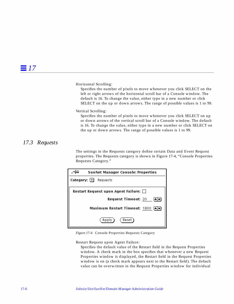
17-6 Solstice Site/SunNet/Domain Manager Administration Guide
17
Horizontal Scrolling:Specifies the number of pixels to move whenever you click SELECT on theleft or right arrows of the horizontal scroll bar of a Console window. Thedefault is 16. To change the value, either type in a new number or clickSELECT on the up or down arrows. The range of possible values is 1 to 99.
Vertical Scrolling:Specifies the number of pixels to move whenever you click SELECT on upor down arrows of the vertical scroll bar of a Console window. The defaultis 16. To change the value, either type in a new number or click SELECT onthe up or down arrows. The range of possible values is 1 to 99.
17.3 RequestsThe settings in the Requests category define certain Data and Event Requestproperties. The Requests category is shown in Figure 17-4, “Console PropertiesRequests Category.”
Figure 17-4 Console Properties Requests Category
Restart Request upon Agent Failure:Specifies the default value of the Restart field in the Request Propertieswindow. A check mark in the box specifies that whenever a new RequestProperties window is displayed, the Restart field in the Request Propertieswindow is on (a check mark appears next to the Restart field). The defaultvalue can be overwritten in the Request Properties window for individual

Props Menu 17-7
17
requests. Click SELECT on the box to toggle the check mark on or off. Bydefault, this field is off (the Restart field is off in the Request Propertieswindow).
Request Timeout:Specifies the time (in seconds) that the Console waits for a response from anagent when starting or stopping requests. The default value is 20. The rangeof possible values is 10 to 300 (5 minutes).
Maximum Restart Timeout:Specifies the maximum interval between attempts to start a failed request. Ifa request fails to start, the Console retries the request after 60 seconds. If therequest fails again, it is retried again after 120 seconds. The interval betweenfailed requests and the re-sending of the request is doubled for each restartattempt. If the maximum restart timeout value is reached before the agentresponds to the request, the maximum restart timeout value becomes theinterval between resent requests. The default value is 1800 seconds (30minutes). The range of possible values is 120 to 3600 (1 hour).
17.4 Automatic ManagementYou can enable Automatic Management to automatically monitor the health ofyour network. You do this by sending an event request to each manageddevice to determined the state of the device. This feature also allowspredefined Event Requests to start automatically for elements that are added tothe management database. The Automatic Management category in theConsole Properties windows in shown in Figure 17-5.

17-8 Solstice Site/SunNet/Domain Manager Administration Guide
17
Figure 17-5 Console Properties Automatic Management Category
By default, the automatic node management feature is disabled. If you enablethis feature, you can also define the reporting characteristics and signal optionsof automatic requests. Before you enable automatic node management, readthe following section, which describes how it works.
If you enable automatic node management, you can specify that predefinedEvent Requests not be sent for elements that are created in certain views orbuses. This is done with the Auto Manage Off option in the bus or view’sGlyph menu. Refer to Section 14.10.12, “Auto Manage Off,” on page 14-32 formore information about this option.
If you enable automatic node management and then load an ASCII databasefile, the Console will attempt to start a predefined Event Request for everyelement defined in the database that supports one of the proxy agents listedabove. You can disable automatic node management for certain views. This isdone with the Auto Manage Off option of the element’s Glyph menu (refer toSection 14.10.12, “Auto Manage Off,” on page 14-32 for more information). Youcan kill launched Event Requests at the same time by using the RequestsSummary window. Once you have killed these requests, re-save the database toan ASCII file. The next time the file is loaded, no predefined Event Requestswill be started.

Props Menu 17-9
17
You can use automatic management in one of two modes: default or custom.Choose the mode (behavior) by selecting the appropriate value in themanagement behavior field as shown in Figure 17-5.
If you choose Default mode, SunNet Manager will send predefined requests asexplained in Section 17.4.1, “The Default Option.”
17.4.1 The Default Option
If automatic node management is enabled with the default option, a predefinedEvent Request is automatically started for new elements that support at leastone of the following proxy agents:
• SNMP• hostperf• ICMP ping
The event specification for each default proxy agent is described below.
If the element supports more than one of the proxy agents in default mode, thepredefined Event Request that is actually sent is determined in the followingorder:
1. If you have specified that the new element can be managed with a Sun-supplied SNMP schema, the following is defined as the event for theelement:
ifOperStatus Not Equal To 1
which specifies the condition where a device is not up.
If the element can be managed with multiple Sun-supplied SNMP schemas,the Console uses the following order of schema files:
a. snmp.schema (MIB I)
b. snmp-mibII.schema (MIB II)
c. sun-snmp.schema (MIB II with Sun enterprise-specific extensions forSun workstation support)
For example, if an element supports MIB I as well as the Sun workstationMIB, the Console uses the schema file associated with MIB I(snmp.schema ) for the auto request. Note that if the element supportsSNMP but does not support the ifOperStatus attribute, an error is

17-10 Solstice Site/SunNet/Domain Manager Administration Guide
17
returned to the Console. If this happens, the request is stopped. If theelement supports the hostperf proxy agent, the predefined Event Requestthat is associated with the hostperf proxy agent is sent. Otherwise, if theelement supports the ping proxy agent, the predefined Event Request thatis associated with the ping proxy agent is sent.
2. If you have specified that the new element can be managed with thehostperf agent, the following is defined as the event for the element:
uptime increased by less than <number>
where <number> is the value of the Polling Interval setting in the ConsoleProperties Automatic Management category minus 2 minutes. By default,the value of <number> is 8 minutes.
3. If you have specified that the new element can be managed with the pingagent, the following is automatically defined as the event for the element:
reachable equal to ‘false’
Once started, an automatic Event Request can be modified like any otherrequest. The window for the Automatic Management category is shown inFigure 17-5 on page 17-8, with the automatic node management featureenabled (checked off). If you disable the automatic node management feature,the rest of the items in the window are grayed-out.
The items in the Automatic Management category window are describedbelow:
Automatic Management:Specifies whether the automatic node management feature is enabled. Acheck mark in the box indicates that the feature is enabled—click SELECTon the box to toggle the check mark on or off. When this field is off(automatic node management is disabled), the remaining items in thewindow are dimmed. If automatic node management is not enabled (checkbox is empty and you click SELECT on Apply), the Auto Manage option inthe element Glyph menus is not available. Note that if you enable automaticnode management then later disable it, all active automatic requests arekilled.

Props Menu 17-11
17
Polling Interval:Specifies the interval (in seconds) for the agent to send reports. By default,the reporting frequency for automatic requests is set to ‘600’ (10 minutes). Tochange the value, either type in a number on the line or click SELECT on theup or down arrows. The range of possible values is 1 to 9999 (seconds).
Caution – If you decrease this number substantially, you can cause networktraffic problems.
Event Priority:Specifies the priority of an event from an automatic node managementrequest. The default is High. To change the setting, click SELECT on theappropriate rectangle.
Glyph Effect:Specifies a visible indicator when an event is reported from an automaticnode management request. Only one glyph effect option can be chosen. Thedefault is Color by Priority. To change the setting, click SELECT on theappropriate rectangle.
Audio Effect:Specifies an audible indicator when an event is reported from an automaticnode management request. Only one audio effect option can be chosen. Thedefault is None (no audible indicator). To change the setting, click SELECTon the appropriate rectangle.
Audio File:Defines the audio file to be played when an event is reported from anautomatic node management request. (The option Play Audio File must bespecified in the Audio Effect field for this setting to be enabled.) Type in thepath name of the audio file. The audio file will be played at the currently-setaudio level.
Note – The Console must be running (not merely displaying) on a machinewith an audio port. If you are running the Console on a server but displayingthe Console windows on a local workstation, the Console will attempt to playthe audio file on the server.

17-12 Solstice Site/SunNet/Domain Manager Administration Guide
17
Send Mail To:Defines one or more mail recipients to whom an Event Report is sent whenan event is reported from an automatic node management request. Type in alist of mail recipients. If there is more than one recipient, use a space orcomma between each entry.
Send To Program:Defines a program or shell script to be run when an event is reported froman automatic node management request. Include the directory path, ifnecessary. A new copy of the program or shell script is forked for each eventreport. The event report is passed to the standard input of the program orshell script. For example, if the value were cat > /tmp/trap.rpt , itwould cause the cat program to receive the event report and write it to thefile /tmp/trap.rpt .
17.4.1.1 The Custom Option
Starting with version 2.3, SunNet Manager provides a powerful addition toAutomatic Management called customized auto management. This featureallows you to selectively perform auto management on a particular class ofdevices.
If the default action does not meet your requirement, you can create apredefined request by selecting the Custom option in the managementbehavior field as shown in Figure 17-5. Your predefined requests will beattached with the type of node against which you want to run the request.Click SELECT on Customize to see the Customize Automatic Managementwindow as shown in Figure 17-6.

Props Menu 17-13
17
Figure 17-6 Automatic Management Customize Window
The Component list on the left side of the screen will list the components inyour runtime database that were identified during initialization from theelements.schema file. The Predefined Request list is read from theSNMpredefined file in your home directory.
A predefined request can be attached to a component type using the followingsteps. Refer to Figure 17-7 for examples of the fields explained in the stepsbelow.

17-14 Solstice Site/SunNet/Domain Manager Administration Guide
17
Figure 17-7 Customizing Auto Management
1. Use the mouse to select a component from the component list.
2. Use the mouse to select a request from the predefined request list.To create a predefined request, click SELECT on Create Predefined and seeChapter 5, “Specifying Event Requests” for information on creatingpredefined event requests.
3. Click SELECT on the Add button.
The component/request pair appear in the Customized AutomaticManagement Request list.
You can detach a predefined request from the component type using thefollowing steps:
1. Use the mouse the select the desired entry from the CustomizedAutomatic Management Request list.
2. Click SELECT on Delete.

Props Menu 17-15
17
You can also detach a predefined request from a component and attach a newpredefined request using the following steps:
1. Use the mouse to select the desired entry from the Customized AutomaticManagement list.The corresponding component/predefined requests are automaticallyselected.
2. Use the mouse to select a new predefined request from the PredefinedRequest list.
3. Click SELECT on the Change button.
4. Click SELECT on Apply to submit changes.
Note that if an element or component supports more than one agent, only onepredefined Event Request is sent.
The changes are saved to .SNMautomanagement in your home directory andthe request(s) is launched.
You can combine customized automatic managed with default automaticmanagement. This means you can choose to run predefined requests for aspecific component type (such as a router), and at the same time run defaultautomanagement for the rest of the nodes. To combine the features:
1. Select a component from the component list.
2. Select a predefined request from the Predefined Request list.
3. Click SELECT on the Add button.
4. Click SELECT on the checkbox at the top of the customized window asshown in Figure 17-6.
5. Click SELECT on Apply.
SunNet Manager will run your predefined request for the component youselected and will run default automatic management for the rest of thecomponents.
To run only customized requests, do not click the checkbox at the top of thecustomized window.

17-16 Solstice Site/SunNet/Domain Manager Administration Guide
17
17.5 Events and TrapsThe settings in the Events and Traps category allow you to define Consoleoperations for events and traps. You can also specify signal options for trapreports.
Note – Trap report signal options are effective for all trap reports the Consolereceives.
The window for the Events and Traps category is shown in Figure 17-8.
Figure 17-8 Console Properties Events and Traps Category

Props Menu 17-17
17
Open on Event or Trap:Specifies whether the Console window should be opened if it is closed to anicon when an event or trap report is received. A check mark in the boxindicates that Console should be opened—click SELECT on the box to togglethe check mark on or off. By default, this is off (Console window is notopened).
Upon Opening:The Open on Event or Trap setting described above must be checked for thissetting to be enabled. Upon Opening specifies the view to be displayedwhen the Console window is opened and an event or trap report has beenreceived. Press MENU in the Upon Opening abbreviated menu button toreceive the menu in Figure 17-9.
Figure 17-9 Events and Traps—Upon Opening Menu
The default is Stay in Current View (the Console displays the same view itdisplayed before the Console window was closed to an icon). To change thesetting, press MENU on the abbreviated menu button and release on thedesired option. Go to Home View causes the Console to always display theHome view while Go to View Containing Element causes the Console todisplay the view that contains the element for which an event or trap reportis received.
Propagate Event Effect:Specifies whether the glyph effect options of events are propagated to allparent views of the affected element. A check mark in the box indicates thatpropagation is enabled—click SELECT on the box to toggle the check markon or off. By default, this is on (events’ effects are propagated through theview hierarchy).

17-18 Solstice Site/SunNet/Domain Manager Administration Guide
17
Note – You can disable glyph state propagation for a view by setting the GlyphState field in the view’s Property window to “Not Inherited.”
If a glyph is contained in more than one view, its state is propagatedthrough its multiple view hierarchies. When the Console is closed to anicon, glyph state changes reflected in the Home view cause the SNMConsole icon to display question marks.
If there are different glyph states propagating to the same view glyph, theview glyph assumes the state of the highest-priority member glyph state.The following list defines glyph-state priority from highest to lowest:
a. Color set by the priority of the event. By default, high, medium, and lowpriority events are red, orange, and yellow, respectively.
b. Dimmed
c. Blinking
You can explicitly change the state of a glyph by using the Glyph Stateoption in the Glyph menu for the element. There are two important pointsto remember when using this option to change glyph state:• When you change the state of a glyph, the new glyph state is propagated
as though an event had occurred to change the glyph state. For example, ifyou change the glyph state of an element from normal to blinking, theglyph state (blinking) propagates as if an event had occurred.
• If you have multiple glyph states propagating into a single view, and youchange the glyph state for the view to normal, the member glyph statesare also reset to normal. For example, if you change the glyph state of aview from blinking to normal, the effects of the event that caused amember element to blink are cleared. This allows you to clear multipleevents by resetting the glyph state of a view.
Starting with version 2.3, you can specify pending mode for a glyph state,(press MENU over the target glyph; release MENU over Pending On/Off).The glyph object is dimmed and outstanding traps/events are cleared. Newtraps/events do not change the glyph state or propagate the effect of thetrap/event to the parent object. If a parent object is in pending state, a statechange for any child object has no affect on the parent. See Chapter 5,“Specifying Event Requests,” for more information about glyph pendingstate.

Props Menu 17-19
17
Event Effect Overlap Time:Specifies the amount of time (in seconds) beyond the reporting interval thatan event’s glyph effect options remain in effect. If another event does notoccur within this overlap time, the Console cancels the current signaloption. The default is 10 seconds. To change the value, either type in anumber on the line or click SELECT on the up or down arrows. The range ofpossible values is 0 (no overlap) to 86400 (24 hours).
Note – If the reporting interval is not specified in the event report, the Consoleassumes the reporting interval to be 60 seconds.
The following fields pertain to traps only.
Glyph Effect:
Specifies a visible indicator when a trap is reported. The default is Color byPriority. Starting with version 2.3, you can customize the color of the glyph toindicate Low, Medium or High priority by clicking on Props➤Custom Colorson the Console menu as shown in Figure 17-10.
Figure 17-10 Custom Colors Category of Console Props Menu
When you receive the Custom Colors window in Figure 17-11, use the mouseto slide the indicators to the color you wish for each priority level.

17-20 Solstice Site/SunNet/Domain Manager Administration Guide
17
Figure 17-11 Custom Color Window
Note that the Console can receive high, medium, and low priority traps. (Lowpriority traps are generated when the SNM database API functions are used toadd, change, or delete elements in the database.) If you keep the default Colorby Priority option, high priority traps cause the element’s glyph to turn redand low priority traps cause the glyph to turn yellow. If both high and lowpriority traps are received for an element, high priority is used. In associationwith the Color by Priority option is the decay feature. The decay featurepertains to traps that have been reported and for which the Effect Decay Timeperiod has expired. In response to these conditions, the glyph for the affectedelement turns blue (the default), or to a color you have customized. Once aglyph shows the decay color, the trap report must be acknowledged in orderfor the glyph to return to its original color. To get a glyph to return to itsoriginal color, you can either:
• Select the Console’s View➤Event Summary option
• Highlight the name of the glyph
• Press the Drop from List button.Or
• From the Glyph Menu for the specific element, pull right over the GlyphState➤Normal option.

Props Menu 17-21
17
Propagate Effect:Specifies whether the glyph effect options of traps are propagated to allparent views of the affected element. A check mark in the box indicates thatpropagation is enabled—click SELECT on the box to toggle the check markon or off. By default, this is on (trap’s effects are propagated through theview hierarchy).
Glyph state changes that result from traps propagate in the Console’s viewhierarchy in the same manner as with glyph state changes that result fromevents. See the description of the Propagate Event Effect setting for moreinformation about propagation of glyph state changes.
Effect Decay Time:Specifies the amount of time (in seconds) during which a trap’s glyph effectoption remains in effect. After the specified time, the effect caused by thetrap is automatically cleared and the glyph’s state is returned to “Normal”or decayed to blue. The latter only occurs when the Color by Priority optionis in effect as described above under Glyph Effect. The default is 0 (glypheffects caused by a trap are not automatically cleared). To change the value,either type in a number on the line or click SELECT on the up or downarrows. The range of possible values is 0 to 86400 (24 hours).
Audio Effect:Specifies an audible indicator when a trap is reported. Only one audio effectoption can be chosen. The default is None (no audible indicator). To changethe setting, click SELECT on the appropriate rectangle.
Audio File:Defines the audio file to be played when a trap is reported. (The option PlayAudio File must be specified in the Audio Effect field for this setting to beenabled.) Type in the path name of the audio file. The audio file will beplayed at the currently-set audio level.
Note – The Console must be running (not merely displaying) on a machinewith an audio port. If you are running the Console on a server but displayingthe Console windows on a local workstation, the Console will attempt to playthe audio file on the server.

17-22 Solstice Site/SunNet/Domain Manager Administration Guide
17
Send Mail To:Defines one or more mail recipients to whom a trap report is sent when atrap is reported. Type in a list of mail recipients. If there is more than onerecipient, use a space or comma between each entry.
Send To Program:Defines a program or shell script to be run when a trap is reported. Includethe directory path, if necessary. A new copy of the program or shell script isforked for each trap report. The trap report is passed to the standard inputof the program or shell script. For example, if the value werecat > /tmp/trap.rpt , it would cause the cat program to receive thetrap report and write it to the file /tmp/trap.rpt .
Ignore Database Traps:Defines whether the traps generated when changes are made in the databaseare displayed by the Console. Low priority traps are generated whenelements are added, changed, or deleted in the database, or if a newdatabase file is loaded. A check mark in the box indicates that these trapsare ignored by the Console — click SELECT on the box to toggle the checkmark on or off.
Note – With the Ignore Database Traps option turned off, when you create anelement, the trap report for that element says that the element was “created.”An analogous operation using the database API returns the word “added”rather than “created.”
17.6 ErrorsThe settings in the Errors category allow you to specify signal options forerrors that the Console receives from agents. Note that the only type of errorsthat cause glyph state changes are errors received from agents; glyph statechanges do not occur as a result of local Console errors. The window for theErrors category is shown in Figure 17-12, “Console Properties ErrorsCategory.”

Props Menu 17-23
17
Figure 17-12 Console Properties Errors Category
Signal On:Specifies whether signal options are in effect for all errors received fromagents or only fatal errors. The default is Fatal Errors. To change the setting,click SELECT on All Errors.
Glyph Effect:Specifies a visible indicator when an agent error is reported. Only one glypheffect option can be chosen. The default is Dim. To change the setting, clickSELECT on the appropriate rectangle. Note that agent errors can be eitherhigh or low priority errors. If you choose the Color by Priority option, highpriority errors (generic errors and agent-specific fatal errors) cause theelement’s glyph to turn red and low priority errors (agent-specific warnings)cause the glyph to turn to the default color of yellow. If both high and lowpriority errors are received for an element, high priority is used.
17-24 Solstice Site/SunNet/Domain Manager Administration Guide
17
Propagate Effect:Specifies whether the glyph effect options of errors are propagated to allparent views of the affected element. A check mark in the box indicates thatpropagation is enabled—click SELECT on the box to toggle the check markon or off. By default, this is off (error’s effects are not propagated).
Glyph state changes that result from errors propagate in the Console’s viewhierarchy in the same manner as with glyph state changes that result fromevents. See the description of the Propagate Event Effect setting in theEvents and Traps category for more information about propagation of glyphstate changes.
Effect Decay Time:Specifies the amount of time (in seconds) during which an error’s glypheffect option remains in effect. After the specified time, the effect caused bythe error is automatically cleared and the glyph’s state is returned to“Normal.” The default is 0 (glyph effects caused by an error are notautomatically cleared). To change the value, either type in a number on theline or click SELECT on the up or down arrows. The range of possiblevalues is 0 to 86400 (24 hours).
Audio Effect:Specifies an audible indicator when an error is reported. Only one audioeffect option can be chosen. The default is None (no audible indicator). Tochange the setting, click SELECT on the appropriate rectangle.
Audio File:Defines the audio file to be played when an error is reported. (The optionPlay Audio File must be specified in the Audio Effect field for this setting tobe enabled.) Type in the path name of the audio file. The audio file will beplayed at the currently-set audio level.
Note – The Console must be running (not merely displaying) on a machinewith an audio port. If you are running the Console on a server but displayingthe Console windows on a local workstation, the Console will attempt to playthe audio file on the server.
Send Mail To:Defines one or more mail recipients to whom an error report is sent when aerror is reported. Type in a list of mail recipients. If there is more than onerecipient, use a space or comma between each entry.
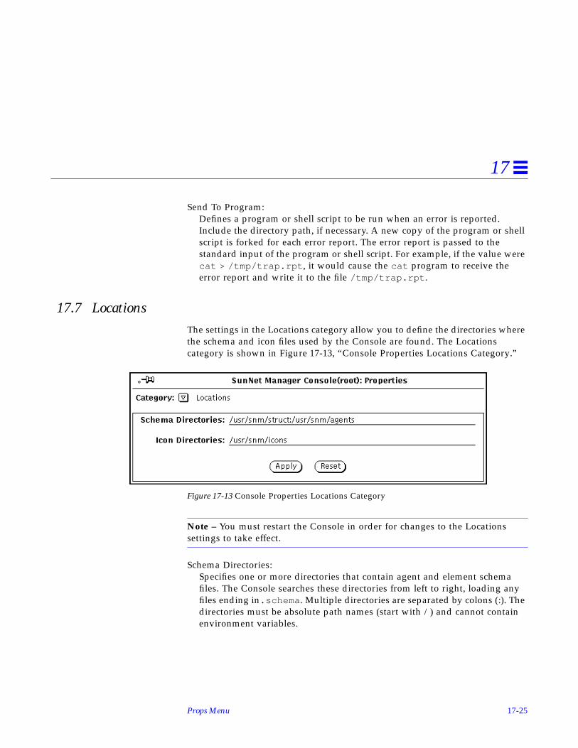
Props Menu 17-25
17
Send To Program:Defines a program or shell script to be run when an error is reported.Include the directory path, if necessary. A new copy of the program or shellscript is forked for each error report. The error report is passed to thestandard input of the program or shell script. For example, if the value werecat > /tmp/trap.rpt , it would cause the cat program to receive theerror report and write it to the file /tmp/trap.rpt .
17.7 LocationsThe settings in the Locations category allow you to define the directories wherethe schema and icon files used by the Console are found. The Locationscategory is shown in Figure 17-13, “Console Properties Locations Category.”
Figure 17-13 Console Properties Locations Category
Note – You must restart the Console in order for changes to the Locationssettings to take effect.
Schema Directories:Specifies one or more directories that contain agent and element schemafiles. The Console searches these directories from left to right, loading anyfiles ending in.schema . Multiple directories are separated by colons (:). Thedirectories must be absolute path names (start with /) and cannot containenvironment variables.

17-26 Solstice Site/SunNet/Domain Manager Administration Guide
17
Icon Directories:Specifies one or more directories that contain icon and icon mask files. TheConsole searches these directories from left to right, loading any files endingin .icon and .iconmask . Multiple directories are separated by colons (:).The directories must be absolute path names (start with /) and cannotcontain environment variables.
17.8 MiscellaneousThe settings in the Miscellaneous category allow you to define Consoleparameters not covered in the other categories. The window for theMiscellaneous category is shown in Figure 17-14, “Console PropertiesMiscellaneous Category.”
Figure 17-14 Console Properties Miscellaneous Category
Different Windows for Load & Save:Specifies whether different windows are displayed for Load and Saveoperations. A check mark in the box indicates that different windows aredisplayed—click SELECT on the box to toggle the check mark on or off. Bydefault, this is off (the same window is used for Load or Save operations).

Props Menu 17-27
17
Verify Quit:Specifies the verification prompt, if any, displayed by the Console wheneveryou choose to quit a Console session. The default is If Requests are Active (averification prompt is displayed only if there are active requests; theverification prompt asks if you want the active requests automatically killedbefore the Console is exited). To change the setting, click SELECT on theappropriate rectangle: Never causes no verification prompt to be displayed,Always causes a verification prompt to be displayed even if there are noactive requests.
SELECTing Goto Button Means:Specifies the view that is displayed whenever you click SELECT on the Gotomenu button. The default is Last Visited View. To change the setting, clickSELECT on Home View (the Home view is displayed whenever you clickSELECT on the Goto menu button).
Goto Empty Views:Specifies whether or not the Console displays an empty view. A check markin the box indicates that the Console can display empty views. ClickSELECT on the box to toggle the check mark on or off. By default, this is on(Console can display empty views). If the box is not checked, the Consoledoes not display empty views and an error message appears in theConsole’s footer. However, an empty view can still be selected if the userclicks SELECT twice on the empty view.
Read-Only ModeIn read-only mode, you can run your applications and manage requests.However, the following menu items are dimmed: Edit, Create PredefinedRequests, and Change Type. See Chapter 14, “Console” for moreinformation regarding Read-Only mode.
Maximum Data Reports:Defines the maximum number of data reports that can be displayed in theData Reports window. The default is 1000. The range of possible values is 10to 99999.
Maximum Error Reports:Defines the maximum number of error reports that can be displayed in theError Reports window. The default is 100. The range of possible values is 10to 99999.

17-28 Solstice Site/SunNet/Domain Manager Administration Guide
17
Maximum Event Reports:Defines the maximum number of event reports that can be displayed in theEvent/Trap Reports window. The default is 1000. The range of possiblevalues is 10 to 99999.
Maximum Trap Reports:Defines the maximum number of trap reports that can be displayed in theEvent/Trap Reports window. The default is 1000. The range of possiblevalues is 10 to 99999.

Props Menu 17-29
17
17.9 Custom ColorsStarting with version 2.3, you can customize trap priority colors by selectingProps➤Category➤Custom Colors. You receive the screen in Figure 17-15.
Figure 17-15 Custom Colors Window
See Section 17.5, “Events and Traps,” on page 17-16 for a description of theCustom Colors function.
When you click SELECT on Apply after selecting the color(s) you wish, thechanges are saved to the .SNMdefaults file. If the colors are different from theprevious values, the glyph state colors for the target objects are recalculatedand displayed.
17.10 Other ConfigurationWhen you apply a setting in the SunNet Manager Console Properties window(under Props, when no glyphs are selected), the information is stored in the$HOME/.SNMdefaults file. The $HOME/.SNMdefaults file is intended tocontain per-user configuration information.
Per-product defaults can be placed in $SNMHOME/defaults . This allows youto set up site-wide Console resources and definitions so that everyone whouses the product uses those defaults. If the user has their own$HOME/.SNMdefaults file, the information in the $HOME/.SNMdefaultsoverrides the information in $SNMHOME. Users can also set the environment

17-30 Solstice Site/SunNet/Domain Manager Administration Guide
17
variable SNMDEFAULTS to have the Console read another file instead of$HOME/.SNMdefaults . If SNMDEFAULTS is not set, the Console reads$HOME/.SNMdefaults .
Note – The Console also supports X11 resources configurations, howeversettings in $HOME/.SNMdefaults take priority.
There are a few optional definitions you can specify to further customize theoperation of the Console. You can add these definitions into one of the filesdescribed above.
17.10.1 Forking Programs For Element Types
You can specify a program that is forked for an element type when an instanceof the element type is created or modified. To do this, use the followingdefinitions:
where <program1> and <program2> are forked whenever the <element-type> iscreated or modified, respectively. Note that you can specify * for<element-category> or <element-type>. If you want programs to be forked for anycreation or modification of an element, use the following definitions:
If you want a program to be forked whenever any view is created, use thefollowing definition:
snm.console. <element-category>.<element-type>.createProg: <program1>snm.consolecomponent. <element-category>.<element-type>.modifyProg: <program2>
snm.console.*.*.createProg: <program1>snm.console.*.*.modifyProg: <program2>
snm.console.view*createProg: < program>

Props Menu 17-31
17
If you want a program to be forked whenever an ethernet element type(bus.ethernet, view.ethernet, etc.) is created, use the followingdefinition:
The process that is forked when an element is created has the followingparameters:
where <viewname> is the current view, and <object_type> is the type of theobject created.
The process that is forked when an element is modified has the followingparameters:
where <viewname> is the current view, and <object_name> is the name of theobject being modified.
17.10.2 Redirecting SNMP Requests
You can have SNMP requests from the Console redirected to another vendor’sSNMP proxy. To do this, use the following definition:
where <label> appears in the bottom left panel of the Data and Event RequestProperties window and <agent> is the name of the SNMP proxy agent to whichthe requests will be redirected. In the Request Properties window, a boxappears next to <label>—click SELECT in the box to toggle a check mark on oroff. A check mark causes the request to be redirected.
snm.console*ethernet.createProg: <program>
<program1> -c -v <viewname> -t <object_type>
<program2> -m -v <viewname> -n <object_name>
snm.console.snmpRedirect: truesnm.console.snmpRedirectItem: <label>snm.console.snmpRedirectAgent: <agent>

17-32 Solstice Site/SunNet/Domain Manager Administration Guide
17
Note – The Console does not kill redirected requests when it starts or exits. Youmust explicitly kill these requests with the snm_kill (1) command. Thisfeature is intended for vendor-supplied SNMP proxies that do not returnreports to the Console.
17.10.3 Activating Console Database Manager Traps for File Loads
The Console can be configured to issue a trap to inform other applicationswhen a new runtime database is loaded. Such a trap contains the names of theelements that have been loaded.
To activate this feature, the .SNMdefaults file needs to be modified to set thevalue of snm.console.DBMgrTrapAlways to true. By default, this propertyis set to false.

Props Menu 17-33
17
17.11 Custom ColorsStarting with version 2.3, you can customize colors of event and trap prioritylevels. The default colors continue to be Low=yellow, Medium=orange,High=Red, and decay=blue. By choosing the Custom Colors category, youreceive the window in Figure 17-16.
Figure 17-16 Custom Colors Configuration Window
You can determine the current RGB value of a color for particular objects bychoosing the checkbox corresponding to the priority state or the decay state ofthe element. Customize the color by sliding the color indicator(s) to the desiredposition. If the colors are different from the previous values, the glyph statecolors for the objects are recalculated and displayed.
Click SELECT on Apply to save the new color to the .SNMdefaults
configuration file.

17-34 Solstice Site/SunNet/Domain Manager Administration Guide
17

18-1
Management Database 18
This chapter discusses the following topics:
• Element type definitions
• Element instance definitions
• Connection definitions
• Background definitions
• Tools menu definitions
• Definition of requests
• Duplicate databases
18.0.1 Purpose of the Management Database
The management database (also called the runtime database) represents thedata model of a site’s environment. It contains information on the agents thatare supported and the objects that are managed. The information in themanagement database determines how the SunNet Manager Console displaysthe layout of the site’s network, machine icons (glyphs in OPEN LOOKparlance), characteristics, and associated menus.
Certain kinds of changes to your management database can only be made byediting a saved MDB file with a text editor. These kinds of changes include:
• Adding or modifying element types.

18-2 Solstice Site/SunNet/Domain Manager Administration Guide
18
• Specifying a new glyph for an element type.
• Adding or modifying tools in an element’s Glyph menu.
“Part 1: Network Management Tasks” describes how to make these changes.This chapter describes the format of the definitions contained in the databasefiles. Specifically, these definitions include:
• Element type, including definition of the glyph and user commandsassociated with an element type.
• Element instances.
• Connections between elements.
• Background images for view instances.
• Tools available from the Console’s Tools menu.
• Data requests.
• Event requests.
Input to the runtime database comes from two sets of ASCII files, structure filesand instance files.
Structure files provide a set of definitions to the Console. These include:
• The snm.glue file that contains a starting set of definitions for the Console.The Console depends on these definitions, so do not modify them.
• The agent schemas that define the attributes each agent manages. (See yourSite/SunNet/Domain Manager Application and Agent Development Guide for adiscussion of agent schema files.)
• The element schema file(s) that define the element types in a site’sconfiguration. Element schema also specify the glyphs and commands foreach element type. SunNet Manager provides definitions of numerouselement types in the file, elements.schema . See Section 18.1, “ElementType Definition,” for more information.
Note – Do not change the elements.schema ornetware_elements.schema file. If you need to add element types, create afile with the .schema extension in the same directory as theelements.schema /netware_elements.schema .
Instance files provide definitions of element and request instances.

Management Database 18-3
18
The runtime database can also be modified by the Console through itsgraphical editing capability and through the Discover Tool. As you moveglyphs and start requests, you are modifying the runtime managementdatabase.
18.1 Element Type DefinitionAlthough many element types are defined in the file, elements.schema ,additional types may be added or current types modified to customize theConsole to meet a particular site’s needs. This section discusses element typedefinition.
Note – Element types are constructed from data types specified in theenumerated type snmdb_type , which is defined the header file netmgt_db.h .These data types are listed and described in your Site/SunNet/Domain ManagerApplication and Agent Development Guide.
There are four categories of elements. New element categories cannot be addedby a user. The element categories are:
• Components. Components represent elements such as workstations,printers, and routers. Components appear as a glyph (see Section 18.1.1,“Glyph Definition (for Component or View Element Type),” for a discussionof how to specify the glyph for a component).
• Views. A view is a collection of elements. A view may contain other views.Like a component, a view also appears as a glyph.
• Buses. Buses represent elements such as an Ethernet LAN segment. A busappears as a line with movable endpoints.
• Connections. A connection is an element that connects two other elements.A connection appears as a line connecting the two elements. Examples are aleased internet work link and an RS-232-C line.

18-4 Solstice Site/SunNet/Domain Manager Administration Guide
18
Element types are defined using a record. The record specifies the fields storedin the database for each instance of that element type. The format is:
where:
<category>one of the element categories discussed above (component, view, bus, orconnection).
<name>provides a name for the element type. Each element category is a separatenamespace. For instance, it is legal to define both a view.ethernet and abus.ethernet . The maximum length of name is 64 bytes.
<type field-name>defines one or more fields that define the properties of the element. Themaximum length of <type field-name> is 64 bytes. Certain fields must bedefined, while other fields have particular functions—these are described inthe following section.
• All element type definitions must have a field called Name, which namesthe element instance.
• Connections must have two additional fields, Object1 and Object2 thatname the endpoints of the connection.
• Glyph_State allows you to enable or disable glyph state propagation tothe element.
• Components may be SNMP devices. The following fields provide SNMPinformation that is included with requests to the SNMP proxy agent (seeChapter 19, “SNMP Support,” for more information):
• SNMP_RdCommunity specifies the SNMP community name to use whenreading attribute values.
• SNMP_WrCommunity specifies the SNMP community name to use whenwriting attribute values.
record <category>.<name> (<type field-name>...
)

Management Database 18-5
18
• SNMP_Vendor_Proxy specifies a non-SNM SNMP proxy agent. This shouldonly be specified when a vendor has supplied an SNMP proxy agent thatcommunicates with the SunNet Manager SNMP proxy agent.
• SNMP_Timeout specifies the number of seconds that the SNMP proxy agentis to wait for a response to requests sent to the target element.
• For bus.ethernet elements, Default_Proxy specifies the default proxysystem for any elements that are discovered in the subnet. When theDiscover Tool is run for the subnet, the name specified in this field is thedefault proxy system for each element in the subnet.
• Label is an optional field you can add that allows a label that is differentfrom Name to appear under the glyph that corresponds to an elementinstance. To use the Label field, enter in a string in the Element Propertiessheet. If no value is entered, the value in the Name field is displayed. If asingle hyphen (-) is entered in the Label field, neither the Label nor theName value is displayed under the element’s glyph.
Other fields are optional and provide information used when displaying theelement’s properties.
The following rules are used to display an element’s properties:
• The properties are the list of field names and values in an element’s record.
• Any field whose name begins with underscore is not displayed in anelement’s properties.
• Embedded underscores in field names are converted to blanks in theProperties list. For instance, the field User_Name will be displayed in theProperties under <User Name>.

18-6 Solstice Site/SunNet/Domain Manager Administration Guide
18
The following example defines some element types:
18.1.1 Glyph Definition (for Component or View Element Type)
Elements that are either a component or view are displayed as a glyph. AnelementGlyph instance in the element’s schema specifies the glyph for acomponent or a view.
record component.sun4 (string[64] Namestring[40] IP_Addressstring[40] Userstring[40] Locationstring[80] Descriptionstring[40] SNMP_RdCommunitystring[40] SNMP_WrCommunitystring[40] SNMP_Vendor_Proxyint SNMP_Timeoutstring[256] SNMP_SysObject_IDstring[40] Physical_Address
)
record view.subnet(string[64] Namestring[80] Description
string [40] NetMaskenum stateProp Glyph_State
)
record connection.rs232 (string[64] Namestring[64] Object1string[64] Object2string[80] Description
)
record bus.ethernet (string[64] Namestring[40] IP_Network_Numberstring[80] Descriptionenum stateProp Glyph_Statestring[64] Default_Proxy
)

Management Database 18-7
18
An elementGlyph instance has the following format:
Note that the elementGlyph instance must be placed after the element typecomponent record. If the <icon-path-name> begins with a slash (/), it is treatedas an absolute path. Otherwise, the path name is relative to the directoriesspecified by the Icon Directories setting in the Console Properties Locationscategory. See Chapter 14, “Console,” for more information about ConsoleProperties settings.
The following example shows an elementGlyph instance that specifiesseveral glyph/component mappings:
Note that you can have up to 1024 icons or raster files defined in the runtimedatabase; this includes background images as well as element glyphs.
instance elementGlyph (( <element> "<icon-path-name>" )...
)
instance elementGlyph (( component.sun3 sun3.icon)( component.sun4 sun4.icon)( component.sun386 sun386.icon)( component.laserwriter laserwriter.icon)( component.pc pc.icon)( component.genhost mainframe.icon)( component.genws generic-ws.icon)( component.router router.icon)( component.bridge bridge.icon)( component.lanbox lanbox.icon)
)

18-8 Solstice Site/SunNet/Domain Manager Administration Guide
18
18.1.2 User Command Definition for an Element Type
A UNIX command may be defined to appear in the Tools menu of acomponent, view, bus, or connection by including an elementCommandinstance in the element schema. This provides the ability to quickly executeany UNIX command by pointing to a glyph and selecting the command. TheelementCommand instance has the following syntax:
where:
<element>specifies an element type. All elements of this type will have the commandin their glyph menu. The maximum length of <element> is 64 bytes.
<menu-name>specifies the name of the command to appear in the menu. The maximumlength of <menu-name> is 32 bytes.
<cmd-string>specifies the UNIX command string to execute. Any word in the commandstring of the format %field will be replaced by the value of field for thatelement. The maximum length of <cmd-string> is 1024 bytes.
Note that the elementCommand instance must be placed after the element typecomponent record.
The following example defines two commands that can be run from elementsof type component.sun4 .
instance elementCommand (( <element> "<menu-name>" "<cmd-string>" )
...)
instance elementCommand ((component.sun4 "Rlogin..." "$SNMHOME/bin/snm_cmdtool
$SNMHOME/bin/snm_exec rlogin %Name")(component.sun4 "Telnet..." "$SNMHOME/bin/snm_cmdtool
$SNMHOME/bin/snm_exec telnet %Name"))

Management Database 18-9
18
As shown in the example above, the environment variables $SNMHOME or$SNMDBDIR can be used, even if you have not explicitly set them.
If you have not set SNMHOME or SNMDBDIR, then
• /usr/snm and /var/adm/snm are assumed for Solaris 1.x environments
• /opt/SUNWconn/snm and /var/opt/SUNWconn/snm are assumed forSolaris 2.x environments.
Thus, for example, if SNM is installed on a SunOS 5.x machine, the string“$SNMHOME/bin/snm_cmdtool” is expanded to“/opt/SUNWconn/snm/bin/snm_cmdtool” if SNMHOME is not otherwisedefined.
18.2 Element Instance DefinitionElement and request instances are defined using cluster records. A clusterrecord provides a means for collecting multiple records to make up a singleinstance. A cluster record contains an initial record defining the instance’s typefollowed by one or more records providing additional information about theelement or request.
For example, the following cluster record defines a component.sun4 :
cluster(component.sun4 ( SunEng14 1.2.2.388 Engineer23
"Building 2, Room 146""Sun 4/110 - monochrome,diskfull" )
membership ( Subnet2 100 230 0 )agent ( etherif )agent ( hostif )agent ( hostmem )proxy ( hostperf SunEngServer )agent ( layers )proxy ( ping SunEngServer )agent ( rpcnfs )glyphColor ( 220 220 250 )connect ( SunLAN )
)

18-10 Solstice Site/SunNet/Domain Manager Administration Guide
18
The first record in the example, component.sun4 , defines the instance’s type.It must be a record defined in your element’s schema file. The first field in therecord is normally the name of the element, in this case, SunEng14 . The string“Building 2, Room 146 ” is a single field with a maximum length of 64 bytes.When a field contains an ASCII string with embedded blanks, surround thestring with double quotes.
Note – Element names are not case-sensitive. SunEng14 is the same assuneng14 .
The other fields in the first record correspond to the component.sun4 recorddefinition in the elements schema. See the section on “Element TypeDefinition” for more information. Except for when the instance is a connection,these other fields are optional. Connections have two additional required fieldsthat specify the endpoints of the connection.
The second record in the example, the membership record, places the instancein a view. Views represent a logical grouping of elements. A view may containother views. The way you choose to arrange instances in views is up to you.Some examples are:
• Lay out your network elements in a “logical” (network) view as well as in a“physical” (machines in a building) view. For instance, display all therouters in the Routers view and also place them in views corresponding totheir location within the network.
• Arrange views in a circular (or loop) arrangement where a view that is amember of the Home view can also contain the Home view.
The first field of the membership record indicates the name of the view—inthis case, Subnet2 . A special view, Home, refers to the view that is displayedwhen the Console is started. This is also the default view if no membershiprecords are specified.
The remaining fields in the membership record provide positioningcoordinates for the instance and are optional. For bus and connection elements,five coordinates are specified: X coordinate, Y coordinate, Z value (used whenglyphs are stacked on top of each other in a view), and X and Y coordinates ofthe second point of the element. For other types of elements, only the X, Y, andZ coordinates are specified. If the coordinates are not specified, the instancewill be automatically positioned in the view by the Console.

Management Database 18-11
18
Although the example shows only a single membership record in the cluster,an instance may be placed into several views by including multiplemembership records in the cluster.
The third through ninth records in the example—the agent and proxyrecords—provide the list of available agents and proxies for the instance. Thefirst field in the record provides the name of the agent or proxy. proxy recordscontain a second field that supplies the name of the system providing theproxy.
The tenth record in the example is a glyphColor record. This record providesthe color for the glyph. It is optional and, if omitted, the glyph is transparent.The three fields provide the red, green, and blue intensities, respectively. Eachintensity can vary between 0 and 255. Transparent is all zeros. White is all 255s.
The final record in the example is a connect record. It is optional andindicates that the element is connected to another instance. This will cause aline to be drawn to the connected instance if it appears in the view. connectrecords are valid only in an instance that is a component, bus, or view. Theexample connects SunEng14 to SunLAN. Connections made via connectrecords are referred to as simple connections since they have no name.
Cluster records can also contain a glyphState record, which should not bemodified. If you are creating a new cluster record, you do not need to definethe glyphState record; glyph state is assumed to be normal.
18.3 Connection DefinitionA connection is another element category supported by the SunNet ManagerConsole. Connections are like any other element and can be selected andnamed, and can contain subviews containing other elements. A connection iscreated by creating a cluster whose first record is of type connection. <type>.The endpoints of the connection are named by the second and third fields inthe connection. <type> record that correspond to the fields Object1 andObject2 .

18-12 Solstice Site/SunNet/Domain Manager Administration Guide
18
The following example shows a definition of a link type of connection:
In this case, BigHost and SomeNet are the elements that are the endpoints ofthe connection named ExtLink . The connection will only appear in the viewHome if the elements BigHost and SomeNet both exist in that view.
18.4 Background DefinitionBackground images may be associated with a view instance by including aviewBackground instance record in an instance file. The image should be inraster file format. Icon format is supported if the file ends with the extension.icon . However, large backgrounds in icon format load much more slowlythan raster format files.
Before you specify a background, you need to create the view instance that willbe associated with the background. If the icon path name begins with a slash(/), it is treated as an absolute path. Otherwise, the path name is relative to thedirectories specified by the Icon Directories setting in the Console PropertiesLocations category. See Chapter 14, “Console,” for more information aboutConsole Properties settings. The following example shows a definition of abackground image file called USmap.im1 with the Home view:
The background image file can be a maximum of 64 bytes. Note that thebackground definitions must be placed after the view instance definition. Youcan have up to 1024 icon or raster files defined in the runtime database; thisincludes background images as well as element glyphs.
cluster (connection.link ( ExtLink BigHost SomeNet )membership ( Home 400 320 32766 401 88 )glyphColor ( 255 0 255 )
)
instance viewBackground (( Home USmap.im1 )
)

Management Database 18-13
18
Note – The preferred method of adding a background image to the currentview is to invoke the View➤Add Background option in the Console window.Refer to your Site/SunNet/Domain Manager Application and Agent DevelopmentGuide for more information.
18.5 Tools Menu DefinitionA UNIX command may be defined to appear in the Tools menu of the Console,allowing you to launch the command as a separate process. This definition isaccomplished by an elementCommand instance, similar to theelementCommand definition for an element type.
Starting with version 2.3, a new database record is defined in the snm.glue file:
This record will allow you to create submenus to facilitate execution of SunNetmanager commands. The other way to create submenus is through the Consoleas follows:
1. Click SELECT on Tools➤Customize➤Menu to receive the followingscreen:
(SNM_Console_Menu “<cmd-name>”

18-14 Solstice Site/SunNet/Domain Manager Administration Guide
18
2. Enter a menu or tool name on the appropriate line.
3. Click SELECT on Apply to save the changes to your runtime database.
Each menu list on the Console provides the opportunity to add submenus,tools or a command menu item.
The following example defines tools that can be invoked from the Console’sTools menu.
As shown in the example above, any string in the form $name is replaced bythe expanded <name> environment variable. The string“$SNMHOME/bin/snm_br” is expanded to “/usr/snm/bin/snm_br” if youhave the SNMHOME environment variable set to /usr/snm . (If you have not setthe SNMHOME environment variable, /usr/snm is assumed for Solaris 1.1installations; /opt/SUNWconn/snm is the default for Solaris 2.x installations.)
18.6 Definition of RequestsThis section discusses the format of requests. Most users will want to createrequests from the Console rather than manually building requests as describedhere. However, this information is included as reference information on howrequests are stored in the management database.
Every request, whether active or held, is defined by a cluster record. Thedefinitions of the records used in these clusters can be found in the Consoledefinitions file. This file is located at:
instance elementCommand ((SNM_Console "Browser..." "$SNMHOME/bin/snm_br")(SNM_Console "Grapher..." "$SNMHOME/bin/snm_gr")(SNM_Console "Snapshot.." "snapshot")(SNM_Console_Menu “Discovery”)(SNM_Console “IP Discover... “$SNMHOME/bin/snm_discover”)(SNM_Console “IPX Discover.. “$SNMHOME/bin/snm_ipx_discover”)}(SNM_Console_Menu “cisco”)
(SNM_Console “Router Mgmt...” “router_mgmt”)(SNM_Console “Switch Mgmt...” “switch_mgmt”)
}(SNM_Console_Menu “Performance”)

Management Database 18-15
18
• /usr/snm/struct/snm.glue , on Solaris 1.1 installations
• /opt/SUNWconn/snm/struct/snm.glue , for Solaris 2.x installations.
Like other instances, the type of request (data or event) is determined by thefirst record in its cluster. Requests for data begin with a dataRequest record,while event requests begin with an eventRequest record.
18.6.1 Data Requests
The following example is a cluster record representing a Data Request:
The first record is the dataRequest record. See Table 18-1.
cluster(dataRequest ( hostperf.data.0 0 SunEng14
SunEngServer hostperf data"‘Interval’ ‘Count’ Times"10 5 "" "" "" undefined TrueFalse "Save Request" undefinedhostperf.data SunEng14 )
dataAttribute ( cpu% True 1 True 1473696 None0 )
dataAttribute ( intr False 0 False 0"Delta Values" 1515136 )
rqstState ( Idle 0 0 )membership ( SunEng14 460 260 0 )
)
Table 18-1 Data Request — dataRequest Record
Field # Field Name Description
1 Name Name of the request. Displayed under the request’s glyph and in messages about therequest. Not sent to the agent. Maximum length is 64 bytes.
2 _serialnumber Serial number of the request. Set serial number to 0 for new requests.3 _targetsystem Name of the target system. Passed to the agent as the <system> name. If the next
field is NULL, this field is also used to determine the location of the agent.Maximum length is 64 bytes.
4 Proxy_System Name of the proxy system. Used to determine the location of the agent. If null, thevalue of the previous field is used to determine the location of the agent. Maximumlength is 64 bytes.
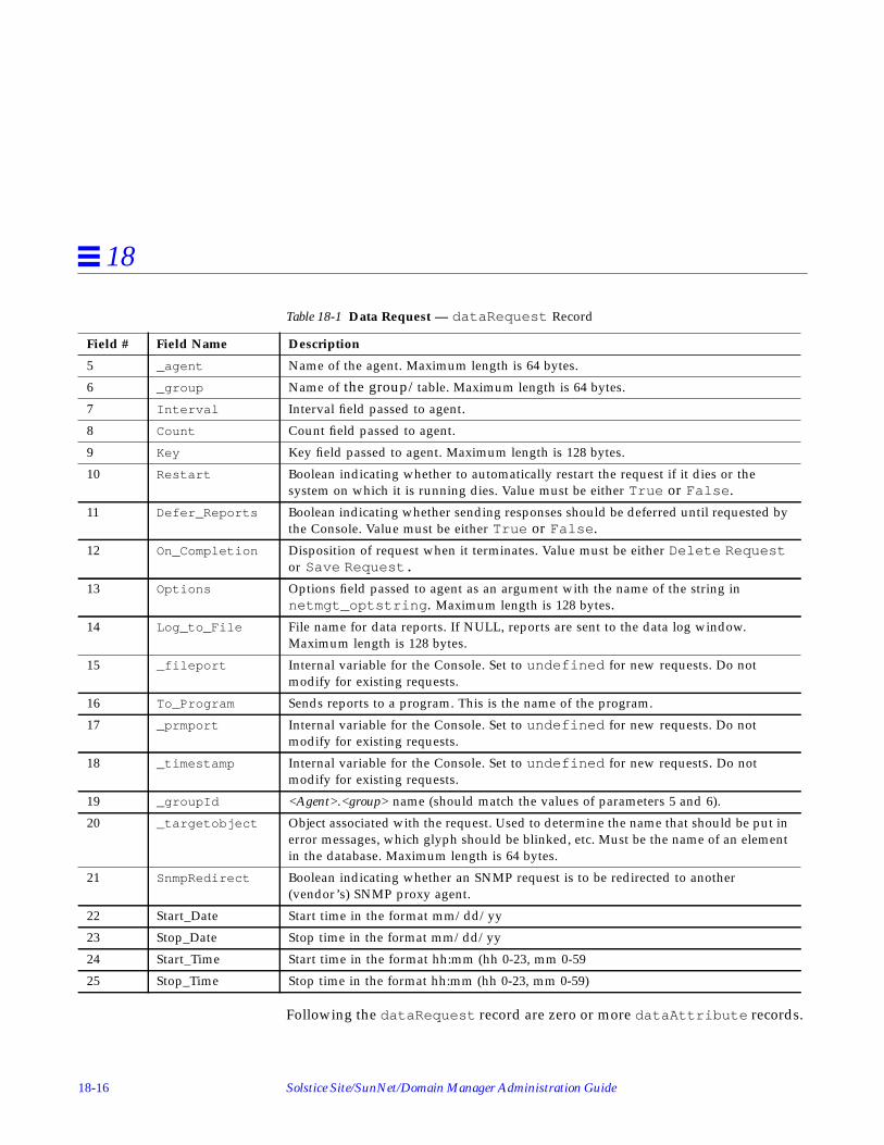
18-16 Solstice Site/SunNet/Domain Manager Administration Guide
18
Following the dataRequest record are zero or more dataAttribute records.
5 _agent Name of the agent. Maximum length is 64 bytes.
6 _group Name of the group/table. Maximum length is 64 bytes.
7 Interval Interval field passed to agent.8 Count Count field passed to agent.
9 Key Key field passed to agent. Maximum length is 128 bytes.
10 Restart Boolean indicating whether to automatically restart the request if it dies or thesystem on which it is running dies. Value must be either True or False .
11 Defer_Reports Boolean indicating whether sending responses should be deferred until requested bythe Console. Value must be either True or False .
12 On_Completion Disposition of request when it terminates. Value must be either Delete Requestor Save Request.
13 Options Options field passed to agent as an argument with the name of the string innetmgt_optstring . Maximum length is 128 bytes.
14 Log_to_File File name for data reports. If NULL, reports are sent to the data log window.Maximum length is 128 bytes.
15 _fileport Internal variable for the Console. Set to undefined for new requests. Do notmodify for existing requests.
16 To_Program Sends reports to a program. This is the name of the program.
17 _prmport Internal variable for the Console. Set to undefined for new requests. Do notmodify for existing requests.
18 _timestamp Internal variable for the Console. Set to undefined for new requests. Do notmodify for existing requests.
19 _groupId <Agent>.<group> name (should match the values of parameters 5 and 6).
20 _targetobject Object associated with the request. Used to determine the name that should be put inerror messages, which glyph should be blinked, etc. Must be the name of an elementin the database. Maximum length is 64 bytes.
21 SnmpRedirect Boolean indicating whether an SNMP request is to be redirected to another(vendor’s) SNMP proxy agent.
22 Start_Date Start time in the format mm/dd/yy
23 Stop_Date Stop time in the format mm/dd/yy
24 Start_Time Start time in the format hh:mm (hh 0-23, mm 0-59
25 Stop_Time Stop time in the format hh:mm (hh 0-23, mm 0-59)
Table 18-1 Data Request — dataRequest Record
Field # Field Name Description

Management Database 18-17
18
These records control how data is displayed by the Console. If nodataAttribute records are in a request element, all data is displayed in theData Reports Log (or specified file). See Table 18-2 for a description of thedataAttribute record.
Table 18-2 Data Request—dataAttribute Record
Field # Field Name Description
1 Attribute Name of the attribute. Maximum length is 64 bytes.
2 Data_Log Boolean indicating whether attribute should be displayed in the Data Log. Valuemust be either True or False .
3 _asciiport Internal variable for the Console. Set value to 0 for new requests. Do not modifyfor existing requests.
4 Indicator Boolean indicating whether this attribute should be displayed in an indicator.Value must be either True or False .
5 _bargraphport Internal variable for the Console. Set value to 0 for new requests. Do not modifyfor existing requests.
6 Strip_Chart If and how the attribute should be displayed in a strip chart. Value must be eitherNone, Absolute Values , or Delta Values . None specifies no strip chart,while Absolute Values and Delta Values specify a strip chart based on<absolute> or <delta> (current - previous) values.
7 _stripchartport Internal variable for the Console. Set value to 0 for new requests. Do not modifyfor existing requests.
8 Graph_Tool If and how the attribute should be displayed in the Grapher. Value must be eitherNone, Absolute Values , or Delta Values . None specifies no graph, whileAbsolute Values and Delta Values specify a grapher based on <absolute>or <delta> (current - previous) values.
9 _grapherhandle Internal variable for the Console. Set value to 0 for new requests. Do not modifyfor existing requests.

18-18 Solstice Site/SunNet/Domain Manager Administration Guide
18
Following the dataAttribute records is the rqstState record. SeeTable 18-3 for a description of the rqstState record.
The final record is a membership record. This record indicates in whichelement’s subview the request glyph will appear. See Table 18-4 for adescription of the membership record.
The remaining fields in this record specify X and Y positioning. These fieldsshould be left blank and the Console used to position the request glyph.
Table 18-3 Data Request — rqstState Record
Field # Field Name Description
1 state State of the request. If you wish the request to be automatically activated when the Console isstarted, set this field to Active and set the Restart field in the dataRequest record toTrue . Otherwise set this field to Idle . Refer to the rqstmgr_state enumeration insnm.glue for other possible values.
2 reqflags Internal variable. Always set this to 0.3 timestamp Internal variable. Always set this to 0.
Table 18-4 Data Request — membership Record
Field # Field Name Description
1 view Name of the element in whose subview the request glyph appears. Normally, this would bethe same as the final value of the dataRequest record. Maximum length is 64 bytes.

Management Database 18-19
18
18.6.2 Event Requests
The following shows a cluster record representing an Event Request:
The first record is an eventRequest record. See Table 18-5 for a description ofthe eventRequest record.
cluster(eventRequest ( hostperf.data.1 1 SunEng14
SunEngServer hostperf data Once0 1 "" "" False False False"Delete Request" undefinedhostperf.data SunEng14 )
eventAttribute ( cpu% "Greater Than" 80"Threshold Not Set" """Blink Glyph" "" Low )
rqstState ( Idle 0 0 )glyphState ( 32 )membership ( SunEng14 )
)
Table 18-5 Event Request — eventRequest Record
Field # Field Name Description
1 Name Name of the request. Displayed under the request glyph and in messages about therequest. Not sent to the agent. Maximum length is 64 bytes.
2 _serialnumber Serial number of the request. Internal serial number used by the tool. Set this field to0 for new requests.
3 _targetsystem Name of the target system. Passed to the agent as the <system> name. If the next fieldis NULL, this field is also used to determine the location of the agent. Maximumlength is 64 bytes.
4 Proxy_System Name of the proxy system. Used to determine the location of the agent. If NULL, thevalue of the previous field is used to determine the location of the agent. Maximumlength is 64 bytes.
5 _agent Name of the agent. Maximum length is 64 bytes.
6 _group Name of the group or table. Maximum length is 64 bytes.
7 Interval Interval field passed to agent.
8 Count Count field passed to agent.
9 Key Key field passed to agent. Maximum length is 128 bytes.

18-20 Solstice Site/SunNet/Domain Manager Administration Guide
18
Following the eventRequest record are one or more eventAttributerecords. These records set thresholds that determine when an event should bereported. Each record can set up to two thresholds for a particular attribute.See Table 18-6 for a description of the eventAttribute record.
10 Restart Boolean indicating whether to automatically restart the request if it dies or the systemon which it is running dies. Value must be either True or False .
11 Send_Once Boolean indicating whether the request terminates after the first report. Value must beeither True or False .
12 Defer_Reports Boolean indicating whether sending responses should be deferred until requested bythe Console. Value must be either True or False .
13 On_Completion Disposition of the request when it terminates. Value must be either DeleteRequest or Save Request .
14 Options Options field passed to agent. Maximum length is 128 bytes.
15 _timestamp Internal variable for the Console. Set to undefined for new requests. Do not modifyfor existing requests.
16 _groupId <Agent>.<group> name (should match values of parameters 5 and 6).
17 _targetobject Object associated with the request. Used to determine the name that should be put inerror messages, which glyph should be blinked, etc. Must be the name of an elementin the database. Maximum length is 64 bytes.
18 SnmpRedirect Boolean indicating whether an SNMP request is to be redirected to another (vendor’s)SNMP proxy agent.
19 Start_Date Start time in the format mm/dd/yy
20 Stop_Date Stop time in the format mm/dd/yy
21 Start_Time Start time in the format hh:mm (hh 0-23, mm 0-59
22 Stop_Time Stop time in the format hh:mm (hh 0-23, mm 0-59)
Table 18-5 Event Request — eventRequest Record
Field # Field Name Description

Management Database 18-21
18
Note – Only one record can be defined for a particular attribute. If you definemultiple eventAttribute records for a request, each eventAttributerecord must be for a different attribute.
Following the eventAttribute records is a rqstState record. SeeTable 18-7 for a description of the rqstState record.
Table 18-6 Event Request — eventAttribute Record
Field # Field Name Description
1 Attribute Name of the attribute. Maximum length is 64 bytes.
2 Relation1 Relation for first threshold. Refer to the enumeration threshold in snm.glue fora list of possible relations.
3 Threshold1 Value for the first threshold. In the example, an event report is generated if cpu% wasgreater than 80. Maximum length is 16 bytes.
4 Relation2 Relation for the second threshold. Threshold Not Set indicates there is nosecond relation.
5 Threshold2 Value for the second threshold. Maximum length is 16 byte.
6 Priority Defines the priority of the event. Must be either Low, Medium, or High .7 Glyph_Effect Action when event is reported. Refer to the enumeration visualopt in snm.glue
for a list of possible actions.
8 Audio_Effect Action when event is reported. Refer to the enumeration audioopt in snm.gluefor a list of possible actions.
9 Audio_File Name of the audio file. Maximum length is 128 bytes.
10 Mail_To Mail address. Maximum length is 128 bytes.
11 To_Program Shell script or program. Maximum length is 128 bytes.
12 _relop Internal value. Leave blank or set to undefined .13 Stop Request Boolean indicating to stop the request in case of failure.
14 Start Request Name of request to be started when this request is stopped.

18-22 Solstice Site/SunNet/Domain Manager Administration Guide
18
The final record is a membership record. This record indicates in whichelement’s subview the request glyph will appear. See Table 18-8 for adescription of the membership record.
Table 18-7 Event Request — rqstState Record
Field # Field Name Description
1 state State of the request. Set this field to Active to automatically activate the request when theConsole is started. Maximum length is 64 bytes.
2 timeout Internal value. Always set this to zero.3 reqflags Internal value. Always set this to zero.
Table 18-8 Event Request — membership Record
Field # Field Name Description
1 view Name of the element in whose subview the request glyph appears. Normally, this would bethe same as the final value of the dataRequest record.

Management Database 18-23
18
18.7 Duplicate DatabasesPreviously, when you loaded ASCII topology databases and duplicate entrieswere found, SunNet Manager would abort the load operation. Starting withthe current version, you have the following options when duplicate entries arefound:
• Abort.• Ignore duplicates and proceed with the load.• Replace the old element with the new one from the ASCII database.
The snm.conf configuration file contains the keyword snm.load-mdb-duplicate-objects to which you may add the appropriate value as follows:
Abort - database loading is aborted when a duplicate entry is found
Ignore - all duplicate entries are ignored and placed in a list in the errorwindow as warnings
Replace - all duplicate entries are replaced by objects from the ASCII database.All duplicates are listed in the error window as warnings.
If the keyword is missing from the snm.conf file or an invalid value isspecified, the Ignore value, which is the default, is implemented.

18-24 Solstice Site/SunNet/Domain Manager Administration Guide
18

19-1
SNMP Support 19
This chapter discusses the following topics:
• SNMP proxy agent operation
• Schema files
• SNMP host files
• Asynchronous event reports (traps)
• SNMP object IDs mapped to strings
• SNMP Version 2 support
Use the SNMP proxy agent to get data and event information from and setattribute values for devices that are managed through SNMP.
Note – SunNet Manager also provides an SNMP agent for Sun workstationscalled the snmpd daemon. The SunNet Manager Console communicates withthe snmpd daemon through the SNMP proxy agent. The snmpd daemon alsoallows Sun workstations to be managed by other SNMP management stations.For more information about the snmpd daemon, see the snmpd(8) man page.
This chapter discusses the operation of the SunNet Manager SNMP proxyagent and trap daemon. Using the build_oid utility to map SNMP objectidentifiers to strings is also described. For step-by-step information on how toadd SNMP devices to your management database and set up the SNMP proxyagent and trap daemon, refer to “Part 1: Network Management Tasks.”

19-2 Solstice Site/SunNet/Domain Manager Administration Guide
19
Note – This chapter assumes that you are familiar with SNMP concepts. If youwill be creating your own enterprise-specific schemas, you should alsounderstand SNMP group, table, and attribute definitions.
19.1 SNMP Proxy Agent OperationThe proxy agent runs on Sun workstations—either the one on which themanagement application is running or another workstation on the network.SunNet Manager management applications, such as the Console, communicatewith the SNMP proxy agent (na.snmp ) using the same RPC-based protocol aswith other SunNet Manager agents. The SNMP proxy agent communicateswith other devices using the SNMP protocol defined in RFC 1157, as shown inFigure 19-1.
Figure 19-1 SNMP Proxy Agent
The proxy agent allows you to manage any number of managementinformation bases (MIBs) in which you can define either standard SNMP MIBobjects or enterprise-specific objects. The proxy agent uses a schema file to mapobjects described in a MIB and SunNet Manager attributes. A schema file is therepresentation of a MIB used by SunNet Manager. How to generate schemafiles from MIBs is discussed later in this chapter. To ensure successfuloperation, a schema file must have a set of object definitions that are identicalto those in the MIB—see Figure 19-2.
Console(or othermanager)
SNMPproxy
SNMPAgent
SNMPRPC

SNMP Support 19-3
19
Figure 19-2 MIB and Schema Definition
Several SNMP schemas are supplied with SunNet Manager:
• snmp.schema describes MIB I, as defined by RFC 1156.
• snmp-mibII.schema describes MIB II, as defined by RFC 1213.
• snmpv2-mibII.schema describes MIB II, as used by SNMP version 2. Seethe “SNMP Version 2 Support” section for a description of SNMPv2 supportin the current release of SNM.
sun-snmp.schema describes the MIB associated with the SNMP agent(snmpd) for Sun workstations. This schema file provides MIB II support withSun enterprise-specific extensions. For more information about the schemasfor various RFC MIBs, refer to the snmpd(8) manual page.
ConsoleUses schema
locations settingsin ConsoleProperties window
Uses na.snmp.schemas in
snm.conf file
Schema Schema Schema
Data definitions inMIB and schemamust be identical
SNMP AgentSNMP Proxy

19-4 Solstice Site/SunNet/Domain Manager Administration Guide
19
Except for the two MIB II files (which differ only in the RPC number specified),each of the schema files listed above is a subset of the file that follows it. Thatis, snmp.schema is a subset of the two MIB II files, which are, in turn, are asubset of sun-snmp.schema
The SNMP proxy agent can simultaneously access any of the above-mentionedschemas, as well as other enterprise-specific schemas that you might create.Both the Console and the SNMP proxy agent need to access the same schemainformation. If the SNMP proxy agent and the Console are running on differentsystems, identical schema files must be accessible to both systems. The Consoleuses the Schema Locations setting of the Console Properties Locations categoryto locate the directories where the schema files reside. SNMP schema files onthe Console are treated like any other schema files; they define groups, tables,attributes, etc., for the user interface. The SNMP proxy agent uses the keywordna.snmp.schemas in the snm.conf file to locate the directories where theSNMP schema files reside.
The following section describes in detail how the SNMP proxy agent works.Note that many of the operations of the proxy agent are defined by argumentspassed in the request or with keywords in the snm.conf file on the proxysystem. You should refer to the snm.conf (5) manual pages for the keywordsthat are related to the SNMP proxy agent.
When the SNMP proxy agent starts up (normally via inetd ) it loads all theSNMP schemas located in the directories specified by the keywordna.snmp.schemas in the snm.conf file on its host system. Only SNMP-related schemas (schemas that contain an rpcid keyword value of ‘100122’)are loaded.
When the SunNet Manager SNMP proxy agent receives a request for an SNMPagent on a particular device, it performs the following sequence of operations:
1. It checks whether there are any new or modified SNMP related schema filessince the last request. If the proxy agent finds a new or modified schemas inany of the directories specified by the na.snmp.schemas keyword in thesnm.conf file on the proxy’s system, it loads the schema file.
2. It passes the request to an existing agent subprocess or forks a newsubprocess, if needed, to handle the request. A single subprocess can handlemultiple SNMP requests from an instance of a management application. Themaximum number of subprocesses that the SNMP proxy agent can fork isset by the keyword na.snmp.max-subprocs in the snm.conf file. At

SNMP Support 19-5
19
installation, this value is set to 20. The maximum number of requests that asubprocess can handle is set by the keyword na.snmp.max-requests inthe snm.conf file. At installation, this value is set to 50.
3. It checks whether the request contained any optional arguments. Requestssent by the SNM management applications may include arguments in anSNMP request. For example, the Console sends SNMP-related argumentsthat are defined in the target element’s Properties window. (Refer to the“Properties” section for information about the element’s Propertieswindow.) These arguments can include:
a. The name of the schema to be used with the request. If, for some reason,the specified schema does not contain the attribute group specified in therequest, the proxy agent attempts to use the schema specified by thekeyword na.snmp.default-schema in the snm.conf file on its hostsystem. At installation, the default schema is set to be:• /usr/snm/agents/snmp-mibII.schema for Solaris 1.x installations•/opt/SUNWconn/snm/agent/snmp-mibII.schema for Solaris 2.x
installations.
This schema supports the MIB II definition.
b. Acommunity name that specifies the SNMP community name the proxyagent is to use when reading or writing attribute values. If no communityname is specified, public is used for both Get and Set requests.
c. Arequest timeout that specifies the number of seconds the proxy agent isto wait for a response to a request sent to the target system. If no requesttimeout is specified, the proxy agent uses the value specified by thekeyword na.snmp.request_timeout in the snm.conf file on itssystem. At installation, the value is set to 5 (seconds).
4. This step only applies if the proxy agent receives a request from amanagement application that is not an SNM version 2.3 or latermanagement application. If you are using the proxy agent for the currentproduct with the Console, skip to Step 5.
If no schema name is specified in the request, the proxy agent searchesvarious schemas for the attribute group specified in the request. Schemasare searched in the following order:
a. The schema(s) specified for the target device in the SNMP host file on theproxy system. The SNMP host file also specifies the community namesand request timeout to be used for the request.

19-6 Solstice Site/SunNet/Domain Manager Administration Guide
19
Versions of the SNMP proxy agent prior to SunNet Manager 2.3 required thatyou define an SNMP host file so that the proxy agent could determine thecorrect schema file to use for each request. When used with the currentversion of the Console or other management application, the SNMP proxyagent does not require the SNMP host file to determine which schema file touse for each request. However, an SNMP host file will need to be defined inthe following cases:
1. If you want to define the handling of traps on a per-device basis.2. If the management application you are using with the current versionSNMP proxy does not supply the schema name in a request.
The location of the SNMP host file is specified by the keywordna.snmp.hostfile in the snm.conf file on the proxy system. See thena.snmp.hostfile (5) man page for more information about the contentsof the SNMP host file.
b. The schema specified by the keyword na.snmp.default-schema . Ifthis schema is used, community names are assumed to be public andthe request timeout is assumed to be 5.
5. The proxy agent then sends an SNMP message to the device and waits for aresponse.
If the proxy agent is sending a Get request, the proxy sends up to threeSNMP requests per reporting interval. (The maximum number of SNMPrequests sent is specified by the keyword na.snmp.max_attempts in thesnm.conf file—by default the value is set to 3.) For each PDU sent, theproxy waits for the specified request timeout for a response from the device.As mentioned previously, the request timeout can be an optional argumentin the request. If it is not specified in the request, request timeout is eitherthe request timeout value specified in the SNMP host file for the device orthe value of the keyword na.snmp.request_timeout in the snm.conffile.
If the proxy agent does not receive a response after sending three SNMPrequests, it sends a “No response from system” report to the Console. (Thekeyword na.snmp.trap-if-no-response in the snm.conf on the proxysystem determines whether the proxy agent sends a trap or an error report.At installation, the keyword’s value is true —send a trap report.) The proxyagent then waits until the next reporting interval to send out another set ofSNMP requests. If no reporting interval has been specified in the request,the proxy agent sends out SNMP requests every 30 seconds. If the proxy

SNMP Support 19-7
19
agent does not receive a response when the last report is due, it sends bothan error report and a trap report to the Console if na.snmp.trap-if-no-response is true .
If the proxy agent is sending a Set request, the proxy waits for the specifiedrequest timeout for a response before timing out. There is no attempt to re-send the request. The reason for this is as follows: Because UDP is thetransport mechanism, there is no guarantee of message delivery, thus thereis no way to determine whether the request or the response to the requestwas lost. If you do not receive a response from your initial Set request, youshould perform a Get request to see whether or not the Set operation wassuccessful.
6. When the proxy agent receives a response from the target device, it sends areport to the SNM rendezvous.
If the proxy agent does not receive an acknowledgment from therendezvous within a specified time, the proxy agent terminates the request.The specified time that the proxy waits for the rendezvous to acknowledgethe report is specified by the na.snmp.report_timeout keyword in thesnm.conf file. At installation, the keyword’s value is set to 5 (seconds).
Normally, if the SNMP proxy agent is not performing any requests, it will exit.The keyword na.snmp.exit-if-no-requests in the snm.conf file allowsyou to specify otherwise.
Asynchronous or unexpected reports (traps) from SNMP agents are handled bythe trap daemon na.snmp-trap , which may run on one or more machines onthe network. The daemon listens for incoming traps on the SNMP trap portand translates them to SunNet Manager traps. The trap daemon uses an SNMPtrap file, which contains information on enterprise-specific traps andattribution of events to pseudo-devices. Refer to the section on “SNMP HostFiles” for more information about SNMP traps.
19.1.1 Trap Filtering
Setting Host Specific Trap FiltersStarting with version 2.3, you can specify filters based on certain hosts. Whatyou specify overrides any enterprise-specific filter. The keyword, <host>, canbe used in the snm.conf file followed by the ip_address or host name and a

19-8 Solstice Site/SunNet/Domain Manager Administration Guide
19
priority keyword. Each line beginning with the keyword <host> can befollowed by subsequent lines describing the action, description, or priority foreach trap.
Precedence ValuesThe snm.conf file specifies general priority for all traps. The trap daemoncompares oid entries with specific settings specified in snmp.traps when itreceives a trap. If a particular trap has an oid entry in snmp.traps , thena.snmp-trap daemon will take priority. The na.snmp-tra p daemon searchesfor the hostname of the target trap. If the name is present, the daemon will useit as its priority.
19.2 Schema FilesIf you do not already have a schema file for the device you want to manage,use the SNM mib2schema utility to convert an existing MIB file for the device.
Note – Nested groups or nested tables are not supported in SNM schema files.
You may need to manually edit the resulting schema file produced bymib2schema . The areas that are likely to require changes are:
• When mib2schema encounters an OCTET STRING, it inserts -C ??? inplace of a format string. If you want to format octet strings in a particularway, search the schema file for occurrences of -C ??? to replace ??? withthe required format string. If a format string is specified, the SNMP proxyagent formats each octet of the attribute value it receives from an SNMPagent before sending the attribute value to a SunNet Manager rendezvous.You may, however, choose not to enter any format string. In this case, thecontents of the OCTET STRING will be printed as is.
The format string is the same as the sprintf(3S) format argument. Up to16 octets can be formatted; each byte is sent to sprintf as a separate,unsigned character. For example, the format string:
causes an OCTET STRING containing a 48-bit Ethernet address to beformatted in standard colon notation (for example, 08:00:20:07:8F:93 ).
%02.2X:%02.2X:%02.2X:%02.2X:%02.2X:%02.2X

SNMP Support 19-9
19
Note – The format string and the length of the OCTET STRING to be formattedmust match. All bytes specified in the format string are displayed. If theOCTET STRING is smaller than the format string, unexpected characters maybe displayed in the formatted output.
Note that the -C format parameter is only used if the parameter -T STRINGis specified for the attribute. If the parameter -T STRING is specified and-C format is not specified, the attribute is displayed as either octets or as astring, depending upon whether the attribute is an octet or display string.
An example of the characteristics string for the ifPhysAddress attribute inthe ifStatus table is shown below:
This results in the display:
ifPhysAddress =08:00:20:09:A0:D5
• Some SNMP devices cannot return groups or tables with a large number ofattributes; this is due to local space limitations. When this happens, theSNMP proxy agent returns an error message that the response is “too big”.This means that very large groups or tables need to be split into smallergroups or tables to be received by the SNMP proxy. mib2schema does notautomatically split groups or tables. Generally, if a group has more than 15fields, it is a good idea to split the fields up into smaller groups. You canchoose your own name for subgroups.
In addition to the schema file, the mib2schema utility produces an objectidentifier file (with the .oid suffix) that contains a table of object identifiersand names. Run the build_oid utility to add the contents of the resultingobject identifier file to the SNM Object Identifier Database. See thebuild_oid (1) manual page for more information.
mib2schema may also produce a trap definition file (with the.traps suffix),depending upon whether traps were specified in the MIB. Refer to (refer toSection 19.4, “Asynchronous Event Reports (Traps),” on page 19-12 for moreinformation about using the trap definition file.
"-N ifPhysAddress -O 1.3.6.1.2.1.2.2.1.6 -T STRING -A RO-C %2.2X:%2.2X:%2.2X:%2.2X:%2.2X:%2.2X -X equal -F 0"

19-10 Solstice Site/SunNet/Domain Manager Administration Guide
19
If mib2schema cannot determine the key for a table characteristics field in theschema file, it inserts -K ??? into the schema file.
19.3 SNMP Host FilesThe SNMP host file maps a request with a schema file. It also maps deviceswith trap files (refer to Section 19.4, “Asynchronous Event Reports (Traps),” onpage 19-12. Create an SNMP host file only for the following conditions:
• You want to specify the handling of traps on a per-device basis.
• You are using the current version of the SNMP proxy agent with an SNM 1.xversion management application.
• You are using a 1.x version of the SNMP proxy agent.
Note – If you do not meet any of the above conditions, you do not need tocreate an SNMP host file.
The name of the SNMP host file is defined by the na.snmp.hostfilekeyword in the snm.conf file. The default location for the hosts file is:
• /var/adm/snm/snmp.hosts for Solaris 1.x environments
• /var/opt/SUNWconn/snm/snmp.hosts for Solaris 2.x environments.
Each line in the SNMP host file specifies information for a single device. Theline contains five to seven fields, defined below (the first five fields aremandatory):
where:
<host-name>is the name of the SNMP device. This name must match the elementinstance name (system name) of the device in a Console view. The name isnot case sensitive.
<host-name> <read-community> <write-community> <request-timeout> <schema-file><trap-file> <vendor-proxy>

SNMP Support 19-11
19
<read-community>is the SNMP community name the proxy agent uses when reading attributevalues from <host-name> and when sending traps.
<write-community>is the SNMP community name the proxy agent uses when writing attributevalues to <host-name>.
<request-timeout>is the number of seconds the proxy agent waits for an SNMP response from<host-name>.
<schema-file>is a colon-separated list of the names of the agent schema files that containthe group and attribute definitions for <host-name>. Each name must be anabsolute path name that begins with a ‘slash’ (/). Note that each schema filemust reside in a directory that is specified by the keywordna.snmp.schemas in the snm.conf file on the proxy system.
<trap-file> (optional)is the name of the trap file that contains the trap definitions for <host-name>.This must be either an absolute path name that begins with a slash (/) or“-” to specify the default trap file. Note that the directory in which the trapfile resides must be a directory that is specified by the keywordna.snmp.schemas in the snm.conf file on the proxy system. Note thatthe Console displays the entries in the most recently submitted trap file. Ifthe SNMP host file points to two different trap files, data in the most recentone will be read. Refer to Section 19.4, “Asynchronous Event Reports(Traps),” on page 19-12 for more information about traps and the trap file.
<vendor-proxy> (optional)is an optional field that specifies the name of a proxy system. If this field isset, the SNMP request is not sent to <host-name>, but will be sent instead to<vendor-proxy>. This parameter should be specified only when a vendor hassupplied an SNMP proxy agent to manage a particular device or set ofdevices. In this situation, the vendor’s SNMP proxy agent communicateswith the SunNet Manager SNMP proxy agent via SNMP, but communicateswith the target device using either SNMP or a different protocol. If youspecify this field, you must specify a value for <trap-file>.

19-12 Solstice Site/SunNet/Domain Manager Administration Guide
19
An example of an SNMP host file with three device entries is shown below:
19.4 Asynchronous Event Reports (Traps)SNMP agents may return unsolicited or unexpected reports called traps. SNMPdefines six generic trap types for the following conditions:
0 coldStart1 warmStart2 linkDown3 linkUp4 authenticationFailure5 egpNeighborLoss
In addition, trap type 6 is used for enterprise-specific traps. Enterprise-specifictraps contain an enterprise object identifier (OID) and an enterprise-specifictrap number.
19.4.1 Trap Daemon Operation
The SNMP trap daemon (na.snmp-trap ) is installed with SunNet Manageragents and daemons, normally in the agents directory. The trap daemontranslates received SNMP traps into SunNet Manager traps and forwards themto the Event Dispatcher on one or more management stations.
When the SunNet Manager SNMP trap daemon receives a trap, it performs thefollowing sequence of operations:
1. It first determines what to do with the received trap. The SNMP trapdaemon uses an SNMP trap file to carry out the following tasks:• Translate trap type numbers to ASCII strings• Determine if a trap should be discarded• Determine the database element (glyph) to which a trap should be
attributed (in cases where elements represent pseudo-devices —components that do not have their own IP address but share the networkaddress of a device they are parts of, or attached to)
sunbox public private 5 /opt/SUNWconn/snm/agents/sun-snmp.schemadevice1 admin admin 10 /snm/vendor/device1.schema /snm/vendor/device1trap.schemadevice2 public administrator 10 /snm/vendor/device2.schema - proximo

SNMP Support 19-13
19
Refer to Section 19.4.2, “SNMP Trap File,” on page 19-14 for moreinformation about creating trap files.
To locate the appropriate trap file, the trap daemon first checks the SNMPhost file to see if there is an entry for the device. The SNMP host file allowsyou to map specific devices to trap files. Refer to Section 19.3, “SNMP HostFiles,” on page 19-10 for more information about the SNMP host file.
If the trap daemon cannot find a trap file for the device in the SNMP hostfile, it then searches a default trap file. The default trap file is specified bythe na.snmp-trap.default-trapfile keyword in the snm.conf file onthe system where the trap daemon is running. Normally, the file name is:
• /var/adm/snm/snmp.traps for Solaris 1.x installations
• /var/opt/SUNWconn/snm/snmp.traps for Solaris 2.x installations.
The default trap file allows you to specify the handling of traps on anenterprise or host basis.
If the trap daemon cannot find an entry for a trap type in a trap file definedin the SNMP host file or in the default trap file, it forwards the trap to theEvent Dispatcher on the management station(s) using the precedence valuesdescribed in “Precedence Values” on page 19-8.
If the trap daemon encounters any kind of syntax error while reading a trapfile, it sends an error message indicating the line of the error and forwardsthe trap.
2. If the trap is not discarded, the trap daemon then searches through theloaded schema files for an OID match.
A trap may include a list of variables and their values that provide furtherinformation about the cause of the trap. Normally, the variable is in the formof a raw object identifier (OID). If the trap includes such variables, theSNMP trap daemon can translate the raw OIDs into ASCII text. If thevariable is an enumerator data type, the trap daemon translates thevariable’s integer value into an equivalent ASCII string. The translation foreach variable can be specified in a SNMP schema file that contains the OID.
When the trap daemon is started up, it loads the following files:
a. Schema files in the directories specified by the keywordna.snmp.schemas in the snm.conf file

19-14 Solstice Site/SunNet/Domain Manager Administration Guide
19
b. The schema file specified by the keyword na.snmp.default-schemain the snm.conf file. This file is normally snmp-mibII.schema in theagents directory.
c. snmp-mibII.schema (in the agents directory), if it is not specified asthe value of the keyword na.snmp.default-schema .
Note – The SNMP trap daemon does not load duplicate schema files. Aparticular OID can only be defined in one schema file.
If an OID match is found in a schema file, the trap daemon performs thetranslation before sending the trap to the Event Dispatcher. Sinceenumeration types for traps are not supported by SunNet Manager, the trapdaemon translates enumerations to a string if it can find the enumerationdefinition in a schema file. Otherwise, the enumeration is returned as aninteger. If the trap daemon is unable to find an OID match in the loadedschema files, the raw OID is forwarded to the Event Dispatcher.
Normally, if the trap daemon finds an OID match in a schema file, it onlyforwards translated attribute name/value pairs to the Event Dispatcher. Thekeyword na.snmp-trap.raw in the snm.conf file allows you to specifythat the SNMP trap daemon return raw OIDs and their values withouttranslation, in addition to the translated attribute names and values—see thesnm.conf (5) manual page for more information.
3. The trap daemon then forwards the trap to the Event Dispatcher. By default,the trap daemon na.snmp-trap sends trap reports to the Event Dispatcheron the machine on which the trap daemon is installed. The keywordna.snmp-trap.rendez in the snm.conf file allows you to specify thenames of one or more manager systems that should receive the trapsprocessed by the SNMP trap daemon — see the snm.conf (5) man page formore information.
19.4.2 SNMP Trap File
As mentioned previously, the SNMP trap daemon uses a trap file to:
• Translate enterprise-specific trap type numbers to ASCII strings
• Determine trap priority
• Determine if a trap should be discarded

SNMP Support 19-15
19
• Determine which database element (glyph) a trap should be attributed to (incases where elements represent pseudo-devices — components that do nothave their own IP address but share the network address of a device theyare parts of, or attached to)
If you used the mib2schema utility to create your schema file and traps werespecified in the MIB, mib2schema generates a trap file. Otherwise, you need tocreate a trap file for any of the above-mentioned purposes.
See Chapter 8, “Managing SNMP Devices” for information on setting trappriorities.
Note – If you use glyph entries in the trap file, the associated SNMP trapdaemon must run on the host which has the SNM database where theseelements reside. The trap daemon cannot be distributed to machines where theSNM Console is not installed because the trap daemon must access the SNMdatabase to retrieve the properties of the specified elements.
19.4.2.1 Trap File Entries for Enterprise and Host-Specific Traps
The trap file may contain one or more lists of generic, enterprise-specific orhost-specific traps. Each list begins with a line containing the keywordenterprise followed by the enterprise object identifier. Subsequent linescontain a trap number, trap name, and, optionally, the keyword discard .Comments may be added by beginning a line with a pound sign (#). Thesyntax for the trap file is shown below:
<enterprise-object-ID>is the enterprise object identifier. If you want to discard generic traps,specify zero for the <enterprise-object-ID>.
<trap-number>is an integer that represents the trap number of an enterprise-specific trap. Ifyou want to discard a generic trap, specify the trap type number: 0, 1, 2, 3,4, or 5.
enterprise <enterprise-object-ID><trap-number> <trap-name> [ discard ]
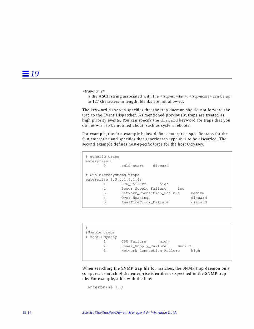
19-16 Solstice Site/SunNet/Domain Manager Administration Guide
19
<trap-name>is the ASCII string associated with the <trap-number>. <trap-name> can be upto 127 characters in length; blanks are not allowed.
The keyword discard specifies that the trap daemon should not forward thetrap to the Event Dispatcher. As mentioned previously, traps are treated ashigh priority events. You can specify the discard keyword for traps that youdo not wish to be notified about, such as system reboots.
For example, the first example below defines enterprise-specific traps for theSun enterprise and specifies that generic trap type 0: is to be discarded. Thesecond example defines host-specific traps for the host Odyssey.
When searching the SNMP trap file for matches, the SNMP trap daemon onlycompares as much of the enterprise identifier as specified in the SNMP trapfile. For example, a file with the line:
enterprise 1.3
# generic trapsenterprise 0
0 cold-start discard
# Sun Microsystems trapsenterprise 1.3.6.1.4.1.42
1 CPU_Failure high2 Power_Supply_Failure low3 Network_Connection_Failure medium4 Over_Heating discard5 RealTimeClock_Failure discard
##Sample traps# host Odyssey
1 CPU_Failure high2 Power_Supply_Failure medium3 Network_Connection_Failure high

SNMP Support 19-17
19
would match all enterprises beginning with 1.3. Since the searching isperformed from the top of the file, you should place more restrictive enterpriseidentifiers before less restrictive ones.
If you define a single trap file that applies to all or most of your SNMP devices,you should make this file the default trap file. For example, suppose that youdo not want to see any generic traps for most of the SNMP devices in yourmanagement domain. You would define a trap file that specifies that generictrap types 0 through 5 be discarded and make this the default trap file. If thereare a couple of critical devices for which you want to see generic trap types,define another trap file that does not specify that the generic trap types bediscarded. Create an entry for each device in the SNMP host file and specifythe second trap file. Because the trap daemon searches the SNMP host file firstto match a trap to a device name, generic traps will be returned for only thosedevices specified in the SNMP host file.
You create the SNMP host file on the system where the trap daemon resides.Refer to “SNMP Host Files” for information on creating the host file. If youhave only one trap file that applies to all your SNMP devices, you can specifythe trap file as the default trap file—you would not need to create an SNMPhost file.
19.4.2.2 Attributing Traps to Glyphs
Glyph entries in the trap file allow the user to attribute traps to databaseelements that represent pseudo-devices — network components that do nothave their own IP address but share the network address of a device that theyare components of, or to which they are attached.
An example would be glyphs that represent the ports on a hub. In this case thetrap-attribution feature would allow the SNMP trap daemon to determinewhich port is the source of the event. When a trap is generated (for example,due to a hub port failure), the appropriate Console effect — such as blinking orcolor by priority — would then be applied to the glyph for that port ratherthan to the hub as a whole, facilitating fault-isolation.
If you have vendor software whose MIB supports this trap-distribution feature,there are five tasks that must be accomplished to enable it for your Console:
• The agent schema file that supports the trap-distribution feature — eitherprovided by the vendor or created from the vendor MIB using themib2schema utility — must be installed in the agents directory.

19-18 Solstice Site/SunNet/Domain Manager Administration Guide
19
• An appropriate glyph entry must be added to an SNMP trap file on thesystem where the SNMP trap daemon runs (and this must be the system onwhich the SNM Console runs).
• The snmp.hosts file must also exist on the system where the trap daemonruns and must contain an entry that identifies the SNMP trap file to be usedfor interpreting traps from the originating device.
• An element definition must be provided for the pseudo-device in theelements.schema file (or a separate element schema file in the agentsdirectory) and this definition must contain a field used to correlate thispseudo-device with a particular glyph. This field must match theappropriate field used by the enterprise-specific agent schema.
• An icon and iconmask to represent the pseudo-device must exist in one ofthe directories specified for icon locations in the Console properties sheet.
For information on creating an agent schema from a vendor MIB, refer toSection 19.2, “Schema Files,” on page 19-8.” How to point the SNM Console tothe location of the icon and iconmask is discussed in “Locations” inChapter 17, “Props Menu.”
The other tasks can be accomplished as follows:
1. Trap File Glyph EntriesThe glyph entry in the trap file must begin with the keyword glyph andhave the following syntax:
<trap_attribute>is the attribute whose value will be matched against the value of theproperty in the component property sheet to determine the glyph to beassociated with the trap.
<database_user_name>is the name of the runtime SNM database without the “db.” prefix. Theuser name must be provided because the trap daemon could have beenstarted by the inetd process; in that case, the user owning the trapdaemon will not be the same as the user running the Console. This fieldis used to create the SNM_NAME environment variable required toaccess the SNM database.
glyph < trap_attribute> < database_user_name> < component_type> < component_property>

SNMP Support 19-19
19
<component_type>is the type of the component whose property is to be compared (forexample, component.pseudo).
<component_property>is the property of the component whose value will be compared againstthe trap attribute value.
A sample glyph entry would be the following:
In this example, ifPortKey is in the variable binding list of the trapProtocol Data Unit (PDU). To determine if this trap should be attributed to aparticular glyph, the trap daemon is to look at the value of the propertyPortKey for an element. The trap is to be attributed to that glyph if theglyph’s PortKey value matches the value passed in the trap’s ifPortKeyvariable. alfred is the name of the SNM database user andcomponent.hubport is the element type.
2. SNMP Host File EntryAn entry must be added to the SNMP hosts file only if a schema file otherthan the trap daemon’s default SNMP schema file is to be used to enable thetrap-distribution feature. The hosts file resides in the same directory as thetrap file. The syntax of host file entries is as follows:
For other types of host file entry, <host-name> is the name of the SNMPdevice. However, for the glyph-distribution feature, <host-name> is to be thename of the host where the proxy agent resides. In a standard host file entry,the proxy system name is specified in the <vendor-proxy> field. However, forpurposes of the pseudo-device trap-attribution feature, the optional <vendor-proxy> field is never used since this information is specified in the <host-
glyph ifPortKey alfred component.hubport PortKey
<host-name> <read-community> <write-community> <request-timeout> <schema-file><trap-file> <vendor-proxy>

19-20 Solstice Site/SunNet/Domain Manager Administration Guide
19
name> field. For more information about the SNMP host file, refer toSection 19.3, “SNMP Host Files,” on page 19-10.” An example of a host fileentry to implement the trap-distribution feature would be the following:
In this example, “bigguy” is the name of the host where the SNMP proxyagent resides. /opt/SUNWconn/snm/agents/snmp-pseudodev.schemais the vendor agent schema; the only reason the host file is necessary is topoint to this file.
3. Adding an Element Definition for the Pseudo-deviceYou will need to add a component definition for the glyph that representsthe pseudio-device. The component definition is created in the form of arecord definition as in the following example:
The fields in this element definition will be displayed in the properties sheetfor glyphs of this type, as shown in Step 19-3.
bigguy public private 20 /opt/SUNWconn/snm/agents/snmp-pseudodev.schema /var/opt/SUNWconn/snm/snmp.traps
record component.hubport ( # generic sun 4 string[64] Name string[40] User string[40] Location string[80] Description netaddress Port_Key string[40] SNMP_RdCommunity string[40] SNMP_WrCommunity string[64] SNMP_Vendor_Proxy int SNMP_Timeout)
# Glyphs for components
instance elementGlyph( ( component.hubport hubport.icon))

SNMP Support 19-21
19
Figure 19-3 Sample Properties Sheet for Pseudo-Devices
Note that underscores in the element definition are displayed as spaces inthe field names. In this example, the Port Key field gives the attribute — auser-defined port number — that is used to match traps to glyphs. (This“Port Key” value is in the same format as an IP address though it is not anIP address.) For information on how to create element definitions, see thesection on “Element Instance Definition.” This definition can be added tothe elements.schema file or to another element schema file in theagents directory.
This component definition must include a field that will have the samevalue as the SNMP trap attribute that will be matched with it. The followingrestrictions apply:
• The trap attribute to be matched with the component property must be inthe variable binding list in the trap PDU. This follows the regular membersof a trap message, which are the following:

19-22 Solstice Site/SunNet/Domain Manager Administration Guide
19
• Version• Community• Enterprise• Agent address• Generic trap type• Specific trap type for enterprise-specific trap• Time stamp
• For purposes of matching the element property to the SNMP attribute, onlythe SNMP types listed in Table 19-1 are supported.
19.4.3 Trap Reports on the Console
On a Console system, trap reports are logged with other event and errorreports and are displayed by selecting the Console’s View➤Event/TrapReports menu item.
Changes in a glyph’s state that results from a trap are propagated through theConsole’s view hierarchy as if an event had occurred. You determine thepriority of an SNMP trap as described in Chapter 8, “Managing SNMPDevices.” The type of signal that the Console uses to indicate received traps isspecified in the Events and Traps category of the Console’s Properties window.By default, the Console blinks the glyph of the target element when a trap isreceived.
Table 19-1 Supported SNMP and Schema Types
SNMP TypeSNMPAttribute Type
Element SchemaAttribute Type
INTEGER int int
INTEGER enum enum
OCTET STRING string string
IPAddress netaddress netaddress
NetworkAddress netaddress netaddress
OBJECT IDENTIFIER objectid string

SNMP Support 19-23
19
19.4.4 Interpreting a Trap Report
A typical trap report logged in the Event/Trap Reports window looks like thefollowing:
Figure 19-4 Trap Report
The lines in the trap report are described below:
The header is the line at the top which shows the date, time and hostname ofthe device which generated the trap.
sequencea counter showing the sequence number of the trap; also keeps track of thenumber of traps generated since the device was last booted
receive-timethe time the Console received the trap

19-24 Solstice Site/SunNet/Domain Manager Administration Guide
19
versionreturned by the device which generated the trap
communitythe SNMP trap community name sent by the device which generated thetrap
enterpriseenterprise name of the device which generated the trap
source-timelength of time between when the device was booted and when the trap wasgenerated
trap-typewhether this trap is generic or enterprise-specific
trap-nowhere in the sequence of traps this one falls
trap-namea name you have specified or a default name
prioritythe priority of this trap (low, medium or high)
Note that underscores in the element definition are displayed as spaces inthe field names. In this example, the Port Key field gives the attribute — auser-defined port number — that is used to match traps to glyphs. (This“Port Key” value is in the same format as an IP address though it is not anIP address.) For information on how to create element definitions, see thesection on “Element Instance Definition.” This definition can be added tothe elements.schema file or to another element schema file in theagents directory.
This component definition must include a field that will have the samevalue as the SNMP trap attribute that will be matched with it. The followingrestrictions apply:
• The trap attribute to be matched with the component property must be inthe variable binding list in the trap PDU. This follows the regular membersof a trap message, which are the following:• Version• Community

SNMP Support 19-25
19
• Enterprise• Agent address• Generic trap type• Specific trap type for enterprise-specific trap• Time stamp
• For purposes of matching the element property to the SNMP attribute, onlythe SNMP types listed in Step 19-2 are supported.
19.4.5 Trap Reports on the Console
On a Console system, trap reports are logged with other event and errorreports and are displayed by selecting the Console’s View➤Event/TrapReports menu item.
Changes in a glyph’s state that results from a trap are propagated through theConsole’s view hierarchy as if an event had occurred. SNMP traps are treatedas high-priority events. The type of signal that the Console uses to indicatereceived traps is specified in the Events and Traps category of the Console’sProperties window. By default, the Console blinks the glyph of the targetelement when a trap is received.
Table 19-2 Supported SNMP and Schema Types
SNMP TypeSNMPAttribute Type
Element SchemaAttribute Type
INTEGER int int
INTEGER enum enum
OCTET STRING string string
IPAddress netaddress netaddress
NetworkAddress netaddress netaddress
OBJECT IDENTIFIER objectid string

19-26 Solstice Site/SunNet/Domain Manager Administration Guide
19
19.4.5.1 Remaining Fields
Remaining fields, if any, are variables whose values are returned by the trap.Some traps do not return variables. These values are usually relevant to thereason the trap was generated. When the trap daemon receives a trap, itattempts to translate variables from OIDs into ASCII text before forwarding thetrap. See the section on “Trap Daemon Operation” for more information.
19.4.6 Mapping SNMP Object IDs to Strings
One of the data types supported by SunNet Manager is an object identifier.Since object identifiers are numeric (for example, 1.2.3.4.5), a database isprovided so the Console can display the object identifier using a moremeaningful string. The Object Identifier Database (OID) provides theinformation for this mapping. The build_oid utility builds the OID. TheConsole uses the database to interpret object identifiers.
You will probably want to build the OID when new object identifiers are addedto the database. Input files for build_oi d are ASCII files with the suffix .oid.Each file has a descriptive name followed by its object identifier. If thedescriptive name contains special characters, enclose it in double quotes. Youcan include comment lines by beginning them with a pound sign (#). Whenmib2schema is used to convert a MIB to a schema file, it also generates a .oid
file.
To locate input files, build_oid uses the directories specified bySNMHOME/agents and SNMHOME/schemas. If you have not defined theSNMHOME environment variable, the directories are:
• /usr/snm/agents and /usr/snm/struct for Solaris 1.x installations
• /opt/SUNWconn/snm/agents and /opt/SUNWconn/snm/struct for Solaris2.x installations
You can also specify other directories as input arguments (see thebuild_oid (1) man page for more information). SunNet Manager providesthree input files which are normally found in the /usr/snm/agents directory:
• enterprises.oid contains the mappings for a variety of enterprise andorganization identifiers.
• snmp.oid contains the mappings for object identifiers for MIB I of theSNMP protocol.

SNMP Support 19-27
19
• sun-snmp.oid contains the mappings for object identifiers referenced by theSun SNMP agent, snmpd. The Sun agent implements a superset of MIB II;thus, this file also serves as a snmp-mibII.oidfile.
The environment variable SNMDBDIR specifies the directory for writing theoutput database oid.dbase . If you have not specified the SNMDBDIR
environment variable, the directories are:
/var/adm/snm for Solaris 1.x installations
/var/opt/SUNWconn/snm for Solaris 2.x installations.
19.5 SNMP Version 2 SupportThis section assumes you are familiar with SNMPv2 concepts. Instructions forinstalling and de-installing SNMPv2 are in your installation guide for Solaris2.x/x86.
SunNet Manager provides a proxy agent that supports SNMPv2. This proxyagent allow you to get data and event information from and set attributevalues for devices managed through SNMPv2.
There is also an SNMP agent for Sun workstations called the snmpv2d daemon.The Console communicates with this daemon through the SNMP proxy agent.The snmpv2d daemon also allows Sun workstations to be managed by otherSNMPv2 and SNMP stations. For more information about the snmpv2d
daemon, see the snmpv2d (8) man page.
The following sections discuss the differences between SNMP and SNMPv2.For information about the SNMPv2 configuration files, see the following manpages:
v2install (1), acl.pty (5), agt.pty (5), context.pty (5), mgr.cnf (5),mgr.pty (5), snmpv2d.conf (5), and view.pty (5).
Note – When the Discover tool locates SNMP devices on your network, itcannot determine whether the devices support functionality specific toSNMPv2.

19-28 Solstice Site/SunNet/Domain Manager Administration Guide
19
19.5.1 SNMPv2 Enhancements
The key enhancements from SNMP to SNMPv2 are in the following categories:
• Structure of Management Information (SMI)
• Protocol operations
• Manager-to-manager capability
• Security
19.5.1.1 Structure of Management Information
The SMI for SNMPv2 is based on the SMI for SNMP. The SNMPv2 SMIprovides more extensive specification and documentation of managed objectsand MIBs.
Several new data types were created for SNMPv2. These include a 64 bit-counter (Counter 64 ) and the UInteger32 type which allows representationof integers in the range 0 to 232 - 1.
The SNMPv2 OBJECT-TYPE macro includes an optional UNITS clause, whichcontains a textual definition of the units associated with an object. This clauseis useful for any object that represents a measurement in units (ex. “seconds”).The OBJECT-TYPE macro for SNMPv2 also incudes a MAX-ACCESS clausewhich allows you to specify the maximum level of access.
19.5.1.2 Protocol Operations
SNMPv2 has three new protocol data units (PDU). The SNMPv2 trap PDUworks in a way similar to that of the SNMP trap PDU, but it uses the sameformat as most other SNMPv2 PDUs. This eases the receiver processing task.
A major enhancement for SNMPv2 is the GetBulkRequest PDU. This PDUcan significantly minimize the number of protocol exchanges required toretrieve a large amount of management information.
The third additional PDU is the InformRequest PDU. This is sent by anSNMPv2 manager, on behalf of an application, to another SNMPv2 manager.The PDU provides management information to an application using the secondSNMPv2 manager.

SNMP Support 19-29
19
19.5.1.3 Manager-to-Manager Capability
Manager-to-Manager operations are supported through the use of themanager-to-manager MIB. This MIB is a set of objects which describe thebehavior of an SNMPv2 entity acting in a manager roll. For more information,see RFC 1451.
19.5.1.4 Security
SNMPv2 uses the Secure SNMP (S-SNMP) party concept for security.Improvements over S-SNMP include the elimination of ordered deliverymechanism and simplification of the clock synchronization algorithm. Inaddition, SNMPv2 introduces the context concept. Contexts provide for moreefficient storage of access control and MIB view information. SNMPv2 usesboth DES and MD5 for message security and authentication.
19.5.2 SNMPv2 Files
You can install SNMPv2 as an agent (snmpv2d ), a manager (na.snmpv2 ), orboth. The required files are installed as part of the current product. Installationsteps are the same for both agents and managers. After the current SunNetManager product is installed, create the three configuration files required bythe v2instal l script. The files are:
• agents - contains names of hosts on which the snmpv2d agent will beinstalled
• mgrs.v1 - contains names of hosts that will be running SNMPv1 managers(na.snmp )
• mgrs.v2 - contains names of hosts that will be running SNMPv2 managers(na.snmpv2 )
See the v2install (1) man page for detailed information about these files.
Procedures for installing (or removing) SNMPv2 software are in yourinstallation guide for Solaris 2.x/x86.
19.5.3 Using the v2mib2schema Program
A program, v2mib2schema , has been included with the current product toallow you to translate your own SNMPv2 MIBs to SNM schema files.

19-30 Solstice Site/SunNet/Domain Manager Administration Guide
19
Be aware that SunNet Manager schemas do not have the flexibility of SNMPv2MIBs, so changes to the MIB may be necessary before v2mib2schema cansuccessfully parse it.
Although v2mib2schema parses TEXTUAL-CONVENTIONS clauses, itcurrently ignores them, so later references to the new types will cause syntaxerrors. See the v2mib2schema (5) man page for more details.

20-1
Browser 20
This chapter discusses the following topics:
• Starting the Results Browser
• Loading files
• Report Streams
• Streams Menu
• Selecting Streams
• Folders
• Customizing the Browser
You can examine data stored in the following files:
• Console Event/Trap log file. This file is normally located at:• /var/adm/snm/event.log for Solaris 1.x installations• /var/opt/SUNWconn/snm/event.log for Solaris 2.x installations.
• Console Data Report log entries that have been saved to a disk file. (Refer to“Data Reports” for more information.)
• Data Report files. You use Save option in the Console Data Report windowto create a log file of data reports.
• Other files that use the data format specified in snm.logfile(5) .
Each instance of the Browser can only work with other SunNet Manager toolsthat have the same user name.

20-2 Solstice Site/SunNet/Domain Manager Administration Guide
20
20.1 Starting the BrowserInvoke the Browser from either the Tools menu in the SunNet ManagerConsole or from a command line. It runs as a separate process from theConsole and remains when you quit the Console. To start the Browser from theConsole, press MENU on the Tools button and drag and release on the Browsermenu option.
To invoke the Browser from the command line, use the following command:
• <tools-path> is /usr/snm for Solaris 1.x installations.
• <tools-path> is /opt/SUNWconn/snm for Solaris 2.x installations.
When you start the Browser from a command line, you can optionally specifyfiles to be automatically loaded into the Results Browser. File names caninclude wildcards. When invoked without any file names specified, the ResultsBrowser displays the window shown in Figure 20-1.
If the Browser is started from a command line with the -b option, this causesgraphs to be plotted on a white background, rather than the default blackbackground, if the Grapher is invoked from the Browser.
mgrhost% <tools-path>/bin/snm_br [-b] [ <filename1>] [ <filename2>] ..

Browser 20-3
20
Figure 20-1 Results Browser Window
20.2 Loading FilesTo load a file (which must be in the prescribed format) into the Browser, pressMENU on the File button and release MENU on the Load option. A pop-upwindow appears, prompting you for the name of a file to be loaded. See theexample in Figure 20-2, “Load Window.”

20-4 Solstice Site/SunNet/Domain Manager Administration Guide
20
Figure 20-2 Load Window
To load a file, double-click SELECT on the file name or its icon or type in thefile name at the Name prompt and then click SELECT on the Load button. Youcan load multiple files into the Browser, one at a time; however, you cannotspecify wildcards in any file name.
Note – Because the Browser keeps open every file it reads, there is a limit to thenumber of files you can load in a Browser session. This limit is determined bythe number of file descriptors allowed by the C-shell to a single process; thedefault is 64. You can increase this number up to 256 by using the limitcommand in the C-shell. You can also run multiple Browser sessions at thesame time.

Browser 20-5
20
20.3 Report StreamsWhen you load a file into the Browser, the data in the file is automaticallyorganized into report streams, which appear in the scrolling list in the upperpane of the Browser window. See Figure 20-3, “Results Browser ReportStreams.”
Figure 20-3 Results Browser Report Streams
Report streams are logical groupings of reports from agents. Each streamcontains the results of a request from a particular requester address at aparticular time. The Browser also distinguishes streams by report type (data,event, error, etc.). For example, if a file contains both data reports and errorreports resulting from an individual request, the data reports are listed in aseparate stream from the error reports.

20-6 Solstice Site/SunNet/Domain Manager Administration Guide
20
Each report stream is defined in the following format in the upper portion ofthe Browser window:
where:
<system> is the name (up to 15 characters) of the target system (the host wherethe managed object resides).
<agent> is the name of the agent.
<group> identifies the attribute group.
<type> identifies the type of report (data, event, trap, error).
<date> is the time stamp of the original request from the manager.
<number_of_reports> indicates the number of reports in the stream.
To view the contents (individual reports) of a particular stream, double-clickSELECT on the stream you want to view. Individual agent reports from theselected stream are displayed in the lower portion of the Browser window, asshown in Figure 20-4, “Agent Reports from Selected Stream.”
<system> <agent> <group> <type> <date> <number_of_reports>

Browser 20-7
20
Figure 20-4 Agent Reports from Selected Stream
If more than one report exists in the selected stream, a slider bar appears. Toview a specific report, type in the report number on the Report line to the leftof the slider bar and press Return. You can also view reports by pressing

20-8 Solstice Site/SunNet/Domain Manager Administration Guide
20
SELECT on the drag area (the small rectangular area between the ends of theslider bar) and dragging the mouse pointer to the right or the left until thedesired report number is reached.
You can clone, delete, or print reports from the selected stream by pressingMENU in the Report window to bring up the Report menu. The Report menuis shown in Figure 20-5, “Report Menu.”
Figure 20-5 Report Menu

Browser 20-9
20
Report Menu functions are described as follows:
• To clone a report, select the Clone option. This causes a copy of the currentreport to be displayed in a pop-up window so that its contents can becompared with other reports. To make the pop-up window disappear, unpinit by clicking SELECT on the pushpin.
• To delete a report, select the Delete option.
• To print a report, press MENU in the Report window and move the pointerto one of the three Print Options:• Report—prints the currently displayed report.• Stream From Here—prints all reports in the stream, beginning with the
currently displayed report.• Entire Stream—prints all reports in the stream.
By default, reports are printed to lpr on Solaris 1.1, or lp if SNM has beeninstalled on a Solaris 2.x machine. You can choose a different printer byusing the Tool Properties option of the Browser’s Edit menu. Refer to thesection on “Customizing the Browser” for more information.
If the reports to be printed exceed a set number of kilobytes, you are askedto confirm that you want the reports printed before printing commences. Bydefault, this limit is set at 100 kilobytes. You can adjust this limit by usingthe Tools Properties option of the Browser’s Edit menu. Refer to the sectionon “Customizing the Browser,” for more information.

20-10 Solstice Site/SunNet/Domain Manager Administration Guide
20
20.4 Streams MenuTo perform operations on one or more streams, invoke the pull-down Streamsmenu by pressing MENU in the top panel of the Browser window. You receive:
Figure 20-6 Results Browser Streams Menu
The following briefly describes Streams menu functions.
• Graph allows you to send selected streams to the Results Grapher. Thisfunction is described in detail in the section, “Sending Data to the ResultsGrapher.”
• Select allows you to select streams based on certain properties. This functionis described in detail in the section “Selecting Streams.”
• Copy to copies selected streams to a folder. The use of folders is describedlater in Section 20.6, “Folders.”
• Delete deletes selected streams.
• Print prints selected streams to your configured printer.
• Clear All Choices deselects any selected streams.
Streams menu

Browser 20-11
20
20.5 Selecting StreamsThe Browser provides mechanisms for selecting streams based on certain user-specified properties. This function can be invoked by pressing MENU in thescrolling list and pulling right on the Select option of the Streams menu. Youcan select streams By System, By Agent.Group, or By Report Type. When youhave made your selections, the names of the report streams in the scrolling listto which the specified properties apply are highlighted. Figure 20-7, “StreamsSelection by System” illustrates selection by system.
Figure 20-7 Streams Selection by System
20.5.1 Sending Data to the Results Grapher
You can have data in a report stream plotted using the Results Grapher. Tosend data to the Grapher, first select the desired streams. Press MENU in thescrolling list in the upper portion of the Browser window to invoke the Streamsmenu, pull right on Graph and release on one of the listed attribute names(shown in an alphabetized list). Figure 20-8, “Sending Data to the Grapher”illustrates how this is done:

20-12 Solstice Site/SunNet/Domain Manager Administration Guide
20
Figure 20-8 Sending Data to the Grapher

Browser 20-13
20
When you make this selection, the Browser sends a set of attribute andcorresponding time values to the Results Grapher for plotting. Only integer,float, counter, gauge, timestamp, and UNIX time data may be plotted.Therefore, only the names of attributes of these data types are included in themenu list.
You can select more than one report stream and have each plotted on the samegraph. For example, you can graph comparative data for multiple systems ontoa single graph.
You can also graph multiple attributes from one or more selected reportstreams. To do this, pull right on either the All Attributes or the Choicesoption. The All Attributes option plots every integer and float attribute listedin the report stream. The Choices option displays a pop-up window with a listfrom which you can select the attributes to be graphed. Note that the AllAttributes option is only available if there is more than one attribute that canbe plotted.
If the Browser was started from a command line with the -b option, graphswill be plotted on a white background when the Results Grapher is invoked.Otherwise, if the -b option was not specified, the Results Grapher will displaygraphs on a black background
After information is sent to the Grapher, you can view the data in a Graphersession. See Chapter 21, “Results Grapher,” for information.
20.6 FoldersWhen you load a file into the Browser, the file is automatically loaded into thedefault folder Main . A folder is a temporary place to logically group reportstreams and store them for reference during a Browser session. You can createother folders to hold specified groups of report streams by using the Editmenu.
To create new folders, press MENU on Edit, drag the pointer to New Folder,and then release the MENU button. A folder named “New Folder” is created,which you can rename by typing the desired name on the line where “NewFolder” is displayed, and pressing Return. The “Main” folder cannot berenamed.

20-14 Solstice Site/SunNet/Domain Manager Administration Guide
20
To load files into a folder, press MENU on File and drag the pointer to theLoad option. A pop-up window appears, prompting you for the name of thedirectory and file name of the file to be loaded. To load the file, click SELECTthe Load button. You can load multiple files into a single folder, but duplicatereports are ignored.
You can also copy selected streams into a folder by using the Copy to option inthe Streams menu. To do so, first select one or more streams by using the Selectoption of the Streams menu or by clicking SELECT on the desired stream in thescrolling list. Press MENU in the scrolling list and drag the pointer to Copy to.Continue to pull right to see a list of folder names; release the pointer on thedesired folder. Figure 20-9, “Copying Streams to a Folder” illustrates copyingstreams to a folder.
Figure 20-9 Copying Streams to a Folder
To empty a folder of all its streams, press MENU on Edit and drag the pointerto Empty Folder.
To delete a folder, press MENU on Edit and drag the pointer to Delete Folder.If you try to delete the Main folder, it will be emptied but not deleted.

Browser 20-15
20
As mentioned previously, folders are temporary places to keep related streamstogether. Once you exit the Browser, the folder names and their contentsdisappear. You can save the contents of a folder to a file for future access. To doso, press MENU on File and drag the pointer to the Save Folder option. In thepop-up window, specify a path and file name and click the Save button. In afuture Browser session, you can load this file to view and manipulate the sameset of streams.
Caution – Do not attempt to save the contents of a folder into a file thatcontains reports that are currently loaded into the Browser, as this will corruptthe file.
Because log files may be extremely large, individual reports are not kept inmemory. Instead, pointers to the files are maintained. Therefore, if a file isoverwritten while it is open, the file would be destroyed and the pointers tothe file would be corrupted.
20.7 Customizing the BrowserYou can customize the properties of the Browser by using the Tool Propertiesoption of the Edit menu. Press the mouse MENU button on Edit and drag andrelease on the Tool Properties option. The Properties window appears, as inFigure 20-10, “Tool Properties Window.”

20-16 Solstice Site/SunNet/Domain Manager Administration Guide
20
Figure 20-10 Tool Properties Window
The following fields in the Properties window affect the operation of theBrowser. Any changes you make take effect when you press the Apply or Savebuttons.
Window Position:Defines the location (in pixels) of where the Browser window is displayed.Default values are 300 and 100 for x and y locations, respectively.
Window Size:Defines the dimensions (in pixels) of the Browser window. Default valuesare 512 and 640 for x and y dimensions, respectively.

Browser 20-17
20
Print Option:Specifies the printer name. lpr is the default printer for Solaris 1.1installations. lp is the default printer for Solaris 2.x machines.
Verify printing more than (100) KBytesDefines a print output size for printing report streams. For any output thatexceeds the specified size, you will be asked to confirm whether you want toprint the reports. Either enter in a new value on the line or click SELECT onthe up- or down-arrow glyphs to increase or decrease the specified size.
Report Format:Defines the appearance and contents of stream reports in the lower portionof the Browser window. All of the listed choices are selected by default,which causes all report information to be displayed in the report window.Click SELECT on any of the fields to deselect or select a choice. You can alsochoose to have attribute names displayed left- or right-justified on thescreen. By default, attribute names are displayed right-justified.
The four buttons at the bottom of the Properties window operate as describedbelow.
• Apply applies any changes that have been made to the fields in the ToolProperties window.
• Save saves window parameter changes to the OpenWindows.Xdefaultsfile and applies any changes you made to the Report Format and PrintOption parameters.
• Load loads window parameters from the X Resource Manager. You can thenclick the Apply button to apply these parameters to the Browser window.
• Reset sets the values in each of the fields to the last applied changes (the lasttime you clicked the Apply button) or to the values when the Propertieswindow was first displayed.

20-18 Solstice Site/SunNet/Domain Manager Administration Guide
20

21-1
Results Grapher 21
This chapter discusses the following topics:
• Starting the Results Grapher
• Results Grapher window
• Graph Properties window
• Displaying graphs
• Merging graphs
The Results Grapher is a graphing utility that you can use to visualize attributevalues returned from Data requests or stored data sent from the ResultsBrowser.
In a Data request, you can choose to have reported attribute values sent to theResults Grapher for display. (This is described in Chapter 15, “RequestsManagement.”) From the Results Browser, you can send data to the ResultsGrapher by selecting a report stream and pulling down a menu to graphselected attribute values from the report stream. (This is described inChapter 20, “Browser.”)
Each instance of the Grapher can only work with other SNM tools that havethe same user name.

21-2 Solstice Site/SunNet/Domain Manager Administration Guide
21
21.0.1 Starting the Results Grapher
The Grapher can be invoked from either the Tools menu in the SunNetManager Console or from a command line. Either way, the Results Grapherruns as a separate process from the SunNet Manager Console and remainsrunning when you quit the Console. To start the Grapher from the Console,press MENU on the Tools button and drag and release on the Grapher menuoption (see Figure 21-1).
Figure 21-1 Invoking the Grapher from the Console
You can also invoke the Grapher from the command line by entering.
where <tools-path> is:
• /usr/snm/bin for Solaris 1.x installations
• /opt/SUNWconn/snm/bin for Solaris 2.x installations.
mgrhost% <tools-path>/snm_gr [-b]

Results Grapher 21-3
21
If the -b option is not specified in the command line, graphs will be plotted ona black background. If the -b option is specified, graphs will be plotted on awhite background. When you invoke the Grapher from the Tools menu, graphsare by default plotted on a black background.
To cause graphs to be displayed on a white background when you invoke theGrapher from the Tools menu, you must add the -b option to the snm_grelementCommand instance in the elements.schema file. (Refer toChapter 18, “Management Database,” for more information about modifyingthe elements.schema file.)
To cause graphs to be displayed on a white background when you invoke theGrapher from the Results Browser, start the Browser with the -b command-lineoption.
When the Grapher is invoked, the Results Grapher window appears. Whenyou send data to the Grapher from the Browser, a graph window appears. Thefollowing describes these windows.
Note – When the Grapher starts, it writes its temporary RPC program numberto /tmp/snm_gr.rpcid. <user> (<user> is either the name of the user or thevalue of the environment variable SNM_USER). Other applications, such as theConsole, the Browser, or snm_cmd, use this file to send data to the Grapher.
21.1 Results Grapher WindowIf you previously sent data to the Grapher, the names of the graphs appear inthe scrolling list; if not, the list is empty. The Results Grapher window containsa scrolling list and four buttons, as shown in Figure 21-2.
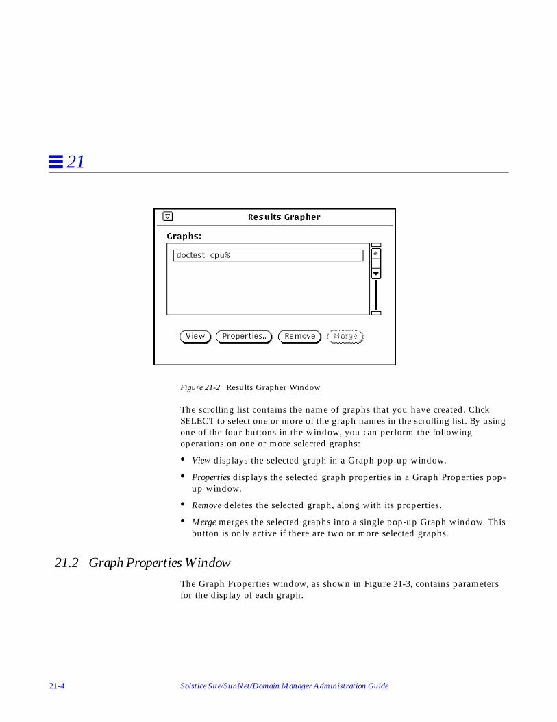
21-4 Solstice Site/SunNet/Domain Manager Administration Guide
21
Figure 21-2 Results Grapher Window
The scrolling list contains the name of graphs that you have created. ClickSELECT to select one or more of the graph names in the scrolling list. By usingone of the four buttons in the window, you can perform the followingoperations on one or more selected graphs:
• View displays the selected graph in a Graph pop-up window.
• Properties displays the selected graph properties in a Graph Properties pop-up window.
• Remove deletes the selected graph, along with its properties.
• Merge merges the selected graphs into a single pop-up Graph window. Thisbutton is only active if there are two or more selected graphs.
21.2 Graph Properties WindowThe Graph Properties window, as shown in Figure 21-3, contains parametersfor the display of each graph.

Results Grapher 21-5
21
Figure 21-3 Graph Properties
The following describes the Properties parameters:

21-6 Solstice Site/SunNet/Domain Manager Administration Guide
21
Name:Specifies the name of the graph that will appear in the scrolling list in theResults Grapher window, and as the label on the Graph pop-up window. Bydefault, this field contains the host name, followed by the attribute selectedto be graphed. If you are graphing data from multiple systems (for example,you select multiple Browser report streams to be plotted on the same graph),the name would contain multiple host names instead of a single name.
Frame Color:Specifies the color of the frame of the graph. By default, this value is Cyanon color monitors. To change the frame color, press MENU over the FrameColor abbreviated menu button and release the pointer on the desired colorin the palette. Note that on monochrome monitors, this parameter and anyother fields that specify color choices are dimmed.
Base Color:Specifies the color of the base of the graph. By default, this value is DarkOrchid on color monitors. To change the base color, press MENU over theBase Color abbreviated menu button and release the pointer on the desiredcolor in the palette.
Data Scale:Specifies whether the data sets (vertical axis) are plotted using Absolute orRelative values. This is useful only if more than one data set is to be plotted.If Absolute is chosen, the maximum and minimum values of the graphassume the greatest and least values among all the data sets. If Relative ischosen, the maximum and minimum values of the graph vary according tothe maximum and minimum values of each data set. Absolute data scaleshould be used when displaying multiple data sets whose data values are ofthe same units—for example, CPU percentage for multiple systems. Relativedata scale should be used when displaying multiple data sets whose datavalues are of different units—for example, CPU percentage, interrupts, andcollisions for a single system. By default, Absolute is selected.
Time Scale:Specifies whether the time stamps of the data sets are plotted in Absolute orRelative scale. If Absolute is chosen, the start and end times of the graphequal the earliest and latest times, respectively, of the data sets. If Relative ischosen, the start and end times of the graph vary according to each data set.Absolute time scale is useful when displaying data sets from reports whosetime spans overlap—for example, yesterday’s CPU percentage for threedifferent systems. Data from a very short time period that is graphed with

Results Grapher 21-7
21
data from a different time (for example, 30-second time slices taken sixmonths apart) can appear almost invisible when graphed in Absolute scale.Relative time scale is useful in comparing data sets whose time stampsdiffer greatly—for example, CPU percentages for a single system on threedifferent days. With Relative time scale, the time stamps at the bottom of thegraph display only the relative time from the first data value. By default,Absolute is selected.
Order:Specifies the order in which the data sets are drawn if there is more than onedata set in the graph. If Normal is chosen, the graph in the foregroundcorresponds to the first data set in the list of the Properties window. IfReverse is chosen, the graphs are drawn in reverse order, that is, the graphin the foreground corresponds to the last data set in the list of the Propertieswindow. By default, Normal is selected.
Fill:Specifies the style in which the graph is to be drawn. If On is chosen, eachgraph is drawn in a solid fashion with the base of the graph extending up tothe apex. If Off is chosen, each graph is drawn in a ribbonlike or linefashion. Setting Fill to Off allows you to view graphs that might otherwisebe hidden by the graph in the foreground. By default, On is selected.
Draw:Specifies whether the graph is drawn in a two-dimensional (2-D) or three-dimensional (3-D) manner. By default, 3-D is selected.
Data SetsA scrolling list containing all the data sets plotted in the graph. Each item inthe list has a color glyph and the host name and attribute graphed. Thecolor glyph corresponds to the color (or line-style for monochromemonitors) used to draw the graph and may be used as a legend for thegraph. This list is an exclusive list; only one item may be selected at anytime.
The following four properties affect only the selected item in the Data Setsscrolling list:
Data Set:Controls the visibility of the selected data set’s graph. Show makes the dataset’s graph visible, while Hide makes the data set’s graph invisible. Bydefault, Show is selected.

21-8 Solstice Site/SunNet/Domain Manager Administration Guide
21
Plot Value:Specifies the data sets to be plotted in one of three modes: Absolute, whichplots the values of the data sets as is; Cumulative, which sums up eachsuccessive data value and plots them; and Delta, which takes the differencebetween each pair of data value and plots them. By default, Absolute isselected.
Line Color:Sets the line color of the graph. The Grapher automatically selects an initialcolor based on the number of data sets plotted.
Line Style:Sets the line-style of the graph. This option is only active when using amonochrome monitor. One of four line-styles may be chosen: Solid, Dotted,Dashed, Dot-Dashed. By default, Solid is chosen.
To establish or change the attributes of the graph, click the Apply button. Toget back the original settings of the properties just after the last Apply, click theReset button.
Note – Changes to the default values of the Graph Properties fields cannot besaved from one Grapher session to another. When you exit a Results Graphersession, all changes you have made to the default values of the GraphProperties fields are lost.
21.3 Displaying GraphsTo display a graph, select it from the scrolling list in the Results Grapherwindow and click SELECT on the View button. A pop-up window appears asshown in Figure 21-4.
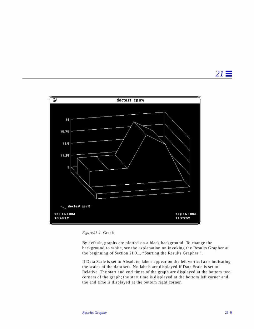
Results Grapher 21-9
21
Figure 21-4 Graph
By default, graphs are plotted on a black background. To change thebackground to white, see the explanation on invoking the Results Grapher atthe beginning of Section 21.0.1, “Starting the Results Grapher.”.
If Data Scale is set to Absolute, labels appear on the left vertical axis indicatingthe scales of the data sets. No labels are displayed if Data Scale is set toRelative. The start and end times of the graph are displayed at the bottom twocorners of the graph; the start time is displayed at the bottom left corner andthe end time is displayed at the bottom right corner.
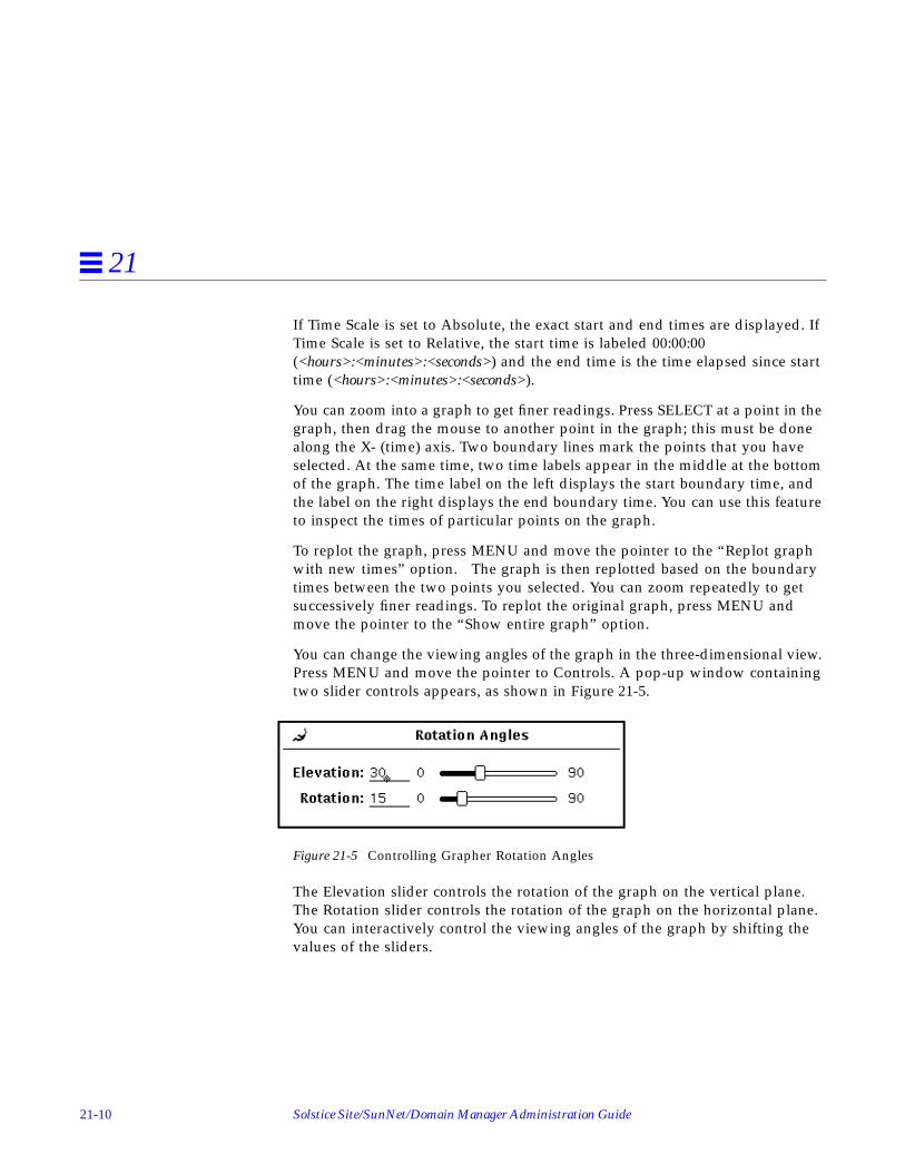
21-10 Solstice Site/SunNet/Domain Manager Administration Guide
21
If Time Scale is set to Absolute, the exact start and end times are displayed. IfTime Scale is set to Relative, the start time is labeled 00:00:00(<hours>:<minutes>:<seconds>) and the end time is the time elapsed since starttime (<hours>:<minutes>:<seconds>).
You can zoom into a graph to get finer readings. Press SELECT at a point in thegraph, then drag the mouse to another point in the graph; this must be donealong the X- (time) axis. Two boundary lines mark the points that you haveselected. At the same time, two time labels appear in the middle at the bottomof the graph. The time label on the left displays the start boundary time, andthe label on the right displays the end boundary time. You can use this featureto inspect the times of particular points on the graph.
To replot the graph, press MENU and move the pointer to the “Replot graphwith new times” option. The graph is then replotted based on the boundarytimes between the two points you selected. You can zoom repeatedly to getsuccessively finer readings. To replot the original graph, press MENU andmove the pointer to the “Show entire graph” option.
You can change the viewing angles of the graph in the three-dimensional view.Press MENU and move the pointer to Controls. A pop-up window containingtwo slider controls appears, as shown in Figure 21-5.
Figure 21-5 Controlling Grapher Rotation Angles
The Elevation slider controls the rotation of the graph on the vertical plane.The Rotation slider controls the rotation of the graph on the horizontal plane.You can interactively control the viewing angles of the graph by shifting thevalues of the sliders.

Results Grapher 21-11
21
21.4 Merging GraphsYou can superimpose graphs on one another. Select the graphs to be mergedfrom the scrolling list in the Results Grapher window, then click SELECT onthe Merge button. A pop-up window appears with the selected graphs plottedtogether.
After graphs are merged, common parameters such as Data Scale or Time Scaletake on default settings. For example, if one of the graphs being merged hasTime Scale set to Relative, its Time Scale is reset to the default value ofAbsolute. Data set-specific parameters, such as Plot Value, retain theirindividual settings. Data sets are always displayed; a new line color may beassigned if there are two or more data sets using the same line color.
21-12 Solstice Site/SunNet/Domain Manager Administration Guide
21

22-1
IP Discover 22
This chapter discusses the following topics:
• Invoking IP Discover
• IP Discover tool configuration
• snm_discover command
• The discover.conf file
The IP Discover Tool has two functions:
• A discover function, which finds hosts, routers, networks, and SimpleNetwork Management Protocol (SNMP) devices reachable from the Consolemachine. On finding a network element, the discover function stores arecord for that element in the runtime database.
• A monitor function, in which the tool compares the elements stored in theruntime database with the elements it finds at a specified interval orspecified time. If new elements are detected, the monitor function stores theelements in a holding-area view and records these elements in a log file.Through the same log file, the monitor function can also notify you if apreviously discovered host is down or was down within a given period.
When you invoke the HeadStart option at startup, IP Discover searches for amaximum of ten elements on the local subnetwork.
The hosts found by the monitor function are hosts added to a network sincethe last running of the discover function and hosts that the discoverfunction did not find.

22-2 Solstice Site/SunNet/Domain Manager Administration Guide
22
IP Discover offers a number of configuration options for both the discover andmonitor functions. These options allow you to fine-tune the extent and depthof the tool’s search and monitoring activities. The configuration options aredescribed later in this chapter.
Note – When IP Discover locates SNMP devices, it cannot determine whetherthese devices support functionality specific to SNMPv2.
22.1 Invoking IP DiscoverYou invoke IP Discover using one of the following methods:
• from the Console window, when you press MENU on Tools➤Discover➤IPDiscover and release MENU;
• from the SunOS command line, if you have the path to the SNM executablesin your PATH variable, invoke snm_discover ; for example, to run IPDiscover and invoke the user interface, enter:
The path to snm_discover is:
• /usr/snm/bin on SunOS 4.x• /opt/SUNWconn/snm/bin on Solaris 2.x
After IP Discover is invoked from the Console window or from the commandline using the -T option, the window shown in Figure 22-1 is displayed. (Youcan start IP Discover directly, bypassing this window, if you use thesnm_discover command without the -T option.)
hostname# snm_discover -T

IP Discover 22-3
22
Figure 22-1 IP Discover Tool Base Window
The buttons in the IP Discover base window are described as follows:
Start/Stop DiscoverThis button is a toggle. When IP Discover is first invoked, Start Discover isdisplayed. If Start Discover is selected, the Discover function is invoked in amode that is determined by the parameters for IP Discover in the IPDiscover Configuration window (see Section 22.2, “Discover ToolConfiguration”). This mode of the discover function can be limited or asextended as your time and machine resources allow. Once Start Discover isselected, the button display changes to read “Stop Discover”. Selecting StopDiscover will cause discovery operations to cease.
Start/Stop MonitorA toggle for which the initial display is Start Monitor. This button invokesthe monitor function, using the parameter values as they are set in theMonitor Properties window, described Section 22.2.3, “Monitor FunctionConfiguration.”

22-4 Solstice Site/SunNet/Domain Manager Administration Guide
22
Configuration OptionsInvokes the IP Discover Configuration window, in which you can switchbetween discover and monitor function properties. These properties arediscussed in the following subsections.
Once IP Discover is started, IP Discover searches for network devices in a two-stage process:
• IP Discover first builds a hierarchical linked-list structure that mirrors thenetwork topology that it uncovers. For each Class A, B, or C network that isdiscovered, an entry is added to the list. Each of these entries contains a listof subnetworks (or a list of hosts directly connected to this network if thenetwork is non-subnetted) and a list of connected networks.
• Once the network structure has been uncovered, IP Discover then issuesInternet Control Message Procotol (ICMP) echo requests to find hosts oneach of the subnetworks in the linked-list structure. By default, IP Discoverpings each host address in the range 0 to 2048 on each subnetwork. (Thecommand-line version of IP Discover has a -r option that can be used topass IP Discover a different range of host addresses to ping. This isdiscussed in Section 22.4.2, “Discovery on Non-Subnetted Class BNetworks.”)
To build the hierarchical network topology structure, IP Discover proceedsthrough the following steps:
• The local routing table is accessed to find the location of the subnetwork’sdefault router.
• The router’s routing table is then retrieved using SNMP.• Routing tables are then retrieved from all next hop gateways.• IP Discover then leapfrogs from gateway to gateway as it retrieves the
routing table from each “next hop” gateway.• IP Discover performs a traceroutes operation to determine the number of
hops to each “next hop” gateway. Each router that a packet must traverse toreach that gateway counts as an additional “hop.” The traceroutesoperations may also reveal gateways that were not uncovered by previousqueries.
• IP Discover continues to retrieve routing tables of “next hop” gateways untilthe “Maximum Hops” count set in the IP Discover Properties sheet isreached. By default, “Maximum Hops” is set to zero and the discoveryprocess is limited to the local subnetwork.
• SNMP is used to obtain the routing tables of any additional gateways thatwere uncovered by tracing the route to gateways previously uncovered.

IP Discover 22-5
22
22.2 Discover Tool ConfigurationWhen you click SELECT on the Configuration Options button in the DiscoverTool base window, you receive the Discover Configuration window as shownin Figure 22-2.
Figure 22-2 Discover Configuration Window:
To view the two categories of properties, Discover and Monitor:
1. Press MENU over the Category button.
2. Release MENU over the category of your choice.
The parameters for these categories are discussed in the following subsections.When either Discover or Monitor is active, you must stop the function beforechanging any properties.

22-6 Solstice Site/SunNet/Domain Manager Administration Guide
22
22.2.1 IP Discover Function Configuration
The parameters in the IP Discover Properties window are described as follows:
Net Name/NumberThe name or subnetwork number—as specified in an NIS map, an NIS+table, or the /etc/networks file—that identifies the subnetwork that willbe the starting point for the discover function. By default, the discover usesthe network number used by the local machine. When specifying a networknumber, be sure to enter a value for each byte within the number. Forexample, specify 129.144.41.0 , not 129.144.41 .
If you enter a network name or number outside of the local subnetwork, thediscover function limits its search to the subnetwork you specify.
NetmaskThe network mask—as specified in an NIS map, an NIS+ table, or the/etc/netmasks file—used in the network(s) on which the discoverfunction is to operate. By default, the discover function uses the netmasknumber used on the local subnetwork. Enter the netmask number inhexadecimal (preceded by 0x ) or dotted decimal notation (for example,255.255.255.0 ).
To limit the number of elements found, IP Discover uses the inverse of thehost portion of the subnet mask. For example, a netmask of 0xffffff00 has ahost portion of 0x00, which becomes 0xff or decimal 255.
The netmask parameter has two uses: one is for when you want discovery tobegin in a subnetwork other than the local subnetwork. The discoverfunction needs to know the netmask used on that subnetwork. The seconduse is as a limit to the number of hosts the discover function will add to theruntime database. The discover function will ping a maximum of 2048network elements per subnetwork.
Maximum HopsA measure of how far the discover function will extend its search. For agiven route from the machine running the IP Discover Tool (or from thesubnetwork specified in the Net Name/Number parameter), this parameteris the maximum number of routers the ICMP packets sent by the discoverfunction will traverse. The default for this parameter is zero hops, which

IP Discover 22-7
22
means searches are restricted to the local subnetwork. By setting MaximumHops to 1 or greater, IP Discover will extend its search to additional subnetsconnected to the local subnetwork’s router.
Note – If there are multiple routers attached to the local subnetwork, thenumber of subnets searched may increase exponentially if Maximum Hops isset higher than zero. Depending on the size of your network, setting MaximumHops to any value above zero can result in very long searches.
ICMP RetriesThe discover function uses the Internet Control Message Protocol (ICMP) tofind network elements that are not SNMP devices. This parameterdetermines the number of times the tool will retry “finding” an elementusing ICMP following an initial non-response. If your network is very busy,you might want to increase this value.
ICMP TimeoutDetermines how long (in seconds) the discover function waits after sendingan ICMP packet that did not receive a response, before sending anotherICMP packet. To speed up the discovery process, reduce this value.
SNMP CommunityThe discover function limits its search for SNMP devices to devices thathave the community name(s) you specify here. You can specify up to fiveSNMP community names. Use a colon to delimit multiple names. Note thatusing multiple community names makes the discover function take a longertime than it would with a single name. This is because the discover functiontries each device with each community name until a response is received.
To make the search faster, you can use the following process:If you are aware of the community strings for specific gateways or hosts,you can enter the information in the snmp.hosts file in the databasedirectory using the format provided in the header of the snmp.hosts file.When you specify the community string for known gateways or hosts in thisfile, IP Discover only uses the read community string entered for that host.The result is a faster search because the correct string is used rather thanrequiring the search process to search each string entered in the SNMPcommunity field (or in the -c option in the command line). If the communitystrings you entered are valid for only specific gateways or hosts, it is veryimportant to use this process in order to avoid a search of each device, usingeach community name, until a response is received.

22-8 Solstice Site/SunNet/Domain Manager Administration Guide
22
SNMP RetriesFor SNMP devices, the discover function uses SNMP for discoverypurposes. This parameter determines the number of times the tool will retrycontacting an element using SNMP following an initial response. Thisparameter comes into play primarily when querying routers. ARP androuting tables are often large and sometimes require multiple retries toobtain complete tables.
SNMP TimeoutDetermines how long (in seconds) the discover function waits for a responseto an SNMP packet before giving up or, for routers, sending another SNMPpacket.
Search MethodStarting with version 2.3, there are three choices for search methods:Default, ARP and Ping.
Default: the default method is a combination of Address ResolutionProtocol (ARP) and Ping. IP Discover first uses the ARP tables of thegateways to update the database topology, therefore allowing you to seenodes on respective segment views. Next, ICMP echo packets are sent tolocate potential devices for the missing IP addresses not found in thegateway ARP tables.
ARP: ARP search method uses ARP tables of the gateways and hosts in thenetwork/subnet to update the database topology. An ARP table is amapping of IP addresses to physical addresses. This search method findshosts/routers that have recently generated traffic. Frequent discovers are,therefore, recommended.

IP Discover 22-9
22
Ping: The Ping search method sends ICMP echo requests, serially, to allpossible addresses. Of the three search methods, this is the most timeconsuming. Command line options you can use starting with version 2.3include the following:
-N <num>: the maximum number of outstanding simultaneous pings perinterval specified by the -N option. The default is 1.
-F<num>: Fast Ping retries - the number of times IP Discover tries tocontact a device. The default value is 1. -F is valid only when -N isgreater than 1.
-f<seconds>: Fast Ping timeout - the frequency between transmissions ofthe batch of ICMP echo requests (in seconds). The default is 3 seconds. -fis valid only when -N is greater than 1.
If you select the -N option, you can set the ICMP response timeout and retry valuesusing the -F and -f options.
Gateway FileYou can specify the gateways to be used for the query phase. The commandline format is -G<gateway_filename>. This is a text file containing the name ofthe list of gateways, one gateway name per line. In addition, you can specifythe ONLY flag as #ONLY with the ‘#’ sign in the first column in thebeginning of the gateway file. There is no default gateway file. If a gatewayfile is not specified, this option is not enabled.
Specifying the ONLY flag will discover the default local subnet and all thenetworks known to the gateways listed in the gateway file, irrespective ofthe user-specified hop count.
If you do not specify the ONLY flag, the networks discovered are the localsubnet, all the networks known to the listed gateways (even if the hop countdoes not match), and all the networks within the user specified hop count.Following is sample gateway file
#ONLYmpk16routermpk17router

22-10 Solstice Site/SunNet/Domain Manager Administration Guide
22
Verbose ModeA yes/no switch for which the default is no. Click SELECT on Yes to havethe discover function report detailed progress in the IP Discover ConsoleOutput window in the IP Discover base window. A no selection means thatthe discover function reports only intermittent progress.
We recommend a yes setting for this parameter, particularly for longsearches.
ViewnameName of the view to which the discover function will add discoverednetwork elements. If Add To All Views (see below) is set to no, the discoverfunction preserves a separate view hierarchy under this name. If the nameyou specify here is not in the runtime database, the discover function createsa new view and adds discovered elements to it. The name specified herewill be appended to all subviews in this view hierarchy.
The SNM database does not permit duplicate names of views (or otherelements). By default, IP Discover uses network and subnetwork names inbuilding the database representation of the network topology. If you want tohave different views into the same subnetwork or network — such as a viewof subnetwork A that shows all hosts and a view of subnetwork A thatshows only routers — then the names specified for these views must bedistinct. By appending Viewname to the names of the subviews in a viewhierarchy, the separateness of the subviews in that view hierarchy ispreserved. IP Discover will append Viewname to the names of subviewsonly if Add To All Views is set to “No.”
Add To All ViewsA yes/no switch for which the default is yes. If you accept the default ofYes, the discover function adds discovered elements to all views in theruntime database, including the view specified in Viewname, if one ispresent. If you click SELECT on No, the discover function appends the namespecified in the Viewname field to all views (that is, elements of categoryview) within the specified view. For an element that is in multiple, high-level views, this feature allows you to distinguish that element as it exists indifferent views, such as a router that is in a routers-only view of asubnetwork but also in a view that shows all devices on that subnetwork.Since the SNM database does not allow views (or other elements) withduplicate names, you can only have multiple views into the same
IP Discover 22-11
22
subnetwork if you assign separate names to maintain the uniqueness of eachview. The use of this parameter to create separate view hierarchies isillustrated in Section 22.2.2, “Example: Creating a Routers-only View.”
Add Object ConnectionsA yes/no switch for which the default is no. Click SELECT on Yes to havethe discover function create manageable connections between discoveredelements and to add the connection information to the linkmap file.However, the discover function only adds connection information to thelinkmap file if Maximum Hops has been set to 2 or more. Refer to thelinkmap (5) manual page for information about the format of the linkmapfile and its usage. A No selection means that the discover function does notmake connections.
Add Object CoordinatesA yes/no switch for which the default is yes. By default, the discoverfunction performs minimal layout of elements within a view. For example,in a subview representing an Ethernet subnetwork, glyphs representinghosts are distributed on both sides of the bus glyph. If you select no,

22-12 Solstice Site/SunNet/Domain Manager Administration Guide
22
elements are created with no layout of elements taking place. A samplesubview created without coordinates is shown in Figure 22-3.
Figure 22-3 Subview Created without Coordinates
Default ProxyWhen the discover function finds an element that has SNM proxy agents, itspecifies the host you enter here as the proxy host. If you leave this itemblank, the proxy host is specified as localhost .
Objects to DiscoverBy default, the All Objects item is selected. If you click SELECT on the AllObjects checkbox to deselect it, the following dimmed items displaynormally:

IP Discover 22-13
22
snm hostsSystems running SunNet Manager agents.
SNMP devicesSystems or other devices running SNMP. Note that the discover functioncannot discover whether the SNMP device supports the addedfunctionality of SNMPv2.
RoutersSystems that have multiple network interfaces to different IP networks.When the discover function finds a router, it fills in IP addresses for thefirst two interfaces and uses the alias feature to give a name to eachinterface (if, indeed, each interface has a unique name), including thosebeyond the first two. You can then specify any of these aliases whensending a data or event request.
Networks/SubnetsCollections of subnetworks or individual subnetworks. If you select thisitem, the discover function finds only networks and subnetworks, plusmanageable connections and routers if the Add Object Connections itemis selected.
Accept the default of All Objects or click SELECT on the checkbox(es) forobject(s) of your choice.
22.2.2 Example: Creating a Routers-only View
You might want to use IP Discover to create a separate view hierarchy —named “Routers” — that contains only routers in addition to another viewhierarchy that contains all objects. To create a routers-only view hierarchy, youwould need to make the following entries (as shown in Figure 22-4) in the IPDiscover Configuration window:
• Specify “Routers” in the Viewname field
• Set Add To All Views to No
• Select Routers only in the Objects To IP Discover field.

22-14 Solstice Site/SunNet/Domain Manager Administration Guide
22
Figure 22-4 Example of Routers-Only IP Discover Configuration
A glyph named “Routers” will be added to the Home view. If there aremultiple subviews under “Routers” that represent subnetworks, the names ofthese views will have “-Routers” appended to them, as shown in Figure 22-5.

IP Discover 22-15
22
Figure 22-5 Subview in Routers-only Hierarchy
22.2.3 Monitor Function Configuration
The window for monitor function configuration is the window you receivewhen you press MENU in the Category button in the IP DiscoverConfiguration window and release MENU over Monitor. The window shownin Figure 22-6 is displayed.

22-16 Solstice Site/SunNet/Domain Manager Administration Guide
22
Figure 22-6 IP Discover Configuration: Monitor Window
The parameters in the window above determine the operation of the monitorfunction only; they have no effect on the discover function. (However, theICMP and SNMP-related discover parameters do apply to the monitorfunction.)
By default, the monitor function works silently. Set the Verbose Mode option(described below) to Yes to have the function display messages in the IPDiscover Tool Console Output window. Also by default, the monitor functionruns daily; you can set it to run weekly instead, by setting the Run Weekly andDay of Week parameters, described below.

IP Discover 22-17
22
To protect the integrity of already-discovered views, the monitor function addshosts to a “holding area” view you define in the property sheet (see HoldingArea Viewname, below).
The monitor parameters in the IP Discover Properties window are described asfollows:
Holding Area ViewnameThe name of the view to which the monitor function adds the hosts it finds.
Non-response TimeoutDetermines how long (in minutes) the monitor function will continue to tryto contact an unresponsive host before marking the host as down in the filespecified in the Log Filename item (described below).
Time Between CyclesWithin the span specified by Start Time and Stop Time (see below), thisparameter determines how long (in minutes) the monitor function will waitbetween monitor cycles. A monitor cycle is one complete pass of themonitor function through the network elements in a runtime database. Avalue of 0 means that the monitor function runs continuously until the StopTime is reached.
ICMP TimeoutDetermines how long (in seconds) the monitor function waits after sendingan ICMP packet before sending another ICMP packet.
Log HistoryAn on/off switch the default for which is on. Determines whether themonitor function keeps a record of its operation. You must set thisparameter to On to have data sent to a log file and to have to the log filesent to an electronic mail address.
Log FilenameFull path name of the file in which the monitor function stores a record of itsoperation. Note that you must specify a valid path name for this parameterto obtain a record of monitor output.
Mail Logfile To:An electronic mail address to which the monitor function sends a record ofits operation upon completion of a cycle. The software performs no errorchecking on the address you enter.

22-18 Solstice Site/SunNet/Domain Manager Administration Guide
22
Ignore-Host File NameFull path name of the file listing names of hosts and views that you want themonitor function to ignore. The requirements for the file are that it be anASCII file with one hostname or view per line, no blank lines, with hostnames beginning in column 1. The monitor function does not look inside aview listed in this file.
You might find the ignore-views feature useful if you have object-type-specific views. For example, if you have a router-only view, the monitorfunction, left unchecked, adds all of the hosts it finds on the routers’subnetworks to this view. If you insert the name of this view in the file youspecify for the Ignore-Host File Name, the monitor function will not lookinside this view.
Use the ignore-hosts feature if the monitor function frequently finds new ordown hosts that are of no interest to you.
Verbose ModeA yes/no switch for which the default is no. Click SELECT on Yes to havethe monitor function report progress in the IP Discover Console Outputwindow in the IP Discover base window. A no selection means that themonitor function works silently. A no selection for this parameter does notaffect the logging-related parameters.
Start TimeA time at or after which the monitor function begins operation within thespecified start and stop dates. The initial display is the current time. Thestart time takes effect for daily or for weekly use of the monitor function.
Stop TimeA time at which the monitor function ceases operation within the specifiedstart and stop dates. The stop time takes effect for daily or for weekly use ofthe monitor function.
Start DateA date on or after which the monitor function begins operation. The initialdisplay is the current date. The start date takes effect for daily or for weeklyuse of the monitor function.
Stop DateA date on which the monitor function ceases operation. The stop date takeseffect for daily or for weekly use of the monitor function.

IP Discover 22-19
22
Run WeeklyA yes/no switch for which the default is no. A no selection means that themonitor function works on a daily rather than a weekly basis. When thisitem is set to no, the following item (Day of Week) is greyed-out. ClickSELECT on Yes to have the monitor function run on a weekly rather than adaily basis.
Day of WeekIf the previous item is set to yes, this item displays normally. The initialselection is the current day of the week. Press MENU in the abbreviatedmenu button to obtain a day-of-the-week menu and release MENU over theday on which you want to monitor function to run.
22.3 Updating the Management DatabaseUse IP Discover’s Monitor function to schedule periodic searches for newadditions to the network or nodes not uncovered previously. Use this tool toalso build a hierarchy of views representing your network topology.
Rather than burden the network with frequent IP Discover searches, Monitormight be scheduled to run once a week. To access the Monitor Configurationwindow do the following:
1. Press MENU on the Tools button on the Console control panel to pulldown the Tools menu.
2. Select Discover.
3. Select IP Discover.
4. When the IP Discover window appears, click SELECT on theConfiguration Options button.
5. Press MENU on the Configuration Category button and select Monitor.
When Monitor discovers new devices, it adds them to a holding area view. InFigure 22-7, this view is named “New_Devices.” In this example Monitor isconfigured to run weekly. You can select the day of the week and the timeperiod in which Monitor will run.
Refer to information on configuring Monitor in the “IP Discover” chapter in“Part 2: Reference.”

22-20 Solstice Site/SunNet/Domain Manager Administration Guide
22
Figure 22-7 Example of Monitor Configuration
22.4 snm_discover CommandYou can invoke the IP Discover Tool from the SunOS command line using thesnm_discover command. Many of the options that you can use with thiscommand correspond to fields in the IP Discover or Monitor menus of the IPDiscover Configuration popup window. If you have installed the Solaris 1.1version of the current product, you enter:
If you have installed the current product on a Solaris 2.x machine, you enter:
hostname% /usr/snm/bin/snm_discover <options>
hostname% /opt/SUNWconn/snm/bin/snm_discover <options>

IP Discover 22-21
22
22.4.1 IP Discover Command-Line Options
-Aspecifies that the search method is ARP only. Refer to Section 22.2.1, “IPDiscover Function Configuration,” on page 22-6 for information on the ARPsearch method.
-c <community><community> specifies the SNMP community string to use. Equivalent to the“SNMP Community” field in the Configuration window. Refer toSection 22.2.1, “IP Discover Function Configuration,” on page 22-6 forinformation on the SNMP community.
-d <objects>By default, IP Discover searches for all objects. The -d option limits thediscovery to types of objects specified in a list. Possible entries: routers,snmp, snm, or network. Entries in the list are separated by colons.Equivalent to the “Objects to Discover” field in the Configuration window.
-F <num>Fast Ping retries - the number of times IP Discover tries to contact a device.The default value is 1. -F is valid only when -N is greater than 1 and the -Poption is selected.
-f <seconds >Fast Ping timeout - the frequency between transmissions of the batch ofICMP echo requests (in seconds). The default is 3 seconds. -f is valid onlywhen -N is greater than 1 and the -P option is selected.
-h <hops><hops> measures how far IP Discover will search. By default this value is 0;in that case, IP Discover limits its search to the local subnet. For a givenroute to a possible target, <hops> measures the number of routers that willbe traversed by packets sent by IP Discover. This is equivalent to the“Maximum Hops” field in the Configuration window.
-G<gateway filename>Use this option to specify the gateway. Refer to Section 22.2.1, “IP DiscoverFunction Configuration,” on page 22-6 for information on the gatewayfilename.
-HUse this option to display IP Discover command line options.

22-22 Solstice Site/SunNet/Domain Manager Administration Guide
22
-lManageable connections are created between discovered elements andconnection information is added to the linkmap file. Equivalent to the“Add Object Connections” field in the Configuration window.
-m <netmask><netmask> specifies the netmask used in IP Discover. This can be inhexadecimal or dotted decimal notation. Equivalent to “Netmask” field inConfiguration window.
-MStarts Monitor.
-N <num>the maximum number of outstanding simultaneous pings per intervalspecified by the -N option. The default is 1.
-n <network><network> specifies the name or subnetwork number—as specified in an NISmap, an NIS+ table, or the /etc/networks file—that identifies thesubnetwork that will be the starting point for the discover function. Bydefault, the discover uses the network number used by the local machine.Equivalent to the “Net Name/Number” field in the Configuration window.
-oWhen a <viewname> is specified with the -V option, and the -o option isalso specified, IP Discover adds elements only under the view specified in<viewname>. Subviews created under this view have <viewname> appended.This is equivalent to entering “No” for the “Add to All Views” field in theConfiguration window. An example illustrating the use of this option isdiscussed in Section 22.2.2, “Example: Creating a Routers-only View.”
-P
Use this option to specify that the Ping search method should be used. Refer toRefer to Section 22.2.1, “IP Discover Function Configuration,” on page 22-6 forinformation on the Ping search method.
-p <num><num> specifies the number of times IP Discover will reissue an ICMP echorequest to a host address after an initial non-response. Equivalent to “ICMPRetries” field in Configuraion window.

IP Discover 22-23
22
-qThis invokes a quick IP Discover, which limits discovery to a maximum often devices on the local subnet.
-r <IPaddress1>:<IPaddress2>By default, IP Discover only pings host addresses in the range 0 to 2048 oneach subnet that it finds. The -r option passes a range of IP addresses to useas targets for ICMP echo requests in searching for hosts. The use of thisoption is discussed in the next section.
-s <seconds><seconds> specifies the number of seconds to wait for a response to anSNMP packet before sending another SNMP packet. Equivalent to the“SNMP Timeout” field in the Configuration window.
-S <num>The number of SNMP retries when sending requests to routers. Equivalentto the “SNMP Retries” field in the Configuration window.
-t <seconds>Determines how many seconds IP Discover waits before sending anotherICMP request after non-response to a prior request. Equivalent to “ICMPTimeout” field in Configuration window.
-TInvokes the IP Discover Tool window interface.
-vTurns on verbose mode. Equivalent to setting “Verbose Mode” field to “Yes”in Configuration window.
-V <viewname>Puts all discovered devices into <viewname>. By default, <viewname> is“Home.” Equivalent to the “Viewname” field in the Configuration window.
-xBy default, IP Discover does some minimal layout of elements in views. Ifthis option is used, elements are created without screen coordinates and nolayout of elements takes place.

22-24 Solstice Site/SunNet/Domain Manager Administration Guide
22
22.4.2 Discovery on Non-Subnetted Class B Networks
When IP Discover attempts to find elements on a network, ICMP echo requestswill be sent to a maximum of 2048 host addresses on each subnetwork. Bydefault, these host addresses will be those in the range 0 to 2048. However,non-subnetted Class B networks may have host addresses higher than 2048.
In a Class B IP network address, two octets (16 bits) of the four-octet (32-bit) IPaddress are available as host addresses. In a subnetted Class B network, aportion (typically one octet) of this 16-bit host address is used for subnetaddresses.
On a non-subnetted Class B network, the entire 16-bit host portion of the IPaddress is available for host addresses, thus allowing host addresses higherthan 2048. (Host addresses higher than 2048 can also occur on subnetted ClassB networks if 4 or fewer bits of the host portion of the IP address are used forsubnet addresses. In general, any subnetted Class A or Class B network thathas 12 or more bits available for the host address can have host numbershigher than 2048.)
Although an individual IP Discover session will only ping 2048 devices oneach network, the possible range of host addresses is not limited to the default0–2048. The IP Discover -r option can be used to modify the range ofaddresses to locate devices with host addresses higher than 2048 on non-subnetted networks. This is done by invoking IP Discover with the -r optionat the SunOS command line:
By default, <snm_path> is /usr/snm/bin for SunOS 4.x installations or/opt/SUNWconn/snm/bin for Solaris 2.x installations.
Progressively higher blocks of host addresses can be passed to IP Discover insubsequent sessions to exhaustively search the range of possible host addresseson large non-subnetted networks.
hostname# < snm_path>/snm_discover -r < IPaddress1>:< IPaddress2>

IP Discover 22-25
22
22.5 The discover.conf FileThe material in this section is for those users who:
• Want to modify the shape or the color of the glyphs that represent theelements found by the IP Discover Tool;
• Want to use system descriptions returned by SNMP agents to specify whichtype of element to create
• Have created customized views that you want to monitor
• want to use the IP Discover Tool to find agents in addition to the agentsshipped with SNM.
• Associate agent schemas with components
The discover.conf file is an ASCII file stored in the following directory
• /var/adm/snm on Solaris 1.x machines• /var/opt/SUNWconn/snm on Solaris 2.x machines
The file contains individual sets of configurable fields, each set identified bythe following uppercase keywords:
• OID
• COLORS
• COMPONENTS
• DEFAULTS
• MAPPINGS
• MONITOR COMPONENTS
• AGENTS
• AGENT SCHEMA MAPPING
In the discover.conf file, each of these keywords must be preceded by ahash mark (#). Except when preceding a keyword, a hash mark indicates acomment.
Within discover.conf , the order of fields is significant.

22-26 Solstice Site/SunNet/Domain Manager Administration Guide
22
22.5.1 OID Section
The OID section maps object identifiers (OIDs) to element types. An elementtype determines the glyph used for a given element. An entry has the form<oid> <element_type>, where <element_type> is in a schema file that has beenloaded into the Console. For example:
When a device is reachable through SNMP, the discover function tries toretrieve the OID for that device. If successful, the discover function maps theOID to a specific SNM element type. In the example above, any devicereturning the OID for Sun (which can be in either the textual form of theexample or the numeric 1.3.6.1.4.1.42.2.1.1.1) is created as the SNM elementtype component.ss10 . Using the same example, if the device returnsHP.2.3.2.5 the element type is component.hpsnake .
22.5.2 COLORS Section
The COLORS section of discover.conf allows you to create your own colornames for the two sections, COMPONENTS and DEFAULTS, that followCOLORS. As shipped with SNM, the COLORS section is as follows:
See the bottom area of an element’s property sheet for slider bars that showvalues for different colors.
#OID#Sun Microsystems.2.1.1 component.ss10HP.2.3.2.5 component.hpsnake
#COLORS#RED 255 0 0BLUE 0 0 255ORANGE 255 0 255YELLOW 255 255 75

IP Discover 22-27
22
22.5.3 COMPONENTS Section
The COMPONENTS section of discover.conf associates element types withthe colors defined in the COLORS section. For example:
22.5.4 DEFAULTS Section
The DEFAULTS section of discover.conf allows you to assign a specificcolor for all SNMP devices. For example:
With the entry above, glyphs for all SNMP devices will be colored green.
#COMPONENTS#component.ss1 ORANGEcomponent.server LIGHT_BLUEbus.ethernet REDview.subnet BROWNview.network DARK_GREENcomponent.link BLACK
#DEFAULTS#snmp_color GREEN

22-28 Solstice Site/SunNet/Domain Manager Administration Guide
22
22.5.5 MAPPINGS Section
The MAPPINGS section allows you to map a keyword returned from theSNMP system description to an SNM element type. If a keyword has whitespace, it must be enclosed in quotes. The IP Discover Tool has the Sun machinetypes listed in Table 22-1 as defaults.
The mappings in the discover.conf file are consulted before the defaultsshown above. For example, if the system description returned by the remoteSNMP agent is:
...and you have the following entries in your discover.conf file:
...the type for the element created by the IP Discover Tool will becomponent.pc . Note that the keyword can appear anywhere in the systemdescription returned by the SNMP agent. Using the preceding example, if asystem description is “better to build a bridge,” the IP Discover Tool will createa component of the type component.bridge .
Table 22-1 Sun Machine Types
“sparcstation 10” component.ss10“sparcstation 1” component.ss1“sparcstation 2” component.ss2“sparcstation 330” component.ss330“sparcstation 370” component.ss370sun386 component.sun386sun3 component.sun3sun4 component.sun3sun470 component.sun3sc2000 component.sc2000sc1000 component.sc2000ipc component.ipcipx component.ipxlx component.lx
SNMP agent ibm pc
#MAPPINGS"ibm pc" component.pcbridge component.bridge

IP Discover 22-29
22
22.5.6 MONITOR COMPONENTS Section
The MONITOR COMPONENTS section enables the monitor function tomonitor views of types other than networks and subnets. An entry in thissection has the following form:
...where <view type> identifies the type of view that you want to the monitorfunction to monitor. The view type and view instance must be successfullyloaded in the Console. The view type must have a netmask field; for the viewinstance, the netmask field must have a non-null value.
The view types shipped with SNM (to see the list, invoke Edit➤Create in theConsole’s control area, then click SELECT on the View category in the CreateObject window) do not qualify for monitoring because they do not have anetmask field.
22.5.7 AGENTS Section
The AGENTS section enables the IP Discover Tool to search for agents inaddition to those shipped with SNM. An entry has the following form:
The entries in this file are described as follows:
<RPC number>The RPC number of the agent as it is specified in the /etc/services file ora directory service map or table.
<agent_name>The agent name as it appears in the properties sheet for an element. Notethat this is not na. <name>, but simply <name>. <agent_name> mustidentify an agent that is in a schema file that is loaded in the Console.
proxyIf the agent is a proxy agent, use the word proxy to indicate its proxystatus.
<view type>
<RPC number> <agent_name> [proxy]

22-30 Solstice Site/SunNet/Domain Manager Administration Guide
22
22.5.8 AGENT SCHEMA MAPPING Section
The agent schema for a specific device is configurable. You can associatespecific agent schemas with specific component types listed in this Section. TheIP Discover application will automatically activate the agent schemas for allthe device types listed in this Section along with the existing defaults. Thefollowing format must be used while using this Section:
...where <snm element type > are the component names such ascomponent.ss1, component.ipc specified in the #MAPPINGS Section of this fileand <agent schema> are the agent schemas such as cpustat, diskinfo, and soforth.
##AGENT SCHEMA MAPPING#<snm element type 1>{
<agent schema 1><agent schema 2>
.
.
.,agent schema n>
}<snm element type 2>{<agent schema 1><agent schema 2>}

23-1
IPX Discover 23
The IPX Discover feature is new for version 2.3 and offers the followingfunctions:
• Discovers IPX nodes, clients, and servers and displays their logical topology
• Discovers IPX Netware services provided by these nodes
See the man page for IPX Discover for details about the functionality andcommand line options. This chapter gives an overview of how the IPXDiscover process works and describes the screens.
23.1 Function OverviewIPX Discovers and models IPX networks by communicating with one or moretopology export/import agent (NXIS) located on the Novell Managementplatform (Managewise). NXIX exports topology data discovered byManagewise; Managewise need not be running during this process. The data isthen modeled appropriately, and a format topology is displayed and stored outto the database.
The NXIS script Format Specification 1.0 specifies how data is exported andprotocols for communication between SunNet Manager and NXIS. NXIS listensfor client connections at TCP/IP port 1486 at the NMS console.

23-2 Solstice Site/SunNet/Domain Manager Administration Guide
23
23.1.1 Configuring the Export/Import Agent
Before you begin IPX Discover, ensure that the Export/Import Agent (NXIS) isrunning on the Novell Managewise console. The console need not be running,but the NetExplorer program which discovers Novell Networks must berunning on the Novell Server.
To configure NXIS on the Novell server:
1. Click on the Export Agent Setup window.
2. Enter the Console Name.The name you provide here must be the same name you provide in the IPXconfiguration setup.
3. Enter the Password.The name you provide here must be the same name you provide in the IPXconfiguration setup.
4. Console Type: Other
5. Select Advance.
6. Port Number: configure for 1486
7. Database Extraction Schedule: Enter information specifying wheninformation is to be extracted from the database.
8. Advance window: Click OK
9. Main window: Click OK
10. Restart Export/Import Communication Agent.
23.1.2 IPX MIBs and Schema
Following are the schemas related to IPX devices that support SNMP over IP.• nwalarm.schema
• nwhostx.schema
• nwserver.schema
• nwtrend.schema
• snmp-mibii.schema

IPX Discover 23-3
23
To begin the search:
1. Click SELECT on the Console Menu Tools button, and drag to Discover,then to IP Discover. You receive the screen in Figure 23-1.
2. Click SELECT on the Configuration button on the IPX Discover Homescreen to configure the search for NetWare devices.You receive the screen shown in Figure 23-2. Enter the appropriate searchinformation.
Figure 23-1 IPX Discover Home Screen

23-4 Solstice Site/SunNet/Domain Manager Administration Guide
23
Figure 23-2 IPX Discover Configuration Screen
Note – You must choose “Other” as the option in which to send data, not IBMFile Format.
23.2 Forwarding Novell’s NMS Alarms to SunNet ManagerThis section describes how to configure the current release of SunNet Managerand Novell’s NetWare Management System (NMS) to forward NMS SNMPalarms from NMS to SunNet Manager over TCP/IP using the NMS ExportImport Service (NXIS).

IPX Discover 23-5
23
23.2.1 Software Requirements
Prior to making the configuration changes described below, verify that thefollowing software requirements are met:
• The current release of SunNet Manager is installed.
• For the NetWare Management System server:• NetWare Management Agent 1.5 software is installed.• TCPIP NLM is loaded.• NW2SNMP NLM is loaded with the GA switch set to ON (“load nw2snmp
ga=on”).
23.2.2 Configuration Changes Needed to SNM and NMS
To forward alarms from NMS to SunNet Manager, configuration changes areneeded on both sides. NMS must be configured to send the alarms to SunNetManager and SunNet Manager must be configured to understand and interpretthe alarm information. These changes are described below.
23.2.2.1 SunNet Manager Configuration Changes
The alarms forwarded from NMS to SunNet Manager are generically referredto as “enterprise-specific traps.” In order for SunNet Manager to handle andinterpret the Novell enterprise traps, Novell’s NetWare Server trap MIB(nwalarm.mib ) must be integrated into SunNet Manager as described in thefollowing steps. For more details, refer to “Part 2: Reference.” In the examplesbelow <SNM_path> refers to the location where SunNet Manager has beeninstalled. The default location is as follows:
• /opt/SUNWconn/snm for Solaris 2.x installations• /usr/snm for Solaris 1.x installations
Obtain a copy of the nwalarm.mib file from the NetWare Management AgentSetup diskette.
4. As root, load this file into the <SNM_path>/agents directory.

23-6 Solstice Site/SunNet/Domain Manager Administration Guide
23
5. As root, run the SunNet Manager mib2schema utility on the nwalarm.mibfile. This will produce three files (nwalarm.mib.schema ,nwalarm.mib.oid , and nwalarm.mib.traps ) as shown below:
6. As root, run the SunNet Manager build_oid utility. This will update theobject identifier database with the information from the nwalarm.mib.oidfile as follows:
7. If the nwalarm.mib.traps file is the only trap file that you need for yourdevices, you can copy the contents of that file to the default trap file. On thesystem where the trap daemon is running, append the contents ofnwalarm.mib.traps to the end of the file specified in snm.conf as thena.snmp-trap.default-trapfile file. (The snm.conf file is located in/etc/opt/SUNWconn/snm for Solaris 2.x; in /etc for Solaris 1.x.) Refer to“Part 2: Reference” for detailed information on the trap daemon andcreating an SNMP host file.
hostname# <SNM_path>/bin/mib2schema nwalarm.mibTranslating....Translation Complete.Schema file in "nwalarm.mib.schema”Oid file in "nwalarm.mib.oid"Traps in "nwalarm.mib.traps"
hostname# <SNM_path> /bin/build_oidParsing <SNM_path>/agents/enterprises.oidParsing <SNM_path>/agents/snmp-mibII.oidParsing <SNM_path>/agents/snmp.oidParsing <SNM_path>/agents/sun-snmp.oidParsing <SNM_path>/agents/nwalarm.mib.oidWriting <database_path> /oid.dbase

IPX Discover 23-7
23
For Solaris 2.x:
For Solaris 1.x:
or:Create (or update) an SNMP host file by inserting the appropriate entry forthe NetWare Management server host and specifying thenwalarm.mib.schema and nwalarm.mib.traps files (in the agentsdirectory) as the schema and trap files respectively. Refer to “Part 2:Reference” for detailed information on the trap daemon and creating anSNMP host file.
An example entry added to the snmp.hosts file for the NMS server“steam” follows:
23.2.2.2 NMS Configuration Changes
In the Netware Management system, the file TRAPTARG.CFG defines therecipients of SNMP traps (alarms).
This file is located in the SYS:\ETC directory of servers in which the NetWareManagement Agent 1.5 software is installed. The file allows the user to definerecipients to receive SNMP traps over IPX and UDP.
hostname# cd /opt/SUNWconn/snm/agentshostname# cat nwalarm.mib.traps >> /var/opt/snm/snmp.traps
hostname# cd /usr/snm/agentshostname# cat nwalarm.mib.traps >> /var/adm/snm/snmp.traps
steam public public 10 <SNM_path>/agents/nwalarm.mib.schema<SNM_path>/agents/nwalarm.mib.traps

23-8 Solstice Site/SunNet/Domain Manager Administration Guide
23
To forward traps to SunNet Manager, edit the TRAPTARG.CFG file and underthe UDP section, add the IP address of the SunNet Manager machine which isto be the recipient of the SNMP alarms. In the following example, the IPaddress 123.123.34.56 has been added to the UDP section of theTRAPTARG.CFG file:
23.2.3 Example Forwarded Trap
Following is a typical trap report which has been generated by SunNetManager after receiving a forwarded trap from NMS. In this particularexample, a supervisor has established a login connection with the serverSTEAM.
Protocol UDP# In this section you can put SNMP managers that want to receive# traps from the local node over UDP. Use either IP address or# logical name. (If you use a logical name be sure the name and its# corresponding ip address appear in the sys:etc\hosts file.)# By default, the local node sends traps at least to itself.
127.0.0.1 # send traps to the loopback address123.123.34.56 # IP address of SunNet Manager system
Mon Sep 20 15:08:56 1993 [ steam ] : Trap:sequence=1receive-time=Mon Sep 20 15:08:56 1993version=0community=PUBLICenterprise=Novell.mibDoc.nwalarm-mibsource-time=87:09:54.30trap-type=loginConnectionserverName=STEAMtrapTime=748555591userName=SUPERVISORconnectionNumber=1

24-1
Set Tool 24
This chapter discusses the following topics:
• Set Tool windows
• Set information list
• Invoking Set Tool from the command line
Use Set Tool to see the details of attribute values and to change the values. Youinvoke the Set Tool with the Set Request option of the element’s Glyph menu.

24-2 Solstice Site/SunNet/Domain Manager Administration Guide
24
Figure 24-1 Invoking Set Tool
When Set Tool is invoked, a pop-up window is displayed as shown inFigure 24-2.

Set Tool 24-3
24
Figure 24-2 Set Tool Window
24.1 Set Tool WindowThis section briefly describes the functions of the Set Tool window. Using thewindow functions to perform Get and Set requests are described later.
The system to be affected is shown to the right of Set in the title bar of thewindow. The Set Tool window is divided into three portions:
• The top portion is a control panel that contains control buttons and text itemfields. The control panel fields determine what is displayed in the middleportion of the window. Control panel buttons and fields are described inmore detail below.

24-4 Solstice Site/SunNet/Domain Manager Administration Guide
24
• The middle portion is an attribute list that displays a group of attributes andtheir values. The attributes that are displayed in the attribute list arespecified in the control panel. Starting with version 2.3, you can click theDetails button to see details of an attribute. More information is in thesection below, “Attribute Details,” provides more information.
• The bottom portion is a Set Information list. The Set Information listdisplays any new values that are entered into the attribute list. The SetInformation list allows you to collect changes to multiple attributes (fromone or more agents or groups) to be set in one operation.
24.1.1 Control panel buttons
The control panel buttons have the following functions:
• Get displays the current values for a group of attributes, or in the case of atable, a row of attributes.
• Set sends a Set request with the current set information.
• Unset undoes, if possible, the last successfully completed Set request.
The text item fields in the control panel allow you to specify the characteristicsof the attributes displayed in the attribute list. These fields have the followingfunctions:
• The Agent and Group fields are menus that allow you to select other set-able agents and groups for the same system. To choose a different agent orgroup, press MENU on the abbreviated menu button.
• The Key field is only displayed if the group is a table and allows you tospecify a key to identify a row (an instance) of attributes in the table. If youknow the key of the row you want, you can simply type in the value on theline. If you do not specify a key value when making a get request, the firstkey in the table is shown and the Key menu becomes available with theabbreviated menu button. The Key menu consists of all the keys of the rowsin a table at the moment that you make the Get request.
• The Options field allows you to specify the community name that the SNMPproxy agent should use when making a Get or Set request. The communityname specified in this field overrides the community name that is defined inthe Properties window for the target element.

Set Tool 24-5
24
24.1.2 Attribute Details
Click the Details button to see a window similar to the one in Figure 24-3.
Figure 24-3 Set Tool Attributes Window
This is a read-only window. The fields have the following meanings:
• Name: name of the attribute
• Type: type of the attribute; if the attribute is an enumeration, the validvalues are listed
• Access: how the attribute may be accessed
• Description: what the attribute means
24.2 Set Information ListThe Set Information list allows you to set the values of multiple attributes—not necessarily from the same group or agent—in a single operation of the SetTool. As individual new values are entered, they are appended to the SetInformation list. When you select the Set button, the Set Tool makes theappropriate number of agent requests to change the selected values.
To change the value of an attribute displayed in the Set Information list,double-click the SELECT button on the desired attribute. The control panel andthe attribute list are updated with the information about the selected attribute.You can then change the New Value column. To delete a line from the SetInformation list, first click SELECT on the line to highlight it, then press MENUon the Delete abbreviated menu button and release on Delete Selection. You

24-6 Solstice Site/SunNet/Domain Manager Administration Guide
24
can also delete multiple lines at a time by selecting the lines and then using theDelete Selection option. The Delete All option from the Delete menu clears theentire Set Information list.
The File button menu allows you to store the current Set Information list to aspecified file, or load previously stored Set Information data. The format of thefile should be exactly the same as the contents of the Set Information list. Eachline in the file (and in the Set Information list) contains the set information fora single attribute. It has the following format:
where:
<agent>is the agent name of the attribute to be set.
<group>is the group name of the attribute to be set.
<attribute>is the attribute name to be set.
(<key>)is the key of the attribute to be set, if the attribute is in a row in a table.
<newvalue>is the new value for the attribute to be set to.
The above variables are delimited by the slash (/) character. One or moreblanks must precede the keyword New Value .
If the file to be loaded has any agent or group data which does not apply to thecurrent target system, the data is not loaded. Data loaded from a file isappended to any entries in the Set Information list.
While a Get or Set request is being performed, a busy pointer is displayed andthe title bar of the Set Tool window is dimmed. The Set Tool window does notaccept any input until a response to the request is received from the agent. Ifthe request is taking an inordinate amount of time, perhaps due to an agenterror, use the Quit option of the window menu to exit the Set Tool.
<agent>/ <group>/ <attribute>( <key>) New Value = <newvalue>

Set Tool 24-7
24
24.3 Invoking Set Tool from the Command LineThe Set Tool is implemented as a separate process and can be invoked from thecommand line (whether or not the SunNet Manager Console is running). Thesnm_set command line tool attempts to use whatever runtime database isavailable on the machine where the command is entered. If the SunNetManager Console is running (or was running at some time), the Console’sruntime database is used. If no database if found, snm_set returns an errormessage.The format for invoking the Set Tool, is:
where:
<tools-path> is:• /usr/snm/bin for Solaris 1.1 installations• /opt/SUNWconn/snm/bin for Solaris 2.x installations.
-t <target_system>is the name of the system you want to change attribute values on.
Note – If the name <target_system> contains spaces, then it must be surroundedby quote marks — for example, “jaks machine”.
-a <default_agent_name>is the name of the default agent you want to change attribute values for.
-g <default_group_name>is the name of the default group you want to change attribute values for.
host% <tools-path>/snm_set -t <target_system> -a <default_agent_name> -g <default_group_name>

24-8 Solstice Site/SunNet/Domain Manager Administration Guide
24

Glossary–1
Glossary
This is a glossary of terms used in the SunNet Manager documentation.Wherever possible, terms have meanings similar to standard usage within thenetwork management community. Some definitions have been slightlymodified to better illustrate unique SunNet Manager concepts.
activity daemonProcess that keeps a list of active agent requests that have been sent from thehost where the daemon is running. The daemon periodically queries the agentsto make sure they are still servicing their requests.
agentA process, usually corresponding to a particular managed object, that carriesout requests from a manager.
agent schemaA formatted description of the groups and attributes available from an agent,with an enumerated list of possible agent errors. This description enablesmanager processes to make requests for specific groups and attributes.
agent servicesThe function library that allows agents and managers to communicate, asviewed by the agent.
APIApplication Programming Interface. The function library interface anapplication can call to perform a particular service.

Glossary-2 Solstice Site/SunNet/Domain Manager Administration Guide
attributeA named data item corresponding to a property of a managed object.
attribute nameThe name of an attribute as defined by the agent schema.
busA non point-to-point network type. Used by the MDB to represent a networklink to which many other elements may connect.
clusterA collection of records in the MDB which together represent an element.Cluster records are defined in instance files. Also called cluster record orinstance record.
componentA type of network element corresponding to devices such as computers,operating systems, gateways, etc.
connectionA point-to-point network link connecting two other elements. Connectionscome in two types: regular and simple. Regular connections are full-fledgedelements that can have properties, can be managed by agents, etc. Simpleconnections are a user-convenience feature that have a graphical representationbut no database representation. (They don’t have properties, can’t be managedby agents, etc.)
ConsoleThe window-based manager application that comes with SunNet Manager.
controlThe ability to modify attribute values to change the characteristics of managedobjects.
data reportAttributes routinely reported for analysis, as opposed to an event report.
decay to blueThe decay-to-blue feature pertains to events and traps that have reached athreshold and then fallen below it, or that have had an event or trap stop beingreported. In response to these conditions, the glyph for the affected elementturns blue.

Glossary-3
discover functionUsing this function, from the machine on which the SNM Console is running,the Discover Tool finds hosts, routers, networks, and Simple NetworkManagement Protocol (SNMP) devices reachable from the Console machine.
dispatch functionAgent routine that calls an appropriate agent function to service a request.
elementAn individual object subject to management. Examples: “the machine calledmgrhost,” “ethernet interface le0,” “building 14,” and so on.
element typeA structural definition of a particular kind of element. Examples:component.sun3 , bus.ethernet , etc.
element categoryA family of element types. The SunNet Manager Console defines four elementcategories: bus, component, connection and view.
eventThe occurrence of a particular change in the state of an attribute.
event dispatcherProcess that acts as a rendezvous for event reports. Management applicationscan ask this daemon to send them selected copies of reports based onparticular criteria.
event reportThe notification an agent sends when an event is detected on a managed object.
gatewayA computer that interconnects two networks and routes packets from one tothe other. A gateway has more than one network interface.
glyphA pictorial representation. Similar to icon (except OPEN LOOK distinguishesbetween the two). The Console provides three forms of glyphs: the fixed-sizedimage (components, views and connections without both end elements in thecurrent view), the variable length vector with grab handles (buses) and thevariable length vector (connections with both end elements in the currentview).

Glossary-4 Solstice Site/SunNet/Domain Manager Administration Guide
groupA collection of related attributes. Defined by the agent writer and specified inthe agent schema.
instanceThe data representing a particular element. As used by the MDB, definitions ofinstances are called instance records.
instance fileA collection of agent request and element instance records.
managed objectA particular resource (computer system, network interface, etc.) subject tomanagement. In the Console this concept is called an element.
MDBManagement database. The collection of all managed object attributedefinitions, along with data definitions specific to the SunNet ManagerConsole.
managerThe collection of programs or processes that work on behalf of a user to helpmanage a particular set of networks and devices. Usually sends requests toagents, accepts collected data from them, and displays the data for the user.Also called manager application or manager process.
manager servicesThe function library that allows agents and managers to communicate, asviewed by the manager.
manager stationThe workstation where a human manages a particular set of networks anddevices, usually running a manager application such snm(1) or snm_cmd(1).
MIBManagement Information Base. The logical representation of network devicesand their components as managed objects.
monitor functionUsing this function, the Discover Tool compares the elements stored in theruntime database with the elements it finds at a specified interval or specifiedtime. If new elements are detected, the monitor function stores the elements in

Glossary-5
a “holding area” view and records these elements in a log file. Through thesame log file, the monitor function can also notify you if a previouslydiscovered host is down or was down within a given period.
predefined requestProvides the user with an easy and quick method of making networkmanagement calls from a manager to an agent process, usually to collect andreturn specific attribute values.
proxy agentAn agent that manages on behalf of the manager. Used to manage objects notdirectly manageable due to different protocol suites or other incompatibilities.Sometimes shortened to proxy.
proxy systemThe host where a proxy agent runs.
rendezvousProcess where an agent sends data and event reports. Also known asrendezvous process.
reportAnswer (usually from an agent to a manager) containing attribute values orerror messages. Sometimes called response.
requestNetwork management call from a manager to an agent process, usually tocollect and return specific attribute values.
RPCRemote Procedure Call.
schemaA description of element structures and instances. While technically every file(except icons and rasterfiles) that the Console loads into the runtime databaseis a schema, in practice, records that define the structure of elements are calledstructure definitions, and records that define the actual elements are calledinstance records. The remaining schema records, used by agents to define theircapabilities, are called agent schema.
schema fileA UNIX file containing one or more agent schema. Also called agent schemafile.

Glossary-6 Solstice Site/SunNet/Domain Manager Administration Guide
SNMPSimple Network Management Protocol, the standard network managementprotocol used in TCP/IP networks.
SNMPv2Simple Network Management Protocol Version 2, an enhanced version of thestandard network management protocol used in TCP/IP networks.
streamA logical grouping of reports created according to the name of the requestingagent, type of report, and the request timestamp.
structure fileA collection of agent and element structure definitions.
systemAn instance of a component. Sometimes called host or device.
target systemThe host where the managed object resides.
verify functionAgent routine that checks the validity of a request before the request isdispatched.
view
A collection of components in the Console’s MDB. Views have members, calledelements. Since views are elements, they may be members of other views.Elements may have multiple memberships. Memberships may be circular.

Index-1
Index
Symbols$HOME/.SNMdefaults file, 13-8$HOME/.SNMpredefined, 15-21$HOME/.SNMpredefined file, 13-8$SNMHOME/defaults file, 17-30.SNMdefaults file, 17-29.SNMpredefined file, 13-8, 15-21/etc/snm.conf file, 4-22/tmp/snm_gr.rpcid. file, 21-3/var/adm/snm directory, 3-7, 3-38, 13-5/var/adm/snm/event.log file, 20-1/var/adm/snm/snmp.traps, 19-13/var/opt/snm directory, 13-5/var/opt/snm/snmp.traps, 19-13~/.SNMpredefined file, 15-21
Numerics5.x directory, 13-6
Aabsolute values
graphing data sets, 21-6graphing time stamps, 21-6
active request state, 15-42activity daemon, 13-1, 13-4, 13-7
definition of, Glossary-1occurrences of, 13-5
activity.log file, 13-7Add button
data report request, 15-30, 15-40adding element types, 18-1adding SNMP devices, 8-2adding Tools for element type, 10-12adding user commands, 18-2agent, 13-1
definition of, Glossary-1security, 11-4
agent configuration, 1-8agent configuration file, 13-5agent directory, 10-13agent files, 13-6agent header files, 13-6agent record, 18-11agent reports, 20-6agent schema, 14-2
definition of, Glossary-1agent schema files, 1-7, 18-2agent services
definition of, Glossary-1agents, 13-2
correlation between presence andrequests available, 5-24

Index-2 Solstice Site/SunNet/Domain Manager Administration Guide
definition of, 1-2how to access information on, 2-9procedure to add, 10-12related to predefined requests, 4-13using Discover for custom .., 22-29writing your own, 13-4
agents directory, 13-6, 19-12agents for Sun products, 13-4agents, shipped with SNM
summary of, 2-8alarm report
definition of, 6-1features of device-specific ..
window, 6-7filtering, 6-7finding agent-specific, 6-10, 16-6printing device-specific, 6-11, 16-7saving device-specific, 6-10, 16-7sorting, 6-8, 16-4viewing device-specific, 16-4
Alarm Reports Summary window, 16-4alarms
forwarding NMS .. to SNM, 23-4Alarms Reports
viewing, 16-2Alias button, 14-29Alias name, 14-30aliases
use in managing multiple networkinterfaces, 3-26
Aliases List, 14-30alternate proxy, 15-15analyzing data reports
Results Browser, 4-22Results Grapher, 4-29
APIdefinition of, Glossary-1
Apply buttonConsole properties, 17-4data report request, 15-10Request Builder template, 15-11
apply button, 12-8ASCII database file
specifying in SNM command line, 3-5asynchronous event reports (traps), 19-7,
19-12attribute
data report request, 15-9, 15-28definition of, Glossary-2
attribute namedefinition of, Glossary-2
attribute valueschanging, 8-18data report request, 15-7, 15-14, 15-27,
15-33event report request, 15-15, 15-34
attributes, 1-2, 1-7, 14-1Audio Effect, 17-11Audio File, 17-11audio file, 15-19, 15-39audio signal for trap, 17-21audio signal options
event report request, 15-19, 15-38play audio file, 15-19, 15-38ring bell, 15-19, 15-38
Automatic Management, 17-10automatic management, 17-7
audio effect, 17-11audio file, 17-11event priority, 17-11glyph effect, 17-11polling interval, 17-11send mail, 17-12send to program, 17-12
Automatic Management category ofConsole Properties, 17-7
automatic node management, 17-7enabling, 17-10
available attributesevent report request, 15-16, 15-35
awaiting activation request state, 15-42awaiting stop request state, 15-42
Bbackground image

Index-3
adding to current view, 10-1comparison of means of adding, 10-5
background image - definition, 18-12background images - definition, 18-2banner
Console, 14-2BasicStart button, 3-7being activated request state, 15-42bin directory, 13-6binary files, 13-6blink glyph signal option, 15-18, 15-37blinking glyph
priority, 17-18Browser, 4-22, 14-3, 14-18
agent reports, 20-6customizing, 20-15file data format, 20-1folders, 20-13loading a file, 20-3report streams, 20-5sending data to Grapher, 20-11starting, 20-2
buildPredefined Data Request, 15-20Predefined Event Request, 15-20
busdefinition of, Glossary-2
buses, 18-3Ethernet LAN, 18-3
buttonsEdit, 14-11File, 14-6Goto, 14-19Props, 14-17Tools, 14-18
Ccause of events, 5-25Ccrcular layout style
node frame percent, 12-33Change button
data report request, 15-30, 15-40
changing an attribute value, 8-18changing element type, 14-31changing glyph state, 5-27changing SNMP attributes, 8-18circular layout style, 12-32 to 12-41
cluster by group ID, 12-39cluster by IP address, 12-37edge degree, 12-36grouping options, 12-34grouping window, 12-39
clients discover IPX/SPX, 23-1clipboard, 14-12, 16-19
function in copying elements, 3-34function in deleting elements, 3-36function in moving elements, 3-32
clusterdefinition of, Glossary-2
cluster record, 18-15cluster records, 18-9color, 12-13
element, 14-29priority, 17-18specifying the .. of an element, 3-20
color of graph, 21-6colormap entries, 17-5colors
specifying .. for discoveredcomponents, 22-26
command-line interface, 13-12community string, 24-4completion of request, 15-7, 15-14, 15-27,
15-33component
changing element type, 14-31definition of, Glossary-2
component element type definition, 18-6components, 18-3
printers, 18-3routers, 18-3workstations, 18-3
conferring right-of-access, 11-4configuration, 1-8
Console, 17-1

Index-4 Solstice Site/SunNet/Domain Manager Administration Guide
IP Discover, 22-6configuring colormap entries, 17-5configuring error effect, 17-23configuring error signals, 17-23configuring event effect, 17-17configuring Goto button operation, 17-27configuring horizontal scrolling, 17-6configuring icon fonts, 17-5configuring location of icon
directories, 17-26configuring request timeout, 17-7configuring Restart field default, 17-6configuring schema file locations, 17-25configuring trap effects, 17-19configuring username display, 17-5configuring vertical scrolling, 17-6configuring window title, 17-5connect record, 18-11connecting elements, 3-32, 14-30connecting two glyphs, 14-31connection
definition of, Glossary-2simple vs. manageable
distinction, 22-11connection - definition, 18-11connection element type definition, 18-4connections, 18-3
distinction between manageable andsimple .., 3-33
leased internetwork link, 18-3RS-232-C line, 18-3
connections - definition, 18-2Console
definition of, Glossary-2introduction to, 1-5multiple instances, 14-2quitting, 3-39rules for control-area functions, 3-8starting up, 3-4user name, 14-2
Console configuration, 1-8, 17-1, 17-29Console customization, 17-30
Console lock file, 13-7Console operation
Edit button, 14-11Glyph menu, 14-20Goto button, 14-19Props button, 14-17Requests button, 14-17Tools button, 14-18
console operationFile button, 14-6
Console Properties, 17-2Category menu, 17-3Events and Traps, 17-16fonts for glyph labels, 17-5Locations, 17-25Miscellaneous, 17-26Requests, 17-6Windows
Display Username in Title, 17-5Horizontal Scrolling, 17-6Icon Font, 17-5Maximum Colors, 17-5Vertical Scrolling, 17-6Window Title, 17-5
Console properties, 14-17Apply button, 17-4Automatic Management, 17-7effects, 17-4Errors, 17-22Reset button, 17-4
Console properties categories, 17-4Console views, 3-16control
definition of, Glossary-2control panel of Set Tool, 24-4Copy
editing, 14-12copying elements, 3-34, 14-12, 14-13copying requests, 4-14count, 15-6, 15-13, 15-25, 15-32Create
editing, 14-13creating a background canvas, 10-1

Index-5
creating an SNMP element, 8-5creating element types, 10-6creating elements, 3-18, 14-13creating glyphs for element types, 10-9creating SNMP elements, 8-5critical nodes
using event requests to monitor, 5-8custom colors
configuring, 17-29customizing Console, 17-30Cut
editing, 14-12cutting elements, 14-12
Ddaemon configuration, 1-8daemon configuration file, 13-5daemon for, 19-27daemons, 13-1, 13-4data files, 4-22data log
data report request, 15-9, 15-29examining, 16-9
data report, 1-6, 14-3definition of, Glossary-2indicator, 16-11security, 11-1Strip Chart, 16-12
Data Report entry format, 16-10data report request
Add button, 15-30, 15-40Agent Schema, 15-25Apply button, 15-10attribute values, 15-7, 15-14, 15-27,
15-33Change button, 15-30, 15-40count, 15-6, 15-13, 15-25, 15-32data log, 15-9, 15-29defer reports, 15-6, 15-13, 15-26, 15-33Define button, 15-30, 15-40Delete button, 15-10, 15-30, 15-40
disposition of request, 15-7, 15-14,15-27, 15-33
file name, destination of ASCIItext, 15-8, 15-27
Grapher Tool, 15-10, 15-29group/table, 15-25Hold button, 15-11indicator, 15-9, 15-29interval, 15-6, 15-13, 15-32key, tabular information, 15-6, 15-13,
15-25, 15-32naming a request, 15-5, 15-12, 15-24option string, 15-7, 15-14, 15-26, 15-32polling interval, 15-25proxy system, 15-6, 15-12, 15-31Request Name, 15-24Reset button, 15-10, 15-11, 15-30,
15-40restart, 15-6, 15-13, 15-26, 15-32specify a particular attribute, 15-9,
15-28Start button, 15-11strip chart, 15-10, 15-29Undefine button, 15-30, 15-40
data reporting, 14-3data reports
maximum number, 17-27Data Reports window, 4-16, 16-9
maximum number, 17-27data request
analyzing results, 4-22how to send, 4-5modifying, 4-35Quick Dump, 4-3viewing results, 4-15
data request - definition, 18-15Data Request template, 15-5data requests - definition, 18-2data sets
graphing, 21-6order in graphing, 21-7
database, 14-2changes, 18-1definitions, 18-1

Index-6 Solstice Site/SunNet/Domain Manager Administration Guide
database API lock file, 13-7database change traps, 17-22database directory, 13-5, 13-7database, create Sun Net Manager
database, 12-4databasees
managing duplicate, 18-23databases, managing duplicate, 3-6dataRequest record, 18-15decay feature
use with manageableconnections, 9-9
Default file locations, summary of, 13-10default request timeout, 17-7default value of Restart field, 17-6defaults button, 12-8defer reports, 15-6, 15-13, 15-26, 15-33
sending, 15-47Define button
data report request, 15-30, 15-40definition
glyph, 18-6Delete
editing, 14-13Delete button
data report request, 15-10, 15-30,15-40
deleting elements, 3-36, 14-13dim glyph signal option, 15-18, 15-37dimmed glyph
priority, 17-18directories
log file, 13-5directories created at installation, 13-5disabling glyph state propagation, 5-30Discover, 14-18discover
configuring IP-Discover, 3-11Discover configuration window, 22-4discover function
IP discover, 22-1Discover Properties
ICMP Retries, 22-7ICMP Timeout, 22-17Verbose Mode, 22-18
Discover Tool, 14-3distinctions among element
types, 3-31invoking, 22-2Monitor
Cycle Time, 22-17Holding Area Viewname, 22-17Ignore Host File Name, 22-18Log Filename, 22-17Log History, 22-17Mail Logfile To, 22-17Response Timeout, 22-17Start Date, 22-18Start Time, 22-18Stop Date, 22-18Stop Time, 22-18
monitor function, 3-9, 22-1, 22-15used to create manageable
connections, 9-10using with large subnetworks, 22-24
discover, invoking IP-Discover, 3-9discover, viewing elements, 3-10discover.conf file
location and description of, 22-25Disk Space Requirements, 3-6Display username, 17-5displaying empty views, 17-27displaying request properties, 15-44disposition of request upon
completion, 15-7, 15-14, 15-27,15-33
Drop All popup menu, 16-17duplicate databases
managing, 18-23duplicate databases, managing, 3-6
EEdit button, 14-11Edit menu
Copy, 14-12

Index-7
Create, 14-13cut, 14-12Delete, 14-13Paste, 14-12Select all, 14-12
effect of event, 17-19effect propagation, 17-17effects of Console properties
changes, 17-4element
definition of, Glossary-3element category
definition of, Glossary-3element Glyph menu
Change Type, 14-31Connect, 14-30Properties, 14-26Quick Dump, 14-21Send Predefined, 14-22Send Request, 14-22Set request, 14-22Show Subview, 14-25Tools, 14-23
element glyph statechanging, 5-27propagation, 5-30
element instance - definition, 18-2, 18-9element instance definition
agent record, 18-11connect record, 18-11glyphState record, 18-11instance type record, 18-10membership record, 18-10proxy record, 18-11
element instance names, 18-10element instances, 1-7element properties, 3-28element Properties window, 3-19element schema
defining an icon mask, 10-9element schema file, 1-6element schema files, 18-2element type
adding Tools for, 10-12changing, 14-31changing component, 3-29creating glyphs for, 10-9definition of, Glossary-3modifying Tools for, 10-12
element type - definition, 18-2, 18-3element type categories, 18-3element type definition
connections, 18-4Glyph_State, 18-4Label, 18-5Name field, 18-4user command, 18-8
element type definition file, 13-6element type definition record, 18-4element type definitions, 1-6element types, 18-1
creating, 10-6restrictions for changing, 3-30
elementCommand instance, 18-8elementGlyph, 10-10elementGlyph instance, 18-6elements
connecting, 3-32copying, 3-34, 14-12, 14-13creating, 3-18, 14-13creating elements within, 3-24creating SNMP elements, 8-5creating with the editor, 3-18cutting, 14-12deleting, 3-36, 14-13finding, 3-17, 3-26glyphs for multiple types, 3-21modifying properties of, 3-28moving between views, 3-32pasting, 14-12selecting, 14-12
elements.schema file, 1-6, 13-6, 18-3, 21-3empty views, 17-27enabling automatic node
management, 17-10enabling propagation of effect, 17-17
Index-8 Solstice Site/SunNet/Domain Manager Administration Guide
enterprise object identifier, 19-15enterprise object identifier (OID), 19-12enterprise-specific trap, 19-15enterprise-specific traps, 19-12, 19-14environment variables, 13-9
HELPPATH, 13-9MANPATH, 13-9SNM_NAME, 13-7SNMDBDIR, 3-7, 13-5, 13-7SNMDISCOVERMAP, 13-10SNMHOME, 13-5SNMLINKMAP, 13-10
error effect, 17-23, 17-24propagating, 17-24
error messages, 6-11Error Reports
maximum number, 17-27viewing, 16-16
Error Reports window, 6-12maximum number, 17-27
error signals, 17-23Errors category of Console
Properties, 17-22event, 1-6
definition of, Glossary-3detecting presence of, 5-24specifying, 5-2
Event Dispatcher, 19-16event dispatcher, 13-1, 13-4, 13-7
definition of, Glossary-3occurrences of, 13-5
event effect, 17-19event glyph changes, 5-27event notification
audio signal options, 15-19, 15-38mail options, 15-20, 15-39program options, 15-20, 15-39
Event Priority, 17-11event report
definition of, Glossary-3polling interval
event reportcount with start/stop, 15-34
security, 11-1event report request, 5-2
agent schema, 15-25attribute values, 5-23, 15-15audio effect, 15-19, 15-38available attributes, 15-16, 15-35count, 15-6, 15-13, 15-25, 15-32count attribute, 15-34defer reports, 15-6, 15-13, 15-26, 15-33disposition of request, 15-7, 15-14,
15-27, 15-33file name, destination of ASCII
text, 15-8, 15-27glyph effect, 15-18, 15-37group/table, 15-25interval, 15-6, 15-13, 15-32key, tabular information, 15-6, 15-13,
15-25, 15-32mail options, 15-20, 15-39naming a request, 15-5, 15-12, 15-24option string, 15-7, 15-14, 15-26, 15-32polling interval, 15-25priority, 15-18, 15-37program options, 15-20, 15-39proxy system, 15-6, 15-12, 15-31relation, 15-16, 15-35Request Name, 15-24restart, 15-6, 15-13, 15-26, 15-32threshold, 15-18, 15-37threshold conditions, 15-17, 15-36threshold value, 15-18, 15-37visual signal options, 15-18, 15-37
event report requestsautomatic, 17-7
event reporting, 14-3event reports
maximum number, 17-28modifying maximum number, 5-27obtaining, 5-25
event requestmodifying, 4-35properties sheet, 5-14sending, 5-4
event request - definition, 18-19event requests - definition, 18-2

Index-9
event.log file, 4-22, 13-7event/trap Log
interpreting traps, 19-23event/trap log
examining, 16-15Event/Trap Reports
viewing, 16-14Event/Trap Reports window, 5-25, 6-15,
16-14, 19-23maximum number, 17-28
event-based requestsscheduling, 5-2
eventRequest record, 18-15Events
clearing with Drop All option, 16-17events
checking cause, 5-25decay to blue, 15-19, 15-38, 17-20SNM response to, 5-2
Events and Traps category of ConsoleProperties, 17-16
events.ind file, 13-7events.rec file, 13-7examining data reports log, 16-9examining event/trap log, 16-15example database, 13-7example.db file, 13-7
Ffatal errors, 17-23File button, 14-6file formats, 20-1File locations, summary of, 13-10files created at installation, 13-5filters
setting host specific, 8-10, 19-7finding elements, 3-17, 3-26, 16-18folders, 20-13
creating, 20-13deleting, 20-14emptying, 20-14
fonts
changing label, 3-24forking programs for element creation or
modification, 17-30
Ggateway
definition of, Glossary-3Get button
Set Tool, 24-4get requests, 8-13glyph
definition of, Glossary-3returning to normal color, 15-19,
15-38, 17-20glyph definition, 18-6glyph directory, 10-13Glyph Effect, 17-11glyph effect
customizing color ofeffect of traps on
defaults for, 17-19event report request, 15-18, 15-37
Glyph MenuQuick Dump, 14-21
Glyph menu, 14-20Change Type, 14-31Connect, 14-30Properties, 14-26Send Predefined, 14-22Send Request, 14-22Set Request, 24-1Set request, 14-22Show Subview, 14-25Tools, 14-23
glyph menuGlyph State, 17-18
glyph stateblinking, 17-18changing, 5-27, 17-18color, 17-18dimmed, 17-18priority, 17-18propagation, 5-30

Index-10 Solstice Site/SunNet/Domain Manager Administration Guide
resetting, 17-18view, 17-18
Glyph State option, 5-27, 17-18Glyph_State, 18-4glyphs, 3-1, 18-2
attributing traps to, 19-14positioning, 14-17procedure to add, 10-12request, 15-45use of for multiple elements, 3-20,
14-16glyphs for element types, 10-9glyphState record, 18-11Goto button, 3-17, 14-19, 17-27graph
data report request, 15-10, 15-29Graph Properties window, 21-4Graph Tool, 4-17, 16-14Grapher, 4-15, 4-29, 14-3, 14-18
-b option, 21-3displaying graphs, 21-8invoking from Browser, 4-42invoking from the command
line, 21-2Merge button, 21-4properties, 21-4Properties button, 21-4Remove button, 21-4starting, 21-2temporary RPC program
number, 21-3View button, 21-4
Grapher Window, 21-3graphical editing, 14-11graphical editor
copying elements, 14-12creating elements, 14-13cutting elements, 14-12deleting elements, 14-13pasting elements, 14-12selecting all elements, 14-12
graphsbackground color, 21-3, 21-9base color, 21-6
data scale, 21-6, 21-9data set order, 21-7dimension specification, 21-7displaying, 21-8drawing style, 21-7fill, 21-7frame color, 21-6hide, 21-7line color, 21-8line style, 21-8merging, 21-11name, 21-6plotting values, 21-8printing, 4-31replotting, 21-10show, 21-7start and end times, 21-6time scale, 21-6, 21-10viewing angles, 21-10zooming, 21-10
groupdefinition of, Glossary-4
grouping windowgroup filter, 12-40refresh list, 12-40sort by, 12-40uingroup all, 12-41
Hheader files, 13-6HeadStart button, 3-7help file, 13-9HELPPATH environment variable, 13-9hiding graphs, 21-7hierarchical layout style, 12-20 to ??, 12-22
to 12-31bus size, 12-30level alignment, 12-24level frame percent, 12-24level orientation, 12-21, 12-23minimum slope, 12-28node frame percent, 12-26stagger end nodes, 12-32
Hold button

Index-11
data report request, 15-11Home view, 3-16Horizontal Scrolling, 17-6hostperf proxy agent, 3-20
Iicon directories, 17-26icon directory, 10-13icon files, 13-6Icon Font, 17-5icon mask, 10-9icons directory, 13-6include directory, 13-6incoming data
viewing, 4-15Indicator, 4-15
data report, 16-11indicator
data report request, 15-9, 15-29Indicators, 4-18installation directory, 13-5instance
definition of, Glossary-4instance file
definition of, Glossary-4instance files, 18-2instance type record, 18-10instances of elements, 1-7interpreting traps, 19-23interval
request properties, 15-6, 15-13, 15-32invoking Discover Tool, 22-2
Console Tools window, 22-2SunOS command line, 22-2
IP addressusing as name of an element, 3-19
IP Discoverconfiguration, 22-6
IP Discover propertiesAdd Object Connections, 22-11Add Object Coordinates, 22-11
Add To All Views, 22-10Default Proxy, 22-12Gateway File, 22-9ICMP Timeout, 22-7Maximum Hops, 22-6Net Name/Number, 22-6Netmask, 22-6Objects to Discover, 22-12Search Method, 22-8SNMP Community, 22-7SNMP Retries, 22-8SNMP Timeout, 22-8Verbose Mode, 22-10Viewname, 22-10
Kkey, 15-6, 15-8, 15-13, 15-25, 15-27, 15-32,
24-4killing a request, 15-46
LLabel, 18-5launch
Predefined data requests, 14-20Quick Dump requests, 14-20standard requests, 14-20
layoutall views check box, 12-7style, 12-7style menu, 12-7
layout option, 12-6layout style
choosing, 12-8lib directory, 13-6library files, 13-6line color of graphs, 21-8line graphs, 21-7line style of graphs, 21-8link creation
using Console’s editor, 9-2link management
description of, 9-1

Index-12 Solstice Site/SunNet/Domain Manager Administration Guide
interaction with Discover Tool, 22-11link naming convention, 9-12linkmap file, 13-9, 13-10, 22-11
use in link management, 9-5list of supplied Predefined Data
requests, 15-22list of supplied Predefined Event
requests, 15-23Load menu
Predefined Requests option, 14-9,14-10
Load optionASCII-format files only, 14-9Predefined Requests, 14-10
Load window, 17-26localhost, 14-28locations
icons directories, 17-26schema files, 17-25
Locations category of ConsoleProperties, 17-25
lock file, 13-7log file directory, 13-5log file locations, 13-6log files
directory, 13-6installation, 13-6
Mmail options
event report request, 15-20, 15-39mailing trap report, 17-22main window controls, 12-7man directory, 13-6, 13-9man pages directory, 13-6manageable connection
properties of, 9-3managed object
definition of, Glossary-4management application, 1-2management database, 1-6, 14-2
changes, 18-1
definitions, 18-1management station, 1-2manager
definition of, Glossary-4manager services
definition of, Glossary-4manager station
definition of, Glossary-4manager-to-manager capability, 19-28managing SNMP devices, 8-1MANPATH environment variable, 13-10Maximum Colors, 17-5maximum data reports, 17-27maximum error reports, 17-27maximum event reports, 17-28maximum trap reports, 17-28MDB, 14-1
definition of, Glossary-4MDB files, 14-2membership record, 18-10
positioning coordinates, 18-10view name, 18-10
menuEdit, 14-11file, 14-6Glyph, 14-20Goto, 14-19Requests, 15-1Tools, 14-18
merging graphs, 21-11MIB
definition of, Glossary-4Miscellaneous category of Console
Properties, 17-26modifying a data request, 4-35modifying a request, 15-46modifying an event request, 4-35modifying element type glyphs, 18-2modifying element types, 18-1modifying Tools for element type, 10-12modifying user commands, 18-2Monitor
Index-13
using to update managementdatabase, 22-19
monitor function, 22-1time parameters for, 22-19
monitor.log file, 13-8moving elements, 3-32multiple Console instances, 14-2
Nna.activity, 13-5na.event, 13-5na.hostif, 13-2na.logger agent, 13-8na.snmp proxy agent, 19-2na.snmp-trap daemon, 19-12name
data report request, 15-5, 15-12, 15-24Name field
in element property sheet, 3-19Name field of element type
definition, 18-4name of graph, 21-6navigating networks, 12-1nc.ind file, 13-7nc.rec file, 13-7netmgt_db.h file, 18-3network
print views, 12-14network layout assistant, 12-1New Folder, 20-13nla, 12-1
what it does, 12-1what it does not do, 12-2
NMS alarmsforwarding to SNM, 23-4
nodes, discover IPX/SPX, 23-1Novell’s NetWare Management System
forwarding alarms to SNM, 23-4number of requests, 15-42NXIS and Sun Net Manmager, 23-1
OObject Identifier Database (OID)
displaying, 19-26Object1 field of element type
definition, 18-4Object2 field of element type
definition, 18-4occurrences of activity daemon, 13-5occurrences of event dispatcher, 13-5OID
mapping to element types inDiscover, 22-26
see Object Identifier Database, 19-26opening Console window, 17-17OpenWindows, 14-2option string, 15-7, 15-14, 15-26, 15-32,
24-4Options field
Set Tool, 24-4order of data sets
graphing, 21-7overview window, 12-10 to 12-14
color, 12-13process all traps check box, 12-12process change traps check box, 12-12refresh contents button, 12-12shapes, 12-12troubleshooting, 12-13
PPaste
editing, 14-12pasting elements, 14-12PATH environment variable, 13-9
adding SNM to, 3-2per-product configuration, 17-30per-user configuration, 17-29ping proxy agent, 3-20planning
for network management, 2-1play audio file signal option, 15-19, 15-38plotting values in graphs, 21-8

Index-14 Solstice Site/SunNet/Domain Manager Administration Guide
Polling Interval, 17-11polling interval
request properties, 15-25position of glyphs, 14-17positioning coordinates in membership
record, 18-10predefined data and event requests, 13-8predefined data requests
sending from glyph menu, 4-11summary of, 4-37
predefined event report requests, 17-7predefined event requests
summary of, 5-8predefined request, Glossary-5predefined requests, 13-8, 14-17, 15-1,
15-20depending on agents present, 4-13
print views of network, 12-14printers
how to manage, 7-1printing a graph, 4-31printing Console screens, 14-18priority
blinking, 17-18color, 17-18dimmed, 17-18event report request, 15-18, 15-37glyph state, 17-18
priority sets color signal option, 15-19,15-38
program directories, 13-5program files, 13-5program options
event report request, 15-20, 15-39propagating error effect, 17-24propagation
blinking priority, 17-18color priority, 17-18dimmed priority, 17-18glyph state priority, 17-18
propagation of event effect, 17-17propagation of glyph state, 5-30
propagation of trap effect, 17-21properties
Console, 14-17element glyph, 14-26finding .. of a request, 4-13
properties of a request, 4-35properties of an element, 3-19, 3-28properties window
agent schema list, 14-28color, 14-29component data, 14-26
Props button, 14-17protocol operations, 19-28proxy agent, 1-2, 1-4, 13-1
default location, 14-28definition of, Glossary-5
proxy agents, 13-2proxy feature
ability to access hostperf and pinginformation, 5-24
proxy record, 18-11proxy system
definition of, Glossary-5request properties, 15-6, 15-12, 15-31
pseudo-deviceelement definition for, 19-20
pseudo-devices, 19-17
Q-q option
to snm command, 3-7Quick Dump
how to make .. request, 4-2Quick Dump request, 4-3Quick Start window
how to suppress, 3-7quit Console verification, 17-27quitting a Console session, 3-39
Rread community, 8-6

Index-15
read-security, 11-1receiving SNMP traps, 8-8record
element type definition, 18-4redirecting SNMP requests, 17-31relation
event report request, 15-16, 15-35relative values
graphing data sets, 21-6graphing time stamps, 21-6
rendezvousdefinition of, Glossary-5
rendezvous process, 13-4replotting graphs, 21-10report
definition of, Glossary-5Report menu, 20-8report streams, 20-5request
definition of, Glossary-5Request Builder template
Apply button, 15-11request glyph, 4-32, 15-45request name, 15-42request properties, 4-35request properties window, 15-44request restart interval, 17-7request state, 15-42request status, 4-33request timeout, 17-7request timestamp, 15-42request type, 15-41Request Viewer window
Props button, 15-44selecting requests, 15-7, 15-14, 15-33Sort menu, 15-44
request.log file, 13-8requests, 14-3
copying, 4-14creating your own, 4-9numbers of, 15-42prioritizing, 4-5
scheduling event-based, 5-2scheduling example, 5-23sending through Console Requests
Menu, 4-6states of active or held, 4-34
Requests button, 14-17Requests category of Console
Properties, 17-6Requests menu, 14-17
Create Predefined, 15-20Quick Dump, 15-2Send Request, 15-4Summary, 15-40
Requests Summary windowuse in finding a request, 4-13
Requests viewer, 4-33requests, definition of, 18-14Reset button
data report request, 15-10, 15-11,15-30, 15-40
reset button, 12-8Rest button
Console properties, 17-4Restart, 17-6restart interval, 17-7restart requests, 13-8, 15-6, 15-13, 15-26,
15-32restarting failed requests, 17-7Results Browser, 1-6, 4-22, 14-3, 14-18
agent reports, 20-6customizing, 20-15folders, 20-13loading a file, 20-3report streams, 20-5using, 4-41
Results Grapher, 1-6, 4-15, 4-22, 4-29, 14-3,14-18, 16-14
-b option, 21-3displaying graphs, 21-8invoking from the command
line, 21-2Merge button, 21-4properties, 21-4

Index-16 Solstice Site/SunNet/Domain Manager Administration Guide
Properties button, 21-4Remove button, 21-4starting, 21-2View button, 21-4
Results Grapher Window, 21-3retrieving current attribute values, 8-13retry-interval for SNMP proxy, 19-6reverse order
graphing datasets, 21-7ribbon graphs, 21-7right-of-access, 11-4ring bell signal option, 15-19, 15-38rlogin, 14-23routers
adding names for multipleinterfaces, 3-24
RPCdefinition of, Glossary-5
RPC program number (for Grapher), 21-3RPC protocol, 1-3runtime database, 14-2, 18-2
clearing and initializing, 3-5difference between .. and stored
ASCII file, 3-38guideline for size requirement
for, 3-7overview of, 3-1saving, 3-37saving to an ASCII file, 10-3value of saving to ASCII file, 1-7
runtime database files, 13-7runtime management database, 3-1
SSave menu
Management Database option, 14-9Predefined Requests option, 14-10
Save window, 17-26saving runtime database
value of, 1-7saving the runtime management
database, 3-37
schemadefinition of, Glossary-5
schema filedefinition of, Glossary-5
schema file for agents, 1-7schema file for element type, 1-6schema file locations, 17-25schema files, 13-6
agent, 18-2element, 18-2relationship among .. shipped with
SNM, 19-4schema list, 14-28schemas
SNMP, 19-3scrolling configuration, 17-6security, 11-1, 19-28security algorithm, 11-3security levels, 11-2, 11-4Select all
editing, 14-12selecting all elements, 14-12selecting requests, 15-7, 15-14, 15-33selecting settable agents
Set Tool, 24-4selecting settable groups
Set Tool, 24-4send
Data request, 14-22, 15-4deferred reports, 15-47Event request, 14-22Predefined Data request, 14-22Predefined Event request, 14-22Quick Dump request, 14-21
Send Mail signal option, 15-20, 15-39Send Mail to, 17-12Send to Program, 17-12Send to Program signal option, 15-20,
15-39sending deferred reports, 15-47sending mail
error report, 17-24

Index-17
sending reportsdeferred, 15-6, 15-13, 15-26, 15-33
sending to programerror report, 17-25
sending trap report to program, 17-22servers discover IPX/SPX, 23-1services, discover IPX/SPX, 23-1Set button
Set Tool, 24-4Set Information list, 24-5Set request
security, 11-1setting attribute values, 14-22
set request, 8-18Set Tool, 8-18
Agent field, 24-4attribute list, 24-3control panel, 24-3control panel buttons, 24-4control panel fields, 24-4Get button, 24-4Group field, 24-4how to invoke, 24-1, 24-7invoking from command line, 24-7Key field, 24-4Options field, 24-4selecting settable agents, 24-4selecting settable groups, 24-4Set button, 24-4Set Information list, 24-3, 24-5Unset button, 24-4window functions, 24-3
setting SNMP attributes, 8-18Show Subview option, 14-25showing graphs, 21-7signal options
audio, 15-19, 15-38blink glyph, 15-18, 15-37dim glyph, 15-18, 15-37mail options, 15-20, 15-39play audio file, 15-19, 15-38priority sets color, 15-19, 15-38program, 15-20, 15-39ring bell, 15-19, 15-38
Send Mail, 15-20, 15-39Send to Program, 15-20, 15-39
Simple Network Management Protocol(SNMP), 14-3
SMNP hosts fileuse for trap attribution, 19-19
Snapshot utility, 4-31snm directory, 13-5SNM hosts view, 3-10SNM libraries, 13-6SNM log files
installation, 13-6snm+lock file, 13-7snm.conf file, 1-8, 8-2, 8-4, 8-8, 8-11, 8-12,
13-5, 13-6, 13-7, 19-4, 19-5, 19-6,19-7, 19-10, 19-11, 19-13
snm.glue file, 13-7, 18-2snm/bin directory, 13-9snm_cmd command, 13-8, 13-12snm_discover command, 22-2SNM_NAME environment variable, 13-7,
13-10snmdb+lock file, 13-7SNMDBDIR environment variable, 13-5,
13-7, 13-10SNMDEFAULTS environment
variable, 17-30SNMDISCOVERMAP environment
variable, 13-10SNMHOME environment variable, 13-5,
13-9requirement for, 3-2
SNMLINKMAP environmentvariable, 13-10
SNMP, 14-1community string, 24-4definition of, Glossary-6managing with, 8-1setting trap priorities, 8-9
SNMP attributessetting, 8-18
SNMP devices

Index-18 Solstice Site/SunNet/Domain Manager Administration Guide
adding to database, 8-2specifying color for, 22-27
SNMP elementcreating in database, 8-5
SNMP get request, 8-13SNMP proxy
enterprise-specific traps, 19-14receiving responses, 19-6retry-interval, 19-6trap handling, 19-12
SNMP proxy agent, 1-2, 8-1, 19-1SNMP read community string, 8-6SNMP requests
redirecting to another proxy, 17-31SNMP schemas, 19-3SNMP set request, 8-18SNMP system description
mapping to element type, 22-28SNMP timeout, 8-6SNMP trap daemon, 19-12, 19-16SNMP trap file, 19-14, 19-16
glyph entries in, 19-18SNMP traps, 8-8, 19-12
interpreting, 19-23SNMP Vendor Proxy, 8-6SNMP view, 3-10SNMP write community string, 8-6snmp.hosts, 19-10snmp.hosts file, 13-8
when required, 19-6, 19-10snmp.schema, 19-3snmp.trapfile file, 13-8snmp.traps file, 8-12snmp-mibII.schema, 19-3snmp-mibII.schema file, 19-14SNMPv2
files, 19-29man pages for, 19-27SMI, 19-28translation program, 19-29
solid graphs, 21-7sorting requests, 15-44
source code for selected agents, 13-6specifying events, 5-2specifying key, 24-4specifying options string, 24-4src directory, 13-6Start button
data report request, 15-11state changes of glyph, 5-27status of requests, 4-33stopped request state, 15-42stopping request state, 15-42stream
definition of, Glossary-6streams
copying to folder, 20-14selecting, 20-11
Streams menu, 20-10Strip Chart
data report, 16-12data report request, 15-10, 15-29
Strip Chart Properties window, 16-13Strip Charts, 4-15, 4-18struct directory, 13-6structure file
definition of, Glossary-6structure files, 18-2style of graphs, 21-7style of network layout, 12-20, 12-22subviews
changing, 14-25summary
Data and Event reports, 15-40Sun products with agents, 13-4Sun SNMP agent (snmpd), 2-10SunNet Manager
command-line options for, 3-5requirement if installed in non-
default location, 3-2supplied predefined data and event
requests, 15-21switching views
Alarm Reports window, 6-4

Index-19
symmetric layout style, 12-41 to ??granularity, 12-43incremental, 12-45node frame percent, 12-42start seed, 12-44threshold, 12-43
systemdefinition of, Glossary-6
Ttarget host, 15-42target system
definition of, Glossary-6Telnet, 14-23three-dimensional graphs, 21-7threshold
event report request, 15-18, 15-37threshold conditions
event report request, 15-17, 15-36threshold value
event report request, 15-18, 15-37time stamps
graphing, 21-6timeout, 8-6timeout for requests, 17-7title of Console windows, 17-5Tool Properties option, 20-15Tools
Glyph menu, 14-23rlogin to target system, 14-23Telnet, 14-23
Tools button, 14-18Tools menu
Discover, 22-2Grapher, 21-2
tools menuadding submenus, 10-10modifying, 10-10
Tools menu - definition, 18-2, 18-13Tools menu for element type, 10-12trap audio signal, 17-21trap effect, 17-21
trap effect propagation, 17-21trap file, 19-14
glyph entries, 19-18trap glyph changes, 5-27trap report
mailing, 17-22sending to program, 17-22
trap reports, 6-15maximum number, 17-28
trap typeauthenticationFailure, 19-12coldStart, 19-12egpNeighborLoss, 19-12enterprise-specific, 19-12linkDown, 19-12linkUp, 19-12warmStart, 19-12
Trapswhen database file loaded, 17-32
traps, 13-8, 19-12attributing to pseudo-devices, 19-17changes to database, 17-22forwarding, 8-11interpreting, 19-23receiving, 8-8setting filters for, 8-10, 19-7setting SNMP trap priorities, 8-9
traps, recieve from SNM database, 12-12troubleshooting, 12-10, 12-13two-dimensional graphs, 21-7type of element, 1-6type of request, 15-41
UUndefine button
data report request, 15-30, 15-40undo button, 12-8Unset button
Set Tool, 24-4user command definition, 18-8user commands, 18-2User Commands menu, 18-8

Index-20 Solstice Site/SunNet/Domain Manager Administration Guide
username display, 17-5
Vverification of Console quit, 17-27verify function
definition of, Glossary-6Vertical Scrolling, 17-6view
Data and Event reports, 16-9, 16-19definition of, Glossary-6Event/Trap reports, 16-9, 16-19glyph state, 17-18
view displayed, 17-17view element type definition, 18-6view hierarchy, 3-16View menu, 4-15
Add Background, 16-18Alarms Reports, 16-2Clipboard, 16-19Data Reports, 16-9Error Reports, 16-16Event/Trap Reports, 16-14, 19-22,
19-25Events, 16-17Find, 16-18Remove Background, 16-18
view name in membership record, 18-10viewBackground instance record, 18-12
for background image, 10-5viewing data, 4-15viewing data in Graph Tool, 4-17viewing data in Indicators, 4-18viewing data in Strip Charts, 4-18viewing Data Reports window, 4-16viewing error messages, 6-11viewing requests, 4-33viewing trap reports, 6-15views, 18-3, 18-10
adding background images, 10-1background images, 18-12changing, 14-25glyph, 18-3
glyph state propagation, 5-30high-level, of network, 12-10moving elements between, 3-32navigating, 3-16, 14-19of networks, 12-1print views of network, 12-14SNM hosts, 3-10SNMP agents, 3-10SNMP devices, 3-10using monitor function for non-
standard .., 22-29views, switching, 6-4visual signal options
blink glyph, 15-18, 15-37dim glyph, 15-18, 15-37event report request, 15-18, 15-37priority sets color, 15-19, 15-38
WWindow Title, 17-5write community, 8-6write-security, 11-1
XX resource configuration, 17-30X terminal, 14-2X11 protocol, 14-2X11 server, 14-2
Zzooming graphs, 21-10

Index-21

Copyright 1996 Sun Microsystems Inc., 2550 Garcia Avenue, Mountain View, Californie 94043-1100, U.S.A.Tous droitsréservés.
Ce produit ou document est protégé par un copyright et distribué avec des licences qui en restreignent l’utilisation, la copie,la distribution, et la décompilation. Aucune partie de ce produit ou de sa documentation associée ne peut être reproduite sousaucune forme, par quelque moyen que ce soit, sans l’autorisation préalable et écrite de Sun et de ses bailleurs de licence, s’ily en a.
Des parties de ce produit pourront être dérivées du système UNIX® licencié par Novell, Inc. et du système Berkeley 4.3 BSDlicencié par l’Université de Californie. UNIX est une marque enregistrée aux Etats-Unis et dans d’autres pays et licenciéeexclusivement par X/Open Company Ltd. Le logiciel détenu par des tiers, et qui comprend la technologie relative aux policesde caractères, est protégé par un copyright et licencié par des fournisseurs de Sun.
Sun, Sun Microsystems, le logo Sun, Solstice, Solstice Site Manager, Solstice SunNet Manager, Solstice Domain Manager, andCooperative Consoles sont des marques déposées ou enregistrées de Sun Microsystems, Inc. aux Etats-Unis et dans d’autrespays. Toutes les marques SPARC, utilisées sous licence, sont des marques déposées ou enregistrées de SPARC International, Inc.aux Etats-Unis et dans d’autres pays. Les produits portant les marques SPARC sont basés sur une architecture développée parSun Microsystems, Inc.
Les interfaces d’utilisation graphique OPEN LOOK® et Sun™ ont été développées par Sun Microsystems, Inc. pour sesutilisateurs et licenciés. Sun reconnaît les efforts de pionniers de Xerox pour la recherche et le développement du concept desinterfaces d’utilisation visuelle ou graphique pour l’industrie de l’informatique. Sun détient une licence non exclusive deXerox sur l’interface d’utilisation graphique Xerox, cette licence couvrant aussi les licenciés de Sun qui mettent en placel’interface d’utilisation graphique OPEN LOOK et qui en outre se conforment aux licences écrites de Sun.
Le système X Window est un produit du X Consortium, Inc.
CETTE PUBLICATION EST FOURNIE “EN L’ETAT” SANS GARANTIE D’AUCUNE SORTE, NI EXPRESSE NI IMPLICITE,Y COMPRIS, ET SANS QUE CETTE LISTE NE SOIT LIMITATIVE, DES GARANTIES CONCERNANT LA VALEURMARCHANDE, L’APTITUDE DES PRODUITS A RÉPONDRE A UNE UTILISATION PARTICULIERE, OU LE FAIT QU’ILSNE SOIENT PAS CONTREFAISANTS DE PRODUITS DE TIERS.