Ravnatelj: pedagog in/ali manager (Director: pedagogue and/or manager)
Upload
khangminh22Category
view
2download
0
2550 Garcia AvenueMountain View, CA 94043U.S.A.
Solstice Enterprise ManagerApplication Development Guide
A Sun Microsystems, Inc. Business

PleaseRecycle
Copyright 1996 Sun Microsystems, Inc., 2550 Garcia Avenue, Mountain View, California 94043-1100 U.S.A. All rights reserved.
This product or document is protected by copyright and distributed under licenses restricting its use, copying, distribution, anddecompilation. No part of this product or document may be reproduced in any form by any means without prior writtenauthorization of Sun and its licensors, if any.
Portions of this product may be derived from the UNIX® system, licensed from Novell, Inc., and from the Berkeley 4.3 BSDsystem, licensed from the University of California. UNIX is a registered trademark in the United States and other countries and isexclusively licensed by X/Open Company Ltd. Third-party software, including font technology in this product, is protected bycopyright and licensed from Sun’s suppliers.
RESTRICTED RIGHTS: Use, duplication, or disclosure by the U.S. Government is subject to restrictions of FAR 52.227-14(g)(2)(6/87) and FAR 52.227-19(6/87), or DFAR 252.227-7015(b)(6/95) and DFAR 227.7202-1(a).
Sun, Sun Microsystems, the Sun logo, Solaris SunSoft, Solstice, Solstice Enterprise Manager, Site/SunNet/Domain Manager,SunNet Manager, SunOS, OpenWindows, DeskSet, ONC, SNM, and NFS are trademarks or registered trademarks of SunMicrosystems, Inc. in the United States and other countries. All SPARC trademarks are used under license and are trademarks orregistered trademarks of SPARC International, Inc. in the United States and other countries. Products bearing SPARC trademarksare based upon an architecture developed by Sun Microsystems, Inc.
The OPEN LOOK® and Sun™ Graphical User Interfaces were developed by Sun Microsystems, Inc. for its users and licensees.Sun acknowledges the pioneering efforts of Xerox in researching and developing the concept of visual or graphical userinterfaces for the computer industry. Sun holds a non-exclusive license from Xerox to the Xerox Graphical User Interface, whichlicense also covers Sun’s licensees who implement OPEN LOOK GUIs and otherwise comply with Sun’s written licenseagreements.
X Window System is a product of the X Consortium, Inc.
THIS PUBLICATION IS PROVIDED “AS IS” WITHOUT WARRANTY OF ANY KIND, EITHER EXPRESS OR IMPLIED,INCLUDING, BUT NOT LIMITED TO, THE IMPLIED WARRANTIES OF MERCHANTABILITY, FITNESS FOR APARTICULAR PURPOSE, OR NON-INFRINGEMENT.

i
Contents
Preface . . . . . . . . . . . . . . . . . . . . . . . . . . . . . . . . . . . . . . . . . . . . . . . xix
1. Introduction . . . . . . . . . . . . . . . . . . . . . . . . . . . . . . . . . . . . . . . . . . 1-1
1.1 Introduction to the Development Environment . . . . . . . . 1-1
1.2 Using the Solstice Enterprise Manager ApplicationDevelopment Guide . . . . . . . . . . . . . . . . . . . . . . . . . . . . . . . 1-2
1.3 Technical Definitions and Resources . . . . . . . . . . . . . . . . . 1-2
2. Network Management Concepts . . . . . . . . . . . . . . . . . . . . . . . . 2-1
2.1 Network Management Concepts . . . . . . . . . . . . . . . . . . . . 2-1
2.1.1 General Concepts . . . . . . . . . . . . . . . . . . . . . . . . . . . . 2-2
2.1.2 ASN.1 . . . . . . . . . . . . . . . . . . . . . . . . . . . . . . . . . . . . . . 2-5
2.2 ISO Network Management Concepts . . . . . . . . . . . . . . . . 2-13
2.2.1 ISO Management Model . . . . . . . . . . . . . . . . . . . . . . 2-14
2.2.2 CMIS and CMIP . . . . . . . . . . . . . . . . . . . . . . . . . . . . . 2-15
2.2.3 Guidelines for the Definition of Managed Objects(GDMO) . . . . . . . . . . . . . . . . . . . . . . . . . . . . . . . . . . . . 2-19
2.2.4 Object Class Inheritance Tree. . . . . . . . . . . . . . . . . . . 2-28

iiii Solstice Enterprise Manager Application Development Guide
2.2.5 Object Identifier (Registration) Tree . . . . . . . . . . . . . 2-30
2.2.6 Management Information Tree and Containment. . 2-31
2.2.7 ASN.1 and CMIP. . . . . . . . . . . . . . . . . . . . . . . . . . . . . 2-44
2.3 Internet Network Management Concepts . . . . . . . . . . . . . 2-44
2.3.1 SNMPv1 Protocol . . . . . . . . . . . . . . . . . . . . . . . . . . . . 2-45
2.3.2 SNMPv2 Protocol . . . . . . . . . . . . . . . . . . . . . . . . . . . . 2-46
2.3.3 Concise MIB. . . . . . . . . . . . . . . . . . . . . . . . . . . . . . . . . 2-47
2.3.4 SNMPv2 MIB . . . . . . . . . . . . . . . . . . . . . . . . . . . . . . . . 2-48
2.3.5 ASN.1 and SNMP . . . . . . . . . . . . . . . . . . . . . . . . . . . . 2-48
2.3.6 ISO and Internet Management Coexistence (IIMC) 2-49
3. EM Programming Concepts . . . . . . . . . . . . . . . . . . . . . . . . . . . . 3-1
3.1 Terminology and Concepts . . . . . . . . . . . . . . . . . . . . . . . . . 3-2
3.2 MIS Subcomponents. . . . . . . . . . . . . . . . . . . . . . . . . . . . . . . 3-3
3.2.1 Requests . . . . . . . . . . . . . . . . . . . . . . . . . . . . . . . . . . . . 3-4
3.2.2 Event Forwarding Discriminators (EFDs) . . . . . . . . 3-6
3.2.3 Log and Log Record Objects . . . . . . . . . . . . . . . . . . . 3-9
3.2.4 Object Class Definitions and Name Bindings . . . . . 3-12
3.2.5 Object Class Definitions with Repository Behavior 3-15
3.3 Client Subcomponents . . . . . . . . . . . . . . . . . . . . . . . . . . . . . 3-16
3.3.1 High-Level Portable Management Interface (PMI). 3-17
3.3.2 Common Functions and Classes . . . . . . . . . . . . . . . . 3-24
3.3.3 Scheduling PMI Events . . . . . . . . . . . . . . . . . . . . . . . 3-24
3.4 Additional Information about Subcomponents . . . . . . . . 3-25

Contents iii
3.4.1 Common Functions and Libraries: Scheduling andCallbacks . . . . . . . . . . . . . . . . . . . . . . . . . . . . . . . . . . . 3-25
3.4.2 Common Functions and Libraries: Asn1Value Class 3-27
3.4.3 EFD Destination Addresses Syntax . . . . . . . . . . . . . 3-31
3.4.4 CMIS Filters . . . . . . . . . . . . . . . . . . . . . . . . . . . . . . . . . 3-33
3.4.5 Solstice EM Managed Objects . . . . . . . . . . . . . . . . . . 3-34
4. Developing EM Solutions . . . . . . . . . . . . . . . . . . . . . . . . . . . . . . 4-1
4.1 Defining Your Requirements: Component and SystemAnalysis . . . . . . . . . . . . . . . . . . . . . . . . . . . . . . . . . . . . . . . . . 4-3
4.1.1 Element Management Analysis (Devices, Systems, andNetworks) . . . . . . . . . . . . . . . . . . . . . . . . . . . . . . . . . . 4-4
4.1.2 Multiple MIS Management Analysis . . . . . . . . . . . . 4-5
4.1.3 Information Presentation Analysis (Client ApplicationIssues) . . . . . . . . . . . . . . . . . . . . . . . . . . . . . . . . . . . . . . 4-5
4.1.4 Management Information Sharing Analysis . . . . . . 4-6
4.1.5 Access Control Issues . . . . . . . . . . . . . . . . . . . . . . . . . 4-7
4.1.6 Managed Object Name Issues . . . . . . . . . . . . . . . . . . 4-8
4.2 Designing and Developing Your Solution. . . . . . . . . . . . . 4-8
4.2.1 Element Management (Devices, Systems, and Networks)Solutions. . . . . . . . . . . . . . . . . . . . . . . . . . . . . . . . . . . . 4-8
4.2.2 Multiple MIS Management Solutions. . . . . . . . . . . . 4-10
4.2.3 Information Presentation (PMI Client ApplicationIssues) Solutions . . . . . . . . . . . . . . . . . . . . . . . . . . . . . 4-12
4.2.4 Management Information Sharing Solutions. . . . . . 4-13
4.3 Designing Access Control for Applications . . . . . . . . . . . 4-14
4.3.1 Platform Connection and User Profile . . . . . . . . . . . 4-15

iiii Solstice Enterprise Manager Application Development Guide
4.3.2 Password Authentication. . . . . . . . . . . . . . . . . . . . . . 4-15
4.3.3 Command Line Utility . . . . . . . . . . . . . . . . . . . . . . . . 4-16
4.3.4 Feature-Level Access Control . . . . . . . . . . . . . . . . . . 4-16
4.3.5 Access Control Configuration Variables. . . . . . . . . . 4-16
4.4 Using Nicknames Instead of FDNs . . . . . . . . . . . . . . . . . . 4-18
4.5 Testing Considerations. . . . . . . . . . . . . . . . . . . . . . . . . . . . . 4-18
4.5.1 Development Components . . . . . . . . . . . . . . . . . . . . 4-19
4.5.2 Run Time Components. . . . . . . . . . . . . . . . . . . . . . . . 4-19
4.6 Additional Solution Development Considerations . . . . . 4-20
4.6.1 Consistent Object Behavior Among Applications. . 4-20
4.6.2 Persistent Store and Data Sharing. . . . . . . . . . . . . . . 4-21
4.6.3 Application Real-time Responsiveness . . . . . . . . . . 4-21
4.7 Additional Considerations for Using High-Level PMI . . 4-22
4.7.1 Error Handling . . . . . . . . . . . . . . . . . . . . . . . . . . . . . . 4-22
4.7.2 Overview of the Development Steps . . . . . . . . . . . . 4-22
4.7.3 Event Handling . . . . . . . . . . . . . . . . . . . . . . . . . . . . . . 4-22
4.8 Adding a New Managed Object Class to the MIS . . . . . . 4-23
4.8.1 Overview of the Development Steps . . . . . . . . . . . . 4-23
4.8.2 Details of a Managed Object Class . . . . . . . . . . . . . . 4-24
4.8.3 Defining the Properties of a Managed Object Class 4-26
4.8.4 Integrating a MOC into the MIS . . . . . . . . . . . . . . . . 4-27
4.9 Application Development Tools . . . . . . . . . . . . . . . . . . . . . 4-29
4.9.1 Debugging and Tracing . . . . . . . . . . . . . . . . . . . . . . . 4-29
4.9.2 Object Compilers and Viewers . . . . . . . . . . . . . . . . . 4-29

Contents v
4.9.3 Compiling . . . . . . . . . . . . . . . . . . . . . . . . . . . . . . . . . . 4-31
4.9.4 Object Development Tools . . . . . . . . . . . . . . . . . . . . . 4-32
5. Developing Object Behaviors . . . . . . . . . . . . . . . . . . . . . . . . . . . 5-1
5.1 Overview . . . . . . . . . . . . . . . . . . . . . . . . . . . . . . . . . . . . . . . . 5-1
5.2 Object Development Environment . . . . . . . . . . . . . . . . . . . 5-2
5.2.1 Object Development Operations . . . . . . . . . . . . . . . . 5-2
5.2.2 Object Development Supporting Functions. . . . . . . 5-3
5.2.3 Object Development Components . . . . . . . . . . . . . . 5-4
5.3 Object Interfaces . . . . . . . . . . . . . . . . . . . . . . . . . . . . . . . . . . 5-4
5.3.1 Object Behavior Interface . . . . . . . . . . . . . . . . . . . . . . 5-5
5.3.2 Object Services API . . . . . . . . . . . . . . . . . . . . . . . . . . . 5-6
5.4 Object Development Process. . . . . . . . . . . . . . . . . . . . . . . . 5-6
5.4.1 Process Description. . . . . . . . . . . . . . . . . . . . . . . . . . . 5-6
5.4.2 Possible Errors . . . . . . . . . . . . . . . . . . . . . . . . . . . . . . . 5-7
5.4.3 Sanity Check Procedure . . . . . . . . . . . . . . . . . . . . . . . 5-8
5.5 Object Code Generator Utility . . . . . . . . . . . . . . . . . . . . . . 5-10
5.5.1 Introduction . . . . . . . . . . . . . . . . . . . . . . . . . . . . . . . . . 5-10
5.5.2 Software Requirements . . . . . . . . . . . . . . . . . . . . . . . 5-11
5.5.3 Generated Code Interfaces. . . . . . . . . . . . . . . . . . . . . 5-11
5.5.4 Code Generation Components . . . . . . . . . . . . . . . . . 5-12
5.5.5 Using the Object Code Generator Utility . . . . . . . . . 5-15
5.5.6 Configuring the Object Code Generator Utility . . . 5-16
5.5.7 How Filter Attributes Affect Code Generation . . . . 5-16
5.6 Debugging Objects . . . . . . . . . . . . . . . . . . . . . . . . . . . . . . . . 5-17

iiii Solstice Enterprise Manager Application Development Guide
5.6.1 Process . . . . . . . . . . . . . . . . . . . . . . . . . . . . . . . . . . . . . 5-17
5.6.2 Dynamic Loading in Solstice EM . . . . . . . . . . . . . . . 5-18
5.6.3 ASN.1 and GDMO Debugging . . . . . . . . . . . . . . . . . 5-19
5.6.4 Printing ASN.1 Values in Human-Readable Form . 5-19
5.6.5 Debugging Flags . . . . . . . . . . . . . . . . . . . . . . . . . . . . 5-20
5.7 Generated Files . . . . . . . . . . . . . . . . . . . . . . . . . . . . . . . . . . 5-20
5.7.1 Makefile (Makefile. <className>) . . . . . . . . . . . . 5-21
5.7.2 Readme File (README.<className>) . . . . . . . . . . . 5-21
5.7.3 User Header File (<className>_user.odt.hh ). . 5-21
5.7.4 PMI Client Create Program for Object Instantiation(pmi_<className>.cc) . . . . . . . . . . . . . . . . . . . . . . . . 5-22
5.7.5 User Code File (className)_user.odt.cc ) . . . . . 5-23
5.7.6 Dynamic Loading File (<className>.load ) . . . . . 5-23
5.7.7 Dynamic Unloading File (<className>.unload ) . 5-23
5.8 TRY Exception Macros . . . . . . . . . . . . . . . . . . . . . . . . . . . . . 5-23
5.8.1 Overview . . . . . . . . . . . . . . . . . . . . . . . . . . . . . . . . . . . 5-24
5.8.2 Code Structure. . . . . . . . . . . . . . . . . . . . . . . . . . . . . . . 5-24
5.8.3 Code Examples . . . . . . . . . . . . . . . . . . . . . . . . . . . . . . 5-24
5.9 Object Development Examples . . . . . . . . . . . . . . . . . . . . . . 5-25
5.9.1 cellSample . . . . . . . . . . . . . . . . . . . . . . . . . . . . . . . . . . 5-26
5.9.2 demoPing . . . . . . . . . . . . . . . . . . . . . . . . . . . . . . . . . . . 5-28
5.9.3 demoregistry . . . . . . . . . . . . . . . . . . . . . . . . . . . . . . . . 5-33
5.9.4 demoServer . . . . . . . . . . . . . . . . . . . . . . . . . . . . . . . . . 5-39
5.9.5 diskInfo . . . . . . . . . . . . . . . . . . . . . . . . . . . . . . . . . . . . 5-39

Contents vii
5.10 Object Development Scenario Using Chai Object . . . . . . 5-41
5.10.1 Debugging Flags . . . . . . . . . . . . . . . . . . . . . . . . . . . . 5-44
5.10.2 Sample Behavior Implementation. . . . . . . . . . . . . . . 5-44
5.10.3 chai Object Class Definitions . . . . . . . . . . . . . . . . . . . 5-45
5.10.4 Sample PMI Program to Create a New chai ObjectInstance. . . . . . . . . . . . . . . . . . . . . . . . . . . . . . . . . . . . . 5-49
5.11 Generated Interfaces and Examples . . . . . . . . . . . . . . . . . . 5-53
5.11.1 Example Generated Code in .cc File . . . . . . . . . . . . . 5-53
5.11.2 Example Generated Code in .hh File. . . . . . . . . . . . 5-69
6. Debugging EM Code . . . . . . . . . . . . . . . . . . . . . . . . . . . . . . . . . . 6-1
6.1 Introduction . . . . . . . . . . . . . . . . . . . . . . . . . . . . . . . . . . . . . 6-1
6.2 Basic EM Architecture . . . . . . . . . . . . . . . . . . . . . . . . . . . . . 6-1
6.2.1 How It Fits Together . . . . . . . . . . . . . . . . . . . . . . . . . . 6-3
6.2.2 Tools to Help Identify Problems . . . . . . . . . . . . . . . . 6-4
6.3 API Debugging Processes and Procedures . . . . . . . . . . . . 6-4
6.4 Using em_debug. . . . . . . . . . . . . . . . . . . . . . . . . . . . . . . . . . 6-5
6.4.1 Overview . . . . . . . . . . . . . . . . . . . . . . . . . . . . . . . . . . . 6-5
6.4.2 Command Line and Options . . . . . . . . . . . . . . . . . . . 6-5
6.4.3 How to use em_debug . . . . . . . . . . . . . . . . . . . . . . . . 6-6
6.4.4 Example Analysis Using em_debug . . . . . . . . . . . . . 6-6
7. Scenarios. . . . . . . . . . . . . . . . . . . . . . . . . . . . . . . . . . . . . . . . . . . . . 7-1
7.1 Scenario 1: Adding and Managing a New Class of Device 7-2
7.1.1 Scenario Problem Description and Requirements. . 7-2
7.1.2 Solution Design Summary . . . . . . . . . . . . . . . . . . . . . 7-4

iiii Solstice Enterprise Manager Application Development Guide
7.1.3 Examples . . . . . . . . . . . . . . . . . . . . . . . . . . . . . . . . . . . 7-7
7.2 Scenario 2: Using PMI Client Applications To PresentInformation . . . . . . . . . . . . . . . . . . . . . . . . . . . . . . . . . . . . . . 7-7
7.2.1 Scenario Problem Description and Requirements. . 7-8
7.2.2 Solution Design Summary . . . . . . . . . . . . . . . . . . . . . 7-8
7.2.3 Examples . . . . . . . . . . . . . . . . . . . . . . . . . . . . . . . . . . . 7-10
7.3 Scenario 3: Sharing Information Among PMI ClientApplications . . . . . . . . . . . . . . . . . . . . . . . . . . . . . . . . . . . . . 7-10
7.3.1 Scenario Problem Description and Requirements. . 7-10
7.3.2 Solution Design Summary . . . . . . . . . . . . . . . . . . . . . 7-11
7.3.3 Examples . . . . . . . . . . . . . . . . . . . . . . . . . . . . . . . . . . . 7-12
7.4 Scenario 4: Using Multiple MISs. . . . . . . . . . . . . . . . . . . . . 7-12
7.4.1 Scenario Problem Description and Requirements. . 7-13
7.4.2 Solution Design Summary . . . . . . . . . . . . . . . . . . . . . 7-13
7.4.3 Overview of Examples . . . . . . . . . . . . . . . . . . . . . . . . 7-15
7.4.4 Examples . . . . . . . . . . . . . . . . . . . . . . . . . . . . . . . . . . . 7-19
8. API Examples. . . . . . . . . . . . . . . . . . . . . . . . . . . . . . . . . . . . . . . . . 8-1
8.1 Compiling the Examples . . . . . . . . . . . . . . . . . . . . . . . . . . . 8-2
8.2 em_cmipconfig Example . . . . . . . . . . . . . . . . . . . . . . . . . 8-2
8.2.1 API Include Files . . . . . . . . . . . . . . . . . . . . . . . . . . . . . 8-2
8.2.2 Using the Platform Class . . . . . . . . . . . . . . . . . . . . 8-3
8.2.3 Registering for Events . . . . . . . . . . . . . . . . . . . . . . . . 8-4
8.2.4 Using dispatch_recursive . . . . . . . . . . . . . . . . . 8-4
8.2.5 Using the Image Class . . . . . . . . . . . . . . . . . . . . . . . . 8-5
8.2.6 Booting an Image . . . . . . . . . . . . . . . . . . . . . . . . . . . . 8-6
Contents ix
8.2.7 Getting and Setting Image Attributes . . . . . . . . . . . 8-7
8.2.8 Using the Album Class . . . . . . . . . . . . . . . . . . . . . . . . 8-8
8.2.9 Using the Morf Class . . . . . . . . . . . . . . . . . . . . . . . . . 8-10
8.3 High-Level PMI Examples . . . . . . . . . . . . . . . . . . . . . . . . . 8-13
8.3.1 General Descriptions . . . . . . . . . . . . . . . . . . . . . . . . . 8-14
8.3.2 Details for Selected Examples . . . . . . . . . . . . . . . . . . 8-19
8.4 Low-Level PMI Examples . . . . . . . . . . . . . . . . . . . . . . . . . . 8-31
8.5 Access Control Examples. . . . . . . . . . . . . . . . . . . . . . . . . . . 8-31
8.6 Other API Examples. . . . . . . . . . . . . . . . . . . . . . . . . . . . . . . 8-32
9. Protocol and Management Adaptors . . . . . . . . . . . . . . . . . . . . . 9-1
9.1 Introduction to EM Protocol Adaptors . . . . . . . . . . . . . . . 9-1
9.1.1 Differences between Protocol Adaptors andManagement Adaptors. . . . . . . . . . . . . . . . . . . . . . . . 9-2
9.1.2 Review of MIS Architecture. . . . . . . . . . . . . . . . . . . . 9-2
9.2 Initializing an Adaptor . . . . . . . . . . . . . . . . . . . . . . . . . . . . 9-4
9.2.1 Services Access Points (SAPs) . . . . . . . . . . . . . . . . . . 9-4
9.2.2 Message Protocol Adaptor Initialization . . . . . . . . . 9-7
9.2.3 Protocol Driver Module Initialization . . . . . . . . . . . 9-9
9.3 Routing Messages. . . . . . . . . . . . . . . . . . . . . . . . . . . . . . . . . 9-12
9.3.1 How Messages are Routed to the Adaptors . . . . . . 9-12
9.3.2 MPA and PDM Addresses . . . . . . . . . . . . . . . . . . . . . 9-15
9.3.3 FDN Table Configuration Options . . . . . . . . . . . . . . 9-18
9.3.4 Source and Destination Fields in the Message . . . . 9-19
9.4 MPA/PDM Request Management . . . . . . . . . . . . . . . . . . . 9-19

iiii Solstice Enterprise Manager Application Development Guide
9.4.1 Asynchronous Request Code Specifics. . . . . . . . . . . 9-21
9.4.2 Validating Requests . . . . . . . . . . . . . . . . . . . . . . . . . . 9-23
9.4.3 Matching Requests to Responses . . . . . . . . . . . . . . . 9-23
9.5 Timer Management . . . . . . . . . . . . . . . . . . . . . . . . . . . . . . . 9-24
9.5.1 Timer Management Interface. . . . . . . . . . . . . . . . . . . 9-25
9.5.2 Stopping a Timer . . . . . . . . . . . . . . . . . . . . . . . . . . . . . 9-27
9.6 File Descriptor Management. . . . . . . . . . . . . . . . . . . . . . . . 9-28
9.6.1 Asynchronous File IO . . . . . . . . . . . . . . . . . . . . . . . . . 9-28
9.6.2 Example of a Read Callback Implementation . . . . . 9-29
9.7 Notifications . . . . . . . . . . . . . . . . . . . . . . . . . . . . . . . . . . . . . 9-32
9.7.1 Creating a Notification . . . . . . . . . . . . . . . . . . . . . . . . 9-33
9.8 Sample MPA/PDM Source Code . . . . . . . . . . . . . . . . . . . . 9-35
9.8.1 Files and Configuration . . . . . . . . . . . . . . . . . . . . . . . 9-35
9.9 Steps to Develop an Adaptor . . . . . . . . . . . . . . . . . . . . . . . 9-38
9.9.1 Defining the Management Information Model . . . . 9-38
9.9.2 The Request Management Interface . . . . . . . . . . . . . 9-39
9.9.3 The Protocol Code. . . . . . . . . . . . . . . . . . . . . . . . . . . . 9-39
10. Topology Database Service . . . . . . . . . . . . . . . . . . . . . . . . . . . . . 10-1
10.1 Summary . . . . . . . . . . . . . . . . . . . . . . . . . . . . . . . . . . . . . . . . 10-1
10.2 Topology Database Service and GDMO . . . . . . . . . . . . . . 10-2
10.3 Configuring Topology Nodes for Alarm Management . . 10-2
10.4 How Alarm Management Works . . . . . . . . . . . . . . . . . . . . 10-3
10.4.1 Discover . . . . . . . . . . . . . . . . . . . . . . . . . . . . . . . . . . . . 10-4

Contents xi
10.4.2 Generic Configuration of Complex Devices in theTopology Database . . . . . . . . . . . . . . . . . . . . . . . . . . . 10-5
10.4.3 Using OCT for Managed Object Instances . . . . . . . . 10-7
10.4.4 Configuring Complex SNMP Devices in the TopologyDatabase . . . . . . . . . . . . . . . . . . . . . . . . . . . . . . . . . . . . 10-8
10.4.5 Configuring Complex RPC Devices in the TopologyDatabase . . . . . . . . . . . . . . . . . . . . . . . . . . . . . . . . . . . . 10-8
11. Writing RPC Agents for EM . . . . . . . . . . . . . . . . . . . . . . . . . . . . 11-1
11.1 Manager-Agent Model. . . . . . . . . . . . . . . . . . . . . . . . . . . . . 11-2
11.2 Types of Agents . . . . . . . . . . . . . . . . . . . . . . . . . . . . . . . . . . 11-2
11.3 Steps for Writing an Agent . . . . . . . . . . . . . . . . . . . . . . . . . 11-3
11.4 Solstice EM Integration . . . . . . . . . . . . . . . . . . . . . . . . . . . . 11-4
11.4.1 Install the Agent . . . . . . . . . . . . . . . . . . . . . . . . . . . . . 11-4
11.4.2 Update the EM MIS Database . . . . . . . . . . . . . . . . . . 11-5
A. Terminology References . . . . . . . . . . . . . . . . . . . . . . . . . . . . . . . A-1
B. Access to Data in the MIS . . . . . . . . . . . . . . . . . . . . . . . . . . . . . . B-1
B.1 Overview . . . . . . . . . . . . . . . . . . . . . . . . . . . . . . . . . . . . . . . . B-1
B.2 Object Orientation . . . . . . . . . . . . . . . . . . . . . . . . . . . . . . . . B-2
B.3 Representation of Objects in the MIT. . . . . . . . . . . . . . . . . B-3
B.4 Identifying an Object in the MIT . . . . . . . . . . . . . . . . . . . . B-5
B.5 Object Behavior Framework . . . . . . . . . . . . . . . . . . . . . . . . B-5
B.6 ASN.1 Definitions. . . . . . . . . . . . . . . . . . . . . . . . . . . . . . . . . B-5
B.7 Transparent Access to the Distributed Storage of ManagedObjects . . . . . . . . . . . . . . . . . . . . . . . . . . . . . . . . . . . . . . . . . . B-6
C. em_debug Analysis . . . . . . . . . . . . . . . . . . . . . . . . . . . . . . . . . . . C-1

iiii Solstice Enterprise Manager Application Development Guide
C.1 EM_DEBUG Analysis of Trace on Object Access ModuleObject . . . . . . . . . . . . . . . . . . . . . . . . . . . . . . . . . . . . . . . . . . . C-1
C.1.1 M-CREATE Request . . . . . . . . . . . . . . . . . . . . . . . . . . C-1
D. Topology Database Architecture . . . . . . . . . . . . . . . . . . . . . . . . D-1
D.1 Introduction . . . . . . . . . . . . . . . . . . . . . . . . . . . . . . . . . . . . . D-1
D.2 Object Relationship Diagram Description. . . . . . . . . . . . . D-3
D.2.1 Containment . . . . . . . . . . . . . . . . . . . . . . . . . . . . . . . . D-3
D.2.2 Reference . . . . . . . . . . . . . . . . . . . . . . . . . . . . . . . . . . . D-3
D.3 topoTypeDB. . . . . . . . . . . . . . . . . . . . . . . . . . . . . . . . . . . . . . D-3
D.3.1 topoType. . . . . . . . . . . . . . . . . . . . . . . . . . . . . . . . . . . . D-3
D.4 topoNodeDB . . . . . . . . . . . . . . . . . . . . . . . . . . . . . . . . . . . . . D-3
D.4.1 topoNode . . . . . . . . . . . . . . . . . . . . . . . . . . . . . . . . . . . D-4
D.5 topoViewDB . . . . . . . . . . . . . . . . . . . . . . . . . . . . . . . . . . . . . D-5
D.5.1 topoView . . . . . . . . . . . . . . . . . . . . . . . . . . . . . . . . . . . D-5
D.5.2 topoViewNode . . . . . . . . . . . . . . . . . . . . . . . . . . . . . . D-6
D.6 Topology Types . . . . . . . . . . . . . . . . . . . . . . . . . . . . . . . . . . . D-6
Index . . . . . . . . . . . . . . . . . . . . . . . . . . . . . . . . . . . . . . . . . . . Index-1

xvi
Figures
Figure 2-1 Network Management Model . . . . . . . . . . . . . . . . . . . . . . . . . . . 2-2
Figure 2-2 ASN.1 BER Encoding Example . . . . . . . . . . . . . . . . . . . . . . . . . . 2-6
Figure 2-3 ASN.1 BER Constructed Value . . . . . . . . . . . . . . . . . . . . . . . . . . 2-9
Figure 2-4 Object Identifier (Registration) Tree . . . . . . . . . . . . . . . . . . . . . . 2-11
Figure 2-5 Managed Resources and Managed Objects . . . . . . . . . . . . . . . . 2-14
Figure 2-6 Object Class Inheritance Tree. . . . . . . . . . . . . . . . . . . . . . . . . . . . 2-29
Figure 2-7 ISO DMI Object Class Inheritance Tree . . . . . . . . . . . . . . . . . . . 2-30
Figure 2-8 Management Information Tree (MIT) . . . . . . . . . . . . . . . . . . . . 2-33
Figure 2-9 Attribute Value Assertion ASN.1 BER Encoding . . . . . . . . . . . 2-36
Figure 2-10 Relative Distinguished Name (RDN) ASN.1 BER . . . . . . . . . . 2-37
Figure 2-11 Distinguished Name ASN.1 BER Encoding . . . . . . . . . . . . . . . 2-38
Figure 2-12 MIT Components. . . . . . . . . . . . . . . . . . . . . . . . . . . . . . . . . . . . . . 2-41
Figure 2-13 Subtrees Selected by Scope. . . . . . . . . . . . . . . . . . . . . . . . . . . . . . 2-43
Figure 3-1 Solstice EM Development and Configuration. . . . . . . . . . . . . . 3-4
Figure 3-2 PMI Platform Object Class . . . . . . . . . . . . . . . . . . . . . . . . . . . . . . 3-18
Figure 3-3 PMI Image Object Class . . . . . . . . . . . . . . . . . . . . . . . . . . . . . . . . 3-19

xvii Solstice Enterprise Manager Application Development Guide
Figure 3-4 PMI Album Object Class . . . . . . . . . . . . . . . . . . . . . . . . . . . . . . . 3-21
Figure 3-5 Distinguished Name Example. . . . . . . . . . . . . . . . . . . . . . . . . . . 3-27
Figure 4-1 Managed Object Implementation Components . . . . . . . . . . . . 4-25
Figure 5-1 ODT components. . . . . . . . . . . . . . . . . . . . . . . . . . . . . . . . . . . . . . 5-4
Figure 5-2 ODT Framework, with Generated Code Interface Highlighted 5-12
Figure 5-3 Code Generation Components . . . . . . . . . . . . . . . . . . . . . . . . . . 5-13
Figure 6-1 MIS Architecture . . . . . . . . . . . . . . . . . . . . . . . . . . . . . . . . . . . . . . 6-3
Figure 7-1 Scenario One, Example 1: Managing a New Device . . . . . . . . 7-6
Figure 7-2 Scenario One, Example 2: Request Template for Managing aDevice . . . . . . . . . . . . . . . . . . . . . . . . . . . . . . . . . . . . . . . . . . . . . . . 7-7
Figure 7-3 Scenario Two: Information Presentation . . . . . . . . . . . . . . . . . . 7-9
Figure 7-4 Scenario Three, Example 6: Sharing Information . . . . . . . . . . . 7-12
Figure 7-5 Scenario Four, Example 7: Event Forwarding. . . . . . . . . . . . . . 7-15
Figure 7-6 Scenario Four, Example 8: MIS-to-MIS Communication. . . . . 7-16
Figure 7-7 Scenario Four, Example 9: Multi-system Overview . . . . . . . . . 7-17
Figure 7-8 Scenario Four, Example 9: Single-system Solution. . . . . . . . . . 7-18
Figure 7-9 Scenario Four, Example 9: CMIP Agent Simulation. . . . . . . . . 7-19
Figure 9-1 Overview of Modules . . . . . . . . . . . . . . . . . . . . . . . . . . . . . . . . . . 9-3
Figure 9-2 Potential Real World Configuration . . . . . . . . . . . . . . . . . . . . . . 9-20

xviii
Tables
Table 2-1 ASN.1 Datatypes and Tag Numbers. . . . . . . . . . . . . . . . . . . . . . 2-7
Table 2-2 CMIS Services. . . . . . . . . . . . . . . . . . . . . . . . . . . . . . . . . . . . . . . . . 2-16
Table 2-3 CMIS Services, CMIS Primitives, And CMIP Messages . . . . . 2-17
Table 2-4 MANAGED OBJECT CLASS Template Definitions. . . . . . . . . 2-21
Table 2-5 Name Binding Template Definitions . . . . . . . . . . . . . . . . . . . . . 2-24
Table 4-1 EM-config Variables . . . . . . . . . . . . . . . . . . . . . . . . . . . . . . . . . . . 4-17
Table 5-1 OCG Command Line Options . . . . . . . . . . . . . . . . . . . . . . . . . . . 5-15
Table 5-2 Object Development Tool Configuration File Parameters . . . 5-16
Table 5-3 Attribute Class Helper Methods . . . . . . . . . . . . . . . . . . . . . . . . . 5-22
Table 5-4 Action Class Helper Methods . . . . . . . . . . . . . . . . . . . . . . . . . . . 5-22
Table 5-5 Object Development Examples . . . . . . . . . . . . . . . . . . . . . . . . . . 5-25
Table 6-1 em_debug Debug Objects. . . . . . . . . . . . . . . . . . . . . . . . . . . . . . . 6-5
Table 8-1 High-Level PMI Examples . . . . . . . . . . . . . . . . . . . . . . . . . . . . . . 8-14
Table 8-2 Low-Level PMI Examples . . . . . . . . . . . . . . . . . . . . . . . . . . . . . . 8-31
Table 8-3 Access Control Examples . . . . . . . . . . . . . . . . . . . . . . . . . . . . . . . 8-32
Table 8-4 Other API Examples . . . . . . . . . . . . . . . . . . . . . . . . . . . . . . . . . . . 8-32

xix Solstice Enterprise Manager Application Development Guide
Table 9-1 Message Services . . . . . . . . . . . . . . . . . . . . . . . . . . . . . . . . . . . . . . 9-5
Table 9-2 MIS and MPA/PDM Connections . . . . . . . . . . . . . . . . . . . . . . . 9-21
Table 9-3 MPA Example Files . . . . . . . . . . . . . . . . . . . . . . . . . . . . . . . . . . . . 9-36
Table A-1 ISO Specifications for Terminology Definitions . . . . . . . . . . . . A-1
Table D-1 Topology Types . . . . . . . . . . . . . . . . . . . . . . . . . . . . . . . . . . . . . . . D-6

xix
Preface
The Solstice Enterprise Manager Application Development Guide provides anoverview of the Solstice™ Enterprise Manager™ (Solstice EM) developmentenvironment and examples of its use. It is a companion document to theSolstice Enterprise Manager API Syntax Manual, which provides a definitive listof the Solstice EM product’s Application Programming Interface (API) classes,methods, and functions.
Who Should Use This BookThe document is intended for programmers developing applications who arevery familiar with C++ and have experience with using complex programmaticinterfaces.
Before You Read This BookIf you have just acquired the Solstice EM product, you should read the SolsticeEnterprise Manager Reference Manual for an overview of the Solstice EM productfunctions, features, and components. You should also read the SolsticeEnterprise Manager 2.0 Release Notes for information on installing and starting,compatibility and minimum machine and software requirements, knownproblems, an inventory of the product components, and late breakinginformation about the Solstice EM product.

xx Solstice Enterprise Manager Application Development Guide
How This Book Is OrganizedThis document contains the following chapters:
Chapter 1, “Introduction,” provides an introduction to the Solstice EMDevelopment Environment.
Chapter 2, “Network Management Concepts,” describes basic concepts ofnetwork management that you need to understand in order to developsolutions using Solstice Enterprise Manager.
Chapter 3, “EM Programming Concepts,” describes some of the conceptsassociated with developing Solstice EM solutions.
Chapter 4, “Developing EM Solutions,” describes how to develop SolsticeEM solutions and discusses issues to consider when developing thosesolutions.
Chapter 5, “Developing Object Behaviors,” explains how to develop objectbehaviors for a specific managed object class.
Chapter 6, “Debugging EM Code,” provides information about how toevaluate problems in your code and how to fix them.
Chapter 7, “Scenarios,” describes some problem scenarios associated withdeveloping Solstice EM solutions.
Chapter 8, “API Examples,” presents a number of examples, showing thecapabilities and breadth of the development environment’s classes,methods, and functions.
Chapter 9, “Protocol and Management Adaptors,” reviews some of theimportant concepts behind the Management Protocol Adaptor (MPA) andProtocol Driver Module (PDM) model.
Chapter 10, “Topology Database Service,” explains the Topology DatabaseService.
Chapter 11, “Writing RPC Agents for EM,” provides a high-level overviewof the agent writing process.
Appendix A, “Terminology References,” provides a road map into the ISOspecifications for terminology definitions.

Preface xxi
Appendix B, “Access to Data in the MIS,” explains how information in theMIS is accessed.
Appendix C, “em_debug Analysis,” provides a walkthrough of adebugging session using the em_debug utility.
Appendix D, “Topology Database Architecture,” explains the topologydatabase, which stores topological information about the managednetworked environments.
Conventions Used in This BookThis section describes the conventions used in this book.
What Typographic Changes and Symbols Mean
The following table describes the type changes and symbols used in this book.
Table P-1 Typographic Conventions
Typeface orSymbol Meaning Example
AaBbCc123 The names of commands, files,and directories; on-screencomputer output
Edit your .login file.Use ls -a to list all files.system% You have mail.
AaBbCc123 What you type, contrastedwith on-screen computeroutput
system% suPassword:
<AaBbCc123> Command-line placeholder:replace with a real name orvalue
To delete a file, type rm<filename>.
AaBbCc123 Book titles, new words orterms, or words to beemphasized
Read Chapter 6 in User’s Guide.These are called class options.You must be root to do this.

xxii Solstice Enterprise Manager Application Development Guide
Shell Prompts in Command Examples
All command line examples in this guide use the C-shell environment. If youuse either the Bourne or Korn shells, refer to sh (1) and ksh (1) man pages forcommand equivalents to the C-shell. The following table shows the defaultsystem prompt and superuser prompt for the C shell, Bourne shell, and Kornshell.
Table P-2 Shell Prompts
Shell Prompt
C shell prompt host_name%
C shell superuser prompt host_name#
Bourne shell and Korn shellprompt
$
Bourne shell and Korn shellsuperuser prompt
#

1-1
Introduction 1
1.1 Introduction to the Development EnvironmentThe Solstice Enterprise Manager (EM) product consists of a ManagementInformation Server (MIS) that serves as a repository of information about thenetwork, and a set of applications (or services) that use the MIS. Applicationsrunning on various workstations communicate with the MIS to get informationabout the network. The MIS plays the role of server to the applications andservices that are its clients. Management functions are distributed between theMIS and its clients.
The Solstice EM Development Environment provides a set of ApplicationProgramming Interfaces (APIs), including the high-level Portable ManagementInterface (PMI) and low-level PMI, and other tools that enable a softwaredeveloper to build comprehensive SNMP- and CMIP-based networkmanagement solutions using Solstice EM.
A Solstice EM solution is a collection of one or more user-configured or user-developed subcomponents that work together to solve a problem. If you are anapplication developer who is new to developing network management
Introduction to the Development Environment page 1-1
Using the Solstice Enterprise Manager Application Development Guide page 1-2
Technical Definitions and Resources page 1-2

1-2 Solstice Enterprise Manager Application Development Guide
1
solutions using Solstice Enterprise Manager (EM), you are probably askingyourself, “Where do I start?” Solstice EM offers a very rich and powerfulenvironment for developing solutions for your enterprise-wide networkmanagement problems. This richness can be intimidating until you come torecognize that you probably only need to focus on a subset of this environmentat a given time.
1.2 Using the Solstice Enterprise Manager Application Development GuideThis document is designed to help you identify the Solstice EM componentsyou need to work with in order to solve some of your initial problems andprovide you with some sample components that you may want to use as astarting point when you develop your own solutions.
There are three main sections in this guide:
• The first section provides background information. This section includes“Network Management Concepts” and “EM Programming Concepts.”These chapter introduce network management and Enterprise Managerconcepts that you need to be familiar with in order to develop Solstice EMsolutions.
• The second section explains how to develop applications for the EMplatform. It includes these chapters: “Developing EM Solutions,”“Developing Object Behaviors,” and “Debugging EM Code.”
• The third section includes the “Scenarios” and “API Examples” chapters.These chapters provide examples that illustrate how to create applications inthe Solstice EM platform that solve specific problems.
This guide does not cover development of EM network management agents,although most of the network management concepts covered in this guide arealso applicable to agent development. This guide does cover development ofRPC Manager agents in “Writing RPC Agents for EM.”
1.3 Technical Definitions and ResourcesFor precise technical definitions and resources associated with managers,agents, SNMP, or CMIP, refer to the specifications, RFCs and books listed inAppendix F, “Additional Sources of Information” in the Solstice Enterprise

Introduction 1-3
1
Manager Reference Manual. The Network Management Form OMNIPointspecification is also an excellent reference source that is easier to read andwork with than the CCITT and ISO specifications.

1-4 Solstice Enterprise Manager Application Development Guide
1
2-1
Network Management Concepts 2
2.1 Network Management ConceptsIf you are not familiar with network management, this chapter presents somebasic concepts you need to understand in order to develop applications andsolutions using Solstice EM. If you are already familiar with networkmanagement, this chapter is a review of the concepts you need to keep in mindas you develop applications and solutions using Solstice EM.
Some of the key terms that will be covered in this section are:
• Manager or Manager Role
• Agent or Agent Role
• Request
• Response
• Notification
• Network Management Protocol
• Management Information Base or MIB
Network Management Concepts page 2-1
ISO Network Management Concepts page 2-13
Internet Network Management Concepts page 2-44

2-2 Solstice Enterprise Manager Application Development Guide
2
2.1.1 General Concepts
The basic network management model (or architecture) is a starting point forunderstanding network management and Solstice EM. Four fundamentalconcepts of this model are:
• Manager or Manager Role
• Agent or Agent Role
• Network Management Protocols
• Management Information Base (MIB)
These concepts are used by network management protocols, including CMIP,SNMP, and SunNet Manager RPC protocols. The basic model and concepts areshown in Figure 2-1 and described in the sections that follow.
Figure 2-1 Network Management Model
2.1.1.1 Manager or Manager Role
In the network management model, a manager is a unit that:
• Provides information to users
Agent or component act-ing in Agent Role
Manager or componentacting inManager Role
Request
Response
Notification
Management Protocol
ManagementInformationBase for man-ager
ManagementInformationBase presentedby agent

Network Management Concepts 2-3
2
• Issues requests1 to devices in a network. A request is used to ask a device totake some action. Typically the action requested is for a device to respondwith specific information requested by the manager.
• Receives responses to the requests
• Receives unsolicited information from devices in the network concerningthe status of the devices. These unsolicited reports are referred to asnotifications and are frequently used to report problems, abnormalities, orchanges in the agent environment.
Performing these activities is also referred to as acting in the manager role.Generally, Solstice EM operates in the manager role for each of themanagement protocols it supports.
2.1.1.2 Agent or Agent Role
In the network management model, an agent is a unit that:
• Is part of a device in the network that monitors and maintains status aboutthat device
• Can act upon and respond to requests from a manager
• Can provide unsolicited information (or notifications) to a manager
Performing these activities is sometimes referred to as acting in the agent role.Solstice EM can act in the agent role for ISO (CMIP) management. EM can alsoact in the agent role to a limited extent for Internet (SNMP) management.
2.1.1.3 Network Management Protocols
Managers and agents require some form of communication to issue theirrequests and responses. SNMP is the protocol used to issue requests andreceive responses in a TCP/IP network. CMIP is the protocol used in ISOnetworks. CMIP and SNMP define:
• Types of requests and responses that can be issued (for example, get, set, getresponse, and set response)
1. The request defined here is a management protocol request and should not be confused with Solstice EMRequest Templates or Requests.

2-4 Solstice Enterprise Manager Application Development Guide
2
• Who can issue requests and responses
• Wording to use when issuing requests and responses (the syntax andencoding of each request and response)
• How the requests and responses are exchanged (for example., using OSI orTCP/IP network protocols to pass the requests and responses back andforth)
Both SNMP and CMIP specify ASN.1 as the language used to encode anddecode request and response messages.
Other management protocols besides CMIP and SNMP exist. These otherprotocols are used primarily to manage devices that existed before SNMP andCMIP became available and are referred to as legacy or proprietary protocols.These other protocols also define functions and services similar to thosedescribed for CMIP and SNMP. EM supports both CMIP and SNMPmanagement protocols and the SunNet Manager RPC management protocol.EM can also be extended to support other management protocols.
2.1.1.4 Management Information Base (MIB)
In addition to being able to pass information back and forth, the manager andthe agent need to agree on and understand what information the manager andagent each receive in any exchange. This information includes:
• The attributes or types of data that can be supplied by an agent to a manager
• The operations or actions performed by an agent that can be requested by amanager
• The behavior exhibited by the agent
• The notifications or the types of unsolicited information an agent can send toa manager
This information varies for each type of agent. For instance, an SNMP agentrunning on a Synoptics hub will be described by one set of attributes andactions, and an SNMP agent running on a Cisco router will be described by adifferent set of attributes and actions.
The collection of this information is referred to as the management informationbase. The ISO standards organization defines a management information basein ISO/IEC 7948-4 as follows, “The conceptual repository of managementinformation within an open system.” A manager normally contains

Network Management Concepts 2-5
2
management information describing each type of agent the manager is capableof managing. This information would typically include Internet MIBdefinitions and ISO GDMO definitions for managed objects and agents. Anagent typically presents (or contains) management information for one type ofdevice, although this information can include descriptions and data for severaltypes of devices.
2.1.2 ASN.1
ASN.1 is an acronym for “Abstract Syntax Notation One” which is an ISOdefined language for defining types of data or datatypes. A set of encodingrules is also associated with ASN.1 which describe how the ASN.1 datatypesare encoded for transfer between machines in a network.
ASN.1 is used by both ISO and Internet network management for thefollowing purposes:
• To describe management information (GDMO and Concise MIB)
• To describe request, response, and notification messages (CMIP and SNMP)
CMIP, GDMO, SNMP, Concise MIB, SNMPv2 and SNMPv2 MIBs are alldefined using ASN.1.
2.1.2.1 ASN.1 Encoding Rules
ASN.1 is encoded using rules specified in CCITT X.209 ISO/IEC 8825Specification of Basic Encoding Rules for Abstract Syntax Notation One(ASN.1). The set of rules defined in this standard are frequently abbreviated asBER (Basic Encoding Rules). ASN.1 values encoded using ASN.1 BER generallyhave three fields:.
• The tag identifies what type of data is contained in the value field. TheASN.1 BER specification refers to the tag field as the identifier octets1
although is more commonly referred to as a tag.
1. The standards use the term octets instead of bytes. An octet is eight bits. A byte is the smallest addressableunit in a computer’s memory. Most application developers consider the term byte to refer to eight bits, andmost computers on the market today use eight bit bytes. When working with Solstice EM you can think ofoctets and bytes as meaning the same thing.

2-6 Solstice Enterprise Manager Application Development Guide
2
• The length field indicates the number of bytes (or octets using standardsterminology) used for the value field1. The length is referred to as the lengthoctets in the ASN.1 BER.
• The value field contains a data value of the type specified by the tag fieldand having a length in bytes as specified by the length field. The value fieldis referred to as the contents octets in the ASN.1 BER specification.
Solstice EM uses the terms tag, length, and value, rather than referring toidentifier octets, length octets, and the contents octets respectively. Figure 2-2shows an example of the number six encoded as an ASN.1 BER integer (Note:a tag of 2 is used to specify an integer value).
Figure 2-2 ASN.1 BER Encoding Example
The tag field is further subdivided into three subfields, represented by theshaded areas in the first byte shown in Figure 2-2.
• The first subfield is the class of the tag and is contained in the first two bitsof the tag.
• The second subfield specifies whether or not the tag is for a constructed typeand is one bit in length.
• The third field is the tag number which specifies the type of data containedin the value field and is five bits in length.
The subfields are a slightly advanced topic that you should be aware of but donot need to understand in detail. The remaining sections provide someadditional overview of the ASN.1 language and BER encoding. For more
1. ASN.1 also supports the concept of indefinite length. Refer to the CCITT X.209 ISO/IEC 8825 specificationfor more information on this concept.
0 0 0 0 0 1 1 00 0 0 0 0 0 0 1
Tag Length Value
Binary
Hexadecimal62 1ASN.1 BER encoded integer value 6:
FirstByte
SecondByte
ThirdByte
0 0 0 1 00 0 0

Network Management Concepts 2-7
2
detailed information than is presented here refer to CCITT X.209 ISO/IEC 8825Specification of Basic Encoding Rules for Abstract Syntax Notation One(ASN.1).
2.1.2.2 ASN.1 Datatypes and Tag Numbers
A datatype is a type of value, such as integer, real, or string. ASN.1 defines anumber of datatypes and assigns a tag number to identify each of the datatypes.The ASN.1 datatypes and tag numbers are shown in Table 2-1. CMIP supportsall ASN.1 datatypes. SNMP Version 1 supports a subset of the datatypes(shown using light shading in Table 2-1). SNMP Version 2 supports the samedatatypes as SNMPv1 plus one additional datatype (the additional datatype isshown using dark shading in the table).
Table 2-1 ASN.1 Datatypes and Tag Numbers
TagNumber ASN.1 Datatypes
Primitive /Constructed
1 BOOLEAN Primitive
2 INTEGER Primitive
3 BIT STRING Either
4 OCTET STRING Either
5 NULL Primitive
6 OBJECT IDENTIFIER Primitive
7 OBJECT DESCRIPTOR Primitive
8 EXTERNAL Primitive
9 REAL Primitive
10 ENUMERATED Primitive
11-15 Reserved for future use
16 SEQUENCE, SEQUENCE-OF Constructed
17 SET, SET-OF Constructed
18 NumericString Either
19 PrintableString Either

2-8 Solstice Enterprise Manager Application Development Guide
2
2.1.2.3 Primitive and Constructed Datatypes
An ASN.1 value is a primitive type if its value field directly represents the valuespecified by the tag. Primitive types are sometimes referred to as simple types.An ASN.1 value is a constructed type if its value field contains a combination ofone or more simple types. Constructed types are sometimes referred to asstructured types. Table 2-1 lists whether each ASN.1 datatype is a primitive type,a constructed types, or whether it can be used for either type.
20 TeletexString Either
21 VideoTexString Either
22 IA5String Either
23 UTCTime Either
24 GeneralizedTime Either
25 GraphicsString Either
26 VisibleString Either
27 GeneralString Either
28 CharacterString Either
29 Reserved for future use
Table 2-1 ASN.1 Datatypes and Tag Numbers
TagNumber ASN.1 Datatypes
Primitive /Constructed

Network Management Concepts 2-9
2
The encoded integer values (6 and 7) shown in Figure 2-2 are examples ofprimitive datatypes. The encoded SET-OF shown in Figure 2-3 is an example ofa constructed type. The SET-OF is constructed from the two integer values.
Figure 2-3 ASN.1 BER Constructed Value
2.1.2.4 Classes of Tags
ASN.1 defines the following four classes of tags:
• Universal Class—Universal class tags are defined by the ASN.1international standards (CCITT X.208 ISO/IEC 8824 and CCITT X.209ISO/IEC 8825). Each universal class tag is assigned to a unique datatype oris assigned to a datatype used to construct new datatypes. Each tag numbershown in Table 2-1 is a universal class tag.
• Application Class—Application class tags are assigned to datatypes by otherinternational standards. An application class tag is unique within astandard. An example of an application class tag is the IpAddress datatypeused for Internet network management applications, which is defined in anInternet RFC.
• Context-specific Class—Context-specific tags are interpreted within thecontext in which they are used. They are normally used with constructeddatatypes such as SET or SEQUENCE. In the case of SET or SEQUENCE, acontext-specific tag only has meaning within the context of the SET orSEQUENCE.
T L V
2 1 6
T L V
2 1 7
T L V
31 2
SET-OF(Constructed)
INTEGER(Simple)
INTEGER(Simple)

2-10 Solstice Enterprise Manager Application Development Guide
2
• Private Class—Private class tags are not assigned by internationalstandards. Private class tags can be used by enterprises to define proprietarydatatypes.
The key thing to be aware of is that four classes of tags exist and that theASN.1 specifications define universal class tags.
Note – The debugging and tracing facilities provided with Solstice EMdisplays tags using a combination of the class and the tag number. Forinstance, a context-specific class which used the value 7 for some specificmeaning would be displayed as C7. Application class tags would be displayedas A1, A2, A3, etc. Private tags would be displayed as P1, P2, P3, etc. Some ofthe Universal class tags are displayed using text identifiers. For instance, an OID tagdisplays as OID rather than as U6. These conventions are also used throughout thisdocument.
2.1.2.5 OBJECT IDENTIFIER Datatype (OID)
The OBJECT IDENTIFIER datatype (commonly abbreviated as OID) is used toprovide unique labels. Object identifiers are used extensively by GDMO, CMIP,Concise MIB, and SNMP and are also referred to and defined in a number ofCCITT and ISO standards. OIDs are used extensively by Solstice EM andreferred to throughout the EM documentation. Object identifiers are generatedfrom a global naming tree, commonly referred to as either the Object IdentifierTree or the Registration Tree. One of the key things to understand is that anOID is a globally unique label.
The Object Identifier Tree contains nodes labeled using nonnegative integervalues and a text label. The top of this tree is called the root (this is actually aninverted tree, with root being at the top, branches going down the tree, andleaf nodes being at the bottom). There are three labeled nodes under rootwhich are administered by the ISO and CCITT standards organizations. Thereare in turn sub-nodes under the three ISO and CCITT nodes some of which areadministered by other organizations. A unique label can be formed for anynode in the tree by concatenating the name of each node in the tree, starting at

Network Management Concepts 2-11
2
root, and proceeding down the tree to a node in the tree. The label formedusing this method is an OBJECT IDENTIFER. Figure 2-4 shows a portion of theglobal naming tree.
Figure 2-4 Object Identifier (Registration) Tree
Human Readable Notation For OIDsObject identifiers are typically written out using one of the following notationtypes:
• The first notation uses the integer label for each node in the registration treein the path from root to the node of interest, separated by periods.
root
ccitt0
iso1
joint-iso-ccitt2
standard0
member-body2
org
3
ms9
dod6
smi
3
internet1
part2
2mgmt
2
mib-21
asn1Module2
1
2

2-12 Solstice Enterprise Manager Application Development Guide
2
Example 1: The OID for the node smi(3) in the above figure (pointed to byarrow number one) would be written as follows:
Example 2: The OID for the node mib-2(1) above (pointed to by arrownumber two) would be written as follows:
• The second notation is a little more formal and uses a combination of thefollowing forms separated by white space and surrounded by curly braces:• The node label (text) and the integer label• Just the node label• Just the integer label
Example 1: The OID 2.9.3 could be written using any of the following forms:
Example 2: The OID 1.3.6.1.2.1 could be written using any of the followingforms:
• It is also common and legal to assign a label to a node (i.e., an OID) andthen to use that label in subsequent assignments. For example, the node2.9.3 (shown in Figure 2-4) used in the preceding examples could beassigned a label as follows:
2.9.3
1.3.6.1.2.1
{2 9 3}{joint-iso-ccitt(2) ms(9) smi(3)}{joint-iso-ccitt ms smi}{joint-iso-ccitt ms(9) 3}
{iso(1) org(3) dod(6) internet(1) mgmt(2) mib-2(1)}{iso(1) org 6 1 2 mib-2(1)}{iso org dod internet mgmt(2) mib-2(1)}
smiISO OBJECT IDENTIFIER ::= {join-iso-ccit(2) ms(9) smi(3}

Network Management Concepts 2-13
2
The smiISO label could then be used subsequently to name the two nodesshown below node 2.9.3 as follows:
BER Encoded OIDsOIDs are encoded using ASN.1 BER. Solstice EM provides library functions tohandle encoding and decoding of OIDs and other ASN.1 BER encoded valuesfor you. You do not need to understand the BER encoding process to developSolstice EM applications. If you are interested in finding out more about theactual mechanics of how the OID in encoded to produce the hexadecimalvalue, refer to CCITT X.209 ISO/IEC 8825.
BER Example: The ASN.1 BER encoded value for the OID 2.9.3 would be:
Breaking this out into tag, length, and value for purposes of readabilitywould result in:
2.2 ISO Network Management ConceptsThis section provides an introduction to ISO network management. Keyconcepts introduced include:
• The ISO management model• CMIS and CMIP• Guidelines for the Definition of Managed Objects (GDMO)
The ISO management model uses tree structures for parts of its model.Understanding these tree structures and what they represent is important tounderstanding the ISO model. The tree structures described in this sectioninclude:
{smiISO part2(2)}{smiISO part2(2) asn1Module(2)}
06025903 16
0616 0216 5903 16
Tag LengthValue

2-14 Solstice Enterprise Manager Application Development Guide
2
• Object class inheritance tree• Object identifier (registration) tree• Management Information Tree (MIT)
2.2.1 ISO Management Model
The ISO management model defines or uses the following terms and concepts:
• A managed resource is a device or logical unit in a network that can bemanaged. The device or logical unit likely contains more information andprovides more services than are needed for managing the device (in otherwords, the device has some purpose or provides some service in addition tobeing manageable). You can think of a managed resource as a real device inyour network, although that definition is limited.
• A managed object or managed object instance presents a view of a managedresource or a portion of a managed resource in your network. The managedobject presents information needed to manage the resource. If you think of amanaged resource as a real device, a managed object is an abstraction of thatdevice.
An ISO agent will typically contain or provide views of multiple managedobjects. Figure 2-5 shows a managed resource and multiple managed objectsthat represent (or are an abstraction of) the resource.
Figure 2-5 Managed Resources and Managed Objects
InterfaceCard 1
InterfaceCard 2
InterfaceCard 3
Managed Objects
Router 1
Interface Card 1 Interface Card 2
Interface Card 3
ISO Agent on Router 1
Router 1
Managed Resources
Network Management Concepts 2-15
2
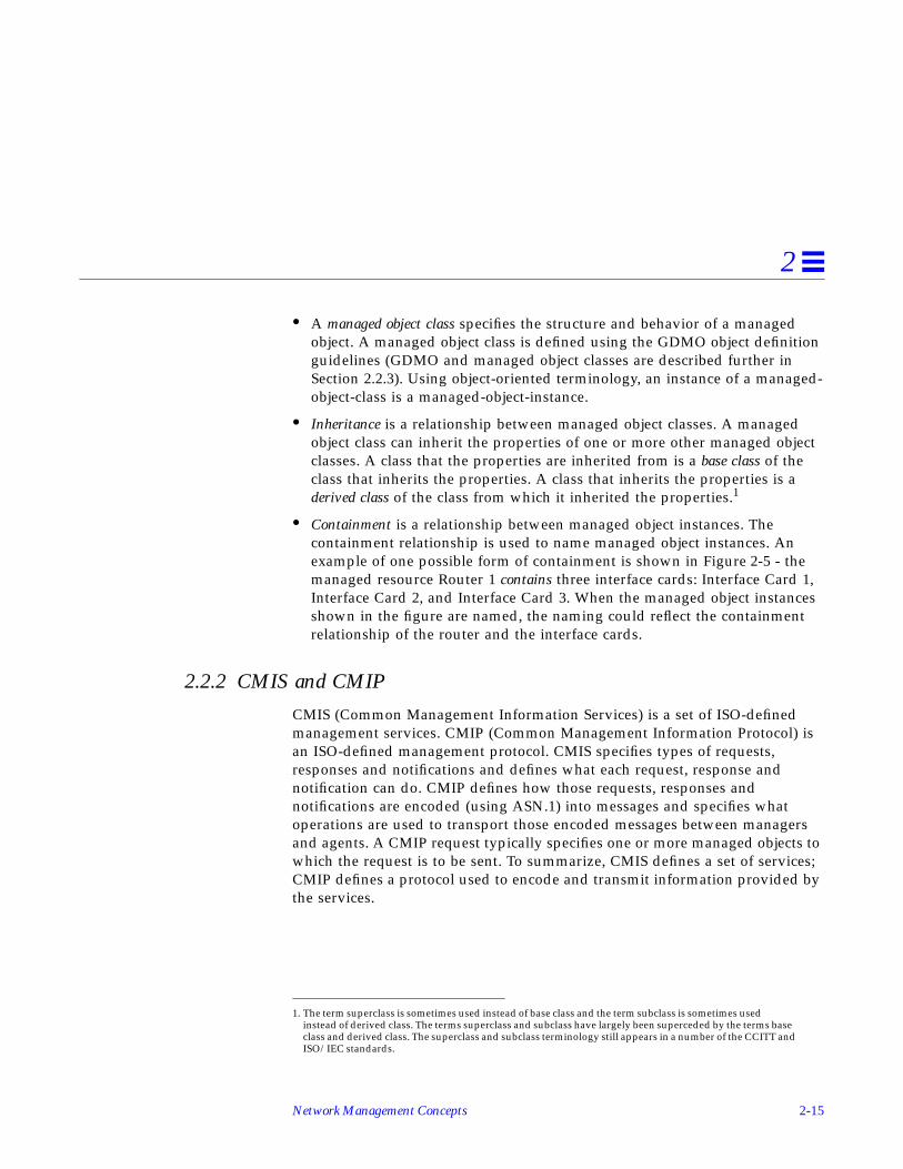
• A managed object class specifies the structure and behavior of a managedobject. A managed object class is defined using the GDMO object definitionguidelines (GDMO and managed object classes are described further inSection 2.2.3). Using object-oriented terminology, an instance of a managed-object-class is a managed-object-instance.
• Inheritance is a relationship between managed object classes. A managedobject class can inherit the properties of one or more other managed objectclasses. A class that the properties are inherited from is a base class of theclass that inherits the properties. A class that inherits the properties is aderived class of the class from which it inherited the properties.1
• Containment is a relationship between managed object instances. Thecontainment relationship is used to name managed object instances. Anexample of one possible form of containment is shown in Figure 2-5 - themanaged resource Router 1 contains three interface cards: Interface Card 1,Interface Card 2, and Interface Card 3. When the managed object instancesshown in the figure are named, the naming could reflect the containmentrelationship of the router and the interface cards.
2.2.2 CMIS and CMIP
CMIS (Common Management Information Services) is a set of ISO-definedmanagement services. CMIP (Common Management Information Protocol) isan ISO-defined management protocol. CMIS specifies types of requests,responses and notifications and defines what each request, response andnotification can do. CMIP defines how those requests, responses andnotifications are encoded (using ASN.1) into messages and specifies whatoperations are used to transport those encoded messages between managersand agents. A CMIP request typically specifies one or more managed objects towhich the request is to be sent. To summarize, CMIS defines a set of services;CMIP defines a protocol used to encode and transmit information provided bythe services.
1. The term superclass is sometimes used instead of base class and the term subclass is sometimes usedinstead of derived class. The terms superclass and subclass have largely been superceded by the terms baseclass and derived class. The superclass and subclass terminology still appears in a number of the CCITT andISO/IEC standards.

2-16 Solstice Enterprise Manager Application Development Guide
2
2.2.2.1 CMIS Services and CMIP Messages
CMIS defines several management services. All of the CMIS services supportconfirmed request operations, and several also support unconfirmedoperations. Confirmed request operations always require a response, regardlessof the success or failure of the operation. Unconfirmed request operations neverreceive responses.
The CMIS specifications define the services listed in Table 2-2:
Table 2-2 CMIS Services
Service Description Operations
M-Get Used by a manager to requestinformation from an agent
Confirmed only
M-Cancel-Get Used by a manager to requestcancellation of a previously requested M-Get operation. M-Cancel-Get is typicallyused to cancel M-Get requests whichspecify scoping and filtering and expectmultiple responses.
Confirmed only
M-Set Used by a manager to request that anagent set attribute values of a managedobject to specific values
Confirmed orunconfirmed
M-Create Used by a manager to request that anagent create a managed object
Confirmed only
M-Delete Used by a manager to request that anagent delete one or more managedobjects
Confirmed only
M-Action Used by a manager to request that anagent invoke a specific behaviorsupported by a managed object
Confirmed orunconfirmed
M-Event-Report Notification used by an agent to sendinformation to a manager
Confirmed orunconfirmed

Network Management Concepts 2-17
2
Each CMIS service defines several CMIS primitives which map into CMIPmessages or protocol data units (PDUs). Table 2-3 lists the mappings between theCMIS services, the CMIS primitives, and the CMIP messages.
Table 2-3 CMIS Services, CMIS Primitives, And CMIP Messages
CMIS Service CMIS Primitive CMIP Message Type
M-Get M-Get Request m-Get request PDU
M-Get Response m-Linked-Reply response PDU
m-Get response PDU
M-Cancel-Get M-Cancel-Get request m-Cancel-Get-Confirmed request PDU
M-Cancel-Getresponse
m-Cancel-Get-Confirmed response PDU
M-Set M-Set Request m-Set request PDU
m-Set-Confirmed request PDU
M-Set Response m-Linked-Reply response PDU
m-Set response PDU
M-Create M-Create Request m-Create request PDU
M-Create Response m-Create response PDU
M-Delete M-Delete Request m-Delete request PDU
M-Delete Response m-Linked-Reply response PDU
m-Delete response PDU
M-Action M-Action Request m-Action request PDU
m-Action-Confirmed request PDU
M-Action Response m-Linked-Reply response PDU
m-Action response PDU
M-Event-Report M-Event-ReportRequest
m-Event-Report request PDU
m-Event-Report-Confirmed request PDU
M-Event-ReportResponse
m-Event-Report response PDU

2-18 Solstice Enterprise Manager Application Development Guide
2
Table 2-3 does not list the error response messages that could result from eachrequest or response operation. For a complete list of CMIS errors by type ofservice and for the complete list of CMIP messages and message formats, referto the CCITT X.710 ISO/IEC 9595 and CCITT X.711 ISO/IEC 9596-1specifications.
2.2.2.2 CMIS Functional Units
CMIS specifies services that managers and agents can support. However,managers and agents are not required to support all the services defined byCMIS. CMIS also defines a set of functional units that specify which CMISservices a manager or agent supports. When an ISO manager and an ISO agentfirst establish communication with each other, they agree on what types ofservices (as defined by functional units) can be used over the communicationpath between them. You do not need to worry about functional units in order todevelop Solstice EM solutions. However, the concepts presented the CMIS functionalunits are important to understand. CMIS defines the following functional units,most of which EM supports:
1. The multipleObjectSelection functional unit pertains to CMIS requests thatspecify scoping. Scoping is a mechanism that allows a single request to befanned out to several different managed objects. The fanned out request willresult in a response being generated by each managed object that receivesthe request (see multipleReply below). Support for multipleObjectSelectionis optional for ISO managers and agents. If a manager or agent supportsmultipleObjectSelection, the manager or agent must also supportmultipleReply. Solstice EM supports multipleObjectSelection in bothmanager and agent roles.
2. The multipleReply functional unit pertains to responses. A request thatuses scoping (see multipleObjectSelection above) can result in multipleresponses. The multipleReply functional unit specifies that an identifier fieldin each of the multiple responses, called the linked identifier, will indicatewhether or not any response is the last response. Support for multipleReplyis optional for ISO managers and agents. If a manager or agent supportsmultipleReply, the manager or agent must also supportmultipleObjectSelection. Solstice EM supports multipleReply in bothmanager and agent roles.

Network Management Concepts 2-19
2
3. The filter functional unit pertains to CMIS requests that specify a test to beapplied to a managed object before the request is carried out. If the test issuccessful, the request is performed. If the test fails, the request is notperformed for that managed object. A filter is almost always used in arequest that also uses scoping. Support for the filter functional unit isoptional for ISO managers and agents. Solstice EM supports the filterfunctional unit in both manager and agent roles.
4. The kernel functional unit specifies support for the following CMIS request,response and notification services: M-Event-Report; M-Get, M-Set, M-Action, M-Create; and M-Delete. All ISO managers and agents (includingSolstice EM) are required to support the kernel functional unit.
5. The confirmedCancelGet functional unit specifies support for the M-Cancel-Get CMIS service. Support for the confirmedCancelGet functional unit isoptional for ISO managers and agents. Solstice EM supportsconfirmedCancelGet in the manager role and provides limited support inthe agent role.
6. Solstice EM does not support the extendedService1 functional unit and youdo not need to worry about it to develop an application. For moreinformation, refer to the CMIS specification (CCITT X.710 ISO 9595) and thespecifications for the ISO communication model (CCITT X.200, X.210, andX.216).
2.2.3 Guidelines for the Definition of Managed Objects (GDMO)
This section is an introduction to GDMO and is not a comprehensive overview.The information included here is intended to explain enough so that you canlook at a GDMO managed object class definition and have a basicunderstanding of the information the object class definition is specifying. Forcomplete information about GDMO, refer to the following specification: CCITTX.722 ISO /IEC 10165-4, The Guidelines for the Definition of Managed Objects.
1. The ISO communication model defines seven different protocol layers. Each layer in this model exchangesinformation with the layer below it. The top layer in the ISO model is the application layer. In this modelCMIP is in the application layer. The layer just below the application layer is the presentation layer. CMIPrequests, responses, and notifications are packaged into P-Data wrappers provided by the presentationlayer. In addition to providing P-Data wrappers, the presentation layer also provides additional services.The extendedService functional unit indicates that these additional services are available for use.

2-20 Solstice Enterprise Manager Application Development Guide
2
2.2.3.1 GDMO Templates
The GDMO guidelines provide templates for defining managed object classesand their supporting constructs (also referred to as supporting productions).The managed object classes defined using GDMO allow agents to describe whatinformation and services they provide in a format that can be understood andused by a manager. GDMO is used to define the following information formanaged object classes:
• Attributes or types of data supported by the managed object class• Operations or actions supported by the managed object class• Behavior exhibited by the managed object• Notifications or the types of unsolicited information a managed object can
generate and send to a manager
GDMO is based on an object-oriented model and uses object-oriented conceptsincluding classes, instances, inheritance, constructors, destructors, attributes,and actions.
The are two basic GDMO templates:
• The MANAGED OBJECT CLASS template is used to define managed objectclasses.
• The NAME BINDING template is used to define name bindings, whichspecify containment for managed objects.
GDMO also defines several other templates that both the MANAGED OBJECTCLASS and NAME BINDING templates directly or indirectly reference.
2.2.3.2 Managed Object Class Template
The format of the MANAGED OBJECT CLASS template is:
<class-label> MANAGED OBJECT CLASS[DERIVED FROM <class-label> [,<class-label>]*;]
[CHARACTERIZED BY<package-label> [,<package-label>]*;]

Network Management Concepts 2-21
2
The capitalized words are GDMO keywords, the words in < > bracketsrepresent information that is filled in when a class is defined, and any item insquare braces represents an optional value. A closing square brace followed byan asterisk indicates that the item enclosed in braces may be repeated zero ormore times. The meaning of each clause or parameter in the above template isshown in Table 2-4.
[CONDITIONAL PACKAGES<package-label> PRESENT IFcondition-definition[,<package-label> PRESENT IF
condition-definition]*;]
REGISTERED AS object-identifier;
Table 2-4 MANAGED OBJECT CLASS Template Definitions
Item Description
<class-label> This label specifies the name of the GDMOmanaged object class. The REGISTERED ASclause in the template is used to associate aunique object identifier with this label.
MANAGED OBJECT CLASS This clause identifies the template as a definitionfor a GDMO managed object class.
DERIVED FROM <class-label> This clause identifies other GDMO managedobject classes that are base classes of the managedobject class being defined. The <class-label>parameters contain the names of the base classes.
CHARACTERIZED BY This clause identifies the packages that themanaged object class supports. A package definesa set of behaviors, attributes, operations, andnotifications.
<package-label> This label identifies the name of a GDMOpackage.
[CONDITIONAL PACKAGES This clause identifies any packages that areconditionally supported by the managed objectclass. Conditional packages will be included in amanaged object instance if the conditionsspecified by the PRESENT-IF clause are true.

2-22 Solstice Enterprise Manager Application Development Guide
2
The other templates referenced directly or indirectly by the MANAGEDOBJECT CLASS template are:
• PACKAGE• PARAMETER• ATTRIBUTE• ATTRIBUTE GROUP• BEHAVIOUR• ACTION• NOTIFICATION
2.2.3.3 Name Binding Template
The format of the NAME BINDING template is:
<package-label> PRESENT IF This clause identifies the condition-definitionsthat must be true in order for a conditionalpackage to be included in a managed objectinstance.
condition-definition This specifies a condition. If this condition is true,the conditional packages identified by theCONDITIONAL PACKAGES clause will beincluded in a managed object instance when it isinstantiated (i.e., created).
REGISTERED AS This clause identifies the globally unique nameassigned to the GDMO managed object class.
object-identifier This parameter is replaced with the name of theOBJECT IDENTIFIER that is used to globally anduniquely identify the GDMO name binding.
<name-binding-label> NAME BINDINGSUBORDINATE OBJECT CLASS<class-label> [AND SUBCLASSES];NAMED BYSUPERIOR OBJECT CLASS<class-label> [AND SUBCLASSES];WITH ATTRIBUTE <attribute-label>;
Table 2-4 MANAGED OBJECT CLASS Template Definitions
Item Description

Network Management Concepts 2-23
2
The capitalized words are GDMO keywords, the words in < > bracketsrepresent information that is filled in when a class is defined, and any item insquare braces represents an optional value. A closing square brace followed byan asterisk indicates that the item enclosed in braces may be repeated zero ormore times.
[BEHAVIOUR <behaviour-definition-label>[,<behaviour-definition-label>]*;
]
[CREATE [create-modifier[,create-modifier]][<parameter-label>]*;
]
[DELETE [delete-modifier][<parameter-label>]*;
]
REGISTERED AS object-identifier;

2-24 Solstice Enterprise Manager Application Development Guide
2
The meaning of each clause or parameter from the NAME BINDING templateis shown in Table 2-5.
Table 2-5 Name Binding Template Definitions
Item Description
<name-binding-label> This label specifies the name of the GDMO namebinding. The REGISTERED AS clause in thetemplate is used to associate a unique objectidentifier with this label.
SUBORDINATE OBJECT CLASS<class-label> [ANDSUBCLASSES]
This clause identifies a GDMO managed objectclass whose instances can be named using aninstance of the GDMO managed object classspecified in the NAMED BY SUPERIOR OBJECTCLASS clause.
The <class-label> subclause identifies thesubordinate GDMO managed object class.
The AND SUBCLASSES subclause, if included,specifies that instances of a derived class of thesubordinate class can also be named using aninstance of the class specified in the NAMED BYSUPERIOR OBJECT CLASS clause.
NAMED BY SUPERIOR OBJECTCLASS <class-label> [ANDSUBCLASSES]
This clause identifies a GDMO managed objectclass whose instances can be used to name aninstance of the GDMO managed object classspecified in the SUBORDINATE OBJECT CLASSclause.
The <class-label> subclause identifies the superiorGDMO managed object class.
The AND SUBCLASSES subclause, if included,specifies that instances of a derived class of thesuperior class can also be used to name aninstance of the class specified in theSUBORDINATE OBJECT CLASS clause.

Network Management Concepts 2-25
2
WITH ATTRIBUTE <attribute-label>
This clause identifies the attribute that will beused to form the relative distinguished name(RDN) of an instance of the managed object classspecified in the SUBORDINATE OBJECT CLASSclause. (Refer to Section 2.2.6.3 for a description ofrelative distinguished names.)
This <attribute-label> identifies the attribute usedto form the RDN for an instance of the object classspecified by the SUBORDINATE OBJECT CLASSclause.
BEHAVIOUR <behaviour-definition-label>
This construct is used to specify any behaviorimpact that results specifically due to the use ofthe name binding.
The <behaviour-definition-label> identifies thebehavior definition.
CREATE This clause specifies that an instance of managedobject specified by the SUBORDINATE OBJECTCLASS clause can be created using a managementoperation (normally a CMIP m-Create operation).
create-modifier This subclause is used to specify permittedoptions for an m-Create operation. The optionsare:WITH-REFERENCE-OBJECT, which specifies thata reference object may be specified in an m-Createoperation; andWITH-AUTOMATIC-INSTANCE-NAMING,which specifies that the object instance name canbe omitted from the m-Create operation.
<parameter-label> This clause is used to identify name binding errorparameters associated with the create or deleteoperations.
DELETE This clause specifies that an instance of managedobject specified by the SUBORDINATE OBJECTCLASS clause can be deleted using a managementoperation (normally a CMIP m-Delete operation).
Table 2-5 Name Binding Template Definitions
Item Description

2-26 Solstice Enterprise Manager Application Development Guide
2
The NAME BINDING template references only one other template:ATTRIBUTE
2.2.3.4 Additional GDMO Templates
Section 2.2.3.2 and Section 2.2.3.3 provided an overview of two GDMOtemplates. This section briefly describes the remaining GDMO templates:
• The PACKAGE template is used to define a combination of behaviordefinitions, attributes, attributes groups, operations, notifications, andparameters for subsequent inclusion in a MANAGED OBJECT CLASStemplate. A package can be referenced by more than one managed objectclass definition.
• The PARAMETER template is used to define parameter syntaxes forsubsequent inclusion in PACKAGE, ATTRIBUTE, ACTION, andNOTIFICATION templates. A parameter can be referenced by one or moreof each of the four templates.
delete-modifier This subclause is used to specify behaviors for amanaged object instance when the instance isdeleted. The options are:ONLY-IF-NO-CONTAINED-OBJECTS, whichspecifies that a delete operation will fail andreturn an error if there are any containedmanaged object instances under the instancebeing deleted; andDELETES-CONTAINED-OBJECTS, whichspecifies that a delete operation will fail andreturn an error if any of the managed objectinstances directly or indirectly under the instancebeing deleted are subject to the ONLY-IF-NO-CONTAINED-OBJECTS delete modifier.
REGISTERED AS This clause identifies the globally unique nameassigned to the GDMO managed object class.
object-identifier This parameter is replaced with the name of theOBJECT IDENTIFIER that is used to globally anduniquely identify the GDMO managed objectclass.
Table 2-5 Name Binding Template Definitions
Item Description

Network Management Concepts 2-27
2
• The ATTRIBUTE template is used to define attributes used by GDMOclasses. A single attribute can be referenced by more than one managedobject class definition.
• The ATTRIBUTE GROUP template is used to define a one or more attributesthat can be referenced as a group. A managed object class definition caninclude all attributes of a group by referencing the group, rather thanreferencing each attribute individually. An attribute group can be referencedby more than one managed object class definition.
• The BEHAVIOUR template is used to describe the expected behavior for oneor more operations supported by a managed object class.
• The ACTION template is used to define actions that can be performed by amanaged object class. The action template defines actions that areperformed using the CMIS m-Action service, and does not include actionsor behaviors defined for other CMIS services, such as m-Get, m-Set, etc. Anaction can be referenced by more than one managed object class.
• The NOTIFICATION template is used to define notifications that can beemitted by a managed object class. A notification can be referenced by morethan one managed object class.
For more information about these templates, refer to the GDMO specification(CCITT X.722 ISO/IEC 10165-4).
2.2.3.5 Definition of Management Information (DMI)
The CCITT X.721 ISO/IEC 10165-2 Definition of Management Information(DMI) defines several managed object classes, name bindings, andcorresponding support constructs. The managed object classes defined in theDMI are base classes for defining other managed object classes (using theDERIVED FROM clause) or are required in order to support the systemmanagement functions defined in the CCITT X.730 ISO/IEC 10164-1 throughCCITT X.736 ISO/IEC 10164-7.
One of the managed object classes defined by the DMI is top. The managedobject class top is base class for every other managed object class defined forISO systems management and cannot be instantiated directly. The definition oftop includes two attributes: objectClass and nameBinding. The definition fortop conditionally includes two additional attributes: packages (in thepackagesPackage PACKAGE) and allomorphs (in the allomorphicPackage).This means that every managed object class supports the objectClass and

2-28 Solstice Enterprise Manager Application Development Guide
2
nameBinding attributes and that every managed object instance is capable ofresponding to M-Get requests asking for the objectClass and nameBindinginformation. The conditional information in top also means that managedobject instances might also provide a list of supported packages andallomorphic behaviors.
The managed object classes defined in the DMI are as follows:
• alarmRecord
• attributeValueChangeRecord
• discriminator
• eventForwardingDiscriminator
• eventLogRecord
• log
• logRecord
• objectCreationRecord
• objectDeletionRecord
• relationshipChangeRecord
• securityAlarmReportRecord
• stateChangeRecord
• system
• top
2.2.4 Object Class Inheritance Tree
The Object Class Inheritance Tree represents inheritance relationships betweenmanaged object classes. A managed object class that inherits the properties ofanother managed object class gains or includes the attributes, behaviors,operations, and notifications defined for the other managed object class. Theclass that inherits the properties is the derived class. The class from which theproperties are inherited is the base class. This type of relationship is sometimesreferred to as an is-a relationship because the derived class is a base class. Forexample, a discriminator is-a top, because it supports all the propertiessupported by top.

Network Management Concepts 2-29
2
The base class is sometimes referred to as a superclass and the derived class issometimes referred to as a subclass. The superclass and subclass terminologyhas largely been replaced by the base-class and derived-class terminology butstill appears in some standards specifications.
In the GDMO MANAGED OBJECT CLASS template, the DERIVED FROMclause is used to specify direct base classes. All GDMO object classes are adirect or indirect derived class of the managed object class, top, defined by theISO DMI. An indirect base class would be a base-class of a base-class. Anexample showing the structure of the Object Class Inheritance Tree is shown inFigure 2-6:
Figure 2-6 Object Class Inheritance Tree
top Indirect Base Class
Base Class
Indirect Derived Class
of Object Class Y
of Object Class X(and of top)
X
Y
Z
Derived Class
KEY:
Managed-Object Class
“is-a”relationship

2-30 Solstice Enterprise Manager Application Development Guide
2
The Managed Object Class Inheritance hierarchy for the ISO DMI is shown inFigure 2-7:
Figure 2-7 ISO DMI Object Class Inheritance Tree
2.2.5 Object Identifier (Registration) Tree
The Object Identifier Tree contains nodes labeled using nonnegative integervalues and a text label. Refer to Section 2.1.2.5 for more details and an exampleObject Identifier Tree.
In review, the top of this tree is called root. There are three labeled nodes underroot which are administered by the ISO and CCITT standards organizations.There are in turn sub-nodes under the three ISO and CCITT nodes some ofwhich are administered by other organizations. A unique label can be formedfor any node in the tree by concatenating the name of each node in the tree,starting at root, and proceeding down the tree to a node in the tree. The labelformed using this method is an OBJECT IDENTIFIER.
Note – Do not confuse the root of the Object Identifier Tree with the root of theManagement Information Tree (MIT) described in Section 2.2.6.2. They areseparate entities, although both have the same name.
top
discriminator log
eventForwarding-Discriminator
logRecord system
eventLogRecord
alarmRecord attributeValue-ChangeRecord
objectCreation-Record
objectDeletion-Record
securityAlarm-ReportRecord
relationship-ChangeRecord
stateChange-Record

Network Management Concepts 2-31
2
2.2.6 Management Information Tree and Containment
To understand Solstice EM and develop Solstice EM solutions, you need tounderstand the concepts of containment and the Management InformationTree. The concepts are simple, but are used in so many ways and underlie somany things that the concepts can seem confusing. In addition to theinformation presented here, CCITT X.720 ISO/IEC 10165-1 contains a sectiontitled “Principles of containment and naming” which provides a goodoverview of containment and the MIT. It is strongly recommended that youalso review the information in that section of the specification.
In addition to the concepts of containment the Management Information Tree(MIT), this section will also cover the following related concepts:
• Managed object instance naming• Attribute Value Assertion (AVA)• Relative Distinguished Name (RDN)• Distinguished Name (DN) or Fully Distinguished Name (FDN)• Local Distinguished Names (LDN)• Human readable name forms• Encoded name form
• Scoping and multiple replies• Filtering
2.2.6.1 Containment
The following description of containment is from CCITT X.721 ISO/IEC10165-1:
A managed object of one class can contain other managed objects of thesame or different class. This relationship is called containment. Thiscontainment relationship is a relationship between managed objectinstances, not classes. A managed object is contained within one and only onecontaining managed object. Containing managed objects may themselves becontained in another managed object.
The containment relationship is capable of reflecting a real-world (or physical)hierarchy of relationships between resources. The following are two examplesof real-world containment hierarchies:

2-32 Solstice Enterprise Manager Application Development Guide
2
• A computer system contains a disk drive, the disk drive contains a filesystem, the file system contains one or more directories, a directory containsone or more files, and so on.
• A network contains a router and the router contains three interface cards.
The containment relationship can also reflect behavioral relationships betweencomponents. For instance, if the computer system in the previous example isdown for any reason, it would not be possible to access the disk drivecontained in the computer system or any of the files contained on the drive.
The preceding examples reflect real-world containment relationships andprovide a good means to represent the concept of containment. For ISOmanagement purposes however, containment is not restricted to reflecting physicalcontainment of one managed resource in another.
2.2.6.2 Management Information Tree (MIT)
The containment relationship is used for naming managed object instances.Object instances that are named in the context of another object are subordinateobject instances of that object. The object instance that establishes the namingcontext is the superior object instance. Superior object instance and subordinateobject instance are synonymous with superior object and subordinate object,respectively.
Note – Do not confuse the terms superior object and subordinate object withthe terms superior object class (base class or “superclass”) and subordinateobject class (derived class or “subclass”). The former refers to object instances,the latter refers to object classes.
A subordinate object instance is named by a combination of the following:
• The name of its superior object
• The name (identifier) and value of one of the subordinate object’s attributes.This attribute is known as the naming attribute. The naming attribute andits value must produce a name that is unambiguous relative to the superiorobject.
A superior object instance is named in the same way relative to its superior,producing a hierarchy of named managed object instances. This hierarchy isthe Management Information Tree (MIT), sometimes referred to as the naming

Network Management Concepts 2-33
2
tree. An example MIT is shown in Figure 2-8. The figure also shows an objectinstance name (a distinguished name). Object instance names and naming isdescribed in the next section.
Figure 2-8 Management Information Tree (MIT)
The top of the MIT is root. Root is never instantiated as a managed object (inother words, root is a null object representing a conceptual starting point forthe MIT). The name of a managed object subordinate to root is the namingattribute and value of the subordinate object.
Note – Do not confuse the MIT root, with the root in the Object Identifier tree.Although neither root has a physical representation, the two roots are separate(conceptual) entities.
The concept of containment and the MIT imply the following for managedobjects:
• A managed object instance can only exist if its superior managed objectinstance exists.
• Every managed object instance has a name, which is derived from where anobject instance resides in the MIT.
root
A1=BA1=A
A1=CA2=D
A2=EA2=F
A2=G
A3=H A2=DA3=J
AttributeName
AttributeValue
Object Instance Name: { A1=B.A2=F.A3=J }
Superior
Subordinate
ContainmentRelationships

2-34 Solstice Enterprise Manager Application Development Guide
2
2.2.6.3 Managed Object Instance Naming
As stated previously, a managed object is named using the name of an attributeof the object and the value of that attribute. A name binding is used to specifythe attribute that is used for naming (See Section 2.2.3.3, “Name BindingTemplate”). The attribute identifier specified in the name binding is theattribute used for the naming attribute in the MIT. The name binding alsospecifies a superior object class and a subordinate object class. The superior andsubordinate object classes in the name binding dictate which object classeshave instances that can contain instances of another object class. (Thecontainment relationship is object class based not object instance based. Thatmeans an instance of class X can be created as a subordinate to an instance ofclass Y only if a name binding exists that specifies that class X can be asubordinate class to class Y (superior class). If that name binding exists, thenwhen the instance of class X is created it will be named using the attributeidentifier specified in the WITH ATTRIBUTE clause of the name binding andthat attribute’s value.)
The following name binding is provided as an example:
For the above example, we assume that a managed object class exampleClasshas been previously defined and that one of the properties specified for theclass is an attribute named objectName. We will further assume that theattribute exampleID is registered as 0.1.2.3.4.5.6 and is defined as being anASN.1 INTEGER.
The example name binding dictates that instances of the managed object classexampleClass can be created under system (system is defined in the ISO DMI)using exampleID as the naming attribute. Furthermore, if this is the only namebinding that exists for exampleClass (i.e., no other naming possibilities exist), itwould mean that instances of exampleClass can only be created under system.
exampleNameBinding1 NAME BINDINGSUBORDINATE OBJECT CLASS exampleClass ;NAMED BY SUPERIOR OBJECT CLASSsystem ;WITH ATTRIBUTE exampleID ;
REGISTERED AS { 0 1 2 3 4 1 } ;

Network Management Concepts 2-35
2
If additional name bindings exist for a class for a subordinate class, they canspecify other superior classes and different naming attributes. An example of asecond name binding is as follows:
This second name binding specifies that instances of exampleClass can becreated under root, and those instances will be named using exampleID. Thenaming attribute is specified in a name binding is left to the name bindingdesigner, subject to the need for an unambiguous identifier relative to thesuperior object class. A naming attribute other than exampleID could just aseasily been used in this second name binding example.
Attribute Value Assertions (AVA)The combination of an attribute identifier and its value is known as anattribute value assertion (AVA)1. An attribute identifier is an OBJECTIDENTIFIER (OID) that has been registered for a particular attribute. Part ofthe information registered for an attribute also specifies what type of data theattribute contains (such as INTEGER, REAL, or other datatype). Taking this astep further and looking at the encoding rules for an AVA we will see that anAVA is defined as a SEQUENCE containing an attribute identifier (an OID)followed by whatever type of data was specified for that attribute. Theexample name bindings in the previous section specified a naming attributecalled exampleID (which was type INTEGER). If we specify a value for thisattribute, we can produce the following human-readable form of the AVA:
1. To be precise, an attribute value assertion is a statement, which may be true or false, concerning the value ofan attribute. If an object instance is created and it has an INTEGER attribute named exampleID that has thevalue 10, we are basically asserting the exampleID=10 is indeed a true statement for the object instancecreated.
exampleNameBinding2 NAME BINDINGSUBORDINATE OBJECT CLASS exampleClass ;NAMED BY SUPERIOR OBJECT CLASSroot ;WITH ATTRIBUTE exampleID ;
REGISTERED AS { 0 1 2 3 4 2 } ;
exampleID=10

2-36 Solstice Enterprise Manager Application Development Guide
2
that would be encoded as shown in Figure 2-9:
Figure 2-9 Attribute Value Assertion ASN.1 BER Encoding
An AVA is only part of the construct that forms the name of a managed objectinstance. An AVA exists for every attribute of a managed object instance. Theconstruct that forms the managed object name is the relative distinguishedname, which is covered in the following section. The syntax for an attributevalue assertion is imported from the ISO directory services and is as follows(the syntax is also be listed in Annex G of CCITT X.721 ISO/IEC 10165-2):
Relative Distinguished Name (RDN)A relative distinguished name (RDN) identifies a managed object instance. TheRDN when joined with the name of the superior object instance provides aunique name for a managed object within the MIT. The RDN by itself must beunique within the context of its superior object instance. The human readableform of the RDN for the example object used previously is:
AttributeValueAssertion ::=SEQUENCE { AttributeType, AttributeValue}
AttributeType ::= OBJECT IDENTIFIERAttributeValue ::= ANY
exampleID=10
U6 6 0.1.2.3.4.5.6T L V T L V
U2 1 0A16SEQU16
T L V
exampleID 10
OID INTEGER

Network Management Concepts 2-37
2
which is the same as the AVA in the preceding section. The encoding for theRDN and the syntax definition differ from an AVA which can be seen inFigure 2-10. The encoding specifies a SET OF Attribute Value Assertions.
Figure 2-10 Relative Distinguished Name (RDN) ASN.1 BER
However, Relative Distinguished Names only use a single AVA (which is thereason the human readable forms look alike). This encoding is by conventionand is not an actual restriction in the standards. The single AVA approachsimplifies the processing and formation of RDNs while still allowing the RDNto match the format of an X.500 directory services name. The syntax for arelative distinguished name is imported from the ISO directory services and isas follows (the syntax is also be listed in Annex G of CCITT X.721 ISO/IEC10165-2):
Distinguished Name (DN) or Fully Distinguished Name (FDN)The distinguished name(DN) of a managed object instance is formed from theconcatenation of the RDNs in the MIT from root to the managed objectinstance. The distinguished name is frequently referred to as the fullydistinguished name (FDN). An example of a distinguished name would be:
RelativeDistinguishedName ::= SET OF AttributeValueAssertion
systemId=acid.exampleID=10
T L V
OID Specified ValueT L V
U6 OID
T L V
SET OFu17
T L V
SEQu16
AVA

2-38 Solstice Enterprise Manager Application Development Guide
2
In the above example, two RDNs are concatenated to form the distinguishedname shown. Distinguished names are encoded as shown in Figure 2-11:
Figure 2-11 Distinguished Name ASN.1 BER Encoding
The syntax for a distinguished name is imported from the ISO directoryservices and is as follows (the syntax is also be listed in Annex G of CCITTX.721 ISO/IEC 10165-2):
Distinguished names are used to name managed object instances. The syntaxfor a managed object instance is as follows:
DistinguishedName ::= RDNSequenceRDNSequence ::= SEQUENCE OF RelativeDistinguishedName
ObjectInstance ::= CHOICE {distinguishedName[2]IMPLICIT DistinguishedName,nonSpecificForm[3]IMPLICIT OCTET STRING,localDistinguishedName[4]IMPLICIT RDNSequence
}
T L V
OID Specified ValueT L V
U6 OID
T L V
SET OFu17
T L V
SEQu16
SEQu16
T L V
T L
SET OFu17
T L V
SEQu16
AVA*
RDN1
DN (FDN)
RDN2
*Only a single AVA is used for an RDN (this is by convention, not specified in the standards). The above format is identical toX.500 names, although X.500 names may use multiple AVAs for a single RDN.

Network Management Concepts 2-39
2
Distinguished names are used for the first form (context-specific tag 2). Thesecond form, nonSpecificForm (context-specific tag 3) is not used an can beignored. The third form, local distinguished name (context-specific tag 4) isdescribed in the following section.
Human Readable Distinguished Name FormsSolstice EM frequently uses either a “slash” representation or “curly braces”representation for distinguished names (object instance names) and relativedistinguished names.
• The curly braces representation is based on the ASN.1 syntax definition fora distinguished name. The curly braces form forsystemId=acid.example=10 is:
• The slash representation is a simpler form defined for use by Solstice EMand is as follows:
EM also provides a number of C++ classes and functions for encodingdistinguished names and supporting constructs.
Local Distinguished Name (LDN)A local distinguished name is an object instance name that is relative to a nodein the MIT other than root. Fully distinguished names are always relative toroot, a local distinguished name is relative to another node. This other node issometimes referred to as the local root. The following slash representation is afully distinguished name for a managed object:
{ { { systemID, “acid ” } }, { { exampleID, 10 } } }
/systemId=name: ”acid ” /exampleID=10
/systemId=name: ”host1 ” /systemId=name: ”hub1 ” /exampleID=10

2-40 Solstice Enterprise Manager Application Development Guide
2
The following slash form is a local distinguished name for the same managedobject:
The local distinguished name is relative to systemId=name:”hub1” (i.e,systemId=name:”hub1” is the local root). Local names are provided due toname handling issues for some agents and managers. In particular some agentscannot understand or work with names that have the entire path from root tothe agent as part of the name. Local distinguished names are provided as amechanism that allows an agent (or manager) to not have to worry aboutunderstanding names that include attributes and values that it knows nothingabout or cannot interpret.
A local distinguished name is used to identify a managed object instance. Aslisted in the section describing FDNs, the syntax for a managed object instanceidentified by a local distinguished name is the third choice in the followingdefinition:
When a local distinguished name is encoded, it is given a context-specific tagof 4, which identifies it as a local distinguished name.
systemId=name: ”hub1 ” /exampleID=10
ObjectInstance ::= CHOICE {distinguishedName[2]IMPLICIT DistinguishedName,nonSpecificForm[3]IMPLICIT OCTET STRING,localDistinguishedName[4]IMPLICIT RDNSequence
}

Network Management Concepts 2-41
2
Distinguished Names and the MITFigure 2-12 shows an example MIT and the naming constructs described in thepreceding sections:
Figure 2-12 MIT Components
2.2.6.4 Scoping, Filtering, and Multiple Replies
A manager can specify scoping and filtering in a CMIP request message.Scoping is used to identify a sub-tree of managed object instances in the MIT.Once a sub-tree has been identified the filter (or test) can be applied to theidentified instances. The instances that pass the test successfully are requestedto perform the management operation specified in the CMIP request message.Finally, each managed object that performed the management operationreturns any required response.
root
systemId=acid
A1=A
A1=C A2=D
exampleID=10
A3=J
ContainmentRelationships
Superior
Subordinate RDN
RDN
RDN
AVA
DNAttributeIdentifier
AttributeValue
systemId=base
systemId=acid
RDN
LDN
2-42 Solstice Enterprise Manager Application Development Guide
2
ScopingA scoping operation always starts from a specified object instance in the MITknown as the base object instance. The name of a base object instance is specifiedin CMIP request messages that support scoping (i.e., m-Get, m-Set, m-Delete,m-Action). Four different types of scoping can be specified. Each type ofscoping identifies a set of managed object instances (subordinate to andincluding the base object instance) in the MIT against which a filter will beapplied. The different types of scope are as follows:
• The base object only. This is the default scope which selects only the baseobject instance specified in the CMIP request. The base object is defined tobe level 0.
• The nth level subordinates of the base object. This selects object instancessubordinate to the base object that are n levels below the base object. Objectinstances directly subordinate to the base object are at level 1. Objectinstances below those objects are at level 2, etc.
• The base object and all subordinates down to the nth level. This selects asubtree that starts with the base object and includes all objects instancessubordinate to the base object down to and including level n.
• The base object and all its subordinates. This selects the base object and allobject instances subordinate to it.

Network Management Concepts 2-43
2
Figure 2-13 shows examples of the four types of scoping. Each type of scopeshown in the example starts from the same base object.
Figure 2-13 Subtrees Selected by Scope
FilteringA filter is used along with scoping to select a set of managed objects which arerequested to perform a management operation. Scoping identifies a subtree ofobjects in the MIT. A filter specifies a test that is to be applied to the managedobjects selected by the scoping operation. If the test is successful, the request isperformed by the managed object. If the test fails, the request is not performed.
A filter can test for a variety of things, such as:
• Is the managed object instance a member of a particular object class?• Does the managed object instance contain a particular attribute?• Does the managed object class contain a particular attribute and does that
attribute have a particular value?
root
base object only
level 2subordinateobjects
base object plussubordinatesdown to level 3
EntireSubtree

2-44 Solstice Enterprise Manager Application Development Guide
2
Multiple RepliesSeveral managed objects are usually selected when scoping and filtering arespecified in a CMIP request. Each managed object that carries out the requestwill return a response to the manager that issued the scoped and filteredrequest. The response sent back by the managed object will be: an errorresponse; a response containing information specified by the request; or a finalresponse. Each response which contains information specified by the request iscalled a linked reply. The linked reply message is used regardless if the originalrequest was an m-Get, m-Set, m-Action or m-Delete request. The final responseis an m-Get response, m-Set response, m-Action, or m-Delete response thatcorresponds to the types of request originally issued by the manager.
A number of different error responses are also possible -- refer to CCITT X.711ISO/IEC 9596-1 for more information about the types of error responses.
2.2.7 ASN.1 and CMIP
ASN.1 is used to encode CMIP requests, responses, and notifications. CMIPdoes not place any restriction on the ASN.1 datatypes that can be used formanagement operations (i.e., see the GDMO and CMIP ANY DEFINED BYclause). CMIP also allows the use of constructed datatypes.
2.3 Internet Network Management ConceptsThis section provides a brief introduction to Internet network management.Key concepts introduced in this section include:
• SNMPv1 Protocol• SNMPv2 Protocol• Concise MIB• SNMPv2 MIB• ISO and Internet Management Coexistence
SNMP relies on a model based on a model using managers and agents. ConciseMIB defines management information for use with the SNMPv1 protocol.SNMPv2 MIB defines management information for use with the SNMPv2protocol. SNMPv1 is used to exchange management information between anSNMPv1 manager and an SNMPv1 agent. SNMPv2 is used to exchange

Network Management Concepts 2-45
2
management information between an SNMPv2 manager and an SNMPv2 agentand also has a provision for exchanging management information between twoSNMPv2 managers.
2.3.1 SNMPv1 Protocol
An SNMPv1 message consists of a version number field, a community namefield, and a data field. The data field can contain any one of five types ofprotocol data units (or PDUs). The first four PDUs in the following list havethe same PDU format. The Trap-PDU has a different format form the otherPDUs. The five SNMPv1 PDUs are as follows:
• GetRequest-PDU
The SNMP get-request is used by a manager to request attribute informationfrom an agent. The agent will typically respond with a get-responsecontaining attribute name-value pairs, called variable bindings. A variablebinding is similar in nature to an ISO attribute value assertion (AVA), whichis also an attribute name-value pair.
• GetNextRequest-PDU
The SNMP get-next request is used by a manager to request sequentialattribute information. It is typically used by the manager to request that anagent read through the rows in a table one row at a time.
• SetRequest-PDU
The SNMP set-request is used by a manager to request that an agent setselected attributes to values specified in the request.
• GetResponse-PDU
The SNMP get-response is used by an agent to return the result of a get-request, a get-next request, or a set-request to a manager. The response foreach of these requests uses the format of the get-response. SNMP version 2simply refers to this operation as a response.
• Trap-PDU
An SNMP trap is used by an agent to send unsolicited information to amanager.

2-46 Solstice Enterprise Manager Application Development Guide
2
Refer to the following RFC for more information about SNMP version 1protocol:
RFC 1157, A Simple Network Management Protocol (SNMP Version 1).
2.3.2 SNMPv2 Protocol
An SNMPv2 message consists of a destination party field and a data field. Thedata field can contain either encrypted or clear text. The data containsauthentication information, the destination party (repeated), the source party, acontext identifier, and a PDU. The PDU can be one of seven types. Five of thetypes are the same as the SNMPv1 PDUs and the trap PDU has been modifiedto also match the other SNMPv2 PDUs. The seven SNMPv2 PDUs are asfollows:
• GetRequest-PDU
The SNMPv2 get-request performs the same service as the SNMPv1 get-request.
• GetNextRequest-PDU
The SNMPv2 get-next-request performs the same service as the SNMPv1get-next-request.
• SetRequest-PDU
The SNMPv2 set-request performs the same service as the SNMPv1 set-request.
• Response-PDU
This PDU performs the same services as the SNMPv1 GetResponse-PDU. Inaddition it is also used as a response to SNMP inform requests.
• snmpV2Trap-PDU
An SNMPv2 trap is used by an agent to send unsolicited information to amanager. The SNMPv2 trap PDU has the same format as the precedingSNMPv2 PDUs.
• InformRequest-PDU
The inform request is used to send information from one SNMPv2 managerto another SNMPv2 manager.

Network Management Concepts 2-47
2
The InformRequest-PDU has the same format as the preceding SNMPv2PDUs.
• GetBulkRequest-PDU
The SNMPv2 get-bulk request is used by a manager to request large blocksof information from an agent.
Refer to the following RFC for more information about SNMP version 2protocol:
RFC 1448, Protocol Operations for version 2 of the Simple NetworkManagement Protocol (SNMPv2)
2.3.3 Concise MIB
Concise MIB provides a set of macros that are used to define managementinformation for SNMPv1. A MIB defined using the Concise MIB format allowsSNMPv1 agents to describe what information and services they provide in aformat that can be understood and used by an SNMPv1 manager. Concise MIBis used to define the following MIB information:
• Attributes or types of data supported by the managed object class• Operations or actions supported by the managed object class• Behavior exhibited by the managed object
The Concise MIB format does not specify SNMP trap formats. Instead aConcise Trap format has been defined to describe traps. SNMP traps are theunsolicited information an SNMPv1 agent can generate and send to a manager(i.e., a notifications).
Refer to the following RFCs for more information about SNMPv1 MIBs andtraps:
• RFC1212, Concise MIB Definitions
• RFC1213, Management Information Base for Network Management ofTCP/IP-based Internets: MIBII
• RFC1215, A Convention for Defining Traps for use with SNMP.

2-48 Solstice Enterprise Manager Application Development Guide
2
2.3.4 SNMPv2 MIB
SNMPv2 MIB provides a set of macros that are used to define managementinformation for SNMPv2. A MIB defined using the SNMPv2 format allowsSNMPv2 agents to describe what information and services they provide in aformat that can be understood and used by an SNMPv2 manager. SNMPv2MIB is used to define the following MIB information:
• Attributes or types of data supported by the managed object class• Operations or actions supported by the managed object class• Behavior exhibited by the managed object• Traps or unsolicited information an SNMPv2 agent can generate and send to
a manager (i.e., a notifications)
Refer to the following RFC for more information about SNMPv2 MIBs:
RFC1442, SNMPv2 Structure Of Management Information (SMI) for version2 of the Simple Network Management Protocol.
2.3.5 ASN.1 and SNMP
SNMPv1 and SNMPv2 support a subset of the ASN.1 datatypes. SNMPv1supports the following ASN.1 datatypes:
• INTEGER
• OCTET STRING
• NULL
• OBJECT IDENTIFIER
• SEQUENCE, SEQUENCE-OF
SNMPv2 supports the same ASN.1 datatypes as SNMPv1 and also addssupport for the following datatype:
• BIT STRING
Both SNMPv1 and SNMPv2 allow the use of constructed types.

Network Management Concepts 2-49
2
2.3.6 ISO and Internet Management Coexistence (IIMC)
The Network Management Forum and X/Open have defined a number ofspecifications that describe how ISO (CMIP and GDMO) network managementand Internet (SNMP and Concise MIB/SNMPv2 MIB) network managementcan coexist. Among other things, these specifications define:
• How to map CMIP requests into SNMP requests• How to map SNMP responses into CMIP responses• How to map SNMP into CMIP event reports• How to map SNMPv1 and SNMPv2 MIBs into GDMO
These mappings allow SNMP version 1 and version 2 agents to be representedas GDMO managed objects.

2-50 Solstice Enterprise Manager Application Development Guide
2

3-1
EM Programming Concepts 3
Solstice EM consists of a Management Information Server (MIS) that serves asa repository of information about the network, and a set of applications (orservices) that use the MIS. Applications running on various workstationscommunicate with a Solstice EM MIS to get information about the network.The MIS plays the role of server to the applications and services that are itsclients. Management functions are distributed between the MIS and its clients.
The Solstice EM development environment provides a set of ApplicationProgramming Interfaces (APIs), including the high-level and low-levelPortable Management Interface (PMI), and other tools that enable a softwaredeveloper to build comprehensive SNMP- and CMIP-based networkmanagement solutions using Solstice EM.
Terminology and Concepts page 3-2
MIS Subcomponents page 3-3
Client Subcomponents page 3-16
Additional Information about Subcomponents page 3-25

3-2 Solstice Enterprise Manager Application Development Guide
3
3.1 Terminology and ConceptsSolstice EM uses several industry recognized terms and concepts and alsointroduces some EM-specific terms. Some of the industry recognized termshave multiple definitions.This section provides specific definitions for thefollowing terms:
• Application
• Client-Server
• Client Subcomponent
• Server Subcomponent
• Object Oriented
• Remote Object
• Local Object
The terms application or PMI application describe a user-developed component(client application) that is linked to and uses the PMI. A PMI application istypically part of a Solstice EM solution, but could also be a complete SolsticeEM solution. The PMI is described in detail in the Solstice Enterprise ManagerAPI Syntax Manual.
The term client-server refers to a distributed architecture, in which a clientapplication accesses information or services provided by a separate serverapplication. The client application can reside on the same workstation as theserver application, or it can be distributed and reside on a different workstation,accessing the server using a network. The Solstice EM MIS is a serverapplication. EM applications, such as the Viewer or the Request Designer, areclient applications.
A client subcomponent is any user-developed or user-configured subcomponentthat is contained in a PMI application. A server subcomponent is any user-developed or user-configured subcomponent that is contained in the MIS.
The term object-oriented refers to a software model that uses objects to definebehavior and data. Object behaviors are sometimes referred to as operations oractions. Data are commonly referred to as attributes. An object class is adefinition — it defines what attributes and behaviors are supported by aparticular type of object. Some of the behaviors defined for a class are typicallyused to read or modify the attributes supported by the object class. An object

EM Programming Concepts 3-3
3
instance is a realization (or instantiation) of the object class definition. Anobject instance will have a value for each attribute defined by the object class.The behaviors defined for the class can be used to access the attribute values.Solstice EM supports object-oriented concepts on three levels:
1. Solstice EM supports the ISO management model and GDMO, both ofwhich are object oriented.
2. Solstice EM uses an internal framework of objects classes and instances tosupport ISO, Internet, SunNet Manager, and other types of managementmodels.
3. Solstice EM has been implemented using C++, which is an object orientedprogramming language.
Within the context of Solstice EM, a remote object (or remote object instance) isany managed object instance that is external to the MIS. The MIS maintains areference to a remote object instance via the MIT, but the object instance isexternal to the MIS. An example of a remote object is a managed objectinstance that is part of an agent that represents a device in your network.
A local object (or local object instance) is any managed object instance that is partof the MIS. The operations supported by the local object are carried out by theMIS process and the attribute values for the local object are stored ormaintained in the MIS or its persistent store. The MIS maintains a reference tothe local object instance in the MIT. Local objects will be described furtherwhen object class definitions with repository behavior are presented.
3.2 MIS SubcomponentsA server subcomponent is a user-configured or user-developed subcomponentthat is contained in the Solstice EM MIS. That means that it is part of the sameUNIX process as the Solstice EM MIS. A server subcomponent or informationfrom a server subcomponent is generally accessible to any PMI applicationprovided the PMI application has proper access permissions. The followingSolstice EM subcomponents are server subcomponents:
• Requests (Nerve Center Engine)
• Event Forwarding Discriminators (EFDs)1
• Log and Log Record Objects
• Object Class Definitions and Name Bindings

3-4 Solstice Enterprise Manager Application Development Guide
3
• Object Class Definitions With Repository Behavior
Figure 3-1 shows the distribution of the MIS subcomponents within the SolsticeEM client-server architecture.
Figure 3-1 Solstice EM Development and Configuration
3.2.1 Requests
Requests are a general purpose mechanism for detecting conditions in anetwork and taking action in response. The conditions in a network aremonitored by a Request using combination of polling and notifications. Whena particular condition is detected a Request can perform one or more actions inresponse to the condition. Each Request is defined by a Request template. ARequest template is a user-configured state diagram that consists of one ormore states, network conditions to test while in a state, transition pathsbetween states, and actions that can be taken when a transition between statesoccurs. Requests are described in greater detail in the Solstice EnterpriseManager Reference Manual. Requests are the most powerful user-configurablesubcomponent available to a solution developer — you do not need to writesoftware in order to use a Request.
1. EFDs can also reside in an agent or in another Solstice EM MIS -- in which case they would be a remoteobject.
RepositoryBehaviors
Solstice EM MISPMI ClientApplication
DBM
HighLevel PMI
xtsched
CommonFunctions &
Classes
EFD
ObjectClass (OC)
OC withbehavior
Log andLog RecordObjects
Nerve CenterRequest

EM Programming Concepts 3-5
3
Note – Do not confuse the Request Templates and Requests with managementprotocol requests, such as an SNMP get request or a CMIP m-Get or m-Setrequest. The Requests described here are used to configure the Solstice EMNerve Center to intelligently manage objects in a network.
What To Use:• Request Designer application
• View results in the Viewer, the Alarm Manager, and the Log Manager
Note – Requests can also log information to the pre-configured (default) logprovided with the MIS.
When To Use:Requests are a general purpose mechanism for detecting conditions in anetwork and taking action in response. There is a variety of conditions inwhich it makes sense to use Requests. The following list provides only a fewexamples:
• Managing devices in your network
This is the most common use for Requests and can range in complexity fromsimply testing a simple up-down state for a device to testing multiple statesfor a device based on availability, performance, and other factors. A singleRequest can be used to monitor multiple devices, including different classesof devices. You can also create specialized Requests which monitor servers,backbone devices, or other mission critical resources in your network.
• Managing a variety of other types of physical or logical devices, processes,or services in your network
Anything that can be represented by a managed object class definition canpotentially be managed by a request.
• Managing network performance
Again this can range in complexity from simple performance to highlyspecialized and tuned performance monitoring. A request could beconfigured to raise an alarm when performance or network loads hitspecified levels.
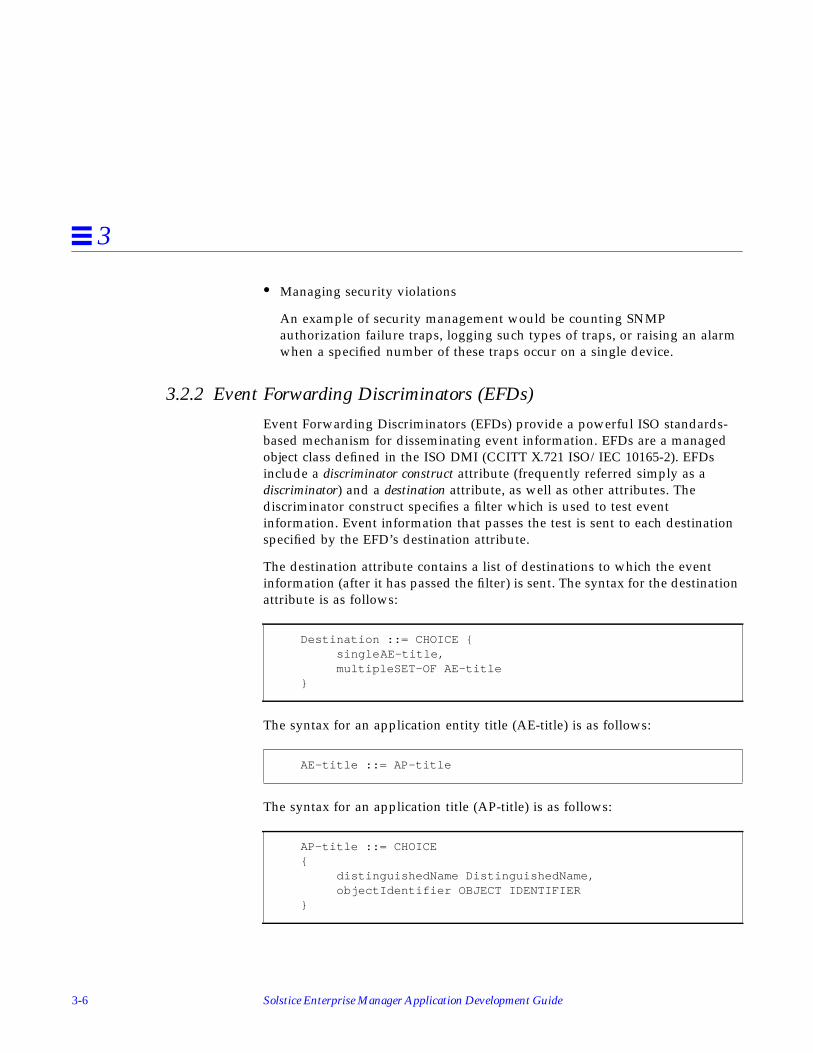
3-6 Solstice Enterprise Manager Application Development Guide
3
• Managing security violations
An example of security management would be counting SNMPauthorization failure traps, logging such types of traps, or raising an alarmwhen a specified number of these traps occur on a single device.
3.2.2 Event Forwarding Discriminators (EFDs)
Event Forwarding Discriminators (EFDs) provide a powerful ISO standards-based mechanism for disseminating event information. EFDs are a managedobject class defined in the ISO DMI (CCITT X.721 ISO/IEC 10165-2). EFDsinclude a discriminator construct attribute (frequently referred simply as adiscriminator) and a destination attribute, as well as other attributes. Thediscriminator construct specifies a filter which is used to test eventinformation. Event information that passes the test is sent to each destinationspecified by the EFD’s destination attribute.
The destination attribute contains a list of destinations to which the eventinformation (after it has passed the filter) is sent. The syntax for the destinationattribute is as follows:
The syntax for an application entity title (AE-title) is as follows:
The syntax for an application title (AP-title) is as follows:
Destination ::= CHOICE { singleAE-title, multipleSET-OF AE-title}
AE-title ::= AP-title
AP-title ::= CHOICE{ distinguishedName DistinguishedName, objectIdentifier OBJECT IDENTIFIER}

EM Programming Concepts 3-7
3
Solstice EM supports both the distinguished name form and the OID form forAP-Titles. However, only the OID form will work with EFDs.
An example of a single destination address using the OID AP-title form ofaddressing is:
An example of multiple destination addresses using the OID AP-title form ofaddressing is:
The syntax for a discriminator construct is as follows:
This is the same syntax as used for filters in CMIP messages. The default filtervalue for an EFD discriminator is:
This default value will cause all event information to match the filter and besent as event reports to all destinations specified in the destination attribute. Itshould be noted that the EFD will only forward event information if the EFD isalso enabled (for example, the value of the administrativeState attribute in theEFD is set to enabled).
What To Use:• CMIP Configuration Utility: em_oct -cmip
• Object Creation Utility: em_objcreate
• EM_SERVER Environment variable
{ 1 2 3 4 }
{ { 1 2 3 4}, { 1 2 3 5 } }
DiscriminatorConstruct ::= CMISFilter
and : {}

3-8 Solstice Enterprise Manager Application Development Guide
3
Note – EFDs can also be created using CMIP m-Create requests or using theLow Level PMI M-Create functions. For more information on using createrequests and creating EFDs refer to CCITT X.711 ISO/IEC 9596-1 and CCITTX.735 ISO/IEC 10165-5.
When To Use:By default, all event information received by the Solstice EM MIS eventmanagement subcomponent can be made available to Nerve Center. NerveCenter (using Requests) is capable of performing additional processing andcorrelation of event information over and above what can be done using anEFD. In most cases a Request should be developed and used instead of an EFD,but there are a number of situations in which an EFD is better suited ornecessary:
• An EFD must be used to pass raw ISO-style event information from oneSolstice EM MIS to another Solstice EM MIS. Either or both of the MISs cansubsequently use their respective Nerve Centers for additional processing ofthe event information. Currently, Nerve Center does not provide amechanism to send raw ISO-style1 event reports to another Solstice EM MIS,or to conditionally pass on raw event information compiled from a numberof different event reports, which is the reason an EFD must be used.
When an EFD is used to pass event information from one Solstice EM MISto another, the MIS that sends the event is acting in the agent role (or actingin both agent and manager roles). The MIS receiving the trap is acting in themanager role (or in both agent and manager roles).
• An EFD should also be used to pass event information from the Solstice EMto a CMIP platform other than Solstice EM MIS. Alternatively, informationcould also be passed to another CMIP platform using a SendAction functionfrom a Nerve Center Request (which translates to a CMIP m-Actionrequest), but this will work only if the other platform contains an objectinstance that supports the specified action.
1. Nerve Center does provide a mechanism to send trap data to another Solstice EM MIS or other SNMPmanagement platform.

EM Programming Concepts 3-9
3
• EFDs must also be used in CMIP agents in order to pass event informationfrom the agent to the Solstice EM MIS. A CMIP m-Create request can beissued by the Solstice EM MIS in order to create an EFD in an agent. Someagents may contain pre-configured or hard-wired EFDs making the m-Create operation unnecessary.
CCITT X.734 ISO/IEC 10164-5.
CCITT X.735 ISO/IEC 10164-6.
CCITT X.711 ISO/IEC 9596-1.
3.2.3 Log and Log Record Objects
Event logs (frequently referred to as logs) maintain a record of informationprovided in notifications. Examples include tracking changes to configurationinformation for one or more devices, recording security notifications receivedfrom different devices in the network, and recording alarm notificationsreceived. Each log contains a discriminator construct attribute that selectswhich event reports to record in the log. The syntax of the discriminatorconstruct is the same as the syntax of the event forwarding discriminators(described in Section 3.2.2). An MIS can contain multiple logs1, each containinga different discriminator, in order to record different types of information inseparate logs. The Log Manager is a client application for creating logs in theSolstice EM MIS. Each log is a local managed object.2
A log contains event log records (sometimes referred to as log records or log recordobjects). Event log records are generated from notifications received by the MISor generated by Nerve Center. A log record is created and stored in a log if thenotification matches the discriminator defined for the log. Each log record is alocal managed object.3
1. The Solstice EM Alarm Manager can work with information from only one log at a time, although thedesignated log can be changed while the MIS is running.
2. Logs can also reside in an agent, in another Solstice EM MIS, or in another ISO management platform — inwhich case, the logs are a remote objects.
3. Log records can also reside in an agent, in another Solstice EM MIS, or in another ISO management platform— in which case the log records are a remote objects.

3-10 Solstice Enterprise Manager Application Development Guide
3
Information in an event log record typically mirrors information in anotification. If you look in the ISO DMI (X.721 ISO/IEC 10165-2), you will finda one-to-one correspondence between notification types and event log recordobjects. For example, the DMI defines an attribute ValueChange notificationtype, which a managed object can emit, and defines a matching attributeValueChangeRecord managed object class which stores information from anattribute ValueChange notification. If you add a new notification type to theMIS (that is, you parse in a GDMO definition that defines a new notificationtype), you should also add a new event log record managed object class thatcorresponds to the new notification type. Solstice EM provides a utility thatcan automatically define event log record managed object classes based on anotification definition.
The Solstice EM MIS is pre-configured with a single AlarmLog (i.e. log objectinstance) that matches and logs a number of types of notifications. The syntaxfor the CMIS filter used by the default log is included in the Solstice EnterpriseManager Reference Manual. The types of notifications logged by the default (pre-configured) log object are:
• nerveCenterAlarm (generated by the alarm() function)
• communicationsAlarm
• environmentalAlarm
• equipmentAlarm
• processingErrorAlarm
• qualityofServiceAlarm
• internetAlarm (SNMP traps)
The following types of notifications defined by the ISO DMI are not logged bythe default log object:
• attributeValueChange
• integrityViolation
• objectCreation
• objectDeletion
• operationalViolation
• physicalViolation

EM Programming Concepts 3-11
3
• relationshipChange
• securityServiceOrMechanismViolation
• stateChange
• timeDomainViolation
What To Use:• Log Manager application: em_logmgr• Log Creation window• CMIS filters• Request Condition Language alarm() function• GDMO definition for new event log record• Object editor to modify the eventZObject Class object that defines the
mappings between notifications and event log records.
For further information see the README file for Scenario One, Example 1included as part of the Solstice EM release.
Note – Logs can also be created using CMIP m-Create requests or using theLow Level PMI M-Create service. For more information on using createrequests and creating logs refer to CCITT X.711 ISO/IEC 9596-1 and CCITTX.735 ISO/IEC 10165-6.
When To Use:Generally you will not need to create logs, as the pre-configured log object inthe Solstice EM MIS will log most types of notifications automatically. You maywant to modify the pre-configured log to handle the following cases:
• Logging ISO DMI or other standards-based notifications not handled by thepre-configured log
• Logging notifications that are specific to a device and not previously definedby a standard or supported by the pre-configured log
You may want to create a new logs in order to:
• Separately log specific information also logged by the pre-configured log(what happens to alarm management extensions if this info is logged in twodifferent logs or is removed from the pre-configured log?)

3-12 Solstice Enterprise Manager Application Development Guide
3
• Create a separate log to selectively track one or more new or existingnotification types (i.e., a new discriminator for the log, a new notificationtype for the log, or both). For example, a new discriminator could bedefined to track notifications from a specific managed object instance orfrom a specific managed object class, or to track only one or two types ofnotifications.
See Also:
• CCITT X.734 ISO/IEC 10164-5.
• CCITT X.735 ISO/IEC 10164-6.
• CCITT X.711 ISO/IEC 9596-1.
3.2.4 Object Class Definitions and Name Bindings
Managed Object ClassesA managed object class specifies the structure and behavior of a managed objectinstance. A managed object class defines the following properties:
• Attributes or types of data supported by the managed object class
• Operations or actions supported by the managed object class
• Behavior exhibited by the managed object
• Notifications or the types of unsolicited information a managed object cangenerate and send to a manager
The managed object class does not contain values for any of the attributes defined for amanaged object class, it simply defines the properties of the managed object class. Theclass definition is used as a mechanism for managers and agents to understandand agree on what types of data and operations are supported by instances ofa managed object class.
Typically an agent will be developed by a device manufacturer. The devicemanufacturer will then provide one or more GDMO (or SNMP MIB)definitions that define and represent the properties of the managed objectclasses supported by the agent. The attributes and operations specified in thedefinition are intrinsic to the agent. These attributes and operations are notintrinsic to the manager (i.e., the entity acting in the manager role). Themanager must be informed of the properties of each managed object class inorder for the manager to effectively manage the object instance.1

EM Programming Concepts 3-13
3
GDMO managed object classes are loaded into the Solstice EM MIS in order totell the MIS about which managed object classes and properties are supportedby an agent. Loading managed object class descriptions will not load anyattribute values into the MIS — the loading process simply loads informationthat describes the structure and behavior of the managed object.
For example, a definition may specify that instances of the managed objectclass support the operationalState attribute and that the operationalStateattribute can take either of the values enabled (0) or disabled (1). However, thisdefinition doesn’t specify or provide knowledge of what the contents or actualvalue of the operationalState attribute in any managed object instance in thenetwork is. It simply says instances of this managed object class contain anoperationalState attribute containing one of two values. The definition mayalso specify that instances of the managed object class support the GET-REPLACE operation for the operationalState attribute which means that themanager is allowed to both read and write the operationalState attribute. If thedefinition only specified the GET operation for operationalState, it would meanthat read operations would be allowed for the operationalState attribute of theinstance, but write operations would result in an error responses.
Another way to describe this is as follows:
• The managed object instance stores the data values and carries out thebehaviors defined for the managed object class.
• The manager (once the managed object class’s GDMO definition has beenloaded) can ask the agent to carry out a supported behavior, and also knowwhat type of data the agent can return to the manager as a result ofperforming the behavior.
Managed object class definitions that have been loaded into the Solstice EMMIS but do not have the capability to exist as instances within the Solstice EMMIS are sometimes referred to as remote objects or remote object instances. Theterm “remote” simply implies that the behavior is carried out external to theSolstice EM MIS process and that the data values are also stored or maintainedexternal to the Solstice EM MIS.
1. The properties of a managed object class are sometimes hard coded or “hard-wired” into a manager, whichmakes it difficult to support new managed object classes without relinking and sometimes recompiling themanager. This is not the case with the Solstice EM MIS which allows managed object classes to be addeddynamically at run time.

3-14 Solstice Enterprise Manager Application Development Guide
3
If you are familiar with SNMP managers and agents, adding a managed objectclass to the Solstice EM MIS is a similar in purpose and concept to adding aMIB definition to an SNMP management platform.
Name BindingsIn addition to understanding managed object class definitions, the MIS mustalso understand where an instance of a managed object class can be placed inthe MIT. Name binding definitions define potential or allowable containmentrelationships in the MIT. Name bindings are normally included in the GDMOmodule that defines a managed object class and are loaded into the Solstice EMMIS (along with the managed object class).
What To Use:• GDMO Managed Object Class definition and supporting productions. This
definition would be developed by you or provided by a device vendor orother vendor
• GDMO compiler: em_gdmo
• ASN.1 compiler: em_asn1
When To Use:If you are developing a Solstice EM solution that will operate with a particularset of managed object classes supported by an agent, you will need to makesure that those managed object class definitions and corresponding namebindings are loaded into the Solstice EM MIS. This includes CMIP agents,SNMP agents, and SunNet Manager proxy agents. If your solution alsodepends on logical processes or other constructs represented by a managedobject class, you will also need to make sure that those managed object classdefinitions are loaded into the Solstice EM MIS.
In general you will need to load managed object class definitions and namebindings into the Solstice EM MIS for every managed object class that will bemanaged by the MIS. The Solstice EM MIS is pre-loaded with a number ofmanaged object class definitions, including:
• The ISO DMI object class definitions
• Managed object class definitions from Forum Object Library 4

EM Programming Concepts 3-15
3
• Definitions needed to support the operation of the Solstice EM MIS and theSolstice EM client applications
You may also have loaded managed object class definitions as part of settingup the MIS server and applications to manage device in your network. You donot need to reload any definitions you previously loaded.
3.2.5 Object Class Definitions with Repository Behavior
Managed object class definitions with repository behavior can be instantiatedwithin the Solstice EM MIS. This implies that data values for instances of thisobject class are stored within the Solstice EM MIS and the operations for theinstances are performed within the Solstice EM MIS process. In short, instancesof these types of managed object classes operate in the agent role within theSolstice EM MIS.
The repository behaviors are predefined and only support operations to readand write data values that are in memory or in persistent storage. No othertypes of behavior or operations can be used. A repository behavior is assignedto a managed object class definition using either the em_compose_oc orem_compose_poc command. Em_compose_oc places data values in memory(non-persistent storage), and em_compose_poc places data values in persistentstorage.
Because these objects exist within the Solstice EM MIS they are commonlyreferred to as local objects or local object instances. Existence within the SolsticeEM MIS implies that the behaviors are carried out by the Solstice EM MIS andthe data is stored within the MIS or its persistent store.
In addition to providing the managed object class definitions and links torepository behavior, the MIS must also understand where an instance thesemanaged objects can be contained in the MIT. Name binding definitions areagain are loaded into the Solstice EM MIS and used to define potential orallowable containment relationships in the MIT.
What To Use:• GDMO Managed Object Class definition and supporting definitions
developed by you
• GDMO compiler: em_gdmo
• ASN.1 compiler: em_asn1

3-16 Solstice Enterprise Manager Application Development Guide
3
• Object behavior link command: em_compose_oc or em_compose_poc
• Name binding loader command: em_load_name_bindings
When To Use:You do not need to link repository behaviors to most object class definitions.Most of the managed objects you will deal with will be remote managed objectinstances that exist in your network and are not part of the Solstice EM MIS. Inparticular, managed object classes that represent physical devices or managedresources in your network should not have repository behavior linked to them.However, if you are developing an EM solution that requires any of thefollowing, you should use a managed object class definition which has linkedrepository behaviors:
• You want to summarize and store information from one or more remotemanaged objects in your network, and you want this information to beavailable to one or more client applications or one or more subcomponentsthat form this or other Solstice EM solutions.
• You want to define a logical managed object class which has no physicalrepresentation (that is, it is not represented by a managed resource) in yournetwork and share information about instances of that managed object classwith multiple client applications or subcomponents that make up a SolsticeEM solution.
See Chapter 4, “Developing EM Solutions” for more information about addinga new managed object class to the MIS.
3.3 Client SubcomponentsA client subcomponent is any user-developed or user-configuredsubcomponent that is contained in a PMI application. That means that it is partof the same UNIX process as the PMI application. The following Solstice EMsubcomponents are client subcomponents:
• PMI API
• Common Functions and Classes1
• xtsched
1. Most of the common functions and classes are also used by the Solstice EM MIS.

EM Programming Concepts 3-17
3
3.3.1 High-Level Portable Management Interface (PMI)
The high-level PMI is a set of programming interfaces for developing SolsticeEM client applications. The client application are user-developed clientcomponents. The high-level PMI provides a number of services to applicationdevelopers. The services provided by the high-level PMI include:
• Initialization services that simplify connecting with the Solstice EM MIS
• Access to event notification, subscription and propagation services
• Access to object instance and object class information
• Representation and management of different types of relationships
Note – This is a related but different concept from ISO relationshipmanagement described in CCITT X.732 ISO/IEC 10164-3.
• Shared access to information that is stored or managed by the MIS
• Simpler syntax for naming and referring to managed objects and the use ofnicknames
For a complete description of the PMI services and interfaces refer to SolsticeEnterprise Manager API Syntax Manual. The following sections provide someoverview of some of the basic PMI classes.
3.3.1.1 PMI Object Classes
The PMI contains nine C++ object classes. A PMI client application developerwill typically work with one of these basic classes:
• The Image class provides a common consistent mechanism to accessinformation from any managed object class.
• The Album class provides a common consistent mechanism for workingwith collections of managed object instances.
• The Platform class provides a connection to the Solstice EM MIS using acommon consistent mechanism.

3-18 Solstice Enterprise Manager Application Development Guide
3
3.3.1.2 Platform: Support for a Specific Solstice EM MIS
A Platform represents an actual or potential connection to a Solstice EM MIS,along with all the implied semantics of the particular MIS. The class provides ageneric attribute-like mechanism that you may use for specifying suchplatform-specific items as access tickets or default time-outs. The Platformclass is shown in Figure 3-2.
Figure 3-2 PMI Platform Object Class
The Platform object also provides connect, disconnect, and other functions insupport of distributed applications and also to support applications thatconnect to more than one MIS.
3.3.1.3 Image: Object in Application to Represent Managed Object
An instance of the Image class is the local representation of an actual orpotential managed object. Typically, an image is a managed object thatrepresents a physical resource: a host, server, router, subnet (that is, the
Platform
PMI Application
A Platformrepresents aconnection to aSolstice EMMIS
SolsticeEM MIS

EM Programming Concepts 3-19
3
representation of a physical device) or a conceptual entity (a line, a queue, orsome other aspect of network operation that can be represented as a managedobject). The Image class is shown in Figure 3-3.
Figure 3-3 PMI Image Object Class
You may think of the Image as the object itself, even though the actual object isacross the network, or in the MIS. Images give you access to the object'smethods and attributes.
An Image usually represents data as text or as an ASN.1 value, but also allows“raw” data to be passed in the form of Morfs. Images also provide attribute-like access to object and attribute schema information. When representing anactual object, an Image can be synchronized with the object it represents eithermanually or automatically using the TRACKMODE property of the Image.
The following example shows the use of the boot function to load an image foran alarm log and then set its administrative state to locked:
// This code fragment is used to set the adminstrativeState// of “AlarmLog” to locked so that any further alarms// generated in the system are not logged
serverImage
PMI Application
SolsticeEM MIS CMIP
server

3-20 Solstice Enterprise Manager Application Development Guide
3
3.3.1.4 Album: Set of Images Convenient to Treat Together
An Album is a set of Images representing a set of objects that are somehowrelated. An Album thus permits you to treat a collection of images as a whole.
Like a mathematical set, an Album may be constructed either by rule or byenumeration. Certain operations can be performed on an Album, and therebyto each of the Images in the Album. Similar to Images, the membership list ofan Album may be maintained either manually or automatically using theTRACKMODE property of the Album.
Image
test_image(“logId=string:\”AlarmLog\”logId=string:\”AlarmLog\””);
test_image.boot();test_image.set_str(“administrativeState”, “locked”);test_image.store();
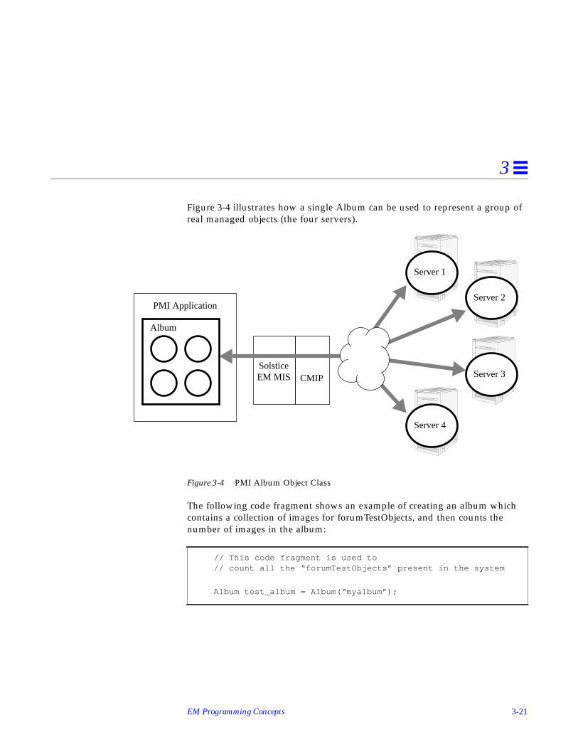
EM Programming Concepts 3-21
3
Figure 3-4 illustrates how a single Album can be used to represent a group ofreal managed objects (the four servers).
Figure 3-4 PMI Album Object Class
The following code fragment shows an example of creating an album whichcontains a collection of images for forumTestObjects, and then counts thenumber of images in the album:
// This code fragment is used to// count all the “forumTestObjects” present in the system
Album test_album = Album(“myalbum”);
PMI Application
SolsticeEM MIS CMIP
Album
Server 2
Server 4
Server 3
Server 1

3-22 Solstice Enterprise Manager Application Development Guide
3
3.3.1.5 Morf and Syntax
A unit of data is represented by an instance of the Morf class (MysteriousObject Related to Framework). Each Morf contains an opaque, encoded value,along with the information the PMI needs in order to decode it. For eachframework, there’s a derived class that’s able to manipulate that type of data inthe context of the framework
An instance of the Syntax class represents a type. All framework-encoded data,whether part of an object or not, has a type. This type specifies, among otherthings, how to produce and understand human-readable representations of thedata. The Syntax class is part of the PMI’s implementation; applicationdevelopers should not need to deal with Syntaxes directly except whenbuilding Morfs.
3.3.1.6 AlbumImage
An AlbumImage is the representation of the state of an iterator that isprogressing through either all of the Images in an Album or all of the Albumscontaining an Image. This is analogous to a pointer into a linked list.
3.3.1.7 CurrentEvent
A CurrentEvent is the representation of an event. When a callback is requestedfrom the PMI, the PMI returns the CurrentEvent parameter in the callback. Theapplication may then interrogate the CurrentEvent by various methods to findout what kind of event occurred, which Image or Album it relates to and so on.
char *fdn = “ALL/CMISFilter(item : equality :{objectClass,forumTestObject})”;
test_album.set_derivation(fdn);
test_album.derive();cout << “Number of forumTestObjects in the system =” <<test_album.num_images() << endl;

EM Programming Concepts 3-23
3
3.3.1.8 Waiter
A Waiter is the representation of an ongoing asynchronous operation. TheWaiter provides methods for cancelling the operation or awaiting itscompletion. The Waiter may also serve as the base class for asynchronousoperations
3.3.1.9 Coder
A Coder is the representation of a pair of methods, for encoding and decodingvalues. The Coder class is a reference-counting wrapper around an inner class,called CoderData. Application developers may derive from CoderData toprovide custom translation routines to the PMI. A Coder may be bound eitherto a Syntax or to an attribute name
What To Use:• Platform C++ object class
• Album C++ object class
• Image C++ object class
• Other PMI C++ object classes
When To Use:The PMI is used to develop client applications. You can use the PMI to developa Solstice EM solution when you have either of the following requirements:
• You need to present information in a specialized fashion that is not possibleto achieve using existing Solstice EM components, such as the Viewer or theAlarm Manager. The presentation of information could include specializedpresentation windows, GUI-based device front ends, or terminal output.
• You need to manipulate information in a manner that is not possible usingSolstice EM subcomponents such as Nerve Center Requests, EFD’s, or logobjects. The manipulation of information could include summarization ofdata, specialized gathering and processing of data, etc.

3-24 Solstice Enterprise Manager Application Development Guide
3
3.3.2 Common Functions and Classes
The common functions and libraries are used to develop PMI clientapplications. The functions and classes are used in user-developed clientsubcomponents.
When To Use:The common functions and classes are required by a number of othersubcomponents -- primarily the high level and low level PMI.
3.3.3 Scheduling PMI Events
Solstice Enterprise Manager includes a scheduler, sched , that can be used withnon-X-windows PMI client applications. This scheduler is contained in thesched.hh library. There is also an X-windows-aware scheduler, xtsched , thatcan be used with X-windows-based PMI applications. This scheduler is locatedin the xtsched.hh library.
A typical X-PMI application must process events on two streams:
• GUI-related X events
• PMI events to and from the platform
xtsched is provided for use with PMI client applications that include agraphical user interface (GUI) based on Motif and the X libraries. Both the Xlibraries and the PMI API present event-driven interfaces. The interfaces forboth can be told to initiate an operation and then invoke an event handler (orcallback) when the operation completes. Both interfaces use an internalscheduler that detects events (i.e., completion of operations, etc.) and invokesthe appropriate callbacks. Not surprisingly, if either the X or PMI schedulers isprevented from running, the interface relying on the halted scheduler will alsovery quickly come to a halt. Two examples:
• In the case of X, if mouse and keyboard events are no longer detected, allkeyboard and mouse input would stop, effectively freezing the display.
• In the case of the PMI, if responses and notifications are no longer detected,no management operations would ever complete, effectively halting thePMI client application.

EM Programming Concepts 3-25
3
xtsched realizes that another scheduler is running as part of a PMIapplication and in the xtsched main scheduler loop provides an opportunityfor the xtscheduler to run.
You should use xtsched whenever you are developing PMI client applicationsthat provide a graphical user interface based on X and Motif.
To implement xtscheduler, do the following in the file that contains the main()loop of your applications:
1. Include the file xtsched.hh .
2. In main() , insert set_app_context(app_context) afterXtAppInitialize(&app_context) .This should occur before platform connect.
3.4 Additional Information about Subcomponents
3.4.1 Common Functions and Libraries: Scheduling and Callbacks
The goal of the scheduler is to discover which callback events ought to happenat the present time, and cause those callbacks to happen. There are three typesof callback events that the scheduler must manage:
• Immediate callbacks
• I/O ready callbacks
• Timer callbacks
Each Solstice EM client application has its own scheduler, either xtsched orsched . The Solstice EM MIS also has a similar scheduler.
Callback events are commonly referred to as callbacks. Callbacks are used bythe Solstice EM MIS and client applications to handle activities that occur andhave an effect on Solstice EM internal resources. Most forms of softwaretechnology would simply refer to these activities as “events”, but within thecontext of the Solstice EM design, these activities are referred to as callbackevents or callbacks so as not to confuse them with network management eventsand event management.

3-26 Solstice Enterprise Manager Application Development Guide
3
Callback event routines are called handlers. A handler is passed two pieces ofdata, one specified by the routine defining the callback event, and the otherspecified by the routine performing the callback event. The C++ class defininga a callback event therefore contains both a pointer to the routine to be called,and the first of the two pieces of data to be passed to the routine. Both piecesof data are defined as pointers to void, which can hold any other pointer (andsome kinds of integers).
A routine which wishes to define a callback event does so merely by declaringan initialized variable of the callback class. The routine may then post, orinitiate, the callback event in any of several ways, depending on the desiredscheduling of the callback event.
File Descriptor (I/O) CallbacksCallback events destined to occur when I/O becomes ready are stored inarrays indexed by file-descriptor. A maximum of three callback events may bescheduled for each file descriptor: one for read events; one for write events;and one for exceptions.
Since multiple callback events and timers may be posted before the schedulerhas time to process them, callback events and timers are kept in queues. Thecallback-event queue is kept in FIFO order, so callback events occur in theorder posted.
The operating system may not provide enough file descriptors to let the clientapplication or server keep everything open at once. Those file descriptors thatcould be closed if necessary should be registered with the file descriptormanager which will place the file descriptor in a priority queue, along with acallback event to be triggered when that file descriptor is to be reclaimed. filedescriptors may be re-prioritized after having been registered with the filedescriptor manager.
Timer CallbacksA timer consists of a callback event associated with one (or more) desired timesof execution. The initial time of the callback event is specified in millisecondsrelative to the posting of the timer. When the timer elapses (and is noticed bythe scheduler), the callback event is triggered, and the callback event handler iscalled. The timer may optionally reschedule itself at some time in the future.

EM Programming Concepts 3-27
3
The timer queue is kept in order of the scheduled times of callback events.Within a particular set of timers scheduled for the same time, ordering is FIFO.Times within the queue are kept relative to the previous queue entry. Thisincreases the overhead of posting a timer, but decreases the overhead in thescheduler, which might otherwise have to scan the timer queue many times foreach posted timer.
3.4.2 Common Functions and Libraries: Asn1Value Class
The Asn1Value class defines storage and operations for ASN.1 values and ispart of the Solstice EM Common Functions and Classes. The Asn1Value classrelies on the DataUnit class to provide storage for ASN.1 values.
A C++ code fragment example is provided here which shows how to use theAsn1Value class to encode a distinguished name. The distinguished nameencoded in the example has the following human-readable form:
The BER encoded version of this distinguished name is shown in Figure 3-5:
Figure 3-5 Distinguished Name Example
systemId=acid.exampleID=10
T L V
U6 2.9.3.2.7.45*
T L V
U25 “acid”4U16 0D16
T L VT L V
U17 0F16
T L V
U6 1.3 ... 288*
T L V
U2 104U16 1016
T L VT L V
U17 1216
U16 2516
T L V
*Approximate Length

3-28 Solstice Enterprise Manager Application Development Guide
3
The distinguished name used in this example is the same DN as used in theDN example in Chapter 2, “Network Management Concepts.” The codefragment is as follows:
Oid *exampleID = “1.3.6.1.2.1.42.1.28”;Oid *systemID = “2.9.3.2.7.4”;DU (char *)*id = “acid”; //I32 value = 10;
Asn1Value dn;Asn1Value rdn1;Asn1Value rdn2;Asn1Value ava1;Asn1Value ava2;Asn1Value id1;Asn1Value id2;Asn1Value value1;Asn1Value value2;
Result status = OK;
if (dn.start_construct(TAG_SEQ) != OK ||// init the DN (FDN)

EM Programming Concepts 3-29
3
The syntax for an object instance is as follows:
In order to create an object instance name from the distinguished name (dn)created in the preceding code fragment, the following code fragment wouldalso be required:
rdn1.start_construct(TAG_SET) != OK ||// init 1st RDNava1.start_constuct(TAG_SEQ) != OK ||// init 1st AVAid1.encode_oid(TAG_OID, systemID) != OK || // encode OID
value1.encode_octets((Octet *)id, TAG_UNIV(26)) != OK ||// encode value
ava1.add_component(id1) != OK ||// complete 1st AVA usingava1.add_component(value1) != OK ||// ... OID and valuerdn1.add_component(ava1) != OK ||// complete 1st RDN
rdn2.start_construct(TAG_SET) != OK ||// init 2nd RDNava2.start_constuct(TAG_SEQ) != OK ||// init 2nd AVAid2.encode_oid(TAG_OID, exampleID) != OK || // encode OIDvalue2.encode_int(value, TAG_INT) != OK || // encode valueava2.add_component(id2) != OK ||// complete 2nd AVA usingava2.add_component(value2) != OK ||// ... OID and valuerdn2.add_component(ava2) != OK ||// complete 2nd RDNdn.add_component(rdn1) != OK ||// complete DN usingdn.add_component(rdn2) != OK // ... the two RDNs created
)Status = NOT_OK; // If any or’s return false
ObjectInstance ::= CHOICE {distinguishedName [2]IMPLICIT DistinguishedName,nonSpecificForm [3]IMPLICIT OCTET STRING,localDistinguishedName[4]IMPLICIT RDNSequence}
Asn1Valueobj_inst;
obj_inst.start_construct(TAG_CONT(2));obj_inst.add_component(dn);

3-30 Solstice Enterprise Manager Application Development Guide
3
This code fragment assumes that the distinguished name represented by dn isrelative to the global root in the MIT. If we instead assume that the namerepresented by dn is relative to a node other than root, then the following codefragment can be used to create an object instance name that is a localdistinguished name:
The three preceding code fragment examples for a distinguished name, anobject instance names, and a local distinguished name also make it clear thatthe curly braces or slash name formats supported by the PMI are much simplerto work with. The same three names using curly braces format would be:
• Distinguished name:
• Object instance (same as distinguished name form):
• Local distinguished name:
The same three names using the slash format would be:
• Distinguished name:
• Object instance (same as distinguished name form):
Asn1Value local_obj_inst;local_obj_inst.start_construct(TAG_CONT(4));local_obj_inst.add_component(dn);
{ { { systemId, “acid”} }, { { exampleID, 10 } } }
{ { { systemId, “acid”} }, { { exampleID, 10 } } }
{ { { systemId, “acid”} }, { { exampleID, 10 } } }
/systemId=acid/exampleID=10
/systemId=acid/exampleID=10

EM Programming Concepts 3-31
3
• Local distinguished name:
3.4.3 EFD Destination Addresses Syntax
The syntax for a destination address used by an EFD is as follows:
The syntax for an application entity title (AE-title) is as follows:
The syntax for an application title (AP-title) is as follows:
Solstice EM supports both the distinguished name form and the OID form forAP-Titles. However, only the OID form will work with EFDs.
AP-title ExamplesAn example of an AP-title using the OID form is as follows:
systemId=acid/exampleID=10
Destination ::= CHOICE{
single AE-title,multiple SET OF AE-title
}
AE-title ::= AP-title
AP-title ::= CHOICE{
distinguishedName DistinguishedName,objectIdentifier OBJECT IDENTIFIER
}
{ 1 2 3 4 }

3-32 Solstice Enterprise Manager Application Development Guide
3
An example of an AP-title using the distinguished name form is as follows:
Destination ExamplesAn example of a single destination address using the OID AP-title form ofaddressing is:
An example of multiple destination addresses using the OID AP-title form ofaddressing is:
Alternative examples showing use of attribute names and values fordestinations is as follows:
An example of an AP-title using the distinguished name form for multipledestinations is as follows:
{ { { systemId, “MasterMIS”} } }
{ 1 2 3 4 }
{ { 1 2 3 4}, { 1 2 3 5 } }
{ { { systemId, “MasterMIS”} } }
{ { { systemId, “MIS_London”} }, { { systemID, “MIS_Dublin”} } }

EM Programming Concepts 3-33
3
3.4.4 CMIS Filters
The syntax for a CMIS filter is as follows:
The syntax for a filter item is as follows:
CMISFilter ::= CHOICE {item [8] FilterItem,and [9] IMPLICIT SET OF CMISFilter,or [10] IMPLICIT SET OF CMISFilter,not [11] CMISFilter
}
FilterItem ::= CHOICE {equality[0] IMPLICIT Attribute,substrings[1] IMPLICIT SEQUENCE OF CHOICE {
initialString[0] IMPLICIT SEQUENCE {attributeIdAttributeId,string ANY DEFINED BY attributeId },anyString [1] IMPLICIT SEQUENCE {attributeIdAttributeId,string ANY DEFINED BY attributeId },finalString[2] IMPLICIT SEQUENCE {attributeIdAttributeId,string ANY DEFINED BY attributeId } },
greaterOrEqual[2] IMPLICIT Attribute, -- asserted value >=-- attribute value
lessOrEqual[3] IMPLICIT Attribute, -- asserted value <=-- attribute value
present [4] AttributeId,subsetOf[5] IMPLICIT Attribute, -- asserted value is a
-- subset of attribute valuesupersetOf[6] IMPLICIT Attribute, -- asserted value is a
-- superset of attribute valuenonNullSetIntersection
[7] IMPLICIT Attribute}

3-34 Solstice Enterprise Manager Application Development Guide
3
3.4.5 Solstice EM Managed Objects
Solstice EM contains managed object class definitions for the ISO DMImanaged object classes. These object classes are automatically loaded into theproduct when it is installed. In addition to the ISO DMI classes, Solstice EMalso contains definitions for a number of OMNIPoint 1.1 defined managedobject classes.

4-1
Developing EM Solutions 4
What is a Solstice EM solution?A Solstice EM solution is a collection of one or more user-configured or user-developed, client and server subcomponents that work together to solve aproblem. User-configured subcomponents are Solstice EM subcomponents thatcan be created without writing any software. User-developed subcomponentscontain application software written by an application developer using theSolstice EM APIs. Server subcomponents are contained in the same Unix processas the Solstice EM MIS. Client subcomponents are contained in a PMI clientapplication and are in a separate Unix process from the MIS.
Defining Your Requirements: Component and System Analysis page 4-3
Designing and Developing Your Solution page 4-8
Designing Access Control for Applications page 4-14
Using Nicknames Instead of FDNs page 4-18
Testing Considerations page 4-18
Additional Solution Development Considerations page 4-20
Additional Considerations for Using High-Level PMI page 4-22
Adding a New Managed Object Class to the MIS page 4-23
Application Development Tools page 4-29

4-2 Solstice Enterprise Manager Application Development Guide
4
This chapter describes the following general types (or classifications) ofSolstice EM solutions and briefly describes the some things you need to do todevelop a Solstice EM solution for each class of problem:
• Element management (devices, systems, and network elements)
• Multiple MIS management problems
• Information presentation problems (PMI client application issues)
• Management information sharing
• Access control issues
• Managed object name issues
Developing a Solstice EM solution follows the basic process associated withsolving any other programming problem:
1. Define your requirements
2. Design and develop your solution
3. Test your solution
This chapter provides the following information related to the above threesteps:
• Descriptions of some of the concepts and issues you need to consider as youdefine your requirements. The concepts and issues to consider are providedfor each of the four general classes of problems.
• A list of subcomponents that you are likely to use as part of the design anddevelopment of a solutions for each of the four general classes of problems.
• A brief list of some issues you may want to consider as part of testing yoursolution.
The classes of problems and solutions described are common types ofproblems that you are likely to encounter when managing your network. Thefour classes of problems presented here are not the only type of problems thatyou are likely to encounter as you manage your network. The four types ofsolutions presented here are also not the only types of solutions you can createusing the Solstice EM product. You will likely find that as you gain morefamiliarity with the Solstice EM product you will “mix and match”

Developing EM Solutions 4-3
4
components and subcomponents in any number of different ways in order tosolve problems you encounter. The classes of problems and solutions describedhere are only meant as a starting point.
4.1 Defining Your Requirements: Component and System AnalysisThere are several questions you may want or need to consider whendeveloping a Solstice EM solution. This section lists some of the questions, butit is not meant to be a comprehensive or exhaustive list. The list is just astarting point for issues and concepts you will need to consider.
You may not be able to answer all the questions provided here, but the more ofthe questions you can answer, and the more questions you can pose andanswer on your own, the better will be your understanding of therequirements for the Solstice EM solution that you will develop and the betterthat solution will be at meeting your needs. In many cases you will be able touse either default values provided with the Solstice EM product in response tosome of the questions, or you will be able to use other defaults that you havecreated as you gain more experience with the platform.
The areas of analysis covered by this section are as follows:
• Element management (devices, systems, and network elements)
• Multiple MIS management problems
• Information presentation problems (PMI client application issues)
• Management information sharing
• Access control issues
• Managed object name issues
This section assumes that you are familiar with the principles and concepts ofnetwork management and that you have had some experience managing ordeveloping applications to help manage a network.

4-4 Solstice Enterprise Manager Application Development Guide
4
4.1.1 Element Management Analysis (Devices, Systems, and Networks)
Device Type AnalysisThe questions listed in this section are geared towards understanding whatyou will need to do to manage a new class of device that you add to yournetwork.
• Are there any notifications, traps, or other types of unsolicited informationassociated with the device?
If so, are the notifications or traps a new type, or does the device generateone of the notification or trap1 types that the MIS already knows about? Ifthe notification is an existing type, can it be handled as that notification typeis handled currently, or does it need special handling? If the notification isnew, does it need to be handled, or can it be ignored? If it needs to behandled, can it be handled like one of the existing notifications or does itrequire special handling?
• Does the device need to be polled?
If so, can it use existing poll rates or should other poll rates be used? Whataction should be taken if the polling operation detects an error? Are thedefault actions sufficient? Does the polling rate need to change when anerror is detected? Does an alarm need to be raised for each error detected?
• What are normal and error states that the device can be in? What severitiesshould the normal and error states be assigned (This is a policy decision)?Who should be notified of error conditions, or is notification on the Viewer(i.e., icon color change) sufficient? Is there any standardized process orcommand that can be used to correct error conditions associated with thedevice? What device (i.e., object class) attributes or behaviors can be used toidentify normal and error states?
• What is normal performance of the device. What performance states existfor the device and which states should cause alarms? What attributes orbehaviors can be used to identify normal performance and abnormalperformance? Can existing performance defaults be used?
1. All SNMP traps are mapped into the CMIP Internet Alarm notification, a notification which the MIS knowsabout. You only need to consider whether or not you need special handling for the trap informationcontained in the Internet Alarm.
Developing EM Solutions 4-5
4
Network and Systems Analysis• Does this device or class of device play a key role in the network? E.g., is
this device part of my backbone, or is this device a dedicated file orapplication server? If its a server, how frequently is it accessed? What is theimpact when the server is down? If this device is polled, should the pollingrate be more frequent than for other less critical devices?
• What is normal performance for the backbone of the network? What ismarginal performance for the backbone? What performance levels shouldgenerate alarms?
4.1.2 Multiple MIS Management Analysis• Will more than one Solstice EM MIS be used to manage your network? If
not, you can ignore these questions and issues listed in this section.
• Which managed objects (representing devices, MISs, or other resources) willbe located under root in the MIT? What are the FDNs for these objects (theRDN and the FDN will be the same in this case, because the objects areunder root) and will need to be manually updated into the FDN table.
• Which managed objects will each MIS contain and manage?
• What types of information do you want to automatically pass from one MISto another? Will one MIS act as a manager or managers (i.e., will all otherMISs pass information to this manager or within the MIT will one MIScontain another MIS), will all managers act as peers (i.e., sharing certaintypes of information with most or all other MISs), or will some combinationof a manager or managers and peers be used?
4.1.3 Information Presentation Analysis (Client Application Issues)• How does the information need to be presented to the user? Does the
information need to be presented in a specialized fashion that is not possibleto achieve using existing Solstice EM components, such as the Viewer or theAlarm Manager? The specialized presentation of information could includespecial presentation windows, GUI-based device front ends, or terminaloutput. If specialized presentation of information is required, does it alsomake sense to still display some information using the Viewer, the LogManager, the Alarm Manager, or other Solstice EM application? Can anyother Solstice EM client application you have developed by used to displaythe information or part of the information?

4-6 Solstice Enterprise Manager Application Development Guide
4
• What information needs to be presented to a user? Where does thisinformation come from? Is it provided from a device? Is it provided byanother application (such as NerveCenter or from an EFD)? Do you need tomanipulate information in a manner that is not possible using Solstice EMsubcomponents such as NerveCenter Requests, EFDs, or log objects? Themanipulation of information could include summarization of data,specialized gathering and processing of data, etc. Does the informationcome from one or more devices or applications? Can a NerveCenter Requestor other Solstice EM subcomponent be designed to provide a portion of theinformation?
• What is the appropriate launch point for the client application? Should it bestarted from the application launcher? Should it be started from aNerveCenter Request? What information is needed upon start-up (e.g.,context or initialization information)? Where does this start-up informationcome from? Does this start-up information differ from the normalinformation used by or displayed by this client application?
4.1.4 Management Information Sharing Analysis• Will more than one person want to use the client application? Is concurrent
access to MIS information from multiple PMI client applications required?Does the information you plan to share already exist in the MIS? (If theanswer to this last question is yes, you would likely only need develop aPMI client application to access the data)
• Does the information gathered or summarized by the client application needto be stored permanently or temporarily and also made accessible to otherclient applications? Does some of the information only need to stored onlyas long as the client is running? Or as long as the server is running? Inaddition to data stored or accessed by the MIS, this data could also includeevent information or information from NerveCenter.
Note – PMI applications have shared access to information stored by ormanaged by (i.e., accessed) the Solstice EM MIS. The PMI does not provide adirect interface from one PMI client application to another. Any informationpassed from one PMI client to another to would need to flow through the MIS(as an M-Action, or M-Set that triggers an EFD, etc.) or would need to usesome “out of band” service provided by the application developer (e.g., a

Developing EM Solutions 4-7
4
socket connection established by one client to communicate with either anotherPMI client or an other non-Solstice-based application without involving theMIS).
• Do multiple copies of the client application need to receive notifications,traps, or other types of unsolicited information?
• Does information used by one copy of the client application need to besecure from information used by another copy of the same client? Or otherclient?
Note – Solstice EM does not currently support this type of data partitioning forsecurity purposes.
4.1.5 Access Control Issues
Solstice EM lets you control levels of access for any application that youdevelop. When you create the EM applications, you need to consider thefollowing:
• Do all users have open access to all features in your application or do youneed to control access to individual features?
• How will your application respond if someone does not have access to theapplication?
• How will your application respond if someone does not have access to aspecific feature or set of features?
When answering these questions, consider the following:
• The applications must give proper feedback to the user if the user doesn’thave access rights to perform certain operations.
• Where possible, the application should prevent the user from performingany operation that he/she is not authorized to perform.
• The application developer should also make the list of application featuresavailable to the system administrator so that the system administrator cangrant users access rights to perform various operations.
For more information about designing access control for your applications, seeSection 4.3, “Designing Access Control for Applications.”

4-8 Solstice Enterprise Manager Application Development Guide
4
4.1.6 Managed Object Name Issues
Solstice EM provides a nickname service that translates managed object namesfrom FDNs (Fully Distinguished Names) into nicknames that are more easilycomprehensible for a user. The nickname service is provided as a standard partof the EM platform. As a developer, you need to decide:
• Whether to use nicknames in place of FDNs for your applications
• How to implement getting and setting nicknames for your applications
For more information on setting up nicknames, see Section 4.4, “UsingNicknames Instead of FDNs.”
4.2 Designing and Developing Your SolutionOnce you understand your requirements you need to determine which SolsticeEM components and subcomponents you need to use to develop your solution.
This section assumes that you are familiar with the principles and concepts ofnetwork management and that you have had some experience managing ordeveloping applications to help manage a network.
4.2.1 Element Management (Devices, Systems, and Networks) Solutions
User Configured SubcomponentsYou will typically use the following user-configured subcomponents as part ofa network element solution:
• NerveCenter Requests (server subcomponent)
• Solstice EM MIS Logging Services (server subcomponent)
• You will only need to modify the default log if the notification generated bythe device or system is not handled by the default log discriminator or ifyou wish to store the notification in a separate log.

Developing EM Solutions 4-9
4
User Developed SubcomponentsYou will typically not need to use user-developed subcomponents as part ofnetwork element solution, unless you want to display the information obtainedfrom a network element in some special way. If you have special informationdisplay requirements, you may want to consider developing a PMI clientapplication.
Solstice EM Application and UtilitiesThe following Solstice EM applications and utilities are likely to be used as partof your solution in order to display information about the class of networkelement that you are adding to your network:
• Solstice EM Viewer
• Solstice EM Alarm Management Application
• Solstice EM Data Viewer
The following Solstice EM applications and utilities are likely to be used to helpcreate your network element solution:
• GDMO Compiler: em_gdmo
• ASN.1 Compiler: em_asn1
• Name binding loader: em_load_name_bindings
If you are working with an SNMP device you will also need to use thefollowing utility to help create your solution.
• Concise MIB Compiler: em_cmib2gdmo
If you are working with a SunNet Manager object you will also need to use thefollowing utility to help create your solution:
• SunNet Manager Schema Compiler: em_snm2gdmo
Other Components, Information, or Steps You May NeedYou will need one of the following types of definitions for the new class ofnetwork element that you are developing a solution for:
• GDMO Managed Object Class definition
• Concise MIB definition

4-10 Solstice Enterprise Manager Application Development Guide
4
• SunNet Manager Schema files
In addition, you may want to add an icon to the Viewer Object Palette torepresent the new class of network element.
Where to start?• Refer to Chapter 7, “Scenarios,” of this Guide. In particular, see Scenario 1.
This scenario can potentially be used as a starting point for developing yourown solution.
• Refer to the “See Also” subheading in the preceding chapter for each of thesubcomponents you are using as part of your solution. The “See Also”sections lists sources of further information for each of the subcomponents.
4.2.2 Multiple MIS Management Solutions
User Configured SubcomponentsYou will typically use the following user-configured subcomponents as part ofa multi-MIS solution:
• Event Forwarding Discriminators (server subcomponent)
• Solstice EM MIS Logging Services (server subcomponent)
You will only need to modify the default log if the notification generated bythe other MIS or other CMIP manager is not handled by the default logdiscriminator or if you wish to store the notification in a separate log.
User Developed SubcomponentsYou will typically not need to use user-developed subcomponents as part ofmulti-MIS solution, unless you want to display the information obtained otherMISs or other CMIP manager in some special way. If you have specialinformation display requirements, you may want to consider developing a PMIclient application.
Solstice EM Application and UtilitiesThe following Solstice EM utilities are likely to be used as to help create yoursolution:
• CMIP Configuration Utility: em_oct -cmip

Developing EM Solutions 4-11
4
• Object Creation Utility: em_objcreate
The following Solstice EM applications and utilities are likely to be used as partof your solution in order to display information about the other MISs or CMIPplatforms that you are using in your network:
• NerveCenter Requests
• Solstice EM Viewer
• Solstice EM Alarm Management Application
• Solstice EM Data Viewer
• Solstice EM Application Launcher
Other Components, Information, or Steps You May NeedYou will need one of the following types of definitions that describes the otherMIS or other CMIP manager that you are using as part of your multi-MISsolution:
• GDMO Managed Object Class definition or definition describingnotifications emitted by the other MIS or CMIP manager.
In addition, you may want to add an icon to the Viewer Object Palette torepresent the other MIS or other CMIP manager.
Where to start?• Refer to Chapter 7, “Scenarios,” of this Guide. In particular, refer to Scenario
2. This scenario can be used as a starting point for developing your ownsolution.
• Refer to the “See Also” subheading in the preceding chapter for each of thesubcomponents you are using as part of your solution. The “See Also”sections lists sources of further information for each of the subcomponents.

4-12 Solstice Enterprise Manager Application Development Guide
4
4.2.3 Information Presentation (PMI Client Application Issues) Solutions
User Configured SubcomponentsIf you are only developing a PMI client application that accesses and presentsdata already present in the MIS, you may not need to use any user-configuredsubcomponents. However, most user-configured server subcomponents couldbe used to provide information to a PMI client application.
User Developed SubcomponentsYou will typically need to use at least the following PMI C++ classes (whichare all client subcomponents) to develop a PMI client application:
• Platform C++ Class
• Image C++ Class
• Album C++ Class
You may also find it useful to use other PMI C++ classes as well as thefollowing common functions and classes:
• Asn1Value C++ Class
In addition, if you are building a GUI-based PMI client application you shouldalso use the following client subcomponent:
• xtsched
Other Components• GDMO Managed Object Class definitions
• Concise MIB definitions
• SunNet Manager Schema files
Where to start?• Refer to Chapter 7, “Scenarios,” of this Guide, in particular, Scenario 3. This
scenario can be used as a starting point for developing your own solution.
• Refer to the Solstice Enterprise Manager API Syntax Manual for furtherinformation about PMI C++ object classes.
Developing EM Solutions 4-13
4
• Refer to the “See Also” subheading in the preceding chapter for each of thesubcomponents you are using as part of your solution. The “See Also”sections lists sources of further information for each of the subcomponents.
4.2.4 Management Information Sharing Solutions
User Configured SubcomponentsIf you are developing an information sharing solution you may not need to useany user-configured subcomponents. However, most user-configured serversubcomponents could be used to provide shared management information toone or more PMI client applications.
User Developed SubcomponentsYou will need to develop a GDMO Managed Object Class definition describingthe information you which to share and then create a local managed object(server subcomponent). The local managed object class is created usingem_compose_oc or em_compose_poc.
You will typically need to use at least the following PMI C++ classes todevelop a PMI client application that works with your local managed object:
• Platform C++ Class
• Image C++ Class
• Album C++ Class
You may also find it useful to use other PMI C++ classes as well as thefollowing common functions and classes:
• Asn1Value C++ Class
In addition, if you are building a GUI-based PMI client application you shouldalso use:
• xtsched
Solstice EM Application and UtilitiesThe following Solstice EM applications and utilities are likely to be used to helpcreate your device, system or network solution:
• GDMO Compiler: em_gdmo

4-14 Solstice Enterprise Manager Application Development Guide
4
• ASN.1 Compiler: em_asn1
• Name binding loader: em_load_name_bindings
• Default Object Behaviors: em_compose_oc or em_compose_poc
Other Components, Information, or Steps You May NeedThe following Solstice EM applications and utilities could be used as part ofyour information sharing solution:
• NerveCenter Requests
• Solstice EM Viewer
• Solstice EM Alarm Management Application
• Solstice EM Data Viewer
• Solstice EM Application Launcher
Where to start?• Refer to Chapter 7, “Scenarios,” of this Guide, in particular, Scenario 4. This
scenario can be used as a starting point for designing and developing yourown solution.
• Refer to the “See Also” subheading in the preceding chapter for each of thesubcomponents you are using as part of your solution. The “See Also”sections lists sources of further information for each of the subcomponents.
4.3 Designing Access Control for Applications
User Configured SubcomponentsIf you are developing an information sharing solution you may not need to useany user-configured subcomponents. However, most user-configured serversubcomponents could be used to provide shared management information toone or more PMI client applications.
User Developed SubcomponentsThe following Solstice EM PMI functions could be used as part of your accesscontrol solution:
• Platform::get_authorized_features

Developing EM Solutions 4-15
4
• Platform::get_authorized_applications
Solstice EM Application and UtilitiesThe following Solstice EM applications and utilities are likely to be used toassign access privileges to users:
• Access Manager: em_accessmgr
• Access Control Command-Line Utility: em_accesscmd
Where to start?• Access control examples are shipped with Solstice EM. For more
information about these examples, see Section 8.5, “Access ControlExamples.”
4.3.1 Platform Connection and User Profile
A user needs a connection access right to establish connection with MIS. Theconnection access rights are stored in the access control profile objects. Theapplication name used in the call to Platform::connect() identifies theapplication being run. User’s privileges to run this application are checked bythe MIS to determine whether to grant or deny the connection. All EMapplications shipped with the product use the same name as their executablename for connection (for example, the Discover application connects as“em_discover” since the executable name for that application isem_discover) .
Anybody can connect with any application if connection level access control isoff or if the user is a super user running the application on one of the trustedhosts. See Section 4.3.5, “Access Control Configuration Variables” for details onthe EM-config variables defining connection level access control.
4.3.2 Password Authentication
The user’s password is verified when starting EM applications, including theEM application launcher. No password is queried if the application isconnecting to the local host and the user is “root” or the application being runis owned by “root” with setuid bit set. If the password is required, then it isqueried automatically from inside the Platform::connect() function.

4-16 Solstice Enterprise Manager Application Development Guide
4
All GUI EM applications popup a dialog box to query the password. All otherapplications use the TTY interface for password query. The application candefine the password query mechanism by extending the PasswordTty class.
The password is not queried if password authentication is off or for superusers running applications on one of the trusted hosts. See Section 4.3.5,“Access Control Configuration Variables” for details on the EM-configvariables defining password authentication.
4.3.3 Command Line Utility
When developing applications that use EM’s access control function, use theaccess control command line interface to create access control objects andassign privileges.
4.3.4 Feature-Level Access Control
You, as an application developer, defines features for your application. Thesystem administrator assigns access rights for the users to use these features.The access rights are stored in MIS in the access control profile objects.Typically, at application start-up, the application finds out which features userscan access by calling a PMI function. It then prevents the user from invokingany unauthorized features. It is the responsibility of the application to enforcethe application feature access.
1. After connection to the MIS succeeds, the application calls thePlatform::get_authorized_features API function.
2. MIS returns the list of features the user is authorized to access.
3. The application enforces the application feature access control. A GUI-based application might do this by making buttons/menus and othercontrols inactive, corresponding to those features the user is notauthorized to access.
4.3.5 Access Control Configuration Variables
The $EM_RUNTIME/conf/EM-config (typically,/var/opt/SUNWconn/em/conf/EM-config ) file contains some variablesthat control the MIS’s behavior with regards to password authentication andenforcement of access control. This file is read at MIS startup only. If you

Developing EM Solutions 4-17
4
change this file, the changes won’t be effective until the next em_services.Table 4-1provides a list of these variables, their default values, and adescription for each.
Table 4-1 EM-config Variables
Variable Default Value Description
EM_ACCESS_PASSWORD_CONTROL TRUE If EM_ACCESS_PASSWORD_CONTROL is notTRUE, password authentication is turned off,password will not be queried for anybody.
EM_ACCESS_CONNECTION_CONTROL TRUE If EM_ACCESS_CONNECTION_CONTROL isnot TRUE, then everybody is assumed to have fullprivilege, i.e. no access control for applicationconnection, features, or non-access control objectsmodification. Password query may still be on.
EM_ACCESS_SUPER_USERS <null> EM_ACCESS_SUPER_USERS is a space separatedlist of user names who are considered as superusers. These users get full access control privilege.They still have to go through passwordauthentication if connecting from a remotemachine. On the local machine, (or from one ofthe EM_ACCESS_TRUSTED_HOSTS), they don’thave to provide password. The “root” userdoesn’t have to be explicitly included inEM_ACCESS_SUPER_USERS.
EM_ACCESS_TRUSTED_HOSTS <null> EM_ACCESS_TRUSTED_HOSTS is a spaceseparated list of host names. If super usersdefined in EM_ACCESS_SUPER_USERS or the“root” user is connecting from these trusted hoststhen they are not subject to passwordauthentication and get full access controlprivilege. Local host is implicitly in theEM_ACCESS_TRUSTED_HOSTS. By adding ahost name to this variable, you can run daemonsremotely without being subject to access controlor password authentication.
EM_ACCESS_BACKWARD_COMPATIBILITY FALSE If EM_ACCESS_BACKWARD_COMPATIBILITYis TRUE, you can connect to EM2.0 MIS withapplications linked with EM1.2 libraries when runas a super user from a trusted host.

4-18 Solstice Enterprise Manager Application Development Guide
4
4.4 Using Nicknames Instead of FDNsThe Solstice EM nickname service translates FDNs (Fully DistinguishedNames) into user-defined nicknames. Solstice EM provides the followingnickname utilities that you use to configure and run the nickname service:
• em_nnadd—Use this utility to add a nickname server.
• em_nnconfig —Use this utility to define mappings between FDNs anduser-defined names (nicknames).
• em_nnmpa—This starts and stops the nickname server daemon.
For more information about these utilities, see the Command Line Utilitieschapter in the Solstice Enterprise Manager Reference Manual.
The High-level PMI provides four functions that a developer can use to workwith nicknames:
• album.find_by_nickname —Use this function to find an album by itsnickname rather than by its FDN.
• image.find_by_nickname —Use this function to find an image by itsnickname rather than by its FDN.
• image.get_nickname —Use this function to get the nickname associatedwith a given FDN.
• image.set_nickname —Use this function to specify the nickname to beassociated with a specified FDN.
For more information about these functions, see the Solstice Enterprise ManagerAPI Syntax Manual. For information about nickname example shipped withSolstice EM, see Section 8.3, “High-Level PMI Examples.”
4.5 Testing ConsiderationsThe Solstice EM product provides a number of tools and components that canhelp you to test your solution. This section lists development components andrun time components that can help you as part of your testing process.

Developing EM Solutions 4-19
4
4.5.1 Development Components
The following debugging and testing components should be built into anyuser-developed subcomponents that are used in your solution:
• PMI Error Classes
• tracing and debugging classes
Refer to the Solstice Enterprise Manager API Syntax Manual for more informationabout these components.
4.5.2 Run Time Components
This section briefly describes some run time components and strategies canhelp you to test your Solstice EM solution.
• When you develop a solution for a network element, you may have aGDMO description for the new device or system, but the device or systemmay not be available or installed in your network when you are ready tobegin testing your solution. Or if you are a vendor and developer ofnetwork equipment, the device or system may not be available for testingwhen you are ready to begin testing your management solution for thedevice. If you run into this situation you can use the Solstice EM MIS tosimulate your device. You can do this by running two copies of the SolsticeEM MIS; one copy will act in the manager role and operate with or containyour management solution and the other copy will act in the agent role andcontain a local managed object that simulates your agent. You can create theagent simulator just like you create any other local managed object:
1. Parse in the GDMO managed object class description, name bindings, andASN.1 productions into the MIS acting in the agent role
2. Run em_compose_oc or em_compose_poc for the new object class on theMIS acting in the agent role
The agent simulator will not be able to support complex actions,notifications, or behaviors, but will be able to perform creates and deletes onmanaged objects, test out name binding relationships, and perform get andset operations on attributes and potentially emit DMI defined notifications.
• If you are having difficulty accessing your agent using your solution, youshould also try to access the agent using the Solstice EM Data Viewer of theSolstice EM Object Editor Browser (OBED). If these two applications cannot

4-20 Solstice Enterprise Manager Application Development Guide
4
access the agent either, then you may be having agent problems,configuration and addressing problems on your agent or on the manager, orthe managed objects you need may not have been created or exist on theagent.
• When testing out NerveCenter requests, you may find it is easier to generatesimulated internetAlarms than it is to generate simulated notifications.
A sample program is included with Scenario Three, Example 6, whichgenerates a notification. This sample program could be modified to be ageneralized notification emitter. There are also a number of public domainor shareware versions of trap generators available. If you include aninternetAlarm in a NerveCenter state, you can partially test out the templateusing an SNMP trap generator. You will eventually need to performnotification testing with a device that emits the CMIP notifications youprocess as part of your solution. In addition, you may also need to go backand remove the internetAlarms from your NerveCenter Request if you donot need them for the solution you are deploying.
4.6 Additional Solution Development ConsiderationsDeveloping an Solstice EM application is like design in any other area: youmust make a clear definition of the requirements. For an Solstice EMapplication, you must decide how to make best use of the facilities the MISprovides. The following is a brief list of topics to explore as the design processprogresses.
4.6.1 Consistent Object Behavior Among Applications
If an application shares some objects with other applications, it must do so in away that makes sense in its particular context. The MIS does not enforce inter-object consistency. It depends on the object’s behavior to enforce anyconstraints. For example, if a circuit is composed of sub-circuits, the behaviorof a circuit would be a failure if any of its sub-circuits disables the composedcircuit. The Solstice EM MIS does not enforce this behavior. The implementorof the circuit object class is responsible for implementing and enforcing thisconstraint. The MIS simply provides the environment in which you can give anobject its desired behavior.

Developing EM Solutions 4-21
4
4.6.2 Persistent Store and Data Sharing
MIS data consists of a number of objects; they can be in persistent or volatilestorage. Data that needs to survive MIS shutdown is said to be persistent. Datathat is short lived is said to be volatile. There are two varieties of volatile data:association-linked data and MIS-life data. Association data lasts only for thelife of the association that created it. MIS-life data remains as long as theSolstice EM MIS keeps running, but is gone the next time the MIS is started.
You have to decide what makes sense for your application. If you needpersistence, you must define your application object classes so that theirinstances are persistent. The object framework includes persistence as part ofits services.
Since the object framework provides persistence as one of its services, there islittle you must do to make use of it. If the data’s volume or content requirespecial attention, you have to design your application in ways that make sense.You may want to encrypt the data, or provide special buffering or compressionschemes. Either of those would require you to go beyond the built-in servicesthat the object framework provides.
4.6.3 Application Real-time Responsiveness
The Solstice EM MIS is not designed to deliver real-time responses. There issome normal latency in every request. If the application requires real-timetransfer of data, an out-of-band mechanism might be appropriate. Thismechanism could be whatever delivers sufficient response. The MIS could stillmanage and monitor this special activity, provided you can define an objectwith the needed behaviors and make its description available to the MIS.
You might want an application to monitor a data source continuously. Thisdata feed might not be regular, and so might not fit easily into a GETREQUEST/RESPONSE model. But you could design and implement objects that:
• Poll the data source and then feed special Event Reports to the user
• Subscribe to the data source (if an interface is available) and issue eventreports whenever data becomes available.

4-22 Solstice Enterprise Manager Application Development Guide
4
4.7 Additional Considerations for Using High-Level PMIThe high-level functions of the PMI can be used to manage all interactions withthe MIS for an application that does not require extensions to the MIS. Thesefunctions provide encoding and decoding of ASN.1 values, and CMIS-likemessages used for communication with the MIS and managed objects. Thehigh-level functions also provide for initialization and for event subscriptionand event propagation.
4.7.1 Error Handling
Error handling is provided by the base class Error . Each of the object classesare derived from the Error class, except for the class AlbumImage . Refer tothe “Error Handling Provided by the PMI” section in the Solstice EnterpriseManager API Syntax Manual for a detailed description of the Error Handlingcapabilities provided with the PMI. Also refer to the example of error handlingin the sample program get.cc in Chapter 8, “API Examples.”
4.7.2 Overview of the Development Steps
To develop an application using the high-level functions of the PMI, followthese basic steps.
1. Write your application. For a full list of the object classes and their methods,refer to the Solstice Enterprise Manager API Syntax Manual.
In your code, #include <pmi/hi.hh> should be sufficient to provideaccess to the PMI components.
2. Use the DevPro C++ compiler to compile and link your application.
4.7.3 Event Handling
One of the features of the Solstice EM MIS, available through the high-levelfunctions of the PMI, is its ability to inform an application of events that occurwithin the MIS, or that the MIS finds out about. An application lets the MISknow the type of events it wants to hear about, and the MIS then notifies theapplication any time such an event occurs.

Developing EM Solutions 4-23
4
The two components of this capability are the Solstice EM MIS event loop, andapplication specific callbacks. An application specifies the types of events itwants to find out about, and provides the name of a callback routine that theMIS can call when such an event occurs. The callback routine is code withinthe application that takes appropriate action when called by the Solstice EMMIS.
The PMI provides a Callback class you use to specify the callback routine.The callback routine is called with a known (predefined) set of arguments,specified as part of the Callback class definition. There are a number of objecttypes, such as CurrentEvent , and methods within the PMI that know how todecompose and manipulate the data passed to a callback routine. Thus it isn’talways necessary for the application developer to have a detailedunderstanding of the format of the data passed with the callback.
Once you have specified your callbacks, you then initiate an event loop. In thiscase, you call a method from which there is no return. Control returns to yourapplication only when one of your callbacks is invoked.
4.8 Adding a New Managed Object Class to the MISThis section describes how to create and add a new managed object class to theMIS. This assumes that you have already determined what kind/type of objectyou are building.
For an example that illustrates this procedure, see Section 7.1, “Scenario 1:Adding and Managing a New Class of Device.”
4.8.1 Overview of the Development Steps
1. Determine what it is that you want to manage, and identify itscharacteristics.What are the attributes? The attributes define the actual data which is storedabout the managed object.
2. Determine if there are any managed object classes that already exist thatyou can reuse.To determine this, inspect the GDMO documents available in the$EM_HOME/etc/gdmo directory. $EM_HOME is an environment variable setto the directory the Solstice EM product was installed in./opt/SUNWconn/em is the default installation directory.

4-24 Solstice Enterprise Manager Application Development Guide
4
3. Implement the Managed Object ClassCode the different parts that comprise a managed object class. These are:
a. GDMO document
b. ASN.1 document (if necessary)
c. Create a link in the MIS between the MOC definitions and the MIT (namebindings) such that the MIS knows where in the MIT to place instances ofthe new MOC.
Run a set of utilities that creates links to the MIT and to default behaviorsthat exist within the MIS.
4.8.2 Details of a Managed Object Class
Note – This section details, from the application development perspective, howa developer can add a new managed object to the Solstice EM MIS. Anydiscussion regarding the internal representation of the managed object is onlyfor clarification.
A managed object contains a set of services and attributes that describes a typeof managed resource. It defines what type of data members exist, and thevarious methods which will perform various operations.
In the Solstice EM MIS, an instance of a managed object will represent aparticular managed resource - data describing the resource is contained in theattributes, and the associated behaviors operate on this data. The goal thereforeis to first create an appropriate managed object class that accurately defines thetype of managed resource you wish to model. Next, actual instances of thismanaged object can be created in the MIS.
To represent the managed object within the Solstice EM MIS, a managed objectclass, or MOC, is created. When an instance of a managed object needs to becreated in the MIS to represent a managed resource, the MOC is consulted todetermine how to create the instance (e.g. what kinds of attributes will it have,and what are its behaviors). The representation of an instance of a managedresource within the Solstice EM MIS is known as a managed object instance, orMOI.
Both the MOC and the MOI described above are implemented in theSolstice EM MIS as C++ classes.

Developing EM Solutions 4-25
4
An overview of these pieces is shown in Figure 4-1.
Figure 4-1 Managed Object Implementation Components
Figure 4-1 shows the relationship of the components produced by thedeveloper to their position within the Solstice EM MIS.
The GDMO and ASN.1 documents that describe the managed object (A) arerepresented in the MIS within the MetaData Repository (MDR). The annotationcode that implements the object behaviors (B) are linked to the MIS in the formof compiled code modules. The annotation code is used by objects and is partof the MIS.
The ObjMethMOC and ObjMethMOI objects are created dynamically by theMIS, as needed. The ObjMethMOC is created when needed to represent amanaged object class; an ObjMethMOI is used when an instance of a managedobject is created to represent a managed resource.
Internal Enterprise ManagerManaged Object Class Implementation
GDMOdocument
ASN.1 documents
MDR
ObjMethMOC
MIS
ObjMethMOI
compiledannotation
code
A A
B
Representation

4-26 Solstice Enterprise Manager Application Development Guide
4
4.8.3 Defining the Properties of a Managed Object Class
The components of a MOC are specified in a GDMO document and possiblyone or more ASN.1 documents. The GDMO document must contain thefollowing:
• Managed object class definition. This includes the name of the object class,and the attributes which are in this managed object class. A unique OID isalso specified such that the MOC can be identified from the MIT.
• Attribute definitions. Each attribute within the MOC has its syntax defined,along with a unique OID.
• Name Binding definition. The naming attribute is identified in the namebinding, along with the various other pieces of information.
• Notification definitions. These are optional, and define any notifications theMOC should generate. The notifications can be ones from the set ofpredefined notifications available within the MIS, or you can define yourown. Predefined notifications include such things as attribute value changes,object creation or deletion, and various error, alarm, or violation conditions.
If the GDMO document refers to any ASN.1 syntax notations, these ASN.1documents must also exist. In most cases, the GDMO document will refer tosyntax defined in existing ASN.1 documents; however if new syntax is needed,the ASN.1 document must be created. The managed object class, defined in theGDMO document, and the naming attribute(s) will be referenced according totheir unique OID values.
From an Solstice EM internal implementation perspective, the OID of themanaged object class is specified and the appropriate definition is then loadedinto the MIS to help in creating the ObjMethMOC which will then represent themanaged object class definition. Remember that the ObjMethMOC is a C++class that represents a managed object class within the MIS. The MIS gainsaccess to the manage object class definition (from the GDMO document) byreading the definition from the MetaData Repository. This assumes that theGDMO document was compiled into the MDR so the MIS can find thedefinition.

Developing EM Solutions 4-27
4
4.8.4 Integrating a MOC into the MIS
If you plan to link your new Managed Object Class to default behaviors, youcan use the utilities em_compose_oc (or em_compose_poc ) andem_load_name_bindings to create the links for a MOC currently installed inthe MDR in an existing Solstice EM runtime environment.
Take the following steps:
1. Edit the GDMO and ASN.1 files to define the MOC.
The convention is to name GDMO files as <className>.gdmo and ASN1files as <className>.asn1.
2. Compile the ASN.1 file.
(Refer to the “Command Line Options” chapter in the Solstice EnterpriseManager Reference Manual for instructions).
3. Compile the new GDMO file.
(Refer to the “Command Line Options” chapter in the Solstice EnterpriseManager Reference Manual for instructions).
host# em_asn1 -o $EM_RUNTIME/usr/data/ASN1 -v <file>.asn1
host# em_gdmo -o $EM_RUNTIME/usr/data/MDR -f -v <file>.gdmo

4-28 Solstice Enterprise Manager Application Development Guide
4
4. Run the command em_compose_oc (or em_compose_poc ) to create linksbetween the new MOC and a set of default behaviors.Use em_compose_oc if the instances of the MOC are volatile; useem_compose_poc is the instances should be persistent. The command islocated in the $EM_HOME/bin directory, and is used as follows:
<className> is the name of the new managed object class.
This takes the managed object class definition, which was defined in ahierarchical fashion in the GDMO document, and ‘flattens it’ such that theObject Access Module within the MIS can access the definition (of themanaged object class). Once this step is done, the MIS will be able to createmanaged object instances of this type and understand how to access theattributes.
5. Run the command em_load_name_bindings to define where in the MITa managed object instance of this type can be created. The command is located in the $EM_HOME/bin directory, and is used asfollows:
<name_bindingn> are the names of the name-binding (as defined in theGDMO document) to be loaded into the MIS.
The em_compose_oc , em_compose_poc , and em_load_name_bindingshave persistent effect. That is, for a specific MOC or name binding, you onlyneed to run the command once before the next time em_services -r is run.To undo the effect, you need to remove all files of the format “MAxxxxxx”from the $EM_RUNTIME/data/MDR and $EM_RUNTIME/usr/data/MDR .
Once these steps are done, you should be able to create instances of the newMOC.
host# em_compose_oc <className>
host# em_load_name_bindings <name_binding1> <name_binding2> ...

Developing EM Solutions 4-29
4
4.9 Application Development ToolsThe Solstice EM Development Environment provides a set of features andutilities to aid the developer in building an Solstice EM application. Theseinclude classes and macros useful for debugging, as well as several utilitiesand tools useful for extending or inspecting the contents of the MIT.
4.9.1 Debugging and Tracing
The Solstice EM development environment provides a debugging facility thatyou can use when you run your application under debug. With this facility youcan print debugging information within your application
4.9.2 Object Compilers and Viewers
Solstice EM provides several programs that translate object descriptionswritten in one format to another format. These programs provide ways toextend the Solstice EM configuration, and to display and adjust some of theMIS data on which applications and services rely. These translator andcompiler tools are:
• Object Configuration tool
• Data Viewer tool
• GDMO compiler
• ASN.1 compiler
• Concise MIB compiler
• Schema compiler
4.9.2.1 The Object Configuration and Data Viewer Tools
The Object Configuration and Data Viewer are tools for inspecting andchanging objects in the Solstice EM MIS’s Management Information Tree (MIT).You can use these tools as aids in determining the state of objects yourapplication is concerned with. Using these tools you can:
• Browse the Management Information Tree (MIT)
• Display existing collections of objects

4-30 Solstice Enterprise Manager Application Development Guide
4
• Display and edit CMIP and SNMP object attribute information
• Add objects to and delete objects from the MIT
• Create pointer objects that refer to remote managed resources
The Object Configuration and Data Viewer tools are described in the SolsticeEnterprise Manager Reference Manual
4.9.2.2 The GDMO, ASN.1, Concise MIB, and Schema-to-GDMOCompilers
If your application will interact with classes of managed objects not previouslyknown to Solstice EM, you need to add the descriptions of these objects to theSolstice EM MIS’s MIT.
The Solstice EM product provides the following compilers for adding thesedescriptions to the MIT:
• The GDMO compiler (em_gdmo) processes a description written in GDMOformat.
• The ASN.1 compiler (em_asn1) processes a description written in ASN.1type format. Such a description may be produced as output from theConcise MIB compiler, or be supplied directly.
• The Concise MIB compiler (em_cmib2gdmo) translates a description writtenin the Internet MIB format into both GDMO format and ASN.1 format, andthus serves as a preprocessor for both the GDMO and ASN.1 compilers.
• The Schema-to-GDMO compiler (em_snm2gdmo) is used to translate SunNetManager 2.x schema files to GMMO format. The resulting GDMO file mustthen be compiled using the GDMO compiler (em_gdmo).
These compilers are described in detail in the “Compilers” chapter in theSolstice Enterprise Manager Reference Manual.

Developing EM Solutions 4-31
4
4.9.3 Compiling
To perform a “full blown” compilation, linking every possible library, enter:
The preceding is far more than is needed in most cases. The following is acommand that will suffice for most situations:
Leaner even than the previous command is the following:
You can remove -lnci from the preceding commands if you do not need theNerve Center Interface Library. This library is described in the SolsticeEnterprise Manager API Syntax Manual.
Also, if you want to use the 1.0 scheduler with an application, you must linkwith -lsched for non-GUI applications and -lxtsched for GUI applications;this is in addiction to using -lpmi .
CC -g -I. -I/usr/openwin/include \-I/opt/SUNWmotif/include -I/opt/SUNWconn/em/include \-DSYSV -DSVR4 -DDEBUG \-o <output> <file>.cc \-L/usr/openwin/lib -L/opt/SUNWmotif/lib \-L/opt/SUNWconn/em/lib \-lpmi -lsched [ or -lxtsched] -lnci -lnsl -lsocket \-lemapp_toolkit -lxpm -lxmp -lpswidget -lXm -lXt -lX11 -lgen \-R/usr/openwin/lib:/opt/SUNWmotif/lib:/opt/SUNWconn/em/lib:
CC <file>.cc -o <output> \-L../../lib -L/usr/openwin/lib -L/opt/SUNWmotif/lib-L<path>/pkgs/sunpro.v3.0.1/5.x-1/SC3.0 \-lpmi -lsched [ or -lxtsched] -lnci -lnsl -lsocket \-lpswidget -lXm \-DSYSV -DDEBUG
CC <file>.cc -I/opt/SUNWconn/em/include \-L/opt/SUNWconn/em/lib -lpmi -lsched [ or -lxtsched] -lnci \-lnsl -lsocket

4-32 Solstice Enterprise Manager Application Development Guide
4
4.9.3.1 Compiling and Linking GUI Applications
For compiling with xtsched, complete the following:
• Include the xtsched.hh file.
• Create a valid X application context (for example,XtAppInitialize(&app_context)).
• Insert set_app_context(app_context) before doing Platform::connect().
To link with the xtschedular library instead of -lsched, use -lxtsched . Referto the “Scheduling for GUI Applications” section of the “Common Functionsand Classes” chapter of the Solstice Enterprise Manager API Syntax Manual, andalso the example code for Scenario two, Example 4 described in Chapter 7,“Scenarios,” of this Guide.
4.9.4 Object Development Tools
EM’s Object Development Tools (ODT) provide a simple and automatedframework you can use to add and write behaviors for managed objects thatreside in the Solstice EM MIS. You define the objects and their behaviors usingGDMO and ASN.1. For more information, see Chapter 5, “Developing ObjectBehaviors.”

5-1
Developing Object Behaviors 5
5.1 OverviewSolstice EM provides a set of Object Development Tools (ODT) that provide asimple and automated framework you can use to add and write behaviors formanaged objects that reside in the Solstice EM MIS. You define the objects andtheir behaviors using GDMO and ASN.1.
ODT includes the following components:
Overview page 5-1
Object Development Environment page 5-2
Object Interfaces page 5-4
Object Development Process page 5-6
Object Code Generator Utility page 5-10
Debugging Objects page 5-17
Generated Files page 5-20
TRY Exception Macros page 5-23
Object Development Examples page 5-25
Object Development Scenario Using Chai Object page 5-41
Generated Interfaces and Examples page 5-53

5-2 Solstice Enterprise Manager Application Development Guide
5
• The Object Code Generator utility (OCG) provides a set of C++ classes andmethods that you use to implement the behavior for managed objectsdefined in GDMO. The OCG is external to the MIS server. The codegenerated and the user-defined implementation reside in a dynamic sharedlibrary linked to the MIS. For more information about this utility, seeSection 5.5, “Object Code Generator Utility.”
• The Object Behavior Interface (OBI) lets you write and extend default objectimplementation for managed objects defined in GDMO. For moreinformation, see Section 5.3.1, “Object Behavior Interface.”
• The Object Services API (OSAPI) lets you access services provided by EMMIS to implement inter-object behaviors or specialized behaviors. For moreinformation see Section 5.3.2, “Object Services API” or the Object Serviceschapter in the Solstice Enterprise Manager API Syntax Manual.
• Framework utilities provide capabilities for building, loading, unloading,and instantiating objects.
5.2 Object Development Environment
5.2.1 Object Development Operations
The ODT allows you to perform the following operations:
• Generate code and interfaces required to support object behavior for aGDMO/ASN.1-defined object.
• Add and remove attributes from the GDMO definition and re-generate thecode and interfaces.
• Add and remove actions from the GDMO definition and re-generate the codeand interfaces.
• Add and remove notifications from the GDMO definition and re-generate thecode and interfaces.
• Switch from using default behaviors to API-user-extended behaviorswithout re-generating the code and interfaces.
• Add or remove discriminators from the GDMO definition and re-generate thecode and interfaces.
• Specify persistence or volatility for the attributes of an object class.

Developing Object Behaviors 5-3
5
• Create and initialize an instance of a new object after the GDMO for it hasbeen loaded.
Early releases of Solstice EM provided only limited default behaviors for anobject class definition. ODT lets you define behavior for actions or definebehavior for generating any events, not just the standard ones. ODT also letsyou define behavior when attributes are accessed or when object instances arecreated and deleted.
5.2.2 Object Development Supporting Functions
To provide a useful object implementation, Solstice EM provides the followingsupporting functions:
• Ability to invoke operations on an object
• Response/error generation
• Standard event generation
• Transaction management
• Lock management
• Persistence
• Concurrent access to objects
• MIT management
• Scoping and filtering support
• Validation of user requests (For example, DELETE, GET, SET, and CREATEoperations for an object follow rules defined in the GDMO.)
• Automatic instance naming
• Package inclusion
Many of these supporting functions are hidden within the EM platform. Thus,to use the framework, user-defined object implementation resides within theMIS process.

5-4 Solstice Enterprise Manager Application Development Guide
5
5.2.3 Object Development Components
Figure 5-1 shows the major components and interfaces the ODT provides oruses:
Figure 5-1 ODT components
5.3 Object InterfacesThe ODT provides object interfaces for object developers to use whenimplementing agent/manager-role behaviors using the ODT. The objectinterfaces are:
Solstice EMMIS
Obj
ect S
ervi
ces
Inte
rfac
e
Obj
ect B
ehav
ior
Inte
rfac
e(G
ener
ated
Cod
e In
terf
ace)
ObjectDeveloperProvided
Code
Request
Response
Request
Response
Dynamically LinkedShared Library
Solstice EM MISUnix Process
MDR(GDMO
and ASN.1definitions)

Developing Object Behaviors 5-5
5
• An Object Behavior Interface (OBI)
• An Object Services Application Programming Interface (OSAPI)
5.3.1 Object Behavior Interface
The Object Behavior Interface (OBI) provides functions that allow the MIS toinvoke (or request) object behavior functions developed by an API user andreceive responses from the user developed functions. It provides the followingfunctions:
• Attribute access for implementing behavior for GET and SET CMIPoperations
• Action access for implementing CMIP ACTION operation
• Instantiation access for implementing behavior for CREATE, DELETE CMIPoperation
• Notification behavior for implementing event generation and behavior to beexecuted on receipt of events
A large part of the software in this interface is generated code. This interfacealso contains generated stub function interfaces (also referred to as stubs) whereyou can add your own object behavior code. To write unique object behaviorcode, you can use the Object Services API or write your own C++ code.
Generated stub function interfaces are provided for the following:
• Each attribute defined for a GDMO object class
• Each action defined for a GDMO object class
• Handling the receipt of notifications by an object
• Handling special instantiation and deletion behavior defined for a GDMOobject class
Except for the action stub function interfaces, you are not required to providefunctionality for every stub function interface. If you do not providefunctionality, default behavior functionality is used.

5-6 Solstice Enterprise Manager Application Development Guide
5
5.3.2 Object Services API
The Object Services Application Programming Interface (OSAPI) provides aninterface that user-developed object behavior functions can use to accessinformation and services provided by the Solstice EM MIS. The decision to usethese services depends on the behavior defined for an object. For example, if anaction defined for a GDMO object requires that object to check theadministrativeState of the log object as part of the action, the user-developedbehavior code needs to use the object services interface to issue a get request toobtain the value of the administrativeState attribute of the log object.
The OSAPI provides the following set of services that can be used within anobject implementation:
• Issue a get request and (asynchronously) receive any responses
• Issue a set request and (asynchronously) receive any responses
• Issue a create request and (asynchronously) receive any responses
• Issue a delete request and (asynchronously) receive any responses
• Issue an action request and (asynchronously) receive any responses
• Issue an unconfirmed event report request
For detailed information on the OSAPI, see the Object Services chapter in theSolstice Enterprise Manager API Syntax Manual.
5.4 Object Development Process
5.4.1 Process Description
The process for defining object behavior is as follows:
1. Define object classes.Define and develop Managed Object Class (MOC) using GDMO and ASN.1definitions to include the behaviors for the MOC. If you have existingGDMO and ASN.1 documents that define the appropriate behaviors, youcan use those existing files.
2. Compile and load MOC into MDR.Use the GDMO/ASN.1 compiler to compile and load the GDMO and ASN.1files into the Meta-Data Repository (MDR).

Developing Object Behaviors 5-7
5
3. Generate object code and develop behavior.Use the Object Code Generator utility (OCG) to generate the default objectimplementation for the MOC. The OCG generates function stub interfaces, aMakefile, object loading and unloading utilities, an object instantiationprogram, and a README file that contains instructions about the generatedfiles and how to extend the default implementation.
To develop additional behavior, add C++ code at insert areas clearlyidentified in the generated code. The code you add implements behaviorsthat are defined in GDMO for the MOC.
4. Build objects.Use the OCG-generated Makefile .<className> to build default or user-extended object implementation. The Makefile builds the objectimplementation as a dynamic library and a PMI client program forinstantiating the object.
5. Load object implementation and restart MIS.Use the object loading utility, <className>.load , to load the new objectimplementation into the platform. Then, restart the MIS to read the newobject implementation. When the MIS restarts, the new objectimplementation is loaded dynamically into the MIS. From now on anyCMIP operation on an object instance for this object class results inexecuting the behavior implemented by the user.
6. Debug object implementation [optional].User-implemented behaviors might contain errors which result in operationfailures and, in some instances, MIS crashes. You can use a debugger toattach to the running MIS or directly debug em_mis to debug new objectimplementations. Using em_debug, you can enable or disable developer-provided object-operation traces at runtime.
For a complete scenario that illustrates this process, see Section 5.10, “ObjectDevelopment Scenario Using Chai Object.”
5.4.2 Possible Errors
Errors can occur in the following phases of object behavior definition:
• GDMO object class definition
5-8 Solstice Enterprise Manager Application Development Guide
5
The GDMO and ASN.1 compiler identify syntax errors in your GDMO andASN.1 documents. For the Object Code Generator to generate appropriatecode, you must provide a complete and syntactically correct GDMO objectdefinition.
• GDMO object class composition
When the MIS restarts, the object class definition and behavior definition arecomposed and registered. Any errors in this phase display on your screen.
• Object class instantiation
When an instance of a class is created, any problems in creating an instancearising out of an improper object definition are returned as an error for thecreate request.
• User-developed code
If you add any user-defined code to the generated code, you mightintroduce errors.
5.4.3 Sanity Check Procedure
It might not be possible to detect all GDMO or ASN.1 errors using theGDMO/ASN.1 compiler or the object implementation process, for example,OID registration clashes, name binding and attribute mismatches for initialvalues, default values, and so on. Sometimes, late in your objectdevelopment process, you find errors or failures that result from mundaneerrors in the GDMO or ASN.1 definition for the MOC. You can use thefollowing sanity-check procedure to minimize potential problems:
1. Comment out ACTION definitions in GDMO.Comment out the ACTION definitions in the GDMO definition for theobject class. You must do this because you cannot compose an object classthat contains actions without loading the appropriate action implementationin a dynamic library.

Developing Object Behaviors 5-9
5
2. Compile and load object class in MDR.The object class definition in GDMO and ASN.1 must be compiled andloaded in the MDR using the following commands:
3. Compose object class.Use the compose program to compose the new object class. This verifies theOIDs, attributes, and syntax and catches such errors as clashes with existingclasses, attribute mismatches, and invalid syntax (referring to a differentdocument/syntax label that is valid but not actually desired by the objectimplementor). Use the following command:
Note – If you find errors in this step, you can often get additional error detailsby using the oammsg* and mdr* tracing flags with the em_debug utility.
4. Load name bindings.Use the load name binding utilities to load the defined name bindings in theplatform. This detects possible errors in the name binding or namingattribute. Use the following command:
Repeat this for all name bindings specified in the GDMO definition for theobject class.
Note – If you find errors in this step, you can often get additional error detailsby using the oammsg* and mdr* tracing flags with the em_debug utility.
host_name% em_gdmo -v -f -o /var/opt/SUNWconn/em/usr/data/MDR/<className>.gdmohost_name% em_asn1 -v -o /var/opt/SUNWconn/em/usr/data/ASN1/<className>.asn1
em_compose_oc < className>
em_load_name_bindings < Namebinding>

5-10 Solstice Enterprise Manager Application Development Guide
5
5. Create an instance.Use OBED or a simple PMI program to create an instance of the MOC. Thisensures that the GDMO/ASN.1 definitions are correct and that all CMIPoperations can be performed. After you verify this, use OBED or the PMIprogram to delete the instance.
6. Restore ACTION definitions in GDMO.Remove the comments to the ACTIONS in the GDMO definition for theMOC. You should now be ready to use ODT.
7. Remove old definitions and prepare to load new object.Run em_services -r to reinitialize the MDR and MIS. Follow the objectdevelopment process (see Section 5.4, “Object Development Process”) toload your new implementation.
5.5 Object Code Generator Utility
5.5.1 Introduction
The Object Code Generator utility (OCG) generates the C++ stubs for attributeaccess, instance access, and action access for the class. You fill in the behaviorin the stubs.
The utility hides the process by which user-defined behavior is connected tothe framework. In other words, you only change code stubs for:
• Attribute access (CMIP GET and SET)
• Action access (CMIP ACTION)
• Instance access (CMIP CREATE and DELETE)
• Notification emission (CMIP NOTIFICATION)
• Discriminator-match stub to implement behavior when a discriminatormatches, if the user includes the discriminator package in the classdefinition.
The generated code also contains debugging information to help you tracewhat happens at run time.

Developing Object Behaviors 5-11
5
5.5.2 Software Requirements
To use the ODT and OCG, you must have the following software:
• SPARC Solaris 2.4 or later
• SparcWorks C++ Compiler 3.0.2 or later
In addition, the EM MIS must be running locally to generate implementation.
5.5.3 Generated Code Interfaces
The generated code interface provides a set of generated code stubs that can beused to invoke user developed object behavior functions. The interfaces andunderlying code are produced by the OCG, which operates on information inthe meta data repository (MDR) and on information in a configuration file. TheGDMO and ASN.1 definitions for GDMO object need to be loaded into theMDR prior to generating the code and interfaces.

5-12 Solstice Enterprise Manager Application Development Guide
5
The Object Behavior Interface is shown in Figure 5-2, with the generated codeinterface highlighted:
Figure 5-2 ODT Framework, with Generated Code Interface Highlighted
5.5.4 Code Generation Components
Figure 5-3 shows the components involved in the agent role behavior codegeneration portion of the Object Behavior Interface. The OCG generates theappropriate agent role behavior code and code stubs for the GDMO-definedmanaged object class based on the GDMO definition loaded into the MDR and
SolsticeEM MIS
Obj
ect S
ervi
ces
Inte
rfac
e
Obj
ect B
ehav
ior
Inte
rfac
e(G
ener
ated
Cod
e In
terf
ace)
ObjectDeveloperProvided
Code
Request
Response
Request
Response
Dynamically LinkedShared Library
Solstice EM MISUnix Process
MDR(GDMO /ASN.1defs)

Developing Object Behaviors 5-13
5
on parameters you specify in a configuration file. The OCG also generates aPMI client create program that you can use to instantiate an instance of thenew managed object class.
Figure 5-3 Code Generation Components
CodeGeneration
Tool
User-ProvidedConfiguration File
Generated PMI ClientCreate Program
(pmi_className.cc)
MDR
Generated FilesclassName_user.odt.hhclassName_user.odt.ccMakefile.classNameclassName.loadclassName.unloadREADME.className
hidden files
MOI
ASN.1Module
GDMOModule
CompilingAnd Dynamic
Linking
CreateRequest
CodeGeneration
MO
C
cla
ssN
am
e.so
SolsticeEM MIS
Abbreviations:
MDR: Meta-Data Repository
MOI: Managed Object Instance
MOC: Managed Object Class
Agent-roleBehaviorCode

5-14 Solstice Enterprise Manager Application Development Guide
5
5.5.4.1 Inputs
The Object Code Generator utility takes input from the following sources:
• GDMO and ASN.1 files containing the class descriptions
• Configuration file
5.5.4.2 Outputs
The Object Code Generator utility provides the following output:
• C++ code stubs for attribute access, actions access, and instance access• The stub for attribute access allows you to add behavior for each attribute
when a CMIP GET/SET is done.• The stubs for action access allow you to add behavior for each action
supported by the GDMO class definition.• The stubs for instance access allow you to add behavior to be executed
when CMIP CREATE/DELETE operations are done.
• Code that links the object implementation to the framework
This is called the annotation code. Object implementors should not changeany of this code. The annotation OID is unique and is generatedautomatically.
Note – All the attributes and the object instance are either persistent or volatile.You control volatility on a per-object class basis.
• Makefile that generates an object implementation (shared library)
• Utilities to load and unload object implementation dynamically
• If a GDMO object class has notification definitions, you need to addspecialized behavior code to specify when the event should be generated. Todo this, you use the SendEventReportRequest function provided by theObject Services API (OSAPI).
• GDMO Inheritance is supported. This means behavior defined for asuperior class is re-used transparently when generating code for a derivedclass. You cannot override any behavior inherited from the superior class.

Developing Object Behaviors 5-15
5
5.5.5 Using the Object Code Generator Utility
Before you use the OCG, you must compile the GDMO and ASN.1 definitionsusing the GDMO and ASN.1 compiler and restart MIS to load the GDMO andASN.1 definitions. You then have the following options for the object behavior:
• Default behavior with persistence
• Default behavior with volatile attributes
• Non-default (user-specified) behavior with persistence
• Non-default (user-specified) behavior with volatile attributes
The OCG is a command line function. To run it, use the following command:
Note – $EM_HOME is an environment variable used to designate the directory inwhich EM is installed, typically /opt/SUNWconn/em .
Table 5-1 identifies the options available for em_obcodegen .
Example:To generate code for the chai example, you would use the following format:
% $EM_HOME/bin/em_obcodegen -help < filename>
Table 5-1 OCG Command Line Options
Option Description
-help Displays a list of command options.
<filename> Identifies the class name to generate code for. TheGDMO and ASN.1 files must match this file name.
% $EM_HOME/bin/em_obcodegen chai

5-16 Solstice Enterprise Manager Application Development Guide
5
5.5.6 Configuring the Object Code Generator Utility
The specific code the OCG generates depends on a number of configurationparameters. You can define these parameters in any of the following locations:
• In your login shell as user-specific environment variables
• In a local configuration file called EM_obcodegen.cfg
• In the global configuration file/etc/opt/SUNWconn/em/conf/odt/EM_obcodegen.cfg
If several developers need to use a standard configuration, use the globalconfiguration file. Table 5-2 lists the parameters you can define for ODTconfiguration.
5.5.7 How Filter Attributes Affect Code Generation
The GDMO definition for your object class can include three attributes thataffect how code is generated for receiving events:
• DiscriminatorConstruct
• OperationalState
Table 5-2 Object Development Tool Configuration File Parameters
Parameter Default Value Description
CODEGENDIR .(Current directory)
Directory for writing the generated codefiles.
DATASTORAGE PERSISTENT Data storage for the object class. Validvalues are VOLATILE or PERSISTENT.
OBAPITRACE YES Enables runtime functional tracing.
OBAPIDEBUG YES Enables runtime debugging output.
HIDDENDIR .hidden Indicates where all the hidden annotationand implementation code is generated.Users should not modify files located inthis directory.
FILTER_ATTR DiscriminatorConstruct If the object class needs to support eventdiscrimination, set this flag toDiscriminatorConstruct. This causes thediscrimination secretary to be generated.

Developing Object Behaviors 5-17
5
• AdministrativeState
If these attributes exist in your GDMO definition and FILTER_ATTR is set toDiscriminatorConstruct, then OCG generates the following code:
If FILTER_ATTR is set to DiscriminatorConstruct and any of these attributesare not defined in your GDMO, then you see a warning message and this lineof code is not generated.
5.6 Debugging Objects
5.6.1 Process
1. Find out the process identifier of the running MIS.
You should see output similar to the following:
2. Run the debugger against the process identifier of the MIS.
Make sure you put a blank space between the hyphen and the processidentifier.
For the output shown in the previous step, you would use the following:
receive_event(EventType, EventInfo);
host_name% ps -eaf | grep mis
root 9324 1 80 08:26:00 pts/12 0:59 em_mis -k
host_name% debugger - < MIS_pid_from_previous_step>
host_name% debugger - 9324

5-18 Solstice Enterprise Manager Application Development Guide
5
3. When the debugger comes up, go to the debugger line and open the file<className>_user.cc . This should look similar to the following:
4. Set a breakpoint in the <className>_user.cc file.
5. Continue.
5.6.2 Dynamic Loading in Solstice EM
OCG generates a default object implementation for a MOC defined usingGDMO and ASN.1 and loaded in the MDR. Application developers can modifythe default object implementation. The object implementation is built as ashared library that is loaded dynamically into the MIS at startup(em_services ). Similarly, object implementations can be unloadeddynamically at MIS startup.
ODT provides two utilities that are generated as part of OCG:
• <className>.load installs the shared library and adds it to the systemconfiguration file that MIS reads to load the object implementation.
• <className>.unload removes the shared library and removes it from thesystem configuration file that MIS reads to unload the objectimplementation.
Because the object implementations are loaded at different address spaces inthe MIS when the MIS is started, an application developer cannot set abreakpoint at a well-known location in the dynamically loaded shared library.To enable users to debug object implementation, em_mis provides a well-known breakpoint that you can use before providing other breakpoints in thedynamically-loaded object implementation.
(debugger) file chai_user.cc
(debugger) stop in < wherever>
(debugger) cont
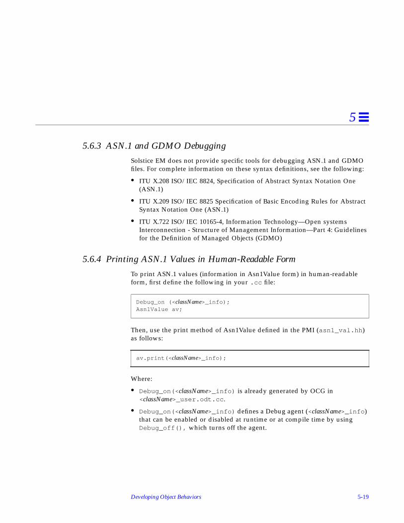
Developing Object Behaviors 5-19
5
5.6.3 ASN.1 and GDMO Debugging
Solstice EM does not provide specific tools for debugging ASN.1 and GDMOfiles. For complete information on these syntax definitions, see the following:
• ITU X.208 ISO/IEC 8824, Specification of Abstract Syntax Notation One(ASN.1)
• ITU X.209 ISO/IEC 8825 Specification of Basic Encoding Rules for AbstractSyntax Notation One (ASN.1)
• ITU X.722 ISO/IEC 10165-4, Information Technology—Open systemsInterconnection - Structure of Management Information—Part 4: Guidelinesfor the Definition of Managed Objects (GDMO)
5.6.4 Printing ASN.1 Values in Human-Readable Form
To print ASN.1 values (information in Asn1Value form) in human-readableform, first define the following in your .cc file:
Then, use the print method of Asn1Value defined in the PMI (asn1_val.hh )as follows:
Where:
• Debug_on(< className>_info) is already generated by OCG in<className>_user.odt.cc .
• Debug_on(< className>_info) defines a Debug agent (<className>_info )that can be enabled or disabled at runtime or at compile time by usingDebug_off(), which turns off the agent.
Debug_on (< className>_info);Asn1Value av;
av.print(< className>_info);

5-20 Solstice Enterprise Manager Application Development Guide
5
5.6.5 Debugging Flags
OCG generates debug agents (<className>_error and <className>_info ) forevery object class. If you specify OBAPIDEBUG as YES in the configurationfile, OCG enables these agents at compile time. To enable or disable theseagents at runtime, use em_debug and the following commands:
• em_debug -c “on < className>_info” to enable agent at runtime
• em_debug -c “off < className>_info” to disable agent at runtime
• em_debug -c “on < className>_*” to enable all debug agents for<className> at runtime
When debugging behaviors that require you to use Object Services API (forexample, if implementing inter-object behaviors), you can enable or disabledebug agents specifically for Object Services API calls. To enable these agents,use the “objsvc_ *” options for the em_debug utility as follows:
Or use the following command:
To disable these agents, use em_debug -c “off objsvc_*.”
5.7 Generated FilesIf you have created valid GDMO and ASN.1 definition files and loaded theminto the MDR, when you run OCG it creates the files in the target directoryspecified in your configuration file:
• Makefile .<className>
• README.<className>
• <className>_user.odt.cc
• <className>_user.odt.hh
• pmi_ <className>.cc
$EM_HOME/bin/em_debug -c "on objsvc_test$EM_HOME/bin/em_debug -c "on objsvc_error
$EM_HOME/bin/em_debug -c "on objsvc_*"

Developing Object Behaviors 5-21
5
• <className>.load
• <className>.unload
For complete examples of each of these files, see Section 5.10, “ObjectDevelopment Scenario Using Chai Object.”
5.7.1 Makefile (Makefile. <className>)
You use the Makefile to create (“make”) a dynamic linked library for everyobject class for either default or user-extended implementation.
5.7.2 Readme File (README.<className>)
The README file explains how to use the files generated by OCG.
5.7.3 User Header File (<className>_user.odt.hh )
This header file contains the class definitions for the object class <className>.OCG generates definitions for Attribute class, Action class, and Instance class.The Attribute and Action classes contain several helper methods that users canuse to access other attributes or actions defined in this file or to performread/write actions on other attributes or actions defined in this file, whileimplementing specific behavior for a given attribute or implementing a specificaction.
In addition to the class definitions, the user header file defines Action indices,Attribute indices, and OIDs for Attributes, Actions, and Name Bindings.
Note – You are not allowed to modify this file directly. The default objectimplementation build uses this file, so changes made to it will causeunpredictable results.
To add function prototypes or members in the header file, copy this file to<className>_user.hh and add your code there.

5-22 Solstice Enterprise Manager Application Development Guide
5
Table 5-3 identifies the Attribute classes OCG defines in this file:
Table 5-4 identifies the Action classes OCG defines in this file:
5.7.4 PMI Client Create Program for Object Instantiation(pmi_ <className>.cc )
The PMI client create program file contains PMI client application code that isused to instantiate an instance of the new object class after the dynamic libraryfor the new object class has been linked into the MIS.
Table 5-3 Attribute Class Helper Methods
Attribute Class Name Description
index2AttributeSectyInfo Converts from AttributeIndex to AttributeInfo
AttributeSectyInfo2index Converts from AttributeInfo to AttributeIndex
index2ActionSectyInfo Converts from ActionIndex to ActionSectyInfo
action Performs action
read/write/fetch/store Read/Write/Fetch/Store Attribute
Table 5-4 Action Class Helper Methods
Action Class Name Description
index2AttrSectyInfo Converts from AttributeIndex to AttributeInfo
index2ActionSectyInfo Converts from ActionIndex to ActionInfo
read Reads attribute
write Writes attribute
fetch Fetches attribute
store Stores attribute

Developing Object Behaviors 5-23
5
5.7.5 User Code File (<className>_user.odt.cc )
The C++ source file contains the user-level methods defined for Attribute,Action, and Instance classes. The user function stubs that OCG generatesinclude: read, write, fetch, store, action, create_vote, and destroy_vote. Inaddition, OCG generates a stub for receive_event if discrimination service isused.
Note – You are not allowed to modify this file directly. The default objectimplementation build uses this file, so changes made to it will causeunpredictable results.
To add user-defined behaviors, copy this file to <className>_user.cc and addyour code in the insertion areas clearly identified.
When implementing intra-object behaviors, you should use only the helpermethods defined in Attribute, Action, and Instances classes. Whenimplementing inter-object behavior, you should use the Object Services APIcalls as needed for behavior implementation.
5.7.6 Dynamic Loading File (<className>.load )
When you run this utility, the object implementation build is loaded into theplatform as a shared library. The new object implementation is read at MISstartup.
5.7.7 Dynamic Unloading File (<className>.unload )
When you run this utility, the object implementation is removed from theplatform. The object implementation is not read at MIS startup.
5.8 TRY Exception MacrosSolstice EM’s development environment includes some exception-handlingmacros that are used in cases where the C++ compiler does not handle theexception. These exception-handling macros are known as TRY macros. Thebasic elements of the TRY macros are the TRY block and the Handler block.

5-24 Solstice Enterprise Manager Application Development Guide
5
5.8.1 Overview
The TRY block brackets the code from which you want to receive exceptions. Itmust be followed immediately by a Handler block in which you specify how tohandle the exception.
Exceptions are scoped dynamically. What this means is that a TRY blockestablishes a new exception context. When you exit the TRY block, you returnto the previous exception context.
5.8.2 Code Structure
The basic structure of a TRY exception is as follows:
5.8.3 Code Examples
The following example from the chai scenario shows how the TRY macros areused in the generated code:
TRY { some block of code that may generate exceptions}
BEGHANDLERS CATCH macros that handle various exceptionsENDHANDLERS
TRY { // Fetch attribute specified by (ai) return subfetch(ai,cb);
} BEGHANDLERS CATCHALL {
#ifdef ODT_DEFAULT return (NOT_OK);#endif

Developing Object Behaviors 5-25
5
5.9 Object Development ExamplesSolstice EM comes with several examples that illustrate how to develop objectbehaviors. All of these examples are located in the $EM_HOME/src/odtdirectory. This directory includes a README file that explains how to buildthe examples.
Table 5-5 identifies the examples and provides a brief description of what eachone includes. A complete scenario that illustrates how to develop an object isincluded in Section 5.10, “Object Development Scenario Using Chai Object.”
} ENDHANDLERS}
Table 5-5 Object Development Examples
Class Name Description
cellSample Defines a set of intra-object complex behaviors. Basically, itlooks at an object and, if its behavior changes then thebehavior of its neighboring objects changes.
chai Looks at an attribute called “chaiReady” to decide whetherthere is any chai (tea) ready to drink. If not, it sends anaction “brewChai” to make more.
demoPing Defines behavior of a “native agent.”
demoregistry Provides an MIS client function to operate as a “remoteagent.” This demonstrates how to register an application,similar to a licensing facility.
demoServer Provides an MIS server function to operate as a “remoteagent.” This provides required support for demoregistryand diskInfo examples.
diskInfo Demonstrates behavior to get information from an external(outside the MIS) process.

5-26 Solstice Enterprise Manager Application Development Guide
5
▼ To Compile all Examples
You can compile and run the object behavior samples shipped with EMindividually or as a group. Instructions for running each of the individualsamples are provided in Section 5.9.1, “cellSample” through Section 5.9.5,“diskInfo.” In addition, Section 5.10, “Object Development Scenario Using ChaiObject” leads you through the entire process for the chai object in detail.
ODT provides a global Makefile that compiles all the object behavior examples.To build these examples, perform the following commands:
Note – This mechanism does not currently compile the cellSample example.You must compile and run cellSample by itself.
5.9.1 cellSample
5.9.1.1 Important Code Functions
The cellSample example illustrates how to use the Object Services API. Specificsections of the code are not specifically identified as being more important thanany others. You might want to look at all the code to see how the ObjectServices API can be used effectively.
▼ To Build the Example
1. Go to the ODT examples directory.
host_name# cd $EM_HOME/odt/srchost_name# Make all
host_name% cd $EM_HOME/src/odt/cellSample
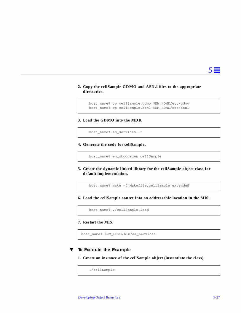
Developing Object Behaviors 5-27
5
2. Copy the cellSample GDMO and ASN.1 files to the appropriatedirectories.
3. Load the GDMO into the MDR.
4. Generate the code for cellSample.
5. Create the dynamic linked library for the cellSample object class fordefault implementation.
6. Load the cellSample source into an addressable location in the MIS.
7. Restart the MIS.
▼ To Execute the Example
1. Create an instance of the cellSample object (instantiate the class).
host_name% cp cellSample.gdmo $EM_HOME/etc/gdmohost_name% cp cellSample.asn1 $EM_HOME/etc/asn1
host_name% em_services -r
host_name% em_obcodegen cellSample
host_name% make -f Makefile.cellSample extended
host_name% ./cellSample.load
host_name% $EM_HOME/bin/em_services
./cellSample

5-28 Solstice Enterprise Manager Application Development Guide
5
2. Start OBED and run actions againt the cellSample.
5.9.2 demoPing
5.9.2.1 Important Code Functions
The demoPing example shows how you can develop a simple native agentusing the ODT.
Action Implementation:
//------------------------------------------------------------------//// ACTION IMPLEMENTATION ////------------------------------------------------------------------//// Switch for all actions specified in the GDMO definition of Managed //// Object Class. Add the Action implementation in individual case //// statements.//
// IMPORTANT NOTE: //// --------------- //// When implementating a Action, Please do not forget to return Action//// result in cd.result for individual actions in switch statement. //// //
// ODT_DEFAULT IMPLEMENTATION: //// ----------------------- //// Default implementation returns a NULL Asn1Value and indicates //// success by returning CHECK_DONE in CheckData. ////------------------------------------------------------------------//
switch(ai.local_value() ) { case IDX_pingHost:
#ifdef ODT_EXTENDED//********* $ODT_EXT_START [ACTION IMPLEMENTATION INSERT] **********//
{

Developing Object Behaviors 5-29
5
DataUnit hostname; input.decode_octets(hostname); demoPing_error.print("IS %s\n",hostname.chp());
if(!demoping(hostname, cb)) { cd.result = CheckData::CHECK_ERROR; cb.exec(&cd); } return;
}
//*********** $ODT_EXT_END [ACTION IMPLEMENTATION INSERT] ********//#endif break;
}; #ifdef ODT_DEFAULT
// Default implementation (returns NULL Action Response & Success) cd.result = CheckData::CHECK_DONE; cb.exec(&cd);#endif }
BEGHANDLERS CATCHALL {
#ifdef ODT_EXTENDED//******* $ODT_EXT_START [ EXCEPTION HANDLING CATCHALL INSERT] *****////******* $ODT_EXT_END [ EXCEPTION HANDLING CATCHALL INSERT] *****//#endif
} ENDHANDLERS}

5-30 Solstice Enterprise Manager Application Development Guide
5
demoPing Callback Function:
voiddemoping_cb(Ptr userdata, Ptr calldata)
{CheckData cd;demoping_userdata *d1 = (demoping_userdata *)userdata;DataUnit hostname = d1->hostname;
struct sockaddr_in from;int len;char buf[1024];int fromlen=sizeof(from);
if ( (len = recvfrom(d1->sockfd, (char *)buf, 1024 , 0,(sockaddr*)&from, &fromlen )) < 0)
{demoPing_error.print("Failed in recvfrom() for ICMP Packet \n");cd.result = CheckData::CHECK_ERROR;d1->cb.exec(&cd);purge_fd_read_callback(d1->sockfd);close(d1->sockfd);delete d1;return;}
demoPing_debug.print("received %d = %s\n",len,buf);demoPing_debug.print("from %ld\n",from.sin_addr);
pingreply_struct prpl;
if(!pr_pack( (char *)buf, len, &prpl)){post_fd_read_callback(d1->sockfd,
Callback((CallbackHandler)demoping_cb, d1));return;}
close(d1->sockfd);

Developing Object Behaviors 5-31
5
▼ To Build the Example
1. Go to the ODT examples directory.
2. Copy the demoPing GDMO and ASN.1 files to the appropriate directories.
3. Load the GDMO into the MDR.
Asn1Value direply;if(!make_pingrpl(&prpl,direply)){demoPing_error.print("Failed in encoding action reply\n");cd.result = CheckData::CHECK_ERROR;d1->cb.exec(&cd);purge_fd_read_callback(d1->sockfd);close(d1->sockfd);delete d1;return;}direply.print(demoPing_error);
cd.rv = direply;cd.result = CheckData::CHECK_DONE;purge_fd_read_callback(d1->sockfd);close(d1->sockfd);d1->cb.exec(&cd);delete d1;
}
host_name% cd $EM_HOME/src/odt/demoPing
host_name% cp demoping.gdmo $EM_HOME/etc/gdmohost_name% cp demoping.asn1 $EM_HOME/etc/asn1
host_name% em_services -r

5-32 Solstice Enterprise Manager Application Development Guide
5
4. Generate the code for demoPing.
5. Create the dynamic linked library for the demoPing object class fordefault implementation.
6. Load the demoPing source into an addressable location in the MIS.
7. Restart the MIS.
▼ To Execute the Example
1. Create an instance of the demoPing object (instantiate the class).
2. Start OBED and run action on instance specifying the hostname you wantto ping.
3. Alternatively, you can run the ODT Sample Program driver (odtsamples )and select the Ping option.
host_name% em_obcodegen demoping
host_name% make -f Makefile.demoping extended
host_name% ./demoping.load
host_name% $EM_HOME/bin/em_services
./pmi_demoPing

Developing Object Behaviors 5-33
5
5.9.3 demoregistry
5.9.3.1 Important Code Functions
Action Implementation:
//------------------------------------------------------------------//// ACTION IMPLEMENTATION ////------------------------------------------------------------------//// Switch for all actions specified in the GDMO definition of Managed //// Object Class. Add the Action implementation in individual case //// statements. //
// IMPORTANT NOTE: //// --------------- //// When implementating a Action, Please do not forget to return Action//// result in cd.result for individual actions in switch statement. //// //
// ODT_DEFAULT IMPLEMENTATION: //// ----------------------- //// Default implementation returns a NULL Asn1Value and indicates //// success by returning CHECK_DONE in CheckData. ////------------------------------------------------------------------//
switch(ai.local_value() ) { case IDX_emDemoRegistryReg:#ifdef ODT_EXTENDED
//********** $ODT_EXT_START [ACTION IMPLEMENTATION INSERT] **********// {
Asn1Value hostasn1; Asn1Value appasn1; Asn1Value appidasn1; Asn1Value temp; DataUnit appname; DataUnit hostname; I32 appid;

5-34 Solstice Enterprise Manager Application Development Guide
5
input.first_component(temp); temp.first_component(hostasn1); input.next_component(temp,temp); temp.first_component(appasn1); input.next_component(temp,temp); temp.first_component(appidasn1);
hostasn1.decode_octets(hostname); appasn1.decode_octets(appname); appidasn1.decode_int(appid);
if(!register_me(appname, hostname, appid, cb)) { cd.result = CheckData::CHECK_ERROR; cb.exec(&cd); } return;
}
//********** $ODT_EXT_END [ACTION IMPLEMENTATION INSERT] **********//#endif break; case IDX_emDemoRegistryValidateCookie:
#ifdef ODT_EXTENDED//*********** $ODT_EXT_START [ACTION IMPLEMENTATION INSERT] *********// // Use it to implement some good cookie eating in your app//*********** $ODT_EXT_END [ACTION IMPLEMENTATION INSERT] **********//#endif
break; case IDX_emDemoRegistryUnreg:
#ifdef ODT_EXTENDED//********* $ODT_EXT_START [ACTION IMPLEMENTATION INSERT] **********//
{ Asn1Value hostasn1; Asn1Value appasn1; Asn1Value appidasn1; Asn1Value temp;

Developing Object Behaviors 5-35
5
DataUnit appname; DataUnit hostname; I32 appid;
input.first_component(temp); temp.first_component(hostasn1); input.next_component(temp,temp); temp.first_component(appasn1); input.next_component(temp,temp); temp.first_component(appidasn1);
hostasn1.decode_octets(hostname); appasn1.decode_octets(appname); appidasn1.decode_int(appid);
if(!unregister_me(appname, hostname, appid, cb)) { cd.result = CheckData::CHECK_ERROR; cb.exec(&cd); } return;
}
//********** $ODT_EXT_END [ACTION IMPLEMENTATION INSERT] **********//#endif break; };
#ifdef ODT_DEFAULT// Default implementation (returns NULL Action Response & Success)
cd.result = CheckData::CHECK_DONE; cb.exec(&cd);#endif

5-36 Solstice Enterprise Manager Application Development Guide
5
Function to Register Application:
} BEGHANDLERS CATCHALL {
#ifdef ODT_EXTENDED//******** $ODT_EXT_START [ EXCEPTION HANDLING CATCHALL INSERT] *****////******** $ODT_EXT_END [ EXCEPTION HANDLING CATCHALL INSERT] *****//#endif
} ENDHANDLERS}
Resultregister_me(DataUnit &appname, DataUnit &hostname, int appid,
Callback &cb){
demoregistry_userdata *d1=new demoregistry_userdata;emDemoRegister info;
strcpy(info.appname,appname.chp());strcpy(info.hostname,hostname.chp());
if(! demoClientSend( &info, DemoRegister, d1->sockfd,hostname.chp()) )
return(NOT_OK);
d1->cb = (Callback *)&cb;d1->appname = appname;d1->hostname = hostname;d1->appid = appid;
post_fd_read_callback(d1->sockfd, Callback((CallbackHandler)demoregistry_cb, d1));
return OK;}

Developing Object Behaviors 5-37
5
Function to Unregister Application:
▼ To Build the Example
1. Go to the ODT examples directory.
2. Copy the demoregistry GDMO and ASN.1 files to the appropriatedirectories.
Resultunregister_me(DataUnit &appname, DataUnit &hostname, int appid,
Callback &cb){
demoregistry_userdata *d1=new demoregistry_userdata;emDemoRegister info;
strcpy(info.appname,appname.chp());strcpy(info.hostname,hostname.chp());
if(! demoClientSend( &info, DemoUnregister, d1->sockfd,hostname.chp()) )
return(NOT_OK);
d1->cb = (Callback *)&cb;d1->appname = appname;d1->hostname = hostname;d1->appid = appid;
post_fd_read_callback(d1->sockfd, Callback((CallbackHandler)demounregistry_cb, d1));
return OK;}
host_name% cd $EM_HOME/src/odt/demoregistry
host_name% cp demoregistry.gdmo $EM_HOME/etc/gdmohost_name% cp demoregistry.asn1 $EM_HOME/etc/asn1

5-38 Solstice Enterprise Manager Application Development Guide
5
3. Load the GDMO into the MDR.
4. Generate the code for demoregistry.
5. Create the dynamic linked library for the demoregistry object class fordefault implementation.
6. Load the demoregistry source into an addressable location in the MIS.
7. Restart the MIS.
▼ To Execute the Example
1. Create an instance of demoregistry class (instantiate the class).
2. Run demo_server on your local host or, if running on a remote host makesure EM is installed on the remote host.
3. Start OBED and find the object instance under EM-MIS.
4. Click on the OI and issue a DemoReg action where the ActionInfoparameter is {“hostname”, “ApplicationName”, 345} .
host_name% em_services -r
host_name% em_obcodegen demoregistry
host_name% make -f Makefile.demoregistry extended
host_name% ./demoregistry.load
host_name% $EM_HOME/bin/em_services
./pmi_demoregistry

Developing Object Behaviors 5-39
5
5. Alternatively, you can run the ODT Sample Program driver (odtsamples )and run the Register option or the UnRegister option.
5.9.4 demoServer
▼ To Build the Example
1. Go to the ODT examples directory.
2. Create the dynamic linked library for the demoServer object class fordefault implementation.
▼ To Execute the Example
To start the demo_server:
5.9.5 diskInfo
▼ To Build the Example
1. Go to the ODT examples directory.
host_name% cd $EM_HOME/src/odt/demoServer
host_name% make
> demo_server
host_name% cd $EM_HOME/src/odt/diskInfo

5-40 Solstice Enterprise Manager Application Development Guide
5
2. Copy the diskInfo GDMO and ASN.1 files to the appropriate directories.
3. Load the GDMO into the MDR.
4. Generate the code for diskInfo.
5. Create the dynamic linked library for the diskInfo object class for defaultimplementation.
6. Load the diskInfo source into an addressable location in the MIS.
7. Restart the MIS.
▼ To Execute the Example
1. Create an instance of the diskInfo object (instantiate the class).
host_name% cp diskInfo.gdmo $EM_HOME/etc/gdmohost_name% cp diskInfo.asn1 $EM_HOME/etc/asn1
host_name% em_services -r
host_name% em_obcodegen diskInfo
host_name% make -f Makefile.diskInfo extended
host_name% ./diskInfo.load
host_name% $EM_HOME/bin/em_services
./pmi_diskInfo

Developing Object Behaviors 5-41
5
2. Start OBED and run an action on the object instance, specifying thehostname about which you want to get disk information.
3. Alternatively, you can run the ODT Sample Program driver (odtsamples )and select the DiskInfo of a Host option.
5.10 Object Development Scenario Using Chai ObjectThe sample files shipped with Solstice Enterprise Manager for objectdevelopment scenarios provide important information in README files.Although the information in the README files is fairly complete, this sectionof the documentation provides an expanded view of the object developmentscenario for the Chai managed object.
▼ To Create Your own Object Class
1. Load the chai managed object into the Meta Data Repository (MDR).
2. Define environment variables, if needed.Location of hidden/intermediate files:HIDDENDIR=/tmp
Data storage for OC whether PERSISTENT or VOLATILE:DATASTORAGE=PERSISTENT
3. Go to the directory where you want your code to be generated.
% cd user_directory
# em_gdmo < hostname > chai.gdmo# em_asn1 -o ‘pwd’ chai.asn1# cp 1.3.6.1.4.1.42.2.2.2.1.96.3.1/var/opt/SUNWconn/em/usr/data/ASN1# cp *-ASN1 /var/opt/SUNWconn/em/usr/data/ASN1

5-42 Solstice Enterprise Manager Application Development Guide
5
4. Generate the C++ code for your objects.You will see output similar to the following:
Note that OCG identifies the attributes, actions, and name bindings forwhich code will be generated.
The following files are generated:• Makefile.chai
• README.chai
• chai.load
• chai.unload
• chai_user.odt.cc
• chai_user.odt.hh
• pmi_chai.cc
5. Compile and make the dynamic library for the default implementation.
This command compiles and makes a dynamic library called chai.so .
host_name% em_obcodegen chaiobjdefn_info: Attribute Name is chaiKettleNumberobjdefn_info: Attribute Name is chaiBlendobjdefn_info: Attribute Name is chaiReadyobjdefn_info: Attribute Name is discriminatorConstructobjdefn_info: Attribute Name is administrativeStateobjdefn_info: Attribute Name is operationalStateobjdefn_info: Total Number Of Attributes is 6objdefn_info: ********************************objdefn_info: Action Name is brewChaiobjdefn_info: Total Number Of Actions is 1objdefn_info: *****************************objdefn_info: Name Binding Name is chai-systemobjdefn_info: Name Binding Name is chai-chaiobjdefn_info: Total Number Of Name Bindings is 2objdefn_info: ***********************************
% make -f Makefile.chai default

Developing Object Behaviors 5-43
5
6. Create a customized implementation.
To create a customized implementation, you need to first modify the sourcecode. Then, to compile and make a customized library, use the followingformat:
7. Load the new dynamic library.
8. Terminate and restart the MIS.
9. Instantiate the new chai object.
10. Run the debugger to verify the object behaves as expected.
% make -f Makefile.chai extended
% chai.load
# em_services
% cd chai_Create_program% make chai% chai// This creates the chai object% chai -g// This gets attributes of new chai object
% debugger $EM_HOME/bin/em_mis & stop in DynLoader::DynLoader run

5-44 Solstice Enterprise Manager Application Development Guide
5
5.10.1 Debugging Flags
The following code lines that contain the debug agents for the chai object classare included in the chai_user.odt.cc file.
If debug agents are spread across multiple files, the above definitions mustonly be included in the chai_user.hh file (copied and modified fromchai_user.odt.hh ). The other files need to contain the following code lines:
5.10.2 Sample Behavior Implementation
The following program implements specialized behavior for the chaiReadyattribute. If chaiReady is 0, then set the chaiBlend to “Earl Grey” and sendbrewAction.
To add this behavior, insert the following piece of code in chai_user.cc atthe location of chai_AttrSecty::read() after the subread is performed.
Debug_on(cahi_info)Debug_on(chai_error)
extern Debug chai_info;extern Debug chai_error;
// User Behavior Extension: Start// Def: If the chaiReady is equal to 0 then// Set the blend to “Earl Grey” and then send a action// to brewchai.
// SectyInfo definitionAttrSectyInfo AttrInfo;ActionSectyInfo ActionInfo;
Asn1Value ready, blend, Orig_Blend;I32 Is_chai_Ready;
// Get original index of our Attributeint org_index = AttrSectyInfo2index(ai);

Developing Object Behaviors 5-45
5
5.10.3 chai Object Class Definitions
The example GDMO and ASN.1 definitions for the chai object class areinstalled into the $EM_HOME/src/odt/chai directory when you install theODT onto your system (SUNWemobj package).
// Check to see we’re reading chaiReady, if yes, thenspecialize// the behavior
if (org_index == IDX_chaiReady) { if (av) {av.decode_int(Is_chai_Ready);if (!Is_chai_Ready){// We’re out of chai.. brew and choose my blend // Earl Grey index2AttrSectyInfo(IDX_chaiBlend, AttrInfo); (void) fetch(AttrInfo, NULL_CALLBACK); (void) read(AttrInfo, Orig_Blend);
DataUnit O_blend; Asn1Value new_blend;
Orig_Blend.decode_octets(O_blend); chai_debug.print(“Read Secretary - chai_Blend is\n”); Orig_Blend.print(chai_debug); if (O_blend != DataUnit(“Earl Grey”)) { // Special check to blend only Earl Grey DataUnit chai_blend(“Earl Grey”);
new_blend.encode_octets(TAG_OCTSTR, chai_blend); (void) write(AttrInfo, new_blend);
(void) store(AttrInfo, NULL_CALLBACK); }
// Go Ahead and Brewchaiindex2ActionSectyInfo(IDX_brewchai, ActionInfo);
action(ActionInfo, new_blend, NULL_CALLBACK);}}
}

5-46 Solstice Enterprise Manager Application Development Guide
5
The chai.gdmo file defines the following attributes:
• chaiKettleNumber
• chaiBlend
• chaiReady
The chai.gdmo file also defines the following action:
• brewChai
5.10.3.1 Sample chai.gdmo Definitions File
-- Copyright 03 Apr 1996 Sun Microsystems, Inc. All Rights Reserved.---- #pragma ident “@(#)chai.gdmo1.2 96/04/03 Sun Microsystems”
MODULE “EM Chai Document”
basechai MANAGED OBJECT CLASSDERIVED FROM “Rec. X.721 | ISO/IEC 10165-2 : 1992” : top;
CHARACTERIZED BYchaiPackage;REGISTERED AS { em-chai-objectClass 0 };
chaiPackage PACKAGEBEHAVIOUR chaiPackageDefinition BEHAVIOUR DEFINED AS!This managed object class represents the chaifrom the neighbourhood chai shop !;;ATTRIBUTESchaiKettleNumber GET-REPLACE,chaiBlend GET-REPLACE,chaiReady GET-REPLACE,“Rec. X.721 | ISO/IEC 10165-2 : 1992” : discriminatorConstruct
REPLACE-WITH-DEFAULTDEFAULT VALUE Attribute

Developing Object Behaviors 5-47
5
ASN1Module.defaultDiscriminatorConstructGET-REPLACE,
“Rec. X.721 | ISO/IEC 10165-2 : 1992” : administrativeStateGET-REPLACE,
“Rec. X.721 | ISO/IEC 10165-2 : 1992” : operationalStateGET;
ACTIONSbrewChai;NOTIFICATIONS“Rec. X.721 | ISO/IEC 10165-2 : 1992” :
objectCreation,“Rec. X.721 | ISO/IEC 10165-2 : 1992” :
objectDeletion,“Rec. X.721 | ISO/IEC 10165-2 : 1992” :
attributeValueChange;REGISTERED AS { em-chai-package 1 };
chai MANAGED OBJECT CLASSDERIVED FROM basechai;REGISTERED AS { em-chai-objectClass 1 };
-- Actions
brewChai ACTIONMODE CONFIRMED;WITH INFORMATION SYNTAX Chai-ASN1.ChaiString;WITH REPLY SYNTAX Chai-ASN1.ChaiString;REGISTERED AS { em-chai-action 1 };
-- Name Bindings
chai-system NAME BINDINGSUBORDINATE OBJECT CLASS chai;NAMED BYSUPERIOR OBJECT CLASS “Rec. X.721 | ISO/IEC 10165-2 : 1992” : system;WITH ATTRIBUTE chaiKettleNumber;BEHAVIOUR chai-rootBehaviour BEHAVIOUR DEFINED AS!This name is used to define the chai objectname binding!;;CREATE;DELETE ONLY-IF-NO-CONTAINED-OBJECTS;REGISTERED AS { em-chai-binding 1 };

5-48 Solstice Enterprise Manager Application Development Guide
5
chai-chai NAME BINDINGSUBORDINATE OBJECT CLASS chai;NAMED BYSUPERIOR OBJECT CLASS chai;WITH ATTRIBUTE chaiKettleNumber;BEHAVIOUR chai-systemchai BEHAVIOUR DEFINED AS!This name is used to define the chai objectname binding under system branch!;;CREATE;DELETE ONLY-IF-NO-CONTAINED-OBJECTS;REGISTERED AS { em-chai-binding 2 };
-- Attributes
chaiKettleNumber ATTRIBUTEWITH ATTRIBUTE SYNTAX Chai-ASN1.ChaiInteger;MATCHES FOR EQUALITY;BEHAVIOUR chaiKettleNumberBehaviour BEHAVIOUR DEFINED AS!This is the naming attribute for the chaiobject.!;;REGISTERED AS { em-chai-attribute 1 };
chaiBlend ATTRIBUTEWITH ATTRIBUTE SYNTAX Chai-ASN1.ChaiString;MATCHES FOR EQUALITY;BEHAVIOUR chaiBlendBehaviour BEHAVIOUR DEFINED AS!This is the blend of chai that is brewingin the current Kettle!;;REGISTERED AS { em-chai-attribute 2 };
chaiReady ATTRIBUTEWITH ATTRIBUTE SYNTAX Chai-ASN1.ChaiInteger;MATCHES FOR EQUALITY;BEHAVIOUR chaiReadyBehaviour BEHAVIOUR DEFINED AS!If this attribute is true there is chai inthe Kettle!;;REGISTERED AS { em-chai-attribute 3 };
END

Developing Object Behaviors 5-49
5
5.10.3.2 Sample chai.asn1 Definitions File
5.10.4 Sample PMI Program to Create a New chai Object Instance
-- Copyright 03 Apr 1996 Sun Microsystems, Inc. All Rights Reserved.---- #pragma ident "@(#)chai.asn11.2 96/04/03 Sun Microsystems
Chai-ASN1{iso(1) org(3) dod(6) internet(1) private(4) enterprises(1) sun(42)
products(2) management(2) em(2) odt(1) em-chai(96)asn1Module(2) 0}
DEFINITIONS ::=BEGINem-chai OBJECT IDENTIFIER ::=
{iso(1) org(3) dod(6) internet(1) private(4) enterprises(1) sun(42) products(2) management(2) em(2) odt(1) em-chai(96)}
em-chai-objectClass OBJECT IDENTIFIER ::= { em-chai 3 }em-chai-package OBJECT IDENTIFIER ::= { em-chai 4 }em-chai-binding OBJECT IDENTIFIER ::= { em-chai 6 }em-chai-attribute OBJECT IDENTIFIER ::= { em-chai 7 }em-chai-action OBJECT IDENTIFIER ::= { em-chai 9 }
ChaiInteger ::= INTEGERChaiString ::= GraphicStringChaiBoolean ::= BOOLEANEND
/*“This file is generated using Solstice EM (2.0) - Object DevelopmentTools” Code Generator*/

5-50 Solstice Enterprise Manager Application Development Guide
5
#include <hi.hh>#include <error.hh>#include <sys/types.h>#include <unistd.h>#ifdef HPUX#include <sys/param.h>#else#include <sys/systeminfo.h>#endif
void create_chai( DU &dn);
main(int argc, char **argv){
printf(“MODIFY THE GENERATED CODE FILE ./pmi_chai.cc \n”);exit(0);
Platform plat(duEM);
if (plat.get_error_type() != PMI_SUCCESS){
printf(“Platform constructor failed...\n”); printf(“Reason: %s\n”, plat.get_error_string()); exit(1); }
// Initialize to the dn of object
// dn can be a name starting from local root or fully distinguishedname
DU dn; /* DISTINIGUISHED NAME OF OBJECT HERE*/
// Connect to the mis running on the local hostif (!plat.connect(“localhost”, “chai_sample”)){printf(“Connecting to platform Failed \n”);
printf(“Reason: %s\n”, plat.get_error_string());exit(2);}

Developing Object Behaviors 5-51
5
// Create the objectcreate_chai(dn);
}
voiddisplay_attributes(Image &im){
// Get all the attribute names in an Array of DataUnits.// Perform a get on each attribute to get its value// Note we have stripped off the document name to make// the attribute value pairs more readable// the chp() method of the DataUnit is necessary to null// terminate the DataUnit.//
Array(DU) attr_names = im.get_attr_names(); fprintf(stdout, “Attribute\tValue\n---------\t-----\n”); for (int i=0; i<attr_names.size; i++) { DU& name = attr_names[i]; // note: next to lines use chp() function to convert a // DataUnit into char *. char *short_name = strrchr(attr_names[i].chp(),’:’); fprintf(stdout, “%s: \t%s \n”, ++short_name, im.get_str(name,USE_EXPLICIT_CHOICE|OMIT_NEWLINES).chp()); } fprintf(stdout, “\n\n”); fflush(stdout);}
voidcreate_chai(DU &dn){
Image im;im = Image(dn,DU(“chai”));

5-52 Solstice Enterprise Manager Application Development Guide
5
if (!im.boot()){printf(“Image::boot Failed %s\n”,im.get_error_string());exit(3);}
/* UNCOMMENT AND MODIFY THE APPROPRIATE LINES IF YOU WANT TO CREATE * OBJECT WITH SOME ATTRIBUTE VALUESif (!im.set_str(“chaiKettleNumber”, “None”)){printf(“Image::set_str() failed for chaiKettleNumber: %s %d\n”,
im.get_error_string(), im.get_error_type());exit(4);}if (!im.set_str(“chaiBlend”, “None”)){printf(“Image::set_str() failed for chaiBlend: %s %d\n”,
im.get_error_string(), im.get_error_type());exit(4);}if (!im.set_str(“chaiReady”, “None”)){printf(“Image::set_str() failed for chaiReady: %s %d\n”,
im.get_error_string(), im.get_error_type());exit(4);} * */if (im.get_error_type() != PMI_SUCCESS){printf(“Image::set_str Failed %s\n”,im.get_error_string());exit(5);}
if (!im.create()){printf(“Create Failed %s\n”,im.get_error_string());exit(6);}printf(“Created instance %s\n”, dn.chp());
display_attributes(im);}

Developing Object Behaviors 5-53
5
5.11 Generated Interfaces and ExamplesThe following list summarizes the functions or points in the generated codethat can be modified by a user of the Object Behavior Interface. For mostobjects, you will not need to supply additional code for every interface pointlisted here:
• Attribute secretary read function: className_AttrSecty::read
• Attribute secretary write function: className_AttrSecty::write
• Attribute secretary read function: className_AttrSecty::fetch
• Attribute secretary write function: className_AttrSecty::store
• Action secretary check function: classNameActionSecty::action
• Action secretary perform function:className_InstanceSecty::create_vote
• Action secretary do not perform function:className_AttributeSecty::destroy_vote
• Dynamic Loader interface: className_loader
5.11.1 Example Generated Code in .cc File
The following generated code stub examples are based on the chai exampleobject. A complete scenario for defining the chai object is provided inSection 5.10, “Object Development Scenario Using Chai Object.” The actualcode that OCG generates can contain additional comments not reflected in thisbook.
Note – Throughout these examples and in any code generated by OCG, thereare lines that are similar to this://********** $ODT_EXT_START [LOCAL VARIABLE INSERT] ************//
//********** $ODT_EXT_END [LOCAL VARIABLE INSERT] ************//
These lines indicate areas in the code where you can safely add your own codeto the generated code to further customize object behaviors.

5-54 Solstice Enterprise Manager Application Development Guide
5
5.11.1.1 Generated Asynchronous Read Stub Function (FETCH)
Function:
Description:This function is an asynchronous interface for reading attributes. For everyattribute requested in a GET request, MIS Framework calls fetch() for thatattribute, followed by a read() of the same attribute.
Arguments:This function uses the following arguments:
• ai indicates the attribute to be read.
• cb identifies the callback routine passed by Framework.
Return Value:This function returns the following values:
• OK if the attribute is fetched and read successfully.
• NOT_OK to indicate failure in fetching/reading attribute specified by ai .
Code Example:
chai_AttrSecty::fetch
Resultchai_AttrSecty::fetch(const AttrSectyInfo &ai, const Callback &cb){ TRACE(Tracer TR(chai_trace, "chai_AttrSecty::fetch", "this = 0x%lx, const AttrSectyInfo &ai = 0x%lx, const Callback &cb= " "0x%lx", (void*)this, &ai, (void*)cb));
#ifdef ODT_EXTENDED//********** $ODT_EXT_START [LOCAL VARIABLE INSERT] ************////********** $ODT_EXT_END [LOCAL VARIABLE INSERT] ************//#endif

Developing Object Behaviors 5-55
5
5.11.1.2 Generated Asynchronous Write Stub Function (STORE)
Function:
Description:This function is an asynchronous interface for storing attributes. For everyattribute requested in a SET request, MIS Framework calls write() for thatattribute, followed by a store() of the same attribute.
TRY { // Fetch attribute specified by (ai) return subfetch(ai,cb);
#ifdef ODT_EXTENDED//***** $ODT_EXT_START [FETCH BEHAVIOUR SPECIALIZATION INSERT ] **////***** $ODT_EXT_END [FETCH BEHAVIOUR SPECIALIZATION INSERT ] **//#endif
} BEGHANDLERS CATCHALL {
#ifdef ODT_DEFAULT return (NOT_OK);#endif
#ifdef ODT_EXTENDED//***** $ODT_EXT_START [ EXCEPTION HANDLING CATCHALL INSERT] *****////***** $ODT_EXT_END [ EXCEPTION HANDLING CATCHALL INSERT] *****//#endif
} ENDHANDLERS}
chai_AttrSecty::store
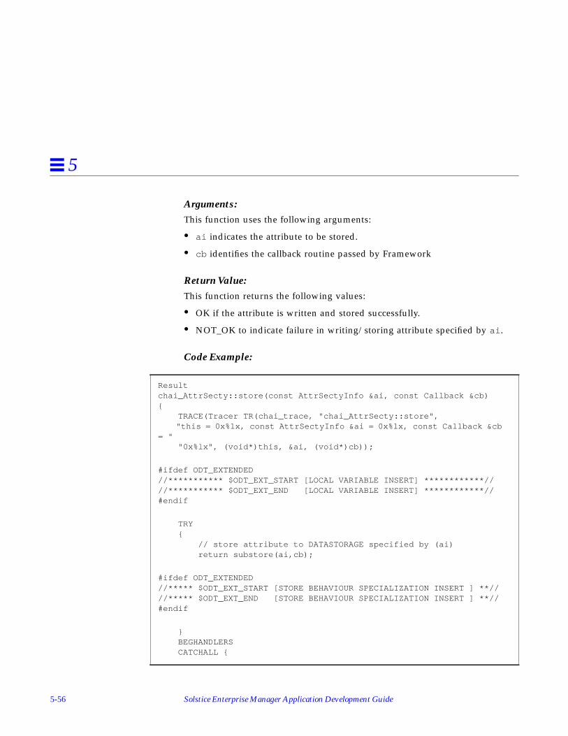
5-56 Solstice Enterprise Manager Application Development Guide
5
Arguments:This function uses the following arguments:
• ai indicates the attribute to be stored.
• cb identifies the callback routine passed by Framework
Return Value:This function returns the following values:
• OK if the attribute is written and stored successfully.
• NOT_OK to indicate failure in writing/storing attribute specified by ai .
Code Example:
Resultchai_AttrSecty::store(const AttrSectyInfo &ai, const Callback &cb){ TRACE(Tracer TR(chai_trace, "chai_AttrSecty::store", "this = 0x%lx, const AttrSectyInfo &ai = 0x%lx, const Callback &cb= " "0x%lx", (void*)this, &ai, (void*)cb));
#ifdef ODT_EXTENDED//*********** $ODT_EXT_START [LOCAL VARIABLE INSERT] ************////*********** $ODT_EXT_END [LOCAL VARIABLE INSERT] ************//#endif
TRY { // store attribute to DATASTORAGE specified by (ai) return substore(ai,cb);
#ifdef ODT_EXTENDED//***** $ODT_EXT_START [STORE BEHAVIOUR SPECIALIZATION INSERT ] **////***** $ODT_EXT_END [STORE BEHAVIOUR SPECIALIZATION INSERT ] **//#endif
} BEGHANDLERS CATCHALL {

Developing Object Behaviors 5-57
5
5.11.1.3 Generated Synchronous Read Stub Function (READ)
Function:
Description:This function is a synchronous interface for reading attributes. For everyattribute requested in a GET request, MIS Framework calls read() for thatattribute.
Arguments:This function uses the following arguments:
• ai indicates the attribute to be read.
• av identifies the Asn1Value of the attribute read (output parameter).
Return Value:This function returns the following values:
• OK if the attribute is read successfully.
• NOT_OK to indicate failure.
#ifdef ODT_DEFAULT return (NOT_OK);#endif
#ifdef ODT_EXTENDED//***** $ODT_EXT_START [ EXCEPTION HANDLING CATCHALL INSERT] *****////***** $ODT_EXT_END [ EXCEPTION HANDLING CATCHALL INSERT] *****//#endif
} ENDHANDLERS}
chai_AttrSecty::read

5-58 Solstice Enterprise Manager Application Development Guide
5
Code Example:
Resultchai_AttrSecty::read(const AttrSectyInfo &ai, Asn1Value &av){ TRACE(Tracer TR(chai_trace, "chai_AttrSecty::read", "this = 0x%lx, const AttrSectyInfo &ai = 0x%lx, Asn1Value &av = " "0x%lx", (void*)this, &ai, (void*)av));
#ifdef ODT_EXTENDED//*********** $ODT_EXT_START [LOCAL VARIABLE INSERT] ************////*********** $ODT_EXT_END [LOCAL VARIABLE INSERT] *************//#endif
TRY { int index = AttrSectyInfo2index(ai);
// Validate passed attribute index if(!is_valid_index(index)) { return NOT_OK; }
// Read in-memory value of attribute specified by (ai) TRYRES (subread(ai,av));
// Assign read attribute value index2lhsvalue(index) = av ;
#ifdef ODT_EXTENDED//***** $ODT_EXT_START [READ BEHAVIOUR SPECIALIZATION INSERT] ****////***** $ODT_EXT_END [READ BEHAVIOUR SPECIALIZATION INSERT] ****//#endif return(OK); } BEGHANDLERS CATCHALL {
#ifdef ODT_DEFAULT return (NOT_OK);#endif

Developing Object Behaviors 5-59
5
5.11.1.4 Generated Synchronous Write Stub Function (WRITE)
Function:
Description:This function is a synchronous interface for writing attributes. For everyattribute requested in a SET request, MIS Framework calls write() for thatattribute.
Arguments:This function uses the following arguments:
• ai indicates the attribute to be written.
• av identifies the Asn1Value of the attribute written (output parameter).
Return Value:This function returns the following values:
• OK if the attribute is written successfully.
• NOT_OK to indicate failure.
#ifdef ODT_EXTENDED//***** $ODT_EXT_START [ EXCEPTION HANDLING CATCHALL INSERT] *****////***** $ODT_EXT_END [ EXCEPTION HANDLING CATCHALL INSERT] *****//#endif
} ENDHANDLERS}
chai_AttrSecty::write

5-60 Solstice Enterprise Manager Application Development Guide
5
Code Example:
Resultchai_AttrSecty::write(const AttrSectyInfo &ai, const Asn1Value &av){ TRACE(Tracer TR(chai_trace, "chai_AttrSecty::write", "this = 0x%lx, const AttrSectyInfo &ai = 0x%lx, const Asn1Value " "&av = 0x%lx", (void*)this, &ai, (void*)av));
#ifdef ODT_EXTENDED//*********** $ODT_EXT_START [LOCAL VARIABLE INSERT] ************////*********** $ODT_EXT_END [LOCAL VARIABLE INSERT] *************//#endif
TRY { int index = AttrSectyInfo2index(ai);
// Validate passed attribute index if(!is_valid_index(index)) { return NOT_OK; }
// Assign written attribute value index2lhsvalue(index) = av ;
// Execute Write thru TRYRES (subwrite(ai,av));
#ifdef ODT_EXTENDED//***** $ODT_EXT_START [WRITE BEHAVIOUR SPECIALIZATION INSERT ] **////***** $ODT_EXT_END [WRITE BEHAVIOUR SPECIALIZATION INSERT ] **//#endif
return(OK); }
BEGHANDLERS CATCHALL {

Developing Object Behaviors 5-61
5
5.11.1.5 Generated Action Stub Function (ACTION)
Function:
Description:This function is an asynchronous interface for handling CMIP ACTIONS. TheCMIP actions handled are those specified in the Managed Object Classdefinition in the GDMO.
Arguments:This function uses the following arguments:
• ai indicates the action.
• av indicates the Asn1Value specified by the user through theINFORMATION SYNTAX clause in the GDMO ACTION definition.
• cb identifies the callback routine passed by Framework to process cb.exec(CheckData) where CheckData contains the returned ACTION RESPONSEand ACTION RESULT.
#ifdef ODT_DEFAULT return (NOT_OK);#endif
#ifdef ODT_EXTENDED//***** $ODT_EXT_START [ EXCEPTION HANDLING CATCHALL INSERT] *****////***** $ODT_EXT_END [ EXCEPTION HANDLING CATCHALL INSERT] *****//#endif
} ENDHANDLERS}
chai_AttrSecty::action

5-62 Solstice Enterprise Manager Application Development Guide
5
Return Value:This function returns no values aside from those passed back in the cbargument. CheckData return values are:
• Operation completed successfully• Set cd.result to CHECK_DONE.• Set cd.rv to encoded Asn1Value of ACTION RESPONSE.
• Operation terminated with an error• Set cd.result to CHECK_ERROR.• Set cd.rv to specific ACTION error or to NULL.
Code Example:
voidchai_ActionSecty::action(const ActionSectyInfo &ai, const Asn1Value &input, const Callback &cb){ TRACE(Tracer TR(chai_trace, "chai_ActionSecty::action", "this = 0x%lx, const ActionSectyInfo &ai = 0x%lx, const Asn1Value " "&input = 0x%lx, const Callback &cb = 0x%lx", (void*)this, &ai, (void*)input, (void*)cb ));
#ifdef ODT_EXTENDED//*********** $ODT_EXT_START [LOCAL VARIABLE INSERT] ************////*********** $ODT_EXT_END [LOCAL VARIABLE INSERT] ************//#endif
TRY {
CheckData cd; // CheckData (cd) - Action Responsevalue //

Developing Object Behaviors 5-63
5
5.11.1.6 Generated Instance Create Stub Function (CREATE)
Function:
switch(ai.local_value() ) { case IDX_brewChai:#ifdef ODT_EXTENDED//********* $ODT_EXT_START [ACTION IMPLEMENTATION INSERT] *******////********* $ODT_EXT_END [ACTION IMPLEMENTATION INSERT] ********//#endif break;
};
#ifdef ODT_DEFAULT// Default implementation (returns NULL Action Response & Success)
cd.result = CheckData::CHECK_DONE; cb.exec(&cd);#endif
}
BEGHANDLERS CATCHALL {
#ifdef ODT_EXTENDED//****** $ODT_EXT_START [ EXCEPTION HANDLING CATCHALL INSERT] ****////****** $ODT_EXT_END [ EXCEPTION HANDLING CATCHALL INSERT] ****//#endif
} ENDHANDLERS}
chai_AttrSecty::create_vote

5-64 Solstice Enterprise Manager Application Development Guide
5
Description:This function lets you validate a CMIP CREATE request before theinfrastructure creates the object instance. The function is passed a resolvedattribute list and FDN, which you can validate before voting OK or NOT_OK.
Arguments:This function uses the following arguments:
• fdn is the FDN (Fully-Distinguished Name) of the object instance to becreated.
• av identifies the Asn1Value of the resolved Attribute List.
Return Value:This function returns the following values:
• OK to go ahead and create the object instance.
• NOT_OK to not create the object instance.
Code Example:
Resultchai_InstanceSecty::create_vote(const Asn1Value &fdn, const Asn1Value &av){ TRACE(Tracer TR(chai_trace, "chai_InstanceSecty::create", "this = 0x%lx, const Asn1Value &fdn = 0x%lx, const Asn1Value " "&av = 0x%lx", (void*)this, &ai, (void*)fdn, (void*)av ));
#ifdef ODT_EXTENDED//*********** $ODT_EXT_START [LOCAL VARIABLE INSERT] ************////*********** $ODT_EXT_END [LOCAL VARIABLE INSERT] *************//#endif
TRY {

Developing Object Behaviors 5-65
5
5.11.1.7 Generated Instance Destroy Stub Function (DELETE)
Function:
Description:This function lets you validate a CMIP DELETE request before theinfrastructure deletes the object instance.
Arguments:This function uses no arguments.
#ifdef ODT_EXTENDED//***** $ODT_EXT_START [CREATE VOTE SPECIALIZATION INSERT ] ******////***** $ODT_EXT_END [CREATE VOTE SPECIALIZATION INSERT ] ******//#endif
return OK; }
BEGHANDLERS CATCHALL {
#ifdef ODT_DEFAULT return (NOT_OK);#endif
#ifdef ODT_EXTENDED//***** $ODT_EXT_START [ EXCEPTION HANDLING CATCHALL INSERT] *****////***** $ODT_EXT_END [ EXCEPTION HANDLING CATCHALL INSERT] *****//#endif
} ENDHANDLERS}
chai_AttrSecty::destroy_vote

5-66 Solstice Enterprise Manager Application Development Guide
5
Return Value:This function returns the following values:
• OK to delete the object instance.
• NOT_OK to not delete the object instance.
Code Example:
Resultchai_AttrSecty::destroy_vote(){ TRACE(Tracer TR(chai_trace, "chai_InstanceSecty::destroy_vote", "this = 0x%lx", (void*)this));
#ifdef ODT_EXTENDED//*********** $ODT_EXT_START [LOCAL VARIABLE INSERT] ************////*********** $ODT_EXT_END [LOCAL VARIABLE INSERT] *************//#endif
TRY {
#ifdef ODT_EXTENDED//****** $ODT_EXT_START [DELETE VOTE SPECIALIZATION INSERT ] *****////****** $ODT_EXT_END [DELETE VOTE SPECIALIZATION INSERT ] *****//#endif
return OK; }
BEGHANDLERS CATCHALL {
#ifdef ODT_DEFAULT return (NOT_OK);#endif
#ifdef ODT_EXTENDED//***** $ODT_EXT_START [ EXCEPTION HANDLING CATCHALL INSERT] *****////***** $ODT_EXT_END [ EXCEPTION HANDLING CATCHALL INSERT] *****//#endif

Developing Object Behaviors 5-67
5
5.11.1.8 Generated Receive Event Stub Function (RECEIVE_EVENT)
Function:
Description:This function lets you receive events and notifications specified inevent_type and event_info . You would provide specialized processingdepending on event_type and event_info which have been received as thediscriminatorConstruct specified in the object instance.
Note – This function is generated only if you specify the three discriminatorattributes (DiscriminatorConstruct, OperationalState, and AdministrativeState)in your GDMO file and specify FILTER_ATTR: DiscriminatorConstruct in yourconfiguration file.
Arguments:This function uses the following arguments:
• event_type is the type of event or notification received
• event_info is the Event Info received
Return Value:This function returns the following values:
• OK if the event or notification was processed successfully.
• NOT_OK to indicate failure in processing event or notification.
} ENDHANDLERS}
chai_AttrSecty::receive_event

5-68 Solstice Enterprise Manager Application Development Guide
5
Code Example:
Result chai_AttrSecty::receive_event( Asn1Value &event_type, Asn1Value &event_info){
#ifdef ODT_EXTENDED//*********** $ODT_EXT_START [LOCAL VARIABLE INSERT] ************////*********** $ODT_EXT_END [LOCAL VARIABLE INSERT] ************//#endif
TRY {
#ifdef ODT_DEFAULT return OK;#endif
#ifdef ODT_EXTENDED//*********** $ODT_EXT_START [EVENT PROCESSING INSERT] **********////*********** $ODT_EXT_END [EVENT PROCESSING INSERT] ***********//#endif
} BEGHANDLERS CATCHALL {
return (NOT_OK);
#ifdef ODT_EXTENDED//***** $ODT_EXT_START [ EXCEPTION HANDLING CATCHALL INSERT] *****////***** $ODT_EXT_END [ EXCEPTION HANDLING CATCHALL INSERT] *****//#endif
} ENDHANDLERS}

Developing Object Behaviors 5-69
5
5.11.2 Example Generated Code in .hh File
The chai_user.hh file contains class definitions required for implementingbehaviors. The object framework uses the methods defined in this file toperform CMIS operations on the managed object instance. The followingsecretaries are defined in this file:
• chai_AttrSecty
• chai_ActionSecty
• chai_InstanceSecty

5-70 Solstice Enterprise Manager Application Development Guide
5
5.11.2.1 Generated Object Definitions
5.11.2.2 Generated OIDs
//-----------------------------------------------------------//// OBJECT ATTRIBUTES ENUMERATION ////-----------------------------------------------------------//enum chai_ATTR_INDEX{ IDX_chaiKettleNumber, IDX_chaiBlend, IDX_chaiReady, NUM_chai_ATTR};
//-----------------------------------------------------------//// OBJECT ACTIONS ENUMERATION ////-----------------------------------------------------------//enum chai_ACTION_INDEX { IDX_brewChai, NUM_chai_ACTION};
//-----------------------------------------------------------//// ATTRIBUTE OBJECT IDENTIFIERS (OID) ////-----------------------------------------------------------//#define OID_chai_chaiKettleNumber"1.3.6.1.4.1.42.2.2.2.1.96.7.1"#define OID_chai_chaiBlend "1.3.6.1.4.1.42.2.2.2.1.96.7.2"#define OID_chai_chaiReady "1.3.6.1.4.1.42.2.2.2.1.96.7.3"
//-----------------------------------------------------------//// ACTION OBJECT INDENTIFIERS (OID) ////-----------------------------------------------------------//#define OID_chai_brewChai "1.3.6.1.4.1.42.2.2.2.1.96.9.1"
//-----------------------------------------------------------//// NAME BINDING OBJECT IDENTIFIERS (OID) ////-----------------------------------------------------------//#define OID_chai_chai_system"1.3.6.1.4.1.42.2.2.2.1.96.6.1"#define OID_chai_chai_chai "1.3.6.1.4.1.42.2.2.2.1.96.6.2"

Developing Object Behaviors 5-71
5
5.11.2.3 Attribute Class Definition
class chai_AttrSecty: public AttrSecty{private:protected: // Constructor ODT RESERVED chai_AttrSecty(ObjMethMOI &m, const AttrSecty *sp, const AttrSectyTmpl &t);
// Destructor ODT RESERVED ~chai_AttrSecty();public: // Local storage for MOI's Attributes Asn1Value chaiKettleNumber; Asn1Value chaiBlend; Asn1Value chaiReady;
// User Methods Result read(const AttrSectyInfo &ai, Asn1Value &av); Result write(const AttrSectyInfo &ai, const Asn1Value &av); Result fetch(const AttrSectyInfo &ai, const Callback &cb); Result store(const AttrSectyInfo &ai, const Callback &cb); Result destroy_vote(); Result receive_event(Asn1Value &event_type, Asn1Value&event_info);
void action(const ActionSectyInfo &ai, const Asn1Value &input, const Callback &cb);
static int AttrSectyInfo2index(const AttrSectyInfo &ai); Result index2AttrSectyInfo(int index, AttrSectyInfo &ai); Result index2ActionSectyInfo(int index, ActionSectyInfo &ai);

5-72 Solstice Enterprise Manager Application Development Guide
5
5.11.2.4 Action Class Definition
// ODT RESERVED METHODS static AttrSecty *new_secty(ObjMethMOI &m, const AttrSecty *sp, const AttrSectyTmpl &t); Asn1Value &index2lhsvalue(int attrindex); Result delete_prepare(DeleteType type); static Result is_valid_index(int index); static Oid index2Oid(int attrindex); chai_ActionSecty *get_actionsecty() { chai_MOI *mm = (chai_MOI *)&moi; chai_ActionSecty *actionsecty = mm->actionsecty; return actionsecty; }
#ifdef ODT_EXTENDED//******* $ODT_EXT_START [MEMBER FUNCTION/PROTOTYPE INSERT] *****////******* $ODT_EXT_END [MEMBER FUNCTION/PROTOTYPE INSERT] ******//#endif
};
class chai_ActionSecty: public ActionSecty{protected: chai_ActionSecty(ObjMethMOI &m, const ActionSecty *sp, const ActionSectyTmpl &t) ;
public: // USER METHODS void action(const ActionSectyInfo &ai, const Asn1Value &input, const Callback &cb);
// INTRA-OBJECT CONV. METHODS Result read(const AttrSectyInfo &ai, Asn1Value &av); Result write(const AttrSectyInfo &ai, const Asn1Value &av); Result fetch(const AttrSectyInfo &ai, const Callback &cb); Result store(const AttrSectyInfo &ai, const Callback &cb); Result index2AttrSectyInfo(int index, AttrSectyInfo &ai); Result index2ActionSectyInfo(int index, ActionSectyInfo &ai);

Developing Object Behaviors 5-73
5
// ODT RESERVED METHODS static ActionSecty *new_secty(ObjMethMOI &m, const ActionSecty *sp, const ActionSectyTmpl &t) { return (ActionSecty *)new chai_ActionSecty(m, sp, t); } static Result is_valid_index(int index); static Oid index2Oid(int attrindex); chai_AttrSecty *get_attrsecty() { chai_MOI *mm = (chai_MOI *)&moi; chai_AttrSecty *attrsecty = mm->attrsecty; return attrsecty; } virtual void check(const ActionSectyInfo &ai, const ActionInfo *t, const Asn1Value &av, const Callback &cb);
#ifdef ODT_EXTENDED//******* $ODT_EXT_START [MEMBER FUNCTION/PROTOTYPE INSERT] *****////******* $ODT_EXT_END [MEMBER FUNCTION/PROTOTYPE INSERT] *****//#endif
};

5-74 Solstice Enterprise Manager Application Development Guide
5

6-1
Debugging EM Code 6
6.1 IntroductionThis chapter provides information on how to debug code that uses the EM PMIto communicate with the MIS. It provides the following information:
• Basic EM Architecture
• API Debugging Processes and Procedures
• Using em_debug
6.2 Basic EM ArchitectureTo easily solve problems associated with how EM interacts with variousapplications, you need to understand the general approach to how EM works.EM generally consists of several major components:
Introduction page 6-1
Basic EM Architecture page 6-1
API Debugging Processes and Procedures page 6-4
Using em_debug page 6-5

6-2 Solstice Enterprise Manager Application Development Guide
6
MIS (Management Information Server)The MIS is the central process which maintains the repository of networkmanagement information and services requests from the client applicationsabout that data.
Protocol adaptersProtocol adapters are the mechanisms that allow proprietary and legacyprotocols to integrate with Solstice EM.
Management applications and utilitiesSolstice EM provides several applications and utilities that allow networkadministrators to start using EM to manage their networks.
Application programming interfacesSolstice EM provides various APIs for you to use when writing applicationsthat interface with EM. For detailed information on the classes, functions, andsyntax of the APIs, see the Solstice Enterprise Manager API Syntax Manual.

Debugging EM Code 6-3
6
6.2.1 How It Fits Together
Figure 6-1 illustrates how the Solstice EM pieces fit together to create anetwork administration environment.
Figure 6-1 MIS Architecture
The items shown in Figure 6-1 with a grayed border indicate areas where youcontrol the interactions. These are also the areas where you may experienceproblems that you can easily solve.
When you create an application that works on the EM platform, the applicationbasically does two things:
• It connects to the MIS.
• It sends and receives information to and from the MIS.
MIS
Client Applications
CMIP/LPPPDM
PMI
CMIP MPA
CMIP/LPPPDM
RPC Agent SNMP Agent CMIP Agent
RPC PDM
SNMP PDM
CMIP PDM
PMI
APIs PMI
PMI
MIS
xtsched X-libraries
X-server
6-4 Solstice Enterprise Manager Application Development Guide
6
To put it another way, MIS functions as an agent (actually sits atop real agents,e.g., CMIP and SNMP); Your applications function as a manager.
6.2.2 Tools to Help Identify Problems
EM includes several tools that can help you identify problems in how yourapplications interact with EM:
• em_debug provides a lot of information about what is going on in the MIS.
• Object Editor/Browser (OBED) lets you view objects in the MIS.
• CMIPtrace is not part of the EM package, but should be part of the standardCMIP environment. CMIPtrace lets you track the network protocolinteractions.
• Other EM tools, such as the Object Configuration Tool (OCT) and the DataViewer provide information about the state of various managed objects inyour network. This can sometimes help you determine where a problem is.
6.3 API Debugging Processes and ProceduresIf you are new to the arena of application development with Solstice EM, hereare some hints to help you determine where your code problems lay:
1. Verify that your GDMO and/or ASN.1 calls are syntactically valid. Formore information about GDMO syntax, see ITU X.722 ISO/IEC 10165-4Guidelines for the Definition of Managed Objects (GDMO). For moreinformation about ASN.1, see ITU X.208 ISO/IEC 8824 Specification ofAbstract Syntax Notation One.
2. Verify that your code syntax (C++) is correct. In other words, determinewhether the problem is in the C++ code or in an API call.
3. Verify that you are using the correct C++ compiler (DevPro C++, includedwith the Solstice Enterprise Manager Developer’s Toolkit).
4. Compile your application using the -g option with em_debug turned on.
5. Use the debugger to step through your code and identify values to narrowdown the cause of your problem.

Debugging EM Code 6-5
6
6. Identify the specific API with which you are experiencing difficulty andverify that the syntax of your API calls is correct. For information onspecific object classes and function calls, see the Solstice EnterpriseManager API Syntax Manual.
6.4 Using em_debug
6.4.1 Overview
The em_debug program is a utility you use to communicate with the MIS, toturn on/off the MIS’s built-in debug features while MIS is running.
6.4.2 Command Line and Options
The em_debug program uses the following command line format:
Output from em_debug is directed to the window from which you invokedem_services . The optional -oamrmt_debug flag allows you to receivemessages from remote MISes.
The following useful debug objects are defined, as shown in Table 6-1:
canton% em_debug [-oamrmt_debug] -h server -c "[on|off] debug agent"
Table 6-1 em_debug Debug Objects
Object Description
actmsg_debug Print PMI Action request and response messages.
oammsg_debug Print PMI non-Action messages, that is, Get, Set, Create, Delete,Cancel-Get and Event requests and responses.
asn_debug Print debug messages on ASN1 modules processing.
asn_info Print detailed debug messages on ASN1 modules processing.
cmip_debug Print CMOT debug messages, including acse , rose , lpp and tcp .
cmip_info Print detailed debug messages on CMOT.
snmp_debug Print SNMP PDM debug messages.

6-6 Solstice Enterprise Manager Application Development Guide
6
For example, to see all messages transmitted between applications and theMIS, assuming the MIS process, em_mis , is running on the machine canton ,enter:
Please note that internally the MIS also generates messages and these messagesare also displayed, in addition to the messages transmitted betweenapplications and the MIS.
6.4.3 How to use em_debug
To use em_debug, you follow basically follow these steps:
• Turn on em_debug for the specific messages you want to look at
• Initiate trace
• Use a combination of em_debug output, ASN.1 definitions, and OBED totrace what the code is doing
6.4.4 Example Analysis Using em_debug
Appendix C, “em_debug Analysis,” provides a walkthrough of a debuggingsession. Basically, this walkthrough goes through a PMI platform.connect() call.It follows six functions:
• M-CREATE emApplicationInstance object
• M-SET attribute administrativeState to unlocked
• Receive M-EVENT-REPORT for successful objectCreation event
• Receive M-EVENT-REPORT for successful attributeValueChange event
snmp_info Print detailed SNMP PDM debug messages.
rpc_debug Print RPC PDM debug messages.
rpc_info Print detailed RPC PDM messages.
canton% em_debug -h nasdaq -c "on oammsg_debug"canton% em_debug -h nasdaq -c "on actmsg_debug"
Table 6-1 em_debug Debug Objects (Continued)
Object Description

Debugging EM Code 6-7
6
• M-GET request of the attribute administrativeState of the log object instance
• Before the PMI client application exits, the PMI callplatform.disconnect()results in a M-DELETE request to the MIS to delete thecorresponding emApplicationInstance object

6-8 Solstice Enterprise Manager Application Development Guide
6

7-1
Scenarios 7
This chapter describes four basic scenarios that deal with problems or situations youmight encounter when managing your own network:
• Adding and managing a new class of device
• Using PMI client applications for specialized presentation of information
• Sharing management information among PMI client applications
• Using multiple MISs
These scenarios parallel the design considerations covered in the “Developing EMSolutions” chapter. Each of the scenarios include one or more example solutions forthe problem that the scenario describes. The solutions presented for each scenario canbe configured or developed using the Solstice EM subcomponents described in the“Enterprise Manager Concepts” chapter. The basic scenarios presented here are generalin nature and do not represent the only types of problems you can address using theSolstice EM product. The scenarios presented here simply address some of theproblem areas you are likely to deal with when using Solstice EM to help solve yournetwork management problems.
Scenario 1: Adding and Managing a New Class of Device page 7-2
Scenario 2: Using PMI Client Applications To Present Information page 7-7
Scenario 3: Sharing Information Among PMI Client Applications page 7-10
Scenario 4: Using Multiple MISs page 7-12

7-2 Solstice Enterprise Manager Application Development Guide
7
Detailed instructions for setting up Solstice EM application solutions are included aspart of the Solstice EM software release. Each scenario described here includes one ormore examples. Each example is contained in an example directory and is described indetail by a README file. The example directories can be found under the followingdirectory:
$EM_HOME/src/scenario
7.1 Scenario 1: Adding and Managing a New Class of Device
A common scenario that you are likely to encounter when managing your network isconfiguring the Solstice EM product to manage new devices that are added to yournetwork. This solutions provided in this first scenario address the configuration of theSolstice EM product to manage of a new CMIP-manageable device.
If you add a new class of device to your network, you will need to load informationabout the new device type into the Solstice EM MIS. If the device is a new class of aCMIP-manageable device you will need to load a GDMO definition for the device intothe MIS. If the device is a new class of an SNMP-manageable device or is representedby a SunNet Manager object, you will need to convert an SNMP MIB or SunNetManager schema file into GDMO and then load that definition into the MIS. Inaddition to loading the device definition, you may also need to perform someadditional steps that will help you manage the device.
7.1.1 Scenario Problem Description and Requirements
This first scenario focuses on management of new types of CMIP devices that you addto your network. The example solutions presented for this scenario are configurationactivities and do not require the development of software. There are two examplesincluded in this scenario.
7.1.1.1 Example 1 Problem Description and Requirements
Example 1 addresses the following situation:
• You have a new class of CMIP device that you want to add to your network. TheGDMO definition for the device will be provided as part of this example.

Scenarios 7-3
7
The fact that it is a new class of device means that either there are no other devicesin your network that are managed using the GDMO definition used by this device,or that the definition has not been pre-configured or previously loaded into theSolstice EM MIS.
For this example, a new managed object class, mySystem, will be derived from thesystem managed object class.
• The mySystem managed object class defines a new type of notification
The GDMO definition derived includes a new notification type.
The default log will be extended to log the new notification type, which will alsoallow the notification type to be used by the NerveCenter.
A new log record class will be defined as part of the GDMO definition to storeinformation from the new notification. The mapping between the notification andthe event log record will also be defined.
• The device can be represented in the Viewer using an existing icon in the Viewer’sObject Palette.
7.1.1.2 Example 2 Problem Description and Requirements
Example 2 addresses the following situations:
• You want to use NerveCenter and the Alarm Manager application to help managethe new device. In particular, you want to use NerveCenter to track the newnotification defined for the device.
A NerveCenter Request will be developed to process the new notification definedfor the mySystem class.
The device can operate using the default polling rates and severities defined for theNerveCenter.
• The system object class emits a number of the notifications that are pre-loaded intothe Solstice EM MIS. These notifications are also valid notifications for themySystem managed object class, which is derived from system.
The system managed object class uses a number of DMI defined notificationsallowing it to operate with default log and log record definitions. These notificationsare also valid for the mySystem managed object class, but will not be used by theRequest Template.

7-4 Solstice Enterprise Manager Application Development Guide
7
Note –The polling rates for a device can be tuned, possibly providing more efficientmanagement of the device. Polling is not used to drive the Request Templatedeveloped here, so poll tuning is not required. In general, most devices should be ableto work fine with the range of default values provided by the Request Designerapplication.
7.1.2 Solution Design Summary
Chapter 4, “Developing EM Solutions,” lists a number of design questions anddecisions you may want to consider when you add a new device. For most of thesedecisions, or if you are unsure about some of the answers associated with the designquestions you should start by using defaults and pre-configured subcomponents. Later,as you gain more experience with the device and with the Solstice EM product, youcan go back if necessary and tune the configuration subcomponents to better managethe device. The examples provided in this scenario use a number of defaults, whichsimplifies the configuration of a new device. The next two subsections list thesubcomponents you will need to work with or develop in order to provide a solutionfor this type of scenario. The third subsection provides a diagram showing thesubcomponents developed for this scenario.
7.1.2.1 Solstice EM Subcomponents Developed or Configured for thisScenario
Example 1 requires the following Solstice EM subcomponents:
• the mySystem GDMO managed object class definition must be created and loadedinto the MIS. The GDMO module includes a new notification type and a new logrecord managed object class definition that matches the new notification type.
• the default log discriminator must be extended to allow logging of the newnotification type;
• a new log record object class must be created to store information from the newnotification
• a mapping must be defined that specifies that the new notification is to be loggedusing the new event log record class.
Example 2 requires the following Solstice EM subcomponents:

Scenarios 7-5
7
• a NerveCenter Request template must be created and configured to help manageinstances of the mySystem class.
7.1.2.2 Additional Solstice EM Components Used
You may also need or want to use the following Solstice EM utilities and componentsto develop your solution:
• You will need to use the following Solstice EM commands to add the GDMOdefinitions to the MIS:
The GDMO compiler: em_gdmo
The ASN.1 compiler: em_asn1
Note – If you are loading an SNMP MIB definition or SNM schema file you will alsoneed to use one of the following components to produce a GDMO definition: theSNMP Concise MIB to GDMO conversion utility: em_cmib2gdmo; or the SunNetManager schema file to GDMO conversion utility: em_snm2mib
• You will need to use one of the following Solstice EM commands to create an agentrole managed object class in the MIS for the new event log record.
The object behavior link commands: em_compose_oc or em_compose_poc
Note –You do not need to use the em_load_name_bindings command to load namebindings for the new event log record. The eventLogRecord base class that the newevent log record is derived from defines name bindings that also apply to its derivedclasses.
• You will need to use the Request Designer to develop the NerveCenter RequestTemplate for Example 2.
• You will need to use the Object Editor to add the notification-to-event log recordmapping to the event2ObjectClass object.

7-6 Solstice Enterprise Manager Application Development Guide
7
7.1.2.3 Overview of Examples
Figure 7-1 shows the subcomponents needed for Example 1 of the scenario.
Figure 7-1 Scenario One, Example 1: Managing a New Device
Note –Providing a manager role object is not sufficient in order to access an instanceof a managed object class. An agent role object must also exist as a local object or asa remote object in your network. This means that you must have a device in yournetwork that contains an instance of the managed object class or you must create aninstance of the managed object class in your network. Typically any CMIP agent orSolstice EM MIS in your network will be represented by an instance of the systemmanaged object class. The creation of an instance of the mySystem managed objectclass (i.e., an agent role object) will be addressed in Example 5 of Scenario Two.
Solstice EM MIS 1
log
log records
mySystem MOC(manager role)
simulatedEven-tRecord MOC(agent role)
GDMO
ASN.1

Scenarios 7-7
7
Figure 7-2 shows the subcomponents that you will need to configure for Example 2 ofthis scenario.
Figure 7-2 Scenario One, Example 2: Request Template for Managing a Device
7.1.3 Examples
The examples developed for Scenario One can be found in the following Solstice EMdirectories:
$EM_HOME/src/scenario/example1
$EM_HOME/src/scenario/example2
7.2 Scenario 2: Using PMI Client Applications To Present Information
PMI client applications can be used to present management information in aspecialized way. This scenario provides examples of two PMI client applications thatare used to present information about the mySystem managed object class used inScenario One. The first example will use the PMI C++ classes for Platform and Imageand display information using standard out (i.e., terminal-based output). The secondversion of the PMI client application will extend the first example to use X and Motifto display information and will also use the xtsched subcomponent (and also providesan option to use the sched subcomponent for comparison). A third example is providedthat uses the GDMO and ASN.1 definitions from Example 1 to create an agent rolemanaged object that the two PMI client applications can examine.
Solstice EM MIS 1
RequestTemplate
mySystem MOC(manager role)

7-8 Solstice Enterprise Manager Application Development Guide
7
7.2.1 Scenario Problem Description and Requirements
In order to effectively manage your network, you may need to develop someapplications to display information in special ways. The basic requirement that thesolution presented for scenario addresses is as follows:
• You need to present information about instances of the mySystem managed objectclass in a specialized fashion that is not possible to achieve using existing SolsticeEM components, such as the Viewer or the Alarm Manager. Two versions ofinformation presentation are needed: terminal output; and GUI based presentation.
7.2.2 Solution Design Summary
The examples provided in this scenario will operate with the mySystem managedobject class developed for Example 1 of Scenario One. The PMI client applicationswill display information about instances of the mySystem managed object class. ThemySystem managed object class definition will be used to produce a local managedobject that the PMI clients can examine.
The next two subsections list the subcomponents you will need to work with ordevelop to provide a solution for this scenario. The third subsection provides a diagramshowing the subcomponents developed as part of the solution.
7.2.2.1 Solstice EM Subcomponents Developed for this Scenario
The following Solstice EM subcomponents were developed for Example 3:
• A PMI client application, which uses:
• Platform
• Image
• A client application makefile
The following Solstice EM subcomponents were developed for Example 4:
• The PMI client application developed for Example 3, but extended to use an X-windows-based display
• A client application makefile which can be used to generates an executable file thatuses xtsched
• A client application makefile which can be used to generate an executable file thatuses sched

Scenarios 7-9
7
No new subcomponents were developed for Example 5.
7.2.2.2 Additional Solstice EM Components Used
The example PMI client applications rely on the GDMO and ASN.1 modulesdeveloped for Example 1 of Scenario One. You will need to use the following SolsticeEM commands to create the local (agent role) managed object for Example 5:
• The GDMO compiler: em_gdmo
• The ASN.1 compiler: em_asn1
• The object behavior link command: em_compose_oc or em_compose_poc
• The load name binding command: em_load_name_bindings
7.2.2.3 Overview of Examples
Figure 7-3 shows the example client applications and an instance of the local objectclass (agent role) developed for this scenario.
Figure 7-3 Scenario Two: Information Presentation
Solstice EM MIS 2
PMI Client(terminal-based)
PlatformImage
PMI Client(X-windows-based)
PlatformImage
xtsched
Example 3
Example 4
mySystem MOC(agent role)
PMI Client(X-windows-based)
PlatformImage
sched
Example 4
Example 5

7-10 Solstice Enterprise Manager Application Development Guide
7
7.2.3 Examples
The examples developed for Scenario Two can be found in the following Solstice EMdirectories:
$EM_HOME/src/scenario/example3
$EM_HOME/src/scenario/example4
$EM_HOME/src/scenario/example5
7.3 Scenario 3: Sharing Information Among PMI Client Applications
Generally when you develop a management application you would like the applicationto be a distributed application that is coordinated with other applications that you maybe running. This scenario shows how local managed objects can be used to share andcoordinate management information between PMI client applications.
Sharing management information among PMI clients describes how managed objectclasses with repository behavior can be used share information among different clientapplications. This type of solution requires the development of a PMI clientapplication as well as the development of a GDMO managed object class that usesdefault repository behaviors.
7.3.1 Scenario Problem Description and Requirements
7.3.1.1 Example 6 Requirements
There are a number of requirements for this scenario:
• You need to present information in a specialized fashion that is not possible toachieve using existing Solstice EM components, such as the Viewer or the AlarmManager. The presentation of information could include specialized presentationwindows, GUI-based device front ends, or terminal output.
• You want to provide shared access to MIS information from multiple PMI clientapplications.
• You want a central repository for at least part of the information processed by thePMI clients.
• You want automated update of information across PMI client applications wheninstance information is modified in the MIS.

Scenarios 7-11
7
• You want the PMI client applications to be notified when a particular type ofnotification occurs.
7.3.2 Solution Design Summary
The example provided in this scenario demonstrates how the PMI and local managedobjects can be used to pass information between PMI client applications and how thiscan be done asynchronously. The agent role managed object class configured forExample 5 of Scenario 2 will be used as the central repository in the MIS for sharingand coordinating information. The PMI client applications from Scenario Two will beextended to asynchronously track information changes in the agent role object.
The next two subsections list the subcomponents you will need to work with ordevelop to provide a solution for this scenario. The third subsection provides a diagramshowing the subcomponents developed as part of the solution.
7.3.2.1 Example Subcomponents Developed or Configured for this Scenario
The following Solstice EM subcomponents were developed for Example 6:
• The PMI client application from Example 3 was extended to: track changes in theattributes of an instance of the mySystem object; automatically re-display theinstance data when an attribute value changes; and indicate when a notification isgenerated by an instance of the mySystem class and display the informationcontained in the notification.
• The PMI client application from Example 4 was extended to: track changes in theattributes of an instance of the mySystem object; automatically update the PMIclient Main Window when an attribute value changes; and indicate when anotification is generated by an instance of the mySystem class the type of thenotification. This example only uses xtsched; the code related to sched has beenremoved.
• The PMI client applicationsimulate_event was developed to generate thesimulatedEvent notification defined for the mySystem object class.
• A makefile for the client applications and the simulate_event program.
7.3.2.2 Additional Solstice EM Components Used
The example PMI client applications rely on and use the local managed object (agentrole) developed for Example 5 of Scenario Two.

7-12 Solstice Enterprise Manager Application Development Guide
7
7.3.2.3 Overview of Example
Figure 7-4 shows the information sharing subcomponents used in Example 6. Allcomponents used in this example were previously developed for use in one or more ofthe five preceding examples.
Figure 7-4 Scenario Three, Example 6: Sharing Information
7.3.3 Examples
The examples developed for scenario three can be found in the following Solstice EMdirectory:
$EM_HOME/src/scenario/example6
7.4 Scenario 4: Using Multiple MISs
If you are managing a large network, you may need more then one MIS to effectivelymanage the network. In order to have multiple MISs work together, you will need todefine EFDs to pass information between MISs and configure each MIS to allowtransparent access to the managed objects which may be controlled by another MIS.A
Solstice EM MIS 2
mySystemMOC
(agent role)
defaultbehaviors
PMI Clientstdio-based
PlatformImage
PMI ClientX-windows-based
PlatformImage
xtsched
simulate_event

Scenarios 7-13
7
number of the items presented in this scenario also apply to solutions using a singleMIS. The section includes an example that shows both a single-MIS and multi-MISapplication solution.
This section describes some basic mechanisms that can be set up to allow multipleMISs to be set up to work together to manage a network. The configuration steps forthis type of solution do not require the development of software.
This class of solution requires that you have a GDMO Managed Object Classdefinition for the other MIS or other CMIP manager that you will be working with. Inthis example, the DMI system managed object class is used. The system class willnormally be used for this purpose.
The solution also demonstrates how a local managed object can be used to simulate aCMIP agent.
7.4.1 Scenario Problem Description and Requirements
In order to manage large networks you may need to use more than one Solstice EMMIS. The basic requirements for this scenario addresses are as follows:
• You have a large network and want to use two MISs to manage the network.
• Each MIS manages a number of devices with no overlap of devices or overlap ofthe containment hierarchy (i.e., a device managed by one MIS, does not contain [inthe MIT] a device managed by the other MIS).
• Each MIS is represented by the DMI system object. The DMI system object isloaded the first time you initialize the Solstice EM MIS (this happens automaticallywhen the product is installed) and does not need to have its GDMO descriptionloaded again.
7.4.2 Solution Design Summary
Three examples are provided to illustrate this class of solution. Example 7 shows howto set up an EFD on an MIS in order to forward events to another MIS. Example 8shows how to configure a cmipAgent object on each MIS to allow MIS-to-MIScommunication. Example 9 is a comprehensive multi-system solution that uses most ofthe components developed for each of the previous scenarios. Example 9 alsoeffectively shows how a local managed object can be used to simulate a CMIP agent.

7-14 Solstice Enterprise Manager Application Development Guide
7
The next two subsections list the subcomponents you will need to work with ordevelop to develop a solution for this scenario. The third subsection provides diagramsshowing how the subcomponents developed or configured for each example.
7.4.2.1 Example Subcomponents Developed or Configured for this Scenario
For Example 7, you will need to use the provided file or create a file containing adescription for two event forwarding discriminators and then create the discriminatorsusing the Solstice EMem_objop command. The first EFD will forwardsimulatedEvent notifications. The second EFD will forward attributeValueChangenotifications that are generated by any instance of the mySystem object class.
For Example 8, you will need to use the Solstice EM command cm_cmipconfig tocreate the cmipAgent object needed for MIS-to-MIS communication.
No new subcomponents were developed for Example 9, although you will need to usethe Solstice EM Viewer to activate the Request Template developed in Example 2 ofScenario One.
7.4.2.2 Additional Solstice EM Components Used
Example 7 uses the local object (agent role) created for Scenario Two, Example 5. Youwill also need to the Solstice EM Object Editor to verify proper operation of the EFD.
Example 8 does not rely on components from previous examples, but does use theSolstice EM Object Editor to verify proper operation of MIS-to-MIS communication.
Example 9 uses most of the subcomponents developed for each of the previousscenarios and examples. It also uses the Solstice EM Viewer, Object Editor, LogManager and Alarm Manager applications to view information. Both single-MIS andmulti-MIS solutions are shown for Example 9.
You might also use the following Solstice EM utilities and components to developyour solution:
• You might want to modify theinit_user template to add a new object to theViewer’s Object Palette to represent each MIS in the Viewer. The steps to add anobject to the Palette are described in theSolstice Enterprise ManagerAdministration Guide.
• You can also use the following applications to display information about objectscontained by either MIS:

Scenarios 7-15
7
• Solstice EM Viewer
• Solstice EM Data Viewer
• Solstice EM Alarm Manager
• Solstice EM Object Editor
7.4.3 Overview of Examples
Figure 7-5 shows the event forwarding discriminators and other components that areused for Example 7.
Figure 7-5 Scenario Four, Example 7: Event Forwarding
MIS 2EFD 1
MIS 1
Object Editor Object Editor
EFD 2 mySystemMOC
(agent role)
simulate_event

7-16 Solstice Enterprise Manager Application Development Guide
7
Figure 7-6 shows the cmipAgent objects and other components used for Example 8.Both Object Editors can access objects on the remote MIS.
Figure 7-6 Scenario Four, Example 8: MIS-to-MIS Communication
System 2
MIS 2MIS 1
cmipAgent
cmipAgent
System 1
Object Editor
System 1
System 2
System 1
System 2
Object Editor

Scenarios 7-17
7
The subcomponents developed for the most of the examples can be put together in asystem for testing and operation purposes. Figure 7-7 shows a number of thesubcomponents used by Example 9.It does not show the Solstice EM applications thatcan also be used as part of this scenario. Refer to the README file in the Example 9directory for more information about setting up this scenario solution.
Figure 7-7 Scenario Four, Example 9: Multi-system Overview
MIS 2
mySystemMOC
(agent role)
defaultbehaviors
Request
Response
simulate_event
NotificationMIS 1
Request
log
log records
mySystemMOC
(manager role)
EFD
PMI Client(X-windows-based)
PlatformImage
xtsched
PMI Client(X-windows-based)
PlatformImage
xtsched
PMI Client(stdio-based)
PlatformImage

7-18 Solstice Enterprise Manager Application Development Guide
7
The components and subcomponents can also be put together on a single workstationto form a single system solution. Figure 7-8 illustrates a single-system solution forScenario Four.
Figure 7-8 Scenario Four, Example 9: Single-system Solution
MIS 1
mySystemMOC
(agent role)
defaultbehaviors
simulate_event
NotificationEFD
PMI Client(X-windows-based)
Request
log
log records
PMI Client(stdio-based)

Scenarios 7-19
7
Figure 7-9 shows the subcomponents from the preceding figures that simulate a CMIPagent and shows the event forwarding discriminator (EFD); the agent role managedobject, including the default behaviors that the managed object is linked to (in ordercreate a local object); and also shows the PMI client application used to generate anevent report. These subcomponents effectively simulate a CMIP agent. The MIS usedin Example 5 includes a subset of these subcomponents and also simulates an agent,but it is not as comprehensive a simulation as the combination of subcomponentsshown below.
Figure 7-9 Scenario Four, Example 9: CMIP Agent Simulation
7.4.4 Examples
The examples developed for Scenario Four can be found in the following Solstice EMdirectories:
$EM_HOME/src/scenario/example7
$EM_HOME/src/scenario/example8
$EM_HOME/src/scenario/example9
Solstice EM MIS
mySystemMOC
(agent role)
EFD
defaultbehaviors
Request
Response
simulate_event
Notification

7-20 Solstice Enterprise Manager Application Development Guide
7

8-1
API Examples 8
This chapter presents several examples that use the Solstice EM ApplicationProgramming Interfaces (APIs). These examples demonstrate use of theprotocol-independent functions of the APIs to access and manipulateinformation about various managed objects known to the Solstice EM MIS.
Because the examples are shipped as part of the product, complete source codefor all examples is not included in this chapter. Only one example,em_cmipconfig Example, is described in detail.
Note – The names of the directories in which these examples exist are allrelative to the $EM_HOME directory, where $EM_HOME is the directory in whichEM is installed and defaults to /opt/SUNWconn/em .
For information on the specific syntax of the API classes and functions, see theSolstice Enterprise Manager API Syntax Manual.
Compiling the Examples page 8-2
em_cmipconfig Example page 8-2
High-Level PMI Examples page 8-13
Low-Level PMI Examples page 8-31
Access Control Examples page 8-31
Other API Examples page 8-32

8-2 Solstice Enterprise Manager Application Development Guide
8
8.1 Compiling the ExamplesThe following command illustrates (using the create.cc example program)how to compile the examples in this chapter.
You must be using the 4.0.1 version of the SunSoft C++ compiler. To verify thecompiler version, enter the following command:
The output from this command has the following format (dates vary):
8.2 em_cmipconfig Exampleem_cmipconfig is an example GUI program that uses many aspects of thehigh-level PMI to configure MIS-to-MIS communication. For a full descriptionof these various areas of high-level PMI functionality, refer to the SolsticeEnterprise Manager API Syntax Manual. The source code for em_cmipconfig islocated in the $EM_HOME/src/pmi_hi/cmipconfig directory.
8.2.1 API Include Files
All applications that use the Solstice EM APIs must include the header filehi.hh . This file is located in the $EM_HOME/include/pmi directory. Includethe following line near the beginning of your program:
Add the option -I/opt/SUNWconn/em/include on the compile line.
host_name% CC -I /opt/SUNWconn/em/include -I/opt/SUNWconn/em/include/pmi -DSYSV -DTESTPGM -DNO_TRACE -noex -g -L/opt/SUNWconn/em/lib -lpmi -lnsl -lsocket -lgen -o create create.cc
hostname% CC -V
CC: SC 4.0.1 18 Oct 1995Usage: CC [ options ] files. Use ’CC -flags’ for details
#include <pmi/hi.hh>

API Examples 8-3
8
8.2.2 Using the Platform Class
Every EM application uses the Platform class to gain access to an MIS. To usethe Platform class, define a variable to represent a connection to an MIS:
Initialize the Platform using the platform type duEM. This is the onlysupported type of Platform . This creates an instance of a connection to oneMIS. One instance must be created for each MIS you wish to connect to.
No connection exists at this point.
Now establish the connection to the MIS:
If the default_platform was not previously set, then it is set to plat .loc specifies the hostname where the MIS resides. The second parameter is thename of the application.
An object in the MIT gets created referring to this application with theattribute:
For example:
Platform plat;// represents a connection to an MIS
plat = Platform(duEM);
if (!plat.connect(loc, "em_cmipconfig")) {cout << "MIS Connection to " << loc << " failed... Exiting." << endl;cout << plat.get_error_string() << endl;exit(0);
}
emApplicationType="em_cmipconfig"
/systemId=name:"pez"/subsystemId="EM-MIS"/emApplicationID=20

8-4 Solstice Enterprise Manager Application Development Guide
8
8.2.3 Registering for Events
Most EM applications will need to register for events. em_cmipconfigregisters for the DISCONNECTED event. This allows the program to exitgracefully when the MIS disconnects. When the specified event happens, theregistered callback function will be called. In the following example, thefunction mis_disconnect_cb () will be called when the MIS exits. Someapplications may want to use this function to connect to a backup MIS, orprocess data before exiting:.
This can also be referenced using the default_platform () function:
mis_disconnect_cb () is defined as:
8.2.4 Using dispatch_recursive
dispatch_recursive () is used for communicating with the MIS. Most APIcalls use it internally to wait for responses from the MIS. Many applicationsmay need to call it directly.
This function does a select on all open file descriptors to determine theirstate. If the parameter is set to TRUE, the select will block, waiting for input.If FALSE, then the select will poll once.
plat.when("DISCONNECTED", Callback(mis_disconnect_cb, 0));
(Platform::default_platform()).when("DISCONNECTED", Callback(mis_disconnect_cb, 0));
voidmis_disconnect_cb(Ptr, Ptr){
// the MIS has disconnected. // Nothing more we can do here.
exit(0);}

API Examples 8-5
8
If your application is waiting for events, you will need to set up a routinewhich calls dispatch_recursive() :
For GUI applications, the GUI needs to have control. You can use the followingfunction to call the dispatcher routine when the application is idle:
When a registered event does come in, the callback function registered byPlatform::when () will be called directly.
For non-GUI applications, a dispatcher function would look similar to this:
8.2.5 Using the Image Class
The Image class is the local representation of one object. Using theDistinguished Name (DN) and the object class, you can use an Image to get toall attributes associated with the DN.
Booleanmy_dispatcher(){
// call the pmi routine which checks for received // events.
// If an event has been received, the Callback// routine specified in plat.when() will get// called directly.dispatch_recursive((char)FALSE);usleep(100000);return FALSE;
}
XtAppAddWorkProc(app_context, (XtWorkProc)my_dispatcher, NULL);
voidmy_dispatcher(){
while (TRUE) {dispatch_recursive(TRUE);
}}

8-6 Solstice Enterprise Manager Application Development Guide
8
In the em_cmipconfig example program, the functionCMIPAgent::get_image () in CMIPAgent.cc takes the Entity Name enteredpez , and transforms it into a DN:
Using the object class cmipAgent , it creates an Image :
8.2.6 Booting an Image
To find out whether the Image object actually exists, call the Image::boot ()function. If the Image refers to a creatable object, then boot will succeedwhether or not the object actually exists. To make sure the object actually doesexist, use Image::exists ():
agentTableType="CMIP"/agentId=id:"pez"
const char *OC = "cmipAgent";const char *CMIP_TABLE = "agentTableType=\"CMIP\"";
char fdn[1000];sprintf(fdn, "%s/agentId=", CMIP_TABLE);
// GraphicStringstrcat(fdn, "id:\"");strcat(fdn, agentname);strcat(fdn, "\"");
Image im(fdn, OC);
if (!im.boot()) {cout << "object doesn't boot" << endl;cout << im.get_error_string() << endl;return 1;
}if (!im.exists()) {
cout << "object doesn't exist" << endl;cout << im.get_error_string() << endl;return 1;
}

API Examples 8-7
8
8.2.7 Getting and Setting Image Attributes
Getting and setting attributes of an Image object are fairly straightforward.Once an object has been booted, you can get at each attribute using one of theImage::get functions. Since get_str() returns a DataUnit , we use theDataUnit::chp() function to get a char * .
You can also use one of the Image::set functions. If the Image exists, useImage::store() to modify existing attributes. If this is a new object, useImage::create() .
char *aet;char *psap;
aet = strdup(im.get_str("applicationEntityTitle").chp());psap = strdup(im.get_str("presentationSelector").chp());
if (!im.set_str("administrativeState", "unlocked")) {cout << "can't set attribute" << endl;cout << im.get_error_string() << endl;return FAILURE;
}
if (!im.set_str("operationalState", "enabled")) {cout << "can't set attribute" << endl;cout << im.get_error_string() << endl;return FAILURE;
}
if (im.exists()) {if (!im.store()) {
cout << "can't store object" << endl;cout << im.get_error_string() << endl;return FAILURE;
}} else {
if (!im.create()) {cout << "can't create object" << endl;cout << im.get_error_string() << endl;return FAILURE;
} }

8-8 Solstice Enterprise Manager Application Development Guide
8
In many applications, the names of the attributes may not be known. If this isthe case, then a function similar to the following may be necessary. Thisfunction gets all the attribute names, and prints the attribute name and itsvalue.
8.2.8 Using the Album Class
The Album class comprises a set of related objects. These are implemented as aset of Images . Albums are used for deriving sections of the MIT. A scoped geton an Album produces the equivalent of booting an Image for each object inthe tree.
In em_cmipconfig , Albums are used to keep track of the Entity List. Wecreate an Album with Tracking and AutoImage on. Tracking tells the PMI toautomatically update Images as they change. AutoImage tells the PMI toautomatically boot the Image.
voidprint_image(Image &im){
Array(DU) attr_names = im.get_attr_names();
U32 maxlen = 0;for (U32 attrix = 0; attrix < attr_names.size; attrix++) {
DU& name = attr_names[attrix];if (name.size() > maxlen)maxlen = name.size();
}for (attrix = 0; attrix < attr_names.size; attrix++) {
DU& name = attr_names[attrix];printf("%-*s => %s\n", maxlen, name.chp(),im.get_str(name).chp());
}}
agent_album = new Album("agent_list");agent_album->set_prop(duTRACKMODE, duTRACK);agent_album->set_prop(duAUTOIMAGE, duYES);

API Examples 8-9
8
8.2.8.1 Deriving an Album
Once we have set up an instance of an Album , we set it up to scope all thechildren under '/systemId=<mis_host>/agentTableType="CMIP"' .Then the call to derive () handles the actual booting of Images .
8.2.8.2 Registering an Album for Events
For this application, we want to be notified whenever an Image is added tothis Album and when an Image is removed. We register a Callback, so whenour application receives either of these events, the specified function will becalled directly.
In em_cmipconfig , the Entity List gets updated to reflect the addition ordeletion of objects.
agent_album->set_derivation("agentTableType=\"CMIP\"/*");agent_album->derive();
agent_album->when("IMAGE_INCLUDED", Callback(agent_added_cb, 0));agent_album->when("OBJECT_DESTROYED", Callback(agent_deleted_cb, 0));
voidagent_added_cb(Ptr userdata, Ptr calldata){
CurrentEvent ce(calldata);Image im = ce.get_image();if (im != NULL) {
char name[500];getAgentId(im, name);// get agent name
// from ImageXmString str = XmStringCreateSimple(name);XmListAddItem(agentlist_list, str, 0);XmStringFree(str);
}}

8-10 Solstice Enterprise Manager Application Development Guide
8
8.2.8.3 Using the AlbumImage Class
In order to get to the different Images in an Album , or the different Albums inan Album (an Album of Albums ), we use the AlbumImage class. This is a verysimple class, with only two functions: next_album() , and next_image() .
Using the Album defined above, we create an AlbumImage usingAlbum::first_image() . Then using AlbumImage::next_image() , we canstep through the AlbumImage creating new Image objects.
8.2.9 Using the Morf Class
Morfs are used as wrappers around an abstract base class. Each instance of aMorf contains information which the PMI can decode.
8.2.9.1 Using Coder and Syntax with Morfs
In em_cmipconfig , the Managed Object Name field is specified as an FDN,but the actual Object in the MIT stores this value as a SET of SETs.
becomes:
In order for this to be done transparently, we can use the Coder and Syntaxclasses. Any time an Image::get_str() or Image::set_str() is done for
// populate listAlbumImage ai;for (ai=agent_album->first_image(); ai; ai = ai.next_image()) {
Image im(ai);char name[500];name = im.get_str("agentId", OMIT_NEWLINES|OMIT_SPACES).chp();printf("agentId=%s",name);
}
'systemId="pez"/subsystemId="test"'
{{{{systemId,"pez"}},{{subsystemId="test"}}}}

API Examples 8-11
8
attributes of type EM-MPA-ASN1.ManagedDNs our functionsDNSetCoderData::get_str() and DNSetCoderData::set_str() arecalled.
8.2.9.2 Splitting Morfs
The best way to explain the use of a Morf is with an example. Inem_cmipconfig , when the Coder DNSetCoderData::get_str() getscalled, a Morf representing the Image for the managed DN attribute is passedin. We also get a Morf returned from the Image::get_raw() function.
Syntax dnset_syn = Syntax( plat, "EM-MPA-ASN1.ManagedDNs");dnset_syn.set_coder( Coder(*new DNSetCoderData(plat)));

8-12 Solstice Enterprise Manager Application Development Guide
8
The following example was modified from em_cmipconfig . It gets the valueof an attribute of an Image object, and uses Morfs to display the information.
image = Image("agentTableType=\"CMIP\"/agentId=\"pez\"");image.boot();if (!image.exists())
exit(1);Morf m;
m = image.get_raw("managedDNs");
printf("MORF=%s\n",m.get_str().chp());
morf_split(m);
voidmorf_split( Morf& m ){ if (m.is_choice()){ morf_split(m.extract(DU())); } else if (m.is_list()) { Array(Morf) mm = m.split_array(); for (int i=0; i<mm.size; i++) { cout << "morf["; cout << i ; cout << "] = ";; cout << mm[i].get_str().chp(); cout << endl; morf_split(mm[i]); } } else { cout << endl; cout << "---scalar value--->"; cout << m.get_str().chp(); cout << endl << endl << endl; }}

API Examples 8-13
8
Using the example above, the Morfs will initially represent:
In order to get to the attributes of the Morf , we use the functionsplit_array() . For each split_array , the newly represented Array ofMorfs will represent a subset of the first Morf . After the first split_array() ,only three encasing brackets are used.
If we continue splitting, we eventually get an Array of Morfs with size 2.
8.3 High-Level PMI ExamplesThese examples are smaller in scope than those of the Section 8.2,“em_cmipconfig Example.” Each example shows how to perform one or twospecific tasks.
This section provides the following information about the examples:
• General descriptions of all of the examples—sorted by task• Detailed descriptions of a few selected examples
{ { { {attributeId "Rec. X.721 | ISO/IEC 10165-2 : 1992":systemId,attributeValue name : "pez"
} }, { {attributeId "Rec. X.723 | ISO/IEC 10165-5":subsystemId,attributeValue "test"
} } } }
{ { {attributeId "Rec. X.721 | ISO/IEC 10165-2 : 1992":systemId,attributeValue name : "pez"
} }, { {attributeId "Rec. X.723 | ISO/IEC 10165-5":subsystemId,attributeValue "test"
} } }
morf[0] = "Rec. X.721 | ISO/IEC 10165-2 : 1992":systemIdmorf[1] = pez

8-14 Solstice Enterprise Manager Application Development Guide
8
For the detailed descriptions, sometimes the major actions are described, andsometimes all of the source code is provided with comments for almost everyaction, whichever seems most appropriate. The sample files have some of thesedescriptions inserted as comments.
The examples described below are in $EM_HOME/src/pmi_high .
8.3.1 General Descriptions
The sample files are summarized below, sorted by task.
Table 8-1 High-Level PMI Examples
Task File Description
Access control: Define dialog box forquerying user passwords.
passwd_dialog/* For more information about access controlexamples, see Section 8.5, “Access ControlExamples.”
Access control: Use feature-level accesscontrol.
access_feature/* For more information about access controlexamples, see Section 8.5, “Access ControlExamples.”
Album: Asynchronously derive an albumof level-2 objects.
Alternate: Asynchronously get all childrenof an object.
album_asyn.cc Asynchronous version of album.cc .
Album: Derive an album of level-2 objects.
Alternate: Get all children of an object.
album.cc Derives an album of all objects at leveltwo, under the root (/) object. For eachobject, this prints the object name andeach attribute name and value.Alternate—It specifies level two, but thesource can be changed to specify anobject, such as MO, or TOPO, orNC_POLL_RATE_CONTAINER; then it getsall children of the specified object.

API Examples 8-15
8
Album: Derive an album of log objects. album_logObj.cc Derives an album of all log objectscreated under the host. In this case, thehost is the one where the MIS is running.This album has the following properties:(1) If a new log object is created, animage representing it is included in thealbum(2) Some callbacks for tracking events areinvoked.
Album: Derive an album of an object, withtracking.
album_wait.cc Derives an album of an object, withtracking. The PMI automatically updatesthe album when images are added ordeleted. The application is notified bycallback functions which are set priorto album derivation. This programspecifies the nerveCenter pollratecontainer or all cmipsnmpproxy agents.
Album: Derive an album for RPC groups. derive_rpc.cc Derives an album for RPC groups, for thespecified host and MIS.
Album: Derive an album for SNMP groups. derive_snmp.cc Derives an album for SNMP MIB IIgroups, for the specified host and MIS.
Attribute: Asynchronously get object; printattributes.
get_asyn.cc Asynchronous version of get.cc .
Attribute: Get object; print attributes. get.cc Gets an object, then gets and printsattributes.Takes up to three arguments, as follows:
get < fdn> < objectClass> < attribute>If an attribute is specified, it gets andprints that attribute, otherwise, it gets andprints all attributes. If no arguments arespecified, it gets the topology databasetopoType object named Host , then getsand prints all attributes.
Attribute: Asynchronously set attributevalue in object.
set_asyn.cc Asynchronous version of set.cc .
Table 8-1 High-Level PMI Examples (Continued)
Task File Description

8-16 Solstice Enterprise Manager Application Development Guide
8
Attribute: Set attribute value in object. set.cc Sets an attribute value in an object.Example: sets maxLogsize in the logobject AlarmLog .Takes four arguments, as follows:set < fdn> < objectClass><attributeName> <attributeValue>By default (if no arguments are specified),it boots the NerveCenter PollRate Fastobject and sets its poll rate value to 777.
Attribute: Get attributes of object. image_boot.cc Gets attributes of specified object from theMIS. Boots an image that containsattributes. If no attributes are specified,obtains all attributes. If attributes arespecified, obtains only specifiedattributes.
Event: Create an Event ForwardingDiscriminator
efd.cc Creates an EFD (Event ForwardingDiscriminator) and sets up one MIS(mis_1) to forward events to another MIS(mis_2).
Event: Send notification with time now. event_send1.cc Sends an event notification to the MIS. Itsends the event name, event information,and a default time stamp of now.
Event: Send notification with custom timestamp.
event_send2.cc Sends an event notification to the MIS. Itsends the event name, event information,and a custom time stamp.
Event: Send notification with ASN.1 timestamp.
event_send3.cc Sends an event notification to the MIS. Itsends the event name, event information,and a custom time stamp using ASN.1notation. It usessend_event(DU,Asn1Value ) anddemonstrates encoding/decoding ofAsn1Values .
Table 8-1 High-Level PMI Examples (Continued)
Task File Description

API Examples 8-17
8
Event: Listen for all events. event.cc Listens to the MIS for all events. If anevent occurs, this program prints out thecontents. This program makes the initialconnection to the MIS; if the MIS closesthe connection, this program receives thatevent and exits cleanly.
Event: Listen for specified events thathappen to all objects.
event_app1.cc Listens for events that match the specifieddiscriminator, then prints out the eventcontents.
Event: Listen for all events that happen tospecified objects.
event_app2.cc Listens for all events that happen to thespecified objects. It selects objects bysetting the discriminator on all managedobject classes that are specified asarguments.
Event: Listen for creations of log objects. event_create_logObj.cc Listens to the MIS for log object creationevents. If such an event occurs, thisprogram prints out the contents. Theinformation of interest is the list ofattribute name and value pairs.
File descriptor: Get file descriptor for MISconnection.
plat_get_conn_fd.cc Gets the file descriptor corresponding tothe connection to the MIS. It connects tothe MIS, then calls thePlatform::get_connection_fd()routine to get the file descriptor, and thenprints it.
Fully Distinguished Names (FDNS):Convert FDNs to nicknames.
Alternate: Get and set nicknames.
nickname/* Files in this directory illustrate how to usethe nickname service-related API calls toget and set nicknames. For moreinformation, see the README file in thisdirectory.
Local object: Count all local objects.
Alternate: Store FDN entries to hash tablefor searching.
object_count.cc Demonstrates how to count all localobjects. It also shows how to store FDNentries to a hash table and search theentries in the hash table. It also calls anaction for an emFdn object instance.
Log object: Asynchronously create a logobject.
create_asyn.cc Asynchronous version of create.cc.
Table 8-1 High-Level PMI Examples (Continued)
Task File Description

8-18 Solstice Enterprise Manager Application Development Guide
8
Log object: Create a log object. create.cc Creates an object that logs specifiedevents (creates it in the MIS).
Log object: Asynchronously delete a logobject.
delete_asyn.cc Asynchronous version of delete.cc .
Log object: Delete a log object. delete.cc Deletes a specified object that logs eventsin the MIS.
MDR object: Invoke object actions. mdr_action.cc Demonstrates how to invoke MDR objectactions. MDR (Meta Data Repository) is astorage area within the MIS for thedescriptions of managed objects. Adescription of every known object isstored in the MDR. MDR supports manyactions to provide information aboutknown objects.
MIS-to-MIS communication: GUI programfor setting up MIS-to-MIS communication.
cmipconfig/* em_cmipconfig is an example GUIprogram that uses many aspects of thehigh-level PMI to configure MIS-to-MIScommunication. For more information,see Section 8.2, “em_cmipconfigExample.”
Morf: Use Morf to split a compound dataattribute value into scalar data values.
morf_topoNode.cc Demonstrates how to use Morf to split acompound data attribute value to scalardata value. This program uses envEM_SERVERU to get remote host name. IfEM_SERVER is not set, the program willtry to connect to MIS on local host.
topoNodeUserData: Get and settopoNodeUserData attribute fortopoNode object instance.
topo_user_data/* Files in this directory show how to setand get user-definedtopoNodeUserData attribute for atopoNode object instance. For moreinformation, see the README file in thisdirectory.
Table 8-1 High-Level PMI Examples (Continued)
Task File Description

API Examples 8-19
8
8.3.2 Details for Selected Examples
8.3.2.1 get
File—pmi_high/get.cc
Purpose—Get and print attributes of an object.
Syntax—get [<fdn> <ObjectClass> [<attribute>]]
<fdn> is the fully distinguished name of the object to retrieve,
<objectClass> is the class of the object to retrieve
<attribute> is an attribute of the object
Defaults
• If no attribute is specified, get and print all attributes
• If no parameters at all, get and print all attributes of the topology databasetopoType object named Host .
Usage
Example 1: Get all attributes of the object named <titleist> of class <system>.
get '/systemId="titleist"' system
Example 2: Get the <operationalState> attribute of object named <titleist>.
get '/systemId="titleist"' system operationalState
Major Coding Actions
• With the platform object <plat>, connect to the host specified in <hostname>.
• Construct an image of object <dn> of class <class_name>, save the image in<im>.
if (!plat.connect(hostname, "test_get")) some error processing…
Image im = Image(dn, class_name);

8-20 Solstice Enterprise Manager Application Development Guide
8
• If there is an attribute specified on the command line, then for image <im>,get that attribute and print it.
• If no attribute is specified, get and print all attributes as follows:• Create the array <attr_names>, an array of type DataUnits .• For image <im>, get all attributes; put them into <attr_names>.• Print each attribute name and value.
Remarks for the above Example
• "Array( t) v" is a macro to create an array v of type t.
• The DU class is a typedef for the DATAUNIT class.
• The im.get_str() would return a DATAUNIT,but im.get_str().chp() returns a character pointer, for printing.
• Note the following error handling code from get.cc :
if (strlen(attribute_name)) {cout << attribute_name;cout << "\t" << im.get_str(attribute_name).chp() << endl;
}
Array(DU) attr_names = im.get_attr_names(); // Create attr_names array of data units. // Get all attributes of im, put them in array.
for (int i=0; i<attr_names.size; i++) { DU& name = attr_names[i]; // Get name as data unit. char *short_name = strrchr(attr_names[i].chp(),':'); // Get name as string. cout << ++short_name << "\t"; // Print name. cout << im.get_str(name, // Get value. USE_EXPLICIT_CHOICE|OMIT_NEWLINES).chp(); // Print value. cout << endl;}
if (!im.boot()) { cout << "Failed to boot " << dn << endl; cout << im.get_error_string() << endl; exit(5);
}

API Examples 8-21
8
If im.boot() fails, the reason and type of error can be obtained by callingfunctions im.get_error_string() and im.get_error_type() . Theobject im is marked as in error and by default—following a strict errorchecking model—all subsequent function calls on im will fail.
• The default error checking model can be modified as follows:
where overlook_previous_error() is defined as follows:
With the above modification, if a derived-from-Error object is in errorbecause of a previous call, then, in general, any function called that is amember of that object first calls overlook_previous_error() . In theget.cc example above, the next function call, im1.get_str() , as a firststep, calls overlook_previous_error() , which resets the error of thatobject.
8.3.2.2 album
File—pmi_high/album.cc
Purpose—Derive an album of all objects through level 2 under the root (/)object. It gets an prints attributes of objects below the top of the network anddown through level 2.
Syntax—album [-h < HostName>]
<HostName> is the name of the host,
Default—If no host name is specified, it uses localhost .
Usage
Example 1: Show level 1 and level 2 objects on local host.
album
Error::error_entry_callback = overlook_previous_error();
void overlook_previous_error(Error *err) { err.reset_error()
}

8-22 Solstice Enterprise Manager Application Development Guide
8
Example 2: Show level 1 and level 2 objects on the host <SomeOtherHost>.
album -h < SomeOtherHost>
If you use the alternate coding, the above examples show the children of thespecified object. The object is specified in the source code.
Source Code for album.cc
The code is listed below and is similar to pmi_high/album.cc , except forthe comments, and possible updates or bug fixes. The alternate code, for arelated purpose, is provided later in this section.
album.cc source file
// Purpose: Show all objects below the top of the network, down through level 2.//// How: Starting at top of network, make the set of all objects that are// either 1 level or 2 levels below. That is, derive an album of objects// through level 2 under root (/). For each object, print the object name// and then print each attribute name and value.
#include <netdb.h>#include <sys/systeminfo.h>#include <stdio.h>#include <hi.hh>
DU NC_POLL_RATE_CONTAINER = "emApplicationType=\"NerveCenter\"/em-name=" "\"pollRateContainer\"/LV(1)";DU MO = "/systemId=name:\"titleist\"/internetClassId=" "{1 3 6 1 4 1 42 2 2 2 9 2 4 1 0}/*";int main( int argc, char **argv ){ Album test_album; Platform plat = Platform(duEM);
// Get the host name from the environment variable. char *host = getenv("EM_SERVER"); if (!host) { host = new char[MAXHOSTNAMELEN+1]; sysinfo(SI_HOSTNAME, host, 255); }
(continued)

API Examples 8-23
8
album.cc source file (continued)
if (!plat.connect(host, "test_album")) { // Connect to the host MIS. cout << "Failed to connect to "<< host << endl; cout << plat.get_error_string() << endl; exit(1); } else { cout << "Connected. " << endl; } test_album = Album("myalbum"); // Construct test_album. if (test_album.get_error_type() != PMI_SUCCESS) { cout << test_album.get_error_string() << endl; exit(2); } if (!test_album.set_derivation("/LV(2)")) { // Derive test_album. cout << test_album.get_error_string() << endl; exit(3); } // For each image ai in test_album, get the object name, then get attributes.
AlbumImage ai; for ( ai = test_album.first_image(); ai; ai = ai.next_image() ) { Image im(ai); // Construct image im from ai. if (im.get_error_type() != PMI_SUCCESS) { cout << im.get_error_string() << endl; exit(5); } DU objname = im.get_objname(); // Get object name. cout << endl << "Fully Distinguished Name: "; // Print object name. cout << objname.chp() << endl; // // Boot the image im to get all attribute names into im. // if (!im.boot()) { cout << im.get_error_string() << endl; exit(6); } // Get the names from im and put them into the attr_names array.
Array(DU) attr_names = im.get_attr_names();

8-24 Solstice Enterprise Manager Application Development Guide
8
album.cc source file (continued)
Remarks for the above Example
• "Album test_album; " Album is a class, defined in a header file.
• "AlbumImage ai; " AlbumImage is a class, defined in a header file.
• "Array(DU) attr_names = " Array( t) v is a macro to create an array v oftype t.
• "DU" The DU class is a typedef for the DATAUNIT class.
• "plat = Platform(duEM); "• duEM is a C++ constant defined to be "EM", the only platform supported.• Platform( p) is a macro to create an array of type p.
• "Platform plat; " Platform is a class, defined in a header file.
• "Image im(ai); " Constructs an image im from an image ai .
8.3.2.3 event_app2
File—pmi_high/event_app2.cc
Purpose—Listen for events that happen to the specified objects.
Syntax—event_app2 <moc1> <moc2> … <mocN>
Each <moci> is a managed object class,
Default—Connects to the local host.
// // For each attribute ai, get name & value as strings, print both. // for (int i=0; i<attr_names.size; i++) { char *name = strrchr(attr_names[i].chp(),':'); // Get name as str. cout << ++name; // Print name. cout << ": "; cout << im.get_str(name).chp() << endl; // Get val as str, print it. } } exit(0);}

API Examples 8-25
8
Source Code for event_app2.cc
The code listed below is similar to pmi_high/event_app2.cc , except forthe comments, and possible updates or bug fixes.
event_app2.cc source file
// Purpose: Listen for all events that happen to the specified objects.//// How: 1. This program selects objects by setting the discriminator on all// managed object classes that are specified as arguments.// 2. This program first connects to, and then listens to the MIS.// Usage: event_app2 <moc1> <moc2> ... <mocN>// where each of the <moci> is a managed object class.// Notes: 1. This program never exits; it enters an infinite listening loop.// Use Control-C to terminate it.// 2. For more on the discriminator, see the "Log Manager" chapter,// in the Solstice EM Reference Manual.
#include <netdb.h>#include <sys/systeminfo.h>#include <hi.hh>
void raw_cb( Ptr, Ptr calldata );int main( int argc, char **argv ){ // Setup the connection to the MIS .
Platform plat = Platform(duEM); // Declare plat to be a Platform. if (plat.get_error_type()!=PMI_SUCCESS) { cout << plat.get_error_string() << endl; exit(1); }
char *host = getenv("EM_SERVER"); // Get the host name. if (!host) { host = new char[MAXHOSTNAMELEN+1]; sysinfo(SI_HOSTNAME, host, 255); }
(continued)

8-26 Solstice Enterprise Manager Application Development Guide
8
event_app2.cc source file (continued)
cout << "Connecting to ... " << host << endl; if (!plat.connect(host, "event_application")) { // Connect to the host. cout << "Failed to connect to " << host << endl; cout << plat.get_error_string() << endl; exit(2); } cout << "Connected." << endl << endl;
Array(DU) classes(argc-1); for(int i=0; i < argc-1; i++) { // Copy any classes from the command line. classes[i] = strdup(argv[i+1]); } /********************************************************* // Alternate: The commented out part below can be used to // filter events based on the type of event, // such as objectCreation, etc. // Set the discriminator so only selected events are forwarded. Array(DU) events(2); events[0] = "objectCreation"; events[1] = "objectDeletion"; if(!em.replace_discriminator_classes(classes, events)) { cout << plat.get_error_string() << endl; exit(3); } *********************************************************/
if(!plat.replace_discriminator_classes(classes)) { // Set discriminator. cout << plat.get_error_string(); exit(4); } if (!plat.when("RAW_EVENT", Callback(raw_cb, 0))) {// When to call raw_cb. cout << plat.get_error_string() << endl; exit(5); } cout << "Waiting for events...... " << endl << endl;
while(1) { // Enter the infinite listen loop. dispatch_recursive(TRUE); } exit(0);} (continued)

API Examples 8-27
8
event_app2.cc source file (continued)
Remarks for the above Example
There are two statements that set the discriminator. One is commented out.Use one or the other, but not both. The one that is currently commented outdoes need the three statements above it, so uncomment carefully.
8.3.2.4 image_boot
File—pmi_high/image_boot.cc
Purpose—Get attributes of the specified object from the MIS.
Syntax—image_boot -d <dn> [-a <attr1> -a <attr2> … -a <attrN> ]
<dn> is the distinguished name of the object
<attri> are the specified attribute names.
Defaults
• If no attributes are specified, obtains all attributes.
• Connects to the local host.
Source Code for image_boot.cc
The code listed below is similar to pmi_high/image_boot.cc , except forthe comments, and possible updates or bug fixes.
void // Define a function to do something with event notification.raw_cb(Ptr, Ptr calldata){ // Print interesting things about the event. CurrentEvent ce(calldata); DU tmp; cout << "****** RAW_EVENT received ******" << endl; if(tmp=ce.get_event()) cout << "EVENT = " << tmp.chp() << endl; cout << endl;}

8-28 Solstice Enterprise Manager Application Development Guide
8
image_boot.cc source file
// Purpose: Get attributes of the specified object from the MIS.//// How: This program boots an image that contains attributes,// that is, sends a GetReq (get request) to the MIS.// It does not display any of the attributes, but to see them,// you can use the utility em_debug.//// Syntax: image_boot -d <dn> -a <attr1> -a <attr2> ... -a <attrN>//// If no attributes are specified, it obtains all attributes.// If attributes are specified, it obtains only the specified attributes.//// Examples://// % image_boot// % image_boot -d 'logId=string:"AlarmLog"'// % image_boot -d 'logId=string:"AlarmLog"' -a logFullAction -a currentLogSize//// Why: This is useful for tracking event flow between MIS and applications.// Used wisely, this method can improve performance, both in terms of time// and memory usage by application.
#include <netdb.h>#include <sys/systeminfo.h>#include <hi_d3.hh>
int main(int argc, char **argv){
// Get the host name.
char *host = getenv("EM_SERVER");if (!host) {
host = new char[MAXHOSTNAMELEN+1];sysinfo(SI_HOSTNAME, host, 255);
}
char dn[300];sprintf(dn, "/systemId=name:\"%s\"", host);
(continued)

API Examples 8-29
8
image_boot.cc source file (continued)
// Parse the cmd line for options.
Array(DU) attrs;// attrs = Array(DU)(argc - 4);int c = 0;int i = 0;attrs = Array(DU)((argc-3)/2);
if (argc >= 4) { while ((c = getopt(argc, argv, "d:a:")) != EOF) {
switch (c) { case 'd':
strcpy(dn, optarg);break;
case 'a':attrs[i] = strdup(optarg);i++;break;
case '?':exit(1);
} }} else if (argc == 3) { while ((c = getopt(argc, argv, "d:")) != EOF) {
switch (c) { case 'd':
strcpy(dn, optarg);break;
case '?':exit(2);
} }} else if (argc == 1) { cout << "No command option using the default value. " << endl; cout << "dn = " << dn << " with all attributes. " << endl << endl;} else { cout << "Usage: boot -d <dn> -a <attr1> -a <attr2> " << endl; exit(3);} (continued)

8-30 Solstice Enterprise Manager Application Development Guide
8
image_boot.cc source file (continued)
Platform plat = Platform(duEM);cout << "Connecting to ... " << host << endl;if (!plat.connect(host, "boot")) { // Connect to the host MIS.
cout << "Failed to connect to "<< host << endl;cout << plat.get_error_string() << endl;exit(4);
} else {cout << "Connected." << endl << endl << endl;
}
Image im(dn);if (im.get_error_type() != PMI_SUCCESS) {
cout << im.get_error_string() << endl;exit(5);
}if(argc > 4 ){
// Get selected attributes.
if(!im.boot(attrs)){ // Boot the image WITH the attribute list.cout << im.get_error_string() << endl;exit(6);
}cout << "booted with selected attributes. " << endl;
} else {// Get all attributes.
if(!im.boot()){ // Boot the image WITHOUT the attribute list.cout << im.get_error_string() << endl;exit(7);
}cout << "booted with all attributes. " << endl;
}Array(DU) attr_names = im.get_attr_names();
for (i=0; i<attr_names.size; i++) { // Print the booted attributes.char *name = strdup(attr_names[i].chp());
cout << name;cout << ": ";cout << im.get_str(name).chp() << endl;
}exit(0);
}

API Examples 8-31
8
8.4 Low-Level PMI ExamplesThe following examples are smaller in scope than Section 8.2, “em_cmipconfigExample." Each example shows how to perform one or two specific tasks.
The examples in Table 8-2 are in/opt/SUNWconn/em/src/pmi_low .
8.5 Access Control ExamplesStarting with the EM 2.0 release, Solstice EM includes access controlmechanisms whereby you can control user’s access to entire applications andto individual features within those applications.
To give you a better understanding of how to implement access control foryour applications, Solstice EM provides the following examples:
• The files in the $EM_HOME/src/pmi_hi/passwd_dialog directoryprovide an example that illustrates creating a dialog box that queries theuser for his password and then starts up the application only if the user isallowed to access that application.
Table 8-2 Low-Level PMI Examples
File Description and Notes
album_low.cc S ends scoped GetReq to MIS. The high level PMI equivalent is Album::derive()with scoping.
boot_low.cc Sends GetReq to MIS with a selected attribute list. The high level PMI equivalent isImage::boot(attrlist) .
create_low.cc Sends CreateReq to MIS with a selected attribute list. The high level PMI equivalentis Image::set() calls followed by Image::create() .
delete_low.cc Sends DeleteReq to MIS. The high level PMI equivalent is Image::destroy() .
event_gen_low.cc Sends events directly to the event manager in the MIS.
filter_low.cc Sends scoped, filtered GetReq to MIS. The high level PMI equivalent isAlbum::derive() with scoping and filtering.
set_low.cc Sends SetReq to MIS with a selected attribute list. The high level PMI equivalent isImage::set() calls followed by Image::store() .
simple_low.cc Sends a simple GetReq to MIS for the root object. No attributes are retrieved. Thereis no high level PMI equivalent.
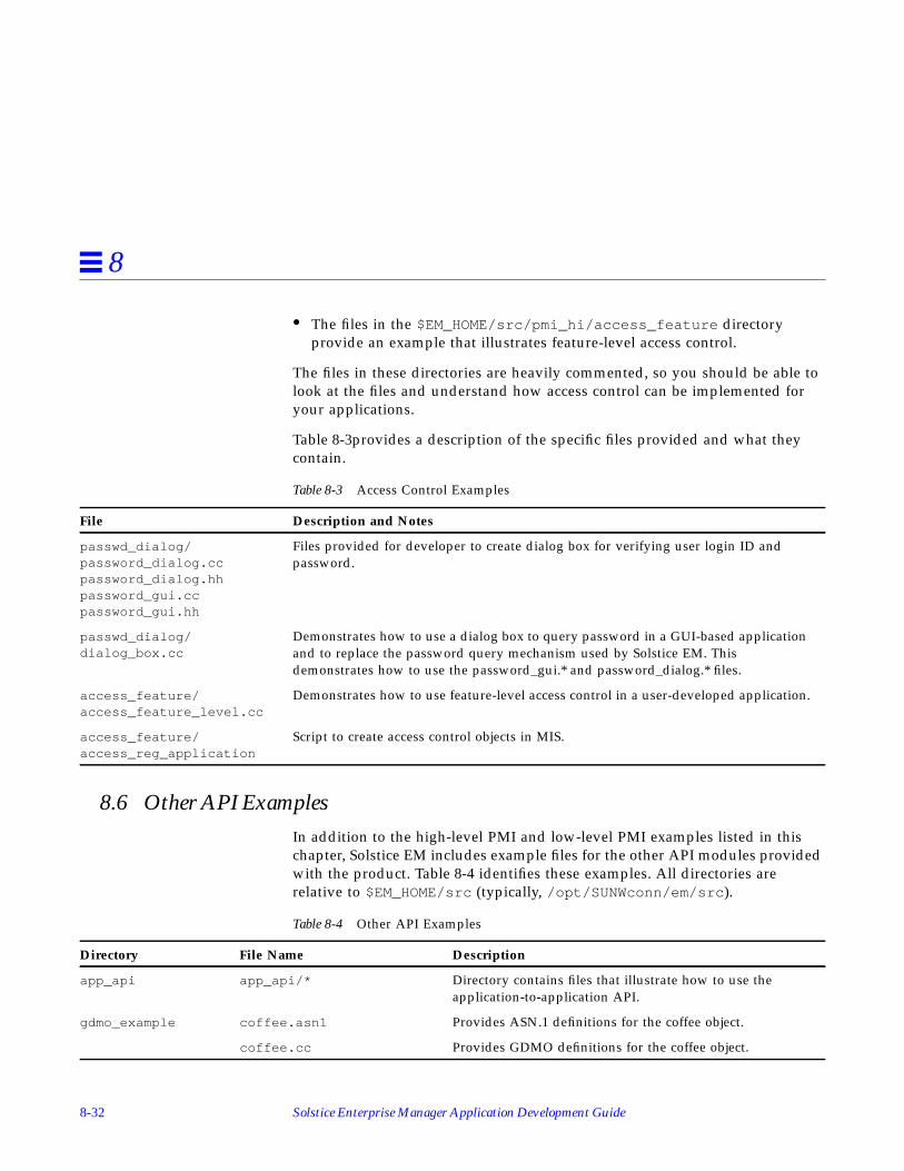
8-32 Solstice Enterprise Manager Application Development Guide
8
• The files in the $EM_HOME/src/pmi_hi/access_feature directoryprovide an example that illustrates feature-level access control.
The files in these directories are heavily commented, so you should be able tolook at the files and understand how access control can be implemented foryour applications.
Table 8-3provides a description of the specific files provided and what theycontain.
8.6 Other API ExamplesIn addition to the high-level PMI and low-level PMI examples listed in thischapter, Solstice EM includes example files for the other API modules providedwith the product. Table 8-4 identifies these examples. All directories arerelative to $EM_HOME/src (typically, /opt/SUNWconn/em/src ).
Table 8-3 Access Control Examples
File Description and Notes
passwd_dialog/password_dialog.ccpassword_dialog.hhpassword_gui.ccpassword_gui.hh
Files provided for developer to create dialog box for verifying user login ID andpassword.
passwd_dialog/dialog_box.cc
Demonstrates how to use a dialog box to query password in a GUI-based applicationand to replace the password query mechanism used by Solstice EM. Thisdemonstrates how to use the password_gui.* and password_dialog.* files.
access_feature/access_feature_level.cc
Demonstrates how to use feature-level access control in a user-developed application.
access_feature/access_reg_application
Script to create access control objects in MIS.
Table 8-4 Other API Examples
Directory File Name Description
app_api app_api/* Directory contains files that illustrate how to use theapplication-to-application API.
gdmo_example coffee.asn1 Provides ASN.1 definitions for the coffee object.
coffee.cc Provides GDMO definitions for the coffee object.
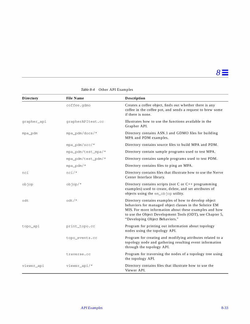
API Examples 8-33
8
coffee.gdmo Creates a coffee object, finds out whether there is anycoffee in the coffee pot, and sends a request to brew someif there is none.
grapher_api grapherAPItest.cc Illustrates how to use the functions available in theGrapher API.
mpa_pdm mpa_pdm/docs/* Directory contains ASN.1 and GDMO files for buildingMPA and PDM examples.
mpa_pdm/src/* Directory contains source files to build MPA and PDM.
mpa_pdm/test_mpa/* Directory contain sample programs used to test MPA.
mpa_pdm/test_pdm/* Directory contains sample programs used to test PDM.
mpa_pdm/* Directory contains files to ping an MPA.
nci nci/* Directory contains files that illustrate how to use the NerveCenter Interface library.
objop objop/* Directory contains scripts (not C or C++ programmingexamples) used to create, delete, and set attributes ofobjects using the em_objop utility.
odt odt/* Directory contains examples of how to develop objectbehaviors for managed object classes in the Solstice EMMIS. For more information about these examples and howto use the Object Development Tools (ODT), see Chapter 5,“Developing Object Behaviors."
topo_api print_topo.cc Program for printing out information about topologynodes using the topology API.
topo_events.cc Program for creating and modifying attributes related to atopology node and gathering resulting event informationthrough the topology API.
traverse.cc Program for traversing the nodes of a topology tree usingthe topology API.
viewer_api viewer_api/* Directory contains files that illustrate how to use theViewer API.
Table 8-4 Other API Examples
Directory File Name Description

8-34 Solstice Enterprise Manager Application Development Guide
8

9-1
Protocol and Management Adaptors 9
This chapter reviews some of the important concepts behind the ManagementProtocol Adaptor (MPA) and Protocol Driver Module (PDM) model. It uses thesample MPA and PDM implementation included in the samples directory toillustrate both the concepts and the specifics of the MPA/PDM interfaces andenvironments.
9.1 Introduction to EM Protocol AdaptorsThe MIS (Management Information Server) is responsible for maintaining theMIT (Management Information Tree) and ensuring that all activity within theMIT is transparent to an application. This transparency allows applications to
Introduction to EM Protocol Adaptors page 9-1
Initializing an Adaptor page 9-4
Routing Messages page 9-12
MPA/PDM Request Management page 9-19
Timer Management page 9-24
File Descriptor Management page 9-28
Notifications page 9-32
Sample MPA/PDM Source Code page 9-35
Steps to Develop an Adaptor page 9-38

9-2 Solstice Enterprise Manager Application Development Guide
9
make requests for information in a normalized fashion without regard forobject location or communications protocol. The MIS resolves the request androutes it to an appropriate entity that is capable of making the correct protocolrequest. These entities are called protocol adaptors. Adaptors exist to mapinformation into the MIT maintained by the MIS.
There are two kinds of adaptors:
• Management Protocol Adaptors (MPAs) which exist as separate processesfrom the MIS
• Protocol Driver Modules (PDMs) which are linked directly to the MISprocess
The MIS is shipped with three adaptors: the SNMP PDM, the RPC PDM, andthe CMIP MPA. These adaptors provide the protocol translation into theSNMP, RPC, and CMIP domains, respectively.
9.1.1 Differences between Protocol Adaptors and Management Adaptors
The fundamental difference between MPAs and PDMs is that an MPA is aseparate process from the MIS where as a PDM links directly to the MIS.
In addition, other differences include:
• MPA requests contain routing information.
• MPAs and PDMs are initialized differently.
MPAs offer some basic advantages over PDMs because they are easier todevelop, debug, and support, and they impact the MIS less than PDMs from astability and performance viewpoint.
The interface between the adaptors and the MIS is well defined and allows forthe addition of other user-provided adaptors.
9.1.2 Review of MIS Architecture
The MIS has a modular architecture. Modules are connected by Service AccessPoints (SAPs). These SAP’s provide an asynchronous bidirectional messagepipe interface. The core of MIS is the Message Routing Module (MRM) which

Protocol and Management Adaptors 9-3
9
routes messages to the appropriate modules. New modules can be added tothe MIS by attaching a SAP from the new module to the MRM. Each SAP has aunique address which is registered with the MRM when it is attached.
New adaptors are introduced to the system by creating a new SAP to theMRM. (For MPA, no new SAP needs to be created. All MPAs are routed by thesame MPA SAP.)
Figure 9-1 illustrates some of the modules within the MIS. The OAM is theObject Access Module. The EMM is the Event Management Module. Logs aremanaged by the LMM (Log Management Module) and the Persistent ObjectStore is maintained behind the BS Intf. (Backing Store Interface).
Figure 9-1 Overview of Modules
The shaded components in Figure 9-1 illustrate how users can add newadaptors to communicate to a proprietary device X. The two choices are clearlyindicated, MPA or PDM.
OAM
MRM
SNMP
EMM
LMM BS Intf.SAPs
CMIPAgent
MPA
CMIP
USERMPA
DEVICE XX-Protocol
RPC
USERPDM
X-Protocol
CMIPMPAProcess
MIS ProcessRemote
Links

9-4 Solstice Enterprise Manager Application Development Guide
9
All requests are initially sent to the Message Routing Module(MRM). TheMRM uses configuration information maintained in the MIT to determinewhere to satisfy the request. Local requests are sent to the OAM. Remoterequests are directed to the appropriate adaptor that has registered to handlethat remote portion of the MIT.
Note – Both the MPA and the PDM use SAP to communicate to the MRM.There is very little difference between a MPA and a PDM once the SAP hasbeen created. They both receive identical messages through the exact sameinterface.
9.2 Initializing an AdaptorThis section describes how Management Protocol Adaptors and ProtocolDriver Modules are initialized. It includes the following topics:
• Service Access Points
• Message Protocol Adaptor Initialization
• Protocol Driver Module Initialization
9.2.1 Services Access Points (SAPs)
SAPs provide an asynchronous message passing service. The message set isbased on the set of CMIP Protocol Data Units (PDUs). The complete set ofmessages that can be passed over a SAP is defined in message.hh .
All SAP’s are C++ class instances derived from the C++ MessageSAP classdefined in message.hh . This class defines the interfaces that allow messagesto be sent and received over SAP pairs. An initialized SAP consists of acoupled pair of MessageSAP instances.
Note – From here on SAP is meant to mean an initialized SAP pair.

Protocol and Management Adaptors 9-5
9
Once a SAP has been initialized, the following functions may be performed:
This set of functions provides the following message services:
The interface is defined to be asynchronous. This is achieved using callbacks.Callbacks are a C++ class that consist of a static function pointer and user data.The user data is passed as a parameter to the callback function when thefunction is invoked.
SendResult send(MessagePtr mp, MTime block_time = INFINITY);SendResult send(MessagePtr mp, const Callback &cb, MTime block_time = INFINITY);Result receive_request(MessagePtr &mp);
Result receive_response(MessId m_id, MessagePtr &mp);Result receive_response(ResponseHandle rh, MessagePtr &mp);void cancel_callback(MessId m_id);void cancel_callback(Callback &cb);
Table 9-1 Message Services
Function Service Provided
Send Send and expect no Response
Send Send and schedule to Receive a Response
Receive Receive a message of a particular id
Receive Receive the first Message on the incoming Q
Cancel Cancel callbacks for a particular Message
Cancel Cancel callbacks for a particular Callback

9-6 Solstice Enterprise Manager Application Development Guide
9
Example 1:The following example from the fdn_register function in samp_utils.ccillustrates a CONFIRMED request message.
Note – A callback is created with a static function called pdm_receive_respas the callback function pointer. The callback data is the SAP instance pointer.The send function includes the callback recv_cb in the send arguments.
When the MIS completes the request, the pdm_receive_resp function iscalled with two parameters. The first parameter is the SAP and the second is aresponse handle which is used to receive the message response.
Example 2:The following example excerpt is from the msgio.cc module and illustratesthe pdm_receive_resp function:
// Need source so responses can come back.areq->source.aclass = AC_PRIMITIVE;areq->source.atag = my_sap_no;Callback recv_cb((CallbackHandler)pdm_receive_resp, sap);// Send off the request to add.TRYRES(sap->send(areq,recv_cb,0));
pdm_receive_resp(Ptr cbh, Ptr rh){Message *mp;MessageSAP *p_sap = (MessageSAP *) cbh;
Vtry {TTRYPROC(p_sap->receive_response(rh, mp));// At this point mp points to the received responseMessage:: delete_message(mp);
}

Protocol and Management Adaptors 9-7
9
SAPs are initialized by creating SAP pairs. When a SAP pair is created, theinit_kernel_msg_sap () function is used. The init_kernel_msg_sap ()function is a utility function which couples two SAPs. Once the SAPs havebeen coupled, the local SAP must have two callback functions initialized: thereceive request callback and the detached callback.
The receive request callback handler is the handler which is invoked whenmessage requests are sent to the SAP. The detach callback handler is invokedwhen the remote SAP is deleted.
9.2.2 Message Protocol Adaptor Initialization
To initialize a Message Protocol Adaptor, the following steps must occur:
• Create listen port and request SAP
• Connect to the MIS and use extract raw SAP
• Lock the application discriminator
9.2.2.1 Creating the Listen Port and Request SAP
The MIS to MPA communication is a form of CMIP over TCP/IP. The MIScreates and manages associations to an MPA on a per request basis. If anassociation is not used for a period of time the association is released. If anassociation is already established it will be reused for subsequent requests.Each request has a request identifier which allows for multiple requests to beoutstanding at any one time. To facilitate demand based associationestablishment, the MPA must allocate an IP listen port. An IP listen port iswhere the MPA listens for association requests from the MIS.
The utility function init_mpa () creates both a SAP and a listen port.
init_mpa(portnum, &p_sap);
where portnumber is a port number for an IP socket, and p_sap is theaddress of a pointer to a MessageSAP data type.

9-8 Solstice Enterprise Manager Application Development Guide
9
9.2.2.2 Connecting to the MIS and Using get_raw_sap ()
Because the underlying transport mechanism for this SAP might not be active(that is, an underlying association is not established), another SAP must becreated to send event reports to the MIS. This other SAP is allocated bycreating a platform instance which is connected to the MIS. This platforminstance gives access to an ApplMessageSAP . This SAP is based on anotherMessageSAP implementation. Because the implementation is derived fromMessageSAP, the ApplMessageSAP can be used as a MessageSAP. This ispossible through C++ inheritance and virtual function mechanisms.
Example:The following code example illustrates how to create a SAP that sends eventreports to the MIS and initialize the resultant SAP to receive requests anddisconnects.
Once the platform instance has been created, the get_raw_sap () methodreturns the SAP which can be used for sending event reports to the MIS.
host = getenv(“EM_MIS_DEFAULT_HOST”);if (!host) {host = def_host;}
if (emPlatform.connect(host, “SAMPLE_MPA”) == OK) {emPlatform.when(“DISCONNECTED”,
Callback(pdm_test_handle_detach, 0));mis_connected = TRUE ;
} elsemis_connected = FALSE ;ev_sap = (MessageSAP *) emPlatform.get_raw_sap();pdm_test_sap->receive_request_cb.handler =
pdm_receive_request_msgs;pdm_test_sap->receive_request_cb.data = (Ptr) pdm_test_sap;pdm_test_sap->detach_cb.handler =
pdm_test_handle_detach;pdm_test_sap->detach_cb.data = (Ptr) pdm_test_sap;

Protocol and Management Adaptors 9-9
9
9.2.2.3 Locking the Application Discriminator
This step must be completed to allow for proper operation of the MPA. It ismost important as locking the application discriminator has direct impact onsystem performance. Every platform instance creates an application objectinstance within the MIS as long as the platform instance is instantiated. Eachapplication object instance contains a discriminator which forwards allplatform notifications to the connected application. The MPA typically doesnot require this feature.
To disable event forwarding, the application instance discriminator must belocked.
Example:The following example excerpt from the samp_main.cc module in thesamples directory illustrates this locking mechanism:
9.2.3 Protocol Driver Module Initialization
Protocol Driver Modules are shared libraries that are loaded at MIS start-uptime. The MIS looks in the $EM_HOME/config/EM_shared_libs file for a listof libraries to load. Once it finds an entry in that file, it uses the dlopen ()system call to load that library. Once the library is loaded, the MIS looks for an
DU appinst = emPlatform.get_prop(duAPPLICATION_OBJNAME) ;Image app_image(appinst);if( app_image.get_error_type()!=PMI_SUCCESS ||
!app_image.boot() ||!app_image.set_str(“administrativeState”,”locked”) ||!app_image.store() ) {
printf(“Error starting MPA %s\n”,app_image.get_error_string());
exit(1);
}

9-10 Solstice Enterprise Manager Application Development Guide
9
instance of the DynLoader class that matches the name of the loaded library.Once the Dynloader instance has been located, the entry point is invokedwith a D_LOAD command.
Note – The second parameter of the instance of the declared DynLoader mustmatch the name of the shared library. See dyn_lib.cc for an example.
To initialize a Protocol Driver Module, the following steps must occur:
• Create a kernel message SAP pair
• Register the SAP with the Fully Distinguished Name (FDN) table
9.2.3.1 Creating a Kernel Message SAP
A kernel message SAP pair is created using the init_kern_msg_sap ()function.
This utility function creates a pair of coupled kernel message SAPs. It returnsto the caller a pointer to a local MessageSAP and initializes the remote SAP tobe attached to the MRM at the SAP Address supplied. This Address must bethe same as the Address supplied in the FDN table configuration step. See thesection on “Example of Timer Initialization” for more information on AddressFormat.
Each request (message) contains a destination address field dest . The MRMsearches in its list of attached SAPs for an Address match. When thedestination address of a request matches a registered SAP, the request is routedover that SAP.
Note – The destination field component is completed by the lookup codewithin the MIS.
extern Result init_kernel_msg_sap ( Address , MessageSAP ** );

Protocol and Management Adaptors 9-11
9
9.2.3.2 Registering an FDN table Entry
The utility function fdn_register () in samp_utils.cc illustrates how toadd an entry to the FDN table.
The fdn_register () function creates a table entry which specifies a mappingbetween a fully distinguished name (FDN) and a specific address. It takes threeparameters to create a table entry:
• A SAP over which to send the addfdn ACTION request
• An INT which specifies the SAP TAG (unique identifier for a SAP)
• An encoded distinguished name
Example:The following example from dyn_libs.cc illustrates the creation of a tableentry:
Result fdn_register(MessageSAP *, int, Asn1Value &);
// Check in em_config for TEST SAP number.// GETENV is a front end MACRO to EM-config file// Using EM-config forces SAP numbers to be unique// if not there use default of defined VAL (64)const char *p_sap_no;
if ( (p_sap_no = GETENV(“TEST_PDM_SAP”) ) ) { pdm_test_addr.atag = atoi(p_sap_no);} else pdm_test_addr.atag = MY_PDM_SAP;
pdm_test_addr.aclass = AC_PRIMITIVE;pdm_test_sap = (MessageSAP *) 0;
// Create a kernel message SAP, this binds us to the// MRM at SAP class AC_PRIMITIVE and SAP number MY_PDM_SAP// Whenever a request’s DN matches a DN in the FDN table// that request is forwarded to the SAP that matches// the Address portion of the FDN Table Entry. In this case// our Address is AC_PRIMITIVE, MY_PDM_SAP.

9-12 Solstice Enterprise Manager Application Development Guide
9
See Section 9.3.2, “MPA and PDM Addresses” for information on usingEM_config. See Section 9.3.1.1, “Address Classes” for more information on theAC_PRIMITIVE class.
9.3 Routing Messages
9.3.1 How Messages are Routed to the Adaptors
The MIS contains a table which is analogous to the NFS mount table that theUNIX kernel maintains. The table is a complete mapping of the remote MIT.The MRM searches this table for complete or partial matches of theDistinguished Name (DN) for every request. If there is a match, the MRM
if ( init_kernel_msg_sap ( pdm_test_addr, &pdm_test_sap ) != OK ) Return(NOT_OK);
// Here is where we set up our request handlers.pdm_test_sap->receive_request_cb.handler = pdm_receive_request_msgs;pdm_test_sap->receive_request_cb.data = (Ptr) pdm_test_sap;pdm_test_sap->detach_cb.handler = pdm_test_handle_detach;pdm_test_sap->detach_cb.data = (Ptr) pdm_test_sap;ev_sap = pdm_test_sap;
// This is where we register the PDM DN with the// fdn table. We register an entry with// DN = /systemId=”pdm” and an address of// of AC_PRIMITIVE and SAP number MY_PDM_SAP
Asn1Value pdm_dn = my_dn(my_name);
// Lets delete first in case we did not unload// gracefully.TRYRES(fdn_unregister(pdm_test_sap, MY_PDM_SAP,pdm_dn));
// Now register should workTRYRES(fdn_register(pdm_test_sap, MY_PDM_SAP,pdm_dn));

Protocol and Management Adaptors 9-13
9
stores the address information found in the FDN table entry in the destinationfield of the message and forwards the message to the SAP that matches thataddress.
To route a message to an adaptor the FDN table must previously have beenupdated with the DN or DNs that the adaptor is responsible for and anaddress for the adaptor’s SAP.
The FDN table is updated by two action requests: emAddFdnEntry andemRemoveFdnEntry . These action requests are defined in the em.gdmodocument. The fdn_register () function uses these actions to update theFDN table. The CMIP Configuration utility (em_cmipconfig ) uses the sameactions to achieve the same purpose.
The FDN table entry has two components: the DN and the Address. Theaddress component is based on the address C++ class defined in address.hh .An address has three components:
• class, type of Address
• tag, particular instance of a particular class
• value, data associated with that address class
9.3.1.1 Address Classes
Four address classes are defined:
• AC_DEFAULT
Implies default routing based on type, for example, an event report isalways routed to the EMM.
• AC_APP
Is the address class for SAPs that are attached to applications. Each PMIapplication results in an Application SAP being created. The address class ofeach application SAP is AC_APP.
• AC_DIR_SERVICE
Is reserved for directory service management.
• AC_PRIMITIVE
Is the address class for PDM’s.

9-14 Solstice Enterprise Manager Application Development Guide
9
9.3.1.2 AC_PRIMITIVE Address Tags (SAP number)
Each Address class uses the tag value to uniquely identify SAP instances. Forthe purposes of developing PDMs, familiarity with AC_PRIMITIVE tags iscritical.
The following is a list of the well known AC_PRIMITIVE tags:
Note – The tags listed above are the well known AC_PRIMITIVE tags that arein use by the MIS system. Providers of new PDM’s must chose a value outsideof this range.
9.3.1.3 Address Data (aval)
The data field of an address can be used for any purpose. It is a DataUnitwhich is of variable length. Of particular interest is the aval syntax for theAT_PRIM_CMIP_PRES_ADDR tagged AC_PRIMITIVE class. This contains acomplete Presentation Address using the following syntax:
#define AT_PRIM_OAM 0#define AT_PRIM_EMM 1#define AT_PRIM_CMIP_PRES_ADDR 2#define AT_PRIM_SNMP_ADDR 3
#define AT_PRIM_AET_ADDR 4 // ASN1: AE-title#define AT_PRIM_MPA_ADDR 5
#define AT_PRIM_AGENT_DN 6 // ASN1: FDN#define AT_PRIM_RPC_ADDR 7#define AT_PRIM_CMIP_CONFIG 8 //String:{psel,ssel,tsel,nsap}
length byte, Presentation Selector,length byte Session Selector,length byte, Transport Selector,count byte (number of Network Selectors),
length byte, Network Selector.....
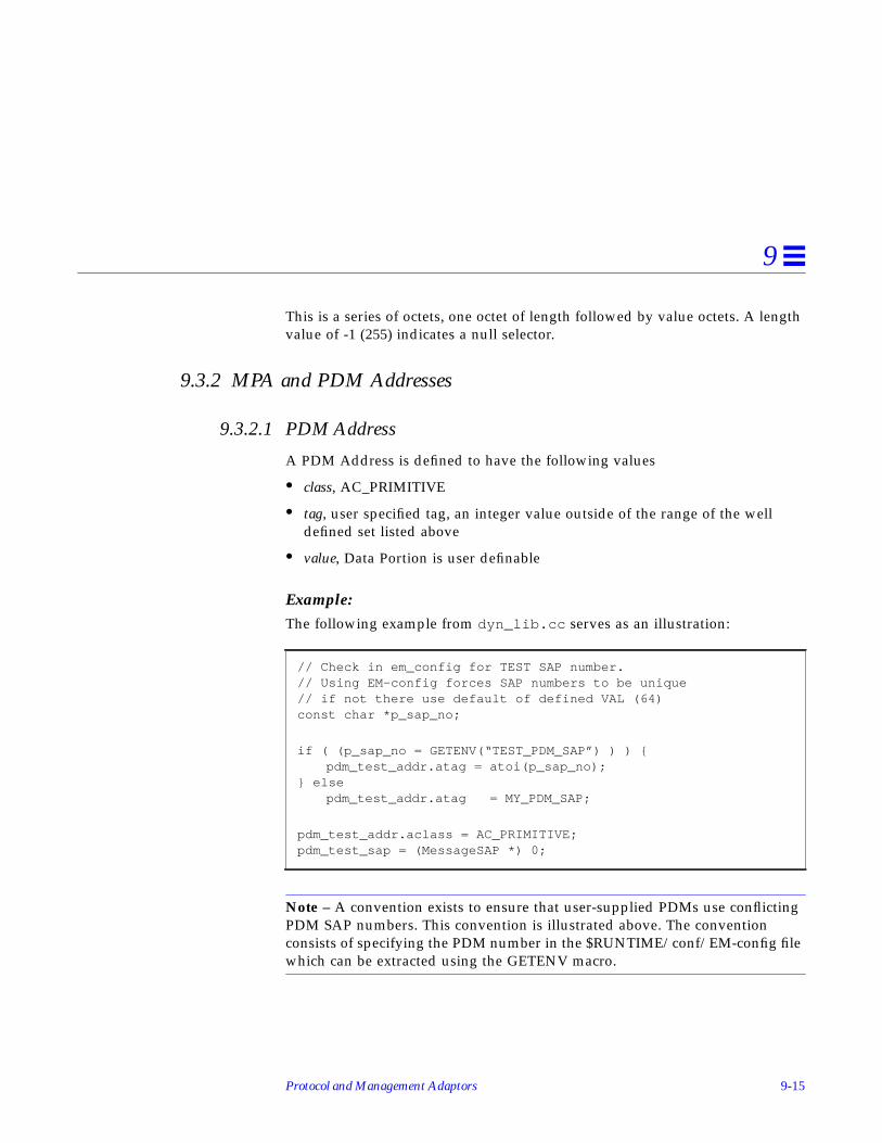
Protocol and Management Adaptors 9-15
9
This is a series of octets, one octet of length followed by value octets. A lengthvalue of -1 (255) indicates a null selector.
9.3.2 MPA and PDM Addresses
9.3.2.1 PDM Address
A PDM Address is defined to have the following values
• class, AC_PRIMITIVE
• tag, user specified tag, an integer value outside of the range of the welldefined set listed above
• value, Data Portion is user definable
Example:The following example from dyn_lib.cc serves as an illustration:
Note – A convention exists to ensure that user-supplied PDMs use conflictingPDM SAP numbers. This convention is illustrated above. The conventionconsists of specifying the PDM number in the $RUNTIME/conf/EM-config filewhich can be extracted using the GETENV macro.
// Check in em_config for TEST SAP number.// Using EM-config forces SAP numbers to be unique// if not there use default of defined VAL (64)const char *p_sap_no;
if ( (p_sap_no = GETENV(“TEST_PDM_SAP”) ) ) {pdm_test_addr.atag = atoi(p_sap_no);
} elsepdm_test_addr.atag = MY_PDM_SAP;
pdm_test_addr.aclass = AC_PRIMITIVE;pdm_test_sap = (MessageSAP *) 0;

9-16 Solstice Enterprise Manager Application Development Guide
9
9.3.2.2 MPA Addresses
MPAs have one more level of indirection than PDMs. The additional levelallows the MPA to be a separate process that can be run anywhere in theTCP/IP domain. The MPA addresses are defined as:
• class, AC_PRIMITVE
• tag, AT_PRIM_MPA_ADDR.
The developer need not worry about configuring an MPA Addressprogrammatically since the Address for an MPA is configured using theem_cmipconfig utility. The em_cmipconfig utility creates an address wherethe aval portion contains all the relevant configuration information. The MISextracts this information and presents it to the MPA using the remote_oi andremote fields of the message request sent to the MPA request routine.
The following fields need to be configured for a custom MPA:
• Entity Name
• Custom MPA: The port and hostname fields must be completed.
• Session Selector
• Network SAP: The Network address of the entity containing the real objectshould be included.
• FDN
Note – If the Presentation address of the remote entity has a null sessionselector, the session selector must be configured with some default value (forexample, “MPA”).
The example MPA supplied used the following configuration:
Entity Name : { 1 2 3 4 5 1 }Custom MPA port : 5597Custom MPA host: “carla”
Session Selector : “Test”Network SAP : carla:5597FDN : /pdmId=string:”testMPA”

Protocol and Management Adaptors 9-17
9
Once the em_cmipconfig configuration has been completed, the MRMattempts to match entries against what has been configured in the FDN tableusing em_cmipconfig .
Requests for multiple entities can be directed to a custom MPA. The samplesource supplied only supports one entity /pdmId=”testMPA” . A customMPA can be created to support multiple entities.
The CMIP MPA provided with the MIS is an example of an MPA that iscapable of supporting multiple entities. Each CMIP agent in the MIS’management domain is viewed as an entity. For each CMIP agent to bemanaged, the user must run em_cmipconfig specifying the agent parameters,in particular, the agent’s presentation address.
9.3.2.3 Message remote_oi and remote Fields
The values in the remote_oi and remote fields are one of the specificdifferences between an MPA and a PDM.
The MPA can make explicit use of these fields. The remote_oi contains theDN of the CMIP table entry that was used to route the request to the MPA. Thelast RDN of this DN can be used to find the AE-Title (Application EntityTable). The remote field contains whatever was configured for that entity’spresentation address. This information is what the CMIP MPA uses to establishan association with a remote entity. The aval portion of the remote fieldcontains a string of the format:
This is an ASCII representation of the remote entities presentation address asconfigured using em_cmipconfig . See the “Address Data (aval )” section formore information.
Note – A PDM can not make use of the remote_oi or the remote field.
Multiple FDN table entries can be stored which point to a single MPA or PDM.This storage mechanism can be used as a persistent configuration store for eachentity supported by the MPA/PDM. This mechanism, in conjunction with theremote_oi and remote fields, allows for easy multiplexing to the real objectinformation.
“{ Pres, Sess, Tsel, Net }”

9-18 Solstice Enterprise Manager Application Development Guide
9
9.3.3 FDN Table Configuration Options
There are multiple ways to configure the MIS to route messages to adaptors. Indeciding which configuration to use, it is important to implement a modelview that is appropriate for the problem being solved. Common sense can be agood start. For example, it would not be appropriate to add thousands ofentries to the FDN table when the MPA could easily implement an efficientproprietary lookup based on the DN.
To help clarify the process, the following options are examined:
• MPA supporting two remote objects
• PDM supporting two remote objects
These examples are used to indicate the various options open to the developer.
Note – These examples are not the only options and are used for illustrativepurposes only.
9.3.3.1 MPA Supporting Two Remote Objects
Two possible strategies for adding entries to the FDN table are:
• Two entries can be added to the FDN table using em_cmipconfig with twodifferent entity names specified.
• Two entries can be added to the FDN table using em_cmipconfig withonly one entity name specified.
The second case illustrates how em_cmipconfig allows one entity to supportmultiple objects. It is assumed that the remote entity that supports theseobjects is identically addressed, that is, the objects live at the same presentationaddress.
9.3.3.2 PDM Supporting Two Remote Objects
Two possible strategies for adding entries to the FDN table are:
• Two entries can be added to the FDN table with an identical PDM address.
• Two entries can be added to the FDN table with identical class and tagvalues in the address with different data value in the address value field.

Protocol and Management Adaptors 9-19
9
The first case assumes that the DN is decoded in the request and that therequest is routed to the appropriate agent entity.
The second case allows the data that is configured in the value (aval ) portionof the dest field of the message to be used for achieving multiplexing to theremote agent entity.
9.3.4 Source and Destination Fields in the Message
All messages contain src and dest fields. These fields are C++ instances ofAddress and are very important for message routing. The src field must becompleted for all CONFIRMED requests. The MPA/PDM developer mustcomplete the src address if responses are expected. The src field is the sameaddress used when creating the SAP and when specifying the addresscomponent of the FDN table registry entry.
The dest field is only important if you wish to explicitly route the message.
Note – Since explicit routing is used for passing messages betweenapplications, it should be used carefully.
9.4 MPA/PDM Request ManagementThe MIS has been designed to be a multi-user server and can handle multiplerequests transparently and asynchronously. The SAP interface has beendesigned to make this asynchronous style of programming easier.

9-20 Solstice Enterprise Manager Application Development Guide
9
In Figure 9-2, a scenario is illustrated that is typical of a real worldenvironment.
Figure 9-2 Potential Real World Configuration
Application1 makes continuous requests to the local MIT. These requests canbe satisfied immediately.
Application2 makes requests to A1 and A2. These agents are at the remote endof very slow links. The architecture must support the scheduling of responsesto requests that could take a long time to complete. The design andimplementation should also handle cases where requests overlap. Ifappropriate, multiple overlapping requests should be queued and servicedwith a single response.
The MPA/PDM module serving A1 and A2 schedules its responses. It achievesthis by using the underlying PMI scheduling services.
The transport mechanism used by the MPA/PDM is normally hidden behind aUNIX file descriptor. The MPA/PDM developer needs to use the underlyingscheduling services to interface to the file descriptor. This scheduling servicemakes use of the underlying poll (select) system call to determine the following:
• Whether data is available at the file descriptor
Application1 Application2
MIS Local MIT
A1 A2
SLOW LINK SLOW LINK
PMI PMI

Protocol and Management Adaptors 9-21
9
• Whether data can be written to the file descriptor
• Whether there is an underlying exception on the file descriptor
To satisfy remote requests, the MPA/PDM code typically opens a filedescriptor to the agent. As requests are made to the agent, they are written tothe file descriptor. The MPA/PDM code then schedules a callback forwhenever data becomes available at the file descriptor. When the data iscompletely transferred, the MPA/PDM sends a response back to the MIS.
At a high level, the steps can be broken down as shown in Table 9-2.:
Note – Because all requests have identifiers, it is easy to match responses torequests.
9.4.1 Asynchronous Request Code Specifics
When managing asynchronous requests, familiarity with some of theunderlying C++ classes that facilitate asynchronous request management iscritical. The most important C++ class is the Callback class. This is used byall of the asynchronous interfaces. There is also a C++ programming style thatmust be understood. The proposed C++ model is that a C++ class must be builtwith a class implementation with the following characteristics:
• Original request information, particularly the request id, the src, and destfields must be stored.
Table 9-2 MIS and MPA/PDM Connections
MIS MPA/PDM
Request for MIS
Create a connection to remote agent.
Schedule a callback to indicate connect complete.
Send request with unique identifier.
Schedule a callback for response.
When data callback, check for data complete.
If data complete, send response to MIS.
MIS receives Response

9-22 Solstice Enterprise Manager Application Development Guide
9
• A static member function must exist that can be used as a callback handler.
• A variable must exist than can be used to count the number of callbacksexpected.
• Class instances must be easily found by the request identifier so thatCANCEL GET requests can be serviced in a timely manner.
• Responses must be queued for Synchronous requests.
These characteristics determine what can be called a pending request class.This type of class encompasses the functionality required for responding torequests asynchronously.
Example:The following example excerpt from a class called pdm_pend_req insamp_inc.hh illustrates some key elements associated with asynchronousrequests:
The pdm_pend_req class has the following characteristics:• Maintains a copy of the original request and request id• Has a callback counter• Can be queued
class pdm_pend_req : public QueueElem {ObjReqMess *orig_msg;MessId req_id;
public:
// hash of all pending requests based on request idHashdeclare(MessId, pdm_pend_req, hash_MessId,
MessIdcmp,0,0)static Hash(MessId, pdm_pend_req) *p_pdm_req_hash;I32cbs_pending;I32num_in_scope;
ReqStatus status;Result start_req(Callback &req_done);// Used in cases where atomic operation requested.Queue(RespQElement) resp_q;
}

Protocol and Management Adaptors 9-23
9
• Can be hashed based on a MessId type• Has an asynchronous interface to a start_req routine• Has a callback to be used for invoking operation completions
The function of this class is to remember original request information, to startrequests, and to ensure that a final response is sent if required. Requests arecompleted when there are no more callbacks pending, that is, cbs_pending ==
0.
The req_mngt.cc module supplied in the samples directory illustrates all ofthese key concepts. The req_mngt.cc starts requests, counts the callbacks,and releases resources that are no longer required.
9.4.2 Validating Requests
Each request can be validated. The extent of the validation is dependent on theimplementor and the specifics of the implementation. In some cases, it willmake no sense to validate requests since much of the intelligence to validate ison the remote agent. The CMIP MPA supplied does little more than storerequest identifiers and forward the requests to the CMIP agent. The samplesource, which is supplied, does some validation for illustrative purposes.
The typical items that can be validated up front are object class and operationtypes. For illustrations of typical items than can be validated, see the code inmsgio.cc particularly pdm_verify_oc() and pdm_verify_dn().
9.4.3 Matching Requests to Responses
Every request is identified with an identifier. To send a response to a particularrequest, set the response message id to the request id. For completeness the srcand dest fields must be completed also.
9-24 Solstice Enterprise Manager Application Development Guide
9
Example:The following example excerpt from msgio.cc send_resp. rmp is a pointer to aresponse message. msg is a pointer to the original request.
9.5 Timer ManagementThe following timer management services are available to the developer:
• Create and delete a timer
• Start a timer
• Stop a timer
Timers are very useful in the MPA/PDM environment. In particular, they areneeded to implement time out strategies. Every request requires a response. Inthe real world, there are occasions when devices do not respond. The timerfacilities are useful to set a timeout callback which can send an TIMED_OUTresponse to the MIS in these types of situations.
Note – MPAs cannot use TIMED_OUT, DEST_UNREACH or NO_SUCH_DESTmessages. PDMs may use these message to signify errors. For error conditionslike these, the MPA should return a PROC_FALL message with a ProbableCause specific error which is defined by the implementor.
Timers can also be used to check on device status. If the device status haschanged, the MPA/PDM can emit an attribute change notification.Applications can then be written to wait for these notifications and to operateon an event driven basis. Asynchronous applications (applications that do notPOLL or that are event driven) have a positive impact on overall systemperformance.
The MPA/PDM developer should always attempt to use a notification basedmechanism to communicate to applications. Timers can be used to schedulethese specific notifications. Using GDMO, any type of notification can be
rmp->id = msg->id;rmp->source = msg->dest;rmp->dest = msg->source;rmp->qos = msg->qos;

Protocol and Management Adaptors 9-25
9
designed. Once the GDMO syntax has been loaded into the Meta DataRepository (MDR), the MPA/PDM can emit the notification based on thebehavior defined in the GDMO.
9.5.1 Timer Management Interface
The timer interface consist of a set of functions which allow the scheduling ofcallback handlers based on criteria specified in instances of a timer C++ class.These timer instances specify the following:
• A callback handler
• An interval specifying expiration time before the handler is invoked
• A reload interval value load after the original interval expires
Note – These timers are not suitable for real time solutions.
The class definition for timer is defined in sched.hh and is listed below aswell as the interface functions to the scheduler.
class Timer {public:
MTime time; // expiration time in millisecondsMTime reload; // reload time after expirationCallback cb; // callback to post when expired
Timer() {time = 0;reload = 0;
}Timer(MTime t, MTime re, CallbackHandler hand, Ptr d) {time = t;reload = re;cb.handler = hand;cb.data = d;}

9-26 Solstice Enterprise Manager Application Development Guide
9
The four functions detailed above provide the interface to the scheduler forenabling and disabling callbacks based on time. The user can choose a purgeinterface suitable for the implementation.
9.5.1.1 Example of Timer Initialization
The following example excerpt start_timer () from rusagobj.cc uses thepost_timer () scheduling function to start a timer. The timer that is passed topost_timer () is an instance of the C++ class timer.
The timer constructor takes three parameters
• Timer intervals
friend int operator==(const Timer &t1, const Timer &t2) {return t1.cb == t2.cb;}
};
void post_timer(const Timer &);// Post an timer into the scheduler queue
void purge_timer(const Timer &);// Purge any matching timers from the scheduler queue
void purge_timer_handler(CallbackHandler handler);// Purge any timers with matching handler
void purge_timer_data(Ptr data);// Purge any timers with matching data
void start_timer() {// Timer Input is in milli secs// parms are, timer interval, timer reload value// Handler and parm passed to handler
post_timer(Timer(timerval * 1000, timerval * 1000,(CallbackHandler) pdmrusage_timer, (Ptr) this));
timer_posted = TRUE;}

Protocol and Management Adaptors 9-27
9
• Timer reload interval value
• Callback to be executed
All interval values are specified in milliseconds. The timer instance createdabove is based on a variable, timerval , stored in the rusageobj instance.This value is in seconds and is converted to milliseconds by * 1000. Theimplementation requires that the timer be continuous so a reload valueidentical to the initial interval is passed for the reload parameter. The callbackparameter is passed containing pdmrusage_timer () as the function to becalled and the rusageobj instance pointer is passed as the Callback user data.
Note – The implementation of post_timer () makes a copy of the timer andCallback parameters passed. It is okay to use timers and Callbacks that getdestructed
9.5.2 Stopping a Timer
Timers are stopped or purged using the purge_timer (),purge_timer_handler () or purge_timer_data () utility functions. Thestop_timer () method in rusageobj.cc , listed below uses thepurge_timer_handler () function to cancel the pdmrusage_timer callbackwhen it is no longer needed, that is, when the runtime attribute is set to 0.
purge_timer_handler () searches the list of active timers for any timer thathas a callback handler equal to the value passed. It then purges any timersmatching from the timer queue.
Note – It is important to remember if timers have been posted. A commonerror is that users forget to purge timers. The callback then tries to use datathat has been deallocated.
void stop_timer() {purge_timer_handler((CallbackHandler) pdmrusage_timer);timer_posted = FALSE;}

9-28 Solstice Enterprise Manager Application Development Guide
9
9.6 File Descriptor ManagementThe normal mechanism of communicating outside of a UNIX process isthrough a UNIX file descriptor. The services provided by the scheduler tointerface to file descriptors are important to understand because mostMPA/PDMs use file descriptors to communicate to remote devices.
9.6.1 Asynchronous File IO
It is important that the MPA/PDM never blocks (makes a system call that doesnot return immediately). The underlying UNIX File IO system allows filedescriptors to be opened or created in NON-BLOCKING modes. It is mostimportant that any file descriptors be opened in a non-blocking mode.
The most important aspect of non-blocking file IO is that some operations maynot complete. The code must handle properly partial reads/writes. By usingthe underlying operating poll system call (select on BSD systems), the schedulerfacilitates non-blocking IO by providing a set of utility functions to allow forcallbacks when particular events happen at a file descriptor. These are based onthe standard UNIX set of:
• Data can be read
• Data can be written
• Error or exception
Whenever a user expects to read from a file descriptor the user should usepost_fd_read_callback (). If data needs to be scheduled to be written, theuser should use post_fd_write_callback (). To handle error cases thereshould be a handler for exceptions. This handler can be set usingpost_fd_except_callback ().
Callback handlers as discussed above are static functions that are invokedwhen the event they have been scheduled to service occurs. The filemanagement functions are passed the file descriptor they are managing asparameter two. Parameter one is the data specified when the CallBack wascreated. Oftentimes parameter one is a pointer to an C++ instance that containsthe file descriptor and any status associated with it.

Protocol and Management Adaptors 9-29
9
The complete set of function prototypes as defined in sched.hh are listedbelow:
Note – File descriptor callbacks should be purged if the instance associatedwith the callback is deleted.
9.6.2 Example of a Read Callback Implementation
The example below is taken from the unixobj.cc sample source code. Thereare two items of importance:
• Scheduling the callback
• Callback execution
9.6.2.1 Scheduling the Callback
The following example is taken from the unxobj.cc start_get_req () routine.Once the pipe has been successfully opened, the code creates a callback andschedules the callback function execution when there is data available from thepipe. The read callback handler is scheduled using thepost_fd_read_callback () routine.
The following should be noted:
• The FPTR (fp ) is converted to a file descriptor using fileno . (See the manpages for more information.)
void post_fd_read_callback(int fd, const Callback &cb);void post_fd_write_callback(int fd, const Callback &cb);void post_fd_except_callback(int fd, const Callback &cb);void purge_fd_read_callback(int fd);void purge_fd_write_callback(int fd);void purge_fd_except_callback(int fd);void purge_fd_callbacks(int fd);
9-30 Solstice Enterprise Manager Application Development Guide
9
• The callback which is created is initialized to have a function pointersh_fetch_input and a data pointer of this. (This is C++ this for instancebeing operated on).
The routine sh_fetch_input is invoked wherever there is data available at thefile descriptor fileno (fp ).
9.6.2.2 Callback Execution
The code below is excerpted from unixobj.cc sh_fetch_input ().
The sh_fetch_input routine does the following:
• Uses parameter one as a pdmunixOi pointer since that is what was definedas the user data parameter when the callback was scheduled.
• Accesses the file descriptor from the instance pointer where it was stored.
• Allocates a temporary dataunit to store the data read.
• Reads the data until there is no more data (for example, EOF). When thathappens, it calls the get_complete () method of the pdmunixOi C++instance.
• If there is more data, it reposts the callback having first saved the data readin sh_data . The dataunit catenate is used to add any new data to the endof the old data.
// Set up to get called back when Data is// available from the pipe.Callback rd_cb((CallbackHandler)sh_fetch_input, this);post_fd_read_callback(fileno(fp),rd_cb);

Protocol and Management Adaptors 9-31
9
Example:
This is a very complete example of a read callback handler since it remembersstate information (data just read) and reschedules itself.
static void sh_fetch_input(pdmunixOi *p_obj, int){
int rv;DataUnit tmp(RSIZ);
// Read the dataif ( !(rv = fread((char *)(const Octet *) tmp,1,
RSIZ,p_obj->fp))) {
// End of pipe, need to encode, save for Persistence// and then call the requestor get_complete routine.pclose(p_obj->fp);p_obj->fp = 0;p_obj->get_complete();return;
}// Store it into the sh_data Dataunit, just the correct amountDataUnit rdata(rv);memcpy((void *)(const Octet *) rdata, (const Octet *) tmp,
rv);
// Need to get rid of old data, so we do not keep growingsh_data
if ( p_obj->firstdata == TRUE ) {p_obj->firstdata = FALSE;p_obj->sh_data = DataUnit();}p_obj->sh_data = catenate(p_obj->sh_data,rdata);
// Need to get Called Back again so reschedulepost_fd_read_callback(fileno(p_obj->fp),Callback((CallbackHandler)sh_fetch_input, p_obj));
}

9-32 Solstice Enterprise Manager Application Development Guide
9
Note – The callback must be rescheduled if more data is to be read. A commonerror is the omissions of reposting the callback when the data transfer has notbeen completed.
9.7 NotificationsNotifications are based on the OSI Management Event Reporting function. Allnotifications are instances of the CMIP Event Report Request. They contain:
• Object Instance
• Object Class
• Event Time
• Event Type
• Event Information
The ASN.1 syntax for a notification is defined in x711.asn and is listed below:
Note – The event information field is an ASN.1 any defined by value, which isdefined by the Event Type field. To generate a notification, the eventInfo mustfirst be constructed according to the syntax defined for that specificnotification.
Notifications can be confirmed or unconfirmed. Typically notifications areunconfirmed.
Notifications are generated based on the behavior of the object class beingmodelled. The standard notification set includes ObjectCreation,ObjectDeletion, and attributeValueChange notifications. New notification types
EventReportArgument ::= SEQUENCE {managedObjectClass ObjectClass,managedObjectInstance ObjectInstance,
eventTime [5] IMPLICIT GeneralizedTime OPTIONAL,eventType EventTypeId,eventInfo [8] ANY DEFINED BY eventType OPTIONAL
}

Protocol and Management Adaptors 9-33
9
can be defined that are specific to the model being presented to theapplications. These new notification types and syntaxes must be loaded intothe Meta Data Repository (MDR) using the em_gdmo and em_asn1 utilities.
9.7.1 Creating a Notification
Notifications are created by:
• Allocating an event report request message
• Filling in the message fields
• Sending the completed messages to the MIS
These steps are illustrated in the pdm_issue_notif () routine in msgio.cc .Excerpts from that routine are used below:
9.7.1.1 Allocating an Event Report Message
Messages are allocated using the new_message function. An example of howthey are allocated follows:
// Allocate Event Report Messageif ((mp = (EventReq *)Message::new_message(EVENT_REPORT_REQ))
== NULL)
{pdm_test_error.print(“pdm_issue_notif:Not enough memory for ““M-Event-Report message\n”);
Return(NOT_OK);}

9-34 Solstice Enterprise Manager Application Development Guide
9
9.7.1.2 Filling in the Event Report Message Fields
The time and info fields are optional and only need to be competed if thesyntax demands that they be completed. All other fields must be filled in. Eachof the fields require an encoded Asn1Value:
Each field has a specific encoding. This must be adhered to as defined by thedefinition of an EventReport. See the “Notifications” section for information onsyntax. The object class field needs to be encoded TAG CONTEXT 0. The OIneeds to be defined according to the specific encoding rules for ObjectInstance.See the x711.asn1 documentation for more information about ObjectInstance.
9.7.1.3 Sending a Notification
All messages are sent to the MIS over an initialized SAP.
mp->mode = UNCONFIRMED;mp->oc = oc;mp->oi = oi;
TRYRES(event.encode_oid(TAG_CONT(6), event_type));mp->event_type = event;mp->event_info = info;getGeneralizedTime(mp->event_time);
// Send the Message to the MISif (ev_sap->send(mp) != SENT)
{// Major System ErrorMessage::delete_message(mp);
pdm_test_error.print(“pdm_issue_notif: Could not send ““M-Event-Report message\n”);
Return(NOT_OK);}

Protocol and Management Adaptors 9-35
9
Unconfirmed event report request messages are sent using the send () function.Confirmed event report requests also use the send () function, however, itneeds the asynchronous version.
The MIS forwards all event report requests to the Event Monitor Module(EMM) where it is discriminated (filtered). The notification is then forwardedto applications that have registered for it.
This routine accepts an already encoded Info parameter. For a complexexample of encoding an eventInfo structure, see pdm_make_attr_chginfo ()in samp_utils.cc .
9.8 Sample MPA/PDM Source CodeThe source code example provided is meant for illustrative and educationalpurposes. Much of the example code would not be used by a standardMPA/PDM. The sample source provides additional Logical Object Servicesthat would normally be provided in the remote agent. To avoid dependencieson a specific remote agent, simple Logical Object Services are included in thesample source.
Note – All of the sample source code should be studied in detail.
9.8.1 Files and Configuration
The sample source and the GDMO and ASN.1 files are included in thempa_samples directory. There is also a set of netperl scripts which can be usedto illustrate the functionality of the MPA/PDM.
Note – The GDMO and ASN.1 files must be loaded before any of the examplecode is used.
SendResult send(MessagePtr mp, const Callback &cb, MTime cdblock_time)

9-36 Solstice Enterprise Manager Application Development Guide
9
The MPA/PDM sample source consists of the files listed in Table 9-3:
The makefile can be used to generate to files, testmpa and testpdm.so. Thetestmap is an executable and testpdm.so is a shared library.
9.8.1.1 Sample MPA Configuration: testmpa
Testmpa is an executable that binds to 5597 on whatever machine it is run on.It manages a logical MIT that begins at /pdmId=”testMPA” .em_cmipconfig must be run to address this MPA. The MPA has a DN of/pdmId=”testMPA”; it is a CUSTOM MPA that lives at a default port of5597. You can choose whatever machine name that is needed. Be sure toinclude a session selector of “test” when using em_cmipconfg .
Table 9-3 MPA Example Files
Filename Description
Makefile contains rules
dyn_lib.cc Portion of Code to create dyn lib entry point andinitialization
samp_main.cc Generates a main for the testmpa program.Attaches to MIS and initializes the MPA eventsap.
dynload.hh Needed by for DynLoader Instance
msgio.cc Handles message IO from the MIS.
req_mngt.cc Manages the Requests
samp_inc.hh Includes and definitions
samp_utils.cc Utility functions
lroot.cc Sample logical Root Object
rusageobj.cc Sample object which reads /proc and generatesrusage info. Can be configured to send AttributeChange notifications.
unixobj.cc Sample that uses the unix popen command toexecute unix commands. Illustrates Asyc File IOand Object Create Notifications.

Protocol and Management Adaptors 9-37
9
Note – The port number can be overridden by using the environment variableTEST_MPA_DEFAULT_PORT. Make sure that this port is entered inem_cmipconfig when configuring the MPA.
9.8.1.2 Sample PDM Configuration: testpdm.so
Testpdm.so is a shared library that can be loaded at platform start-up time. Toload testpdm.so, edit $EM_HOME/config/EM_shared_libs. There are twomethods for loading testpdm.so:
• Provide a complete pathname in the file
To do so, include the complete pathname of the shared library inEM_shared_libs, e.g. “/opt/ger/pdmsrc/testpdm.so”.
• Provide the library name if the library will be placed in $EM_HOME/lib
To do so, include the libname and place the shared library in$EM_HOME/lib.
The PDM manages a logical MIT that begins at /pdmId=”testPDM” , itconfigures itself to be attached to the MRM at an AC_PRIMITIVE SAP typewith a SAP number of 64.
Note – PDM SAP numbers can be chosen by the implementor.
To allow for multiple PDMs to exist, this SAP number should be configurableand readable from a file. By convention and default, SAP tag numbers arestored in var/opt/SUNWconn/em/conf/EM-config. The format is Name :Value. For example:
could be added to the file. This entry can be read usingGETENV(“TEST_PDM_SAP”). See the source example in dyn_lib.cc .
TEST_PDM_SAP : 64

9-38 Solstice Enterprise Manager Application Development Guide
9
9.9 Steps to Develop an AdaptorTo develop a new adaptor, use the following procedure:
1. Define the management information model
2. Design and implement the request management interface
3. Design and implement the protocol code
9.9.1 Defining the Management Information Model
The information model presented to the MIS must be defined in GDMO. If theexisting agent already has some GDMO definitions, the task may be easier. Insome cases, the existing GDMO definitions may not be adequately abstractedand therefore, will not be suitable. If the existing GDMO model does notprovide a sufficient level of abstraction, new definitions should be defined. TheGDMO model defined should make every attempt to fully abstract themanagement problem being solved.
For example, in a case where a device has 5000 ports, the following activitiescould be defined:
• The device could be defined as one single object with a set of attributes andACTIONS that could be used to access the ports.
• Each port could be defined as an object with multiple attributes.
The model that chosen is dependent on the problem being solved. In mostcases, the more abstract models can provide for less complex development andbetter performance for the most common operations. Models can also beoptimized to enhance the solution.
The preferred solution in the above scenario would be the single object view.This view would be less complex to implement and require less code. Sincethere is only one logical object to manage, the overhead in maintaining alogical tree would be minimal and the performance may be better. If the objectwas defined properly, the applications using the model would also be simpler.They would not have to incur the overhead of managing thousands of objects.
There are no specific rules that can be applied here. Common sense and a clearunderstanding of the real problem and specific solution required by thecustomer are the best guides.

Protocol and Management Adaptors 9-39
9
9.9.2 The Request Management Interface
As outlined in the sample source, the interface to the MIS must be completelyasynchronous. The interface code must be capable of managing multipleoutstanding requests. In addition, it must have minimal impact on the overallsystem performance. This is critical in the case of the PDM. The requestinterface can be modeled on the sample source and the msgio.cc andreq_mngt.cc modules can provide the basis for any adaptor.
9.9.3 The Protocol Code
Each device or remote entity must support some type of remote access.Oftentimes there are existing libraries that have already implemented asuitable protocol interface to the devices which are to be managed. Theseinterfaces should be reused as much as possible. The most importantconsideration when reusing existing protocol stack code is that there be nounderlying interface element that could block. All code must be asynchronous.In the case where only synchronous interfaces are provided, a layer needs to bebuilt that provides the asynchronous interface.

9-40 Solstice Enterprise Manager Application Development Guide
9
10-1
Topology Database Service 10
10.1 SummaryTopology Database Service is a module in the MIS that provides topologydatabase functions that can be accessed by the PMI. In this release, theTopology Database Service supports the following new features:
• Alarm Service control
• Device Management
Note – This release replaces the old toponodeDefaultMO and SNMP/RPC MOattributes with the toponodeMOSet attribute.
Summary page 10-1
Topology Database Service and GDMO page 10-2
Configuring Topology Nodes for Alarm Management page 10-2
How Alarm Management Works page 10-3

10-2 Solstice Enterprise Manager Application Development Guide
10
10.2 Topology Database Service and GDMOThe Topology Database Service is based on the GDMO, whose syntax is in twoparts: the formal and the informal. Informal syntax refers to those specified inthe “behavior” section of each object. In other words, it is free text,synonymous to behavior. The formal syntax is checked by the GDMOcompiler.
The MIS implements the formal syntax. But because the MIS cannotunderstand the informal syntax, the users must implement it. A secretary is themanifestation of the informal syntax (behavior); this gives rise to the name“object behavior API.”
For example, the following GDMO document contains both formal andinformal syntax.
The formal syntax is provided by the MIS to parse and check the input andoutput parameters and register the action OID. The informal part(BEHAVIOUR) is implemented in the Topology Database Service to propagatethe severity.
10.3 Configuring Topology Nodes for Alarm ManagementTopology nodes are created by users to logically model managed objects intheir management environments. Each topology node has an attributetopoNodeMOSet, which points to the managed object instances (MOIs) thistopology node represents. These MOIs can be SNMP agent objects, RPC agentobjects, CMIP agent objects, or any object in the management information tree(MIT).
topoNodeIncreaseAlarmCount ACTIONBEHAVIOUR topoNodeIncreaseCountBehaviour BEHAVIOUR DEFINED AS
!This action increase the counter attribute by 1. ThetopoNodeSeverity will be updated to the highest severityof uncleared alarms, according to the values of severitycounters.!;
;WITH INFORMATION SYNTAX EM-TOPO-ASN1.TopoNodeCounter;REGISTERED AS { em-topo-action 5 };

Topology Database Service 10-3
10
The topology node can be thought of as a logical placeholder, representing thestate of the managed object or MOI. When an alarm comes into the platform, itis against an MOI, not a topology node. A new service called the Alarm Serviceautomatically does a mapping from the MOI to the topology node that has theequivalent MOI in its topoNodeMOSet attribute. When the Alarm Service findsa match, it sets the state of the topology node to the highest severity in the listof alarms against that topology node. For detailed information on the AlarmService, see the Alarm Service chapter in the Solstice Enterprise ManagerReference Manual. An alarm can be generated against an MOI in several ways.
1. An agent or application outside the EM platform detects some exceptional(fault or failure) condition in a managed object and emits an alarm with thespecific MOI.
2. A NerveCenter template, which is based on a certain set of states andconditions, can post an alarm against a specific MOI using one of theNerveCenter Request Condition Language (RCL) functions.
Note – Request Designer is one of the EM core applications used for creatingNerveCenter request templates. This application allows users to graphicallybuild up an event/poll driven state machine that can be used for resourcemanagement. For additional information on the Request Designer, see theSolstice Enterprise Manager Reference Manual.
When a topology node can represent multiple managed objects, we need tostore the multiple MOIs. This is best illustrated in the case of a link-typetopology node. Because a link has two endpoints, the topology node must havea place to store two MOIs, one for each endpoint of the link.
The topoNode object class has an attribute topoNodeMOSet, defined as a set ofObjectInstance (a set of MOIs). There is no limit to the number of MOIs atopology node can represent.
10.4 How Alarm Management WorksAlarm Service maps the alarm condition from MOIs to topology nodes, basedon the topoNodeMOSet attribute. When an alarm event is received by the MIS,the alarm event is stored as an alarm log record, based on the alarm logdiscriminator. (Refer to Alarm Management chapter in the Solstice EnterpriseManager Reference Manual.) The alarm service is notified with the creation of an

10-4 Solstice Enterprise Manager Application Development Guide
10
alarm log record. It maps the managed object instance value to thecorresponding topology node and updates the alarm counters based onseverity. This triggers the severity propagation of topoNode in two ways:
1. Propagate to parents, according to topoNodeParents. (You can have multipleparents,) This applies if topoNodePropagateUp is set to true.
2. Propagate to peers, according to attribute topoNodePropagatePeers.
In addition, the Alarm Service keeps the topoNodeSeverity synchronized sothat it represents the highest (most critical) value assigned to it by all unclearedalarm log records that are against this topology node. When there are no longerany uncleared alarms posted against a topology node, then thetopoNodeSeverity returns to its “normal” value of cleared.
10.4.1 Discover
Discover creates topology nodes for each device that it finds on the network,such as hosts, routers, networks, and links. Discover also updates attributeslike the toponodeMOSet to enable actual management of these devices andtheir interfaces. In addition, the toponodeUserdata is updated with some of theactual interface and/or ip-address information.
When a network is monitored by Discover, a communications alarm can beissued (see the section on monitoring alarms in the Solstice Enterprise ManagerReference Manual) when a host is unreachable.
Discover has a mapping file that allows the user to map informationdiscovered to topology-specific data. For example, if Discover finds a devicethat has the SNMP sysLocation filled in, the user might want sysLocation to bepart of the Host topology node.
Since topology nodes now store vital information such as interfaces, physicaladdresses, and multiple IP addresses, Discover does some simple linkmanagement. Discover periodically runs through the topology database andqueries all the links and interfaces for reachability. If it finds one down, itgenerates a communications alarm. When a downed interface comes back up itgenerates a communications alarm with perceivedSeverity set to cleared.
Discover periodically retrieves the IpAddress table and IfTable from a host orrouter and checks for changes in physical and IP address mappings.

Topology Database Service 10-5
10
10.4.2 Generic Configuration of Complex Devices in the Topology Database
Topology database configuration involves configuration of complex devicessuch as routers and links into the topology database to enable effectivemanagement. Discover updates a special attribute (topoNodeMOSet) tocontain references to the interfaces of the Router or Link.
This attribute enables other components (Auto Manager, Alarm Service, andNerveCenter) to use this attribute in order to reference interfaces forconfiguration and fault management.
The topology database allows users to model their management environmentby creating topology nodes with specific topology types, such as host, router,and device. Each topology node is distinguishable from the next by its name,type, and location in the topology hierarchy. If a topology node has otherdistinguishing characteristics, the only way to configure or show thesecharacteristics is by querying the underlying managed objects that thistopology node represents. This solution is not optimal, since managed objectsusually reside in remote agents and the data in question is usually static. A fewexamples of topology nodes are:
• Routers with multiple interfaces
• Switches with multiple circuits
• Topology nodes that represent a set of applications
Topology nodes have some generic user-configurable method for storingdevice specific data. This not only allows users to add useful data to a topologynode, but it also allows vendors to add their own topology types and their ownuser data fields. topoNodeUserData is used as a generic placeholder forspecific topology type data.
The GDMO and ASN.1 have been defined for any topology type that uses thetopoNodeUserData attribute. Not all topology types defined are required touse this attribute. By default the value of this attribute is null.
The topoType attribute topoTypeUserDataAttrs contains the GDMO attribute-to-topology type mapping.

10-6 Solstice Enterprise Manager Application Development Guide
10
For each topoType, the topoTypeUserDataAttrs is defined to have syntax ofSET OF AttributeId . For example, the topoType Router has the value
Link has the value:
‘{globalForm:"EM Topology":topoLinkData}’
Any tool that creates a topology node or sets the topoNodeUserData attributethrough the PMI consults this attribute to get the syntax of thetopoNodeUserData attribute. This syntax must be used when setting theattribute. The syntax for a GDMO attribute can be retrieved by the PMI Syntaxclass.
Because the TopoNodeUserData attribute is defined in ASN.1 as a SET OFSEQUENCE construct, it is possible to have a set of more than one ASN.1 type ofdata. For example, in the Router entry above, two attribute syntaxes presentlinkData and myData. When multiple GDMO parameters are present for atopology type, both attributes must be present in the topoNodeUserDataattribute when created or set
The topoNodeUserData attribute in the topoNode class is of the ASN.1 type.
The AttributeValueAssertion is defined as:
‘{globalForm:"EM Topology":topoRouterData}’
TopoNodeUserData::= CHOICE {null NULL,value SET OF AttributeValueAssertion
}
AttributeValueAssertion::= SEQUENCE{attributeId OBJECT IDENTIFIER,attributeValue ANY DEFINED BY attributeId
}

Topology Database Service 10-7
10
In order to use an ANY DEFINED BY construct in the EM platform the usermust define both the ASN.1 and GDMO documents. ASN.1 must be definedfor the specific data and the GDMO attribute template must reference thatASN.1 syntax. Following is a sample GDMO attribute template definitionreferencing a LinkPair ASN.1 construct.
10.4.3 Using OCT for Managed Object Instances
The Object Configuration Tool (OCT) is the tool within the Viewer used toconfigure topology nodes. When users create or modify a topology node, OCTallows them to enter the name of the managed object and configure protocol-specific information for RPC, CMIP, or SNMP.
When users elect to enter their own MOIs, OCT presents a Data Viewer typeinterface for browsing the MIT and choosing which MOIs to populate thetopoNodeMOSet with. OCT sets the topoNodeMOSet to thecmipsnmpProxyAgent object by default.
OCT reads the GDMO attribute corresponding to the topology type beingcreated from the TopoTypeUserDataAttrs file. The ASN.1 syntax for theattribute is retrieved by the PMI and the user is presented with the type fields
-- GDMO--linkData ATTRIBUTE
WITH ATTRIBUTE SYNTAX Link-ASN1.LinkPair;MATCHES FOR EQUALITY;BEHAVIOUR linkDataBehaviour BEHAVIOUR DEFINED AS!This attribute contains linkname address pairs for Routers!;
REGISTERED AS { 1 2 3 4 5 6 7 5 };
--ASN.1--
Link ::= SEQUENCE {linkname GraphicString,address GraphicString
}LinkPair ::= SEQUENCE {
endpoint1 Link,endpoint2 Link
}

10-8 Solstice Enterprise Manager Application Development Guide
10
of the ASN.1 construct and allowed to enter values for each type field. OCTthen stores the specific user entered data in the topoNodeUserData attribute inthe topology node.
In the case of an ASN.1 SEQUENCE construct, OCT allows the user to enter avalue for each type definition in the SEQUENCE. In the case of an ASN.1 SETOF construct, OCT allows the user to enter from 0 to N entries of whatevertypes or constructs are in the SET OF.
When parsing and displaying ASN.1 types to the user, OCT displays thelowest level of expansion. For example, with the ASN.1 constructs, LinkPairdefined above the display gives the user a place to enter two link names andtwo corresponding addresses.
When OCT displays an existing topology node, it does not look up the GDMOattribute for topoNodeUserData in the TopoTypeUserDataAttrs file. OCTdisplays the attribute based on the ASN.1 type or types returned by the PMI. Ifusers change the topology type of a managed object, OCT warns them that thecurrent topoNodeUserData is not meant for that topology type, and allowsthem to enter new topoNodeUserData corresponding to the new type.
10.4.4 Configuring Complex SNMP Devices in the Topology Database
Each SNMP agent the EM platform communicates with is represented by acmipsnmpProxyAgent object in the local MIS. This managed object containsthe agentId, the IP address, and the MIBs that the agent supports. When arequest for a DN is generated, which translates into a managed object in theagents MIB, the request is translated to SNMP and forwarded to the agent.
Note – The IIMC provides a standard mapping of SNMP Internet MIBs toGDMO object classes.
10.4.5 Configuring Complex RPC Devices in the Topology Database
Each SNM RPC agent the EM platform communicates with is represented byan rpcAgent object in the local MIS. This managed object contains the agentId,the IP address, and the schemas that the agent supports. When a request for aDN is received that translates into a managed object in the agent’s schema, therequest is translated to RPC and forwarded to the agent.

Topology Database Service 10-9
10
Note – This translation is similar to the IIMC translation from CMIP to SNMP.This translation is a proprietary definition to allow SunNet Manager RPCschemas to translate to the GDMO model.
When a request is started the em_autod passes as arguments to thenci_request_start all the MOIs in the topoNodeMOSet. For additionalinformation, see the section on the NerveCenter in Solstice Enterprise ManagerReference Manual.
10.4.5.1 Scenario
Suppose user X wants to model, within the topology, a host and five criticalapplications that run on that host. User X follows this procedure.
1. X creates a topology type Host and, in the same view, 5 topology-typeApplication objects surrounding the host.X sets up the system to manage not only the host but also the fiveapplications.
2. If an application fails, X wants to color the applications glyph.If the host fails, X wants not only the host to be colored, but all theapplications. For this to occur there must be some way to definepropagation relationships between topology nodes in the same view.
An additional attribute, topoNodePropagatePeers, defined for the topoNodeobject class, consists of a SET OF topoNodeId .
When the Viewer checks for propagation of a topoNodeSeverity, it also checksfor the topoNodePropagatePeers attribute. If this attribute is set, the Viewerpropagates the severity to the peer topology nodes.

10-10 Solstice Enterprise Manager Application Development Guide
10

11-1
Writing RPC Agents for EM 11
Solstice Enterprise Manager supports agents written to theSite/SunNet/Domain Manager (SNM) interfaces and libraries. SNM agentscan communicate with the Enterprise Manager MIS via the EM MIS RPCinterface. The EM MIS RPC interface translates from SNM ONC RPC to theEnterprise Manager PMI. The role of SNM agents and applications in theSolstice EM architecture is described in the Solstice Enterprise Manager ReferenceManual.
In this chapter, “SNM” refers to the 2.2 or later release of SunNet Manager orreleases of Solstice Site Manager or Solstice Domain Manager.
This chapter provides guidance for software developers who wish to developSNM agents. For complete information on writing agents, see theSite/SunNet/Domain Manager Application and Agent Development Guide.
Manager-Agent Model page 11-2
Types of Agents page 11-2
Steps for Writing an Agent page 11-3

11-2 Solstice Enterprise Manager Application Development Guide
11
11.1 Manager-Agent ModelThe SNM design is based on the manager/agent model in the Open SystemsInterconnection (OSI) management framework. The manager is a processstarted by the user (for example, the EM MIS). The agent is a process thatcollects data from the managed resource and reports it to the manager.
The Manager/Agent Services libraries provide the management infrastructureand handle the communication services. The agent and manager need not beconcerned with the underlying networking involved in their communication.The agent process need be concerned only with collecting data from themanaged resource. The manager and agent processes make use of the Servicesthrough Application Programming Interfaces (APIs).
Another aspect of the manager/agent model involves the definition ofmanagement data. Open management standards (for example, OSI and theSimple Network Management Protocol (SNMP)) specify that agents abstractthe properties (or attributes) of managed resources into data items (forexample, “how busy a CPU is” becomes a value between 0 and 100). In SNM,the attributes for a managed resource are described in the agent schema. Theagent is able to respond to the manager’s request, because both use the samedata definitions for the managed resource.
11.2 Types of AgentsAll SNM agents communicate with the manager in the manner just described.Agent types differ in the relationship with their respective managed resources.
Agents can directly or indirectly access managed resources. Most of the SNMagents provided with Solstice EM manage resources on the Sun workstationswhere they are installed (for example, the hostmem agent uses the samemechanism as netstat -m to get memory utilization data).
The second type of agent provides the ability to manage objects that are notdirectly accessible. Such agents are called proxy agents. Proxy agents run on Sunworkstations, called proxy systems, and use protocol translation mechanisms toprovide the necessary access to the managed resources. The proxy system maybe the workstation on which the EM MIS is running or another workstation onthe network.

Writing RPC Agents for EM 11-3
11
The ping proxy agent provides the ability to test the reachability of InternetProtocol (IP) devices, translating manager requests into Internet ControlMessage Protocol (ICMP) echo requests. Similarly, the hostperf proxy agentuses the rstat protocol to gather host statistics.
11.3 Steps for Writing an AgentFrom a high-level viewpoint, the steps involved in implementing an agent areas follows:
1. Access to the managed resource must exist (that is, code must be written toget the required management data).
Note – The prefixes NETMGT, Netmgt , and netmgt are reserved for networkmanagement functions.
2. Assign a name to each discrete management data item—attribute. Forexample, if the input packet count is an attribute, ipkts would be a goodname.
3. Determine the data type for each attribute. In the example, ipkts is aninteger.
4. Use the attribute information to form the agent schema file, which will bespecific to the particular agent.
Note – The conversion of SNM schema files into GDMO files for use with theEM MIS requires that only alphanumeric characters be used for names.Therefore, you should use special characters with caution.
5. Expand the original code written for accessing the managed resource toincorporate the agent schema definitions.
6. Write the code that uses the SNM Agent Services library. This includes codefor agent initialization, request handling, and error reporting.
7. Incorporate any agent-specific error messages into the agent schema file.
8. Test and integrate the completed agent code and schema file with SolsticeEM.
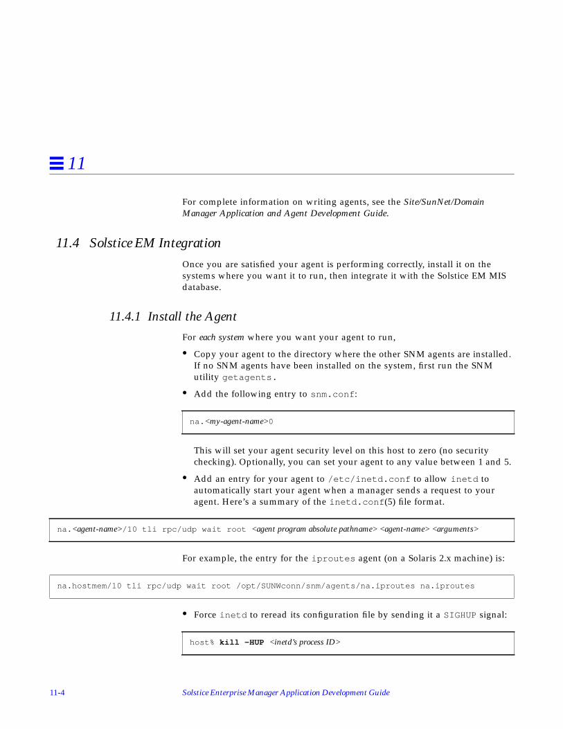
11-4 Solstice Enterprise Manager Application Development Guide
11
For complete information on writing agents, see the Site/SunNet/DomainManager Application and Agent Development Guide.
11.4 Solstice EM IntegrationOnce you are satisfied your agent is performing correctly, install it on thesystems where you want it to run, then integrate it with the Solstice EM MISdatabase.
11.4.1 Install the Agent
For each system where you want your agent to run,
• Copy your agent to the directory where the other SNM agents are installed.If no SNM agents have been installed on the system, first run the SNMutility getagents.
• Add the following entry to snm.conf :
This will set your agent security level on this host to zero (no securitychecking). Optionally, you can set your agent to any value between 1 and 5.
• Add an entry for your agent to /etc/inetd.conf to allow inetd toautomatically start your agent when a manager sends a request to youragent. Here’s a summary of the inetd.conf (5) file format.
For example, the entry for the iproutes agent (on a Solaris 2.x machine) is:
• Force inetd to reread its configuration file by sending it a SIGHUP signal:
na. <my-agent-name>0
na. <agent-name>/10 tli rpc/udp wait root <agent program absolute pathname> <agent-name> <arguments>
na.hostmem/10 tli rpc/udp wait root /opt/SUNWconn/snm/agents/na.iproutes na.iproutes
host% kill -HUP <inetd’s process ID>

Writing RPC Agents for EM 11-5
11
11.4.2 Update the EM MIS Database
Solstice EM uses GDMO descriptions, rather than the schema files used bySNM products, to represent the managed object classes available to themanagement database. Thus, the Solstice EM Schema compiler(em_snm2gdmo) is used as the first step in converting the SNM schema filesinto GDMO descriptions used in Solstice EM.
To translate an SNM schema file, run the Schema compiler with the file to betranslated as an argument (<filename>).
The output of the translation is a GDMO document, with a name of the form<filename>.gdmo , and an ASN.1 document, with a name of the form<filename>.asn1 . You must then pass the GDMO file through the GDMOcompiler.
For more information on the GDMO and schema-to-GDMO compilers, refer toChapter 2, “Utilities,” in the Solstice Enterprise Manager Reference Manual.
hostname% em_snm2gdmo < < filename>

11-6 Solstice Enterprise Manager Application Development Guide
11

A-1
Terminology References A
The ISO specifications provide precise technical definitions for a number ofterms used through out this document. This Appendix provides a road mapinto the ISO specifications for terminology definitions.
Table A-1 ISO Specifications for Terminology Definitions
Term Defined In
action X.720 ISO/IEC 10165-1
agent X.701 ISO/IEC 10040
agent role X.701 ISO/IEC 10040
Application Entity Title (AE-Title) ISO 7498-3
Application Program Title (AP-Ttile) ISO 7498-3
attribute X.710 ISO/IEC 9595
attribute identifier X.720 ISO 10165-1
attribute type X.720 ISO 10165-1
attribute value assertion X.720 ISO 10165-1
constructed encoding X.209 ISO 8825
containment X.720 ISO 10165-1
destination (see distination Attributesyntax))
X.734 ISO 10164-5
discriminator X.734 ISO 10164-5

A-2 Solstice Enterprise Manager Application Development Guide
A
distinguished name X.720 ISO 10165-1
end-of-contents octets X.209 ISO 8825
event forwarding discriminator (seeeventForwardingDiscriminator ManagedObject Class syntax)
X.734 ISO 10164-5
event report management function X.734 ISO 10164-5
filter (see CMISfilter syntax) X.711 ISO/IEC 9596-1
functional unit X.710 ISO/IEC 9595
identifier octets X.209 ISO 8825
length octets X.209 ISO 8825
local distinguished name (see ObjectIn-stance syntax)
X.711 ISO/IEC 9596-1
managed object ISO 7498-4
managed object class X.701 ISO/IEC 10040
management information X.701 ISO/IEC 10040
managed information base ISO 7498-4
manager X.701 ISO/IEC 10040
manager role X.701 ISO/IEC 10040
naming binding X.720 ISO 10165-1
naming tree X.720 ISO 10165-1
notification X.701 ISO/IEC 10040
notification type X.701 ISO/IEC 10040
open system X.200 ISO 7498
primitive encoding X.209 ISO 8825
relative distinguished name X.720 ISO 10165-1
systems management X.200 ISO 7498
top managed object class X.721 ISO/IEC 10165-2
Table A-1 ISO Specifications for Terminology Definitions
Term Defined In

B-1
Access to Data in the MIS B
B.1 OverviewThe central function of the Solstice EM MIS is to make data regarding managedobjects available to its client services. The term managed objects includes boththe physical resources connected to the network, such as hosts, bridges, androuters—as well as conceptual objects, such as lines, circuits, and queues. Italso includes any objects an application may choose to create, such as requests,views, counters, lists, or collections.
All managed objects are accessed through the MIT. There is one global tree,and that tree provides a single naming scheme for all data. The MIT isconstructed according to rules provided by OMNIPoint. The tree has a singleroot (called root). The shape of the tree is arbitrary, and may vary considerably
Overview page B-1
Object Orientation page B-2
Representation of Objects in the MIT page B-3
Identifying an Object in the MIT page B-5
Object Behavior Framework page B-5
ASN.1 Definitions page B-5
Transparent Access to the Distributed Storage of Managed Objects page B-6

B-2 Solstice Enterprise Manager Application Development Guide
B
from one Solstice EM MIS to another. Generally speaking, the tree’s structurerepresents containment relationships. That is, below an object, one finds thoseobjects that in some sense are related to it.
Data from managed resources (including MIB data) are also a part of the MIT.The Solstice EM MIS makes this data accessible both through the namingconventions that come from the managed resources it describes, and through aresource-independent naming convention, in which identifiers are specifiedusing Fully Distinguished Names (FDNs). It is this mechanism that enables theSolstice EM MIS to achieve transparency of location.
B.2 Object OrientationObject orientation is central to the Solstice EM product, which takes advantageof object-oriented design in two complementary ways:
• It describes managed objects in terms of OMNIPoint and ISO terminology;
• It uses C++ objects for internal storage and manipulation of network data.
The Solstice EM MIS uses one or more C++ classes to correspond directly tothe classes used in the formal descriptions. Within this document the followingterminology is used:
• class refers to a C++ class as described in The Annotated C++ ReferenceManual1.
• instance refers to the memory which is allocated for the instantiation of aC++ class according to its definition. A variable name is usually associatedwith a particular instance of a class.
• managed resource refers to an actual physical device or entity that exists in anetwork or system. This is consistent with the OSI/NM Forum definition ofthis term.
• managed object (MO) refers to a set of services and attributes that describes atype of managed resource. Again, this is consistent with the OSI/NM Forumdefinition for this term.
1. Annotated C++ Reference Manual, Margaret Ellis and Bjarne Stroustrop. Addison-Wesley Publishing Co.,Reading, MA. Copyright 1990 by AT&T Bell Telephone Laboratories.

Access to Data in the MIS B-3
B
• managed object class (MOC). This term refers to the internal representation ofa managed object (as defined by OSI/NM Forum). A MOC is typically theGDMO description, but might also be an SNMP MIB description. Putanother way, the MOC represents the attributes and behaviors for particulartypes of manageable objects. The MOC defines the type of data stored, andthe behaviors that can be taken, but does not represent actual data for anymanaged object. The MOC is the internal representation used by the SolsticeEM MIS.
• managed object instance (MOI) relates to a managed object class in the sameway as an instance relates to a class. The MOC determines the type ofattributes and behaviors available to operate on an object of this type; anMOI refers to actual data that represents an object which is being managedby the MIS. An MOI is also an internal representation used by the SolsticeEM MIS.
B.3 Representation of Objects in the MITEvery object known to the MIS is represented in the Management InformationTree (MIT), including all types of objects. Such objects:
• Represent physical devices, such as hosts, bridges, and routers
• Represent parts of a device, such as ports and network access cards
• Are primarily conceptual, such as lines and functional groups
• Are primarily the creation of software, such as queues
• Are entirely the creation of client services, such as counters, tables, and lists
Each object in the MIS has either an entry—consisting of a Fully DistinguishedName—in the Management Information Tree or, if it is outside of the local MIS,an entry in the FDN Table, which contains a pointer to where the object resides.The FDN Table maps a remote object’s Distinguished Name to its PresentationAddress. When an application requests information of an object, if the object isin the FDN Table, the MIS forwards the application’s request to agent ormanager at the address listed in the table.
Storage for local objects is shown in Figure B-1.

B-4 Solstice Enterprise Manager Application Development Guide
B
Figure B-1 Objects in the Management Information Tree and C++ Objects
For each local object, the MIS contains a corresponding C++ object. Such C++objects are either a Managed Object Instance (MOI), or a class derived from aMOI.
Each MOI includes a reference to its class. Each class description is an MOC:that is, an instance of the C++ class called MOC (Managed Object Class).
Each MOC instance describes the characteristic of a class of managed objects,and is constructed by referring to an entry in the MetaData Repository (whichcontains the GDMO form of its description).
ASDefin
MOC
MOC
MOC
MOC
MOI
MOI
MOI
MOI
MOI
MOI
(each identified by its FDN;
C++ objects
MOC
MOI
MOI
MOI
MOIMOI
Objects in theManagement Information Tree
Managed
InstanceObject
Managed
ClassObject
(one for each local objectin the MIT)
some local, some remote objects)
C++ objects(one for each class
in the MIT)
Routing to remote objectRouting to remote object
MetRepo
GDMODefinitions

Access to Data in the MIS B-5
B
Descriptions of managed resources in the MetaData Repository, and also MOCand MOI definitions, can refer to ASN.1 definitions, so all of them makereference to the MIS’s set of ASN.1 definition files.
B.4 Identifying an Object in the MITEach managed object is uniquely identified by its fully distinguished name, orFDN, which is the path through the MIT required to reach the object. Paths arewritten in a format similar to paths in the UNIX file system. That is, a pathbeginning with / starts from the root of the tree. Each successive level of thetree starts with another /.
Each segment of the path identifies both the syntactic category and theindividual name of an object in that category. In this regard, paths through theMIT are more complex than the names of UNIX files. The following is anexample of an FDN:
B.5 Object Behavior FrameworkMuch of the MIS’s power comes from the ability not just to describe objects butto specify the actions they can take—their behaviors. When an object’sbehavior is specified, it becomes possible to elicit the behavior. The MIS allowsyou to specify behaviors of objects through the ACTION clause of a GDMOdescription and through the behaviors already defined in the MIS.
B.6 ASN.1 DefinitionsBoth in its CMIS-like messages and in data storage for managed objects, theSolstice EM MIS makes extensive use of an ISO standard description of theway data is represented. The description is called ASN.1 (Abstract SyntaxNotation One). A message that uses ASN.1 must include not only the encodeddata, but also information about the type of the encoded information. Aprocess that represents a value by an ASN.1 encoding, or that extracts a valuefrom an ASN.1 encoding, must be able to access the definition of the particularencoding employed. The GDMO descriptions of new objects also makereference to ASN.1 descriptions of their data.
/systemId=name:"myhost"/systemId=NAME:"EM"

B-6 Solstice Enterprise Manager Application Development Guide
B
To provide effective access to the needed ASN.1 definitions, the Solstice EMMIS keeps a set of files containing type definitions and encoding rules. Whenthe definitions of new objects make reference to new ASN.1 types, filescontaining the new ASN.1 definitions must be included in the MIS’s/var/opt/SUNWconn/em/data/ASN.1 directory. At startup andperiodically, the Solstice EM MIS loads these ASN.1 type files into the MDR.Refer to the “Utilities” chapter in the Solstice Enterprise Manager ReferenceManual for detailed information about ASN.1 documents and how they arecompiled.
B.7 Transparent Access to the Distributed Storage of Managed ObjectsA managed resource can reside anywhere in the network. The MIS’s MITserves as a map of all the information in the network. It contains an entry forevery managed object known to the Solstice EM MIS. For each managed object,the MIT contains data about the route by which the MIS can get the managedinformation, including objects whose information is stored in the Solstice EMMIS itself, referred to as local objects.
To access objects whose information is stored outside the local MIT, the MISuses the FDN Table. The FDN Table contains the Presentation Addresses ofobjects not in the local MIT. Whenever the local MIS receives a request for thevalue of attributes for a remote object, a request must be sent to the remoteentity (agent or MIS) to fetch the current attribute value.
Access to a non-local object might require a protocol translation. Where amanaged object is reported by an agent that is limited to SNMP, the MITmanager software creates a proxy agent. Although the proxy accepts CMIP-based requests and returns CMIP-based responses, it uses SNMP tocommunicate with the remote agent. Because CMIP provides facilities that arenot directly supported in SNMP, the proxy agent is considerably more than atranslator. For example, to support CMIP scoping, the proxy may have togenerate multiple requests and coordinate multiple responses. To handle someCMIP notifications, the proxy may have to poll the SNMP agent.
An Solstice EM application can refer to any object that has an entry in the MIT.The application does not need to know how the MIS communicates with themanaged object. In particular, it addresses remote objects or proxies in thesame way as other managed objects.

Access to Data in the MIS B-7
B
Figure B-2 illustrates the mechanism by which Solstice EM applications cancommunicate with remote managed objects.
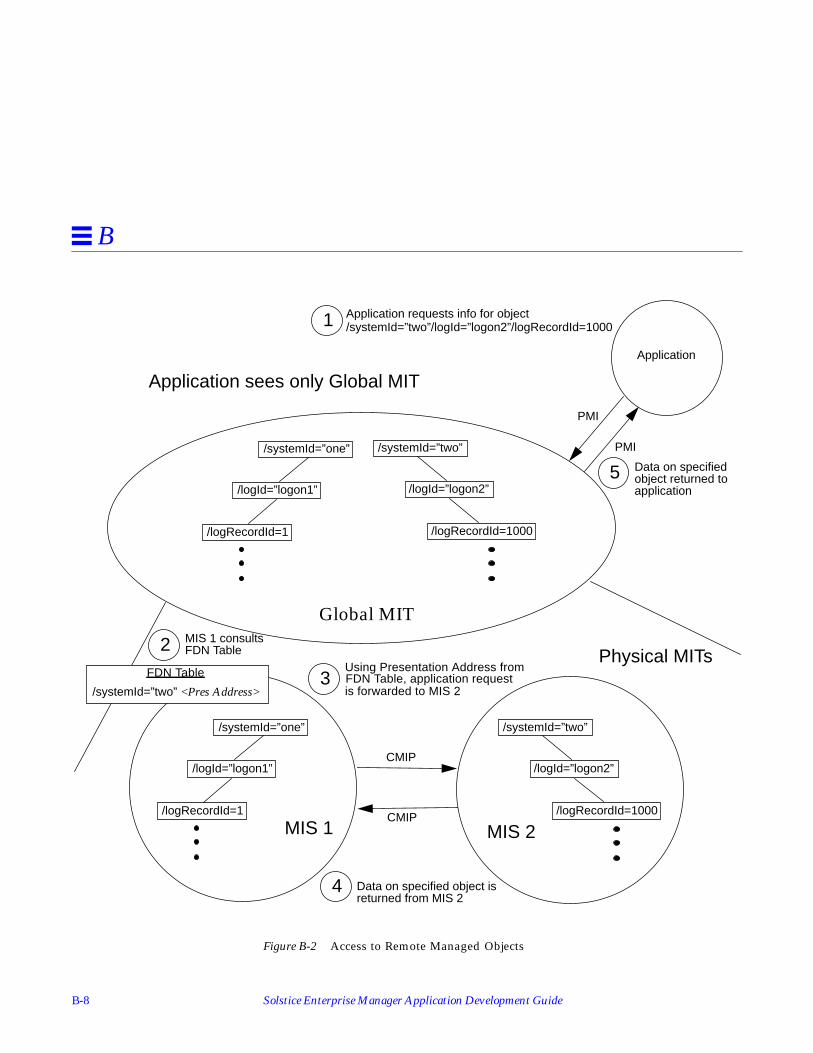
B-8 Solstice Enterprise Manager Application Development Guide
B
Figure B-2 Access to Remote Managed Objects
Application
1
2
4
5
Application requests info for object
MIS 1 consultsFDN Table
3Using Presentation Address fromFDN Table, application requestis forwarded to MIS 2
CMIP
PMI
PMI
Data on specified object is
Data on specifiedobject returned to
/systemId=”one”
/logId=”logon1”
/logRecordId=1
/systemId=”two”
/logId=”logon2”
/logRecordId=1000
FDN Table
/systemId=”two” <Pres Address>
Global MIT
MIS 1 MIS 2
CMIP
/systemId=”two”/logId=”logon2”/logRecordId=1000
returned from MIS 2
application
/systemId=”one”
/logId=”logon1”
/logRecordId=1
/systemId=”two”
/logId=”logon2”
/logRecordId=1000
Physical MITs
Application sees only Global MIT

Access to Data in the MIS B-9
B
Note the sequence illustrated in Figure B-2:
1. An application, using the PMI, makes a request for information about theobject with the FDN of/systemId=”two”/logId=”logon2”/logRecordId=1000 .
2. As with each incoming request, MIS 1 consults its FDN Table, where it findsan entry for /systemId=”two” .
3. MIS 1 forwards the request to MIS 2 over a CMIP connection, using thePresentation Address found in the FDN Table entry.
4. MIS2 returns Data for specified object to MIS 1, over a CMIP connection.
5. MIS 1 returns data for specified object to application, by the PMI.

B-10 Solstice Enterprise Manager Application Development Guide
B
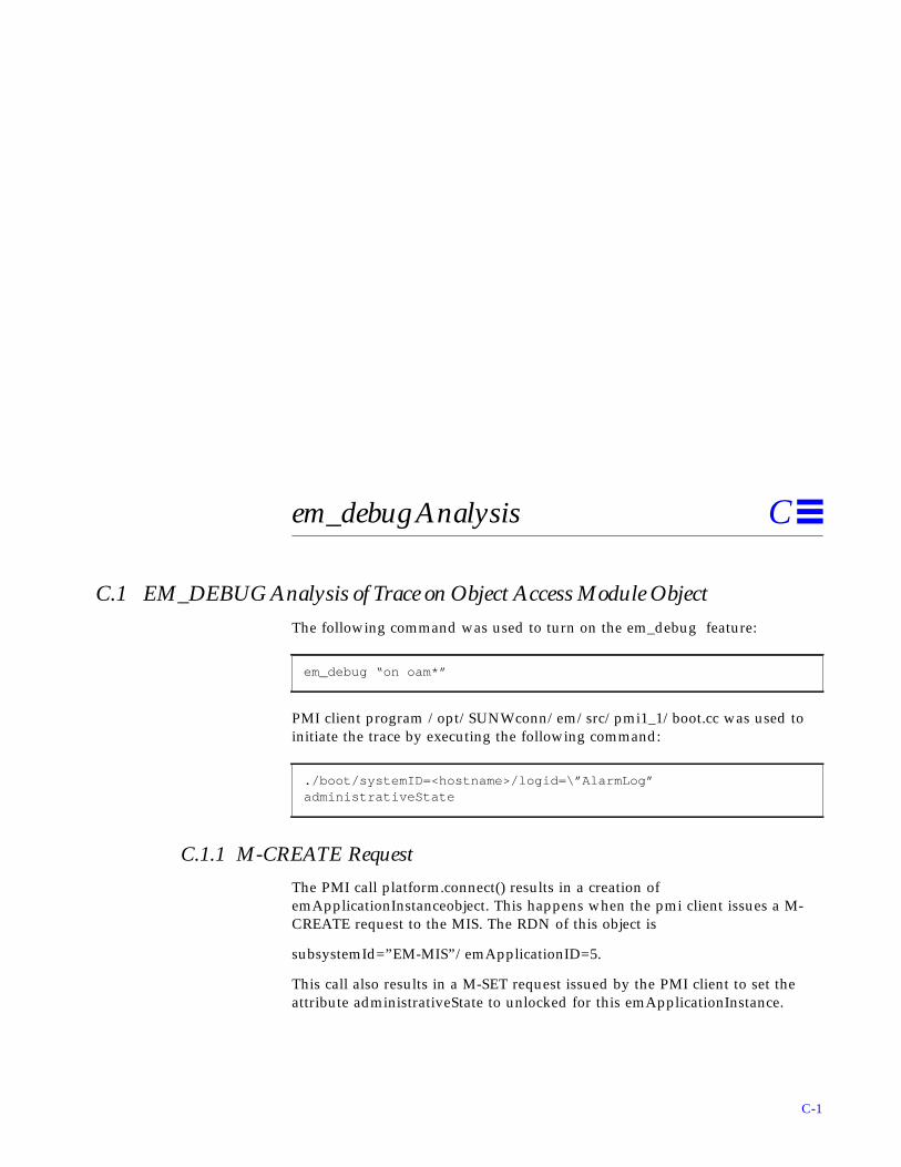
C-1
em_debug Analysis C
C.1 EM_DEBUG Analysis of Trace on Object Access Module ObjectThe following command was used to turn on the em_debug feature:
PMI client program /opt/SUNWconn/em/src/pmi1_1/boot.cc was used toinitiate the trace by executing the following command:
C.1.1 M-CREATE Request
The PMI call platform.connect() results in a creation ofemApplicationInstanceobject. This happens when the pmi client issues a M-CREATE request to the MIS. The RDN of this object is
subsystemId=”EM-MIS”/emApplicationID=5.
This call also results in a M-SET request issued by the PMI client to set theattribute administrativeState to unlocked for this emApplicationInstance.
em_debug “on oam*”
./boot/systemID=<hostname>/logid=\”AlarmLog”administrativeState

C-2 Solstice Enterprise Manager Application Development Guide
C
These two events result in MIS sending 2 M-EVENT-REPORT requests tonotify the PMI client of an objectCreation [emApplicationInstance object] eventand an AVC [administrative attribute of this emApplicationInstance changedto unlocked] event.
M-Create Indication is received by Object Access Manager. The format for anM-Create Indication from ITU X.711
[/opt/SUNWconn/em/etc/asn1/x711.asn1]
is as follows:
Thus the M-Create Indication (CreateArgument) will contain the following (instrict order):
• managedObjectClass
• optionally managedObjectInstance or superiorObjectInstance
• optionally accessControl
• optionally referenceObjectInstance
## PLAT_CONNECT## oammsg_debug:**************************************************************oammsg_debug: received by OAM: create requestoammsg_debug: message type = create request
CreateArgument ::= SEQUENCE { managedObjectClass ObjectClass, CHOICE { managedObjectInstance ObjectInstance, superiorObjectInstance [8] ObjectInstance } OPTIONAL, accessControl [5] AccessControl OPTIONAL, referenceObjectInstance [6] ObjectInstance OPTIONAL, attributeList [7] IMPLICIT SET OF AttributeOPTIONAL}

em_debug Analysis C-3
C
• optionally attributeList
The mode is CONFIRMED. i.e. M-Create is a confirmed operation. The senderof the M-Create expects a response.
The above, oc , is the managedObjectClass of the target of this operation. Thatis, the Object Class of the new object that is to be created. From earlier we seethat: managedObjectClass is of type ObjectClass. And from ITU X.711
[/opt/SUNWconn/em/etc/asn1/x711.asn1]
ObjectClass is defined as follows:
oammsg_debug: id = 7oammsg_debug: source =oammsg_debug: aclass = DEF, atag = 0 aval = Du: no data unit allocatedoammsg_debug: dest =oammsg_debug: aclass = DEF, atag = 0 aval = Du: no data unit allocatedoammsg_debug: remote =oammsg_debug: aclass = DEF, atag = 0 aval = Du: no data unit allocatedoammsg_debug: mode = CONFIRMED
oammsg_debug: app_context = Du: no data unit allocatedoammsg_debug: oc =oammsg_debug: Tag Length Valueoammsg_debug: C0 c 1.3.6.1.4.1.42.2.2.2.1.3.2
ObjectClass ::= CHOICE { globalForm [0] IMPLICIT OBJECT IDENTIFIER, localForm [1] IMPLICIT INTEGER}

C-4 Solstice Enterprise Manager Application Development Guide
C
Enterprise Manager always uses the global Form CHOICE as this is guaranteedto be unique. We can see that globalForm is of type OBJECT IDENTIFIER.Em_debug always prints out the encoded value of CMIP Protocol Data Units.The general form for an encoded value is:
Tag Length Value
where Tag indicates the ASN.1 type that exists in the Value field. In the abovedefinition of ObjectClass we have [0] which indicates that the Tag forglobalForm is a Context Specific 0 [C0]. This tag replaces the Tag that would beused, OID, is the [0] IMPLICIT was not in this definition. So themanagedObjectClass has the following encoded form:
Tag Length ValueC0 Length of Value <Object Identifier>
In this specific case we see:
Thus, the OBJECT IDENTIFIER of the managedObjectClass is
1.3.6.1.4.1.42.2.2.2.1.3.2
The easy way to find out what this means is to use the Object Editor to issue anaction against the Meta Data Repository.
1. Select the /systemId=name:”hostname”/metaName=”MDR” object
2. Select Object->Action->getOidName
3. When the Action dialog box appears enter the OID in curly braces asfollows:
{ 1 3 6 1 4 1 42 2 2 2 1 3 2 }
4. Click OK
5. The Output Window will then be displayed. For this example it will be:
oammsg_debug: oc =oammsg_debug: Tag Length Valueoammsg_debug: C0 c 1.3.6.1.4.1.42.2.2.2.1.3.2

em_debug Analysis C-5
C
Thus, we can see that this M-Create is for a new object with Object ClassemApplicationInstance.
We can see from the earlier definition of CreateArgument that theObjectInstance (the name of the object that we are creating) can be specified inone of two ways:
That is, we can specify either the name of the object to be created(managedObjectInstance) or the name of the object that contains the object tobe created (superiorObjectInstance).
{ oid “EM GMI”:emApplicationInstance, name “““EM GMI””:emApplicationInstance” }
oammsg_debug: oi = NULLoammsg_debug: superior_oi =oammsg_debug: Tag Length Valueoammsg_debug: C4 13oammsg_debug: Tag Length Valueoammsg_debug: SET 11oammsg_debug: Tag Length Valueoammsg_debug: SEQ foammsg_debug: Tag Length Valueoammsg_debug: OID 5 2.9.3.5.7.11oammsg_debug: Tag Length Valueoammsg_debug: GRPH 6 “EM-MIS”
CHOICE { managedObjectInstance ObjectInstance, superiorObjectInstance [8] ObjectInstance } OPTIONAL,

C-6 Solstice Enterprise Manager Application Development Guide
C
em_debug calls managed ObjectInstanceoi, and calls superiorObjectInstancesuperior_oi. So in this case the superiorObjectInstance is being used. To decodethe message further, we start with the definition of superiorObjectInstance:
superiorObjectInstance [8] ObjectInstance
from ITU X.711
[/opt/SUNWconn/em/etc/asn1/x711.asn1]
ObjectInstance is defined as follows:
Note the context specific tag of each member of the choice. The first tag in theem_debug output is:
Thus what follows in localDistinguishedName form. Again,localDistinguishedName is of ASN.1 Type RDNSequence.
From the InformationFramework
[/opt/SUNWconn/em/etc/asn1/infofw.asn1]
RDNSequence is defined as follows:RDNSequence ::= SEQUENCE OFRelativeDistinguishedName and that:
RelativeDistinguishedName ::= SET OF AttributeValueAssertion and that:
ObjectInstance ::= CHOICE { distinguishedName [2] IMPLICIT DistinguishedName, nonSpecificForm [3] IMPLICIT OCTET STRING, localDistinguishedName [4] IMPLICIT RDNSequence}
oammsg_debug: superior_oi =oammsg_debug: Tag Length Valueoammsg_debug: C4 13

em_debug Analysis C-7
C
Putting this all together we get:
ObjectInstance is the
Note – When a type defined in a CHOICE e.g. RDNSequence has a contextspecific Tag e.g. [4], this tag replaces the TAG of the type that follows (like theOBJECT IDENTIFIER example earlier). So in this case the TAG C4 replacesSEQUENCE OF in the encoded value of localDistinguishedName.
Thus, superiorObjectInstance will have the following form for its value:
AttributeValueAssertion ::= SEQUENCE { attributeId OBJECT IDENTIFIER, attributeValue ANY DEFINED BY attributeId}
localDistinguishedName [4] IMPLICIT SEQUENCE OF SET OF SEQUENCE{ attributeId OBJECT IDENTIFIER, attributeValue ANY DEFINEDBY attributeId }

C-8 Solstice Enterprise Manager Application Development Guide
C
The final Tag is X because it depends on the value of the previous OID.Compare this with the em_debug output:
We note that the final part:
Tag Length ValueC4 ATag Length ValueSET BTag Length ValueSEQUENCE CTag Length ValueOID DTag Length ValueX E
oammsg_debug: superior_oi =oammsg_debug: Tag Length Valueoammsg_debug: C4 13oammsg_debug: Tag Length Valueoammsg_debug: SET 11oammsg_debug: Tag Length Valueoammsg_debug: SEQ foammsg_debug: Tag Length Valueoammsg_debug: OID 5 2.9.3.5.7.11oammsg_debug: Tag Length Valueoammsg_debug: GRPH 6 “EM-MIS”
oammsg_debug: Tag Length Valueoammsg_debug: OID 5 2.9.3.5.7.11oammsg_debug Tag Length Valueoammsg_debug: GRPH 6 “EM-MIS”

em_debug Analysis C-9
C
is actually
So we need to first look up the OID. Using the Object Editor we find that2.9.3.5.7.11 is subsystemId. Now we can lookup the syntax of subsystemId.This will help us resolve the ANY DEFINED BY attributeId. Using the ObjectEditor issue an action against the MDR as before. This time the action will begetAttribute. The parameter is as before:
{ 2 9 3 5 7 11 }
The output window will display the syntax:
We see that subsystemId has a syntax or ASN.1 type of GraphicString. Thus weexpect the second part of the sequence to be:
Tag Length Value
Graphic String X
AttributeValueAssertion ::= SEQUENCE { attributeId OBJECT IDENTIFIER, attributeValue ANY DEFINED BY attributeId
{ “Rec. X.723 | ISO/IEC 10165-5”:subsystemId, { { document “Rec. X.723 | ISO/IEC 10165-5”, label “subsystemId” } }, defined : { module ““, name “GraphicString” }}

C-10 Solstice Enterprise Manager Application Development Guide
C
Now compare this with the real encoded value:
Thus the superiorObjectInstance is:
subsystemId=”EM-MIS”
Because we are using localDistinguishedName form, this name is relative to
/systemId=name:”hostname”
and we are specifiying that the Object to be created will be contained by:
/systemId=name:”hostname”/subsystemId=”EM-MIS”
This is where the object instances that represent EM application are alwaysfound.
We saw earlier in the definition of a CreateArgument that:
That is, both accessControl, and referenceObjectInstance are optional.em_debug represents the absence of a parameter by NULL.
The final field in the M-Create Indication is the attributes that are to be set inthe new object instance and the initial values of these attributes. This is theattributeList parameter:
attributeList [7] IMPLICIT SET OF Attribute OPTIONAL
From ITU X.711
[/opt/SUNWconn/em/etc/asn1/x711.asn1])
Attribute is as follows:
oammsg_debug: Tag Length Valueoammsg_debug: GRPH 6 “EM-MIS”
oammsg_debug: access = NULLoammsg_debug: reference_oi = NULL
accessControl [5] AccessControl OPTIONAL, referenceObjectInstance [6] ObjectInstance OPTIONAL,

em_debug Analysis C-11
C
Thus, attributeList is defined as follows:
And AttributeId is defined as:
Attribute ::= SEQUENCE { attributeId AttributeId, attributeValue ANY DEFINED BY attributeId}
attributeList [7] IMPLICIT SET OF SEQUENCE { attributeId AttributeId, attributeValue ANY DEFINED BYattributeId }
AttributeId ::= CHOICE { globalForm [0] IMPLICIT OBJECT IDENTIFIER, localForm [1] IMPLICIT INTEGER}

C-12 Solstice Enterprise Manager Application Development Guide
C
Remembering that [7] replaces SET OF (as in the earlier example) we have thefollowing encoding for attributeList:
and so on. One of the Tags is ? because it depends on the value of AttributeId.
Note – The AttributeId can be either: globalForm tagged as C0 : type isOBJECT IDENTIFIER OR localForm tagged as C1 : type is INTEGER.
Now, we can decode the attributeList as follows using the above and the ObjectEditor:
We have attributeList:
Tag Length ValueC7 ATag Length ValueSEQUENCE BTag Length ValueC0 or C1 CTag Length Value? DTag Length ValueSEQUENCE ETag Length ValueC0 or C1 FTag Length Value? G
oammsg_debug: attr_list =oammsg_debug: Tag Length Valueoammsg_debug: C7 7b
oammsg_debug: Tag Length Valueoammsg_debug: SEQ 11oammsg_debug: Tag Length Valueoammsg_debug: C c 1.3.6.1.4.1.42.2.2.2.1.7.1oammsg_debug: Tag Length Valueoammsg_debug: 1 = 5U

em_debug Analysis C-13
C
First attribute (SEQuence of AttributeId, AttributeValue). The AttributeId is inglobalform (Tag C0). As this is an OID, it decodes to:
emApplicationID
Next, we must find the syntax of emApplicationID. The getAttribute actionyields:
The syntax is EMApplicationID defined in module EM-GMI-ASN1. We can usethe Object Editor MDR Action getAsn1Module with parameter EM-GMI-ASN1to recover all the ASN.1 types in the module. Looking down we see that:
{ “EM GMI”:emApplicationID, { { document “EM GMI”, label “emApplicationID” } }, defined : { module “EM-GMI-ASN1”, name “EMApplicationID” }}
{ name “EMApplicationID”, type integer : { }

C-14 Solstice Enterprise Manager Application Development Guide
C
That is, EMApplicationID ::= INTEGER Thus, the next TAG should be INT.From em_debug we see:
Thus, the value is 5 (INTEGER).
And, finally, this attribute and value are:
emApplicationID=5
emApplicationType=”Test_album”
This one is more complex. Let us examine it step by step.
AttributeId = emUserID
oammsg_debug: Tag Length Valueoammsg_debug: INT 1 = 5U
oammsg_debug Tag Length Valueoammsg_debug:SE 1aoammsg_debug:Tag Length Valueoammsg_debug:C0 c 1.3.6.1.4.1.42.2.2.2.1.7.2oammsg_debug Tag Length Valueoammsg_debug:GRPH a “Test_album”
oammsg_debug: Tag Length Valueoammsg_debug: SEQ 2coammsg_debug: Tag Length Valueoammsg_debug: C0 c 1.3.6.1.4.1.42.2.2.2.1.7.6oammsg_debug: Tag Length Valueoammsg_debug: SEQ 1coammsg_debug: Tag Length Valueoammsg_debug: SET 1aoammsg_debug: Tag Length Valueoammsg_debug: SEQ 18oammsg_debug: Tag Length Valueoammsg_debug: OID c 1.3.6.1.4.1.42.2.2.2.1.7.7oammsg_debug: Tag Length Valueoammsg_debug: GRPH 8 “sudhakar”

em_debug Analysis C-15
C
AttributeValue has the syntax of emUserID. We can resolve this totypeDistinguishedName which the EM-GMI-ASN1 module imports from theInformationFramework:
DistinguishedName ::= RDNSequence
RDNSequence ::= SEQUENCE OF RelativeDistinguishedName
RelativeDistinguishedName ::= SET OF AttributeValueAssertion
AttributeValueAssertion ::=
Thus, DistinguishedName has the following syntax:
Thus, DistinguishedName will have the following form for its encoded value:
SEQUENCE { attributeId OBJECT IDENTIFIER, attributeValue ANY DEFINED BY attributeId}
SEQUENCE OF SET OF SEQUENCE { attributeId OBJECT IDENTIFIER, attributeValue ANY DEFINED BY attributeId }

C-16 Solstice Enterprise Manager Application Development Guide
C
The final Tag is X because its value depends on the value of the previous OID.Thus, we have:
or, if you prefer:
Tag Length ValueSEQ ATag Length ValueSET BTag Length ValueSEQUENCE CTag Length ValueOID DTag Length ValueX E
emUserID= { { { emUserLogin, “sudhakar” } }}
emUserID= /emUserLogin=”sudhakar”
oammsg_debug: Tag Length Valueoammsg_debug: SEQ 10oammsg_debug Tag Length Valueoammsg_debug: C0 c 1.3.6.1.4.1.42.2.2.2.1.7.11oammsg_debug: Tag Length Valueoammsg_debug: SET 0
emSpecialEvents = {}

em_debug Analysis C-17
C
(the empty set)
Here the OID has not been decoded for us. Thus, we need to do so manually:
0x59 03 02 07 1f = 2.9 3 2 7 31 = 2.9.3.2.7.31 = administrativeState
The syntax for administrativeState from dmi.asn1 is:
AdministrativeState ::= ENUMERATED
Thus, we have:
administrativeState=locked
We have now completed the M-Create Request.
oammsg_debug: Tag Length Valueoammsg_debug: SEQ aoammsg_debug: Tag Length Valueoammsg_debug: C0 5 0x59 03 02 07 1foammsg_debug: Tag Length Valueoammsg_debug: ENUM 1 = 0
{ locked (0), unlocked (1), shuttingDown (2)}
oammsg_debug: ************************************************

C-18 Solstice Enterprise Manager Application Development Guide
C
The MIS now resolves those attributes in the M-Create Request and creates a new emApplicationInstance object.
oam_debug: resolve_attr: attr 1.3.6.1.4.1.42.2.2.2.1.7.1resolved to supplied
oam_debug: resolve_attr: attr 1.3.6.1.4.1.42.2.2.2.1.7.2resolved to supplied
oam_debug: resolve_attr: attr 1.3.6.1.4.1.42.2.2.2.1.7.6resolved to supplied
oam_debug: resolve_attr: attr 1.3.6.1.4.1.42.2.2.2.1.7.11resolved to supplied
oam_debug: resolve_attr: attr 2.9.3.2.7.31 resolved tosupplied
oam_debug: resolve_attr: attr 2.9.3.2.7.35 resolved tomagical
oam_debug: resolve_attr: attr 2.9.3.2.7.50 resolved tomagical
oam_debug: resolve_attr: attr 2.9.3.2.7.56 resolved todefault
oam_debug: resolve_attr: attr 2.9.3.2.7.63 resolved tomagical
oam_debug: resolve_attr: attr 2.9.3.2.7.65 resolved tomagical
oam_debug: resolve_attr: attr 2.9.3.2.7.66 resolved tomagical

em_debug Analysis C-19
C
oam_info: DiscriminatorAttrSecty:write validx=1DiscriminatorAttrSecty:write val idx=2DiscriminatorAttrSecty:write validx=0DiscriminatorAttrSecty:read val idx=2
C.1.1.1 M-Event Report
The MIS now generated an M-Event-Report.
The mode is unconfirmed. The MIS does not expect a response. The syntax ofan Event Report is (from ITU X.711):
oamnot_debug: M-Event-Report Message =oamnot_debug: message type = event_report requestoamnot_debug: id = 14915424oamnot_debug: source =oamnot_debug: aclass = DEF, atag = 0 aval = Du: no data unit allocatedoamnot_debug: dest =oamnot_debug: aclass = DEF, atag = 1 aval = Du: no data unit allocatedoamnot_debug: remote =oamnot_debug: aclass = DEF, atag = 0 aval = Du: no data unit allocated
oamnot_debug: mode = UNCONFIRMEDoamnot_debug: app_context = Du: no data unit allocated
EventReportArgument ::= SEQUENCE {managedObjectClass ObjectClass, managedObjectInstance ObjectInstance, eventTime [5] IMPLICIT GeneralizedTime OPTIONAL, eventType EventTypeId, eventInfo [8] ANY DEFINED BY eventType OPTIONAL}

C-20 Solstice Enterprise Manager Application Development Guide
C
The above, oc, is the managedObjectClass of the source of this operation (M-Event-Report). That is, the Object Class of the new object that was just created.From earlier we see that: managedObjectClass is of type ObjectClass. And fromITU X.711
[/opt/SUNWconn/em/etc/asn1/x711.asn1]
ObjectClass is defined as follows:
Thus, from the em_debug trace we see that once again we use theglobalFormCHOICE and that managedObjectClass = emApplicationInstance.
oamnot_debug: oc =oamnot_debug: Tag LengthValueoamnot_debug: C0 c 1.3.6.1.4.1.42.2.2.2.1.3.2
ObjectClass ::= CHOICE { globalForm [0] IMPLICIT OBJECT IDENTIFIER, localForm [1] IMPLICIT INTEGER}

em_debug Analysis C-21
C
We can see from the earlier definition of EventReportArgument that themanagedObjectInstance is of type ObjectInstance.
From ITU X.711
[/opt/SUNWconn/em/etc/asn1/x711.asn1]
ObjectInstance is defined as follows:
camnot_debug: oi =camnot_debug: Tag Length Valuecamnot_debug: C2 3dcamnot_debug: Tag Length Valuecamnot_debug: SET 13camnot_debug: Tag Length Valuecamnot_debug: SEQ 11camnot_debug: Tag Length Valuecamnot_debug: OID 5 2.9.3.2.7.4camnot_debug: Tag Length Valuecamnot_debug: GRPH 8 “dynamics”camnot_debug: Tag Length Valuecamnot_debug: SET 11camnot_debug: Tag Length Valuecamnot_debug: SEQ fcamnot_debug: Tag Length Valuecamnot_debug: OID 52.9.3.5.7.11camnot_debug: Tag Length Valuecamnot_debug: GRPH 6 “EM-MIS”camnot_debug: Tag Length Valuecamnot_debug: SET 13camnot_debug: Tag Length Valuecamnot_debug: SEQ llcamnot_debug: Tag Length Valuecamnot_debug: OID C 1.3.6.1.4.1.42.2.2.2.1.7.1camnot_debug: Tag Length Valuecamnot_debug: INT 1 = 5U

C-22 Solstice Enterprise Manager Application Development Guide
C
Note the context specific tag of each member of the choice. Looking at theem_debug output we can see the first tag is:
Thus, what follows in DistinguishedName form. From theInformationFramework
[/opt/SUNWconn/em/etc/asn1/infofw.asn1]
is defined as follows: DistinguishedName ::= RDNSequence
RDNSequence ::= SEQUENCE OF RelativeDistinguishedName
RelativeDistinguishedName ::= SET OF AttributeValueAssertion
Thus, DistinguishedName has the following syntax:
ObjectInstance ::= CHOICE { distinguishedName [2] IMPLICIT DistinguishedName, nonSpecificForm [3] IMPLICIT OCTET STRING, localDistinguishedName [4] IMPLICIT RDNSequence}
oammsg_debug: Tag Length Valueoammsg_debug: C2 13
AttributeValueAssertion ::= SEQUENCE { attributeId OBJECT IDENTIFIER, attributeValue ANY DEFINED BY attributeId}
SEQUENCE OF SET OF SEQUENCE { attributeId OBJECT IDENTIFIER, attributeValue ANY DEFINED BY attributeId }

em_debug Analysis C-23
C
Thus, DistinguishedName will have the following form for its encoded value:
The final Tag is X because it depends on the value of the previous OID. Now,compare this with the em_debug output:
Tag Length Value SEQ A Tag Length Value SET B Tag Length Value
SEQ C Tag Length Value
OID DTag Length ValueX E

C-24 Solstice Enterprise Manager Application Development Guide
C
AttributeId : emApplicationID
Thus, the managedObjectInstance is:
/systemId=name:”dynamics”/subsystemId=”EM-MIS”/emApplicationID=5
camnot_debug: oi =camnot_debug: Tag Length Valuecamnot_deubg: C2 3dDistinguishedNameformcamnot_debug: Tag Length Valuecamnot_debug: SET 13camnot_deubg: Tag Length Valuecamnot_debug: SET 13camnot_debug: Tag Length Valuecamnot_debug: SEQ 11camnot_debug: Tag Length Valuecamnot_debug: OID 5 2.9.3.2.7.4camnot_debug: Tag Length Valuecamnot_debug: GRPH 8 “dynamics”AttributeId : systemIdAttributeValue: “dynamics” (uses the name CHOICE)camnot_debug: Tag Length Valuecamnot_debug: SET 11camnot_debug: Tag Length Valuecamnot_debug: SEQ fcamnot_debug: Tag Length Valuecamnot_debug: OID 5 2.9.3.5.7.11camnot_debug: Tag Length Valuecamnot_debug: GRAPH 6 “EM-MIS”AttributeId : subsystemIdAttributeValue: “EM-MIS”camnot_debug: Tag Length Valuecamnot_debug: SET 13camnot_debug: TAG Length Valuecamnot_debug: SEQ 11camnot_debug: Tag Length Valuecamnot_debug: OID c 1.3.6.1.4.1.42.2.2.2.1.7.1camnot_debug: Tag Length Valuecamnot_debug: INT 1 = 5UAttributeId : emApplicationIDAttributeValue: 5

em_debug Analysis C-25
C
From earlier we have:
eventType EventTypeId,
and from X.711 EventTypeId has the following syntax:
As the first Tag from the em_debug trace is C6, we are using globalForm, andthe value of type OBJECT IDENTIFIER. Thus, eventType= 0x59 03 02 0a 06 =2.9.3.2.10.6 = objectCreation
From earlier we have:
eventTime [5] IMPLICIT GeneralizedTime OPTIONAL,
Thus, the Tag is C6 and the value is of type GeneralizedTime. Thus eventTime=13th May 1996 13:52:18.
oamnot_debug: event_type =oamnot_debug: Tag Length Valueoamnot_debug: C6 5 0x59 03 02 0a 06
EventTypeId ::= CHOICE { globalForm [6] IMPLICIT OBJECT IDENTIFIER, localForm [7] IMPLICIT INTEGER}
oamnot_debug: event_time =oamnot_debug: Tag Length Valueoamnot_debug: C5 e “19960513135218”
oamnot_debug: event_info = NULL

C-26 Solstice Enterprise Manager Application Development Guide
C
There is NO eventInfo field in this M-Event-Report (eventInfo is defined asOPTIONAL).
The M-Event-Report is now complete.
C.1.1.2 M-Create Response
The MIS now sends a response to the original M-Create Indication. As this isthe only response, linked is set to FALSE. The M-Create Response is definedfrom ITU X.711 as follows:
oammsg_debug: ***********************************************
oammsg_debug: sent by OAM: create responseoammsg_debug: message type = create responseoammsg_debug: id = 7oammsg_debug: source =oammsg_debug: aclass = DEF, atag = 0 aval = Du: no data unit allocatedoammsg_debug: dest =oammsg_debug: aclass = DEF, atag = 0 aval = Du: no data unit allocatedoammsg_debug: remote =oammsg_debug: aclass = DEF, atag = 0 aval = Du: no data unit allocatedoammsg_debug: linked = FALSE
CreateResult ::= SEQUENCE { managedObjectClass ObjectClass OPTIONAL, managedObjectInstance ObjectInstance OPTIONAL, currentTime [5] IMPLICIT GeneralizedTimeOPTIONAL, attributeList [6] IMPLICIT SET OF AttributeOPTIONAL}

em_debug Analysis C-27
C
The above, oc, is the managedObjectClass of the source of this operation (M-Create Response). i.e. the Object Class of the new object that was just created.From earlier we see that: managedObjectClass is of type ObjectClass. Andfrom ITU X.711
[/opt/SUNWconn/em/etc/asn1/x711.asn1]
ObjectClass is defined as follows:
Thus, from the em_debug trace we see that once again we use the globalFormCHOICE and that managedObjectClass = emApplicationInstance.
oammsg_debug: oc =oammsg_debug: Tag Length Valueoammsg_debug: C0 c 1.3.6.1.4.1.42.2.2.2.1.3.2
ObjectClass ::= CHOICE { globalForm [0] IMPLICIT OBJECT IDENTIFIER, localForm [1] IMPLICIT INTEGER}

C-28 Solstice Enterprise Manager Application Development Guide
C
We can see from the earlier definition of EventReportArgument that the
managedObjectInstance is of type ObjectInstance.
From ITU X.711
[/opt/SUNWconn/em/etc/asn1/x711.asn1]
ObjectInstance is defined as follows:
cammsg_debug: oi =oammsg_debug: Tag Length Valueoammsg_debug: C2 3doammsg_debug: Tag Length Valueoammsg_deubg: SET 13oammsg_debug: Tag Length Valueoammsg_debug: SEQ 11oammsg_debug: Tag Length Valueoammsg_debug: OID 5 2.9.3.2.7.4oammsg_debug: Tag Length Valueoammsg_debug: GRPH 8 “dynamics”oammsg_debug: Tag Length Valueoammsg_debug: SET 11oammsg_debug: Tag Length Valueoammsg_debug: SEQ foammsg_debug: Tag Length Valueoammsg_debug: OID 5 2.9.3.5.7.11oammsg_debug: Tag Length Valueoammsg_debug: GRPH 6 “EM-MIS”oammsg_debug: Tag Length Valueoammsg_debug: SET 13oammsg_debug: Tag Length Valueoammsg_debug: SEQ 11oammsg_debug: Tag length Valueoammsg_debug: OID c 1.2.6.1.4.1.42.2.2.2.1.7.1oammsg_debug: Tag Length Valueoammsg_debug: INT 1 = 5U

em_debug Analysis C-29
C
Note the context specific tag of each member of the choice. Looking at theem_debug output we can see the first tag is:
Thus, what follows in DistinguishedName form. From theInformationFramework
[/opt/SUNWconn/em/etc/asn1/infofw.asn1]
is defined as follows: DistinguishedName ::= RDNSequence RDNSequence ::=SEQUENCE OF RelativeDistinguishedName. RelativeDistinguishedName ::=SET OF AttributeValueAssertion
Thus, DistinguishedName will have the following form for its encoded value:
Tag Length Value
ObjectInstance ::= CHOICE { distinguishedName [2] IMPLICIT DistinguishedName, nonSpecificForm [3] IMPLICIT OCTET STRING, localDistinguishedName [4] IMPLICIT RDNSequence}
oammsg_debug: Tag Length Valueoammsg_debug: C2 13
AttributeValueAssertion ::= SEQUENCE { attributeId OBJECT IDENTIFIER, attributeValue ANY DEFINED BY attributeId}
Thus DistinguishedName has the following syntax:
SEQUENCE OF SET OF SEQUENCE { attributeId OBJECT IDENTIFIER, attributeValue ANY DEFINED BY attributeID }

C-30 Solstice Enterprise Manager Application Development Guide
C
The final Tag is X because it depends on the value of the previous OID. Nowcompare this with the em_debug output:
Tag Length ValueSEQ ATag Length ValueSET BTag Length ValueSEQUENCE CTag Length ValueOID DTag Length ValueX E

em_debug Analysis C-31
C
Thus, the managedObjectInstance is:
/systemId=name:”dynamics”/subsystemId=”EM-MIS”/emApplicationID=5
camnot_debug: oi =camnot_debug: Tag Length Valuecamnot_debug: C2 3dLocalDistinguishedName formcamnot_debug: Tag Length Valuecamnot_debug: SET 13camnot_debug: Tag Length Valuecamnot_debug: SEQ 11camnot_debug: Tag Length Valuecamnot_debug: OID 5 2.9.3.2.7.4camnot_debug: Tag Length Valuecamnot_debug: GRPH 8 “dynamics”camnot_debug: Tag Length Valuecamnot_debug: AttributeId : systemIdcamnot_debug: AttributeValue: “dynamics” (uses the name CHOICE)camnot_debug: Tag Length Valuecamnot_debug: SET 11camnot_debug: Tag Length Valuecamnot_debug: SEQ fcamnot_debug: Tag Length Valuecamnot_debug: OID 5 2.9.3.5.7.11camnot_debug: Tag Length Valuecamnot_debug: GRPH 6 “EM-MIS”AttrubuteId : subsystemIdAttributeValue: “EM-MIS”camnot_debug: Tag Length Valuecamnot_debug: SET 13camnot_debug: Tag Length Valuecamnot_debug: SEQ 11camnot_debug: Tag Length Valuecamnot_debug: OID c 1.3.6.1.4.1.42.2.2.2.1.7.1camnot_debug: Tag Length Valuecamnot_debug: INT 1 = 5UAttributeId : emApplicationIDAttributeValue: 5

C-32 Solstice Enterprise Manager Application Development Guide
C
currentTime is OPTIONAL, and is not present
oammsg_debug: curr_time = NULL
oammsg_debug: attr_list =oammsg_debug: Tag Length Valueoammsg_debug:C6 c0oammsg_debug: Tag Length Valueoammsg_debug: SEQ 11oammsg_debug: Tag Length Valueoammsg_debug: C0 c 1.3.6.1.4.1.42.2.2.2.1.7.1oammsg_debug: Tag Length Valueoammsg_debug: INT 1 = 5Uoammsg_debug: Tag Length Valueoammsg_debug: SEQ 1aoammsg_debug: Tag Length Valueoammsg_debug: C0 c 1.3.6.1.4.1.42.2.2.2.1.7.2oammsg_debug: Tag Length Valueoammsg_debug: GRPH a “Test_album”oammsg_debug: Tag Length Valueoammsg_debug: SEQ 2coammsg_debug: Tag Length Valueoammsg_debug: C0 c 1.3.6.1.4.1.42.2.2.2.1.7.6oammsg_debug: Tag Length Valueoammsg_debug: SEQ 1coammsg_debug: Tag Length Valueoammsg_debug: SET 1a

em_debug Analysis C-33
C
oammsg_debug: Tag Length Valueoammsg_debug: SEQ 18oammsg_debug: Tag Length Valueoammsg_debug: OID c 1.3.66.1.4.1.42.2.2.2.1.7.7oammsg_debug: Tag Length Valueoammsg_debug: GRPH 8 “sudhakar”oammsg_debug: Tag Length Valueoammsg_debug: SEQ 10oammsg_debug: Tag Length Valueoammsg_debug: C0 c 1.3.6.1.4.1.42.2.2.2.1.7.11oammsg_debug: Tag Length Valueoammsg_debug: SET 0oammsg_debug: Tag Length Valueoammsg_debug: SEQ aoammsg_debug: Tag Length Valueoammsg_debug: C0 5 0x59 03 02 07 1foammsg_debug: Tag Length Valueoammsg_debug: ENUM 1 = 0oammsg_debug: Tag Length Valueoammsg_debug: SEQ aoammsg_debug: Tag Length Valueoammsg_debug: C0 5 0x59 03 02 07 23

C-34 Solstice Enterprise Manager Application Development Guide
C
The final parameter is the attributeList. This is defined in X.711 as follows:
attributeList [6] IMPLICIT SET OF Attribute OPTIONAL
And Attribute is defined as:
oammsg_debug: Tag Length Valueoammsg_debug: ENUM 1 = 1oammsg_debug: Tag Length Valueoammsg_debug: SEQ 9oammsg_debug: Tag Length Valueoammsg_debug: C0 5 0x59 03 02 07 38oammsg_debug: Tag Length Valueoammsg_debug: C9 0oammsg_debug: Tag Length Valueoammsg_debug: SEQ 15oammsg_debug: Tag Length Valueoammsg_debug: C0 5 0x59 03 02 07 3foammsg_debug: Tag Length Valueoammsg_debug: OID c 1.3.6.1.4.1.42.2.2.2.1.6.3oammsg_debug: Tag Length Valueoammsg_debug: SEQ 15oammsg_debug: Tag Length Valueoammsg_debug: C0 5 0x59 03 02 07 41oammsg_debug: Tag Length Valueoammsg_debug: C0 c 1.3.6.1.4.1.42.2.2.2.1.3.2
Attribute ::= SEQUENCE { attributeId AttributeId, attributeValue ANY DEFINED BY attributeId}
and AttributeId is defined as:
AttributeId ::= CHOICE { globalForm [0] IMPLICIT OBJECT IDENTIFIER, localForm [1] IMPLICIT INTEGER}

em_debug Analysis C-35
C
Remembering that [6] replaces SET OF (as in the earlier example), we have thefollowing encoding for attributeList:
and so on. One of the Tags is ? because it depends on the value ofAttributeId. Also, the AttributeId can be either: globalForm tagged as C0 :type is OBJECT IDENTIFIER OR localForm tagged as C1 : type is INTEGER.Thus, we can now decode the attributeList as follows using the above and theObject Editor:
Tag Length ValueC6 ATag Length ValueSEQUENCE BTag Length ValueC0 or C1 CTag Length Value? DTag Length ValueSEQUENCE ETag Length ValueC0 or C1 FTag Length Value? G

C-36 Solstice Enterprise Manager Application Development Guide
C
oammsg_debug: Tag Length Valueoammsg_debug: SEQ 11oammsg_debug: Tag Length Valueoammsg_debug: C0 c 1.3.6.1.4.1.42.2.2.2.1.7.1oammsg_debug: Tag Length Valueoammsg_debug: INT 1 = 5Uoammsg_debug: Tag Length Value
emApplicationID=5
oammsg_debug: SEQ 1aoammsg_debug: Tag Length Valueoammsg_debug: C0 c 1.3.6.1.4.1.42.2.2.2.1.7.2oammsg_debug: Tag Length Valueoammsg_debug: GRPH a “Test_album
emApplicaionType=”Test_album”
oammsg_debug: Tag Length Valueoammsg_debug: SEQ 2coammsg_debug: Tag Length Valueoammsg_debug: C0 c 1.3.6.1.4.1.42.2.2.2.1.7.6oammsg_debug: Tag Length Valueoammsg_debug: SEQ 1coammsg_debug: Tag Length Valueoammsg_debug: SET 1aoammsg_debug: Tag Length Valueoammsg_debug: SEQ 18oammsg_debug: Tag Length Valueoammsg_debug: OID c 1.3.6.1.4.1.42.2.2.2.1.7.7oammsg_debug: Tag Length Valueoammsg_debug: GRPH 8 “sudhakar”
emUserID= {{{emUserLogin, “sudhakar”}}}
or, if you prefer:emUserID= /emUserLogin=”sudhakar”

em_debug Analysis C-37
C
discriminatorConstruct=
The syntax for discriminatorConstruct is:
DiscriminatorConstruct ::= discriminatorConstruct
oammsg_debug: Tag Length Valueoammsg_debug: SEQ 10oammsg_debug: Tag Length Valueoammsg_debug: C0 c 1.3.6.1.4.1.42.2.2.2.1.7.11oammsg_debug: Tag Length Valueoammsg_debug: SET 0
emSpecialEvents = {}
(the empty set)
oammsg_debug: Tag Length Valueoammsg_debug: SEQ aoammsg_debug: Tag Length Valueoammsg_debug: C0 5 0x59 03 02 07 1foammsg_debug: Tag Length Valueoammsg_debug: ENUM 1 = 0
administrativeState=locked
oammsg_debug: Tag Length Valueoammsg_debug: SEQ aoammsg_debug: Tag Length Valueoammsg_debug: C0 a 0x59 03 02 07 23oammsg_debug: Tag Length Valueoammsg_debug: ENUM 1 = 1
operationalState=enabled
oammsg_debug: Tag Length Valueoammsg_debug: SEQ 9oammsg_debug: Tag Length Valueoammsg_debug: C0 5 0x59 03 02 07 38oammsg_debug: Tag Length Valueoammsg_debug: C9 0

C-38 Solstice Enterprise Manager Application Development Guide
C
So, the encoded value is:
and : {}
Thus,
discriminatorConstruct= and : {}
The M-Create Response is complete
CMISFilter ::= CHOICE { item [8] FilterItem, and [9] IMPLICIT SET OF CMISFilter, or [10] IMPLICIT SET OF CMISFilter, not [11] CMISFilter}
oammsg_debug: Tag Length Valueoammsg_debug: SEQ 15oammsg_debug: Tag Length Valueoammsg_debug: C0 5 0x59 03 02 07 3foammsg_debug: Tag Length Valueoammsg_debug: OID c 1.3.6.1.4.1.42.2.2.2.1.6.3
naemBinding=emApplicationInstance-emKernel
oammsg_debug: Tag Length Valueoammsg_debug: SEQ 15oammsg_debug: Tag Length Valueoammsg_debug: C0 5 0x59 03 02 07 41oammsg_debug: Tag Length Valueoammsg_debug: C0 c 1.3.6.1.4.1.42.2.2.2.1.3.2
objectClass=emapplicationInstance
oammsg_debug: ***********************************************
oammsg_debug: received by OAM: set requestoammsg_debug: message type = set request

em_debug Analysis C-39
C
C.1.1.3 M-Set Indication
The MIS now receives an M-Set Indication. From ITU X.711 this has thefollowing syntax:
and where BaseManagedObjectId is defined as follows:
SetArgument ::= SEQUENCE { COMPONENTS OF BaseManagedObjectId, accessControl [5] AccessControl OPTIONAL, synchronization [6] IMPLICIT CMISSync DEFAULT bestEffort, scope [7] Scope DEFAULT baseObject, filter CMISFilter DEFAULT and : { }, modificationList [12] IMPLICIT SET OF SEQUENCE { modifyOperator [2] IMPLICIT ModifyOperator DEFAULTreplace, attributeId AttributeId, attributeValue ANY DEFINED BY attributeId OPTIONAL -- absent for setToDefault }}
BaseManagedObjectId ::= SEQUENCE { baseManagedObjectClass ObjectClass, baseManagedObjectInstance ObjectInstance}

C-40 Solstice Enterprise Manager Application Development Guide
C
The above is the ManagedObjectClass. As before, this is in globalForm. Thevalue decodes once again to emApplicationInstance.
The above oc is the baseManagedObjectClass of the source of this operation(M-Set Indication); that is. the Object Class of the object that the M-Set is to beapplied to.
From earlier we see that baseManagedObjectClass is of type ObjectClassAndfrom ITU X.711
[/opt/SUNWconn/em/etc/asn1/x711.asn1]
ObjectClass is defined as follows:
Thus, from the em_debug trace see see that once again we use the globalFormCHOICE and that managedObjectClass = emApplicationInstance.
oammsg_debug: id = 5oammsg_debug: source =oammsg_debug: aclass = APP, atag = 5 aval =“[0xff][0xff][0x2][0xc6][0x1a][0x1][0x4][0x7f][00][00][0x1]”oammsg_debug: dest =oammsg_debug: aclass = DEF, atag = 0 aval = Du: no data unit allocatedoammsg_debug: remote =oammsg_debug: aclass = DEF, atag = 0 aval = Du: no data unit allocatedoammsg_debug: mode = CONFIRMEDoammsg_debug: app_context = Du: no data unit allocatedoammsg_debug: oc =oammsg_debug: Tag LengthValueoammsg_debug: C0 5 0x59 03 04 03 2a
ObjectClass ::= CHOICE { globalForm [0] IMPLICIT OBJECT IDENTIFIER, localForm [1] IMPLICIT INTEGER}

em_debug Analysis C-41
C
We can see from the earlier definition of SetArgument that thebaseManagedObjectInstance is of type ObjectInstance.
From ITU X.711
[/opt/SUNWconn/em/etc/asn1/x711.asn1]
ObjectInstance is defined as follows:
oammsg_debug: oi =oammsg_debug: Tag Length Valueoammsg_debug: C4 28oammsg_debug: Tag Length Valueoammsg_debug: SET 11oammsg_debug: Tag Length Valueoammsg_debug: SEQ foammsg_debug: Tag Length Valueoammsg_debug: OID 5 2.9.3.5.7.11oammsg_debug: Tag Length Valueoammsg_debug: GRPH 6 “EM-MIS”oammsg_debug: Tag Length Valueoammsg_debug: SET 13oammsg_debug: Tag Length Valueoammsg_debug: SEQ 11oammsg_debug: Tag Length Valueoammsg_debug: OID c 1.3.6.1.4.1.42.2.2.2.1.7.1oammsg_debug: Tag Length Valueoammsg_debug: INT 10x05
ObjectInstance ::= CHOICE { distinguishedName [2] IMPLICIT DistinguishedName, nonSpecificForm [3] IMPLICIT OCTET STRING, localDistinguishedName [4] IMPLICIT RDNSequence}

C-42 Solstice Enterprise Manager Application Development Guide
C
Note the context specific tag of each member of the choice. Looking at theem_debug output we can see the first tag is:
Thus, what follows in localDistinguishedName form. Again we can see thatlocalDistinguishedName is of ASN.1 Type RDNSequence. From theInformationFramework
[/opt/SUNWconn/em/etc/asn1/infofw.asn1]
RDNSequence is defined as follows: RDNSequence ::= SEQUENCE OFRelativeDistinguishedName and that: RelativeDistinguishedName ::= SET OFAttributeValueAssertion and that:
Putting this all together we get:
Note – According to ASN.1, when a type defined in a CHOICE e.g.RDNSequence has a context specific Tag e.g. [4], this tag replaces the TAG ofthe type that follows (like the OBJECT IDENTIFIER example earlier). So in thiscase the TAG C4 replaces SEQUENCE OF in the encoded value oflocalDistinguishedName.
oammsg_debug: superior_oi =oammsg_debug: Tag Length Valueoammsg_debug: C4 13
AttributeValueAssertion ::= SEQUENCE { attributeId OBJECT IDENTIFIER, attributeValue ANY DEFINED BY attributeId}
ObjectInstance is the localDistinguishedName [4] IMPLICIT SEQUENCE OF SET OF SEQUENCE { attributeId OBJECT IDENTIFIER, attributeValue ANY DEFINEDBY attributeId }

em_debug Analysis C-43
C
Thus, superiorObjectInstance will have the following form for its value:
The final Tag is X because it depends on the value of the previous OID. Now,compare this with the em_debug output:
Thus, the baseManagedObjectInstance is: subsystemId=”EM-MIS”/emApplicationID=5. Because we are using localDistinguishedNameform, this name is relative to
Tag Length ValueC4 ATag Length ValueSET BTag Length ValueSEQUENCE CTag Length ValueOID DTag Length ValueX E
oammsg_debug: oi =oammsg_debug: Tag Length Valueoammsg_debug: C4 28localDistinguishedNameoammsg_debug: Tag Length Valueoammsg_debug: SEt 11oammsg_debug: Tag Length Valueoammsg_debug: SEQ 1oammsg_debug: Tag Length Valueoammsg_debug: OID 5 2.9.3.5.7.11oammsg_debug: Tag Length Valueoammsg_debug: GRPH 6 “EM-MIS”subsystemId=”EM-MIS”oammsg_debug: Tag Length Valueoammsg_debug: SET 13oammsg_debug: Tag Length Valueoammsg_debug: SEQ 11oammsg_debug: Tag Length Valueoammsg_debug: OID c 1.3.6.1.4.1.42.2.2.2.1.7.1oammsg_debug: Tag Length Value0x05emApplicationID=5

C-44 Solstice Enterprise Manager Application Development Guide
C
/systemId=name:”hostname”
and we are specifiying that the Object to be created will be contained by:
/systemId=name:”hostname”/subsystemId=”EM-MIS”/emApplicationID=5
This is the object that was created by the M-Create received by the MIS earlier.
The scope is Base Object Only. No filter or access is defined. Thesynchronization is best effort.
The final parameter is the list of attributes to modify and the new values forthese attributes (modificationList). From earlier this is defined as follows:
From X.711 ModifyOperator, AttributeId are defined as follows:
oammsg_debug: scope = BASE_OBJECToammsg_debug: filter = NULLoammsg_debug: access = NULLoammsg_debug: sync = BEST_EFFORT
oammsg_debug: modify_list =oammsg_debug: Tag Length Valueoammsg_debug: C12 coammsg_debug: Tag Length Valueoammsg_debug: SEQ aoammsg_debug: Tag Length Valueoammsg_debug: C0 5 0x59 030207 1foammsg_debug: Tag Length Valueoammsg_debug: ENUM 1 “[0x1]”
modificationList[12] IMPLICIT SET OF SEQUENCE { modifyOperator [2] IMPLICIT ModifyOperator DEFAULTreplace, attributeId AttributeId, attributeValue ANY DEFINED BY attributeId OPTIONAL }

em_debug Analysis C-45
C
and the earlier definition indicates that if this parameter is not present thedefault is replace.
Thus, we can decode the em_debug output as follows:
ModifyOperator ::= INTEGER { replace (0), addValues (1), removeValues (2), setToDefault (3)}
oammsg_debug: modify_list =oammsg_debug: Tag Length Valueoammsg_debug: C12 c
modificationList ( C12 of SEQUENCE)
oammsg_debug: Tag Length Valueoammsg_debug: SEQ aoammsg_debug: Tag Length Valueoammsg_debug: C0 5 0x59 03 02 07 1f
attributeId = globalForm = administrativeState
oammsg_debug: Tag Length Valueoammsg_debug: ENUM 1 “[0x1]”
attributeValue = 1 = unlocked
This modificationList consists of a single attribute and value
administrativeState = unlocked

C-46 Solstice Enterprise Manager Application Development Guide
C
C.1.1.4 M-Event-Report
M-Event-Report Message =
The MIS set the administrativeState sttribute to unlocked and now generatedan M-Event-Report.
oammsg_debug:**************************************************************oam_debug: MODOP = 0, stat = 0oam_info: DiscriminatorAttrSecty:read val idx=1oam_info: DiscriminatorAttrSecty:write validx=1oamnot_debug:
oamnot_debug: message type = event_report requestoamnot_debug: id = 15003840oamnot_debug: source =oamnot_debug: aclass = DEF, atag = 0 aval = Du: no data unit allocatedoamnot_debug: dest =oamnot_debug: aclass = DEF, atag = 1 aval = Du: no data unit allocatedoamnot_debug: remote =oamnot_debug: aclass = DEF, atag = 0 aval = Du: no data unit allocated
oamnot_debug: mode = UNCONFIRMEDoamnot_debug: app_context = Du: no data unit allocated

em_debug Analysis C-47
C
The mode is unconfirmed. The MIS does not expect a response. The syntax ofan Event Report is (from ITU X.711): EventReportArgument ::=
The above, oc, is the managedObjectClass of the source of this operation (M-Event-Report). That is, the Object Class of the object for which theadministrativeState sttribute was just set. From earlier we see that:managedObjectClass is of type ObjectClass. And from ITU X.711
[/opt/SUNWconn/em/etc/asn1/x711.asn1]
ObjectClass is defined as follows:
ObjectClass ::=
Thus, from the em_debug trace we see that once again we use the globalFormCHOICE and that managedObjectClass = emApplicationInstance.
SEQUENCE { managedObjectClass ObjectClass, managedObjectInstance ObjectInstance, eventTime [5] IMPLICIT GeneralizedTime OPTIONAL, eventType EventTypeId, eventInfo [8] ANY DEFINED BY eventType OPTIONAL}
oamnot_debug: oc =oamnot_debug: Tag Length Valueoamnot_debug: C0 c 1.3.6.1.4.1.42.2.2.2.1.3.2
CHOICE { globalForm [0] IMPLICIT OBJECT IDENTIFIER, localForm [1] IMPLICIT INTEGER}

C-48 Solstice Enterprise Manager Application Development Guide
C
We can see from the earlier definition of EventReportArgument that themanagedObjectInstance is of type ObjectInstance.
From ITU X.711
[/opt/SUNWconn/em/etc/asn1/x711.asn1]
ObjectInstance is defined as follows:
oamnot_debug: oi =oamnot_debug: Tag Length Valueoamnot_debug: C2 3doamnot_debug: Tag Length Valueoamnot_debug: SET 13oamnot_debug: Tag Length Valueoamnot_debug: SEQ 11oamnot_debug: Tag Length Valueoamnot_debug: OID 5 2.9.3.2.7.4oamnot_debug: Tag Length Valueoamnot_debug: GRPH 8 “dynamics”oamnot_debug: Tag Length Valueoamnot_debug: SET 11oamnot_debug: Tag Length Valueoamnot_debug: SEQ 1oamnot_debug: Tag Length Valueoamnot_debug: OID 5 2.9.3.5.7.11oamnot_debug: Tag Length Valueoamnot_debug: GRPH 6 “EM-MIS”oamnot_debug: Tag Length Valueoamnot_debug: SET 13oamnot_debug: Tag Length Valueoamnot_debug: SEQ 11oamnot_debug: Tag Length Valueoamnot_debug: OID c 1.3.6.1.4.1.42.2.2.2.1.7.1oamnot_debug: Tag Length Valueoamnot_debug: INT 1 = 5

em_debug Analysis C-49
C
Note the context specific tag of each member of the choice. Looking at theem_debug output, we can see the first tag is:
Thus, what follows in DistinguishedName form. From theInformationFramework
[/opt/SUNWconn/em/etc/asn1/infofw.asn1]
is defined as follows:
Thus, DistinguishedName has the following syntax:
Thus, DistinguishedName will have the following form for its encoded value:
ObjectInstance ::= CHOICE { distinguishedName [2] IMPLICIT DistinguishedName, nonSpecificForm [3] IMPLICIT OCTET STRING, localDistinguishedName [4] IMPLICIT RDNSequence}
oammsg_debug: Tag Length Valueoammsg_debug: C2 13
DistinguishedName ::= RDNSequence RDNSequence ::= SEQUENCE OFRelativeDistinguishedNameRelativeDistinguishedName ::= SET OF AttributeValueAssertionAttributeValueAssertion ::= SEQUENCE { attributeId OBJECT IDENTIFIER, attributeValue ANY DEFINED BY attributeId}
SEQUENCE OF SET OF SEQUENCE { attributeId OBJECT IDENTIFIER, attributeValue ANY DEFINED BY attributeId }

C-50 Solstice Enterprise Manager Application Development Guide
C
The final Tag is X because it depends on the value of the previous OID.Compare this with the em_debug output:
Tag Length ValueSEQ ATag Length ValueSET BTag Length ValueSEQUENCE CTag Length ValueOID DTag Length ValueX E
camnot_debug: oi =camnot_debug: Tag Length Valuecamnot_debug: C2 3d
DistinguishedName form
camnot_debug: Tag Length Valuecamnot_debug: SET 13camnot_debug: Tag Length Valuecamnot_debug: SEQ 11camnot_debug: Tag Length Valuecamnot_debug: OID 5 2.9.3.2.7.4camnot_debug: Tag Length Valuecamnot_debug: GRPH 8 “dynamics”
AttributeId : systemIdAttributeValue: “dynamics” (uses the name CHOICE)
camnot_debug: Tag Length Valuecamnot_debug: SET 11camnot_debug: Tag Length Valuecamnot_debug: SEQ fcamnot_debug: Tag Length Valuecamnot_debug: OID 5 2.9.3.5.7.11camnot_debug: Tag Length Valuecamnot_debug: GRPH 6 “EM-MIS”

em_debug Analysis C-51
C
Thus, the managedObjectInstance is:
/systemId=name:”dynamics”/subsystemId=”EM-MIS”/emApplicationID=5
From earlier we have:
eventType EventTypeId,
and from X.711 EventTypeId has the following syntax:
As the first Tag from the em_debug trace is C6, we are using globalForm andthe value of type OBJECT IDENTIFIER. Thus, eventType= 2.9.3.2.10.1 =attributeValueChange
AttributeId : subsystemIdAttributeValue: “EM-MIS”
camnot_debug: Tag Length Valuecamnot_debug: SET 13camnot_debug: Tag Length Valuecamnot_debug: SEQ 11camnot_debug: Tag Length Valuecamnot_debug: OID c 1.3.6.1.4.1.42.2.2.2.1.7.1camnot_debug: Tag Length Valuecamnot_debug: INT 1 = 5U
AttributeId : emApplicationIDAttributeValue: 5
oamnot_debug: event_type =oamnot_debug: Tag Length Valueoamnot_debug: C6 5 2.9.3.2.10.1
EventTypeId ::= CHOICE { globalForm [6] IMPLICIT OBJECT IDENTIFIER, localForm [7] IMPLICIT INTEGER}

C-52 Solstice Enterprise Manager Application Development Guide
C
From earlier we have:
eventTime [5] IMPLICIT GeneralizedTime OPTIONAL,
Thus, the Tag is C6 and the value is of type GeneralizedTime. Thus,eventTime= 13th May 1996 13:52:18
For an attributeValueChange notification, the contents of the eventInfo field aredefined as ( from /opt/SUNWconn/em/etc/asn1/dmi.asn1 ):
oamnot_debug: event_time =oamnot_debug: Tag Length Valueoamnot_debug: C5 e “19960513135218”
oamnot_debug: event_info =camnot_debug: Tag Length Valuecamnot_debug: SEQ 21camnot_debug: Tag Length Valuecamnot_debug: ENUM 1 = 1camnot_debug: Tag Length Valuecamnot_debug: C1 7camnot_debug: Tag Length Valuecamnot_debug: C0 5 0x59 03 02 07 1fcamnot_debug: Tag Length Valuecamnot_debug: SET 13camnot_debug: Tag Length Valuecamnot_debug: SEQ 11camnot_debug: Tag Length Valuecamnot_debug: C0 5 0x59 03 02 07 1fcamnot_debug: Tag Length Valuecamnot_debug: C1 3camnot_debug: Tag Length Valuecamnot_debug: ENUM 1 = 0camnot_debug: Tag Length Valuecamnot_debug: C2 3camnot_debug: Tag Length Valuecamnot_debug: ENUM 1 = 1

em_debug Analysis C-53
C
Thus, we can decode the AttributeValueChangeInfo as follows:
The first component in the sequence has Tag ENUMERATE and, therefore,must be sourceIndicator. SourceIndicator is defined as:
AttributeValueChangeInfo ::= SEQUENCE{ sourceIndicator SourceIndicator OPTIONAL, attributeIdentifierList [1] AttributeIdentifierListOPTIONAL, attributeValueChangeDefinitionAttributeValueChangeDefinition, notificationIdentifier NotificationIdentifierOPTIONAL, correlatedNotifications [2] CorrelatedNotificationsOPTIONAL, additionalText AdditionalText OPTIONAL, additionalInformation [3] AdditionalInformationOPTIONAL}
oamnot_debug: event_info =oamnot_debug: Tag Length Valueoamnot_debug: SEQ 21AttributeValueChangeInfooamnot_debug: Tag Length Valueoamnot_debug: ENUM 1 = 1
SourceIndicator ::= ENUMERATED{ resourceOperation (0), managementOperation (1), unknown (2)}

C-54 Solstice Enterprise Manager Application Development Guide
C
Thus, sourceIndicator = managementOperation
The next item in the Sequence has a Context Specific Tag of 1. Thus, we haveattributeIdentifierList [1] AttributeIdentifierList OPTIONAL. Fromdmi.asn1 the AttributeIdentifierList is defined as follows:
AttributeIdentifierList ::= SET OF AttributeId
And AttributeId (from X.71) is:
Thus, the general encoded form will be:
From em_debug:
We have the globalForm choice. Thus, attributeIdentifierList = 0x59 03 02 07 1f= administrativeState, which is the attribute we just set.
Note that AttributeValueChangeDefinition is not OPTIONAL. It is defined inDMI as:
oamnot_debug: Tag Length Valueoamnot_debug: C1 7oamnot_debug: Tag Length Valueoamnot_debug: C0 5 0x59 03 02 07 1f
AttributeId ::= CHOICE { globalForm [0] IMPLICIT OBJECT IDENTIFIER, localForm [1] IMPLICIT INTEGER}
Tag Length ValueC1 ATag Length ValueC0/C1 B
oamnot_debug: C0 5 0x59 03 02 07 1f

em_debug Analysis C-55
C
Thus, we have:
What follows is attributeID, oldAttributeValue, newAttributeValue
AttributeValueChangeDefinition ::= SET OF SEQUENCE{ attributeID AttributeId, oldAttributeValue [1] ANY DEFINED BY attributeIDOPTIONAL, newAttributeValue [2] ANY DEFINED BY attributeID}
camnot_debug: Tag Length Valuecamnot_debug: SET 13camnot_debug: Tag Length Valuecamnot_debug: SEQ 11
camnot_debug: Tag Length Valuecamnot_debug: CO 5 0x59 03 02 07 1f
AttributeId (globalForm) = administrativeState
camnot_debug: Tag Length Valuecamnot_debug: C1 3camnot_debug: Tag Length Valuecamnot_debug: ENUM 1 = 0
oldAttributeValue = locked
camnot_debug: Tag Length Valuecamnot_debug: C2 3camnot_debug: Tag Length Valuecamnot_debug: ENUM 1 = 1
Tag C2 = newAttributeValue = unlocked
oammsg_debug: ************************************************

C-56 Solstice Enterprise Manager Application Development Guide
C
The M-Event-Report is now complete.
C.1.1.5 M-Set Response
The MIS now sends a response to the M-Set. This is defined in X.711 to be:
This is the only response. That is, it is not linked with others.
oammsg_debug: sent by OAM: set responseoammsg_debug: message type = set responseoammsg_debug: id = 5oammsg_debug: source =oammsg_debug: aclass = DEF, atag = 0 aval = Du: no data unit allocatedoammsg_debug: dest =oammsg_debug: aclass = APP, atag = 5 aval =“[0xff][0xff][0x2][0xc6][0x1a][0x1][0x4][0x7f][0x0][0x0][0x1]”oammsg_debug: remote =oammsg_debug: aclass = DEF, atag = 0 aval = Du: no data unit allocated
SetResult ::= SEQUENCE { managedObjectClass ObjectClass OPTIONAL, managedObjectInstance ObjectInstance OPTIONAL, currentTime [5] IMPLICIT GeneralizedTimeOPTIONAL, attributeList [6] IMPLICIT SET OF AttributeOPTIONAL}
oammsg_debug: linked = FALSE

em_debug Analysis C-57
C
Once again: managedObjectClass = emApplicationInstance
Once again: managedObjectInstance =
/systemId=name:”dynamics”/subsystemId=”EM-MIS”/emApplicationInstance:5
oammsg_debug: oc =oammsg_debug: Tag Length Valueoammsg_debug: C0 c 1.3.6.1.4.1.42.2.2.2.1.3.2
oammsg_debug: oi =oammsg_debug: Tag Length Valueoammsg_debug: C2 3doammsg_debug: Tag Length Valueoammsg_debug: SET 13oammsg_debug: Tag Length Valueoammsg_debug: SEQ 11oammsg_debug: Tag Length Valueoammsg_debug: OID 5 2.9.3.2.7.4oammsg_debug: Tag Length Valueoammsg_debug: GRPH 8 “dynamics”oammsg_debug: Tag Length Valueoammsg_debug: SET 11oammsg_debug: Tag Length Valueoammsg_debug: SEQ foammsg_debug: Tag Length Valueoammsg_debug: OID 5 2.9.3.5.7.11oammsg_debug: Tag Length Valueoammsg_debug: GRPH 6 “EM-MIS”oammsg_debug: Tag Length Valueoammsg_debug: SET 13oammsg_debug: Tag Length Valueoammsg_debug: SEQ 11oammsg_debug: Tag Length Valueoammsg_debug: OID c 1.3.6.1.4.1.42.2.2.2.1.7.1oammsg_debug: Tag Length Valueoammsg_debug: INT 1 0x05

C-58 Solstice Enterprise Manager Application Development Guide
C
currentTime is NOT present (NULL)
The attributeList is defined as:
attributeList [6] IMPLICIT SET OF Attribute OPTIONAL. Thus:
oammsg_debug: curr_time = NULL
oammsg_debug: attr_list =oammsg_debug: Tag Length Valueoammsg_debug: C6 coammsg_debug: Tag Length Valueoammsg_debug: SEQ aoammsg_debug: Tag Length Valueoammsg_debug: C0 5 0x59 03 02 07 1foammsg_debug: Tag Length Valueoammsg_debug: ENUM 1 = 1
oammsg_debug: Tag Length Valueoammsg_debug: C6 c
attributeList
oammsg_debug: Tag Length Valueoammsg_debug: SEQ aoammsg_debug: Tag Length Valueoammsg_debug: C0 5 0x59 03 02 07 1f
administrativeState =
oammsg_debug: Tag Length Valueoammsg_debug: ENUM 1 = 1
unlocked
oammsg_debug: ***********************************************

em_debug Analysis C-59
C
The M-Set operation is now complete
C.1.1.6 M-GET Request
The PMI call image.boot(attr=administrativeState) call results in the PMI clientissuing a M-GET request of the attribute administrativeState of the log objectinstance /systemId=<hostname>/logid=\”AlarmLog\”.
The MIS receives an M-Get indication, and a response is expected. X.711defines the M-Get Request/Indication as follows:
### IMAGE_BOOT#### oammsg_debug:**************************************************************oammsg_debug: received by OAM: get requestoammsg_debug: message type = get requestoammsg_debug: id = 14oammsg_debug: source =oammsg_debug: aclass = APP, atag = 5 aval = “[0xff] [0xff] [0xc6][0x1s] [0x1] [0x4] [0x7f] [00] [00] [0x1]”oammsg_debug: dest =oammsg_debug: aclass = DEF, atag =0 aval = Du: no data unit isallocatedoammsg_debug: remote =oammsg_debug: aclass = DEF, atag =0 aval= Du: no data unitallocatedoammsg_debug: mode = CONFIRMED

C-60 Solstice Enterprise Manager Application Development Guide
C
and where BaseManagedObjectId is defined as:
By a similiar method as before: baseManagedObjectClass = 0x59 03 04 03 2a =2.9.3.4.3.42 = actualClass. ActualClass is a wildcard. This indicates to the MISthat the application does not know the ObjectClass.
GetArgument ::= SEQUENCE { COMPONENTS OF BaseManagedObjectId, accessControl [5] AccessControl OPTIONAL, synchronization [6] IMPLICIT CMISSync DEFAULT bestEffort, scope [7] Scope DEFAULT baseObject, filter CMISFilter DEFAULT and : {}, attributeIdList [12] IMPLICIT SET OF AttributeIdOPTIONAL}
BaseManagedObjectId ::= SEQUENCE { baseManagedObjectClass ObjectClass, baseManagedObjectInstance ObjectInstance}
oammsg_debug: app_context = Du: no data unit allocatedoammsg_debug: oc =oammsg_debug: Tag Length Valueoammsg_debug: C0 5 0x59 03 04 03 2a

em_debug Analysis C-61
C
By a similiar method as before: baseManagedObjectInstance is indistinguishedName form
= /systemId=name:”dynamics”/logId=”AlarmLog”
Scope is the base object only. No filter is present. No access is present. Thesynchronization is Best Effort.
oammsg_debug: oi =oammsg_debug: Tag Length Valueoammsg_debug: C2 2aoammsg_debug: Tag Length Valueoammsg_debug: SET 13oammsg_debug: Tag Length Valueoammsg_debug: SEQ 11oammsg_debug: Tag Length Valueoammsg_debug: OID 5 2.9.3.2.7.4oammsg_debug: Tag Length Valueoammsg_debug: GRPH 8 “dynamics”oammsg_debug: Tag Length Valueoammsg_debug: SET 13oammsg_debug: Tag Length Valueoammsg_debug: SEQ 11oammsg_debug: Tag Length Valueoammsg_debug: OID 5 2.9.3.2.7.2oammsg_debug: Tag Length Valueoammsg_debug: GRPH 8 “AlarmLog’
oammsg_debug: scope = BASE_OBJECToammsg_debug: filter = NULLoammsg_debug: access = NULLoammsg_debug: sync = BEST_EFFORT

C-62 Solstice Enterprise Manager Application Development Guide
C
From earlier the attributeIdList is defined as attributeIdList [12] IMPLICIT SETOF AttributeId OPTIONAL, and AttributeId is defined as:
Thus, the encoded form will be:
Thus, we have:
the AttributeId in globalForm = 0x59 03 02 07 1f = administrativeState
oammsg_debug: attr_id_list =oammsg_debug: Tag Length Valueoammsg_debug: C12 7oammsg_debug: Tag Length Valueoammsg_debug: C0 5 0x59 03 02 07 1f
AttributeId ::= CHOICE { globalForm [0] IMPLICIT OBJECT IDENTIFIER, localForm [1] IMPLICIT INTEGER}
Tag Length ValueC12 ATag Length ValueC0/C1 BTag Length ValueC0/C1 C
oammsg_debug: C0 5 0x59 03 02 07 1f
oammsg_debug: ************************************************DiscriminatorAttrSecty:read val idx=1oammsg_debug: ************************************************
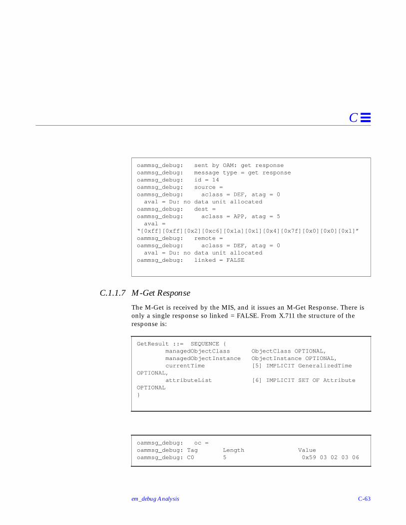
em_debug Analysis C-63
C
C.1.1.7 M-Get Response
The M-Get is received by the MIS, and it issues an M-Get Response. There isonly a single response so linked = FALSE. From X.711 the structure of theresponse is:
oammsg_debug: sent by OAM: get responseoammsg_debug: message type = get responseoammsg_debug: id = 14oammsg_debug: source =oammsg_debug: aclass = DEF, atag = 0 aval = Du: no data unit allocatedoammsg_debug: dest =oammsg_debug: aclass = APP, atag = 5 aval =“[0xff][0xff][0x2][0xc6][0x1a][0x1][0x4][0x7f][0x0][0x0][0x1]”oammsg_debug: remote =oammsg_debug: aclass = DEF, atag = 0 aval = Du: no data unit allocatedoammsg_debug: linked = FALSE
GetResult ::= SEQUENCE { managedObjectClass ObjectClass OPTIONAL, managedObjectInstance ObjectInstance OPTIONAL, currentTime [5] IMPLICIT GeneralizedTimeOPTIONAL, attributeList [6] IMPLICIT SET OF AttributeOPTIONAL}
oammsg_debug: oc =oammsg_debug: Tag Length Valueoammsg_debug: C0 5 0x59 03 02 03 06

C-64 Solstice Enterprise Manager Application Development Guide
C
By a similiar method as before: managedObjectClass = 0x59 03 04 03 2a =2.9.3.4.3.42 = actualClass. actualClass is a wildcard. This indicates to theapplication that it should not care about this field.
By a similiar method as before: baseManagedObjectInstance is indistinguishedName form
= /systemId=name:”dynamics”/logId=”AlarmLog”
current time is NOT present.
oammsg_debug: oi =oammsg_debug: Tag Length Valueoammsg_debug: C2 2aoammsg_debug: Tag Length Valueoammsg_debug: SET 13oammsg_debug: Tag Length Valueoammsg_debug: SEQ 11oammsg_debug: Tag Length Valueoammsg_debug: OID 5 2.9.3.2.7.4oammsg_debug: Tag Length Valueoammsg_debug: GRPH 8 “dynamics”oammsg_debug: Tag Length Valueoammsg_debug: SET 13oammsg_debug: Tag Length Valueoammsg_debug: SEQ 11oammsg_debug: Tag Length Valueoammsg_debug: OID 5 2.9.3.2.7.2oammsg_debug: Tag Length Valueoammsg_debug: GRPH 8 “AlarmLog”
oammsg_debug: curr_time = NULL

em_debug Analysis C-65
C
By a similiar method as before: attributeList is administrateState = locked.
C.1.1.8 M-DELETE Request
The M-Get operation is complete (The PMI Image::boot() is complete). Beforethe PMI client application exits, the PMI call platform.disconnect()results in aM-DELETE request to the MIS to delete the correspondingemApplicationInstance object.
oammsg_debug: attr_list =oammsg_debug: Tag Length Valueoammsg_debug: C6 coammsg_debug: Tag Length Valueoammsg_debug: SEQ aoammsg_debug: Tag Length Valueoammsg_debug: C0 5 0x59 03 02 07 1foammsg_debug: Tag Length Valueoammsg_debug: ENUM 1 = 0
oammsg_debug: ***********************************************
### PLAT_DISCONNECT## oammsg_debug: ************************************************

C-66 Solstice Enterprise Manager Application Development Guide
C
The MIS receives an M-Delete indication, and a response is expected. X.711defines the M-Delete Request/Indication as follows:
and where BaseManagedObjectId is defined as:
oammsg_debug: received by OAM: delete requestoammsg_debug: message type = delete requestoammsg_debug: id = 8oammsg_debug: source =oammsg_debug: aclass = DEF, atag = 0 aval = Du: no data unit allocatedoammsg_debug: dest =oammsg_debug: aclass = DEF, atag = 0 aval = Du: no data unit allocatedoammsg_debug: remote =oammsg_debug: aclass = DEF, atag = 0 aval = Du: no data unit allocatedoammsg_debug: mode = CONFIRMEDoammsg_debug: app_context = Du: no data unit allocated
DeleteArgument ::= SEQUENCE { COMPONENTS OF BaseManagedObjectId, accessControl [5] AccessControl OPTIONAL, synchronization [6] IMPLICIT CMISSync DEFAULT bestEffort, scope [7] Scope DEFAULT baseObject, filter CMISFilter DEFAULT and : {}}
BaseManagedObjectId ::= SEQUENCE { baseManagedObjectClass ObjectClass, baseManagedObjectInstance ObjectInstance}

em_debug Analysis C-67
C
The above is the baseManagedObjectClass. As before, this is in globalForm.The value decodes once again to emApplicationInstance.
Once again, we have baseManagedObjectInstance using thelocalDistinguishedName CHOICE. Once against this is
subsystemId=”EM-MIS”/emApplicationID=5
Because we are using localDistinguishedName form this name is relative to
/systemId=name:”dynamics”
and we are specifiying that the Object to be deleted will be:
/systemId=name:”dynamics”/subsystemId=”EM-MIS”/emApplicationID=5
This is the object instance that was created when the Platform::connect() wasperformed.
oammsg_debug: oc =oammsg_debug: Tag Length Valueoammsg_debug: C0 c 1.3.6.1.4.1.42.2.2.2.1.3.2
oammsg_debug: oi =oammsg_debug: Tag Length Valueoammsg_debug: C4 28oammsg_debug: Tag Length Valueoammsg_debug: SET 11oammsg_debug: Tag Length Valueoammsg_debug: SEQ foammsg_debug: Tag Length Valueoammsg_debug: OID 5 2.9.3.5.7.11oammsg_debug: Tag Length Valueoammsg_debug: GRPH 6 “EM-MIS”oammsg_debug: Tag Length Valueoammsg_debug: SET 13oammsg_debug: Tag Length Valueoammsg_debug: SEQ 11oammsg_debug: Tag Length Valueoammsg_debug: OID c 1.3.6.1.4.1.42.2.2.2.1.7.1oammsg_debug: INT 1 = 5U

C-68 Solstice Enterprise Manager Application Development Guide
C
Scope is this object only. No filter is present. No access is present. Thesynchronization is Best Effort.
The M-Delete is received by the MIS. It deletes the emApplicationInstanceobject that represented this PMI application and it issues an M-DeleteResponse. There is only a single response so linked = FALSE. From X.711 thestructure of the response is:
oammsg_debug: scope = BASE_OBJECToammsg_debug: filter = NULLoammsg_debug: access = NULLoammsg_debug: sync = BEST_EFFORToammsg_debug: ************************************************
oammsg_debug: ******************************************oammsg_debug: sent by OAM: delete responseoammsg_debug: message type = delete responseoammsg_debug: id = 8oammsg_debug: source =oammsg_debug: aclass = DEF, atag = 0 aval = Du: no data unit allocatedoammsg_debug: dest =oammsg_debug: aclass = DEF, atag = 0 aval = Du: no data unit allocatedoammsg_debug: remote =oammsg_debug: aclass = DEF, atag = 0 aval = Du: no data unit allocatedoammsg_debug: linked = FALSE
DeleteResult ::= SEQUENCE { managedObjectClass ObjectClass OPTIONAL, managedObjectInstance ObjectInstance OPTIONAL, currentTime [5] IMPLICIT GeneralizedTime OPTIONAL}

em_debug Analysis C-69
C
managedObjectClass = emApplicationInstance
managedObjectInstance uses the distinguishedName CHOICE
= /systemId=name:”dynamics”/subsystemId=”EM-MIS’/emApplicationID=5
oammsg_debug: oc =oammsg_debug: Tag Length Valueoammsg_debug: C0 c 1.3.6.1.4.1.42.2.2.2.1.3.2
oammsg_debug: oi =oammsg_debug: Tag Length Valueoammsg_debug: C2 3doammsg_debug: Tag Length Valueoammsg_debug: SET 13oammsg_debug: Tag Length Valueoammsg_debug: SEQ 11oammsg_debug: Tag Length Valueoammsg_debug: OID 5 2.9.3.2.7.4oammsg_debug: Tag Length Valueoammsg_debug: GRPH 8 “dynamics”oammsg_debug: Tag Length Valueoammsg_debug: SET 11oammsg_debug: Tag Length Valueoammsg_debug: SEQ foammsg_debug: Tag Length Valueoammsg_debug: OID 5 2.9.3.5.7.11oammsg_debug: Tag Length Valueoammsg_debug: GRPH 6 “EM-MIS”oammsg_debug: Tag Length Valueoammsg_debug: SET 13oammsg_debug: Tag Length Valueoammsg_debug: SEQ 11oammsg_debug: Tag Length Valueoammsg_debug: OID c 1.3.6.1.4.1.42.2.2.2.1.7.1oammsg_debug: Tag Length Valueoammsg_debug: INT 1 0x05

C-70 Solstice Enterprise Manager Application Development Guide
C
currentTime is not present (NULL)
The MIS generates an Event Report and does not expect a response. X.711defines the structure as follows:
managedObjectClass uses the globalForm CHOICE = emApplicationInstance
oammsg_debug: curr_time = NULLoammsg_debug: ****************************************
oamnot_debug: M-Event-Report Message =oamnot_debug: message type = event_report requestoamnot_debug: id = 14986600oamnot_debug: source =oamnot_debug: aclass = DEF, atag = 0 aval = Du: no data unit allocatedoamnot_debug: dest =oamnot_debug: aclass = DEF, atag = 1 aval = Du: no data unit allocatedoamnot_debug: remote =oamnot_debug: aclass = DEF, atag = 0 aval = Du: no data unit allocatedoamnot_debug: mode = UNCONFIRMEDoamnot_debug: app_context = Du: no data unit allocated
EventReportArgument ::= SEQUENCE { managedObjectClass ObjectClass, managedObjectInstance ObjectInstance, eventTime [5] IMPLICIT GeneralizedTime OPTIONAL, eventType EventTypeId, eventInfo [8] ANY DEFINED BY eventType OPTIONAL}
oamnot_debug: oc =oamnot_debug: Tag Length Valueoamnot_debug: C0 c 1.3.6.1.4.1.42.2.2.2.1.3.2

em_debug Analysis C-71
C
managedObjectInstance uses the distinguishedName CHOICE
= /systemId=name:”dynamics”/subsystemId=”EM-MIS’/emApplicationID=5
eventType = 0x59 03 02 0a 07 = 2.9.3.2.10.7 = objectDeletion
oamnot_debug: oi =camnot_debug: Tag Length Valuecamnot_debug: C2 3dcamnot_debug: Tag Length Valuecamnot_debug: SET 13camnot_debug: Tag Length Valuecamnot_debug: SEQ 11camnot_debug: Tag Length Valuecamnot_debug: OID 5 2.9.3.2.7.4camnot_debug: Tag Length Valuecamnot_debug: GRPH 8 “dynamics”camnot_debug: Tag Length Valuecamnot_debug: SET 11camnot_debug: Tag Length Valuecamnot_debug: SEQ fcamnot_debug: Tag Length Valuecamnot_debug: OID 5 2.9.3.5.7.11camnot_debug: Tag Length Valuecamnot_debug: GRPH 6 “EM-MIS”camnot_debug: Tag Length Valuecamnot_debug: SET 11camnot_debug: Tag Length Valuecamnot_debug: SEQ 11camnot_debug: Tag Length Valuecamnot_debug: OID c 1.3.6.1.4.1.42.2.2.2.1.7.1camnot_debug: Tag Length Valuecamnot_debug: INT 1 0x05
oamnot_debug: event_type =oamnot_debug: Tag Length Valueoamnot_debug: C6 5 0x59 03 02 0a 07

C-72 Solstice Enterprise Manager Application Development Guide
C
eventTime = 13th May 1996 12:52:49. The PMI program is now complete.
oamnot_debug: event_time =oamnot_debug: Tag Length Valueoamnot_debug: C5 e “19960513135249”oamnot_debug: event_info = NULL

D-1
Topology Database Architecture D
D.1 IntroductionThe purpose of the topology database is to store topological information aboutthe managed networked environments. Topological information is in the formof objects which represent a topological node, view, viewnodes, and type. Thetopology database consists of a topoTypeDB, a topoNodeDB, and atopoViewDB and is used by Enterprise Manager applications to manage theuser’s networks.
The topoTypeDB object class contains the general relationship or rules betweenobjects (which represent a topoType). In other words, topoTypeDB contains alist of object types.
Introduction page D-1
Object Relationship Diagram Description page D-3
topoTypeDB page D-3
topoNodeDB page D-3
topoViewDB page D-5
Topology Types page D-6

D-2 Solstice Enterprise Manager Application Development Guide
D
The topoNodeDB object class contains a flat layout of the objects in themanaged networked environment, that is, lists of all nodes and their attributes.The topoViewDB object class contains views of the objects in the managednetworked environment, that is, a list of all views.
system
topoViewDB topoNodeDB topoTypeDB
topoView topoNode topoType
topoViewNode
Figure D-1 Object Relationship Diagram
1
1 1 1
1
1
1
n n n
n
n
1/0 1
1
1
1
n
11
Containment
Reference
n n

Topology Database Architecture D-3
D
D.2 Object Relationship Diagram Description
D.2.1 Containment• TopoViewDB, topoNodeDB, and topoTypeDB are contained within system.• A topoView is contained within topoViewDB.• A topoViewNode is contained within topoView.• A topoNode is contained within topoNodeDB.• A topoType is contained within topoTypeDB.
D.2.2 Reference• A topoView must reference a topoNode.• Only one topoView can reference a single topoNode.• A topoViewNode must reference a topoNode.• One or more topoViewNodes can reference a single topoNode.
• A topoNode can reference other topoNodes as topoNodeParents ortopoNodeChildren.
• A topoNode must reference one topoType.
• A topoType can be referenced by multiple topoNodes.
D.3 topoTypeDBTopoTypeDB is a managed object class that acts as a container for all topoTypeobjects. The topoTypeDB object class is named under the system object andonly one instance of a topoTypeDB object class can be created under a system.
D.3.1 topoType
TopoType is an object class that is named under the topoTypeDB object class.
D.4 topoNodeDBTopoNodeDB is a managed object class that acts as the container for alltopoNode objects. This object class lists all nodes and their attributes. ThetopoNodeDB object class is named under the system object and only oneinstance of the topoNodeDB object class can be created under a system.

D-4 Solstice Enterprise Manager Application Development Guide
D
D.4.1 topoNode
TopoNode is an object class that is named under the topoNodeDB object class.
The topoNode object class has the following features:
• TopoNode can be positioned in multiple view.
This attribute is allowed since the behavior of topoTypeLegalChildren ischecked for all parents specified by the attribute. The ASN1 syntax oftopoNodeParents is a set of topoNodeId.
• Special secondary index queries can be done with actions.
• TopoNode objects can be renamed.
The topoNodeName attribute is unique across all topoNodes under thesame topoNodeDB. The reason that topoNodeName is not used as thenaming attribute is to allow renaming of topoNode objects.
Note – If a topoNode object is renamed, it’s new name cannot be the same asthe name of an existing node.
• Data integrity between topoNode, topoView, and topoViewNode ismaintained.
Data integrity is maintained by the behavior of the class. Once a newtopoNode is created, if the type of the topoNode can contain othertopoNodes, the MIS will create a topoView object associated to thetopoNode. If a topoNode is deleted, all topoView and topoViewNodeobjects associated with the topoNode are automatically removed by the MIS.
• TopoViewNode objects are automatically updated.
When a new parent is added to the topoNodeParents attribute, the MIScreates a topoViewNode object associating to the topoNode under atopoView object which associates to the new parent. When an old parent isremoved from topoNodeParents, the MIS deletes the topoViewNode objectassociating to the topoNode from the topoView object which associates tothe old parent.
Note – If you want to move or place a topoNode in a different or another view,be sure to change the topoNode’s topoNodeParents attribute.

Topology Database Architecture D-5
D
The topoNodeChildren attribute is a reverse relationship attribute of thetopoNodeParents attribute. It specifies all the topoNode children that arecontained by this topoNode.
• Propagation severity of topoNode objects can be tracked and propagationcan be controlled.
The tracking of the propagated severity is done with thetopoNodePropogateSeverity attribute. This attribute is the maximum valueof the topoNodeSeverity of the topoNode and thetopoNodePropagatedSeverity of all its children.
To control the propagation locally, the topoNode’s topoNodePropagateUpattribute is used. To turn the propagation off for the entire topologydatabase, the topoNodeDB’s topoStatePropagation attribute is used. Bydefault, the global propagation flag is set on.
A topoNode propagates its current severity to its parents only if itstopoNodePropagateUp flag is on and topoNodeDB’s topoStatePropagationflag is on.
D.5 topoViewDBTopoViewDB is a managed object class that acts as the container for alltopoView objects. TopoViewDB lists all views; each of these views are called atopoView. The topoViewDB object class is named under the system object andonly one instance of the topoViewDB object class can be created under asystem.
A view is a graphical representation of a set of related managed objects. Forexample, in a network that contains multiple subnetworks, the network mightbe one view that contains the subnetwork views and each subnetwork within itmight constitute separate views.
D.5.1 topoView
TopoView is an object class that lists views and is named under thetopoViewDB object class. Each topoView object is called a topoViewNode.
Each instance of the topoView class represents a view in em_viewer to displayobjects that are in the view and store attributes that are related to the view.TopoView objects show relationships and hierarchy between objects.

D-6 Solstice Enterprise Manager Application Development Guide
D
Instances of the class are named under topoViewDB, but create/deleteoperations are not supported by the name binding. All topoView objects arecreated/deleted as side effects of creating/deleting topoNode objects andchanging the topoNodeParents attribute of a topoNode. The MIS is responsiblefor maintaining a one-to-one relationship between a topoView object and acontainer type topoNode object (for example, a topoNode can contain othertopoNodes).
D.5.2 topoViewNodeThe topoViewNode objects represent topoNode objects in different views.Each topoViewNode object is associated with a topoNode object. There is amany-to-one relationship between topoViewNode and topoNode objects. Ifthe information is available in the topoViewNode’s associated topoNodeobject, the information is not duplicated in the topoViewNode object. Theexception is that the topoNodeId attribute is used as the naming attribute tocreate topoViewNode objects.
Since instances of the class are named under topoView, create/deleteoperations are not supported by the name binding. All topoViewNodeobjects are created/deleted as side effects of creating/deleting topoNodesand adding/removing parents to/from the topoNodeParents attribute oftopoNode objects. The MIS is responsible for maintaining the referentialintegrity between topoViewNode and topoNode objects.
D.6 Topology TypesThe following descriptions of topology types are general descriptions.
Table D-1 Topology Types
Topology Type Description
Container A generic view representation.
Universe A generic view, generally used at the top level.
Internet Any combination of IP networks.
Subnetwork Containers specific to the Internet.
Host An IP device on a network.

Topology Database Architecture D-7
D
Caution – Users are not allowed to create their own base topoTypes.
Device A generic representation of a network element.
Link A physical connection between two network elements.
Router, Bridge,Hub
Multiple interface devices capable of transferring packetsbetween networks.
Table D-1 Topology Types
Topology Type Description

D-8 Solstice Enterprise Manager Application Development Guide
D

Index-1
Index
Aaccess control, 4-7action
GDMO template, 2-27adding a new managed object class, 4-23
overview of steps, 4-23AdministrativeState, 5-17agent, 2-3
directly access managedresource, 11-2
indirectly access managedresource, 11-2
manager-agent model, 11-2process that accesses the managed
object, 11-2process that accesses the managed
resource, 11-2process that collects data, 11-2proxy, B-6
alarmdefault notifications, 3-10
Alarm Service management, 10-3Album class
definition, 3-17defintion, 3-20example of use, 8-8
AlbumImage classdefinition, 3-22
example of use, 8-10analysis
access control, 4-7client application, 4-5device, 4-4FDNs, 4-8information presentation, 4-5multiple MIS, 4-5network, 4-5nicknames, 4-8sharing management
information, 4-6system, 4-5
application, 3-2application development
using the PMI, 4-22ASN.1, 2-5
and CMIP, 2-44and SNMP, 2-48datatypes, 2-7definition, 2-5, B-5encoding rules, 2-5primitive type, 2-8printing values, 5-19sanity check, 5-8tag numbers, 2-7tags, 2-9value, 2-8

Index-2 Solstice Enterprise Manager Application Development Guide
ASN.1 compiler, 4-29, 4-30Asn1Value
printing, 5-19Asn1Value class
definition, 3-27association-linked data, 4-21attribute
AdministrativeState, 5-17code generation and filters, 5-16destination, 3-6discriminator, 3-6DiscriminatorConstruct, 5-16GDMO template, 2-27OperationalState, 5-16
attribute groupGDMO template, 2-27
attribute value assertion, 2-35attributes, 4-23, 4-26AutoImage mode
example of, 8-8
Bbase class, 2-29behaviour
GDMO template, 2-27BER encoding for OIDs, 2-13
CC++, 6-4callback routine, 4-23callbacks, 3-25
file descriptor, 3-26timer, 3-26
cellSample example, 5-26chai example, 5-41class, B-2
managed object, B-3, B-4class definitions
which pre-loaded in MIS, 3-14classes
Album, 3-17, 3-20AlbumImage, 3-22
Asn1Value, 3-27Coder, 3-23Image, 3-17, 3-18Morf, 3-22Platform, 3-17Syntax, 3-22tags, 2-9Waiter, 3-23
className.load, 5-18, 5-23className.unload, 5-18, 5-23className_error, 5-20className_info, 5-20className_user.odt.cc, 5-23className_user.odt.hh, 5-21client applications, 1-1, 3-1
overview of development steps, 4-22client-server
definition, 3-2CMIP, 2-3, 2-15, 4-30
and ASN.1, 2-44filtering, 2-43messages, 2-17scoping, 2-42
CMIP request, 2-44CMIS, 2-15
confirmedCancelGet functionalunit, 2-19
extended service functional unit, 2-19filter functional unit, 2-19functional unit, 2-18, 2-19functional units, 2-18kernal functional unit, 2-19multipleObjectSelection, 2-18multipleReply functional unit, 2-18services, 2-16
CMIS filtersyntax, 3-33
CMIS primitives mapping to CMIPmessages, 2-17
code generator utility, 5-2CODEGENDIR, 5-16Coder class
definition, 3-23

Index-3
example of use, 8-10common functions and libraries
callbacks, 3-25scheduler, 3-25
Common Management InformationProtocol, 2-15
Common Management InformationService, 2-15
CompilerASN.1, 4-29, 4-30Concise MIB, 4-29GDMO, 4-29
compiler, 6-4component analysis, 4-3concise MIB
definitionsconcise MIB, 2-47
Concise MIB compiler, 4-29, 4-30configuration
OCG, 5-16OCG, CODEGENDIR, 5-16OCG, DATASTORAGE, 5-16OCG, FILTER_ATTR, 5-16OCG, HIDDENDIR, 5-16OCG, OBAPIDEBUG, 5-16OCG, OBAPITRACE, 5-16
confirmed request operations, 2-16confirmedCancelGet, 2-19containment, 2-15, 2-31, B-2converting SNM 2.x schema files to
GDMO descriptions, 11-5CurrentEvent
definition, 3-22
Ddata
persistent, 4-21, 4-28volatile, 4-21, 4-28
Data Viewer tool, 4-29DATASTORAGE, 5-16datatype
object identifier, 2-10
OID, 2-10datatypes
ASN.1, 2-7SNMPv1, 2-48SNMPv2, 2-48
debug objects, 6-5debug utility, 6-5debugger, 6-4debugging agents, 5-20debugging ASN.1, 5-19debugging GDMO, 5-19debugging objects, 5-17defining object behavior, 5-6defining requirements, 4-3definitions, 2-31
agent, 2-3Album class, 3-20AlbumImage class, 3-22application, 3-2ASN.1, 2-5Asn1Value class, 3-27attribute value assertion, 2-35base class, 2-29callbacks, 3-25client subcomponent, 3-2client subcomponents, 4-1client-server, 3-2CMIP, 2-15CMIS functional units, 2-18CMIS, definitions
Common ManagementInformation Service, 2-15
Coder class, 3-23Common Management Information
Protocol, 2-15containment, 2-15, 2-31CurrentEvent, 3-22Definition of Management
Information, 2-27derived class, 2-29discriminator, 3-6distinguished name, 2-37distributed, 3-2DMI, 2-27

Index-4 Solstice Enterprise Manager Application Development Guide
DN, 2-37EFD, 3-6Event Forwarding Discriminator, 3-6event log, 3-9filtering, 2-43GDMO, 2-19Guidelines for the Definition of
Managed Objects, 2-19handlers, 3-26high-level PMI, 3-17Image class, 3-18inheritance, 2-15local distinguished name, 2-39local object, 3-3local object instance, 3-3log, 3-9log records, 3-9managed object, 2-14managed object class, 2-15managed resource, 2-14manager, 2-2MIB, 2-4MIT, 2-31MIT, definitions
naming tree, 2-32MOC, 2-15Morf class, 3-22name binding, 3-14object class inheritance tree, 2-28object-oriented, 3-2OID, 2-10PMI application, 3-2protocol, 2-3protocol adaptors, 9-2RDN, 2-36relative distinguished name, 2-36remote object, 3-3remote object instance, 3-3repository behavior, 3-15request, 3-4request template, 3-4SAPs, 9-4scheduler, 3-24scoping operation, 2-42server subcomponent, 3-2server subcomponents, 4-1
Service Access Points, 9-4solution, 1-1subclass, 2-29superclass, 2-29Syntax class, 3-22top class, 2-27user-configured subcomponents, 4-1user-developed subcomponents, 4-1Waiter class, 3-23
defintionsmanaged object class, 3-12
demoPing example, 5-28demoregistry example, 5-33demoServer example, 5-39derived class, 2-29deriving an Album
example of, 8-9destination, 3-6Development Environment
overview, 1-1, 3-1device type analysis, 4-4Discover and topology nodes, 10-4discriminator construct, 3-6
syntax, 3-9DiscriminatorConstruct, 5-16diskInfo example, 5-39dispatch_recursive()
example of, 8-4distinguished name, 2-37distinguished names
BER encoded forms, 3-27human readable forms, 2-39, 3-27
distributeddefinition, 3-2
DMI, 2-27dynamic libraries, 5-18
EEFD
creating, 8-16definition, 3-6example, 8-16

Index-5
syntax, 3-9, 3-31em_asn1 compiler, 4-30em_cmib2gdmo compiler, 4-30em_cmipconfig
See em_octem_cmipconfig example, 8-2em_compose_oc command, 4-27, 4-28em_compose_poc command, 4-27, 4-28em_debug
-oamrmt_debug, 6-5ODT agents, 5-20
em_debug trace utility, 6-5em_gdmo compiler, 4-30em_load_name_bindings command, 4-27,
4-28em_snm2gdmo compiler, 4-30, 11-5encoding rules for ASN.1, 2-5Entity List
use in em_cmipconfig, 8-8environment variable
EM_HOME, 4-23Event Forwarding Discriminator
See EFDevent loop, 4-23event registration
example of, 8-4events, waiting for
example of, 8-5example
asynchronous deriving all objects intoa tracking album, 8-14
asynchronously boot the NerveCenterPollRate Fast object, 8-15
asynchronously create logobject, 8-17
asynchronously delete logobject, 8-18
asynchronously get and print allattributes for the topologydatabase, 8-15
boot the NerveCenter PollRate Fastobject, 8-16
cellSample, 5-26
chai, 5-41compiling the examples, 8-2count all local objects, 8-17create log object, 8-18creating an EFD, 8-16delete log object, 8-18demoPing, 5-28demoregistry, 5-33demoServer, 5-39deriving all objects into a tracking
album, 8-14deriving an album, 8-15, 8-17deriving an album of only specified
attributes, 8-16diskInfo, 5-39em_cmipconfig, 8-2forwarding events from one MIS to
another, 8-16get and print all attributes for the
topology database, 8-15invoke MDR object actions, 8-18listen for all events, 8-17listen for events of the specified
objects, 8-17listen for events that match a
discriminator, 8-17listen for object creation events, 8-17ODT, 5-25send an event notification, 8-16store and search FDNs in hash
table, 8-17exception macros, 5-23
FFDN, B-2FDNs
and nicknames, 4-8file descriptor corresponding to
connection to MIS, 8-17filter
CMIS functional unit, 2-19filter attributes, 5-16FILTER_ATTR, 5-16filtering, 2-43

Index-6 Solstice Enterprise Manager Application Development Guide
fully distinguished name, B-2
GGDMO, 2-19
ACTION template, 2-27ATTRIBUTE GROUP template, 2-27ATTRIBUTE template, 2-27BEHAVIOUR template, 2-27description, B-3, B-4format, 4-30MANAGED OBJECT CLASS
template, 2-20, 2-21NAME BINDING template, 2-20,
2-22, 2-24NOTIFICATION template, 2-27other templates, 2-26PACKAGE template, 2-26PARAMETER template, 2-26sanity check, 5-8templates, 2-20
GDMO compiler, 4-29, 4-30GDMO compiler (em_gdmo), 11-5GDMO document, 4-24, 4-27, 11-5
attributes, 4-26MOC definition, 4-26name binding, 4-26notification, 4-26
get.ccerror handling code, 8-20
GetBulkRequest, 2-47GetNextRequest, 2-45, 2-46GetRequest, 2-45, 2-46GetResponse, 2-45global naming tree, 2-11GUI program
example of, 8-2GUI program example, 8-2Guidelines for the Definition of Managed
Objectssee GDMO, 2-19
HHandler block, 5-23handlers
definition, 3-26HIDDENDIR, 5-16how to generate code, 5-15human readable distinguished
names, 2-39human readable notation for OIDs, 2-11
IImage attributes
getting and setting, 8-7Image booting
example of, 8-6Image class
definition, 3-17, 3-18example of use, 8-5
information presentation analysis, 4-5InformRequest, 2-46inheritance, 2-15instance, 4-24
definition of, B-2Internet
MIB format, 4-30ISO, 2-13
network management model, 2-13,2-14
Kkernal
CMIS functional unit, 2-19
Llibraries
manager/agent services API, 11-2loading libraries, 5-18local distinguished name, 2-39local object, B-6
definition, 3-3
Index-7
local objects, 3-15log object
asynchronous create example, 8-17asynchronous delete example, 8-18create example, 8-18default notifications, 3-10
Mmacros, 5-23makefile
example, 8-2managed object, 2-14, 2-34, B-1, B-2
naming, 2-34managed object class, 2-15, 4-23, 4-24, B-3,
B-4definition, 3-12GDMO, 3-13GDMO template, 2-20, 2-21properties of, 4-26
managed object instance, 4-24, B-3, B-4managed resource, 2-14
definition of, B-2Management Information Base, 2-4Management Information Server
(MIS), 1-1, 3-1management information sharing
analysis, 4-6Management Information Tree, B-3management information tree, 2-31Management Information Tree, see
MIT, 2-31manager, 2-2manager-agent model
agent, 11-2MDR, 4-25, 4-26, B-4MetaData Repository, 4-25, B-4MetaData Repository (MDR), 4-26MIB, 2-4
concise, 2-47SNMPv2, 2-48
MIS, 1-1, 3-1analysis of multiple use, 4-5
MIT, 2-31, 4-29, B-3naming, 2-32
MOC, 4-24, B-3, B-4properties of, 4-26
MOI, 4-24, B-3, B-4Morf class
definition, 3-22example of use, 8-10
Morf, splitting of, 8-11multiple MIS analysis, 4-5multipleObjectSelection, 2-18multipleReply, 2-18Mysterious Object Related to Framework
See Morf
NName Binding, 4-26name binding, 2-34
definition, 3-14GDMO template, 2-20, 2-22, 2-24
namingand containment, 2-32managed object, 2-34managed object instances, 2-32
NerveCenter template, 10-3network analysis, 4-5network management concepts
ISO, 2-13nicknames
and FDNS, 4-8Notification, 4-26notification
GDMO template, 2-27notifications
default, 3-10
O-oamrmt_debug, 6-5OBAPIDEBUG, 5-16OBAPITRACE, 5-16OBI, 5-2

Index-8 Solstice Enterprise Manager Application Development Guide
objectdebugging process, 5-17local, 3-3, 3-15, B-6ODT interfaces, 5-4platform, 3-18remote, 3-3, 3-13shadow, 4-30
Object Access Module, 4-28object API, 5-2object behavior interface, 5-2object class
repository behavior, 3-15object class inheritance tree, 2-28object classes, 3-17Object Code Generator
See OCGObject Configuration tool, 4-29Object Development Tools
See ODTobject framework, 4-21, 5-2object identifier tree, 2-30
root, 2-30object instance
subordinate, 2-32superior, 2-32
object services, 5-2object utilities, 5-2object-oriented, 3-2ObjMethMOC, 4-25ObjMethMOI, 4-25objsvc_error, 5-20objsvc_test, 5-20OBSAPI, 5-2OCG, 5-2
className.load, 5-23className.unload, 5-23className_user.odt.cc, 5-23className_user.odt.hh, 5-21client create file, 5-22CODEGENDIR, 5-16components, 5-12configuration, 5-16DATASTORAGE, 5-16
dynamic loading file, 5-23dynamic unloading file, 5-23exception-handling macros, 5-23filter attributes, 5-16FILTER_ATTR, 5-16generated code interfaces, 5-11generated files, 5-20HIDDENDIR, 5-16how to use, 5-15inputs, 5-14Makefile, 5-21OBAPIDEBUG, 5-16OBAPITRACE, 5-16outputs, 5-14pmi_className.cc, 5-22README, 5-21software requirements, 5-11user code file, 5-23user header file, 5-21
OCT and topology database, 10-7ODT
cellSample example, 5-26chai example, 5-41className.load, 5-18className.unload, 5-18code generation components, 5-12components, 5-1, 5-4definition, 5-1demoPing example, 5-28demoregistry example, 5-33demoServer example, 5-39diskInfo example, 5-39dynamic libraries, 5-18em_debug agents, 5-20examples, 5-25generated code, 5-11interfaces, 5-4Object Behavior Interface, 5-5Object Code Generator, 5-10object development scenario, 5-41Object Services API, 5-6operations, 5-2process, 5-6sanity check, 5-8software requirements, 5-11

Index-9
OIDBER encoding, 2-13datatype definition, 2-10human readable notation, 2-11tree, 2-11
OperationalState, 5-16OSAPI
debug agents, 5-20
Ppackage
GDMO template, 2-26parameter
GDMO template, 2-26parameters
OCG, CODEGENDIR, 5-16OCG, DATASTORAGE, 5-16OCG, FILTER_ATTR, 5-16OCG, HIDDENDIR, 5-16OCG, OBAPIDEBUG, 5-16OCG, OBAPITRACE, 5-16
persistent storage, 4-21, 4-28platform
class definition, 3-18object definition, 3-18
Platform classdefinition, 3-17, 3-18example of use, 8-3
platform debug utility, 6-5PMI, 1-1, 3-1
definition, 3-17object classes, 3-17
PMI application, 3-2PMI example
asynchronous get, 8-15asynchronous set attribute
value, 8-15asynchronously create log
object, 8-17asynchronously delete log
object, 8-18count local objects, 8-17create EFD, 8-16
create log object, 8-18creation events, listen for, 8-17delete log object, 8-18derive_rpc, 8-15derive_snmp, 8-15event
listen for events that matchdiscriminator, 8-17
event, listen for, 8-17FDNs in hash table, 8-17get, 8-15invoke MDR object actions, 8-18set attribute value, 8-16
PMI examples, 8-1PMI scheduler, 3-24pmi_className.cc, 5-22Portable Management Interface
(PMI), 1-1, 3-1preprocessor for MIB, 4-30primitive types, 2-8primitives
CMIS, map to CMIP messages, 2-17process
defining object behavior, 5-6properties
of MOC, 4-26protocol, 2-3
SNMPv1, 2-45protocol adaptors, 9-2proxy agent, B-6
manage resources not directlyaccessible, 11-2
protocol translation, 11-2
Rregistering an Album for events, 8-9registering for events
example of, 8-4registration tree, 2-30relative distinguished name, see RDNremote object
definition, 3-3

Index-10 Solstice Enterprise Manager Application Development Guide
remote objects, 3-13request
definition, 3-4SNMP, GetBulkRequest, 2-47SNMP, GetNextRequest, 2-45, 2-46SNMP, GetRequest, 2-45, 2-46SNMP, InformRequest, 2-46SNMP, SetRequest, 2-45, 2-46template, 3-4
Response, 2-46response
SNMP, GetResponse, 2-45SNMP, Response, 2-46
root, 2-30MIT, definitions
root, 2-33RPC, 2-4runtime environment, 4-27
Ssanity checking, 5-8SAPs, 9-4scenario
developing object behaviors, 5-41sched, 3-24scheduler for PMI apps, 3-24scheduling PMI events, 3-24Schema compiler (em_snm2gdmo), 11-5Schema-2-GDMO compiler, 4-29Schema-to-GDMO compiler, 4-30scoping, 2-42scoping and filtering, 2-44server, 1-1, 3-1server-life data, 4-21Service Access Points, 9-4SetRequest, 2-45, 2-46shadow object, 4-30SNM 2.x schema files, 4-30SNMP, 2-3, 4-30
GetBulkRequest, 2-47GetNextRequest, 2-45, 2-46GetRequest, 2-45, 2-46
GetResponse, 2-45InformRequest, 2-46protocol, 2-45Response, 2-46SetRequest, 2-45, 2-46trap, 2-45, 2-46
SNMPv1, 2-45and ASN.1, 2-48GetNextRequest, 2-45GetReponse, 2-45GetRequest, 2-45SetRequest, 2-45trap, 2-45
SNMPv2and ASN.1, 2-48GetBulkRequest, 2-47GetNextRequest, 2-46GetRequest, 2-46InformRequest, 2-46Response, 2-46SetRequest, 2-46trap, 2-46
solutiondefinition, 1-1
subclass, 2-29subcomponent
client, 3-2server, 3-2
subcomponentsclient, 4-1server, 4-1user-configured, 4-1user-developed, 4-1
subordinate object, 2-32subordinate object instance, 2-32superclass, 2-29superior object, 2-32superior object instance, 2-32syntax, 6-5
CMIS filter, 3-33EFD, 3-31
Syntax classdefinition, 3-22example of use, 8-10

Index-11
system analysis, 4-3, 4-5
Ttags
application class, 2-9ASN.1, 2-9context-specific class, 2-9private class, 2-10universal class, 2-9
templatesGDMO, 2-26GDMO ACTION, 2-27GDMO ATTRIBUTE, 2-27GDMO ATTRIBUTE GROUP, 2-27GDMO BEHAVIOUR, 2-27GDMO NOTIFICATION, 2-27GDMO PACKAGE, 2-26GDMO PARAMETER, 2-26
timers, 3-26top
managed object class definition, 2-27topology database
configuration, 10-5configuring devices, 10-8link, 10-6OCT, 10-7scenario, 10-9
topology database serviceGDMO, 10-2
topology nodesconfiguring for alarm
management, 10-2topoNodeMOSet, 10-2topoNodeUserData, 10-5topoTypeUserDataAttrs, 10-5trace utility, 6-5Tracking mode
example of, 8-8trap, 2-45, 2-46tree
global naming, 2-11management information, 2-31naming, 2-32
object class inheritance, 2-28object identifier, 2-11, 2-30OID, 2-11registration, 2-30
TRY block, 5-23TRY execption macros, 5-23
Uunconfirmed request operations, 2-16
Vvolatile storage, 4-21, 4-28
association-linked data, 4-21server-life data, 4-21
WWaiter class
definition, 3-23waiting for events
example of, 8-5
Xxtsched, 3-24

Copyright 1996 Sun Microsystems Inc., 2550 Garcia Avenue, Mountain View, Californie 94043-1100, U.S.A. Tous droitsréservés.
Ce produit ou document est protégé par un copyright et distribué avec des licences qui en restreignent l’utilisation, la copie,la distribution, et la décompilation. Aucune partie de ce produit ou de sa documentation associée ne peut être reproduite sousaucune forme, par quelque moyen que ce soit, sans l’autorisation préalable et écrite de Sun et de ses bailleurs de licence, s’ily en a.
Des parties de ce produit pourront être dérivées du système UNIX® licencié par Novell, Inc. et du système Berkeley 4.3 BSDlicencié par l’Université de Californie. UNIX est une marque enregistrée aux Etats-Unis et dans d’autres pays et licenciéeexclusivement par X/Open Company Ltd. Le logiciel détenu par des tiers, et qui comprend la technologie relative aux policesde caractères, est protégé par un copyright et licencié par des fournisseurs de Sun.
Sun, Sun Microsystems, le logo Sun, SunSoft, Solstice, Solstice Enterprise Manager, Site/SunNet/Domain Manager, SunNetManager, SunOS, OpenWindows, DeskSet, ONC, SNM, and NFS sont des marques déposées ou enregistrées de SunMicrosystems, Inc. aux Etats-Unis et dans d’autres pays. Toutes les marques SPARC, utilisées sous licence, sont des marquesdéposées ou enregistrées de SPARC International, Inc. aux Etats-Unis et dans d’autres pays. Les produits portant les marquesSPARC sont basés sur une architecture développée par Sun Microsystems, Inc.
Les interfaces d’utilisation graphique OPEN LOOK® et Sun™ ont été développées par Sun Microsystems, Inc. pour sesutilisateurs et licenciés. Sun reconnaît les efforts de pionniers de Xerox pour la recherche et le développement du concept desinterfaces d’utilisation visuelle ou graphique pour l’industrie de l’informatique. Sun détient une licence non exclusive deXerox sur l’interface d’utilisation graphique Xerox, cette licence couvrant aussi les licenciés de Sun qui mettent en placel’interface d’utilisation graphique OPEN LOOK et qui en outre se conforment aux licences écrites de Sun.
Le système X Window est un produit de X Consortium, Inc.
CETTE PUBLICATION EST FOURNIE “EN L’ETAT” SANS GARANTIE D’AUCUNE SORTE, NI EXPRESSE NI IMPLICITE,Y COMPRIS, ET SANS QUE CETTE LISTE NE SOIT LIMITATIVE, DES GARANTIES CONCERNANT LA VALEURMARCHANDE, L’APTITUDE DES PRODUITS A RÉPONDRE A UNE UTILISATION PARTICULIERE, OU LE FAIT QU’ILSNE SOIENT PAS CONTREFAISANTS DE PRODUITS DE TIERS.

Copyright © 2022 FDOKUMEN