Design and Application of Radio Frequency Identification ...
Upload
khangminh22Category
view
1download
0
Citation: Seo, J.-H.; Ryu, Y.; Chung,
J.-Y. Simulation Study of Radio
Frequency Safety and the Optimal
Size of a Single-Channel Surface
Radio Frequency Coil for Mice at
9.4 T Magnetic Resonance Imaging.
Sensors 2022, 22, 4274. https://
doi.org/10.3390/s22114274
Academic Editor: Hendrik Rogier
Received: 22 April 2022
Accepted: 1 June 2022
Published: 3 June 2022
Publisher’s Note: MDPI stays neutral
with regard to jurisdictional claims in
published maps and institutional affil-
iations.
Copyright: © 2022 by the authors.
Licensee MDPI, Basel, Switzerland.
This article is an open access article
distributed under the terms and
conditions of the Creative Commons
Attribution (CC BY) license (https://
creativecommons.org/licenses/by/
4.0/).
sensors
Article
Simulation Study of Radio Frequency Safety and the OptimalSize of a Single-Channel Surface Radio Frequency Coil forMice at 9.4 T Magnetic Resonance ImagingJeung-Hoon Seo 1 , Yeunchul Ryu 2,* and Jun-Young Chung 3,*
1 Neuroscience Research Institute, Gachon University, Incheon 21988, Korea; [email protected] Department of Radiological Science, Gachon University, Incheon 21936, Korea3 Department of Neuroscience, College of Medicine, Gachon University, Incheon 21565, Korea* Correspondence: [email protected] (Y.R.); [email protected] (J.-Y.C.);
Tel.: +82-32-822-5362 (Y.R.); +82-32-822-5361 (J.-Y.C.)
Abstract: The optimized size of a single-channel surface radio frequency (RF) coil for mouse bodyimages in a 9.4 T magnetic resonance imaging (MRI) system was determined via electromagnetic-fieldanalysis of the signal depth according to the size of a single-channel coil. The single-channel surface RFcoils used in electromagnetic field simulations were configured to operate in transmission/receptionmode at a frequency of 9.4 T–400 MHz. Computational analysis using the finite-difference time-domain method was used to assess the single-channel surface RF coil by comparing single-channelsurface RF coils of varying sizes in terms of |B1|-, |B1
+|-, |B1−|- and |E|-field distribution.
RF safety for the prevention of burn injuries to small animals was assessed using an analysis ofthe specific absorption rate. A single-channel surface RF coil with a 20 mm diameter providedoptimal B1-field distribution and RF safety, thus confirming that single-channel surface RF coils with≥25 mm diameter could not provide typical B1-field distribution. A single-channel surface RF coilwith a 20 mm diameter for mouse body imaging at 9.4 T MRI was recommended to preserve thecharacteristics of single-channel surface RF coils, and ensured that RF signals were applied correctlyto the target point within RF safety guidelines.
Keywords: radiofrequency coil; finite-difference time-domain; preclinical magnetic resonance imag-ing; 9.4 T magnetic resonance imaging system; specific absorption rate; radiofrequency safety;ultra-high field magnetic resonance imaging
1. Introduction
Recently, preclinical researches of human diseases have been frequently studied byusing small animal models of artificially generated human diseases such as tumors andneurodegeneration. The use of mice or rats enables significant cost savings, particularlyfor studies using expensive chemicals such as contrast mediums, even when factoringin the cost of managing animals. Therefore, the rodent has become a key animal in thedevelopment of model diseases [1–11]. Magnetic resonance imaging (MRI) is particularlysuitable for animal model investigation because it provides functional, anatomical, and/orphysiological information without affecting animal integrity. Furthermore, due to the highimage quality produced by ultra-high field (UHF) MRI scanners, they have been used in awide range of preclinical applications. As interest grows in the use of small rodents such asmice and rats in animal models for conducting researches on human diseases, there hasemerged a new trend of utilizing high-resolution images produced with preclinical MRIscanners at UHF strengths (≥7.0 T) [12,13]. For this reason, preclinical researches in UHFMRI have been actively underway, and the importance of high-performance radiofrequency(RF) coils has emerged to obtain high-resolution anatomical images in preclinical MRIsystems for small animals [14–19]. The researches to improve the performance of RF coils
Sensors 2022, 22, 4274. https://doi.org/10.3390/s22114274 https://www.mdpi.com/journal/sensors
Sensors 2022, 22, 4274 2 of 16
have been conducted in various ways in both preclinical MRI and clinical MRI fields, ofwhich studies using additional structures (such as wireless element and HPM) [20–35],transmission line based RF coil to allow it to be independent of the length of the RFcoil [36–41], and researches on the dedicated shapes of RF coils themselves have mainlyfocused [15,42–48]. In addition, research on volume coils such as birdcage coils at variousmagnetic field strengths [49] and the development of new RF coil techniques have beenactively conducted [50].
Especially in preclinical magnetic resonance (MR) experiments, MR images are ob-tained by controlling animal movements with anesthesia. Preclinical studies are mainlyconducted using single-channel surface RF coils, thus making it easy to install and capableof high signal sensitivity images that are close to the target; however, preclinical MR im-ages must be acquired quickly before the animal awakens from anesthesia. Due to theselimitations, single-channel surface RF coils have been designed for operation primarily intransmit/receive (Tx/Rx) configurations [24,51,52]. However, preclinical experiments havebeen conducted without considering the optimal size of RF coils depending on the mainmagnetic field strength and type of animal models. Therefore, it is necessary to configure asingle-channel RF coil that provides sufficient signal depth for the size of the animal used inthe preclinical experiment, as well as the distance to the target point for image acquisition.
In addition, preclinical MRI studies should be conducted in adherence to ethicalguidelines for animal use [53–59]. In terms of animal ethics and morality of animal use inhuman society, this paper aimed to improve animal ethics by securing the minimum RFsafety of experimental animals sacrificed for humans in MRI preclinical experiments ofmice. In MRI experiments, the RF safety guideline that is relevant to the selection of RFcoils is the risk of burn injuries, which may occur when the RF coil system is not configuredproperly for the animal models; it can be mitigated by considering the specific absorptionrate (SAR) [60–65]. Although RF safety is generally considered when conducting clinicalMRI studies, most preclinical MRI studies have relatively neglected the consideration of RFsafety due to a lack of established ethical guidelines for the SAR in small animal models.Nevertheless, the physiological effects of tissue heating due to heavy RF deposition in smallanimals could be a serious confounding factor in preclinical MRI studies and should not beignored. Because it may be difficult to obtain accurate MR images without considering theSAR, tissue changes caused by tissue heating may not protect the rights of animals. In MRIstudies, most burn injuries occur due to SAR problems in RF coils, and this risk increasesas magnetic field strength increases [66–68].
In this work, we proposed the optimal size of a single-channel surface RF coil thatcould provide sufficient signal depth when acquiring mouse body images using preclinicalMRI at 9.4 T. To propose the optimal size and RF safety of a single-channel surface RFcoil, electromagnetic field (EM-field) analysis was performed using finite-difference time-domain (FDTD) methods by adjusting the diameter of the single-channel coil from 30 mmto 10 mm with 5 mm intervals. The single-channel surface RF coils used in the EM-fieldsimulation were 10 mm, 15 mm, 20 mm, 25 mm, and 30 mm in diameter. Three types ofnumerical phantoms for EM-field simulation were used: oil phantom, water phantom, andmouse phantom. The oil phantom and water phantom were used to compare the relativechanges in signal depth under various dielectric properties to the size of a single-channelsurface RF coil, whereas the mouse phantom was used to assume an actual MR experiment.
2. Materials and Methods
To evaluate the optimal size of single-channel surface RF coils for preclinical MRI,EM-field simulations were performed using Sim4Life™ v4.4 (Zurich MedTech AG, Zürich,Switzerland) commercial software, which is widely used in numerical calculations usingthe FDTD method based on Yee cells [69]. EM-field analysis was validated in terms ofthe signal depth of |B1|-field and SAR distribution due to the |E|-field concentration,depending on the size of the single-channel surface RF coil.
Sensors 2022, 22, 4274 3 of 16
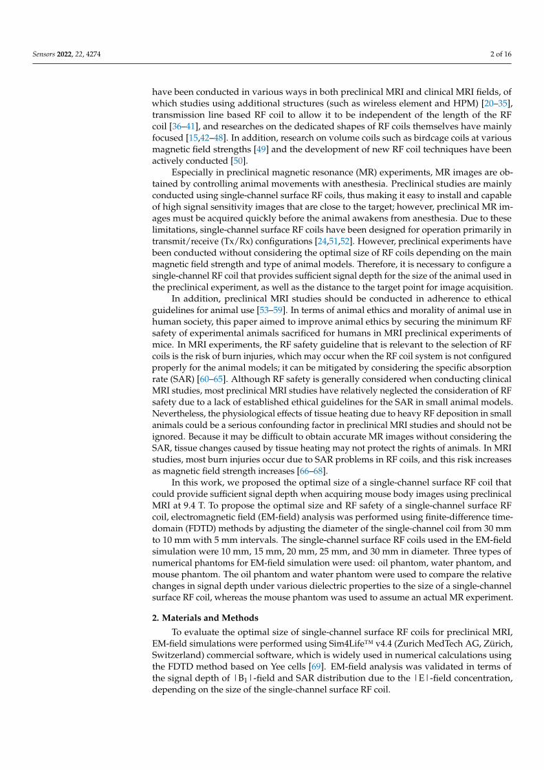
In Figure 1, for EM-field simulation, the single-channel surface RF coils were con-structed in a square shape using perfect electric conductor material. The diameter ofsingle-channel surface RF coils was set at a 5 mm interval from 10 mm to 30 mm (1 mm,15 mm, 20 mm, 25 mm, and 30 mm). The single-channel surface RF coil for the Tx/Rxmode had four ports as a voltage source of 1 V and the geometrical phase (0◦, 90◦, 180◦,and 270◦). The EM-field calculation was performed with a target frequency of 400 MHz forthe 9.4 T MRI system. The target frequency (ω) was defined as the gyromagnetic ratio (γ)and main magnetic field strength (B0) as following:
ω = γB0 (1)
Sensors 2022, 22, x FOR PEER REVIEW 3 of 17
using the FDTD method based on Yee cells [69]. EM-field analysis was validated in terms of the signal depth of |B1|-field and SAR distribution due to the |E|-field concentration, depending on the size of the single-channel surface RF coil.
In Figure 1, for EM-field simulation, the single-channel surface RF coils were con-structed in a square shape using perfect electric conductor material. The diameter of sin-gle-channel surface RF coils was set at a 5 mm interval from 10 mm to 30 mm (10 mm, 15 mm, 20 mm, 25 mm, and 30 mm). The single-channel surface RF coil for the Tx/Rx mode had four ports as a voltage source of 1 V and the geometrical phase (0°, 90°, 180°, and 270°). The EM-field calculation was performed with a target frequency of 400 MHz for the 9.4 T MRI system. The target frequency (𝜔𝜔) was defined as the gyromagnetic ratio (𝛾𝛾) and main magnetic field strength (B0) as following:
𝜔𝜔 = 𝛾𝛾B0 (1)
Figure 1. Geometric structures and simulation conditions of electromagnetic field simulation for the finite-different time-domain (FDTD) method using an oil phantom, water phantom, and mouse model: (a) oil phantom and water phantom with dielectric properties; (b) mouse phantom with di-electric properties.
The volumetric RF coil, since the RF transmission field was excited by the iso-center of the RF coil, achieved a B1+-field strength of 2.0 μT based on the center of the RF coil. However, it was difficult to quantitatively analyze the surface coil because various results were derived according to the change in the position of the target point when analyzing the field by randomly setting the target point. Therefore, in general, in the FDTD analysis of the surface coil, the RF power was fixed, and the analysis was performed in terms of signal depth and sensitivity of the RF coil.
The numerical phantoms for EM-field simulation utilized the cylindrical phantom (oil phantom and the water phantom (shown in Figure 1a)) and the mouse phantom (Male PIM1 Mouse by IT’IS Foundation (Information Technologies in Society), Switzerland), as shown in Figure 1b. The oil phantom and water phantom had a diameter of 30 mm and a length of 100 mm. The oil phantom consisted of dielectric properties with a conductivity of 0 S·m−1 and a permittivity of 4. Meanwhile, the water phantom using distilled water consisted of dielectric properties with a conductivity of 5 × 10⁻⁵ S·m−1 and a permittivity of 76.7. The reason for performing the simulation using the oil phantom was to evaluate the quantitative performance of the RF coil and to verify the EM-fields generated by the RF coil itself under ideal conditions. As the strength of the magnetic field increases, RF field
Figure 1. Geometric structures and simulation conditions of electromagnetic field simulation forthe finite-different time-domain (FDTD) method using an oil phantom, water phantom, and mousemodel: (a) oil phantom and water phantom with dielectric properties; (b) mouse phantom withdielectric properties.
The volumetric RF coil, since the RF transmission field was excited by the iso-centerof the RF coil, achieved a B1
+-field strength of 2.0 µT based on the center of the RF coil.However, it was difficult to quantitatively analyze the surface coil because various resultswere derived according to the change in the position of the target point when analyzingthe field by randomly setting the target point. Therefore, in general, in the FDTD analysisof the surface coil, the RF power was fixed, and the analysis was performed in terms ofsignal depth and sensitivity of the RF coil.
The numerical phantoms for EM-field simulation utilized the cylindrical phantom (oilphantom and the water phantom (shown in Figure 1a)) and the mouse phantom (MalePIM1 Mouse by IT’IS Foundation (Information Technologies in Society), Switzerland), asshown in Figure 1b. The oil phantom and water phantom had a diameter of 30 mm and alength of 100 mm. The oil phantom consisted of dielectric properties with a conductivityof 0 S·m−1 and a permittivity of 4. Meanwhile, the water phantom using distilled waterconsisted of dielectric properties with a conductivity of 5 × 10⁻⁵ S·m−1 and a permittivityof 76.7. The reason for performing the simulation using the oil phantom was to evaluatethe quantitative performance of the RF coil and to verify the EM-fields generated by theRF coil itself under ideal conditions. As the strength of the magnetic field increases, RFfield inhomogeneity occurred by shifted |B1
+|-field and |B1−|-field, it became difficult to
quantitatively evaluate the unique characteristics of RF coils [70,71]. In particular, it was

Sensors 2022, 22, 4274 4 of 16
difficult to quantitatively evaluate the RF field due to the inhomogeneity of the |B1+|-field
and |B1−|-field since the reciprocity theorem was not applied to ultra-high field MRI
above 7.0 T, and this inhomogeneity became more severe as it has higher conductivity.For this reason, the EM-field generated by the RF coil could be quantitatively evaluatedin simulation using the oil phantom, whereas the EM-field simulation using the waterphantom, which consisted of distilled water, could calculate EM-fields similar to the MRimages using the actual mice assuming that there was a 1H proton signal inside the watermolecule of the experimental mice. The mouse phantom had a length of 98 mm withouta tail and a mass of 45 g, with 49 tissue parameters. The PIM1 mouse phantom wasbased on MR segmented data, and each of the 49 defined tissue parameters was describedanalytically. The tissue parameters were assigned, such as electric conductivity, permittivity,and permeability for EM-field simulations. Tissue parameters for application to thermalsimulations (such as thermal conductivity, heat generation rate, heat transfer rate, and heatcapacity) were also defined in detail. The tissue parameter values, including density anddielectric properties, were included in the material database provided by IT’IS Foundation(DOI: 10.13099/VIP91201-01-0) [72].
The distance between the single-channel surface RF coil and each phantom (Oilphantom, water phantom, and mouse phantom) was set to be the closest possible distanceof 1 mm. In clinical MRI, MR images could be obtained that provide higher sensitivityand uniformity by using a multi-channel RF coil configured with volumetric features inultra-high field MRI. However, in the case of preclinical MRI, it was difficult to insert bothvolumetric multi-channel RF coils and experimental animals within the limited magnetbore size. Therefore, in order to obtain a higher SNR MR image, the surface coil was usedmainly in contact with object as close as possible to obtain the image.
For numerical calculations, the computational space composed of Yee cells was setto 86 × 83 × 156 cells (1.114 mega cells) for oil phantom and 171 × 166 × 418 cells(11.865 mega cells) for mouse phantom along the x, y, and z directions. Along the x,y, and z-axis, three-dimensional Yee cells were adopted with a resolution of less than1 mm, including the absorbing boundary condition with a perfectly matched layer forthe acquisition of accurate EM-field distribution and −70 dB conversions to produce asteady-state equilibrium condition of a single-channel surface RF coil. EM-field simulationswere calculated by a complex data matrix using MATLAB (Version 2020a, MathWorks,Inc., Natick, MA, USA). The EM-field simulation results calculated using MATLAB weredisplayed by setting the voxel resolution to 0.2 × 0.2 × 0.45 mm.
The single-channel surface RF coil produces a highly local EM-field sensitivity depend-ing on the signal depth. The signal depth is defined as the point at which the sensitivity ofthe single-channel surface RF coil drops to 37% of that at the center of the single-channelsurface RF coil. The signal depth of the single-channel surface RF coil is proportional to thediameter of the coil [73,74]. In other words, as the coil diameter increases, the interferencewith the target to obtain the MR image increases, which means that noise coming throughthe target tissue is affected. In addition, as the size of the single-channel surface RF coildecreases, a lot of RF power is required to acquire MR images in the target region. For thisreason, signal depth optimization had to be performed to optimize the single-channel sur-face RF coil. In addition, RF safety optimization considered SAR should also be performedto ensure the safety of experimental mice.
To analyze the performance of the single-channel surface RF coil in terms of thesignal depth and sensitivity, we compared the |B1|-, |B1
+|-, and |B1−|-field distributions
depending on the size of the single-channel surface RF coil at the center slice. |B1|-,|B1
+|-, and |B1−|-fields refer to absolute values of B1, B1
+, and B1− fields. The B1 field
distribution involving the x- and y-component as expressed as B1xy as follows:
B1 =
√(B+
1x)2
+ i(
B−1y
)2(2)
Sensors 2022, 22, 4274 5 of 16
And B1 includes two circularly polarized components defined as B1+ and B1
−, whereB1x and B1y are B1 components on the x-axis and y-axis, respectively. B1
+ and B1− can be
defined as follows:
B+1 =
∣∣∣∣ (B1x + iB1y)√2
∣∣∣∣, B−1 =
∣∣∣∣ (B1x − iB1y)√2
∣∣∣∣ (3)
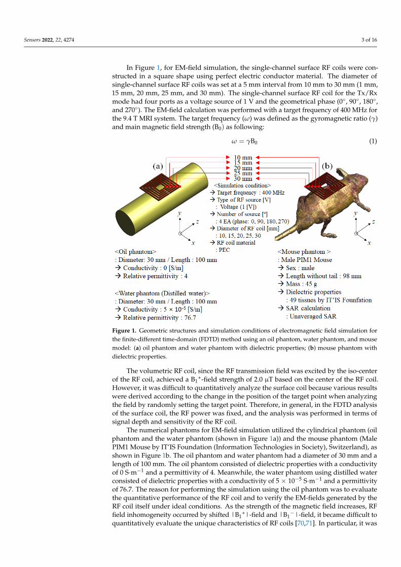
The signal depth of the |B1|-field was compared using a slice profile in the directionof RF penetration from P1 to P2 in the A–P (anterior to posterior) direction along they-axis, from the center of the single-channel surface RF coil, as shown in Figures 2 and 3.Meanwhile, the SAR-map on the basis of the |E|-field concentration was validated fordetermining the RF safety of a single-channel surface RF coil. In addition, for a morequantitative comparison, the maximum, mean, and standard deviation (STD) values weremeasured from the SAR-map results.
Sensors 2022, 22, x FOR PEER REVIEW 5 of 17
B1 = �(B1𝑥𝑥+ )2+𝑖𝑖�B1𝑦𝑦− �2 (2)
And B1 includes two circularly polarized components defined as B1+ and B1−, where B1x and B1y are B1 components on the x-axis and y-axis, respectively. B1+ and B1− can be defined as follows:
B1+ = �(B1𝑥𝑥 + 𝑖𝑖B1𝑦𝑦)
√2 � , B1− = �
(B1𝑥𝑥 − 𝑖𝑖B1𝑦𝑦)√2
� (3)
The signal depth of the |B1|-field was compared using a slice profile in the direction of RF penetration from P1 to P2 in the A–P (anterior to posterior) direction along the y-axis, from the center of the single-channel surface RF coil, as shown in Figures 2 and 3. Meanwhile, the SAR-map on the basis of the |E|-field concentration was validated for determining the RF safety of a single-channel surface RF coil. In addition, for a more quan-titative comparison, the maximum, mean, and standard deviation (STD) values were measured from the SAR-map results.
Figure 2. EM-field simulation results using oil phantom in the axial slice (x–y plane): (a) |B1|-field, (b) |B1+|-field, (c) |B1−|-field, and (d) |E|-field.
Figure 2. EM-field simulation results using oil phantom in the axial slice (x–y plane): (a) |B1|-field,(b) |B1
+|-field, (c) |B1−|-field, and (d) |E|-field.
Sensors 2022, 22, 4274 6 of 16
Sensors 2022, 22, x FOR PEER REVIEW 6 of 17
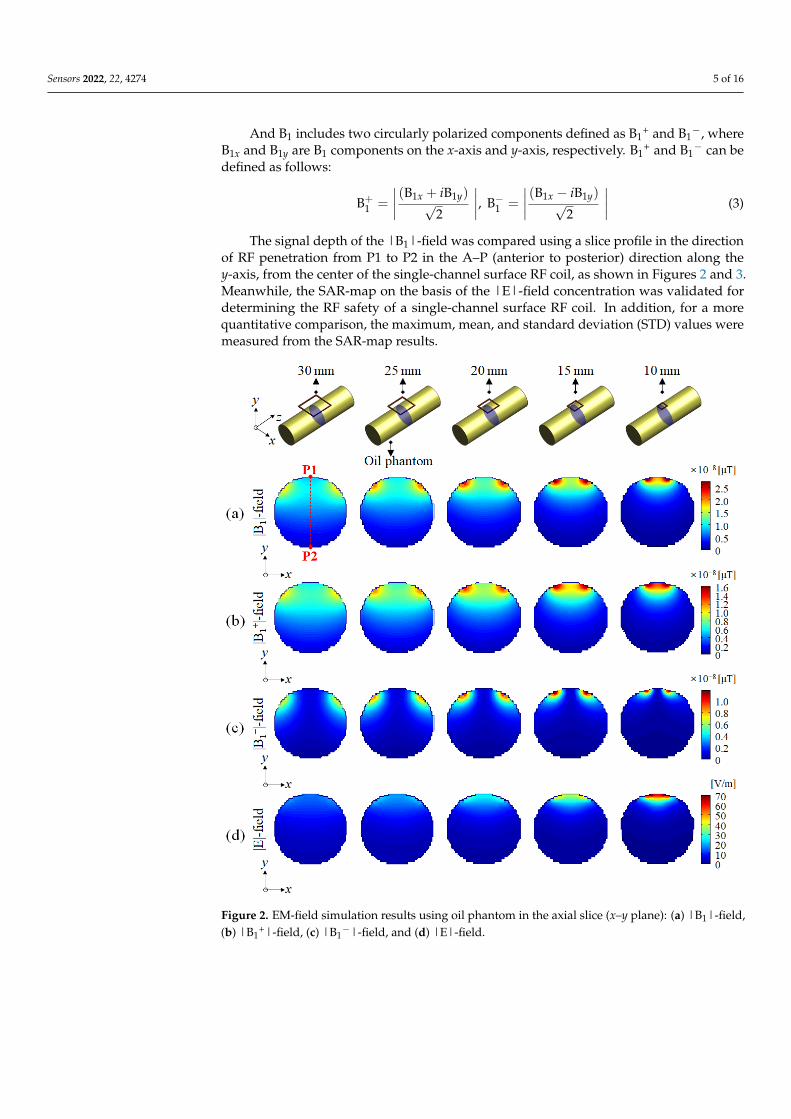
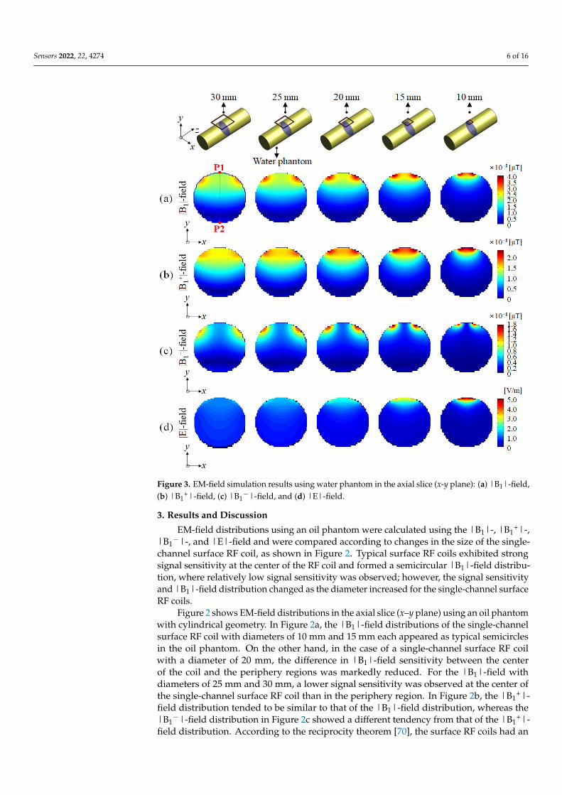
Figure 3. EM-field simulation results using water phantom in the axial slice (x-y plane): (a) |B1|-field, (b) |B1+|-field, (c) |B1−|-field, and (d) |E|-field.
3. Results and Discussion EM-field distributions using an oil phantom were calculated using the |B1|-, |B1+|-,
|B1−|-, and |E|-field and were compared according to changes in the size of the single-channel surface RF coil, as shown in Figure 2. Typical surface RF coils exhibited strong signal sensitivity at the center of the RF coil and formed a semicircular |B1|-field distribu-tion, where relatively low signal sensitivity was observed; however, the signal sensitivity and |B1|-field distribution changed as the diameter increased for the single-channel sur-face RF coils.
Figure 2 shows EM-field distributions in the axial slice (x–y plane) using an oil phan-tom with cylindrical geometry. In Figure 2a, the |B1|-field distributions of the single-chan-nel surface RF coil with diameters of 10 mm and 15 mm each appeared as typical semicir-cles in the oil phantom. On the other hand, in the case of a single-channel surface RF coil with a diameter of 20 mm, the difference in |B1|-field sensitivity between the center of the coil and the periphery regions was markedly reduced. For the |B1|-field with diameters of 25 mm and 30 mm, a lower signal sensitivity was observed at the center of the single-channel surface RF coil than in the periphery region. In Figure 2b, the |B1+|-field distribu-tion tended to be similar to that of the |B1|-field distribution, whereas the |B1−|-field dis-tribution in Figure 2c showed a different tendency from that of the |B1+|-field distribution. According to the reciprocity theorem [70], the surface RF coils had an equal distribution as that of the |B1+|-field for RF transmission and the |B1−|-field for RF reception. However,
Figure 3. EM-field simulation results using water phantom in the axial slice (x-y plane): (a) |B1|-field,(b) |B1
+|-field, (c) |B1−|-field, and (d) |E|-field.
3. Results and Discussion
EM-field distributions using an oil phantom were calculated using the |B1|-, |B1+|-,
|B1−|-, and |E|-field and were compared according to changes in the size of the single-
channel surface RF coil, as shown in Figure 2. Typical surface RF coils exhibited strongsignal sensitivity at the center of the RF coil and formed a semicircular |B1|-field distribu-tion, where relatively low signal sensitivity was observed; however, the signal sensitivityand |B1|-field distribution changed as the diameter increased for the single-channel surfaceRF coils.
Figure 2 shows EM-field distributions in the axial slice (x–y plane) using an oil phantomwith cylindrical geometry. In Figure 2a, the |B1|-field distributions of the single-channelsurface RF coil with diameters of 10 mm and 15 mm each appeared as typical semicirclesin the oil phantom. On the other hand, in the case of a single-channel surface RF coilwith a diameter of 20 mm, the difference in |B1|-field sensitivity between the centerof the coil and the periphery regions was markedly reduced. For the |B1|-field withdiameters of 25 mm and 30 mm, a lower signal sensitivity was observed at the center ofthe single-channel surface RF coil than in the periphery region. In Figure 2b, the |B1
+|-field distribution tended to be similar to that of the |B1|-field distribution, whereas the|B1
−|-field distribution in Figure 2c showed a different tendency from that of the |B1+|-
field distribution. According to the reciprocity theorem [70], the surface RF coils had an

Sensors 2022, 22, 4274 7 of 16
equal distribution as that of the |B1+|-field for RF transmission and the |B1
−|-field forRF reception. However, as the magnetic field strength increased, the reciprocity theoremwas not established due to inhomogeneity between RF transmission and RF reception.Figure 2d shows the |E|-field concentration of a single-channel surface RF coil. Themaximum |E|-field value was observed with a diameter of 10 mm, and the |E|-fielddistribution relatively decreased as the diameter of the single-channel surface RF coilsincreased. According to the EM-field simulation results shown in Figure 2, the fartherthe distance from the single-channel surface RF coil along P1–P2, a more linear reductionfield pattern was observed in the EM field. As shown in Figure 2, a single-channel surfaceRF coil consisting of a diameter of 20 mm provided optimal |B|-field distribution. Onthe other hand, surface RF coils with a diameter of more than 25 mm increased the signalsensitivity of the |B|-field in the periphery region rather than in the center of the coil.
EM-field simulation results of the water phantom using distilled water modeled to thesame size as the oil phantom were calculated as shown in Figure 3. EM-field distributionsusing the water phantom were calculated using the |B1|-, |B1
+|-, |B1−|-, and |E|-fields
and were compared in the same way as the EM-field simulation results using the oilphantom in Figure 2.
In the EM-field simulation result using the water phantom, as shown in Figure 3, adeeper signal depth could be observed in the |B1|- and |B1
+|-fields compared to theresult using the oil phantom (in Figure 2). This was due to the characteristics of the waterphantom using distilled water that had higher dielectric properties than the oil phantom.The simulation results using the water phantom showed that the EM-field was distortedalong the y-direction (near the P2 point), but it was not found in the EM-field simulationresult using the oil phantom. It was possible to observe an EM-field distribution in whichthe signal strength increases in the opposite direction where the single-channel surface RFcoil was located.
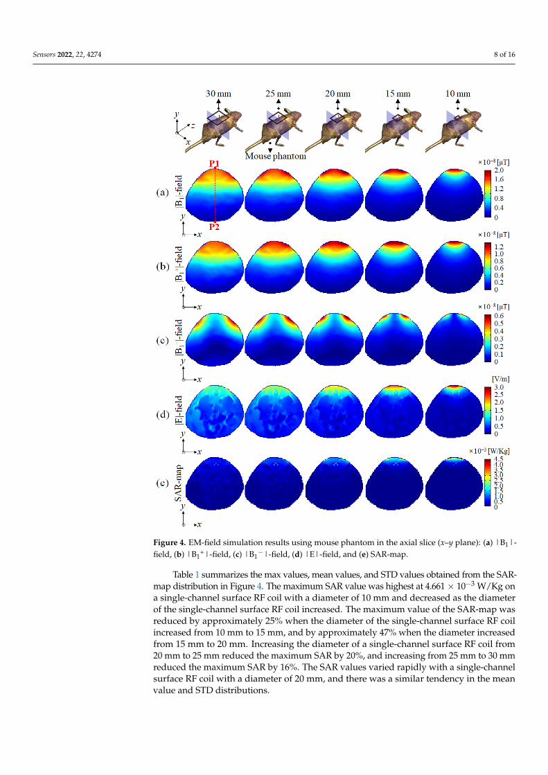
In Figure 4, EM-field distributions using a mouse phantom were verified for the |B1|-field, |B1
+|-field, |B1−|-field, |E|-field, and SAR-map, depending on the change in the
size of the single-channel surface RF coil. Figure 4 shows that the results of using a mousephantom were similar to the results obtained using an oil phantom and water phantom,as shown in Figures 2 and 3. However, due to the narrowed dorsal shape of the mousephantom, high signal sensitivity patterns close to the microstrip line of the single-channelsurface RF coil were not observed, which contrasted with the patterns shown in the oilphantom and water phantom results. In addition, the distorted EM-field distribution withreversed signal intensity near the P2 point observed in the water phantom result wasequally observed in the |B1|-, |B1
+|-, and |B1−|-field distribution.
In Figure 4a, typical |B1|-field distribution was observed in a single-channel surfaceRF coil with a diameter of 20 mm, but a single-channel surface RF coil with a diameter ofmore than 25 mm was observed to flatten the |B1|-field distribution. For the |B1
+|-fielddistribution, shown in Figure 4b, we verified field patterns that were similar to those ofthe |B1|-field distribution, as shown in Figure 4a. The |B1
−|-field distribution shownin Figure 4c produced a non-linear field pattern in which the |B1
−|-field distributionincreased at a certain point without linearly decreasing. Figure 4d shows the |E|-field dis-tribution using a mouse phantom as the single-channel surface RF coil diameter increased.The |E|-field concentration generated a maximum value near the single-channel surfaceRF coil, and penetration into the mouse phantom was observed as the diameter of thesingle-channel surface RF coil increased. Meanwhile, unlike that shown in Figure 2d, thepenetration depth of the |E|-field was observed to deepen due to the dielectric propertiesof the mouse phantom consisting of various tissues. In terms of RF safety, the SAR-mapresults in Figure 4e showed a similar tendency as the |E|-field results shown in Figure 4d.The results of the single-channel surface RF coil with a diameter of 10 mm showed thatthe SAR field was concentrated close to the single-channel surface RF coil. Meanwhile, theSAR distribution penetrated the mouse model due to an increase in the diameter of thesingle-channel surface RF coil.
Sensors 2022, 22, 4274 8 of 16
Sensors 2022, 22, x FOR PEER REVIEW 8 of 17
Figure 4. EM-field simulation results using mouse phantom in the axial slice (x–y plane): (a) |B1|-field, (b) |B1+|-field, (c) |B1−|-field, (d) |E|-field, and (e) SAR-map.
In Figure 4a, typical |B1|-field distribution was observed in a single-channel surface RF coil with a diameter of 20 mm, but a single-channel surface RF coil with a diameter of more than 25 mm was observed to flatten the |B1|-field distribution. For the |B1+|-field distribution, shown in Figure 4b, we verified field patterns that were similar to those of the |B1|-field distribution, as shown in Figure 4a. The |B1−|-field distribution shown in Figure 4c produced a non-linear field pattern in which the |B1−|-field distribution in-creased at a certain point without linearly decreasing. Figure 4d shows the |E|-field dis-tribution using a mouse phantom as the single-channel surface RF coil diameter increased. The |E|-field concentration generated a maximum value near the single-channel surface RF coil, and penetration into the mouse phantom was observed as the diameter of the single-channel surface RF coil increased. Meanwhile, unlike that shown in Figure 2d, the penetration depth of the |E|-field was observed to deepen due to the dielectric properties of the mouse phantom consisting of various tissues. In terms of RF safety, the SAR-map results in Figure 4e showed a similar tendency as the |E|-field results shown in Figure 4d. The results of the single-channel surface RF coil with a diameter of 10 mm showed that
Figure 4. EM-field simulation results using mouse phantom in the axial slice (x–y plane): (a) |B1|-field, (b) |B1
+|-field, (c) |B1−|-field, (d) |E|-field, and (e) SAR-map.
Table 1 summarizes the max values, mean values, and STD values obtained from the SAR-map distribution in Figure 4. The maximum SAR value was highest at 4.661× 10⁻³ W/Kg ona single-channel surface RF coil with a diameter of 10 mm and decreased as the diameterof the single-channel surface RF coil increased. The maximum value of the SAR-map wasreduced by approximately 25% when the diameter of the single-channel surface RF coilincreased from 10 mm to 15 mm, and by approximately 47% when the diameter increasedfrom 15 mm to 20 mm. Increasing the diameter of a single-channel surface RF coil from20 mm to 25 mm reduced the maximum SAR by 20%, and increasing from 25 mm to 30 mmreduced the maximum SAR by 16%. The SAR values varied rapidly with a single-channelsurface RF coil with a diameter of 20 mm, and there was a similar tendency in the meanvalue and STD distributions.

Sensors 2022, 22, 4274 9 of 16
Table 1. SAR values according to the change in size of single-channel surface RF coils using amouse phantom.
SAR [× 10−3 W/Kg] 30 mm 25 mm 20 mm 15 mm 10 mm
Max values 1.251 1.488 1.853 3.496 4.661Mean values 0.163 0.154 0.139 0.117 0.082
STD 0.164 0.206 0.257 0.312 0.337
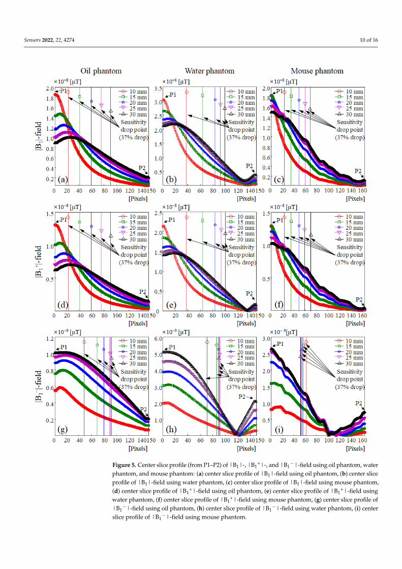
In Figure 5, the signal depth according to the size of the single-channel surface RFcoil was compared with a resolution of 0.2 mm per point in the y-axis direction usinga slice profile between the P1 and P2 points, as shown in Figures 2–4. As can be seenfrom the simulation results using the oil phantom in Figure 5a,d,g, |B1|- and |B1
+|-fieldsindicated similar slice profiles, except for differences in the signal sensitivity. The signalsensitivity of the |B1|- and |B1
+|-fields tended to decrease with the increasing diameter ofthe single-channel surface RF coil, and in the |B1
−|-field distribution, the signal sensitivitytended to increase with the increasing diameter of the single-channel surface RF coil. The|B1
−|-field results in Figure 5g showed an opposite tendency from the |B1|- and |B1+|-
field distributions. This tendency was similar in the EM simulation of the water phantom(shown in Figure 5b,e,h) and mouse phantom (shown in Figure 5c,f,i), but unlike EMsimulation with the oil phantom, signal sensitivity was reversed at approximately 23.6 mm(at 118 points) from a single-channel surface RF coil in the |B1
−|-field distribution of thewater phantom (in Figure 5h). This signal reversal was also observed in the |B1
−|-fielddistribution of the mouse phantom (in Figure 5i), with the signal sensitivity reversedat approximately 21 mm (105) on the single-channel surface RF coil. The |B1
−|-fieldsensitivity reversed in this way was caused by the inhomogeneity of the main magneticfield and the complex dielectric properties of the mouse phantom in UHF MRI [75,76].
The signal depth, an important measure for evaluating the performance of a singlechannel surface coil, was defined as the point where the coil’s sensitivity drops to 37%of that at the center of the coil [73,74]. To evaluate the signal depth of the central sliceprofile in the |B1|- and |B1
+|-fields, the point at which the signal intensity decreased by37% based on the field sensitivity value of the point P1 (in Table 2) was measured andshown in Table 3. In the results of the oil phantom and mouse phantom in Figure 5 andTable 3, for single-channel surface RF coils with a size of 10 mm and 15 mm, the signaldepth of |B1|- and |B1
+|-fields were less than 10 mm and sufficient signal depths were notprovided. However, in the results of the |B1|- and |B1
+|-fields, a single-channel surfaceRF coil with a diameter of 20 mm provided a sufficient signal depth of more than 10 mm.Exceptionally, the water phantom results showed that a sufficient signal depth of more than10 mm was provided in a single-channel surface RF coil with a diameter of 15 mm. Theresults of the |B1|- and |B1
+|-fields of the water phantom showed that the signal depthincreased rapidly as the diameter of the single-channel surface RF coil decreased comparedto the oil phantom result. It was confirmed that there was a high similarity between thewater phantom result and the mouse phantom result in the |B1
−|-field distribution. In|B1
−|-field results (shown in Table 3), the difference in signal depth according to the sizechange of the single-channel surface RF coil was measured to be up to 3.8 mm with thewater phantom and up to 1.6 mm with the mouse phantom.
Sensors 2022, 22, 4274 10 of 16
Sensors 2022, 22, x FOR PEER REVIEW 10 of 17
Figure 5. Center slice profile (from P1–P2) of |B1|-, |B1+|-, and |B1−|-field using oil phantom, water phantom, and mouse phantom: (a) center slice profile of |B1|-field using oil phantom, (b) center slice profile of |B1|-field using water phantom, (c) center slice profile of |B1|-field using mouse phantom, (d) center slice profile of |B1+|-field using oil phantom, (e) center slice profile of |B1+|-field using water phantom, (f) center slice profile of |B1+|-field using mouse phantom, (g) center slice profile of |B1−|-field using oil phantom, (h) center slice profile of |B1−|-field using water phan-tom, (i) center slice profile of |B1−|-field using mouse phantom.
The signal depth, an important measure for evaluating the performance of a single channel surface coil, was defined as the point where the coil’s sensitivity drops to 37% of that at the center of the coil [73,74]. To evaluate the signal depth of the central slice profile in the |B1|- and |B1+|-fields, the point at which the signal intensity decreased by 37% based on the field sensitivity value of the point P1 (in Table 2) was measured and shown in Table 3. In the results of the oil phantom and mouse phantom in Figure 5 and Table 3, for single-channel surface RF coils with a size of 10 mm and 15 mm, the signal depth of |B1|- and |B1+|-fields were less than 10 mm and sufficient signal depths were not pro-vided. However, in the results of the |B1|- and |B1+|-fields, a single-channel surface RF coil with a diameter of 20 mm provided a sufficient signal depth of more than 10 mm. Exceptionally, the water phantom results showed that a sufficient signal depth of more than 10 mm was provided in a single-channel surface RF coil with a diameter of 15 mm. The results of the |B1|- and |B1+|-fields of the water phantom showed that the signal depth
Figure 5. Center slice profile (from P1–P2) of |B1|-, |B1+|-, and |B1
−|-field using oil phantom, waterphantom, and mouse phantom: (a) center slice profile of |B1|-field using oil phantom, (b) center sliceprofile of |B1|-field using water phantom, (c) center slice profile of |B1|-field using mouse phantom,(d) center slice profile of |B1
+|-field using oil phantom, (e) center slice profile of |B1+|-field using
water phantom, (f) center slice profile of |B1+|-field using mouse phantom, (g) center slice profile of
|B1−|-field using oil phantom, (h) center slice profile of |B1
−|-field using water phantom, (i) centerslice profile of |B1
−|-field using mouse phantom.

Sensors 2022, 22, 4274 11 of 16
Table 2. Field sensitivity at P1 point according to the change in size of single-channel surface RF coilsusing oil phantom, water phantom, and mouse phantom.
Field Sensitivity at P1 Point [× 10−8 µT] B1-Field B1+-Field B1−-Field
Oil phantom
30 mm 0.885 0.618 0.10025 mm 1.002 0.702 0.09620 mm 1.159 0.815 0.08815 mm 1.424 1.004 0.07510 mm 1.849 1.306 0.055
Water phantom
30 mm 2.108 1.401 0.50725 mm 2.205 1.492 0.45220 mm 2.341 1.610 0.38715 mm 2.647 1.847 0.30410 mm 3.043 2.142 0.196
Mouse phantom
30 mm 1.488 1.019 0.26325 mm 1.160 1.110 0.25520 mm 1.728 1.201 0.22315 mm 1.824 1.280 0.15910 mm 1.825 1.288 0.079
Table 3. The point where the sensitivity drops to 37% according to the change in size of single-channelsurface RF coils using oil phantom, water phantom, and mouse phantom.
Sensitivity 37% Drop Point [Pixels] B1-Field B1+-Field B1−-Field
Oil phantom
30 mm 92 (18.4 mm) 92 (18.4 mm) 92 (18.4 mm)25 mm 77 (15.4 mm) 77 (15.4 mm) 89 (17.8 mm)20 mm 60 (12.0 mm) 60 (12.0 mm) 80 (16.0 mm)15 mm 41 (8.2 mm) 41 (8.2 mm) 68 (13.6 mm)10 mm 23 (4.6 mm) 22 (4.4 mm) 47 (9.4 mm)
Water phantom
30 mm 99 (19.8 mm) 100 (20.0 mm) 89 (17.8 mm)25 mm 93 (18.6 mm) 94 (18.8 mm) 91 (18.2 mm)20 mm 84 (16.8 mm) 84 (16.8 mm) 89 (17.8 mm)15 mm 64 (12.8 mm) 64 (12.8 mm) 86 (17.2 mm)10 mm 38 (7.6 mm) 38 (7.6 mm) 72 (14.4 mm)
Mouse phantom
30 mm 68 (13.6 mm) 71 (14.2 mm) 53 (10.6 mm)25 mm 60 (12.0 mm) 59 (11.8 mm) 54 (10.8 mm)20 mm 50 (10.0 mm) 50 (10.0 mm) 55 (11.0 mm)15 mm 35 (7.0 mm) 35 (7.0 mm) 56 (11.2 mm)10 mm 23 (4.6 mm) 23 (4.6 mm) 61 (12.2 mm)
The brain of the mouse phantom used in the EM-field simulation had a height of8 mm, and the signal depth had to be 10 mm or more to obtain an image of the entiremouse brain region, considering the skull and skin. In addition, the signal depth had to beat least 10 mm to obtain spinal cord images of the mouse’s body. In other words, in orderto obtain mouse brain and spinal code images in preclinical MRI experiments using mice, asingle-channel surface RF coil with a diameter of at least 20 mm had to be used.
The effectiveness of the proposed 20 mm diameter surface RF coil in mouse experi-ments using preclinical 9.4 T MRI could be confirmed not only in axial slices but also inthe results of the sagittal slice (in Figures S1–S3) and coronal slice (in Figures S4–S6). As aresult of the distribution of EM-fields using the oil phantom (in Figure S1), water phantom(in Figure S2), and mouse phantom (in Figure S3) in the sagittal slice, it was confirmed thatthe same distribution as the axial slice appeared. In addition, according to the results of theEM-fields using the oil phantom (in Figure S4), water phantom (in Figure S5), and mousephantom (in Figure S6) in the coronal slice, it was confirmed that the single-channel surfaceRF coil with a diameter of 20 mm is the minimum usage criteria.
Sensors 2022, 22, 4274 12 of 16
In this paper, according to the results while using the oil phantom, water phantom, andmouse phantom, a single-channel surface RF coil consisting of a 20 mm diameter providedan optimal |B1|-field distribution and confirmed that single-channel surface RF coils witha diameter of more than 25 mm could not provide a typical |B1|-field distribution withinthe guidelines for RF safety. To preserve the characteristics of typical single-channel surfaceRF coils and ensure that the RF signal is correctly applied to the target point, we proposedusing a single-channel coil with a diameter of 20 mm for 9.4 T MRI.
To discuss the results of this study, we proposed a single-channel RF coil with adiameter of 20 mm optimized for small mice at 9.4 T MRI. The proposed 20mm diametersingle-channel RF coil provided signal depth of RF coil suitable for mouse experiments inthe 9.4 T MRI study and confirmed the RF safety of experimental animals.
Although the proposed 20 mm diameter single-channel RF coil was expected tobe readily applicable to preclinical 9.4 T MRI studies, this study was conducted withtwo limitations.
First, comparative studies on MRIs of various magnetic field intensities had not beenconducted. The EM field characteristics and SAR distribution of the RF coil change dueto the decrease in the wavelength of the RF frequency depending on the strength of themagnetic field. In this paper, we proposed a single-channel RF coil optimized only for 9.4 TMRI but failed to compare the electromagnetic field and RF safety of a single-channel RFcoil in preclinical MRIs with different magnetic field intensities. In the following study, acomparative analysis of preclinical MRI of various magnetic field strengths such as 3.0 T,7.0 T, 11.4 T, and 21.0 T is required [44,77–80].
Second, the RF coil size required in MRI experiments is typically defined accordingto the type and size of the target animal and the image acquisition region. The EM-fieldsimulations using various experimental animal models are required to accurately assess theperformance of the single-channel surface RF coil in preclinical MRI. Therefore, comparativestudies on experimental animals of various sizes and types are essential. The EM-fieldsimulation program used in this study can apply various animal phantoms provided bythe IT’IS Foundation, enabling comparative studies on animals of various sizes and types.
Experimental animal models for EM-field simulations provided by the IT’IS Founda-tion provide 17 animal phantoms consisting of a total of 9 species of animals, as shownin Table S1. However, it takes a lot of time to conduct comparative research on variousspecies of animals, and it is difficult to compare all of them within a limited page-lengthmanuscript. Therefore, in this study, size optimization was performed according to thesize of the single-channel surface RF coil using only mice, which are the most frequentlyused in animal experiments [81,82]. In recent research trends using experimental animals(especially in Asia, the European Union, and the United Kingdom), experiments using miceand rats account for 70–80% of the total animal experiments, of which the utilization rate ofmice is overwhelmingly high at 60–70% [83].
To solve these two limitations, a comparative study using various main magneticfield strengths and various animal phantoms will be performed. In addition, based on theproposed single-channel surface RF coil with a diameter of 20 mm in this study, we areplanning to extend the suggested single-channel surface RF coil to a multi-channel RF coiland are also planning an optimized diameter to provide RF safety of experimental animals.
4. Conclusions
In preclinical MRI, single-channel surface RF coils have been used in the Tx/Rx modefor small animal studies using rat or mouse models due to their high signal sensitivity.However, as the main magnetic field strength increases, single-channel surface RF coilsof optimized size have been used without performing quantitative analysis or followingthe guidelines of RF safety. Therefore, it is essential to define a single-channel surfaceRF coil that has been optimized according to the main magnetic field strength and withconsideration for the signal depth to ensure that the RF signal is correctly applied to thetarget image acquisition point within the RF safety guidelines.

Sensors 2022, 22, 4274 13 of 16
From the results of this study, the sensitivity and signal depth of |B1|-, |B1+|-,
and |B1−|-field, including RF safety, were verified by using numerical calculations for
preclinical MRI. A single-channel surface RF coil of 10 mm and 15 mm each provided high|B1|-field sensitivity, and the small size of the single-channel surface RF coil caused an|E|-field concentration, thus resulting in an increase in the SAR value. The use of single-channel surface RF coils with diameters of 10 mm and 15 mm in a preclinical MRI doubledthe SAR compared to the use of single-channel surface RF coils with a diameter of 20 mmat a location close to a single-channel surface RF coil, thus resulting in many drawbacks inSAR safety for experiments using small animals. In preclinical MRI, single-channel surfaceRF coil acquires images as close as possible to the target small animal, and an increase inthe maximum SAR due to the |E|-field concentration lead to a burn injury or changes inthe biological properties of the small animal.
Considering RF safety for small animals, the optimal single-channel surface RF coilsize should be at least 20 mm, and it is recommended to use a 20 mm single-channel surfaceRF coil while considering high signal sensitivity, signal depth, and RF safety. In this paper,we verified the efficiency and safety of the single-channel surface RF coil with a diameterof 20 mm for mouse experiments in 9.4 T preclinical MRI. The proposed 20 mm diametersingle-channel surface RF coil showed excellent performance in terms of |B1|-field signaldepth and SAR, which could be utilized to improve the quality of small animal images forpreclinical MRI.
In addition, we also expect to be able to conduct research on RF coils that are suitablefor more diverse purposes using methods considering the signal depth and SAR analysisfor determining optimized single-channel surface RF coils for preclinical MRI studies.In addition, the proposed 20 mm diameter single-channel surface RF coil can be easilyapplied to multi-channel RF coils in preclinical 9.4 T MRI systems and will provide high|B1|-field sensitivity with sufficient signal depth, and will also satisfy SAR safety ofexperimental mice.
Supplementary Materials: The following supporting information can be downloaded at: https://www.mdpi.com/article/10.3390/s22114274/s1, Figure S1. EM-field simulation results using oilphantom in the sagittal slice (y–z plane): (a) |B1|-field, (b) |B1
+|-field, (c) |B1−|-field, and (d) |E|-
field; Figure S2. EM-field simulation results using water phantom in the sagittal slice (y–z plane):(a) |B1|-field, (b) |B1
+|-field, (c) |B1−|-field, and (d) |E|-field; Figure S3. EM-field simulation
results using mouse phantom in the sagittal slice (y–z plane): (a) |B1|-field, (b) |B1+|-field, (c) |B1
−|-field, (d) |E|-field, and (e) SAR-map; Figure S4. EM-field simulation results using oil phantom in thecoronal slice (x–z plane): (a) |B1|-field, (b) |B1
+|-field, (c) |B1−|-field, and (d) |E|-field; Figure S5.
EM-field simulation results using water phantom in the coronal slice (x–z plane): (a) |B1|-field,(b) |B1
+|-field, (c) |B1−|-field, and (d) |E|-field; Figure S6. EM-field simulation results using mouse
phantom in the coronal slice (x–z plane): (a) |B1|-field, (b) |B1+|-field, (c) |B1
−|-field, (d) |E|-field,and (e) SAR-map. Table S1. Types of experimental animal phantom provided by IT’IS Foundation forEM-field simulation.
Author Contributions: Conceptualization, J.-H.S. and Y.R.; methodology, J.-H.S.; software, J.-H.S.;validation, J.-H.S., Y.R. and J.-Y.C.; formal analysis, J.-H.S.; investigation, J.-H.S.; resources, J.-Y.C.;data curation, J.-H.S.; writing—original draft preparation, J.-H.S.; writing—review and editing, Y.R.and J.-Y.C.; visualization, J.-H.S.; supervision, Y.R. and J.-Y.C.; project administration, J.-Y.C.; fundingacquisition, J.-Y.C. All authors have read and agreed to the published version of the manuscript.
Funding: This work was supported by a grant from the Korea Health Technology R&D Projectthrough the Korea Health Industry Development Institute (KHIDI), funded by the Ministry of Healthand Welfare of the Republic of Korea (Grant HR14C-0002-010014).
Data Availability Statement: Not applicable.
Conflicts of Interest: The authors declare no conflict of interest.

Sensors 2022, 22, 4274 14 of 16
References1. Koretsky, A.P. Insights into cellular energy metabolism from transgenic mice. Physiol. Rev. 1995, 75, 667–688. [CrossRef] [PubMed]2. Christensen, G.; Wang, Y.; Chien, K.R. Physiological assessment of complex cardiac phenotypes in genetically engineered mice.
Am. J. Physiol. 1997, 272, H2513–H2524. [CrossRef] [PubMed]3. James, J.F.; Hewett, T.E.; Robbins, J. Cardiac physiology in transgenic mice. Circ. Res. 1998, 82, 407–415. [CrossRef] [PubMed]4. Roman, B.B.; Goldspink, P.H.; Spaite, E.; Urboniene, D.; McKinney, R.; Geenen, D.L.; Solaro, R.J.; Buttrick, P.M. Inhibition of PKC
phosphorylation of cTnI improves cardiac performance in vivo. Am. J. Physiol. Heart Circ. Physiol. 2004, 286, H2089–H2095. [CrossRef]5. Benveniste, H.; Blackband, S. MR microscopy and high resolution small animal MRI: Applications in neuroscience research. Prog.
Neurobiol. 2002, 67, 393–420. [CrossRef]6. Cantley, M.D.; Bartold, P.M.; Marino, V.; Reid, R.C.; Fairlie, D.P.; Wyszynski, R.N.; Zilm, P.S.; Haynes, D.R. The use of live-animal
micro-computed tomography to determine the effect of a novel phospholipase A2 inhibitor on alveolar bone loss in an in vivomouse model of periodontitis. J. Periodontal Res. 2009, 44, 317–322. [CrossRef]
7. Kim, Y.; Hamada, N.; Takahashi, Y.; Sasaguri, K.; Tsukinoki, K.; Onozuka, M.; Sato, S. Cervical sympathectomy causes alveolarbone loss in an experimental rat model. J. Periodontal Res. 2009, 44, 695–703. [CrossRef]
8. Marques, M.R.; dos Santos, M.C.; da Silva, A.F.; Nociti, F.H.; Barros, S.P., Jr. Parathyroid hormone administration may modulateperiodontal tissue levels of interleukin-6, matrix metalloproteinase-2 and matrix metalloproteinase-9 in experimental periodontitis.J. Periodontal Res. 2009, 44, 744–750. [CrossRef]
9. Polak, D.; Wilensky, A.; Shapira, L.; Halabi, A.; Goldstein, D.; Weiss, E.I.; Houri-Haddad, Y. Mouse model of experimentalperiodontitis induced by Porphyromonas gingivalis/Fusobacterium nucleatum infection: Bone loss and host response. J. Clin.Periodontol. 2009, 36, 406–410. [CrossRef]
10. Fernandes, L.A.; de Almeida, J.M.; Theodoro, L.H.; Bosco, A.F.; Nagata, M.J.; Martins, T.M.; Okamoto, T.; Garcia, V.G. Treatment ofexperimental periodontal disease by photodynamic therapy in immunosuppressed rats. J. Clin. Periodontol. 2009, 36, 219–228. [CrossRef]
11. Queiroz-Junior, C.M.; Pacheco, C.M.; Maltos, K.L.; Caliari, M.V.; Duarte, I.D.; Francischi, J.N. Role of systemic and localadministration of selective inhibitors of cyclo-oxygenase 1 and 2 in an experimental model of periodontal disease in rats.J. Periodontal Res. 2009, 44, 153–160. [CrossRef] [PubMed]
12. Marzola, P.; Osculati, F.; Sbarbati, A. High field MRI in preclinical research. Eur. J. Radiol. 2003, 48, 165–170. [CrossRef] [PubMed]13. Leynes, A.P.; Chen, Y.; Sukumar, S.; Xu, D.; Zhang, X. A compact planar triple-nuclear coil for small animal 1H, 13C, and 31P
metabolic MR imaging at 14.1 T. arXiv 2021, arXiv:2109.03015.14. Slawson, S.E.; Roman, B.B.; Williams, D.S.; Koretsky, A.P. Cardiac MRI of the normal and hypertrophied mouse heart. Magn.
Reson. Med. 1998, 39, 980–987. [CrossRef]15. Kim, K.-N.; Seo, J.-H.; Han, S.-D.; Heo, P.; Im, G.H.; Lee, J.H. Development of double-layer coupled coil for improving S/N in 7 T
small-animal MRI. Scanning 2015, 37, 361–371. [CrossRef]16. Gatto, R.G.; Weissmann, C. Preliminary examination of early neuroconnectivity features in the R6/1 mouse model of Huntington’s
disease by ultra-high field diffusion MRI. Neural Regen. Res. 2022, 17, 983–986. [CrossRef]17. Zhu, X.H.; Chen, W. In vivo x-nuclear MRS imaging methods for quantitative assessment of neuroenergetic biomarkers in
studying brain function and aging. Front. Aging Neurosci. 2018, 10, 394. [CrossRef]18. Niendorf, T.; Pohlmann, A.; Reimann, H.M.; Waiczies, H.; Peper, E.; Huelnhagen, T.; Seeliger, E.; Schreiber, A.; Kettritz, R.; Strobel,
K.; et al. Advancing cardiovascular, neurovascular, and renal magnetic resonance imaging in small rodents using cryogenicradiofrequency coil technology. Front. Pharmacol. 2015, 6, 255. [CrossRef]
19. Öz, G.; Tkác, I.; Ugurbil, K. Animal models and high field imaging and spectroscopy. Dialogues Clin. Neurosci. 2013, 15, 263–278.[CrossRef] [PubMed]
20. Chi, Z.; Yi, Y.; Wang, Y.; Wu, M.; Wang, L.; Zhao, X.; Meng, Y.; Zheng, Z.; Zhao, Q.; Zhou, J. Adaptive cylindrical wirelessmetasurfaces in clinical magnetic resonance imaging. Adv. Mater. 2021, 33, 2102469. [CrossRef]
21. Mahmood, M.F.; Gharghan, S.K.; Mohammed, S.L.; Al-Naji, A.; Chahl, J. Design of powering wireless medical sensor based onspiral-spider coils. Designs 2021, 5, 59. [CrossRef]
22. Park, B.S.; Rajan, S.S.; McCright, B. Sensitivity and uniformity improvement of phased array MR images using inductive couplingand RF detuning circuits. Magn. Reson. Mater. Phys. Biol. Med. 2020, 33, 725–733.
23. Park, B.S.; Ma, G.; Koch, W.T.; Rajan, S.S.; Mastromanolis, M.; Lam, J.; Sung, K.; McCright, B. Improvement of 19F MR image uniformityin a mouse model of cellular therapy using inductive coupling. Magn. Reson. Mater. Phys. Biol. Med. 2019, 32, 15–23. [CrossRef]
24. Seo, J.-H.; Lee, J.J.; Kim, K.-N. Surface coil with an inductively coupled wireless surface and volume coil for improving themagnetic field sensitivity at 400-MHz MRI. J. Magn. 2018, 23, 192–195. [CrossRef]
25. Bulumulla, S.B.; Fiveland, E.; Park, K.J.; Foo, T.K.; Hardy, C.J. Inductively coupled wireless RF coil arrays. Magn. Reson. Imaging2015, 33, 351–357.
26. Mett, R.R.; Sidabras, J.W.; Hyde, J.S. MRI surface-coil pair with strong inductive coupling. Rev. Sci. Instrum. 2016, 87, 124704. [CrossRef]27. Wang, T.; Ciobanu, L.; Zhang, X.; Webb, A. Inductively coupled RF coil design for simultaneous microimaging of multiple
samples. Concepts Magn. Reson. Part B Magn. Reson. Eng. 2008, 33B, 236–243. [CrossRef]28. Kell, R.C.; Greenham, A.C.; Olds, G.C.E. High-permittivity temperature-stable ceramic dielectrics with low microwave loss. Am.
Ceram. Soc. 1973, 56, 352–354. [CrossRef]
Sensors 2022, 22, 4274 15 of 16
29. Seo, J.-H.; Han, Y.; and Chung, J.-Y. A Comparative study of birdcage RF coil configurations for ultra-high field magneticresonance imaging. Sensors 2022, 22, 1741. [CrossRef]
30. Vorobyev, V.; Shchelokova, A.; Zivkovic, I.; Slobozhanyuk, A.; Baena, J.D.; Risco, J.P.; Abdeddaim, R.; Webb, A.; Glybovski, S. Anartificial dielectric slab for ultra high-field MRI: Proof of concept. J. Magn. Reson. 2020, 320, 106835. [CrossRef]
31. Zivkovic, I.; Teeuwissea, W.; Slobozhanyukb, A.; Nenashevac, E.; Webb, A. High permittivity ceramics improve the transmit fieldand receive efficiency of a commercial extremity coil at 1.5 Tesla. J. Magn. Reson. 2019, 299, 59–65. [CrossRef]
32. Lee, B.-Y.; Zhu, X.-H.; Rupprecht, S.; Lanagan, M.T.; Yang, Q.X.; Chen, W. Large improvement of RF transmission efficiencyand reception sensitivity for human in vivo 31P MRS imaging using ultrahigh dielectric constant materials at 7 T. Magn. Reson.Imaging 2017, 42, 158–163. [CrossRef]
33. Byun, J.-D.; Seo, J.-H.; Kang, T.; Ryu, Y.; Kim, K.-N. Birdcage coil with inductively coupled RF coil array for improving |B1|-fieldsensitivity in 7-T MRI. J. Magn. 2017, 22, 378–381. [CrossRef]
34. Dang, Z.-M.; Yuan, J.-K.; Yao, S.-H.; Liao, R.-J. Flexible nanodielectric materials with high permittivity for power energy storage.Adv. Mater. 2013, 25, 6334–6365. [CrossRef]
35. Seo, J.-H.; Han, S.-D.; Kim, K.-N. Improvements in magnetic field intensity and uniformity for small-animal MRI through ahigh-permittivity material attachment. Electron. Lett. 2016, 52, 898–900. [CrossRef]
36. Hernandez, D.; Seo, J.-H.; Kim, K.-N. Linear array arrangement using composite right-/left-handed transmission lines formagnetic resonance imaging. Int. J. Imaging Syst. 2020, 30, 216–223. [CrossRef]
37. Li, Z.; Willoquet, G.; Guillot, G.; Hosseinnezhadian, S.; Jourdain, L.; Poirier-quinot, M.; Darrasse, L.; Ginefri, J.C. Study of twocontact-less tuning principles for small monolithic radiofrequency MRI coils and development of an automated system based onpiezoelectric motor. Sens. Actuator A Phys. 2016, 241, 176–189. [CrossRef]
38. Caloz, C.; Itoh, T.; Rennings, A. CRLH metamaterial leaky-wave and resonant antennas. IEEE Antenn. Propag. Mag. 2008, 50,25–39. [CrossRef]
39. Caloz, C.; Sanada, A.; Itoh, T. A novel composite right-/left-handed coupled-line directional coupler with arbitrary coupling leveland broad bandwidth. IEEE Trans. Microw. Theory Tech. 2004, 52, 980–992. [CrossRef]
40. Lai, A.; Itoh, T.; Caloz, C. Composite right/left-handed transmission line metamaterials. IEEE Microw. Mag. 2004, 5, 34–50. [CrossRef]41. Lee, C.J.; Huang, W.; Gummalla, A.; Achour, M. Small antennas based on CRLH structures: Concept, design, and applications.
IEEE Antenn. Propag. Mag. 2011, 53, 10–25. [CrossRef]42. Puddu, C.; Rao, M.; Xu, X.; Deppe, M.H.; Collier, G.; Maunder, A.; Chan, H.-F.; Zanche, N.D.; Robb, F.; Wild, J.M. An asymmetrical
whole-body birdcage RF coil without RF shield for hyperpolarized 129Xe lung MR imaging at 1.5 T. Magn. Reson. Med. 2021, 86,3373–3381. [CrossRef]
43. Kim, K.-N.; Han, S.-D.; Seo, J.-H.; Heo, P.; Yoo, D.; Im, G.H.; Lee, J.H. An asymmetric birdcage coil for small-animal MR imagingat 7T. Magn. Reson. Med. Sci. 2017, 16, 253–258. [CrossRef]
44. Seo, J.-H.; Ryu, Y.; Han, S.-D.; Song, H.; Kim, H.-K.; Kim, K.-N. Influence of biological subject, shielding cage, and resonancefrequency on radio wave propagation in a birdcage coil. Electron. Lett. 2016, 52, 801–803. [CrossRef]
45. Seo, J.-H.; Song, H.; Kim, H.J.; Han, S.-D.; Heo, P.; Kim, D.; Ryu, Y.; Kim, K.-N. Helmholtz transceiver array for improving the|B1|-field homogeneity at 7-T magnetic resonance imaging. Phys. Wave Phen. 2017, 25, 147–150. [CrossRef]
46. Seo, J.-H.; Han, S.D.; Kim, K.N. Design of crisscrossed double-layer birdcage coil for improving B1+ field homogeneity for
small-animal magnetic resonance imaging at 300 MHz. J. Magn. 2015, 20, 308–311. [CrossRef]47. Welsch, G.H.; Mamisch, T.C.; Weber, M.; Horger, W.; Bohndorf, K.; Trattnig, S. High-resolution morphological and biochemical
imaging of articular cartilage of the ankle joint at 3.0 T using a new dedicated phased array coil: In vivo reproducibility study.Skeletal Radiol. 2008, 37, 519–526. [CrossRef]
48. Zanche, N.D.; Chhina, N.; Teh, K.; Randell, C.; Pruessmann, K.P.; Wild, J.M. Asymmetric quadrature split birdcage coil forhyperpolarized 3He lung MRI at 1.5T. Magn. Reson. Med. 2008, 60, 431–438. [CrossRef]
49. Ahmad, S.F.; Kim, Y.C.; Choi, I.C.; Kim, H.D. Recent progress in birdcage RF coil technology for MRI system. Diagnostics 2020,10, 1017. [CrossRef]
50. Labbé, A.; Authelet, G.; Baudouy, B.; van der Beek, C.J.; Briatico, J.; Darrasse, L.; Poirier-Quinot, M. Recent advances andchallenges in the development of radiofrequency HTS coil for MRI. Front. Phys. 2021, 9, 386. [CrossRef]
51. Doty, F.D.; Entzminger, G.; Kulkarni, J.; Pamarthy, K.; Staab, J.P. Radio frequency coil technology for small-animal MRI. NMRBiomed. 2007, 20, 304–325. [CrossRef]
52. David, E.S.; Guangping, D.; Matthias, N.; Bruce, R.R.; Ravi, S. Cardiac MRI in mice at 9.4 Tesla with a transmit-receive surface coil and acardiac-tailored intensity-correction algorithm. J. Magn. Reson. Imaging 2007, 26, 279–287.
53. Jans, V.; Dondorp, W.; Goossens, E.; Mertes, H.; Pennings, G.; de Wert, G. Balancing animal welfare and assisted reproduction: Ethics ofpreclinical animal research for testing new reproductive technologies. Med. Health Care Philos. 2018, 21, 537–545. [CrossRef]
54. Pasupuleti, M.K.; Molahally, S.S.; Salwaji, S. Ethical guidelines, animal profile, various animal models used in periodontalresearch with alternatives and future perspectives. J. Indian Soc. Periodontol. 2016, 20, 360–368. [CrossRef]
55. Varga, O.; Hansen, A.; Sandøe, P.; Olsson, I. Validating animal models for preclinical research: A scientific and ethical discussion.ATLA Altern. Lab. Anim. 2010, 38, 245–248. [CrossRef]

Sensors 2022, 22, 4274 16 of 16
56. Champagne, C.; Yoshinari, N.; Oetjen, J.A.; Riché, E.L.; Beck, J.D.; Offenbacher, S. Gender differences in systemic inflammation andatheroma formation following Porphyromonas gingivalis infection in heterozygous apolipoprotein E-deficient mice. J. PeriodontalRes. 2009, 44, 569–577. [CrossRef]
57. Breivik, T.; Gundersen, Y.; Gjermo, P.; von Hörsten, S.; Opstad, P.K. Nicotinic acetylcholine receptor activation mediatesnicotine-induced enhancement of experimental periodontitis. J. Periodontal Res. 2009, 44, 110–116. [CrossRef]
58. Pereira, S.; Veeraraghavan, P.; Ghosh, S.; Gandhi, M. Animal experimentation and ethics in India: The CPCSEA makes a difference.Altern. Lab. Anim. 2004, 32, 411–415. [CrossRef]
59. Richmond, J. Refinement, reduction, and replacement of animal use for regulatory testing: Future improvements and implemen-tation within the regulatory framework. ILAR J. 2002, 43, S63–S68. [CrossRef]
60. Eising, E.G.; Hughes, J.; Nolte, F.; Jentzen, W.; Bockisch, A. Burn injury by nuclear magnetic resonance imaging. Clin. Imaging2010, 34, 293–297. [CrossRef]
61. Tian, J.; Shrivastava, D.; Strupp, J.; Zhang, J.; Vaughan, J.T. From 7T to 10.5T: B1+, SAR and temperature distribution for head and
body MRI. Proc. Int. Soc. Magn. Reson. Med. 2012, 20, 2666.62. Eryaman, Y.; Akin, B.; Atalar, E. Reduction of implant RF heating through modification of transmit coil electric field. Magn. Reson.
Med. 2011, 65, 1305–1313. [CrossRef]63. Fiedler, T.M.; Ladd, M.E.; Bitz, A.K. SAR simulations & safety. NeuroImage 2018, 168, 33–58.64. Niendorf, T.; Graessl, A.; Thalhammer, C.; Dieringer, M.A.; Kraus, O.; Santoro, D.; Fuchs, K.; Hezel, F.; Waiczies, S.; Ittermann, B.;
et al. Progress and promises of human cardiac magnetic resonance at ultrahigh fields: A physics perspective. J. Magn. Reson.2013, 229, 208–222. [CrossRef]
65. Garcia, M.M.; Oliveira, T.R.; Papoti, D.; Chaim, K.T.; Otaduy, M.C.G.; Erni, D.; Zylka, W. Experimental and numerical investigations of asmall animal coil for ultra-high field magnetic resonance imaging (7T). Curr. Dir. Biomed. Eng. 2019, 5, 525–528. [CrossRef]
66. Nitz, W.R.; Brinker, G.; Diehl, D.; Frese, G. Specific absorption rate as a poor indicator of magnetic resonance-related implantheating. Invest. Radiol. 2005, 40, 773–776. [CrossRef]
67. Nakamura, T.; Fukuda, K.; Hayakawa, K.; Aoki, I.; Matsumoto, K.; Sekine, T.; Ueda, H.; Shimizu, Y. Mechanism of burn injuryduring magnetic resonance imaging (MRI)—Simple loops can induce heat injury. Front. Med. Biol. Eng. 2001, 11, 117–129.
68. Chen, B.; Wang, J.; Qi, H.; Zhang, J.; Chen, S.; Wang, X. The specific absorption rate of tissues in rats exposed to electromagnetic planewaves in the frequency range of 0.05–5 GHz and SARwb in free-moving rats. Australas. Phys. Eng. Sci. Med. 2017, 40, 21–28. [CrossRef]
69. Yee, K.S. Numerical solution of initial boundary value problems involving Maxwell’s equations in isotropic media. IEEE Trans.Antennas Propag. 1996, 14, 302–307.
70. Hoult, D.I. The principle of reciprocity in signal strength calculations—A mathematical guide. Concepts Magn. Reson. 2000, 12,173–187. [CrossRef]
71. Im, G.H.; Seo, J.-H.; Kim, K.-N.; Heo, P.; Chung, C.C.; Jang, M.S.; Lee, J.H.; Kim, S.I. Effective arrangement of separated transmit-only/receive-only RF coil for improvement of B1 homogeneity at 7 Tesla. J. Korean Phys. Soc. 2014, 65, 616–624. [CrossRef]
72. Kagadis, G.C.; Ford, N.R.; Karnabatidis, D.N.; Loudos, G.K. Handbook of Small Animal Imaging: Preclinical Imaging, Therapy, andApplications; CRC Press, Taylor & Francis Group: New York, NY, USA, 2016; pp. 438–441. ISBN 978-1-4665-5569-3.
73. Gruber, B.; Froeling, M.; Leiner, T.; Klomp, D.W.J. RF coils: A practical guide for nonphysicists. J. Magn. Reson. Imaging 2018, 48,590–604. [CrossRef] [PubMed]
74. Haase, A.; Odoj, F.; Von Kienlin, M.; Warnking, J.; Fidler, F.; Weisser, A.; Nittka, M.; Rommel, E.; Lanz, T.; Kalusche, B.; et al. NMRprobeheads for in vivo applications. Concepts Magn. Reson. 2000, 12, 361–388. [CrossRef]
75. Delgado, P.R.; Kuehne, A.; Periquito, J.S.; Millward, J.M.; Pohlmann, A.; Waiczies, S.; Niendorf, T. B1 inhomogeneity correction ofRARE MRI with transceive surface radiofrequency probes. Magn. Reson. Med. 2020, 84, 2684–2701. [CrossRef] [PubMed]
76. Vaidya, M.V.; Collins, C.M.; Sodickson, D.K.; Brown, R.; Wiggins, G.C.; Lattanzi, R. Dependence of B1+ and B1
− field patterns ofsurface coils on the electrical properties of the sample and the MR operating frequency. Concepts Magn. Reson. Part B Magn. Reson.Eng. 2016, 46, 25–40. [CrossRef]
77. Sklinda, K.; Karpowicz, J.; Stepniewski, A. Electromagnetic exposure of personnel involved in cardiac MRI examinations in 1.5T,3T and 7T scanners. Int. J. Environ. Res. Public Health 2022, 19, 76. [CrossRef]
78. Seo, J.-H.; Chung, J.-Y. A preliminary study for reference RF coil at 11.7 T MRI: Based on electromagnetic field simulation ofhybrid-BC RF Coil according to diameter and length at 3.0, 7.0 and 11.7 T. Sensors 2022, 22, 1512. [CrossRef]
79. Seo, J.-H.; Han, S.D.; Kim, K.-N. Investigation of the B1 field distribution and RF power deposition in a birdcage coil as functionsof the number of coil legs at 4.7 T, 7.0 T, and 11.7 T. J. Korean Phys. Soc. 2015, 66, 1822–1826. [CrossRef]
80. Cao, Z.; Park, J.; Cho, Z.-H.; Collins, C.M. Numerical evaluation of image homogeneity, signal-to-noise ratio, and specificabsorption rate for human brain imaging at 1.5, 3, 7, 10.5, and 14T in an 8-channel transmit/receive array. J. Magn. Reson. Imaging2015, 41, 1432–1439. [CrossRef]
81. Carbone, L. Estimating mouse and rat use in American laboratories by extrapolation from Animal Welfare Act-regulated species.Sci. Rep. 2021, 11, 493. [CrossRef]
82. Sinmez, C.C.; Yasar, A. Experimental animal use in Turkey: A comparison with other countries. Altern. Lab. Anim. 2019, 47, 82–92.[CrossRef] [PubMed]
83. Lee, S.Y.; Lee, D.Y.; Kang, J.H.; Jeong, J.W.; Kim, J.H.; Kim, H.W.; Oh, D.H.; Kim, J.-M.; Rhim, S.-J.; Kim, G.-D.; et al. Alternativeexperimental approaches to reduce animal use in biomedical studies. J. Drug Deliv. Sci. Technol. 2022, 68, 103131. [CrossRef]
Copyright © 2022 FDOKUMEN