Time Varying and Frequency Selective Radio Channel - KIT - IHE
35
www.ihe.kit.edu KIT – The Research University in the Helmholtz Association INSTITUTE OF RADIO FREQUENCY ENGINEERING AND ELECTRONICS Time Varying and Frequency Selective Radio Channel Advanced Radio Communication I Prof. Dr.-Ing. Marwan Younis
-
Upload
khangminh22 -
Category
Documents
-
view
2 -
download
0
Transcript of Time Varying and Frequency Selective Radio Channel - KIT - IHE
www.ihe.kit.eduKIT – The Research University in the Helmholtz Association
INSTITUTE OF RADIO FREQUENCY ENGINEERING AND ELECTRONICS
Time Varying and Frequency Selective Radio ChannelAdvanced Radio Communication IProf. Dr.-Ing. Marwan Younis
2 Institute of Radio Frequency Engineering and Electronics
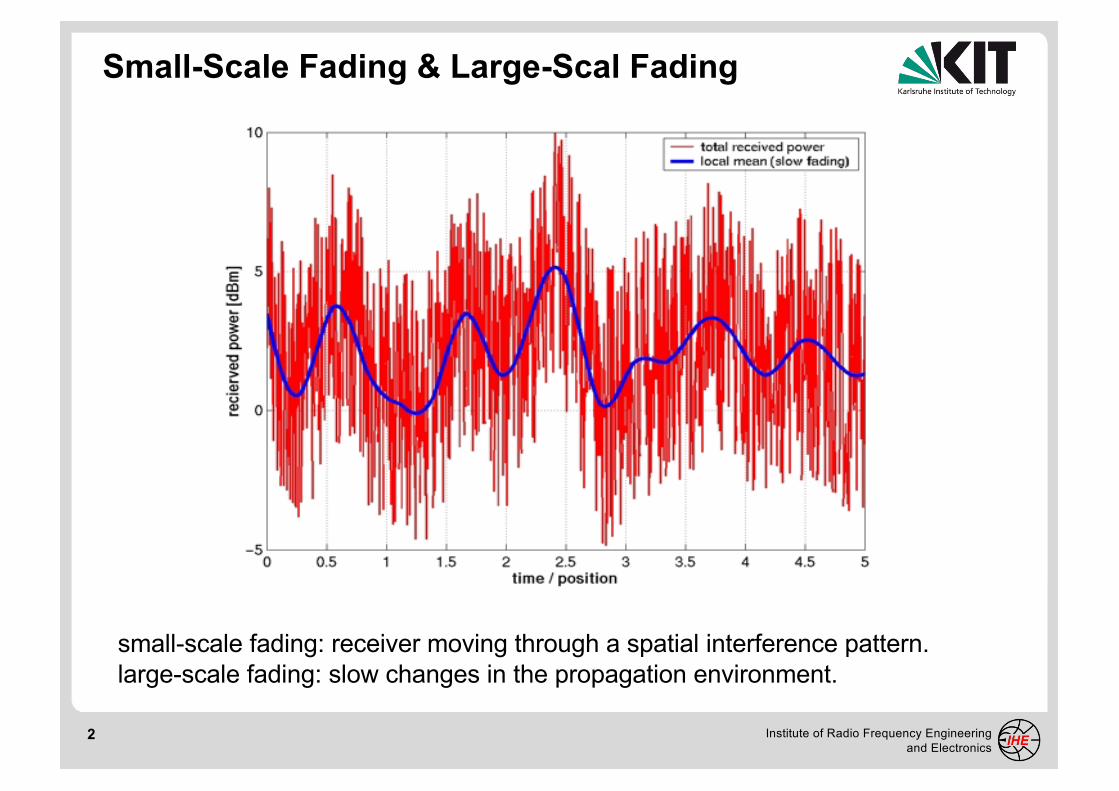
Small-Scale Fading & Large-Scal Fading
small-scale fading: receiver moving through a spatial interference pattern.large-scale fading: slow changes in the propagation environment.

3 Institute of Radio Frequency Engineering and Electronics
Multipath Effects
Multipath in the radio channel creates small-scale fading effects. This results in:
• rapid changes in signal strength over a small travel distanceor time interval
• frequency selectivity caused by multipath propagation delays• frequency modulation due to varying Doppler shifts on
different multipath signals

4 Institute of Radio Frequency Engineering and Electronics
Spatial and Temporal Variations
Consider a moving mobile station, a fixed base station and a staticenvironment, i.e. only the mobile receiver is moving. Then, the spatial
variations of the signal are seen as temporal variations by the receiver as it moves through the interference pattern
time or position
5 Institute of Radio Frequency Engineering
and Electronics
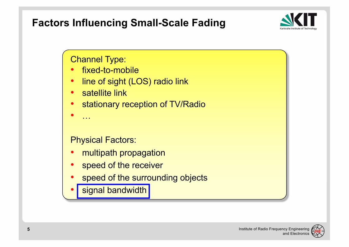
Factors Influencing Small-Scale Fading
Channel Type:
• fixed-to-mobile
• line of sight (LOS) radio link
• satellite link
• stationary reception of TV/Radio
• …
Physical Factors:
• multipath propagation
• speed of the receiver
• speed of the surrounding objects
• signal bandwidth

6 Institute of Radio Frequency Engineering and Electronics
Advanced Radio Communication I
Small-Scale Fading

7 Institute of Radio Frequency Engineering and Electronics
Small-Scale Fading f(t)Larg-Scale Fading m(t)
The Components of Fading

8 Institute of Radio Frequency Engineering and Electronics
2-Dimensional Gaussian distribution for ℜ(#$) and ℑ(#$)
'ℑ(#$()
ℜ(#$()
#$)
*)
*$
#$
ℜ(#$)
'ℑ(#$)
Superposition of Multipath Signals
#$(
*(

9 Institute of Radio Frequency Engineering and Electronics
0
0.1
0.2
0.3
0.4
0.5
0.6
0.7
0 1 2 3 4 5 6 7 8 9 10 11 12 13 14
Ricean PDF with K=SRV=0 (Rayleigh)Ricean PDF with K=SRV=0.51Ricean PDF with K=SRV=5Ricean PDF with K=SRV=50 (≈Gauß)
prob
abilit
y de
nsity
func
tion
(PD
F) [1
/Vol
t]
Probability Density Funciton
magnitude of the open circuit voltage VR

10 Institute of Radio Frequency Engineering and Electronics
Advanced Radio Communication I
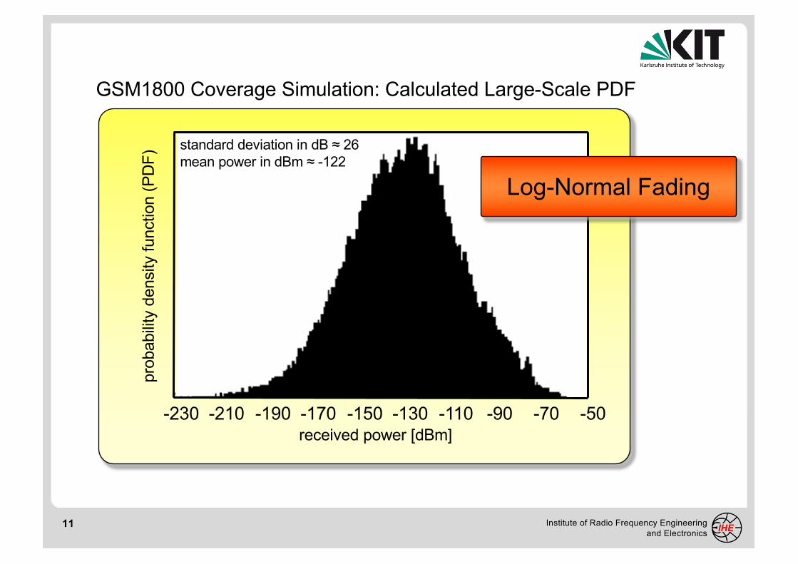
Large-Scale Fading (Log-Normal Fading)
11 Institute of Radio Frequency Engineering and Electronics
-230 -210 -190 -170 -150 -130 -110 -90 -70 -50
standard deviation in dB ≈ 26mean power in dBm ≈ -122
received power [dBm]
prob
abilit
y de
nsity
func
tion
(PD
F)
Log-Normal Fading
GSM1800 Coverage Simulation: Calculated Large-Scale PDF
12 Institute of Radio Frequency Engineering and Electronics
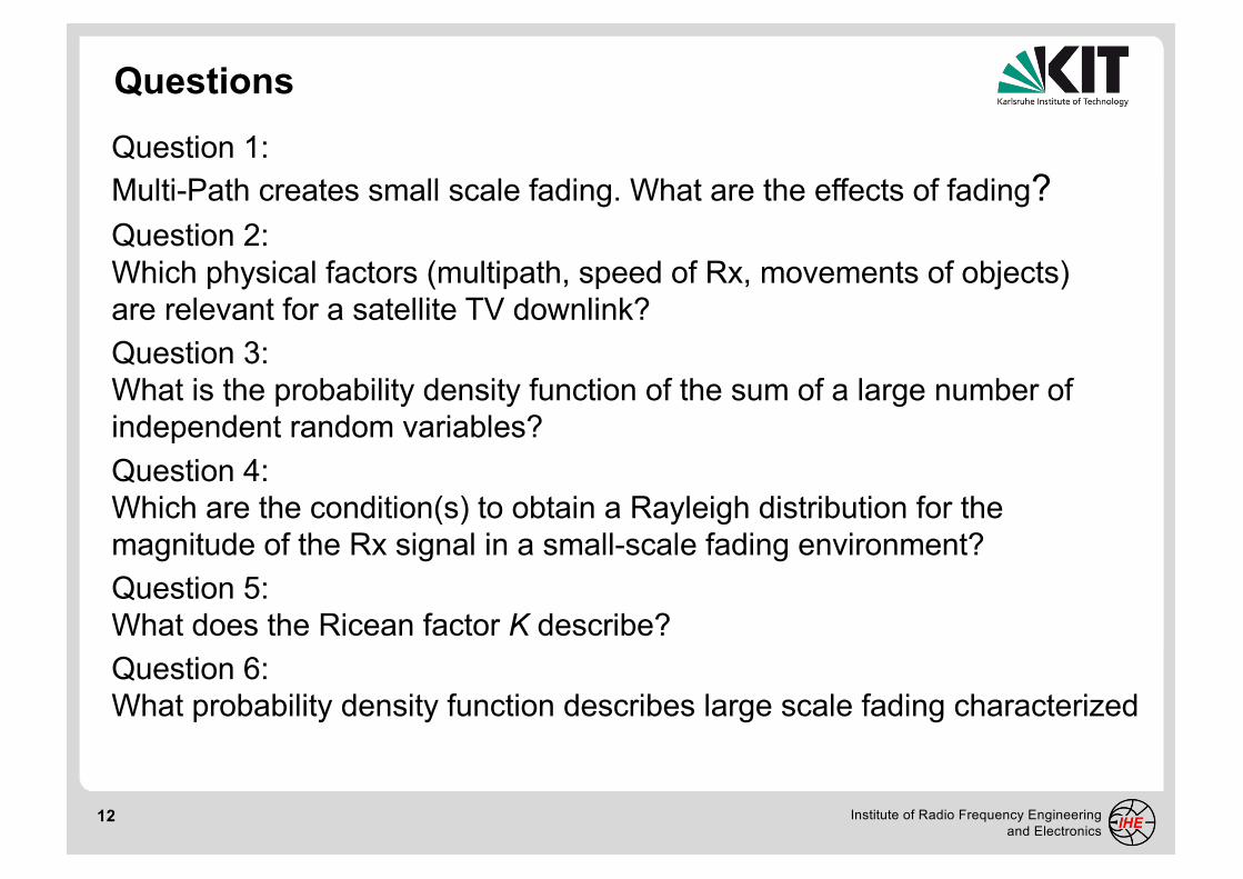
Question 1:Multi-Path creates small scale fading. What are the effects of fading?Question 2:Which physical factors (multipath, speed of Rx, movements of objects) are relevant for a satellite TV downlink?Question 3:What is the probability density function of the sum of a large number of independent random variables? Question 4:Which are the condition(s) to obtain a Rayleigh distribution for the magnitude of the Rx signal in a small-scale fading environment? Question 5:What does the Ricean factor K describe? Question 6:What probability density function describes large scale fading characterized
Questions

13 Institute of Radio Frequency Engineering and Electronics
Advanced Radio Communication I
Channel Transfer Function and Impulse Response
14 Institute of Radio Frequency Engineering and Electronics
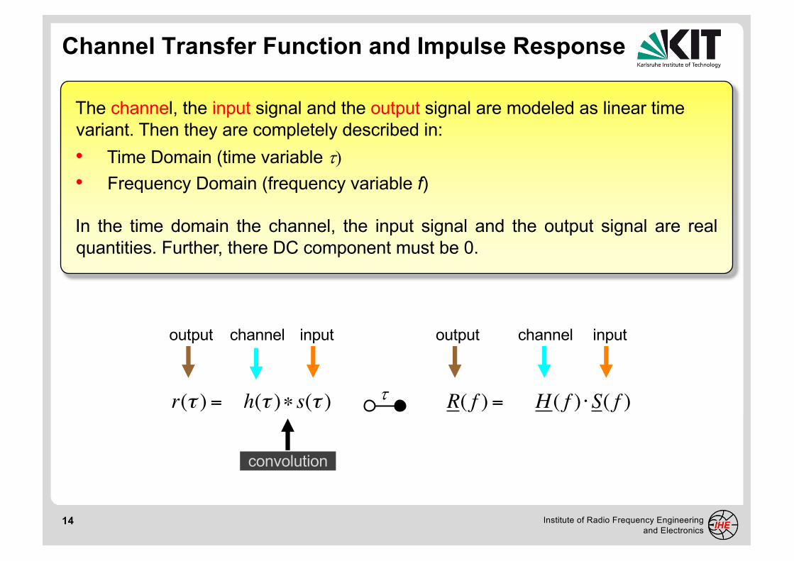
Channel Transfer Function and Impulse Response
The channel, the input signal and the output signal are modeled as linear time variant. Then they are completely described in:• Time Domain (time variable t)• Frequency Domain (frequency variable f)
In the time domain the channel, the input signal and the output signal are realquantities. Further, there DC component must be 0.
r(τ ) = h(τ )∗ s(τ )
output channel input
R( f ) = H ( f ) ⋅S( f )
output channel input
t
convolution

15 Institute of Radio Frequency Engineering and Electronics
spectrum of equivalent baseband signal
real partimaginary part
C(Δf )
f
real partimaginary part
+f0-f0
spectrum of bandpass signal for positive frequencies
spectrum of bandpass signal for negative frequencies
H ( f ) for f > 0H ( f ) for f < 0
Bandpass and Equivalent Baseband Signals

16 Institute of Radio Frequency Engineering and Electronics
Channel Transfer Function and Impulse Response
The channel, the input signal and the output signal are modeled as linear time variant. Then they are completely described in:• Time Domain (time variable t)• Frequency Domain (frequency variable f)
Since all signals are band-limited (bandpass) the equivalent (complex) basebandrepresentation can be used (known as low-pass or complex envelope)
bandpass
equivalent baseband
€
r(τ) = h(τ )∗ s(τ)
v(τ) =12c(τ )∗ x(τ)
time domain
output channel input
€
R( f ) = H( f ) ⋅ S( f )
V (Δf ) =12C(Δf ) ⋅ X(Δf )
frequency domain
output channel input
t
t
17 Institute of Radio Frequency Engineering and Electronics
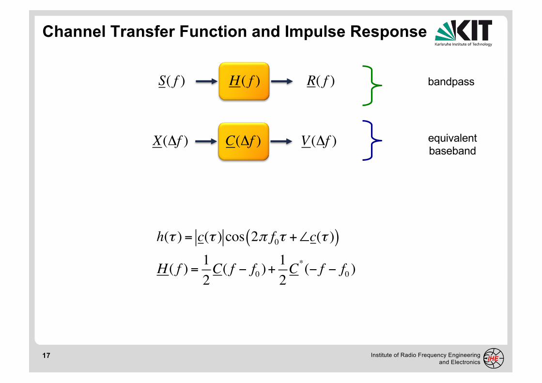
Channel Transfer Function and Impulse Response
H ( f ) R( f )S( f )
C(Δf ) V (Δf )X(Δf )
bandpass
equivalent baseband
h(τ ) = c(τ ) cos 2π f0τ +∠c(τ )( )
H ( f ) = 12C( f − f0 )+
12C*(− f − f0 )

18 Institute of Radio Frequency Engineering and Electronics
time
dom
ain
sign
al
time t in millisecond
Bandpass Signal and its Complex Envelope
19 Institute of Radio Frequency Engineering and Electronics
Characterization of the Frequency-Selective Channel
– Time Domain –

20 Institute of Radio Frequency Engineering
and Electronics
Band-Limited Impulse Response Function
0.0
0.1
0.2
0.3
0.4
0.5
0.6
0.7
0.8
0.9
1.0
1.1
1.2
1.3
50 52 54 56 58 60 62 64 66 68 70
not bandlimited
ideal filter of bandwidth B=500kHzm
agnitude o
f equiv
ale
nt baseband r
esponse
time delay parameter t [µs]
Gaussian filter, B(-20dB)=500kHz
21 Institute of Radio Frequency Engineering and Electronics
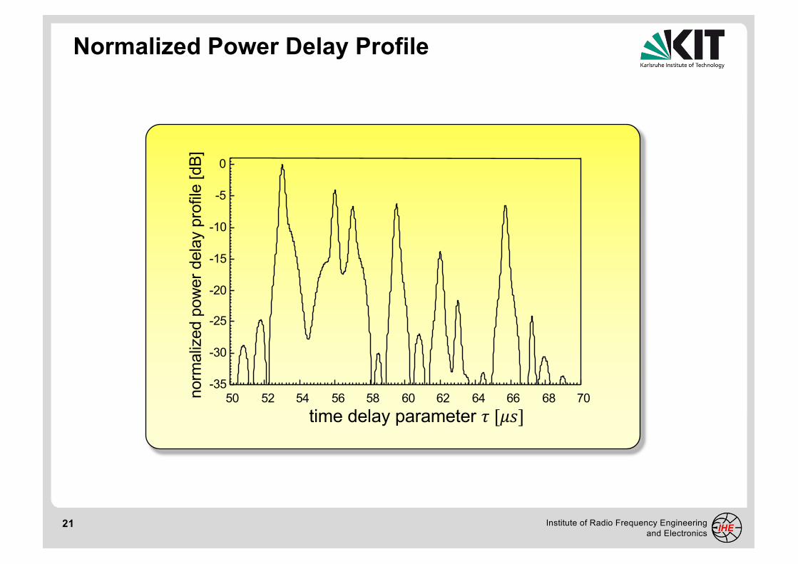
Normalized Power Delay Profile
-35
-30
-25
-20
-15
-10
-5
0
50 52 54 56 58 60 62 64 66 68 70norm
aliz
ed p
ower
del
ay p
rofil
e [d
B]
time delay parameter ! [#$]

22 Institute of Radio Frequency Engineering and Electronics
Frequency-Selective Channel
The radio channel can be characterized:• in the time domain by the impulse response• in the frequency domain by the channel transfer function
In the time domain, the characterization is based on the powerdelay profile (PDP) function which describes the relative receivedpower as a function of the delay.
In order to compare different channels, parameters whichquantify the channel are utilized. The mean excess delay and theRMS delay spread are parameters determined directly from thePDP

23 Institute of Radio Frequency Engineering and Electronics
Characterization of the Frequency-Selective Channel
– Frequency Domain –
24 Institute of Radio Frequency Engineering and Electronics
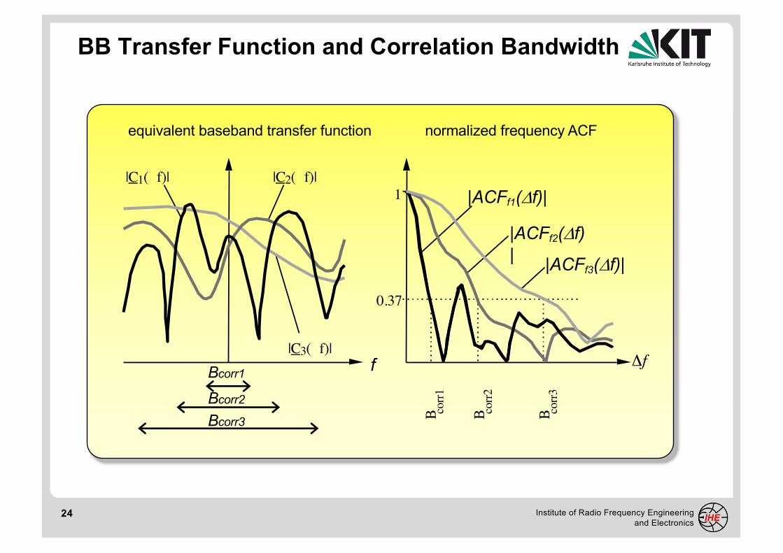
BB Transfer Function and Correlation Bandwidth
normalized frequency ACF
1
0.37
|ACFf1(Df)|
B corr1
B corr2
B corr3
equivalent baseband transfer function
|C1( f)|
|ACFf2(Df)|
|C3( f)|
|C2( f)|
|ACFf3(Df)|
Δf
Bcorr2Bcorr3
Bcorr1 f
25 Institute of Radio Frequency Engineering and Electronics
Frequency-Selective Channel
In the frequency domain, the characterization is based on thefrequency autocorrelation function (ACF) which describes overwhich frequencies the channel is flat.
In order to compare different channels, parameters whichquantify the channel are utilized. The coherence or correlationbandwidth is a parameters determined directly from thefrequency ACF

26 Institute of Radio Frequency Engineering and Electronics
Relating the Channel to the Signal
normalized frequency ACFbaseband transfer function

27 Institute of Radio Frequency Engineering and Electronics
Characterization of the Time-Variant Channel
– Time Domain –

28 Institute of Radio Frequency Engineering and Electronics
Signal Envelope and Coherence Time
normalized temporal ACFtime-varying envelope

29 Institute of Radio Frequency Engineering and Electronics
Characterization of the Time-Variant Channel
In the time domain, the characterization is based on the temporalautocorrelation function (ACF) which describes how fast thechannel changes in time.
In order to compare different channels, parameters whichquantify the channel are utilized. The coherence or correlationtime is a parameters determined directly from the temporal ACF
30 Institute of Radio Frequency Engineering and Electronics
Characterization of the Time-Variant Channel
– Frequency Domain –
31 Institute of Radio Frequency Engineering and Electronics
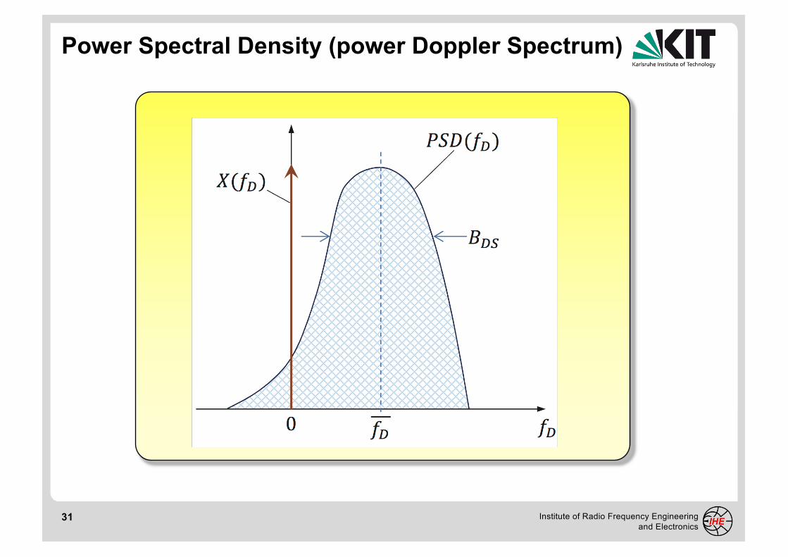
Power Spectral Density (power Doppler Spectrum)

32 Institute of Radio Frequency Engineering and Electronics
Characterization of the Time-Variant Channel
In the frequency domain, the characterization is based on thePower Spectral Density (PSD) or power Doppler spectrum(function) which is the received power spectrum for a puresinusoidal transmitted signal.
In order to compare different channels, parameters whichquantify the channel are utilized. The Doppler spread is ameasure of the spectral broadening.

33 Institute of Radio Frequency Engineering and Electronics
Signal Envelope and Coherence Time
normalized temporal ACFtime-varying envelope
34 Institute of Radio Frequency Engineering and Electronics
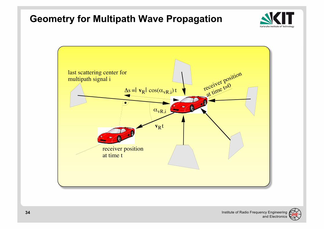
Geometry for Multipath Wave Propagation
last scattering center formultipath signal i
αvR,i
receiver positionat time t
receiver position
at time t=0
vR t
Δs =| vR| cos(αvR,i) t

35 Institute of Radio Frequency Engineering and Electronics
Jakes Doppler Spectrum
-202468
10121416
-303691215182124
-250-200-150-100 -50 0 50 100 150 200 250
Jakes spectrum (linear)Jakes spectrum (in dB)
norm
aliz
ed J
akes
spe
ctru
m (l
inea
r)norm
alized Jakes spectrum [dB]
doppler frequency [Hz]