Simple Network Design PRACTICE SESSION - IS MUNI
19
Simple Network Design PRACTICE SESSION OBJECTIVES: The goal of this practice segment is to create a simple network composing of three routers and two host end devices using the Cisco Packet Tracer software. You might remember exhibit n.4 from the theoretical part of this chapter: The network from exhibit n.4 shall be our topology for this scenario and we will try create a similar network ourselves, only with slightly altered IP addresses to better reflect the individual devices. During this task we will learn about: 1. Constructing the topology 2. Static routing 3. Dynamic routing
-
Upload
khangminh22 -
Category
Documents
-
view
0 -
download
0
Transcript of Simple Network Design PRACTICE SESSION - IS MUNI
Simple Network Design
PRACTICE SESSION
OBJECTIVES:
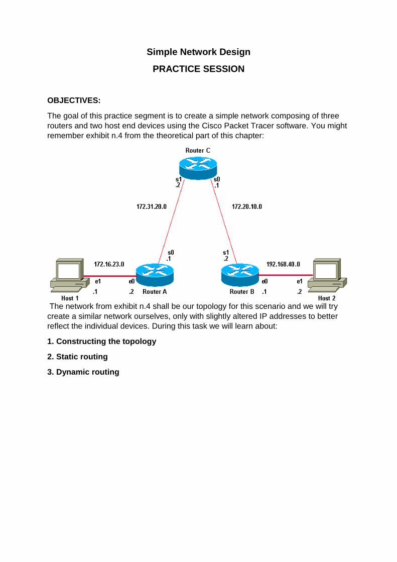
The goal of this practice segment is to create a simple network composing of three
routers and two host end devices using the Cisco Packet Tracer software. You might
remember exhibit n.4 from the theoretical part of this chapter:
The network from exhibit n.4 shall be our topology for this scenario and we will try
create a similar network ourselves, only with slightly altered IP addresses to better
reflect the individual devices. During this task we will learn about:
1. Constructing the topology
2. Static routing
3. Dynamic routing
1. Constructing the topology
Before we can begin constructing our network, we are going to have to learn the
basic principles of our router’s IOS. Once you have loaded up the Packet tracer,
observe the panel in the lower-left section of the screen.
This panel is used to add devices to the network. In this task, we shall only use
routers, end devices and two types of connections.
Select the router icon, then select the 1841 router model. Place the router
anywhere on the network.
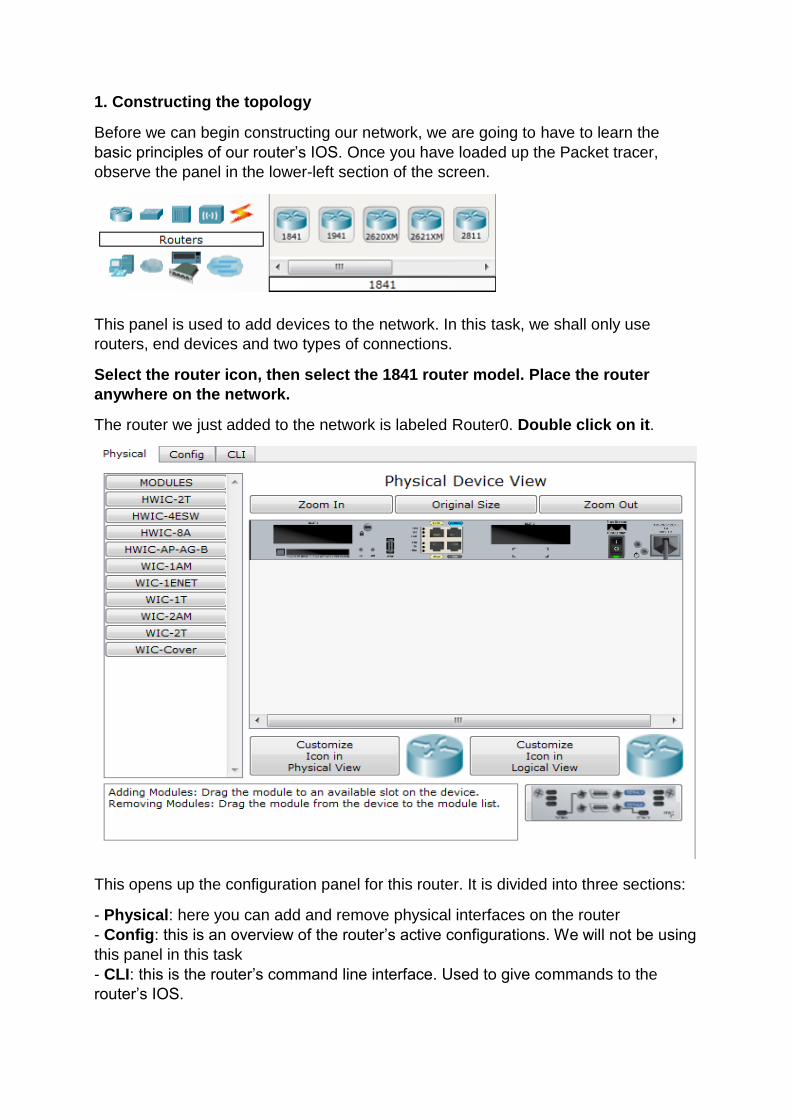
The router we just added to the network is labeled Router0. Double click on it.
This opens up the configuration panel for this router. It is divided into three sections:
- Physical: here you can add and remove physical interfaces on the router
- Config: this is an overview of the router’s active configurations. We will not be using
this panel in this task
- CLI: this is the router’s command line interface. Used to give commands to the
router’s IOS.
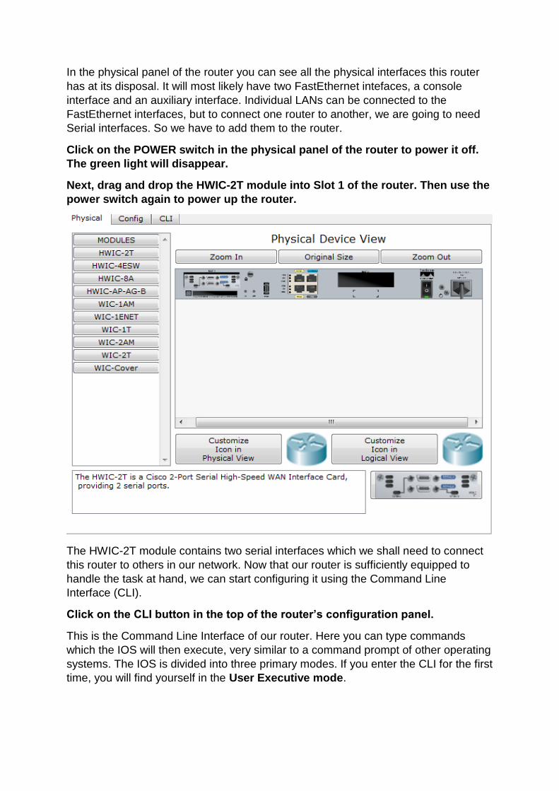
In the physical panel of the router you can see all the physical interfaces this router
has at its disposal. It will most likely have two FastEthernet intefaces, a console
interface and an auxiliary interface. Individual LANs can be connected to the
FastEthernet interfaces, but to connect one router to another, we are going to need
Serial interfaces. So we have to add them to the router.
Click on the POWER switch in the physical panel of the router to power it off.
The green light will disappear.
Next, drag and drop the HWIC-2T module into Slot 1 of the router. Then use the
power switch again to power up the router.
The HWIC-2T module contains two serial interfaces which we shall need to connect
this router to others in our network. Now that our router is sufficiently equipped to
handle the task at hand, we can start configuring it using the Command Line
Interface (CLI).
Click on the CLI button in the top of the router’s configuration panel.
This is the Command Line Interface of our router. Here you can type commands
which the IOS will then execute, very similar to a command prompt of other operating
systems. The IOS is divided into three primary modes. If you enter the CLI for the first
time, you will find yourself in the User Executive mode.
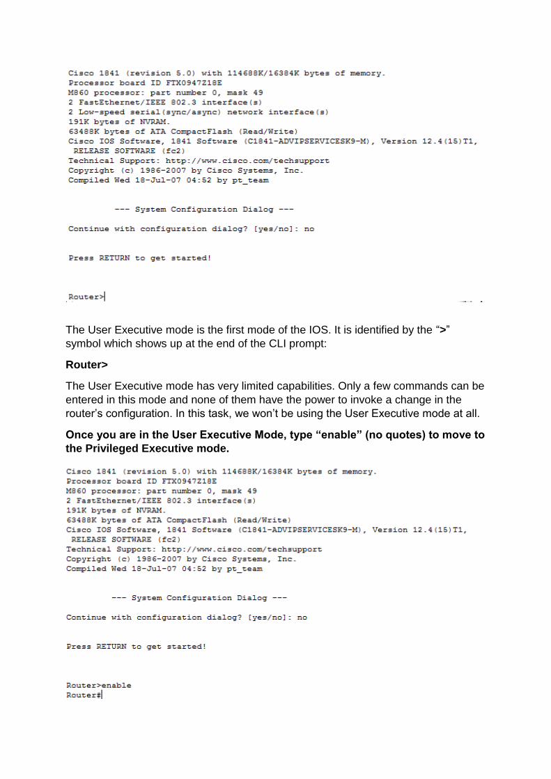
The User Executive mode is the first mode of the IOS. It is identified by the “>”
symbol which shows up at the end of the CLI prompt:
Router>
The User Executive mode has very limited capabilities. Only a few commands can be
entered in this mode and none of them have the power to invoke a change in the
router’s configuration. In this task, we won’t be using the User Executive mode at all.
Once you are in the User Executive Mode, type “enable” (no quotes) to move to
the Privileged Executive mode.
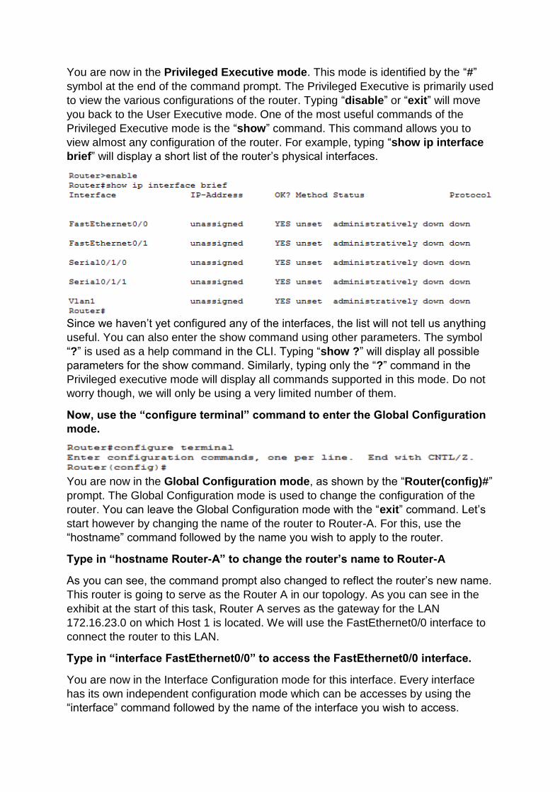
You are now in the Privileged Executive mode. This mode is identified by the “#”
symbol at the end of the command prompt. The Privileged Executive is primarily used
to view the various configurations of the router. Typing “disable” or “exit” will move
you back to the User Executive mode. One of the most useful commands of the
Privileged Executive mode is the “show” command. This command allows you to
view almost any configuration of the router. For example, typing “show ip interface
brief” will display a short list of the router’s physical interfaces.
Since we haven’t yet configured any of the interfaces, the list will not tell us anything
useful. You can also enter the show command using other parameters. The symbol
“?” is used as a help command in the CLI. Typing “show ?” will display all possible
parameters for the show command. Similarly, typing only the “?” command in the
Privileged executive mode will display all commands supported in this mode. Do not
worry though, we will only be using a very limited number of them.
Now, use the “configure terminal” command to enter the Global Configuration
mode.
You are now in the Global Configuration mode, as shown by the “Router(config)#”
prompt. The Global Configuration mode is used to change the configuration of the
router. You can leave the Global Configuration mode with the “exit” command. Let’s
start however by changing the name of the router to Router-A. For this, use the
“hostname” command followed by the name you wish to apply to the router.
Type in “hostname Router-A” to change the router’s name to Router-A
As you can see, the command prompt also changed to reflect the router’s new name.
This router is going to serve as the Router A in our topology. As you can see in the
exhibit at the start of this task, Router A serves as the gateway for the LAN
172.16.23.0 on which Host 1 is located. We will use the FastEthernet0/0 interface to
connect the router to this LAN.
Type in “interface FastEthernet0/0” to access the FastEthernet0/0 interface.
You are now in the Interface Configuration mode for this interface. Every interface
has its own independent configuration mode which can be accesses by using the
“interface” command followed by the name of the interface you wish to access.
Now that we are in this interface, we need to change its IP address so that it
becomes a part of the172.16.23.0 network.
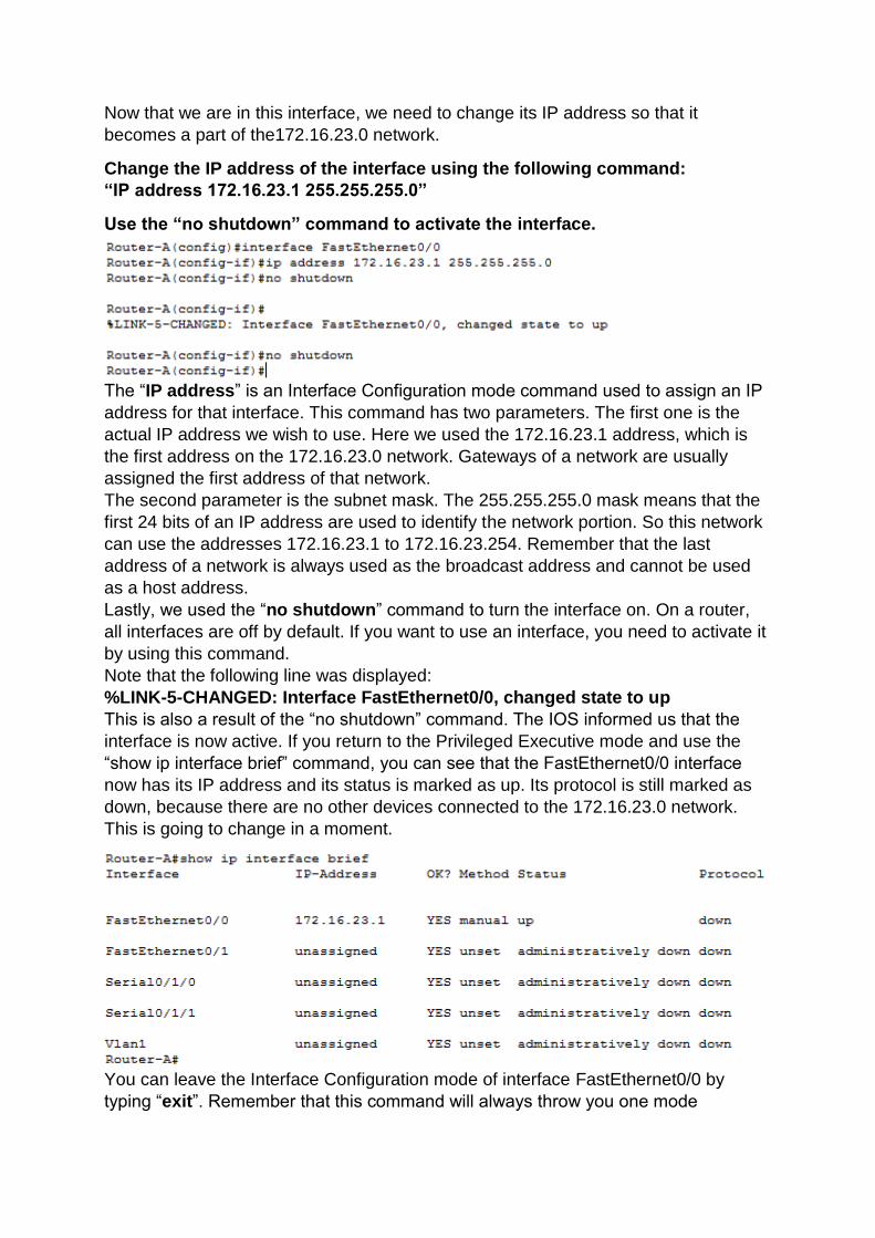
Change the IP address of the interface using the following command:
“IP address 172.16.23.1 255.255.255.0”
Use the “no shutdown” command to activate the interface.
The “IP address” is an Interface Configuration mode command used to assign an IP
address for that interface. This command has two parameters. The first one is the
actual IP address we wish to use. Here we used the 172.16.23.1 address, which is
the first address on the 172.16.23.0 network. Gateways of a network are usually
assigned the first address of that network.
The second parameter is the subnet mask. The 255.255.255.0 mask means that the
first 24 bits of an IP address are used to identify the network portion. So this network
can use the addresses 172.16.23.1 to 172.16.23.254. Remember that the last
address of a network is always used as the broadcast address and cannot be used
as a host address.
Lastly, we used the “no shutdown” command to turn the interface on. On a router,
all interfaces are off by default. If you want to use an interface, you need to activate it
by using this command.
Note that the following line was displayed:
%LINK-5-CHANGED: Interface FastEthernet0/0, changed state to up
This is also a result of the “no shutdown” command. The IOS informed us that the
interface is now active. If you return to the Privileged Executive mode and use the
“show ip interface brief” command, you can see that the FastEthernet0/0 interface
now has its IP address and its status is marked as up. Its protocol is still marked as
down, because there are no other devices connected to the 172.16.23.0 network.
This is going to change in a moment.
You can leave the Interface Configuration mode of interface FastEthernet0/0 by
typing “exit”. Remember that this command will always throw you one mode
backward. So, from Interface Configuration mode to Global Configuration mode, from
Global Configuration mode to Privileged Executive mode, etc. You can exit the CLI of
the router for now.
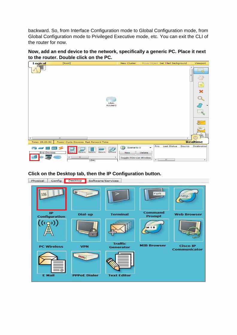
Now, add an end device to the network, specifically a generic PC. Place it next
to the router. Double click on the PC.
Click on the Desktop tab, then the IP Configuration button.
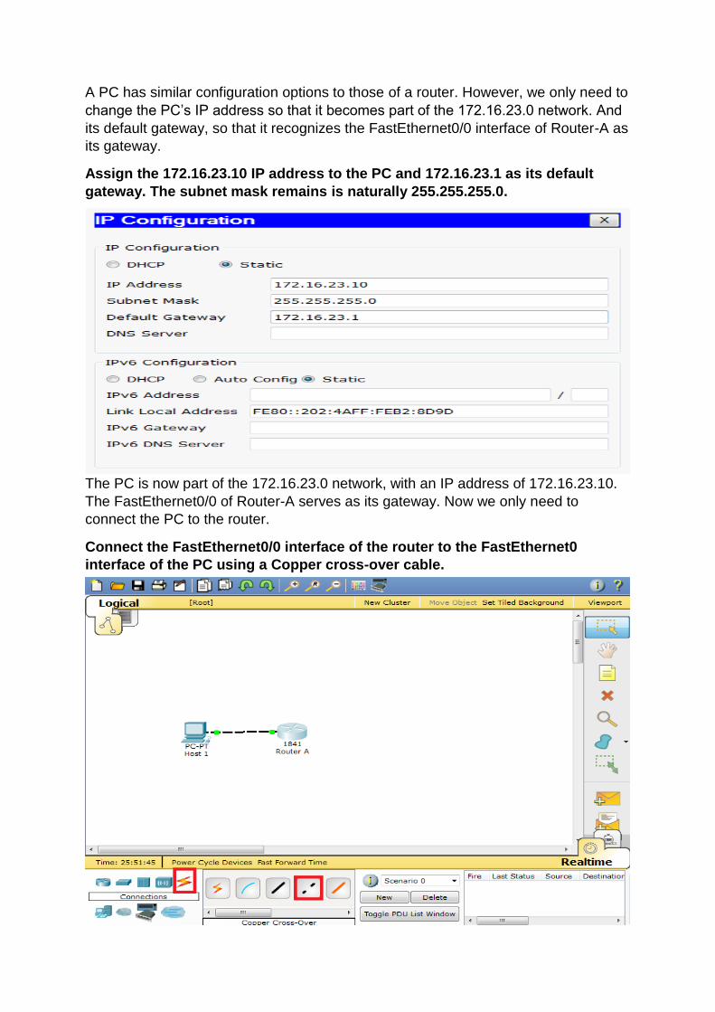
A PC has similar configuration options to those of a router. However, we only need to
change the PC’s IP address so that it becomes part of the 172.16.23.0 network. And
its default gateway, so that it recognizes the FastEthernet0/0 interface of Router-A as
its gateway.
Assign the 172.16.23.10 IP address to the PC and 172.16.23.1 as its default
gateway. The subnet mask remains is naturally 255.255.255.0.
The PC is now part of the 172.16.23.0 network, with an IP address of 172.16.23.10.
The FastEthernet0/0 of Router-A serves as its gateway. Now we only need to
connect the PC to the router.
Connect the FastEthernet0/0 interface of the router to the FastEthernet0
interface of the PC using a Copper cross-over cable.
Note that you can also rename the devices in your topology by clicking on their
names. Thus, we have renamed PC0 to Host 1 and Router0 to Router-A, to better
reflect our desired topology.
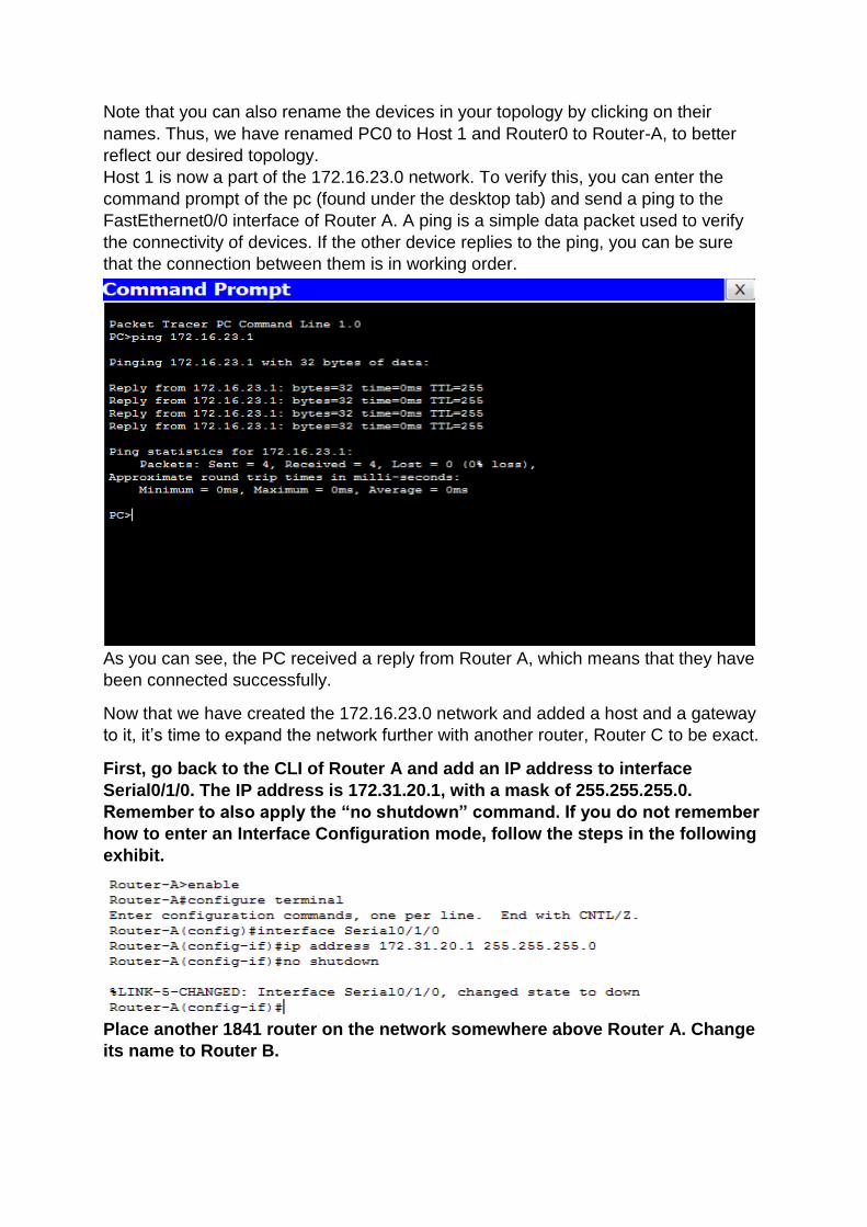
Host 1 is now a part of the 172.16.23.0 network. To verify this, you can enter the
command prompt of the pc (found under the desktop tab) and send a ping to the
FastEthernet0/0 interface of Router A. A ping is a simple data packet used to verify
the connectivity of devices. If the other device replies to the ping, you can be sure
that the connection between them is in working order.
As you can see, the PC received a reply from Router A, which means that they have
been connected successfully.
Now that we have created the 172.16.23.0 network and added a host and a gateway
to it, it’s time to expand the network further with another router, Router C to be exact.
First, go back to the CLI of Router A and add an IP address to interface
Serial0/1/0. The IP address is 172.31.20.1, with a mask of 255.255.255.0.
Remember to also apply the “no shutdown” command. If you do not remember
how to enter an Interface Configuration mode, follow the steps in the following
exhibit.
Place another 1841 router on the network somewhere above Router A. Change
its name to Router B.
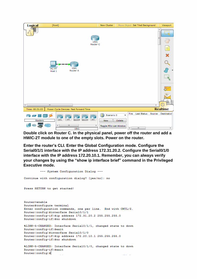
Double click on Router C. In the physical panel, power off the router and add a
HWIC-2T module to one of the empty slots. Power on the router.
Enter the router’s CLI. Enter the Global Configuration mode. Configure the
Serial0/1/1 interface with the IP address 172.31.20.2. Configure the Serial0/1/0
interface with the IP address 172.20.10.1. Remember, you can always verify
your changes by using the “show ip interface brief” command in the Privileged
Executive mode.
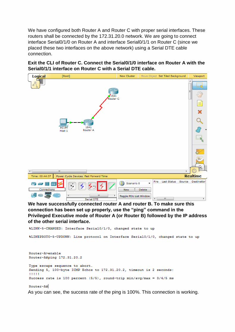
We have configured both Router A and Router C with proper serial interfaces. These
routers shall be connected by the 172.31.20.0 network. We are going to connect
interface Serial0/1/0 on Router A and interface Serial0/1/1 on Router C (since we
placed these two interfaces on the above network) using a Serial DTE cable
connection.
Exit the CLI of Router C. Connect the Serial0/1/0 interface on Router A with the
Serial0/1/1 interface on Router C with a Serial DTE cable.
We have successfully connected router A and router B. To make sure this
connection has been set up properly, use the “ping” command in the
Privileged Executive mode of Router A (or Router B) followed by the IP address
of the other serial interface.
As you can see, the success rate of the ping is 100%. This connection is working.
Next, we are going to add Router B to our network. Router B is connected to the
Serial0/1/0 interface of Router C. We already configured this interface, so now you
only need to configure the Serial0/1/1 interface on Router B (you could also configure
the other serial interface, Serial0/1/0, on router B, however it is a known practice join
different serial interfaces according to their last number, i.e an interface ending with a
0 with an interface ending with a 1). Router B is added and configured the same way
we configured the previous two routers, so by now, you should be familiar with the
steps necessary.
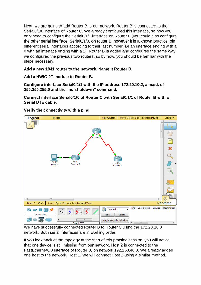
Add a new 1841 router to the network. Name it Router B.
Add a HWIC-2T module to Router B.
Configure interface Serial0/1/1 with the IP address 172.20.10.2, a mask of
255.255.255.0 and the “no shutdown” command.
Connect interface Serial0/1/0 of Router C with Serial0/1/1 of Router B with a
Serial DTE cable.
Verify the connectivity with a ping.
We have successfully connected Router B to Router C using the 172.20.10.0
network. Both serial interfaces are in working order.
If you look back at the topology at the start of this practice session, you will notice
that one device is still missing from our network. Host 2 is connected to the
FastEthernet0/0 interface of Router B, on network 192.168.40.0. We already added
one host to the network, Host 1. We will connect Host 2 using a similar method.
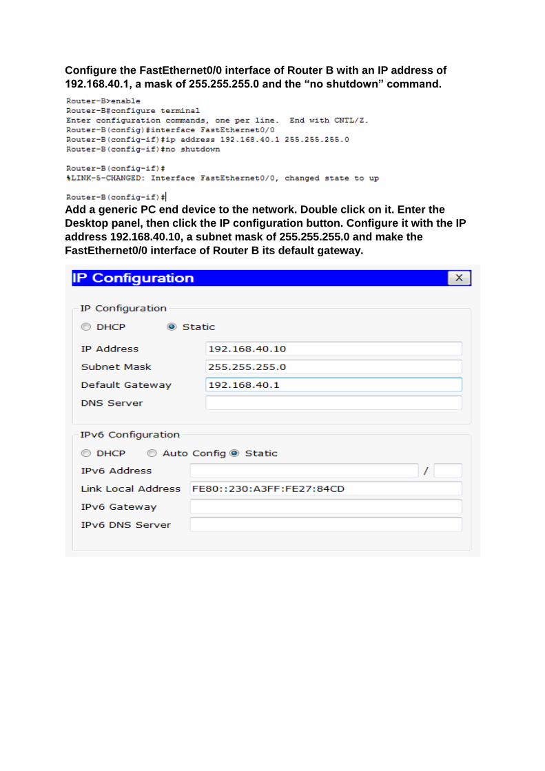
Configure the FastEthernet0/0 interface of Router B with an IP address of
192.168.40.1, a mask of 255.255.255.0 and the “no shutdown” command.
Add a generic PC end device to the network. Double click on it. Enter the
Desktop panel, then click the IP configuration button. Configure it with the IP
address 192.168.40.10, a subnet mask of 255.255.255.0 and make the
FastEthernet0/0 interface of Router B its default gateway.
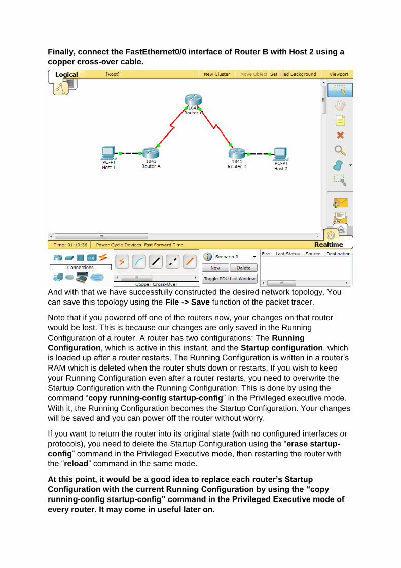
Finally, connect the FastEthernet0/0 interface of Router B with Host 2 using a
copper cross-over cable.
And with that we have successfully constructed the desired network topology. You
can save this topology using the File -> Save function of the packet tracer.
Note that if you powered off one of the routers now, your changes on that router
would be lost. This is because our changes are only saved in the Running
Configuration of a router. A router has two configurations: The Running
Configuration, which is active in this instant, and the Startup configuration, which
is loaded up after a router restarts. The Running Configuration is written in a router’s
RAM which is deleted when the router shuts down or restarts. If you wish to keep
your Running Configuration even after a router restarts, you need to overwrite the
Startup Configuration with the Running Configuration. This is done by using the
command “copy running-config startup-config” in the Privileged executive mode.
With it, the Running Configuration becomes the Startup Configuration. Your changes
will be saved and you can power off the router without worry.
If you want to return the router into its original state (with no configured interfaces or
protocols), you need to delete the Startup Configuration using the “erase startup-
config” command in the Privileged Executive mode, then restarting the router with
the “reload” command in the same mode.
At this point, it would be a good idea to replace each router’s Startup
Configuration with the current Running Configuration by using the “copy
running-config startup-config” command in the Privileged Executive mode of
every router. It may come in useful later on.
2. Static Routing
Although our network is up and running, you will find that it is far from complete. You
already know that every device on a network keeps track of other directly-connected
devices and adds them to their routing table. However, they know nothing about
devices which are more than one hop away. In our network, Host 1 is able to
communicate with Router A, because it considers it a directly-connected device, not
to mention its gateway. Unfortunately, the same cannot be said about Host 1 and
Host 2.
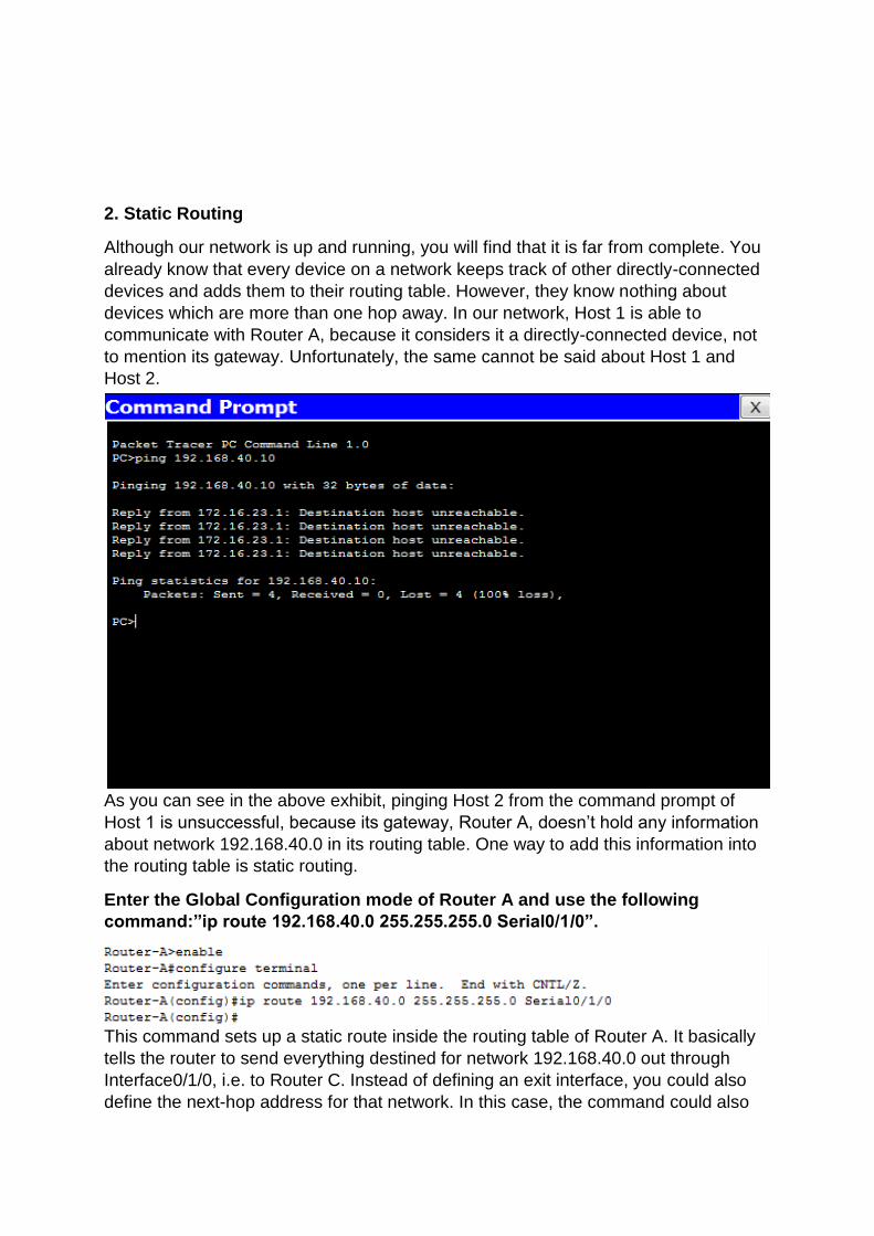
As you can see in the above exhibit, pinging Host 2 from the command prompt of
Host 1 is unsuccessful, because its gateway, Router A, doesn’t hold any information
about network 192.168.40.0 in its routing table. One way to add this information into
the routing table is static routing.
Enter the Global Configuration mode of Router A and use the following
command:”ip route 192.168.40.0 255.255.255.0 Serial0/1/0”.
This command sets up a static route inside the routing table of Router A. It basically
tells the router to send everything destined for network 192.168.40.0 out through
Interface0/1/0, i.e. to Router C. Instead of defining an exit interface, you could also
define the next-hop address for that network. In this case, the command could also
be formulated as:”ip route 192.168.40.0 255.255.255.0 172.31.20.2”. As you know,
172.31.20.2 is the address of interface Serial0/1/1 of Router C. These two commands
are synonymous and have the exact same effect for Router A, so it doesn’t matter
which one you choose.
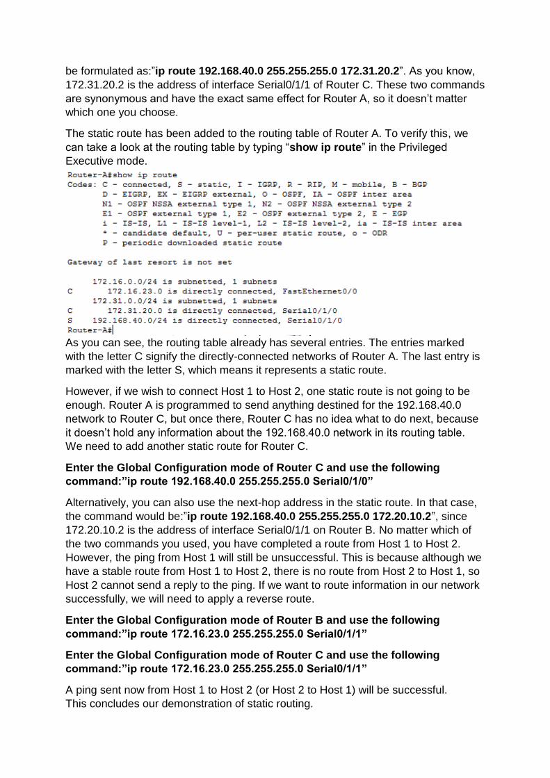
The static route has been added to the routing table of Router A. To verify this, we
can take a look at the routing table by typing “show ip route” in the Privileged
Executive mode.
As you can see, the routing table already has several entries. The entries marked
with the letter C signify the directly-connected networks of Router A. The last entry is
marked with the letter S, which means it represents a static route.
However, if we wish to connect Host 1 to Host 2, one static route is not going to be
enough. Router A is programmed to send anything destined for the 192.168.40.0
network to Router C, but once there, Router C has no idea what to do next, because
it doesn’t hold any information about the 192.168.40.0 network in its routing table.
We need to add another static route for Router C.
Enter the Global Configuration mode of Router C and use the following
command:”ip route 192.168.40.0 255.255.255.0 Serial0/1/0”
Alternatively, you can also use the next-hop address in the static route. In that case,
the command would be:”ip route 192.168.40.0 255.255.255.0 172.20.10.2”, since
172.20.10.2 is the address of interface Serial0/1/1 on Router B. No matter which of
the two commands you used, you have completed a route from Host 1 to Host 2.
However, the ping from Host 1 will still be unsuccessful. This is because although we
have a stable route from Host 1 to Host 2, there is no route from Host 2 to Host 1, so
Host 2 cannot send a reply to the ping. If we want to route information in our network
successfully, we will need to apply a reverse route.
Enter the Global Configuration mode of Router B and use the following
command:”ip route 172.16.23.0 255.255.255.0 Serial0/1/1”
Enter the Global Configuration mode of Router C and use the following
command:”ip route 172.16.23.0 255.255.255.0 Serial0/1/1”
A ping sent now from Host 1 to Host 2 (or Host 2 to Host 1) will be successful.
This concludes our demonstration of static routing.
3. Dynamic routing
Before we continue on to dynamic routing, we need to clean up the static routes we
have configured on our devices. This is done simply by typing the same commands
again, but this time starting with the “no” prefix. For example: using the “no ip route
192.168.40.0 255.255.255.0 Serial0/1/0” command on Route A will delete the static
route we configured for that router. Alternatively, if you saved your Running
Configuration before we started configuring the static routes, you can simply use the
“reload” command in the Privileged Executive mode of every router. This will delete
the current Running Configuration (with the static routes) and load up the Startup
Configuration (before static routes) again. Use of these methods to remove the static
routing information from the routing tables of our routers.
Static routing is very efficient when the number of routers in your network is limited.
However, setting up multiple static routes for hundreds of routers can be difficult,
especially when adding new routers to existing networks. This time, we are going to
use RIP version 1, a distance vector dynamic routing protocol, to fill up the routing
tables of our routers.
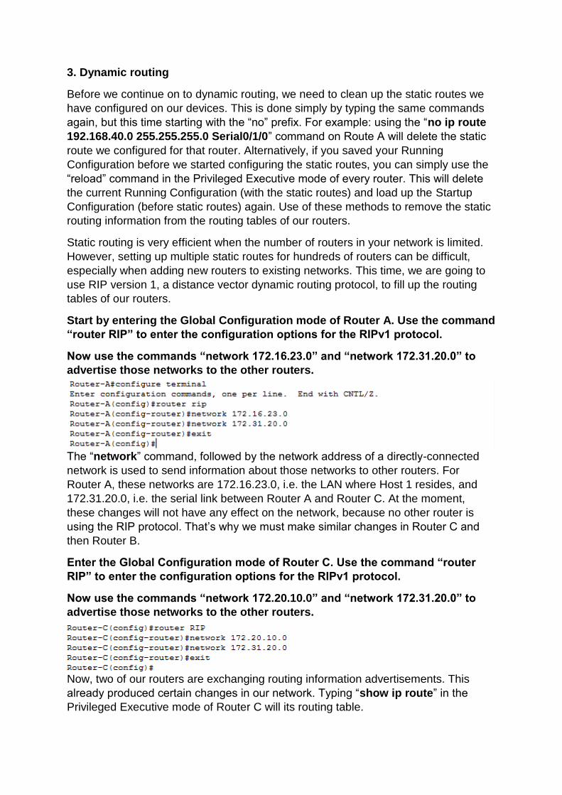
Start by entering the Global Configuration mode of Router A. Use the command
“router RIP” to enter the configuration options for the RIPv1 protocol.
Now use the commands “network 172.16.23.0” and “network 172.31.20.0” to
advertise those networks to the other routers.
The “network” command, followed by the network address of a directly-connected
network is used to send information about those networks to other routers. For
Router A, these networks are 172.16.23.0, i.e. the LAN where Host 1 resides, and
172.31.20.0, i.e. the serial link between Router A and Router C. At the moment,
these changes will not have any effect on the network, because no other router is
using the RIP protocol. That’s why we must make similar changes in Router C and
then Router B.
Enter the Global Configuration mode of Router C. Use the command “router
RIP” to enter the configuration options for the RIPv1 protocol.
Now use the commands “network 172.20.10.0” and “network 172.31.20.0” to
advertise those networks to the other routers.
Now, two of our routers are exchanging routing information advertisements. This
already produced certain changes in our network. Typing “show ip route” in the
Privileged Executive mode of Router C will its routing table.
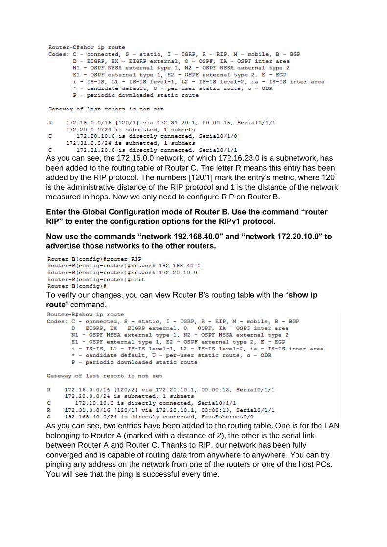
As you can see, the 172.16.0.0 network, of which 172.16.23.0 is a subnetwork, has
been added to the routing table of Router C. The letter R means this entry has been
added by the RIP protocol. The numbers [120/1] mark the entry’s metric, where 120
is the administrative distance of the RIP protocol and 1 is the distance of the network
measured in hops. Now we only need to configure RIP on Router B.
Enter the Global Configuration mode of Router B. Use the command “router
RIP” to enter the configuration options for the RIPv1 protocol.
Now use the commands “network 192.168.40.0” and “network 172.20.10.0” to
advertise those networks to the other routers.
To verify our changes, you can view Router B’s routing table with the “show ip
route” command.
As you can see, two entries have been added to the routing table. One is for the LAN
belonging to Router A (marked with a distance of 2), the other is the serial link
between Router A and Router C. Thanks to RIP, our network has been fully
converged and is capable of routing data from anywhere to anywhere. You can try
pinging any address on the network from one of the routers or one of the host PCs.
You will see that the ping is successful every time.
There is one last command which may come in handy when using the RIP protocol.
As you know, a router using RIP sends regular advertisements to other routers on the
network. This is done by sending such advertisements through all the interfaces of a
router. However, you can imagine that sending them through a LAN interface is quite
useless, as there are certainly no routers inside a local area network. Thus, you can
use the “passive-interface” command followed by a specific interface to stop RIP
advertisements from passing through that interface.
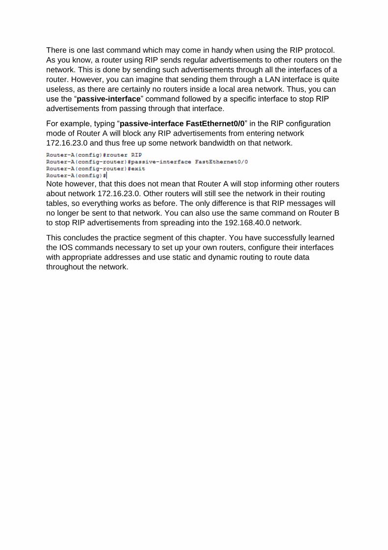
For example, typing “passive-interface FastEthernet0/0” in the RIP configuration
mode of Router A will block any RIP advertisements from entering network
172.16.23.0 and thus free up some network bandwidth on that network.
Note however, that this does not mean that Router A will stop informing other routers
about network 172.16.23.0. Other routers will still see the network in their routing
tables, so everything works as before. The only difference is that RIP messages will
no longer be sent to that network. You can also use the same command on Router B
to stop RIP advertisements from spreading into the 192.168.40.0 network.
This concludes the practice segment of this chapter. You have successfully learned
the IOS commands necessary to set up your own routers, configure their interfaces
with appropriate addresses and use static and dynamic routing to route data
throughout the network.