
Silicon Sculptor Software Programmer User's Guide - Microsemi
126
Silicon Sculptor Software v5.0 for Silicon Sculptor II and Silicon Sculptor 3 Programmer User’s Guide NOTE: PDF files are intended to be viewed on the printed page; links and cross-references in this PDF file may point to external files and generate an error when clicked. View the online help included with software to enable all linked content.
-
Upload
khangminh22 -
Category
Documents
-
view
0 -
download
0
Transcript of Silicon Sculptor Software Programmer User's Guide - Microsemi

Silicon Sculptor Software v5.0 for Silicon Sculptor II and Silicon Sculptor 3
Programmer User’s Guide NOTE: PDF files are intended to be viewed on the printed page; links and cross-references in this PDF file may point to external files and generate an error when clicked. View the online help included with software to enable all linked content.
Silicon Sculptor Software Programmer User's Guide
Silicon Sculptor Software Programmer User's Guide 3
NOTE: Links and cross-references in this PDF file may point to external files and generate an error when clicked. View the online help included with software to enable all linked content.
Table of Contents
Getting Started ............................................................................................... 7 About Silicon Sculptor Software (SculptW) ................................................................................ 8 About Silicon Sculptor 3 ............................................................................................................. 9 About Silicon Sculptor II ........................................................................................................... 10 Installation Requirements ........................................................................................................ 11 Compatibility ............................................................................................................................. 12 Software Installation ................................................................................................................. 13 Hardware Installation ............................................................................................................... 14 USB 2.0 Initial Setup ................................................................................................................ 16 Prebroadcast for RTAX and Axcelerator Devices .................................................................... 17
SculptW Software GUI ................................................................................. 19 SculptW Software Introduction ................................................................................................. 20 File Menu ................................................................................................................................. 22 Device Menu ............................................................................................................................ 25 Tools Menu .............................................................................................................................. 27 JobMaster Menu ...................................................................................................................... 29 Help Menu ................................................................................................................................ 31 Action Window ......................................................................................................................... 32 Button Description .................................................................................................................... 34 Command Tabs ........................................................................................................................ 36 Status Bar ................................................................................................................................ 39 Toolbar ..................................................................................................................................... 40 Keyboard and Hotkeys ............................................................................................................. 41
Using File Formats....................................................................................... 43 BIT File Format ........................................................................................................................ 44 STAPL File Format ................................................................................................................... 45 AFM File Format ...................................................................................................................... 46
Software Basics ........................................................................................... 47 Selecting a Device ................................................................................................................... 48 Loading a Data Pattern Programming File .............................................................................. 50 Data Pattern Information .......................................................................................................... 53 Placing a Chip in the Socket .................................................................................................... 55 Antifuse Programming ............................................................................................................. 56 Continuity Test ......................................................................................................................... 62 ACT 1 or 40MX Security Fuse Configurations ......................................................................... 64 Non-Act 1 or 40MX Security Fuse Configurations ................................................................... 66 Flash Programming a Bit or STAPL File .................................................................................. 67 Flash Programming with a STAPL File .................................................................................... 71 Programming ProASIC3 and Fusion Devices .......................................................................... 74
Table of Contents
4 Silicon Sculptor Software Programmer User's Guide
Multi-Site Programming .............................................................................. 75 Multi-site Programming ............................................................................................................ 76 Individual System Diagnostic Self-Test.................................................................................... 77 Multi-Site Setup ........................................................................................................................ 78 Executing Concurrent Operation .............................................................................................. 79 Silicon Sculptor I Multi-Site Programming ............................................................................... 80
JobMaster Mode .......................................................................................... 84 JobMaster Mode Introduction .................................................................................................. 85 Creating a New Job.................................................................................................................. 86 Updating a Job ......................................................................................................................... 87 Locking the Programmer in Operator Mode ............................................................................ 88 Running a Job in Operator Mode ............................................................................................. 89 Returning to Normal (Supervisor Mode) .................................................................................. 90
Troubleshooting .......................................................................................... 91 Contacting Technical Support .................................................................................................. 92 Testing Hardware ..................................................................................................................... 93 Software Updates ..................................................................................................................... 95 Frequently Asked Questions (FAQs) ....................................................................................... 96 Programming Errors ................................................................................................................. 98 Cleaning a Dirty DIP Socket .................................................................................................... 99 Error Messages and Suggested Actions ............................................................................... 100 Exit Codes and Messages - All Families................................................................................ 109 RTAX-S/D Exit Codes and Messages ................................................................................... 110 eX/SX-A Exit Codes and Messages ...................................................................................... 112 42MX Exit Codes and Messages ........................................................................................... 113 40MX Exit Codes and Messages ........................................................................................... 115
Technical Specifications ........................................................................... 116 Silicon Sculptor III Technical Specifications .......................................................................... 117 Silicon Sculptor Memory Components ................................................................................... 118
Appendix A ................................................................................................. 119 Act_Verify Flow Diagram ....................................................................................................... 120 AVI TXT Log Files in Silicon Sculptor .................................................................................... 121
Contacting Microsemi ............................................................................... 122 Microsemi Headquarters ........................................................................................................ 123 Technical Support .................................................................................................................. 124 Customer Service ................................................................................................................... 125 Sales ...................................................................................................................................... 126 Documentation Feedback ...................................................................................................... 127
Product Support ........................................................................................ 129

Silicon Sculptor Software Programmer User's Guide 7
NOTE: Links and cross-references in this PDF file may point to external files and generate an error when clicked. View the online help included with software to enable all linked content.
Getting Started

8 Silicon Sculptor Software Programmer User's Guide
NOTE: Links and cross-references in this PDF file may point to external files and generate an error when clicked. View the online help included with software to enable all linked content.
About Silicon Sculptor Software (SculptW) The Silicon Sculptor software (SculptW) is designed to operate with both Silicon Sculptor II (older, parallel port based programmer) and Silicon Sculptor 3 (newer USB 2.0 based programmer). The online help was originally designed for Silicon Sculptor II usage only and is being augmented for Silicon Sculptor 3 usage. Concurrent programming from a single PC can only support a maximum of two Silicon Sculptor II programmers connected to a single PC, and the adapter modules on both programmers must be identical. You can connect Silicon Sculptor 3 programmers via a powered USB hub to a single PC (you can connect up to 12 programmers to a single PC). All the adapter modules on such a concurrent chain must be identical. Note: Note: Your computer must not enter Sleep mode during programming or your programming may fail.

Silicon Sculptor Software Programmer User's Guide 9
About Silicon Sculptor 3 Silicon Sculptor 3 includes a high-speed USB 2.0 interface that allows a customer to connect as many as 12 programmers to a single PC. Further, Silicon Sculptor 3 is compatible with adapter modules from Silicon Sculptor II, thereby preserving a customer’s investment and enabling a seamless upgrade to future generations of the tool. Silicon Sculptor 3 is a low-cost and reliable programmer for Microsemi’s portfolio of FPGAs, including the Fusion Programmable System Chip (PSC), ProASIC3 and ProASIC3/E flash-based devices, and ARM-enabled versions of these devices. It also supports all antifuse products, including Axcelerator and the high-density, high-reliability RTAX4000S device. Leveraging an Axcelerator antifuse device at the heart of the system, Silicon Sculptor 3 offers increased memory size and faster data processing compared to previous Microsemi programmers. With 64 MB of internal memory, Silicon Sculptor 3 allows concurrent programming of large parts without performance degradation and supports the larger algorithms of planned future parts. As many as 12 Silicon Sculptor 3 systems can be connected to a single PC through a nested set of high-speed USB 2.0 hubs to enable an easily expandable, low-cost programming system. The programmers also support advanced pin drivers that incorporate high-speed circuitry to deliver unparalleled programming and testing performance. Much like expensive IC testers, the programmer uses high-speed bipolar analog pin drivers with microstrip transmission lines to deliver 800 ps rise times at the programming socket, without overshoot or ground bounce. Each programmer has 240 pin drivers standard to allow complete continuity and functionality testing is available on every pin before programming begins, saving time and money, and eliminating frustration. Note: Note: The Silicon Sculptor 3 programmer has nonvolatile memory. See Technical Specifications for
detailed information. An optional In-House Programming (IHP) service is available if you are purchasing Microsemi devices in volume. Contact Microsemi for more information.

10 Silicon Sculptor Software Programmer User's Guide
NOTE: Links and cross-references in this PDF file may point to external files and generate an error when clicked. View the online help included with software to enable all linked content.
About Silicon Sculptor II Silicon Sculptor II is a robust, compact, single-device programmer with standalone software for the PC. It is designed to allow concurrent programming of multiple units from the same PC, with speeds equivalent to or faster than those of Microsemi's previous programmers. Note: Note: The Silicon Sculptor II programmer has nonvolatile memory. See Technical Specifications for
detailed information. An optional In-House Programming (IHP) service is available if you are purchasing Microsemi devices in volume. Contact Microsemi for more information.

Silicon Sculptor Software Programmer User's Guide 11
Installation Requirements For Windows 2000/XP systems, Administration rights to the local workstation are required both for installation and for at least one launch of SculptW after installation. See the readme file in the SculptW installation folder for detailed information.

12 Silicon Sculptor Software Programmer User's Guide
NOTE: Links and cross-references in this PDF file may point to external files and generate an error when clicked. View the online help included with software to enable all linked content.
Compatibility The SculptW software is designed to operate with any PC that meets the following minimum system requirements: • Windows 2000 with SP1 (SP4 is recommended) • Windows XP with SP1 (SP2 is recommended) • Pentium 200 or higher processor (Pentium III or higher is recommended) • 64 MB of available memory (1 GB is recommended) • 50 MB of available hard disk space • SVGA 256-color and 800x600 or higher resolution recommended for video adapter • One of the following ports is required: • Parallel printer port (LPT1, LPT2, or LPT3) is required for Silicon Sculptor II programmer usage • USB 2.0 port is required for Silicon Sculptor 3 programmer usage • CD-ROM drive and a hard disk • Microsoft Mouse or compatible pointing device
Note: For Windows 2000 and Windows XP systems, you must have administrative rights to the local workstation for installation purposes and for at least one launch of SculptW after installation. You must have Full Control permissions for the following registry keys and all subkeys:
HKEY_LOCAL_MACHINE\Software\BP Microsystems
HKEY_CURRENT_USER\Software\BP Microsystems\SculptW
Silicon Sculptor Software Programmer User's Guide 13
Software Installation SculptW is downloaded from the internet. Starting with SculptW 4.7X, multiple SculptW versions can exist on the PC. Follow the instructions below to install SculptW on your computer.
To install the software from the Internet download and not retain earlier versions: 1. Go to http://www.microsemi.com/products/fpga-soc/design-resources/programming/silicon-sculptor-
3#downloads and download the latest Windows version of Silicon Sculptor (SculptW) programming software.
2. When prompted, choose the drive and directory in which you want to save the self-extracting EXE file. Once the download is complete, double-click the EXE file to install the software.
To install the latest software from the Internet download and retain existing SculptW versions: 1. Go to http://www.microsemi.com/products/fpga-soc/design-resources/programming/silicon-sculptor-
3#downloads and download the latest Windows version of Silicon Sculptor (SculptW) programming software.
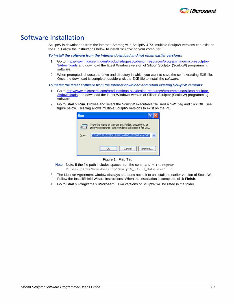
2. Go to Start > Run. Browse and select the SculptW executable file. Add a "-P" flag and click OK. See figure below. This flag allows multiple SculptW versions to exist on the PC.
Figure 1 · Flag Tag
Note: Note: If the file path includes spaces, run the command "C:\Program Files\FolderName\Desktop\SculptW_v4700_Date.exe" –P.
3. The License Agreement window displays and does not ask to uninstall the earlier version of SculptW. Follow the InstallShield Wizard instructions. When the installation is complete, click Finish.
4. Go to Start > Programs > Microsemi. Two versions of SculptW will be listed in the folder.
http://www.microsemi.com/products/fpga-soc/design-resources/programming/silicon-sculptor-3#downloads
http://www.microsemi.com/products/fpga-soc/design-resources/programming/silicon-sculptor-3#downloads

14 Silicon Sculptor Software Programmer User's Guide
NOTE: Links and cross-references in this PDF file may point to external files and generate an error when clicked. View the online help included with software to enable all linked content.
Hardware Installation After you unpack the equipment, you are ready to connect the Silicon Sculptor II or Silicon Sculptor 3 programmer to your PC. Note: Note: Do not invoke SculptW before the programmer’s power-on self test is completed. If you do so,
the software displays in “Demo Mode”. You cannot perform any programming operations in Demo Mode.
To connect the Silicon Sculptor II programmer to your PC: 1. Connect the programmer to a parallel printer port on your PC. Connect one end of the cable to the
programmer’s connector and tighten the screws. Plug the other end of the cable into your parallel printer port.
2. Verify that you have connected to the correct parallel port on your computer.
Note: Microsemi recommends that you dedicate a port to the programmer. Connecting to a serial port or third-party card can damage the programmer. This type of damage is not covered by the warranty.
3. Plug the programmer AC power cord into a power socket.
The Silicon Sculptor II power supply operates from 90 to 250 VAC for simplified worldwide use. 4. Turn on the computer and programmer. Both the green Power LED and the yellow Active LED on the
programmer site will light up.
Silicon Sculptor II is performing a power-on self-test when the Active LED is on. After a minute or two, the yellow Active LED will turn off and only the green Power LED will remain on. If the red Fail LED turns on, the Silicon Sculptor II programmer has detected an error during the power-on self-test. If this occurs, call the Microsemi technical support line. See Contacting the Customer Technical Support Center for a complete list of technical support options. The software will not recognize the Silicon Sculptor II programmer as being connected if you have a Silicon Sculptor 3 programmer connected to the USB port; the Silicon Sculptor 3 programmer will take precedence and will be the only programmer recognized. Disconnect all Silicon Sculptor 3 programmers prior to connecting the Silicon Sculptor II programmer if you wish to use it. Do not use non-standard hardware with the Silicon Sculptor programmer when attempting programming; only use Microsemi-approved adapter modules and cables. Licensing dongles should never be attached to the parallel port during programming as they may interfere with programming and could potentially cause damage to the parts being programmed.
Note: The SculptW software v4.59.2 or later is required to recognize the Silicon Sculptor 3 programmer.
To connect the Silicon Sculptor 3 programmer to your PC: 1. Connect the programmer to a USB 2.0 port on your PC. 2. Connect one end of the USB cable to the programmer’s connector and plug the other end of the cable
into your PC’s USB port. 3. Plug the programmer AC power cord into a power socket.
The Silicon Sculptor 3 power supply operates from 90 to 250 VAC for simplified worldwide use. 4. Turn on the computer and programmer. Both the green Power LED and the yellow Active LED on the
programmer site will light up.
Silicon Sculptor 3 is performing a power-on self-test when the Active LED is on. The yellow Active LED will turn off and only the green Power LED will remain on. If the red Fail LED turns on, the Silicon Sculptor 3 programmer has detected an error during the power-on self-test. If this occurs, call the Microsemi technical support line. See Contacting the Customer Technical Support Center for a complete list of technical support options.
Note: Note: Do not use non-standard hardware with this programmer when attempting programming; only use Microsemi-approved adapter modules and cables. Licensing dongles should never be attached to the parallel port during programming as they may interfere with programming and could potentially cause damage to the parts being programmed.

Silicon Sculptor Software Programmer User's Guide 15
Note: When a computer has both a parallel port and a USB 2.0 port, only connect either Silicon Sculptor II programmers or Silicon Sculptor 3 programmers. Do not mix programmer types attached to the same PC.
16 Silicon Sculptor Software Programmer User's Guide
NOTE: Links and cross-references in this PDF file may point to external files and generate an error when clicked. View the online help included with software to enable all linked content.
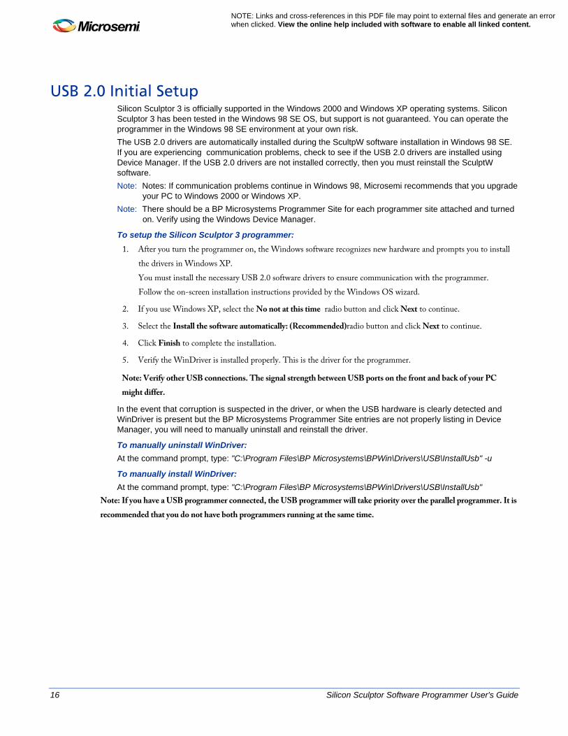
USB 2.0 Initial Setup Silicon Sculptor 3 is officially supported in the Windows 2000 and Windows XP operating systems. Silicon Sculptor 3 has been tested in the Windows 98 SE OS, but support is not guaranteed. You can operate the programmer in the Windows 98 SE environment at your own risk. The USB 2.0 drivers are automatically installed during the ScultpW software installation in Windows 98 SE. If you are experiencing communication problems, check to see if the USB 2.0 drivers are installed using Device Manager. If the USB 2.0 drivers are not installed correctly, then you must reinstall the SculptW software. Note: Notes: If communication problems continue in Windows 98, Microsemi recommends that you upgrade
your PC to Windows 2000 or Windows XP. Note: There should be a BP Microsystems Programmer Site for each programmer site attached and turned
on. Verify using the Windows Device Manager.
To setup the Silicon Sculptor 3 programmer: 1. After you turn the programmer on, the Windows software recognizes new hardware and prompts you to install
the drivers in Windows XP. You must install the necessary USB 2.0 software drivers to ensure communication with the programmer. Follow the on-screen installation instructions provided by the Windows OS wizard.
2. If you use Windows XP, select the No not at this time radio button and click Next to continue.
3. Select the Install the software automatically: (Recommended)radio button and click Next to continue.
4. Click Finish to complete the installation.
5. Verify the WinDriver is installed properly. This is the driver for the programmer.
Note: Verify other USB connections. The signal strength between USB ports on the front and back of your PC might differ.
In the event that corruption is suspected in the driver, or when the USB hardware is clearly detected and WinDriver is present but the BP Microsystems Programmer Site entries are not properly listing in Device Manager, you will need to manually uninstall and reinstall the driver.
To manually uninstall WinDriver: At the command prompt, type: "C:\Program Files\BP Microsystems\BPWin\Drivers\USB\InstallUsb" -u
To manually install WinDriver: At the command prompt, type: "C:\Program Files\BP Microsystems\BPWin\Drivers\USB\InstallUsb"
Note: If you have a USB programmer connected, the USB programmer will take priority over the parallel programmer. It is recommended that you do not have both programmers running at the same time.
Silicon Sculptor Software Programmer User's Guide 17
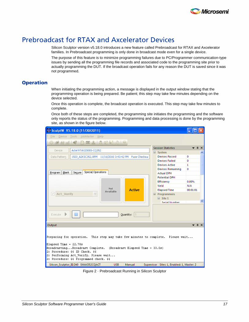
Prebroadcast for RTAX and Axcelerator Devices Silicon Sculptor version v5.18.0 introduces a new feature called Prebroadcast for RTAX and Axcelerator families. In Prebroadcast programming is only done in broadcast mode even for a single device. The purpose of this feature is to minimize programming failures due to PC/Programmer communication-type issues by sending all the programming file records and associated code to the programming site prior to actually programming the DUT. If the broadcast operation fails for any reason the DUT is saved since it was not programmed.
Operation When initiating the programming action, a message is displayed in the output window stating that the programming operation is being prepared. Be patient; this step may take few minutes depending on the device selected. Once this operation is complete, the broadcast operation is executed. This step may take few minutes to complete. Once both of these steps are completed, the programming site initiates the programming and the software only reports the status of the programming. Programming and data processing is done by the programming site, as shown in the figure below.
Figure 2 · Prebroadcast Running in Silicon Sculptor
18 Silicon Sculptor Software Programmer User's Guide
NOTE: Links and cross-references in this PDF file may point to external files and generate an error when clicked. View the online help included with software to enable all linked content.
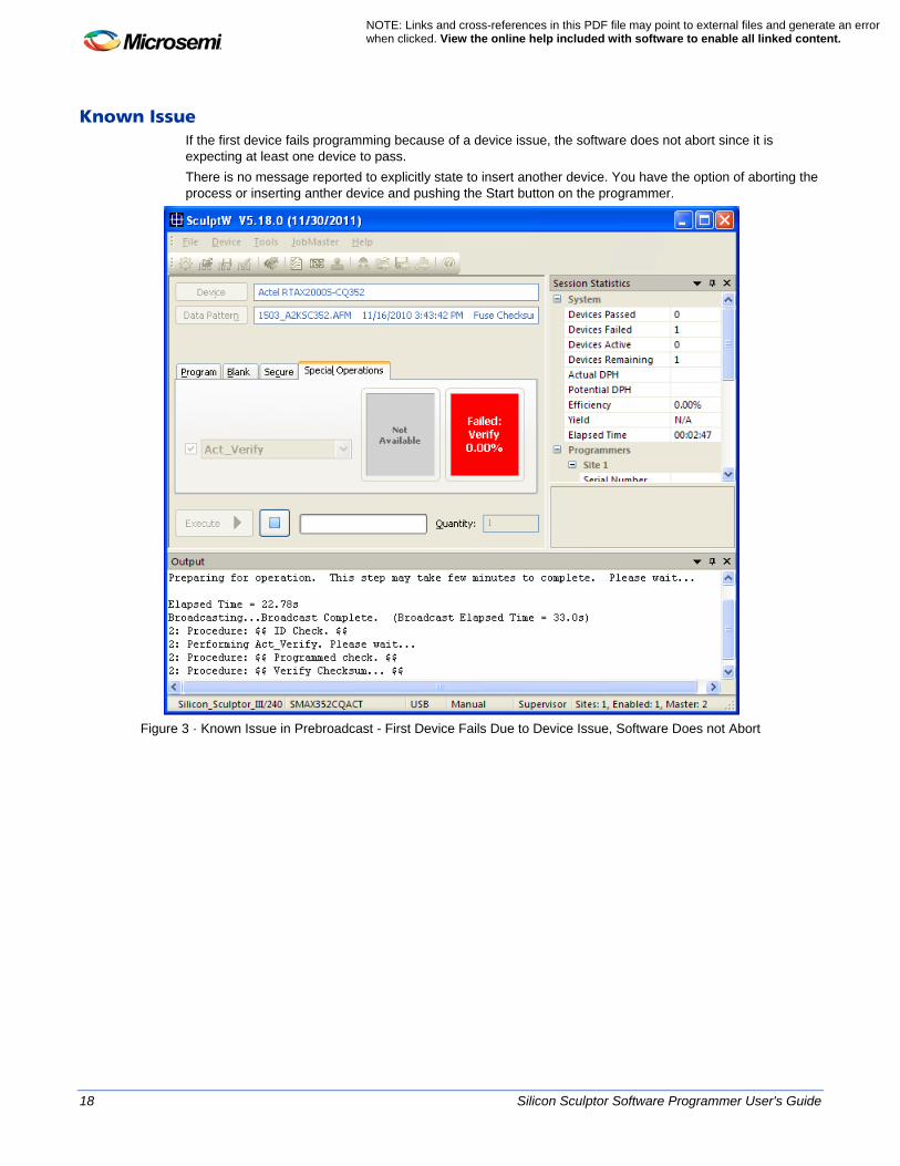
Known Issue If the first device fails programming because of a device issue, the software does not abort since it is expecting at least one device to pass. There is no message reported to explicitly state to insert another device. You have the option of aborting the process or inserting anther device and pushing the Start button on the programmer.
Figure 3 · Known Issue in Prebroadcast - First Device Fails Due to Device Issue, Software Does not Abort

Silicon Sculptor Software Programmer User's Guide 19
SculptW Software GUI
20 Silicon Sculptor Software Programmer User's Guide
NOTE: Links and cross-references in this PDF file may point to external files and generate an error when clicked. View the online help included with software to enable all linked content.
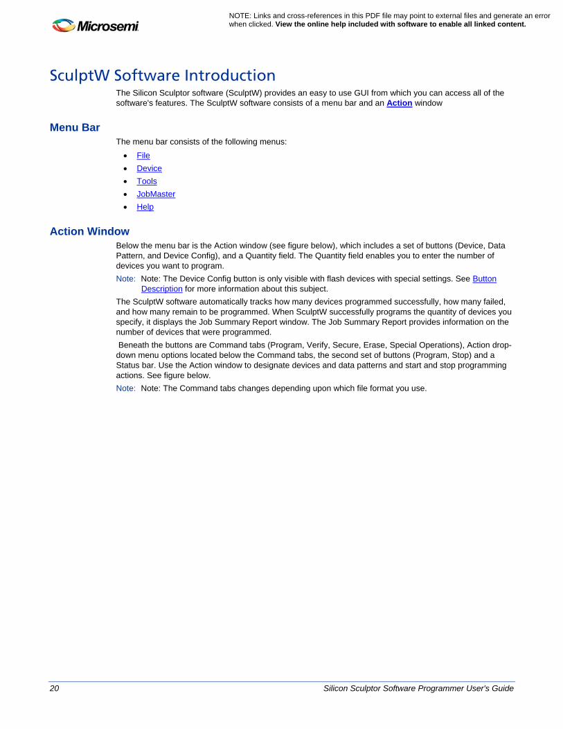
SculptW Software Introduction The Silicon Sculptor software (SculptW) provides an easy to use GUI from which you can access all of the software's features. The SculptW software consists of a menu bar and an Action window
Menu Bar The menu bar consists of the following menus: • File • Device • Tools • JobMaster • Help
Action Window Below the menu bar is the Action window (see figure below), which includes a set of buttons (Device, Data Pattern, and Device Config), and a Quantity field. The Quantity field enables you to enter the number of devices you want to program. Note: Note: The Device Config button is only visible with flash devices with special settings. See Button
Description for more information about this subject. The SculptW software automatically tracks how many devices programmed successfully, how many failed, and how many remain to be programmed. When SculptW successfully programs the quantity of devices you specify, it displays the Job Summary Report window. The Job Summary Report provides information on the number of devices that were programmed. Beneath the buttons are Command tabs (Program, Verify, Secure, Erase, Special Operations), Action drop-down menu options located below the Command tabs, the second set of buttons (Program, Stop) and a Status bar. Use the Action window to designate devices and data patterns and start and stop programming actions. See figure below. Note: Note: The Command tabs changes depending upon which file format you use.
Silicon Sculptor Software Programmer User's Guide 21
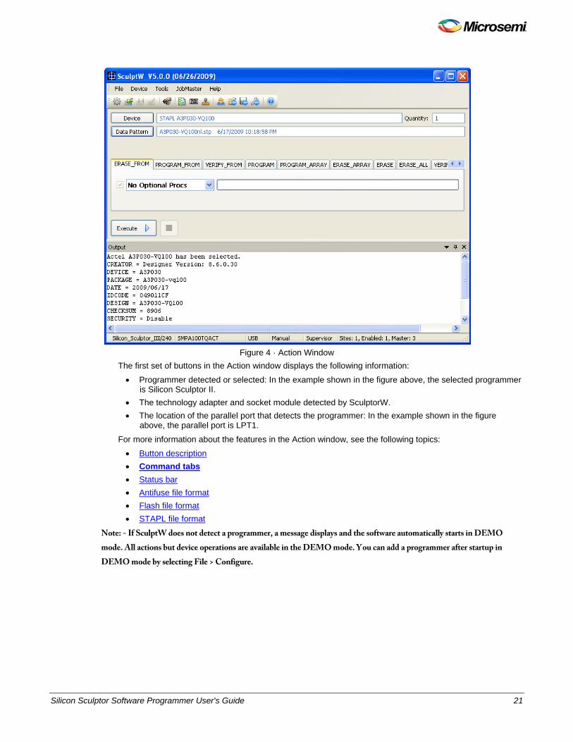
Figure 4 · Action Window
The first set of buttons in the Action window displays the following information:
• Programmer detected or selected: In the example shown in the figure above, the selected programmer is Silicon Sculptor II.
• The technology adapter and socket module detected by SculptorW. • The location of the parallel port that detects the programmer: In the example shown in the figure
above, the parallel port is LPT1.
For more information about the features in the Action window, see the following topics: • Button description • Command tabs • Status bar • Antifuse file format • Flash file format • STAPL file format
Note: - If SculptW does not detect a programmer, a message displays and the software automatically starts in DEMO mode. All actions but device operations are available in the DEMO mode. You can add a programmer after startup in DEMO mode by selecting File > Configure.
22 Silicon Sculptor Software Programmer User's Guide
NOTE: Links and cross-references in this PDF file may point to external files and generate an error when clicked. View the online help included with software to enable all linked content.
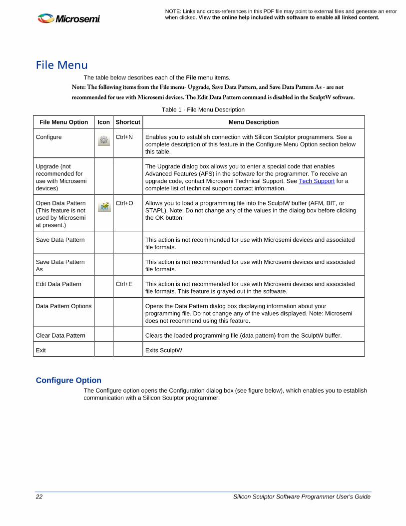
File Menu The table below describes each of the File menu items.
Note: The following items from the File menu- Upgrade, Save Data Pattern, and Save Data Pattern As - are not recommended for use with Microsemi devices. The Edit Data Pattern command is disabled in the SculptW software.
Table 1 · File Menu Description
File Menu Option Icon Shortcut Menu Description
Configure
Ctrl+N Enables you to establish connection with Silicon Sculptor programmers. See a complete description of this feature in the Configure Menu Option section below this table.
Upgrade (not recommended for use with Microsemi devices)
The Upgrade dialog box allows you to enter a special code that enables Advanced Features (AFS) in the software for the programmer. To receive an upgrade code, contact Microsemi Technical Support. See Tech Support for a complete list of technical support contact information.
Open Data Pattern (This feature is not used by Microsemi at present.)
Ctrl+O Allows you to load a programming file into the SculptW buffer (AFM, BIT, or
STAPL). Note: Do not change any of the values in the dialog box before clicking the OK button.
Save Data Pattern This action is not recommended for use with Microsemi devices and associated file formats.
Save Data Pattern As
This action is not recommended for use with Microsemi devices and associated file formats.
Edit Data Pattern Ctrl+E This action is not recommended for use with Microsemi devices and associated file formats. This feature is grayed out in the software.
Data Pattern Options Opens the Data Pattern dialog box displaying information about your programming file. Do not change any of the values displayed. Note: Microsemi does not recommend using this feature.
Clear Data Pattern Clears the loaded programming file (data pattern) from the SculptW buffer.
Exit Exits SculptW.
Configure Option The Configure option opens the Configuration dialog box (see figure below), which enables you to establish communication with a Silicon Sculptor programmer.
Silicon Sculptor Software Programmer User's Guide 23
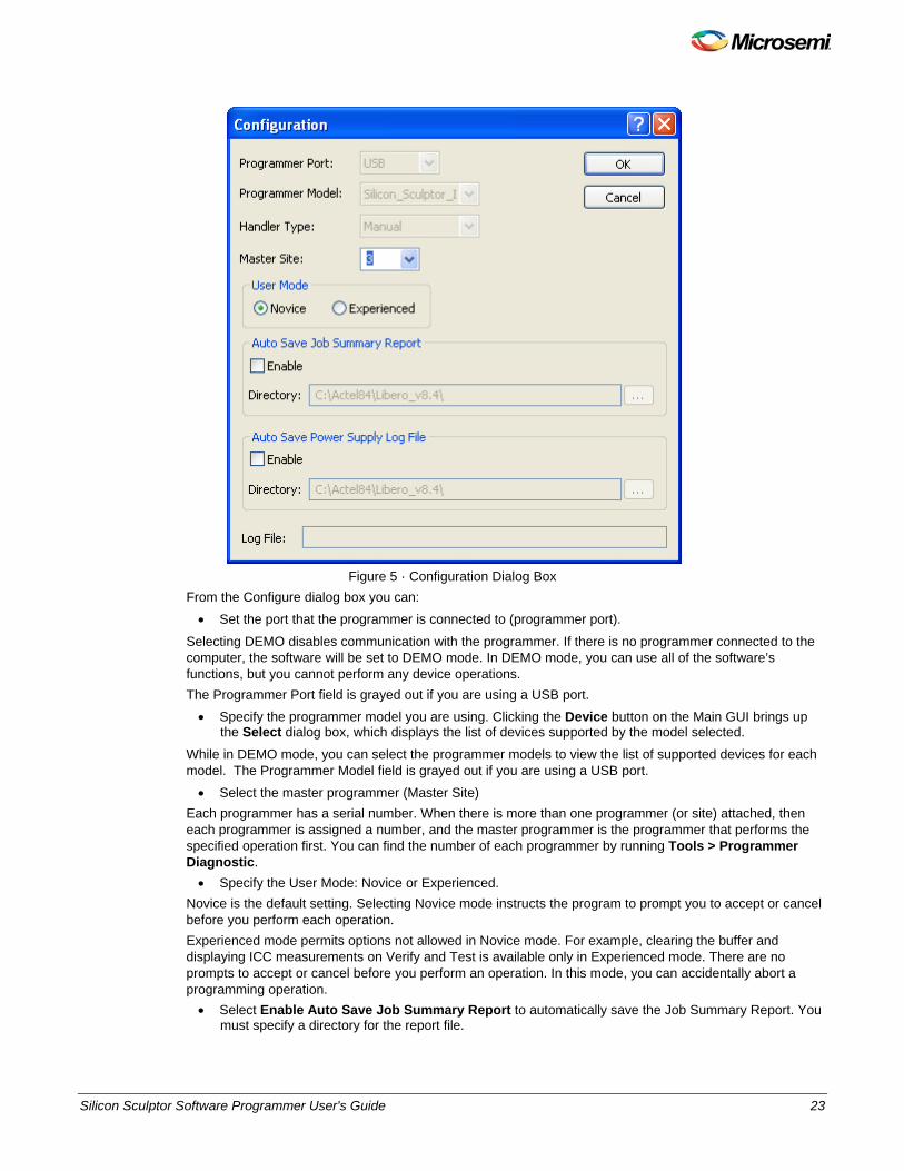
Figure 5 · Configuration Dialog Box
From the Configure dialog box you can: • Set the port that the programmer is connected to (programmer port).
Selecting DEMO disables communication with the programmer. If there is no programmer connected to the computer, the software will be set to DEMO mode. In DEMO mode, you can use all of the software’s functions, but you cannot perform any device operations. The Programmer Port field is grayed out if you are using a USB port. • Specify the programmer model you are using. Clicking the Device button on the Main GUI brings up
the Select dialog box, which displays the list of devices supported by the model selected.
While in DEMO mode, you can select the programmer models to view the list of supported devices for each model. The Programmer Model field is grayed out if you are using a USB port. • Select the master programmer (Master Site)
Each programmer has a serial number. When there is more than one programmer (or site) attached, then each programmer is assigned a number, and the master programmer is the programmer that performs the specified operation first. You can find the number of each programmer by running Tools > Programmer Diagnostic. • Specify the User Mode: Novice or Experienced.
Novice is the default setting. Selecting Novice mode instructs the program to prompt you to accept or cancel before you perform each operation. Experienced mode permits options not allowed in Novice mode. For example, clearing the buffer and displaying ICC measurements on Verify and Test is available only in Experienced mode. There are no prompts to accept or cancel before you perform an operation. In this mode, you can accidentally abort a programming operation. • Select Enable Auto Save Job Summary Report to automatically save the Job Summary Report. You
must specify a directory for the report file.

24 Silicon Sculptor Software Programmer User's Guide
NOTE: Links and cross-references in this PDF file may point to external files and generate an error when clicked. View the online help included with software to enable all linked content.
• Select Enable Auto Save Power Supply Log File to automatically save the Power Supply log. This log shows the power supply levels for each programmer being used. Disabled programmer sites are not included in the log file.
Note: An asterisk (*) next to any power supply value indicates a supply that is out of range. We recommend that you run Tools > Programmer Diagnostics on any site that is out of range.
Silicon Sculptor Software Programmer User's Guide 25
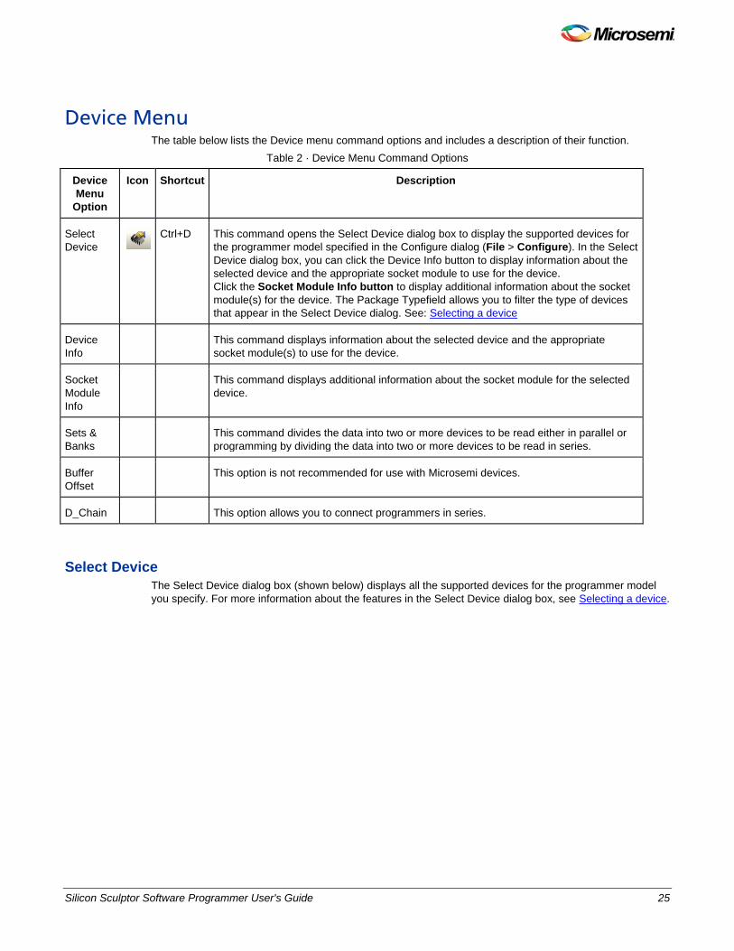
Device Menu The table below lists the Device menu command options and includes a description of their function.
Table 2 · Device Menu Command Options
Device Menu
Option
Icon Shortcut Description
Select Device
Ctrl+D This command opens the Select Device dialog box to display the supported devices for the programmer model specified in the Configure dialog (File > Configure). In the Select Device dialog box, you can click the Device Info button to display information about the selected device and the appropriate socket module to use for the device. Click the Socket Module Info button to display additional information about the socket module(s) for the device. The Package Typefield allows you to filter the type of devices that appear in the Select Device dialog. See: Selecting a device
Device Info
This command displays information about the selected device and the appropriate socket module(s) to use for the device.
Socket Module Info
This command displays additional information about the socket module for the selected device.
Sets & Banks
This command divides the data into two or more devices to be read either in parallel or programming by dividing the data into two or more devices to be read in series.
Buffer Offset
This option is not recommended for use with Microsemi devices.
D_Chain This option allows you to connect programmers in series.
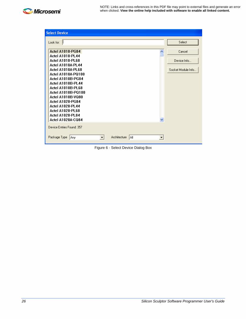
Select Device The Select Device dialog box (shown below) displays all the supported devices for the programmer model you specify. For more information about the features in the Select Device dialog box, see Selecting a device.
26 Silicon Sculptor Software Programmer User's Guide
NOTE: Links and cross-references in this PDF file may point to external files and generate an error when clicked. View the online help included with software to enable all linked content.
Figure 6 · Select Device Dialog Box

Silicon Sculptor Software Programmer User's Guide 27
Tools Menu You can use the commands in the Tools menu to reset the Silicon Sculptor configuration. See the table below for a description of the commands in the Tools menu.
Table 3 · Tools Menu Command Description
File Menu Option
Icon Menu Description
Programmer Diagnostics
Note: Remove any chips from the programmer before you run the Programmer Diagnostic. Programmer Diagnostic runs the programmer diagnostic test, also called self-test. The Silicon Sculptor diagnostics ensure that the power supplies function properly and test the integrity of the pin drivers. This command runs the programmer diagnostic test, which tests certain features in the programmer(s). If there are multiple programmers attached, you can perform these tests for one programmer or for all programmers. The tests include the following: A power supply test to ensure that all power supplies in the programmer are functioning properly A pin driver test to verify the integrity of the pin drivers A socket module test to verify the integrity of the attached socket module Diagnostic Dialog Box Click OK to run the test on the CPU, RAM, ROM, logic communication, power supplies, motherboard analog, pin driver boards, current regulators, and motherboard. The Diagnostics Report dialog box opens when the tests are complete.
Output Window Opens the Output window, which displays the operation status and error message
Set Default Configuration
Resets the SculptW software settings (fields, options, etc.) to its initial state (same state as after a new install). This command cannot be selected while in Operator mode. The Default Configure dialog box displays a window to confirm whether or not you want to reset to the default configuration. The Default Configure dialog box displays when you choose the Set Default Configuration command. For example, if a device calls for a mandatory verify and the operator changes it to Verify Twice, the Default Configure option will allow you to change the setting back to a single verify.
Options Opens the User Options dialog box, which allows you to set the following options: Error Beep turns on a sound to indicate programming completion, errors, etc. Elapsed Time displays the duration of the specified command. Note: The total time is displayed in the Output window as well as in the Status bar, for each device. Matching Chip Pin Count with Socket: This option enforces the matching device pin count with the socket pin count. It must be set to No. Concurrent Mode Memory Integrity Check. This feature checks the integrity of the memory in each programmer after broadcasting, prior to the device operations. This feature is not compatible with Serialization.
Device Marker Note: Not supported in Silicon Sculptor II or Silicon3 programmers)
Used to select the Market Package type, either Plastic or Ceramic, and to designate up to three lines of text. SculptW does not support this feature; it is designed for automated systems.
Socket Module Counter
Displays the number of operations performed on a particular module. You can view the number of operations on the screen by selecting a site number. The software tracks the number of operations performed by the socket. Any normal operation will turn the counter. A combination operation only counts as one operation. This information is also available in the Job Summary report. There is also a separate "trip counter" that can be reset by the user. This is to be used when a replacement socket is

28 Silicon Sculptor Software Programmer User's Guide
NOTE: Links and cross-references in this PDF file may point to external files and generate an error when clicked. View the online help included with software to enable all linked content.
File Menu Option
Icon Menu Description
installed. Resetting the trip counter is only available in Supervisor Mode. For example a Read or a Compare counts as one operation, and an Erase/Program/Verify counts as one operation. Each verification counts as one operation.
Serialization
This option brings up the Serialization dialog box. This is available only when a STAPL file with serialization features are loaded. The Log file locations can be specified, as well as the option to Retry Failed Serial Numbers (default is to skip failed serial numbers). Note: You can also set the index range of serial numbers to be programmed.
Power Supply This command displays the real-time voltage readings for each of the power supplies in the master site. The value on the left is the nominal voltage level, and the voltage on the right is the reading. An asterisk (*) next to any power supply value indicates that the power supply is out of range. To change the programmer being read, you can change the master site in the Configure window (File > Configure). Microsemi recommends that you perform Programmer Diagnostics on any programmer that is out of range. Power Supply values can be automatically recorded in a log file by setting the Auto Save Power Supply Log File option in the Configure dialog box (File > Configure).
Flash BIOS Not currently supported on Silicon Sculptor II or Silicon Sculptor 3 programmers.
Site Number Assignment
This feature allows you to assign a number to each connected programmer. This feature only supports the USB-based programmer, Silicon Sculptor 3.
Silicon Sculptor Software Programmer User's Guide 29
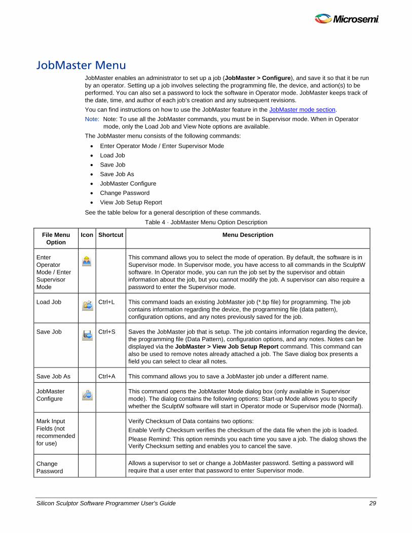
JobMaster Menu JobMaster enables an administrator to set up a job (JobMaster > Configure), and save it so that it be run by an operator. Setting up a job involves selecting the programming file, the device, and action(s) to be performed. You can also set a password to lock the software in Operator mode. JobMaster keeps track of the date, time, and author of each job’s creation and any subsequent revisions. You can find instructions on how to use the JobMaster feature in the JobMaster mode section. Note: Note: To use all the JobMaster commands, you must be in Supervisor mode. When in Operator
mode, only the Load Job and View Note options are available. The JobMaster menu consists of the following commands: • Enter Operator Mode / Enter Supervisor Mode • Load Job • Save Job • Save Job As • JobMaster Configure • Change Password • View Job Setup Report
See the table below for a general description of these commands. Table 4 · JobMaster Menu Option Description
File Menu Option
Icon Shortcut Menu Description
Enter Operator Mode / Enter Supervisor Mode
This command allows you to select the mode of operation. By default, the software is in
Supervisor mode. In Supervisor mode, you have access to all commands in the SculptW software. In Operator mode, you can run the job set by the supervisor and obtain information about the job, but you cannot modify the job. A supervisor can also require a password to enter the Supervisor mode.
Load Job
Ctrl+L This command loads an existing JobMaster job (*.bp file) for programming. The job contains information regarding the device, the programming file (data pattern), configuration options, and any notes previously saved for the job.
Save Job
Ctrl+S Saves the JobMaster job that is setup. The job contains information regarding the device, the programming file (Data Pattern), configuration options, and any notes. Notes can be displayed via the JobMaster > View Job Setup Report command. This command can also be used to remove notes already attached a job. The Save dialog box presents a field you can select to clear all notes.
Save Job As Ctrl+A This command allows you to save a JobMaster job under a different name.
JobMaster Configure
This command opens the JobMaster Mode dialog box (only available in Supervisor mode). The dialog contains the following options: Start-up Mode allows you to specify whether the SculptW software will start in Operator mode or Supervisor mode (Normal).
Mark Input Fields (not recommended for use)
Verify Checksum of Data contains two options: Enable Verify Checksum verifies the checksum of the data file when the job is loaded. Please Remind: This option reminds you each time you save a job. The dialog shows the Verify Checksum setting and enables you to cancel the save.
Change Password
Allows a supervisor to set or change a JobMaster password. Setting a password will require that a user enter that password to enter Supervisor mode.

30 Silicon Sculptor Software Programmer User's Guide
NOTE: Links and cross-references in this PDF file may point to external files and generate an error when clicked. View the online help included with software to enable all linked content.
File Menu Option
Icon Shortcut Menu Description
View Job Setup Report
Displays the JobMaster File Notes window. This window displays any notes saved with a JobMaster job, along with a revision history to keep track of all the modifications made to the JobMaster file, including notes added, date, time, and author.

Silicon Sculptor Software Programmer User's Guide 31
Help Menu See the table below for a description of the commands in the Help menu.
Table 5 · Help Menu Commands
File Menu Option
Menu Description
SculptW Help Displays the online help for the SculptW software.
Tech Support Displays the phone numbers and email address for reaching Microsemi Technical Support.
Registration Registration is not required for Silicon Sculptor programmers.
About SculptW Displays the SculptW software version number.
32 Silicon Sculptor Software Programmer User's Guide
NOTE: Links and cross-references in this PDF file may point to external files and generate an error when clicked. View the online help included with software to enable all linked content.
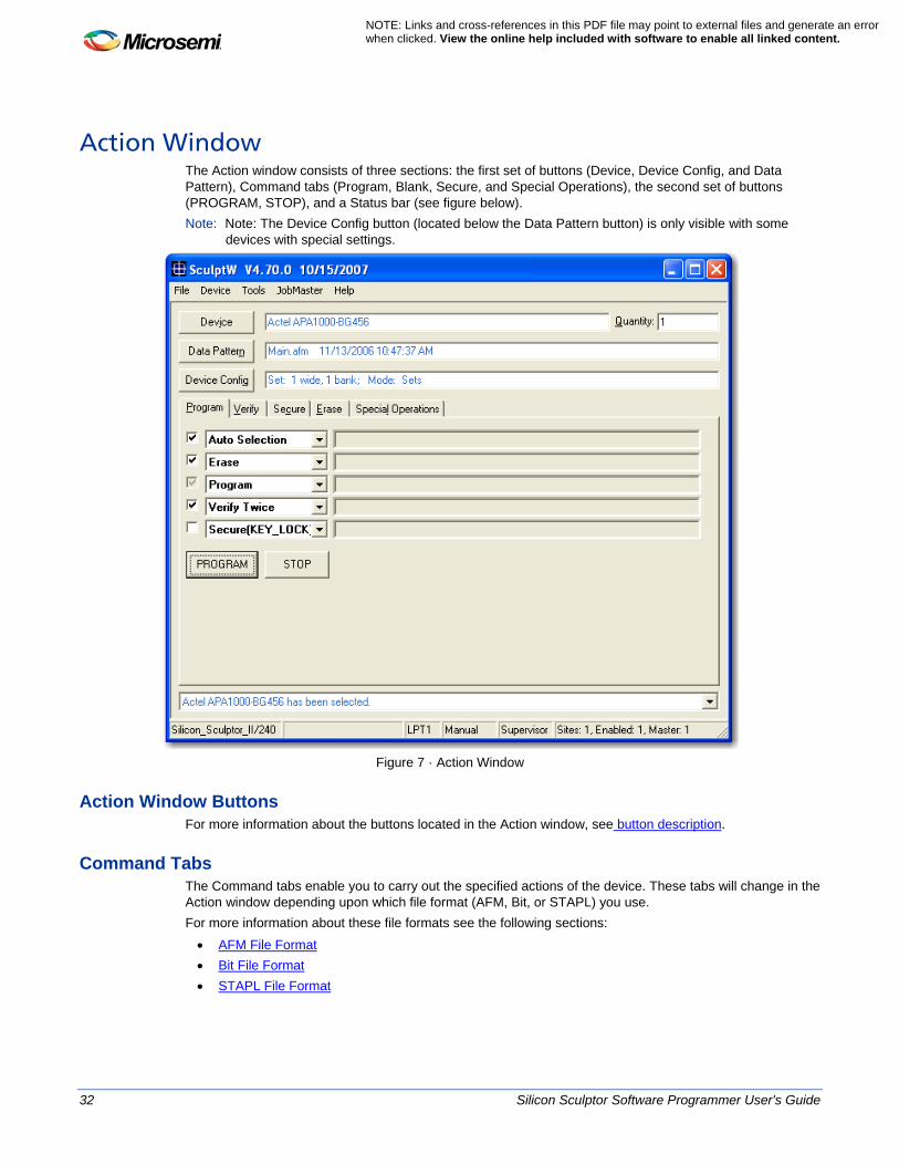
Action Window The Action window consists of three sections: the first set of buttons (Device, Device Config, and Data Pattern), Command tabs (Program, Blank, Secure, and Special Operations), the second set of buttons (PROGRAM, STOP), and a Status bar (see figure below). Note: Note: The Device Config button (located below the Data Pattern button) is only visible with some
devices with special settings.
Figure 7 · Action Window
Action Window Buttons For more information about the buttons located in the Action window, see button description.
Command Tabs The Command tabs enable you to carry out the specified actions of the device. These tabs will change in the Action window depending upon which file format (AFM, Bit, or STAPL) you use. For more information about these file formats see the following sections: • AFM File Format • Bit File Format • STAPL File Format

Silicon Sculptor Software Programmer User's Guide 33
Status Bar The Status Bar keeps a running list of all the actions you have performed and the device(s) you select during active use of the software. Once you exit the software, the tracking list is reset.
34 Silicon Sculptor Software Programmer User's Guide
NOTE: Links and cross-references in this PDF file may point to external files and generate an error when clicked. View the online help included with software to enable all linked content.
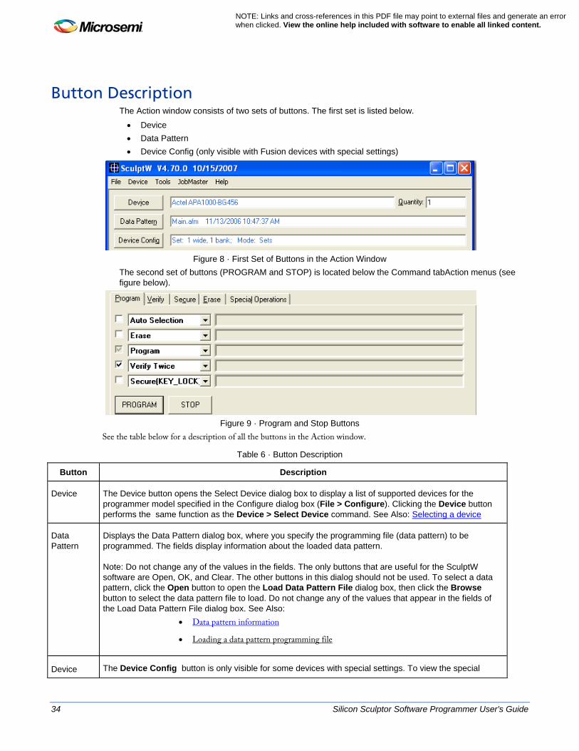
Button Description The Action window consists of two sets of buttons. The first set is listed below.
• Device • Data Pattern • Device Config (only visible with Fusion devices with special settings)
Figure 8 · First Set of Buttons in the Action Window
The second set of buttons (PROGRAM and STOP) is located below the Command tabAction menus (see figure below).
Figure 9 · Program and Stop Buttons
See the table below for a description of all the buttons in the Action window.
Table 6 · Button Description
Button Description
Device The Device button opens the Select Device dialog box to display a list of supported devices for the programmer model specified in the Configure dialog box (File > Configure). Clicking the Device button performs the same function as the Device > Select Device command. See Also: Selecting a device
Data Pattern
Displays the Data Pattern dialog box, where you specify the programming file (data pattern) to be programmed. The fields display information about the loaded data pattern. Note: Do not change any of the values in the fields. The only buttons that are useful for the SculptW software are Open, OK, and Clear. The other buttons in this dialog should not be used. To select a data pattern, click the Open button to open the Load Data Pattern File dialog box, then click the Browse button to select the data pattern file to load. Do not change any of the values that appear in the fields of the Load Data Pattern File dialog box. See Also:
• Data pattern information
• Loading a data pattern programming file
Device The Device Config button is only visible for some devices with special settings. To view the special

Silicon Sculptor Software Programmer User's Guide 35
Button Description
Config settings for a device, select the device and click the Device Config button.
PROGRAM Programs the Action from the Command tabs.
STOP Stops the currently running action.
36 Silicon Sculptor Software Programmer User's Guide
NOTE: Links and cross-references in this PDF file may point to external files and generate an error when clicked. View the online help included with software to enable all linked content.
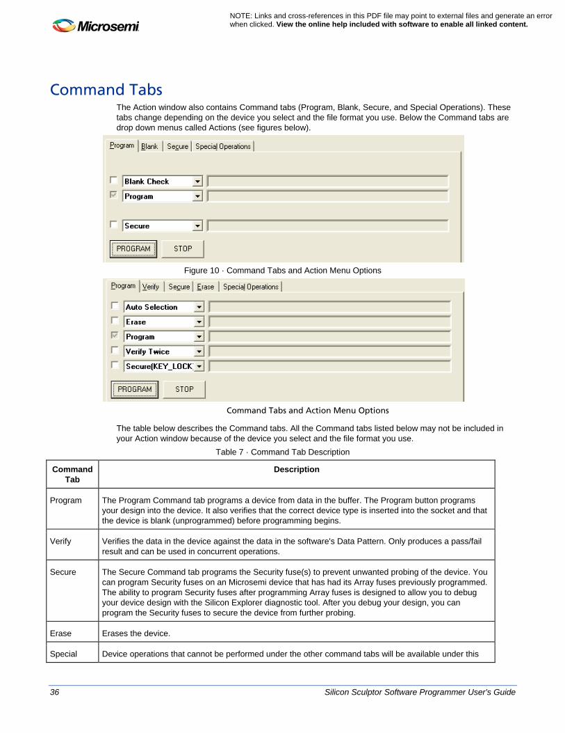
Command Tabs The Action window also contains Command tabs (Program, Blank, Secure, and Special Operations). These tabs change depending on the device you select and the file format you use. Below the Command tabs are drop down menus called Actions (see figures below).
Figure 10 · Command Tabs and Action Menu Options
Command Tabs and Action Menu Options
The table below describes the Command tabs. All the Command tabs listed below may not be included in your Action window because of the device you select and the file format you use.
Table 7 · Command Tab Description
Command Tab
Description
Program The Program Command tab programs a device from data in the buffer. The Program button programs your design into the device. It also verifies that the correct device type is inserted into the socket and that the device is blank (unprogrammed) before programming begins.
Verify Verifies the data in the device against the data in the software's Data Pattern. Only produces a pass/fail result and can be used in concurrent operations.
Secure The Secure Command tab programs the Security fuse(s) to prevent unwanted probing of the device. You can program Security fuses on an Microsemi device that has had its Array fuses previously programmed. The ability to program Security fuses after programming Array fuses is designed to allow you to debug your device design with the Silicon Explorer diagnostic tool. After you debug your design, you can program the Security fuses to secure the device from further probing.
Erase Erases the device.
Special Device operations that cannot be performed under the other command tabs will be available under this
Silicon Sculptor Software Programmer User's Guide 37
Command Tab
Description
Operations tab. If you previously used JobMaster with Special Operations, you need to update your JobMaster file.
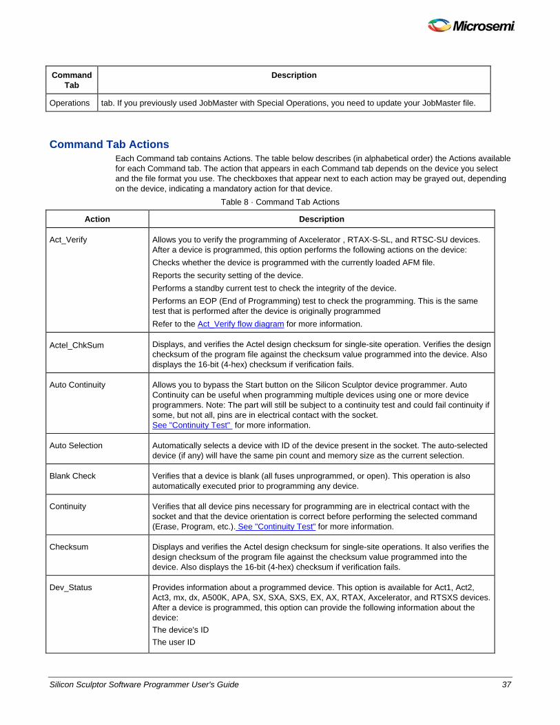
Command Tab Actions Each Command tab contains Actions. The table below describes (in alphabetical order) the Actions available for each Command tab. The action that appears in each Command tab depends on the device you select and the file format you use. The checkboxes that appear next to each action may be grayed out, depending on the device, indicating a mandatory action for that device.
Table 8 · Command Tab Actions
Action Description
Act_Verify Allows you to verify the programming of Axcelerator , RTAX-S-SL, and RTSC-SU devices. After a device is programmed, this option performs the following actions on the device: Checks whether the device is programmed with the currently loaded AFM file. Reports the security setting of the device. Performs a standby current test to check the integrity of the device. Performs an EOP (End of Programming) test to check the programming. This is the same test that is performed after the device is originally programmed Refer to the Act_Verify flow diagram for more information.
Actel_ChkSum Displays, and verifies the Actel design checksum for single-site operation. Verifies the design checksum of the program file against the checksum value programmed into the device. Also displays the 16-bit (4-hex) checksum if verification fails.
Auto Continuity Allows you to bypass the Start button on the Silicon Sculptor device programmer. Auto Continuity can be useful when programming multiple devices using one or more device programmers. Note: The part will still be subject to a continuity test and could fail continuity if some, but not all, pins are in electrical contact with the socket. See "Continuity Test" for more information.
Auto Selection Automatically selects a device with ID of the device present in the socket. The auto-selected device (if any) will have the same pin count and memory size as the current selection.
Blank Check Verifies that a device is blank (all fuses unprogrammed, or open). This operation is also automatically executed prior to programming any device.
Continuity Verifies that all device pins necessary for programming are in electrical contact with the socket and that the device orientation is correct before performing the selected command (Erase, Program, etc.). See "Continuity Test" for more information.
Checksum Displays and verifies the Actel design checksum for single-site operations. It also verifies the design checksum of the program file against the checksum value programmed into the device. Also displays the 16-bit (4-hex) checksum if verification fails.
Dev_Status Provides information about a programmed device. This option is available for Act1, Act2, Act3, mx, dx, A500K, APA, SX, SXA, SXS, EX, AX, RTAX, Axcelerator, and RTSXS devices. After a device is programmed, this option can provide the following information about the device: The device's ID The user ID
38 Silicon Sculptor Software Programmer User's Guide
NOTE: Links and cross-references in this PDF file may point to external files and generate an error when clicked. View the online help included with software to enable all linked content.
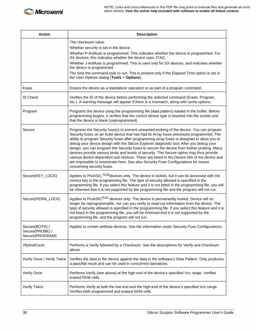
Action Description
The checksum value Whether security is set in the device Whether P-Antifuse is programmed. This indicates whether the device is programmed. For SX devices, this indicates whether the device uses JTAG. Whether J-Antifuse is programmed. This is used only for SX devices, and indicates whether the device is programmed. The time the command took to run. This is present only if the Elapsed Time option is set in the User Options dialog (Tools > Options).
Erase Erases the device as a standalone operation or as part of a program command.
ID Check Verifies the ID of the device before performing the selected command (Erase, Program, etc.). A warning message will appear if there is a mismatch, along with some options.
Program Programs the device using the programming file (data pattern) loaded in the buffer. Before programming begins, it verifies that the correct device type is inserted into the socket and that the device is blank (unprogrammed).
Secure Programs the Security fuse(s) to prevent unwanted probing of the device. You can program Security fuses on an Actel device that has had its Array fuses previously programmed. The ability to program Security fuses after programming array fuses is designed to allow you to debug your device design with the Silicon Explorer diagnostic tool. After you debug your design, you can program the Security fuses to secure the device from further probing. Many devices provide various kinds and levels of security. The Secure option may thus provide various device-dependent sub-choices. These are listed in the Device Info of the device and are impossible to enumerate here. See also Security Fuse Configurations for issues concerning security fuses.
Secure(KEY_LOCK) Applies to ProASIC PLUSdevices only. The device is locked, but it can be accessed with the correct key in the programming file. The type of security allowed is specified in the programming file. If you select this feature and it is not listed in the programming file, you will be informed that it is not supported by the programming file and the program will not run.
Secure(PERM_LOCK) Applies to ProASICPLUS devices only. The device is permanently locked. Device will no longer be reprogrammable, nor can you verify or read-out information from the device. The type of security allowed is specified in the programming file. If you select this feature and it is not listed in the programming file, you will be informed that it is not supported by the programming file, and the program will not run.
Secure(BOTH) / Secure(PROBE) / Secure(PROGRAM)
Applies to certain antifuse devices. See the information under Security Fuse Configurations.
VfyAndCsum Performs a Verify followed by a Checksum. See the descriptions for Verify and Checksum above.
Verify Once / Verify Twice Verifies the data in the device against the data in the software's Data Pattern. Only produces a pass/fail result and can be used in concurrent operations.
Verify Once Performs Verify (see above) at the high end of the device's specified Vcc range. Verifies erased NVM cells.
Verify Twice Performs Verify at both the low end and the high-end of the device's specified Vcc range. Verifies both programmed and erased NVM cells.

Silicon Sculptor Software Programmer User's Guide 39
Status Bar The Status bar, the field bar at the bottom of the Action window, is visible only when the program window is fully expanded. The Status bar keeps a running list of all the actions you have performed and the device(s) you select during active use of the software. Once you exit the software, the tracking list is reset.
40 Silicon Sculptor Software Programmer User's Guide
NOTE: Links and cross-references in this PDF file may point to external files and generate an error when clicked. View the online help included with software to enable all linked content.
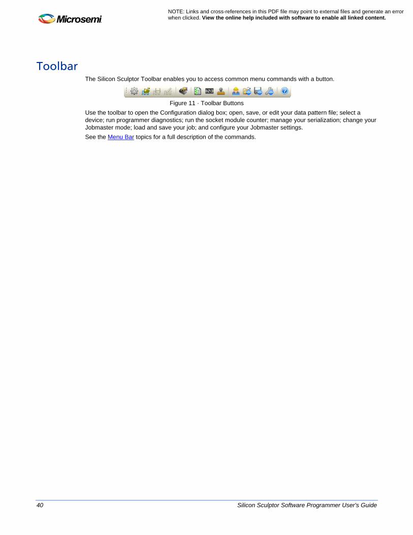
Toolbar The Silicon Sculptor Toolbar enables you to access common menu commands with a button.
Figure 11 · Toolbar Buttons
Use the toolbar to open the Configuration dialog box; open, save, or edit your data pattern file; select a device; run programmer diagnostics; run the socket module counter; manage your serialization; change your Jobmaster mode; load and save your job; and configure your Jobmaster settings. See the Menu Bar topics for a full description of the commands.
Silicon Sculptor Software Programmer User's Guide 41
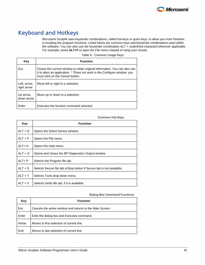
Keyboard and Hotkeys Microsemi SculpW uses keystroke combinations, called hot-keys or quick keys, to allow you more freedom in invoking the program functions. Listed below are common keys and keystroke combinations used within the software. You can also use the keystroke combination ALT + underlined character] wherever applicable. For example, press ALT+F to open the File menu instead of using your mouse.
Table 9 · Common Usage Keys
Key Function
Esc Closes the current window to retain original information. You can also use it to abort an application. * *Does not work in the Configure window: you must click on the Cancel button.
Left, arrow, right arrow
Move left or right to a selection.
Up arrow, down arrow
Move up or down to a selection.
Enter Executes the function command selected.
Common Hot-Keys
Key Function
ALT + D Opens the Select Device window.
ALT + F Opens the File menu.
ALT+ H Opens the Help menu.
ALT + O Opens and closes the BP Diagnostics Output window.
ALT+ P Selects the Program file tab.
ALT + S Selects Secure file tab orStop button if Secure tab is not available.
ALT + T Selects Tools drop-down menu.
ALT + V Selects Verify file tab, if it is available.
Dialog Box Command Functions
Key Function
Esc Cancels the active window and returns to the Main Screen.
Enter Exits the dialog box and Executes command.
Home Moves to first selection of current line.
End Moves to last selection of current line.
42 Silicon Sculptor Software Programmer User's Guide
NOTE: Links and cross-references in this PDF file may point to external files and generate an error when clicked. View the online help included with software to enable all linked content.
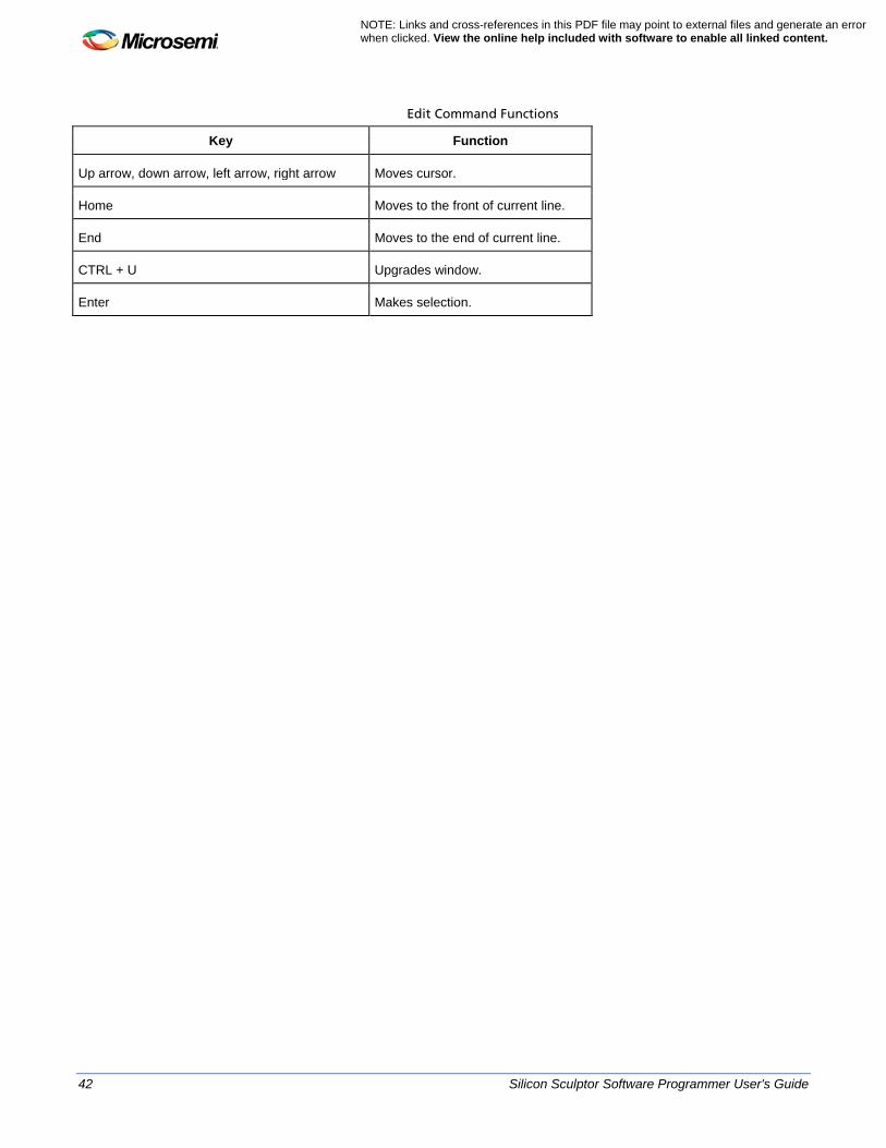
Edit Command Functions
Key Function
Up arrow, down arrow, left arrow, right arrow Moves cursor.
Home Moves to the front of current line.
End Moves to the end of current line.
CTRL + U Upgrades window.
Enter Makes selection.

Silicon Sculptor Software Programmer User's Guide 43
Using File Formats

44 Silicon Sculptor Software Programmer User's Guide
NOTE: Links and cross-references in this PDF file may point to external files and generate an error when clicked. View the online help included with software to enable all linked content.
BIT File Format The Command tabs, located in the Action window, change depending upon which file format you use (AFM, BIT, or STAPL). The BIT file format can be used for programming ProASIC 500K and ProASICPLUS devices. When you program a device using a bit file, you must select a device from the Select Device dialog box. After you select your device, the Action window updates with the following Command tabs: • Program • Verify • Secure • Erase • Special Operations
For a description of these Command tabs, see Command Tab Descriptions. Note: Note: The drop-down menu items, called Actions, are located below each Command tab. For a
description of these actions, see the Command Tab Action table. After you select your device and specify your action, load your data pattern programming file (BIT file) from the Data Pattern dialog box. For complete instructions on how to program a flash device using a BIT file, see the following: • Selecting a device • Loading a programming data file • Flash programming with a bit file

Silicon Sculptor Software Programmer User's Guide 45
STAPL File Format The STAPL file format supports all flash devices (ProASIC, ProASICPLUS, ProASIC3, Fusion, M7 devices, and future products). When programming a device using a STAPL file, you will follow a different procedure than if you were to program a device using a BIT file. Instead of selecting a device from the Select Device dialog box, load your data pattern programming file (STAPL file) from the Data Programming dialog box. See Flash programming with a STAPL file for complete instructions on how to program a Flash device using a STAPL file. After you load your STAPL file (from the Data Pattern dialog box), the Action window updates the Command tabs to reflect the content embedded in your STAPL file. The Command tabs change depending upon information in your STAPL file.
See Also: Loading a data pattern programming file Data pattern information Flash programming with a STAPL file Programming ProASIC and Fusion devices
46 Silicon Sculptor Software Programmer User's Guide
NOTE: Links and cross-references in this PDF file may point to external files and generate an error when clicked. View the online help included with software to enable all linked content.
AFM File Format The AFM file format is used for programming all the Antifuse devices and families (ACT1-ACT3, MX, DX, EX, SX, and Axcelerator). For complete instructions on how to program an antifuse device, see Antifuse programming. When programming an antifuse device, you must first select your target device from the Select Device dialog box. The SculptW software will update the Command tabs in the Action window with the following: • Program • Blank • Secure • Special Operations
Note: The Command tabs change in the Action window depending upon which file format you use. See Command tabs for a description of the above commands.
See Also: Antifuse programming ACT 1 or 40MX security fuse configuration Non-ACT 1 or 40MX security fuse configuration

Silicon Sculptor Software Programmer User's Guide 47
Software Basics
48 Silicon Sculptor Software Programmer User's Guide
NOTE: Links and cross-references in this PDF file may point to external files and generate an error when clicked. View the online help included with software to enable all linked content.
Selecting a Device Note: Note: Your computer must not enter Sleep mode during programming or your programming may fail. MicroSemi recommends that you execute programming in Novice mode to prevent unintentional user interruption. Novice mode prompts you to accept or cancel before you perform an operation. It is useful if you click the screen during programming to prevent the computer from entering sleep mode. Before you can program a device, you must select one.
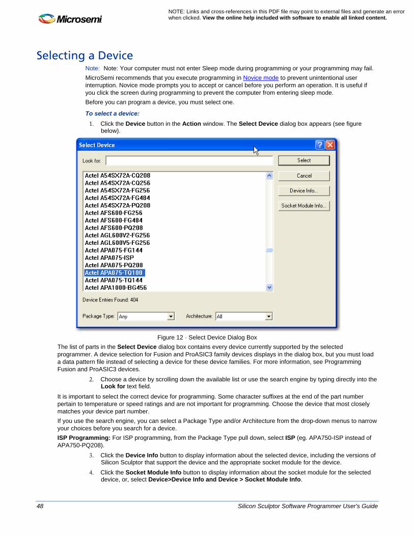
To select a device: 1. Click the Device button in the Action window. The Select Device dialog box appears (see figure
below).
Figure 12 · Select Device Dialog Box
The list of parts in the Select Device dialog box contains every device currently supported by the selected programmer. A device selection for Fusion and ProASIC3 family devices displays in the dialog box, but you must load a data pattern file instead of selecting a device for these device families. For more information, see Programming Fusion and ProASIC3 devices.
2. Choose a device by scrolling down the available list or use the search engine by typing directly into the Look for text field.
It is important to select the correct device for programming. Some character suffixes at the end of the part number pertain to temperature or speed ratings and are not important for programming. Choose the device that most closely matches your device part number. If you use the search engine, you can select a Package Type and/or Architecture from the drop-down menus to narrow your choices before you search for a device. ISP Programming: For ISP programming, from the Package Type pull down, select ISP (eg. APA750-ISP instead of APA750-PQ208).
3. Click the Device Info button to display information about the selected device, including the versions of Silicon Sculptor that support the device and the appropriate socket module for the device.
4. Click the Socket Module Info button to display information about the socket module for the selected device, or, select Device>Device Info and Device > Socket Module Info.
Silicon Sculptor Software Programmer User's Guide 49
5. When you have highlighted the correct device and entered the appropriate information, click the Select button to load the algorithm for that device or Cancel to exit without selecting.
After you select a device, the Select Device window closes and the device information appears in the field next to the Device button. A note or warning may appear in the Device Information window to inform you of any additional relevant information.
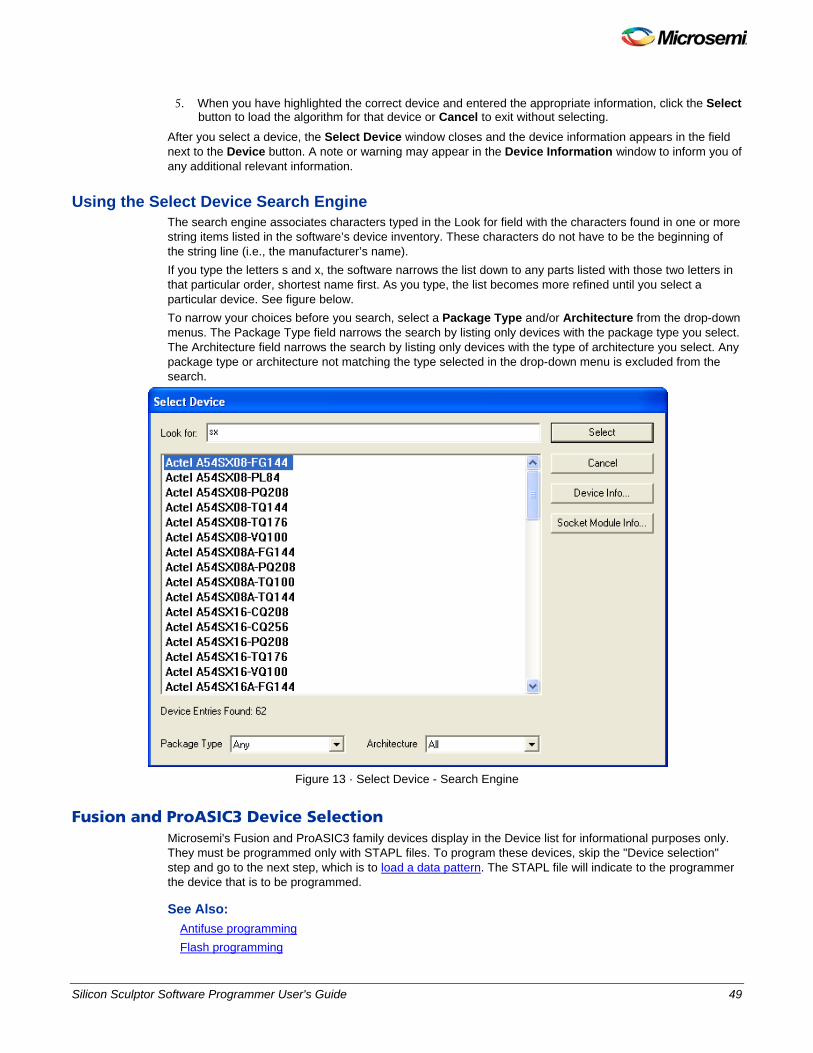
Using the Select Device Search Engine The search engine associates characters typed in the Look for field with the characters found in one or more string items listed in the software’s device inventory. These characters do not have to be the beginning of the string line (i.e., the manufacturer’s name). If you type the letters s and x, the software narrows the list down to any parts listed with those two letters in that particular order, shortest name first. As you type, the list becomes more refined until you select a particular device. See figure below. To narrow your choices before you search, select a Package Type and/or Architecture from the drop-down menus. The Package Type field narrows the search by listing only devices with the package type you select. The Architecture field narrows the search by listing only devices with the type of architecture you select. Any package type or architecture not matching the type selected in the drop-down menu is excluded from the search.
Figure 13 · Select Device - Search Engine
Fusion and ProASIC3 Device Selection Microsemi's Fusion and ProASIC3 family devices display in the Device list for informational purposes only. They must be programmed only with STAPL files. To program these devices, skip the "Device selection" step and go to the next step, which is to load a data pattern. The STAPL file will indicate to the programmer the device that is to be programmed.
See Also: Antifuse programming Flash programming
50 Silicon Sculptor Software Programmer User's Guide
NOTE: Links and cross-references in this PDF file may point to external files and generate an error when clicked. View the online help included with software to enable all linked content.
Loading a Data Pattern Programming File After you have selected your device from the Select Device dialog box (for *.afm and *.bit file formats), you are ready to load the data pattern programming file. Note: Note: When programing a device using a STAPL file, it is important that you load a data pattern
programming file instead of selecting a device.
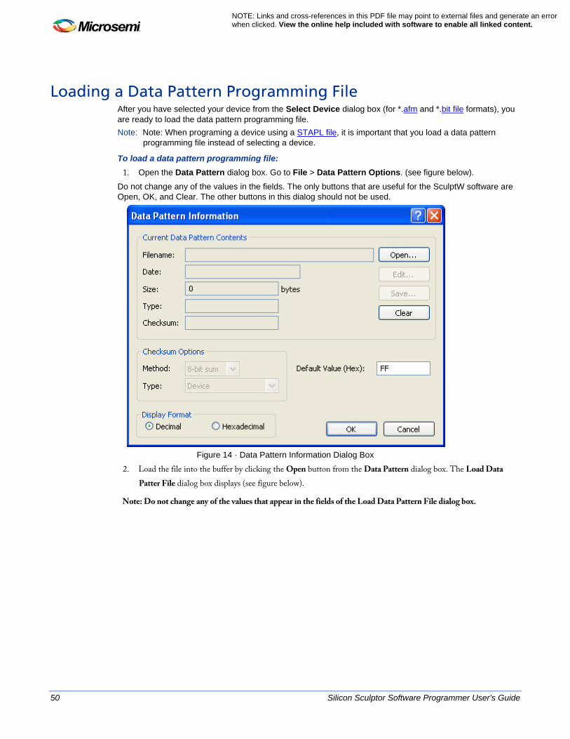
To load a data pattern programming file: 1. Open the Data Pattern dialog box. Go to File > Data Pattern Options. (see figure below).
Do not change any of the values in the fields. The only buttons that are useful for the SculptW software are Open, OK, and Clear. The other buttons in this dialog should not be used.
Figure 14 · Data Pattern Information Dialog Box
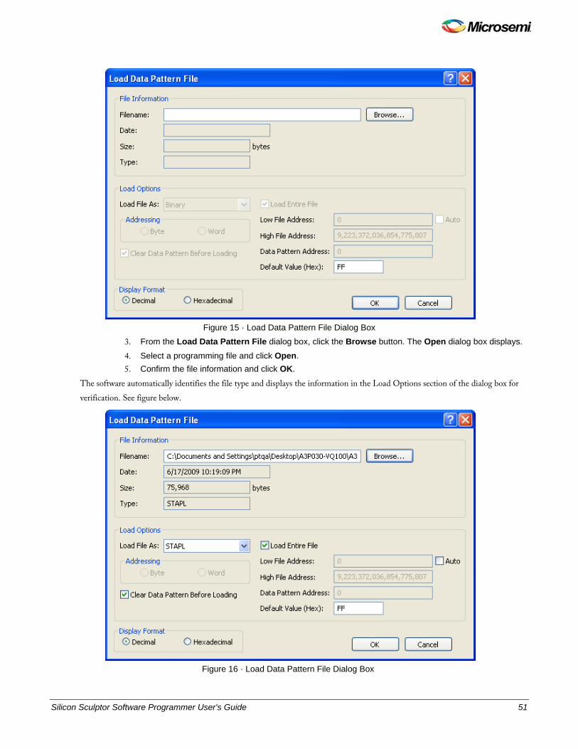
2. Load the file into the buffer by clicking the Open button from the Data Pattern dialog box. The Load Data Patter File dialog box displays (see figure below).
Note: Do not change any of the values that appear in the fields of the Load Data Pattern File dialog box.
Silicon Sculptor Software Programmer User's Guide 51
Figure 15 · Load Data Pattern File Dialog Box
3. From the Load Data Pattern File dialog box, click the Browse button. The Open dialog box displays.
4. Select a programming file and click Open. 5. Confirm the file information and click OK.
The software automatically identifies the file type and displays the information in the Load Options section of the dialog box for verification. See figure below.
Figure 16 · Load Data Pattern File Dialog Box
52 Silicon Sculptor Software Programmer User's Guide
NOTE: Links and cross-references in this PDF file may point to external files and generate an error when clicked. View the online help included with software to enable all linked content.
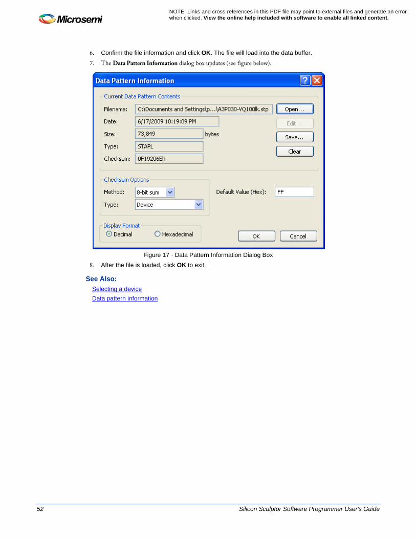
6. Confirm the file information and click OK. The file will load into the data buffer.
7. The Data Pattern Information dialog box updates (see figure below).
Figure 17 · Data Pattern Information Dialog Box
8. After the file is loaded, click OK to exit.
See Also: Selecting a device Data pattern information
Silicon Sculptor Software Programmer User's Guide 53
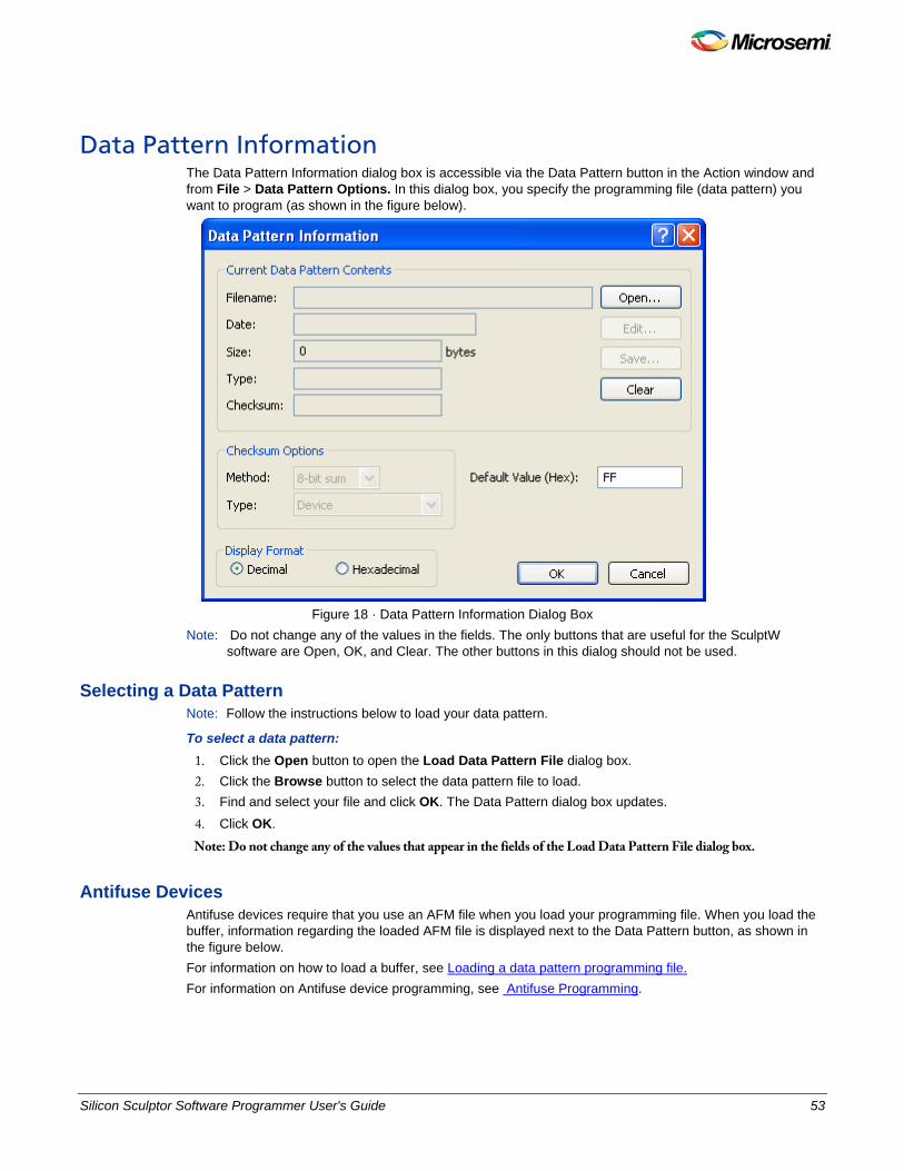
Data Pattern Information The Data Pattern Information dialog box is accessible via the Data Pattern button in the Action window and from File > Data Pattern Options. In this dialog box, you specify the programming file (data pattern) you want to program (as shown in the figure below).
Figure 18 · Data Pattern Information Dialog Box
Note: Do not change any of the values in the fields. The only buttons that are useful for the SculptW software are Open, OK, and Clear. The other buttons in this dialog should not be used.
Selecting a Data Pattern Note: Follow the instructions below to load your data pattern.
To select a data pattern: 1. Click the Open button to open the Load Data Pattern File dialog box. 2. Click the Browse button to select the data pattern file to load. 3. Find and select your file and click OK. The Data Pattern dialog box updates. 4. Click OK.
Note: Do not change any of the values that appear in the fields of the Load Data Pattern File dialog box.
Antifuse Devices Antifuse devices require that you use an AFM file when you load your programming file. When you load the buffer, information regarding the loaded AFM file is displayed next to the Data Pattern button, as shown in the figure below. For information on how to load a buffer, see Loading a data pattern programming file. For information on Antifuse device programming, see Antifuse Programming.
54 Silicon Sculptor Software Programmer User's Guide
NOTE: Links and cross-references in this PDF file may point to external files and generate an error when clicked. View the online help included with software to enable all linked content.
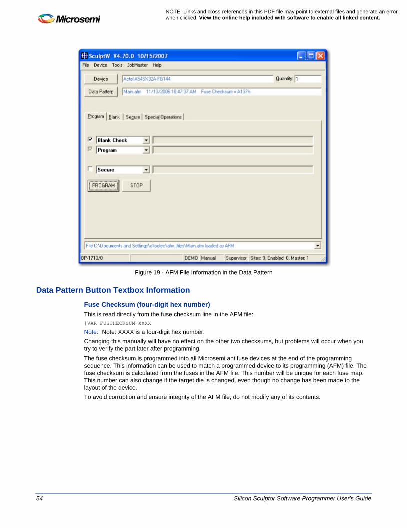
Figure 19 · AFM File Information in the Data Pattern
Data Pattern Button Textbox Information
Fuse Checksum (four-digit hex number) This is read directly from the fuse checksum line in the AFM file: |VAR FUSCHECKSUM XXXX
Note: Note: XXXX is a four-digit hex number. Changing this manually will have no effect on the other two checksums, but problems will occur when you try to verify the part later after programming. The fuse checksum is programmed into all Microsemi antifuse devices at the end of the programming sequence. This information can be used to match a programmed device to its programming (AFM) file. The fuse checksum is calculated from the fuses in the AFM file. This number will be unique for each fuse map. This number can also change if the target die is changed, even though no change has been made to the layout of the device. To avoid corruption and ensure integrity of the AFM file, do not modify any of its contents.

Silicon Sculptor Software Programmer User's Guide 55
Placing a Chip in the Socket Refer to the appropriate device programmer manual to place a device in the socket module. Note: Note:Parts must not be inserted or removed when the Active LED is on.
56 Silicon Sculptor Software Programmer User's Guide
NOTE: Links and cross-references in this PDF file may point to external files and generate an error when clicked. View the online help included with software to enable all linked content.
Antifuse Programming Antifuse programming requires that you program your device using an .afm file. AFM files support all the antifuse devices and families (ACT1-ACT3, MX, DX, EX, SX, SXA, and Axcelerator). Follow the instructions below to program an antifuse device.
Selecting an Antifuse Target Device You begin programming a device by selecting an antifuse device from the Select Device dialog box.
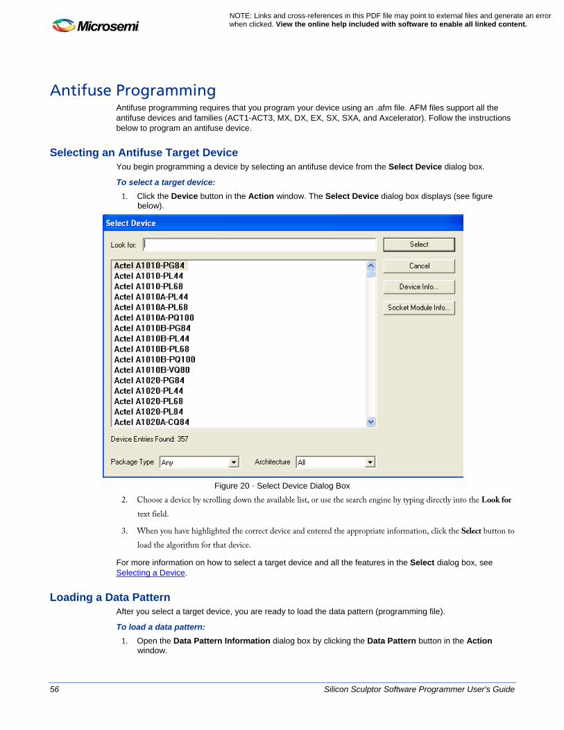
To select a target device: 1. Click the Device button in the Action window. The Select Device dialog box displays (see figure
below).
Figure 20 · Select Device Dialog Box
2. Choose a device by scrolling down the available list, or use the search engine by typing directly into the Look for text field.
3. When you have highlighted the correct device and entered the appropriate information, click the Select button to load the algorithm for that device.
For more information on how to select a target device and all the features in the Select dialog box, see Selecting a Device.
Loading a Data Pattern After you select a target device, you are ready to load the data pattern (programming file).
To load a data pattern: 1. Open the Data Pattern Information dialog box by clicking the Data Pattern button in the Action
window.
Silicon Sculptor Software Programmer User's Guide 57
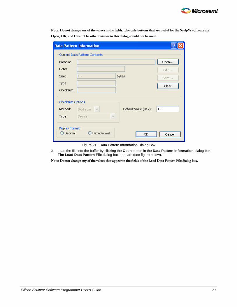
Note: Do not change any of the values in the fields. The only buttons that are useful for the SculpW software are Open, OK, and Clear. The other buttons in this dialog should not be used.
Figure 21 · Data Pattern Information Dialog Box
2. Load the file into the buffer by clicking the Open button in the Data Pattern Information dialog box. The Load Data Pattern File dialog box appears (see figure below).
Note: Do not change any of the values that appear in the fields of the Load Data Pattern File dialog box.
58 Silicon Sculptor Software Programmer User's Guide
NOTE: Links and cross-references in this PDF file may point to external files and generate an error when clicked. View the online help included with software to enable all linked content.
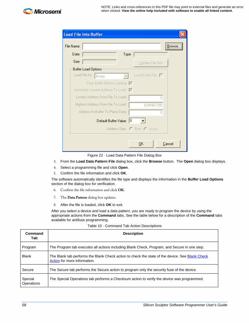
Figure 22 · Load Data Pattern File Dialog Box
3. From the Load Data Pattern File dialog box, click the Browse button. The Open dialog box displays.
4. Select a programming file and click Open. 5. Confirm the file information and click OK.
The software automatically identifies the file type and displays the information in the Buffer Load Options section of the dialog box for verification.
6. Confirm the file information and click OK.
7. The Data Pattern dialog box updates.
8. After the file is loaded, click OK to exit.
After you select a device and load a data pattern, you are ready to program the device by using the appropriate actions from the Command tabs. See the table below for a description of the Command tabs available for antifuse programming.
Table 10 · Command Tab Action Descriptions
Command Tab
Description
Program The Program tab executes all actions including Blank Check, Program, and Secure in one step.
Blank The Blank tab performs the Blank Check action to check the state of the device. See Blank Check Action for more information.
Secure The Secure tab performs the Secure action to program only the security fuse of the device.
Special Operations
The Special Operations tab performs a Checksum action to verify the device was programmed.

Silicon Sculptor Software Programmer User's Guide 59
Programming an Antifuse Device You can perform the Blank and Secure Actions (from their Command tabs) individually or you can perform these actions during the programming sequence. See the sections below for programming a device using the Actions from the Program Command tab.
Blank Check Action You can perform the Blank Check action to check the state of the device. A Blank Check failure does not damage the device.
To perform the Blank Check action from the Blank Check Command tab: 1. Select the Blank Command tab.
2. Click Blank
Note: Blank Check is a mandatory operation and can not be deselected in the Blank Command tab.
To perform the Blank Check action from the Program Command tab: 1. Select the Program Command tab. 2. Check Blank Check. 3. Click Execute.
Program Action Follow the steps below to program the device.
To program an antifuse device: 4. Select the Program Command tab from the Action window.
5. Check the Blank Check Action check box in the Program Command tab (recommended). 6. The second drop-down menu, Program, is selected by default. See figure below. 7. If desired, check the Secure Action checkbox in the Program tab to program the Security fuse. 8. Click PROGRAM.
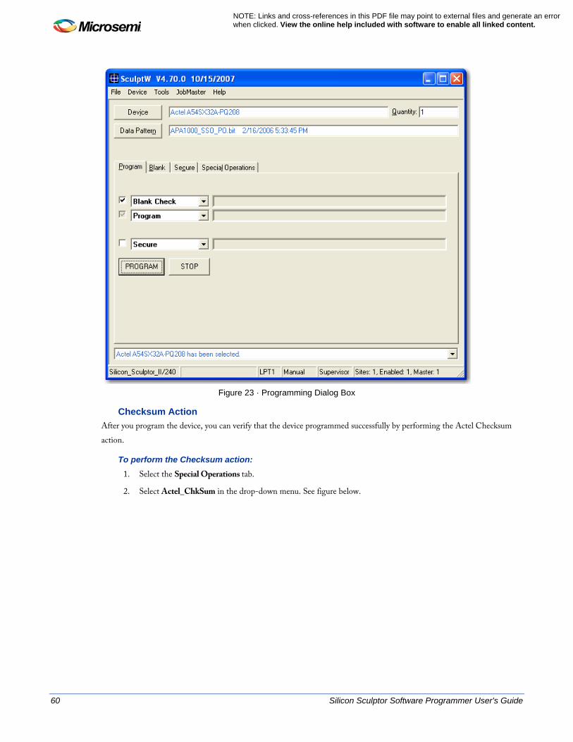
60 Silicon Sculptor Software Programmer User's Guide
NOTE: Links and cross-references in this PDF file may point to external files and generate an error when clicked. View the online help included with software to enable all linked content.
Figure 23 · Programming Dialog Box
Checksum Action After you program the device, you can verify that the device programmed successfully by performing the Actel Checksum action.
To perform the Checksum action: 1. Select the Special Operations tab.
2. Select Actel_ChkSum in the drop-down menu. See figure below.
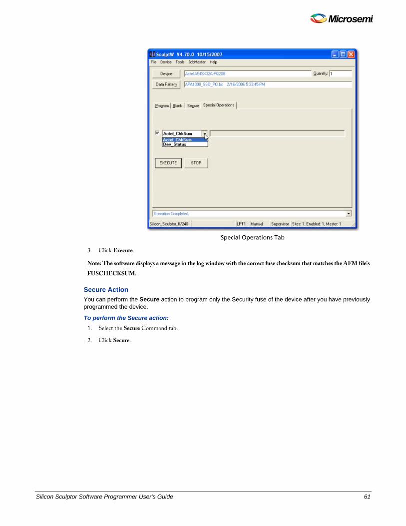
Silicon Sculptor Software Programmer User's Guide 61
Special Operations Tab
3. Click Execute.
Note: The software displays a message in the log window with the correct fuse checksum that matches the AFM file's FUSCHECKSUM.
Secure Action You can perform the Secure action to program only the Security fuse of the device after you have previously programmed the device.
To perform the Secure action: 1. Select the Secure Command tab.
2. Click Secure.
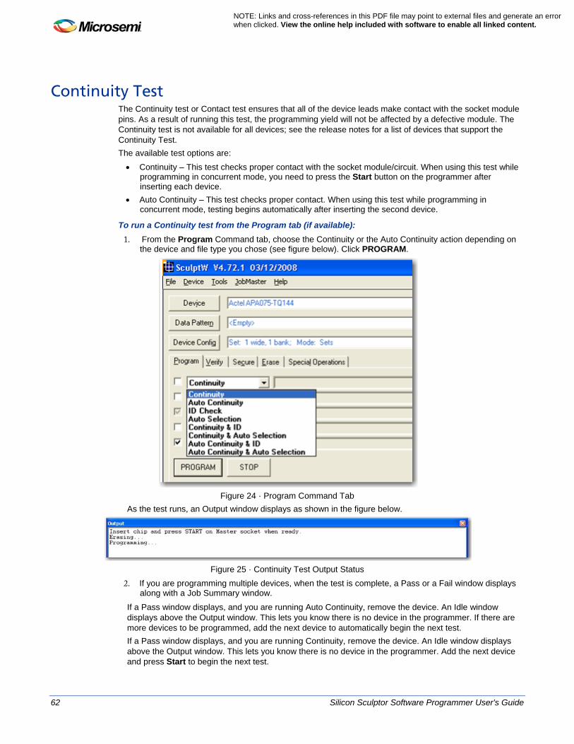
62 Silicon Sculptor Software Programmer User's Guide
NOTE: Links and cross-references in this PDF file may point to external files and generate an error when clicked. View the online help included with software to enable all linked content.
Continuity Test The Continuity test or Contact test ensures that all of the device leads make contact with the socket module pins. As a result of running this test, the programming yield will not be affected by a defective module. The Continuity test is not available for all devices; see the release notes for a list of devices that support the Continuity Test. The available test options are: • Continuity – This test checks proper contact with the socket module/circuit. When using this test while
programming in concurrent mode, you need to press the Start button on the programmer after inserting each device.
• Auto Continuity – This test checks proper contact. When using this test while programming in concurrent mode, testing begins automatically after inserting the second device.
To run a Continuity test from the Program tab (if available): 1. From the Program Command tab, choose the Continuity or the Auto Continuity action depending on
the device and file type you chose (see figure below). Click PROGRAM.
Figure 24 · Program Command Tab
As the test runs, an Output window displays as shown in the figure below.
Figure 25 · Continuity Test Output Status
2. If you are programming multiple devices, when the test is complete, a Pass or a Fail window displays along with a Job Summary window.
If a Pass window displays, and you are running Auto Continuity, remove the device. An Idle window displays above the Output window. This lets you know there is no device in the programmer. If there are more devices to be programmed, add the next device to automatically begin the next test. If a Pass window displays, and you are running Continuity, remove the device. An Idle window displays above the Output window. This lets you know there is no device in the programmer. Add the next device and press Start to begin the next test.
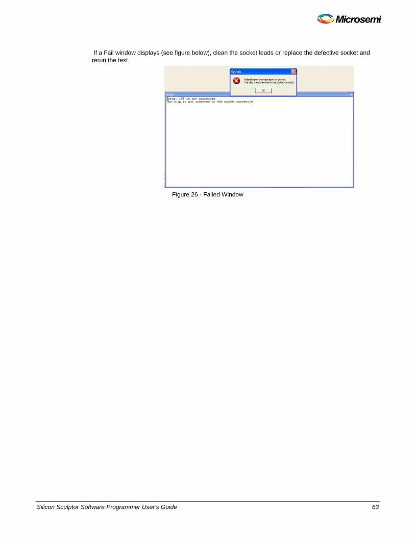
Silicon Sculptor Software Programmer User's Guide 63
If a Fail window displays (see figure below), clean the socket leads or replace the defective socket and rerun the test.
Figure 26 · Failed Window
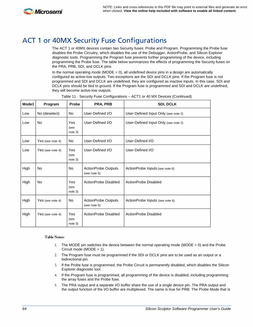
64 Silicon Sculptor Software Programmer User's Guide
NOTE: Links and cross-references in this PDF file may point to external files and generate an error when clicked. View the online help included with software to enable all linked content.
ACT 1 or 40MX Security Fuse Configurations The ACT 1 or 40MX devices contain two Security fuses: Probe and Program. Programming the Probe fuse disables the Probe Circuitry, which disables the use of the Debugger, ActionProbe, and Silicon Explorer diagnostic tools. Programming the Program fuse prevents further programming of the device, including programming the Probe fuse. The table below summarizes the effects of programming the Security fuses on the PRA, PRB, SDI, and DCLK pins. In the normal operating mode (MODE = 0), all undefined device pins in a design are automatically configured as active-low outputs. Two exceptions are the SDI and DCLK pins. If the Program fuse is not programmed and SDI and DCLK are undefined, they are configured as inactive inputs. In this case, SDI and DCLK pins should be tied to ground. If the Program fuse is programmed and SDI and DCLK are undefined, they will become active-low outputs.
Table 11 · Security Fuse Configurations – ACT1 or 40 MX Devices (Continued)
Mode1 Program Probe PRA, PRB SDI, DCLK
Low No (deselect) No User-Defined I/O User-Defined Input Only (see note 2)
Low No Yes (see note 3)
User-Defined I/O User-Defined Input Only (see note 2)
Low Yes (see note 4) No User-Defined I/O User-Defined I/O
Low Yes (see note 4) Yes (see note 3)
User-Defined I/O User-Defined I/O
High No No ActionProbe Outputs (see note 5)
ActionProbe Inputs (see note 6)
High No Yes (see note 3)
ActionProbe Disabled ActionProbe Disabled
High Yes (see note 4) No ActionProbe Outputs (see note 5)
ActionProbe Inputs (see note 6)
High Yes (see note 4) Yes (see note 3)
ActionProbe Disabled ActionProbe Disabled
Table Notes:
1. The MODE pin switches the device between the normal operating mode (MODE = 0) and the Probe Circuit mode (MODE = 1).
2. The Program fuse must be programmed if the SDI or DCLK pins are to be used as an output or a bidirectional pin.
3. If the Probe fuse is programmed, the Probe Circuit is permanently disabled, which disables the Silicon Explorer diagnostic tool.
4. If the Program fuse is programmed, all programming of the device is disabled, including programming the array fuses and the Probe fuse.
5. The PRA output and a separate I/O buffer share the use of a single device pin. The PRA output and the output function of the I/O buffer are multiplexed. The same is true for PRB. The Probe Mode that is

Silicon Sculptor Software Programmer User's Guide 65
loaded into the Mode Register determines which output buffer is active during probing. There are three possible Probe Modes: PRA only, PRB only, and PRA and PRB.
6. When you select the PRA only mode, the PRA output becomes active and the output function of the I/O buffer associated with the PRA pin is inhibited. However, the input buffer portion of the I/O buffer associated with the PRA pin is still active. Any internal signal that appears on the PRA output is fed back through that input buffer to the internal Logic Modules. This could interfere with the expected function of the design during probing. Microsemi recommends that you use an input latch on PRA and PRB to prevent the feedback while probing. PRB functions as a normal I/O in the PRA only mode. The PRB only mode is functionally equivalent to the PRA only mode. PRA also functions as a normal user I/O in the PRB only mode.
7. When you select the “PRA and PRB” mode, both the PRA and PRB outputs become active and the output function of the I/O buffers associated with both pins are inhibited. However, the input buffer of the I/O buffers associated with both pins are still active. Any internal signals that appear on the PRA and PRB outputs are fed back through the input buffers to the internal Logic Modules. This could interfere with the expected function of the design while probing. Microsemi recommends that you use an input latch on PRA and PRB to prevent the feedback during probing.
8. The SDI input and a separate I/O buffer share the use of a single device pin. The SDI input and the input function of the I/O buffer are connected in parallel. When the Mode pin is high, both inputs are active. The same is true for DCLK. External Probe Circuit control signals sent to those pins are also sent to the internal Logic Modules. This could interfere with the expected function of the design while probing.
9. Microsemi recommends that you use an input latch on SDI and DCLK to prevent the external Probe Circuit control signals from effecting the functionality of your design during probing. If either SDI or DCLK are configured so that the output function of the I/O buffer is active, the Program fuse must be programmed. In this configuration, the signals from your design are fed back to the Shift Register and will interfere with the function of the Probe Circuitry. In addition, the I/O drivers will conflict the external SDI and DCLK drivers. Damage to both drivers could occur.
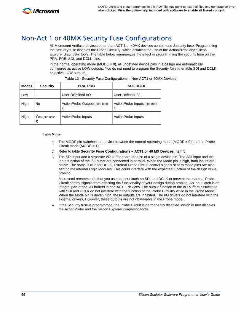
66 Silicon Sculptor Software Programmer User's Guide
NOTE: Links and cross-references in this PDF file may point to external files and generate an error when clicked. View the online help included with software to enable all linked content.
Non-Act 1 or 40MX Security Fuse Configurations All Microsemi Antifuse devices other than ACT 1 or 40MX devices contain one Security fuse. Programming the Security fuse disables the Probe Circuitry, which disables the use of the ActionProbe and Silicon Explorer diagnostic tools. The table below summarizes the effect or programming the security fuse on the PRA, PRB, SDI, and DCLK pins. In the normal operating mode (MODE = 0), all undefined device pins in a design are automatically configured as active LOW outputs. You do not need to program the Security fuse to enable SDI and DCLK as active LOW outputs.
Table 12 · Security Fuse Configurations – Non-ACT1 or 40MX Devices
Mode1 Security PRA, PRB SDI, DCLK
Low - User-DSefined I/O User-Defined I/O
High No ActionProbe Outputs (see note 2)
ActionProbe Inputs (see note 3)
High Yes (see note 4)
ActionProbe Inputs ActionProbe Inputs
Table Notes:
1. The MODE pin switches the device between the normal operating mode (MODE = 0) and the Probe Circuit mode (MODE = 1).
2. Refer to table Security Fuse Configurations – ACT1 or 40 MX Devices, item 5. 3. The SDI input and a separate I/O buffer share the use of a single device pin. The SDI input and the
input function of the I/O buffer are connected in parallel. When the Mode pin is high, both inputs are active. The same is true for DCLK. External Probe Circuit control signals sent to those pins are also sent to the internal Logic Modules. This could interfere with the expected function of the design while probing. Microsemi recommends that you use an input latch on SDI and DCLK to prevent the external Probe Circuit control signals from affecting the functionality of your design during probing. An input latch is an integral part of the I/O buffers in non-ACT 1 devices. The output function of the I/O buffers associated with SDI and DCLK do not interfere with the function of the Probe Circuitry while in the Probe Mode. When the Mode pin is driven high, these outputs are inhibited. The I/O drivers do not interfere with the external drivers. However, these outputs are not observable in the Probe mode.
4. If the Security fuse is programmed, the Probe Circuit is permanently disabled, which in turn disables the ActionProbe and the Silicon Explorer diagnostic tools.
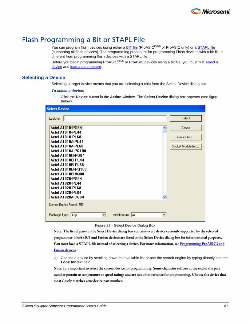
Silicon Sculptor Software Programmer User's Guide 67
Flash Programming a Bit or STAPL File You can program flash devices using either a BIT file (ProASICPLUS or ProASIC only) or a STAPL file (supporting all flash devices). The programming procedure for programming Flash devices with a bit file is different from programming flash devices with a STAPL file. Before you begin programming ProASICPLUS or ProASIC devices using a bit file, you must first select a device and load a data pattern.
Selecting a Device Selecting a target device means that you are selecting a chip from the Select Device dialog box.
To select a device: 1. Click the Device button in the Action window. The Select Device dialog box appears (see figure
below).
Figure 27 · Select Device Dialog Box
Note: The list of parts in the Select Device dialog box contains every device currently supported by the selected programmer. ProASIC3 and Fusion devices are listed in the Select Device dialog box for informational purposes. You must load a STAPL file instead of selecting a device. For more information, see Programming ProASIC3 and Fusion devices.
2. Choose a device by scrolling down the available list or use the search engine by typing directly into the Look for text field.
Note: It is important to select the correct device for programming. Some character suffixes at the end of the part number pertain to temperature or speed ratings and are not of importance for programming. Choose the device that most closely matches your device part number.

68 Silicon Sculptor Software Programmer User's Guide
NOTE: Links and cross-references in this PDF file may point to external files and generate an error when clicked. View the online help included with software to enable all linked content.
3. Click the Device Info button to display information about the selected device, including the versions of Silicon Sculptor that support the device and the appropriate socket module or the device.
4. Click the Socket Module Info button to display information about the socket module for the selected device.
5. When you have highlighted the correct device and entered the appropriate information, click the Select button to load the algorithm for that device or Cancel to exit without selecting.
After you select a device, the Select Device window closes and the device information appears in the field next to the Device button. A note or warning may appear in the Device Information window to inform you of any additional relevant information. Note: Note: For information on how to use the search engine feature in the Select Device dialog box and
other useful information, see Selecting a device.
Loading a Data Pattern After you select the device, you are ready to load the data pattern (programming file).
To load the data pattern file: 1. Open the Data Pattern dialog box by clicking the Data Pattern button in the Action window (see
figure below).
Note: Do not change any of the values in the fields. The only buttons that are useful for the SculptW software are Open, OK, and Clear. The other buttons in the dialog box should not be used.
Figure 28 · Data Pattern Information Dialog Box
2. Load the file into the buffer by clicking the Open button from the Data Pattern dialog box. The Load Data Pattern File dialog box displays.
Note: Do not change any of the values that appear in the fields of the Load Data Pattern File dialog box.
3. From the Load Data Pattern File dialog box, click the Browse button. The Open dialog box displays.
4. Select a programming file and click Open. 5. Confirm the file information and click OK.
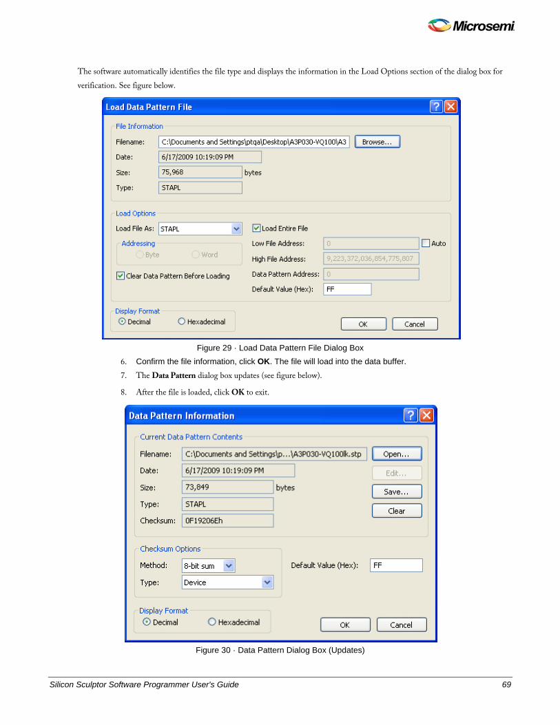
Silicon Sculptor Software Programmer User's Guide 69
The software automatically identifies the file type and displays the information in the Load Options section of the dialog box for verification. See figure below.
Figure 29 · Load Data Pattern File Dialog Box
6. Confirm the file information, click OK. The file will load into the data buffer.
7. The Data Pattern dialog box updates (see figure below).
8. After the file is loaded, click OK to exit.
Figure 30 · Data Pattern Dialog Box (Updates)
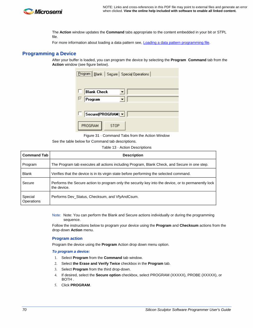
70 Silicon Sculptor Software Programmer User's Guide
NOTE: Links and cross-references in this PDF file may point to external files and generate an error when clicked. View the online help included with software to enable all linked content.
The Action window updates the Command tabs appropriate to the content embedded in your bit or STPL file. For more information about loading a data pattern see, Loading a data pattern programming file.
Programming a Device After your buffer is loaded, you can program the device by selecting the Program Command tab from the Action window (see figure below).
Figure 31 · Command Tabs from the Action Window
See the table below for Command tab descriptions. Table 13 · Action Descriptions
Command Tab Description
Program The Program tab executes all actions including Program, Blank Check, and Secure in one step.
Blank Verifies that the device is in its virgin state before performing the selected command.
Secure Performs the Secure action to program only the security key into the device, or to permanently lock the device.
Special Operations
Performs Dev_Status, Checksum, and VfyAndCsum.
Note: Note: You can perform the Blank and Secure actions individually or during the programming sequence.
Follow the instructions below to program your device using the Program and Checksum actions from the drop-down Action menu.
Program action Program the device using the Program Action drop down menu option.
To program a device: 1. Select Program from the Command tab window. 2. Select the Erase and Verify Twice checkbox in the Program tab. 3. Select Program from the third drop-down. 4. If desired, select the Secure option checkbox, select PROGRAM (XXXXX), PROBE (XXXXX), or
BOTH . 5. Click PROGRAM.
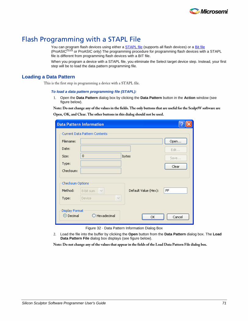
Silicon Sculptor Software Programmer User's Guide 71
Flash Programming with a STAPL File You can program flash devices using either a STAPL file (supports all flash devices) or a Bit file (ProASICPLUS or ProASIC only) The programming procedure for programming flash devices with a STAPL file is different from programming flash devices with a BIT file. When you program a device with a STAPL file, you eliminate the Select target device step. Instead, your first step will be to load the data pattern programming file.
Loading a Data Pattern This is the first step in programming a device with a STAPL file.
To load a data pattern programming file (STAPL): 1. Open the Data Pattern dialog box by clicking the Data Pattern button in the Action window (see
figure below).
Note: Do not change any of the values in the fields. The only buttons that are useful for the SculptW software are Open, OK, and Clear. The other buttons in this dialog should not be used.
Figure 32 · Data Pattern Information Dialog Box
2. Load the file into the buffer by clicking the Open button from the Data Pattern dialog box. The Load Data Pattern File dialog box displays (see figure below).
Note: Do not change any of the values that appear in the fields of the Load Data Pattern File dialog box.
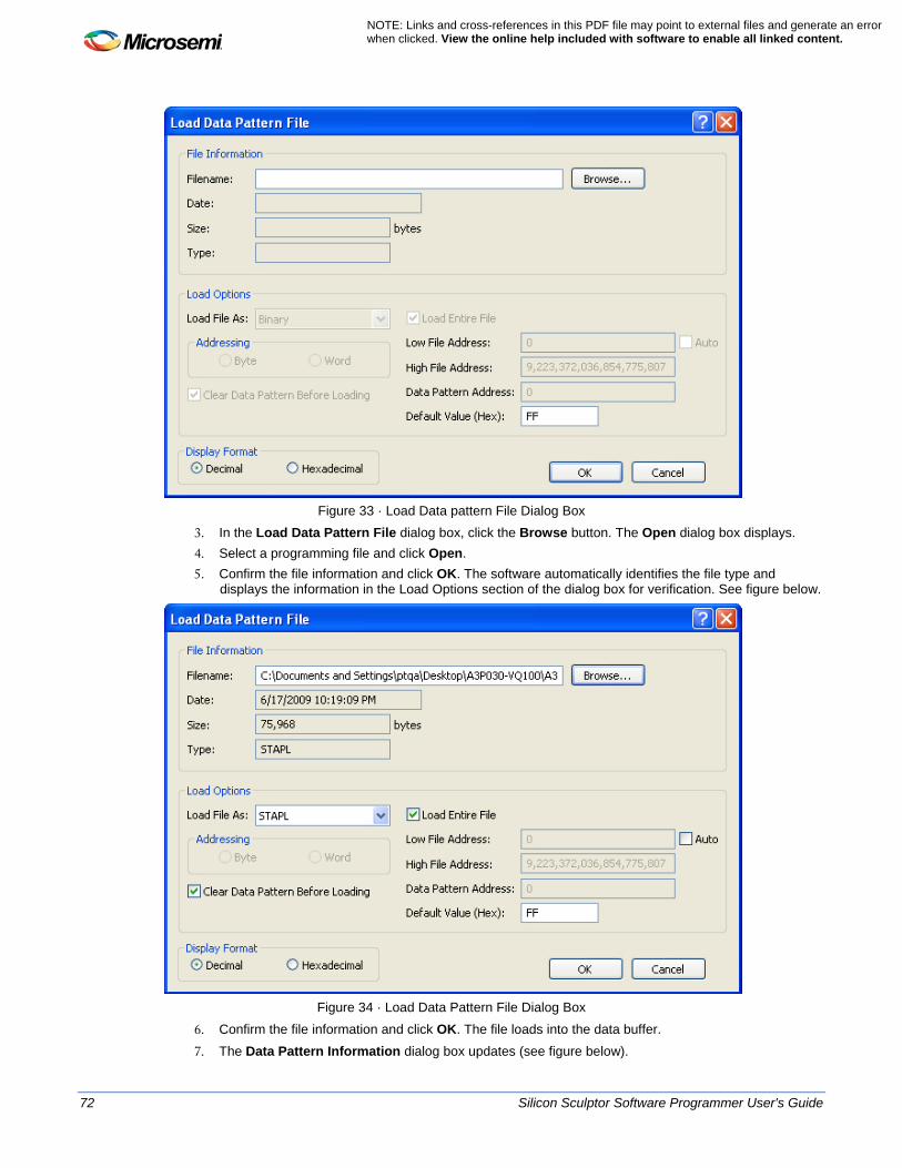
72 Silicon Sculptor Software Programmer User's Guide
NOTE: Links and cross-references in this PDF file may point to external files and generate an error when clicked. View the online help included with software to enable all linked content.
Figure 33 · Load Data pattern File Dialog Box
3. In the Load Data Pattern File dialog box, click the Browse button. The Open dialog box displays. 4. Select a programming file and click Open. 5. Confirm the file information and click OK. The software automatically identifies the file type and
displays the information in the Load Options section of the dialog box for verification. See figure below.
Figure 34 · Load Data Pattern File Dialog Box
6. Confirm the file information and click OK. The file loads into the data buffer. 7. The Data Pattern Information dialog box updates (see figure below).
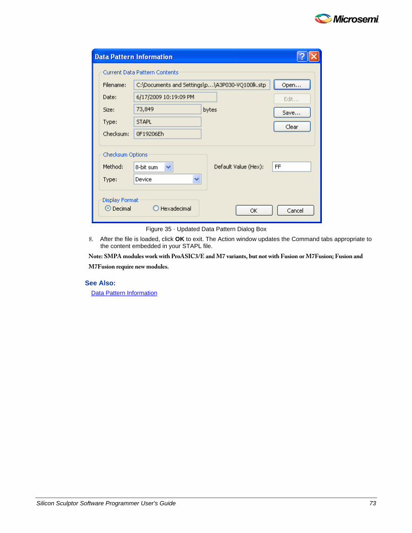
Silicon Sculptor Software Programmer User's Guide 73
Figure 35 · Updated Data Pattern Dialog Box
8. After the file is loaded, click OK to exit. The Action window updates the Command tabs appropriate to the content embedded in your STAPL file.
Note: SMPA modules work with ProASIC3/E and M7 variants, but not with Fusion or M7Fusion; Fusion and M7Fusion require new modules.
See Also: Data Pattern Information
74 Silicon Sculptor Software Programmer User's Guide
NOTE: Links and cross-references in this PDF file may point to external files and generate an error when clicked. View the online help included with software to enable all linked content.
Programming ProASIC3 and Fusion Devices The procedure for programming ProASIC3 and Fusion devices (see list) will differ from the procedure for programming a bit or AFM file. See the section below for more information about how to select these devices. • ProASIC3 • ProASIC3E • M7 ProASIC3 • M7 ProASIC3E • Fusion • M7 Fusion
ProASIC3 and Fusion Device Selection Microsemi's latest ProASIC3 and Fusion devices display in the Device list for informational purposes only. They must be programmed only with STAPL files. To program these devices, skip the Device selection step and go to the next step, which is to load a data pattern. The STAPL file indicates to the programmer the device that is to be programmed. Note: Note: You can also program ProASICPLUS and ProASIC devices using a STAPL file.
See Also: STAPL file format Flash programming with STAPL file

Silicon Sculptor Software Programmer User's Guide 75
Multi-Site Programming

76 Silicon Sculptor Software Programmer User's Guide
NOTE: Links and cross-references in this PDF file may point to external files and generate an error when clicked. View the online help included with software to enable all linked content.
Multi-site Programming Silicon Sculptor II and Silicon Sculptor 3 are concurrent programmers, so multiple sites can simultaneously program the same design. Your PC is used to hold the data that will be programmed into the devices. Specific programming algorithms and instructions are stored on the PC and downloaded to the programmer when you select a device and load the buffer. Thus, the algorithm is actually executed by each programmer's internal microprocessor. This guarantees accurate waveforms and precisely controlled critical time delays, independent of the PC's performance. The speed of your PC will only affect the rate at which the programming algorithm and data is downloaded to the programmer and will not affect programming yield. Two is the maximum number of Silicon Sculptor II units that you can connect for concurrent programming. The two Silicon Sculptor IIs must be joined together via a standard IEEE 1284 parallel cable (the special extension cable for use with the Silicon Sculptor cannot be used with Silicon Sculptor II). Twelve is the maximum number of Silicon Sculptor 3 units that you can connect via nested powered USB hubs for concurrent programming. The Silicon Sculptor 3s must be joined together via USB-IF -type approved USB cables and powered USB hubs. Silicon Sculptor 3 programmers should not be simultaneously connected to a PC on which a Silicon Sculptor II programmer is already connected; the Silicon Sculptor II programmer should be disconnected first. Note: Note: This section assumes that you have installed the SculptW software. If you have not installed it,
download the latest version from the Microsemi website. To set up concurrent programming:
1. Individually run a full system diagnostic self-test on each Silicon Sculptor. See Individual System Diagnostic Self-Test.
2. Connect the Silicon Sculptors. See Multi-Site Setup. 3. Execute the concurrent operation. See Executing Concurrent Operation .
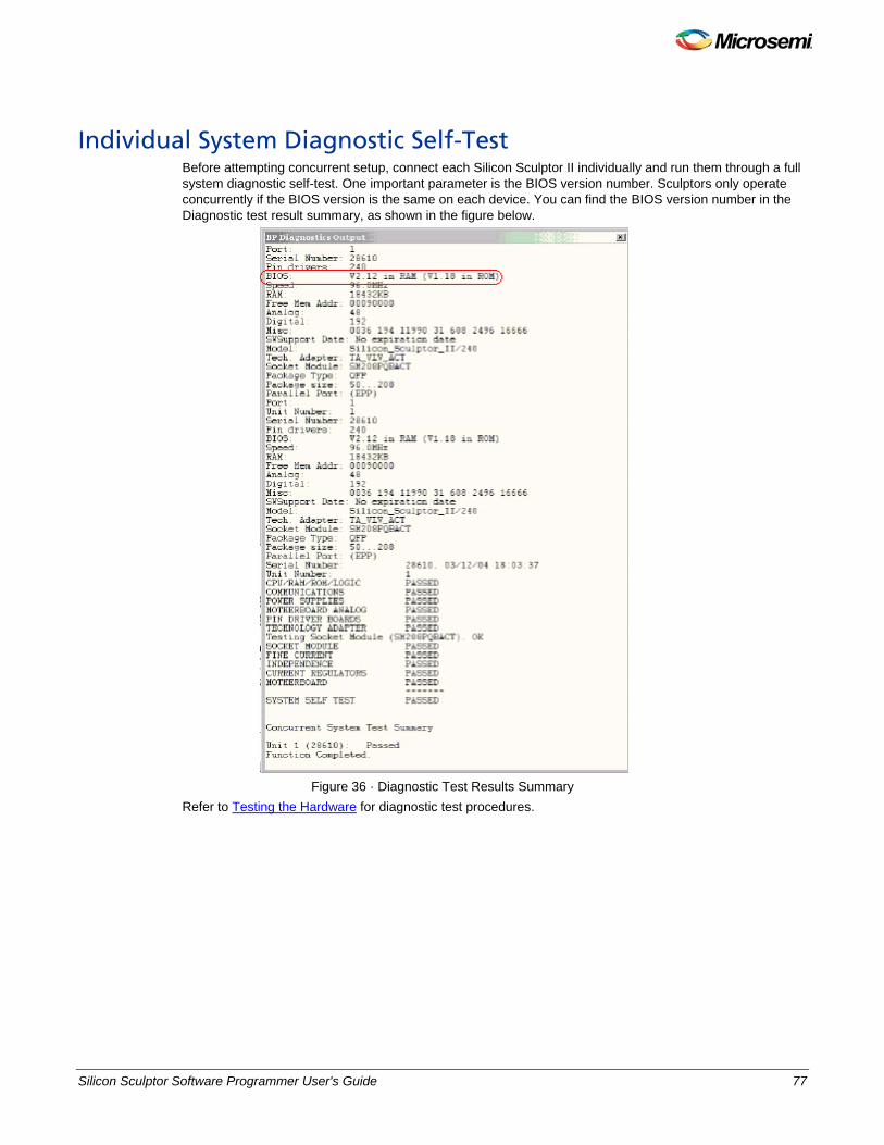
Silicon Sculptor Software Programmer User's Guide 77
Individual System Diagnostic Self-Test Before attempting concurrent setup, connect each Silicon Sculptor II individually and run them through a full system diagnostic self-test. One important parameter is the BIOS version number. Sculptors only operate concurrently if the BIOS version is the same on each device. You can find the BIOS version number in the Diagnostic test result summary, as shown in the figure below.
Figure 36 · Diagnostic Test Results Summary
Refer to Testing the Hardware for diagnostic test procedures.
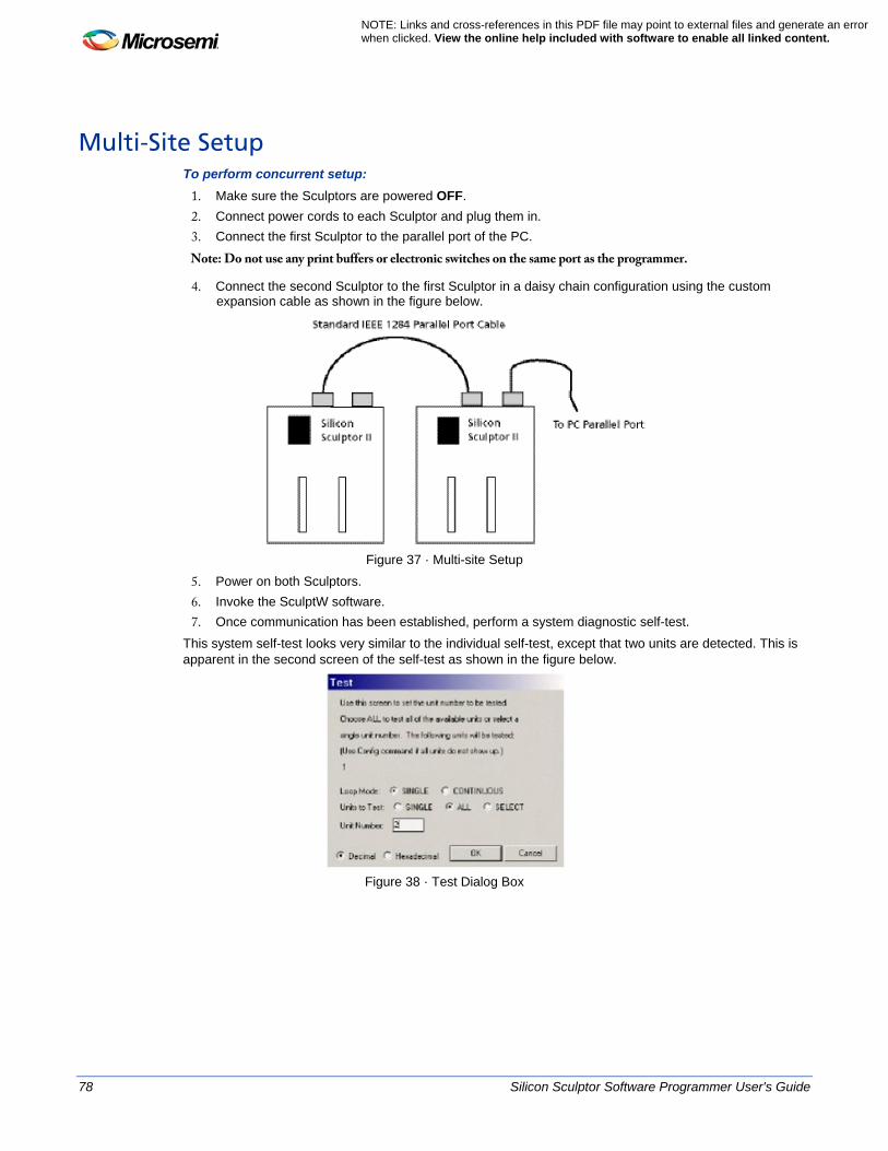
78 Silicon Sculptor Software Programmer User's Guide
NOTE: Links and cross-references in this PDF file may point to external files and generate an error when clicked. View the online help included with software to enable all linked content.
Multi-Site Setup To perform concurrent setup:
1. Make sure the Sculptors are powered OFF. 2. Connect power cords to each Sculptor and plug them in. 3. Connect the first Sculptor to the parallel port of the PC.
Note: Do not use any print buffers or electronic switches on the same port as the programmer.
4. Connect the second Sculptor to the first Sculptor in a daisy chain configuration using the custom expansion cable as shown in the figure below.
Figure 37 · Multi-site Setup
5. Power on both Sculptors. 6. Invoke the SculptW software. 7. Once communication has been established, perform a system diagnostic self-test.
This system self-test looks very similar to the individual self-test, except that two units are detected. This is apparent in the second screen of the self-test as shown in the figure below.
Figure 38 · Test Dialog Box

Silicon Sculptor Software Programmer User's Guide 79
Executing Concurrent Operation Once all systems have passed the self-test, you are ready to insert the correct adaptor modules and begin programming devices. Follow the same procedures as described in Programming a Device.
80 Silicon Sculptor Software Programmer User's Guide
NOTE: Links and cross-references in this PDF file may point to external files and generate an error when clicked. View the online help included with software to enable all linked content.
Silicon Sculptor I Multi-Site Programming The following description applies only to Silicon Sculptor I, not Silicon Sculptor II. You can only connect two Silicon Sculptor II units together via a standard IEEE 1284 parallel cable. The special extension cable for use with Silicon Sculptor I units only and cannot be used with Silicon Sculptor II units. Silicon Sculptor is a concurrent programmer, which means multiple sites can simultaneously program the same design. Your PC is used to hold the data that will be programmed into the devices. Specific programming algorithms and instructions are stored on the PC and downloaded to the programmer when you select a device and load the buffer. The algorithm is executed by each programmer’s internal microprocessor. This guarantees accurate waveforms and precisely controlled critical time delays, independent of the PC’s performance. The speed of your PC will only affect the rate at which the programming algorithm and data is downloaded to the programmer and will not affect the programming yield. The next section explains how to setup multiple Silicon Sculptor units to facilitate concurrent programming. You must install the SCULPT software before you complete the instructions below. If you have not installed the software, you can download the latest version at http://www.microsemi.com/products/fpga-soc/design-resources/programming/silicon-sculptor-3#downloads.
Step 1 - Individual System Self-Test Before beginning the concurrent setup, connect each Sculptor individually and run them through a full system self-test. Pay special attention to the firmware version number; the Sculptor units can only operate concurrently if the firmware version is the same for each one.
To run a system self-test: 1. Make sure that the Sculptor is powered off. 2. Connect the power cord to the Sculptor and plug it in. 3. Connect the Sculptor to the parallel port of your PC.
Note: Do not attempt to use any print buffers or electronic switches on the same port as the programmer.
4. Turn on the Sculptor. 5. Open a command prompt. At the command prompt, type SculptW to invoke the Sculptor software. 6. Once communication has been established, press ALT+ D to begin the system self-test. 7. Record the firmware version number. In this example, the firmware version number is V1.13. 8. Press any key and accept all default selections to proceed through the remaining self-test. Make sure
all tests are marked "Passed." 9. Repeat steps 1 to 8 for each Sculptor and verify that all firmware versions are exactly the same. Only
Sculptors with the same firmware version will operate concurrently.
Step 2 - Concurrent Setup for Two Sculptors Only If you are going to use only two Sculptors concurrently, follow the instructions below.
1. Make sure the Sculptors are powered off. 2. Connect power cords to each Sculptor and plug them in. 3. Connect the first Sculptor to the parallel port of the PC.
Note: Do not attempt to use any print buffers or electronic switches on the same port as the programmer.
4. Connect the second Sculptor to the first Sculptor in a daisy chain configuration using the custom expansion cable as shown in the figure below.
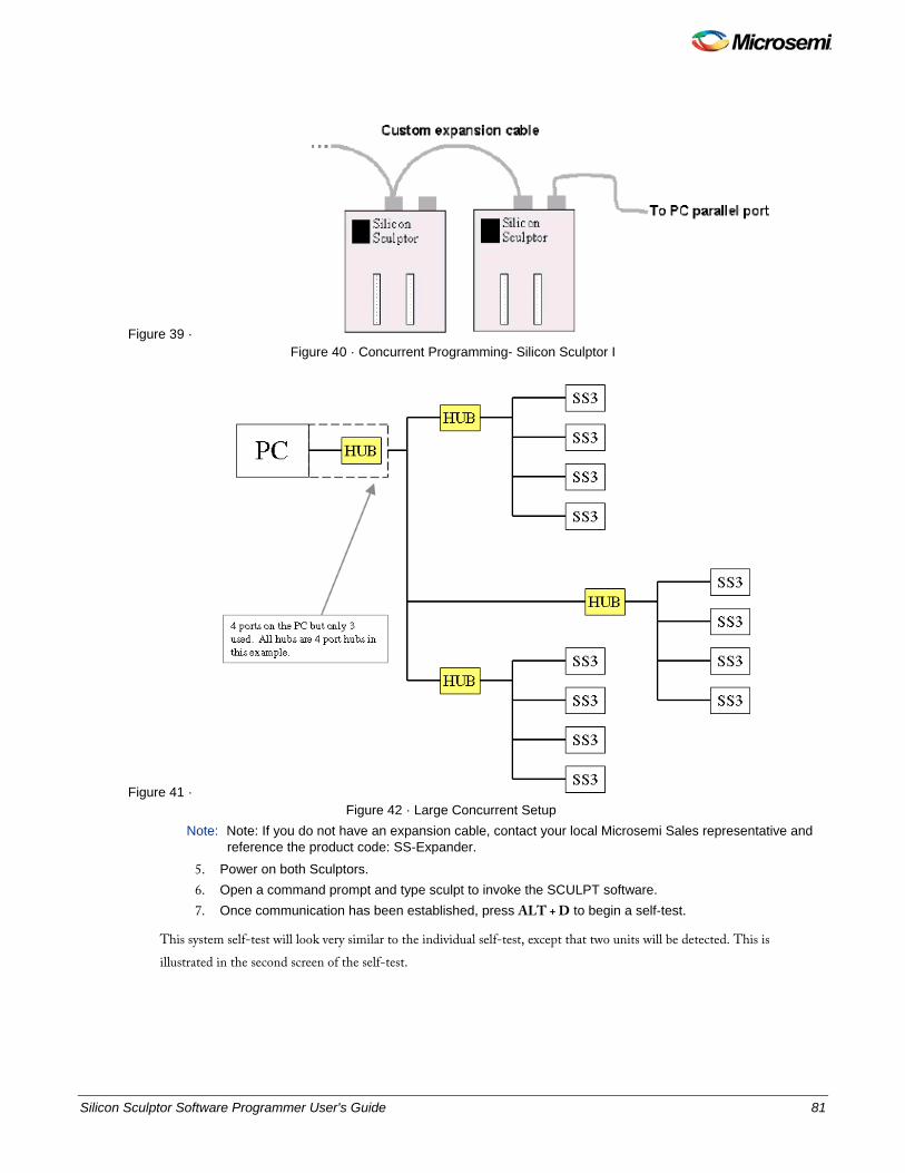
Silicon Sculptor Software Programmer User's Guide 81
Figure 39 · Figure 40 · Concurrent Programming- Silicon Sculptor I
Figure 41 · Figure 42 · Large Concurrent Setup
Note: Note: If you do not have an expansion cable, contact your local Microsemi Sales representative and reference the product code: SS-Expander.
5. Power on both Sculptors. 6. Open a command prompt and type sculpt to invoke the SCULPT software. 7. Once communication has been established, press ALT + D to begin a self-test.
This system self-test will look very similar to the individual self-test, except that two units will be detected. This is illustrated in the second screen of the self-test.
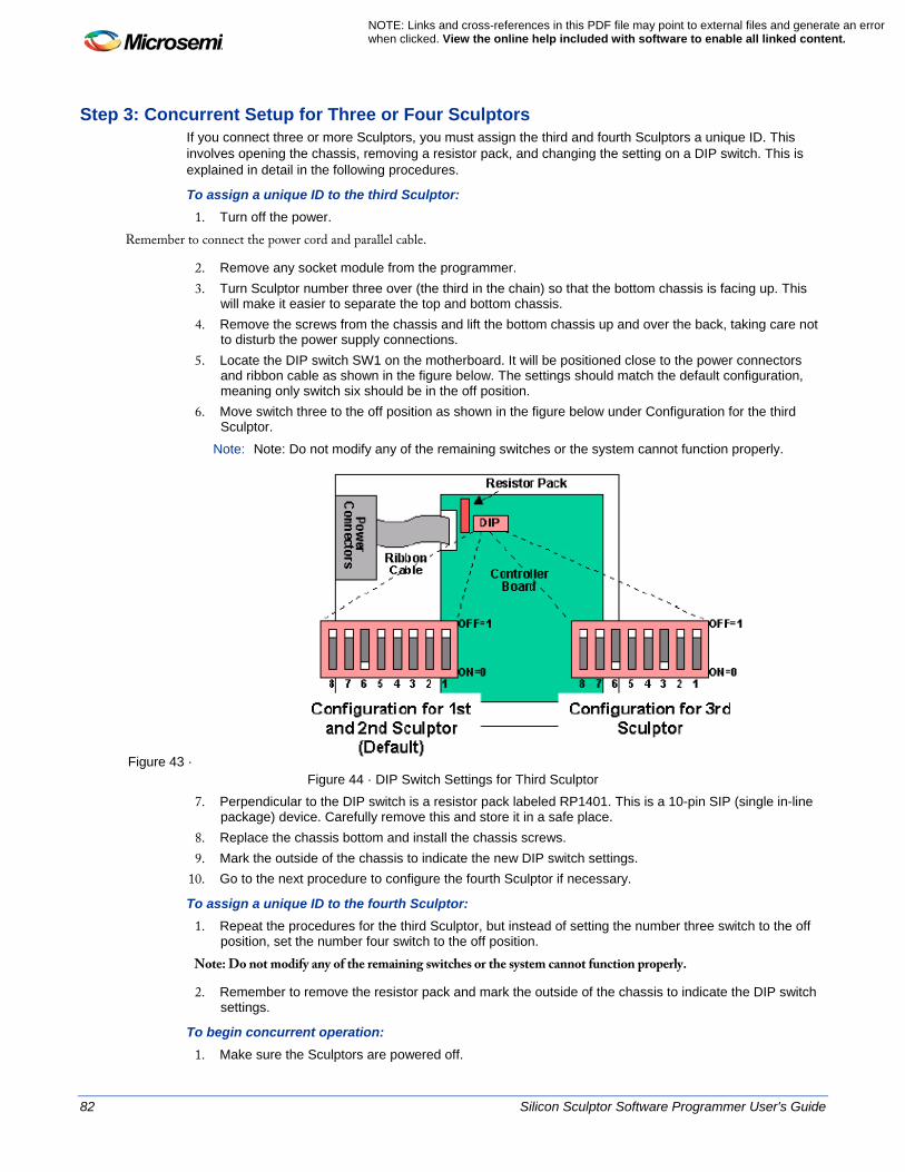
82 Silicon Sculptor Software Programmer User's Guide
NOTE: Links and cross-references in this PDF file may point to external files and generate an error when clicked. View the online help included with software to enable all linked content.
Step 3: Concurrent Setup for Three or Four Sculptors If you connect three or more Sculptors, you must assign the third and fourth Sculptors a unique ID. This involves opening the chassis, removing a resistor pack, and changing the setting on a DIP switch. This is explained in detail in the following procedures.
To assign a unique ID to the third Sculptor: 1. Turn off the power.
Remember to connect the power cord and parallel cable.
2. Remove any socket module from the programmer. 3. Turn Sculptor number three over (the third in the chain) so that the bottom chassis is facing up. This
will make it easier to separate the top and bottom chassis. 4. Remove the screws from the chassis and lift the bottom chassis up and over the back, taking care not
to disturb the power supply connections. 5. Locate the DIP switch SW1 on the motherboard. It will be positioned close to the power connectors
and ribbon cable as shown in the figure below. The settings should match the default configuration, meaning only switch six should be in the off position.
6. Move switch three to the off position as shown in the figure below under Configuration for the third Sculptor.
Note: Note: Do not modify any of the remaining switches or the system cannot function properly.
Figure 43 · Figure 44 · DIP Switch Settings for Third Sculptor
7. Perpendicular to the DIP switch is a resistor pack labeled RP1401. This is a 10-pin SIP (single in-line package) device. Carefully remove this and store it in a safe place.
8. Replace the chassis bottom and install the chassis screws. 9. Mark the outside of the chassis to indicate the new DIP switch settings.
10. Go to the next procedure to configure the fourth Sculptor if necessary.
To assign a unique ID to the fourth Sculptor: 1. Repeat the procedures for the third Sculptor, but instead of setting the number three switch to the off
position, set the number four switch to the off position.
Note: Do not modify any of the remaining switches or the system cannot function properly.
2. Remember to remove the resistor pack and mark the outside of the chassis to indicate the DIP switch settings.
To begin concurrent operation: 1. Make sure the Sculptors are powered off.

Silicon Sculptor Software Programmer User's Guide 83
2. Connect power cords to each Sculptor and plug them in. 3. Connect the first Sculptor to the parallel port of the PC.
Note: Note: Do not attempt to use any print buffers or electronic switches on the same port as the programmer.
4. Connect the first Sculptor to the second Sculptor, the second to the third, and the third to the fourth in a daisy-chain configuration using the custom expansion cable.
5. Power on all Sculptors.
Each Sculptor in the chain will run its power-on system-test consecutively.
6. Open a command prompt. Type SculptW to invoke the Sculptor software. 7. Once communication has been established, press ALT + D to begin a self-test.
This system self-test will look very similar to the individual self-test, except that all the units will be detected and will be available for test. Once all systems have passed the self-test, you are ready to insert the correct adapter modules and begin programming devices.

84 Silicon Sculptor Software Programmer User's Guide
NOTE: Links and cross-references in this PDF file may point to external files and generate an error when clicked. View the online help included with software to enable all linked content.
JobMaster Mode

Silicon Sculptor Software Programmer User's Guide 85
JobMaster Mode Introduction JobMaster enables an Administrator to set up a job to precise specifications, test the results, and protect the routine so that it cannot be modified inadvertently. After you have programmed and approved a master device, JobMaster is ready to begin full-scale programming. JobMaster has two modes for the production facility: • Supervisor mode – designated to set up jobs within the software as well as regulate any changes
made to existing jobs. • Operator mode – runs the jobs to program the device.
JobMaster is supplied with the SculptW software. If you would like to automatically start up the SculptW software in Operator mode instead of Supervisor mode, you must purchase the JobMaster feature. Contact BP Microsystems at http://www.bpmicrosystems.com to purchase JobMaster. The following sections describe how to use JobMaster.

86 Silicon Sculptor Software Programmer User's Guide
NOTE: Links and cross-references in this PDF file may point to external files and generate an error when clicked. View the online help included with software to enable all linked content.
Creating a New Job Before you create a job, make sure you understand the basics of programming a device using the SculptW software. When creating a new job with JobMaster, make sure you complete all of the steps below.
To create a new job: 1. Make sure you are in Supervisor mode. 2. Select the device that you want to program. 3. Load the buffer with the programming file to be programmed into the device. 4. Set any special configuration options.
After you have chosen at least one device, loaded the contents, and set any special configurations, you are ready to create a new job.
5. Choose JobMaster > Save Job As to save your settings. A dialog box appears to prompt the Supervisor to enter in notes. The Note option is a user-definable field that alerts the Operator when the job is selected. If the Verify Checksum of Data option is enabled and if data has changed since you created the job, the system stops and prevents the job from running.
6. After you have set the options, save the Job.
Note: Note: Microsemi recommends that you enable the Verify Checksum of Data option if you have a data file that does not change frequently.

Silicon Sculptor Software Programmer User's Guide 87
Updating a Job When you choose the JobMaster > Load Job option, JobMaster displays the date, time, author, and notes of each job you create and revise.
To update a job: 1. Choose JobMaster > Load Job to load the job. 2. Using the SculptW software to change the (Device/Configuration, Buffer/Options, or other parameters),
select JobMaster/Update to accept the current job. 3. Choose JobMaster > Save Job to save changes to the Job and update any notes you may have.
88 Silicon Sculptor Software Programmer User's Guide
NOTE: Links and cross-references in this PDF file may point to external files and generate an error when clicked. View the online help included with software to enable all linked content.
Locking the Programmer in Operator Mode Before switching to Operator mode, you can enter a Supervisor password to lock the job in Operator mode. Select JobMaster > Change Password to enter the password. If you enter a password, you must use it to exit the Operator mode. If you do not want to enter a password, leave the password area blank. The Operator mode selection is stored both in the programmer and in the SculptW software. In either case (for PC or software), the password is required to unlock that programmer and exit the Operator mode. After all the settings have been selected, you can either switch to Operator mode by selecting JobMaster > Enter Operator Mode, or configure the setting to invoke the software in Operator mode at the startup of each session. Note: Note: The Operator mode offers only the Execute and Stop options.

Silicon Sculptor Software Programmer User's Guide 89
Running a Job in Operator Mode Follow the steps below to run a job in Operator mode.
To run a job in operator mode: 1. Type the number of devices that should be successfully programmed (not the number of attempts) and
press Enter. This will allow for any rejects that may normally occur. 2. Evaluate the summary screen and continue by selecting JobMaster > View Notes. If everything is
correct, click Close. This system is now ready to begin programming devices.

90 Silicon Sculptor Software Programmer User's Guide
NOTE: Links and cross-references in this PDF file may point to external files and generate an error when clicked. View the online help included with software to enable all linked content.
Returning to Normal (Supervisor Mode) You must have the Supervisor password to return the SculptW software to normal (Supervisor) mode.
To return to normal mode: 1. In Operator mode, Select JobMaster > Enter Supervisor Mode. 2. Enter the Supervisor password.
When the SculptorW software starts up again, it will be in the normal access mode.

Silicon Sculptor Software Programmer User's Guide 91
Troubleshooting

92 Silicon Sculptor Software Programmer User's Guide
NOTE: Links and cross-references in this PDF file may point to external files and generate an error when clicked. View the online help included with software to enable all linked content.
Contacting Technical Support You can get technical support from Microsemi whenever you experience a problem that you cannot solve. Have the following information ready when you contact technical support: • The model number of the Microsemi programmer (title bar of secondary screen) • The software version number (from the top of the main screen) • The exact error message and error number received • The exact algorithm that was selected • The exact part number on the chip you were trying to program • The command executed • The results of running the self-test command on your programmer (BP Microsystems Diagnostics). • The log file of your programming history. You can find the log file of your programming history at
C:\BP\DATALOG.
It is also useful to have a screen print of the error. You may be asked to send your programming file (PLEASE ZIP BEFORE SENDING) and/or send in your devices so we can analyze the error at the factory. If you need to return your programmer to Microsemi for any reason, you must call and get a Return Material Authorization (RMA) number before shipping. Mark the RMA number clearly on the shipping container. Be sure to include a description of the problem experienced and a return address, contact person, and contact phone number. Refer to Technical Support for contact information.
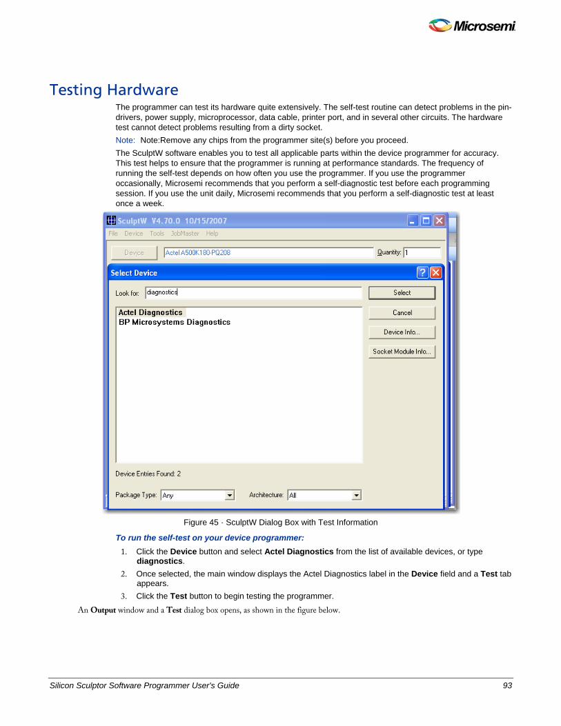
Silicon Sculptor Software Programmer User's Guide 93
Testing Hardware The programmer can test its hardware quite extensively. The self-test routine can detect problems in the pin-drivers, power supply, microprocessor, data cable, printer port, and in several other circuits. The hardware test cannot detect problems resulting from a dirty socket. Note: Note:Remove any chips from the programmer site(s) before you proceed. The SculptW software enables you to test all applicable parts within the device programmer for accuracy. This test helps to ensure that the programmer is running at performance standards. The frequency of running the self-test depends on how often you use the programmer. If you use the programmer occasionally, Microsemi recommends that you perform a self-diagnostic test before each programming session. If you use the unit daily, Microsemi recommends that you perform a self-diagnostic test at least once a week.
Figure 45 · SculptW Dialog Box with Test Information
To run the self-test on your device programmer: 1. Click the Device button and select Actel Diagnostics from the list of available devices, or type
diagnostics. 2. Once selected, the main window displays the Actel Diagnostics label in the Device field and a Test tab
appears. 3. Click the Test button to begin testing the programmer.
An Output window and a Test dialog box opens, as shown in the figure below.
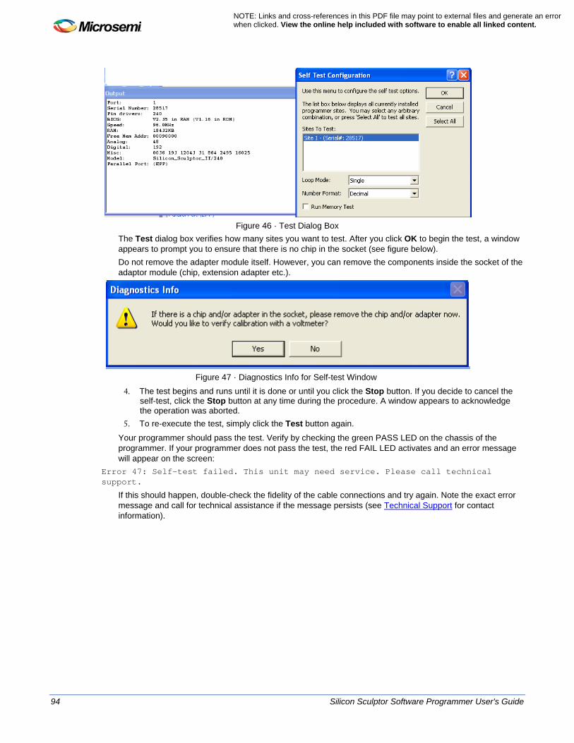
94 Silicon Sculptor Software Programmer User's Guide
NOTE: Links and cross-references in this PDF file may point to external files and generate an error when clicked. View the online help included with software to enable all linked content.
Figure 46 · Test Dialog Box
The Test dialog box verifies how many sites you want to test. After you click OK to begin the test, a window appears to prompt you to ensure that there is no chip in the socket (see figure below). Do not remove the adapter module itself. However, you can remove the components inside the socket of the adaptor module (chip, extension adapter etc.).
Figure 47 · Diagnostics Info for Self-test Window
4. The test begins and runs until it is done or until you click the Stop button. If you decide to cancel the self-test, click the Stop button at any time during the procedure. A window appears to acknowledge the operation was aborted.
5. To re-execute the test, simply click the Test button again.
Your programmer should pass the test. Verify by checking the green PASS LED on the chassis of the programmer. If your programmer does not pass the test, the red FAIL LED activates and an error message will appear on the screen:
Error 47: Self-test failed. This unit may need service. Please call technical support.
If this should happen, double-check the fidelity of the cable connections and try again. Note the exact error message and call for technical assistance if the message persists (see Technical Support for contact information).

Silicon Sculptor Software Programmer User's Guide 95
Software Updates The control software for your programmer is updated on a frequent basis (typically every three months) to add features and provide you with support for new chips. Software updates can be obtained from Microsemi (visit the Microsemi website at www.microsemi.com). Depending on the type of programmer you have (engineer, production, or automated), you may need to make upgrades and renewals by contacting the Microsemi sales department. If you decline the software/hardware upgrade and your software support runs out, the following message will appear when you select a part:
Error Code 57: Device Not Enabled
Your programmer is designed to be highly flexible and programmable, allowing it to program a wide variety of chips. Consequently, when a problem does arise, it can usually be fixed with a software update. Microsemi recommends that you obtain the latest software revision before calling the support line with a software problem. The solution for many of technical support calls is the latest version of the software.
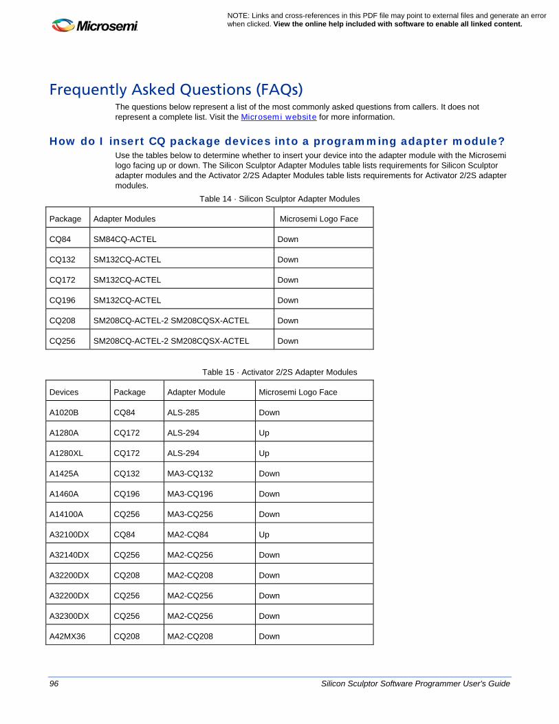
96 Silicon Sculptor Software Programmer User's Guide
NOTE: Links and cross-references in this PDF file may point to external files and generate an error when clicked. View the online help included with software to enable all linked content.
Frequently Asked Questions (FAQs) The questions below represent a list of the most commonly asked questions from callers. It does not represent a complete list. Visit the Microsemi website for more information.
How do I insert CQ package devices into a programming adapter module? Use the tables below to determine whether to insert your device into the adapter module with the Microsemi logo facing up or down. The Silicon Sculptor Adapter Modules table lists requirements for Silicon Sculptor adapter modules and the Activator 2/2S Adapter Modules table lists requirements for Activator 2/2S adapter modules.
Table 14 · Silicon Sculptor Adapter Modules
Package Adapter Modules Microsemi Logo Face
CQ84 SM84CQ-ACTEL Down
CQ132 SM132CQ-ACTEL Down
CQ172 SM132CQ-ACTEL Down
CQ196 SM132CQ-ACTEL Down
CQ208 SM208CQ-ACTEL-2 SM208CQSX-ACTEL Down
CQ256 SM208CQ-ACTEL-2 SM208CQSX-ACTEL Down
Table 15 · Activator 2/2S Adapter Modules
Devices Package Adapter Module Microsemi Logo Face
A1020B CQ84 ALS-285 Down
A1280A CQ172 ALS-294 Up
A1280XL CQ172 ALS-294 Up
A1425A CQ132 MA3-CQ132 Down
A1460A CQ196 MA3-CQ196 Down
A14100A CQ256 MA3-CQ256 Down
A32100DX CQ84 MA2-CQ84 Up
A32140DX CQ256 MA2-CQ256 Down
A32200DX CQ208 MA2-CQ208 Down
A32200DX CQ256 MA2-CQ256 Down
A32300DX CQ256 MA2-CQ256 Down
A42MX36 CQ208 MA2-CQ208 Down

Silicon Sculptor Software Programmer User's Guide 97
A42MX36 CQ256 MA2-CQ256 Down
A54SX16 CQ208 MASX-CQ208-1 Down
A54SX16 CQ256 MASX-CQ256-1 Down
A54SX32 CQ208 MASX-CQ208-1 Down
A54SX32 CQ256 MASX-CQ256-1 Down
What is the proper way to handle the programming file for electronic transfer? Microsemi strongly recommends that you always ZIP the programming files before performing any file transfers electronically. This will ensure that the integrity and contents of the programming file are intact and will prevent file corruption during transfer.
The Silicon Sculptor II programmer does not communicate with computers installed with Windows 2000/XP, and the GUI is fixed in Demo mode. What is the communication problem and why is the GUI fixed in the Demo mode?
Silicon Sculptor II programmers are based on the BP x600 technology. These programmers are faster than other programmers from BP partly because they use EPP communication on the LPT1 port. The Silicon Sculptor I programmer communicates using bidirectional, ECP, or EPP. You must set the Silicon Sculptor II programmer to EPP; otherwise, it does not communicate on most computers and the GUI is fixed in Demo mode. You need to go into the BIOS setup, find the LPT1 port settings, and change the LPT1 Port mode to EPP. There may be cases where the Silicon Sculptor II programmer will still fail to communicate with computers installed with Windows 2000 operating systems, no matter which parallel port setting is used. In this case, if the Silicon Sculptor II programmer still cannot communicate with the computer, the parallel port cable may be the cause of the problem. Silicon Sculptor II programmers must use IEEE 1284-compliant parallel port cables. Make sure the parallel port cable is IEEE 1284-compliant.
In the DOS version, the configuration settings were saved to a file. Where did they go? With the introduction of the Windows version of SculptW, the configuration settings are no longer saved to a file. These settings are now being saved in the Windows 98/2000/XP registry and are not deleted when they are uninstalled. This allows you to continue to use previous settings when upgrading to a new version of the software. There may be cases however, when you are required to delete these settings. To do so, execute the following steps:
1. Run the Registry Editor. Choose Start > Run and type regedit. 2. Select HKEY_CURRENT_USER\Software\BP Microsystems\SculptW. 3. Delete the SculptW registry settings.
The SculptW registry settings are now deleted. The new registry settings will appear in this location when you reinstall or upgrade the software.

98 Silicon Sculptor Software Programmer User's Guide
NOTE: Links and cross-references in this PDF file may point to external files and generate an error when clicked. View the online help included with software to enable all linked content.
Programming Errors Note: Note: Your computer must not enter Sleep mode during programming or your programming may fail. If you experience problems while trying to program a device, try to narrow down the problem. If you receive a Cannot program or Cannot erase error message while programming, try the following: • Make sure you have selected the proper device (i.e., the device programming algorithm) • The device may have been previously secured; use Blank Check to verify whether or not the device is
blank • The device may have a newer die than the one supported by the device (i.e., the device programming
algorithm)

Silicon Sculptor Software Programmer User's Guide 99
Cleaning a Dirty DIP Socket If the DIP socket becomes dirty, it sometimes fails to make contact with all the chip pins. The simple fix is to place your chip in the socket, push the lever down, and slide the chip left and right a few times. Microsemi also recommends cleaning sockets with a blast of high-pressure air on a regular basis. If this does not resolve the problem, run the hardware self-test. If your hardware passes the self-test, there may be an error in the programming algorithm you are using, or Microsemi may have updated the programming algorithm for your device. In either event, your can probably correct your problem with a software update.

100 Silicon Sculptor Software Programmer User's Guide
NOTE: Links and cross-references in this PDF file may point to external files and generate an error when clicked. View the online help included with software to enable all linked content.
Error Messages and Suggested Actions Error messages are usually generated by the device programmer. When you receive an error message, refer to the appropriate device programmer manual's troubleshooting section. During execution of an operation, BPWin/SculptW logs Microsemi exit codes and exit messages. This information is useful when performing failure analysis. The following is a list of error messages that could originate from the software.
Algo Database Error – loading BPAlg.db This is a “catch all” error code. SculptW generates this error if anything not listed above causes an error while loading the algorithm database. Accepting this error message prompts an exit from the software. Contact technical support for further assistance. Refer to Technical Support for contact information.
BPPgmr.ocx – internal error SculptW generates this error when the unique coding sequence attached to both the BPPgmr.ocx and the BPEng.dll do not match. Accepting this error message prompts an exit from the software. Contact technical support for further assistance. Refer to Technical Support for contact information.
Version Mismatch – BPEng.dll and BPAlg.db versions mismatched The engine and algorithm database versions do not match. Accepting this error message prompts an exit from the software. Contact technical support for further assistance. Refer to Technical Support for contact information.
Error 3: Cannot reset hardware The software cannot establish communication with the programmer: • Be sure the programmer has power and that the green PASS LED is on. Since the programmer
performs an automatic Power On Self-Test (POST) on startup, it could be that the programmer failed the test and has signaled the software into the default DEMO mode. If this should happen, contact technical support for further assistance. See Technical Support for contact information.
• Make sure the cable from the programmer to the computer is properly connected to a parallel printer port. If you are using a ribbon cable, this is probably the problem (ribbon cable connectors are designed for use inside a chassis where the cable is not flexed). You should use a shielded 25-pin standard IEEE 1284 compliant cable, not an RS-232 cable.
• Check your LPT port. If you have multiple parallel ports, you may have the ports configured incorrectly, with two at the same address.
• Some laptops have the ability to disable the port. If you are working on a laptop, make sure the LPT port is enabled.
• Another program (such as a print cache) may be interfering with the port. When running under Windows, you increase the likelihood of another program trying to access the same parallel port and changing the expected status at the port.
• If you have a hardware lock key between the programmer and the port, try removing it. • The programmer may be damaged. Try using a different computer and/or parallel port and see if it
works.
Error 5: Hardware time-out The software issues this error message when it is waiting on a response from the programmer while executing a command and the programmer does not respond within the expected amount of time. This error can result from several causes. You may be experiencing communication errors (see Error 3: Cannot reset hardware). There may be a bug in the software for this particular algorithm (see Error 10: Error in programming algorithm. Please call technical support.). Refer to Testing the Hardware for more information.
Error 6: Wrong model number See Error 3: Cannot reset hardware for possible causes.

Silicon Sculptor Software Programmer User's Guide 101
Error 8: LPTx: is not a functioning port The parallel port LPTx (where x = 1, 2 or 3) that is selected with the Configure command does not exist on your computer, is not functional, or has a bad cable connected to it.
Error 9: Programmer execution error The programmer failed an internal consistency check. See Error 3: Cannot reset hardware and Error 5: Hardware time-out for possible causes.
Error 10: Error in programming algorithm. Please call technical support. The software has detected an internal error. You should contact Microsemi to report the error. You may need to upgrade your system with the most recent release of the software posted on the Microsemi website. See Microsemi Technical Support for contact information.
Error 11: There is no data in the buffer. You must load a file or read a chip. A command tried to read data from the buffer to program or verify a chip, but nothing has been loaded into the buffer yet or the buffer was recently cleared.
Error 14: There is no chip in the programmer site Be certain that you inserted your chip correctly. If it was inserted correctly, remove it and run the hardware self-test to make sure your programmer is functioning correctly using Microsemi Diagnostics (see Testing the Hardware). A defective chip may also cause this error. When using an autohandler, the contactor may not have closed or the connection between the programmer and the contactor may be disconnected.
Error 15: The chip is not inserted in the programmer site correctly The continuity test determined that the chip in the programmer site does not have continuity on all the proper pins. You should examine these pins carefully. Possible causes are: • A bent pin • The chip is not in the proper position in the programmer site. • The chip has a different number of pins than the chip selected. • The algorithm selected has a *, indicating that it requires an adapter but you did not use the adapter, or
vice-versa. • The socket is dirty and not making a connection. See Cleaning a Dirty DIP Socket for more
information. • The wrong socket module or adapter is being used for this part. • The device may be a very low power device that is not properly detected by Microsemi’s continuity
methodology. If so, please notify Microsemi.
Note: Note: - It is not easy to get continuity on an LCC device in a PLCC socket. If you are trying to do so, you may need to add a spacer between the chip and the lid in order to apply the proper force to the device pins. The best solution is to purchase an LCC socket module that does not require any such modification. Also, LCC devices do not work at all in the autoeject sockets designed strictly for PLCC devices.
Error 16: The chip is inserted backwards The chip has passed the continuity tests, but appears to have the GND and Vcc pins improperly placed in the socket. If LCC, PLCC, or QFP is not accidentally rotated, then the device is probably defective. Try a known good device.
Error 17: Out of base memory. You should have at least 200K free. Your computer's configuration does not have enough RAM available to run the software. You should have 640 K RAM installed with at least 200 K available for program execution. Memory resident programs, such as network drivers, can reduce the RAM available to the programmer, so you may need to remove these programs from your CONFIG.SYS and AUTOEXEC.BAT files.
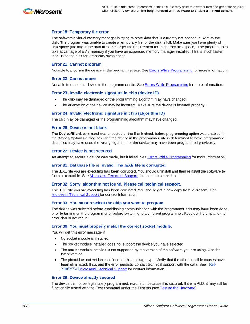
102 Silicon Sculptor Software Programmer User's Guide
NOTE: Links and cross-references in this PDF file may point to external files and generate an error when clicked. View the online help included with software to enable all linked content.
Error 18: Temporary file error The software's virtual memory manager is trying to store data that is currently not needed in RAM to the disk. The program was unable to create a temporary file, or the disk is full. Make sure you have plenty of disk space (the larger the data files, the larger the requirement for temporary disk space). The program does take advantage of EMS memory if you have an expanded memory manager installed. This is much faster than using the disk for temporary swap space.
Error 21: Cannot program Not able to program the device in the programmer site. See Errors While Programming for more information.
Error 22: Cannot erase Not able to erase the device in the programmer site. See Errors While Programming for more information.
Error 23: Invalid electronic signature in chip (device ID) • The chip may be damaged or the programming algorithm may have changed. • The orientation of the device may be incorrect. Make sure the device is inserted properly.
Error 24: Invalid electronic signature in chip (algorithm ID) The chip may be damaged or the programming algorithm may have changed.
Error 26: Device is not blank The Device/Blank command was executed or the Blank check before programming option was enabled in the Device/Options dialog box, and the device in the programmer site is determined to have programmed data. You may have used the wrong algorithm, or the device may have been programmed previously.
Error 27: Device is not secured An attempt to secure a device was made, but it failed. See Errors While Programming for more information.
Error 31: Database file is invalid. The .EXE file is corrupted. The .EXE file you are executing has been corrupted. You should uninstall and then reinstall the software to fix the executable. See Microsemi Technical Support for contact information.
Error 32: Sorry, algorithm not found. Please call technical support. The .EXE file you are executing has been corrupted. You should get a new copy from Microsemi. See Microsemi Technical Support for contact information.
Error 33: You must reselect the chip you want to program. The device was selected before establishing communication with the programmer; this may have been done prior to turning on the programmer or before switching to a different programmer. Reselect the chip and the error should not recur.
Error 36: You must properly install the correct socket module. You will get this error message if:
• No socket module is installed. • The socket module installed does not support the device you have selected. • The socket module installed is not supported by the version of the software you are using. Use the
latest version. • The pinout has not yet been defined for this package type. Verify that the other possible causes have
been eliminated. If so, and the error persists, contact technical support with the data. See _Ref-210825542Microsemi Technical Support for contact information.
Error 39: Device already secured The device cannot be legitimately programmed, read, etc., because it is secured. If it is a PLD, it may still be functionally tested with the Test command under the Test tab (see Testing the Hardware).

Silicon Sculptor Software Programmer User's Guide 103
Error 44: Internal error. Please call technical support. The software detected an internal inconsistency. This may be caused by the computer not performing correctly. Contact technical support. See _Ref-210825542Microsemi Technical Support for contact information.
Error 46: AFS software required to execute this function This is a function that is available to users who have purchased the Advanced Feature Software only. In order to use the chosen function you must purchase the AFS upgrade.
Error 47: Self-test failed. This unit may need service. Please call technical support. The self-test (Microsemi Diagnostics) has detected a hardware problem. The unit may need to be returned for repair. Note the exact error message and contact Technical Support. See Microsemi Technical Support for contact information.
Error 57: You must purchase support for this device to use it. The device that you selected is not supported in the default device set for this programmer. Call Microsemi Sales to purchase an upgrade code for your programmer (see Product Support for contact information).
Error 70: The buffer data cannot be used to program this device. You loaded a file type that is not a valid option for the currently selected device. Re-select the device and load the buffer again. If the error persists, call technical support. See Microsemi Technical Support for technical support contact information.
AFM has incorrect record length. The file may be corrupted, please load a valid AFM. This message applies to SculptW, A-SXS, EX. Make sure that the AFM is valid, up-to-date and correct for this device.
AFM Version not found. Please load a valid AFM file. This message applies to SXA-SXS. Check that the AFM is valid, up-to-date and correct for this device. Regenerate AFM using current version of Designer.
Antifuse Pulse <number > This message applies to ScultpW. There has been a program error.
Antifuse programming failed. The afm used is from an older revision of Designer software. Please use an afm generated from the latest Designer software. This message applies to AX-AXS. Regenerate an AFM from current version of Designer.
Antifuse programming failure. Antifuse Pulse <number >. This message applies to EX, SX The device did not program correctly.
Blank check failure. Device is not blank. This message applies to EX, SX. Make sure the correct blank device is inserted. Make sure the device is not programmed already. Make sure the device is not damaged.
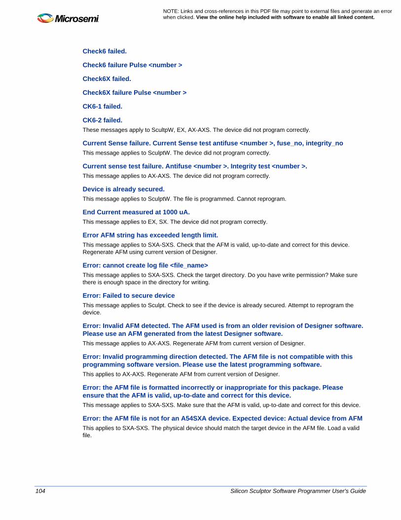
104 Silicon Sculptor Software Programmer User's Guide
NOTE: Links and cross-references in this PDF file may point to external files and generate an error when clicked. View the online help included with software to enable all linked content.
Check6 failed.
Check6 failure Pulse <number >
Check6X failed.
Check6X failure Pulse <number >
CK6-1 failed.
CK6-2 failed. These messages apply to ScultpW, EX, AX-AXS. The device did not program correctly.
Current Sense failure. Current Sense test antifuse <number >, fuse_no, integrity_no This message applies to SculptW. The device did not program correctly.
Current sense test failure. Antifuse <number >. Integrity test <number >. This message applies to AX-AXS. The device did not program correctly.
Device is already secured. This message applies to SculptW. The file is programmed. Cannot reprogram.
End Current measured at 1000 uA. This message applies to EX, SX. The device did not program correctly.
Error AFM string has exceeded length limit. This message applies to SXA-SXS. Check that the AFM is valid, up-to-date and correct for this device. Regenerate AFM using current version of Designer.
Error: cannot create log file <file_name> This message applies to SXA-SXS. Check the target directory. Do you have write permission? Make sure there is enough space in the directory for writing.
Error: Failed to secure device This message applies to Sculpt. Check to see if the device is already secured. Attempt to reprogram the device.
Error: Invalid AFM detected. The AFM used is from an older revision of Designer software. Please use an AFM generated from the latest Designer software. This message applies to AX-AXS. Regenerate AFM from current version of Designer.
Error: Invalid programming direction detected. The AFM file is not compatible with this programming software version. Please use the latest programming software. This applies to AX-AXS. Regenerate AFM from current version of Designer.
Error: the AFM file is formatted incorrectly or inappropriate for this package. Please ensure that the AFM is valid, up-to-date and correct for this device. This message applies to SXA-SXS. Make sure that the AFM is valid, up-to-date and correct for this device.
Error: the AFM file is not for an A54SXA device. Expected device: Actual device from AFM This applies to SXA-SXS. The physical device should match the target device in the AFM file. Load a valid file.

Silicon Sculptor Software Programmer User's Guide 105
Error: the AFM file is not for an RT54SXS device. Expected device: Actual device from AFM This message applies to SXA-SXS. The physical device should match the target device in the AFM file. Load a valid file.
Error: the loaded programming file is not a valid AFM file. This message applies to SXA-SXS. Incorrect device. Load a valid file.
Expected Design Checksum does not match the actual Design Checksum read from the unit. Expected Checksum: <number> Actual Design Checksum:<number> . This message applies to SculptW, EX, SX, AX-AXS. Verify the design is programmed correctly and the design is correct.
Failed Actel Checksum. Please load an AFM file This message applies to SX. Load an AFM file to do Actel Checksum.
Failed blank check. <Device is not blank> (System error message) This message applies to AX-AXS, SX, EX. Make sure the correct blank device is inserted. Make sure the device is not programmed already. Make sure the device is not damaged.
Failed Blank Check. Device is not blank. This message applies to SculptW, SXA-SXS. Make sure the correct blank device is inserted. Make sure the device is not programmed already. Make sure the device is not damaged.
Failed Check6 Pulse <number>
Failed Check6X Pulse <number> These error messages apply to SXA-SXS. The device did not program correctly.
Failed Design Checksum. Expected Design Checksum does not match the actual Design Checksum read from the unit This message applies to SX, SXA-SX. Verify the device is designed correctly. Verify the device is programmed correctly.
Failed Design Checksum. Expected Design Checksum does not match the actual Design Checksum read from the unit. Expected Checksum: <number> Actual Design Checksum <number> This message applies to SXA-SXS. Verify the design is programmed correctly and the design is correct.
Failed Design Checksum. Expected Design Checksum does not match the actual Design Checksum read from the unit. Expected Checksum: <number> Actual Design Checksum: <number> This message applies to SX. Verify the device is designed correctly. Verify the device is programmed correctly.
Failed Device ID. Expected Device ID does not match the actual Device ID read from the unit. Expected Device ID: <number> Actual ID: <number> This applies to "SculptW, SXA-SXS, AX-AXS. Make sure the correct device is inserted. Make sure the device is inserted correctly (orientation, facing correct direction). Make sure the socket and device are physically undamaged. If there is still a problem after verifying, contact Technical Support.
Failed FUS3 test This message applies to SXA-SXS, SculptW. Programming failure.
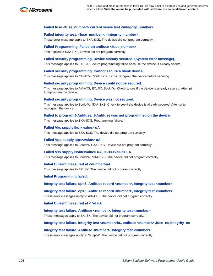
106 Silicon Sculptor Software Programmer User's Guide
NOTE: Links and cross-references in this PDF file may point to external files and generate an error when clicked. View the online help included with software to enable all linked content.
Failed fuse <fuse_number> current sense test <integrity_number>
Failed integrity test. <fuse_number>. <integrity_number> These error message apply to SXA-SXS. The device did not program correctly.
Failed Programming. Failed on antifuse <fuse_number> This applies to SXA-SXS. Device did not program correctly.
Failed security programming. Device already secured. (System error message). This message applies to EX, SX. Secure programming failed because the device is already secure.
Failed security programming. Cannot secure a blank device. This message applies to "ScultpW, SXA-SXS, EX SX. Program the device before securing.
Failed security programming. Device could not be secured. This message applies to AX-AXS, EX, SX, SculptW. Check to see if the device is already secured. Attempt to reprogram the device.
Failed security programming. Device was not secured. This message applies to SculptW, SXA-SXS. Check to see if the device is already secured. Attempt to reprogram the device.
Failed to program J-Antifuse. J-Antifuse was not programmed on the device. This message applies to SXA-SXS. Programming failure.
Failed Vks supply iks=<value> uA This message applies to SXA-SXS. The device did not program correctly.
Failed Vpp supply ipp=<value> uA This message applies to SculptW SXA-SXS. Device did not program correctly.
Failed Vsv supply isv0=<value> uA, isv1=<value> uA This message applies to SculptW, SXA-SXS. The device did not program correctly.
Initial Current measured at <number>uA This message applies to EX, SX. The device did not program correctly.
Initial Programming failed.
Integrity test failure. op=5, Antifuse record <number>, Integrity test <number>
Integrity test failure. op=6, Antifuse record <number>, Integrity test <number> These error messages apply to AX-AXS. The device did not program correctly.
Initial Current measured at < >d uA
Integrity test failure. Antifuse <number>. Integrity test <number> These messages apply to EX, SX. The device did not program correctly.
Integrity test failure. Integrity test <number>lu., antifuse <number> ,fuse_no,integrity_no
Integrity test failure. Antifuse <number>. Integrity test <number> These error messages apply to SculptW. The device did not program correctly.

Silicon Sculptor Software Programmer User's Guide 107
Invalid AFM detected. The afm used is from an older revision of Designer software. Please use an afm generated from the latest Designer software This message applies to AX-AXS. Regenerate AFM from current version of Designer.
Invalid AFM detected. A string in the AFM has exceeded the expected length limit. The file may be corrupted, please load a valid AFM This message applies to SculptW, EX, SX. Make sure the AFM is valid, up-to-date and correct for this device. Make sure the AFM is valid, up-to-date and correct for this device.
Invalid DIE type is specified in the AFM. < >s is not a valid DIE This message applies to AX-AXS. The physical device should match the target device on the AFM file.
Invalid opcode=<number>. The AFM file is not compatible with this programming software version. Please use the latest version of SculptW software. This message applies to SXA-SXS. Use the latest version of SculptW software. Regenerate AFM from current version of Designer.
Invalid Socket Module. A54SX and RTSXS devices in the CQ208/256 packages are not supported on this Socket Module. Please use the SM208CQSX-ACTEL (or later) This message applies to SXA-SXS. The wrong socket module or adapter is being used for this part.
Invalid Socket Module. A54SX devices in the VQ100 package are not supported on the SM100VQ-ACTEL-1 Socket Module. Please use the SM100VQ-ACTEL-2 (or later) instead. This message applies to SXA-SXS. The wrong socket module or adapter is being used for this part.
J-Antifuse is not programmed. This message applies to SX, EX,SculptW. The device did not program correctly.
J-Antifuse programming failure. The message applies to EX, Sculpt. The device did not program correctly.
Measured standby Icca has exceeded the required limit. This message applies to SculptW, SXA-SXS. Failed current test. Program failure.
P-Antifuse is not programmed. This message applies to AX-AXS. The device did not program correctly.
The AFM file is formatted with incorrect package or pin count. Please ensure that the AFM is valid, up-to-date and correct for this device. This message applies to ScultpW. Make sure the AFM is valid, up-to-date and correct for this device. Regenerate AFM from current version of Designer.
The AFM file is not compatible with this programming software version. Please use an AFM generated from the latest Designer software. This message applies to EX, SX, SculptW. Make sure the AFM is valid, up-to-date and correct for this device. Use latest version of SculptW software
The AFM file was formatted with incorrect package or pincount. Please ensure that the AFM is valid, up-to-date and correct for this device. This message applies to EX, SX. Make sure the AFM is valid, up-to-date and correct for this device. Regenerate AFM from current version of Designer.

108 Silicon Sculptor Software Programmer User's Guide
NOTE: Links and cross-references in this PDF file may point to external files and generate an error when clicked. View the online help included with software to enable all linked content.
The afm used is from an older revision of Designer software. Please use an afm generated from the latest Designer software. This message applies to SculptW, SXA-SXS. Make sure the AFM is valid, up-to-date and correct for this device. Regenerate AFM from current version of Designer.
The loaded programming file is not a valid AFM file. Please use a valid AFM file. This message applies to SculptW. Make sure the AFM is valid, up-to-date and correct for this device. Regenerate AFM from current version of Designer .
The loaded programming file is not a valid AFM file. Please use a valid AFM file This message applies to EX, SX. Make sure the AFM is valid, up-to-date and correct for this device. Regenerate AFM from current version of Designer.
The PGM Log command is not available in concurrent mode. Set the Quantity to 1 to program with PGM Log. This message applies to AX-AXS. When programming PGM log, set Quantity to 1.
This AFM was not designed for an A54SX device. Please load a valid AFM file. This error message applies to SX. Invalid AFM detected. Load a valid AFM
This AFM was not designed for an eX device. Please load a valid AFM file. This message applies to EX, SX. Incorrect device. Load a valid file.
Vks supply failure. iks=<>uA. <>wIks
Vpp supply failure. ipp=< >uA. < >wIpp
Vsv supply failure. isv0= < > uA, isv1=< >uA. wIsv0, wIsv1 These error messages apply to SculptW. Program failure .

Silicon Sculptor Software Programmer User's Guide 109
Exit Codes and Messages - All Families The following exit codes and messages are applicable for all families. For family-specific exit codes and messages, see the topic for your specific family. • RTAX-S/D Exit Codes and Messages • eX/SX-A Exit Codes and Messages • 42MX Exit Codes and Messages • 40MX Exit Codes and Messages
Generic Exit Codes and Messages Message: $$ ID Check $$ ID check procedure is being performed. Actions: All Message: $$ Blank Check $$ Blank check procedure is being performed. Actions: Blank check, Program Message: $$ Security Programming $$ Security antifuse procedure is being performed. Actions: Secure Exit Code: 0 Exit Message: $$ Success $$ Action performed is successful. Actions: All
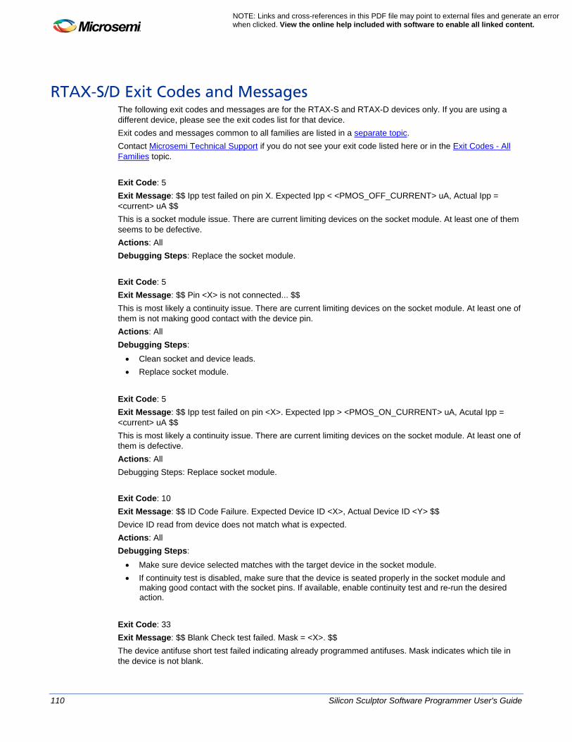
110 Silicon Sculptor Software Programmer User's Guide
NOTE: Links and cross-references in this PDF file may point to external files and generate an error when clicked. View the online help included with software to enable all linked content.
RTAX-S/D Exit Codes and Messages The following exit codes and messages are for the RTAX-S and RTAX-D devices only. If you are using a different device, please see the exit codes list for that device. Exit codes and messages common to all families are listed in a separate topic. Contact Microsemi Technical Support if you do not see your exit code listed here or in the Exit Codes - All Families topic. Exit Code: 5 Exit Message: $$ Ipp test failed on pin X. Expected Ipp < <PMOS_OFF_CURRENT> uA, Actual Ipp = <current> uA $$ This is a socket module issue. There are current limiting devices on the socket module. At least one of them seems to be defective. Actions: All Debugging Steps: Replace the socket module. Exit Code: 5 Exit Message: $$ Pin <X> is not connected... $$ This is most likely a continuity issue. There are current limiting devices on the socket module. At least one of them is not making good contact with the device pin. Actions: All Debugging Steps:
• Clean socket and device leads. • Replace socket module.
Exit Code: 5 Exit Message: $$ Ipp test failed on pin <X>. Expected Ipp > <PMOS_ON_CURRENT> uA, Acutal Ipp = <current> uA $$ This is most likely a continuity issue. There are current limiting devices on the socket module. At least one of them is defective. Actions: All Debugging Steps: Replace socket module. Exit Code: 10 Exit Message: $$ ID Code Failure. Expected Device ID <X>, Actual Device ID <Y> $$ Device ID read from device does not match what is expected. Actions: All Debugging Steps:
• Make sure device selected matches with the target device in the socket module. • If continuity test is disabled, make sure that the device is seated properly in the socket module and
making good contact with the socket pins. If available, enable continuity test and re-run the desired action.
Exit Code: 33 Exit Message: $$ Blank Check test failed. Mask = <X>. $$ The device antifuse short test failed indicating already programmed antifuses. Mask indicates which tile in the device is not blank.

Silicon Sculptor Software Programmer User's Guide 111
Actions: Program , Blank Check. Debugging Steps: The device may be programmed. Perform the Dev_Status action to see if the checksum is programmed. Exit Code: 60 Exit Message: $$ Checksum verification failure. Expected = <X>, Actual = <Y> $$ Checksum verification failed. Checksum read from the device does not match with what is expected. Actions: Program, Act_Checksum Debugging Steps: If Act_checksum is performed, make sure the correct AFM file is loaded.
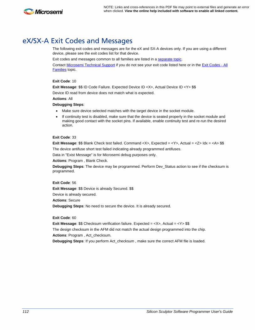
112 Silicon Sculptor Software Programmer User's Guide
NOTE: Links and cross-references in this PDF file may point to external files and generate an error when clicked. View the online help included with software to enable all linked content.
eX/SX-A Exit Codes and Messages The following exit codes and messages are for the eX and SX-A devices only. If you are using a different device, please see the exit codes list for that device. Exit codes and messages common to all families are listed in a separate topic. Contact Microsemi Technical Support if you do not see your exit code listed here or in the Exit Codes - All Families topic. Exit Code: 10 Exit Message: $$ ID Code Failure. Expected Device ID <X>, Actual Device ID <Y> $$ Device ID read from device does not match what is expected. Actions: All Debugging Steps:
• Make sure device selected matches with the target device in the socket module. • If continuity test is disabled, make sure that the device is seated properly in the socket module and
making good contact with the socket pins. If available, enable continuity test and re-run the desired action.
Exit Code: 33 Exit Message: $$ Blank Check test failed. Command <X>, Expected = <Y>, Actual = <Z> Idx = <A> $$ The device antifuse short test failed indicating already programmed antifuses. Data in ”Exist Message” is for Microsemi debug purposes only. Actions: Program , Blank Check. Debugging Steps: The device may be programmed. Perform Dev_Status action to see if the checksum is programmed. Exit Code: 56 Exit Message: $$ Device is already Secured. $$ Device is already secured. Actions: Secure Debugging Steps: No need to secure the device. It is already secured. Exit Code: 60 Exit Message: $$ Checksum verification failure. Expected = <X>, Actual = <Y> $$ The design checksum in the AFM did not match the actual design programmed into the chip. Actions: Program , Act_checksum. Debugging Steps: If you perform Act_checksum , make sure the correct AFM file is loaded.
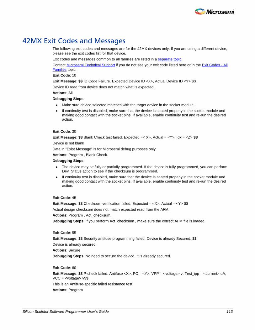
Silicon Sculptor Software Programmer User's Guide 113
42MX Exit Codes and Messages The following exit codes and messages are for the 42MX devices only. If you are using a different device, please see the exit codes list for that device. Exit codes and messages common to all families are listed in a separate topic. Contact Microsemi Technical Support if you do not see your exit code listed here or in the Exit Codes - All Families topic. Exit Code: 10 Exit Message: $$ ID Code Failure. Expected Device ID <X>, Actual Device ID <Y> $$ Device ID read from device does not match what is expected. Actions: All Debugging Steps:
• Make sure device selected matches with the target device in the socket module. • If continuity test is disabled, make sure that the device is seated properly in the socket module and
making good contact with the socket pins. If available, enable continuity test and re-run the desired action.
Exit Code: 30 Exit Message: $$ Blank Check test failed. Expected =< X>, Actual = <Y>, Idx = <Z> $$ Device is not blank Data in ”Exist Message” is for Microsemi debug purposes only. Actions: Program , Blank Check. Debugging Steps:
• The device may be fully or partially programmed. If the device is fully programmed, you can perform Dev_Status action to see if the checksum is programmed.
• If continuity test is disabled, make sure that the device is seated properly in the socket module and making good contact with the socket pins. If available, enable continuity test and re-run the desired action.
Exit Code: 45 Exit Message: $$ Checksum verification failed. Expected = <X>, Actual = <Y> $$ Actual design checksum does not match expected read from the AFM. Actions: Program , Act_checksum. Debugging Steps: If you perform Act_checksum , make sure the correct AFM file is loaded. Exit Code: 55 Exit Message: $$ Security antifuse programming failed. Device is already Secured. $$ Device is already secured. Actions: Secure Debugging Steps: No need to secure the device. It is already secured. Exit Code: 60 Exit Message: $$ P-check failed. Antifuse <X>. PC = <Y>, VPP = <voltage> v, Test_ipp = <current> uA, VCC = <voltage> v$$ This is an Antifuse-specific failed resistance test. Actions: Program

114 Silicon Sculptor Software Programmer User's Guide
NOTE: Links and cross-references in this PDF file may point to external files and generate an error when clicked. View the online help included with software to enable all linked content.
Debugging Steps: Replace the existing socket module with the latest revision. This is a known issue that shows up with older versions of the socket modules.

Silicon Sculptor Software Programmer User's Guide 115
40MX Exit Codes and Messages The following exit codes and messages are for the 40MX devices only. If you are using a different device, please see the exit codes list for that device. Exit codes and messages common to all families are listed in a separate topic. Contact Microsemi Technical Support if you do not see your exit code listed here or in the Exit Codes - All Families topic. Exit Code: 10 Exit Message: $$ ID Code Failure. Expected Device ID <X>, Actual Device ID <Y> $$ Device ID read from device does not match what is expected. Actions: All Debugging Steps:
• Make sure device selected matches with the target device in the socket module. • If continuity test is disabled, make sure that the device is seated properly in the socket module and
making good contact with the socket pins. If available, enable continuity test and re-run the desired action.
Exit Code: 30 Exit Message: $$ Blank Check test failed. Expected =< X>, Actual = <Y>, Idx = <Z> $$ Device is not blank Data in ”Exist Message” is for Microsemi debug purposes only. Actions: Program , Blank Check. Debugging Steps:
• The device may be fully or partially programmed. If the device is fully programmed, you can perform Dev_Status action to see if the checksum is programmed.
• If continuity test is disabled, make sure that the device is seated properly in the socket module and making good contact with the socket pins. If available, enable continuity test and re-run the desired action.
Exit Code: 55 Exit Message: $$ Security antifuse programming failed. Device is already Secured. $$ Device is already secured. Actions: Secure Debugging Steps: No need to secure the device. It is already secured.

116 Silicon Sculptor Software Programmer User's Guide
NOTE: Links and cross-references in this PDF file may point to external files and generate an error when clicked. View the online help included with software to enable all linked content.
Technical Specifications

Silicon Sculptor Software Programmer User's Guide 117
Silicon Sculptor III Technical Specifications • Operating Voltage: 90-260 VAC • Frequency: 47-63 Hz • Current Rating: 4-2 A (Fuse 250V 6A SB) • 100VAC =4A, 240VAC =2A • Power: 0.12 KVA
For more information on Silicon Sculptor III you can use the datashet for BP1710.
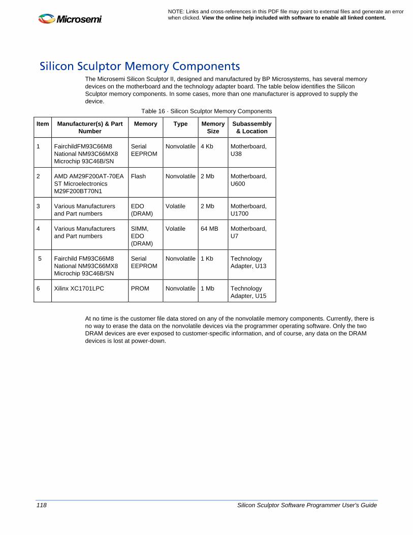
118 Silicon Sculptor Software Programmer User's Guide
NOTE: Links and cross-references in this PDF file may point to external files and generate an error when clicked. View the online help included with software to enable all linked content.
Silicon Sculptor Memory Components The Microsemi Silicon Sculptor II, designed and manufactured by BP Microsystems, has several memory devices on the motherboard and the technology adapter board. The table below identifies the Silicon Sculptor memory components. In some cases, more than one manufacturer is approved to supply the device.
Table 16 · Silicon Sculptor Memory Components
Item Manufacturer(s) & Part Number
Memory Type Memory Size
Subassembly & Location
1 FairchildFM93C66M8 National NM93C66MX8 Microchip 93C46B/SN
Serial EEPROM
Nonvolatile 4 Kb Motherboard, U38
2 AMD AM29F200AT-70EA ST Microelectronics M29F200BT70N1
Flash Nonvolatile 2 Mb Motherboard, U600
3 Various Manufacturers and Part numbers
EDO (DRAM)
Volatile 2 Mb Motherboard, U1700
4 Various Manufacturers and Part numbers
SIMM, EDO (DRAM)
Volatile 64 MB Motherboard, U7
5 Fairchild FM93C66M8 National NM93C66MX8 Microchip 93C46B/SN
Serial EEPROM
Nonvolatile 1 Kb Technology Adapter, U13
6 Xilinx XC1701LPC PROM Nonvolatile 1 Mb Technology Adapter, U15
At no time is the customer file data stored on any of the nonvolatile memory components. Currently, there is no way to erase the data on the nonvolatile devices via the programmer operating software. Only the two DRAM devices are ever exposed to customer-specific information, and of course, any data on the DRAM devices is lost at power-down.

Silicon Sculptor Software Programmer User's Guide 119
Appendix A
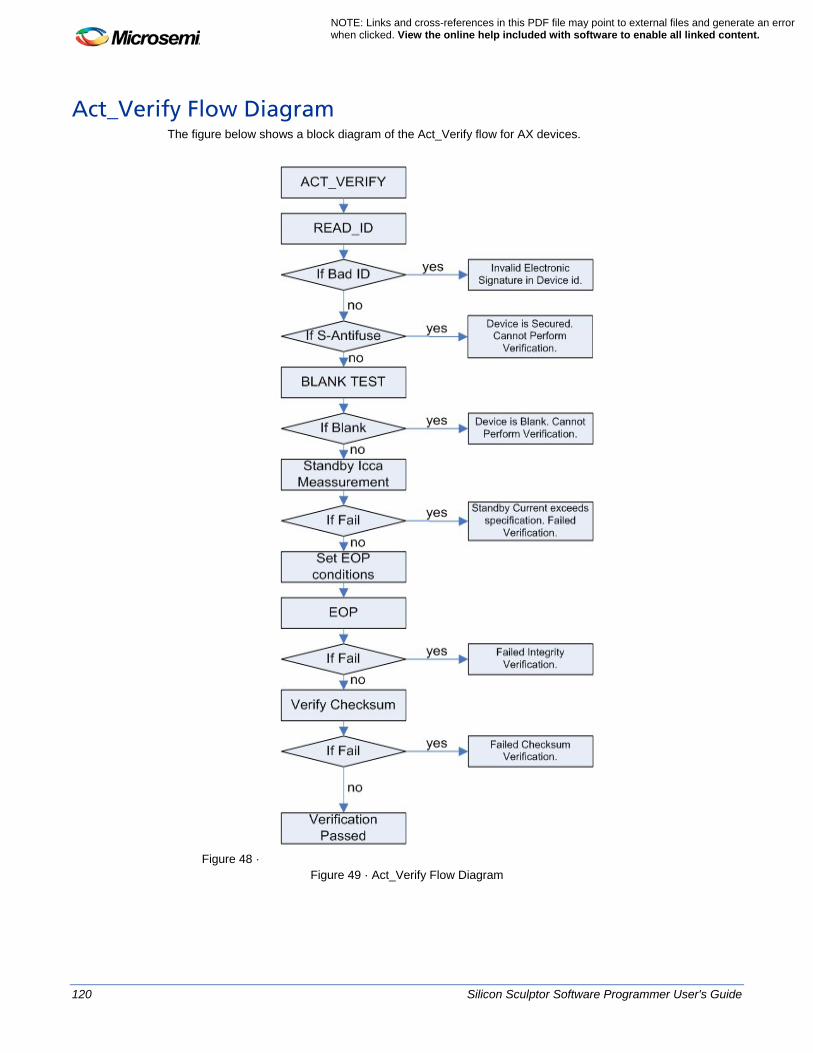
120 Silicon Sculptor Software Programmer User's Guide
NOTE: Links and cross-references in this PDF file may point to external files and generate an error when clicked. View the online help included with software to enable all linked content.
Act_Verify Flow Diagram The figure below shows a block diagram of the Act_Verify flow for AX devices.
Figure 48 · Figure 49 · Act_Verify Flow Diagram
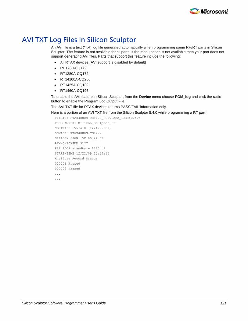
Silicon Sculptor Software Programmer User's Guide 121
AVI TXT Log Files in Silicon Sculptor An AVI file is a text (*.txt) log file generated automatically when programming some RH/RT parts in Silicon Sculptor. The feature is not available for all parts; if the menu option is not available then your part does not support generating AVI files. Parts that support this feature include the following: • All RTAX devices (AVI support is disabled by default) • RH1280-CQ172, • RT1280A-CQ172 • RT14100A-CQ256 • RT1425A-CQ132 • RT1460A-CQ196
To enable the AVI feature in Silicon Sculptor, from the Device menu choose PGM_log and click the radio button to enable the Program Log Output File. The AVI TXT file for RTAX devices returns PASS/FAIL information only. Here is a portion of an AVI TXT file from the Silicon Sculptor 5.4.0 while programming a RT part: FILEID: RTAX4000S-CG1272_20091222_133340.txt
PROGRAMMER: Silicon_Sculptor_III
SOFTWARE: V5.4.0 (12/17/2009)
DEVICE: RTAX4000S-CG1272
SILICON SIGN: 5F 80 42 0F
AFM-CHECKSUM 317C
PRE ICCA standby = 1165 uA
START-TIME 12/22/09 13:34:15
Antifuse Record Status
000001 Passed
000002 Passed
...
...

122 Silicon Sculptor Software Programmer User's Guide
NOTE: Links and cross-references in this PDF file may point to external files and generate an error when clicked. View the online help included with software to enable all linked content.
Contacting Microsemi

Silicon Sculptor Software Programmer User's Guide 123
Microsemi Headquarters Microsemi Corporation is a supplier of innovative programmable logic solutions, including field-programmable gate arrays (FPGAs) based on Antifuse and Flash technologies, high-performance intellectual property (IP) cores, software development tools, and design services targeted for the high-speed communications, application-specific integrated circuit (ASIC) replacement, and radiation-tolerant markets.
See Also Customer service Technical support Sales
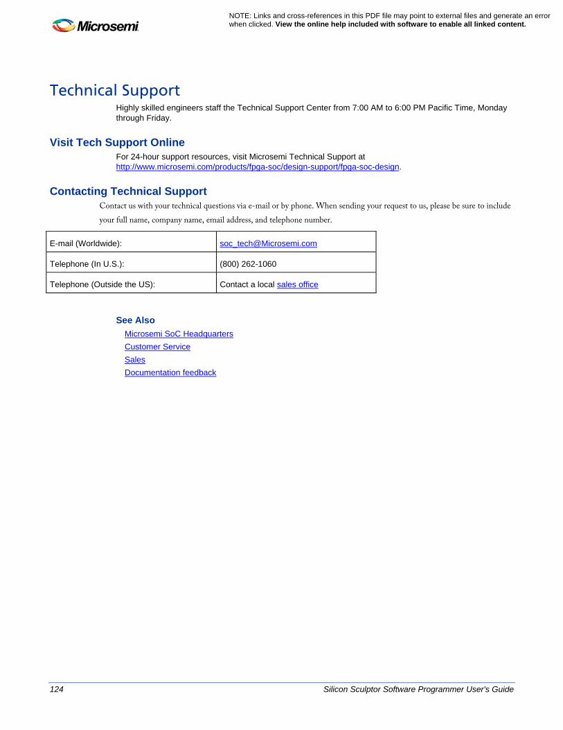
124 Silicon Sculptor Software Programmer User's Guide
NOTE: Links and cross-references in this PDF file may point to external files and generate an error when clicked. View the online help included with software to enable all linked content.
Technical Support Highly skilled engineers staff the Technical Support Center from 7:00 AM to 6:00 PM Pacific Time, Monday through Friday.
Visit Tech Support Online For 24-hour support resources, visit Microsemi Technical Support at http://www.microsemi.com/products/fpga-soc/design-support/fpga-soc-design.
Contacting Technical Support Contact us with your technical questions via e-mail or by phone. When sending your request to us, please be sure to include your full name, company name, email address, and telephone number.
E-mail (Worldwide): [email protected]
Telephone (In U.S.): (800) 262-1060
Telephone (Outside the US): Contact a local sales office
See Also Microsemi SoC Headquarters Customer Service Sales Documentation feedback
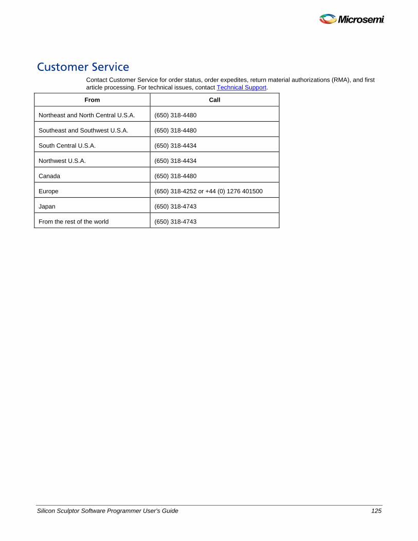
Silicon Sculptor Software Programmer User's Guide 125
Customer Service Contact Customer Service for order status, order expedites, return material authorizations (RMA), and first article processing. For technical issues, contact Technical Support.
From Call
Northeast and North Central U.S.A. (650) 318-4480
Southeast and Southwest U.S.A. (650) 318-4480
South Central U.S.A. (650) 318-4434
Northwest U.S.A. (650) 318-4434
Canada (650) 318-4480
Europe (650) 318-4252 or +44 (0) 1276 401500
Japan (650) 318-4743
From the rest of the world (650) 318-4743

126 Silicon Sculptor Software Programmer User's Guide
NOTE: Links and cross-references in this PDF file may point to external files and generate an error when clicked. View the online help included with software to enable all linked content.
Sales The latest Sales office information is available on the Microsemi SoC website.
Microsemi Corporate Headquarters One Enterprise Drive, Aliso Viejo CA 92656 Within the USA: (800) 713-4113 Outside the USA: (949) 221-7100 Fax: (949) 756-0308 · www.microsemi.com

Silicon Sculptor Software Programmer User's Guide 127
Documentation Feedback Microsemi Corporation strives to produce the highest quality online help and printed documentation. We want to help you learn about our products. We welcome your feedback. Please send your comments to [email protected].
See Also Microsemi headquarters Technical support Customer service Sales

Silicon Sculptor Software Programmer User's Guide 129
NOTE: Links and cross-references in this PDF file may point to external files and generate an error when clicked. View the online help included with software to enable all linked content.
Product Support
The Microsemi SoC Products Group backs its products with various support services including a Customer Technical Support Center and Non-Technical Customer Service. This appendix contains information about contacting the SoC Products Group and using these support services.
Contacting the Customer Technical Support Center Microsemi staffs its Customer Technical Support Center with highly skilled engineers who can help answer your hardware, software, and design questions. The Customer Technical Support Center spends a great deal of time creating application notes and answers to FAQs. So, before you contact us, please visit our online resources. It is very likely we have already answered your questions.
Technical Support Microsemi customers can receive technical support on Microsemi SoC products by calling Technical Support Hotline anytime Monday through Friday. Customers also have the option to interactively submit and track cases online at My Cases or submit questions through email anytime during the week. Web: www.actel.com/mycases Phone (North America): 1.800.262.1060 Phone (International): +1 650.318.4460 Email: [email protected]
ITAR Technical Support Microsemi customers can receive ITAR technical support on Microsemi SoC products by calling ITAR Technical Support Hotline: Monday through Friday, from 9 AM to 6 PM Pacific Time. Customers also have the option to interactively submit and track cases online at My Cases or submit questions through email anytime during the week. Web: www.actel.com/mycases Phone (North America): 1.888.988.ITAR Phone (International): +1 650.318.4900 Email: [email protected]
Non-Technical Customer Service Contact Customer Service for non-technical product support, such as product pricing, product upgrades, update information, order status, and authorization. Microsemi’s customer service representatives are available Monday through Friday, from 8 AM to 5 PM Pacific Time, to answer non-technical questions. Phone: +1 650.318.2470 .

5-02-9111-10/03.14
Microsemi Corporate Headquarters One Enterprise, Aliso Viejo CA 92656 USA Within the USA: +1 (949) 380-6100 Sales: +1 (949) 380-6136 Fax: +1 (949) 215-4996
Microsemi Corporation (NASDAQ: MSCC) offers a comprehensive portfolio of semiconductor solutions for: aerospace, defense and security; enterprise and communications; and industrial and alternative energy markets. Products include high-performance, high-reliability analog and RF devices, mixed signal and RF integrated circuits, customizable SoCs, FPGAs, and complete subsystems. Microsemi is headquartered in Aliso Viejo, Calif. Learn more at www.microsemi.com.
© 2014 Microsemi Corporation. All rights reserved. Microsemi and the Microsemi logo are trademarks of Microsemi Corporation. All other trademarks and service marks are the property of their respective owners.