Signal converter for mass flowmeters - Fagerberg
32
MFC 400 MFC 400 MFC 400 MFC 400 Technical Datasheet Technical Datasheet Technical Datasheet Technical Datasheet Signal converter for mass flowmeters • High performance signal converter for all applications • Stable in multi-phase applications due to Entrained Gas Management (EGM ® ) • High developed diagnostic functions acc. to NAMUR NE 107 © KROHNE 06/2015 - 4002075704 - TD MFC 400 R04 en The documentation is only complete when used in combination with the relevant documentation for the flow sensor.
-
Upload
khangminh22 -
Category
Documents
-
view
4 -
download
0
Transcript of Signal converter for mass flowmeters - Fagerberg

MFC 400MFC 400MFC 400MFC 400 Technical DatasheetTechnical DatasheetTechnical DatasheetTechnical Datasheet
Signal converter for mass flowmeters
• High performance signal converter for all applications
• Stable in multi-phase applications due to Entrained Gas Management (EGM®)• High developed diagnostic functions acc. to NAMUR NE 107
© KROHNE 06/2015 - 4002075704 - TD MFC 400 R04 en
The documentation is only complete when used in combination with the relevant documentation for the flow sensor.

CONTENTS
2 www.krohne.com 06/2015 - 4002075704 - TD MFC 400 R04 en
MFC 400
1 Product features 3
1.1 The high performance signal converter for all applications ........................................... 31.2 Options and variants......................................................................................................... 51.3 Signal converter/flow sensor combination possibilities ................................................. 61.4 Measuring principle.......................................................................................................... 6
2 Technical data 7
2.1 Technical data................................................................................................................... 72.2 Dimensions and weights ................................................................................................ 18
2.2.1 Housing ................................................................................................................................. 182.2.2 Mounting plate, field housing ............................................................................................... 18
3 Installation 19
3.1 Intended use ................................................................................................................... 193.2 Installation specifications .............................................................................................. 193.3 Mounting of the compact version................................................................................... 193.4 Mounting the field housing, remote version .................................................................. 20
3.4.1 Pipe mounting ....................................................................................................................... 203.4.2 Wall mounting ....................................................................................................................... 21
4 Electrical connections 22
4.1 Safety instructions.......................................................................................................... 224.2 Connection diagram ....................................................................................................... 224.3 Grounding the flow sensor ............................................................................................. 234.4 Connecting power – all housing variants....................................................................... 244.5 Inputs and outputs, overview ......................................................................................... 25
4.5.1 Combinations of the inputs/outputs (I/Os) ........................................................................... 254.5.2 Description of the CG number .............................................................................................. 264.5.3 Fixed, non-alterable input/output versions.......................................................................... 274.5.4 Alterable input/output versions............................................................................................ 29
5 Notes 30

PRODUCT FEATURES 1
3
MFC 400
www.krohne.com06/2015 - 4002075704 - TD MFC 400 R04 en
1.1 The high performance signal converter for all applications
The MFC 400MFC 400MFC 400MFC 400 Coriolis mass flow signal converter will provide the highest performance possible across a wide range of applications. For the measurement of liquids or gases, cryogenic to high temperature fluids, single or multi-phase fluids and advanced digital signal processing techniques is used to give stable and accurate measurements of mass flow, density and temperature.
Conforming to the NAMUR standard NE 107 for status and error handling, the MFC 400 features enhanced meter diagnostics. This provides extensive self-checking of internal circuits and information regarding the health of the measuring sensor, but just as importantly, vital information about the process and process conditions.
(signal converter in field housing)
1 Communication with any third party system possible via Foundation Fieldbus, Profibus PA/DP or Modbus2 Intuitive navigation and a wide variety of languages integrated as standard for ease of operation3 Supply voltage: 100...230 VAC (standard) and 24 VDC or 24 VAC/DC (optional)

1 PRODUCT FEATURES
4
MFC 400
www.krohne.com 06/2015 - 4002075704 - TD MFC 400 R04 en
Highlights• High performance signal converter with multiple output options• Advanced diagnostic functions acc. to NE 107
• With Entrained Gas Management (EGMTM) – the new standard for entrained gas immunity• Excellent long-term stability• Easy to install and program due to improved user interface• Optical and mechanical keys for ease of use• Redundant data storage in signal converter housing• Real time clock for logging events
• HART® 7
Industries• Water & Wastewater• Chemicals• Power plants• Food & Beverage• Machinery• Oil & Gas• Petrochemical• Pulp & Paper• Pharmaceutical• Marine
Applications• Liquids and gases• Liquids with gas entrainment• Slurries and viscous products• Concentration measurement for quality control• Measurement of volume flow• Measurement of density and reference density• Custody transfer loading/unloading• Custody transfer measurements
PRODUCT FEATURES 1
5
MFC 400
www.krohne.com06/2015 - 4002075704 - TD MFC 400 R04 en
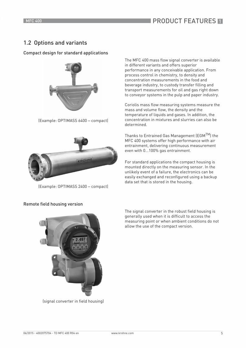
1.2 Options and variants
Compact design for standard applications
Remote field housing version
(Example: OPTIMASS 6400 – compact)
(Example: OPTIMASS 2400 – compact)
The MFC 400 mass flow signal converter is available in different variants and offers superior performance in any conceivable application. From process control in chemistry, to density and concentration measurements in the food and beverage industry, to custody transfer filling and transport measurements for oil and gas right down to conveyor systems in the pulp and paper industry.
Coriolis mass flow measuring systems measure the mass and volume flow, the density and the temperature of liquids and gases. In addition, the concentration in mixtures and slurries can also be determined.
Thanks to Entrained Gas Management (EGMTM) the MFC 400 systems offer high performance with air entrainment, delivering continuous measurement even with 0...100% gas entrainment.
For standard applications the compact housing is mounted directly on the measuring sensor. In the unlikely event of a failure, the electronics can be easily exchanged and reconfigured using a backup data set that is stored in the housing.
(signal converter in field housing)
The signal converter in the robust field housing is generally used when it is difficult to access the measuring point or when ambient conditions do not allow the use of the compact version.

1 PRODUCT FEATURES
6
MFC 400
www.krohne.com 06/2015 - 4002075704 - TD MFC 400 R04 en
1.3 Signal converter/flow sensor combination possibilities
1.4 Measuring principle
The signal converter has been designed to work with all the measuring tube designs used in the mass flowmeters. For information regarding the measuring principle for a specific measuring tube design, please refer to the technical documentation of the relevant flow sensor.
Flow sensor Flow sensor + signal converter MFC 400
Compact Remote field housing
OPTIMASS 1000 OPTIMASS 1400 C OPTIMASS 1400 F
OPTIMASS 2000 OPTIMASS 2400 C OPTIMASS 2400 F
OPTIMASS 3000 OPTIMASS 3400 C OPTIMASS 3400 F
OPTIMASS 6000 OPTIMASS 6400 C OPTIMASS 6400 F
OPTIMASS 7000 OPTIMASS 7400 C OPTIMASS 7400 F

TECHNICAL DATA 2
7
MFC 400
www.krohne.com06/2015 - 4002075704 - TD MFC 400 R04 en
2.1 Technical data
• The following data is provided for general applications. If you require data that is more relevant to your specific application, please contact us or your local sales office.
• Additional information (certificates, special tools, software,...) and complete product documentation can be downloaded free of charge from the website (Downloadcenter).
Measuring systemMeasuring principle Coriolis principle
Application range Measurement of mass flow, density, temperature, volume flow, flow velocity, concentration
DesignModular construction The measuring system consists of a flow sensor and a signal converter.
Flow sensorFlow sensorFlow sensorFlow sensor
OPTIMASS 1000 DN15…50 / ½…2"
OPTIMASS 2000 DN100…250 / 4...10"
OPTIMASS 3000 DN01…04 / 1/25...4/25"
OPTIMASS 6000 DN08…250 / 3/8...10"
OPTIMASS 7000 DN06…80 / ¼…3"
All flow sensors are also available in an Ex version.
Signal converterSignal converterSignal converterSignal converter
Compact version (C) OPTIMASS x400 C (x = 1, 2, 3, 6 or 7)
Field housing (F) -remote version
MFC 400 F
Compact and field housing versions are also available in an Ex version.
OptionsOptionsOptionsOptions
Outputs / inputs Current output (incl. HART®), pulse output, frequency output, and/or status output, limit switch and/or control input (depending on the I/O version)
Totaliser 2 (optional 3) internal totalisers with a max. of 8 counter places (e.g. for counting volume and/or mass units)
Verification Integrated verification, diagnostic functions: measuring device, process, measured value, stabilisation
Concentration measurement Universal concentration measurement, °Brix, °Baume, °Plato, alcohol concentration, NaOH and API density
Communication interfaces Foundation Fieldbus, Profibus PA and DP, Modbus, HART®
2 TECHNICAL DATA
8
MFC 400
www.krohne.com 06/2015 - 4002075704 - TD MFC 400 R04 en
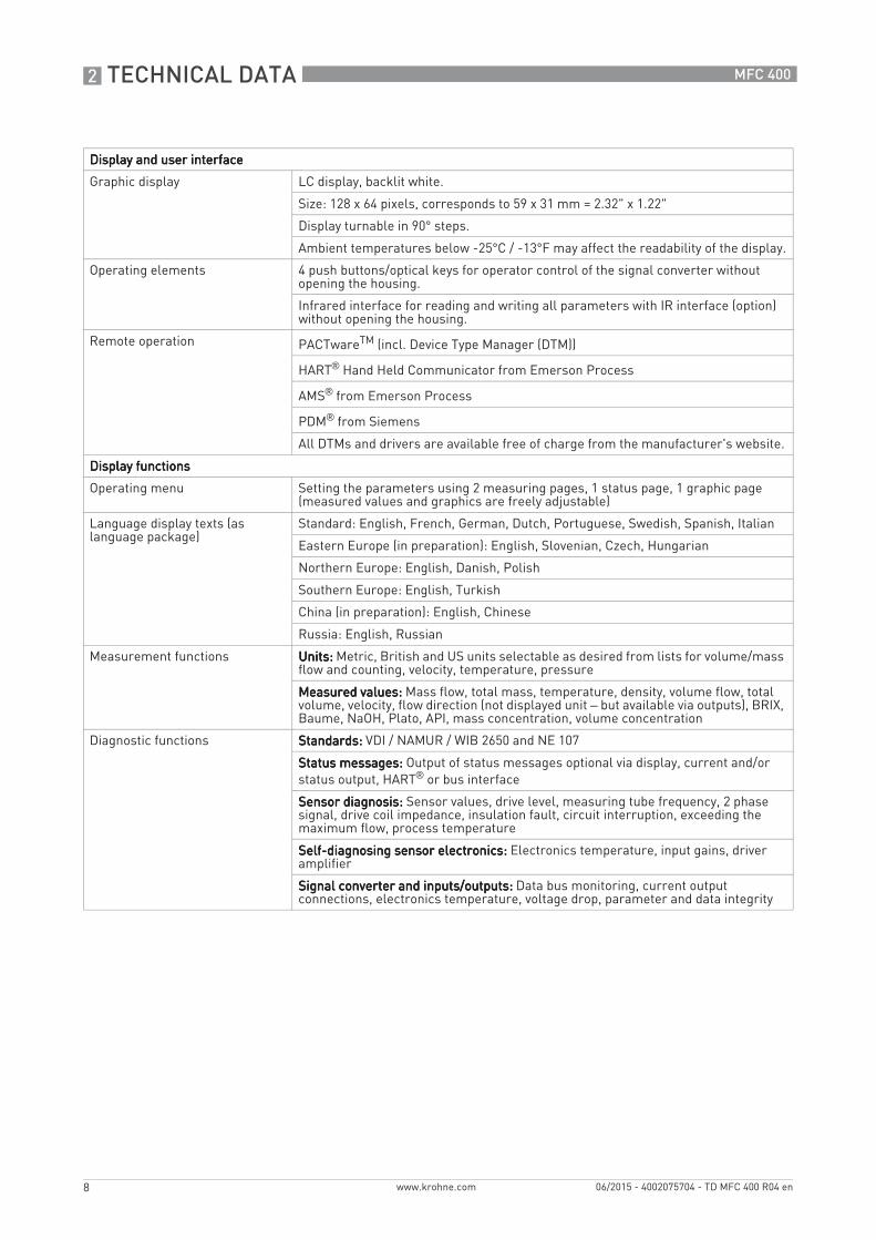
Display and user interfaceDisplay and user interfaceDisplay and user interfaceDisplay and user interface
Graphic display LC display, backlit white.
Size: 128 x 64 pixels, corresponds to 59 x 31 mm = 2.32" x 1.22"
Display turnable in 90° steps.
Ambient temperatures below -25°C / -13°F may affect the readability of the display.
Operating elements 4 push buttons/optical keys for operator control of the signal converter without opening the housing.
Infrared interface for reading and writing all parameters with IR interface (option) without opening the housing.
Remote operation PACTwareTM (incl. Device Type Manager (DTM))
HART® Hand Held Communicator from Emerson Process
AMS® from Emerson Process
PDM® from Siemens
All DTMs and drivers are available free of charge from the manufacturer's website.
Display functionsDisplay functionsDisplay functionsDisplay functions
Operating menu Setting the parameters using 2 measuring pages, 1 status page, 1 graphic page (measured values and graphics are freely adjustable)
Language display texts (as language package)
Standard: English, French, German, Dutch, Portuguese, Swedish, Spanish, Italian
Eastern Europe (in preparation): English, Slovenian, Czech, Hungarian
Northern Europe: English, Danish, Polish
Southern Europe: English, Turkish
China (in preparation): English, Chinese
Russia: English, Russian
Measurement functions Units:Units:Units:Units: Metric, British and US units selectable as desired from lists for volume/mass flow and counting, velocity, temperature, pressure
Measured values:Measured values:Measured values:Measured values: Mass flow, total mass, temperature, density, volume flow, total volume, velocity, flow direction (not displayed unit – but available via outputs), BRIX, Baume, NaOH, Plato, API, mass concentration, volume concentration
Diagnostic functions Standards:Standards:Standards:Standards: VDI / NAMUR / WIB 2650 and NE 107
Status messages:Status messages:Status messages:Status messages: Output of status messages optional via display, current and/or status output, HART® or bus interface
Sensor diagnosis:Sensor diagnosis:Sensor diagnosis:Sensor diagnosis: Sensor values, drive level, measuring tube frequency, 2 phase signal, drive coil impedance, insulation fault, circuit interruption, exceeding the maximum flow, process temperature
Self-diagnosing sensor electronics:Self-diagnosing sensor electronics:Self-diagnosing sensor electronics:Self-diagnosing sensor electronics: Electronics temperature, input gains, driver amplifier
Signal converter and inputs/outputs:Signal converter and inputs/outputs:Signal converter and inputs/outputs:Signal converter and inputs/outputs: Data bus monitoring, current output connections, electronics temperature, voltage drop, parameter and data integrity

TECHNICAL DATA 2
9
MFC 400
www.krohne.com06/2015 - 4002075704 - TD MFC 400 R04 en
Measuring accuracyReference conditions Medium: water
Temperature: +20°C / +68°F
Pressure: 1 bar / 14.5 psi
Maximum measuring error Refer to technical data for the flow sensor.
Current output electronics ±5 µA
Operating conditionsTemperatureTemperatureTemperatureTemperature
Process temperature Refer to technical data for the flow sensor.
Ambient temperature Depending on the version and combination of outputs.
It is a good idea to protect the signal converter from external heat sources such as direct sunlight as higher temperatures reduce the life cycle of all electronic components.
-40…+65°C / -40…+149°F
Stainless steel housing: -40…+60°C / -40…+140°F
Ambient temperatures below -25°C / -13°F may affect the readability of the display.
Storage temperature -50…+70°C / -58…+158°F
PressurePressurePressurePressure
Medium Refer to technical data for the flow sensor.
Ambient pressure Atmospheric
Chemical propertiesChemical propertiesChemical propertiesChemical properties
State of aggregation Liquids, gases and slurries
Flow rate Refer to technical data for the flow sensor.
Other conditionsOther conditionsOther conditionsOther conditions
Ingress protection acc. to IEC 529 / EN 60529
IP66/67 (acc. to NEMA 4/4X)
Installation conditionsInstallation For detailed information, refer to chapter "Installation conditions".
Dimensions and weights For detailed information refer to chapter "Dimensions and weights".

2 TECHNICAL DATA
10
MFC 400
www.krohne.com 06/2015 - 4002075704 - TD MFC 400 R04 en
MaterialsSignal converter housing Standard: die-cast aluminium (polyurethane coated)
Option: stainless steel 316 (1.4408)
Flow sensor For housing material, process connections, measuring tubes, accessories and gaskets, refer to technical data for the flow sensor.
Electrical connectionGeneral Electrical connection is carried out in conformity with the VDE 0100 directive
"Regulations for electrical power installations with line voltages up to 1000 V" or equivalent national specifications.
Power supply Standard: 100…230 VAC (-15% / +10%), 50/60 Hz
Option 1: 24 VDC (-55% / +30%)
Option 2: 24 VAC/DC (AC: -15% / +10%, 50/60 Hz; DC: -25% / +30%)
Power consumption AC: 22 VA
DC: 12 W
Signal cable Only for remote versions.
10 core shielded cable. Detailed specifications are available on request.
Length: max. 20 m / 65.6 ft
Cable entries Standard: M20.5 (8...12 mm)
Option: ½ NPT, PF ½
TECHNICAL DATA 2
11
MFC 400
www.krohne.com06/2015 - 4002075704 - TD MFC 400 R04 en
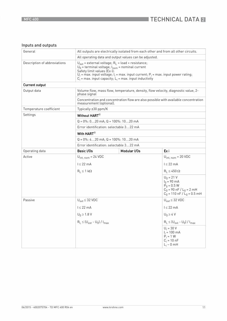
Inputs and outputsGeneral All outputs are electrically isolated from each other and from all other circuits.
All operating data and output values can be adjusted.
Description of abbreviations Uext = external voltage; RL = load + resistance;U0 = terminal voltage; Inom = nominal currentSafety limit values (Ex i):Ui = max. input voltage; Ii = max. input current; Pi = max. input power rating;Ci = max. input capacity; Li = max. input inductivity
Current outputCurrent outputCurrent outputCurrent output
Output data Volume flow, mass flow, temperature, density, flow velocity, diagnostic value, 2-phase signal
Concentration and concentration flow are also possible with available concentration measurement (optional).
Temperature coefficient Typically ±30 ppm/K
Settings Without HARTWithout HARTWithout HARTWithout HART®
Q = 0%: 0…20 mA; Q = 100%: 10…20 mA
Error identification: selectable 3…22 mA
With HARTWith HARTWith HARTWith HART®
Q = 0%: 4…20 mA; Q = 100%: 10…20 mA
Error identification: selectable 3…22 mA
Operating data Basic I/OsBasic I/OsBasic I/OsBasic I/Os Modular I/OsModular I/OsModular I/OsModular I/Os Ex iEx iEx iEx i
Active Uint, nom = 24 VDC
I ≤ 22 mA
RL ≤ 1 kΩ
Uint, nom = 20 VDC
I ≤ 22 mA
RL ≤ 450 Ω
U0 = 21 VI0 = 90 mAP0 = 0.5 WC0 = 90 nF / L0 = 2 mHC0 = 110 nF / L0 = 0.5 mH
Passive Uext ≤ 32 VDC
I ≤ 22 mA
U0 ≥ 1.8 V
RL ≤ (Uext - U0) / Imax
Uext ≤ 32 VDC
I ≤ 22 mA
U0 ≥ 4 V
RL ≤ (Uext - U0) / Imax
Ui = 30 VIi = 100 mAPi = 1 WCi = 10 nFLi ~ 0 mH
2 TECHNICAL DATA
12
MFC 400
www.krohne.com 06/2015 - 4002075704 - TD MFC 400 R04 en
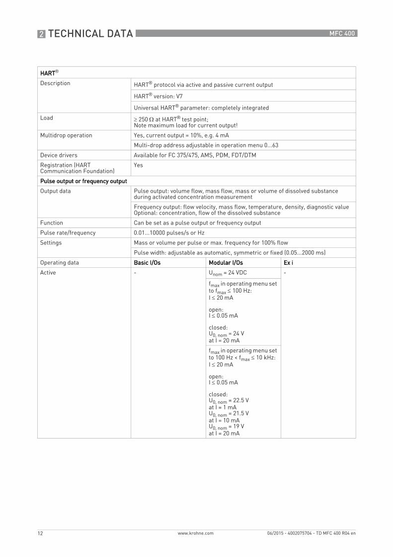
HARTHARTHARTHART®
Description HART® protocol via active and passive current output
HART® version: V7
Universal HART® parameter: completely integrated
Load ≥ 250 Ω at HART® test point;Note maximum load for current output!
Multidrop operation Yes, current output = 10%, e.g. 4 mA
Multi-drop address adjustable in operation menu 0...63
Device drivers Available for FC 375/475, AMS, PDM, FDT/DTM
Registration (HART Communication Foundation)
Yes
Pulse output or frequency outputPulse output or frequency outputPulse output or frequency outputPulse output or frequency output
Output data Pulse output: volume flow, mass flow, mass or volume of dissolved substance during activated concentration measurement
Frequency output: flow velocity, mass flow, temperature, density, diagnostic valueOptional: concentration, flow of the dissolved substance
Function Can be set as a pulse output or frequency output
Pulse rate/frequency 0.01...10000 pulses/s or Hz
Settings Mass or volume per pulse or max. frequency for 100% flow
Pulse width: adjustable as automatic, symmetric or fixed (0.05...2000 ms)
Operating data Basic I/OsBasic I/OsBasic I/OsBasic I/Os Modular I/OsModular I/OsModular I/OsModular I/Os Ex iEx iEx iEx i
Active - Unom = 24 VDC -
fmax in operating menu set to fmax ≤ 100 Hz:I ≤ 20 mA
open:I ≤ 0.05 mA
closed: U0, nom = 24 Vat I = 20 mA
fmax in operating menu set to 100 Hz < fmax ≤ 10 kHz:I ≤ 20 mA
open:I ≤ 0.05 mA
closed:U0, nom = 22.5 Vat I = 1 mAU0, nom = 21.5 Vat I = 10 mAU0, nom = 19 Vat I = 20 mA

TECHNICAL DATA 2
13
MFC 400
www.krohne.com06/2015 - 4002075704 - TD MFC 400 R04 en
Passive Uext ≤ 32 VDC -
fmax in operating menu set to fmax ≤ 100 Hz:I ≤ 100 mA
open:I ≤ 0.05 mA at Uext = 32 VDC
closed:U0, max = 0.2 V at I ≤ 10 mAU0, max = 2 V at I ≤ 100 mA
fmax in operating menu set to100 Hz < fmax ≤ 10 kHz:I ≤ 20 mA
open:I ≤ 0.05 mA at Uext = 32 VDC
closed:U0, max = 1.5 V at I ≤ 1 mAU0, max = 2.5 V at I ≤ 10 mAU0, max = 5.0 V at I ≤ 20 mA
NAMUR - Passive to EN 60947-5-6
open:Inom = 0.6 mA
closed:Inom = 3.8 mA
Passive to EN 60947-5-6
open:Inom = 0.43 mA
closed:Inom = 4.5 mA
Ui = 30 VIi = 100 mAPi = 1 WCi =10 nFLi ~ 0 mH
Low flow cut offLow flow cut offLow flow cut offLow flow cut off
Function Switching point and hysteresis separately adjustable for each output, counter and the display
Switching point Set in increments of 0.1%.
0…20% (current output, frequency output)
Hysteresis Set in increments of 0.1%.
0…5% (current output, frequency output)
Time constantTime constantTime constantTime constant
Function The time constant corresponds to the elapsed time until 67% of the end value has been reached according to a step function.
Settings Set in increments of 0.1 seconds.
0…100 seconds

2 TECHNICAL DATA
14
MFC 400
www.krohne.com 06/2015 - 4002075704 - TD MFC 400 R04 en
Status output / limit switchStatus output / limit switchStatus output / limit switchStatus output / limit switch
Function and settings Adjustable as automatic measuring range conversion, display of flow direction, overflow, error or switching point.
Valve control with activated dosing function
Status and/or control: ON or OFF
Operating data Basic I/OsBasic I/OsBasic I/OsBasic I/Os Modular I/OsModular I/OsModular I/OsModular I/Os Ex iEx iEx iEx i
Active - Uint = 24 VDCI ≤ 20 mA
open:I ≤ 0.05 mA
closed:U0, nom = 24 Vat I = 20 mA
-
Passive Uext ≤ 32 VDC
I ≤ 100 mA
open:I ≤ 0.05 mA at Uext = 32 VDC
closed:U0, max = 0.2 Vat I ≤ 10 mAU0, max = 2 Vat I ≤ 100 mA
Uext ≤ 32 VDC
I ≤ 100 mA
RL, max = 47 kΩRL, min = (Uext - U0) / Imax
open:I ≤ 0.05 mAat Uext = 32 VDC
closed:U0, max = 0.2 Vat I ≤ 10 mAU0, max = 2 Vat I ≤ 100 mA
-
NAMUR - Passive to EN 60947-5-6
open:Inom = 0.6 mA
closed:Inom = 3.8 mA
Passive to EN 60947-5-6
open:Inom = 0.43 mA
closed:Inom = 4.5 mA
Ui = 30 VIi = 100 mAPi = 1 WCi =10 nFLi = 0 mH

TECHNICAL DATA 2
15
MFC 400
www.krohne.com06/2015 - 4002075704 - TD MFC 400 R04 en
Control inputControl inputControl inputControl input
Function Hold value of the outputs (e.g. for cleaning work), set value of the outputs to "zero", counter and error reset, stop counter, range conversion, zero calibration
Start of dosing when dosing function is activated.
Operating data Basic I/OsBasic I/OsBasic I/OsBasic I/Os Modular I/OsModular I/OsModular I/OsModular I/Os Ex iEx iEx iEx i
Active - Uint = 24 VDC
Ext. contact open:U0, nom = 22 V
Ext. contact closed:Inom = 4 mA
Contact open (Off):U0 ≥ 12 Vwith Inom = 1.9 mA
Contact closed (On):U0 ≤ 10 Vwith Inom = 1.9 mA
-
Passive 8 V ≤ Uext ≤ 32 VDC
Imax = 6.5 mAat Uext ≤ 24 VDCImax = 8.2 mAat Uext ≤ 32 VDC
Contact closed (On):U0 ≥ 8 Vwith Inom = 2.8 mA
Contact open (Off):U0 ≤ 2.5 Vwith Inom = 0.4 mA
3 V ≤ Uext ≤ 32 VDC
Imax = 9.5 mAat Uext ≤ 24 VImax = 9.5 mAat Uext ≤ 32 V
Contact closed (On):U0 ≥ 3 Vwith Inom = 1.9 mA
Contact open (Off):U0 ≤ 2.5 Vwith Inom = 1.9 mA
Uext ≤ 32 VDC
I ≤ 6 mA at Uext = 24 VI ≤ 6.6 mA at Uext = 32 V
On:U0 ≥ 5.5 V or I ≥ 4 mA
Off: U0 ≤ 3.5 V or I ≤ 0.5 mA
Ui = 30 VIi = 100 mAPi = 1 WCi = 10 nFLi = 0 mH
NAMUR - Active to EN 60947-5-6
Terminals open:U0, nom = 8.7 V
Contact closed (On):U0, nom = 6.3 Vwith Inom > 1.9 mA
Contact open (Off):U0, nom = 6.3 Vwith Inom < 1.9 mA
Detection of cable break:U0 ≥ 8.1 Vwith I ≤ 0.1 mA
Detection of cable short circuit:U0 ≤ 1.2 V with I ≥ 6.7 mA
-

2 TECHNICAL DATA
16
MFC 400
www.krohne.com 06/2015 - 4002075704 - TD MFC 400 R04 en
PROFIBUS DPPROFIBUS DPPROFIBUS DPPROFIBUS DP
Description Galvanically isolated acc. to IEC 61158
Profile version: 3.02
Automatic data transmission rate recognition (max. 12 MBaud)
Bus address adjustable via local display at the measuring device
Function blocks 8 x analogue input, 3 x totaliser
Output data Mass flow, volume flow, mass counter 1 + 2, volume counter, product temperature, several concentration measurements and diagnostic data
PROFIBUS PAPROFIBUS PAPROFIBUS PAPROFIBUS PA
Description Galvanically isolated acc. to IEC 61158
Profile version: 3.02
Current consumption: 10.5 mA
Permissible bus voltage: 9…32 V; in Ex application: 9...24 V
Bus interface with integrated reverse polarity protection
Typical error current FDE (Fault Disconnection Electronic): 4.3 mA
Bus address adjustable via local display at the measuring device
Function blocks 8 x analogue input, 3 x totaliser
Output data Mass flow, volume flow, mass counter 1 + 2, volume counter, product temperature, several concentration measurements and diagnostic data
FOUNDATION FieldbusFOUNDATION FieldbusFOUNDATION FieldbusFOUNDATION Fieldbus
Description Galvanically isolated acc. to IEC 61158
Current consumption: 10.5 mA
Permissible bus voltage: 9…32 V; in Ex application: 9...24 V
Bus interface with integrated reverse polarity protection
Link Master function (LM) supported
Tested with Interoperable Test Kit (ITK) version 6.01
Function blocks 6 x analogue input, 2 x integrator, 1 x PID
Output data Mass flow, volume flow, density, temperature of tube, several concentration measurements and diagnostic data
ModbusModbusModbusModbus
Description Modbus RTU, Master/Slave, RS485
Address range 1…247
Supported function codes 01, 03, 04, 05, 08, 16, 43
Supported Baudrate 1200, 2400, 3600, 4800, 9600, 19200, 38400, 57600, 115200 Baud

TECHNICAL DATA 2
17
MFC 400
www.krohne.com06/2015 - 4002075704 - TD MFC 400 R04 en
Approvals and certificatesCE The device fulfils the statutory requirements of the EC directives. The manufacturer
certifies that these requirements have been met by applying the CE marking.
Non-Ex Standard
Hazardous areasHazardous areasHazardous areasHazardous areas
Option (C version only)Option (C version only)Option (C version only)Option (C version only)
ATEX II 1/2 (1) G - Ex d ia [ia Ga] IIC T6…T1 Ga/Gb
II 1/2 (1) G - Ex de ia [ia Ga] IIC T6…T1 Ga/Gb
II 2 (1) G - Ex d ia [ia Ga] IIC T6…T1 Gb
II 2 (1) G - Ex de ia [ia Ga] IIC T6…T1 Gb
II 2 (1) D - Ex t [ia Da] IIIC Txxx°C Db
II 1/2 G - Ex d ia IIC T6…T1 Ga/Gb; II 1/2 G - Ex de ia IIC T6…T1 Ga/Gb
II 2 G - Ex d ia IIC T6…T1 Gb; II 2 G - Ex de ia IIC T6…T1 Gb
II 2 D - Ex t IIIC Txxx°C Db
Option (F version only)Option (F version only)Option (F version only)Option (F version only)
ATEX II 2 (1) G - Ex d [ia Ga] IIC T6 Gb
II 2 (1) G - Ex de [ia Ga] IIC T6 Gb
II 2 (1) D - Ex t [ia Da] IIIC T75°C Db
II 2 G - Ex d [ia] IIC T6 Gb; II 2 G - Ex de [ia] IIC T6 Gb
II 2 D - Ex t IIIC T75°C Db
NEPSI Ex d ia [ia Ga] IIC T6…T1 Ga/Gb; Ex de ia [ia Ga] IIC T6…T1 Ga/Gb
OptionOptionOptionOption
FM / CSA FM: Class I, Div 1 groups A, B, C, DCSA: Class I, Div 1 groups C, D
Class II, Div 1 groups E, F, G
Class III, Div 1 hazardous areas
FM: Class I, Div 2 groups A, B, C, DCSA: Class I, Div 2 groups C, D
Class II, Div 2 groups E, F, G
Class III, Div 2 hazardous areas
IECEx Ex zone 1 + 2
Custody transferCustody transferCustody transferCustody transfer
Without Standard
Option Liquids other than water 2004/22/EC (MID MI005) acc. to OIML R 117-1
Gases 2004/22/EC (MID MI002) acc. to OIML R 137
Other standards and approvalsOther standards and approvalsOther standards and approvalsOther standards and approvals
Shock and vibration resistance IEC 68-2-3
Electromagnetic compatibility (EMC)
2004/108/EC in conjunction with EN 61326-1 (A1, A2)
European pressure equipment directive
PED 97/23/EC
NAMUR NE 21, NE 43, NE 53, NE 107

2 TECHNICAL DATA
18
MFC 400
www.krohne.com 06/2015 - 4002075704 - TD MFC 400 R04 en
2.2 Dimensions and weights
2.2.1 Housing
2.2.2 Mounting plate, field housing
Dimensions in mm and inch
Figure 2-1: Dimensions for field housing (F) - remote version
Dimensions [mm / inch] Weight [kg / lb]
a b c g h
202 / 7.75 120 / 4.75 155 / 6.10 295.8 / 11.60 277 / 10.90 5.7 / 12.60
[mm] [inch]
a 72 2.8
b 72 2.8
c Ø9 Ø0.4

INSTALLATION 3
19
MFC 400
www.krohne.com06/2015 - 4002075704 - TD MFC 400 R04 en
3.1 Intended use
The mass flowmeters are designed exclusively to directly measure mass flow rates, product density and temperature as well to indirectly measure parameters such as the total volume and concentration of dissolved substances as well as the volume flow rate.
3.2 Installation specifications
3.3 Mounting of the compact version
For devices used in hazardous areas, additional safety notes apply; please refer to the Ex documentation.
If the device is not used according to the operating conditions (refer to chapter Technical data), the intended protection could be affected.
The following precautions must be taken to ensure reliable installation.• Make sure that there is adequate space to the sides.• Protect the signal converter from direct sunlight and install a sun shade if necessary.• Signal converters installed in control cabinets require adequate cooling, e.g. by fan or heat
exchanger.• Do not expose the signal converter to intense vibrations. The measuring devices are tested
for a vibration level in accordance with IEC 68-2-64.
The signal converter is mounted directly on the flow sensor. For installation of the flowmeter, please observe the instructions in the supplied product documentation for the flow sensor.

3 INSTALLATION
20
MFC 400
www.krohne.com 06/2015 - 4002075704 - TD MFC 400 R04 en
3.4 Mounting the field housing, remote version
3.4.1 Pipe mounting
1 Fix the signal converter to the pipe.2 Fasten the signal converter using standard U-bolts and washers.3 Tighten the nuts.
Remarks for sanitary applications• To prevent contamination and dirt deposits behind the mounting plate, a cover plug must be
installed between the wall and the mounting plate.• Pipe mounting is not suitable for sanitary applications!
Assembly materials and tools are not part of the delivery. Use the assembly materials and tools in compliance with the applicable occupational health and safety directives.
Figure 3-1: Pipe mounting of the field housing
INSTALLATION 3
21
MFC 400
www.krohne.com06/2015 - 4002075704 - TD MFC 400 R04 en
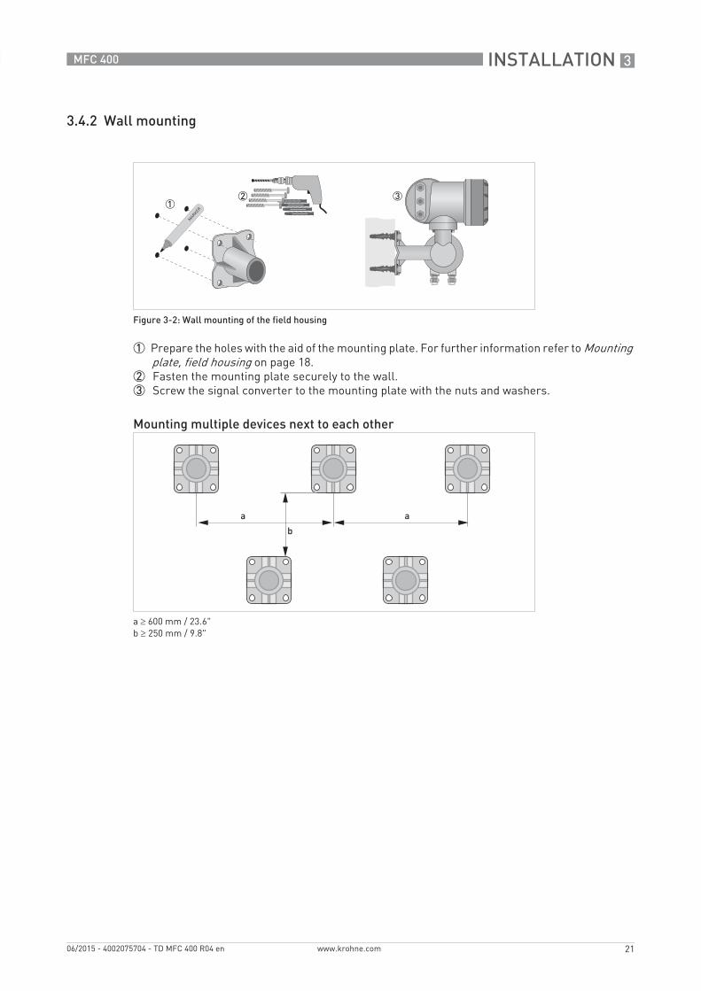
3.4.2 Wall mounting
1 Prepare the holes with the aid of the mounting plate. For further information refer to Mounting plate, field housing on page 18.
2 Fasten the mounting plate securely to the wall.3 Screw the signal converter to the mounting plate with the nuts and washers.
Figure 3-2: Wall mounting of the field housing
Mounting multiple devices next to each other
a ≥ 600 mm / 23.6"b ≥ 250 mm / 9.8"
4 ELECTRICAL CONNECTIONS
22
MFC 400
www.krohne.com 06/2015 - 4002075704 - TD MFC 400 R04 en
4.1 Safety instructions
4.2 Connection diagram
All work on the electrical connections may only be carried out with the power disconnected. Take note of the voltage data on the nameplate!
Observe the national regulations for electrical installations!
For devices used in hazardous areas, additional safety notes apply; please refer to the Ex documentation.
Observe without fail the local occupational health and safety regulations. Any work done on the electrical components of the measuring device may only be carried out by properly trained specialists.
Look at the device nameplate to ensure that the device is delivered according to your order. Check for the correct supply voltage printed on the nameplate.
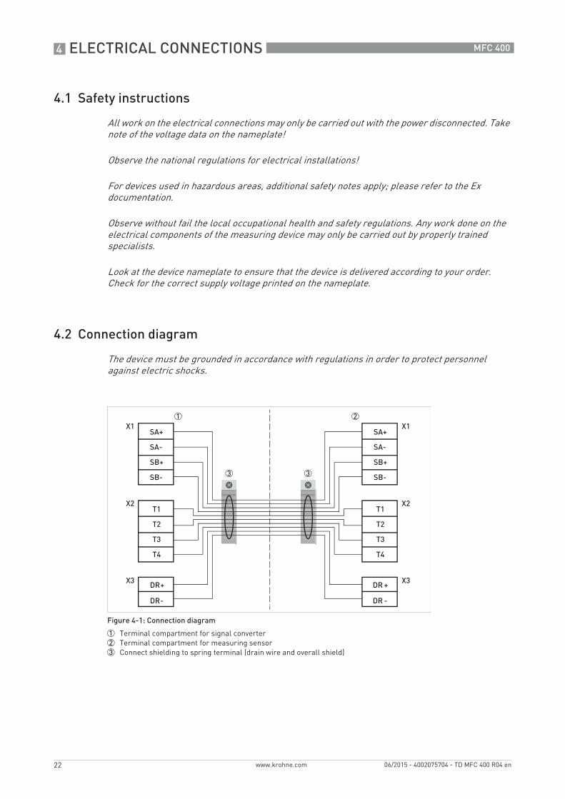
The device must be grounded in accordance with regulations in order to protect personnel against electric shocks.
Figure 4-1: Connection diagram
1 Terminal compartment for signal converter2 Terminal compartment for measuring sensor3 Connect shielding to spring terminal (drain wire and overall shield)

ELECTRICAL CONNECTIONS 4
23
MFC 400
www.krohne.com06/2015 - 4002075704 - TD MFC 400 R04 en
4.3 Grounding the flow sensor
• The flow sensor must be properly grounded.• The grounding cable should not transmit any interference voltages.• Do not use the grounding cable to connect more than one device to ground.• The flow sensors are connected to ground by means of a functional grounding conductor FE.• In hazardous areas, grounding is used at the same time for equipotential bonding. Additional
grounding instructions are provided in the supplementary "Ex documentation", which are only supplied together with hazardous area equipment.
Cable Cable Connection terminal
Cable pair Colour
1 yellow X1 SA+
1 black X1 SA-
2 green X1 SB+
2 black X1 SB-
3 blue X2 T1
3 black X2 T2
4 red X2 T3
4 black X2 T4
5 white X3 DR+
5 black X3 DR-
There should be no difference in potential between the flow sensor and the housing or protective earth of the signal converter!

4 ELECTRICAL CONNECTIONS
24
MFC 400
www.krohne.com 06/2015 - 4002075704 - TD MFC 400 R04 en
4.4 Connecting power – all housing variants
• The protection category depends on the housing versions (IP65...67 to IEC 529 / EN 60529 or NEMA4/4X/6).
• The housings of the devices, which are designed to protect the electronic equipment from dust and moisture, should be kept well closed at all times. Creepage distances and clearances are dimensioned to VDE 0110 and IEC 664 for pollution severity 2. Supply circuits are designed for overvoltage category III and the output circuits for overvoltage category II.
• Fuse protection (IN ≤ 16 A) for the infeed power circuit, as well as a separator (switch, circuit breaker) to isolate the signal converter must be provided close to the device. The separator must be marked as the separator for this device.
100...230 VAC (tolerance range: -15% / +10%)• Note the power supply voltage and frequency (50...60 Hz) on the nameplate.• The protective ground terminal PEPEPEPE of the power supply must be connected to the separate U-
clamp terminal in the terminal compartment of the signal converter
24 VDC (tolerance range: -55% / +30%)24 VAC/DC (tolerance range: AC: -15% / +10%; DC: -25% / +30%)• Note the data on the nameplate!• For measurement process reasons, a functional ground FEFEFEFE must be connected to the
separate U-clamp terminal in the terminal compartment of the signal converter.• When connecting to functional extra-low voltages, provide a facility for protective separation
(PELV) (acc. to VDE 0100 / VDE 0106 and/or IEC 364 / IEC 536 or relevant national regulations).
The device must be grounded in accordance with regulations in order to protect personnel against electric shocks.
For devices used in hazardous areas, additional safety notes apply; please refer to the Ex documentation.
240 VAC + 5% is included in the tolerance range.
For 24 VDC, 12 VDC - 10% is included in the tolerance range.
Power supply connection
1 100...230 VAC (-15% / +10%), 22 VA2 24 VDC (-55% / +30%), 12 W3 24 VAC/DC (AC: -15% / +10%; DC: -25% / +30%), 22 VA or 12 W

ELECTRICAL CONNECTIONS 4
25
MFC 400
www.krohne.com06/2015 - 4002075704 - TD MFC 400 R04 en
4.5 Inputs and outputs, overview
4.5.1 Combinations of the inputs/outputs (I/Os)
This signal converter is available with various input/output combinations.
Basic version• Has 1 current output, 1 pulse output and 2 status outputs / limit switches.• The pulse output can be set as status output/limit switch and one of the status outputs as a
control input.
Ex i version• Depending on the task, the device can be configured with various output modules.• Current outputs can be active or passive.• Optionally available also with Foundation Fieldbus and Profibus PA
Modular version• Depending on the task, the device can be configured with various output modules.
Bus systems• The device allows intrinsically safe and non intrinsically safe bus interfaces in combination
with additional modules.• For connection and operation of bus systems, note the supplementary instructions.
Ex option• For hazardous areas, all of the input/output variants for the housing designs C and F can be
delivered with terminal compartment in Ex d (pressure-resistant casing) or Ex e (increased safety).
• For connection and operation of Ex devices, note the supplementary instructions.

4 ELECTRICAL CONNECTIONS
26
MFC 400
www.krohne.com 06/2015 - 4002075704 - TD MFC 400 R04 en
4.5.2 Description of the CG number
The last 3 digits of the CG number (5, 6 and 7) indicate the assignment of the terminal connections. Please refer to the following examples.
Examples for CG number
Description of abbreviations and CG identifier for possible optional moduleson terminals A and B
Figure 4-2: Marking (CG number) of the electronics module and input/output variants
1 ID number: 32 ID number: 0 = standard; 9 = special3 Power supply option4 Display (language versions)5 Input/output version (I/O)6 1st optional module for connection terminal A7 2nd optional module for connection terminal B
CG 330 11 100 100...230 VAC & standard display; basic I/O: Ia or Ip & Sp/Cp & Sp & Pp/Sp
CG 330 11 7FK 100...230 VAC & standard display; modular I/O: Ia & PN/SN and optional module PN/SN & CN
CG 330 81 4EB 24 VDC & standard display; modular I/O: Ia & Pa/Sa and optional module Pp/Sp & Ip
Abbreviation Identifier for CG No. Description
Ia A Active current output
Ip B Passive current output
Pa / Sa C Active pulse output, frequency output, status output or limit switch (changeable)
Pp / Sp E Passive pulse output, frequency output, status output or limit switch (changeable)
PN / SN F Passive pulse output, frequency output, status output or limit switch acc. to NAMUR (changeable)
Ca G Active control input
Cp K Passive control input
CN H Active control input to NAMURSignal converter monitors cable breaks and short circuits acc. to EN 60947-5-6. Errors indicated on LC display. Error messages possible via status output.
- 8 No additional module installed
- 0 No further module possible
ELECTRICAL CONNECTIONS 4
27
MFC 400
www.krohne.com06/2015 - 4002075704 - TD MFC 400 R04 en
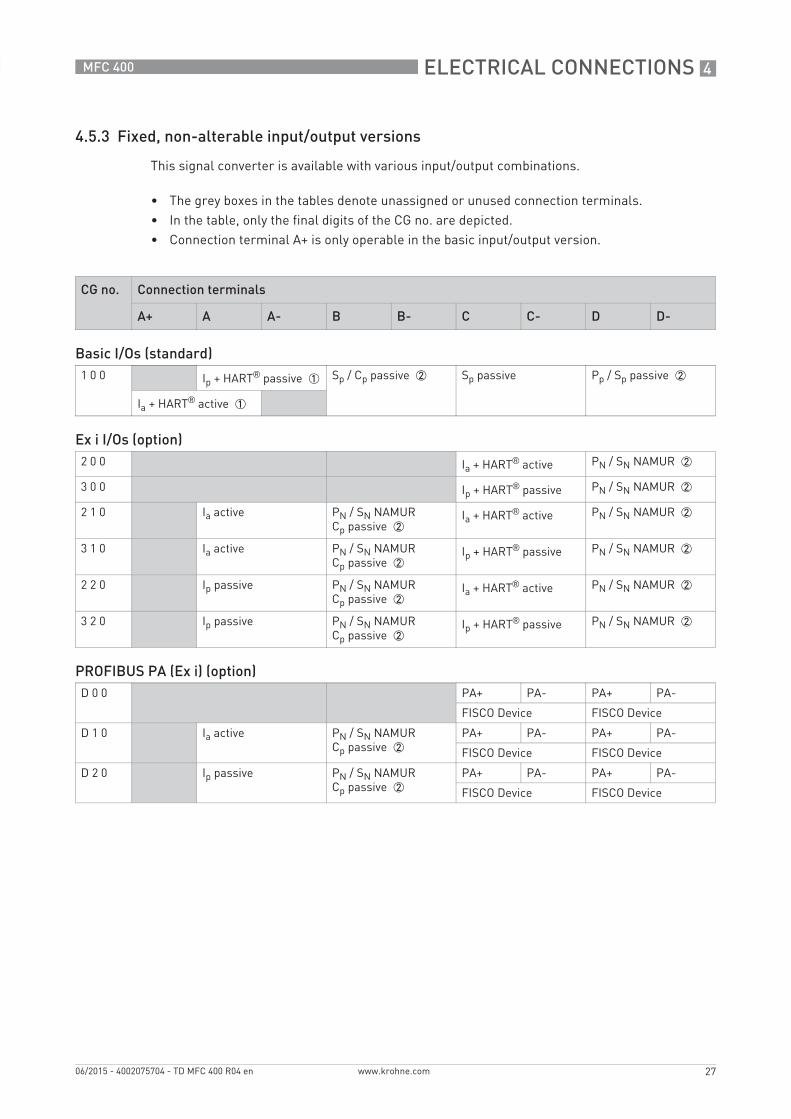
4.5.3 Fixed, non-alterable input/output versions
This signal converter is available with various input/output combinations.
• The grey boxes in the tables denote unassigned or unused connection terminals.• In the table, only the final digits of the CG no. are depicted.• Connection terminal A+ is only operable in the basic input/output version.
CG no. Connection terminals
A+ A A- B B- C C- D D-
Basic I/Os (standard)1 0 0 Ip + HART® passive 1 Sp / Cp passive 2 Sp passive Pp / Sp passive 2
Ia + HART® active 1
Ex i I/Os (option)2 0 0 Ia + HART® active PN / SN NAMUR 2
3 0 0 Ip + HART® passive PN / SN NAMUR 2
2 1 0 Ia active PN / SN NAMURCp passive 2
Ia + HART® active PN / SN NAMUR 2
3 1 0 Ia active PN / SN NAMURCp passive 2
Ip + HART® passive PN / SN NAMUR 2
2 2 0 Ip passive PN / SN NAMURCp passive 2
Ia + HART® active PN / SN NAMUR 2
3 2 0 Ip passive PN / SN NAMURCp passive 2
Ip + HART® passive PN / SN NAMUR 2
PROFIBUS PA (Ex i) (option)D 0 0 PA+ PA- PA+ PA-
FISCO Device FISCO Device
D 1 0 Ia active PN / SN NAMURCp passive 2
PA+ PA- PA+ PA-
FISCO Device FISCO Device
D 2 0 Ip passive PN / SN NAMURCp passive 2
PA+ PA- PA+ PA-
FISCO Device FISCO Device

4 ELECTRICAL CONNECTIONS
28
MFC 400
www.krohne.com 06/2015 - 4002075704 - TD MFC 400 R04 en
FOUNDATION Fieldbus (Ex i) (option)E 0 0 V/D+ V/D- V/D+ V/D-
FISCO Device FISCO Device
E 1 0 Ia active PN / SN NAMURCp passive 2
V/D+ V/D- V/D+ V/D-
FISCO Device FISCO Device
E 2 0 Ip passive PN / SN NAMURCp passive 2
V/D+ V/D- V/D+ V/D-
FISCO Device FISCO Device
1 Function changed by reconnecting2 Changeable

ELECTRICAL CONNECTIONS 4
29
MFC 400
www.krohne.com06/2015 - 4002075704 - TD MFC 400 R04 en
4.5.4 Alterable input/output versions
This signal converter is available with various input/output combinations.
• The grey boxes in the tables denote unassigned or unused connection terminals.• In the table, only the final digits of the CG no. are depicted.• Term. = (connection) terminal
CG no. Connection terminals
A+ A A- B B- C C- D D-
Modular I/Os (option)4 _ _ max. 2 optional modules for term. A + B Ia + HART® active Pa / Sa active 1
8 _ _ max. 2 optional modules for term. A + B Ip + HART® passive Pa / Sa active 1
6 _ _ max. 2 optional modules for term. A + B Ia + HART® active Pp / Sp passive 1
B _ _ max. 2 optional modules for term. A + B Ip + HART® passive Pp / Sp passive 1
7 _ _ max. 2 optional modules for term. A + B Ia + HART® active PN / SN NAMUR 1
C _ _ max. 2 optional modules for term. A + B Ip + HART® passive PN / SN NAMUR 1
PROFIBUS PA (option)D _ _ max. 2 optional modules for term. A + B PA+ (2) PA- (2) PA+ (1) PA- (1)
FOUNDATION Fieldbus (option)E _ _ max. 2 optional modules for term. A + B V/D+ (2) V/D- (2) V/D+ (1) V/D- (1)
PROFIBUS DP (option)F _ 0 1 optional module for
term. ATermina-tion P
RxD/TxD-P(2)
RxD/TxD-N(2)
Termina-tion N
RxD/TxD-P(1)
RxD/TxD-N(1)
Modbus (option)G _ _ 2 max. 2 optional modules for term. A + B Common Sign. B
(D1)Sign. A (D0)
H _ _ 3 max. 2 optional modules for term. A + B Common Sign. B (D1)
Sign. A (D0)
1 Changeable2 Not activated bus terminator 3 Activated bus terminator
5 NOTES
30
MFC 400
www.krohne.com 06/2015 - 4002075704 - TD MFC 400 R04 en
NOTES 5
31
MFC 400
www.krohne.com06/2015 - 4002075704 - TD MFC 400 R04 en

KROHNE – Process instrumentation and measurement solutions
• Flow
• Level
• Temperature
• Pressure
• Process Analysis
• Services
Head Office KROHNE Messtechnik GmbHLudwig-Krohne-Str. 547058 Duisburg (Germany)Tel.: +49 203 301 0Fax: +49 203 301 [email protected]
© K
RO
HN
E 06
/201
5 -
4002
0757
04 -
TD
MFC
400
R04
en
- Su
bjec
t to
chan
ge w
ithou
t not
ice.
The current list of all KROHNE contacts and addresses can be found at:www.krohne.com
KK
K