Signal Controller Ti98, Ref.no. 245.80.312 - stahl tranberg
8
Kockum Sonics AB, Industrigatan 39, P.O. Box 1035, SE-212 10 Malmö, Sweden, Tel: +46 (0) 40 671 88 00 Fax: +46 (0) 40 21 65 13, e-mail: [email protected], www.kockumsonics.com TYFON ® Signal Controller Ti98, Ref.no. 245.80.312 KSM726EN/1014 Front panel Operating and installation manual About this manual This manual is divided in 2 parts: • Operating manual • Installation manual explains the details for: • Mechanical mounting • Connection diagram showing how to replace the TI 96. • Electric connection diagrams for most common applications. • Configuration of the unit • Test procedure after installation Technical Data Voltage supply: 24V DC (18-31,2V DC) Power consumption: 3 W Relay contacts: Max. voltage: 250V Max. current: 6A Dimensions: 206 x 116 x 40 (L x H x D) Weight: 0.6 kg Cable area: 0,2 - 2.5 mm 2 Max cable diameter: 14 mm (for optional enclosure) Colour: Black RAL9005 Protection class: IP55 (on front), IP20 (on rear side) Operating ambient temp: 0 o C ... +50 o C General Signal Controller Ti98 is a signal controller for both whistle and morse light. It is a robust, simple to use and inexpensive unit which can be installed in all types of vessels. Features: • Panel made of membrane key technology • LCD matrix display that shows all necessary information • All illumination on the panel has red light and the brightness can be adjusted with dimmer buttons • "Whistle activated" output • General Emergency Alarm input • Input for external manual push button • Separate mains for whistle and morse light/lantern • Possibility to enable/disable characters to be used in automatic mode • All signalling can be made automatic or by hand manoeurve Compliance to following standards: EN60945 ,CISPR 16-2-1, CISPR 16-2-3, CISPR 16-4-2 EN61000-4-2, EN61000-4-3, EN61000-4-4, EN61000-4-6 EN61000-4-11
-
Upload
khangminh22 -
Category
Documents
-
view
0 -
download
0
Transcript of Signal Controller Ti98, Ref.no. 245.80.312 - stahl tranberg

Kockum Sonics AB, Industrigatan 39, P.O. Box 1035, SE-212 10 Malmö, Sweden, Tel: +46 (0) 40 671 88 00
Fax: +46 (0) 40 21 65 13, e-mail: [email protected], www.kockumsonics.com
TYFO
N®
Signal Controller Ti98, Ref.no. 245.80.312
KSM726EN/1014
Front panel
Operating and installation manual
About this manual
This manual is divided in 2 parts:
• Operatingmanual
• Installationmanualexplains the details for: • Mechanicalmounting • Connection diagram showing how to replace the TI 96. • Electricconnectiondiagramsformostcommon applications. • Configurationoftheunit • Testprocedureafterinstallation
Technical Data
Voltage supply: 24V DC (18-31,2V DC)Power consumption: 3 W Relay contacts: Max. voltage: 250V Max. current: 6ADimensions: 206 x 116 x 40 (L x H x D)Weight: 0.6 kgCable area: 0,2 - 2.5 mm2
Max cable diameter: 14 mm (for optional enclosure)Colour: Black RAL9005Protection class: IP55 (on front), IP20 (on rear side)Operating ambient temp: 0 oC ... +50 oC
General
Signal Controller Ti98 is a signal controller for both whistle and morse light. It is a robust, simple to use and inexpensive unit which can be installed in all types of vessels.
Features:
• Panelmadeofmembranekeytechnology• LCD matrix display that shows all necessary information• All illumination on the panel has red light and the brightness can be adjusted with dimmer buttons• "Whistleactivated"output• GeneralEmergencyAlarminput• Inputforexternalmanualpushbutton• Separatemainsforwhistleandmorselight/lantern• Possibilitytoenable/disablecharacterstobeused in automatic mode• Allsignallingcanbemadeautomaticorbyhand manoeurve
Compliance to following standards:EN60945 ,CISPR 16-2-1, CISPR 16-2-3, CISPR 16-4-2EN61000-4-2, EN61000-4-3, EN61000-4-4, EN61000-4-6EN61000-4-11

Symbol Description
Whistle de-selected
Whistle selected
Morse light de-selected
Morse light selected
Output selector*Press this to select the output to be used.Dependingoftheconfiguration(seesection"Confi-gurationoftheunit")amixofAft,Forewhistleandmorselight could be choosed.
Character selector*Press this to browse between different output signal characters.See seesection"Configurationoftheunit" how to enable more characters.
Time interval selector*Press this to choose appropriate time interval between 60, 90 or 120 sec of the given signal characters.
Automatic activationTurns the signal controllers automatics on or off.A LED above the button shows if the function is on oroff.WhenautomaticsisONthetext"AUT"willbeshown on the display and the LED for the Manual activation button will be lit when the character is generated. The remaining time interval will also be shownunderthetext"AUT".If Automatics is turned off, the LED above the button will be turned off and if an character is generated the text"AUT"willflashuntilthecharacterhasfinished.
DimmerChanges the brightness of the red background light and the 2 LED's.
Manual activationPressing this directly stops the automatics if it's on.Activate outputs selected on the display. When manually activating, either by pushing this button orbyexternalpushbutton,thetext"MAN"willbeshown on the display.
Automatic Signalling
The automatics has by default 5 signal characters. 5 more characters can easily be enabled in the software.All characters can be used for the whistles or the morse light or both simultaneously.The outputs to be activated is shown on the display.The period time can be changed between 60, 90 and 120 sec.If the automatics is on and an activation is done of the panels manual button or external push button will immediately turn the automatics to off. Characters and period time can be changed both when automa-tics is on or off.A LED indicator above the button shows the status of the automatics.
Manual Signalling
The push button for manual activation on the panel activates the choosen outputs shown on the display. When used, it will de-activate the automatics if enabled.
Default characters:
Optional characters(seesection"Configurationoftheunit"howtoenable):
"Makingwaythroughthewater""Makingnowaythroughthewater""Vesselatanchor""Vesselnotundercommand""Towedvessel"
"Keepclear(inland)""Vesselaground""Iamalteringmycoursetostarboard""Iamalteringmycoursetoport""Iamoperatingasternpropulsion"
i
Matrix LCD display
Whistle active function
When a whistle are activated a potential-free relay output will change its state. This is very useful if a Sound Signal Surveil-lance System is installed onboard such as Kockum Sonics S90. With this relay it is possible to connect to the surveillance system to mute the ships own whistle.
OPERATING
GEA function
ThecontrolunithasaninputforGEAthatcanbecontrolledbyan external poteintial free relay.Activating this input will stop any automatics and activates all connected whistle and morselight (even if they are disabled in the software). The signal pattern is controlled by the connected externalGEAsystem.Theinformationforthetimeintervalandcharacterwillbereplacedwiththetext"EXTERNALALARM".After the last activated signal there is a time out of 5 seconds before the units returns to normal function.
Bargraph shows the actual dimmer value.Can be set between 0 and 10.
This field shows the selec-ted time interval.
* Only selectable when automatics is turned off.

Recomended spare parts (to be kept onboard):
Ref. Description Data Kockum Sonics ref. no.
F1 Fuse 5 x 20 mm 315 mA fast blow 205.56.121
F2, 3 Fuse 5 x 20 mm 6.3 A slow blow 205.56.260
Cables to be moved to TI98
PE
1
2
3
4
5
6
7
8
9
10
11
12
13
TI96
Only if external push button is used
Only if lantern is used
Common for whistle
Only if Fore whistle
Only if Aft whistle
Common for whistle
21
22
23
24
25
26
27
28
F26 AS
1
2
3
4
5
6
7
8
F1
F3
6 AS
1 AS
Ti98
9
10
11
12
Connection diagram showing how to replace the TI 96
Mechanical mounting
Bulkhead mounting - Rear view
4 holes Ø 5,2mm for mounting to console
Panel mounting
170
95
188
98
(all units in mm)
cut out
164
87
Note! Extra enclosure for bulkhead mounting and protection as an option.Must be ordered separately.Ref no: 217.76.066
4
Ti 98
45 mm (60 mm withoptional enclosure)
INSTALLATION
F2 F1 F3

TI98 connected to 24V DC supply TI98 connected to 115/230 AC supply
Example of electric connection diagrams for most common applications
NOTE!Don’t use terminal 7 on the MTK250 as a feeding supply for the TI98 terminal 2
1 2 3 4 5 6 177 8 9 10 11 12 13 14 15 16
ETD 100/350Observe polarity of the
internal driver connection
MTK 250
ShieldBlack
Red or Yellow
White
To microphone(optional)
2
4 3 2 1
2 1
1
WhistleHeating
Sig
nP
tt+1
2VG
ND
2 x 4mm2
Ø12...15.5-+
Com
+24V
Inpu
t
4 x 4mm2
Ø12...15.5
** 0.5mm2
Ø8.5...11.5
To lampMax 60WMax 30V
Unfused
24V12A
FORE WHISTLE
AFT WHISTLE
24V DC supply for electronics
21
22
23
24
25
26
27
28 PE
F2
1
2
3
4
5
6
7
External manual switch
8
24V DC supply for Lantern
Output to Lantern
-
-+
+
F1
F3
Ti98
9
10
11
12
Whistle active
-
+
ExternalGEA system
315 mA (fast)
6.3 A (slow)
6.3 A (slow)
TI98 connected to 24V DC and MTK250
24V DC supply for electronics
21
22
23
24
25
26
27
Output to Aft Whistle
28
Output to Fore Whistle
PE
F2
24V DC supply for whistle
1
2
3
4
5
6
7
External manual switch
8
24V DC supply for Lantern
Output to Lantern
-
-+
+
F1
F3
6.3 A (slow)
315 mA (fast)
Ti98
9
10
11
12
Whistle active
-
+
ExternalGEA system
6.3 A (slow)-
+-
+-
+
21
22
23
24
25
26
27
Output to Aft Whistle
28
Output to Fore Whistle
PE
L
N
F2
L
N
L
N
115/230V AC supply for whistle
1
2
3
4
5
6
7
External manual switch
8
115/230V AC supply for Lantern
Output to Lantern
F1
F3
Ti98
9
10
11
12
Whistle active
115/230V AC supplyfor electronics
-
+24V DC / 700mA DC
AC
ExternalGEA system
L
N
L
N
315 mA (fast)
6.3 A (slow)
6.3 A (slow)

TI98 connected to one SUPERTYFON and one ELECTRO-TYFON with motor control unit TK 75 / TK 80
21
22
23
24
25
26
27
28 PE
L
N
F2
115/230V AC supply for whistles
1
2
3
4
5
6
7
External manual switch
8
115/230V AC supply for Lantern
Output to Lantern
F1
F3
Ti98
9
10
11
12
Whistle active
115/230V AC supplyfor electronics
-
+24V DC / 400mA DC
AC
ExternalGEA system
L
N
L
N
U1 V1 W1
1 2 L1 L2 L3 T1 T2 T3
Motor Control Unit ELECTRO-TYFONFore
Mains400V/50Hz440/60Hz
ValveCoil 1
ValveCoil 2 Heating
SUPERTYFONAft
Emergencysupply
24V DC
115 or 230V50/60Hz
315 mA (fast)
6.3 A (slow)
6.3 A (slow)
For details such as cable dimensions etc, see respective products datasheet.

i
When installation and any configuration is completed, the function of the unit should be performed.1. Poweruptheunitandthedisplayshouldbevisible.TrytochangetheilluminationwithuseofthedimmerbuttonsFandG.2. Press button A until both whistles and lantern is chosen (depends of the configuration). A filled symbol for whistle or lantern means that this output has been chosen.3. Press the button E. The selected output is now activated. Check also that the LED I lights up when the button is pressed.4. Press the button D to turn on the automatic signalling of the chosen output(s). Check that the LED H lights up. The sequence (character) of the output will be the same as shown in the display and can be changed by the B button. Time interval (repeat frequency) of the selected character is shown on the display and can be changed by the C button.5. Turn off the automatic signalling by pressing the button D once again. The LED H will be turned off.6. Chose individual outputs with the button A and test its function with button E.7. If external push button is connected, test this. The selected whistle on the display will be activated.
Note! If the display has no backlight after power on, try to to adjust with the dimmer.
A
B
C
D E
F
G
H I
J
Test procedure after installation
Configuration of the unit
i
The Ti98 is delivered with full functionality, i.e. all outputs are enabled.However, in some application it is desirable to disable some functionality such as the lantern output, enable more signal characters etc.To make this, the unit has to be in configuration mode.1. Press the button C and D at the same time while powering up the unit. A menu as the picture to the upper left is shown.2. With the button E and F the arrow can be moved up or down to select the row (function) to be changed.3. While on this row press the button C to toggle it on or off. A filled circle means that this function is enabled.4. If a signal character should be enabled, just move the arrow down until the picture for characters is shown.5. Whensettingsisdonemovetothe'SAVESETTINGS"andpressthebuttonD. The unit will now restart with the new settings.
A
B
C D
Available characters(cannot be disabled):
Optional characters(can be enabled):
E
F
Note! The 'DBW > 100M' means that if whistles are fitted at a distance apart of more than 100m this feature must be enabled. In that case it is is not possible to operate both AFT and FORE whistle simultaneously according to Colreg rule 34(f).Only AFT whistle will be used.
Subject to alteration without notice.
Push-button SwitchTL - 80 or TL - 85 (with lamp/LED) for panel or box mounting. Box mounted size (including box): height 107mm (fig. shows TL - 80)
Type Ref. no.
TL - 80 24500009
Box (IP66) 24500007
Lamp block 20570033
Lamp 230V 20560124
Lamp 115V 20560125
LED for 24V 20560127
AC-DC converter for supplying Ti98UniversalAC input range from 85 ~ 264V AC 50/60 Hz.Easily mounted on DIN rail type TS-35/7.5 or 15.Dimensions:22.5 x 90 x 100 mm (WxHxD)Weight: 0.19 kg
Type Ref. no.
MDR-20-24 20142028
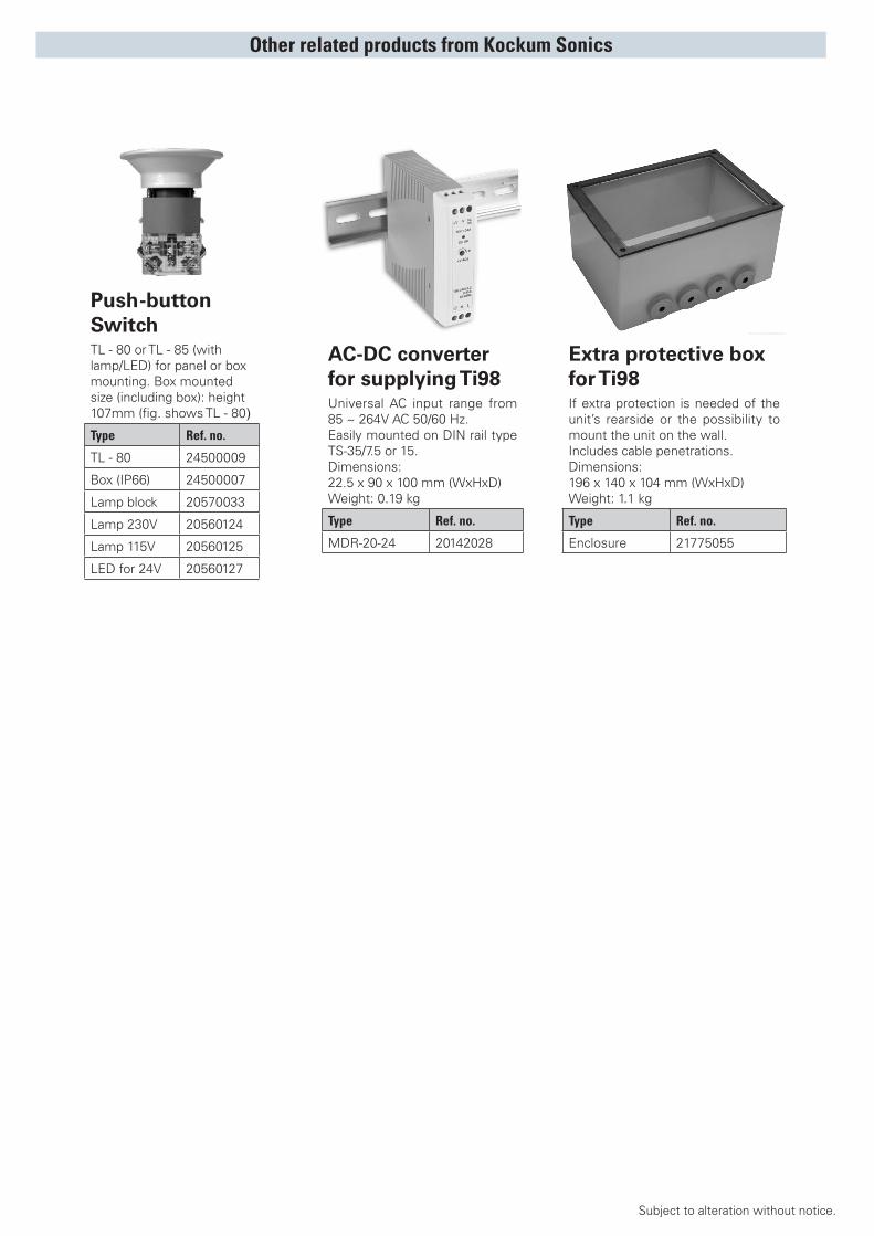
Extra protective box for Ti98If extra protection is needed of the unit’s rearside or the possibility to mount the unit on the wall.Includes cable penetrations. Dimensions:196 x 140 x 104 mm (WxHxD)Weight: 1.1 kg
Type Ref. no.
Enclosure 21775055
Other related products from Kockum Sonics
Optional characters(can be enabled):

HEAD OFFICEKockum Sonics AB
Industrigatan 39, P.O. Box 1035, SE-212 10 Malmö, SwedenTel: +46(0)40-671 88 00 Fax: +46(0)40-21 65 13
E-mail: [email protected] Internet: www.kockumsonics.com
with affiliated companies in . . .
CHINAKockum Sonics
2123 Pudong Da Dao 506, Dragon PearlComplex, Shanghai 200135, CHINATel: +86 (21) 5885 2729, 5860 3661
Fax: +86 (21) 6853 84 00E-mail: [email protected]
SWITZERLANDKockum Sonics AG
Oberdorfstrasse 64, Postfach 448, CH-8600 Dübendorf, SwitzerlandTel: +41(0) 820 31 91 Fax: +41(0) 821 26 52
E-mail: [email protected]
RUSSIAKockum Sonics
14,ObvodnyKanal,RU-192019,St.Petersburg,RussiaTel: +7 (8) 812 412 70 04 Fax: +7 (8) 812 412 70 04
E-mail: [email protected]
UNITED KINGDOMKockum Sonics (UK) Ltd.
Unit7,LeightonIndustrialPark,BillingtonRoadLeightonBuzzardBEDSLU74AJ,UnitedKingdomTel: +44(0)1525 85 23 23 Fax: +44(0)1525 85 35 05
E-mail: [email protected]
Marine equipment includingTYFON®, SUPERTYFON®, ELECTRO-TYFON®, LOADMASTER®, LEVELMASTER H8®
is supplied by.....
Kockum Sonics, a
company