
SICAM MMU Measurement and Monitoring Unit - Siemens
16
Energy Automation Answers for infrastructure and cities. SICAM MMU Measurement and Monitoring Unit Catalog SR 10.4.2 · Edition 1
-
Upload
khangminh22 -
Category
Documents
-
view
2 -
download
0
Transcript of SICAM MMU Measurement and Monitoring Unit - Siemens
Energy Automation
Answers for infrastructure and cities.
SICAM MMU Measurement and Monitoring Unit
Catalog SR 10.4.2 · Edition 1

SICAM MMU Measurement and Monitoring Unit · Siemens SR 10.4.2 · Edition 1 3
Contents – SICAM MMU
Page
Device description 4
Specifi c functions and design 6
Measurands 7
Connection types 8
Graphical user interface 9
Technical data 11
Connection diagram, dimension drawings 13
Selection and ordering data 14
Disclaimer of liability 15
SICAM MMU Measurement and Monitoring UnitEnergy Automation
Catalog SICAM MMU · Edition 1
The products and systems described in this catalog are manufactured and sold according to a certifi ed management system (acc. to ISO 9001, ISO 14001 and BS OHSAS 18001).
SICAM MMU Measurement and Monitoring Unit · Siemens SR 10.4.2 · Edition 1
SICAM MMU
4
Device description
SIC
AM
-MM
U-0
01
.tif
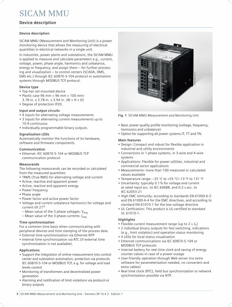
Fig. 1 SICAM MMU Measurement and Monitoring Unit
Device description
SICAM MMU (Measurement and Monitoring Unit) is a power monitoring device that allows the measuring of electrical quantities in electrical networks in a single unit.
In industries, power plants and substations, the SICAM MMU is applied to measure and calculate parameters e.g., current, voltage, power, phase angle, harmonics and unbalance, energy or frequency, and assign them – for further process-ing and visualization – to control centers (SCADA, DMS, EMS etc.) through IEC 60870-5-104 protocol or automation systems through MODBUS TCP protocol.
Device type• Top-hat rail mounted device• Plastic case 96 mm × 96 mm × 100 mm/
3.78 in. x 3.78 in. x 3.94 in. (W × H × D)• Degree of protection IP20.
Input and output circuits• 4 inputs for alternating voltage measurements• 3 inputs for alternating current measurements up to
10 A continuous• Individually programmable binary outputs.
Signalization LEDsAutomatically monitor the functions of its hardware, software and fi rmware components.
Communication• Ethernet: IEC 60870-5-104 or MODBUS TCP
communication protocol.
MeasurandsThe following measurands can be recorded or calculated from the measured quantities:• TRMS (True RMS) for alternating voltage and current• Active, reactive and apparent power• Active, reactive and apparent energy• Power frequency• Phase angle• Power factor and active power factor• Voltage and current unbalance harmonics for voltage and
current till 21st
– Mean value of the 3 phase voltages: Vavg – Mean value of the 3 phase currents: Iavg.
Time synchronizationFor a common time basis when communicating with peripheral devices and time stamping of the process data. • External time synchronization via Ethernet NTP• Internal time synchronization via RTC (if external time
synchronization is not available).
Applications• Support the integration of online measurement into control
center and substation automation, protection via protocols IEC 60870-5-104 or MODBUS TCP, e.g. for voltage and load levels control
• Monitoring of transformers and decentralized power generation
• Alarming and notifi cation of limit violations via protocol or binary outputs
• Basic power quality profi le monitoring (voltage, frequency, harmonics and unbalance)
• Option for supporting all power systems IT, TT and TN.
Main features• Design: Compact and robust for fl exible application in
industrial and utility environments• Connections in 1-phase systems, in 3-wire and 4-wire
systems• Applications: Flexible for power utilities, industrial and
commercial sector applications• Measurements: more than 100 measured or calculated
values available• Temperature range: –25 °C to +55 °C/–13 °F to 131 °F• Uncertainty: typically 0.1 % for voltage and current
at rated input acc. to IEC 60688, and 0.2 s acc. to IEC 62053-21
• High EMC immunity: according to standards EN 61000-6-2 and EN 61000-6-4 for the EMC directives, and according to standard EN 61010-1 for the low-voltage directive
• UL Certfi cation: This product is UL-certifi ed to standard UL 61010-1.
Highlights• Flexible current measurement range (up to 2 × In)• 2 individual binary outputs for fast switching, indications
(e.g., limit violation) and operation status monitoring • 4 LEDs for local status visualization• Ethernet communications via IEC 60870-5-104 or
MODBUS TCP protocols• Internal battery for real time clock and saving of energy
counter values in case of a power outage• User-friendly operation through Web server (no extra
software for parameterization needed, no converters and extra cables)
• Real time clock (RTC), fi eld bus synchronization or network synchronization possible via NTP.
SICAM MMU Measurement and Monitoring Unit · Siemens SR 10.4.2 · Edition 1
SICAM MMU
5
Device description
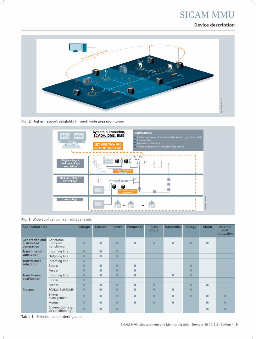
Application area Voltage Current Power Frequency Phase angle
Harmonics Energy Alarm Internal cost
allocation
Generation and distributedgeneration
Generator /upstream transformer
■ ■ ■ ■ ■ ■ ■ ■
Transmission substation
Incoming line ■ ■ ■
Outgoing line ■ ■ ■
Transformer substation
Incoming line ■
Busbar ■ ■ ■ ■ ■
Feeder ■ ■ ■ ■ ■
Transformer distribution
Incoming line ■ ■ ■ ■ ■ ■
Busbar ■
Feeder ■ ■ ■ ■ ■ ■ ■
Process SCADA / EMS / DMS ■ ■ ■ ■ ■ ■ ■
Energy management ■ ■ ■ ■ ■ ■ ■ ■ ■
Motors ■ ■ ■ ■ ■ ■ ■ ■
Commercial (e.g. air conditioning) ■ ■ ■ ■ ■
Fig. 3 Wide application in all voltage levels
Fig. 2 Higher network reliability through wide area monitoring
Table 1 Selection and ordering data
Applications
C Evaluation from substation and distributed generation dataC Load profi leC Network power fl owC Voltage, frequency and harmonics profi le
SIC
AM
-MM
U-0
02
.tif
SIC
AM
-MM
U-0
03
.tif
SICAM MMU Measurement and Monitoring Unit · Siemens SR 10.4.2 · Edition 1
SICAM MMU
6
Specifi c functions and design
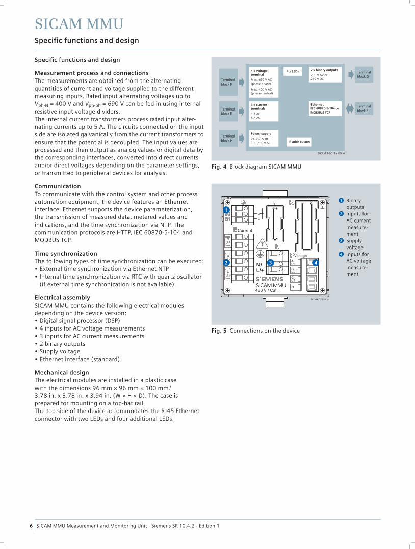
4 x voltageterminal
Max. 690 V AC(phase-phase)
Max. 400 V AC(phase-neutral)
4 x LEDs
Terminalblock F
Terminalblock G
Terminalblock ZTerminal
block E
Terminalblock H
2 x binary outputs
230 V AV or250 V DC
Ethernet IEC 60870-5-104 or MODBUS TCP
3 x currentterminals
1 A AC5 A AC
Power supply
24-250 V DC100-230 V AC IP addr button
SICAM T-0018a.EN.ai
AL1
BL2
CL3
N/-L/+
SICAM T-0008.ai
432
1
Binary outputs
Inputs for AC current measure-ment
Supply voltage
Inputs for AC voltage measure-ment
Fig. 5 Connections on the device
Fig. 4 Block diagram SICAM MMU
Specifi c functions and design
Measurement process and connectionsThe measurements are obtained from the alternating quantities of current and voltage supplied to the different measuring inputs. Rated input alternating voltages up to Vph-N = 400 V and Vph-ph = 690 V can be fed in using internal resistive input voltage dividers. The internal current transformers process rated input alter-nating currents up to 5 A. The circuits connected on the input side are isolated galvanically from the current transformers to ensure that the potential is decoupled. The input values are processed and then output as analog values or digital data by the corresponding interfaces, converted into direct currents and/or direct voltages depending on the parameter settings, or transmitted to peripheral devices for analysis.
CommunicationTo communicate with the control system and other process automation equipment, the device features an Ethernet interface. Ethernet supports the device parameterization, the transmission of measured data, metered values and indications, and the time synchronization via NTP. The communication protocols are HTTP, IEC 60870-5-104 and MODBUS TCP.
Time synchronizationThe following types of time synchronization can be executed:• External time synchronization via Ethernet NTP • Internal time synchronization via RTC with quartz oscillator
(if external time synchronization is not available).
Electrical assemblySICAM MMU contains the following electrical modules depending on the device version:• Digital signal processor (DSP)• 4 inputs for AC voltage measurements• 3 inputs for AC current measurements• 2 binary outputs• Supply voltage• Ethernet interface (standard).
Mechanical designThe electrical modules are installed in a plastic case with the dimensions 96 mm × 96 mm × 100 mm/3.78 in. x 3.78 in. x 3.94 in. (W × H × D). The case is prepared for mounting on a top-hat rail.The top side of the device accommodates the RJ45 Ethernet connector with two LEDs and four additional LEDs.
SICAM MMU Measurement and Monitoring Unit · Siemens SR 10.4.2 · Edition 1
SICAM MMU
7
Measurands
Measurand Circuit 1-phase system
3-wire network (delta) 4-wire network (star)
balanced (1I)
unbalanced (3I)
unbalanced (2I)
balanced (1I)
unbalanced (3I)
AC voltage Va a-N ■ ■ ■
Vb b-N ■
Vc c-N ■
Vab, Vbc, Vca a-b, b-c, c-a ■ ■ ■ ■
VN a, b, c ■
Vavg a, b, c ∑Vph/3 ∑Vph/3 ∑Vph/3 a-N ∑Vph/3
Vunbal a-b, b-c, c-a ■ ■ ■ ■
AC current Ia a ■ ■ ■ ■ ■ ■
Ib, Ic b, c ■ ■ ■
IN a, b, c ■ ■
Iavg a, b, c ■ ■ ∑Iph/3
Iunbal a, b, c ■ ■ ■
Active power factor
cos φ (a) a ■ ■
cos φ (b), cos φ (c) b, c ■
cos φ a, b, c ■ ■ ■ ■ ■
Power factor PFa a ■ ■
PFb, PFc b, c ■
PF a, b, c ■ ■ ■ ■ ■
Phase angle φa a ■ ■
φb, φc b, c ■
φ a, b, c ■ ■ ■ ■ ■
Angle between the phase-ground voltages
φab a-b ■
φac a-c ■
Frequency f a, b, c ■ ■ ■ ■ ■ ■
Active power Pa a ■ ■
Pb, Pc b, c ■
P a, b, c ■ ■ ■ ■ ■
Reactive power Qa a ■ ■
Qb, Qc b, c ■
Q a, b, c ■ ■ ■ ■ ■
Apparent power Sa a ■ ■
Sb, Sc b, c ■
S a, b, c ■ ■ ■ ■ ■
Active energy – supply
WPa supply a ■ ■
WPb supply, WPc supply b, c ■
WPsupply a, b, c ■ ■ ■ ■ ■
Active energy – demand
WPa demand a ■ ■
WPb demand, WPc demand b, c ■
WPdemand a, b, c ■ ■ ■ ■ ■
Reactive energy – inductive
WQa inductive a ■ ■
WQb inductive, WQc inductive b, c ■
WQinductive a, b, c ■ ■ ■ ■ ■
Reactive energy – capacitive
WQa capacitive a ■ ■
WQb capacitive, WQc capacitive b, c ■
WQcapacitive a, b, c ■ ■ ■ ■ ■
Apparent energy WSa a ■ ■
WSb, WSc b, c ■
WS a, b, c ■ ■ ■ ■ ■
Harmonics voltage HVa a-N ■ ■ ■
HVb b-N ■
HVc c-N ■
Harmonics current HIa a ■ ■ ■ ■ ■ ■
HIb b ■ ■ ■
HIc c ■ ■ ■
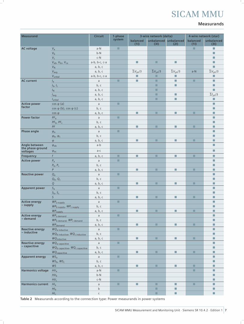
Table 2 Measurands according to the connection type: Power measurands in power systems
SICAM MMU Measurement and Monitoring Unit · Siemens SR 10.4.2 · Edition 1
SICAM MMU
8
Connection types
PE
AI
L1
AL1
BL2
CL3
NBI
L2
CI
L3
P1 P2
S1 S2
L1(a)
N
Current Voltage
SICAM T-0009.EN.ai
1-phase system, no voltage transformer
ab
AB A
B
abPE
AI
L1
AL1
BL2
CL3
NBI
L2
CI
L3
P1 P2
P1 P2
S1 S2 S1 S2
L1(a)
L3(c)
S1 S2
L2(b)
P1 P2
Current Voltage
SICAM T-0012.EN.ai
3-wire network, 2 voltage transformers and 3 current transformers, unbalanced*
P1 P2
P1 P2
S1 S2 S1 S2
L1(a)
PE
L3(c)
S1 S2
N
AI
L1
AL1
BL2
CL3
NBI
L2
CI
L3
L2(b)
P1 P2
SICAM T-0014.EN.ai
Current Voltage
4-wire network, no voltage transformer and 3 current transformers, unbalanced
P1 P2
P1 P2
S1 S2 S1 S2
a
b b b
L1(a)
PE
L3(c)
S1 S2
N
AI
L1
AL1
BL2
CL3
NBI
L2
CI
L3
a a
A A A
B B B
L2(b)
P1 P2
Current Voltage
SICAM T-0015.EN.ai
4-wire network, 3 voltage transformers and 3 current transformers, unbalanced
ab
AB A
B
abPE
AI
L1
AL1
BL2
CL3
NBI
L2
CI
L3
P1 P2
S1 S2
L1(a)
L2(b)
L3(c)
Current Voltage
SICAM T-0010.EN.ai
3-wire network, 2 voltage transformers and 1 current transformer, balanced*
a b
A B
PE
AI
L1
AL1
BL2
CL3
NBI
L2
CI
L3
N
P1 P2
S1 S2
L1(a)
L3(c)
L2(b)
Current
SICAM T-0013.EN.ai
Voltage
4-wire network, 1 voltage transformer and 1 current transformer, balanced
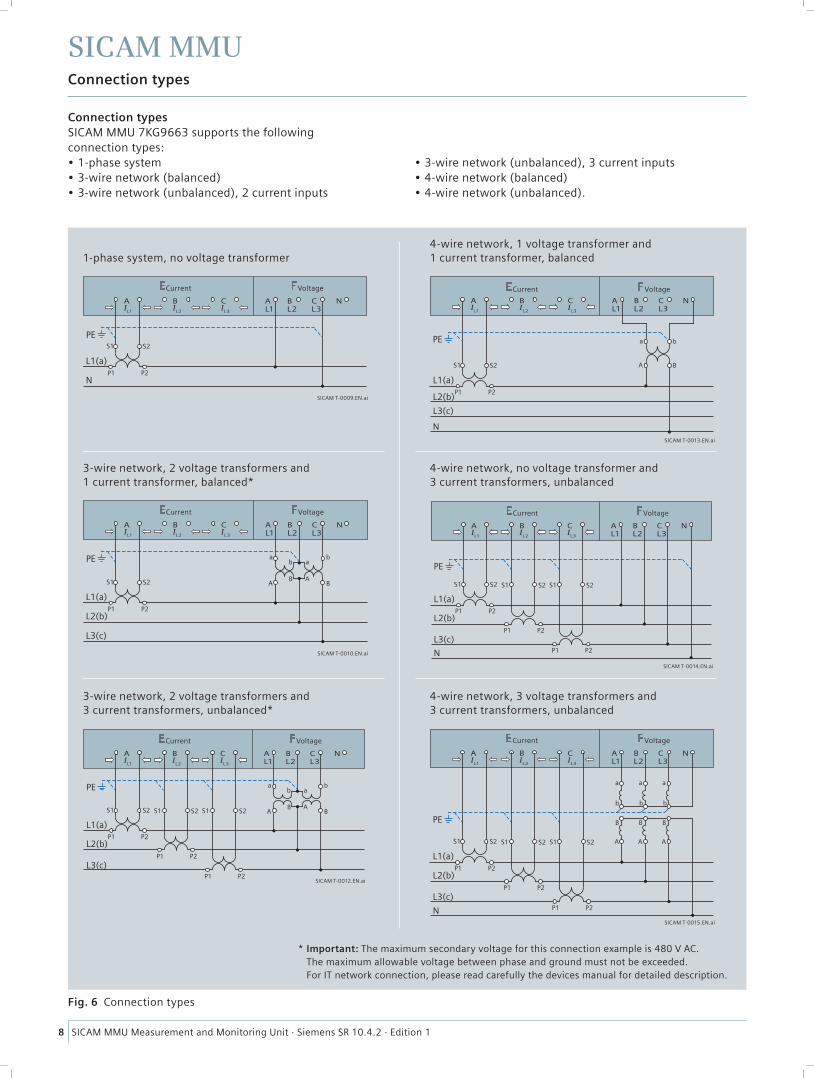
Fig. 6 Connection types
* Important: The maximum secondary voltage for this connection example is 480 V AC. The maximum allowable voltage between phase and ground must not be exceeded. For IT network connection, please read carefully the devices manual for detailed description.
Connection typesSICAM MMU 7KG9663 supports the following connection types: • 1-phase system• 3-wire network (balanced)• 3-wire network (unbalanced), 2 current inputs
• 3-wire network (unbalanced), 3 current inputs• 4-wire network (balanced)• 4-wire network (unbalanced).
SICAM MMU Measurement and Monitoring Unit · Siemens SR 10.4.2 · Edition 1
SICAM MMU
9
Graphical user interface
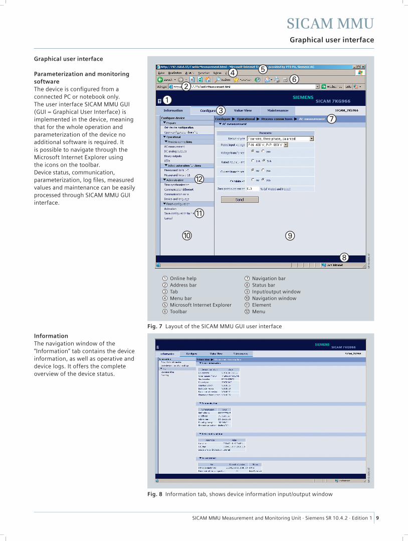
Online help Address bar Tab Menu bar Microsoft Internet Explorer Toolbar
Navigation bar Status bar Input/output window Navigation window Element Menu
Fig. 7 Layout of the SICAM MMU GUI user interface
Fig. 8 Information tab, shows device information input/output window
SR1
0-0
04
.tif
SR1
0-0
05
.tif
Graphical user interface
Parameterization and monitoring softwareThe device is confi gured from a connected PC or notebook only. The user interface SICAM MMU GUI (GUI = Graphical User Interface) is implemented in the device, meaning that for the whole operation and parameterization of the device no additional software is required. It is possible to navigate through the Microsoft Internet Explorer using the icons on the toolbar.Device status, communication, parameterization, log fi les, measured values and maintenance can be easily processed through SICAM MMU GUI interface.
InformationThe navigation window of the “Information” tab contains the device information, as well as operative and device logs. It offers the complete overview of the device status.
SICAM MMU Measurement and Monitoring Unit · Siemens SR 10.4.2 · Edition 1
SICAM MMU
10
Graphical user interface
SR1
0-0
07
.tif
SR1
0-0
08
.tif
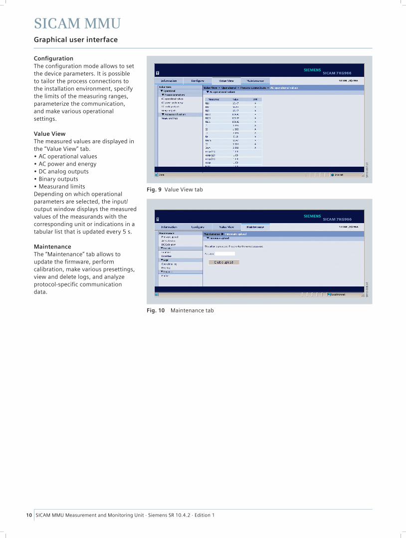
Confi gurationThe confi guration mode allows to set the device parameters. It is possible to tailor the process connections to the installation environment, specify the limits of the measuring ranges, parameterize the communication, and make various operational settings.
Value ViewThe measured values are displayed in the “Value View” tab.• AC operational values• AC power and energy• DC analog outputs• Binary outputs• Measurand limitsDepending on which operational parameters are selected, the input/output window displays the measured values of the measurands with the corresponding unit or indications in a tabular list that is updated every 5 s.
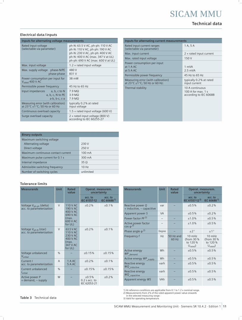
MaintenanceThe “Maintenance” tab allows to update the fi rmware, perform calibration, make various presettings, view and delete logs, and analyze protocol-specifi c communication data.
Fig. 9 Value View tab
Fig. 10 Maintenance tab
SICAM MMU Measurement and Monitoring Unit · Siemens SR 10.4.2 · Edition 1
SICAM MMU
11
Technical data
Electrical data / inputs
Inputs for alternating voltage measurements
Rated input voltage (selectable via parameter)
ph-N: 63.5 V AC, ph-ph: 110 V ACph-N: 110 V AC, ph-ph: 190 V ACph-N: 230 V AC, ph-ph: 400 V ACph-N: 400 V AC (max. 347 V at UL)ph-ph: 690 V AC (max. 600 V at UL)
Max. input voltage 1.2 × rated input voltage
Max. supply voltage phase-N/PE phase-phase
480 V831 V
Power consumption per input for Vrated 400 V AC
38 mW
Permissible power frequency 45 Hz to 65 Hz
Input impedances a, b, c to N a, b, c, N to PE a-b, b-c, c-a
7.9 MΩ3.9 MΩ7.9 MΩ
Measuring error (with calibration) at 23 °C ±1 °C; 50 Hz or 60 Hz
typically 0.2 % at rated input voltage
Continuous overload capacity 1.5 × rated input voltage (600 V)
Surge overload capacity 2 × rated input voltage (800 V) according to IEC 60255-27
Inputs for alternating current measurements
Rated input current ranges (selectable via parameter)
1 A, 5 A
Max. input current 2 × rated input current
Max. rated input voltage 150 V
Power consumption per inputat 1 A ACat 5 A AC
1 mVA2.5 mVA
Permissible power frequency 45 Hz to 65 Hz
Measuring error (with calibration) at 23 °C ±1 °C; 50 Hz or 60 Hz:
typically 0.2 % at rated input current
Thermal stability 10 A continuous100 A for max. 1 s according to IEC 60688
Binary outputs
Maximum switching voltage
Alternating voltage
Direct voltage
230 V
250 V
Maximum continuous contact current 100 mA
Maximum pulse current for 0.1 s 300 mA
Internal impedance 35 Ω
Admissible switching frequency 10 Hz
Number of switching cycles unlimited
Table 3 Technical data
Tolerance limits
Measurands Unit Rated value
Operat. measurem. uncertainty
acc. toIEC 61557-12
acc. toIEC 60688 1)
Voltage Vph-ph (delta) acc. to parameterization
V 110 V AC190 V AC400 V AC690 V AC(max. 600 V AC for UL)
±0.2 % ±0.1 %
Voltage Vph-N (star) acc. to parameterization
V 63.5 V AC110 V AC230 V AC400 V AC(max. 347 V AC for UL)
±0.2 % ±0.1 %
Voltage unbalanced Vunbal
% – ±0.15 % ±0.15 %
Current I acc. to parameterization
A 1 A AC5 A AC
±0.2 % ±0.1 %
Current unbalanced Iunbal
% – ±0.15 % ±0.15 %
Active power P + demand, – supply
W – ±0.5 %0.2 s acc. to IEC 62053-21
±0.2 %
Measurands Unit Rated value
Operat. measurem. uncertainty
acc. toIEC 61557-12 3)
acc. toIEC 60688 1)
Reactive power Q + inductive, – capacitive
var – ±0.5 % ±0.2 %
Apparent power S VA ±0.5 % ±0.2 %
Power factor PF 2) – – ±1.0 % ±0.5 %
Active power factor cos φ 2)
– – ±1.0 % ±0.5 %
Phase angle φ 2) Degree – ±2 ° ±1 °
Frequency f Hz 50 Hz and 60 Hz
10 mHz(from 30 % to 120 %
Urated)
10 mHz(from 30 % to 120 %
Urated)
Active energy WP_demand
Wh – ±0.5 % ±0.5 %
Active energy WP_supply Wh – ±0.5 % ±0.5 %
Reactive energy WQ_inductive
varh – ±0.5 % ±0.5 %
Reactive energy WQ_capacitive
varh – ±0.5 % ±0.5 %
Apparent energy WS VAh – ±0.5 % ±0.5 %
1) At reference conditions are applicable from 0.1 to 1.2 x nominal range.2) Measurements from 2 % of the rated apparent power value onwards
in the selected measuring range.3) Valid for operating temperature.
SICAM MMU Measurement and Monitoring Unit · Siemens SR 10.4.2 · Edition 1
SICAM MMU
12
Technical data
Communication data
Ethernet
Bus protocol IEC60870-5-104 Server or MODBUS TCP
Transmission rate 10/100 Mbit/s
Communication protocol IEEE 802.3
Connection 100Base-T (RJ45)
Cable for 100Base-T 100 Ω to 150 Ω STP, CAT5
Maximum cable length 100Base-T 100 m (if well installed)
Voltage strength 700 V DC
Environmental data
Supply voltage
Operating temperaturecontinuous operation –25 °C to +55 °C /
–13 °F to 131 °F
Temperatureduring transportation
during storage
–25 °C to +70 °C /–13 °F to 158 °F–25 °C to +70 °C /–13 °F to 158 °F
Maximum temperature gradient 20 K/h
Air humiditymean relative air humidity per yearmaximum relative air humidity
≤ 75 %95 % 30 days a year
Condensationduring operationduring transportation and storage
not permittedpermitted
Regulations and standards
Climate
Cold IEC 60688-2-1 Test AdIEEE C37.90
Dry heat during operation, storage, and transportation
IEC 60688-2-2 Test BdIEEE C37.90
Damp heat DIN EN 60688-2-78:2002-09IEEE C37.90
Damp heat – cyclic IEC 60688-2-30 Test Db
Change of temperature IEC 60688-2-14 Tests Na and Nb
Individual gas test, industrial atmo-sphere, sequential gas test
IEC 60688-2-42 Test KcIEC 60688-2-43
Flowing mixed gas IEC 60688-2-60 Method 4
Salt fog test IEC 60688-2-11 Test Ka
Mechanics
Vibration during operation IEC 60688-2-6 Test FcIEC 60255-21-1
General electrical data and reference conditions
Supply voltage
Rated input voltages 110 V AC to 230 V AC or 24 V DC to 250 V DC
System frequency at AC 45 Hz to 65 Hz
Admissible input voltage tolerance (valid for all input voltages)
±20 %
Permitted ripple of the input voltage at 24 V DC, 48 V DC, 60 V DC, 110 V DC, 220 V DC, 250 V DC
15 %
Permitted harmonics at 115 V, 230 V 2 kHz
Max. inrush current at ≤ 110 V DC; ≤ 115 V ACat 220 V DC to 300 V DC; 230 V AC
< 15 A≤ 22 A (after 250 μs: < 5 A)
Maximum power consumption 6 W / 9 VA
Battery
Type CR2032
Voltage 3 V
Capacity 230 mAh
Degree of protection according to IEC 60529
Device front IP20
Device rear (connections) IP20
Reference conditions for determining the test data (precision specifi cations under reference conditions)
Rated input current ±1 %
Rated input voltage ±1 %
Frequency 45 Hz to 65 Hz
Curve shape sine, total harmonic distortion
≤ 5 %
Ambient temperature 23 °C ±1 °C
Supply voltage VHN ±1 %
Warm-up time ≥ 15 min
Interfering fi elds none
Table 4 Technical data
SICAM MMU Measurement and Monitoring Unit · Siemens SR 10.4.2 · Edition 1
SICAM MMU
13
Connection diagram, dimension drawings
IL1A
AL1
L/+
L/–
BL2
CL3
N
IL2B
IL3
B0B1B2
C
CurrentE
F
H
G
ZVoltage
Power supply
Ethernetinterface
SEN
T T-
00
19
.EN
.ai
1
AL1
BL2
CL3
N/-L/+
96 / 3.78
96
SICAM MMU
SENT T-0020.EN.ai
103.8 / 4.09
Snap-in clip
Guiding of thesnap-in clip
Top-hat rail
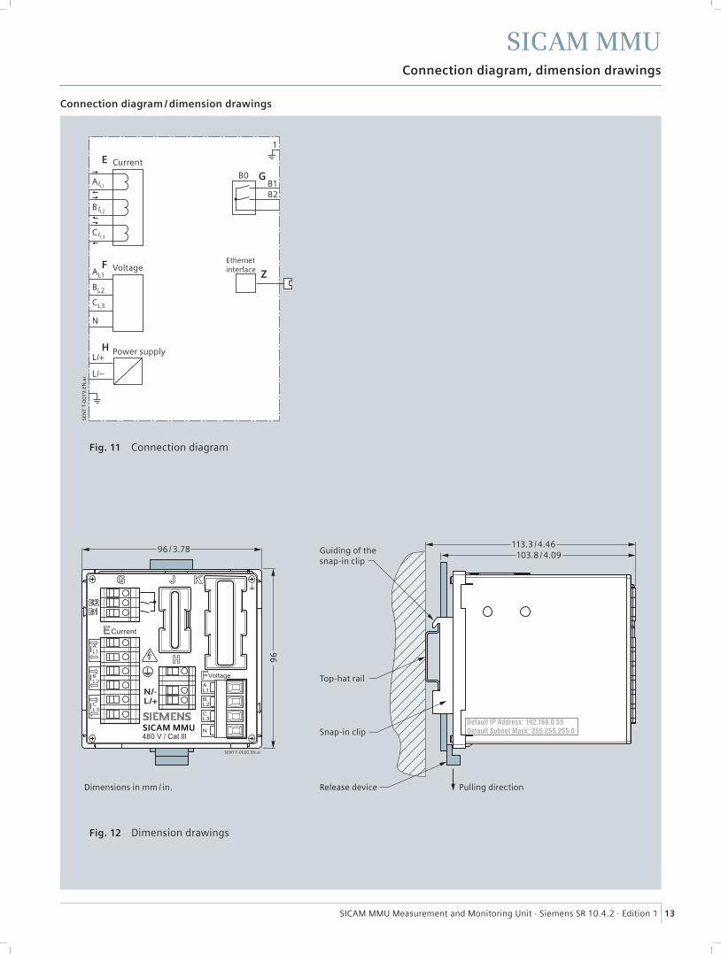
Release device Pulling directionDimensions in mm / in.
113.3 / 4.46
Connection diagram / dimension drawings
Fig. 11 Connection diagram
Fig. 12 Dimension drawings
SICAM MMU Measurement and Monitoring Unit · Siemens SR 10.4.2 · Edition 1
SICAM MMU
14
Selection and ordering data
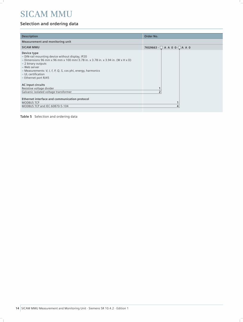
Description Order No.
Measurement and monitoring unit
SICAM MMU 7KG9663 - A A 0 0 - A A 0
Device type– DIN-rail mounting device without display, IP20– Dimensions 96 mm x 96 mm x 100 mm / 3.78 in. x 3.78 in. x 3.94 in. (W x H x D)– 2 binary outputs– Web server– Measurements: V, I, f, P, Q, S, cos phi, energy, harmonics– UL certifi cation– Ethernet port RJ45
AC input circuitsResistive voltage dividerGalvanic isolated voltage transformer
Ethernet interface and communication protocolMODBUS TCPMODBUS TCP and IEC 60870-5-104
Table 5 Selection and ordering data
14
21
SICAM MMU Measurement and Monitoring Unit · Siemens SR 10.4.2 · Edition 1
SICAM MMU
15
Disclaimer of liability
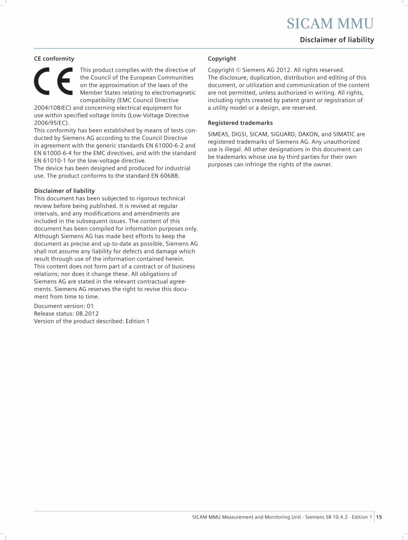
CE conformity
This product complies with the directive of the Council of the European Communities on the approximation of the laws of the Member States relating to electromagneticcompatibility (EMC Council Directive
2004/108/EC) and concerning electrical equipment for use within specifi ed voltage limits (Low-Voltage Directive 2006/95/EC).This conformity has been established by means of tests con-ducted by Siemens AG according to the Council Directivein agreement with the generic standards EN 61000-6-2 andEN 61000-6-4 for the EMC directives, and with the standardEN 61010-1 for the low-voltage directive.The device has been designed and produced for industrial use. The product conforms to the standard EN 60688.
Disclaimer of liabilityThis document has been subjected to rigorous technical review before being published. It is revised at regular intervals, and any modifi cations and amendments are included in the subsequent issues. The content of this document has been compiled for information purposes only. Although Siemens AG has made best efforts to keep the document as precise and up-to-date as possible, Siemens AG shall not assume any liability for defects and damage which result through use of the information contained herein.This content does not form part of a contract or of business relations; nor does it change these. All obligations of Siemens AG are stated in the relevant contractual agree-ments. Siemens AG reserves the right to revise this docu-ment from time to time.
Document version: 01Release status: 08.2012Version of the product described: Edition 1
Copyright
Copyright © Siemens AG 2012. All rights reserved.The disclosure, duplication, distribution and editing of this document, or utilization and communication of the content are not permitted, unless authorized in writing. All rights, including rights created by patent grant or registration of a utility model or a design, are reserved.
Registered trademarks
SIMEAS, DIGSI, SICAM, SIGUARD, DAKON, and SIMATIC are registered trademarks of Siemens AG. Any unauthorized use is illegal. All other designations in this document can be trademarks whose use by third parties for their own purposes can infringe the rights of the owner.
For more information, please contact
our Customer Support Center.
Customer Support Center.
Tel.: +49 180 524 84 37
Fax: +49 180 524 24 71
(Charges depending on provider)
E-mail: [email protected]
Order No. IC1000-K4042-A101-A1-7600
Printed in Germany
Dispo 06200, c4bs 752
KG 08.12 1.0 16 En
7500 / 42792 WÜ
Printed on elementary chlorine-free bleached paper.
Published by and copyright © 2012:
Siemens AG
Infrastructure & Cities Sector
Smart Grid Division
Energy Automation
Humboldtstr. 59
90459 Nuremberg, Germany
www.siemens.com/powerquality
All rights reserved.
If not stated otherwise on the individual pages of this
catalog, we reserve the right to include modifications,
especially regarding the stated values, dimensions and
weights.
Drawings are not binding.
All product designations used are trademarks or
product names of Siemens AG or other suppliers.
lf not stated otherwise, all dimensions in this catalog
are given in mm/inch.
Subject to change without prior notice.
The information in this document contains general
descriptions of the technical options available, which
may not apply in all cases. The required technical
options should therefore be specified in the contract.