Service Manual M~~-900F (AU)
96
Service Manual CD Portable FM Stereo/AM Cassette Recorder Specifications ( CASSETTE SECTION ) Recording system ..... AC bias, 4 track stereo Erasing system ....... Magnet erase Tape speed .......... 4.75 cm /sec. Fast forward and rewind time .......... 110 sec. (C-60 tape) Frequency response ... 80-12,000 Hz (Normal tape) ( CD SECTION ) Channels ... ........ 2 channels SIN ratio ........... 70dB Wow & Flutter ........ undetectable Sampling frequency ... 44.1 kHz Quantization ......... 16 bits linear / ch Pick-up light source . Semi-conductor laser Pick-up wave length . 790 nm Laset output ......... Continuous wave max. 0.6 mW Specifications subject to change without notice. ( RADIO SECTION ) Tuning ranges ......... Antennas ............. ( GENERAL) Output power ... . . Speaker .............. Terminal impedance .. Power Source ......... Memory back-up (CD) ... Dimensions ........... Weight .............. .4 FILE NO. M~~-900F (AU) PRODUCT CODE No. 142 963 02 FM:88-108 MHZ AM :525-1,710 kHz Built-in ferrite bar and telescopic rod antennas 4.0 W x 2 (DC max.) 12 cm x 2, 4 ohms PIEZO X 2 PHONES :32 ohms MIC :200-600 ohms/mV AC :230-240 V, 50 tiz DC: 12V (8 x “D “ size batteries) DC : 6V (4 x “AA HP7/R6° size batteries)) 460 (W) x 220 (H) x 245 (D) Imm Approx. 4.8 kg without batteries REFERENCE No. SM580346
-
Upload
khangminh22 -
Category
Documents
-
view
10 -
download
0
Transcript of Service Manual M~~-900F (AU)
Service Manual CD PortableFM Stereo/AMCassette Recorder
Specifications
( CASSETTE SECTION )
Recording system . . . . . AC bias, 4 track stereo
Erasing system . . . . . . . Magnet erase
Tape speed . . . . . . . . . . 4.75 cm /sec.
Fast forward and
rewind time . . . . . . . . . . 110 sec. (C-60 tape)
Frequency response . . . 80-12,000 Hz (Normal tape)
( CD SECTION )
Channels . . . . . . . . . . . 2 channels
SIN ratio . . . . . . . . . . . 70dB
Wow & Flutter . . . . . . . . undetectable
Sampling frequency . . . 44.1 kHz
Quantization . . . . . . . . . 16 bits linear / ch
Pick-up light source . Semi-conductor laser
Pick-up wave length . 790 nm
Laset output . . . . . . . . . Continuous wave
max. 0.6 mW
Specifications subject to change without notice.
( RADIO SECTION )
Tuning ranges . . . . . . . . .
Antennas . . . . . . . . . . . . .
( GENERAL)
Output power . . . . .
Speaker . . . . . . . . . . . . . .
Terminal impedance . .
Power Source . . . . . . . . .
Memory back-up (CD) . . .
Dimensions . . . . . . . . . . .
Weight . . . . . . . . . . . . . .
.4
FILE NO.
M~~-900F (AU)
PRODUCT CODE No.
142 963 02
FM:88-108 MHZ
AM :525-1,710 kHz
Built-in ferrite bar and
telescopic rod antennas
4.0 W x 2 (DC max.)
12 cm x 2, 4 ohms
PIEZO X 2
PHONES :32 ohms
MIC :200-600 ohms/mV
AC :230-240 V, 50 tiz
DC: 12V
(8 x “D “ size batteries)
DC : 6V
(4 x “AA HP7/R6° size batteries))
460 (W) x 220 (H) x 245 (D) Imm
Approx. 4.8 kg without batteries
REFERENCE No. SM580346
CONTENTS —
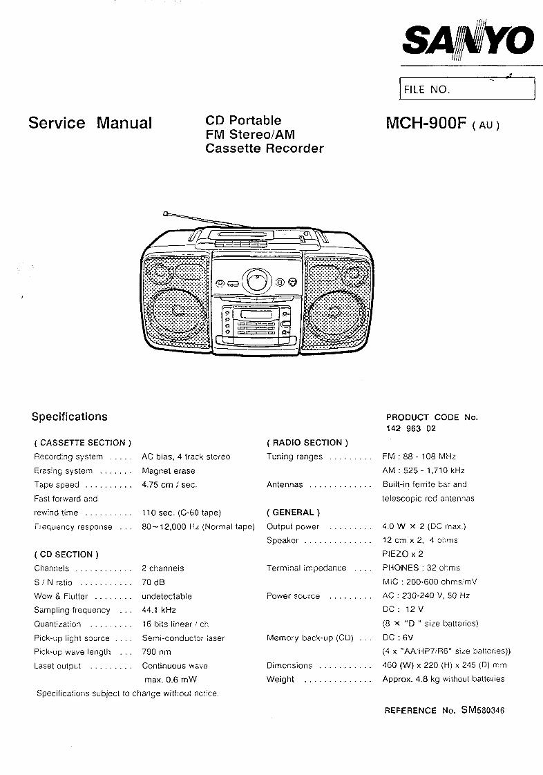
LASER BEAM SAFETY PRECAUTIONS . . . . . . . . 1
OPERATING THE RESET SWITCH . . . . . . . . . . . 1
REMOVAL AND INSTALLATION . . . . . . . . . . . . . 2
TUNER ADJUSTMENTS . . . . . . . . . . . . . . . ...-6
TAPE DECK ADJUSTMENTS . . . . . . . . . . . . ...7
CD PLAYER ADJUSTMENTS . . . . . . . . . . . . ...8
SERVICE MODE . . . . . . . . . . . . . . . . . . . . . . ...11
CD CHANGER MECHANISM OPERATION
DESCRIPTION . . . . . . . . . . . . . . . . . . . . . . . . .-14
LASER BEAM SAFETY PRECAUTIONS—
. Pick-up that emits a laser beam is used in this CD player.
CAUTION :
USE OF CONTROLS OR ADJUSTMENTS
OR PERFORMANCE OF PROCEDURES
OTHER THAN THOSE SPECIFIED
HEREIN MAY RESULT IN HAZARDOUS
RADIATION EXPOSURE
LASER OUTPUT ........0.6mW Max. (CW)
WAVELENGTH ........... KIO nm
REPLACING THE PRINCIPAL PARTS&
OF THE CD CHANGER MECHANISM . . . . . . . . . 17
EXPLODED VIEW . . . . . . . . . . . . . . . . . . . . . ...25
PARTS LIST . . . . . . . . . . . . . . . . . . . . . . . . ...27
IC BLOCK DIAGRAM & DESCRIPTION . . . . . . . . 38
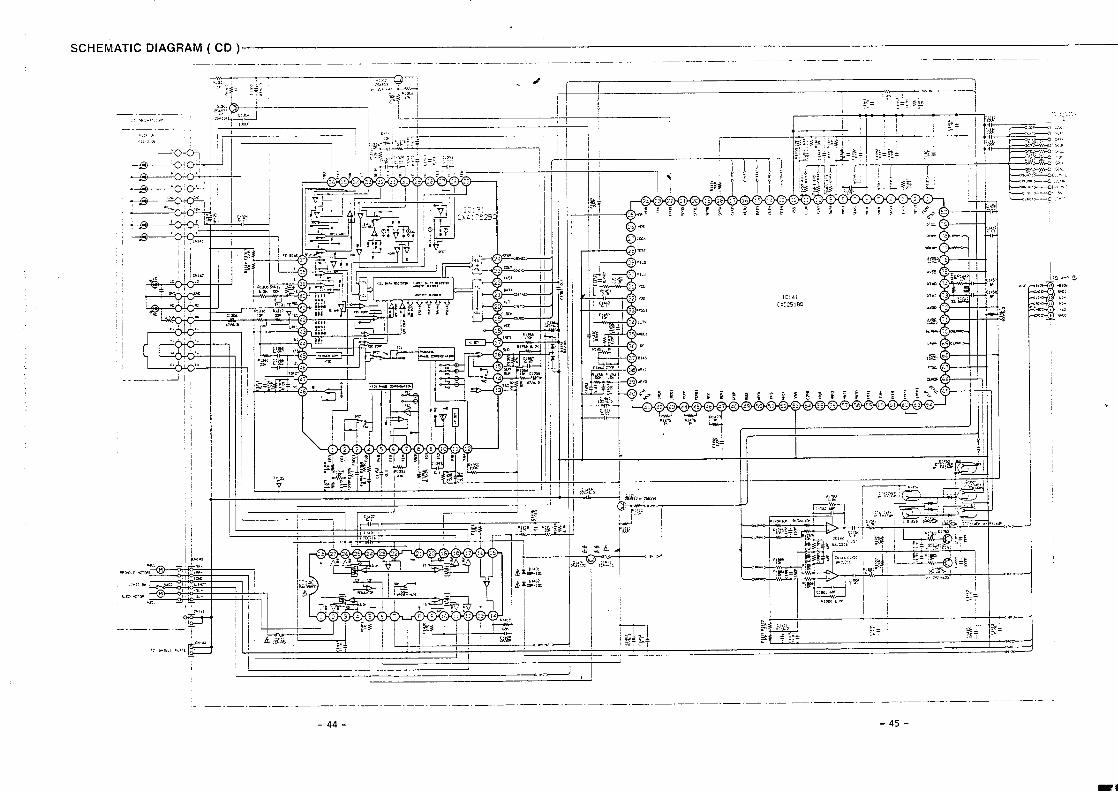
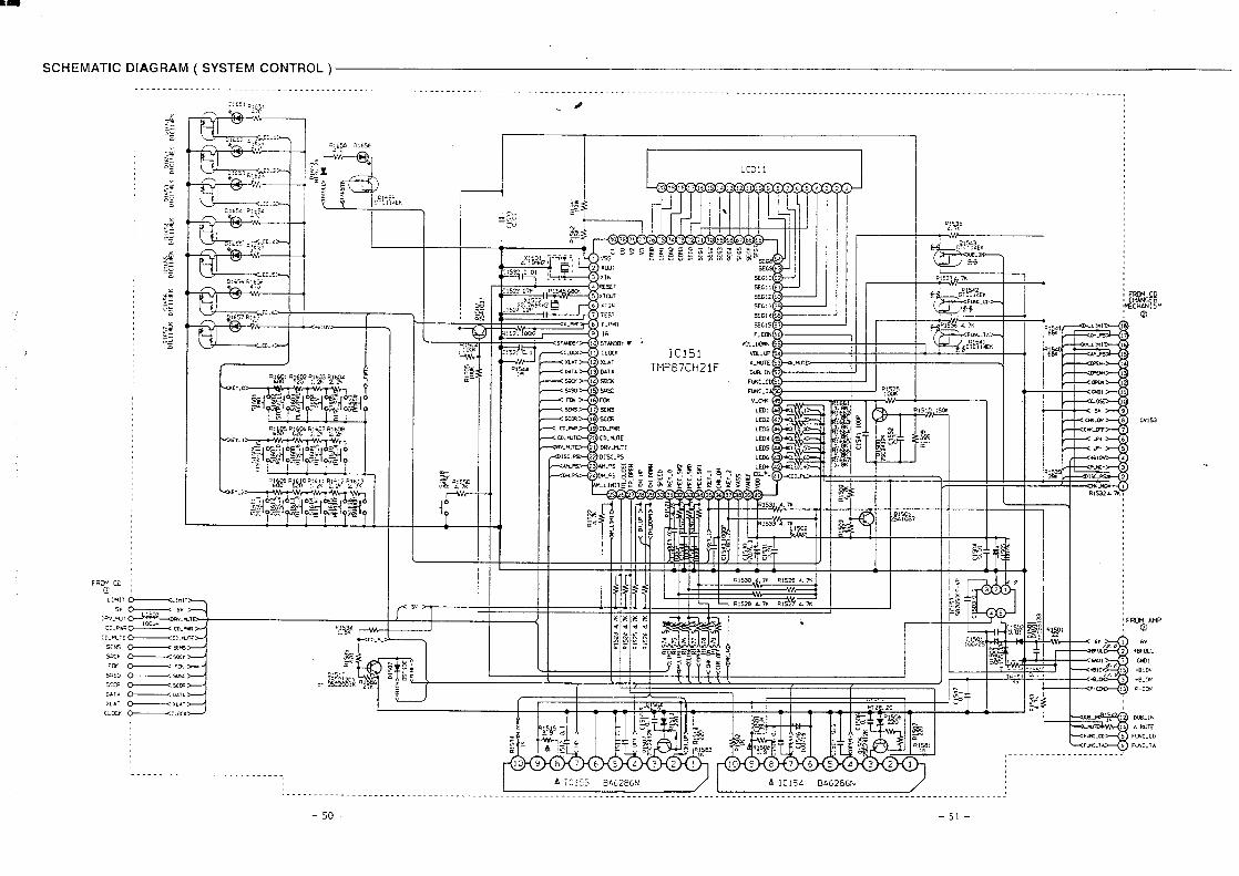
SCHEMATIC DIAGRAM . . . . . . . . . . . . . . . . . ...40
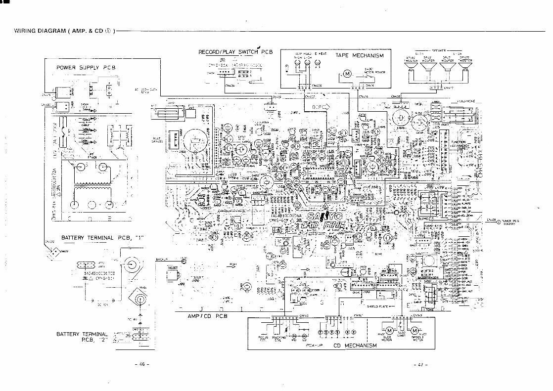
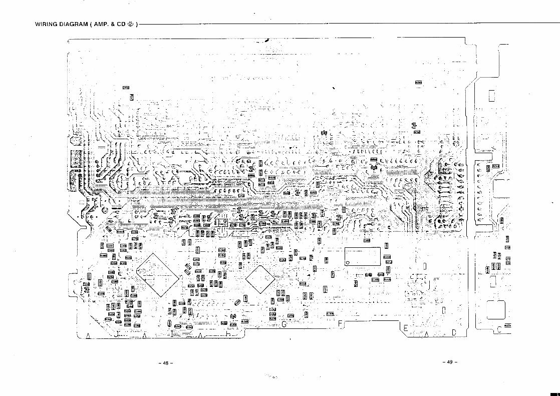
WIRING DIAGRAM . . . . . . . . . . . . . . . . . . . . ...41
CD CHANGER BLOCK
SYSTEM CONTROL TERMINAL LEVELS . . . . ...63
CD CHANGER BLOCK FLOWCHART . . . . . . . . . 65
CLASS 1 LASER PROOULUOKAN 1 LASERLAIT
KLASS 1 LASERAPPAR
CAUTION–INVISIBLE LASER RAOIATIONWHEN OPEN AND INTERLOCKS OEFEATEO.AvOIO EXPOSURE TO BEAM.
,AOVARSEL-USYNLIG LAiEtiTRALING VEO A8NING.NAR SIKKERHEOSAF8RYDERE ER UOE AF FUNKTION,UNOGk UDS /ZTTELSE FOR STR~LING.
VARNING–0SYNLN3 LASER STR~LNIN.G NAROENNA DEL AR OPPNAO OCH SPARR AR URKOPPLAO.STRALEN AR FARLIG.
VORSICHT-UNSICHTBARE LASERSTRAHLUNG TRITT AUS.‘WENN OECKEL GEOFFNET UNO WENN SICHERHEITSVERRIEGELUNGuBERBRUCKT [ST. NICHT, OEM STRAHL AUSSET2EN.
AVARO! .Avawssa fa suoialuk!lus. ohilellaes~a Olel allliinanakyma!lomalle Iasemileilylle. Ali kalso saleeseen.
I I
OPERATING THE RESET SWITCH
WHAT TO DO IF ...
If the operation of the unit or display is n
normal, disconnect the power cord from the P
outlet and remove the batteries (if applicabl[
then press the RESET bulton (back of the un
for at least 20 seconds.
-1-
I
ii
REMOVAL AND INSTALLATION*
,.
●
●
●
●
●
●
a.
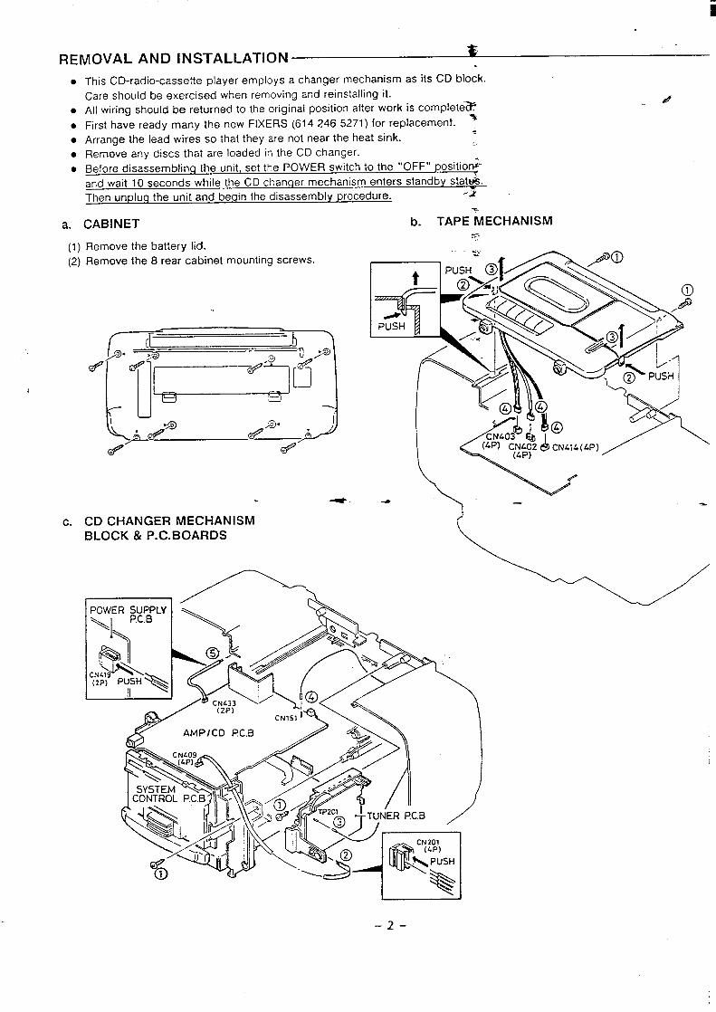
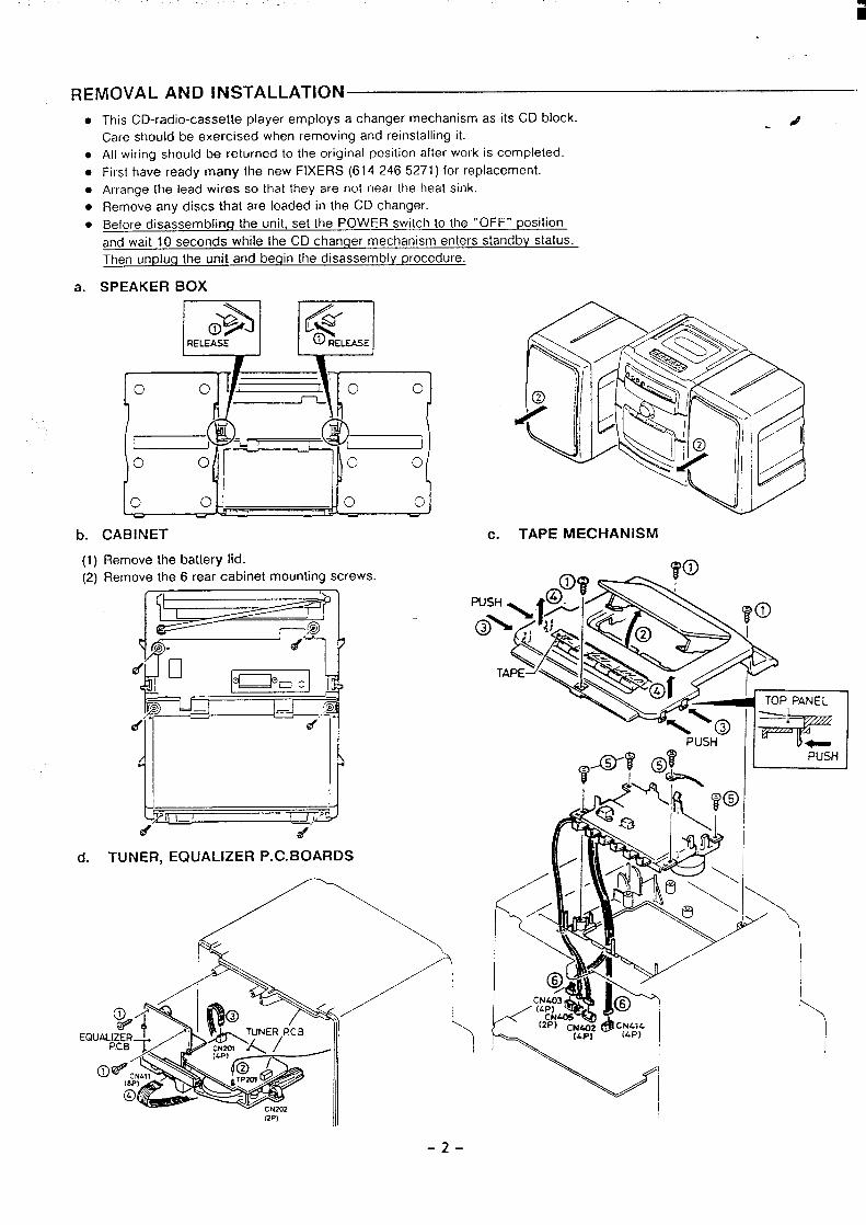
This CD-radio-cassette player employs a changer mechanism as its CD block.
Care should be exercised when removing and reinstalling it.
All wiring should be returned to the original position after work is complete=4
First have ready many the new FIXERS (61 4246 5271) for replacement. %
Arrange the lead wires so that they are not near the heat sink..
Remove any discs that are loaded in the CD changer....
Before disassembling the unit, set the POWER switch to the “OFF” positio~”
and wait 10 seconds while the CD changer mechanism enters standby stat&..
Then unplug the unit and begin the disassembly procedure. -2
CABINET
(1) Remove the battery lid.
(2) Remove the 8 rear cabinet mounting screws.
4. --
c. CD CHANGER MECHANISM
BLOCK & P. C. BOARDS
—/’-’--k
.
b. TAPE MECHANISMs---.,
.\. y
I J
–2-
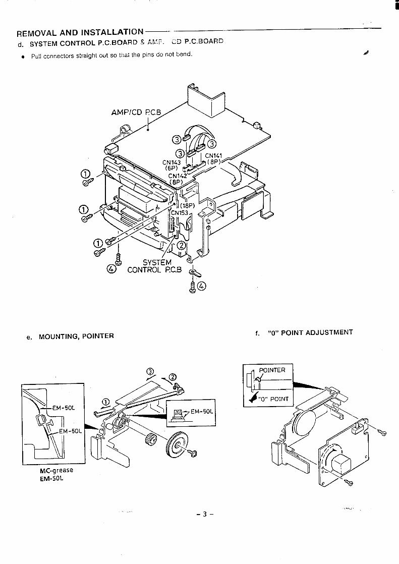
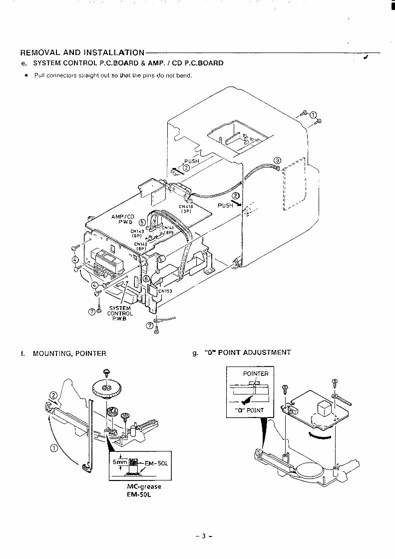
REMOVAL AND INSTALLATION(j. SYSTEM CONTROL P. C. BOARD S AMF. CD P. C. BOARD
● Pull connectors straight out so that the pins do not bend.J
AMPICD
$04
e. MOUNTING, POINTERf. “0” POINT ADJUSTMENT
1
I I
MC-grease
EM-50L
...-3-
-*..,
... ,.
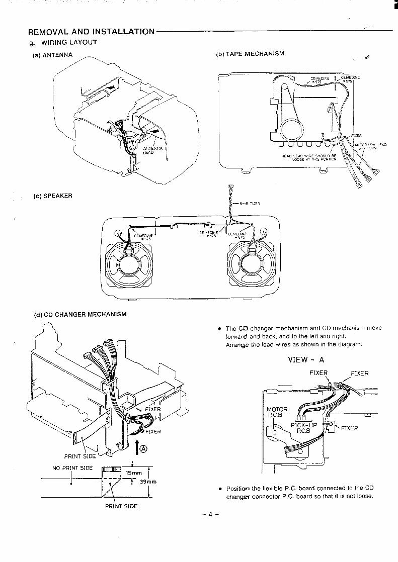
REMOVAL AND INSTALLATIONg. WIRING LAYOUT
‘a)ANTENNk(b) TAPE MECHANISM
#
(c) SPEAKER
I
(’/— 5-5 TuRN
(d) CD CHANGER MECHANISM
7“7
‘“p’~””’p+g-m~+
PRINT SIDE
● The CD changer mechanism and CD mechanism move
forward and back, and to the left and right.
Arranq& the lead wires as shown in the diagram.
VIEW - A
FIXER
~
I MOTOR1 f?C.B
FIXER/
lr-r--=-. Positiom the flexible P.C. board connected to the CEI
changer connector P.C. board so that it is not loose.
-4-
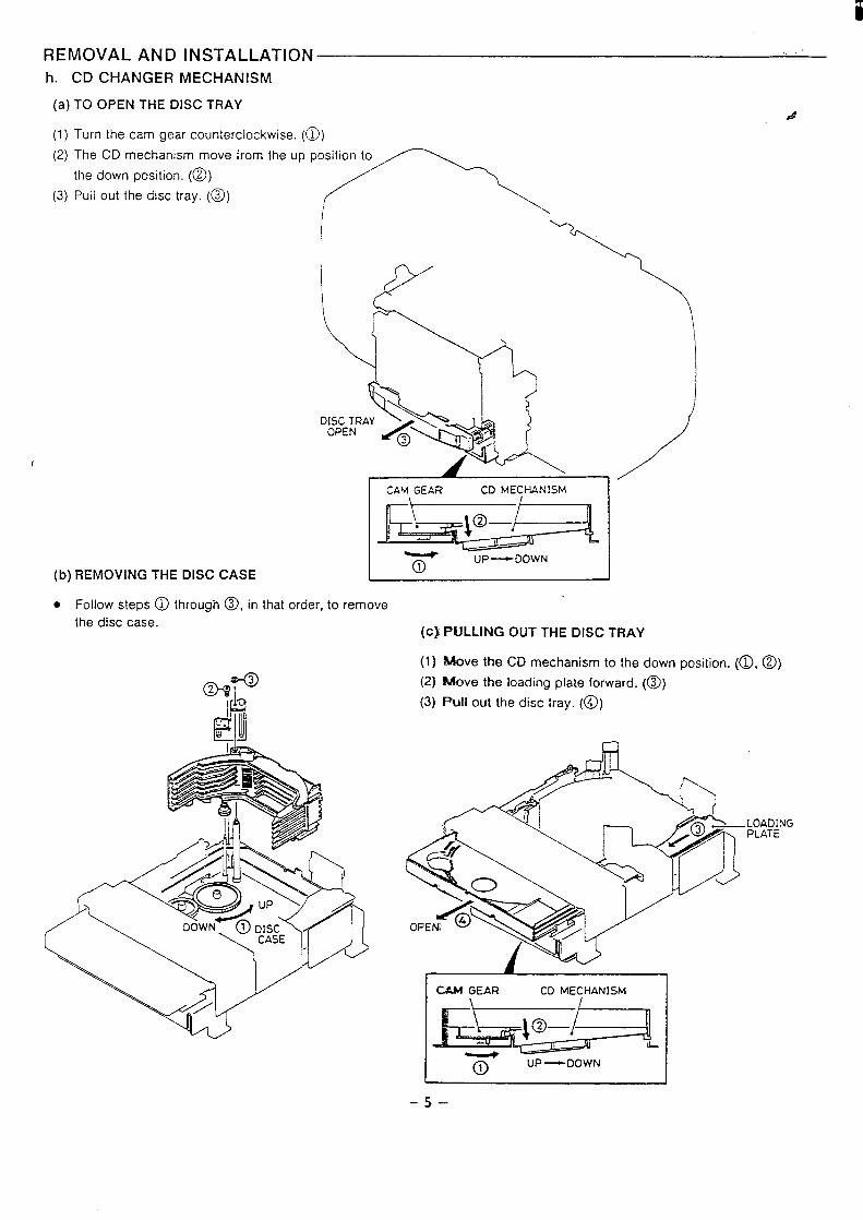
REMOVAL AND INSTALLATIONh. CD CHANGER MECHANISM
(a) TO OPEN THE DISC TRAYd
(1) Turn the cam gear counterclockwise. (~)
(2) The CD mechanism move
the down position. (~)
(3) Pull out the disc tray. (@))
1
(b) REMOVING THE DISC CASE
‘romtheuppo;n
CAM GEAR CD MECHANISM
1+ \,&. p
k--, .,.,
—
T ‘p‘UUWN
. Follow steps @ through ~, in that order, to remove
the disc case.(c} PULLING OUT THE DfSC TRAY
(1) Move the CD mechanism to the down position. (~,@)
(2) Rllove the loading plate forward. (~)
(3) Pull out the disc tray. (@)
Q
I M GEAR CD MECHANISM
T UP—DOWN
-5–
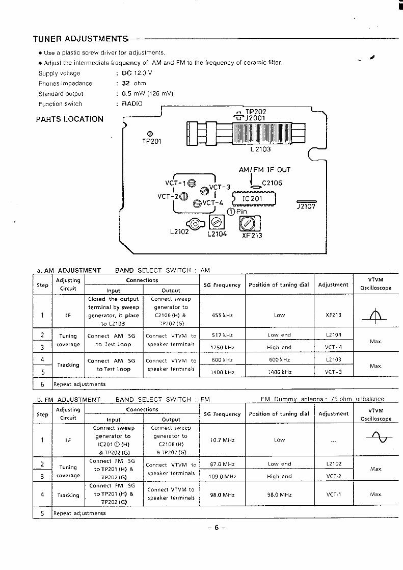
TUNER ADJUSTMENTS
. Use a plastic screw driver for adjustments.
● Adjust the intermediate frequency of AM and FM to the frequency of ceramic filter.
Supply voltage
Phones impedance :
Standard output
Function switch
PARTS LOCATION
a. AM ADJUST
AdjustingStep
Circuit
1 I IF
i
2 Tuning
3coverage
i-
4Tracking
5
DC 12.0 V
32 oh!m
&5 mW (126 mV)
RADIO f
IENT BAND SELECT SWITCH :
Connections
Input output
Closed the output Connect sweep
terminal by sweep generator to
generator, it place C2106 (H) &
to L2103. TP202 (G)
Connect AM SG Connect VTVM to
to Test Loop speaker terminals
Connect AM SG Connect VTVM to
to Test Loop speaker terminals
6 lRepeat adjustments
455 kHz I Low I XF213
517k Hz Low end L2104
1750 kHz High end VCT -4
600 kHz 600 kHz L2103
1400 kHz 1400 kHz VCT -3
VTVM
Oscilloscope
-4-Max.
Max.
I
b. FM ADJUSTMENT BAND SELECT SWITCH : FM FM Dummy antenna : 75 ohm unbalancer
Adjusting ConnectionsStep
CircuitSG Frequency Position of tuning dial Adjustment
Input output
Connect sweep Connect sweep
1 IFgenerator to generator to
IC201 @ (H) C2106 (H)10.7 MHz Low . .-
& TP202 (G) & TP202 (G)
2Connect FM SG
Tuning Connect VTVM to 87.0 ~~Z Low end L2102to TP201 (H) &
3 coverage TP202 (G)speaker terminals
109.0 MHz High end VCT-2
Connect FM SGConnect VTVM to
4 Tracking to TP201 (H) &speaker terminals
98.0 MHz 98.0 MHz VCT- 1
TP202 (G)
5 lReDeat adjustments
VTVM
Oscilloscope
A
Max
Max.
I
-6–
iii
. .
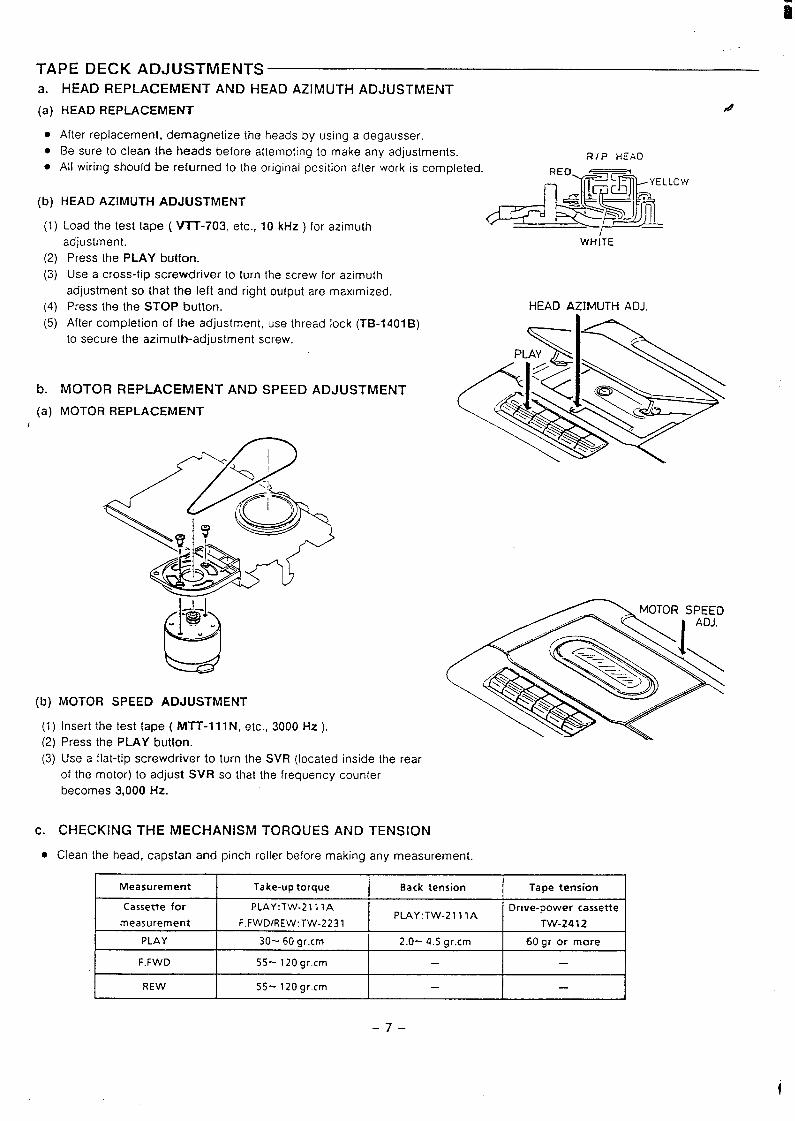
TAPE DECK ADJUSTMENTSa.
(a)
●
●
●
(b)
(1)
(2)
(3)
(4)
(5)
b.
(a)I
(b)
HEAD REPLACEMENT AND HEAD AZIMUTH ADJUSTMENT
HEAD REPLACEMENT 4
After replacement, demagnetize the heads by using a degausser.
Be sure to clean the heads before attempting to make any adjustments. 21P HEAD
Ml wiring should be returned to the original position after work is completed.LOW
HEAD AZIMUTH ADJUSTMENT
Load the test tape ( VIT-703, etc., 10 kHz ) for azimuth
adjustment.
Press the PLAY button.
Use a cross-tip screwdriver to turn the screw for azimuth
adjustment so that the left and right output are maximized.
Press the the STOP button.
After completion of the adjustment, use thread lock (TB-1401 B)
to secure the azimuth-adjustment screw.
MOTOR REPLACEMENT AND SPEED ADJUSTMENT
MOTOR REPLACEMENT
MOTOR SPEED ADJUSTMENT
(1) Insert the test tape ( MTT-lllN, etc., 3000 Hz).
(2) Press the PLAY button.
(3) Use a flat-tip screwdriver to turn the SVR (located inside the rear
of the motor) to adjust SVR so that the frequency counter
becomes 3,000 Hz.
c. CHECKING THE MECHANISM TORQUES AND TENSION
WHiTE
HEAD AZIMUTH ADJ.
MOTOR SPEED
. Clean the head, capstan and pinch roller before making any measurement.
Measurement Take-up torque Back tension Tape tension
Cassette for PLAY:TW-211 1A Orive-power cassettePLAY: TW-21 11A
measurement F.FWD/REW:TW-2231 TW-2412
PLAY 30-60 gr.cm 2.0- 4.5 gr.cm 60 gr or more
F.FWD 55-120 gr.cm
REW 55-120 gr.cm —
-7–
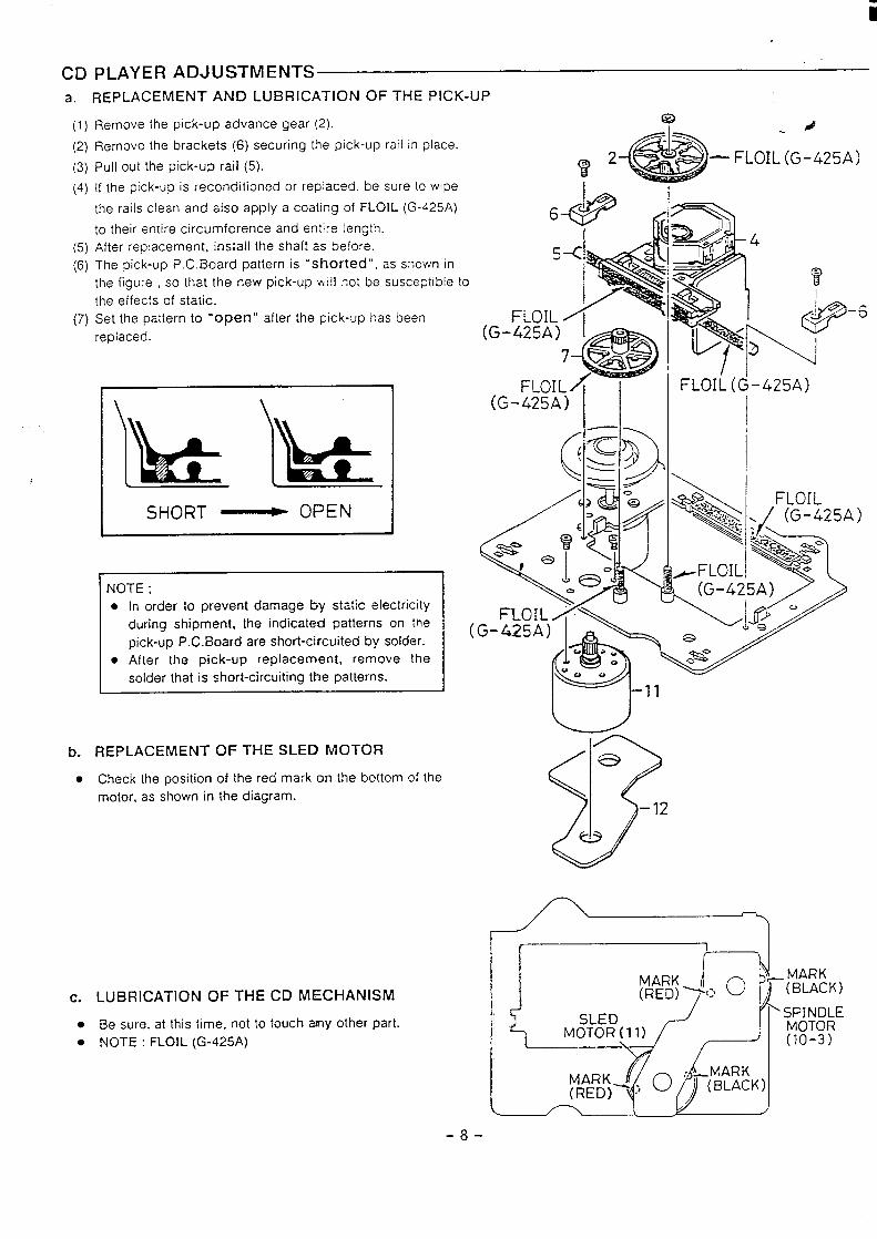
CD PLAYER ADJUSTMENTSa. REPLACEMENT AND LUBRICATION OF THE PICK-UP
(1)
(2)
(3)
(4)
(5)
(6)
(7)
Remove the pick-up advance gear (2).
Remove the brackets (6) securing [he pick-up rail in place.
Pull out the pick-up rail (5).
If the pick-up is reconditioned or repiaced, be sure to wipe
the rails clean and also apply a coating of FLOIL (G-425A)
to their entire circumference and entire length.
After replacement. install the shaft as before.
The pick-up P. C. Board pattern is “shorted”, as shown in
the figure , so that the new pick-up will not be susceptible to
the effects of static.
Set the pattern to “’Open” after the pick-up has been
replaced.
SHORT ~ OPEN
NOTE ;
● In order to prevent damage by static electricity
during shipment. the indicated patterns on the
pick-up P.C. Board are short-circuited by solder.
● After the pick-up replacement, remove the
solder that is short-circuiting the patterns.
b.
●
REPLACEMENT OF THE SLED MOTOR
Check the position of the red mark on the bottom of the
motor, as shown in the diagram.
c. LUBRICATION OF THE CD MECHANISM
● Be sure, at this time, not to touch MY other part.
● NOTE : FLOIL (G-425A)
(
fa d
.4f$iij)%’2 :“-‘FLOIL(G-425A)
-6(G-:>
F(G-425A) I I I
[f I
-8-
iii
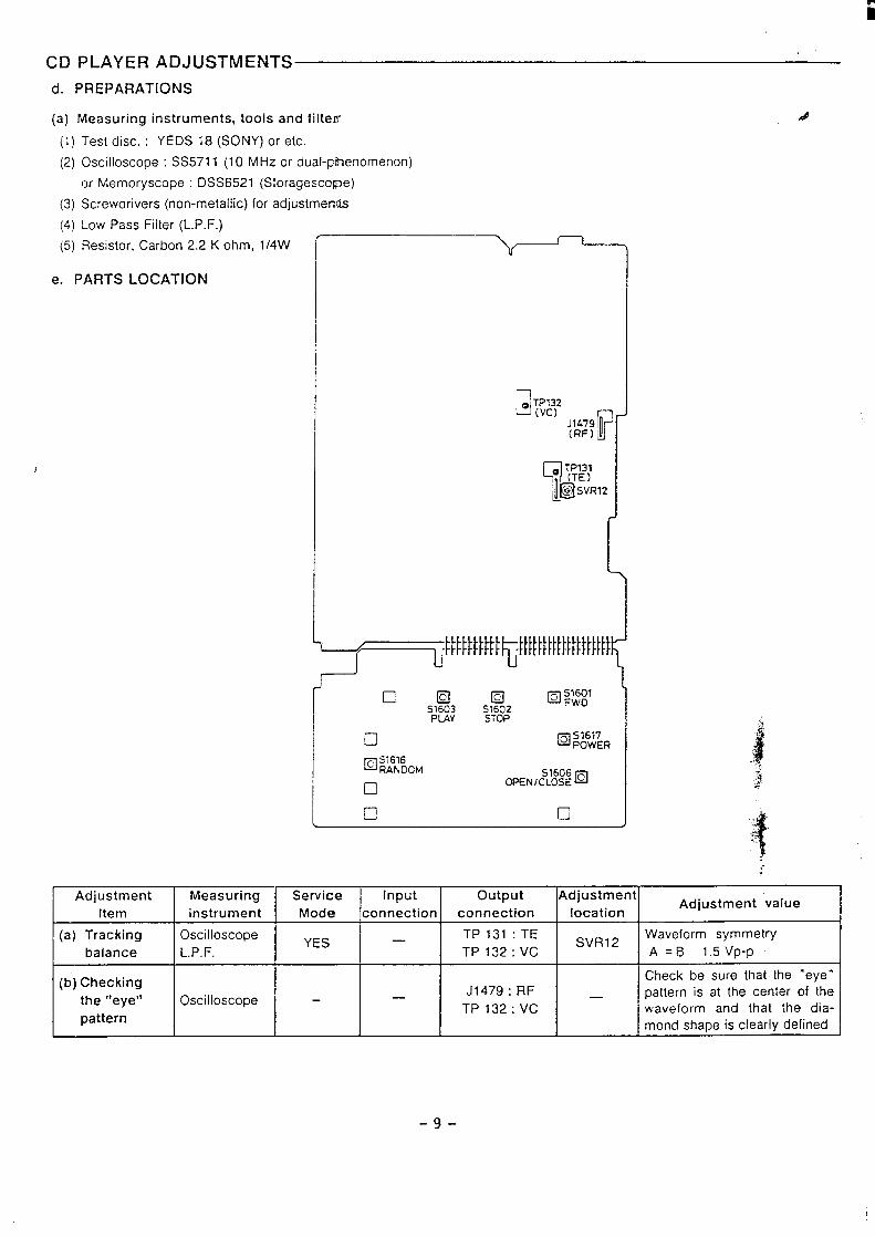
CD PLAYER ADJUSTMENTS
d. PREPARATIONS
(a) Measuring instruments, tools and fiiterr
(1)
(2)
(3)
(4)
(5)
Test disc. : YEDS 18 (SONY) or etc.
Oscilloscope : SS5711 (10 MHz or dual-phenomenon)
or Memory scope : DSS6521 (Storagescope)
Screwdrivers (non-metallic) for adjustments
Low Pass Filter (L. P.F.)
Resistor, Carbon 2.2 K ohm, l/4W
e. PARTS LOCATION
1
S1606gOPEN ICLOSE
In ❑ I
.#f
:
Adjustment Measuring Service Input output Adjustment
Item instrument Mode connection connection locationAdjustment value
(a) Tracking OscilloscopeYES
TP 131 :TE— SVR12Waveform symmetry
balance L.P.F. TP132:VC A =B 1.5 Vp-p
(b) CheckingCheck be sure that the “eye”
J1479 : RF _the “eye” Oscilloscope – — pattern is at the center of the
TP 132:VCpattern
waveform and that the dia-mond shape is clearly defined
-9-
i
CD PLAYER ADJUSTMENTS
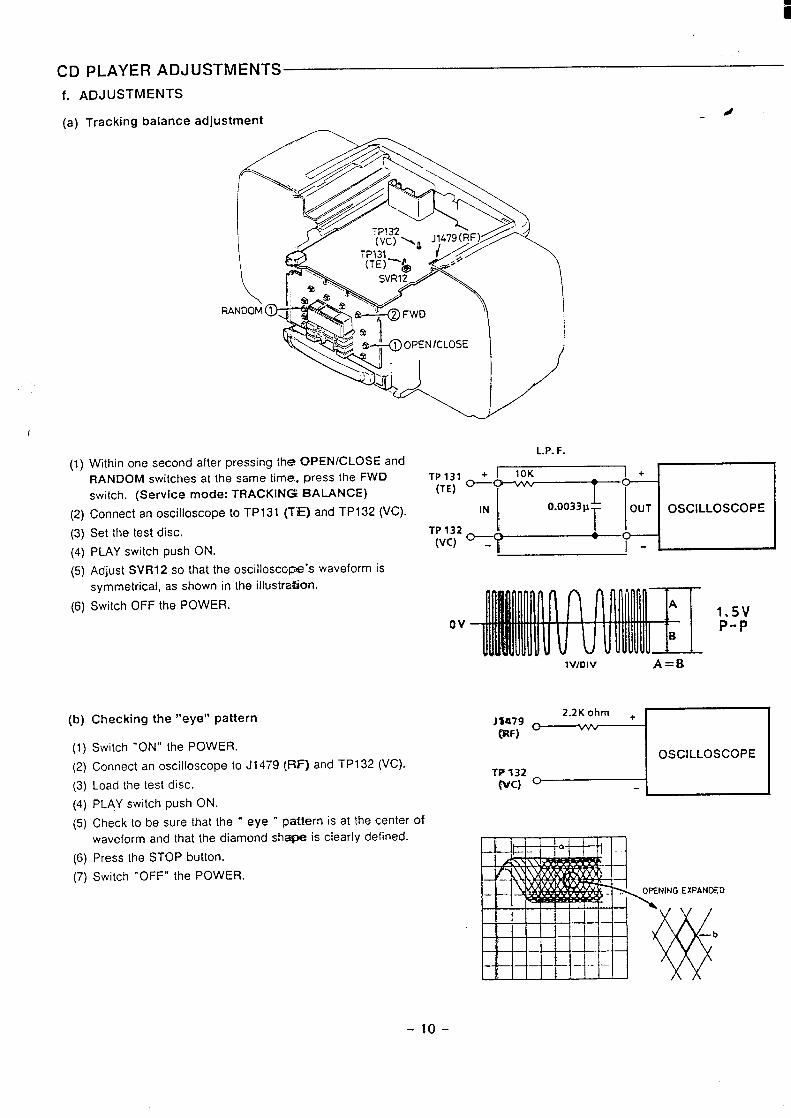
f. ADJUSTMENTS
(a) Tracking balance adjustment4
I
(1)
(2)
(3)
(4)
(5)
symmetrical, as shown in the illustration.
(6) Switch OFF the POWER.
Within one second after pressing the! OPENICLOSE and
RANDOM switches at the same time. press the FWD TP 131 +
switch. (Service mode: TRACKING BALANCE)(TE) -
Connect an oscilloscopetoTP131 (T=) and TP132 (VC). IN
Set the test disc. TP132&
PLAY switch push ON.(Vc) -
Adjust SVR12 so that the oscilloscope’s waveform is
(b) Checking the “eye” pattern
(1) Switch “ON” the POWER.
(2) Connect an oscilloscope to J1 479 (RF] and TPI 32 (VC).
(3) Load the test disc.
(4) PLAY switch push ON.
(5) Check to be sure that the “ eye “ pattern is at the center of
waveform and that the diamond shape is clearly defined.
(6) Press the STOP button.
(7) Switch “OFF” the POWER.
L.P. F.
10K
‘7
~ ~ o~c,LLoscop=
T
1*5VOv P-P
lV)DIV A=B
2.2K ohm +Jlf179(RF)
o V&
I OSCILLOSCOPEI
TP132Wc) 1
NING EXPANOED
-1o-
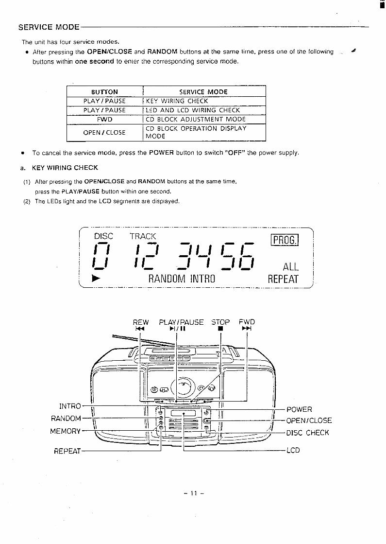
SERVICE MODE
The unit has four service modes.
e
●
a.
(1)
(2)
After pressing the OPEhl/CLOSE and RANDOM buttons at the same time, press one of the following . ~
buttons within one second to enter the corresponding service mode.
I BIJ?TON I SERVICE MODE IPLAY / PAUSE [ KEY WIRING CHECK
PLAY / PAUSE I LED AND LCD WIRING CHECK
FWD CD BLOCK ADJUSTMENT MODE
OPEN I CLOSECD BLOCK OPERATION DISP~YMODE
To cancel the
KEY WIRING
After pressing
service mode, press the POWER button to switch “OFF” the power supply.
CHECK
the OPENfCLOSE and RANDOM buttons at the same time,
press the PLAYIPAUSE button within one second.
The LEDs light and the LCD segments are displayed.
~ ..–. .—. .— ..—.. —..—.. —..—.. —..—.. —..—.. —..—.. —..—..._ ..—.. —.._.. _ ..
I DISC TRACKl—
I // / :/
ml‘HI 1-1- 1I II 1 I_ :1 ‘/ :/ /:!:- ALL ~1
RANDOM INTRO REPEAT :L . . . . . . . . . . . . .. . . . . . . . . . . . . . . . . . . . .. . . . . . . . . . . . . . . . . . . . . . . . . . . . . ..J
REW PLAJ ;AUSE ST#P FJDm
— ;---
INTRO
RANDOM — OPEN/CLOSE
-11–
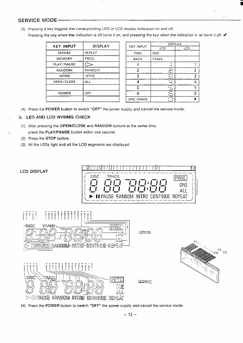
SERVICE MODE
(3) Pressing a key toggles the corresponding LED or LCD display indication on and off.
Pressing the key when the indication is off turns it on, and pressing the key when the indication is on turns it off. #
KEY INPUT DISPLAY
REPEAT I REPEAT
MEMORY PROG.
PLAY / PAUSE lb
POWER I OFF
I
KEY INPUTDISPLAY
LCD LED
FWD DISC
BACK I TRACK
Ill2
——1I_ 2
3 ❑ 1—1 3
141 II—. I 41
(4) Press the POWER button to switch “OFF” the power supply and cancel the service mode.
b. LED AND LCD WIRING CHECK
(1)
J
(2)
(3)
After pressing the OPEN/CLOSE and RANDOM buttons at the same time,
press the PLAYIPAUSE button within one second.
Press the STOP button.
All the LEDs light and all the LCD segments are displayed.
[ .—..–.-. --–.-–..–.. –.. --------- -–-.–.. –.. –..–..–.. –.. –
t ! ➤ 11 PAUSE RANDOM INTRO CONTINUE REPEAT i\ L . . . . . . . . . . . . . . . . . . . . . . . . . . . . . . . . . . . . . . . . . . . . . . . . . . . . . . . . . . . . . . . ..J
l—l
(n-lr-m
SE@!EM.
51,
3“’co
(4) Press the POWER button to switch “OFF” the power supply and cancel the service mode.
-12–
i
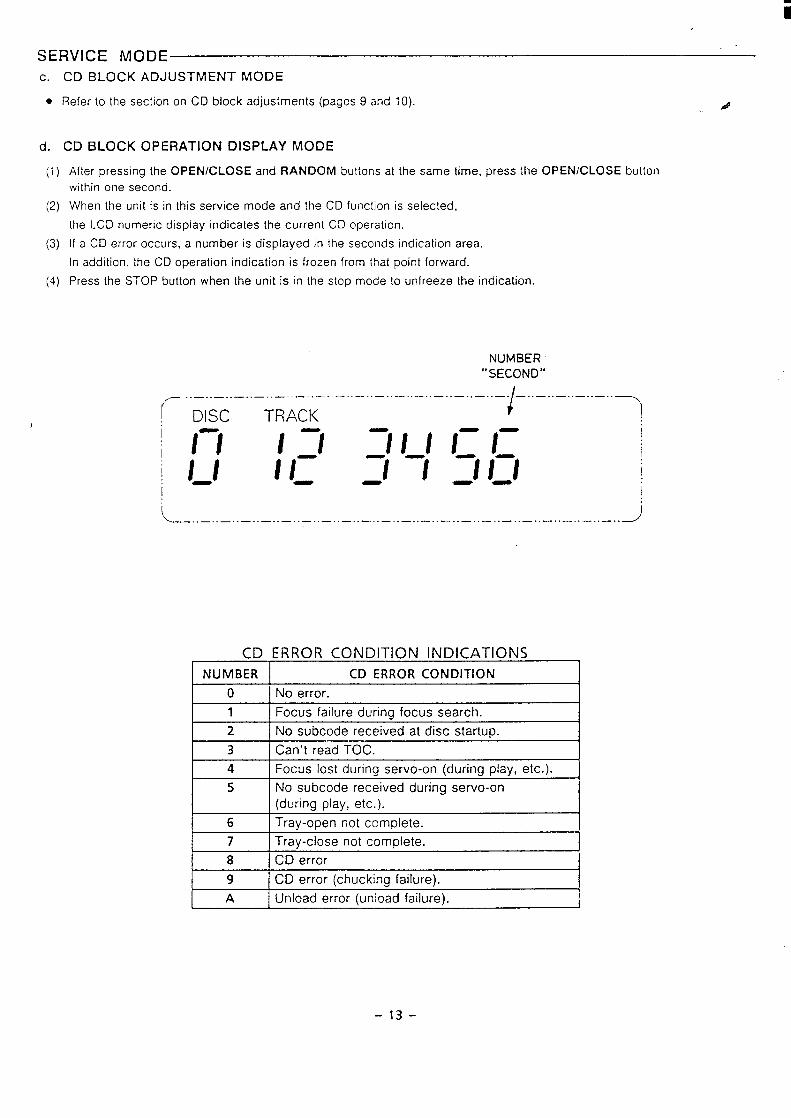
SERVICE MODE
c.
●
d.
(1)
(2)
(3)
(4)
I
CD BLOCK ADJUSTMENT MODE
~efer to the section on CD block adjustments (pages 9 and 10).
CD BLOCK OPERATION DISPLAY MODE
After pressing the OPEN/CLOSE and RANDOM buttons at the same time, press the OPEN/CLOSE
within one second.
When the unit is in this service mode and the CD function is selected,
the LCD numeric display indicates the current CD operation.
If a CD error occurs, a number is displayed in the seconds indication area.
In addition, the CD operation indication is frozen from that point forward.
Press the STOP button when the unit is in the stop mode {o unfreeze the indication.
button
NUMBER“SECOND”
.- .---------------------------------1----------( DISCi-
1 //
I //:-1
TRACK
/ :/
1 I_
{
‘// I 1-/-:1 ‘1 ‘/n--
I
I
I
I
L ... ... ... ... ... ... ... ... ... ... ... ... ... ... ... ... ... ... ... ... ... ..J
CD ERROR CONDITION INDICATIONS1 I
NUMBER CD ERROR CONDITION
o No error.
1 Focus failure during focus search.
2 No subcode received at disc startup.
3 Can’t read TOC.
4 Focus lost during servo-on (during play, etc.).
5 No subcode received during servo-on
(durinq plav, etc.).
6 Tray-open not complete.
7 Tray-close not complete.
18 I CD error I9 CD error (chucking failure).
A Unload error (unioad failure).
-13-
CD CHANGER MECHANISM OPERATION DESCRIPTION
●
●
●
a.
●
(1
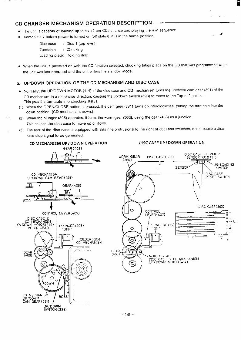
The unit is capable of loading up to six 12 cm CDs at once and playing them in sequence.
Immediately before power is turned on (off status), it is in the home position..4
Disc case : Disc 1 (top level)
Turntable : Chucking
Loading plate: Holding disc
When the unit is powered on with the CD function selected, chucking takes place on the CD that was programmed when
the unit was last operated and the unit enters the standby mode.
UP/DOWN OPERATION OF THE CD MECHANISM AND DISC CASE
Normally, the UP/DOWN MOTOR (41 4) of the disc case and CD mechanism turns the up/down cam gear (391) of the
CD mechanism in a clockwise direction, causing the up/down switch (393) to move to the “up on” position.
This puts the turntable into chucking status.
When the OPEN/CLOSE button is pressed, the cam gear (391) turns counterclockwise, putting the turntable into the
down position. (CD mechanism: down.)
(2) When the plunger (395) operates, it turns the worm gear (3661. using the gear (408) as a junction.
This causes the disc case to move up or down.
r (3) The rear of the disc case is equipped with slits (the protrusions to the right of 363) and switches, which cause a disc
case stop signal to be generated.
UPI
CD MECHANISM UP/ DOWN OPERATION
GEAR (408 )
%
CD MECHANISfVlUPI DOWN CAM GEAR ( 391)
E& ~,,’ ;(?W
GEAR (-408)
r?
BOSS
+CONTROL LEVER (407)
:D MECHANISM
IWN M0T0R(414) PLuNGER (395),.n’,-n” er. n
DISC CASE & I
D:\Mu I
(385)ANISM
GEAR(408)
DISC CASE UP/ DOWN OPERATION
wy3M&RDISC CASE ELEVATOR
DISC CASE(363) SENSOR P.C.B(315)
I~-
SENSOR/--C-’
(k)‘\, RESET SWITCH
o )
.,, ,1,!,,,, , ,,
Iiikw ,’ II
‘L
(F=:’ ~
~ “<MOTOR GEAR
(0)
DISC CASE & CD MECHANISM@J ) UP/ DOWN MOTOR(414)
UPI DOWNSWITCH(393)
- 141 –
CD CHANGER MECHANISM OPERATION DESCRIPTIONb.
●
(1)
(2)
(3)
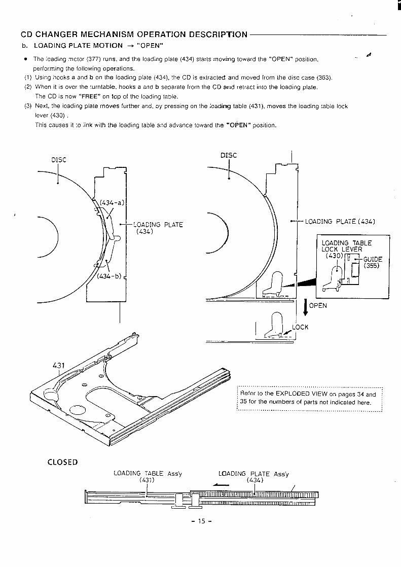
LOADING PLATE MOTION + “’OPENr’
The loading motor (377) runs, and the loading plate (434) starts movtig toward the “OPEN” position,d..
performing the following operations.
Using hooks a and b on the loading plate (434), the CD is extractecf and moved from the disc case (363).
When it is over the turntable, hooks a and b separate from the CD and retract into the loading plate.
The CD is now “FREE” on top of the loading table.
Next, the loading plate moves further and, by pressing on the Ioadimg table (431), moves the loading table lock
lever (430) .
This causes it to link with the loading table and advance toward the “OPEN” position.
DISC
LOADING(434)
PLATE
I
CMsc I
*
“ LOADING PLATE (434)
n
.. .. .......... ... ..... .................................................~Refer to the EXPLODED VIEW on pages 34 and ~
~35 for the numbers of parts not indicated here. :.. . . . . . . . . . . . . . . . . . . . . . . . . . . . . . . . . . . . . . . . . . . . . . . . . . . . . . . . . . . .. . . .. . . . . . :
CLOSED
LOADING TABL~ AS5’Y LOADING PLATE J%S’V
(431) - (434) “
-15-
i
I
CD CHANGER MECHAN
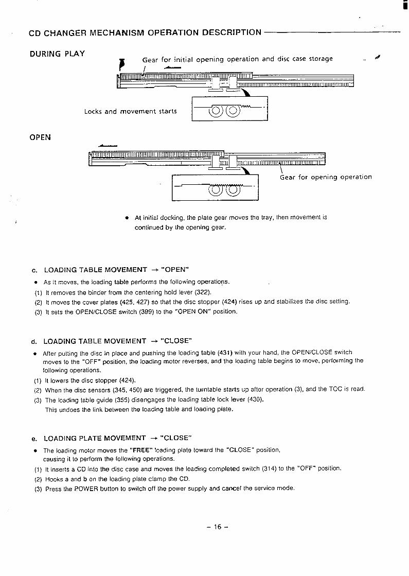
DURING PLAY
SM OPERATION DESCRIPTION
Gear for initial opening operation and disc case storage d
Locks and movement starts I @’x2--1OPEN
1\Gear for opening operation
. At initial docking, the plate gear moves the tray, then movement is
continued by the opening gear.
c. LOADING TABLE MOVEMENT + “OPEN”
. As it moves, the loading table performs the following operations.
(1) [t removes the binder from the centering hold lever (322).
(2) It moves the cover plates (425, 427) so that the disc stopper (424) rises up and stabilizes the disc setting.
(3) It sets the OPEN/CLOSE switch (399) to the “OPEN ON” position.
d. LOADING TABLE MOVEMENT -+ “CLOSE”
. After putting the disc in place and pushing the loading table (431} with your hand, the OPEN/CLOSE switch
moves to the “OFF” position, the loading motor reverses, and the loading table begins to move, performing the
following operations.
(1) It lowers the disc stopper (424).
(2) When the disc sensors (345, 450) are triggered, the turntable starts up after operation (3), and the TOC is read.
(3) The loading table guide (355) disengages the loading table lock lever (430).
This undoes the link between the loading table and loading plate.
e. LOADING PLATE MOVEMENT + “CLOSE”
● The loading motor moves the “FREE’” loading plate toward the “CLOSE” position,
causing it to perform the following operations.
(1) [t inserts a CD into the disc case and moves the loading completed switch (314) to the “OFF” position.
(2) Hooks a and b on the loading plate clamp the CD.
(3) Press the POWER button to switch off the power supply and cancel the service mode.
-16-
i
I
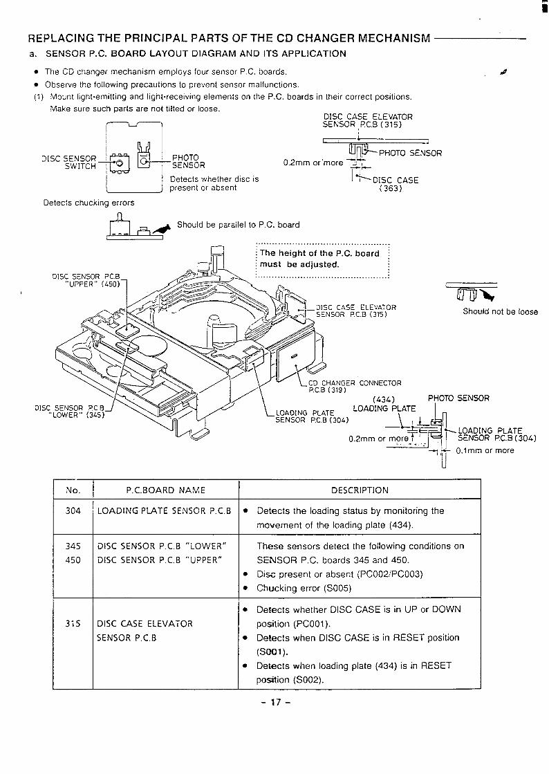
REPLACING THE PRINCIPAL PARTS OF THE CD CHANGER MECHANISM
a. SENSOR P.C. BOARD LAYOUT DIAGRAM AND ITS APPLICATION
. The CD changer mechanism employs four sensor P.C. boards. d
. Observe the following precautions to prevent sensor malfunctions.
(1) Mount light-emitting and light-receiving elements on the P.C. boards in their correct positions.
Make sure such parts are not tilted or loose.
r u1
DISC CASE ELEVATORSENSOR ,PC.B (315)
I
“sC;Y;:; PI+ :%:.1 J
w PHOTO SENSOR0.2mm or”more 7VT
i-l-Detects whether disc is I * DISC CASEpresent or absent (363).
Detects chucking errors
La@as!Should be parallel to P.C. board
.... .. . . . . . . . . . . . . . . . . . . . . . . . . . .. . . . . . . . . . . . . .—
M ~The height of the P.c. board !
r-+, ; must be adiusted.
mTiF> E% -+wi%’:.’i’%’?’ Should not be loose
%L-.._xxYA\\ /1’ v v LCD CHANGER CONNECTOR
\.‘-/ .. -
_ ‘L........-#
/-” (434) PHOTO SENSORDISC SENSOR P.C.B LOADING PLATE
“LOWER” (345) / ~ LOADING PLATESENSOR P.C.B(304)
h
\+
o,2mm or more~~ ~+ LOADING PLATE
IISENSOR I?C.B (304),. -.. .
“’ “+~ O.lmm or more
u
F-—
No.
304
345
450
315
P.C.BOARD NAME I DESCRIPTION
LOADING PIATE SENSOR P.C.B
DISC SENSOR P.C.B “LOWER”
DISC SENSOR P.C.B “UPPER”
DISC CASE ELEVATOR
SENSOR P.C.B
. Detects the loading status by monitoring the
movement of the loading plate (434).
Tks.e sensors detect the following conditions on
SENSOR P.C. boards 345 and 450.
. Disc present or absent (PCO02/PCO03)
● Chucking error (S005)
. Detects whether DISC CASE is in UP or DOWN
position (PCOO1 ).
. Detects when DISC CASE is in RESET position
(s001).
● Detects when loading plate (434) is in RESET
position (S002).
-17–
ii
REPLACING THE PRINCIPAL PARTS OF THE CD CHANGEF? MECHANISM
b.
●
●
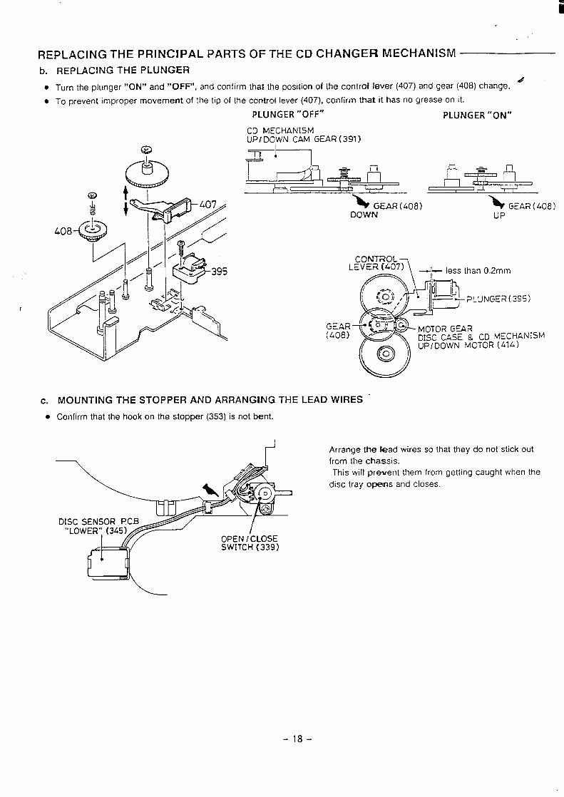
REPLACING THE PLUNGER
Turn the plunger “ON” and “OFF”, and confirm that the position of the controf fever (407) and gear (408) change..4
To prevent improper movement Of the tip of the control lever (407), confirm that it has no grease on it.
PLUNGER “OFF” PLUNGER “ON”
CD MECHANISMUPIDOWN CAM GEAR (391)
c.
●
> GEAR (408)DOWN
\ GEAR ( 408)UP
CQNTnOL
1
LEVER (407)
R
= ~~~than0.2mm
~%j ‘ ~ti-pLuNGER(’”)
~zAR f 63 ---)
(408) “*MOTOR GEARDISC CASE & CD MECHANISM
o
uP/DOWN MOTOR (414)o
MOUNTING THE STOPPER AND ARRANGING THE LEAD WIRES
Confirm that the hook on the stopper (353) is not bent.
I
DISC SENSOR f?CB“LOWER’” (345)
OPEN / CLOSESWITCH (339)
Arrange the fead wires so that they do not stick out
from the chassis.
This will prevent [hem from getting caught when the
disc tray opens and closes.
-18-
i
REPLACING THE PRINCIPAL PARTS OF THE CD CliAN(3ER MECHANISM
d.
●
●
(a)
●
●
(b)
(1)
(2)
(3)
(4)
(5)
(6)
(7)
(8)
(9)
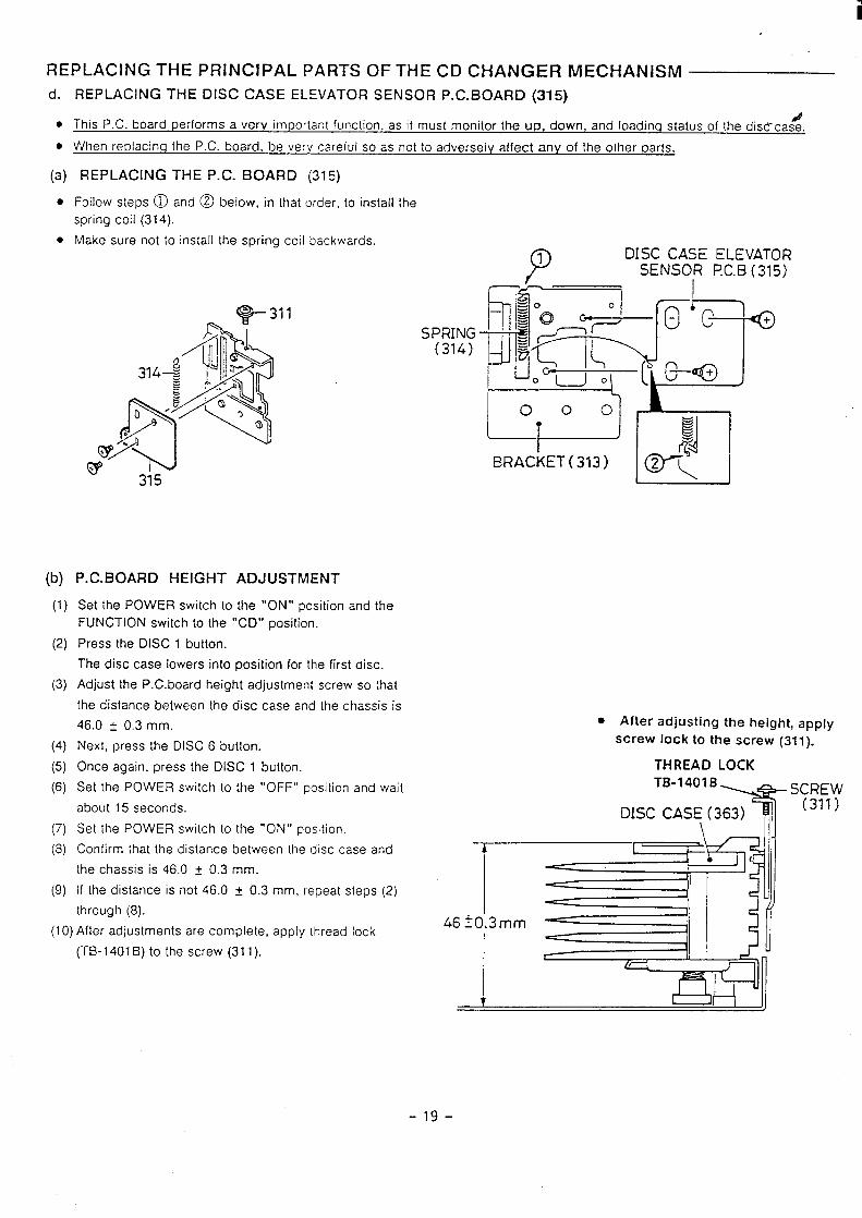
REPLACING THE DISC CASE ELEVATOR SENSOR P. C. BOARD (315)
This P.C. board performs a very important function. as it must monitor the up, down, and Ioadinq status of the disd-cas%.
When replacinq the P.C. board, be verv careful so as not to adversely affect any of the other parts.
REPLACING THE P.C. BOARD (315)
Follow steps @ and @ below, in that order, to install the
spring coil (314).
Make sure not to install the spring coil backwards.
P. C. BOARD HEIGHT ADJUSTMENT
Set the POWER switch to the “ON” position and theFUNCTION switch to the “CD” position.
Press the DISC 1 button.
The disc case lowers into position for the first disc.
Adjust the P.C.board height adjustment screw so that
the distance between the disc case and the chassis is
46.0 t 0,3 mm.
Next, press the DISC 6 button.
Once again, press the DISC 1 button.
Set the POWER switch to the “OFF” position and wait
about 15 seconds.
Set the POWER switch to the “ON” position.
Confirm that the distance between [he disc case and
the chassis is 46.0 f 0.3 mm.
If the distance is not 46.0 t 0.3 mm, repeat steps (2)
through (8).
(1O)After adjustments are complele, apply thread lock
(TB-1401 B) to the screw (31 1).
SPRING(314)
P1 DISC CASE ELEVATORSENSOR PC.B (315)
f[~
– 1: ‘Q b/?+
~“c ~=~uL1 .“~o [&Q,
000
$g
BRACKET ( 313) w?
● After adjusting the height, apply
screw lock to the screw (311).
THREAD LOCKTB-1401B
T
SCREW
DISC CAS: (363)(311)
-19-
ii
REPLACING THE PRINCiPAL PARTS OF THE CD CHANGER MECHANISM
e.
●
●
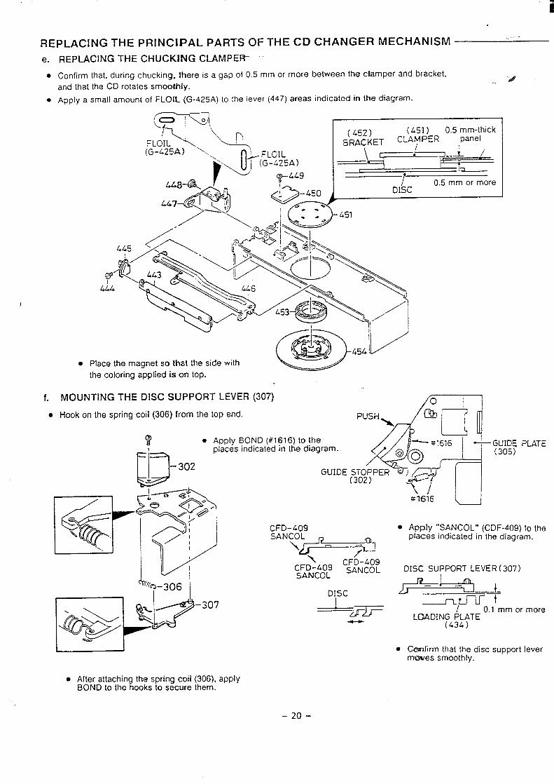
REPLACING THE CHUCKING CLAMPEIT
Confirm that, during chucking. Ihere is a gap of 0.5 mrn or more between the clamper and bracket,
and that the CD rotates smoothly...
Apply a small amount of FLOW (G-425A) to the lever (447) areas indicated in the diagram.
~q
t~
\
P( .452) (L51) 0.5 mm-thick
FLOIL ,1 BRACKET CLA:PER panel
(G-L25A) \\ o-. FLGIL \
‘ (G-L25A) —~●
/w L !~
i 0.5 mm or more~:ti DISC
1
(lij&iij!ji,,.11/f.
●
● Place the magnet so that the side with
the coloring applied is on top.
MOUNTING THE DISC SUPPORT LEVER (307) /0 1
D – 302.
##
Hook on the spring coil (306) from the top end.
4 “
PUSH @l\
n[Apply BOND (#1616) to theplaces indicated in the diagram.
“- =1616 — GUIDE PLATE
@~o (305)
GUIDE ~OT~PER
m
-q
R~~$
\1-1
0’./
e-< /54’
1
:;IH:9
/1\#~~=
\:FD-:$3: c::;::;
r@~-306
p+!s.k?
DISC -~p+
–307.? +!ldF——— 0.1 mm or more
./ LC3ADINGPj;TE.
●
$$7616
● Apply “SANCOL” (C DF-409) to theplaces indicated in the diagram.
DISC SUPPORT LEVER ( 307)
Ckrmfirrn that the disc support leverrmwes smoothly.
. After attachin the spring coil (306), apply$BOND to the ooks to secure them.
-20-
i
REPLACING THE PRINCIPAL PARTS OF THE CD CHANGER MECHANIS1’vl
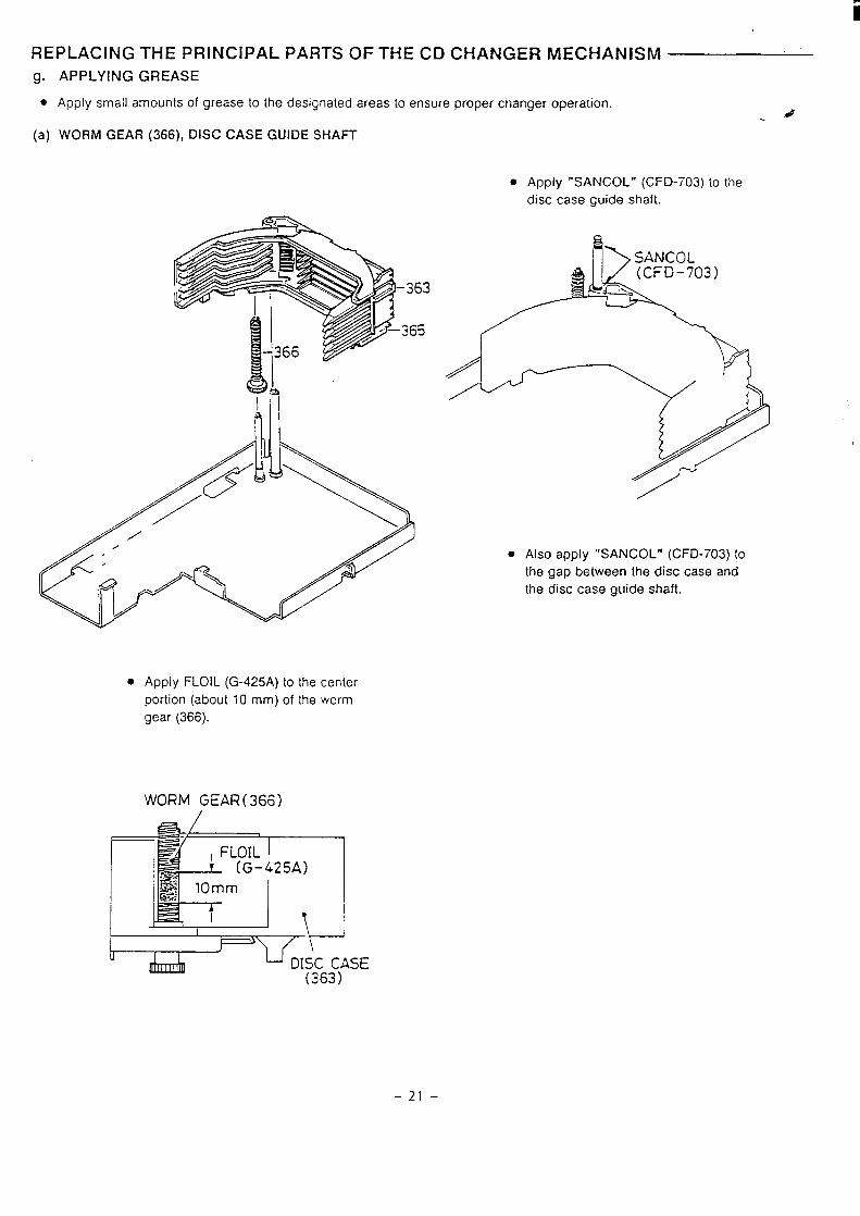
g. APPLYING GREASE
. Apply small amounts of grease to the designated areas to ensure proper changer operation..4..
(a) WORM GEAR (366), DISC CASE GUIDE SHAFT
. Apply FLOIL (G-425A) to the center
portion (about 10 mm) of the worm
gear (366).
WORM GEAR(366)
7\ FLOIL I~ (G-425A)
10mm
— 1 \ I
● Apply “SANCOL” (CFD-703) to the
disc case guide shaft.
● Also apply “SANCOL” (CFD-703) to
the gap between the disc case and
the disc case guide shaft.
I 1
‘)JY
DISC CASE(363)
-21-
k
REPLACING THE PRINCIPAL PARTS OF THE CD CHANGER MECHANISM
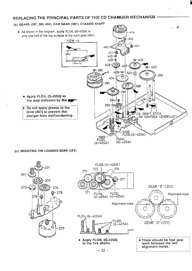
(b) GEARS (397, 398, 402), CAM GEAR (391), CHASSIS SHAFf
. AS shown in the diagram, appl!f FLOIL (G-425A) tO –.414
onlv one half of the top surfatx$ of the cam gear (391).
vIEW-AI
I -4/4 I
&l 1
● Apply FLOIL (G-425A} tothe area indicated by the ~
~...Dnotoappjyjg reaieitottheh: ....-.
~ lever (407) to prevent the; plunger from malfunctioning. I. ... ......... ... .............. ....... ..... .. .. ..... .. . ..
(c) MOUNTING THE LOADING GEAR (3= )
dLuL
FLOIL FLOIL(G-425A) (G-425A)
FLOIL (G-425A)
Alignment mark
FLOIL (G-425A)
GEAR ,’”E “ (373)
mark
GEAR “D” (371)
. ...... .. ... ....... .......... ....................... .... Apf)ty FLOIL (G-425A) ~ . There should be four gear ~
to the five shafts. teeth between the twoalignment marks.
-22- . ... ... .. .......... ....... ... .... ..... .................
1
REPLACING THE PRINCIPAL PARTS OF THE CD CEfANGER
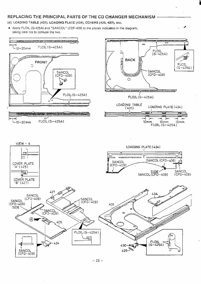
(d) LOADING TABLE (431), LOADING PLATE (434), COVERS (425, 427), etc.
MECHANISM
. Apply FLOIL (G-425A) and “5ANCOL” (C DF-409) 10 the places indicated in the diagram, &..
taking care not to confuse the two.
m ,,-----,..am-m- ,..r*-.—--
Y
. J&.-1‘T
ulo.~o~~ FLOIL(G-42!5A)
d ~
P-1’Y,
SANCOL(CFD-409)
B@
,,, -
I
.,.~.<L o
\1
FLOIL (G-425A)
LOADING TABLE(431) LOADING PLATE ( 434)
Bw
—;Om: Tom: - k-
10-20 mm FLOIL(G-L25A) 10mmFLOIL (G-425A)
VIEW - A
COVER PLATE‘OA’’(.$25)
=5==COVER PLATE“B” (427)
LOADING PLATE (434)
C=L!===-1
jp:-=jE-----’3c:SANCOL(CFD-409)
QNCOL
-23-
REPLACING THE PRINCIPAL PARTS OF THE CD CHANGER MECHANISM
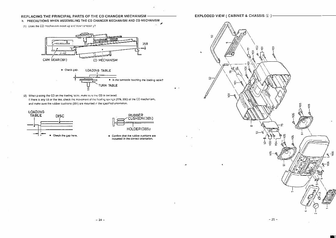
h. PRECAUTIONS WHEN ASSEMBLING THE CD CHANGER MECHANISM AND CD MECHANISM#
(1) Does the CD mechamsm move up and down smoothly?
/CAM GEAR (391 ) CD MECHANISM
. Check gap. LOADING TABLE
+1----T&l ● Is the turntable touching the loading table?
‘l-l= TURN TABLE
(2) When placing the CD on the loading table, make sure the CD is centered.
If there is any tilt or the like, check the movement of the floating springs (379, 380) of the CD mechanism,
and make sure the rubber cushions (381 ) are mounted in the specified orientation.
+1- ● Check the gap here. ● Confirm that the rubber cushions aremounted in the correct orientation.
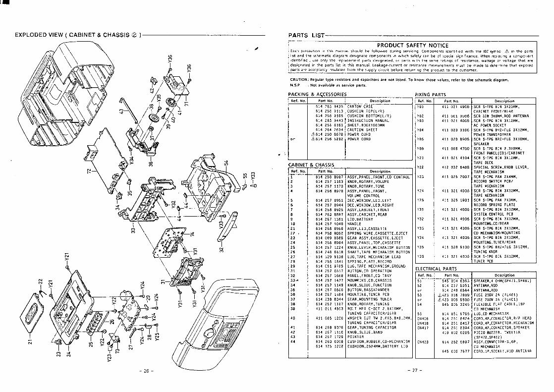
EXPLODED VIEW ( CABINET & CHASSIS ~ )
-
I \,—
-24-
-s I.
-25-
-Lz--9z-
4
—
VNNIINV00M411X30S<dI”Oti03LL6L~oosk9WSINVN13W03
4d9’S-UOL33NU03’ASSVL68SZ9Zb19(Z9t’dS’ZLi’dS)
!43133/41ati3zzn80731d90Z0ZOO611J
U3XV3dScti0133NN01’dt’0H03k6t8192!719iSINVH33W’HO133NN03’dt’0H03Ltlf8192t19OV3Hd/M’M0123NNOl”dk’0U03?zb8192*19
WSINVH33H01’’3fllS8161S0*19wsINmiJ31403
d8L’319V31V143161X314SbZC~005$9(IObfl~)VZ.A05Z3Sl1400S6S00tZkT
-
(IO?f14)VZAOSZ3Sf14608L910tZbw
(18bdS’ILPdS)WHOtmU3W3dSCS’29bOO9*9
SlllVdlb
8JdH3Nfll‘WWZTXFN199dJ-Sti3SSO09120lIb
90NI9NINlll‘WWZIXC91.i+Z8E9dl-S83S001602011*
tiV3H/ii3Nn1’5NIlNnOW‘WWZIXSNIS9dl-St13Ssoot120IIr9NIlNnOW/WSINVti33W03‘WWZIX’SN189dl-SI13SSoobTz”oItb
LlV3U/03’9NIlNf10W‘WWZIX’3N189dl-S8XSoob12011)
91d10N1NO2K31SAS“WWZIXCNIS%1-SM3SSooti12011?
31V7d9NItidS0U023U‘WWf.XZNVd9dl-S83S1061SZOTIb
WSINVH23W3dVL“WWZIXFN189dl-Sii3SSoob120Ilk
WSINVH33W3dVl/83dH311ASOb’023ti
I ‘WWtXZNVd9dl-S83SLOOZSZO11?WSINVH33W3dVl
‘83A31EONI‘M3B3SlV133dS80t’9ZCOZIi’X3303dVL
‘WWZIXtN183dl-SHIStotb120Ilb13N19V3/(03)13NVdlNOb’4‘WW8XC”ZNIE!JdL-Sti3S00Lk!36011$
U3XV3dS‘WWOIX’S914+ZM89dL-S83SS068OzoIlk
L13k4H04SNVMlU3MOd‘WWZIXF91J+ZM89dl-SH3S0016OzolIb
13x30SU3ROd3U‘WWZIX’iN1139dL-S83Ssoot12011P
VNN31NV00U’WW8XCN1883S900610011PW3H/lNOUJL3NIWl
‘WWOZXSN199dl-SU3SI906P12011Puo!$d!nsaaONUed
CZbNl
LItN3
91bN3
90vNI
9s
bsJO
:sJo
ZsIs
ON.}an
81331
9CA
SCA
bEA
EEA
ZCA
IEA
SZA
tZA
FZA
ZZA
IZA
90A
SOA
VOA
COAZOA
IOAON.~an
9NIXI
011AU311V8’WWkXSZ’NOIHSn3WSINVt133W-03’M39SflLl<NOIHSn3
U3LNIOd0NV8’3017S’90NX
UOLIlVdW3!ININlll’MV3EltiV39/HOlIJVdV33NINnl
WWC”0X8’SX9”ZM1lnOM3HSWMHV39/MOl13VdV39NINnL
‘WW91X9’Z13S-3X3H11OE9NINnl’AUVIOU’80NY
N3Nnl9NIlNnOW’HV39133dM3Nnl’9NIlNf10WU30NVdXSSVS’NOllflE
NOI13Nn4’3011S’80NXsIssvH3’03’9NIl+NlowAV8103’lNOU4’13NVdNOIlVM3d003’NOllfl!3
0NnOU9’WSINWH33W3dV1-9n70HOJ3H<31V7d’9NI!4dS
0V31WSINVH33W3dvl’9nlNOlln9WSINVH33W3dV1’L~VHSNolln9wsINvH33w’M3A31’aoNn
3113SSV3’dO1’13NVd”ASSV133C3(3113SSV3’ASSMtlv39
133r3’31L3SSV3’3UIM9NIUdS3113ssv3’aIl’Assv
370NVHAU311V8’017
MV3il’13N18V3’ASSV1N084’L3N19V3’ASSV
1H91U’031’MOONIMC1301~31’031’MOONIM”330
10M1NO33wn70A‘1NOM4‘13NVd‘ASSV3N01‘AWJ1OM‘SON]
3Wn10A’A$4V10ti’80NY10M1NO303’1NOM3’13NVd’ASSV
uo!td!maa
ZOZI9ZIi7T9
600009Zb19
6ZLILGZbt9
9911LSZ}!9
9L068S2t’19
0021S8011P
Cost110IIbL8tILSZ?19
t7P088CZP19
i78tILSZ?19
00s0Lsz1$19
6911LS??19
LLv1LSZt19
8991LSZ919
LISOLSZ*19
S8L61s0b19
I*9I892*I9
9’S15621ti19
8T8981J?b19kZZ(LSZb19
b6688SZbL9
S8f0690P19
ZS068SZt19
9S688S2*19
O*OILSZ*I9
19C[LSZk19
L688S9Zt19
SZ6882Z*I9
PP60LSZb19
1S60LSZt19
0L688SZP19
OLILLSZt19
C91TLSZP19
L8688S2#19
.ONW?.j
SISSVH3%
0803M3MOd262S9S2ti19v
0ti03M3MOd8L990S2k19&’
133HSNOIlflV3)’C9Zb9z*I9
WWOOOIX008C133HS19188S2t19
lVnNUWNOI12nMlSNlE!/v6F9Zt19(U/l)WOl109N01HSn390168SZP19
(M/l)dOlNOIHSl13C1168SZb19
sueda>!massealqel!eneION:d’SN
1S11SlklWd
uN
f-~
(@SISSVH3‘8LIN1EIV3)M31AC13C101dX3
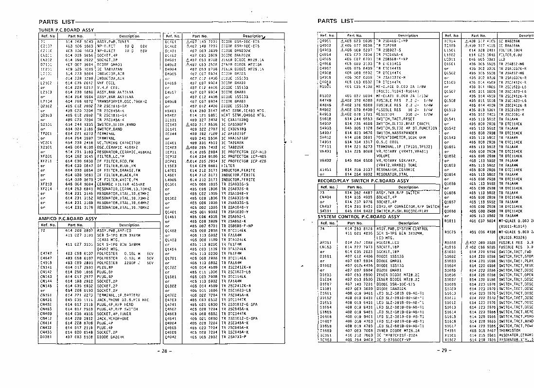
PARTS LIST PARTS LIST
TUNER F
Ref. No.
71C2107C21:6
CN2C1
CN2C2
D21GI
IC2CIL2:a1
or
L2102orL21G3or
L2104Q2102orQ2103or
S2101orTP201orVC201X2101orXF201xF211ororororXF213XF214orororor
4MP/C[Ref. No
72
C4747C4847C4915CN141CN142CN143ct4144CN145orCN151CN401CN402CN403CN409Ct4412CN414CN432CN433D1381
-.Dv/+nu A+>>T
Part No.
614 262 5040403 106 16034G3 106 1603614 035 5956614 1S18 2922407 007 9904409 325 7006614 233 5864614 238 1298614 035 00126:4 229 0217614 230 6888614 254 9964614 256 6572405 012 2002405 020 72o4405 012 2002405 020 7204614 244 8335614 024 3185614 221 8273614 254 3597614 239 2416645 004 6100614 231 3183614 252 1045614 030 5630614 030 5647614 030 5654614 030 5661614 030 5678645 004 6094614 253 6841614 231 3145614 231 3152614 231 3169614 231 3176
‘.C.BOARD ASSPart No.
614 260 88o7411 027 3101
411 027 3101
403 058 6107403 058 6107403 059 2801614 017 2591614 250 1665614 017 2577614 198 2922614 035 5932614 206 0193614 221 8273645 005 1111614 017 2119614 017 2553614 035 4935614 229 3812614 228 0706614 017 2119614 020 6548407 003 5108
Description
ASSY, PW8, TUNERNP-ELEc T liJQ 50VNP-ELECT lU Q 50VSOCK ET.4PSOCKET,2PDIODE GMAO1IC TA8122ANINDUCTOR, AIRINDUCTOR, A12VHF COILV.H. F COILASSY,8AR ANTENNAASSY, BAR ANTENNATRANSFORME R.0SC,796KHZTR 2SC1815-GRTR 2SC945A-KTR 2SC1815-GRTR 2SC945A-KSWITCH, SLIDE, BANDSWITCH,8AN0TERMINALTERMINALVC, TUNING CAPACITOROSC, CERAMIC 456KH2RESONATOR, CERAMIC,456KH2FILTER, LC, FMIF fILTER, RED, FMIF FILTER, BLUE, FMIF FILTER, ORANGE, FMIF FILTER .BLACK. FMIF FILTER, WHITE, FMCERAMIC FILTER 455xHZRESONATOR, CERAM.1O.7OMH2RESONATOR, XTAL, IO.67MHZRESONATOR, XTAL.10.73MHZRESONATOR, XTAL, I0,64MHZRESONATOR, XTAL,1O,76MHZ
Description
ASSY, PWB, AMP/CDSCR S-TPG BIN 3X8MMIC403 MTG.SCR S-TPG BIN 3X8ttMQ4952 MTG.POLYESTER 0.15U M 50VPOLYESTER 0.15UM 50VPOLYESTER 2200P J 50VPLUG,8PPLUG,8PPLUG,6PSOCKET,2PSOCKET,2PSOCKET ,2PTERMZNAL, lP.8ATTERYJACK, PHONE D3.6, MIx MICPLUG,4P, R/P HEAOPLUG,4P, R/P SWITCHSOCKET,4P, TUNERJACK, HEADPHONEPLUG ,4PPLUG.4PSOCKET,2PDIOOE DA204K
Ref. No.
0140101402D1451D145204951D4952D4954D4955or
D4956or
D4957or04958orHS401HS402IC1311C140IC141IC144orIC401IC403ICP1lICP12ICP41L1503L4701L4801L4905Q1301or
;;302or
or
Q1401Q1451or
or
01452
;;453
;;454
;:781or
Q1782
:;881
;;882
;;702Q4703Q4741Q4802Q4803Q4841Q490404905Q490604942
Part No.
.L407 140 7201~407 140 7z01
407 003 3609407 003 3609
&407 053 B108~407 053 2508
407 053 8708407 007 9904407 012 4406407 007 9904407 012 4406407 007 9904407 012 4406407 007 9904407 012 4406614 26o 3147614 121 5891409 327 3402
k409 317 8509409 322 2707409 192 7109409 241 5506409 331 4501
~409 295 7402614 205 2884614 234 9106
b614 205 2914614 028 6861614 212 3171614 212 3171814 212 3171405 006 1905405 006 1806405 002 1305405 006 1806405 006 1905405 002 1305405 001 9302405 006 4005405 006 3909405 007 6701405 000 2908405 113 5902405 000 1109405 113 6200405 000 1109405 113 8200405 000 2908405 113 5902405 014 4509405 011 1006405 000 2908405 113 5902405 014 4509405 011 1006405 020 7204405 060 6502405 021 0600405 020 7204405 060 6502405 021 0600405 020 7204405 020 72o4405 020 72o4405 005 2002
Description&
O1OOE OSR-1OC-ET5OIODE OSR-1OC-ET5D1OUE 0AN202KDIODE 0AN202KZENER DIOOE MT Z9,1AZENER DIDOE MT21OAZENER OIODE MT Z9,1AEII09E GY,AO1DIODE 1SS133OIOCIE GMAO1DIOOE 1SS133O1OOE GMAO1DIOOE 1SS133OIOOE GMAO1DIODE 1SS133HEAT SINK, 1[403 MTG.HEAT SINK, Q4952 MTG.lC CXA17828QIC BA6398FPIC CX02518QIC 8A15218FIC XRA15218FlC TA2068NIC TA8229KXC PROTECTOR ICP-N1OIC PROTECTOR ICP-N05lC PROTECTOR ICP-N25FILTERINDUCTOR, FERITEINDUCTOR, FERITEINDUCTOR, FERITETR 2SA933S-STR 2SA933S-RTR 2SA1048-YTR 2SA933S-RTR 2SA933S-STR 2SA1048-YTR 2SA102O-YTR 2SA952-LTR 2SA952-KTR 2S8598-F-NPTR OTC114EKTR FA1A4MTR oTA124EKTR FN1F4MTR 0TA124EKTR FN1F4MTR OTC114EKTR FA1A4MTR 2SC2412K-RTR 2SC1623-L6TR OTC114EKTR FA1A4MTR 2SC2412K-RTR 2SC1623-L6TR 2SC945A-KTR OTC144TKTR 2SDI012-G-SPATR 2SC945A-KTR DTC144TUTR 2SO1O12-G-SPATR 2SC945A-KTR 2SC945A-KTR 2SC945A-KTR 2SA733-P
.
Ref. No.
Q4951Q4952Q4953Q4954Q4955Q4956Q4957Q495804959Q4960RiO?l
R1032R4749R4849R4952R4953S1618S4902S4903S4907SVR12T4901TP131VR491
VR492
X1451
~
RECOR[
r
Ref. No
73CN404or
CN407S4Q01
SYSTEN
Ref. No
74
8RISICN153orD1501orD1502orD15030150401507015810165101652016530165401655D16560165701658D1659IC1511C153
Part No.
.&405 023 5009L405 077 9008L405 009 5207
405 020 7204405 007 6701405 000 3103405 075 8409405 060 6502405 002 0308405 060 6502401 035 4108
401 037 5004fi402 070 6-JOO
&402 070 6300L?j402 070 6409~402 070 1701
614 244 6553614 235 4506645 005 1128614 023 9676614 256 0501614 034 1317614 221 8273614 225 8088
645 004 6506
614 259 2137614 254 6932
DescritNion
TR 2S0400-E-MPTR TIP29BTR 2SB927-STR 2SC945A-KTR 2S8596-F-NPTR 0TCI14ESTR 0TC144TSTR DTC144TKTR 2SAI037K-RTR 0TC144TKMT-GLAZE 0.000 2A l/8W(R 1031, R1O41-R1O44)MT-GLAZE 0.000 ZA l/10WFUS18LE P.ES 2,2 J- l/4wFUSIBLE RES 2,2 J- l/4WFUSIBLE RES 10 J- l/4wRESISTOR 330 J- l/2WSWITCH, TACT, RESETSWITCH, SLIOE,8EAT CANCELSWITCH, SLIOE 4P-3 T, FUNCTIONSWITCH,8ASSXPANOERPOT ENTIOMETER,1OOK OHMO.S. C COILTERMINAL, lP (TP131, TP132)VR, ROTARY (VR471, VR481)VOLUMEVR, ROTARY 50 K/AX2,(VR472,VR482) TONEResonator, CERAMICRESONATOR, XTAL
LAY SWITCH P.C.BOARD ASSYPart No. Description
614 262 4487 IASSY, PWB, R/P SWITCH614 035 4935 SOCKET,4P614 237 9776 SOCKET,4P614 261 8431 COR0,4P CONNECTOR .R/P SWITCH645 004 9422 ISWITCH, PUSH, RECORO/PLAY I
:ONTROL P.C.BOARD ASSYPan No.
614 263 8125411 021 4005
614 257 1088614 221 7973614 035 2023407 012 4406407 007 9904407 012< 4406407 007 9904407 053 8500407 053 8500407 140 7201407 003 3609408 019 9401408 019 9401406 019 9401408 019 9401408 019 9401408 019 9401408 019 4703408 019 4703407 053 7008410 212 7603409 254 9409
Description
ASSY, PWB, SYSTEM CONTROLSCR S-TPG BIN 3x12 MM,LCO MTG.HOLDER, LCDSOCK ET,18PSOCK ET,18POIODE 1SS133OIODE GMAO1OIOOE 1SS133O1OOE GMAO1
ZENER D1ODE MT Z8.2CZENER DIDDE MTZ8.2CDIooE OSR-1OC-ET5OIOOE OAN202KLED SLZ-381B-09-AB-T1LEO SL2-381B-09-AB-T1LED SLZ-3B1B-09-AB-T1LED SLZ-381B-09-AB-T1
LLED SL2-381B-Q9-AB-T1LEO SLZ-3B18-09-AB-TILEO SLZ-9818-09-A8-T1LEO SL2-981B-09-AB-T12ENER OIODE MT Z6.2AIC TMP87CH21F-20Z4IC S-87050 CF-VP
Ref.No.
IC1541C155L1501L1502LCO1101501orQ1502orQ15C6orQ1507or01508or
Q151Oor
Q1541or
Q1542orQ1543orQ1651orQ1652orQ1653or
Q1654orQ1655or
Q1656orQ1657
;;658or
R1011
R1OZ5
R1508R1515S1601S1602S1603S1604S1605S1606S1607S1608S1609S161OS1611S1612S1613S1614S1615S1616s1617TH151X1501_
Part No.
,jJ409 317 4105A409 317 4105
614 028 2481614 028 3648645 005 0381405 005 55o8405 002 030B405 005 5508405 002 0308405 014 4509405 011 1006405 011 1006405 014 4509405 011 1006405 014 4509405 013 1301405 012 7403405 113 5902405 000 2908405 113 59o2405 000 2908405 113 59o2405 000 2908405 113 59o2405 000 29o8405 000 2908405 113 5902405 113 59o2405 000 2908405 113 5902405 000 2908405 113 59o2405 000 2906405 113 5902405 000 2908405 113 5902405 000 2908405 000 29o8405 113 5902401 037 5004
40; 035 4106
b402 069 5505$402 069 5505
614 220 5556614 220 5556614 220 5556614 220 5556614 220 5556614 220 5556614 220 5556614 220 5570614 220 5570614 220 5570614 220 5570614 220 5570614 220 5570614 220 5556614 220 5556614 220 5556614 220 5556408 016 8407614 215 5561614 219 7936
Descript
lC BA6Z86NXC 8A6286NFILTER,39UHFILTER,6.8ULCOlR 2SA812-M6TR 2SA:037K-RTR 2SA812-M6TR 2SAI037K-RTR 2SC2412K-RTR 2SC1623-L6TR 2SC1623-L6TR 2SC241ZK-RTR 2SC1623-L6TR ZSC2412K-RTR 2SC21Z0-YTR 2SC2001-KTR FAIA4!4TR DTC114EKTR FAIA4MTR 0TC114EKTR FA1A4MTR 0TC114EKTR FAIA4MTR 0TC114EKTR 0TC114EKTR FA1A4MTR FA1A4MTR 0TC114EKTR FA1A4MTR 0TC114EKTR FA1A4MTR 0TC114EKTR FA1A4MTR DTC114EKTR FA1A4MTR 0TC114EKTR 0TC114EKTR FA1A4M
NT-GLAZE 0.000 ZA
(R1011-RIO14)
MT-GLAZE 0.000 2A
(RIOZ5,R1O26)
FUSIBLE RES 3.9FuS18LE RES 3.9SWITCH,TACT, FWDSWITCH, TACT, STOP/S’WITCH,TACT, PLAY/SWITCH, TACT, REVERSWITCH, TACT, OISCSUITCH, TACT, OPEN/SWITCH, TACT, DISCSUITCH,TACT, OISCSWITCH .TACT.OISCSWITCH ;TACT,OISCSWITCH .TACT,DISCSWITCH,TACT, OISCSWITCH,TACT, OISCSWITCH, TACT, REPEASWITCH, TACT, MEMORSWITCH,TACT ,RANOOSWITCH, TACT ,POWERTHERMISTORRESONATOR, CERAMICRESOtiATOR,XTAL,32
-28- -29-
I w 0 1
.....
....
..
.
● ✎
,,,
.
J-u
?I=
:11
,+ “(/)
L.-—
——
——
—n
. i
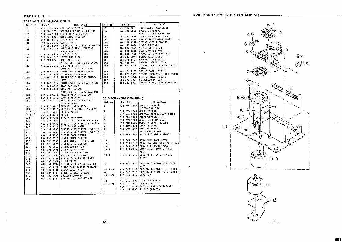
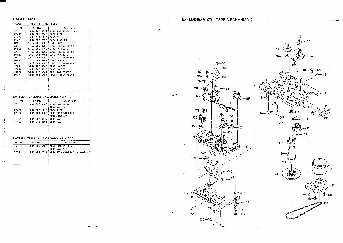
PARTS LIST
APE MRef. No,
191102i!33104105106icll:L78
109110111
112
1131:4115
116117118
119120121
122123(N.S.P)(N, S.P)124125126127131132133134135136:37138139140141142143144145146147i50
HANISM (TM-ClPart No.
614 204 5695
614 208614 140614 204614 204614 134614 151412 026
614 067614 140412 026
412 026
614 152614 024614 152
614 152614 134412 013
614 205614 204412 012
0351150857018771904682992003
277015222201
2300
128216931305
127590535000
620287407005
614 210 9946614 265 6693614 206 5366614 262 4746614 262 4302412 031 65o8412 031 9400614 262 4319614 152 126.9614 152 1251614 151 4703614 208 0313614 196 0531614 196 0524614 196 0517614 196 0555614 196 0500614 129 0669614 151 7186614 208 0320614 152 1244614 139 1120614 140 1539614 201 1744614 129 0676614 201 8181
900TN)Description
?EEL ASSY, SUPPLYSPRING, COMP. BACK TENSION.EvER, REC030 SAFETY?EEL ASSY,:AKE UP,EVER, SENSOR;EAR, F.FWOSPRING PLATE .CASSETTE HOLOESPECIAL SC REW, C TAPPINGSCREW 2X4f!tiCHASSIS ASSYLEvER. EJECT SLIOESPECIAL SC?:W,P TAPPING BiNO SCREW 2x5MMSPECIAL SC PEW,CAMERA TAP?ING 2X4.5MMSPRING WI RE, PAUSE LEVERSWITCH, MOTCR POWERSPRING WI RE. RECORO BUTTONLEVERSPRING WI RE, EJECT ACTUATORGEAR. CAM GEARSPECi AL w& StiER,P WASHER CUT 1.2x3 .8X0.3MMPULLEY ASSY. RF CLUTCHSQUARE BE LT, RFSPECIAL WASHER, FW,THRUST2.1 X4 X0.25MMFLYWHEEL OISK ASSYMOTOR ASSEY (WITH PULLEY)PULLEY, MOTGRMOTORBRACKET -M,h!OTORSPECIAL SC REW, MOTOR COLLERSPECIAL SCREW, BRACKET MOTORBE LT, SQUARE, MAINSPRING WI RE, BUTTON LEVER (BSPRING WI RE, BUTTON LEVER (PSPRING COIL. GROUNOLEVER, PAUSE BUTTONLEVER, STOP/EJECT BUTTONLEVER, F.FWI BUTTONLEVER .REW BUTTONLEVER, PLAY BUTTONLEvER, RECGRO BUTTONBOSS, PAUSE STOPPERSPRING CO IL, PAUSE LEVERLEVER .PAUSESPRING WI RE, PAUSE CONTROLSLIOE, PUSH BUTTON ACTUATORLEVER .EJECT KICKSLIOE. SWITCH ACTUATORBOSS, PR STOPPERSPRING CO: L,MAGNET ARM
Ref.No.
151152
153154155156157158159160161162163
164165166167168
:D MECRef. No.
1
2345678
9
101o-110-210-3
10-4
11
(N. S.P)or
(N. S.P)
;;. S.P]
-32-
Part No. I Descrioti& I
614 067 3258 SUB CHASSIS ASSY.8ASE1808 SPECIAL WASHER.412 026
614 070614 151614 152614 140614 237614 205614 021614 211614 146412 026412 026
614 151412 031614 20B614 249614 210
P w CUT 1.45 X3.8 X0.5MM0916 LEVER ASSY, GEAR PLATEB312 SPRING PLATE, GEAR PLATE1299 SPRING WI RE, M CONTROL1614 LEVER, SENSING2371 ASSY, PINCH ROLLER1306 LEVER .MAGNET ARM7605 MAGNETIC HE AO. ERASING6944 SL1OE ,HEAO PANEL5111 BRACXET TAPE GUIOE1501 SPECIAL SCREW,2X6Y,M1709 SPECIAL SCREW, HEAO A21MU ITH
2X7MM7162 SPRING CO IL. AZIMUTH I6607 SPECIAL SC REW. (+)BINO 2x3MM0276 LUG, R/P HEAO GROUNO9931 HEAD, RECOROIPLAY3432 SPRING WI RE, PANE L(P) SPRING
1.
ANISM (TN-23(Pam No.
412 049 3B03
614 259 1543412 049 8709
614 256 1058
614 259 12B4
614 259 6555
614 259 1536
412 049 7603
614 259 1161
614 26o 1846
614 259 2946
614 26o 4335
614 24B 2315
412 049 7603
614 260 7213
614 045 2112614 24B 2650614 259 1529
614 265 6006614 259 1840614 259 2038614 017 3857
-B)Description
SPECIAL WASHER.1.55 X4.5 X0.3MMGEAR, ”C”GEARSPECIAL SC REW. SHAFT GUIOEPICKUP .LASERSHAFT, PICK-UP SHAFTMOUNT-M, SHAFT HOLOERGEAR, ’>B’’GEARSPECIAL SCREW,S-TAPPING,2X3MMGUI OE, PICK-UP SUPPORT
ASSY , TURN TABLE BASEASSY, CHASSIS, TURN TABLE BASASSY, OISK, TURN TkBLECOMMUTATE MOTOR, SPINOLEMOTOR
SPECIAL SCREW, S-TAPPING2x3MM
COMMUTATE MOTOR ASSY ,SLEDMOTORCOMMUTATE MOTOR, SLEO MOTORCOMMUTATE MOTOR. SLED MOTORGEAR, ”A”
ASSY ,PCB ,MOTOR?cB,MOTORSWITCH, LEAF. LIM1T(S402)PLuG,6P(CN423)
EXPLODED VIEW ( CD MECHANISM )
@– 1
.
.
i IO-I M’=ll
IL=’<
I-_1-
fi,
L———— I_ —I—_—__— —— ——
12
33-
i
F‘3
;,,
~..-.:
.,
,$’
..-
/-3
05-
,..
C.‘
\%
-3o
f3
“y30
6
,
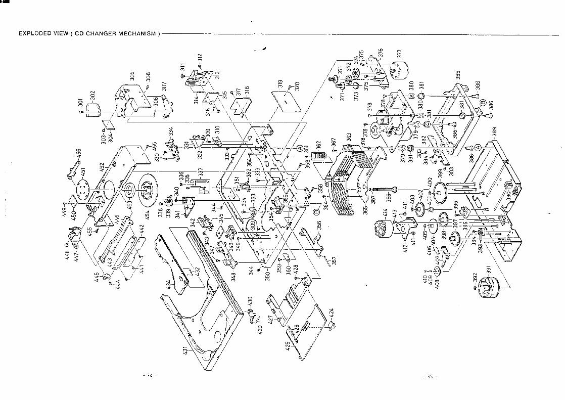
PARTS LIST
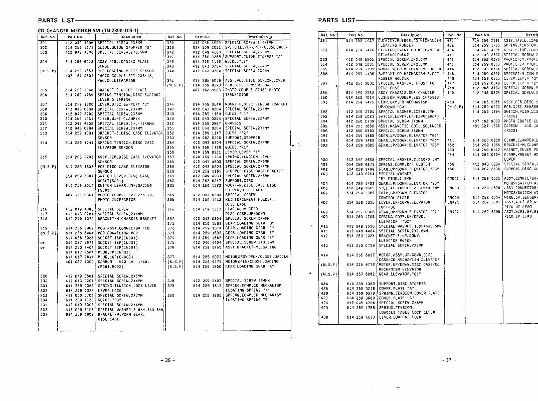
l) CHIRef.NC
301302303
304
(N. S.P
305306
307308309310311312313
314
315
(N.S.P
316317318
319(N. S.P
oror
32o330331332333334335336337
iER MECHANI!Part No.
412 049 4206614 259 1178412 049 48OO
614 265 6013
614 259 1857407 161 0304
614 259 1048614 259 1789
614 259 1680412 043 0204412 049 8709614 259 14S1412 049 4602412 043 0204614 259 1031
614 259 1741
614 265 5993
614 259 1833
614 259 2007
614 259 2014
407 161 0304
412 049 400841.2 043 0204614 259 1079
614 266 5962614 256 6404614 035 2023614 227 7973614 260 7404614 017 2584614 017 2614401 027 1306
412 049 85ol412 043 0204614 259 0362614 259 0324412 050 0709614 259 1123412 049 83o3412 049 8105614 259 1062
J (TN-23OO-1O3-I)Description
SPECIAL SCREW.2X6MMGUI DE, GUIOE STOPPER “8”SPECIAL SCREW,2X3.5MM
ASSY. PCB, LOAOING PLATESENSORPCB, LOAOING PLATE SENSORPHOTO COUPLE SPI-235-18,PHOTO INTIRAPTOR
BRACKET-E. GUIOE PLATESPRING, TENS ION, DISC SUPPORTLEVER 3 SPRi NGLEVER, DISC SUPPORT “3”SPECIAL SC REW,2X4MMSPECIAL SCREW.2X5MMFIXER, WIRE CLAMPERSPECIAL SCREW .(+, -)2XEMMSPECIAL SC REW,2X4MMBRACKET -E,OISC CASE ELEVATOPSENSORSPRING, TENSION, OISC CASEELEVATOR SENSOR
ASSY, PC8,01SC CASE ELEVATORSENSORPCB, OISC CASE ELEVATORSENSORSWITCH, LEVER, OISC CASERESET (SOO1)SWITCH, LEVER, UN- LOAOING(s002)PHOTO COUPLE SPI-235-18,PHOTO INTERAPTOR
SPECIAL SCREWSPECIAL SC REW,2X4MM8RACKET-M, CHASSIS BRACKET
PCB ASSY, CONNECTOR PC8PCB .CONNEC70R PCBSOCKET,18P(CNO01)SOCKET,18P(CNOOI)SOCKET,18P(CNO01)PLuG,7P(CNO02)PLUG, 1OP(CNOO3)CARBON 510 JA l/6w,(ROO1, RO02)
SPECIAL SC REW,2X5MMSPECIAL SC REW,2X4MMSPRING, TENSION, LOCK LEvERLEVER, LOCKSPECIAL SC REW,2X3MMGUI OE, ”R3”SPECIAL SC REW,2X4MMSPECIAL WASHER,2,6X4 .5X0.5KVBRACKET -M,WORM GEAR,OISC CASE
Ref.NO
338339340341342343344
345[N.S.P,
346347348349350351352353354355356357358359360361362363
364365
366
367371372373374375376
377(N.S.P(N.S.P
378379
380
Part No,
412 049 4909614 259 ,?021412 049 4206614 259 0256614 259 1116412 043 0204412 043 0204
614 265 5979614 259 0393407 162 8903
614 259 0249412 043 0204614 259 1154412 043 0204614 259 0997412 043 0204614 259 1147614 262 6030412 043 0204614 259 1130614 259 0331614 259 1134412 049 4503412 043 0204614 259 1185412 049 4603614 262 6047614 259 1093
412 043 0204614 259 1413
614 259 1512
412 043 0204
614 259 1581614 259 1574
614 259 1598
614 259 1567
412 049 4404
614 259 2960
614 265 6020614 228 9778614 259 1550
412 049 8402614 259 1819
614 259 1802
Description&
SPECIAL SC REW.2.6X5t4MSWITCH,LEVER,OPEN/C LOSE(SO03)SPECIAL SCREW,2X6MMSUPPORT, GUIOE STOPPER ,,A.GUI OE. ,!L2”SPECIAL SC REW,2X4MMSPECIAL SCREW,2X4MM
ASSY, PCB, OISC SE NSOR, LOWERPCB,OISC SENSOR, LOWERPHOTO COUPLE PT480, PHOT0TRANSISTOR
MOUNT -E,OISC SENSOR BRACKETSPECIAL SC REW,2X4MMGUI DE. ”L1.SPECIAL sCREW,2X4MMCHASSISSPECIAL SC REW.2X4MMGuIOE, ‘7R2”SUPPORT, STOPPERSPECIAL sCREW,2X4MMGUI OE,’’R1”LEVER, LEVER “1”SPRING, TENSION, LEVERSPECIAL SCREW,2X6MMSPECIAL SCREW,2X4MMSTOPPER, OISC BASE BRACKETSPECIAL SC REW,2X6MMSUPPORT .OISCMOUNT -M:OISC CASE, OISCHOLOER, OISC RACKSPECIAL SCREWREIN FORCEMENT, HOLOER,OISC CASEGEAR, wORM GEAR,OISC CASE, UP/OOWNSPECIAL sCREW,2X4MMGEAR, LOAOING GEAR “O”GEAR. LoAOING GEAR “C”GEAR; LOAOING GEAR “E“GEAR, LOAOING GEAR “B”SPECIAL SCREW,2X3,5MMASSY, BRACKET-M, LOAOING
MOTOR,ASSY,OPEN/CLOSE, LOAOINGMOTOR,OPEN/CLOSE, LOAOINGGEAR, LOAOING GEAR “A”
SPECIAL SC REW,2X4MMSPRING, COMP, CO MECHANISMFLOATING SPRING “A”SPRING, COMP, CO MECHANISMFLOATING SPRING “8”
.
..
PARTS LIST
Ref. No
381
382
383384385386
3B7
389390391
39239339439539639739B399
400401402403
404405406
407
408409
.410411412
413
414
(U. S.P
(N. S.P
424425426427428429
430
Part No.
614 259
614 259
412 049412 049614 259614 259
412 051
614 259614 260614 259
412 049614 259412 050614 261412 050614 259614 2596;4 259
412 049614 259614 259412 049
614 259412 049614 259
614 259
614 257614 259
1437
1420
5005500511091406
1002
295340141475
37042021070916850303146814991505
3605927314998204
148236051369
1635
69081796
412 049 3506412 049 4404614 259 1024
412 050 0709
614 265 6037
614 228 9778
614 257 6892
614 259 1383614 259 0218614 259 0379614 259 0980412 049 4206614 259 1758
614 259 1673
Description
11---
Ref.No.
:USHION, RUBBER, CO MECHANISM 431~LOATING RUBBER 432REINFORCEMENT, CO MECHANISM 434?EINIORCEMENT 441SPECIAL SCREW,2X3.5MM 442
SUPPORT, CO MECHANISM FLOAT 445RUBBER HOLOER 446SPECIAL WASH ER, THRUST FOR 44731SC CASE 4484SSY, CHASSIS, SUB. CHANGER 449:USHION, RUBBER, SUB CHASSIS2EAR, CAM, C0 MECHANISM 450JP/oowN, ”G4” (N,S.P,SPECIAL WASHER,3X6X0.5MMSWITCH, LEVER, UP/DOWN(SO04)SPECIAL SC REW,2X3MMRSSY, MAGNET IC, COIL, SOLENO1OSPECIAL SCREW,2X8MMGEAR, UP/OOWN, ELEVATOR “G3HCiEAR,UP/ OOWN, ELEVATOR “G6- 451GEAR, uP/DOWN, ELEVATOR “GE” 452
453454
SPECIAL WASH ER,2.6X6X0,5MMSPRING, COMP, R/F CLUTCH 456GEAR, uP/oowN, ELEvAToR,’’G6” 456SPECIAL WASHER,“E” RING,2.5MM CNO02GEAR, UP/OOWN, ELEVATOR “G5”SPECIAL WASHER,2 ,6x6X0.5MM CND03CHIP. UP/OOWN, ELEVATOR
LEVER.UP/OOWN. ELEVATOR II;;:;;CONTROL PLATE
CONTROLGEAR, uP/OOWN, ELEVATOR “G2” CN422SPRING, COMP, UP/OOWN.ELEVATOR “G2”SPECIAL WASHER,l .85X5X0.5MMSPECIAL SCREW,2X2.5MMBRACKET- E.UP/OOWN,ELEVATOR MOTORSPECIAL SCREW,2X3MM
MOTOR ,ASSY ,UP/OOWN ,OISCCASE/CO MECHANISM ELEVATORMOTOR, UP/OOWN, OISC CASEICOMECHANISM ELEVATORGEAR ELEVATOR, ”G1”
SUPPORT, OISC STOPPERCOVER, PLATE “A”SPRING, TENSION, COVER PLATECOVER, PLATE “6”SPECIAL sCREW,2X6MMSPRING, TENSION,LOAOING TABLE LOCK LEvERLEvER, LOAOING LOCK
Part No.
614 259 2951614 259 1765614 262 4296412 049 6600614 259 0270614 259 0263412 043 0204614 259 G232614 259 0355614 259 0348412 005 8101412 043 0204
614 265 5986614 259 0409614 259 1994
407 162 9009401 027 1306
614 259 0300614 259 1055614 259 031T614 259 0294
412 043 0204614 262 6536
614 25B 0561
614 25B 0578
614 25B 0714614 262 5101
614 262 5095
Descrip
~SSY, TABLE, LOAOSPRING, TENS ION,QSSY, SLID E, LOAO
SPECIAL SCREW,2XPROTECTOR, PROTE~ROTECTOR, PROTESPECIAL SCREW,2X3RACKET-M, CAM PLEVER.LEVER ,3,LEVER, LEVER ,2!,SPECIAL SCREW, PSPECIAL SC REW,2X
GSSY, PCB, OISC SPcB,OISC SENSOR,SWITCH, PUSH, OIS(s005))HOTO”cOUpLE GLCARBON 510 JA(RO03)
CLAMP, CLAMPER, UBRACKET -M,CLAMPEMAGNET, CHUCK PUCLAMP, MAGNET HOLOWERSPECIAL SCREW,2XSUPPORT ,OISC GU
ASSY, CONNECTOR-MOTOR/SWITCH WIASSY, CONNECTOR-SMOTOR/SWITCH WIWI RE,5P, SENSOR-PASSY, WI RE,8P, WHPICK UP LEAOASSY, WI RE,8P, REPICK UP LEAO
-36-
....
-37-
w2 z m w IA <
K=
VI $ 3
0—
_. “KUA
,8,
I w m
.L&&
.)— .- — r- . 0 . ; — 0 . ‘2 — ; : ‘2 —
3 1 E c > .
4 > 0 n
I w m ,
‘33=-
.. 0 .
-, : .
Ln
.GIN
-
<.”<
.;E.
:g
;
/gm0
(60’7N3)
O--E
g’~d
a2/dW
VL
LO
ZN
2m)
,9“3d
tEIN
ill-
.vrsEo201
avavt.
.1
-:nYIQ.Wwl~”
‘OLzEa
‘
(60VNJ)dt4Y
!4UH4
-
T
,“,3.>
1PS
9P
z
1959
f?
1PS
92<
L’VS9
12
ivS
9_o
c_
2151
61—
1010
et
S[
0911
St
5991
8f6S
St01
01v{
01Ot
[I1’$
V9ZtlbOt
o0
6Lv
590
19S9
1[’b
$.99
Ot0
5Z’f
1sv
2<L5
[o
0t
LO0
1
WiM1/Mw
‘ON
(A)IOzx ‘1——
...
...
.1
&olzl
L
.
b
2-1012s!-1012s
~nv~
?
—-l----l-r----l
IIQ
---+--IPl&ST,
IL
__--!?w
lII.?,xIcr-ix
!!-102.+1
WW30Nm
1
I0uI
i
,. ,f,,1
,,;,,
m;:
:,,=
,,: ,;;’
‘.”,;
,..,
,,...”
L?
?.
.,.
,..,
.,.=
,
:rc
:!~w
x,?,
,,4;,!,
,.,,,
.,,
,.
,!!’
,
1-
—
-1-
4,. ;:,, K!
-––w
-,.$ ... ,1
!—
..:,
g%$.
--–-*-.–-
;,::
;.$
1.-.
.....4
.&
——
i.––
,..
,.,.
_:,.:
tj—
L.
....-
--1
,“J r.-1
1—
!...
,,. ,ii__
_J– ‘@
.U.
‘i ...
,.,: .$—
,11
,
I
I
I
I
,.1.
1—
——
,—.
~lc
m3
I1/
2)IM
229K
.,/...
/,..
4..”
..,.
.---
--!
1--–
+—
-
I
ii
41-!:
f,
—
IIW
Y!
&,
–41
i ,,#,<
.,,~.?
.,;
—...e
———
I
—-
Il-—-—
M,...c-—
Im
I
I
➤✎
✍✎
1!/_
--------
ID=
1-“--abi-‘–
I
.——
w,,
w.,.,,
k—.(
,,.,.,,
::1-1.1
l-j1..1
I
I-.
,.....,,,
..
.,,...
...
I—-
1[3
L~
.—I“
:i
,.1
,s;
,,,g>
.,.:,
,,.,,
r..-
,L.
=.–
-.i
J
,, :, .:
1 s 1
in G’
1%
.
I#
,..’.
...--
.....
..”,,,
_-_w--
.-..
I
--l..
~(4
!: ~T.=.
......
......
....
____
___
1 ~ I I In ,
,H
‘L
—1IJ
co:”
.,,
I115
ZJ
4,7,
R15
2447
1
D15
254.
n
!?15
264.
7!
KfY
.0
KC
.5K
2F
fc.s
m
<m
.—
5EG
5mI
:,L . ,. ..
1—
---t
2.
..
..
..
..
..
..
..
..
..
..
..
..
--2:
:”
----
-”
”--
-”-------
“---
----
--..
..
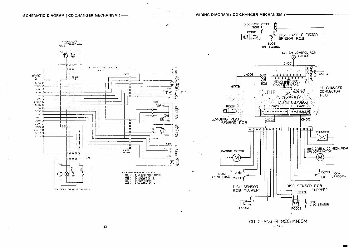
DIAGRAM ( CD CHANGER MECHANISM ) WIRING
.d
m cHANGER M: CHAN15M SE]TcH:5S001 D:5C C#.SE RESET SEi TCHSW2 . LM-.OLD1NG SWITCH5003 . . . 0PEN,cL05E SWITCHSCXM . UP/DLMN SWITCHsoc5.. D:SC 5ENscH75w]TcH
.
DIAGRAM ( CD CHANGER MECHANISM )
DISC CASE RESET f)
SO02UN-LOADING
SVSTEM CONTROL F’C B
~ (CN153)
?
CNOO1I
~
@DIP 1 ‘%. ~Y-,. ..! ~ i ~,c$~s$81$ ~~L,,. ~,
,: :. 1AD4BIOB79600” “:.~~pcoo.’$:: :t if ’<ho3f ’ “,’cNoo2:; .-
ti
!,.,,.4>
IF000”0”00000 ~o’o’oooo J.,
.. ---- .—.. —- .. . .. . . . .. “.. -
---- !,
LOADING PLATE CNO03SENSOR P.C.B
dLOADING MOTOR
M
SO03 < OPENLOPEN/ CLOSE CLOSE
DISC SENSORf?C.B “ LOWER”
m=PCO03
[
ICNO02
k PLUNGER
L21DISC CASE & CD MECHANISMUPI DOWN MOTOR
M
2 ‘OwNSO04UP/ DOWN
DISC SENSOR P.C.B—
RO03“UPPER”
——
‘HI $ %% SENSORPCO02
{
-52-CD CHANGER MECHANISM
-53-
...
I
m
)<1
J’--
-i-n)
“1
1“
i.
I
E19f
sz1
9rs
[r9Js
:.,
..——
A—
IL–
__.
___—
_-..
u
D
AD
C@
ElC
3 IIIC
15
3
ElE
m
CIlgm
l,.
1
-6S--8S-
aN9aN98.?I
(-)bH3i+3A18Civlno-tH>L@?
(+)bH3U;AIWIElf10-t7HJ9C
bHlL+3AIM0VNI-DH3Sz
SV18NISVIEEl’
33A33Az?
3>A33ALZ
a3snLON8NI-SH>or
iEH3M3AMIIVNI-SH>16LI
(+)EH>t13AlE!a8lno-cH38:
(-)EH>l13AluaVlnO.EH3Lt
dvdv“’do(+)NldO9*
dtUV“dO(-)NIdOSL
●✍
1dWV“dOtKIOdOlbL\
.
IaN9IaN98
I
..
(+)1~]~3Al)jaalno-lH>z
(-)IH3u3iwdavlno-lH3L
NOlLdll13S303WVN“0N
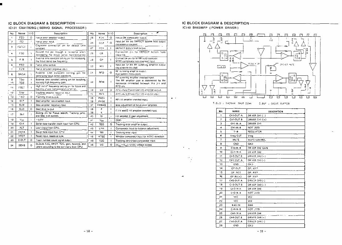
B2+”!S3AId0,ineaNMC@lnHSlVW&3Hl:C-s.i
(k13AlHClE13MOd)d486&9VEODLOI
-t-+ ,,,-,-..-----Z(lHd?,:
lndu!pauam!m~qdweA-[jH:,-,,,-“
-t+1.--.- jndulaAqE6auJe,&lldwepalsIWlsSL
]ndu,papam!.uo”mjqdwepaISIdlS*L
vdmoaA$>p6WW3LoOVLEL
F
(E10SS300Eld1VN91SOAH3S)09Z8L1VXI1S101
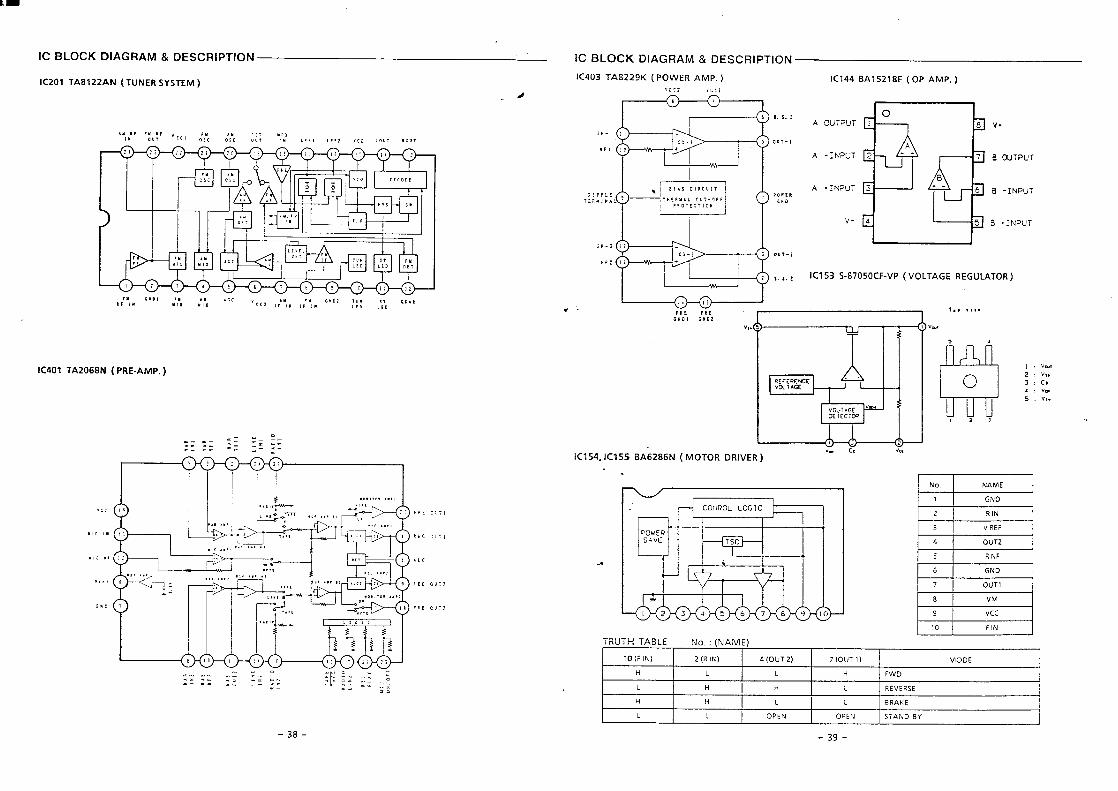
IC BLOCK DIAGRAM & DESCRIPTION —
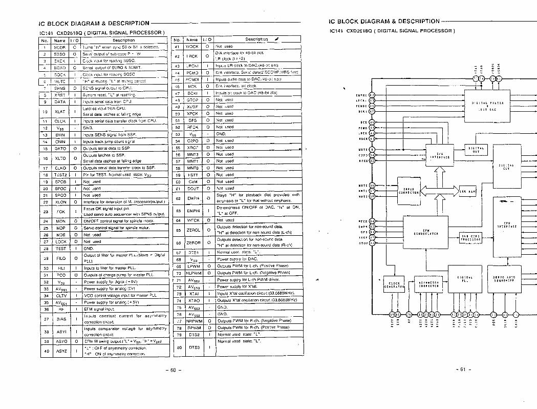
IC141 CXD2518Q ( DIGITAL SIGNAL PROCESSOR )
IC BLOCK DIAGRAM & DESCRIPTION
IC141 CXD2518Q ( DIGITAL SIGNAL PROCESSOR )
No. Name 1/0 Description &
41 WDCK o Nol used
D/A ,n,erface (0, 48-bet s10[.42 LRCK o
LR clock(i=FS)
43 LRCKI I lnD”lsLR clock10DAC. (48.b$lsIo1)
44 PCMD~
O Turns “H” when sync SO or S1 ,s oe!ec,e$
3s0 I o ] Seraloulwt of sub-code P - V
31 ExCK II I Cock ,nout for readmc SBSO.
a I soso I O ISmal o.twl ofSUBO & SOBITo DIA mlerface. Scr,al da1a12’SCOMP MBS f,rst)~ SOCK I Clock mpt,: for reading SOSO
45 PCMDI 1 lnpu!s add)o dala lo DAC (48.bl sIo1)
46 BCK o D/A interlace. B,t clock
47 BCKI I Inputs b,t clock to DAC. (48-blf slOt)
A9 GTOP o Not used
49 XUGF o Not used
tUPH1
LRCKIPC” D1
BCKIXLAT ILatches input from CPU.
;0Ser,al dala latches at falltng edge.
11 CLOK I Inputs serial data transfer clock from CPU.
50 XPCK I O Not used1 I 1 I
Bcs
?CMDLRCK
rDc K
12 Vss - I GND.1–
13 SEIN I inputs SENS sgnal from SSP.
14 CNIN I In?uls track lump count sgnal
15 DATO o Outputs serial data 10 SSP
16 XLTO oOutputs latches to SSP.
Serial data latches a! fa!lmg edge.
77 CLKO o Outputs serial dala transfer clock to SSP.
18 TEST2 I Pin for TEST. Normal used slate VDD
MUTE
C2P0
Rrcx
EEEEaInterface for exfenson of M. Prccessor(oulPut )
Used servo auto sequencer w!th SENS outpul.
IIERROR /f
CORRECTOR
I I
uNTO
U8T1UNT3
61 DOUT O Not usedI
62 tMVf+ uemphasis or ‘L” !Or that Wlthoul emphasis.
63 EMPHI IDe-emphasK ON/OFF 01 DAC. “H” at ON,
“L” at OFF.
64 WFCK o Not used
E
1-- I Stays “H” for playback disc provided w,th I-.
24 MON o ONIOFF control signal for spindle motor.I
8rc1
tuPn
Crs
XUC1
C1OP
65 lzErl -Outputs delecbon for non-sound dam.
“H- at delechon for non-sound data (L.ch) I
I. .
l#T18fACCiru
OEUODULATOR
1
I
1 II
25 MOP o Sewo control signal fors?mdle motor.
26 MOS o Not used
27 LOCK o Not used
.*
t 66 IZk~,~ o Outputs detection for non-sound dala.
“H” al deteciton for non.sound data (R-ch),t F,7 DTS ? I Normal used staie “L”.
28 TEST I 1 I GND.
Output of f!lter for mas!er PLL.( Slave = O@al29 FILO o
PLL) 68 Vm Power supply for DAC.
69 LPWM o OulpulsPwkl for L-ch. (Posbve Phase)
70 NLPWM o OUIP.!S PwM forL-ch.(New.bve phase)
71 AVD02 Power supPly for L-ch PWM dr,ver.
72 AVD33 - Power supply for X’(al.
73 XTAI I Inputs X’lal osc$llahoncmcwt (33.868 SMHZ).
74 XTAO I Outputs X’lal Oscdlabonctrcud (33.8688 MHz).
75 AV~~3 - GNO.
30 FILI 1’1 Inputs to fdfer for master PLL.I
31 Pco o Outputs of charge pump for mzster PLL.
32 ‘DD - Power supply for d,gj!al.f. 5V)
33 AV~~l Power supply for analog.
34 CLTV I vCO control voltage mpul for master PLL.
I ‘R rf=d-’l“’”ALI I I==SERVOAUTOSEQUtNCER
35 AV9D1 Power supply for analo~.( + 5V)
36 RF I EFM s,gnal input.
37Inpu!s constant current for asymmetry
BIAS ICorrectIonCIICUIL
38Inputs comparator voltage for asymmetry
ASYI Icorrection clrcutt.
39 ASYO o EFM {Ill swm oumul.[”L” = V*C. “’H” = V“”)
76 AV~~2 GND.
77 NRPwM o OuIputsPWM forR.ch.(NegativePhase)
78 RPwM o OutputsPwM forR-ch.(PosIIIvePhase)
79 0TS2 I Normal used stale “L”.
Normal used state. “L”.
40“L“ :OFF ofasymmehy correction.
ASYE 1*H” :ON ofasymmel~ correcl,on.
II+W ‘1
-61--60-
-f9--z9-
t‘--.IbE1SL21
(AWE)7lIWI1—
NO113313CINOlllSOd(SIE)9“2”dEIOSN3SH01VA3133SKIC)SICl“a
.“
(AO’S)HH.>la
(AL”Z)1HNMOCit7&1s!31
(Ah”:)H1dn—
MS40X3MSNOX3NOlllSOdWSINVH>3Wa3‘oNNld
NOlllSOdS3H311MS..
NOllC1313aNOlllSOd(’S6C)H311MSNMOC1/dnWSINVH@VCIO“P
HH.ua
(At’”E)1H3s01>f:lst>l
(AL’Z)H7N3d0—,
MS3S013MSN3d0NOILISOdAtOil3Sla“ONNld
NotusodS.3H311MSI11
NO113313CINOlllSOd(6CC)H311MS3S01CI/N3d0“~
.dO15,,.dn..NAJOG,,
WSINVHJ3W0)WSINVH33Wa)LhSlNVH)3Wa3,,7,,=ld—ao,,.,,,,.,.,,.,.,.,,,,,,,..,,.,,,,01s10
..dols,,35v3>sla.NMO13,,3SV>>S10..dfl,,3SV>>Sla.H,,=id—cl>
7H7NMoa—a621S131 ,,.,.,,,.,.,,.,,,,..,,,..,,.,.,,.,...,.,
1’1Hdr—-a821S[>1
13A313bNVNlVNlWti31/“ONNld* 1III
(NMOWdn)NO11CJ313CINOlllSOdWSINVH33WCKlCINV(C9C)3SV33SICI“q
H1HN3d0—UlLZlS~31
dOIS3s01>N3d0/3LPJVN1’VNIIPJM31]“ONNld1I1II1
NOl13313aNOILISOd(lCti)(319V1ONl@/01)AVH1OSICI
-----“,.I
CJ3S1710N_[-12-*3XI,c] LndNlA3Y
In~<n,n.,I-3Nl-lON
....----I
LIW17‘H311MSWSINVH23W-[:- ~“‘~:Z:i440N0>20H2‘H311MSWSINVH33W
3S013IN3d0‘H311,4!SWSINVH33W-
)3WZE
a37-00093sZLlf3dNlA3Y--O—A3YLs
a370LO!33SlLa3sn10N-0a33ds0s
aol02093sOL10!51NO3.,NMOa,,H301OH0S10HoNMoa—Ha62
Ilo*L\’23,,d(l,.‘d3a70HaslaHodn—Ha
70H1NO0N3d0AVtILHoN3d0—1m ,I
a37-0
0011-10 ---Law-0
a370
‘:‘‘:‘:”m
13mw-A8alLZ
I!1,1
-,—-u,.,nnL,.,,a,.7n,,=..,-,l“.\Il(ldNlVIVa7Vlt13S‘lfldN1O’J(lSI-III0S0SISL ,Lndlno>~ol~lVlt13’S‘lndNlOsns-0X30Svi
..
(aa=)Aol)NOIKJ
I111.Hv~OL7
aaAam07‘NldSNIK13NNO0t101vNOS3HoLnoxz
3%11OA32N3H3j3’d&lbvA6E(AO)0N9SSAL
i.
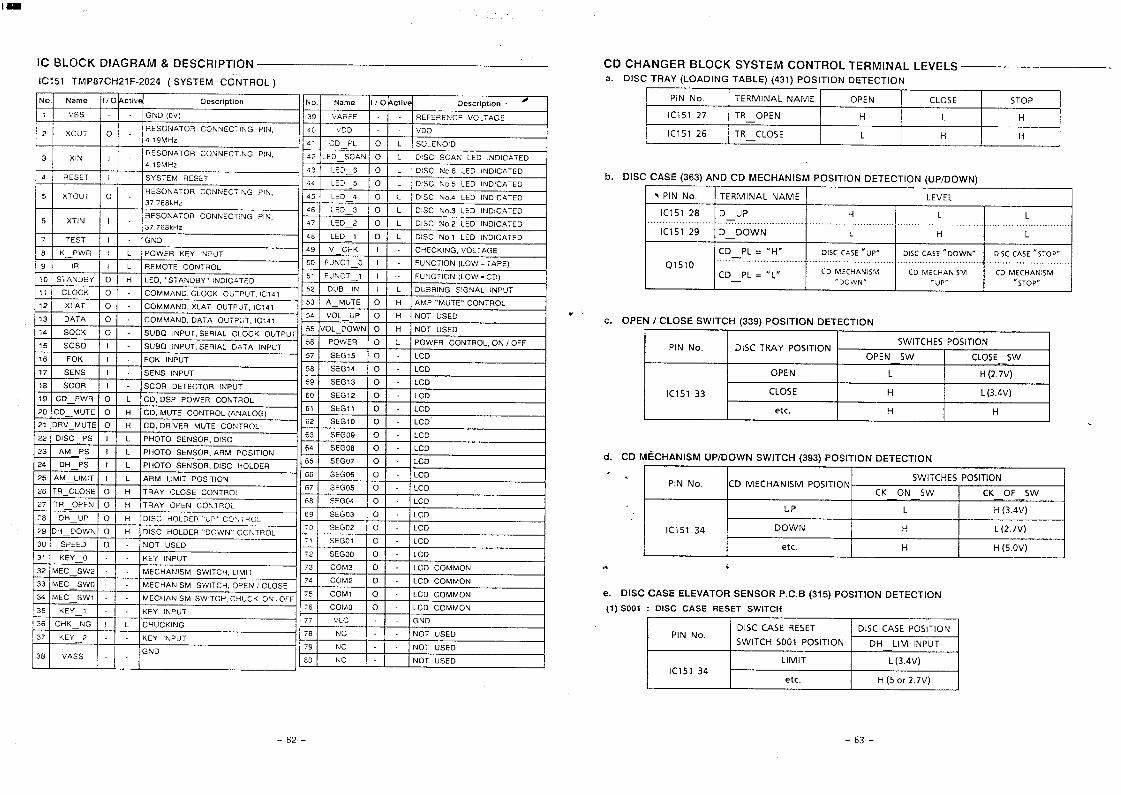
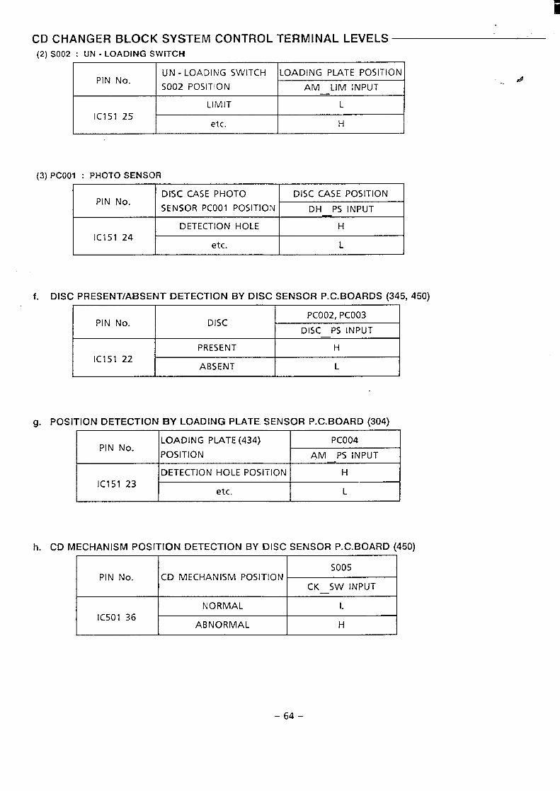
CD CHANGER BLOCK SYSTEM CONTROL TERMINAL LEVELS(2)
(3)
SO02 : UN- LOADIFJG SWITCH
UN-LOADING SWITCHPIN No.
LOADING PLATE POSITION
S002 POSITION AM LIM INPUT—
LIMIT L
IC151 25etc. H
Pcool : PHOTO SENSOR
DISC CASE PHOTOPIN No.
DISC CASE POSITION
SENSOR PCOO1 POSITION DH PS INPUT
DETECTION HOLE H
IC151 24etc. L
f. DISC PRESENT/ABSENT DETECTION BY DISC SENSOR P. C. BOARDS (345, 450)
PIN No.PCO02, PCO03
DISCDISC PS INPUT—
PRESENT H
IC151 22ABSENT L
g. POSITION DETECTION BY LOADING PLATE SENSOR P. C. BOARD (304)
LOADING PLATE (434}PIN No.
PCO04
POSITION ARA PS INPUT—
DETECTION HOLE POSITION H
IC151 23etc. L
h. CD MECHANISM POSITION DETECTION BY DISC SENSOR P. C. BOARD (450)
##
SO05PIN hlo. CD MECHANISM POSITION
CK SW INPUT—
NORMAL LIC501 36
ABNORMAL H
-64-
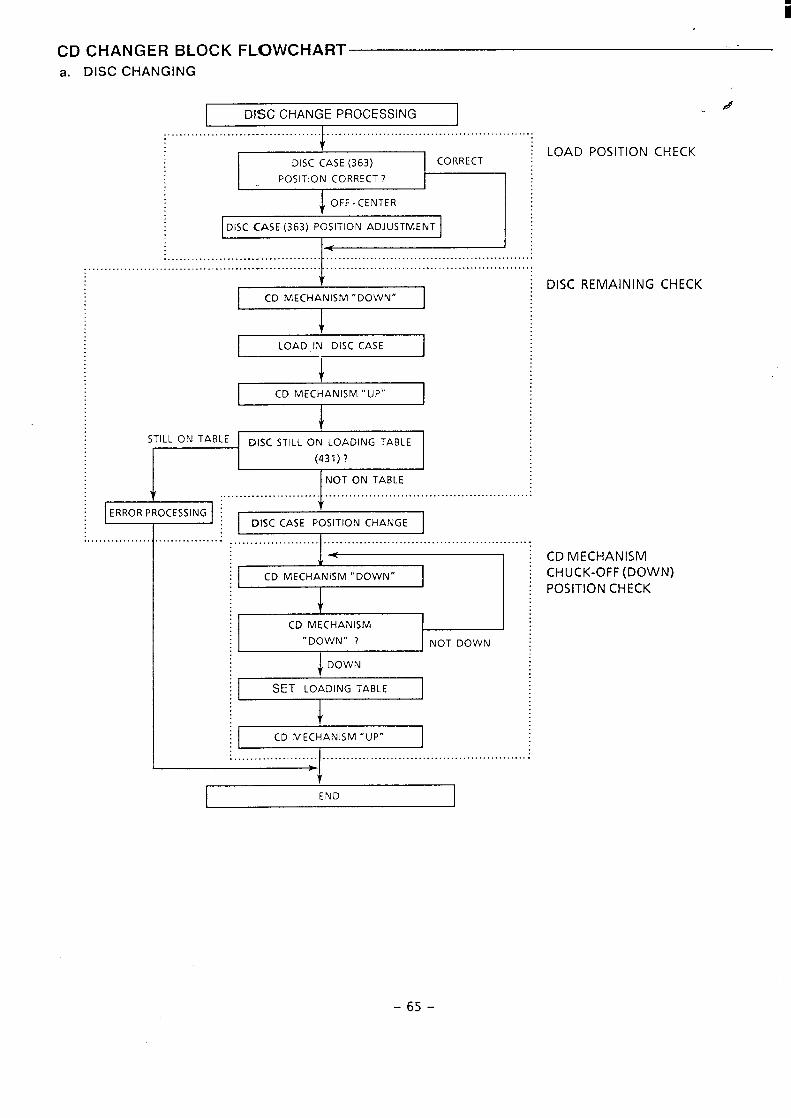
FLOWCHARTCD CHANGER BLOCKa. DISC CHANGING
IX3C CHANGE PROCESSINGd
t : LOAD POSITION CHECKDISC CASE (363) CORRECT
POSITION CORRECT ?
:CLJ 1DISC CASE (363) POSITION ADJUSTMENT
....................... .. ........... L. . . . . . . . . . . . . . . . . . . . . . . . . . . . . . . . . . . . . . . . . . . . . . . . . . . .. ........ .
: DISC REMAINING CHECK
LOAD IN DISC CASEI
I
CD MECHANISM “UP”
It
STILL ON TABLEI DISC STILL ON LOADING TABLE
I ..5%!K!........................
I ERROR PROCESSING IDISC CASE POSITION CHANGE
... .. . . . . . . . . . . . . . . . . . . . . . . . . . . . . . . . . . . . . . . . .
I
. . . . . . . . . . . . . . ...... . ... ......... . .
~1-~CD MECHANISM “UP”
. . . . . . . . . . . . . . . . . . . . . . . . . . . . . . . . . . . . . . . . . . . . . . . . . . . . . . . . . . . .
END
-65-
ii
. .
CDb.
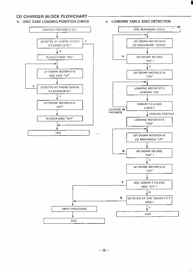
CHANGER BLOCK FLOWCHARTDISC CASE LOADING POSITION CHECK c. LOADING TABLE DISC DETECTION
LOADING POSITION CHECK
I 1-DETECTED BY PHOTO SENSOR Y
P.C.BOARD (315) ?
iN
I PLUNGE R(395) ‘ON” 1
+UP I DOWN MOTOR (414)
I DISC CASE “UP”1
+N
IDETECTED BY PHOTO SENSOR I
“OFF” I
I PLUNGER (395) “OFF” I
ENDJ
I DISC REMAINING CHECK -1
>
-1NJ UP/DOWN SW(393)“ON$’ ?
tY
UP I DOWN MOTOR (414),,OFF/,
I
vLOADING MOTOR (377) 1
1LOADING “ON”
I
I1
SENSOR P.C.B (304) II
LOADING WCHECK ?
IPROGRESS
LOADING POSITION
I LOADING MOTOR(377) I
I “OFF” I
] UP/DOWN MOTOR(414) I
CD MECHANISM “UP”I
I UP I DOWN MOTOR (414)
“OFF” I
~1 DISC SENSOR P.C.B (450) I
IS005 “ON” ?
I
I
1+1
DETECTED BY DISC SENSOR P.C B
(450) ?
,- I
END
-66-
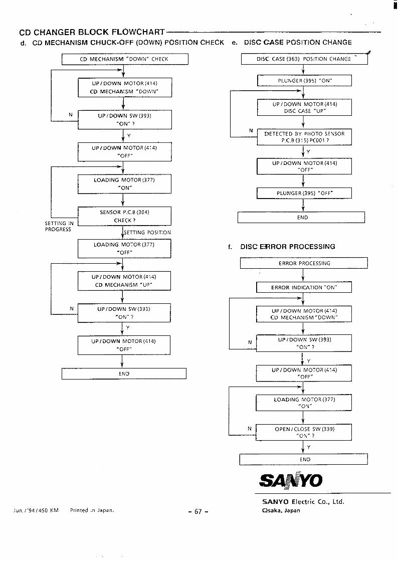
CD CHANGER BLOCK FLOWCHARTd. CD MECHANISM C1-fUCK-oFF (DOWN) POSITION CHECK e. DISC CASE POSITION CHANGE
CD MECHANISM “DOWN” CHECK DISC CASE (363) POSITION CHANGE -
*
UP/ DOWN MOTOR (41 4) PLUNGER (395) “ON”
CD MECHANISM “DOWN”
+N UP/ DOWN SW (393)
“ON” ?
p+
iY
t 1
Iiv
I DETECTED BY PHOTO SENSORP.C.B (315) PCOO1? I
I I LOADING MOTOR (377)
“ON” It
SENSOR P.C.B (304) IL
SETTING IN ICHECK ?
IPROGRESS
SETTING POSITION
UP i DOWN MOTOR (414)“OFF” I1 1
i
I PLUNGER (395) “OFF” 1
I LOADING MOTOR (377)
“OFF” I f. DISC ERROR PROCESSING
n==~owl, I
ERROR PROCESSING
J
I CD MECHANISM “UP”I
I UP/ DOWN MOTOR (414)
“OFF” I
ERROR INDICATION “ON”1
JfY
I UP/DOWN MOTOR (414)“OFF” I
r=+
N
[
OPEN/CLOSE SW (339)“ON” ?
I END I
I
!sA#wioI
Jun. /’94505O KM Printed in Japan. -67-
SUU’dYO Electric Co., Ltd.
CXaka, Japan
i
Service Manual
CONTENTS
—
#FILE NO. ‘ I
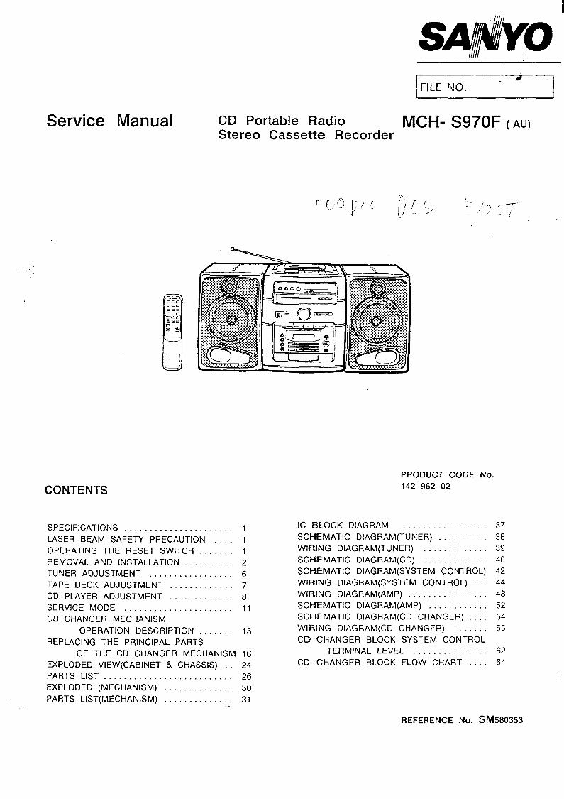
CD Portable Radio MCH- S970F (AU)Stereo Cassette Recorder
SPECIFICATIONS . . . . . . . . . . . . . . . . . . . . . . 1
LASER BEAM SAFETY PRECAUTION . . . . 1
OPERATING THE RESET SWITCH . . . . . . . 1
REMOVAL AND INSTALLATION . . . . . . . . . . 2
TUNER ADJUSTMENT . . . . . . . . . . . . . . . . . 6
TAPE DECK ADJUSTMENT . . . . . . . . . . . . . 7
CD PLAYER ADJUSTMENT . . . . . . . . . . . . . 8
SERVICE MODE . . . . . . . . . . . . . . . . . . . . . . 11
CD CHANGER MECHANISM
OPERATION DESCRIPTION . . . . . . . 13
REPLACING THE PRINCIPAL PARTS
OF THE CD CHANGER MECHANISM 16EXPLODED VIEW(CABINET & CHASSIS) . . 24
PARTS LIST . . . . . . . . . . . . . . . . . . . . . . . . . . 26
EXPLODED (MECHANISM) . . . . . . . . . . . . . . 30
PARTS LIST(MECHANISM) . . . . . . . . . . . . . . 31
PRODUCT CODE NO.
142 962 02
IC BLOCK DIAGRAM . . . . . . . . . . . . . . . . .
SCHEMATIC DIAGRAM(TUNER) . . . . . . . . . .
WIWNG DIAGRAM(TUNER) . . . . . . . . . . . . .
SCHEMATIC DIAGRAM . . . . . . . . . . . . .
SCHEMATIC DIAGRAM(SYSTEM CONTROL)
WIWNG DIAGRAM(SYSTEM CONTROL) . . .
WIFUNGDIAGRAM(AMP) . . . . . . . . . . . . . . . .
SCHEMATIC DIAGRAM(AMP) . . . . . . . . . . . .
SCHEMATIC DIAGRAM(CD CHANGER) . . . .
WIRING DIAGRAM(CD CHANGER) . . . . . . .
CD CHANGER BLOCK SYSTEM CONTROL
TERMINAL LEVEL . . . . . . . . . . . . . . .
CD CHANGER BLOCK FLOW CHART . . . .
37
38
39
40
42
44
48
52
54
55
62
64
REFERENCE No. SM580353
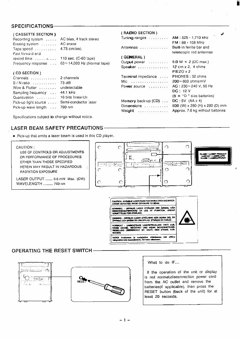
SPECIFICATIONS
( CASSETTE SECTION) ( RAf3K3 SECTION ) #
Recording system . . . . . AC bias, 4 track stereo Tuniq ranges . . . . . . . . . AfW:525-l,710kHz
Erasing system . . . . AC erase FM:88-108 MHZ
Tape speed . . . . . . . . . . 4.75 cmlsec. Antennas . . . . . . . . . . . . . Built-in ferrite bar and
Fast forward and telescopic rod antennas
rewind time . .. . . . . 110 sec. (C-60 tape) ( GEBIERAL )
Frequency response . . . 63-14,000 Hz (Normal tape) Out@ power . . . . . . . . . 6.0 WX2(DC max.)
Speaker . . . . . . . . . . . . . . 12cmx2,40hms
( CD SECTION ) PIEZO X 2
Channels . . . . . . . . . . . . 2 channels Terminal impedance . . . . PHONES :32 ohms
S/ Nratio . . . . . . . . . . . 73dB Mic . . . . . . . . . . . . . . . . . 200-600 ohms/mV
Wow & Flutter . . . . ---- undetectable Povua?r source . . . . . . . . . AC:230-240V,50HZ
Sampling frequency . . . 44.1 kHz DC: 12V
Quantization . . . . . . . . . 16 bits linear/ch (8 x “D “ size batteries)
Pick-up light source . . . . Semi-conductor laser Memory back-up (CD) . . . DC : 6V (AA x 4)
Pick-up wave length . . . 790 nm Dimensions . . . . . . . . . . . 600 (W) x 280 (H) x 280 (D) mm
Weight . . . . . . . . . . . . . . Approx. 7.6 kg without batteries
Specifications subject to change without notice.
LASER BEAM SAFETY PRECAUTIONS
● Pick-up that emits a laser beam is used in this CD player.
CAUTION :
USE OF CONTROLS OR ADJUSTMENTS
OR PERFORMANCE OF PROCEDURES
OTHER THAN THOSE SPECIFIED
HEREIN MAY RESULT IN HAZARDOUS
RADIATION EXPOSURE
LASER OUTPUT ........0.6 mW Max. (CW)
WAVELENGTH ........... i’90 nm
, ~—.. —.......—..—.———.....
‘c,
OPERATING THE RESET SWITCH
What to do IF ....
If the operation of the unit or displayis not normal, disconnection power cord
from the AC outlet and remove the
batteries(if applicable), then press the
RESET button (back of the unit) for at
least 20 seconds.
–l-
REMOVAL AND INSTALLATION
●
●
●
●
●
●
a.
b.
This CD-radio-casselte player employs a changer mechanism as its CD block. -dCare should be exercised when removing and reinstalling it.
All wiring should be returned to the original position after work is completed.
First have ready many the new FIXERS (61 4246 5271) for replacement.
Arrange the lead wires so that they are not near the heat sink.
Remove any discs that are loaded in the CD changer.
Before disassembling the unit, set the POWER switch to the “OFF” position
and wait 10 seconds while the CD chanqer mechanism enters standby status.
Then unplug the unit and beqin the disassembly procedure.
SPEAKER BOX
mm
CABINET
(1) Remove the battery lid.
(2) Remove the 6 rear cabinet mounting SCI
T
P ~~ ;@
d
I
d
h
‘ews.
d. TUNER, EQUALIZER P. C. BOARDS
/
EQ
c. TAPE MECHANISM
b’
wTOP PANEL
—h
PUSH
I
(2P) Ill I
-2-
i
REMOVAL AND INSTALLATION Ae. SYSTEM CONTROL P. C. BCIARD & AMP. /CD P. C. BOARD
. Pull connectors straight out so that the pins do not bend.
f, MOUNTING, POINTER
$?
MC-grease
EM-SOL
I
9. “(l” POINT ADJUSTMENT
-3-
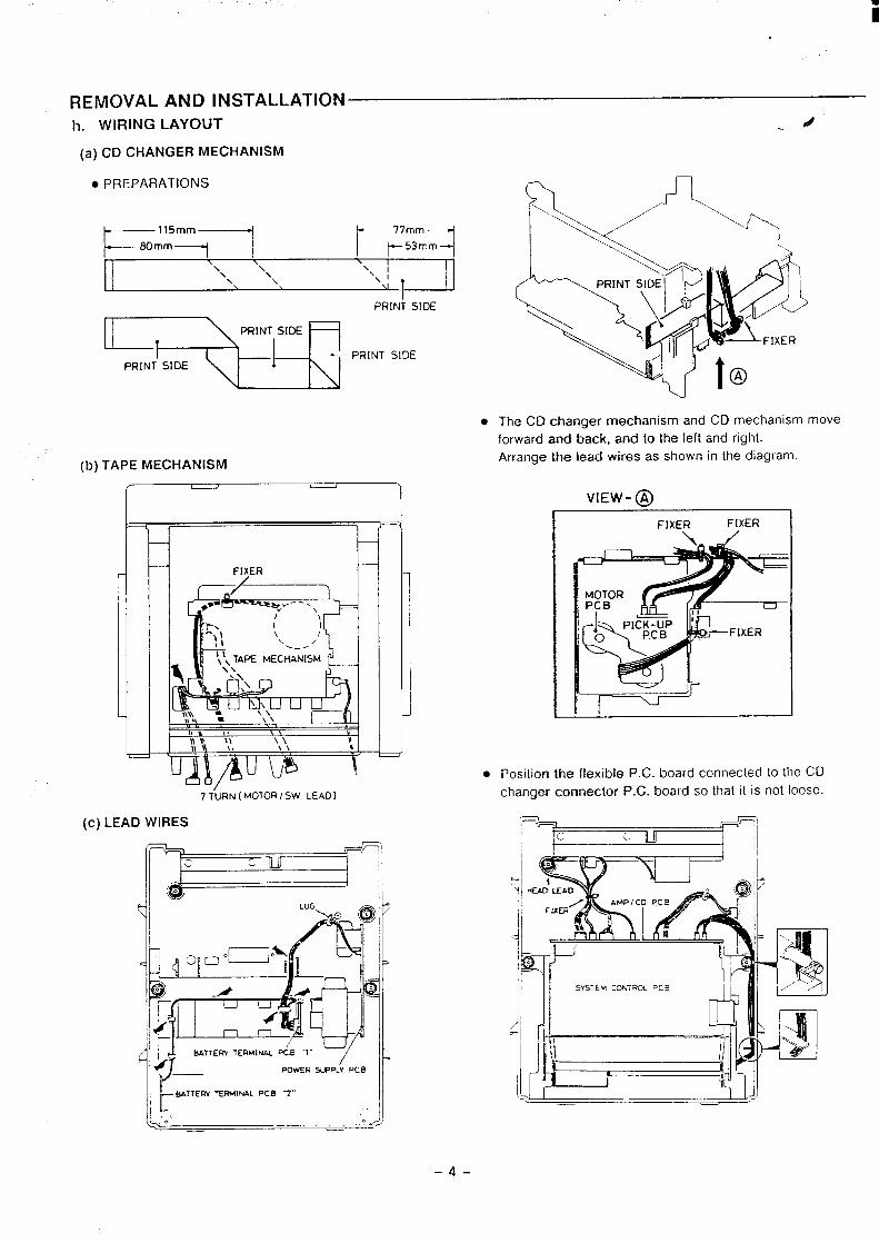
i
REMOVAL AND INSTALLATIONh. WIRING LAYOUT -d
(a) CD CHANGER MECHANISM
● PREPARATIONS
. \ I
[1\\ \ \,\ \\ \ x, I
‘ 1I
PRINi SIDE
--pR’NT”DE
(b) TAPE MECHANISM
● The CD changer mechanism and CD mechanism move
forward and back, and to the left and right.
Arrange the lead wires as shown in the diagtam.
—
—
7 T“URN ( MO1ORI5W LEAD)
(c) LEAD WIRES
~~m:_Lp.B2- _ ,,j,
VIEW-@
FIXERFIXEjl ,
ri-=-i-=-
. Position the flexible P.C. board connected to the CD
changer connector P.C. board so that it is not loose.
~~ ,-. c1, ~
-4-
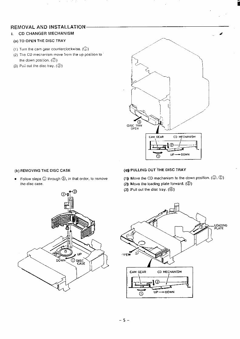
.-
REMOVAL AND INSTALLATIONi. CD CHANGER MECHANISM
(a) TO OPEN THE DISC TRAY
(I) Turn the cam gear counterclockwise. (~)
(2) The CDmechanism move from theup position to
[he down position. (@)
(3) Pull outthe disc tray.(@)
CAM GEAR CD MECHANISM
r~i’
(b) REMOVING THE DISC CASE
. Follow steps ~ through ~, in that order, to remove
the disc case.
T up -DOWN
(q PULLING OUT THE DISC TRAY
(t;}
(2]
(3)
Move the CD mechanism to the down posiiion. (@,@)
lvlove the loading plate forward. (@)
Pull out the disc tray. (@)
la
I IXM GEAR CD MECHANISM I
i-UP —DOWN
-5-
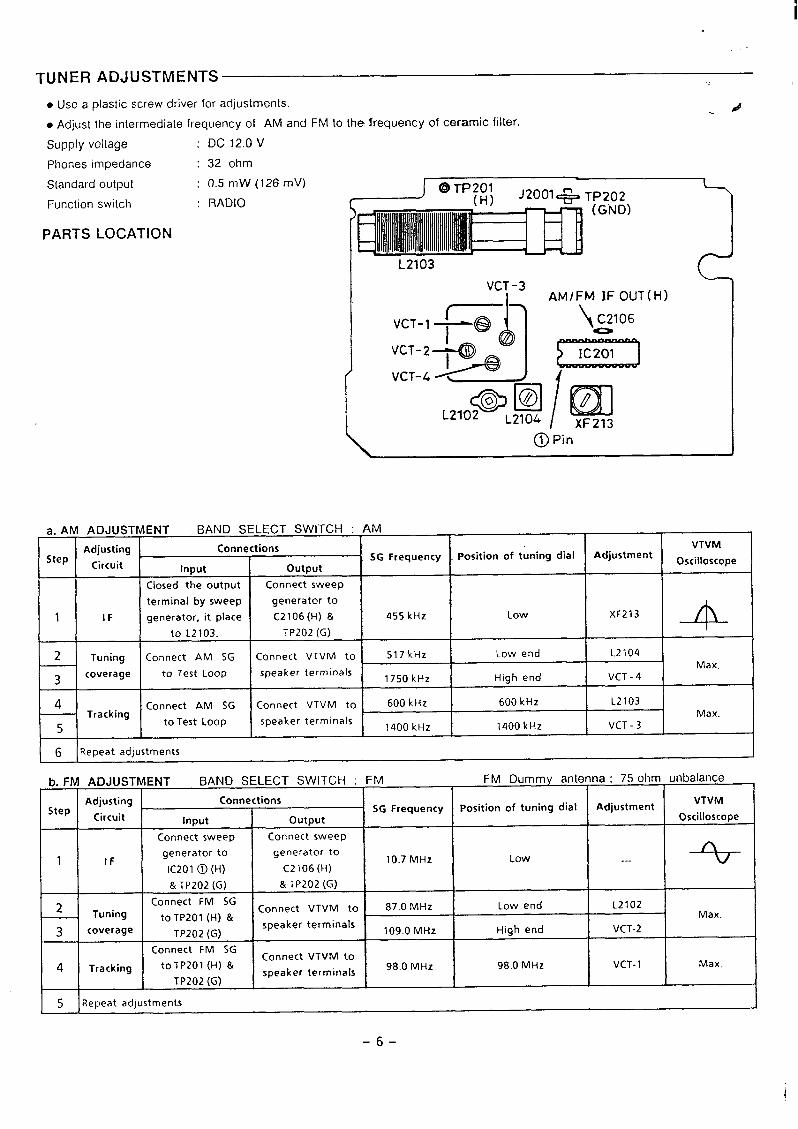
TUNER ADJUSTMENTS
● Use a plastic screw driver for adjustments.A
● Adjust the intermediate frequency of AM and FM to the frequency of ceramic filter.
Supply voltage : DC 12.OV
Phones impedance
Standard output
Function switch
PARTS LOCATION
a. AM ADJUST
-1--Adjusting
StepCircuit
1 I IF
+
2 Tuning
3coverage
3=4Tracking
5
32 ohm
05mW(126mV)
RADIO ~k.--. ~1 ,1 @
L2103
VCT -3AM/FM lF OUT(H)
vcT_l ~
-3 -
\ C2106
T@
:-;-p -
/
,,lo@ I@l ~L2104 XF213
\ @ Pin
ENT BAND SELECT SWITCH : AM (Connections VTVM
SG Frequency Position of tuning dial AdjustmentInput output Oscilloscope
Closed the output Connect sweep
terminal by sweep generator to
generator, it place C2106 (H) & 455 kHz Low XF213
to L2103. TP202 (G) 4 -I t
Connect AM SG Connect VTVM to 517kHz Low end L2104
to Test Loop speaker terminalsMax.
1750k Hz High end VCT -4
Connect AM SG Connect VTVM to 600 kHz 600 kHz L2103Max.to Test Loop speaker terminals
i 1400 kHz 1400 kHz VCT -3
(j Repeat adjustments
b. FM ADJUSTMENT BAND SELECT SWITCH : FM FM Dummy antenna : 75 ohm unbalancef
Adjusting ConnectionsStep SG Frequency position of tuning dial Adjustment
VTVM
Circuit Input output Oscilloscope
Connect sweep Connect sweepn
1 IFgenerator to generator to
10.7 MHz LowIC201 @ (H) C2106 (H)
---
& TP202 (G) & TP202 (G) i
2 Connect FM SGTuning Connect VTVM to 87.0 MHz Low end L2102
to TP201 (H) & Max.
3 coverage speaker terminalsTP202 (G) i 109.0 MHz High end VCT-2
Connect FM SG
4Connect VTVM to
Tracking to TP201 (H) & 98.0 MHz 98.0 MHz VCT-1 Max.speaker terminals
TP202 (G)
5 Repeat adjustments)
-6-
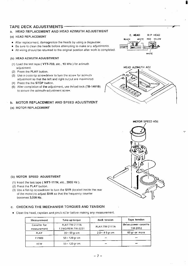
ii
TAPE DECK ADJUSTMENTS ua. HEAD REPLACEMENTA NDHEADA ZIMUTHADJUSTMENT
(a) HEAD REPLACEMENT
. Af[er replacement, demagnetize the heads by using a degausser.
. Be sure to clean [he heads be[ote attempting to make any adjustments.
. All wiring should be returned to the original posilion after work is completed
E. HEAD RIP HEAD
BLACK wHITE RED YELLOW
**
*
I/WHiTE
(b) HEAD AZIMUTH ADJUSTMENT
(1)HEAD AZIMUTH ADJ
(2)
(3)
(4)
(5)
b.
(a)
Load the test tape ( VTT-703, etc., 10 kHz ) for azimuth
adjustment.
Press the PLAY button.
Use a cross-tip screwdriver to turn the screw for azimuth .
/
adjustment so that the left and right output are maximized.
Press the the STOP button.
Arler completion of the adjustment, use thread lock (TB-1401 B)
to secure the azimuth-adjustment screw.
<<*3
MOTOR REPLACEMENT AND SPEED ADJUSTMENT \y/
MOTOR REPLACEMENT
MOTOR SPEED ADJ/
—
(b) MOTOR SPEED ADJUSTMENT
(1) Insert the test tape ( MIT-ill N, etc., 3000 Hz ).
(2) Press the PLAY button.
(3) Use a flat-tip screwdriver to turn the SVR (located inside the rear
of the motor) to adjust SVR so that the frequency counter
becomes 3,000 Hz.
c.
●
CHECKING THE MECHANISM TORQUES AND TENSION
Clean the head, caps!an and pinch roller before making any measurement.
Measurement Take-up torque Back tension Tape tension
Cassette for PLAY: TW-21 11A Drive-power cassettePLAY: TW-21 11A
measurement F. FWD/REW:TW-2231 TW-2412
PLAY 30-60 gr.cm 2.O-4.5 gr.cm 60 gr or more
F.FWD 55- 120gr cm
REW 55- 120gr cm
-7-
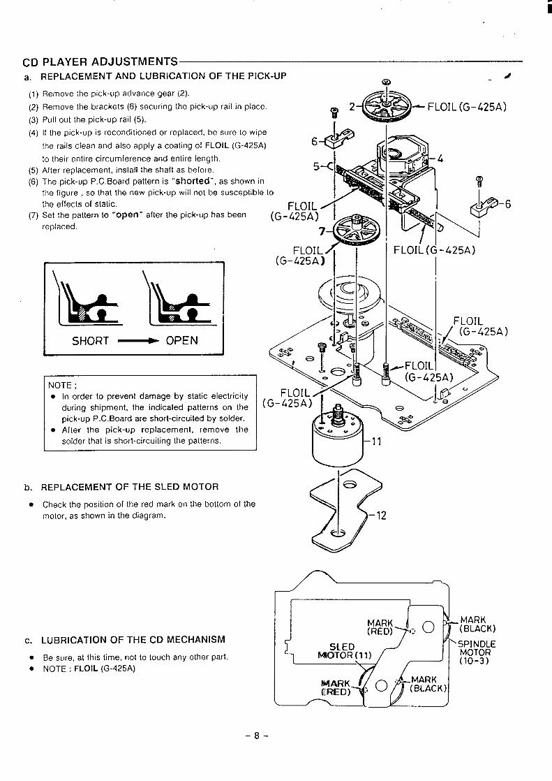
i
CD PLAYER ADJUSTMENTSa. REPLACEMENT AND LUBRICATION OF THE PICK-UP
Q-#
(1)
(2)
(3)
(4)
(5)
(6)
(7)
Remove Ihe pick-up advance gear (2).
Remove the brackets (6) securing the pick-up rail in place.V* *
— FLOIL (G-425A)Pull out the pick-up rail (5). 1
If the pick-up is reconditioned or replaced, be sure [o wipe
the rails clean and also apply a coaling of FLOIL (G-425A)
10 their entire circumference and enlire length.
After replacement, inslall the shaft as before.
The pick-up P.C. Board pattern is “shorted”, as shown in
the figure , so that the new pick-up will not be susceptible to
Ihe effects of static. FLOISet the pattern to “Open” after the pick-up has been (G-425A) Ireplaced.
P
“a7 w~~
FLOIL ~ I
1 (G-425A) ~ I\
SHORT ~ OPEN
NOTE ;
● In order to prevent damage by static electricity
during shipment, the indicated patterns on the
pick-up P.C. Board are short-circuited by solder.
● After the pick-up replacement, remove the
solder that is short-circuiting the patterns.
b. REPLACEMENT OF THE SLED MOTOR
● Check the position of the red mark on the bottom of the
motor, as shown in the diagram.
c. LUBRICATION OF THE CD MECHANISM
. Be sure, at this time, not to touch any oiher part.
● NOTE : FLOIL (G-425A)
-6
FLOIi_(G-425A)
~ “432,
~FLOIL
(
/10
-8-
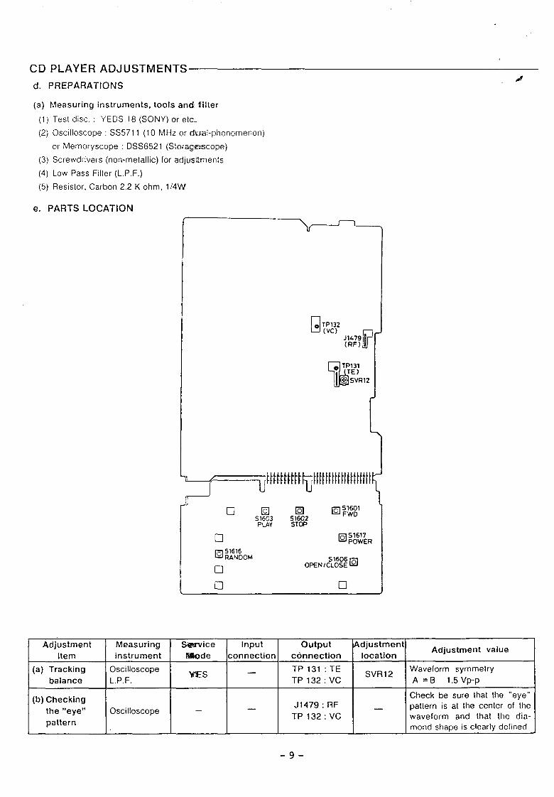
CD PLAYER ADJUSTMENTS
d. PREPARATIONS
(a) Measuring instruments, tools and%ilter
(1) Test disc.: YEDS 18( SONY) ore[c.
(2) Oscilloscope: SS5711 (l OMHzorc#ual-phenornenon)
or Memory scope : DSS6521 (StoragEscope)
(3) Screwdrivers (non-metallic) for adjustments
(4) Low Pass Filter (L. P. F.)
(5) Resistor, Carbon 2.2 K ohm, 1/4kV
e. PARTS LOCATION
n
❑ ❑
Adjustment Measuring Service Input output Adjustment
Item instrument IWode connectionAdjustment value
connection location
(a) Tracking Oscilloscope=s
TP 131 :TE— SVR12Waveform symmetry
balance L.P.F. TP132:VC A =B 1.5 Vp-P
(b) Checking Check be sure that the “eye”J1479 : RF _
the “eye” Oscilloscope –— pa[lern is at Ihe center of [he
TP132:VCpattern
waveform and that the dia-mond shape is clearly defined
-9-
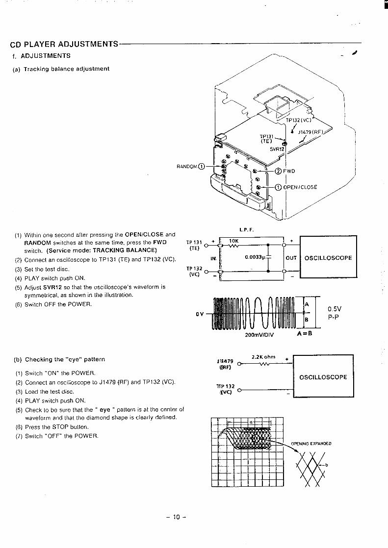
ii
CD PLAYER ADJUSTMENTS
f. ADJUSTMENTS
(a) Tracking balance adjustment
A-”,...”
Y* ‘&\.L’-&,”,)
f’a J1479(RF)
TP131(TE) ‘m /
‘\ SVR12‘ ‘/
~ /
~ -$RANDOM @ —
(a-@FwD\<< &3
N
‘1‘. (a— ~ ~pEN I cLosE
‘\‘4+..
\‘--&G”
L.P. F.(1) Within one second afler pressing the OPEN/CLOSE and
RANDOM switches at Ihe same time, press the FWD
switch. (Service mode: TRACKING BALANCE)
(2) Connect anoscilloscope to TP131 (TE)and TP132(VC).
(3)
(4)
(5)
(6)
Set the test disc.
PLAY switch push ON.
Adjust SVRI 2 so that the oscilloscope’s waveform is
symmetrical, as shown in the illustration.
Switch OFF the POWER.
(b)
(1)
(2)
(3)
(4)
(5)
(6)
(7)
Checking the “eye” pattern
Switch “ON” the POWER.
Connect an oscilloscope to J1 479 (RF) and TP132 (VC).
Load the test disc.
PLAY switch push ON.
Check 10 be sure that the “ eye “ pattern is at the center
waveform and that the diamond shape is clearly defined.
Press the STOP button.
Switch “OFF”’ the POWER.
0.5VOv P-P
200mVlDlV A=B
2.2K ohm +Jm479@F)
o w
I OSCILLOSCOPE I
7TP 132iwfc) o
of
-1o-
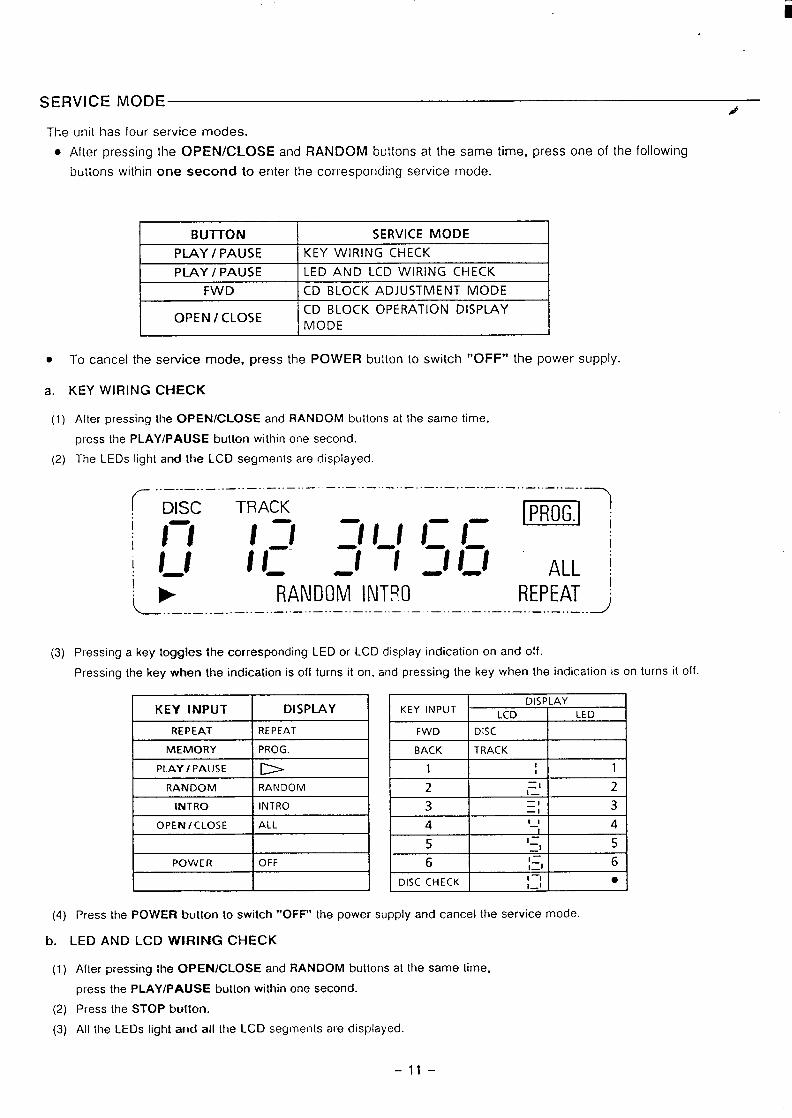
i
SERVICE MODE,#
The unit has four service modes.
. After pressing the OPEN/CLOSE and RANDOM buttons at the same time, press one of the following
buttons within one second to enter the corresponding service mode.
BUTTON SERVICE MODE
PLAY I PAUSE KEY WIRING CHECK
I PLAY I PAUSE I LED AND LCD WIRING CHECK I1
t FWD t CD BLOCK ADJUSTMENT MODE
OPEN/CLOSECD BLOCK OPERATION DISPLAYMODE
. To cancel the service mode, press the POWER button to switch “OFF” the power supply.
a. KEY WIRING CHECK
(1) After pressing [he OPEN/CLOSE and RANDOM buttons at the same time,
press the PLAY/PAUSE button within one second.
(2) The LEDs light and the LCD segments are displayed.
~ .. —.. —.. —..—-. —..—.. —..—.. —-.—.. —..—..—..—-. —--—.. —--—.. —--—.-—.-
! Disc TRACK1- - m!I II I_l :1I_/1:/: I
I // 1 If _/l ///:- -- ALL 1RANDOM INTRO REPEAT ~
L ... ... ... ... ... ... ... ... ... ... ... ... ... ... ... ... ... ... ... ... ... ..J
(3) Pressing a key toggles the corresponding LED or LCD display indication on and off.
Pressing the key when the indication is off turns it on, and pressing the key when the indication is on turns it off.
I KEY INPUT I DISPLAY I
REPEAT REPEAT
MEMORY I PROG. IPLAY I PAUSE b
RANDOM RANDOM
I INTRO I INTRO I
OPEN/CLOSE I ALL
I
I POWER OFF
I
I BACU
t--z-H-I=
5
6
DISC CHECK
=
DISPLAYLCD LED
DISC
TRACK1 1
I—
l—_’ 2
=
=1—1 311— 4l—=1 5cl_l 61—1 ●#_l
(4) Press the POWER button to switch “OFF” the power supply and cancel the service mode.
b. LED AND LCD WIRING CHECK
(1)
(2)
(3)
A(ter pressing the OPEN/CLOSE and RANDOM buttons at the same time,
press the PLAY/PAUSE button within one second.
Press the STOP button.
All the LEDs light and all the LCD segments are displayed.
-11–
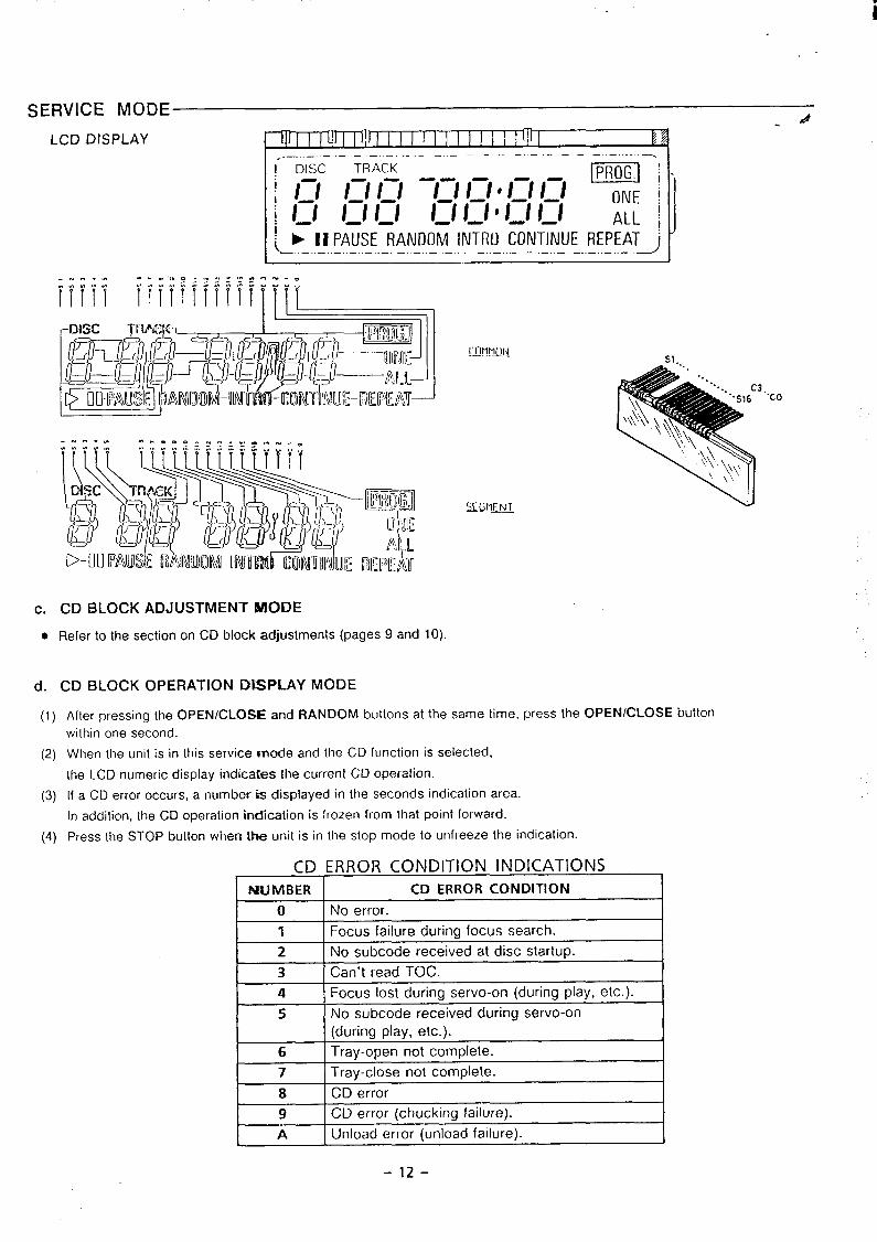
i
SERVICE MODE -#
LCD DISPLAY ~llJlll UJllllJ lllllllllllli[l]l q,.—. — —.. .. . . -—— ——— ——— —.-----
1 DISC TRACK m-i‘!n 1:1n -1:11:1‘1:/n ONE /i /-/ 1 / I-1 l_l I_/ ‘ I_/ 1:1 ALL jK--~..-. !A!!:E.}E.}.!N!!M_ INTRO CONT’INUEREPEAT~
I—..—..——..—.—..—.,_..—..—
I 1
[’OMMIIN.—. .— - S1.
3.“co
c.
●
d.
CD BLOCK ADJUSTMENT MODE
Refer to the section on CD block adjustments (pages 9 and 10)
CD BLOCK OPERATION DkSPLAY MODE
(1) After pressing the OPEN/CLOSE and RANDOM buttons at the same time, press the OPEN/CLOSE buttonwilhin one second.
(2) When the unit is in this service mode and the CD function is selected,
the LCD numeric display indicates the current CD operation.
(3) If a CD error occurs, a number is displayed in the seconds indication area.
In addition, the CD operation indication is frozen from [hat point forward.
(4) Press the STOP bui[on when the unit is in the stop mode to unfreeze the indication.
CD ERROR CONDITION INDICATIONS 1NUMBER CD ERROR CONDITION
o No error.
1 Focus failure during focus search.
2 No subcode received at disc startup.
3 Can’t read TOC.
4 Focus lost during servo-on (during play, etc.).
5 No subcode received during servo-on
(during play, etc.).
6 Tray-open not complete.
7 Tray-close not complete.
8 CD error
9 CD error (chucking failure).
A Unload error (unload failure).
-12-
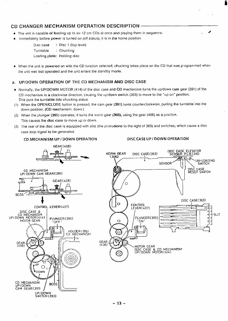
iii
CD CHANGER MECHANISM OPERATION DESCRIPTION
● The unit is capable of toading LIP [o six 12 cm CDs al once and playing [hem in sequence. d
● Immediately before power is Iurned on (off status), it is in the home position.
Disc case : Disc 1 (top level)
Turntable : Chucking
Loading plate: Holding disc
. When the unit is powered on with the CD function selected, chucking takes place on the CD that was programmed when
the unit was last operated and the unit enters the standby mode.
a. UP/DOWN OPERATION OF THE CD MECHANISM AND DISC CASE
● Normally, the UP/DOWN MOTOR (414) of the disc case and CD mechanism turns the up/down cam gear (391) of the
CD mechanism in a clockwise direction, causing the up/down switch (393) to move to the “up on” position.
This puts the turntable into chucking status.
(1)
(2)
(3)
UPI
When the OPEfWCLOSE button is pressed, the cam gear (391) turns counterclockwise, putting the turntable into the
down position. (CD mechanism: down.)
When the plunger (395) operates, it turns the worm gear (366), using the gear (408) as a junction.
This causes the disc case to move up or down.
The rear of the disc case is equipped with slits (the protrusions to the right of 363) and switches, which cause a disc
case stop signal to be generated.
CD MECHANISM UP/ DOWN OPERATION DISC CASE UP/ DOWN OPERATION
GEAR ( 408)
CD MECHANISMUP/ DOW,N CAM GEAF?(391 )
G&&GEAR ( 408)
BOSSI
t-CC)NTROL LEVER (407)
DISC CASE &CD MECHANISM
I DO~oT~~T~~~;l & ) p~”NGER(395). “’OFF”
—
WO~~6~ARDISC ~SE ELEVATOR
DISC CASE(363)~1————
SENSOR P.CB (315).
%~~ IJN-I OADING;HY SENSOR’
uJ\
-----SWITC
/— — DISC CASE
/(1 \ DISC CASE( 363)
.!T
GEAR(408)
–13-
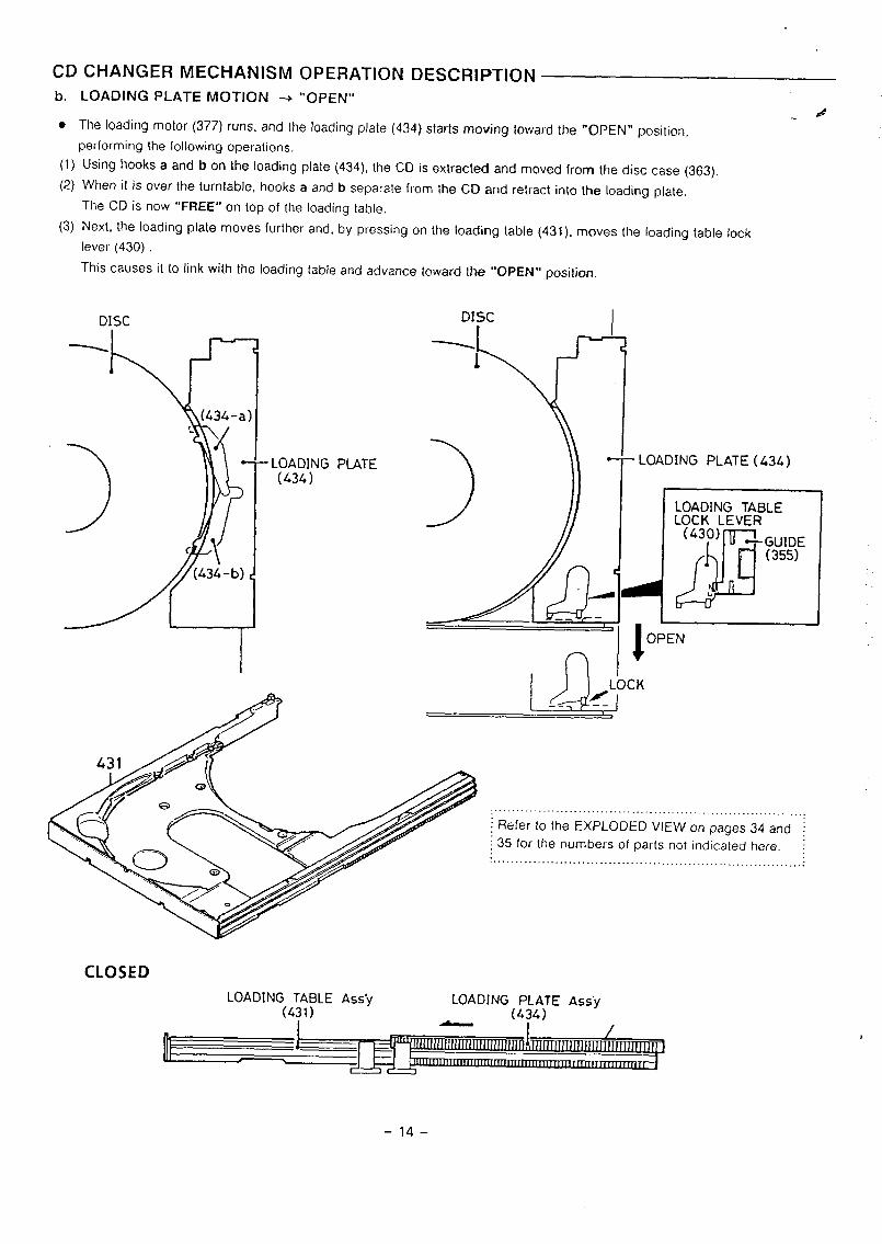
CD CHANGER MECHANISM
b. LOADING PLATE MOTION +
OPERATION DESCRIPTION
“OPEN”.4
● The loading mo[or (377) runs, and the loading plate (434) starts moving toward the *’OPEN” position,
performing the following operations.
(1)
(2)
(3)
Using hooks a and b on the loading plate (434), the CD is extracted and moved from the disc case (363).
When it is over the turntable, hooks a and b separate from the CD and retract into the loading plate.
The CD is now “FREE” on top of the loading table.
Next, the loading plate moves further and, by pressing on the loading table (431), moves the loading table lock
lever (430)
This causes it to link with the loading table and advance toward the “OPEN” position.
DISC
- LOADING PLATE(434)
DISC
CLOSED
n
● - LOADING PLATE (434)
4M ~LOADING TABLEL~;~O}EVER
GUIDE(355)
&
1’I
OPEN
.. . ... .. ......... ... ...... .. ..... ... ... ........... ... ..... ,,, ..j Refer to the EXPLODED VIEW on pages 34 and ~
~35 for the numbers of parts not indicated here. ~.. . . . . . . . . . . . . . . . . . . . . . . . . . . . . . . . . . . . . . . . . . . . . . . . . . . . . . . . . . . . . . . .:
-14–
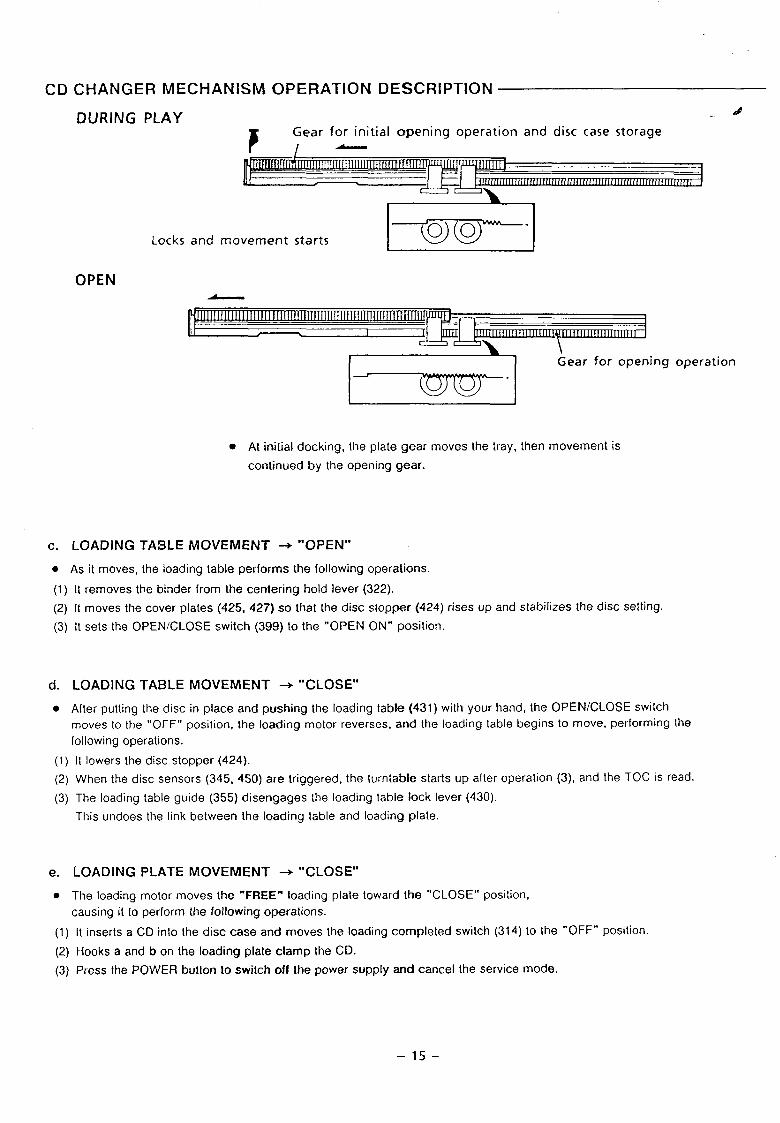
CD CHANGER MECHANISM OPERATION DESCRIPTION
DURING PLAYd-.
Locks and movement startsE
OPEN/
Gear for opening operation
~-
. At initial docking, the plate gear moves the tray, then movement is
corr[inued by the opening gear.
c. LOADING TA3LE MOVEMENT + ‘*OPEN”
. As it moves, the loading table performs the following operations.
(1) It removes the binder from the centering hold lever (322).
(2) It moves the cover plates (425, 427) so that the disc stopper (424) rises up and stabilizes the disc selting.
(3) It sets the OPEN/CLOSE switch (399) to the “OPEN ON” position.
d. LOADING TABLE MOVEMENT + “CLOSE’”
● After putting the disc in place and pushing the loading table (431) with your hand, the OPEN/CLOSE switch
moves to the “OFF” position, the loading motor reverses, and the loading table begins to move, performing Ihe
following operations.
(1) It lowers the disc stopper (424).
(2) When the disc sensors (345, 450) are triggered, the turntable starts up after operation (3), and the TOC is read.
(3) The loading table guide (355) disengages the loading table lock lever (430).
This undoes the link between the loading table and loading plate.
e. LOADING PLATE MOVEMENT + “CLOSE”
. The loading motor moves the ““FREE””loading plate toward the “CLOSE” position,
causing it to perform the following operations.
(1) It inserts a CD into the disc case and moves the loading completed switch (314) to the “OFF” posiiion.
(2) Hooks a and bon the loading plate clamp the CD.
(3) Press the POWE13 button to switch off the power supply and cancel the service mode.
–15-
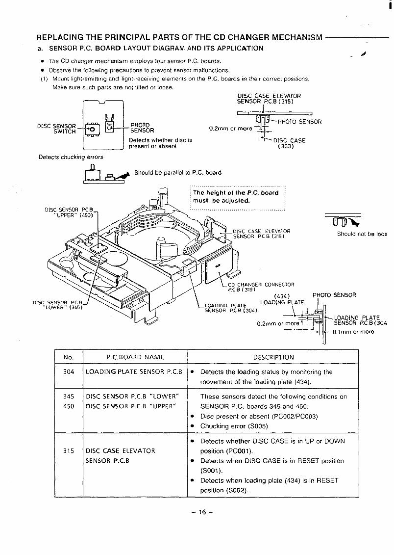
RE
a.
●
●
(1
?LACING THE pR~NclpAL PARTS OF THE CD cj+~Nf_JER
SENSOR P.C. BOARD LAYOUT DIAGRAM AND ITS APPLICATION
The CD changer mechanism employs four sensor P.C. boards.
Observe the following precautions to prevent sensor malfunctions.
. .
MECHANISM
.A4
Mount light-emitting and light-receiving elements on the P.C. boards M their correct positions.
Make sure such parts are not tilted or loose.DISC CASE ELEVATORSENSOR ,PC.B (315)
I ! 1
T!!?!!JDISC ~EW~;~fi ~ PHOTO
T
-1 ~PHOTO SENSOR
SENSOR 0.2mm or mOre
Detects whether disc is % D~3;3~ASEpresent or absent
Detects chucking errors
J5_E@‘hou’dbepara’’e’to’chard1 1
. . . . . . . . . . . . . . . . . . . . . . . . . . . . . . . . . . . . . . . . . . . . . . . .
-!ijij:; The height of the P.C. board ;
I must be adjusted.. ... . . . . . . . .. . . . . . . . . . . . . . . . . . . . . . . . . . . . . . . . . . . .
No.
304
345
450
ER CONNECTOR
(434) PHOTO SENSOR
DISC
&
LOADING PLATE..
) \f-
-fI rLOADING PLATE().2mm or more SENSOR I?C.B (304
315
nnmShould not be loos
+~II O.lmm or more
u
P.C. BOARD NAME DESCRIPTION
LOADING PLATE SEN50R P.C. B . Detects the loading status by monitoring the
movement of the loading plate (434).
DISC SENSOR P.C. B “LOWER” These sensors detect the following conditions on
DISC SENSOR P.C. B “UPPER” SENSOR P.C. boards 345 and 450.
. Disc present or absent (PCO02/PCO03)
● Chucking error (S005)
● Detects whether DISC CASE is in UP or DOWN
DISC CASE ELEVATOR position (PCOO1 ).
SENSOR P.C.B ● Detects when DISC CASE is in RESET position
(s001).
. Detects when loading plate (434) is in RESET
position (S002).
-16-
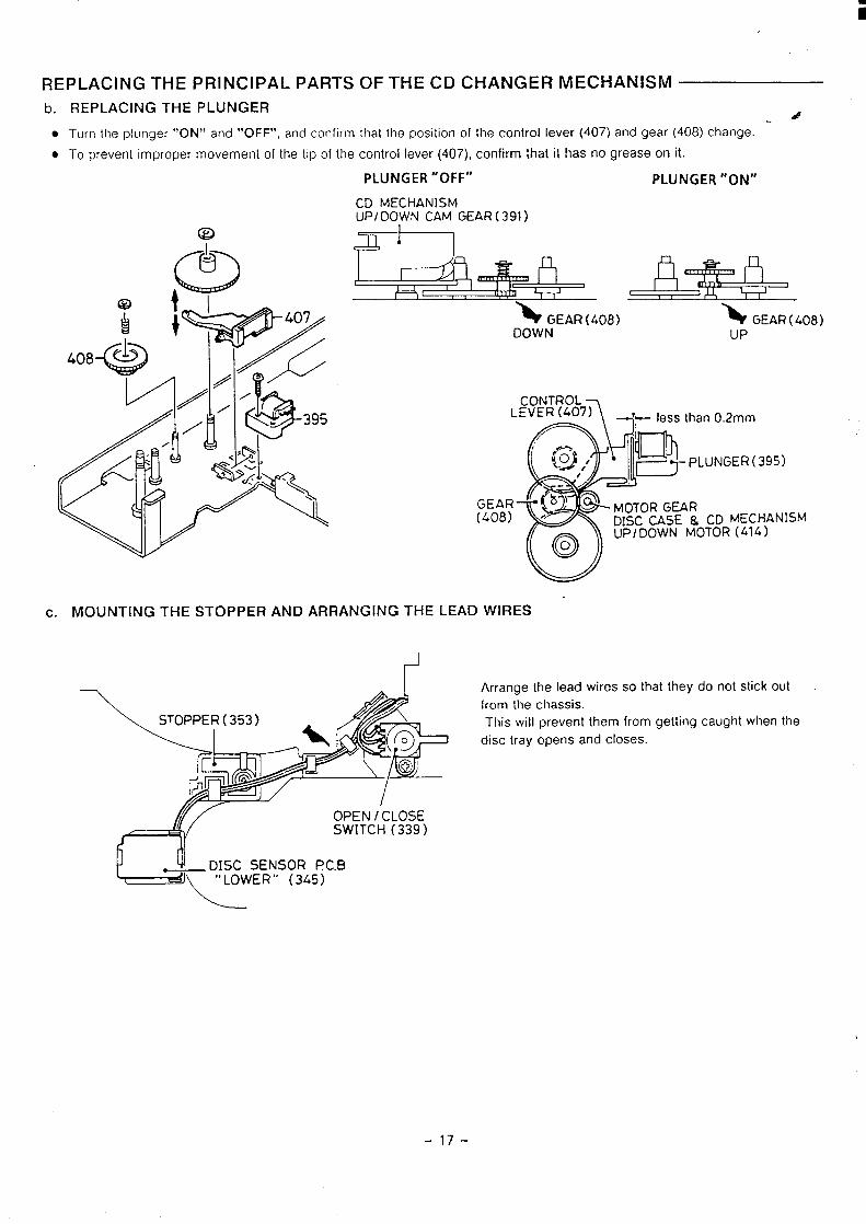
i
REPLAC NG THE PRINCIPAL PARTS OF THE CD CHANGER MECHANISM
b. REPLACING THE PLUNGER &
. TUH7 the plL]nger “ON” and “OFF”, and confirm that the position of the control lever (407) and gear (408) change.
● To prevent improper movement of the lip of the control lever (407), confirm that it has no grease on it.
PLUNGER “OFF” PLUNGER “ON”
CD MECHANISMUP I DOWN CAM GEAR ( 391 )
=+--l
% GEAR (408) N GEAR ( 408)DOWN UP
c. MOUNTING THE STOPPER AND ARRANGING THE
1’
~-------
LE
#--‘;wn II- 1essthan02mm
UNGER(395)
GEAR(408) Cf) MECHANISM
TOR (414)
uLEAD WIRES “
Arrange the lead wires so that they do not stick out
from the chassis.
This will prevent them from getting caught when the
disc tray opens and closes.
d[OPEN / CLOSESWITCH (339)
DISC SENSOR I?C.B
<
— “ LOWER “ ( 345)
-17-
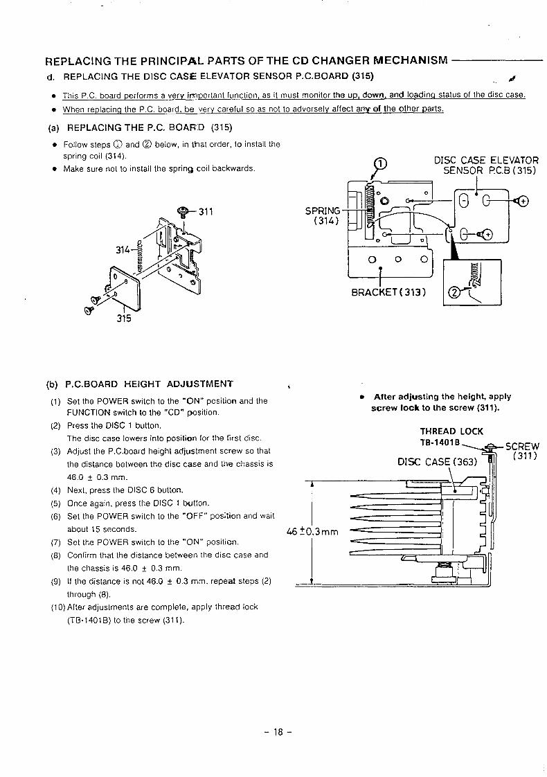
REPLACING THE PRINCIPAL PARTS OF THE CD CHANGER MECHANISMd. REPLACING THE DISC CA9E ELEVATOR SENSOR P. C. BOARD (315) 4..
● This PC. board performs a very ir?nportant function, as it must monitor the up, down, and loading status of the disc case.
● When replacinq the P.C. board, be very careful so as not to adversely affect any of the other parts.
(a) REPLACING THE P.C. BOARD (315)
●
●
(b)
(1)
(2)
(3)
(4)
(5)
(6)
(7)
(8)
(9)
Follow steps @ and @ below, in that order, to install the
spring coil (314).
P
1 DISC CASE ELEVATORMake sure not to install the spring coil backwards. SENSO~ I?C.B (315)
——
P. C. BOARD HEIGHT ADJUSTMENT
Set the POWER switch to the ‘“ON” position and the
FUNCTION switch to the “CD” position.
Press the DISC 1 button.
The disc case lowers into position for the first disc.
Adjust the P.C.board height adjustment screw so that
the distance between the disc case and the chassis is
46.0 ~ 0.3 mm.
Next, press the DISC 6 button.
Once again, press the DISC 1 button.
Se[ the POWER switch to the “OFF” position and wail
about 15 seconds.
Set the POWER switch to the “ON” position.
Confirm that the distance between the disc case and
the chassis is 46.0 t 0.3 mm.
If the distance is not 46.0 t 0.3 mm, repeat steps (2)
SPRING(314)
000
LI
BRACKET ( 313)
i* After adjusting the height, apply
screw lock to the screw (311).
THREAD LOCKTB-1401B
T
SCREW
DISC CAS{ (363)(311)
through (8).
(1O)After adjustments are complete, apply thread lock
(TB-1401 B) to the screw (31 1).
-18-
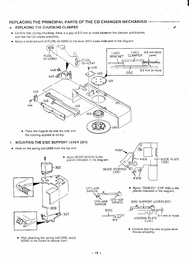
REPLACING THE PRINCIPAL PARTS OF THE CD CHANGER MECHANISM
e.
●
●
f.
●
REPLACING THE CHUCKING CLAMPER ..
Confirm that, during chucking, there is a gap of 0.5 mm or more belween the clamper and bracket,
and [hal the CD rotales smoothly.
Apply a small amount of FLOIL (G-425A) to the lever (447) areas indicated in the diagram.
T
7°FLOIL(G-L25A)
r
.::p
\.
‘z
9( 452) (.451 ) O 5 mm-thick
BRACKET CLAMPER panel
FLGIL L--n
&(G-425A) —
/
Tm*449
1 .I 0.5 mm or more
$ Q-45.* DISC
\& >~~sl
&&$!: &\
o Place the mawret so that the side Wilh L-”.the coloring applied is on top.
MOUNTING THE DISC SUPPORT LEVER (307)fo
4
Hook on the spring coil (306) from the top end.
4.fl
PUSH m>
Apply BOND (#1616) to the n~
places indicated in the diagram. -— *1616 :;IJ;; PLATE
@oo
GUIDE :~2~PER “y
- ~Mq T
B ~
‘0*
e#1616
1,-- \ -#>@
CFD-409
/1SANCOO p+
~.
\:;DN-::: c;:;;::
DISC
--%RF
●
—
Apply “SANCOL*’ (CDF-409) to theplaces indicaled in the diagram.
DISC SUPPORT LEVER ( 307)
I 0.1 mm or moreLOADING PLATE
(434)
Confirm Ihal the disc support levermoves smoothly.
● Af[er attachin the spring coil (306), apply?BOND to the looks to secure them.
-19-
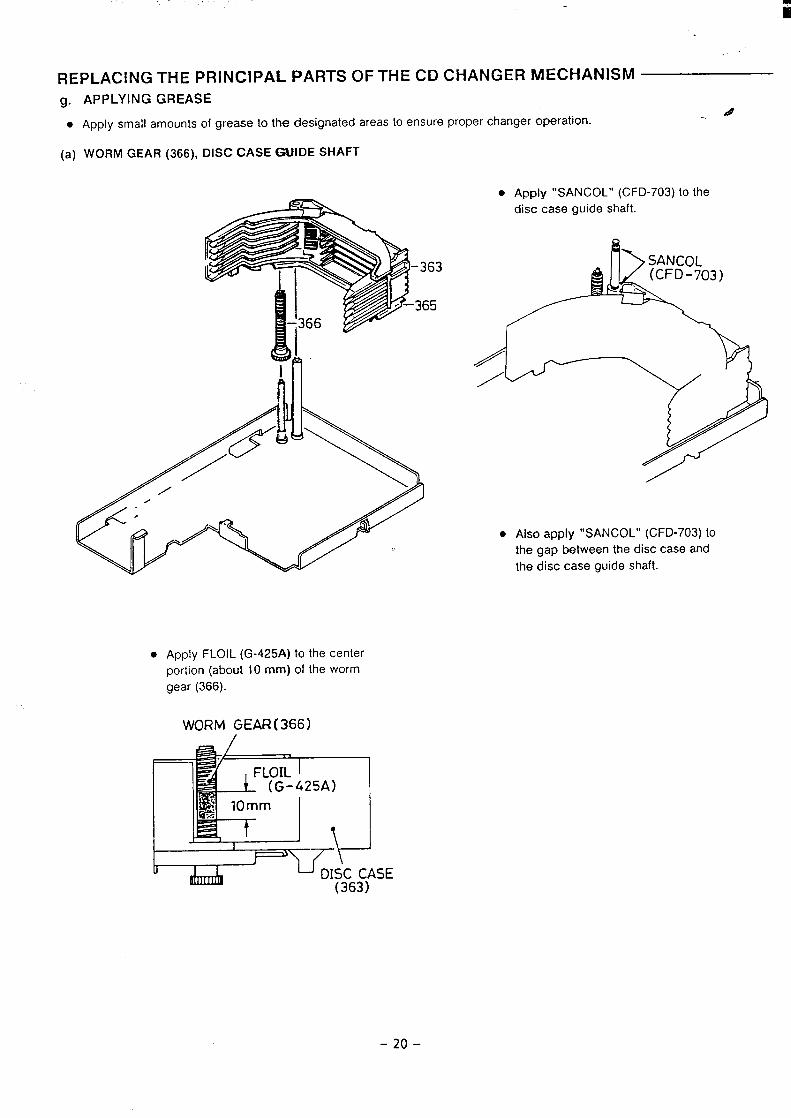
.
REPLACING THE PRINCIPAL PARTS OF THE CD CHANGER MECHANISM
9.
●
(a)
APPLYING GREASE
Apply small amounts of grease to the designated areas to ensure proper changer operation.d
WORM GEAR (366), DISC CASE GUIDE SHAFT
. Apply “SANCOL” (C FD-703) to the
disc case guide shaft.
● AISO apply “SANCOL” (CFD-703) to
the gap between the disc case and
the disc case guide shaft.
● Apply FLOIL (G-425A) to the center
portion (about 10 mm) of the worm
gear (366).
WORM GEAR(366)
-20-
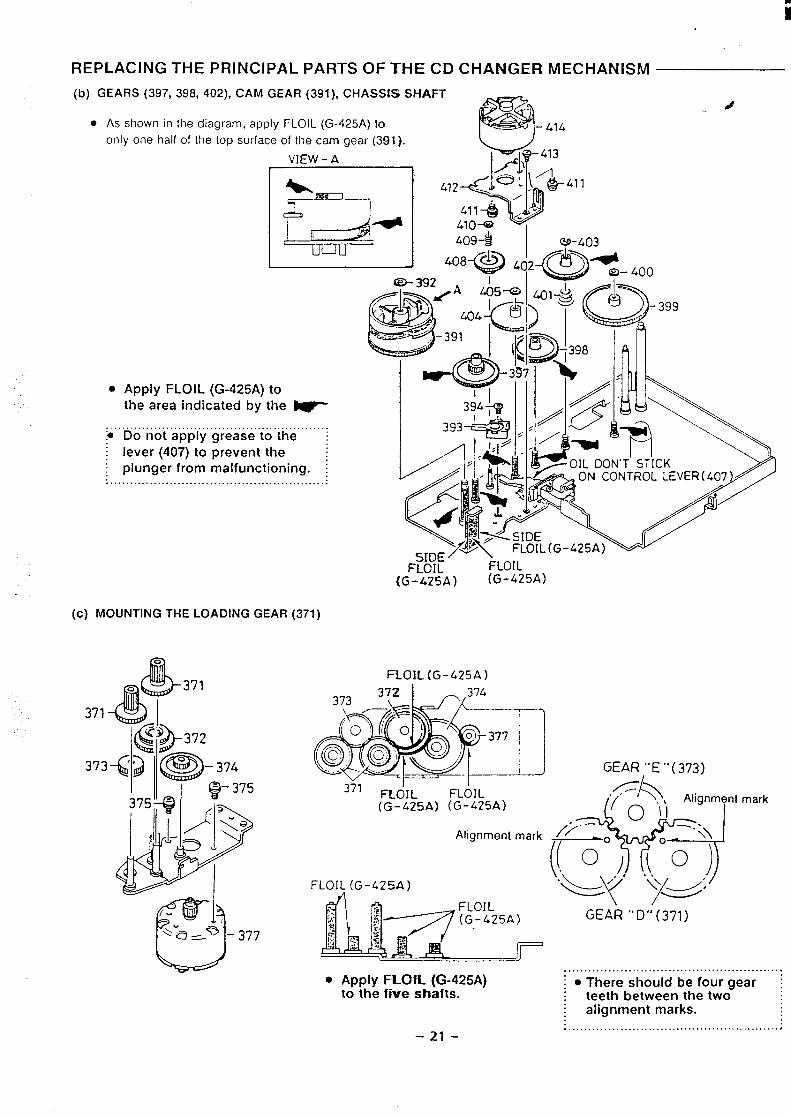
ii
REPLACING THE PRINCIPAL PARTS OF THE CD CHANGER MECHANISM
(b) GEARS (397, 398, 402), CAM GEAR (391 ), CHASSIS Sf+AFT
● AS shown in the diagram, apply FLOIL (G-425A) to 4only one half of the top surface of the cam gear (391].
VIEW-A
H
- 41 -411
Q3-403
I
lJuuI 408-(
● Appiy FLOIL (G-425A) to -~the area indicated by the ~ 394* I Yzedl
. ...... .:$ Do not apply grease to the :
I
““” j7q].1’//i.
: lever (407) to prevent the ~I plunger from malfunctioning. ; 1/’”1,4>A. ... ......... ...........................................
(C) MOUNTfNG THE LOADING GEAR (371)
.4
H-OIL(G-425A)
371 FL&IL FL61L(G-425A) (G-425A)
Alignment mark
GEAR ,“E ‘“(373)
mark
GEAR “D’’(371)
. ......... . ... ..................................● Apply FL(XL (G-425A) ! ● There should be four gear ~
to the We shafts. teeth between the twoalignment marks.
. ...... ...... ... .. ..............................–21-
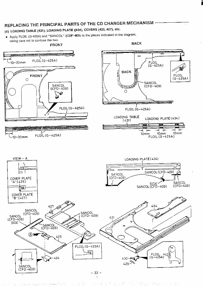
i
REPLACING THE PRINCIPAL PAF?TS OF THE CD CHANGER MECHANISM
(d) LOADING TABLE (431), LOADING PLATE (434), COVERS (425, 427), etc.
● Apply FLOIL (G-425A) and “SANCOL” (CDF-409) to the places indicated in the diagram,
taking care not to confuse the two.
FRONT
B, .,. m.w
BACK
, t \ II I I —Y
T’ 10-20mmFLOI~(G-425A)
FLOIL (G-425A)
VIEW - A
~
a.
ICOVER PLATE“A” ( f25)
1—7==
SANCOL
o\
A
FLOIL(G-425A)
\n’----
1
+
FLOIL (G-425A)
LOADING TABLE( 431) LOADING PLATE ( 434)
I
bI
10mm 10mm 10mm
FLOIL (G-425A)
LOADING PLATE ( 434)
,---- .-. —-
---d ~
(
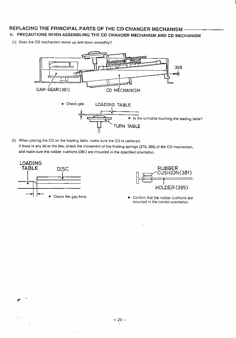
REPLACING THE PRINCIPAL PARTS OF THE CD CHANGER MECHANISMh. PRECAUTIONS WHEN ASSEMBLING THE CD CHANGER MECHANISM AND CD MECHANISM
(1)
(2)
Does the CD mechanism move up and down smoothly’?
8
—-
CAM GEAR (391 ) CD MECHANISM
. Check gap. LOADING TABLE
+--c=+=-T
. Is the turntable touching the loading table?
TURN TABLE
When placing the CD on the loading table, make sure the CD is centered.
If there is any tilt or the like, check the movement of the floating springs (379, 380) of the CD mechanism,
and make sure the rubber cushions (381 ) are mounted in the specified orientation.
LOADINGTABLE DISC “
I r----l----
~ k ● Check the gap here
RUBBER
~=HOLDER (385)
. Confirm that the rubber cushions aremounted in the correct orientation.
-23-
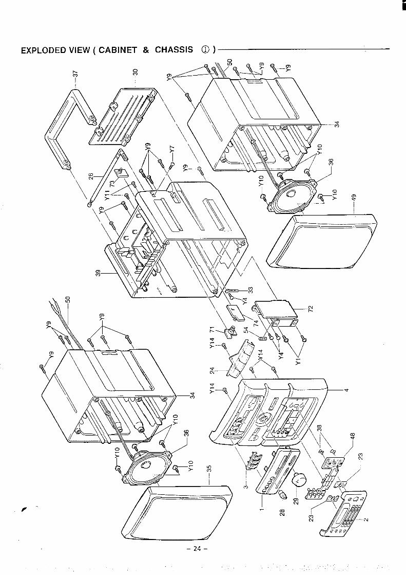
EXPLODED VIEW ( CABINET & CHASSIS d) )
0FY
0
‘i\&?
\
o-l*—
P ‘“
-24-
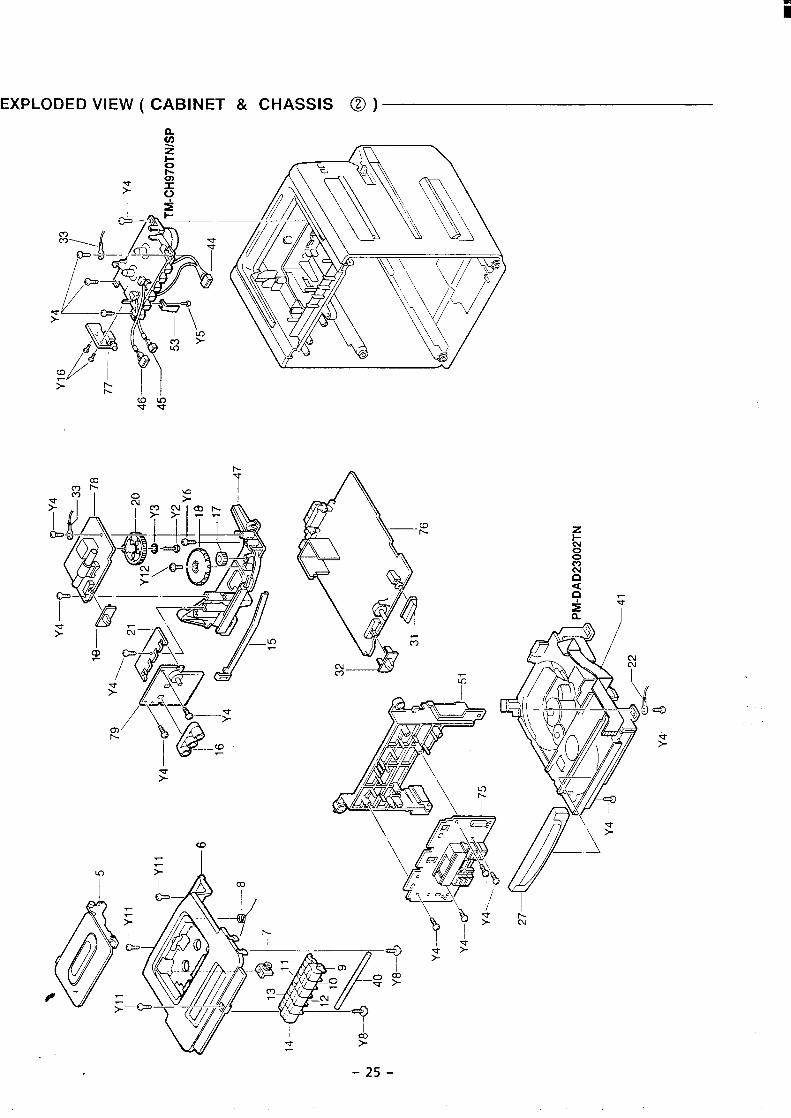
EXPLODED VIEW ( CABINET & CHASSIS @ )
%52 AR \
‘4/
-25-
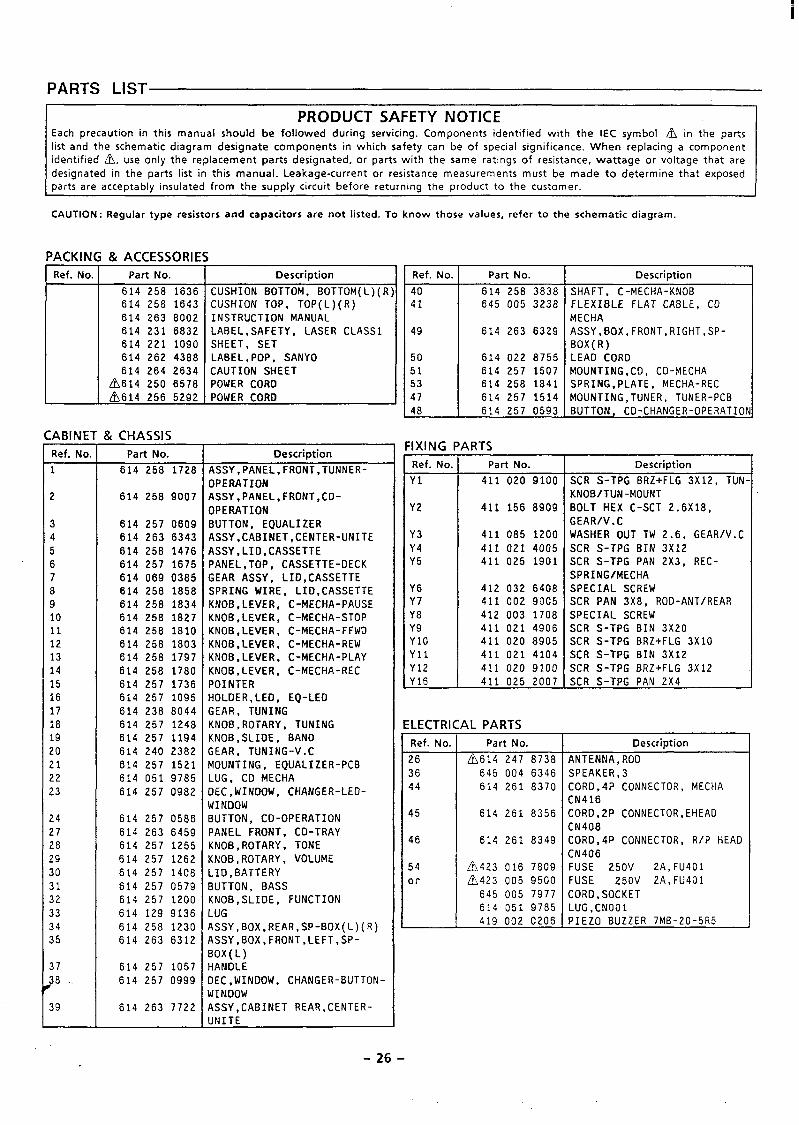
i
PARTS LIST
I PRODUCT SAFETY NOTICE I
Each precaution in this manual should be followed during servicing. Components identified with the IEC symbol ~ in the partslist and the schematic diagram designate components in which safety can be of special significance. When replacing a componentidentified ~, use only the replacement parts designated, or parts with the same ratings of resistance, wattage or voltage that are
designated in the parts list in this manual. Leakage-current or resistance measurements must be made to determine that exposedparts are acceptably insulated from the supply circuit before returning the product to the customer.
CAUTION: Regular type resistors and capacitors are not listed. To know those values, refer to the schematic diagram.
ACKI N
Ref. No
ABINE-
Ref. No.
1
?
34557B210111213141516171819?0?1!2!3
?4?7?8?9103112%33415
37J8
39
& ACCESSORIESPart No.
614 258 1636614 258 1643614 263 8002614 231 6832614 221 1090614 262 4388614 264 2634
~614 250 6578
~614 256 5292
&CHASSIS
Part No.
614 258 17.28
614 258 9007
614 257 0609614 263 6343614 258 1476614 257 1675614 069 0385614 258 1858614 258 1834614 258 1827614 258 1810614 258 1803614 258 1797614 258 1780614 257 1736614 257 1095614 238 8044614 257 1248614 257 1194614 240 2382614 257 1521614 051 9785614 257 0982
614 257 0586614 263 6459614 257 1255614 257 1262614 257 1406614 257 0579614 257 1200614 129 9136614 258 1230614 263 6312
614 257 1057614 257 0999
614 263 7722
i
Description
CUSHION BOTTOM, BOTTOM(L)(RCUSHION TOP, TOP(L)(R)INSTRUCTION MANUALLABEL,SAFETY, LASER CLASS1SHEET, SETLABEL,POP, SANYOCAUTION SHEETPOWER CORDPOWER CORD
Description
ASSY,PANEL,FRONT,TUNNER-
OPERATIONASSY,PANEL,FRONT ,CD-OPERATIONBUTTON, EQUALIZERASSY,CABINET,CENTER-UNITEASSY,LID,CASSETTEPANEL,TOP, CASSETTE-DECKGEAR ASSY, LID,CASSETTESPRING WIRE, LID,CASSETTEKNOB,LEVER, C-MECHA-PAUSEKNOB,LEVER, C-MECHA-STOPKNOB,LEVER, C-MECHA-FFWDKNOB,LEVER, C-MECHA-REWKNOB,LEVER, C-MECHA-PLAYKNOB,LEVER, C-MECHA-RECPOINTERHOLDER,LEO, EQ-LEOGEAR, TUNINGKNOB,ROTARY, TUNINGKNOB,SLIDE, BANDGEAR, TUNING-V.CMOUNTING, EQUALIZER-PCBLUG, CD MECHADEC,WINDOW, CHANGER-LED-WINDOWBUTTON, CD-OPERATIONPANEL FRONT, CD-TRAYKNOB,ROTARY, TONEKNOB,ROTARY, VOLUMELID,BATTERYBUTTON, BASSKNOB,SLIDE, FUNCTIONLUG4SSY,BOX.REAR,SP-BOX(L)(R)4SSY,BOX,FRONT,LEFT,SP-30X(L)-IANDLE)EC,WINDOW, CHANGER-BUTTON-~INDOWVSSY,CABINET REAR,CENTER-JNITE
Ref. No.
4041
49
50
5153
47
48
lXING I
Ref. No.
Y1
Y2
Y3Y4Y5
Y6Y7Y8Y9YloYllY12Y16
:LECTRI
Ref. No.
26
3644
45
46
54or
Part No.
614 258 3838645 005 3238
614 263 6329
614 022 8755614 257 1507614 258 1B41614 257 1514614 257 0593
iRTS
Part No.
411 020 9100
411 156 8909
411 085 1200
411 021 4005411 025 1901
412 032 6408411 002 9005
412 003 1708
411 021 4906411 020 8905
411 021 4104
411 020 9100
411 025 2007
4L PARTS
Part No.
~614 247 8738645 004 6346614 261 8370
614 261 8356
614 261 8349
~423 016 7809~423 005 9500
645 005 7977614 051 9785419 002 0206i
Description
SHAFT, C-MECHA-KNOBFLEXIBLE FLAT CABLE, CDMECHAASSY,BOX,FRONT,RIGHT,SP-BOX(R)LEAD CORDMOUNTING,CO, CD-MECHASPRING,PLATE, MECHA-RECMOUNTING,TUNER, TUNER-PC8BUTTON, CD-CHANGER-OPERATIO
Description
SCR S-TPG BRZ+FLG 3X12, TUNKNOB/TUN-MOUNTBOLT HEX C-SCT 2.6X18,GEAR/V.CWASHER OUT TW 2.6, GEAR/V.C
SCR S-TPG BIN 3X12SCR S-TPG PAN 2X3, REC-
SPRING/MECHASPECIAL SCREWSCR PAN 3X8, ROD-ANT/REARSPECIAL SCREWSCR S-TPG BIN 3X20SCR S-TPG BRZ+FLG 3X1OSCR S-TPG BIN 3X12SCR S-TPG BRZ+FLG 3X12SCR S-TPG PAN 2X4
Description
ANTENNA,ROD
SPEAKER,3COR0,4P CONNECTOR, MECHAEN416COR0,2P CONNECTOR,EHEADEN408CORD,4P CONNECTOR, R/P HEADCN406FUSE 250V 2A,FU401FUSE 250V 2A,FU401CORD,SOCKETLUG,CNOO1PIEZO BUZZER 7MB-20-5R5
-26-
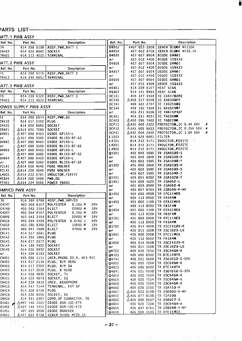
i
)ARTS LIST
IATT. 1 PWB ASSY
Ref. No. Part No. Description
74 614 258 5108 ASSY, PWB, BATT 1CN422 614 020 6562 SOCKETTR401 614 213 4023 TERMINAL
IATT.2 PWB ASSY
Ref. No. Part No. Description
71 614 258 5115 ASSY,PWB,BATT 2TR402 614 246 8661 TERMINAL
IATT.3 PWBASSY
Ref. No. Part No. Description
73 614 258 5122 ASSY,PWB,BATT 3TR403 614 213 4023 TERMINAL
‘OWER
Ref. No.
72CN419CN420CN421D4961orD4962orD4963orD4964
orFCL41FCL42L4906PCB44PT401
\MP/CD
Ref. No.
76
C4747C4749C4847C4849C4915C4932C4944CN141CN142CN143CN144CN145orCN401CN402CN403CN405CN409CN41OCN412CN413CN414CN418CN434D1401 ~D140201451D4951
UPPLY PWBAS
Part No.
614 260 2874614 017 2102
614 020 6555~614 020 7590~407 088 6403L?J407 098 3300
~407 088 6403~407 098 3300~407 088 6403~407 098 3300~407 088 6403
~407 098 3300~614 208 4540~614 208 4540
~614 213 5761~614 260 3406~614 234 5559
‘WB ASSY
Part No.
614 260 8760403 058 6107403 043 3104403 058 6107403 043 3104403 058 2406403 200 8300403 047 7009614 017 2591614 250 1665614 017 2577614 198 2922614 035 5932614 206 0193645 005 1111614 017 2119614 017 2553614 017 2539614 035 4935614 035 4973614 229 3812614 247 7144614 228 0706614 020 6555614 261 8387
~407 140 7201~407 140 7201
407 003 3609
~407 053 8708
;Y
Description
ASSY,PWB,DGPLUGSOCKETSOCKETDIODE GP15D-LDIOOE RL153-BF-S2DIODE GP15D-LDIODE RL153-BF-S2DIOOE GP15D-LDIODE RL153-BF-S2DIODE GP15D-LDIODE RL153-BF-S2FUSE HOLDERFUSE HOLDERINDUCTOR,FERITEPWB , DGPOWER TRANS
Description
ASSY,PWB,AMPICDPOLYESTER 0.15U M 50V
ELECT 2200U M 16VPOLYESTER 0.15U M 50VELECT 2200U M 16VPOLYESTER 0,015U J 50VELECT 1000U M 10VELECT 4700U M 25VPLUGPLUGPLUGSOCKETSOCKETSOCKETJACK,PHONE D3.6, MIX MICPLUG, R/P HEADPLUG, R/P SWPLUG, E HEADSOCKET, TUSOCKET, EQJACK, HEADPHONETERMINAL, EXT SPPLUG
SOCKET, DGCORD,3P CONNECTOR, DGDIOOE OSR-1OC-ET5OIOOE OSR-1OC-ET5OIOOE 0AN202KZENER DIODE MTZ9.lA
Ref. No,
04952Q495404955orD4956orD4957orD4958orHS401HS402IC131IC140IC141IC144ol-IC401IC403ICP1lICP12ICP41L1503L4701L4801L4905Q1301or
on-
Q1302or
;;401
Q1451orOvQ1452
;;453or
Q1454orQ17810 !rQ1782or
Q1881or
Q1882or
Q4702Q4703Q4741Q4802Q4803Q4841
Q4904Q4905Q4906@4942Q4951Q4952Q4953Q4954Q4955Q4956
Part No.
X407 053 2508407 053 8708407 007 9904407 012 4406407 007 9904407 012 4406407 007 9904407 012 4406407 007 9904407 012 4406614 229 8107614 121 5891409 327 3402
~409 317 8509409 322 2707409 192 7109409 241 5506409 331 4501
/h409 295 7402
~645 006 2322~645 005 9933~645 006 2360
614 028 6861614 212 3171614 212 3171614 212 3171405 006 1905405 006 1806405 002 1305405 006 1806405 006 1905405 002 1305405 001 9302405 006 4005405 006 3909405 007 6701405 000 2908405 113 5902405 000 1109405 113 8200405 000 1109405 113 8200405 000 2908405 113 5902405 014 4509405 011 1006405 000 2908405 113 5902405 014 4509405 011 1006405 020 7204405 060 6502405 021 0600405 020 7204405 060 6502405 021 0600405 020 7204405 020 7204405 020 7204405 005 2002
Lh405 023 5009/!)405 077 9008/j!i405 009 5207
405 020 7204405 007 6701405 000 3103
Description
ZENER 01CU3E MTZ1OAZENER 01DK3E MTZ9.lAOIODE GMAL31DIOOE 1SS133DIOOE GMAQ1OIODE 1SS133OIODE GMA?I1OIOOE 1S.S133OIOOE GMAOIOIODE 1SS133HEAT SINKHEAT SINKIC CXA17i32BQIC BA639t3KPIC CX0251~QIC BA1521$3FIC XRA152T8FIC TA2068$JIC TA822WIPROTECTOR.IC 0.4A 50V #PROTECTOR.IC 0.25A 50V #PROTECTOR.IC l,OA 50V #FILTERINOUCTOR,FERITE ‘INDUCTOR,EERITEINOUCTOR.EERITETR 2SA933S-STR 2SA9335-RTR 2SA104$3-YTR 2SA932S-RTR 2SA933S-STR 2SA104M3-%TR 2SA1OZ9-YTR 2SA952-LTR 2SA95Z<KTR 2SB59f&-F-NPTR 0TCl14@KTR FAlA416TR 0TA12%IKTR FNlF4f@TR 0TA124EKTR FN1F4B?TR 0TC114HTR FAlA4f4TR 2SC24SiZK-RTR 2SC16Z.3-L6TR OTCll@EKTR FA1A4E%TR 2SC24it2K-RTR 2SC16Z3-L6TR 2SC94SA-KTR DTC14J%TKTR 2SO1OI2-G-SPATR 2SC94%A-KTR DTC144WKTR 2SO1O12?-G-SPA
TR 2SC94%A-KTR 2SC94!iA.-KTR 2SC945$I-KTR 2SA733-PTR 2S040Ct-E-MPTR TIP29E3TR 2SB921-STR 2SC94$3A-KTR 2SB5W5-F-NPTR OTCIIIISES
-27-
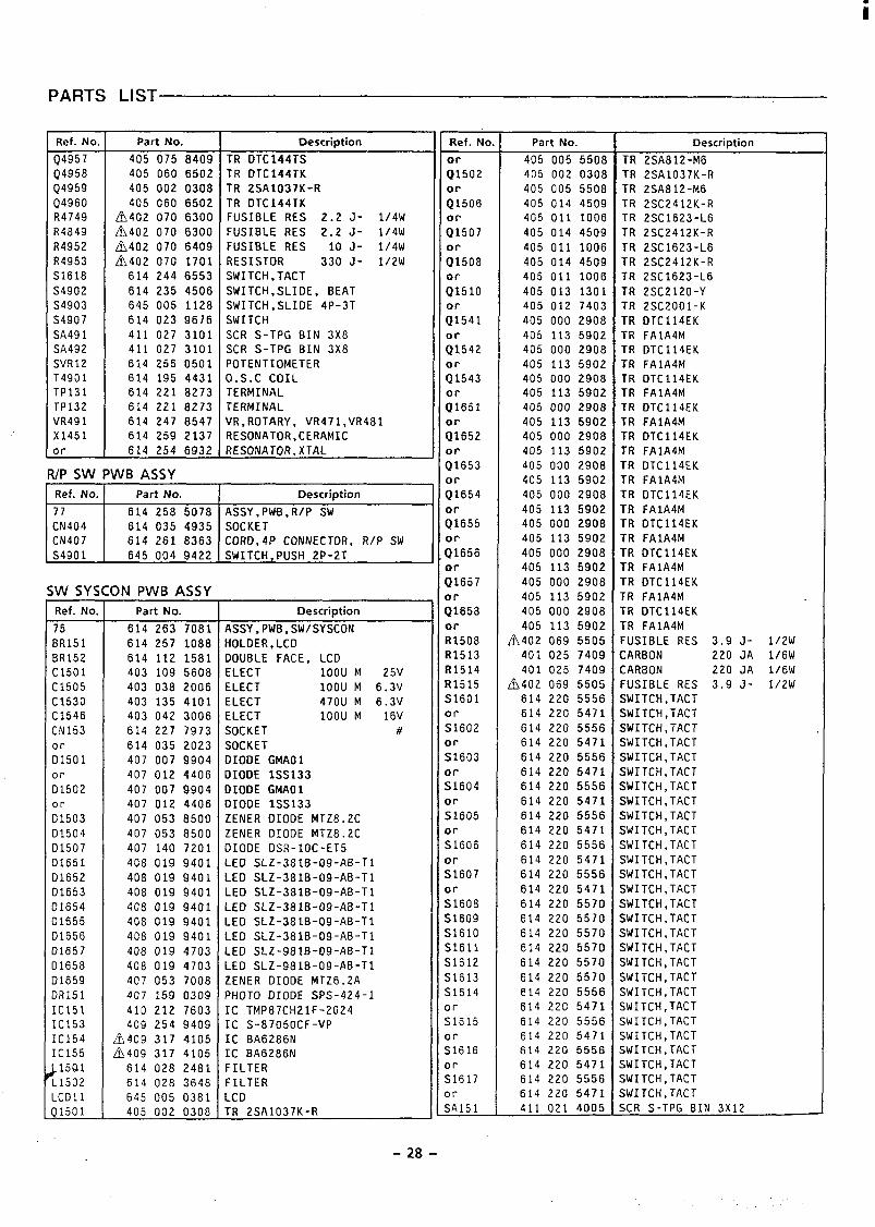
PARTS LIST
Ref. No.
Q4957Q4958Q4959Q4960R4749R4849R4952R4953S1618
S4902S4903S4907SA491SA492SVR12T4901TP131TP132VR491X1451or
Part No.
405 075 8409405 060 6502405 002 0308405 060 6502
~402 070 6300
/f1402 070 6300~402 070 6409LtJ402 070 1701
614 244 6553
614 235 4506645 005 1128614 023 9676411 027 3101411 027 3101614 256 0501614 195 4431614 221 8273614 221 8273614 247 8547614 259 2137614 254 6932
Description
TR DTC144TSTR DTC144TKTR 2SA1037K-RTR DTC144TKFUSIBLE RES 2.2 J- l/4W
FUSIBLE RES 2.2 J- l/4WFUSIBLE RES 10 J- l/4WRESISTOR 330 J- l/2wSWITCH,TACTSWITCH,SLIDE, BEATSWITCH,SLIDE 4P-3TSWITCHSCR S-TPG BIN 3X8SCR S-TPG BIN 3X8POTENTIOMETERO.S.C COIL
TERMINALTERMINALVR,ROTARY, VR471,VR481RESONATOR,CERAMICRESONATOR,XTAL
RIPSW PVVB AS.SY
mSW SYZ
Ref. No,
75BR151BR152C1501C1505C1530C1546CN153orD1501orD1502orD150301504D1507D1651D1652D165301654D1655D1656D1657D1658D1659DR151IC151IC153IC154IC155j15alL1502LCD1lQ1501
ON PVVBASSY
Part No.
614 263 7081614 257 1088614 112 1581403 109 5608403 038 2006403 135 4101403 042 3006
614 227 7973614 035 2023407 007 9904407 012 4406407 007 9904407 012 4406407 053 8500407 053 8500407 140 7201408 019 9401408 019 9401408 019 9401408 019 9401408 019 9401408 019 9401408 019 4703408 019 4703407 053 700B407 159 0309410 212 7603409 254 9409
A409 317 4105A409 317 4105
614 028 2481614 028 3648645 005 0381405 002 0308
Description
ASSY,PWB,R/P SWSOCKETCORD,4P CONNECTOR, R/P SWSWITCH,PUSH 2P-2T
Description,.ASSY,PWB,SWISYSCONHOLDER,LCDDOUBLE FACE, LCDELECT 100U M 25VELECT 100U M 6.3VELECT 470U M 6.3VELECT 100U M 16VSOCKET #SOCKETDIODE GMAO1OIODE 1SS133DIODE GMAO1DIODE 1SS133ZENER DIODE MTZ8.2CZENER DIOOE MTZ8.2COIODE DSR-1OC-ET5LEIJ SLZ-381B-09-AB-T1LED SLZ-381B-09-AB-T1LED SLZ-381B-09-AB-T1LEO SLZ-381B-09-AB-T1LED SLZ-381B-09-AB-T1LED SLZ-381B-09-AB-T1LED SLZ-981B-09-AB-T1LED SLZ-9B1B-09-AB-T1ZENER DIODE MTZ6.2APHOTO DIODE SPS-424-1IC TMP87CH21F-2024IC S-87050CF-VPIC BA6286NIC BA6286NFILTERFILTERLCDTR 2SA1037K-R
Ref. No
::502
:f506
;:507
;[508
;;510
:;541
li542orQ1543
&651
;i652
:;653
::654
;i655
:~656
;;657
;:658
orR1508R1513R1514R1515S1601orS1602orS1603orS1604orS1605orS1606orS1607orS1608S1609S161OS1611S1612S1613S1614orS1615orS1616orS1617orSA151
Part No.
405 005 550B405 002 0308405 005 5508405 014 4509405 011 1006405 014 4509405 011 1006405 014 4509405 011 1006
405 013 1301405 012 7403405 000 2908405 113 5902405 000 2908405 113 5902405 000 2908405 113 5902405 000 2908405 113 5902405 000 2908405 113 5902405 000 2908405 113 5902405 000 2908405 113 5902405 000 2908405 113 5902405 000 2908405 113 5902405 000 2908405 113 5902405 000 2908
405 113 5902Lh402 069 5505
401 025 7409401 025 7409
fh402 069 5505614 220 5556614 220 5471614 220 5556614 220 5471614 220 5556614 220 5471614 220 5556614 220 5471614 220 5556614 220 5471614 220 5556614 220 5471614 220 5556614 220 5471614 220 5570614 220 5570614 220 5570614 .220 5570614 220 5570
614 220 5570614 220 5556614 220 5471614 220 5556614 220 5471614 220 5556614 220 5471614 220 5556614 220 5471411 021 4005
Description
TR 2SA812-M6TR 2SA1037K-RTR 2SA812-M6TR 2SC2412K-RTR 2SC1623-L6TR 2SC2412K-R
TR 2SC1623-L6TR 2SC2412K-RTR 2SC1623-L6
TR 2SC2120-YTR 2SC2001-KTR DTC114EKTR FA1A4MTR DTC114EKTR FA1A4MTR DTC114EKTR FA1A4MTR DTC114EKTR FA1A4MTR 0TC114EKTR FA1A4MTR DTC114EKTR FAIA4MTR DTC114EKTR FA1A4MTR DTC114EKTR FA1A4MTR DTC114EKTR FA1A4MTR DTC114EKTR FA1A4MTR DTC114EK
TR FA1A4MFUSIBLE RES 3.9 J- l/2WCARBON 220 JA l/6WCARBON 220 JA l/6WFUSIBLE RES 3.9 J- i/ZWSWITCH,TACTSWITCH,TACTSWITCH,TACTSWITCH,TACTSWITCH,TACTSWITCH,TACTSWITCH,TACTSWITCH,TACTSWITCH,TACTSWITCH,TACTSWITCH,TACTSWITCH,TACTSWITCH,TACTSWITCH,TACTSWITCH,TACTSWITCH,TACTSWITCH,TACTSWITCH,TACTSWITCH,TACTSWITCH,TACTSWITCH,TACTSWITCH,TACTSWITCH,TACTSWITCH,TACTSWITCH,TACTSWITCH,TACTSWITCH,TACTSWITCH,TACTSCR S-TPG BIN 3X12
-28-
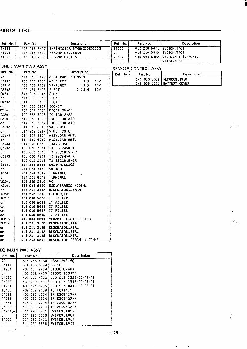
Ref. No. Part No. Description Ref. No. Part No. Description
TH151 408 016 8407 THERMISTOR PTH60G308D330N S4906 614 220 5471 SWITCH,TACTX1501 614 215 5561 RESONATOR.KERAM or 614 220 5556 SWITCH,TACT
X1502 VR493 645 004 6490 VR,ROTARY 50K/WX2,VR473,VR483
IIJNER MAIN PWBASSY
Ref. No.
78
C2107C2116C2802CN201
:J202or02101IC201L2101orL2102orL2103orL2104Q2102
;;103
:;101
;;201
orVC201X2101orXF201XF211ororororXF213XF214orororor
Part No.
614 258 9472403 106 1603403 106 1603403 121 3408614 206 0216614 035 5956614 206 0193614 035 5932407 007 9904409 325 7006614 238 1298614 233 5864614 035 0012614 229 0217614 254 9964614 230 6888614 256 6572405 020 7204405 012 2002405 020 7204405 012 2002614 244 8335614 024 3185614 254 3597614 221 8273614 239 2416645 004 6100614 231 3183614 252 1045614 030 5678614 030 5661614 030 5654614 030 5647614 030 5630645 004 6094614 231 3176614 231 3169614 231 3152614 231 3145614 253 6841
:Q MAIN PWBASSY
Ref. No. Part No.
79 614 258 5160CN411 614 035 599404931 407 007 9904or 407 012 4406D4932 408 019 4703D4933 408 019 9401
D4934 408 021 1905IC402 409 052 9809Q4721 405 020 7204Q4722 405 020 7204Q4821 405 020 7204Q4822 405 020 7204S4904 # ’614 220 5471
614 220 5556:;905 614 220 5471or 614 220 5556
REMOTE CONTROL ASSYDescription
ASSY,PWB, TU MAINNP-ELECT lU Q 50VNP-ELECT lU Q 50V
ELECT 2.2U M 50V
SOCKETSOCKETSOCKETSOCKETDIODE CiMA(31IC TA8122ANINDUCTOR,AIRINDUCTOR,AIRVHF COILV.H.F COILASSY,BAR AMT.ASSY,BAR AMT.TRANS.OSCTR 2SC945A-KTR 2SC1815-GRTR 2SC945A-KTR 2SC1B15-GRSWITCH,SLIBESWITCHTERMINALTERMINALVcOSC,CERAMKK 456KHZRESONATORVKERAMFILTER,LCIF FILTERIF FILTERIF FILTERIF FILTERIF FILTERCERAMIC FILTER 455KHZRESONATOR.”XTALRESONATOR.XTALRESONATOR.XTALRESONATOR*XTALRESONATOR.CERAM, 10.7OMHZ
Ref. No. Part No. Description
645 006 7662 REMOCON,S980645 005 7007 BATTERY COVER
I
DescriptionASSY,PWB.ZQSOCKETDIODE GMAlllDIODE 1SS133LED SLZ-Q$31B-09-AB-T1LED SLZ-%$91B-09-AB-T1LED SLZ-4’fllB-09-AB-TlIC TC914WTR 2SC94!%%-KTR 2SC945$l-KTR 2SC94!%A-KTR 2SC94!5A-KSWITCH,Tk%CTSWITCH,TJWCTSWITCH,TXTSWITCH,TJ%CT —
-29-
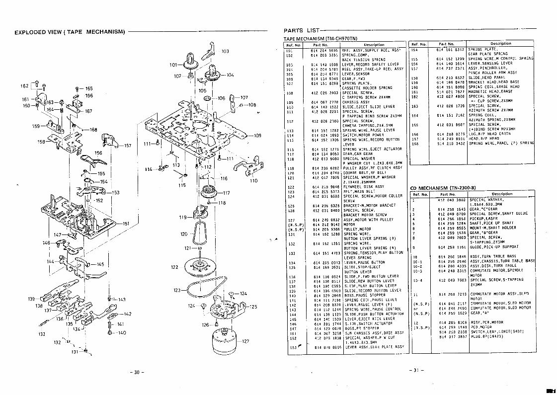
EXPLODED VIEW ( TAPE MECHANISM) PARTS LIST
170TN)Description
EEL ASSY, SUPPLY REEL ASSY
PRING, COMP,
APEME
7
Ref.No.
101102
103104105)617
38
091011
12
131415
161718
192021
222324
,25,26
~27:N.S.P]:N.S.P]131
132
133
134135
136137138139140141142143144145146147151152
153 f
ANISM (TM-CPart No.
614 204 5695614 208 0351
+&J,, —103
~1 ‘ I
101— L+) /’./’
.) _lo~102--y ~ ,
ef.No.
54
555657
5859606162
63
64
65
666768
Part No. Description
614 151 8312 SPRING PLATE.GEAR PLATE SPRING
614 152 1299 SPRING WI RE. M CONTROL SPRIN’6i4 140 1614 LEVER .SENSING LEVER614 237 2371 ASSY. PINCH ROLLER,
PINCH ROLLER ARM ASSY
614 210 6822 SLIDE .HEAO PANEL614 196 0470 BRACKET HEAO, HEAO BASE614 151 5090 SPRING COIL. ERASE HEAO614 021 1827 MAGNETIC HEAO, ERASE412 027 4600 SPECIAL SCREW.
+- CUP SCREW.2X8MM
412 026 1709 SPECIAL SCREW,A21MUTH SCREW 2X7MM
614 151 7162 SPRING COIL,AZIMUTH SPRING,2XBMM
412 031 6607 SPECIAL SCREW,(+)BIND SCREW M2X3MM
614 208 0276 LUG. R/P HEAO EARTH614 249 9931 HEAO, R/P HEAO
614 210 3432 SPRING wIRE. PANEL (P) SPRIN
ACK TENSION SPRINGEVER, RECORO SAFETY LEVEREEL ASSY. TAKE-UP REEL ASSYEVER, SENSOREAR,F.FWO,PRING PLATE.,ASSETTE HOLDER SPRING;PECIAL SCREW,; TAPPING SCREW 2X4MM:HASSIS ASSY;LIOE. EJECT SLIOE LEVER;PECIAL SC RE!W,1 TAPPING BINO SCREW 2x5MM;PECIAL SCREW,:AMERA TAP PING.2X4.5MM;PRING WI RE, PAUSE LEVER;WITCH,MOTOR POWER;PRING WI RE, RECORO BUTTON.EVERjPRING WI RE, EJECT ACTUATOR;EAR,CAM GEARjPECIAL WASHER~ WASHER CUT 1.2X3.8 X0.3MM]uLLEY ASSY. RF CLUTCH ASSYSQUARE BELT. RF BELTSPECIAL WASHER, P wASHER2.1X4X0.25MMMMFLYWHEEL OISK ASSY
614 140 1508614 204 5701614 204 8771614 134 9046614 151 8299
412 026 2003
614 067 2770614 140 1522412 026 2201
412 026 23OO
li105i
614 152 12B2614 024 1693614 152 1305
-157614 152 1275614 134 9053412 013 5000
614 205 6202614 204 6740412 012 7005
614 210 9946614 205 6373412 031 6508
614 205 5328412 031 940C
614 249 9832614 212 9142614 205 536(614 152 126[
%.—155 ‘f-j ,%–154
B)D MECRef.No.
4NISM (TN-230Part No,
412 049 3603
BELT, MAIN BELTSPECIAL SCREW .MOTOR COLLER Description
;PECIAL WASHER.SCREWBRACKET-M, MOTOR BRACKETSPECIAL SCREW,BRACKET MOTOR SCREWASSY, MOTOR WITH PULLEYMOTORPULL EY,MOTORSPRING WIRE.BuTTON LEVER SPRING (B)SPRING WIRE,BuTTON LEVER SPRING (A)SPRING, TENS ION,PLAY 8UTTONLEVER SPRING
~“‘–”8I
&ii5119—
i.55x4.5xo.3MM;EAR. ”C”GEARjPECIAL SC REW. SHAFT GUIDE~ICKUP, LASER3HAFT. PICK-UP SHAFT40UNT-M. SHAFT HOLOER;EAR, ”B”GEARSPECIAL SCREW,S-TAP PING. 2X3MM
3UIOE, PICK-UP SUPPORT
.,“-.-.
4
b> –151 ,,
It>)
r
1
1
10
1o-110-210-3
10-4
11
(N.S.P)or
(N.S.P)
12(N,S.P;
614 259 1543
412 049 8709
614 256 1058
614 259 1284
614 259 6555
614 259 1536
412 049 76o3
/’,/
@l146— S>
‘&
,i,-%1 /5
614 152 125’
614 151 410:
614 259 1161
614 26o 1B46614 259 2946614 26o 4335614 248 2315
8SSY ,TURN TABLE BASElSSY ,CHASSIS. TURN TABLE 6A!AsSY. OISK. TURN TABLECOMMUTATE MoTOR, SPINOLEMOTORSPECIAL SC REW, S-TAPPING2x3MM
614 298 031:614 196 053
LEVER , PAUSE BUTTONSLIOE. STOP/EJECT8UTTON LEVERSLIOE, F.FWO BuTTON LEVERSLIOE, REW BUTTON LEVERSLIOE, PLAY BUTTON LEVERSLIDE, RECORO BUTTON LEVERBOSS, PAUSE STOPPERSPRING CO IL.PAUSE LEVERLEVER, PAUSE LEVER (E)SPRING WIRE ,PAUSE CONTROLSLIDE, PUSH 8uTTON ACTUATORLEvER, EJECT KICK LEVERSLIDE, SWITCH ACTUATORBOSS, PR STOPPERSUB CHASSIS ASSY ,BASE ASSYSPECIAL WASHER, P W CUT1.45X3. BXO.5MMLEVER ASSY, GEAR PLATE ASSY
614 196 0524614 196 0517614 196 0555614 196 0500614 129 0669614 151 7186614 208 032c614 152 124{614 139 112(614 140 153!614 201 174,614 129 067f614 067 325[412 026 180[
412 049 7603
COMMUTATE MOTOR ASSY , SLEO614 260 7213
614 045 2112614 248 2650614 259 1529
614 265 60066;4 259 1840614 25’3 2038614 017 3B57
MOTORCOMMUTATE MOTOR, SLED MOTORCOMMUTATE MOTOR, SLEO MOTORGEAR, ”A”
ASSY, PCB,MOTORPCB, MOTORSW ITCH,LEAF, LIMIT (S402)PLuG.6P(CN423)
133
132-614 070 091(
-30- -31-
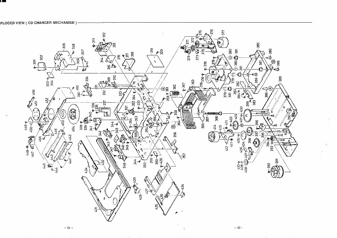
o m o < E
w .
‘h’
@
,&
-334
331
J,,(
,,*J*
433
2‘\
3
b
9-30
9 -310
‘~*:
,
-~.,->
~=
,..
‘Y.>
‘‘%-3
05
..<%
-30
8
““[~
-306
/-3
07R
&,-
9-31
1
431
4-~
/1;
I..
.,@
-312
316>
->.
Wq,’
/’”
313
315
Q
a ‘3{7
-318
\
o,7‘
-319
~-’-
.,Y 32
0.
I w w
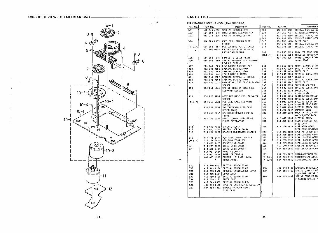
EXPLODED VIEW ( CD MECHANISM ) PARTS LIST
.&9– 1
6
I10--1
I
I
/l––_.
l––l–––––––––––
I
I
I
.
-+
D CHA
tef, No.
101
102!03
104
N. S.P:
1
105io6
iD7108io9L1O)11112)13
114
i15
[N.S.P
316’317318
319[U. S.P
M_
w
320330331332
333334535336331
iER MECHANI!Part No.
412 049 4206614 259 1178412 049 4800
614 265 6013
614 259 1857407 161 0304
614 259 1048614 259 1789
614 259 1680412 043 0204412 049 8709614 259 1451412 049 4602412 043 0204614 259 1031
614 259 1741
614 265 5993
614 259 1833
614 259 2007
614 259 2014
407 161 0304
412 049 400e412 043 0204614 259 107S
614 265 5962614 256 6404614 035 202:614 227 197:
614 26o 7401614 017 258~614 017 261~401 027 1301
.
412 049 650:412 043 0201614 259 036;614 259 032,412 050 070$614 259 112:412 049 830:412 049 810!614 259 106:
I (TN-2300-103-1)Description
;PECIAL SC REW,2X6MM;uIDE,GuIDE STOPPER “B”;PECIAL SCREW.2X3.5MM
\SSY,PCB. LOADING PLATEjENSOR‘CB, LOAOING PLATE SENSOR~HOTO COUPLE SPI-235-18,>HOTO lNTERAPTOR
IRACKET-E, GUIOE PLATE;PRING, TENS ION, OISC SUPPORT.EVER 3 SPRING.EVER, DISC SUPPORT “3”SPECIAL SC REW,2X4MMSPECIAL SCREW,2X5MMFIXER,WIRE CLAMPERjPECIAL SCREW, (+,-)2X6MMSPECIAL SCREW.2X4MM3RACKET-E, OISC CASE ELEVATOSENSORSPRING, TENSION .OISC CASEELEVATOR SENSOR
4SSY, PCB ,OISC CASE ELEvATORSENSORPCB, OISC CASE ELEVATORSENSORSWITCH, LEVER, OISC CASERESET (SOO1)SWITCH, LEVER, UN- LOAOING(s002)PHOTO COUPLE SPI-235-18,PHOTO INTERAPTOR
SPECIAL SCREWSPECIAL sCREW,2X4MMBRACKET -M,CHASSIS BRACKET
PCB ASSY, CONNECTOR PCBPCB, CONNECTOR PCBSOCKET .18P(CNO01)SOCKET,16P(CNO01)SOCKET,16P(CNO01)PLUG,7P(CNO02)PLUG,1OP(CNOO3)CARBON 510 JA l/6w,(ROO1, RO02)
SPECIAL SCREW,2X5MMSPECIAL SCREW,2X4MMSPRING, TENSION, LOCK LEVERLEVER .LOCKSPECIAL SCREW,2X3MMGUI OE, ”R3”SPECIAL SC REW,2X4MMSPECIAL WASHER,2 .6X4.5X0.5*BRACKET-M, WORM GEAR,OISC CASE
Ref. No.
338339340341342343344
345(N.S.P)
346347348349350351362353354355356357358359360361362363
364365
366
367371372373374375376
377(N.S,P;(N.S.P:
378379
380
Part No.
412 049 4909614 259 2021412 049 4206614 259 0256614 259 1116412 043 0204412 043 0204
614 265 5979614 259 0393407 162 6903
614 259 0249412 043 0204614 259 1154412 043 0204614 259 0997412 043 0204614 259 1147614 262 6030412 043 0204614 259 1130614 259 0331614 259 1734412 049 4503412 043 0204614 259 1185412 049 4503614 262 6047614 259 1093
412 043 0204614 259 1413
614 259 1512
412 043 0204614 259 1581614 259 1674614 259 1598614 259 1567412 049 4404614 259 2960
614 265 6020614 228 9118
614 259 15S0
412 049 8402614 259 181S
614 259 1802
Description
SPECIAL SC REW,2.6X5M
SWITCH, LEVER, OPEN/C
SPECIAL SCREW,2X6MM
SUPPORT, GUIDE STOPP
GUIOE. ”L2”SPECIAL SCREW,2X4MMSPECIAL SCREW,2X4MM
ASSY. PCB, OISC SENSPCB,OISC SENSOR .LOPHOTO COUPLE P7480TRANSISTOR
MOUNT -E,OISC SENSOSPECIAL SCREW,2X4MGuIOE, ”L1’SPECIAL SCREW,2X4MMCHASSISSPECIAL SCREW,2X4MGUIOE. ”R2”SUPPORT, STOPPERSPECIAL SCREW,2X4MMGUIOE, ”R1”LEVER, LEVER “1”SPRING, TENSION, LEVSPECIAL SCREW,2X6MSPECIAL SCREW,2X4MMSTOPPER, OISC BASESPECIAL SCREW,2X6MSUPPORT, OISCMOUNT -M,DISC CASE,HOLOER, OISC RACKSPECIAL SCREWREINFORCEMENT, HOLOOISC CASEGEAR ,WORM GEAR,OISC CASE ,UP/OOWNSPECIAL sCREW,2X4MGEAR, LOAOING GEARGEAR, LOAOING GEARGEAR, LOAOING GEARGEAR, LOAOING GEARSPECIAL SCREW,2X3.ASSY, BRACKET -M,LOA
MOTOR,ASSY,OPEN/CLOMOTOR,OPENICLOSE,LOGEAR. LOADING GEAR
SPECIAL SCREW, 2X4MSPRING, COMP, CO MECFLOATING SPRING “SPRING, COMP, CO MECFLOATING SPRING “
-34- -35-
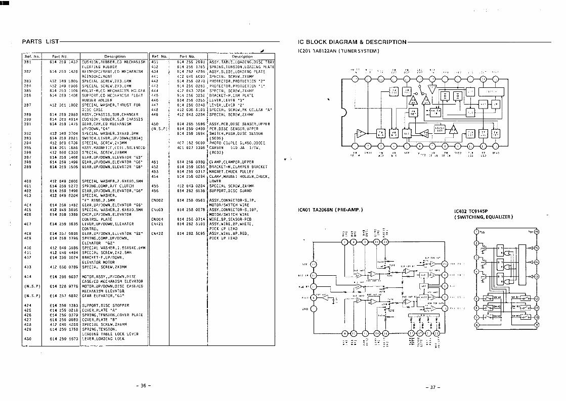
-9s-
““3
,.!,
‘,>.”
“1,’”
,>”
(S13ZllVfIb3‘9NIH311MS)dSP16XZOLOl(“dWV-3Ud)N890ZV1LOfOl
..“,,,,,,3,x,”,:”
0“>8‘13s”::12,33“,,,A,,,,,“,,,,,“,
.,,
II1
.,,,>,,...,..$,,-,,,,,s,,;>,,.,,.,K,”,,,“““:4,”.,,”7
(VJ31SASWNfll)NVZZL8V1LOZ31
Klol9NIOV07’U3A31tL916gZ-19Oc$U3A31x301316V19NIOV01
‘NOISN31’9N18dSes[[6s2*I96Z9NH9XZ’M3B3SlW133dS9ozt6boZlti8?*
.$3,,31V7d’U3A03086065Z*L9Lzb31V7dt13A03’NOISN31’9N1HdS6LC06S?*I99Z*
.Y.31Vld’h’3A0381Z065Zt19SzvL13ddOlS1310’lMOddflSC8CI69Z*19Pzv
.19.’uO1VA373NW39Z689LSZb19(d’S’N)HOLVA313HSINVH33W
03/3SV33S10’NMOO/dll’HOIOW8LL68ZZV19(d”S”N)801VA313HSINVH23Wf33/3SV3
3sla‘NMO(l/dfl‘Ass-d’nolawLca9S9Z*19tI*
KIwFxZ’M3M3S7W133dS60L00s0ZI?tltUO1OWLI01VA313
‘NnOa/dn’3-13X2V88bZOI69Zbt9ZtbWW5”ZXZ’M3M3SlV133dSPot.b6L.OZI*IIt
W!4S”OXSXS8’I’U3HSVi!7W133dS90SC6t0Zl?Olti.Z9>,U01VA373
0V31drlY31d‘NMOO/dll’dW03’9NIUdS96LI6’3ZP1960b‘f13M’d8’3MIfl’ASSVq609Z9Zb19Z?bN2.Z9,,MOLVA313’NAIOO/dfl’UV358069L5Z*I980k
OV37dnX31d70tilN03‘311HM’d8’3MIM’ASSVIalsZ9Z*I9IZ*!12lJfJlVA313’NMOO/dfl’H3A319C916SZ*19LOk03d-80SN3S’dS’3MIMtlLO8qZt19l.aoNI31WldT3HLN023HIMH3JIAlS/L!OIOWU01VA313‘NMOO/dfl’d1H369CI6SZb1990b
‘d01’S-t10133NN03’ASSV8LS0!3s2?19COON2ww9”0x9X9’Z’M3HSVMlV133dSS09C6b0Zltisot3HIMH311MS/HOIOW.q9,.UOlWA313’NMOO/dfl’MV39Z8tI6SZ*19bOb
‘dL’S-UOL13NNOI’ASSV19908gZ!’19zaaN3WWS”Z’9NIM.3.‘!43HSVMlV133dSPOZ86$70ZIPcat
OHVl133S10‘lLIOddflSqSS9Z8Z91995V.99,,’HOlVA313’NMOO/dfl’UV3366LPI65Z*I9ZO*WMbXZ’M3U2SlV123dSvOZOCbIlZIbSSbH31fllJ4/H’dWO)’9N1HdSELZ66SZt1310?
u3molWW5”0X9X9”Z’U3HSVMlV1J3dSS09’26b0ZI)Oot“YlllH2’b’3Ll10H13NWLW’dWW13v6Z065Zb19bSb
A317ildM311H3’13N9VWLIEO6qZb19Cst13X3VH8M3dWV13’W-13XlVH9SS0169Zb19ZGb.8’3.,t101VA313’NMOO/dll’Ww’39SOgT6SZ*I966’2
U3dd11’ti3dWV13’dWV1300C0612Zt19lSb.99.801VA373’NMOO/df1’MV3966bI6SZ)1986E.f9,,HOlVA313’NMOO/dl1’HV3989i-16SZ*I9L6Z
(Coou)WW8XZ’M3M3S7V133dSCo’zo0s0Zlb96s‘M9/LVr0!sN08HV290’S1LZOIObIIION310S’7IO3’2I13N9VW’ASSVS89119Z*19S6’2
30010”08t7931df103OIOHd6f306Z9TLObWWCKZ’M3H3S7w133ds60L0050Zlbb5E(s00s)(*LIOS)NMOO/df1’U3A31’H)lIMSIZOZ65Z*I9S’6C
LIOSN3S3S10’HSlld’H311ftSv6616SZt19WHS’0X9XC’U3HSVMlV133dSVOLE6b0ZIbZ6tU3ddfl’UOSN3S3SI0’83d60b06SZb$9(d”S”N).b9,.’NMOIl/dfl
U3dd11’iJOSN3S2SI0’83d’ASSV9865S9Zb19OS*WS1NVH33WL12’WV3’UV395LtJT6SZbT916ES1SSVH38nS’H388flH’NOIHSflJblob09Z*I906C
WWPXZ’f13M3S7V133dSbazo‘2?0Zttifit?ti35NVH3’8flS’SISSVH3’ASSVSS6Z6SZb1968’2,V..MY170JXd’M3U3S7V133dSla18SooZI*Ebt3SV33s10
“Z<aM3A31’U3A318bC06SZP19Lbt804lSflHH1’b’3HSVM7V131dSzoaI150ZI*LEE.s!!‘d3A37’n3A315S’2069Zb199VVu3aloH83aenu
21VldWVI”W-L313VM0ZSZO6SZb19S*91Y014WSINWH33Wal’l~oddfls9ob16s251999sNHPXZ’M3UIS7V133dSPOZOFbOZltiVP?n3aloHWSI!JW133Wa3<~q.lNflow6ot16Gzb1958S
,,1,,NOIl1310Md’UO13310HdC9Z06SZ*I9C*>WWS”CXZ’M3M3SlV133dSS00S6t.oZIVPas.Z,,N0113310Hd’MO133LOHdOLZO6SZb19Z?!I
WW9X2’M383SlV123dS00986t0Z1bWWs”cxZ’M3N3S7V133dSS00S6b0ZIbE8’i
ItvlN3W3YdCIIN13tl3LV7d9NIIIV01’3011S’ASSV96ZbZ9ZP19b:?WS1NtiH13W03’1N3W33H04N13LIOZbl6S2*I9Z8’S
.Vld9NIllV01’N01SN31’9N18dSS9Lt6SZP19Z:*H399n89NIlva33inl3S!0’9N!OV01’319V1’ASSV165Z6SZ)19IttiWSINVH33Wa3’n3sanu’wo1Hsn3[Cbl6qZb1918C
.o!bd!maaONU?dor+.,a~uo!$d!,>saaONliedONJai+
*
NOlldlki3S3a‘8iNVklE3ViClYO01821-LSllSIEiVd
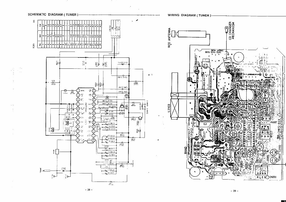
-r
\
WS1N
VH
33WU
39NV
H3
C13
~IT—1
Lb
S“9
b<
LbS’9
[?
L“OS“9
Zz
L’bS9
12.L’11
S“9Oz
z1
S161
[’0LO
815“s
09[i
SE59
918“E
6551
Ot01
V1
01o’1
ElL’c
09ZILt
01
00
6LV
S“98
L“vS“9
1L“LI
S’99
Oto
s
Z“tLS
bZ’[
L’SE
o0
zL’O
o1
Wdw?
‘ON
(A)[02>1
&o
Lzl
.
?
.,b2-!012s
l-lolzs
Ix?
%-
wo
w0,
0I
a,{1.,,,
1lllL
4xA!()(,,,
ImmI
.>“:
.
ImmI
,..,.,
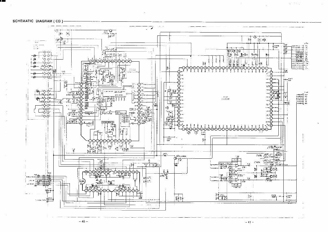
I
.,,,,
4+,, ,.,
,
J’
I ~
I 1 6 1
—
l-lI
—. 1-
-1-1
-1.—
1:$
~— . —
— —.
.1
<m”>
I
— — “.,-
--@
”’
—
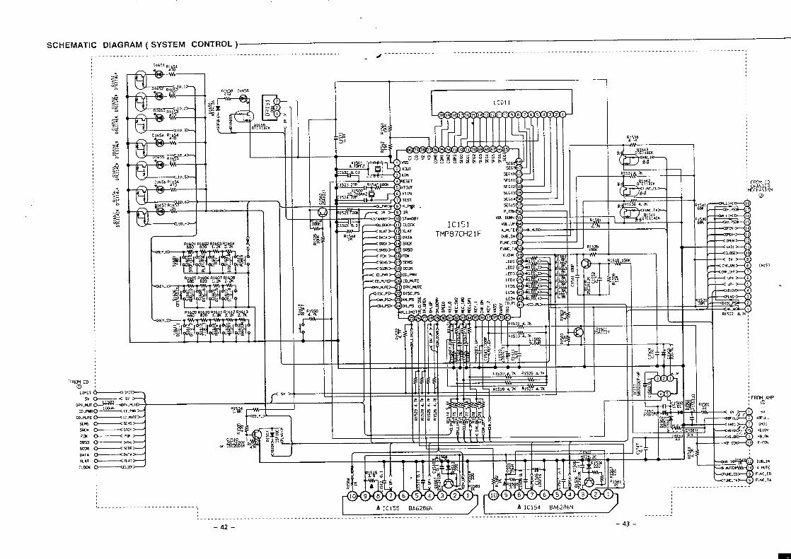
SCHEMATIC DIAGRAM ( SYSTEM CONTROL )_.-_..z ----------------------------------------------------------------------------------------------- . . . . .
—
.
I
—
—
LCD1 1
I I I I 1 I I I II II I%
I
I
I liz5YEi_l
CN153
..
I I I I I II II 1 A, L * 1 I I 1 1 T
I I I i 1 11
}
1 1
f I I
6V
,Brm,
GNDI
.Blow
‘9. m
P-cm.
A tiJTf
FUK.CD
FwC.TA
.. . . . . . . . . . . . . . . . . . . . . . . . . . . .. I A IC155 BA6286N I A IC154 BA6286N
......---------------------------------------------------------------------------------------------------------------------.....
-42- -43-
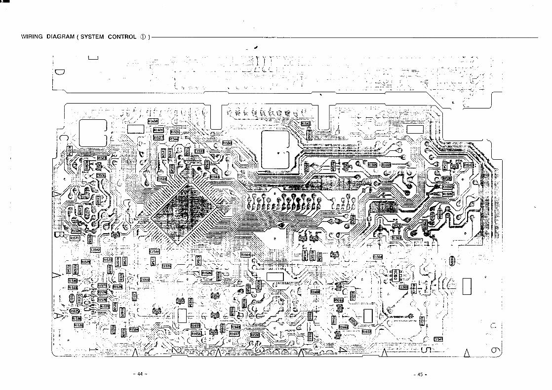
i
a
[
).,-
,’:
i,,
f“”,
,[ ..
!,
‘(.:.,
~,.;
.,: .
T“
....,
iI
(/Y
-c (n
-1 m z
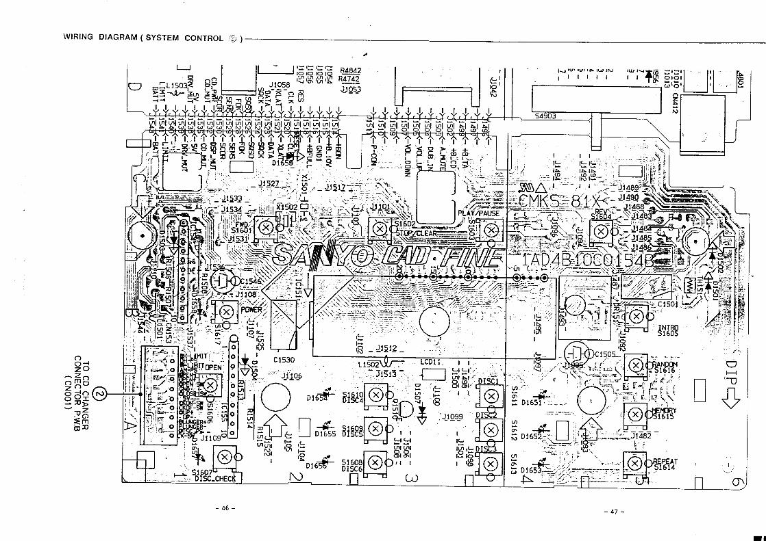
%J3-
1956*--3.-2.-
rl(
—i--$_
q
omvU-I
.,6’-:
......
4
0 2T
OC
DC
HA
NG
ER
CO
NN
EC
TO
RP
.W.B
(C
NO
O1
)
ii
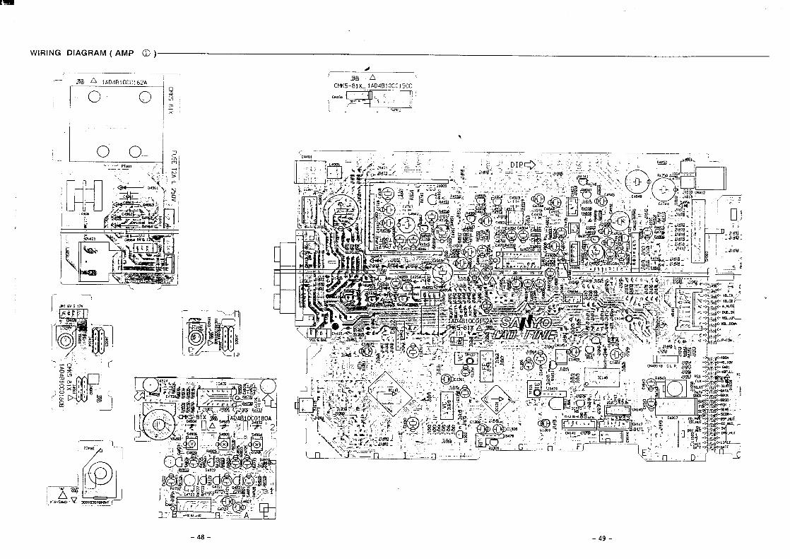
ii
I & I ?2.
I
1.~
-—.
——
..
k7—
–Jn
-.=
.A–—
k
r-—
——
,#pm
----
m
,.7
.g
—,
—n
I(u
II
I‘,
..
...
..
_..J
oD
og
‘
o#
D
-1X
iw-s
wc
I
I,
1II
1
*
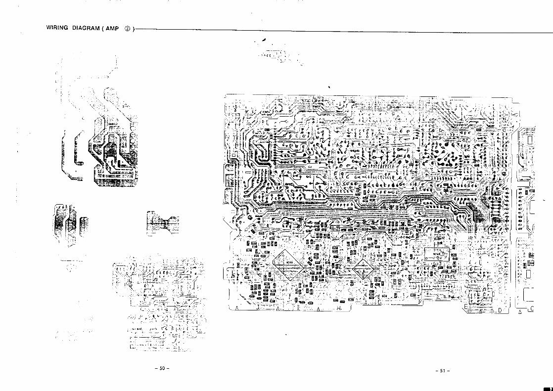
,,.,
,-.,.-)
,,r--‘
;,I:’
\:1.
L5
J.-
<‘\v
E..
2~ %..L
#w
..”’.,,.
,,:
t,‘...
,.“t
E..
,.,
.,
t171I
&,
.,1
3
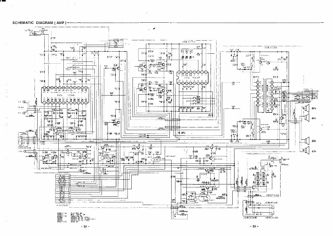
.
-.<
—t-- ul’------
,— Iu
–q,W
I
--.-
--5
I
——
-.—
.–—
.—.
.——
.—.
—,<
—-—
—.—
.—
II
!’ I i
1
IL
11
II
L–..
——.
—.—.
—.—
.-—.
—–-
——-
L.
----
-.-
-—.
—-.
..—
.—–.
..-—
.-.
–
1~
‘-—–-
1I
I
I I
1.
<//,
/,-
.l— I
II
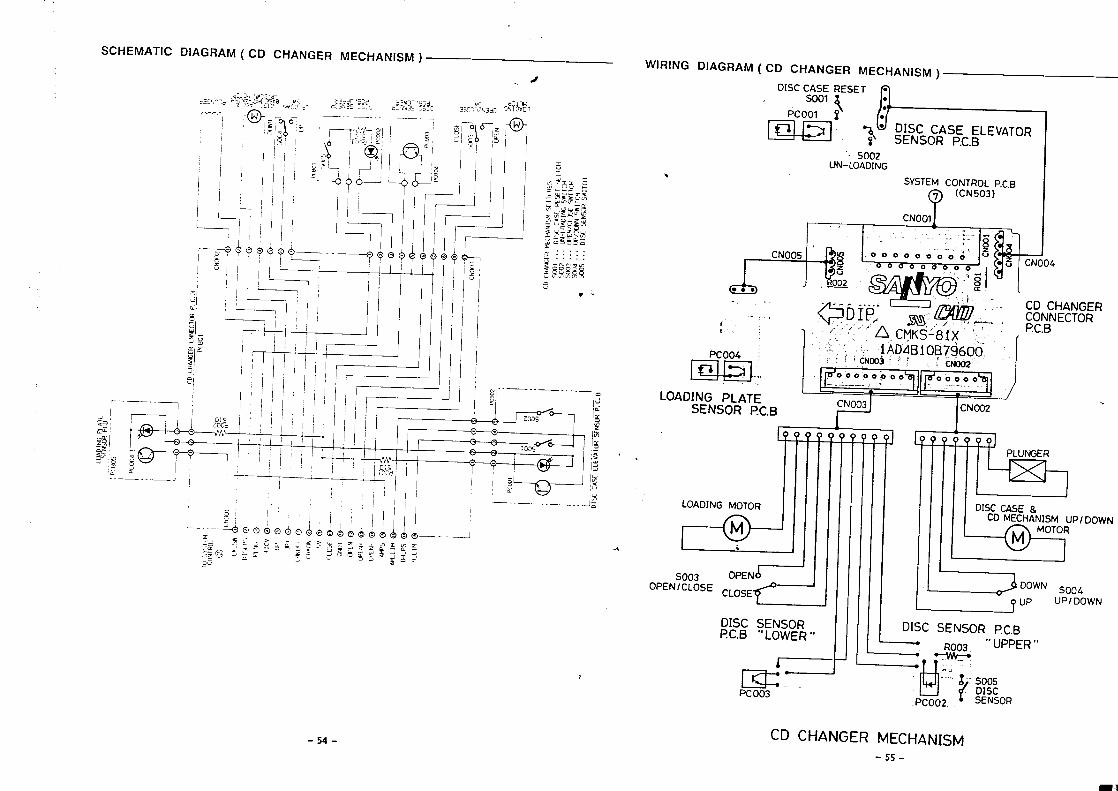
i
z
a
\
c1
mu
41.“
●●●,
.,“
#
o“Z
’~N
3$
L0
1V
A3
13
3y0
x[O
—.
___
l—1
..
II
I
I
1
.11
--J ,ilI1-H
.
Lo
132<,
—.
.—__~b
Y:’,
a—
—.
_
L—
-——._
,:[:~
.’~
~1crn
+c—
——
__lw
111
-–--–—--==
1
,_*.._.-.__@S
.-H,
J~~
,-.
..
..
..
..
____j7
J“,,,
.I
.-u.:
Ill(IN)
iI!ON
)
41[+
(!3
10flM:
Hw?
“?,,-—
.._..
_8
~“d
W31J3N
N3U
3r3NV
H30,
—.
.__...(
,,_______
I
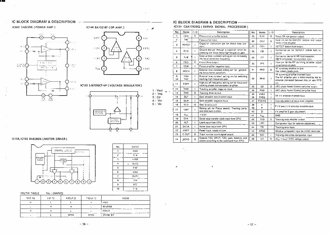
-Ls--9s-
1AsONVISN3dClN3d0I7I7
3>VM871HH
3SM3A3MI1IHIHI1
t
aM3H11H
3aow(1100)L(zmo)D(N1M)Z(N14)OL
(3WWN):“ON37avlHlnMl
H33A6
WA8
LlnoL
aN99
3NNs
zmo-b
43tJAc
N)Hz
aN31
w
3AVStj3MCId
&..-
13WVNIoiul
(Li3’AIUaIIO1OLN)N98Z9VS
=
luaujsn[peaweleqJO,)ndu,iolejeduo~I
Indtnojaa),ldwe,oj,a6u1x3e,L
Iuaumnlpeu!efi3Jatl,ldweA.IwammwxpaISpue‘dunl6UW3eIL‘qmeessnmj>01utd6u01asi13s1LL
uldlnoeA!lppals()01SI9Llndu,peua,wm,ldweA.I~pueAId
111;1:1,11IIJagildwe)omsn>ojIO]uaulsn(pesefe,SVIE34LE.mdu!a.qe6au>eq!{dwepOIS,WlsSL!,”,,,”,
3,,?,,
Imdu!peLraAu!Ja!p!dweA-Ij!j
IIZCIHdI9SII.mdwDeua.w.uouml!$!dueoom[I[AT<I*,1
.lndu,,a!,,,due(IOIWODmhiodO)nv)OdVIIIa
...-+-a.
I.Indp
(l101Vlf193~39V11OA)dA-430SOL8-SES131
iI
.,nd,n”,,,,,?,,,,,-,,,,,,,,,,,,..,8--––!<\mdua,ic)e6a”,a,i$[dwesnmj,W3+L
IndinoampsmodIoI034I9
.33,4
I!JI+
lNl-
[Lno
ZN
ZN
..,.....,.—...-—.,paldnog.awm!xdex
md;nom(j,ldwe6“,wums4HeqIKI,u,d,Cdu{I14HOc,I1
mdupasm.w.cou,oiejedmozHHIW,Amxanba,iMOo,uessnaojauImxoede>pIOUHHIV410Iu,dUO113.3UU03do6Zfiu!SWJXJJOIu,d6u1uas)uUSU03WIJ(l,et,,alx?IS14s
-u03awtilzalapAOIuldUO!I>Q
-------,..tndu,)omsnxoj[ I11!133z
]ndmo,owiedumMOSnmdoY04Sz.Indmoja!pldwexm,asn>od0034L
uo!td!iasaaItO/1[a~eNI“ONIIuopd!msaa10111aUJeNIONI
#-(“d!JIVdO)48LZSLVSIbbL31(“dWVt43MOd)x6zz8V1EOti31
NOlldlHW3Cl?3WVE19VlClYC)OIE!31
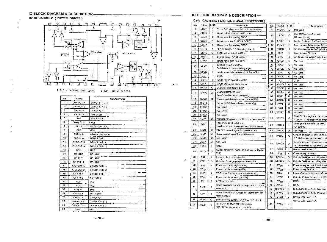
IC BLOCK DIAGRAM & DESCRIPTION
IC140 BA63SSFP ( POWER DRIVER)/
I+R5
74 OP OUT OP. AMP
35 OP IN (-) OP. AMP
36 OP IN(+) OP. AMP
77 CH3-OUT A DRIVER CH3(-)
18 CH3-CJUT B DRIvER CH3(+)
19 CH3-IN A DRIvER CH3
20 CH3-IN Er NOT USED
21 Vcc Vcc
22 Vcc Vcc
23 BIAS IN BIAS
24 CH4-IN B NOT USEO
25 CH4-IN A DRIvER CH4
26 CH4-OUT B ORWER CH4 (+ )
27 CH4-OUT A ORIVER CH4(-)
28 GND GND
* “.
IC BLOCK DIAGRAM & DESCRIPTION
IC141 CXD2518Q ( DIGITAL SIGNAL PROCESSOR )
No. Name 1/0 Description
,
. [
No.
T SCOR o Turns “H- when sync SO or S1 m delecred. 41
2 SBSO o serial OUtPul 01 sub-code P - W.
3 EXCK I42
Clock ,nput for reading SBSO.
4 S(X3O o Serial output 01 SUBO & SOBIT. 43
5 SOCK r Clock mp.1 for reading SL3S0. 44
6 MUTE I “H” al mubng, “L” al mut,ng cancel. 45
7 SENS o SENS sgnal output to CPU. 46
8 XRST 1 System reset, “L- at ,esetfmg. 47
9 DATA I Inputs serial data from CPU. 48
Latches input from CPU.10
49XLAT I
Serial data latches at Ming edge. 50
11 CLOK I Inpuls serial data transfer clock from CPU. 51
12 Vss - GND. 52
13 SEIN I Inputs SENS signal from SSP. 53
14 CNIN I Inputs track jump count $ignal 54
15 DATO o Outputs serial data to sSP 55
&H==+Serial data latches at lalhng edge.
O Oulputs serial data transrer clock 10 SSP.
PI” for TEST. Normal used state VDD.
=BEiE=ainterlace (or extenson of M. processor(oulput )
%44==2+Used servo auto sequencer w,th SENS output.
ONIOFF control s!gna! {or spindle momr.
O Servo control signal for spindle motor.
E56
57
58
59
60
61
62
E63
64
65
I 27 LOCK o Not usedl16Li
28 TEST I GND.
29 FILO o
‘ ‘ I
Output of falterfor master PLL. (Slave = O@al 67
PLL) 68
30 FILI rnpuls to filter for master PLL. 69
31 Pco o Outputs of charge pump for master PLL. 70
32 VOD - Power supply for d!g4aL( + 5V) 71
33 AV=~l - Power supply Ior analog. 72
34 CLTV I VCO control voltage ,np”t for master PLL. 73
35 AVDD1 - Power supply for analog.( + 5v) 74
36 RF EFM s,gnat mprt 75
37Inputs constant cwfent for asymmetry correc- 76
BIAS Ihon C,rc”it. 77
38Inputs compamtor voltage for asyrnmetiy cop
ASYI I78
reCllOn CIICUIL 7939 ASYO o EFM NI $wmg O“tp”t.(”L- = V~~, “H”= VDO)
40“L” : OFF of asymmeky correction.
ASYE I JL80
‘“H” : ON of asymmetry correction.
Name I/o Description
WDCK I O ] Not used
-
lnpul$ LR Clcck10DAC (48. blt slo
O DIA mleriace. Serial data(2SCOMP
!EBEInputs a“dto dara to DAC.(48.br! sl
inputs bit dock to DAC.(48 -bit slot
XPCK } O I Not used
h4NT3 I O I Not used
MNT1 I O I NoI ,,4
yo ( o Itd”t!!4
.
-E
I . . ---
w-r I 0 Not used
;4M O ] Not used
EMPH oSays “H” hx playback dwc prowd
phasis of ‘L- kx that w,thoul emph
EMPHI IDe-emphasis ONK)FF of DAC. “
“L. al OFF.
WFCK o Not used
Outputs detecvcmlor non-sound daZEROL o
“H” al dekxxm Icunon+ound data
?EROR oOutputs delec!mn for non.sound da
“H” at &tec@ for non.smmd dala
DTS1 1 Normalwed slate“L-.
AVDD3 - Power sup@yk Xlal.
XTAI I Inpuls X’L31mlral,o” circwt (33.668
XTAO i OuIpuIs X%1 ascdlabonCtrcult(33.6
AV~~3 - GND.
AV.q-, - GND.
IRPWM o Outpuls PWM & R.ch. (Negabve P
?PWM O I Outputs PWM fw R.ch. (Pos,rwe P
DTS2 I Normal US.% slate “L”.
I i Normalusedsag ‘L-.
0TS3 II
-58- -59-
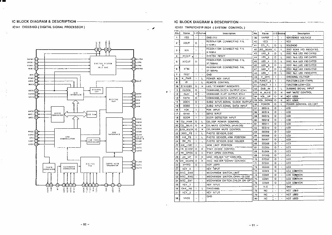
iiii
.m2:
”;:
:5:
e.-.
”.
..s.
”.,-
-
-( —~
I1s
71CLM
R1
AS
YI
XP
CK
FILO
PIL[
CLTV
Id1xl
’,!
XT
AO
1ZE
RO
LZ
ER
OK
I1 I
I
1—
I
Q ,,
I ) ) , ) ; ?
m
(-l o z -1 m o r
> 7 1 ) > ) : > >
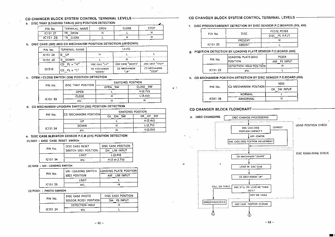
CD CHANGER BLOCK SYSTEM CONTROL TERMINAL LEVELS CD CHANGER BLOCK SYSTEM CONTROL TERMINAL LEVELS
a. DISC TRAY (LOADING TABLE) (431) POSITION DETECTION d I
PIN No. TERMINAL NAME OPEN CLOSE STOP
IC151 27 TR OPEN H L H
IC151 26 TR CLOSE L H H
b. DISC CASE (363) AND CD MECHANISM POSITION DETECTION (UP/DOWN)1
PIN No. TERMINAL NAME LEVEL
IC151 28 D UP H L L.... . ...... ... ...... .... . .. ... .. . . . .. .. ..... .. ..
IC151 29 D DOWN L H L
CD PL = “H” DISC CASE ‘UP- D15C CASE “DOWN- DISC CASE “STOP”., . ..-. . . . . . . . . . . . . . ......... ....
Q151O CD PL = “’L”CD MECHANISM CD MECHANISM CD MECHANISM
— - DOWN” -uP- “STOP-
C. OPEN I CLOSE SWITCH (339) POSITION DETECTION
SWITCHES POSITIONPIN No. DISC TRAY POSITION
CIPFN SW I CLOSE SW 1------OPEN L H (2.7V)
CLOSE H L (3.4V)IC151 33
etc. H H
d. CD MECHANISM UPIDOWN SWITCH (393) POSITION DETECTION1
PIN No. CD MECHANISM POSITIONSWITCHES POSITION
CK ON SW CK OF SW——UP L ;(3.4;)
DOWN HIC151 34
L (2.7V)
etc. H H (5.OV)
e. DISC CASE ELEVATOR SENSOR P.C.B (315) POSITION DETECTION
(1) S001 : DISC CASE RESET SWITCH
DISC CASE RESETPIN No.
DISC CASE POSITION
SWITCH S001 POSITION DH LIM INPUT
LIMIT ‘L (3.4V)
IC151 34 etc. H (5 Or 2.7V)
(2)SO02 : UN - LOADING SWITCH
UN - LOADING SWITCH LOADING PL4TE POSITIONPIN No.
S002 POSITION AM LIM INPUT
LIMIT L
IC151 25 etc. H
(3) Pcool : PHOTO SENSOR
DISC CASE PHOTOPIN No.
DISC CASE POSITION
SENSOR PCOO1 POSITION DH PS INPUTI 1
DETECTION HOLE H
IC151 24 et c I L
f. DISC PRESENT/ABSENT DETECTION BY DISC SENSOR P. C. BOARDS (345, 450),
I PIN No. I “SC I-%%%&i—PRESENT H
IC151 22 ABSENT L
g. PC$ITION OETECTION BY LOADING PLATE SENSOR P. C. BOARD (304)
LOADING PLATE (434) PCO04PIN No.
POSITION AM PS INPUT
DETECTION HOLE POSITION H
IC151 23 etc. L
h. CD MECHANISM POSITION OETECTION BY DISC SENSOR P.C. BOARD (450)I 1 1 I
CD CHANGER BLOCK FLOWCHART
a. DISC CHANGING DISC CHANGE PROCESSING I —.... ... ..... ............... ....... .... ... . .... .. .. ........ ... ...................... ..
tI DISC CASE (363) I
j LOAD POSITION CHECKCORRECT :
1............s....1DISC CASE (363) POSITION ADJUSTMENT
ILOAO IN DISC CASE
I
=+=
; .....................J. .. ...
~.=+= +“”’””””’’’”””””t)2
DISC REMAINING CHECK
-62- -63-
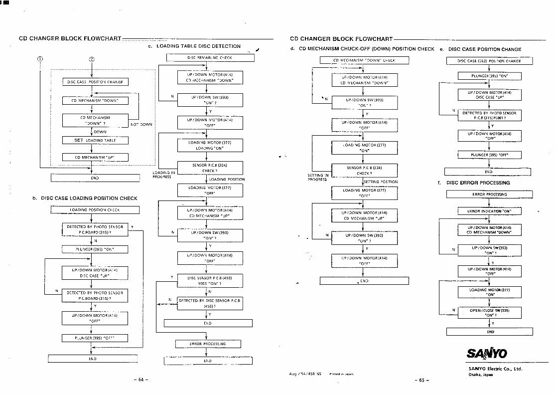
-s9--t79-ueder,e~eso
“Pll‘“mwwOANIVS
IaN3
&
aN3
+
N
aN:IO*S
‘A4
=%=-lI
.440.
(7!9)HO1OWNMOO/dnI
I
i1I>-L“NO”500S
(OSD)9”3dMOSN3S3S10A
t
t——————l
-,L-No.
(C6ESMSNMOO/dnN
II
&I
“~jo.(@Lb)tlOiOWNMOCI/ dfl
.
*
s
.df).WSlNVH33kVcl>
(tit@)MO1OWNMOa/drl
.440.
(LLE)UO1OW‘3NIOV01
G+d= .dn.WSINVH>3Wa>
(DIP)L401OOINAIOa/df)
t+
I
.440.
(LLZ)HoLow9Nlavol
I.NO”(S6E)!d39NnldI
&.
1
t-,I.NO.NOILVX3NI i10bw3II>>?H3NOlllSOd9NlaVOlI
t9NlSSI10HdMOMM3
Y03H3NOlllSOd!3NlaVOl3SVCIZX31a“q
9NlSS330HdHOW33SICI
‘R%k--F=’IaN3I
IaN3I
‘“r-2E+zl 431SV19NlavolLqs
I
NMoa+
.440.(Pi?)NO1OWNMOCT fdfl
~
,NMOO10Nt.NMO13,,
L.NO,,(E6E)MSNMOO/dn
}N%
f
1,,NO.
(:6E)AMNmoa/dnI
__.J_._N
I.dn.3SV)xla
(ttv)~olawNMoa/dnI
I
,.N,moa”kw51NvH33wa>
(DID)‘doLowNMoa/dnII
.NMOO,,WSINVH>3WCl>
(tilP)BO1OWNMOCl/dflI
1
[.NO.(56E)t139Nllld
4f~““”””””””“’”””””””’”’’”’”””””’”’”’”’””’””~................
IX>3H39NINIVW3Mxla@) (
33NVH3NOIJ.lSOd3SV33SICI“~X33H3NOlllSOd(NMOa)+0-)10nH3WSINVH33MaClP