SERE TRAINING COMPLEX PN 80774 Camp MacKall ... - AWS
374
RFP No. W912PM19R0018 SERE TRAINING COMPLEX PN 80774 Camp MacKall, North Carolina FF&E and Audio Visual Specifications - Volume 3 of 3 FOUO June 2019
-
Upload
khangminh22 -
Category
Documents
-
view
0 -
download
0
Transcript of SERE TRAINING COMPLEX PN 80774 Camp MacKall ... - AWS
RFP No. W912PM19R0018
SERE TRAINING COMPLEX PN 80774Camp MacKall, North Carolina
FF&E and Audio Visual
Specifications - Volume 3 of 3
FOUO
June 2019

RFP No. W912PM18F0045
SERE Training Complex
PN 80774 Camp Mackall, North Carolina
FF&E and Audio Visual - Volume 3 Corrected Final Submittal
6302 Fairview Road, Suite 600
Charlotte, North Carolina 28210 Phone (704) 358-8240
NC Eng. License No.: C-3190 NC Arch. License No.: 52842
March 2019

SERE TRAINING COMPLEX CAMP MACKALL, NC
PN 80774
Table of Contents Page 1
PROJECT TABLE OF CONTENTS
VOLUME 1 - SPECIFICATIONS
DIVISION 00 – PROCUREMENT AND CONTRACTING REQUIREMENTS
00 01 15 LIST OF DRAWINGS 00 10 00 CONTRACT LINE NUMBER SCHEDULE 00 70 00 CONDITIONS OF THE CONTRACT 00 73 00 SUPPLEMENTARY CONDITIONS
DIVISION 01 - GENERAL REQUIREMENTS
01 10 00 SUMMARY OF WORK 01 10 00.10 38 SUPPLEMENTARY SPECIAL CONTRACT REQUIREMENTS 01 11 00 STATEMENT OF WORK 01 11 01 SITE CIVIL UTILITIES AND LANDSCAPE 01 11 02 LIMITED USE INSTRUCTION BUILDING 01 11 03 INDIVIDUAL TRAINING BUILDING 01 11 04 CAMP AID STATION 01 11 05 AV-INTERVIEW 01 11 06 MULTI-PURPOSE BUILDING 01 11 07 PODIUM 01 11 08 INSTRUCTOR CONTROL BUILDING 01 11 09 TOWERS 01 11 10 LARGE GROUP INSTRUCTION BUILDING 01 11 11 LATRINE 01 11 12 KITCHEN 01 11 13 CONTROL POINT 01 11 14 COVERED AREA 01 14 00 WORK RESTRICTIONS 01 20 00.00 20 PRICE AND PAYMENT PROCEDURES 01 30 00 ADMINISTRATIVE REQUIREMENTS 01 32 01.00 37 PROJECT SCHEDULE 01 33 00.00 37 SUBMITTAL PROCEDURES 01 33 16.00 10 DESIGN DATA (DESIGN AFTER AWARD)
01
33 29.00 37 SUSTANABILITY 01 35 26 GOVERNMENTAL SAFETY REQUIREMENTS 01 42 00 SOURCES FOR REFERENCE PUBLICATIONS 01 45 00.00 10 QUALITY CONTROL 01 45 00.15 10 RESIDENT MANAGEMENT SYSTEM CONTRACTOR MODE (RMS 01 45 35 SPECIAL INSPECTIONS 01 50 00 TEMPORARY CONSTRUCTION FACILITIES AND CONTROLS 01 57 19 TEMPORARY ENVIRONMENTAL CONTROLS 01 57 19.00 37 INDOOR AIR QUALITY (IAQ) MANAGEMENT 01 58 00 PROJECT IDENTIFICATION 01 74 19.00 37 CONSTRUCTION AND DEMOLITION WASTE MANAGEMENT 01 78 00.00 37 CLOSEOUT SUBMITTALS 01 78 23 OPERATION AND MAINTENANCE DATA 01 78 24.00 10 FACILITY DATA REQUIREMENTS 01 91 00.00 37 COMMISSIONING

SERE TRAINING COMPLEX CAMP MACKALL, NC
PN 80774
Table of Contents Page 2
VOLUME 2 – APPENDICES
APPENDIX A GEOTECHNICAL REPORT APPENDIX B DD FORM 1391 APPENDIX C ENVIRONMENTAL PROTECTION PLANS APPENDIX D HYDRANT FLOW TEST APPENDIX E FORT BRAGG WEATHER DATA APPENDIX F FORT BRAGG TREE MITIGATION APPENDIX G FORT BRAGG SEEDING SPECIFICATION APPENDIX H UTILITY RATES AND CHARGES APPENDIX I FORT BRAGG ACCESS FORMS APPENDIX J RECYCLING APPENDIX K PERMIT LISTS AND FORMS APPENDIX L GIS NON-DISCLOSURE AND REQUEST APPENDIX M TOTAL DESIGN ANALYSIS APPENDIX N FINDING OF NO SIGNIFICANT IMPACT APPENDIX O PROGRAMMATIC ENVIRONMENTAL ASSESSMENT APPENDIX P ROOM INFORMATION SHEETS APPENDIX Q USACOC VTC PRODUCT DESIGN GUIDE APPENDIX R NATIONAL SECURITY TELECOM APPENDIX S SECRET INTERNET PROTOCOL ROUTER (SIPR) APPENDIX T USASOC IT TECHNICAL DESIGN GUIDE APPENDIX U FORT BRAGG COMMS IDC APPENDIX V TYPICAL ICIDS INSTALLATION APPENDIX W USASOC TELECOM ROOM LAYOUT APPENDIX X FORT HAUCHUCA 13A APPENDIX Y CYBER SECURITY APPENDIX Z ENVIRONMENTAL COMPLIANCE CHECKLIST
Volume 3 - FF&E and AV
Furniture, Fixtures, and Equipment (FF&E) Audio-Visual Package (AV)
-- End of Project Table of Contents –

SERE Training Complex Camp Mackall, NC
PN 80774
FURNITURE, FIXTURES, AND EQUIPMENT (FF&E)
SERE Training Complex Camp Mackall, NC
PN 80774
THIS PAGE IS INTENTIONALLY LEFT BLANK

FF&E PACKAGE
Wilmington District
SOF SERE RESISTANCE TRAINING LABORATORY CAMP MACKALL, NC
CONTRACT NO: W912HN-18-D-2001
TASK ORDER: W912PM-18-F-0045
PROJECT NO: 80774
CORRECTED FINAL DESIGN SUBMITTAL
April 22, 2019

SERE RESISTANCE TRAINING LABORATORY FF&E PACKAGE
100% DESIGN SUBMITTAL 03.08.2019
TABLE OF CONTENTS
Section 1 ............................................................ Narrative
Section 2 ....................................... Keyed Furniture Plans
Section 3 ......................... Furniture Specification Sheets
Section 4 .......................................................... Equipment
Section 5 ................................................ Item Code Index

SERE RESISTANCE TRAINING LABORATORY FF&E PACKAGE
100% DESIGN SUBMITTAL 03.08.2019
SECTION 1 NARRATIVE

SERE RESISTANCE TRAINING LABORATORY FF&E PACKAGE
100% DESIGN SUBMITTAL 03.08.2019
Project Overview
The intent of this project is to design and construct a quality SOF SERE Resistance Training Laboratory at Camp Mackall consisting of multiple buildings. The buildings with FF&E requirements include AV/Interview Building, Multi-Purpose Building, Instructor Control Building, Guard Tower, Limited Use Instruction, Individual Training Building, and Camp Aid Station. Key areas within these buildings will be designed to have an authentic 2nd-world appearance and the FF&E is required to align with this appearance.
The items identified in this document have been programmed and coordinated with the user. Furniture, fixtures & equipment shall comply as noted to support the proper needs of this training facility.
Furniture, Fixtures & Equipment Procurement & Installation
The FF&E package shall be provided by the contractor. The contractor shall provide FF&E items in accordance with this document and shall supply the government with Specifications, Keyed Plans and itemized cost for review.
The items in this document include but are not limited to task seating, conference seating, side seating, stools, interview tables, pull-up chairs, work and conference tables, work bench, storage cabinets, shelves and cubbies, cots, rolling industrial tables, laundry equipment, kitchen ancillary equipment, lockers/wardrobes/benches, desking, bookcase, exam chair, medical cabinet, AED, therapy tub and privacy curtain. The contractor will be responsible for accommodating and coordinating with GFGI items.
Furniture Requirements
FF&E items are identified and tagged on the furniture plans. Each item is tagged with a unique identification letter/number. The furniture specification sheets provide a description of each product along with the location and quantity.

SERE RESISTANCE TRAINING LABORATORY FF&E PACKAGE
100% DESIGN SUBMITTAL 03.08.2019
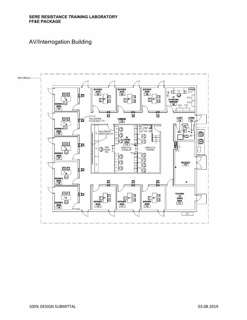
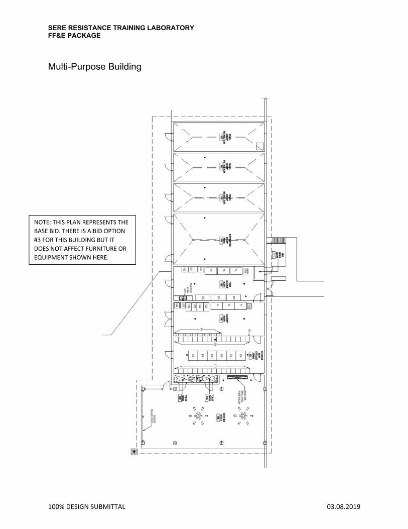
SECTION 2 KEYED FURNITURE PLANS
SERE RESISTANCE TRAINING LABORATORY FF&E PACKAGE
100% DESIGN SUBMITTAL 03.08.2019
AV/Interrogation Building
SERE RESISTANCE TRAINING LABORATORY FF&E PACKAGE
100% DESIGN SUBMITTAL 03.08.2019
Multi-Purpose Building
NOTE: THIS PLAN REPRESENTS THE
BASE BID. THERE IS A BID OPTION
#3 FOR THIS BUILDING BUT IT
DOES NOT AFFECT FURNITURE OR
EQUIPMENT SHOWN HERE.

SERE RESISTANCE TRAINING LABORATORY FF&E PACKAGE
100% DESIGN SUBMITTAL 03.08.2019
Instructor Control Building
SERE RESISTANCE TRAINING LABORATORY FF&E PACKAGE
100% DESIGN SUBMITTAL 03.08.2019
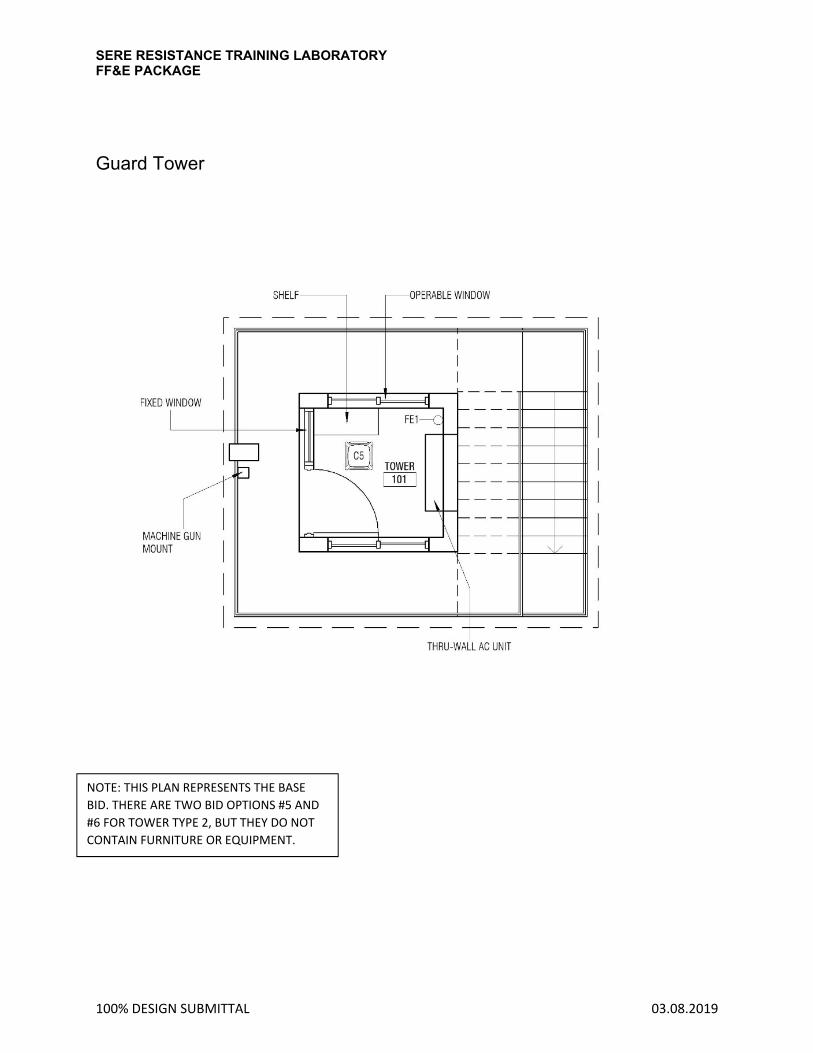
Guard Tower
NOTE: THIS PLAN REPRESENTS THE BASE
BID. THERE ARE TWO BID OPTIONS #5 AND
#6 FOR TOWER TYPE 2, BUT THEY DO NOT
CONTAIN FURNITURE OR EQUIPMENT.

SERE RESISTANCE TRAINING LABORATORY FF&E PACKAGE
100% DESIGN SUBMITTAL 03.08.2019
Individual Training Building
NOTE: THIS PLAN REPRESENTS THE BASE BID. THERE IS A
BID OPTION #4 FOR THIS BUILDING BUT IT DOES NOT
AFFECT FURNITURE OR EQUIPMENT SHOWN HERE.

SERE RESISTANCE TRAINING LABORATORY FF&E PACKAGE
100% DESIGN SUBMITTAL 03.08.2019
Limited Use Instruction – First Floor
SERE RESISTANCE TRAINING LABORATORY FF&E PACKAGE
100% DESIGN SUBMITTAL 03.08.2019
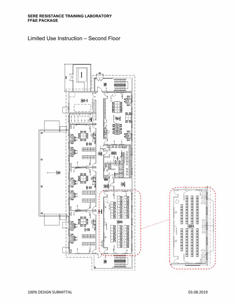
Limited Use Instruction – Second Floor

SERE RESISTANCE TRAINING LABORATORY FF&E PACKAGE
100% DESIGN SUBMITTAL 03.08.2019
Camp Aid Station

SERE RESISTANCE TRAINING LABORATORY FF&E PACKAGE
100% DESIGN SUBMITTAL 03.08.2019
SECTION 3 FURNITURE SPECIFICATION SHEETS
Project Date CodeItem Name
Manufacturer | Specification Illustration
Location Quantity
Warranty/Testing
Total Quantity
FURNITURE FIXTURE + EQUIPMENT SPECIFICATION IA Interior Architects
Camp Mackall SERE Training - 100% Submittal 03.08.19
Fabric/Finish
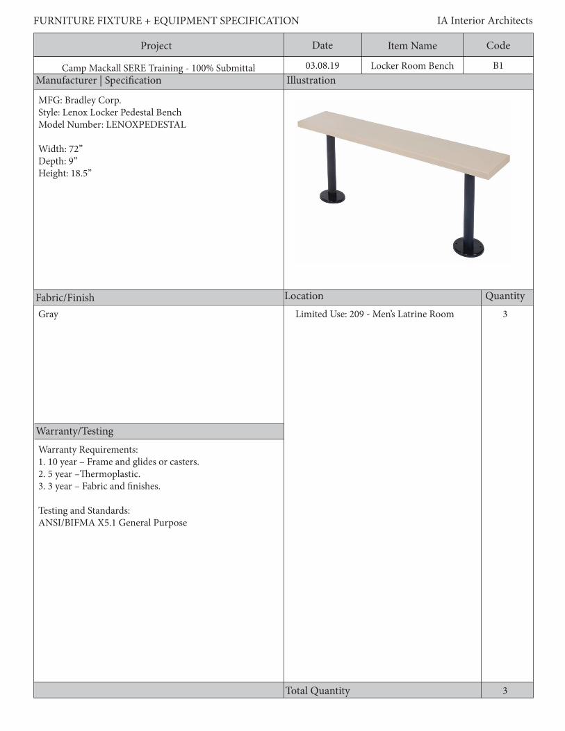
B1Locker Room Bench
3Gray Limited Use: 209 - Men’s Latrine Room
3
MFG: Bradley Corp.Style: Lenox Locker Pedestal BenchModel Number: LENOXPEDESTAL
Width: 72”Depth: 9”Height: 18.5”
Warranty Requirements:1. 10 year – Frame and glides or casters.2. 5 year –Thermoplastic.3. 3 year – Fabric and finishes.
Testing and Standards:ANSI/BIFMA X5.1 General Purpose

Project Date CodeItem Name
Description
FURNITURE FIXTURE + EQUIPMENT SPECIFICATION IA Interior Architects
Camp Mackall SERE Training - 100% Submittal 03.08.19
General Requirements:1. Frame shall be tubular steel or die-cast aluminum or ½” diameter wire rod.2. Joints shall be welded3. Seat shall be composed of HDPE plastic4. Shall be impervious to moisture
Material: Chair padding materials and fabric shall comply with the State of California Technical Information Bulletin 117.
B1Locker Room Bench

Project Date CodeItem Name
Manufacturer | Specification Illustration
Location Quantity
Warranty/Testing
Total Quantity
FURNITURE FIXTURE + EQUIPMENT SPECIFICATION IA Interior Architects
Camp Mackall SERE Training - 100% Submittal 03.08.19
Fabric/Finish
B2Locker Room Bench
1Limited Use: 210 - Women’s Latrine Room
1
Grey
Warranty Requirements:1. 10 year – Frame and glides or casters.2. 5 year –Thermoplastic.3. 3 year – Fabric and finishes.
Testing and Standards:ANSI/BIFMA X5.1 General Purpose
MFG: Bradley Corp.Style: Lenox Locker Pedestal BenchModel Number: LENOXPEDESTAL
Width: 48”Depth: 9”Height: 18.5”

Project Date CodeItem Name
Description
FURNITURE FIXTURE + EQUIPMENT SPECIFICATION IA Interior Architects
Camp Mackall SERE Training - 100% Submittal 03.08.19 B2Locker Room Bench
General Requirements:1. Frame shall be tubular steel or die-cast aluminum or ½” diameter wire rod.2. Joints shall be welded3. Seat shall be composed of HDPE plastic4. Shall be impervious to moisture
Material: Chair padding materials and fabric shall comply with the State of California Technical Information Bulletin 117.

Project Date CodeItem Name
Manufacturer | Specification Illustration
Location Quantity
Warranty/Testing
Total Quantity
FURNITURE FIXTURE + EQUIPMENT SPECIFICATION IA Interior Architects
Camp Mackall SERE Training - 100% Submittal 03.08.19
Fabric/Finish
B3Metal Handcuff Bench
4
MFG: NorixStyle: Cuff BenchModel Number: IBF-72
Width: 72”Depth: 18”Height: 18”Weight Limit: 750 lbs.
Steel Limited Use: 102 - Holding Area
4
Warranty Requirements:3. Warranty shall cover users up to 300 pounds
Testing and Standards:1. ANSI/BIFMA X5.1 General Purpose

Project Date CodeItem Name
Description
FURNITURE FIXTURE + EQUIPMENT SPECIFICATION IA Interior Architects
Camp Mackall SERE Training - 100% Submittal 03.08.19
General Requirements:1. Frame shall be cut, formed, and welded steel2. Joints shall be welded.3. Bench shall have floor mounting at all legs, anchord to floor4. Frame shall be 12 gauge steel5. Bench shall have powder-coated cuff rings welded to frame6. Bench shall have a min. 750 lb static load capacity
Material: Chair padding materials and fabric shall comply with the State of California Technical Information Bulletin 117.
B3Metal Handcuff Bench
Project Date CodeItem Name
Manufacturer | Specification Illustration
Location Quantity
Warranty/Testing
Total Quantity
FURNITURE FIXTURE + EQUIPMENT SPECIFICATION IA Interior Architects
Camp Mackall SERE Training - 100% Submittal 03.08.19
Fabric/Finish
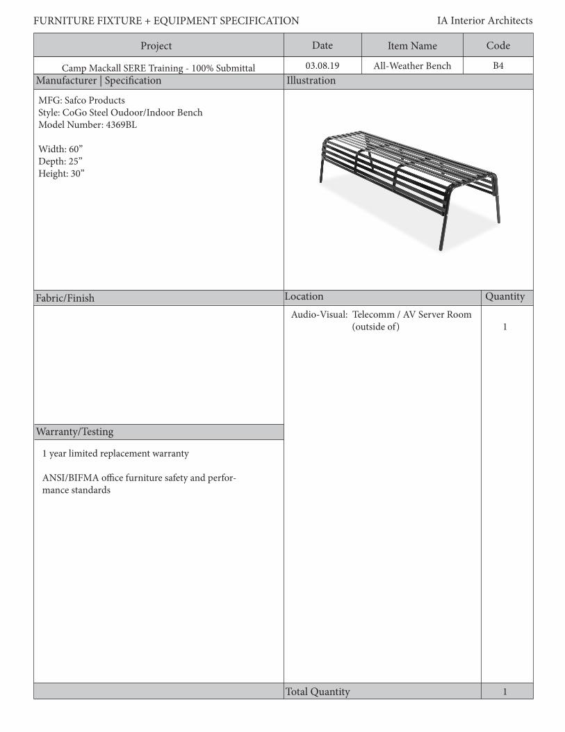
B4All-Weather Bench
1
1 year limited replacement warranty
ANSI/BIFMA office furniture safety and perfor-mance standards
Audio-Visual: Telecomm / AV Server Room (outside of)
1
MFG: Safco ProductsStyle: CoGo Steel Oudoor/Indoor BenchModel Number: 4369BL
Width: 60”Depth: 25”Height: 30”
Project Date CodeItem Name
Description
FURNITURE FIXTURE + EQUIPMENT SPECIFICATION IA Interior Architects
Camp Mackall SERE Training - 100% Submittal 03.08.19
General Requirements:1. Frame shall be tubular steel or die-cast aluminum or ½” diameter wire rod.2. Joints shall be welded.3. UV and weather resistant
B4All-Weather Bench
Project Date CodeItem Name
Manufacturer | Specification Illustration
Location Quantity
Warranty/Testing
Total Quantity
FURNITURE FIXTURE + EQUIPMENT SPECIFICATION IA Interior Architects
Camp Mackall SERE Training - 100% Submittal 03.08.19
Fabric/Finish
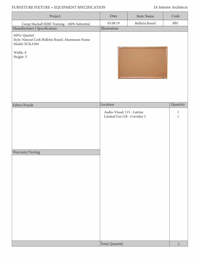
2
BB1Bulletin Board
MFG: QuartetStyle: Natural Cork Bulletin Board, Aluminum FrameModel: ECKA304
Width: 4’Height: 3’
11
Audio-Visual: 115 - LatrineLimited Use:128 - Corridor 3

Project Date CodeItem Name
Description
FURNITURE FIXTURE + EQUIPMENT SPECIFICATION IA Interior Architects
Camp Mackall SERE Training - 100% Submittal 03.08.19
General Requirements:1. Wall mounted2. Aluminum frame
BB1Bulletin Board

Project Date CodeItem Name
Manufacturer | Specification Illustration
Location Quantity
Warranty/Testing
Total Quantity
FURNITURE FIXTURE + EQUIPMENT SPECIFICATION IA Interior Architects
Camp Mackall SERE Training - 100% Submittal 03.08.19
Fabric/Finish
CC1Cubicle Curtain
3Camp Aid: 101 - Primary Exam/Treatment
3
MFG: WincoStyle: Privess Modular Privacy ScreenModel Number: 3749
Warranty: One year warranty
Sure-Check vinyl in Light Blue

Project Date CodeItem Name
Description
FURNITURE FIXTURE + EQUIPMENT SPECIFICATION IA Interior Architects
Camp Mackall SERE Training - 100% Submittal 03.08.19
General Requirements:1. 4 fabric panel modular hinged privacy screen2. Antimicrobial fabric, flame, stain, fluid, and odor resistant; anti-static; hypoallergenic; tear resistant; free of heavy metals such as lead, chromium, molybdenum, cadmium, etc.
CC1Cubicle Curtain

Project Date CodeItem Name
Manufacturer | Specification Illustration
Location Quantity
Warranty/Testing
Total Quantity
FURNITURE FIXTURE + EQUIPMENT SPECIFICATION IA Interior Architects
Camp Mackall SERE Training - 100% Submittal 03.08.19
Fabric/Finish
CT1Cot
12
Audio-Visual:101 - AV Technicians WorkshopCamp Aid: 103 - Ready Room
3
MFG: WEHSCOStyle: Rollaway Bed , 48 In.Model Number: 475
Width: 48”Length: 72-1/2”Height: 21-1/2”Weight Capacity: 275 lbs.
Heavy-duty vinyl mattress cover

Project Date CodeItem Name
Description
FURNITURE FIXTURE + EQUIPMENT SPECIFICATION IA Interior Architects
Camp Mackall SERE Training - 100% Submittal 03.08.19
General Requirements:1. Folding Roll-a-way Bed2. Min. weight capacity 275 lbs.3. 6 in. foam waterproof mattress included4. 4 in. Ball-bearing tires5. Heavy-duty, hospital-grade vinyl mattress cover that is antibacterial, anti-fungal, water proof, and flame retardant
CT1Cot

Project Date CodeItem Name
Manufacturer | Specification Illustration
Location Quantity
Warranty/Testing
Total Quantity
FURNITURE FIXTURE + EQUIPMENT SPECIFICATION IA Interior Architects
Camp Mackall SERE Training - 100% Submittal 03.08.19
Fabric/Finish
C1Rolling Desk Chair (AV)
36
13111144443
MFG: SteelcaseStyle: Gesture 442 Series Work ChairsModel: 442A50
Width: 22-3/8” - 34-5/8”Depth: 21” - 23-5/8” (Adjustable seat depth)Overall Height: 39-1/4” - 44-1/4”Seat Height: 16” - 21”
Audio-Visual: 117 - AV Control RoomLimited Use: 125 - Brief RoomLimited Use: 126 - NCOIC RoomLimited Use: 127 - Senior Civillian RoomLimited Use: 131 - Security OfficeLimited Use: 201 - Team Room 3Limited Use: 202 - Team Room 2Limited Use: 203 - Team Room 1Limited Use: 207 - Training Cell RoomCamp Aid: 102- Medical/Psychologist Office
Mesh seat and back: BlackChair trim and frame: BlackCasters: Black
10 YR - mechanisms, pneumatic cylinders, caster, arms, and seat pan adjustment. 5 YR - foam and fabric. Warranty shall cover 24/7 application and users up to 300 pounds. Multi-shift appliacations shall not cause warranty to be pro-rated. Warranty for conference seating to cover up to 300 pounds. Testing Standards: ANSI/BIFMA X5.1-3022-General

Project Date CodeItem Name
Description
FURNITURE FIXTURE + EQUIPMENT SPECIFICATION IA Interior Architects
Camp Mackall SERE Training - 100% Submittal 03.08.19
General Requirements: 1. A pneumatic cylinder shall be used to accomplish the seat height adjustment. 2. Chairs shall have a forward seat edge flex, or shall tilt at least 1”, and/or have a waterfall edge. 3. Chairs adjustment: a. Synchronized tilt with a minimum 2:1 back-to-seat recline ratio with a user adjustment for tilt and a means of adjusting the backrest tension. The tension adjustment shall be achieved by a user- adjustable control. OR b. The user adjustment for tilt shall be achieved by a weight sensing mechanism. 4. Chairs shall have a tilt lock or stop position mechanism that the user can adjust while seated. 5. The recline angle (angle between the seat and back) shall have an adjustment of 15 degrees or more, and should fall within the range of 90 to approximately 120 degrees from the horizontal position. 6. Chairs shall have a 360 degree swivel. 7. Mesh back fabrics shall have elasticity elongation properties that will not allow the mesh to sag, sink, cradle, or hammock. 8. There shall be no hard edges on the frame’s structure which comes in contact with the user and shall not cause discomfort when changing posture. 9. Chairs shall have a 5-star base with a minimum dimension of 25” in diameter.
Material: Chair padding materials and fabric shall comply with the State of California Technical Information Bulletin 117.
Adjustable Arm Requirements: 1. Arm adjustments shall be made without the use of any tools. 2. Chairs shall have a height and width 4-way adjustable arm. 3. The arm depth adjustment shall be independent of the seat depth adjustment. 4. User shall be able to make all arm adjustments while seated.
C1Rolling Desk Chair (AV)
Project Date CodeItem Name
Manufacturer | Specification Illustration
Location Quantity
Warranty/Testing
Total Quantity
FURNITURE FIXTURE + EQUIPMENT SPECIFICATION IA Interior Architects
Camp Mackall SERE Training - 100% Submittal 03.08.19
Fabric/Finish
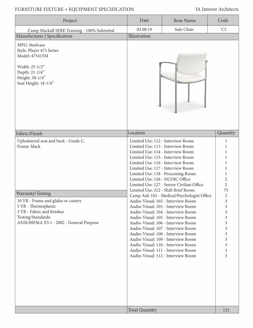
121
C2
111111122
75233333333333
Side Chair
MFG: SteelcaseStyle: Player 475 SeriesModel: 475415M
Width: 25-1/2”Depth: 21-1/4”Height: 30-1/4”Seat Height: 18-1/4”
Upholstered seat and back - Grade C.Frame: black
Limited Use: 112 - Interview RoomLimited Use: 113 - Interview RoomLimited Use: 114 - Interview RoomLimited Use: 115 - Interview RoomLimited Use: 116 - Interview RoomLimited Use: 117 - Interview RoomLimited Use: 118 - Processing RoomLimited Use: 126 - NCOIC OfficeLimited Use: 127 - Senior Civilian OfficeLimited Use: 212 - Shift Brief RoomCamp Aid: 102 - Medical/Psychologist OfficeAudio-Visual: 102 - Interview RoomAudio-Visual: 103 - Interview RoomAudio-Visual: 104 - Interview RoomAudio-Visual: 105 - Interview RoomAudio-Visual: 106 - Interview RoomAudio-Visual: 107 - Interview RoomAudio-Visual: 108 - Interview RoomAudio-Visual: 109 - Interview RoomAudio-Visual: 110 - Interview RoomAudio-Visual: 111 - Interview RoomAudio-Visual: 112 - Interview Room
10 YR - Frame and glides or casters5 YR - Thermoplastic3 YR - Fabric and finishesTesting/Standards:ANSI/BIFMA X5.1 - 2002 - General Purpose
Project Date CodeItem Name
Description
FURNITURE FIXTURE + EQUIPMENT SPECIFICATION IA Interior Architects
Camp Mackall SERE Training - 100% Submittal 03.08.19
General Requirements:1. Frame shall be tubular steel or die-cast aluminum or ½” diameter wire rod.2. Joints shall be welded.3. Non-marring floor glides4. Chair shall have a reinforced back, legs, and arms.5. The seat shall have a waterfall edge.6. The back attachment to the frame shall be concealed.7. Back flex mechanisms shall gradually increase resistance with applied pressure.8. Fully upholstered seat and backMaterial: 1. Chair padding materials and fabric shall comply with the State of California Technical Information Bulletin 117.
C2Side Chair

Project Date CodeItem Name
Manufacturer | Specification Illustration
Location Quantity
Warranty/Testing
Total Quantity
FURNITURE FIXTURE + EQUIPMENT SPECIFICATION IA Interior Architects
Camp Mackall SERE Training - 100% Submittal 03.08.19
Fabric/Finish
38
C3Metal Chair
MFG: Furniture LabStyle: Deco Series - ChairModel Number: 712
Width: 16”Depth: 19.5”Height (Overall): 34.5”
Silvertone 222222422222222222
Limited Use: 112 - Interview RoomLimited Use: 113 - Interview RoomLimited Use: 114 - Interview RoomLimited Use: 115 - Interview RoomLimited Use: 116 - Interview RoomLimited Use: 117 - Interview RoomLimited Use: 118 - Processing RoomAudio-Visual: 102 - Interview RoomAudio-Visual: 103 - Interview RoomAudio-Visual: 104 - Interview RoomAudio-Visual: 105 - Interview RoomAudio-Visual: 106 - Interview RoomAudio-Visual: 107 - Interview RoomAudio-Visual: 108 - Interview RoomAudio-Visual: 109 - Interview RoomAudio-Visual: 110 - Interview RoomAudio-Visual: 111 - Interview RoomAudio-Visual: 112 - Interview Room
Warranty Requirements:1. 10 year – Frame and glides or casters.2. 5 year –Thermoplastic.3. 3 year – Fabric and finishes.
Testing and Standards:ANSI/BIFMA X5.1-2002 General Purpose
Project Date CodeItem Name
Description
FURNITURE FIXTURE + EQUIPMENT SPECIFICATION IA Interior Architects
Camp Mackall SERE Training - 100% Submittal 03.08.19
General Requirements:1. Frame shall be tubular steel or die-cast aluminum or ½” diameter wire rod.2. Joints shall be welded.3. Non-marring floor glides or casters.4. Chair shall have a reinforced back, legs, and arms.
C3Metal Chair
Project Date CodeItem Name
Manufacturer | Specification Illustration
Location Quantity
Warranty/Testing
Total Quantity
FURNITURE FIXTURE + EQUIPMENT SPECIFICATION IA Interior Architects
Camp Mackall SERE Training - 100% Submittal 03.08.19
Fabric/Finish
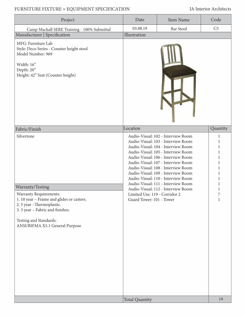
C5Bar Stool
19
1111111111171
MFG: Furniture LabStyle: Deco Series - Counter height stoolModel Number: 969
Width: 16”Depth: 20”Height: 42” Seat (Counter height)
Audio-Visual: 102 - Interview RoomAudio-Visual: 103 - Interview RoomAudio-Visual: 104 - Interview RoomAudio-Visual: 105 - Interview RoomAudio-Visual: 106 - Interview RoomAudio-Visual: 107 - Interview RoomAudio-Visual: 108 - Interview RoomAudio-Visual: 109 - Interview RoomAudio-Visual: 110 - Interview RoomAudio-Visual: 111 - Interview RoomAudio-Visual: 112 - Interview RoomLimited Use: 119 - Corridor 2Guard Tower: 101 - Tower
Silvertone
Warranty Requirements:1. 10 year – Frame and glides or casters.2. 5 year –Thermoplastic.3. 3 year – Fabric and finishes.
Testing and Standards:ANSI/BIFMA X5.1 General Purpose

Project Date CodeItem Name
Description
FURNITURE FIXTURE + EQUIPMENT SPECIFICATION IA Interior Architects
Camp Mackall SERE Training - 100% Submittal 03.08.19
General Requirements:1. Frame shall be tubular steel or die-cast aluminum or ½” diameter wire rod.2. Joints shall be welded.3. Non-marring floor glides or casters.4. Chair shall have a reinforced back, legs, and arms.5. Seat shall be upholstered
Material: Chair padding materials and fabric shall comply with the State of California Technical Information Bulletin 117.
C5Bar Stool

Project Date CodeItem Name
Manufacturer | Specification Illustration
Location Quantity
Warranty/Testing
Total Quantity
FURNITURE FIXTURE + EQUIPMENT SPECIFICATION IA Interior Architects
Camp Mackall SERE Training - 100% Submittal 03.08.19
Fabric/Finish
C6Desk Chair (2nd World)
2
11
MFG: Furniture LabStyle: Deco Series - ChairModel Number: 654
Width: 16”Depth: 19.5”Height (Overall):34.5”
Frame: SilvertoneUpholstery: Grade D
Individual Training: 101 - Guard RoomInstructor Control: 101 - Instructor Room
Warranty Requirements:1. 10 year – Frame and glides or casters.2. 5 year –Thermoplastic.3. 3 year – Fabric and finishes.
Testing and Standards:ANSI/BIFMA X5.1 General Purpose

Project Date CodeItem Name
Description
FURNITURE FIXTURE + EQUIPMENT SPECIFICATION IA Interior Architects
Camp Mackall SERE Training - 100% Submittal 03.08.19
General Requirements:1. Frame shall be tubular steel or die-cast aluminum or ½” diameter wire rod.2. Joints shall be welded.3. Non-marring floor glides or casters.4. Chair shall have a reinforced back, legs, and arms.5. Seat shall be upholstered
Material: Chair padding materials and fabric shall comply with the State of California Technical Information Bulletin 117.
C6Desk Chair (2nd World)

Project Date CodeItem Name
Manufacturer | Specification Illustration
Location Quantity
Warranty/Testing
Total Quantity
FURNITURE FIXTURE + EQUIPMENT SPECIFICATION IA Interior Architects
Camp Mackall SERE Training - 100% Submittal 03.08.19
Fabric/Finish
C8Sofa bed
3
111
MFG: CarolinaStyle: RetrospectModel Number: 7058-S76
Width: 76”Depth: 34”Height: 33”
Provide mid-grade fabric allowance Limited Use: 126 - NCOIC Limited Use: 127 - Senior Civilian RoomCamp Aid: 102 - Medical/Psychologist Office
Warranty Requirements:1. 10 year – Structure.2. 5 year – Foam and fabric.3. 5 year – Wood veneer and functional mechanisms.
Testing and Standards:ANSI/BIFMA X5.4 Lounge Seating ORGSA 3FNE-CO 00-594A/596A Lounge Seating Traditional and Transitional

Project Date CodeItem Name
Description
FURNITURE FIXTURE + EQUIPMENT SPECIFICATION IA Interior Architects
Camp Mackall SERE Training - 100% Submittal 03.08.19
General Requirements:1. Seat and back shall be upholstered 2. Shall have a loose folding back cushion3. Shall have a tight seat cushion4. Sleep surface shall be antimicrobial5. Non-marring adjustable glidesMaterial1. Chair padding materials and fabric shall comply with the State of California Technical Information Bulletin 117.
C8Sofa bed

Project Date CodeItem Name
Manufacturer | Specification Illustration
Location Quantity
Warranty/Testing
Total Quantity
FURNITURE FIXTURE + EQUIPMENT SPECIFICATION IA Interior Architects
Camp Mackall SERE Training - 100% Submittal 03.08.19
Fabric/Finish
C9Medical Station Stool
2
MFG: SafcoStyle: Lab Stool, Low Base with Screw LiftModel Number: 3432BL
Width: 23”Depth: 23”Height: 17” - 25”Weight limit: 325 lbs.
Black vinyl seat Camp Aid: 101 -Primary Exam/Treatment
2
Warranty Requirements:1. 10 year – Mechanisms, pneumatic cylinders, casters, arms, and seat pan adjustment.2. 5 year – Foam and fabric.3. Warranty shall cover users up to 300 pounds
Testing and Standards:1. ANSI/BIFMA X5.1 General Purpose Office Chairs

Project Date CodeItem Name
Description
FURNITURE FIXTURE + EQUIPMENT SPECIFICATION IA Interior Architects
Camp Mackall SERE Training - 100% Submittal 03.08.19
General Requirements:1. There shall be no hard edges on the frame’s structure which comes in contact with the user and/or causes discomfort when changing posture.2. Chairs shall have a 5-star base with a minimum dimension of 25” in diameter.3.Caster base4. Joints shall be welded5. 360 degree swivel6. Shall have screw lift base7. Shall have a min. 5-inch height range adjustment8. Cushioned seatMaterial: Chair padding materials and fabric shall comply with the State of California Technical Information Bulletin 117.
C9Medical Station Stool

Project Date CodeItem Name
Manufacturer | Specification Illustration
Location Quantity
Warranty/Testing
Total Quantity
FURNITURE FIXTURE + EQUIPMENT SPECIFICATION IA Interior Architects
Camp Mackall SERE Training - 100% Submittal 03.08.19
Fabric/Finish
C10Lounge Chair
3
MFG: HaworthStyle: Poppy Lounge - BasketModel Number: SLP-22-T
Width: 31”Depth: 29.4”Height: 32.6”
Seat: Upholstery, mid-grade allowanceBack: Upholstery, mid-grade allowanceTrim: TR-F Black
Limited Use Instruction Building129 - Waiting Room
3
Warranty Requirements:1. 10 year – Structure.2. 5 year – Foam and fabric.3. 5 year – Wood veneer and functional mechanisms.
Testing and Standards:ANSI/BIFMA X5.4 Lounge Seating ORGSA 3FNE-CO 00-594A/596A Lounge Seating Traditional and Transitional

Project Date CodeItem Name
Description
FURNITURE FIXTURE + EQUIPMENT SPECIFICATION IA Interior Architects
Camp Mackall SERE Training - 100% Submittal 03.08.19
General Requirements: 1. Chair shall have upholstered back and arms2. Shall have a four leg steel basket frame
Material: Chair padding materials and fabric shall comply with the State of California Technical Information Bulletin 117.
C10Lounge Chair

Project Date CodeItem Name
Manufacturer | Specification Illustration
Location Quantity
Warranty/Testing
Total Quantity
FURNITURE FIXTURE + EQUIPMENT SPECIFICATION IA Interior Architects
Camp Mackall SERE Training - 100% Submittal 03.08.19
Fabric/Finish
C11Couch
1
MFG: DarranStyle: FilmoreModel Number: FIL0100DAS03
Width: 71”Depth: 31-1/2”Height: 31”
Seat: Upholstery, Haworth Collection - mid- grade allowanceBack: Upholstery, Haworth Collection - mid- grade allowance
Limited Use: 129 - Waiting Room
1
Warranty Requirements:1. 10 year – Structure.2. 5 year – Foam and fabric.3. 5 year – Wood veneer and functional mechanisms.
Testing and Standards:ANSI/BIFMA X5.4 Lounge Seating ORGSA 3FNE-CO 00-594A/596A Lounge Seating Traditional and Transitional
Project Date CodeItem Name
Description
FURNITURE FIXTURE + EQUIPMENT SPECIFICATION IA Interior Architects
Camp Mackall SERE Training - 100% Submittal 03.08.19
General Requirements:1. Shall be a three seat sofa2. Frame shall be constructed of hardwood3. Joints shall be securely fastened with mortise4. Leg shall be anodized aluminum
Material: Chair padding materials and fabric shall comply with the State of California Technical Information Bulletin 117.
C11Couch
Project Date CodeItem Name
Manufacturer | Specification Illustration
Location Quantity
Warranty/Testing
Total Quantity
FURNITURE FIXTURE + EQUIPMENT SPECIFICATION IA Interior Architects
Camp Mackall SERE Training - 100% Submittal 03.08.19
Fabric/Finish
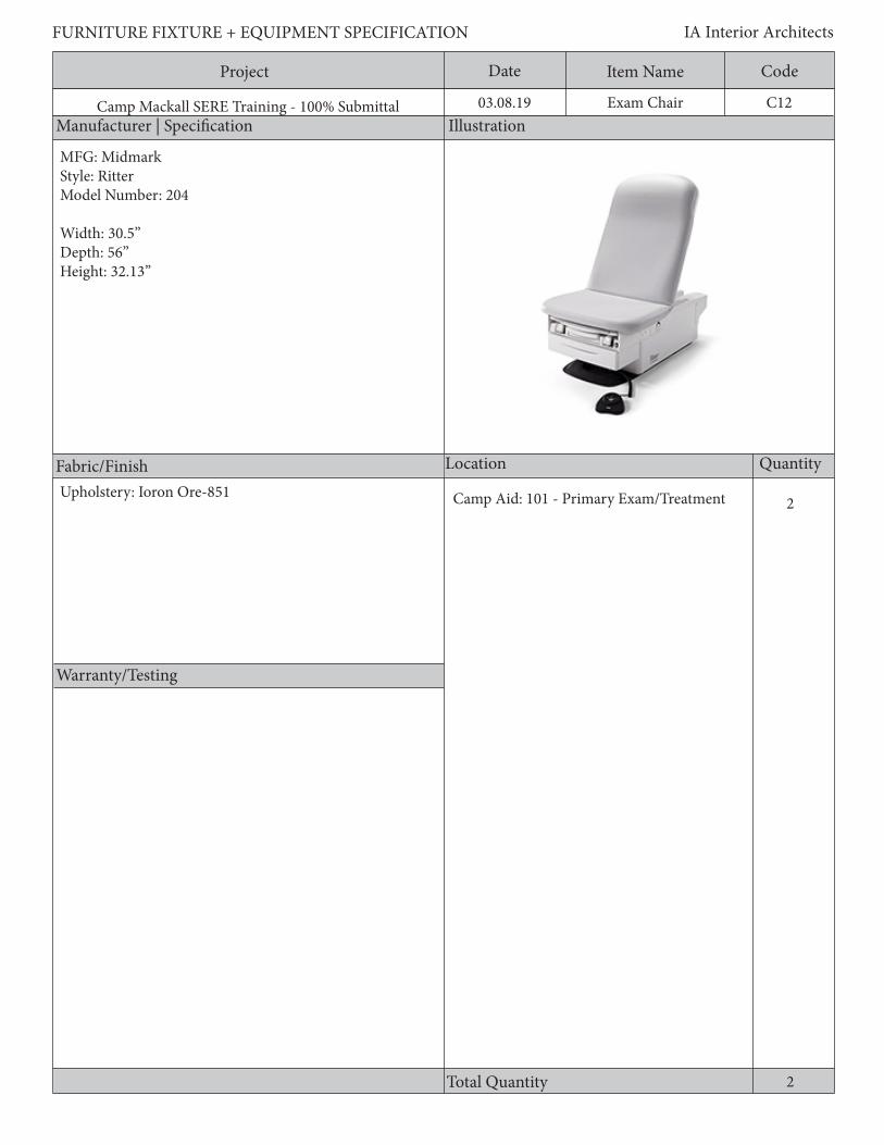
C12Exam Chair
2
MFG: MidmarkStyle: RitterModel Number: 204
Width: 30.5”Depth: 56”Height: 32.13”
Upholstery: Ioron Ore-851 Camp Aid: 101 - Primary Exam/Treatment
2

Project Date CodeItem Name
Description
FURNITURE FIXTURE + EQUIPMENT SPECIFICATION IA Interior Architects
Camp Mackall SERE Training - 100% Submittal 03.08.19
General Requirements:1. Non-powered exam table/chair2. Min. 500 lb weight capacity3. Soft touch vinyl upholstery top with antimicrobial properties
C12Exam Chair

Project Date CodeItem Name
Manufacturer | Specification Illustration
Location Quantity
Warranty/Testing
Total Quantity
FURNITURE FIXTURE + EQUIPMENT SPECIFICATION IA Interior Architects
Camp Mackall SERE Training - 100% Submittal 03.08.19
Fabric/Finish
C13Stacking Chair
2
MFG: AllseatingStyle: Tuck 4-legModel Number: 11054-WA-CM-AHZ-BHZ-SHZ-NG-FA-AS
Width: 24.5”Depth: 23”Height: 32.25”
Warranty Requirements:1. 10 year – Frame and glides or casters.2. 5 year –Thermoplastic.3. 3 year – Fabric and finishes
Testing and Standards:ANSI/BIFMA X5.1 General Purpose
Camp Aid: 103 - Ready Room
2
Poly seat & back - base grade color to be selected by User

Project Date CodeItem Name
Description
FURNITURE FIXTURE + EQUIPMENT SPECIFICATION IA Interior Architects
Camp Mackall SERE Training - 100% Submittal 03.08.19
General Requirements:1. Frame shall be tubular steel or die-cast aluminum or ½” diameter wire rod.2. Joints shall be welded.3. Non-marring floor glides4. Chair shall have a reinforced back, legs, and arms.5. The seat shall have a waterfall edge.6. Back flex mechanisms shall gradually increase resistance with applied pressure.
Material: Chair padding materials and fabric shall comply with the State of California Technical Information Bulletin 117.
C13Stacking Chair

Project Date CodeItem Name
Manufacturer | Specification Illustration
Location Quantity
Warranty/Testing
Total Quantity
FURNITURE FIXTURE + EQUIPMENT SPECIFICATION IA Interior Architects
Camp Mackall SERE Training - 100% Submittal 03.08.19
Fabric/Finish
C14Chair with Casters
2516888
18
MFG: Global Industries Inc.MFG Number: GLB3212-3NBK-IM11
Width: 26”Depth: 22-1/2”Height: 40”
Limited Use: 125 - Brief RoomLimited Use: 134 - Ready RoomLimited Use: 201 - Team Room 3Limited Use: 202 - Team Room 2Limited Use: 203 - Team Room 1Limited Use: 207 - Training Cell Room
83
Mid-grade fabric seat and backBlack base
10 YR - mechanisms, pneumatic cylinders, caster, arms, and seat pan adjustment. 5 YR - foam and fabric. Warranty shall cover 24/7 application and users up to 300 pounds. Multi-shift appliacations shall not cause warranty to be pro-rated. Warranty for conference seating to cover up to 300 pounds. Testing Standards: ANSI/BIFMA X5.1-3022-General

Project Date CodeItem Name
Description
FURNITURE FIXTURE + EQUIPMENT SPECIFICATION IA Interior Architects
Camp Mackall SERE Training - 100% Submittal 03.08.19
General Requirements:1. A pneumatic cylinder shall be used to accomplish the seat height adjustment.2. Chairs shall have a forward seat edge flex, or shall tilt at least 1”, and/or have a waterfall edge.3. Chairs adjustment: a. Synchronized tilt with a minimum 2:1 back-to-seat recline ratio with a user adjustment for tilt and a means of adjusting the backrest tension. The tension adjustment shall be achieved by a user- adjustable control. OR b. The user adjustment for tilt shall be achieved by a weight sensing mechanism.4. Chairs shall have a tilt lock or stop position mechanism that the user can adjust while seated.5. The recline angle (angle between the seat and back) shall have an adjustment of 15 degrees or more, and should fall within the range of 90 to approximately 120 degrees from the horizontal position.6. Chairs shall have a 360 degree swivel.7. Mesh back fabrics shall have elasticity elongation properties that will not allow the mesh to sag, sink, cradle, or hammock.8. There shall be no hard edges on the frame’s structure which comes in contact with the user and shall not cause discomfort when changing posture.9. Chairs shall have a 5-star base with a minimum dimension of 25” in diameter.
Adjustable Arm Requirements:1. Arm adjustments shall be made without the use of any tools.2. Chairs shall have a height and width 4-way adjustable arm.3. The arm depth adjustment shall be independent of the seat depth adjustment.4. User shall be able to make all arm adjustments while seated.
Material: Chair padding materials and fabric shall comply with the State of California Technical Information Bulletin 117.
C14Chair with Casters

Project Date CodeItem Name
Manufacturer | Specification Illustration
Location Quantity
Warranty/Testing
Total Quantity
FURNITURE FIXTURE + EQUIPMENT SPECIFICATION IA Interior Architects
Camp Mackall SERE Training - 100% Submittal 03.08.19
Fabric/Finish
C15Task Stool
1
MFG: SitOnItStyle: OnCallModel Number: 90T S1
Width: 26”Depth: 26”Height: 37.5”- 41.5”Wight limit: 250 lbs.
Audio-Visual:101 - AV Technicians Workshop
1
Task stool; Plastic seat & back - blackBuilt-in pull handle
Warranty Requirements:1. 10 year – Mechanisms, pneumatic cylinders, casters, arms, and seat pan adjustment.2. 5 year – Foam and fabric.3. Warranty shall cover users up to 300 pounds
Testing and Standards:1. ANSI/BIFMA X5.1 General Purpose Office Chairs

Project Date CodeItem Name
Description
FURNITURE FIXTURE + EQUIPMENT SPECIFICATION IA Interior Architects
Camp Mackall SERE Training - 100% Submittal 03.08.19
General Requirements:1. A pneumatic cylinder shall be used to accomplish the seat height adjustment.2. Chairs shall have a forward seat edge flex, or shall tilt at least 1”, and/or have a waterfall edge.4. Chair adjustment:a. A user adjustment for tilt and a means of adjusting the backrest tension. The tension adjustment shall be achieved by a user-adjustable control.ORb. The user adjustment for tilt shall be achieved by a weight sensing mechanism.5. Chairs shall have a 360 degree swivel.6. There shall be no hard edges on the frame’s structure which comes in contact with the user and/or causes discomfort when changing posture.7. Chairs shall have a 5-star base with a minimum dimension of 25” in diameter.8. Casters shall be non-marring.
Material: Chair padding materials and fabric shall comply with the State of California Technical Information Bulletin 117.
C15Task Stool
Project Date CodeItem Name
Manufacturer | Specification Illustration
Location Quantity
Warranty/Testing
Total Quantity
FURNITURE FIXTURE + EQUIPMENT SPECIFICATION IA Interior Architects
Camp Mackall SERE Training - 100% Submittal 03.08.19
Fabric/Finish
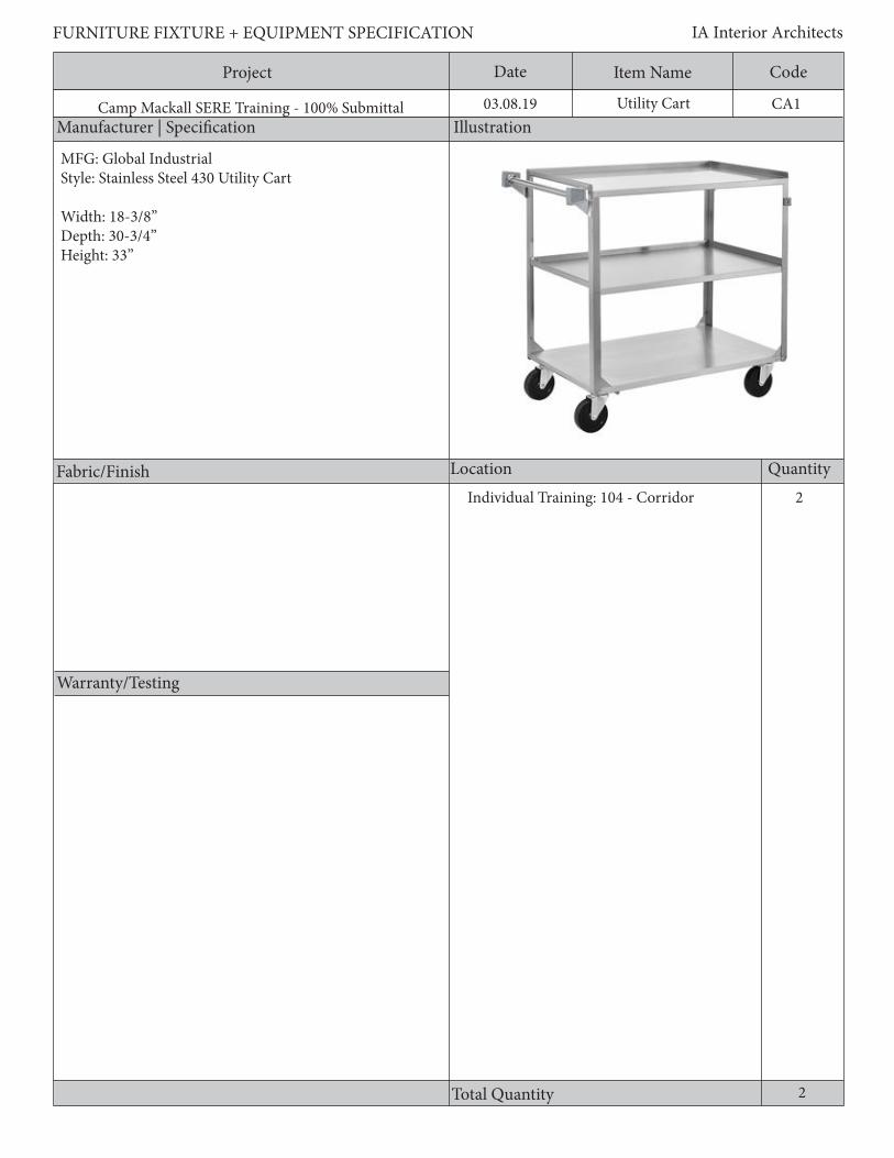
CA1Utility Cart
Individual Training: 104 - Corridor 2
2
MFG: Global IndustrialStyle: Stainless Steel 430 Utility Cart
Width: 18-3/8”Depth: 30-3/4”Height: 33”

Project Date CodeItem Name
Description
FURNITURE FIXTURE + EQUIPMENT SPECIFICATION IA Interior Architects
Camp Mackall SERE Training - 100% Submittal 03.08.19
General Requirements:1. Utility cart shall be constructed with welded 20 gauge steel posts and 22 gauge shelves2. Cart shall have rubber casters for mobility3. Cart shall have min. 300 lb shelf capacity4. Car shall be a 3-shelf unit
CA1Utility Cart
Project Date CodeItem Name
Manufacturer | Specification Illustration
Location Quantity
Warranty/Testing
Total Quantity
FURNITURE FIXTURE + EQUIPMENT SPECIFICATION IA Interior Architects
Camp Mackall SERE Training - 100% Submittal 03.08.19
Fabric/Finish
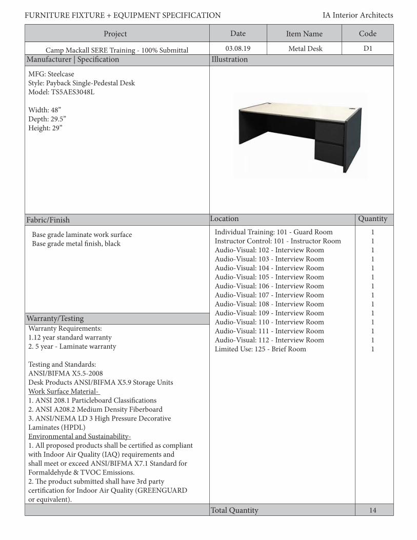
D1Metal Desk
11111111111111
14
Individual Training: 101 - Guard RoomInstructor Control: 101 - Instructor RoomAudio-Visual: 102 - Interview RoomAudio-Visual: 103 - Interview RoomAudio-Visual: 104 - Interview RoomAudio-Visual: 105 - Interview RoomAudio-Visual: 106 - Interview RoomAudio-Visual: 107 - Interview RoomAudio-Visual: 108 - Interview RoomAudio-Visual: 109 - Interview RoomAudio-Visual: 110 - Interview RoomAudio-Visual: 111 - Interview RoomAudio-Visual: 112 - Interview RoomLimited Use: 125 - Brief Room
MFG: SteelcaseStyle: Payback Single-Pedestal DeskModel: TS5AES3048L
Width: 48”Depth: 29.5”Height: 29”
Warranty Requirements:1.12 year standard warranty2. 5 year - Laminate warranty
Testing and Standards:ANSI/BIFMA X5.5-2008 Desk Products ANSI/BIFMA X5.9 Storage UnitsWork Surface Material- 1. ANSI 208.1 Particleboard Classifications2. ANSI A208.2 Medium Density Fiberboard3. ANSI/NEMA LD 3 High Pressure Decorative Laminates (HPDL)Environmental and Sustainability-1. All proposed products shall be certified as compliant with Indoor Air Quality (IAQ) requirements and shall meet or exceed ANSI/BIFMA X7.1 Standard for Formaldehyde & TVOC Emissions.2. The product submitted shall have 3rd party certification for Indoor Air Quality (GREENGUARD or equivalent).
Base grade laminate work surfaceBase grade metal finish, black
Project Date CodeItem Name
Description
FURNITURE FIXTURE + EQUIPMENT SPECIFICATION IA Interior Architects
Camp Mackall SERE Training - 100% Submittal 03.08.19
Modularity Requirements: All desk components shall be provided by one manufacturer. All items shall meet the specified flexibility and interchangeability requirements of the desk solutions. Furniture is to be modular and non-handed so components can be used anywhere within the facility. Units which are selectively removable and replaceable without disturbing adjacent components shall be provided.General Requirements:1. Freestanding units shall have components that include a work surface, floor supports, end supports, back panel, and accommodations for concealing cords and cables.2. Freestanding units shall be specified complete with no exposed or “raw” parts. Include available covers, fillers, and trims available in the standard GSA specifications guide to provide for a complete and finished appearance and function.3. Work surfaces shall be fully supported by floor-standing pedestals or other supports such as brackets, legs, panels, etc., following the manufacturer’s standard practices for the size, type, and placement. Size and placement of supports shall not interfere with knee space clearances. All pedestals and supports shall be clearly indicated, including model numbers, on the drawings or in a components listing.4. The work surface height shall be 28-1/2” to 30” from the finished floor.5. Freestanding unit end supports shall provide a flush termination at the exposed end of the freestanding unit.6. Freestanding unit leveling glides shall adjust to allow installation on uneven floors. Minimum adjustment shall be 1-1/2”.7. Freestanding unit shall have powder coated steel exterior8. Freestanding unit shall include 2 drawers for storage.Work Surfaces:1.Work surfaces shall be constructed of Grade M2 or M3 particleboard or a ~45 lb. medium density fireboard core with a minimum VGS General Purpose Grade High Pressure Laminate on the face and backer material on the underside.2. Laminates shall be bonded to the core with PVA adhesive in a cold press or hot press to prevent separation of the laminate from the core.3. Low pressure laminate and thermally fused laminate is non-conforming and will be considered unacceptable. 4. Work surface edges shall be total finished and sealed against moisture with a flat edged, impact resistant vinyl/ABS, or similar plastic, have a radius of at least 1/8”, and be 2mm-3mm thick. 5. Laminate self edges are non-conforming.6. Abutting work surfaces shall mate closely and at equal heights when used in side-by-side configurations in order to provide a continuous and level work surface.7. Work surfaces shall include pre-drilled locations holes that ensure accurate and secure attachment of desk supports, storage products, and legs.
D1Metal Desk

Project Date CodeItem Name
Manufacturer | Specification Illustration
Location Quantity
Warranty/Testing
Total Quantity
FURNITURE FIXTURE + EQUIPMENT SPECIFICATION IA Interior Architects
Camp Mackall SERE Training - 100% Submittal 03.08.19
Fabric/Finish
D2Workstation
44443
Steelcase ContextStandard Shell Desk with Partial Height Modesty Panel (18: AFF), and Pencil DrawerWidth: 60”Depth: 30”Overheads Storage UnitWidth: 60”Depth: 13-3/8”
Locking overhead cabinets with tackable surface below. Cabinets to have receding doors. provide (2) grommets and wire management,
Base grade laminate work surfaceBase grade metal finish
19
Limited Use: 201 - Team Room 3Limited Use: 202 - Team Room 2Limited Use: 203 - Team Room 1Limited Use: 207 - Training Cell RoomCamp Aid: 102 - Medical/Psychologist Office
Warranty Requirements:1.12 year standard warranty2. 5 year - Laminate warranty
Testing and Standards:ANSI/BIFMA X5.5Desk Products ANSI/BIFMA X5.9 Storage UnitsWork Surface Material- 1. ANSI 208.1 Particleboard Classifications2. ANSI A208.2 Medium Density Fiberboard3. ANSI/NEMA LD 3 High Pressure Decorative Laminates (HPDL)Environmental and Sustainability-1. All proposed products shall be certified as compliant with Indoor Air Quality (IAQ) requirements and shall meet or exceed ANSI/BIFMA X7.1 Standard for Formaldehyde & TVOC Emissions.2. The product submitted shall have 3rd party certification for Indoor Air Quality (GREENGUARD or equivalent).
Project Date CodeItem Name
Description
FURNITURE FIXTURE + EQUIPMENT SPECIFICATION IA Interior Architects
Camp Mackall SERE Training - 100% Submittal 03.08.19
Modularity Requirements:All desk components shall be provided by one manufacturer. All items shall meet the specified flexibility and interchangeability requirements of the desk solutions. Furniture is to be modular and non-handed so components can be used anywhere within the facility. Units which are selectively removable and replaceable without disturbing adjacent components shall be provided.General Requirements:1. Freestanding units shall have components that include a work surface, floor supports, end supports, back panel, and accommodations for concealing cords and cables.2. Freestanding units shall be specified complete with no exposed or “raw” parts. Include available covers, fillers, and trims available in the standard GSA specifications guide to provide for a complete and finished appearance and function.3. Work surfaces shall be fully supported by floor-standing pedestals or other supports such as brackets, legs, panels, etc., following the manufacturer’s standard practices for the size, type, and placement. Size and placement of supports shall not interfere with kneespace clearances. All pedestals and supports shall be clearly indicated, including model numbers, on the drawings or in a components listing.4. The work surface height shall be 28-1/2” to 30” from the finished floor.5. Freestanding unit end supports shall provide a flush termination at the exposed end of the freestanding unit.6. Freestanding unit leveling glides shall adjust to allow installation on uneven floors. Minimum adjustment shall be 1-1/2”.Work Surfaces:1.Work surfaces shall be constructed of Grade M2 or M3 particleboard or a ~45 lb. medium density fireboard core with a minimum VGS General Purpose Grade High Pressure Laminate on the face and backer material on the underside.2. Laminates shall be bonded to the core with PVA adhesive in a cold press or hot press to prevent separation of the laminate from the core.3. Low pressure laminate and thermally fused laminate is non-conforming and will be considered unacceptable. 4. Work surface edges shall be total finished and sealed against moisture with a flat edged, impact resistant vinyl/ABS, or similar plastic, have a radius of at least 1/8”, and be 2mm-3mm thick. 5. Laminate self edges are non-conforming.6. Abutting work surfaces shall mate closely and at equal heights when used in side-by-side configurations in order to provide a continuous and level work surface.7. Work surfaces hall include predrilled locations holes that ensure accurate and secure attachment of desk supports, storage products, and legs.Wire Management:1. Provide concealed wire routing below work surface.2. All desks, returns, bridges, and other freestanding work surfaces shall provide an option for mounting a modesty panel with at least a 1-1/2” gap between the modesty panel and the underside of the work surface for cable management.3. A cable tray or cable clips shall be provided to manage cords.4. All grommets shall be provided with an insert and cap.Modesty Panels and End Supports:1. Modesty panels shall be designed to accommodate access to wall outlets 18” from floor.2. Modesty panels shall be constructed of 20-gauge steel pans with removable 16-gauge attachment brackets for attachment to end supports, peninsula supports, and corner supports3. Modesty panels shall span the entire width of the work surface or attach to pedestal backs leaving no gaps.4. End supports shall be constructed of approximately 22-gauge outer and inner pans welded to no less than 14-gauge brackets at the top and bottom.
D2Workstation
Project Date CodeItem Name
Description
FURNITURE FIXTURE + EQUIPMENT SPECIFICATION IA Interior Architects
Camp Mackall SERE Training - 100% Submittal 03.08.19 D2Workstation
Flush Mount Brackets:1. Flush mount brackets shall be available to connect a return or bridge work surface to the front edge of another work surface, providing support and alignment.2. Flush mount brackets shall employ a two-plate design so the same bracket package can be used for 18”, 24”, and 30” nominal depth return and bridge work surfaces.3. Flush mount brackets shall be constructed of approximately 11-gauge steel.Overhead Storage Units:1. The vertical clearance between the work surface and the overhead shall be a minimum of 18”.2. The total height of a desk with overhead storage shall match the height of adjacent storage products including storage towers.3. Units shall be capable of spanning two work surfaces arranged in an “L” configuration, with one end mounted at the front edge of one work surface and the other end mounted at the back edge of the other work surface.4. Units shall be capable of being mounted on corner and extended corner work surfaces.5. Units shall be attached securely with concealed cam-locks, brackets, screws, and/or industrial strength double stick tape, to ensure a rigid assembly.6. The inside clearance depth shall accommodate a 3-ring binder for 8-1/2” x 11” paper and shall be a minimum overall depth of 13”. The door shall fully close.7. The minimum inside height clearance shall be 12”.8. Units shall be 5-sided with a door and fully enclosed back.9. Units shall be of steel construction in the following gauges: a. Shelves shall be 18 to 20-gauge steel. b.Tops shall be 20 to 22-gauge steel. c. Doors shall be 20 to 24-gauge steel.Task Lighting:1. Task lights shall be a standard component of the manufacturer’s furniture products.2. Task lights shall recess into the bottom of overhead cabinets and shelves.3. Task lights for 72” wide, and greater, overhead storage bins shall be the no less than 46” wide.4. All other task lights shall be sized appropriately for the overhead storage bin.5. Electronic ballasts shall be provided to eliminate fluorescent lamp flicker and computer screen interference. Shared ballasts shall not be used.6. Task lights shall provide glare control.7. Task lights shall have an easily accessible on-off switch.8. Daisy chain cords shall be available for the modular connection of shelf lights.9. All fixture diffusers, grilles, or other coverings shall be easily removable to permit cleaning and replacement.10. Task lights shall be UL listed and labeled.
Project Date CodeItem Name
Manufacturer | Specification Illustration
Location Quantity
Warranty/Testing
Total Quantity
FURNITURE FIXTURE + EQUIPMENT SPECIFICATION IA Interior Architects
Camp Mackall SERE Training - 100% Submittal 03.08.19
Fabric/Finish
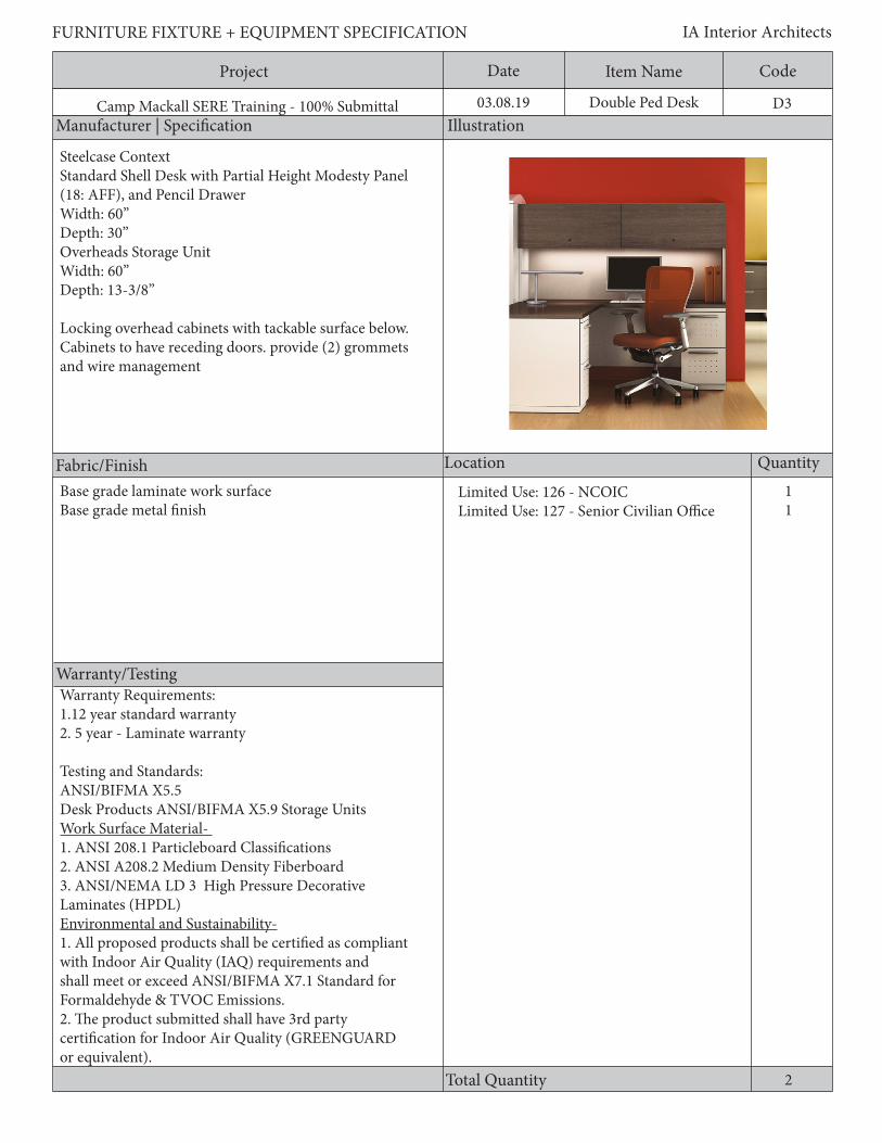
D3Double Ped Desk
11
Steelcase ContextStandard Shell Desk with Partial Height Modesty Panel (18: AFF), and Pencil DrawerWidth: 60”Depth: 30”Overheads Storage UnitWidth: 60”Depth: 13-3/8”
Locking overhead cabinets with tackable surface below. Cabinets to have receding doors. provide (2) grommets and wire management
2
Limited Use: 126 - NCOICLimited Use: 127 - Senior Civilian Office
Base grade laminate work surfaceBase grade metal finish
Warranty Requirements:1.12 year standard warranty2. 5 year - Laminate warranty
Testing and Standards:ANSI/BIFMA X5.5 Desk Products ANSI/BIFMA X5.9 Storage UnitsWork Surface Material- 1. ANSI 208.1 Particleboard Classifications2. ANSI A208.2 Medium Density Fiberboard3. ANSI/NEMA LD 3 High Pressure Decorative Laminates (HPDL)Environmental and Sustainability-1. All proposed products shall be certified as compliant with Indoor Air Quality (IAQ) requirements and shall meet or exceed ANSI/BIFMA X7.1 Standard for Formaldehyde & TVOC Emissions.2. The product submitted shall have 3rd party certification for Indoor Air Quality (GREENGUARD or equivalent).
Project Date CodeItem Name
Description
FURNITURE FIXTURE + EQUIPMENT SPECIFICATION IA Interior Architects
Camp Mackall SERE Training - 100% Submittal 03.08.19
Modularity Requirements:All desk components shall be provided by one manufacturer. All items shall meet the specified flexibility and interchangeability requirements of the desk solutions. Furniture is to be modular and non-handed so components can be used anywhere within the facility. Units which are selectively removable and replaceable without disturbing adjacent components shall be provided.General Requirements:1. Freestanding units shall have components that include a work surface, floor supports, end supports, back panel, and accommodations for concealing cords and cables.2. Freestanding units shall be specified complete with no exposed or “raw” parts. Include available covers, fillers, and trims available in the standard GSA specifications guide to provide for a complete and finished appearance and function.3. Work surfaces shall be fully supported by floor-standing pedestals or other supports such as brackets, legs, panels, etc., following the manufacturer’s standard practices for the size, type, and placement. Size and placement of supports shall not interfere with kneespace clearances. All pedestals and supports shall be clearly indicated, including model numbers, on the drawings or in a components listing.4. The work surface height shall be 28-1/2” to 30” from the finished floor.5. Freestanding unit end supports shall provide a flush termination at the exposed end of the freestanding unit.6. Freestanding unit leveling glides shall adjust to allow installation on uneven floors. Minimum adjustment shall be 1-1/2”.Work Surfaces:1.Work surfaces shall be constructed of Grade M2 or M3 particleboard or a ~45 lb. medium density fireboard core with a minimum VGS General Purpose Grade High Pressure Laminate on the face and backer material on the underside.2. Laminates shall be bonded to the core with PVA adhesive in a cold press or hot press to prevent separation of the laminate from the core.3. Low pressure laminate and thermally fused laminate is non-conforming and will be considered unacceptable. 4. Work surface edges shall be total finished and sealed against moisture with a flat edged, impact resistant vinyl/ABS, or similar plastic, have a radius of at least 1/8”, and be 2mm-3mm thick. 5. Laminate self edges are non-conforming.6. Abutting work surfaces shall mate closely and at equal heights when used in side-by-side configurations in order to provide a continuous and level work surface.7. Work surfaces hall include predrilled locations holes that ensure accurate and secure attachment of desk supports, storage products, and legs.Wire Management:1. Provide concealed wire routing below work surface.2. All desks, returns, bridges, and other freestanding work surfaces shall provide an option for mounting a modesty panel with at least a 1-1/2” gap between the modesty panel and the underside of the work surface for cable management.3. A cable tray or cable clips shall be provided to manage cords.4. All grommets shall be provided with an insert and cap.Modesty Panels and End Supports:1. Modesty panels shall be designed to accommodate access to wall outlets 18” from floor.2. Modesty panels shall be constructed of 20-gauge steel pans with removable 16-gauge attachment brackets for attachment to end supports, peninsula supports, and corner supports3. Modesty panels shall span the entire width of the work surface or attach to pedestal backs leaving no gaps.4. End supports shall be constructed of approximately 22-gauge outer and inner pans welded to no less than 14-gauge brackets at the top and bottom.
D3Double Ped Desk

Project Date CodeItem Name
Description
FURNITURE FIXTURE + EQUIPMENT SPECIFICATION IA Interior Architects
Camp Mackall SERE Training - 100% Submittal 03.08.19
Flush Mount Brackets:1. Flush mount brackets shall be available to connect a return or bridge work surface to the front edge of another work surface, providing support and alignment.2. Flush mount brackets shall employ a two-plate design so the same bracket package can be used for 18”, 24”, and 30” nominal depth return and bridge work surfaces.3. Flush mount brackets shall be constructed of approximately 11-gauge steel.Overhead Storage Units:1. The vertical clearance between the work surface and the overhead shall be a minimum of 18”.2. The total height of a desk with overhead storage shall match the height of adjacent storage products including storage towers.3. Units shall be capable of spanning two work surfaces arranged in an “L” configuration, with one end mounted at the front edge of one work surface and the other end mounted at the back edge of the other work surface.4. Units shall be capable of being mounted on corner and extended corner work surfaces.5. Units shall be attached securely with concealed cam-locks, brackets, screws, and/or industrial strength double stick tape, to ensure a rigid assembly.6. The inside clearance depth shall accommodate a 3-ring binder for 8-1/2” x 11” paper and shall be a minimum overall depth of 13”. The door shall fully close.7. The minimum inside height clearance shall be 12”.8. Units shall be 5-sided with a door and fully enclosed back.9. Units shall be of steel construction in the following gauges: a. Shelves shall be 18 to 20-gauge steel. b.Tops shall be 20 to 22-gauge steel. c. Doors shall be 20 to 24-gauge steel.Task Lighting:1. Task lights shall be a standard component of the manufacturer’s furniture products.2. Task lights shall recess into the bottom of overhead cabinets and shelves.3. Task lights for 72” wide, and greater, overhead storage bins shall be the no less than 46” wide.4. All other task lights shall be sized appropriately for the overhead storage bin.5. Electronic ballasts shall be provided to eliminate fluorescent lamp flicker and computer screen interference. Shared ballasts shall not be used.6. Task lights shall provide glare control.7. Task lights shall have an easily accessible on-off switch.8. Daisy chain cords shall be available for the modular connection of shelf lights.9. All fixture diffusers, grilles, or other coverings shall be easily removable to permit cleaning and replacement.10. Task lights shall be UL listed and labeled.
D3Double Ped Desk

Project Date CodeItem Name
Manufacturer | Specification Illustration
Location Quantity
Warranty/Testing
FURNITURE FIXTURE + EQUIPMENT SPECIFICATION IA Interior Architects
Camp Mackall SERE Training - 100% Submittal 03.08.19
Fabric/Finish
Total Quantity
D4Study Carrel
6
MFG: MooreCo Inc.Model Number: 89822
Width: 33”Depth: 25”Height: 44.5”
6
Limited Use: 207 - Training Cell Room
Warranty Requirements:1.12 year standard warranty2. 5 year - Laminate warranty
Testing and Standards:ANSI/BIFMA X5.5Desk Products ANSI/BIFMA X5.9 Storage UnitsWork Surface Material- 1. ANSI 208.1 Particleboard Classifications2. ANSI A208.2 Medium Density Fiberboard3. ANSI/NEMA LD 3 High Pressure Decorative Laminates (HPDL)Environmental and Sustainability-1. All proposed products shall be certified as compliant with Indoor Air Quality (IAQ) requirements and shall meet or exceed ANSI/BIFMA X7.1 Standard for Formaldehyde & TVOC Emissions.2. The product submitted shall have 3rd party certification for Indoor Air Quality (GREENGUARD or equivalent).
Frame: black powder coatPanel/Worksurface: Cherry
Project Date CodeItem Name
Description
FURNITURE FIXTURE + EQUIPMENT SPECIFICATION IA Interior Architects
Camp Mackall SERE Training - 100% Submittal 03.08.19
Study carrels with 3/4” laminated panel and dowel constructionModularity Requirements:All desk components shall be provided by one manufacturer. All items shall meet the specified flexibility and interchangeability requirements of the desk solutions. Furniture is to be modular and non-handed so components can be used anywhere within the facility. Units which are selectively removable and replaceable without disturbing adjacent components shall be provided.General Requirements:1. Freestanding units shall have components that include a work surface, floor supports, end supports, back panel, and accommodations for concealing cords and cables.2. Freestanding units shall be specified complete with no exposed or “raw” parts. Include available covers, fillers, and trims available in the standard GSA specifications guide to provide for a complete and finished appearance and function.3. Work surfaces shall be fully supported by floor-standing pedestals or other supports such as brackets, legs, panels, etc., following the manufacturer’s standard practices for the size, type, and placement. Size and placement of supports shall not interfere with kneespace clearances. All pedestals and supports shall be clearly indicated, including model numbers, on the drawings or in a components listing.4. The work surface height shall be 28-1/2” to 30” from the finished floor.5. Freestanding unit end supports shall provide a flush termination at the exposed end of the freestanding unit.6. Freestanding unit leveling glides shall adjust to allow installation on uneven floors. Minimum adjustment shall be 1-1/2”.Work Surfaces:1.Work surfaces shall be constructed of Grade M2 or M3 particleboard or a ~45 lb. medium density fireboard core with a minimum VGS General Purpose Grade High Pressure Laminate on the face and backer material on the underside.2. Laminates shall be bonded to the core with PVA adhesive in a cold press or hot press to prevent separation of the laminate from the core.3. Low pressure laminate and thermally fused laminate is non-conforming and will be considered unacceptable. 4. Work surface edges shall be total finished and sealed against moisture with a flat edged, impact resistant vinyl/ABS, or similar plastic, have a radius of at least 1/8”, and be 2mm-3mm thick. 5. Laminate self edges are non-conforming.6. Abutting work surfaces shall mate closely and at equal heights when used in side-by-side configurations in order to provide a continuous and level work surface.7. Work surfaces hall include predrilled locations holes that ensure accurate and secure attachment of desk supports, storage products, and legs.Wire Management:1. Provide concealed wire routing below work surface.2. All desks, returns, bridges, and other freestanding work surfaces shall provide an option for mounting a modesty panel with at least a 1-1/2” gap between the modesty panel and the underside of the work surface for cable management.3. A cable tray or cable clips shall be provided to manage cords.4. All grommets shall be provided with an insert and cap.Modesty Panels and End Supports:1. Modesty panels shall be designed to accommodate access to wall outlets 18” from floor.2. Modesty panels shall be constructed of 20-gauge steel pans with removable 16-gauge attachment brackets for attachment to end supports, peninsula supports, and corner supports3. Modesty panels shall span the entire width of the work surface or attach to pedestal backs leaving no gaps.4. End supports shall be constructed of approximately 22-gauge outer and inner pans welded to no less than 14-gauge brackets at the top and bottom.
D4Study Carrel

Project Date CodeItem Name
Manufacturer | Specification Illustration
Location Quantity
Warranty/Testing
Total Quantity
FURNITURE FIXTURE + EQUIPMENT SPECIFICATION IA Interior Architects
Camp Mackall SERE Training - 100% Submittal 03.08.19
Fabric/Finish
Project Date CodeItem Name
Description
FURNITURE FIXTURE + EQUIPMENT SPECIFICATION IA Interior Architects
D5Desk
1
MFG: HONStyle: 38000 Series Desk ShellModel Number: H38925
Width: 72”Depth: 24”Height: 29.5”
1
Limited Use: 131 - Security Office
Warranty Requirements:1.12 year standard warranty2. 5 year - Laminate warranty
Testing and Standards:ANSI/BIFMA X5.5Desk Products ANSI/BIFMA X5.9 Storage UnitsWork Surface Material- 1. ANSI 208.1 Particleboard Classifications2. ANSI A208.2 Medium Density Fiberboard3. ANSI/NEMA LD 3 High Pressure Decorative Laminates (HPDL)Environmental and Sustainability-1. All proposed products shall be certified as compliant with Indoor Air Quality (IAQ) requirements and shall meet or exceed ANSI/BIFMA X7.1 Standard for Formaldehyde & TVOC Emissions.2. The product submitted shall have 3rd party certification for Indoor Air Quality (GREENGUARD or equivalent).
Total Quantity
Project Date CodeItem Name
Description
FURNITURE FIXTURE + EQUIPMENT SPECIFICATION IA Interior Architects
Camp Mackall SERE Training - 100% Submittal 03.08.19
Modularity Requirements: All desk components shall be provided by one manufacturer. All items shall meet the specified flexibility and interchangeability requirements of the desk solutions. Furniture is to be modular and non-handed so components can be used anywhere within the facility. Units which are selectively removable and replaceable without disturbing adjacent components shall be provided.General Requirements:1. Freestanding units shall have components that include a work surface, floor supports, end supports, back panel, and accommodations for concealing cords and cables.2. Freestanding units shall be specified complete with no exposed or “raw” parts. Include available covers, fillers, and trims available in the standard GSA specifications guide to provide for a complete and finished appearance and function.3. Work surfaces shall be fully supported by floor-standing pedestals or other supports such as brackets, legs, panels, etc., following the manufacturer’s standard practices for the size, type, and placement. Size and placement of supports shall not interfere with kneespace clearances. All pedestals and supports shall be clearly indicated, including model numbers, on the drawings or in a components listing.4. The work surface height shall be 28-1/2” to 30” from the finished floor.5. Freestanding unit end supports shall provide a flush termination at the exposed end of the freestanding unit.6. Freestanding unit leveling glides shall adjust to allow installation on uneven floors. Minimum adjustment shall be 1-1/2”.7. Freestanding unit shall have powder coated steel exteriorWork Surfaces:1.Work surfaces shall be constructed of Grade M2 or M3 particleboard or a ~45 lb. medium density fireboard core with a minimum VGS General Purpose Grade High Pressure Laminate on the face and backer material on the underside.2. Laminates shall be bonded to the core with PVA adhesive in a cold press or hot press to prevent separation of the laminate from the core.3. Low pressure laminate and thermally fused laminate is non-conforming and will be considered unacceptable. 4. Work surface edges shall be total finished and sealed against moisture with a flat edged, impact resistant vinyl/ABS, or similar plastic, have a radius of at least 1/8”, and be 2mm-3mm thick. 5. Laminate self edges are non-conforming.6. Abutting work surfaces shall mate closely and at equal heights when used in side-by-side configurations in order to provide a continuous and level work surface.7. Work surfaces shall include predrilled locations holes that ensure accurate and secure attachment of desk supports, storage products, and legs.
D5Desk

Project Date CodeItem Name
Manufacturer | Specification Illustration
Location Quantity
Warranty/Testing
Total Quantity
FURNITURE FIXTURE + EQUIPMENT SPECIFICATION IA Interior Architects
Camp Mackall SERE Training - 100% Submittal 03.08.19
Fabric/Finish
DC1Display Case
2
MFG: Waddell DisplayStyle: ProminenceModel Number: 445PB-CH-CH
Width: 48”Depth: 18”Height: 78”Weight limit: 25 lbs. per shelf
N/A Limited Use: 129 - Waiting Room
2
Testing:ANSI/BIFMA X5.9 Storage Units

Project Date CodeItem Name
Description
FURNITURE FIXTURE + EQUIPMENT SPECIFICATION IA Interior Architects
Camp Mackall SERE Training - 100% Submittal 03.08.19
General Requirements:1. Aluminum framed glass case2. (2) full-length glass adjustable shelves with 25 lb weight capacity3. Tempered glass
DC1Display Case
Project Date CodeItem Name
Manufacturer | Specification Illustration
Location Quantity
Warranty/Testing
Total Quantity
FURNITURE FIXTURE + EQUIPMENT SPECIFICATION
Camp Mackall SERE Training - 100% Submittal 03.08.19
Fabric/Finish
IA Interior Architects
EQ1
1
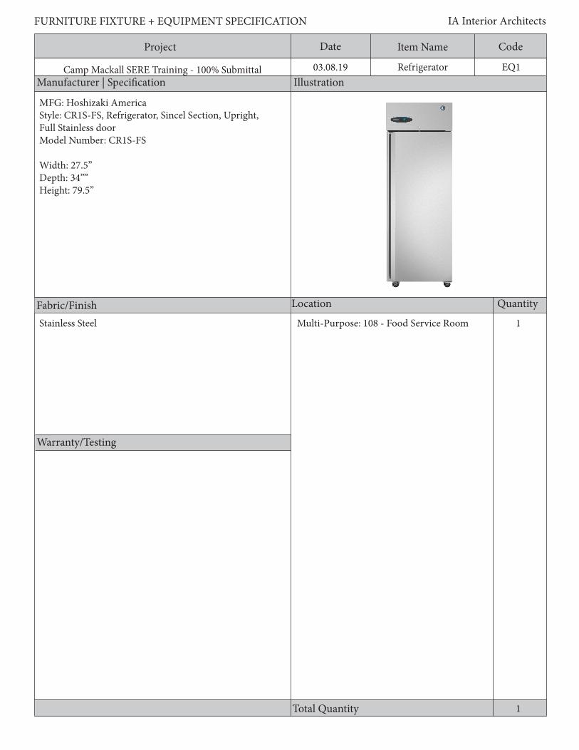
MFG: Hoshizaki AmericaStyle: CR1S-FS, Refrigerator, Sincel Section, Upright, Full Stainless doorModel Number: CR1S-FS
Width: 27.5”Depth: 34””Height: 79.5”
Refrigerator
1
Stainless Steel Multi-Purpose: 108 - Food Service Room

Project Date CodeItem Name
Description
FURNITURE FIXTURE + EQUIPMENT SPECIFICATION IA Interior Architects
Camp Mackall SERE Training - 100% Submittal 03.08.19 EQ1Refrigerator
General Requirements:1. 20.9 cu.ft. refrigerator with stainless steel interior, exterior front and sides2. Equipment shall have stainless steel supports adjustable in 1” increments3. Equipment shall provide door reversal kit4. Equipment shall be Energy Star rated5. Equpment shall include all spll-proof glass shelves with fixed full width6. Provide leveling glides
Project Date CodeItem Name
Manufacturer | Specification Illustration
Location Quantity
Warranty/Testing
Total Quantity
FURNITURE FIXTURE + EQUIPMENT SPECIFICATION IA Interior Architects
Camp Mackall SERE Training - 100% Submittal 03.08.19
Fabric/Finish
2
EQ2Industrial Washer
2
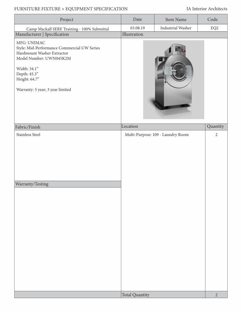
MFG: UNIMACStyle: Mid-Performance Commercial UW Series Hardmount Washer ExtractorModel Number: UWN045K2M
Width: 34.1”Depth: 45.3”Height: 64.7”
Warranty: 5 year; 3 year limited
Stainless Steel Multi-Purpose: 109 - Laundry Room
Project Date CodeItem Name
Description
FURNITURE FIXTURE + EQUIPMENT SPECIFICATION IA Interior Architects
Camp Mackall SERE Training - 100% Submittal 03.08.19 EQ2Industrial Washer
General Requirements:1. Min. 45 lb. capacity2. Equipment shall have auto-leak detection3. Shall be front loading4. Stand off from floor5. Perforated cylinder ribs to maximize wash action6. Min. 31” diameter cylinder7. Equipment shall have water-saving eco-efficient technology8. Shall be designed to run 24-7

Project Date CodeItem Name
Manufacturer | Specification Illustration
Location Quantity
Warranty/Testing
Total Quantity
FURNITURE FIXTURE + EQUIPMENT SPECIFICATION IA Interior Architects
Camp Mackall SERE Training - 100% Submittal 03.08.19
Fabric/Finish
4
EQ3
4
Industrial Dryer
MFG: UNIMACStyle: Heavy Duty Industrial UT Series Single Tumble DryerModel Number: UT035N
Width: 31.5”Depth: 46.875”Height: 63.875”
Warranty: 3 year limited
Steel finish Multi-Purpose: 109 - Laundry Room
Project Date CodeItem Name
Description
FURNITURE FIXTURE + EQUIPMENT SPECIFICATION IA Interior Architects
Camp Mackall SERE Training - 100% Submittal 03.08.19 EQ3Industrial Dryer
General Requirements:1. Min. 35 lb dry weight capacity2. Min. 30” diameter cylinder4. Equipment shall have high-grade steel with heavy duty door and hinges5. Shall be front loading6. Shall provide stand-offs from floor7. Timed-dry cycles8. Automatic lint screen cleaner
Project Date CodeItem Name
Manufacturer | Specification Illustration
Location Quantity
Warranty/Testing
Total Quantity
FURNITURE FIXTURE + EQUIPMENT SPECIFICATION IA Interior Architects
Camp Mackall SERE Training - 100% Submittal 03.08.19
Fabric/Finish
2
EQ4
11
Ice Machine
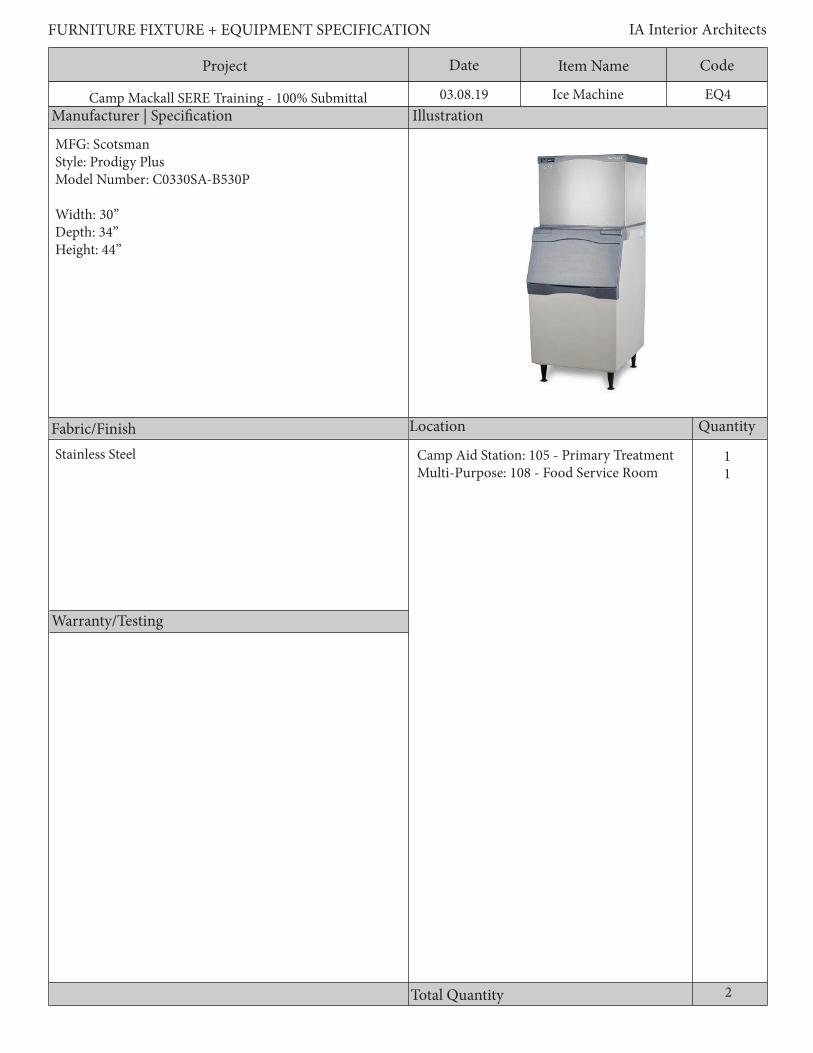
MFG: ScotsmanStyle: Prodigy PlusModel Number: C0330SA-B530P
Width: 30”Depth: 34”Height: 44”
Stainless Steel Camp Aid Station: 105 - Primary TreatmentMulti-Purpose: 108 - Food Service Room
Project Date CodeItem Name
Description
FURNITURE FIXTURE + EQUIPMENT SPECIFICATION IA Interior Architects
Camp Mackall SERE Training - 100% Submittal 03.08.19 EQ4Ice Machine
General Requirements:1. Ice machine and storage bin combo unit2. Air-cooled condenser3. Filter line kit4. Min. 525 lb ice yield per day5. Min. 536 lb ice storage capacity6. Energy Star rated7. Adjustable glides8. Equipment shall include auto indicator lights9. Equipment shall include a removeable front-located air filter10. Ice scoop included11. Energy Star qualified

Project Date CodeItem Name
Manufacturer | Specification Illustration
Location Quantity
Warranty/Testing
Total Quantity
FURNITURE FIXTURE + EQUIPMENT SPECIFICATION IA Interior Architects
Camp Mackall SERE Training - 100% Submittal 03.08.19
Fabric/Finish
3
EQ5
111
Undercounter Refrigerator
MFG: GEStyle: Compact RefrigeratorModel Number: GCE06GSHSB
Width: 23-5/8”Depth: 23-3/4”Height: 34-1/8”
Stainless Steel Limited Use: 126 - NCIOC RoomLimited Use: 127 - Senior Civillian RoomInstructor Control: 101 - Instructor Room
Project Date CodeItem Name
Description
FURNITURE FIXTURE + EQUIPMENT SPECIFICATION IA Interior Architects
Camp Mackall SERE Training - 100% Submittal 03.08.19
General Requirements:1. Counter height refrigerator2. 5.6 Cu. Ft.;3. Reversible door swing4. Stainless steel finish5. 2 front leveling legs6. Energy Star rated
EQ5Undercounter Refrigerator

Project Date CodeItem Name
Manufacturer | Specification Illustration
Location Quantity
Warranty/Testing
Total Quantity
FURNITURE FIXTURE + EQUIPMENT SPECIFICATION IA Interior Architects
Camp Mackall SERE Training - 100% Submittal 03.08.19
Fabric/Finish
EQ6 Small Ice Machine
MFG: Scotsman Style: EssentialModel Number: CU0415MA-1
Width: 15”Depth: 24”Height: 38”
Stainless Steel Instructor Control: 101 - Instructor Room
1
1

Project Date CodeItem Name
Description
FURNITURE FIXTURE + EQUIPMENT SPECIFICATION IA Interior Architects
Camp Mackall SERE Training - 100% Submittal 03.08.19
General Requirements:1. Ice machine and storage bin combo unit2. Air-cooled self contained condenser3. Min. 58 lb 24 hour ice yield4. Min. 36 lb ice storage capacity5. Adjustable glides6. Equipment shall include removeable air filter7. Equipment shall include in-line filter8. Ice scoop included
EQ6 Small Ice Machine

Project Date CodeItem Name
Manufacturer | Specification Illustration
Location Quantity
Warranty/Testing
Total Quantity
FURNITURE FIXTURE + EQUIPMENT SPECIFICATION IA Interior Architects
Camp Mackall SERE Training - 100% Submittal 03.08.19
Fabric/Finish
EQ7Refrigerator
MFG: FrigidaireStyle: Top Freezer RefrigeratorModel Number: FFHT2131QS
Width: 31.75”Depth: 29.62”
Stainless Steel
6
111111
Limited Use: 201 - Team Room 3Limited Use: 202 - Team Room 2Limited Use: 203 - Team Room 1Limited Use: 207 - Training Cell RoomCamp Aid: 103 - Ready RoomCamp Aid: 104 - Medical Storage

Project Date CodeItem Name
Description
FURNITURE FIXTURE + EQUIPMENT SPECIFICATION IA Interior Architects
Camp Mackall SERE Training - 100% Submittal 03.08.19
General Requirements: 1. Min. 20.5 cu. ft. capacity2. Reversible door swing3. Energy Star rated4. Equpment shall include all spll-proof glass shelves with fixed full width5. Provide leveling glides
EQ7Refrigerator

Project Date CodeItem Name
Manufacturer | Specification Illustration
Location Quantity
Warranty/Testing
Total Quantity
FURNITURE FIXTURE + EQUIPMENT SPECIFICATION IA Interior Architects
Camp Mackall SERE Training - 100% Submittal 03.08.19
Fabric/Finish
EQ8Microwave
MFG: GEStyle: GE Profile 1.5 Cu. Ft. Countertop MicrowaveModel Number: PEB9159SJSS
Width: 22-5/8”Depth: 19-7/8”Height: 14-7/8”
Warranty: Ltd. 1-Year Warranty, Parts & Labor, Ltd 5-Year Magnetron Tube
Brushed Stainless Steel
9
111111111
Limited Use: 201 - Team Room 3Limited Use: 202 - Team Room 2Limited Use: 203 - Team Room 1Limited Use: 207 - Training CellLimited Use: 126 - NCIOCLimited Use: 127 - Senior Civilian RoomCamp Aid: 103 - Ready RoomInstructor Control: 101 - Instructor RoomAudio-Visual: 117 - AV Control Room

Project Date CodeItem Name
Description
FURNITURE FIXTURE + EQUIPMENT SPECIFICATION IA Interior Architects
Camp Mackall SERE Training - 100% Submittal 03.08.19
General Requirements:1. Stainless steel finish2. 1.5 Cu. Ft. 3. 1000 watts4. Glass Recessed Turntable5. Electronic touch controls6. Cooking complete reminder7. ADA compliant8. 10 power levels9. 13.0 Amperage10. Digital clock
EQ8Microwave

Project Date CodeItem Name
Manufacturer | Specification Illustration
Location Quantity
Warranty/Testing
Total Quantity
FURNITURE FIXTURE + EQUIPMENT SPECIFICATION IA Interior Architects
Camp Mackall SERE Training - 100% Submittal 03.08.19
Fabric/Finish
EQ9Coffee Maker
6
MFG: BUNNStyle: Automatic Coffee BrewerModel Number: 12950.0211
111111
Limited Use: 201 - Team Room 3Limited Use: 202 - Team Room 2Limited Use: 203 - Team Room 1Limited Use: 207 - Training Cell RoomCamp Aid: 103 - Ready RoomAudio-Visual: 117 - AV Control Room
Project Date CodeItem Name
Description
FURNITURE FIXTURE + EQUIPMENT SPECIFICATION IA Interior Architects
Camp Mackall SERE Training - 100% Submittal 03.08.19
General Requirements:1. Automatic coffee brewer2. 1 upper and 1 lower warmer3. Brews 3.8 gallons per hour 4. Hot water faucet5. All stainless steel construction and finish6. 2 decanters7. 1670 Watts
EQ9Coffee Maker
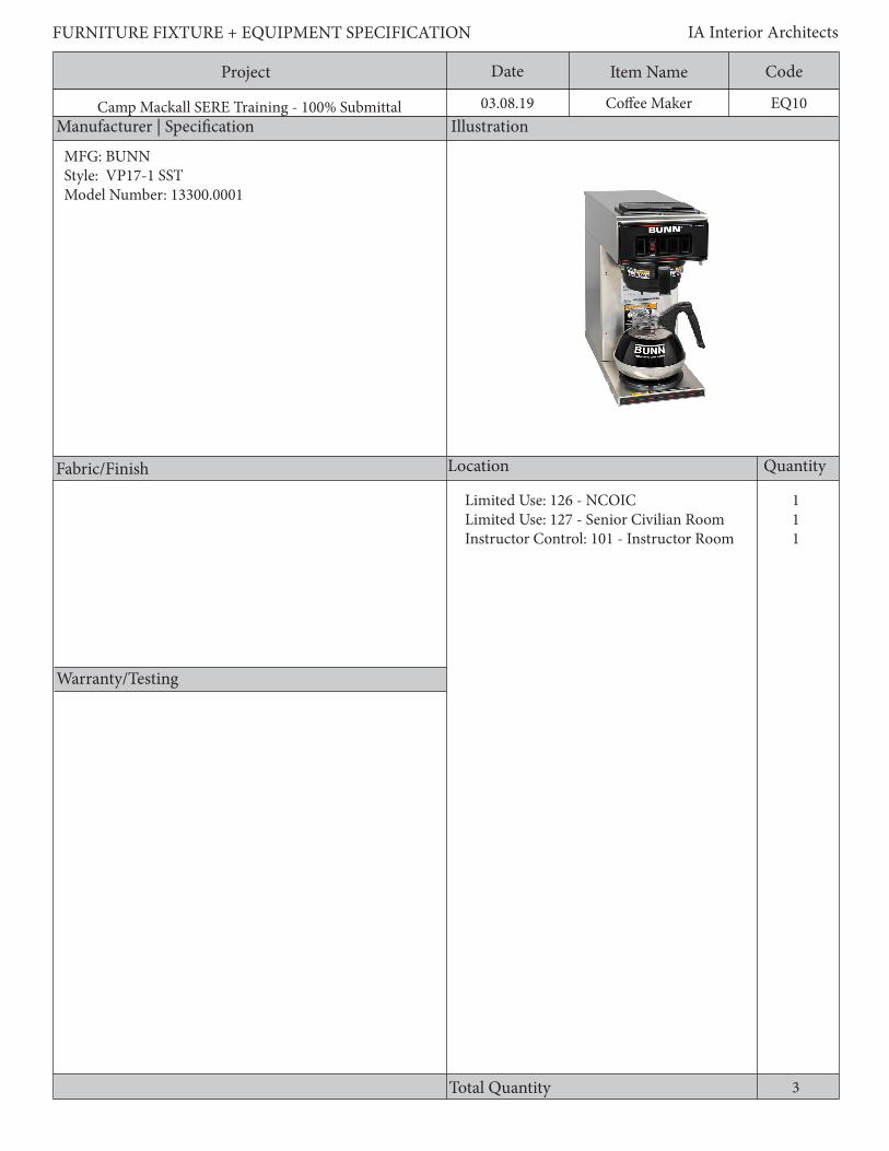
Project Date CodeItem Name
Manufacturer | Specification Illustration
Location Quantity
Warranty/Testing
Total Quantity
FURNITURE FIXTURE + EQUIPMENT SPECIFICATION IA Interior Architects
Camp Mackall SERE Training - 100% Submittal 03.08.19
Fabric/Finish
EQ10Coffee Maker
111
3
MFG: BUNNStyle: VP17-1 SSTModel Number: 13300.0001
Limited Use: 126 - NCOICLimited Use: 127 - Senior Civilian RoomInstructor Control: 101 - Instructor Room
Project Date CodeItem Name
Description
FURNITURE FIXTURE + EQUIPMENT SPECIFICATION IA Interior Architects
Camp Mackall SERE Training - 100% Submittal 03.08.19
General Requirements:1. 12 cup Pourover coffee brewer2. One lower brewer/warmer3. All stainless steel construction and finish4. 1 decanter5. 1600 Watts
EQ10Coffee Maker

Project Date CodeItem Name
Manufacturer | Specification Illustration
Location Quantity
Warranty/Testing
Total Quantity
FURNITURE FIXTURE + EQUIPMENT SPECIFICATION IA Interior Architects
Camp Mackall SERE Training - 100% Submittal 03.08.19
Fabric/Finish
EQ11AED
CABINETMFG: PhilipsModel Number: PFE7024DWidth: 16”Depth: Approx. 6”Height: Approx. 22.5”
AEDMFG: PhilipsStyle: AED Onsite BusinessModel Number: M5066A
Width: Approx. 8.3”Depth: Approx. 2.8”Height: Approx. 7.4”
1Camp Aid: 101 - Primary Exam/Treatment
1

Project Date CodeItem Name
Description
FURNITURE FIXTURE + EQUIPMENT SPECIFICATION IA Interior Architects
Camp Mackall SERE Training - 100% Submittal 03.08.19
Cabinet1. Surface mounted cabient with M5066A Heartstart Defibulator2. Cabinet with audible door-activated alarm and strobe light3. Heavy gauge steel and tempered glass4. Two 9-volt alkaline batteries or alarm can be wired to external panel
AED1. Opt R01 Earstart HS Ready-Pack2. 68- PCHAT Fast response kit3. M5006-89100 Heartstart HS1 Toolkit, NTSC4. Rechargable battery required. Recharge with appropriate electrical outlet. 5. Standard case & 2 sets of pads
EQ11AED

Project Date CodeItem Name
Manufacturer | Specification Illustration
Location Quantity
Warranty/Testing
Total Quantity
FURNITURE FIXTURE + EQUIPMENT SPECIFICATION IA Interior Architects
Camp Mackall SERE Training - 100% Submittal 03.08.19
Fabric/Finish
EQ12Icing Tub
1Camp Aid: 105 - Primary Treatment
1
MFG: Whitehall ManufacturingStyle: Stationary S-110-SL Series WhirlpoolModel Number: SS-110-SL
Width: 24””Length: 56”Height: 34”
Stainless steel

Project Date CodeItem Name
Description
FURNITURE FIXTURE + EQUIPMENT SPECIFICATION IA Interior Architects
Camp Mackall SERE Training - 100% Submittal 03.08.19
General Requirements:1. 1/2 hp jet pump motor2. Variable pressure control3. Thermometer4. Stainless steel tank5. Auxiliary drain valve6. Turbine raising and lover device7. Adjustable stainless steel legs
EQ12Icing Tub

Project Date CodeItem Name
Manufacturer | Specification Illustration
Location Quantity
Warranty/Testing
Total Quantity
FURNITURE FIXTURE + EQUIPMENT SPECIFICATION IA Interior Architects
Camp Mackall SERE Training - 100% Submittal 03.08.19
Fabric/Finish
EQ13Mop Rack
1Camp Aid: 107 - Patient Latrine
1
GSA AdvantageStyle: Mop Sink Utility Shelf, 24 in.Model Number: FMRAK-245
Width: 24”Depth: 8”Height: 8”
Stainless steel

Project Date CodeItem Name
Description
FURNITURE FIXTURE + EQUIPMENT SPECIFICATION IA Interior Architects
Camp Mackall SERE Training - 100% Submittal 03.08.19
General Requirements:1. Wall mounted2. 18 gauge stainless steel
EQ13Mop Rack
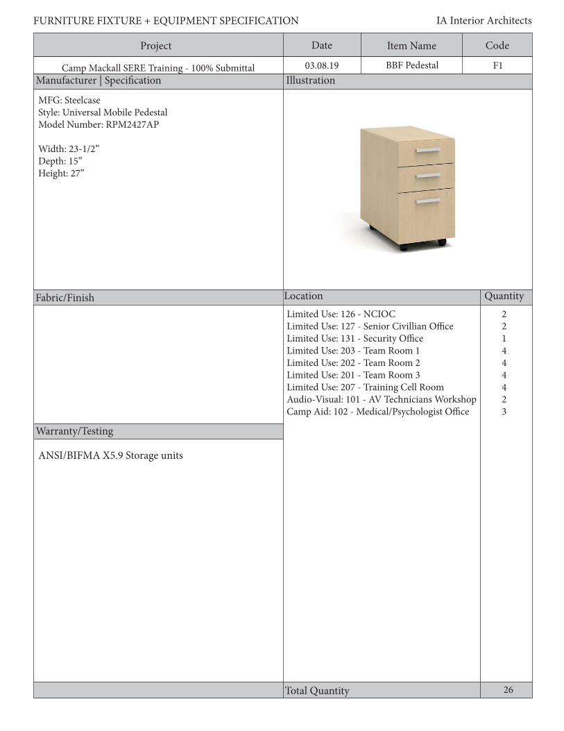
Project Date CodeItem Name
Manufacturer | Specification Illustration
Location Quantity
Warranty/Testing
Total Quantity
FURNITURE FIXTURE + EQUIPMENT SPECIFICATION IA Interior Architects
Camp Mackall SERE Training - 100% Submittal 03.08.19
Fabric/Finish
MFG: SteelcaseStyle: Universal Mobile PedestalModel Number: RPM2427AP
Width: 23-1/2”Depth: 15”Height: 27”
F1BBF Pedestal
Limited Use: 126 - NCIOCLimited Use: 127 - Senior Civillian OfficeLimited Use: 131 - Security OfficeLimited Use: 203 - Team Room 1Limited Use: 202 - Team Room 2Limited Use: 201 - Team Room 3Limited Use: 207 - Training Cell RoomAudio-Visual: 101 - AV Technicians WorkshopCamp Aid: 102 - Medical/Psychologist Office
221444423
26
ANSI/BIFMA X5.9 Storage units

Project Date CodeItem Name
Description
FURNITURE FIXTURE + EQUIPMENT SPECIFICATION IA Interior Architects
Camp Mackall SERE Training - 100% Submittal 03.08.19
General Requirements:1. File cases, bases, tops, drawers, shelves, drawer fronts, and doors shall be constructed of steel.2. File cabinets shall be equally and fully finished on all sides.3. Units shall have a steel base. The base is comprised of a lower pan and leveling glides, and shall be welded in the bot-tom cavity of the cabinet body, or in a similar construction.4. Mobile unit on casters.5. The drawer sides and back shall be full height to accommodate a standard hanging file with a tab (used for labeling).6. Drawer bodies shall be formed steel in a welded construction with hanging file rails and removable drawer fronts that can be replaced in the field.7. Drawer suspension slides shall be full extension, progressive, heavy duty steel.8. A safety interlock system that allows only one drawer to be opened at a time shall be standard on all files.9. Units shall be shipped fully assembled.10. Files shall have a front removable lock core supporting the ability to remove or replace a lock plug as needed.11. Standard files shall have a minimum 20-gauge steel top spanning the width and depth of the case.12. Drawers shall be of a minimum 20-gauge steel construction.
F1BBF Pedestal

Project Date CodeItem Name
Manufacturer | Specification Illustration
Location Quantity
Warranty/Testing
Total Quantity
FURNITURE FIXTURE + EQUIPMENT SPECIFICATION IA Interior Architects
Camp Mackall SERE Training - 100% Submittal 03.08.19
Fabric/Finish
IV1IV Pole
2Camp Aid: 101 - Primary Exam/Treatment
2
MFG: Clinton IndustriesModel Number: IV-35
Width: 48”Length: 72-1/2”Height: 21-1/2”
Standard Warranty

Project Date CodeItem Name
Description
FURNITURE FIXTURE + EQUIPMENT SPECIFICATION IA Interior Architects
Camp Mackall SERE Training - 100% Submittal 03.08.19
General Requirements:1. 5 leg base 2. 2 hooks
IV1IV Pole

Project Date CodeItem Name
Manufacturer | Specification Illustration
Location Quantity
Warranty/Testing
Total Quantity
FURNITURE FIXTURE + EQUIPMENT SPECIFICATION IA Interior Architects
Camp Mackall SERE Training - 100% Submittal 03.08.19
Fabric/Finish
K1Keyboard Tray
MFG: SteelcaseStyle: Classic Rectangular Keyboard PlatformModel Number: CR1000
Width: 27.5”Depth: 10.25”Height: 2.5”
Limited Use: 126 - NCIOCLimited Use: 127 - Senior Civillian OfficeLimited Use: 131 - Security OfficeLimited Use: 203 - Team Room 1Limited Use: 202 - Team Room 2Limited Use: 201 - Team Room 3Limited Use: 207 - Training Cell RoomCamp Aid: 102 - Medical/Psychologist Office
11144443
22

Project Date CodeItem Name
Description
FURNITURE FIXTURE + EQUIPMENT SPECIFICATION IA Interior Architects
Camp Mackall SERE Training - 100% Submittal 03.08.19
General Requirements:1. Tray shall be ambidextrous2. Shall have an integrated mouse surface3. No palm rest
K1Keyboard Tray

Project Date CodeItem Name
Manufacturer | Specification Illustration
Location Quantity
Warranty/Testing
Total Quantity
FURNITURE FIXTURE + EQUIPMENT SPECIFICATION IA Interior Architects
Camp Mackall SERE Training - 100% Submittal 03.08.19
Fabric/Finish
L1Lockers
Limited Use: 209 - Men’s Latrine RoomLimited Use: 210 - Women’s Latrine RoomCamp Aid: 102 - Medical/Psychologist Office
*Quantities noted indicate number of towers consisting of 2 components each
MFG: EDSALStyle: Wardrobe lockerModel Number: CL4091TN / CL4093TN
Width: 12”Depth: 18”Height: 78”
4241
47
ANSI/BIFMA X5.9 Storage units
Powder coat finish

Project Date CodeItem Name
Description
FURNITURE FIXTURE + EQUIPMENT SPECIFICATION IA Interior Architects
Camp Mackall SERE Training - 100% Submittal 03.08.19
General Requirements:1. The case body is made up of a steel back, two sides, a top, and a base.2. Units shall be equally and fully finished on all interior and exterior surfaces.3. Units shall be freestanding and provide interiors which can be customized for both personal and work related storage.4. Leveling glides shall provide a minimum ¾” adjustment.5. Units shall be ventilated 6. Units shall include latching mechanism and be pad lock capable7. Units shall have number plates
L1Lockers
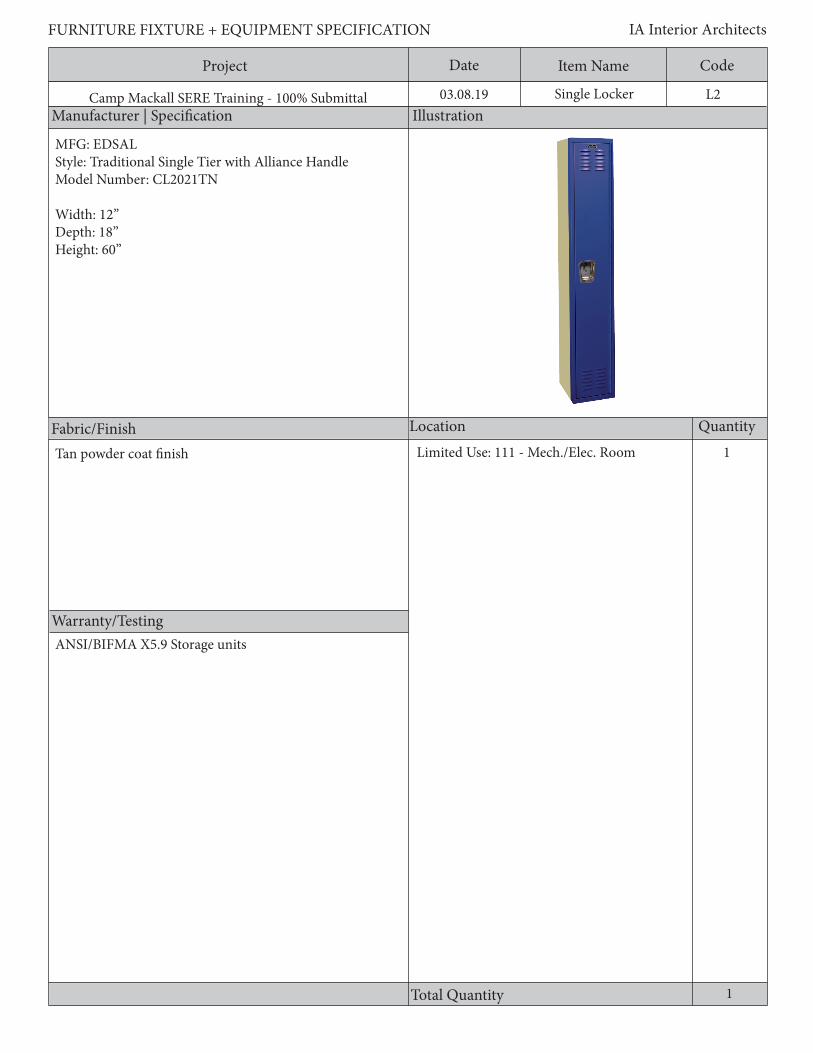
Project Date CodeItem Name
Manufacturer | Specification Illustration
Location Quantity
Warranty/Testing
Total Quantity
FURNITURE FIXTURE + EQUIPMENT SPECIFICATION IA Interior Architects
Camp Mackall SERE Training - 100% Submittal 03.08.19
Fabric/Finish
L2Single Locker
MFG: EDSALStyle: Traditional Single Tier with Alliance HandleModel Number: CL2021TN Width: 12”Depth: 18”Height: 60”
Tan powder coat finish Limited Use: 111 - Mech./Elec. Room 1
1
ANSI/BIFMA X5.9 Storage units

Project Date CodeItem Name
Description
FURNITURE FIXTURE + EQUIPMENT SPECIFICATION IA Interior Architects
Camp Mackall SERE Training - 100% Submittal 03.08.19
General Requirements:1. Unit shall have heavy 16 gauge door and frame with welded frame construction.2. Units shall be equally and fully finished on all interior and exterior surfaces.3. Units shall have louvered doors4. Unit shall have at least 3 single-prong wall hooks and 1 double prong ceiling hook5. Unit shall have stand-offs from floor6. Unit shall have multiple-point positive latching through a fully enclosed latching channel.7. Unit shall be a single tiered locker, one unit wide.
L2Box Locker
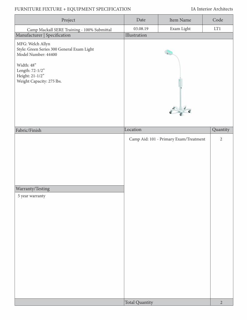
Project Date CodeItem Name
Manufacturer | Specification Illustration
Location Quantity
Warranty/Testing
Total Quantity
FURNITURE FIXTURE + EQUIPMENT SPECIFICATION IA Interior Architects
Camp Mackall SERE Training - 100% Submittal 03.08.19
Fabric/Finish
LT1Exam Light
2Camp Aid: 101 - Primary Exam/Treatment
2
MFG: Welch AllynStyle: Green Series 300 General Exam LightModel Number: 44400
Width: 48”Length: 72-1/2”Height: 21-1/2”Weight Capacity: 275 lbs.
5 year warranty

Project Date CodeItem Name
Description
FURNITURE FIXTURE + EQUIPMENT SPECIFICATION IA Interior Architects
Camp Mackall SERE Training - 100% Submittal 03.08.19
General Requirements: 1. Intense light output 2. Extra-long light pipe3. Touch-less on/off4. No bulb replacement needed5. 5500K color temperature6. LED bulb7. 50,000 hours LED bulb light8. Illuminance - 15,000 lux (1,393 footcandles) at 20” working distance min.
LT1Exam Light
Project Date CodeItem Name
Manufacturer | Specification Illustration
Location Quantity
Warranty/Testing
Total Quantity
FURNITURE FIXTURE + EQUIPMENT SPECIFICATION IA Interior Architects
Camp Mackall SERE Training - 100% Submittal 03.08.19
Fabric/Finish
16
MB1Markerboard
MFG: ClaridgeStyle: 6000 Series - 1/2” radius face powder coat finishModel Number: LCS6046
Width: 6’Depth: N/AHeight: 4’
Powder coat finished trim 1112223211
Limited Use: 126 - NCIOC RoomLimited Use: 127 - Senior Civilian OfficeLimited Use: 131 - Security OfficeLimited Use: 201 - Team Room 3Limited Use: 202 - Team Room 2Limited Use: 203 - Team Room 1Limited Use: 207 - Training Cell RoomLimited Use: 212 - Shift Brief ClassroomIsolation Building: 101 - Guard RoomCamp Aid: 102 - Medical/Psychologist Office
Standard 1 year
Project Date CodeItem Name
Description
FURNITURE FIXTURE + EQUIPMENT SPECIFICATION IA Interior Architects
Camp Mackall SERE Training - 100% Submittal 03.08.19
General Requirements:1. Wall mounted porcelain enamel steel markerboard with magnetic surface2. Powder coat finish aluminum trim3. Z-bar clips4. GREENGUARD certified5. Include accessories tray
MB1Markerboard

Project Date CodeItem Name
Manufacturer | Specification Illustration
Location Quantity
Warranty/Testing
Total Quantity
FURNITURE FIXTURE + EQUIPMENT SPECIFICATION IA Interior Architects
Camp Mackall SERE Training - 100% Submittal 03.08.19
Fabric/Finish
MB2
211
Markerboard
MFG: ClaridgeStyle: LCS Deluxe Markerboard - 5/8” Face TrimModel Number: LCS2410RWidth: 8’Depth: N/AHeight: 4’
Limited Use: 125 - Brief RoomLimited Use: 134 - Ready RoomLimited Use: 212 - Shift Brief Room
4
Standard 1 year
Powder coat finished trim

Project Date CodeItem Name
Description
FURNITURE FIXTURE + EQUIPMENT SPECIFICATION IA Interior Architects
Camp Mackall SERE Training - 100% Submittal 03.08.19 MB2Markerboard
General Requirements:1. Wall mounted porcelain enamel steel markerboard with magnetic surface2. Powder coat finish aluminum trim3. Z-bar clips4. GREENGUARD certified5. Include accessories tray

Project Date CodeItem Name
Manufacturer | Specification Illustration
Location Quantity
Warranty/Testing
Total Quantity
FURNITURE FIXTURE + EQUIPMENT SPECIFICATION IA Interior Architects
Camp Mackall SERE Training - 100% Submittal 03.08.19
Fabric/Finish
MB3
1
Markerboard
MFG: ClaridgeStyle: 2800 SeriesModel Number: 2843L
Width: 4’Depth: N/AHeight: 3’
Warranty: Standard 1 year
Camp Aid: 101 - Primary Exam/Treatment
1
Black vinyl trim

Project Date CodeItem Name
Description
FURNITURE FIXTURE + EQUIPMENT SPECIFICATION IA Interior Architects
Camp Mackall SERE Training - 100% Submittal 03.08.19
General Requirements:1. Wall mounted white porcelain enamel steel markerboard with magnetic surface2. Black vinyl trim3. Z-bar clips4. GREENGUARD certified5. Include marker/accessories tray
MB3Markerboard
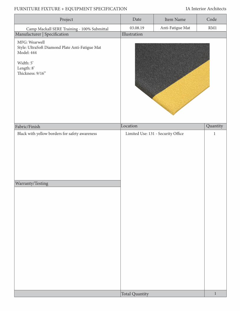
Project Date CodeItem Name
Manufacturer | Specification Illustration
Location Quantity
Warranty/Testing
Total Quantity
FURNITURE FIXTURE + EQUIPMENT SPECIFICATION IA Interior Architects
Camp Mackall SERE Training - 100% Submittal 03.08.19
Fabric/Finish
RM1Anti-Fatigue Mat
1Limited Use: 131 - Security Office
1
MFG: WearwellStyle: UltraSoft Diamond Plate Anti-Fatigue MatModel: 444
Width: 5’Length: 8’Thickness: 9/16”
Black with yellow borders for safety awareness

Project Date CodeItem Name
Description
FURNITURE FIXTURE + EQUIPMENT SPECIFICATION IA Interior Architects
Camp Mackall SERE Training - 100% Submittal 03.08.19
General Requirements:1. Sponge base PVC loaded with nitrile rubber;2. All edges shall have a safety bevel3. Shall have diamond plated surface4. Resistant to abrasion/chemical spills;5. Color: black with yellow borders for safety awareness6. 9/16” Thickness7. Min. of 50% recycled content
RM1Anti-Fatigue Mat
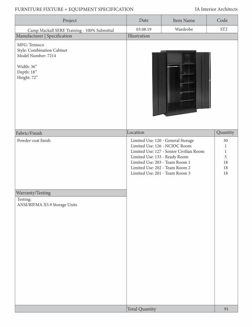
Project Date CodeItem Name
Manufacturer | Specification Illustration
Location Quantity
Warranty/Testing
Total Quantity
FURNITURE FIXTURE + EQUIPMENT SPECIFICATION IA Interior Architects
Camp Mackall SERE Training - 100% Submittal 03.08.19
Fabric/Finish
91
ST2Wardrobe
Powder coat finish Limited Use: 120 - General StorageLimited Use: 126 - NCIOC RoomLimited Use: 127 - Senior Civilian RoomLimited Use: 133 - Ready RoomLimited Use: 203 - Team Room 1Limited Use: 202 - Team Room 2Limited Use: 201 - Team Room 3
30115
181818
MFG: TennscoStyle: Combination CabinetModel Number: 7214
Width: 36” Depth: 18”Height: 72”
Testing:ANSI/BIFMA X5.9 Storage Units

Project Date CodeItem Name
Description
FURNITURE FIXTURE + EQUIPMENT SPECIFICATION IA Interior Architects
Camp Mackall SERE Training - 100% Submittal 03.08.19
2 door, powder coated wardrobe, minimum 22 gauge steel and features top fixed shelf, one full width top shelf and 4 half shelves plus garment hanger bar for full length clothing storage; 150 lb shelf capacityGeneral Requirements:1. The case body is made up of a steel back, two sides, a back, a top, and a base.2. Units shall be equally and fully finished on all interior and exterior surfaces.3. Units shall be freestanding and provide interiors which can be customized for both personal and work related storage.4. Leveling glides shall provide a minimum ¾” adjustment.5. Unit shall stand-off from floor.
ST2Wardrobe

Project Date CodeItem Name
Manufacturer | Specification Illustration
Location Quantity
Warranty/Testing
Total Quantity
FURNITURE FIXTURE + EQUIPMENT SPECIFICATION IA Interior Architects
Camp Mackall SERE Training - 100% Submittal 03.08.19
Fabric/Finish
ST3Open Food Shelving
3
MFG: Rivetwell Style: Double Rivet Boltless ShelvingModel Number: DRHC603084-3S-W-ME
Width: 60”Depth: 30”Height: 84”
Weight capacity: 2000 lbs. per shelf
Black powder-coat finish Mulit-Purpose: 110 - Food Service Room
3
Lifetime warranty against rust and corrosion
ANSI/BIFMA X5.9 Storage Units
Project Date CodeItem Name
Description
FURNITURE FIXTURE + EQUIPMENT SPECIFICATION IA Interior Architects
Camp Mackall SERE Training - 100% Submittal 03.08.19
General Requirements:1. All welded T-bar style shelving2. Shelves shall provide a minimum weight capacity of 1000 lb per shelf3. Units shall be freestanding and provide interiors which can be customized for both personal and work related storage.4. Leveling glides shall provide a minimum ¾” adjustment.5. Minimum of 3-shelves6. 14 gauge cold rolled steel 7. Units shall be open on all sides8. Unit shall stand-off from floor
ST3Open Food Shelving

Project Date CodeItem Name
Manufacturer | Specification Illustration
Location Quantity
Warranty/Testing
Total Quantity
FURNITURE FIXTURE + EQUIPMENT SPECIFICATION IA Interior Architects
Camp Mackall SERE Training - 100% Submittal 03.08.19
Fabric/Finish
ST4Open Storage Shelving
20Multi-Purpose: 111 - Laundry room
*Quantities noted indicate number of towers consisting of 6 components each
20
Cherry wood, clear stain
MFG: Unique ConceptsStyle: CustomModel Number: Custom
Width: 12”Depth: 12”Height: 72”
*Storage cubbies to be built custom to fulfill size requirementsMinimum weight capacity 50 lbs/cubby
Testing:ANSI/BIFMA X5.9 Storage Units

Project Date CodeItem Name
Description
FURNITURE FIXTURE + EQUIPMENT SPECIFICATION IA Interior Architects
Camp Mackall SERE Training - 100% Submittal 03.08.19
1’ x 1’ x 1’ open cubby storage; open 1-side; 6 units tallGeneral Requirements:1. Solid wood components shall be kiln dried with moisture content from 5-10%.2. All solid wood shall be compatible for color and grain.3. Sound, scattered birdseye in maple is permitted.4. Sound knots shall be no more than ¼” in diameter.5. Mineral stain shall not exceed 10% of the face.6. Sapwood in cherry and walnut shall be less than 5% of the face.7. Worm holes less than 1/16” are permitted.8. No bark pockets, honeycomb, pitch pockets or streaks, sticker discoloration, mineral stain, or shake is allowed.9. Units shall be freestanding with floor and wall anchoring mechanisms.10. Leveling glides shall provide a minimum ¾” adjustment.11. Units shall stand off from floor min. 2”
ST4Open Storage Shelving

Project Date CodeItem Name
Manufacturer | Specification Illustration
Location Quantity
Warranty/Testing
Total Quantity
FURNITURE FIXTURE + EQUIPMENT SPECIFICATION IA Interior Architects
Camp Mackall SERE Training - 100% Submittal 03.08.19
Fabric/Finish
ST5Personal Gear Storage
32Multi-Purpose: 112 - Student Gear Storage Room
*Quantities noted indicate number of towers consisting of 4 components each
32
Cherry wood, clear stain
MFG: Uunique ConceptsStyle: CustomModel Number: Custom
Width: 24”Depth: 24”Height: 72”
*Storage cubbies to be built custom to fulfill size requirementsMinimum weight capacity 100 lbs/cubby
Testing:ANSI/BIFMA X5.9 Storage Units

Project Date CodeItem Name
Description
FURNITURE FIXTURE + EQUIPMENT SPECIFICATION IA Interior Architects
Camp Mackall SERE Training - 100% Submittal 03.08.19
2’ x 2’ x 2’ open cubby storage; open 1-side; 3 units tallGeneral Requirements:1. Solid wood components shall be kiln dried with moisture content from 5-10%.2. All solid wood shall be compatible for color and grain.3. Sound, scattered birdseye in maple is permitted.4. Sound knots shall be no more than ¼” in diameter.5. Mineral stain shall not exceed 10% of the face.6. Sapwood in cherry and walnut shall be less than 5% of the face.7. Worm holes less than 1/16” are permitted.8. No bark pockets, honeycomb, pitch pockets or streaks, sticker discoloration, mineral stain, or shake is allowed.9. Units shall be freestanding with floor and wall anchoring mechanisms.10. Leveling glides shall provide a minimum ¾” adjustment.11. Unit shall stand off from floor min. 2”
ST5Personal Gear Storage
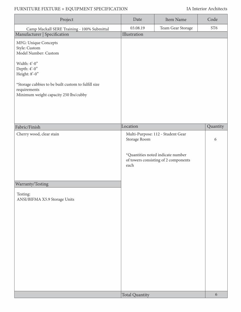
Project Date CodeItem Name
Manufacturer | Specification Illustration
Location Quantity
Warranty/Testing
Total Quantity
FURNITURE FIXTURE + EQUIPMENT SPECIFICATION IA Interior Architects
Camp Mackall SERE Training - 100% Submittal 03.08.19
Fabric/Finish
ST6Team Gear Storage
6Multi-Purpose: 112 - Student Gear Storage Room
*Quantities noted indicate number of towers consisting of 2 components each
6
Cherry wood, clear stain
Testing:ANSI/BIFMA X5.9 Storage Units
MFG: Unique ConceptsStyle: CustomModel Number: Custom
Width: 4’-0”Depth: 4’-0”Height: 8’-0”
*Storage cubbies to be built custom to fulfill size requirementsMinimum weight capacity 250 lbs/cubby
Project Date CodeItem Name
Description
FURNITURE FIXTURE + EQUIPMENT SPECIFICATION IA Interior Architects
Camp Mackall SERE Training - 100% Submittal 03.08.19 ST6Team Gear Storage
4’ x 4’ x 4’ open cubby storage; open 1-side; 2 units tallGeneral Requirements:1. Solid wood components shall be kiln dried with moisture content from 5-10%.2. All solid wood shall be compatible for color and grain.3. Sound, scattered birdseye in maple is permitted.4. Sound knots shall be no more than ¼” in diameter.5. Mineral stain shall not exceed 10% of the face.6. Sapwood in cherry and walnut shall be less than 5% of the face.7. Worm holes less than 1/16” are permitted.8. No bark pockets, honeycomb, pitch pockets or streaks, sticker discoloration, mineral stain, or shake is allowed.9. Units shall be freestanding with floor and wall anchoring mechanisms.10. Leveling glides shall provide a minimum ¾” adjustment.11. Unit shall stand off from floor min. 2”

Project Date CodeItem Name
Manufacturer | Specification Illustration
Location Quantity
Warranty/Testing
Total Quantity
FURNITURE FIXTURE + EQUIPMENT SPECIFICATION IA Interior Architects
Camp Mackall SERE Training - 100% Submittal 03.08.19
Fabric/Finish
ST7Open Shelving
4
22
Individual Training: 104 - CorridorIndividual Training: xxx - Outside Dump Station Audio-Visual: 101 - AV Technicians Workshop
8
Stainless steel
MFG: ULINEStyle: Industrial Steel ShelvingModel Number: H-3355
Width: 48”Depth: 18”Height: 75”Shelf Weight Capacity: 550 lbs.
Testing:ANSI/BIFMA X5.9 Storage Units
Project Date CodeItem Name
Description
FURNITURE FIXTURE + EQUIPMENT SPECIFICATION IA Interior Architects
Camp Mackall SERE Training - 100% Submittal 03.08.19
General Requirements:1. All welded T-bar style shelving2. Shelves shall provide a minimum weight capacity of 800 lb per shelf 3. Units shall be freestanding and provide interiors which can be customized for both personal and work related storage.4. Leveling glides shall provide a minimum ¾” adjustment.5. Minimum of 5-shelves6. Constructed of 20 gauge steel7. Unit shall stand off from floor8. Unit shall be open on all sides
ST7Open Shelving

Project Date CodeItem Name
Manufacturer | Specification Illustration
Location Quantity
Warranty/Testing
Total Quantity
FURNITURE FIXTURE + EQUIPMENT SPECIFICATION IA Interior Architects
Camp Mackall SERE Training - 100% Submittal 03.08.19
Fabric/Finish
ST8Chest of drawers
11
Limited Use: 126 - NCOICLimited Use: 127 - Senior Civilian Room
2
MFG: CorilamStyle: SienaModel Number: 405-0230
Width: 30”Depth: 19”Height: 30”
Finish: Laminate - woodgrainHardware: H923
Warranty Requirements:12 year.
Testing:ANSI/BIFMA X5.9 Storage Units
Project Date CodeItem Name
Description
FURNITURE FIXTURE + EQUIPMENT SPECIFICATION IA Interior Architects
Camp Mackall SERE Training - 100% Submittal 03.08.19
General Requirements:1. The case body shall be made up of a back, two sides, a top, and a base.2. Units shall be equally and fully finished on all interior and exterior surfaces.3. Units shall be freestanding and provide interiors which can be customized for both personal and work related storage.4. Leveling glides shall provide a minimum ¾” adjustment.5. Unit shall have 3 drawers6. Unit shall stand off from floor7. Drawers shall have min. weight capacity of 75 lbs. eachMaterial Requirements:1. Shall have a minimum VGS General Purpose Grade High Pressure Laminate 2. Laminates shall be bonded to the core with PVA adhesive in a cold press or hot press to prevent separation of the laminate from the core.3. Low pressure laminate and thermally fused laminate is non-conforming and will be considered unacceptable. 5. Laminate self edges are non-conforming.
ST8Chest of drawers
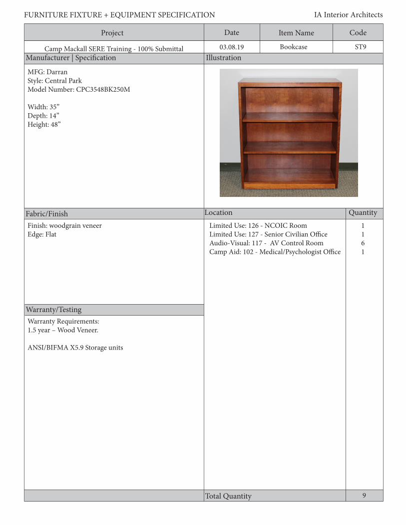
Project Date CodeItem Name
Manufacturer | Specification Illustration
Location Quantity
Warranty/Testing
Total Quantity
FURNITURE FIXTURE + EQUIPMENT SPECIFICATION IA Interior Architects
Camp Mackall SERE Training - 100% Submittal 03.08.19
Fabric/Finish
ST9Bookcase
1161
MFG: DarranStyle: Central ParkModel Number: CPC3548BK250M
Width: 35”Depth: 14”Height: 48”
Finish: woodgrain veneerEdge: Flat
Limited Use: 126 - NCOIC RoomLimited Use: 127 - Senior Civilian OfficeAudio-Visual: 117 - AV Control RoomCamp Aid: 102 - Medical/Psychologist Office
9
Warranty Requirements:1.5 year – Wood Veneer.
ANSI/BIFMA X5.9 Storage units

Project Date CodeItem Name
Description
FURNITURE FIXTURE + EQUIPMENT SPECIFICATION IA Interior Architects
Camp Mackall SERE Training - 100% Submittal 03.08.19
Environmental and Sustainability: 1. All proposed products shall be certified as compliant with Indoor Air Quality (IAQ)requirements and shall meet or exceed ANSI/BIFMA X7.1-2011-VOC.2. The product submitted shall have 3rd party certification for Indoor Air Quality (GREENGUARD or equivalent).General Requirements:1. Freestanding units shall be specified complete with no exposed or “raw” parts. Include available covers, fillers, and trims available in the standard GSA specifications guide to provide for a complete and finished appearance and function.2. Freestanding unit end supports shall provide a flush termination at the exposed end of the freestanding unit.3. Freestanding unit leveling glides shall adjust to allow installation on uneven floors. Minimum adjustment shall be 3/4”.4. 2 Adjustable shelves5. 120lbs per shelf weight capacity6. Unit shall stand off from floor7. The case body shall be made up of two sides, a back, a top, and a base.Veneer Requirements:1. Veneers shall be “natural”. “Composite” or “reconstituted veneer” shall not be acceptable.2. Veneer thickness shall be 0.4mm - 0.7mm.3. All segments in one panel shall be the same size, except the two outside edge segments can be narrower to visually balance the panel. Any cathedral grain pattern shall be centered within the flitch.4. All veneer plates on one panel shall come from the same flitch of veneer; mismatched plates are non- conforming.5. The grain direction on exterior panels, including doors and drawers, shall be vertical, with cathedral peaks pointed toward the top of the panel.6. The grain direction on straight and extended corner work surfaces shall run parallel to the long dimension of the work surface, and shall have a visual balance in the wood grain pattern in both width and depth.7. The veneer on a separate corner work surface shall run parallel to the 45 degree user edge.
ST9Bookcase

Project Date CodeItem Name
Manufacturer | Specification Illustration
Location Quantity
Warranty/Testing
Total Quantity
FURNITURE FIXTURE + EQUIPMENT SPECIFICATION IA Interior Architects
Camp Mackall SERE Training - 100% Submittal 03.08.19
Fabric/Finish
ST11Supply Locker
111
Instructor Control: 102 - Unisex LatrineLimited Use: 122 - Men’s Latrine RoomLimited Use: 123 - Women’s Latrine Room
3
MFG: EdsalStyle: Compact Storage CabinetModel Number: 6602TN
Width: 18”Depth: 18”Height: 66”
Warranty Requirements:12 year.
Testing:ANSI/BIFMA X5.9 Storage Units
Powder coat finish

Project Date CodeItem Name
Description
FURNITURE FIXTURE + EQUIPMENT SPECIFICATION IA Interior Architects
Camp Mackall SERE Training - 100% Submittal 03.08.19
General Requirements:1. The case body shall be made up of a 24 gauge steel back, two sides, a top, and a base.2. Units shall be equally and fully finished on all interior and exterior surfaces.3. Units shall be freestanding and provide interiors which can be customized for both personal and work related storage.4. Leveling glides shall provide a minimum ¾” adjustment.5. Shall have (4) 24 gauge steel adjustable shelves6. Unit shall stand off from floor7. Unit shall have min. weight capacity of 35 lbs. per shelf
ST11Supply Locker

Project Date CodeItem Name
Manufacturer | Specification Illustration
Location Quantity
Warranty/Testing
Total Quantity
FURNITURE FIXTURE + EQUIPMENT SPECIFICATION IA Interior Architects
Camp Mackall SERE Training - 100% Submittal 03.08.19
Fabric/Finish
ST12Lockable Storage Cabinet
53
MFG: SanduskyStyle: Clear View Storage CabinetModel Number: CA4V361872-05
Width: 36” Depth: 18”Height: 72”
Dove gray powder coat Camp Aid: 101 - Primary Exam/TreatmentCamp Aid: 106 - Medical Storage
8
Warranty Requirements:12 year.
Testing:ANSI/BIFMA X5.9-2004 Storage Units

Project Date CodeItem Name
Description
FURNITURE FIXTURE + EQUIPMENT SPECIFICATION IA Interior Architects
Camp Mackall SERE Training - 100% Submittal 03.08.19
Locking storage cabinet with acrylic doors and 4 adjustable shelvesGeneral Requirements:1. The case body shall be made up of a 22 gauge steel back, two sides, a top, and a base.2. Units shall be equally and fully finished on all interior and exterior surfaces.3. Units shall be freestanding and provide interiors which can be customized for both personal and work related storage.4. Leveling glides shall provide a minimum ¾” adjustment.5. Shall have 4 adjustable shelves6. Unit shall stand off from floor7. Weight capacity per shelf shall be min. 150 lbs.
ST12Lockable Storage Cabinet

Project Date CodeItem Name
Manufacturer | Specification Illustration
Location Quantity
Warranty/Testing
Total Quantity
FURNITURE FIXTURE + EQUIPMENT SPECIFICATION IA Interior Architects
Camp Mackall SERE Training - 100% Submittal 03.08.19
Fabric/Finish
ST13Storage Cabinet
396
Limited Use: 120 - General StorageLimited Use: 207 - Training Cell Room
45
Powder coat finish
MFG: TennscoStyle: Standard Storage CabinetModel Number: 7218
Width: 36” Depth: 18”Height: 72”
Warranty Requirements:12 year.
Testing:ANSI/BIFMA X5.9 Storage Units

Project Date CodeItem Name
Description
FURNITURE FIXTURE + EQUIPMENT SPECIFICATION IA Interior Architects
Camp Mackall SERE Training - 100% Submittal 03.08.19
Industrial storage cabinet with 4 shelves and locking doorsGeneral Requirements:1. The case body is made up of a steel back, two sides, a top, and a base.2. Units shall be equally and fully finished on all interior and exterior surfaces.3. Units shall be freestanding and provide interiors which can be customized for both personal and work related storage.4. Leveling glides shall provide a minimum ¾” adjustment.5. 22 gauge shelves6. 24 gauge bottom, sides, and rear7. Unit shall stand off from floor8. Weight capacity per shelf shall be min. 180 lbs.
ST13Storage Cabinet
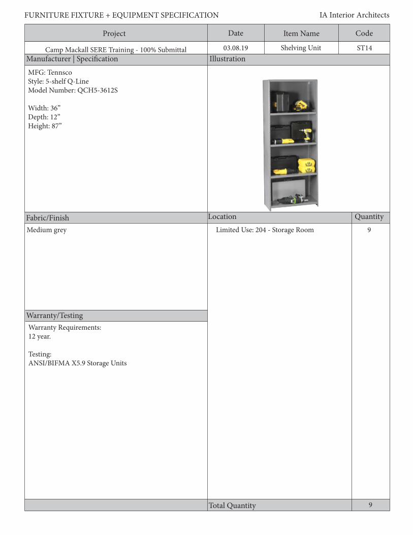
Project Date CodeItem Name
Manufacturer | Specification Illustration
Location Quantity
Warranty/Testing
Total Quantity
FURNITURE FIXTURE + EQUIPMENT SPECIFICATION IA Interior Architects
Camp Mackall SERE Training - 100% Submittal 03.08.19
Fabric/Finish
ST14Shelving Unit
9Limited Use: 204 - Storage Room
9
MFG: TennscoStyle: 5-shelf Q-Line Model Number: QCH5-3612S
Width: 36” Depth: 12”Height: 87”
Medium grey
Warranty Requirements:12 year.
Testing:ANSI/BIFMA X5.9 Storage Units

Project Date CodeItem Name
Description
FURNITURE FIXTURE + EQUIPMENT SPECIFICATION IA Interior Architects
Camp Mackall SERE Training - 100% Submittal 03.08.19
Industrial shelving unit with back and side panels, 5 adjustable shelvesGeneral Requirements:1. The case body is made up of a steel back, two sides, a top, and a base.2. Units shall be equally and fully finished on all interior and exterior surfaces.3. Units shall be freestanding and provide interiors which can be customized for both personal and work related storage.4. Leveling glides shall provide a minimum ¾” adjustment.5. 20 gauge shelves6. Steel construction7. Unit shall stand off from floor8. Weight capacity shall be min. 1000 lbs. per shelf
ST14Shelving Unit

Project Date CodeItem Name
Manufacturer | Specification Illustration
Location Quantity
Warranty/Testing
Total Quantity
FURNITURE FIXTURE + EQUIPMENT SPECIFICATION IA Interior Architects
Camp Mackall SERE Training - 100% Submittal 03.08.19
Fabric/Finish
ST15Open Storage Cubbies
31Limited Use: 101 - Sally Port
*Quantities noted indicate number of towers consisting of 4 components each
31
Powder coat finish, color to be selected by User
MFG: Unique ConceptsStyle: CustomModel Number: Custom
Width: 24”Depth: 24”Height: 72”
*Storage cubbies to be built custom to fulfill size requirementsMinimum weight capacity 50 lbs/cubby
Testing:ANSI/BIFMA X5.9 Storage Units

Project Date CodeItem Name
Description
FURNITURE FIXTURE + EQUIPMENT SPECIFICATION IA Interior Architects
Camp Mackall SERE Training - 100% Submittal 03.08.19
2’ x 2’ x 2’ storage cubbies; open 1-side; 4 units tallIndustrial shelving unit with back and side panelsGeneral Requirements:1. The case body is made up of a steel back, two sides, a top, and a base.2. Units shall be equally and fully finished on all interior and exterior surfaces.3. Units shall be freestanding and provide interiors which can be customized for both personal and work related storage.4. Leveling glides shall provide a minimum ¾” adjustment.5. Material and finish to be exterior grade.6. Units shall stand off from floor
ST15Open Storage Cubbies

Project Date CodeItem Name
Manufacturer | Specification Illustration
Location Quantity
Warranty/Testing
Total Quantity
FURNITURE FIXTURE + EQUIPMENT SPECIFICATION IA Interior Architects
Camp Mackall SERE Training - 100% Submittal 03.08.19
Fabric/Finish
ST16Industrial Shelving
2Audio-Visual: 101 - AV Technicians Workshop
MFG: PucelStyle: Industrial Shelving UnitModel Number: DR-1842
Width: 42” Depth: 18”Height: 72”Total Weight Capacity: 6000 lbs.
Steel
Testing:ANSI/BIFMA X5.9 Storage Units
2

Project Date CodeItem Name
Description
FURNITURE FIXTURE + EQUIPMENT SPECIFICATION IA Interior Architects
Camp Mackall SERE Training - 100% Submittal 03.08.19
General Requirements:1. Shelves shall provide a minimum weight capacity of 1000 lb per shelf2. Units shall be freestanding3. Leveling glides shall provide a minimum ¾” adjustment.4. Minimum of 5-shelves5. 10 gauge angle posts and 14 gauge shelves6. Unit shall have open sides with X braces provided on both sides and back.7. Unit shall stand off from floor.
ST16Industrial Shelving

Project Date CodeItem Name
Manufacturer | Specification Illustration
Location Quantity
Warranty/Testing
Total Quantity
FURNITURE FIXTURE + EQUIPMENT SPECIFICATION IA Interior Architects
Camp Mackall SERE Training - 100% Submittal 03.08.19
Fabric/Finish
ST21Open Wire Shelving
4
MFG: ULINEStyle: Stainless Steel Wire ShelvingModel Number: H-4895
Width: 48” Depth: 18”Height: 72”Shelf Weight Capacity: 800 lbs.
Camp Aid: 106 - Medical Storage
4
Gray
Testing:ANSI/BIFMA X5.9 Storage Units

Project Date CodeItem Name
Description
FURNITURE FIXTURE + EQUIPMENT SPECIFICATION IA Interior Architects
Camp Mackall SERE Training - 100% Submittal 03.08.19
General Requirements: 1. Open wire shelving2. Shelves shall provide a minimum weight capacity of 800 lb per shelf 3. Units shall be freestanding and provide interiors which can be customized for both personal and work related storage.4. Unit shall stand-off from floor.5. Leveling glides shall provide a minimum ¾” adjustment.6. Unit shall have a minimum of 4-shelves7. Unit shall be a minimum of 22 gauge steel.8. Unit shall have 4 open sides.
ST21Open Wire Shelving

Project Date CodeItem Name
Manufacturer | Specification Illustration
Location Quantity
Warranty/Testing
Total Quantity
FURNITURE FIXTURE + EQUIPMENT SPECIFICATION IA Interior Architects
Camp Mackall SERE Training - 100% Submittal 03.08.19
Fabric/Finish
ST22Key Storage Cabinet
MFG: Assured LockStyle: 100 Key Capacity Standard Box W/ Keyed Slam LockModel Number: TT-KB01
1Limited Use: 133 - Secure Foyer
1
Testing:ANSI/BIFMA X5.9 Storage Units
Powder coat - black

Project Date CodeItem Name
Description
FURNITURE FIXTURE + EQUIPMENT SPECIFICATION IA Interior Architects
Camp Mackall SERE Training - 100% Submittal 03.08.19
General Requirements:1. Hook style key cabinet with 2. Cabinet shall be made of min. 18 gauge steel with seamless body and tamper-proof lock3. Cabinet shall have key-drop slot for after hours security4. Powder coat finish5. Shall include two keys per cabinet6. Unit shall hold all keys plus 10% spares7. Unit shall be wall mounted8. The case body shall be made up of a steel back, two sides, a top, back, and door.
ST22Key Storage Cabinet

Project Date CodeItem Name
Manufacturer | Specification Illustration
Location Quantity
Warranty/Testing
Total Quantity
FURNITURE FIXTURE + EQUIPMENT SPECIFICATION IA Interior Architects
Camp Mackall SERE Training - 100% Submittal 03.08.19
Fabric/Finish
ST23Credenza
MFG: SteelcaseStyle: Classic Payback Full-Storage CredenzaModel Number: TS5ACS2466
Width: 64”Depth: 24”Height: 29”
1Audio-Visual : 117 -AV Control Room
Testing:ANSI/BIFMA X5.9 Storage Units
Laminate finish
1

Project Date CodeItem Name
Description
FURNITURE FIXTURE + EQUIPMENT SPECIFICATION IA Interior Architects
Camp Mackall SERE Training - 100% Submittal 03.08.19
General Requirements:1. The case body is made up of a full height back panel, laminate work surface, and laminate finished sides.2. Units shall be equally and fully finished on all interior and exterior surfaces.3. Units shall be freestanding and provide interiors which can be customized for both personal and work related storage.4. Leveling glides shall provide a minimum ¾” adjustment.5. Unit shall have min. 1” thick worksurface with square edge profile and high-impact plastic to match work surface.6. Unit shall stand off from floor
ST23Credenza

Project Date CodeItem Name
Manufacturer | Specification Illustration
Location Quantity
Warranty/Testing
Total Quantity
FURNITURE FIXTURE + EQUIPMENT SPECIFICATION IA Interior Architects
Camp Mackall SERE Training - 100% Submittal 03.08.19
Fabric/Finish
ST24Key Tags
MFG: MMF STEELMASTERStyle: ID Key Tags Model Number: 201400604
100Limited Use: 133 - Secure Foyer
100
Project Date CodeItem Name
Description
FURNITURE FIXTURE + EQUIPMENT SPECIFICATION IA Interior Architects
Camp Mackall SERE Training - 100% Submittal 03.08.19
Black, hook style key tags
ST24Key Tags
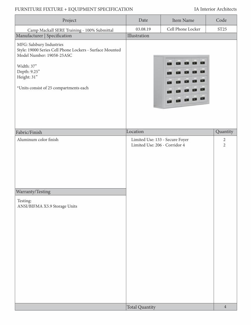
Project Date CodeItem Name
Manufacturer | Specification Illustration
Location Quantity
Warranty/Testing
Total Quantity
FURNITURE FIXTURE + EQUIPMENT SPECIFICATION IA Interior Architects
Camp Mackall SERE Training - 100% Submittal 03.08.19
Fabric/Finish
ST25Cell Phone Locker
MFG: Salsbury IndustriesStyle: 19000 Series Cell Phone Lockers - Surface MountedModel Number: 19058-25ASC
Width: 37”Depth: 9.25”Height: 31”
*Units consist of 25 compartments each
22
Limited Use: 133 - Secure FoyerLimited Use: 206 - Corridor 4
Testing:ANSI/BIFMA X5.9 Storage Units
Aluminum color finish
4
Project Date CodeItem Name
Description
FURNITURE FIXTURE + EQUIPMENT SPECIFICATION IA Interior Architects
Camp Mackall SERE Training - 100% Submittal 03.08.19
General Requirements:1. Surface mount2. Constructed of entirely heavy duty aluminum3. Durable powder coat finish4. Resettable combination locks5. Clear plastic card holder to identify each compartment6. Provide master control key for resettable combination locks that can override combination to open lockers7. The case body shall be made up of a steel back, two sides, a top, base, and doors.8. Unit shall have weight capacity min. of 10 lbs.
ST25Cell Phone Locker

Project Date CodeItem Name
Manufacturer | Specification Illustration
Location Quantity
Warranty/Testing
Total Quantity
FURNITURE FIXTURE + EQUIPMENT SPECIFICATION IA Interior Architects
Camp Mackall SERE Training - 100% Submittal 03.08.19
Fabric/Finish
T1Laminate Table
6
MFG: Furniture LabStyle: Millennium Round Legs
Width: 36”Depth: 24”Height: 28”
6
Audio-Visual: 117 - AV Control Room
Warranty Requirements:1.10 year standard warranty2. 5 year - Laminate warranty
Testing and Standards:ANSI/BIFMA X5.5 Desk/Table Products Material:1. ANSI 208.1Particleboard Classifications.2. ANSI A208.2 Medium Density Fiberboard.3. ANSI/NEMA LD 3 High Pressure Decorative Laminates (HPDL).
Steel baseWood laminate top table

Project Date CodeItem Name
Description
FURNITURE FIXTURE + EQUIPMENT SPECIFICATION IA Interior Architects
Camp Mackall SERE Training - 100% Submittal 03.08.19
General Requirements:1. Work surfaces shall be constructed of a Grade M2 or M3 particleboard or a ~45 lb. medium density fiberboard core with a minimum VGS General Purpose Grade High-Pressure Laminate on the face and a backer material on the underside.2. Laminates shall be bonded to the core with a PVA adhesive in a cold press or hot press process to prevent separation of the laminate from the core.3. Low pressure laminate and thermally fused laminate is non-conforming and will be considered unacceptable.4. Work surface edges shall be totally finished and sealed against moisture.5. Laminate self edges are non-conforming.6. Abutting surfaces shall mate closely and at equal heights when used in side-by-side configurations in order to provide a continuous and level surface.7. The leg shaft shall be welded to a formed steel plate, and the plate shall be attached to the bottom of the table with mechanical fasteners in metal inserts.8. Provide locking casters.9. Table shall have tubular, 18 gauge steel legsGeneral Power Requirements:1. Field or factory installed metal grommets shall be available. Grommets shall be minimum 1 ¾” in diameter with covers and shall have a low profile. Verify with User, grommet locations and quantity prior to ordering.2. Electrical components shall be manufactured in compliance with NEC regulations and shall be UL approved.3. Power/Data modules shall be recessed from view and accessed via a touch latch or a hinged or sliding cover.4. No hardwired connections permitted. If applicable, connections shall be plug-in type.
T1Laminate Table
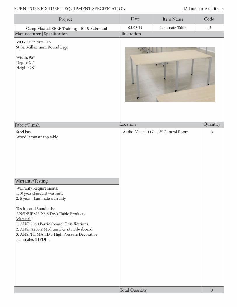
Project Date CodeItem Name
Manufacturer | Specification Illustration
Location Quantity
Warranty/Testing
Total Quantity
FURNITURE FIXTURE + EQUIPMENT SPECIFICATION IA Interior Architects
Camp Mackall SERE Training - 100% Submittal 03.08.19
Fabric/Finish
T2Laminate Table
3
MFG: Furniture LabStyle: Millennium Round Legs
Width: 96”Depth: 24”Height: 28”
Steel baseWood laminate top table
3
Audio-Visual: 117 - AV Control Room
Warranty Requirements:1.10 year standard warranty2. 5 year - Laminate warranty
Testing and Standards:ANSI/BIFMA X5.5 Desk/Table Products Material:1. ANSI 208.1Particleboard Classifications.2. ANSI A208.2 Medium Density Fiberboard.3. ANSI/NEMA LD 3 High Pressure Decorative Laminates (HPDL).
Project Date CodeItem Name
Description
FURNITURE FIXTURE + EQUIPMENT SPECIFICATION IA Interior Architects
Camp Mackall SERE Training - 100% Submittal 03.08.19
General Requirements:1. Work surfaces shall be constructed of a Grade M2 or M3 particleboard or a ~45 lb. medium density fiberboard core with a minimum VGS General Purpose Grade High-Pressure Laminate on the face and a backer material on the underside.2. Laminates shall be bonded to the core with a PVA adhesive in a cold press or hot press process to prevent separation of the laminate from the core.3. Low pressure laminate and thermally fused laminate is non-conforming and will be considered unacceptable.4. Work surface edges shall be totally finished and sealed against moisture.5. Laminate self edges are non-conforming.6. Abutting surfaces shall mate closely and at equal heights when used in side-by-side configurations in order to provide a continuous and level surface.7. The leg shaft shall be welded to a formed steel plate, and the plate shall be attached to the bottom of the table with mechanical fasteners in metal inserts.8. Provide locking casters.9. Table shall have tubular, 18 gauge steel legsGeneral Power Requirements:1. Field or factory installed metal grommets shall be available. Grommets shall be minimum 1 ¾” in diameter with covers and shall have a low profile. Verify with User, grommet locations and quantity prior to ordering.2. Electrical components shall be manufactured in compliance with NEC regulations and shall be UL approved.3. Power/Data modules shall be recessed from view and accessed via a touch latch or a hinged or sliding cover.4. No hardwired connections permitted. If applicable, connections shall be plug-in type.
T2Laminate Table
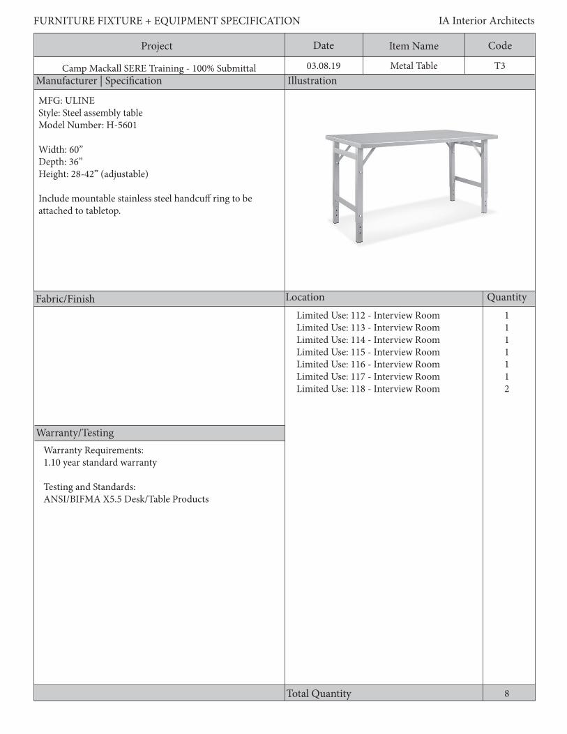
Project Date CodeItem Name
Manufacturer | Specification Illustration
Location Quantity
Warranty/Testing
Total Quantity
FURNITURE FIXTURE + EQUIPMENT SPECIFICATION IA Interior Architects
Camp Mackall SERE Training - 100% Submittal 03.08.19
Fabric/Finish
T3Metal Table
MFG: ULINEStyle: Steel assembly tableModel Number: H-5601
Width: 60”Depth: 36”Height: 28-42” (adjustable)
Include mountable stainless steel handcuff ring to be attached to tabletop.
8
1111112
Limited Use: 112 - Interview RoomLimited Use: 113 - Interview RoomLimited Use: 114 - Interview RoomLimited Use: 115 - Interview RoomLimited Use: 116 - Interview RoomLimited Use: 117 - Interview RoomLimited Use: 118 - Interview Room
Warranty Requirements:1.10 year standard warranty
Testing and Standards:ANSI/BIFMA X5.5 Desk/Table Products

Project Date CodeItem Name
Description
FURNITURE FIXTURE + EQUIPMENT SPECIFICATION IA Interior Architects
Camp Mackall SERE Training - 100% Submittal 03.08.19
General Requirements:1. Table shall be constructed of 12 gauge steel2. Shall provide stainless steel mountable handcuff ring to be attached to table
T3Metal Table
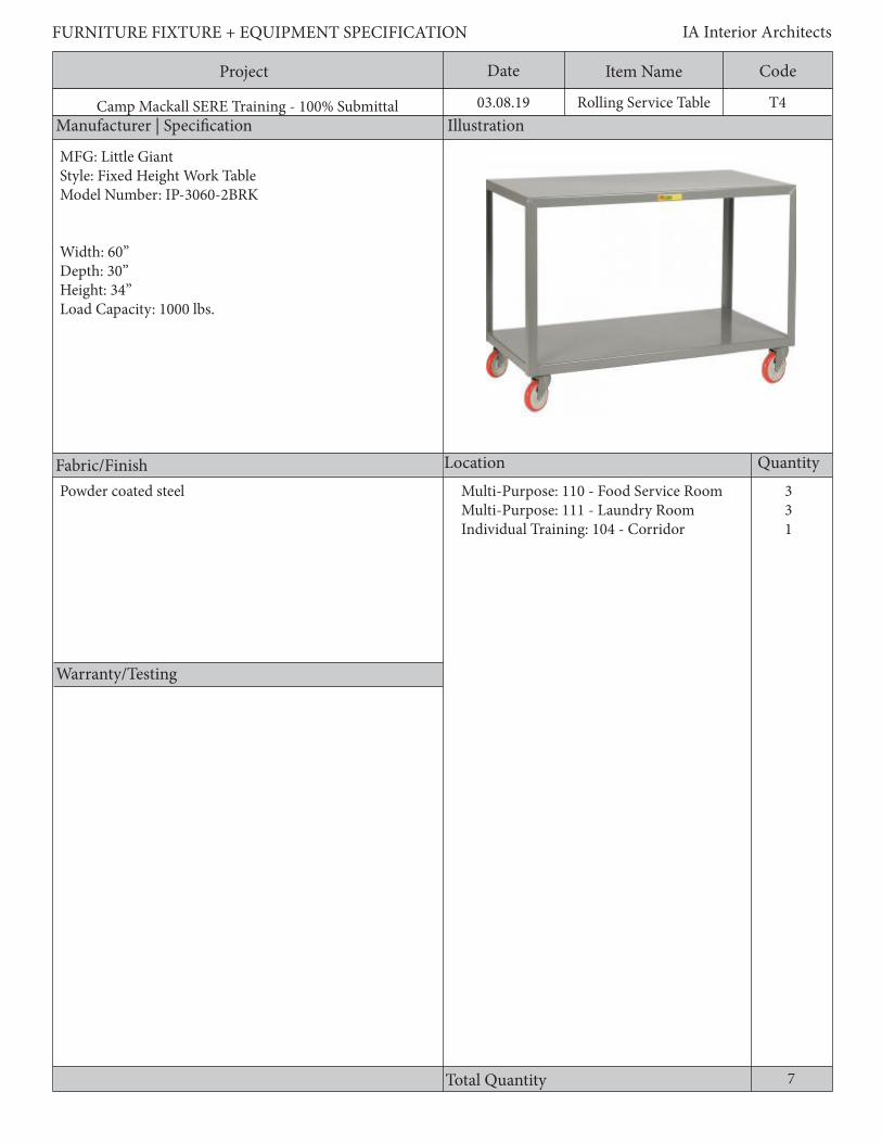
Project Date CodeItem Name
Manufacturer | Specification Illustration
Location Quantity
Warranty/Testing
Total Quantity
FURNITURE FIXTURE + EQUIPMENT SPECIFICATION IA Interior Architects
Camp Mackall SERE Training - 100% Submittal 03.08.19
Fabric/Finish
T4Rolling Service Table
331
MFG: Little GiantStyle: Fixed Height Work TableModel Number: IP-3060-2BRK
Width: 60”Depth: 30”Height: 34”Load Capacity: 1000 lbs.
Powder coated steel Multi-Purpose: 110 - Food Service RoomMulti-Purpose: 111 - Laundry RoomIndividual Training: 104 - Corridor
7

Project Date CodeItem Name
Description
FURNITURE FIXTURE + EQUIPMENT SPECIFICATION IA Interior Architects
Camp Mackall SERE Training - 100% Submittal 03.08.19
General Requirements:1. Frame shall be 12 gauge steel2. Shall have locking casters
T4Rolling Service Table

Project Date CodeItem Name
Manufacturer | Specification Illustration
Location Quantity
Warranty/Testing
Total Quantity
FURNITURE FIXTURE + EQUIPMENT SPECIFICATION IA Interior Architects
Camp Mackall SERE Training - 100% Submittal 03.08.19
Fabric/Finish
T5Training Table
MFG: HONStyle: Build Rectangle TableModel Number: HETR-2460E-4L
Width: 60”Depth: 24”Height: 29”
76
Aluminum baseLaminate top- woodgrain/base grade
Limited Use: 120 - General StorageLimited Use: 125 - Brief Room
13
Warranty Requirements:1.10 year standard warranty2. 5 year - Laminate warranty
Testing and Standards:ANSI/BIFMA X5.5 Desk/Table Products Material:1. ANSI 208.1 Particleboard Classifications.2. ANSI A208.2 Medium Density Fiberboard.3. ANSI/NEMA LD 3 High Pressure Decorative Laminates (HPDL).

Project Date CodeItem Name
Description
FURNITURE FIXTURE + EQUIPMENT SPECIFICATION IA Interior Architects
Camp Mackall SERE Training - 100% Submittal 03.08.19
General Requirements:1. Work surfaces shall be constructed of a Grade M2 or M3 particleboard or a ~45 lb. medium density fiberboard core with a minimum VGS General Purpose Grade High-Pressure Laminate on the face and a backer material on the underside.2. Laminates shall be bonded to the core with a PVA adhesive in a cold press or hot press process to prevent separation of the laminate from the core.3. Low pressure laminate and thermally fused laminate is non-conforming and will be considered unacceptable.4. Work surface edges shall be totally finished and sealed against moisture.5. Laminate self edges are non-conforming.6. Abutting surfaces shall mate closely and at equal heights when used in side-by-side configurations in order to provide a continuous and level surface.7. The leg shaft shall be welded to a formed steel plate, and the plate shall be attached to the bottom of the table with mechanical fasteners in metal inserts.8. Provide locking casters.General Power Requirements:1. Field or factory installed metal grommets shall be available. Grommets shall be minimum 1 ¾” in diameter with covers and shall have a low profile. Verify with User, grommet locations and quantity prior to ordering.2. Electrical components shall be manufactured in compliance with NEC regulations and shall be UL approved.3. Power/Data modules shall be recessed from view and accessed via a touch latch or a hinged or sliding cover.4. No hardwired connections permitted. If applicable, connections shall be plug-in type.
T5Training Table
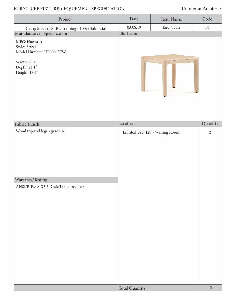
Project Date CodeItem Name
Manufacturer | Specification Illustration
Location Quantity
Warranty/Testing
Total Quantity
FURNITURE FIXTURE + EQUIPMENT SPECIFICATION IA Interior Architects
Camp Mackall SERE Training - 100% Submittal 03.08.19
Fabric/Finish
T6End Table
2
MFG: Haworth Style: AtwellModel Number: HE900-FEW
Width: 21.1”Depth: 21.1”Height: 17.4”
Wood top and legs - grade A Limited Use: 129 - Waiting Room
2
ANSI/BIFMA X5.5 Desk/Table Products

Project Date CodeItem Name
Description
FURNITURE FIXTURE + EQUIPMENT SPECIFICATION IA Interior Architects
Camp Mackall SERE Training - 100% Submittal 03.08.19 T6End Table
General Requirements:1. Transitional wood products blend the light, clean lines of contemporary styling with the influence of tradi-tional period styling without appearing heavy or bulky. Elements such as base molding or trim and surface edge details may be simpler than their traditional counterparts and may be curvilinear or rectilinear in design. 2. Contemporary wood products have light, clean geometric shapes with no ornamentation except for simple edge detailing on surfaces when required.3. The finish color shall match on all components within a room.4. All wood shall be of the same species, except contrasting wood species shall be permitted for decorative inlays and accents.

Project Date CodeItem Name
Manufacturer | Specification Illustration
Location Quantity
Warranty/Testing
Total Quantity
FURNITURE FIXTURE + EQUIPMENT SPECIFICATION IA Interior Architects
Camp Mackall SERE Training - 100% Submittal 03.08.19
Fabric/Finish
T7Mobile Conf. Table
422 216
MFG: HONStyle: Build Rectangle TableModel Number: HETR-3060E-4L
Width: 60”Depth: 30”Height: 29”
Limited Use: 134 - Ready RoomLimited Use: 201 - Team Room 3Limited Use: 202 - Team Room 2Limited Use: 203 - Team Room 1Limited Use: 204 - Storage RoomLimited Use: 207 - Training Cell Room
17
Warranty Requirements:1.10 year standard warranty2. 5 year - Laminate warranty
Testing and Standards:ANSI/BIFMA X5.5 Desk/Table Products Material:1. ANSI 208.1 Particleboard Classifications.2. ANSI A208.2 Medium Density Fiberboard.3. ANSI/NEMA LD 3 High Pressure Decorative Laminates (HPDL).
Aluminum baseLaminate Top - solid/ base grade
Project Date CodeItem Name
Description
FURNITURE FIXTURE + EQUIPMENT SPECIFICATION IA Interior Architects
Camp Mackall SERE Training - 100% Submittal 03.08.19
General Requirements:1. Work surfaces shall be constructed of a Grade M2 or M3 particleboard or a ~45 lb. medium density fiberboard core with a minimum VGS General Purpose Grade High-Pressure Laminate on the face and a backer material on the underside.2. Laminates shall be bonded to the core with a PVA adhesive in a cold press or hot press process to prevent separation of the laminate from the core.3. Low pressure laminate and thermally fused laminate is non-conforming and will be considered unacceptable.4. Work surface edges shall be totally finished and sealed against moisture.5. Laminate self edges are non-conforming.6. Abutting surfaces shall mate closely and at equal heights when used in side-by-side configurations in order to provide a continuous and level surface.7. The leg shaft shall be welded to a formed steel plate, and the plate shall be attached to the bottom of the table with mechanical fasteners in metal inserts.8. Provide locking casters.General Power Requirements:1. Field or factory installed metal grommets shall be available. Grommets shall be minimum 1 ¾” in diameter with covers and shall have a low profile. Verify with User, grommet locations and quantity prior to ordering.2. Electrical components shall be manufactured in compliance with NEC regulations and shall be UL approved.3. Power/Data modules shall be recessed from view and accessed via a touch latch or a hinged or sliding cover.4. No hardwired connections permitted. If applicable, connections shall be plug-in type.
T7Mobile Conf. Table

Project Date CodeItem Name
Manufacturer | Specification Illustration
Location Quantity
Warranty/Testing
Total Quantity
FURNITURE FIXTURE + EQUIPMENT SPECIFICATION IA Interior Architects
Camp Mackall SERE Training - 100% Submittal 03.08.19
Fabric/Finish
T8Nesting Training Table
22
MFG: hi5Style: HarborModel Number:
Width: 60”Depth: 30”Height: 29”
Limited Use: 212 - Shift Brief Room
22
Warranty Requirements:1.10 year standard warranty2. 5 year - Laminate warranty
Testing and Standards:ANSI/BIFMA X5.5 Desk/Table Products Material:1. ANSI 208.1 Particleboard Classifications.2. ANSI A208.2 Medium Density Fiberboard.3. ANSI/NEMA LD 3 High Pressure Decorative Laminates (HPDL).
Aluminum baseLaminate Top - woodgrain/base grade

Project Date CodeItem Name
Description
FURNITURE FIXTURE + EQUIPMENT SPECIFICATION IA Interior Architects
Camp Mackall SERE Training - 100% Submittal 03.08.19
Nesting training table with locking casters; laminate topGeneral Requirements:1. Work surfaces shall be constructed of a Grade M2 or M3 particleboard or a ~45 lb. medium density fiberboard core with a minimum VGS General Purpose Grade High-Pressure Laminate on the face and a backer material on the underside.2. Laminates shall be bonded to the core with a PVA adhesive in a cold press or hot press process to prevent separation of the laminate from the core.3. Low pressure laminate and thermally fused laminate is non-conforming and will be considered unacceptable.4. Work surface edges shall be totally finished and sealed against moisture.5. Laminate self edges are non-conforming.6. Abutting surfaces shall mate closely and at equal heights when used in side-by-side configurations in order to provide a continuous and level surface.7. The leg shaft shall be welded to a formed steel plate, and the plate shall be attached to the bottom of the table with mechanical fasteners in metal inserts.8. Provide locking casters.General Power Requirements:1. Field or factory installed metal grommets shall be available. Grommets shall be minimum 1 ¾” in diameter with covers and shall have a low profile. Verify with User, grommet locations and quantity prior to ordering.2. Electrical components shall be manufactured in compliance with NEC regulations and shall be UL approved.3. Power/Data modules shall be recessed from view and accessed via a touch latch or a hinged or sliding cover.4. No hardwired connections permitted. If applicable, connections shall be plug-in type.
T8Nesting Training Table
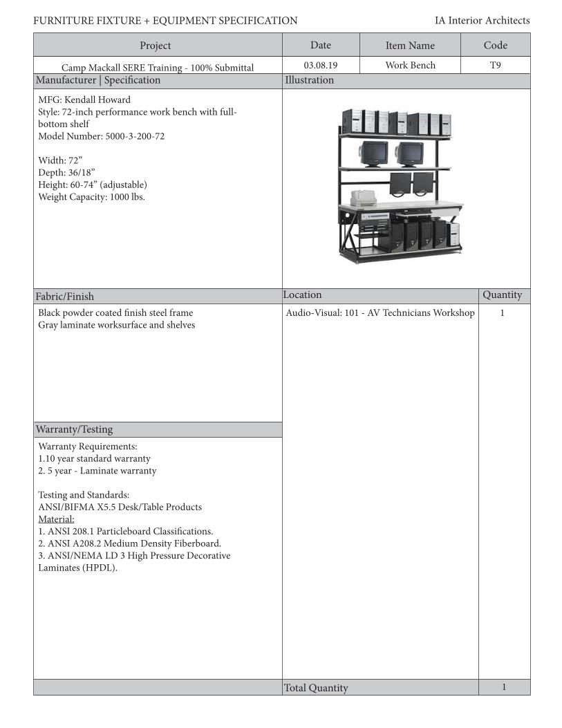
Project Date CodeItem Name
Manufacturer | Specification Illustration
Location Quantity
Warranty/Testing
Total Quantity
FURNITURE FIXTURE + EQUIPMENT SPECIFICATION IA Interior Architects
Camp Mackall SERE Training - 100% Submittal 03.08.19
Fabric/Finish
T9Work Bench
1Audio-Visual: 101 - AV Technicians Workshop
1
Warranty Requirements:1.10 year standard warranty2. 5 year - Laminate warranty
Testing and Standards:ANSI/BIFMA X5.5 Desk/Table Products Material:1. ANSI 208.1 Particleboard Classifications.2. ANSI A208.2 Medium Density Fiberboard.3. ANSI/NEMA LD 3 High Pressure Decorative Laminates (HPDL).
Black powder coated finish steel frameGray laminate worksurface and shelves
MFG: Kendall HowardStyle: 72-inch performance work bench with full-bottom shelfModel Number: 5000-3-200-72
Width: 72”Depth: 36/18”Height: 60-74” (adjustable)Weight Capacity: 1000 lbs.

Project Date CodeItem Name
Description
FURNITURE FIXTURE + EQUIPMENT SPECIFICATION IA Interior Architects
Camp Mackall SERE Training - 100% Submittal 03.08.19
General Requirements:1. Frame shall steel 2. Shall have (2) 18”d adjustable shelves in 2” increments3. Bench shall allow for vertical cable management4. Shall include (2) keyboard trays with mouse shelves5. Bench shall include 2-post medium duty LAN rack for loads up to 300 lbs per upper shelf and 500 lbs per surface & server shelves72” Performance work bench with full bottom shelf; Steel frame w/ adjustable shelves adjustable in 2” increments; (2) 18”d shelves; (1) 36”d worksurface; (2) vertical cable management; (2) keyboard trays with mouse shelves; 2-post medium duty LAN rack for loads up to 300 lbs per upper shelf and 500 lbs surface & server shelves
T9Work Bench

Project Date CodeItem Name
Manufacturer | Specification Illustration
Location Quantity
Warranty/Testing
Total Quantity
FURNITURE FIXTURE + EQUIPMENT SPECIFICATION IA Interior Architects
Camp Mackall SERE Training - 100% Submittal 03.08.19
Fabric/Finish
T10Cafe Table
1
MFG: HONStyle: Between TablesModel Number: HBTTRND30 / HBTTX30S
Width: 30”Depth: 30”Height: 30”
Camp Aid: 103 - Ready Room
1
Warranty Requirements:1.10 year standard warranty2. 5 year - Laminate warranty
Testing and Standards:ANSI/BIFMA X5.5 Desk/Table Products Material:1. ANSI 208.1 Particleboard Classifications.2. ANSI A208.2Medium Density Fiberboard.3. ANSI/NEMA LD 3 High Pressure Decorative Laminates (HPDL).
Aluminum baseLaminate top - solid/base grade

Project Date CodeItem Name
Description
FURNITURE FIXTURE + EQUIPMENT SPECIFICATION IA Interior Architects
Camp Mackall SERE Training - 100% Submittal 03.08.19
General Requirements:1. Work surfaces shall be constructed of a Grade M2 or M3 particleboard or a ~45 lb. medium density fiberboard core with a minimum VGS General Purpose Grade High-Pressure Laminate on the face and a backer material on the underside.2. Laminates shall be bonded to the core with a PVA adhesive in a cold press or hot press process to prevent separation of the laminate from the core.3. Low pressure laminate and thermally fused laminate is non-conforming and will be considered unacceptable.4. Work surface edges shall be totally finished and sealed against moisture.5. Laminate self edges are non-conforming.6. Abutting surfaces shall mate closely and at equal heights when used in side-by-side configurations in order to provide a continuous and level surface.7. The leg shaft shall be welded to a formed steel plate, and the plate shall be attached to the bottom of the table with mechanical fasteners in metal inserts.
T10Cafe Table
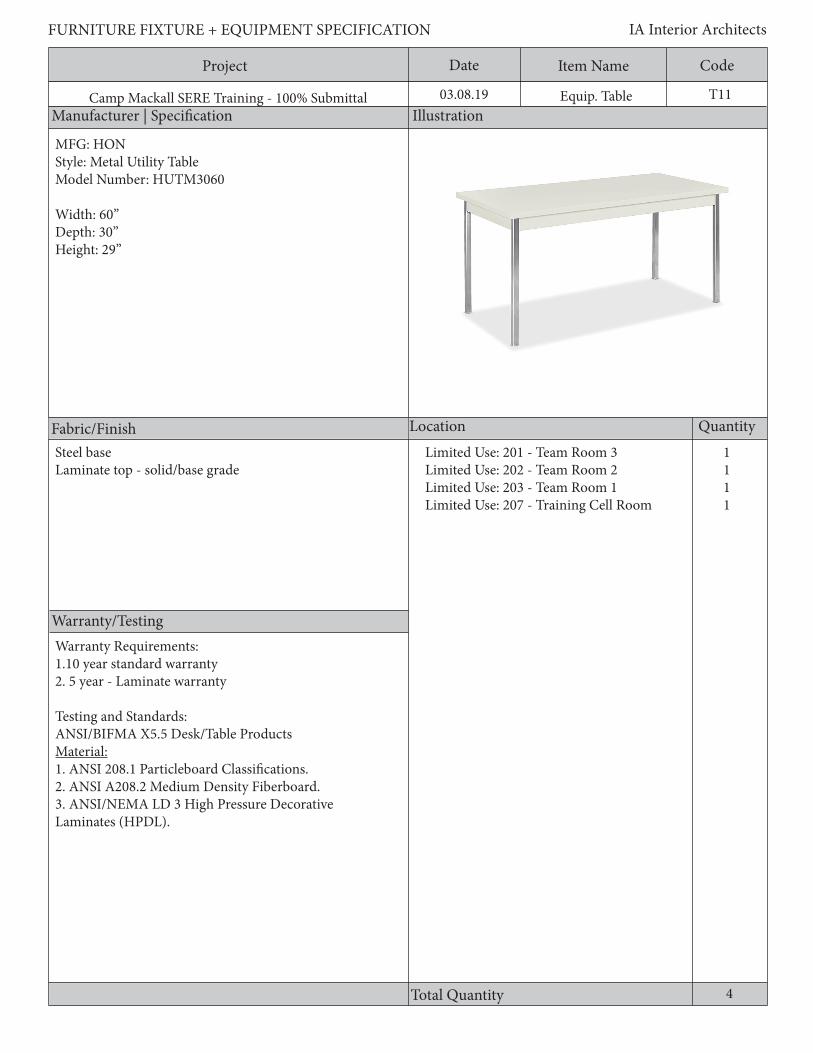
Project Date CodeItem Name
Manufacturer | Specification Illustration
Location Quantity
Warranty/Testing
Total Quantity
FURNITURE FIXTURE + EQUIPMENT SPECIFICATION IA Interior Architects
Camp Mackall SERE Training - 100% Submittal 03.08.19
Fabric/Finish
T11Equip. Table
1111
MFG: HONStyle: Metal Utility TableModel Number: HUTM3060
Width: 60”Depth: 30”Height: 29”
Limited Use: 201 - Team Room 3Limited Use: 202 - Team Room 2Limited Use: 203 - Team Room 1Limited Use: 207 - Training Cell Room
4
Steel baseLaminate top - solid/base grade
Warranty Requirements:1.10 year standard warranty2. 5 year - Laminate warranty
Testing and Standards:ANSI/BIFMA X5.5 Desk/Table Products Material:1. ANSI 208.1 Particleboard Classifications.2. ANSI A208.2 Medium Density Fiberboard.3. ANSI/NEMA LD 3 High Pressure Decorative Laminates (HPDL).

Project Date CodeItem Name
Description
FURNITURE FIXTURE + EQUIPMENT SPECIFICATION IA Interior Architects
Camp Mackall SERE Training - 100% Submittal 03.08.19
General Requirements:1. Work surfaces shall be constructed of a Grade M2 or M3 particleboard or a ~45 lb. medium density fiberboard core with a minimum VGS General Purpose Grade High-Pressure Laminate on the face and a backer material on the underside.2. Laminates shall be bonded to the core with a PVA adhesive in a cold press or hot press process to prevent separation of the laminate from the core.3. Low pressure laminate and thermally fused laminate is non-conforming and will be considered unacceptable.4. Work surface edges shall be totally finished and sealed against moisture.5. Laminate self edges are non-conforming.6. Abutting surfaces shall mate closely and at equal heights when used in side-by-side configurations in order to provide a continuous and level surface.7. The leg shaft shall be welded to a formed steel plate, and the plate shall be attached to the bottom of the table with mechanical fasteners in metal inserts.8. Shall have leveling glides
T11Equip. Table

Project Date CodeItem Name
Manufacturer | Specification Illustration
Location Quantity
Warranty/Testing
Total Quantity
FURNITURE FIXTURE + EQUIPMENT SPECIFICATION IA Interior Architects
Camp Mackall SERE Training - 100% Submittal 03.08.19
Fabric/Finish
T12Utility Table
1Instructor Control: 101 - Instructor Room
1
MFG: HONStyle: Utility TablesModel Number: HUTM2040
Width: 40”Depth: 20.”Height: 29”
Steel baseLaminate top - solid/base grade
Warranty Requirements:1.10 year standard warranty2. 5 year - Laminate warranty
Testing and Standards:ANSI/BIFMA X5.5 Desk/Table Products Material:1. ANSI 208.1 Particleboard Classifications.2. ANSI A208.2 Medium Density Fiberboard.3. ANSI/NEMA LD 3 High Pressure Decorative Laminates (HPDL).
Project Date CodeItem Name
Description
FURNITURE FIXTURE + EQUIPMENT SPECIFICATION IA Interior Architects
Camp Mackall SERE Training - 100% Submittal 03.08.19
General Requirements:1. Work surfaces shall be constructed of a Grade M2 or M3 particleboard or a ~45 lb. medium density fiberboard core with a minimum VGS General Purpose Grade High-Pressure Laminate on the face and a backer material on the underside.2. Laminates shall be bonded to the core with a PVA adhesive in a cold press or hot press process to prevent separation of the laminate from the core.3. Low pressure laminate and thermally fused laminate is non-conforming and will be considered unacceptable.4. Work surface edges shall be totally finished and sealed against moisture.5. Laminate self edges are non-conforming.6. Abutting surfaces shall mate closely and at equal heights when used in side-by-side configurations in order to provide a continuous and level surface.7. The leg shaft shall be welded to a formed steel plate, and the plate shall be attached to the bottom of the table with mechanical fasteners in metal inserts.8. Shall have leveling glides
T12Utility Table

Project Date CodeItem Name
Manufacturer | Specification Illustration
Location Quantity
Warranty/Testing
Total Quantity
FURNITURE FIXTURE + EQUIPMENT SPECIFICATION IA Interior Architects
Camp Mackall SERE Training - 100% Submittal 03.08.19
Fabric/Finish
T13Mulit-Purpose Table
1Camp Aid: 101 - Primary Exam/Treatment
1
MFG: Furniture LabModel Number: Millennium Round Legs
Width: 30”Depth: 30”Height: 28”
Steel baseLaminate top - solid/base grade
Warranty Requirements:1.10 year standard warranty2. 5 year - Laminate warranty
Testing and Standards:ANSI/BIFMA X5.5 Desk/Table Products Material:1. ANSI 208.1 Particleboard Classifications.2. ANSI A208.2 Medium Density Fiberboard.3. ANSI/NEMA LD 3 High Pressure Decorative Laminates (HPDL).

Project Date CodeItem Name
Description
FURNITURE FIXTURE + EQUIPMENT SPECIFICATION IA Interior Architects
Camp Mackall SERE Training - 100% Submittal 03.08.19
General Requirements:1. Work surfaces shall be constructed of a Grade M2 or M3 particleboard or a ~45 lb. medium density fiberboard core with a minimum VGS General Purpose Grade High-Pressure Laminate on the face and a backer material on the underside.2. Laminates shall be bonded to the core with a PVA adhesive in a cold press or hot press process to prevent separation of the laminate from the core.3. Low pressure laminate and thermally fused laminate is non-conforming and will be considered unacceptable.4. Work surface edges shall be totally finished and sealed against moisture.5. Laminate self edges are non-conforming.6. Abutting surfaces shall mate closely and at equal heights when used in side-by-side configurations in order to provide a continuous and level surface.7. The leg shaft shall be welded to a formed steel plate, and the plate shall be attached to the bottom of the table with mechanical fasteners in metal inserts.
T13Utility Table

Project Date CodeItem Name
Manufacturer | Specification Illustration
Location Quantity
Warranty/Testing
Total Quantity
FURNITURE FIXTURE + EQUIPMENT SPECIFICATION IA Interior Architects
Camp Mackall SERE Training - 100% Submittal 03.08.19
Fabric/Finish
T14Laminate Table
3Audio-Visual: 117 - AV Control Room
3
MFG: Furniture LabModel Number: Millennium Round Legs
Width: 60”Depth: 24”Height: 28”
Warranty Requirements:1.10 year standard warranty2. 5 year - Laminate warranty
Testing and Standards:ANSI/BIFMA X5.5-2008 Desk/Table Products Material:1. ANSI 208.1-2009 Particleboard Classifications.2. ANSI A208.2-2009 Medium Density Fiberboard.3. ANSI/NEMA LD 3-2005 High Pressure Decorative Laminates (HPDL).
Steel baseWood laminate top table
Project Date CodeItem Name
Description
FURNITURE FIXTURE + EQUIPMENT SPECIFICATION IA Interior Architects
Camp Mackall SERE Training - 100% Submittal 03.08.19
General Requirements:1. Work surfaces shall be constructed of a Grade M2 or M3 particleboard or a ~45 lb. medium density fiberboard core with a minimum VGS General Purpose Grade High-Pressure Laminate on the face and a backer material on the underside.2. Laminates shall be bonded to the core with a PVA adhesive in a cold press or hot press process to prevent separation of the laminate from the core.3. Low pressure laminate and thermally fused laminate is non-conforming and will be considered unacceptable.4. Work surface edges shall be totally finished and sealed against moisture.5. Laminate self edges are non-conforming.6. Abutting surfaces shall mate closely and at equal heights when used in side-by-side configurations in order to provide a continuous and level surface.7. The leg shaft shall be welded to a formed steel plate, and the plate shall be attached to the bottom of the table with mechanical fasteners in metal inserts.8. Provide locking casters.9. Legs shall be tubular, 18 gauge steelGeneral Power Requirements:1. Field or factory installed metal grommets shall be available. Grommets shall be minimum 1 ¾” in diameter with covers and shall have a low profile. Verify with User, grommet locations and quantity prior to ordering.2. Electrical components shall be manufactured in compliance with NEC regulations and shall be UL approved.3. Power/Data modules shall be recessed from view and accessed via a touch latch or a hinged or sliding cover.4. No hardwired connections permitted. If applicable, connections shall be plug-in type.
T14Laminate Table
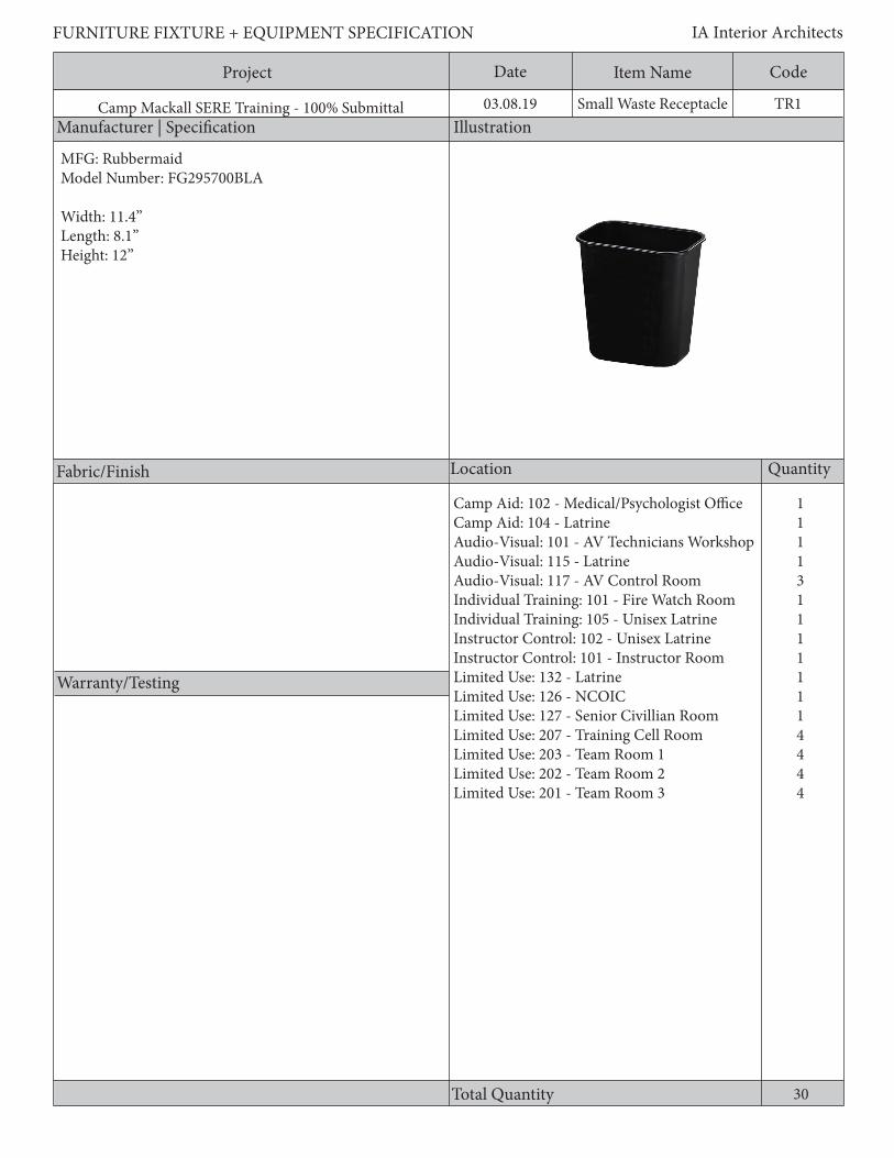
Project Date CodeItem Name
Manufacturer | Specification Illustration
Location Quantity
Warranty/Testing
Total Quantity
FURNITURE FIXTURE + EQUIPMENT SPECIFICATION IA Interior Architects
Camp Mackall SERE Training - 100% Submittal 03.08.19
Fabric/Finish
TR1Small Waste Receptacle
1111311111114444
Camp Aid: 102 - Medical/Psychologist OfficeCamp Aid: 104 - LatrineAudio-Visual: 101 - AV Technicians WorkshopAudio-Visual: 115 - LatrineAudio-Visual: 117 - AV Control RoomIndividual Training: 101 - Fire Watch RoomIndividual Training: 105 - Unisex LatrineInstructor Control: 102 - Unisex LatrineInstructor Control: 101 - Instructor RoomLimited Use: 132 - LatrineLimited Use: 126 - NCOICLimited Use: 127 - Senior Civillian RoomLimited Use: 207 - Training Cell RoomLimited Use: 203 - Team Room 1Limited Use: 202 - Team Room 2Limited Use: 201 - Team Room 3
30
MFG: RubbermaidModel Number: FG295700BLA
Width: 11.4”Length: 8.1”Height: 12”
Project Date CodeItem Name
Description
FURNITURE FIXTURE + EQUIPMENT SPECIFICATION IA Interior Architects
Camp Mackall SERE Training - 100% Submittal 03.08.19
General Requirements:1. Black soft molded plastic 2. Leak resistant 3. 14 qt capacity
TR1Small Waste Receptacle

Project Date CodeItem Name
Manufacturer | Specification Illustration
Location Quantity
Warranty/Testing
Total Quantity
FURNITURE FIXTURE + EQUIPMENT SPECIFICATION IA Interior Architects
Camp Mackall SERE Training - 100% Submittal 03.08.19
Fabric/Finish
TR2Half-Round Waste Receptacle
2111111
Camp Aid: 101 - Primary Exam/TreatmentCamp Aid: 103 - Ready RoomIndividual Training: 104 - CorridorLimited Use: 201 - Team Room 3Limited Use: 202 - Team Room 2Limited Use: 201 - Team Room 1Limited Use: 207 - Training Cell Room
8
MFG: RubbermaidModel Number: 352000 GRAY
Width: 12”Depth: 21”Height: 28.6”

Project Date CodeItem Name
Description
FURNITURE FIXTURE + EQUIPMENT SPECIFICATION IA Interior Architects
Camp Mackall SERE Training - 100% Submittal 03.08.19
General Requirements:1. 21 gal capacity2. Leak resistant3. Soft molded plastic
TR2Half-Round Waste Receptacle
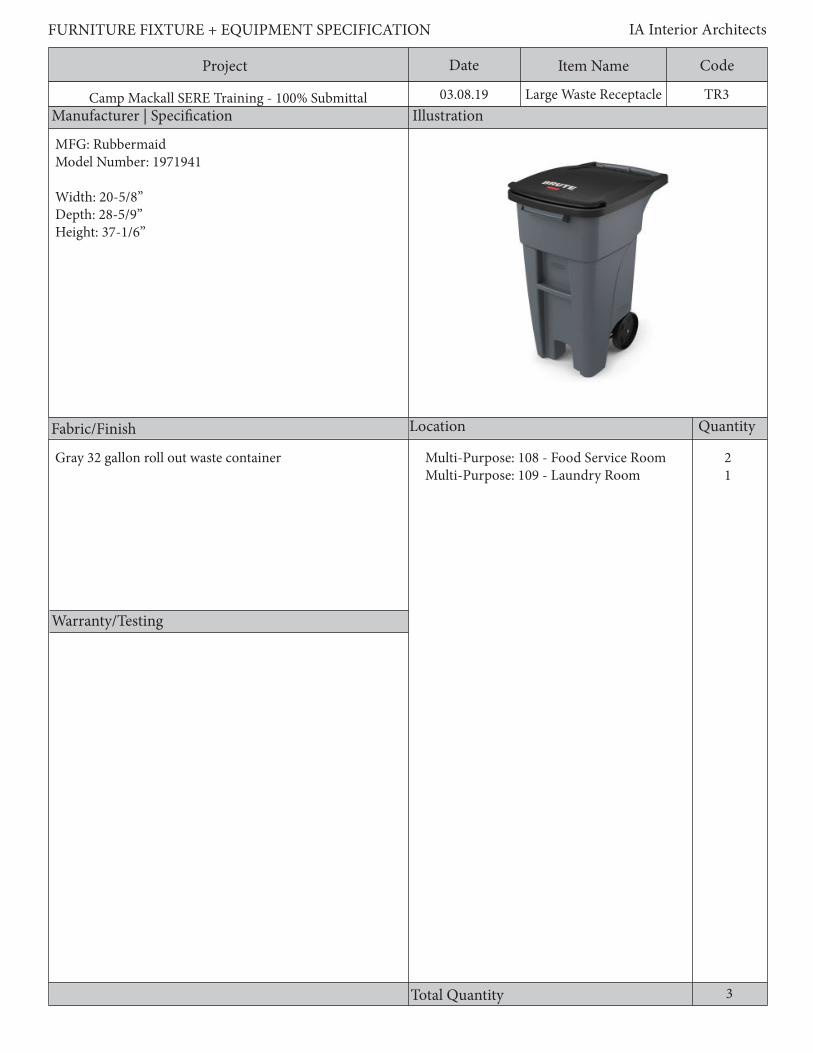
Project Date CodeItem Name
Manufacturer | Specification Illustration
Location Quantity
Warranty/Testing
Total Quantity
FURNITURE FIXTURE + EQUIPMENT SPECIFICATION IA Interior Architects
Camp Mackall SERE Training - 100% Submittal 03.08.19
Fabric/Finish
TR3Large Waste Receptacle
21
Multi-Purpose: 108 - Food Service RoomMulti-Purpose: 109 - Laundry Room
MFG: RubbermaidModel Number: 1971941
Width: 20-5/8”Depth: 28-5/9”Height: 37-1/6”
Gray 32 gallon roll out waste container
3

Project Date CodeItem Name
Description
FURNITURE FIXTURE + EQUIPMENT SPECIFICATION IA Interior Architects
Camp Mackall SERE Training - 100% Submittal 03.08.19
General Requirements:1. 32 gallon roll out waste container
TR3Large Wast Receptacle

SERE RESISTANCE TRAINING LABORATORY FF&E PACKAGE
100% DESIGN SUBMITTAL 03.08.2019
SECTION 4 EQUIPMENT
463L Pallet Guard Shack
Fire Extinguisher

SERE RESISTANCE TRAINING LABORATORY FF&E PACKAGE
100% DESIGN SUBMITTAL 03.08.2019
463L Pallet Individual Training Building – Pallet Plans

SERE RESISTANCE TRAINING LABORATORY FF&E PACKAGE
100% DESIGN SUBMITTAL 03.08.2019
463L Pallet Individual Training Building – Locking Mechanism
Project Date CodeItem Name
Manufacturer | Specification Illustration
Location Quantity
Warranty/Testing
Total Quantity
FURNITURE FIXTURE + EQUIPMENT SPECIFICATION IA Interior Architects
Camp Mackall SERE Training - 100% Submittal 03.08.19
Fabric/Finish
PL1463L Pallet
104
MFG: Sea BoxStyle: 463L PalletModel: SB463L
Length: 7’-4”Height: 2-1/4”Width: 9’-0”
Individual Training Building
m.graner
Text Box
104
Project Date CodeItem Name
Description
FURNITURE FIXTURE + EQUIPMENT SPECIFICATION IA Interior Architects
Camp Mackall SERE Training - 100% Submittal 03.08.19
General Requirements: 1. Unit shall be corrosion, heat moisture and UV-light resistant2. Unit shall be compatible with 463L load restraint system3. All extrusions shall be heavy duty 1708-T6 Aluminum Alloy4. The bottom sheet of unit shall be constructed with heavy duty 7021-T6 Aluminum Alloy which is 4mm thick5. Unit shall have 22 tie down rings: (7500 lbs. capacity each in any direction)6. Unit shall have perimeter track on the frame for additional tie down options7. Unit shall have certification to: TSO C90 C Class 1B6N8. Unit shall be transportable by both air and surface methods, meet military and air transport requirements.9. Unit shall provide on-site short-term storage of equipment and materials10. Unit shall be of lightweight and durable construction11. Unit shall provide cargo up to 10,000 lbs.12. Unit shall provide rapid deployment of cargo13. Unit shall have capability to be stacked when empty for storage.
PL1463L Pallet

Project Date CodeItem Name
Manufacturer | Speci cation Illustration
Location Quantity
Warranty/Testing
Total Quantity
FURNITURE FIXTURE + EQUIPMENT SPECIFICATION IA Interior Architects
Camp Mackall SERE Training - 100% Submittal 04.22.19
Fabric/Finish
GB1Guard Booth
1
MFG: FutureNet Security SolutionsStyle: Guard BoothsModel: 10’ x 12’
Site: General Ridgeway Rd/Rowe Ln Entry Point
1

Project Date CodeItem Name
Description
FURNITURE FIXTURE + EQUIPMENT SPECIFICATION IA Interior Architects
Camp Mackall SERE Training - 100% Submittal 04.22.19
General Requirements:1. Unit shall be prefabricated, preassembled, designed, and structurally engineered, ASTM A500.2. All joints shall be pressure sealed3. Unit shall have outdoor dimensions of 10’ x 12’4. Unit shall have bathroom with lavatory and commode, exhaust fan, and instantaneous water heater.5. Unit shall have bathroom accessories included: soap dispenser, paper towel dispenser, tissue holder, and mirror.6. Unit shall have minimum ballistic protection level IIA per UL Standard 7527. Unit shall include a desk with (minimum) 14 gauge stainless steel, a 20” depth and 42" height, with three 2” diameteraccess ports for cables.8. Unit shall include canopy (or roof overhand) over door on one side to protect guard from rain.9. Unit shall have a minimum 7’-6” clear interior height10. Unit shall have minimum of R-10 insulation in walls and R-19 insulation in roof.11. Unit shall have UL Certi! cation and compliance with NEC12. Unit doors shall have heavy duty hardware, keyed lock, and weather stripping.13. Unit door shall have a vision light14. Unit shall have rust inhibiting epoxy primer and urethane ! nish coat, or equal15. Maximize view on a minimum of 3 sides, 4 sides preferred16. Unit shall have interior lighting with single pole switch, separate lighting and switch for lavatory17. Unit shall have a minimum of two exterior " ood lights on one side with single pole switch18. Unit shall have a minimum of four 20-amp, 120 volt duplex outlets mounted under front desk19. Unit shall have a minimum of one 20-amp, 120 volt duplex outlets mounted on each other walls (total 3)20. Unit shall have a prewired 125 amp, 120/240 volt, 3-wire 8/16 circuit breaker panel, single phase to be " ushmounted in control cabinet21. Unit shall have a wall mounted HVAC unit 230/208V heating and cooling with integral thermostat control andbullet resistant shroud in rear22. Unit shall have a Duress Button
GB1Guard Booth

Project Date CodeItem Name
Manufacturer | Specification Illustration
Location Quantity
Warranty/Testing
Total Quantity
FURNITURE FIXTURE + EQUIPMENT SPECIFICATION IA Interior Architects
Camp Mackall SERE Training - 100% Submittal 03.08.19
Fabric/Finish
FE1Fire Extinguisher
11111
11111
10
MFG: JL IndustriesModel: Cosmic 10E - ABC Dry Chemical
Nominal Capacity: 10 lbs.UL Rating: 4A-80BC
Cylinder Dia: 5-1/8”Height: 21”Width: 7-3/4”
Conforms to Test Standards: CAN/ULC-S504-ANSI/UL299 & CAN/ULC S508-ANSI/UL711
Powder coat finish, red Limited Use: 119 - Corridor 2Limited Use: 128 - Corridor 3Limited Use: S200 - Stair 1Limited Use: S201 - Stair 2Individual Training: 101 - Fire Watch Room (outside of)Camp Aid: 101 - Primary Exam/TreatmentAudio-Visual: 118 - CorridorMulti-Purpose: 106 - Laundry RoomInstructor Control: 101 - Instructor RoomGuard Tower: 101 - Tower
Project Date CodeItem Name
Description
FURNITURE FIXTURE + EQUIPMENT SPECIFICATION IA Interior Architects
Camp Mackall SERE Training - 100% Submittal 03.08.19
General Requirements:1. Unit shall be a heavy-duty steel cylinder with rugged metal valve and siphon tube2. Unit shall have replaceable molded valve stem seal3. Unit shall have visual pressure gauge4. Unit shall have pull pin and upright squeeze grip.5. Unit shall have corrosion and impact-resistant powder coat finish6. Upright squeeze grip operation approved to -65 degrees Fahrenheit 7. J hook wall bracket shall be supplied for wall mounting
FE1Fire Extinguisher

SERE RESISTANCE TRAINING LABORATORY FF&E PACKAGE
100% DESIGN SUBMITTAL 03.08.2019
SECTION 5
ITEM CODE INDEX

SERE RESISTANCE TRAINING LABORATORY FF&E PACKAGE
100% DESIGN SUBMITTAL 03.08.2019
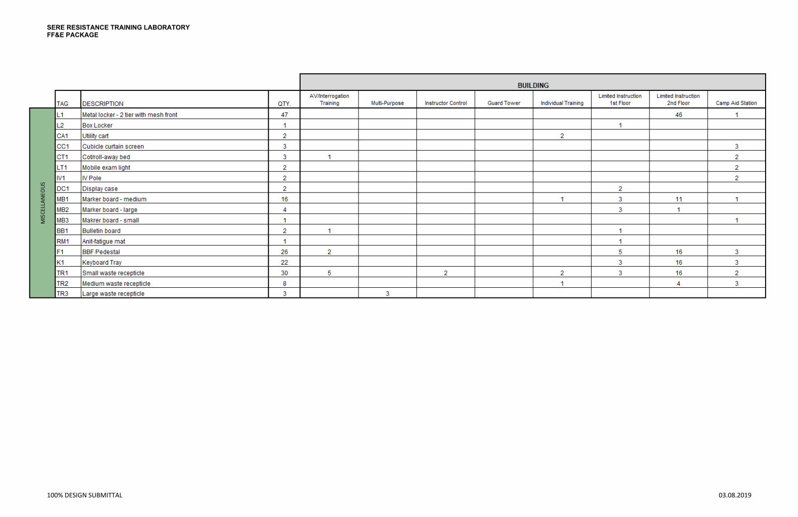
SERE RESISTANCE TRAINING LABORATORY FF&E PACKAGE
100% DESIGN SUBMITTAL 03.08.2019
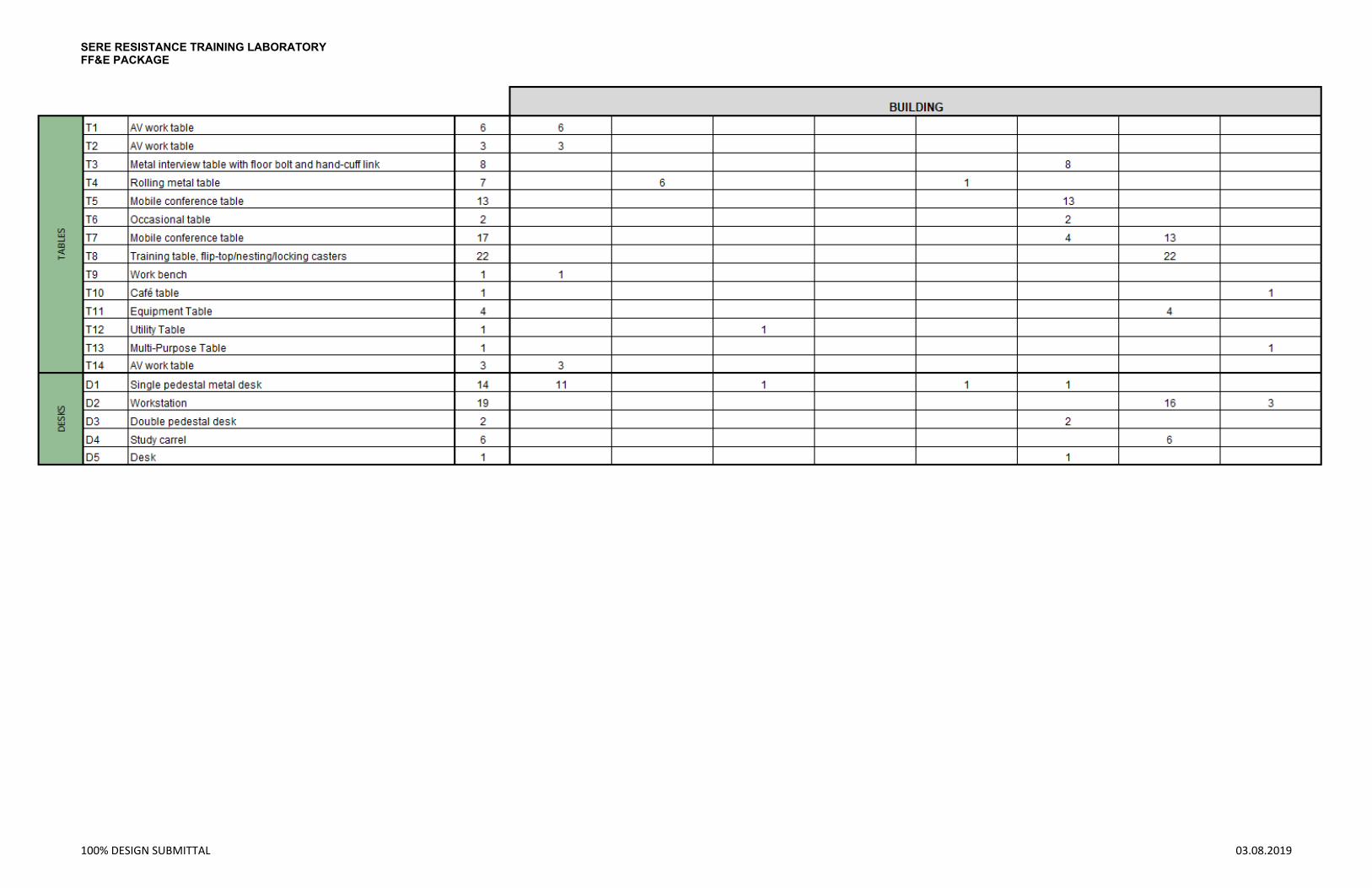
SERE RESISTANCE TRAINING LABORATORY FF&E PACKAGE
100% DESIGN SUBMITTAL 03.08.2019

SERE RESISTANCE TRAINING LABORATORY FF&E PACKAGE
100% DESIGN SUBMITTAL 03.08.2019

SERE RESISTANCE TRAINING LABORATORY FF&E PACKAGE
100% DESIGN SUBMITTAL 03.08.2019
SERE TRAINING COMPLEX PN 80774 CAMP MACKALL, NC
Page 1
THIS PAGE INTENTIONALLY LEFT BLANK

SERE Training Complex Camp Mackall, NC
PN 80774
AUDIO-VISUAL PACKAGE (AV)

SERE Training Complex Camp Mackall, NC
PN 80774
THIS PAGE IS INTENTIONALLY LEFT BLANK
AUDIO VISUAL A/V EQUIPMENT
TABLE OF CONTENTS
SECTION 1 A/V PLAN SHEETS
SECTION 2 A/V PRODUCT CUTSHEETS
AME Consulting Engineers
705 E. Morehead St.
Charlotte, NC 28202
SECTION 1
A/V PLAN SHEETS
AME Consulting Engineers
705 E. Morehead St.
Charlotte, NC 28202
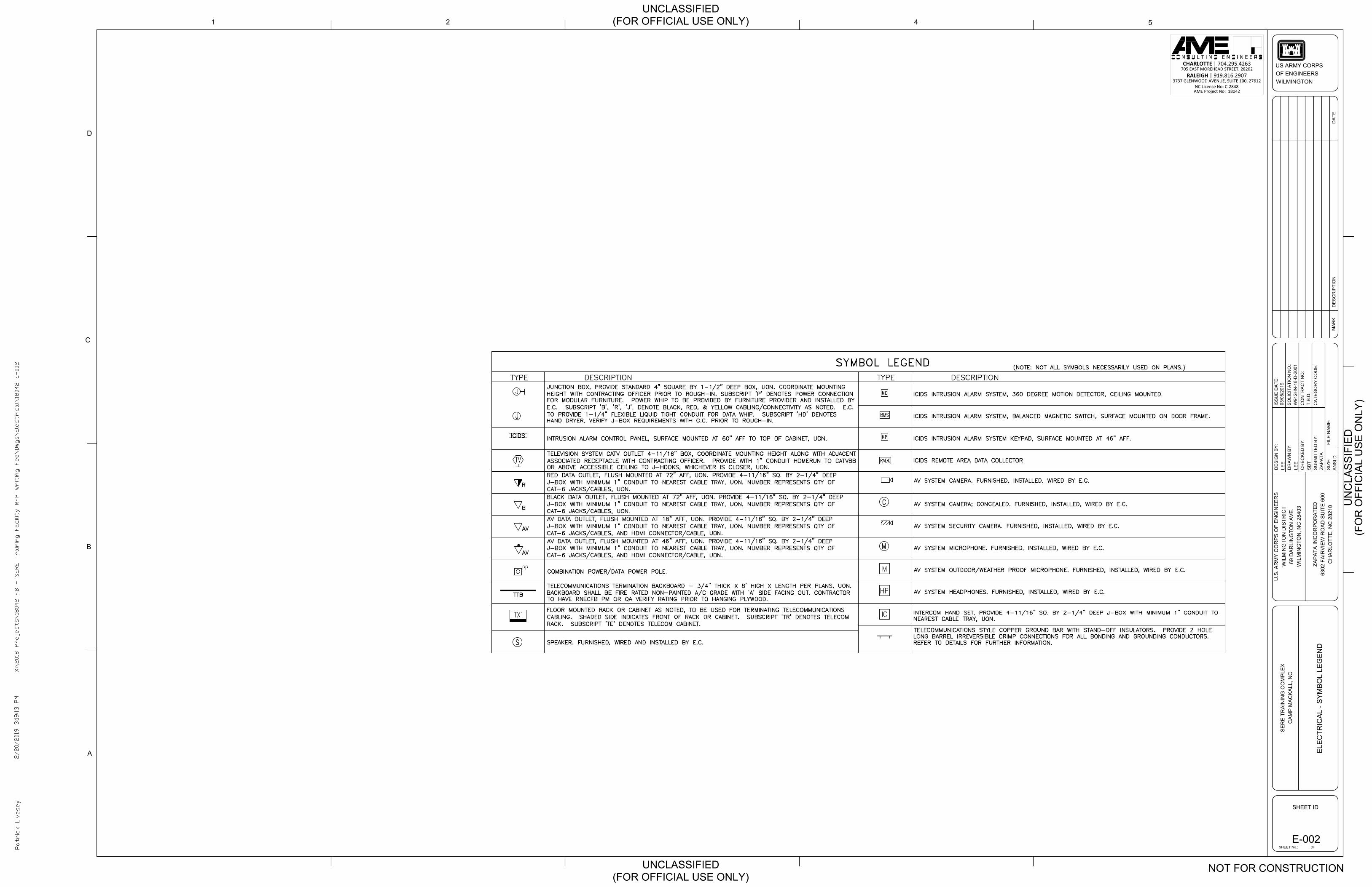
CHARLOTTE | 704.295.4263705 EAST MOREHEAD STREET, 28202
RALEIGH | 919.816.29073737 GLENWOOD AVENUE, SUITE 100, 27612
NC License No: C-2848AME Project No: 18042
LEE
LEE
SB
T
1
D
2
C
4 5
A
B
SO
LIC
ITA
TIO
N N
O.:
FILE
NA
ME
:
DR
AW
N B
Y:
CH
EC
KE
D B
Y:
DE
SIG
N B
Y:
MA
RK
SHEET ID
US ARMY CORPSOF ENGINEERSWILMINGTON
ISS
UE
DA
TE:
SIZ
E:
SU
BM
ITTE
D B
Y:
DE
SC
RIP
TIO
ND
ATE
CO
NTR
AC
T N
O:
AN
SI D
03/0
8/20
19
W91
2HN
-18-
D-2
001
CA
TEG
OR
Y C
OD
E:
ZAP
ATA
ZAP
ATA
INC
OR
PO
RA
TED
6302
FA
IRV
IEW
RO
AD
SU
ITE
600
CH
AR
LOTT
E, N
C 2
8210
U.S
. AR
MY
CO
RP
S O
F E
NG
INE
ER
SW
ILM
ING
TON
DIS
TRIC
T69
DA
RLI
NG
TON
AV
E.
WIL
MIN
GTO
N, N
C 2
8403
SE
RE
TR
AIN
ING
CO
MP
LEX
CA
MP
MA
CK
ALL
, NC
UN
CLA
SS
IFIE
D
UNCLASSIFIED(FOR OFFICIAL USE ONLY)
UNCLASSIFIED(FOR OFFICIAL USE ONLY)
T.B
.D.
OFSHEET No.:
(FO
R O
FFIC
IAL
US
E O
NLY
)
NOT FOR CONSTRUCTION
E-002
ELE
CTR
ICA
L - S
YM
BO
L LE
GE
ND
AutoCAD SHX Text
X:\2018 Projects\18042 FB - SERE Training Facility RFP Writing Fee\Dwgs\Electrical\18042 E-002
AutoCAD SHX Text
2/20/2019 3:19:13 PM
AutoCAD SHX Text
Patrick Livesey
AutoCAD SHX Text
DESCRIPTION
AutoCAD SHX Text
TYPE
AutoCAD SHX Text
SYMBOL LEGEND
AutoCAD SHX Text
DESCRIPTION
AutoCAD SHX Text
TYPE
AutoCAD SHX Text
(NOTE: NOT ALL SYMBOLS NECESSARILY USED ON PLANS.)
AutoCAD SHX Text
TELEVISION SYSTEM CATV OUTLET 4-11/16" BOX, COORDINATE MOUNTING HEIGHT ALONG WITH ADJACENT ASSOCIATED RECEPTACLE WITH CONTRACTING OFFICER. PROVIDE WITH 1" CONDUIT HOMERUN TO CATVBB OR ABOVE ACCESSIBLE CEILING TO J-HOOKS, WHICHEVER IS CLOSER, UON.
AutoCAD SHX Text
TTB
AutoCAD SHX Text
TELECOMMUNICATIONS STYLE COPPER GROUND BAR WITH STAND-OFF INSULATORS. PROVIDE 2 HOLE LONG BARREL IRREVERSIBLE CRIMP CONNECTIONS FOR ALL BONDING AND GROUNDING CONDUCTORS. REFER TO DETAILS FOR FURTHER INFORMATION.
AutoCAD SHX Text
TELECOMMUNICATIONS TERMINATION BACKBOARD - 3/4" THICK X 8' HIGH X LENGTH PER PLANS, UON. BACKBOARD SHALL BE FIRE RATED NON-PAINTED A/C GRADE WITH 'A' SIDE FACING OUT. CONTRACTOR TO HAVE RNECFB PM OR QA VERIFY RATING PRIOR TO HANGING PLYWOOD.
AutoCAD SHX Text
INTRUSION ALARM CONTROL PANEL, SURFACE MOUNTED AT 60" AFF TO TOP OF CABINET, UON.
AutoCAD SHX Text
ICIDS
AutoCAD SHX Text
BLACK DATA OUTLET, FLUSH MOUNTED AT 72" AFF, UON. PROVIDE 4-11/16" SQ. BY 2-1/4" DEEP J-BOX WITH MINIMUM 1" CONDUIT TO NEAREST CABLE TRAY, UON. NUMBER REPRESENTS QTY OF CAT-6 JACKS/CABLES, UON.
AutoCAD SHX Text
B
AutoCAD SHX Text
AV DATA OUTLET, FLUSH MOUNTED AT 18" AFF, UON. PROVIDE 4-11/16" SQ. BY 2-1/4" DEEP J-BOX WITH MINIMUM 1" CONDUIT TO NEAREST CABLE TRAY, UON. NUMBER REPRESENTS QTY OF CAT-6 JACKS/CABLES, AND HDMI CONNECTOR/CABLE, UON.
AutoCAD SHX Text
AV
AutoCAD SHX Text
RED DATA OUTLET, FLUSH MOUNTED AT 72" AFF, UON. PROVIDE 4-11/16" SQ. BY 2-1/4" DEEP J-BOX WITH MINIMUM 1" CONDUIT TO NEAREST CABLE TRAY, UON. NUMBER REPRESENTS QTY OF CAT-6 JACKS/CABLES, UON.
AutoCAD SHX Text
R
AutoCAD SHX Text
FLOOR MOUNTED RACK OR CABINET AS NOTED, TO BE USED FOR TERMINATING TELECOMMUNICATIONS CABLING. SHADED SIDE INDICATES FRONT OF RACK OR CABINET. SUBSCRIPT 'TR' DENOTES TELECOM RACK. SUBSCRIPT 'TE' DENOTES TELECOM CABINET.
AutoCAD SHX Text
TX1
AutoCAD SHX Text
ICIDS INTRUSION ALARM SYSTEM, 360 DEGREE MOTION DETECTOR, CEILING MOUNTED.
AutoCAD SHX Text
ICIDS INTRUSION ALARM SYSTEM, BALANCED MAGNETIC SWITCH, SURFACE MOUNTED ON DOOR FRAME.
AutoCAD SHX Text
ICIDS INTRUSION ALARM SYSTEM KEYPAD, SURFACE MOUNTED AT 46" AFF.
AutoCAD SHX Text
AV SYSTEM CAMERA. FURNISHED, INSTALLED, WIRED BY E.C.
AutoCAD SHX Text
MD
AutoCAD SHX Text
BMS
AutoCAD SHX Text
KP
AutoCAD SHX Text
JUNCTION BOX, PROVIDE STANDARD 4" SQUARE BY 1-1/2" DEEP BOX, UON. COORDINATE MOUNTING HEIGHT WITH CONTRACTING OFFICER PRIOR TO ROUGH-IN. SUBSCRIPT 'P' DENOTES POWER CONNECTION FOR MODULAR FURNITURE. POWER WHIP TO BE PROVIDED BY FURNITURE PROVIDER AND INSTALLED BY E.C. SUBSCRIPT 'B', 'R', 'J', DENOTE BLACK, RED, & YELLOW CABLING/CONNECTIVITY AS NOTED. E.C. TO PROVIDE 1-1/4" FLEXIBLE LIQUID TIGHT CONDUIT FOR DATA WHIP. SUBSCRIPT 'HD' DENOTES HAND DRYER, VERIFY J-BOX REQUIREMENTS WITH G.C. PRIOR TO ROUGH-IN.
AutoCAD SHX Text
J
AutoCAD SHX Text
J
AutoCAD SHX Text
TV
AutoCAD SHX Text
AV SYSTEM SECURITY CAMERA. FURNISHED, INSTALLED, WIRED BY E.C.
AutoCAD SHX Text
C
AutoCAD SHX Text
AV SYSTEM CAMERA; CONCEALED. FURNISHED, INSTALLED, WIRED BY E.C.
AutoCAD SHX Text
M
AutoCAD SHX Text
AV SYSTEM MICROPHONE. FURNISHED, INSTALLED, WIRED BY E.C.
AutoCAD SHX Text
AV SYSTEM OUTDOOR/WEATHER PROOF MICROPHONE. FURNISHED, INSTALLED, WIRED BY E.C.
AutoCAD SHX Text
M
AutoCAD SHX Text
AV DATA OUTLET, FLUSH MOUNTED AT 46" AFF, UON. PROVIDE 4-11/16" SQ. BY 2-1/4" DEEP J-BOX WITH MINIMUM 1" CONDUIT TO NEAREST CABLE TRAY, UON. NUMBER REPRESENTS QTY OF CAT-6 JACKS/CABLES, AND HDMI CONNECTOR/CABLE, UON.
AutoCAD SHX Text
AV
AutoCAD SHX Text
INTERCOM HAND SET, PROVIDE 4-11/16" SQ. BY 2-1/4" DEEP J-BOX WITH MINIMUM 1" CONDUIT TO NEAREST CABLE TRAY, UON.
AutoCAD SHX Text
HP
AutoCAD SHX Text
IC
AutoCAD SHX Text
AV SYSTEM HEADPHONES. FURNISHED, INSTALLED, WIRED BY E.C.
AutoCAD SHX Text
ICIDS REMOTE AREA DATA COLLECTOR
AutoCAD SHX Text
RADC
AutoCAD SHX Text
COMBINATION POWER/DATA POWER POLE.
AutoCAD SHX Text
PP
AutoCAD SHX Text
S
AutoCAD SHX Text
SPEAKER. FURNISHED, WIRED AND INSTALLED BY E.C.

CHILLER
109
WATER HEATERROOM
110
FIRE RISERROOM
S101STAIR 2
112
INTERVIEWROOM
113
INTERVIEWROOM
101
SALLYPORT
121
JANITORCLOSET
128CORRIDOR 3
119CORRIDOR 2
135CORRIDOR 1
102
HOLDINGAREA
122
MEN'S LATRINEROOM
S100STAIR 1
129
WAITINGROOM
127
SR CIVROOM
126
NCOICROOM
125
BRIEFROOM
123
WOMEN'S LATRINEROOM
124
TELECOMMROOM
120
GENERALSTORAGE
117
INTERVIEWROOM
116
INTERVIEWROOM
115
INTERVIEWROOM
114
INTERVIEWROOM
118
PROCESSINGROOM
134
READYROOM
103
HOLDINGROOM
104
HOLDINGROOM
105
HOLDINGROOM
106
HOLDINGROOM
107
HOLDING ROOM
108
HOLDINGROOM111
MECH. / ELECT.ROOM
133
SECURE FOYER
132LATRINE
130
ARMSVAULT
131
SECURITYOFFICE
CHARLOTTE | 704.295.4263705 EAST MOREHEAD STREET, 28202
RALEIGH | 919.816.29073737 GLENWOOD AVENUE, SUITE 100, 27612
NC License No: C-2848AME Project No: 18042
LEE
LEE
SB
T
1
D
2
C
4 5
A
B
SO
LIC
ITA
TIO
N N
O.:
FILE
NA
ME
:
DR
AW
N B
Y:
CH
EC
KE
D B
Y:
DE
SIG
N B
Y:
MA
RK
SHEET ID
US ARMY CORPSOF ENGINEERSWILMINGTON
ISS
UE
DA
TE:
SIZ
E:
SU
BM
ITTE
D B
Y:
DE
SC
RIP
TIO
ND
ATE
CO
NTR
AC
T N
O:
AN
SI D
03/0
8/20
19
W91
2HN
-18-
D-2
001
CA
TEG
OR
Y C
OD
E:
ZAP
ATA
ZAP
ATA
INC
OR
PO
RA
TED
6302
FA
IRV
IEW
RO
AD
SU
ITE
600
CH
AR
LOTT
E, N
C 2
8210
U.S
. AR
MY
CO
RP
S O
F E
NG
INE
ER
SW
ILM
ING
TON
DIS
TRIC
T69
DA
RLI
NG
TON
AV
E.
WIL
MIN
GTO
N, N
C 2
8403
SE
RE
TR
AIN
ING
CO
MP
LEX
CA
MP
MA
CK
ALL
, NC
UN
CLA
SS
IFIE
D
UNCLASSIFIED(FOR OFFICIAL USE ONLY)
UNCLASSIFIED(FOR OFFICIAL USE ONLY)
T.B
.D.
OFSHEET No.:
(FO
R O
FFIC
IAL
US
E O
NLY
)
NOT FOR CONSTRUCTION
KEY PLANNOT TO SCALE
GRAPHIC SCALE1/8" = 1'-0"
8'4'0 16'EY101L
ELE
CTR
ICA
L - L
IMIT
ED
US
E IN
STR
UC
TIO
NB
UIL
DIN
G -
FIR
ST
FLO
OR
PLA
N -
SY
STE
MS
TRUENORTH
ELECTRICAL - LIMITED USE INSTRUCTION BUILDING - FIRST FLOOR PLAN - SYSTEMSSCALE: 1/8" = 1'-0"1
PLANNORTH
AutoCAD SHX Text
IC
AutoCAD SHX Text
IC
AutoCAD SHX Text
AV
AutoCAD SHX Text
IC
AutoCAD SHX Text
IC
AutoCAD SHX Text
IC
AutoCAD SHX Text
IC
AutoCAD SHX Text
IC
AutoCAD SHX Text
IC
AutoCAD SHX Text
IC
AutoCAD SHX Text
IC
AutoCAD SHX Text
IC
AutoCAD SHX Text
IC
AutoCAD SHX Text
IC
AutoCAD SHX Text
IC
AutoCAD SHX Text
IC
AutoCAD SHX Text
IC
AutoCAD SHX Text
M
AutoCAD SHX Text
M
AutoCAD SHX Text
M
AutoCAD SHX Text
M
AutoCAD SHX Text
M
AutoCAD SHX Text
M
AutoCAD SHX Text
M
AutoCAD SHX Text
M
AutoCAD SHX Text
M
AutoCAD SHX Text
M
AutoCAD SHX Text
M
AutoCAD SHX Text
M
AutoCAD SHX Text
M
AutoCAD SHX Text
IC
AutoCAD SHX Text
M
AutoCAD SHX Text
IC
AutoCAD SHX Text
WP
AutoCAD SHX Text
IC
AutoCAD SHX Text
IC
AutoCAD SHX Text
IC
AutoCAD SHX Text
M
AutoCAD SHX Text
M
AutoCAD SHX Text
M
AutoCAD SHX Text
HP
AutoCAD SHX Text
HP
AutoCAD SHX Text
HP
AutoCAD SHX Text
HP
AutoCAD SHX Text
HP
AutoCAD SHX Text
HP
AutoCAD SHX Text
HP
AutoCAD SHX Text
AV
AutoCAD SHX Text
IC
AutoCAD SHX Text
M
AutoCAD SHX Text
AV
AutoCAD SHX Text
AV
AutoCAD SHX Text
BMS
AutoCAD SHX Text
M
AutoCAD SHX Text
WP
AutoCAD SHX Text
WP
AutoCAD SHX Text
BMS
AutoCAD SHX Text
EL
AutoCAD SHX Text
M
AutoCAD SHX Text
WP
AutoCAD SHX Text
WP
AutoCAD SHX Text
WP
AutoCAD SHX Text
AV
AutoCAD SHX Text
AV
AutoCAD SHX Text
AV
AutoCAD SHX Text
AV MONITOR(32")
AutoCAD SHX Text
AV MONITOR(32")
AutoCAD SHX Text
WP
AutoCAD SHX Text
MD
AutoCAD SHX Text
KP
AutoCAD SHX Text
KP
AutoCAD SHX Text
KP
AutoCAD SHX Text
MD
AutoCAD SHX Text
MD
AutoCAD SHX Text
2
AutoCAD SHX Text
2
AutoCAD SHX Text
2
AutoCAD SHX Text
2
AutoCAD SHX Text
2
AutoCAD SHX Text
2
AutoCAD SHX Text
1
AutoCAD SHX Text
1
AutoCAD SHX Text
1
AutoCAD SHX Text
2
AutoCAD SHX Text
2
AutoCAD SHX Text
2
AutoCAD SHX Text
2
AutoCAD SHX Text
2
AutoCAD SHX Text
2
AutoCAD SHX Text
1
AutoCAD SHX Text
1
AutoCAD SHX Text
2
AutoCAD SHX Text
AV MONITOR(80")
AutoCAD SHX Text
AV
AutoCAD SHX Text
1
AutoCAD SHX Text
1
AutoCAD SHX Text
1
AutoCAD SHX Text
1
AutoCAD SHX Text
1
AutoCAD SHX Text
WP
AutoCAD SHX Text
1
AutoCAD SHX Text
BMS
AutoCAD SHX Text
BMS
AutoCAD SHX Text
BMS
AutoCAD SHX Text
1
AutoCAD SHX Text
AV MONITOR(80")
AutoCAD SHX Text
1
AutoCAD SHX Text
M
AutoCAD SHX Text
KP
AutoCAD SHX Text
MD
AutoCAD SHX Text
1
AutoCAD SHX Text
ICIDS
AutoCAD SHX Text
2
AutoCAD SHX Text
AV MONITOR(32")
AutoCAD SHX Text
X:\2018 Projects\18042 FB - SERE Training Facility RFP Writing Fee\Dwgs\Electrical\18042 EY101L
AutoCAD SHX Text
2/20/2019 2:10:10 PM
AutoCAD SHX Text
Patrick Livesey
AutoCAD SHX Text
1. PAN, TILT, ZOOM CAMERA WITH INFRARED PAN, TILT, ZOOM CAMERA WITH INFRARED TECHNOLOGY. 2. FIXED CAMERA WITH FISHEYE LENS AND FIXED CAMERA WITH FISHEYE LENS AND INFRARED TECHNOLOGY.
AutoCAD SHX Text
KEYED NOTES:
AutoCAD SHX Text
X
AutoCAD SHX Text
BASIS OF DESIGN GENERAL NOTES: "THIS PLAN IS BASED ON THE ARCHITECTURAL FLOOR PLAN. (WHICH SERVES AS THE "BASIS OF DESIGN FOR THE BUILDING). SEE SPECIFICATION SECTION 01 11 02 FOR FURTHER PERFORMANCE CRITERIA FOR THIS BUILDING. REFER ALSO TO THE CORRESPONDING ROOM INFORMATION SHEETS FOR ADDITIONAL DETAIL."
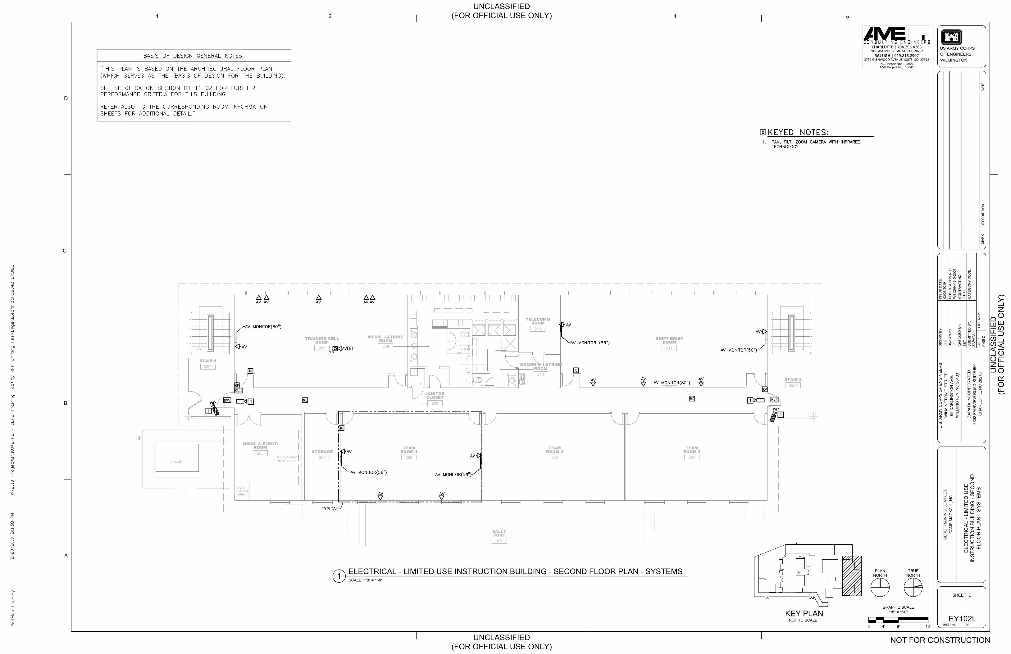
4' X 5'ELECTRICAL AREA
14' -9 1/4" X 6'-8" MECH. EQUIP.CHILLER
101
SALLYPORT
S201STAIR 2
208
JANITORCLOSET
204STORAGE
207
TRAINING CELLROOM
S200STAIR 1
211
TELECOMMROOM
210
WOMEN'S LATRINEROOM
209
MEN'S LATRINEROOM
205
MECH. & ELECT.ROOM
201
TEAMROOM 3
202
TEAMROOM 2
203
TEAMROOM 1
212
SHIFT BRIEFROOM
CHARLOTTE | 704.295.4263705 EAST MOREHEAD STREET, 28202
RALEIGH | 919.816.29073737 GLENWOOD AVENUE, SUITE 100, 27612
NC License No: C-2848AME Project No: 18042
LEE
LEE
SB
T
1
D
2
C
4 5
A
B
SO
LIC
ITA
TIO
N N
O.:
FILE
NA
ME
:
DR
AW
N B
Y:
CH
EC
KE
D B
Y:
DE
SIG
N B
Y:
MA
RK
SHEET ID
US ARMY CORPSOF ENGINEERSWILMINGTON
ISS
UE
DA
TE:
SIZ
E:
SU
BM
ITTE
D B
Y:
DE
SC
RIP
TIO
ND
ATE
CO
NTR
AC
T N
O:
AN
SI D
03/0
8/20
19
W91
2HN
-18-
D-2
001
CA
TEG
OR
Y C
OD
E:
ZAP
ATA
ZAP
ATA
INC
OR
PO
RA
TED
6302
FA
IRV
IEW
RO
AD
SU
ITE
600
CH
AR
LOTT
E, N
C 2
8210
U.S
. AR
MY
CO
RP
S O
F E
NG
INE
ER
SW
ILM
ING
TON
DIS
TRIC
T69
DA
RLI
NG
TON
AV
E.
WIL
MIN
GTO
N, N
C 2
8403
SE
RE
TR
AIN
ING
CO
MP
LEX
CA
MP
MA
CK
ALL
, NC
UN
CLA
SS
IFIE
D
UNCLASSIFIED(FOR OFFICIAL USE ONLY)
UNCLASSIFIED(FOR OFFICIAL USE ONLY)
T.B
.D.
OFSHEET No.:
(FO
R O
FFIC
IAL
US
E O
NLY
)
NOT FOR CONSTRUCTION
KEY PLANNOT TO SCALE
GRAPHIC SCALE1/8" = 1'-0"
8'4'0 16'EY102L
ELE
CTR
ICA
L - L
IMIT
ED
US
EIN
STR
UC
TIO
N B
UIL
DIN
G -
SE
CO
ND
FLO
OR
PLA
N -
SY
STE
MS
TRUENORTH
ELECTRICAL - LIMITED USE INSTRUCTION BUILDING - SECOND FLOOR PLAN - SYSTEMSSCALE: 1/8" = 1'-0"1
PLANNORTH
AutoCAD SHX Text
AV
AutoCAD SHX Text
AV
AutoCAD SHX Text
IC
AutoCAD SHX Text
IC
AutoCAD SHX Text
IC
AutoCAD SHX Text
AV
AutoCAD SHX Text
AV
AutoCAD SHX Text
AV
AutoCAD SHX Text
AV
AutoCAD SHX Text
AV
AutoCAD SHX Text
TYPICAL
AutoCAD SHX Text
BMS
AutoCAD SHX Text
BMS
AutoCAD SHX Text
1
AutoCAD SHX Text
KP
AutoCAD SHX Text
RADC
AutoCAD SHX Text
AV MONITOR(80")
AutoCAD SHX Text
AV MONITOR (56")
AutoCAD SHX Text
AV MONITOR(56")
AutoCAD SHX Text
AV
AutoCAD SHX Text
AV MONITOR(80")
AutoCAD SHX Text
PP
AutoCAD SHX Text
AV(6)
AutoCAD SHX Text
1
AutoCAD SHX Text
1
AutoCAD SHX Text
KP
AutoCAD SHX Text
WP
AutoCAD SHX Text
AV
AutoCAD SHX Text
AV
AutoCAD SHX Text
AV
AutoCAD SHX Text
AV
AutoCAD SHX Text
AV
AutoCAD SHX Text
MD
AutoCAD SHX Text
MD
AutoCAD SHX Text
AV MONITOR(56")
AutoCAD SHX Text
AV MONITOR(56")
AutoCAD SHX Text
AV
AutoCAD SHX Text
AV
AutoCAD SHX Text
1
AutoCAD SHX Text
WP
AutoCAD SHX Text
X:\2018 Projects\18042 FB - SERE Training Facility RFP Writing Fee\Dwgs\Electrical\18042 EY102L
AutoCAD SHX Text
2/20/2019 2:11:58 PM
AutoCAD SHX Text
Patrick Livesey
AutoCAD SHX Text
1.PAN, TILT, ZOOM CAMERA WITH INFRARED PAN, TILT, ZOOM CAMERA WITH INFRARED TECHNOLOGY.
AutoCAD SHX Text
KEYED NOTES:
AutoCAD SHX Text
X
AutoCAD SHX Text
BASIS OF DESIGN GENERAL NOTES: "THIS PLAN IS BASED ON THE ARCHITECTURAL FLOOR PLAN. (WHICH SERVES AS THE "BASIS OF DESIGN FOR THE BUILDING). SEE SPECIFICATION SECTION 01 11 02 FOR FURTHER PERFORMANCE CRITERIA FOR THIS BUILDING. REFER ALSO TO THE CORRESPONDING ROOM INFORMATION SHEETS FOR ADDITIONAL DETAIL."
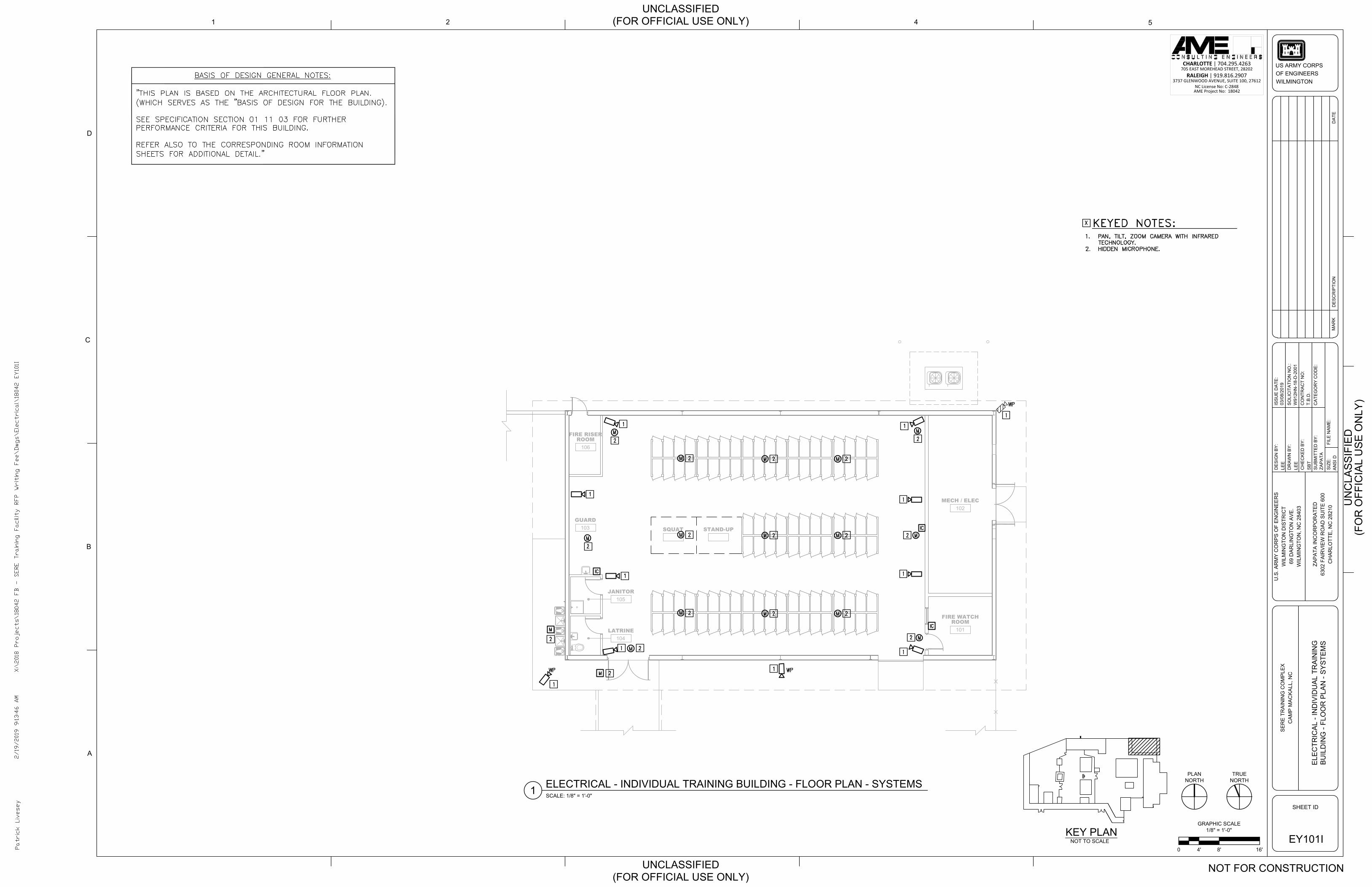
102
MECH / ELEC
101
FIRE WATCH
ROOM
106
FIRE RISER
ROOM
104
LATRINE
STAND-UP
103
GUARD
SQUAT
105
JANITOR
CHARLOTTE | 704.295.4263705 EAST MOREHEAD STREET, 28202
RALEIGH | 919.816.29073737 GLENWOOD AVENUE, SUITE 100, 27612
NC License No: C-2848AME Project No: 18042
LE
E
LE
E
SB
T
1
D
2
C
4
5
A
B
SO
LIC
IT
AT
IO
N N
O.:
FILE
N
AM
E:
DR
AW
N B
Y:
CH
EC
KE
D B
Y:
DE
SIG
N B
Y:
MA
RK
SHEET ID
US ARMY CORPS
OF ENGINEERS
WILMINGTON
IS
SU
E D
AT
E:
SIZ
E:
SU
BM
IT
TE
D B
Y:
DE
SC
RIP
TIO
ND
AT
E
CO
NT
RA
CT
N
O:
AN
SI D
03/08/2019
W912H
N-18-D
-2001
CA
TE
GO
RY
C
OD
E:
ZA
PA
TA
ZA
PA
TA
IN
CO
RP
OR
AT
ED
6302 F
AIR
VIE
W R
OA
D S
UIT
E 600
CH
AR
LO
TT
E, N
C 28210
U.S
. A
RM
Y C
OR
PS
O
F E
NG
IN
EE
RS
WILM
IN
GT
ON
D
IS
TR
IC
T
69 D
AR
LIN
GT
ON
A
VE
.
WILM
IN
GT
ON
, N
C 28403
SE
RE
T
RA
IN
IN
G C
OM
PLE
X
CA
MP
M
AC
KA
LL, N
C
UN
CLA
SS
IF
IE
D
UNCLASSIFIED
(FOR OFFICIAL USE ONLY)
UNCLASSIFIED
(FOR OFFICIAL USE ONLY)
T.B
.D
.
(F
OR
O
FF
IC
IA
L U
SE
O
NLY
)
NOT FOR CONSTRUCTION
KEY PLAN
NOT TO SCALE
GRAPHIC SCALE
1/8" = 1'-0"
8'4'0 16'
EY101I
EL
EC
TR
IC
AL
- IN
DIV
ID
UA
L T
RA
IN
IN
G
BU
IL
DIN
G - F
LO
OR
P
LA
N - S
YS
TE
MS
TRUE
NORTH
ELECTRICAL - INDIVIDUAL TRAINING BUILDING - FLOOR PLAN - SYSTEMS
SCALE: 1/8" = 1'-0"
1
PLAN
NORTH
AutoCAD SHX Text
IC
AutoCAD SHX Text
M
AutoCAD SHX Text
M
AutoCAD SHX Text
M
AutoCAD SHX Text
WP
AutoCAD SHX Text
M
AutoCAD SHX Text
IC
AutoCAD SHX Text
IC
AutoCAD SHX Text
M
AutoCAD SHX Text
M
AutoCAD SHX Text
M
AutoCAD SHX Text
M
AutoCAD SHX Text
M
AutoCAD SHX Text
M
AutoCAD SHX Text
WP
AutoCAD SHX Text
1
AutoCAD SHX Text
2
AutoCAD SHX Text
2
AutoCAD SHX Text
2
AutoCAD SHX Text
2
AutoCAD SHX Text
2
AutoCAD SHX Text
1
AutoCAD SHX Text
1
AutoCAD SHX Text
2
AutoCAD SHX Text
1
AutoCAD SHX Text
1
AutoCAD SHX Text
2
AutoCAD SHX Text
2
AutoCAD SHX Text
1
AutoCAD SHX Text
1
AutoCAD SHX Text
WP
AutoCAD SHX Text
1
AutoCAD SHX Text
2
AutoCAD SHX Text
2
AutoCAD SHX Text
1
AutoCAD SHX Text
1
AutoCAD SHX Text
M
AutoCAD SHX Text
M
AutoCAD SHX Text
M
AutoCAD SHX Text
2
AutoCAD SHX Text
2
AutoCAD SHX Text
2
AutoCAD SHX Text
M
AutoCAD SHX Text
M
AutoCAD SHX Text
M
AutoCAD SHX Text
2
AutoCAD SHX Text
2
AutoCAD SHX Text
2
AutoCAD SHX Text
M
AutoCAD SHX Text
2
AutoCAD SHX Text
1
AutoCAD SHX Text
X:\2018 Projects\18042 FB - SERE Training Facility RFP Writing Fee\Dwgs\Electrical\18042 EY101I
AutoCAD SHX Text
2/19/2019 9:13:46 AM
AutoCAD SHX Text
Patrick Livesey
AutoCAD SHX Text
1. PAN, TILT, ZOOM CAMERA WITH INFRARED PAN, TILT, ZOOM CAMERA WITH INFRARED TECHNOLOGY. 2. HIDDEN MICROPHONE.HIDDEN MICROPHONE.
AutoCAD SHX Text
KEYED NOTES:
AutoCAD SHX Text
X
AutoCAD SHX Text
BASIS OF DESIGN GENERAL NOTES: "THIS PLAN IS BASED ON THE ARCHITECTURAL FLOOR PLAN. (WHICH SERVES AS THE "BASIS OF DESIGN FOR THE BUILDING). SEE SPECIFICATION SECTION 01 11 03 FOR FURTHER PERFORMANCE CRITERIA FOR THIS BUILDING. REFER ALSO TO THE CORRESPONDING ROOM INFORMATION SHEETS FOR ADDITIONAL DETAIL."
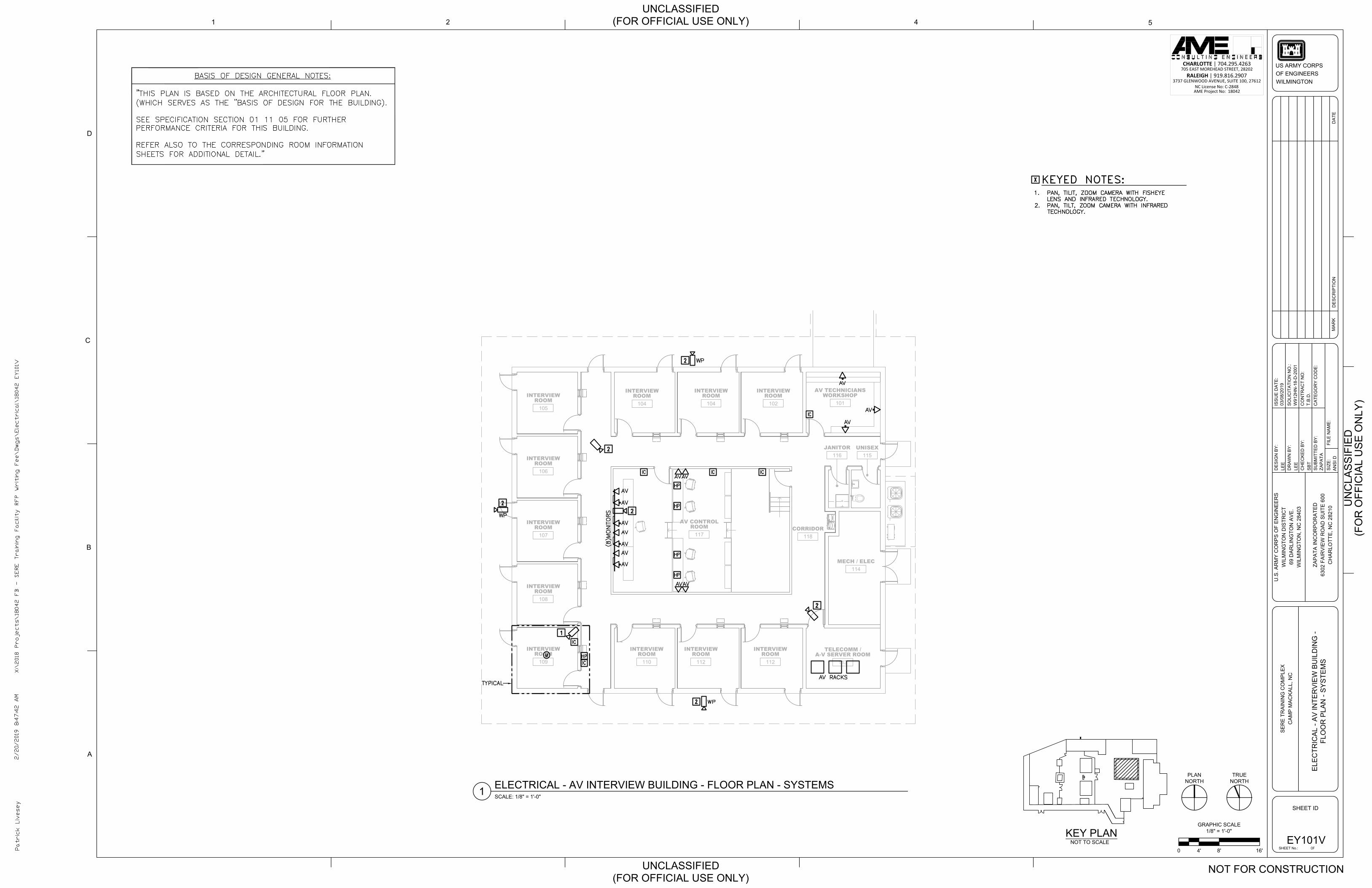
113
TELECOMM /A-V SERVER ROOM
112
INTERVIEWROOM
104
INTERVIEWROOM
118CORRIDOR
117
AV CONTROLROOM
101
AV TECHNICIANSWORKSHOP
102
INTERVIEWROOM
104
INTERVIEWROOM
105
INTERVIEWROOM
106
INTERVIEWROOM
107
INTERVIEWROOM
108
INTERVIEWROOM
109
INTERVIEWROOM
110
INTERVIEWROOM
112
INTERVIEWROOM
115UNISEX
116JANITOR
114MECH / ELEC
CHARLOTTE | 704.295.4263705 EAST MOREHEAD STREET, 28202
RALEIGH | 919.816.29073737 GLENWOOD AVENUE, SUITE 100, 27612
NC License No: C-2848AME Project No: 18042
LEE
LEE
SB
T
1
D
2
C
4 5
A
B
SO
LIC
ITA
TIO
N N
O.:
FILE
NA
ME
:
DR
AW
N B
Y:
CH
EC
KE
D B
Y:
DE
SIG
N B
Y:
MA
RK
SHEET ID
US ARMY CORPSOF ENGINEERSWILMINGTON
ISS
UE
DA
TE:
SIZ
E:
SU
BM
ITTE
D B
Y:
DE
SC
RIP
TIO
ND
ATE
CO
NTR
AC
T N
O:
AN
SI D
03/0
8/20
19
W91
2HN
-18-
D-2
001
CA
TEG
OR
Y C
OD
E:
ZAP
ATA
ZAP
ATA
INC
OR
PO
RA
TED
6302
FA
IRV
IEW
RO
AD
SU
ITE
600
CH
AR
LOTT
E, N
C 2
8210
U.S
. AR
MY
CO
RP
S O
F E
NG
INE
ER
SW
ILM
ING
TON
DIS
TRIC
T69
DA
RLI
NG
TON
AV
E.
WIL
MIN
GTO
N, N
C 2
8403
SE
RE
TR
AIN
ING
CO
MP
LEX
CA
MP
MA
CK
ALL
, NC
UN
CLA
SS
IFIE
D
UNCLASSIFIED(FOR OFFICIAL USE ONLY)
UNCLASSIFIED(FOR OFFICIAL USE ONLY)
T.B
.D.
OFSHEET No.:
(FO
R O
FFIC
IAL
US
E O
NLY
)
NOT FOR CONSTRUCTION
KEY PLANNOT TO SCALE
GRAPHIC SCALE1/8" = 1'-0"
8'4'0 16'EY101V
ELE
CTR
ICA
L - A
V IN
TER
VIE
W B
UIL
DIN
G -
FLO
OR
PLA
N -
SY
STE
MS
TRUENORTHELECTRICAL - AV INTERVIEW BUILDING - FLOOR PLAN - SYSTEMS
SCALE: 1/8" = 1'-0"1
PLANNORTH
AutoCAD SHX Text
IC
AutoCAD SHX Text
IC
AutoCAD SHX Text
M
AutoCAD SHX Text
IC
AutoCAD SHX Text
IC
AutoCAD SHX Text
IC
AutoCAD SHX Text
IC
AutoCAD SHX Text
TYPICAL
AutoCAD SHX Text
HP
AutoCAD SHX Text
HP
AutoCAD SHX Text
HP
AutoCAD SHX Text
HP
AutoCAD SHX Text
AV
AutoCAD SHX Text
HP
AutoCAD SHX Text
AV
AutoCAD SHX Text
AV
AutoCAD SHX Text
AV
AutoCAD SHX Text
AV
AutoCAD SHX Text
AV
AutoCAD SHX Text
AV
AutoCAD SHX Text
AV
AutoCAD SHX Text
AV
AutoCAD SHX Text
AV
AutoCAD SHX Text
(8)MONITORS
AutoCAD SHX Text
WP
AutoCAD SHX Text
WP
AutoCAD SHX Text
WP
AutoCAD SHX Text
2
AutoCAD SHX Text
2
AutoCAD SHX Text
1
AutoCAD SHX Text
2
AutoCAD SHX Text
2
AutoCAD SHX Text
2
AutoCAD SHX Text
2
AutoCAD SHX Text
AV RACKS
AutoCAD SHX Text
AV
AutoCAD SHX Text
AV
AutoCAD SHX Text
AV
AutoCAD SHX Text
AV
AutoCAD SHX Text
X:\2018 Projects\18042 FB - SERE Training Facility RFP Writing Fee\Dwgs\Electrical\18042 EY101V
AutoCAD SHX Text
2/20/2019 8:47:42 AM
AutoCAD SHX Text
Patrick Livesey
AutoCAD SHX Text
1. PAN, TILIT, ZOOM CAMERA WITH FISHEYE PAN, TILIT, ZOOM CAMERA WITH FISHEYE LENS AND INFRARED TECHNOLOGY. 2. PAN, TILT, ZOOM CAMERA WITH INFRARED PAN, TILT, ZOOM CAMERA WITH INFRARED TECHNOLOGY.
AutoCAD SHX Text
KEYED NOTES:
AutoCAD SHX Text
X
AutoCAD SHX Text
BASIS OF DESIGN GENERAL NOTES: "THIS PLAN IS BASED ON THE ARCHITECTURAL FLOOR PLAN. (WHICH SERVES AS THE "BASIS OF DESIGN FOR THE BUILDING). SEE SPECIFICATION SECTION 01 11 05 FOR FURTHER PERFORMANCE CRITERIA FOR THIS BUILDING. REFER ALSO TO THE CORRESPONDING ROOM INFORMATION SHEETS FOR ADDITIONAL DETAIL."
AutoCAD SHX Text
BASIS OF DESIGN GENERAL NOTES: "THIS PLAN IS BASED ON THE ARCHITECTURAL FLOOR PLAN. (WHICH SERVES AS THE "BASIS OF DESIGN FOR THE BUILDING). SEE SPECIFICATION SECTION 01 11 03 FOR FURTHER PERFORMANCE CRITERIA FOR THIS BUILDING. REFER ALSO TO THE CORRESPONDING ROOM INFORMATION SHEETS FOR ADDITIONAL DETAIL."
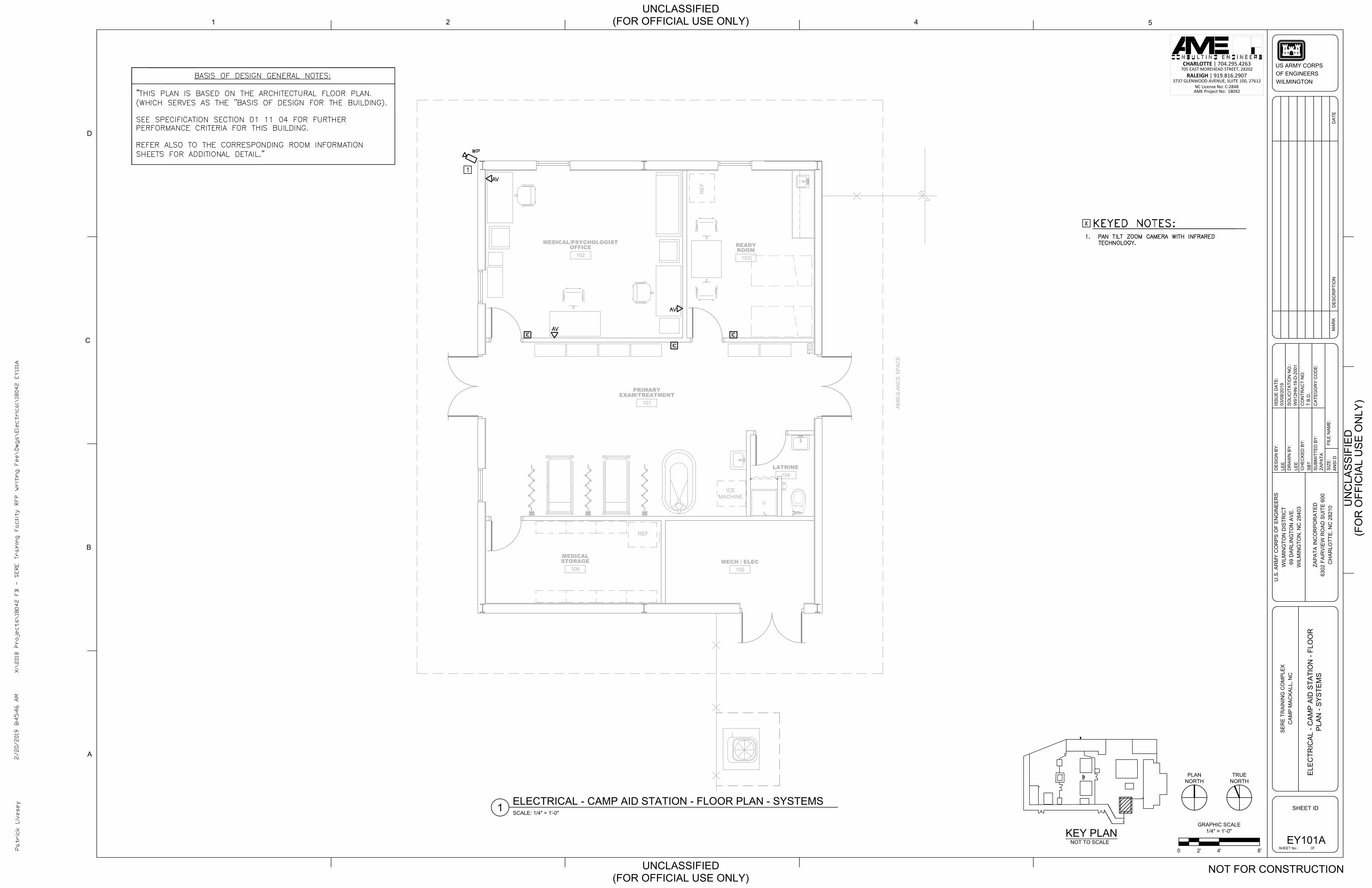
101
PRIMARYEXAM/TREATMENT
105MECH / ELEC
104LATRINE
103
READYROOM
102
MEDICAL/PSYCHOLOGISTOFFICE
RE
F
ICEMACHINE
REF
106
MEDICALSTORAGE
AM
BU
LAN
CE
SP
AC
E
FEC
CHARLOTTE | 704.295.4263705 EAST MOREHEAD STREET, 28202
RALEIGH | 919.816.29073737 GLENWOOD AVENUE, SUITE 100, 27612
NC License No: C-2848AME Project No: 18042
LEE
LEE
SB
T
1
D
2
C
4 5
A
B
SO
LIC
ITA
TIO
N N
O.:
FILE
NA
ME
:
DR
AW
N B
Y:
CH
EC
KE
D B
Y:
DE
SIG
N B
Y:
MA
RK
SHEET ID
US ARMY CORPSOF ENGINEERSWILMINGTON
ISS
UE
DA
TE:
SIZ
E:
SU
BM
ITTE
D B
Y:
DE
SC
RIP
TIO
ND
ATE
CO
NTR
AC
T N
O:
AN
SI D
03/0
8/20
19
W91
2HN
-18-
D-2
001
CA
TEG
OR
Y C
OD
E:
ZAP
ATA
ZAP
ATA
INC
OR
PO
RA
TED
6302
FA
IRV
IEW
RO
AD
SU
ITE
600
CH
AR
LOTT
E, N
C 2
8210
U.S
. AR
MY
CO
RP
S O
F E
NG
INE
ER
SW
ILM
ING
TON
DIS
TRIC
T69
DA
RLI
NG
TON
AV
E.
WIL
MIN
GTO
N, N
C 2
8403
SE
RE
TR
AIN
ING
CO
MP
LEX
CA
MP
MA
CK
ALL
, NC
UN
CLA
SS
IFIE
D
UNCLASSIFIED(FOR OFFICIAL USE ONLY)
UNCLASSIFIED(FOR OFFICIAL USE ONLY)
T.B
.D.
OFSHEET No.:
(FO
R O
FFIC
IAL
US
E O
NLY
)
NOT FOR CONSTRUCTION
KEY PLANNOT TO SCALE EY101A
ELE
CTR
ICA
L - C
AM
P A
ID S
TATI
ON
- FL
OO
RP
LAN
- S
YS
TEM
S
TRUENORTH
ELECTRICAL - CAMP AID STATION - FLOOR PLAN - SYSTEMSSCALE: 1/4" = 1'-0"1
PLANNORTH
GRAPHIC SCALE1/4" = 1'-0"
4'2'0 8'
AutoCAD SHX Text
IC
AutoCAD SHX Text
IC
AutoCAD SHX Text
AV
AutoCAD SHX Text
IC
AutoCAD SHX Text
AV
AutoCAD SHX Text
WP
AutoCAD SHX Text
AV
AutoCAD SHX Text
X:\2018 Projects\18042 FB - SERE Training Facility RFP Writing Fee\Dwgs\Electrical\18042 EY101A
AutoCAD SHX Text
2/20/2019 8:45:46 AM
AutoCAD SHX Text
Patrick Livesey
AutoCAD SHX Text
1.PAN TILT ZOOM CAMERA WITH INFRARED PAN TILT ZOOM CAMERA WITH INFRARED TECHNOLOGY.
AutoCAD SHX Text
KEYED NOTES:
AutoCAD SHX Text
X
AutoCAD SHX Text
1
AutoCAD SHX Text
BASIS OF DESIGN GENERAL NOTES: "THIS PLAN IS BASED ON THE ARCHITECTURAL FLOOR PLAN. (WHICH SERVES AS THE "BASIS OF DESIGN FOR THE BUILDING). SEE SPECIFICATION SECTION 01 11 04 FOR FURTHER PERFORMANCE CRITERIA FOR THIS BUILDING. REFER ALSO TO THE CORRESPONDING ROOM INFORMATION SHEETS FOR ADDITIONAL DETAIL."

101
SMALL GROUP INSTRUCTION
102
SMALL GROUP INSTRUCTION
103
SMALL GROUP INSTRUCTION
105
FOOD SERVICEROOM
106
LAUNDRYROOM
107
STUDENT GEARSTORAGE ROOM
109
TOILETROOM
110
TOILETROOM
108
COVERED AREA 3
104
INSTRUCTION GROUP ROOM
X
X
X
116
FIRE RISER ROOM
CHARLOTTE | 704.295.4263705 EAST MOREHEAD STREET, 28202
RALEIGH | 919.816.29073737 GLENWOOD AVENUE, SUITE 100, 27612
NC License No: C-2848AME Project No: 18042
LEE
LEE
SB
T
1
D
2
C
4 5
A
B
SO
LIC
ITA
TIO
N N
O.:
FILE
NA
ME
:
DR
AW
N B
Y:
CH
EC
KE
D B
Y:
DE
SIG
N B
Y:
MA
RK
SHEET ID
US ARMY CORPSOF ENGINEERSWILMINGTON
ISS
UE
DA
TE:
SIZ
E:
SU
BM
ITTE
D B
Y:
DE
SC
RIP
TIO
ND
ATE
CO
NTR
AC
T N
O:
AN
SI D
03/0
8/20
19
W91
2HN
-18-
D-2
001
CA
TEG
OR
Y C
OD
E:
ZAP
ATA
ZAP
ATA
INC
OR
PO
RA
TED
6302
FA
IRV
IEW
RO
AD
SU
ITE
600
CH
AR
LOTT
E, N
C 2
8210
U.S
. AR
MY
CO
RP
S O
F E
NG
INE
ER
SW
ILM
ING
TON
DIS
TRIC
T69
DA
RLI
NG
TON
AV
E.
WIL
MIN
GTO
N, N
C 2
8403
SE
RE
TR
AIN
ING
CO
MP
LEX
CA
MP
MA
CK
ALL
, NC
UN
CLA
SS
IFIE
D
UNCLASSIFIED(FOR OFFICIAL USE ONLY)
UNCLASSIFIED(FOR OFFICIAL USE ONLY)
T.B
.D.
OFSHEET No.:
(FO
R O
FFIC
IAL
US
E O
NLY
)
NOT FOR CONSTRUCTION
KEY PLANNOT TO SCALE
GRAPHIC SCALE1/8" = 1'-0"
8'4'0 16'EY101MA
ELE
CTR
ICA
L - M
ULT
I-PU
RP
OS
E B
UIL
DIN
G -
FIR
ST
FLO
OR
PLA
N -
SY
STE
MS
- B
AS
E B
ID
TRUENORTH
ELECTRICAL - MULTI-PURPOSE BUILDING - FIRST FLOOR PLAN - SYSTEMS - BASE BIDSCALE: 1/8" = 1'-0"1
PLANNORTH
AutoCAD SHX Text
M
AutoCAD SHX Text
M
AutoCAD SHX Text
M
AutoCAD SHX Text
M
AutoCAD SHX Text
M
AutoCAD SHX Text
M
AutoCAD SHX Text
M
AutoCAD SHX Text
M
AutoCAD SHX Text
2
AutoCAD SHX Text
2
AutoCAD SHX Text
2
AutoCAD SHX Text
2
AutoCAD SHX Text
2
AutoCAD SHX Text
2
AutoCAD SHX Text
2
AutoCAD SHX Text
2
AutoCAD SHX Text
3
AutoCAD SHX Text
3
AutoCAD SHX Text
3
AutoCAD SHX Text
3
AutoCAD SHX Text
3
AutoCAD SHX Text
3
AutoCAD SHX Text
3
AutoCAD SHX Text
3
AutoCAD SHX Text
1
AutoCAD SHX Text
WP
AutoCAD SHX Text
1
AutoCAD SHX Text
WP
AutoCAD SHX Text
M
AutoCAD SHX Text
4
AutoCAD SHX Text
M
AutoCAD SHX Text
4
AutoCAD SHX Text
M
AutoCAD SHX Text
4
AutoCAD SHX Text
M
AutoCAD SHX Text
4
AutoCAD SHX Text
X:\2018 Projects\18042 FB - SERE Training Facility RFP Writing Fee\Dwgs\Electrical\18042 EY101MA
AutoCAD SHX Text
2/20/2019 2:19:54 PM
AutoCAD SHX Text
Patrick Livesey
AutoCAD SHX Text
1. PAN, TILT, ZOOM CAMERA WITH INFRARED PAN, TILT, ZOOM CAMERA WITH INFRARED TECHNOLOGY. 2. HIDDEN CAMERA WITH INFRARED HIDDEN CAMERA WITH INFRARED TECHNOLOGY 3. HIDDEN MICROPHONE. HIDDEN MICROPHONE. 4. HIDDEN EXTERIOR MICROPHONE.HIDDEN EXTERIOR MICROPHONE.
AutoCAD SHX Text
KEYED NOTES:
AutoCAD SHX Text
X
AutoCAD SHX Text
BASIS OF DESIGN GENERAL NOTES: "THIS PLAN IS BASED ON THE ARCHITECTURAL FLOOR PLAN. (WHICH SERVES AS THE "BASIS OF DESIGN FOR THE BUILDING). SEE SPECIFICATION SECTION 01 11 06 FOR FURTHER PERFORMANCE CRITERIA FOR THIS BUILDING. REFER ALSO TO THE CORRESPONDING ROOM INFORMATION SHEETS FOR ADDITIONAL DETAIL."

X
X
X
X
X
X
113
COVERED AREA 3
115
TOILETROOM
114
TOILETROOM
104
SMALL GROUP INSTRUCTION B4
103
SMALL GROUP INSTRUCTION B3
116
FIRE RISER ROOM
107
SMALL GROUPINSTRUCTION A3
109
INSTRUCTION GROUP ROOM
112
STUDENT GEARSTORAGE ROOM
111
LAUNDRYROOM
110
FOOD SERVICEROOM
108
SMALL GROUPINSTRUCTION A4
106
SMALL GROUPINSTRUCTION A2
105
SMALL GROUP INSTRUCTION A1
102
SMALL GROUP INSTRUCTION B2
101
SMALL GROUP INTRUCTION B1
CHARLOTTE | 704.295.4263705 EAST MOREHEAD STREET, 28202
RALEIGH | 919.816.29073737 GLENWOOD AVENUE, SUITE 100, 27612
NC License No: C-2848AME Project No: 18042
LEE
LEE
SB
T
1
D
2
C
4 5
A
B
SO
LIC
ITA
TIO
N N
O.:
FILE
NA
ME
:
DR
AW
N B
Y:
CH
EC
KE
D B
Y:
DE
SIG
N B
Y:
MA
RK
SHEET ID
US ARMY CORPSOF ENGINEERSWILMINGTON
ISS
UE
DA
TE:
SIZ
E:
SU
BM
ITTE
D B
Y:
DE
SC
RIP
TIO
ND
ATE
CO
NTR
AC
T N
O:
AN
SI D
03/0
8/20
19
W91
2HN
-18-
D-2
001
CA
TEG
OR
Y C
OD
E:
ZAP
ATA
ZAP
ATA
INC
OR
PO
RA
TED
6302
FA
IRV
IEW
RO
AD
SU
ITE
600
CH
AR
LOTT
E, N
C 2
8210
U.S
. AR
MY
CO
RP
S O
F E
NG
INE
ER
SW
ILM
ING
TON
DIS
TRIC
T69
DA
RLI
NG
TON
AV
E.
WIL
MIN
GTO
N, N
C 2
8403
SE
RE
TR
AIN
ING
CO
MP
LEX
CA
MP
MA
CK
ALL
, NC
UN
CLA
SS
IFIE
D
UNCLASSIFIED(FOR OFFICIAL USE ONLY)
UNCLASSIFIED(FOR OFFICIAL USE ONLY)
T.B
.D.
OFSHEET No.:
(FO
R O
FFIC
IAL
US
E O
NLY
)
NOT FOR CONSTRUCTION
KEY PLANNOT TO SCALE
GRAPHIC SCALE1/8" = 1'-0"
8'4'0 16'EY101MB
ELE
CTR
ICA
L - M
ULT
I-PU
RP
OS
E B
UIL
DIN
G- F
IRS
T FL
OO
R P
LAN
- S
YS
TEM
S -
BID
OP
TIO
N #
3
TRUENORTH
ELECTRICAL - MULTI-PURPOSE BUILDING - FIRST FLOOR PLAN - SYSTEMS - BID OPTION #3SCALE: 1/8" = 1'-0"1
PLANNORTH
AutoCAD SHX Text
M
AutoCAD SHX Text
M
AutoCAD SHX Text
M
AutoCAD SHX Text
M
AutoCAD SHX Text
M
AutoCAD SHX Text
M
AutoCAD SHX Text
M
AutoCAD SHX Text
M
AutoCAD SHX Text
M
AutoCAD SHX Text
M
AutoCAD SHX Text
M
AutoCAD SHX Text
M
AutoCAD SHX Text
2
AutoCAD SHX Text
2
AutoCAD SHX Text
2
AutoCAD SHX Text
2
AutoCAD SHX Text
2
AutoCAD SHX Text
2
AutoCAD SHX Text
2
AutoCAD SHX Text
2
AutoCAD SHX Text
2
AutoCAD SHX Text
2
AutoCAD SHX Text
2
AutoCAD SHX Text
2
AutoCAD SHX Text
2
AutoCAD SHX Text
2
AutoCAD SHX Text
3
AutoCAD SHX Text
3
AutoCAD SHX Text
3
AutoCAD SHX Text
3
AutoCAD SHX Text
3
AutoCAD SHX Text
3
AutoCAD SHX Text
3
AutoCAD SHX Text
3
AutoCAD SHX Text
3
AutoCAD SHX Text
3
AutoCAD SHX Text
3
AutoCAD SHX Text
3
AutoCAD SHX Text
1
AutoCAD SHX Text
WP
AutoCAD SHX Text
1
AutoCAD SHX Text
WP
AutoCAD SHX Text
2
AutoCAD SHX Text
2
AutoCAD SHX Text
2
AutoCAD SHX Text
2
AutoCAD SHX Text
M
AutoCAD SHX Text
M
AutoCAD SHX Text
3
AutoCAD SHX Text
3
AutoCAD SHX Text
M
AutoCAD SHX Text
M
AutoCAD SHX Text
3
AutoCAD SHX Text
3
AutoCAD SHX Text
M
AutoCAD SHX Text
M
AutoCAD SHX Text
3
AutoCAD SHX Text
3
AutoCAD SHX Text
M
AutoCAD SHX Text
4
AutoCAD SHX Text
M
AutoCAD SHX Text
4
AutoCAD SHX Text
M
AutoCAD SHX Text
4
AutoCAD SHX Text
M
AutoCAD SHX Text
4
AutoCAD SHX Text
M
AutoCAD SHX Text
4
AutoCAD SHX Text
M
AutoCAD SHX Text
4
AutoCAD SHX Text
M
AutoCAD SHX Text
4
AutoCAD SHX Text
X:\2018 Projects\18042 FB - SERE Training Facility RFP Writing Fee\Dwgs\Electrical\18042 EY101MB
AutoCAD SHX Text
2/20/2019 8:49:24 AM
AutoCAD SHX Text
Patrick Livesey
AutoCAD SHX Text
1. PAN, TILT, ZOOM CAMERA WITH INFRARED PAN, TILT, ZOOM CAMERA WITH INFRARED TECHNOLOGY. 2. HIDDEN CAMERA WITH INFRARED TECHNOLOGY. HIDDEN CAMERA WITH INFRARED TECHNOLOGY. 3. HIDDEN MICROPHONE. HIDDEN MICROPHONE. 4. HIDDEN EXTERIOR MICROPHONE.HIDDEN EXTERIOR MICROPHONE.
AutoCAD SHX Text
KEYED NOTES:
AutoCAD SHX Text
X
AutoCAD SHX Text
BASIS OF DESIGN GENERAL NOTES: "THIS PLAN IS BASED ON THE ARCHITECTURAL FLOOR PLAN. (WHICH SERVES AS THE "BASIS OF DESIGN FOR THE BUILDING). SEE SPECIFICATION SECTION 01 11 06 FOR FURTHER PERFORMANCE CRITERIA FOR THIS BUILDING. REFER ALSO TO THE CORRESPONDING ROOM INFORMATION SHEETS FOR ADDITIONAL DETAIL."

ICE
MA
CH
INE
101
INSTRUCTORROOM
102
UNISEXLATRINE
CHARLOTTE | 704.295.4263705 EAST MOREHEAD STREET, 28202
RALEIGH | 919.816.29073737 GLENWOOD AVENUE, SUITE 100, 27612
NC License No: C-2848AME Project No: 18042
LEE
LEE
SB
T
1
D
2
C
4 5
A
B
SO
LIC
ITA
TIO
N N
O.:
FILE
NA
ME
:
DR
AW
N B
Y:
CH
EC
KE
D B
Y:
DE
SIG
N B
Y:
MA
RK
SHEET ID
US ARMY CORPSOF ENGINEERSWILMINGTON
ISS
UE
DA
TE:
SIZ
E:
SU
BM
ITTE
D B
Y:
DE
SC
RIP
TIO
ND
ATE
CO
NTR
AC
T N
O:
AN
SI D
03/0
8/20
19
W91
2HN
-18-
D-2
001
CA
TEG
OR
Y C
OD
E:
ZAP
ATA
ZAP
ATA
INC
OR
PO
RA
TED
6302
FA
IRV
IEW
RO
AD
SU
ITE
600
CH
AR
LOTT
E, N
C 2
8210
U.S
. AR
MY
CO
RP
S O
F E
NG
INE
ER
SW
ILM
ING
TON
DIS
TRIC
T69
DA
RLI
NG
TON
AV
E.
WIL
MIN
GTO
N, N
C 2
8403
SE
RE
TR
AIN
ING
CO
MP
LEX
CA
MP
MA
CK
ALL
, NC
UN
CLA
SS
IFIE
D
UNCLASSIFIED(FOR OFFICIAL USE ONLY)
UNCLASSIFIED(FOR OFFICIAL USE ONLY)
T.B
.D.
OFSHEET No.:
(FO
R O
FFIC
IAL
US
E O
NLY
)
NOT FOR CONSTRUCTION
KEY PLANNOT TO SCALE
GRAPHIC SCALE1/4" = 1'-0"
4'2'0 8'EY101C
ELE
CTR
ICA
L - I
NS
TRU
CTO
R C
ON
TRO
LB
UIL
DIN
G -
FLO
OR
PLA
N -
SY
STE
MS
TRUENORTH
ELECTRICAL - INSTRUCTOR CONTROL BUILDING - FLOOR PLAN - SYSTEMSSCALE: 1/4" = 1'-0"1
PLANNORTH
AutoCAD SHX Text
IC
AutoCAD SHX Text
AV
AutoCAD SHX Text
HP
AutoCAD SHX Text
WP
AutoCAD SHX Text
1
AutoCAD SHX Text
WP
AutoCAD SHX Text
1
AutoCAD SHX Text
M
AutoCAD SHX Text
2
AutoCAD SHX Text
M
AutoCAD SHX Text
2
AutoCAD SHX Text
M
AutoCAD SHX Text
2
AutoCAD SHX Text
M
AutoCAD SHX Text
2
AutoCAD SHX Text
X:\2018 Projects\18042 FB - SERE Training Facility RFP Writing Fee\Dwgs\Electrical\18042 EY101C
AutoCAD SHX Text
2/20/2019 2:15:53 PM
AutoCAD SHX Text
Patrick Livesey
AutoCAD SHX Text
1. PAN, TILT, ZOOM CAMERA WITH INFRARED PAN, TILT, ZOOM CAMERA WITH INFRARED TECHNOLOGY. 2. HIDDEN EXTERIOR MICROPHONE.HIDDEN EXTERIOR MICROPHONE.
AutoCAD SHX Text
KEYED NOTES:
AutoCAD SHX Text
X
AutoCAD SHX Text
BASIS OF DESIGN GENERAL NOTES: "THIS PLAN IS BASED ON THE ARCHITECTURAL FLOOR PLAN. (WHICH SERVES AS THE "BASIS OF DESIGN FOR THE BUILDING). SEE SPECIFICATION SECTION 01 11 08 FOR FURTHER PERFORMANCE CRITERIA FOR THIS BUILDING. REFER ALSO TO THE CORRESPONDING ROOM INFORMATION SHEETS FOR ADDITIONAL DETAIL."
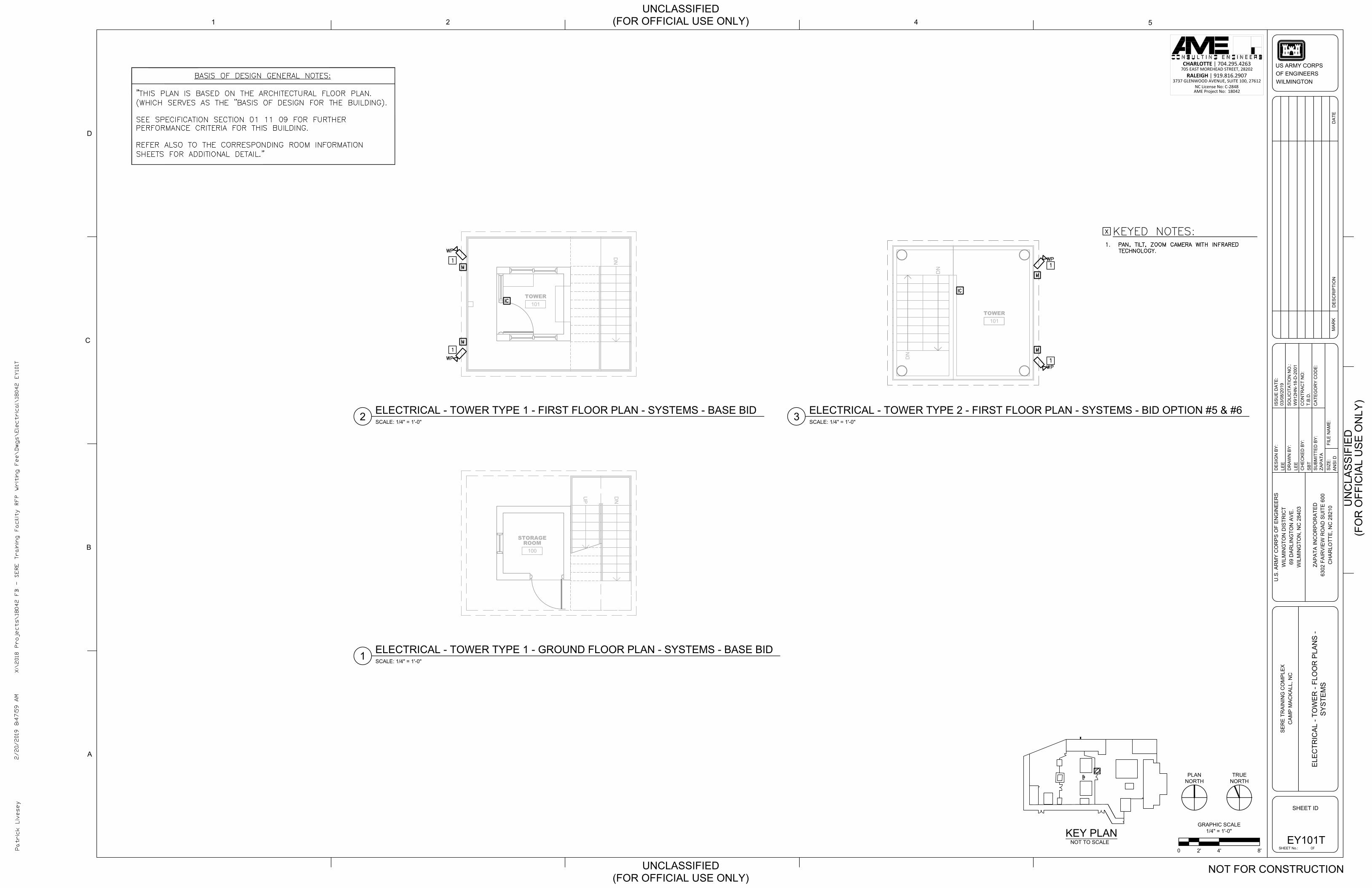
DN
UP
100
STORAGEROOM
DN
101TOWER
DN
DN
101TOWER
CHARLOTTE | 704.295.4263705 EAST MOREHEAD STREET, 28202
RALEIGH | 919.816.29073737 GLENWOOD AVENUE, SUITE 100, 27612
NC License No: C-2848AME Project No: 18042
LEE
LEE
SB
T
1
D
2
C
4 5
A
B
SO
LIC
ITA
TIO
N N
O.:
FILE
NA
ME
:
DR
AW
N B
Y:
CH
EC
KE
D B
Y:
DE
SIG
N B
Y:
MA
RK
SHEET ID
US ARMY CORPSOF ENGINEERSWILMINGTON
ISS
UE
DA
TE:
SIZ
E:
SU
BM
ITTE
D B
Y:
DE
SC
RIP
TIO
ND
ATE
CO
NTR
AC
T N
O:
AN
SI D
03/0
8/20
19
W91
2HN
-18-
D-2
001
CA
TEG
OR
Y C
OD
E:
ZAP
ATA
ZAP
ATA
INC
OR
PO
RA
TED
6302
FA
IRV
IEW
RO
AD
SU
ITE
600
CH
AR
LOTT
E, N
C 2
8210
U.S
. AR
MY
CO
RP
S O
F E
NG
INE
ER
SW
ILM
ING
TON
DIS
TRIC
T69
DA
RLI
NG
TON
AV
E.
WIL
MIN
GTO
N, N
C 2
8403
SE
RE
TR
AIN
ING
CO
MP
LEX
CA
MP
MA
CK
ALL
, NC
UN
CLA
SS
IFIE
D
UNCLASSIFIED(FOR OFFICIAL USE ONLY)
UNCLASSIFIED(FOR OFFICIAL USE ONLY)
T.B
.D.
OFSHEET No.:
(FO
R O
FFIC
IAL
US
E O
NLY
)
NOT FOR CONSTRUCTION
KEY PLANNOT TO SCALE
GRAPHIC SCALE1/4" = 1'-0"
4'2'0 8'EY101T
ELE
CTR
ICA
L - T
OW
ER
- FL
OO
R P
LAN
S -
SY
STE
MS
TRUENORTH
ELECTRICAL - TOWER TYPE 1 - GROUND FLOOR PLAN - SYSTEMS - BASE BIDSCALE: 1/4" = 1'-0"1
ELECTRICAL - TOWER TYPE 1 - FIRST FLOOR PLAN - SYSTEMS - BASE BIDSCALE: 1/4" = 1'-0"2
PLANNORTH
ELECTRICAL - TOWER TYPE 2 - FIRST FLOOR PLAN - SYSTEMS - BID OPTION #5 & #6SCALE: 1/4" = 1'-0"3
AutoCAD SHX Text
IC
AutoCAD SHX Text
WP
AutoCAD SHX Text
WP
AutoCAD SHX Text
M
AutoCAD SHX Text
M
AutoCAD SHX Text
1
AutoCAD SHX Text
1
AutoCAD SHX Text
WP
AutoCAD SHX Text
WP
AutoCAD SHX Text
M
AutoCAD SHX Text
M
AutoCAD SHX Text
IC
AutoCAD SHX Text
1
AutoCAD SHX Text
1
AutoCAD SHX Text
X:\2018 Projects\18042 FB - SERE Training Facility RFP Writing Fee\Dwgs\Electrical\18042 EY101T
AutoCAD SHX Text
2/20/2019 8:47:59 AM
AutoCAD SHX Text
Patrick Livesey
AutoCAD SHX Text
BASIS OF DESIGN GENERAL NOTES: "THIS PLAN IS BASED ON THE ARCHITECTURAL FLOOR PLAN. (WHICH SERVES AS THE "BASIS OF DESIGN FOR THE BUILDING). SEE SPECIFICATION SECTION 01 11 09 FOR FURTHER PERFORMANCE CRITERIA FOR THIS BUILDING. REFER ALSO TO THE CORRESPONDING ROOM INFORMATION SHEETS FOR ADDITIONAL DETAIL."
AutoCAD SHX Text
1.PAN, TILT, ZOOM CAMERA WITH INFRARED PAN, TILT, ZOOM CAMERA WITH INFRARED TECHNOLOGY.
AutoCAD SHX Text
KEYED NOTES:
AutoCAD SHX Text
X

101PODIUM
CHARLOTTE | 704.295.4263705 EAST MOREHEAD STREET, 28202
RALEIGH | 919.816.29073737 GLENWOOD AVENUE, SUITE 100, 27612
NC License No: C-2848AME Project No: 18042
LEE
LEE
SB
T
1
D
2
C
4 5
A
B
SO
LIC
ITA
TIO
N N
O.:
FILE
NA
ME
:
DR
AW
N B
Y:
CH
EC
KE
D B
Y:
DE
SIG
N B
Y:
MA
RK
SHEET ID
US ARMY CORPSOF ENGINEERSWILMINGTON
ISS
UE
DA
TE:
SIZ
E:
SU
BM
ITTE
D B
Y:
DE
SC
RIP
TIO
ND
ATE
CO
NTR
AC
T N
O:
AN
SI D
03/0
8/20
19
W91
2HN
-18-
D-2
001
CA
TEG
OR
Y C
OD
E:
ZAP
ATA
ZAP
ATA
INC
OR
PO
RA
TED
6302
FA
IRV
IEW
RO
AD
SU
ITE
600
CH
AR
LOTT
E, N
C 2
8210
U.S
. AR
MY
CO
RP
S O
F E
NG
INE
ER
SW
ILM
ING
TON
DIS
TRIC
T69
DA
RLI
NG
TON
AV
E.
WIL
MIN
GTO
N, N
C 2
8403
SE
RE
TR
AIN
ING
CO
MP
LEX
CA
MP
MA
CK
ALL
, NC
UN
CLA
SS
IFIE
D
UNCLASSIFIED(FOR OFFICIAL USE ONLY)
UNCLASSIFIED(FOR OFFICIAL USE ONLY)
T.B
.D.
OFSHEET No.:
(FO
R O
FFIC
IAL
US
E O
NLY
)
NOT FOR CONSTRUCTION
KEY PLANNOT TO SCALE
GRAPHIC SCALE1/2" = 1'-0"
2'1'0 4'EY101P
ELE
CTR
ICA
L - P
OD
IUM
- FL
OO
R P
LAN
-S
YS
TEM
S
TRUENORTH
ELECTRICAL - PODIUM - FLOOR PLAN - SYSTEMSSCALE: 1/2" = 1'-0"1
PLANNORTH
AutoCAD SHX Text
M
AutoCAD SHX Text
1
AutoCAD SHX Text
M
AutoCAD SHX Text
M
AutoCAD SHX Text
1
AutoCAD SHX Text
1
AutoCAD SHX Text
X:\2018 Projects\18042 FB - SERE Training Facility RFP Writing Fee\Dwgs\Electrical\18042 EY101P
AutoCAD SHX Text
2/20/2019 8:49:04 AM
AutoCAD SHX Text
Patrick Livesey
AutoCAD SHX Text
1.HIDDEN MICROPHONE.HIDDEN MICROPHONE.
AutoCAD SHX Text
KEYED NOTES:
AutoCAD SHX Text
X
AutoCAD SHX Text
BASIS OF DESIGN GENERAL NOTES: "THIS PLAN IS BASED ON THE ARCHITECTURAL FLOOR PLAN. (WHICH SERVES AS THE "BASIS OF DESIGN FOR THE BUILDING). SEE SPECIFICATION SECTION 01 11 07 FOR FURTHER PERFORMANCE CRITERIA FOR THIS BUILDING. REFER ALSO TO THE CORRESPONDING ROOM INFORMATION SHEETS FOR ADDITIONAL DETAIL."
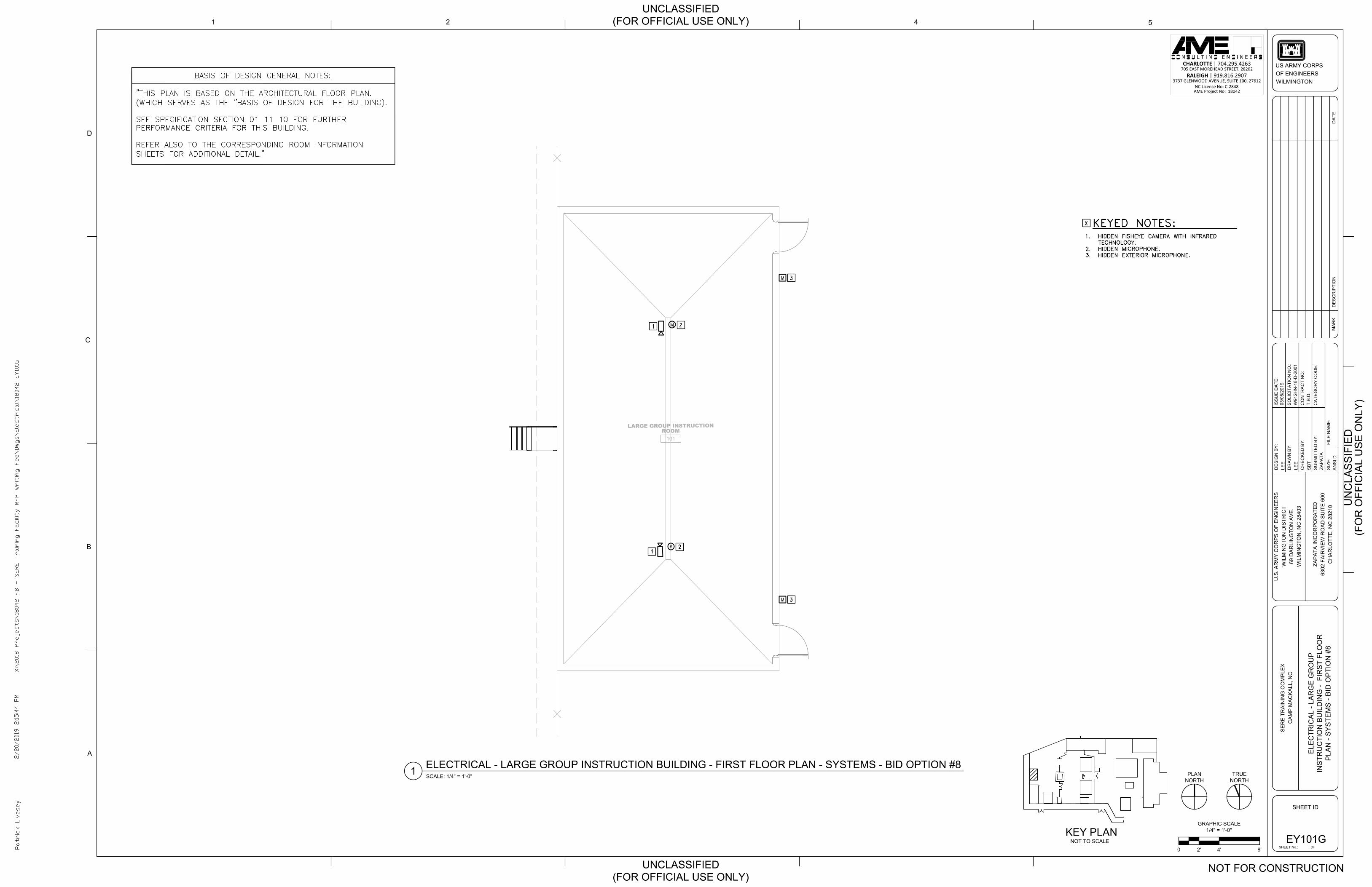
101
LARGE GROUP INSTRUCTIONROOM
CHARLOTTE | 704.295.4263705 EAST MOREHEAD STREET, 28202
RALEIGH | 919.816.29073737 GLENWOOD AVENUE, SUITE 100, 27612
NC License No: C-2848AME Project No: 18042
LEE
LEE
SB
T
1
D
2
C
4 5
A
B
SO
LIC
ITA
TIO
N N
O.:
FILE
NA
ME
:
DR
AW
N B
Y:
CH
EC
KE
D B
Y:
DE
SIG
N B
Y:
MA
RK
SHEET ID
US ARMY CORPSOF ENGINEERSWILMINGTON
ISS
UE
DA
TE:
SIZ
E:
SU
BM
ITTE
D B
Y:
DE
SC
RIP
TIO
ND
ATE
CO
NTR
AC
T N
O:
AN
SI D
03/0
8/20
19
W91
2HN
-18-
D-2
001
CA
TEG
OR
Y C
OD
E:
ZAP
ATA
ZAP
ATA
INC
OR
PO
RA
TED
6302
FA
IRV
IEW
RO
AD
SU
ITE
600
CH
AR
LOTT
E, N
C 2
8210
U.S
. AR
MY
CO
RP
S O
F E
NG
INE
ER
SW
ILM
ING
TON
DIS
TRIC
T69
DA
RLI
NG
TON
AV
E.
WIL
MIN
GTO
N, N
C 2
8403
SE
RE
TR
AIN
ING
CO
MP
LEX
CA
MP
MA
CK
ALL
, NC
UN
CLA
SS
IFIE
D
UNCLASSIFIED(FOR OFFICIAL USE ONLY)
UNCLASSIFIED(FOR OFFICIAL USE ONLY)
T.B
.D.
OFSHEET No.:
(FO
R O
FFIC
IAL
US
E O
NLY
)
NOT FOR CONSTRUCTION
KEY PLANNOT TO SCALE
GRAPHIC SCALE1/4" = 1'-0"
4'2'0 8'EY101G
ELE
CTR
ICA
L - L
AR
GE
GR
OU
PIN
STR
UC
TIO
N B
UIL
DIN
G -
FIR
ST
FLO
OR
PLA
N -
SY
STE
MS
- B
ID O
PTI
ON
#8
TRUENORTH
ELECTRICAL - LARGE GROUP INSTRUCTION BUILDING - FIRST FLOOR PLAN - SYSTEMS - BID OPTION #8SCALE: 1/4" = 1'-0"1 PLAN
NORTH
AutoCAD SHX Text
M
AutoCAD SHX Text
M
AutoCAD SHX Text
2
AutoCAD SHX Text
2
AutoCAD SHX Text
1
AutoCAD SHX Text
1
AutoCAD SHX Text
M
AutoCAD SHX Text
3
AutoCAD SHX Text
M
AutoCAD SHX Text
3
AutoCAD SHX Text
X:\2018 Projects\18042 FB - SERE Training Facility RFP Writing Fee\Dwgs\Electrical\18042 EY101G
AutoCAD SHX Text
2/20/2019 2:15:44 PM
AutoCAD SHX Text
Patrick Livesey
AutoCAD SHX Text
1. HIDDEN FISHEYE CAMERA WITH INFRARED HIDDEN FISHEYE CAMERA WITH INFRARED TECHNOLOGY. 2. HIDDEN MICROPHONE. HIDDEN MICROPHONE. 3. HIDDEN EXTERIOR MICROPHONE.HIDDEN EXTERIOR MICROPHONE.
AutoCAD SHX Text
KEYED NOTES:
AutoCAD SHX Text
X
AutoCAD SHX Text
BASIS OF DESIGN GENERAL NOTES: "THIS PLAN IS BASED ON THE ARCHITECTURAL FLOOR PLAN. (WHICH SERVES AS THE "BASIS OF DESIGN FOR THE BUILDING). SEE SPECIFICATION SECTION 01 11 10 FOR FURTHER PERFORMANCE CRITERIA FOR THIS BUILDING. REFER ALSO TO THE CORRESPONDING ROOM INFORMATION SHEETS FOR ADDITIONAL DETAIL."
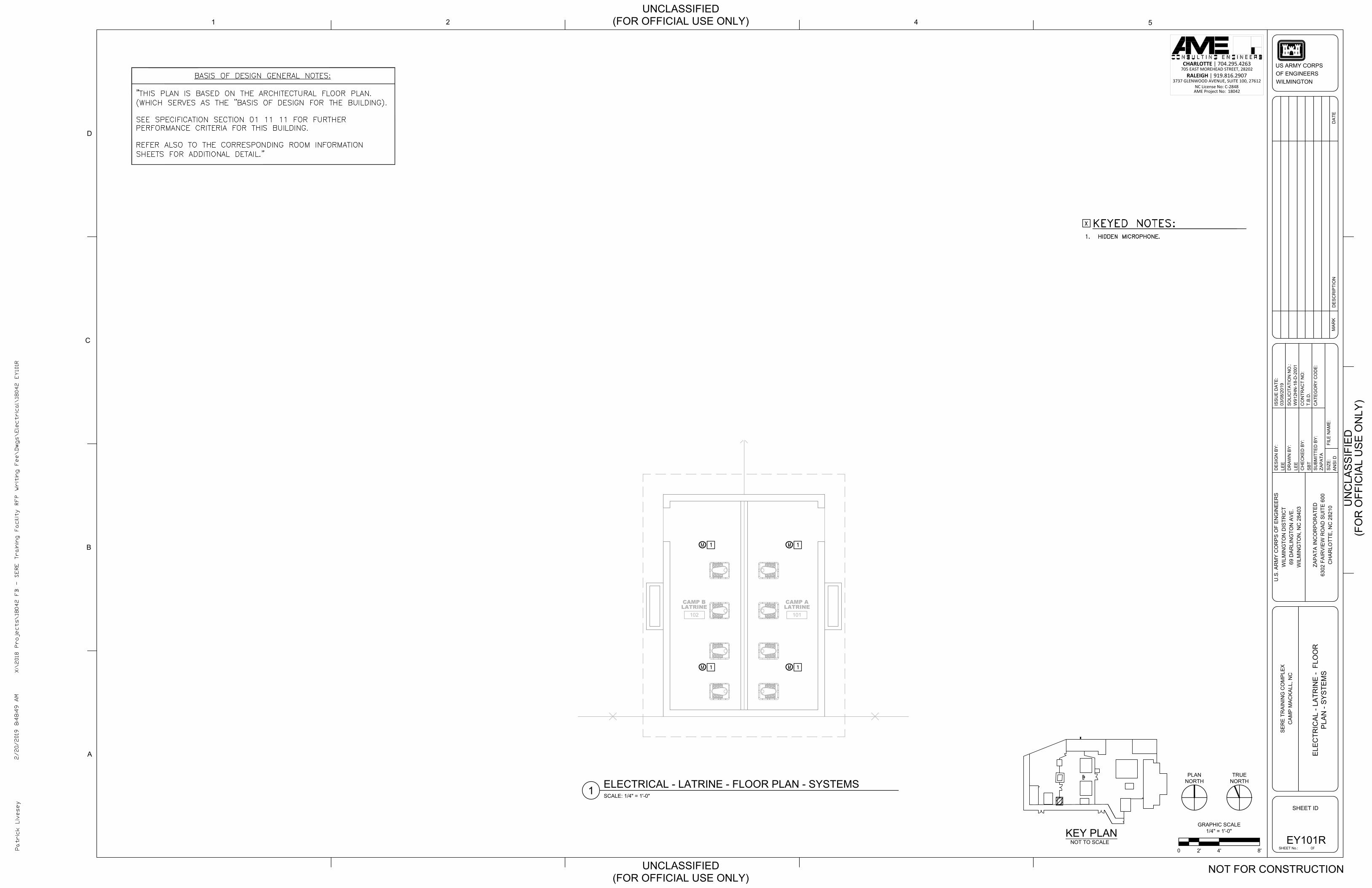
102
CAMP BLATRINE
101
CAMP ALATRINE
CHARLOTTE | 704.295.4263705 EAST MOREHEAD STREET, 28202
RALEIGH | 919.816.29073737 GLENWOOD AVENUE, SUITE 100, 27612
NC License No: C-2848AME Project No: 18042
LEE
LEE
SB
T
1
D
2
C
4 5
A
B
SO
LIC
ITA
TIO
N N
O.:
FILE
NA
ME
:
DR
AW
N B
Y:
CH
EC
KE
D B
Y:
DE
SIG
N B
Y:
MA
RK
SHEET ID
US ARMY CORPSOF ENGINEERSWILMINGTON
ISS
UE
DA
TE:
SIZ
E:
SU
BM
ITTE
D B
Y:
DE
SC
RIP
TIO
ND
ATE
CO
NTR
AC
T N
O:
AN
SI D
03/0
8/20
19
W91
2HN
-18-
D-2
001
CA
TEG
OR
Y C
OD
E:
ZAP
ATA
ZAP
ATA
INC
OR
PO
RA
TED
6302
FA
IRV
IEW
RO
AD
SU
ITE
600
CH
AR
LOTT
E, N
C 2
8210
U.S
. AR
MY
CO
RP
S O
F E
NG
INE
ER
SW
ILM
ING
TON
DIS
TRIC
T69
DA
RLI
NG
TON
AV
E.
WIL
MIN
GTO
N, N
C 2
8403
SE
RE
TR
AIN
ING
CO
MP
LEX
CA
MP
MA
CK
ALL
, NC
UN
CLA
SS
IFIE
D
UNCLASSIFIED(FOR OFFICIAL USE ONLY)
UNCLASSIFIED(FOR OFFICIAL USE ONLY)
T.B
.D.
OFSHEET No.:
(FO
R O
FFIC
IAL
US
E O
NLY
)
NOT FOR CONSTRUCTION
KEY PLANNOT TO SCALE
GRAPHIC SCALE1/4" = 1'-0"
4'2'0 8'EY101R
ELE
CTR
ICA
L - L
ATR
INE
- F
LOO
RP
LAN
- S
YS
TEM
S
TRUENORTHELECTRICAL - LATRINE - FLOOR PLAN - SYSTEMS
SCALE: 1/4" = 1'-0"1PLAN
NORTH
AutoCAD SHX Text
M
AutoCAD SHX Text
1
AutoCAD SHX Text
M
AutoCAD SHX Text
1
AutoCAD SHX Text
M
AutoCAD SHX Text
1
AutoCAD SHX Text
M
AutoCAD SHX Text
1
AutoCAD SHX Text
X:\2018 Projects\18042 FB - SERE Training Facility RFP Writing Fee\Dwgs\Electrical\18042 EY101R
AutoCAD SHX Text
2/20/2019 8:48:49 AM
AutoCAD SHX Text
Patrick Livesey
AutoCAD SHX Text
1.HIDDEN MICROPHONE.HIDDEN MICROPHONE.
AutoCAD SHX Text
KEYED NOTES:
AutoCAD SHX Text
X
AutoCAD SHX Text
BASIS OF DESIGN GENERAL NOTES: "THIS PLAN IS BASED ON THE ARCHITECTURAL FLOOR PLAN. (WHICH SERVES AS THE "BASIS OF DESIGN FOR THE BUILDING). SEE SPECIFICATION SECTION 01 11 11 FOR FURTHER PERFORMANCE CRITERIA FOR THIS BUILDING. REFER ALSO TO THE CORRESPONDING ROOM INFORMATION SHEETS FOR ADDITIONAL DETAIL."

102
CAMP BKITCHEN
101
CAMP AKITCHEN
CHARLOTTE | 704.295.4263705 EAST MOREHEAD STREET, 28202
RALEIGH | 919.816.29073737 GLENWOOD AVENUE, SUITE 100, 27612
NC License No: C-2848AME Project No: 18042
LEE
LEE
SB
T
1
D
2
C
4 5
A
B
SO
LIC
ITA
TIO
N N
O.:
FILE
NA
ME
:
DR
AW
N B
Y:
CH
EC
KE
D B
Y:
DE
SIG
N B
Y:
MA
RK
SHEET ID
US ARMY CORPSOF ENGINEERSWILMINGTON
ISS
UE
DA
TE:
SIZ
E:
SU
BM
ITTE
D B
Y:
DE
SC
RIP
TIO
ND
ATE
CO
NTR
AC
T N
O:
AN
SI D
03/0
8/20
19
W91
2HN
-18-
D-2
001
CA
TEG
OR
Y C
OD
E:
ZAP
ATA
ZAP
ATA
INC
OR
PO
RA
TED
6302
FA
IRV
IEW
RO
AD
SU
ITE
600
CH
AR
LOTT
E, N
C 2
8210
U.S
. AR
MY
CO
RP
S O
F E
NG
INE
ER
SW
ILM
ING
TON
DIS
TRIC
T69
DA
RLI
NG
TON
AV
E.
WIL
MIN
GTO
N, N
C 2
8403
SE
RE
TR
AIN
ING
CO
MP
LEX
CA
MP
MA
CK
ALL
, NC
UN
CLA
SS
IFIE
D
UNCLASSIFIED(FOR OFFICIAL USE ONLY)
UNCLASSIFIED(FOR OFFICIAL USE ONLY)
T.B
.D.
OFSHEET No.:
(FO
R O
FFIC
IAL
US
E O
NLY
)
NOT FOR CONSTRUCTION
KEY PLANNOT TO SCALE
GRAPHIC SCALE1/4" = 1'-0"
4'2'0 8'EY101K
ELE
CTR
ICA
L - K
ITC
HE
N -
FLO
OR
PLA
N -
SY
STE
MS
TRUENORTH
ELECTRICAL - KITCHEN - FLOOR PLAN - SYSTEMSSCALE: 1/4" = 1'-0"1
PLANNORTH
AutoCAD SHX Text
M
AutoCAD SHX Text
M
AutoCAD SHX Text
1
AutoCAD SHX Text
1
AutoCAD SHX Text
M
AutoCAD SHX Text
M
AutoCAD SHX Text
1
AutoCAD SHX Text
1
AutoCAD SHX Text
X:\2018 Projects\18042 FB - SERE Training Facility RFP Writing Fee\Dwgs\Electrical\18042 EY101K
AutoCAD SHX Text
2/20/2019 8:43:17 AM
AutoCAD SHX Text
Patrick Livesey
AutoCAD SHX Text
1.HIDDEN MICROPHONE.HIDDEN MICROPHONE.
AutoCAD SHX Text
KEYED NOTES:
AutoCAD SHX Text
X
AutoCAD SHX Text
BASIS OF DESIGN GENERAL NOTES: "THIS PLAN IS BASED ON THE ARCHITECTURAL FLOOR PLAN. (WHICH SERVES AS THE "BASIS OF DESIGN FOR THE BUILDING). SEE SPECIFICATION SECTION 01 11 12 FOR FURTHER PERFORMANCE CRITERIA FOR THIS BUILDING. REFER ALSO TO THE CORRESPONDING ROOM INFORMATION SHEETS FOR ADDITIONAL DETAIL."
SECTION 2
A/V PRODUCT CUTSHEETS
AME Consulting Engineers
705 E. Morehead St.
Charlotte, NC 28202
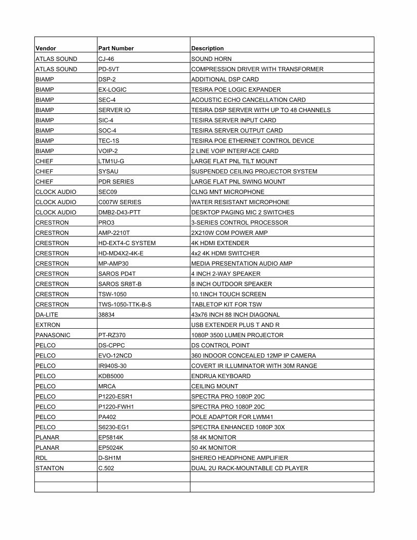
Vendor Part Number Description
ATLAS SOUND CJ-46 SOUND HORN
ATLAS SOUND PD-5VT COMPRESSION DRIVER WITH TRANSFORMER
BIAMP DSP-2 ADDITIONAL DSP CARD
BIAMP EX-LOGIC TESIRA POE LOGIC EXPANDER
BIAMP SEC-4 ACOUSTIC ECHO CANCELLATION CARD
BIAMP SERVER IO TESIRA DSP SERVER WITH UP TO 48 CHANNELS
BIAMP SIC-4 TESIRA SERVER INPUT CARD
BIAMP SOC-4 TESIRA SERVER OUTPUT CARD
BIAMP TEC-1S TESIRA POE ETHERNET CONTROL DEVICE
BIAMP VOIP-2 2 LINE VOIP INTERFACE CARD
CHIEF LTM1U-G LARGE FLAT PNL TILT MOUNT
CHIEF SYSAU SUSPENDED CEILING PROJECTOR SYSTEM
CHIEF PDR SERIES LARGE FLAT PNL SWING MOUNT
CLOCK AUDIO SEC09 CLNG MNT MICROPHONE
CLOCK AUDIO C007W SERIES WATER RESISTANT MICROPHONE
CLOCK AUDIO DMB2-D43-PTT DESKTOP PAGING MIC 2 SWITCHES
CRESTRON PRO3 3-SERIES CONTROL PROCESSOR
CRESTRON AMP-2210T 2X210W COM POWER AMP
CRESTRON HD-EXT4-C SYSTEM 4K HDMI EXTENDER
CRESTRON HD-MD4X2-4K-E 4x2 4K HDMI SWITCHER
CRESTRON MP-AMP30 MEDIA PRESENTATION AUDIO AMP
CRESTRON SAROS PD4T 4 INCH 2-WAY SPEAKER
CRESTRON SAROS SR8T-B 8 INCH OUTDOOR SPEAKER
CRESTRON TSW-1050 10.1INCH TOUCH SCREEN
CRESTRON TWS-1050-TTK-B-S TABLETOP KIT FOR TSW
DA-LITE 38834 43x76 INCH 88 INCH DIAGONAL
EXTRON USB EXTENDER PLUS T AND R
PANASONIC PT-RZ370 1080P 3500 LUMEN PROJECTOR
PELCO DS-CPPC DS CONTROL POINT
PELCO EVO-12NCD 360 INDOOR CONCEALED 12MP IP CAMERA
PELCO IR940S-30 COVERT IR ILLUMINATOR WITH 30M RANGE
PELCO KDB5000 ENDRUA KEYBOARD
PELCO MRCA CEILING MOUNT
PELCO P1220-ESR1 SPECTRA PRO 1080P 20C
PELCO P1220-FWH1 SPECTRA PRO 1080P 20C
PELCO PA402 POLE ADAPTOR FOR LWM41
PELCO S6230-EG1 SPECTRA ENHANCED 1080P 30X
PLANAR EP5814K 58 4K MONITOR
PLANAR EP5024K 50 4K MONITOR
RDL D-SH1M SHEREO HEADPHONE AMPLIFIER
STANTON C.502 DUAL 2U RACK-MOUNTABLE CD PLAYER

1601 JACK MCKAY BLVD. ENNIS, TEXAS 75119 U.S.A.TELEPHONE: (800) 876-3333FAX (800) 765-3435 AtlasSound.com 1/3
©20
11 A
tlas
Sou
nd L
.P. A
ll ri
ghts
res
erve
d. A
tlas
Sou
nd a
nd S
trat
egy
Ser
ies
are
trad
emar
ks o
f A
tlas
Sou
nd L
.P.
All
othe
r tr
adem
arks
are
the
pro
pert
y of
the
ir r
espe
ctiv
e ow
ners
. A
TS00
1744
Rev
C 6
/11
CJ-46Projector Horn For Wide-Angle Sound Dispersion
CJ-46
Features
• Directional High-Efficiency Reflex Sound Projector with Wide Angle Dispersion
• Equipped with Standard 13⁄8" - 18 Male Threads for Use with Compression Driver Units
• Heavy-Duty Positive Locking Steel Mounting Bracket for Secure Po si tion ing
• Environment-Resistant Con struc tion for Outdoor/Indoor Applications
Sound Pressure Levels of Model CJ-46 with Atlas Sound Compression Drivers
PD-30T 125dB
PD-5VH 127dB
PD-5VT 129dB
PD-60A/PD-60TA 129dB
SD-70 131dB
PD75T 131dB
Applications
Reflex projector Model CJ-46 is for directional sound and sig nalling distribution where wide-angle dispersion and maximum au di bil ity are re quired. Combine this weatherproof unit with a 13⁄8" - 18 male threaded com pres sion driver for use at various indoor/outdoor events where crowds gather in large areas. Model CJ-46 offers positioning flexibility for horizontal, vertical or stacked clusters enhancing its usage as a sound system com po nent at various out door ac tivi ties in clud ing political rallies and sport ing events. The wide-angle sound projector is also ideal for use with community warning systems and for in stal la tion in manu factur ing fa cili ties, ware houses, trans por ta tion ter mi nals, and rec rea tional buildings.
General Description
The all-purpose Model CJ-46 wide-angle sound projector screw mounts to Atlas Sound PD and SD Series compression driv ers to provide maximum audio penetration through adverse ambient sound levels and coverage over long distances. For versatile mount ing ap pli ca tions, Model CJ-46 features a heavy-duty steel mount ing bracket with positive lock for hori zon tal and vertical po si tion ing in single or stacked multi-unit clusters. To meet application re quire ments, the prime sound dis per sion axis may be changed from horizontal to vertical via a 90˚ bell rotation and four 1⁄4" screws. Model CJ-46 is a low silhouette reflex unit manufactured of non-resonant fiberglass with a spun aluminum re-entrant section. Weight is 141⁄2 lbs.
Specifications
Dispersion 120°
Low Frequency Cut Off 115Hz
Air Column Length 41⁄2'
Bell Size 22" x 12" (584 x 330mm)
Horn Length 17" (432mm)
Bracket 83⁄4" (222mm)
Architect and Engineer Specifications
Sound projector shall be Atlas Sound__________ (Model CJ-46) or ap proved equal. The weatherproof exponential-flared reflex type unit shall have an air column length of 41⁄2'. Low frequency cut-off shall be 115 Hz. Unit shall have a dispersion angle of 120˚ in the plane of narrower horn dimension and 60˚ in the wider dimension. It shall be supplied with coupler to accept 13⁄8" - 18 threaded com pres sion driver. The mount ing bracket shall be of steel with choice of prime directional sound dis tri bu tion emphasis via rotation of the horn bell. Bell size shall be 22" W x 12" H x 17"D. Sound projector shall be constructed of non-resonant fiberglass with spun aluminum re-entrant sec tion. Projector shall have a black finish and weigh 141⁄2 lbs.
MODEL CJ-46 with PD60A Beamwidth
Frequency Q Di Horizontal Vertical
500 6 8 85 125
1000 12 11 70 80
2000 20 13 65 45
4000 33 15 55 30
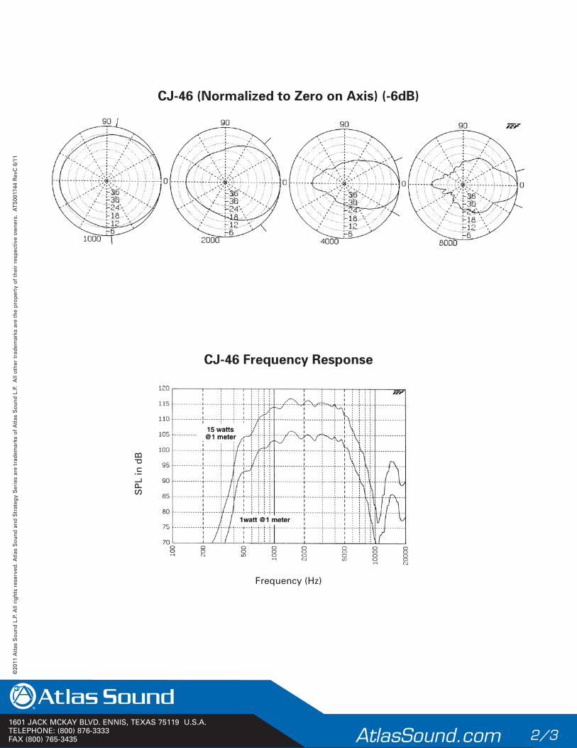
1601 JACK MCKAY BLVD. ENNIS, TEXAS 75119 U.S.A.TELEPHONE: (800) 876-3333FAX (800) 765-3435 AtlasSound.com 2/3
©20
11 A
tlas
Sou
nd L
.P. A
ll ri
ghts
res
erve
d. A
tlas
Sou
nd a
nd S
trat
egy
Ser
ies
are
trad
emar
ks o
f A
tlas
Sou
nd L
.P.
All
othe
r tr
adem
arks
are
the
pro
pert
y of
the
ir r
espe
ctiv
e ow
ners
. A
TS00
1744
Rev
C 6
/11
Frequency (Hz)
SP
L in
dB
CJ-46 Frequency Response
CJ-46 (Normalized to Zero on Axis) (-6dB)

1601 JACK MCKAY BLVD. ENNIS, TEXAS 75119 U.S.A.TELEPHONE: (800) 876-3333FAX (800) 765-3435 AtlasSound.com 3/3
©20
11 A
tlas
Sou
nd L
.P. A
ll ri
ghts
res
erve
d. A
tlas
Sou
nd a
nd S
trat
egy
Ser
ies
are
trad
emar
ks o
f A
tlas
Sou
nd L
.P.
All
othe
r tr
adem
arks
are
the
pro
pert
y of
the
ir r
espe
ctiv
e ow
ners
. A
TS00
1744
Rev
C 6
/11
Frequency (Hz) Octave Smoothing = 30.0%
Oh
ms
CJ-46 Impedance

1601 JACK MCKAY BLVD. ENNIS, TEXAS 75119 U.S.A.TELEPHONE: (800) 876-3333FAX (800) 765-3435 AtlasSound.com 1/4
©20
12 A
tlas
Sou
nd L
.P. A
ll ri
ghts
res
erve
d. A
tlas
Sou
nd a
nd S
trat
egy
Ser
ies
are
trad
emar
ks o
f A
tlas
Sou
nd L
.P.
All
othe
r tr
adem
arks
are
the
pro
pert
y of
the
ir r
espe
ctiv
e ow
ners
. A
TS00
4136
R
evA
7/
12
PD SeriesHigh Efficiency 40 Watt Compression Drivers
Features
• Powerful Driver Mounts to Large Format Horns to Deliver Outstanding Sound Reproduction for Music, Public Address, and Signaling Systems
• Extended Frequency Response Range for Optimum Intelligibility
• 40 Watt Power Rating
• Environment-Resistant Construction for both Indoor or Outdoor Use
• Offered With or Without Transformer
Applications
PD-5VH and PD-5VT are versatile 40 Watt compression drivers designed for use in conjunction with Atlas Sound large format horns Models CD Series, CJ-46, BIA-100, DR Series or other similar equipment. The drivers, which are most commonly used in commercial sound, signaling, and public-address systems, provide uniform, extended response and clear, natural sound reproduction in high and mid-range frequencies.
The high-power handling capacity of PD-5VH and PD-5VT enables the drivers to penetrate through high-ambient noise levels to deliver superior intelligibility in sizeable listening areas — even under the most demanding conditions. This performance capability makes the units ideal for a variety of applications including: recreational and athletic facilities, arenas, church towers, exhibit and meeting halls, civil defense and government facilities, transportation and storage terminals, factories, and warehouses.
Both the PD-5VH and transformer-equipped PD-5VT, are environment-resistant for dependable and long-term performance, indoors or outdoors.
General Description
Models PD-5VH and PD-5VT are similar in performance characteristics. Both are 40 Watt drivers with a sound chamber, phasing plug, magnetic-structure components machined to optimum tolerances and a 2" voice coil. The internal components are enclosed within a protective die-cast housing.
Model PD-5VH has an Alnico V-DG magnet which offers maximum temperature stability and optimizes output for yielding the lowest amplifier power requirements. It also provides terminals for matching direct to the 16Ω voice coil impedance. Model PD-5VT is equipped with a ceramic magnet and includes a built-in, varnish-impregnated, tropic-sealed, multi-tap 70.7V line-matching transformer, (also adaptable to 25V audio system operation) which offers a selection of terminals for matching to the appropriate impedance and power taps. The durable compression drivers mount easily to large format horns that terminate in the standard 13⁄8"–18 male coupling thread. Model PD-5VT is equipped with corrosion-resistant, screw-type, wiring terminals which are protected by a transparent impact-resistant plastic cover. The protective cover also provides strain relief for interconnecting cable. Diaphragms are replaceable with the appropriate equipment. Units are finished in grey, baked epoxy.
PD-5VH
PD-5VT
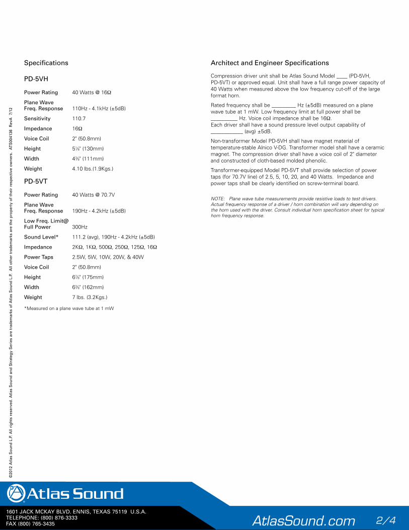
1601 JACK MCKAY BLVD. ENNIS, TEXAS 75119 U.S.A.TELEPHONE: (800) 876-3333FAX (800) 765-3435 AtlasSound.com 2/4
©20
12 A
tlas
Sou
nd L
.P. A
ll ri
ghts
res
erve
d. A
tlas
Sou
nd a
nd S
trat
egy
Ser
ies
are
trad
emar
ks o
f A
tlas
Sou
nd L
.P.
All
othe
r tr
adem
arks
are
the
pro
pert
y of
the
ir r
espe
ctiv
e ow
ners
. A
TS00
4136
R
evA
7/
12
Specifications
PD-5VH
Power Rating 40 Watts @ 16Ω
Plane Wave Freq. Response 110Hz - 4.1kHz (±5dB)
Sensitivity 110.7
Impedance 16Ω
Voice Coil 2" (50.8mm)
Height 51⁄8" (130mm)
Width 43⁄8" (111mm)
Weight 4.10 lbs.(1.9Kgs.)
PD-5VT
Power Rating 40 Watts @ 70.7V
Plane Wave Freq. Response 190Hz - 4.2kHz (±5dB)
Low Freq. Limit@ Full Power 300Hz
Sound Level* 111.2 (avg), 190Hz - 4.2kHz (±5dB)
Impedance 2KΩ, 1KΩ, 500Ω, 250Ω, 125Ω, 16Ω
Power Taps 2.5W, 5W, 10W, 20W, & 40W
Voice Coil 2" (50.8mm)
Height 67⁄8" (175mm)
Width 63⁄8" (162mm)
Weight 7 lbs. (3.2Kgs.)
*Measured on a plane wave tube at 1 mW
Architect and Engineer Speci fi ca tions
Compression driver unit shall be Atlas Sound Model ____ (PD-5VH, PD-5VT) or approved equal. Unit shall have a full range power capacity of 40 Watts when measured above the low frequency cut-off of the large format horn.
Rated frequency shall be _________ Hz (±5dB) measured on a plane wave tube at 1 mW. Low frequency limit at full power shall be __________ Hz. Voice coil impedance shall be 16Ω. Each driver shall have a sound pressure level output capability of ____________ (avg) ±5dB.
Non-transformer Model PD-5VH shall have magnet material of temperature-stable Alnico V-DG. Transformer model shall have a ceramic magnet. The compression driver shall have a voice coil of 2" diameter and constructed of cloth-based molded phenolic.
Transformer-equipped Model PD-5VT shall provide selection of power taps (for 70.7V line) of 2.5, 5, 10, 20, and 40 Watts. Impedance and power taps shall be clearly identified on screw-terminal board.
NOTE: Plane wave tube measurements provide resistive loads to test drivers. Actual frequency response of a driver / horn combination will vary depending on the horn used with the driver. Consult individual horn specification sheet for typical horn frequency response.
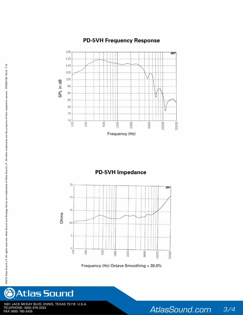
1601 JACK MCKAY BLVD. ENNIS, TEXAS 75119 U.S.A.TELEPHONE: (800) 876-3333FAX (800) 765-3435 AtlasSound.com 3/4
©20
12 A
tlas
Sou
nd L
.P. A
ll ri
ghts
res
erve
d. A
tlas
Sou
nd a
nd S
trat
egy
Ser
ies
are
trad
emar
ks o
f A
tlas
Sou
nd L
.P.
All
othe
r tr
adem
arks
are
the
pro
pert
y of
the
ir r
espe
ctiv
e ow
ners
. A
TS00
4136
R
evA
7/
12
Frequency (Hz)
SP
L in
dB
PD-5VH Frequency Response
Frequency (Hz) Octave Smoothing = 30.0%
Oh
ms
PD-5VH Impedance
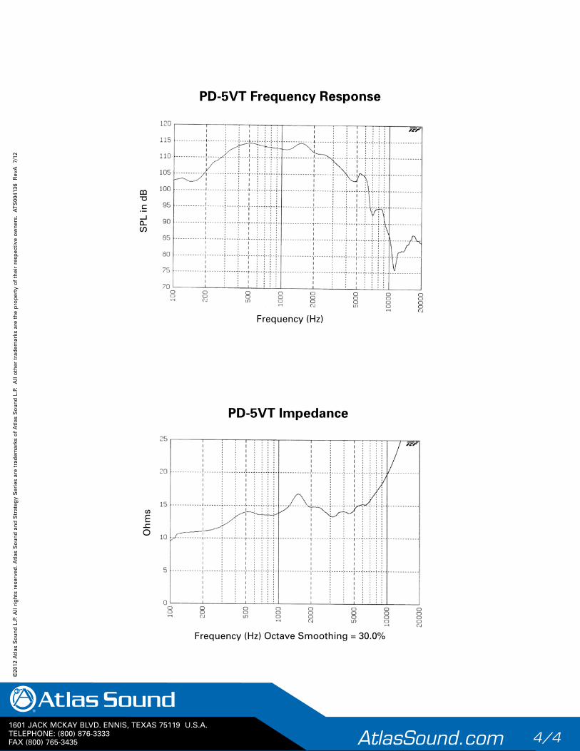
1601 JACK MCKAY BLVD. ENNIS, TEXAS 75119 U.S.A.TELEPHONE: (800) 876-3333FAX (800) 765-3435 AtlasSound.com 4/4
©20
12 A
tlas
Sou
nd L
.P. A
ll ri
ghts
res
erve
d. A
tlas
Sou
nd a
nd S
trat
egy
Ser
ies
are
trad
emar
ks o
f A
tlas
Sou
nd L
.P.
All
othe
r tr
adem
arks
are
the
pro
pert
y of
the
ir r
espe
ctiv
e ow
ners
. A
TS00
4136
R
evA
7/
12
Frequency (Hz) Octave Smoothing = 30.0%
Oh
ms
PD-5VT Impedance
Frequency (Hz)
SP
L in
dB
PD-5VT Frequency Response
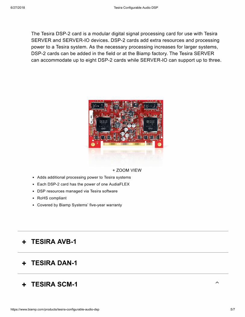
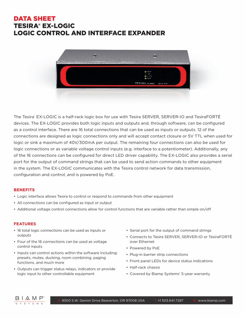
A: 9300 S.W. Gemini Drive Beaverton, OR 97008 USA T: +1 503.641.7287 W: www.biamp.com
FEATURES• 16 total logic connections can be used as inputs or
outputs
• Four of the 16 connections can be used as voltage control inputs
• Inputs can control actions within the software including: presets, mutes, ducking, room combining, paging functions, and much more
• Outputs can trigger status relays, indicators or provide logic input to other controllable equipment
• Serial port for the output of command strings
• Connects to Tesira SERVER, SERVER-IO or TesiraFORTÉ over Ethernet
• Powered by PoE
• Plug-in barrier strip connections
• Front panel LEDs for device status indications
• Half-rack chassis
• Covered by Biamp Systems’ 5-year warranty
BENEFITS• Logic interface allows Tesira to control or respond to commands from other equipment
• All connections can be configured as input or output
• Additional voltage control connections allow for control functions that are variable rather than simple on/off
The Tesira® EX-LOGIC is a half-rack logic box for use with Tesira SERVER, SERVER-IO and TesiraFORTÉ
devices. The EX-LOGIC provides both logic inputs and outputs and, through software, can be configured
as a control interface. There are 16 total connections that can be used as inputs or outputs. 12 of the
connections are designed as logic connections only and will accept contact closure or 5V TTL when used for
logic or sink a maximum of 40V/300mA per output. The remaining four connections can also be used for
logic connections or as variable voltage control inputs (e.g. interface to a potentiometer). Additionally, any
of the 16 connections can be configured for direct LED driver capability. The EX-LOGIC also provides a serial
port for the output of command strings that can be used to send action commands to other equipment
in the system. The EX-LOGIC communicates with the Tesira control network for data transmission,
configuration and control, and is powered by PoE.
DATA SHEETTESIRA® EX-LOGICLOGIC CONTROL AND INTERFACE EXPANDER
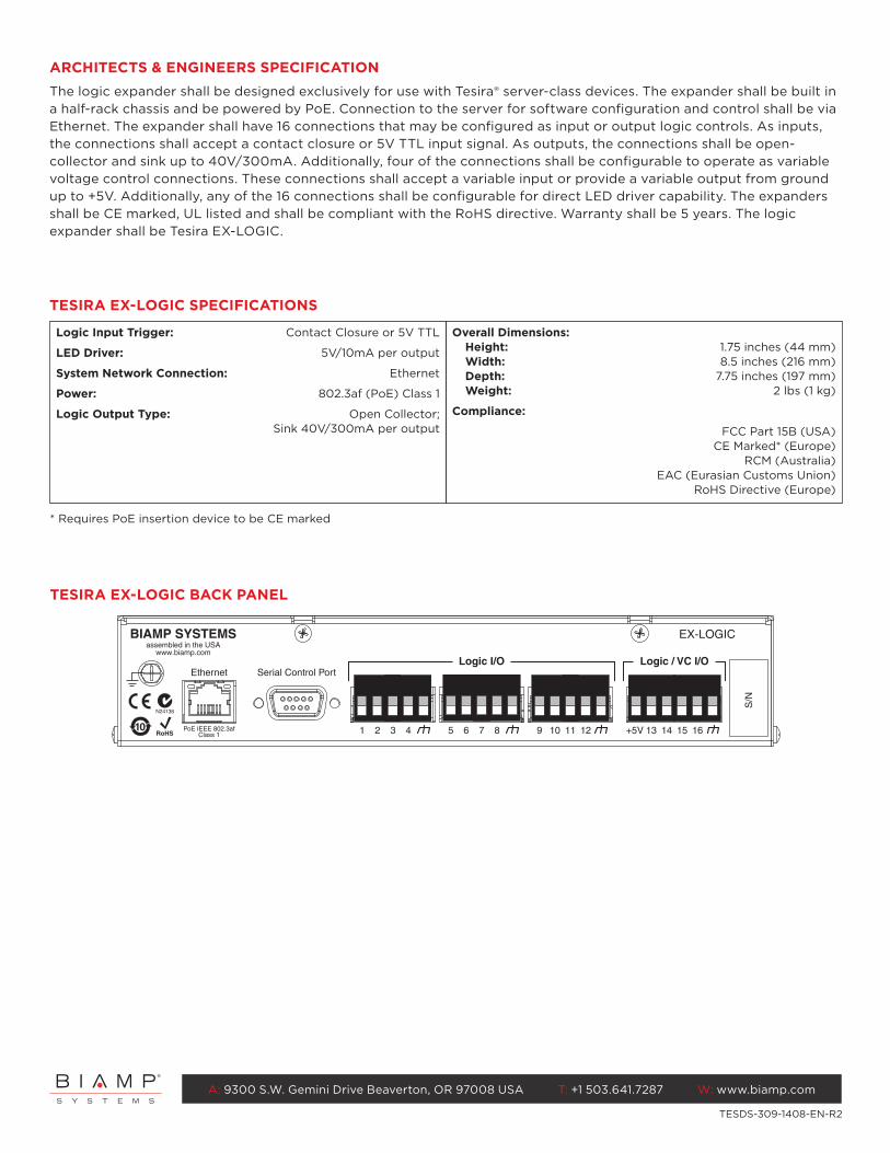
A: 9300 S.W. Gemini Drive Beaverton, OR 97008 USA T: +1 503.641.7287 W: www.biamp.com
S/N
1 2 3 4 5 6 7 8 9 10 11 12 13+5V 14 15 16
Logic I/O Serial Control PortEthernet
Logic / VC I/O
BIAMP SYSTEMSassembled in the USA
www.biamp.com
PoE IEEE 802.3afClass 1
EX-LOGIC
10
N24138
TESIRA EX-LOGIC BACK PANEL
ARCHITECTS & ENGINEERS SPECIFICATIONThe logic expander shall be designed exclusively for use with Tesira® server-class devices. The expander shall be built in a half-rack chassis and be powered by PoE. Connection to the server for software configuration and control shall be via Ethernet. The expander shall have 16 connections that may be configured as input or output logic controls. As inputs, the connections shall accept a contact closure or 5V TTL input signal. As outputs, the connections shall be open-collector and sink up to 40V/300mA. Additionally, four of the connections shall be configurable to operate as variable voltage control connections. These connections shall accept a variable input or provide a variable output from ground up to +5V. Additionally, any of the 16 connections shall be configurable for direct LED driver capability. The expanders shall be CE marked, UL listed and shall be compliant with the RoHS directive. Warranty shall be 5 years. The logic expander shall be Tesira EX-LOGIC.
TESDS-309-1408-EN-R2
* Requires PoE insertion device to be CE marked
TESIRA EX-LOGIC SPECIFICATIONS
Logic Input Trigger: Contact Closure or 5V TTL
LED Driver: 5V/10mA per output
System Network Connection: Ethernet
Power: 802.3af (PoE) Class 1
Logic Output Type: Open Collector; Sink 40V/300mA per output
Overall Dimensions:Height: 1.75 inches (44 mm) Width: 8.5 inches (216 mm) Depth: 7.75 inches (197 mm) Weight: 2 lbs (1 kg)
Compliance:
FCC Part 15B (USA)CE Marked* (Europe)
RCM (Australia)EAC (Eurasian Customs Union)
RoHS Directive (Europe)
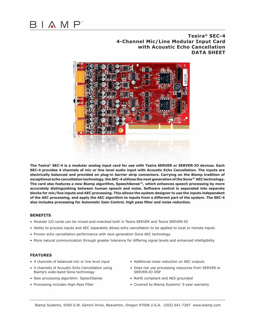
FEATURES• 4 channels of balanced mic or line level input
• 4 channels of Acoustic Echo Cancellation using Biamp’s wide-band Sona technology
• New processing algorithm: SpeechSense
• Processing includes High-Pass Filter
• Additional noise reduction on AEC outputs
• Does not use processing resources from SERVER or SERVER-IO DSP
• RoHS compliant and AES grounded
• Covered by Biamp Systems’ 5-year warranty
BENEFITS• Modular I/O cards can be mixed-and-matched both in Tesira SERVER and Tesira SERVER-IO
• Ability to process inputs and AEC separately allows echo cancellation to be applied to local or remote inputs
• Proven echo cancellation performance with next generation Sona AEC technology
• More natural communication through greater tolerance for differing signal levels and enhanced intelligibility
Tesira® SEC-44-Channel Mic/Line Modular Input Card
with Acoustic Echo CancellationDATA SHEET
Biamp Systems, 9300 S.W. Gemini Drive, Beaverton, Oregon 97008 U.S.A. (503) 641-7287 www.biamp.com
The Tesira® SEC-4 is a modular analog input card for use with Tesira SERVER or SERVER-IO devices. Each SEC-4 provides 4 channels of mic or line level audio input with Acoustic Echo Cancellation. The inputs are electrically balanced and provided on plug-in barrier strip connectors. Carrying on the Biamp tradition of exceptional echo cancellation technology, the SEC-4 utilizes the next generation of the Sona™ AEC technology. The card also features a new Biamp algorithm, SpeechSense™, which enhances speech processing by more accurately distinguishing between human speech and noise. Software control is separated into separate blocks for mic/line inputs and AEC processing. This allows the system designer to use the inputs independent of the AEC processing, and apply the AEC algorithm to inputs from a different part of the system. The SEC-4 also includes processing for Automatic Gain Control, high pass filter and noise reduction.
Biamp Systems, 9300 S.W. Gemini Drive, Beaverton, Oregon 97008 U.S.A. (503) 641-7287 www.biamp.com
15June11
SEC-4 SPECIFICATIONS
Frequency Response (20Hz~20kHz @ +4dBu):
+0/-0.25dB Phantom Power: +48 VDC (7mA/input)
THD+N (20Hz~20kHz @ +4dBu, AEC off): @ 0dB Gain (line level) @ 54dB Gain (mic level)
< 0.006% < 0.055%
Cross Talk (channel to channel @ 1kHz): @ 0dB Gain, +4dBu In @ 54dB Gain, -50dBu In
< 85dB < 75dB
Tail Length: up to 300ms Input Gain Range (6dB Steps): 0 - 66dB
Convergence: up to 100dB/sec Sampling Rate: 48kHz
EIN (20Hz~20kHz, 66dB Gain, 150Ω): < -125dBu A/D Converters: 24-bit
Dynamic Range (20Hz~20kHz, 0dB): > 108dB Compliance:AES48-2005 Grounding
and EMI practicesEU Directive 2002/95/EC,
RoHS Directive
Input Impedance (balanced): 8kΩ
Maximum Input: +24dBu
Maximum Gain: 66dB
ARCHITECTS & ENGINEERS SPECIFICATIONThe acoustic echo cancellation shall be a 4-channel card designed exclusively for use with Tesira Server devices. The modular card shall provide 4 balanced mic or line level inputs on plug-in barrier strip connections. Software configuration and control for each input shall include: gain with clip indicator, phantom power on/off, mute, level, and signal invert. The acoustic echo cancellation algorithm shall be configured and controlled separately in software and include processing for high-pass filtering, automatic gain control and noise reduction. Programmable parameters shall include: conferencing mode, noise reduction, threshold, mute and level. The modular input card shall incorporate AES48-2005 Grounding and EMC practices and shall be compliant with EU Directive 2002/95/EC, the RoHS Directive.Warranty shall be 5 years.The input card shall be Tesira SEC-4.
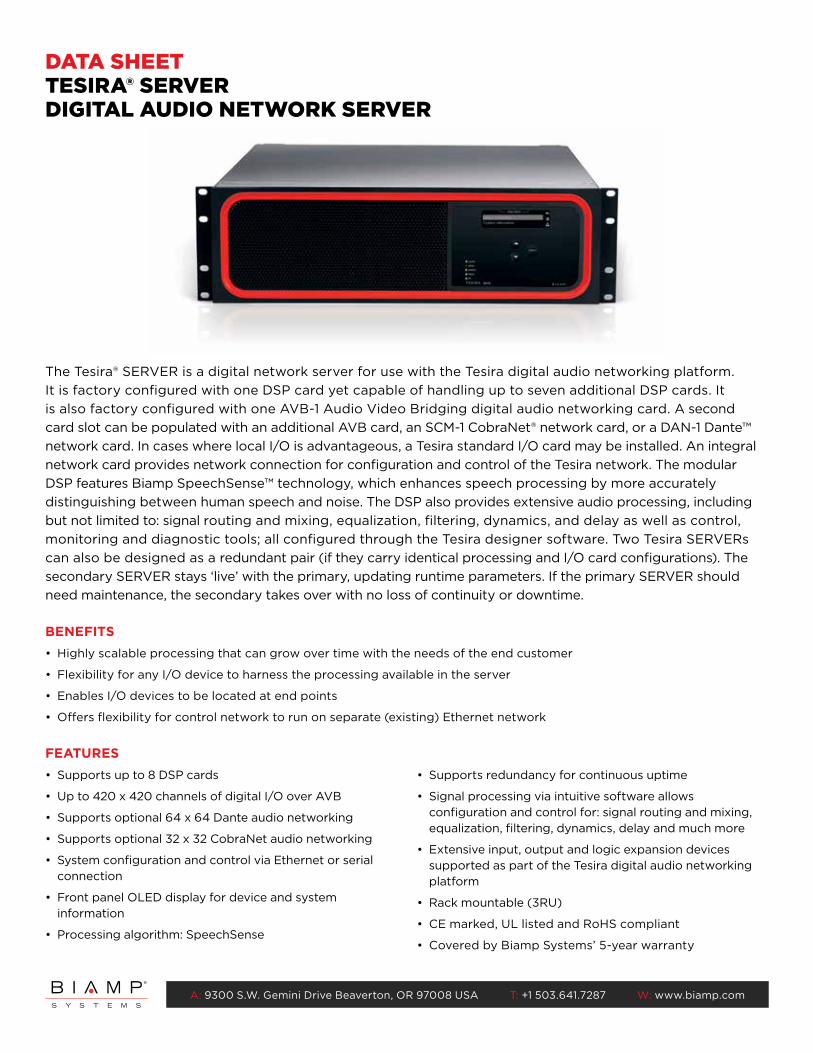
A: 9300 S.W. Gemini Drive Beaverton, OR 97008 USA T: +1 503.641.7287 W: www.biamp.com
FEATURES• Supports up to 8 DSP cards
• Up to 420 x 420 channels of digital I/O over AVB
• Supports optional 64 x 64 Dante audio networking
• Supports optional 32 x 32 CobraNet audio networking
• System configuration and control via Ethernet or serial connection
• Front panel OLED display for device and system information
• Processing algorithm: SpeechSense
• Supports redundancy for continuous uptime
• Signal processing via intuitive software allows configuration and control for: signal routing and mixing, equalization, filtering, dynamics, delay and much more
• Extensive input, output and logic expansion devices supported as part of the Tesira digital audio networking platform
• Rack mountable (3RU)
• CE marked, UL listed and RoHS compliant
• Covered by Biamp Systems’ 5-year warranty
BENEFITS• Highly scalable processing that can grow over time with the needs of the end customer
• Flexibility for any I/O device to harness the processing available in the server
• Enables I/O devices to be located at end points
• Offers flexibility for control network to run on separate (existing) Ethernet network
The Tesira® SERVER is a digital network server for use with the Tesira digital audio networking platform. It is factory configured with one DSP card yet capable of handling up to seven additional DSP cards. It is also factory configured with one AVB-1 Audio Video Bridging digital audio networking card. A second card slot can be populated with an additional AVB card, an SCM-1 CobraNet® network card, or a DAN-1 Dante™ network card. In cases where local I/O is advantageous, a Tesira standard I/O card may be installed. An integral network card provides network connection for configuration and control of the Tesira network. The modular DSP features Biamp SpeechSense™ technology, which enhances speech processing by more accurately distinguishing between human speech and noise. The DSP also provides extensive audio processing, including but not limited to: signal routing and mixing, equalization, filtering, dynamics, and delay as well as control, monitoring and diagnostic tools; all configured through the Tesira designer software. Two Tesira SERVERs can also be designed as a redundant pair (if they carry identical processing and I/O card configurations). The secondary SERVER stays ‘live’ with the primary, updating runtime parameters. If the primary SERVER should need maintenance, the secondary takes over with no loss of continuity or downtime.
DATA SHEETTESIRA® SERVERDIGITAL AUDIO NETWORK SERVER

A: 9300 S.W. Gemini Drive Beaverton, OR 97008 USA T: +1 503.641.7287 W: www.biamp.com
S/N
1234
+5V
SNC-2
Primary
Secondary
Logic I/O
123BIAMP SYSTEMS
SERVER
assembled in the USAwww.biamp.com
10N24138N24138
GREEN connectors = INPUTSORANGE connectors = AEC INPUTSBLUE connectors = ANC INPUTSBLACK connectors = OUTPUTSUS: 6RMBR00BSTC-2, Complies with FCC Part 68IC: 3184A-STC24HW3
100 - 240V~50/60Hz 5.5 - 2.3A
Serial 1
Serial 2
AVB-1
Primary
Secondary
AVBconnections
only
TESIRA SERVER BACK PANEL
ARCHITECTS & ENGINEERS SPECIFICATIONThe digital audio network server shall be designed exclusively for use with Tesira® systems. The server shall support AVB digital audio and control networking by means of a factory configured 420 x 420 modular card. The server shall also support an additional 420 x 420 channel AVB networking card, one 32 x 32 channel CobraNet® networking card, one 64 x 64 channel Dante™ networking card, or one standard analog I/O card. The server shall be factory configured with one DSP card and shall be capable of supporting a total of eight cards. The server shall provide dual Ethernet ports for configuration and control connection. The server shall support redundancy if both the primary secondary units are identically configured. The server shall provide front panel LED identification of server power, status, alarm, and activity as well as system-wide alarm. The server shall provide front panel OLED display for server and system information. The server shall be rack mountable (3RU) and feature software-configurable signal processing, including but not limited to: signal routing and mixing, equalization, filtering, dynamics, and delay, as well as control, monitoring, and diagnostic tools. The server shall be CE marked, UL listed and shall be compliant with the RoHS directive. Warranty shall be 5 years. The digital audio network server shall be Tesira SERVER.
TESDS-305-1408-EN-R1
TESIRA SERVER SPECIFICATIONS (AUDIO SPECIFICATIONS GIVEN REFLECT USE OF SIC-4 AND SOC-4)
Frequency Response (20Hz~20kHz @ +4dBu): +0/-0.25dB
THD+N (20Hz~20kHz):@ 0dB Gain, +4dBu In: < 0.006% @ 54dB Gain, -50dBu In: < 0.040%
EIN (20Hz~20kHz, 66dB Gain, 150Ω): < -125dBu
Dynamic Range (20Hz~20kHz, 0dB): > 108dB
Tail Length: up to 300ms
Convergence: up to 100dB/sec
Input Impedance (balanced): 8kΩ
Maximum Input: +24dBu
Input Gain Range (6dB Steps): 0 - 66dB
Output Impedance (balanced): 200Ω
Maximum Output: +24dBu
Power Consumption (100~240VAC 50/60Hz): < 150W
Phantom Power: +48 VDC (7mA/input)
Cross Talk (channel to channel @ 1kHz):@ 0dB Gain, +4dBu In: < -85dB @ 54dB Gain, -50dBu In: < -75dB
Overall Dimensions:Height: 5.25 inches (133 mm) Width: 19.0 inches (483 mm) Depth: 17.0 inches (432 mm) Weight: 18 lbs (8.2 kg)
Sampling Rate: 48kHz
A/D Converters: 24-bit
Compliance:FCC Part 15B (USA)FCC Part 68 (USA)
Industry Canada CS-03 (Canada)CE marked (Europe)
UL and C-UL listed (USA & Canada)RCM (Australia)
EAC (Eurasian Customs Union)RoHS Directive (Europe)

FEATURES
• 4channelsofbalancedmicorlinelevelinput
• Plug-inbarrierstripconnectors
• 0–66dBgain,adjustablein6dBincrements
• Clipindicator
• +48VPhantomPower
• -100to+12dBfaderrangeforlevel
• Signalinvertforreversepolarity
• RoHScompliantandAESgrounded
• CoveredbyBiampSystems’5-yearwarranty
BENEFITS
• ModularI/Ocardscanbemixed-and-matchedbothinTesiraSERVERandTesiraSERVER-IO
• Largeinputgainsensitivityallowsforanaloginputfromvirtuallyanysource
• Fullyconfigurableandcontrollablewithsoftware
• Premiumqualitypre-ampforclean,naturalsound
ARCHITECTS & ENGINEERS SPECIFICATION
Themic/lineinputshallbea4-channelcarddesignedexclusivelyforusewithTesiraServerdevices.Themodularcard shall provide4 balanced inputs onplug-in barrier strip connections.Software configuration and control foreachinputshallinclude:gainwithclipindication,phantompoweron/off,mute,level,andsignalinvert.Analog-to-Digitalconversionshallbe24-bitwithasamplingrateof48kHz.Performancespecifications(20Hz˜20kHz)shallbe:FrequencyResponse+0/-0.25dB;THD+N<0.006%(line),<0.040%(mic);EIN<-125dBu;andDynamicRange>108dB.ThemodularinputcardshallincorporateAES48-2005GroundingandEMCpracticesandshallbecompliantwithEUDirective2002/95/EC,theRoHSDirective.Warrantyshallbe5years.TheinputcardshallbeTesiraSIC-4.
Tesira® SIC-44-Channel Mic/Line Modular Input Card
DATA SHEET
BiampSystems,9300S.W.GeminiDrive,Beaverton,Oregon97008U.S.A.(503)641-7287www.biamp.com
The Tesira® SIC-4 is a modular analog input card for use with Tesira SERVER and SERVER-IO devices. Each SIC-4 provides 4 channels of Mic or Line level audio input. The inputs are electrically balanced and provided on plug-in barrier strip connectors. Software control of each input includes gain with clip indicator, +48V phantom power, mute, level and signal invert.
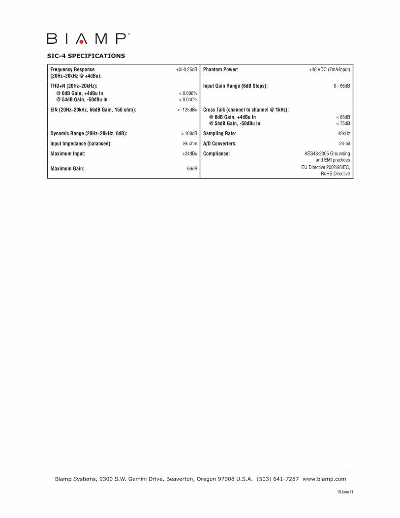
BiampSystems,9300S.W.GeminiDrive,Beaverton,Oregon97008U.S.A.(503)641-7287www.biamp.com
15June11
SIC-4 SPECIFICATIONS
Frequency Response (20Hz~20kHz @ +4dBu):
+0/-0.25dB Phantom Power: +48 VDC (7mA/input)
THD+N (20Hz~20kHz): @ 0dB Gain, +4dBu In @ 54dB Gain, -50dBu In
< 0.006% < 0.040%
Input Gain Range (6dB Steps): 0 - 66dB
EIN (20Hz~20kHz, 66dB Gain, 150 ohm): < -125dBu Cross Talk (channel to channel @ 1kHz): @ 0dB Gain, +4dBu In @ 54dB Gain, -50dBu In
< 85dB < 75dB
Dynamic Range (20Hz~20kHz, 0dB): > 108dB Sampling Rate: 48kHz
Input Impedance (balanced): 8k ohm A/D Converters: 24-bit
Maximum Input: +24dBu Compliance: AES48-2005 Grounding and EMI practices
EU Directive 2002/95/EC, RoHS Directive
Maximum Gain: 66dB
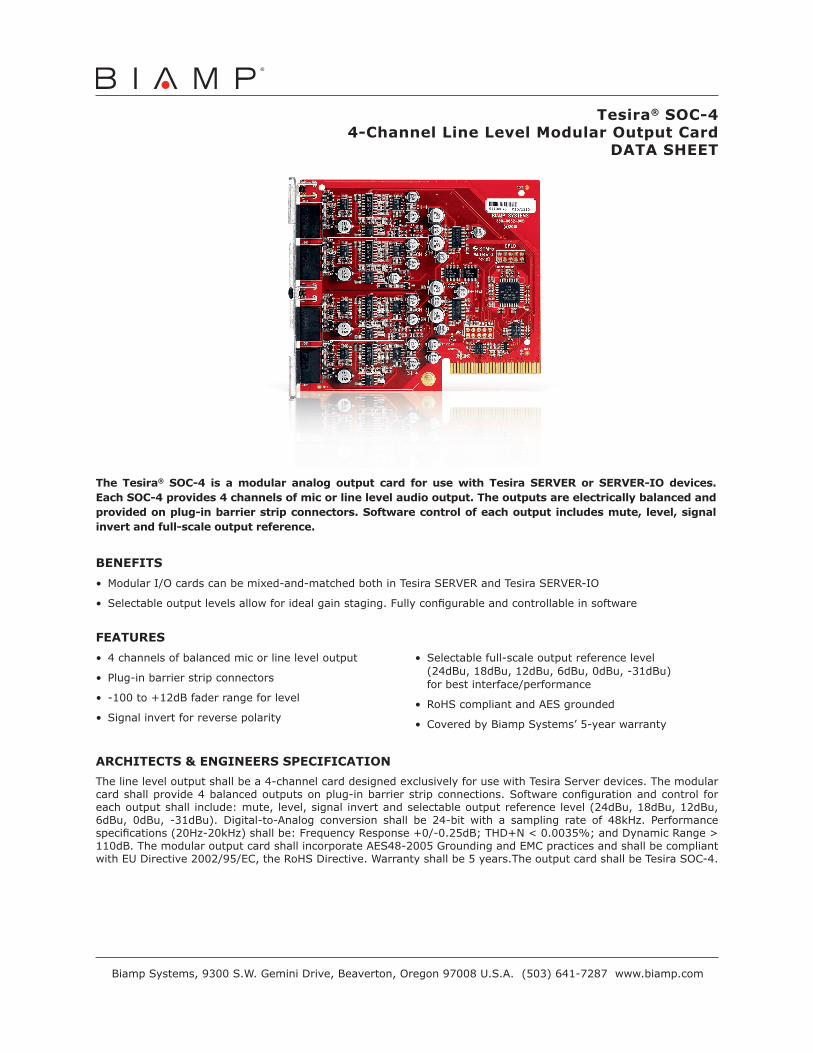
FEATURES• 4channelsofbalancedmicorlineleveloutput
• Plug-inbarrierstripconnectors
• -100to+12dBfaderrangeforlevel
• Signalinvertforreversepolarity
• Selectablefull-scaleoutputreferencelevel(24dBu,18dBu,12dBu,6dBu,0dBu,-31dBu)forbestinterface/performance
• RoHScompliantandAESgrounded
• CoveredbyBiampSystems’5-yearwarranty
BENEFITS• ModularI/Ocardscanbemixed-and-matchedbothinTesiraSERVERandTesiraSERVER-IO
• Selectableoutputlevelsallowforidealgainstaging.Fullyconfigurableandcontrollableinsoftware
ARCHITECTS & ENGINEERS SPECIFICATIONThelineleveloutputshallbea4-channelcarddesignedexclusivelyforusewithTesiraServerdevices.Themodularcardshallprovide4balancedoutputsonplug-inbarrierstripconnections.Softwareconfigurationandcontrol foreachoutputshall include:mute,level,signalinvertandselectableoutputreferencelevel(24dBu,18dBu,12dBu,6dBu, 0dBu, -31dBu). Digital-to-Analog conversion shall be 24-bit with a sampling rate of 48kHz. Performancespecifications(20Hz-20kHz)shallbe:FrequencyResponse+0/-0.25dB;THD+N<0.0035%;andDynamicRange>110dB.ThemodularoutputcardshallincorporateAES48-2005GroundingandEMCpracticesandshallbecompliantwithEUDirective2002/95/EC,theRoHSDirective.Warrantyshallbe5years.TheoutputcardshallbeTesiraSOC-4.
Tesira® SOC-44-Channel Line Level Modular Output Card
DATA SHEET
BiampSystems,9300S.W.GeminiDrive,Beaverton,Oregon97008U.S.A.(503)641-7287www.biamp.com
The Tesira® SOC-4 is a modular analog output card for use with Tesira SERVER or SERVER-IO devices. Each SOC-4 provides 4 channels of mic or line level audio output. The outputs are electrically balanced and provided on plug-in barrier strip connectors. Software control of each output includes mute, level, signal invert and full-scale output reference.

BiampSystems,9300S.W.GeminiDrive,Beaverton,Oregon97008U.S.A.(503)641-7287www.biamp.com
15June11
SOC-4 SPECIFICATIONS
Frequency Response (20Hz~20kHz @ +4dBu):
+0/-0.25dB
Sampling Rate: 48kHz
THD+N (20Hz~20kHz): < 0.0035% D/A Converters: 24-bit
Dynamic Range (20Hz~20kHz, 0dB):
> 110dB
Selectable Full Scale Output Levels: +24dBu, +18dBu, +12dBu, +6dBu, 0dBu, -31dBu
Output Impedance (balanced): 200Ω Compliance:AES48-2005 Grounding
and EMI practicesEU Directive 2002/95/EC,
RoHS Directive
Maximum Output: +24dBu
Cross Talk (channel to channel @ 1kHz): < -95dB
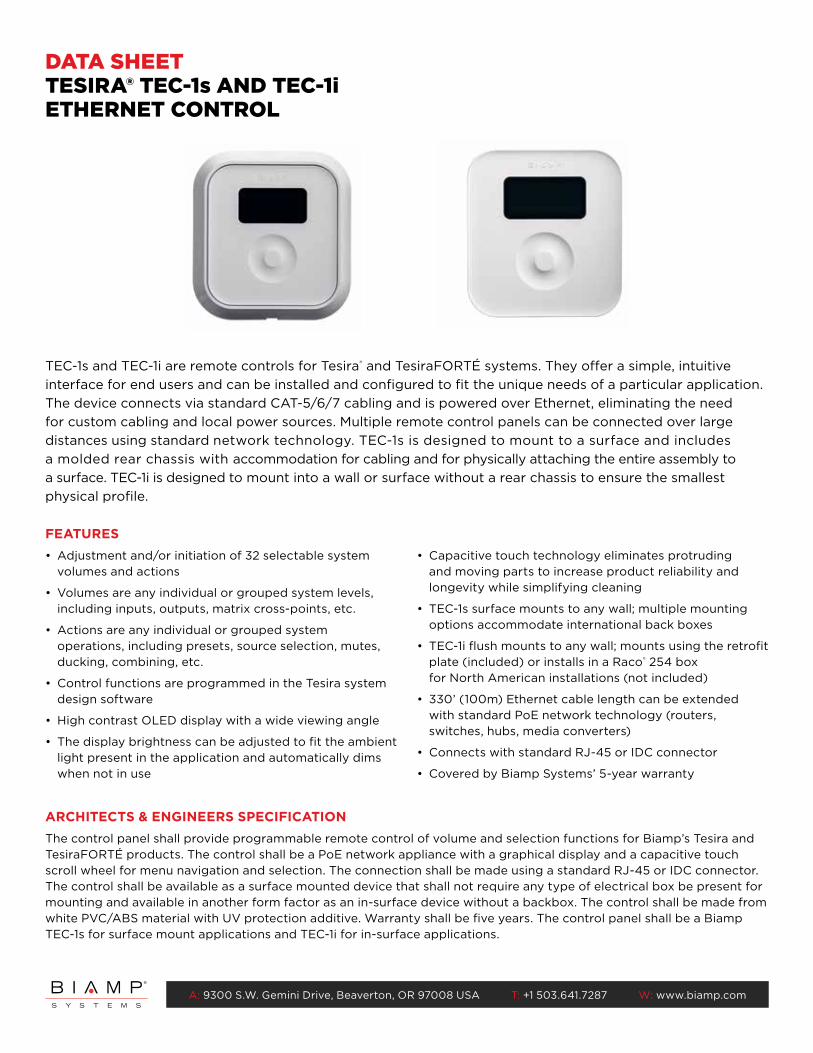
A: 9300 S.W. Gemini Drive, Beaverton, OR 97008 USA T: +1 503.641.7287 W: www.biamp.com
FEATURES• Adjustment and/or initiation of 32 selectable system
volumes and actions
• Volumes are any individual or grouped system levels, including inputs, outputs, matrix cross-points, etc.
• Actions are any individual or grouped system operations, including presets, source selection, mutes, ducking, combining, etc.
• Control functions are programmed in the Tesira system design software
• High contrast OLED display with a wide viewing angle
• The display brightness can be adjusted to fit the ambient light present in the application and automatically dims when not in use
• Capacitive touch technology eliminates protruding and moving parts to increase product reliability and longevity while simplifying cleaning
• TEC-1s surface mounts to any wall; multiple mounting options accommodate international back boxes
• TEC-1i flush mounts to any wall; mounts using the retrofit plate (included) or installs in a Raco® 254 box for North American installations (not included)
• 330’ (100m) Ethernet cable length can be extended with standard PoE network technology (routers, switches, hubs, media converters)
• Connects with standard RJ-45 or IDC connector
• Covered by Biamp Systems’ 5-year warranty
TEC-1s and TEC-1i are remote controls for Tesira® and TesiraFORTÉ systems. They offer a simple, intuitive interface for end users and can be installed and configured to fit the unique needs of a particular application. The device connects via standard CAT-5/6/7 cabling and is powered over Ethernet, eliminating the need for custom cabling and local power sources. Multiple remote control panels can be connected over large distances using standard network technology. TEC-1s is designed to mount to a surface and includes a molded rear chassis with accommodation for cabling and for physically attaching the entire assembly to a surface. TEC-1i is designed to mount into a wall or surface without a rear chassis to ensure the smallest physical profile.
DATA SHEETTESIRA® TEC-1s AND TEC-1iETHERNET CONTROL
ARCHITECTS & ENGINEERS SPECIFICATIONThe control panel shall provide programmable remote control of volume and selection functions for Biamp’s Tesira and TesiraFORTÉ products. The control shall be a PoE network appliance with a graphical display and a capacitive touch scroll wheel for menu navigation and selection. The connection shall be made using a standard RJ-45 or IDC connector. The control shall be available as a surface mounted device that shall not require any type of electrical box be present for mounting and available in another form factor as an in-surface device without a backbox. The control shall be made from white PVC/ABS material with UV protection additive. Warranty shall be five years. The control panel shall be a Biamp TEC-1s for surface mount applications and TEC-1i for in-surface applications.
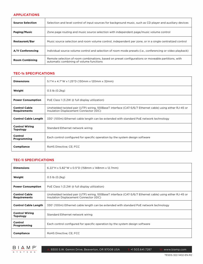
A: 9300 S.W. Gemini Drive, Beaverton, OR 97008 USA T: +1 503.641.7287 W: www.biamp.com
APPLICATIONS
Source Selection Selection and level control of input sources for background music, such as CD player and auxiliary devices
Paging/Music Zone page routing and music source selection with independent page/music volume control
Restaurant/Bar Music source selection and room volume control, independent per zone, or in a single centralized control
A/V Conferencing Individual source volume control and selection of room mode presets (i.e., conferencing or video playback)
Room Combining Remote selection of room combinations, based on preset configurations or moveable partitions, with automatic combining of volume functions
TEC-1s SPECIFICATIONS
Dimensions 5.1”H x 4.7"W x 1.25"D (130mm x 120mm x 32mm)
Weight 0.5 lb (0.2kg)
Power Consumption PoE Class 1 (3.2W @ full display utilization)
Control Cable Requirements
Unshielded twisted pair (UTP) wiring, 100BaseT interface (CAT-5/6/7 Ethernet cable) using either RJ-45 or Insulation Displacement Connector (IDC)
Control Cable Length 330' (100m) Ethernet cable length can be extended with standard PoE network technology
Control Wiring Topology Standard Ethernet network wiring
Control Programming Each control configured for specific operation by the system design software
Compliance RoHS Directive; CE; FCC
TEC-1i SPECIFICATIONS
Dimensions 6.22"H x 5.82"W x 0.5"D (158mm x 148mm x 12.7mm)
Weight 0.5 lb (0.2kg)
Power Consumption PoE Class 1 (3.2W @ full display utilization)
Control Cable Requirements
Unshielded twisted pair (UTP) wiring, 100BaseT interface (CAT-5/6/7 Ethernet cable) using either RJ-45 or Insulation Displacement Connector (IDC)
Control Cable Length 330' (100m) Ethernet cable length can be extended with standard PoE network technology
Control Wiring Topology Standard Ethernet network wiring
Control Programming Each control configured for specific operation by the system design software
Compliance RoHS Directive; CE; FCC
TESDS-322-1402-EN-R2
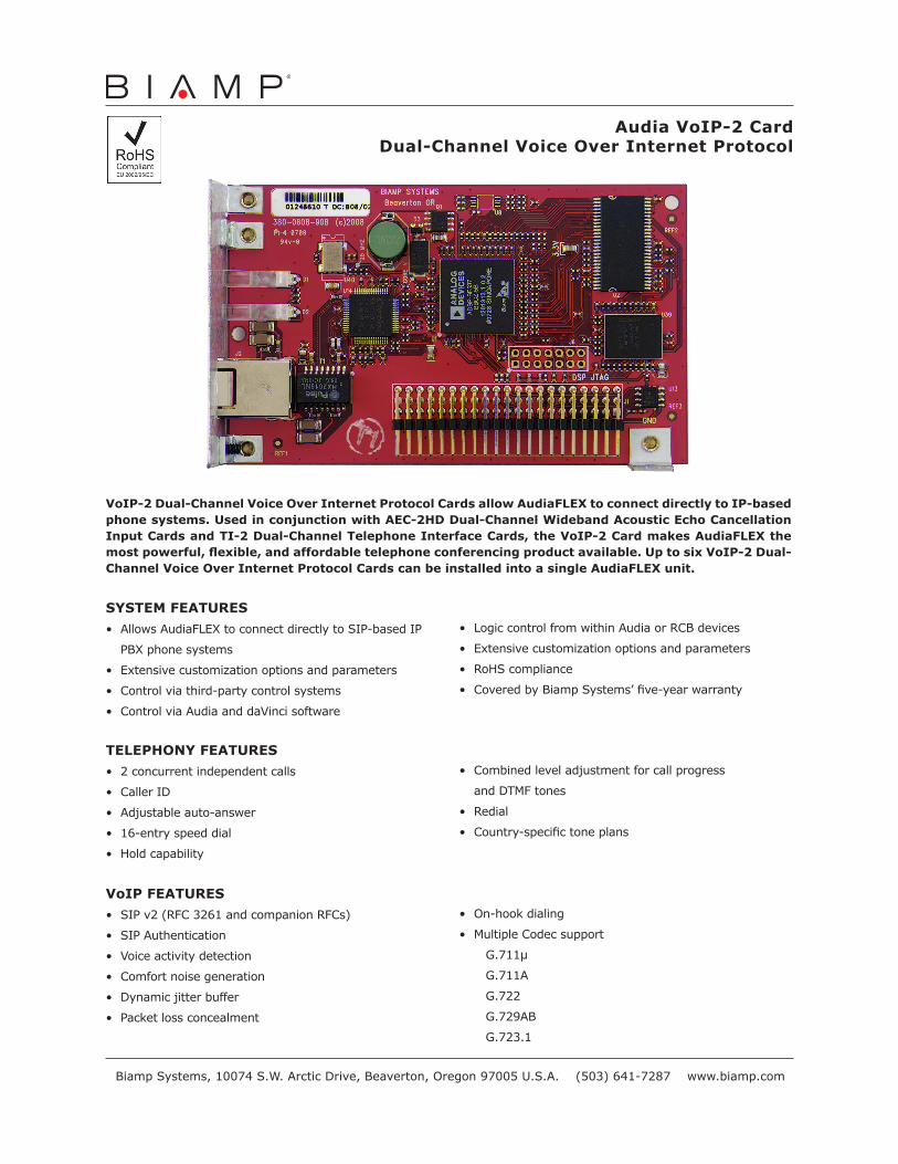
VoIP-2 Dual-Channel Voice Over Internet Protocol Cards allow AudiaFLEX to connect directly to IP-based phone systems. Used in conjunction with AEC-2HD Dual-Channel Wideband Acoustic Echo Cancellation Input Cards and TI-2 Dual-Channel Telephone Interface Cards, the VoIP-2 Card makes AudiaFLEX the most powerful, flexible, and affordable telephone conferencing product available. Up to six VoIP-2 Dual-Channel Voice Over Internet Protocol Cards can be installed into a single AudiaFLEX unit.
SYSTEM FEATURES
• AllowsAudiaFLEXtoconnectdirectlytoSIP-basedIP
PBXphonesystems
• Extensivecustomizationoptionsandparameters
• Controlviathird-partycontrolsystems
• ControlviaAudiaanddaVincisoftware
• LogiccontrolfromwithinAudiaorRCBdevices
• Extensivecustomizationoptionsandparameters
• RoHScompliance
• CoveredbyBiampSystems’five-yearwarranty
TELEPHONY FEATURES
• 2concurrentindependentcalls
• CallerID
• Adjustableauto-answer
• 16-entryspeeddial
• Holdcapability
• Combinedleveladjustmentforcallprogress
andDTMFtones
• Redial
• Country-specifictoneplans
VoIP FEATURES
• SIPv2(RFC3261andcompanionRFCs)
• SIPAuthentication
• Voiceactivitydetection
• Comfortnoisegeneration
• Dynamicjitterbuffer
• Packetlossconcealment
• On-hookdialing
• MultipleCodecsupport
G.711µ
G.711A
G.722
G.729AB
G.723.1
Audia VoIP-2 CardDual-Channel Voice Over Internet Protocol
BiampSystems,10074S.W.ArcticDrive,Beaverton,Oregon97005U.S.A.(503)641-7287www.biamp.com
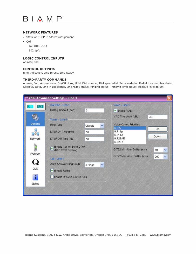
NETWORK FEATURES
• StaticorDHCPIPaddressassignment
• QoS
ToS(RFC791)
802.1p/q
LOGIC CONTROL INPUTSAnswer,End.
CONTROL OUTPUTS RingIndication,LineInUse,LineReady.
THIRD-PARTY COMMANDSAnswer,End,Auto-answer,On/OffHook,Hold,Dialnumber,Dialspeed-dial,Setspeed-dial,Redial,Lastnumberdialed,CallerIDData,Lineinusestatus,Linereadystatus,Ringingstatus,Transmitleveladjust,Receiveleveladjust.
BiampSystems,10074S.W.ArcticDrive,Beaverton,Oregon97005U.S.A.(503)641-7287www.biamp.com

I N S T A L L A T I O N I N S T R U C T I O N S
LSM1ULTM1U
MSM1UMTM1U
FUSION HEIGHT ADJUST
FLAT PANEL MOUNTS
Spanish Product Description
German Product Description
Portuguese Product Description
Italian Product Description
MSM1U / MTM1U /LSM1U / LTM1U
PLivesey
Highlight
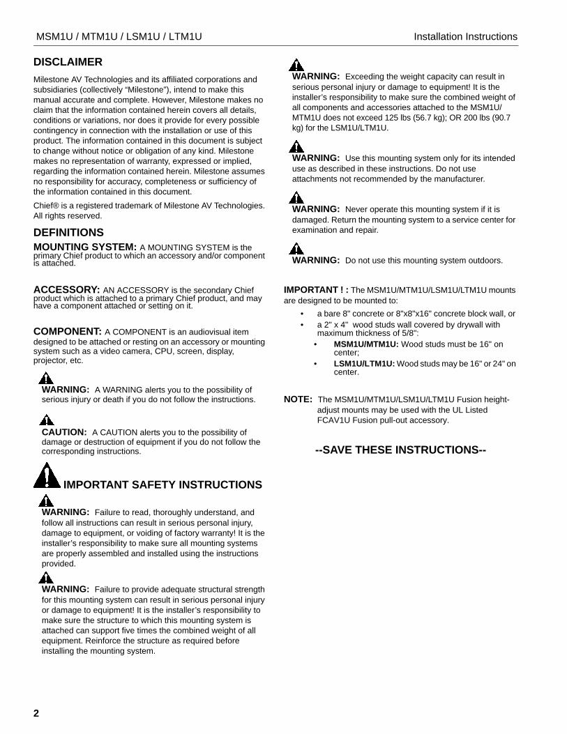
MSM1U / MTM1U / LSM1U / LTM1U Installation Instructions
2
DISCLAIMER
Milestone AV Technologies and its affiliated corporations and
subsidiaries (collectively “Milestone”), intend to make this
manual accurate and complete. However, Milestone makes no
claim that the information contained herein covers all details,
conditions or variations, nor does it provide for every possible
contingency in connection with the installation or use of this
product. The information contained in this document is subject
to change without notice or obligation of any kind. Milestone
makes no representation of warranty, expressed or implied,
regarding the information contained herein. Milestone assumes
no responsibility for accuracy, completeness or sufficiency of
the information contained in this document.
Chief® is a registered trademark of Milestone AV Technologies.
All rights reserved.
DEFINITIONS
MOUNTING SYSTEM: A MOUNTING SYSTEM is the primary Chief product to which an accessory and/or component is attached.
ACCESSORY: AN ACCESSORY is the secondary Chief product which is attached to a primary Chief product, and may have a component attached or setting on it.
COMPONENT: A COMPONENT is an audiovisual item
designed to be attached or resting on an accessory or mounting system such as a video camera, CPU, screen, display, projector, etc.
WARNING: A WARNING alerts you to the possibility of serious injury or death if you do not follow the instructions.
CAUTION: A CAUTION alerts you to the possibility of damage or destruction of equipment if you do not follow the corresponding instructions.
IMPORTANT SAFETY INSTRUCTIONS
WARNING: Failure to read, thoroughly understand, and
follow all instructions can result in serious personal injury,
damage to equipment, or voiding of factory warranty! It is the
installer’s responsibility to make sure all mounting systems
are properly assembled and installed using the instructions
provided.
WARNING: Failure to provide adequate structural strength
for this mounting system can result in serious personal injury
or damage to equipment! It is the installer’s responsibility to
make sure the structure to which this mounting system is
attached can support five times the combined weight of all
equipment. Reinforce the structure as required before
installing the mounting system.
WARNING: Exceeding the weight capacity can result in
serious personal injury or damage to equipment! It is the
installer’s responsibility to make sure the combined weight of
all components and accessories attached to the MSM1U/
MTM1U does not exceed 125 lbs (56.7 kg); OR 200 lbs (90.7
kg) for the LSM1U/LTM1U.
WARNING: Use this mounting system only for its intended
use as described in these instructions. Do not use
attachments not recommended by the manufacturer.
WARNING: Never operate this mounting system if it is
damaged. Return the mounting system to a service center for
examination and repair.
WARNING: Do not use this mounting system outdoors.
IMPORTANT ! : The MSM1U/MTM1U/LSM1U/LTM1U mounts
are designed to be mounted to:
• a bare 8" concrete or 8"x8"x16" concrete block wall, or
• a 2" x 4" wood studs wall covered by drywall with maximum thickness of 5/8":
• MSM1U/MTM1U: Wood studs must be 16" on center;
• LSM1U/LTM1U: Wood studs may be 16" or 24" on center.
NOTE: The MSM1U/MTM1U/LSM1U/LTM1U Fusion height-
adjust mounts may be used with the UL Listed
FCAV1U Fusion pull-out accessory.
--SAVE THESE INSTRUCTIONS--

Installation Instructions MSM1U / MTM1U / LSM1U / LTM1U
3
DIMENSIONS
6.00152.4
RAILS CAN BE SLID LEFT OR RIGHT FOR OFFSET
1. MAXIMUM MOUNTING PATTERN IS 22.25" (565 mm) WITHOUT REVERSING UPRIGHTS2. MAXIMUM MOUNTING PATTERN IS 25.6" (650 mm) WITH REVERSING UPRIGHTS3. FOR RECESSED APPLICATIONS, MINIMUM VERTICAL LIFT FOR HOOK
ENGAGEMENT IS .75" (19 mm)
MTM1U
DIMENSIONS: INCHES [MILLIMETERS]
6.00152.4
RAILS CAN BE SLID LEFT OR RIGHTFOR OFFSET
1. MAXIMUM MOUNTING PATTERN IS 22.7" (576 mm) WITHOUT REVERSING UPRIGHTS2. MAXIMUM MOUNTING PATTERN IS 25.3" (642 mm) WITH REVERSING UPRIGHTS3. FOR RECESSED APPLICATIONS, MINIMUM VERTICAL LIFT FOR HOOK
ENGAGEMENT IS .75" (19) mm)
DIMENSIONS: INCHES
MSM1U
[MILLIMETERS]
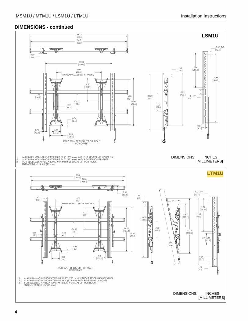
MSM1U / MTM1U / LSM1U / LTM1U Installation Instructions
4
DIMENSIONS - continued
DIMENSIONS: INCHES
LSM1U
[MILLIMETERS]
DIMENSIONS: INCHES [MILLIMETERS]
LTM1U
PLivesey
Highlight

Installation Instructions MSM1U / MTM1U / LSM1U / LTM1U
5
LEGEND
Tighten Fastener
Apretar elemento de fijación
Befestigungsteil festziehen
Apertar fixador
Serrare il fissaggio
Bevestiging vastdraaien
Serrez les fixations
Loosen Fastener
Aflojar elemento de fijación
Befestigungsteil lösen
Desapertar fixador
Allentare il fissaggio
Bevestiging losdraaien
Desserrez les fixations
Phillips Screwdriver
Destornillador Phillips
Kreuzschlitzschraubendreher
Chave de fendas Phillips
Cacciavite a stella
Kruiskopschroevendraaier
Tournevis à pointe cruciforme
Open-Ended Wrench
Llave de boca
Gabelschlüssel
Chave de bocas
Chiave a punte aperte
Steeksleutel
Clé à fourche
By Hand
A mano
Von Hand
Com a mão
A mano
Met de hand
À la main
Hex-Head Wrench
Llave de cabeza hexagonal
Sechskantschlüssel
Chave de cabeça sextavada
Chiave esagonale
Zeskantsleutel
Clé à tête hexagonale
Pencil Mark
Marcar con lápiz
Stiftmarkierung
Marcar com lápis
Segno a matita
Potloodmerkteken
Marquage au crayon
Drill Hole
Perforar
Bohrloch
Fazer furo
Praticare un foro
Gat boren
Percez un trou
Adjust
Ajustar
Einstellen
Ajustar
Regolare
Afstellen
Ajuster
Remove
Quitar
Entfernen
Remover
Rimuovere
Verwijderen
Retirez
Optional
Opcional
Optional
Opcional
Opzionale
Optie
En option
Security Wrench
Llave de seguridad
Sicherheitsschlüssel
Chave de segurança
Chiave di sicurezza
Veiligheidssleutel
Clé de sécurité

MSM1U / MTM1U / LSM1U / LTM1U Installation Instructions
6
TOOLS REQUIRED FOR INSTALLATION
PARTS
7/32" (5.5mm) Wood Stud
#2
3/8" (9.5mm) Concrete
1/8"(included)
3/16" x 10" (included)
C (4) E (4) A (4)M4x12mm
B (4)M4x20mm M4x25mm
D (4)M5x12mm M5x20mm
F (4)M5x25mm
G (4)M6x12mm
H (4)M6x20mm
[Interface brackets]
Universal Hardware Kit
I (4)M6x25mm K (4) J (4)
M8x12mm M8x20mm L (4)M8x30mm
MA (8)[Nesting
MB (4)[Universal washer]
Wall Mounting Hardware Kit
N (4)5/16 x 2-1/2"
P (4)UX10x60mm
Q (4)[Slottedwasher]
X (4)[Wall cover]
MSM1/LSM1 Mount Hardware
R (1) 1/8"
S (1)3/16"
T (4)1/4-20 x 3/4"
U (2)3/8-16 x 3/4"
MTM1/LTM1 Mount Hardware
R (1) 1/8"
S (1)3/16"
T (4)1/4-20 x 3/4"
U (2)3/8-16 x 3/4"
V (2)1/4-20 x 1"
W (2) 1/4-20
Y (1) Z (1) [left] [right]
AA (1) BB (1)
[left] [right]
LTM1U
[Interface brackets]
CC (1)[MSM1U/MTM1U mount]
CC (1)[LSM1U/LTM1U mount]
OR
spacer][Included in hardware box]
[Included in hardware box][Included in hardware box]
MSM1U
Y (1) Z (1) [left] [right]
LSM1U
AA (1) [left]
BB (1) [right]
MTM1U

Installation Instructions MSM1U / MTM1U / LSM1U / LTM1U
7
INSTALLATION
The MSM1U/MTM1U/LSM1U/LTM1U mounts are designed to be mounted to a bare 8" concrete, 8"x8"x16" concrete block; or 2" x 4" wood studs (16" on center for MSM1U/MTM1U, and 16" or 24" on center for LSM1U/LTM1U) wall covered by drywall of 5/8" maximum thickness.
The MTM1U and LTM1U have brackets which allow the TV to
be tilted. The MSM1U and LSM1U have static brackets which
keep the TV in an upright position.
Locate Mounting Site
WARNING: IMPROPER INSTALLATION CAN LEAD TO MOUNT FALLING CAUSING SEVERE PERSONAL INJURY OR DAMAGE TO EQUIPMENT! It is the installers responsibility to make certain the structure to which the mount is being attached is capable of supporting five times the combined weight of all components located on the mount, not to exceed 125 lbs (56.7 kg) for the MSM1U/MTM1U OR 200 lbs (90.7 kg) for the LSM1U/LTM1U.
NOTE: Proceed to either the Installing to a Wood Stud Wall
section or the Installing to a Concrete Wall section.
Installing to a Wood Stud Wall
1. Determine the center of the TV screen, and where it should be located on the wall.
2. Locate the closest stud to the left and right of the selected location.
NOTE: If the screen area lies over a stud, use that stud and the stud to either the left or right of it.
3. Line up the notches on mount (CC) with center of screen marking to determine vertical center. (See Figure 1)
4. Measure up 8" (203.2mm) from the center point to mark location of the upper mounting slots.
Figure 1
5. Using a level, mark the wall on each stud to attach the mount through the upper mounting slots. (See Figure 2)
6. Drill one 7/32" (5.5mm) pilot hole in each stud.
7. Partially install two 5/16 x 2-1/2" flanged lag bolts (N) into pilot holes but do not tighten to wall.
8. Hang mount (CC), aligning upper mounting slots over lag bolts and adjust side-to-side for proper location.
9. Place one slotted washer (Q) over each flanged lag bolt. (See Figure 2)
10. Tighten lag bolts to secure mount (CC) to wall at upper mounting slots.
Figure 2
11. Mark the attachment points for the lower mounting slots, making sure the attachment points are located on the studs. (See Figure 2)
12. Drill 7/32" (5.5mm) pilot holes at markings for lower mounting holes. (See Figure 2)
13. Use two 5/16 x 2-1/2" flanged lag bolts (N) and two 5/16" slotted washers (Q) to attach the mount to the wall through the lower mounting holes. (See Figure 2)
14. Slide rails to approximate center of screen location.
15. Proceed to Locking Rails section.
Center of screen
8"
Vertical centerof mount
(203.2mm)
(MSM1U shown)
11 12
5 6
(Q) x 2
7
10(N) x 2
(CC)
9 (Q) x 2
13 (N) x 2
13
(MSM1U shown)

MSM1U / MTM1U / LSM1U / LTM1U Installation Instructions
8
Installing to a Concrete Wall
1. Determine the center of the TV screen, and where it should be located on the wall.
2. Line up the notches on mount (CC) with center of screen marking to determine vertical center. (See Figure 1)
3. Measure up 8" (203.2mm) from the center point to mark location of the upper mounting slots. (See Figure 1)
4. Using a level, mark the wall through both upper mounting slots. (See Figure 3)
Figure 3
CAUTION: MINIMUM HORIZONTAL DISTANCE
BETWEEN WALL BRACKETS IS 16" (406.4mm). Do not
place mounting brackets closer together than 16" (406.4mm).
5. Drill one 3/8" x 3-1/2" (9.5mm x 88.9mm) pilot hole at each marking.
6. Install an anchor (P) into each pilot hole using a hammer, making sure that the anchor is flush with the wall.
7. Partially install two 5/16 x 2-1/2" flanged lag bolts (N) into pilot holes but do not tighten to wall.
8. Hang mount (CC), aligning upper mounting slots over lag bolts and adjust side-to-side for proper location.
9. Place one slotted washer (Q) over each flanged lag bolt. (See Figure 3)
10. Tighten lag bolts to secure mount (CC) to wall at upper mounting slots.
11. Mark the attachment points for the lower mounting slots, making sure the attachment points are located on the studs. (See Figure 3)
12. Drill 3/8" x 3-1/2" (9.5mm x 88.9mm) pilot holes at markings for lower mounting holes. (See Figure 3)
13. Use two 5/16 x 2-1/2" flanged lag bolts (N) and two 5/16" slotted washers (Q) to attach the mount to the wall through the lower mounting holes. (See Figure 3)
14. Slide rails to approximate center of screen location.
Locking Rails (Optional)
1. Lock rails into place using two 1/4-20 x 3/4" set screws (T) on mount upright (CC) and the 1/8" hex key (R). (See Figure 4)
2. Repeat for remaining mount upright.
NOTE: To easily install upper set screw against upper rail, place set screw (T) onto hex key (R), and feed up into hole while turning to tighten.
Figure 4
11
5
6
4
12
x 4
(P) x 4107 10 (N) x 2
(Q) x 29
(Q) x 213
13 (N) x 2
(MSM1U shown)
(T) x 41
(R)(R)

Installation Instructions MSM1U / MTM1U / LSM1U / LTM1U
9
Attaching Interface Brackets to Screen
1. Align the center of the bracket (Y and Z or AA and BB) with center of screen. (See Figure 5)
NOTE: The diamond-shape holes in the bracket correspond to
the center of the mount.
Figure 5
WARNING: IMPROPER INSTALLATION CAN LEAD TO
DISPLAY FALLING CAUSING SERIOUS PERSONAL
INJURY OR DAMAGE TO EQUIPMENT! Using screws of
improper size may damage your display. Properly sized
screws will easily and completely thread into display
mounting holes. If spacers are required, be sure to use longer
screws of the same diameter.
2. Select correct screws, nesting spacers (if necessary) and universal washers (if required) from the hardware bag (A-M) and attach brackets to back of screen. (See Figure 5)
IMPORTANT ! : The M8 screws do NOT require a
washer. Use the universal washer (MB) only with M4, M5
and M6 screws.
NOTE: The nesting spacers (MA) may be used separately, or
put two together in different configurations to create
different size spacers. (See Figure 6)
Figure 6
Switching Interface Brackets (Optional)
If an installation situation makes adjusting the location of
interface brackets necessary, there are several options.
1. The wall brackets may be adjusted side to side at the point of attachment. (See Figure 7)
2. The location of the left and right interface brackets (Y and Z or AA and BB) may be switched, with the knobs on the MTM1U/LTM1U interface brackets (AA and BB) facing the inside of the mount. (See Figure 7)
Figure 7
Center of bracket
Pull cord
[Brackets Y and Z shown]
(MA)
(MB)
(A-L)
NOTE: Use universal washer (MB) ONLY with M4, M5 and M6 screws.
(Single) (Nested) (Stacked)
0.375 [9.5]
0.563 [14.3]
0.750 [19.1]
1
2
Knobs
[Brackets AA and BB shown]
(MTM1U shown)

MSM1U / MTM1U / LSM1U / LTM1U Installation Instructions
10
3. If necessary, the tilt interface bracket knobs may be switched to allow the interface brackets (AA and BB) to be reversed. (See Figure 8)
a. Remove display from mount.
b. Remove interface brackets from display.
c. Hold the right interface bracket horizontally, tightly gripping it so that spacers do not move.
d. Remove the knob and screw.
e. Replace the knob and screw in the opposite order, with the knob on the inside of the bracket.
f. Switch the right interface bracket to the left side of the wall mount.
g. Repeat Steps 3c through 3f with the left interface bracket.
Figure 8
Attaching Screen to Wall Mount
1. Attach wall covers (X) to top and bottom of both wall brackets. (See Figure 9)
Figure 9
NOTE: NEVER place both interface brackets (Y and Z or AA
and BB) to one side of the wall mount center line! (See
Figure 10)
NOTE: Do NOT allow both interface brackets (Y and Z or AA
and BB) to be located on same side of wall bracket.
(See Figure 10)
Figure 10
3e
Knobs to outside of brackets
[Brackets AA and BB shown]
3d
(MTM1U shown)
(X) x 4
Both interface brackets must NEVER be locatedto one side of the wall brackets!
NEVER place both interface brackets to oneside of the wall mount center line (CL)!
Center Line (CL)
[Brackets Y and Z shown](MSM1U shown)

Installation Instructions MSM1U / MTM1U / LSM1U / LTM1U
11
2. Hang screen onto the top rail of the mount (CC). (See Figure 11)
• MSM1U / LSM1U: Hang top hook of interface brackets (Y and Z) onto the top rail of the mount (CC). (See Figure 11)
• MTM1U / LTM1U: Move latch on top of interface bracket to OPEN position and hang top hook of interface brackets (AA and BB) onto the top rail of the mount (CC). (See Figure 11)
NOTE: The screen initially installs into the "service mode" to
allow easy cable access.
3. Adjust screen and rails to desired viewing position.
4. Route cables between wall and rails.
CAUTION: PINCH POINTS! Keep fingers, hands and
cables out of pinch point areas.
5. Pull downward on the pull cords and swing inward toward wall, latching interface brackets to lower rail and fastening bottom of screen to the mount. (See Figure 11)
6. Attach end of pull cord (a magnet) to mount so it does not extend beyond bottom of screen. (See Figure 11)
Figure 11
6 Pull
2TopHook
cords
Latch in
6 Pullcords
5
5
55
2
OPENposition
(MSM1U shown) (MTM1U shown)
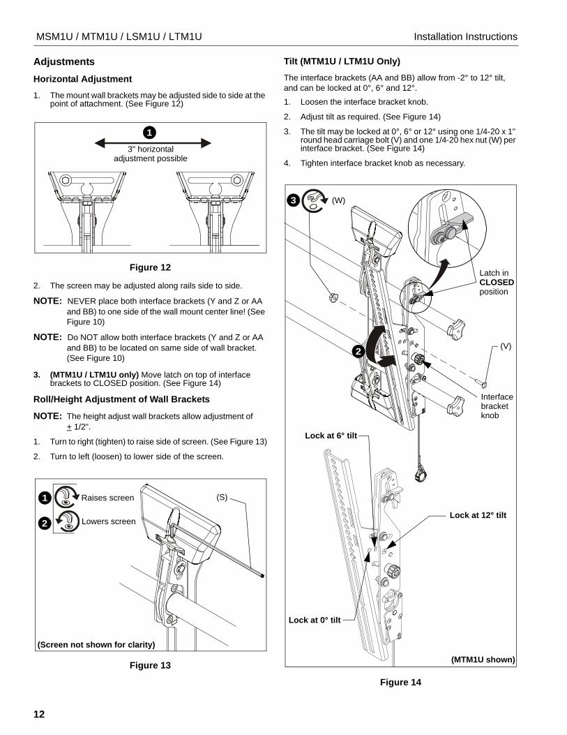
MSM1U / MTM1U / LSM1U / LTM1U Installation Instructions
12
Adjustments
Horizontal Adjustment
1. The mount wall brackets may be adjusted side to side at the point of attachment. (See Figure 12)
Figure 12
2. The screen may be adjusted along rails side to side.
NOTE: NEVER place both interface brackets (Y and Z or AA
and BB) to one side of the wall mount center line! (See
Figure 10)
NOTE: Do NOT allow both interface brackets (Y and Z or AA
and BB) to be located on same side of wall bracket.
(See Figure 10)
3. (MTM1U / LTM1U only) Move latch on top of interface brackets to CLOSED position. (See Figure 14)
Roll/Height Adjustment of Wall Brackets
NOTE: The height adjust wall brackets allow adjustment of
+ 1/2".
1. Turn to right (tighten) to raise side of screen. (See Figure 13)
2. Turn to left (loosen) to lower side of the screen.
Figure 13
Tilt (MTM1U / LTM1U Only)
The interface brackets (AA and BB) allow from -2° to 12° tilt,
and can be locked at 0°, 6° and 12°.
1. Loosen the interface bracket knob.
2. Adjust tilt as required. (See Figure 14)
3. The tilt may be locked at 0°, 6° or 12° using one 1/4-20 x 1" round head carriage bolt (V) and one 1/4-20 hex nut (W) per interface bracket. (See Figure 14)
4. Tighten interface bracket knob as necessary.
Figure 14
3" horizontal
1
adjustment possible
Raises screen
Lowers screen
1
2
(S)
(Screen not shown for clarity)
Latch inCLOSEDposition
3 (W)
(V)2
Lock at 12° tilt
Lock at 6° tilt
Lock at 0° tilt
Interfacebracket knob
(MTM1U shown)

Installation Instructions MSM1U / MTM1U / LSM1U / LTM1U
13
Locking Screen Interface Brackets (Optional)
1. Lock screen interface brackets onto mount rails using one 3/8-16 x 3/4" set screw (U) on each interface bracket. (See Figure 15)
Figure 15
Locking Mount (Optional)
1. Add padlock (not included) to interface bracket to complete security. (See Figure )
NOTE: The padlock maximum shackle diameter is 5/16"
(7.9 mm).
Figure 16
(MTM1U shown)
(MSM1U shown)
1 (U) x 2
1 (U) x 2
1
(MTM1U shown)
Padlock shackle
- 5/16" (7.9mm)
maximum diameter:
1
Padlock shackle
- 5/16" (7.9mm)
maximum diameter:
(MSM1U shown)

MSM1U / MTM1U / LSM1U / LTM1U Installation Instructions
14

Installation Instructions MSM1U / MTM1U / LSM1U / LTM1U
15
MSM1U / MTM1U / LSM1U / LTM1U Installation Instructions
USA/International A 6436 City West Parkway, Eden Prairie, MN 55344
P 800.582.6480 / 952.225.6000
F 877.894.6918 / 952.894.6918
Europe A Franklinstraat 14, 6003 DK Weert, Netherlands
P +31 (0) 495 580 852
F +31 (0) 495 580 845
Asia Pacific A Office No. 918 on 9/F, Shatin Galleria18-24 Shan Mei Street
Fotan, Shatin, Hong Kong
P 852 2145 4099 F 852 2145 4477
Chief, a products division of
Milestone AV Technologies
8800-002851 Rev00
2016 Milestone AV Technologies
www.milestone.com
05/16
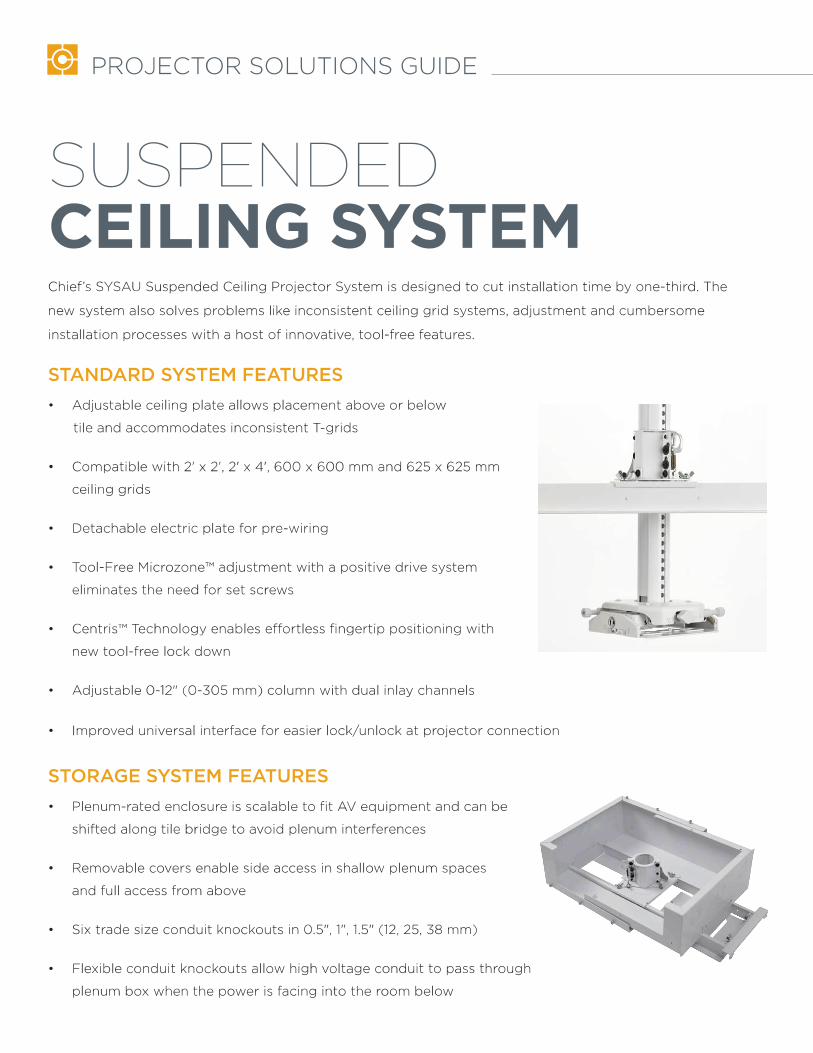
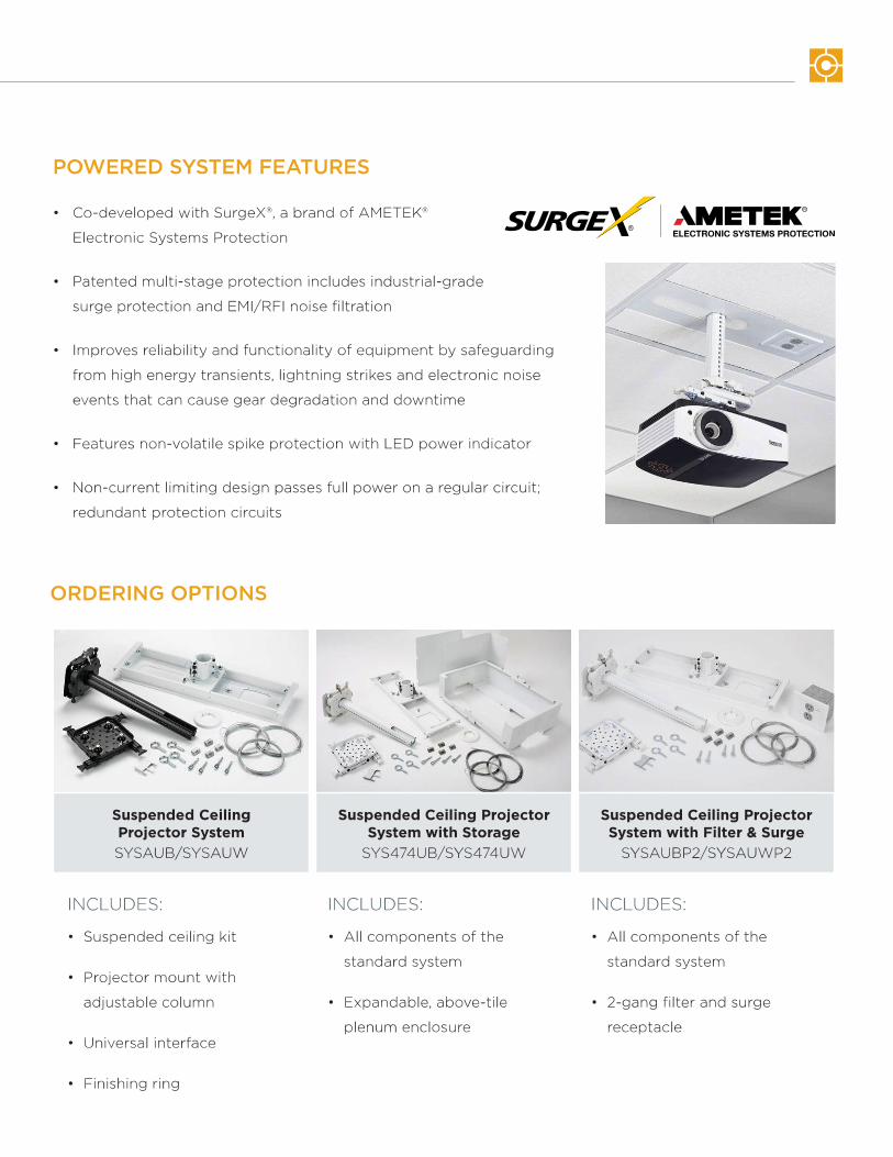
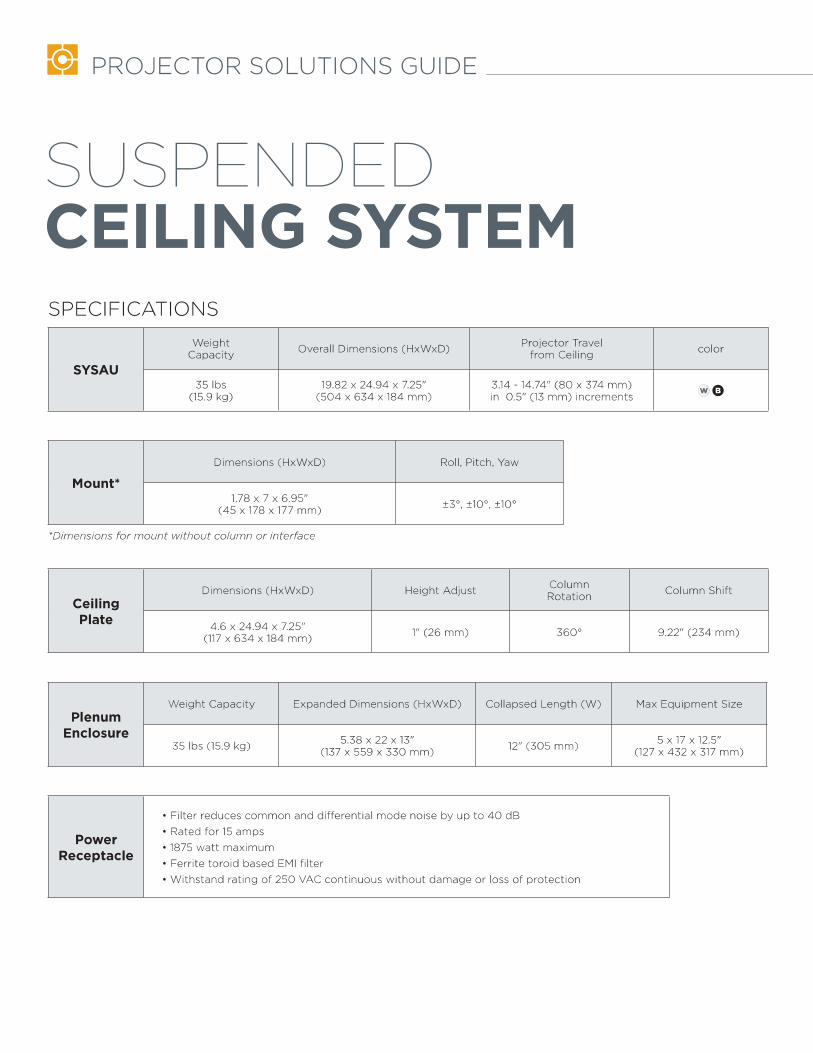

19.69500
16.00406
19.00483
1.0025 7.00
178
1.0025
2.2557
DEPTH
[86]3.40
22.04560
23.62END CAP TO END CAP
600
ALL MEASUREMENTS ARE IN THE FOLLOWING FORMAT:
[MILLIMETERS]INCHES
NOTE: CUSTOM INTERAFCE BRACKETNOT SHOWN. THE CUSTOM INTERFACEBRACKET NEEDED FOR YOUR DISPLAYWILL ADD BETWEEN 1/2" AND 2" IN DEPTHAND MAY AFFECT LOCATION OF DISPLAYON THE MOUNT.
SEE PSB-XXXX DRAWING ALSO.
Mounting PatternPRODUCT FEATURES
WEIGHT CAPACITY 200 LBSHEIGHT ADJUSTMENT 1"
TILT / ROLL / YAW +5, -17 / 2 / 0
D
C
B
AA
B
C
D
SIZE DWG. NO.
B87654321
1 2 3 4 5 6 7 8
THE INFORMATION AND DESIGNS CONTAINEDIN THIS DRAWING ARE CONFIDENTIAL AND THEPROPRIETARY PROPERTY OF CHIEF MFG., INC.NEITHER THIS DESIGN NOR ANY INFORMATIONCONTAINED IN THIS DRAWING MAY BEREPRODUCED OR DISCLOSED TO OTHERSWITHOUT THE EXPRESS WRITTEN CONSENT OFCHIEF MFG., INC.
TITLE
PDR-2000
CUSTOMER PRINTPDR-2000
PDR-2000
CHIEF MANUFACTURING INC.MOUNT ORDER NUMBER IS PDR-2000PHONE: 1-800-582-6480 SHEET SCALE = 1:5
8401 EAGLE CREEK PKYSUITE #700SAVAGE, MN 55378PHONE: 952-894-6280FAX: 877-894-6918

37.00940
3.40[86]
39.501003
2.8171
1.6843
5°16°
2°
Extended
Unit Depth
Retracted
Highest Height Setting
Lowest Height Setting
Roll Adjustment
*The range of adjustment will vary with different weight and depth screens
Tilt Adjustment *
Tilted Down
Tilted Up
D
C
B
AA
B
C
D
SIZE DWG. NO.
B87654321
1 2 3 4 5 6 7 8
THE INFORMATION AND DESIGNS CONTAINEDIN THIS DRAWING ARE CONFIDENTIAL AND THEPROPRIETARY PROPERTY OF CHIEF MFG., INC.NEITHER THIS DESIGN NOR ANY INFORMATIONCONTAINED IN THIS DRAWING MAY BEREPRODUCED OR DISCLOSED TO OTHERSWITHOUT THE EXPRESS WRITTEN CONSENT OFCHIEF MFG., INC.
TITLE
PDR-2000
CUSTOMER PRINTPDR-2000
PDR-2000
8401 EAGLE CREEK PKYSUITE #700SAVAGE, MN 55378PHONE: 952-894-6280FAX: 877-894-6918
SHEET SCALE = 1:10

90°
32.47825
11.19284
79°MAX
84°
2.5966
161°MAX
79°MAX
D
C
B
AA
B
C
D
SIZE DWG. NO.
B87654321
1 2 3 4 5 6 7 8
THE INFORMATION AND DESIGNS CONTAINEDIN THIS DRAWING ARE CONFIDENTIAL AND THEPROPRIETARY PROPERTY OF CHIEF MFG., INC.NEITHER THIS DESIGN NOR ANY INFORMATIONCONTAINED IN THIS DRAWING MAY BEREPRODUCED OR DISCLOSED TO OTHERSWITHOUT THE EXPRESS WRITTEN CONSENT OFCHIEF MFG., INC.
TITLE
PDR-2000
CUSTOMER PRINTPDR-2000
PDR-2000SHEET SCALE = 1:8
8401 EAGLE CREEK PKYSUITE #700SAVAGE, MN 55378PHONE: 952-894-6280FAX: 877-894-6918
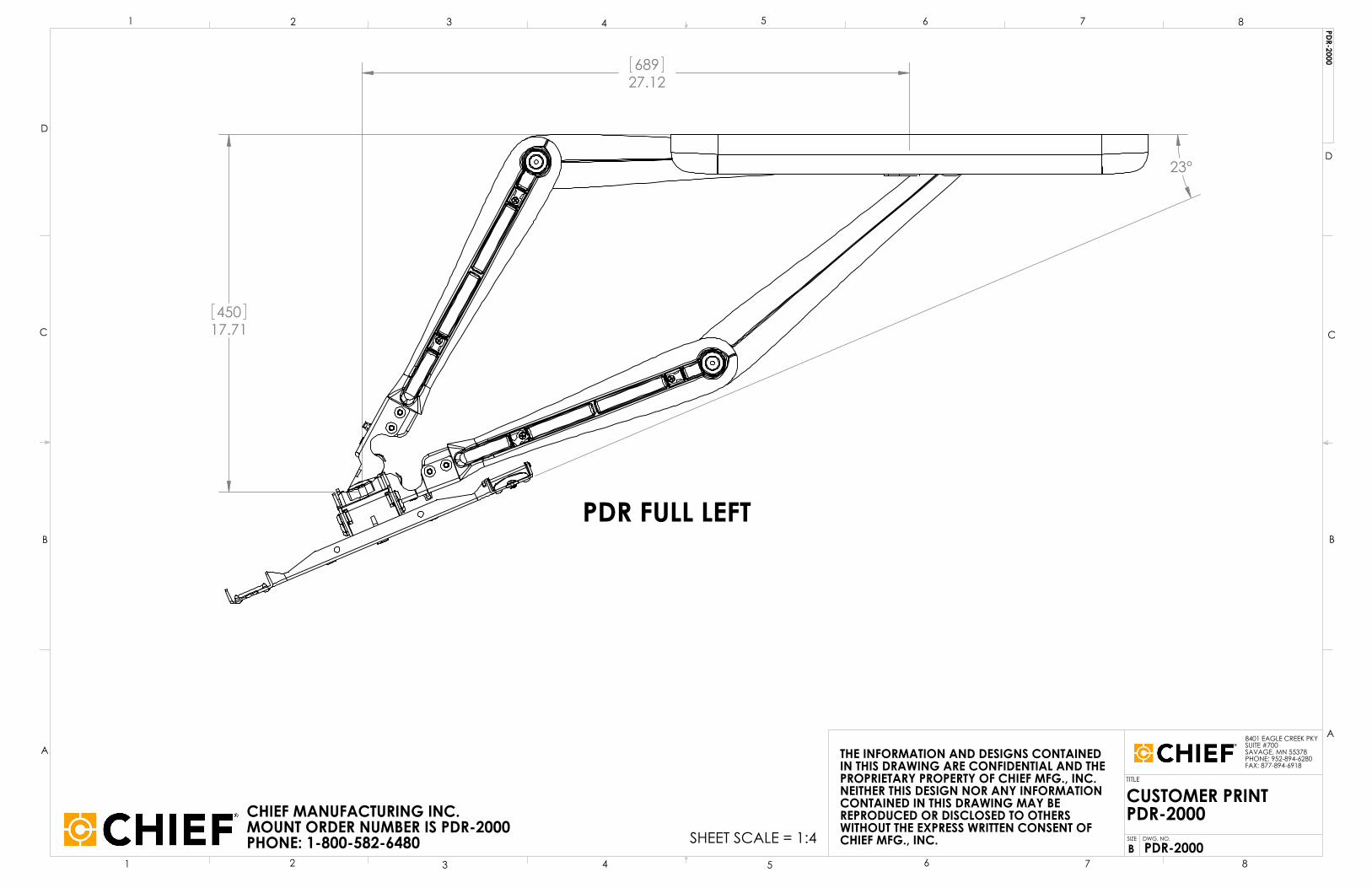
23°
17.71450
27.12689
PDR FULL LEFT
D
C
B
AA
B
C
D
SIZE DWG. NO.
B87654321
1 2 3 4 5 6 7 8
THE INFORMATION AND DESIGNS CONTAINEDIN THIS DRAWING ARE CONFIDENTIAL AND THEPROPRIETARY PROPERTY OF CHIEF MFG., INC.NEITHER THIS DESIGN NOR ANY INFORMATIONCONTAINED IN THIS DRAWING MAY BEREPRODUCED OR DISCLOSED TO OTHERSWITHOUT THE EXPRESS WRITTEN CONSENT OFCHIEF MFG., INC.
TITLE
PDR-2000
CUSTOMER PRINTPDR-2000
PDR-2000
CHIEF MANUFACTURING INC.MOUNT ORDER NUMBER IS PDR-2000PHONE: 1-800-582-6480 SHEET SCALE = 1:4
8401 EAGLE CREEK PKYSUITE #700SAVAGE, MN 55378PHONE: 952-894-6280FAX: 877-894-6918

Thcescr
S
P R O F
he SEC 09 has ilings the SECrew terminals
Specifications
• Frequ
• Imped
• Sensit
• Dime
Wiring in
Input: P P P P
Line leveSwitch p
PhantomSwitch p
E S S I O N A L M I
been designeC 09 has the as, eliminating
s
uency respon
dance:
tivity:
nsions:
Height: Diameter:Weight:
nformation:
Pin 1 +24V Pin 2 PhasePin 3 PhasePin 4 GND
el set up: ins 7,5,3 to O
m power set uins 8,6,4 to O
C R O P H O N E S
ed for securitappearance og the need for
se: 50Hz to
75 ohm
1.4V/P
55 mm 105 mm
126g (4
ac / 12V dc e + e – / ‐ac/dc
ON
up: ON
M
Y S T E M S
www.clockau
ty and surveilf an ordinary r connectors.
o 12KHz
ms
a
m (2.16”) m (4.13”) 4.44ounces)
M
Max
udio.com
lance applicafire detector
• O
• B
• S
• 91
• P
• R
• S
• E
• Uc
Freque
Polar
1K giv
2K giv
3.9K g
18.2K
100K
Min
ations. Offerinr. Electronics
Omni‐directio
Built‐in line le
Selectable sen
9‐48V Phanto12‐24V dc op
Pick up range
Red LED statu
Sturdy ABS ho
Easy to install
Universal moconduit boxes
ency response
r Pattern
ves minimum
ves approxim
gives approxi
K gives approx
gives maximu
ng easy mounhoused withi
onal.
evel pre‐amp
nsitivity switc
om power swieration
e of 15m (50ft
us indicators
ousing.
l.
unting to elecs
e
headroom
ately 6 dB mo
mately 12 dB
ximately 18 d
um headroom
SEC
nting to walls in the SEC 09
ching
itchable for
t).
ctrical
ore headroom
B more headro
B more head
m
C 09
or offer
m
oom
room
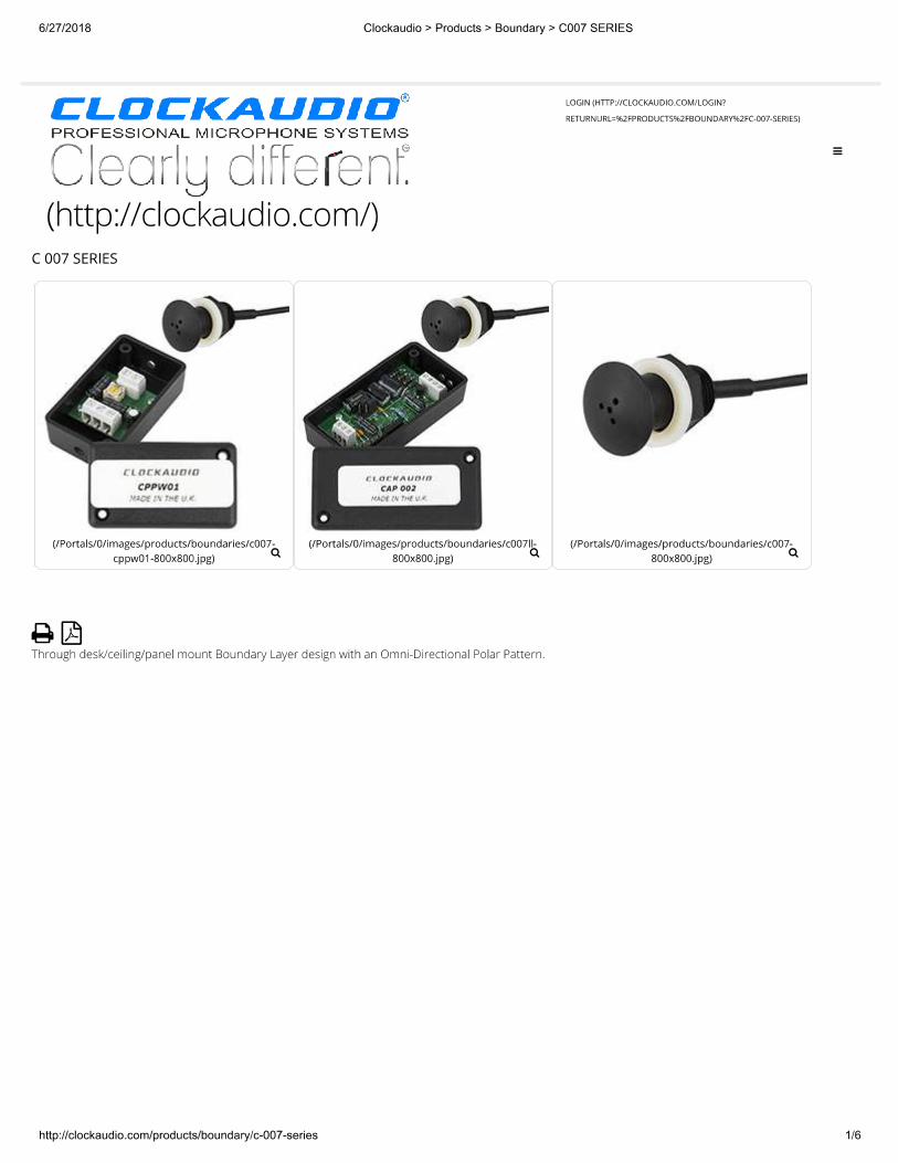


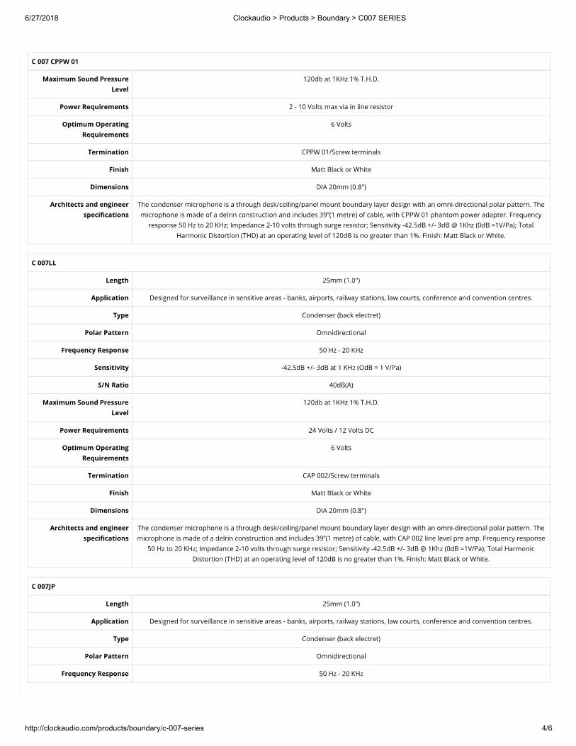
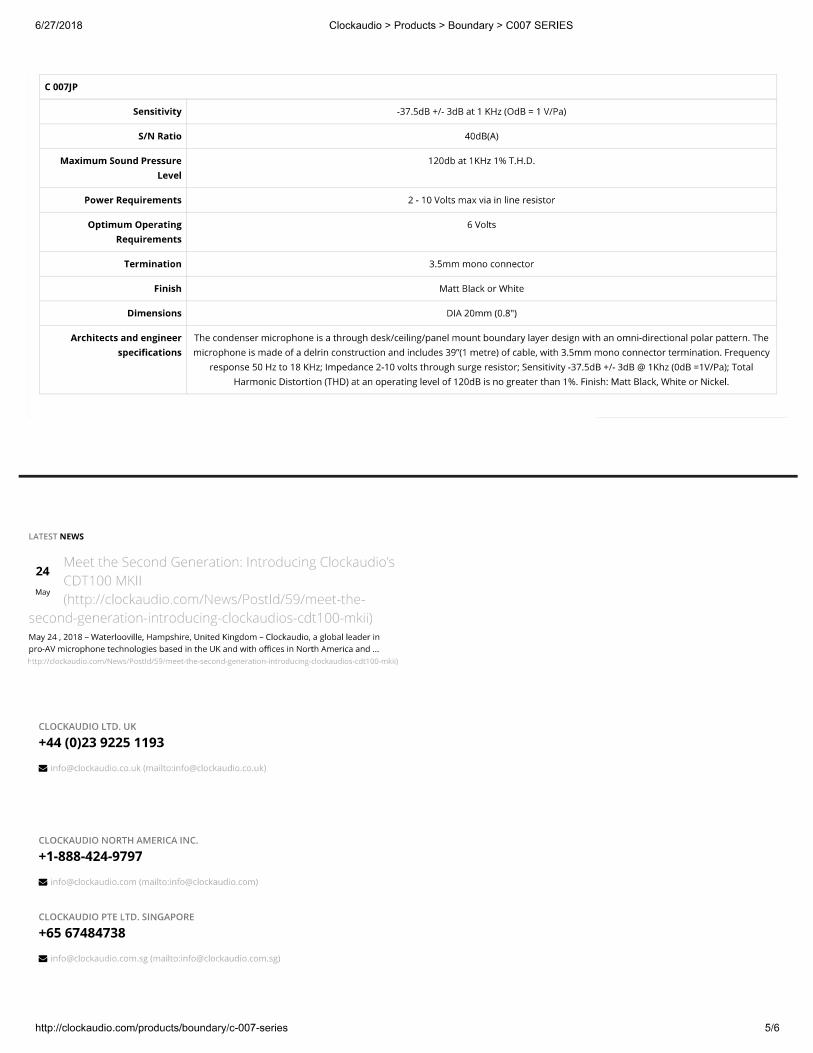

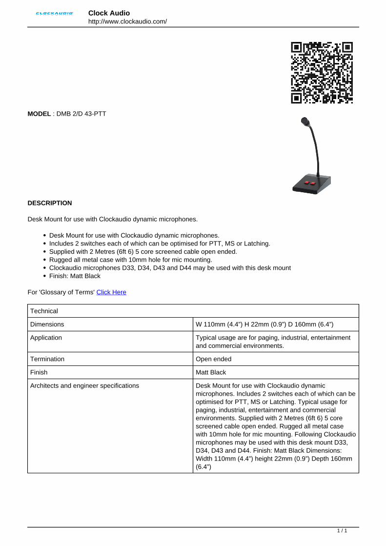
Clock Audiohttp://www.clockaudio.com/
MODEL : DMB 2/D 43-PTT
DESCRIPTION
Desk Mount for use with Clockaudio dynamic microphones.
Desk Mount for use with Clockaudio dynamic microphones.Includes 2 switches each of which can be optimised for PTT, MS or Latching.Supplied with 2 Metres (6ft 6) 5 core screened cable open ended.Rugged all metal case with 10mm hole for mic mounting.Clockaudio microphones D33, D34, D43 and D44 may be used with this desk mountFinish: Matt Black
For 'Glossary of Terms' Click Here
Technical
Dimensions W 110mm (4.4”) H 22mm (0.9”) D 160mm (6.4”)
Application Typical usage are for paging, industrial, entertainmentand commercial environments.
Termination Open ended
Finish Matt Black
Architects and engineer specifications Desk Mount for use with Clockaudio dynamicmicrophones. Includes 2 switches each of which can beoptimised for PTT, MS or Latching. Typical usage forpaging, industrial, entertainment and commercialenvironments. Supplied with 2 Metres (6ft 6) 5 corescreened cable open ended. Rugged all metal casewith 10mm hole for mic mounting. Following Clockaudiomicrophones may be used with this desk mount D33,D34, D43 and D44. Finish: Matt Black Dimensions:Width 110mm (4.4”) height 22mm (0.9”) Depth 160mm(6.4”)
Powered by TCPDF (www.tcpdf.org)
1 / 1
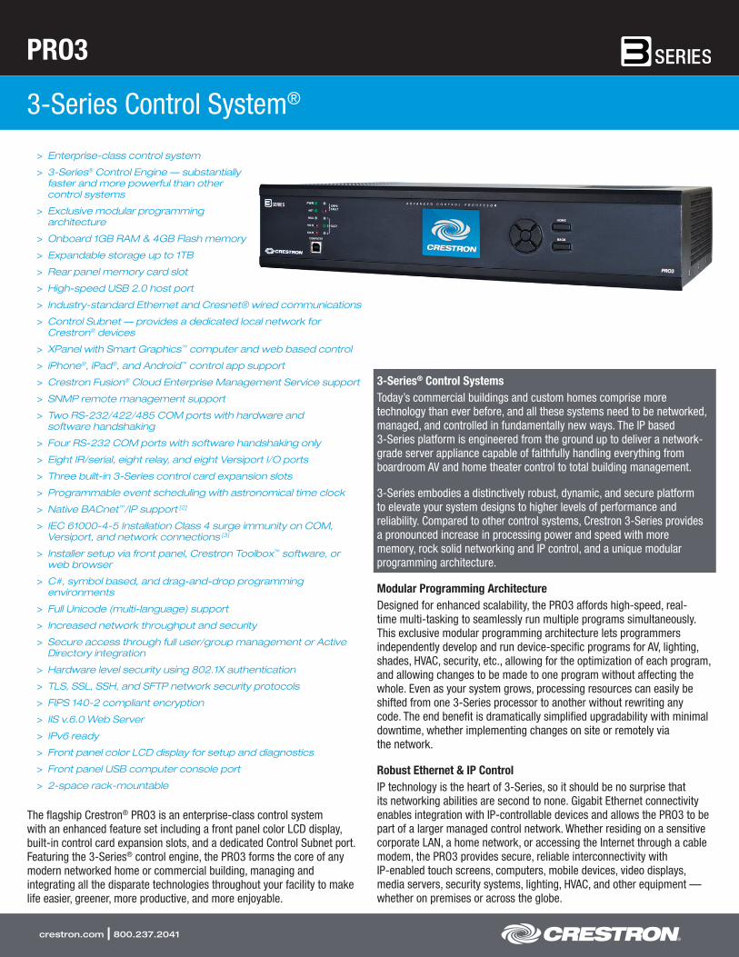
PRO3
3-Series Control System®
crestron.com | 800.237.2041
> Enterprise-class control system
> 3-Series® Control Engine — substantially faster and more powerful than other control systems
> Exclusive modular programming architecture
> Onboard 1GB RAM & 4GB Flash memory
> Expandable storage up to 1TB
> Rear panel memory card slot
> High-speed USB 2.0 host port
> Industry-standard Ethernet and Cresnet® wired communications
> Control Subnet — provides a dedicated local network for Crestron® devices
> XPanel with Smart Graphics™ computer and web based control
> iPhone®, iPad®, and Android™ control app support
> Crestron Fusion® Cloud Enterprise Management Service support
> SNMP remote management support
> Two RS-232/422/485 COM ports with hardware and software handshaking
> Four RS-232 COM ports with software handshaking only
> Eight IR/serial, eight relay, and eight Versiport I/O ports
> Three built-in 3-Series control card expansion slots
> Programmable event scheduling with astronomical time clock
> Native BACnet™/IP support [2]
> IEC 61000-4-5 Installation Class 4 surge immunity on COM, Versiport, and network connections [3]
> Installer setup via front panel, Crestron Toolbox™ software, or web browser
> C#, symbol based, and drag-and-drop programming environments
> Full Unicode (multi-language) support
> Increased network throughput and security
> Secure access through full user/group management or Active Directory integration
> Hardware level security using 802.1X authentication
> TLS, SSL, SSH, and SFTP network security protocols
> FIPS 140-2 compliant encryption
> IIS v.6.0 Web Server
> IPv6 ready
> Front panel color LCD display for setup and diagnostics
> Front panel USB computer console port
> 2-space rack-mountable
The flagship Crestron® PRO3 is an enterprise-class control system with an enhanced feature set including a front panel color LCD display, built-in control card expansion slots, and a dedicated Control Subnet port. Featuring the 3-Series® control engine, the PRO3 forms the core of any modern networked home or commercial building, managing and integrating all the disparate technologies throughout your facility to make life easier, greener, more productive, and more enjoyable.
3-Series® Control SystemsToday’s commercial buildings and custom homes comprise more technology than ever before, and all these systems need to be networked, managed, and controlled in fundamentally new ways. The IP based 3-Series platform is engineered from the ground up to deliver a network- grade server appliance capable of faithfully handling everything from boardroom AV and home theater control to total building management.
3-Series embodies a distinctively robust, dynamic, and secure platform to elevate your system designs to higher levels of performance and reliability. Compared to other control systems, Crestron 3-Series provides a pronounced increase in processing power and speed with more memory, rock solid networking and IP control, and a unique modular programming architecture.
Modular Programming ArchitectureDesigned for enhanced scalability, the PRO3 affords high-speed, real- time multi-tasking to seamlessly run multiple programs simultaneously. This exclusive modular programming architecture lets programmers independently develop and run device-specific programs for AV, lighting, shades, HVAC, security, etc., allowing for the optimization of each program, and allowing changes to be made to one program without affecting the whole. Even as your system grows, processing resources can easily be shifted from one 3-Series processor to another without rewriting any code. The end benefit is dramatically simplified upgradability with minimal downtime, whether implementing changes on site or remotely via the network.
Robust Ethernet & IP ControlIP technology is the heart of 3-Series, so it should be no surprise that its networking abilities are second to none. Gigabit Ethernet connectivity enables integration with IP-controllable devices and allows the PRO3 to be part of a larger managed control network. Whether residing on a sensitive corporate LAN, a home network, or accessing the Internet through a cable modem, the PRO3 provides secure, reliable interconnectivity with IP-enabled touch screens, computers, mobile devices, video displays, media servers, security systems, lighting, HVAC, and other equipment — whether on premises or across the globe.
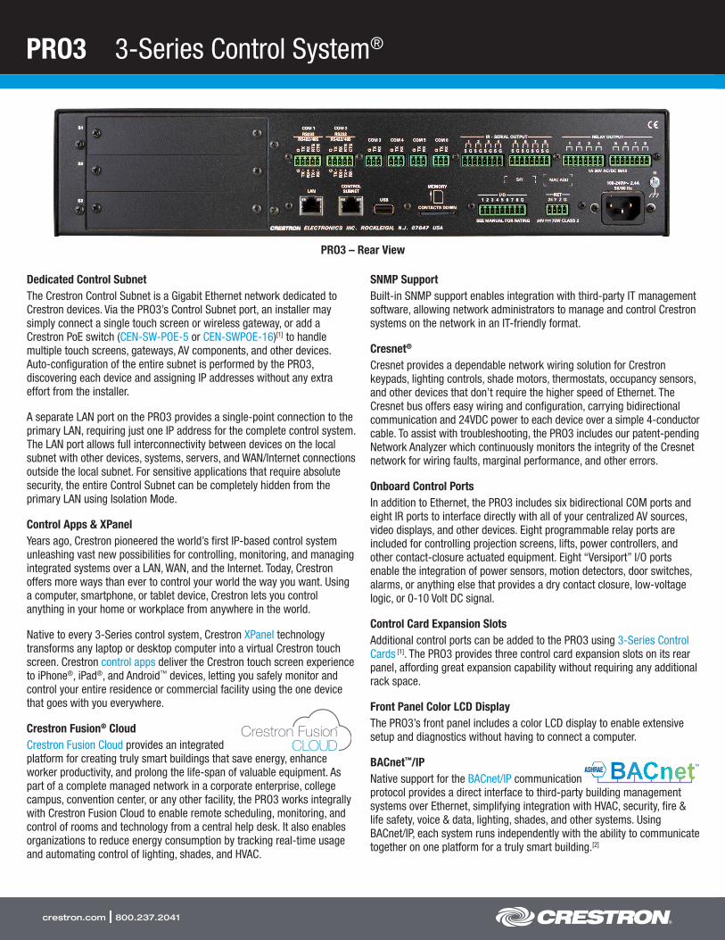
PRO3 3-Series Control System®
crestron.com | 800.237.2041
Dedicated Control SubnetThe Crestron Control Subnet is a Gigabit Ethernet network dedicated to Crestron devices. Via the PRO3’s Control Subnet port, an installer may simply connect a single touch screen or wireless gateway, or add a Crestron PoE switch (CEN-SW-POE-5 or CEN-SWPOE-16)[1] to handle multiple touch screens, gateways, AV components, and other devices. Auto-configuration of the entire subnet is performed by the PRO3, discovering each device and assigning IP addresses without any extra effort from the installer.
A separate LAN port on the PRO3 provides a single-point connection to the primary LAN, requiring just one IP address for the complete control system. The LAN port allows full interconnectivity between devices on the local subnet with other devices, systems, servers, and WAN/Internet connections outside the local subnet. For sensitive applications that require absolute security, the entire Control Subnet can be completely hidden from the primary LAN using Isolation Mode.
Control Apps & XPanelYears ago, Crestron pioneered the world’s first IP-based control system unleashing vast new possibilities for controlling, monitoring, and managing integrated systems over a LAN, WAN, and the Internet. Today, Crestron offers more ways than ever to control your world the way you want. Using a computer, smartphone, or tablet device, Crestron lets you control anything in your home or workplace from anywhere in the world.
Native to every 3-Series control system, Crestron XPanel technology transforms any laptop or desktop computer into a virtual Crestron touch screen. Crestron control apps deliver the Crestron touch screen experience to iPhone®, iPad®, and Android™ devices, letting you safely monitor and control your entire residence or commercial facility using the one device that goes with you everywhere.
Crestron Fusion® CloudCrestron Fusion Cloud provides an integrated platform for creating truly smart buildings that save energy, enhance worker productivity, and prolong the life-span of valuable equipment. As part of a complete managed network in a corporate enterprise, college campus, convention center, or any other facility, the PRO3 works integrally with Crestron Fusion Cloud to enable remote scheduling, monitoring, and control of rooms and technology from a central help desk. It also enables organizations to reduce energy consumption by tracking real-time usage and automating control of lighting, shades, and HVAC.
SNMP SupportBuilt-in SNMP support enables integration with third-party IT management software, allowing network administrators to manage and control Crestron systems on the network in an IT-friendly format.
Cresnet®
Cresnet provides a dependable network wiring solution for Crestron keypads, lighting controls, shade motors, thermostats, occupancy sensors, and other devices that don’t require the higher speed of Ethernet. The Cresnet bus offers easy wiring and configuration, carrying bidirectional communication and 24VDC power to each device over a simple 4-conductor cable. To assist with troubleshooting, the PRO3 includes our patent-pending Network Analyzer which continuously monitors the integrity of the Cresnet network for wiring faults, marginal performance, and other errors.
Onboard Control PortsIn addition to Ethernet, the PRO3 includes six bidirectional COM ports and eight IR ports to interface directly with all of your centralized AV sources, video displays, and other devices. Eight programmable relay ports are included for controlling projection screens, lifts, power controllers, and other contact-closure actuated equipment. Eight “Versiport” I/O ports enable the integration of power sensors, motion detectors, door switches, alarms, or anything else that provides a dry contact closure, low-voltage logic, or 0-10 Volt DC signal.
Control Card Expansion SlotsAdditional control ports can be added to the PRO3 using 3-Series Control Cards [1]. The PRO3 provides three control card expansion slots on its rear panel, affording great expansion capability without requiring any additional rack space.
Front Panel Color LCD DisplayThe PRO3’s front panel includes a color LCD display to enable extensive setup and diagnostics without having to connect a computer.
BACnet™/IPNative support for the BACnet/IP communication protocol provides a direct interface to third-party building management systems over Ethernet, simplifying integration with HVAC, security, fire & life safety, voice & data, lighting, shades, and other systems. Using BACnet/IP, each system runs independently with the ability to communicate together on one platform for a truly smart building.[2]
PRO3 – Rear View
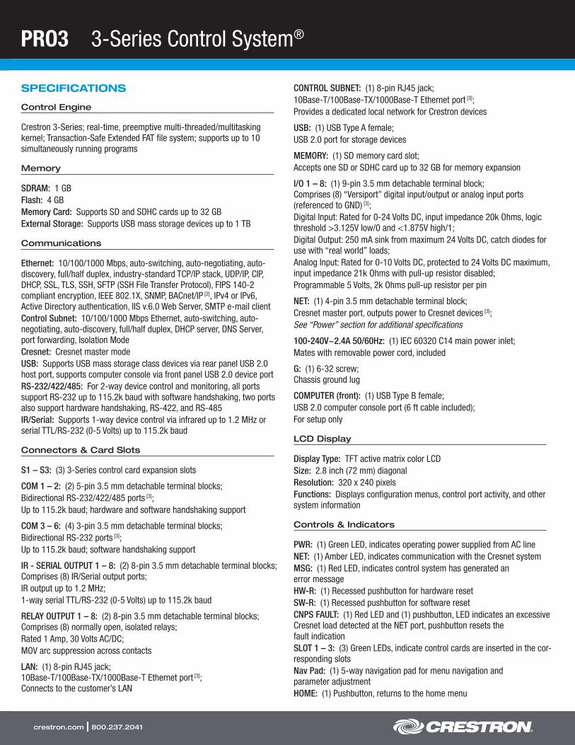
PRO3 3-Series Control System®
crestron.com | 800.237.2041
SPECIFICATIONS
Control Engine
Crestron 3-Series; real-time, preemptive multi-threaded/multitasking kernel; Transaction-Safe Extended FAT file system; supports up to 10 simultaneously running programs
Memory
SDRAM: 1 GBFlash: 4 GBMemory Card: Supports SD and SDHC cards up to 32 GBExternal Storage: Supports USB mass storage devices up to 1 TB
Communications
Ethernet: 10/100/1000 Mbps, auto-switching, auto-negotiating, auto- discovery, full/half duplex, industry-standard TCP/IP stack, UDP/IP, CIP, DHCP, SSL, TLS, SSH, SFTP (SSH File Transfer Protocol), FIPS 140-2 compliant encryption, IEEE 802.1X, SNMP, BACnet/IP [2], IPv4 or IPv6, Active Directory authentication, IIS v.6.0 Web Server, SMTP e-mail clientControl Subnet: 10/100/1000 Mbps Ethernet, auto-switching, auto- negotiating, auto-discovery, full/half duplex, DHCP server, DNS Server, port forwarding, Isolation ModeCresnet: Cresnet master modeUSB: Supports USB mass storage class devices via rear panel USB 2.0 host port, supports computer console via front panel USB 2.0 device portRS-232/422/485: For 2-way device control and monitoring, all ports support RS-232 up to 115.2k baud with software handshaking, two ports also support hardware handshaking, RS-422, and RS-485IR/Serial: Supports 1-way device control via infrared up to 1.2 MHz or serial TTL/RS-232 (0-5 Volts) up to 115.2k baud
Connectors & Card Slots
S1 – S3: (3) 3-Series control card expansion slots
COM 1 – 2: (2) 5-pin 3.5 mm detachable terminal blocks;Bidirectional RS-232/422/485 ports [3];Up to 115.2k baud; hardware and software handshaking support
COM 3 – 6: (4) 3-pin 3.5 mm detachable terminal blocks;Bidirectional RS-232 ports [3];Up to 115.2k baud; software handshaking support
IR - SERIAL OUTPUT 1 – 8: (2) 8-pin 3.5 mm detachable terminal blocks; Comprises (8) IR/Serial output ports;IR output up to 1.2 MHz;1-way serial TTL/RS-232 (0-5 Volts) up to 115.2k baud
RELAY OUTPUT 1 – 8: (2) 8-pin 3.5 mm detachable terminal blocks; Comprises (8) normally open, isolated relays;Rated 1 Amp, 30 Volts AC/DC;MOV arc suppression across contacts
LAN: (1) 8-pin RJ45 jack; 10Base-T/100Base-TX/1000Base-T Ethernet port [3]; Connects to the customer’s LAN
CONTROL SUBNET: (1) 8-pin RJ45 jack;10Base-T/100Base-TX/1000Base-T Ethernet port [3];Provides a dedicated local network for Crestron devices
USB: (1) USB Type A female;USB 2.0 port for storage devices
MEMORY: (1) SD memory card slot;Accepts one SD or SDHC card up to 32 GB for memory expansion
I/O 1 – 8: (1) 9-pin 3.5 mm detachable terminal block; Comprises (8) “Versiport” digital input/output or analog input ports (referenced to GND) [3];Digital Input: Rated for 0-24 Volts DC, input impedance 20k Ohms, logic threshold >3.125V low/0 and <1.875V high/1;Digital Output: 250 mA sink from maximum 24 Volts DC, catch diodes for use with “real world” loads;Analog Input: Rated for 0-10 Volts DC, protected to 24 Volts DC maximum, input impedance 21k Ohms with pull-up resistor disabled;Programmable 5 Volts, 2k Ohms pull-up resistor per pin
NET: (1) 4-pin 3.5 mm detachable terminal block;Cresnet master port, outputs power to Cresnet devices [3];See “Power” section for additional specifications
100-240V~2.4A 50/60Hz: (1) IEC 60320 C14 main power inlet;Mates with removable power cord, included
G: (1) 6-32 screw; Chassis ground lug
COMPUTER (front): (1) USB Type B female;USB 2.0 computer console port (6 ft cable included);For setup only
LCD Display
Display Type: TFT active matrix color LCDSize: 2.8 inch (72 mm) diagonalResolution: 320 x 240 pixelsFunctions: Displays configuration menus, control port activity, and other system information
Controls & Indicators
PWR: (1) Green LED, indicates operating power supplied from AC lineNET: (1) Amber LED, indicates communication with the Cresnet systemMSG: (1) Red LED, indicates control system has generated an error messageHW-R: (1) Recessed pushbutton for hardware resetSW-R: (1) Recessed pushbutton for software resetCNPS FAULT: (1) Red LED and (1) pushbutton, LED indicates an excessive Cresnet load detected at the NET port, pushbutton resets the fault indicationSLOT 1 – 3: (3) Green LEDs, indicate control cards are inserted in the cor-responding slotsNav Pad: (1) 5-way navigation pad for menu navigation and parameter adjustmentHOME: (1) Pushbutton, returns to the home menu

PRO3 3-Series Control System®
crestron.com | 800.237.2041
BACK: (1) Pushbutton, steps menu back one levelLAN (rear): (2) Bi-color green/amber LEDs, left LED indicates Ethernet link status and connection speed, right LED indicates Ethernet activityCONTROL SUBNET (rear): (2) Bi-color green/amber LEDs, left LED indicates Ethernet link status and connection speed, right LED indicates Ethernet activity
Power
Main Power: 2.4 Amps @ 100-240 Volts AC, 50/60 HzAvailable Cresnet Power: 75 Watts (3.125 Amps @ 24 Volts DC)
Environmental
Temperature: 41° to 113° F (5° to 45° C)Humidity: 10% to 90% RH (non-condensing)Heat Dissipation: 45 BTU/hr with no Cresnet devices, no control cards;
71 BTU/hr with full Cresnet load, no control cards;
See individual control card spec sheets for additional specifications
Enclosure
Chassis: Metal, black finish, vented top and sidesFaceplate: Extruded metal, black finish, polycarbonate label overlayMounting: Freestanding or 2 RU 19-inch rack-mountable (adhesive feet and rack ears included)
Dimensions
Height: 3.47 in (89 mm) without feetWidth: 17.28 in (439 mm), 19.00 in (483 mm) with rack earsDepth: 10.13 in (258 mm)
Weight
5.0 lb (2.3 kg)
MODELS & ACCESSORIES
Available Models
PRO3: 3-Series Control System®
Available Accessories
C3COM-3: 3-Series® Control Card - 3 COM PortsC3IO-16: 3-Series® Control Card - 16 Versiport I/O PortsC3IR-8: 3-Series® Control Card - 8 IR PortsC3RY-8: 3-Series® Control Card - 8 Relay PortsC3RY-16: 3-Series® Control Card - 16 Relay PortsPWE-4803RU: PoE InjectorCEN-SW-POE-5: 5-Port PoE SwitchCEN-SWPOE-16: 16-Port Managed PoE SwitchC2N-HBLOCK: Multi-type Cresnet Distribution BlockCNTBLOCK: Cresnet Distribution BlockCNSP-XX: Custom Serial Interface CableIRP2: IR Emitter Probe w/Terminal Block Connector
Crestron® App: Control App for Apple® iOS® & Android™
XPanel: Crestron Control® for ComputersmyCrestron: Dynamic DNS Service for Crestron SystemsCrestron Fusion®: Enterprise Management Platform3-Series® BACnet™/IP Support: 3-Series Native BACnet/IP Interface LicenseCSP-LIR-USB: IR Learner
Notes:
1. Item(s) sold separately.2. License required. The PRO3 supports a maximum of 2000 BACnet objects when dedicated
for BACnet use only. Actual capabilities are contingent upon the overall program size and complexity.
3. The following connections comply with IEC 61000-4-5 Installation Class 4 surge immunity levels: COM 1 - 6, I/O 1 - 8, NET, LAN, and CONTROL SUBNET.
This product may be purchased from an authorized Crestron dealer. To find a dealer, please contact the Crestron sales representative for your area. A list of sales representatives is available online at www.crestron.com/salesreps or by calling 800-237-2041.
The specific patents that cover Crestron products are listed online at: patents.crestron.com.
Certain Crestron products contain open source software. For specific information, please visit www.crestron.com/opensource.
Crestron, the Crestron logo, 3-Series, 3-Series Control System, Cresnet, Crestron Control, Crestron Fusion, Crestron Toolbox, and Smart Graphics are either trademarks or registered trademarks of Crestron Electronics, Inc. in the United States and/or other countries. BACnet and the BACnet logo are either trademarks or registered trademarks of American Society of Heating, Refrigerating and Air-Conditioning Engineers, Inc. in the United States and/or other countries. Apple, iPad, and iPhone are either trademarks or registered trademarks of Apple Inc. in the United States and/or other countries. IOS is either a trademark or registered trademark of Cisco Technology, Inc. in the United States and/or other countries. Android is either a trademark or registered trademark of Google, Inc. in the United States and/or other countries. Other trademarks, registered trademarks, and trade names may be used in this document to refer to either the entities claiming the marks and names or their products. Crestron disclaims any proprietary interest in the marks and names of others. Crestron is not responsible for errors in typography or photography. Specifications are subject to change without notice. ©2016 Crestron Electronics, Inc.
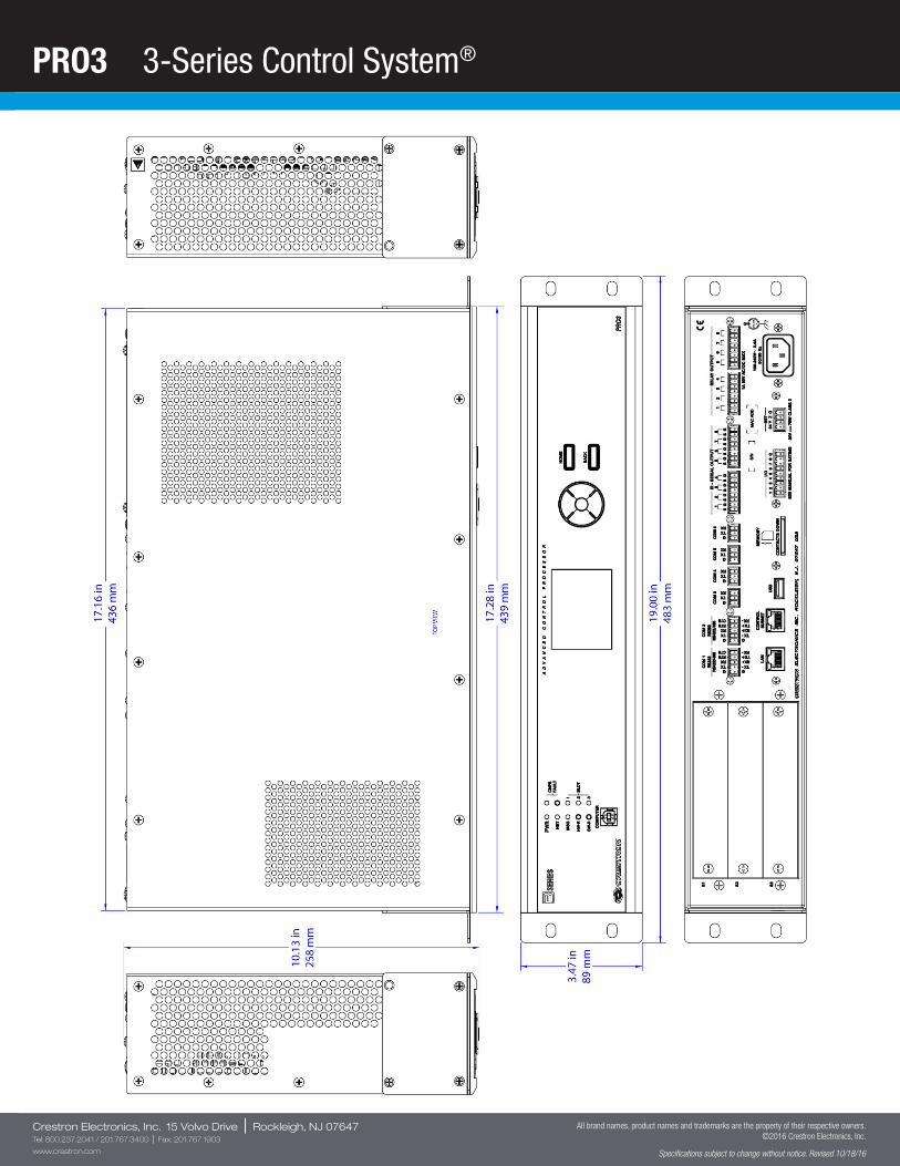
PRO3 3-Series Control System®
Crestron Electronics, Inc. 15 Volvo Drive | Rockleigh, NJ 07647Tel: 800.237.2041 / 201.767.3400 | Fax: 201.767.1903
www.crestron.com
All brand names, product names and trademarks are the property of their respective owners. ©2016 Crestron Electronics, Inc.
Specifications subject to change without notice. Revised 10/18/16
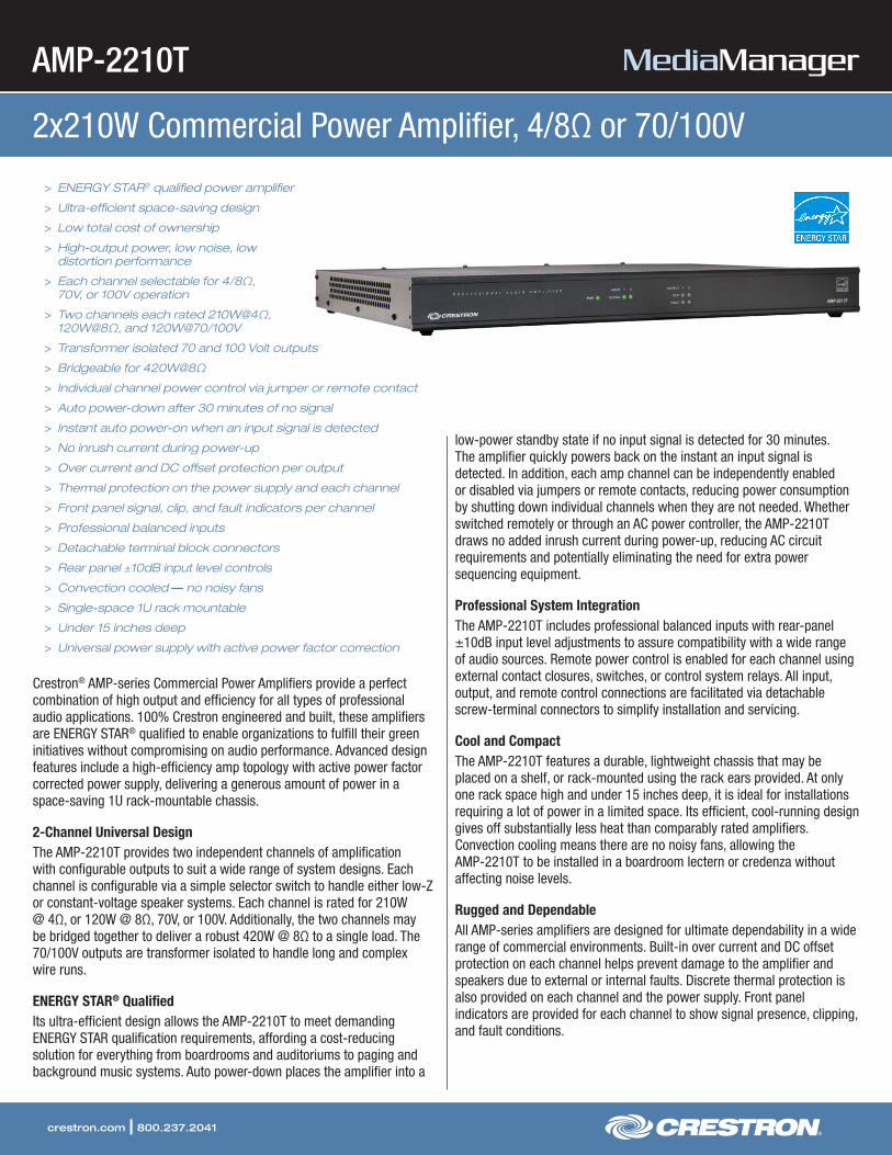
AMP-2210T
2x210W Commercial Power Amplifier, 4/8Ω or 70/100V
crestron.com | 800.237.2041
> ENERGY STAR® qualified power amplifier
> Ultra-efficient space-saving design
> Low total cost of ownership
> High-output power, low noise, low distortion performance
> Each channel selectable for 4/8Ω, 70V, or 100V operation
> Two channels each rated 210W@4Ω, 120W@8Ω, and 120W@70/100V
> Transformer isolated 70 and 100 Volt outputs
> Bridgeable for 420W@8Ω
> Individual channel power control via jumper or remote contact
> Auto power-down after 30 minutes of no signal
> Instant auto power-on when an input signal is detected
> No inrush current during power-up
> Over current and DC offset protection per output
> Thermal protection on the power supply and each channel
> Front panel signal, clip, and fault indicators per channel
> Professional balanced inputs
> Detachable terminal block connectors
> Rear panel ±10dB input level controls
> Convection cooled — no noisy fans
> Single-space 1U rack mountable
> Under 15 inches deep
> Universal power supply with active power factor correction
Crestron® AMP-series Commercial Power Amplifiers provide a perfect combination of high output and efficiency for all types of professional audio applications. 100% Crestron engineered and built, these amplifiers are ENERGY STAR® qualified to enable organizations to fulfill their green initiatives without compromising on audio performance. Advanced design features include a high-efficiency amp topology with active power factor corrected power supply, delivering a generous amount of power in a space-saving 1U rack-mountable chassis.
2-Channel Universal DesignThe AMP-2210T provides two independent channels of amplification with configurable outputs to suit a wide range of system designs. Each channel is configurable via a simple selector switch to handle either low-Z or constant-voltage speaker systems. Each channel is rated for 210W @ 4Ω, or 120W @ 8Ω, 70V, or 100V. Additionally, the two channels may be bridged together to deliver a robust 420W @ 8Ω to a single load. The 70/100V outputs are transformer isolated to handle long and complex wire runs.
ENERGY STAR® QualifiedIts ultra-efficient design allows the AMP-2210T to meet demanding ENERGY STAR qualification requirements, affording a cost-reducing solution for everything from boardrooms and auditoriums to paging and background music systems. Auto power-down places the amplifier into a
low-power standby state if no input signal is detected for 30 minutes. The amplifier quickly powers back on the instant an input signal is detected. In addition, each amp channel can be independently enabled or disabled via jumpers or remote contacts, reducing power consumption by shutting down individual channels when they are not needed. Whether switched remotely or through an AC power controller, the AMP-2210T draws no added inrush current during power-up, reducing AC circuit requirements and potentially eliminating the need for extra power sequencing equipment.
Professional System IntegrationThe AMP-2210T includes professional balanced inputs with rear-panel ±10dB input level adjustments to assure compatibility with a wide range of audio sources. Remote power control is enabled for each channel using external contact closures, switches, or control system relays. All input, output, and remote control connections are facilitated via detachable screw-terminal connectors to simplify installation and servicing.
Cool and CompactThe AMP-2210T features a durable, lightweight chassis that may be placed on a shelf, or rack-mounted using the rack ears provided. At only one rack space high and under 15 inches deep, it is ideal for installations requiring a lot of power in a limited space. Its efficient, cool-running design gives off substantially less heat than comparably rated amplifiers. Convection cooling means there are no noisy fans, allowing the AMP-2210T to be installed in a boardroom lectern or credenza without affecting noise levels.
Rugged and DependableAll AMP-series amplifiers are designed for ultimate dependability in a wide range of commercial environments. Built-in over current and DC offset protection on each channel helps prevent damage to the amplifier and speakers due to external or internal faults. Discrete thermal protection is also provided on each channel and the power supply. Front panel indicators are provided for each channel to show signal presence, clipping, and fault conditions.

AMP-2210T 2x210W Commercial Power Amplifier, 4/8Ω or 70/100V
crestron.com | 800.237.2041
SPECIFICATIONS
Audio
Typical of 2 mono amplifier channels: Input Signal Type: Balanced or unbalanced analog line-levelOutput Signal Types: 4/8 Ohm, 70 Volt, or 100 VoltOutput Power: 120 Watts at 8 Ohms; 210 Watts at 4 Ohms; 420 Watts at 8 Ohms bridged; 120 Watts at 70 or 100 Volts (Transformer isolated)Damping Factor: >100Protection: Over Current, Over/Under Voltage, Over Temperature, DC OffsetFrequency Response: 20Hz to 20kHz ±0.5 dB at 4/8 Ohms; 80Hz to 20kHz +0/-3 dB at 70/100 VoltsTHD: 0.05% @ 1kHz, full rated power at 4/8 Ohms, 8 Ohms Bridged, or 70/100 Volts; 0.1% @ 20Hz to 20kHz, 120W at 8 Ohms; 0.2% @ 20Hz to 20kHz, 210W at 4 Ohms; 0.1% @ 20Hz to 20kHz, 420W at 8 Ohms Bridged; 0.1% @ 80Hz to 20kHz, 120W at 70/100 VoltsS/N Ratio: >103 dB, A-weightedCrosstalk: >70 dB @ 1kHzGain: 23 dB with INPUT LEVEL control set at 12 o’clock nominal positionInput Sensitivity: 2.22 Vrms for rated output power with INPUT LEVEL control set at 12 o’clock nominal positionInput Detection Threshold: 40 mV RMS @ 1 kHzInput Level Adjustment: ±10 dB from nominal
Connectors
G: 6-32 screw, chassis ground lug
INPUT CH 1 – 2: (2) 3-pin 3.5mm detachable terminal blocks;Balanced/unbalanced line-level audio inputs;Input Level: 5.3 Vrms maximum with INPUT LEVEL control set at minimum position;Input Impedance: 24k Ohms balanced, 12k Ohms unbalanced
SPEAKER OUTPUT CH 1 – 2: (2) 4-pin 7.62mm 15A detachable terminal blocks;4Ω/8Ω and 70/100V power amplifier outputs;Wire Size: Terminals accept up to 14 AWG
REMOTE: (1) 6-pin 3.5mm detachable terminal block;Provides (2) remote control inputs; enables independent power control of each channel via local jumpers or remote contact closures;inputs may be safely paralleled for global control
FUSE T6.3AH 250V: Main fuse holder;5x20 mm, 250V, 6.3AH, time-lag, high-rupture rated
100-240V~50/60Hz: (1) IEC C14 male chassis plugs, main power input;Mates with removable power cord (included)
Controls & Indicators
PWR: (1) dual-color LED, green indicates ACTIVE state, yellow indicates STANDBY stateINPUT 1 – 2, SIGNAL: (2) green LEDs, indicate signal presence on each corresponding channelOUTPUT 1 – 2, CLIP: (2) amber LEDs, indicate a clipping condition on each corresponding channelOUTPUT 1 – 2, FAULT: (2) red LEDs; indicate over-temperature, over-current, over or under power supply voltage, or DC offset condition on each corresponding channelINPUT CH 1 – 2 LEVEL (rear): (2) Rotary input boost/attenuate adjustments w/center detent at nominalSPEAKER OUTPUT CH 1 – 2, 100V / 70V / 4/8Ω (rear): (2) 3-position slide switches, select the output configuration for each corresponding channelON/REMOTE/OFF (rear): (1) 3-position slide switch; selects between all channels powered on, all channels powered off, or remote control of each individual channel
Power Requirements
Main Power: 100-240 Volts AC, 50/60 HzPower Consumption: 62 Watts @ 8 Ohms, all channels driven at 1/8th output power; 88 Watts @ 4 Ohms, all channels driven at 1/8th output power; 63 Watts @ 70/100V, all channels driven at 1/8th output power; 26 Watts, all channels idle; <1 Watt in standby
Environmental
Temperature: 41° to 104°F (5° to 40°C)Humidity: 10% to 90% RH (non-condensing)Heat Dissipation: 110 BTU/Hr @ 8 Ohms, all channels driven at 1/8th output power; 121 BTU/Hr @ 4 Ohms, all channels driven at 1/8th output power; 113 BTU/Hr @ 70/100V, all channels driven at 1/8th output power; 89 BTU/Hr, all channels idle; <3.4 BTU/Hr in standby
Enclosure
Chassis: Metal with black finish, vented top and sides, convection cooledFront Panel: Metal, black finish with polycarbonate label overlayMounting: Freestanding or 1U 19-inch rack-mountable (adhesive feet and rack ears included)
Dimensions
Height: 1.70 in (44 mm)Width: 17.28 in (439 mm); 19.0 in (483 mm) with rack earsDepth: 14.59 in (371 mm)
Weight
15.1 lb (6.9 kg)

AMP-2210T 2x210W Commercial Power Amplifier, 4/8Ω or 70/100V
crestron.com | 800.237.2041
MODELS & ACCESSORIES
Available Models
AMP-2210T: 2x210W Commercial Power Amplifier, 4/8Ω or 70/100V
Notes:
This product may be purchased from an authorized Crestron dealer. To find a dealer, please contact the Crestron sales representative for your area. A list of sales representatives is available online at www.crestron.com/salesreps or by calling 800-237-2041.
Specifications subject to change without notice. Crestron is not responsible for errors in typography or photography.
Crestron and the Crestron logo are trademarks or registered trademarks of Crestron Electronics, Inc. in the United States and other countries. ENERGY STAR is either a trademark or registered trademark of the United States Environmental Protection Agency in the United States and/or other countries. Other trademarks and trade names may be used in this document to refer to either the entities claiming the marks and names or their products. Crestron disclaims any proprietary interest in the marks and names of others. ©2011 Crestron Electronics, Inc.
AMP-2210T – Rear View
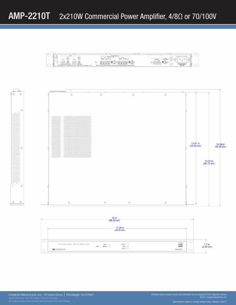
AMP-2210T 2x210W Commercial Power Amplifier, 4/8Ω or 70/100V
Crestron Electronics, Inc. 15 Volvo Drive | Rockleigh, NJ 07647Tel: 800.237.2041 / 201.767.3400 | Fax: 201.7671903
All Crestron products are proudly manufactured in the United States.
All brand names, product names and trademarks are the property of their respective owners. ©2011 Crestron Electronics, Inc.
Specifications subject to change without notice. Revised 10/03/11
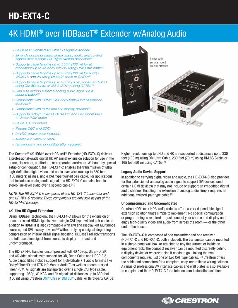
HD-EXT4-C
4K HDMI® over HDBaseT® Extender w/Analog Audio
crestron.com | 800.237.2041
> HDBaseT® Certified 4K Ultra HD signal extender
> Extends uncompressed digital video, audio, and control signals over a single CAT type twisted pair cable [1]
> Supports cable lengths up to 330 ft (100 m) for all resolutions up to 4K and Ultra HD using DM® Ultra cable [1]
> Supports cable lengths up to 330 ft (100 m) for 1080p, WUXGA, and 2K using DM 8G® cable or CAT5e [1]
> Supports cable lengths up to 230 ft (70 m) for 4K and UHD using DM 8G cable, or 165 ft (50 m) using CAT5e [1]
> Can also extend a stereo analog audio signal via a second cable [2]
> Compatible with HDMI®, DVI, and DisplayPort Multimode sources [3]
> Compatible with HDMI and DVI display devices [3]
> Supports Dolby® TrueHD, DTS-HD®, and uncompressed 7.1 linear PCM audio
> HDCP 2.2 compliant
> Passes CEC and EDID
> 24VDC power pack included
> Available in white or black
> No programming or configuration required
The Crestron® 4K HDMI® over HDBaseT® Extender (HD-EXT4-C) delivers a professional-grade digital HD AV signal extension solution for use in the home, classroom, auditorium, or corporate boardroom. Without any special setup or configuration, the HD-EXT4-C enables the transmission of ultra high-definition digital video and audio over wire runs up to 330 feet (100 meters) using a single CAT type twisted pair cable. For applications that include an analog audio signal, the HD-EXT4-C can also handle stereo line-level audio over a second cable.[1,2]
NOTE: The HD-EXT4-C is composed of one HD-TX4-C transmitter and one HD-RX4-C receiver. These components are only sold as part of the HD-EXT4-C package.
4K Ultra HD Signal ExtensionUsing HDBaseT technology, the HD-EXT4-C allows for the extension of uncompressed HDMI signals over a single CAT type twisted pair cable. In addition to HDMI, it is also compatible with DVI and DisplayPort Multimode sources, and DVI display devices.[2] Without relying on signal-degrading compression or inferior HDMI signal boosting, HDBaseT reliably transports the full resolution signal from source to display — intact and uncompromised.
The HD-EXT4-C handles uncompressed Full HD 1080p, Ultra HD, 2K, and 4K video signals with support for 3D, Deep Color, and HDCP 2.2. Audio capabilities include support for high-bitrate 7.1 audio formats like Dolby® TrueHD and DTS-HD Master Audio™ as well as uncompressed linear PCM. All signals are transported over a single CAT type cable, supporting 1080p, WUXGA, and 2K signals at distances up to 330 feet (100 m) using Crestron DM® Ultra or DM 8G® Cable, or third-party CAT5e.
Higher resolutions up to UHD and 4K are supported at distances up to 330 feet (100 m) using DM Ultra Cable, 230 feet (70 m) using DM 8G Cable, or 165 feet (50 m) using CAT5e.[1]
Legacy Audio Device SupportIn addition to carrying digital video and audio, the HD-EXT4-C also provides for the extension of an analog audio signal to support DVI devices (and certain HDMI devices) that may not include or support an embedded digital audio channel. Enabling the extension of analog audio simply requires an additional twisted-pair type cable.[2]
Uncompromised and UncomplicatedCrestron HDMI over HDBaseT products afford a very dependable signal extension solution that’s simple to implement. No special configuration or programming is required — just connect your source and display and enjoy high-quality video and audio from across the room — or the other end of the house.
The HD-EXT4-C is composed of one transmitter and one receiver (HD-TX4-C and HD-RX4-C, both included). The transmitter can be mounted in a single-gang wall box, or attached to any flat surface or inside an equipment rack. The compact receiver can be mounted discreetly behind a display device or wherever else it needs to go. Linking the two components requires just one or two CAT type cables.[1,2] Crestron offers the cable and connectors for a complete, easy, and reliable wiring solution. A range of professional AV interface cables and wall plates is also available to complement the HD-EXT4-C for a total custom installation solution.
Shown with surface mount bracket attached
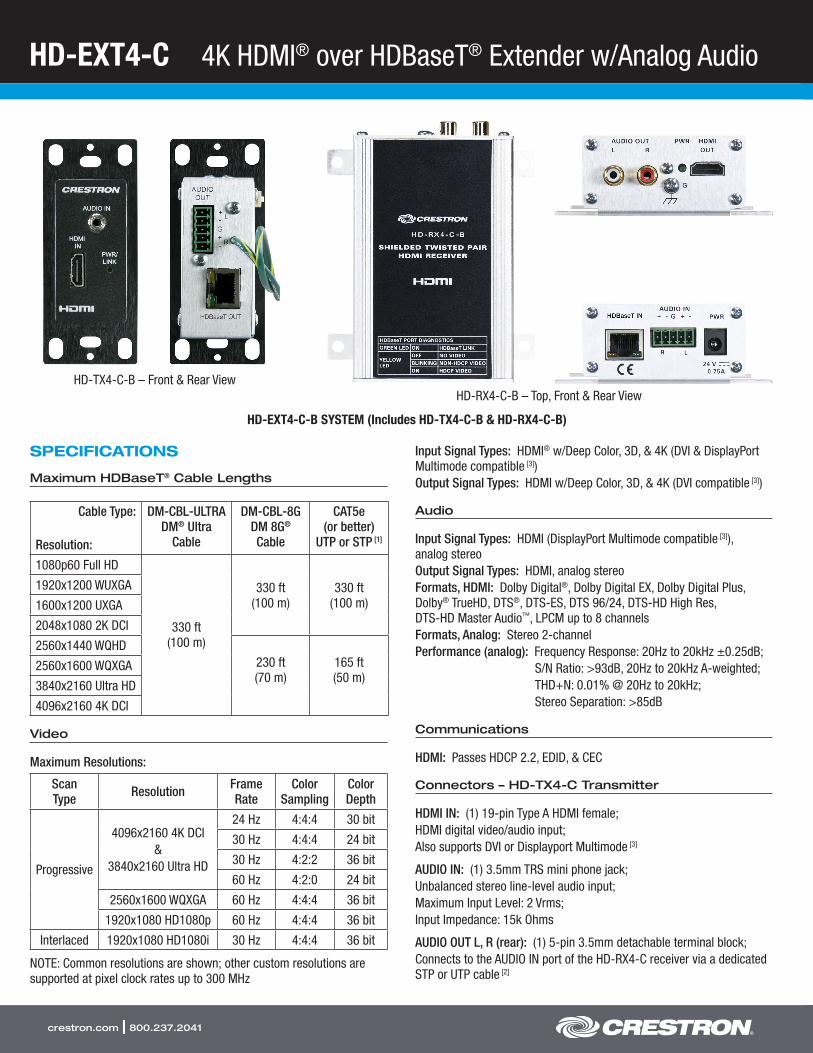
HD-EXT4-C 4K HDMI® over HDBaseT® Extender w/Analog Audio
crestron.com | 800.237.2041
SPECIFICATIONS
Maximum HDBaseT® Cable Lengths
Cable Type:
Resolution:
DM-CBL-ULTRA DM® Ultra
Cable
DM-CBL-8G DM 8G® Cable
CAT5e (or better)
UTP or STP [1]
1080p60 Full HD
330 ft (100 m)
330 ft (100 m)
330 ft (100 m)
1920x1200 WUXGA
1600x1200 UXGA
2048x1080 2K DCI
2560x1440 WQHD230 ft (70 m)
165 ft (50 m)
2560x1600 WQXGA
3840x2160 Ultra HD
4096x2160 4K DCI
Video
Maximum Resolutions:
Scan Type Resolution Frame
RateColor
SamplingColor Depth
Progressive
4096x2160 4K DCI&
3840x2160 Ultra HD
24 Hz 4:4:4 30 bit
30 Hz 4:4:4 24 bit
30 Hz 4:2:2 36 bit
60 Hz 4:2:0 24 bit
2560x1600 WQXGA 60 Hz 4:4:4 36 bit
1920x1080 HD1080p 60 Hz 4:4:4 36 bit
Interlaced 1920x1080 HD1080i 30 Hz 4:4:4 36 bit
NOTE: Common resolutions are shown; other custom resolutions are supported at pixel clock rates up to 300 MHz
Input Signal Types: HDMI® w/Deep Color, 3D, & 4K (DVI & DisplayPort Multimode compatible [3])Output Signal Types: HDMI w/Deep Color, 3D, & 4K (DVI compatible [3])
Audio
Input Signal Types: HDMI (DisplayPort Multimode compatible [3]), analog stereoOutput Signal Types: HDMI, analog stereoFormats, HDMI: Dolby Digital®, Dolby Digital EX, Dolby Digital Plus, Dolby® TrueHD, DTS®, DTS-ES, DTS 96/24, DTS-HD High Res, DTS-HD Master Audio™, LPCM up to 8 channelsFormats, Analog: Stereo 2-channelPerformance (analog): Frequency Response: 20Hz to 20kHz ±0.25dB;
S/N Ratio: >93dB, 20Hz to 20kHz A-weighted;THD+N: 0.01% @ 20Hz to 20kHz;Stereo Separation: >85dB
Communications
HDMI: Passes HDCP 2.2, EDID, & CEC
Connectors – HD-TX4-C Transmitter
HDMI IN: (1) 19-pin Type A HDMI female;HDMI digital video/audio input;Also supports DVI or Displayport Multimode [3]
AUDIO IN: (1) 3.5mm TRS mini phone jack;Unbalanced stereo line-level audio input;Maximum Input Level: 2 Vrms;Input Impedance: 15k Ohms
AUDIO OUT L, R (rear): (1) 5-pin 3.5mm detachable terminal block;Connects to the AUDIO IN port of the HD-RX4-C receiver via a dedicated STP or UTP cable [2]
HD-TX4-C-B – Front & Rear ViewHD-RX4-C-B – Top, Front & Rear View
HD-EXT4-C-B SYSTEM (Includes HD-TX4-C-B & HD-RX4-C-B)
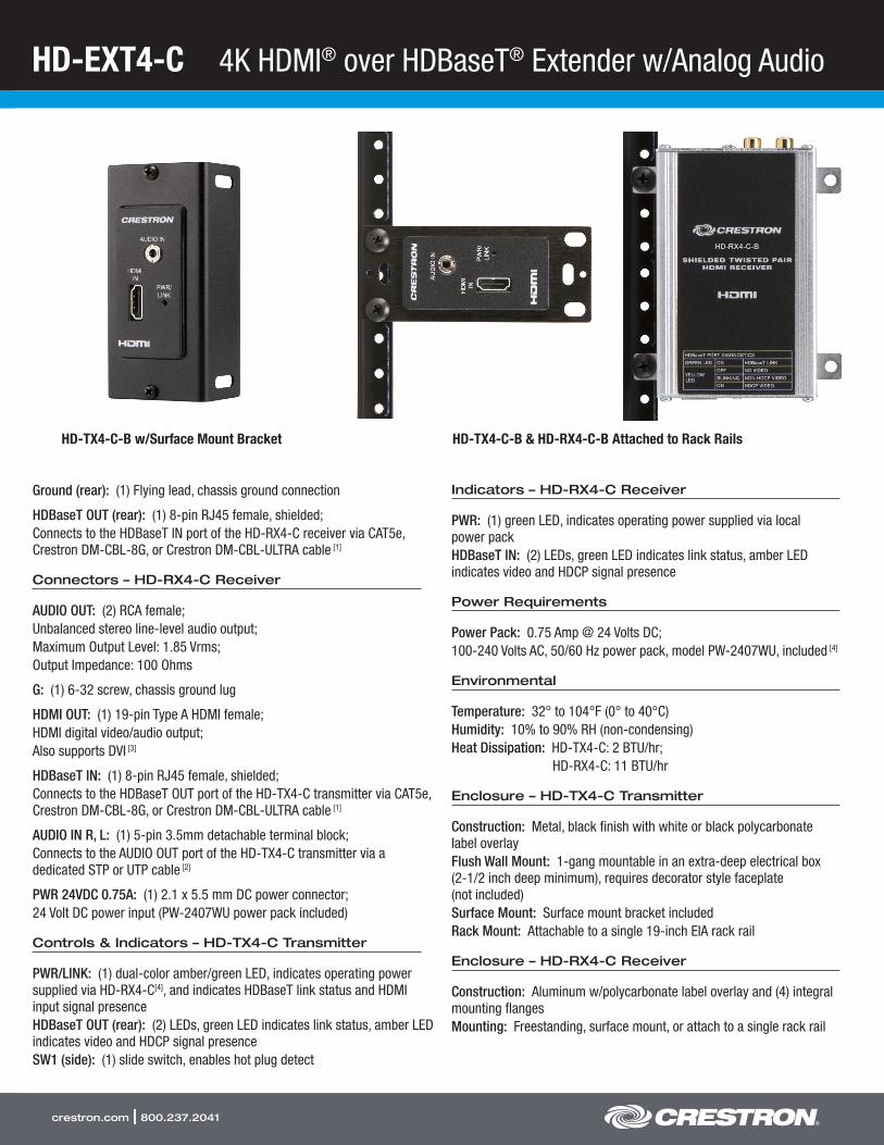
HD-EXT4-C 4K HDMI® over HDBaseT® Extender w/Analog Audio
crestron.com | 800.237.2041
Ground (rear): (1) Flying lead, chassis ground connection
HDBaseT OUT (rear): (1) 8-pin RJ45 female, shielded;Connects to the HDBaseT IN port of the HD-RX4-C receiver via CAT5e, Crestron DM-CBL-8G, or Crestron DM-CBL-ULTRA cable [1]
Connectors – HD-RX4-C Receiver
AUDIO OUT: (2) RCA female;Unbalanced stereo line-level audio output;Maximum Output Level: 1.85 Vrms;Output Impedance: 100 Ohms
G: (1) 6-32 screw, chassis ground lug
HDMI OUT: (1) 19-pin Type A HDMI female;HDMI digital video/audio output;Also supports DVI [3]
HDBaseT IN: (1) 8-pin RJ45 female, shielded;Connects to the HDBaseT OUT port of the HD-TX4-C transmitter via CAT5e, Crestron DM-CBL-8G, or Crestron DM-CBL-ULTRA cable [1]
AUDIO IN R, L: (1) 5-pin 3.5mm detachable terminal block;Connects to the AUDIO OUT port of the HD-TX4-C transmitter via a dedicated STP or UTP cable [2]
PWR 24VDC 0.75A: (1) 2.1 x 5.5 mm DC power connector;24 Volt DC power input (PW-2407WU power pack included)
Controls & Indicators – HD-TX4-C Transmitter
PWR/LINK: (1) dual-color amber/green LED, indicates operating power supplied via HD-RX4-C[4], and indicates HDBaseT link status and HDMI input signal presenceHDBaseT OUT (rear): (2) LEDs, green LED indicates link status, amber LED indicates video and HDCP signal presenceSW1 (side): (1) slide switch, enables hot plug detect
Indicators – HD-RX4-C Receiver
PWR: (1) green LED, indicates operating power supplied via local power packHDBaseT IN: (2) LEDs, green LED indicates link status, amber LED indicates video and HDCP signal presence
Power Requirements
Power Pack: 0.75 Amp @ 24 Volts DC;100-240 Volts AC, 50/60 Hz power pack, model PW-2407WU, included [4]
Environmental
Temperature: 32° to 104°F (0° to 40°C)Humidity: 10% to 90% RH (non-condensing)Heat Dissipation: HD-TX4-C: 2 BTU/hr;
HD-RX4-C: 11 BTU/hr
Enclosure – HD-TX4-C Transmitter
Construction: Metal, black finish with white or black polycarbonate label overlayFlush Wall Mount: 1-gang mountable in an extra-deep electrical box (2-1/2 inch deep minimum), requires decorator style faceplate (not included)Surface Mount: Surface mount bracket includedRack Mount: Attachable to a single 19-inch EIA rack rail
Enclosure – HD-RX4-C Receiver
Construction: Aluminum w/polycarbonate label overlay and (4) integral mounting flangesMounting: Freestanding, surface mount, or attach to a single rack rail
HD-TX4-C-B w/Surface Mount Bracket HD-TX4-C-B & HD-RX4-C-B Attached to Rack Rails

HD-EXT4-C 4K HDMI® over HDBaseT® Extender w/Analog Audio
crestron.com | 800.237.2041
Dimensions
HD-TX4-C Transmitter: Height: 4.12 in (105 mm); Width: 1.72 in (44 mm); Depth: 2.38 in (61 mm)
HD-RX4-C Receiver: Height: 1.43 in (37 mm); Width: 3.91 in (100 mm); Depth: 4.85 in (124 mm)
Weight
HD-TX4-C Transmitter: 5.8 oz (165 g)HD-RX4-C Receiver: 11.6 oz (330 g)
MODELS & ACCESSORIES
Available Models
HD-EXT4-C-B_SYSTEM: 4K HDMI® over HDBaseT® Extender w/Analog Audio, BlackHD-EXT4-C-W_SYSTEM: 4K HDMI® over HDBaseT® Extender w/Analog Audio, White
Included Accessories
PW-2407WU: Wall Mount Power Pack 24VDC, 0.75A, Universal (Qty. 1 included)
Available Accessories
DM-CBL-ULTRA-NP: DigitalMedia™ Ultra Cable, Non-Plenum Type CMRDM-CBL-ULTRA-P: DigitalMedia™ Ultra Cable, Plenum Type CMPDM-CBL-ULTRA-LSZH: DigitalMedia™ Ultra Cable, Low Smoke Zero HalogenDM-CONN: Connector for DM-CBL-ULTRADM-CBL-8G-NP: DigitalMedia 8G™ Cable, non-plenumDM-CBL-8G-P: DigitalMedia 8G™ Cable, plenumDM-8G-CONN-WG: Connector with Wire Guide for DM-CBL-8GDM-8G-CRIMP-WG: Crimping Tool for DM-8G-CONN-WGDM-8G-CONN: Connector for DM-CBL-8GDM-8G-CRIMP: Crimping Tool for DM-8G-CONNCBL Series: Crestron® Certified Interface CablesMP-WP Series: Media Presentation Wall PlatesMPI-WP Series: Media Presentation Wall Plates - International Version
Notes:
1. The maximum cable length for HDBaseT is dependent upon the type of cable and resolution of the video signal. Refer to the “Maximum HDBaseT Cable Lengths” table for a detailed overview. Shielded cable and connectors are recommended to safeguard against unpredictable environmental electrical noise which may impact performance at resolutions above 1080p. All wire and cables are sold separately.
2. For the balanced analog “AUDIO” connection between the HD-TX4-C transmitter and HD-RX4-C receiver, use dual-twisted pair shielded audio cable or quality CAT5 (or better) UTP or STP. Crestron DM-CBL-8G DigitalMedia 8G Cable is recommended.
3. HDMI IN requires an appropriate adapter or interface cable to accommodate a DVI or DisplayPort Multimode signal. HDMI OUT requires an appropriate adapter or interface cable to accommodate a DVI signal. CBL-HD-DVI interface cables are available separately.
4. The power pack must be connected to the HD-RX4-C receiver. Power is passed to the HD-TX4-C transmitter via the HDBaseT connection. Please note, the HD-TX4-C and HD-RX4-C are not PoH compatible. They cannot be powered by, or supply power to, another HDBaseT device. They may however be connected to such devices without risk of malfunction.
This product may be purchased from an authorized Crestron dealer. To find a dealer, please contact the Crestron sales representative for your area. A list of sales representatives is available online at www.crestron.com/salesreps or by calling 800-237-2041.
The specific patents that cover Crestron products are listed online at: patents.crestron.com.
Crestron, the Crestron logo, DigitalMedia, DigitalMedia 8G, DM, and DM 8G are either trademarks or registered trademarks of Crestron Electronics, Inc. in the United States and/or other countries. Dolby and Dolby Digital are either trademarks or registered trademarks of Dolby Laboratories in the United States and/or other countries. DTS, DTS-HD, and DTS-HD Master Audio are either trademarks or registered trademarks of DTS, Inc. in the United States and/or other countries. HDBaseT and the HDBaseT Alliance logo are either trademarks or registered trademarks of the HDBaseT Alliance in the United States and/or other countries. HDMI and the HDMI Logo are either trademarks or registered trademarks of HDMI Licensing LLC in the United States and/or other countries. Other trademarks, registered trademarks, and trade names may be used in this document to refer to either the entities claiming the marks and names or their products. Crestron disclaims any proprietary interest in the marks and names of others. Crestron is not responsible for errors in typography or photography. Specifications are subject to change without notice. ©2015 Crestron Electronics, Inc.

HD-EXT4-C 4K HDMI® over HDBaseT® Extender w/Analog Audio
crestron.com | 800.237.2041
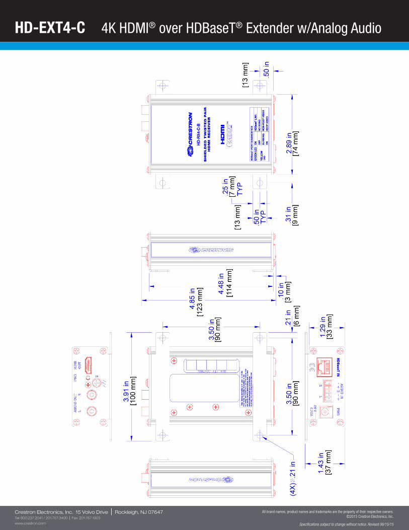
HD-EXT4-C 4K HDMI® over HDBaseT® Extender w/Analog Audio
Crestron Electronics, Inc. 15 Volvo Drive | Rockleigh, NJ 07647Tel: 800.237.2041 / 201.767.3400 | Fax: 201.767.1903
www.crestron.com
All brand names, product names and trademarks are the property of their respective owners. ©2015 Crestron Electronics, Inc.
Specifications subject to change without notice. Revised 06/15/15
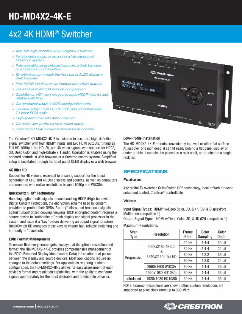
HD-MD4X2-4K-E
4x2 4K HDMI® Switcher
crestron.com | 800.237.2041
> 4x2 ultra high-definition 4K/60 digital AV switcher
> For standalone use, or as part of a fully integrated Crestron® system
> Fully operable using onboard controls, a Web browser, or a Crestron control system
> Simplified setup through the front panel OLED display or Web browser
> Four HDMI® inputs and two independent HDMI outputs
> DVI and DisplayPort Multimode compatible [1]
> QuickSwitch HD® technology manages HDCP keys for fast, reliable switching
> Comprehensive built-in EDID configuration tools
> Handles Dolby® TrueHD, DTS-HD®, and uncompressed 7.1 linear PCM audio
> High-speed Ethernet LAN connection
> Compact, low-profile surface mount design
> Universal 100-240V external power pack included
The Crestron® HD-MD4X2-4K-E is a simple to use, ultra high-definition signal switcher with four HDMI® inputs and two HDMI outputs. It handles Full HD 1080p, Ultra HD, 2K, and 4K video signals with support for HDCP, 3D, Deep Color, and high-bitrate 7.1 audio. Operation is enabled using the onboard controls, a Web browser, or a Crestron control system. Simplified setup is facilitated through the front panel OLED display or a Web browser.
4K Ultra HDSupport for 4K video is essential to ensuring support for the latest generation of UHD and 4K DCI displays and sources, as well as computers and monitors with native resolutions beyond 1080p and WUXGA.
QuickSwitch HD® TechnologyHandling digital media signals means handling HDCP (High-bandwidth Digital Content Protection), the encryption scheme used by content providers to protect their DVDs, Blu-ray™ discs, and broadcast signals against unauthorized copying. Viewing HDCP encrypted content requires a source device to “authenticate” each display and signal processor in the system and issue it a “key” before delivering an output signal. Crestron QuickSwitch HD manages these keys to ensure fast, reliable switching and immunity to “blackouts.”
EDID Format ManagementTo ensure that every source gets displayed at its optimal resolution and format, the HD-MD4X2-4K-E provides comprehensive management of the EDID (Extended Display Identification Data) information that passes between the display and source devices. Most applications require no changes to the default settings. For applications requiring custom configuration, the HD-MD4X2-4K-E allows for easy assessment of each device’s format and resolution capabilities, with the ability to configure signals appropriately for the most desirable and predictable behavior.
Low-Profile InstallationThe HD-MD4X2-4K-E mounts conveniently to a wall or other flat surface. At just over one inch deep, it can fit easily behind a flat panel display or under a table. It can also be placed on a rack shelf, or attached to a single rack rail.
SPECIFICATIONS
Features
4x2 digital AV switcher, QuickSwitch HD® technology, local or Web browser setup and control, Crestron® controllable
Video:
Input Signal Types: HDMI® w/Deep Color, 3D, & 4K (DVI & DisplayPort Multimode compatible [1]) Output Signal Types: HDMI w/Deep Color, 3D, & 4K (DVI compatible [1])
Maximum Resolutions:
Scan Type Resolution Frame
RateColor
SamplingColor Depth
Progressive
4096x2160 4K DCI&
3840x2160 Ultra HD
24 Hz 4:4:4 30 bit
30 Hz 4:4:4 24 bit
30 Hz 4:2:2 36 bit
60 Hz 4:2:0 24 bit
2560x1600 WQXGA 60 Hz 4:4:4 36 bit
1920x1080 HD1080p 60 Hz 4:4:4 36 bit
Interlaced 1920x1080 HD1080i 30 Hz 4:4:4 36 bit
NOTE: Common resolutions are shown; other custom resolutions are supported at pixel clock rates up to 300 MHz

HD-MD4X2-4K-E 4x2 4K HDMI® Switcher
crestron.com | 800.237.2041
Audio
Input Signal Types: HDMI (DisplayPort Multimode compatible [1]) Output Signal Types: HDMI Formats: Dolby Digital®, Dolby Digital EX, Dolby Digital Plus, Dolby® TrueHD, DTS®, DTS-ES, DTS 96/24, DTS-HD High Res, DTS-HD Master Audio™, LPCM up to 8 channels [6]
Communications
Ethernet: 10/100 Mbps, auto-switching, auto-negotiating, auto-discovery, full/half duplex, DHCP, Web browser setup and control, Crestron control system integration USB: For factory use only HDMI: HDCP, EDID
NOTE: Supports management of EDID
Connectors
INPUT 1 – 4: (4) 19-pin Type A HDMI female;HDMI digital video/audio inputs;Also supports DVI and DisplayPort Multimode [1]
OUTPUT 1 – 2: (2) 19-pin Type A HDMI female;HDMI digital video/audio outputs;Also supports DVI [1]
LAN: (1) 8-wire RJ45 female;10Base-T/100Base-TX Ethernet port
24VDC 0.75A: (1) 2.1 x 5.5 mm DC power connector;24 Volt DC power input;PW-2407WU power pack included
SERVICE: (1) USB Type A female;For factory use only
Display
Display Type: 2x20 character alphanumeric OLED Functions: Displays setup and configuration menus, signal information, customizable input names
Controls & Indicators
MENU: (1) pushbutton, opens the setup menu p,q,t,u: (4) pushbuttons, for menu navigation and parameter adjustment Enter: (1) pushbutton, applies a change BACK: (1) pushbutton, steps menu back one level EXIT: (1) pushbutton, exits the menu PWR: (1) bicolor green/amber LED, indicates operating power supplied from power pack, turns amber while booting and green when operating INPUT 1 – 4: (4) pushbuttons for input selection, and (4) bicolor green/amber LEDs to indicate which input is currently routed or pending output selection, and signal presence at each corresponding input OUTPUT 1 – 2: (2) pushbuttons for output selection, and (2) bicolor green/amber LEDs to indicate sink detection and signal presence at each corresponding HDMI output
LAN: (2) LEDs, amber LED indicates Ethernet activity, green LED indicates Ethernet link status
Power Requirements
Power Pack: 0.75 Amps @ 24 Volts DC;100-240 Volts AC, 50/60 Hz power pack, model PW-2407WU included
Environmental
Temperature: 32° to 104°F (0° to 40°C) Humidity: 10% to 90% RH (non-condensing)
Enclosure
Chassis: Metal, black finish, with (2) integral mounting flanges Mounting: Freestanding, surface mount, or attach to a single rack rail
Dimensions
Height: 4.08 in (104 mm) Width: 8.68 in (221 mm) Depth: 1.08 in (28 mm)
Weight
1.35 lb (0.62 kg)
HD-MD4X2-4K-E – Top, Front, and Bottom Views
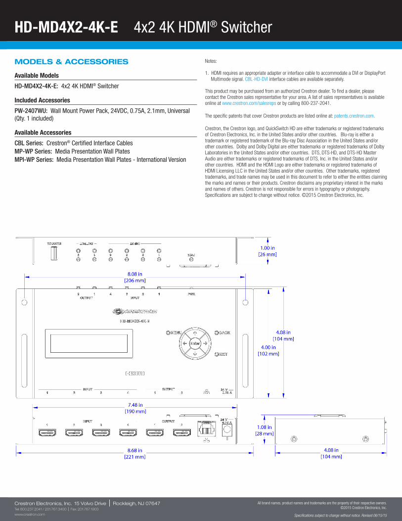
HD-MD4X2-4K-E 4x2 4K HDMI® Switcher
Crestron Electronics, Inc. 15 Volvo Drive | Rockleigh, NJ 07647Tel: 800.237.2041 / 201.767.3400 | Fax: 201.767.1903
www.crestron.com
All brand names, product names and trademarks are the property of their respective owners. ©2015 Crestron Electronics, Inc.
Specifications subject to change without notice. Revised 06/15/15
MODELS & ACCESSORIES
Available Models
HD-MD4X2-4K-E: 4x2 4K HDMI® Switcher
Included Accessories
PW-2407WU: Wall Mount Power Pack, 24VDC, 0.75A, 2.1mm, Universal (Qty. 1 included)
Available Accessories
CBL Series: Crestron® Certified Interface CablesMP-WP Series: Media Presentation Wall PlatesMPI-WP Series: Media Presentation Wall Plates - International Version
Notes:
1. HDMI requires an appropriate adapter or interface cable to accommodate a DVI or DisplayPort Multimode signal. CBL-HD-DVI interface cables are available separately.
This product may be purchased from an authorized Crestron dealer. To find a dealer, please contact the Crestron sales representative for your area. A list of sales representatives is available online at www.crestron.com/salesreps or by calling 800-237-2041.
The specific patents that cover Crestron products are listed online at: patents.crestron.com.
Crestron, the Crestron logo, and QuickSwitch HD are either trademarks or registered trademarks of Crestron Electronics, Inc. in the United States and/or other countries. Blu-ray is either a trademark or registered trademark of the Blu-ray Disc Association in the United States and/or other countries. Dolby and Dolby Digital are either trademarks or registered trademarks of Dolby Laboratories in the United States and/or other countries. DTS, DTS-HD, and DTS-HD Master Audio are either trademarks or registered trademarks of DTS, Inc. in the United States and/or other countries. HDMI and the HDMI Logo are either trademarks or registered trademarks of HDMI Licensing LLC in the United States and/or other countries. Other trademarks, registered trademarks, and trade names may be used in this document to refer to either the entities claiming the marks and names or their products. Crestron disclaims any proprietary interest in the marks and names of others. Crestron is not responsible for errors in typography or photography. Specifications are subject to change without notice. ©2015 Crestron Electronics, Inc.

MP-AMP30
Media Presentation Audio Amplifier
crestron.com | 800.237.2041
> Compact stereo power amplifier
> 15 Watts per channel into 8 or 4 Ohms
> Stereo or mono-summed operation
> High-efficiency Class D topology
> Energy saving design reduces power consumption when idle
> Convection cooled for noiseless operation
> Simple volume, bass, and treble adjustments
> Built-in loudness contour circuit
> Electronic short-circuit and overload protection
> Detachable terminal block speaker connections
> Unbalanced RCA line input, 3’ cable included
> Integral surface mounting flanges
> UL 2043 compliant for installation within a plenum-rated suspended ceiling[1]
The Crestron® MP-AMP30 provides a convenient, low-cost audio amplifier solution for a variety of applications. A perfect complement to the entire Media Presentation line from Crestron, it features a compact surface-mountable design that installs virtually anywhere without requiring an equipment rack. The MP-AMP30 meets the requirements of UL 2043 for installation in an environmental air-handling (plenum) space, such as above a suspended ceiling[1].
High-efficiency Class D circuitry delivers 15 Watts per channel to drive one or two pairs of 8 Ohm speakers, or a single pair of 4 Ohm speakers, making it ideal to support stereo speakers at the front of a room or mono speakers in the ceiling. Mono-summed operation is enabled by changing two jumpers on the front panel.
Refined, reliable operation is ensured thanks to pop-free turn-on circuitry and electronic short-circuit and overload protection. An energy-saving design achieves optimum efficiency under load, and the amplifier powers down automatically when no input signal is detected for more than 5 minutes, reducing overall power consumption and heat as part of a green system design. The amplifier quickly powers back on the instant an input signal is detected. Its extruded aluminum housing is both attractive and effective at dissipating heat, affording a silent running design without cooling fans.
Installation and setup of the MP-AMP30 is simple. Detachable output connectors facilitate the termination of speaker wiring up to 16 gauge. RCA inputs connect directly to the line output of a video projector or display, audio processor, mixer, or AV switcher. Rotary controls provide for adjusting the overall speaker volume, as well as bass and treble. For quiet environments, loudness compensation is employed by setting the volume control below the center detent position.
SPECIFICATIONS
Audio
Input Volume Range: -55dB to +20dBLoudness: Active at volume settings below center detentBass Gain Range: ±15dB @ 100HzTreble Gain Range: ±15dB @ 10kHzFrequency Response: 20Hz to 20kHz ±0.5dBS/N Ratio: 75dB 20Hz to 20kHz A-weighted THD+N: 0.7% 20Hz to 20kHzOutput Power: 15 Watts per channel at 8 or 4 OhmsAmplifier Protection: Electronic short-circuit and overload protection
Connectors – Top Panel
AUDIO OUT 8Ω: (2) 2-pin 3.5mm detachable terminal blocks;Left & right channel speaker-level audio outputs;Wire Size: Connector accepts 16 AWG maximum;Output Power: 15 Watts per channel at 8 or 4 Ohms
Connectors – Bottom Panel
AUDIO IN: (2) RCA female, unbalanced stereo line-level audio input;Maximum Input Level: 2 Vrms;Input Impedance: 18k Ohms;3 ft (0.9 m) stereo RCA-RCA cable included
PWR 24VDC 2.0A: (1) 2.1 x 5.5 mm DC power connector;24 Volt DC power input;(power pack included)

MP-AMP30 Media Presentation Audio Amplifier
crestron.com | 800.237.2041
Controls & Indicators
BASS: Rotary low frequency boost/cut adjustment, flat at center detentTREBLE: Rotary high frequency boost/cut adjustment, flat at center detentVOL: Rotary input level adjustmentST, MO: Mode selection jumpers, select stereo or mono-summed operationPower: (1) green LED, indicates operating power supplied from external power pack
Power Requirements
Power Pack: 2.0 Amps @ 24 Volts DC;100-240 Volts AC, 50/60 Hz power pack included
Environmental
Temperature: 41° to 104°F (5° to 40°C)Humidity: 10% to 90% RH (non-condensing)Heat Dissipation: 21 BTU/Hr
Enclosure
Chassis: Aluminum w/polycarbonate label overlay and (4) integral mounting flanges, meets the requirements of UL 2043 for installation in an environmental air-handling (plenum) space[1]
Mounting: Freestanding or surface mount
Dimensions
Height: 5.85 in (149 mm)Width: 3.91 in (100 mm)Depth: 1.43 in (37 mm)
Weight
11.8 oz (335 g)
MODELS & ACCESSORIES
Available Models
MP-AMP30: Media Presentation Audio Amplifier
Included Accessories
CBL Series: Crestron® Certified Interface CablesCBL-KAUDIO-RCAM2-L-P-50: RCA Stereo Audio Cable Kit, Plenum, 50 ftCBL-SPK-P-35: Speaker Cable, 16AWG, Plenum, 35 ftCBL-PWR-EXT24V-P-6: DC Power Extension Cable, Plenum, 6 ftMP-WP Series: Media Presentation Wall PlatesMPI-WP Series: Media Presentation Wall Plates - International Version
MP-AMP30 – Front, Top and Bottom Views
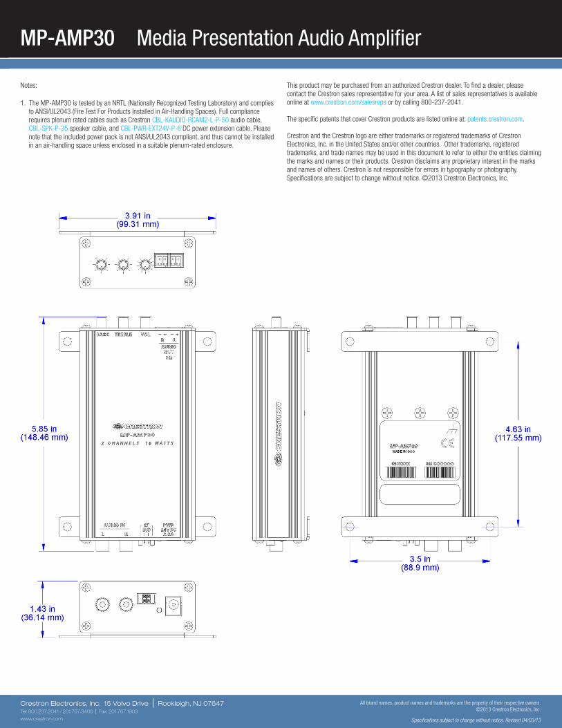
MP-AMP30 Media Presentation Audio Amplifier
Crestron Electronics, Inc. 15 Volvo Drive | Rockleigh, NJ 07647Tel: 800.237.2041 / 201.767.3400 | Fax: 201.767.1903
www.crestron.com
All brand names, product names and trademarks are the property of their respective owners. ©2013 Crestron Electronics, Inc.
Specifications subject to change without notice. Revised 04/03/13
Notes:
1. The MP-AMP30 is tested by an NRTL (Nationally Recognized Testing Laboratory) and complies to ANSI/UL2043 (Fire Test For Products Installed in Air-Handling Spaces). Full compliance requires plenum rated cables such as Crestron CBL-KAUDIO-RCAM2-L-P-50 audio cable, CBL-SPK-P-35 speaker cable, and CBL-PWR-EXT24V-P-6 DC power extension cable. Please note that the included power pack is not ANSI/UL2043 compliant, and thus cannot be installed in an air-handling space unless enclosed in a suitable plenum-rated enclosure.
This product may be purchased from an authorized Crestron dealer. To find a dealer, please contact the Crestron sales representative for your area. A list of sales representatives is available online at www.crestron.com/salesreps or by calling 800-237-2041.
The specific patents that cover Crestron products are listed online at: patents.crestron.com.
Crestron and the Crestron logo are either trademarks or registered trademarks of Crestron Electronics, Inc. in the United States and/or other countries. Other trademarks, registered trademarks, and trade names may be used in this document to refer to either the entities claiming the marks and names or their products. Crestron disclaims any proprietary interest in the marks and names of others. Crestron is not responsible for errors in typography or photography. Specifications are subject to change without notice. ©2013 Crestron Electronics, Inc.
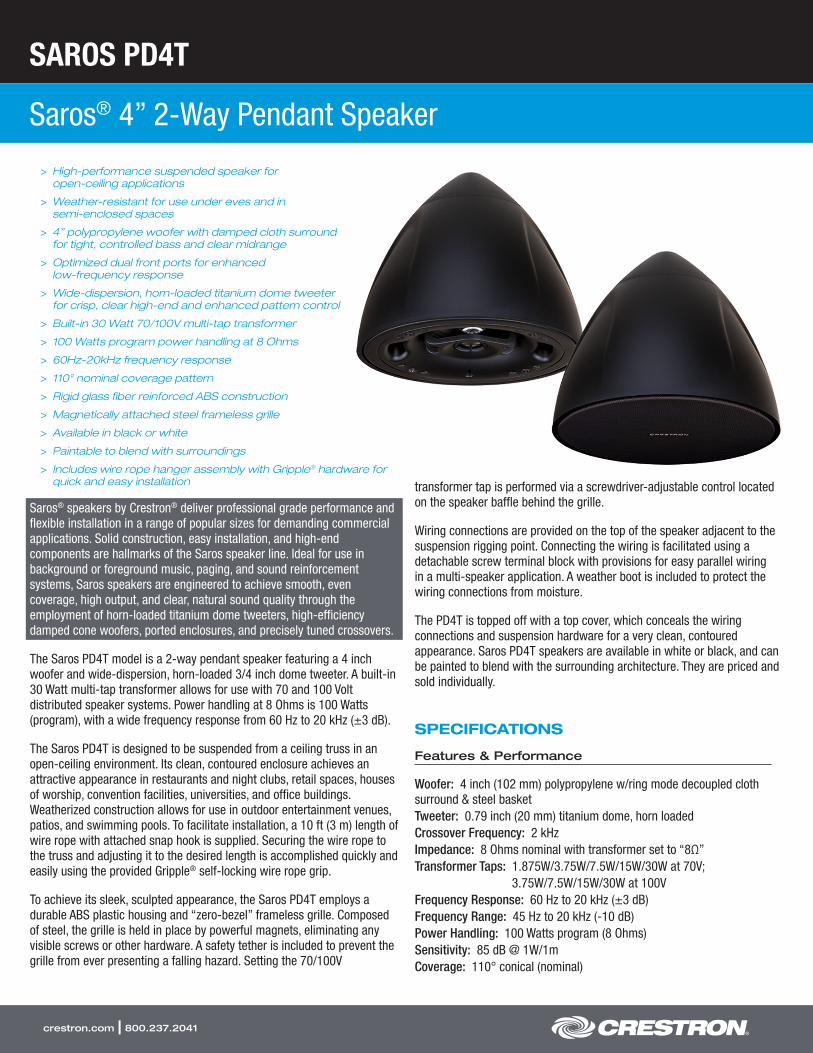
SAROS PD4T
Saros® 4” 2-Way Pendant Speaker
crestron.com | 800.237.2041
> High-performance suspended speaker for open-ceiling applications
> Weather-resistant for use under eves and in semi-enclosed spaces
> 4” polypropylene woofer with damped cloth surround for tight, controlled bass and clear midrange
> Optimized dual front ports for enhanced low-frequency response
> Wide-dispersion, horn-loaded titanium dome tweeter for crisp, clear high-end and enhanced pattern control
> Built-in 30 Watt 70/100V multi-tap transformer
> 100 Watts program power handling at 8 Ohms
> 60Hz-20kHz frequency response
> 110° nominal coverage pattern
> Rigid glass fiber reinforced ABS construction
> Magnetically attached steel frameless grille
> Available in black or white
> Paintable to blend with surroundings
> Includes wire rope hanger assembly with Gripple® hardware for quick and easy installation
Saros® speakers by Crestron® deliver professional grade performance and flexible installation in a range of popular sizes for demanding commercial applications. Solid construction, easy installation, and high-end components are hallmarks of the Saros speaker line. Ideal for use in background or foreground music, paging, and sound reinforcement systems, Saros speakers are engineered to achieve smooth, even coverage, high output, and clear, natural sound quality through the employment of horn-loaded titanium dome tweeters, high-efficiency damped cone woofers, ported enclosures, and precisely tuned crossovers.
The Saros PD4T model is a 2-way pendant speaker featuring a 4 inch woofer and wide-dispersion, horn-loaded 3/4 inch dome tweeter. A built-in 30 Watt multi-tap transformer allows for use with 70 and 100 Volt distributed speaker systems. Power handling at 8 Ohms is 100 Watts (program), with a wide frequency response from 60 Hz to 20 kHz (±3 dB).
The Saros PD4T is designed to be suspended from a ceiling truss in an open-ceiling environment. Its clean, contoured enclosure achieves an attractive appearance in restaurants and night clubs, retail spaces, houses of worship, convention facilities, universities, and office buildings. Weatherized construction allows for use in outdoor entertainment venues, patios, and swimming pools. To facilitate installation, a 10 ft (3 m) length of wire rope with attached snap hook is supplied. Securing the wire rope to the truss and adjusting it to the desired length is accomplished quickly and easily using the provided Gripple® self-locking wire rope grip.
To achieve its sleek, sculpted appearance, the Saros PD4T employs a durable ABS plastic housing and “zero-bezel” frameless grille. Composed of steel, the grille is held in place by powerful magnets, eliminating any visible screws or other hardware. A safety tether is included to prevent the grille from ever presenting a falling hazard. Setting the 70/100V
transformer tap is performed via a screwdriver-adjustable control located on the speaker baffle behind the grille.
Wiring connections are provided on the top of the speaker adjacent to the suspension rigging point. Connecting the wiring is facilitated using a detachable screw terminal block with provisions for easy parallel wiring in a multi-speaker application. A weather boot is included to protect the wiring connections from moisture.
The PD4T is topped off with a top cover, which conceals the wiring connections and suspension hardware for a very clean, contoured appearance. Saros PD4T speakers are available in white or black, and can be painted to blend with the surrounding architecture. They are priced and sold individually.
SPECIFICATIONS
Features & Performance
Woofer: 4 inch (102 mm) polypropylene w/ring mode decoupled cloth surround & steel basketTweeter: 0.79 inch (20 mm) titanium dome, horn loadedCrossover Frequency: 2 kHzImpedance: 8 Ohms nominal with transformer set to “8Ω”Transformer Taps: 1.875W/3.75W/7.5W/15W/30W at 70V;
3.75W/7.5W/15W/30W at 100VFrequency Response: 60 Hz to 20 kHz (±3 dB)Frequency Range: 45 Hz to 20 kHz (-10 dB)Power Handling: 100 Watts program (8 Ohms)Sensitivity: 85 dB @ 1W/1mCoverage: 110° conical (nominal)
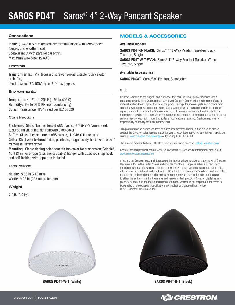
SAROS PD4T Saros® 4” 2-Way Pendant Speaker
crestron.com | 800.237.2041
Connections
Input: (1) 4-pin 5 mm detachable terminal block with screw-down flanges and weather boot;Speaker input with parallel pass-thru;Maximum Wire Size: 12 AWG
Controls
Transformer Tap: (1) Recessed screwdriver-adjustable rotary switch on baffle;Used to select 70/100V tap or 8 Ohms (bypass)
Environmental
Temperature: -2° to 120° F (-19° to 49° C)Humidity: 5% to 95% RH (non-condensing)Splash Resistance: IPx4 rated per IEC 60529
Construction
Enclosure: Glass fiber reinforced ABS plastic, UL® 94V-0 flame rated, textured finish, paintable, removable top coverBaffle: Glass fiber reinforced ABS plastic, UL 94V-0 flame ratedGrille: Steel with textured finish, paintable, magnetically-held “zero-bezel” frameless, safety tetherMounting: Single rigging point beneath top cover for suspension; Gripple® 10 ft (3 m) wire rope (aka, aircraft cable) hanger with attached snap hook and self-locking wire rope grip included
Dimensions
Height: 8.33 in (212 mm)Width: 9.02 in (223 mm) diameter
Weight
7.0 lb (3.2 kg)
MODELS & ACCESSORIES
Available Models
SAROS PD4T-B-T-EACH: Saros® 4” 2-Way Pendant Speaker, Black Textured, SingleSAROS PD4T-W-T-EACH: Saros® 4” 2-Way Pendant Speaker, White Textured, Single
Available Accessories
SAROS PDS8T: Saros® 8” Pendant Subwoofer
Notes:
Crestron warrants to the original end purchaser that this Crestron Speaker Product, when purchased directly from Crestron or an authorized Crestron Dealer, will be free from defects in material and workmanship for the life of the product except for speaker grills and outdoor rated speakers, which are warranted for five (5) years. Crestron will at its option and expense either repair the defect or replace the Speaker Product with a new or remanufactured Product or a reasonable equivalent. In cases where a new model is substituted, a modification to the mounting surface may be required. If mounting surface modification is required, Crestron assumes no responsibility or liability for such modifications.
This product may be purchased from an authorized Crestron dealer. To find a dealer, please contact the Crestron sales representative for your area. A list of sales representatives is available online at www.crestron.com/salesreps or by calling 800-237-2041.
The specific patents that cover Crestron products are listed online at: patents.crestron.com.
Certain Crestron products contain open source software. For specific information, please visit www.crestron.com/opensource.
Crestron, the Crestron logo, and Saros are either trademarks or registered trademarks of Crestron Electronics, Inc. in the United States and/or other countries. Gripple is either a trademark or registered trademark of Gripple Limited in the United States and/or other countries. UL is either a trademark or registered trademark of UL LLC in the United States and/or other countries. Other trademarks, registered trademarks, and trade names may be used in this document to refer to either the entities claiming the marks and names or their products. Crestron disclaims any proprietary interest in the marks and names of others. Crestron is not responsible for errors in typography or photography. Specifications are subject to change without notice. ©2016 Crestron Electronics, Inc.
SAROS PD4T-W-T (White) SAROS PD4T-B-T (Black)

SAROS PD4T Saros® 4” 2-Way Pendant Speaker
Crestron Electronics, Inc. 15 Volvo Drive | Rockleigh, NJ 07647Tel: 800.237.2041 / 201.767.3400 | Fax: 201.767.1903
www.crestron.com
All brand names, product names and trademarks are the property of their respective owners. ©2016 Crestron Electronics, Inc.
Specifications subject to change without notice. Revised 05/06/16
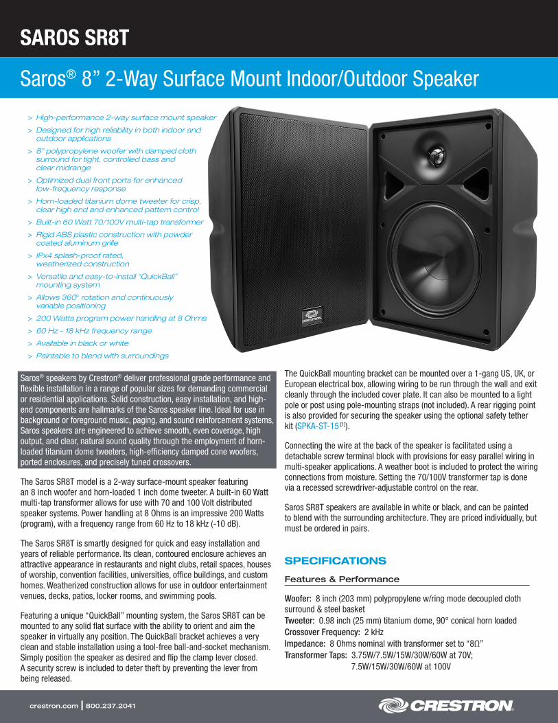
SAROS SR8T
Saros® 8” 2-Way Surface Mount Indoor/Outdoor Speaker
crestron.com | 800.237.2041
> High-performance 2-way surface mount speaker
> Designed for high reliability in both indoor and outdoor applications
> 8” polypropylene woofer with damped cloth surround for tight, controlled bass and clear midrange
> Optimized dual front ports for enhanced low-frequency response
> Horn-loaded titanium dome tweeter for crisp, clear high end and enhanced pattern control
> Built-in 60 Watt 70/100V multi-tap transformer
> Rigid ABS plastic construction with powder coated aluminum grille
> IPx4 splash-proof rated, weatherized construction
> Versatile and easy-to-install “QuickBall” mounting system
> Allows 360° rotation and continuously variable positioning
> 200 Watts program power handling at 8 Ohms
> 60 Hz - 18 kHz frequency range
> Available in black or white
> Paintable to blend with surroundings
Saros® speakers by Crestron® deliver professional grade performance and flexible installation in a range of popular sizes for demanding commercial or residential applications. Solid construction, easy installation, and high-end components are hallmarks of the Saros speaker line. Ideal for use in background or foreground music, paging, and sound reinforcement systems, Saros speakers are engineered to achieve smooth, even coverage, high output, and clear, natural sound quality through the employment of horn-loaded titanium dome tweeters, high-efficiency damped cone woofers, ported enclosures, and precisely tuned crossovers.
The Saros SR8T model is a 2-way surface-mount speaker featuring an 8 inch woofer and horn-loaded 1 inch dome tweeter. A built-in 60 Watt multi-tap transformer allows for use with 70 and 100 Volt distributed speaker systems. Power handling at 8 Ohms is an impressive 200 Watts (program), with a frequency range from 60 Hz to 18 kHz (-10 dB).
The Saros SR8T is smartly designed for quick and easy installation and years of reliable performance. Its clean, contoured enclosure achieves an attractive appearance in restaurants and night clubs, retail spaces, houses of worship, convention facilities, universities, office buildings, and custom homes. Weatherized construction allows for use in outdoor entertainment venues, decks, patios, locker rooms, and swimming pools.
Featuring a unique “QuickBall” mounting system, the Saros SR8T can be mounted to any solid flat surface with the ability to orient and aim the speaker in virtually any position. The QuickBall bracket achieves a very clean and stable installation using a tool-free ball-and-socket mechanism. Simply position the speaker as desired and flip the clamp lever closed. A security screw is included to deter theft by preventing the lever from being released.
The QuickBall mounting bracket can be mounted over a 1-gang US, UK, or European electrical box, allowing wiring to be run through the wall and exit cleanly through the included cover plate. It can also be mounted to a light pole or post using pole-mounting straps (not included). A rear rigging point is also provided for securing the speaker using the optional safety tether kit (SPKA-ST-15 [1]).
Connecting the wire at the back of the speaker is facilitated using a detachable screw terminal block with provisions for easy parallel wiring in multi-speaker applications. A weather boot is included to protect the wiring connections from moisture. Setting the 70/100V transformer tap is done via a recessed screwdriver-adjustable control on the rear.
Saros SR8T speakers are available in white or black, and can be painted to blend with the surrounding architecture. They are priced individually, but must be ordered in pairs.
SPECIFICATIONS
Features & Performance
Woofer: 8 inch (203 mm) polypropylene w/ring mode decoupled cloth surround & steel basketTweeter: 0.98 inch (25 mm) titanium dome, 90° conical horn loadedCrossover Frequency: 2 kHzImpedance: 8 Ohms nominal with transformer set to “8Ω”Transformer Taps: 3.75W/7.5W/15W/30W/60W at 70V;
7.5W/15W/30W/60W at 100V
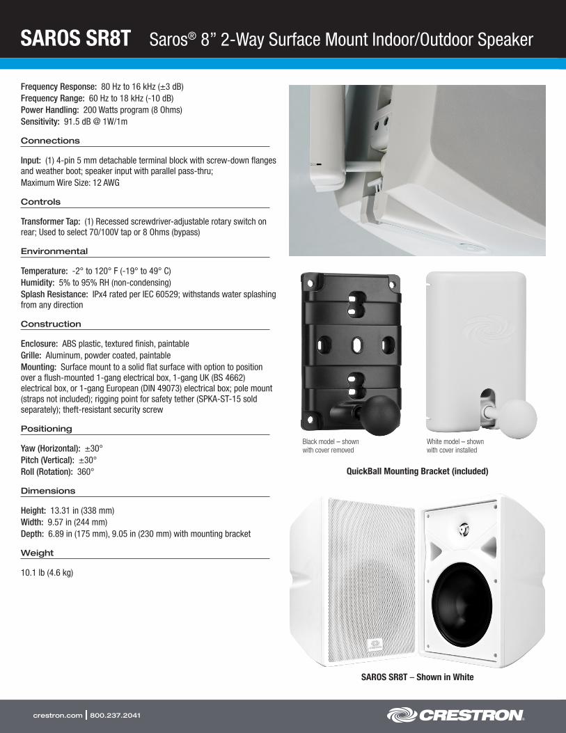
SAROS SR8T Saros® 8” 2-Way Surface Mount Indoor/Outdoor Speaker
crestron.com | 800.237.2041
Frequency Response: 80 Hz to 16 kHz (±3 dB)Frequency Range: 60 Hz to 18 kHz (-10 dB)Power Handling: 200 Watts program (8 Ohms)Sensitivity: 91.5 dB @ 1W/1m
Connections
Input: (1) 4-pin 5 mm detachable terminal block with screw-down flanges and weather boot; speaker input with parallel pass-thru;Maximum Wire Size: 12 AWG
Controls
Transformer Tap: (1) Recessed screwdriver-adjustable rotary switch on rear; Used to select 70/100V tap or 8 Ohms (bypass)
Environmental
Temperature: -2° to 120° F (-19° to 49° C)Humidity: 5% to 95% RH (non-condensing)Splash Resistance: IPx4 rated per IEC 60529; withstands water splashing from any direction
Construction
Enclosure: ABS plastic, textured finish, paintableGrille: Aluminum, powder coated, paintableMounting: Surface mount to a solid flat surface with option to position over a flush-mounted 1-gang electrical box, 1-gang UK (BS 4662) electrical box, or 1-gang European (DIN 49073) electrical box; pole mount (straps not included); rigging point for safety tether (SPKA-ST-15 sold separately); theft-resistant security screw
Positioning
Yaw (Horizontal): ±30°Pitch (Vertical): ±30°Roll (Rotation): 360°
Dimensions
Height: 13.31 in (338 mm)Width: 9.57 in (244 mm)Depth: 6.89 in (175 mm), 9.05 in (230 mm) with mounting bracket
Weight
10.1 lb (4.6 kg)
QuickBall Mounting Bracket (included)
Black model – shown with cover removed
White model – shown with cover installed
SAROS SR8T – Shown in White
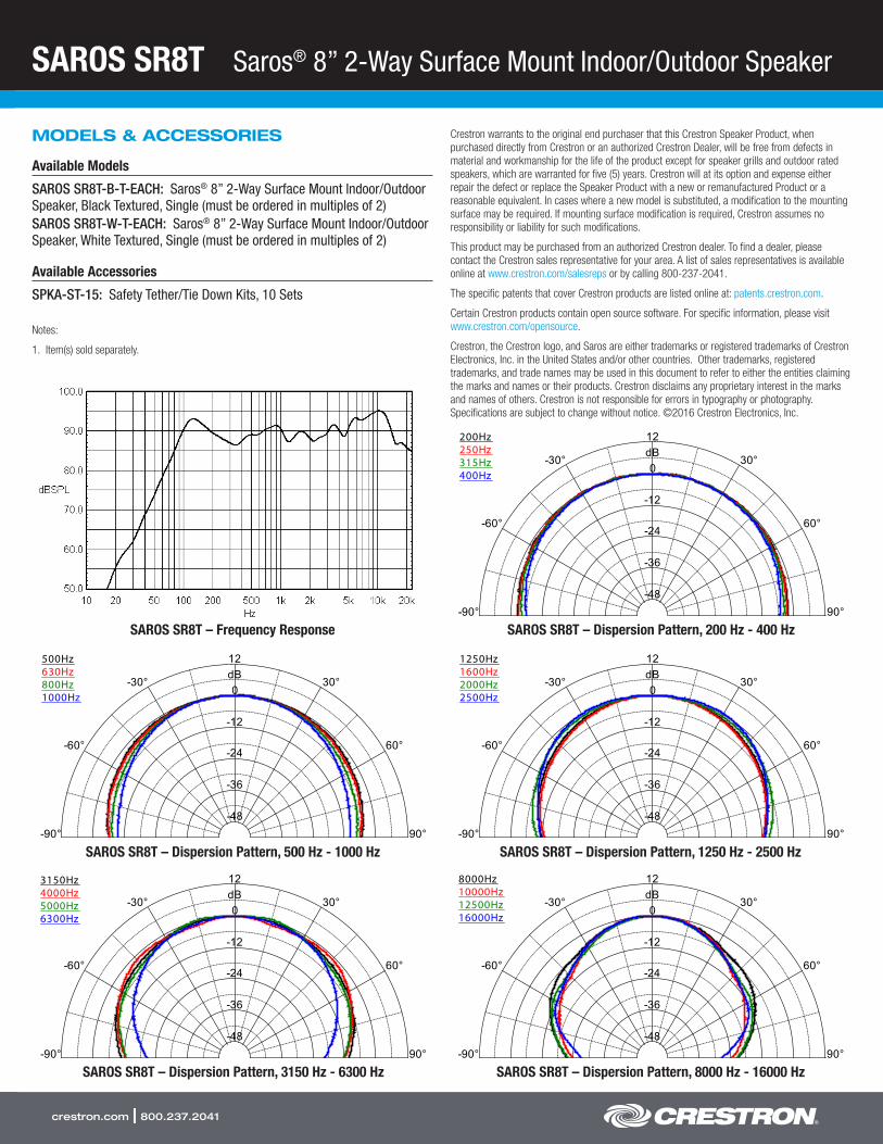
SAROS SR8T Saros® 8” 2-Way Surface Mount Indoor/Outdoor Speaker
crestron.com | 800.237.2041
12
0
-12
-24
-36
-48
dB30°
60°
90°-90°
-60°
-30°
200Hz250Hz315Hz400Hz
SAROS SR8T – Frequency Response SAROS SR8T – Dispersion Pattern, 200 Hz - 400 Hz
12
0
-12
-24
-36
-48
dB30°
60°
90°-90°
-60°
-30°
500Hz630Hz800Hz1000Hz
SAROS SR8T – Dispersion Pattern, 500 Hz - 1000 Hz
12
0
-12
-24
-36
-48
dB30°
60°
90°-90°
-60°
-30°
1250Hz1600Hz2000Hz2500Hz
SAROS SR8T – Dispersion Pattern, 1250 Hz - 2500 Hz
12
0
-12
-24
-36
-48
dB30°
60°
90°-90°
-60°
-30°
3150Hz4000Hz5000Hz6300Hz
SAROS SR8T – Dispersion Pattern, 3150 Hz - 6300 Hz
12
0
-12
-24
-36
-48
dB30°
60°
90°-90°
-60°
-30°
8000Hz10000Hz12500Hz16000Hz
SAROS SR8T – Dispersion Pattern, 8000 Hz - 16000 Hz
MODELS & ACCESSORIES
Available Models
SAROS SR8T-B-T-EACH: Saros® 8” 2-Way Surface Mount Indoor/Outdoor Speaker, Black Textured, Single (must be ordered in multiples of 2)SAROS SR8T-W-T-EACH: Saros® 8” 2-Way Surface Mount Indoor/Outdoor Speaker, White Textured, Single (must be ordered in multiples of 2)
Available Accessories
SPKA-ST-15: Safety Tether/Tie Down Kits, 10 Sets
Notes:
1. Item(s) sold separately.
Crestron warrants to the original end purchaser that this Crestron Speaker Product, when purchased directly from Crestron or an authorized Crestron Dealer, will be free from defects in material and workmanship for the life of the product except for speaker grills and outdoor rated speakers, which are warranted for five (5) years. Crestron will at its option and expense either repair the defect or replace the Speaker Product with a new or remanufactured Product or a reasonable equivalent. In cases where a new model is substituted, a modification to the mounting surface may be required. If mounting surface modification is required, Crestron assumes no responsibility or liability for such modifications.
This product may be purchased from an authorized Crestron dealer. To find a dealer, please contact the Crestron sales representative for your area. A list of sales representatives is available online at www.crestron.com/salesreps or by calling 800-237-2041.
The specific patents that cover Crestron products are listed online at: patents.crestron.com.
Certain Crestron products contain open source software. For specific information, please visit www.crestron.com/opensource.
Crestron, the Crestron logo, and Saros are either trademarks or registered trademarks of Crestron Electronics, Inc. in the United States and/or other countries. Other trademarks, registered trademarks, and trade names may be used in this document to refer to either the entities claiming the marks and names or their products. Crestron disclaims any proprietary interest in the marks and names of others. Crestron is not responsible for errors in typography or photography. Specifications are subject to change without notice. ©2016 Crestron Electronics, Inc.

SAROS SR8T Saros® 8” 2-Way Surface Mount Indoor/Outdoor Speaker
Crestron Electronics, Inc. 15 Volvo Drive | Rockleigh, NJ 07647Tel: 800.237.2041 / 201.767.3400 | Fax: 201.767.1903
www.crestron.com
All brand names, product names and trademarks are the property of their respective owners. ©2016 Crestron Electronics, Inc.
Specifications subject to change without notice. Revised 10/25/16

TSW-1050
10.1” Touch Screen
crestron.com | 800.237.2041
> Ultra clean, modern appearance
> Thin profile and compact footprint
> Affordable and easy to install
> 10.1” widescreen active-matrix color display
> 1280 x 800 WXGA display resolution
> Capacitive touch screen technology
> Smart Graphics™ support [1]
> High-performance H.264 streaming video
> Rava® SIP intercom and phone technology
> Customizable audio feedback
> Built-in microphone and speakers
> 5 soft-touch capacitive buttons
> Single-wire Ethernet connectivity
> PoE network powered
> Supports US or European electrical wall box mounting
> Can be mounted directly to drywall or paneling over a cutout
> Compatible with TSW-UMB Universal Mounting Bracket [2]
> Compatible with TSW-RMB Retrofit Mounting Brackets [2]
> Pre-construction and masonry mounting options available [2]
> Available tabletop and swivel mount options [2]
> Available in smooth black or white finish
Advanced Touch Screen ControlA Crestron® touch screen offers an ideal user-interface for controlling all the technology in your home, boardroom, classroom, courtroom, or command center. Touch screens do away with piles of remote controls, cluttered wall switches, and cryptic computer screens, simplifying and enhancing the way you use technology. For controlling audio, video, lighting, shades, HVAC, security, and other systems, Crestron touch screens are fully-customizable with easy-to-use controls and icons, true feedback and real-time status display, live streaming video, and advanced navigation of digital media servers, tuners, and other devices.
With its clean, contemporary design highlighted by edge-to-edge glass and stunning HD color graphics, the Crestron TSW-1050 touch screen makes an elegant statement on any wall, tabletop, or lectern. Perfectly at home in the most contemporary residence or modern office building, its high-tech good looks underline its power for simplifying everyday tasks and functions throughout any facility.
The TSW-1050 delivers the ultimate touch screen experience in an unobtrusive, space-saving design featuring a brilliant, high-definition 10.1 inch capacitive touch screen display and 5 soft-touch buttons. PoE connectivity and a range of mounting options make installation a breeze for both new and retrofit applications. Additional features include high- performance H.264 video, audio feedback, Rava® SIP Intercom, and advanced Smart Graphics™.
Smart Graphics™[1]
Crestron touch screens use Smart Graphics to deliver the ultimate user experience and the ultimate value by enabling the creation of dynamically rich user interfaces with incredible efficiency and unparalleled functionality. Using Smart Graphics, programmers can swiftly integrate fluid gesture-driven controls, animated feedback, rich metadata, embedded apps and widgets, and full-motion video for a deeply engaging and ultra-intuitive touch screen experience.
Crestron Smart Graphics offers these enhancements and more:
• Cool-looking graphical buttons, sliders, knobs, and gauges that are intuitive and fun to use
• Kinetic effects to enhance the feeling of realism, with lists and toolbars that scroll with momentum at the flick of a fingertip
• Drag-and-drop objects that snap into place, offering an easy way to switch sources
• Dashboard widgets to personalize the touch screen with clocks, weather, news, and other information
• Customizable themes allowing a completely different look and feel for every user, event, or season
• Fully-developed SmartObjects™ that enable sophisticated control over complex devices with minimal programming
Soft-Touch ButtonsThe TSW-1050 includes five soft-touch capacitive buttons for quick access to commonly used functions. The buttons are pre-labeled with icons for “Power”, “Home”, “Lights”, “Up”, and “Down” functions. Each button is programmable via the control system for custom functionality.
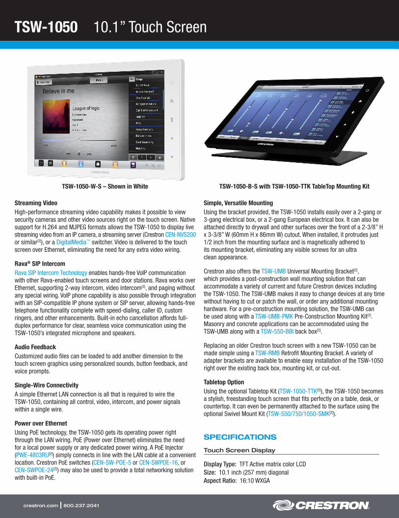
TSW-1050 10.1” Touch Screen
crestron.com | 800.237.2041
Streaming VideoHigh-performance streaming video capability makes it possible to view security cameras and other video sources right on the touch screen. Native support for H.264 and MJPEG formats allows the TSW-1050 to display live streaming video from an IP camera, a streaming server (Crestron CEN-NVS200 or similar[2]), or a DigitalMedia™ switcher. Video is delivered to the touch screen over Ethernet, eliminating the need for any extra video wiring.
Rava® SIP IntercomRava SIP Intercom Technology enables hands-free VoIP communication with other Rava-enabled touch screens and door stations. Rava works over Ethernet, supporting 2-way intercom, video intercom[3], and paging without any special wiring. VoIP phone capability is also possible through integration with an SIP-compatible IP phone system or SIP server, allowing hands-free telephone functionality complete with speed-dialing, caller ID, custom ringers, and other enhancements. Built-in echo cancellation affords full-duplex performance for clear, seamless voice communication using the TSW-1050’s integrated microphone and speakers.
Audio FeedbackCustomized audio files can be loaded to add another dimension to the touch screen graphics using personalized sounds, button feedback, and voice prompts.
Single-Wire ConnectivityA simple Ethernet LAN connection is all that is required to wire the TSW-1050, containing all control, video, intercom, and power signals within a single wire.
Power over EthernetUsing PoE technology, the TSW-1050 gets its operating power right through the LAN wiring. PoE (Power over Ethernet) eliminates the need for a local power supply or any dedicated power wiring. A PoE Injector (PWE-4803RU[2]) simply connects in line with the LAN cable at a convenient location. Crestron PoE switches (CEN-SW-POE-5 or CEN-SWPOE-16, or CEN-SWPOE-24[2]) may also be used to provide a total networking solution with built-in PoE.
Simple, Versatile MountingUsing the bracket provided, the TSW-1050 installs easily over a 2-gang or 3-gang electrical box, or a 2-gang European electrical box. It can also be attached directly to drywall and other surfaces over the front of a 2-3/8” H x 3-3/8” W (60mm H x 86mm W) cutout. When installed, it protrudes just 1/2 inch from the mounting surface and is magnetically adhered to its mounting bracket, eliminating any visible screws for an ultra clean appearance.
Crestron also offers the TSW-UMB Universal Mounting Bracket[2], which provides a post-construction wall mounting solution that can accommodate a variety of current and future Crestron devices including the TSW-1050. The TSW-UMB makes it easy to change devices at any time without having to cut or patch the wall, or order any additional mounting hardware. For a pre-construction mounting solution, the TSW-UMB can be used along with a TSW-UMB-PMK Pre-Construction Mounting Kit[2]. Masonry and concrete applications can be accommodated using the TSW-UMB along with a TSW-550-BBI back box[2].
Replacing an older Crestron touch screen with a new TSW-1050 can be made simple using a TSW-RMB Retrofit Mounting Bracket. A variety of adapter brackets are available to enable easy installation of the TSW-1050 right over the existing back box, mounting kit, or cut-out.
Tabletop OptionUsing the optional Tabletop Kit (TSW-1050-TTK[2]), the TSW-1050 becomes a stylish, freestanding touch screen that fits perfectly on a table, desk, or countertop. It can even be permanently attached to the surface using the optional Swivel Mount Kit (TSW-550/750/1050-SMK[2]).
SPECIFICATIONS
Touch Screen Display
Display Type: TFT Active matrix color LCDSize: 10.1 inch (257 mm) diagonalAspect Ratio: 16:10 WXGA
TSW-1050-B-S with TSW-1050-TTK TableTop Mounting KitTSW-1050-W-S – Shown in White
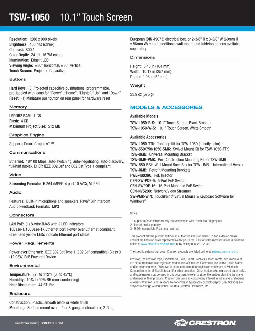
TSW-1050 10.1” Touch Screen
crestron.com | 800.237.2041
Resolution: 1280 x 800 pixelsBrightness: 400 nits (cd/m²)Contrast: 800:1Color Depth: 24-bit, 16.7M colorsIllumination: Edgelit LEDViewing Angle: ±80° horizontal, ±80° verticalTouch Screen: Projected Capacitive
Buttons
Hard Keys: (5) Projected capacitive pushbuttons, programmable, pre-labeled with icons for “Power”, “Home”, “Lights”, “Up”, and “Down”Reset: (1) Miniature pushbutton on rear panel for hardware reset
Memory
LPDDR2 RAM: 1 GBFlash: 4 GBMaximum Project Size: 512 MB
Graphics Engine
Supports Smart Graphics™ [1]
Communications
Ethernet: 10/100 Mbps, auto-switching, auto-negotiating, auto-discovery, full/half duplex, DHCP, IEEE 802.3af and 802.3at Type 1 compliant
Video
Streaming Formats: H.264 (MPEG-4 part 10 AVC), MJPEG
Audio
Features: Built-in microphone and speakers, Rava® SIP IntercomAudio Feedback Formats: MP3
Connectors
LAN PoE: (1) 8-wire RJ45 with 2 LED indicators;10Base-T/100Base-TX Ethernet port, Power over Ethernet compliant;Green and yellow LEDs indicate Ethernet port status
Power Requirements
Power over Ethernet: IEEE 802.3at Type 1 (802.3af compatible) Class 3 (12.95W) PoE Powered Device
Environmental
Temperature: 32° to 112°F (0° to 45°C)Humidity: 10% to 90% RH (non-condensing)Heat Dissipation: 44 BTU/hr
Enclosure
Construction: Plastic, smooth black or white finishMounting: Surface mount over a 2 or 3-gang electrical box, 2-Gang
European (DIN 49073) electrical box, or 2-3/8” H x 3-3/8” W (60mm H x 86mm W) cutout; additional wall mount and tabletop options available separately
Dimensions
Height: 6.46 in (164 mm)Width: 10.12 in (257 mm)Depth: 2.03 in (52 mm)
Weight
23.9 oz (675 g)
MODELS & ACCESSORIES
Available Models
TSW-1050-B-S: 10.1” Touch Screen, Black SmoothTSW-1050-W-S: 10.1” Touch Screen, White Smooth
Available Accessories
TSW-1050-TTK: Tabletop Kit for TSW-1050 [specify color]TSW-550/750/1050-SMK: Swivel Mount Kit for TSW-1050-TTKTSW-UMB: Universal Mounting BracketTSW-UMB-PMK: Pre-Construction Mounting Kit for TSW-UMBTSW-550-BBI: Wall Mount Back Box for TSW-UMB – International VersionTSW-RMB: Retrofit Mounting BracketsPWE-4803RU: PoE InjectorCEN-SW-POE-5: 5-Port PoE SwitchCEN-SWPOE-16: 16-Port Managed PoE SwitchCEN-NVS200: Network Video StreamerSW-VMK-WIN: TouchPoint® Virtual Mouse & Keyboard Software for Windows®
Notes:
1. Supports Smart Graphics only. Not compatible with “traditional” UI projects.2. Item(s) sold separately.3. H.264 compatible IP camera required.
This product may be purchased from an authorized Crestron dealer. To find a dealer, please contact the Crestron sales representative for your area. A list of sales representatives is available online at www.crestron.com/salesreps or by calling 800-237-2041.
The specific patents that cover Crestron products are listed online at: patents.crestron.com.
Crestron, the Crestron logo, DigitalMedia, Rava, Smart Graphics, SmartObjects, and TouchPoint are either trademarks or registered trademarks of Crestron Electronics, Inc. in the United States and/or other countries. Windows is either a trademark or registered trademark of Microsoft Corporation in the United States and/or other countries. Other trademarks, registered trademarks, and trade names may be used in this document to refer to either the entities claiming the marks and names or their products. Crestron disclaims any proprietary interest in the marks and names of others. Crestron is not responsible for errors in typography or photography. Specifications are subject to change without notice. ©2014 Crestron Electronics, Inc.
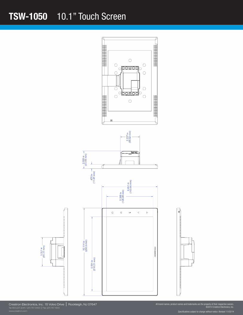
TSW-1050 10.1” Touch Screen
Crestron Electronics, Inc. 15 Volvo Drive | Rockleigh, NJ 07647Tel: 800.237.2041 / 201.767.3400 | Fax: 201.767.1903
www.crestron.com
All brand names, product names and trademarks are the property of their respective owners. ©2014 Crestron Electronics, Inc.
Specifications subject to change without notice. Revised 11/03/14
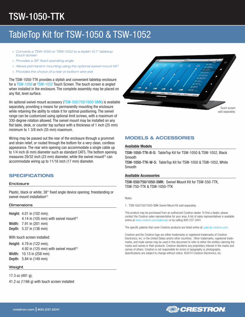
TSW-1050-TTK
TableTop Kit for TSW-1050 & TSW-1052
crestron.com | 800.237.2041
> Converts a TSW-1050 or TSW-1052 to a stylish 10.1” tabletop touch screen
> Provides a 38° fixed operating angle
> Allows permanent mounting using the optional swivel mount kit[1]
> Provides the choice of a rear or bottom wire exit
The TSW-1050-TTK provides a stylish and convenient tabletop enclosure for a TSW-1050 or TSW-1052 Touch Screen. The touch screen is angled when installed in the enclosure. The complete assembly may be placed on any flat, level surface.
An optional swivel mount accessory (TSW-550/750/1050-SMK) is available separately, providing a means for permanently mounting the enclosure while retaining the ability to rotate it for optimal positioning. The swivel range can be customized using optional limit screws, with a maximum of 330-degree rotation allowed. The swivel mount may be installed on any flat table, desk, or counter top surface with a thickness of 1 inch (25 mm) minimum to 1 3/8 inch (35 mm) maximum.
Wiring may be passed out the rear of the enclosure through a grommet and strain relief, or routed through the bottom for a very clean, cordless appearance. The rear wire opening can accommodate a single cable up to 1/4 inch (6 mm) diameter such as standard CAT5. The bottom opening measures 29/32 inch (23 mm) diameter, while the swivel mount[1] can accommodate wiring up to 11/16 inch (17 mm) diameter.
SPECIFICATIONS
Enclosure
Plastic, black or white; 38° fixed angle device opening; freestanding or swivel mount installation[1]
Dimensions
Height: 4.01 in (102 mm); 4.14 in (105 mm) with swivel mount[1]
Width: 7.91 in (201 mm)Depth: 5.37 in (136 mm)
With touch screen installed:
Height: 4.79 in (122 mm); 4.92 in (125 mm) with swivel mount[1]
Width: 10.13 in (258 mm)Depth: 5.84 in (149 mm)
Weight
17.3 oz (491 g);
41.2 oz (1166 g) with touch screen installed
MODELS & ACCESSORIES
Available Models
TSW-1050-TTK-B-S: TableTop Kit for TSW-1050 & TSW-1052, Black SmoothTSW-1050-TTK-W-S: TableTop Kit for TSW-1050 & TSW-1052, White Smooth
Available Accessories
TSW-550/750/1050-SMK: Swivel Mount Kit for TSW-550-TTK, TSW-750-TTK & TSW-1050-TTK
Notes:
1. TSW-550/750/1050-SMK Swivel Mount Kit sold separately.
This product may be purchased from an authorized Crestron dealer. To find a dealer, please contact the Crestron sales representative for your area. A list of sales representatives is available online at www.crestron.com/salesreps or by calling 800-237-2041.
The specific patents that cover Crestron products are listed online at: patents.crestron.com.
Crestron and the Crestron logo are either trademarks or registered trademarks of Crestron Electronics, Inc. in the United States and/or other countries. Other trademarks, registered trade-marks, and trade names may be used in this document to refer to either the entities claiming the marks and names or their products. Crestron disclaims any proprietary interest in the marks and names of others. Crestron is not responsible for errors in typography or photography. Specifications are subject to change without notice. ©2014 Crestron Electronics, Inc.
Touch screen sold separately.

TSW-1050-TTK TableTop Kit for TSW-1050 & TSW-1052
Crestron Electronics, Inc. 15 Volvo Drive | Rockleigh, NJ 07647Tel: 800.237.2041 / 201.767.3400 | Fax: 201.767.1903
www.crestron.com
All brand names, product names and trademarks are the property of their respective owners. ©2014 Crestron Electronics, Inc.
Specifications subject to change without notice. Revised 04/16/14

The Easy Install Manual with CSR is a manual wall- or ceiling-
mounted screen with a controlled screen return that ensures a quiet,
controlled return to the case. Screens with CSR must be fully
extended.
Features
• Quiet, controlled screen return to case
• Satin aluminum finish
• Flexible mounting brackets for wall or ceiling mount
• Standard Matte White surface
• Includes pull cord
Optional Accessories:
• Green Laser Pointers
• Pull Rod
• Red Laser Pointers
• RF PowerPoint Remote with
Green Laser Pointer
• Tilt Lock
Easy Install Manual with CSR
4:3 Video FormatViewing Area (H x W) Nominal Diagonal Overall Case Length
in. cm in. cm in. cm
45" x 60" 114 x 152 75" 191 67¾" 172
51" x 68" 130 x 173 85" 216 75¾" 192
57" x 76" 145 x 193 95" 241 83½" 212
69" x 92" 175 x 234 120" 305 99¼" 252
16:9 HDTV FormatViewing Area (H x W) Nominal Diagonal Overall Case Length
in. cm in. cm in. cm
38" x 68" 97 x 173 78" 198 75¾" 192
43" x 76" 109 x 193 88" 224 83½" 212
52" x 92" 132 x 234 106" 269 99¼" 252
Matte White
Half Angle: 60º Gain: 1.0
Available with the Following Screen Surfaces
A Milestone AV Technologies Brand
3100 North Detroit Street
Warsaw, Indiana 46582
P: 574.267.8101 or 800.622.3737
F: 574.267.7804 or 877.325.4832
www.da-lite.com
DL–0500 08.14
© 2014 Milestone AV Technologies LLC. Printed in U.S.A.

1Extron USB Extender Plus Rack Mount, AAP, and Decorator-Style Transmitters and Receivers • Specifications
SpecificationsUSB Extender Plus T/R Series
USB Extender Plus T/R SeriesUSB host support xHCI (USB 30), EHCI (USB 20), OHCI/UHCI (USB 11)USB data rates Low speed (15 Mbps), full speed (12 Mbps), high speed (480 Mbps)USB host — Tx units
Number/signal type 1 USBConnectors 1 female USB type B
USB hub — Rx unitsNumber/signal type (1) 4-port USB hubConnectors 4 female USB type A
Interconnection between transmitter and receiver
NOTE: This product supports the four types of data transfer defined by USB: bulk, control, interrupt, and isochronous transfers
Connectors 1 female RJ-45 per unitTermination standards TIA 568BSignal transmission distance
Point to point Up to 330' (100 m)Over the network Up to 1980' (600 m)**
NOTE: **Over the network distance is through connection of up to five network switches
NOTE: The transmission distance varies depending on the type of cable used in the system
NetworkProtocol EthernetTransport TCP/IP, UDPAll supported IPv4, IPv6, UDP, SSL, DHCP, HTTP, HTTPS, RTP, RTSP, SNMP, SNMP V2 (RFC
1213), SNMP V3 SNTP/NTP, SAP (RFC 2974), SDP (RFC 4566), QoS (RFC 2474), NTPv4 (RFC 4330), IGMP, Unicast or Multicast
Standards IEEE 8023u (100Base-T), IEEE 8023ab (1000Base-T)IP Configuration Static IP (default) or DHCP
General — USB Extender Plus T/RPower supply External
Transmitter Input: 100-240 VAC, 50-60 Hz Output: 12 VDC, 05 A
Receiver Input: 100-240 VAC, 50-60 Hz Output: 12 VDC, 15 A
Power consumptionTransmitter
Device 25 wattsDevice and power supply 34 watts
ReceiverDevice 124 wattsDevice and power supply 149 watts
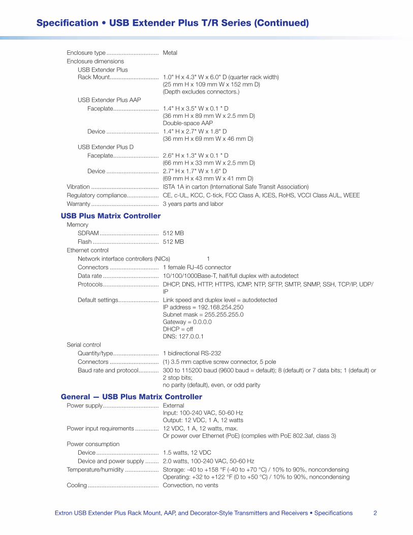
2
Specification • USB Extender Plus T/R Series (Continued)
Extron USB Extender Plus Rack Mount, AAP, and Decorator-Style Transmitters and Receivers • Specifications
Enclosure type MetalEnclosure dimensions
USB Extender Plus Rack Mount 10" H x 43" W x 60" D (quarter rack width)
(25 mm H x 109 mm W x 152 mm D) (Depth excludes connectors)
USB Extender Plus AAPFaceplate 14" H x 35" W x 01 " D
(36 mm H x 89 mm W x 25 mm D) Double-space AAP
Device 14" H x 27" W x 18" D (36 mm H x 69 mm W x 46 mm D)
USB Extender Plus DFaceplate 26" H x 13" W x 01 " D
(66 mm H x 33 mm W x 25 mm D)Device 27" H x 17" W x 16" D
(69 mm H x 43 mm W x 41 mm D)Vibration ISTA 1A in carton (International Safe Transit Association)Regulatory compliance CE, c-UL, KCC, C-tick, FCC Class A, ICES, RoHS, VCCI Class AUL, WEEE Warranty 3 years parts and labor
USB Plus Matrix ControllerMemory
SDRAM 512 MBFlash 512 MB
Ethernet controlNetwork interface controllers (NICs) 1Connectors 1 female RJ-45 connectorData rate 10/100/1000Base-T, half/full duplex with autodetectProtocols DHCP, DNS, HTTP, HTTPS, ICMP, NTP, SFTP, SMTP, SNMP, SSH, TCP/IP, UDP/
IPDefault settings Link speed and duplex level = autodetected
IP address = 192168254250 Subnet mask = 2552552550 Gateway = 0000 DHCP = off DNS: 127001
Serial controlQuantity/type 1 bidirectional RS-232Connectors (1) 35 mm captive screw connector, 5 poleBaud rate and protocol 300 to 115200 baud (9600 baud = default); 8 (default) or 7 data bits; 1 (default) or
2 stop bits; no parity (default), even, or odd parity
General — USB Plus Matrix ControllerPower supply External
Input: 100-240 VAC, 50-60 Hz Output: 12 VDC, 1 A, 12 watts
Power input requirements 12 VDC, 1 A, 12 watts, max Or power over Ethernet (PoE) (complies with PoE 8023af, class 3)
Power consumptionDevice 15 watts, 12 VDCDevice and power supply 20 watts, 100-240 VAC, 50-60 Hz
Temperature/humidity Storage: -40 to +158 °F (-40 to +70 °C) / 10% to 90%, noncondensing Operating: +32 to +122 °F (0 to +50 °C) / 10% to 90%, noncondensing
Cooling Convection, no vents

3
Specification • USB Extender Plus T/R Series (Continued)
© 2015-2018 Extron Electronics, All Rights Reserved. All trademarks mentioned are the property of their respective owners. www.extron.com
Thermal dissipationDevice 52 BTU/hrDevice and power supply 68 BTU/hr
MountingRack mount Yes, with optional 1U rack shelf or back of the rack mounting kitFurniture mount Yes, with optional bracket kit
Enclosure type MetalEnclosure dimensions 10" H x 43" W x 60" D (1U high, quarter rack wide)
(25 mm H x 109 mm W x 152 mm D) (Depth excludes connectors)
Product weight 06 lbs (03 kg)Regulatory compliance CE, c-UL, UL, C-tick, FCC Class A, ICES, KCC, RoHS, WEEE, VCCIWarranty 3 years parts and labor
NOTE: All nominal levels are at ±10%
NOTE: Specifications are subject to change without notice
NOTE: Shipping weights and dimensions are available at www.extron.com
4172-D12
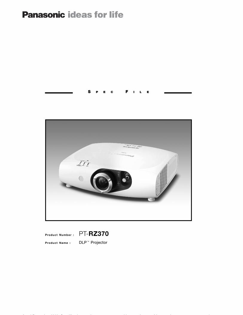
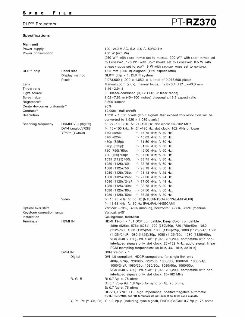
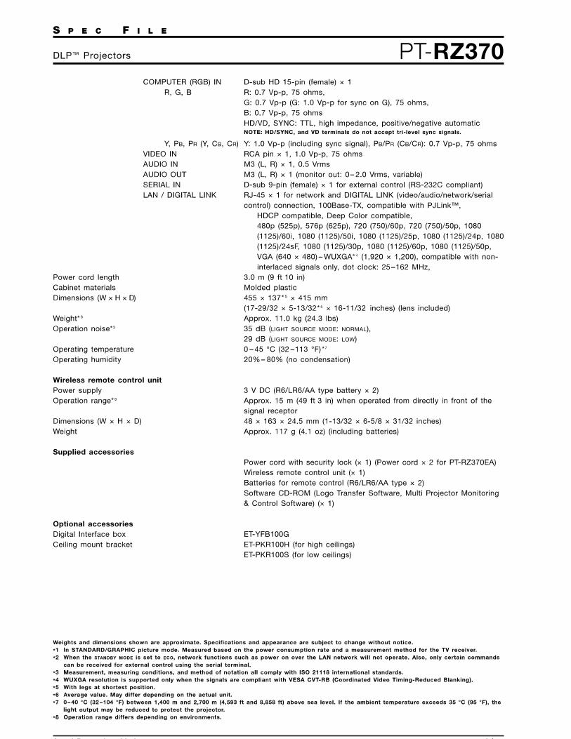

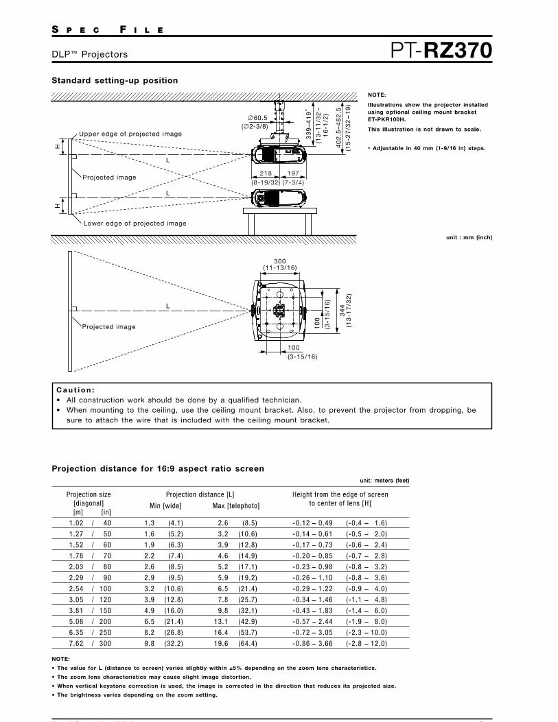

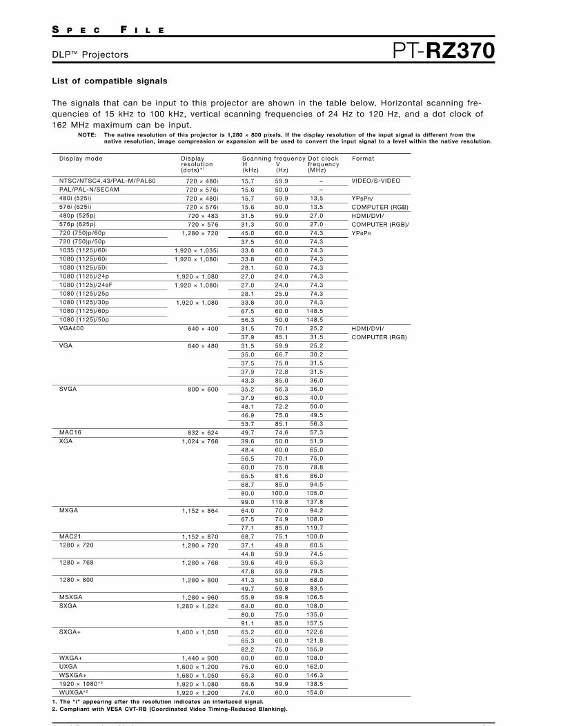


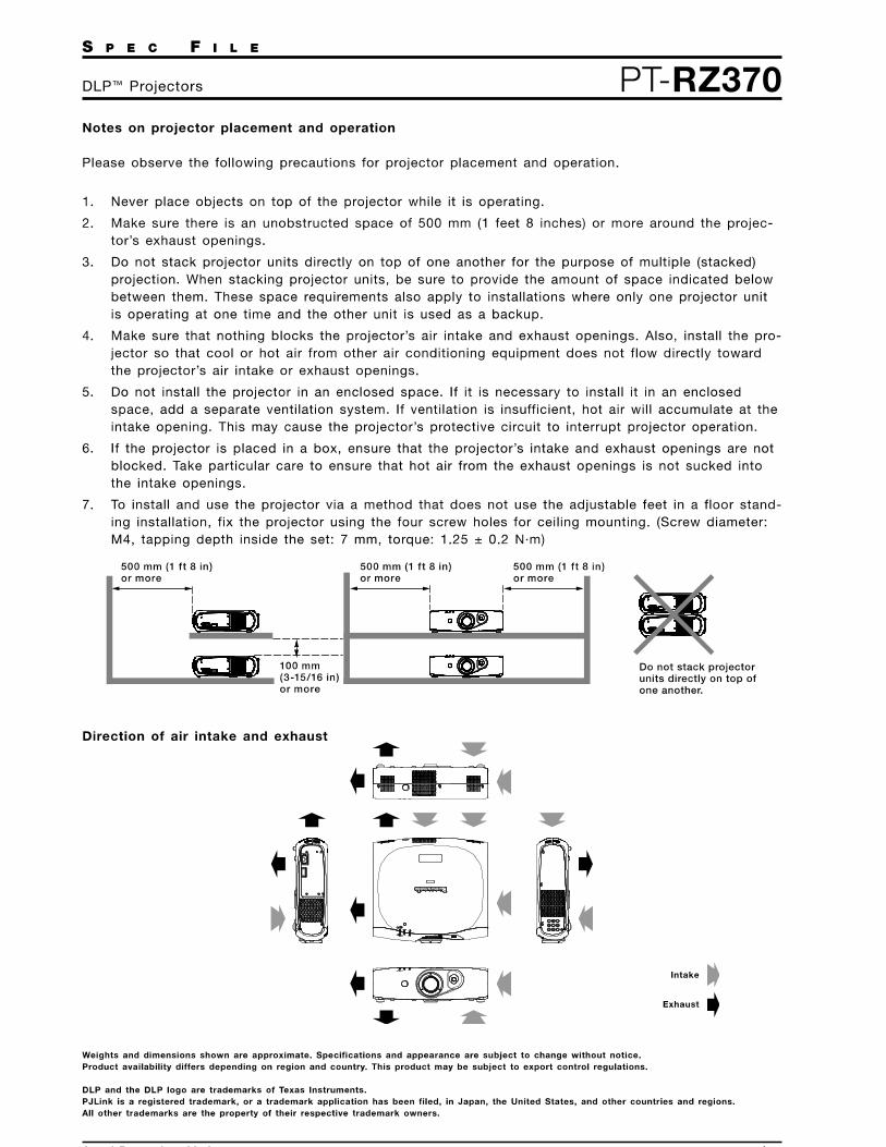

PRODUCT SPECIFICATION video management solutions
C4010 / NEW 9-18-14
International StandardsOrganization Registered Firm;
ISO 9001 Quality System
Digital Sentry® DS-CPPC WorkstationWITH DS CONTROLPOINT SOFTWARE FOR OPERATORS
Product Features• Optimized to Support Pre-Installed DS ControlPoint Software
• Provides Access to Multiple DS Servers
• Supports Pelco and Third-Party IP Cameras and Network Encoders
• Compatible with DS ControlPoint for Simultaneous Monitoring of AllDS Series and DX Series Products in a Single Client Interface
• Displays Up to 10X 1080p Video Streams or 54X 720p Video Streams
• Network Health and Event Monitoring Support Through SimpleNetwork Management Protocol (SNMP) and New Digital Sentry®
System Information (DSSI) Utility
• Compatible with the DS Archive Utility
• Supports Pelco NET5300T Series and NET5400T Series Video Servers(Encoders)
• Supports Pelco IP Cameras with Sarix® HD Technology
• Supports the Display of MJPEG; MPEG-4; and H.264 Baseline, Main,and High Profile-Encoded Streams from IP Cameras
Optimized For Video SurveillanceThe Digital Sentry® ControlPoint Workstation (DS-CPPC) isoptimized to deliver the essential hardware support for theDS ControlPoint software without the extra cost or risk of integratinghardware and software.
Boosted by the 4th Generation Intel® Xeon processor and 8 GB ofRAM, DS-CPPC provides an optimal combination of processingpower and reliability to meet the demands of HD video recording andplayback operations.
Two gigabit network ports provide for convenient networkarchitecture planning, allowing the DS-CPPC to access DS serversspanning across networks.
Front panel LED displays on the DS-CPPC provide information onsystem operation. The LEDs are integrated with the new DigitalSentry System Information (DSSI) utility, providing critical, real-timestatistics on system resource utilization, temperature, andthroughput status.
DS ControlPointDS ControlPoint is an intuitive, graphical user interface used tomonitor and operate a combination of analog and IP video capturedevices across an IP network.
DS ControlPoint is easy to use with a tabbed environment, whichallows operators to quickly switch between several work spaces.Selecting live or recorded data from one or more locations is assimple as a single click.
DS ControlPoint displays exceptionally high-quality imagescaptured by any one of Pelco’s robust line of standard resolution andmegapixel IP cameras, along with hundreds of IP video capturedevices from major industry providers.
DS ControlPoint includes a video scrub bar to make finding theright segment of video efficient and effortless. Built-in bandwidththrottling, along with override capabilities on a client-by-client basis,makes deploying IP video security nonintrusive over an existingnetwork topology. Operator alerting functions, such as video pop-upon alarm, allow for effective monitoring of hundreds of cameras.
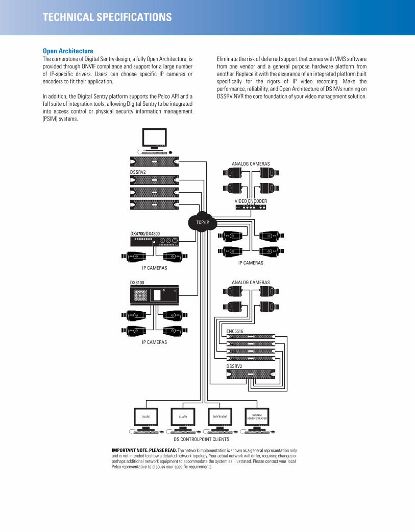
TECHNICAL SPECIFICATIONS
Open ArchitectureThe cornerstone of Digital Sentry design, a fully Open Architecture, isprovided through ONVIF compliance and support for a large numberof IP-specific drivers. Users can choose specific IP cameras orencoders to fit their application.
In addition, the Digital Sentry platform supports the Pelco API and afull suite of integration tools, allowing Digital Sentry to be integratedinto access control or physical security information management(PSIM) systems.
Eliminate the risk of deferred support that comes with VMS softwarefrom one vendor and a general purpose hardware platform fromanother. Replace it with the assurance of an integrated platform builtspecifically for the rigors of IP video recording. Make theperformance, reliability, and Open Architecture of DS NVs running onDSSRV NVR the core foundation of your video management solution.
DS CONTROLPOINT CLIENTS
SYSTEMADMINISTRATORSUPERVISORGUARDGUARD
DSSRV2
ENC5516
ANALOG CAMERAS
IP CAMERAS
VIDEO ENCODER
ANALOG CAMERAS
TCP/IP
IP CAMERAS
DX8100
IP CAMERAS
DX4700/DX4800
DSSRV2
IMPORTANT NOTE. PLEASE READ. The network implementation is shown as a general representation onlyand is not intended to show a detailed network topology. Your actual network will differ, requiring changes orperhaps additional network equipment to accommodate the system as illustrated. Please contact your localPelco representative to discuss your specific requirements.

TECHNICAL SPECIFICATIONS
SYSTEMProcessor Intel® Xeon E3-1275 v3Operating System Windows 7 Ultimate 64-bitInternal Memory 8 GB DDR3 Non-ECC RAMUser Interface DS ControlPointInternal Storage
SSD 120 GBHDD 4 TBDrive Bays 4 (2 unused)
Optical Drive DVD±RWUSB Ports 3 USB 2.0 ports (1 front, 2 rear)
2 USB 3.0 ports (rear)
VIDEOVideo System Intel HD Graphics P4700 (shared memory
Max Resolution 3840 x 2160 per DisplayPort output (2x)1920 x 1200 @ 60 hz on DVI-D output1920 x 1200 @ 60 hz on VGA output
Video Outputs Supports up to 3 simultaneous displays usingany combination of the four outputs
Video Standards 60 Hz capable for NTSC75 Hz capable for PAL
Video Decoding Supported MPEG-4 ASP; H.264 Baseline, Main, and Highprofiles
Decoding Performance 10X H.264 streams at 1920 x 1080, 100 imagequality, 30 frames per second, averaging3.5Mbps54X H.264 streams at 1280x720, 100 imagequality,12.5 frames per second, averaging3 Mbps
AUDIOAudio Decoding G.711 speech codecAudio Bit-rate 64 kbpsAudio Levels
Input Electret microphoneOutput Up to 3 Vp-p, adjustable, minimum load of
8 ohmsAudio Connectors 2, 3.5 mm stereo jacks
Connector Tip Signal left (input and output)Connector Ring Signal right (input and output)Connector Sleeve Common
Audio Inputs MicrophoneAudio Outputs Speaker or line out
NETWORKInterface Gigabit Ethernet (1000Base-T) port (2x)
POWERPower Input 100 to 240 VAC, 50/60 Hz, autorangingPower Supply InternalPower Consumption Operating maximum
Watts Amperes BTU/H100 VAC / 50 Hz 222.0 2.22 758.0110 VAC / 50 Hz 224.0 2.02 759.4110 VAC / 60 Hz 223.0 2.03 761.4115 VAC / 50 Hz 217.0 1.89 740.8115 VAC / 60 Hz 215.5 1.87 735.7220 VAC / 50 Hz 213.0 0.97 727.2220 VAC / 60 Hz 204.1 0.93 696.8240 VAC / 50 Hz 211.9 0.88 723.4240 VAC / 60 Hz 207.6 0.86 708.8
FRONT PANEL INDICATORS/FUNCTIONSButtons PowerIndicators
Unit Status Green, amber, redPrimary Network Green, amber, redSecondary Network Green, amber, redSoftware Status Green, amber, red (based on diagnostics)Hard Disk Status Green, red, off (behind bezel)
ENVIRONMENTALOperating Temperature 10° to 35°C (50° to 95°F)Storage Temperature –40° to 65°C (–40° to 149°F)Operating Humidity 20% to 80%, noncondensingMaximum Humidity Gradient 10% per hourOperating Altitude –15 to 3,048 m (–50 to 10,000 ft)Operating Vibration 0.25 G at 3 Hz to 200 Hz at a rate of
0.5 octave/minuteNote: The temperature at the unit air intake can be significantly higher thanroom temperature. Temperature is affected by rack configuration, floorlayout, air conditioning strategy, and other issues. To prevent performancefailure and unit damage, make sure the temperature at the unit iscontinuously within the operating temperature range.
PHYSICALDimensions 50.8 x 43.4 x 8.9 cm
(20" D x 17.1" W x 3.5" H)Mounting Desktop (feet) or rack (2 RU per unit)Weight Unit Shipping
DS-CPPC 11.8 kg (26 lb) 20.9 kg (46 lb)

Pelco by Schneider Electric3500 Pelco Way, Clovis, California 93612-5699 United StatesUSA & Canada Tel (800) 289-9100 Fax (800) 289-9150International Tel +1 (559) 292-1981 Fax +1 (559) 348-1120www.pelco.com www.pelco.com/community
TECHNICAL SPECIFICATIONS
MODELSThe following table describes the DS-CPPC modeling scheme; each modelnumber consists of the base model and the country code. For example, themodel number for a unit sold in the UK is DS-CPPC-UK.Note: Units shipped to China do not include power cords.
SUPPLIED ACCESSORIESPower Cord 1 USA standard, 1 based on country
designation; all cables are 3 prong, moldedconnector, 1.8 m (6 ft)Note: Units shipped to China do not includepower cords.
USB Keyboard and Mouse 1Bezel Key 2Rack Mount Kit Brackets, rails, and hardware for mounting in
a 2 RU rackDS-CPPC-LIT Documentation and other resourcesUSB-DS Contains recovery image for the unit
CERTIFICATIONS/RATINGS• CE, Class A; meets EN50130-4 standard requirements• FCC, Class A• UL/cUL Listed• C-Tick• CCC• KCC• S-Mark
STANDARDS/ORGANIZATIONS• Pelco is a member of the MPEG-4 Industry Forum• Pelco is a member of the Universal Plug and Play (UPnP) Forum, Steering
Committee• Pelco is a member of the Universal Serial Bus (USB) Implementers Forum• Pelco is a contributor to the Internal Standards for Organization/
Electrotechnical Commission (ISO/IEC) Joint Technical Committee 1(JTC1), “Information Technology,” Subcommittee 29, Working Group 11
• Compliance, ISO/IEC 14496 standard (also known as MPEG-4)• Compliance, International Telecommunication Union (ITU)
Recommendation G.711, “Pulse Code Modulation (PCM) of VoiceFrequencies”
• Pelco is a member of the ONVIF Open Industry Forum
Model Country Code
DS-CPPC
US = North AmericaEU = EuropeUK = United KingdomCN = ChinaAU = AustraliaAR = Argentina
Pelco, the Pelco logo, and other trademarks associated with Pelco products referredto in this publication are trademarks of Pelco, Inc. or its affiliates. ONVIF and the
ONVIF logo are trademarks of ONVIF Inc. All other product names andservices are the property of their respective companies.
Product specifications and availability are subject to change without notice.©Copyright 2014, Pelco, Inc. All rights reserved.
Notice: Judgment as to the suitability of the products for users’ purposes is solely theusers’ responsibility. Users should refer to the Operation manuals for cautionarystatements regarding user selected options and how they might affect video quality.Users shall determine the suitability of the products for their own intended application,picture rate and picture quality. In the event users intend to use the video for evidentiarypurposes in a judicial proceeding or otherwise, users should consult with their attorneyregarding any particular requirements for such use.

Extensive VMS/NVR platform integration with Oncam SDK
• Market leading Oncam Grandeye 3D dewarping software
• Full live and retrospective dewarping available
• Camera features are accessible through VMS platforms
• Simultaneous multiple video streams
• 10x digital zoom capability through client-side dewarping
• H.264 / MJPEG streaming with multiple quality levels
• Optimizes bandwidth and storage utilization
• Intuitive web-based interface for viewing and configuration
• Supported by major VMS / NVR systems including
VideoXpert (version 1.6 or later) and
Digital Sentry (version 7.8.90 or later)
• ONVIF profile S conformant
Evolution 12360° Indoor Concealed CameraThe next step in 360° total situational awareness
12 MP high-resolution sensor
• Constant 360° surveillance with no blind spots
• No moving parts, no maintenance and silent operation
• High quality images in low-light conditions
• 12 fps at 9.6 MP max resolution and up to 30 fps at 2.0 MP
• 0.1 lux minimum illumination
• PoE or 12 VDC powered
• 3-years warranty
Advanced features
• Local 3D dewarping providing 4x VCams at 1 MP max each
• Local SD card slot for event recording
• Configurable privacy regions
• Polygonal video motion detection regions
• Local alarm digital input and output
• Audio microphone input
A truly discreet installation
• Simple and fast installation
• Light weight enclosure, conceals behind ceiling or wall voids
• Spray-paint to match your environment
• Fits up to 25 mm (1 in.) ceiling / wall thickness
EVO-12NCDBlack and WhiteBezel Included
International StandardsOrganization Registered Firm;
ISO 9001 Quality System
C4020 Revised 5.1.17
PRODUCT SPECIFICATION

Model EVO-12NCD
General Lens Field of View 180º Horizontal, 180º Vertical
Image Sensor 4072 H x 3046 V, 12.4 MP (approximately), 1/2.3 in. Sony CMOS Sensor
Lens 185° / F2.0
Minimum Illumination 0.1 lux = 50 IRE F/2.0
Frame Rate 12 fps typical at maximum resolution
Video Motion Detection 8 configurable regions
External Input 1x contact input
External Output 1x contact output
Security Configurable password protection
Advanced Event Management Triggered by motion, external input or HTTP event, result configurable, external output,FTP/SMTP upload, Local recording
Networking TCP/IP, HTTP, DHCP, DNS, NTP, FTP, SMTP and RSTP
Privacy 10 configurable privacy regions
SD Card Built-in SD card slot. Supports cards up to 128 GB capacity. Speed class 10 or higher required.
Audio Connections Audio In through 3.5 mm jack, RTSP using G711 codec and ONVIF S
Analog Video Out Test port for production, not available in normal operation
White Balance Range Auto White Balance (Range = approx. 2500 K ~ 8000 K)
Video Video Stream 1 Codec H.264 in 9.6 MP, 6 MP, 4 MP, 2 MP
Video Stream 1 Compression Level Multi-levels of compression and frame rate adjustment
Video Stream 1 Pixel Resolution Fisheyes at: 9.6 MP (3200 x 3000), 6 MP (2528 x 2376),
4 MP (2080 x 1960), 2 MP (1472 x 1384)
Video Stream 2 Codec H.264 in 4 MP, 2 MP, 1 MP and ¼ MP
Video Stream 2 Compression Level Multi-levels of compression and frame rate adjustment
Video Stream 2 Pixel Resolution Fisheyes at: 4 MP (2080 x 1960), 2 MP (1472 x 1384), 1 MP (1056 x 992), ¼ MP (544 x 512)
Video Stream 3 Codec MJPEG in 4 MP, 2 MP, 1 MP and ¼ MP
Video Stream 3 Compression Level Multi-levels of compression and frame rate adjustment
Video Stream 3 Pixel Resolution Fisheyes at: 2 MP (1472 x 1384), 1 MP (1056 x 992), ¼ MP (544 x 512)
* VCam Stream 4, 5, 6, 7 Codec H.264
* VCam Stream 4, 5, 6, 7 Compression Level Multi-levels of compression and frame rate adjustment
* VCam Stream 4, 5, 6, 7 Pixel Resolution 4x independent onboard dewarped VCams at 1 MP (1280 x 720), ¼ MP (640 x 480)
Maximum Frame Rate 30 fps
Image Control Settings: brightness / contrast / saturation / exposure compensation,
compression quality and wall / ceiling / table mount
Image Enhancement Electronic WDR 60dB
PTZ Functionality 10x zoom with Oncam 3D client-side dewarping software
VMS / NVR Support Contact Oncam Sales for the supported VMS / NVR list
Web Browser Compatibility Internet Explorer 9, Edge 25, Firefox 23 and Chrome 29 or above. Plug-in required for full functionality
Unicast Up to 20 simultaneous users depending on the resolution settings
Multicast Supported for H.264 main camera stream
Bit Rate Control Options include Constant Bit Rate Control and Constant Quality Control* Video Stream 2 and VCams cannot be used simultaneously.
TECHNICAL SPECIFICATION

Electrical Ports RJ45 for 1000Base-TX
2.1 mm DC Input jack 6-pin 1.5 mm Phoenix for external I/O
BNC for test video output
Network Cable Type CAT5 or better for 1000Base-TX
Power Input 12 VDC, 1.0 A (min) LPS or NEC Class 2 power supply or Power over Ethernet (PoE), IEEE standard 802.3af
Power Consumption (maximum) 8.4 W (PoE 48 VDC) / 7.32 W (DC 12 VDC)
Mechanical Camera Mount Indoor Concealed mount
Weight 0.53 kg (1.17 lbs)
Dimensions Diameter cut out 60 mm (2.4 in.)
Housing Material Polymer
Environmental Operating temperature range 0 to +40° C (-32 to +104° F)
Operating Humidity Up to 98% non-condensing
Ingress Protection IP20
CertificationsApprovals IEEE802.3af, CE, AS/NZS CISPR 22:2009+A1:2010, CISPR 24:2010 (Class A),
FCC, ICES-003, KCC, CU, RCM, SASOUL 60950-1(ed.2) & CAN/CSA C22.2No. 60950-1-07, RoHS, REACH
TECHNICAL SPECIFICATION

Dimensions
101mm4.0in
137mm5.4in
90mm3.6in
60mm2.4in
©2016, 2017 Oncam Global Group AG. All rights reserved. Oncam Grandeye is the trade name of Oncam Global Group AG. Specifications and configurations subject to change without notice.
TECHNICAL SPECIFICATION
Pelco by Schneider Electric | 3500 Pelco Way, Clovis, California 93612-5699 United States | USA & Canada Tel (800) 289-9100 Fax (800) 289-9150 International Tel +1 (559) 292-1981 Fax +1 (559) 348-1120 | www.pelco.com | www.pelco.com/community
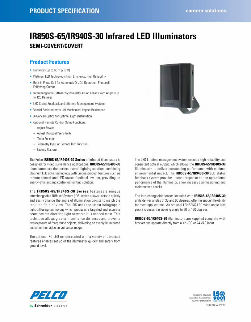
PRODUCT SPECIFICATION camera solutions
C3966 / NEW 9-12-13
International StandardsOrganization Registered Firm;
ISO 9001 Quality System
IR850S-65/IR940S-30 Infrared LED IlluminatorsSEMI-COVERT/COVERT
Product Features • Distances Up to 65 m (213 ft)
• Platinum LED Technology; High Efficiency, High Reliability
• Built-in Photo Cell for Automatic On/Off Operation; Photocell Following Output
• Interchangeable Diffuser System (IDS) Using Lenses with Angles Up to 120 Degrees
• LED Status Feedback and Lifetime Management Systems
• Vandal Resistant with IK9 Mechanical Impact Resistance
• Advanced Optics for Optimal Light Distribution
• Optional Remote Control Setup Functions:
– Adjust Power
– Adjust Photocell Sensitivity
– Timer Function
– Telemetry Input or Remote Dim Function
– Factory Restore
The Pelco IR850S-65/IR940S-30 Series of infrared illuminators isdesigned for video surveillance applications. IR850S-65/IR940S-30illuminators are the perfect overall lighting solution, combiningplatinum LED optic technology with unique product features such asremote control and LED status feedback system, providing anenergy-efficient and controlled lighting solution.
Th e IR 85 0S-6 5 / IR 94 0S-3 0 Ser ies f ea tu r es a un iq ueInterchangeable Diffuser System (IDS) which allows users to quicklyand easily change the angle of illumination on-site to match therequired field of view. The IDS uses the latest holographiclight-diffusing technology which produces a targeted and accuratebeam pattern directing light to where it is needed most. Thistechnique allows greater illumination distances and preventsoverexposure of foreground objects, delivering an evenly illuminatedand smoother video surveillance image.
The optional RC-LED remote control with a variety of advancedfeatures enables set up of the illuminator quickly and safely fromground level.
The LED Lifetime management system ensures high reliability andconsistent optical output, which allows the IR850S-65/IR940S-30illuminators to deliver outstanding performance with minimalenvironmental impact. The IR850S-65/IR940S-30 LED statusfeedback system provides instant response on the operationalperformance of the illuminator, allowing easy commissioning andmaintenance checks.
The interchangeable lenses included with IR850S-65/IR940S-30units deliver angles of 35 and 60 degrees, offering enough flexibilityfor most applications. An optional LENSPKS-LED wide-angle lenspack increases the viewing angle to 80 or 120 degrees.
IR850S-65/IR940S-30 illuminators are supplied complete withbracket and operate directly from a 12 VDC or 24 VAC input.

Pelco by Schneider Electric3500 Pelco Way, Clovis, California 93612-5699 United StatesUSA & Canada Tel (800) 289-9100 Fax (800) 289-9150International Tel +1 (559) 292-1981 Fax +1 (559) 348-1120www.pelco.com www.pelco.com/community
TECHNICAL SPECIFICATIONS
MODELSIR850S-65 Semi-covert 850 nm infrared LED illuminator;
65 m (213 ft) maximum distance IR940S-30 Covert infrared 940 nm LED illuminator
30 m (98 ft) maximum distance
ELECTRICALInput Voltage 12 VDC ±10%;
24 VAC ±10%Power Consumption 12 W maximumPower Cord 2.5 m 12 or 24 VAC/DC
GENERALWavelength 850 nm/940 nm Average Life (Lamp) 10 yearsConstruction Aluminum body, stainless steel bracket,
polycarbonate coverFinish Gray polyester powder coatOperating Temperature –40° to 50°C (–40° to 122°F)Storage Temperature –50° to 75°C (–58° to 167°F)Weight Unit Shipping
0.65 kg (1.40 lb) 0.80 kg (1.70 lb)
MECHANICALBracket Mounting 6.50 mm (0.25 in) hole diameterBracket Adjustment 2, 4 mm AF hex (M6 hex button head)
CERTIFICATIONS/PATENTS• CE• FCC, Class B• UL/cUL Listed• Meets IP66 rating (environmental) and IK9 (vandal resistant)
SUPPLIED ACCESSORIESUnits are factory-installed with a 35 x 10° Interchangeable Diffuser System (IDS); an additional 60 x 25° IDS is supplied.
INTERCHANGEABLE DIFFUSER SYSTEM (IDS)Angles with Diffuser IR850S-65 Distance IR940S-30 Distance
10° x 10° (no diffuser) 65 m (213 ft) 30 m (98 ft)35° x 10° (standard) 45 m (148 ft) 20 m (66 ft)60° x 25° (included) 30 m (98 ft) 15 m (49 ft)80° x 30° (optional) 20 m (66 ft) 10 m (33 ft)120° x 50° (optional) 15 m (49 ft) 7 m (23 ft)
RECOMMENDED ACCESSORIESRC-LED Remote control for IR850, IR940, or WLED
illuminatorsLENSPKS-LED Wide angle lens pack (80° and 120°) for
IR850S-65, IR940S-30, or WLEDS-50LBKT-LED Mounting bracket for installing IR850, IR940,
or WLED illuminators on walls or flat surfaces
INTEGRATED COMMAND AND CONTROLStandard Built-in photocell for automatic on/off
operation; LED Status Feedback System provides status on performance of the unit; photocell following output
Advanced Accessed with remote control:– Power adjust from 20 to 100%– Photocell sensitivity adjust– Timer function (up to 30 minutes)– Telemetry control or remote dimming– LED Status Feedback System on/off– Restore factory default settings
Pelco, the Pelco logo, and other trademarks associated with Pelco products referredto in this publication are trademarks of Pelco, Inc. or its affiliates. ONVIF and the
ONVIF logo are trademarks of ONVIF Inc. All other product names andservices are the property of their respective companies.
Product specifications and availability are subject to change without notice.©Copyright 2013, Pelco, Inc. All rights reserved.
VALUES IN PARENTHESES ARE INCHES; ALL OTHERS ARE CENTIMETERS.
11.95(4.71)
9.30(3.66)
1.40 (0.55)
Ø 6.5(0.26)
7.50 (2.95) 6.41 (2.52)
3.00(1.18)
10.00(3.94)
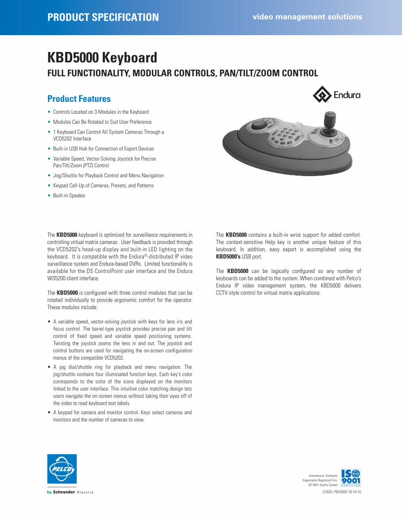
PRODUCT SPECIFICATION
video management solutions
C1620 / REVISED 10-14-10
International StandardsOrganization Registered Firm;
ISO 9001 Quality System
KBD5000 Keyboard
FULL FUNCTIONALITY, MODULAR CONTROLS, PAN/TILT/ZOOM CONTROL
Product Features
• Controls Located on 3 Modules in the Keyboard
• Modules Can Be Rotated to Suit User Preference
• 1 Keyboard Can Control All System Cameras Through a VCD5202 Interface
• Built-in USB Hub for Connection of Export Devices
• Variable Speed, Vector-Solving Joystick for Precise Pan/Tilt/Zoom (PTZ) Control
• Jog/Shuttle for Playback Control and Menu Navigation
• Keypad Call-Up of Cameras, Presets, and Patterns
• Built-in Speaker
The
KBD5000
keyboard is optimized for surveillance requirements incontrolling virtual matrix cameras. User feedback is provided throughthe VCD5202’s head-up display and built-in LED lighting on thekeyboard. It is compatible with the Endura
®
-distributed IP videosurveillance system and Endura-based DVRs. Limited functionality isavailable for the DS ControlPoint user interface and the EnduraWS5200 client interface.
The
KBD5000
is configured with three control modules that can berotated individually to provide ergonomic comfort for the operator.These modules include:
• A variable speed, vector-solving joystick with keys for lens iris andfocus control. The barrel-type joystick provides precise pan and tiltcontrol of fixed speed and variable speed positioning systems.Twisting the joystick zooms the lens in and out. The joystick andcontrol buttons are used for navigating the on-screen configurationmenus of the compatible VCD5202.
• A jog dial/shuttle ring for playback and menu navigation. Thejog/shuttle contains four illuminated function keys. Each key’s colorcorresponds to the color of the icons displayed on the monitorslinked to the user interface. This intuitive color matching design letsusers navigate the on-screen menus without taking their eyes off ofthe video to read keyboard text labels.
• A keypad for camera and monitor control. Keys select cameras andmonitors and the number of cameras to view.
The
KBD5000
contains a built-in wrist support for added comfort.The context-sensitive Help key is another unique feature of thiskeyboard. In addition, easy export is accomplished using the
KBD5000’s
USB port.
The
KBD5000
can be logically configured so any number ofkeyboards can be added to the system. When combined with Pelco’sEndura IP video management system, the KBD5000 deliversCCTV-style control for virtual matrix applications.
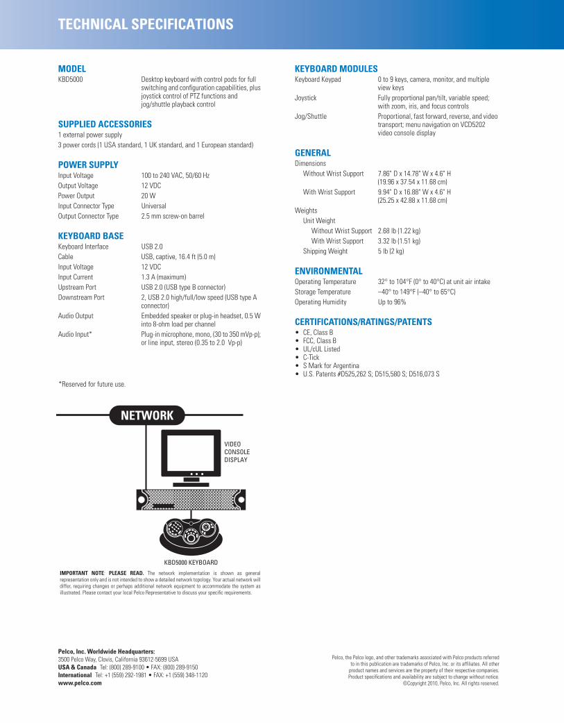
Pelco, Inc. Worldwide Headquarters:
3500 Pelco Way, Clovis, California 93612-5699 USA
USA & Canada
Tel: (800) 289-9100 • FAX: (800) 289-9150
International
Tel: +1 (559) 292-1981 • FAX: +1 (559) 348-1120
www.pelco.com
TECHNICAL SPECIFICATIONS
MODEL
KBD5000 Desktop keyboard with control pods for full switching and configuration capabilities, plus joystick control of PTZ functions and jog/shuttle playback control
SUPPLIED ACCESSORIES
1 external power supply3 power cords (1 USA standard, 1 UK standard, and 1 European standard)
POWER SUPPLY
Input Voltage 100 to 240 VAC, 50/60 HzOutput Voltage 12 VDCPower Output 20 WInput Connector Type UniversalOutput Connector Type 2.5 mm screw-on barrel
KEYBOARD BASE
Keyboard Interface USB 2.0Cable USB, captive, 16.4 ft (5.0 m)Input Voltage 12 VDCInput Current 1.3 A (maximum)Upstream Port USB 2.0 (USB type B connector)Downstream Port 2, USB 2.0 high/full/low speed (USB type A
connector)Audio Output Embedded speaker or plug-in headset, 0.5 W
into 8-ohm load per channelAudio Input* Plug-in microphone, mono, (30 to 350 mVp-p);
or line input, stereo (0.35 to 2.0 Vp-p)
*Reserved for future use.
KEYBOARD MODULES
Keyboard Keypad 0 to 9 keys, camera, monitor, and multiple view keys
Joystick Fully proportional pan/tilt, variable speed; with zoom, iris, and focus controls
Jog/Shuttle Proportional, fast forward, reverse, and video transport; menu navigation on VCD5202 video console display
GENERAL
DimensionsWithout Wrist Support 7.86" D x 14.78" W x 4.6" H
(19.96 x 37.54 x 11.68 cm)With Wrist Support 9.94" D x 16.88" W x 4.6" H
(25.25 x 42.88 x 11.68 cm)Weights
Unit Weight Without Wrist Support 2.68 lb (1.22 kg)With Wrist Support 3.32 lb (1.51 kg)
Shipping Weight 5 lb (2 kg)
ENVIRONMENTAL
Operating Temperature 32° to 104°F (0° to 40°C) at unit air intakeStorage Temperature –40° to 149°F (–40° to 65°C)Operating Humidity Up to 96%
CERTIFICATIONS/RATINGS/PATENTS
• CE, Class B• FCC, Class B• UL/cUL Listed• C-Tick• S Mark for Argentina• U.S. Patents #D525,262 S; D515,580 S; D516,073 S
IMPORTANT NOTE: PLEASE READ. The network implementation is shown as generalrepresentation only and is not intended to show a detailed network topology. Your actual network willdiffer, requiring changes or perhaps additional network equipment to accommodate the system asillustrated. Please contact your local Pelco Representative to discuss your specific requirements.
KBD5000 KEYBOARD
VIDEOCONSOLEDISPLAY
Pelco, the Pelco logo, and other trademarks associated with Pelco products referredto in this publication are trademarks of Pelco, Inc. or its affiliates. All other
product names and services are the property of their respective companies.Product specifications and availability are subject to change without notice.
©Copyright 2010, Pelco, Inc. All rights reserved.

PRODUCT SPECIFICATION
cameras
C234 / REVISED 10-14-09
International StandardsOrganization Registered Firm;
ISO 9001 Quality System
MRCA Mount
CEILING MOUNT, DOME OR MONITOR
Product Features
• Ceiling Mounting
• Black Polyester Powder Coat Finish
• For Use with Full-Sphere Pendant Style Domes Using 1.5-Inch NPT Threaded Pipe for Mounting
• Indoor Applications Only
• Can Also Be Used with MR3000, MR3050, MR4050, and MR5000 Series Monitor Mounts
The
MRCA
is a ceiling mount designed for use with full-spherependant mount domes that use a suitable length of 1.5-inch NPTthreaded pipe for mounting.
The
MRCA
is compatible with Pelco Spectra
®
, DF5, and DF8 Seriespendant style domes. It can also be used with MR3000, MR3050,MR4050, and MR5000 Series monitor mounts.
The
MRCA
is constructed of steel and has a black polyester powdercoat finish. This mount is for indoor use only.
MRCA CEILING MOUNT
0.90(2.29)
4.50(11.43)
1-1/2 NPTPIPE THREAD
Ø 0.32 (0.81) 4XEQ SP ON A 3.50 (8.89) BC
NOTE: VALUES IN PARENTHESES ARE CENTIMETERS;ALL OTHERS ARE INCHES.

Pelco, Inc. Worldwide Headquarters:
3500 Pelco Way, Clovis, California 93612-5699 USA
USA & Canada
Tel: (800) 289-9100 • FAX: (800) 289-9150
International
Tel: +1 (559) 292-1981 • FAX: +1 (559) 348-1120
www.pelco.com
TECHNICAL SPECIFICATIONS
MODEL
MRCA Ceiling mount for full-sphere pendant style domes that use 1.5-inch NPT threaded pipe for mounting
GENERAL
Dome Mounting Suitable length of 1.5-inch NPT threaded pipe required (not supplied)
Mounting Method Four 5/16-inch diameter fasteners (not supplied)
Construction SteelFinish Black polyester powder coatUnit Weight 1.22 lb (0.55 kg)Shipping Weight 2 lb (0.9 kg)
CERTIFICATIONS
• UL Listed
Pelco, the Pelco logo, and Spectra are registered trademarks of Pelco, Inc.All product names and services identified throughout this document are trademarks or registered
trademarks of their respective companies. The absence of a trademark or registered trademarkfrom this document does not constitute a waiver of intellectual property rights.
Product specifications and availability subject to change without notice.©Copyright 2009, Pelco, Inc. All rights reserved.

PRODUCT SPECIFICATION camera solutions
C4013 / REVISED 1-08-16
International StandardsOrganization Registered Firm;
ISO 9001 Quality System
Spectra® Professional Series IP Dome SystemP1220 MODELS, HIGH DEFINITION PAN/TILT/ZOOM HIGH-SPEED DOME
Product Features • Up to 1920 x 1080 Resolution
• 16:9 Aspect Ratio; 1080p at 30 Images per Second (ips)
• 2.0 Megapixel (MPx), 20X Optical Zoom, 12X Digital Zoom IP Camera
• Ability to Control and Monitor Video Over IPv4 Network
• Built-in Analytics Including Motion Detection and Camera Sabotage
• 2 Video Streams: Dual H.264 or H.264 and Scalable MJPEG
• 360° Continuous Pan Rotation up to 430° per Second
• Supported Protocols: TCP/IP, UDP/IP (Unicast, Multicast IGMP), UPnP, DNS, DHCP, RTP, RTSP, NTP, and More
• PoE+ IEEE 802.3at Class 4 (For Non-Environmental Units)
• 16 Preset Tours, 128 Dome Presets, 8 Window Blanks
• Open IP Standards
• ONVIF Profile S and Profile G Conformant
Value-based Network Dome SystemPelco breaks the performance versus affordability barrier with thevery powerful, cost-effective Spectra® Professional Series ofdiscreet, integrated camera dome positioning systems. The SpectraProfessional Series delivers clear, live streaming, high-definitionimages over the Internet using a standard Web browser (Microsoft®
Internet Explorer®, Chrome, or Mozilla® Firefox®). With six times theresolution of standard definition domes, Spectra Professional is anideal solution to view details such as faces, license plates, tattoos,or other specific features when in a zoomed-in position.
Spectra Professional supports High-Profile H.264 compression, avast improvement in quality over MPEG-4 and up to 20 times moreefficient than MJPEG. The dome system features open architectureconnectivity for third-party software recording solutions allowingintegration into virtually any IP-based HD system. It is alsocompatible with Digital Sentry® video management systems. As withall Pelco IP camera solutions, Spectra Professional is EnduraEnabled™ to record, manage, configure, and view multiple livestreams. When connected to an Endura® HD network-based videosecurity system, the dome system has access to EnduraStor™ andEnduraView™ for optimized image quality and bandwidth efficiency.
Spectra Professional Series features ease of installation and ease ofmaintenance that you have come to expect from Pelco. Each domesystem consists of a back box, a dome drive, and a lower dome, allprepackaged as a system.
Spectra Professional Series includes a choice of four back boxmodels: in-ceiling, environmental in-ceiling, pendant, andenvironmental pendant. All environmental models meet Type 4X,IP66 when properly installed.
Built-In AnalyticsPelco video Analytics enhance the flexibility and performance ofSpectra Professional. Two preloaded Pelco behaviors are included asstandard features and can be configured and enabled using astandard Web browser. They are compatible with Endura or a third-party system that supports alarms using Pelco’s API.• Motion Detection: Built-in video motion detection (VMD) provides more
efficient and reliable surveillance by triggering an alarm when motion occurs based on the user-defined area and sensitivity levels.
• Camera Sabotage: Detects contrast changes in the field of view. An alarm is triggered if the lens is obstructed by spray paint, a cloth, or a lens cap. Any unauthorized repositioning of the camera also triggers an alarm.
Web InterfaceSpectra Professional uses a standard Web browser for powerfulremote setup and administration.
Window BlankingWindow blanking is used to conceal user-defined privacy areas thatcannot be viewed by an operator. Spectra Professional Seriessupports up to eight blanked windows. A blanked area will appear onthe screen as a solid gray window.
Video SystemizationSpectra Professional Series easily connects to Pelco IP and hybridsystems.
Spectra Professional Series features open architecture connectivityto third-party software. Pelco offers an application programminginterface (API) and software developer’s kit (SDK) for interfacing withPelco’s IP cameras.
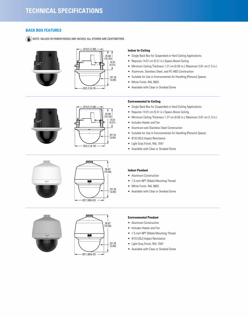
TECHNICAL SPECIFICATIONS
BACK BOX FEATURES
NOTE: VALUES IN PARENTHESES ARE INCHES; ALL OTHERS ARE CENTIMETERS.
Indoor In-Ceiling
• Single Back Box for Suspended or Hard Ceiling Applications
• Requires 14.01 cm (5.51 in.) Space Above Ceiling
• Minimum Ceiling Thickness 1.27 cm (0.50 in.); Maximum 3.81 cm (1.5 in.)
• Aluminum, Stainless Steel, and PC-ABS Construction
• Suitable for Use in Environmental Air Handling (Plenum) Spaces
• White Finish, RAL 9003
• Available with Clear or Smoked Dome
Environmental In-Ceiling
• Single Back Box for Suspended or Hard Ceiling Applications
• Requires 14.01 cm (5.51 in.) Space Above Ceiling
• Minimum Ceiling Thickness 1.27 cm (0.50 in.); Maximum 3.81 cm (1.5 in.)
• Includes Heater and Fan
• Aluminum and Stainless Steel Construction
• Suitable for Use in Environmental Air Handling (Plenum) Spaces
• IK10 (20J) Impact Resistance
• Light Gray Finish, RAL 7047
• Available with Clear or Smoked Dome
Indoor Pendant
• Aluminum Construction
• 1.5-inch NPT (Male) Mounting Thread
• White Finish, RAL 9003
• Available with Clear or Smoked Dome
Environmental Pendant
• Aluminum Construction
• Includes Heater and Fan
• 1.5-inch NPT (Male) Mounting Thread
• IK10 (20J) Impact Resistance
• Light Gray Finish, RAL 7047
• Available with Clear or Smoked Dome
R7.76(3.05)
Ø22.2 (8.74)
25.08(10.16)
Ø19.5 (7.68)
14.01(5.51)
R7.76(3.05)
Ø22.2 (8.74)
Ø19.5 (7.68)
25.80(10.16)
14.01(5.51)
R7.76(3.05)
Ø21.38(8.42)
26.67(10.50)
R7.76(3.05)
Ø21.38(8.42)
26.67(10.50)

TECHNICAL SPECIFICATIONS
CAMERA/OPTICSSensor Type 1/3-inch CMOS SensorOptical Zoom 20XDigital Zoom 12XMaximum Resolution 1920 x 1080Lens f/1.6 ~ f/4.2
focal length 4.3 mm (wide) ~ 86.0 mm (tele)Horizontal Angle of View 55.4° (wide) ~ 2.9° (tele)Aspect Ratio 16:9Shutter Range 1 ~ 1/8,000 secDynamic Range 60 dBWhite Balance Range 2,500° to 8,000°K3D Noise Reduction Yes (ON/OFF selectable)Signal to Noise Ratio 50 dBLight Sensitivity
Color (33 ms) 0.3 luxColor (200 ms) 0.08 luxMono (33 ms) 0.1 luxMono (200 ms) 0.015 lux
Note: Sensitivity in lux for 90% reflectance, f/1.6 (wide angle), 24 dB noise at 30 IRE (30% of signal level).Day/Night Capabilities YesIR Cut Filter YesIris Control Auto iris Automatic Gain Control YesActive Noise Filtering Yes
SOFTWARE FEATURES• 128 Presets• 16 Tours• Preset Accuracy: Pan ±0.1°; Tilt ±0.05° • Multilingual Menus (English, Spanish, Portuguese, Italian, German,
French, Russian, Turkish, Arabic, Simplified Chinese, and Korean)• Password Protection• 430°/sec Maximum Pan Preset Speed and 200°/sec Maximum Tilt Preset
Speed• 8 Window Blanks, Configurable in Size*• “Auto Flip” Feature Rotates Dome 180° at Bottom of Tilt Travel• Configurable Park with Actions• Proportional Pan/Tilt Continually Decreases Pan/Tilt Speeds in Proportion
to Depth of Zoom*Using the maximum number of window blanks in a single view can
affect camera performance and could interrupt certain camera functions.
AUDIOStreaming Embedded with stream 1 and stream 2Input Line in/terminal blockEncoding G.711 A-law/G.711 U-law

TECHNICAL SPECIFICATIONS
VIDEOVideo Encoding H.264 High, Main, or Base profiles and
MJPEGVideo Streams Up to 2 simultaneous streams; the second
stream is variable based on the setup of the primary stream
Frame Rate Up to 30, 25, 20, 16.67, 15, 12.5, 10, 7.5, 5, 3, 2, 1 (depending on the combination of coding, resolution, and stream configuration)
NETWORKSupported Protocols TCP/IP, UDP/IP (Unicast, Multicast IGMP),
UPnP, DNS, DHCP, RTP, RTSP, NTP, IPv4, IPv6, SNMP v2c/v3, QoS, HTTP, HTTPS, LDAP (client), SSH, SSL, SMTP, FTP, and 802.1x (EAP), GB28181
UsersUnicast 1 admin and up to 4 viewers simultaneously
depending on resolution settings (2 guaranteed streams)
Multicast Unlimited users H.264 Security Access Password protectedSoftware Interface Web browser view and setupPelco System Integration Endura 2.0 (or later)
Digital Sentry 7.3.208 (or later)Open API Pelco API, ONVIF Profile S and Profile GMobile Application Integrated to Pelco Mobile AppVideo Motion Detection Simple motion detection and camera
SabotageLocal Storage Up to 32GB onboard;
Micro SD, SDHC Compatible (see manual for details)Capture 1–5–10 second video clips on camera sabotage, motion detection, or alarm input (accessible using FTP protocol); record video continuously using ONVIF Profile G.
Minimum System RequirementsProcessor Intel® Core™ i3 Processor, 2.4 GHzOperating System Windows® 7 (32-bit and 64-bit), Windows 8Memory 4 GB RAMNetwork Interface Card 100 megabits (or greater)Monitor Minimum of 1024 x 768 resolution, 16- or
32-bit pixel color resolutionWeb Browser Internet Explorer 9.0 (or later), Firefox 31
(or later), or Chrome 23 (or later)Media Player* Pelco Media Player† or QuickTime® 7.6.5 for
Windows; or QuickTime 7.6.4 for Mac OS X 10.4 (or later)
Available Resolutions ResolutionH.264 High Profile (IP GOP structure)
MPx Width HeightAspect Ratio
Maximum IPS
2.07 1920 1080 16:9 30
0.92 1280 720 16:9 30
0.59 1024 576 16:9 30
0.52 960 540 16:9 25
0.23 640 352 16:9 30
0.06 320 180 16:9 30
*This product is not compatible with QuickTime version 7.6.4 for Windows. If you have this version installed on your PC, you will need to upgrade to QuickTime version 7.6.5.
† Pelco Media Player is recommended for control, smoothness, and reduced latency as compared to QuickTime.

TECHNICAL SPECIFICATIONS
GENERALConstruction
Back Box AssemblyIndoor Aluminum and stainless steelEnvironmental Aluminum
Dome Drive Assembly PC-ABS and sheet metalLower Dome Assembly
Indoor Polycarbonate and PC-ABSEnvironmental Polycarbonate and aluminum
Light AttenuationSmoked 50% light attenuationClear f/0.0 light loss
Cable Entry (back box)In-Ceiling 0.75-inch conduit fittingPendant 1.5-inch NPT pendant mount
Weight (approximate) Unit ShippingIndoor In-Ceiling 2.79 kg (6.17 lb) 4.41 kg (9.73 lb)Environmental In-Ceiling 3.09 kg (6.83 lb) 4.71 kg (10.39 lb)Indoor Pendant 3.10 kg (6.84 lb) 4.67 kg (10.30 lb)Environmental Pendant 3.12 kg (6.89 lb) 4.69 kg (10.35 lb)
ENVIRONMENTALInstallation Environment
In-Ceiling Indoor/environmentalPendant Indoor/environmental
Operating TemperatureIndoor –10° to 50°C (14° to 122°F)Environmental –40° to 50°C (–40° to 122°F)
Absolute Maximum Operating Temperature
Indoor 50°C (122°F)Environmental 74°C (165.2°F) ambient per NEMA TS-2
(para 2.2.7.3 - 2.2.7.7)Operating Humidity 20% to 80% (noncondensing)Storage All models
Temperature –40° to 60°C (–40° to 140°F)Humidity 20% to 80% (noncondensing)
Effective Projected Area (EPA)Without Mount 869 square centimeters (135 square inches)With IWM Series Mount 1,592 square centimeters (247 square inches)
MECHANICALPan Movement 360° continuous pan rotationTilt Movement +1° to –90°Preset Speed
Pan 430°/secTilt 200°/sec
Preset AccuracyPan ±0.1°Tilt ±0.05°
Variable Manual SpeedPan 0.1°/sec to 100°/secTilt 0.1°/sec to 50°/sec
ELECTRICALPorts RJ-45 connector for 100Base-TX
Auto MDI/MDI-X;Autonegotiate/manual setting
Cabling Type Cat5 or better for 100Base-TXInput Voltage 18 to 32 VAC; 24 VAC nominalInput Power
Indoor 24 VAC; 26 VA; PoE+ IEEE 802.3at Class 4, 48 V, 600 mA
Environmental 24 VAC; 50 VAAlarms
Inputs 4Output 1; PhotoMOS™ relay (30 V, 1 A)Triggers Unsupervised mode that detects switch
closures (N.O. and N.C.)
CERTIFICATIONS/RATINGS• CE, Class A• FCC, Class A• UL/cUL Listed• C-Tick• NEMA TS-2 (Temp.) para 2.2.7.3 - 2.2.7.7• KCC*• ONVIF Profile S and Profile G Conformant†
• Models were tested in accordance with:– IEC 60068-2-1 Low Temperature – IEC 60068-2-2 High Temperature – IEC 60068-2-3 High Temperature & Humidity – IEC 60068-2-6 Product Vibration – IEC 60068-2-14 Thermal Shock – IEC 60068-2-27 Product Shock – IEC 60068-2-52 Salt Fog– IEC 62262 Impact (IK10)– IEC 60529 Ingress for Water & Dust (IP66) – ISTA 2A Package Drop
• Meets Type 4X enclosure and IP66 standards when installed properly *At the time of this printing, this certification is pending. Please
consult the factory, our Web site (www.pelco.com), or the most recent B.O.S.S.® update for the current status of certifications.
† Refer to the Pelco Developer Network (pdn.pelco.com) for more information about ONVIF conformance.

Pelco by Schneider Electric3500 Pelco Way, Clovis, California 93612-5699 United StatesUSA & Canada Tel (800) 289-9100 Fax (800) 289-9150International Tel +1 (559) 292-1981 Fax +1 (559) 348-1120www.pelco.com www.pelco.com/community
TECHNICAL SPECIFICATIONS
SYSTEM MODEL NUMBERS
COMPONENT MODEL NUMBERSDome Assemblies
LDP-FWH-0 In-ceiling, indoor, white trim ring, smoked domeLDP-FWH-1 In-ceiling, indoor, white trim ring, clear domeLDP-YSR-0 In-ceiling, environmental, light gray trim ring, smoked dome LDP-YSR-1 In-ceiling, environmental, light gray trim ring, clear domeLDP-PWH-0 Pendant, indoor, white trim ring, smoked domeLDP-PWH-1 Pendant, indoor, white trim ring, clear domeLDP-ESR-0 Pendant, environment, light gray trim ring, smoked domeLDP-ESR-1 Pendant, environment, light gray trim ring, clear dome
RECOMMENDED MOUNTSIWM-SR, IWM24-SR Wall mount, with or without integral 24 VAC,
100 VA transformer; can be adapted for corner, parapet or pole application
WMVE-SW Indoor wall mount; white finish; can be installed directly to a wall or any vertical surface; power and video wiring can be routed through the back of the mount or through the conduit access located on the bottom of the mount arm; can also be mounted to a pole using a PA101 pole mount adapter
WMVE-SR Environmental wall mount; light gray finish; can be installed directly to a wall or any vertical surface; power and video wiring can be routed through the back of the mount or through the conduit access located on the bottom of the mount arm; can also be mounted to a pole using a PA101 pole mount adapter
MRCA Ceiling mount, blackPP4348 Parapet roof mountPP350/PP351 Parapet wall/roof mount
OPTIONAL ACCESSORIESMCS Series Indoor, 24 VAC power supplyWCS Series Outdoor, 24 VAC power supplyPOE1AT-US Single-port PoE+ midspan with US power
cordPOE1AT-EU Single-port PoE+ midspan with European
power cordPOE8ATN-US 8-port PoE+ Midspan with US power cordPOE8ATN-EU 8-port PoE+ Midspan with EU power cordPOE16ATN-US 16-port PoE+ Midspan with US power cordPOE16ATN-EU 16-port PoE+ Midspan with EU power cord
Refer to individual power supply specifications for more information.
TypeBack Box
ColorDome Assembly
Spectra Professional 2.0 MPx, 20X
In-ceiling, indoor BlackSmoked with white trim ring P1220-FWH0
Clear with white trim ring P1220-FWH1
In-ceiling, environmental Black Smoked with light gray trim ring P1220-YSR0
Clear with light gray trim ring P1220-YSR1
Pendant, indoor WhiteSmoked with white trim ring P1220-PWH0
Clear with white trim ring P1220-PWH1
Pendant, environmental Light GraySmoked with light gray trim ring P1220-ESR0
Clear with light gray trim ring P1220-ESR1
Pelco, the Pelco logo, and other trademarks associated with Pelco products referredto in this publication are trademarks of Pelco, Inc. or its affiliates. ONVIF and the
ONVIF logo are trademarks of ONVIF Inc. All other product names andservices are the property of their respective companies.
Product specifications and availability are subject to change without notice.©Copyright 2016, Pelco, Inc. All rights reserved.
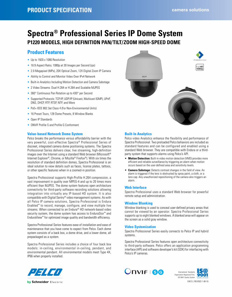
PRODUCT SPECIFICATION camera solutions
C4013 / REVISED 1-08-16
International StandardsOrganization Registered Firm;
ISO 9001 Quality System
Spectra® Professional Series IP Dome SystemP1220 MODELS, HIGH DEFINITION PAN/TILT/ZOOM HIGH-SPEED DOME
Product Features • Up to 1920 x 1080 Resolution
• 16:9 Aspect Ratio; 1080p at 30 Images per Second (ips)
• 2.0 Megapixel (MPx), 20X Optical Zoom, 12X Digital Zoom IP Camera
• Ability to Control and Monitor Video Over IPv4 Network
• Built-in Analytics Including Motion Detection and Camera Sabotage
• 2 Video Streams: Dual H.264 or H.264 and Scalable MJPEG
• 360° Continuous Pan Rotation up to 430° per Second
• Supported Protocols: TCP/IP, UDP/IP (Unicast, Multicast IGMP), UPnP, DNS, DHCP, RTP, RTSP, NTP, and More
• PoE+ IEEE 802.3at Class 4 (For Non-Environmental Units)
• 16 Preset Tours, 128 Dome Presets, 8 Window Blanks
• Open IP Standards
• ONVIF Profile S and Profile G Conformant
Value-based Network Dome SystemPelco breaks the performance versus affordability barrier with thevery powerful, cost-effective Spectra® Professional Series ofdiscreet, integrated camera dome positioning systems. The SpectraProfessional Series delivers clear, live streaming, high-definitionimages over the Internet using a standard Web browser (Microsoft®
Internet Explorer®, Chrome, or Mozilla® Firefox®). With six times theresolution of standard definition domes, Spectra Professional is anideal solution to view details such as faces, license plates, tattoos,or other specific features when in a zoomed-in position.
Spectra Professional supports High-Profile H.264 compression, avast improvement in quality over MPEG-4 and up to 20 times moreefficient than MJPEG. The dome system features open architectureconnectivity for third-party software recording solutions allowingintegration into virtually any IP-based HD system. It is alsocompatible with Digital Sentry® video management systems. As withall Pelco IP camera solutions, Spectra Professional is EnduraEnabled™ to record, manage, configure, and view multiple livestreams. When connected to an Endura® HD network-based videosecurity system, the dome system has access to EnduraStor™ andEnduraView™ for optimized image quality and bandwidth efficiency.
Spectra Professional Series features ease of installation and ease ofmaintenance that you have come to expect from Pelco. Each domesystem consists of a back box, a dome drive, and a lower dome, allprepackaged as a system.
Spectra Professional Series includes a choice of four back boxmodels: in-ceiling, environmental in-ceiling, pendant, andenvironmental pendant. All environmental models meet Type 4X,IP66 when properly installed.
Built-In AnalyticsPelco video Analytics enhance the flexibility and performance ofSpectra Professional. Two preloaded Pelco behaviors are included asstandard features and can be configured and enabled using astandard Web browser. They are compatible with Endura or a third-party system that supports alarms using Pelco’s API.• Motion Detection: Built-in video motion detection (VMD) provides more
efficient and reliable surveillance by triggering an alarm when motion occurs based on the user-defined area and sensitivity levels.
• Camera Sabotage: Detects contrast changes in the field of view. An alarm is triggered if the lens is obstructed by spray paint, a cloth, or a lens cap. Any unauthorized repositioning of the camera also triggers an alarm.
Web InterfaceSpectra Professional uses a standard Web browser for powerfulremote setup and administration.
Window BlankingWindow blanking is used to conceal user-defined privacy areas thatcannot be viewed by an operator. Spectra Professional Seriessupports up to eight blanked windows. A blanked area will appear onthe screen as a solid gray window.
Video SystemizationSpectra Professional Series easily connects to Pelco IP and hybridsystems.
Spectra Professional Series features open architecture connectivityto third-party software. Pelco offers an application programminginterface (API) and software developer’s kit (SDK) for interfacing withPelco’s IP cameras.

TECHNICAL SPECIFICATIONS
BACK BOX FEATURES
NOTE: VALUES IN PARENTHESES ARE INCHES; ALL OTHERS ARE CENTIMETERS.
Indoor In-Ceiling
• Single Back Box for Suspended or Hard Ceiling Applications
• Requires 14.01 cm (5.51 in.) Space Above Ceiling
• Minimum Ceiling Thickness 1.27 cm (0.50 in.); Maximum 3.81 cm (1.5 in.)
• Aluminum, Stainless Steel, and PC-ABS Construction
• Suitable for Use in Environmental Air Handling (Plenum) Spaces
• White Finish, RAL 9003
• Available with Clear or Smoked Dome
Environmental In-Ceiling
• Single Back Box for Suspended or Hard Ceiling Applications
• Requires 14.01 cm (5.51 in.) Space Above Ceiling
• Minimum Ceiling Thickness 1.27 cm (0.50 in.); Maximum 3.81 cm (1.5 in.)
• Includes Heater and Fan
• Aluminum and Stainless Steel Construction
• Suitable for Use in Environmental Air Handling (Plenum) Spaces
• IK10 (20J) Impact Resistance
• Light Gray Finish, RAL 7047
• Available with Clear or Smoked Dome
Indoor Pendant
• Aluminum Construction
• 1.5-inch NPT (Male) Mounting Thread
• White Finish, RAL 9003
• Available with Clear or Smoked Dome
Environmental Pendant
• Aluminum Construction
• Includes Heater and Fan
• 1.5-inch NPT (Male) Mounting Thread
• IK10 (20J) Impact Resistance
• Light Gray Finish, RAL 7047
• Available with Clear or Smoked Dome
R7.76(3.05)
Ø22.2 (8.74)
25.08(10.16)
Ø19.5 (7.68)
14.01(5.51)
R7.76(3.05)
Ø22.2 (8.74)
Ø19.5 (7.68)
25.80(10.16)
14.01(5.51)
R7.76(3.05)
Ø21.38(8.42)
26.67(10.50)
R7.76(3.05)
Ø21.38(8.42)
26.67(10.50)

TECHNICAL SPECIFICATIONS
CAMERA/OPTICSSensor Type 1/3-inch CMOS SensorOptical Zoom 20XDigital Zoom 12XMaximum Resolution 1920 x 1080Lens f/1.6 ~ f/4.2
focal length 4.3 mm (wide) ~ 86.0 mm (tele)Horizontal Angle of View 55.4° (wide) ~ 2.9° (tele)Aspect Ratio 16:9Shutter Range 1 ~ 1/8,000 secDynamic Range 60 dBWhite Balance Range 2,500° to 8,000°K3D Noise Reduction Yes (ON/OFF selectable)Signal to Noise Ratio 50 dBLight Sensitivity
Color (33 ms) 0.3 luxColor (200 ms) 0.08 luxMono (33 ms) 0.1 luxMono (200 ms) 0.015 lux
Note: Sensitivity in lux for 90% reflectance, f/1.6 (wide angle), 24 dB noise at 30 IRE (30% of signal level).Day/Night Capabilities YesIR Cut Filter YesIris Control Auto iris Automatic Gain Control YesActive Noise Filtering Yes
SOFTWARE FEATURES• 128 Presets• 16 Tours• Preset Accuracy: Pan ±0.1°; Tilt ±0.05° • Multilingual Menus (English, Spanish, Portuguese, Italian, German,
French, Russian, Turkish, Arabic, Simplified Chinese, and Korean)• Password Protection• 430°/sec Maximum Pan Preset Speed and 200°/sec Maximum Tilt Preset
Speed• 8 Window Blanks, Configurable in Size*• “Auto Flip” Feature Rotates Dome 180° at Bottom of Tilt Travel• Configurable Park with Actions• Proportional Pan/Tilt Continually Decreases Pan/Tilt Speeds in Proportion
to Depth of Zoom*Using the maximum number of window blanks in a single view can
affect camera performance and could interrupt certain camera functions.
AUDIOStreaming Embedded with stream 1 and stream 2Input Line in/terminal blockEncoding G.711 A-law/G.711 U-law
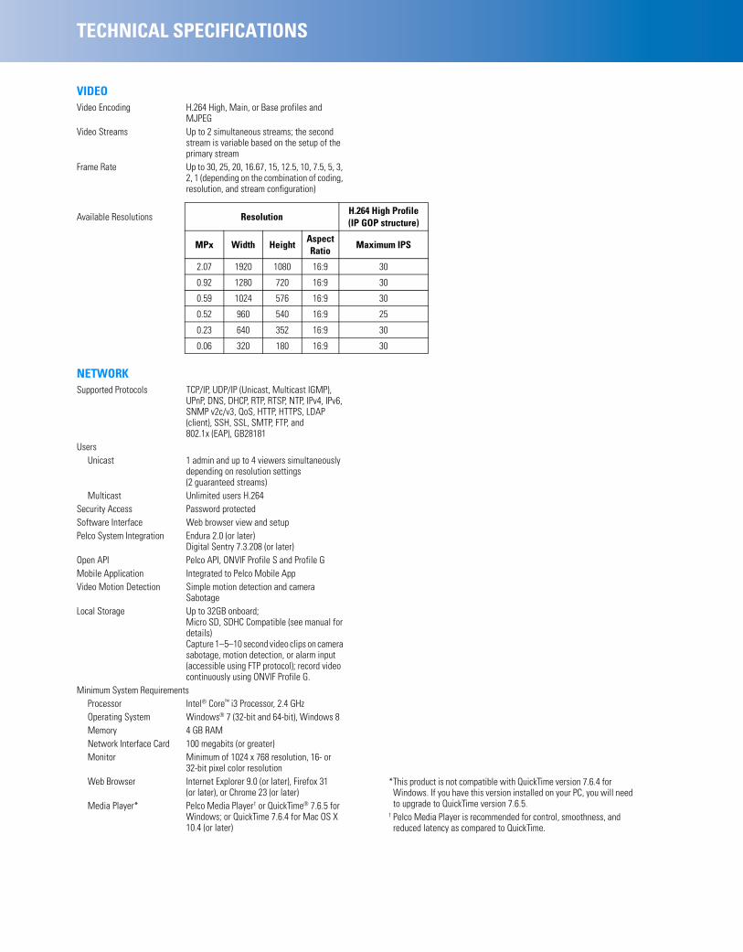
TECHNICAL SPECIFICATIONS
VIDEOVideo Encoding H.264 High, Main, or Base profiles and
MJPEGVideo Streams Up to 2 simultaneous streams; the second
stream is variable based on the setup of the primary stream
Frame Rate Up to 30, 25, 20, 16.67, 15, 12.5, 10, 7.5, 5, 3, 2, 1 (depending on the combination of coding, resolution, and stream configuration)
NETWORKSupported Protocols TCP/IP, UDP/IP (Unicast, Multicast IGMP),
UPnP, DNS, DHCP, RTP, RTSP, NTP, IPv4, IPv6, SNMP v2c/v3, QoS, HTTP, HTTPS, LDAP (client), SSH, SSL, SMTP, FTP, and 802.1x (EAP), GB28181
UsersUnicast 1 admin and up to 4 viewers simultaneously
depending on resolution settings (2 guaranteed streams)
Multicast Unlimited users H.264 Security Access Password protectedSoftware Interface Web browser view and setupPelco System Integration Endura 2.0 (or later)
Digital Sentry 7.3.208 (or later)Open API Pelco API, ONVIF Profile S and Profile GMobile Application Integrated to Pelco Mobile AppVideo Motion Detection Simple motion detection and camera
SabotageLocal Storage Up to 32GB onboard;
Micro SD, SDHC Compatible (see manual for details)Capture 1–5–10 second video clips on camera sabotage, motion detection, or alarm input (accessible using FTP protocol); record video continuously using ONVIF Profile G.
Minimum System RequirementsProcessor Intel® Core™ i3 Processor, 2.4 GHzOperating System Windows® 7 (32-bit and 64-bit), Windows 8Memory 4 GB RAMNetwork Interface Card 100 megabits (or greater)Monitor Minimum of 1024 x 768 resolution, 16- or
32-bit pixel color resolutionWeb Browser Internet Explorer 9.0 (or later), Firefox 31
(or later), or Chrome 23 (or later)Media Player* Pelco Media Player† or QuickTime® 7.6.5 for
Windows; or QuickTime 7.6.4 for Mac OS X 10.4 (or later)
Available Resolutions ResolutionH.264 High Profile (IP GOP structure)
MPx Width HeightAspect Ratio
Maximum IPS
2.07 1920 1080 16:9 30
0.92 1280 720 16:9 30
0.59 1024 576 16:9 30
0.52 960 540 16:9 25
0.23 640 352 16:9 30
0.06 320 180 16:9 30
*This product is not compatible with QuickTime version 7.6.4 for Windows. If you have this version installed on your PC, you will need to upgrade to QuickTime version 7.6.5.
† Pelco Media Player is recommended for control, smoothness, and reduced latency as compared to QuickTime.
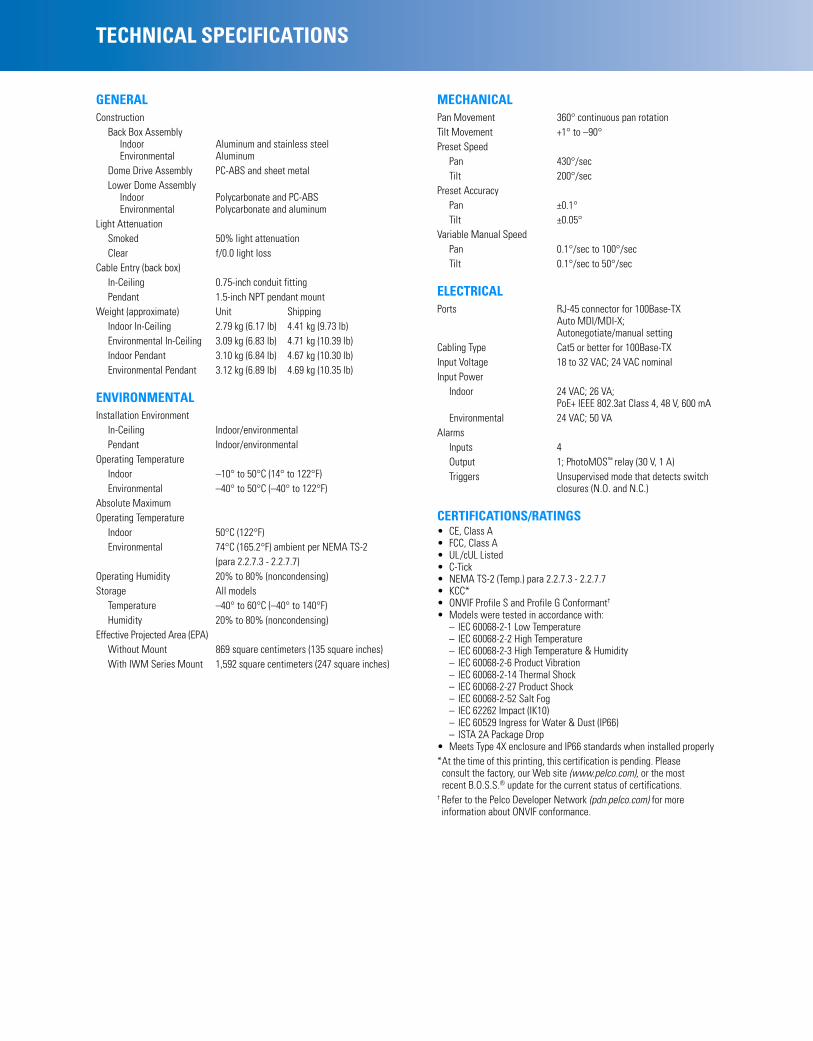
TECHNICAL SPECIFICATIONS
GENERALConstruction
Back Box AssemblyIndoor Aluminum and stainless steelEnvironmental Aluminum
Dome Drive Assembly PC-ABS and sheet metalLower Dome Assembly
Indoor Polycarbonate and PC-ABSEnvironmental Polycarbonate and aluminum
Light AttenuationSmoked 50% light attenuationClear f/0.0 light loss
Cable Entry (back box)In-Ceiling 0.75-inch conduit fittingPendant 1.5-inch NPT pendant mount
Weight (approximate) Unit ShippingIndoor In-Ceiling 2.79 kg (6.17 lb) 4.41 kg (9.73 lb)Environmental In-Ceiling 3.09 kg (6.83 lb) 4.71 kg (10.39 lb)Indoor Pendant 3.10 kg (6.84 lb) 4.67 kg (10.30 lb)Environmental Pendant 3.12 kg (6.89 lb) 4.69 kg (10.35 lb)
ENVIRONMENTALInstallation Environment
In-Ceiling Indoor/environmentalPendant Indoor/environmental
Operating TemperatureIndoor –10° to 50°C (14° to 122°F)Environmental –40° to 50°C (–40° to 122°F)
Absolute Maximum Operating Temperature
Indoor 50°C (122°F)Environmental 74°C (165.2°F) ambient per NEMA TS-2
(para 2.2.7.3 - 2.2.7.7)Operating Humidity 20% to 80% (noncondensing)Storage All models
Temperature –40° to 60°C (–40° to 140°F)Humidity 20% to 80% (noncondensing)
Effective Projected Area (EPA)Without Mount 869 square centimeters (135 square inches)With IWM Series Mount 1,592 square centimeters (247 square inches)
MECHANICALPan Movement 360° continuous pan rotationTilt Movement +1° to –90°Preset Speed
Pan 430°/secTilt 200°/sec
Preset AccuracyPan ±0.1°Tilt ±0.05°
Variable Manual SpeedPan 0.1°/sec to 100°/secTilt 0.1°/sec to 50°/sec
ELECTRICALPorts RJ-45 connector for 100Base-TX
Auto MDI/MDI-X;Autonegotiate/manual setting
Cabling Type Cat5 or better for 100Base-TXInput Voltage 18 to 32 VAC; 24 VAC nominalInput Power
Indoor 24 VAC; 26 VA; PoE+ IEEE 802.3at Class 4, 48 V, 600 mA
Environmental 24 VAC; 50 VAAlarms
Inputs 4Output 1; PhotoMOS™ relay (30 V, 1 A)Triggers Unsupervised mode that detects switch
closures (N.O. and N.C.)
CERTIFICATIONS/RATINGS• CE, Class A• FCC, Class A• UL/cUL Listed• C-Tick• NEMA TS-2 (Temp.) para 2.2.7.3 - 2.2.7.7• KCC*• ONVIF Profile S and Profile G Conformant†
• Models were tested in accordance with:– IEC 60068-2-1 Low Temperature – IEC 60068-2-2 High Temperature – IEC 60068-2-3 High Temperature & Humidity – IEC 60068-2-6 Product Vibration – IEC 60068-2-14 Thermal Shock – IEC 60068-2-27 Product Shock – IEC 60068-2-52 Salt Fog– IEC 62262 Impact (IK10)– IEC 60529 Ingress for Water & Dust (IP66) – ISTA 2A Package Drop
• Meets Type 4X enclosure and IP66 standards when installed properly *At the time of this printing, this certification is pending. Please
consult the factory, our Web site (www.pelco.com), or the most recent B.O.S.S.® update for the current status of certifications.
† Refer to the Pelco Developer Network (pdn.pelco.com) for more information about ONVIF conformance.

Pelco by Schneider Electric3500 Pelco Way, Clovis, California 93612-5699 United StatesUSA & Canada Tel (800) 289-9100 Fax (800) 289-9150International Tel +1 (559) 292-1981 Fax +1 (559) 348-1120www.pelco.com www.pelco.com/community
TECHNICAL SPECIFICATIONS
SYSTEM MODEL NUMBERS
COMPONENT MODEL NUMBERSDome Assemblies
LDP-FWH-0 In-ceiling, indoor, white trim ring, smoked domeLDP-FWH-1 In-ceiling, indoor, white trim ring, clear domeLDP-YSR-0 In-ceiling, environmental, light gray trim ring, smoked dome LDP-YSR-1 In-ceiling, environmental, light gray trim ring, clear domeLDP-PWH-0 Pendant, indoor, white trim ring, smoked domeLDP-PWH-1 Pendant, indoor, white trim ring, clear domeLDP-ESR-0 Pendant, environment, light gray trim ring, smoked domeLDP-ESR-1 Pendant, environment, light gray trim ring, clear dome
RECOMMENDED MOUNTSIWM-SR, IWM24-SR Wall mount, with or without integral 24 VAC,
100 VA transformer; can be adapted for corner, parapet or pole application
WMVE-SW Indoor wall mount; white finish; can be installed directly to a wall or any vertical surface; power and video wiring can be routed through the back of the mount or through the conduit access located on the bottom of the mount arm; can also be mounted to a pole using a PA101 pole mount adapter
WMVE-SR Environmental wall mount; light gray finish; can be installed directly to a wall or any vertical surface; power and video wiring can be routed through the back of the mount or through the conduit access located on the bottom of the mount arm; can also be mounted to a pole using a PA101 pole mount adapter
MRCA Ceiling mount, blackPP4348 Parapet roof mountPP350/PP351 Parapet wall/roof mount
OPTIONAL ACCESSORIESMCS Series Indoor, 24 VAC power supplyWCS Series Outdoor, 24 VAC power supplyPOE1AT-US Single-port PoE+ midspan with US power
cordPOE1AT-EU Single-port PoE+ midspan with European
power cordPOE8ATN-US 8-port PoE+ Midspan with US power cordPOE8ATN-EU 8-port PoE+ Midspan with EU power cordPOE16ATN-US 16-port PoE+ Midspan with US power cordPOE16ATN-EU 16-port PoE+ Midspan with EU power cord
Refer to individual power supply specifications for more information.
TypeBack Box
ColorDome Assembly
Spectra Professional 2.0 MPx, 20X
In-ceiling, indoor BlackSmoked with white trim ring P1220-FWH0
Clear with white trim ring P1220-FWH1
In-ceiling, environmental Black Smoked with light gray trim ring P1220-YSR0
Clear with light gray trim ring P1220-YSR1
Pendant, indoor WhiteSmoked with white trim ring P1220-PWH0
Clear with white trim ring P1220-PWH1
Pendant, environmental Light GraySmoked with light gray trim ring P1220-ESR0
Clear with light gray trim ring P1220-ESR1
Pelco, the Pelco logo, and other trademarks associated with Pelco products referredto in this publication are trademarks of Pelco, Inc. or its affiliates. ONVIF and the
ONVIF logo are trademarks of ONVIF Inc. All other product names andservices are the property of their respective companies.
Product specifications and availability are subject to change without notice.©Copyright 2016, Pelco, Inc. All rights reserved.
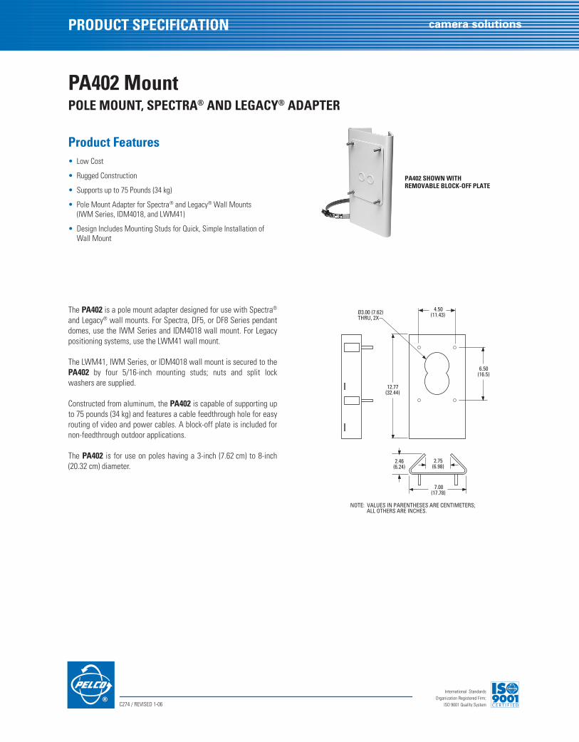
C274 / REVISED 1-06
International StandardsOrganization Registered Firm;
ISO 9001 Quality System
PRODUCT SPECIFICATION
camera solutions
PA402 Mount
POLE MOUNT, SPECTRA
®
AND LEGACY
®
ADAPTER
Product Features
• Low Cost
• Rugged Construction
• Supports up to 75 Pounds (34 kg)
• Pole Mount Adapter for Spectra
®
and Legacy
®
Wall Mounts (IWM Series, IDM4018, and LWM41)
• Design Includes Mounting Studs for Quick, Simple Installation of Wall Mount
The
PA402
is a pole mount adapter designed for use with Spectra
®
and Legacy
®
wall mounts. For Spectra, DF5, or DF8 Series pendantdomes, use the IWM Series and IDM4018 wall mount. For Legacypositioning systems, use the LWM41 wall mount.
The LWM41, IWM Series, or IDM4018 wall mount is secured to the
PA402
by four 5/16-inch mounting studs; nuts and split lockwashers are supplied.
Constructed from aluminum, the
PA402
is capable of supporting upto 75 pounds (34 kg) and features a cable feedthrough hole for easyrouting of video and power cables. A block-off plate is included fornon-feedthrough outdoor applications.
The
PA402
is for use on poles having a 3-inch (7.62 cm) to 8-inch(20.32 cm) diameter.
PA402 SHOWN WITHREMOVABLE BLOCK-OFF PLATE
NOTE: VALUES IN PARENTHESES ARE CENTIMETERS;ALL OTHERS ARE INCHES.
12.77(32.44)
4.50(11.43)
6.50(16.5)
Ø3.00 (7.62)THRU, 2X
2.46(6.24)
7.00(17.78)
2.75(6.98)
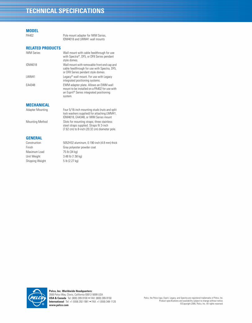
Pelco, Inc. Worldwide Headquarters:
3500 Pelco Way, Clovis, California 93612-5699 USA
USA & Canada
Tel: (800) 289-9100 • FAX: (800) 289-9150
International
Tel: +1 (559) 292-1981 • FAX: +1 (559) 348-1120
www.pelco.com
TECHNICAL SPECIFICATIONS
MODEL
PA402 Pole mount adapter for IWM Series, IDM4018 and LWM41 wall mounts
RELATED PRODUCTS
IWM Series Wall mount with cable feedthrough for use with Spectra
®
, DF5, or DF8 Series pendant style domes.
IDM4018 Wall mount with removable front end cap and cable feedthrough for use with Spectra, DF5, or DF8 Series pendant style domes.
LWM41 Legacy
®
wall mount. For use with Legacy integrated positioning systems.
EA4348 EWM adapter plate. Allows an EWM wall mount to be installed on a PA402 for use with an Esprit
®
Series integrated positioning system.
MECHANICAL
Adapter Mounting Four 5/16-inch mounting studs (nuts and split lock washers supplied) for attaching LWM41, IDM4018, EA4348, or IWM Series mount
Mounting Method Slots for mounting straps; three stainless steel straps supplied. Straps fit 3-inch (7.62 cm) to 8-inch (20.32 cm) diameter pole.
GENERAL
Construction 5052H32 aluminum, 0.190-inch (4.8 mm) thickFinish Gray polyester powder coatMaximum Load 75 lb (34 kg)Unit Weight 3.48 lb (1.58 kg)Shipping Weight 5 lb (2.27 kg)
Pelco, the Pelco logo, Esprit, Legacy, and Spectra are registered trademarks of Pelco, Inc.Product specifications and availability subject to change without notice.
©Copyright 2006, Pelco, Inc. All rights reserved.

PRODUCT SPECIFICATION camera solutions
C3946 / REVISED 12-08-16
International StandardsOrganization Registered Firm;
ISO 9001 Quality System
Spectra® Enhanced Series IP PTZ DomesHIGH-SPEED PTZ, 20X & 30X MODELS, FULL HD, WDR, LOW-LIGHT PERFORMANCE
Product Features • SureVision 3.0 Technology, Including:
– 130 dB Wide Dynamic Range (WDR)
– Advanced Low Light Down to 0.03 LUX on Select Models
– Anti-Bloom Technology
– 3D Noise Filtering
– Enhanced Tone Mapping
• Up to Full HD 1080p and up to 60 Images per Second (ips)
• Power over Ethernet (HPoE and PoE+), 24 VAC, 24 VDC
• Pelco H.264 Smart Compression Technology
• Three Automatic Defog Options
• Electronic Image Stabilization (EIS)
• Built-in Analytics Suite
• Vandal Resistant IK10 Smoked or Clear Bubble
• Up to 32 GB Edge Storage with Micro SD Card
• Compatible with Pelco and Third-Party Video Systems
• ONVIF Profile S and Profile G Conformant
• 3-Year Warranty and Support
Top of the Line IP PerformancePelco’s Spectra® Series of high speed PTZ domes provide top tierimage quality and performance. They include valuable embeddedfeatures that enhance the value of the product. Low latency videoand control make the camera incredibly easy to use.
Full High Definition SureVision 3.0 CamerasSpectra Enhanced has long provided Full HD 1080p 20x and 30xoptical zoom cameras that run at up to 60 frames per second andprovide 130dB of True Wide Dynamic Range (WDR). With Pelco’slatest product evolution a powerful new camera option is nowavailable that features the same powerful WDR capabilities asbefore but now with the addition of Pelco’s latest SureVision 3.0 lowlight performance. In addition to 130dB of True WDR SureVision 3.0adds a new level of low light performance that is up to twenty timesbetter than base Spectra Enhanced models. The new SureVision 3.0camera is available in both the 20x and 30x optical zoom in selectmodels.
Embedded FeaturesIncluded in all models are a full suite of built in video analyticsincluding: Abandoned Object, Adaptive Motion Detection,AutoTracker, Camera Sabotage, Directional Motion, LoiteringDetection, Object Counting, Object Removal, and Stopped Vehicle.Spectra Enhanced also allows for up to 32 window blanking privacyzones that are configurable with custom blurring options. Threelevels of Image Defog provide options for enhancing the image onfoggy or rainy days. Five White Balance modes are available for
overcoming difficult lighting conditions day and night. A VividImaging mode can be enabled to automatically increases colorsaturation and sharpening. Spectra Enhanced supports up to 32GB ofonboard local storage (not supplied) that is easily accessible throughthe ONVIF Profile G protocol or FTP.
Intuitive DesignSpectra Enhanced features the same ease of installation andmaintenance that you have come to expect from Spectra. Each domesystem consists of a back-box, a dome drive, and an IK10 rated lowerdome. There is a choice of five form factors: in-ceiling, environmentalin-ceiling, pendant, environmental pendant, and stainless steelenvironmental pendant.
VMS IntegrationSpectra Enhanced easily connects to Pelco IP and hybrid videosystems such as VideoXpert, Endura 2.0 (or later), and Digital Sentry7.3 (or later). The camera is also compatible with Digital Sentry NVS(DS NVS), a full-featured video management software, which isavailable as a free download at www.pelco.com. DS NVS includesfour free Pelco IP licenses and allows for the management of videofrom up to 64 cameras.
Pelco endeavors to be the most open and integrated camera providerin the industry and as a part of that effort Spectra Enhanced isintegrated with a long and ever-growing list of 3rd party softwareand Video Management Systems (VMS).

BACK BOX FEATURES
NOTE: VALUES IN PARENTHESES ARE INCHES; ALL OTHERS ARE CENTIMETERS.
In-Ceiling (Indoor)
• Single Back Box for Suspended or Hard Ceiling Applications with Light Gray Trim Ring, RAL9002
• Requires 13.35 cm (5.25 in.) Space Above Ceiling and 8.25 cm (3.25 in.) Below
• Minimum Ceiling Thickness 1.27 cm (0.50 in.); Maximum 4.45 cm (1.75 in.)
• Aluminum Construction, IK10 Rated Nylon Bubble
• Suitable for Use in Environmental Air Handling Spaces
• 0° to 50°C (32° to 122°F) Sustained Operating Temperature
Environmental In-Ceiling
• Single Back Box, RAL9011, for Hard Ceiling Applications
• Requires 11.18 cm (4.40 in.) Space Above Ceiling;10.92 cm (4.30 in.) Below
• Type 4X and IP66
• Includes Heater and Blower
• Minimum Ceiling Thickness 1.27 cm (0.50 in.); Maximum 4.45 cm (1.75 in.)
• Aluminum Construction, IK10 Rated Nylon Bubble
• –45° to 50°C (–50° to 122°F) Sustained Operating Temperature
Standard Pendant
• Standard Pendant Available in Black or Light Gray Finish, RAL9002
• Aluminum Construction, IK10 Rated Nylon Bubble
• Uses 1 1/2-inch NPT Thread
• –5° to 50°C (23° to 122°F) Sustained Operating Temperature
Environmental Pendant
• Environmental Pendant Available in Light Gray Finish, RAL9002
• Aluminum Construction, IK10 Rated Nylon Bubble
• Type 4X and IP66
• Uses 1 1/2-inch NPT Thread
• Includes Sun Shield, Heater, and Blower
• –45° to 50°C (–50°F to 122°F) Sustained Operating Temperature
Stainless Steel Environmental Pendant
• Stainless Steel Environmental Pendant Available in Light Gray Finish, RAL9002
• All Stainless Steel Construction, IK10 Rated Nylon Bubble
• Type 4X and IP66
• Uses 1 1/2-inch NPT Thread
• Includes Sun Shield, Heater, and Blower
• –45° to 50°C (–50° to 122°F) Sustained Operating Temperature
13.2(5.2)
19.0 (7.5)
20.8 (8.2)
15.0 (5.9)
9.2(3.6)
25.2 (9.9)
11.2(4.4)
15.0 (5.9)21.8 (8.6)
11.2(4.4)
21.8 (8.6)15.0 (5.9)
28.2(11.1)
15.0 (5.9)
28.2(11.1)
23.8 (9.4)
15.0 (5.9)
28.2(11.1)
23.6 (9.3)

TECHNICAL SPECIFICATIONS
CAMERA/OPTICS
SOFTWARE FEATURES• 256 presets• 16 tours• ±0.1° preset accuracy• Multilingual menus (English, Spanish, Portuguese, Italian, German,
French, Russian, Turkish, Arabic, Simplified Chinese, and Korean)• Password protection• 32 window blanks, configurable in size, with 5 window blur options• “Auto Flip” feature rotates dome 180° at bottom of tilt travel• Configurable park with actions• Proportional pan/tilt continually decreases pan/tilt speeds in proportion
to depth of zoom• Pelco analytics including nine user-configurable behaviors• Image Defog modes
PELCO ANALYTICS BEHAVIORS
Spectra Enhanced includes nine user-configurable behaviors. Thecamera is capable of running up to three behaviors simultaneously;although, the number of behaviors is limited to the availableprocessing power of the camera and the type of analytic being used.
• Abandoned Object: Detects objects placed within a defined zone and triggers an alarm if the object remains in the zone longer than the user-defined time allows. An airport terminal is a typical installation for this behavior. This behavior can also detect objects left behind at an ATM, signaling possible card skimming.
• Adaptive Motion Detection: Detects and tracks objects that enter a scene and then triggers an alarm when the objects enter a user-defined zone. This behavior is primarily used in outdoor environments with light traffic to reduce the number of false alarms caused by environmental changes.
• AutoTracker: Detects and tracks movement in the field of view. When the AutoTracker behavior is configured, the system automatically pans and tilts to follow the moving object until the object stops or disappears from the monitored area.
• Camera Sabotage: Detects contrast changes in the field of view. An alarm is triggered if the lens is obstructed by spray paint, a cloth, or a lens cap. Any unauthorized repositioning of the camera also triggers an alarm.
• Directional Motion: Generates an alarm in a high traffic area when a person or object moves in a specified direction. Typical installations for this behavior include an airport gate or tunnel where cameras can detect objects moving in the opposite direction of the normal flow of traffic or an individual entering through an exit door.
• Loitering Detection: Identifies when people or vehicles remain in a defined zone longer than the user-defined time allows. This behavior is effective in real-time notification of suspicious behavior around ATMs, stairwells, and school grounds.
• Object Counting: Counts the number of objects that enter a defined zone. This behavior can be used to count the number of people at a store entrance/exit or inside a store where the traffic is light. This behavior is based on tracking and does not count people in a crowded setting.
• Object Removal: Triggers an alarm if an object is removed from a user-defined zone. This behavior is ideal for customers who want to detect the removal of high value objects, such as painting from a wall or a statue from a pedestal.
• Stopped Vehicle: Detects vehicles stopped near a sensitive area longer than the user-defined time allows. This behavior is idea for airport curbside drop-offs, parking enforcement, suspicious parking, traffic lane breakdowns, and vehicles waiting at gates.
Specification 20X 20X Low Light 30X 30X Low Light
Sensor Type 1/2.8-inch Type Exmor CMOS Sensor 1/2.8-inch Type Exmor CMOS Sensor
Optical Zoom 20X 30X
Digital Zoom 12X 12X
Maximum Resolution 1920 x 1080 1920 x 1080
Lens f/1.6 ~ f/3.5, focal length 4.7 mm (wide) ~ 94.0 mm (tele) f/1.6 ~ f/4.7, focal length 4.3 mm (wide) ~ 129.0 mm (tele)
Horizontal Angle of View 55.4° (wide) ~ 2.9° (tele) 59.5° wide - 3.3° tele 59.5° (wide) ~ 2.1° (tele) 63.7° wide - 2.3° tele
Aspect Ratio 16:9 16:9
Light Sensitivity
Color (33 ms) 0.20 lux 0.03 lux 0.20 lux 0.03 lux
Color (250 ms) 0.025 lux 0.008 lux 0.025 lux 0.008 lux
Mono (33 ms) 0.06 lux 0.004 lux 0.06 lux 0.004 lux
Mono (250 ms) 0.008 lux 0.001 lux 0.008 lux 0.001 lux
Note: Sensitivity in lux for 90% reflectance, f/1.6 (wide angle), 50 dB gain at 30 IRE (30% of signal level) with Sensitivity Boost OFF; 4X improvement to sensitivity with Sensitivity Boost ON
Day/Night Capabilities Yes Yes
Shutter Range 1/1 ~ 1/10,000 sec 1/1 ~ 1/10,000 sec
Signal-to-Noise Ratio >50dB >50dB
IR Cut Filter Yes Yes
Wide Dynamic Range 130 dB 130 dB
Iris Control Auto iris with manual override Auto iris with manual override
Backlight Compensation Yes Yes
Automatic Gain Control Yes Yes
Active Noise Filtering Yes 3D Noise Filtering Yes 3D Noise Filtering
Electronic Image Stabilization (EIS)
Yes No Yes

TECHNICAL SPECIFICATIONS
VIDEOVideo Encoding H.264 High, Main, or Base profiles and
MJPEGVideo Streams Up to 2 simultaneous streams; the second
stream is variable based on the setup of the primary stream
Frame Rate Up to 60, 50, 30, 25, 15, 12.5, 10, 8.333, 7.5, 6, 5, 3, 2.5, 2, 1 (depending on the coding, resolution, and stream configuration)
Available Resolutions
NETWORKSupported Protocols TCP/IP, UDP/IP (Unicast, Multicast IGMP),
UPnP, DNS, DHCP, RTP, RTSP, NTP, IPv4, IPv6*, SNMP v2c/v3, QoS, HTTP, HTTPS, SSH, SSL, SMTP, FTP, and 802.1x (EAP)
UsersUnicast Up to 20 simultaneous users depending on
resolution settings (2 guaranteed streams)Multicast Unlimited users H.264
Security Access Password protectedSoftware Interface Web browser view and setupPelco System Integration Endura 2.0 (or later)
Digital Sentry 7.3 (or later)Open API Pelco API or ONVIF Profile G and Profile SMobile Application Integrated to Pelco Mobile AppVideo Motion Detection Simple motion detection and camera
sabotageLocal Storage 32 GB SD Card;
Capture 1–5–10 second video clips on camera sabotage, motion detection, or alarm input; record video continuously in the case of network outage with option to overwrite; access video through FTP protocol and ONVIF Profile G
MINIMUM SYSTEM REQUIREMENTSProcessor Intel® Core™ i3 Processor, 2.4 GHzOperating System Windows® 7 (32-bit and 64-bit) with
DirectX® 11, Windows XP Service Pack 3 with DirectX 9.0c, or Mac® OS X 10.4 (or later)
Memory 4 GB RAMNetwork Interface Card 100 megabits (or greater)Monitor Minimum of 1024 x 768 resolution, 16- or
32-bit pixel color resolutionWeb Browser Internet Explorer® 8.0(or later) or Firefox 3.5
(or later); Internet Explorer 8.0 (or later) is recommended for configuring analytics
Media Player Pelco Media Player† or QuickTime® 7.6.5 for Windows XP and Windows 7; or QuickTime 7.6.4 for Mac OS X 10.4 (or later)
ANALYTICSRequired Systems for Pelco Analytics
Pelco Interface WS5200 Advanced System Management Software on an Endura 2.0 (or later) system
Open API The Pelco API can transmit behavior alarm data to third-party applications, available at pdn.pelco.com
GENERALConstruction
Back Box AluminumDome Drive Aluminum, thermo plasticLower Dome Nylon
Stainless Steel ConstructionBack Box 316 stainless steel; gray, polyurethane
powder coated finishLower Dome 316 stainless steel; black, polyurethane
powder coated finishBubble Nylon, clear or smoked
Light AttenuationSmoked f/0.5 light lossClear f/0.0 light loss
Cable Entry (back box)In-Ceiling 0.75-inch conduit fittingPendant Through 1.5-inch NPT pendant mount
Weight (approximate) Unit ShippingIn-Ceiling 2.6 kg (5.7 lb) 4.6 kg (10.2 lb)Environmental In-Ceiling 2.9 kg (6.5 lb) 4.9 kg (10.8 lb)Standard Pendant 3.1 kg (6.8 lb) 5.0 kg (11 lb)Environmental Pendant 3.7 kg (8.2 lb) 5.5 kg (12.2 lb)Stainless Steel 6.5 kg (14.3 lb) 8.6 kg (19 lb)Environmental Pendant
Effective Projected Area (EPA) 20.5 square inches (without mount), 47 square inches (with IWM Series mount)
ALARMUnsupervised Detects open or closed alarm stateSupervised Detects open and short alarm state with
external 1-kohm resistor Input 3.5 VDC maximum, 3.5 mA maximumRelay Output ±32 VDC maximum, 150 mA maximum
AUDIOInput/Output Line level/external microphone input;
600-ohm differential, 1Vp-p maximum signal level
Streaming Embedded audio
ResolutionH.264 High Profile (IP GOP structure)
MPx Width HeightAspect Ratio
MaximumIPS
RecommendedBit Rate (Mbps)
2.07 1920 1080 16:9 60 8.00
2.07 1920 1080 16:9 30 6.05
0.92 1280 720 16:9 30 3.00
0.36 800 448 16:9 30 2.00
0.23 640 352 16:9 30 1.80
* Supports mixed IPv4 and IPv6 installations, but not IPv6-only deployments.† Pelco Media Player is recommended for control, smoothness, and reduced
latency as compared to QuickTime.

TECHNICAL SPECIFICATIONS
OPERATING TEMPERATURE*
* Assumes no wind chill factor. † Cold starts within 90 minutes at specified temperature.‡ Removes icing of 2.5 mm (0.1 in.) within 3 hours after power-up.§ PEO75U HPoE injector accessory required for heater operation.
OPERATING HUMIDITYIn-Ceiling (indoor),Standard Pendant 10 to 90% RH (noncondensing)Environmental In-Ceiling,Environmental Pendant,Stainless Steel Environmental Pendant 10 to 100% RH (condensing)
MECHANICAL(Dome Drive Only)Variable Speed 0.1° to 80°/sec (manual pan speed)Preset Accuracy ±0.1°Pan Movement 360° continuous pan rotationVertical Tilt +1° to –90°Maximum Pan Speed Up to 450° per secondMaximum Tilt Speed Up to 450° per secondManual Pan/Tilt Speeds
Pan 0.1° to 80°/sec manual operationTilt 0.1° to 45°/sec manual operation
Preset SpeedsPan 450°/secTilt 450°/sec
PELCO’S H.264 SMART COMPRESSION TECHNOLOGYPelco’s H.264 Smart Compression Technology lowers bandwidth and storagerequirements by up to 70%, while reducing storage requirements.
Pelco’s Smart Compression Technology dynamically analyzes motion occurring within live video in real-time, to intelligently compress the information you don’t need, while retaining details with clear quality in the areas that are important in the scene. By enabling Dynamic GOP, an added feature of Smart Compression, the number of I-frames are automatically reduced in scenes with low motion. Based on the complexity of scenes and motion occurring, such as a store room that has limited entry and exit, up to 70% bandwidth savings can be achieved.
ELECTRICALPorts RJ-45 connector for 100Base-TX
Auto MDI/MDI-XAutonegotiate/manual setting
Cabling Type Cat5e or better for 100Base-TXInput Voltage 18 to 32 VAC; 24 VAC nominal
22 to 27 VDC; 24 VDC nominalInput Power
24 VAC 24 VA nominal (without heater and blower);81 VA nominal (with heater and blower)
24 VDC 1 VA nominal (without heater and blower);3 VA nominal (with heater and blower)
PoE+ 18 W, Environmental models (with heater off, blower on);*15 W, Non-Environmental (with heater and blower off)
HPoE 60 W, Environmental models (with heater and blower on);†
15 W, Non-environmental (with heater and blower off)
* Heater is disabled with PoE+ power selection. †Only 27 W of power is supplied to the heater.
CERTIFICATIONS/RATINGS/PATENTS• CE, Class A• FCC, Class A• ICES-003, Class A• UL/cUL Listed• C-Tick• NEMA TS-2 (Temp.) para 2.2.7.3 - 2.2.7.7• KC• ONVIF Profile S• ONVIF Profile G• Cisco® Medianet Media Services Proxy 2.0 compatible• Environmental models, including stainless steel, were tested in
accordance with:– IEC 60068-2-1, IEC 60068-2-2, IEC 60068-2-14, IEC 60068-2-30, and IEC
60068-2-78• Environmental pendants, including stainless steel, were tested in
accordance with:– IEC 60068-2-6 and IEC 60068-2-27
• Environmental models meet NEMA Type 4X and IP66 standards when installed properly (B6-F-E, B6-PG-E, and B6-PSG-E)
• U.S. Patents 5,931,432; 6,793,415 B2; 6,802,656 B2; 6,821,222 B2; 7,161,615 B2
• IK10 impact-resistant bubble on all models were tested in accordance with:– IEC 62262
Temperature
Models
In-Ceiling(24 VAC, PoE+)
Standard Pendant(24 VAC, PoE+)
Environmental Pendant and In-Ceiling
24 VAC HPoE§ PoE+
Sustaining Maximum 50°C (122°F) 50°C (122°F) 50°C (122°F) 50°C (122°F) 50°C (122°F)
Minimum 0°C (32°F) –5°C (23°F) –45°C (–49°F) –45°C (–49°F) –20°C (–4°F)
Absolute Maximum N/A N/A 60°C (140.2°F) 60°C (140.2°F) 60°C (140.2°F)
Minimum N/A N/A –51°C (–60°F) N/A N/A
Ice Free N/A N/A –30°C (–22°F) –30°C (–22°F) –10°C (14°F)
Cold Start† 0°C (32°F) 0°C (32°F) –40°C (–40°F) –35°C (–31°F) –10°C (14°F)
De-Icing‡ N/A N/A –30°C (–22°F) –30°C (–22°F) N/A
Storage Temperature –20°C to 60°C (–5°F to 140°F)
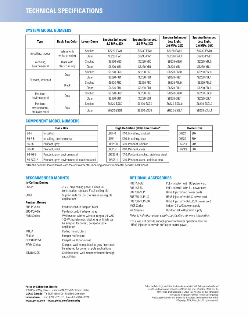
Pelco by Schneider Electric3500 Pelco Way, Clovis, California 93612-5699 United StatesUSA & Canada Tel (800) 289-9100 Fax (800) 289-9150International Tel +1 (559) 292-1981 Fax +1 (559) 348-1120www.pelco.com www.pelco.com/community
TECHNICAL SPECIFICATIONS
SYSTEM MODEL NUMBERS
COMPONENT MODEL NUMBERS
*Use the pendant lower domes with the environmental in-ceiling and environmental pendant back boxes.
RECOMMENDED MOUNTSIn-Ceiling DomesSD5-P 2' x 2' drop ceiling panel, aluminum
construction; replaces 2' x 2' ceiling tileSCA1 Support rails for B5-F; for use in ceiling tile
applicationsPendant DomesBB5-PCA-BK Pendant conduit adapter, blackBB5-PCA-GY Pendant conduit adapter, grayIWM Series Wall mount, with or without integral 24 VAC,
100 VA transformer; black or gray finish; can be adapted for corner, parapet or pole application
MRCA Ceiling mount, blackPP4348 Parapet roof mountPP350/PP351 Parapet wall/roof mountSWM Series Compact wall mount, black or gray finish; can
be adapted for corner or pole applicationsIDM4012SS Stainless steel wall mount with feed-through
capabilities
OPTIONAL ACCESSORIESPOE1AT-US PoE+ Injector† with US power cordPOE1AT-EU PoE+ Injector† with EU power cordPOE75U-1UP HPoE Injector† (no power cord)POE75U-1UP-US HPoE Injector† with US power cordPOE75U-1UP-EUK HPoE Injector† with EU/UK power cordMCS Series Indoor, 24 VAC power supplyWCS Series Outdoor, 24 VAC power supply
Refer to individual power supply specifications for more information.†PoE+ will not provide enough power for heater operation. Use the HPoE Injector to provide sufficient heater power.
Type Back Box Color Lower DomeSpectra Enhanced,
2.0 MPx, 20XSpectra Enhanced,
2.0 MPx, 30X
Spectra Enhanced Low Light,
2.0 MPx, 20X
Spectra EnhancedLow Light,
2.0 MPx, 30X
In-ceiling, indoorWhite with
white trim ringSmoked S6220-FW0 S6230-FW0 S6220-FWL0 S6230-FWL0
Clear S6220-FW1 S6230-FW1 S6220-FWL1 S6230-FWL1
In-ceiling, environmental
Black with black trim ring
Smoked S6220-YB0 S6230-YB0 S6220-YBL0 S6230-YBL0
Clear S6220-YB1 S6230-YB1 S6220-YBL1 S6230-YBL1
Pendant, standard
GraySmoked S6220-PG0 S6230-PG0 S6220-PGL0 S6230-PGL0
Clear S6220-PG1 S6230-PG1 S6220-PGL1 S6230-PGL1
BlackSmoked S6220-PB0 S6230-PB0 S6220-PBL0 S6230-PBL0
Clear S6220-PB1 S6230-PB1 S6220-PBL1 S6230-PBL1
Pendant, environmental
GraySmoked S6220-EG0 S6230-EG0 S6220-EGL0 S6230-EGL0
Clear S6220-EG1 S6230-EG1 S6220-EGL1 S6230-EGL1
Pendant, environmental, stainless steel
GraySmoked S6220-ESG0 S6230-ESG0 S6220-ESGL0 S6230-ESGL0
Clear S6220-ESG1 S6230-ESG1 S6220-ESGL1 S6230-ESGL1
Back Box High Definition (HD) Lower Dome* Dome Drive
B6-F In-ceiling LD6F-0 IK10, In-ceiling, smoked D6220 20X
B6-F-E In-ceiling, environmental LD6F-1 IK10, In-ceiling, clear D6230 30X
B6-PG Pendant, gray LD6PB-0 IK10, Pendant, smoked D6220L 20X
B6-PB Pendant, black LD6PB-1 IK10, Pendant, clear D6230L 30X
B6-PG-E Pendant, gray, environmental LD6SS-0 IK10, Pendant, smoked, stainless steel
B6-PSG-E Pendant, gray, environmental, stainless steel LD6SS-1 IK10, Pendant, clear, stainless steel
Pelco, the Pelco logo, and other trademarks associated with Pelco products referredto in this publication are trademarks of Pelco, Inc. or its affiliates. ONVIF and the
ONVIF logo are trademarks of ONVIF Inc. All other product names andservices are the property of their respective companies.
Product specifications and availability are subject to change without notice.©Copyright 2016, Pelco, Inc. All rights reserved.
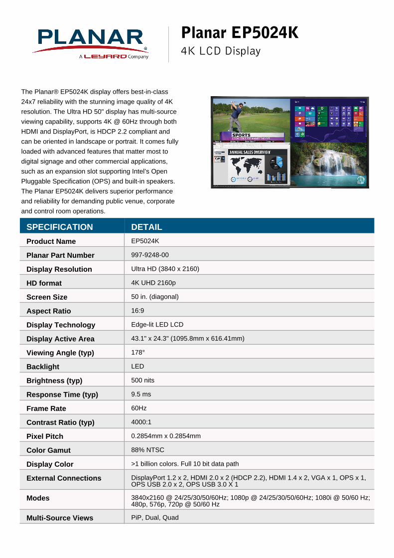
Planar EP5024K4K LCD Display
The Planar® EP5024K display offers best-in-class
24x7 reliability with the stunning image quality of 4K
resolution. The Ultra HD 50" display has multi-source
viewing capability, supports 4K @ 60Hz through both
HDMI and DisplayPort, is HDCP 2.2 compliant and
can be oriented in landscape or portrait. It comes fully
loaded with advanced features that matter most to
digital signage and other commercial applications,
such as an expansion slot supporting Intel’s Open
Pluggable Specification (OPS) and built-in speakers.
The Planar EP5024K delivers superior performance
and reliability for demanding public venue, corporate
and control room operations.
SPECIFICATION DETAIL
Product Name EP5024K
Planar Part Number 997-9248-00
Display Resolution Ultra HD (3840 x 2160)
HD format 4K UHD 2160p
Screen Size 50 in. (diagonal)
Aspect Ratio 16:9
Display Technology Edge-lit LED LCD
Display Active Area 43.1" x 24.3" (1095.8mm x 616.41mm)
Viewing Angle (typ) 178°
Backlight LED
Brightness (typ) 500 nits
Response Time (typ) 9.5 ms
Frame Rate 60Hz
Contrast Ratio (typ) 4000:1
Pixel Pitch 0.2854mm x 0.2854mm
Color Gamut 88% NTSC
Display Color >1 billion colors. Full 10 bit data path
External Connections DisplayPort 1.2 x 2, HDMI 2.0 x 2 (HDCP 2.2), HDMI 1.4 x 2, VGA x 1, OPS x 1,OPS USB 2.0 x 2, OPS USB 3.0 X 1
Modes 3840x2160 @ 24/25/30/50/60Hz; 1080p @ 24/25/30/50/60Hz; 1080i @ 50/60 Hz;480p, 576p, 720p @ 50/60 Hz
Multi-Source Views PiP, Dual, Quad

Display Control IR, RS-232, LAN, Keypad
Cabinet Dimensions (W x Hx D)
44.9" x 26.0" x 2.6" (1140.2mm x 659.6mm x 67.4mm)
Cabinet Dimensions withHandles (W x H x D)
Not Applicable
Orientation Landscape/Portrait
Bezel Width 0.8" (21.1mm) left and right, 0.8" (20.6mm) top and bottom
Weight 62 lbs (28 kg)
Weight (Shipping) 77 lbs (35 kg)
Audio Output PC Line Out, S/PDIF
Speakers 10W x 2 built-in
Enclosure Metal, Industrial
Auto Brightness Control Ambient light sensor
Mounting VESA: 200mm x 200mm
Fanless Yes
Line Voltage 100-240V; 50/60Hz
Power Consumption (typ) 115W (standby: <0.5W)
Operating Temperature 0° to +40°C (32° to 104°F) up to 3000m
Humidity 20 - 85% RH (non-condensing)
Options / Features OPS slot, On/Off scheduling, Presets, TAA compliant
Approvals FCC Class A, CE, cTUVus
Warranty 3 years Advance Exchange
Recommended Usage Up to 24x7
In the Box EP5024K display, power cord, HDMI cable, IR cable, remote control, and cableclamps
UPC 8 10689 00453 0
For more information, please visit www.planar.comSpecifications are subject to change without notice.
Specification Report Date: 6/27/2018
© Copyright 2018 Planar Systems, Inc. All rights reserved
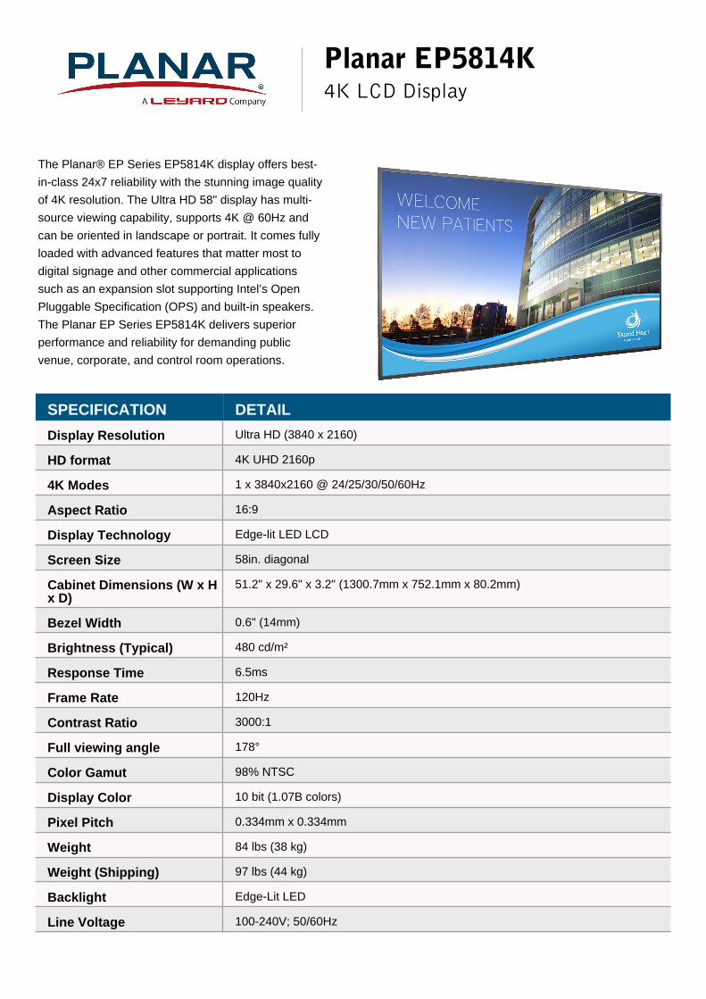
Planar EP5814K4K LCD Display
The Planar® EP Series EP5814K display offers best-
in-class 24x7 reliability with the stunning image quality
of 4K resolution. The Ultra HD 58" display has multi-
source viewing capability, supports 4K @ 60Hz and
can be oriented in landscape or portrait. It comes fully
loaded with advanced features that matter most to
digital signage and other commercial applications
such as an expansion slot supporting Intel’s Open
Pluggable Specification (OPS) and built-in speakers.
The Planar EP Series EP5814K delivers superior
performance and reliability for demanding public
venue, corporate, and control room operations.
SPECIFICATION DETAIL
Display Resolution Ultra HD (3840 x 2160)
HD format 4K UHD 2160p
4K Modes 1 x 3840x2160 @ 24/25/30/50/60Hz
Aspect Ratio 16:9
Display Technology Edge-lit LED LCD
Screen Size 58in. diagonal
Cabinet Dimensions (W x Hx D)
51.2" x 29.6" x 3.2" (1300.7mm x 752.1mm x 80.2mm)
Bezel Width 0.6" (14mm)
Brightness (Typical) 480 cd/m²
Response Time 6.5ms
Frame Rate 120Hz
Contrast Ratio 3000:1
Full viewing angle 178°
Color Gamut 98% NTSC
Display Color 10 bit (1.07B colors)
Pixel Pitch 0.334mm x 0.334mm
Weight 84 lbs (38 kg)
Weight (Shipping) 97 lbs (44 kg)
Backlight Edge-Lit LED
Line Voltage 100-240V; 50/60Hz

Power Consumption (typ) 135W
Operating Environments Temperature: 0-40° C (32-104° F); Humidity: 20-90% humidity non-condensing
Safety regulations FCC Class A, cTUVus, CE
Standard Inputs HDMI 1.4 x 4; Displayport 1.2, VGA, IR, OPS, OPS USB 2.0 x 2, OPS USB 3.0
Audio Input PC Audio in (Jack)
Audio Output R/L Line out (Jack)
Multi-Source Views PiP, Dual, Triple, Quad
Display Control LAN RJ45, RS232 in, IR, Keypad (lockable)
Speakers 10W x 2 built-in
Optional Accessories Fixed wall mount, tilting wall mount, table stand
Auto Brightness Control Ambient light sensor
Enclosure Metal, Industrial
Orientation Landscape/Portrait
Mounting 200 mm x 200 mm VESA
Fanless Yes
Recommended Usage Up to 24x7 operation
Backlight life (1/2brightness)
50,000 hours
Bezel color Black
Features OPS slot, On/Off scheduling, TAA compliant
Warranty 3 years Advance Exchange
Planar Part Number 997-7926-01
UPC 8 10689 00235 2
For more information, please visit www.planar.comSpecifications are subject to change without notice.
Specification Report Date: 6/27/2018
© Copyright 2018 Planar Systems, Inc. All rights reserved

ACCESSORIES
Models D-SH1, DB-SH1, DS-SH1 Stereophonic Headphone Amplifier 1/4" (6.3mm) Jack
Models D-SH1M, DB-SH1M, DS-SH1M Stereophonic Headphone Amplifier 1/8" (3.5mm) Jack Integral Long-Life VCA Stereo Level Control Balanced or Unbalanced Inputs Switch-Selectable Input Sensitivity Switch-Selectable Mono (Left) or Stereo Operation Amplifier To Drive High or Low Impedance Headsets Output: ¼ ” (6.3 mm) standard headphone jack (-SH1) Output: ⅛” (3.5 mm) mini jack (-SH1M) Convenience of Decora®
Mounting Possibilities The D SERIES-SH1/M is a Decora-compatible stereophonic headphone amplifier from Radio Design Labs. All metal enclosures are attractively finished in white, black or brushed stainless steel to complement the decor encountered in commercial environments. Custom labeling is available at www.rdlnet.com. APPLICATION: The D SERIES-SH1/M is used in applications requiring headphones of any impedance to be driven from consumer or professional audio sources. The -SH1/M is ideally suited to applications as diverse as language translation, museums, interview studios and music stores. The -SH1/M is a dual channel headphone amplifier with balanced/unbalanced left (INPUT L) and right (INPUT R) inputs. Each input accepts operating levels between -20 dBV and +20 dBu. Two recessed slide switches located on the side of the rear enclosure are set prior to mounting the module. One switch is provided for setting the INPUT SENSITIVITY. The MODE switch selects between stereo and mono operation. In the MONO (L) position, the left input is used to drive both output channels. When the module is used in a monaural system, only the left channel input must be wired. The front panel level control is a long-life potentiometer controlling matched VCAs. Audio does not pass through this control, assuring years of noise-free level adjustment. The output amplifiers deliver more than 50 mW into either high or low impedance headphones through a durable, metal ¼” (6.3 mm) standard headphone jack (-SH1) or a ⅛” (3.5 mm) mini jack (-SH1M). Module operation is from a 24 Vdc ground-referenced power supply. It can also operate from a 12 Vdc supply with a 6 dB reduction in headroom and a maximum output power of 10 mW. The versatile input level range, low distortion, audio clarity and excellent crosstalk performance make this module ideally suited to a wide variety of audio applications. Use this module in conjunction with other RDL modules as part of a high quality, flexible audio/video system.
RDL 659 6th St. Prescott, AZ., USA 86301 (928) 443-9391 FAX (928) 443-9392 www.rdlnet.com
DS-SH1 D-SH1 DB-SH1
DS-SH1M D-SH1M DB-SH1M

Accessories
Models D-SH1/M, DB-SH1/M, DS-SH1/M
Stereophonic Headphone Amp
TYPICAL PERFORMANCE Inputs (2): 10 k balanced or unbalanced bridging Input Level: +4 dBu nominal (Low input sensitivity) balanced; -15 dBV nominal (High input sensitivity) unbalanced Maximum Input Level: +21 dBu (Low input sensitivity) balanced; +3 dBV (High input sensitivity) unbalanced Output Signal (normal rated): 10 mW into 100 Output Signal (maximum): 50 mW into 100 THD+N: < 0.5% @ 1 kHz Frequency Response: 30 Hz to 20 kHz (± 2 dB) Noise: < -70 dB below normal operating level Gain: User-adjustable on front panel; 18.5 dB (maximum, High input sensitivity); Unity (maximum, Low input sensitivity) CMRR: > 60 dB (50 to 120 Hz) Crosstalk: Below noise floor (20 Hz to 20 kHz) Ambient Operating Environment: 0° C to 55° C Power Requirement: 24 Vdc @ 50 mA, Ground referenced
Installation/Operation
Declaration of Conformity available from rdlnet.com. Sole EMC specifications provided on product package.
Specifications are subject to change without notice.
891-5350B
Radio Design Labs Technical Support Centers U.S.A. (800) 933-1780, (928) 778-3554; Fax: (928) 778-3506
Europe [NH Amsterdam] (++31) 20-6238 983; Fax: (++31) 20-6225-287

C.502DUAL RACKMOUNT CD PLAYER
PRODUCT OVERVIEW
The Stanton C.502 is an affordable dual CD player with full MP3 capabilities. From seamless looping to anti-shock buffer memory, the C.502 is fully equipped with large LCD screens for easy MP3 text information readability. Ideal for use in clubs, bars, restaurants, gyms, theme parks, radio stations, or anywhere a professional dual MP3 CD player is needed, the C.502 is designed with a familiar DJ friendly layout for ease-of-use.
• Dual 2U rackmount CD player with MP3 playback• Large LCD screens with ID3 tags (MP3 text information)• Anti-shock Buffer Memory• Seamless Loop• +10/Folder track key makes finding tracks fast and easy• Fader Start to control play/cue functions from a compatible DJ mixer• Relay play automatically alternate tracks or entire CDs from one drive to the other• Instant Start• Auto cue function cues track to start of music• Single and Continuous play modes• Easy jogwheel control for cueing or pitch bending• Versatile pitch adjustment with +/- 4, 8 or 16% control• S/PDIF digital output• Connect control unit to the transport unit with only one control cable
FEATURES
Specifications & appearance subject to change.
3000 SW 42nd St. Hollywood, FL 33312 • P 954.316.1500 • F 954.316.1590