The Geometry of Relativistic Spacetime: from Euclid's Geometry to Minkowski's Spacetime
Upload
independentCategory
view
0download
0
Separating topology and geometry in space planning
B. Medjdouba,* , B. Yannoub,1
aThe Martin Centre, University of Cambridge, 6 Chaucer Road, Cambridge CB2 2EB, UKbLaboratoire Productique Logistique, Ecole Centrale Paris, Grande Voie des Vignes, 92295 Chatenay Malabry, Paris, France
Received 12 August 1999; received in revised form 19 October 1999; accepted 28 October 1999
Abstract
We are dealing with the problem of space layout planning here. We present an architectural conceptual CAD approach. Starting withdesign specifications in terms of constraints over spaces, a specific enumeration heuristics leads to a complete set of consistent conceptualdesign solutions named topological solutions. These topological solutions which do not presume any precise definitive dimension correspondto the sketching step that an architect carries out from the Design specifications on a preliminary design phase in architecture.q 2000Elsevier Science Ltd. All rights reserved.
Keywords: Layout; Heuristic; Optimization; Constraints; Conceptual design; Topological solutions
1. Introduction
Many architects are confronted on a daily basis with theproblem of space layout planning, i.e. the best spacearrangement with regards to objective requirements.Objective requirements are expressed by constraints:
• Dimensional constraints: over one space such asconstraints on surface, length or width, or spaceorientation.
• Topological constraints: over a couple of spaces such asadjacency, adjacency to the perimeter of the building,non-adjacency, proximity.
Currently, architects solve these placement problems “byhand”. Traditionally, starting from specification constraints,they start by drawing some sketches which represent spaceplanning principles or topologically feasible solutions withno precise geometrical dimensions. This is the sketch stage.Next, geometrical dimensioning is more dependent uponobjective requirements (good space proportion, minimumsurface area required…). For this automatic or manualgeometrical stage, architects may use parametric or varia-tional CAD softwares. These programs allow the architectsto directly handle a parameterized space planning.
At the present time, the main weaknesses of this
methodology are in the sketch research stage. On the onehand, an architect may omit some sketches. On the otherhand, some sketches, found by the architect, which areapparently topologically sound, turn out, in fact, to beinconsistent solutions, when trying to evaluate spacedimensions.
Many attempts of space layout planning in architecturehave used expert systems [2,6]. These approaches presentmany disadvantages: we are never sure of the completenessand the consistency, we are never sure of obtaining theglobal optimum, and reply times are long.
Another recent approach, the evolutionary approach[7,8,10,15] is an optimization process which deals withpractical problems (up to 20 spaces and several floors) butresults are sub-optimal solutions.
It has been shown that constraint programming techni-ques bring a great flexibility in the constraint utilizationsince the constraint definition is separated from resolutionalgorithms, as well as highly combinatorial problems as isthe case for optimal placement [1,3,4,14].
All these approaches enumerate all the placement solu-tions. Then, two quasi-equivalent solutions, where only apartition is translated by amodule2 are considered as twodifferentgeometrical solutions(see Fig. 1). It is clear that, inpreliminary design, it is useless to discriminate between twogeometrical close solutions, as this provokes an explosion of
Computer-Aided Design 32 (2000) 39–61
COMPUTER-AIDEDDESIGN
0010-4485/00/$ - see front matterq 2000 Elsevier Science Ltd. All rights reserved.PII: S0010-4485(99)00084-6
www.elsevier.com/locate/cad
* Corresponding author. Tel.:144-1223-331714; fax:144-1223-331701.
E-mail addresses:[email protected] (B. Medjdoub), [email protected] (B. Yannou).
1 Tel.: 133-1-41-13-1605; fax:133-1-41-13-1272.
2 Architects define a module as the distance increment for the spacedimensions (width, length) and the grid spacing. The grid is the grid ofcolumns, beams and load-bearing walls.

solutions (typically several thousands or millions) whichcannot be apprehended in their globality by the architect.In addition, they are too precise at this design stage.Conceptual designs are more judicious in a first stage,they can be compared to architects’ sketches in this primaryresearch of placement principles.
Several approaches [19,20,21], based on a graph-theore-tical model, have already introduced the topological level asa part of the computational process. Contrary to ourapproach, the topological level does not allow any initialdomain reduction of the variables. This fact makes impos-sible to evaluate or graphically represent the topologicalsolutions. The evaluation and the graphical representationof the solutions are done at the geometrical level.
Our approach and its implementation within the ARCHi-PLAN prototype is based on a constraint programmingapproach which importantly avoids the inherent combina-torial complexity for practical space layout problems.Moreover, we propose to get closer to natural architect’sdesign processes in considering a primary solution level oftopological solutions.These topological solutions mustrespect the specification constraints of the design problemand they must lead to consistent geometrical placementsolutions (see Fig. 2). For that purpose, we have proposeda new definition of a topological solution and we havedeveloped a specific topological enumeration heuristics.
Our topological solution turns out to be an equivalenceclass of geometrical solutions respecting the same conditions
of relative orientation (north, south, east, west) between allthe pairs of spaces. Thus, twotopologically differentsolu-tions, are differentiated by at least one different adjacency.We noticed that such atopological solutionrepresentationcorresponds to a sketch drawing, i.e. a sketch made by thearchitect in the preliminary design. The advantage of thetopological solution levelis the low number of existingsolutions (typically less than 100), a number that can beeasily apprehended by the architects. Architects are nowable to have a global view of all the design alternatives;they will then only study in detail a small number of topol-ogies which correspond to their aesthetic appreciation, as inpractice. Anyway, thanks to the optimization, a geometricalstep determines the best geometrical placement solution foreach topological solution from a set of user-defined criteria.On the one hand, optimization leads to geometrical solu-tions minimizing or maximizing criteria such as wall-lengthor some surface area, these criteria are useful for architects.On the other hand, optimization limits the number ofsolutions. This result turns out to be a determining deci-sion-making tool because it allows comparison betweentopological solutions in terms of their realizability.
In Section 2, we briefly present the architectural model. InSection 3, we present our constraint model. The algorithmof topological solution enumeration is presented in Section4 and the geometrical solution optimization is presented inSection 5. Before concluding, we present a case study inSection 6.
2. Model of architectural space representation
Our knowledge model holds the main architecturalelements corresponding to empty spaces, i.e. which areneither structural elements (walls, beams, windows, etc.)nor furniture. Each defined class is characterized by attri-butes and class constraints. After presenting the generic
B. Medjdoub, B. Yannou / Computer-Aided Design 32 (2000) 39–6140
the problem defined bythe constraintspecifications Geometrical solutions
Fig. 1. Conventional approaches in constraint-based space layout planning.An exhaustive enumeration of geometrical solutions is performed.
Topological level
Geometrical level
Specification constraints
Optimal solutionminimizing r3 area
r1
r2
r3
c1
r1
r2
r3c1
r1r2
r3
Functional diagram
One topologicalsolution (sketch)
Fig. 2. Solution levels in ARCHiPLAN: topological and geometrical. For each topological solution, only the best corresponding geometrical solution iscalculated or few are tested.

space class, we describe the two main classes of ourarchitectural space model:roomclass andstair class.
2.1. Space class
As we deal with orthogonal geometry, we callspaceanisothetic rectangle (see Fig. 3), which is representative of animportant part of architectural problems. This class is char-acterized by an identifier, two reference points (x1, y1) and(x2, y2) (at the opposite of the rectangle), a lengthL, a widthW and a surface areaS. All these attributes, except theidentifier, are integer-constrained variables. We used anarc-consistency on integersconstraint programming techni-que which explains the need for adistance increment; butthis is not too limitative as architects are used to reasoningwith dimensional modules. L-shape and T-shape areallowed, and they correspond to two adjacent spaces witha minimum contact length.
The three following class constraints have been definedso as to ensure the geometrical consistency of the spaceclasses:
• �c1� x2� x1 1 L• �c2� y2� y1 1 W• �c3� S� L × W
A modification of a variable domain composing theconstraint (c1), (c2) or (c3) entails the modification of vari-able domains of the other related variables, thanks to thearc-consistency on integersthat we used. Arc-consistencytechnique asserts that these constraints will always berespected for a specific instantiation and try to rule outvariable domain values which have no chance to be in asolution. But this technique does not reduce a domain vari-able to its minimal size; solutions are complete but they arenot all consistent. This is a problem we will have to dealwith when generatingtopological solutions.
Fig. 4 illustrates a domain reduction propagation witharc-consistency on integers. In this example, spacee1 isconstrained to be inside a contour of fixed dimensions�0;10� × �0;10�: The domains of lengthL and widthW areboth set to [2,6]. Then, bothx1 andy1 domains are auto-matically reduced to [0,8] andx2 and y2 domains arereduced to [2,10]. Let us consider an additional constrainton the surface,S. 12: A domain reduction ofL andW isimmediately achieved, leading to [3,6], because for thevalue L � 2 (respectively,W) no consistent value existsin the W domain (resp.,L domain) which respects theconstraint:S� L × W . 12:
2.2. Room
The room class defines spaces other than circulations. Itinherits, of course, allattributes, methods and classconstraintsof the spaceclass. This class is characterizedby anorientationattribute, which is a constrained discretevariable defined over the domain {08,908}. Indeed, by stat-ing, for example, that we want one side of the space tomeasure between 2 and 4, we are not making any particularreference to either the lengthL, nor the widthW. Conse-quently, it is necessary to consider the two possible
B. Medjdoub, B. Yannou / Computer-Aided Design 32 (2000) 39–61 41
L
w
x1 x2
y1
y2
S
reference pointsX
Y
O
Fig. 3. Space class geometrical representation.
Propagation
S(e1)>12
Space Attributes
Domains of thegeometricalattributes
Fig. 4. Illustration of the domain reduction propagation with the arc-consistency technique.
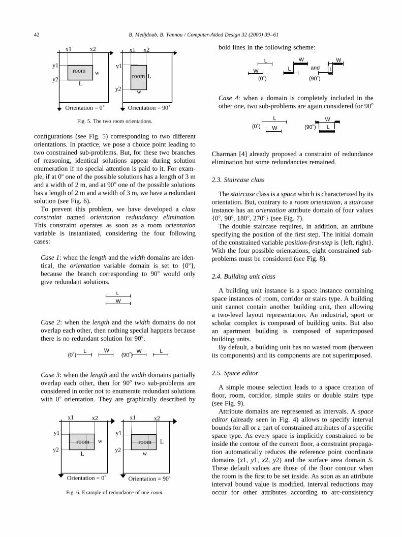
configurations (see Fig. 5) corresponding to two differentorientations. In practice, we pose a choice point leading totwo constrained sub-problems. But, for these two branchesof reasoning, identical solutions appear during solutionenumeration if no special attention is paid to it. For exam-ple, if at 08 one of the possible solutions has a length of 3 mand a width of 2 m, and at 908 one of the possible solutionshas a length of 2 m and a width of 3 m, we have a redundantsolution (see Fig. 6).
To prevent this problem, we have developed aclassconstraint named orientation redundancy elimination.This constraint operates as soon as a roomorientationvariable is instantiated, considering the four followingcases:
Case 1: when thelengthand thewidth domains are iden-tical, the orientation variable domain is set to {08},because the branch corresponding to 908 would onlygive redundant solutions.
L
W
Case 2: when thelength and thewidth domains do notoverlap each other, then nothing special happens becausethere is no redundant solution for 908.
L W L W (0˚) (90˚)
Case 3: when thelengthand thewidth domains partiallyoverlap each other, then for 908 two sub-problems areconsidered in order not to enumerate redundant solutionswith 08 orientation. They are graphically described by
bold lines in the following scheme:
(0˚) (90˚) W
L
L
W
L
W and
Case 4: when a domain is completely included in theother one, two sub-problems are again considered for 908
L
W L W
(0˚) (90˚)
Charman [4] already proposed a constraint of redundanceelimination but some redundancies remained.
2.3. Staircase class
Thestaircaseclass is aspacewhich is characterized by itsorientation. But, contrary to aroom orientation, a staircaseinstance has anorientationattribute domain of four values{08, 908, 1808, 2708} (see Fig. 7).
The double staircase requires, in addition, an attributespecifying the position of the first step. The initial domainof the constrained variableposition-first-stepis {left, right}.With the four possible orientations, eight constrained sub-problems must be considered (see Fig. 8).
2.4. Building unit class
A building unit instance is a space instance containingspace instances of room, corridor or stairs type. A buildingunit cannot contain another building unit, then allowinga two-level layout representation. An industrial, sport orscholar complex is composed of building units. But alsoan apartment building is composed of superimposedbuilding units.
By default, a building unit has no wasted room (betweenits components) and its components are not superimposed.
2.5. Space editor
A simple mouse selection leads to a space creation offloor, room, corridor, simple stairs or double stairs type(see Fig. 9).
Attribute domains are represented as intervals. Aspaceeditor (already seen in Fig. 4) allows to specify intervalbounds for all or a part of constrained attributes of a specificspace type. As every space is implicitly constrained to beinside the contour of the current floor, a constraint propaga-tion automatically reduces the reference point coordinatedomains (x1, y1, x2, y2) and the surface area domainS.These default values are those of the floor contour whenthe room is the first to be set inside. As soon as an attributeinterval bound value is modified, interval reductions mayoccur for other attributes according to arc-consistency
B. Medjdoub, B. Yannou / Computer-Aided Design 32 (2000) 39–6142
x1
Orientation = 90˚Orientation = 0˚
L
w
x1 x2
y1
y2
roomL
x2
y1
y2
room
w
Fig. 5. The two room orientations.
Orientation = 0˚ Orientation = 90˚
L
w
x1
L
w
x2
y1
y2room
x1 x2
y1
y2room
Fig. 6. Example of redundance of oneroom.

technique. An attribute interval bound may be modified atany moment after the space creation.
In practice, it is not necessary to define all the variabledomains, theL andW domains can suffice.
3. Architectural constraint model
Our architectural constraint model makes the distinctionbetweenspecification constraintsand implicit constraintsthat depend on the fact that:
• they belong to thefunctional diagramand are explicitlydeclared by the architect (the case ofspecificationconstraints),
• they are implicitly generated in order to reduce thecombinatorial complexity (the case ofimplicitconstraints).
3.1. Specification constraints
These constraints gather dimensional and topologicalconstraints overrooms, corridors, floors, stairsandcontour.They are specified by the architects and stored in afunctional diagram.
Dimensional constraints are applied to the attributes of asingle architectural object whereas topological constraintsare applied between two or more architectural objects.
3.1.1. Dimensional constraints
3.1.1.1. Setting a minimal or maximal domain value.As ithas been seen before, setting a minimal or a maximaldomain value (especiallywidth, length and surface area)is done through thespace editor. After the space creationand its initial domain reduction due to its inclusion into thefloor contour, additional dimensional constraints on intervalbounds are entered if and only if they help to reduce theconcerned interval.
Table 1 presents the dimensional constraints of ahouse with two floors(this benchmark is our ownproposition).
3.1.1.2. Setting a ratio constraint.We developed a ratioconstraint between two variablesp1 andp2. Practically, itallows to set aesthetic proportions between the dimensionsLand W of a space. But, a ratio constraint may also be setbetween two length, width or surface area variables of twodifferent spaces. In all cases, this constraint must beconsidered as a dimensional constraint.
We had to constrain a ratiop1/p2 to be in a real interval,with constraints on integers. Therefore, we modeled the twointerval limits by four positive integers in order to have:a1=a2 , p1=p2 , a2=b2: The constraintratio(variable#1,variable#2, a1, b1, a2, b2) leads to two elementary
B. Medjdoub, B. Yannou / Computer-Aided Design 32 (2000) 39–61 43
orientation = 0˚
orientation = 90˚ orientation = 270˚
orientation = 180˚
Fig. 7. The four possible orientations of a simple staircase.
position-first-step = right
orientation = 0˚ orientation = 90˚ orientation = 180˚ orientation = 270˚
orientation = 0˚ orientation = 90˚ orientation = 180˚ orientation = 270˚
2 position-first-step = left
1
Fig. 8. The eight possible configurations of a double staircase.

constraints on integers:
a1 × p2 , b1 × p1
a2 × p2 , b2 × p1
For example, if we want to have atoilets surface areavalue between 0.4 and 0.5 times theshower unitsurfacearea value, we pose the following constraint:ratio(toilets.S,shower_unit.S,2,5,1,2).
3.1.2. Topological constraints
3.1.2.1. Global overview. As we said, topologicalconstraints allow to specify adjacency, non-adjacency orproximity of a space with another space or with the contourof the current floor. As we will see, thenon-overlappingbetween spaces is an implicit constraint systematicallyconsidered (even if it can be released) which, consequently,is not considered as aspecificationconstraint. The topolo-gical constraints can be combined with logical operatorssuch as “OR” and “AND”.
In our example of ahouse with two floors, the topologicalconstraints are:
The constraints between floors◦ the first floor is over thesecond floor,◦ the staircaseCommunicatesbetween thefirst floorand
the second floor.Constraints between spaces of the first floor◦ all the spaces of the first floor areadjacent to the
corridor with 1 meter minimum for contact length,
◦ thekitchenand theliving roomareadjacentwith 1 mminimum for contact length,
◦ thekitchenis on thesouth wallor on thenorth wall ofthe building contour,
◦ the kitchenand theToilet/Shower-unitare adjacent,◦ the living room is on thesouth wallof the building
contour,◦ all the rooms are naturally lit,◦ no space is wasted (the total of the space areas of the
first floor correspond to the first floor area).Constraints between spaces of second floor◦ all the spaces of thesecond floorareadjacentto the
corridor with 1 m minimum for contact length,◦ room4 andbath2 areadjacentwith 1 m minimum for
contact length,◦ room4 andbalconyare adjacentwith 1 m minimum
for contact length,◦ the balcony is on the south wall of the building
contour,◦ all the rooms are naturally lit,◦ no space is wasted (the total of thespaceareas of the
first floor correspond to thesecond floorarea).
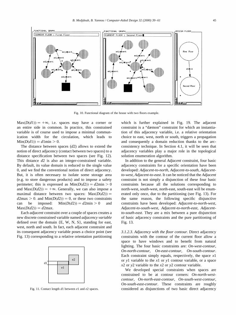
All these constraints have been introduced into ARCHi-PLAN interactively by graph handling and incrementalconstruction (see the specification editor in Fig. 17 andthe resulting functional diagram in Fig. 10).
3.1.2.2. The generalized adjacency constraint.The act ofconceiving buildings is largely linked with fixing theadjacency between rooms and circulations or fixing thedistance between two rooms. All the topologicalconstraints between two spaces (i.e. except constraintsbetween a space and the floor contour) derive from ourgeneralized adjacency constraint. Our generalizedadjacency constraint is not restricted to direct contact,which is usually called adjacency, but it allows, moregenerally, to control the relative positioning between twospaces. This constraint is based on two variable notions: thecontact length and the distance between spaces.
The contact lengthd1 is an integer-constrained variablewhich allows to impose communication between twospaces (see Fig. 11). By default, Min�D�d1�� � 0 and
B. Medjdoub, B. Yannou / Computer-Aided Design 32 (2000) 39–6144
Space class
Circulation FloorRoom
Corridor Stair
A flight of stairs A double flight of stairs
Fig. 9. Hierarchy class in ARCHiPLAN.
Table 1Dimensional constraints between spaces (house with two floorsexample). The dimensions are in a module of 0.5 m (L-minstands forminimum lengthandW-min for minimum width)
Unit Area domain values L-min W-min Unit Area domain values L-min W-min
Ft_Floor [320,320] 20 16 Sd_Floor [320,320] 20 16Living [72,128] 6 6 Room1 [48,60] 6 6Kitchen [36,60] 5 5 Room2 [48,60] 6 6Toilet/Sh [16,36] 4 4 Room3 [48,60] 6 6Office [36,60] 6 6 Room4 [48,72] 6 6Corridor [9,64] 3 3 Bath1 [16,36] 4 4Staircase [24,28] 4 4 Bath2 [16,36] 4 4Corridor2 [9,64] 3 3 Balcony [12,24] 3 3
Max�D�d1�� � 1∞; i.e. spaces may have a corner oran entire side in common. In practice, this constrainedvariable is of course used to impose a minimal commun-ication width for the circulation, which leads toMin�D�d1�� � d1min . 0:
The distance between spaces (d2) allows to extend thenotion of direct adjacency (contact between two spaces) to adistance specification between two spaces (see Fig. 12).This distanced2 is also an integer-constrained variable.By default, its value domain is reduced to the single value0, and we find the conventional notion of direct adjacency.But, it is often necessary to isolate some storage area(e.g. to store dangerous products) and to impose a safetyperimeter; this is expressed as Min�D�d2�� � d2min . 0and Max�D�d2�� � 1∞: Generally, we can also impose amaximal distance between two spaces: Max�D�d2�� �d2max. 0: and Min�D�d2�� � 0; or these two constraintscan be imposed: Min�D�d2�� � d2min . 0 andMax�D�d2�� � d2max:
Eachadjacentconstraint over a couple of spaces creates anew discrete constrained variable namedadjacency variabledefined over the domain {E, W, N, S}, standing for east,west, north and south. In fact, each adjacent constraint andits consequent adjacency variable poses a choice point (seeFig. 13) corresponding to a relative orientation partitioning
which is further explained in Fig. 19. The adjacentconstraint is a “dæmon” constraint for which an instantia-tion of this adjacency variable, i.e. a relative orientationchoice to east, west, north or south, triggers a propagationand consequently a domain reduction thanks to the arc-consistency technique. In Section 4.1, it will be seen thatadjacency variables play a major role in the topologicalsolution enumeration algorithm.
In addition to the generalAdjacentconstraint, four basicadjacency constraints for a specific orientation have beendeveloped:Adjacent-to-north, Adjacent-to-south, Adjacent-to-west, Adjacent-to-east. It can be noticed that theAdjacentconstraint is not simply a disjunction of these four basicconstraints because all the solutions corresponding tonorth-west, south-west, north-east, south-east will be enum-erated only once, due to the partitioning (see Fig. 13). Forthe same reason, the following specific disjunctiveconstraints have been developed:Adjacent-to-north-west,Adjacent-to-south-west, Adjacent-to-north-east, Adjacent-to-south-east. They are a mix between a pure disjunctionof basic adjacency constraints and the pure partitioning ofFig. 13.
3.1.2.3. Adjacency with the floor contour.Direct adjacencyconstraints with the contour of the current floor allow aspace to have windows and to benefit from naturallighting. The four basic constraints are:On-west-contour,On-north-contour, On-east-contour, On-south-contour.Each constraint simply equals, respectively, the spacex1or y1 variable to thex1 or y1 contour variable, or a spacex2 or y2 variable to thex2 or y2 contour variable.
We developed special constraints when spaces areconstrained to be at contour corners:On-north-west-contour, On-north-east-contour, On-south-west-contour,On-south-east-contour. These constraints are roughlyconsidered as disjunctions of two basic direct adjacency
B. Medjdoub, B. Yannou / Computer-Aided Design 32 (2000) 39–61 45
Fig. 10. Functional diagram of the house with two floors example.
e1
e2d1
Fig. 11. Contact lengthd1 betweene1 ande2 spaces.
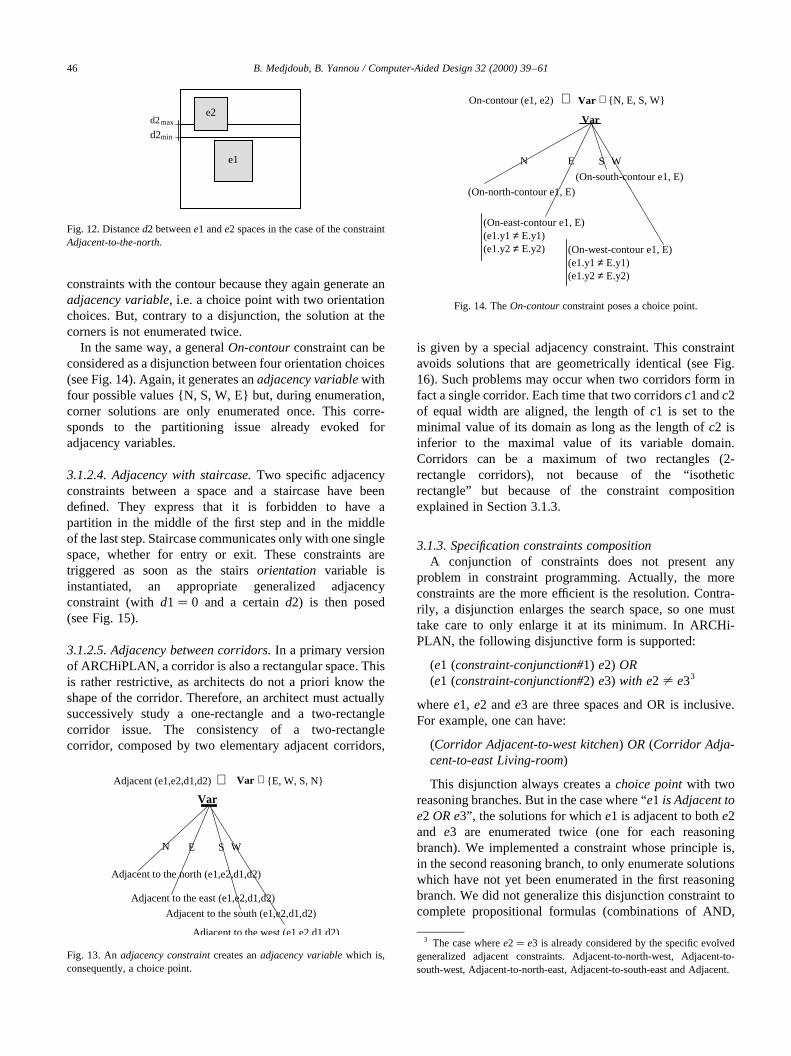
constraints with the contour because they again generate anadjacency variable, i.e. a choice point with two orientationchoices. But, contrary to a disjunction, the solution at thecorners is not enumerated twice.
In the same way, a generalOn-contourconstraint can beconsidered as a disjunction between four orientation choices(see Fig. 14). Again, it generates anadjacency variablewithfour possible values {N, S, W, E} but, during enumeration,corner solutions are only enumerated once. This corre-sponds to the partitioning issue already evoked foradjacency variables.
3.1.2.4. Adjacency with staircase.Two specific adjacencyconstraints between a space and a staircase have beendefined. They express that it is forbidden to have apartition in the middle of the first step and in the middleof the last step. Staircase communicates only with one singlespace, whether for entry or exit. These constraints aretriggered as soon as the stairsorientation variable isinstantiated, an appropriate generalized adjacencyconstraint (withd1� 0 and a certaind2) is then posed(see Fig. 15).
3.1.2.5. Adjacency between corridors.In a primary versionof ARCHiPLAN, a corridor is also a rectangular space. Thisis rather restrictive, as architects do not a priori know theshape of the corridor. Therefore, an architect must actuallysuccessively study a one-rectangle and a two-rectanglecorridor issue. The consistency of a two-rectanglecorridor, composed by two elementary adjacent corridors,
is given by a special adjacency constraint. This constraintavoids solutions that are geometrically identical (see Fig.16). Such problems may occur when two corridors form infact a single corridor. Each time that two corridorsc1 andc2of equal width are aligned, the length ofc1 is set to theminimal value of its domain as long as the length ofc2 isinferior to the maximal value of its variable domain.Corridors can be a maximum of two rectangles (2-rectangle corridors), not because of the “isotheticrectangle” but because of the constraint compositionexplained in Section 3.1.3.
3.1.3. Specification constraints compositionA conjunction of constraints does not present any
problem in constraint programming. Actually, the moreconstraints are the more efficient is the resolution. Contra-rily, a disjunction enlarges the search space, so one musttake care to only enlarge it at its minimum. In ARCHi-PLAN, the following disjunctive form is supported:
(e1 (constraint-conjunction#1) e2) OR(e1 (constraint-conjunction#2) e3) with e2 ± e33
wheree1, e2 ande3 are three spaces and OR is inclusive.For example, one can have:
(Corridor Adjacent-to-west kitchen) OR (Corridor Adja-cent-to-east Living-room)
This disjunction always creates achoice pointwith tworeasoning branches. But in the case where “e1 is Adjacent toe2 OR e3”, the solutions for whiche1 is adjacent to bothe2and e3 are enumerated twice (one for each reasoningbranch). We implemented a constraint whose principle is,in the second reasoning branch, to only enumerate solutionswhich have not yet been enumerated in the first reasoningbranch. We did not generalize this disjunction constraint tocomplete propositional formulas (combinations of AND,
B. Medjdoub, B. Yannou / Computer-Aided Design 32 (2000) 39–6146
e1
e2d2max
d2min
Fig. 12. Distanced2 betweene1 ande2 spaces in the case of the constraintAdjacent-to-the-north.
Adjacent (e1,e2,d1,d2) Var ∈ {E, W, S, N}
Var
Adjacent to the north (e1,e2,d1,d2)
Adjacent to the east (e1,e2,d1,d2)
Adjacent to the south (e1,e2,d1,d2)
Adjacent to the west (e1,e2,d1,d2)
EN WS
⇒
Fig. 13. Anadjacency constraintcreates anadjacency variablewhich is,consequently, a choice point.
On-contour (e1, e2)⇒ Var ∈ {N, E, S, W}
Var
(On-north-contour e1, E)
(On-east-contour e1, E)(e1.y1 ≠ E.y1)(e1.y2 ≠ E.y2)
(On-south-contour e1, E)
(On-west-contour e1, E)(e1.y1 ≠ E.y1)(e1.y2 ≠ E.y2)
EN S W
Fig. 14. TheOn-contourconstraint poses a choice point.
3 The case wheree2� e3 is already considered by the specific evolvedgeneralized adjacent constraints. Adjacent-to-north-west, Adjacent-to-south-west, Adjacent-to-north-east, Adjacent-to-south-east and Adjacent.

OR, NOT) because of the complexity of eliminatingredundant solutions.
Let us recall that, in all constraints implementation, wewere always concerned with the fact that a solution shouldbe enumerated only once (so that for our futuretopologicalsolutionsbe distinct, see Section 4). Moreover, this simpledisjunction is important because it allows adjacency with atwo-rectangle corridor (of L-shape or T-shape), a spacebeing adjacent to one part of the corridor at least.
3.1.4. Specification editorSpecifications of an architectural problem are represented
into a graph, calledfunctional diagramby the architects.Graph nodes stand for spaces and supportdimensionalconstraints (except ratio constraint) over them. Graphlinks support topological constraints(between two ormore spaces) andratio constraintsbetween two constrainedattributes of the same space (reflexive link) or of twodifferent spaces.
The generalspecification editorallows to build, cut,paste, save, load and graphically edit thisfunctionaldiagram.
We already mentioned thatdimensional constraints,exceptratio constraint, were defined with thespace editor.Thespace editoris activated each time the mouse clicks ona graph node.
The generalspecification editor(see Fig. 17) is split intothree main panels:
• the building unit layout window (to the right),• the current building unit window (in the middle),• the topological constraints specification panel (to the
left).
The building unit layout window(to the right) (see Fig.17) is dedicated to the definition and specifications betweenbuilding units of the same floor and/or different floors.Building units may be constrained by generalized adjacencyconstraints as well as rooms between them inside a particu-lar building unit. But, when two building units are consecu-tive floors of an apartment building, two special constraintsare allowed:
• building units are constrained to have a similar contour;this is thesuperimpositionconstraint,
• astairs constraintcan link two consecutive floors, i.e. the
stairs have the same size on both floors but in taking intoaccount the position of the first and the last step for anadjacencyconstraint (see further) with a corridor or aroom. This constraint appears as a graph link betweenbuilding units and staircase instances are automaticallycreated in each building unit.
In a first stage, building units and stairs are created andconstrained in the right-hand window. In a second stage, andfor each building unit, rooms and corridors are created andconstrained in thecurrent building unit window(in themiddle, see Fig. 17). Spaces are created inside the currentbuilding unit. One can switch from a current building unit toanother by a simple selection on the appropriate node in thebuilding unit layout window. By default, the followingimplicit constraintsare automatically posed:inclusion inthe contour, non-overlapping between spaces,contourtotal recovery(see Section 3.2) unless the architects inten-tionally release them. For example, thecontour total recov-ery constraint may be released, solutions with extra-spaceare then proposed. In such a case, the criterion of corridorsurface area minimization (see Section 5.3) is extended tothis extra-space area.
Topological constraintsare edited from the left-handpanel of thespecification editor(see Fig. 17). This zoneconcerns the main constraints of a space in relation withthe contour (On-west-contour, On-north-contour, On-east-contour, On-south-contour, On-contour) and the maingeneralized adjacency constraintsbetween two spaces(Adjacent-to-north, Adjacent-to-south, Adjacent-to-west,Adjacent-to-east, Adjacent). In Fig. 18, we see that theconstraints composition can simply be specified by quickinteractions on some buttons. We saw that, in the generalcase where(e1 (constraint-conjunction#1) e2) OR (e1(constraint-conjunction#2) e3) with e2 ± e3; a specialconstraint was activated for posing a choice point withoutenumerating redundant solutions. Whene2� e3 aconstraint analyzer detects such a case and activates theappropriate constraint among:Adjacent-to-north-west,Adjacent-to-south-west, Adjacent-to-north-east, Adjacent-to-south-eastand On-north-west-contour, On-north-east-contour, On-south-west-contour, On-south-east-contour.
For example, it is possible to state thattoiletsareAdjacent(directly, i.e.distance between spaces d2 is instantiated to 0)to kitchenwith a contact length l1 OR to bathroomwithcontact length l2.4 In practice, the notions ofcontact lengthanddistance between spacesproved to be very flexible andpowerful. For example, thenon-adjacencyconstraint isdefined by setting the minimal value ofd2 to 1. By default,
B. Medjdoub, B. Yannou / Computer-Aided Design 32 (2000) 39–61 47
C1 C2 C1 C2
Fig. 16. Example of geometrically identical solutions for two corridors.
contact lengthfirst step
Fig. 15. Adjacency constraint with staircase for climbing.
4 With a distance increment of 0.25, one can think of a minimal contactlength value of 4 corresponding to a communication of 1 m.

B. Medjdoub, B. Yannou / Computer-Aided Design 32 (2000) 39–6148
Space
Room Corridor Floor
Simple staircase
Double staircase
Fig. 17. The specification editor of ARCHiPLAN.
Fig. 18. Selection zone for the topological specifications definition in ARCHiPLAN. Case (a) represents the constraintOn-west-contourAND On-south-contour. Case (b) represents the constraintOn-west-contourOR On-south-contour.

the editor proposes the following bounds ford1 and d2intervals: Min�D�d1�� � 0; Max�D�d1�� � 1∞ andMin�D�d2�� � 0; Max�D�d2�� � 0: These values corre-spond to a conventional direct adjacency without anyparticular minimalcontact lengthvalue.
As soon as a constraint is defined, it appears as a graphlink or several graph links if the constraint is a disjunction.All these constraints may be modified by a simple click withthe middle button of the mouse (the left-hand button is for adrag and drop of the graphic item).
All these constraints have been introduced in ARCHi-PLAN interactively by graph handling and incrementalconstruction. This functional diagram of the example ofthe house with two floors example has already been givenin Fig. 10.
3.2. Implicit constraints
3.2.1. Default constraintsThese constraints are considered by default but they can
be released for special cases.
3.2.1.1. Inclusion in the current building unit contour.Thissimple constraint consists of four conjunctive inequalitiesover x1, x2, y1, y2 in order to be inside of the currentbuilding unit contour.
3.2.1.2. The contour total recovery constraint.Thecontourtotal recovery constraintexpresses the fact that there is no
lost space in a building unit and therefore, that the sum ofspace surface areas of a given building unit equals the wholebuilding unit surface area.
3.2.1.3. Non-overlapping constraints.A non-overlappingconstraint expresses the fact that a space cannot overlapanother space; it is automatically posed between all pairsof rooms. Of course, pairs of rooms which are alreadyconstrained to be directly adjacent verify thenon-overlapping constraint. Fig. 19 shows the positionpermitted for e2.x2 and e2.y25 by the non-overlappingconstraint between spacese1 and e2. This constraint isdependent on theminimal space dimensionnotion. Theminimal space dimension is, at any moment, equal to thesmallest dimension value (width or length) of all spaces.This value is used in order to constrain two spaces to beadjacent, or to be separated by a sufficient distance whichallows another space to be inserted in between. As theAdjacency constraint, the non-overlapping constraintintroduces a newnon-overlapping variablewith fourvalues {E, W, N, S}. This variable divides the spacesurroundings into four parts (see Fig. 19) but notsymmetrically. Indeed, we observe that the N and Svalues give more solutions that the E and W values. It isthe instantiation of thesenon-overlapping variablesand theadjacency variableswhich, if proven consistent, gives atopological solution. We can consider the followingequivalence:
non-overlapping(e1,e2)� Adjacent(e1 e2 d1 d2)(1) with d1 [ �0 1 ∞� andd2 [ �0 1 ∞�:
3.2.2. Research space reduction constraintsThese constraints which allow a drastic reduction of the
combinatorial, are specific to our approach. They regroup:
• the incoherent space elimination constraint,• the symmetry constraints,• the topological reduction constraint,• the orientation propagation constraint.
3.2.2.1. The incoherent space elimination constraint.Thisconstraint is also dependent on theminimal spacedimensionnotion. The aim is to constrain each space tobe either directly adjacent to the building unit contour orto be distant from a certain value, for another space to beinserted in between. This value is distancedmin�Min�Lmin;Wmin�: This constraint is activated if andonly if the contour total recovery constraintis activatedtoo. Fig. 20 shows the positions permitted for (x2, y2)point of spacee1 with this constraint, relatively to thebuilding unit contour. The constraint algorithm isdescribed in Fig. 21.
B. Medjdoub, B. Yannou / Computer-Aided Design 32 (2000) 39–61 49
Fig. 19. Positions permitted for point (x2, y2) of spacee2 after the non-overlapping constraint applied between spacee1 ande2. The partitioning ofthe surroundings of a space in {E, W, N, S} is given.
Fig. 20. Permissible positions for (x2, y2) point of spacee1 for the inco-herent space elimination constraint. 5 e2.y2 represents the constrained variabley2 of spacee2.

3.2.2.2. The symmetry constraints.The symmetryconstraints are meant to avoid functionally identicalsolutions by solution combinations over spaces of thesame type and with the same constraints: same initialdomains and same topological constraints with otherspaces. For example, let us take a house with three similarrooms (for children) having the same initial dimensionaldomains and the same direct adjacency constraint with thecorridor.
In order to rule out symmetrical combinations betweentwo spacese1 ande2, it is sufficient to constraine1:x1 toalways be lower than or equal toe2:x1 and whene1:x1�e2:x1; one must imposee1:y1 , e2:y1 (see Fig. 22). Thisprocedure is applied forn symmetrical spaces, the algorithmis described in Fig. 23.
This above elementarysymmetry constraintalgorithmhas been generalized to the different orientations of aroom, the orientation attribute having {08,908} initialdomain. In the case where two symmetrical rooms havetwo possible orientations, the previous elementary symme-try constraint is triggered each time both orientationattribute values are equal. When�V�orientation:e1� � 08and V�orientation:e2� � 908�; there is no symmetricalsolutions. But all solutions corresponding toV�orientation:e1� � 908 and V�orientation:e2� � 08 havebeen enumerated in the previous caseV�orientation:e1� �08 and V�orientation:e2� � 908: In order to rule out theseredundant solutions, we will consider only the case when theorientation attribute values are different only once. Fig. 24illustrates the symmetry constraint generalized to differentorientations.
3.2.2.3. The topological reduction constraint.The
topological reduction constraintoperates when adjacencyconstraints with the building unit contour exist. Theprinciple is: when a spacee1 is On-north-contour, noother space can be to the north of spacee1. Thetopological reduction constraint rules out the {N} value ofthe domains of the�n 2 1� non-overlapping variablesrelative to spacee1 (coming from thenon-overlappingconstraints). When reducing these variable domains, wedirectly eliminate some inconsistent topologies (see Fig.25).
This topological reduction constraintis similar for thethree other orientations:
• if a space isOn-South-contour, no space can be to theSouth of it,
• if a space isOn-West-contour, no space can be to theWest of it,
• if a space isOn-East-contour, no space can be to the Eastof it.
3.2.2.4. The orientation propagation constraint.Theorientation propagation constraintuses the orientationtransitivity property to automatically instantiatenon-overlapping variables. For instance, if spacee1 is North-of e2 and e2 is North-of e3, thuse1 is North-of e3. Wedeveloped such a transitivity constraint for relativeorientations of North and South. We did not developequivalent constraints for East and West because the non-symmetrical partitioning into {N, E, O, S} does notguarantee the transitivity (see Fig. 19). This partitioningconsiders north-west and north-east as a part of North, andsouth-west and south-east as a part of South (e.g. if spacee1
B. Medjdoub, B. Yannou / Computer-Aided Design 32 (2000) 39–6150
Constraint Eliminate-inconsistency (IN: e1, E)For i varying from 1 to (dmin - 1)
→ e1.x1 ≠ E.x1+ie1.x1 ≠ E.x2 - e1.L + i
For j varying from 1 to (dmin - 1)→ e1.y1 ≠ E.y1+j
e1.y1 ≠ E.y2 - e1.W + jEnd Constraint
Fig. 21. Theincoherent space elimination constraintalgorithm. E is thebuilding unit space.
Symmetry Constraint (I: List-of-symmetrical-spaces)n = length (l)For i varying from 1 to n
ei = element-of (i, l)For j varying from (i + 1) to n
eJ = element -of(j, l)→ ei.x1 ≤ ej.x1When V(ei.x1) ≡ V(ej.x1)
→ ei.y1 < ej.y1End Constraint
Fig. 23. Thesymmetry constraintalgorithm. E is the building unit space.
GenSymmetry Contrainte (I: List-of-symmetrical-spaces)n = length (l)For i varying from 1 to n
ei = element of (i, l)For j varying from (i + 1) to n WhenV(ei.orientation) ≡ V(ej.orientation)
(Symmetry (list(ei, ej))) WhenV(ei.orientation) ≠ V(ej.orientation)
When V(ei.orientation) ≡ 90˚→ V(ej.orientation) ≠ 0˚
End Constraint
Fig. 24. The symmetry constraint generalized to different orientations.Fig. 22. Permissible positions for (x2,y2) point of spacee2 for thesymmetryandnon-overlappingconstraints.

is East-ofe2 and e2 is East-ofe3, e1 can be North or South-of e3).
4. The topological solution level
4.1. The topological solution definition
We wanted ourtopological solutiondefinition to corre-spond to the architect’s notion of sketching where the adja-cency between spaces is defined but where space sizes areimprecise. This geometrical precision is treated in Section4.2 with geometrical solutions where all space attributes areinstantiated.
Finally, we converged to the following definition of atopological solution:
Each space layout Constraint Satisfaction Problem(CSP) where the n�n 2 1�=2 (n being the number ofspaces) non-overlapping variables and adjacency vari-ables are instantiated and which remains geometricallyconsistent (i.e. for which at least one geometrical solutionexists) is a topological solution.
At this stage, value domains have undergone reductionbut dimensional variable domains are not necessarilyreduced to a unique value (i.e. instantiated), only non-over-lapping and adjacency variables have been instantiated. Wetherefore believe that there can exist several geometricalsolutions consistent with this topological solution. What isimportant to say is that the whole constraint model has beendeveloped in such a way that a geometrical solution canderive from only one topological solution. This is particu-larly the case for:
• the non-overlapping and generalized adjacencyconstraintsand their non-symmetrical relative orienta-tion partitioning,
• the orientation redundancy elimination class constraint,• the symmetry constraint.
Consequently, topological solutions are distinct equiva-lence classes of geometrical solutions. This is an importantproperty which allows to make design decisions over topo-logical solutions (elimination or further study of completesolutions classes). If it is impossible to satisfy the topo-logical constraints the user can modify the module of the
instantiation (if the module was 10 cm it could be possibleto satisfy the topological constraints for a module equal to5 cm or 1 cm).
The verification of a topological solution consistencyamounts to the research of a first geometrical solution.This research uses the same algorithm as the geometricalsolution optimization algorithm presented in a furthersection.
4.2. The two topological enumeration heuristics
The topological solutions enumeration algorithm is basedupon two enumeration heuristics which were detailed in aprevious paper (see Ref. [18] for more details).
Traditionally, the constraint programming approachesthat have been developed enumerate the geometrical solu-tions straightforwardly. The image that can be used issuccessively to dimension and to place each space in thebuilding unit contour which is initially empty. The heuris-tics that have been already proposed corresponds essentiallyto the choice of the next space to dimension and to place[2,5,22], and sometimes to the choice of the location wherethe first space considered must be placed [4].
Our approach is different because it enumerates the topol-ogy in a first instance. This does not correspond to thedimensional space attributes instantiations but to instantia-tions ofnon-overlappingandadjacency variablesrelative toalready placed spaces.
A first heuristics consists in choosing the next space todeal with. It is based on the choice of the currently mostconstrained space with the building unit contour and withthe already placed spaces.
A second heuristics consists in choosing the variableinstantiation order (amongnon-overlappingandadjacencyvariables).
Both heuristics have been generalized to several buildingunits.
4.3. The topological graphical representation
Naturally, we tried to represent the topological solutionsgraphically by adopting average values of the value domainof the space attributes (x1, y1, x2, y2). We then noticed thestriking resemblance between such graphic representationsand sketches that are made by hand by architects in preli-minary design. Similar to a sketch, the graphic representa-tion of a topological solution reveals a slight overlapping ofrectangles (see Fig. 26). In the example of thehouse withtwo floors, 49 topological solutions are found and aredisplayed by ARCHiPLAN (see Fig. 26).
4.4. The topological solutions manager
ARCHiPLAN is an automatic conceptual solutiongenerator. It can be functionally compared to the ABDapproach [20,21]. But both approaches are not identical(see Section 7.2). An architect makes efforts to imagine
B. Medjdoub, B. Yannou / Computer-Aided Design 32 (2000) 39–61 51
Var1
Var2
(Non-overlapping space1 space2)→ Var1
(Non-overlapping space1 space3)→ Var2
N
WN E S
E S
WN E S WN E S WE SN
W
Space1 On-North-Contour
Fig. 25. Elimination of the {N} value from thenon-overlapping variabledomains.

some topological sketches from the functional diagram, butwhereas architects are creative and innovative, a computeris exhaustive and runs fast. Such a conceptual solutionsgenerator lets the architects embrace the “fields of possi-bles” at a glance. Far from imposing a specific design,such an approach immediately shows them what is notpossible. For example, although architects can think theyhave found a correct sketch (or topological solution)because topological orientations are checked, it can revealitself as an incoherent solution when taking geometricalconstraints into account. In ARCHiPLAN, only consistentsolutions are presented. In the same way, ARCHiPLANprovides some interesting functionalities for the conceptualdesign stage:
• Comparing two topological solutions. ARCHiPLANstresses the topological differences between, by default,two consecutive topological solutions in the enumerationor between two selectioned solutions, thanks to a colorstandard (see Fig. 27).
• Sorting topological solutions from several criteria. For
example, the architects ask to sort the only topologicalsolutions which will permit to have the surface area of aspace lower than 20 m2. ARCHiPLAN allows this type ofhypothetical reasoning. TheS, 20 constraint is added toall topological solutions and constraint propagation andconsistency checking (in finding a first geometrical solu-tion) are carried out. The sorted solutions are those whichlead to consistent solutions after applying the additionalconstraint. Finally, initial constrained systems for sortedsolutions are restored after this hypothetical reasoning.
The aim of these two first functionalities is to help thearchitects to choose among the conceptual solutions inorder to study the most interesting solutions in moredetails.
• Better apprehending a topological solution. The archi-tects can benefit from capital information when editingspace attributes of a topological solution. The narrowerthe domains are, the more constrained the system is, andthe less additional constraints have a chance to beaccepted.
• Numerically exploring a topological solution.
B. Medjdoub, B. Yannou / Computer-Aided Design 32 (2000) 39–6152
Fig. 26. Some topological solutions of thehouse with two floors exampleamong the 49.

ARCHiPLAN lets the architects manually explore thenumerical space of a topological solution. In the casewhere no explicit cost function exists but where expertiseis in the architect’s mind, the architects can test hypoth-eses successively and come backwards at any moment. Itproceeds by domain reductions or instantiations, thesystem carrying out constraint propagation and geome-trical consistency checking at every step. This incremen-tal design by successive refinements is allowed by theconstraint programming facilities. This functionalitymust be compared with the variational geometry forwhich we have no information about the remainingdegrees of freedom of the geometry. Moreover, it canbe decided, at any moment, to enumerate all the remain-ing geometrical solutions (with the risk of leading to acombinatorial explosion). Geometrical solutions are thencollected into a geometrical solutions manager detailedfurther.
4.5. Checking of consistency
After our definition, a topological solution must beproved geometrically consistent. At least one geometricalsolution must be enumerated. We wanted to measure thespecific efficiency of the arc-consistency technique. Forthat purpose, we compared the numberN1 of potential topo-logical solutions after constraint propagation to the numberN2 of effective topological solutions after the geometricalconsistency checking. The relevance of arc-consistency on
this issue is given by the ratio ofN2 overN1, i.e. the percen-tage of effective solutions in potential solutions.
We adopted the following problems:
• The Pfefferkornproblem (Pfk) [22]: Six rectangles offixed dimensions: 6× 2; 4 × 2; 2 × 3; 2 × 3; 2 × 3 and 2×1 must be assembled into another rectangle of fixeddimensions 8× 5: The rectangles have a unique 08 orien-tation.
• The Lauriere problem (Lr) [9]: It is a variant of thePfefferkorn problem. Here, rectangles can have twoorientations.
• TheTongproblem (Tng) [11]: Four rectangles where allthe sides vary from 4 to 9 and must be placed into a 9× 9rectangle.
• The 9 perfect squares (Col9) ofCharman[4] inspired byColmerauer [12].
• The Maculet problem (Mac) [16]: this is a one-familydwelling problem with ten spaces in a field buildingunit contour. Detailed constraints are given in thecasestudieschapter. It was the most complex problem.
For example with initially instantiated spaces, topologicalsolutions are obviously consistent because they are alsogeometrical solutions (see Table 2). For the two remainingproblems, a ratio of about 20% reveals a rather good effi-ciency for arc-consistency. It had been noted that timeT2for finding the first geometrical solution is slightly lowerthan time T20 for finding the best geometrical solution(see next chapter for optimization algorithm and cost func-tions). We will see further why this surprising property
B. Medjdoub, B. Yannou / Computer-Aided Design 32 (2000) 39–61 53
Table 2Relevance of the arc-consistency technique for a space layout planning problem
Problem Tng Pfk Lr Col9 Mac
Number of rooms 4 6 6 9 10N1 potential 24 24 72 4 345N2 consistent 4 24 72 4 72N2/N1 17 100 100 100 21T1: all potential solutions 0.65 11.1 72 4.56 3245T2: first geometrical solution 0.085 0.09 0.09 0.09 0.20T20: best geometrical solution 0.103 0.111 0.12 0.11 0.205
sej = living room
coul = corridor
san = bathroom
cui = kitchen
ch = room
Fig. 27. A color standard stresses topological differences between a solution and the previous one in the enumeration.

exists for the native “branch and bound” optimization algo-rithm of a constraint programming package. In conse-quence, we decided to directly adopt the optimal solutionsearch for the geometrical consistency checking rather thanthe first solution search.
5. The geometrical solutions level
5.1. The detailed design
For the architects each topological solution is a spacelayout planning principle. ARCHiPLAN enumerates allthese conceptual solutions starting from a functionaldiagram. As they are generic classes of geometrical solu-tions, their number is not so important even for problems ofpractical size (20 rooms) and for low-constrained problems.This number typically varies from ten to one hundred, anumber easily apprehendable as a whole. Three possibilitiesexist to tackle with the detailed design process:
• For a low number of attractive topological solutions, thearchitects can try to refine them by adding subjectiveconstraints that were not initially in the functionaldiagram in order to converge step by step towards aninstantiated solution that we call a geometrical solution.We saw previously that ARCHiPLAN lets the architectslead this incremental design approach with sorting andhypothetical reasoning mechanisms.
• A second approach is to let the architects express a costfunction to find the best geometrical solution correspond-ing to each topological solution of interest. The limit ofthis approach is to be able to explain an exhaustive set ofcriteria and to be able to weigh their respective impor-tance. At present, ARCHiPLAN proposes to minimizethe total length of walls and the surface area of corridors.In the short term, we aim to develop grid criteria, noiseminimization criteria, cost criteria, flow lengths minimi-zation criteria and insulation maximization criteria.
• The third solution is to straightforwardly enumerate allthe geometrical solutions. The risk remains the highnumber of solutions and the very long reply time. Thetime to find all the solutions of a constrained problem isgreater than that required to find the best solution with the“branch and bound” algorithm already evoked.
5.2. Optimization algorithm
Very few optimization approaches in architecture exist,let us mention Ligett’s [13]. Our optimization approachconsists in minimizing an objective function, calledcostfunction, composed as a weighted sum of criteria. Our“branch and bound” optimization method leads to the deter-mination of the global optimum (eventually global optima)of a topological solution. This is not the case of expertsystems approaches or evolutionary approaches [7,10]which only lead to “satisfactory solutions”.
The “Branch and Bound” algorithm is based on theenumeration algorithmwhich builds a depth-first researchtree.
For theenumeration algorithm, each choice point in theresearch tree corresponds to a variable choice (for examplex) among those which have not been instantiated yet. Eachbranch corresponds to a particular instantiated value (forexamplev) in the variable domain. Coming down the treeconsists in adding the constraintx� v; coming up orback-trackingconsists in releasing this constraint, i.e. in restoringthe ancient constraint set. Each addition of a constraint trig-gers a constraint propagation which reduces the domains ofthe remaining variables to instanciate. When a domainbecomes empty, no solution exists in this branch and a back-track is carried out. In the enumeration algorithm the orderof the choice of variables considerably influences the size ofthe tree and consequently the overall duration of theenumeration process. The algorithm leading to the choiceof variables is called thevariable choice heuristics. Typi-cally it consists in choosing first the most constrained vari-able in order to quickly backtrack if no solution exists. Thisheuristics is dynamic, i.e. it is not applied only once leadingto a fixed global variable ordering but it is applied at eachstep for the remaining set of non-instantiated variables. Theheuristics term is somewhat confusing because thisenumeration algorithm provides the complete solution set;there is no approximation. The secondvalue choice heur-istics does not influence the overall enumeration processduration at all.
With the previous enumeration algorithm, the “branchand bound” algorithm consists in finding, a first solutionS1. Let us recall that the objective is to find the solution withthe lowest cost function value. This is why the newconstraint Cost-function, Cost-function�S1� is applied,and this constraint is not released when backtracking. Thisnew constraint provokes domain reductions. Better the solu-tion S1 is (i.e.Cost-function(S1) is low), more efficiently thedomains reduction are. A second solution S2, better than S1,can be found and a stronger constraint is posed:Cost-function, Cost-function�S2�; and so on until all thevalues have been tested. We can conceive here that theoptimization process duration is related to the ability tofind a correct solution immediately and thus to thevaluechoice heuristics.
For the choice of spaces, we have developed avariablechoice heuristicsand avalue choice heuristics. The valuechoice heuristicsis based on a first building unit choiceheuristics.
For the issue of theconsistency checking, the factthat the optimization process duration and that thefirst solution search process duration are very close isdue to two reasons:
• we have a satisfactoryvalue choice heuristics,• the actual optimization criteria (see further) of the cost
function are linear criteria of space variables. The first
B. Medjdoub, B. Yannou / Computer-Aided Design 32 (2000) 39–6154

solution S1 provokes already large domain reductionseven if S1 is not so satisfactory.
The fact that both durations are small is also due to tworeasons:
• a topological solution is already a very constrainedproblem for which variable domains have strongly beenreduced,
• the inconsistent space elimination constraint, which is adynamic constraint, efficiently prune the research tree.Indeed, as soon as a space is instantiated, if the minimaldistance to the building unit contour is lower than thelowest side of the remaining spaces to be placed, itprovokes a backtrack.
5.3. Optimization criteria
Usually, an architect wants to favor room surface areasrather than corridor surface areas. For that purpose, wedeveloped thecorridors’ surface area criteriongiven bythe following formula:
C_circulation�Xni�1
Circulationi :S
But this minimization can also take spaces other than corri-dors into account.
In order to minimize the amount brickwork, thetotallength of wallsmust be minimized, comprising internalpartitions and external walls (building unit contours arenot necessarily initially instantiated).
The term: 2�ei :L 1 ei :W� represents the sum of all inter-nal space perimeters. Hence, this term equals the sum of thelength of external walls and twice the length of internalpartitions because a partition length is considered twicein two perimeters. Thus theinternal partitions’ lengthcriterion is given by the following formula:
�ei:L 1 ei:W�2 E:L=2 2 E:W=2
The internal walls’ length criterionand theexternal walls’length criterionmust be weighed by their respective linear
costs, leading to the formulas:
C_L_Internal wall�Xni�1
�ei :L 1 ei :W�2E:L 1 E:W
2
" #
× Costinternal wall
C_L_External wall� �E:L 1 E:W� × Costexternal wall
C_Lwall � C_L_External wall1 C_L_Internal wall
When these costs are not a priori known, an solution accep-table for both internal partitions and external wall can be:
�ei:L 1 ei:W�1 E:L=2 1 E:W=2
Numerous other criteria should be introduced to enrich thedecision making process. A great flexibility for such exten-sions is that the geometrical optimization algorithm is notmodified at all thanks to constraint programming techniqueswhich well separate constraints from enumeration andoptimization algorithms.
5.4. The cost function editor
From a viewpoint of CAD user-friendliness, it is verysimple to offer the architects an interactive tool to composehis cost function by tuning the relative importance of theevoked elementary criteria (see Fig. 28). As has beenmentioned, it is very easy to extend and customize thecriteria library.
5.5. The geometrical solutions manager
Most of the time, the optimization of a topological solu-tion leads to one (more seldom several) optimal geometricalsolution. Then (or more) optimal geometrical solutionscorresponding to then topological solutions are globallydisplayed in amanager of best geometrical solutions.These geometrical solutions are ordered by increasingvalue of the function cost value (see Fig. 29). In return,the topological solutions are ordered with the same orderin the manager of the topological solutions.
The architects are not compelled to simply accept numer-ical optima because the cost function ignores some specificcriteria which were very difficult to implement. Anyway, theexisting ordering remains somewhat relevant and the archi-tects may benefit from this information to focus on the firsttopological solutions to achieve an incremental design, asmentioned before. During these incremental designs, thearchitects could take their subjective preferences intoaccount.
When several global minima exist for a topological solu-tion, a small window with a scrollbar corresponds in itsplace in the geometrical solutions manager. The scrollbarallows a scrolling on geometrical solutions of minimal cost.
B. Medjdoub, B. Yannou / Computer-Aided Design 32 (2000) 39–61 55
Optimization criteria
Geometrical criteria
Surface area ofcorridors
Length of walls
Grid
Fig. 28. Choosing to minimize thetotal corridor surface areacriterion.

6. Case studies
Several examples in constraint-based space layout plan-ning were tested [17]. The results of the classical bench-marks were improved, as for the Maculet problem [16] (seefurther). An internal courtyard is allowed. To do this wehave two options:
1. The user can relax the “contour total recovery constraint”as we have indicated in Section 3.2.1.
2. The user can consider the courtyard as a space. Fig. 33shows an example with a Patio. We have put explicitlythis patio in the South/East corner, we can put it in themiddle of the building.
6.1. Implementation
ARCHiPLAN has been developed on IBM Risc6000320H (workstation) in Lelisp v.15 interpreted (object-oriented language: Lelisp is a trademark of INRIA), andthe constraint library called PECOS [23]. The graphic inter-face has been developed with the Aı`DA graphic library and
Grapher (PECOS, Aı`DA and GRAPHER are trademarks ofILOG S.A.).
6.2. The Maculet problem
The Maculet problem [16] consists in designing a housewith 11 spaces in a building unit contour of 120 m2.
6.2.1. Dimensional constraintsTable 3 presents the dimensional constraints, the module
being of 1 m.Topological constraints between spaces are:
• Living is On-South-West-contour,• Kitchen is On-South-contourOR On-North-contour,• Room1is On-South-contourOR On-North-contour,• Room2is On-South-contourOR On-North-contour,• Room3is On-South-contourOR On-North-contour,• Room4is On-South-contour,• All spaces, exceptkitchen, areAdjacentto Corridor1 OR
Adjacent to Corridor2, with 1 meter minimum forcontact length,
B. Medjdoub, B. Yannou / Computer-Aided Design 32 (2000) 39–6156
Fig. 29. Then optimal geometrical solutions, for thetotal corridor surface area minimizationcriterion, corresponding to then topological solutionsof Fig. 26.

• Living is Adjacentto Kitchen,• Kitchen is Adjacentto Shower,• Toilet is Adjacentto Kitchenor Adjacentto Shower,• Corridor1 is Adjacentto Corridor2,• The contour total recovery constraint is activated (no
room is wasted),• Non-overlapping constraints are activated (spaces do not
overlap each other).
In this example, 72 solutions are enumerated in30 min and displayed by ARCHiPLAN (see Fig. 30).The 72 corresponding best geometrical solutions, forthe corridor surface area minimization criterion, aredisplayed in Fig. 31.
7. Conclusions and perspectives
7.1. Our contributions
In this paper, we have presented a model with two solu-tion levels: topological and geometrical, which is close tothe methodology of architectural design. Indeed, it has beennoticed in architects’ opinion that the graphic representationof a topological solution is equivalent to an architecturalsketch which has not been seen in other approaches. Thepartitioning of a relative space orientation into {N, S, W, E}(see Fig. 19), the topological solution definition, and topo-logical enumeration heuristics [18] are our main contribu-tions. The constraint model has been presented, it is split
B. Medjdoub, B. Yannou / Computer-Aided Design 32 (2000) 39–61 57
Fig. 30. Some topological solutions among the 72 possible solutions for the Maculet problem.
Table 3Dimensional constraints for spaces (Maculet problem)
Unit Area domain value L-min W-min Unit Area domain value L-min W-min
Floor [12,10] 12 10 Corridor2 (c2) [1,12] 3 3Living (sej) [33,42] 4 4 Room1 (ch1) [11,15] 3 3Kitchen (cuis) [9,15] 3 3 Room2 (ch2) [11,15] 3 3Shower (SDB) [6,9] 2 2 Room3 (ch3) [11,15] 3 3Toilet (wc) [1,2] 1 1 Room4 (ch-p) [15,20] 1 1Corridor1(c1) [1,12] 1 1

into specification constraintscontributing to the functionaldiagram andimplicit constraintscontributing to reducingthe combinatorial complexity. Thegeneralized adjacencyconstraintturns out to be a general and expressive specifi-cation constraint thanks to its two arguments ofcontactlength and distance between spaces(which are alsoconstrained variables). All the constraints have been devel-oped to confer the property of equivalence classes to topo-logical solutions, i.e. one space layout planning(geometrical solution) is addressed by only one topologicalsolution. This way, a topological solution is a conceptualsolution.
The ARCHiPLAN approach fits the architect’s habits.After the functional diagram definition, ARCHiPLAN auto-matically generates topological solutions, i.e. all potentialsketches without omission. Next, architects may evolve inthis topological solution space, which is of rather small size;afterwards, architects can choose some of them for a moredetailed study: by incremental design, by an explicit opti-mization process or by a combination of both. At the presenttime, determining the best dimensional solution for eachtopological solution is straightforward because it hasalready been made for the checking of the topological solu-tion consistency. The current optimization criteria are thetotal corridor surface area and the total wall length. To finishwith, this level of topological solutions limits the combina-torial explosion of geometrical solutions and fits the
architect’s habits. ARCHiPLAN can be considered as anarchitect’s assistant, able to propose all the conceptual solu-tions and helping to refine the solutions when the architect’sskills are required.
7.2. Related works
We have tested numerous examples with ARCHIPLAN[17]. We have improved the results of classical benchmarks[5,12,22]. But we have also introduced new benchmarksbecause a lot of conventional benchmarks in literatureseemed to be restricted to simple problems defined by:
• fixed dimensions for building unit contours;• small number of spaces;• strongly constrained problems, which is not the case of
real problems;• sometimes spaces of fixed dimensions;• problems restricted to a unique building unit contour.
ARCHiPLAN is able to cope with all these aspects.Contrary to the evolutionary approaches [7,10] which
deal with out-size problems (i.e. Ligett problem, 1985) butobtain under-optimal solutions, our approach deals withmiddle-size problems (20 spaces with two floors) withexhaustive enumeration (all the topological solutions) andoptimal solutions (one criterion).
We have a complementary approach to the one of [20,21]
B. Medjdoub, B. Yannou / Computer-Aided Design 32 (2000) 39–6158
Fig. 31. Some geometrical solutions among the 72 possible solutions for the corridor surface area minimization criterion.

that is based on a graph-theoretical model. In this approachthe topological level is apart of the computation process, butthe evaluation of the solutions is done at the geometricallevel. It is restricted to the small-size problems (does notexceed nine rooms) and the shape contour of the building isa result of the design process. In our approach, thanks to theconstraint programming technique and the topologicalconstraints of our model, the variables of the problem arealready reduced during the topological enumeration stage.This allows us to represent graphically the topologicalsolutions and, with little effort, to calculate the best corre-sponding geometrical solutions. The shape contour of thebuilding can be defined before the design process or canbe let free with relaxing thecontour total recoveryconstraint.
Another feature of our approach is the modular aspect ofARCHiPLAN, which is due to the oriented object program-ming as well as to the constraint programming (discouplingbetween constraints and algorithms) which means that the
core of ARCHiPLAN will remain unchanged in case ofextension of the architectural objects, constraint model orcriteria library.
7.3. Perspectives
In ARCHiPLAN, many extensions are presently understudy:
• Optimization criteria enrichment.• Generalization of a building unit contour to any shape is
essential for this approach to be used for practicalproblems. The extension of the contour to an assemblyof rectangles presents no difficulty. It could even becomethe object of a user-friendly interface in which the archi-tects would graphically enter the contour.
• Application to the rehabilitation of old buildings (by costminimization).
• Extension to the industrial space layout planning of aproduction unit (taking flow constraints of different
B. Medjdoub, B. Yannou / Computer-Aided Design 32 (2000) 39–61 59
Fig. 32. Some topological solutions among the 102 solutions.

types into account, and progressive evolution of theproduction unit).
• Extension to the modeling of more functional specifica-tions according to a primary functional analysis. Thesefunctional specifications could be automatically trans-lated to one or several actual ARCHiPLAN’s functionaldiagrams.
• Taking into account the uncertainty of the relevanceof a functional specification or its persistence duringthe life-cycle of the project seems to be a majorpreoccupation of some industrialists. We thereforeenvisage to confer to each functional constraint adegree of uncertainty. Functional constraints whichare not called into question will be considered as
B. Medjdoub, B. Yannou / Computer-Aided Design 32 (2000) 39–6160
Fig. 33. Some geometrical solutions among the 102 possible solutions with the corridor surface area minimization.
Table A1Dimensional constraints between spaces. The dimensions are in a module of 1 m (L-min stands forminimum lengthand W-min forminimum width)
Unit Area domain values L-min W-min Unit Area domain values L-min W-min
Ft_Floor [120,120] 12 10 Office9 [9,15] 3 3Office1 [9,15] 3 3 Office10 [9,15] 3 3Office2 [9,15] 3 3 Toilet1 [6,9] 2 2Office3 [9,15] 3 3 Toilet2 [6, 9] 2 2Office4 [9,15] 3 3 Entrance [9,15] 3 3Office5 [9,15] 3 3 Corridor1 [1,30] 1 1Office6 [9,15] 3 3 Corridor2 [1,30] 1 1Office7 [9,15] 3 3 Patio [49,49] 7 7Office8 [9,15] 3 3

hard constraints and, consequently, they will besubmitted to constraint propagation. The otherconstraints described as “uncertain” will just intervenein the framework of the best geometrical solutionresearch. Each of these constraints will be consideredas a criterion of the optimization cost function, therelative importance of this criterion being functionof the degree of uncertainty.
Appendix A. Office example
The topological constraints are (see Figs. 32 and 33,Table A1):
• All the spaces areAdjacentto Corridor1 ORCorridor2,with 1 m minimum for contact length,
• The entrance isAdjacentto thebuilding contour.• Corridor1 is Adjacentto Corridor2,• The contour total recovery constraint is activated (no
room is wasted),• Non-overlapping constraints are activated (spaces do not
overlap each other).
References
[1] Aggoun A, Beldiceanu N. Extending CHIP in order to solve complexscheduling and placement problems. Mathematical and ComputerModelling 1993;17(7):57–73.
[2] Andre JM, Vers un syste`me d’aide intelligent pour l’ame´nagementspatial: CADOO. Colloque International d’IA de Marseille, 1986.
[3] Baykan C, Fox M. Constraint satisfaction techniques for spatialplanning. Intelligent CAD Systems III, Practical Experience andEvaluation, 1991.
[4] Charman Ph. Une approche base´e sur les contraintes pour laconception pre´liminaire des plans de sol. CERMICS-INRIA, 1994.
[5] Eastman Ch. Automated space planning. Artificial Intelligence1973;4:41–64.
[6] Flemming U. A generative expert system for the design of buildinglayouts, Artificial intelligence in engineering: design. New York:Elsevier, 1988.
[7] Damski JC, Gero JS. An evolutionary approach to generating
constraint-based space layout topologies. In: Junge R (ed.), KluwerAcademic Publishers. CAAD Future, 1997. p. 855–74.
[8] Gero JS, Kazakov VA. Evolving design genes in space layoutplanning problems. Arificial Intelligence in Engineering 1998;12(3):163–76.
[9] Lauriere JL. Un langage et un programme pour re´soudre et e´noncerdes proble`mes combinatoires: ALICE. The`se de doctorat d’e´tat del’Universite Paris 6, 1976.
[10] Jo JH, Gero JS. Space layout planning using an evolutionaryapproach. Arificial Intelligence in Engineering 1998;12(3):149–62.
[11] Tong C. Towards an engineering science of knowledge-based design.Artificial Intelligence in Engineering 1987;2(3):133–66.
[12] Colmerauer A. An introduction to Prolog III. In: Communication ofthe ACM 1990;33(7):69–90.
[13] Ligett RS. Designer-automated algorithm partnership: an interactivegraphic approach to facility layout. In: Kalay YE, editor. Evaluatingand predicting design performance, New York: Wiley-Interscience,1992. p. 101–23.
[14] Ligett RS, Mitchell WJ. Optimal space planning in practice.Computer Aided Design 1981;13(5):277–88.
[15] Rosenman MA. The generation of form using evolutionary approach.In: Gero JS, Sudweeks F, editors. AI in Design’96, Dordrecht: KluwerAcademic, 1996. p. 643–62.
[16] Maculet R. Repre´sentation des connaissances spatiales (alge`bre deManhattan et raisonnement spatial avec contraintes. The´se deDoctorat de l’universite´ Paris VI, Paris VI, 1991.
[17] Medjdoub B. Methode de conception fonctionnelle en architecture:une approche CAO basee sur les contraintes: ARCHiPLAN, PhDthesis of Ecole Centrale Paris, May 1996.
[18] Medjdoub B, Yannou B. Topological enumeration heuristics inconstraint-based space layout planning. In: Gero JS, Sudweeks F,editors. AI in Design’98, 1998. p. 271–90.
[19] Mitchell WJ, Steadman JP, Liggett RS. Synthesis and optimization ofa small rectangular floor plans. Environment and Planning B1976;3:37–70.
[20] Schwarz A, et al. On the use of the automated building design system.Computer Aided Design 1994;26:747–62.
[21] Schwarz A, et al. Representing and solving the automated buildingdesign problem. Computer Aided Design 1994;26:689–98.
[22] Pfefferkorn GE. A Heuristic problem solving design system for equip-ment or furniture layouts. Communications of the ACM 18, May1975.
[23] Puget P. Pecos: programmation pour contraintes oriente´e objets.Genie Logiciel & Systemes Experts 1991:100–5.
B. Medjdoub, B. Yannou / Computer-Aided Design 32 (2000) 39–61 61
Copyright © 2022 FDOKUMEN