Self-assembly of nanostructures towards transparent, superhydrophobic surfaces
15
Self-assembly of nanostructures towards transparent, superhydrophobic surfaces Yudi Rahmawan, Lebo Xu and Shu Yang * High transparency is important to the performance of optical equipment and devices, such as windows, lenses, solar panels, and safety goggles. As many of them are constantly exposed to various environmental conditions, it is highly desirable to develop a self-cleaning coating that can prevent microbial growth, fouling, corrosion and icing. One of these technologies is superhydrophobic coating. In this review, we discuss recent progress in design, synthesis and fabrication of transparent, superhydrophobic surfaces. First, we revisit different models of superhydrophobicity and present the potential challenges in the nanofabrication of transparent superhydrophobic surfaces. We then discuss the general fabrication methods, including the top-down fabrication methods and self-assembly approaches, to create roughness with a size in the sub-visible wavelength with or without post- hydrophobilization steps. While top-down fabrication offers well-defined size and shape of surface topography, self-assembly is more versatile and could enable mass-production of nano-roughness on a wide range of substrates at a lower cost. Therefore, we focus on discussion of different self-assembly methods, including sol–gel processes, microphase separation, templating, and nanoparticle assembly, to create transparent, superhydrophobic surfaces. The review concludes with perspectives on future directions and challenges in manipulation of surface nanoroughness, specifically, using nanoparticles, for both high transparency and superhydrophobicity and their potential applications. 1 Introduction In nature, many plants leaves, 1–3 insect legs, 4 hairs, 5 and wings, 6 as well as animal fur and feathers 7 show extremely high water repellency: the water contact angle (WCA) is 150 or greater with Yudi Rahmawan received his BS degree in Metallurgical and Materials Engineering from University of Indonesia (2002), MS degree in Materials Science from Yeungnam University, Korea (2007) and PhD degree in Mechanical Engineering from Seoul National University, Korea (2012). He is currently a postdoctoral fellow in Professor Shu Yang’s group in the Department of Materials Science and Engineering at the University of Pennsylvania. His research area is the design and analysis of bio-inspired functional surfaces with multiscale patterns. Specically, he is interested in explora- tion of (de)-wetting and dry adhesion behaviors of bio-inspired surfaces by tuning both physical and chemical aspects for practical applications. Lebo Xu received his BS (2003) and MS (2005) in Polymer Chemistry and Physics from Shanghai University (Shanghai, China). He received his PhD (2011) in Chemistry from North Carolina State University (Raleigh, NC, USA) under the direction of Prof. Christopher B. Gorman, where he worked on biodegradable polymer brushes and replacement lithography. He joined Prof. Yang's group at the University of Pennsylvania in 2011 as a postdoctoral fellow. His research interests are surface modication using graed polymer, self-assembled monolayer and nanoparticles. Department of Materials Science and Engineering, University of Pennsylvania, 3231 Walnut Street, Philadelphia, Pennsylvania 19104, USA. E-mail: shuyang@seas. upenn.edu Cite this: J. Mater. Chem. A, 2013, 1, 2955 Received 12th September 2012 Accepted 12th November 2012 DOI: 10.1039/c2ta00288d www.rsc.org/MaterialsA This journal is ª The Royal Society of Chemistry 2013 J. Mater. Chem. A, 2013, 1, 2955–2969 | 2955 Journal of Materials Chemistry A FEATURE ARTICLE Downloaded by University of Pennsylvania Libraries on 05 February 2013 Published on 05 December 2012 on http://pubs.rsc.org | doi:10.1039/C2TA00288D View Article Online View Journal | View Issue
-
Upload
independent -
Category
Documents
-
view
0 -
download
0
Transcript of Self-assembly of nanostructures towards transparent, superhydrophobic surfaces

Journal ofMaterials Chemistry A
FEATURE ARTICLE
Dow
nloa
ded
by U
nive
rsity
of
Penn
sylv
ania
Lib
rari
es o
n 05
Feb
ruar
y 20
13Pu
blis
hed
on 0
5 D
ecem
ber
2012
on
http
://pu
bs.r
sc.o
rg |
doi:1
0.10
39/C
2TA
0028
8D
View Article OnlineView Journal | View Issue
Self-assembly of n
YdMUMfKMSKpSD
and Engineering at the Universityarea is the design and analysis ofwith multiscale patterns. Specication of (de)-wetting and dry adhesurfaces by tuning both physical anapplications.
Department of Materials Science and Engin
Walnut Street, Philadelphia, Pennsylvani
upenn.edu
Cite this: J. Mater. Chem. A, 2013, 1,2955
Received 12th September 2012Accepted 12th November 2012
DOI: 10.1039/c2ta00288d
www.rsc.org/MaterialsA
This journal is ª The Royal Society of
anostructures towards transparent,superhydrophobic surfaces
Yudi Rahmawan, Lebo Xu and Shu Yang*
High transparency is important to the performance of optical equipment and devices, such as windows,
lenses, solar panels, and safety goggles. As many of them are constantly exposed to various
environmental conditions, it is highly desirable to develop a self-cleaning coating that can prevent
microbial growth, fouling, corrosion and icing. One of these technologies is superhydrophobic coating.
In this review, we discuss recent progress in design, synthesis and fabrication of transparent,
superhydrophobic surfaces. First, we revisit different models of superhydrophobicity and present the
potential challenges in the nanofabrication of transparent superhydrophobic surfaces. We then discuss
the general fabrication methods, including the top-down fabrication methods and self-assembly
approaches, to create roughness with a size in the sub-visible wavelength with or without post-
hydrophobilization steps. While top-down fabrication offers well-defined size and shape of surface
topography, self-assembly is more versatile and could enable mass-production of nano-roughness on a
wide range of substrates at a lower cost. Therefore, we focus on discussion of different self-assembly
methods, including sol–gel processes, microphase separation, templating, and nanoparticle assembly, to
create transparent, superhydrophobic surfaces. The review concludes with perspectives on future
directions and challenges in manipulation of surface nanoroughness, specifically, using nanoparticles,
for both high transparency and superhydrophobicity and their potential applications.
udi Rahmawan received his BSegree in Metallurgical andaterials Engineering fromniversity of Indonesia (2002),S degree in Materials Science
rom Yeungnam University,orea (2007) and PhD degree inechanical Engineering fromeoul National University,orea (2012). He is currently aostdoctoral fellow in Professorhu Yang’s group in theepartment of Materials Scienceof Pennsylvania. His research
bio-inspired functional surfaceslly, he is interested in explora-sion behaviors of bio-inspiredd chemical aspects for practical
eering, University of Pennsylvania, 3231
a 19104, USA. E-mail: shuyang@seas.
Chemistry 2013
1 Introduction
Innature,manyplants leaves,1–3 insect legs,4hairs,5 andwings,6 aswell as animal fur and feathers7 show extremely high waterrepellency: the water contact angle (WCA) is 150� or greater with
Lebo Xu received his BS (2003)and MS (2005) in PolymerChemistry and Physics fromShanghai University (Shanghai,China). He received his PhD(2011) in Chemistry from NorthCarolina State University(Raleigh, NC, USA) under thedirection of Prof. Christopher B.Gorman, where he worked onbiodegradable polymer brushesand replacement lithography.He joined Prof. Yang's group at
the University of Pennsylvania in 2011 as a postdoctoral fellow.His research interests are surface modication using graedpolymer, self-assembled monolayer and nanoparticles.
J. Mater. Chem. A, 2013, 1, 2955–2969 | 2955
Journal of Materials Chemistry A Feature Article
Dow
nloa
ded
by U
nive
rsity
of
Penn
sylv
ania
Lib
rari
es o
n 05
Feb
ruar
y 20
13Pu
blis
hed
on 0
5 D
ecem
ber
2012
on
http
://pu
bs.r
sc.o
rg |
doi:1
0.10
39/C
2TA
0028
8DView Article Online
very small contact angle hysteresis (typically <10�). Such surfacesare oen referred to as superhydrophobic surfaces. On a super-hydrophobic surface, a water droplet has little contact with thesurface, only 2–3% area on a surface with WCA of 160�, and assmall as 0.6% for a surfacewithWCA of 170�. Therefore, the waterdroplet has a very small sliding angle (typically <10�) when it startsto roll off a superhydrophobic surface, exhibiting self-cleaningproperties: the rolling water droplet dislodges the hydrophiliccontaminants on the surface due to the reduced contact area andthe large adhesion between water and contaminants. By stayingclean, plant leaves have smooth gas exchange to support photo-synthesis,8,9 while preventing leaching of nutrients10 and foulingby dusts and organisms (e.g. bacteria and fungi), which couldotherwise lead to a signicant increase of the leaf temperature.11
Superhydrophobicity has also been utilized by water striders’ legsfor rapid locomotion on water,4 by butteries to prevent the self-matting of wings,12 bymoths and butteries to reduce blurring ofeye-sight due to dew condensation on the compound eyes,13 andby shark skins to reduce the body drag force.14
Generally, wetting behavior is dependent on both surfacechemistry (i.e. surface energy) and surface topography (i.e. phys-ical roughness).15,16 For example, a lotus leaf surface is composedof 3D epicuticular wax crystals (surface energy of 26 mJ m�2),consisting ofmicron-sized papillose epidermal cells (10 to 20 mmin height and 10 to 15 mm in width) with sub-micron sizedrandomly oriented tubules on it.17 Roughness on intrinsicallyhydrophobic solids reduces the effective three-phase (vapor–liquid–solid) contact area, and thus increases theWCA and waterdroplet mobility. The presence of hierarchical roughness such asthat found in lotus leaves further increases the wetting angle bycreating more trapped air pocket on the surfaces and lowers thecontact angle hysteresis.18,19 Superhydrophobic surfaces are ofinterest for many potential applications, including anti-foulinganddrag-force reduction of ship hulls, combustion engines, anti-contamination packaging, self-cleaning windshields for auto-mobiles, airplanes and buildings, anti-fouling and non-wettable
Shu Yang is an AssociateProfessor in the Department ofMaterials Science and Engi-neering at University of Pennsyl-vania. She received her BS degreein Materials Chemistry fromFudan University, China in 1992,and PhD degree in Chemistry andChemical Biology from ProfessorChristopher K. Ober at CornellUniversity in 1999. She thenjoined Bell Laboratories, LucentTechnologies as a Member of
Technical Staff before joining Penn in 2004. Her research interestsinclude synthesis and engineering of well-dened polymers andinorganic materials with controlled size, shape, and morphologyover multiple length scales, study of their directed assembly andunique surface, optical, and mechanical properties, as well asdynamic tuning.
2956 | J. Mater. Chem. A, 2013, 1, 2955–2969
clothing, droplet transfer inmicrouidics,20–23 and freeze-delay oranti-frost/anti-icing.24–39Forpractical applications, it is importantthat the coating should be mechanically durable against wear,shear and ice adhesion.40–44
Inspired by the self-cleaning properties and surface texturesobserved innatural surfaces, therehasbeen tremendous effort tocreate superhydrophobic surfaces, including vapor-inducedphase separation,45,46 crystallization of polyethylene,47 micelli-zation of block copolymers,48 colloidal lithography,49 andsynthesis ofnanowires andnanotubes.50Recently, the increasinginterest in energy efficiency has prompted research in devel-oping coatings that are both self-cleaning and transparent.44,51–58
For example, the desire for alternative energy has driven signif-icant advances in the development of solar cells. However, thebuildup of dust, dirt, pollution, wet-snow, tree saps and birddroppings on the surface of the solar panels can block the sunlight from reaching the solar cells, therefore, dramaticallydecreasing the efficiency and output of the solar energy. Trans-parent, superhydrophobic coating will also be very useful for theprotection of buildings, clothes, papers, and art pieces. Inbiotechnology and microuidics, superhydrophobicity is oendesired to efficiently transfer liquid with minimal forces whilehigh transparency of the channels is essential to directly observesuch experiments using optical microscopy.
The surface roughness and transparency, however, in generalare competitive properties. While the surface roughness is aprerequisite to achieving superhydrophobicity, it may also leadto opacity due to undesired light scattering. Light scattering is afunction of roughness size and the refractive index of the mate-rials. Therefore, careful control of thedegree of roughness aswellas matching of the refractive index of the coating materials withthe substrate are critical to prevent light scattering and achieveboth high transparency and superhydrophobicity.
This review is organized as follows. First, we discuss thegeneral design aspects, including different theoretical wettingmodels to achieve superhydrophobicity and contribution of Miescattering and Rayleigh scattering to the optical properties dueto surface roughness. We then discuss different fabricationmethods to create transparent superhydrophobicity with focuson the exploitation of self-assembly approaches to create robustsurface nanoroughness. Lastly, we discussed perspectives onfuture directions in manipulation of surface nanoroughness,specically using nanoparticles, on non-at and so substratesfor potential large-area applications.
2 The design of transparent,superhydrophobic surfaces2.1 Contact angle and surface roughness
On a at substrate, the contact angle of a liquid droplet isdetermined by the interfacial energy between the substrate, theliquid, and its vapor, which is designated as Young's equation:
cos q0 ¼ (gsv � gsl)/glv (1)
where q0 is the equilibrium contact angle on a at solid, orYoung's contact angle, gsv, gsl, and glv are the interfacial tension
This journal is ª The Royal Society of Chemistry 2013
Feature Article Journal of Materials Chemistry A
Dow
nloa
ded
by U
nive
rsity
of
Penn
sylv
ania
Lib
rari
es o
n 05
Feb
ruar
y 20
13Pu
blis
hed
on 0
5 D
ecem
ber
2012
on
http
://pu
bs.r
sc.o
rg |
doi:1
0.10
39/C
2TA
0028
8DView Article Online
of the solid–vapor, the solid–liquid, and the liquid–vapor,respectively (Fig. 1a). On a rough surface, hydrophobicity orhydrophilicity can be strongly amplied depending on q0. Twodistinct models have emerged from the early work by Wenzel15
and Cassie–Baxter16 to explain the surface roughness effect onthe apparent contact angle. In Wenzel's model, roughnesseffectively increases the actual surface area, and the apparentWenzel contact angle, qwr , is dened as:
cos qwr ¼ rcos q0 (2)
where r is the roughness factor and is dened as the ratio ofactual surface area over the apparent surface area (r > 1) (seeFig. 1b). If q0 > 90�, qwr is increased by roughness.
In Cassie–Baxter model, the surface can be considered as acomposite surface of solid and air, which has a Cassie–Baxtercontact angle, qcr:
cosqcr ¼ f(cosq0 + 1) � 1 (3)
where f is the fraction of liquid–solid contact, a unit smallerthan 1 (Fig. 1c). A composite contact is established when q0 > qc,a threshold contact angle dened by cosqc ¼ (f � 1)/(r � f).Additional energy is needed to press the droplet down and forma wetting contact (Wenzel model). On a surface of moderatehydrophobicity (90� < q0 < qc), or equivalently, moderateroughness, Cassie–Baxter state and Wenzel state may coexist,and a metastable Cassie–Baxter non-wetting state can be easilytransformed into a stable Wenzel wetting state, that is a wettedcontact is favored and liquid lls the grooves of the roughsurface only below the droplet.
When the substrate is intrinsically hydrophilic (q0 < 90�),solid–liquid interaction is favored, leading to a Wenzel contactangle. When r > 1, the hydrophilicity is amplied and thesurface becomes more wettable unless the surface texture isdesigned to favor air trapping59 and meets the condition ofstable states, q0 < qc. Clearly, surface wettability and tunabilitycan be controlled by careful design of the surface chemistry andcomposition to vary q0, and topography to vary f, respectively.
Another important parameter that describes the wettinguctuation is the contact angle hysteresis (CAH), dened asthe difference between advancing and receding contact angles(Dq ¼ qadv � qrec).60 A combination of high WCA and low CAHcan result in a reduced force required to set a drop into motion.On a chemically homogeneous and hydrophobic surface, Dq issmall, and the liquid droplet on such a surface is unstable andtends to slide off when the substrate is tilted. In contrast, whenthe surface chemistry is inhomogeneous, Dq is large, and liquiddroplet will be pinned on the surface.
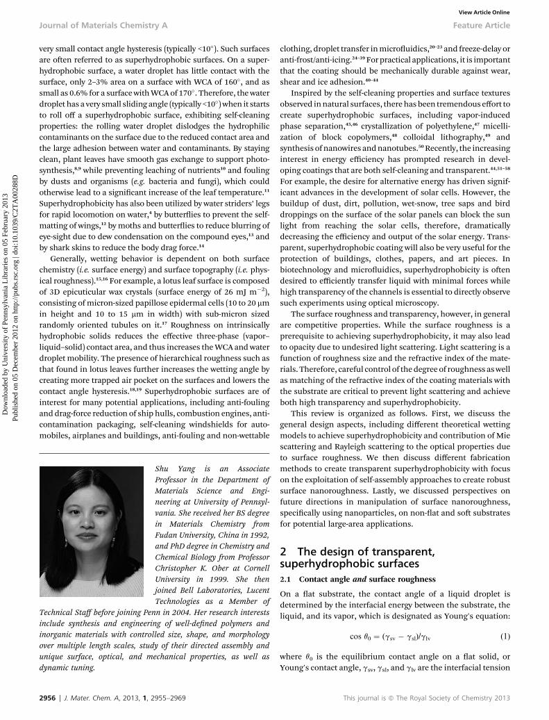
Fig. 1 Illustration of different wetting states of a liquid on a solid surface. (a) Flatsurface. (b and c) Rough surfaces.
This journal is ª The Royal Society of Chemistry 2013
To achieve robust superhydrophobicity, it is important tomaintain the existence of the Cassie–Baxter non-wetting state.As mentioned earlier, on a moderately hydrophobic surface,the Cassie–Baxter state and Wenzel state may coexist.Although both states may have the same apparent staticWCAs, the CAH is signicantly higher in the Wenzel state,which will increase the adhesion force between the waterdroplet and substrate, thus, weakening the self-cleaningability. In practical applications, the transition from Cassie–Baxter state to Wenzel state can be induced by an externalpressure, such as dynamic water impact on an automobilewindow, or change of a droplet size, such as dew condensa-tion in a high humidity environment. Therefore, it is criticalto ensure q0 > qc. However, it is known that on a at surface,the maximum q0 is 120� from a close-packed highly aligneduoro-terminated self-assembled monolayer.61,62 To achievehigher WCA (>120�), structural hierarchy on the surface couldbe introduced as exhibited on many natural surfaces. Studieshave shown that a nanoscale roughness enhances the existingmicro-roughness, especially when the feature size of themicrostructures is large and the asperity is small,18,19 thus,increasing the air cushion between the water and the solidsurface, and preventing the water droplet pinning to thesurface. In a special case, surface roughness could show verylarge WCAs and CAHs, so-called rose petal effect or stickysuperhydrophobic surfaces,27,29,63,64 where the water dropletwith a WCA greater than 150� could adhere to the substrateeven in the upside down position. Such a surface usually hashierarchical roughness consisting of high density nano-asperities on well-separated microstructures.63,64 Therefore,water is in the Cassie–Baxter impregnating wetting state, thatis the surface is in Cassie–Baxter non-wetting state at thenanoscale but in the Wenzel state at the microscale.
2.2 Transparency vs. surface roughness
When the roughness on a hydrophobic surface increases, theWCA increases. Meanwhile, the transparency oen decreasesdue to the scattering of light from the rough surface. The lightscattering behavior can be described by Rayleigh scattering andMie scattering theories depending on roughness size, assumingthat roughness behaves like spherical, non-absorbing (dielec-tric) particles to redirect the incident light.65 According to Ray-leigh scattering, when light passes through a surface withroughness dimension of sub-wavelength of light, the intensityof scattered light, I, is
I=I0 ¼ 1þ cos2 q
2S2
�2p
l
�4�n2 � 1
n2 þ 2
�2�d
2
�6
(4)
where I0 is the intensity of the incident light, S is the distancebetween the particle and the detector, typically a few centime-ters, n is the index of refraction of the particle, d is diameter ofthe particle, and l is the wavelength of light.
As seen from Fig. 2, when the roughness size is smaller than100 nm, Rayleigh scattering in the visible region (l¼ 532 nm) isnegligible from different materials, including silica (n ¼ 1.43),PDMS (n ¼ 1.46), PMMA (n ¼ 1.49), PET (n ¼ 1.58), and carbon
J. Mater. Chem. A, 2013, 1, 2955–2969 | 2957
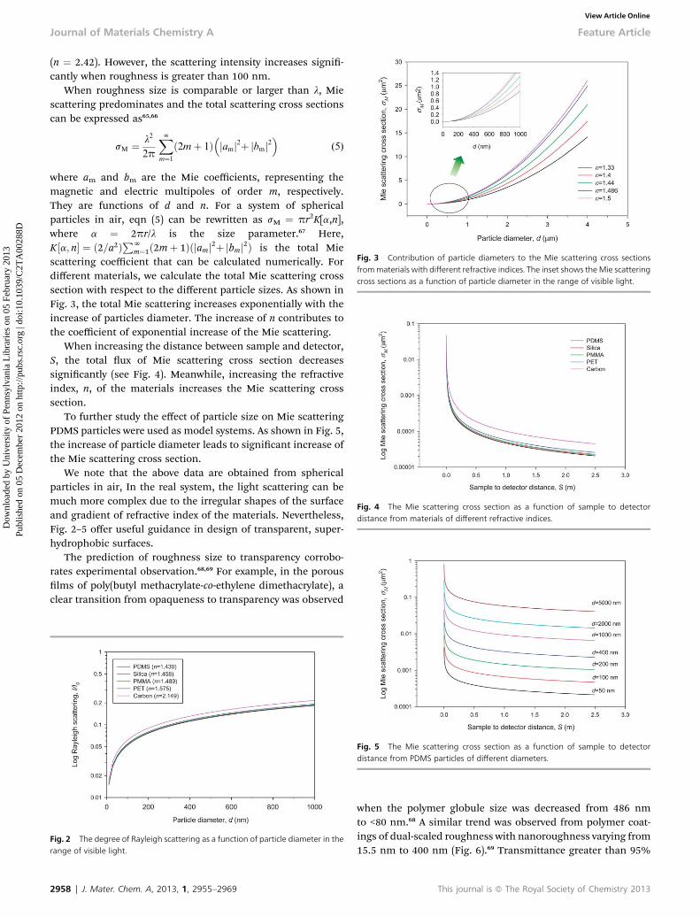
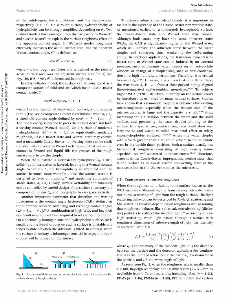
Fig. 3 Contribution of particle diameters to the Mie scattering cross sectionsfrommaterials with different refractive indices. The inset shows the Mie scatteringcross sections as a function of particle diameter in the range of visible light.
Fig. 4 The Mie scattering cross section as a function of sample to detectordistance from materials of different refractive indices.
Journal of Materials Chemistry A Feature Article
Dow
nloa
ded
by U
nive
rsity
of
Penn
sylv
ania
Lib
rari
es o
n 05
Feb
ruar
y 20
13Pu
blis
hed
on 0
5 D
ecem
ber
2012
on
http
://pu
bs.r
sc.o
rg |
doi:1
0.10
39/C
2TA
0028
8DView Article Online
(n ¼ 2.42). However, the scattering intensity increases signi-cantly when roughness is greater than 100 nm.
When roughness size is comparable or larger than l, Miescattering predominates and the total scattering cross sectionscan be expressed as65,66
sM ¼ l2
2p
XNm¼1
ð2mþ 1Þ�jamj2þ jbmj2
�(5)
where am and bm are the Mie coefficients, representing themagnetic and electric multipoles of order m, respectively.They are functions of d and n. For a system of sphericalparticles in air, eqn (5) can be rewritten as sM ¼ pr2K[a,n],where a ¼ 2pr/l is the size parameter.67 Here,K ½a; n� ¼ ð2=a2ÞPN
m¼1ð2mþ 1Þðjamj2þ jbmj2Þ is the total Miescattering coefficient that can be calculated numerically. Fordifferent materials, we calculate the total Mie scattering crosssection with respect to the different particle sizes. As shown inFig. 3, the total Mie scattering increases exponentially with theincrease of particles diameter. The increase of n contributes tothe coefficient of exponential increase of the Mie scattering.
When increasing the distance between sample and detector,S, the total ux of Mie scattering cross section decreasessignicantly (see Fig. 4). Meanwhile, increasing the refractiveindex, n, of the materials increases the Mie scattering crosssection.
To further study the effect of particle size on Mie scatteringPDMS particles were used as model systems. As shown in Fig. 5,the increase of particle diameter leads to signicant increase ofthe Mie scattering cross section.
We note that the above data are obtained from sphericalparticles in air, In the real system, the light scattering can bemuch more complex due to the irregular shapes of the surfaceand gradient of refractive index of the materials. Nevertheless,Fig. 2–5 offer useful guidance in design of transparent, super-hydrophobic surfaces.
The prediction of roughness size to transparency corrobo-rates experimental observation.68,69 For example, in the porouslms of poly(butyl methacrylate-co-ethylene dimethacrylate), aclear transition from opaqueness to transparency was observed
Fig. 2 The degree of Rayleigh scattering as a function of particle diameter in therange of visible light.
Fig. 5 The Mie scattering cross section as a function of sample to detectordistance from PDMS particles of different diameters.
2958 | J. Mater. Chem. A, 2013, 1, 2955–2969
when the polymer globule size was decreased from 486 nmto <80 nm.68 A similar trend was observed from polymer coat-ings of dual-scaled roughness with nanoroughness varying from15.5 nm to 400 nm (Fig. 6).69 Transmittance greater than 95%
This journal is ª The Royal Society of Chemistry 2013
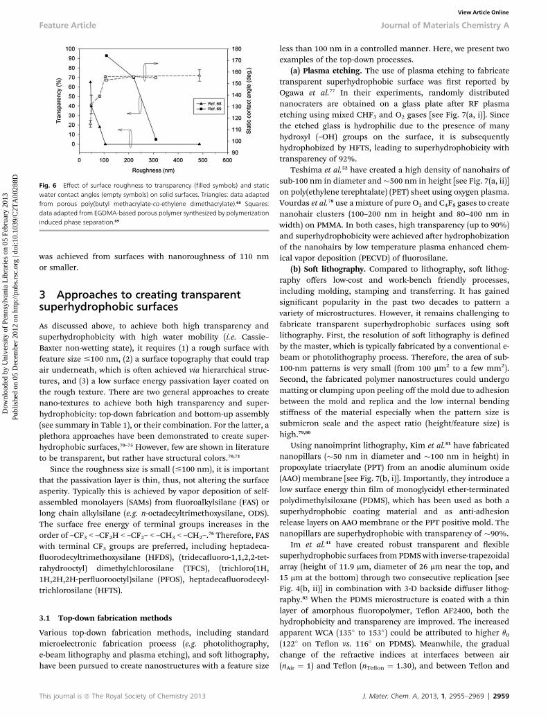
Fig. 6 Effect of surface roughness to transparency (filled symbols) and staticwater contact angles (empty symbols) on solid surfaces. Triangles: data adaptedfrom porous poly(butyl methacrylate-co-ethylene dimethacrylate).68 Squares:data adapted from EGDMA-based porous polymer synthesized by polymerizationinduced phase separation.69
Feature Article Journal of Materials Chemistry A
Dow
nloa
ded
by U
nive
rsity
of
Penn
sylv
ania
Lib
rari
es o
n 05
Feb
ruar
y 20
13Pu
blis
hed
on 0
5 D
ecem
ber
2012
on
http
://pu
bs.r
sc.o
rg |
doi:1
0.10
39/C
2TA
0028
8DView Article Online
was achieved from surfaces with nanoroughness of 110 nmor smaller.
3 Approaches to creating transparentsuperhydrophobic surfaces
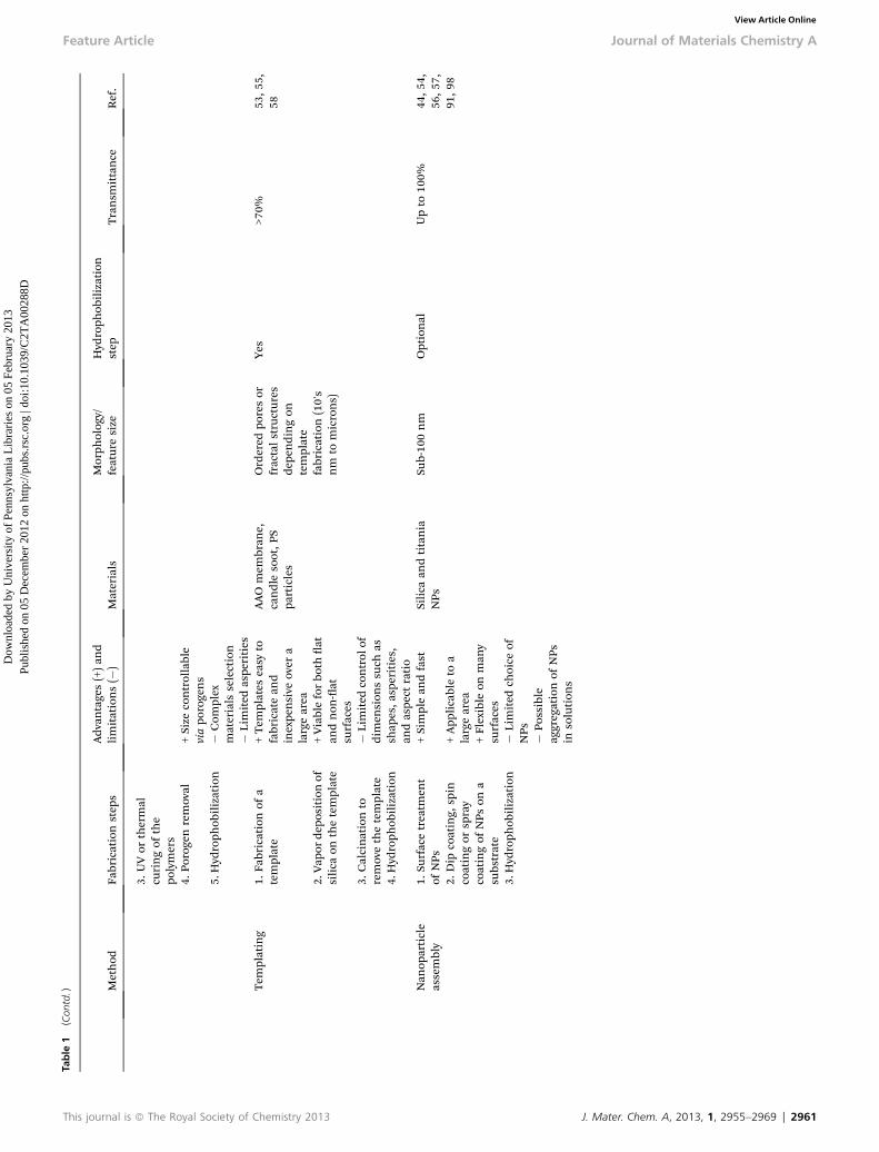
As discussed above, to achieve both high transparency andsuperhydrophobicity with high water mobility (i.e. Cassie–Baxter non-wetting state), it requires (1) a rough surface withfeature size #100 nm, (2) a surface topography that could trapair underneath, which is oen achieved via hierarchical struc-tures, and (3) a low surface energy passivation layer coated onthe rough texture. There are two general approaches to createnano-textures to achieve both high transparency and super-hydrophobicity: top-down fabrication and bottom-up assembly(see summary in Table 1), or their combination. For the latter, aplethora approaches have been demonstrated to create super-hydrophobic surfaces,70–75 However, few are shown in literatureto be transparent, but rather have structural colors.70,71
Since the roughness size is small (#100 nm), it is importantthat the passivation layer is thin, thus, not altering the surfaceasperity. Typically this is achieved by vapor deposition of self-assembled monolayers (SAMs) from uoroalkylsilane (FAS) orlong chain alkylsilane (e.g. n-octadecyltrimethoxysilane, ODS).The surface free energy of terminal groups increases in theorder of –CF3 < –CF2H < –CF2– < –CH3 < –CH2–.76 Therefore, FASwith terminal CF3 groups are preferred, including heptadeca-uorodecyltrimethoxysilane (HFDS), (tridecauoro-1,1,2,2-tet-rahydrooctyl) dimethylchlorosilane (TFCS), (trichloro(1H,1H,2H,2H-peruorooctyl)silane (PFOS), heptadecauorodecyl-trichlorosilane (HFTS).
3.1 Top-down fabrication methods
Various top-down fabrication methods, including standardmicroelectronic fabrication process (e.g. photolithography,e-beam lithography and plasma etching), and so lithography,have been pursued to create nanostructures with a feature size
This journal is ª The Royal Society of Chemistry 2013
less than 100 nm in a controlled manner. Here, we present twoexamples of the top-down processes.
(a) Plasma etching. The use of plasma etching to fabricatetransparent superhydrophobic surface was rst reported byOgawa et al.77 In their experiments, randomly distributednanocraters are obtained on a glass plate aer RF plasmaetching using mixed CHF3 and O2 gases [see Fig. 7(a, i)]. Sincethe etched glass is hydrophilic due to the presence of manyhydroxyl (–OH) groups on the surface, it is subsequentlyhydrophobized by HFTS, leading to superhydrophobicity withtransparency of 92%.
Teshima et al.52 have created a high density of nanohairs ofsub-100 nm in diameter and�500 nm in height [see Fig. 7(a, ii)]on poly(ethylene terephtalate) (PET) sheet using oxygen plasma.Vourdas et al.78 use amixture of pure O2 and C4F8 gases to createnanohair clusters (100–200 nm in height and 80–400 nm inwidth) on PMMA. In both cases, high transparency (up to 90%)and superhydrophobicity were achieved aer hydrophobizationof the nanohairs by low temperature plasma enhanced chem-ical vapor deposition (PECVD) of uorosilane.
(b) So lithography. Compared to lithography, so lithog-raphy offers low-cost and work-bench friendly processes,including molding, stamping and transferring. It has gainedsignicant popularity in the past two decades to pattern avariety of microstructures. However, it remains challenging tofabricate transparent superhydrophobic surfaces using solithography. First, the resolution of so lithography is denedby the master, which is typically fabricated by a conventional e-beam or photolithography process. Therefore, the area of sub-100-nm patterns is very small (from 100 mm2 to a few mm2).Second, the fabricated polymer nanostructures could undergomatting or clumping upon peeling off the mold due to adhesionbetween the mold and replica and the low internal bendingstiffness of the material especially when the pattern size issubmicron scale and the aspect ratio (height/feature size) ishigh.79,80
Using nanoimprint lithography, Kim et al.81 have fabricatednanopillars (�50 nm in diameter and �100 nm in height) inpropoxylate triacrylate (PPT) from an anodic aluminum oxide(AAO) membrane [see Fig. 7(b, i)]. Importantly, they introduce alow surface energy thin lm of monoglycidyl ether-terminatedpolydimethylsiloxane (PDMS), which has been used as both asuperhydrophobic coating material and as anti-adhesionrelease layers on AAO membrane or the PPT positive mold. Thenanopillars are superhydrophobic with transparency of �90%.
Im et al.41 have created robust transparent and exiblesuperhydrophobic surfaces from PDMSwith inverse-trapezoidalarray (height of 11.9 mm, diameter of 26 mm near the top, and15 mm at the bottom) through two consecutive replication [seeFig. 4(b, ii)] in combination with 3-D backside diffuser lithog-raphy.82 When the PDMS microstructure is coated with a thinlayer of amorphous uoropolymer, Teon AF2400, both thehydrophobicity and transparency are improved. The increasedapparent WCA (135� to 153�) could be attributed to higher q0
(122� on Teon vs. 116� on PDMS). Meanwhile, the gradualchange of the refractive indices at interfaces between air(nAir ¼ 1) and Teon (nTeon ¼ 1.30), and between Teon and
J. Mater. Chem. A, 2013, 1, 2955–2969 | 2959

Table
1Su
mmaryofdifferen
tap
proaches
tocrea
tetran
sparen
tsuperhyd
rophobicsurfaces
Method
Fabricationstep
sAdv
antages(+)an
dlimitations(�
)Materials
Morph
olog
y/featuresize
Hyd
roph
obilization
step
Transm
ittance
Ref.
Top
-dow
nPlasma
etch
ing
1.O2plasmaor
O2/
CHF 3
mixture
plasma
treatm
entof
aat
subs
trate
+Simple,
clean,a
nd
fast
Glass
ortran
sparen
tpo
lymers,
such
asPE
T
Nan
ocraters
(glass),
nan
ohairs
(polym
ers)
Yes
>90%
52,7
7
+App
licableto
alargearea
�Exp
ensive
tools
�Diffi
cultto
ne-
tunethefeaturesize
�Limited
range
ofap
plicab
lematerials
So
lithog
raph
y1.
Rep
lica
molding
from
asu
b-micrometer
mold
fabricated
bye-be
amor
photolithog
raph
y
+Fa
stTriacrylate,
polyurethan
e,PD
MS
Nan
opillars,
inversetrap
ezoid
Yes
>90%
(nan
o-structures)77%
(micro-
structures)
41,8
1+Reu
sablemolds
2.Hyd
roph
obilization
�Master
fabricationcanbe
complex
and
expe
nsive
�Limited
range
ofap
plicab
lematerials
andfeaturesize
Bottom-
upSo
l–gel
1.Sp
incoatingor
dip
coatingof
thesol
precursor
solution
+Broad
range
ofap
plicab
lematerials
andprocessing
parameters(e.g.sol
mixtures,
gelation
process,
pH)
Tetraethyl
orthosilicate(TEOS)
basedsilica
and
orga
nosilicates
Bothrando
man
dorde
redpo
rearrays
(nan
ometer)
Optional
Dep
endon
processing
parameters,
typically
>70%
83,8
5,86
,88
–90
2.Gelation
�Sm
allaspe
rities
3.Hyd
roph
obilization
�Po
ssible
degrad
ationun
der
UV/outdo
oren
vironmen
tMicroph
ase
sepa
ration
during
polymerization
1.Fo
rmulationof
mon
omer/porog
enmixture
solution
+Sim
plean
dfast
Porogens:
inert
solven
ts,s
uchas
cycloh
exan
ol1-
decanol,a
ndmethyl
alka
noa
tes,
and
solublelinear
polymers,
such
aspo
ly(isobu
tyl
methacrylate)
Ran
dom
pores
(sub
-micron's)
Optional
>95%
68,6
9
2.Sp
incoating
ordipcoating
thesolution
+Viableto
differen
ttype
sof
surfaces
(e.g.at
andnon
-at,fab
rics)
+Transferrableto
other
subs
trates
2960 | J. Mater. Chem. A, 2013, 1, 2955–2969 This journal is ª The Royal Society of Chemistry
Journal of Materials Chemistry A Feature Article
Dow
nloa
ded
by U
nive
rsity
of
Penn
sylv
ania
Lib
rari
es o
n 05
Feb
ruar
y 20
13Pu
blis
hed
on 0
5 D
ecem
ber
2012
on
http
://pu
bs.r
sc.o
rg |
doi:1
0.10
39/C
2TA
0028
8DView Article Online
2013
Table
1(Con
td.) M
ethod
Fabricationstep
sAdv
antages(+)an
dlimitations(�
)Materials
Morph
olog
y/featuresize
Hyd
roph
obilization
step
Transm
ittance
Ref.
3.UVor
thermal
curingof
the
polymers
4.Po
rogenremoval
+Size
controllable
viapo
rogens
5.Hyd
roph
obilization
�Com
plex
materials
selection
�Limited
aspe
rities
Tem
plating
1.Fa
bricationof
atemplate
+Tem
plates
easy
tofabricatean
dinexpe
nsive
over
alargearea
AAO
mem
bran
e,candlesoot,P
Spa
rticles
Ordered
poresor
fractalstructures
depe
ndingon
template
fabrication(10's
nm
tomicrons)
Yes
>70%
53,5
5,58
2.Vap
ordep
ositionof
silica
onthetemplate
+Viableforbo
that
andnon
-at
surfaces
3.Calcinationto
removethetemplate
�Limited
control
ofdimen
sion
ssu
chas
shap
es,a
sperities,
andaspe
ctratio
4.Hyd
roph
obilization
Nan
oparticle
assembly
1.Su
rfacetreatm
ent
ofNPs
+Simplean
dfast
Silica
andtitania
NPs
Sub-10
0nm
Optional
Upto
100%
44,5
4,56
,57,
91,9
82.
Dip
coating,
spin
coatingor
spray
coatingof
NPs
ona
subs
trate
+App
licableto
alargearea
+Flexible
onman
ysu
rfaces
3.Hyd
roph
obilization
�Limited
choice
ofNPs �Po
ssible
aggregationof
NPs
insolution
s
This journal is ª The Royal Society of Chemistry 2013 J. Mater. Chem. A, 2013, 1, 2955–2969 | 2961
Feature Article Journal of Materials Chemistry A
Dow
nloa
ded
by U
nive
rsity
of
Penn
sylv
ania
Lib
rari
es o
n 05
Feb
ruar
y 20
13Pu
blis
hed
on 0
5 D
ecem
ber
2012
on
http
://pu
bs.r
sc.o
rg |
doi:1
0.10
39/C
2TA
0028
8DView Article Online
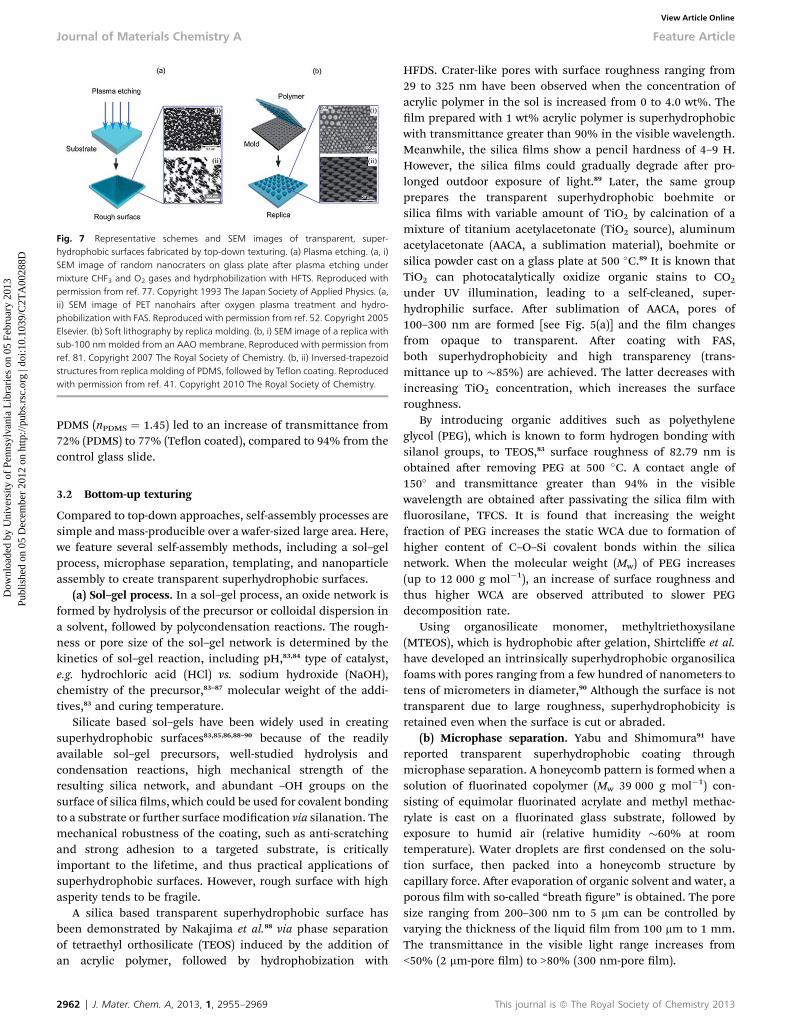
Fig. 7 Representative schemes and SEM images of transparent, super-hydrophobic surfaces fabricated by top-down texturing. (a) Plasma etching. (a, i)SEM image of random nanocraters on glass plate after plasma etching undermixture CHF3 and O2 gases and hydrphobilization with HFTS. Reproduced withpermission from ref. 77. Copyright 1993 The Japan Society of Applied Physics. (a,ii) SEM image of PET nanohairs after oxygen plasma treatment and hydro-phobilization with FAS. Reproduced with permission from ref. 52. Copyright 2005Elsevier. (b) Soft lithography by replica molding. (b, i) SEM image of a replica withsub-100 nm molded from an AAO membrane. Reproduced with permission fromref. 81. Copyright 2007 The Royal Society of Chemistry. (b, ii) Inversed-trapezoidstructures from replica molding of PDMS, followed by Teflon coating. Reproducedwith permission from ref. 41. Copyright 2010 The Royal Society of Chemistry.
Journal of Materials Chemistry A Feature Article
Dow
nloa
ded
by U
nive
rsity
of
Penn
sylv
ania
Lib
rari
es o
n 05
Feb
ruar
y 20
13Pu
blis
hed
on 0
5 D
ecem
ber
2012
on
http
://pu
bs.r
sc.o
rg |
doi:1
0.10
39/C
2TA
0028
8DView Article Online
PDMS (nPDMS ¼ 1.45) led to an increase of transmittance from72% (PDMS) to 77% (Teon coated), compared to 94% from thecontrol glass slide.
3.2 Bottom-up texturing
Compared to top-down approaches, self-assembly processes aresimple and mass-producible over a wafer-sized large area. Here,we feature several self-assembly methods, including a sol–gelprocess, microphase separation, templating, and nanoparticleassembly to create transparent superhydrophobic surfaces.
(a) Sol–gel process. In a sol–gel process, an oxide network isformed by hydrolysis of the precursor or colloidal dispersion ina solvent, followed by polycondensation reactions. The rough-ness or pore size of the sol–gel network is determined by thekinetics of sol–gel reaction, including pH,83,84 type of catalyst,e.g. hydrochloric acid (HCl) vs. sodium hydroxide (NaOH),chemistry of the precursor,83–87 molecular weight of the addi-tives,83 and curing temperature.
Silicate based sol–gels have been widely used in creatingsuperhydrophobic surfaces83,85,86,88–90 because of the readilyavailable sol–gel precursors, well-studied hydrolysis andcondensation reactions, high mechanical strength of theresulting silica network, and abundant –OH groups on thesurface of silica lms, which could be used for covalent bondingto a substrate or further surface modication via silanation. Themechanical robustness of the coating, such as anti-scratchingand strong adhesion to a targeted substrate, is criticallyimportant to the lifetime, and thus practical applications ofsuperhydrophobic surfaces. However, rough surface with highasperity tends to be fragile.
A silica based transparent superhydrophobic surface hasbeen demonstrated by Nakajima et al.88 via phase separationof tetraethyl orthosilicate (TEOS) induced by the addition ofan acrylic polymer, followed by hydrophobization with
2962 | J. Mater. Chem. A, 2013, 1, 2955–2969
HFDS. Crater-like pores with surface roughness ranging from29 to 325 nm have been observed when the concentration ofacrylic polymer in the sol is increased from 0 to 4.0 wt%. Thelm prepared with 1 wt% acrylic polymer is superhydrophobicwith transmittance greater than 90% in the visible wavelength.Meanwhile, the silica lms show a pencil hardness of 4–9 H.However, the silica lms could gradually degrade aer pro-longed outdoor exposure of light.89 Later, the same groupprepares the transparent superhydrophobic boehmite orsilica lms with variable amount of TiO2 by calcination of amixture of titanium acetylacetonate (TiO2 source), aluminumacetylacetonate (AACA, a sublimation material), boehmite orsilica powder cast on a glass plate at 500 �C.89 It is known thatTiO2 can photocatalytically oxidize organic stains to CO2
under UV illumination, leading to a self-cleaned, super-hydrophilic surface. Aer sublimation of AACA, pores of100–300 nm are formed [see Fig. 5(a)] and the lm changesfrom opaque to transparent. Aer coating with FAS,both superhydrophobicity and high transparency (trans-mittance up to �85%) are achieved. The latter decreases withincreasing TiO2 concentration, which increases the surfaceroughness.
By introducing organic additives such as polyethyleneglycol (PEG), which is known to form hydrogen bonding withsilanol groups, to TEOS,83 surface roughness of 82.79 nm isobtained aer removing PEG at 500 �C. A contact angle of150� and transmittance greater than 94% in the visiblewavelength are obtained aer passivating the silica lm withuorosilane, TFCS. It is found that increasing the weightfraction of PEG increases the static WCA due to formation ofhigher content of C–O–Si covalent bonds within the silicanetwork. When the molecular weight (Mw) of PEG increases(up to 12 000 g mol�1), an increase of surface roughness andthus higher WCA are observed attributed to slower PEGdecomposition rate.
Using organosilicate monomer, methyltriethoxysilane(MTEOS), which is hydrophobic aer gelation, Shirtcliffe et al.have developed an intrinsically superhydrophobic organosilicafoams with pores ranging from a few hundred of nanometers totens of micrometers in diameter,90 Although the surface is nottransparent due to large roughness, superhydrophobicity isretained even when the surface is cut or abraded.
(b) Microphase separation. Yabu and Shimomura91 havereported transparent superhydrophobic coating throughmicrophase separation. A honeycomb pattern is formed when asolution of uorinated copolymer (Mw 39 000 g mol�1) con-sisting of equimolar uorinated acrylate and methyl methac-rylate is cast on a uorinated glass substrate, followed byexposure to humid air (relative humidity �60% at roomtemperature). Water droplets are rst condensed on the solu-tion surface, then packed into a honeycomb structure bycapillary force. Aer evaporation of organic solvent and water, aporous lm with so-called “breath gure” is obtained. The poresize ranging from 200–300 nm to 5 mm can be controlled byvarying the thickness of the liquid lm from 100 mm to 1 mm.The transmittance in the visible light range increases from<50% (2 mm-pore lm) to >80% (300 nm-pore lm).
This journal is ª The Royal Society of Chemistry 2013

Fig. 8 Representative schematics and SEM images of transparent superhydrophobic surfaces obtained by bottom-up assemblies. (a) Porous sol–gel film. Reproducedwith permission from ref. 89. Copyright 2000 American Chemical Society. (b) Porous EGDMA-based polymer synthesized by polymerization induced phase separation(PIPS). Reproduced with permission from ref. 69. Copyright 2012 The Royal Society of Chemistry. (c) Microporous silica shell coated on carbon network obtained fromcandle-soot, followed by calcination. TEM image of silica network after calcinations reproduced with permission from ref. 58. Copyright 2012 American Association forthe Advancement of Science.
Feature Article Journal of Materials Chemistry A
Dow
nloa
ded
by U
nive
rsity
of
Penn
sylv
ania
Lib
rari
es o
n 05
Feb
ruar
y 20
13Pu
blis
hed
on 0
5 D
ecem
ber
2012
on
http
://pu
bs.r
sc.o
rg |
doi:1
0.10
39/C
2TA
0028
8DView Article Online
Using inert solvents, such as cyclohexanol and 1-decanol,which are miscible with the monomers but immiscible withthe crosslinked polymer network, as porogens during the insitu copolymerization, Levkin et al. have created porouspoly(butyl methacrylate-co-ethylene dimethacrylate).68 Whenthe growing crosslinked polymer chains reach a critical size,the porogens become phase separated from the matrix,resulting in a highly porous structure consisting of inter-connected globules. By increasing the volume ratio of cyclo-hexanol to 1-decanol (total of 50%) in the polymerizationmixture while keeping the amounts of monomer and cross-linker unchanged, the average globule size of the polymernetwork can be decreased from 486 nm (pure 1-decanol asporogen) to 45 nm (pure cyclohexanol as porogen). Becausethe polymer network is intrinsically hydrophobic, the super-hydrophobicity is highly durable even aer removing the topsurface layer. It is also demonstrated that the porous lm canbe stripped off and ground into powders to coat differentsubstrates, including rubber gloves and tissue papers.However, as the pore size and roughness decreases toincrease the transparency, the superhydrophobicity is alsolost. By UV graing 2,2,3,3,3-pentauoropropyl methacrylatewith an average globule size of 48 and 45 nm, respectively,onto the nanoporous lms, superhydrophobicity is regainedwith a slight decrease of transmittance (by 5–10%) in thevisible light.
This journal is ª The Royal Society of Chemistry 2013
Kato and Sato69 have created highly transparent(transmittance >95%) superhydrophobic coatings on glass andfabric textiles (e.g. cotton gauze and hydrophilic non-wovenpolyolen) via polymerization-induced phase separation (PIPS)between porogens and the polymer network. Specically,ethylene glycol dimethacrylate (EGDMA), tert-butyl methacry-late (TBMA), and peruorooctylethyl methacrylate (FMA) aremixed with solvents, such as methyl alkanoates (from methylhexanoate to methyl palmitate), tetradecane, and isobutylbenzene, and soluble linear polymers, poly(isobutyl methacry-late) (PIBMA, Mw of 3.0 � 105 g mol�1). Aer UV curing andethanol ushing to remove PIBMA, microtextured surface con-sisting small polymer globules is observed [see Fig. 8(b)]. Byvarying the aliphatic chain length of methyl alkanoates,concentration of PIBMA (0–10 wt%) and lm thickness(controlled by spin coating speed), the root-mean-square (rms)roughness could be varied from 15.5 nm to 400 nm.
(c) Templating. AAO membranes of different pore size andheight have been widely used as templates to create functionalmaterials.92–95They are prepared by anodization of Allm and thepores size can be controlled by the concentration of electrolytesolutions and the applied voltage. The pore size can be furtherwidened by chemical etching, e.g. using 10 wt% H3PO4 aq. solu-tions.96 Kim et al.81 have created polymeric nanopillars viananoimprint lithography using a AAO template. The porous AAOmembranes (10–120 nm in diameter and 300 nm in height) can
J. Mater. Chem. A, 2013, 1, 2955–2969 | 2963
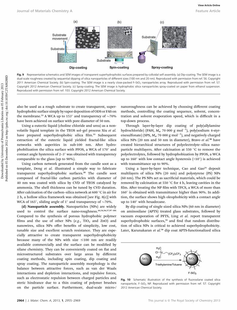
Fig. 10 Schematic illustration of the synthesis of fluorosilane coated silicananoparticle, F–SiO2 NP. Reproduced with permission from ref. 57. Copyright2012 American Chemical Society.
Fig. 9 Representative schematics and SEM images of transparent superhydrophobic surfaces prepared by colloidal self-assembly. (a) Dip-coating. The SEM image is adual-scale roughness created by sequential dipping of silica nanoparticles of different sizes (100 nm and 20 nm). Reproduced with permission from ref. 56. Copyright2011 American Chemical Society. (b) Spin-coating. The SEM image is a nearly close-packed F–SiO2 nanoparticles array. Reproduced with permission from ref. 57.Copyright 2012 American Chemical Society. (c) Spray-coating. The SEM image is hydrophobic silica nanoparticles spray-coated on paper from ethanol suspension.Reproduced with permission from ref. 103. Copyright 2012 American Chemical Society.
Journal of Materials Chemistry A Feature Article
Dow
nloa
ded
by U
nive
rsity
of
Penn
sylv
ania
Lib
rari
es o
n 05
Feb
ruar
y 20
13Pu
blis
hed
on 0
5 D
ecem
ber
2012
on
http
://pu
bs.r
sc.o
rg |
doi:1
0.10
39/C
2TA
0028
8DView Article Online
also be used as a rough substrate to create transparent, super-hydrophobic surface simply by vapordepositionofODSor FAS onthe membrane.53 A WCA up to 153� and transparency of �70%have been achieved on surface with pore diameter of 50 nm.
Using a eutectic liquid (choline chloride and urea) as a non-volatile liquid template in the TEOS sol–gel process Xiu et al.have prepared superhydrophobic silica lm.55 Subsequentextraction of the eutectic liquid yielded fractal-like silicanetworks with asperities in sub-100 nm. Aer hydro-phobilization the silica surface with PFOS, a WCA of 170� andcontact angle hysteresis of 2–3� was obtained with transparencycomparable to the glass (up to 90%).
Using carbon network generated from the candle soot as atemplate, Deng et al. illustrated a simple way to fabricatetransparent superhydrophobic surfaces.58 The candle sootcomposed of fractal-like carbon particles with diameter of40 nm was coated with silica by CVD of TEOS catalyzed byammonia. The shell thickness can be tuned by CVD duration.Aer calcination of the carbon–silica network at 600 �C in air for2 h, a hollow silica framework was obtained [see Fig. 8(c)] withWCA of 165�, sliding angle of 1� and transparency of �70%.
(d) Nanoparticle assembly. Nanoparticles (NPs) are widelyused to control the surface nano-roughness.44,54,56,57,97–101
Compared to the synthesis of porous hydrophobic polymerlms and the use of other NPs (e.g., TiO2 and ZnO) andnanowires, silica NPs offer benets of simplicity, low cost,tunable size and excellent scratch resistance. They are espe-cially attractive to create transparent superhydrophobicitybecause many of the NPs with size #100 nm are readilyavailable commercially and the surface can be modied bysilane chemistry. They can be conveniently coated on at andmicrostructured substrates over large areas by differentcoating methods, including spin coating, dip coating andspray coating. The nanoparticle assembly morphology is thebalance between attractive forces, such as van der Waalsinteractions and depletion interactions, and repulsive forces,such as electrostatic repulsion between charged particles andsteric hindrance due to a thin coating of polymer brusheson the particle surface. Furthermore, dual-scale micro-/
2964 | J. Mater. Chem. A, 2013, 1, 2955–2969
nanoroughness can be achieved by choosing different coatingmethods, controlling the coating sequence, solvent, concen-tration and solvent evaporation speed, which is difficult in atop-down process.
Through layer-by-layer dip coating of poly(allylaminehydrochloride) (PAH, Mw 70 000 g mol�1), poly(sodium 4-styr-enesulfonate) (SPS, Mw 70 000 g mol�1), and negatively chargedsilica NPs (20 nm and 50 nm in diameter), Bravo et al.98 havecreated hierarchical structures of polyelectrolyte–silica nano-particle multilayers. Aer calcination at 550 �C to remove thepolyelectrolytes, followed by hydrophobization by PFOS, a WCAup to 160� with low contact angle hysteresis (<10�) is achievedwith transmittance up to 90%.
Using a layer-by-layer technique, Cao and Gao51 depositmultilayers of silica NPs (20 nm) and polystyrene (PS) NPs(60 nm). The PS NPs act as sacricial materials, which could beremoved by calcination at 550 �C for 4 h, leaving cavities in thelm. Aer treating the NP lm with TFCS, a WCA of more than160� is obtained with transmittance higher than 90%. In addi-tion, the surface shows high oleophobicity with a contact angleup to 140� with hexadecane.
By dip coating of single sized silica NPs (60 nm in diameter)on aminosilane (APTS) treated glass substrates, followed byvacuum evaporation of PFTS, Ling et al. report transparentsuperhydrophobic surfaces,54 and nd that random distribu-tion of silica NPs is critical to achieved superhydrophobicity.Later, Karunakaran et al.56 dip coat APTS-functionalized silica
This journal is ª The Royal Society of Chemistry 2013

Fig. 11 Wetting states of water on a colloidal array: (a) Cassie–Baxter state and(b) Wenzel state.
Feature Article Journal of Materials Chemistry A
Dow
nloa
ded
by U
nive
rsity
of
Penn
sylv
ania
Lib
rari
es o
n 05
Feb
ruar
y 20
13Pu
blis
hed
on 0
5 D
ecem
ber
2012
on
http
://pu
bs.r
sc.o
rg |
doi:1
0.10
39/C
2TA
0028
8DView Article Online
NPs (100 nm, 50 nm and 20 nm) onto different substrates,including glass, Si, epoxy, and fabrics, followed by vapordeposition of PFTS. They conrm the importance of randomlydistribution of NPs to achieve superhydrophobicity, however,superhydrophobicity is observed only from sequential dipcoating of NPs of two different sizes (100 and 20 nm), regardlessthe coating sequence. For example, when dip coating 20 nmNPson an existing 100 nm NP lm, the 20 nm NPs populate both in-between the 100 nmNPs, of which the distribution is dependenton the concentration (or coverage) of 100 nm particles, and ontop of the 100 nm NPs, forming raspberry-like particles [seeFig. 9(a)]. Raspberry-like particles have previously beensynthesized by Ming et al.97 to create the necessary compositeinterface for highly mobile water droplet. Thermal annealingfurther enhances the stability of the NP coating against PDMSmolding, and superhydrophobicity is maintained against pro-longed exposure to UV light (200 mW cm�2 for 1 week) underambient conditions.
Using micron-sized PS particles (800 nm in diameter) astemplates, Deng et al.44 have created raspberry-like particles bygrowing 50 nm silica NPs on the surface of PS. The number ofsilica particles on PS core can be tuned by the amount ofacrylic acid added in emulsion polymerization and the sizeof the silica particles was controlled by the amount of TEOSused in the Stober reaction. The negatively charged raspberry-like particles are then dip coated on a positively charged glasssubstrate with random distribution. To increase the mechan-ical stability of the nanoparticle coating, CVD of TEOS in thepresence of ammonia is performed, which chemically bondthe neighboring particles and particles to the surface via silicabridges, and gives rise to asperities with a height of 0.8–1.5 mm. Aer calcination at 350 �C for 2 h to remove PS cores,hollow microcapsules with 50 nm silica shells [see similarstructures in Fig. 8(c)] are obtained. Aer hydrophobization byCVD of a semi-uorosilane, the surface exhibited a static WCAof 160� and a water sliding angle <5�. It is interesting to notethat although the porous silica capsules are micrometer sized,the transmittance of the superhydrophobic coating in thevisible wavelength is comparable to that of bare glass slides.The authors attributed the high transparency to destructiveinterference between light reected from the particle–substrateand the air–particle interfaces. Furthermore, the coating canwithstand peeling against double sided adhesive tapes pressedat 10 kPa and impact abrasion by sand grains (100–300 mm)with an impact energy at least 1.6 � 10�9 J. The post-treatmentby CVD of a thin layer TEOS on the capsules was found to bethe key to the high thermal and mechanical strength of thetransparent superhydrophobicity due to the lock-bridgingsilica network.
In all the above systems discussed so far, deposition of a thinlayer of low surface energy coating (typically uorosilane) on thenewly generated nanoparticle assembly is necessary. However,the post-treatment step could signicantly increase the cost ofcoating for large-area substrates, or may not be desirable forcertain polymeric substrates and applications in consumerproducts. We recently reported superhydrophobic surface withhigh transparency (>95% transmission in the visible region)
This journal is ª The Royal Society of Chemistry 2013
from the assembly of uorosilane modied silica (F–SiO2) NPs(100 nm in diameter) (see Fig. 10).57 When the F–SiO2 NPs ($0.8wt% in a uorinated solvent) were spin coated on varioussubstrates (hydrophilic, hydrophobic Si and polymers), thesurface exhibited superhydrophobicity, whereas dip coated NPlms were highly hydrophobic but not superhydrophobic. Themain difference is that F–SiO2 NPs were nearly close-packed inthe spin coated lms [Fig. 9(b)], but randomly distributed in thedip coated lms. Previously, colloidal crystals have been used tocreate superhydrophobic surfaces, however, plasma etching isneeded to reduce the bead size (thus, decreasing f),102 or useinverse microporous opal.70 In both scenarios, hydro-phobilization is required.
To conrm it is possible to achieve superhydrophobicityfrom close-packed, intrinsically hydrophobic particles, we esti-mated the azimuthal angle, 4 (see Fig. 11), representing thelevel of water wetting on the particle surface. By assuming thatthe wetting line holds at the same level and the liquid pene-tration between particles can be ignored, the lling fraction canbe expressed as
f ¼ 2pR2ð1� cos 4ÞN2pR2ð1� cos 4ÞN þ
�1� pðRsin 4Þ2N
� (6)
where R is the particle radius and N is the number density ofNPs. In the Cassie–Baxter non-wetting state, water shouldmerely wet the top area of NPs, thus, 4 should be small. On theother hand, in the Wenzel state, water should wet into the NPassembly as shown in Fig. 11(b). In our spin coated F–SiO2 NPlm (0.8 wt%), we obtained f¼ 0.23 and 4� 29�, indicating thata Cassie–Baxter state could be achieved.
While dip coating and spin coating are commonly used inthe labs to coat hard substrates, spray coating is preferred forconsumer applied coatings, non-at (e.g. coiled wires) anddelicate substrates (e.g. paper products). Ogihara et al., createdtransparent superhydrophobicity on paper by repetitivespray coating alcohol suspension of hydrophobic silica NPs(average size ca. 25 nm), which were functionalized by dode-cyltrichlorosilane.103 The hydrophobic SiO2 NPs formedaggregates in alcohol, �470 nm in ethanol, 410 nm in1-propanol, and 350 nm in 1-butanol before coating. Whenincreasing the number of spray coating, thus, the amount ofSiO2 NPs coatings, the hydrophobicity of the paper increased.However, it also decreased the transparency. An optimalcoating number was in the range of 20–30 times. Super-hydrophobicity (WCA of 155� and sliding angle of 7.2�)was obtained only from ethanol suspension, where bothmicro- and nanoroughness appeared [see Fig. 9(c)].
J. Mater. Chem. A, 2013, 1, 2955–2969 | 2965
Journal of Materials Chemistry A Feature Article
Dow
nloa
ded
by U
nive
rsity
of
Penn
sylv
ania
Lib
rari
es o
n 05
Feb
ruar
y 20
13Pu
blis
hed
on 0
5 D
ecem
ber
2012
on
http
://pu
bs.r
sc.o
rg |
doi:1
0.10
39/C
2TA
0028
8DView Article Online
Superhydrophobicity was maintained aer touching with barehands and folding the paper.
4 Robustness of transparentsuperhydrophobic surfaces
The long-term durability of the self-assembled nanostructuresagainst mechanical wear, shear and liquid ow is critical toapply the fabricated superhydrophobic surfaces for practicalapplications. In general, inorganic micro- and nano-particles104,105 or carbon nanotubes40 offer much higher wearresistance than that of polymer surfaces as shown in tribologyexperiments, where a borosilicate ball (radius 15 mm) mountedon a Si(100) cantilever was used in AFM to wear the nanoparticlesurfaces, and a ball-on-at tribometer was applied normal tothe surface at a load of 10 mN to stroke the surface.
However, if there is no chemical or physical bondingbetween the particles and particles with the substrate, thecoating can be easily removed by Scotch tape peeling.57 Toimprove adhesion and mechanical stability, silica NPs surfacecan be functionalized with aminosilane106 or coated with a thinlayer of silica bridge network by chemical vapor deposition ofTEOS (see detailed discussion in Section 3.2(c)).58,107
It is especially challenging to create a robust, transparent,superhydrophobic coating on a plastic surface, since pre- andpost-surface treatment or use of solvent could potentiallydamage the substrate, thus degrading the optical properties. Inthis regard, polymer binders (polyurethane and silicone) havebeen mixed with NPs to improve the durability of thecoating.42,108 It is important that the polymer binder should notcover the nanotexture, which will diminish the nanoroughness.However, precise control of the binder thickness (<100 nm) vs.nanotexture is non-trivial.
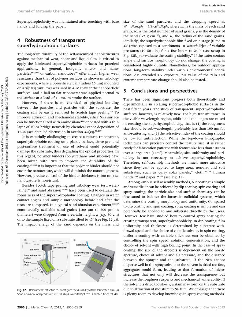
Besides Scotch tape peeling and tribology wear test, water-fall/jet40 and sand abrasion58,107 have been used to evaluate therobustness of the superhydrophobic coating. Changes in watercontact angles and sample morphology before and aer thetests are compared. In a typical sand abrasion experiment,58,107
commercially available sand grains (100 mm to 300 mm indiameter) were dropped from a certain height, h (e.g. 30 cm)onto the sample xed on a substrate tilted to 45� (see Fig. 12(a)).The impact energy of the sand depends on the mass and
Fig. 12 Robustness test setup to investigate the durability of the fabricatedfilm. (a)Sand abrasion. Adapted from ref. 58. (b) A waterfall/jet test. Adapted from ref. 40.
2966 | J. Mater. Chem. A, 2013, 1, 2955–2969
size of the sand particles, and the dropping speed asW ¼ Nsmsgh ¼ 4/3pR3rNsgh, where ms is the mass of each sandgrain, Ns is the total number of sand grains, r is the density ofthe sand (�2 g cm�3), and Rs the radius of the sand grains.Similarly, the superhydrophobic lm xed on a stage (tilted to45�) was exposed to a continuous DI waterfall/jet of variablepressures (10–50 kPa) for a few hours to 24 h (see setup inFig. 12(b)) to evaluate the coating stability.40 If the water contactangle and surface morphology do not change, the coating isconsidered highly durable. Nonetheless, for outdoor applica-tions, long-term stability under various environmental condi-tions, e.g. extended UV exposure, pH value of the rain andextreme temperature change should also be tested.
5 Conclusions and perspectives
There has been signicant progress both theoretically andexperimentally in creating superhydrophobic surfaces in thepast een years. The study of transparent, superhydrophobicsurfaces, however, is relatively new. For high transmittance inthe visible wavelength region, additional challenges are raisedin creating the superhydrophobicity, that is (1) the roughnesssize should be sub-wavelength, preferably less than 100 nm foranti-scattering and (2) the refractive index of the coating shouldbe low for antireection. While the top-down lithographictechniques can precisely control the feature size, it is rathercostly for fabrication patterns with feature size less than 100 nmover a large area (>cm2). Meanwhile, size uniformity and peri-odicity is not necessary to achieve superhydrophobicity.Therefore, self-assembly methods are much more attractivesince they can be applied to large area, non-at and sosubstrates, such as curvy solar panels,20 cloth,57,103 humanhands,109 and paper103,109 (see Fig. 13).
Among various self-assembly methods, NP coating is simpleand versatile: it can be achieved by dip coating, spin coating andspray coating; the particle size and surface chemistry can bene-tuned to balance the forces in colloidal systems, whichdetermine the coating morphology and uniformity. Comparedto dip coating and spin coating, spray coating is simple and canpotentially be applied to any substrate directly by the users.However, few have studied how to control spray coating forcreating transparent, superhydrophobicity. In dip coating, lmuniformity and thickness is determined by substrate with-drawal speed and the choice of volatile solvent. In spin coating,uniform coating with variable thickness can be obtained bycontrolling the spin speed, solution concentration, and thechoice of solvent with high boiling point. In the case of spraycoating, the size of the droplets is dependent on the nozzleaperture, choice of solvent and air pressure, and the distancebetween the sprayer and the substrate. If the NPs cannotdisperse well in the spray solvent or the solvent is dried too fast,aggregates could form, leading to that formation of micro-structures that not only will decrease the transparency butincrease the roughness asperity andmechanical vulnerability. Ifthe solvent is dried too slowly, a stain may form on the substratedue to attraction of moisture to NP lm. We envisage that thereis plenty room to develop knowledge in spray coating methods.
This journal is ª The Royal Society of Chemistry 2013
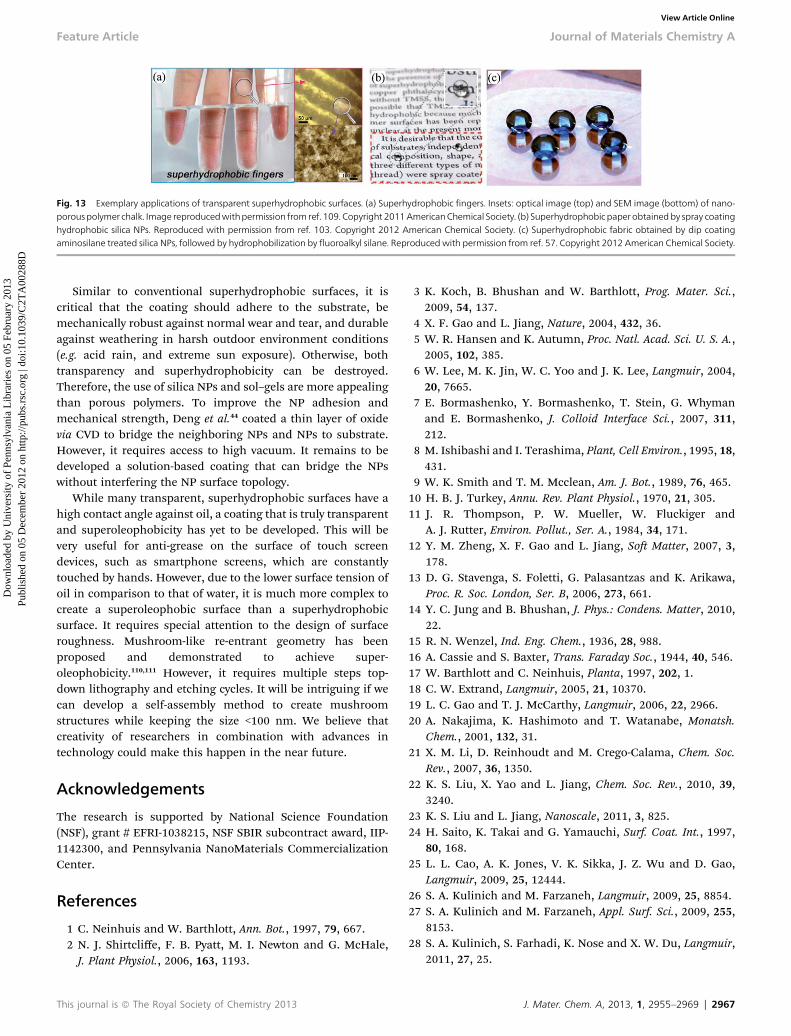
Fig. 13 Exemplary applications of transparent superhydrophobic surfaces. (a) Superhydrophobic fingers. Insets: optical image (top) and SEM image (bottom) of nano-porouspolymerchalk. Image reproducedwithpermission from ref. 109. Copyright 2011AmericanChemical Society. (b) Superhydrophobic paperobtainedby spray coatinghydrophobic silica NPs. Reproduced with permission from ref. 103. Copyright 2012 American Chemical Society. (c) Superhydrophobic fabric obtained by dip coatingaminosilane treated silica NPs, followed by hydrophobilization by fluoroalkyl silane. Reproduced with permission from ref. 57. Copyright 2012 American Chemical Society.
Feature Article Journal of Materials Chemistry A
Dow
nloa
ded
by U
nive
rsity
of
Penn
sylv
ania
Lib
rari
es o
n 05
Feb
ruar
y 20
13Pu
blis
hed
on 0
5 D
ecem
ber
2012
on
http
://pu
bs.r
sc.o
rg |
doi:1
0.10
39/C
2TA
0028
8DView Article Online
Similar to conventional superhydrophobic surfaces, it iscritical that the coating should adhere to the substrate, bemechanically robust against normal wear and tear, and durableagainst weathering in harsh outdoor environment conditions(e.g. acid rain, and extreme sun exposure). Otherwise, bothtransparency and superhydrophobicity can be destroyed.Therefore, the use of silica NPs and sol–gels are more appealingthan porous polymers. To improve the NP adhesion andmechanical strength, Deng et al.44 coated a thin layer of oxidevia CVD to bridge the neighboring NPs and NPs to substrate.However, it requires access to high vacuum. It remains to bedeveloped a solution-based coating that can bridge the NPswithout interfering the NP surface topology.
While many transparent, superhydrophobic surfaces have ahigh contact angle against oil, a coating that is truly transparentand superoleophobicity has yet to be developed. This will bevery useful for anti-grease on the surface of touch screendevices, such as smartphone screens, which are constantlytouched by hands. However, due to the lower surface tension ofoil in comparison to that of water, it is much more complex tocreate a superoleophobic surface than a superhydrophobicsurface. It requires special attention to the design of surfaceroughness. Mushroom-like re-entrant geometry has beenproposed and demonstrated to achieve super-oleophobicity.110,111 However, it requires multiple steps top-down lithography and etching cycles. It will be intriguing if wecan develop a self-assembly method to create mushroomstructures while keeping the size <100 nm. We believe thatcreativity of researchers in combination with advances intechnology could make this happen in the near future.
Acknowledgements
The research is supported by National Science Foundation(NSF), grant # EFRI-1038215, NSF SBIR subcontract award, IIP-1142300, and Pennsylvania NanoMaterials CommercializationCenter.
References
1 C. Neinhuis and W. Barthlott, Ann. Bot., 1997, 79, 667.2 N. J. Shirtcliffe, F. B. Pyatt, M. I. Newton and G. McHale,J. Plant Physiol., 2006, 163, 1193.
This journal is ª The Royal Society of Chemistry 2013
3 K. Koch, B. Bhushan and W. Barthlott, Prog. Mater. Sci.,2009, 54, 137.
4 X. F. Gao and L. Jiang, Nature, 2004, 432, 36.5 W. R. Hansen and K. Autumn, Proc. Natl. Acad. Sci. U. S. A.,2005, 102, 385.
6 W. Lee, M. K. Jin, W. C. Yoo and J. K. Lee, Langmuir, 2004,20, 7665.
7 E. Bormashenko, Y. Bormashenko, T. Stein, G. Whymanand E. Bormashenko, J. Colloid Interface Sci., 2007, 311,212.
8 M. Ishibashi and I. Terashima, Plant, Cell Environ., 1995, 18,431.
9 W. K. Smith and T. M. Mcclean, Am. J. Bot., 1989, 76, 465.10 H. B. J. Turkey, Annu. Rev. Plant Physiol., 1970, 21, 305.11 J. R. Thompson, P. W. Mueller, W. Fluckiger and
A. J. Rutter, Environ. Pollut., Ser. A., 1984, 34, 171.12 Y. M. Zheng, X. F. Gao and L. Jiang, So Matter, 2007, 3,
178.13 D. G. Stavenga, S. Foletti, G. Palasantzas and K. Arikawa,
Proc. R. Soc. London, Ser. B, 2006, 273, 661.14 Y. C. Jung and B. Bhushan, J. Phys.: Condens. Matter, 2010,
22.15 R. N. Wenzel, Ind. Eng. Chem., 1936, 28, 988.16 A. Cassie and S. Baxter, Trans. Faraday Soc., 1944, 40, 546.17 W. Barthlott and C. Neinhuis, Planta, 1997, 202, 1.18 C. W. Extrand, Langmuir, 2005, 21, 10370.19 L. C. Gao and T. J. McCarthy, Langmuir, 2006, 22, 2966.20 A. Nakajima, K. Hashimoto and T. Watanabe, Monatsh.
Chem., 2001, 132, 31.21 X. M. Li, D. Reinhoudt and M. Crego-Calama, Chem. Soc.
Rev., 2007, 36, 1350.22 K. S. Liu, X. Yao and L. Jiang, Chem. Soc. Rev., 2010, 39,
3240.23 K. S. Liu and L. Jiang, Nanoscale, 2011, 3, 825.24 H. Saito, K. Takai and G. Yamauchi, Surf. Coat. Int., 1997,
80, 168.25 L. L. Cao, A. K. Jones, V. K. Sikka, J. Z. Wu and D. Gao,
Langmuir, 2009, 25, 12444.26 S. A. Kulinich and M. Farzaneh, Langmuir, 2009, 25, 8854.27 S. A. Kulinich and M. Farzaneh, Appl. Surf. Sci., 2009, 255,
8153.28 S. A. Kulinich, S. Farhadi, K. Nose and X. W. Du, Langmuir,
2011, 27, 25.
J. Mater. Chem. A, 2013, 1, 2955–2969 | 2967
Journal of Materials Chemistry A Feature Article
Dow
nloa
ded
by U
nive
rsity
of
Penn
sylv
ania
Lib
rari
es o
n 05
Feb
ruar
y 20
13Pu
blis
hed
on 0
5 D
ecem
ber
2012
on
http
://pu
bs.r
sc.o
rg |
doi:1
0.10
39/C
2TA
0028
8DView Article Online
29 S. A. Kulinich and M. Farzaneh, Cold Reg. Sci. Technol.,2011, 65, 60.
30 K. K. Varanasi, T. Deng, J. D. Smith, M. Hsu and N. Bhate,Appl. Phys. Lett., 2010, 97, 234102.
31 S. Farhadi, M. Farzaneh and S. A. Kulinich, Appl. Surf. Sci.,2011, 257, 6264.
32 S. Jung, M. Dorrestijn, D. Raps, A. Das, C. M. Megaridis andD. Poulikakos, Langmuir, 2011, 27, 3059.
33 Y. F. Huang, M. J. Hu, S. P. Yi, X. H. Liu, H. B. Li, C. Huang,Y. B. Luo and Y. Li, Thin Solid Films, 2012, 520, 5644.
34 H. Wang, G. G. He and Q. Q. Tian, Appl. Surf. Sci., 2012, 258,7219.
35 Y. F. Zhang, X. Q. Yu, H. Wu and J. Wu, Appl. Surf. Sci., 2012,258, 8253.
36 V. Bahadur, L. Mishchenko, B. Hatton, J. A. Taylor,J. Aizenberg and T. Krupenkin, Langmuir, 2011, 27, 14143.
37 P. Kim, T. S. Wong, J. Alvarenga, M. J. Kreder, W. E. Adorno-Martinez and J. Aizenberg, ACS Nano, 2012, 6, 6569.
38 L. Mishchenko, B. Hatton, V. Bahadur, J. A. Taylor,T. Krupenkin and J. Aizenberg, ACS Nano, 2010, 4, 7699.
39 T. S. Wong, S. H. Kang, S. K. Y. Tang, E. J. Smythe,B. D. Hatton, A. Grinthal and J. Aizenberg, Nature, 2011,477, 443.
40 Y. C. Jung and B. Bhushan, ACS Nano, 2009, 3, 4155.41 M. Im, H. Im, J. H. Lee, J. B. Yoon and Y. K. Choi, So
Matter, 2010, 6, 1401.42 Q. P. Ke, W. Q. Fu, H. L. Jin, L. Zhang, T. D. Tang and
J. F. Zhang, Surf. Coat. Technol., 2011, 205, 4910.43 T. Verho, C. Bower, P. Andrew, S. Franssila, O. Ikkala and
R. H. A. Ras, Adv. Mater., 2011, 23, 673.44 X. Deng, L. Mammen, Y. F. Zhao, P. Lellig, K. Mullen, C. Li,
H. J. Butt and D. Vollmer, Adv. Mater., 2011, 23, 2962.45 N. Zhao, J. Xu, Q. D. Xie, L. H. Weng, X. L. Guo, X. L. Zhang
and L. H. Shi, Macromol. Rapid Commun., 2005, 26, 1075.46 H. Y. Erbil, A. L. Demirel, Y. Avci and O. Mert, Science, 2003,
299, 1377.47 X. Y. Lu, C. C. Zhang and Y. C. Han, Macromol. Rapid
Commun., 2004, 25, 1606.48 Q. D. Xie, G. Q. Fan, N. Zhao, X. L. Guo, J. Xu, J. Y. Dong,
L. Y. Zhang, Y. J. Zhang and C. C. Han, Adv. Mater., 2004,16, 1830.
49 J. Y. Shiu, C. W. Kuo, P. L. Chen and C. Y. Mou, Chem.Mater., 2004, 16, 561.
50 K. K. S. Lau, J. Bico, K. B. K. Teo, M. Chhowalla,G. A. J. Amaratunga, W. I. Milne, G. H. McKinley andK. K. Gleason, Nano Lett., 2003, 3, 1701.
51 L. L. Cao and D. Gao, Faraday Discuss., 2010, 146, 57.52 K. Teshima, H. Sugimura, Y. Inoue, O. Takai and A. Takano,
Appl. Surf. Sci., 2005, 244, 619.53 M. Kemell, E. Farm, M. Leskela and M. Ritala, Phys. Status
Solidi A, 2006, 203, 1453.54 X. Y. Ling, I. Y. Phang, G. J. Vancso, J. Huskens and
D. N. Reinhoudt, Langmuir, 2009, 25, 3260.55 Y. H. Xiu, F. Xiao, D. W. Hess and C. P. Wong, Thin Solid
Films, 2009, 517, 1610.56 R. G. Karunakaran, C. H. Lu, Z. H. Zhang and S. Yang,
Langmuir, 2011, 27, 4594.
2968 | J. Mater. Chem. A, 2013, 1, 2955–2969
57 L. Xu, R. G. Karunakaran, J. Guo and S. Yang, ACS Appl.Mater. Interfaces, 2012, 4, 1118.
58 X. Deng, L. Mammen, H. J. Butt and D. Vollmer, Science,2012, 335, 67.
59 S. Herminghaus, Europhys. Lett., 2000, 52, 165.60 G. McHale, N. J. Shirtcliffe and M. I. Newton, Langmuir,
2004, 20, 10146.61 J. Wang and C. K. Ober, Macromolecules, 1997, 30, 7560.62 T. Nishino, M. Meguro, K. Nakamae, M. Matsushita and
Y. Ueda, Langmuir, 1999, 15, 4321.63 L. Feng, Y. A. Zhang, J. M. Xi, Y. Zhu, N. Wang, F. Xia and
L. Jiang, Langmuir, 2008, 24, 4114.64 Z. G. Guo and W. M. Liu, Appl. Phys. Lett., 2007, 90, 223111.65 M. Kerker, The Scattering of Light and Other Electromagnetic
Radiation, Academic, New York, 1969.66 K. L. Cho, I. I. Liaw, A. H. F. Wu and R. N. Lamb, J. Phys.
Chem. C, 2010, 114, 11228.67 R. B. Penndorf, J. Opt. Soc. Am., 1957, 47, 1010.68 P. A. Levkin, F. Svec and J. M. J. Frechet, Adv. Funct. Mater.,
2009, 19, 1993.69 S. Kato and A. Sato, J. Mater. Chem., 2012, 22, 8613.70 Z.-Z. Gu, H. Uetsuka, K. Takahashi, R. Nakajima, H. Onishi,
A. Fujishima and O. Sato, Angew. Chem., Int. Ed., 2003, 42,894.
71 J. Li, G. Liang, X. Zhu and S. Yang, Adv. Funct. Mater., 2012,22, 2980.
72 S. G. Park, J. H. Moon, H. C. Jeon and S. M. Yang, SoMatter, 2012, 8, 4567.
73 Y. Li, W. P. Cai, B. Q. Cao, G. T. Duan, F. Q. Sun, C. C. Li andL. C. Jia, Nanotechnology, 2006, 17, 238.
74 Y. Li, C. C. Li, S. O. Cho, G. T. Duan andW. P. Cai, Langmuir,2007, 23, 9802.
75 Y. Li, E. J. Lee and S. O. Cho, J. Phys. Chem. C, 2007, 111,14813.
76 E. F. Hare, E. G. Shafrin and W. A. Zisman, J. Phys.Chem.,1954, 58, 236.
77 K. Ogawa, M. Soga, Y. Takada and I. Nakayama, Jpn. J. Appl.Phys., Part 2, 1993, 32, L614.
78 N. Vourdas, A. Tserepi and E. Gogolides, Nanotechnology,2007, 18, 125304.
79 Y. Zhang, C. W. Lo, J. A. Taylor and S. Yang, Langmuir, 2006,22, 8595.
80 D. Chandra and S. Yang, Acc. Chem. Res., 2010, 43, 1080.81 M. Kim, K. Kim, N. Y. Lee, K. Shin and Y. S. Kim, Chem.
Commun., 2007, 2237.82 J. H. Lee, W. S. Choi, K. H. Lee and J. B. Yoon, J. Micromech.
Microeng., 2008, 18.83 K. C. Chang, Y. K. Chen and H. Chen, J. Appl. Polym. Sci.,
2008, 107, 1530.84 K. C. Chang, Y. K. Chen and H. Chen, Surf. Coat. Technol.,
2008, 202, 3822.85 S. S. Latthe, H. Imai, V. Ganesan, C. Kappenstein and
A. V. Rao, J. Sol-Gel Sci. Technol., 2010, 53, 208.86 S. S. Latthe, D. Y. Nadargi and A. V. Rao, Appl. Surf. Sci.,
2009, 255, 3600.87 G. J. Wang, J. Y. Yang and Q. A. Shi, J. Coat. Technol. Res.,
2011, 8, 53.
This journal is ª The Royal Society of Chemistry 2013
Feature Article Journal of Materials Chemistry A
Dow
nloa
ded
by U
nive
rsity
of
Penn
sylv
ania
Lib
rari
es o
n 05
Feb
ruar
y 20
13Pu
blis
hed
on 0
5 D
ecem
ber
2012
on
http
://pu
bs.r
sc.o
rg |
doi:1
0.10
39/C
2TA
0028
8DView Article Online
88 A. Nakajima, K. Abe, K. Hashimoto and T. Watanabe, ThinSolid Films, 2000, 376, 140.
89 A. Nakajima, K. Hashimoto, T. Watanabe, K. Takai,G. Yamauchi and A. Fujishima, Langmuir, 2000, 16, 7044.
90 N. J. Shirtcliffe, G. McHale, M. I. Newton and C. C. Perry,Langmuir, 2003, 19, 5626.
91 H. Yabu and M. Shimomura, Chem. Mater., 2005, 17, 5231.92 H. Masuda and K. Fukuda, Science, 1995, 268, 1466.93 J. Li, C. Papadopoulos, J. M. Xu and M. Moskovits, Appl.
Phys. Lett., 1999, 75, 367.94 K. B. Shelimov, D. N. Davydov andM. Moskovits, Appl. Phys.
Lett., 2000, 77, 1722.95 J. Choi, G. Sauer, K. Nielsch, R. B. Wehrspohn and
U. Gosele, Chem. Mater., 2003, 15, 776.96 F. Y. Li, L. Zhang and R. M. Metzger, Chem. Mater., 1998, 10,
2470.97 W. Ming, D. Wu, R. van Benthem and G. de With, Nano
Lett., 2005, 5, 2298.98 J. Bravo, L. Zhai, Z. Z. Wu, R. E. Cohen and M. F. Rubner,
Langmuir, 2007, 23, 7293.99 X. M. Li, T. He, M. Crego-Calama and D. N. Reinhoudt,
Langmuir, 2008, 24, 8008.100 P. C. Lin and S. Yang, So Matter, 2009, 5, 1011.101 Z. Qian, Z. C. Zhang, L. Y. Song and H. R. Liu, J. Mater.
Chem., 2009, 19, 1297.
This journal is ª The Royal Society of Chemistry 2013
102 J. Y. Shiu, C. W. Kuo, P. L. Chen and C. Y. Mou, Chem.Mater., 2004, 16, 561.
103 H. Ogihara, J. Xie, J. Okagaki and T. Saji, Langmuir, 2012,28, 4605.
104 D. Ebert and B. Bhushan, J. Colloid Interface Sci., 2012, 368,584.
105 D. Ebert and B. Bhushan, Langmuir, 2012, 28,11391.
106 P. F. Rios, H. Dodiuk, S. Kenig, S. McCarthy and A. Dotan,Polym. Adv. Technol., 2008, 19, 1684.
107 M. Deng, S. G. Kumbar, L. S. Nair, A. L. Weikel,H. R. Allcock and C. T. Laurencin, Adv. Funct. Mater.,2011, 21, 2641.
108 R. P. S. Chakradhar, V. D. Kumar, J. L. Rao and B. J. Basu,Appl. Surf. Sci., 2011, 257, 8569.
109 Y. L. Zhang, J. N. Wang, Y. He, Y. Y. He, B. B. Xu, S. Wei andF. S. Xiao, Langmuir, 2011, 27, 12585.
110 A. Tuteja, W. Choi, M. L. Ma, J. M. Mabry, S. A. Mazzella,G. C. Rutledge, G. H. McKinley and R. E. Cohen, Science,2007, 318, 1618.
111 A. Tuteja, W. Choi, J. M. Mabry, G. H. McKinley andR. E. Cohen, Proc. Natl. Acad. Sci. U. S. A., 2008, 105,18200.
112 S. A. Kulinich and M. Farzaneh, Cold Reg. Sci. Technol.,2011, 65, 60.
J. Mater. Chem. A, 2013, 1, 2955–2969 | 2969