Selective edge enhancement using shifted anisotropic vortex filter
9
1 23 Journal of Optics ISSN 0972-8821 J Opt DOI 10.1007/s12596-012-0089-6 Selective edge enhancement using shifted anisotropic vortex filter Manoj Kumar Sharma, Joby Joseph & Paramasivam Senthilkumaran
-
Upload
independent -
Category
Documents
-
view
2 -
download
0
Transcript of Selective edge enhancement using shifted anisotropic vortex filter

1 23
Journal of Optics ISSN 0972-8821 J OptDOI 10.1007/s12596-012-0089-6
Selective edge enhancement using shiftedanisotropic vortex filter
Manoj Kumar Sharma, Joby Joseph &Paramasivam Senthilkumaran

1 23
Your article is protected by copyright and all
rights are held exclusively by Optical Society
of India. This e-offprint is for personal use only
and shall not be self-archived in electronic
repositories. If you wish to self-archive your
work, please use the accepted author’s
version for posting to your own website or
your institution’s repository. You may further
deposit the accepted author’s version on
a funder’s repository at a funder’s request,
provided it is not made publicly available until
12 months after publication.

RESEARCH ARTICLE
Selective edge enhancement using shifted anisotropicvortex filter
Manoj Kumar Sharma & Joby Joseph &
Paramasivam Senthilkumaran
Received: 29 December 2011 /Accepted: 4 October 2012# Optical Society of India 2012
Abstract We propose a new method for selectiveedge enhancement using shifted anisotropic vortexphase mask. The shifted anisotropic phase mask isgenerated by introducing controllable anisotropy inconventional vortex mask [ exp iθð Þ] with the help ofsine function and shifting the singularity away fromthe zero frequency component in the filter plane. Theshifted anisotropic vortex mask is capable of enhanc-ing the edges of the given object selectively in anydesired direction.
Keywords Anisotropic vortex . Selective edgeenhancement . CGH . Shifted anisotropic vortex
Introduction
An optical vortex is an isolated point singularity, in awavefront phase distribution. These vortices can begenerated using holograms [1, 2]. Multiple vorticesarranged in a lattice can also be realized using inter-ference of vortex free beams [3–6]. Vortices are useful
in metrology [7, 8] and are generally avoided in dif-fractive optical designs [9]. Optical vortices can beused for isotropic edge enhancement of an object. Inimage processing, to understand the images, it is al-ways preferred to enhance the edges. For edge en-hancement, the spatial filtering operation isemployed by Fourier transforming the object and thisFourier transform is manipulated with the help of afilter function before taking the inverse Fourier trans-form [10, 11].
An optical phase singularity with topologicalcharge m can be used to perform mth order Hankeltransform [12]. Davis et al have used a vortexphase mask, exp iθð Þ; 0 < θ < 2p as a spatial filterin the 4f geometry. To achieve radially symmetricedge enhancement the charge of the vortex m isunity and for selective edge enhancement m is noninteger. If the phase profile of the vortex mask isanalyzed, it is obvious that there is a phase differ-ence of mπ at a symmetric position in any radialline with respect to the vortex core. Similar char-acteristics can be seen in the 1D-Hilbert transform[13–15]. Therefore, vortex filters can be used toperform radially symmetric edge enhancement. Thespiral phase filtering using an spiral phase plate(SPP), which is characterized by function exp(imθ) performs symmetric Hilbert transform andis regarded as radial Hilbert phase mask with mas order of the radial Hilbert transform. Generallythe edge enhancing effect is isotropic, when spiralphase plate (SPP) of topological charge 1 is used
J OptDOI 10.1007/s12596-012-0089-6
M. K. Sharma (*) : J. Joseph : P. SenthilkumaranDepartment of Physics, Indian Institute of technology Delhi,Hauzkhas New Delhi 110016, Indiae-mail: [email protected]
J. Josephe-mail: [email protected]
P. Senthilkumarane-mail: [email protected]
Author's personal copy

as a radial Hilbert phase mask. The radial Hilberttransform which is effectively the vortex spatialfiltering, does the edge enhancement by redistrib-uting the intensity in a symmetric manner becausethe radial Hilbert mask is symmetric. Therefore, toenhance the selective edges in a particular desireddirection, one has to break this symmetry of Hil-bert mask.
The methods reported for selective edge enhance-ment and phase contrast enhancement, use fractionalvortex mask and the shifted vortex mask [16, 17]. Thefractional Hilbert transform [12, 18] method usesmodified Hilbert transform in which the phase differ-ence between two radial points on either side of thevortex core is a fractional multiple of π. In anotherstudy, Guohai et al [19] have proposed selective edgeenhancement using fractional spiral phase filter withadditional offset angle and by positioning the vortexcore away from the zero frequency component in thefilter plane. Very recently we have proposed anisotrop-ic vortex phase mask [20] for selective edge enhance-ment which can control the selectivity. In this paperwe demonstrate a new method for the selective edgeenhancement in any desired direction using shiftedanisotropic vortex phase mask. Apart from vortexanisotropy induced selective edge enhancement wehave exploited the concept of positioning the vortexcore away from the zero frequency component toachieve better selectivity.
Anisotropic vortex filter
Isolated optical vortices are phase singularities char-acterized by helical wavefronts winding about ampli-tude zeros where the phase is indeterminate. Aroundthe singularity, the phase variation shows helical struc-ture keeping the singularity at the centre. The phasesingularity in an optical beam is also known as opticalvortex. Even though, the phase singularity exists at thecentre; it affects the phase distribution over the entirebeam. Analytically an optical vortex can be defined bya complex field
Vi x; yð Þ ¼ xþ iy ¼ r exp iθð Þ ð1Þwhere r is the distance from the vortex center and θ ¼arctan y=xð Þ is the azimuthal angle. The phase distri-bution y r; θð Þ ¼ θ and the rate of change of the phasearound the vortex is constant.
In an anisotropic optical vortex [21] this is not aconstant. Consider an anisotropic vortex given by
~Va x; yð Þ ¼ xþ iσy ¼ r exp iy x; yð Þð Þ ð2Þwhere, the phase is given as
y x; yð Þ ¼ tan�1 σy
x
� �¼ tan�1 σ
sin θcos θ
� �ð3Þ
Here σ is anisotropy parameter which determinesthe internal structure of the optical vortex. When weuse this type of filter for edge enhancement the prop-erty of realizing the effect of radial Hilbert mask isaffected because the filter can no longer representsignum function in any radial direction except for asmall range of azimuthal directions. As a consequencethe edge enhancement becomes selective.
Shifted isotropic vortex filter
The selective edge enhancement can also be achievedby translating an isotropic vortex phase mask in thefilter plane. We know that in an isotropic vortex phasedistribution of charge 1, any two points opposite to thevortex core have π phase difference. Hence isotropicedge enhancement is possible only if the dark core ofthe filter as well as the zero frequency component ofthe object Fourier transform coincide. This is becauseof the presence of the signum filters all around the zerofrequency component of the spectrum of the object. Ifthe dark core of the vortex filter doesn’t coincide withthe zero frequency component of the spectrum of the
Fig. 1 The schematic showing the position of the shifted vortexcore with respect to the zero frequency component in the filterplane
J Opt
Author's personal copy

object the signum functions are not available along allazimuthal directions with respect to the zero frequencycomponent of object spectrum. The schematic show-ing the position of the vortex core with respect to thezero frequency component in the filter plane is shownin Fig. 1, and the plot of the phase difference intro-duced by the shifted vortex filter on the frequencycomponents fx; fy
� �and �fx;�fy
� �which are radially
opposite to the zero frequency, is shown in Fig. 2.
Let F ¼ffiffiffiffiffiffiffiffiffiffiffiffiffiffiffiffiffiffiffiffiffiffiffifxs
2 þ fys2
� �qis the shift that represents
the separation between the zero frequency of the ob-ject and the vortex core. The phase difference intro-duced by the shifted filter between the diametrically
opposite frequency components, say between fx; fy� �
and �fx;�fy� �
about the zero frequency are computedand plotted as a function of azimuthal angle in theinterval between 0 and π. The frequency components of
the object that lie within the regionffiffiffiffiffiffiffiffiffiffiffiffiffiffiffiffiffiffiffiffif 2x þ fy
2� �q
< F do
not acquire phase shifts by the shifted vortex filter thatcan be termed as Hilbert like as it is evident from thecurve ‘a’ in Fig. 2. On the other hand for the frequencies
fx; fy� �
satisfying the conditionffiffiffiffiffiffiffiffiffiffiffiffiffiffiffiffiffiffiffiffif 2x þ fy
2� �q
> F, the
phase shifts introduced by the filter are such thatthe phase difference between diametrically oppo-site frequencies follows curve ‘b’. Note that onlyat one azimuthal direction the phase difference isπ that is responsible for selective edge enhance-ment, whereas for other directions the Hilberttransform is fractional. For a vortex filter in whichthe zero frequency component of the object spec-trum coincides with the vortex core, the phaseshifts acquired by the diametrically opposite fre-quency components of the object follow curve ‘c’.From the curves of the Fig. 2 one can see that ashifted vortex leaves the lower frequency compo-nents less disturbed while the higher frequencycomponents experience phase shifts leading to an-isotropic edge enhancement of the object.
Shifted anisotropic vortex filter for selective edgeenhancement
We have seen that the selective edge enhancement ispossible either by anisotropy or by shifting the filter inthe FT plane. Hence we believe that a shifted aniso-tropic vortex filter will perform selective edge en-hancement more effectively.
Fig. 3 Simulation resultsfor a circular aperture usinganisotropic vortex filter withn030 and no spatial shift isprovided to the phase of thefilter (a) phase mask (b) 3Dplot of output intensity
Fig. 2 The plot of the phase difference introduced by the filterto the diametrically opposite frequency components of the ob-ject as a function of azimuthal angle. a For lower frequencycomponents of the object by the shifted vortex filter, (b) For thehigher frequency components of the object by the shifted vortexfilter and (c) For all the frequency components of the object byan unshifted vortex filter
J Opt
Author's personal copy

Fig. 5 Simulation resultsfor edge enhancement of acircular aperture when ashifted anisotropic filterwith n030 is used. a, c areshifted anisotropic maskswith different shifts, (b), and(d) are 3D plots of edge en-hanced output intensity
Fig. 4 Simulation resultsfor a circular aperture usingshifted isotropic vortexmask (a) and (c) are rightand left shifted masks eachby 20 pixels, (b) and (d) arecorresponding edge en-hanced 3D plots of outputintensity
J Opt
Author's personal copy
We consider the anisotropic vortex phase mask [20]given by
S r; θð Þ ¼ exp iθ sinn θ=2ð Þj jf g½ � ð4Þfor our experiment here. In an anisotropic vortex filterthe phase varies in such a manner that it enhances theedges selectively but in radially symmetric manner.
The shifted anisotropic vortex phase mask can berepresented as
Ssh r; θð Þ ¼ S r; θð Þ � d r0 � Rð Þ ð5Þwhere, the convolution with delta function determinesthe shift R of the filter with respect to the centralposition r0.
The Fourier transform of the shifted anisotropicvortex phase mask, using the convolution theorem,can be given as
ssh ρ;ϕð Þ ¼ FT Sshf g ¼ s ρ;ϕð Þ � 2pRJ0 2pRρð Þ ð6Þwhere s ρ;ϕð Þ is the Fourier transform of the aniso-tropic vortex filter [20] and the Bessel-Fourier trans-form of the shifted delta function in polar coordinatesis given as [10]
FT d r0 � Rð Þf g ¼ 2pRJ0 2pRρð Þ ð7ÞThe filter function specified by Eq. (5) yields radially
non symmetric selective edge enhancement after spatialfiltering operation. The selectivity is controlled by pa-rameter n, which is a measure of anisotropy in the filterfunction and the shift in the phase of the anisotropicvortex filter function provides the enhancement in one
side of the centre of the object [19]. The output of thefiltering operation can be given by the convolution ofthe object with the spectrum of the filter function givenby Eq. (6).
Anisotropy induced selectivity enhances edges in± ϕ directions; whereas shift induced selective edgeenhancement happens either in + ϕ or in − ϕ direction,depending on the direction of the shift. On the otherhand in the anisotropy induced selectivity one cancontrol the range of Δϕ whereas in shifted vortexfiltering such a selection on Δϕ is not seen.
Simulation results
Edge enhancement in a smaller region can be achievedby increasing the power n of sine function. The orien-tation selection is done by adding θ0 to θ and thespatial shift in phase of the filter provides the enhance-ment in one side of the centre. More over after addingθ0 to θ the function θ + θ0 is made to lie between − πand π by modulo 2π operation. This is done to pre-serve the helical shape of the wavefront. Figure 3shows the simulation results of edge enhancementfor a circular aperture, using anisotropic vortex func-tion S and it can be seen that the edge enhancement isselective but the same region of the edges isenhanced on either side of the centre. In oursimulation the grid size is taken equal to 600×600 pixels and the size of circular aperture is keptequal to 150 pixels. Figure 4 shows the simulationresults for edge enhancement of a circular aperture
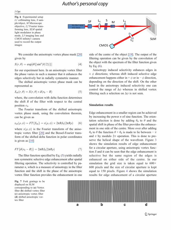
Fig. 7 Fork gratings to bedisplayed on SLMcorresponding to (a) Vortexfilter (b) shifted vortex filter(c) anisotropic vortex filter(d) shifted anisotropic vor-tex filter
Fig. 6 Experimental setupL1 collimating lens, S sam-ple/object, M Microscopeobjective, L2 Fourier trans-forming lens, SLM spatiallight modulator in phasemode, L3 imaging lens andCMOS infinity1 cameraused to record the outputimages
J Opt
Author's personal copy

by the shifted vortex mask. The 3D plots of theintensity versus azimuthal angle, in Fig. 5, showthe angular selectivity of edge enhancement usingthe shifted anisotropic vortex mask. Increased en-hancement selectivity at different orientations isclearly visible.
Experimental results
We have implemented the phase masks correspondingto the function Swith the help of reflective Spatial LightModulator (SLM), Holoeye LC-R 2,500 with resolution
1,024×768, pixel pitch 19μm. The object used is acircular aperture of size 200μm. The experimental setupis shown in Fig. 6 and the fork grating corresponding tothe different phase masks have been shown in Fig. 7.The object is illuminated by collimated beam from He-Ne laser (632.8 nm) and Fourier transformed with thehelp of Newport 10X microscopic objective and theFourier transform is imaged on the SLM with 4X mag-nification by a lens of focal length 135 mm. The SLM isoperated in phase mode keeping the polarizer at angle170° to get the phase shift up to 2π.
The computer generated holograms (CGH)corresponding to function S is formed and displayed
Fig. 9 Experimental results for selective edge enhancement with anisotropy (n030) and the shift (20 pixels) is provided towards (a)right (b) left (c) down
Fig. 8 Experimental resultsfor selective edge enhance-ment with (a) Vortex filter(b) Shifted vortex filter, (c)anisotropic (n05) andshifted (20 pixels) vortexfilter, (d) Anisotropic (n030) and shifted (20 pixels)vortex filter
J Opt
Author's personal copy

on the SLM. This CGH is a fork grating formed byinterference of anisotropic vortex beam and a tiltedplane wave. The CGH corresponding to the pro-posed function S and Ssh are formed in MATLABkeeping the resolution same as that of the SLMand the grating period has been kept equal to thesix pixels of the SLM. The incident light wave isthen diffracted by the fork grating displayed on theSLM, and only the light diffracted at the firstdiffraction order is used. The undesired diffractionorders are blocked. Imaging is done with help of alens of focal length 200 mm, kept in betweenSLM and infinity-1 CMOS camera. The experi-mental results recorded for different values of an-isotropy and for a given shift, are shown in Fig. 8for circular aperture and the experimental results agiven shift and for different values of angle ofrotation are shown in Fig. 9. The experimentalresults are in well support of simulated results.
Conclusion
We have proposed a new method for selectiveedge enhancement, capable of selecting desiredregion at any required redial direction. The pro-posed function provides the controllable anisotropyand shift in the phase of the vortex function andhence it is possible to enhance only the region ofinterest. Using a high resolution spatial light mod-ulator (SLM) for displaying the phase maskscorresponding to the proposed shifted anisotropicvortex mask, it is possible to get selective edgeenhancement for an object. We have successfullyimplemented the method for the selective edgeenhancement of a circular aperture. The methodis efficient and useful in image processing whenselective region of edges of the objects are impor-tant. More over the selective edge detection ofphase objects is also possible using the samephase mask. The application of such filters ispossible in microscopy to detect the edges of smallbiological objects selectively and in the anisotropicsignal processing.
Acknowledgement Manoj Kumar Sharma would like tothankfully acknowledge council of scientific and industrial re-search of India (CSIR) for senior research fellowship (SRF).
References
1. N.R. Heckenberg, R. McDuff, C.P. Smith, A.G. White,Generation of phase singularities by computer generatedholograms. Opt. Lett. 17, 221 (1990)
2. M.R. Reicherter, T. Haist, E.U. Wagemann, H.J. Tiziani,Optical particle trapping with computer-generated holo-grams written on a liquid-crystal display. Opt. Lett. 24,608 (1999)
3. S. Vyas, P. Senthilkumaran, Interferometric optical vortexarray generation. Appl. Opt. 46, 2893 (2009)
4. S. Vyas, P. Senthilkumaran, Vortex array generation byinterference of spherical waves. Appl. Opt. 46, 7862 (2009)
5. D.P. Ghai, S. Vyas, P. Senthilkumaran, R.S. Sirohi, Vortexlattice generation using interferometric techniques based onlateral shearing. Opt. Commun 282, 2692 (2009)
6. B.K. Singh, G. Singh, P. Senthilkumaran, D.S. Mehta, Gen-eration of optical vortex array using single elementreversed-wave front folding interferometer. Int. J. Opt.2012(689612), 7 (2012). doi:10.1155/2012/689612
7. P. Senthilkumaran, Optical phase singularities in detectionof laser beam collimation. Appl. Opt. 42, 6314 (2003)
8. P. Senthilkumaran, J. Masajada, S. Sato, Interferometry withvortices. Int. J. Opt. 2012(517591), 18 (2012). doi:10.1155/2012/517591
9. P. Senthilkumaran, F. Wyrowski, H. Schimmel, Vortex stag-nation problem in iterative Fourier transform algorithm.Opt. and lasers in Eng., 43, 43–56 (2005)
10. J.W. Goodman, Introduction to Fourier optics (Roberts andCo, Colardo, 2007)
11. S.N. Khonina, V.V. Kotlyar, M.V. Shinkaryev, V.A. Soifer, G.V.Uspleniev, The phase rotor filter. J. Mod.Optics 39, 1147 (1992)
12. J.A. Davis, D.E. Mcnamara, D.M. Cottrel, J. Campos, Im-age processing with the radial Hilbert transform: theory andexperiments. Opt. Lett. 25, 99 (2000)
13. R.B. Bracewell, The Fourier transform and its application(McGraw-Hill, New York, 1965)
14. J.A. Davis, D.E. McNamara, D.M. Cottrell, Analysis of thefractional Hilbert transform. Appl. Optics 37, 6911 (1998)
15. J.A. Davis, D.A. Smith, D.E. McNamara, D.M. Cottrell, J.Campos, Fractional derivatives—analysis and experimentalimplementation. Appl. Optics 40, 5943 (2001)
16. A.W. Lohmann, D. Mendlovic, Z. Zalevsky, FractionalHilbert transform. Opt. Lett. 21, 281 (1996)
17. G. Situ, M. Warber, G. Pedrini, W. Osten, Phasecontrastenhancement in microscopy in microscopy using spiralphase filtering. Opt. Commun. 283, 1273–1277 (2010)
18. A.W. Lohmann, E. Tepichı’n, J.G. Ramı’rez, Optical imple-mentation of the fractional Hilbert transform for two-dimensional objects. Appl. Optics 36, 6620 (1997)
19. S. Guohai, P. Giancarlo, O. Wolfgang, Spiral phase filteringand orientation-selective edge detection/enhancement. J.Opt. Soc Am. A 26, 1788 (2009)
20. M. K. Sharma, J. Joseph, P. Senthilkumaran, Selective edgeenhancement using anisotropic vortex filter. Appl. Optics50, 5279 (2011)
21. K. Guang-Hoon, L. Hae June, K. Jong-Uk, S. Hyyong,Propagation dynamics of optical vortices with anisotropicphase profiles. J. Opt. Soc Am. B 20, 351 (2003)
J Opt
Author's personal copy