Selection of Site for Thermal Power Plant - Sibsagar Polytechnic
22
THERMAL POWER PLANT (PPE NOTES by Priyanka Nath) Basic Principal of Steam Power Plant The heat produced for burning of coal & with the help of water steam is produced. This produced steam flow towards turbine i.e. kinetic energy is converted into mechanical energy. The input steam drives the prime mover or turbine, simultaneously the generator also start to rotate. At that time mechanical energy is converted into electrical energy. Selection of Site for Thermal Power Plant 1. Supply of Fuel: The Steam power station should be located near the coal mine so that transportation cost of fuel is minimum. If the land is not available near to coal mines then provide adequate facilities for transportation of fuel. 2. Available of Water: A huge amount of water is required in boiler & condenser, so that the plant should be located near the river, lake etc. 3. Transportation Facility: For steam power station provide better transportation facility for the transportation of man, machinery etc. 4. Cost & Type of Land: The Steam Power Station should be located where the cost of land is chief & also future extension is possible. 5. Near to Load Center: In order to reduce transmission & distribution losses the plant should be located near to load center. 6. Distance from Populated Area: As the thermal power plant produces flue gases, these gases will effect to live human being, so that the plant should be located away from thickly populated area. 7. Disposal Facility Provided: As the thermal power plant produces ash, while burning of coal. So, disposal of ash facility should be provided.
-
Upload
khangminh22 -
Category
Documents
-
view
1 -
download
0
Transcript of Selection of Site for Thermal Power Plant - Sibsagar Polytechnic
THERMAL POWER PLANT (PPE NOTES by Priyanka Nath)
Basic Principal of Steam Power Plant
The heat produced for burning of coal & with the help of water steam is produced. This produced
steam flow towards turbine i.e. kinetic energy is converted into mechanical energy. The input
steam drives the prime mover or turbine, simultaneously the generator also start to rotate. At that
time mechanical energy is converted into electrical energy.
Selection of Site for Thermal Power Plant
1. Supply of Fuel:
The Steam power station should be located near the coal mine so that transportation cost of fuel
is minimum. If the land is not available near to coal mines then provide adequate facilities for
transportation of fuel.
2. Available of Water:
A huge amount of water is required in boiler & condenser, so that the plant should be located
near the river, lake etc.
3. Transportation Facility:
For steam power station provide better transportation facility for the transportation of man,
machinery etc.
4. Cost & Type of Land:
The Steam Power Station should be located where the cost of land is chief & also future
extension is possible.
5. Near to Load Center:
In order to reduce transmission & distribution losses the plant should be located near to load
center.
6. Distance from Populated Area:
As the thermal power plant produces flue gases, these gases will effect to live human being, so
that the plant should be located away from thickly populated area.
7. Disposal Facility Provided:
As the thermal power plant produces ash, while burning of coal. So, disposal of ash facility
should be provided.
8. Earth-Quake:
The area under the thermal power plant should be free from earth quake.
9. Availability of labour:
Skilled and unskilled labour should be available nearly. To the extent possible, the thermal
station should be far away from an aerodrome.
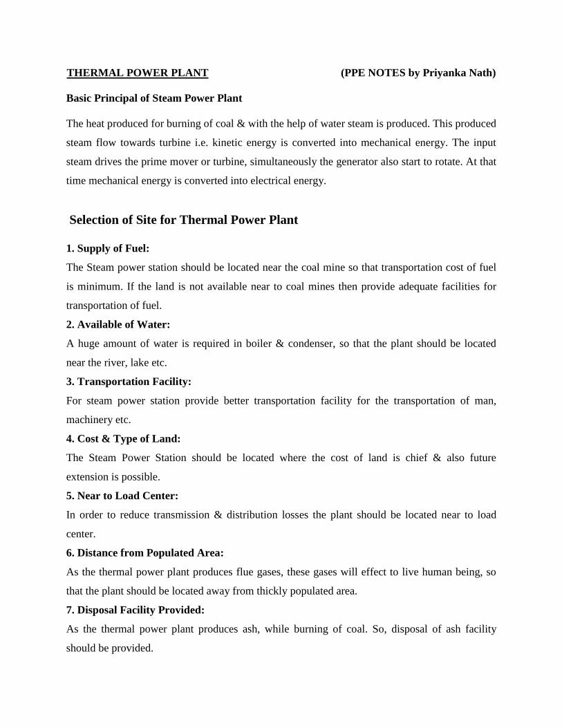
General Layout of Thermal Power Plant
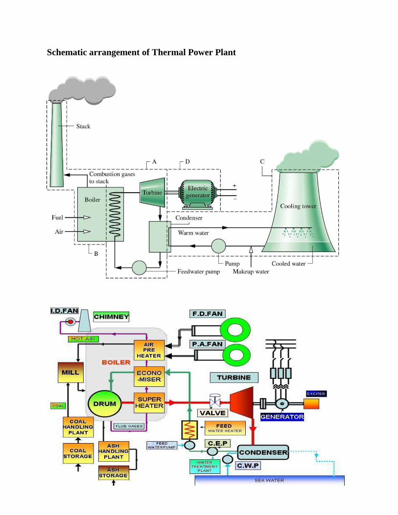
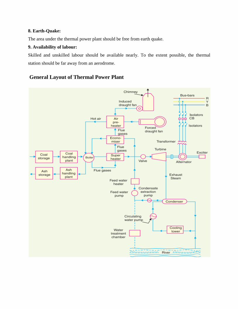
Schematic arrangement of Thermal Power Plant
The above figure shows the schematic arrangement of thermal power plant. The Major
Components of a Thermal Power Plant are:-
1. Coal and ash handling arrangement.
2. Steam generating plant.
3. Steam turbine.
4. Alternator.
5. Feed water.
6. Cooling arrangement.
Function of each Part used in Thermal Power Station:
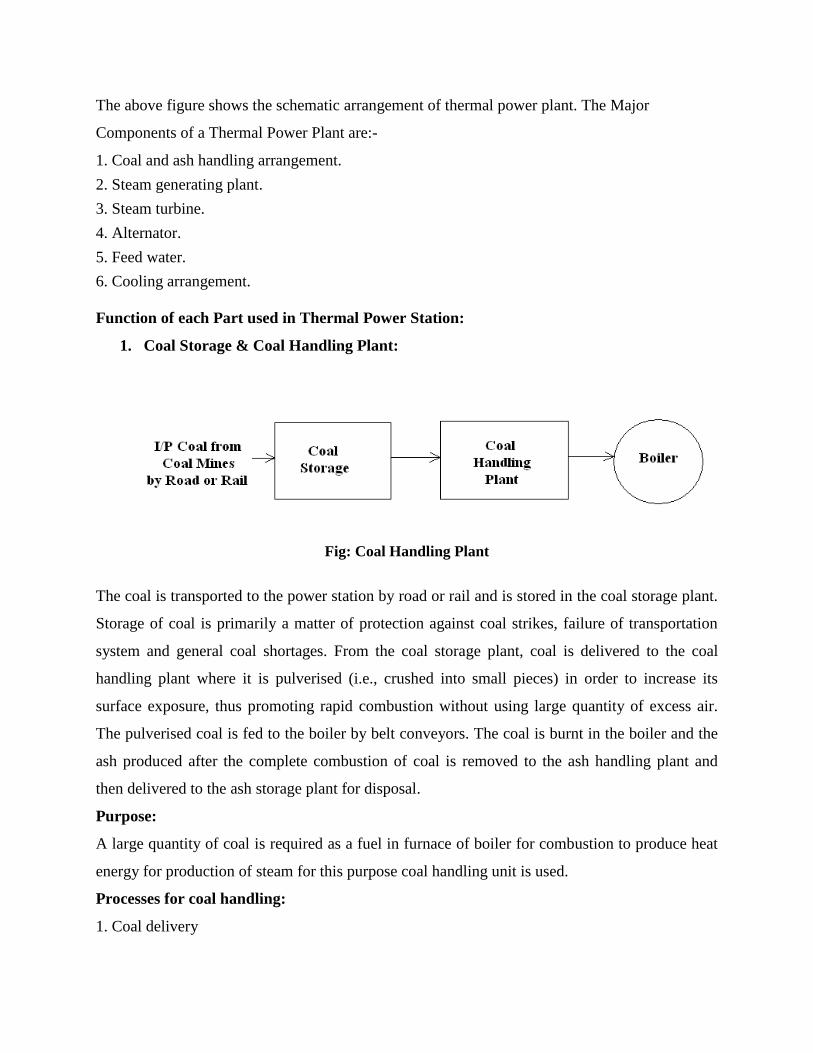
1. Coal Storage & Coal Handling Plant:
Fig: Coal Handling Plant
The coal is transported to the power station by road or rail and is stored in the coal storage plant.
Storage of coal is primarily a matter of protection against coal strikes, failure of transportation
system and general coal shortages. From the coal storage plant, coal is delivered to the coal
handling plant where it is pulverised (i.e., crushed into small pieces) in order to increase its
surface exposure, thus promoting rapid combustion without using large quantity of excess air.
The pulverised coal is fed to the boiler by belt conveyors. The coal is burnt in the boiler and the
ash produced after the complete combustion of coal is removed to the ash handling plant and
then delivered to the ash storage plant for disposal.
Purpose:
A large quantity of coal is required as a fuel in furnace of boiler for combustion to produce heat
energy for production of steam for this purpose coal handling unit is used.
Processes for coal handling:
1. Coal delivery
2. Coal unloading
3. Coal storage:- a) outdoor storage (dead storage) b) Indoor storage (live storage)
4. In the plant coal is crushed into small pieces with the help of crusher and breaker. The coal is
crushed to 2.5 cm. or less.
5. Then it is cleaned by passing forced air to remove the dust contain.
6. Then it is dewatered (remove of moisture) with the help of dryer. The moisture content must
be less than 2% after drying operation.
7. Then it is passed through magnetic separator to separate the iron particles mixed in it.
8. Then coal is passed to pulverizing mill.
9. Pulverized Coal weighing
10. Pulverized coal is than transfer into the boiler furnace.
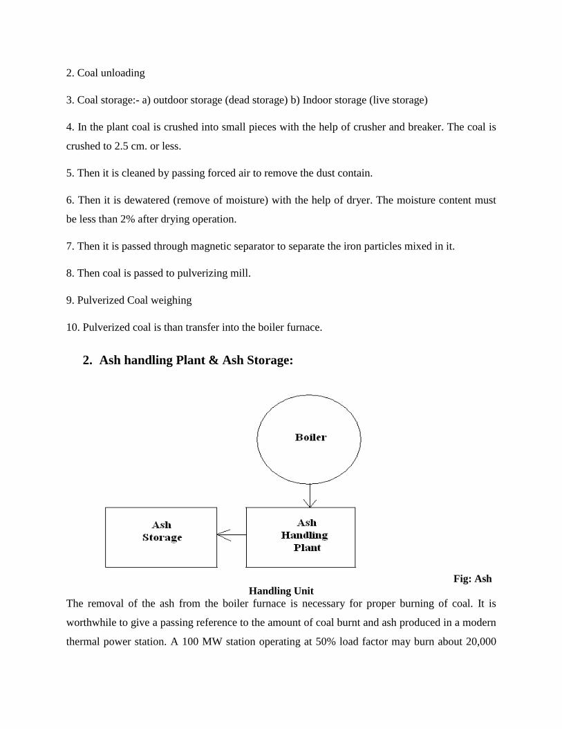
2. Ash handling Plant & Ash Storage:
Fig: Ash
Handling Unit
The removal of the ash from the boiler furnace is necessary for proper burning of coal. It is
worthwhile to give a passing reference to the amount of coal burnt and ash produced in a modern
thermal power station. A 100 MW station operating at 50% load factor may burn about 20,000
tons of coal per month and ash produced may be to the tune of 10% to 15% of coal fired i.e..,
2,000 to 3,000 tons. In fact, in a thermal station, about 50% to 60% of the total operating cost
consists of fuel purchasing and its handling.
A large quantity of ash about 10 % produces in furnace, the removal of ash from boiler furnace is
necessary for efficient combustion for this purpose ash handling unit is used.
Steps for Ash handling:
Before handling the Ash it is desirable to quench the ash.
Handling of Ash includes:
1. Removal of ash from furnace.
2. Loading of ash on conveyer’s belt.
3. And delivered to the space where it can be disposed off.
The various methods for the disposal of ash are as follows:
a. Hydraulic system.
b. Water Jetting.
c. Pneumatic system.
d. Mechanical ash handling system.
3. Boiler: (Steam Generating Plant)
A boiler is a closed vessel in which water is converted into steam by utilizing the heat of coal
combustion. The heat of combustion of coal in the boiler is utilised to convert water into steam at
high temperature and pressure. The flue gases from the boiler make their journey through super
heater economiser, air pre-heater and are finally exhausted to atmosphere through the chimney.
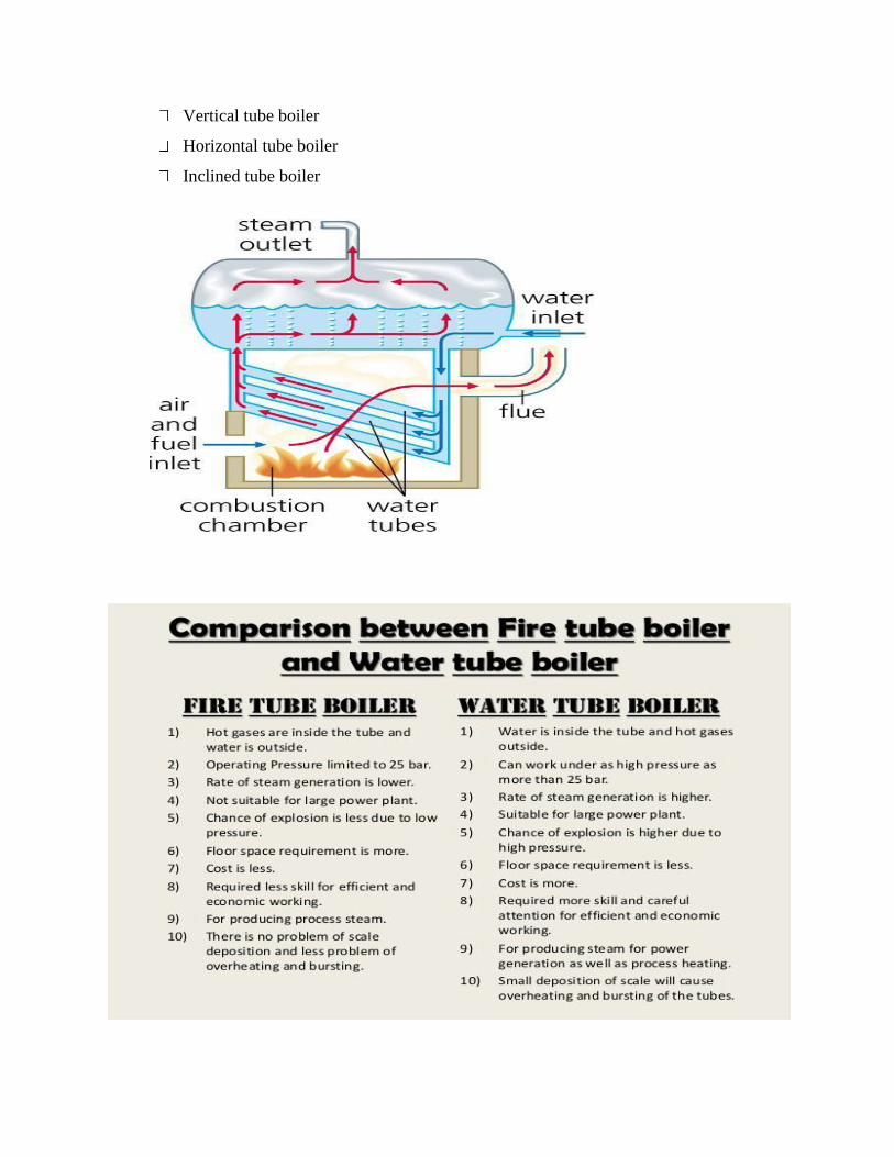
Major types of boilers are: (i) fire tube boiler and (ii) water tube boiler
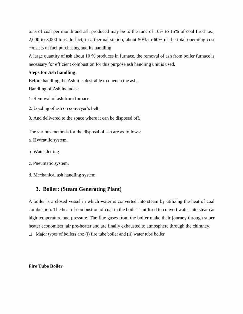
Fire Tube Boiler
The boiler is named so because the production of combustion pass through the tubes which are
surrounded by water. Depending on whether the tube is vertical or horizontal the fire tube
boiler is divided into two types:-
Vertical tube boiler
Horizontal tube boiler
A fire tube boiler is simple ,compact and rugged in construction. Its initial cost is low.
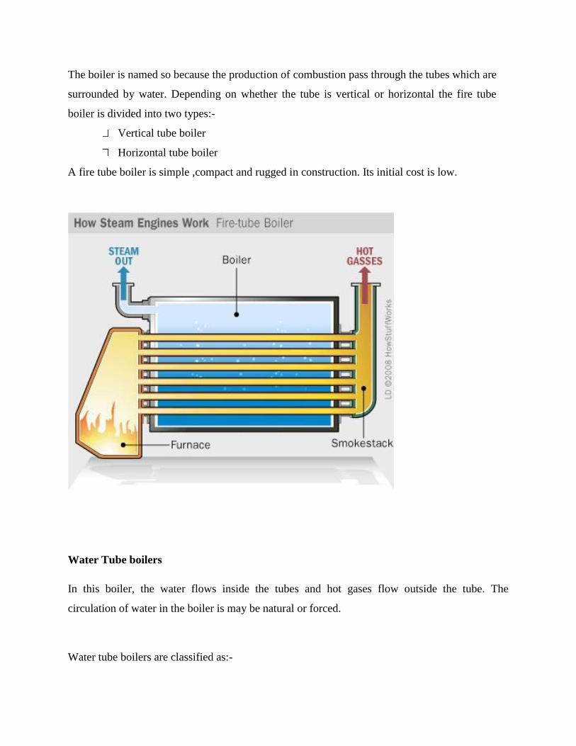
Water Tube boilers
In this boiler, the water flows inside the tubes and hot gases flow outside the tube. The
circulation of water in the boiler is may be natural or forced.
Water tube boilers are classified as:-
Vertical tube boiler
Horizontal tube boiler
Inclined tube boiler
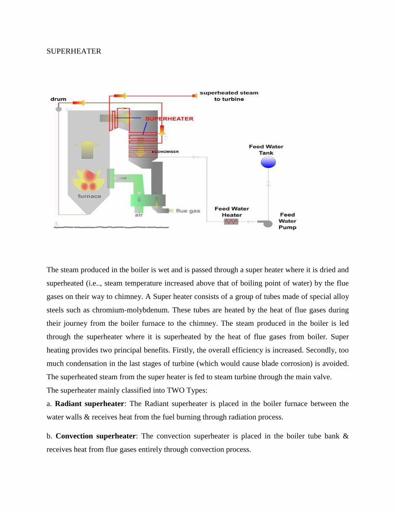
SUPERHEATER
The steam produced in the boiler is wet and is passed through a super heater where it is dried and
superheated (i.e.., steam temperature increased above that of boiling point of water) by the flue
gases on their way to chimney. A Super heater consists of a group of tubes made of special alloy
steels such as chromium-molybdenum. These tubes are heated by the heat of flue gases during
their journey from the boiler furnace to the chimney. The steam produced in the boiler is led
through the superheater where it is superheated by the heat of flue gases from boiler. Super
heating provides two principal benefits. Firstly, the overall efficiency is increased. Secondly, too
much condensation in the last stages of turbine (which would cause blade corrosion) is avoided.
The superheated steam from the super heater is fed to steam turbine through the main valve.
The superheater mainly classified into TWO Types:
a. Radiant superheater: The Radiant superheater is placed in the boiler furnace between the
water walls & receives heat from the fuel burning through radiation process.
b. Convection superheater: The convection superheater is placed in the boiler tube bank &
receives heat from flue gases entirely through convection process.
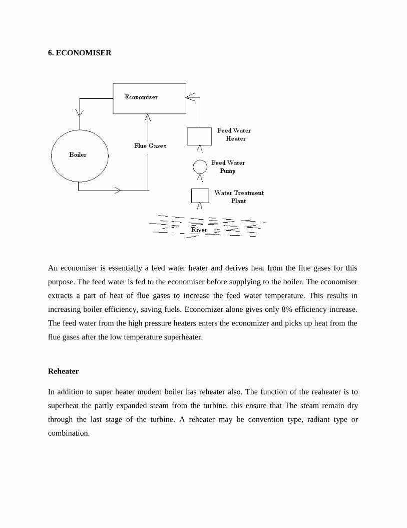
6. ECONOMISER
An economiser is essentially a feed water heater and derives heat from the flue gases for this
purpose. The feed water is fed to the economiser before supplying to the boiler. The economiser
extracts a part of heat of flue gases to increase the feed water temperature. This results in
increasing boiler efficiency, saving fuels. Economizer alone gives only 8% efficiency increase.
The feed water from the high pressure heaters enters the economizer and picks up heat from the
flue gases after the low temperature superheater.
Reheater
In addition to super heater modern boiler has reheater also. The function of the reaheater is to
superheat the partly expanded steam from the turbine, this ensure that The steam remain dry
through the last stage of the turbine. A reheater may be convention type, radiant type or
combination.
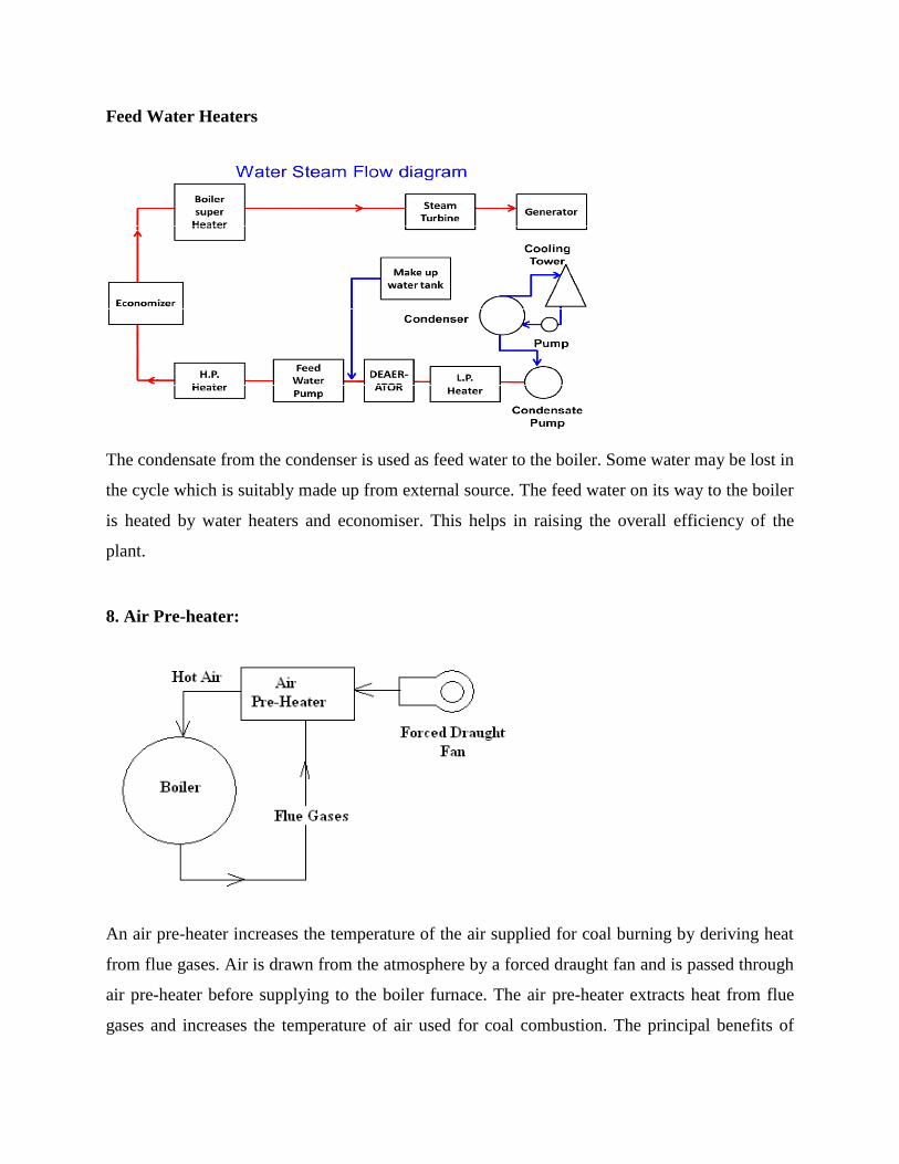
Feed Water Heaters
The condensate from the condenser is used as feed water to the boiler. Some water may be lost in
the cycle which is suitably made up from external source. The feed water on its way to the boiler
is heated by water heaters and economiser. This helps in raising the overall efficiency of the
plant.
8. Air Pre-heater:
An air pre-heater increases the temperature of the air supplied for coal burning by deriving heat
from flue gases. Air is drawn from the atmosphere by a forced draught fan and is passed through
air pre-heater before supplying to the boiler furnace. The air pre-heater extracts heat from flue
gases and increases the temperature of air used for coal combustion. The principal benefits of
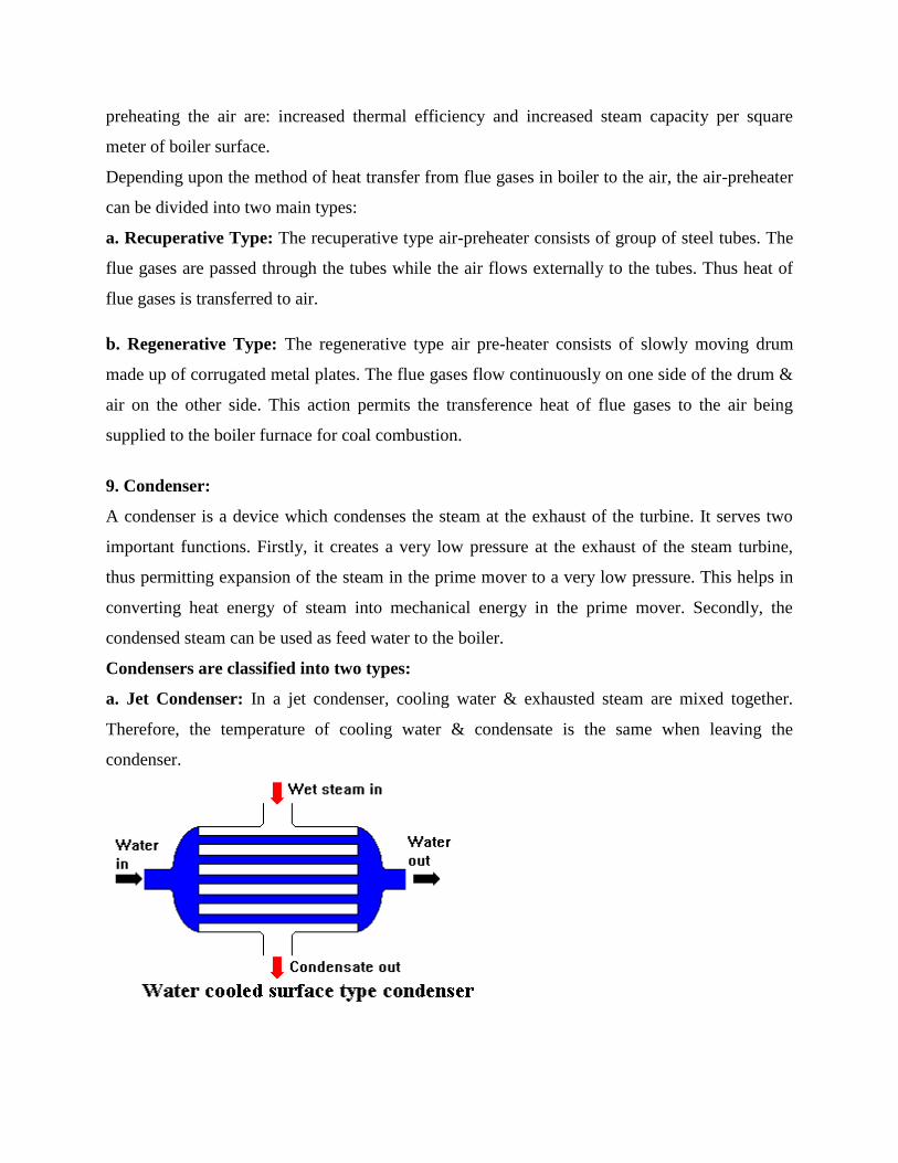
preheating the air are: increased thermal efficiency and increased steam capacity per square
meter of boiler surface.
Depending upon the method of heat transfer from flue gases in boiler to the air, the air-preheater
can be divided into two main types:
a. Recuperative Type: The recuperative type air-preheater consists of group of steel tubes. The
flue gases are passed through the tubes while the air flows externally to the tubes. Thus heat of
flue gases is transferred to air.
b. Regenerative Type: The regenerative type air pre-heater consists of slowly moving drum
made up of corrugated metal plates. The flue gases flow continuously on one side of the drum &
air on the other side. This action permits the transference heat of flue gases to the air being
supplied to the boiler furnace for coal combustion.
9. Condenser:
A condenser is a device which condenses the steam at the exhaust of the turbine. It serves two
important functions. Firstly, it creates a very low pressure at the exhaust of the steam turbine,
thus permitting expansion of the steam in the prime mover to a very low pressure. This helps in
converting heat energy of steam into mechanical energy in the prime mover. Secondly, the
condensed steam can be used as feed water to the boiler.
Condensers are classified into two types:
a. Jet Condenser: In a jet condenser, cooling water & exhausted steam are mixed together.
Therefore, the temperature of cooling water & condensate is the same when leaving the
condenser.
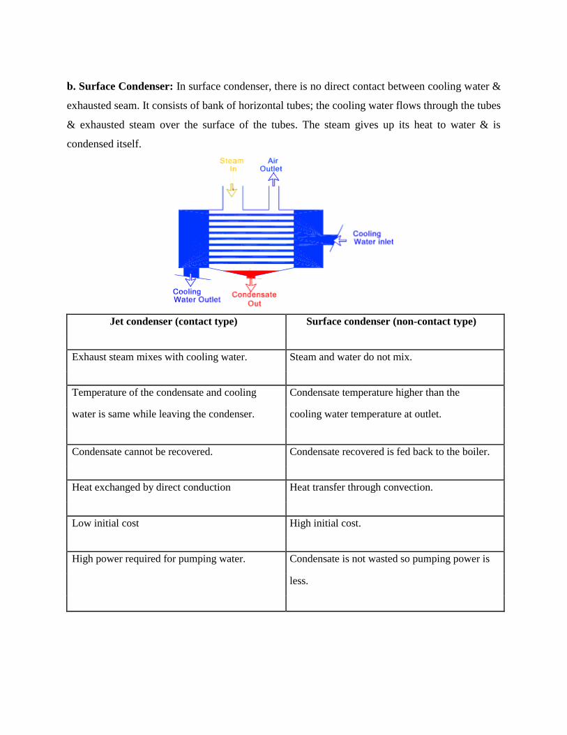
b. Surface Condenser: In surface condenser, there is no direct contact between cooling water &
exhausted seam. It consists of bank of horizontal tubes; the cooling water flows through the tubes
& exhausted steam over the surface of the tubes. The steam gives up its heat to water & is
condensed itself.
Jet condenser (contact type) Surface condenser (non-contact type)
Exhaust steam mixes with cooling water. Steam and water do not mix.
Temperature of the condensate and cooling Condensate temperature higher than the
water is same while leaving the condenser. cooling water temperature at outlet.
Condensate cannot be recovered. Condensate recovered is fed back to the boiler.
Heat exchanged by direct conduction Heat transfer through convection.
Low initial cost High initial cost.
High power required for pumping water. Condensate is not wasted so pumping power is
less.
Deaerators
A deaerator is a device that is widely used for the removal of oxygen and other dissolved gases
from thefeed water to steam-generating boilers.
In particular, dissolved oxygen in boiler feed waters will cause serious corrosion damage in steam
systems by attaching to the walls of metal piping and other metallic equipment and forming
oxides (rust).
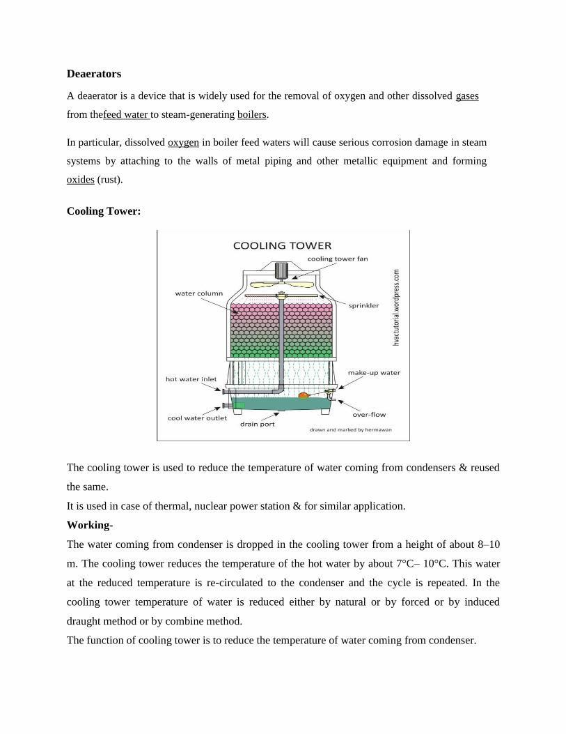
Cooling Tower:
The cooling tower is used to reduce the temperature of water coming from condensers & reused
the same.
It is used in case of thermal, nuclear power station & for similar application.
Working-
The water coming from condenser is dropped in the cooling tower from a height of about 8–10
m. The cooling tower reduces the temperature of the hot water by about 7°C– 10°C. This water
at the reduced temperature is re-circulated to the condenser and the cycle is repeated. In the
cooling tower temperature of water is reduced either by natural or by forced or by induced
draught method or by combine method.
The function of cooling tower is to reduce the temperature of water coming from condenser.
A cooling tower is a steel or concrete hyperbolic structure. There is reservoir at the bottom for
storing the cold water. Water is circulated from the basin of the cooling tower to the condenser.
It absorbs latent heat from the steam and get warm. This warm water is return to the cooling
tower to reduce the temperature. Hot water from condenser outlet is dropped from a height of
about 8–10 m. The cooling tower reduces the temperature of the hot water by about 7°C–10°C,
as it falls down into the basin at the bottom of the cooling tower. This water at the reduced
temperature is re-circulated through the condenser and the cycle is repeated. In cooling Tower
temperature of water is reduced either by natural or forced or induced draught method or
combine.
Prime Mover (Steam Turbine)
The dry and superheated steam from the super heater is fed to the steam turbine through main
valve. The heat energy of steam when passing over the blades of turbine is converted into
mechanical energy. After giving heat energy to the turbine, the steam is exhausted to the
condenser which condenses the exhausted steam by means of cold water circulation.
The steam turbines are generally classified into two types according to the action of steam on
moving blades:
a. Impulse Turbine
b. Reaction Turbine
Water Treatment Plant:
The boiler of the thermal plant required clean & soft water for longer life & better efficiency.
However, the source of boiler feed water is generally a river or lake which may contain
suspended & dissolved impurities, gases etc. therefore, it is very important that water is purified
& softened by chemical treatment & then delivered to boiler.
Draught System
The combustion in the boiler requires supply of sufficient quality of air and removal of
exhaust gases. The Circulation of air is caused by difference of pressure is known as
draught. Thus draught is the differential in pressure between the two points.
A draught tube may be:- 1) Natural Draught
2) Mechanical Draught
Natural Draught
A natural Draught is provided by the chimney or stack. Natural draught has its limitation .
Modern plants has high rate of heat transfer and Draught losses are very high. in view of this
Natural draught is used only for small boilers.
Mechanical Draught
Modern large size plants use very large size of boilers of capacity above 1000,000 kg per
hour. Such boiler needs tremendous volume of air (around 200000 m3) per minute. A
chimney provides this. Therefore mechanical draught is used.
• In a mechanical draught the system the movement air is due to the action of fan. A
mechanical Draught consists of forced Draught or induced draught or both.
• In forced draught system the fan is installed near the boiler .the fan force the air
through the furnace, economizer, air preheater and chimney. The pressure of air,
throughout the system, is above atmospheric and air is forced to flow through the
system
• In an induced draught system, the fan is installed near the base of the chimney .The
burnt gases are sucked out from the boiler, thus reducing the pressure inside the
boiler to less than atmosphere. This induces fresh air to enter the furnace.
• A mechanical Draught need additional capital investment and maintenance .But it
required for proper operation of modern power plant. In super thermal power plant,
each boiler may use two forced fans and two induced fan.
Function of Chimney:
Flue gases (smoke) are produced during combustion process. These flue gases produce air
pollution, so to reduce air pollution it should be passed in air as high as possible with the help of
Chimney.
List major electrical equipment in thermal power station
i) Alternator
The steam turbine is coupled to an alternator. The alternator converts mechanical energy of
turbine into electrical energy. The electrical output from the alternator is delivered to the bus bars
through transformer, circuit breakers and isolators.
ii) Exciter
iii) Transformer: A generating station has different types of transformers:-
• Main step-up transformer which step-up the generation voltage for transmission of
power.
• Station Transformer which is used for general services (e.g. lighting) in the power
station.
• Auxiliary transformer which supply to individual unit-auxiliaries.
iv) Switch gear:
It is used to locate the fault & isolate the faulty part from healthy section. It contains circuit
breaker, relays, switches and other control devices.
Merits and demerits of a thermal power plant:
Advantages:
Cost of fuel: Fuel used in thermal power station (TPS) is cheaper than cost of fuel used in diesel
& nuclear power station.
Capital cost: Capital cost of TPS is less than hydro & nuclear power station.
Near load center: TPS can be located near load center. The coal can be transport from coal
mines to power plant. As it is located load centre it reduces transmission cost and losses in it.
Space required: Less space required as compared to hydro power station.
Generating capacity: TPS build/construct of high generating capacity, so used as a base load
power plant.
Time required for completion of project: Time required for completion of Thermal power
project is very less as compare to hydroelectric power station.
Disadvantages:
• Air pollution: It produces air pollution due to smoke and ash produced during
combustion of fuel.
• Starting Time: TPP cannot be put into service immediately like hydroelectric power
plant. As thermal power plant required few hours (6-7 hour) to generate steam at high
pressure and high temperature.
• Handling of fuel: Handling of coal and disposal of ash is quite difficult.
• Fuel transportation cost: When power plant are located away from coal mines i.e. near
load centre at that time fuel transportation cost is more.
• Preparation for fuel: There is more expenditure for preparation of coal (raw coal to
pulverized coal).
• Space required: Large amount of space is required for storage of fuel and ash as
compare to Nuclear power plant.
• Efficiency: It is less efficient power plant overall efficiency is maximum 30 %.
• Stand by losses: Stand by losses is more as furnace is required to keep in operation even
when there is no load.
• Maintenance cost: High maintenance and operating cost because number of axillaries
plant are required such as coal and ash handling plant, pulverizing plant, condensing
plant and water purification plant etc.
• Availability of fuel: Less availability of high grade coal.
• Simplicity and cleanness: Layout of thermal power plant is complicated than
hydroelectric power plant due to coal and ash.
• Life: Life of thermal power plant is less than hydro power plant.
• Cost per unit (cost of generation) is high