Thermal Engineering – II - ng patel polytechnic
26
Thermal Engineering – II (3351901) UNIT – 1: Internal Combustion Engine 1. State the function of an IC Engine Also Explain the working of four stroke S. I. engine with neat sketch. 2. Define governing system of an I. C. engine. List different method of governing and explain any one of them with neat sketch. 3. Define : (a) Supercharging (b) Scavenging 4. State the function of following parts of an I.C. engine: (a) Spark plug (b) Carburetor (c) Crankshaft (d) Flywheel (e) Fuel pump 5. Explain the working of two stroke cycle petrol engine. 6. Differentiate between SI engine and CI engine. 7. Differentiate between four stroke cycle and two stroke cycle of IC engine. 8. State advantages of I.C. Engine. 9. Explain Valve timing diagram of four stroke diesel engine with P-V diagram. 10. A single cylinder two stroke oil engine has following observations. Mechanical efficiency = 78 % Bore diameter = 34 cm Stroke length = 42 cm Engine speed = 650 rpm Indicated m. e. p. = 4 bar Determine : (i) Indicated power in kW (ii) Brake power in kW (iii) Friction power in kW 11. A single cylinder two stroke oil engine having following data. Mean effective pressure = 3 bar Cylinder diameter of the engine = 30 cm Length of the piston stroke = 40 cm Engine speed = 300 rpm Mechanical efficiency of the engine = 65 %
-
Upload
khangminh22 -
Category
Documents
-
view
1 -
download
0
Transcript of Thermal Engineering – II - ng patel polytechnic
Thermal Engineering – II
(3351901)
UNIT – 1: Internal Combustion Engine
1. State the function of an IC Engine Also Explain the working of four stroke S. I. engine
with neat sketch.
2. Define governing system of an I. C. engine. List different method of governing and
explain any one of them with neat sketch.
3. Define : (a) Supercharging (b) Scavenging
4. State the function of following parts of an I.C. engine: (a) Spark plug (b) Carburetor (c)
Crankshaft (d) Flywheel (e) Fuel pump
5. Explain the working of two stroke cycle petrol engine.
6. Differentiate between SI engine and CI engine.
7. Differentiate between four stroke cycle and two stroke cycle of IC engine.
8. State advantages of I.C. Engine.
9. Explain Valve timing diagram of four stroke diesel engine with P-V diagram.
10. A single cylinder two stroke oil engine has following observations.
Mechanical efficiency = 78 %
Bore diameter = 34 cm
Stroke length = 42 cm
Engine speed = 650 rpm
Indicated m. e. p. = 4 bar
Determine :
(i) Indicated power in kW
(ii) Brake power in kW
(iii) Friction power in kW
11. A single cylinder two stroke oil engine having following data.
Mean effective pressure = 3 bar
Cylinder diameter of the engine = 30 cm
Length of the piston stroke = 40 cm
Engine speed = 300 rpm
Mechanical efficiency of the engine = 65 %

Calculate : (i) Indicated power in kw
(ii) Brake power in kw
UNIT - 2: Alternate Fuels
1. Explain about different kinds of alternative fuels.
2. What is CNG? Explain the properties of CNG.
3. What do you understand by LPG? How it is obtained? State its adv. and disadvantages.
4. What are the different problems to be faced while using alternative fuels?
5. Write a brief note on emission norms.
6. Discuss the effect of emitted gases, in atmosphere.
7. Why we need alternate fuel? List different kinds of alternate fuel. Explain in brief about
Biodiesel.
8. Explain system required for CNG & LPG supply vehicle.
9. State its advantages of CNG.
10. List the name of different eco friendly fuels and reason. Why hydrogen is not much
popular as an automotive fuel?
11. List advantages and disadvantages of natural gas as an automotive fuel.
UNIT - 3: Refrigeration
1. Explain the effect of Sub cooling & superheating of refrigerant before entering
expansion valve
& compressor respectively with P-H & T-S plane.
2. Differentiate Heat Engine, Refrigerator & Heat Pump with neat sketch.
3. Prove that C.O.P. of heat pump is always one or greater than unity.
4. Define T.O.R. & give its value in S.I. system.
5. Differentiate Dry & Wet compression in a vapor compression refrigeration system with
P-h
& T-s plane.
6. Define:
I. R.E.
II. Refrigeration Capacity
III. C.O.P.

7. Plot reversed Carnot cycle, using vapor fluid on P-V, T-s & P-h diagram.
8. Define refrigerant and classify it.
9. Explain domestic refrigerator with neat sketch.
UNIT -4: Air - conditioning
1. Sketch Psychometric chart & show various property lines of air on it.
2. Define: (i) Saturated air (ii) W.B.T. (iii) D.B.T. (iv) Relative Humidity (v) Specific
Humidity (vi) Dew Point temperature
3. Explain the working of Window Air Conditioner with neat sketch.
4. What is air conditioning?
5. Describe working of a water cooler used to provide cold drinking water.
6. Write short note on air conditioning for industry and human comfort.
7. Explain each in brief : (1) Sensible Cooling (2) Humidification
8. Classify air conditioner fans.
9. State criteria of fan selection for air conditioning.
10. The temperature of a room is 30º C, and the Relative Humidity is 50%. Find : (1)
Partial Pressure of water vapour (2) Specific Humidity. The barometer reading
is 760 mm of Hg.
Design of Machine Elements
(3351902)
UNIT 1: GENERAL CONSIDERATION OF DESIGN OF M/C ELEMENTS
1. Define machine design and explain types of design.
2. State the factors influencing the design of machine elements.
3. Explain the design procedure for machine elements of also the draw block
diagram for D.M.E.
4. Define the following terms:
a. Formability
b. Castability
c. Machinability
d. Weldability
5. State the different types of load and stresses. Explain each with suitable
example.
6. State and explain stress concentration.
7. State the importance of standardization.
8. What are preferred number and derive R10 series.
9. What are derived series?
10. Give I.S. designation of following:
a. Grey C.I.
b. Malleable C.I.
c. Carbon steels
d. Cupper alloy
11. Define F.O.S. and its importance in machine design.
UNIT 2: DESIGN OF M/C ELEMENTS SUBJECTED TO
DIRECT STRESSES
1. A tie rod is subjected to an axial tensile load of 40 KN. If the
allowable tensile stress for the rod material is 65 MPa,
determine the diameter of tie rod.
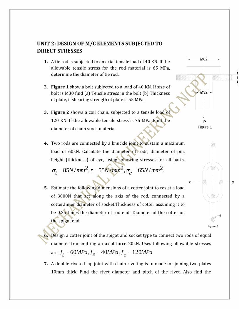
2. Figure 1 show a bolt subjected to a load of 40 KN. If size of
bolt is M30 find (a) Tensile stress in the bolt (b) Thickness
of plate, if shearing strength of plate is 55 MPa.
3. Figure 2 shows a coil chain, subjected to a tensile load of
120 KN. If the allowable tensile stress is 75 MPa. Find the
diameter of chain stock material.
4. Two rods are connected by a knuckle joint to sustain a maximum
load of 60kN. Calculate the diameter of rods, diameter of pin,
height (thickness) of eye, using following stresses for all parts.
2/65,2/55,2/85 mmNc
mmNmmNt
.
5. Estimate the following dimensions of a cotter joint to resist a load
of 3000N that act along the axis of the rod, connected by a
cotter.Inner diameter of socket.Thickness of cotter assuming it to
be 0.25 times the diameter of rod ends.Diameter of the cotter on
the spigot end.
6. Design a cotter joint of the spigot and socket type to connect two rods of equal
diameter transmitting an axial force 20kN. Uses following allowable stresses
are MPac
fMPasfMPat
f 120,40,60
7. A double riveted lap joint with chain riveting is to made for joining two plates
10mm thick. Find the rivet diameter and pitch of the rivet. Also find the
P
Ø62
Ø32
t
Figure 1
d
X X
Figure 2
efficiency of the joint. The allowable stresses are
MPac
fMPasfMPat
f 80,50,60 .
8. A double riveted double cover but joint is used to connect two plates 12 mm
thick. A pitch of the rivet is 60 mm.
MPafMPasfMPat
f Cr 100,55,70 . Find diameter of rivet and
strength of riveted joint. Draw neat sketch of the joint.
9. A screw jack is acted upon by a load of 80 KN. Assuming single start thread of 8
mm pitch, neglecting buckling of screw, find the diameter of screw and height of
nut. Assume safe compressive stress of 100 MPa for screw and safe bearing
pressure of 18 MPa for nut.
10. Determine safe tensile load for a bolt of M30, assuming a safe tensile stress of
40 MPa.
UNIT 3: DESIGN OF M/C ELEMENTS SUBJECTED TO DIRECT BENDING
Q. 1 State the fundamental equation for bending and list six machine elements which
are subjected to pure bending.
Q. 2 State the modulus of section for cross-sections below:
a) rectangular c/s.
b) circular c/s.
c) elliptical c/s.
d) hollow circular c/s.
e) hollow rectangular c/s.
Design of Levers:
Q. 3 Define lever and state its important uses. Also state the types of levers.
Q. 4 Explain the complete procedure for lever design.
Q. 5 Design a fulcrum pin of a bell crank lever to lift a load of 2250 N acting at the
end of 125 mm long arm. The effort is applied at the end of 150 mm long arm.
Allowable shear stress and bearing pressure for pin are 70 N/mm2 and 10
N/mm2 resp. Take L/D =1.25 for pin.
Q. 6 5 kN load is applied on the exhaust valve to open it in I.C. engine. The arms of a
rocker arm are 200 mm and 300 mm resp.. The angle between two arms is
140o.the allowable tensile, shear and bending stresses are 70 N/mm2, 40
N/mm2 and 10 N/mm2.Design the fulcrum pin. Assume l/d = 1.5 for the pin.
Design of Pulleys:
Q. 7 A C.I. pulley of 500 mm dia has six straight arms of elliptical c.s.. The pulley is
mounted on a shaft which transmit 16 kw at 220 rpm.. If the allowable stress is
14 MPa. Calculate the c.s. of pulley arms at the hub.
Q. 8 A C.I. flywheel of 3 m diameter, having 6 arms of elliptical c.s., is subjected to a
max. torque of 16 103 Nm. The safe stress in tension for C.I. is 12.5 MPa. And
a=2b, determine c.s. at the hub end.
Design of Leaf spring:
Q. 9 Draw a neat sketch of a leaf spring and show all its parts.
Q. 10 State the uses and functions of leaf springs.
Q. 11 A semi-elliptical leaf spring 800 mm long and 50 mm wide is held together at
the centre by a band 45 mm wide. The thickness of each leaf is 5 mm. Calculate
the no. of leaves to carry a central load of 5.5 kN. Take working stress of 450
MPa. If two of these leaves are of full length, then find the deflection of spring.
Take E = 2.1 105
Q. 12 Determine bending stress induced and deflection of a semi-elliptical leaf spring
from following data:

i) central load = 8 kN.
ii) Effective span = 900 mm.
iii) Width of levers = 50 mm.
iv) Thickness of leaves = 5 mm.
v) Total no. of leaves = 10, mm including two extra
full length leaves.
Take E = 2 105
UNIT 4: DESIGN OF M/C ELEMENTS SUBJECTED TO TWISTING
MOMENT
Q. 1. Define torsion and state fundamental equation of twisting moment.
Q. 2. State the difference between shaft, spindle and axle.
Q. 3 List various types of key with their application.
Q. 4 Explain design procedure of sunk key.
Q. 5 State the functions of coupling & list various types of couplings in brief.
Q. 6. A hollow shaft transmits 600 KW at 500 RPM. The maximum shear stress is 62.4
N/mm2. Find the out side & in side diameters of the shaft. Assume that maximum
torque is 20 % greater than the mean torque.
Q. 7. The solid shaft and hollow shaft are having equal strength in tension. The hollow
shaft diameter is 10 % more than the solid shaft. Find the ratio of their weight, if
both the shafts are of same material.
Q. 8. A shaft is to transmit 15 KW. at 1400 RPM. The shaft is also subjected to bending
moment of 120 N-m, due to a pulley mounted on it. Determine the diameter of
shaft, if permissible shear stress and bending stress are 50 N/mm2 & 80 N/mm2.
Q. 9. An engine indicator has a plunger diameter of 20 mm. The indicator spring
attached to this plunger is to be compressed by 12 mm, when the steam

pressure acting on the plunger is 5 N/mm2. If the spring index is 3, and
allowable shear stress in the wire is 550 N/mm2, find : (1) Spring wire
diameter (2) Mean coil diameter (3) No. of active coils. Take G = 83 Kn/mm2
Q. 10. A valve spring designed to have a maximum load of 500 N with a corresponding
deflection of 4 cm is to have an internal dia. Of coil 4 cm. The spring wire has
working stress limit of 30000 N/cm2. Assuming spring index to be 6 and
modulus of rigidity to be 0.82 X 10⁶ N/cm2. Determine the size of the spring
wire and no. of turns to be used.
Q. 11. A helical compression spring is subjected to load range of 2500 N to 3250 N.
Deflection due to this load is 5 mm. The wire dia. Is 10 mm. and spring index is
5. Find (1) Active no. of coils (2) Max. shear stress induced in wire. Take G =
0.84 X 10⁵ N/mm2
Q. 12. In a spring balance, find (1) Wire dia. (2) Active no. of coils from the following
data:
Load range = 0 to 500 N
Maximum deflection of a pointer = 100 mm.
Safe shear stress for spring mat. = 600 N/mm2
Modulus of rigidity = 0.8 X 10⁵ N/mm2
Spring index = 7
UNIT 5: DESIGN OF MACHINE ELEMENTS SUBJECTED TO DIRECT AND
BENDING STRESSES
Q. 1 Define eccentric loading and state at least five components comes under the effect of it.
Q. 2 Explain different types of loads on bolts in various assembly.
Q. 3 explain the procedure to find the size of bolt when load is applied on bracket
perpendicular to bolt axis.

Q. 4 A frame of a ‘C’ clamp has a rectangular cross section of 60mm 20mm. A max.
clamping load of 20 kN is acting at a distance of 60mm from the inner edge of the
frame. Find out max. & min. stresses induced in the frame section.
Q. 5 A cover bolt of a steam engine cylinder is secured by means of 12 bolts. The inner dia of
the cylinder is 275 mm and max. Steam pressure is 1.15 MPa. If the allowable tensile
stress for the bolt material is 50 MPa, find out the size of the bolt.
Q.6 A pillar crane is fastened to a foundation by 4 bolts, two bolts on X-X axis and two Y-Y
axis, in the plane of flange. A load of 30 kN is to be raised at an eccentricity of 3500 mm,
the flange dia is 2500 mm and bolt circle dia is 2000 mm. If allowable tensile stress is
60 Mpa for bolt material, find out the size of the foundation bolt.
UNIT 6: PRESSURE VESSELS
1. A C.I. pipe 200 mm internal diameter and 3 mm thick is subjected to internal water
pressure of 1.2 N/mm2. find
a. Hoop stress
b. Longitudinal stress
c. Maximum shear stress
2. A hydraulic press ram having 200 mm internal diameter is subjected to 10 MPa
pressure. If the material for the ram has 28 MPa stress, find the external diameter.
3. A steam boiler of 1.2 m diameter has steam gauge pressure of 0.7 N/mm2. if
ultimate tensile stress is 400 N/mm2 and the joint efficiency is 70%. Find thickness
of the shell. Take FOS 5.
4. The maximum force exerted by a small hydraulic press 60x104 N. The working
pressure of fluid is 20 MPa. A table is operated by a plunger which reciprocates in
CI cylinder by fluid pressure. Determine plunger diameter and thickness of
cylinder. If permissible stress of CI is 100 MPa.
5. For a steel cylinder outside diameter 20 cm, 1.5 cm thickness and internal pressure
600 N/cm2. Find:
1. Longitudinal stress
2. Hoop stress
6. Derive an equation for hoop stress and longitudinal stress of thin cylinder

UNIT 7: SELECTION PROCEDURE FOR BEARINGS
1. Define “bearing” and write design procedure for journal bearing.
2. Classify and sketch various types of bearings (At least 4)
3. For sliding contact bearing, following data is given for centrifugal pump.
Load of journal =20 KN Speed =900 RPM Absolute at 55o C =0.017 N/mm2 Ambient Temp. =16o C Bearing pressure =15 N/mm2 Clearance ratio =0.001 Temp. rise of oil =10o C d/c =1000 Length of journal =1.5 times diameter of journal Assuming end leakage factor K = 0.002 Heat dissipation co-efficient = 73.75 KJ/min Specific Heat of Oil = 1.89 KJ/Kg Find out, Dimensions of bearing Heat generated Heat dissipated Mass of oil to be circulated as an artificial cooling
4. Following data refers to a journal bearing of centrifugal pump
Bearing Diameter = 80.08 mm Journal Diameter = 80 mm Length of Bearing = 100 mm Journal speed = 900 RPM Bearing pressure = 2 N/mm2 Absolute viscosity of Oil at 700 = 0.013 Kg. / m-s Ambient Temp. = 36o Heat dissipation Constant = 24 x 10-4 m2 oc min/joule

Determine, Bearing load Bearing characteristics No. Co-efficient of friction Heat generated Heat dissipated
5. A ball bearing of 4 KN and thrust load of 5 KN. It is operating at a speed of 600 RPM for an average life of 5 years at 10 hrs./day for 300 working days. Determine the basic dynamic load rating. Take X = 0.56, Y = 1.6, s = 1 and K = 3.
6. What radial load a roller bearing sustain, if its capacity is 4 KN when it is operated at 90 % speed of 800 RPM. Bearing life in hrs. is 7500.
7. A ball bearing carries 10 KN radial load with a dynamic load capacity of 22.8
KN. Determine,
(1) Expected life in millions of revolutions that 90 % of bearing will reach.
(2) Corresponding life in hours when shaft rotates at 1450 RPM.
(3) Life that 50 % of bearings will exceed before fatigue failure.
8. A ball bearing is subjected to a radial load of 3.5 KN, thrust load of 1.5 KN. The
bearing is to be used for 10000 Hrs. Speed of the shaft is 900 RPM. Determine
basic dynamic load. X = 0.56, Y = 1.5
9. A radial bearing has basic load rating of 50 KN. If bearing life is 600 Hrs., what
equivalent radial load the bearing can carry at 500 RPM ? Take K = 3

MANUFACTURING ENGINEERING-
III
(3351903)
UNIT 1: INTRODUCTION TO MANUFACTURING ENGINEERING-III
1. State Need, Scope & importance of Manufacturing Engineering-III in the industries.
2. Define machine tool, cutting speed, feed, depth of cut, metal removal rate.
3. State need of attitude, knowledge & skill required for shop floor supervisor in Machine
tools.
UNIT 2: GRINDING AND SUPERFINISHING PROCESSES
1. Explain cutting action of grinding wheel.
2. Explain nomenclature of grinding wheel mark with code WA46K5V17.
3. Name and sketch the different types of grinding wheels according to their shapes.
4. Explain loading, glazing, trueing and dressing.
5. Explain selection criteria for grinding wheel.
6. Write short notes on centerless grinding.
7. Explain self sharpening of grinding wheel.
8. Explain “Why would you use a soft wheel for grinding a hard material and a hard
wheel for grinding a soft material”.
9. Write short notes on
a) Honing processes
b) Lapping processes
c) Buffing processes

UNIT 3: GEAR MANUFACTURING AND FINISHING PROCESSES
1. Define following terms for gear:
Pressure angle, module, addendum, circular pitch, cone distance
2. Differentiate between gear generating and gear forming methods.
3. Explain gear hobbing process & list its merits & demerits.
4. Classify the various methods of gear production.
5. State different methods of gear finishing and explain gear shaving.
6. Explain Gear Milling Process or gear shaping process.
7. State advantages and limitations of gear shaping process.
UNIT 4: THREAD PRODUCTION METHODS
1. List various thread production methods. State the factors to be considered for
the selection of thread production process.
2. Explain with a neat sketch the thread production process on a lathe machine.
3. Explain thread milling with neat sketch.
4. Explain Thread Chasing operation with neat sketch.
5. Explain Thread rolling with neat sketch.
6. Draw ‘V’ Thread and explain various elements.
7. Write the advantages and disadvantages of Thread Milling and Thread Rolling
operation.
8. Enlist ten different types of Threads.
UNIT 5: BROACHING, JIG BORING AND SPECIAL PURPOSE MACHINE
TOOLS
1. Draw neat sketch of a broach & show its various elements.
2. Classify broaching machine.
3. Explain advantages & disadvantages of broaching process.
4. With the help of neat sketches explain pull broaching and push broaching operations.
5. List and sketch five parts produced by broaching processes.
6. Explain measurement system use in jig bring machine.
7. Explain procedure for locating a hole in jig boring machine.
8. Draw neat sketch of single column jig boring machine& list the function of each.

9. Explain the working principal of jig boring machine.
10. Compare special purpose machines and automates.
11. Classify transfer machines and with a neat sketch explain rotary type transfer
machines.
12. Differentiate between standard machine tools and special purpose machine
tools.
13. Why transfer line system is needed?
14. Write advantages and disadvantages of SPM.
15. List the factors affecting selection of SPM. Elaborate any one.
UNIT 6: NON-CONVENTIONAL AND ADVANCE METHODS OF
MACHINING
1. Write short note on:
a) Electric discharge machining(EDM)
b) Lesser beam machining(LBM)
c) Ultrasonic machining(USM)
d) Abrasive jet machining(AJM)
e) Electro chemical machining(ECM)
2. Compare conventional & non conventional machining methods.
3. Classify non conventional methods of machining.
4. State need of micro electro mechanical systems.
5. Explain working principle and applications of (any one)
a) Chemical vapour deposition
b) Lithography
c) Photolithography
d) Dry and wet etching
INDUSTRIAL ENGINEERING
(3351904)
Unit 1: Introduction to Industrial Engineering.
1. Define industrial engineering. State the objective of it.
2. Define production & productivity. Explain factors affecting productivity.
3. Explain the methods of improving productivity.
4. State the basic procedure of work study.
5. List the objectives of work study.
Unit 2: Work study
1. What is method study? Why method study precede “work measurement?
2. Enlist various charts and diagrams used in method study. Draw the neat sketch of the
component.
3. Explain flow process chart with an example. Draw the sketch of the component.
4. What is work measurement? Explain the importance of rating in work measurement.
5. What is Therbligs? Illustrate any FIVE Therbligs with example.
6. Write a short note on Man Machine chart.
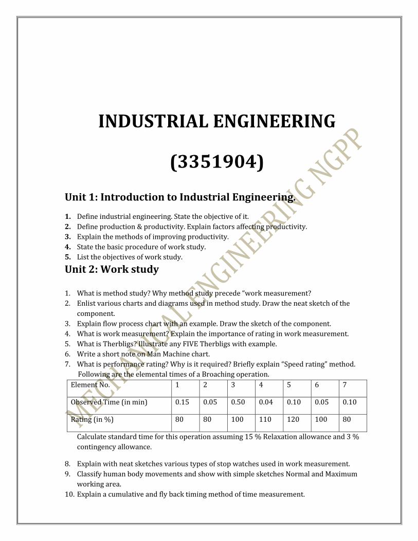
7. What is performance rating? Why is it required? Briefly explain “Speed rating” method.
Following are the elemental times of a Broaching operation.
Element No. 1 2 3 4 5 6 7
Observed Time (in min) 0.15 0.05 0.50 0.04 0.10 0.05 0.10
Rating (in %) 80 80 100 110 120 100 80
Calculate standard time for this operation assuming 15 % Relaxation allowance and 3 %
contingency allowance.
8. Explain with neat sketches various types of stop watches used in work measurement.
9. Classify human body movements and show with simple sketches Normal and Maximum
working area.
10. Explain a cumulative and fly back timing method of time measurement.

Unit 3: QUALITY ASSURANCE
1. Define Quality. State and explain factors affecting quality. 2. Define Quality control. State objectives of quality control. 3. Define SQC. State its advantages and dis-advantages. 4. State objectives of SQC. 5. Explain Quality cycle. 6. Define following terms. (i) Quality of design (ii) Quality of performance (iii) Quality of conformity (iv) Total Quality (v) Quality assurance (vi) Quality characteristics 7. Explain ‘Central tendency’ and ‘Dispersion’. 8. Define following terms.
(i) Mean (ii) Mode (iii) Median (iv)Standard Deviation (v) Range 9. Explain Variation and its causes. 10.The shafts were manufactured with specifications for diameter as 35.00 mm (Specification
Limit is 35.00+0.75 and 35.00-0.25 mm). if mean and standard deviation of shafts are
35.25mm and 0.25mm respectively. What percentage of shafts fall within and out of
specifications limits.(Area from middle of normal curve up to z = 2 to be 0.4772)
11. A large number of data collected on line voltages to various residences are normally
distributed with mean of 118.5 V and standard deviation of 1.2 V. determine what
percentage of data lies between 116 V and 120 V.(area from middle of normal curve
for Z= 1.25 and Z= 2.08 are 0.3941 and 0.4812 respectively.
12. Define reliability and state the factors affecting the reliability.
13. State factors for improving reliability.
14. Differentiate quality control and reliability.
Unit 4: Statistical Quality Control (SQC).
1. Explain X-R chart in detail.
2. State the difference between variable and attribute control chart.
3. In a certain manufacturing process the values obtained after analyzing data are as
= 9.485 mm, = 0.011. The subgroup size is 5 for which value of constant are D4

= 2.11, D3 = 0, and d2 = 2.326. Find limits of X and R chart. Also find natural tolerance
limits.
4 Explain: Trend, Shift, Extreme variation and cyclic variation.
5. Find control limits of X –R chart for following data. No of Sample =20, ∑X = 681.00mm,
∑ R=12.40mm,D3=0,D4=2.282,d2=2.059
6. There are 10 samples of shaft taken for inspection. Draw p-chart and State whether
the process is under control or not from the data given below.
No. of
product 200 200 200 200 200 200 200 200 200 200
Defective
products 12 4 8 3 7 6 0 8 5 9
7. In a production of bearings 10 samples each of sample size of 100 were taken and
inspected. Draw p-chart and State whether the process is under control or not from the data
given below.
Sample
no. 1 2 3 4 5 6 7 8 9 10
Defective
bearings 12 4 8 3 7 6 0 8 5 9
8. Name the factors to be considered in interpreting the R chart.
9. Explain p-chart. State the usefulness of P chart
10. Differentiate between P charts and C charts.
11. Explain process capability and specific limits.
12. What is acceptance sampling? How specification for a sampling plan can be obtained? 13. Define different terminology used in acceptance sampling.
14. Explain double sampling plan for accepting a purchased lot. 15. Differentiate single sampling plan & double sampling plan. 16. Draw a block diagram for double sampling plan by using following data:
Lot size Sample Sample size a r
2400 First 150 5 8
Second 150 9 10

17. Draw a block diagram for double sampling plan by using following data:
18. Explain ideal and actual O.C. curve. 19. Explain different parameters of an O.C. curve. 20. Draw and explain single sampling plan for following data:
Lot size-1000
Sample size-50
Acceptance no.-3
21. Explain average outgoing quality level (A.O.Q.L)
Unit 5: Plant layout and material handling equipments.
1. Explain various types of plant layouts with their merits, demerits. 2. Explain the Role of material handling systems in industries. 3. Classify material handling equipments. 4. State criteria for selection of material handling equipments.
UNIT 6: RECENT TRENDS IN I.E
1. Write short notes on: i) TQM ii) TQC.
2. Define kaizen and list its objectives.
3. Explain importance of six sigma concept.
4. Explain importance of ISO- 9000.
5. Define RE- Engineering. State the advantages of it.
6. Explain following: i) Zero Defects
ii) Just in Time (JIT)
7. Define ERGONOMICS and list its objectives. 8. Explain normal and maximum working area. 9. State environmental requirement of work place. 10. Explain in brief psycho-physiological data with respect to ergonomics.
Lot size Sample Sample size a r
750 First 50 3 7
Second 50 8 9

ESTIMATING, COSTING & CONTRACTING
(3351905) UNIT 1: INTRODUCTION 1. Explain need, scope and importance of estimating in an industry. 2. Define costing. State the objectives of costing in an industry. 3. Explain estimating procedure in detail. 4. Differentiate between estimating and costing. 5. State advantages costing. 6. Classify overhead and explain it with example. 7. State the various methods of overhead allocation with their applications. 8. What is depreciation? List method of calculating depreciation. Explain straight iine
method and sinking fund method. 9. Define following:
a) Discount b) Overheads c) Catalogue price d) Selling price e) Direct- material f) Direct labour g) Fixed overheads h) Market value i) Book- value j) Salvage value k) Scrap value. l) Variable cost
10. List causes of physical and functional depreciation. 11. Explain method to calculate PHR for any process 12. Draw the ladder of elements of cost. 13. What is obsolescence? 14. List method of overhead allocation. Describe machine hour rate method of
overhead allocation. 15. The catalogue price of an electric motor is Rs. 15,000/-. The discount given to
distributor is 10%. The selling overhead is 20% of factory cost. The direct material cost, direct labour cost and factory overheads are in the ratio of 1:4:2. If the direct material cost is Rs.1500/-, what will be the profit on each motor?
16. The expenses details of a company are as below. Find out total monthly expenses and overhead by man hour rate method.
(a) Material expense: Rs. 3,00,000
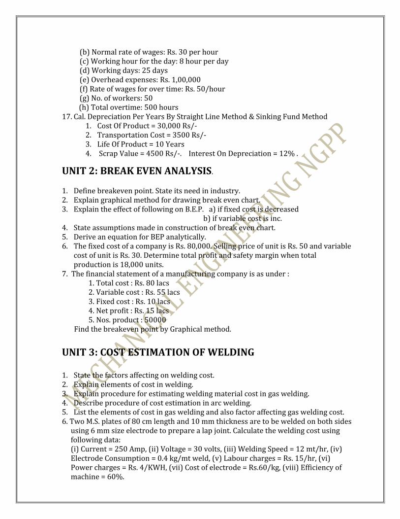
(b) Normal rate of wages: Rs. 30 per hour (c) Working hour for the day: 8 hour per day (d) Working days: 25 days (e) Overhead expenses: Rs. 1,00,000 (f) Rate of wages for over time: Rs. 50/hour (g) No. of workers: 50
(h) Total overtime: 500 hours 17. Cal. Depreciation Per Years By Straight Line Method & Sinking Fund Method
1. Cost Of Product = 30,000 Rs/- 2. Transportation Cost = 3500 Rs/- 3. Life Of Product = 10 Years 4. Scrap Value = 4500 Rs/-. Interest On Depreciation = 12% .
UNIT 2: BREAK EVEN ANALYSIS.
1. Define breakeven point. State its need in industry. 2. Explain graphical method for drawing break even chart. 3. Explain the effect of following on B.E.P. a) if fixed cost is decreased
b) if variable cost is inc. 4. State assumptions made in construction of break even chart. 5. Derive an equation for BEP analytically. 6. The fixed cost of a company is Rs. 80,000. Selling price of unit is Rs. 50 and variable
cost of unit is Rs. 30. Determine total profit and safety margin when total production is 18,000 units.
7. The financial statement of a manufacturing company is as under : 1. Total cost : Rs. 80 lacs 2. Variable cost : Rs. 55 lacs 3. Fixed cost : Rs. 10 lacs 4. Net profit : Rs. 15 lacs 5. Nos. product : 50000
Find the breakeven point by Graphical method.
UNIT 3: COST ESTIMATION OF WELDING 1. State the factors affecting on welding cost. 2. Explain elements of cost in welding. 3. Explain procedure for estimating welding material cost in gas welding. 4. Describe procedure of cost estimation in arc welding. 5. List the elements of cost in gas welding and also factor affecting gas welding cost. 6. Two M.S. plates of 80 cm length and 10 mm thickness are to be welded on both sides
using 6 mm size electrode to prepare a lap joint. Calculate the welding cost using following data: (i) Current = 250 Amp, (ii) Voltage = 30 volts, (iii) Welding Speed = 12 mt/hr, (iv) Electrode Consumption = 0.4 kg/mt weld, (v) Labour charges = Rs. 15/hr, (vi) Power charges = Rs. 4/KWH, (vii) Cost of electrode = Rs.60/kg, (viii) Efficiency of machine = 60%.

7. 100 x 100 x 100 cms open tank is to be gas welded only inner sides from 5 mm thick M.S. plate. Find the welding time if welding speed is 5 cm/min. Take fatigue allowance 5 % of welder is paid Rs. 160 per day of eight working hours. Find the labour charges to weld the tank.
8. A lap joint is to be prepared in 10mm MS plate using flat welding position and 6mm electrode. Current used is 260A, voltage 30v,welding speed 15m/hr and 0.3 kg metal is deposited per meter length of joint. Labour charge Rs15/hr, power cost Rs3.5/kwh, electrode cost Rs 30/kw, efficiency of m/c is 50% and operating factors is 60%. Calculate the cost of labour, power, electrode per meter of weld.
UNIT 4: COST ESTIMATION OF FORGING AND CASTING 1. Define pattern. List and explain types of pattern allowance. 2. Explain procedure of estimating cost of pattern making. 3. Explain various types of losses occur during the forging process. 4. Explain procedure of calculating material cost of a product for foundry shop. 5. Define: Gross weight, net weight & Shape weight. 6. A square bar of size 10cm x 4.5cm x 4.5 cm is to be drop forged from dia 6cms MS
bar. if the cost of the round bar is Rs. 3/m. Find the material cost of manufacturing 200 pieces.
7. Estimate the cost of CI pulley of 1250 cm3 volume, using following data. a. Metal rate 22Rs/kg b. No of mould prepared in day 20/moulder c. Melting charge 20% of metal cost d. Machining allow. on each side 2mm e. Wages of moulder 120 Rs/day f. Material density 7.2gm/cc g. Overhead cost 15% of metal cost
UNIT 5: COST ESTIMATION OF MACHINED PART 1. How will you estimate machine time in case of shaping and planning operation 2. Define the terms of machining: Approach and Over travel. 3. Explain different terminology associated with machine shop. 4. Estimate the time required to drill 4 holes in C.I Flange from the following data:
Hole length:- 20 mm Hole dia:- 12 mm
Cutting speed:- 15 mm/min. Feed:- 0.2 mm/rev. 5. M.S. bar having diameter 5 cm and length 10 cm is to be turned down to 4.0 cm in
one cut. Estimate the machining time if cutting speed is 25 m/min and feed 0.1 mm/revolution.
6. Calculate the total milling time required to cut 60 teeth on a gear blank having length of cut and feed are 60 mm and 35 mm/min. respectively. Take over all set-up time is 10 min

7. Estimate the total time taken to turn a 10 cm long 2.5 cm diameter. M.S. rod to a diameter of 2.3 cm in a single cut. Assume cutting speed to be 25 m/min. feed 0.1 mm/rev., and the mounting time I self centering three jaw chuck to be 40 sec. neglect the time taken for setting up tool etc.
8. A CI rectangular block 20cm x 3cm is required to be shaped to reduce from 2 cm to 1.5 cm in one cut. Estimate time required to shape if cutting speed is 20 m/ min and feed is 0.2mm/stroke.
UNIT 6: ESTIMATION OF PROCESS COST 1. Explain procedure of cost estimation for following process:
Producing power using diesel generating set (cost per hour and cost per unit)
Power produced at thermal power plants. (Cost per unit). Pouch packaging. (Cost per pouch). Heat exchanger, cooling or heating. (Cost per hour). Ice plant. (Cost per unit weight).
UNIT 7: BUDGETING AND CONTRACTING 1. Define budget and budgetary control. State the benefits of budget. 2. State objectives of budget. 3. List methods of increasing profit. Explain any on in brief. 4. List types of budgets. Explain any one in detail. 5. Explain need for earning profit by an industry. 6. Define: a) Contract b) Specification. 7. State characteristics of contract. 8. List types of contracts & state its advantages. 9. State the conditions of contract and explain one of them. 10. Write short note: a) Tender form b) Deed. 11. Short note on security bond. 12. Define: work in progress, Net present value, Gross domestic product

Self Employment and
Entrepreneurship Development
(3351906) Unit 1: Introduction to self employment and Entrepreneurship
Development
1. Define Entrepreneur and explain qualities of an entrepreneur.
2. Discuss the concept and need of Entrepreneurship Development.
3. Explain factors influencing entrepreneurship development.
4. State need to generate self-employment.
5. State and explain types of enterprises.
6. Explain the concept of Productivity and Quality.
Unit 2: Entrepreneurial support Agencies
1. Explain importance of SSI in Indian Economy.
2. Discuss the need and importance of SSI giving the definition of SSI.
3. Define SSI and explain the role of SSI.
4. Explain Ancillary Industries with need and Importance.

5. List some important national and state level promotional agencies for SSI with their role.
6. Explain the role of GIDC, GSFC and Commercial bank in the development of SSI.
7. Explain Sources of finance for SSI.
UNIT 3:Project setup planning
1.Explain brief the stages of the product development.
2.Define product, product item, product line and product mix.
3.Explain concept product selection.
4.Explain technology life cycle.
5.State the difference between production and productivity.
6.Explain the concept of process and explain its importance.
7. Explain the factors affecting the location of an industries.
8. Discuss the factors affecting the location of small scale industries.
9. Differantiate product layout and process layout.
10. Discuss the objectives of plant layout.
11. Explain any two type of material handling equipments.
12. Explain the need for flexibility in capacity planning.
13. Explain the importance of capacity planning.
14. Explain the methods of estimation of capacity planning.
Unit 4: Project proposal planning
1. Explain the concept of 7M resources or inputs.
2. Giving the meaning of Balance sheet and explain its importance.
3. Explain the funds flow statement.
4. Explain importance and methods of cost control.
5. Define cost and discuss the elements of cost.
6. Explain the elements of cost.
7. Explain 4ps channel of marketing.
8. Explain the steps in project planning.
9. Prepare project report for any small product.
10. Explain project planning and project report
UNIT5 : Entreprise and risk management
1.Explain ’SWOT‘ analysis.
2.What is leadership ? Discuss the styles of leadership.
3.Explain decision tree.
4.What is risk management ? Explain the concept of certainty and uncertainty in the context of the decision making process.
5.Explain various types of risk.
6.Explain various methods of measurement of risk.
7.Write short note on :-
1.Methods to deal with industrial uncertainty.
2.Concept of risk and uncertainty.
UNIT 6: CASE STUDIES
1. Mr.Rambhai started a small scale industry, manufacturing plastic toys. He
started his industry in 1995 by employing only 10 persons and manufacturing 500
small toys in a month. In the year 2002, 150 persons are working in his industry,
manufacturing 5000 automatic toys of various types. The sales of toys have increased
10 times more, as the toys are of the best quality. Explain the reasons for his success.
2. Mr.Sohan Shah, having completed the course of CED, decided to set up a small
scale unit for producing plastic Bottles. He has capital so he obtained a loan of Rs.
100000 from Bank. For one year he faced a problem of marketing and competition. But
he over come these problem. At present his annual turnover is of Rs. 150000 and his
bottles are in high demand. Explain the reason for his success.
a) Explain advantages and disadvantages of partnership.
b) Explain causes of sickness of industrial unit.