Selected Elements of the Vector and Tensor Calculus
33
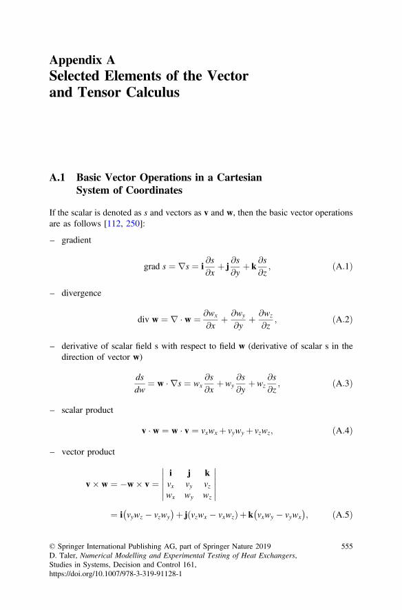
Appendix A Selected Elements of the Vector and Tensor Calculus A.1 Basic Vector Operations in a Cartesian System of Coordinates If the scalar is denoted as s and vectors as v and w, then the basic vector operations are as follows [112, 250]: – gradient grad s ¼rs ¼ i @s @ x þ j @ s @y þ k @ s @ z ; ðA:1Þ – divergence div w ¼r w ¼ @ w x @x þ @ w y @ y þ @ w z @ z ; ðA:2Þ – derivative of scalar field s with respect to field w (derivative of scalar s in the direction of vector w) ds dw ¼ w rs ¼ w x @s @ x þ w y @ s @y þ w z @ s @ z ; ðA:3Þ – scalar product v w ¼ w v ¼ v x w x þ v y w y þ v z w z ; ðA:4Þ – vector product v w ¼w v ¼ i j k v x v y v z w x w y w z ¼ i v y w z v z w y þ j v z w x v x w z ð Þþ k v x w y v y w x ; ðA:5Þ © Springer International Publishing AG, part of Springer Nature 2019 D. Taler, Numerical Modelling and Experimental Testing of Heat Exchangers, Studies in Systems, Decision and Control 161, https://doi.org/10.1007/978-3-319-91128-1 555
-
Upload
khangminh22 -
Category
Documents
-
view
2 -
download
0
Transcript of Selected Elements of the Vector and Tensor Calculus
Appendix ASelected Elements of the Vectorand Tensor Calculus
A.1 Basic Vector Operations in a CartesianSystem of Coordinates
If the scalar is denoted as s and vectors as v and w, then the basic vector operationsare as follows [112, 250]:
– gradient
grad s ¼ rs ¼ i@s@x
þ j@s@y
þ k@s@z
; ðA:1Þ
– divergence
div w ¼ r � w ¼ @wx
@xþ @wy
@yþ @wz
@z; ðA:2Þ
– derivative of scalar field s with respect to field w (derivative of scalar s in thedirection of vector w)
dsdw
¼ w � rs ¼ wx@s@x
þwy@s@y
þwz@s@z
; ðA:3Þ
– scalar product
v � w ¼ w � v ¼ vxwx þ vywy þ vzwz; ðA:4Þ
– vector product
v� w ¼ �w� v ¼i j kvx vy vzwx wy wz
������������
¼ i vywz � vzwy� �þ j vzwx � vxwzð Þþ k vxwy � vywx
� �; ðA:5Þ
© Springer International Publishing AG, part of Springer Nature 2019D. Taler, Numerical Modelling and Experimental Testing of Heat Exchangers,Studies in Systems, Decision and Control 161,https://doi.org/10.1007/978-3-319-91128-1
555
– substantial derivative in a medium moving with velocity w
DsDt
¼ @s@t
þw � rs; ðA:6Þ
– Laplace operator (Laplacian)
r2s ¼ div grad s ¼ r � rs ¼ @2s@x2
þ @2s@y2
þ @2s@z2
; ðA:7Þ
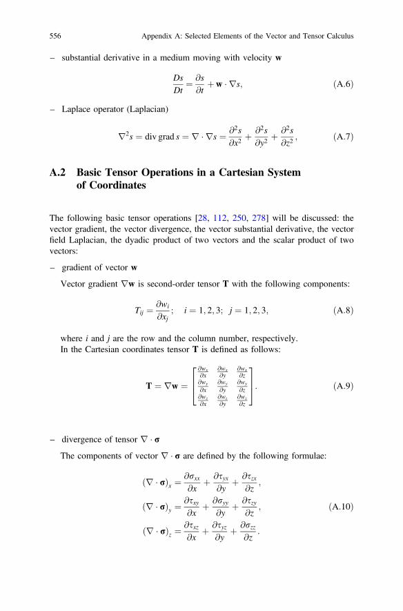
A.2 Basic Tensor Operations in a Cartesian Systemof Coordinates
The following basic tensor operations [28, 112, 250, 278] will be discussed: thevector gradient, the vector divergence, the vector substantial derivative, the vectorfield Laplacian, the dyadic product of two vectors and the scalar product of twovectors:
– gradient of vector w
Vector gradient rw is second-order tensor T with the following components:
Tij ¼ @wi
@xj; i ¼ 1; 2; 3; j ¼ 1; 2; 3; ðA:8Þ
where i and j are the row and the column number, respectively.In the Cartesian coordinates tensor T is defined as follows:
T ¼ rw ¼@wx@x
@wx@y
@wx@z
@wy
@x@wy
@y@wy
@z@wz@x
@wz@y
@wz@z
264
375: ðA:9Þ
– divergence of tensor r � rThe components of vector r � r are defined by the following formulae:
r � rð Þx ¼@rxx@x
þ @syx@y
þ @szx@z
;
r � rð Þy ¼@sxy@x
þ @ryy@y
þ @szy@z
;
r � rð Þz ¼@sxz@x
þ @syz@y
þ @rzz@z
:
ðA:10Þ
556 Appendix A: Selected Elements of the Vector and Tensor Calculus

Product v � rw can be calculated in a similar manner:
v � rwð Þx ¼ vx@wx
@xþ vy
@wx
@yþ vz
@wx
@z;
v � rwð Þy ¼ vx@wy
@xþ vy
@wy
@yþ vz
@wy
@z;
v � rwð Þz ¼ vz@wz
@xþ vy
@wz
@yþ vz
@wz
@z
ðA:11Þ
It should be noted that product w � rw can be determined as follows:
w � rð Þw ¼ r w2=2� �� w� r� wð Þ: ðA:12Þ
Expression w � rð Þw denotes the directional derivative of vector field w withrespect to field w. In a Cartesian system of coordinates, the directional derivativevector components can be calculated as follows:
w � rð Þw ¼ w � rð Þ wxiþwyjþwzk� �
¼ wx@
@xþwy
@
@yþwz
@
@z
� �wxiþwyjþwzk� �
¼ wx@wx
@xþwy
@wx
@yþwz
@wx
@z
� �i
þ wx@wy
@xþwy
@wy
@yþwz
@wy
@z
� �j
þ wx@wz
@xþwy
@wz
@yþwz
@wz
@z
� �k
ðA:13Þ
The components of product w � rw in other systems of coordinates (e.g.cylindrical or spherical) can be found more easily using the last term in formula(A.12).
– substantial derivative of vector w
DwDt
¼ @w@t
þ w � rwð Þ ¼ @w@t
þ w � rð Þw ¼ @w@t
þr w2=2� �� w� r� wð Þ;
ðA:14Þ
Appendix A: Selected Elements of the Vector and Tensor Calculus 557
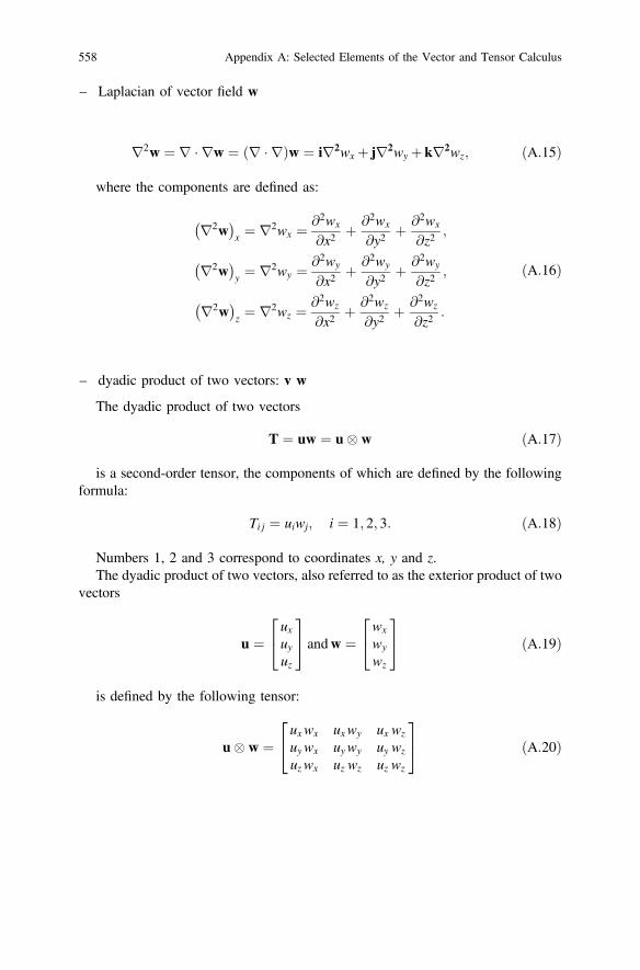
– Laplacian of vector field w
r2w ¼ r � rw ¼ r � rð Þw ¼ ir2wx þ jr2wy þ kr2wz; ðA:15Þ
where the components are defined as:
r2w� �
x ¼ r2wx ¼ @2wx
@x2þ @2wx
@y2þ @2wx
@z2;
r2w� �
y ¼ r2wy ¼ @2wy
@x2þ @2wy
@y2þ @2wy
@z2;
r2w� �
z ¼ r2wz ¼ @2wz
@x2þ @2wz
@y2þ @2wz
@z2:
ðA:16Þ
– dyadic product of two vectors: v w
The dyadic product of two vectors
T ¼ uw ¼ u� w ðA:17Þ
is a second-order tensor, the components of which are defined by the followingformula:
Ti j ¼ uiwj; i ¼ 1; 2; 3: ðA:18Þ
Numbers 1, 2 and 3 correspond to coordinates x, y and z.The dyadic product of two vectors, also referred to as the exterior product of two
vectors
u ¼uxuyuz
24
35 andw ¼
wx
wy
wz
24
35 ðA:19Þ
is defined by the following tensor:
u� w ¼uxwx uxwy ux wz
uywx uywy uy wz
uzwx uz wz uz wz
24
35 ðA:20Þ
558 Appendix A: Selected Elements of the Vector and Tensor Calculus

– the scalar product of two tensors is defined as:
r : rw ¼rxx sxy sxzsyx ryy syzszx szy rzz
264
375 :
@wx@x
@wx@y
@wx@z
@wy
@x@wy
@y@wy
@z
@wz@x
@wz@y
@wz@z
2664
3775
¼ rxx@wx
@xþ sxy
@wy
@xþ sxz
@wz
@x
þ syx@wx
@yþ ryy
@wy
@yþ syz
@wz
@y
þ szx@wx
@zþ szy
@wy
@zþ rzz
@wz
@z:
ðA:21Þ
Appendix A: Selected Elements of the Vector and Tensor Calculus 559
Appendix BThe Navier-Stokes Equationin a Cylindrical and a Spherical Systemof Coordinates
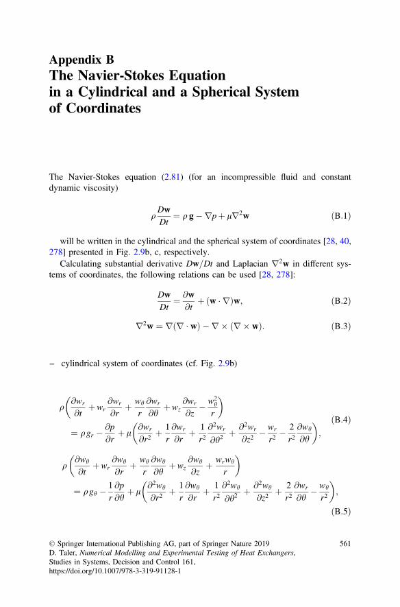
The Navier-Stokes equation (2.81) (for an incompressible fluid and constantdynamic viscosity)
qDwDt
¼ q g�rpþ lr2w ðB:1Þ
will be written in the cylindrical and the spherical system of coordinates [28, 40,278] presented in Fig. 2.9b, c, respectively.
Calculating substantial derivative Dw=Dt and Laplacian r2w in different sys-tems of coordinates, the following relations can be used [28, 278]:
DwDt
¼ @w@t
þ w � rð Þw; ðB:2Þ
r2w ¼ r r � wð Þ � r � r� wð Þ: ðB:3Þ
– cylindrical system of coordinates (cf. Fig. 2.9b)
q@wr
@tþwr
@wr
@rþ wh
r@wr
@hþwz
@wr
@z� w2
h
r
� �
¼ qgr � @p@r
þ l@wr
@r2þ 1
r@wr
@rþ 1
r2@2wr
@h2þ @2wr
@z2� wr
r2� 2r2@wh
@h
� �;
ðB:4Þ
q@wh
@tþwr
@wh
@rþ wh
r@wh
@hþwz
@wh
@zþ wrwh
r
� �
¼ qgh � 1r@p@h
þ l@2wh
@r2þ 1
r@wh
@rþ 1
r2@2wh
@h2þ @2wh
@z2þ 2
r2@wr
@h� wh
r2
� �;
ðB:5Þ
© Springer International Publishing AG, part of Springer Nature 2019D. Taler, Numerical Modelling and Experimental Testing of Heat Exchangers,Studies in Systems, Decision and Control 161,https://doi.org/10.1007/978-3-319-91128-1
561
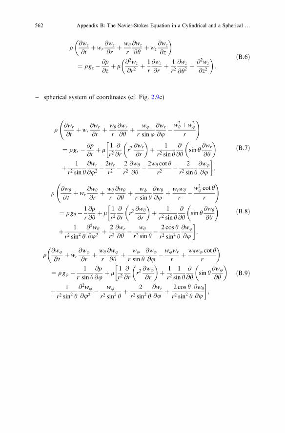
q@wz
@tþwr
@wz
@rþ wh
r@wz
@hþwz
@wz
@z
� �
¼ qgz � @p@z
þ l@2wz
@r2þ 1
r@wz
@rþ 1
r2@wz
@h2þ @2wz
@z2
� �;
ðB:6Þ
– spherical system of coordinates (cf. Fig. 2.9c)
q@wr
@tþwr
@wr
@rþ wh
r@wr
@hþ wu
r sinu@wr
@u� w2
h þw2u
r
!
¼ qgr � @p@r
þ l1r2
@
@rr2@wr
@r
� �þ 1
r2 sin h@
@hsin h
@wr
@h
� ��
þ 1r2 sin h
@wr
@u2 �2wr
r2� 2r2@wh
@h� 2wh cot h
r2� 2r2 sin h
@wu
@u
�;
ðB:7Þ
q@wh
@ tþwr
@wh
@rþ wh
r@wh
@hþ w/
r sin h@wh
@uþ wrwh
r� w2
u cot h
r
!
¼ qgh � 1r@p@h
þ l1r2
@
@rr2@wh
@r
� �þ 1
r2 sin h@
@hsin h
@wh
@h
� ��
þ 1
r2 sin2 h
@2wh
@u2 þ 2r2@wr
@h� wh
r2 sin h� 2 cos h
r2 sin2 h
@wu
@u
�;
ðB:8Þ
q@wu
@ tþwr
@wu
@rþ wh
r@wu
@hþ wu
r sin h@wu
@u� wuwr
rþ whwu cot h
r
� �
¼ qgu � 1r sin h
@p@u
þ l1r2
@
@rr2@wu
@r
� �þ 1
r21
sin h@
@hsin h
@wu
@h
� ��
þ 1
r2 sin2 h
@2wu
@u2 � wu
r2 sin2 hþ 2
r2 sin2 h
@wr
@uþ 2 cos h
r2 sin2 h
@wh
@u
�;
ðB:9Þ
562 Appendix B: The Navier-Stokes Equation in a Cylindrical and a Spherical …
Appendix CThe Energy Conservation Equationin a Cartesian, a Cylindricaland a Spherical System of Coordinates
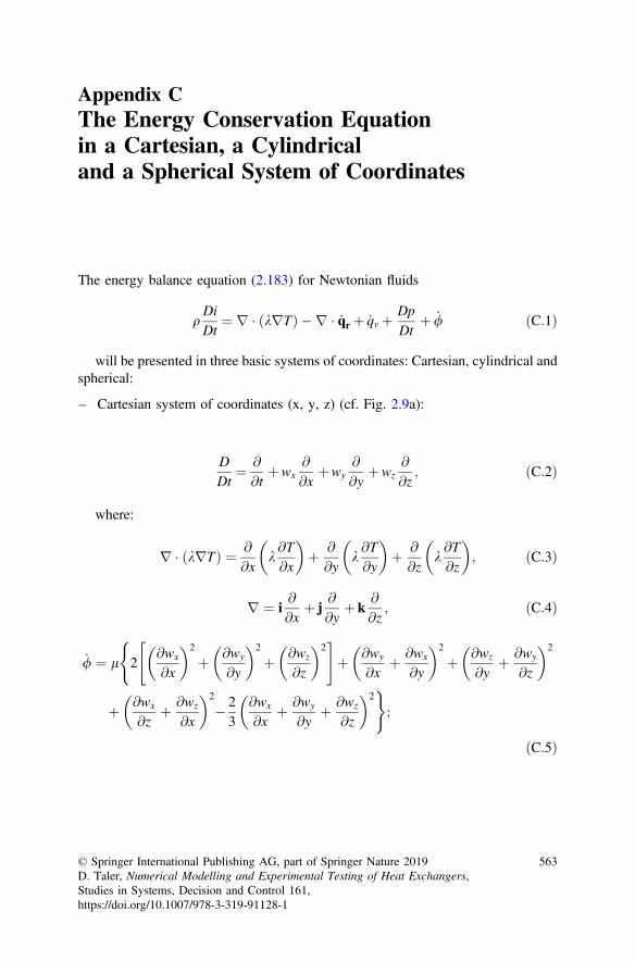
The energy balance equation (2.183) for Newtonian fluids
qDiDt
¼ r � krTð Þ � r � _qr þ _qv þ DpDt
þ _/ ðC:1Þ
will be presented in three basic systems of coordinates: Cartesian, cylindrical andspherical:
– Cartesian system of coordinates (x, y, z) (cf. Fig. 2.9a):
DDt
¼ @
@tþwx
@
@xþwy
@
@yþwz
@
@z; ðC:2Þ
where:
r � krTð Þ ¼ @
@xk@T@x
� �þ @
@yk@T@y
� �þ @
@zk@T@z
� �; ðC:3Þ
r ¼ i@
@xþ j
@
@yþ k
@
@z; ðC:4Þ
_/ ¼ l 2@wx
@x
� �2
þ @wy
@y
� �2
þ @wz
@z
� �2" #(
þ @wy
@xþ @wx
@y
� �2
þ @wz
@yþ @wy
@z
� �2
þ @wx
@zþ @wz
@x
� �2
� 23
@wx
@xþ @wy
@yþ @wz
@z
� �2);
ðC:5Þ
© Springer International Publishing AG, part of Springer Nature 2019D. Taler, Numerical Modelling and Experimental Testing of Heat Exchangers,Studies in Systems, Decision and Control 161,https://doi.org/10.1007/978-3-319-91128-1
563
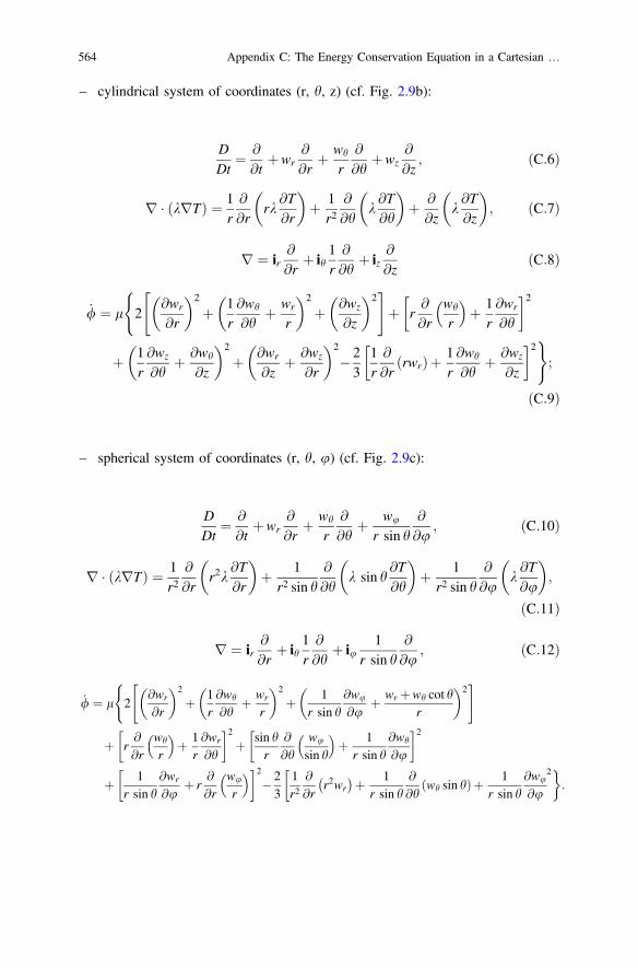
– cylindrical system of coordinates (r, h, z) (cf. Fig. 2.9b):
DDt
¼ @
@tþwr
@
@rþ wh
r@
@hþwz
@
@z; ðC:6Þ
r � krTð Þ ¼ 1r@
@rrk
@T@r
� �þ 1
r2@
@hk@T@h
� �þ @
@zk@T@z
� �; ðC:7Þ
r ¼ ir@
@rþ ih
1r@
@hþ iz
@
@zðC:8Þ
_/ ¼ l 2@wr
@r
� �2
þ 1r@wh
@hþ wr
r
� �2
þ @wz
@z
� �2" #(
þ r@
@rwh
r
þ 1
r@wr
@h
� �2
þ 1r@wz
@hþ @wh
@z
� �2
þ @wr
@zþ @wz
@r
� �2
� 23
1r@
@rrwrð Þþ 1
r@wh
@hþ @wz
@z
� �2);
ðC:9Þ
– spherical system of coordinates (r, h, u) (cf. Fig. 2.9c):
DDt
¼ @
@tþwr
@
@rþ wh
r@
@hþ wu
r sin h@
@u; ðC:10Þ
r � krTð Þ ¼ 1r2
@
@rr2k
@T@r
� �þ 1
r2 sin h@
@hk sin h
@T@h
� �þ 1
r2 sin h@
@uk@T@u
� �;
ðC:11Þ
r ¼ ir@
@rþ ih
1r@
@hþ iu
1r sin h
@
@u; ðC:12Þ
_/ ¼ l 2@wr
@r
� �2
þ 1r@wh
@hþ wr
r
� �2
þ 1r sin h
@wu
@uþ wr þwh cot h
r
� �2" #(
þ r@
@rwh
r
þ 1
r@wr
@h
� �2þ sin h
r@
@hwu
sin h
þ 1
r sin h@wh
@u
� �2
þ 1r sin h
@wr
@uþ r
@
@rwu
r
� �2� 23
1r2
@
@rr2wr� ��
þ 1r sin h
@
@hwh sin hð Þþ 1
r sin h@wu
@u
2�:
564 Appendix C: The Energy Conservation Equation in a Cartesian …
Appendix DPrinciples of Determinationof the Uncertainty of ExperimentalMeasurements and Calculation ResultsAccording to the ASME [232]
Experimental testing results should include the following information:
Z1. Precision limit (limit of accuracy) P with respect to the nominal (single oraveraged) result, which is the 95% confidence interval which should comprisethe mean values obtained from many measurements if the experiment isrepeated many times in identical conditions and using the same equipment.Consequently, the precision limit is an estimator of the lack of repeatabilitydue to random errors and unsteadiness of parameters during the experiment.
Z2. The bias limit B, which is an estimator of the systematic error. It is assumedhere that the experimenter is 95% sure that the systematic error real value, ifknown, should be less than Bj j.
Z3. Uncertainty U, where the ±U interval with respect to the nominal result is arange within which real results lie with the 95% confidence. Assuming the95% confidence interval, the result uncertainty is calculated using the fol-lowing formula:
U ¼ B2 þP2� �12: ðD:1Þ
Z4. An uncertainty analysis conducted according either to the brief descriptionpresented above or to literature guidelines.
The precision and systematic error limits should be estimated in a time repre-sentative of the experiment. The uncertainty assessment should include additionalinformation, presented preferably in a table format. The required items are asfollows:
(a) precision and systematic error limits for each variable and parameter usedduring the testing,
(b) the equation needed to develop the results (indirect measurement),(c) presentation of results, including a comparison between the spread of results
obtained from the experiment repeated many times and anticipated spread (±P)determined from the analysis of the measurement uncertainty.
© Springer International Publishing AG, part of Springer Nature 2019D. Taler, Numerical Modelling and Experimental Testing of Heat Exchangers,Studies in Systems, Decision and Control 161,https://doi.org/10.1007/978-3-319-91128-1
565
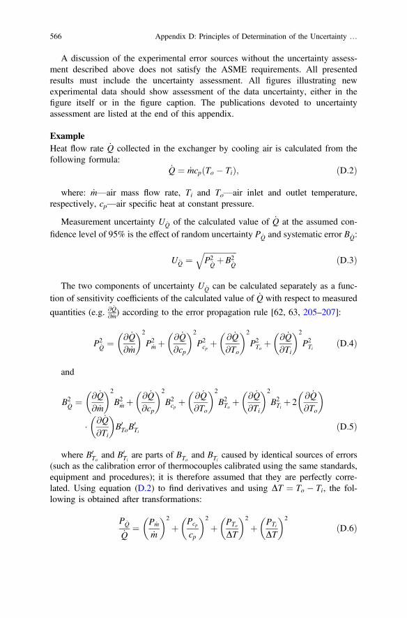
A discussion of the experimental error sources without the uncertainty assess-ment described above does not satisfy the ASME requirements. All presentedresults must include the uncertainty assessment. All figures illustrating newexperimental data should show assessment of the data uncertainty, either in thefigure itself or in the figure caption. The publications devoted to uncertaintyassessment are listed at the end of this appendix.
ExampleHeat flow rate _Q collected in the exchanger by cooling air is calculated from thefollowing formula:
_Q ¼ _mcp To � Tið Þ; ðD:2Þ
where: _m—air mass flow rate, Ti and To—air inlet and outlet temperature,respectively, cp—air specific heat at constant pressure.
Measurement uncertainty U _Q of the calculated value of _Q at the assumed con-fidence level of 95% is the effect of random uncertainty P _Q and systematic error B _Q:
U€Q ¼ffiffiffiffiffiffiffiffiffiffiffiffiffiffiffiffiffiP2
_QþB2
_Q
qðD:3Þ
The two components of uncertainty U _Q can be calculated separately as a func-tion of sensitivity coefficients of the calculated value of _Q with respect to measured
quantities (e.g. @ _Q@ _m) according to the error propagation rule [62, 63, 205–207]:
P2_Q ¼ @ _Q
@ _m
� �2
P2_m þ @ _Q
@cp
� �2
P2cp þ
@ _Q@To
� �2
P2To þ
@ _Q@Ti
� �2
P2Ti ðD:4Þ
and
B2_Q ¼ @ _Q
@ _m
� �2
B2_m þ @ _Q
@cp
� �2
B2cp þ
@ _Q@To
� �2
B2To þ
@ _Q@Ti
� �2
B2Ti þ 2
@ _Q@To
� �
� @ _Q@Ti
� �B0ToB
0Ti ðD:5Þ
where B0To and B0
Ti are parts of BTo and BTi caused by identical sources of errors(such as the calibration error of thermocouples calibrated using the same standards,equipment and procedures); it is therefore assumed that they are perfectly corre-lated. Using equation (D.2) to find derivatives and using DT ¼ To � Ti, the fol-lowing is obtained after transformations:
P _Q
_Q¼ P _m
_m
� �2
þ Pcp
cp
� �2
þ PTo
DT
� �2
þ PTi
DT
� �2
ðD:6Þ
566 Appendix D: Principles of Determination of the Uncertainty …
and
B _Q
_Q¼ B _m
_m
� �2
þ Bcp
cp
� �2
þ BTo
DT
� �2
þ BTi
DT
� �2
�2B0T0
DT
� �� B0
Ti
DT
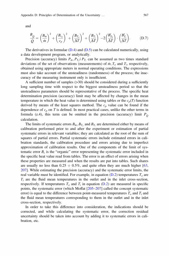
� �: ðD:7Þ
The derivatives in formulae (D.4) and (D.5) can be calculated numerically, usinga data development program, or analytically.
Precision (accuracy) limits P _m;PTo i PTi can be assumed as two times standarddeviations of the set of observations (measurements) of _m; To and Ti, respectively,obtained using appropriate meters in normal operating conditions. The expressionsmust also take account of the unsteadiness (randomness) of the process; the inac-curacy of the measuring instrument only is insufficient.
A sufficient number of samples (>30) should be considered during a sufficientlylong sampling time with respect to the biggest unsteadiness period so that theunsteadiness parameters should be representative of the process. The specific heatdetermination precision (accuracy) limit may be affected by changes in the meantemperature in which the heat value is determined using tables or the cp(T) functionderived by means of the least squares method. The cp value can be found if thedependence of cp on T is defined. In most practical cases, unlike the other terms informula (z.4), this term can be omitted in the precision (accuracy) limit P _Q
calculation.The limits of systematic errors B _m;BTo and BTi are determined either by means of
calibration performed prior to and after the experiment or estimation of partialsystematic errors in relevant variables; they are calculated as the root of the sum ofsquares of partial errors. Partial systematic errors include estimated errors in cali-bration standards, the calibration procedure and errors arising due to imperfectapproximation of calibration results. One of the components of the limit of sys-tematic error Bc is the “organic” error representing the systematic error included inthe specific heat value read from tables. The error is an effect of errors arising whenthese properties are measured and when the results are put into tables. Such sharesare usually no less than 0.25 � 0.5%, and quite often they are much higher [63,207]. While estimating the precision (accuracy) and the systematic error limits, thereal variable must be identified. For example, in equation (D.2) temperatures To areTi are the fluid mean temperatures in the outlet and in the inlet cross-section,respectively. If temperatures To and Ti in equation (D.2) are measured in specificpoints, the systematic error (which Moffat [205–207] called the concept systematicerror) is equal to the difference between point-measured temperatures To and Ti andthe fluid mean temperatures corresponding to them in the outlet and in the inletcross-section, respectively.
In order to take this difference into consideration, the indications should becorrected, and while calculating the systematic error, the correction residualuncertainty should be taken into account by adding it to systematic errors in cali-bration, etc.
Appendix D: Principles of Determination of the Uncertainty … 567
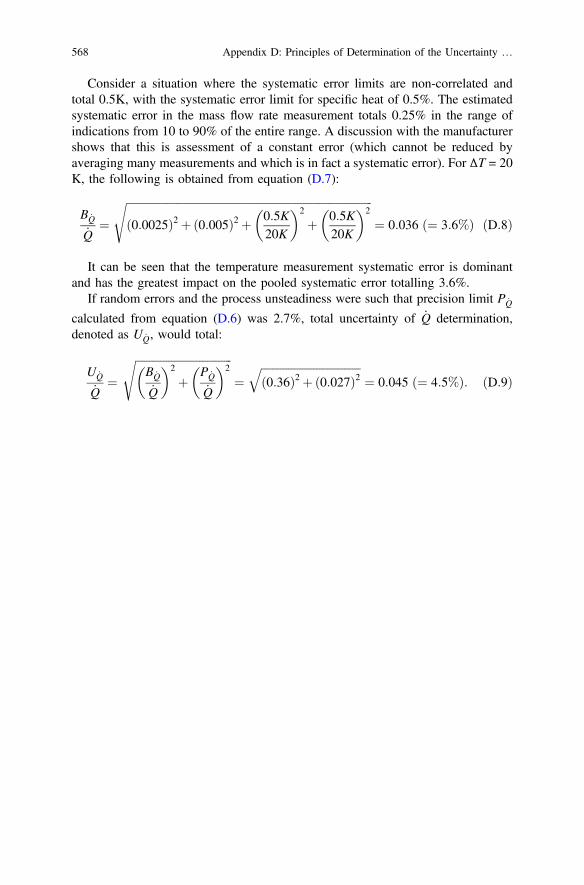
Consider a situation where the systematic error limits are non-correlated andtotal 0.5K, with the systematic error limit for specific heat of 0.5%. The estimatedsystematic error in the mass flow rate measurement totals 0.25% in the range ofindications from 10 to 90% of the entire range. A discussion with the manufacturershows that this is assessment of a constant error (which cannot be reduced byaveraging many measurements and which is in fact a systematic error). For ΔT = 20K, the following is obtained from equation (D.7):
B _Q
_Q¼
ffiffiffiffiffiffiffiffiffiffiffiffiffiffiffiffiffiffiffiffiffiffiffiffiffiffiffiffiffiffiffiffiffiffiffiffiffiffiffiffiffiffiffiffiffiffiffiffiffiffiffiffiffiffiffiffiffiffiffiffiffiffiffiffiffiffiffiffiffiffiffiffiffiffiffiffiffiffiffiffiffiffiffiffiffiffiffiffiffi0:0025ð Þ2 þ 0:005ð Þ2 þ 0:5K
20K
� �2
þ 0:5K20K
� �2s
¼ 0:036 ð¼ 3:6%Þ ðD:8Þ
It can be seen that the temperature measurement systematic error is dominantand has the greatest impact on the pooled systematic error totalling 3.6%.
If random errors and the process unsteadiness were such that precision limit P _Q
calculated from equation (D.6) was 2.7%, total uncertainty of _Q determination,denoted as U _Q, would total:
U _Q
_Q¼
ffiffiffiffiffiffiffiffiffiffiffiffiffiffiffiffiffiffiffiffiffiffiffiffiffiffiffiffiffiffiffiffiffiffiffiB _Q
_Q
� �2
þ P _Q
_Q
� �2s
¼ffiffiffiffiffiffiffiffiffiffiffiffiffiffiffiffiffiffiffiffiffiffiffiffiffiffiffiffiffiffiffiffiffiffiffiffi0:36ð Þ2 þ 0:027ð Þ2
q¼ 0:045 ð¼ 4:5%Þ: ðD:9Þ
568 Appendix D: Principles of Determination of the Uncertainty …
Appendix EPrediction Interval Determination
This appendix presents a more detailed discussion of determination of the predic-tion (forecast) interval in a linear least squares problem [25, 261, 375].
The indirectly measured quantity g is defined as:
g ¼ a0 þ a1x1 þ . . .þ aNxN ; ðE:1Þ
where coefficients a0; a1. . .aN are determined by means of the least squaresmethod.
The predicted value of g in point x0:
x0 ¼
1x01...
x0N
8>>><>>>:
9>>>=>>>;
ðE:2Þ
is calculated from the following expression:
~g0 ¼ ~a0 þ ~a1x1 þ . . .þ ~aNxN ; ðE:3Þ
which can be written in the following vector form:
~g0 ¼ x0� �T
a: ðE:4Þ
In order to find the mean prediction error, the value of the measured quantity y inpoint x0 will be determined first:
y0 ¼ g0 þ e0 ¼ a0 þ a1x01 þ . . .þ aNx
0N þ e0; ðE:5Þ
where e0 is the measurement random error.
© Springer International Publishing AG, part of Springer Nature 2019D. Taler, Numerical Modelling and Experimental Testing of Heat Exchangers,Studies in Systems, Decision and Control 161,https://doi.org/10.1007/978-3-319-91128-1
569
The expected value of y0 is defined as:
E y0ð Þ ¼ E a0 þ a1x01 þ . . .þ aNx
0N þ e0
� � ¼ g0; ðE:6Þ
where:
g0 ¼ a0 þ a1x01 þ . . .þ aNx
0N : ðE:7Þ
It can be noticed that
E ~g0ð Þ ¼ E x0� �T
~ah i
¼ x0� �T
E ~að Þ ¼ x0� �T
a ¼ E y0ð Þ ðE:8Þ
because estimators ~a0; ~a1; . . .; ~aN of the model parameters a0; a1; . . .; aN areunbiased, i.e. E ~aið Þ ¼ ai .
Variance var y0 � ~g0ð Þ is found in the following way:
var y0 � ~g0ð Þ ¼ E y0 � ~g0ð Þ2h i
¼ E x0� �T
aþ e0 � x0� �T
~ah i2 �
¼ E x0� �T
a� ~að Þþ e0h i2 �
¼ E x0� �T
a� ~að Þ a� ~að ÞTx0h
þ 2 x0� �T
a� ~að Þe0 þ e20
i¼ E x0
� �Ta� ~að Þ a� ~að ÞTx0
h iþE 2 x0
� �Ta� ~að Þe0
h iþE e20
� �¼ x0� �T
a� ~að Þ a� ~að ÞT� �x0 þ 0þ r20 ¼ x0
� �TC~ax0 þ r20
¼ r20 x0� �T
XTGyX� ��1
x0 þ r20:
ðE:9Þ
Assuming that r2 ¼ r20, formula (E.9) gives (11.149).Approximating standard deviation of random measuring errors by means of sy,
the 1� að Þ � 100% prediction interval for the measured quantity y at any point x0,which does not need to be a measuring point, is obtained from the followingexpression:
P �tn�N�1;a\y0 � ~g0
syffiffiffiffiffiffiffiffiffiffiffiffiffiffiffiffiffiffiffiffiffiffiffiffiffiffiffiffiffiffiffiffiffiffiffiffiffiffiffiffiffiffiffiffiffiffiffi1þ x0ð ÞT XTGyX
� ��1x0q \tn�N�1;a
8><>:
9>=>; ¼ 1� a: ðE:10Þ
For the 95% confidence interval a = 0.05. Transforming the term in the curlybracket in expression (E.10), formula (11.151) is obtained.
570 Appendix E: Prediction Interval Determination
Bibliography
1. Abell, M. L., Braselton, J. P., & Rafter, J. A. (1999). Statistics with Mathematica. SanDiego: Academic Press.
2. Abernathy, R. B., Benedict, R. P., & Diwdell, R. B. (1985). ASME measurementuncertainty. ASME Journal of Fluids Engineering, 107, 161–164.
3. Abraham, J. P., Sparrow, E. M., & Minkowycz, W. J. (2011). Internal-flow Nusseltnumbers for the low-Reynolds-number end of the laminar-to-turbulent transition regime.International Journal of Heat and Mass Transfer, 54, 584–588.
4. Abraham, J. P., Sparrow, E. M., & Tong, J. C. K. (2009). Heat transfer in all pipe flowregimes: laminar, transitional/intermittent and turbulent. International Journal of Heat andMass Transfer, 52, 557–563.
5. Acharya, S., Baliga, B., Karki, K., Murthy, J. Y., Prakash, C., & Vanka, S. P. (2007).Pressure-based finite-volume methods in computational fluid dynamics. ASME Journal ofHeat Transfer, 129, 407–424.
6. Agrawal, H. C. (1960). Heat transfer in laminar flow between parallel plates at small Péclétnumbers. Applied Scientific Research, 9(1), 177–189.
7. Allen, J. J., Shockling, M. A., Kunkel, G. J., & Smits, A. J. (2007). Turbulent flow insmooth and rough pipes. Philosophical Transactions of Royal Society A, 365(1852), 699–714.
8. Allen, R. W., & Eckert, E. R. G. (1964). Friction and heat-transfer measurements toturbulent pipe flow of water (Pr = 7 and 8) at uniform wall heat flux. Transactions of theASME, Journal of Heat Transfer, 86, 301–310.
9. Anderson, J. D. (1995). Computational fluid dynamics: The basics with applications.Boston: McGraw-Hill.
10. Anderson, J. D. (2000). Hypersonic and high temperature gas dynamics. Reston, Virginia:American Institute of Aeronautics and Astronautics.
11. ANSYS CFX, Release 13.0, Documentation, 2011.12. Aoki, S. (1963). A consideration on the heat transfer in liquid metal. Bulletin of the Tokyo
Institute of Technology, 54, 63–73.13. Aravinth, S. (2000). Prediction of heat and mass transfer for fully developed turbulent fluid
flow through tubes. International Journal of Heat and Mass Transfer, 43, 1399–1408.14. ASHRAE Handbook, Fundamentals volume, American Society of Heating, Refrigerating
and Air-Conditioning Engineers, Inc. Atlanta, GA. 1997.15. Baclic, B. S. (1978). A simplified formula for cross-flow heat exchanger. Transactions of
the ASME, Journal of Heat transfer, 100, 746–747.16. Baehr, H. D., & Stephan, K. (1994). Wärme-und Stoffübertragung. Berlin: Springer.17. Baker, R. C. (2000). Flow measurement handbook. Cambridge: Cambridge University
Press.18. Baliga, B. R., & Patankar, S. V. (1983). A control-volume finite element method for
two-dimensional fluid flow and heat transfer. Numerical Heat Transfer, 6, 245–261.
© Springer International Publishing AG, part of Springer Nature 2019D. Taler, Numerical Modelling and Experimental Testing of Heat Exchangers,Studies in Systems, Decision and Control 161,https://doi.org/10.1007/978-3-319-91128-1
571
19. Baliga, B. R., & Patankar, S. V. (1988). Elliptic systems: Finite element II. Wiley, NewYork: Handbook of numerical heat transfer.
20. Beck, J. V., Balckwell, B., Clair, Ch. R. St. Jr. (1985). Inverse heat conduction. Ill-posedproblems. New York: A Wiley Interscience.
21. Bejan, A. (1993). Heat transfer. New York: Wiley.22. Bejan, A. (2004). Convection heat transfer (3rd ed.). Hoboken: Wiley.23. Bejan, A., & Kraus, A. D. (2004). Heat transfer handbook. Hoboken: Wiley.24. Bertin, J. J. (2002). Aerodynamics for engineers (4th ed.). Upper Saddle River, New Jersey:
Prentice Hall.25. Bevington, P. R. (1969). Data reduction and error analysis for the physical sciences. New
York: McGraw-Hill.26. Bhatti, M. S., & Shah, R. K. (1987). Turbulent and transition flow convective heat transfer
in ducts (Chapter 4). In S. Kakaç, R. K. Shah, & W. Aung (Eds.), Handbook ofsingle-phase convective heat transfer. New York: Wiley Interscience.
27. Binnie, A. M., & Poole, E. G. C. (1937). The theory of the single-pass cross-flow heatexchange. Proceedings of the Cambridge Philosophical Society, 33, 403–411.
28. Bird, R. B., Stewart, W. E., & Lightfoot, E. N. (2007). Transport phenomena (2nd ed.).New York: Wiley.
29. Björck, Å., & Dahlguist, G. (1987). Metody numeryczne. Warszawa: WydawnictwoNaukowe PWN [Björck, Å., Dahlguist, G. (1987). Numerical methods. Warsaw: ScientificPublishing House PWN].
30. Black, A. W. (1966). The effect of circumferentially-varying boundary conditions onturbulent heat transfer in a tube, Ph.D. Thesis. University of Minnesota, Minneapolis.
31. Blasius, P. R. H. (1913). Das Ähnlichkeitsgesetz bei Reibungsvorgängen in Flüssigkeiten.VDI Forschungsheft, 131, 1–41.
32. Boam, D., & Sattary, J. (2001). Uncertainty in flow measurement. In rozdział w Spitzer D.W. (Ed.), Flow measurement, ISA—The Instrumentation, Systems and AutomationSociety, Research Triangle Park, USA 2001, pp. 713–730.
33. Borkowski, B., Dudek H., & Szczesny W. (2004). Ekonometria. Wybrane zagadnienia.Warszawa: Wydawnictwo Naukowe PWN [Borkowski, B., Dudek, H., & Szczesny, W.(2004). Econometrics. Selected problems. Warsaw: Scientific Publishing House PWN].
34. Brandt, F. (1985).Wärmeübertragung in Dampferzeugern und Wärmeaustauschern. Essen,FDBR Fachverband Dampfkessel-, Behälter - und Rohrleitungsbau e.V.. Essen: VulkanVerlag.
35. Brandt, S. (1998). Analiza danych. Metody statystyczne i obliczeniowe. Warszawa:Wydawnictwo Naukowe PWN [Brandt, S. (1998). Data analysis. Statistical andcomputational methods. Warszawa: Scientific Publishing House PWN].
36. Brower, W. B. (1999). A Primer in fluid mechanics. Dynamics of flows in one spacedimension. Boca Raton: CRC Press.
37. Brown, G. M. (1960). Heat or mass transfer in a fluid in laminar flow in a circular or flatconduit. AIChE Journal, 6, 179–183.
38. Burden, R. L., & Faires, J. D. (1985). Instructor’s manual to accompany numericalanalysis (3rd ed.). Boston: PWS Publishers.
39. Burden, R. L., & Faires, J. D. (1985). Numerical analysis (3rd ed.). Boston: PWSPublishers.
40. Burmeister, L. C. (1993). Convective heat transfer (2nd ed.). New York: WileyInterscience.
41. Buyukalaca, O., Ozceyhan, V., & Gunes, S. (2012). Experimental investigation of thermalperformance in a tube with detached circular ring turbulators. Heat Transfer Engineering,33(8), 682–692.
42. Carrigan, R. C., & Eichelberger, J. (2006). Automotive heating and air conditioning.Clifton Park, NY, USA: Thomson Delmar Learning.
572 Bibliography
43. Carslaw, H. S., & Jaeger, J. G. (2008). Conduction of heat in solids (2nd ed.). Oxford:Clarendon Press.
44. Cebeci, T. (1973). A model for eddy conductivity and turbulent Prandtl number. ASMEJournal of Heat Transfer, 95, 227.
45. Cebeci, T. (2002). Convective heat transfer (2nd rev. ed.). Long Beach: HorizonsPublishing and Berlin: Springer.
46. Cebeci, T. (2004). Turbulence models and their application. Long Beach: HorizonsPublishing and Berlin: Springer.
47. Çengel, Y. A., & Turner, R. H. (2001). Fundamentals of thermal-fluid sciences. Boston:McGraw-Hill International Edition.
48. Cess, R. D., & Shaffer, E. C. (1959). Heat transfer to laminar flow between parallel plateswith a prescribed wall heat flux. Applied Scientific Research, Section A, 8, 339–344.
49. Chen, C. J., & Chiou, J. S. (1981). Laminar and turbulent heat transfer in the pipe entranceregion for liquid metals. International Journal of Heat and Mass Transfer, 24(7),1179–1189.
50. Chen, N. H. (1979). An explicit equation for friction factor in pipe. Industrial andEngineering Chemistry Fundamentals, 18(3), 296–297.
51. Cheng, N. S. (2008). Formulas for friction factor in transitional regions. Journal ofHydraulic Engineering, ASCE, 134(9), 1357–1362.
52. Cheng, X., & Tak, N.-I. (2006). Investigation on turbulent heat transfer to lead-bismutheutectic flows in circular tubes for nuclear applications. Nuclear Engineering and Design,236, 385–393.
53. Ching-Jen, C., & Jenq, S. C. (1981). Laminar and turbulent heat transfer in the pipeentrance region for liquid metals. International Journal of Heat and Mass Transfer, 24(7),1179–1189.
54. Chow, C. C. (1983). Econometric methods. New York: McGraw-Hill.55. Churchill, S. W. (1973). Empirical expressions for the shear stress in turbulent flow in
commercial pipe. American Institute of Chemical Engineering Journal, 19(2), 375–376.56. Churchill, S. W. (1977). Friction-factor equation spans all fluid-flow regimes. Chemical
Engineering, 84, 91–92.57. Churchill, S. W., & Ozoe, H. (1973). Correlations for laminar forced convection in flow
over an isothermal flat plate and in developing and fully developed flow in an isothermaltube. ASME Journal of Heat Transfer, 95, 416–419.
58. Churchill, S. W., & Usagi, R. (1972). A general expression for the correlation of rates oftransfer and other phenomena. AIChE Journal, 18, 1121–1128.
59. Colburn, A. P. (1933). A method of correlating forced convection heat transfer data and acomparison with fluid friction. Transactions of the American Institute of ChemicalEngineers, 29, 174–210.
60. Colebrook, C.F. (1938–1939). Turbulent flow in pipes, with particular reference to thetransition region between the smooth and rough pipe laws. Journal of the Institution of CivilEngineers, 11, 133–156.
61. Colebrook, C. F., & White, C. M. (1937). Experiments with fluid friction in roughenedpipes. Proceedings of the Royal Society of London, 161, 367–381.
62. Coleman, H. W., & Steele, W. G. (1998). Uncertainty analysis (Chapter 39). In R.W. Johnson (Ed.), The handbook of fluid dynamics. Boca Raton, Heidelberg: CRC Press iSpringer.
63. Coleman, H. W., & Steele, W. G. (2009). Experimentation, validation, and uncertaintyanalysis for engineers (3rd ed.). New York: Wiley.
64. Coles, D. (1955). The law of the wall in turbulent shear flow (Chapter 50). In H. Görtler &W. Tollmien (Eds.), Jahre Grenzschichtforschung (pp. 153–163). Braunschweig: Vieweg.
65. Cornwell, K. (1977). The flow of heat. Wokingham, Berkshire, England: Van NostrandReinhold Company Ltd.
Bibliography 573
66. Coulson, J. M., Richardson, J. F., Backhurst, J. R., & Harker, J. H. (2000). Fluid flow, heattransfer and mass transfer. In Coulson and Richardson’s chemical engineering (6th ed., vol.1). Oxford: Butterworth-Heinemann.
67. Crowe, C. T., Elger, D. F., & Roberson, J. A. (2005). Engineering fluid mechanics (8th ed.).Hoboken: Wiley.
68. Cuevas, C., Makaire, D., Dardenne, L., & Ngendakumana, P. (2011). Thermo-hydrauliccharacterization of a louvered fin and flat tube heat exchanger. Experimental Thermal andFluid Science, 35, 154–164.
69. Cutlip, M. B., & Shacham, M. (1999). Problem solving in chemical engineering withnumerical methods. Upper Saddle River: Prentice Hall PTR.
70. Czermiński, J. B., Iwasiewicz, A., Paszek, Z., Sikorski, A. (1992). Metody statystyczne dlachemików, Wydanie drugie zmienione. Warszawa: Wydawnictwo Naukowe PWN[Czermiński, J. B., Iwasiewicz, A., Paszek, Z., & Sikorski, A. (1992). Statistical methodsin chemistry (2nd ed.). Warsaw: Scientific Publishing House PWN].
71. Daly, S. (2006). Automotive air-conditioning and climate control systems. Amsterdam:Elsevier.
72. Date, A. W. (2005). Introduction to computational fluid dynamics. New York: CambridgeUniversity Press.
73. Davidson, J. (2000). Econometric theory. Oxford: Blackwell.74. Davidson, R., & MacKinnon, J. G. (1993). Estimation and inference in econometrics.
Oxford: Oxford University Press.75. Deissler, R. G. (1950). Analytical and experimental investigation of adiabatic turbulent flow
in smooth tubes. NACA Technical Notes, No. 2138.76. Deissler, R. G. (1955). Analysis of turbulent heat transfer, mass transfer, and friction in
smooth tubes at high Prandtl and Schmidt numbers. NACA Report 1210.77. Diaz-Mendez, S. E., Patiño-Carachure, C., & Herrera-Castillo, J. A. (2014). Reducing the
energy consumption of an earth-air heat exchanger with a PID control system. EnergyConversion and Management, 77, 1–6.
78. Dieterich Company Catalogue, Standard annubar-flow measurement systems. An ISO 9001Certified Manufacturer, March 1995.
79. Dittus, F. W., Boelter, L. M. K. (1985). Heat transfer in automobile radiators of the tubulartype, University of California Publications on Engineering 2, 1930, s. 443–461. (Reprintedin: International Communications on Heat and Mass Transfer, 12, pp. 3–22, 1985).
80. Dixon, S. L. (1998). Fluid mechanics and thermodynamics of turbomachinery (4th ed.).Boston: Butterworth-Heinemann.
81. Dormand, J. R. (1996). Numerical methods for differential equations. A computationalapproach. Boca Raton: CRC Press.
82. Draper, N. R., & Smith, H. (1998). Applied regression analysis. New York: Wiley.83. Duda, P., Taler, J., & Roos, E. (2004). Inverse method for temperature and stress
monitoring in complex-shaped bodies. Nuclear Engineering and Design, 227, 331–347.84. Dukelow, S. G. (1991). The control of boilers. Instrument Society of America 67 Alexander
Drive, P.O. Box 12277, Research Triangle Park, NC 27709, 1991.85. Eckert, E. R. G., & Drake, R. M. Jr. (1972). Analysis of heat and mass transfer. Routledge:
Taylor & Francis.86. Eiamsa-Ard, S., Kongkaitpaiboon, V., & Promvonge, P. (2011). Thermal performance
assessment of turbulent tube flow through wire coil turbulators. Heat Transfer Engineering,32(11–12), 957–967.
87. Ekonometria. Zbiór zadań, praca zbiorowa pod redakcją Welfe A., Wydanie trzeciezmienione, Polskie Wydawnictwo Ekonomiczne, Warszawa 2003 [Welfe A. (ed.),Econometrics. Excercises, 3rd ed., Warsaw: Polish Publishing House for Economy 2003].
88. ESDU (Engineering Sciences Data Units) International plc, Forced convection heattransfer in circular tubes. Part 1: correlation for fully developed flow, ESDU Item 67016.
574 Bibliography
89. Fang, X., Xu, Y., & Zhou, Z. (2011). New correlations of single-phase friction factor forturbulent pipe flow and evaluation of existing single-phase friction factor correlations.Nuclear Engineering and Design, 241, 897–902.
90. Favre-Marinet, M., & Tardu, S. (2008). Convective heat transfer. Hoboken: Wiley.91. Figliola, R. S., & Beasley, D. E. (2000). Theory and design for mechanical measurements
(3rd ed.). New York: Wiley.92. Filonienko, G. K. (1954). Friction factor for turbulent pipe flow. Teploenergetika, 1(4),
40–44.93. Spitzer, D. W. (ed.), (2001). Flow measurement. Practical guides for measurement and
control. Reseach Triangle Park: ISA.94. (1996). Fluid mechanics. REA’s problem solvers. Piscataway, New Jersey: Research and
Education Association.95. Forsythe, G. E., Malcolm, M. A., & Moler, C. B. (1977). Computer methods for
mathematical computations. Englewood Cliffs, New Jersey: Prentice-Hall.96. Gajda, J. B. (2004). Ekonometria. Warszawa: Wydawnictwo C.H.Beck [Gajda, J. B.
(2004). Econometrics. Warsaw: Publishing House C.H.Beck].97. Ganapathy, V. (2003). Industrial boilers and heat recovery steam generators. Design,
applications, and calculations. Boca Raton: CRC Press.98. Genić, S., Arandjelović, I., Kolendić, P., Jarić, M., Budimir, N., & Genić, V. (2011).
A review of explicit approximations of Colebrook’s equation. FME Transactions, 39,67–71.
99. Gerald, C. F., & Wheatley, P. O. (1994). Applied numerical analysis (5th ed.). Reading,Massachusetts: Addison-Wesley.
100. Ghajar, A. J., & Madon, K. F. (1992). Pressure drop measurements in the transition regionfor a circular tube with three different inlet configurations. Experimental Thermal and FluidScience, 5, 129–135.
101. Ghajar, A. J., Tam, L. M., & Tam, S. C. (2004). Improved heat transfer correlation in thetransition region for a circular tube with three inlet configurations using artificial neuralnetworks. Heat Transfer Engineering, 25(2), 30–40.
102. Ghiaasiaan, S. M. (2014). Convective heat and mass transfer (2nd ed.). Cambridge:Cambridge University Press.
103. Glockner, P. S., & Naterer, G. F. (2005). Near-wall velocity profile with adaptive shapefunctions for turbulent forced convection. International Communications in Heat and MassTransfer, 32, 72–79.
104. Gnielinski, V. (1975). Neue Gleichungen für den Wärme- und den Stoffübergang inturbulent durchströmten Rohren und Kanälen. Forschung im Ingenieurwesen, 41(1), 8–16.
105. Gnielinski, V. (1995). Ein neues Berechnungsverfahren für die Wärmeübertragung imÜbergangsbereich zwischen laminarer und turbulenter Rohrströmung. Forschung imIngenieurwesen-Engineering Research, 61(9), 240–248.
106. Gnielinski, V. (2010). Heat transfer in concentric annular and parallel plate ducts. In:Rozdział G2 w VDI Heat Atlas (2nd ed.). Berlin: Springer, pp. 701–708.
107. Gnielinski, V. (2013). Durchströmte Rohre (Chapter G1 ). In VDI-Wärmeatlas 11.,bearbeitete und erweiterte Auflage. Berlin: Springer, pp. 785–791.
108. Gnielinski, V. (2013). On heat transfer in tubes. International Journal of Heat and MassTransfer, 63, 134–140.
109. Gnielinski, V., Žukauskas, A., & Skrinska, A. (1992). Banks of plain and finned tubes(Chapter 2.5.3). In G. F. Hewitt (ed.), Handbook of heat exchanger design. New York:Begell House, pp. 2.5.3–1–2.5.3–16.
110. Graebel, W. P. (2007). Advanced fluid mechanics. Amsterdam: Elsevier-Academic Press.111. Graetz, L. Über die Wärmeleitungsfähigkeit von Flüssigkeiten, Part 1, Annals of Physical
Chemistry (pp. 79–94). 18, 1883; Part 2, Annals of Physical Chemistry (pp. 337–357). 25,1885.
Bibliography 575
112. Greenberg, M. D. (1988). Advanced engineering mathematics (2nd ed.). Upper SaddleRiver, New Jersey: Prentice Hall.
113. Greene, W. H. (2000). Econometric analysis. Upper Saddle River, New Jersey: PrenticeHall.
114. Grote, K., Meyer, J. P., & McKrell, T. (2013) The influence of multi-walled carbonnanotubes on the pressure drop characteristics in the transitional flow regime of smoothtubes. Poster Session 1, Paper 489 w Proceedings of the 8th World Conference onExperimental Heat Transfer, Fluid Mechanics and Thermodynamics (ExHFT-8), June16–20, 2013. Lisbon, Portugal.
115. Grötzbach, G. (2013). Challenges in low-Prandtl number heat transfer simulation andmodelling. Nuclear Engineering and Design, 264, 41–55.
116. Guide to the expression of uncertainty in measurement (1995). Geneva: InternationalOrganization for Standardization.
117. Haaland, S. E. (1983). Simple and explicit formulas for the friction factor in turbulentpipe-flow. Transactions of the ASME, Journal of Fluids Engineering, 105(1), 89–90.
118. Han, X., & Liu, G. R. (2003). Computational inverse technique in nondestructiveevaluation. Boca Raton: CRC Press.
119. Hausen, H. (1959). Neue Gleichungen für die Wärmeübertragung bei freier odererzwungener Strӧmung. Allgemeine Wärmetechnik, 9(4/5), 75–79.
120. Hausen, H. (1974). Erweiterte Gleichungen für den Wärmeübertragung in Rohren beiturbulenter Strömung. Wärme- und Stoffübertragung, 4.
121. Hausen, H. (1983). Heat transfer in counter flow, parallel flow, and cross-flow. New York:McGraw-Hill.
122. Hewitt, G. F. (Ed.). (1992). Handbook of heat exchanger design. New York: Begell House.123. Hewitt, G. F., Shires, G. L., & Bott, T. R. (1994). Process heat transfer. Boca Raton: CRC
Press i Begell House.124. Hickman, W. H. (1975). Annubar properties investigation. In Proceedings of ISA’s Industry
Conference and Exhibit, Milwaukee, October 6–9, 1975, pp. 1–14. Instrument Society ofAmerica 30, Part 3.
125. Hobler, T. (1986). Ruch ciepła i wymienniki. Warszawa: Wydanie szóste, WNT [Hobler, T.(1986). Heat transfer and heat exchangers (6th ed.). Warsaw: WNT].
126. Hodge, B. K., & Taylor, R. P. (1999). Analysis and design of energy systems (3rd ed.).Upper Saddle River: Prentice Hall.
127. Holman, J. P. (2001). Experimental methods for engineers (7th ed.). Boston: McGraw-Hill.128. Holman, J. P. (2010). Heat transfer (10th ed.). Boston: McGraw Hill.129. Hsu, C. J. (1965). Heat transfer in a round tube with sinusoidal wall heat flux distribution.
AIChE Journal, 11, 690–695.130. Huber, D., & Walter, H. (2010). Forced convection heat transfer in the transition region
between laminar and turbulent flow for a vertical tube. In Mastorakis, N., Mladenov, V., &Bojkovic, Z. (eds.), Latest trends on theoretical and applied mechanics, fluid mechanicsand heat transfer (pp. 132–136). Wisconsin: WSEAS Press.
131. Hughes, W. F., & Brighton, J. A. (1999). Fluid dynamics (3rd ed., Schaum`s OutlineSeries). New York: McGraw-Hill.
132. Incropera, F. P., & DeWitt, D. P. (1996). Fundamentals of heat and mass transfer (4th ed.).New York: Wiley.
133. Ingham, J., Dunn, I. J., Heinzle, E., Přenosil, J. E., & Snape, J. B. (2007). Chemicalengineering dynamics. An introduction to modelling and computer simulation. Weinheim:Wiley VCH.
134. International Mathematical and Scientific Library IMSL Math/Library, IMSL Inc., 2500CityWest Boulevard, Houston TX 77042.
135. International vocabulary of basic and general terms in metrology (1993). Geneva:International Organization for Standarization.
136. Inverse engineering handbook (2003). In Woodbury K. A. (ed.). Boca Raton: CRC Press.
576 Bibliography
137. Jaluria, Y. (1980). Natural convection. Heat and mass transfer. Oxford: Pergamon Press.138. Janke, E., Emde, F., & Lösch, F. (1960). Tafeln höherer Funktionen. Stuttgart: Teubner.139. Ji, W.-T., Zhang, D.-C., He, Y.-L., & Tao, W.-Q. (2012). Prediction of fully developed
turbulent heat transfer of internal helically ribbed tubes—An extension of Gnielinskiequation. International Journal of Heat and Mass Transfer, 55, 1375–1384.
140. Jischa, M. (1982). Konvektiver Impuls-, Wärme- und Stoffaustausch.Braunschweig/Wiesbaden: Friedr. Vieweg & Sohn.
141. Jischa, M., & Rieke, H. B. (1979). About the prediction of turbulent Prandtl and Schmidtnumbers. International Journal of Heat and Mass Transfer, 22, 1547–1555.
142. Kakaç, S., & Yener, Y. (1995). Convective heat transfer (2nd ed.). Boca Raton: CRC Press.143. Kakaç, S., & Liu, H. (2002). Heat exchangers, selection, rating, and thermal design (2nd
ed.). Boca Raton: CRC Press.144. Kandlikar, S. G., Garimella, S., Li, D., Colin, S., & King, M. R. (2013). Heat transfer and
fluid flow in minichannels and microchannels (2nd ed.). Amsterdam: Elsevier.145. von Kármán, Th. (1939). The analogy between fluid friction and heat transfer. Transactions
of ASME, 61, s. 705–710 [von Kármán, Th. (1930). Mechanische Ähnlichkeit undTurbulenz, Ges. der Wiss. zu Gött., Nachrichten, Math.-Phys. Kl., pp. 58–76].
146. Kast, W., & Nirschl, H. (2013). Druckverlust in durchströmten Rohren, Rozdział L1.2 wVDI-Wärmeatlas, 11., bearbeitete und erweiterte Auflage. Berlin: Springer.
147. Kays, W. (1994). Turbulent Prandtl Number—Where are we? Transactions of the ASME,Journal of Heat Transfer, 116, 284–295.
148. Kays, W., Crawford, M., & Weigand, B. (2005). Convective heat and mass transfer (4thed.). Boston: McGraw-Hill.
149. Kays, W. M., & London, A. L. (1998). Compact heat exchangers (3rd ed.). Malabar,Florida, USA: Krieger.
150. Kemink, R. (1997). Heat transfer in a downstream tube of a fluid withdrawal branch (Ph.D. Thesis). Minneapolis: University of Minnesota.
151. Kirillov, P. L., Yuriev, Y. S., & Bobkov, W. P. (1984). Handbook of hydraulic calculations(Nuclear reactors, heat exchangers, steam generators). Moscow: Energoatomizdat.
152. Kiusalaas, J. (2005). Numerical methods in engineering with MATLAB®. New York:Cambridge University Press.
153. Kline, S. J., & McClintock, F. A. (1955). Describing uncertainties in single-sampleexperiments. Mechanical Engineering, 75, 3–8.
154. Kline, S. J. (1985). Symposium on uncertainty analysis closure. ASME Journal of FluidsEngineering, 107(1983), 181–182.
155. Kline, S. J. (1985). The purposes of uncertainty analysis. ASME Journal of FluidsEngineering, 107(1983), 153–160.
156. Koenig, D. M. (2009). Practical control engineering. New York: McGraw-Hill.157. Konakov, P. K. (1946). A new correlation for the friction coefficient in smooth tubes.
Izvestija AN SSSR, 51(7), 503–506.158. Korzeń, A., & Taler, D. (2015). Modeling of transient response of a plate fin and tube heat
exchanger. International Journal of Thermal Sciences, 92, 188–198.159. Kraus, A. D., Aziz, A., & Welty, J. (2001). Extended surface heat transfer. New York:
Wiley.160. Kreith, F., Manglik, R. M., & Bohn, M. S. (2011). Principles of heat transfer (7th ed.).
Stamford, USA: Cengage Learning.161. Kröger, D. G. (1985). Radiator characterization and optimization. SAE Paper 840380,
pp. 2.984–2.990.162. Kröger, D. G. (1998). Air-cooled heat exchangers and cooling towers. Matieland, South
Africa: University of Stellenbosch.163. Kruger, W. (1972). Theorie der Volumenstrommessung in Rohren mit Rechteckquerschnitt.
HLH, 23(4), 121–123.
Bibliography 577

164. Kundu, B., & Das, P. K. (2000). Performance of symmetric polygonal fins with and withouttip loss—a comparison of different methods of prediction. The Canadian Journal ofChemical Engineering, 78, 395–401.
165. Kundu, B., & Das, P. K. (2009). Performance and optimum dimensions of flat fins fortube-and-fin heat exchangers: A generalized analysis. International Journal of Heat andFluid Flow, 30, 658–668.
166. Kundu, B., Maiti, B., & Das, P. K. (2006). Performance analysis of plate finscircumscribing elliptic tubes. Heat Transfer Engineering, 27, 86–94.
167. Kundu, P. K., & Cohen, I. M. (2008). Fluid mechanics (4th ed.). Amsterdam: Elsevier.168. Kunze, H. J. (1986). Physikalische Messmethoden. Eine Einführung in Prinzipien
klassischer und moderner Verfahren. Stuttgart: B. G. Teubner.169. Kuppan, T. (2013). Heat exchanger design handbook (2nd ed.). Boca Raton: CRC Press
Taylor & Francis Group.170. Langtry, R. B., & Menter, F. R. (2005). Transition modeling for general CFD applications
in aeronautics. AIAA 2005, paper 552.171. Larkin, B. K. (1961). High-order eigenfunctions of the Graetz problem. AIChE Journal, 7
(191), 530.172. Lassahn, G. D. (1985). Uncertainty definition. ASME Journal of Fluids Engineering, 107,
179.173. Lau, S. (1981). Effect of plenum length and diameter of turbulent heat transfer in a
downstream tube and on plenum-related pressure loss (Ph.D. Thesis). Minneapolis:University of Minnesota.
174. Lawson, Ch L, & Hanson, R. J. (1974). Solving least squares problems. Englewood Cliffs:Prentice-Hall.
175. Lee, T.-W. (2008). Thermal and flow measurements. Boca Raton: CRC Press Taylor &Francis Group.
176. Lévêque, M. A. (1928). Les lois de la transmission de chaleur par convection. Annales desMines, Memoires, Series 12, 13, pp. 201–299, 305–362, 381–415.
177. Lewis, P. E., & Ward, J. P. (1991). The finite element method. Principles and applications.Wokingham, England: Addison-Wesley Publishing Company.
178. Li, C. H. (1987). A new simplified formula for cross-flow heat exchange effectiveness.Transactions of the ASME, Journal of Heat transfer, 109, 521–522.
179. Li, Q., & Xuan, Y. (2002). Convective heat transfer and flow characteristics of Cu-waternanofluid. Science in China Series E: Technolgical Science, 45(4), 408–416.
180. Li, X.-W., Meng, J.-A., & Guo, Z.-Y. (2009). Turbulent flow and heat transfer in discretedouble inclined ribs tube. International Journal of Heat and Mass Transfer, 52, 962–970.
181. Li, X.-W., Meng, J.-A., & Li, Z.-X. (2007). Experimental study of single-phase pressuredrop and heat transfer in a micro-fin tube. Experimental Thermal and Fluid Science, 32,641–648.
182. Lienhard, J. H. V., & Lienhard, J. H., IV. (2011). A Heat transfer textbook (4th ed.).Mineola, New York: Dover Publications Inc.
183. Lingfield, G., & Penny, J. (1995). Numerical methods using Matlab. New York: EllisHorwood.
184. Liu, Z. H., & Liao, L. (2010). Forced convective flow and heat transfer characteristics ofaqueous drag-reducing fluid with carbon nanotubes added. International Journal ofThermal Sciences, 49, 2331–2338.
185. Ludowski, P., Taler, D., & Taler, J. (2013). Identification of thermal boundary conditions inheat exchangers of fluidized bed boilers. Applied Thermal Engineering, 58, 194–204.
186. Lyon, R. N. (1951). Liquid metal heat transfer coefficients. Chemical engineering progress,47(2), 75–79.
578 Bibliography
187. Madejski, J. (1996). Teoria wymiany ciepła. Wydawnictwo Uczelniane, Szczecin:Zachodniopomorski Uniwersytet Technologiczny w Szczecinie [Madejski, J. (1996).Theory of heat transfer. Szczecin: Publishing House of West Pomerania University inSzczecin].
188. Mały poradnik mechanika, Tom II, Wydanie 18 poprawione i uaktualnione, WNT,Warszawa 1994 [Small handbook for mechanical engineers (volume II, 18th ed.). Warsaw:Publishing House WNT].
189. Manadilli, G. (1997). Replace implicit equations with sigmoidal functions. ChemicalEngineering, 104(8), 187.
190. Martin, H. (1990). Vorlesung Wärmeübertragung I. Karlsruhe: Universität Karlsruhe (TH).191. Martin, H. (1996). A theoretical approach to predict the performance of chevron-type plate
heat exchangers. Chemical Engineering and Processing, 35, 301–310.192. Martin, H. (2002). The generalized Lévêque equation and its use to predict heat or mass
transfer from fluid friction. In Invited Lecture, Proceedings 20th National Heat Conference,UIT, Maratea, Italy, 27–29 June 2002, pp. 21–29.
193. Martin, H. (2002). The generalized Lévêque equation and its practical use for the predictionof heat and mass transfer rates from pressure drop. Chemical Engineering Science, 57,3217–3223.
194. Mathpati, C. S., & Joshi, J. B. (2007). Insight into theories of heat and mass transfer at thesolid-fluid interface using direct numerical simulation and large eddy simulation. Industrial& Engineering Chemistry Research, 46, 8525–8557.
195. MATLAB online documentation. http://www.mathworks.com/help/matlab.196. McAdams, W. H. (1954). Heat transmission (3rd ed.). New York: McGraw-Hill.197. McQuiston, F. C., Parker, J. D., & Spitler, J. D. (2005). Heating, ventilating, and air
conditioning. Analysis and design. Hoboken: Wiley.198. Menter, F. R. (1994). Two-equation eddy-viscosity turbulence models for engineering
applications. AIAA Journal, 32(8), 1598–1605.199. Mercer, A. M. (1960). The growth of the thermal boundary layer at the inlet to a circular
tube. Applied Scientific Research, Section A, 9, 450–456.200. Method of testing air-to-air heat exchangers, ASHRAE STANDARD, ANSI/ASHRAE
84-1991, American Society of Heating, Refrigerating and Air-Conditioning Engineers,1791 Tullie Circle, Atlanta 1992.
201. Mikielewicz, J. (1994). Modelowanie procesów cieplno-przepływowych, Tom 17,Wydawnictwo Instytutu Maszyn Przepływowych PAN, Gdańsk [Mikielewicz, J. (1994).Modeling of flow-thermal processes (vol. 17). Gdańsk: Publishing House of the Institute ofFluid Flow Machinery, Polish Academy of Sciences].
202. Mills, A. F. (1999). Basic heat & mass transfer. Upper Saddle River, New Jersey: PrenticeHall.
203. Mirth, D. R., Ramadhyani, S., & Hittle D. C. (1993). Thermal performance of chilled-watercooling coils at low water velocities. ASHRAE Transactions, 99(Part 1), 43–53.
204. Mirth, D. R., & Ramadhyani, S. (1994). Correlations for predicting the air-side Nusseltnumbers and friction factors in chilled-water cooling coils. Experimental Heat Transfer, 7,143–162.
205. Moffat, R. J. (1982). Contributions to the theory of single-sample uncertainty analysis.ASME Journal of Fluids Engineering, 104, 250–260.
206. Moffat, R. J. (1985). Using Uncertainty analysis in the planning of an experiment. ASMEJournal of Fluids Engineering, 107, 173–178.
207. Moffat, R. J. (1988). Describing the uncertainties in experimental results. ExperimentalThermal and Fluid Science, 1, 3–17.
208. Moody, L. F. (1944). Friction factors for pipe flow. Transactions of the American Society ofMechanical Engineers, 66, 671–684.
Bibliography 579
209. Muzychka, Y. S., & Yovanovich, M. M. (2004). Laminar forced convection heat transfer inthe combined of non-circular ducts. Transactions of the ASME, Journal of Heat Transfer,126, 54–60.
210. Nellis, G., & Klein, S. (2009). Heat transfer. New York: Cambridge University Press.211. Newman, J. (1969). Extension of the Lévêque solution. ASME Journal of Heat Transfer,
91, 177–178.212. Nielsen, A. A. (2013). Least squares adjustment: Linear and nonlinear weighted regression
analysis (pp. 1–52). http://www.imm.dtu.dk/alan. September 19, 2013.213. Nikuradse, J. (1932). Gesetzmäßigkeit der turbulenten Strömung in glatten Rohren.
Forschung im Ingenieurwesen, 356 (NASA TT F-IO 359, 1966, Trans.).214. Nikuradse, J. Strömungsgesetze in rauhen Rohren, VDI Forschungsheft 361, Beilage zu
Forsch. Arb. Ing. Wes., Ausgabe B, Band 4, Juli/August 1933 VDI Verlag, Berlin (Laws offlow in rough pipes, NACA TM 1292, 1950, Trans.).
215. Nowak, E. (2002). Zarys metod ekonometrii. Wydanie trzecie poprawione, Warszawa:Wydawnictwo Naukowe PWN [Nowak, E. (2002). Introduction to econometrics methods(3rd ed.). Warsaw: Scientific Publishing House PWN].
216. Nunge, R. J., Porta, E. W., & Bentley, R. (1970). A correlation of local Nusselt numbers forlaminar flow heat transfer in annuli. International Journal of Heat and Mass Transfer, 13,927–931.
217. Nusselt, W. (1930). Eine neue Formel für den Wärmedurchgang im Kreuzstrom.Technische Mechanik und Thermodynamik, 1, 417–42.
218. Olander, D. R. (2008). General thermodynamics. Boca Raton: CRC Press Taylor&FrancisGroup.
219. Oleśkowicz-Popiel, C., & Wojtkowiak, J. (2007). Eksperymenty w wymianie ciepła(Wydanie drugie rozszerzone). Poznań: Wydawnictwo Politechniki Poznańskiej[Oleśkowicz-Popiel, C., & Wojtkowiak, J. (2007). Experiments in heat transfer (2nded.). Poznań: Publishing House of Poznań University of Technology].
220. Olivier, J. A., & Meyer, J. P. (2010). Single-phase heat transfer and pressure drop of thecooling water inside smooth tubes for transitional flow with different inlet geometries.HVAC&R Research, 16(4), 471–496.
221. Oosthuizen, P. H., & Naylor, D. (1999). Introduction to convective heat transfer analysis.New York: WCB-McGraw-Hill.
222. Orłowski, P., Dobrzański, W., Szwarc, E. (1979). Kotły parowe, konstrukcja i obliczenia(Wydanie trzecie). Warszawa: WNT [Orłowski, P., Dobrzański, W., & Szwarc E. (1979).Steam boilers, design and calculations (3rd ed.). Warsaw: Publishing house WNT].
223. Özisik, M. N., & Orlande, H. R. B. (2000). Inverse heat transfer. Fundamentals andApplications: Taylor & Francis, New York.
224. Peng, W. W. (2008). Fundamentals of turbomachinery. Hoboken: Wiley.225. Petchers, N. (2012). Combined heating, cooling & power handbook. Technologies &
applications (2nd ed.). Lilburn: The Fairmont Press.226. Pietukhov, B. S. (1970). Heat transfer and friction in turbulent pipe flow with variable
physical properties. In praca w Hartnett J. P., Irvine T.F. (eds.), Advances in heat transfer(vol. 6, pp. 503–564). New York: Academic Press.
227. Пeтyxoв, Б. C., Гeнин, Л. Г., & Кoвaлeв, C. A. (1974). Teплooбмeн в ядepныxэнepгeтичecкиx ycтaнoвкax. Mocквa: Aтoмиздaт [Pietukhov, B. S., Genin, L. G., &Kovalev, S.A. (1974). Heat transfer in nuclear energy installations. Moskwa: Atomizdat].
228. Пeтyxoв, Б. C., Киpиллoв, B. B. (1958). К вoпpocy o тeплooбмeнe пpи тypбyлeнтнoмтeчeнии жидкocти в тpyбax, Teплoэнepгeтикa 5(4), s. 63–68 [Petukhov, B. S., &Kirillov, V. V. (1958). The problem of heat exchange in the turbulent flow of liquids intubes. Teploenergetika, 5(4), 63–68].
580 Bibliography
229. Пeтyxoв, Б. C., & Кypгaнoв, B. A., Глaдyнцoв, A. И. (1972). Teплooбмeн в тpyбax пpитypбyлeнтнoм тeчeнии гaзoв c пepeмeнными cвoйcтвaми, в cб. Teплo-и мaccoпepeнoc,1, ч. 2, 117 [Pietukhov, B. S., Kurganov, V. A., Gladuncov, A. I. (1972). Heat transfer inturbulent flow in tubes of gases with variable properties. Heat and mass transfer, 1, Part 2,1972, 117).
230. Пeтyxoв, Б. C., & Пoпoв, B. H. (1963). Teopeтичecкий pacчeт тeплooбмeнa иcoпpoтивлeния тpeния пpи тypбyлeнтнoм тeчeнии в тpyбax нecжимaeмoй жидкocти cпepeмeнными физичecкими cвoйcтвaми. Teплoфизикa выcoкиx тeмпepaтyp, 1(1), 69–83 [Pietukhov, B. S., Popov V. N., Theoretical calculation of heat transfer in turbulent flowin tubes of an inompressible fluid with variable properties. High Temperature Physics, 1(1),69–83].
231. Pohlhausen, E. (1921). Wärmeaustausch zwischen festen Körpern und Flüssigkeiten mitkleiner Wärmeleitung. Zeitschrift für Angewandte Mathematik und Mechanik, 1(2), 115–121.
232. (2000). Policy on reporting uncertainties in experimental measurements and results. ASMEJournal of Heat Transfer, 122, 411–413.
233. (1973). Poradnik inżyniera. Matematyka. Warszawa: WNT [(1973). Hanbook forEngineers. Mathematics. Warsaw: Publishing House WNT].
234. Prandtl, L. (1910). Eine Beziehung zwischen Wärmeaustausch und Strömungswiderstandder Flüssigkeit. Z. Physik, 11, 1072–1078.
235. Prandtl, L. (1925). Über die ausgebildete Turbulenz. Zeitschrift für angewandteMathematik und Mechanik, 5, 136–139.
236. Prandtl, L. (1949). Führer durch die Strömungslehre, Vieweg und Sohn, Braunschweig[Prandtl, L. (1949). Essentials of fluid dynamics. London: Blackie & Son, 117, Trans.].
237. Prandtl, L. (1961). Gesammelte Abhandlungen. In W. Tollmien, H. Schlichting, & H.Görtler (eds.), Band 2. Berlin: Springer.
238. Prandtl, L. (1905). Über Flüssigkeitsbewegung bei sehr kleiner Reibung. Lepzig:Verhandlungen des III. Internationalen Mathematiker- Kongresses.
239. Press, W. H., Teukolsky, S. A., Vetterling, W. T., & Flannery, B. P. (2006). Numericalrecipes in Fortran 77, The art of scientific computing. Cambridge: Cambridge UniversityPress.
240. Purtell, L. P., Klebanoff, P. S., & Buckley, F. T. (1981). Turbulent boundary layer at lowReynolds number. The Physics of Fluids, 24, 802–811.
241. Rabas, T. J., & Taborek, J. (1987). Survey of turbulent forced convection heat transfer andpressure drop characteristics of low finned tube banks in crossflow. Heat TransferEngineering, 8, 49–61.
242. Rachunek wyrównawczy w technice cieplnej, Praca zbiorowa pod redakcją J. Szarguta,Wydawnictwo PAN, Zakład Narodowy imienia Ossolińskich, Wrocław 1984 (Datareconciliation in thermal engineering, Szargut J., Publishing House of Polish Academy ofSciences PAN, Ossoliński Publishing House, Wrocław 1984).
243. Reichardt, H. (1940). Die Wärmeübertragung in turbulenten Reibungsschichten, Zeitschriftfür angewandte Mathematik und Mechanik 20, pp. 297 (tłumaczenie na język angielski:Heat transfer through turbulent friction layers, NACA TM1047, 1943).
244. Reichardt, H. (1944). Impuls-und Wärmeaustausch in freier Turbulenz. Zeitschrift fürangewandte Mathematik und Mechanik, Bd, 24, 268.
245. Reichardt, H. (1951). Vollständige Darstellung der turbulenten Geschwindigkeitsverteilungin glatten Leitungen. Zeitschrift für angewandte Mathematik und Mechanik, Bd, 31(7),208–219.
246. Rennels, D. C., & Hudson, H. M. (2012). Pipe flow. A practical and comprehensive guide.Hoboken: AIChE, Wiley.
247. Rennie, T. J., & Raghavan, V. G. S. (2005). Experimental studies of a double-pipe helicalheat exchanger. Experimental Thermal and Fluid Science, 29, 919–924.
Bibliography 581
248. Reynolds, O. (1874). On the extent and action of the heating surface for steam boilers.Proceedings of the Literary and Philosophical Society, 14, 7–12.
249. Rich, D. G. (1966). The efficiency of thermal resistance of annular and rectangular fins. InProceedings of the Third International Heat Transfer Conference (vol. III, pp. 281–289).
250. Riley, K. F., Hobson, M. P., & Bence, S. J. (1998). Mathematical methods for physics andengineering. Cambridge: Cambridge University Press.
251. Roffel, B., & Betlem, B. (2006). Process dynamics and control, modeling for control andprediction. Chichester, England: Wiley.
252. Rose, J. W. (2004). Heat-transfer coefficients, Wilson plots and accuracy of thermalmeasurements. Experimental Thermal and Fluid Science, 28, 77–86.
253. Sacharczuk, J., & Taler, D. (2013). Wykorzystanie kształtek betonowych lub ceramicznychdo magazynowania ciepła pozyskiwanego w instalacji solarnej. Rynek Energii, 107, 37–42[Sacharczuk, J., & Taler, D. (2013). Applying of concrete or ceramic elements for heatstorage in sollar installation. Rynek Energii, 107, 37–42].
254. Sacharczuk, J., & Taler, D. (2014). A concrete heat accumulator for use in solar heatingsystems - a mathematical model and experimental verification. Archives ofThermodynamics, 35(3), 281–295.
255. Schenk, J., & Beckers, H. L. (1954). Heat transfer in laminar flow between parallel plates.Applied Scientific Research, Section A, 4(5–6), 405–413.
256. Schlichting, H. (1982). Grenzschicht-Theorie. In G. Braun (ed), Karlsruhe [Schlichting, H.(1968). Boundary layer theory (6th ed.). New York: McGraw-Hill].
257. Schlünder, E. U., & Martin, H. (1995). Einführung in die Wärmeübertragung, 8.,neubearbeitete Auflage, Vieweg, Braunschweig-Wiesbaden.
258. Schmidt, Th. E. (April, 1949). Heat transfer calculations for extended surfaces. Journal ofASHRAE, Refrigerating Engineering. 351–357.
259. Schmidt, Th. E. (1950). Die Wärmeleistung von berippten Oberflächen, Abh. Deutsch.Kältetechn. Verein., Nr. 4, C.F. Müller, Karlsruhe.
260. Schroeder, D. W. (2001). A tutorial on pipe flow equations. Carlisle, Pennsylvania: StonerAssociates Inc.
261. Seber, G. A. F., & Wild, C. J. (1989). Nonlinear regression. New York: Wiley.262. Seborg, D. F., Edgar, T. F., Mellichamp, D. A., & Doyle, F. J., III. (2011). Process
dynamics and control (3rd ed.). Hoboken: Wiley.263. Segerlind, L. J. (1984). Applied finite element analysis (2nd ed.). New York: Wiley.264. Sellars, J., Tribus, M., Klein, J. (1954). Heat transfer to laminar flow in a round tube or flat
conduit. The Graetz problem extended, Wright Air Development Center. Technical report54-255.
265. Sellars, R. J., Tribus, M., & Klein, J. S. (1956). Heat transfer to laminar flow in a round tubeor flat conduit—Graetz problem extended. Transactions of the ASME, 78, 441–448.
266. Cepoв, E. П., Кopoлькoв, Б. П. (1981). Динaмикa пapoгeнepaтopoв, Энepгoиздaт,Mocквa [Serov. E. P., & Korolkov, B. P. (1981). Dynamics of steam generators. Moscow:Energoizdat].
267. Serth, R. W. (2007). Process heat transfer, Principles and applications. Amsterdam:Academic Press.
268. Shah, R. K., & Bhatti, M. S. (1987). Laminar convective heat transfer in ducts. In Rozdział3 w Kakaç S., & Shah, R.K., Aung, W. (eds.), Handbook of single-phase convective heattransfer. New York: Wiley.
269. Shah, R. K., & London, A. L. (1978). Laminar flow forced convection in ducts, Suplement1 w advances in heat transfer. New York: Academic Press.
270. Shah, R. K., & Sekulić, D. P. (2003). Fundamentals of heat exchanger design. Hoboken:Wiley.
271. Sheriff, N., & O’Kane, D. J. (1981). Sodium eddy diffusivity of heat measurements in acircular duct. International Journal of Heat Mass Transfer, 24, 205–211.
582 Bibliography
272. Sieder, E. N., & Tate, G. E. (1936). Heat transfer and pressure drop of liquids in tubes.Industrial and Engineering Chemistry, 28, 1429–1436.
273. Siegel, R., Sparrow, E. M., & Hallman T. M. (1958). Steady laminar heat transfer in acircular tube with prescribed wall heat flux. Applied Scientific Research, Section A, 7(5),386–392.
274. Sinalski, E. G. (2011). Hydromechanics, theory and fundamentals. Weinheim: Wiley VCH.275. Skelland, A. H. P. (1974). Diffusional mass transfer. London: Krieger.276. Składzień, J. (1974). Zależność bezwymiarowej temperatury podgrzania od bezwymiarowej
powierzchni grzejnej dla najczęściej stosowanych typów rekuperatorów konwekcyjnych,Hutnik, Nr 10, pp. 507–512. [Składzień, J. (1974). Dimensionless fluid temperatureincrease as a function of heating surface area for the most used types of recuperators.Hutnik (vol. 10, pp. 507–512).
277. Skupinski, E., Tortel, J., & Vautrey, L. (1965). Détermination de coefficients de convectiond’un alliage sodium-potassium dans une tube circulaire. International Journal of Heat andMass Transfer, 8, 937–951.
278. Slattery, J. C. (1999). Advanced transport phenomena. Cambridge: Cambridge UniversityPress.
279. Sleicher, C. A., & Rouse, M. W. (1975). A convenient correlation for heat transfer toconstant and variable property fluids in turbulent pipe flow. International Journal HeatMass Transfer, 18, 677–683.
280. Smith, C. L. (2009). Practical process control. Hoboken: Wiley.281. Smith, R. E., Jr., & Wehofer, S. (1985). From measurement uncertainty to measurement
communications, Credibility and cost control in propulsion ground test facilities. ASMEJournal of Fluids Engineering, 107, 165–172.
282. Sobota, T. (2011). Eksperymentalne wyznaczanie średnich współczynników wnikaniaciepła, Rozdział 3.7 w Taler J. (ed.), Procesy cieplne i przepływowe w dużych kotłachenergetycznych, Wydawnictwo Naukowe. Warszawa: PWN, 351–366 [Sobota T. (2011).Experimental determining mean heat transfer coefficients (Chapter 3.7). In Taler J. (ed.),Thermal and flow processes in large steam boilers. Warsaw: Publishing House PWN,351–366].
283. Sapali, S. N., & Patil, P. A. (2010). Heat transfer during condensation of HFC-134a andR-404A inside of a horizontal smooth and micro-fin tube. Experimental Thermal and FluidScience, 34, 1133–1141.
284. Spang, B. (1996). Einfluss der thermischen Randbedingungen auf den laminarenWärmeübergang im Kreisrohr bei hydrodynamischer Einlaufströmung. Heat and MassTransfer, 31, 199–204.
285. Sparrow, E. M., & Lin, S. H. (1964). Heat-transfer characteristics of polygonal and platefins. International Journal of Heat and Mass Transfer, 7, 951–953.
286. Sparrow, E. M., & Ohadi, M. M. (1977). Numerical and experimental studies of turbulentheat transfer in a tube. Numerical Heat Transfer, 11, 461–476.
287. Speziale, C. G. (1991). Analytical methods for the development of Reynolds-stress closuresin turbulence. Annual Review of Fluid Mechanics, 23, 107–157.
288. Stoer, J., & Bulirsch, R. (1987). Wstęp do analizy numerycznej, WydawnictwoNaukowe PWN, Warszawa [Stoer, J., & Bulirsch, R. (1987). Introduction to numericalanalysis. Warsaw: Publishing House PWN].
289. Stultz, S. C., & Kitto, J. B. (Eds.). (1992). Steam/Its generation and use. Barberton, USA:The Babcock & Wilcox Company.
290. Sung, S. W., Lee, J., & Lee, I. (2009). Process identification and PID control. Singapore:Wiley.
291. Swamee, P. K., & Jain, A. K. (1976). Explicit equations for pipe-flow problems. Journal ofthe Hydraulics Division, 102(HY5), 657–664.
292. Szydłowski, H. (1994). Pracownia fizyczna. Warszawa: Wydawnictwo Naukowe PWN[Szydłowski, H. (1994). Physics laboratory. Warsaw: Publishing House PWN].
Bibliography 583
293. Table Curve. Automated curve fitting software, Jandel Scientific, San Rafael 2014,CA94901.
294. Taborek, J. (1994). Design method for tube-side laminar and transition flow regime witheffects of natural convection. Paper OPF-11-21, 9th International Heat Transfer Conference.Jerusalem.
295. Taitel, Y., & Dukler, A. E. (1976). A model for predicting flow regime transition inhorizontal and near horizontal gas-liquid flow. AIChE J, 22, 47–55.
296. Taler, D. (2002). Theoretical and experimental analysis of heat exchangers with extendedsurfaces, Polska Akademia Nauk Oddział w Krakowie, Teka KomisjiNaukowo-Problemowej Motoryzacji, Kraków, Volume 25, Monograph 3.
297. Taler, D. (2004). Determination of heat transfer correlations for plate-fin-and-tube heatexchangers. Heat and Mass Transfer, 40, 809–822.
298. Taler, D. (2004). Experimental determination of heat transfer and friction correlations forplate fin-and-tube heat exchangers. Journal of Enhanced Heat Transfer, 11(3), 183–204.
299. Taler, D. (2005). Prediction of heat transfer correlations for compact heat exchangers.Forschung im Ingenieurwesen (Engineering Research) 69, 137–150.
300. Taler, D. (2006). Pomiar ciśnienia, prędkości i strumienia przepływu płynu, UczelnianeWydawnictwa Naukowo-Dydaktyczne, Kraków (Taler, D. (2006). Measurements ofpressure, velocity, and mass flow rate. Cracow: Publishing House of AGH.
301. Taler, D. (2006). Dynamic response of a cross-flow tube heat exchanger. Chemical andProcess Engineering, 27, 1053–1067.
302. Taler, D. (2007). Experimental and numerical predictions of the heat transfer correlations inthe cross-flow plate fin and tube heat exchangers. Archives of Thermodynamics, 28(2),3–18.
303. Taler, D. (2007). Analytical and numerical model of transient heat transfer in a single tuberow heat exchanger. Archives of Thermodynamics, 28(1), 51–64.
304. Taler, D. (2008). Effect of thermal contact resistance on the heat transfer in plate finned tubeheat exchangers. In praca w Müller-Steinhagen H., Reza Malayeri M., &Watkinson P. (eds.), ECI Symposium Series, Volume RP5: Proceedings of 7thInternational Conference on Heat Exchanger Fouling and Cleaning—Challenges andOpportunities, Engineering Conferences International, Tomar, Portugal, July 1–6, 2007(pp. 362–371). Berkeley: Berkeley Electronic Press. Available in electronic form. http://services.bepress.com/eci/heatexchanger2007/47.
305. Taler, D. (2009). Control of the rate of heat flow in a compact heat exchanger by changingthe speed of fan rotation. Archives of Thermodynamics, 30(4), 67–80.
306. Taler, D. (2009). Dynamika rurowych wymienników ciepła, Rozprawa habilitacyjna,Rozprawy, habilitacje – nr 193, Uczelniane Wydawnictwa Naukowo-Dydaktyczne,Kraków [Taler, D. Dynamics of tubular heat exchangers. Habilitation Thesis,Monograph no. 193. Cracow: Publishing House of AGH].
307. Taler, D. (2011). Direct and inverse heat transfer problems in dynamics of plate fin and tubeheat exchangers (Chapter 3). In A. Belmiloudi (Ed.), Heat transfer, mathematicalmodelling, numerical methods and information technology (pp. 77–100). Rijeka: InTech.
308. Taler, D. (2011). Kotłowe wymienniki ciepła. In Rozdział 3.5 w książce Taler J. (ed.),Procesy cieplne i przepływowe w dużych kotłach energetycznych. Modelowanie imonitoring. Warszawa: Wydawnictwo Naukowe PWN, pp. 273–308 [Taler, D. (2011).Boiler heat exchangers (Chapter 3.5). In Taler J. (ed.), Thermal and flow processes in largesteam boilers. Modeling and monitoring (pp. 273–308). Warsaw: Publishing House PWN].
309. Taler, D. (2013). Experimental determination of correlations for average heat transfercoefficients in heat exchangers on both fluid sides. Heat and Mass Transfer, 49(8),1125–1139.
310. Taler, D. (2018). Mathematical modeling and experimental study of heat transfer in alow-duty air-cooled heat exchanger. Energy Conversion and Management, 159, 232–243.
584 Bibliography
311. Taler, D. (2014). Fins of rectangular and hexagonal geometry. In R. B. Hetnarski (Ed.),Encyclopedia of thermal stresses (pp. 1658–1670). Dordrecht Heidelberg, New York,London: Springer.
312. Taler, D. (2014). Fins of straight and circular geometry. In R. B. Hetnarski (Ed.),Encyclopedia of thermal stresses (pp. 1670–1683). Dordrecht Heidelberg, New York,London: Springer.
313. Taler, D. (2015). Mathematical modeling and control of plate fin and tube heat exchangers.Energy Conversion and Management, 96, 452–462.
314. Taler, D., & Cebula, A. (2009). Modelling of air flow and heat transfer in compact heatexchangers. Archives of Thermodynamics, 30(4), 45–66.
315. Taler, D., & Cebula, A. (2010). A new method for determination of thermal contactresistance of a fin-to-tube attachment in plate fin-and-tube heat exchangers. Chemical andProcess Engineering, 31, 839–855.
316. Taler, D., & Korzeń, A. (2011). Modelowanie wymiany ciepła w żebrach o złożonychkształtach. Rynek Energii, 97, 61–65 [Taler, D., & Korzeń, A. (2011). Modeling of heattransfer in fins of complicated shapes. Rynek Energii, 97, 61–65].
317. Taler, D., & Korzeń, A., & Madejski, P. (). Wyznaczanie temperatury rur w grodziowymprzegrzewaczu pary w kotle fluidalnym. Rynek Energii, 93, 56–60 [Taler, D., Korzeń, A., &Madejski P. (). Determination of tube temperature in platen steam superheaters in afluidized bed boiler. Rynek Energii, 93, 56–60].
318. Taler, D., & Ocłoń, P. (2014). Determination of heat transfer formulas for gas flow infin-and-tube heat exchanger with oval tubes using CFD simulations. Chemical Engineeringand Processing, 83, 1–11.
319. Taler, D., & Ocłoń, P. (2014). Thermal contact resistance in plate fin-and-tube heatexchangers determined by experimental data and CFD simulations. International Journal ofThermal Sciences, 84, 309–322.
320. Taler, D., & Sury, A. (2011). Inverse heat transfer problem in digital temperature control inplate fin and tube heat exchangers. Archives of Thermodynamics, 32(4), 17–32.
321. Taler, D. (2013). Experimental determination of correlations for average heat transfercoefficients in heat exchangers on both fluid sides. Heat and Mass Transfer, 49(8), 1125–1139.
322. Taler, D., & Sury, A. (2013). Modele matematyczne rurowych krzyżowo-prądowychwymienników ciepła i ich zastosowanie do regulacji temperatury wylotowej czynnika,Wydawnictwo Politechniki Krakowskiej, seria Mechanika, Monografia 437, Kraków[Taler, D., & Sury, A. (2013). Mathematical models of tubular cross-flow heat exchangersand their application for control of fluid temperature at the heat exchanger outlet. Cracow:Publishing House of Cracow University of Technology, Mechanical Engineering Series,Monograph no. 437].
323. Taler, D., & Taler, J. (2014). Steady-state and transient heat transfer through fins ofcomplex geometry. Archives of Thermodynamics, 35(2), 117–133.
324. Taler, D. (2016). Determining velocity and friction factor for turbulent flow in smoothtubes. International Journal of Thermal Sciences, 105, 109–122.
325. Taler, D. (2016). A new heat transfer correlation for transition and turbulent fluid flow intubes. International Journal of Thermal Sciences, 108, 108–122.
326. Taler, D. (2017). Simple power-type heat transfer correlations for turbulent pipe flow intubes. Journal of Thermal Science, 26(4), 339–348.
327. Taler, D. (2018). Semi-empirical heat transfer correlations for turbulent tube flow of liquidmetals. International Journal of Numerical Methods for Heat and Fluid Flow, 28(1),151–172.
328. Taler, D., & Korzeń, A. (2018). Numerical modeling transient response of tubular crossflow heat exchanger. International Journal of Numerical Methods for Heat and Fluid Flow,28(1), 81–91.
Bibliography 585
329. Taler, J. (1995). Teoria i praktyka identyfikacji procesów przepływu ciepła. Wrocław:Ossolineum [Taler, J. (1995). Theory and practice of identification of heat flow processes.Wrocław: Publishing House Ossolineum].
330. Taler, J., & Duda, P. (1999). A space marching method for multidimensional transientinverse heat conduction problems. Heat and Mass Transfer, 34, 349–356.
331. Taler, J., & Duda, P. (2006). Solving direct and inverse heat conduction problems. Berlin:Springer.
332. Taler, J., Taler, D., Sobota, T., & Cebula, A. (2012). Theoretical and experimental study offlow and heat transfer in a tube bank. In Rozdział 1 w książce Petrova V. M. (ed.),Advances in engineering research (vol. 1, pp. 1–56). New York: Nova Science Publishers.
333. Tam, L. M., & Ghajar, A. J. (1997). Effect of inlet geometry and heating on the fullydeveloped Friction factor in the transition region of a horizontal tube. ExperimentalThermal and Fluid Science, 15, 52–64.
334. Tam, L. M., & Ghajar, A. J. (2006). Transitional heat transfer in plain horizontal tubes.Heat Transfer Engineering, 27(5), 23–38.
335. Tam, L. M., & Ghajar, A. J. (2008). Contribution analysis of dimensionless variables forlaminar and turbulent flow convection heat transfer in a horizontal tube using artificialneural network. Heat Transfer Engineering, 29(9), 793–804.
336. Tavoularis, S. (2009). Measurement in fluid mechanics. New York: Cambridge UniversityPress.
337. Taylor, G. I. (1960). Scientific papers. In Batchelor G. K. (Ed.), Volume II: Meteorology,oceanography and turbulent flow. Cambridge: Cambridge University Press.
338. Teoria pomiarów, praca pod redakcją Szydłowski H., Wydawnictwo Naukowe PWN,Warszawa 1981 [Theory of measurements, in Szydłowski H., Editor, Publishing HouseWydawnictwo Naukowe PWN, Warsaw 1981].
339. Thakre, S. S., & Joshi, J. B. (2002). Momentum, mass and heat transfer in single-phaseturbulent flow. Reviews in Chemical Engineering, 18, 283–293.
340. The handbook of fluid dynamics. (1998). In praca pod redakcją Johnson R. W (ed.). BocaRaton, Heidelberg: CRC Press, Springer.
341. Thermally developing laminar flow, z Thermal-FluidsPedia. https://www.thermalfluidscentral.org/encyclopedia/index.php.
342. Thomson, W. J. (1997). Atlas for computing mathematical functions. New York: WileyInterscience.
343. TORBAR. Flowmeters Ltd, Unit 21, Star Road, Partridge Green West Sussex RH 138RA,United Kingdom.
344. Tucker, A. S. (1996). The LMTD correction factor for single-pass cross-flow heatexchangers with both fluids unmixed. Transactions of the ASME, Journal of Heat transfer,118, 488–490.
345. Tucker, P. G. (2001). Computation of unsteady internal flows. Dordrecht: KluwerAcademic Publishers.
346. Van Wylen, G., Sonntag, R., & Borgnakke, C. (2008). Fundamentals of classicalthermodynamics (4th ed.). Hoboken: Wiley.
347. VDI-Wärmeatlas, 11., bearbeitete und erweiterte Auflage, Springer Vieweg, Berlin,Heidelberg 2013.
348. Venkateshan, S. P. (2008). Mechanical measurements. Boca Raton: CRC Press Taylor &Francis Group.
349. Versteeg, H. K., & Malalasekera, W. (1995). An introduction to computational fluiddynamics. The finite volume method. England, Harlow: Addison Wesley Longman Limited.
350. Visioli, A. (2006). Practical PID control. London: Springer.351. Wang, C. C., Webb, R. L., & Chi, K. Y. (2000). Data reduction for air-side performance of
fin-and-tube heat exchangers. Experimental Thermal and Fluid Science, 21, 218–226.
586 Bibliography
352. Webb, R. L. (1971). A critical evaluation of analytical solutions and Reynolds analogyequations for turbulent heat and mass transfer in smooth tubes. Wärme undStoffübertragung, 4, 197–204.
353. Webb, R. L. (1994). Principles of enhanced heat transfer. New York: Wiley.354. Weigand, B. (2004). Analytical methods for heat transfer and fluid flow problems. Berlin:
Springer.355. Weigand, B., Ferguson, J. R., & Crawford, M. E. (1997). An extended Kays and Crawford
turbulent Prandtl number model. International Journal of Heat and Mass Transfer, 40(17),4191–4196.
356. Welfe, A. (2003). Ekonometria, Wydanie trzecie zmienione, Polskie WydawnictwoEkonomiczne, Warszawa [Welfe, A. (2003). Econometrics (3rd ed.). Warsaw: PolishPublishing House for Economics].
357. Welty, J. R., Wicks, C. E., Wilson, R. E., & Rorrer, G. L. (2008). Fundamentals ofmomentum, heat, and mass transfer (5th ed.). Hoboken: Wiley.
358. Welty, R. W. (1974). Engineering heat transfer. New York: Wiley.359. Wendt, J. F. (Ed.). (2009). Computational fluid dynamics, An introduction (3rd ed.). Berlin,
Heidelberg: Springer.360. Wesley, D. (1976). Heat transfer in pipe downstream of a tee, (Ph.D. Thesis). Minneapolis:
University of Minnesota.361. White, F. M. (1991). Heat and mass transfer. Reading: Addison Wesley.362. Wilcox, D. C. (1988). Reassessment of scale—determining equation for advanced
turbulence models. AIAA Journal, 26, 1299–1310.363. Wilcox, D. C. (1993). Comparison of two-equation turbulence models for boundary layers
with pressure gradient. AIAA Journal, 31, 1414–1421.364. Wilcox, D. C. (1994). Simulation of transition with a two-equation turbulence model. AIAA
Journal, 26, 247–255.365. Wilson, E. E. (1915). A basis for rational design of heat transfer apparatus. Transactions of
the ASME, 37, 47–82.366. Wilson, N. W., & Azad, R. S. (1975). A continuous prediction method for fully developed
laminar transitional and turbulent flows in pipes. Journal of Applied Mechanics, 42, 51–54.367. Wiśniewski, S., & Wiśniewski, T. S. (1994). Wymiana ciepła. Wydanie trzecie zmienione,
WNT, Warszawa [Wiśniewski, S., & Wiśniewski, T. S. (1994). Heat transfer (3rd ed.).Warsaw: Publishing House WNT].
368. Worsøe-Schmidt, P. M. (1967). Heat transfer in the thermal entrance region of circulartubes and annular passages with fully developed laminar flow. International Journal ofHeat and Mass Transfer, 10, 541–551.
369. Wright, T. (1999). Fluid machinery performance, analysis, and design. Boca Raton: CRCPress.
370. Xiao-wei, L., Ji-an, M., & Zhi-xin, L. (2011). Roughness enhanced mechanism forturbulent convective heat transfer. International Journal of Heat and Mass Transfer, 54,1775–1781.
371. Yildrim, G. (2009). Computer-based analysis of explicit approximations to the implicitColebrook-White equation in turbulent flow friction factor calculation. Advances inEngineering Software, 40, 1183–1190.
372. Yu, C. C. (2006). Autotuning of PID controllers. London: Springer.373. Zamzamian, A., Oskouie, S. N., Doosthoseini, A., Joneidi, A., & Pazouki, M. (2011).
Experimental investigation of forced convective heat transfer coefficient in nanofluids ofAl2O3/EG and CuO/EG in a double pipe and plate heat exchangers under turbulent flow.Experimental Thermal and Fluid Science, 35, 495–502.
374. Zdaniuk, G. J., Chamra, L. M., & Mago, P. J. (2008). Experimental determination of heattransfer and friction in helically-finned tubes. Experimental Thermal and Fluid Science, 32,761–775.
Bibliography 587

375. Zeliaś, A., & Pawełek, B., & Wanat, S. (2004). Prognozowanie ekonomiczne. Teoria,przykłady, zadania, Wydawnictwo Naukowe PWN, Warszawa [Zeliaś, A., Pawełek, B., &Wanat, S. (2004). Prediction in economics. Theory, examples, and excercises. Warsaw:Publishing House PWN].
376. Zeller, M., & Grewe, M. (1994). Verallgemeinerte Näherungsgleichung für denWirkungsgrad von Rippen auf kreisförmigen und elliptischen Kernrohren. Wärme-undStoffübertragung, 29, 379–382.
377. Zhang, Z., Yang, W., Guan, C., Ding, Y., Li, F., & Yan, H. (2012). Heat transfer andfriction characteristics of turbulent flow through plain tube inserted with rotor-assembledstrands. Experimental Thermal and Fluid Science, 38, 33–39.
588 Bibliography