Vector field statistical analysis of kinematic and force trajectories
Upload
khangminh22Category
view
0download
0
1
C H A P T E R
Vector Analysis
V ector analysis is a subject that is better taught by mathematicians than by engineers. Most junior and senior engineering students have not had the time (or the inclination) to take a course in vector analysis, although it is likely that
vector concepts and operations were introduced in the calculus courses. These are cov-ered in this chapter, and the time devoted to them now should depend on past exposure.
The viewpoint here is that of the engineer or physicist and not that of the math-ematician. Proofs are indicated rather than rigorously expounded, and physical inter-pretation is stressed. It is easier for engineers to take a more rigorous course in the mathematics department after they have been presented with a few physical pictures and applications.
Vector analysis is a mathematical shorthand. It has some new symbols and some new rules, and it demands concentration and practice. The drill problems, first found at the end of Section 1.4, should be considered part of the text and should all be worked. They should not prove to be difficult if the material in the accompanying section of the text has been thoroughly understood. ■
1.1 SCALARS AND VECTORSThe term scalar refers to a quantity whose value may be represented by a single (pos-itive or negative) real number. The x, y, and z we use in basic algebra are scalars, as are the quantities they represent. If we speak of a body falling a distance L in a time t, or the temperature T at any point whose coordinates are x, y, and z, then L, t, T, x,y, and z are all scalars. Other scalar quantities are mass, density, pressure (but not force), volume, volume resistivity, and voltage.
A vector quantity has both a magnitude1 and a direction in space. We are con-cerned with two- and three-dimensional spaces only, but vectors may be defined in
1
1 We adopt the convention that magnitude infers absolute value; the magnitude of any quantity is therefore always positive.
hay28159_ch01_001-025.indd 1 27/11/17 11:28 am

E N G I N E E R I N G E L E C T R O M AG N E T I C S2
n-dimensional space in more advanced applications. Force, velocity, acceleration, and a straight line from the positive to the negative terminal of a storage battery are examples of vectors. Each quantity is characterized by both a magnitude and a direction.
Our work will mainly concern scalar and vector fields. A field (scalar or vector) may be defined mathematically as some function that connects an arbitrary origin to a general point in space. We usually associate some physical effect with a field, such as the force on a compass needle in the earth’s magnetic field, or the movement of smoke particles in the field defined by the vector velocity of air in some region of space. Note that the field concept invariably is related to a region. Some quantity is defined at every point in a region. Both scalar fields and vector fields exist. The tem-perature and the density at any point in the earth are examples of scalar fields. The gravitational and magnetic fields of the earth, the voltage gradient in a cable, and the temperature gradient in a soldering-iron tip are examples of vector fields. The value of a field varies in general with both position and time.
In this book, as in most others using vector notation, vectors will be indicated by boldface type, for example, A. Scalars are printed in italic type, for example, A. When writing longhand, it is customary to draw a line or an arrow over a vector quan-tity to show its vector character. (CAUTION: This is the first pitfall. Sloppy notation, such as the omission of the line or arrow symbol for a vector, is the major cause of errors in vector analysis.)
1.2 VECTOR ALGEBRAIn this section, the rules of vector arithmetic, vector algebra, and (later) vector calcu-lus are defined. Some of the rules will be similar to those of scalar algebra, some will differ slightly, and some will be entirely new.
1.2.1 Addition and Subtraction
The addition of vectors follows the parallelogram law. Figure 1.1 shows the sum of two vectors, A and B. It is easily seen that A + B = B + A, or that vector addition obeys the commutative law. Vector addition also obeys the associative law,
A + (B + C) = (A + B) + C
Note that when a vector is drawn as an arrow of finite length, its location is de-fined to be at the tail end of the arrow.
Coplanar vectors are vectors lying in a common plane, such as those shown in Figure 1.1. Both lie in the plane of the paper and may be added by expressing each vector in terms of “horizontal” and “vertical” components and then adding the cor-responding components.
Vectors in three dimensions may likewise be added by expressing the vectors in terms of three components and adding the corresponding components. Examples of this process of addition will be given after vector components are discussed in Section 1.4.
hay28159_ch01_001-025.indd 2 27/11/17 11:29 am

C H A P T E R 1 Vector Analysis 3
The rule for the subtraction of vectors follows easily from that for addition, for we may always express A − B as A + (−B); the sign, or direction, of the second vec-tor is reversed, and this vector is then added to the first by the rule for vector addition.
1.2.2 Multiplication and Division
Vectors may be multiplied by scalars. The magnitude of the vector changes, but its direction does not when the scalar is positive, although it reverses direction when multiplied by a negative scalar. Multiplication of a vector by a scalar also obeys the associative and distributive laws of algebra, leading to
(r + s) (A + B) = r(A + B) + s(A + B) = rA + rB + sA + sB
Division of a vector by a scalar is merely multiplication by the reciprocal of that scalar. The multiplication of a vector by a vector is discussed in Sections 1.6 and 1.7. Two vectors are said to be equal if their difference is zero, or A = B if A − B = 0.
In our use of vector fields we always add and subtract vectors that are defined at the same point. For example, the total magnetic field about a small horseshoe magnet will be shown to be the sum of the fields produced by the earth and the permanent magnet; the total field at any point is the sum of the individual fields at that point.
1.3 THE RECTANGULAR COORDINATE SYSTEMTo describe a vector accurately, some specific lengths, directions, angles, projec-tions, or components must be given. There are three simple coordinate systems by which this is done, and about eight or ten other systems that are useful in very special cases. We are going to use only the three simple systems, the simplest of which is the rectangular, or rectangular cartesian, coordinate system.
1.3.1 Right-Handed Coordinate Systems
In the rectangular coordinate system we set up three coordinate axes mutually at right angles to each other and call them the x, y, and z axes. It is customary to choose a right-handed coordinate system, in which a rotation (through the smaller angle) of the x axis into the y axis would cause a right-handed screw to progress in the direction of the z axis. If the right hand is used, then the thumb, forefinger, and
B
A + B A + BA
B
A
Figure 1.1 Two vectors may be added graphically either by drawing both vectors from a common origin and completing the parallelogram or by beginning the second vector from the head of the first and completing the triangle; either method is easily extended to three or more vectors.
hay28159_ch01_001-025.indd 3 27/11/17 11:29 am

E N G I N E E R I N G E L E C T R O M AG N E T I C S4
middle finger may be identified, respectively, as the x, y, and z axes. Figure 1.2a shows a right-handed rectangular coordinate system. A point is located by giving its x, y, and z coordinates. These are, respectively, the distances from the origin to the intersection of perpendicular lines dropped from the point to the x, y, and z axes.
1.3.2 Point Locations as Intersections of Planes
An alternative method of interpreting coordinate values, which must be used in all other coordinate systems, is to consider a point as being at the common intersec-tion of three surfaces. In rectangular coordinates, these are the planes x = constant, y = constant, and z = constant, where the constants are the coordinate values of the point.
Figure 1.2b shows points P and Q whose coordinates are (1, 2, 3) and (2, −2, 1), respectively. Point P is therefore located at the common point of intersection of the
Figure 1.2 (a) A right-handed rectangular coordinate system. If the curved fingers of the right hand indicate the direction through which the x axis is turned into coincidence with the y axis, the thumb shows the direction of the z axis. (b) The location of points P(1, 2, 3) and Q(2, −2, 1). (c) The differential volume element in rectangular coordinates; dx, dy, and dz are, in general, independent differentials.
Originy = 0 plane
z = 0 plane
P(1, 2, 3)P'
Volume = dx dy dz
dx dy
dx dzdy dz
dydx
dz
Q(2, –2, 1)
(a)
(b) (c)
x = 0 plane
z
zz
x
x
y
y
y
x
hay28159_ch01_001-025.indd 4 27/11/17 11:29 am

C H A P T E R 1 Vector Analysis 5
planes x = 1, y = 2, and z = 3, whereas point Q is located at the intersection of the planes x = 2, y = −2, and z = 1.
In other coordinate systems, as discussed in Sections 1.8 and 1.9, we expect points to be located at the common intersection of three surfaces, not necessarily planes, but still mutually perpendicular at the point of intersection.
If we visualize three planes intersecting at the general point P, whose coordinates are x, y, and z, we may increase each coordinate value by a differential amount and obtain three slightly displaced planes intersecting at point P′, whose coordinates are x + dx, y + dy, and z + dz. The six planes define a rectangular parallelepiped whose volume is dv = dxdydz; the surfaces have differential areas dS of dxdy, dydz, and dzdx. Finally, the distance dL from P to P′ is the diagonal of the parallelepiped andhas a length of √
________________ (dx) 2 + (dy) 2 + (dz) 2 . The volume element is shown in Figure 1.2c;
point P′ is indicated, but point P is located at the only invisible corner.All this is familiar from trigonometry or solid geometry and as yet involves only sca-
lar quantities. We will describe vectors in terms of a coordinate system in the next section.
1.4 VECTOR COMPONENTS AND UNIT VECTORS
To describe a vector in the rectangular coordinate system, first consider a vector r extending outward from the origin. A logical way to identify this vector is by giving the three component vectors, lying along the three coordinate axes, whose vector sum must be the given vector. If the component vectors of the vector r are x, y, and z, then r = x + y + z. The component vectors are shown in Figure 1.3a. Instead of one vector, we now have three, but this is a step forward because the three vectors are of a very simple nature; each is always directed along one of the coordinate axes.
The component vectors in Figure 1.3 have magnitudes that depend on the given vector (such as r), but they each have a known and constant direction. This suggests the use of unit vectors having unit magnitude by definition; these are parallel to the coordinate axes and they point in the direction of increasing coordinate values. We reserve the symbol a for a unit vector and identify its direction by an appropriate sub-script. Thus ax, ay, and az are the unit vectors in the rectangular coordinate system.2 They are directed along the x, y, and z axes, respectively, as shown in Figure 1.3b.
If the component vector y happens to be two units in magnitude and directed toward increasing values of y, we then write y = 2ay. A vector rP pointing from the origin to point P(1, 2, 3) is written rP = ax + 2ay + 3az. The vector from P to Q is obtained by applying the rule of vector addition. This rule shows that the vector from the origin to P plus the vector from P to Q is equal to the vector from the origin to Q. The desired vector from P(1, 2, 3) to Q(2, −2, 1) is therefore
RPQ = rQ − rP = (2 − 1) ax + (−2 − 2) ay + (1 − 3) az
= ax − 4 ay − 2 az
The vectors rP, rQ, and RPQ are shown in Figure 1.3c.
2 The symbols i, j, and k are also commonly used for the unit vectors in rectangular coordinates.
hay28159_ch01_001-025.indd 5 27/11/17 11:29 am

E N G I N E E R I N G E L E C T R O M AG N E T I C S6
The last vector does not extend outward from the origin, as did the vector r we initially considered. However, we have already learned that vectors having the same magnitude and pointing in the same direction are equal, so we see that to help our visualization processes we are at liberty to slide any vector over to the origin before determining its component vectors. Parallelism must, of course, be maintained dur-ing the sliding process.
In discussing a force vector F, or any vector other than a displacement-type vector such as r, the problem arises of providing suitable letters for the three compo-nent vectors. It would not do to call them x, y, and z, for these are displacements, or directed distances, and are measured in meters (abbreviated m) or some other unit of length. The problem is most often avoided by using component scalars, simply called components, Fx,Fy, and Fz. The components are the signed magnitudes of the com-ponent vectors. We may then write F = Fxax + Fyay + Fzaz. The component vectors are Fxax, Fyay, and Fzaz.
Figure 1.3 (a) The component vectors x, y, and z of vector r. (b) The unit vectors of the rectangular coordinate system have unit magnitude and are directed toward increasing val-ues of their respective variables. (c) The vector RPQ is equal to the vector difference rQ − rP.
z
z
z
y y
y
xx
x
(a) (b)
(c)
Q(2, –2, 1)
P(1, 2, 3)
rP
ayax
az
yr
z
xr = x + y + z
rQ
RPQ
hay28159_ch01_001-025.indd 6 27/11/17 11:29 am

C H A P T E R 1 Vector Analysis 7
Any vector B then may be described by B = Bxax + Byay + Bzaz. The magnitude of B written |B| or simply B, is given by
∣B∣ = √ ___________
B x 2 + B y 2 + B z 2 (1)
Each of the three coordinate systems we discuss will have its three fundamental and mutually perpendicular unit vectors that are used to resolve any vector into its com-ponent vectors. Unit vectors are not limited to this application. It is helpful to write a unit vector having a specified direction. This is easily done, for a unit vector in a given direction is merely a vector in that direction divided by its magnitude. A unit vector in the r direction is r / √
_________ x 2 + y 2 + z 2 , and a unit vector in the direction of the vector B is
a B = B ___________ √
___________ B x 2 + B y 2 + B z 2 = B _
| B | (2)
Specify the unit vector extending from the origin toward the point G(2, −2, −1).Solution. We first construct the vector extending from the origin to point G,
G = 2ax – 2ay – az
We continue by finding the magnitude of G,
|G | = √ ________________
(2) 2 + (− 2) 2 + (− 1) 2 = 3
and finally expressing the desired unit vector as the quotient,
a G = G ___ | G |
= 2 __ 3 a x − 2 __ 3 a y − 1 __ 3 a z = 0.667 a x − 0.667 a y − 0.333 a zA special symbol is desirable for a unit vector so that its character is immediately
apparent. Symbols that have been used are uB, aB, 1B, or even b. We will consistently use the lowercase a with an appropriate subscript.
[NOTE: Throughout the text, drill problems appear following sections in which a new principle is introduced in order to allow students to test their understanding of the basic fact itself. The problems are useful in gaining familiarity with new terms and ideas and should all be worked. More general problems appear at the ends of the chapters. The answers to the drill problems are given in the same order as the parts of the problem.]
EXAMPLE 1 .1
D1.1. Given points M(−1, 2, 1), N(3, −3, 0), and P(−2, −3, −4), find: (a) RMN; (b) RMN + RMP; (c) ∣rM∣; (d) aMP; (e) ∣2rP – 3rN∣.
Ans. (a) 4ax – 5ay – az; (b) 3ax – 10ay – 6az; (c) 2.45; (d) –0.14ax – 0.7ay – 0.7az; (e) 15.56
hay28159_ch01_001-025.indd 7 27/11/17 11:29 am
E N G I N E E R I N G E L E C T R O M AG N E T I C S8
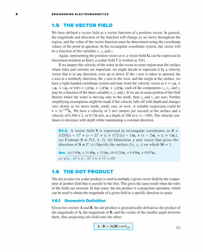
1.5 THE VECTOR FIELDWe have defined a vector field as a vector function of a position vector. In general, the magnitude and direction of the function will change as we move throughout the region, and the value of the vector function must be determined using the coordinate values of the point in question. In the rectangular coordinate system, the vector will be a function of the variables x, y, and z.
Again, representing the position vector as r, a vector field G can be expressed in functional notation as G(r); a scalar field T is written as T(r).
If we inspect the velocity of the water in the ocean in some region near the surface where tides and currents are important, we might decide to represent it by a velocity vector that is in any direction, even up or down. If the z axis is taken as upward, the x axis in a northerly direction, the y axis to the west, and the origin at the surface, we have a right-handed coordinate system and may write the velocity vector as v = vxax + vyay + vzaz, or v(r) = vx(r)ax + vy(r)ay + vz(r)az; each of the components vx, vy, and vz may be a function of the three variables x, y, and z. If we are in some portion of the Gulf Stream where the water is moving only to the north, then vy and vz are zero. Further simplifying assumptions might be made if the velocity falls off with depth and changes very slowly as we move north, south, east, or west. A suitable expression could be v = 2ez /100ax. We have a velocity of 2 m/s (meters per second) at the surface and a velocity of 0.368 × 2, or 0.736 m/s, at a depth of 100 m (z = −100). The velocity con-tinues to decrease with depth while maintaining a constant direction.
1.6 THE DOT PRODUCTThe dot product (or scalar product) is used to multiply a given vector field by the compo-nent of another field that is parallel to the first. This gives the same result when the roles of the fields are reversed. In that sense, the dot product is a projection operation, which can be used to obtain the magnitude of a given field in a specific direction in space.
1.6.1 Geometric Definition
Given two vectors A and B, the dot product is geometrically defined as the product of the magnitude of A, the magnitude of B, and the cosine of the smaller angle between them, thus projecting one field onto the other:
A · B = | A | | B | cos θ AB (3)
D1.2. A vector field S is expressed in rectangular coordinates as S = { 125/[(x − 1)2 + (y − 2)2 + (z + 1)2]}{(x − 1)ax + (y − 2)ay + (z + 1)az}. (a) Evaluate S at P(2, 4, 3). (b) Determine a unit vector that gives the direction of S at P. (c) Specify the surface f (x, y, z) on which |S| = 1.
Ans. (a) 5.95ax + 11.90ay + 23.8az; (b) 0.218ax + 0.436ay + 0.873az; (c) √
______________________ (x – 1)2 + (y – 2)2 + (z + 1)2 = 125
hay28159_ch01_001-025.indd 8 27/11/17 11:29 am

C H A P T E R 1 Vector Analysis 9
The dot appears between the two vectors and should be made heavy for emphasis. The dot, or scalar, product is a scalar, as one of the names implies, and it obeys the commutative law,
A · B = B · A (4)
for the sign of the angle does not affect the cosine term. The expression A · B is read “A dot B.”
A common application of the dot product is in mechanics, where a constant force F applied over a straight displacement L does an amount of work FL cos θ, which is more easily written F · L. If the force varies along the path, integration is necessary to find the total work (as is taken up in Chapter 4), and the result becomes
Work = ∫ F · dL
Another example occurs in magnetic fields. The total flux Φ crossing a surface of area S is given by BS if the magnetic flux density B is perpendicular to the surface and uniform over it. We define a vector surface S as having area for its magnitude and having a direction normal to the surface (avoiding for the moment the problem of which of the two possible normals to take). The flux crossing the surface is then B · S. This expression is valid for any direction of the uniform magnetic flux density. If the flux density is not constant over the surface, the total flux is Φ = ∫ B · d S.Integrals of this general form appear in Chapter 3 in the context of electric flux density.
1.6.2 Operational Definition
Finding the angle between two vectors in three-dimensional space is often a job we would prefer to avoid, and for that reason the definition of the dot product is usually not used in its basic form. A more helpful result is obtained by considering two vectors whose rectangular components are given, such as A = Axax + Ayay + Azaz and B = Bxax + Byay + Bzaz. The dot product also obeys the distributive law, and, therefore, A · B yields the sum of nine scalar terms, each involving the dot product of two unit vectors. Because the an-gle between two different unit vectors of the rectangular coordinate system is 90°, we then have
ax · ay = ay · ax = ax · az = az · ax = ay · az = az · ay = 0
The remaining three terms involve the dot product of a unit vector with itself, which is unity, giving finally the operational definition:
A · B = A x B x + A y B y + A z B z (5)
which is an expression involving no angles.
hay28159_ch01_001-025.indd 9 27/11/17 11:29 am

E N G I N E E R I N G E L E C T R O M AG N E T I C S10
A vector dotted with itself yields the magnitude squared, or
A · A = A 2 = | A | 2 (6)
and any unit vector dotted with itself is unity,
a A · a A = 1
One of the most important applications of the dot product is that of finding the component of a vector in a given direction. Referring to Figure 1.4a, we can obtain the component (scalar) of B in the direction specified by the unit vector a as
B · a = |B| |a| cos θBa = |B| cos θBa
The sign of the component is positive if 0 ≤ θBa ≤ 90◦ and negative whenever 90◦ ≤ θBa ≤ 180◦.
To obtain the component vector of B in the direction of a, we multiply the com-ponent (scalar) by a, as illustrated by Figure 1.4b. For example, the component of B in the direction of ax is B · ax = Bx, and the component vector is Bxax, or (B · ax)ax. Hence, the problem of finding the component of a vector in any direction becomes the problem of finding a unit vector in that direction, and that we can do.
The geometrical term projection is also used with the dot product. Thus, B · a is the projection of B in the a direction.
(a)
B B
aa
B ∙ a (B ∙ a) a
θBaθBa
(b)
Figure 1.4 (a) The scalar component of B in the direction of the unit vector a is B · a. (b) The vector component of B in the direction of the unit vector a is (B · a)a.
EXAMPLE 1 .2
In order to illustrate these definitions and operations, consider the vector field G = yax − 2.5xay + 3az and the point Q(4, 5, 2). We wish to find: G at Q; the scalar component of G at Q in the direction of a N = 1 __ 3 (2 a x + a y − 2 a z ); the vector com-ponent of G at Q in the direction of aN; and finally, the angle θGa between G(rQ) and aN.Solution. Substituting the coordinates of point Q into the expression for G, we have
G(rQ) = 5ax − 10ay + 3az
hay28159_ch01_001-025.indd 10 27/11/17 11:29 am

C H A P T E R 1 Vector Analysis 11
1.7 THE CROSS PRODUCTHere, we introduce the second special vector operation, the cross product (or vector product). This operation effectively multiplies one vector field by the component of another field that is perpendicular to the first. The result is specified as a third field that is normal to both fields at every point. In that sense, the operation is slightly more complicated than the dot product in that the result is a vector, rather than a sca-lar. Many physical phenomena are well described by a cross product of some kind; this is particularly true in electromagnetics as we will see.
1.7.1 Geometric Definition
Given two vectors A and B, we now define the cross product, or vector product, of A and B, written with a cross between the two vectors as A × B and read “A cross B.” The cross product A × B is a vector; the magnitude of A × B is equal to the product of the magnitudes of A, B, and the sine of the smaller angle between A and B; the direction of A × B is perpendicular to the plane containing A and B and is along one of the two possible perpendiculars which is in the direction of advance of a right-handed screw as A is turned into B. This direction is illustrated in Figure 1.5. Remember that either vector may be moved about at will, maintaining its direction constant, until the two vectors have a “common origin.” This determines the plane containing both. However, in most of our applications we will be concerned with vectors defined at the same point.
D1.3. The three vertices of a triangle are located at A(6, −1, 2), B(−2, 3, −4), and C(−3, 1, 5). Find: (a) RAB; (b) RAC; (c) the angle θBAC at vertex A; (d) the (vector) projection of RAB on RAC
.
Ans. (a) −8ax + 4ay − 6az; (b) −9ax + 2ay + 3az; (c) 53.6◦; (d) −5.94ax + 1.319ay + 1.979az
Next we find the scalar component. Using the dot product, we have
G · a N = (5 a x − 10 a y + 3 a z ) · 1 __ 3 (2 a x + a y − 2 a z ) = 1 __ 3 (10 − 10 − 6 ) = −2
The vector component is obtained by multiplying the scalar component by the unit vector in the direction of aN,
(G · a N ) a N = −(2) 1 __ 3 (2 a x + a y − 2 a z ) = −1.333 a x − 0.667 a y + 1.333 a zThe angle between G(rQ) and aN is found from
G · a N
= | G | cos θ Ga = √
__________ 25 + 100 + 9 cos θ Ga
and θ Ga = cos −1 − 2 ___
√ ____
134 = 99.9 °
–2
hay28159_ch01_001-025.indd 11 27/11/17 11:29 am

E N G I N E E R I N G E L E C T R O M AG N E T I C S12
As an equation we can write
A × B = aN |A| |B| sin θAB(7)
where an additional statement, such as that given above, is required to explain the direction of the unit vector aN. The subscript N stands for “normal.”
Reversing the order of the vectors A and B results in a unit vector in the opposite direction, and we see that the cross product is not commutative, for B × A = −(A × B). If the definition of the cross product is applied to the unit vectors ax and ay, we find ax × ay = az, for each vector has unit magnitude, the two vectors are per-pendicular, and the rotation of ax into ay indicates the positive z direction by the definition of a right-handed coordinate system. In a similar way, ay × az = ax and az × ax = ay. Note the alphabetic symmetry. As long as the three vectors ax, ay, and az are written in order (and assuming that ax follows az, like three elephants in a circle holding tails, so that we could also write ay, az, ax or az, ax, ay), then the cross and equal sign may be placed in either of the two vacant spaces. As a matter of fact, it is now simpler to define a right-handed rectangular coordinate system by saying that ax × ay = az.
A simple example of the use of the cross product may be taken from geometry or trigonometry. To find the area of a parallelogram, the product of the lengths of two adjacent sides is multiplied by the sine of the angle between them. Using vector notation for the two sides, we then may express the (scalar) area as the magnitude of A × B, or |A × B|.
The cross product may be used to replace the right-hand rule familiar to all electrical engineers. Consider the force on a straight conductor of length L, where the direction assigned to L corresponds to the direction of the steady current I, and
A × B
A
BθAB
Figure 1.5 The direction of A × B is inthe direction of advance of a right-handed screw as A is turned into B.
hay28159_ch01_001-025.indd 12 27/11/17 11:29 am

C H A P T E R 1 Vector Analysis 13
a uniform magnetic field of flux density B is present. Using vector notation, we may write the result neatly as F = I L × B. This relationship will be obtained later in Chapter 8.
1.7.2 Operational Definition
The evaluation of a cross product by means of its definition turns out to be more work than the evaluation of the dot product from its definition, for not only must we find the angle between the vectors, but we must also find an expression for the unit vector aN. This work may be avoided by using rectangular components for the two vectors A and B and expanding the cross product as a sum of nine simpler cross products, each involving two unit vectors,
A × B = A x B x a x × a x + A x B y a x × a y + A x B z a x × a z
+ A y B x a y × a x + A y B y a y × a y + A y B z a y × a z + A z B x a z × a x + A z B y a z × a y + A z B z a z × a z
We have already found that ax × ay = az, ay × az = ax, and az × ax = ay. The three remaining terms are zero, for the cross product of any vector with itself is zero, since the included angle is zero. These results may be combined to give the operational definition in rectangular coordinates:
A × B = ( A y B z − A z B y ) a x + ( A z B x − A x B z ) a y + ( A x B y − A y B x ) a z
This can be written as a determinant in a more easily remembered form:
A × B = | a x
a y
a z A x A y A z
B x
B y
B z | (9)
Thus, if A = 2ax − 3ay + az and B = −4ax − 2ay + 5az, we have
A × B = | a x
a y
a z
2 − 3 1 − 4
− 2
5 |
= [(− 3) (5) − (1(− 2)] a x − [(2) (5) − (1) (− 4)] a y + [(2) (− 2) − (− 3) (− 4)] a z = − 13 a x − 14 a y − 16 a z
(8)
D1.4. The three vertices of a triangle are located at A(6, −1, 2), B(−2, 3, −4), and C(−3, 1, 5). Find: (a) RAB × RAC; (b) the area of the triangle; (c) a unit vector perpendicular to the plane in which the triangle is located.
Ans. (a) 24ax + 78ay + 20az; (b) 42.0; (c) 0.286ax + 0.928ay + 0.238az
hay28159_ch01_001-025.indd 13 27/11/17 11:29 am

E N G I N E E R I N G E L E C T R O M AG N E T I C S14
1.8 OTHER COORDINATE SYSTEMS: CIRCULAR CYLINDRICAL COORDINATES
The rectangular coordinate system is generally the one in which students prefer to work every problem. This often means a lot more work, because many problems possess a type of symmetry that pleads for a more logical treatment. It is easier to do now, once and for all, the work required to become familiar with cylindrical and spherical coordinates, instead of applying an equal or greater effort to every problem involving cylindrical or spherical symmetry later. With this in mind, we will take a careful and unhurried look at cylindrical and spherical coordinates.
1.8.1 Point Coordinates
The circular cylindrical coordinate system is the three-dimensional version of the polar coordinates of analytic geometry. In polar coordinates, a point is located in a plane by giv-ing both its distance ρ from the origin and the angle ϕ between the line from the point to the origin and an arbitrary radial line, taken as ϕ = 0.3 In circular cylindrical coordinates, we also specify the distance z of the point from an arbitrary z = 0 reference plane. For simplicity, we usually refer to circular cylindrical coordinates simply as cylindrical coor-dinates. This will not cause any confusion in reading this book, but it is only fair to point out that there are such systems as elliptic cylindrical coordinates, hyperbolic cylindrical coordinates, parabolic cylindrical coordinates, and others.
We no longer set up three axes as with rectangular coordinates, but we must in-stead consider any point as the intersection of three mutually perpendicular surfaces. These surfaces are a circular cylinder (ρ = constant), a plane (ϕ = constant), and an-other plane (z = constant). This corresponds to the location of a point in a rectangular coordinate system by the intersection of three planes (x = constant, y = constant, and z = constant). The three surfaces of circular cylindrical coordinates are shown in Figure 1.6a. Note that three such surfaces may be passed through any point, unless it lies on the z axis, in which case one plane suffices.
1.8.2 Unit Vectors
Three unit vectors are defined for the cylindrical system, but we may no longer direct them along the “coordinate axes,” for such axes exist only in rectangular coordinates. Instead, we take a broader view of the unit vectors in rectangular coordinates and real-ize that they are directed toward increasing coordinate values and are perpendicular to the surface on which that coordinate value is constant (i.e., the unit vector ax is normal to the plane x = constant and points toward larger values of x). In a corresponding way we may now define three unit vectors in cylindrical coordinates, aρ, aϕ, and az.
3 The two variables of polar coordinates are commonly called r and θ. With three coordinates, however, it is more common to use ρ for the radius variable of cylindrical coordinates and r for the (different) radius variable of spherical coordinates. Also, the angle variable of cylindrical coordinates is custom-arily called ϕ because everyone uses θ for a different angle in spherical coordinates. The angle ϕ is common to both cylindrical and spherical coordinates. See?
hay28159_ch01_001-025.indd 14 27/11/17 11:29 am

C H A P T E R 1 Vector Analysis 15
The unit vector aρ at a point P(ρ1, ϕ1, z1) is directed radially outward, normal to the cylindrical surface ρ = ρ1. It lies in the planes ϕ = ϕ1 and z = z1. The unit vector aϕ is normal to the plane ϕ = ϕ1, points in the direction of increasing ϕ, lies in the plane z = z1, and is tangent to the cylindrical surface ρ = ρ1. The unit vector az is the same as the unit vector az of the rectangular coordinate system. Figure 1.6b shows the three vectors in cylindrical coordinates.
In rectangular coordinates, the unit vectors are not functions of the coordinates. Two of the unit vectors in cylindrical coordinates, aρ and aϕ, however, do vary with the coordinate ϕ, as their directions change. In integration or differentiation with respect to ϕ, then, aρ and aϕ must not be treated as constants.
The unit vectors are again mutually perpendicular, for each is normal to one of the three mutually perpendicular surfaces, and we may define a right-handed cylin-drical coordinate system as one in which aρ × aϕ = az, or (for those who have flexible fingers) as one in which the thumb, forefinger, and middle finger point in the direc-tion of increasing ρ, ϕ, and z, respectively.
Figure 1.6 (a) The three mutually perpendicular surfaces of the circular cylindrical co-ordinate system. (b) The three unit vectors of the circular cylindrical coordinate system. (c) The differential volume unit in the circular cylindrical coordinate system; dρ, ρd, and dz are all elements of length.
(c)
z + dz z
z
dz
dρ
ρ + dρϕ + dϕ
ρdϕρ
ρ ρ1z1
(ρ1 , ϕ1 , z1 )
ϕ1
P aϕ
aρ
az
P
ϕ
ϕ
ϕ = a constant
ρ = a constant
z = a constant
(b)(a)
y y
y
z z
x x
x
z
hay28159_ch01_001-025.indd 15 27/11/17 11:29 am

E N G I N E E R I N G E L E C T R O M AG N E T I C S16
1.8.3 Differential Area and Volume
A differential volume element in cylindrical coordinates may be obtained by increas-ing ρ, ϕ, and z by the differential increments dρ, dϕ, and dz. The two cylinders of radius ρ and ρ + dρ, the two radial planes at angles ϕ and ϕ + dϕ, and the two “hori-zontal” planes at “elevations” z and z + dz now enclose a small volume, as shown in Figure 1.6c, having the shape of a truncated wedge. As the volume element becomes very small, its shape approaches that of a rectangular parallelepiped having sides of length dρ, ρdϕ, and dz. Note that dρ and dz are dimensionally lengths, but dϕ is not; ρdϕ is the length. The surfaces have areas of ρ dρ dϕ, dρ dz, and ρ dϕ dz, and the volume is the product of the three side lengths, or ρ dρ dϕ dz.
1.8.4 Point Transformations
The variables of the rectangular and cylindrical coordinate systems are easily related to each other. Referring to Figure 1.7, we see that
x = ρ cos ϕy = ρ sin ϕz = z
From the other viewpoint, we may express the cylindrical variables in terms of x, y, and z:
ρ = √ _____
x 2 + y 2 (ρ ≥ 0 ) ϕ = tan −1 y_x z = z
(10)
(11)
Figure 1.7 The relationship between the rectangular variables x, y, z and the cylindrical coordinate variables ρ, , z. There is no change in the variable zbetween the two systems.
ϕ
ρ sin ϕρ cos ϕ ρ
x
y
z
P
z
hay28159_ch01_001-025.indd 16 27/11/17 11:29 am

C H A P T E R 1 Vector Analysis 17
We consider the variable ρ to be positive or zero, thus using only the positive sign for the radical in (11). The proper value of the angle ϕ is determined by inspecting the signs of x and y. Thus, if x = −3 and y = 4, we find that the point lies in the second quadrant so that ρ = 5 and ϕ = 126.9°. For x = 3 and y = −4, we have ϕ = −53.1° or 306.9°, whichever is more convenient.
Using (10) or (11), scalar functions given in one coordinate system are easily transformed into the other system.
1.8.5 Vector Component Transformations
A vector function in one coordinate system requires two steps in order to transform it to another coordinate system, because a different set of component vectors is gener-ally required. That is, we may be given a rectangular vector
A = A x a x + A y a y + A z a z
where each component is given as a function of x, y, and z, and we need a vector in cylindrical coordinates
A = A ρ a ρ + A ϕ a ϕ + A z a z
where each component is given as a function of ρ, ϕ, and z.To find any desired component of a vector, we recall from the discussion of the
dot product that a component in a desired direction may be obtained by taking the dot product of the vector and a unit vector in the desired direction. Hence,
A ρ = A · a ρ and A ϕ = A · a ϕ
In other words, Aρ and Aϕ are the projections of A into the aρ and aϕ directions. Ex-panding these dot products, we have
A ρ = ( A x a x + A y a y + A z a z ) · a ρ = A x a x · a ρ + A y a y · a ρ A ϕ = ( A x a x + A y a y + A z a z ) · a ϕ = A x a x · a ϕ + A y a y · a ϕ
and A z = ( A x a x + A y a y + A z a z ) · a z = A z a z · a z = A z
since az · aρ and az · aϕ are zero.In order to complete the transformation of the components, it is necessary to
know the dot products ax · aρ, ay · aρ, ax · aϕ, and ay · aϕ. Applying the definition of the dot product, we see that since we are concerned with unit vectors, the re-sult is merely the cosine of the angle between the two unit vectors in question. Referring to Figure 1.7 and thinking mightily, we identify the angle between ax and aρ as ϕ, and thus ax · aρ = cos ϕ, but the angle between ay and aρ is 90° − ϕ, and ay · aρ = cos (90° − ϕ) = sin ϕ. The remaining dot products of the unit vectors are found in a similar manner, and the results are tabulated as functions of ϕ in Table 1.1.
(12)(13)
(14)
hay28159_ch01_001-025.indd 17 27/11/17 11:29 am

E N G I N E E R I N G E L E C T R O M AG N E T I C S18
Transforming vectors from rectangular to cylindrical coordinates or vice versa is therefore accomplished by using (10) or (11) to change variables, and by using the dot products of the unit vectors given in Table 1.1 to change components. The two steps may be taken in either order.
Table 1.1 Dot products of unit vectors in cylindrical and rectangular coordinate systems
aρ aϕ az
ax · cosϕ −sinϕ 0ay · sinϕ cosϕ 0az · 0 0 1
D1.5. (a) Give the rectangular coordinates of the point C (ρ = 4.4, ϕ = −115°,z = 2). (b) Give the cylindrical coordinates of the point D (x = −3.1, y = 2.6,z = −3). (c) Specify the distance from C to D. Ans. (a) C(x = −1.860, y = −3.99, z = 2); (b) D(ρ = 4.05, ϕ = 140.0◦, z = −3); (c) 8.36
D1.6. Transform to cylindrical coordinates: (a) F = 10ax − 8ay + 6az at point P(10, −8, 6); (b) G = (2x + y)ax − (y − 4x)ay at point Q (ρ, ϕ, z). (c) Give the rectangular components of the vector H = 20aρ − 10aϕ + 3az at P(x = 5,y = 2, z = −1). Ans. (a) 12.81aρ + 6az; (b) (2ρ cos2 ϕ − ρ sin2 ϕ + 5ρ sin ϕ cos ϕ)aρ + (4ρ cos2 ϕ − ρ sin2 ϕ − 3ρ sin ϕ cos ϕ)aϕ; (c) Hx = 22.3, Hy = −1.857, Hz = 3
1.9 THE SPHERICAL COORDINATE SYSTEMWe have no two-dimensional coordinate system to help us understand the three- dimensional spherical coordinate system, as we have for the circular cylindri-cal coordinate system. In certain respects we can draw on our knowledge of the
EXAMPLE 1 .3
Transform the vector B = yax − xay + zaz into cylindrical coordinates.Solution. The new components are
Bρ = B · a! = y(ax · a!) − x(ay · a!)= y cos ϕ − x sin ϕ = ρ sin ϕ cos ϕ − ρ cos ϕ sin ϕ = 0
Bϕ = B · a" = y(ax · a") − x(ay · a")= −y sin ϕ − x cos ϕ = − ρ sin2 ϕ − ρ cos2 ϕ = − ρ
Thus,
B = − ρ a ϕ + z a z
hay28159_ch01_001-025.indd 18 27/11/17 11:29 am

C H A P T E R 1 Vector Analysis 19
latitude-and-longitude system of locating a place on the surface of the earth, but usually we consider only points on the surface and not those below or above ground.
1.9.1 Coordinates of a Point
We begin by building a spherical coordinate system on the three rectangular axes (Figure 1.8a). The distance from the origin to any point is defined as r. The surface r = constant is a sphere.
The second coordinate is an angle θ between the z axis and the line drawn from the origin to the point in question. The surface θ = constant is a cone, and the two surfaces, cone and sphere, are everywhere perpendicular along their intersection, which is a circle of radius r sin θ. The coordinate θ corresponds to latitude, except that latitude is measured from the equator and θ is measured from the “North Pole.”
Figure 1.8 (a) The three spherical coordinates. (b) The three mutually perpendicular surfaces of the spherical coordinate system. (c) The three unit vectors of spherical coordi-nates: ar × aθ = a. (d#) The differential volume element in the spherical coordinate system.
ϕ = a constant(plane)
ϕ
ϕ
r = a constant(sphere)
θ = a constant(cone)
θ
θ
PP
Par
aθ
aϕ
dr
r dθ
r sin θ dϕ
r
r
(a) (b)
(c) (d)
z
zz
y y
yy
xx
xx
z
hay28159_ch01_001-025.indd 19 27/11/17 11:29 am

E N G I N E E R I N G E L E C T R O M AG N E T I C S20
The third coordinate ϕ is also an angle and is exactly the same as the angle ϕ of cylindrical coordinates. It is the angle between the x axis and the projection in the z = 0 plane of the line drawn from the origin to the point. It corresponds to the angle of longitude, but the angle ϕ increases to the “east.” The surface ϕ = constant is a plane passing through the θ = 0 line (or the z axis).
We again consider any point as the intersection of three mutually perpendicular surfaces—a sphere, a cone, and a plane—each oriented in the manner just described. The three surfaces are shown in Figure 1.8b.
1.9.2 Unit Vectors in Spherical Coordinates
Three unit vectors may again be defined at any point. Each unit vector is perpen-dicular to one of the three mutually perpendicular surfaces and is oriented in that direction in which the coordinate increases. The unit vector ar is directed radially outward, normal to the sphere r = constant, and lies in the cone θ = constant and the plane ϕ = constant. The unit vector aθ is normal to the conical surface, lies in the plane, and is tangent to the sphere. It is directed along a line of “longitude” and points “south.” The third unit vector aϕ is the same as in cylindrical coordinates, being normal to the plane and tangent to both the cone and the sphere. It is directed to the “east.”
The three unit vectors are shown in Figure 1.8c. They are, of course, mutually perpendicular, and a right-handed coordinate system is defined by causing ar × aθ = aϕ. Our system is right-handed, as an inspection of Figure 1.8c will show, on appli-cation of the definition of the cross product. The right-hand rule identifies the thumb, forefinger, and middle finger with the direction of increasing r, θ, and ϕ, respectively. (Note that the identification in cylindrical coordinates was with ρ, ϕ, and z, and in rectangular coordinates with x, y, and z.)
1.9.3 Differential Surfaces and Volume
A differential volume element may be constructed in spherical coordinates by in-creasing r, θ, and ϕ by dr, dθ, and dϕ, as shown in Figure 1.8d. The distance between the two spherical surfaces of radius r and r + dr is dr; the distance between the two cones having generating angles of θ and θ + dθ is rdθ; and the distance between the two radial planes at angles ϕ and ϕ + dϕ is found to be r sin θ dϕ, after a few mo-ments of trigonometric thought. The surfaces have areas of r dr dθ, r sin θ dr dϕ, and r2 sin θ dθ dϕ, and the volume is r2 sin θ dr dθ dϕ.
1.9.4 Point Transformations
The transformation of scalars from the rectangular to the spherical coordinate system is easily made by using Figure 1.8a to relate the two sets of variables:
x = r sin θ cos ϕ y = r sin θ sin ϕz = r cos θ
(15)
hay28159_ch01_001-025.indd 20 27/11/17 11:29 am

C H A P T E R 1 Vector Analysis 21
The transformation in the reverse direction is achieved with the help of
Table 1.2 Dot products of unit vectors in spherical and rectangular coordinate systems
ar aθ aϕ
ax · sin θ cos ϕ cosθ cos ϕ −sin ϕay · sin θ sin ϕ cosθ sin ϕ cos ϕaz · cosθ −sin θ 0
We illustrate this procedure by transforming the vector field G = (xz/y)ax into spher-ical components and variables.Solution. We find the three spherical components by dotting G with the appropriate unit vectors, and we change variables during the procedure:
Gr = G · ar = xz __ y ax · ar = xz __ y sin θ cos ϕ
= r sin θ cos θ cos2 ϕ______sin ϕ
EXAMPLE 1 .4
r = √ ________ x 2 + y 2 + z 2 (r ≥ 0)
θ = cos −1 z _______ √
________ x 2 + y 2 + z 2 (0° ≤ θ ≤ 180 °) (16)
ϕ = tan −1 y_xThe radius variable r is nonnegative, and θ is restricted to the range from 0° to 180°, inclu-sive. The angles are placed in the proper quadrants by inspecting the signs of x, y, and z.
1.9.5 Vector Component Transformations
The transformation of vectors requires us to determine the products of the unit vec-tors in rectangular and spherical coordinates. We work out these products from Fig-ure 1.8c and a pinch of trigonometry. Because the dot product of any spherical unit vector with any rectangular unit vector is the component of the spherical vector in the direction of the rectangular vector, the dot products with az are found to be
az · ar = cos θaz · aθ = − sin θ az · aϕ = 0
The dot products involving ax and ay require first the projection of the spherical unit vector on the xy plane and then the projection onto the desired axis. For example, ar · ax is obtained by projecting ar onto the xy plane, giving sin θ, and then projecting sin θ on the x axis, which yields sin θ cos ϕ. The other dot products are found in a like manner, and all are shown in Table 1.2.
hay28159_ch01_001-025.indd 21 27/11/17 11:29 am

E N G I N E E R I N G E L E C T R O M AG N E T I C S22
REFERENCES1. Grossman, S. I. Calculus. 3d ed. Orlando, Fla.: Academic Press and Harcourt Brace
Jovanovich, 1984. Vector algebra and cylindrical and spherical coordinates appear inChapter 17, and vector calculus is introduced in Chapter 20.
2. Spiegel, M. R. Vector Analysis. Schaum Outline Series. New York: McGraw-Hill, 1959.A large number of examples and problems with answers are provided in this concise,inexpensive member of an outline series.
3. Swokowski, E. W. Calculus with Analytic Geometry. 3d ed. Boston: Prindle, Weber, &Schmidt, 1984. Vector algebra and the cylindrical and spherical coordinate systems arediscussed in Chapter 14, and vector calculus appears in Chapter 18.
4. Thomas, G. B., Jr., and R. L. Finney. Calculus and Analytic Geometry. 6th ed. Reading,Mass.: Addison-Wesley Publishing Company, 1984. Vector algebra and the threecoordinate systems we use are discussed in Chapter 13. Other vector operations arediscussed in Chapters 15 and 17.
CHAPTER 1 PROBLEMS1.1 If A represents a vector two units in length directed due west, B represents
a vector three units in length directed due north, and A + B = C − D and
Gθ = G · a# = xz __ y ax · a# = xz __ y cos θ cos ϕ
= r cos2 θ cos2 ϕ______sin ϕ
Gϕ = G · a" = xz __ y ax · a" = xz __ y (−sin ϕ)= − r cos θ cos ϕ
Collecting these results, we have
G = r cos θ cos ϕ (sin θ cot ϕ a r + cos θ cot ϕ a θ − a ϕ )
Appendix A describes the general curvilinear coordinate system of which the rectangular, circular cylindrical, and spherical coordinate systems are special cases. The first section of this appendix could well be scanned now.
D1.7. Given the two points, C(−3, 2, 1) and D(r = 5, θ = 20°, ϕ = −70°), find: (a) the spherical coordinates of C; (b) the rectangular coordinates of D; (c) the distance from C to D.
Ans. (a) C(r = 3.74, θ = 74.5◦, ϕ = 146.3◦); (b) D(x = 0.585, y = −1.607, z = 4.70); (c) 6.29
D1.8. Transform the following vectors to spherical coordinates at the points given: (a) 10ax at P(x = −3, y = 2, z = 4); (b) 10ay at Q(ρ = 5, ϕ = 30°, z = 4); (c) 10az at M(r = 4, θ = 110°, ϕ = 120°).
Ans. (a) −5.57ar − 6.18aθ − 5.55aϕ; (b) 3.90ar + 3.12aθ + 8.66aϕ; (c) −3.42ar − 9.40aθ
hay28159_ch01_001-025.indd 22 27/11/17 11:29 am

C H A P T E R 1 Vector Analysis 23
2B − A = C + D, find the magnitudes and directions of C and D. Take north as the positive y direction.
1.2 Vector A extends from the origin to (1, 2, 3), and vector B extends from the origin to (2, 3, −2). Find (a) the unit vector in the direction of (A − B); (b) the unit vector in the direction of the line extending from the origin to the midpoint of the line joining the ends of A and B.
1.3 The vector from the origin to point A is given as (6, −2, −4), and the unit vector directed from the origin toward point B is (2, −2, 1)/3. If points A and B are ten units apart, find the coordinates of point B.
1.4 A circle, centered at the origin with a radius of 2 units, lies in the xy plane. Determine the unit vector in rectangular components that lies in the xy plane,is tangent to the circle at ( √
__ 3 , −1, 0), and is in the general direction of
increasing values of x.
1.5 An equilateral triangle lies in the xy plane with its centroid at the origin. One vertex lies on the positive y axis. (a) Find unit vectors that are directed from the origin to the three vertices. (b) Find unit vectors that are directed from the origin to the three sides, intersecting these at right angles.
1.6 Find the acute angle between the two vectors A = 2ax + ay + 3az and B = ax − 3ay + 2az by using the definition of (a) the dot product; (b) the cross product.
1.7 Given the field F = x a x + y ay. If F · G = 2xy and F × G = ( x 2 – y 2 ) a z find G.1.8 Demonstrate the ambiguity that results when the cross product is used to find the
angle between two vectors by finding the angle between A = 3ax − 2ay + 4az and B = 2ax + ay − 2az. Does this ambiguity exist when the dot product is used?
1.9 A field is given as G = [25/(x2 + y2)](xax + yay). Find (a) a unit vector in the direction of G at P(3, 4, −2); (b) the angle between G and ax at P; (c) the value of the following double integral on the plane y = 7.
∫ 0
4 ∫ 0
2 G · a y dzdx
1.10 By expressing diagonals as vectors and using the definition of the dot product, find the smaller angle between any two diagonals of a cube, where each diagonal connects diametrically opposite corners and passes through the center of the cube.
1.11 Given the points M(0.1, −0.2, −0.1), N(−0.2, 0.1, 0.3), and P(0.4, 0, 0.1), find (a) the vector RMN; (b) the dot product RMN · RMP; (c) the scalar projection of RMN on RMP; (d) the angle between RMN and RMP .
1.12 Write an expression in rectangular components for the vector that extends from (x1, y1, z1) to (x2, y2, z2) and determine the magnitude of this vector.
1.13 Find (a) the vector component of F = 10ax − 6ay + 5az that is parallel to G = 0.1ax + 0.2ay + 0.3az; (b) the vector component of F that is perpendicular to G; (c) the vector component of G that is perpendicular to F.
hay28159_ch01_001-025.indd 23 27/11/17 11:29 am

E N G I N E E R I N G E L E C T R O M AG N E T I C S24
1.14 Given that A + B + C = 0, where the three vectors represent line segments and extend from a common origin, must the three vectors be coplanar? If A + B + C + D = 0, are the four vectors coplanar?
1.15 Three vectors extending from the origin are given as r1 = (7, 3, −2), r2 = (−2, 7, −3), and r3 = (0, 2, 3). Find (a) a unit vector perpendicular to both r1 and r2; (b) a unit vector perpendicular to the vectors r1 − r2 and r2 − r3; (c) the area of the triangle defined by r1 and r2; (d) the area of the triangle defined by the heads of r1, r2, and r3.
1.16 In geometrical optics, the path of a light ray can be treated as a vector having the usual three components in a rectangular coordinate system. When light reflects from a plane surface, the effect is to reverse the vector component of the ray that is normal to that surface. This yields a reflection angle that is equal to the incidence angle. Using a vector representation in rectangular coordinates, demonstrate what happens when a light ray reflects from a corner cube reflector, consisting of three mutually orthogonal surfaces that occupy, for example, the xy, xz, and yz planes. The ray is incident in an arbitrary direction within the first octant of the coordinate system and has initially negative x, y, and z components of travel.
1.17 Point A(−4, 2, 5) and the two vectors, RAM = (20, 18, −10)? and RAN = (−10, 8, 15), define a triangle. Find (a) a unit vector perpendicular to the triangle; (b) a unit vector in the plane of the triangle and perpendicular to RAN; (c) a unit vector in the plane of the triangle that bisects the interior angle at A.
1.18 Given two fields in spherical coordinates, E = (A/r) sin θ aθ and H = (B/r) sin θ aϕ (a) evaluate S = E × H and express the result in rectangular coordinates. (b) Determine S along the x, y, and z axes.
1.19 Consider the important inverse-square radial field, expressed in spherical coordinates: F = Ar−2 ar where A is a constant. (a) Transform the field into cylindrical coordinates. (b) Transform the field into rectangular coordinates.
1.20 If the three sides of a triangle are represented by vectors A, B, and C, all directed counterclockwise, show that |C|2 = (A + B) · (A + B) and expand the product to obtain the law of cosines.
1.21 Express in cylindrical components: (a) the vector from C(3, 2, −7) to D(−1, −4, 2); (b) a unit vector at D directed toward C; (c) a unit vector at D directed toward the origin.
1.22 A sphere of radius a, centered at the origin, rotates about the z axis at angular velocity Ω rad/s. The rotation direction is clockwise when one is looking in the positive z direction. (a) Using spherical components, write an expression for the velocity field, v, that gives the tangential velocity at any point on the sphere surface. (b) Derive an expression for the difference in velocities between two points on the surface that have different latitudes, where the latitude difference is Δθ in radians. Assume Δθ is small. (c) Find the difference in velocities one degree on either side of 45° north latitude on earth. Take the earth’s radius as 6370 km at 45°.
hay28159_ch01_001-025.indd 24 27/11/17 11:29 am

C H A P T E R 1 Vector Analysis 25
1.23 The surfaces ρ = 3, ρ = 5, ϕ = 100°, ϕ = 130°, z = 3, and z = 4.5 define a closed surface. Find (a) the enclosed volume; (b) the total area of the enclosing surface; (c) the total length of the 12 edges of the surfaces; (d) the length of the longest straight line that lies entirely within the volume.
1.24 Two unit vectors, a1 and a2, lie in the xy plane and pass through the origin. They make angles ϕ1 and ϕ2, respectively, with the x axis (a) Express each vector in rectangular components; (b) take the dot product and verify the trigonometric identity, cos(ϕ1 − ϕ2) = cos ϕ1 cos ϕ2 + sin ϕ1 sin ϕ2; (c) take the cross product and verify the trigonometric identity sin(ϕ2 − ϕ1) = sin ϕ2 cos ϕ1 − cos ϕ2 sin ϕ1.
1.25 Convert the vector field H = A(x2+ y2)−1 [xay − yax] into cylindrical coordinates. A is a constant.
1.26 Express the uniform vector field F = 10ay in (a) cylindrical components; (b) spherical components.
1.27 The important dipole field (to be addressed in Chapter 4) is expressed in spherical coordinates as
E = A __ r3 (2 cos θ ar + sin θ aθ)
where A is a constant, and where r > 0. See Figure 4.9 for a sketch. (a) Identify the surface on which the field is entirely perpendicular to the xy plane and express the field on that surface in cylindrical coordinates. (b) Identify the coordinate axis on which the field is entirely perpendicular to the xy plane and express the field there in cylindrical coordinates. (c) Specify the surface on which the field is entirely parallel to the xy plane.
1.28 State whether or not A = B and, if not, what conditions are imposed on A and B when (a) A · ax = B · ax; (b) A × ax = B × ax; (c) A · ax = B · ax and A × ax = B × ax; (d) A · C = B · C and A × C = B × C where C is any vector except C = 0.
1.29 A vector field is expressed as F = Az az where A is a constant. Evaluate the components of this field that are (a) normal and (b) tangent to a spherical surface of radius a. Express all results in spherical coordinates and components.
1.30 Consider a problem analogous to the varying wind velocities encountered by transcontinental aircraft. We assume a constant altitude, a plane earth, a flight along the x axis from 0 to 10 units, no vertical velocity component, and no change in wind velocity with time. Assume ax to be directed to the east and ay to the north. The wind velocity at the operating altitude is assumed to be:
v(x, y ) = (0.01 x 2 − 0.08x + 0.66 ) a x − (0.05x − 0.4 ) a y ____________________________
1 + 0.5 y 2
Determine the location and magnitude of (a) the maximum tailwind encountered; (b) repeat for headwind; (c) repeat for crosswind; (d) Would more favorable tailwinds be available at some other latitude? If so, where?
hay28159_ch01_001-025.indd 25 27/11/17 11:29 am
Copyright © 2022 FDOKUMEN